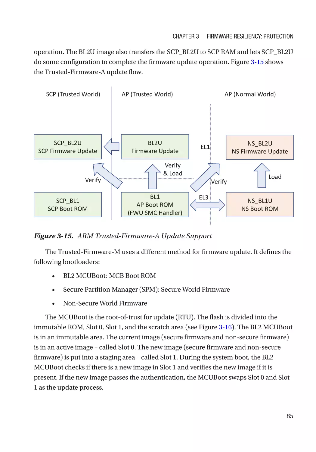
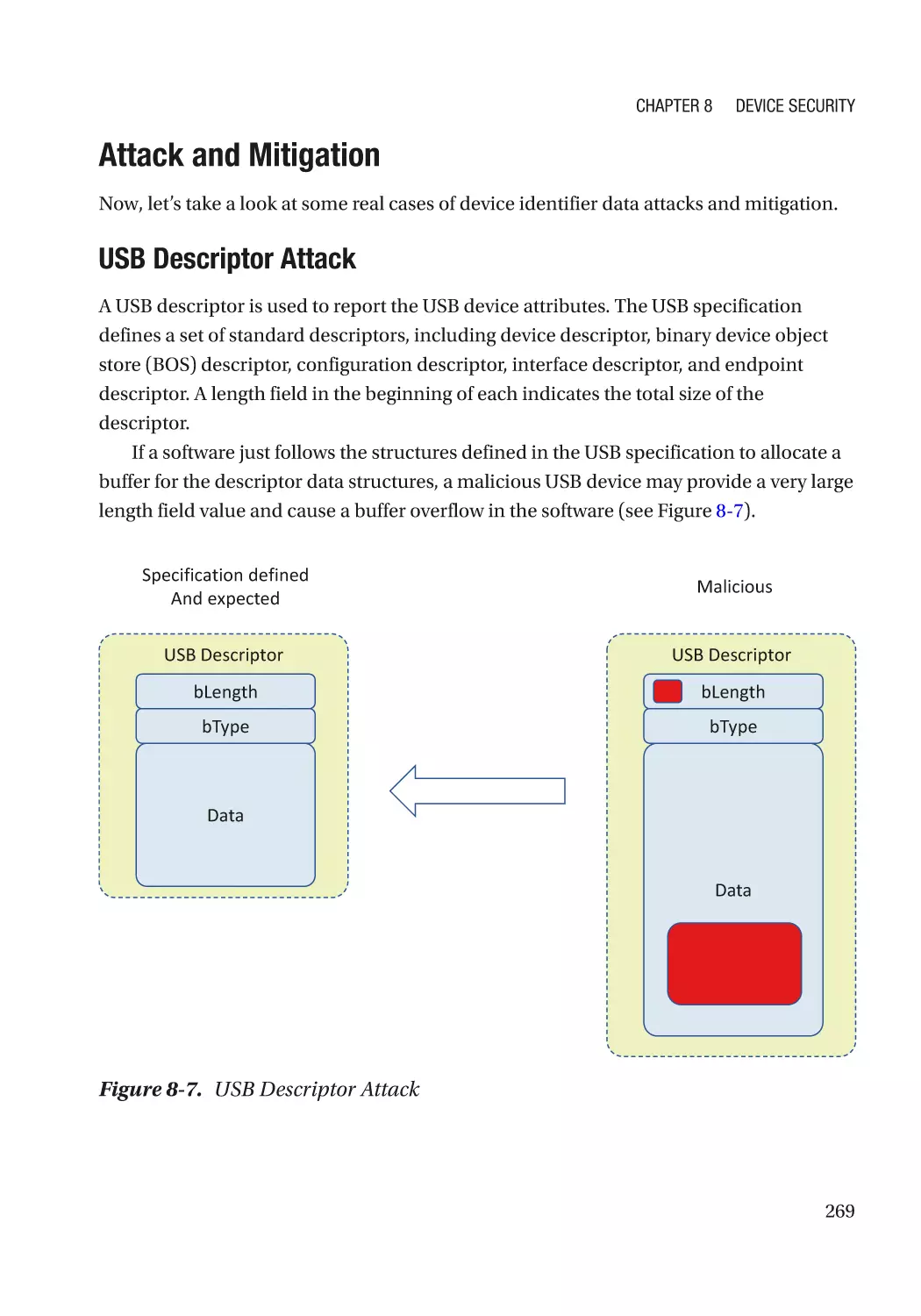
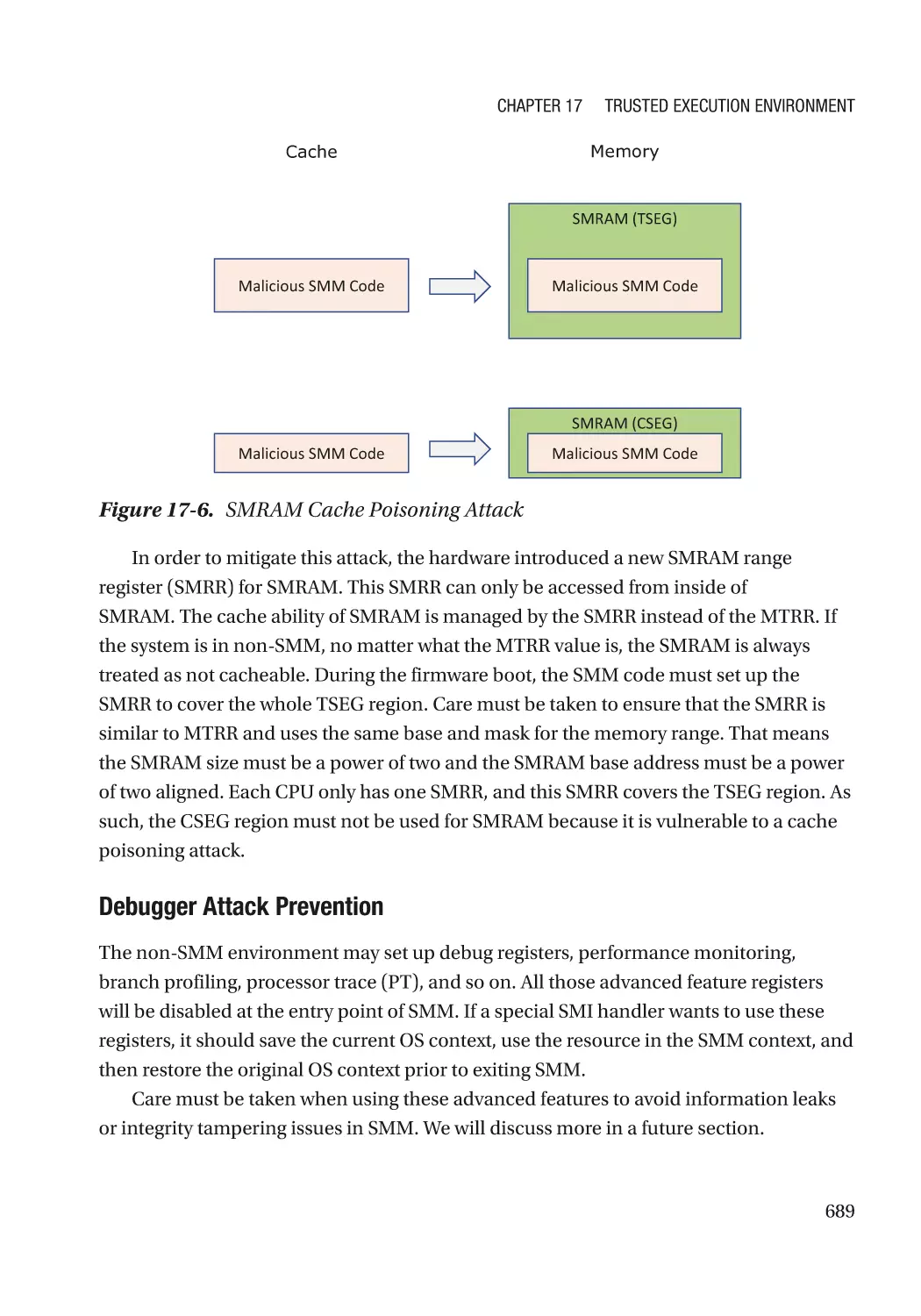
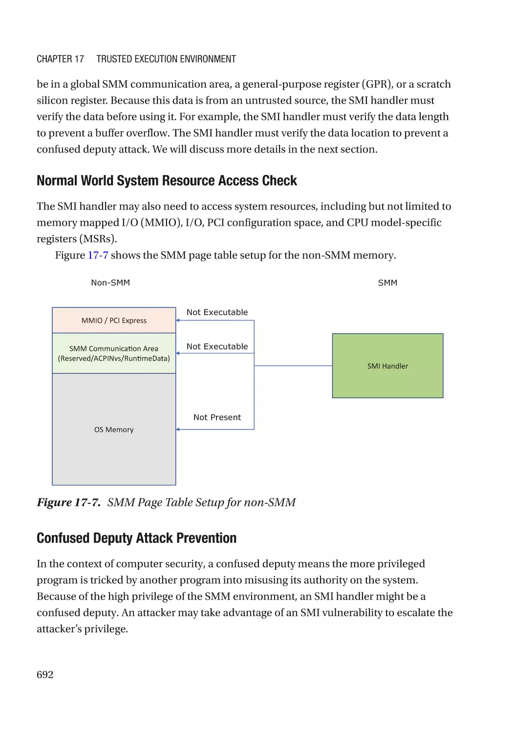
/


Author: Zimmer Vincent Yao Jiewen
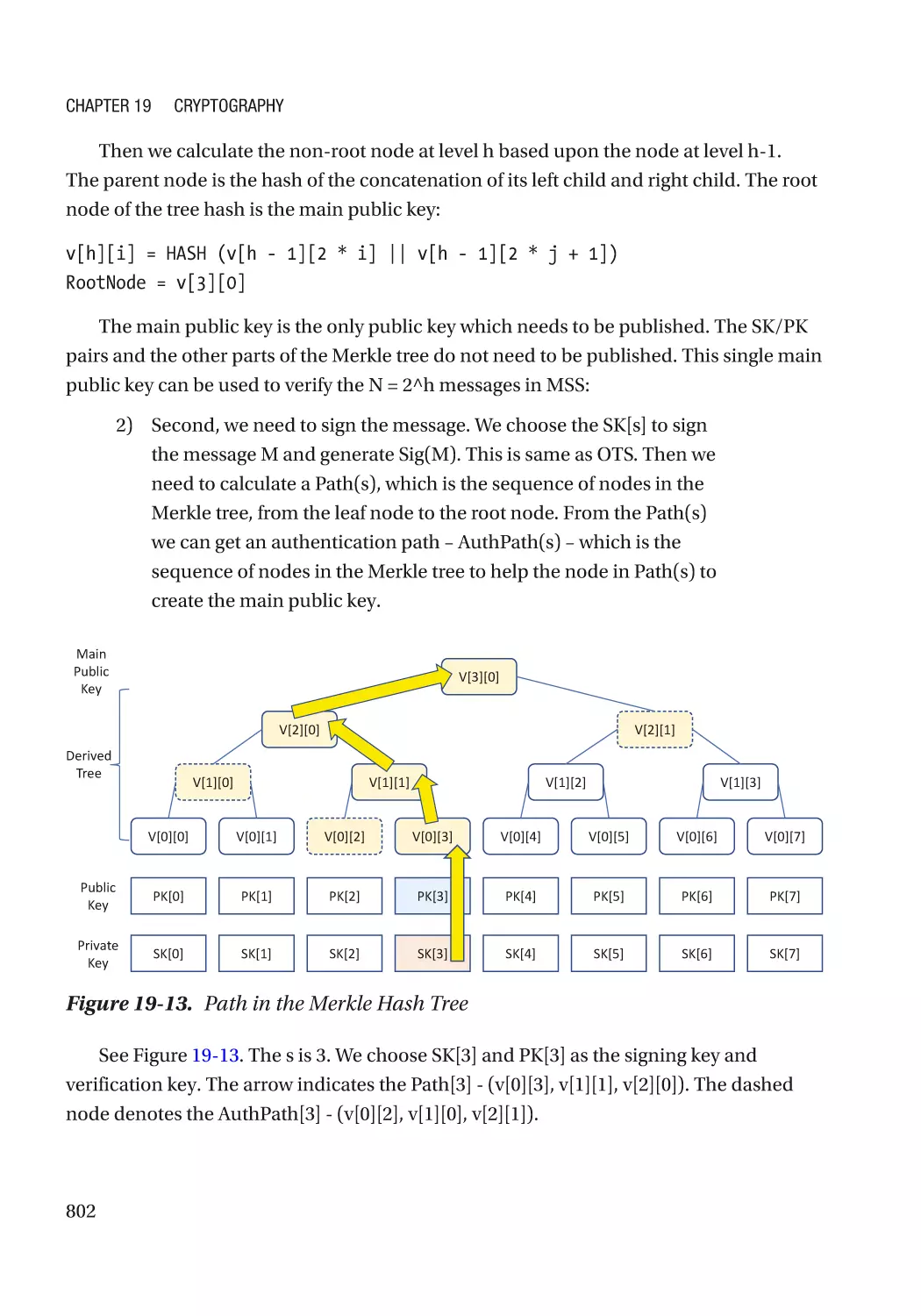
Tags: programming software computer systems computer technologies
ISBN: 978-1-4842-6105-7
Year: 2020


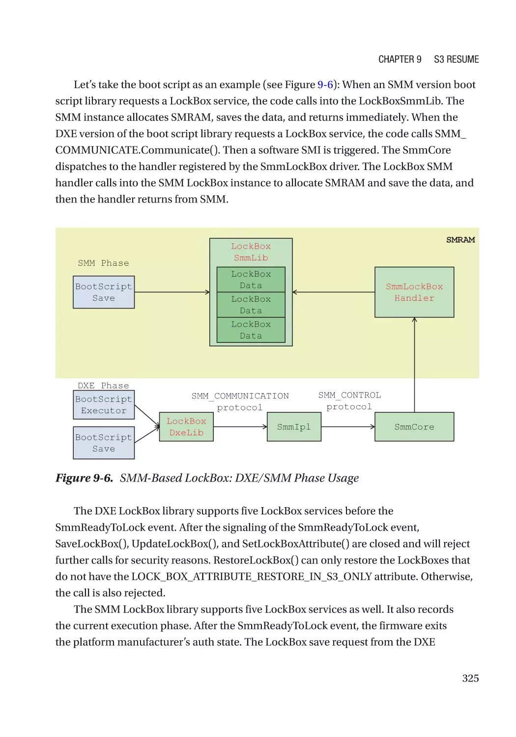
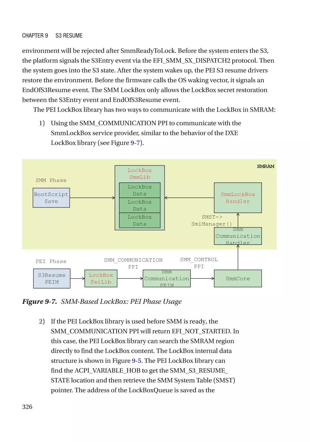
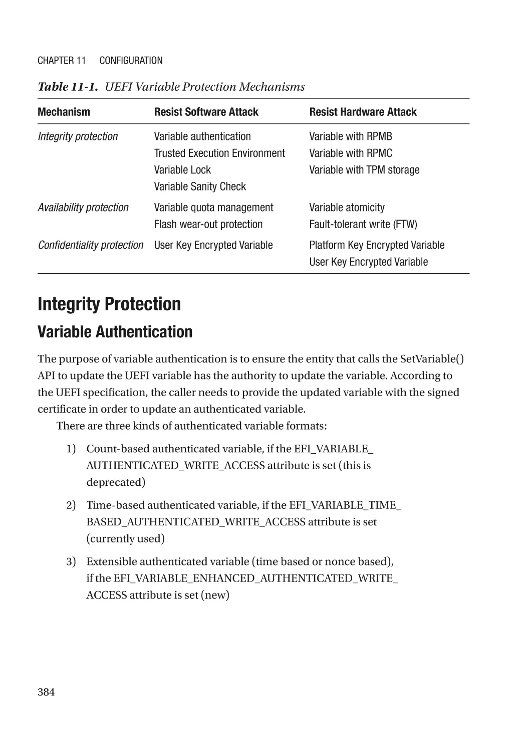
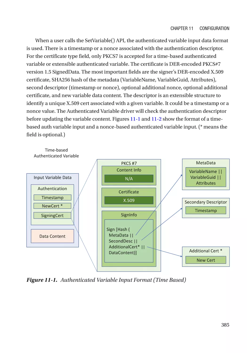
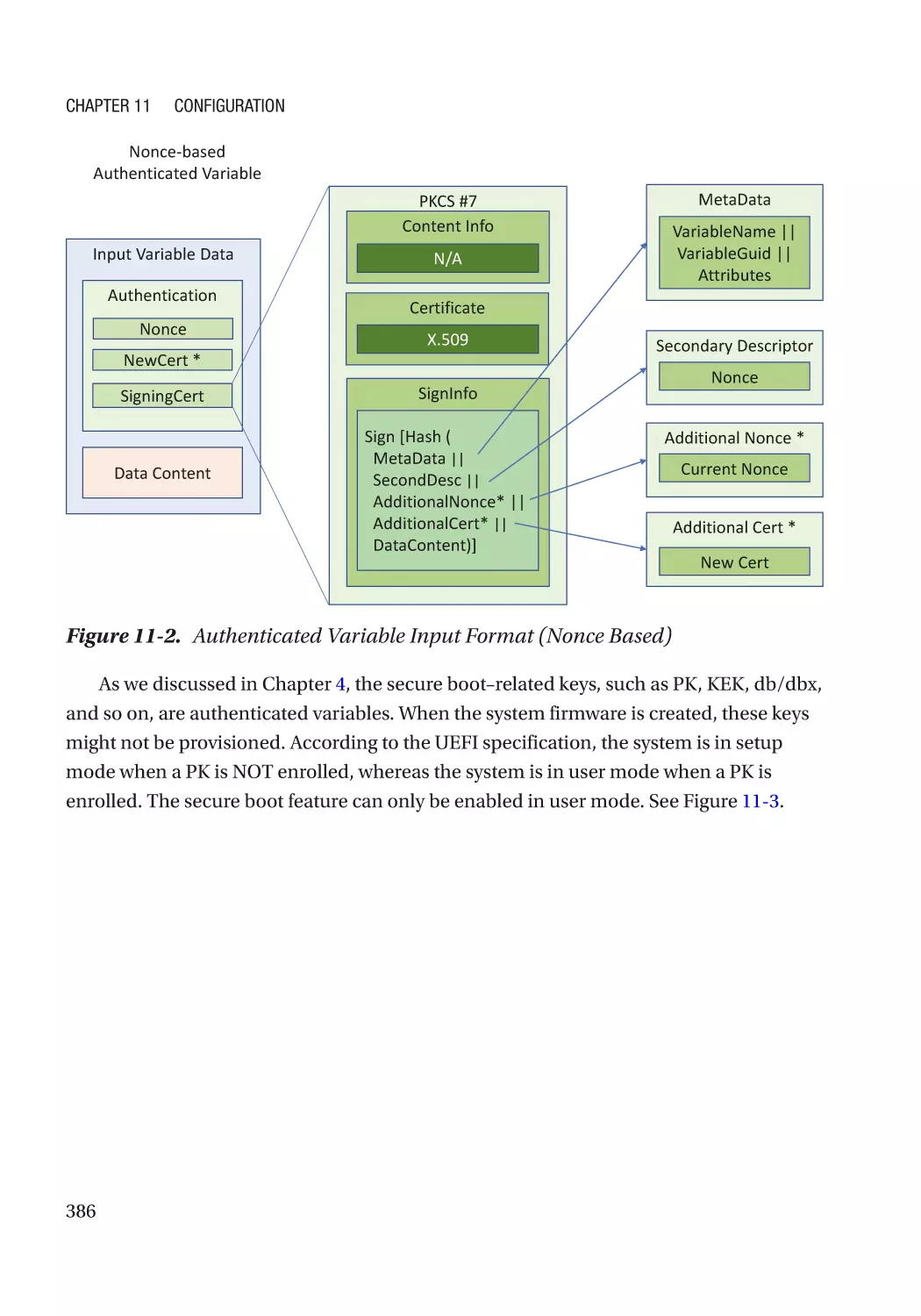
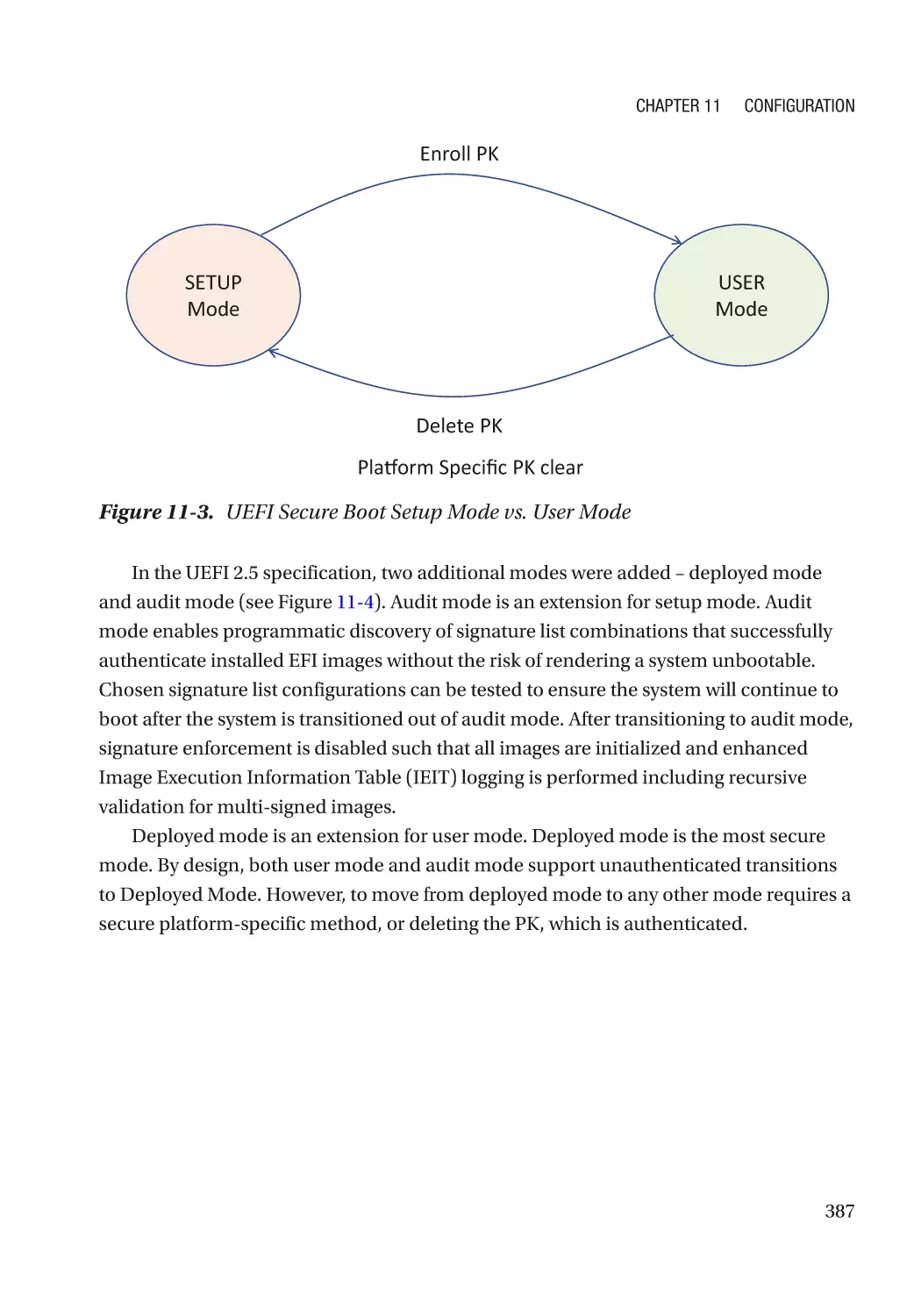
Text
Building Secure
Firmware
Armoring the Foundation of the Platform
—
Jiewen Yao
Vincent Zimmer
Building Secure Firmware
Armoring the Foundation
of the Platform
Jiewen Yao
Vincent Zimmer
Building Secure Firmware: Armoring the Foundation of the Platform
Jiewen Yao
Shanghai, China
Vincent Zimmer
Issaquah, WA, USA
ISBN-13 (pbk): 978-1-4842-6105-7
https://doi.org/10.1007/978-1-4842-6106-4
ISBN-13 (electronic): 978-1-4842-6106-4
Copyright © 2020 by Jiewen Yao and Vincent Zimmer
This work is subject to copyright. All rights are reserved by the Publisher, whether the whole or part of the
material is concerned, specifically the rights of translation, reprinting, reuse of illustrations, recitation,
broadcasting, reproduction on microfilms or in any other physical way, and transmission or information
storage and retrieval, electronic adaptation, computer software, or by similar or dissimilar methodology now
known or hereafter developed.
Trademarked names, logos, and images may appear in this book. Rather than use a trademark symbol with
every occurrence of a trademarked name, logo, or image we use the names, logos, and images only in an
editorial fashion and to the benefit of the trademark owner, with no intention of infringement of the
trademark.
The use in this publication of trade names, trademarks, service marks, and similar terms, even if they are not
identified as such, is not to be taken as an expression of opinion as to whether or not they are subject to
proprietary rights.
While the advice and information in this book are believed to be true and accurate at the date of publication,
neither the authors nor the editors nor the publisher can accept any legal responsibility for any errors or
omissions that may be made. The publisher makes no warranty, express or implied, with respect to the
material contained herein.
Managing Director, Apress Media LLC: Welmoed Spahr
Acquisitions Editor: Susan McDermott
Development Editor: Laura Berendson
Coordinating Editor: Jessica Vakili
Distributed to the book trade worldwide by Springer Science+Business Media New York, 233 Spring Street,
6th Floor, New York, NY 10013. Phone 1-800-SPRINGER, fax (201) 348-4505, e-mail orders-ny@springersbm.com, or visit www.springeronline.com. Apress Media, LLC is a California LLC and the sole member
(owner) is Springer Science + Business Media Finance Inc (SSBM Finance Inc). SSBM Finance Inc is a
Delaware corporation.
For information on translations, please e-mail booktranslations@springernature.com; for reprint, paperback,
or audio rights, please e-mail bookpermissions@springernature.com.
Apress titles may be purchased in bulk for academic, corporate, or promotional use. eBook versions and
licenses are also available for most titles. For more information, reference our Print and eBook Bulk Sales
web page at http://www.apress.com/bulk-sales.
Any source code or other supplementary material referenced by the author in this book is available to
readers on GitHub via the book’s product page, located at www.apress.com/978-1-4842-6105-7. For more
detailed information, please visit http://www.apress.com/source-code.
Printed on acid-free paper
To my lovely wife, Wenjun Zeng. Thank you for your constant
encouragement and unconditional support!
—Jiewen Yao
To my parents; to my wife, Jan; and to my daughters, Ally and Zoe.
Your support and love are rays of sunshine that warm my days.
—Vincent Zimmer
Table of Contents
About the Authors���������������������������������������������������������������������������������������������������xix
About the Technical Reviewer��������������������������������������������������������������������������������xxi
Organization and What Is Covered�����������������������������������������������������������������������xxiii
Acknowledgments�������������������������������������������������������������������������������������������������xxv
Preface����������������������������������������������������������������������������������������������������������������xxvii
Foreword��������������������������������������������������������������������������������������������������������������xxix
Part I: Overview���������������������������������������������������������������������������������������������� 1
Chapter 1: Introduction to Firmware������������������������������������������������������������������������ 3
Similarity Between Firmware and Software��������������������������������������������������������������������������������� 3
Distinction Between Firmware and Software������������������������������������������������������������������������������� 5
Introduction to Firmware Security������������������������������������������������������������������������������������������������ 6
Firmware Resiliency���������������������������������������������������������������������������������������������������������������� 7
Firmware Measurement and Attestation��������������������������������������������������������������������������������� 8
Secure Device Communication������������������������������������������������������������������������������������������������ 8
Introduction to Variants of Host Firmware������������������������������������������������������������������������������������ 9
Industry Standards���������������������������������������������������������������������������������������������������������������������� 10
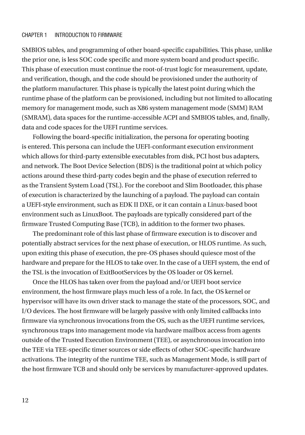
Boot Flow and Phased Handoff��������������������������������������������������������������������������������������������������� 11
Introduction to Non-host Firmware��������������������������������������������������������������������������������������������� 13
Introduction to Device Firmware������������������������������������������������������������������������������������������������� 14
Summary������������������������������������������������������������������������������������������������������������������������������������ 14
References���������������������������������������������������������������������������������������������������������������������������������� 15
v
Table of Contents
Chapter 2: Proactive Firmware Security Development������������������������������������������� 17
Requirement Phase��������������������������������������������������������������������������������������������������������������������� 17
Security Requirements���������������������������������������������������������������������������������������������������������� 17
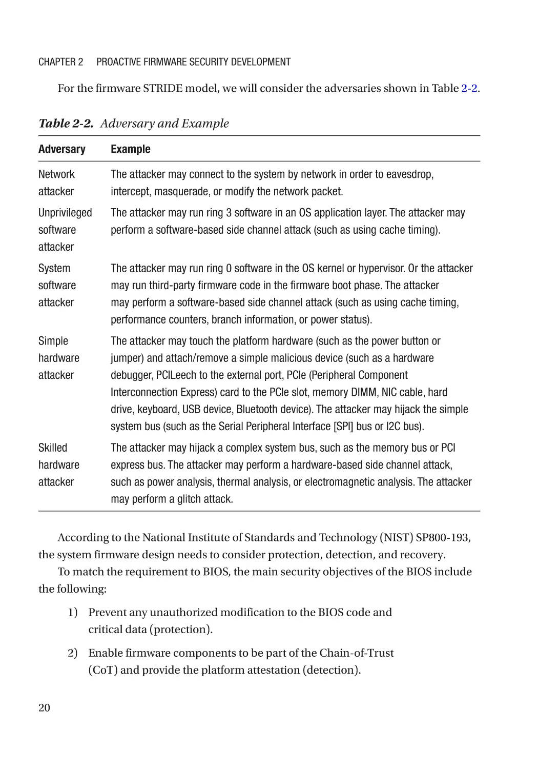
Threat Model and Architecture Phase����������������������������������������������������������������������������������������� 18
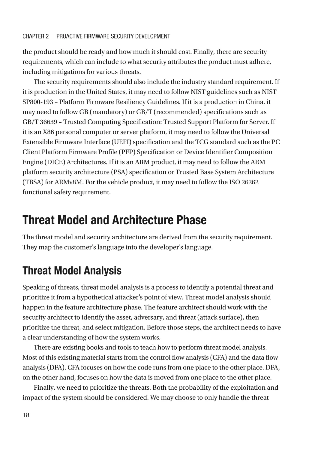
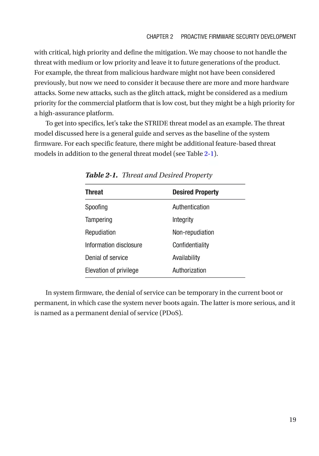
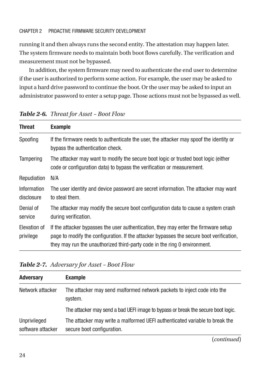
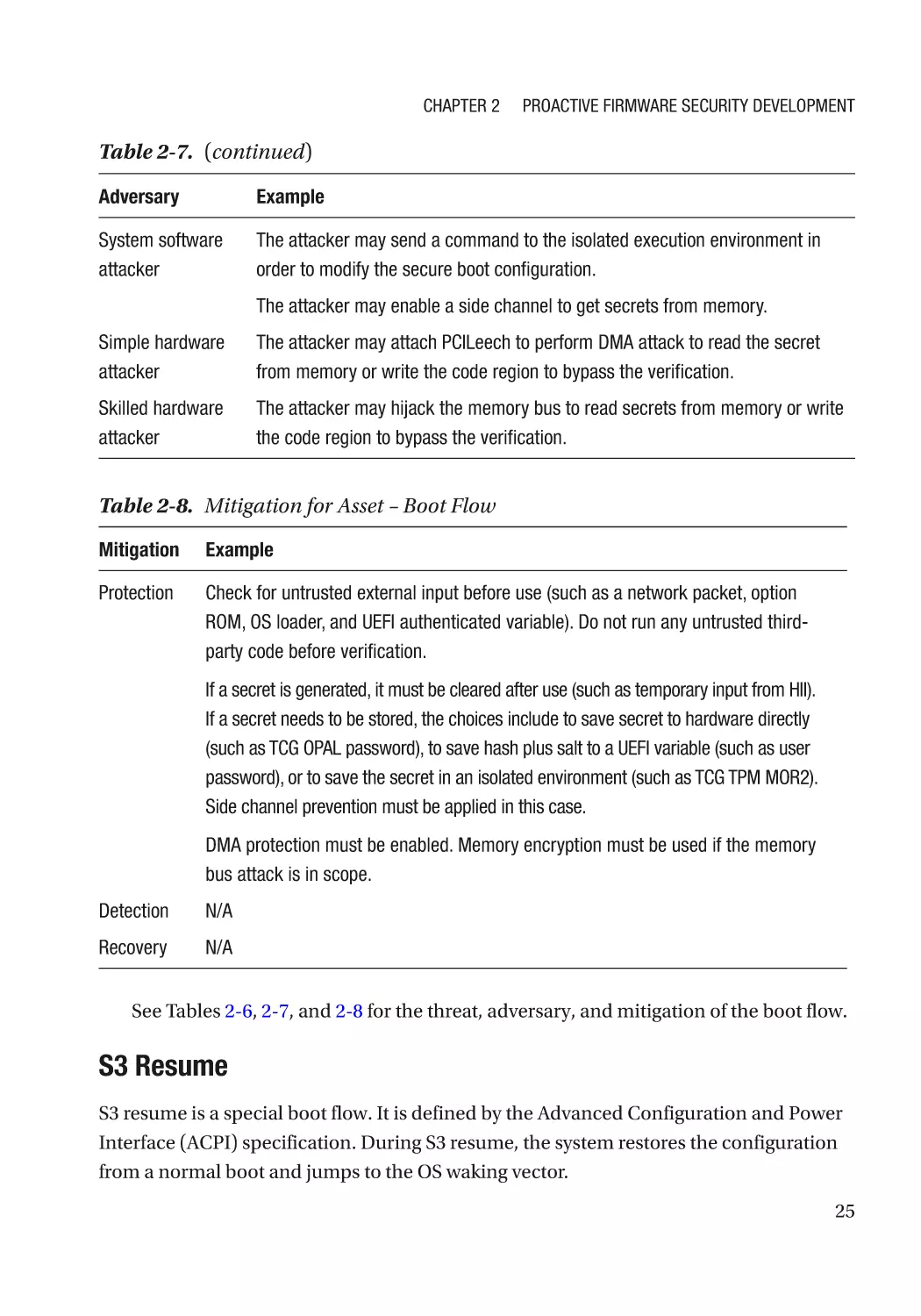
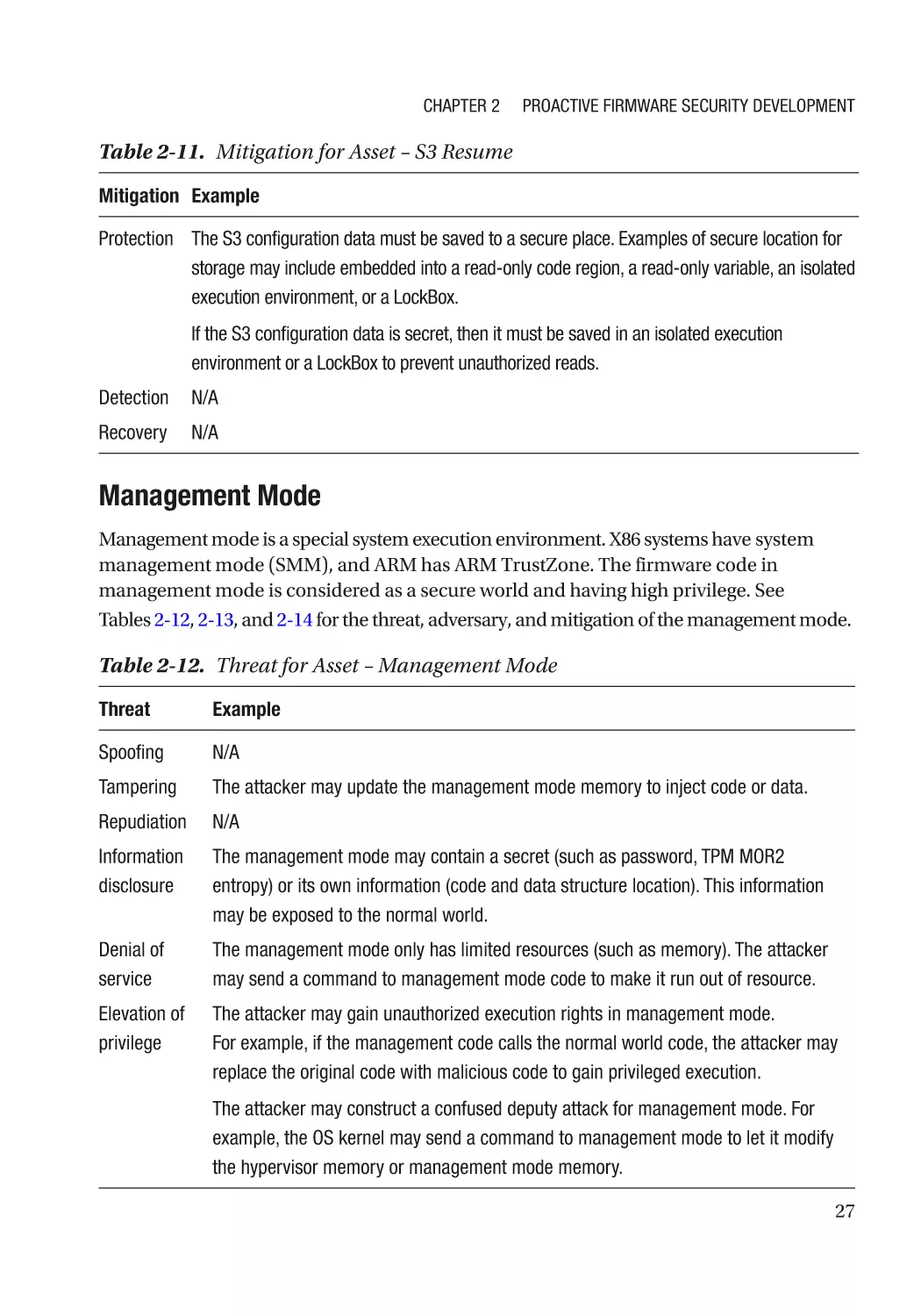
Threat Model Analysis����������������������������������������������������������������������������������������������������������� 18
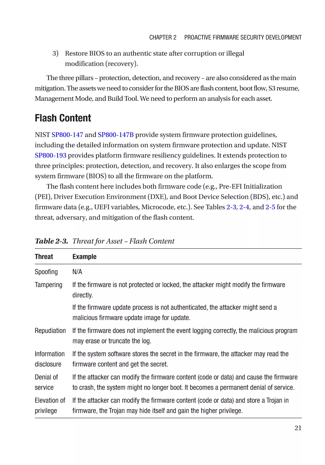
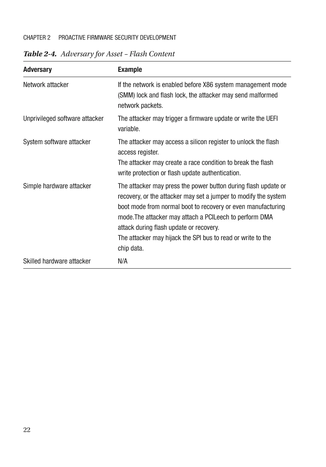
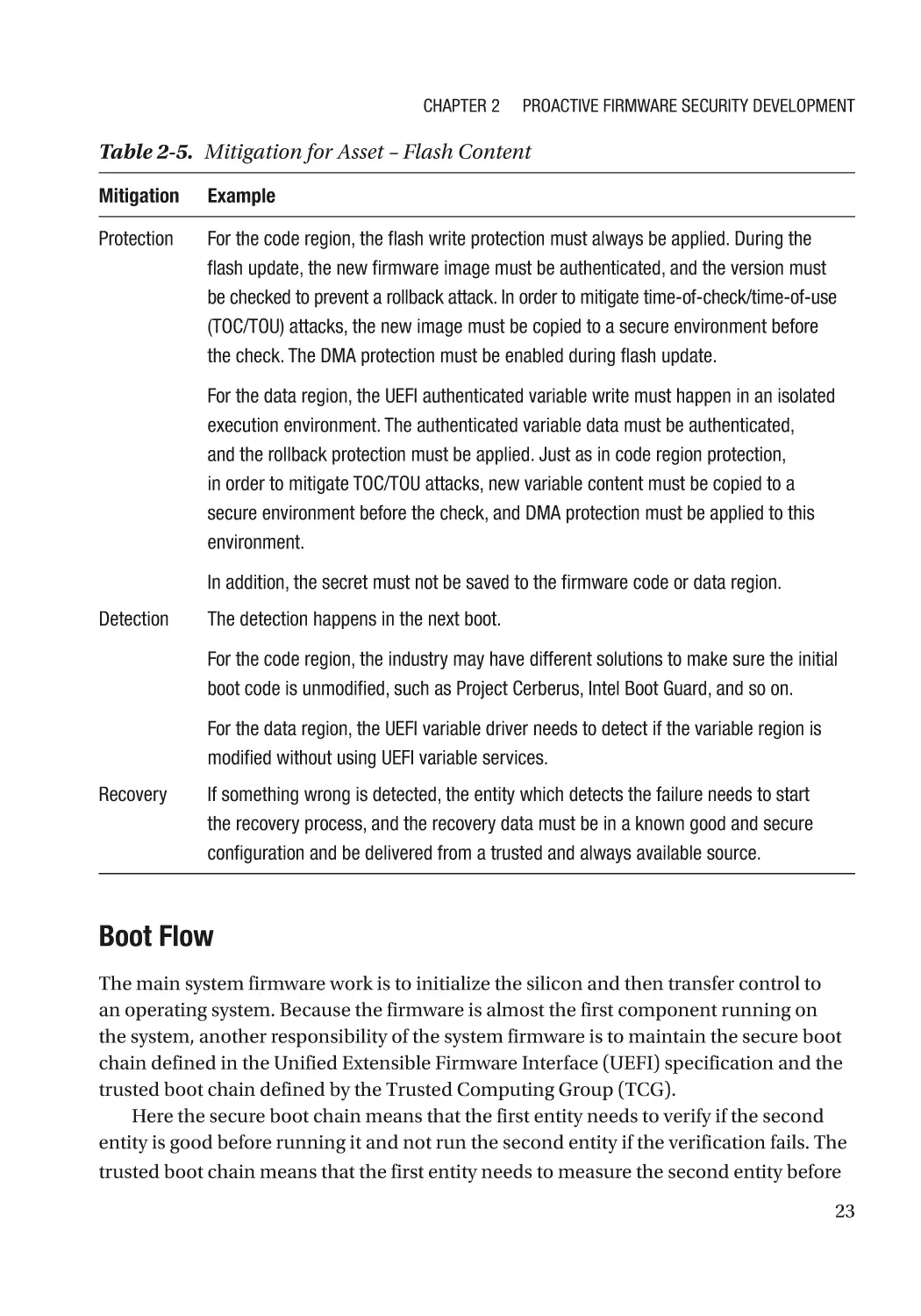
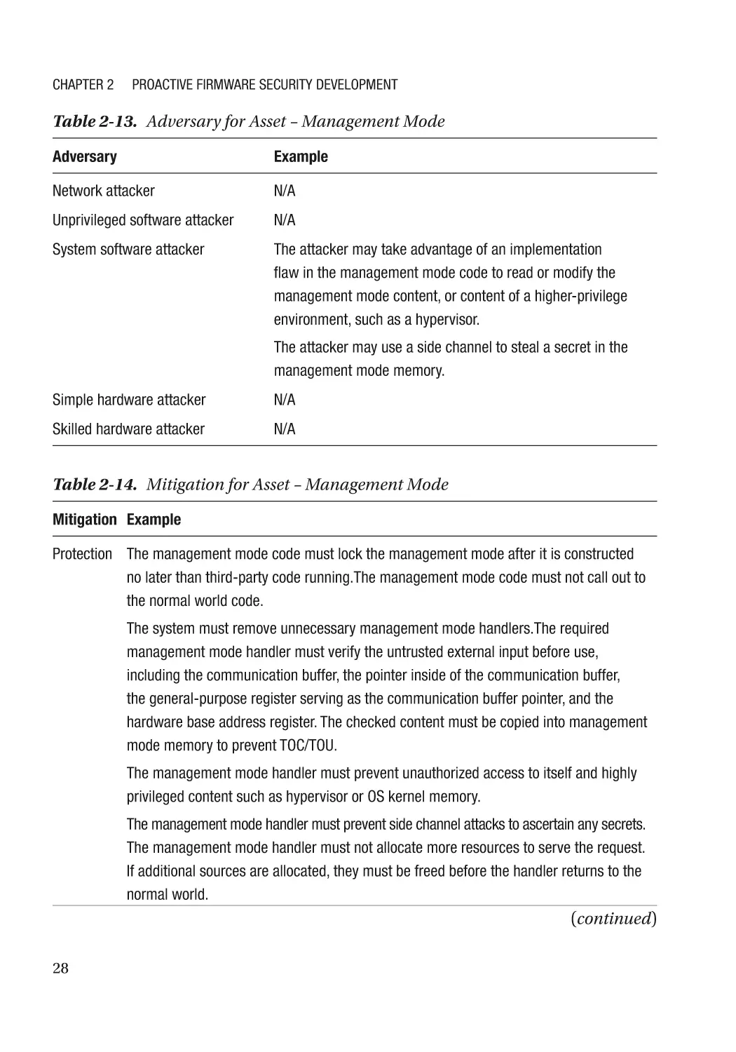
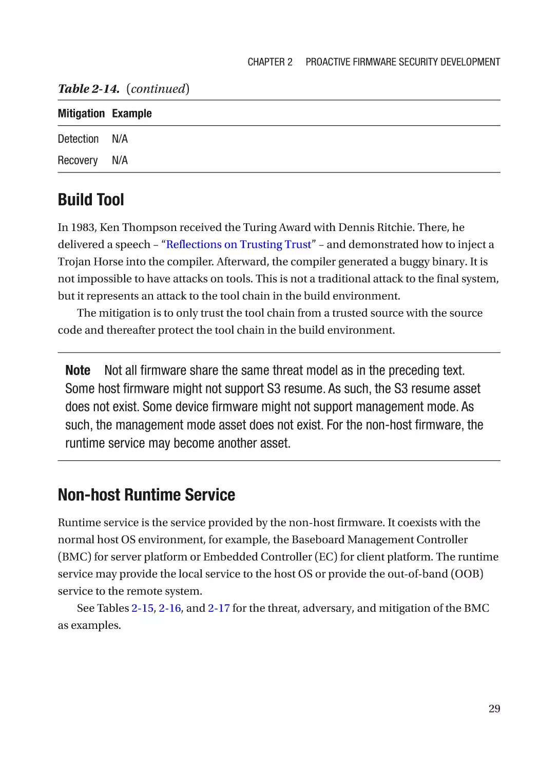
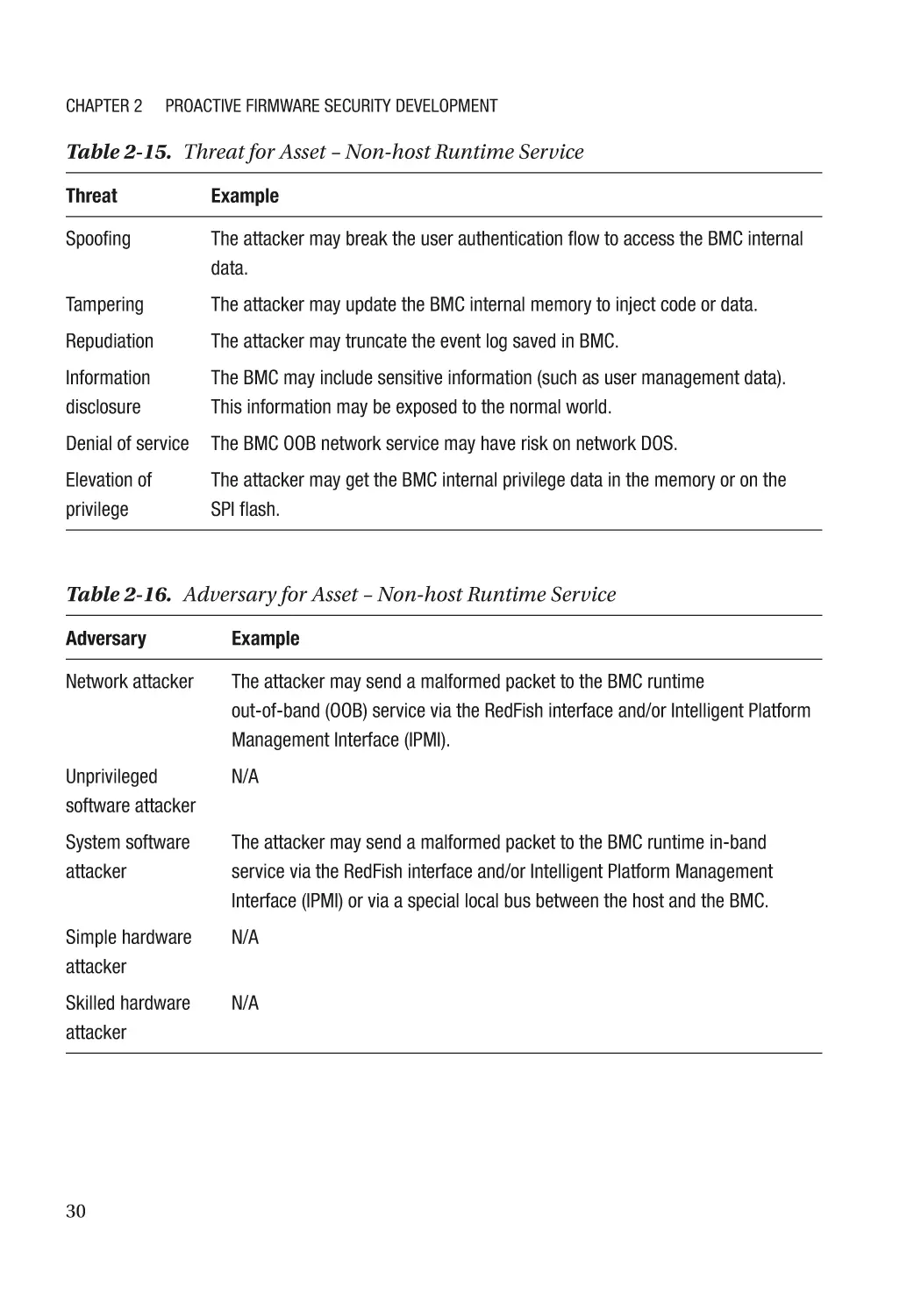
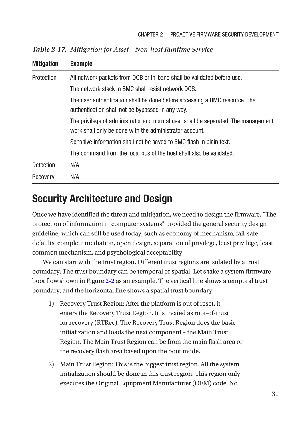
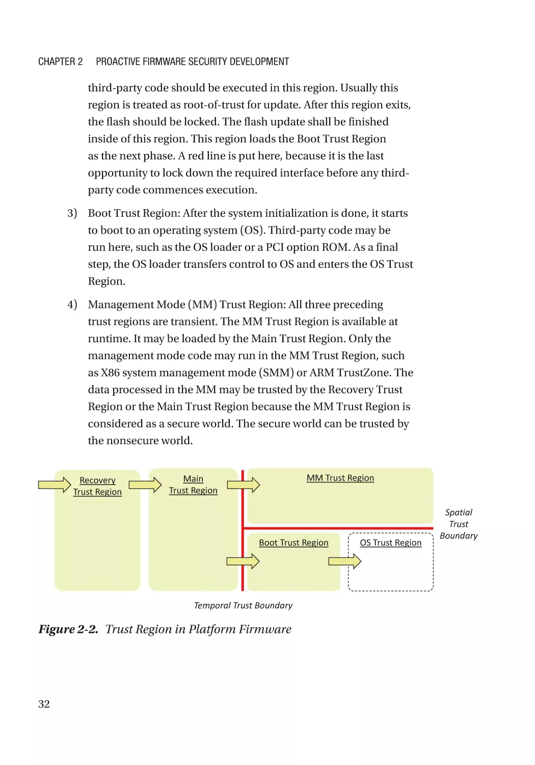
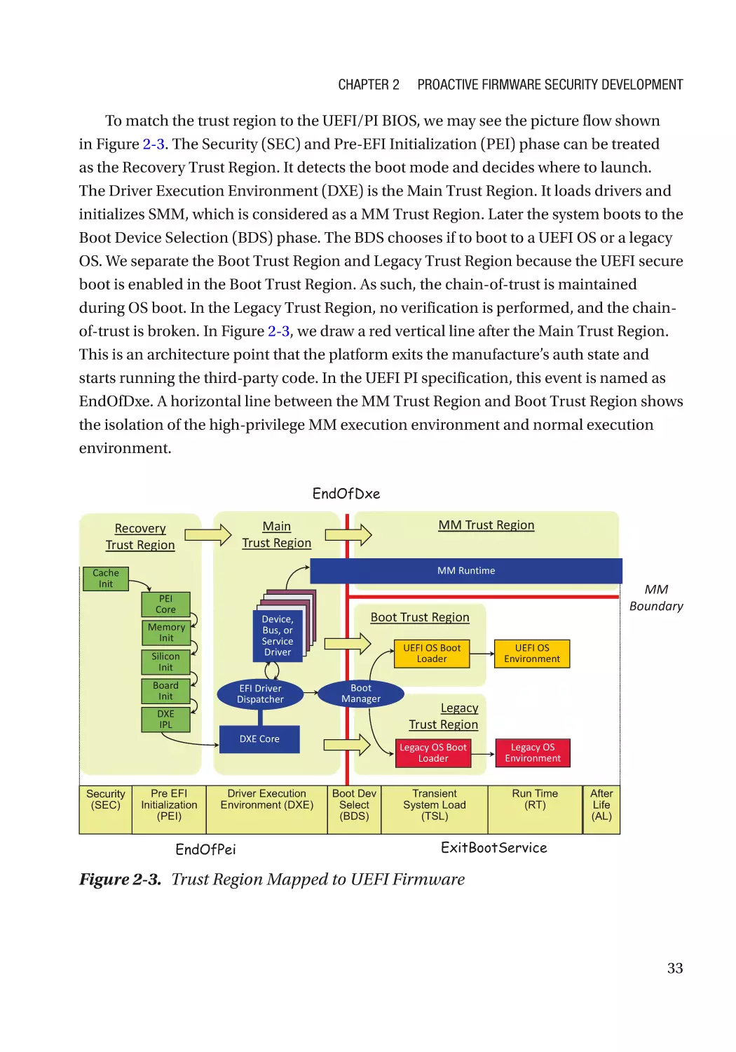
Security Architecture and Design������������������������������������������������������������������������������������������ 31
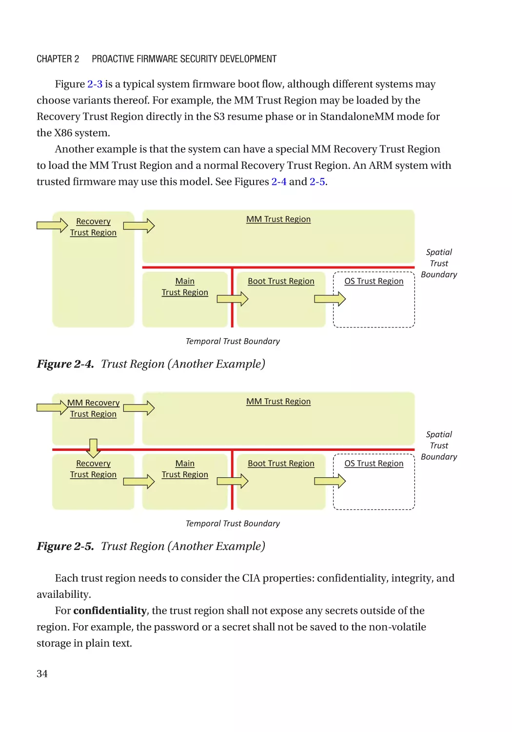
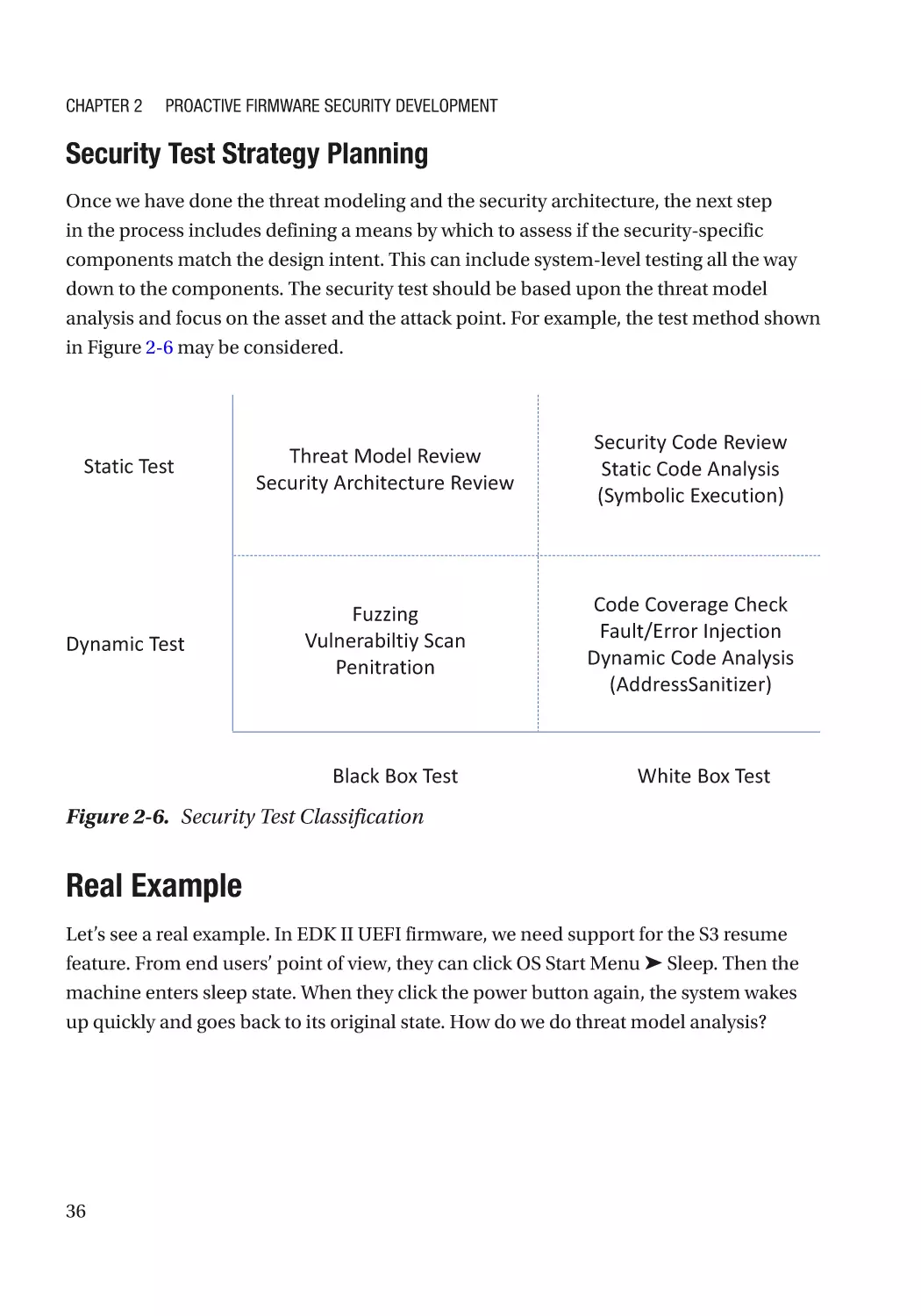
Real Example������������������������������������������������������������������������������������������������������������������������� 36
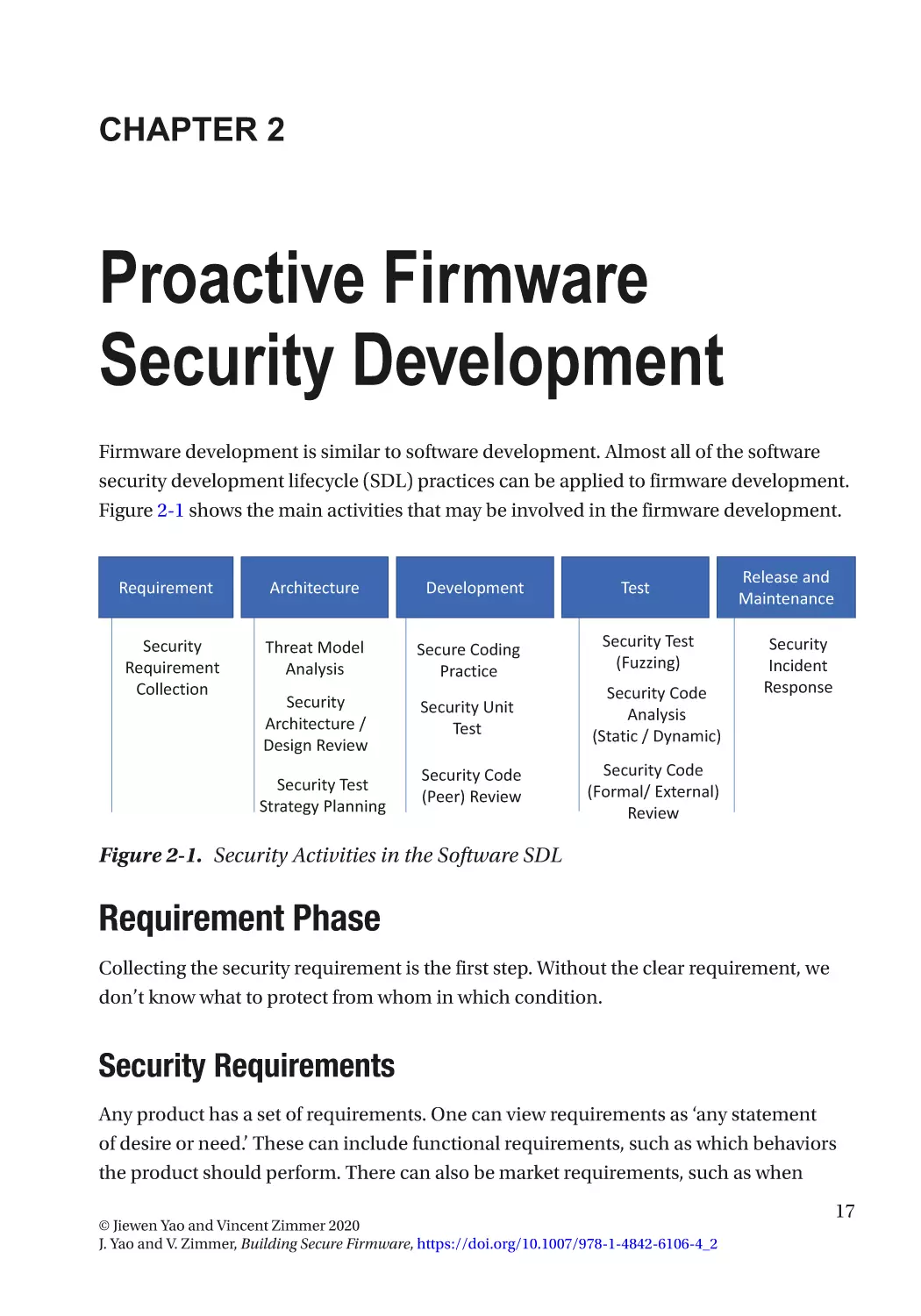
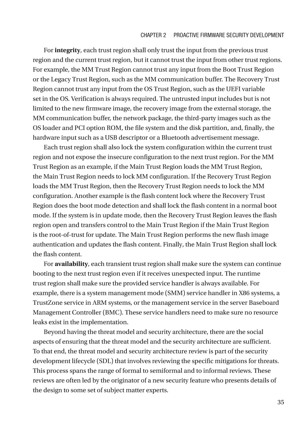
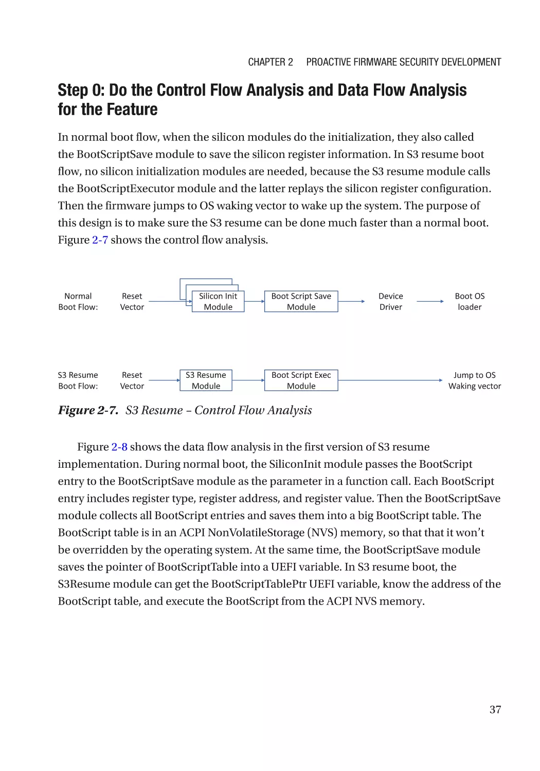
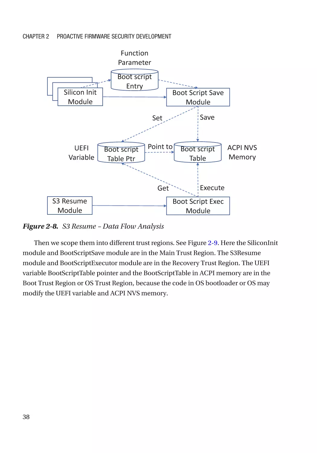
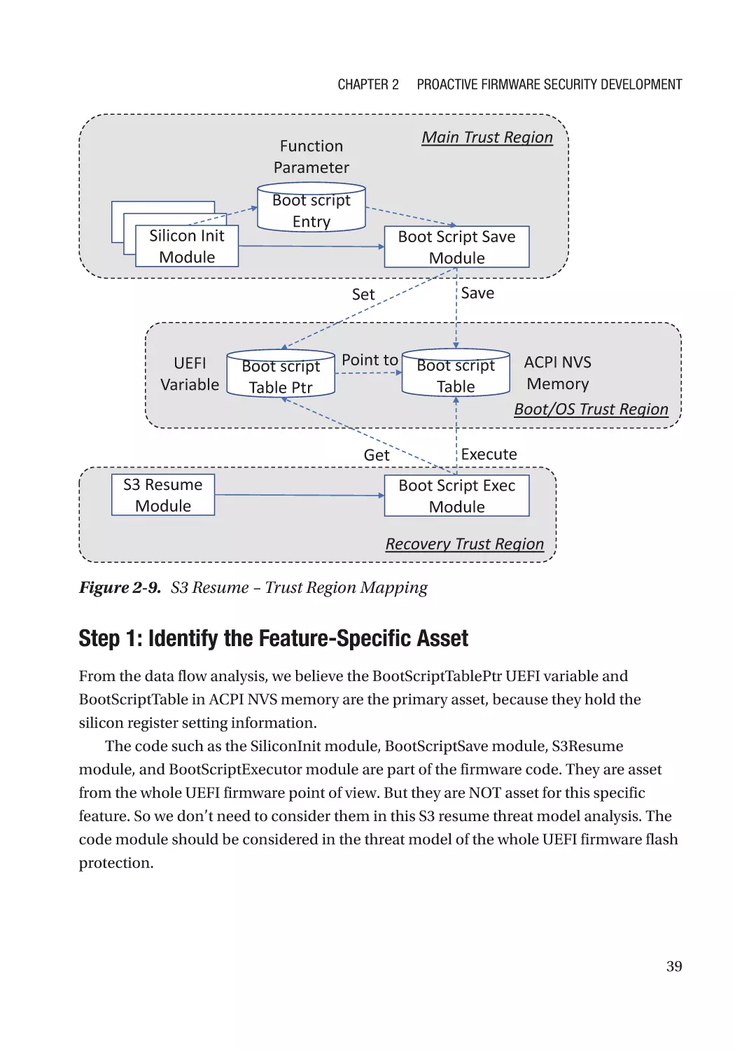
Development Phase�������������������������������������������������������������������������������������������������������������������� 49
Secure Coding Practice��������������������������������������������������������������������������������������������������������� 49
Security Unit Test������������������������������������������������������������������������������������������������������������������� 49
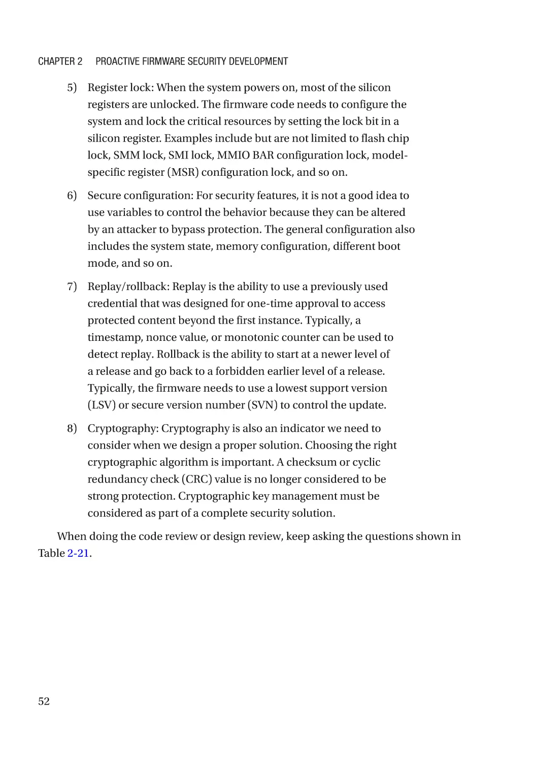
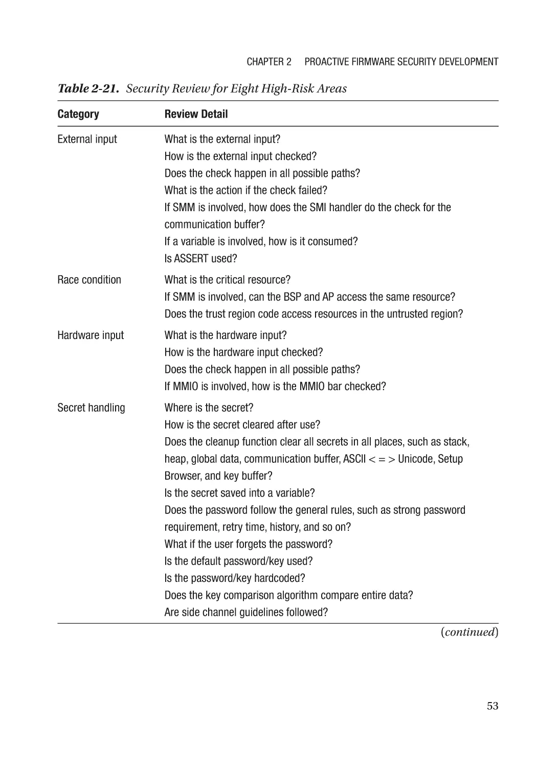
Security Code Review������������������������������������������������������������������������������������������������������������ 49
Test Phase����������������������������������������������������������������������������������������������������������������������������������� 55
Fuzzing���������������������������������������������������������������������������������������������������������������������������������� 55
Static Code Analysis�������������������������������������������������������������������������������������������������������������� 56
Dynamic Code Analysis��������������������������������������������������������������������������������������������������������� 56
Vulnerability Scan������������������������������������������������������������������������������������������������������������������ 57
Release and Maintenance Phase������������������������������������������������������������������������������������������������ 57
Security Incidence Response������������������������������������������������������������������������������������������������ 57
People Education������������������������������������������������������������������������������������������������������������������������ 58
Before the Project Starts������������������������������������������������������������������������������������������������������� 58
After the Project Release������������������������������������������������������������������������������������������������������� 58
Fallacy and Pitfall������������������������������������������������������������������������������������������������������������������������ 58
Security Technology�������������������������������������������������������������������������������������������������������������� 58
Security Process�������������������������������������������������������������������������������������������������������������������� 59
Summary������������������������������������������������������������������������������������������������������������������������������������ 60
References���������������������������������������������������������������������������������������������������������������������������������� 61
Part II: Security Architecture������������������������������������������������������������������������ 65
Chapter 3: Firmware Resiliency: Protection����������������������������������������������������������� 67
Resiliency Building Block������������������������������������������������������������������������������������������������������������ 67
Immutable ROM�������������������������������������������������������������������������������������������������������������������������� 69
vi
Table of Contents
Integrity��������������������������������������������������������������������������������������������������������������������������������� 69
Confidentiality����������������������������������������������������������������������������������������������������������������������� 69
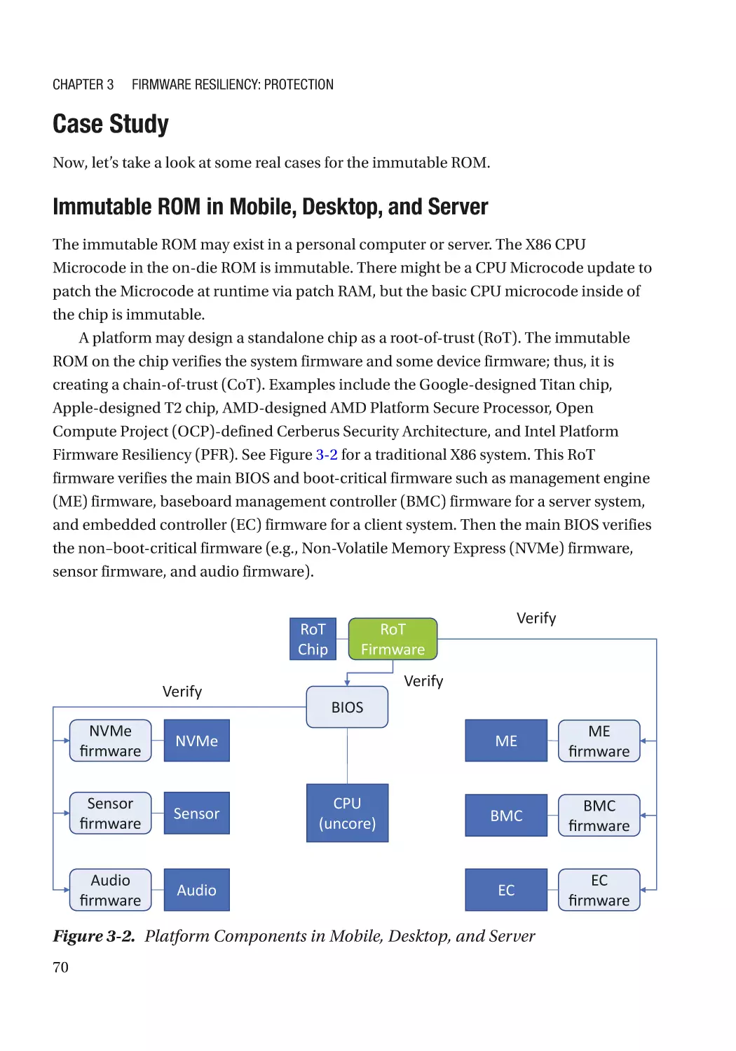
Case Study����������������������������������������������������������������������������������������������������������������������������� 70
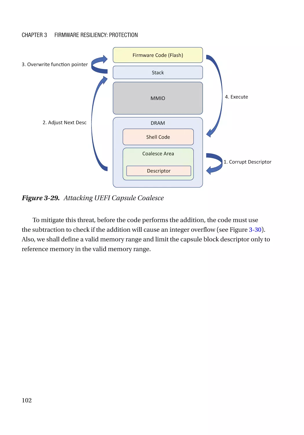
Attack and Mitigation������������������������������������������������������������������������������������������������������������ 72
Updatable Firmware�������������������������������������������������������������������������������������������������������������������� 73
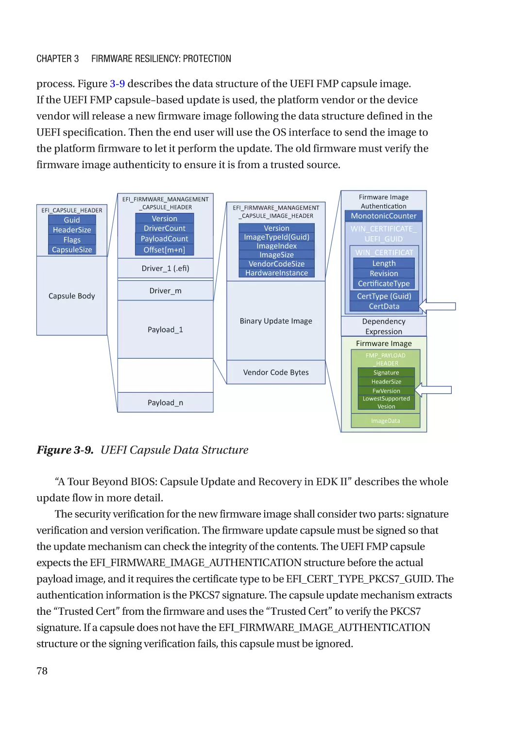
Authenticated Update Mechanism���������������������������������������������������������������������������������������� 73
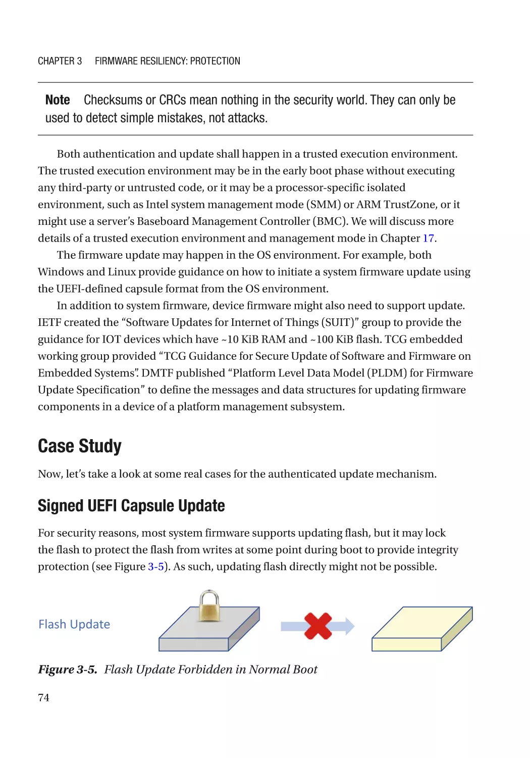
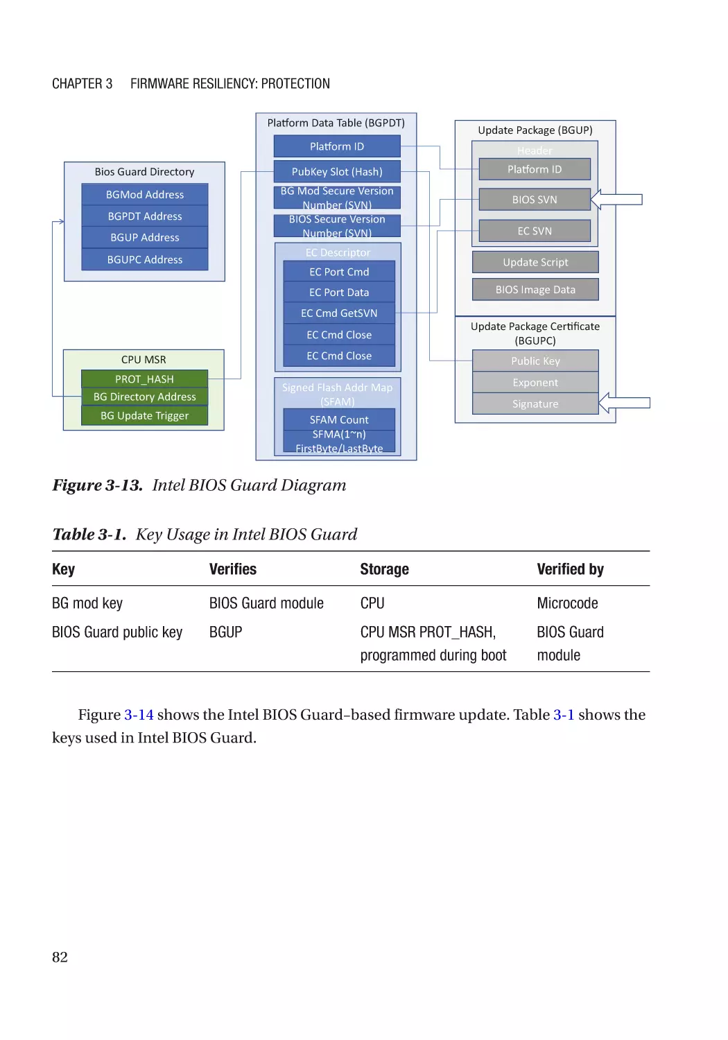
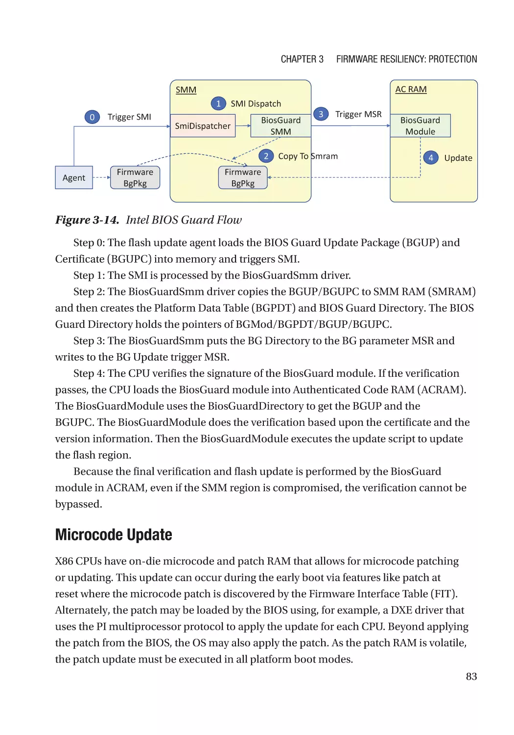
Case Study����������������������������������������������������������������������������������������������������������������������������� 74
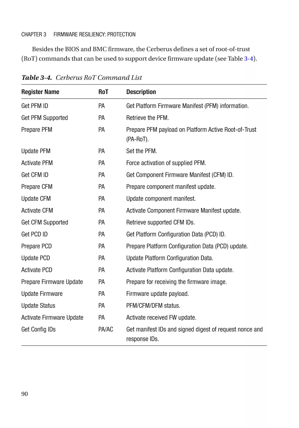
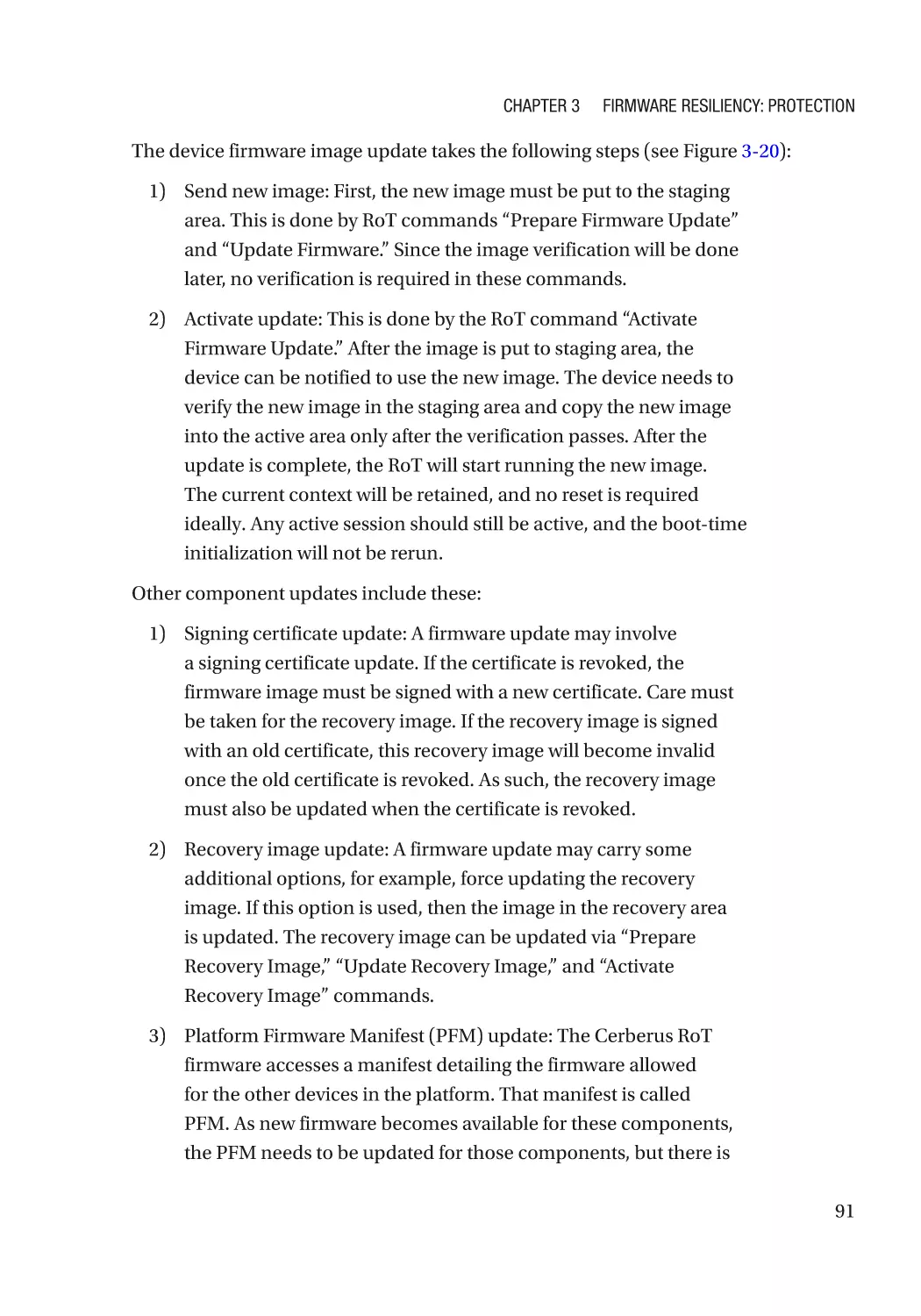
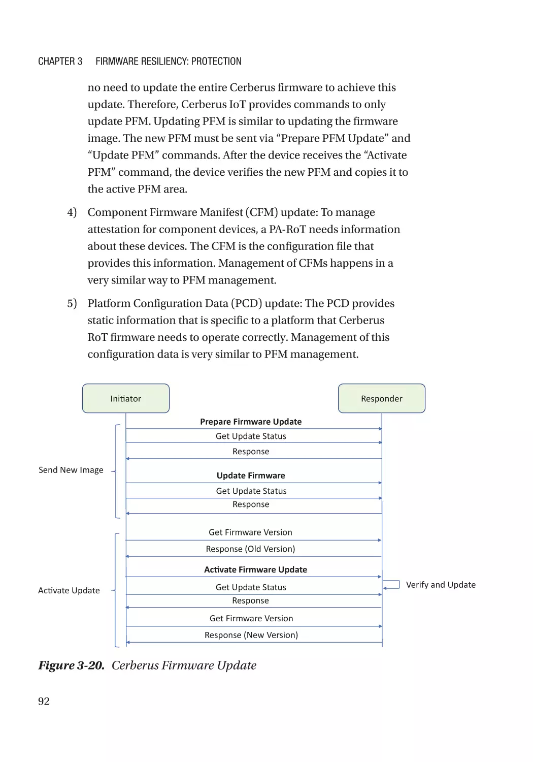
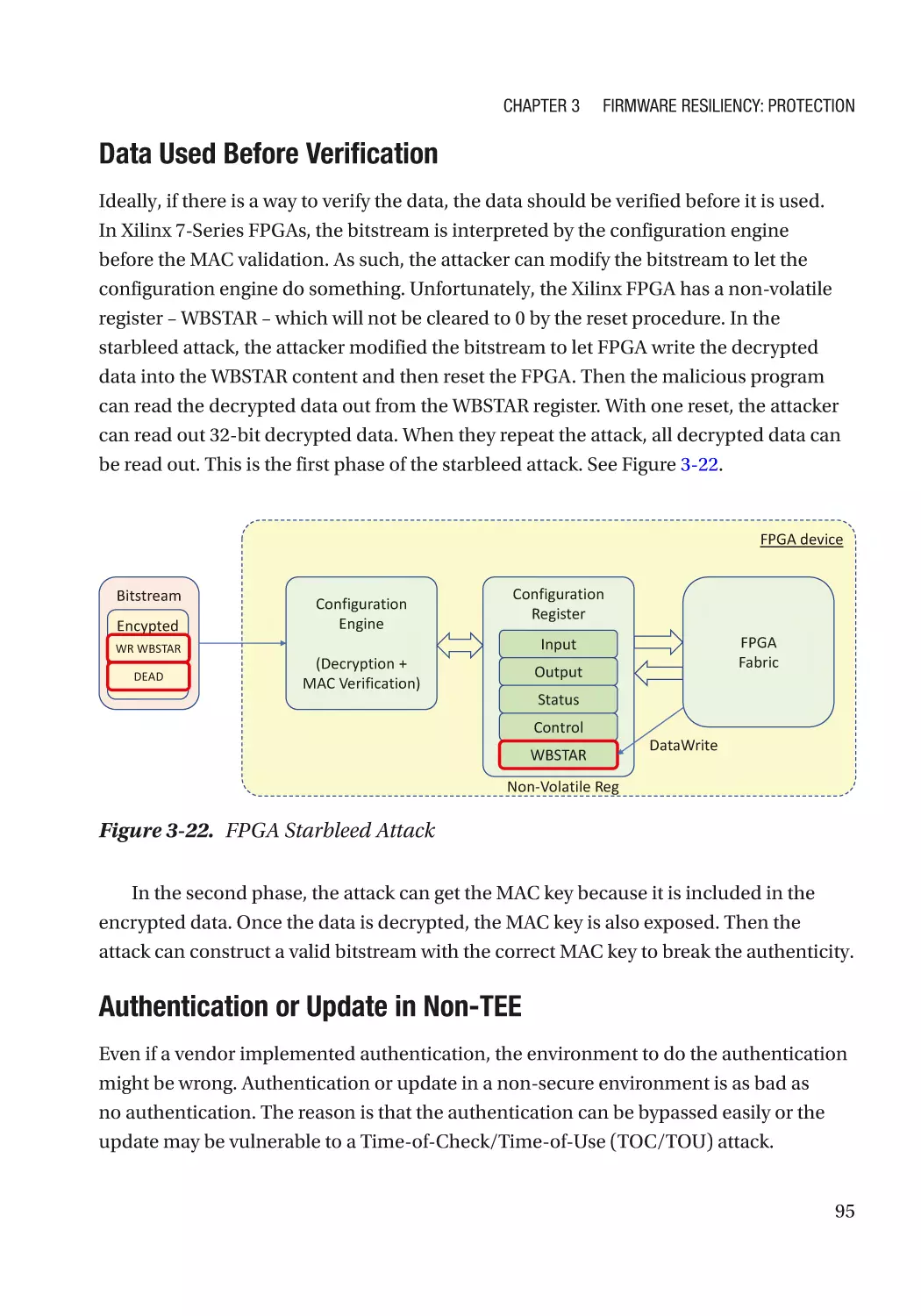
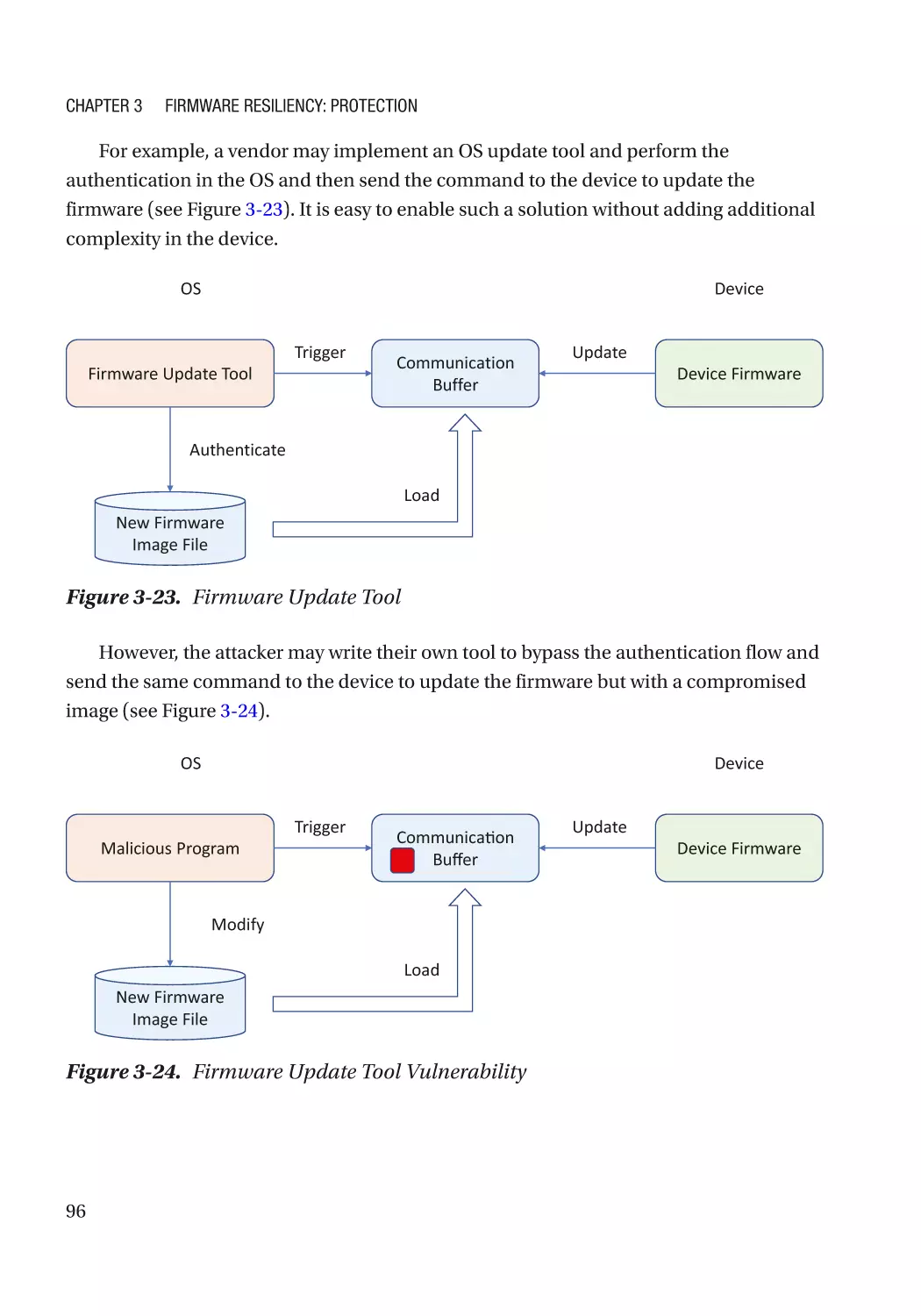
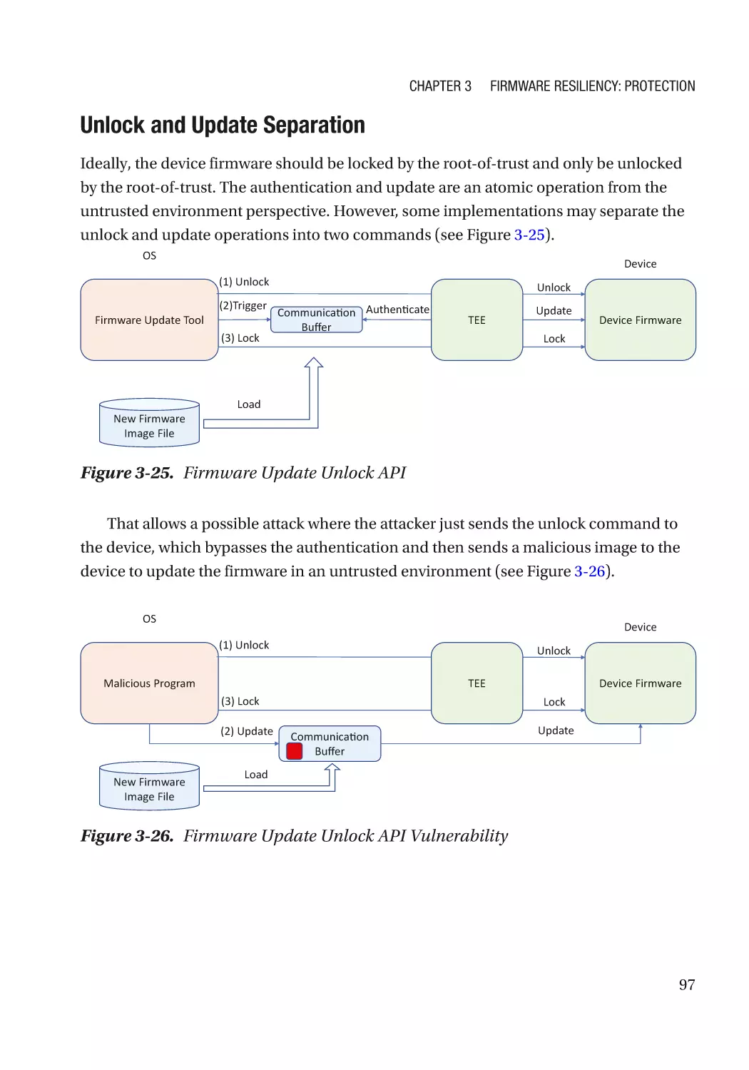
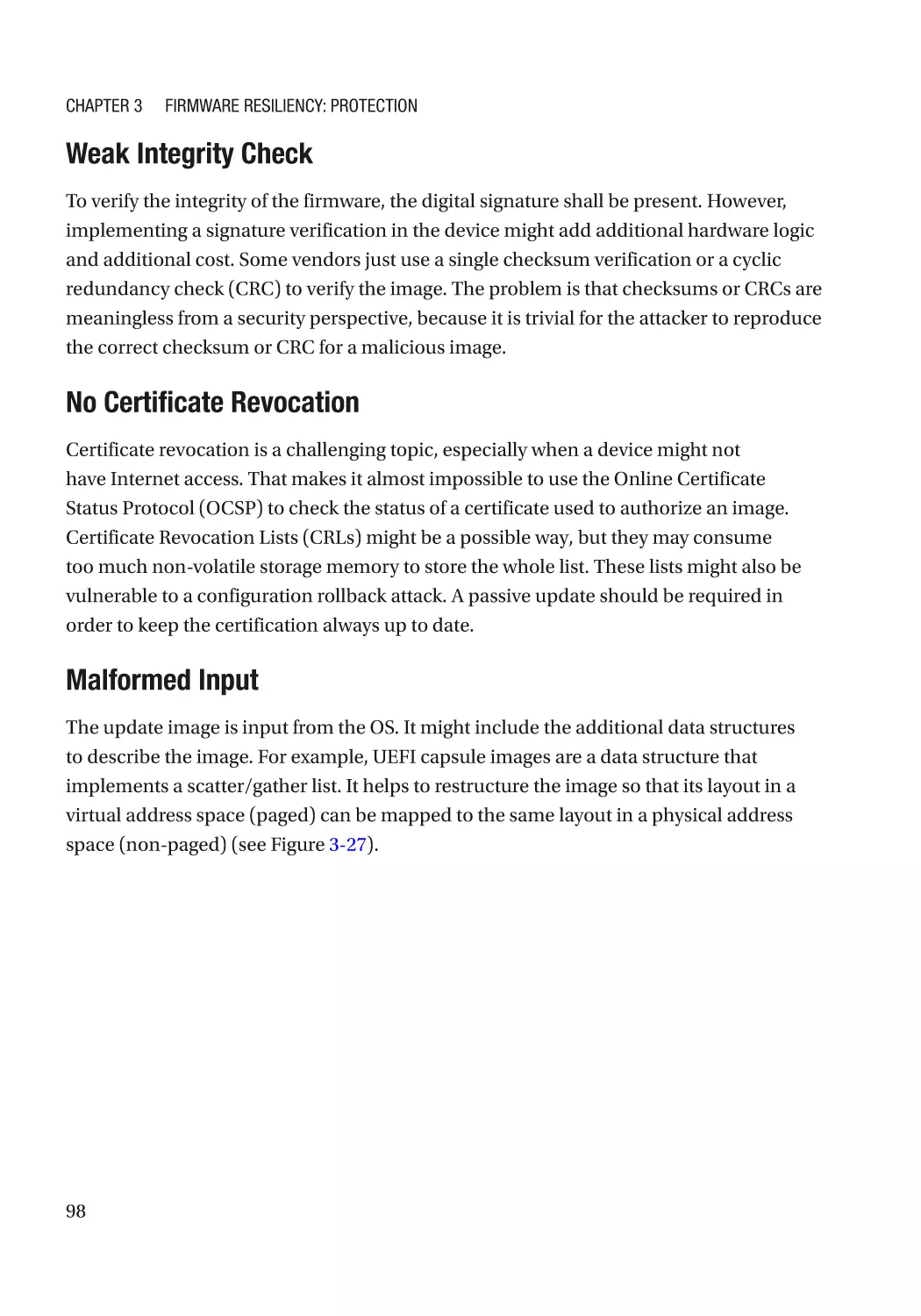
Integrity Protection���������������������������������������������������������������������������������������������������������������� 93
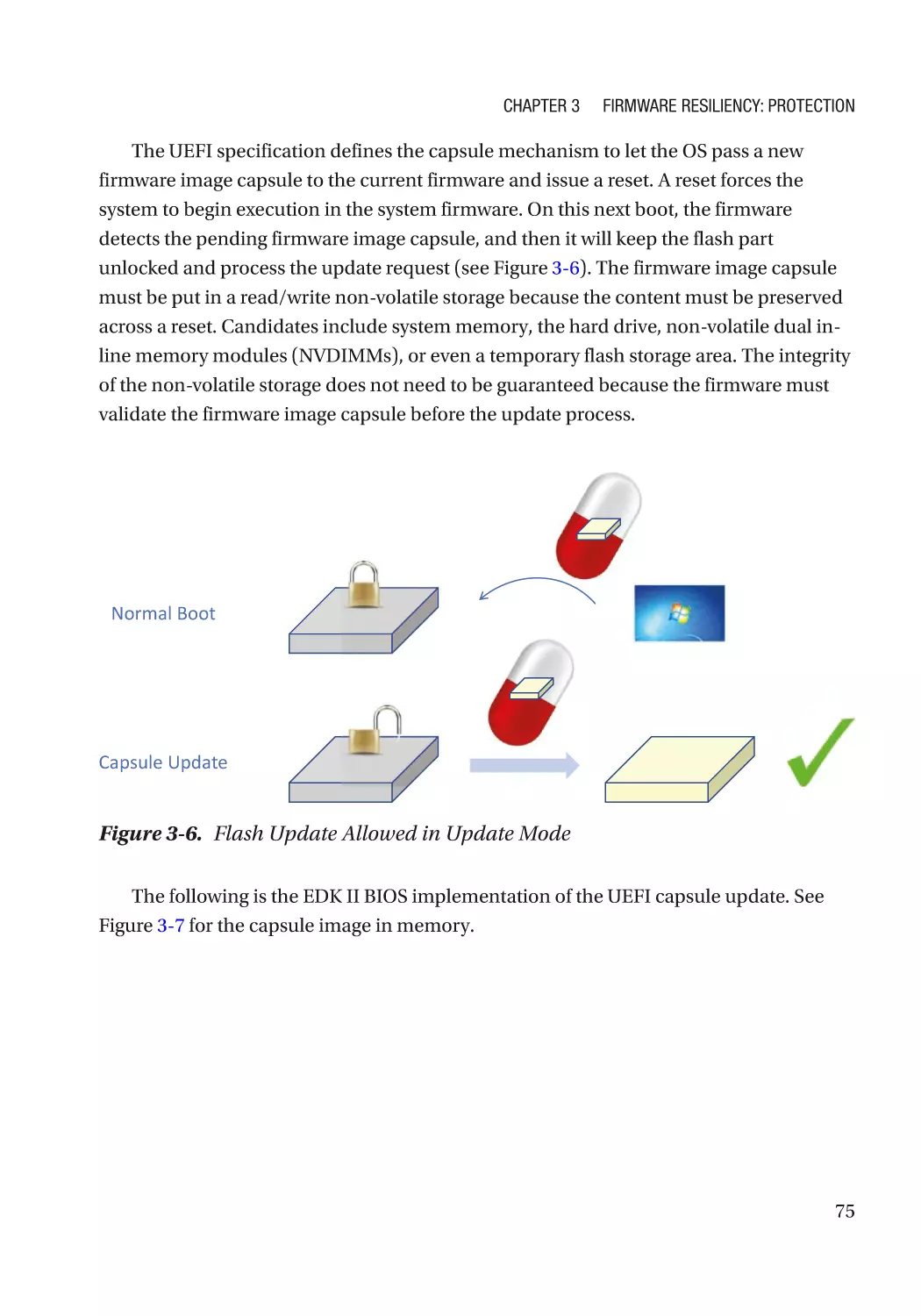
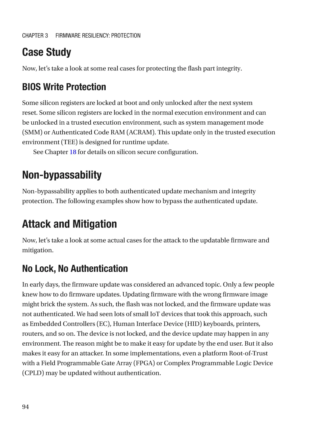
Case Study����������������������������������������������������������������������������������������������������������������������������� 94
Non-bypassability������������������������������������������������������������������������������������������������������������������ 94
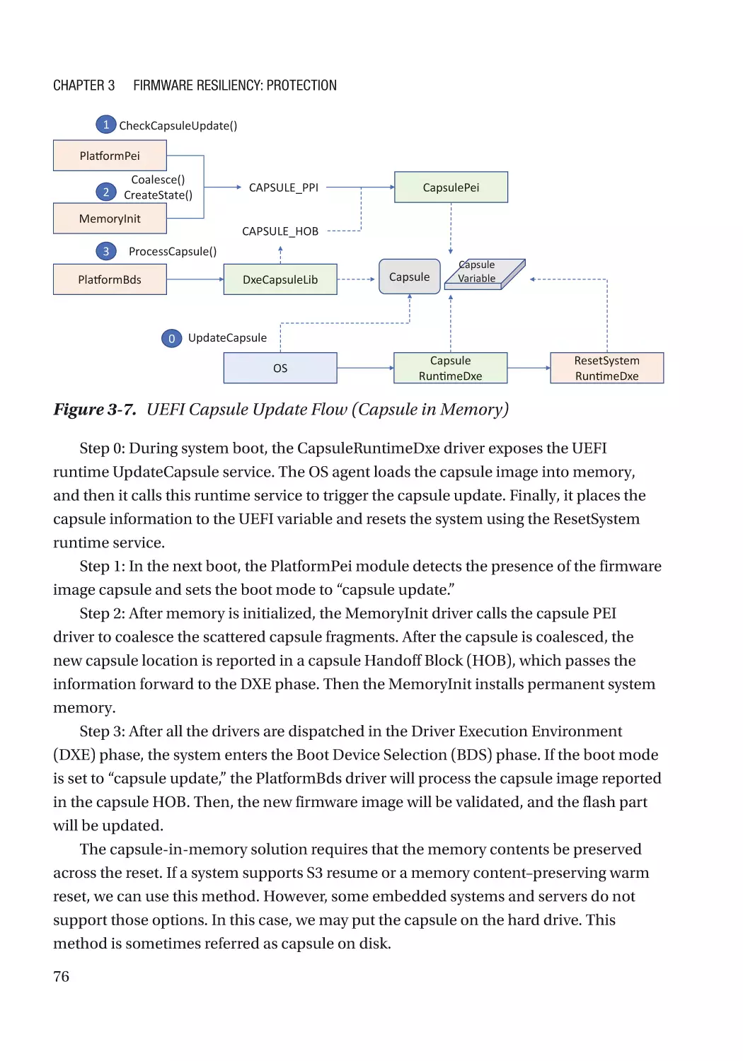
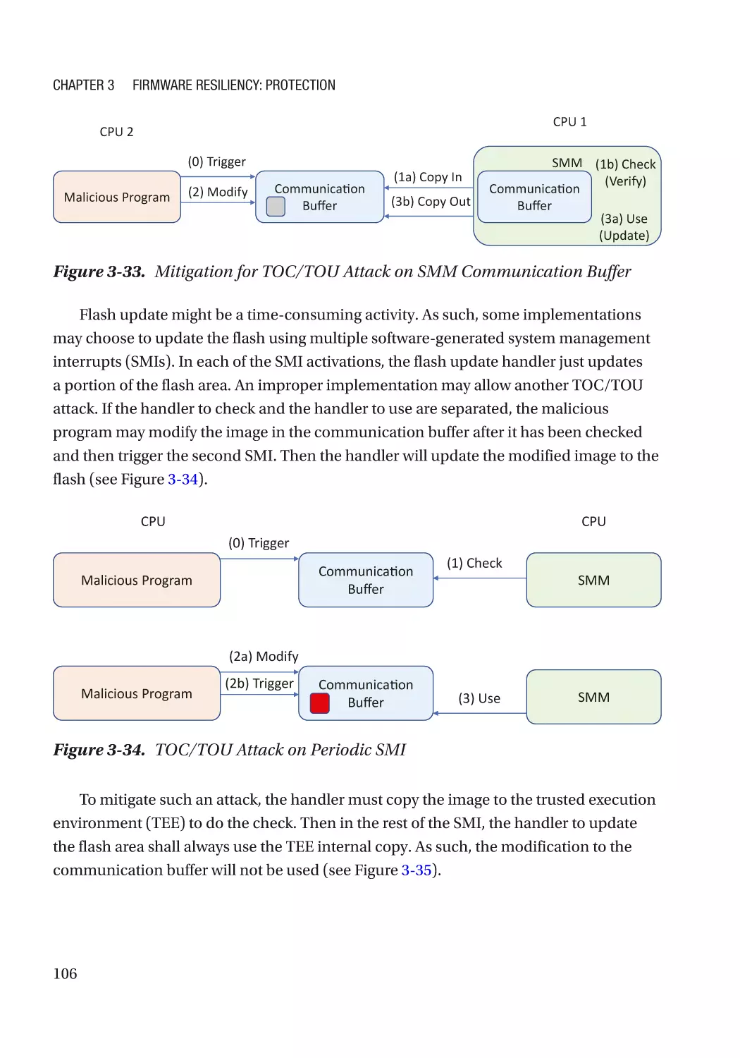
Attack and Mitigation������������������������������������������������������������������������������������������������������������ 94
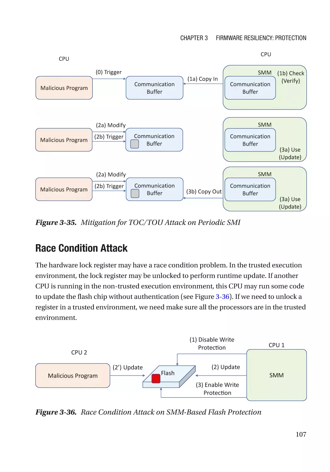
Configurable Data��������������������������������������������������������������������������������������������������������������������� 108
Case Study��������������������������������������������������������������������������������������������������������������������������� 108
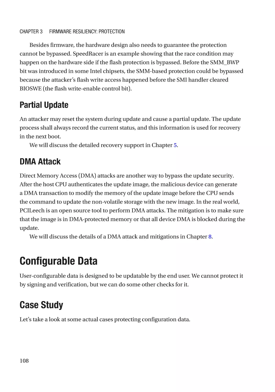
Attack and Mitigation���������������������������������������������������������������������������������������������������������� 110
Summary���������������������������������������������������������������������������������������������������������������������������������� 111
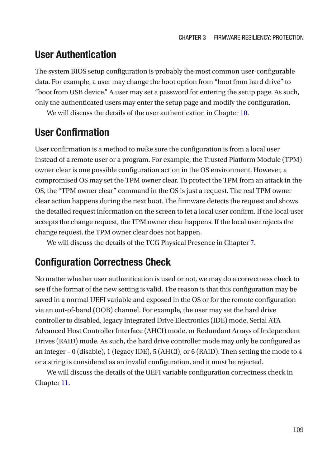
References�������������������������������������������������������������������������������������������������������������������������������� 111
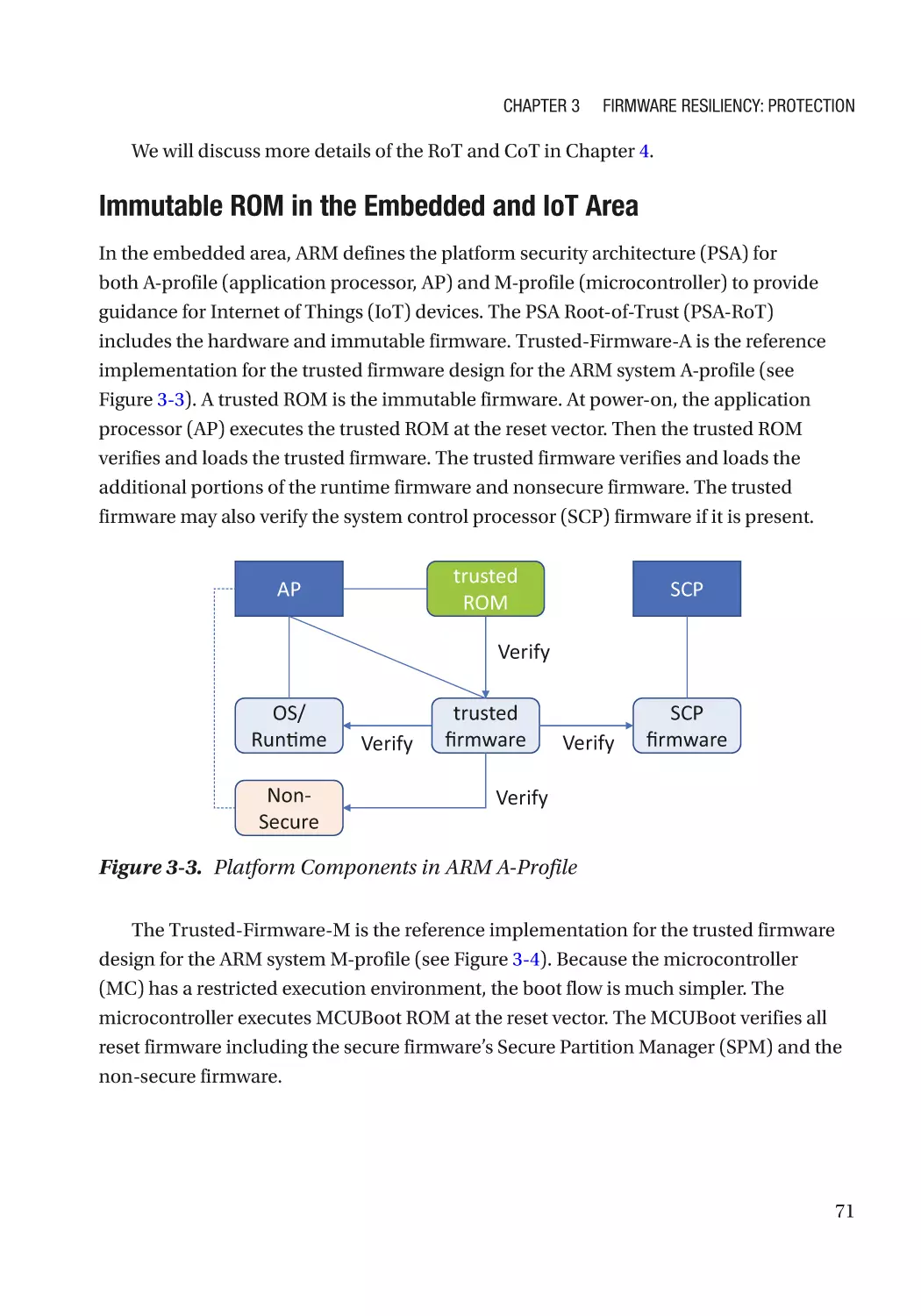
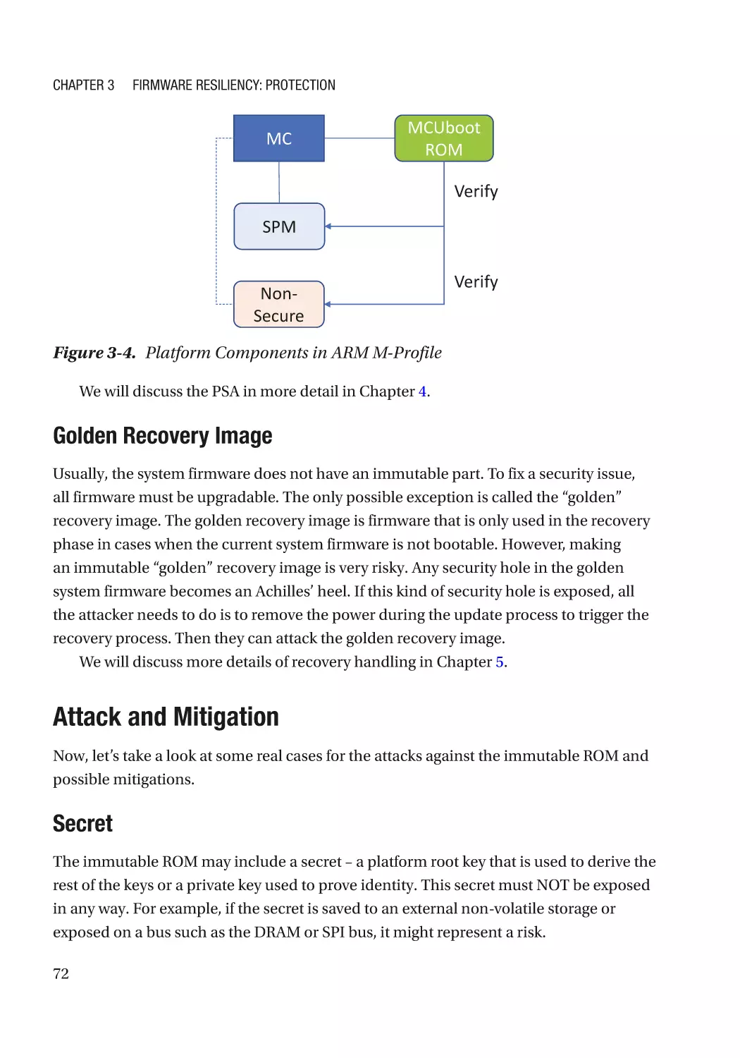
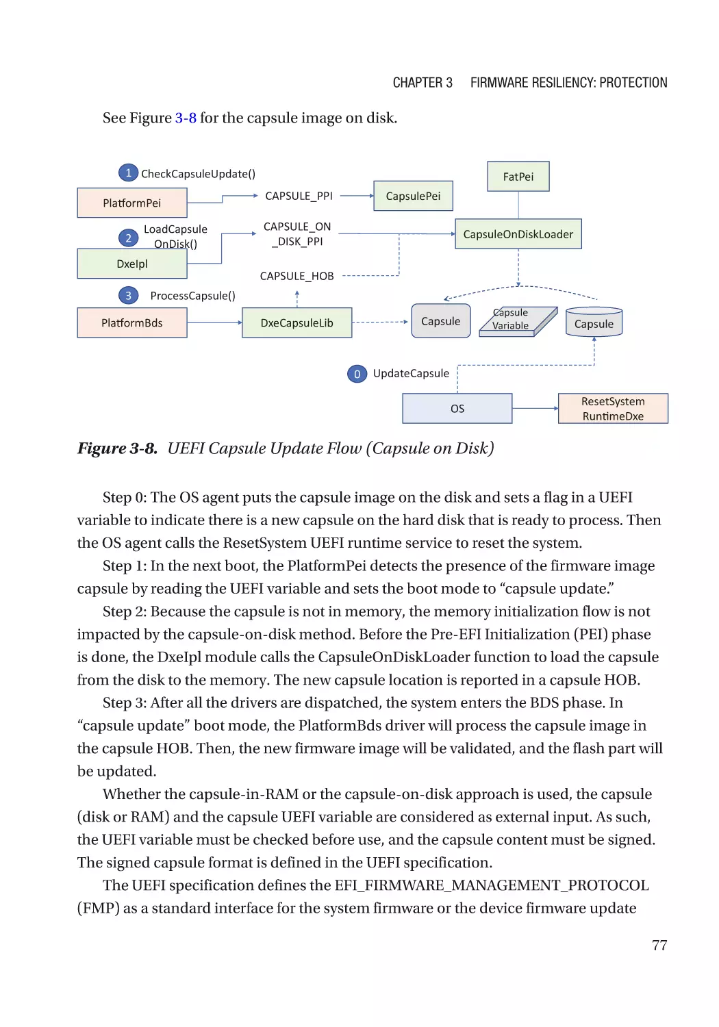
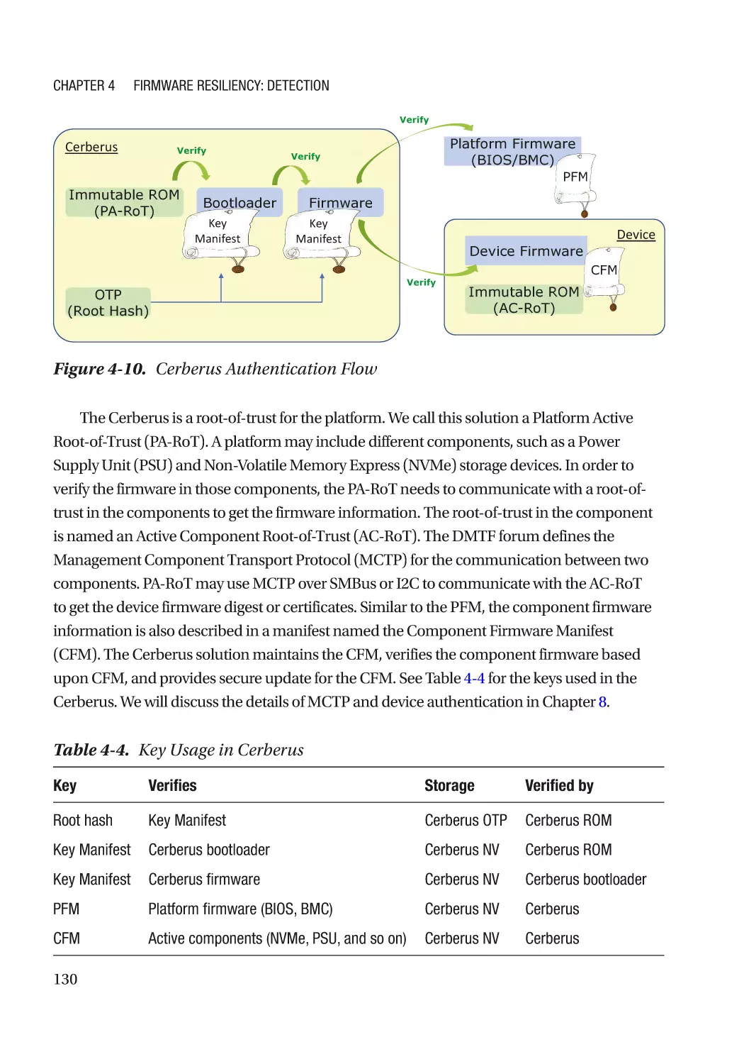
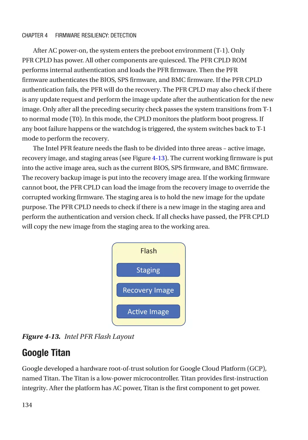
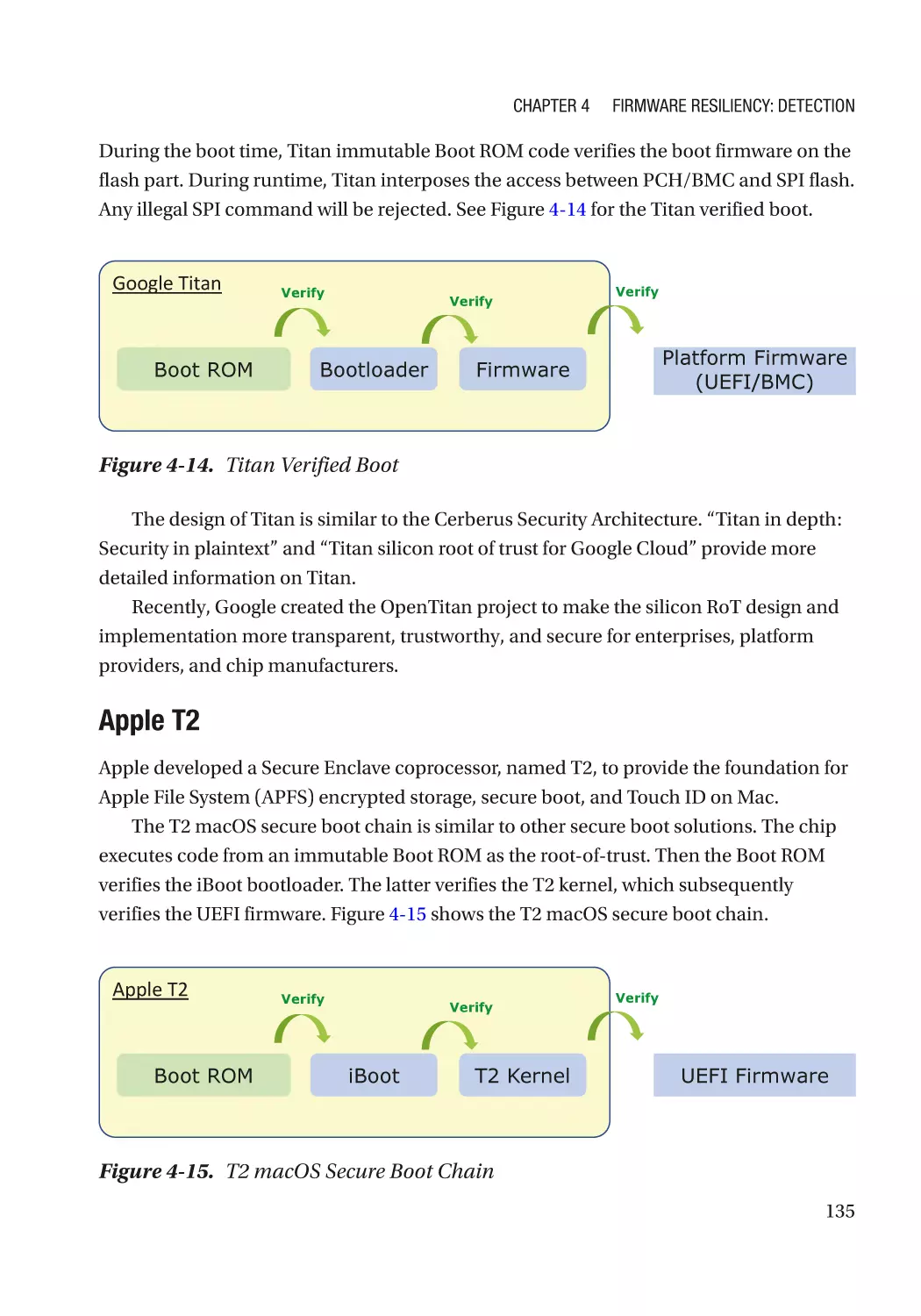
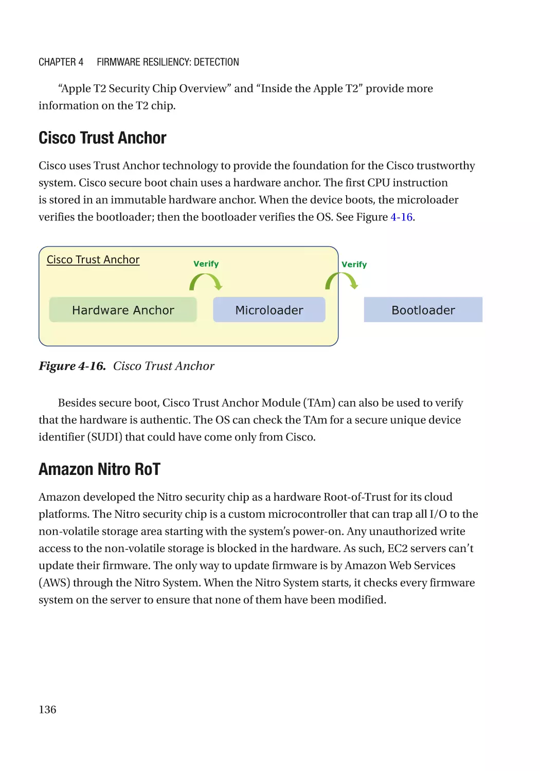
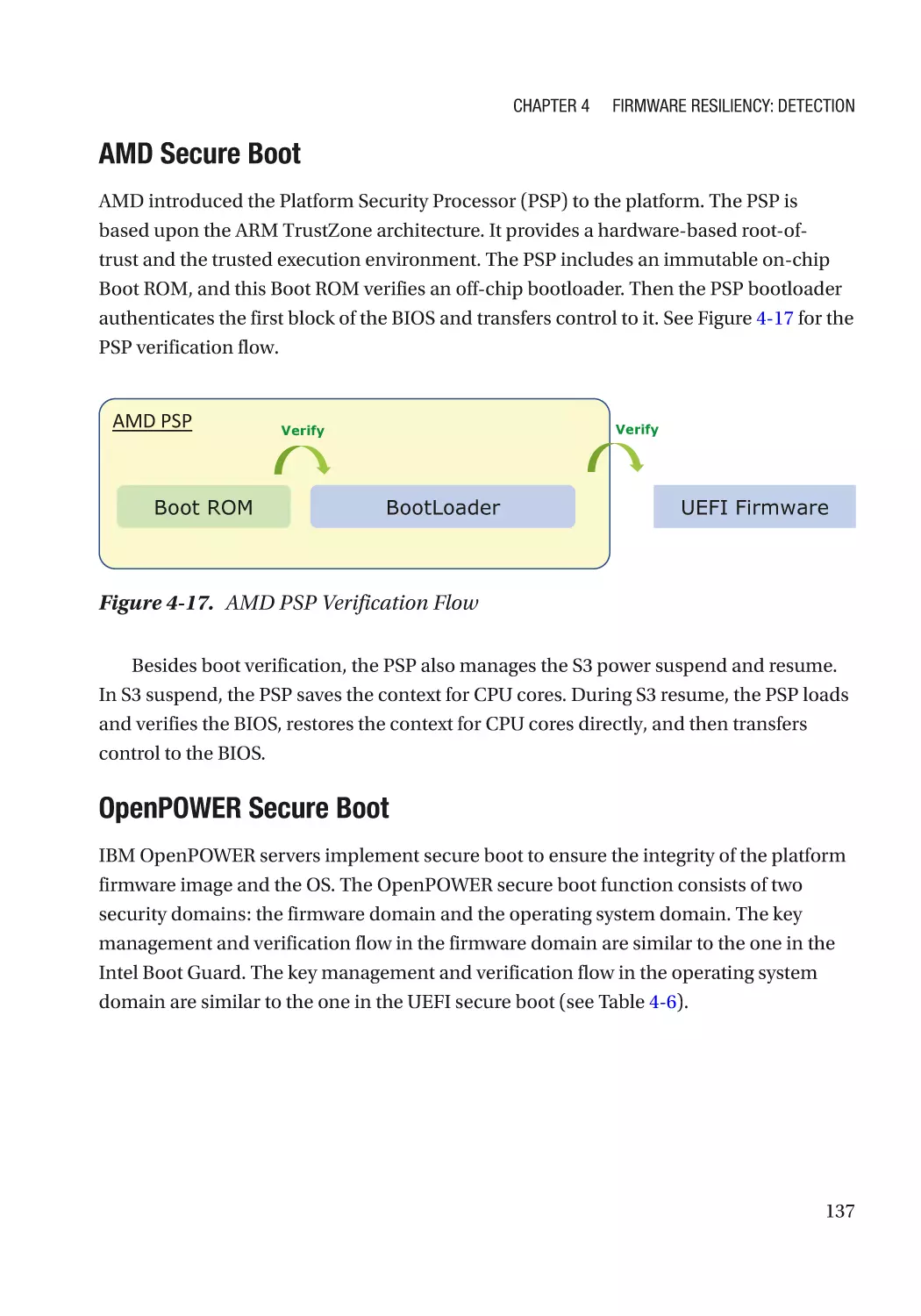
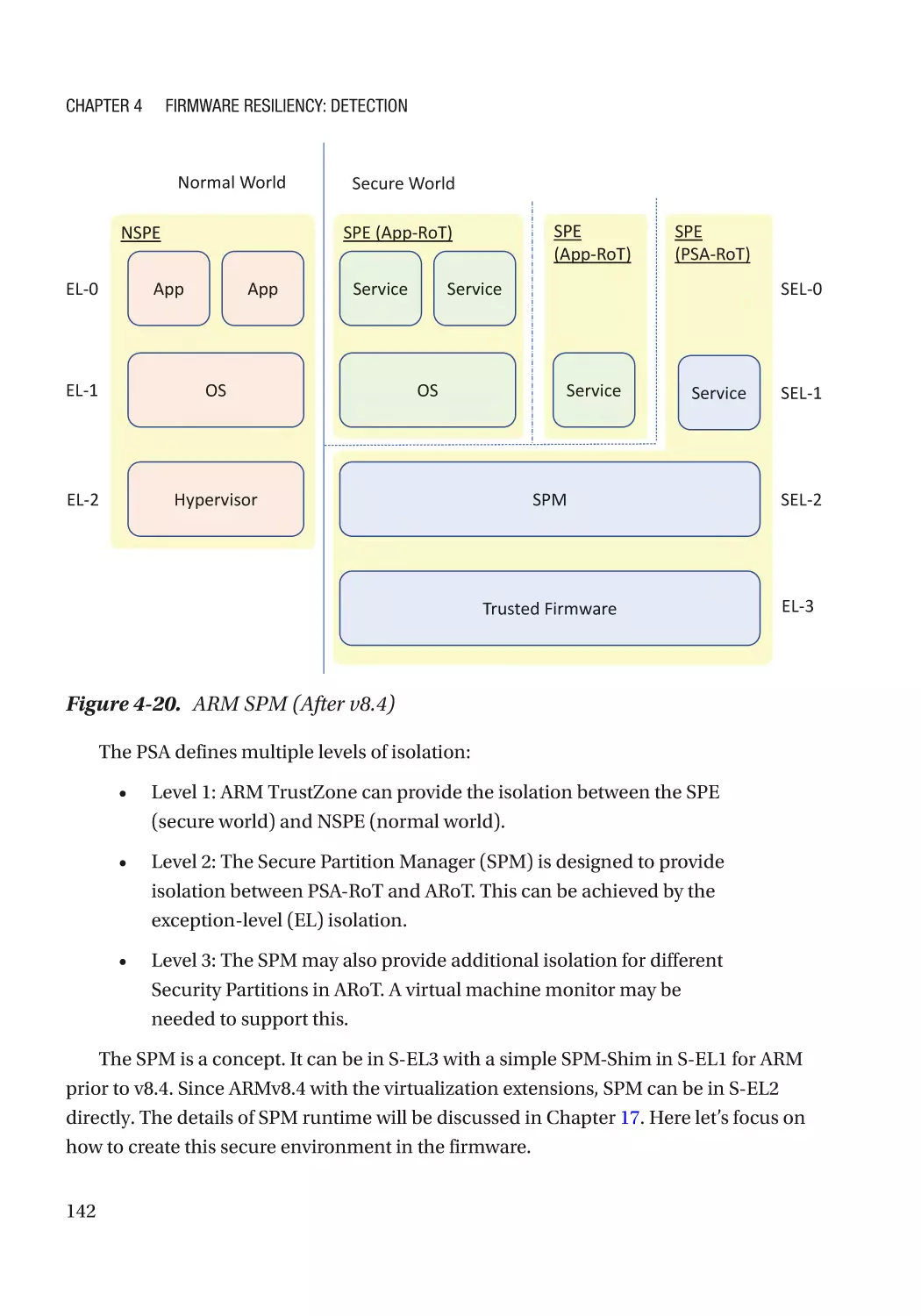
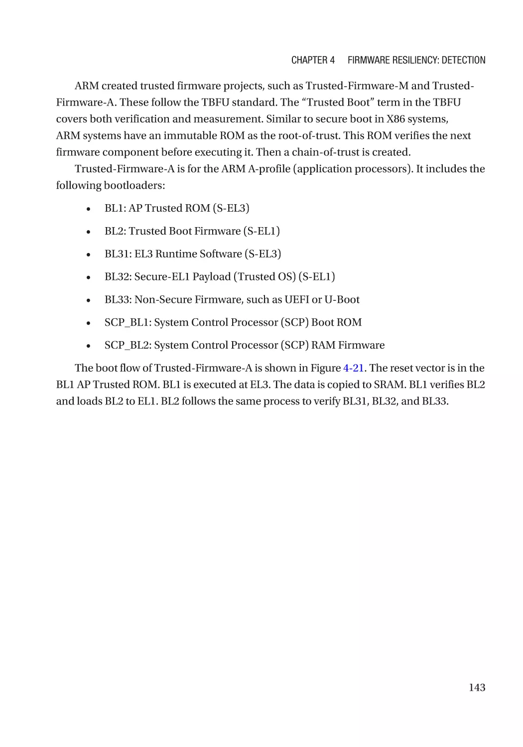
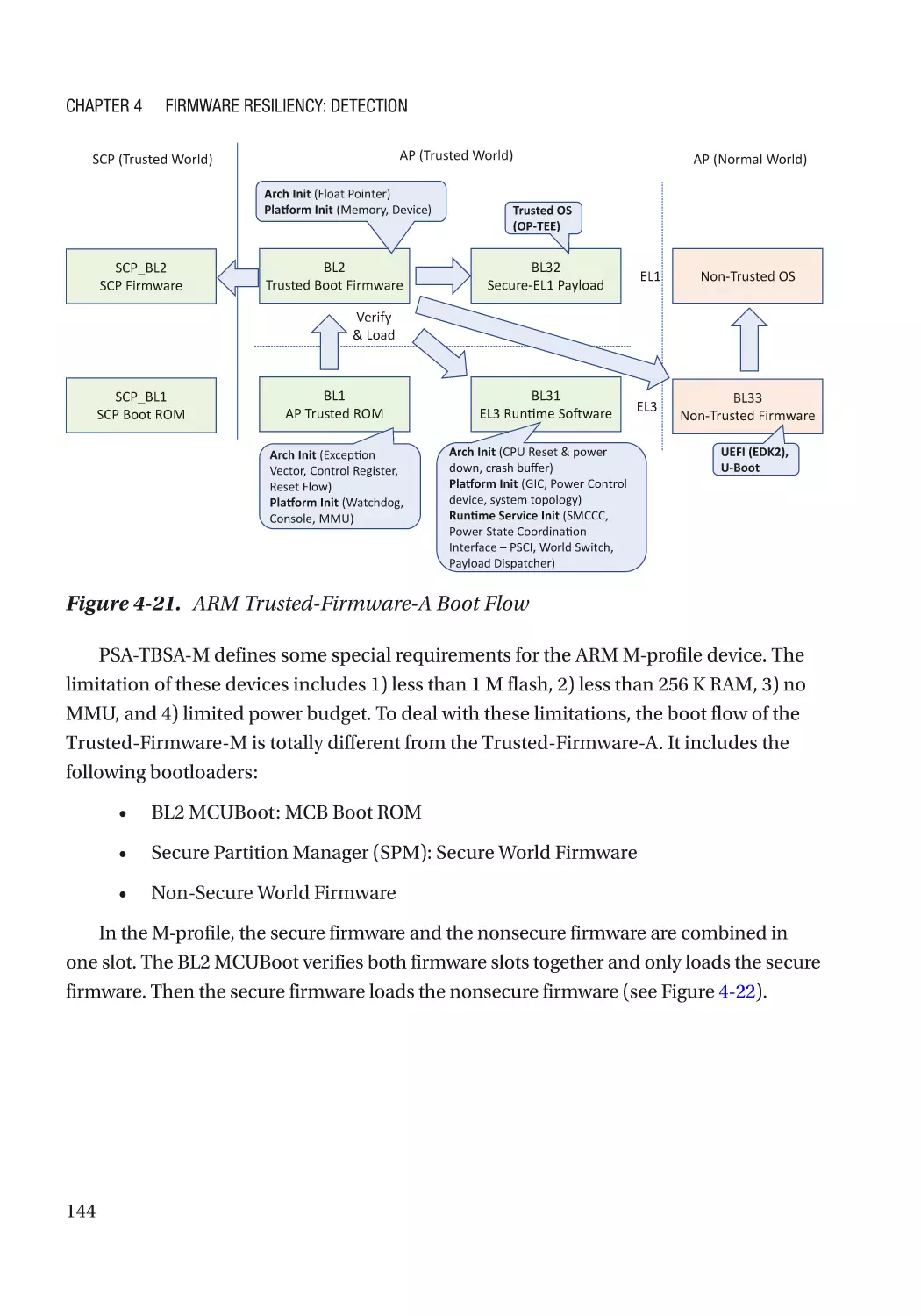
Chapter 4: Firmware Resiliency: Detection���������������������������������������������������������� 115
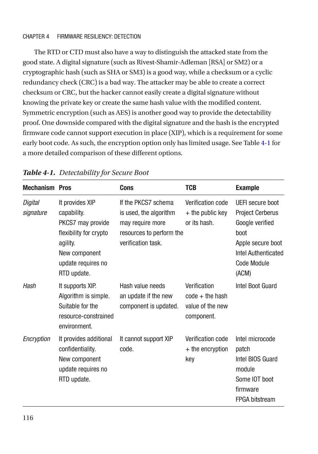
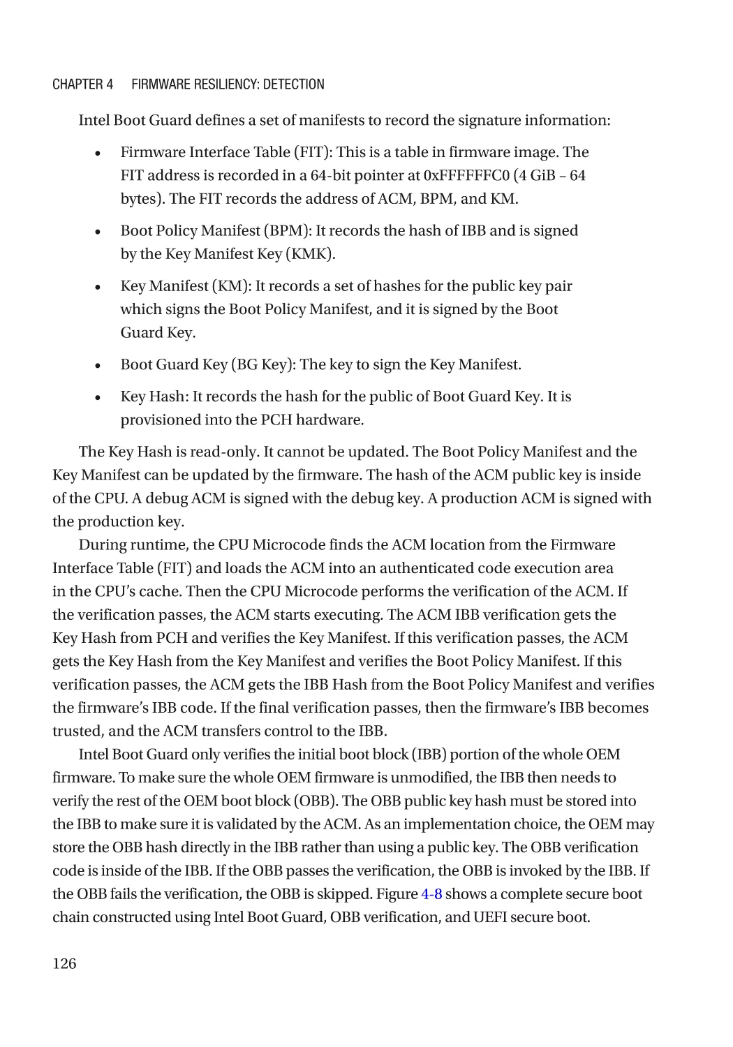
Secure Boot������������������������������������������������������������������������������������������������������������������������������ 115
Detectability������������������������������������������������������������������������������������������������������������������������ 115
Version��������������������������������������������������������������������������������������������������������������������������������� 117
Policy Revocation���������������������������������������������������������������������������������������������������������������� 117
Non-bypassability���������������������������������������������������������������������������������������������������������������� 117
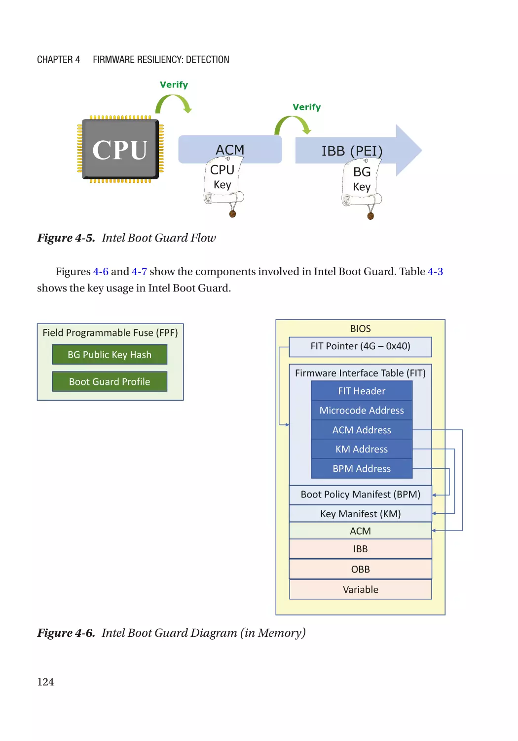
Additional Capability������������������������������������������������������������������������������������������������������������ 118
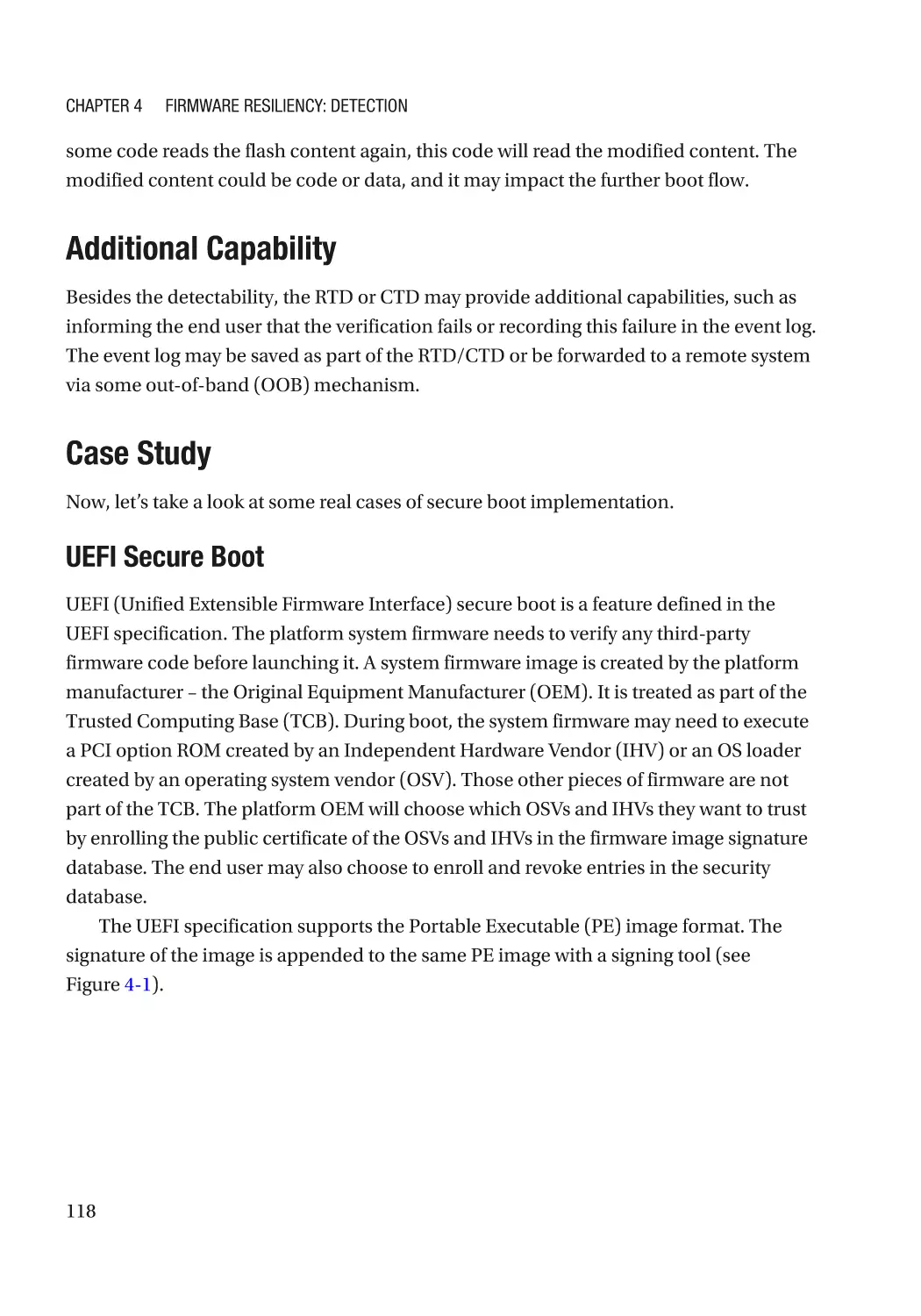
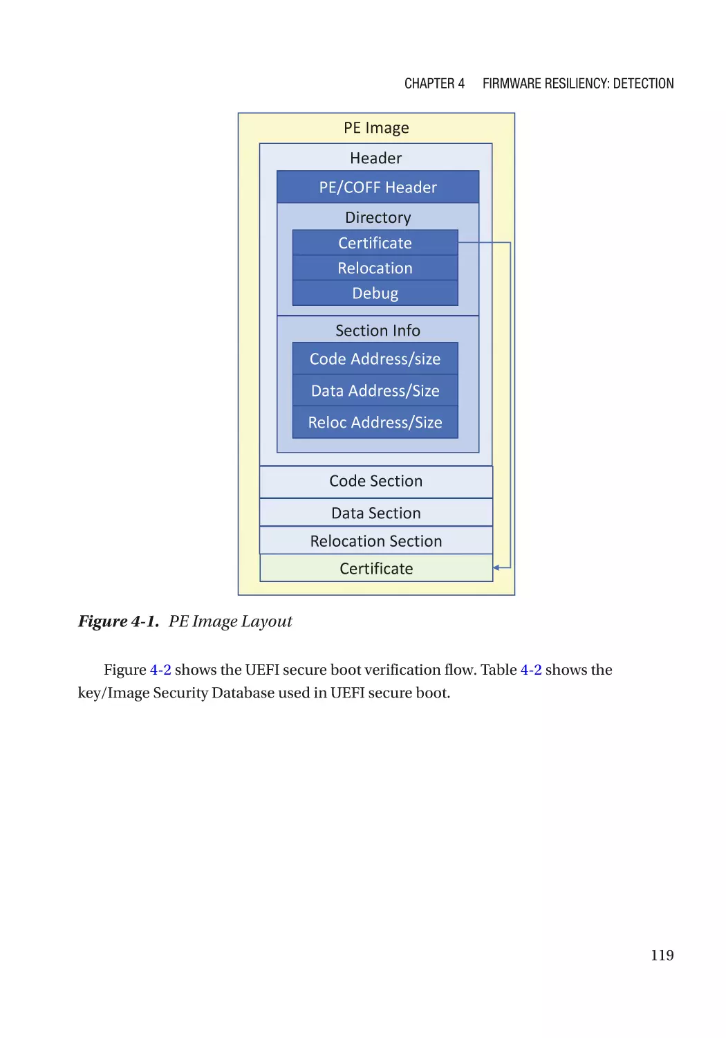
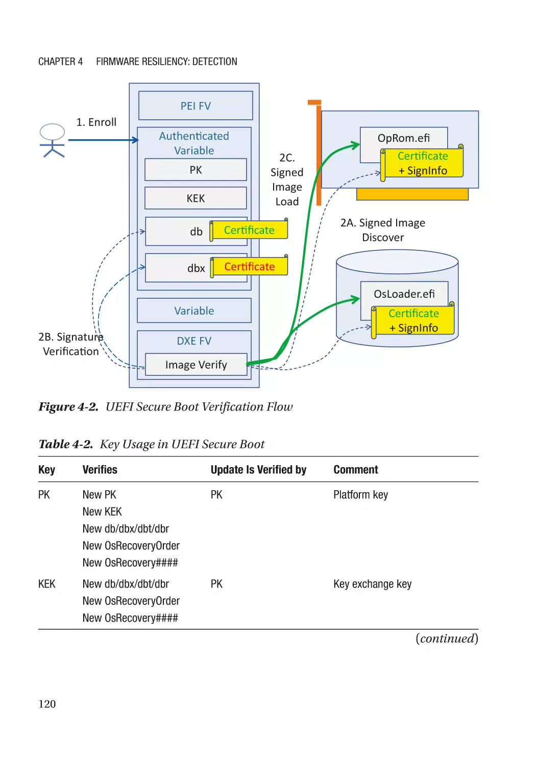
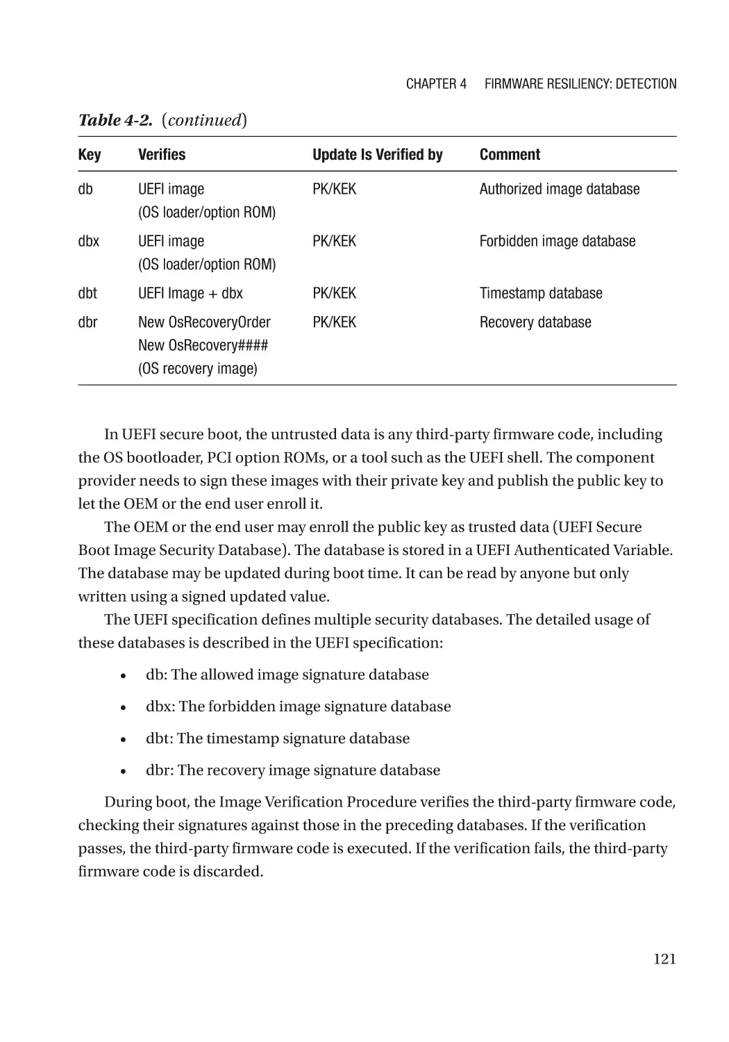
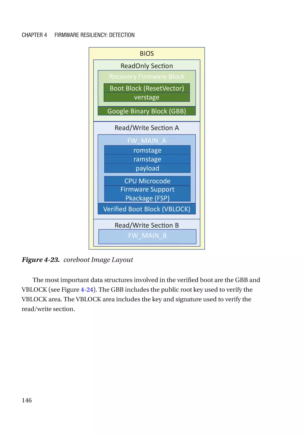
Case Study��������������������������������������������������������������������������������������������������������������������������� 118
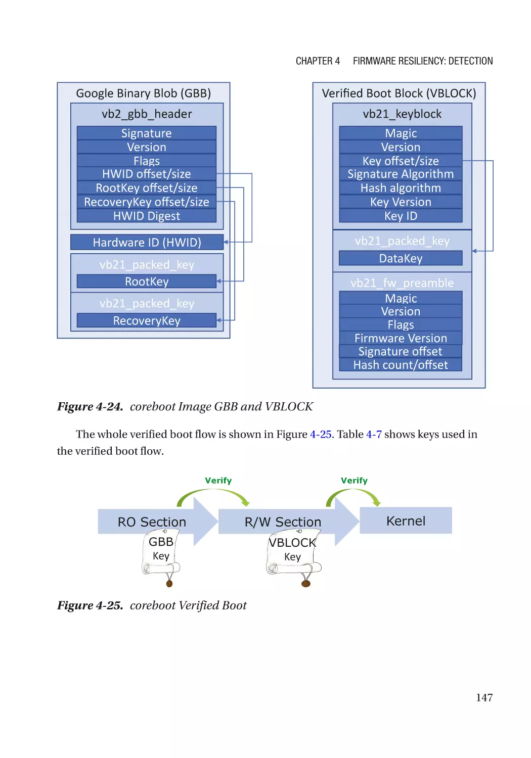
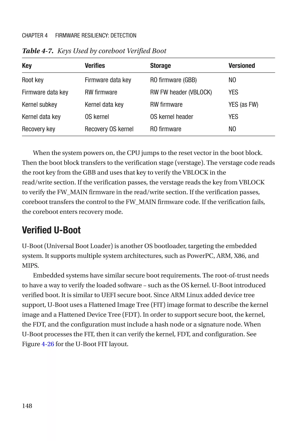
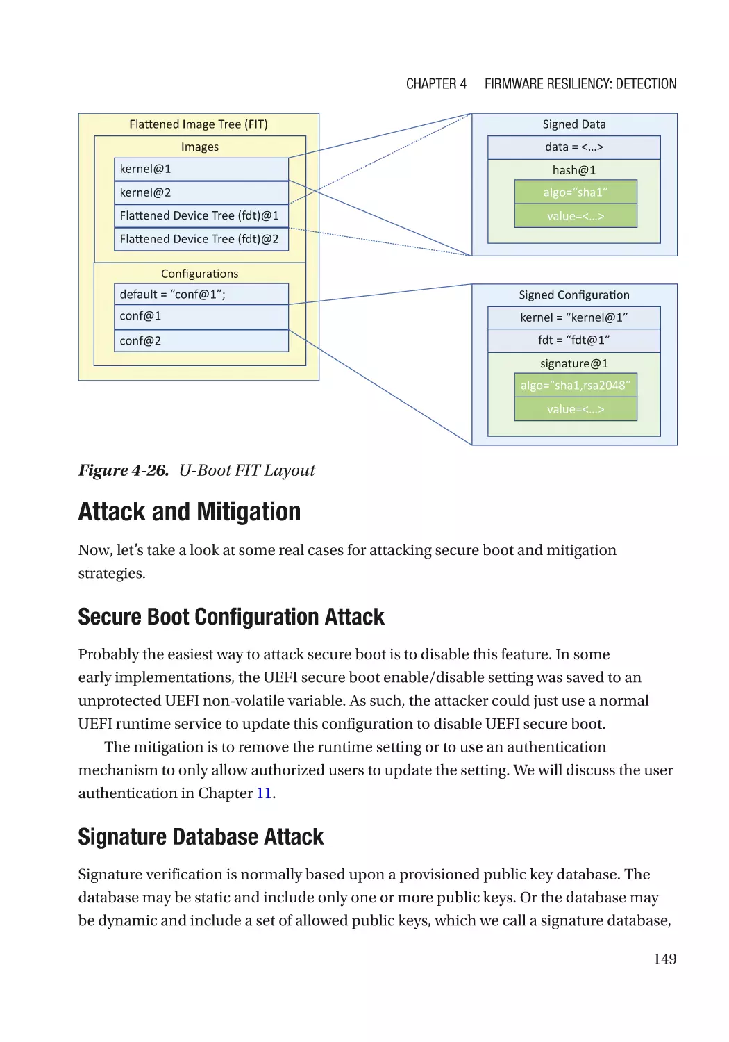
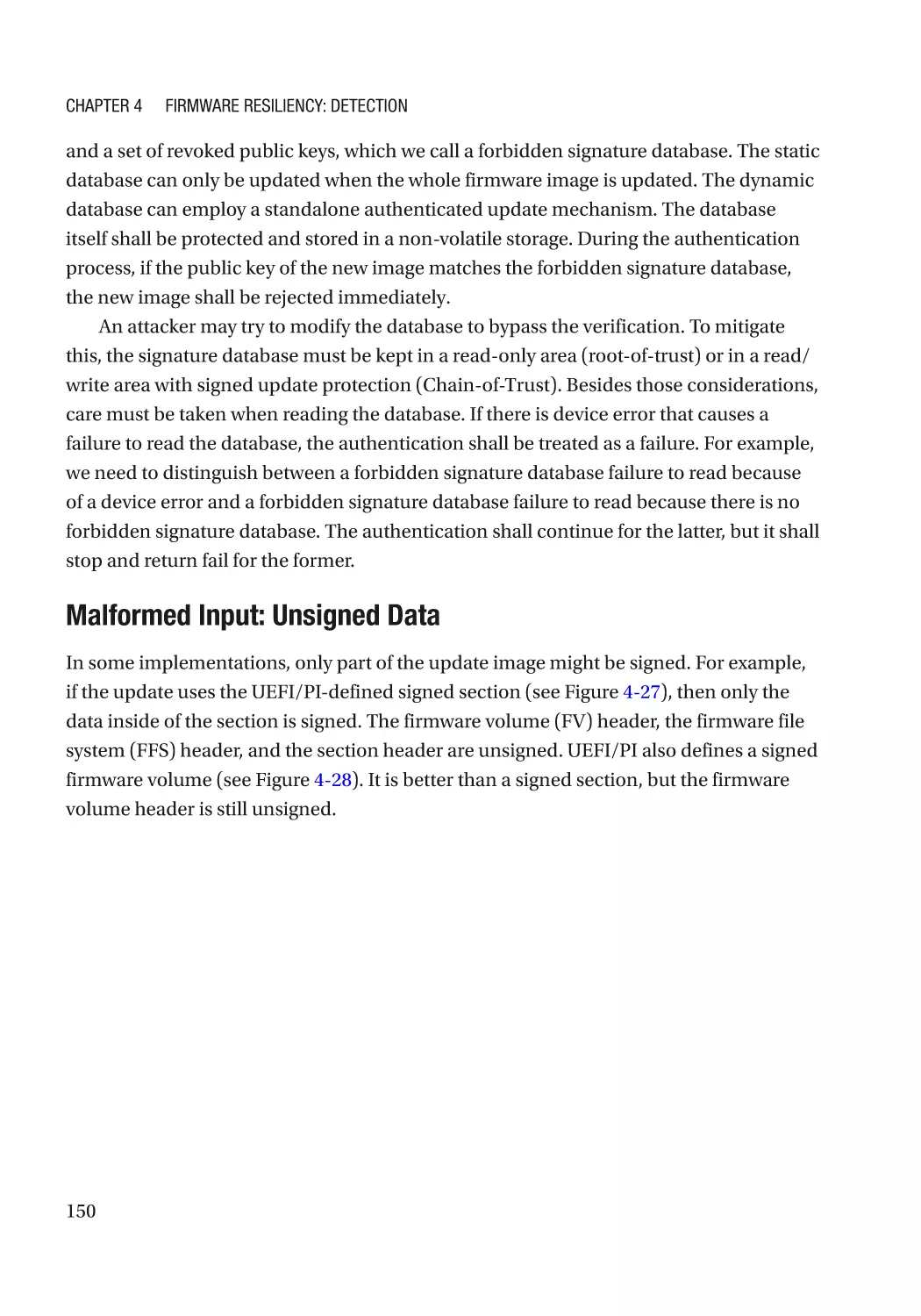
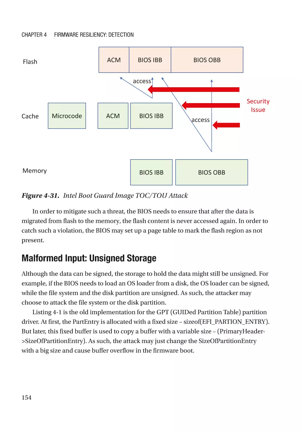
Attack and Mitigation���������������������������������������������������������������������������������������������������������� 149
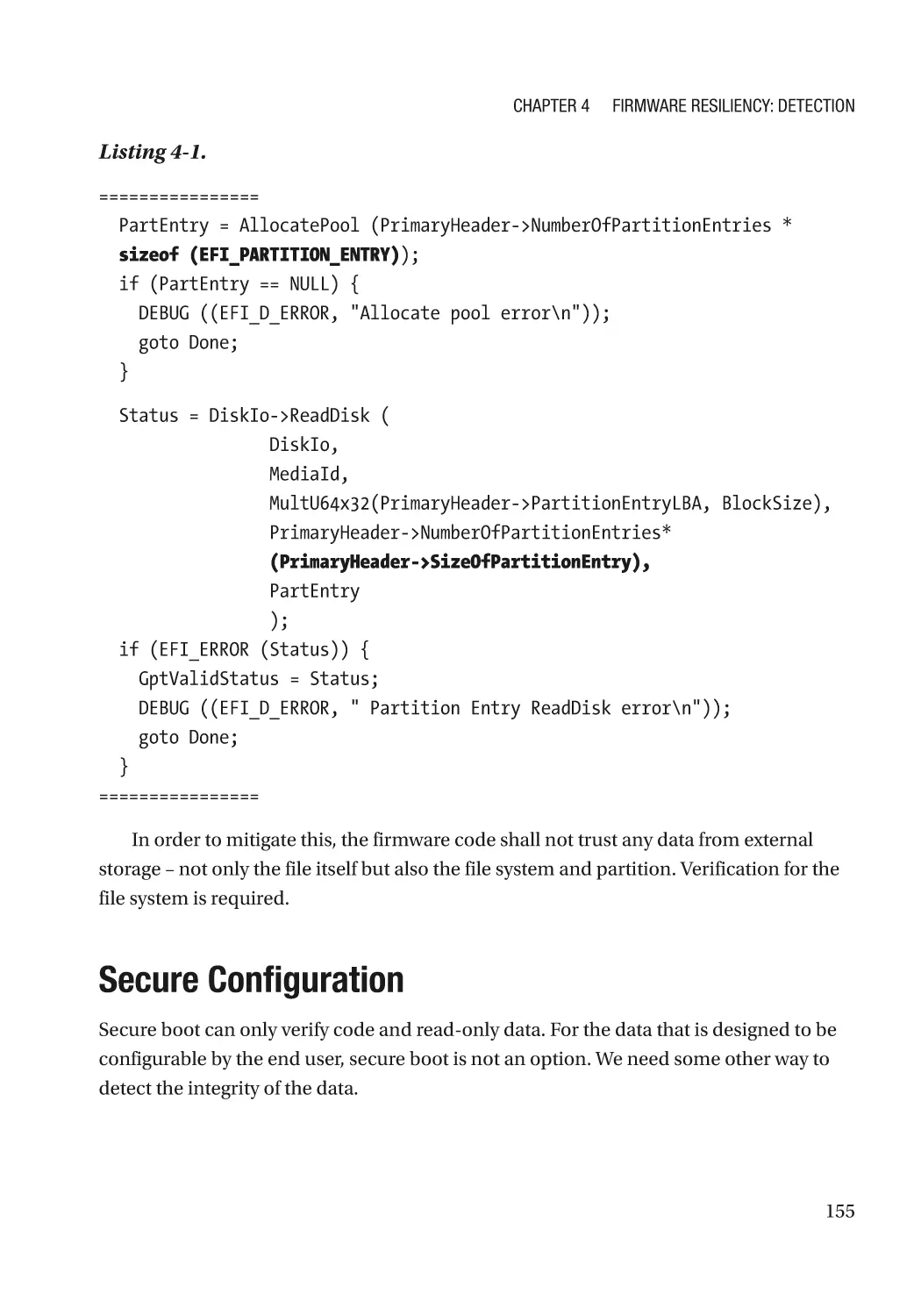
Secure Configuration���������������������������������������������������������������������������������������������������������������� 155
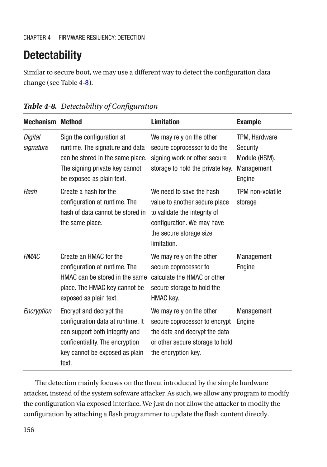
Detectability������������������������������������������������������������������������������������������������������������������������ 156
Attack and Mitigation���������������������������������������������������������������������������������������������������������� 157
Summary���������������������������������������������������������������������������������������������������������������������������������� 158
References�������������������������������������������������������������������������������������������������������������������������������� 158
vii
Table of Contents
Chapter 5: Firmware Resiliency: Recovery����������������������������������������������������������� 163
Image Recovery������������������������������������������������������������������������������������������������������������������������ 163
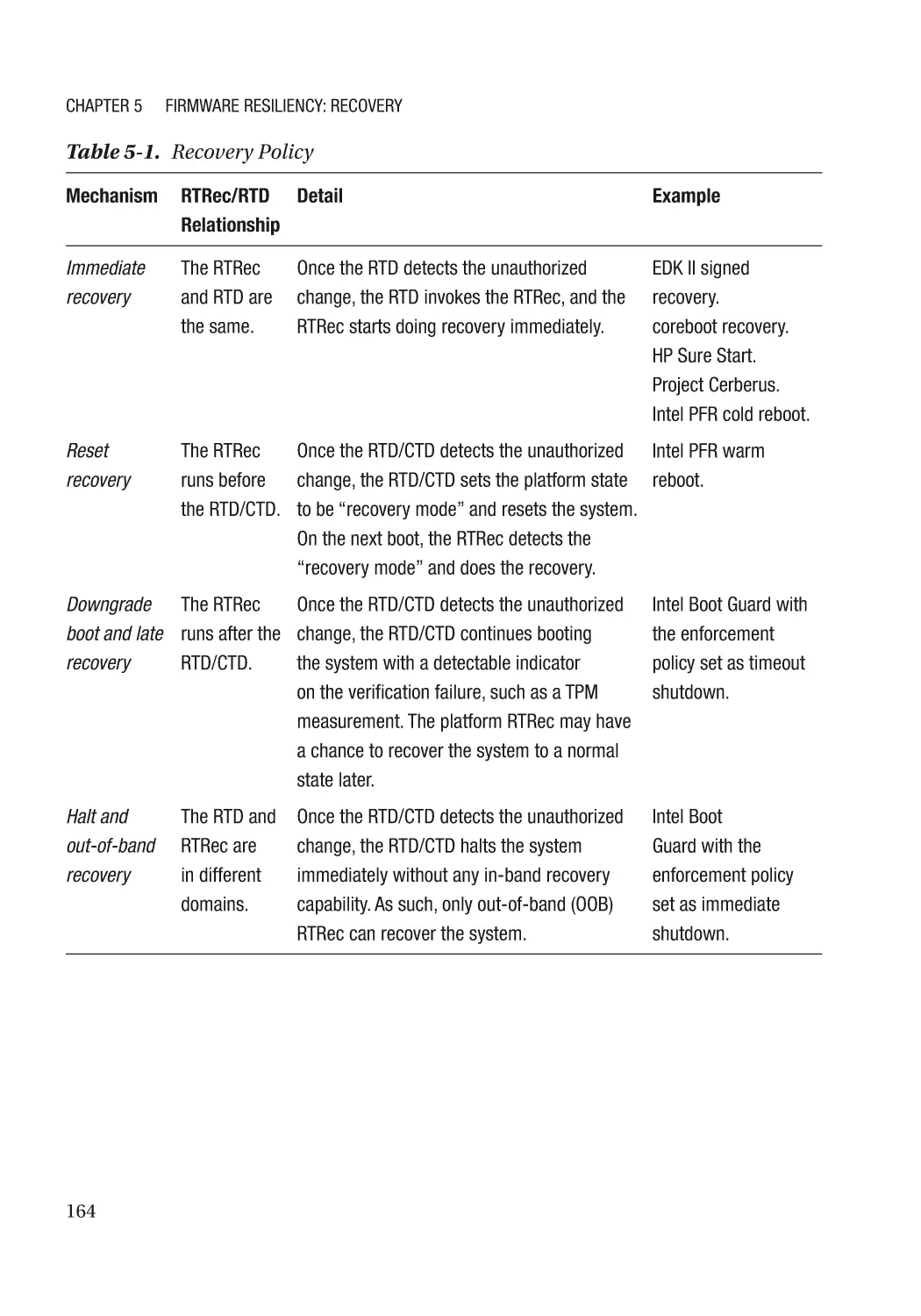
RTRec Selection and Recovery Policy��������������������������������������������������������������������������������� 163
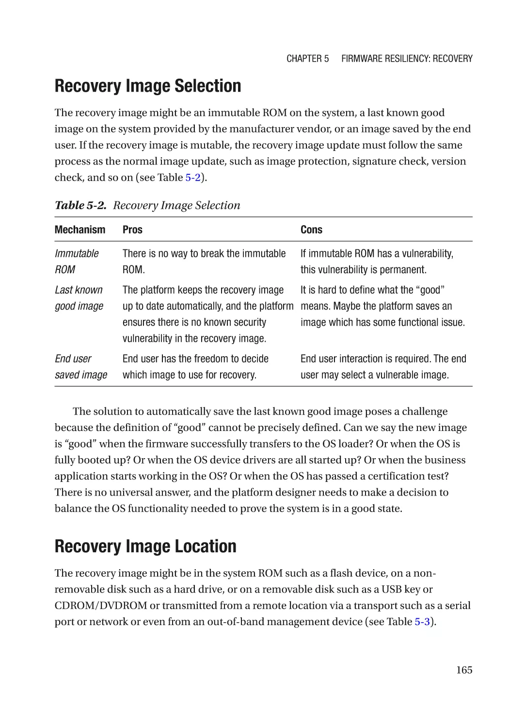
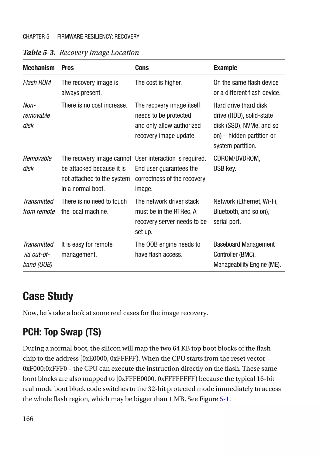
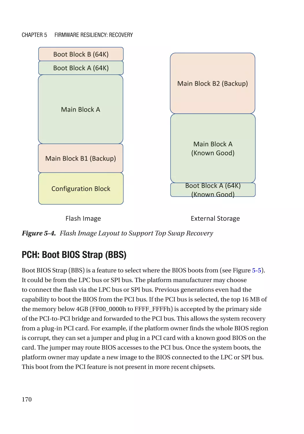
Recovery Image Selection��������������������������������������������������������������������������������������������������� 165
Recovery Image Location���������������������������������������������������������������������������������������������������� 165
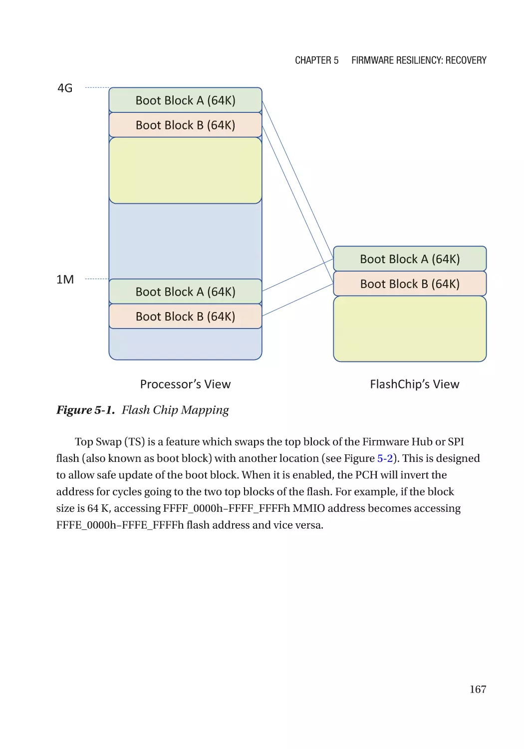
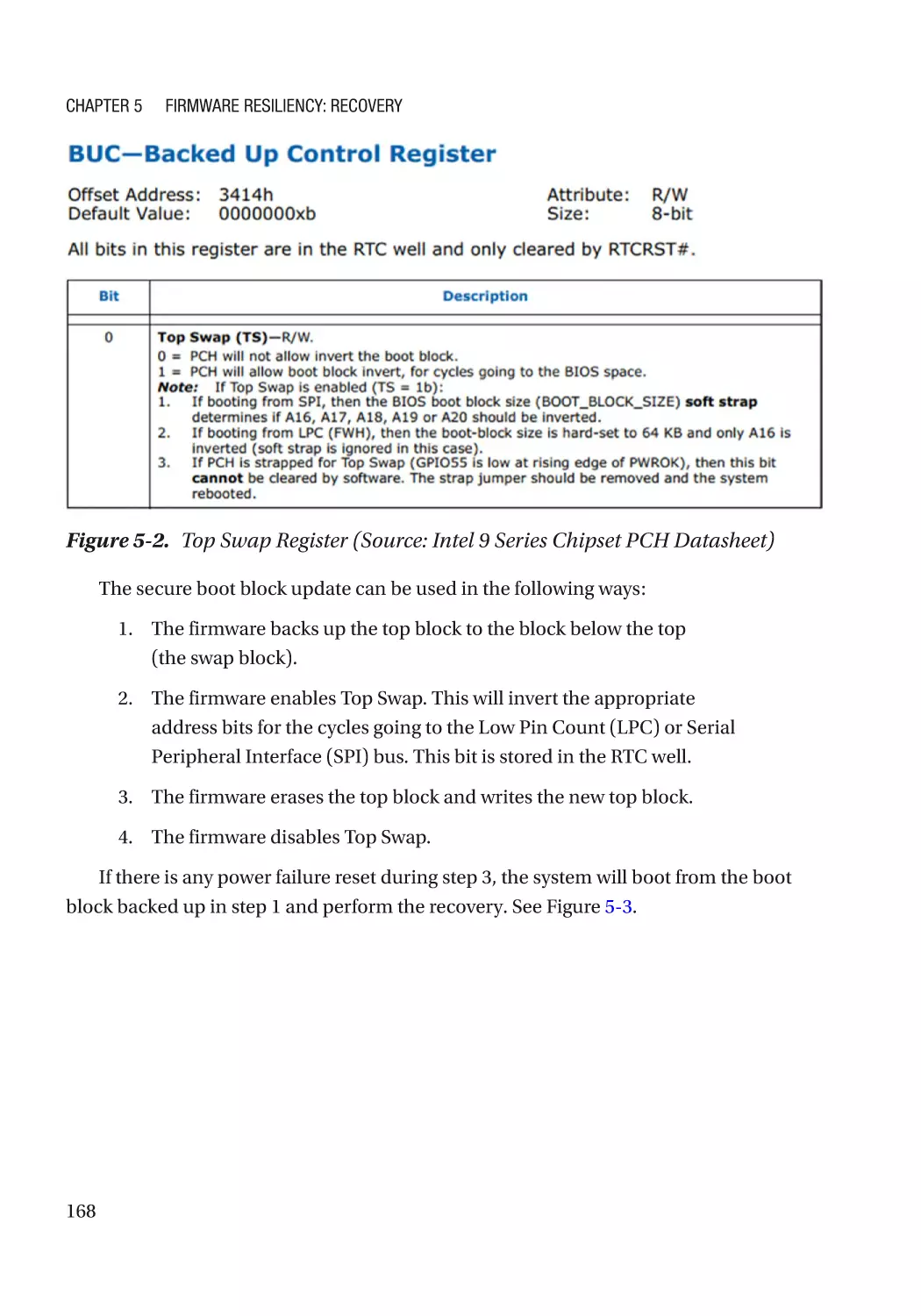
Case Study��������������������������������������������������������������������������������������������������������������������������� 166
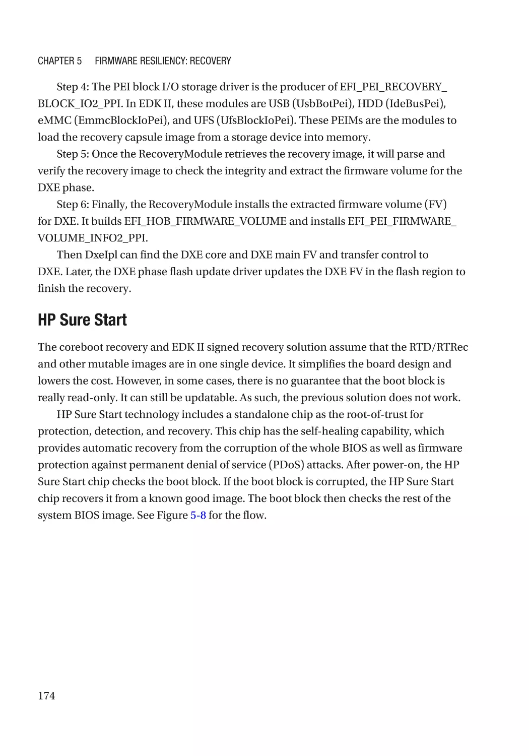
Attack and Mitigation���������������������������������������������������������������������������������������������������������� 177
Configuration Recovery������������������������������������������������������������������������������������������������������������� 178
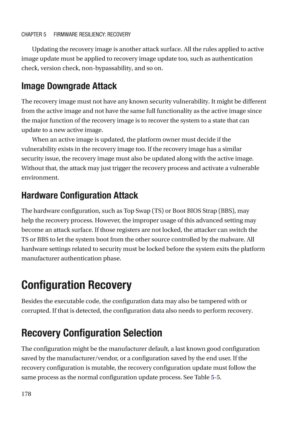
Recovery Configuration Selection��������������������������������������������������������������������������������������� 178
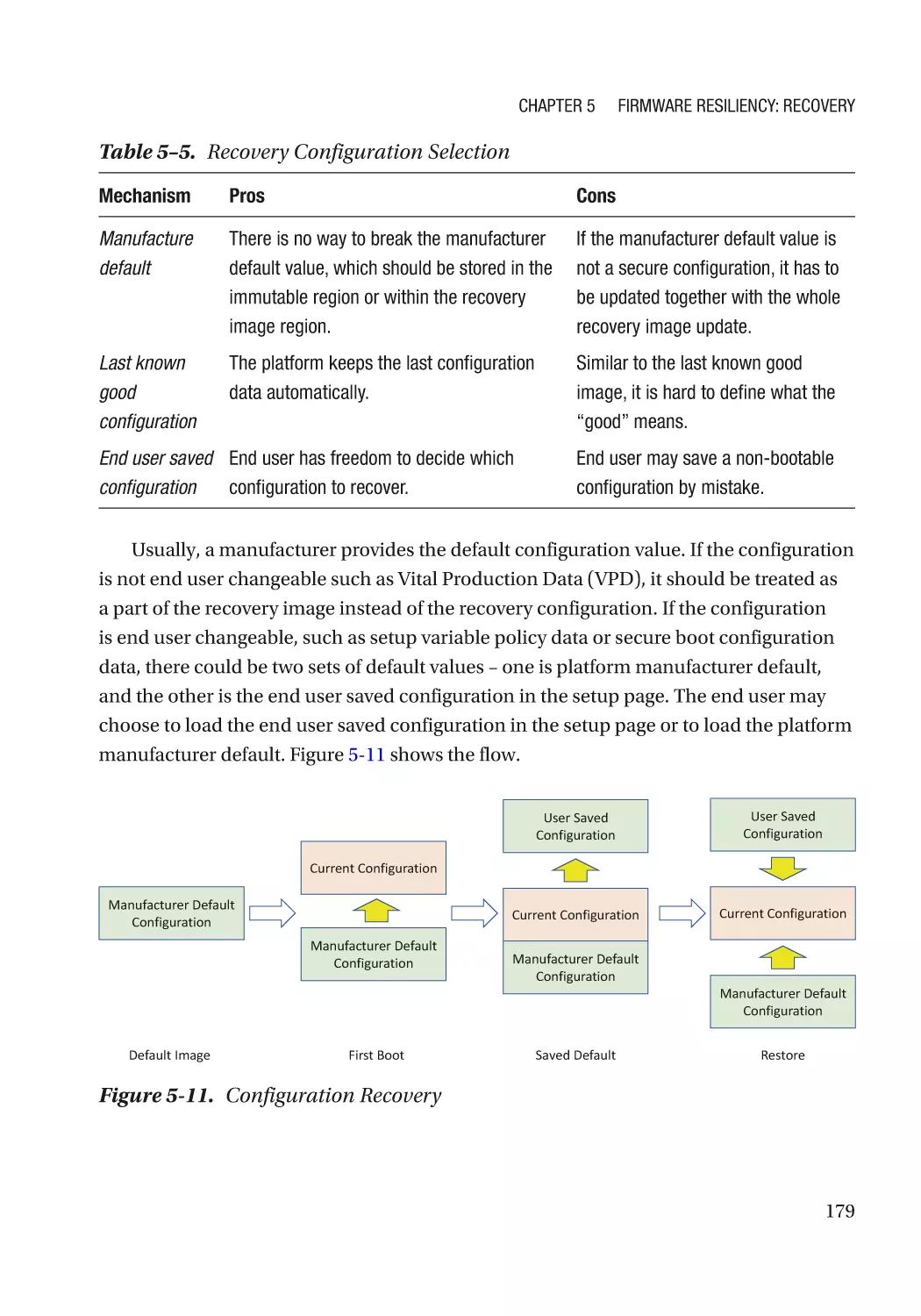
Attack and Mitigation���������������������������������������������������������������������������������������������������������� 180
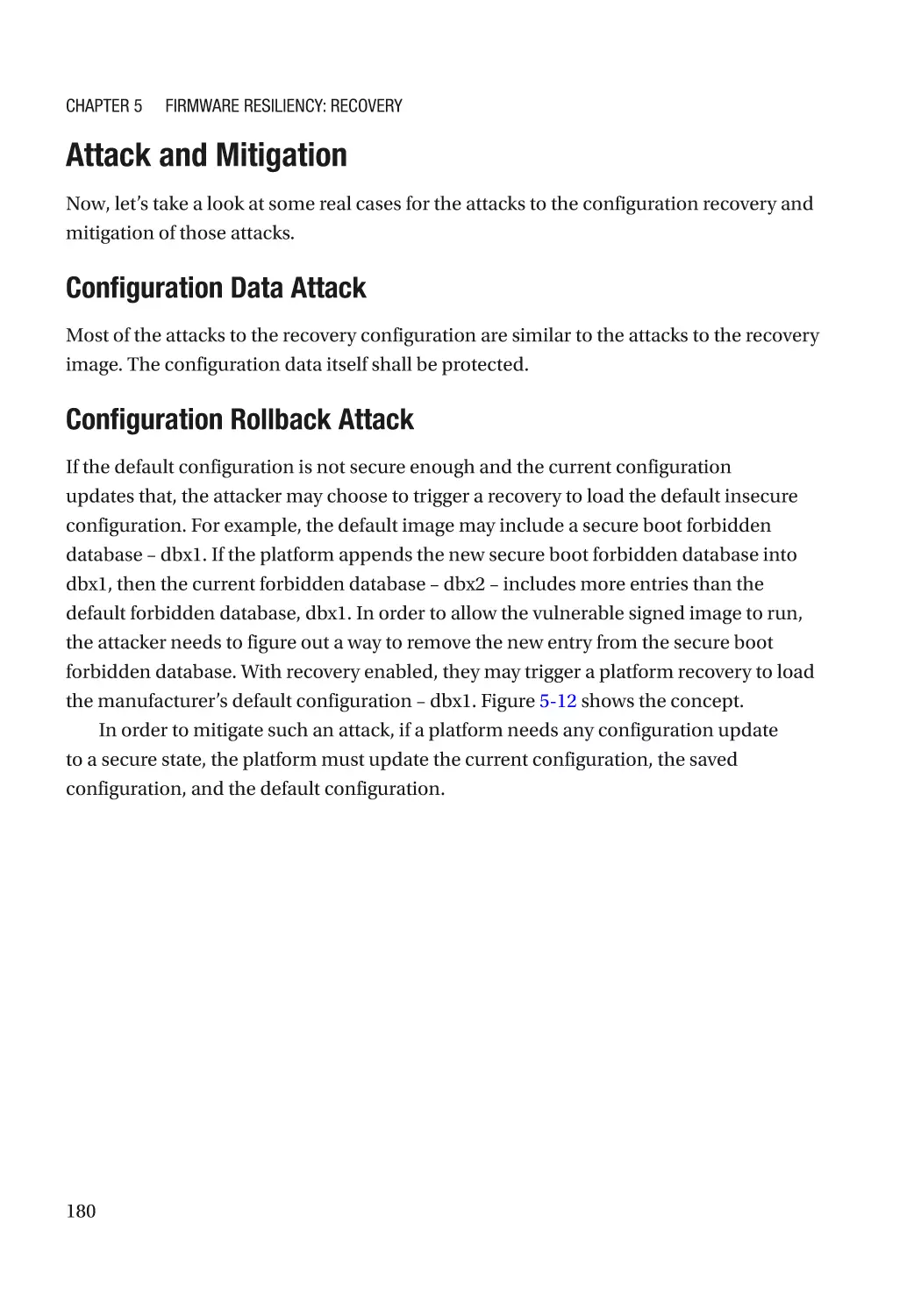
Watchdog���������������������������������������������������������������������������������������������������������������������������������� 181
Summary���������������������������������������������������������������������������������������������������������������������������������� 182
References�������������������������������������������������������������������������������������������������������������������������������� 182
Chapter 6: OS Resiliency�������������������������������������������������������������������������������������� 185
Protection���������������������������������������������������������������������������������������������������������������������������������� 186
Automated Update��������������������������������������������������������������������������������������������������������������� 186
Detection����������������������������������������������������������������������������������������������������������������������������������� 186
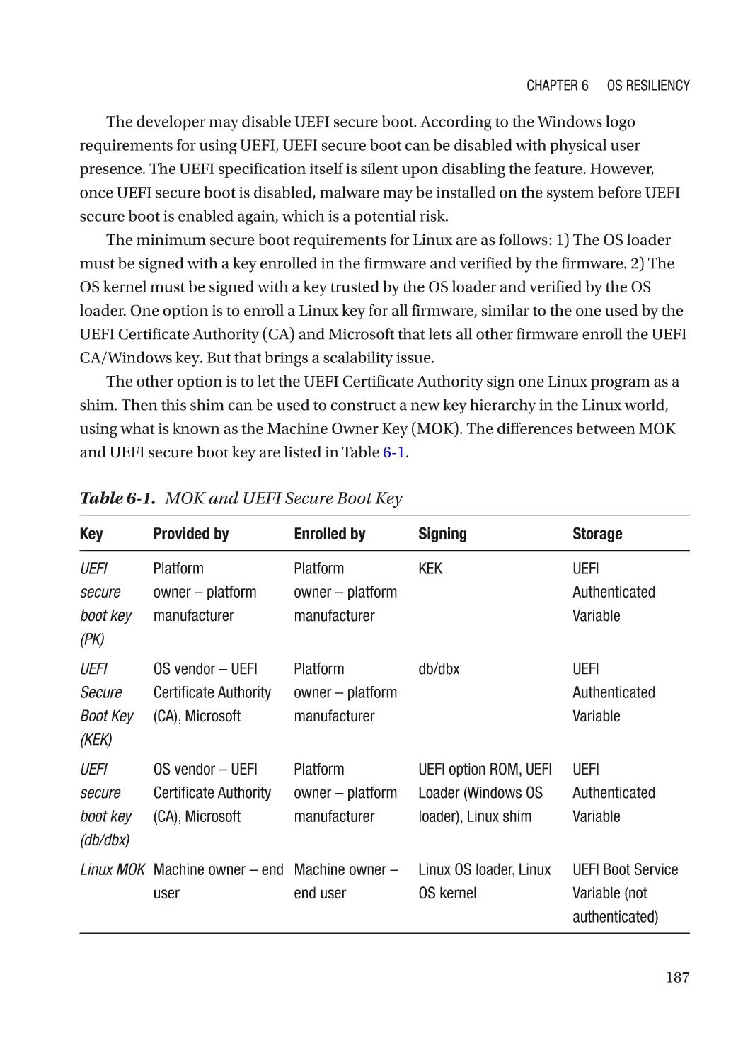
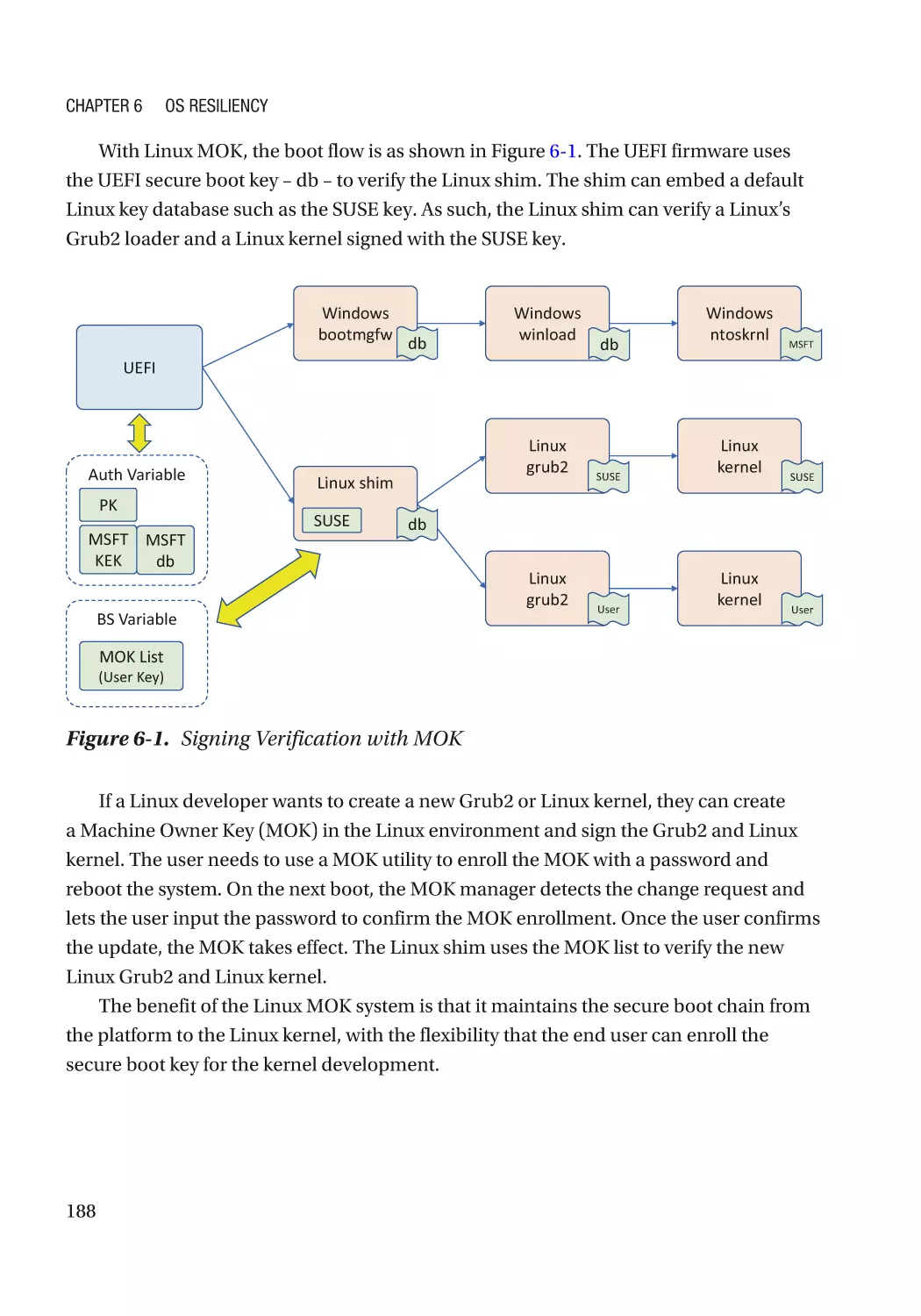
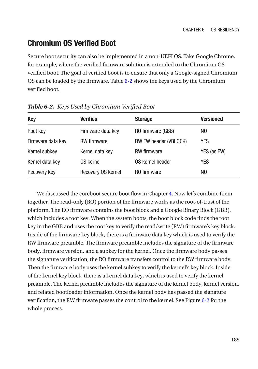
Image Signing���������������������������������������������������������������������������������������������������������������������� 186
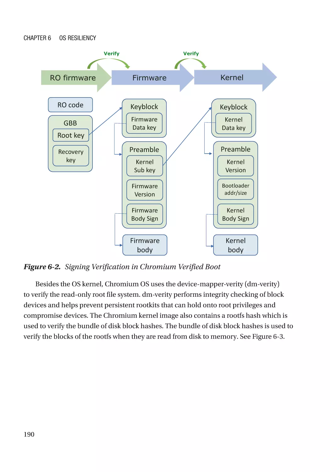
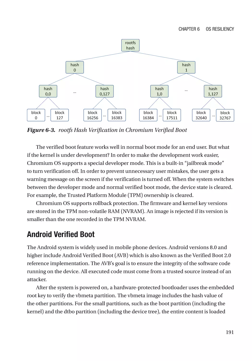
Case Study��������������������������������������������������������������������������������������������������������������������������� 186
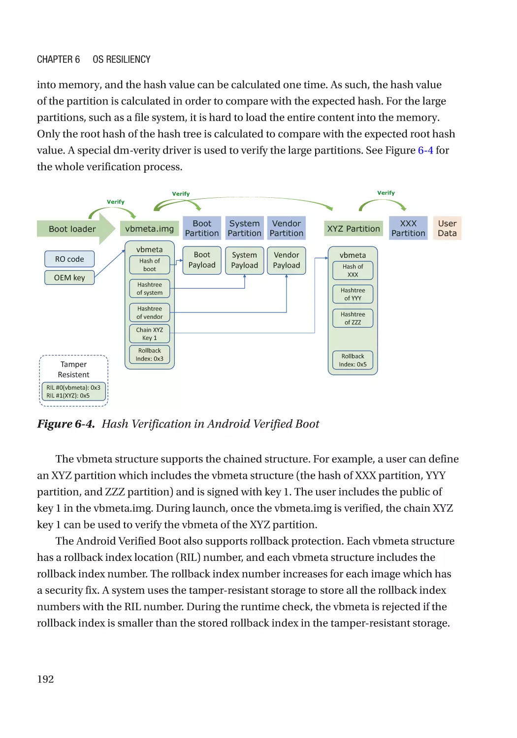
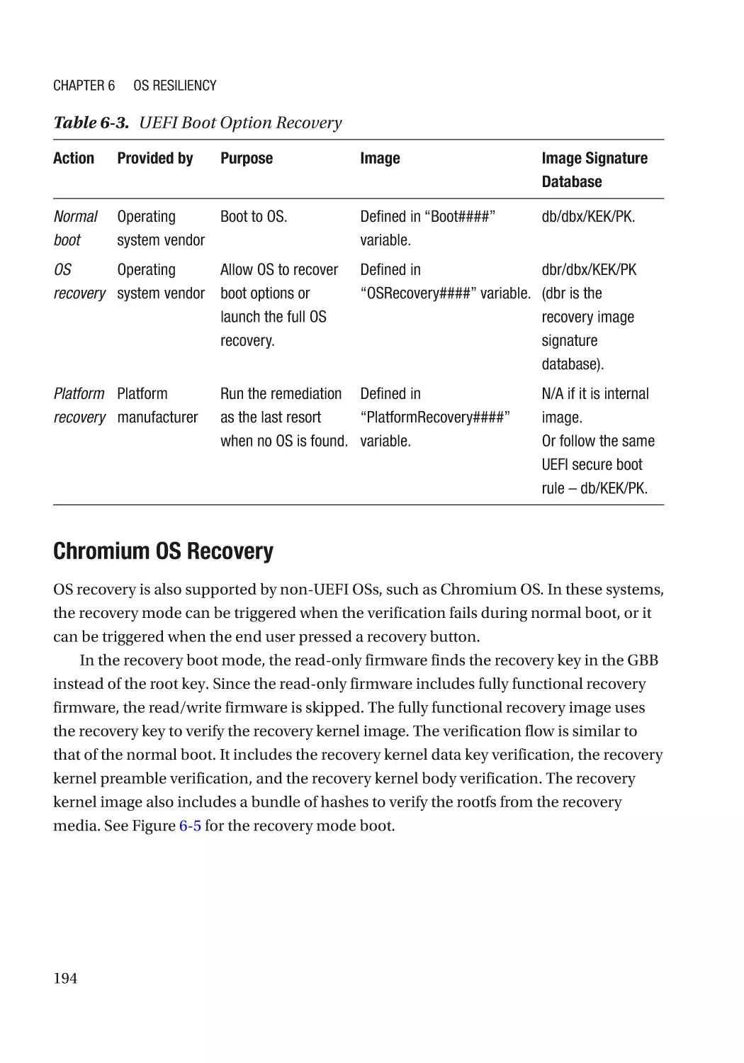
Recovery����������������������������������������������������������������������������������������������������������������������������������� 193
Automated Recovery����������������������������������������������������������������������������������������������������������� 193
Case Study��������������������������������������������������������������������������������������������������������������������������� 193
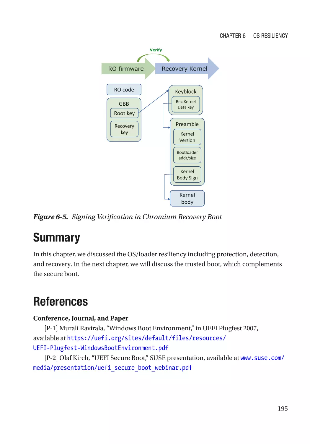
Summary���������������������������������������������������������������������������������������������������������������������������������� 195
References�������������������������������������������������������������������������������������������������������������������������������� 195
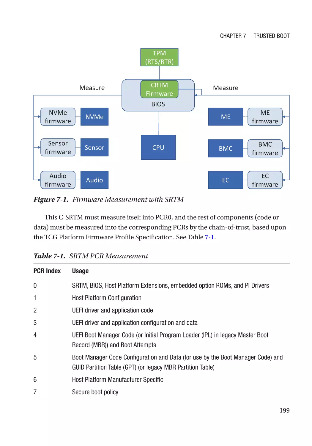
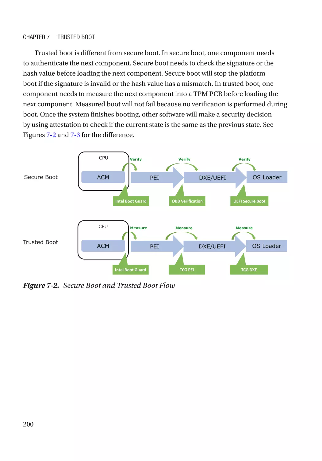
Chapter 7: Trusted Boot���������������������������������������������������������������������������������������� 197
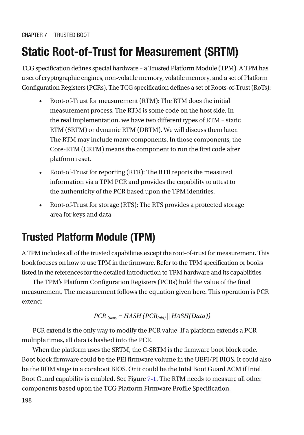
Static Root-of-Trust for Measurement (SRTM)�������������������������������������������������������������������������� 198
Trusted Platform Module (TPM)������������������������������������������������������������������������������������������� 198
TPM Device Type����������������������������������������������������������������������������������������������������������������� 201
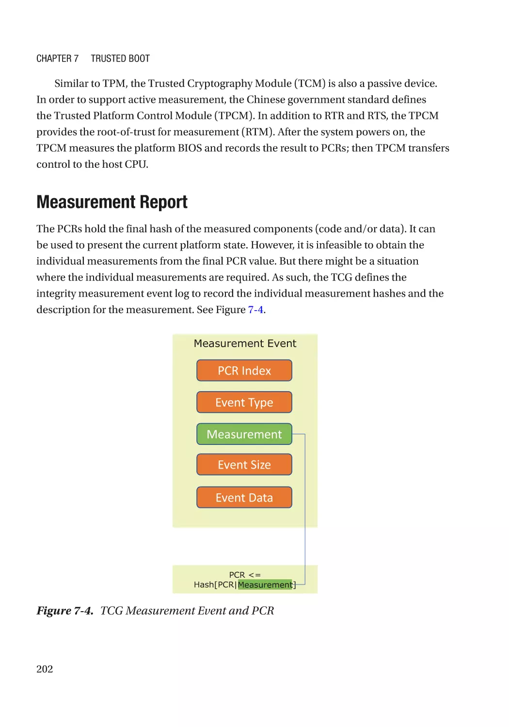
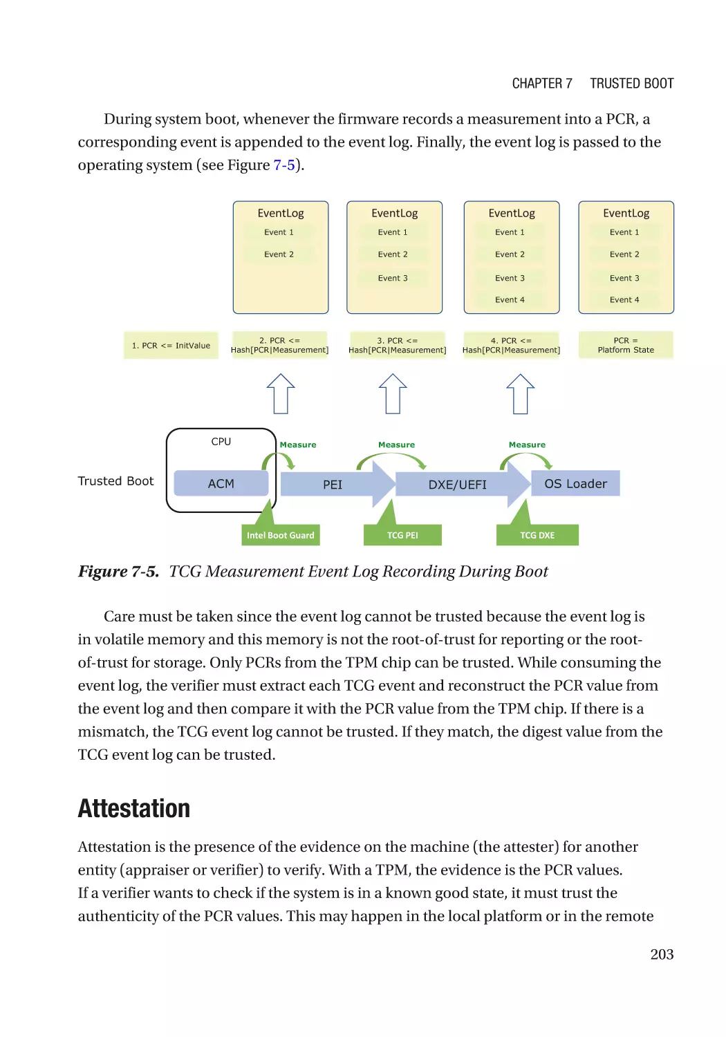
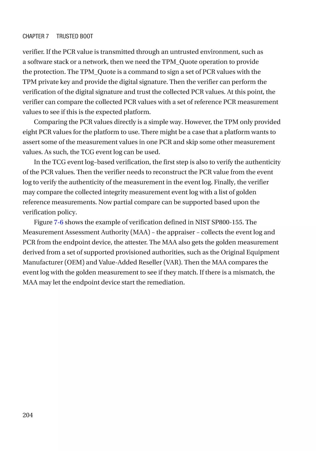
Measurement Report����������������������������������������������������������������������������������������������������������� 202
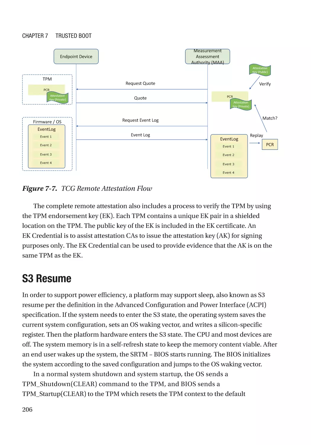
Attestation��������������������������������������������������������������������������������������������������������������������������� 203
viii
Table of Contents
S3 Resume�������������������������������������������������������������������������������������������������������������������������� 206
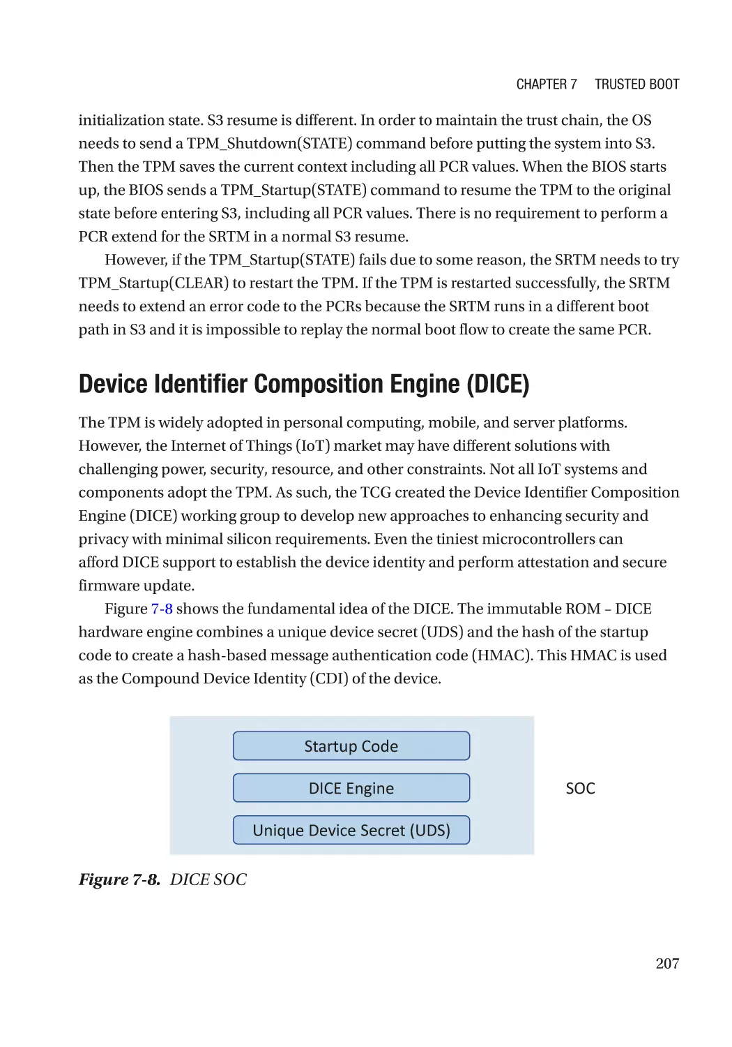
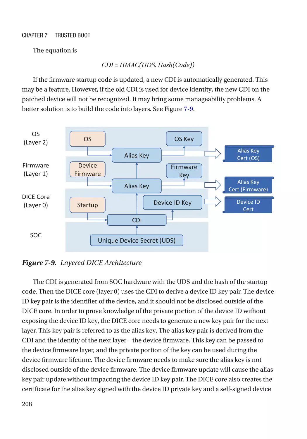
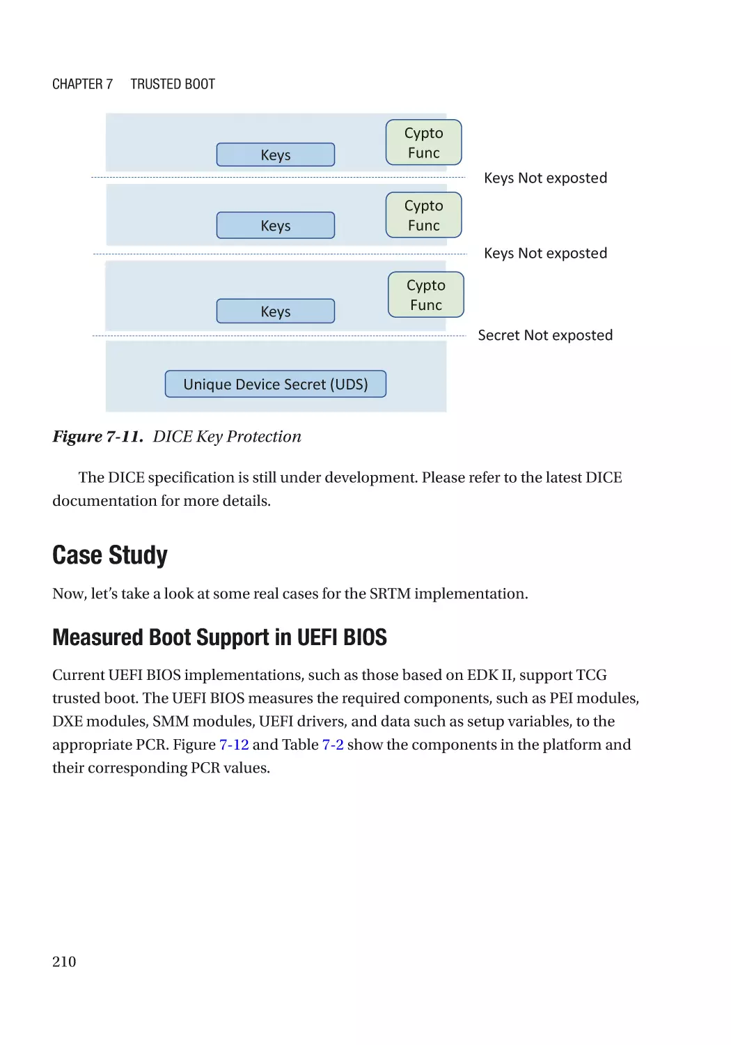
Device Identifier Composition Engine (DICE)����������������������������������������������������������������������� 207
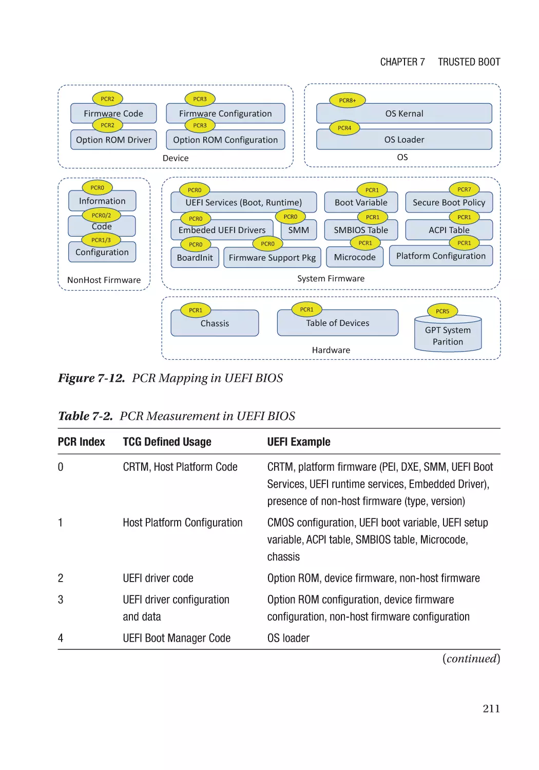
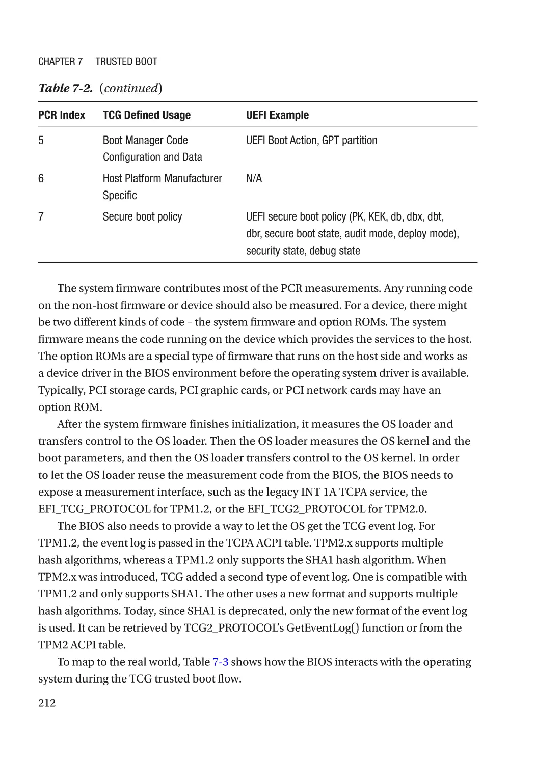
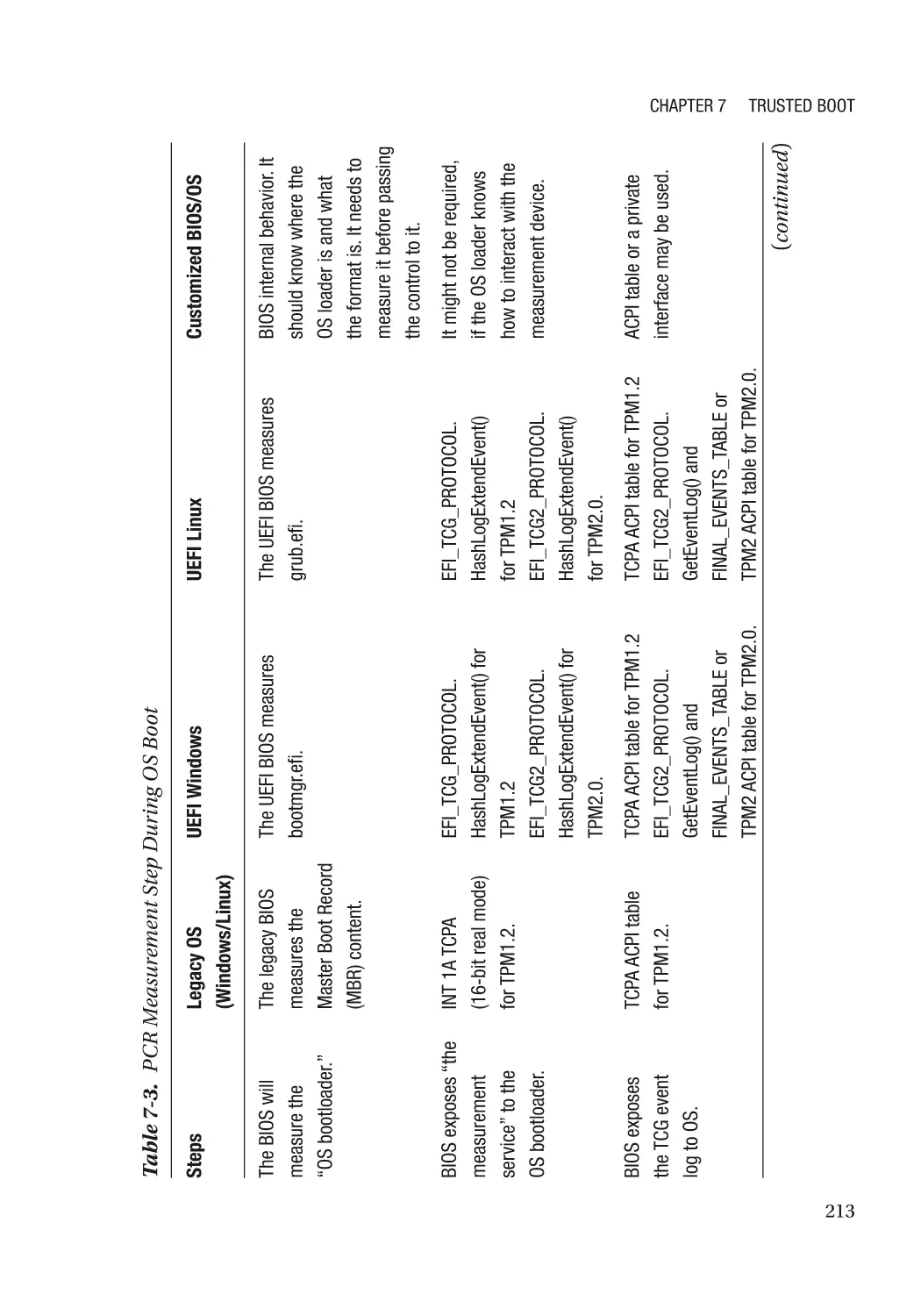
Case Study��������������������������������������������������������������������������������������������������������������������������� 210
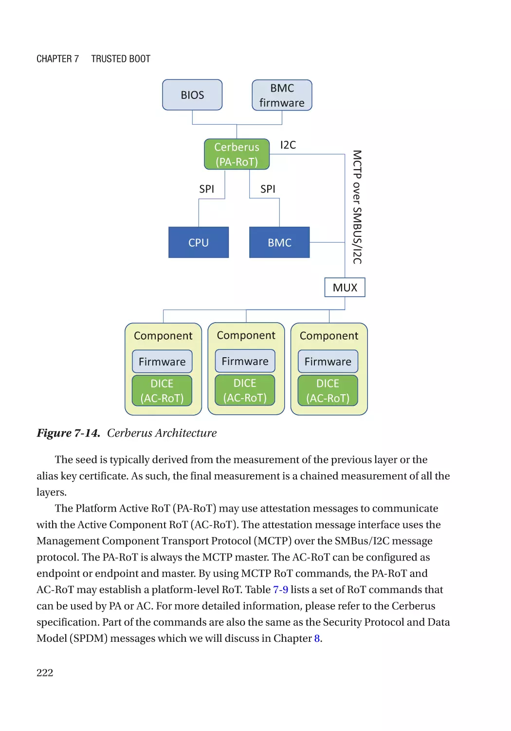
Attack and Mitigation���������������������������������������������������������������������������������������������������������� 224
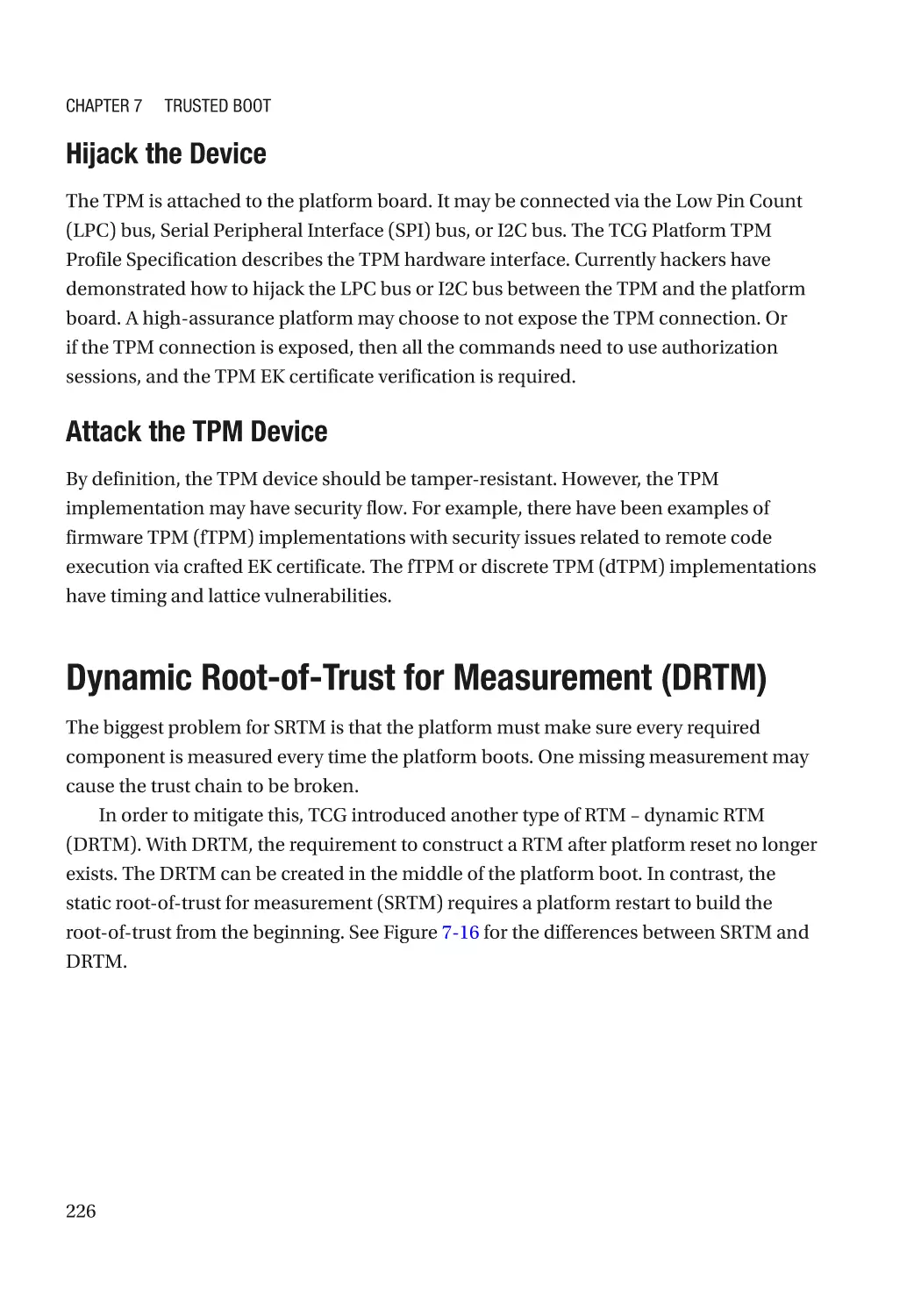
Dynamic Root-of-Trust for Measurement (DRTM)��������������������������������������������������������������������� 226
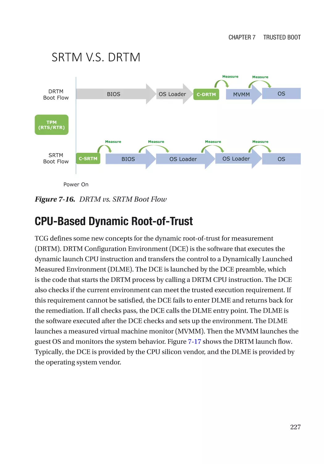
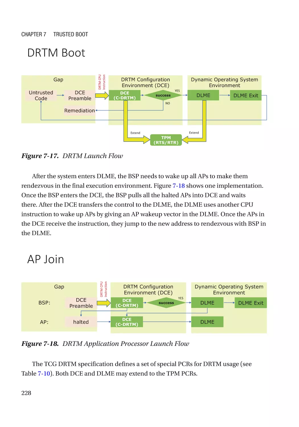
CPU-Based Dynamic Root-of-Trust�������������������������������������������������������������������������������������� 227
S3 Resume�������������������������������������������������������������������������������������������������������������������������� 229
DEC’s Execution Environment���������������������������������������������������������������������������������������������� 230
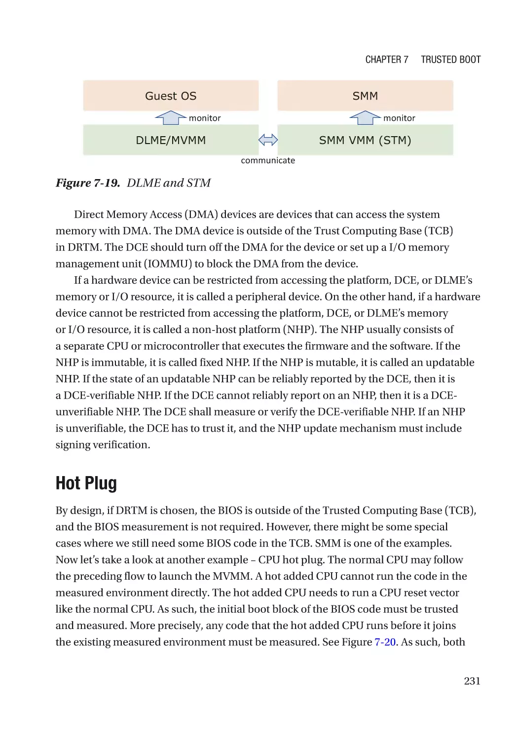
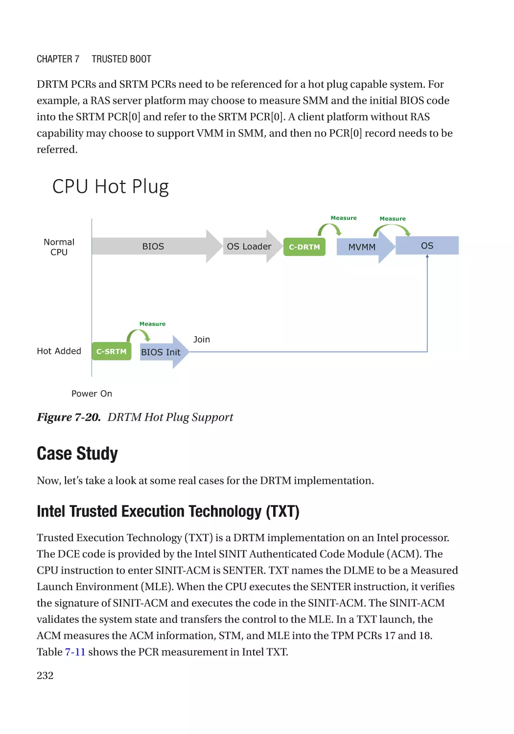
Hot Plug������������������������������������������������������������������������������������������������������������������������������� 231
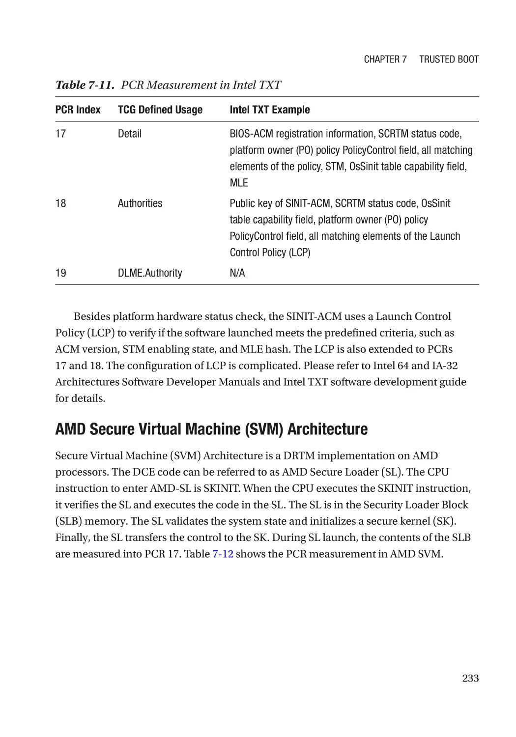
Case Study��������������������������������������������������������������������������������������������������������������������������� 232
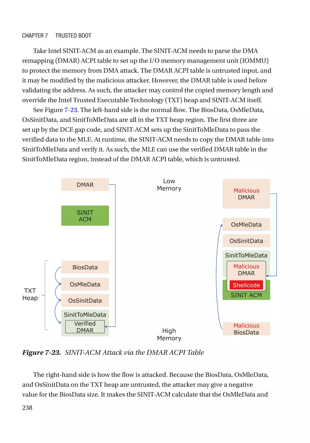
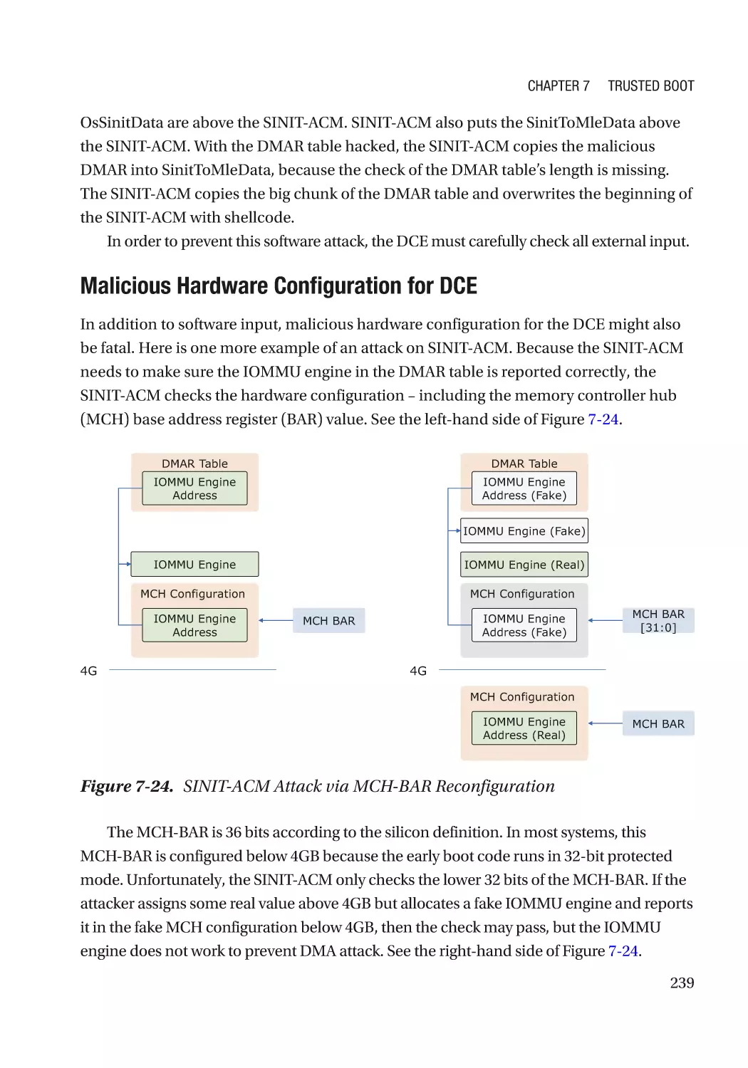
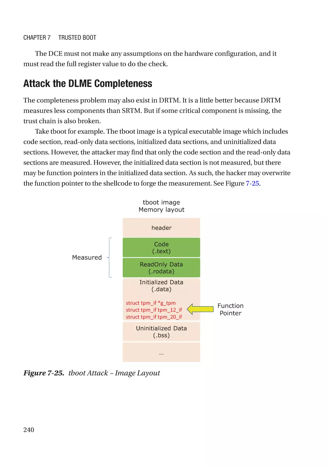
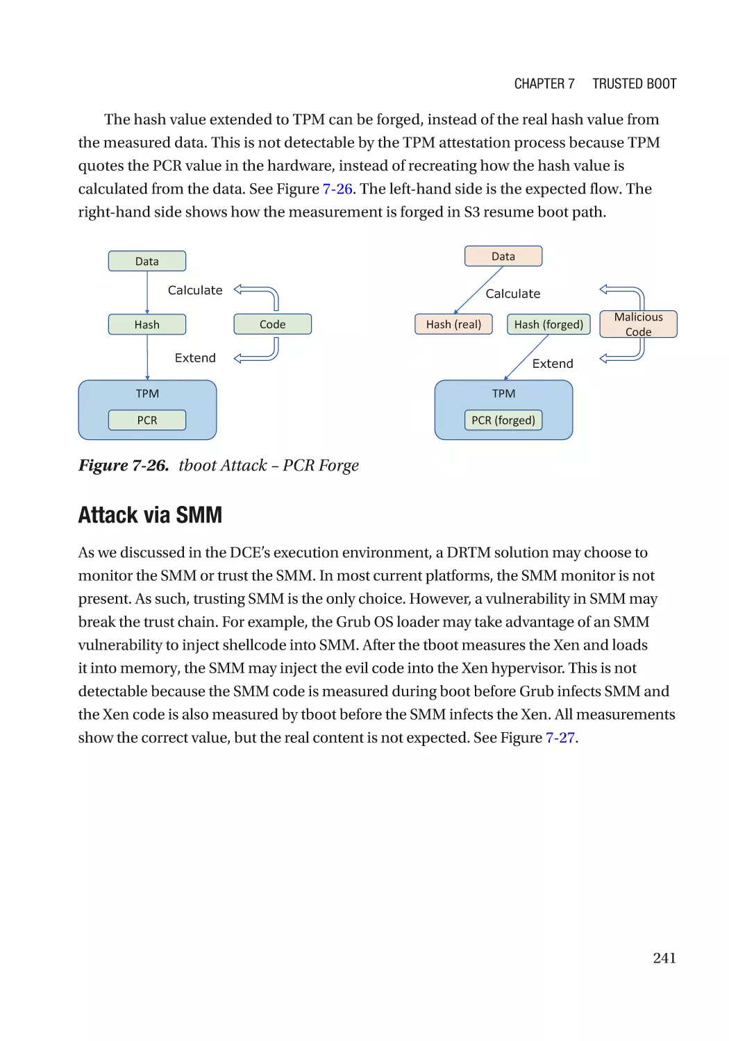
Attack and Mitigation���������������������������������������������������������������������������������������������������������� 237
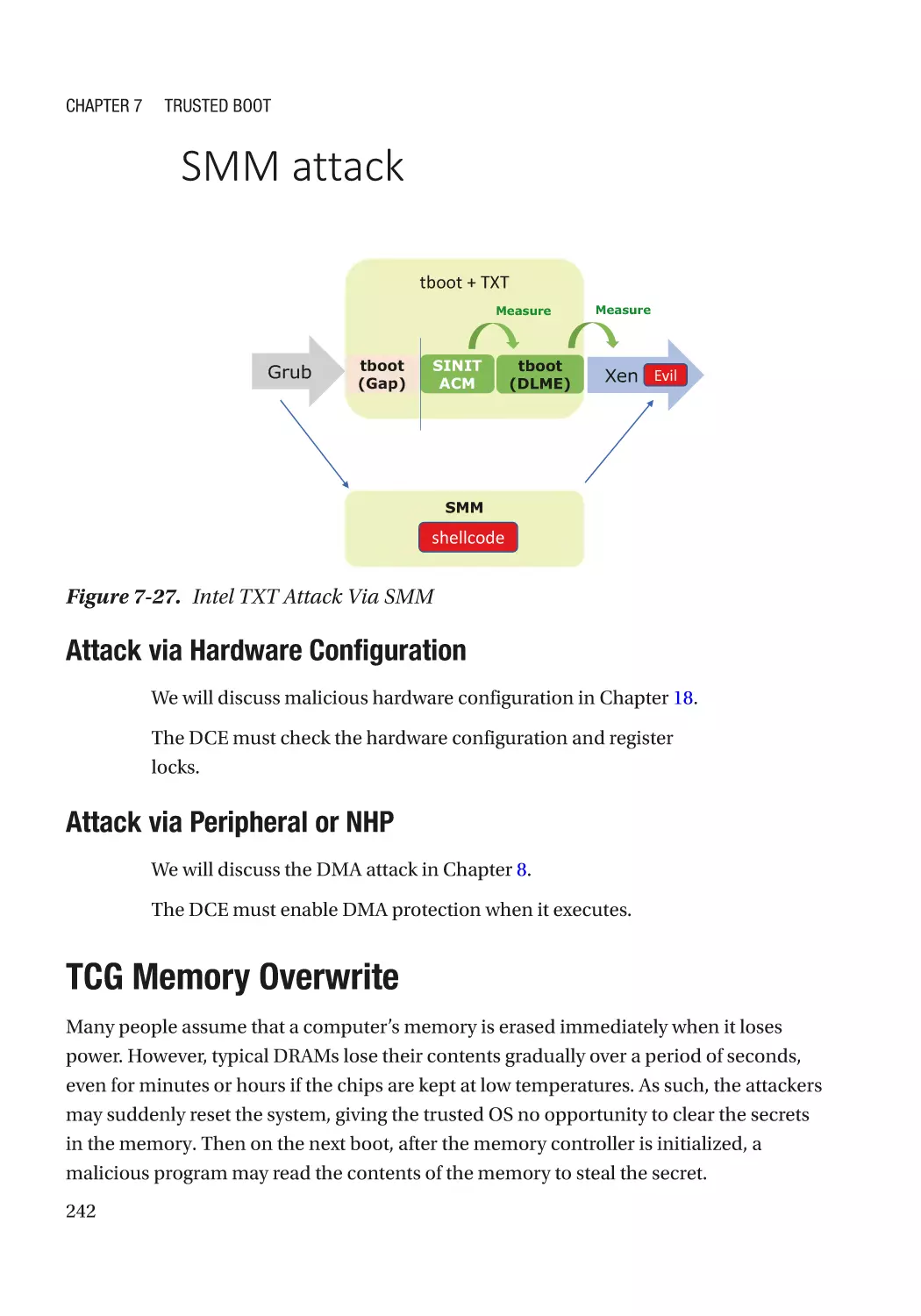
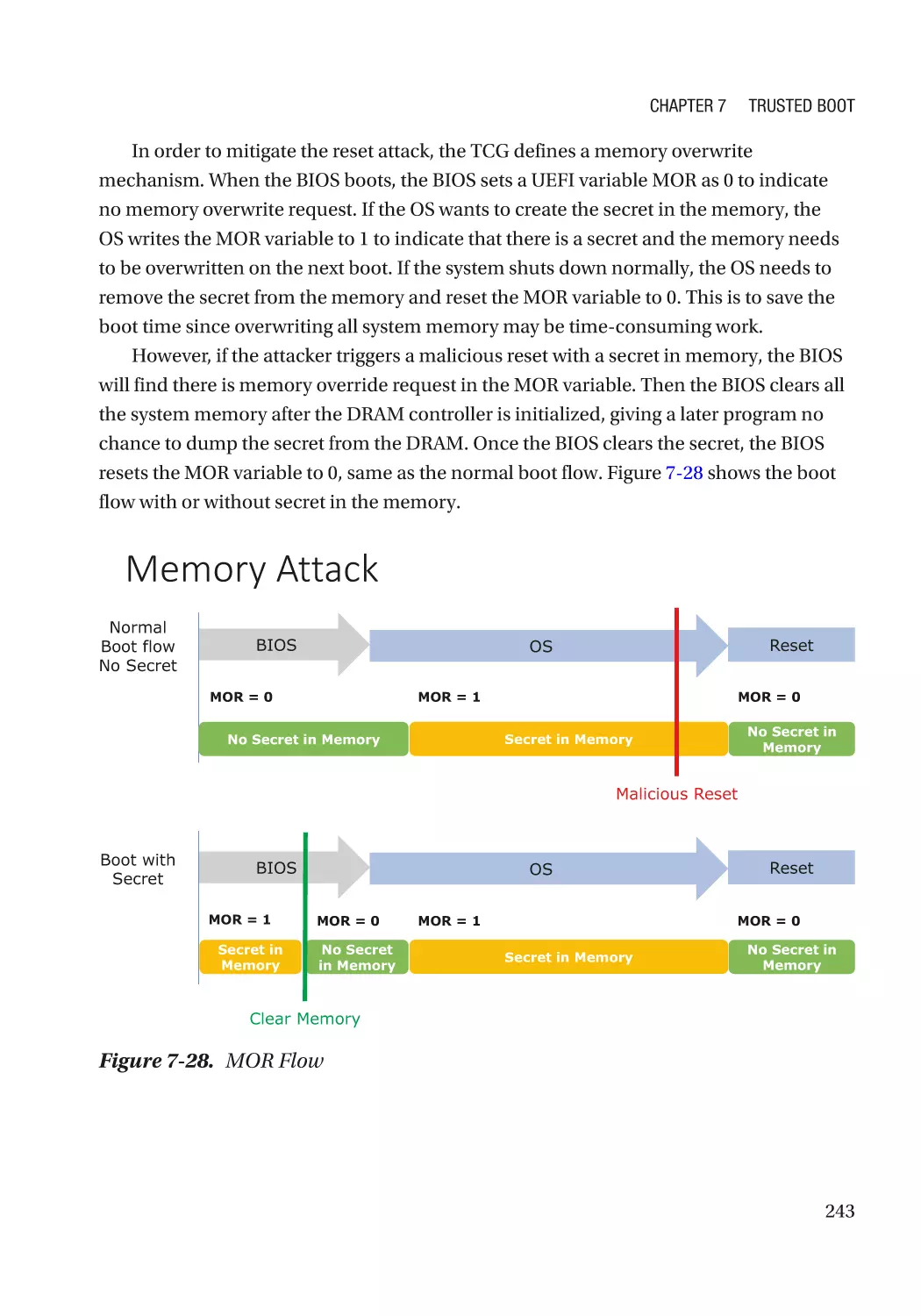
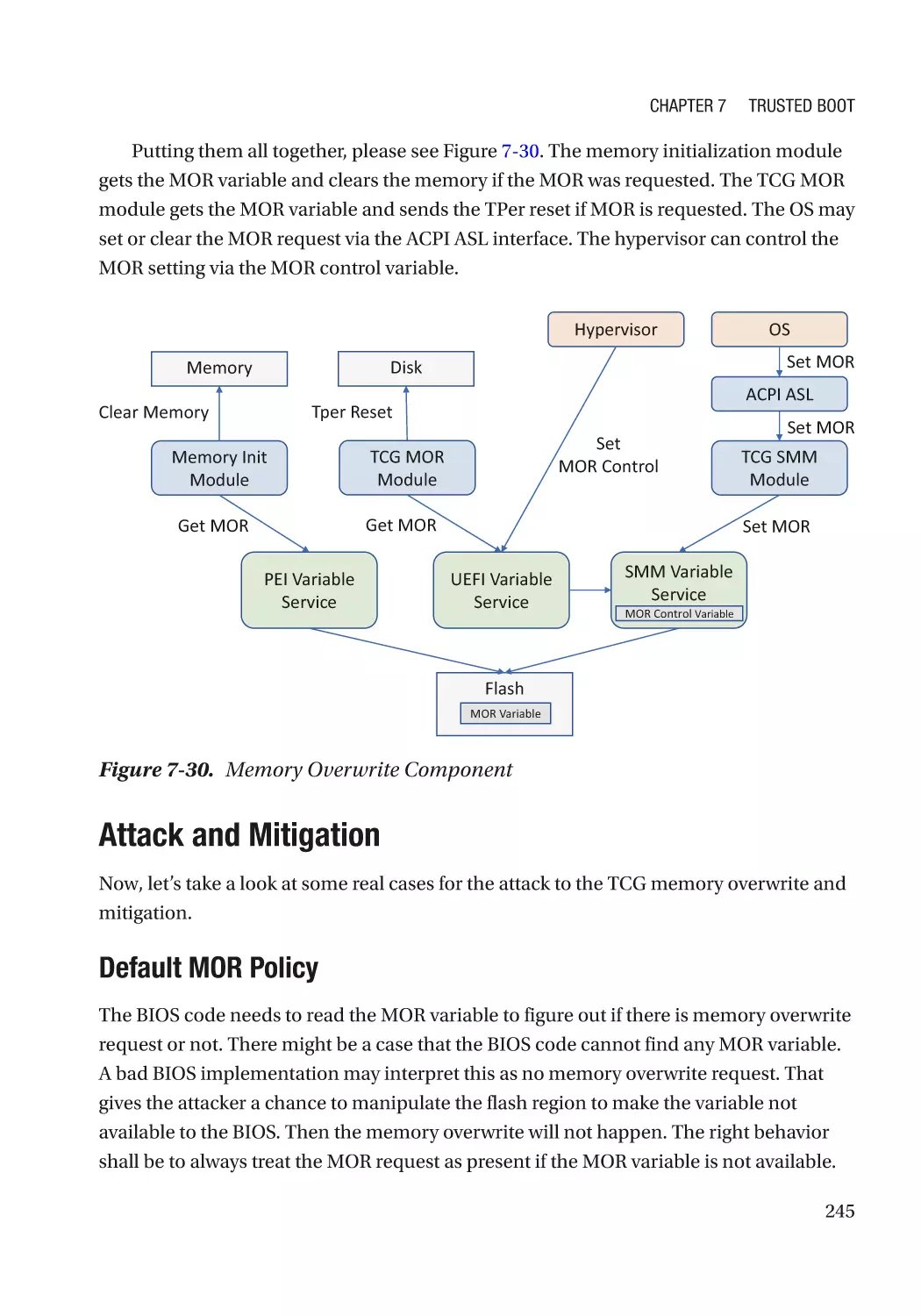
TCG Memory Overwrite������������������������������������������������������������������������������������������������������������� 242
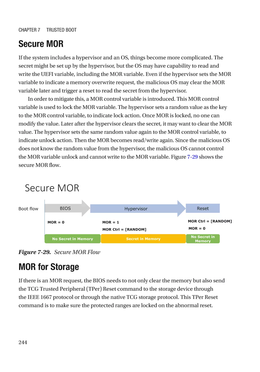
Secure MOR������������������������������������������������������������������������������������������������������������������������� 244
MOR for Storage������������������������������������������������������������������������������������������������������������������ 244
Attack and Mitigation���������������������������������������������������������������������������������������������������������� 245
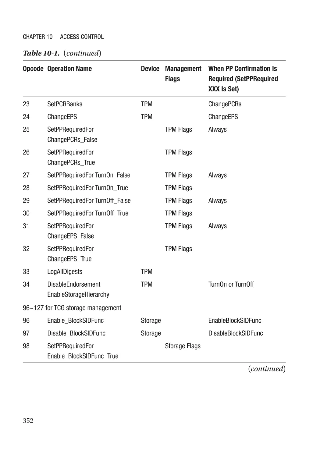
TCG Physical Presence Configuration��������������������������������������������������������������������������������������� 246
TCG Storage������������������������������������������������������������������������������������������������������������������������������ 246
Summary���������������������������������������������������������������������������������������������������������������������������������� 246
References�������������������������������������������������������������������������������������������������������������������������������� 246
Chapter 8: Device Security����������������������������������������������������������������������������������� 257
Device Firmware Resiliency������������������������������������������������������������������������������������������������������ 257
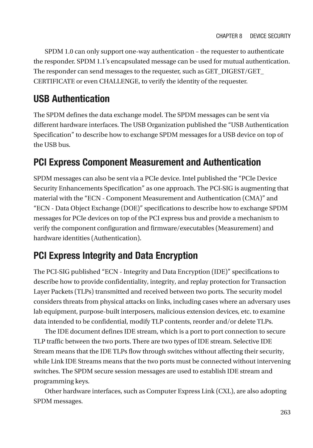
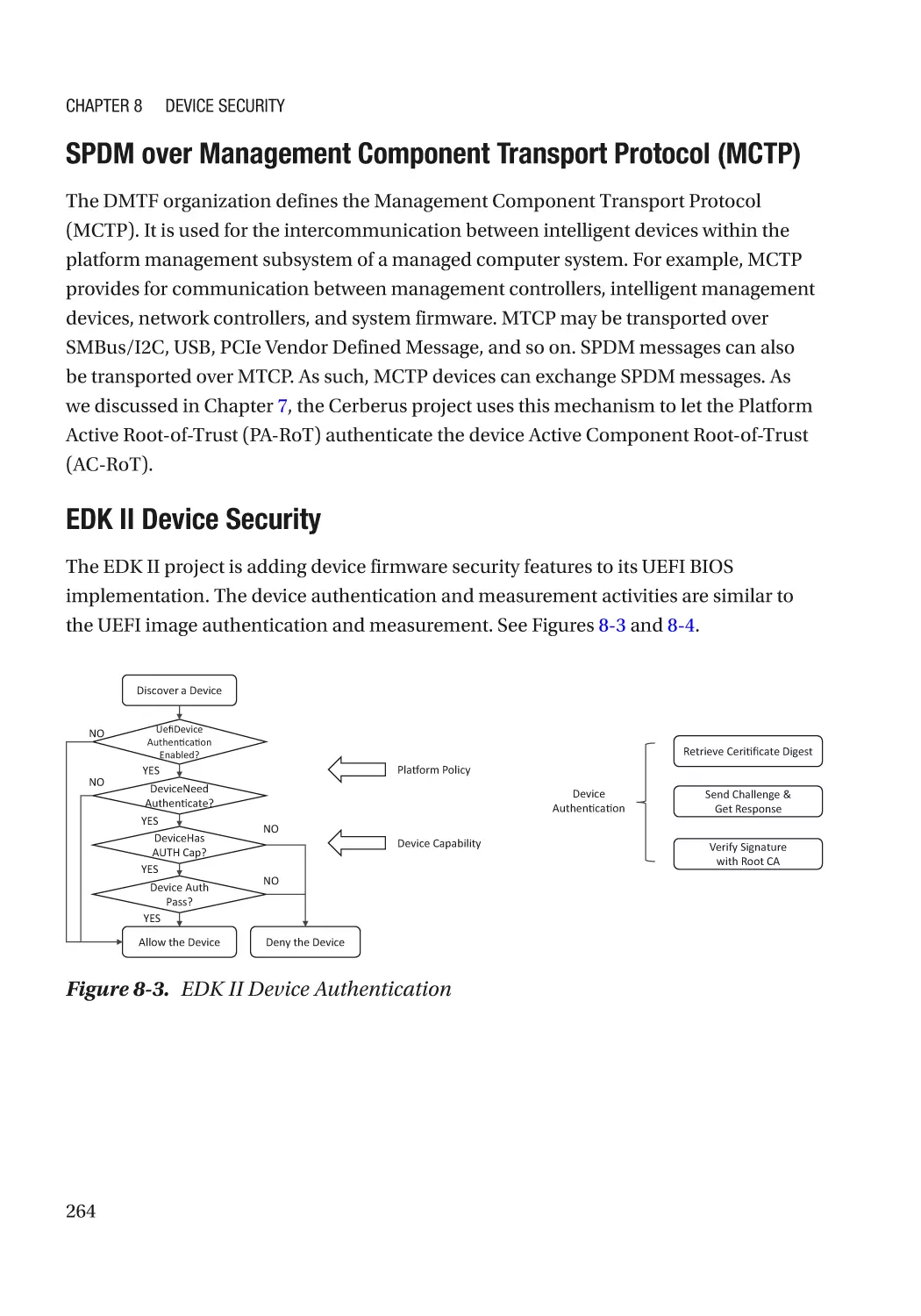
Secure Device Communication������������������������������������������������������������������������������������������������� 258
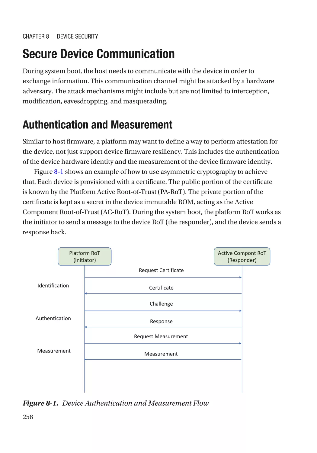
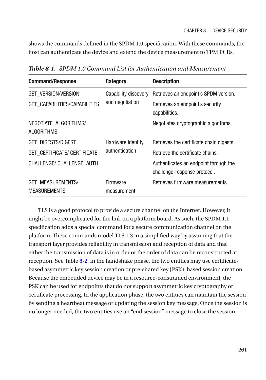
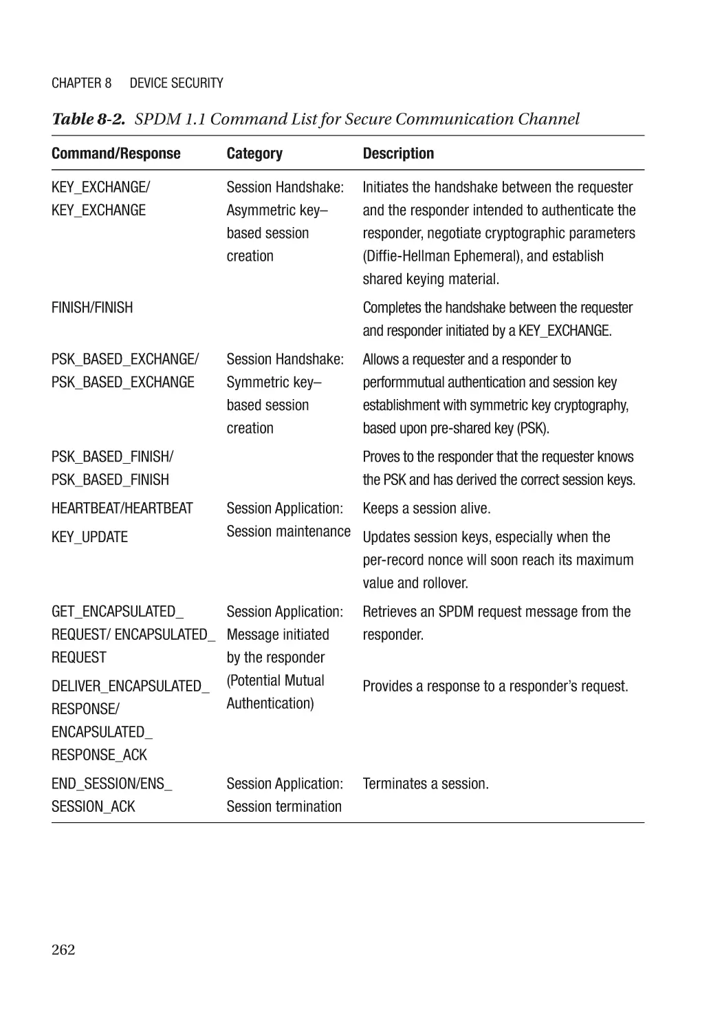
Authentication and Measurement��������������������������������������������������������������������������������������� 258
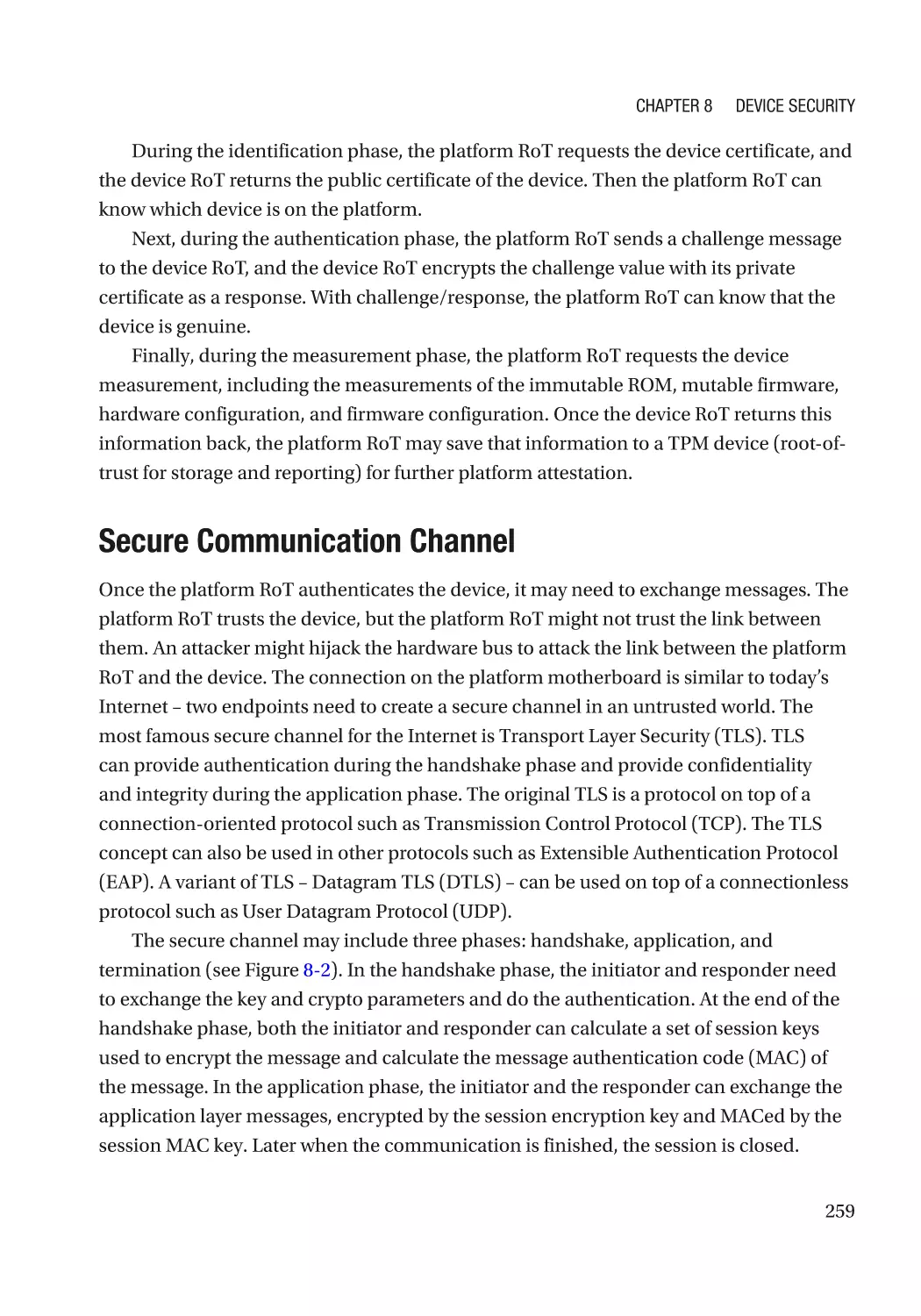
Secure Communication Channel����������������������������������������������������������������������������������������� 259
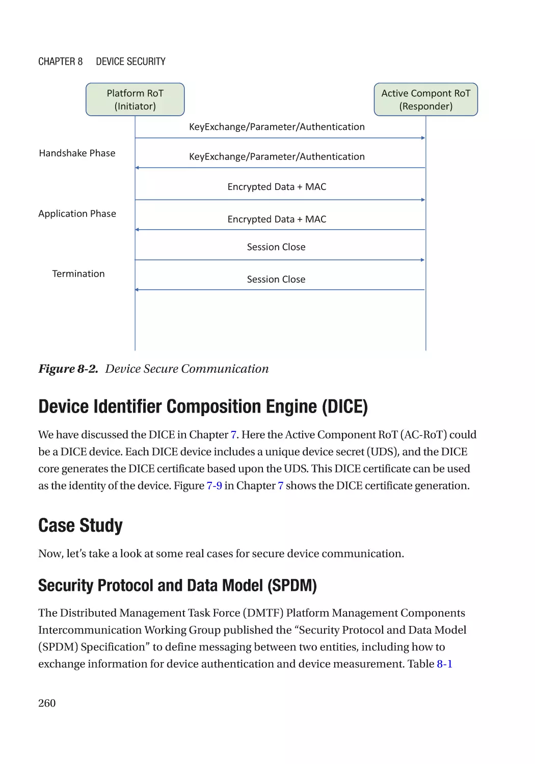
Device Identifier Composition Engine (DICE)����������������������������������������������������������������������� 260
Case Study��������������������������������������������������������������������������������������������������������������������������� 260
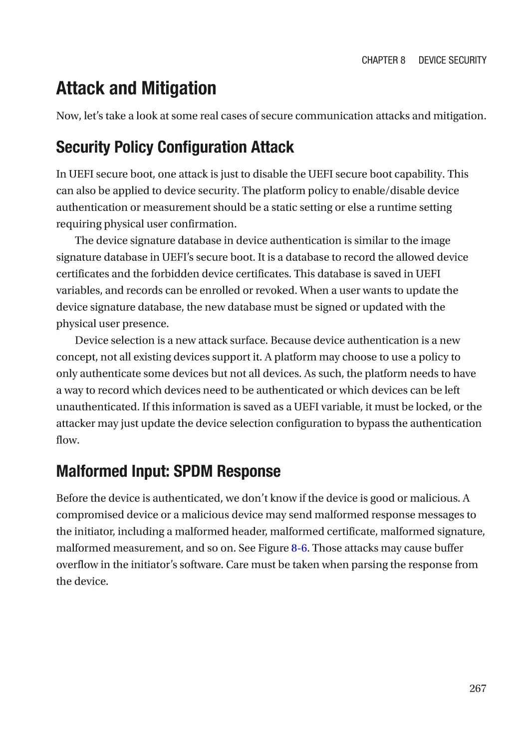
Attack and Mitigation���������������������������������������������������������������������������������������������������������� 267
Device Attack Prevention���������������������������������������������������������������������������������������������������������� 268
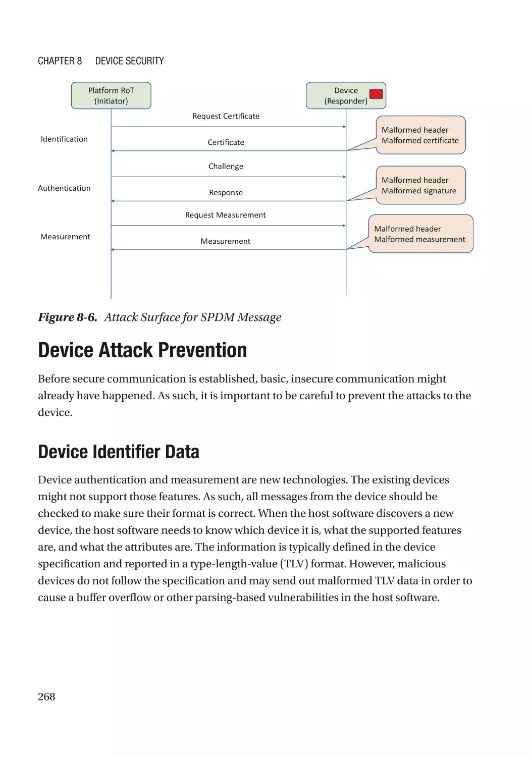
Device Identifier Data���������������������������������������������������������������������������������������������������������� 268
Attack and Mitigation���������������������������������������������������������������������������������������������������������� 269
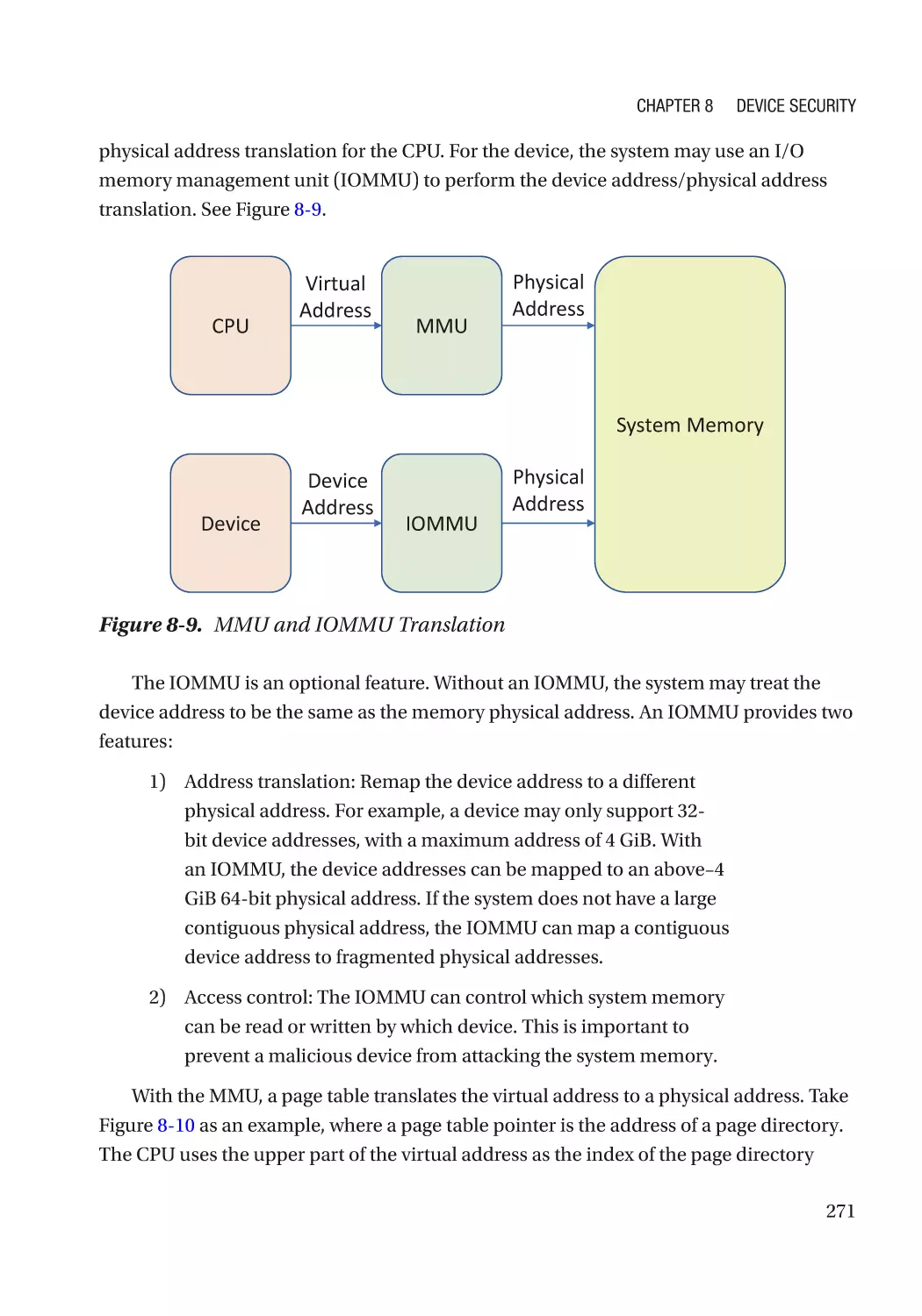
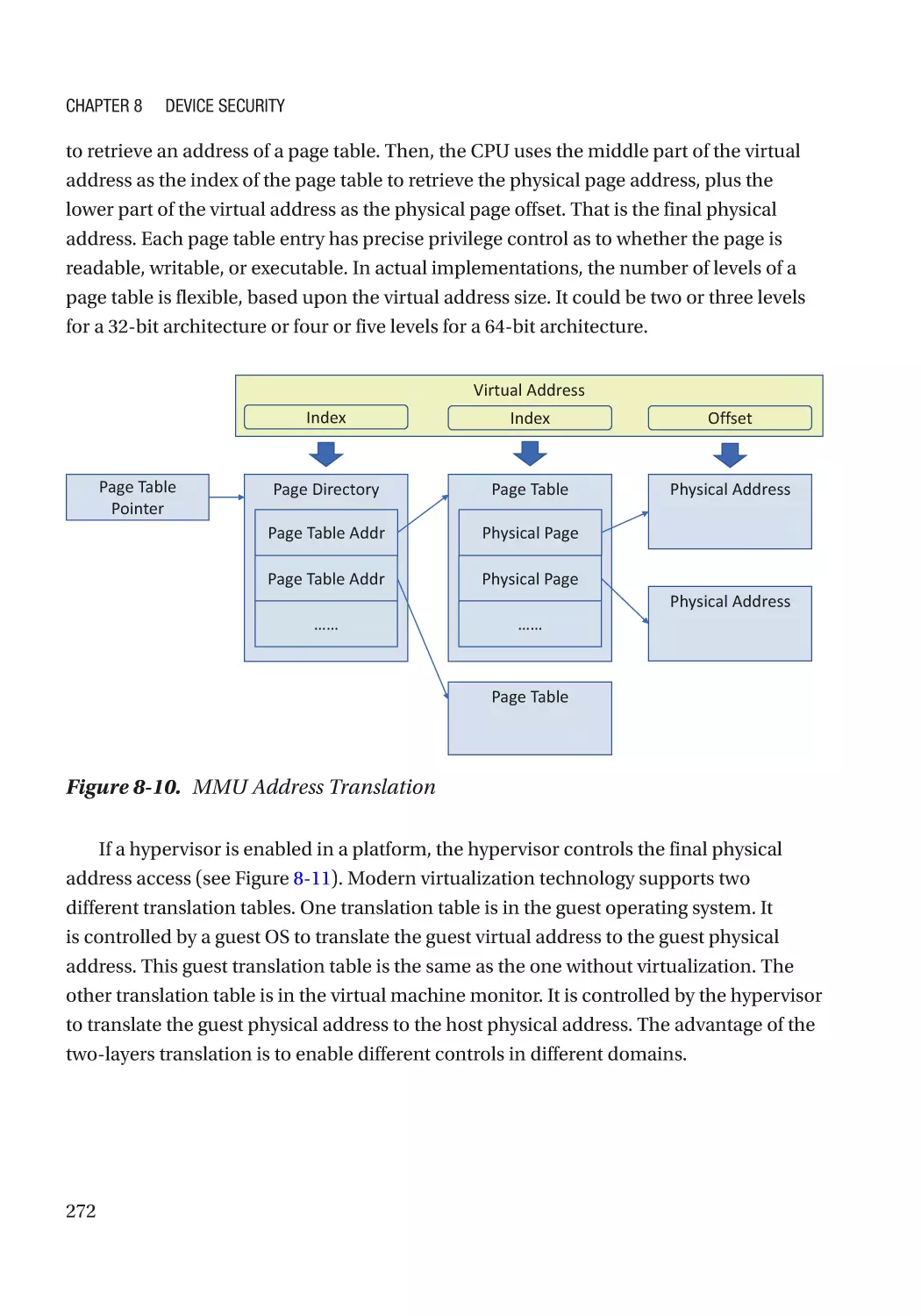
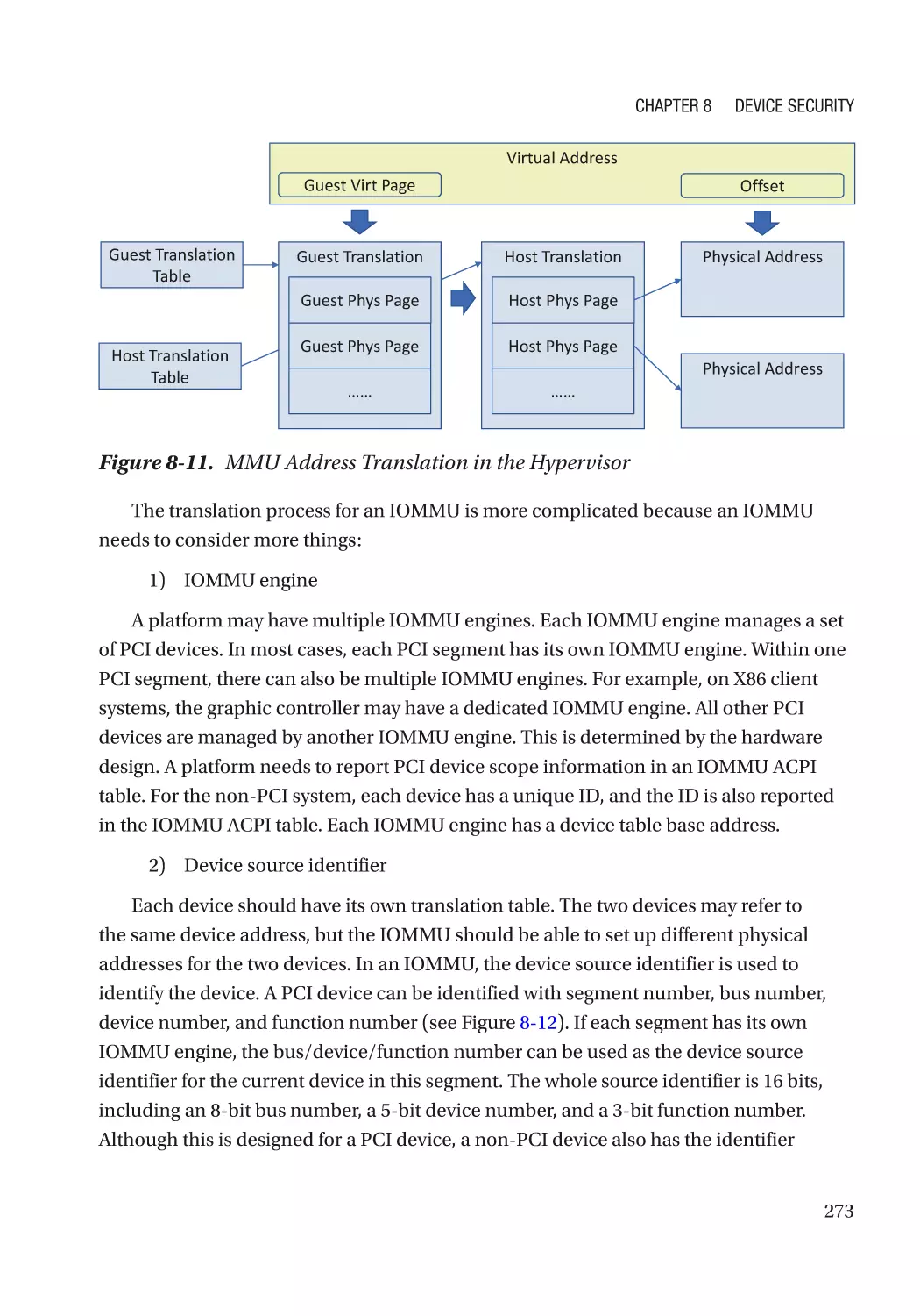
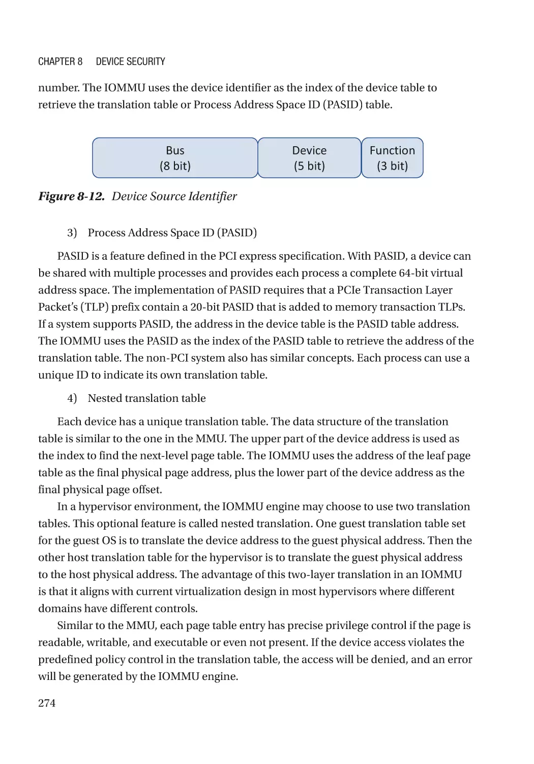
Direct Memory Access (DMA)���������������������������������������������������������������������������������������������� 270
ix
Table of Contents
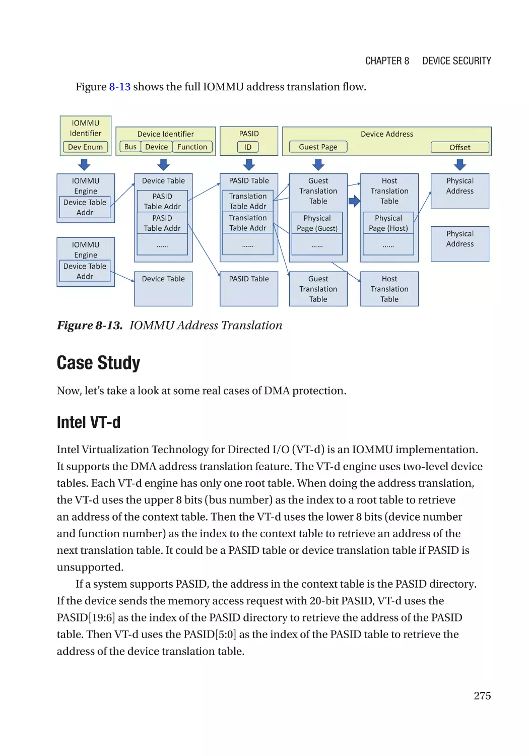
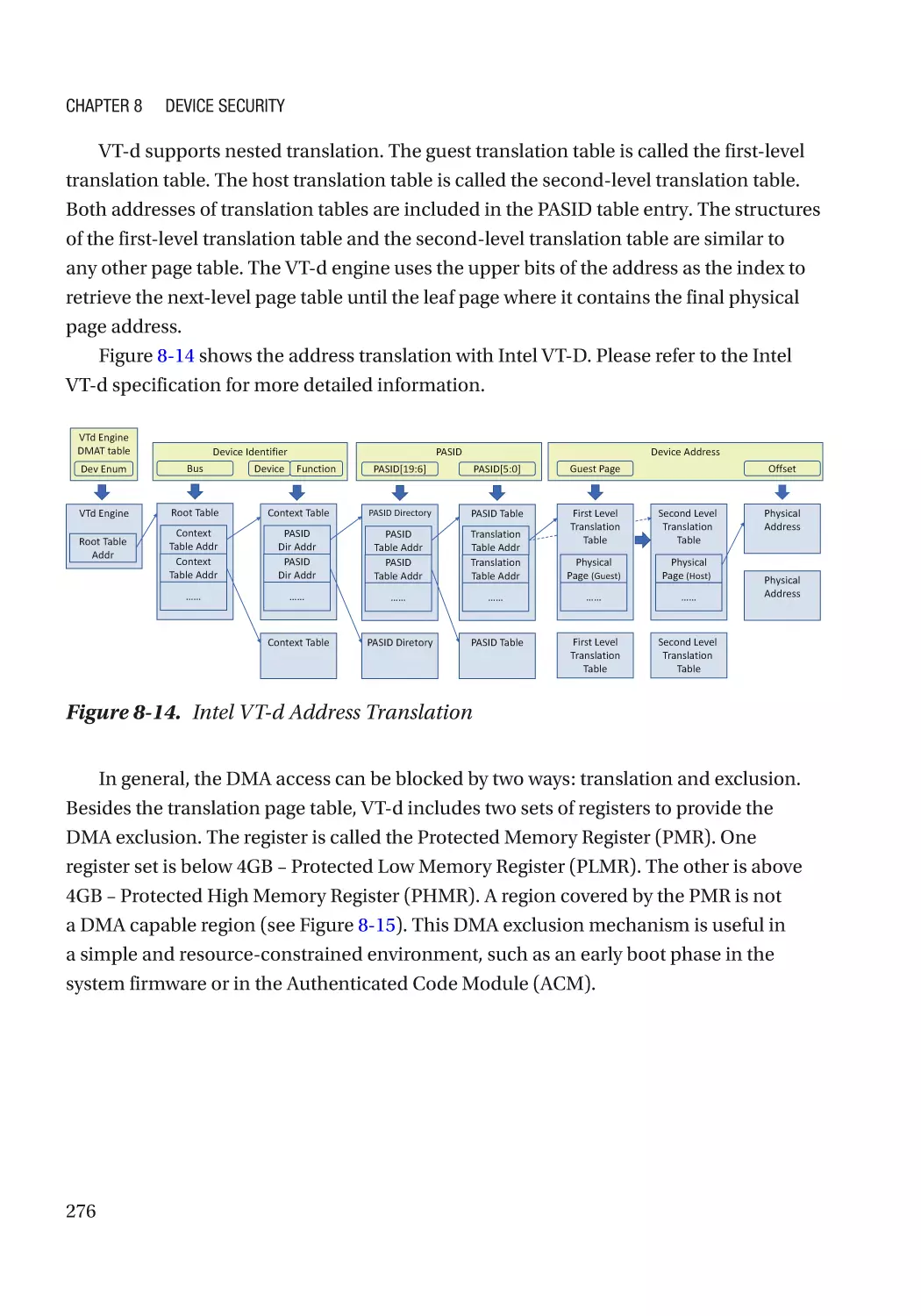
Case Study��������������������������������������������������������������������������������������������������������������������������� 275
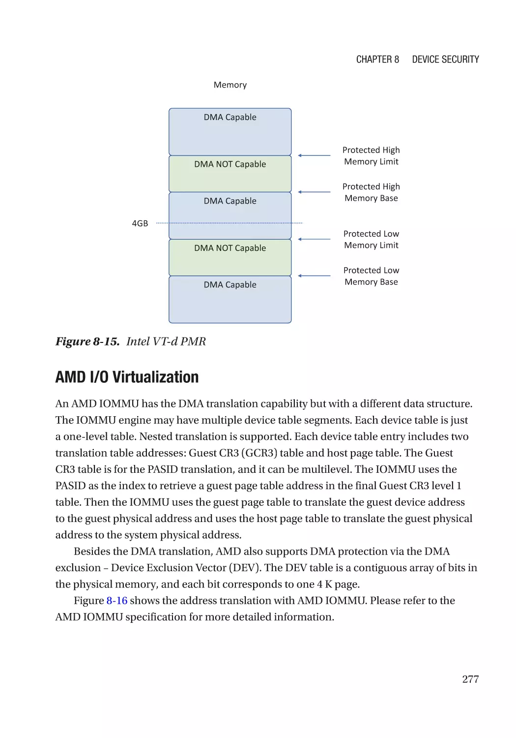
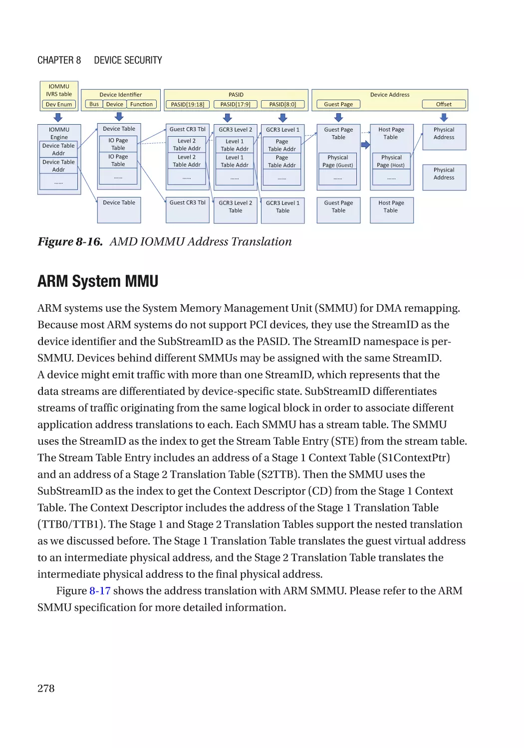
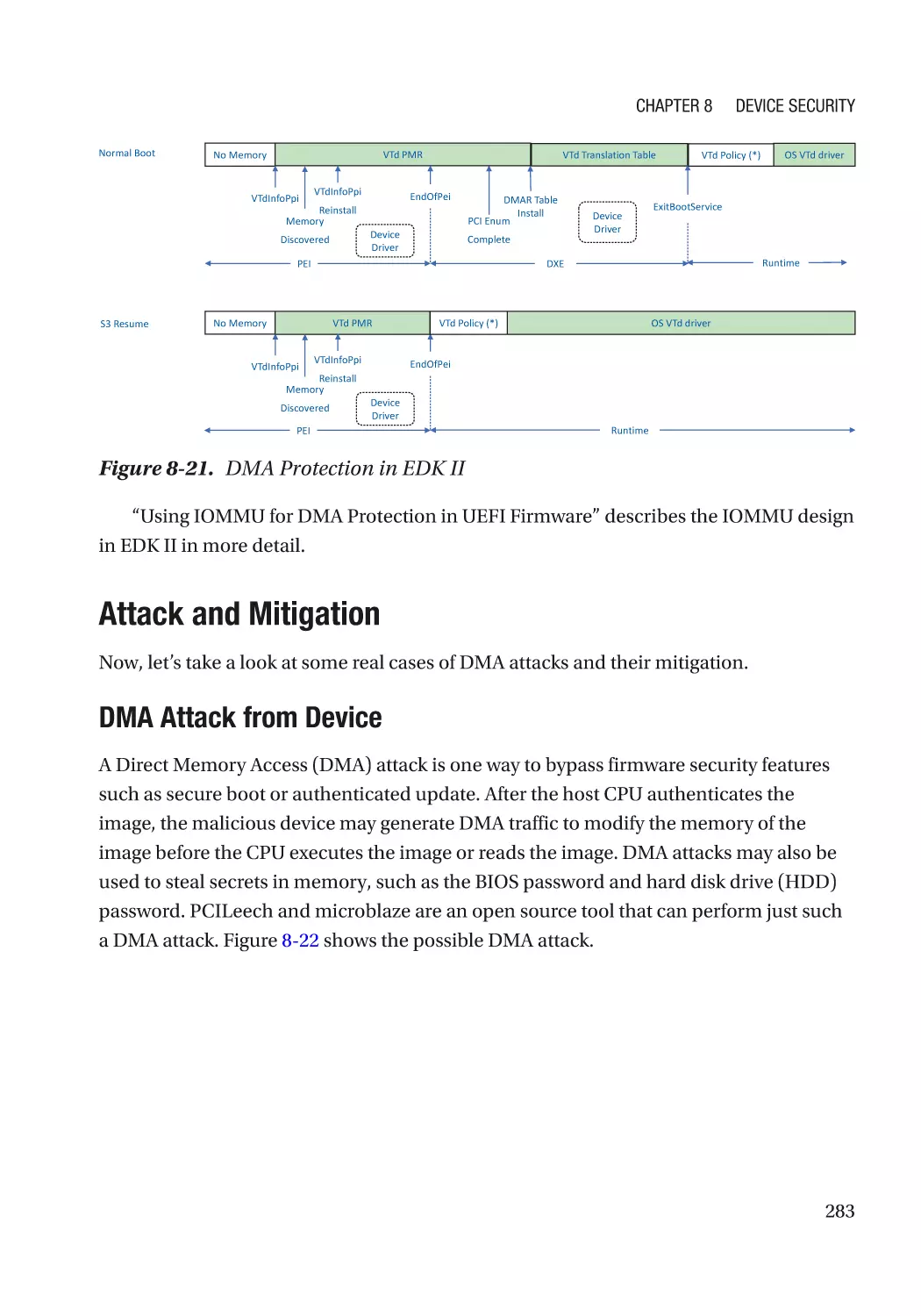
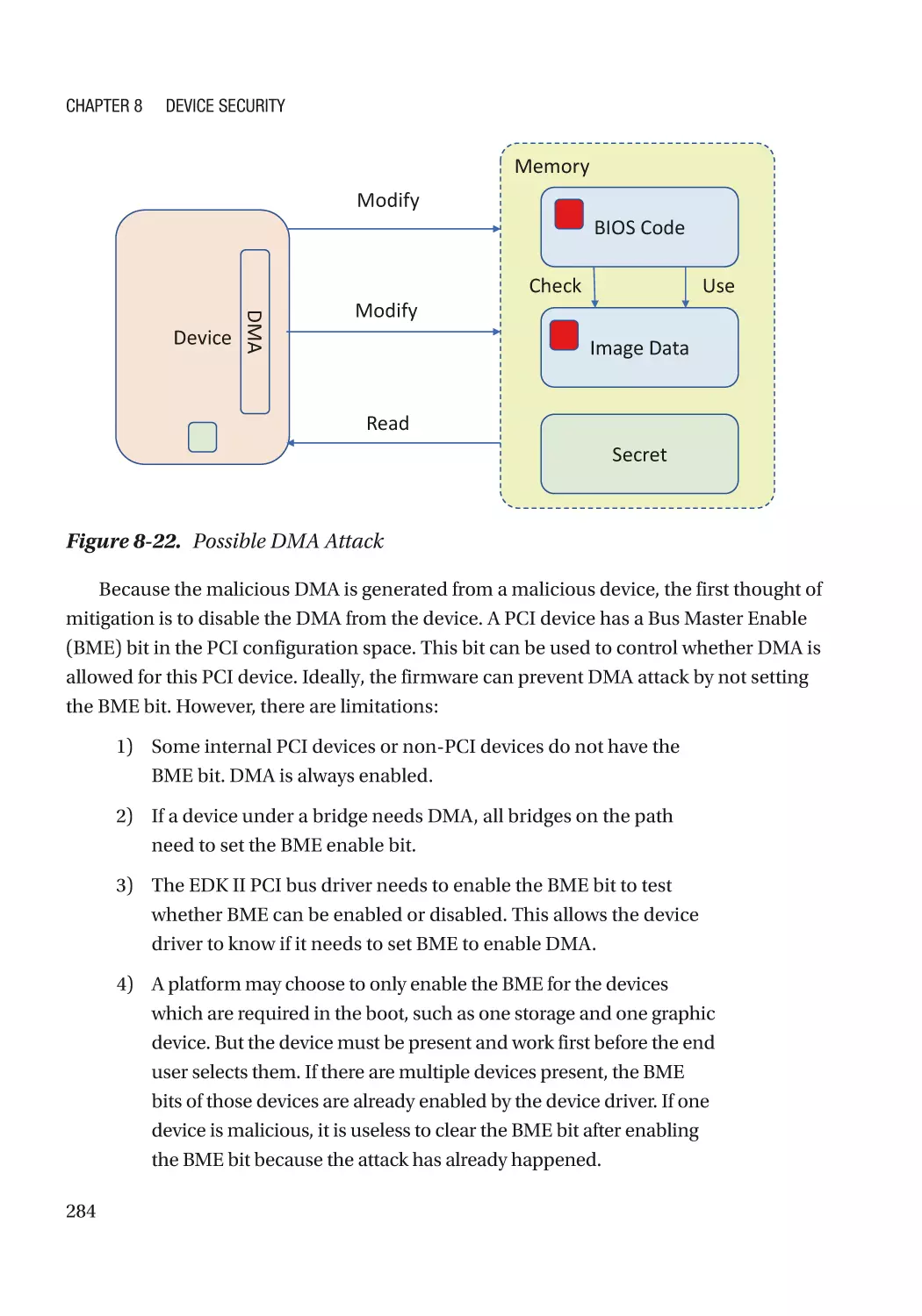
Attack and Mitigation���������������������������������������������������������������������������������������������������������� 283
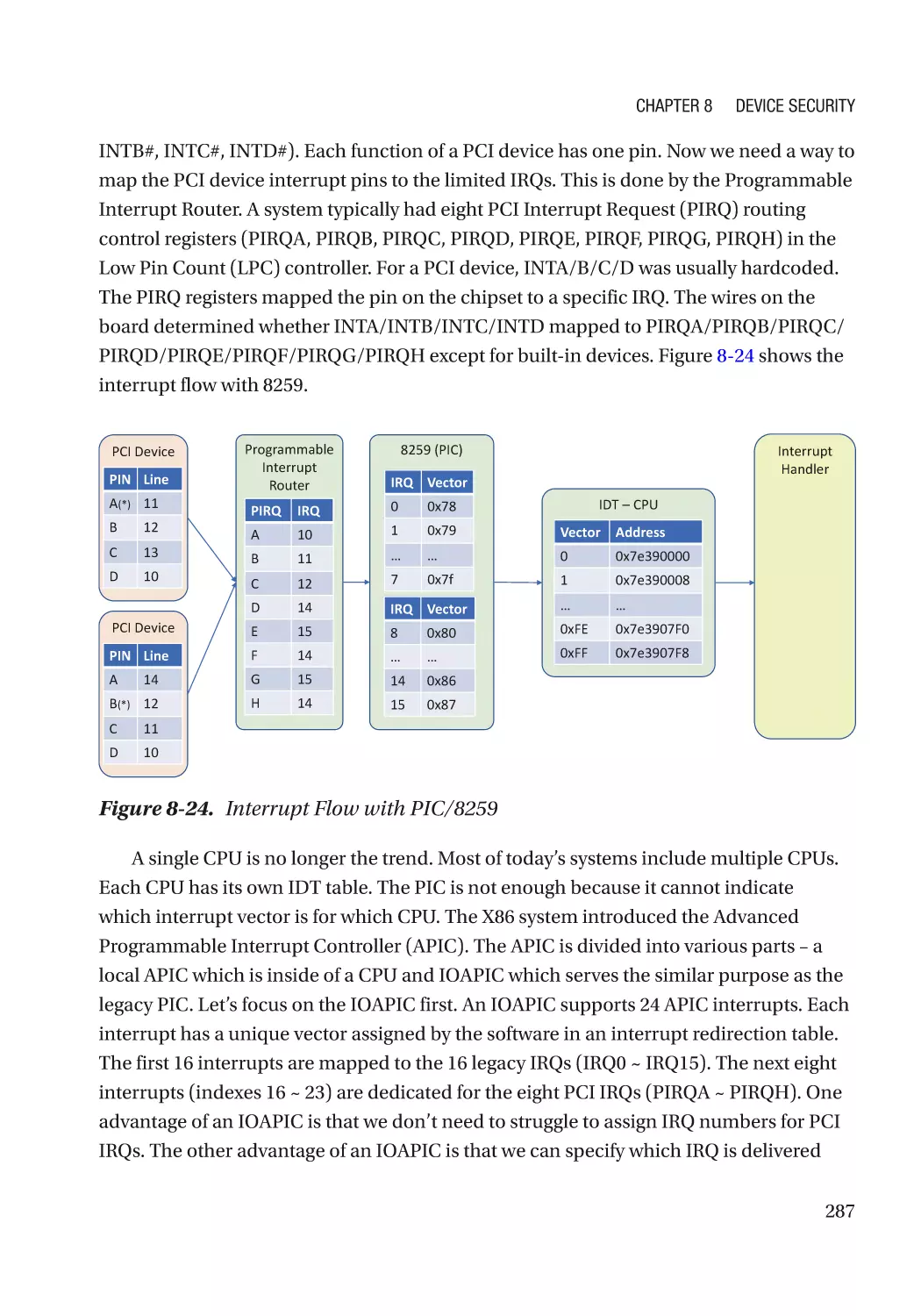
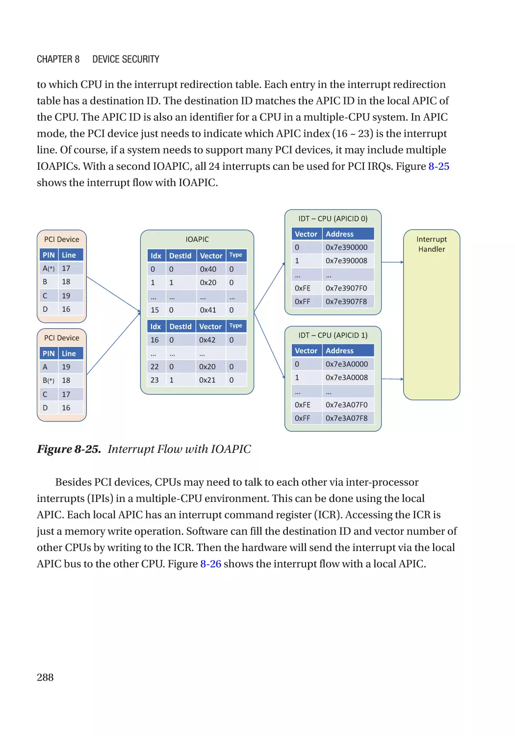
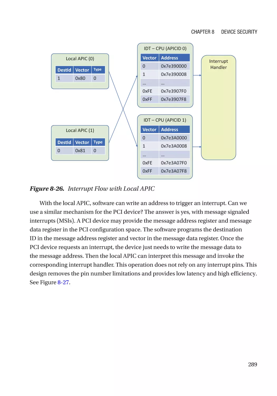
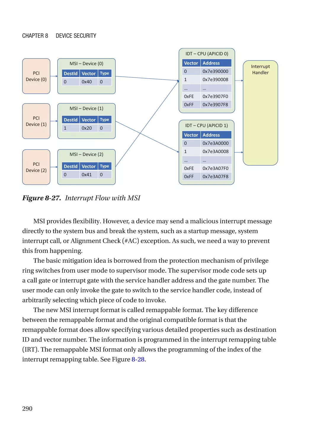
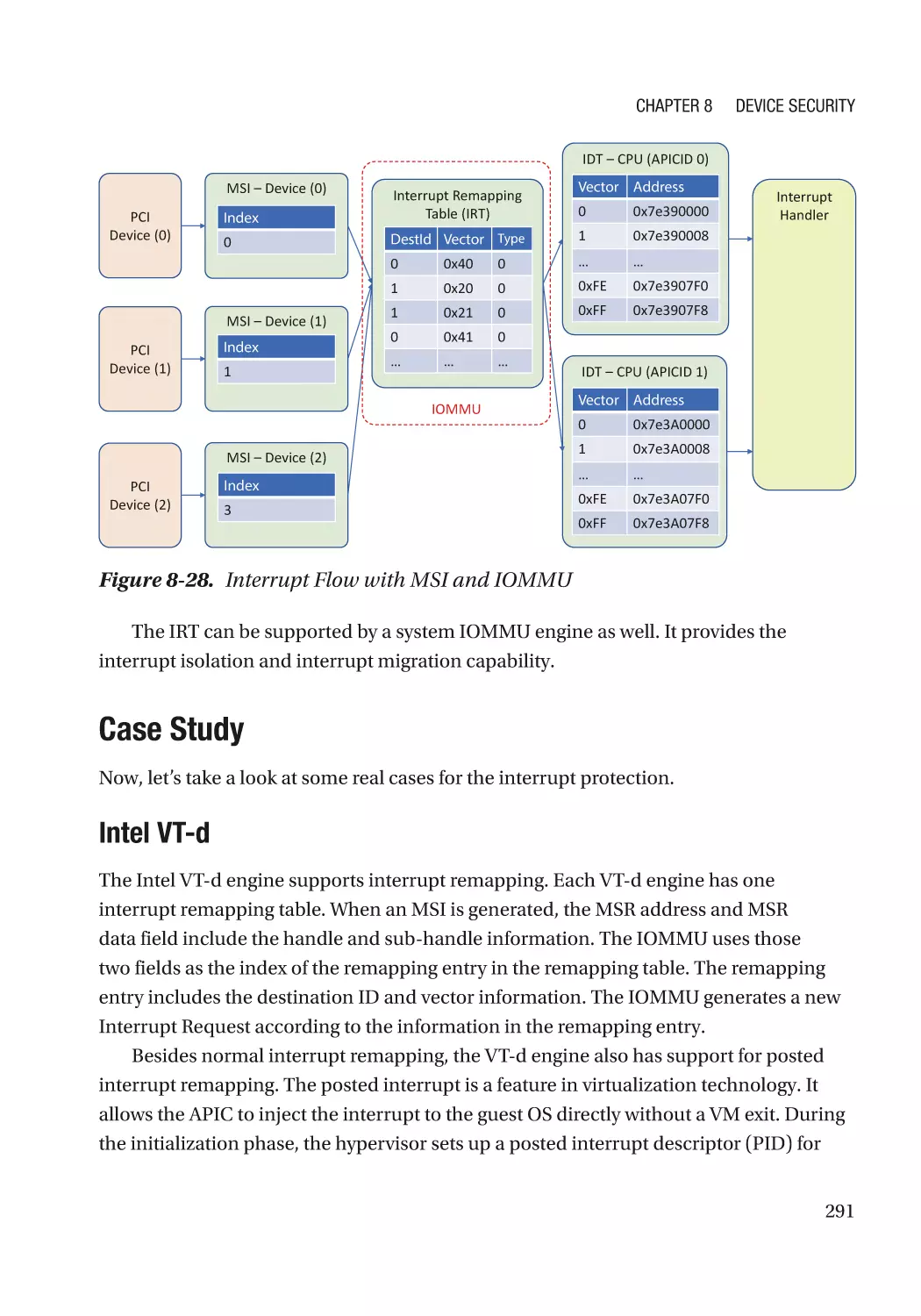
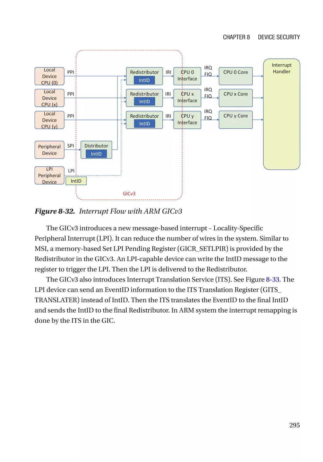
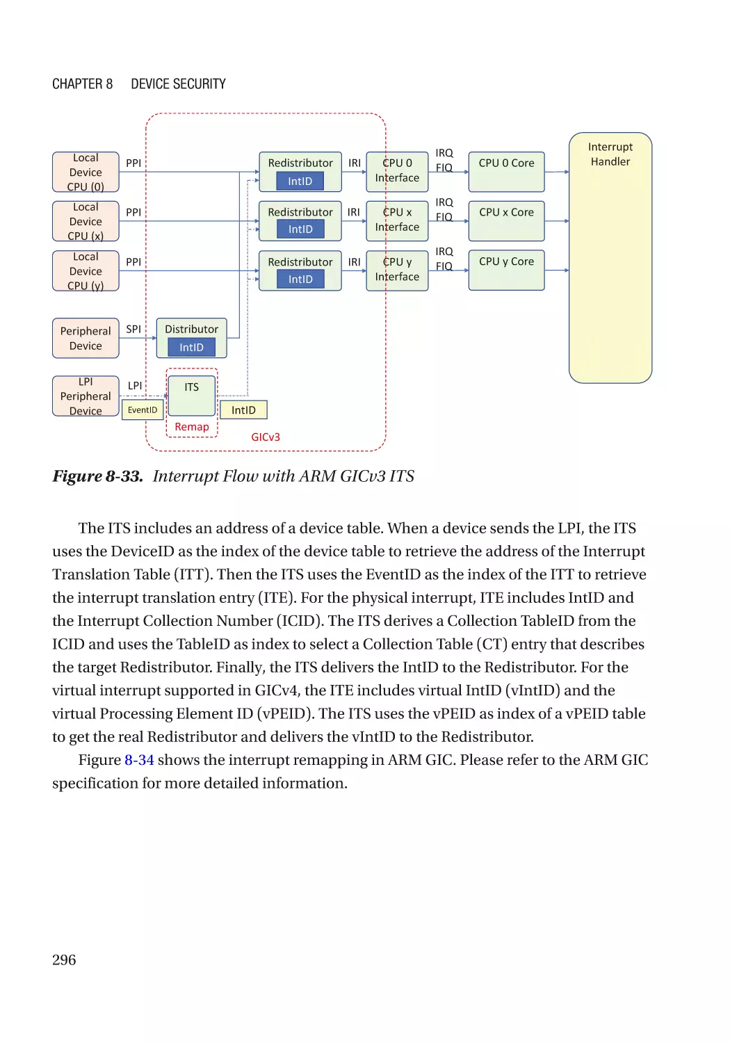
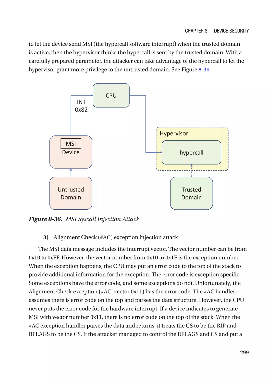
Message Signaled Interrupt (MSI)��������������������������������������������������������������������������������������� 286
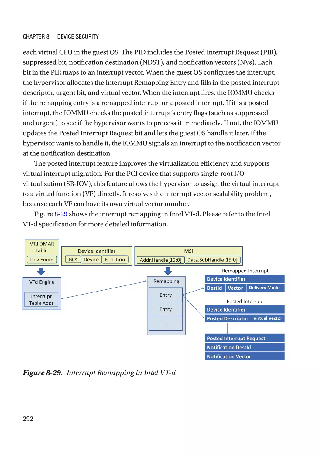
Case Study��������������������������������������������������������������������������������������������������������������������������� 291
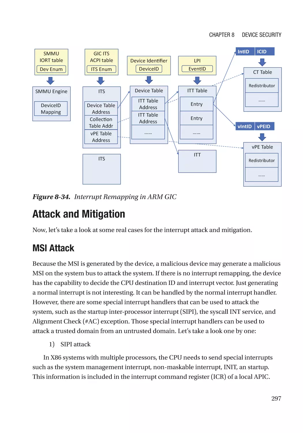
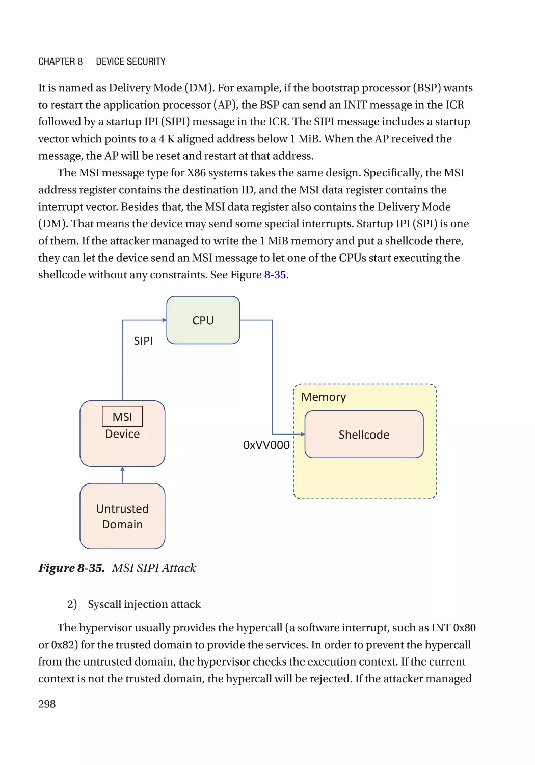
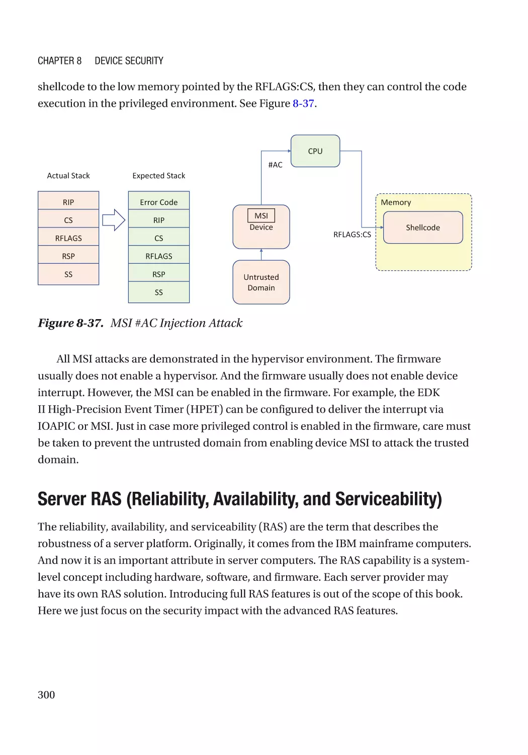
Attack and Mitigation���������������������������������������������������������������������������������������������������������� 297
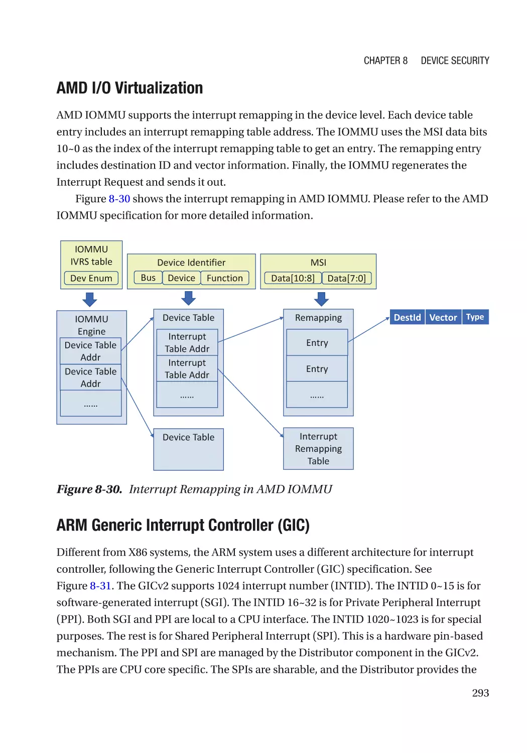
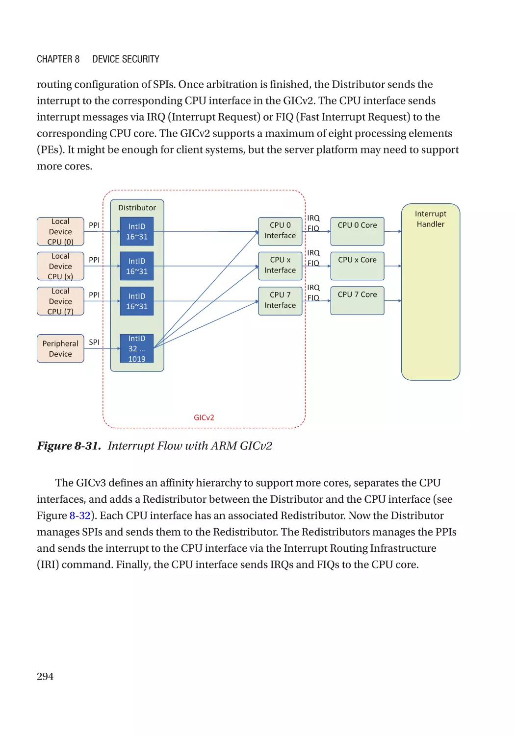
Server RAS (Reliability, Availability, and Serviceability)������������������������������������������������������� 300
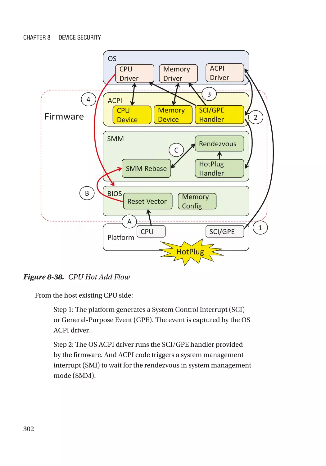
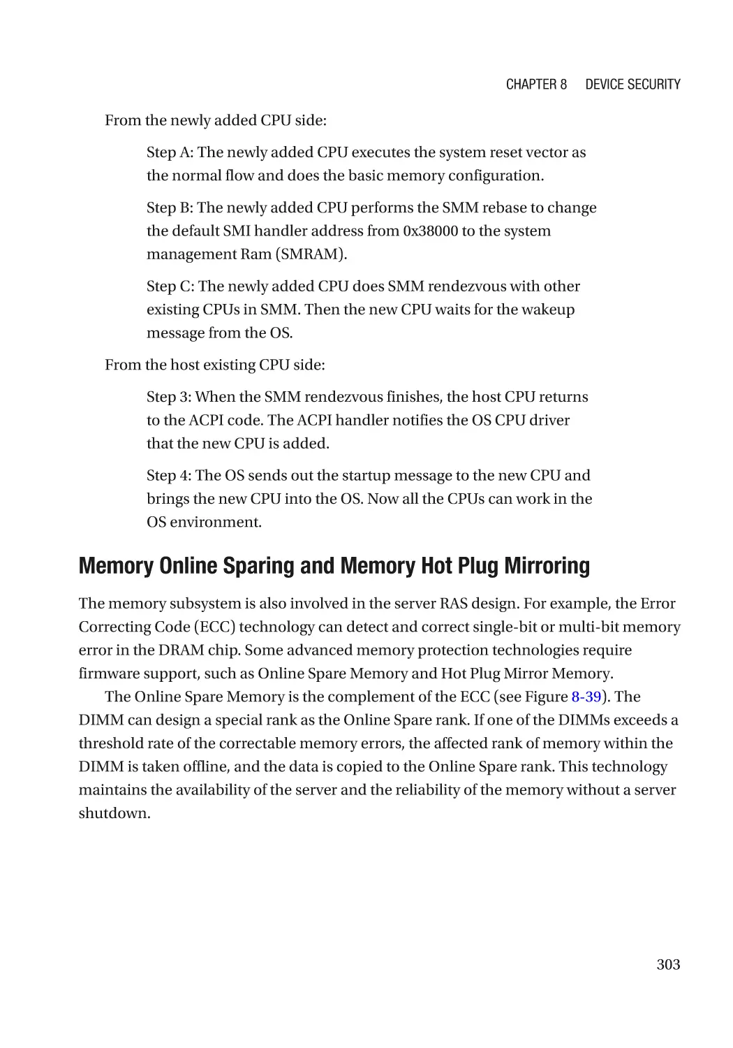
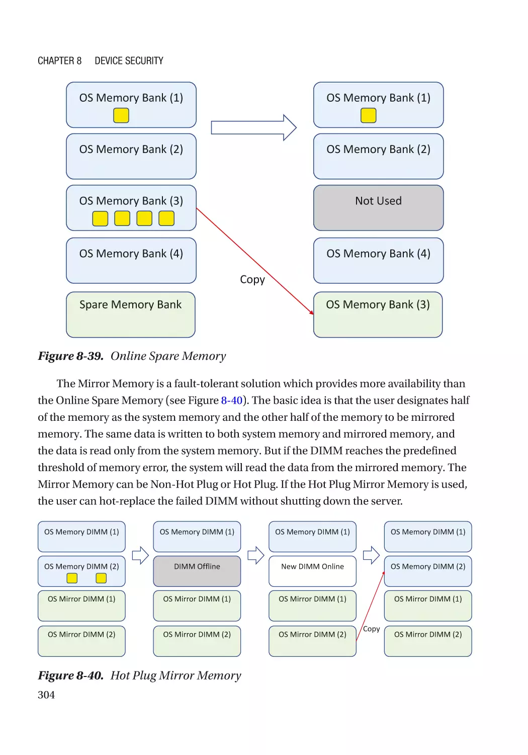
Case Study��������������������������������������������������������������������������������������������������������������������������� 301
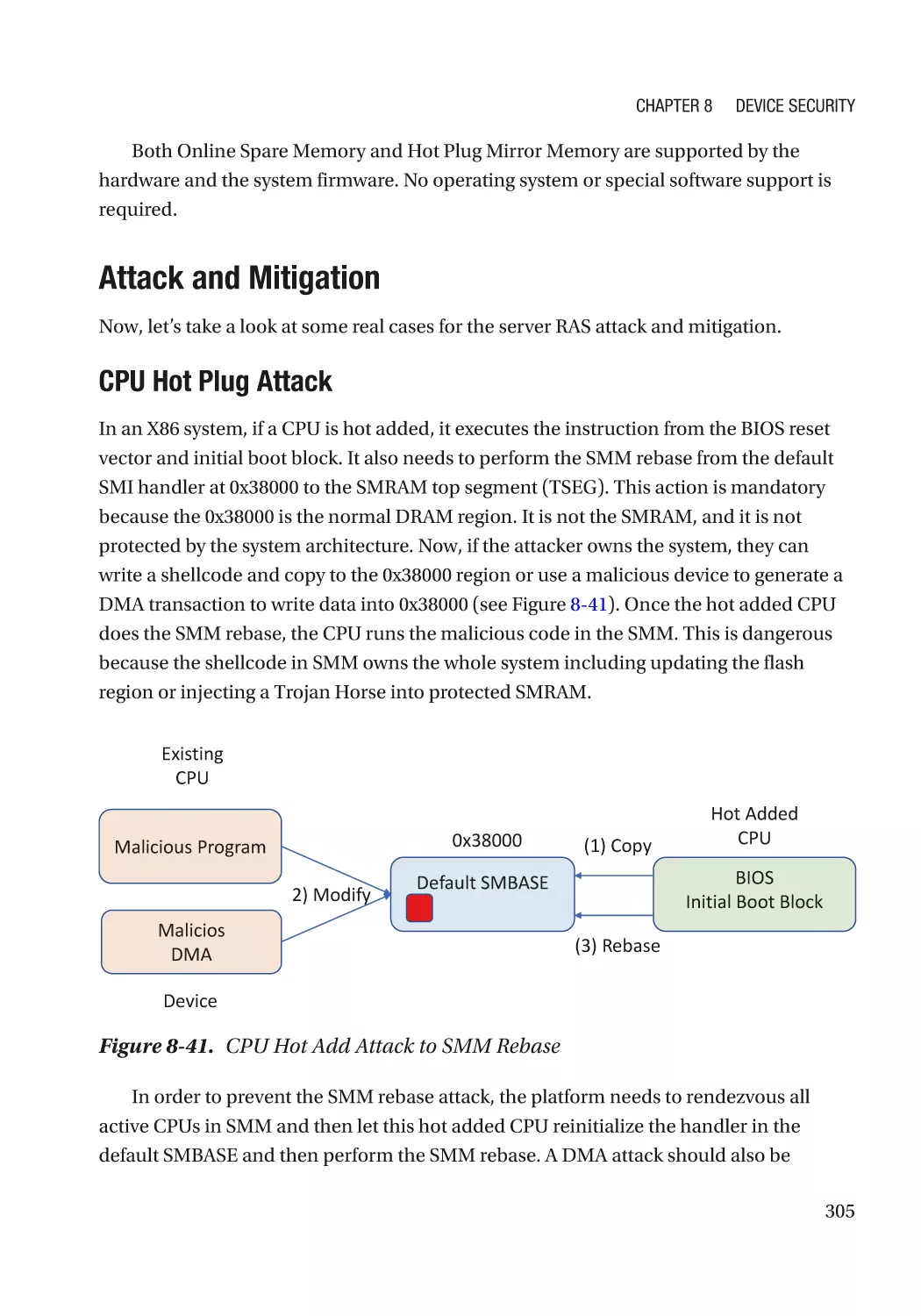
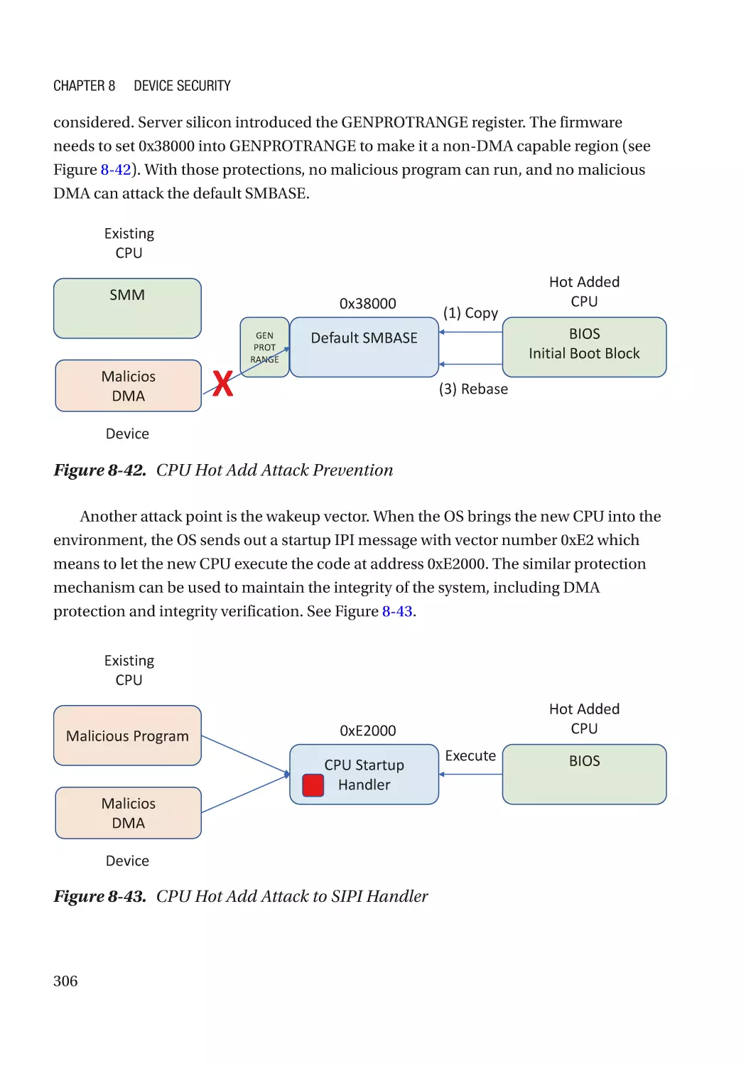
Attack and Mitigation���������������������������������������������������������������������������������������������������������� 305
Summary���������������������������������������������������������������������������������������������������������������������������������� 307
References�������������������������������������������������������������������������������������������������������������������������������� 307
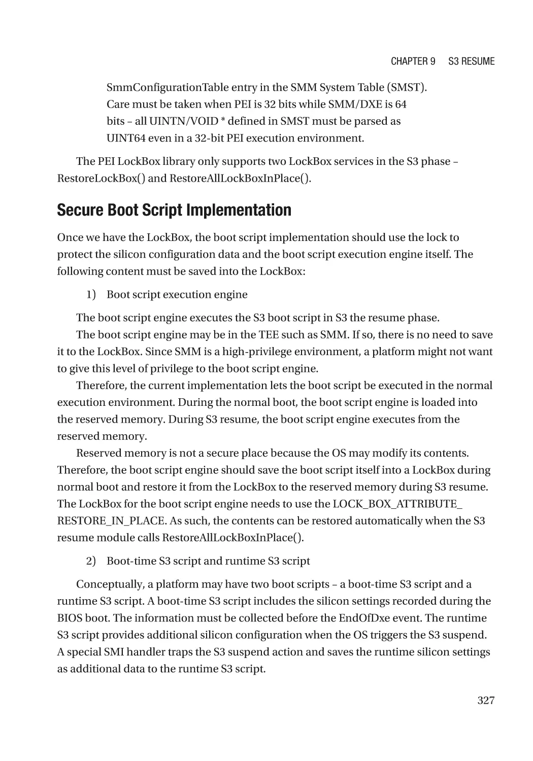
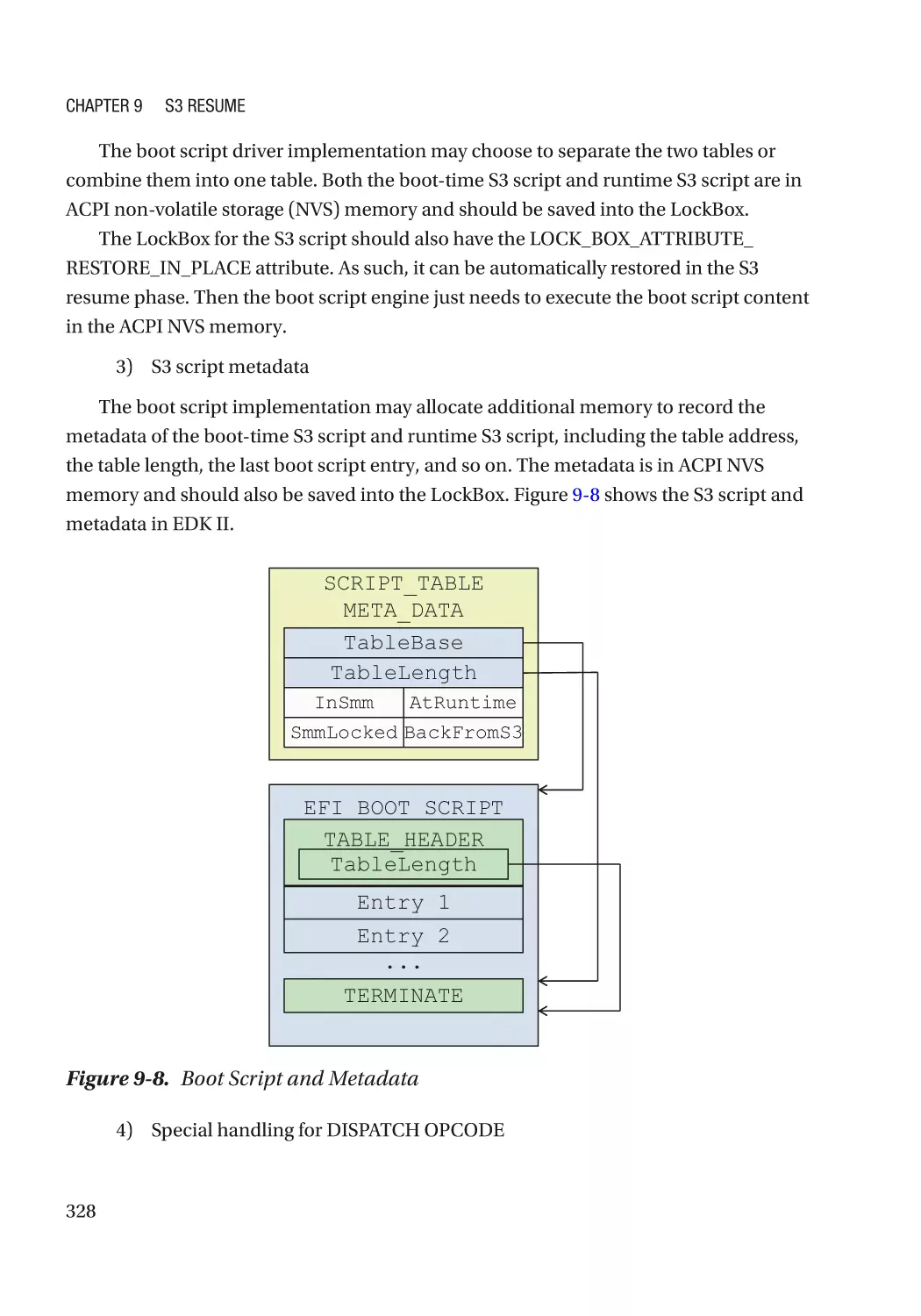
Chapter 9: S3 Resume������������������������������������������������������������������������������������������ 313
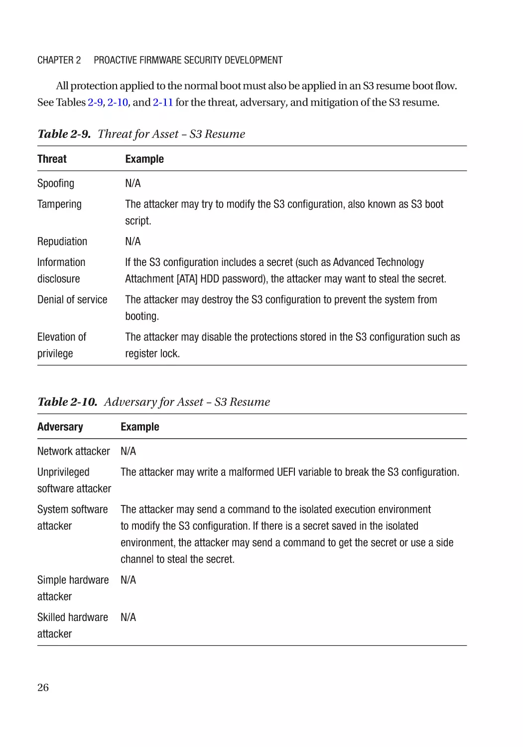
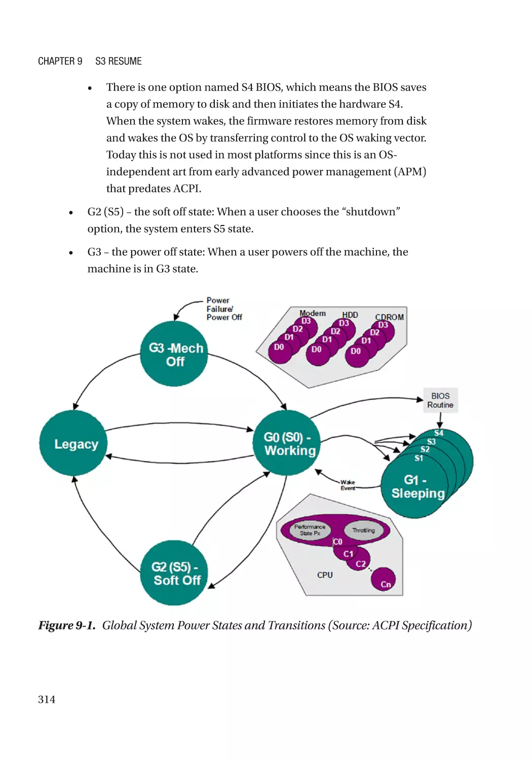
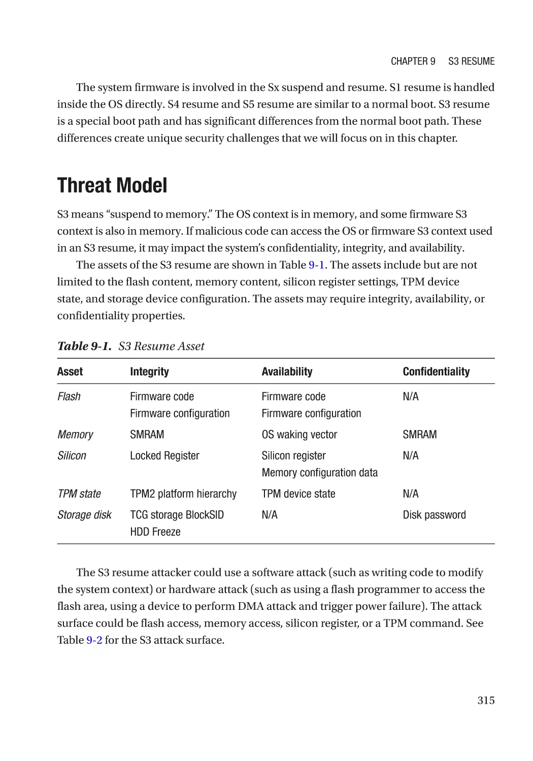
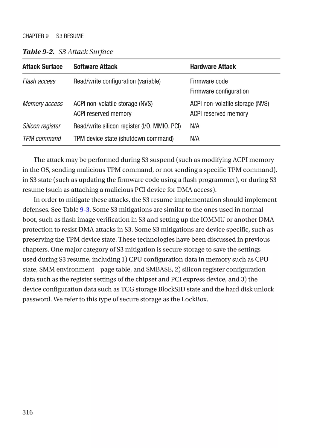
Threat Model����������������������������������������������������������������������������������������������������������������������������� 315
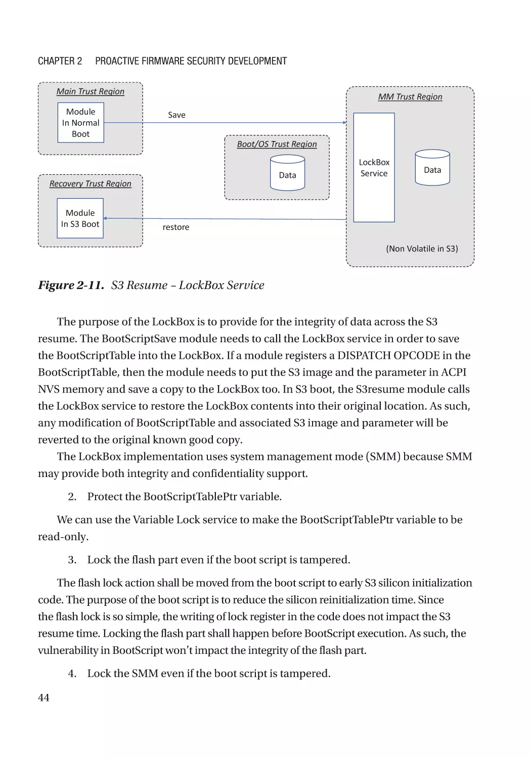
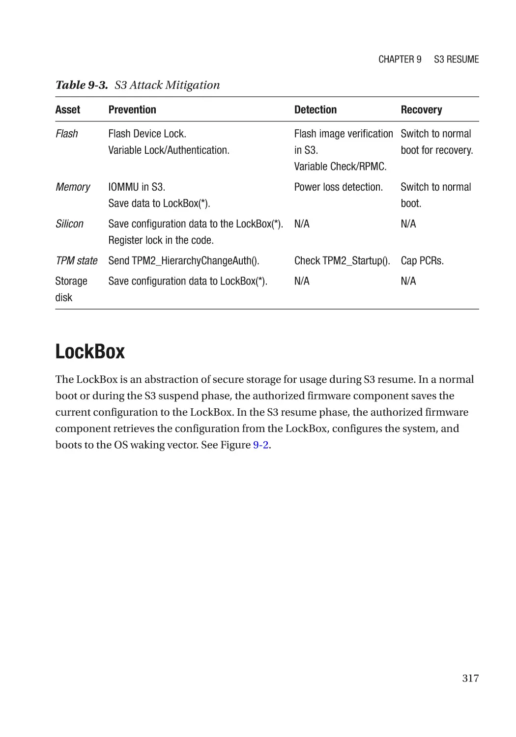
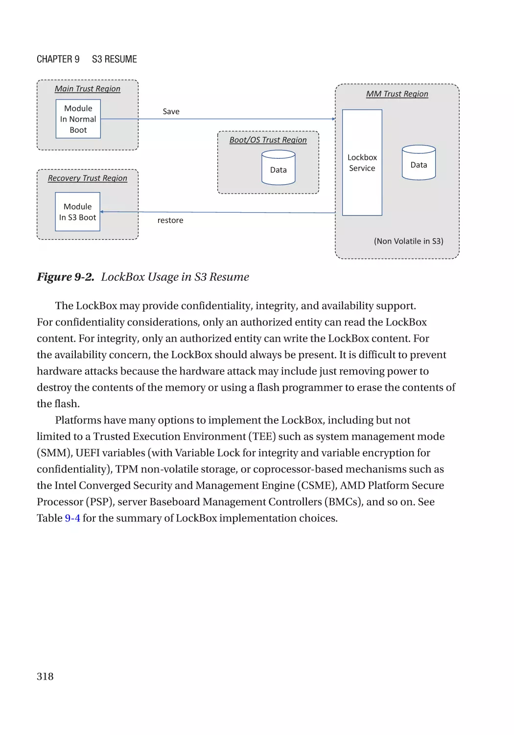
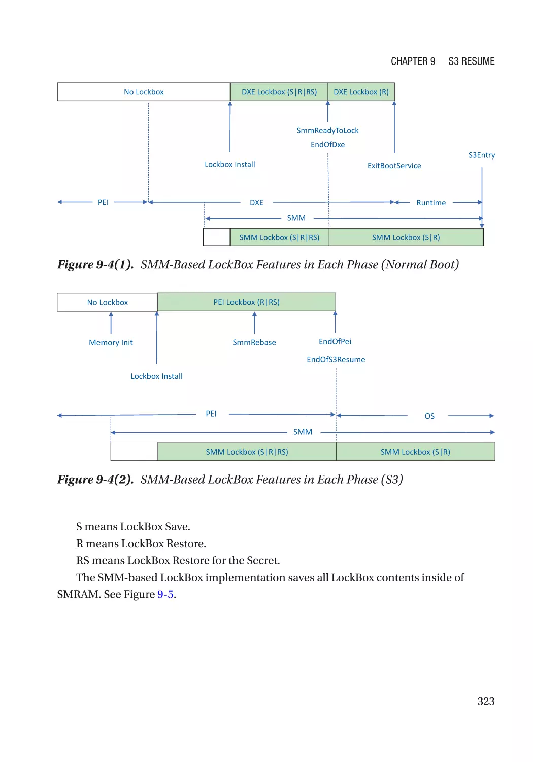
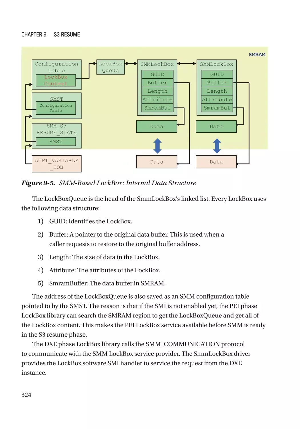
LockBox������������������������������������������������������������������������������������������������������������������������������������ 317
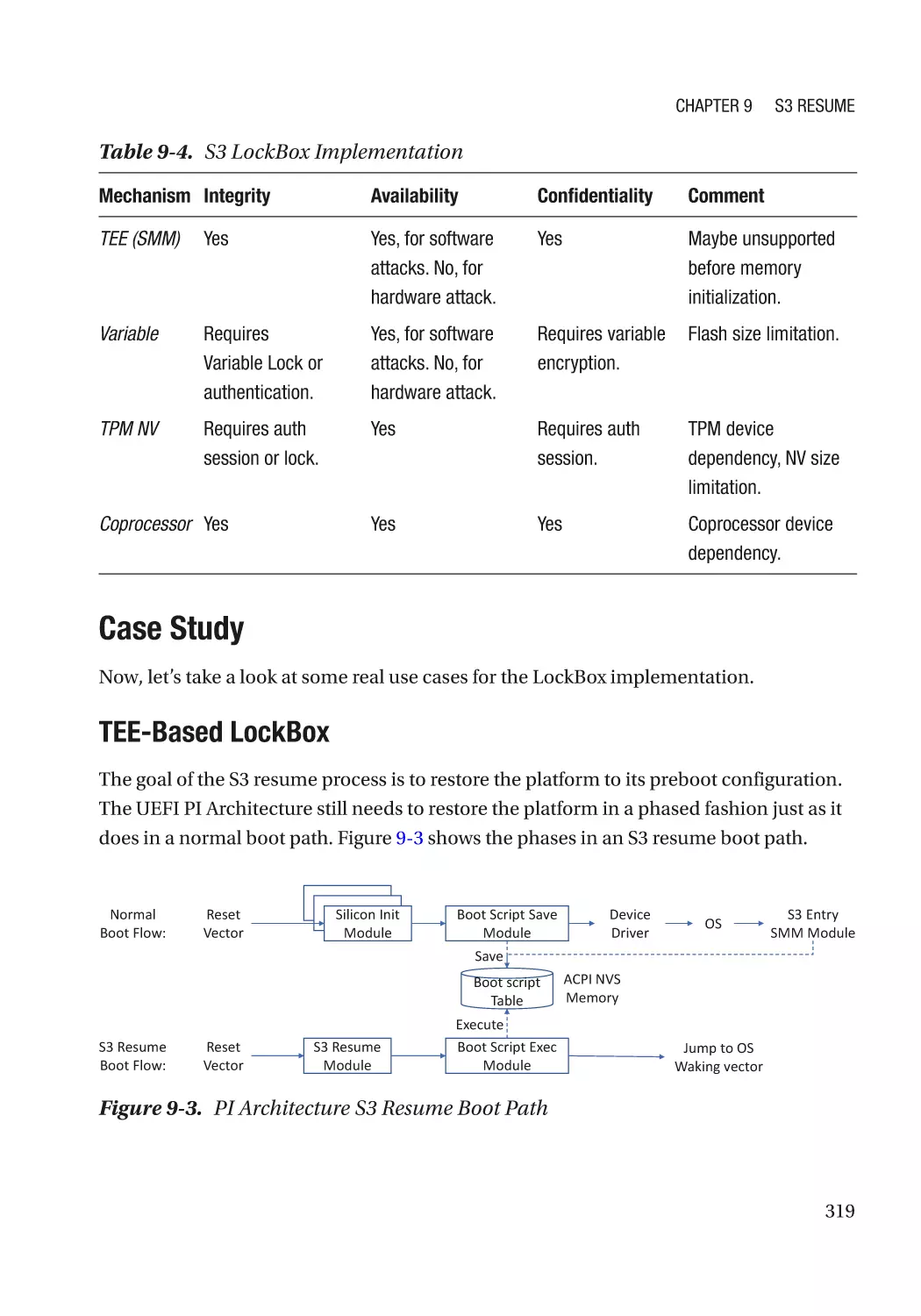
Case Study��������������������������������������������������������������������������������������������������������������������������� 319
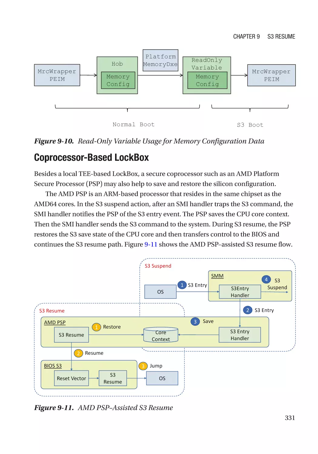
Attack and Mitigation���������������������������������������������������������������������������������������������������������� 332
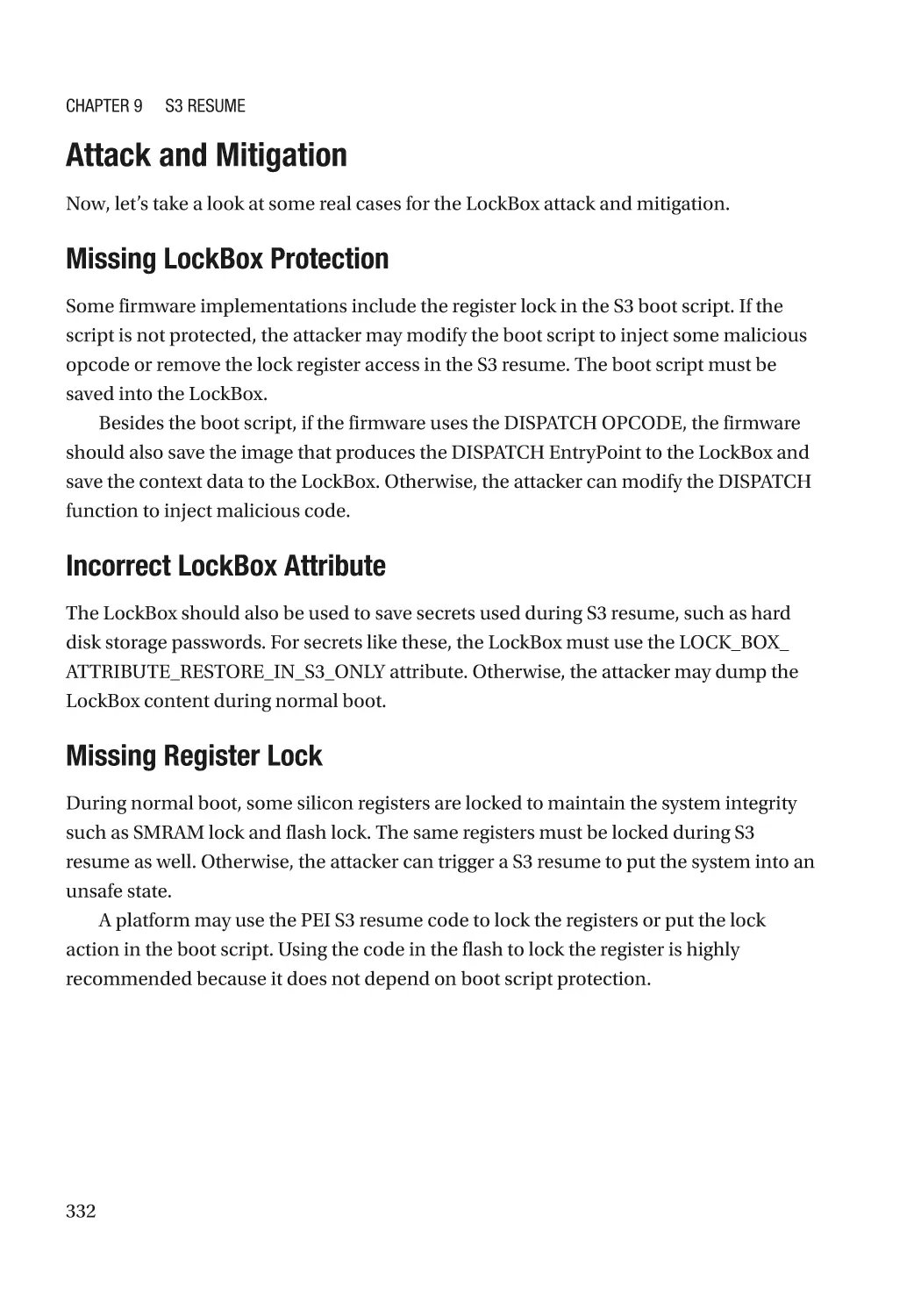
Summary���������������������������������������������������������������������������������������������������������������������������������� 333
References�������������������������������������������������������������������������������������������������������������������������������� 333
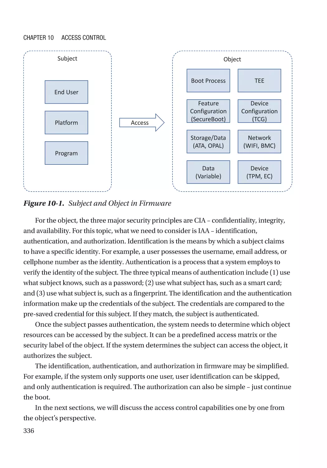
Chapter 10: Access Control���������������������������������������������������������������������������������� 335
Boot Access Control������������������������������������������������������������������������������������������������������������������ 337
What a User Knows: Password�������������������������������������������������������������������������������������������� 337
What a User Has: Token������������������������������������������������������������������������������������������������������� 342
What a User Is: Biometrics�������������������������������������������������������������������������������������������������� 342
Other Considerations����������������������������������������������������������������������������������������������������������� 342
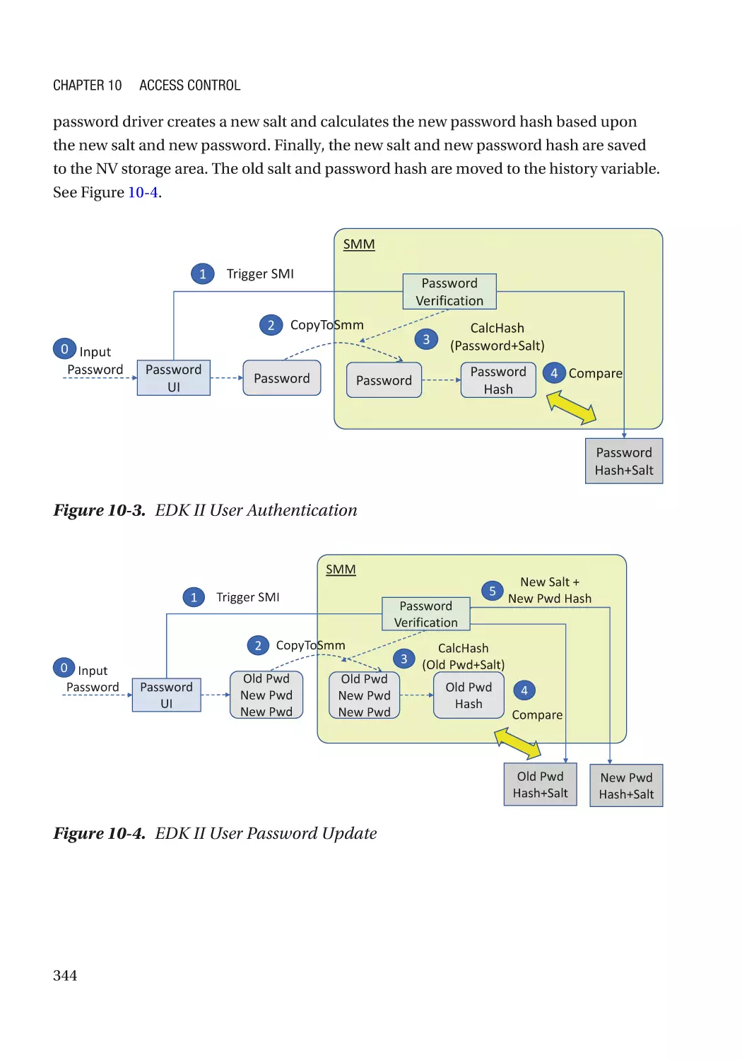
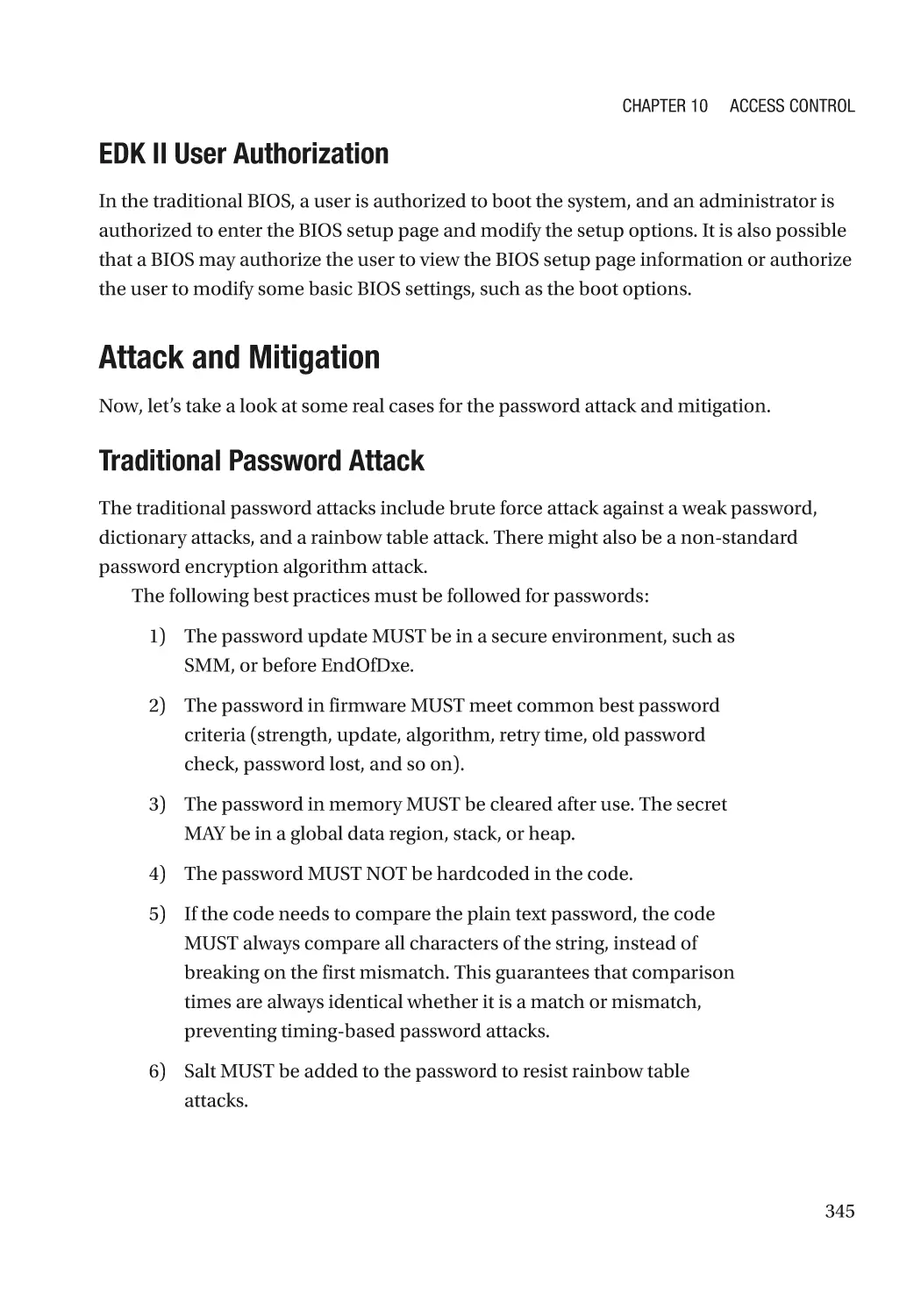
Case Study��������������������������������������������������������������������������������������������������������������������������� 343
Attack and Mitigation���������������������������������������������������������������������������������������������������������� 345
TEE Access Control������������������������������������������������������������������������������������������������������������������� 347
Feature Configuration Control��������������������������������������������������������������������������������������������������� 347
User Physical Presence������������������������������������������������������������������������������������������������������� 347
UEFI Variable������������������������������������������������������������������������������������������������������������������������ 347
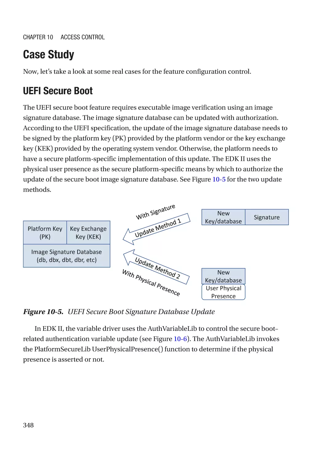
Case Study��������������������������������������������������������������������������������������������������������������������������� 348
Attack and Mitigation���������������������������������������������������������������������������������������������������������� 349
x
Table of Contents
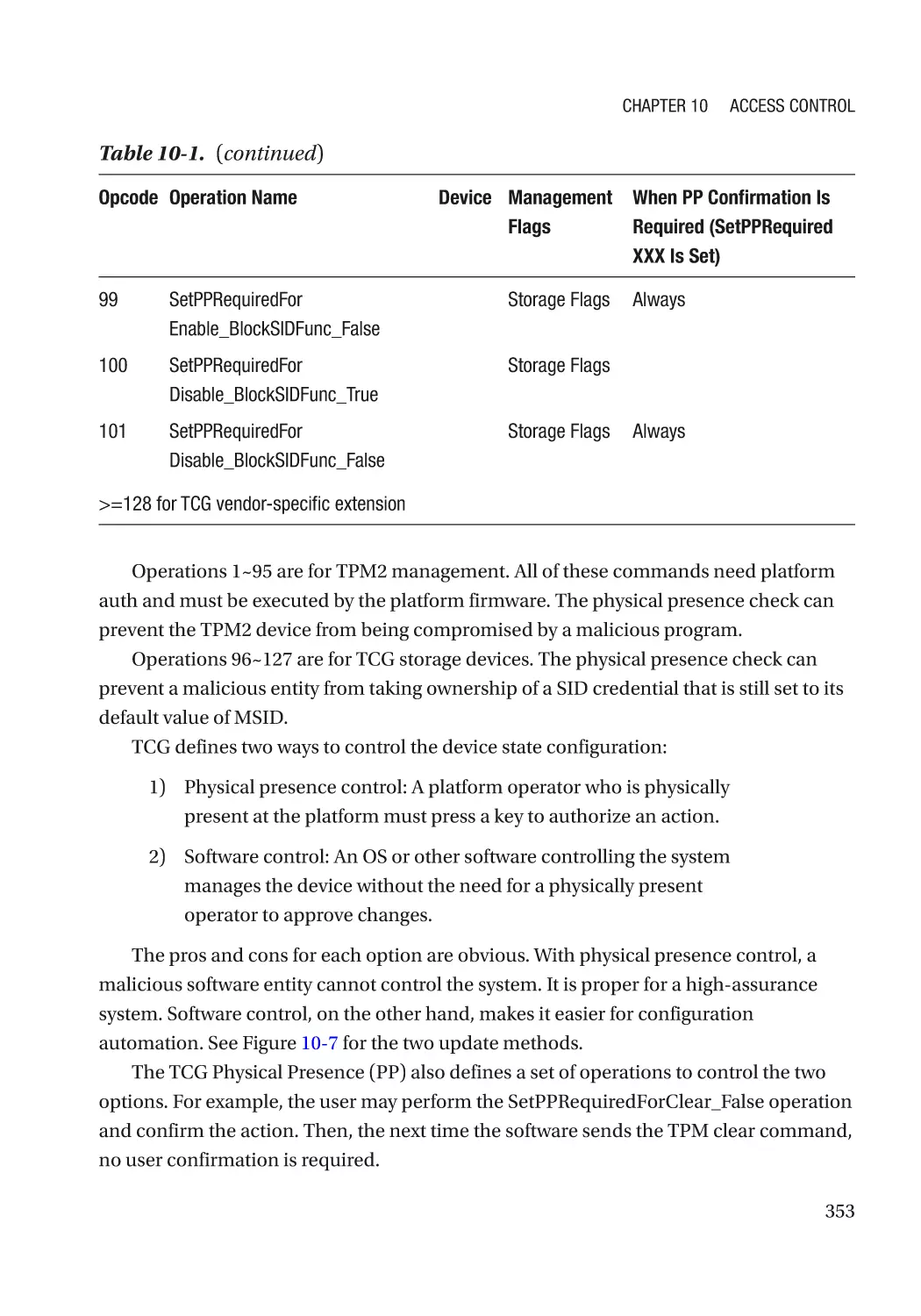
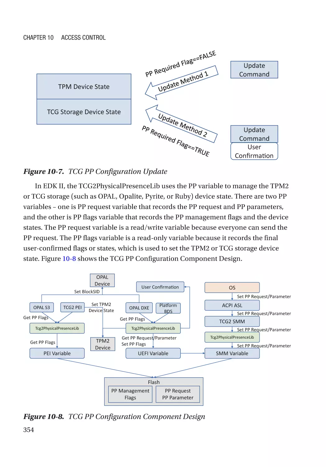
Device Configuration Control���������������������������������������������������������������������������������������������������� 349
Physical Presence��������������������������������������������������������������������������������������������������������������� 350
Secure Console�������������������������������������������������������������������������������������������������������������������� 350
Case Study��������������������������������������������������������������������������������������������������������������������������� 351
Attack and Mitigation���������������������������������������������������������������������������������������������������������� 355
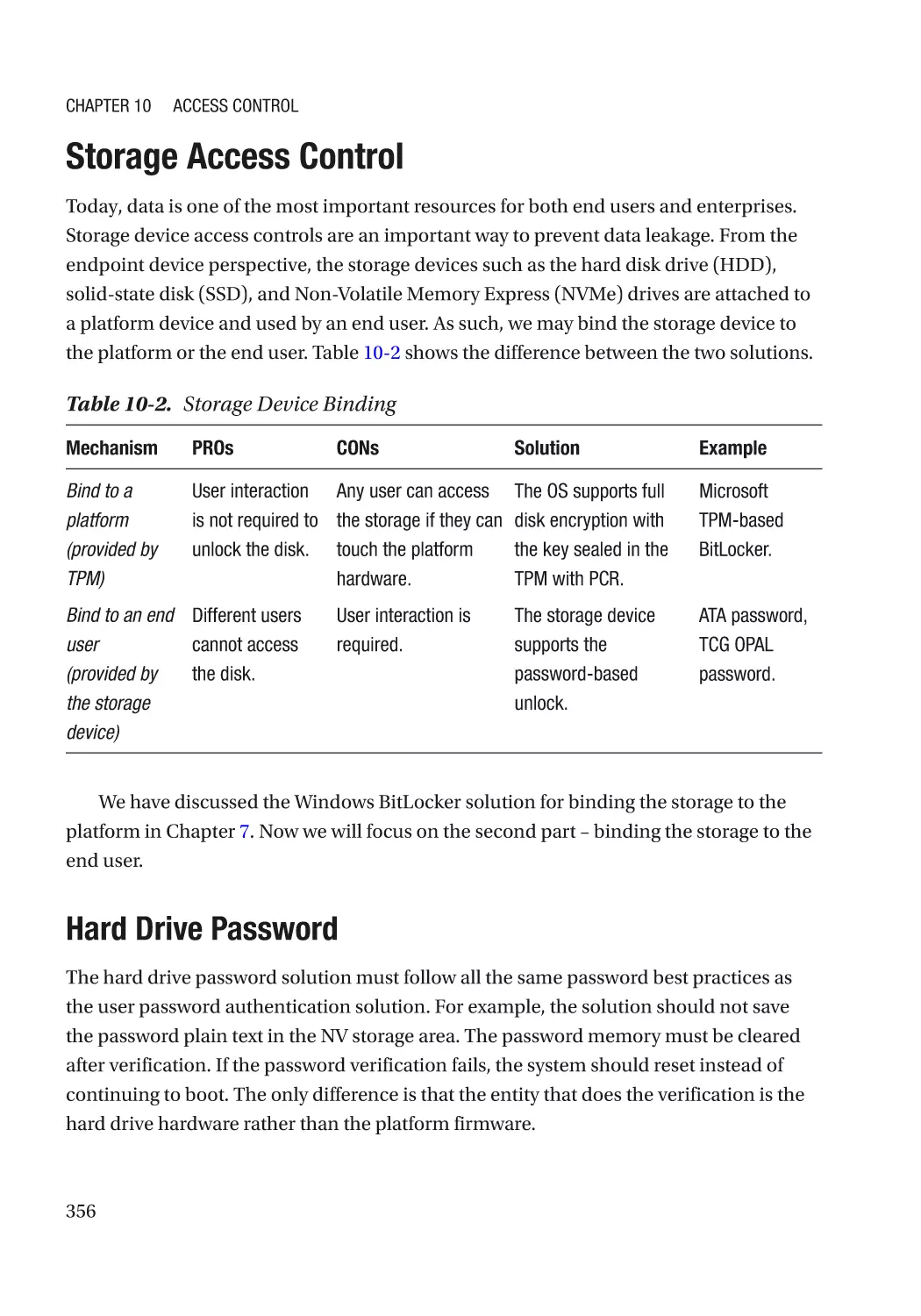
Storage Access Control������������������������������������������������������������������������������������������������������������� 356
Hard Drive Password����������������������������������������������������������������������������������������������������������� 356
Fast Boot Impact����������������������������������������������������������������������������������������������������������������� 357
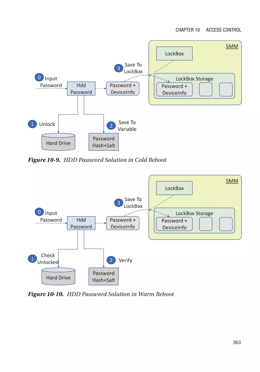
Unlock in a Warm Reset������������������������������������������������������������������������������������������������������ 357
Auto Unlock in S3���������������������������������������������������������������������������������������������������������������� 357
Runtime D3 impact�������������������������������������������������������������������������������������������������������������� 358
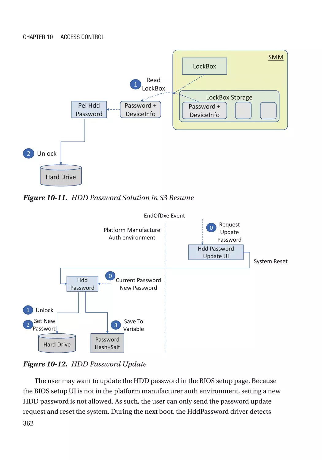
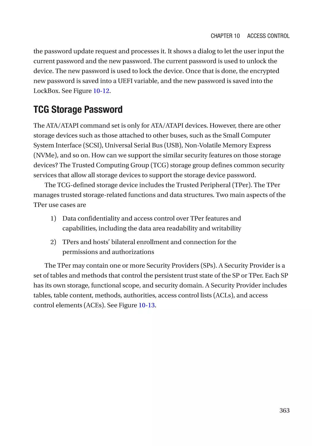
Password Update����������������������������������������������������������������������������������������������������������������� 359
User Password vs. Master Password���������������������������������������������������������������������������������� 359
Retry Count�������������������������������������������������������������������������������������������������������������������������� 359
Hard Drive Freeze���������������������������������������������������������������������������������������������������������������� 359
Secure Console�������������������������������������������������������������������������������������������������������������������� 359
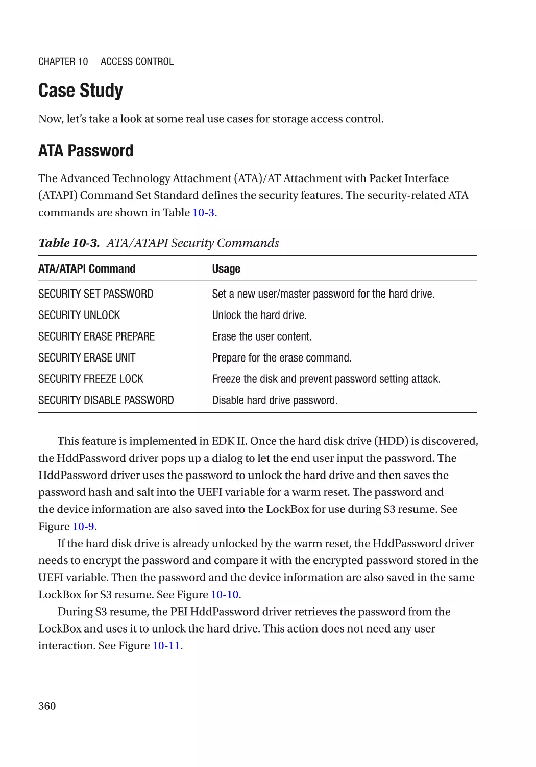
Case Study��������������������������������������������������������������������������������������������������������������������������� 360
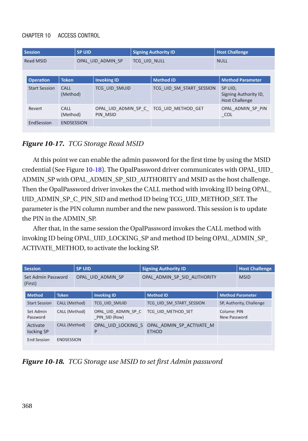
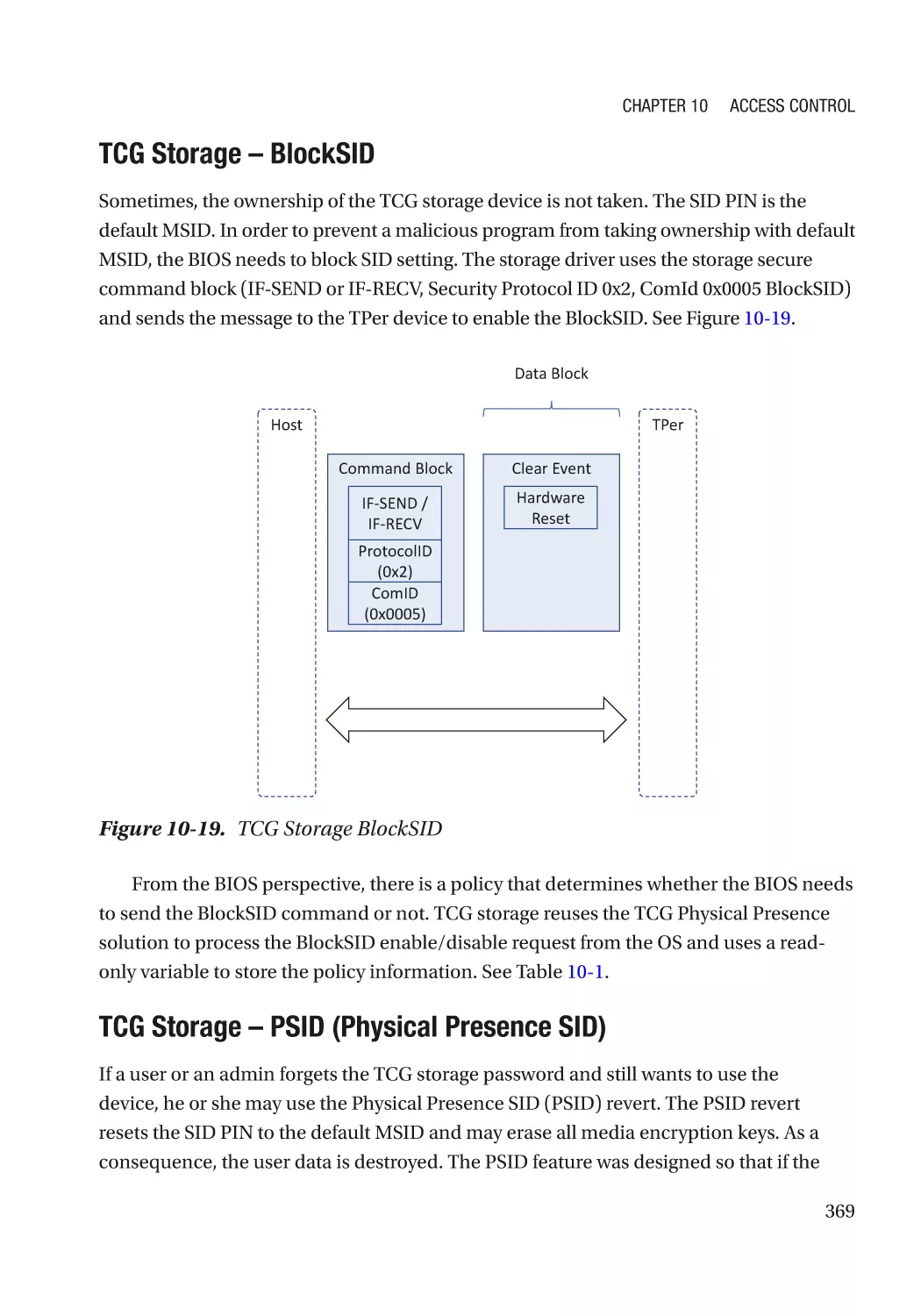
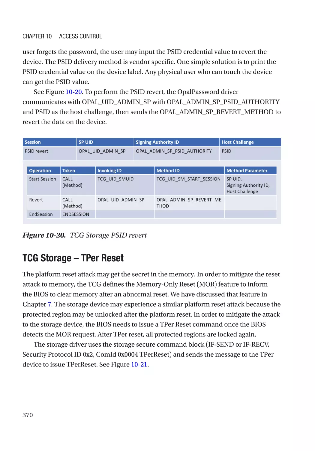
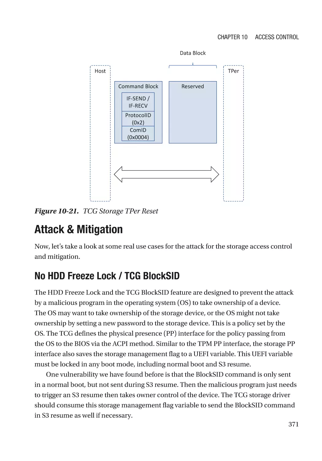
Attack & Mitigation�������������������������������������������������������������������������������������������������������������� 371
Network Access Control������������������������������������������������������������������������������������������������������������ 372
Case Study��������������������������������������������������������������������������������������������������������������������������� 372
Attack & Mitigation�������������������������������������������������������������������������������������������������������������� 374
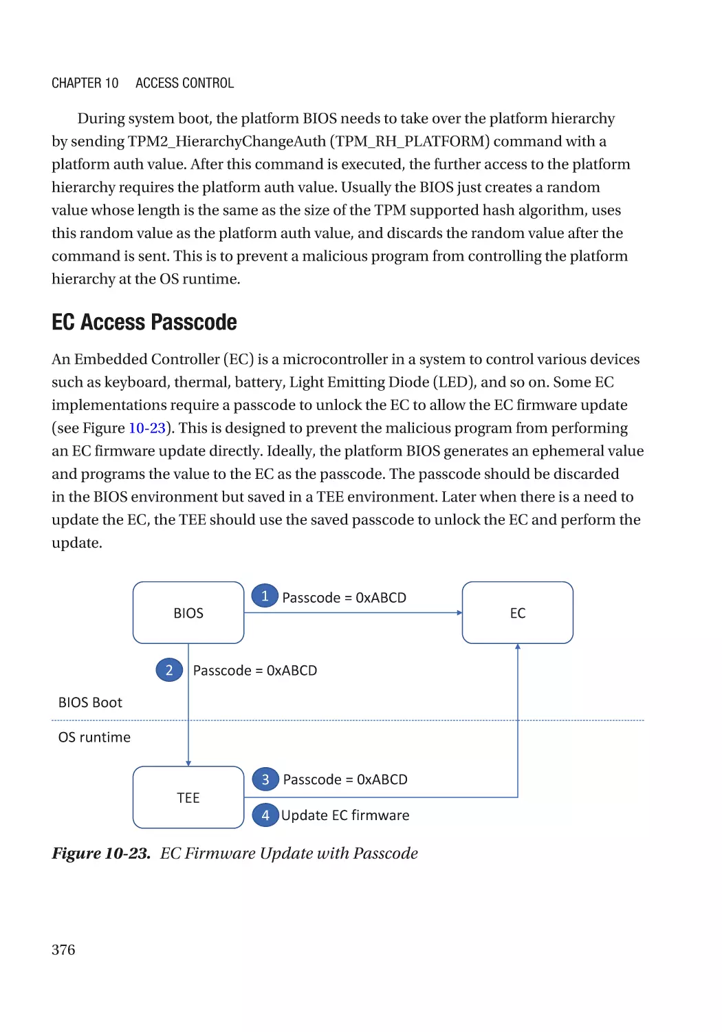
Device Access Control��������������������������������������������������������������������������������������������������������������� 375
Case Study��������������������������������������������������������������������������������������������������������������������������� 375
Attack & Mitigation�������������������������������������������������������������������������������������������������������������� 377
Summary���������������������������������������������������������������������������������������������������������������������������������� 378
References�������������������������������������������������������������������������������������������������������������������������������� 378
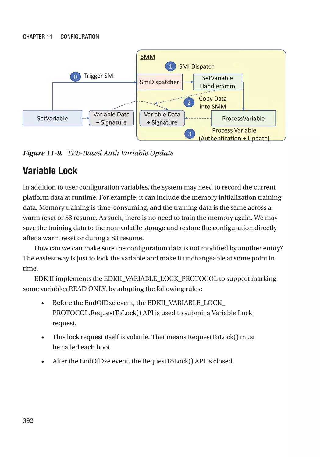
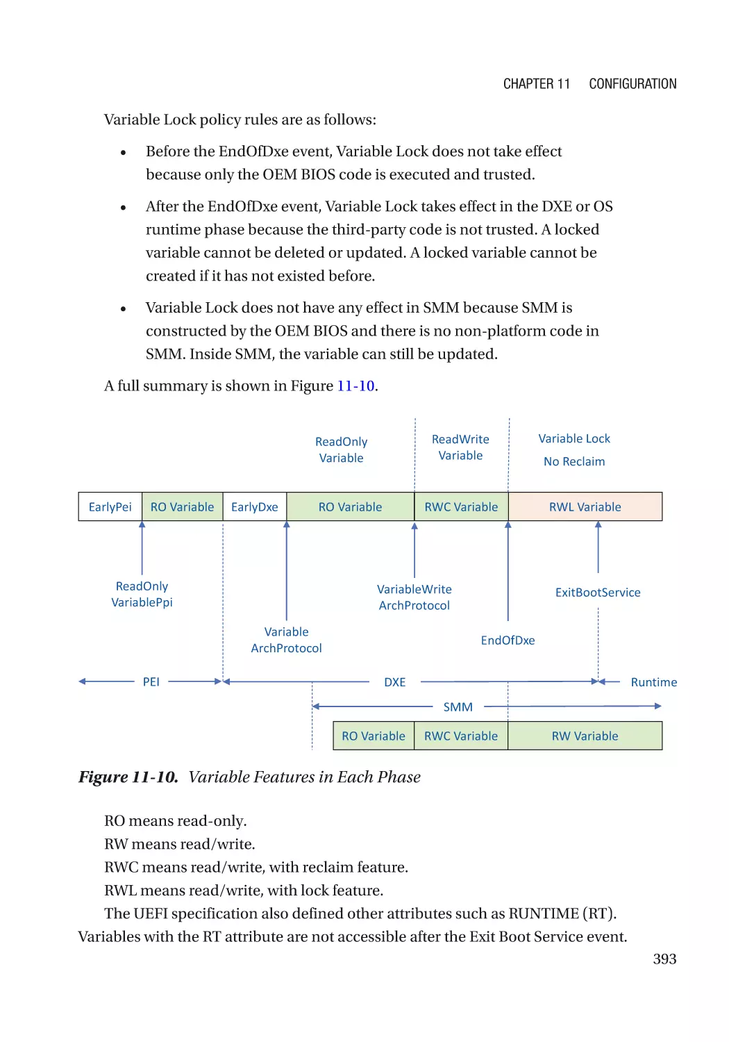
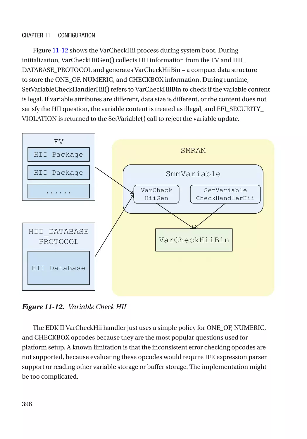
Chapter 11: Configuration������������������������������������������������������������������������������������ 383
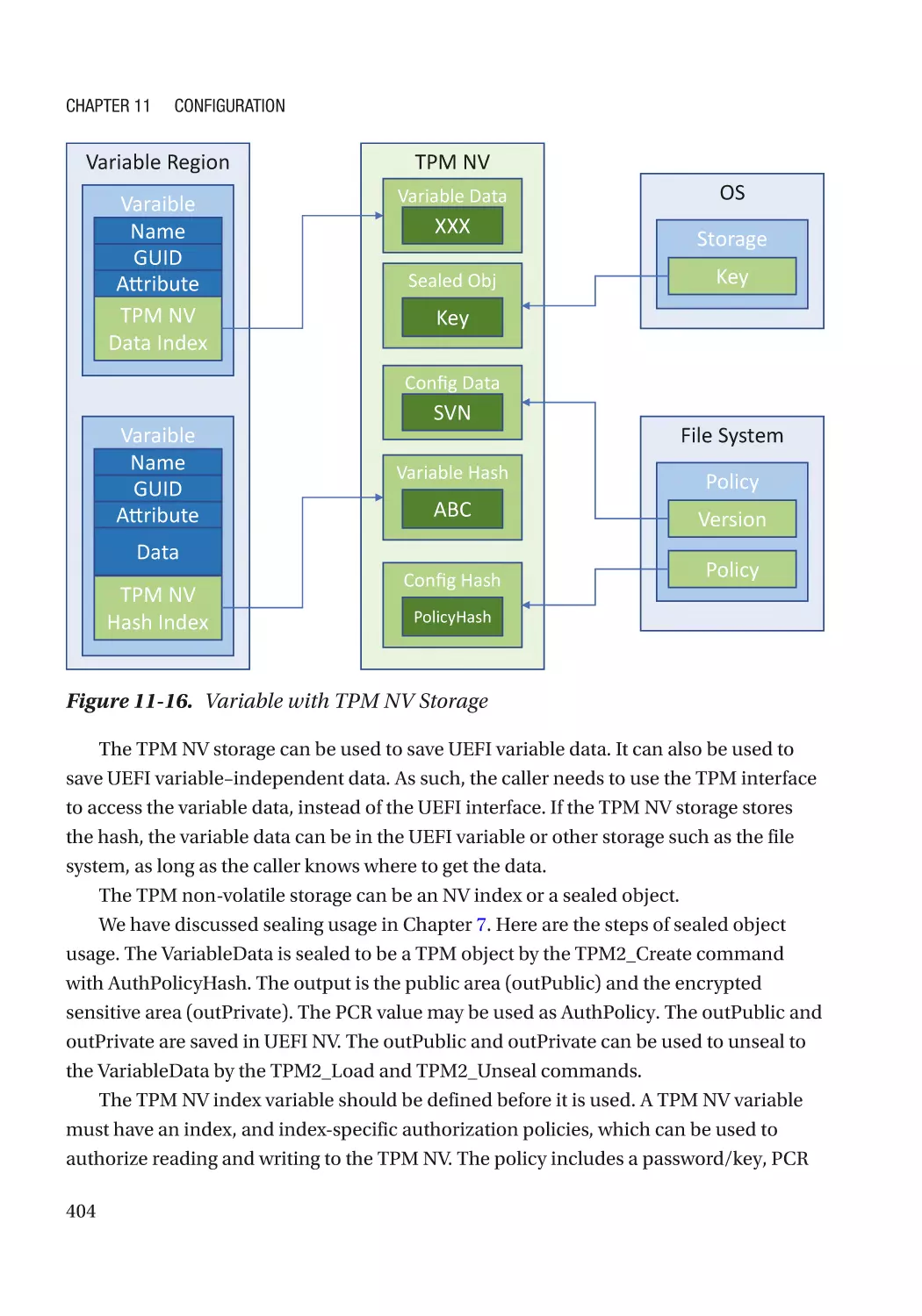
UEFI Variables��������������������������������������������������������������������������������������������������������������������������� 383
Integrity Protection�������������������������������������������������������������������������������������������������������������� 384
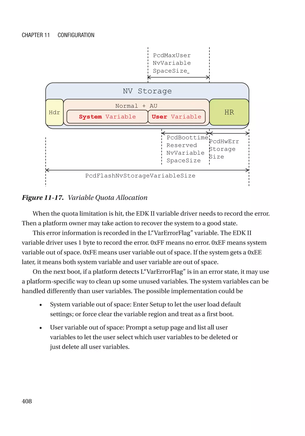
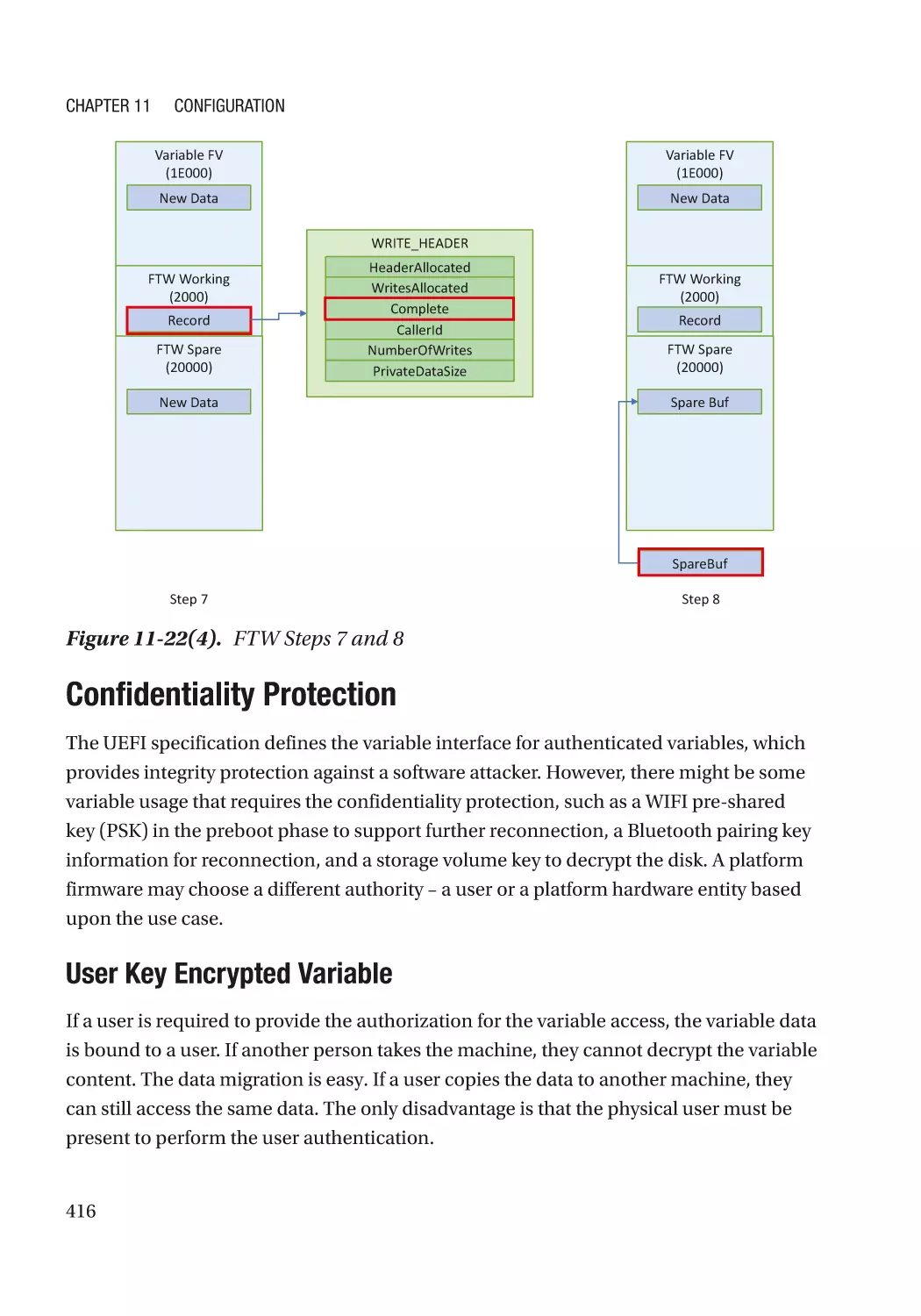
Availability Protection���������������������������������������������������������������������������������������������������������� 406
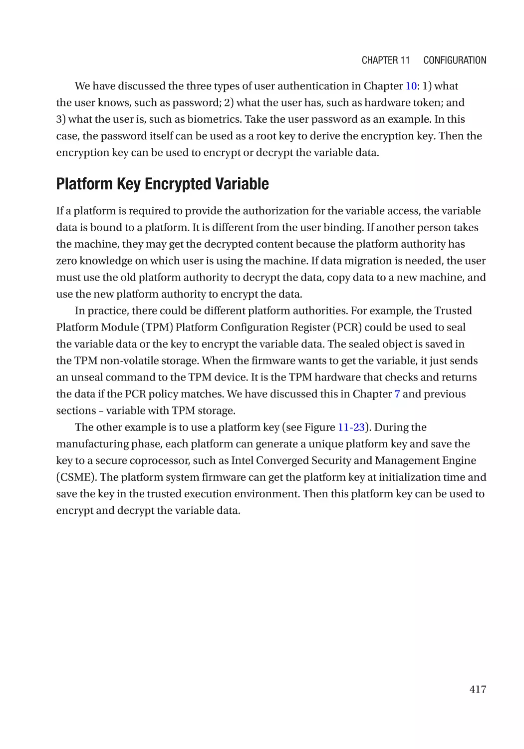
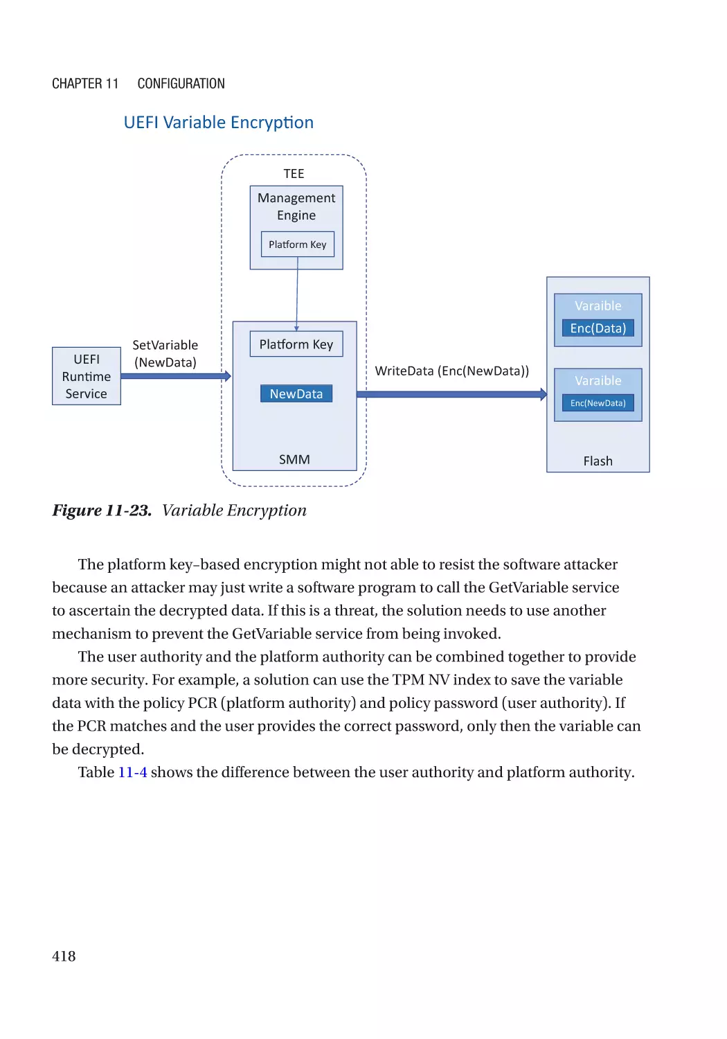
Confidentiality Protection���������������������������������������������������������������������������������������������������� 416
xi
Table of Contents
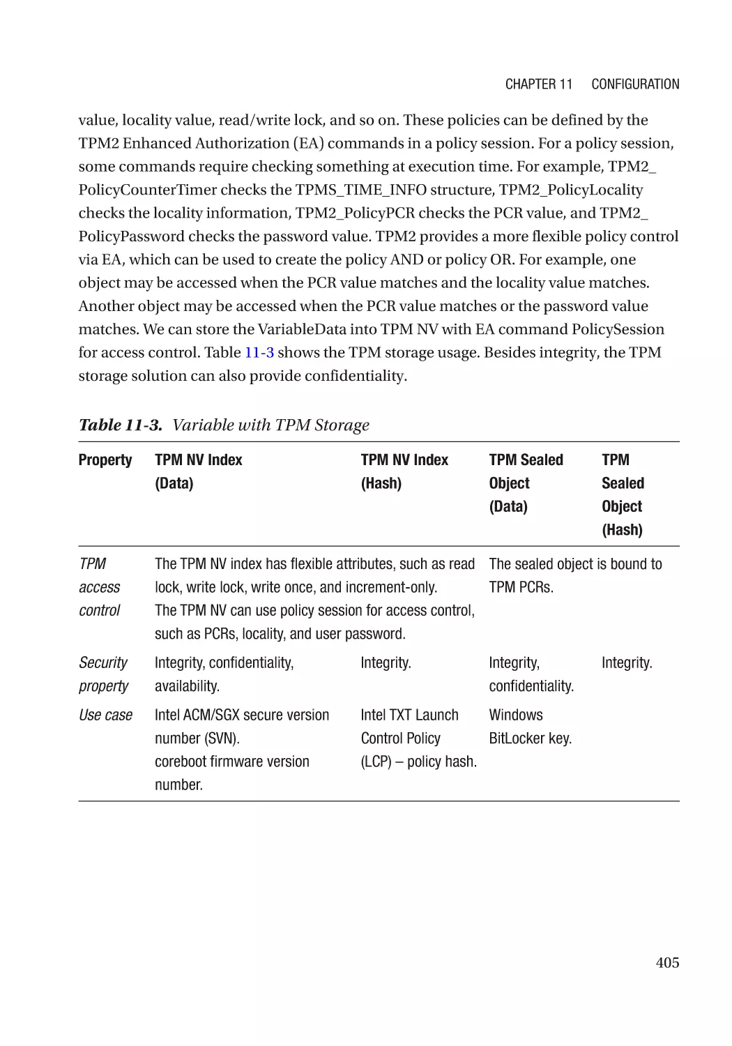
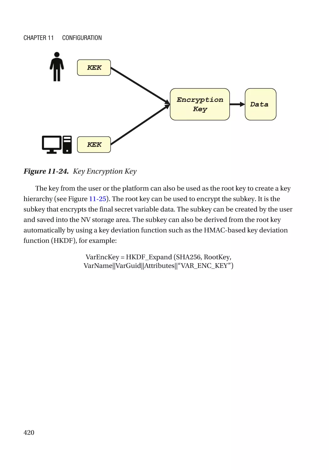
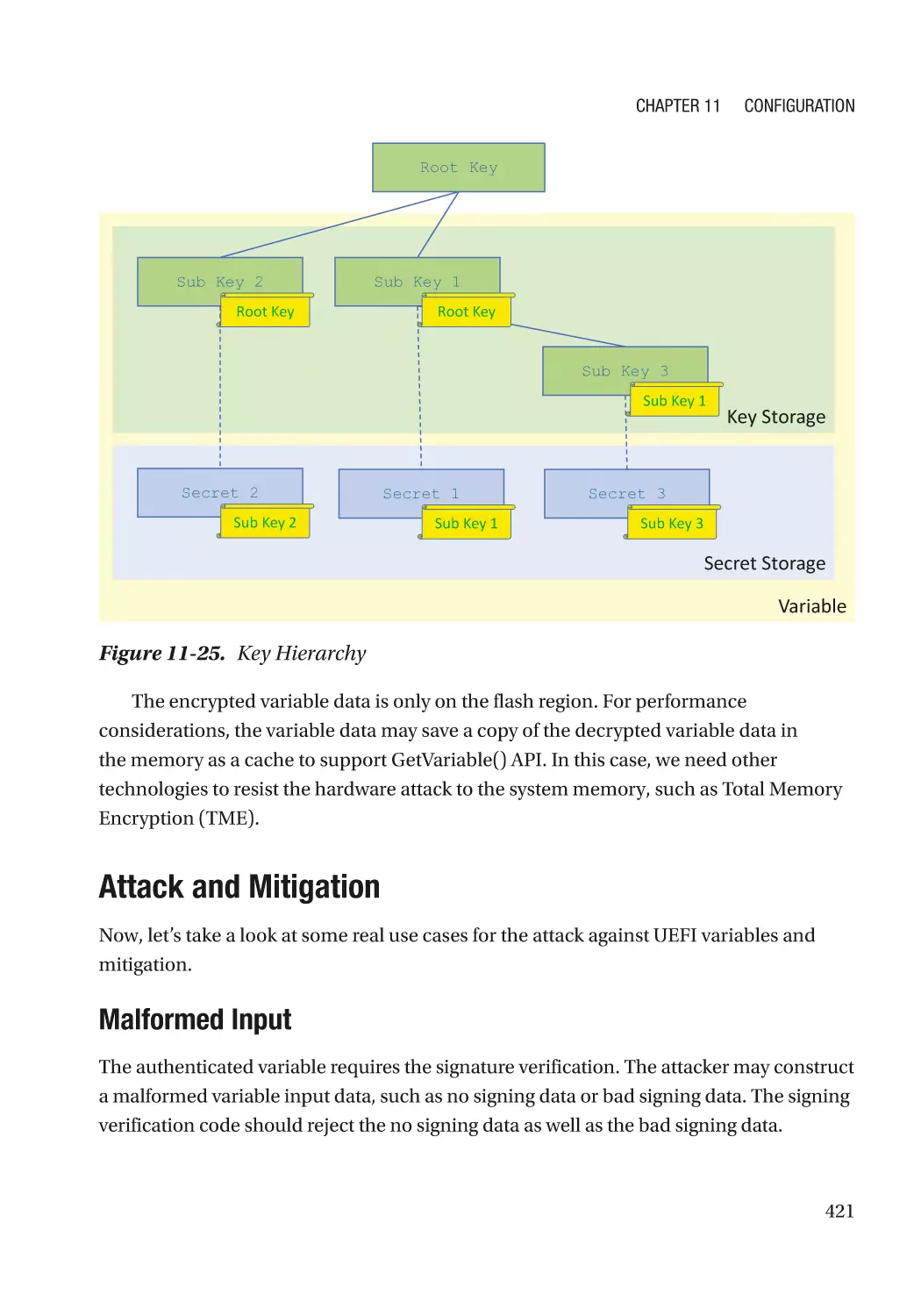
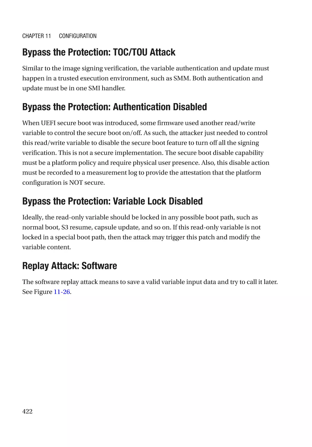
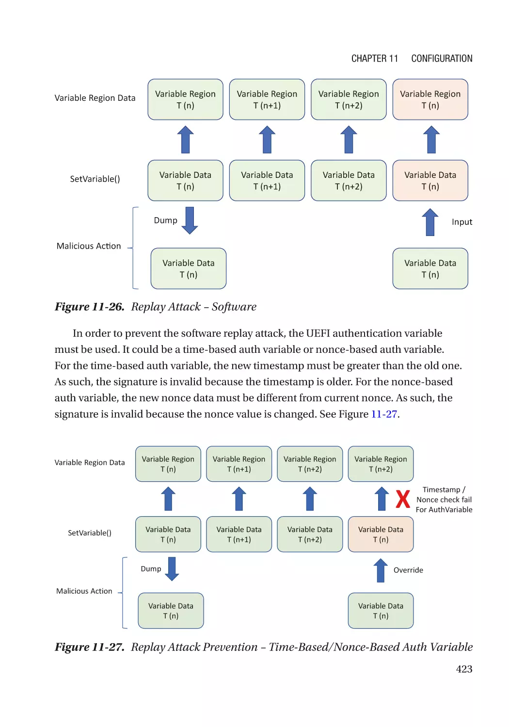
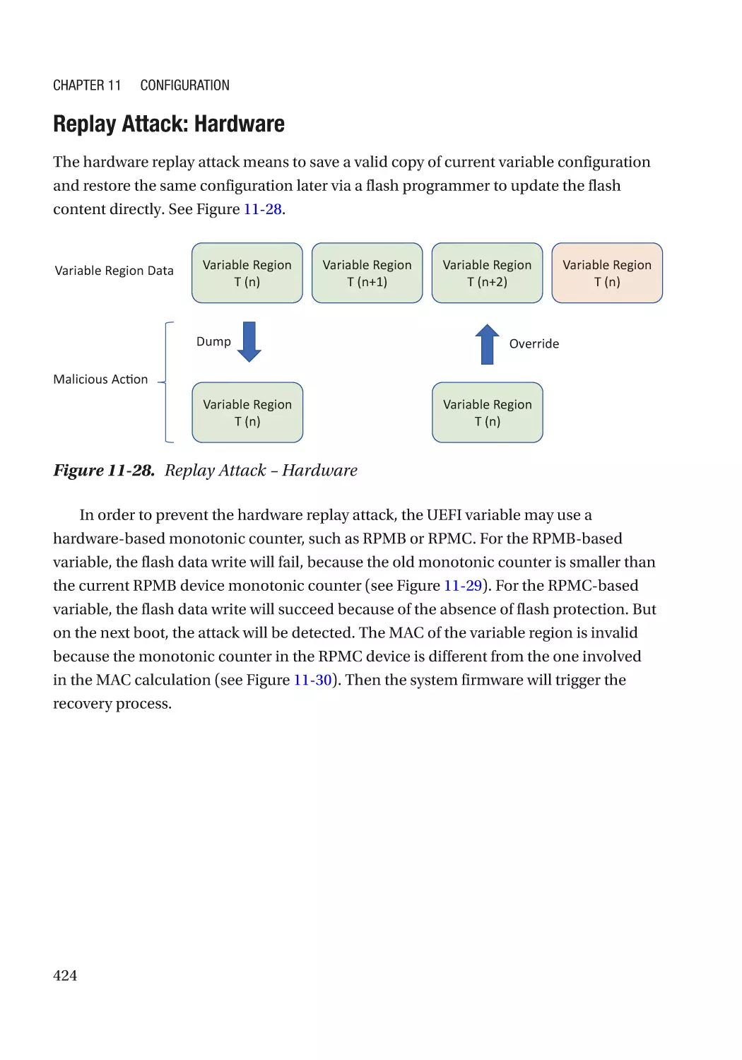
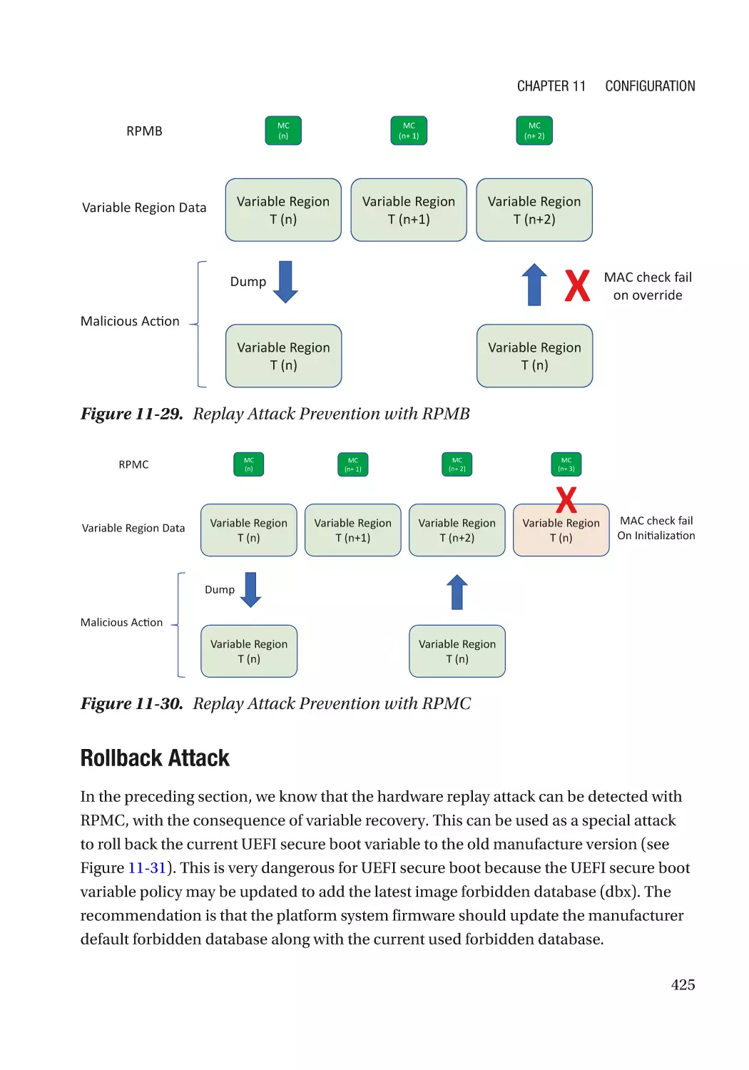
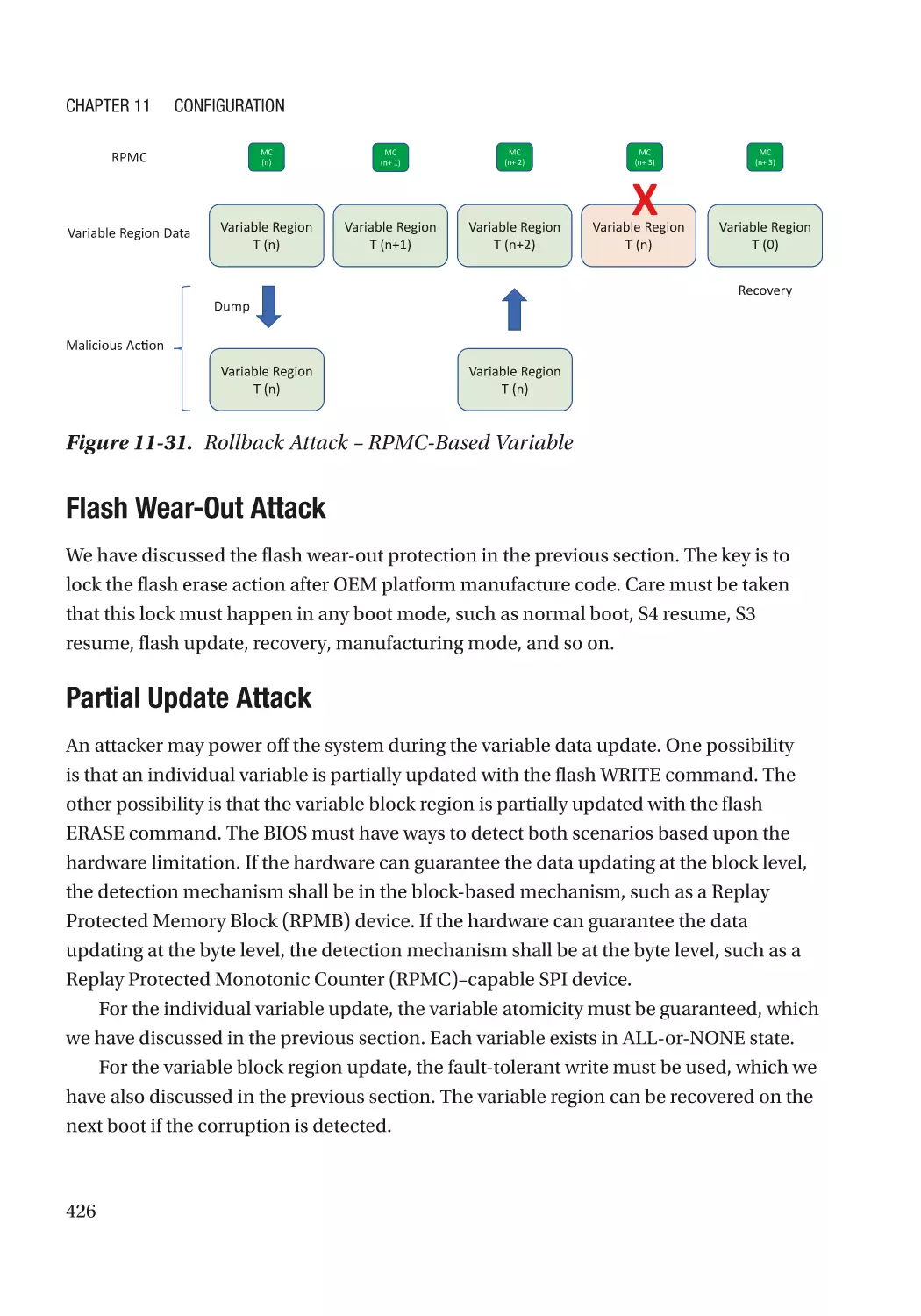
Attack and Mitigation���������������������������������������������������������������������������������������������������������� 421
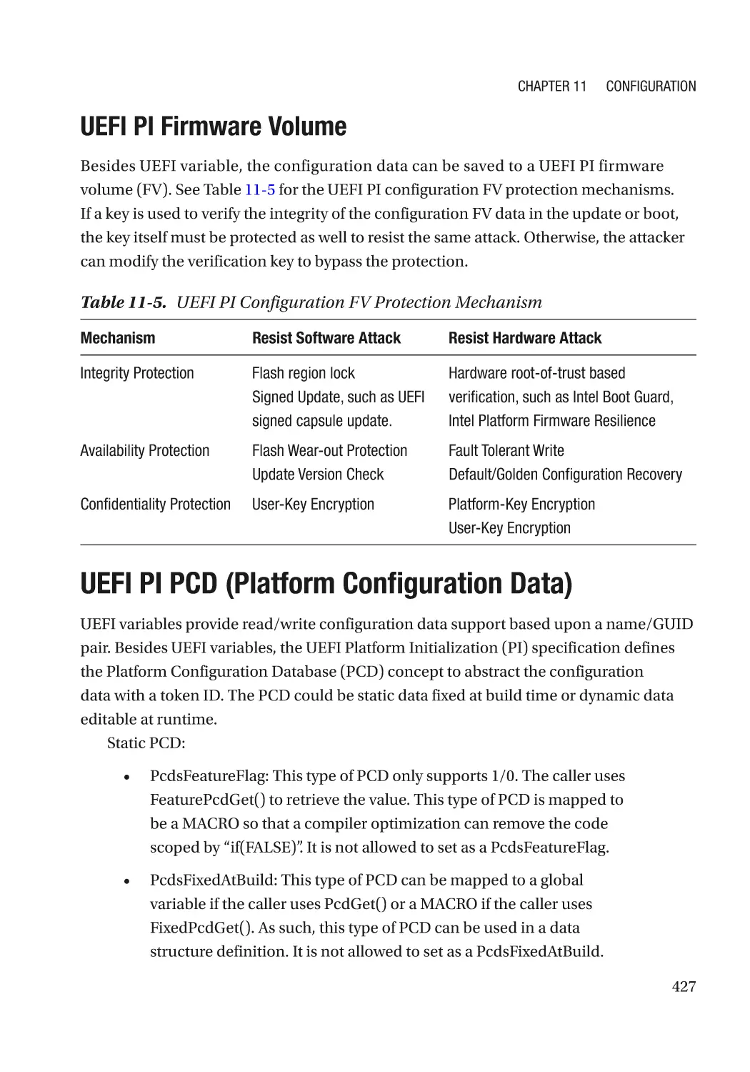
UEFI PI Firmware Volume���������������������������������������������������������������������������������������������������� 427
UEFI PI PCD (Platform Configuration Data)�������������������������������������������������������������������������������� 427
Summary���������������������������������������������������������������������������������������������������������������������������������� 429
References�������������������������������������������������������������������������������������������������������������������������������� 430
Chapter 12: Security Model���������������������������������������������������������������������������������� 433
Confidentiality��������������������������������������������������������������������������������������������������������������������������� 433
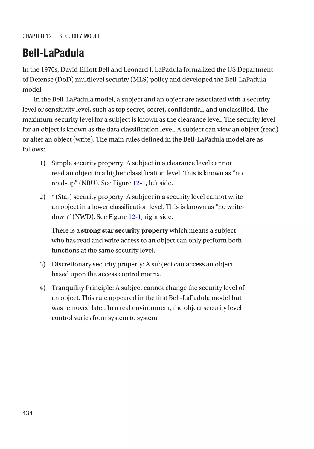
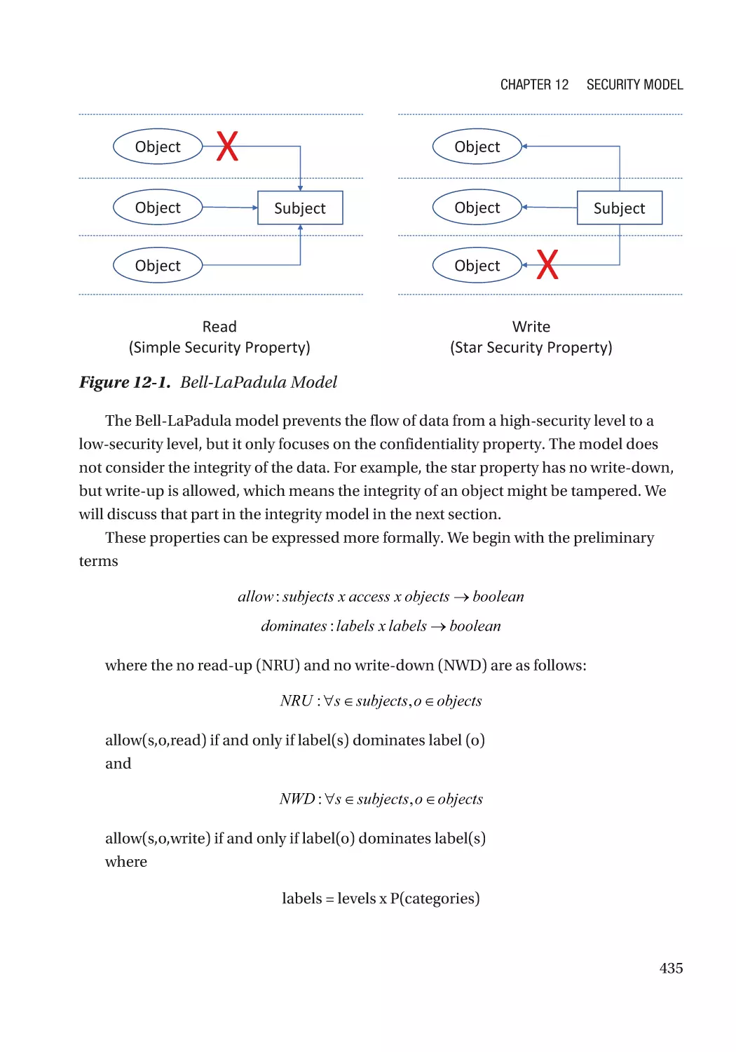
Bell-LaPadula���������������������������������������������������������������������������������������������������������������������� 434
Integrity������������������������������������������������������������������������������������������������������������������������������������� 436
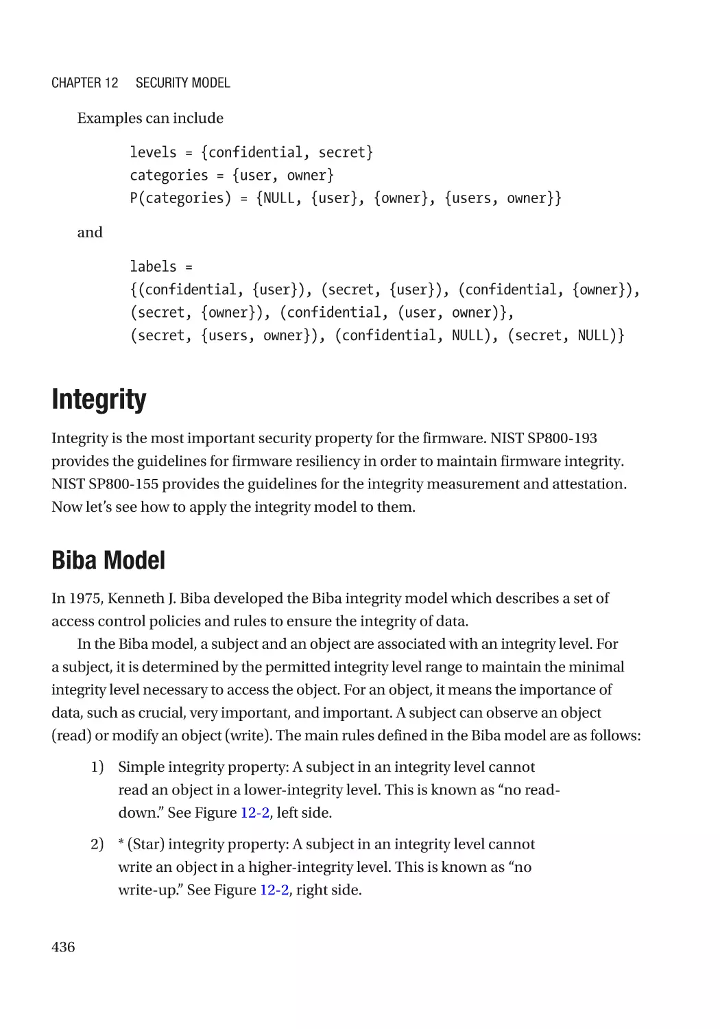
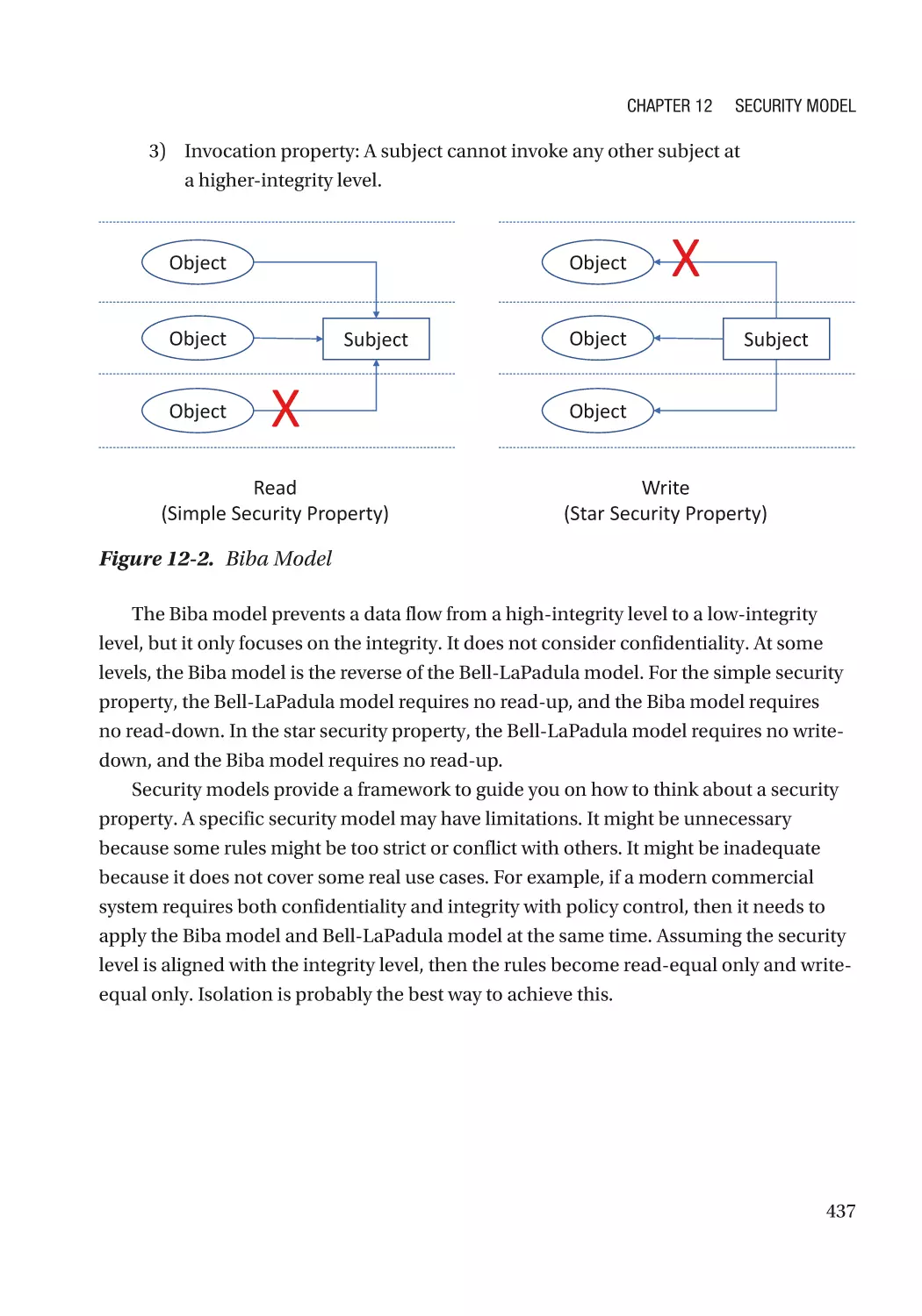
Biba Model��������������������������������������������������������������������������������������������������������������������������� 436
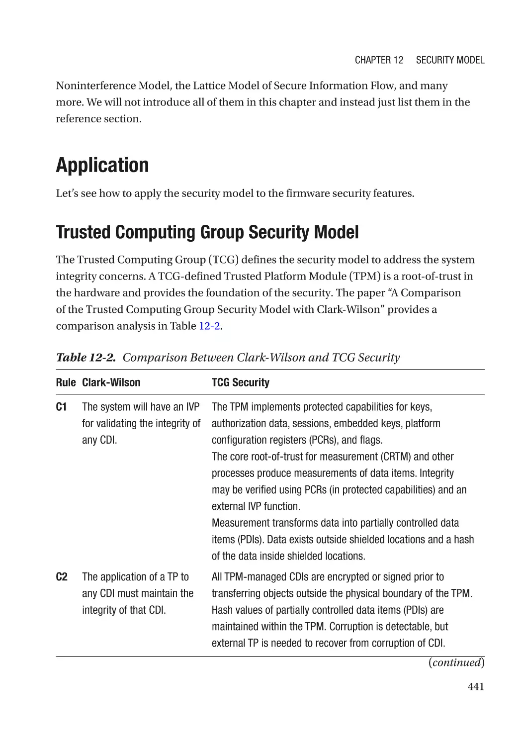
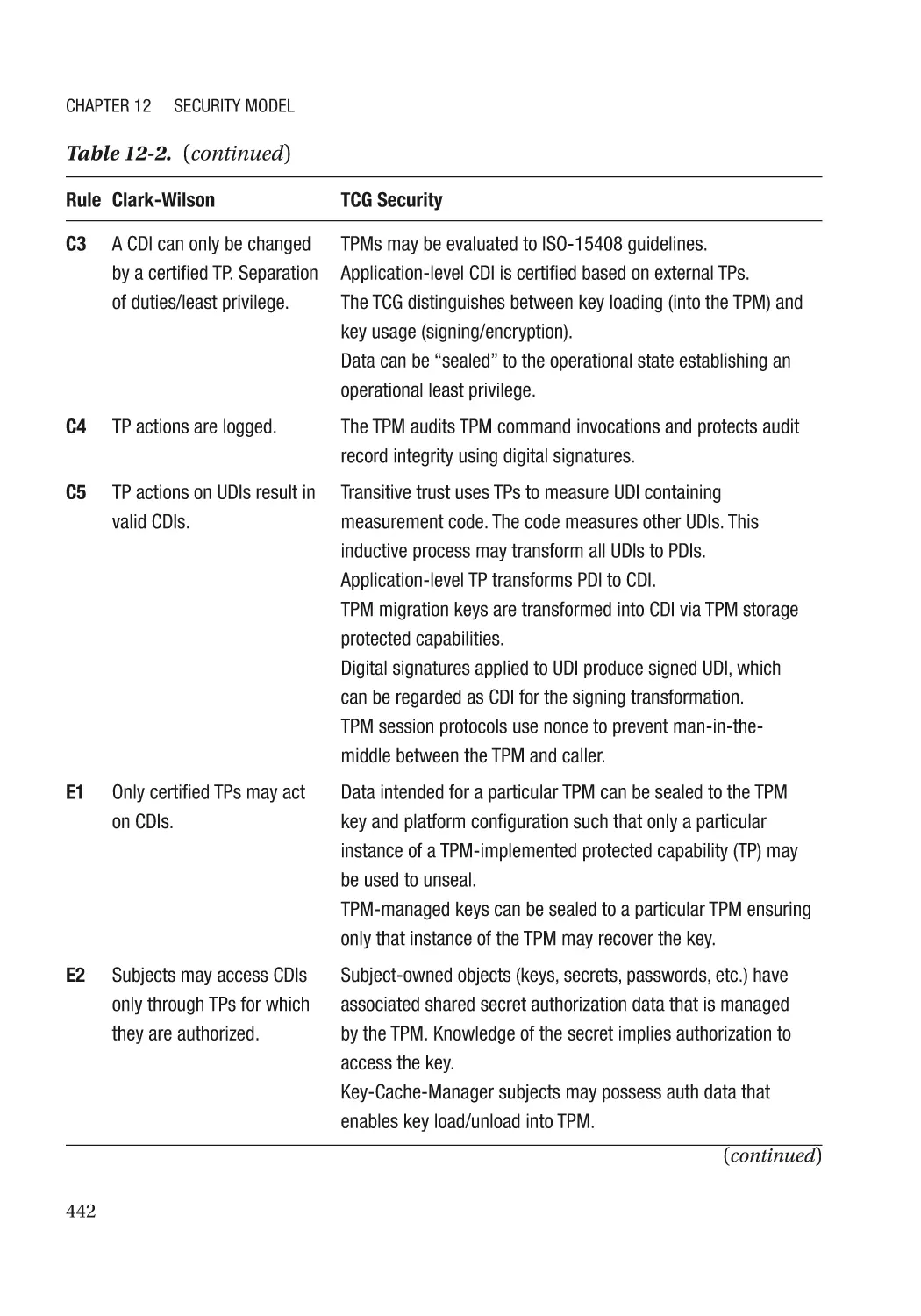
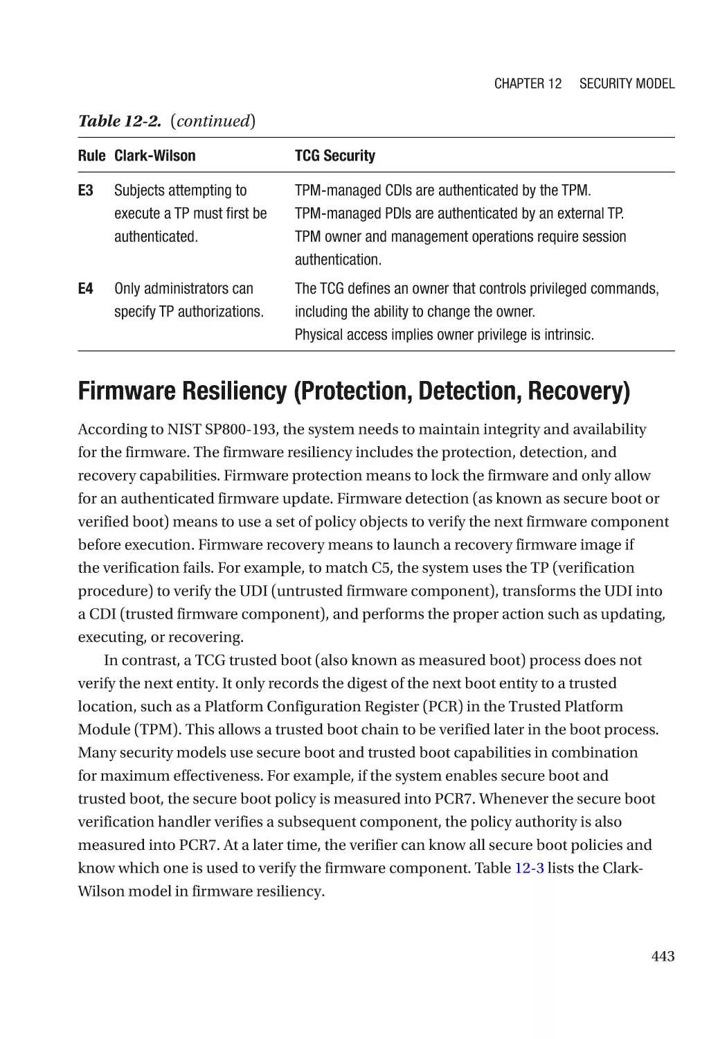
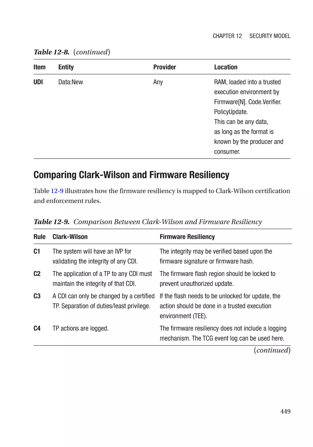
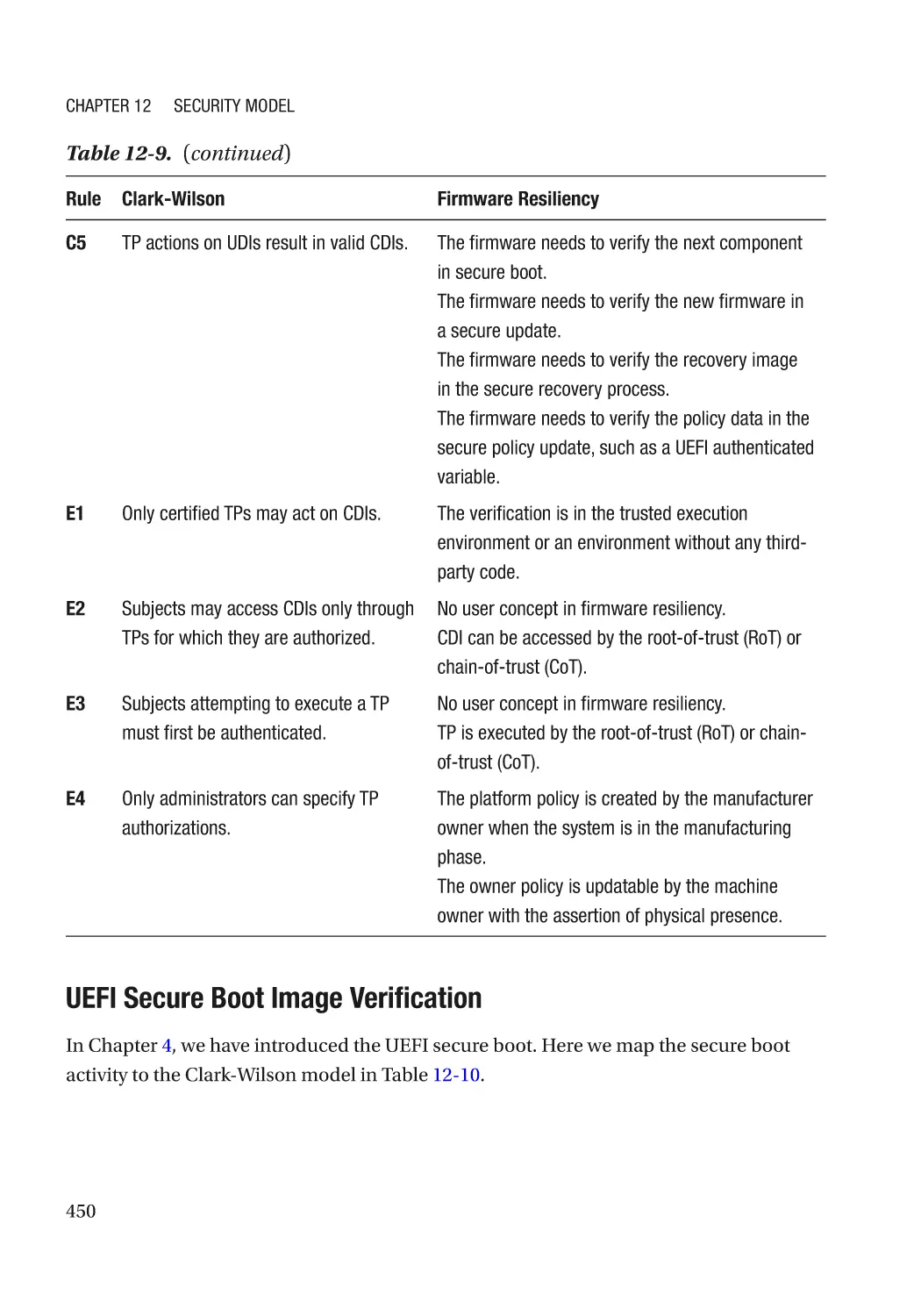
Clark-Wilson Model������������������������������������������������������������������������������������������������������������� 438
Others��������������������������������������������������������������������������������������������������������������������������������������� 440
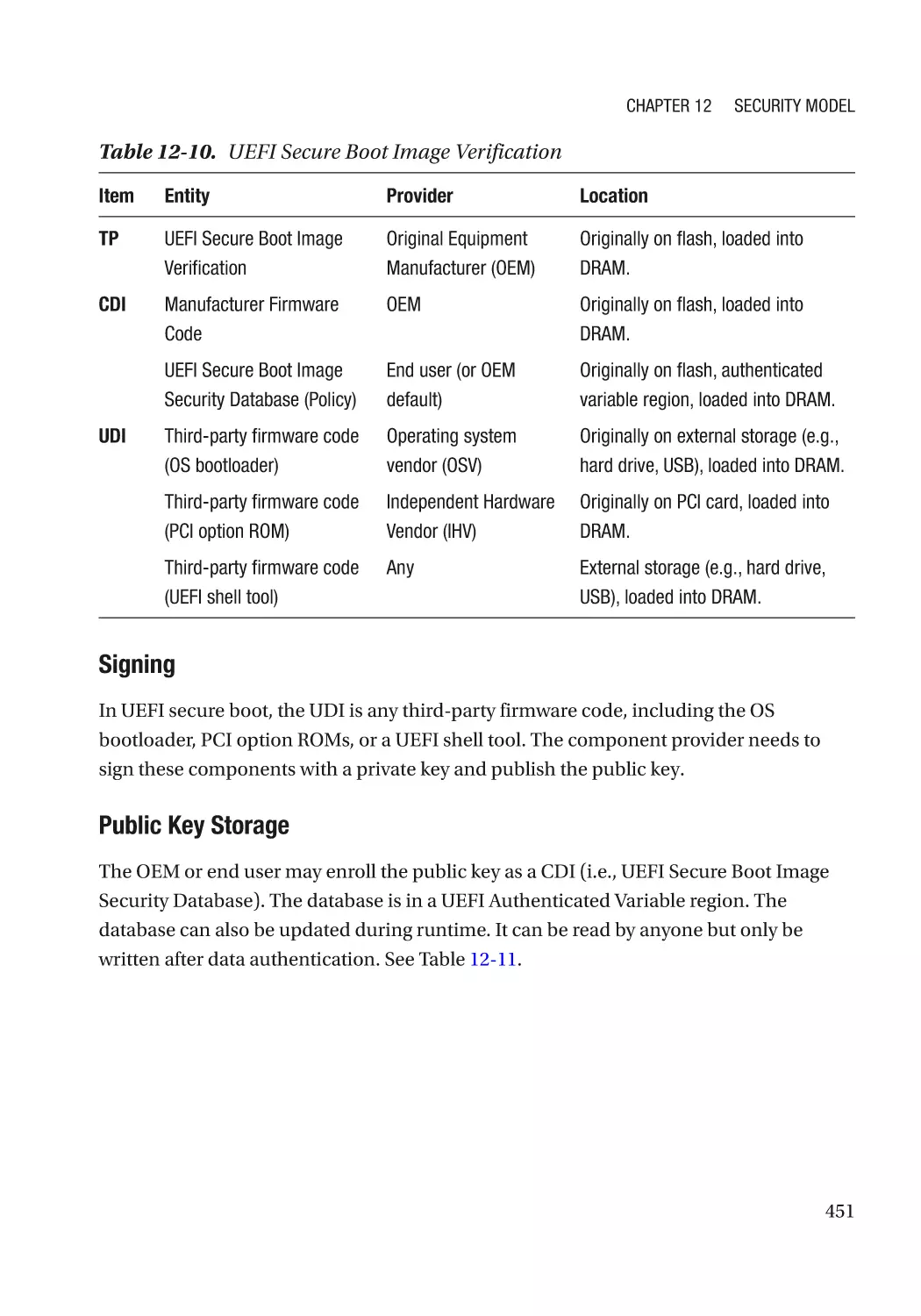
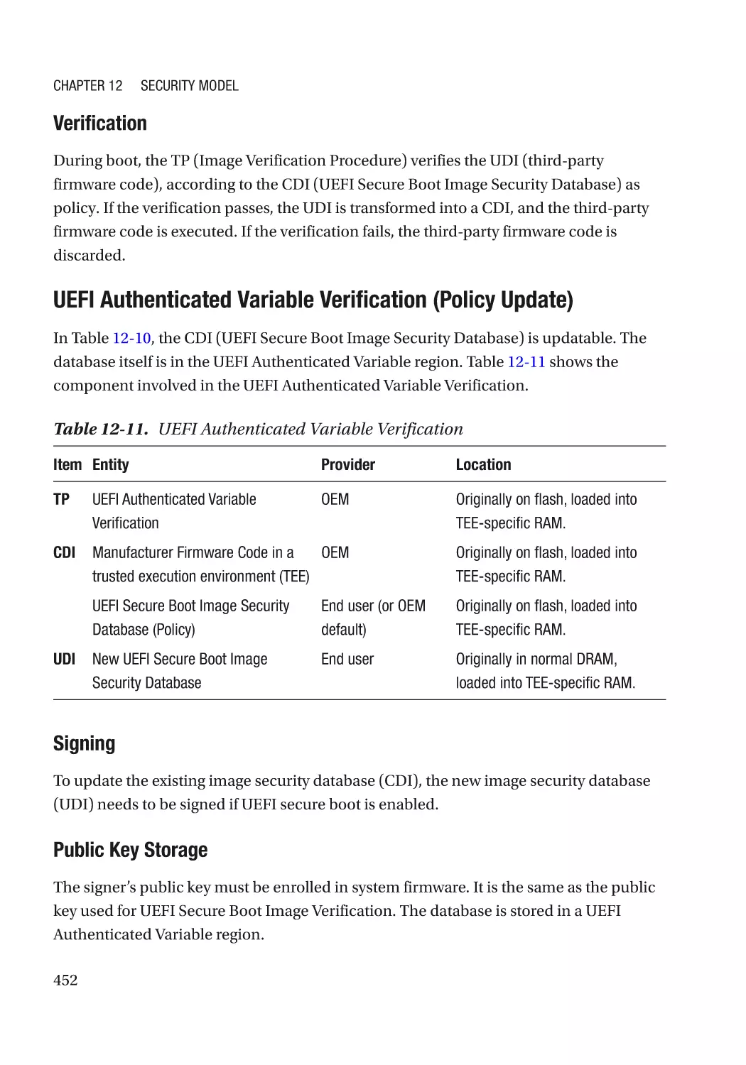
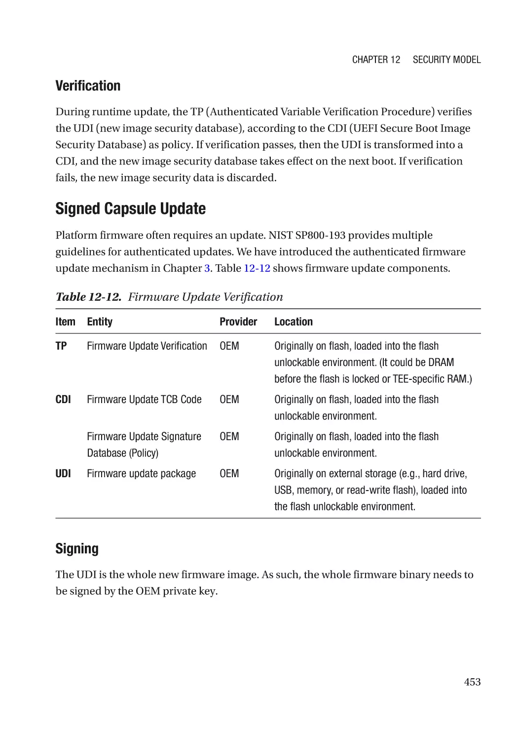
Application�������������������������������������������������������������������������������������������������������������������������������� 441
Trusted Computing Group Security Model��������������������������������������������������������������������������� 441
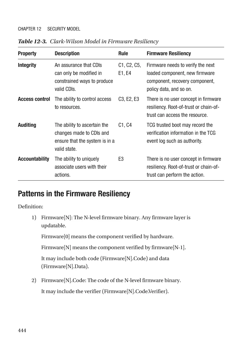
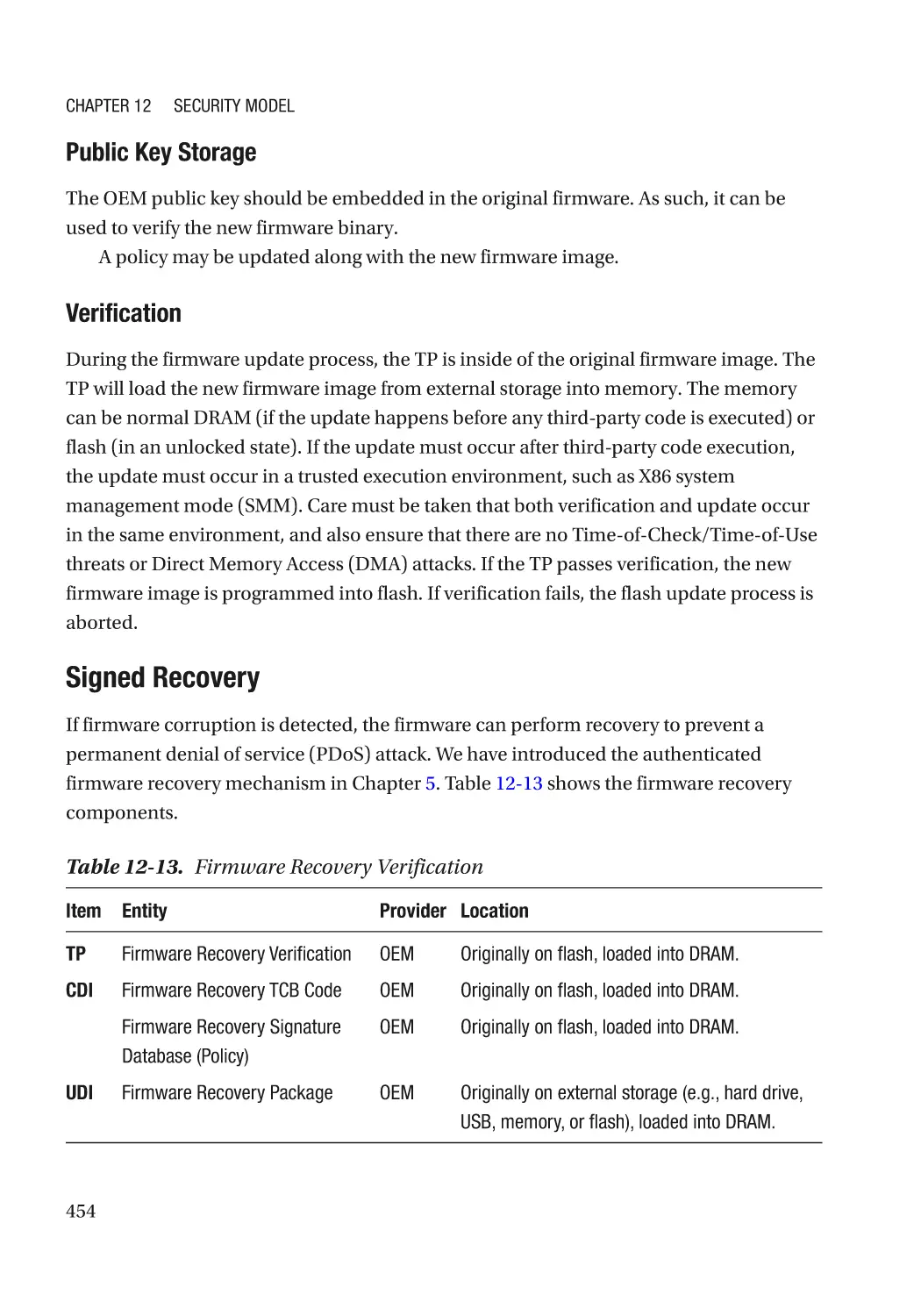
Firmware Resiliency (Protection, Detection, Recovery)������������������������������������������������������� 443
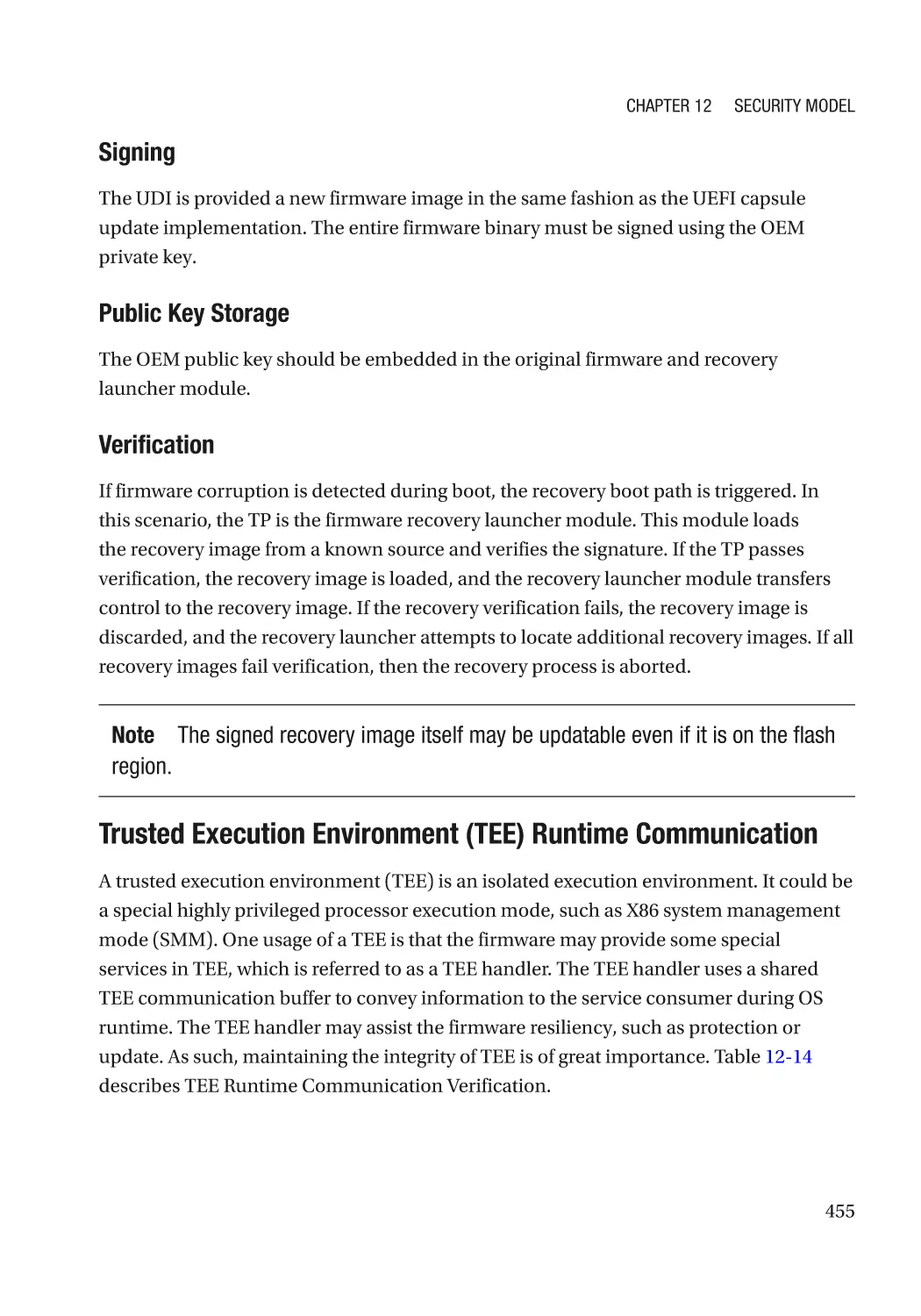
Summary���������������������������������������������������������������������������������������������������������������������������������� 456
References�������������������������������������������������������������������������������������������������������������������������������� 456
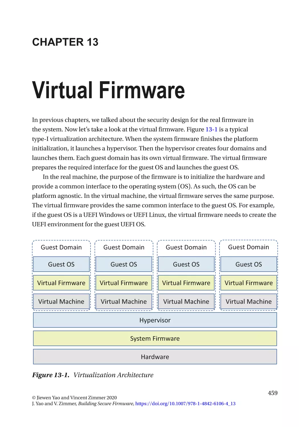
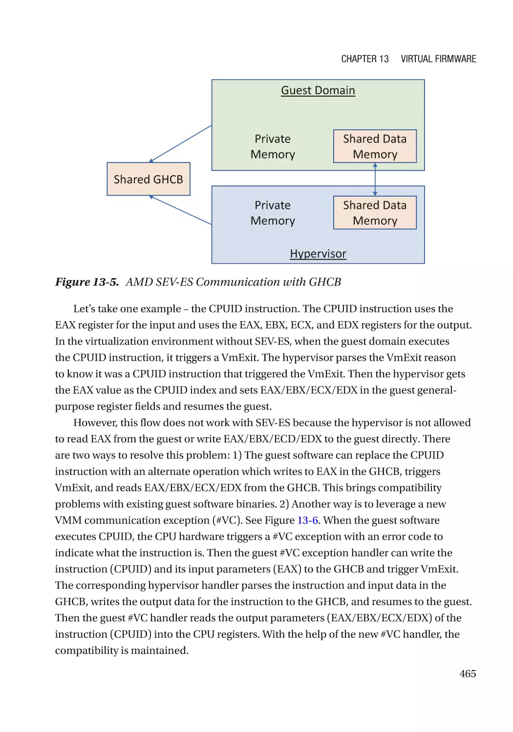
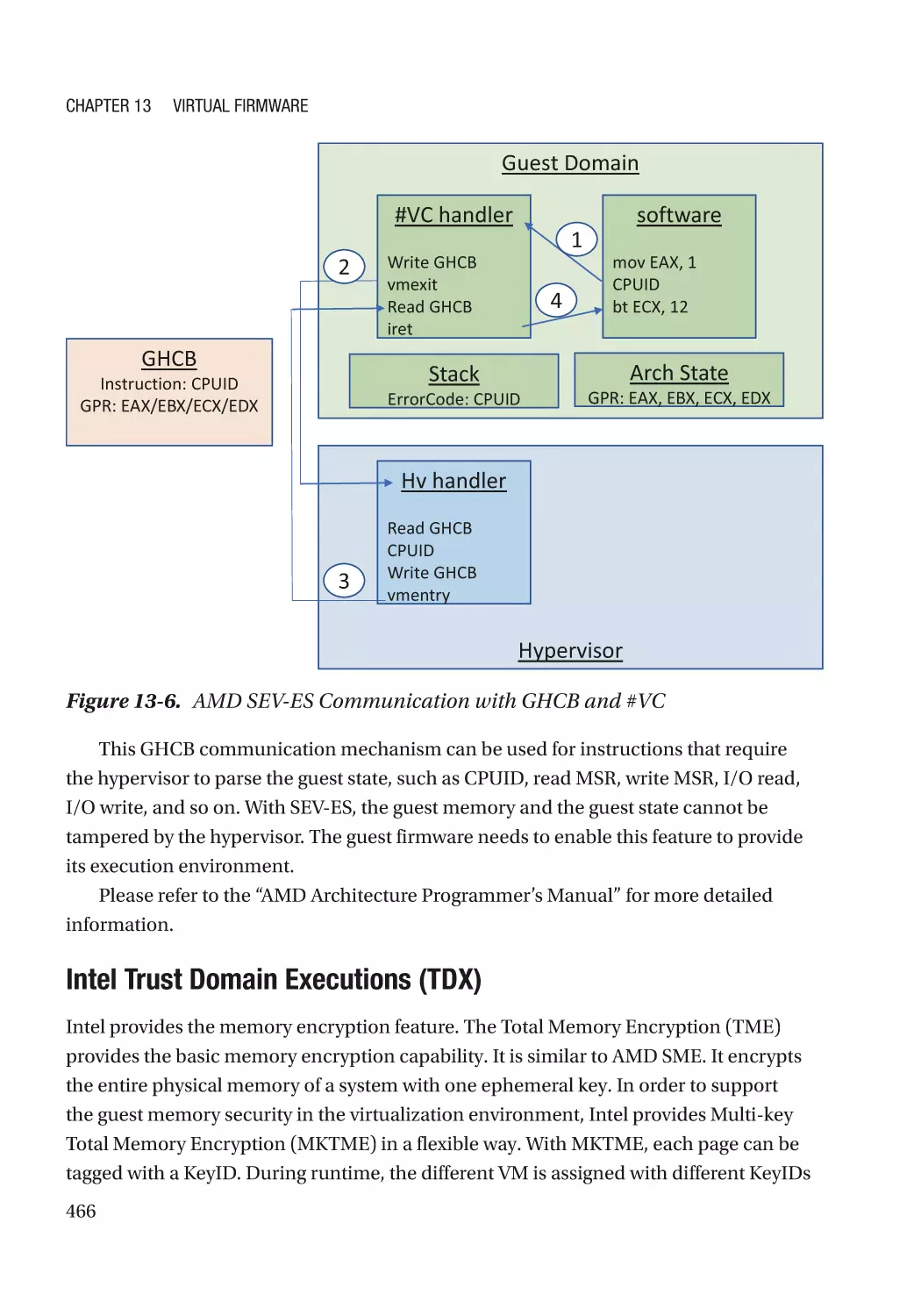
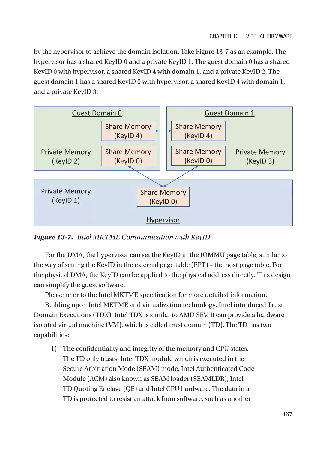
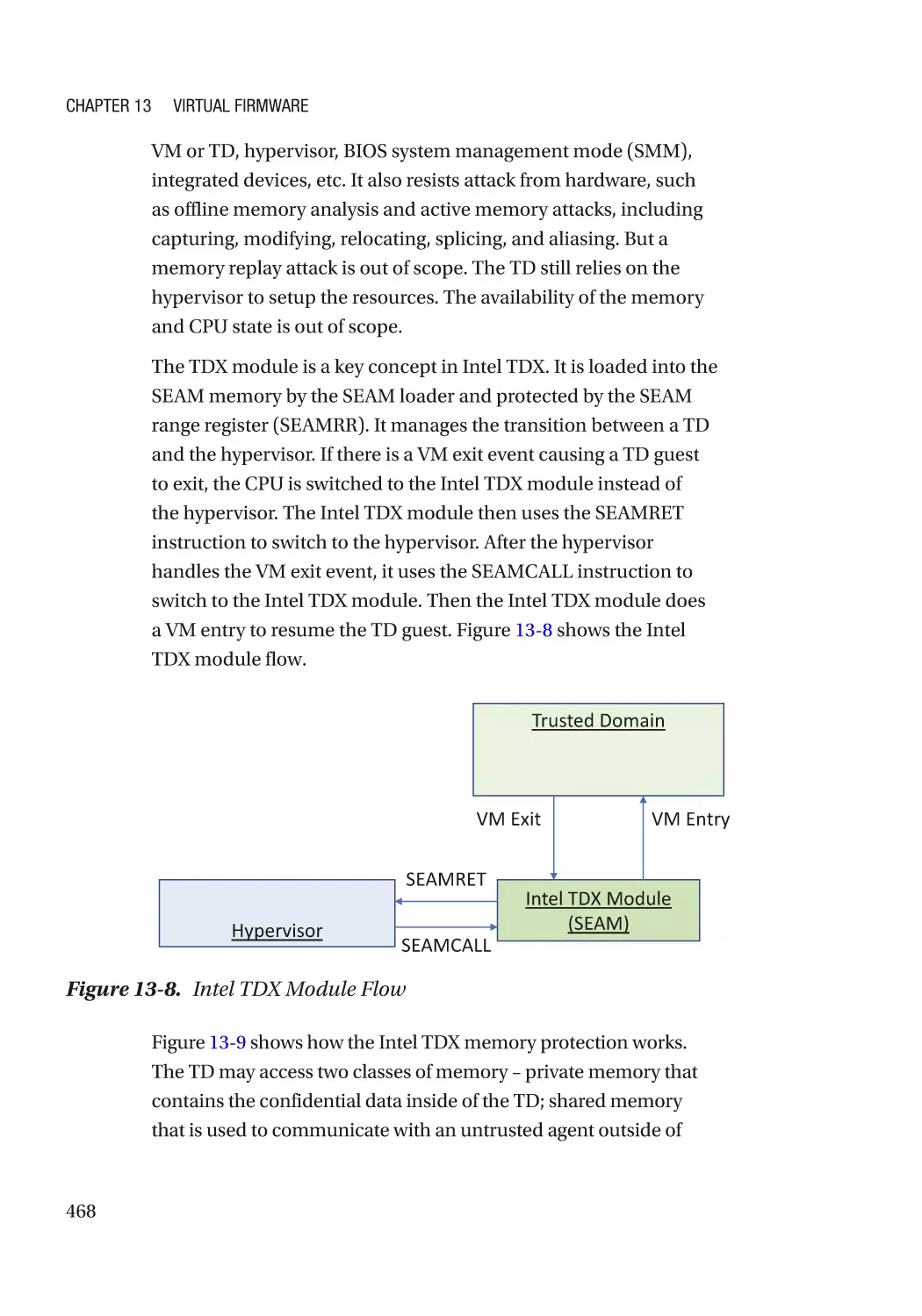
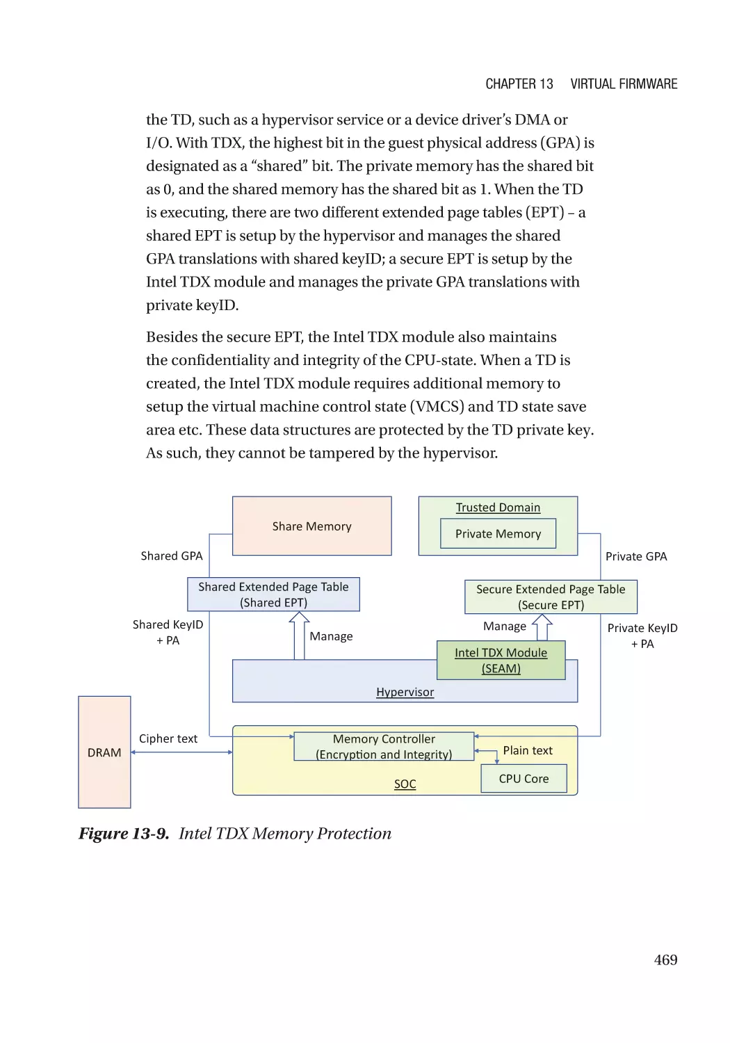
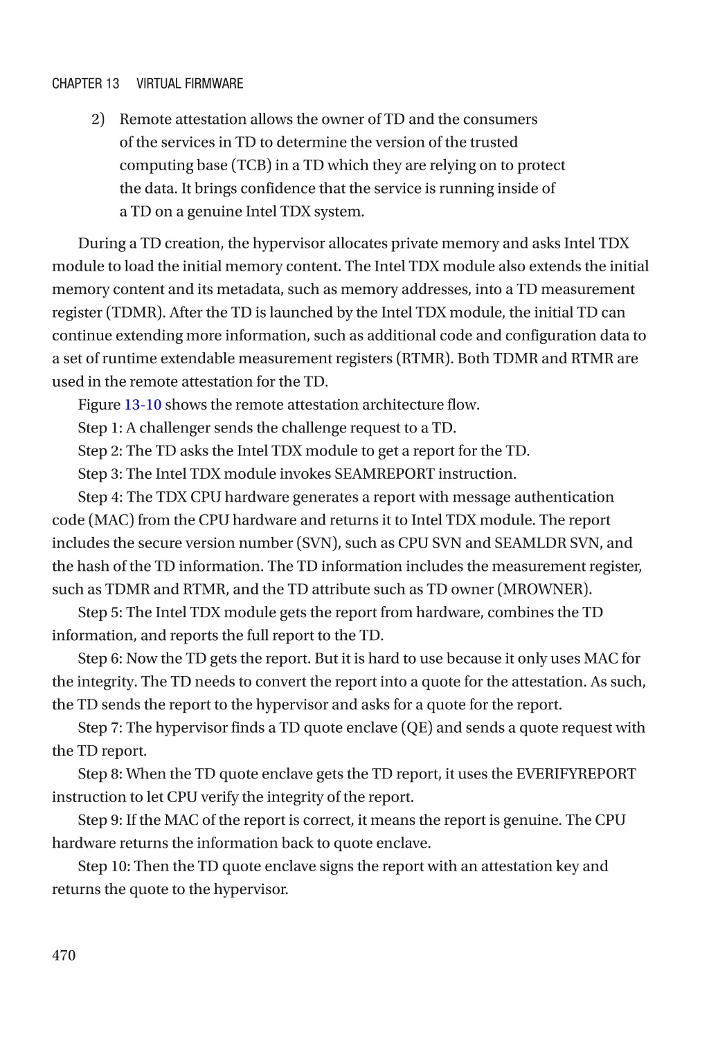
Chapter 13: Virtual Firmware������������������������������������������������������������������������������� 459
New Threats in the Guest Domain��������������������������������������������������������������������������������������������� 460
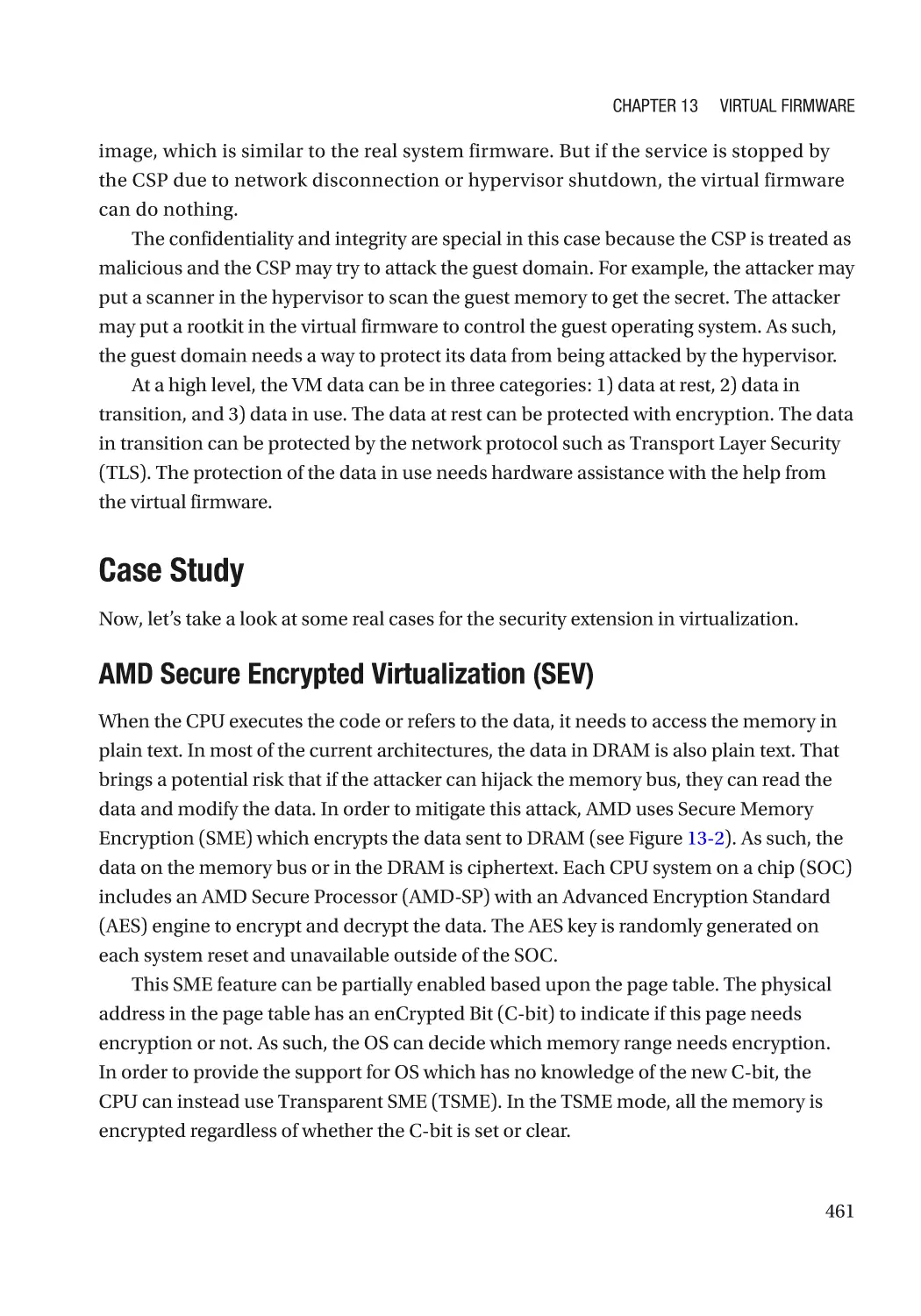
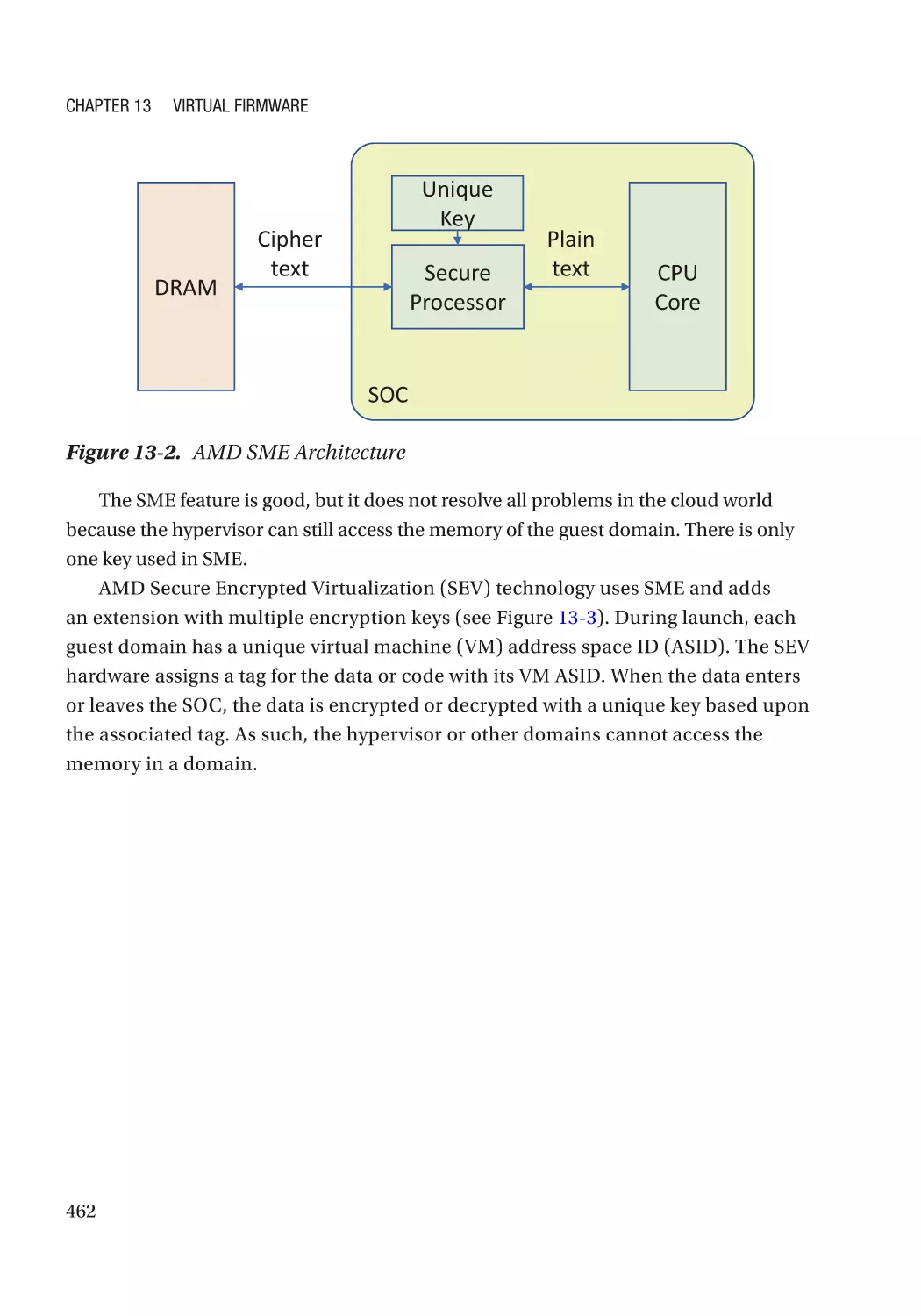
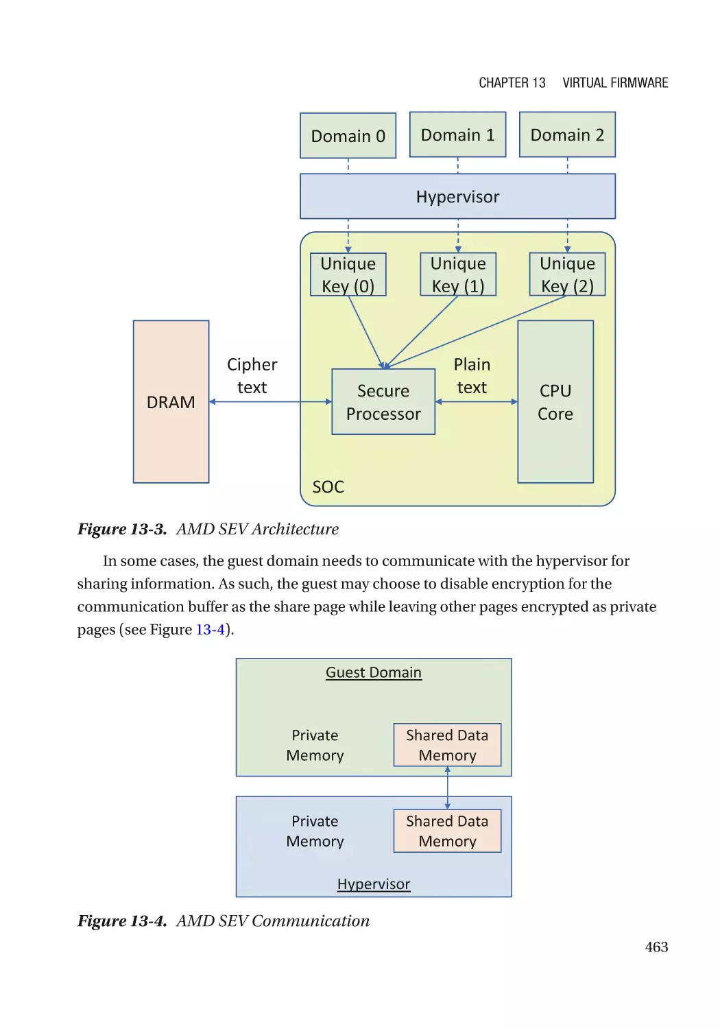
Case Study��������������������������������������������������������������������������������������������������������������������������� 461
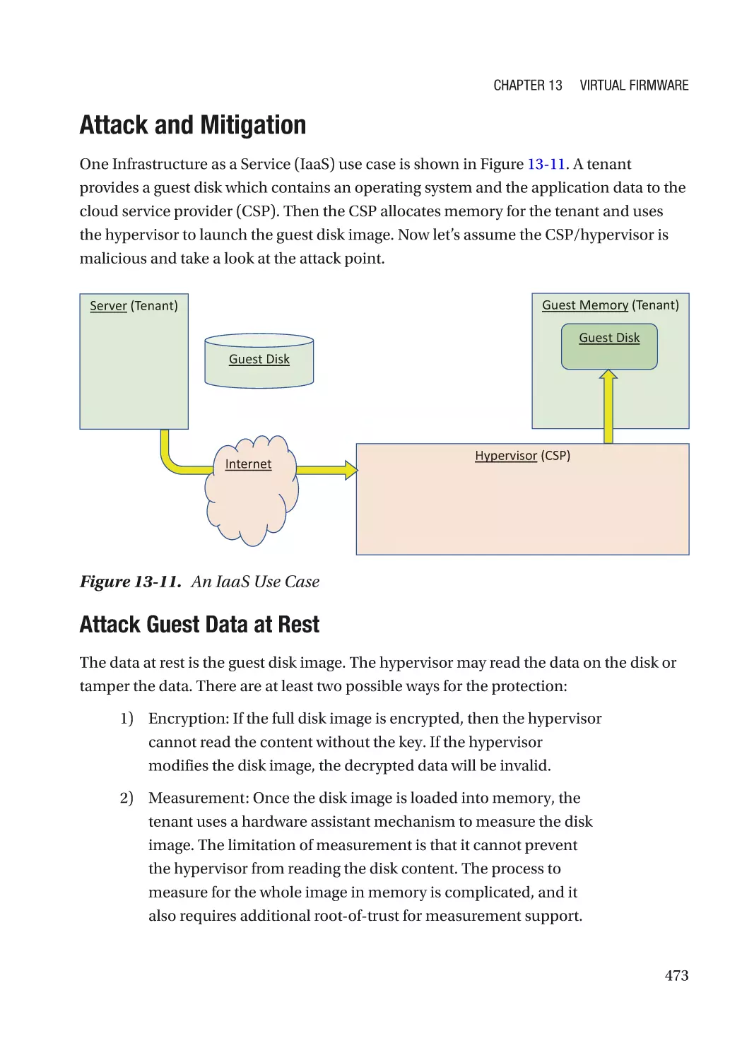
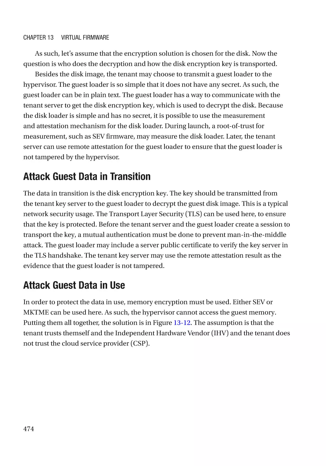
Attack and Mitigation���������������������������������������������������������������������������������������������������������� 473
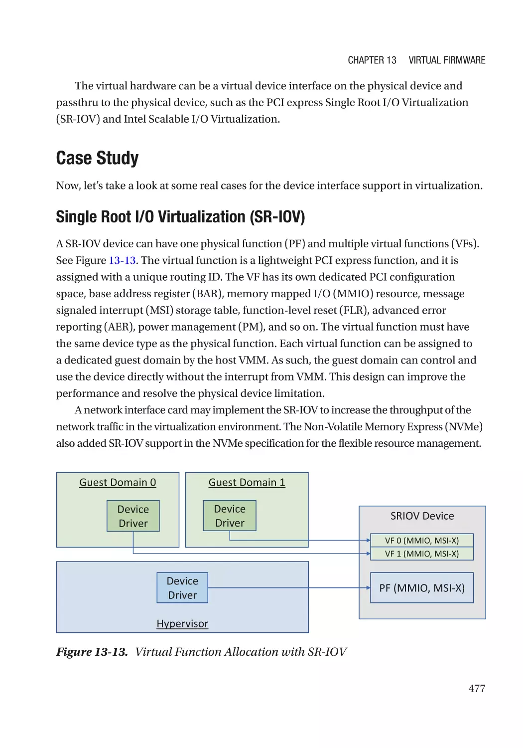
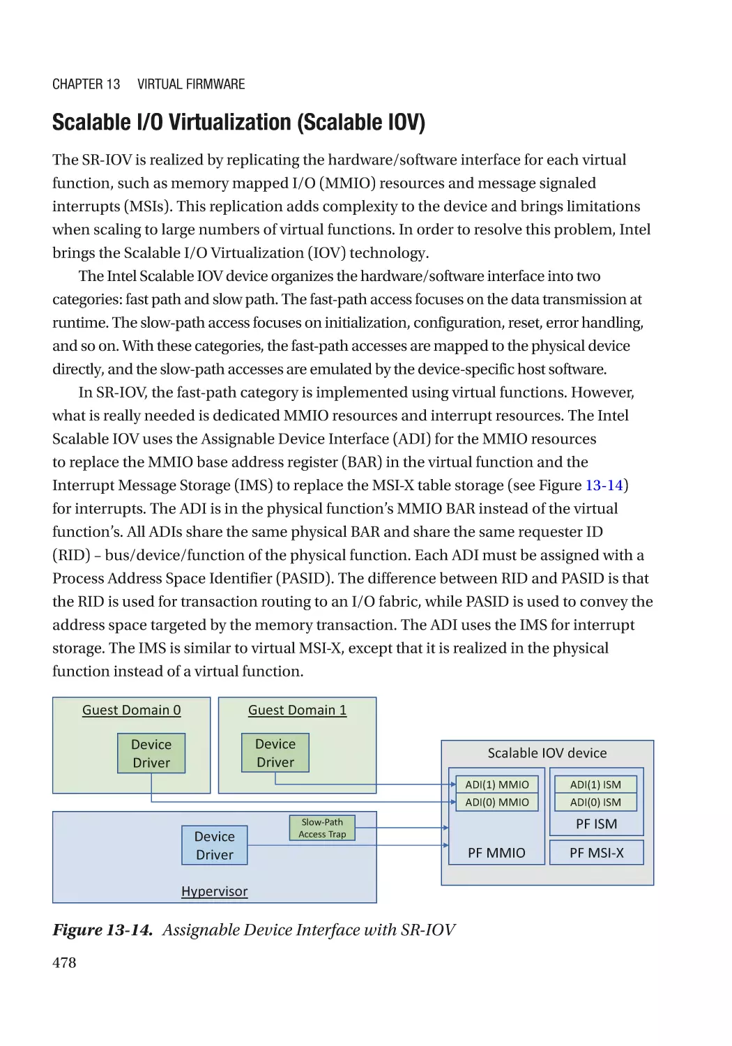
Device Interface������������������������������������������������������������������������������������������������������������������������ 476
Case Study��������������������������������������������������������������������������������������������������������������������������� 477
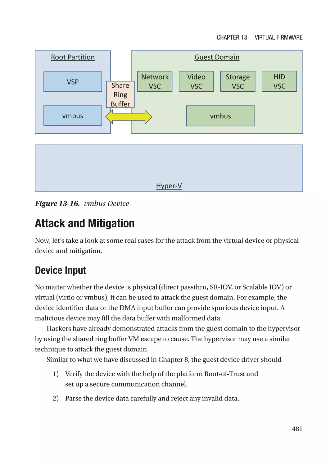
Attack and Mitigation���������������������������������������������������������������������������������������������������������� 481
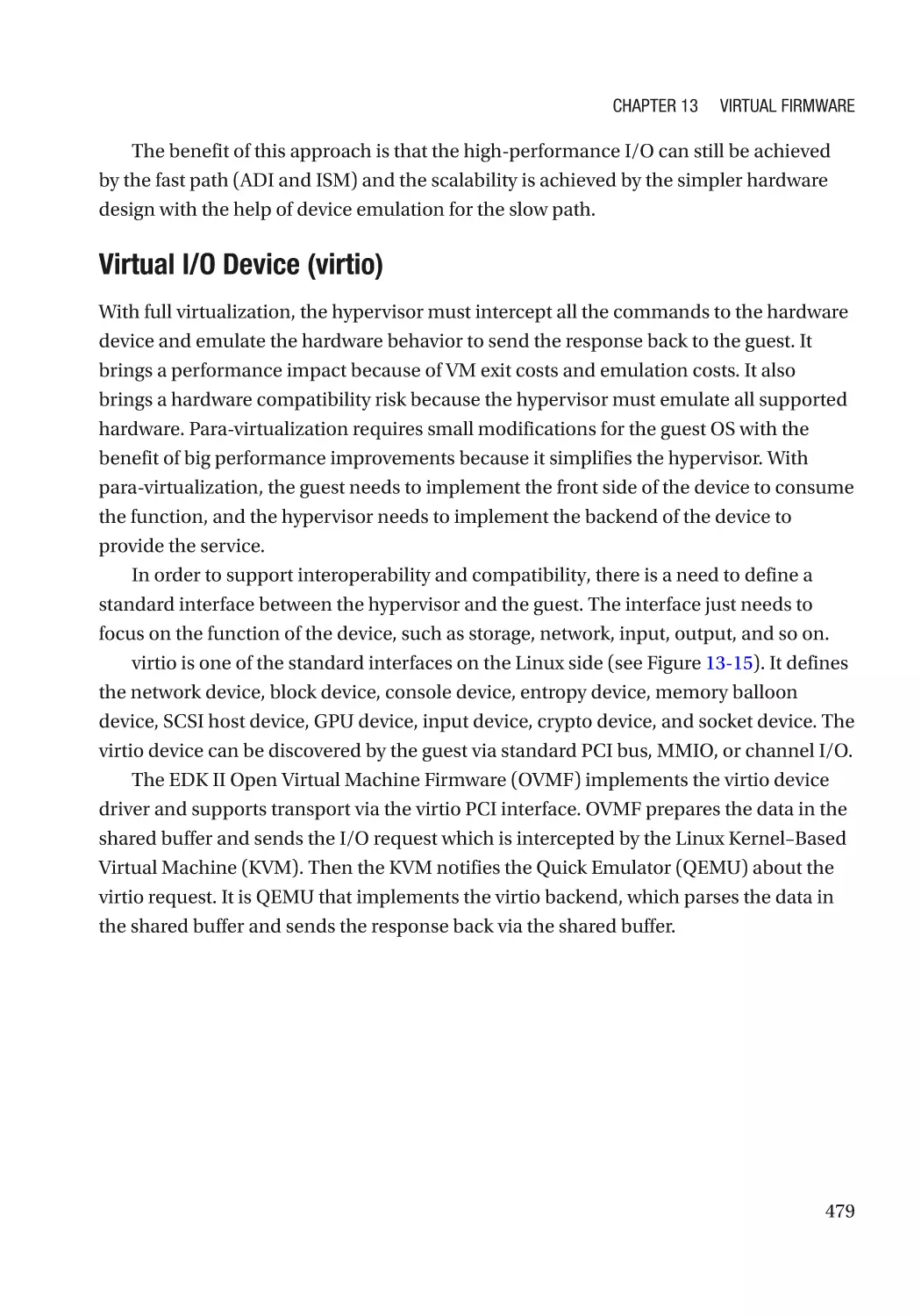
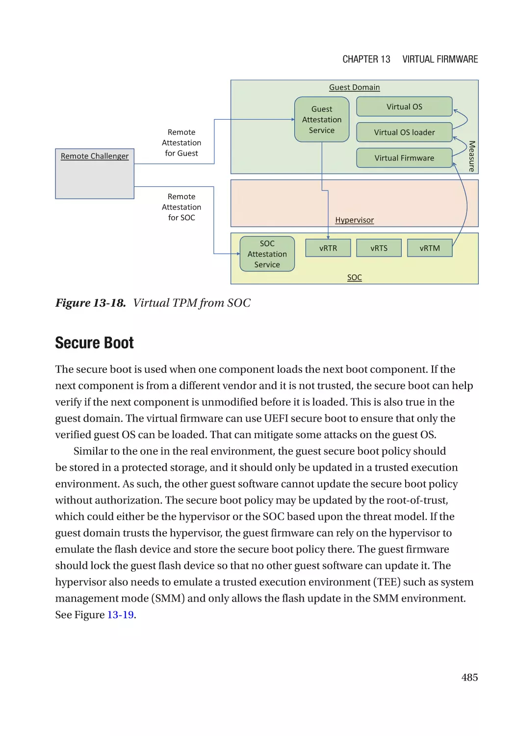
Special Feature������������������������������������������������������������������������������������������������������������������������� 482
Case Study��������������������������������������������������������������������������������������������������������������������������� 483
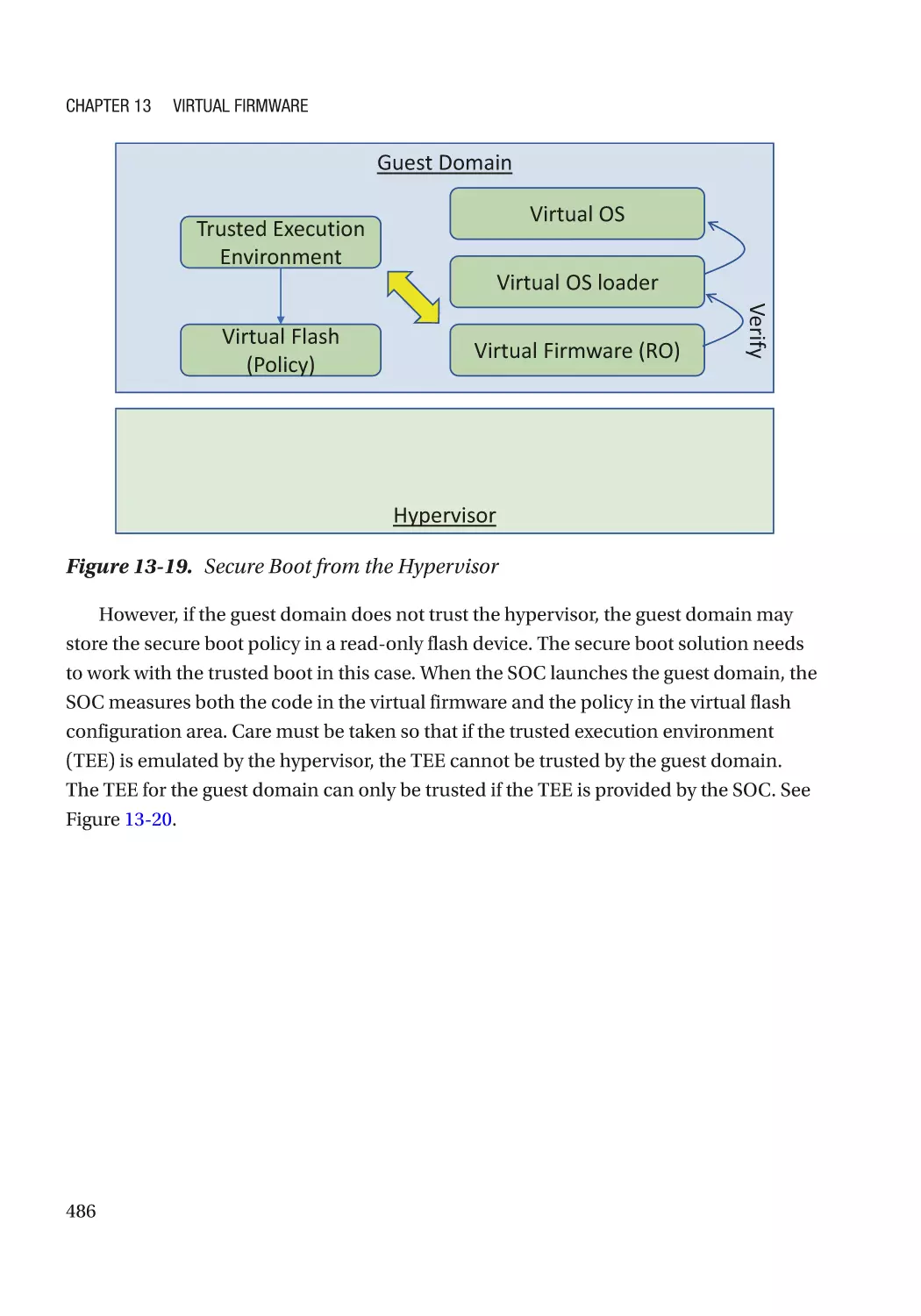
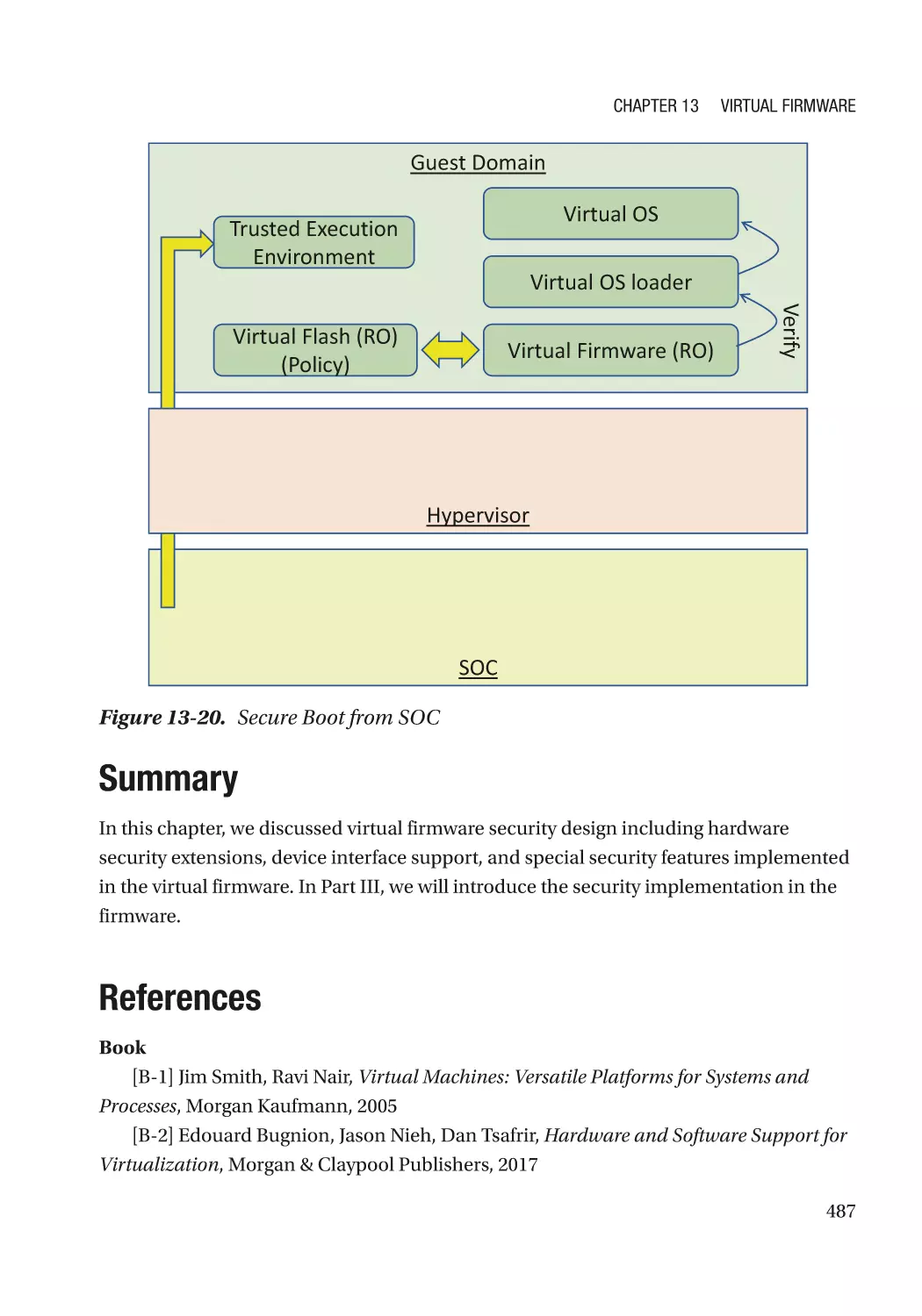
Summary���������������������������������������������������������������������������������������������������������������������������������� 487
References�������������������������������������������������������������������������������������������������������������������������������� 487
xii
Table of Contents
Part III: Security Development�������������������������������������������������������������������� 493
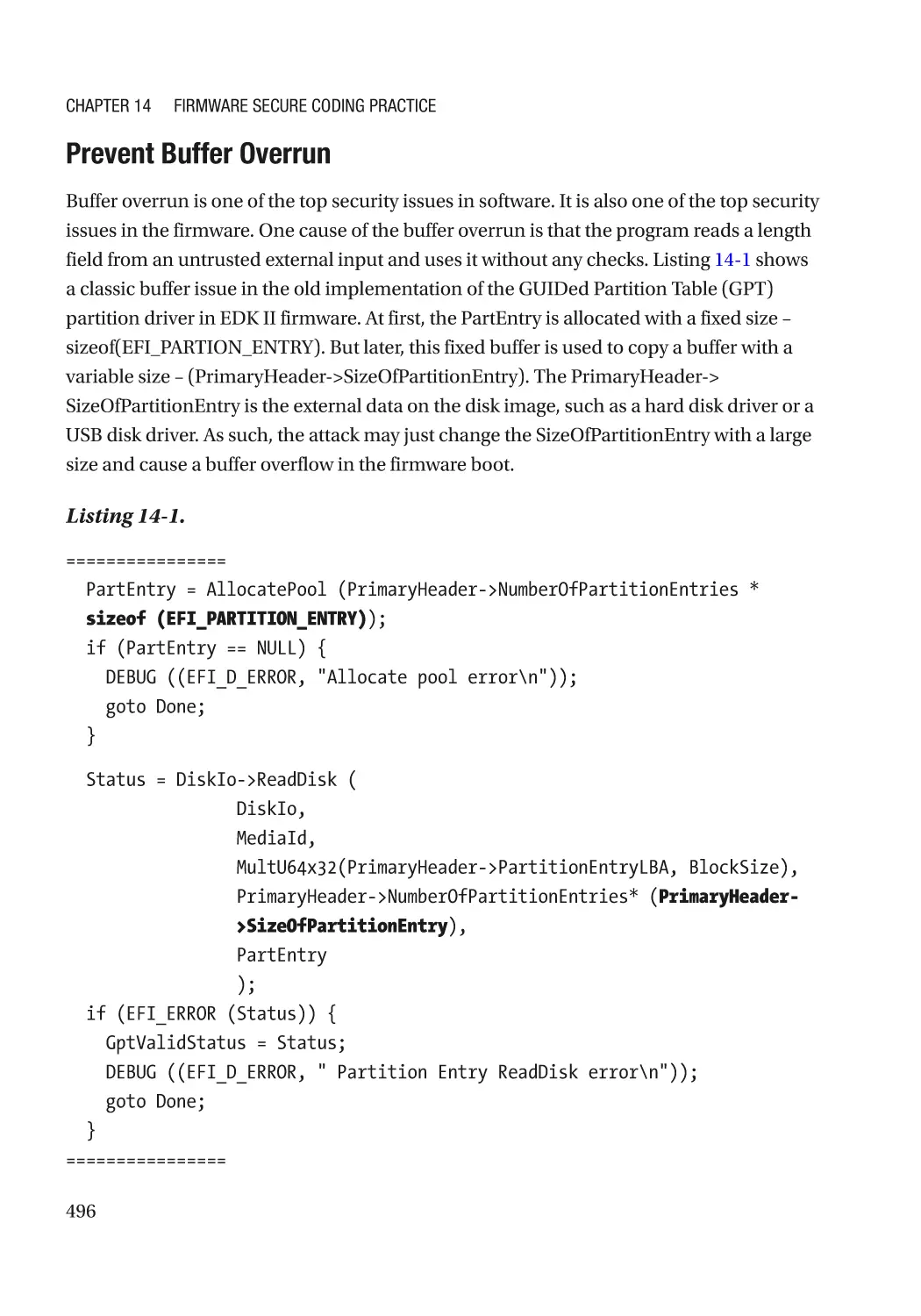
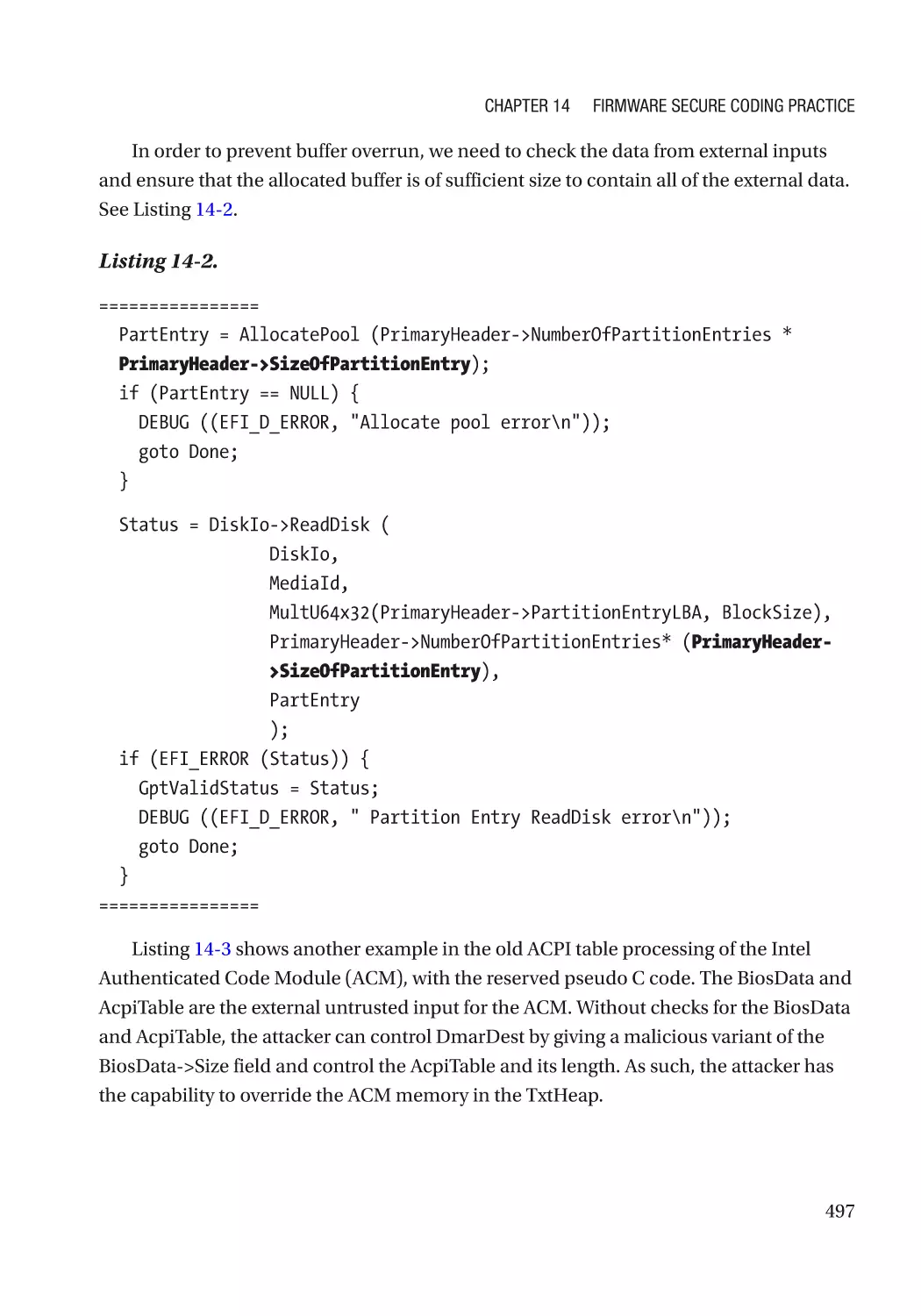
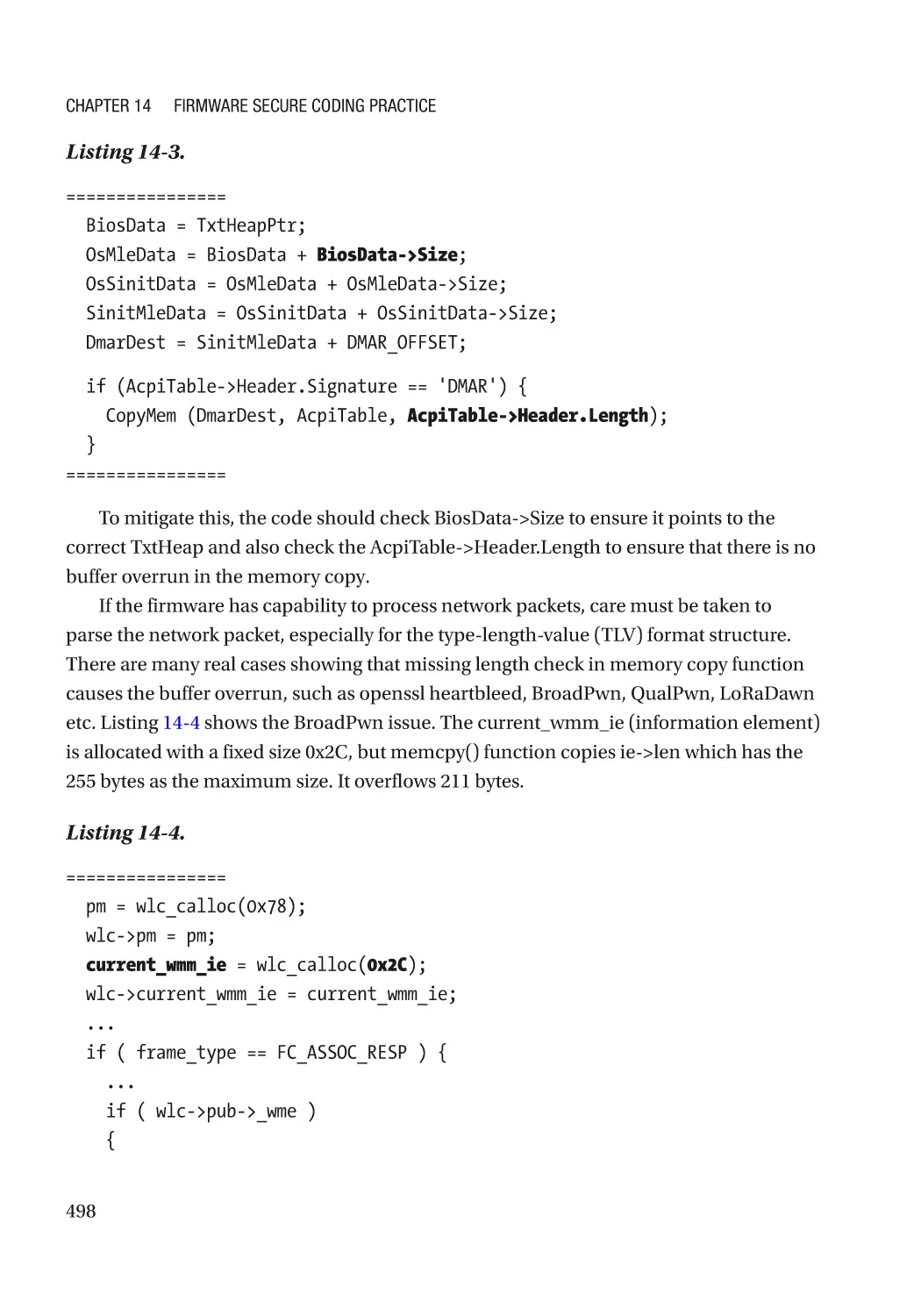
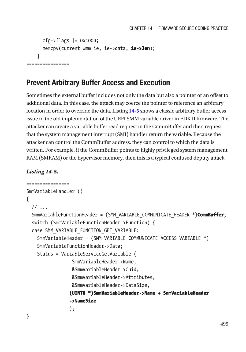
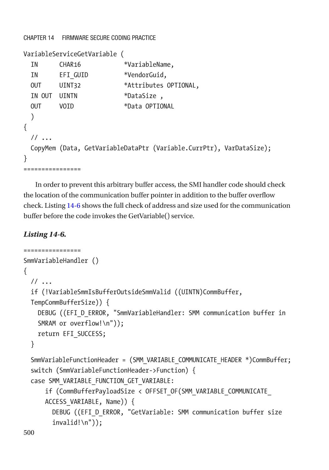
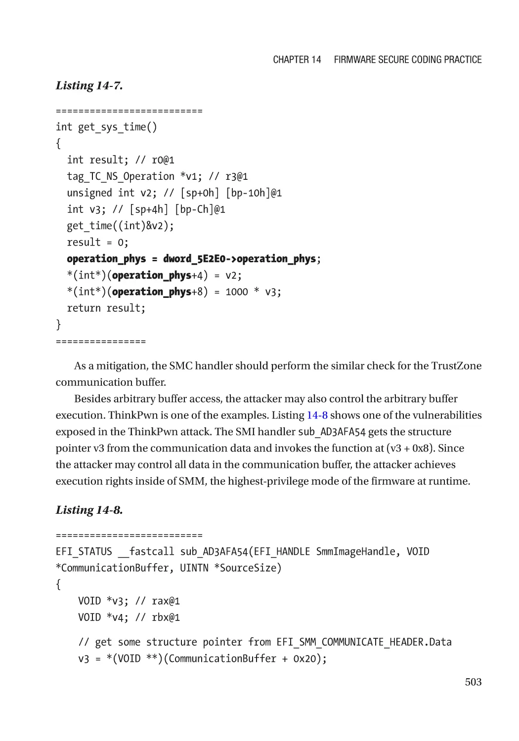
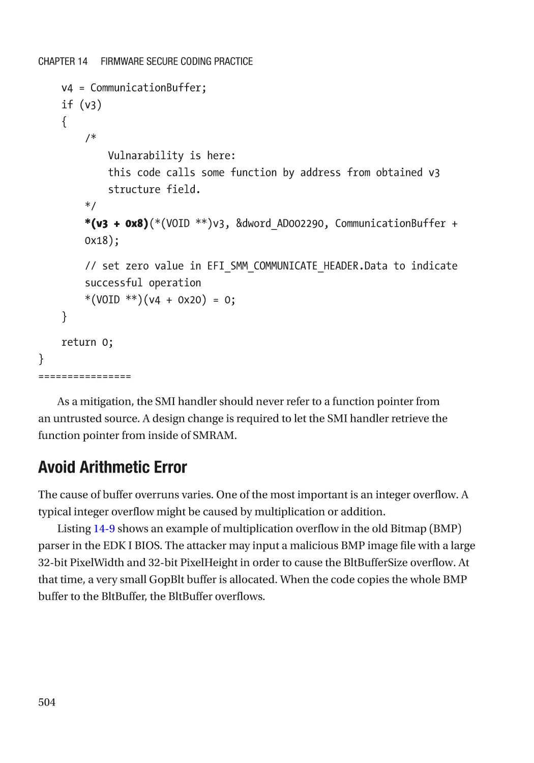
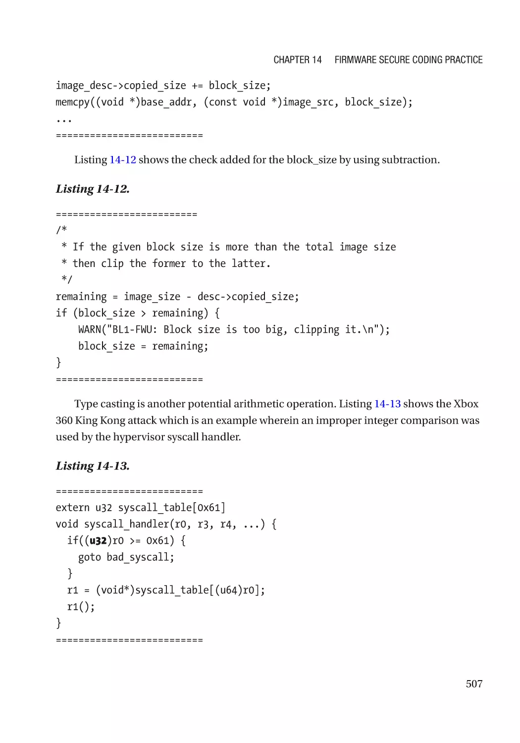
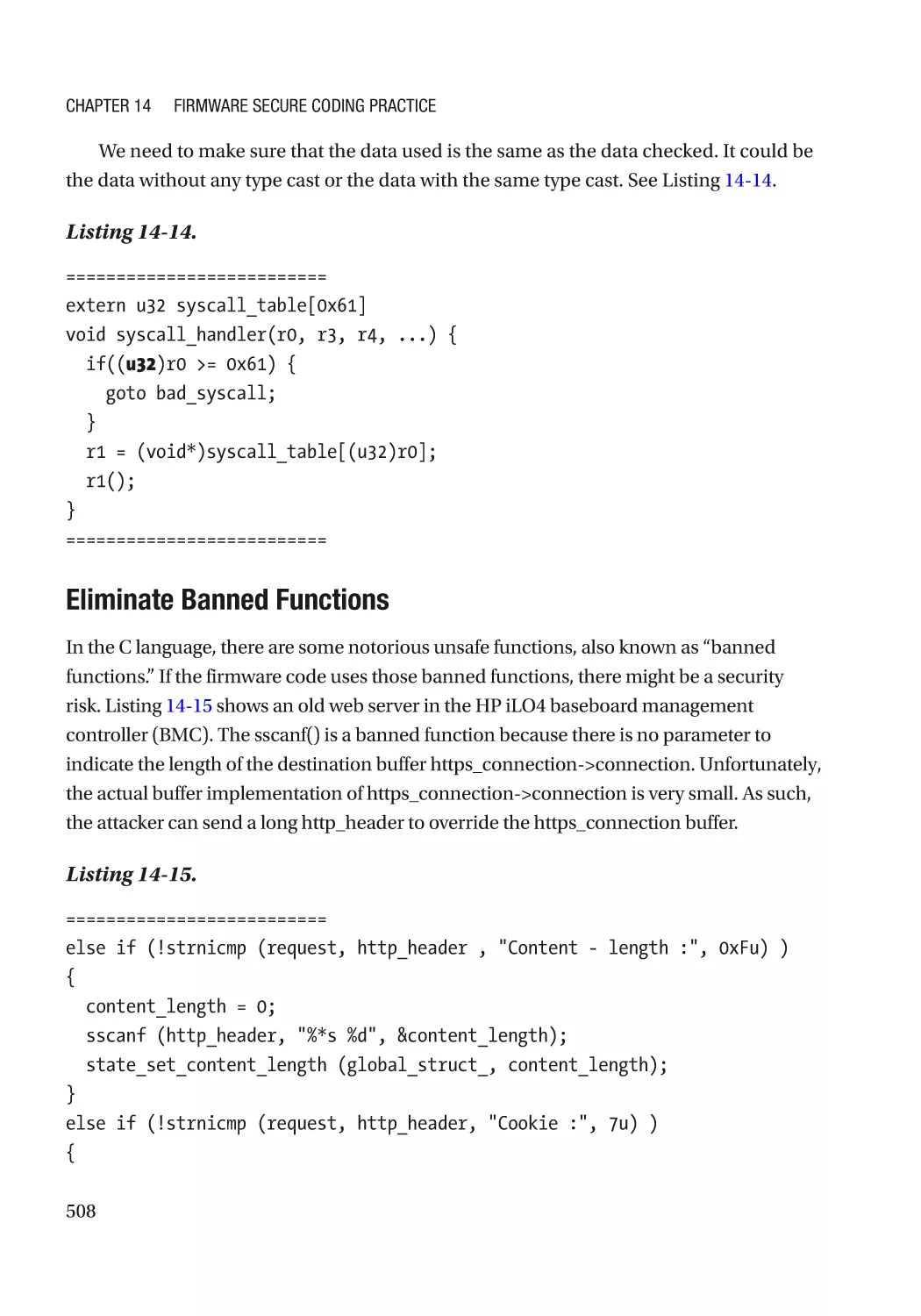
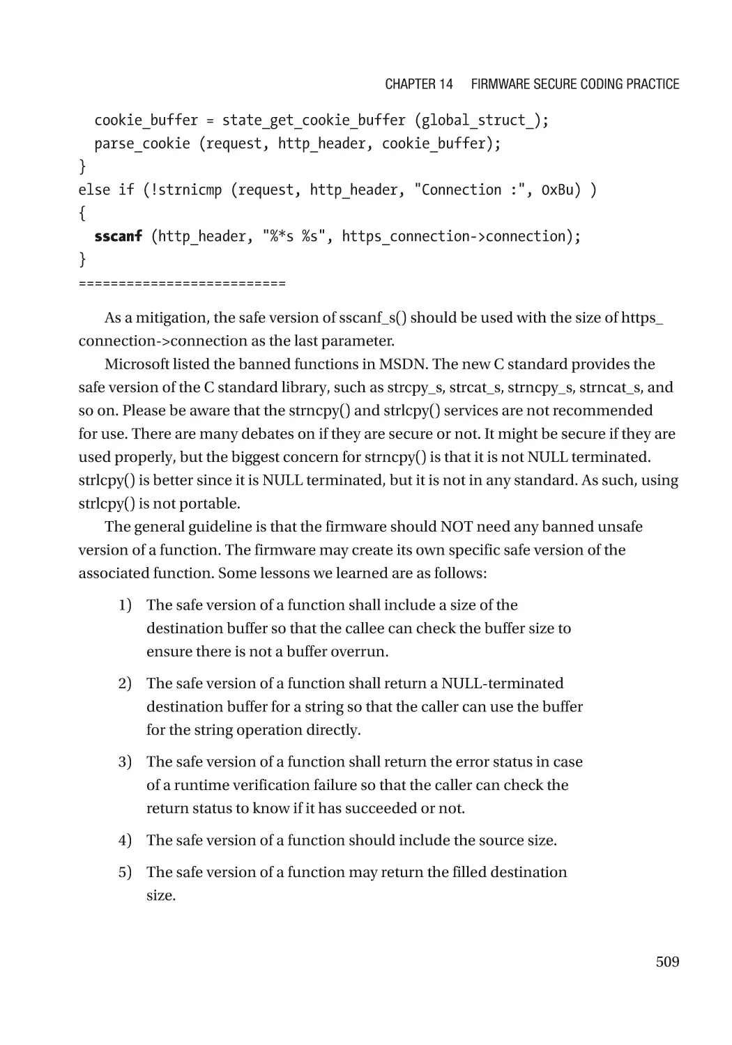
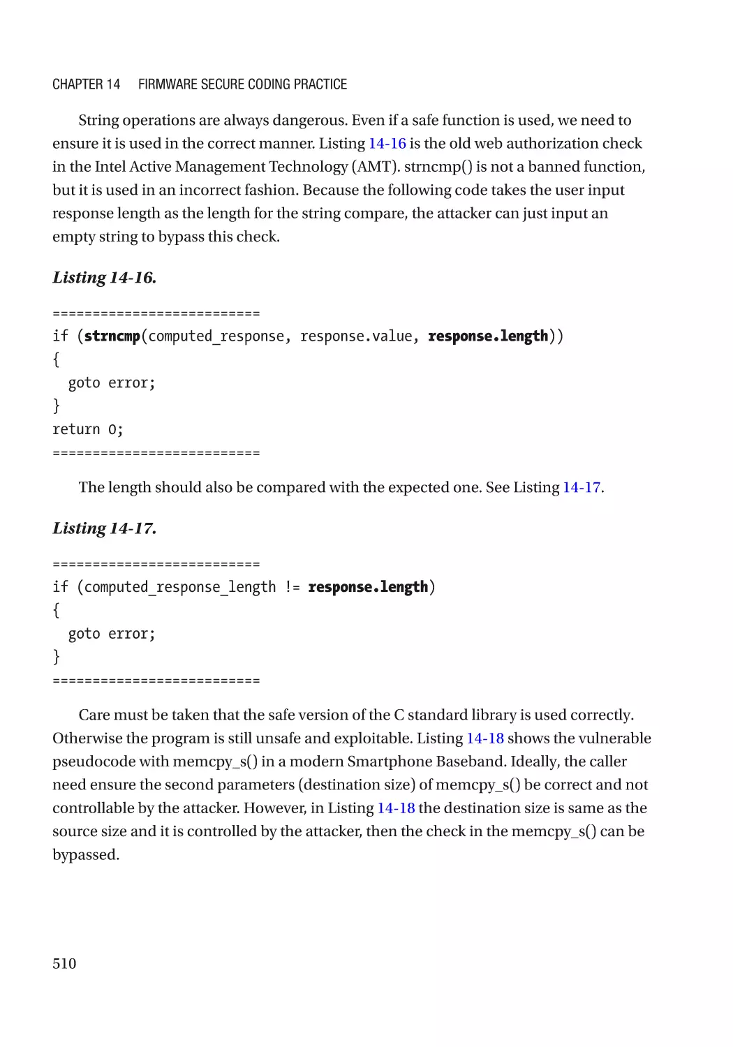
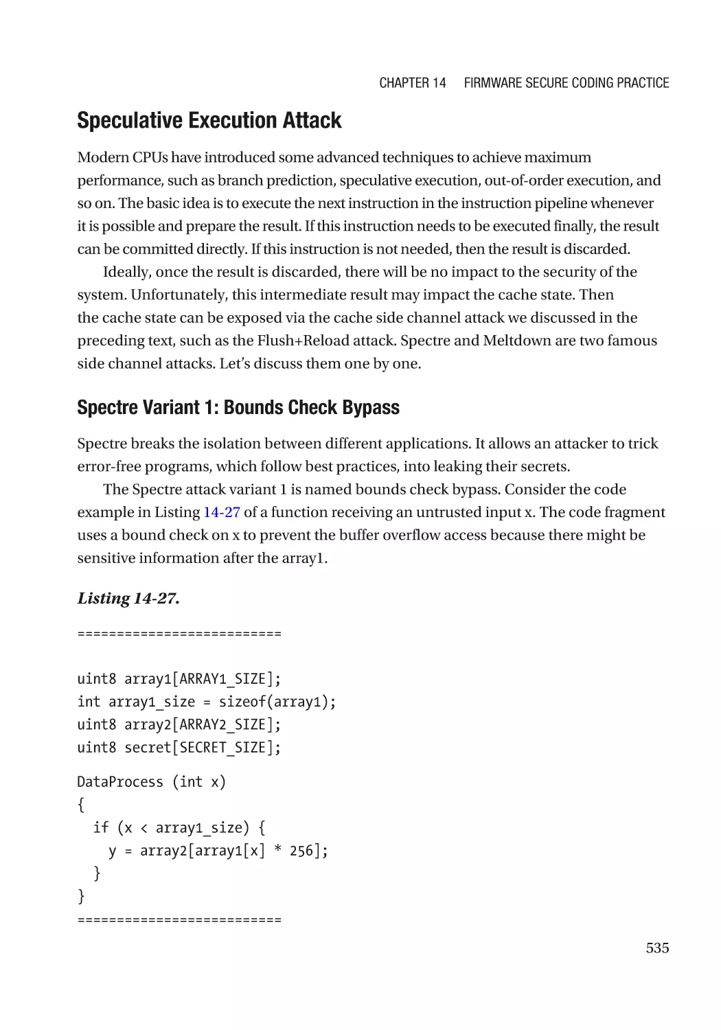
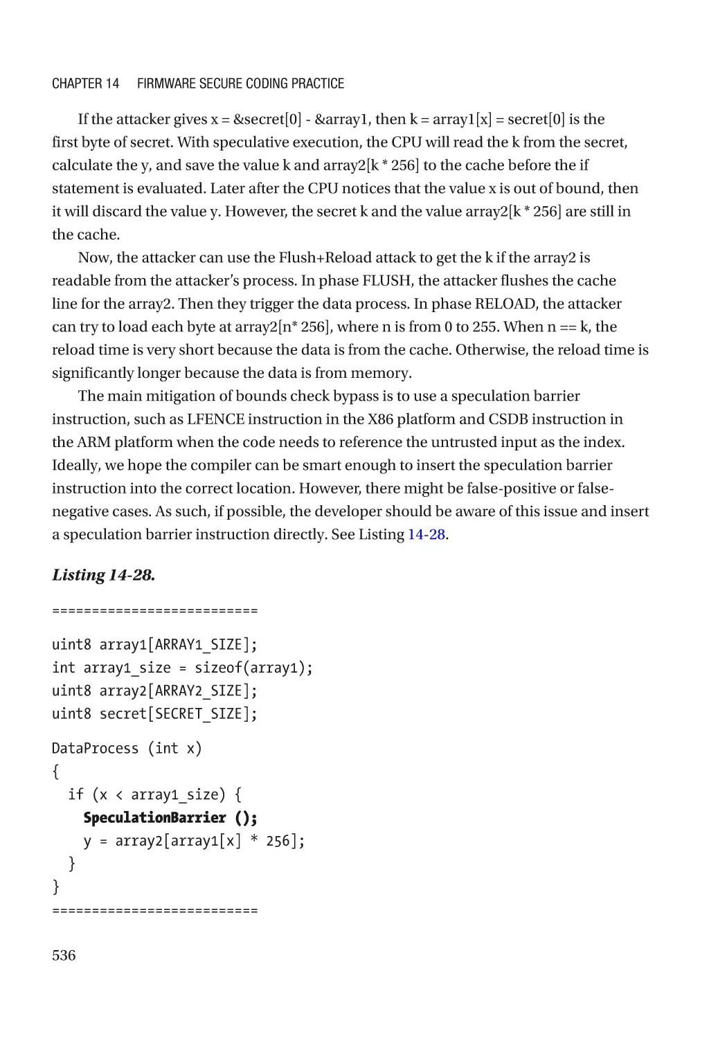
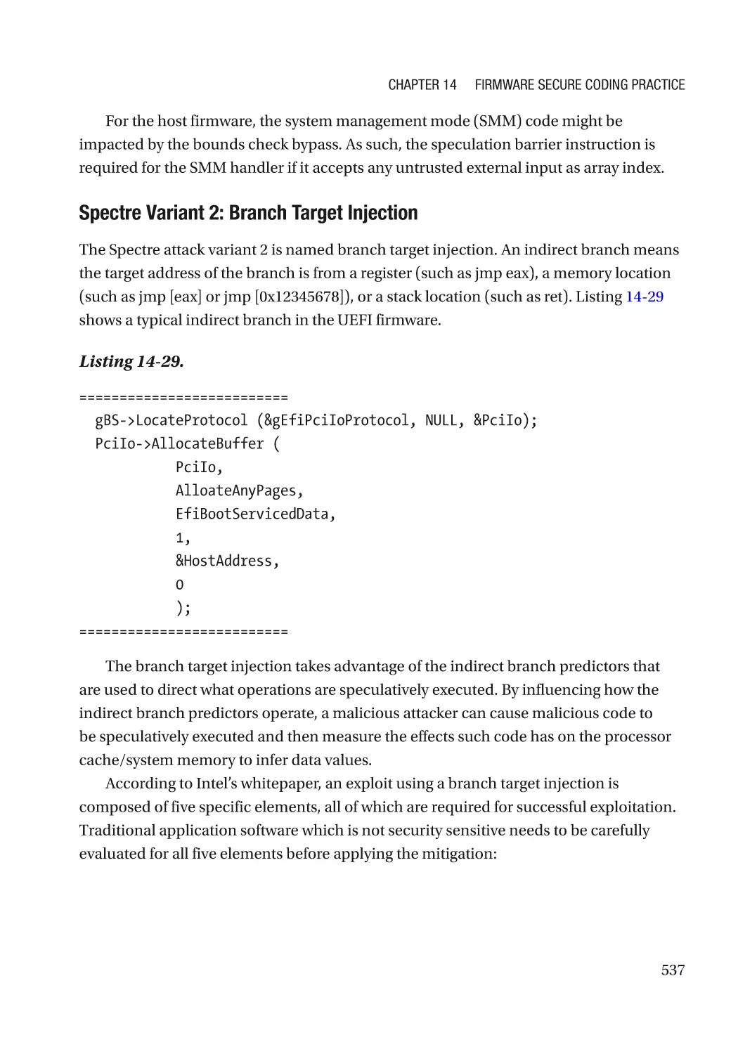
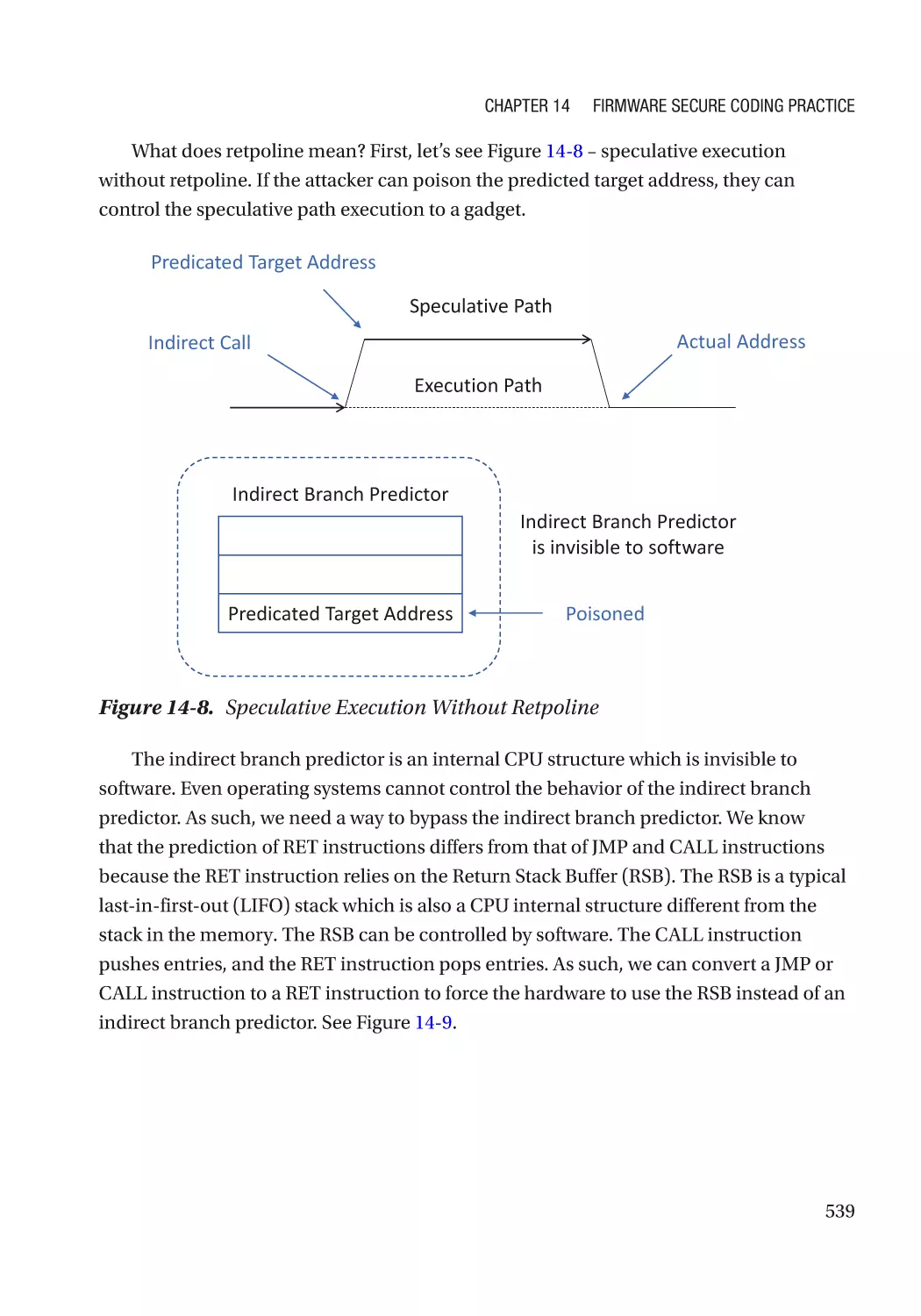
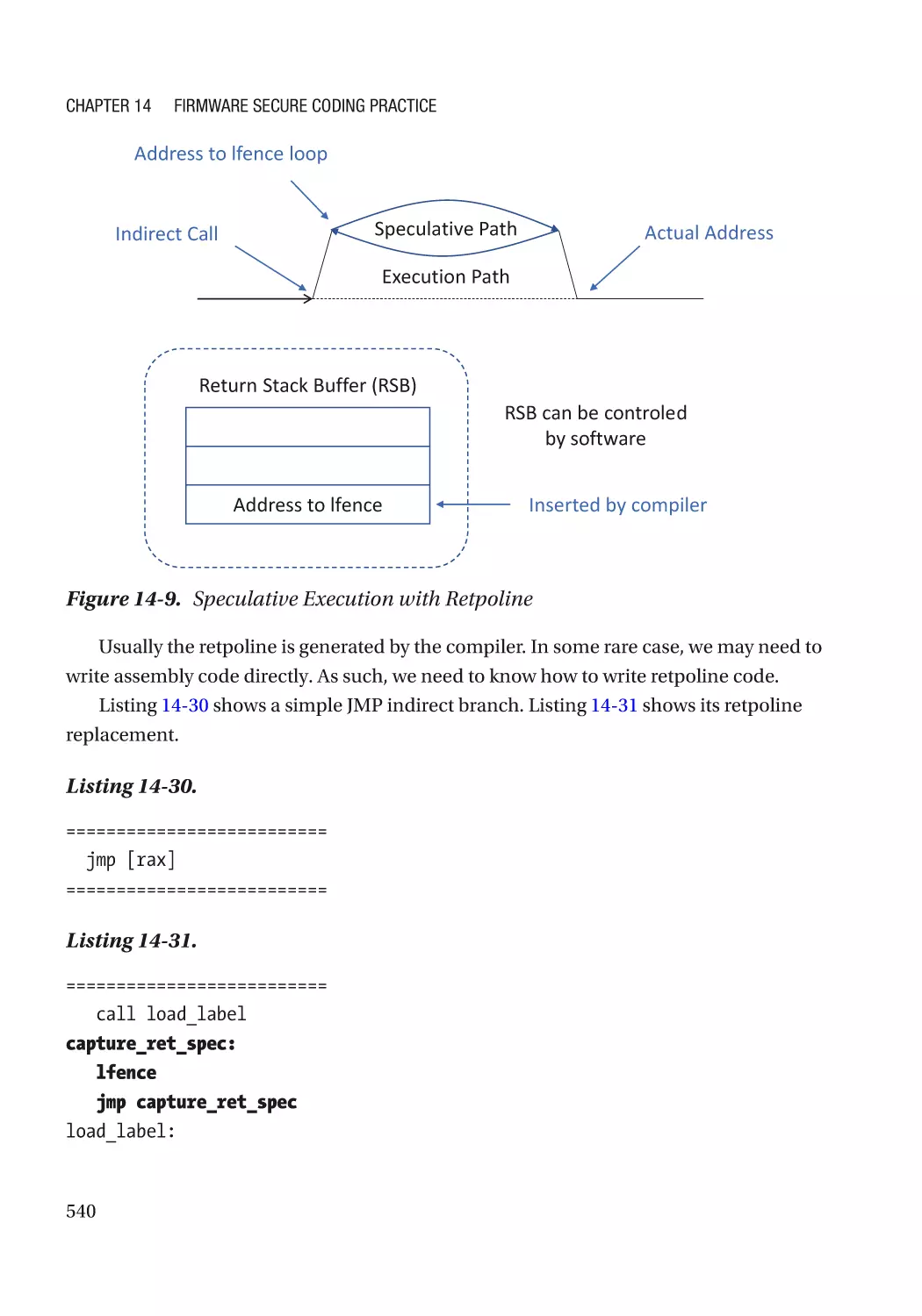
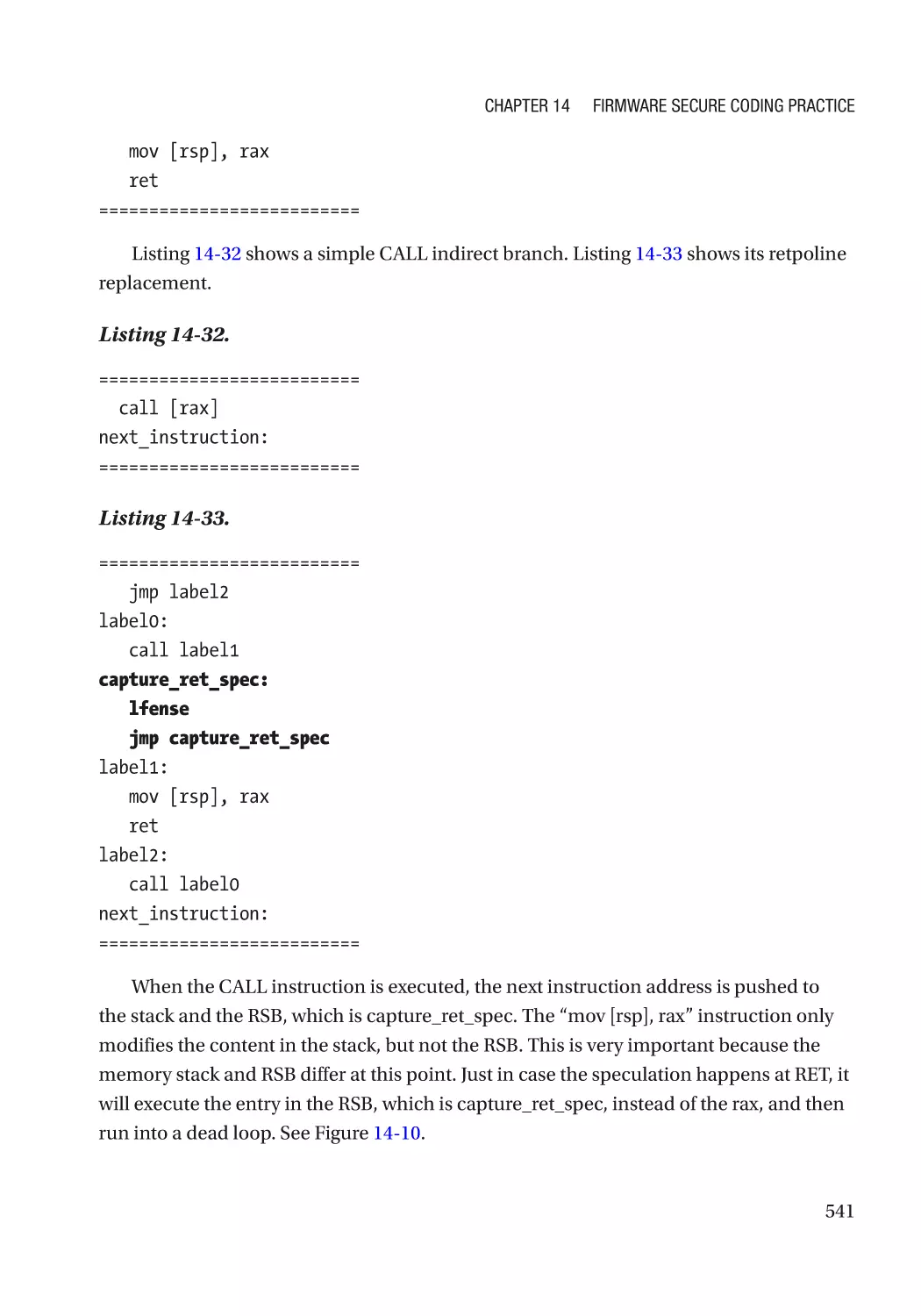
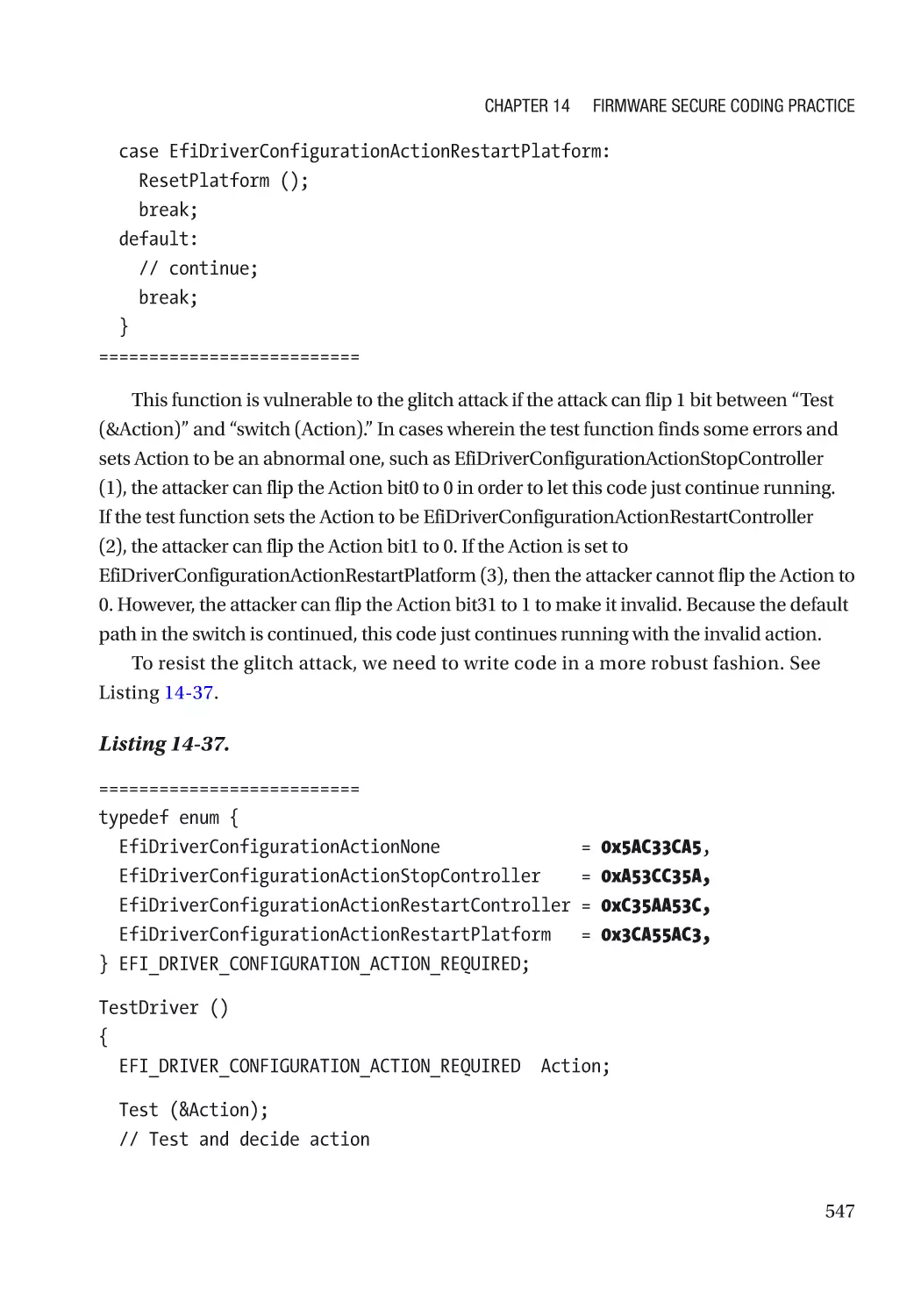
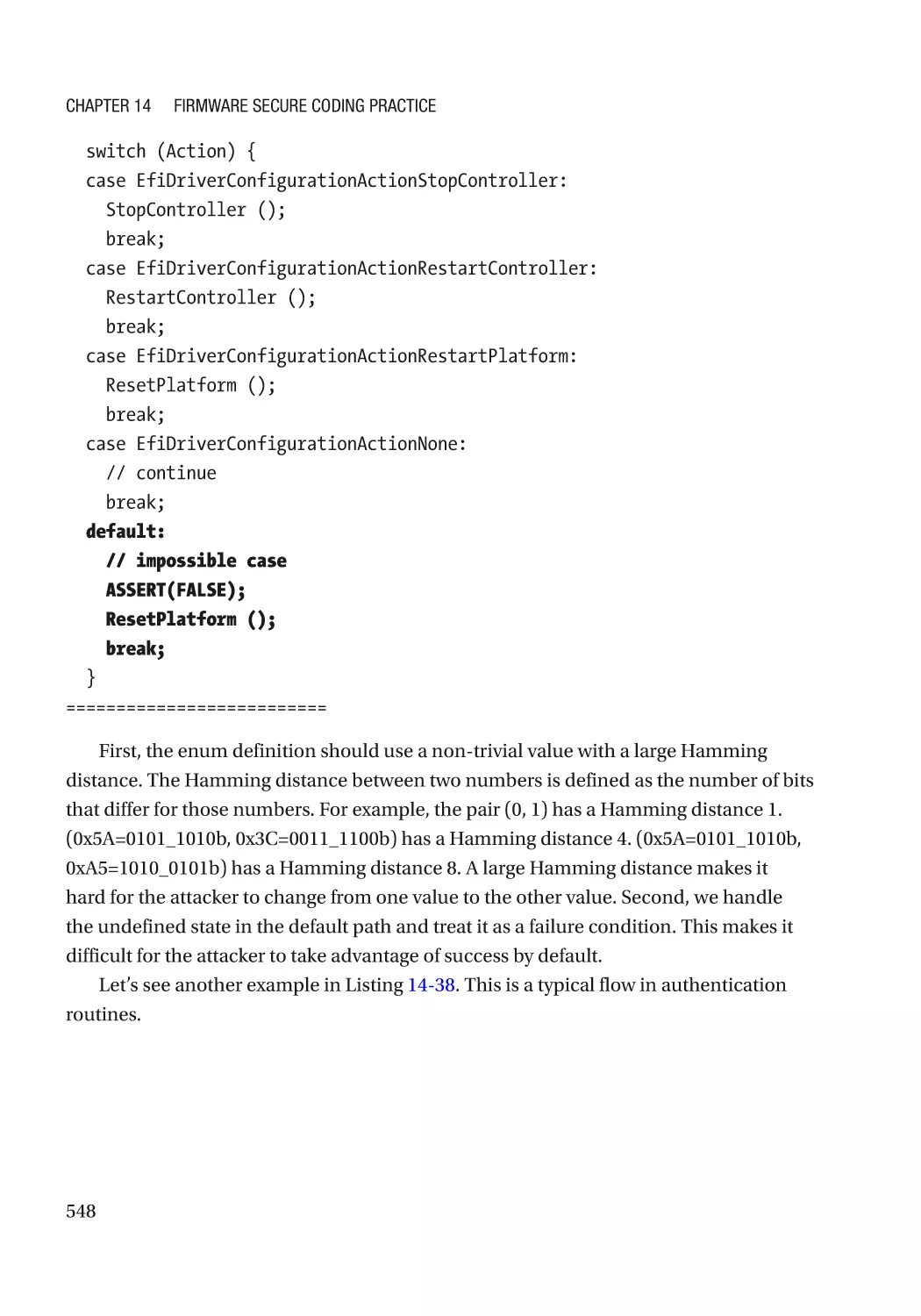
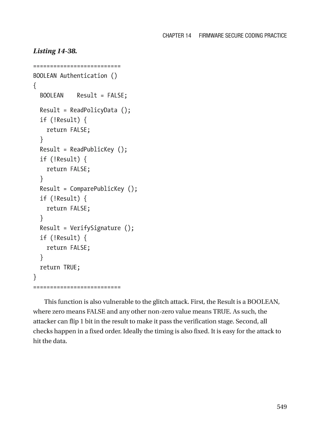
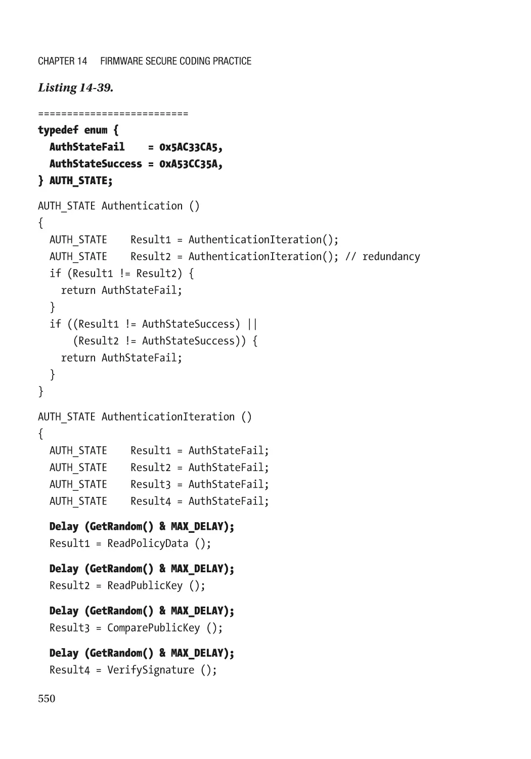
Chapter 14: Firmware Secure Coding Practice����������������������������������������������������� 495
Basic Security Practice������������������������������������������������������������������������������������������������������������� 495
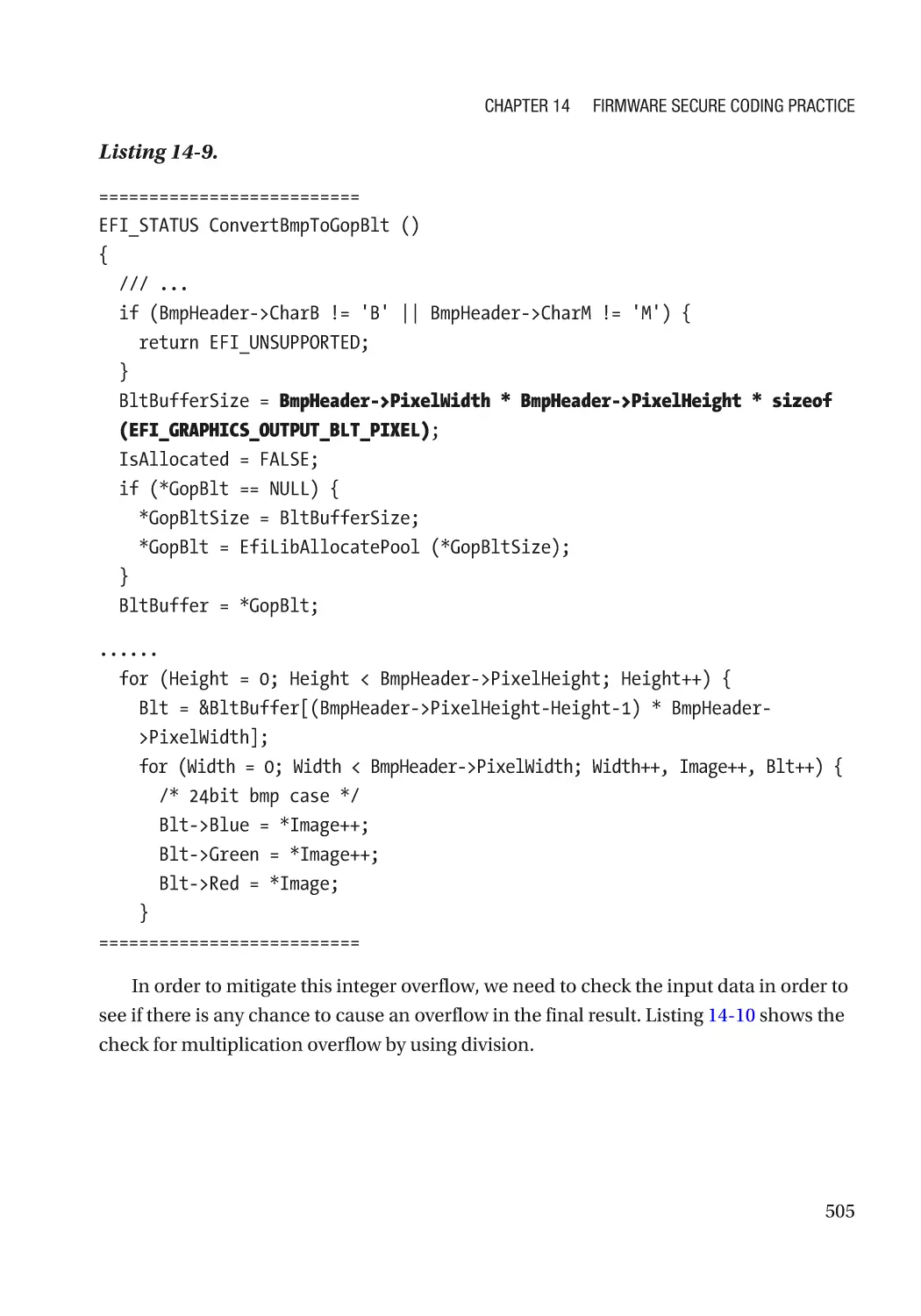
Secure Coding Practice������������������������������������������������������������������������������������������������������� 495
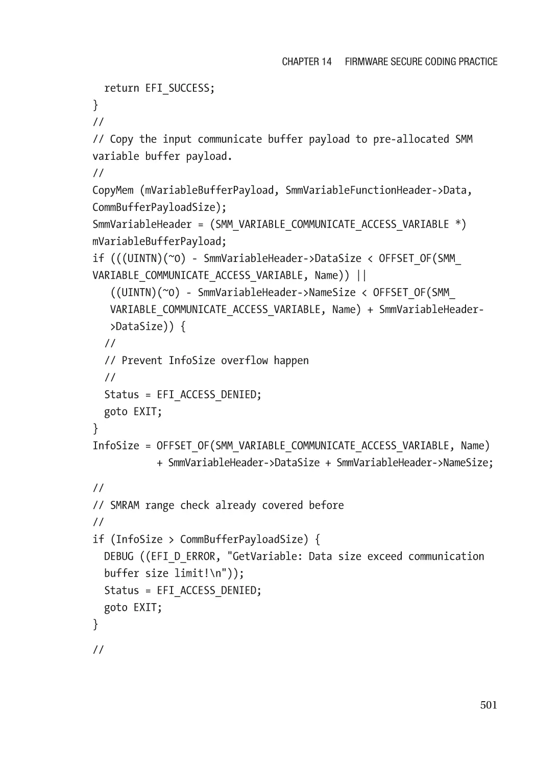
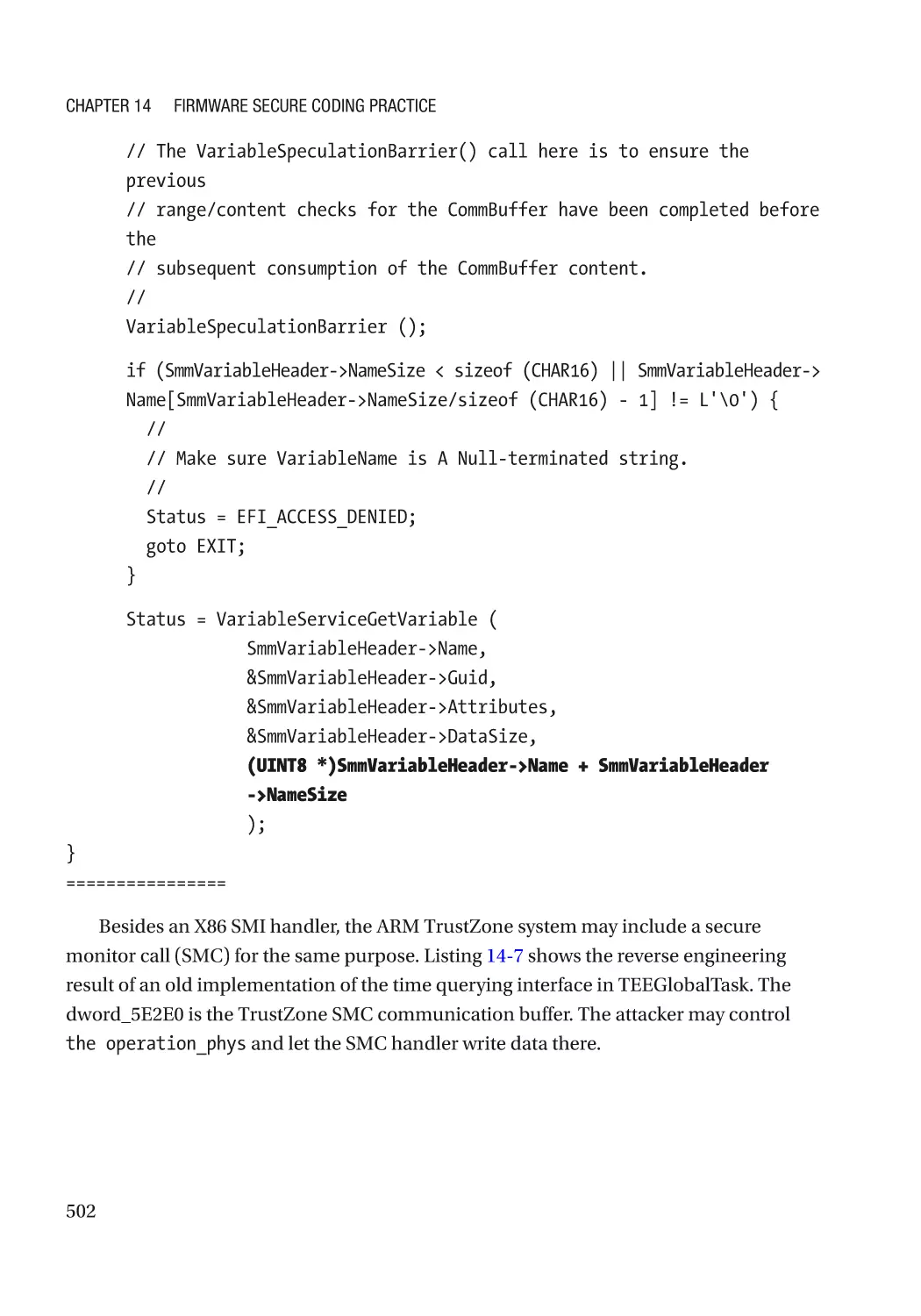
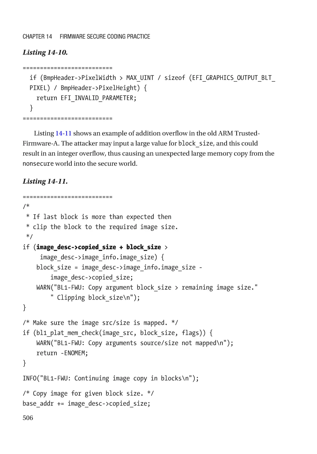
Secure Design Practice������������������������������������������������������������������������������������������������������� 517
Boot Firmware Secure Design Practice������������������������������������������������������������������������������� 522
Advanced Secure Coding Topic������������������������������������������������������������������������������������������������� 525
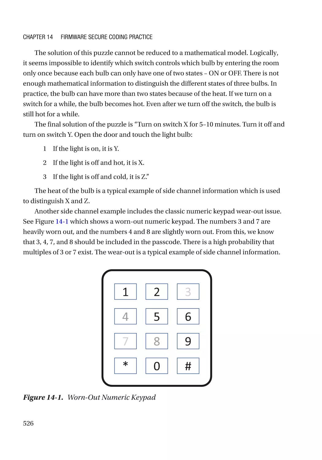
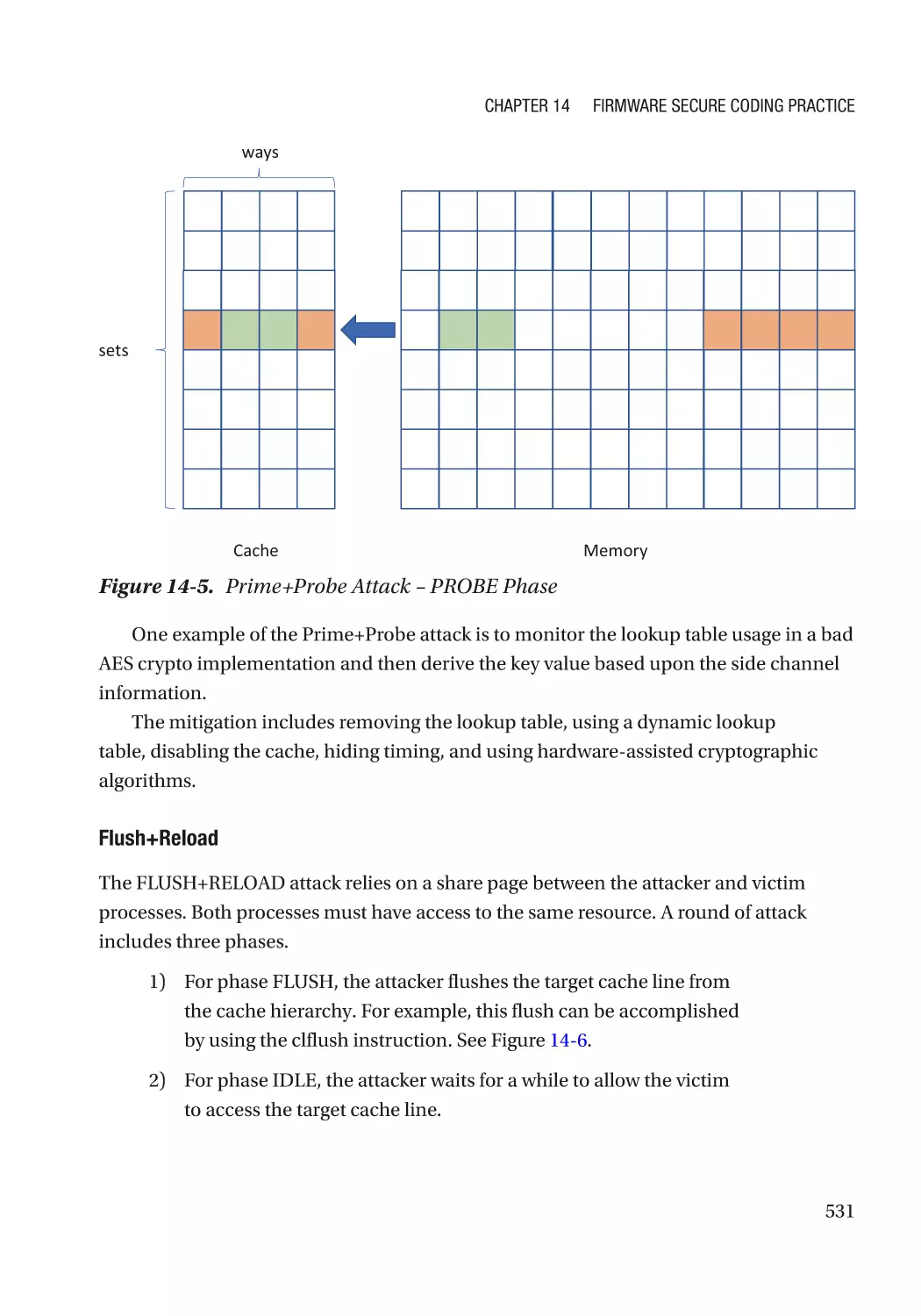
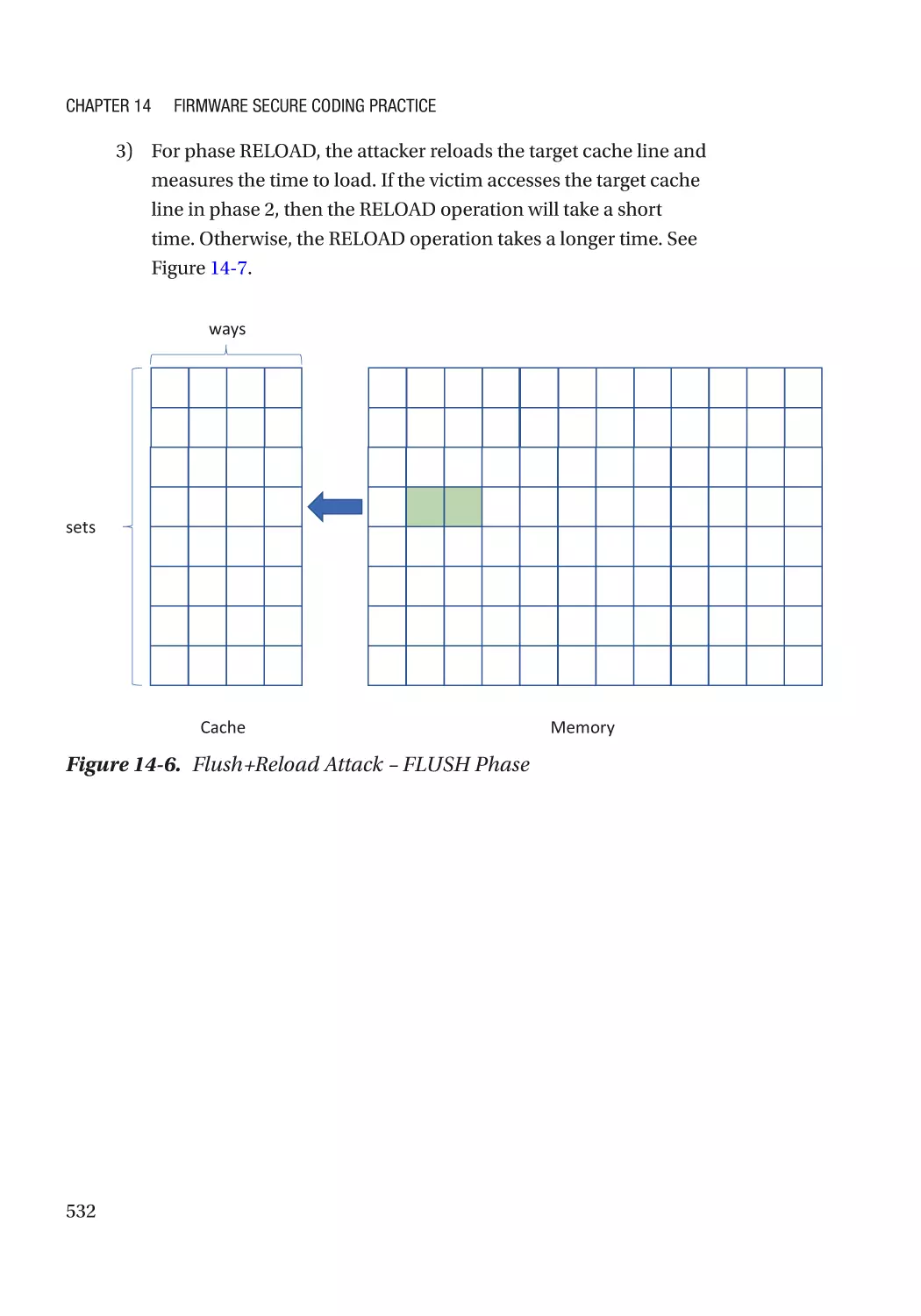
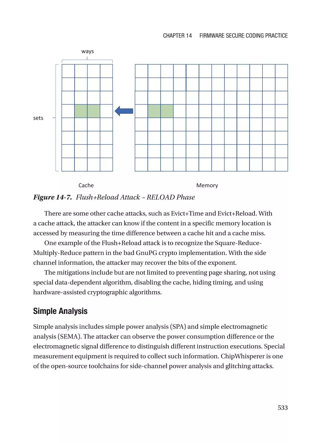
Side Channel Attack������������������������������������������������������������������������������������������������������������ 525
Fault Injection���������������������������������������������������������������������������������������������������������������������� 545
High-Risk Area in Firmware������������������������������������������������������������������������������������������������������ 551
External Input���������������������������������������������������������������������������������������������������������������������� 552
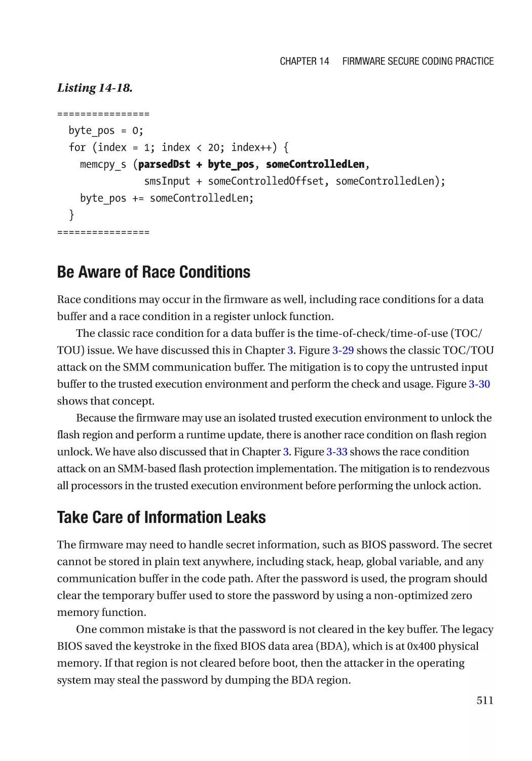
Race Condition�������������������������������������������������������������������������������������������������������������������� 553
Hardware Input�������������������������������������������������������������������������������������������������������������������� 554
Secret Handling������������������������������������������������������������������������������������������������������������������� 555
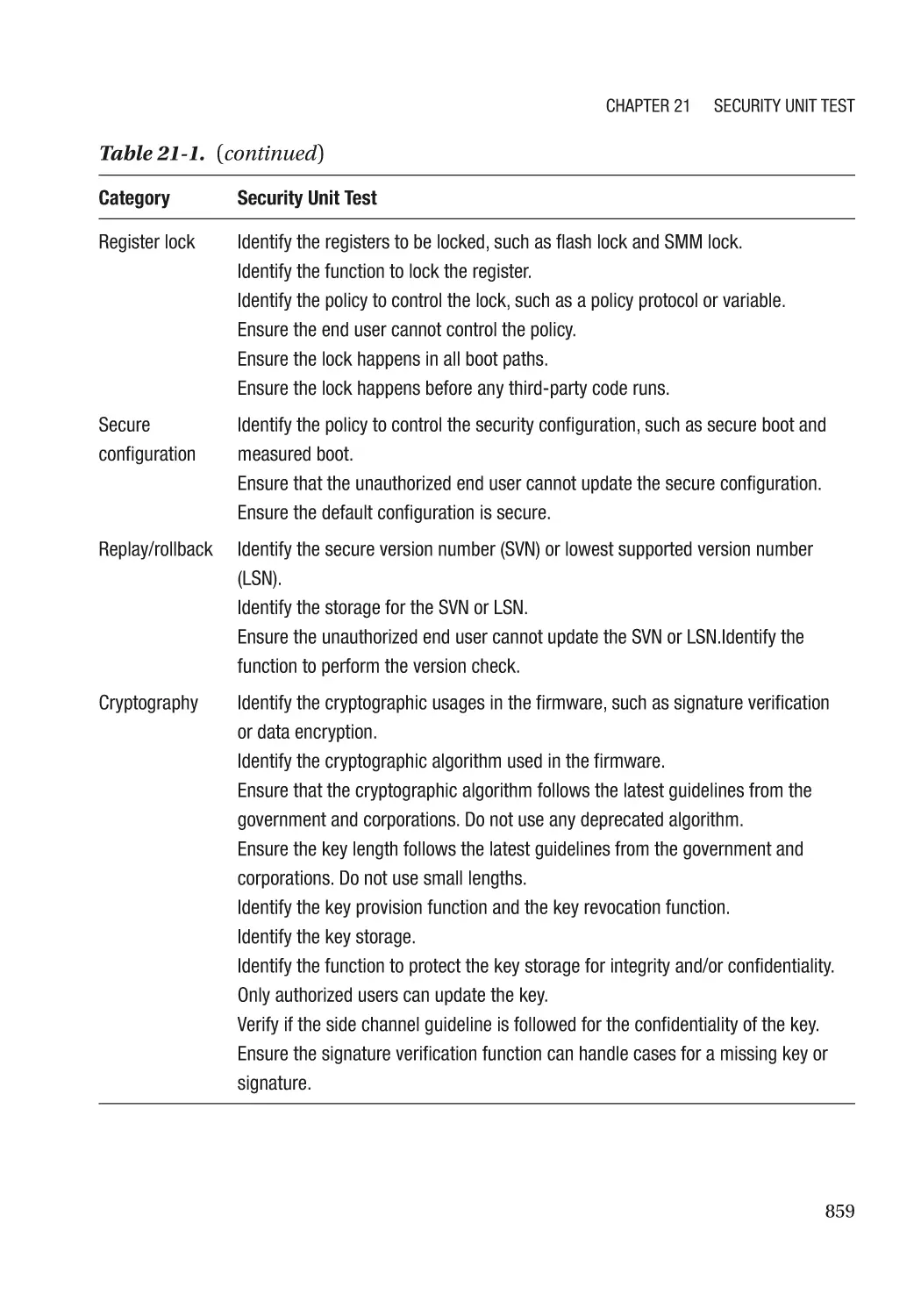
Register Lock����������������������������������������������������������������������������������������������������������������������� 556
Secure Configuration����������������������������������������������������������������������������������������������������������� 556
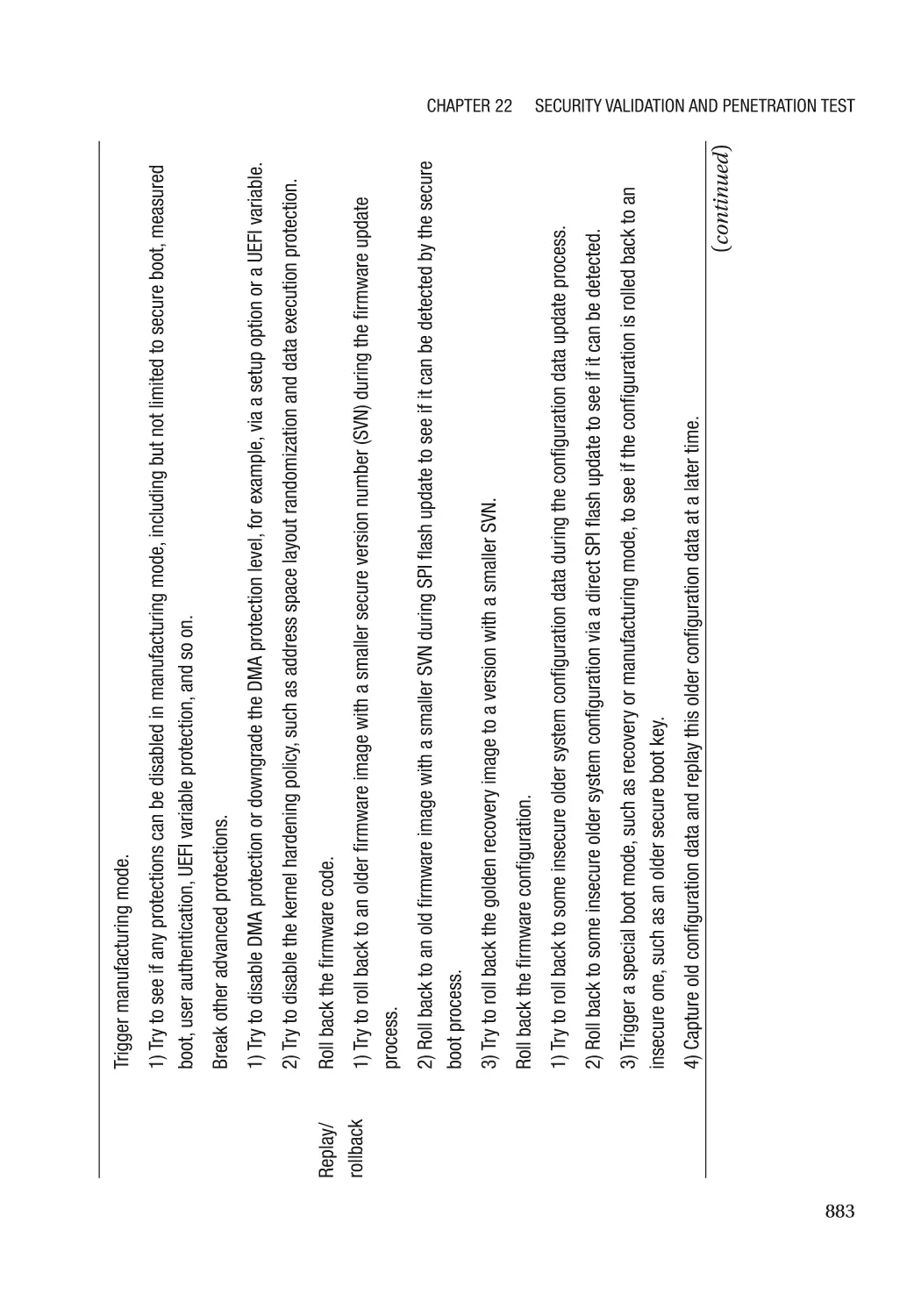
Replay/Rollback������������������������������������������������������������������������������������������������������������������� 557
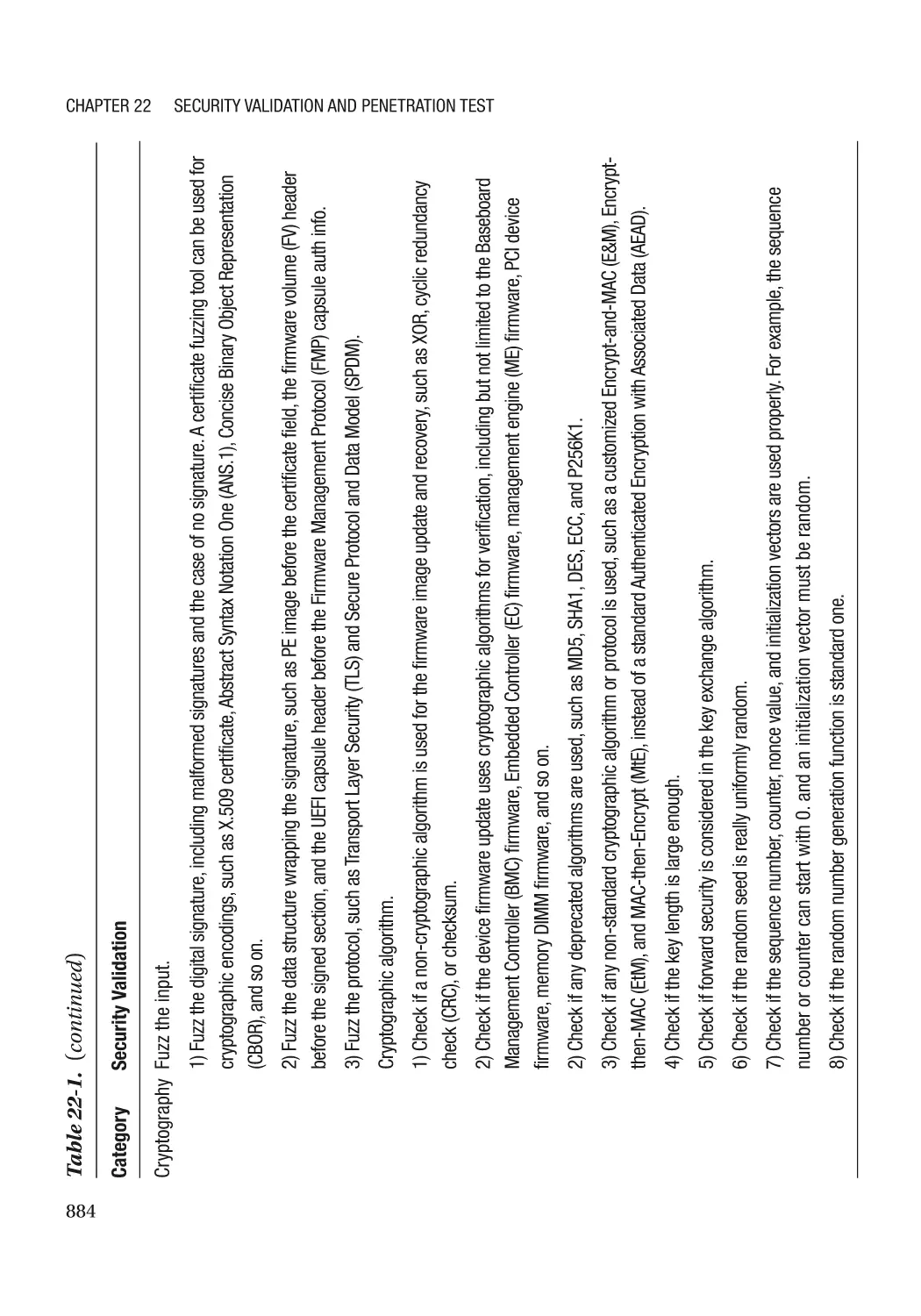
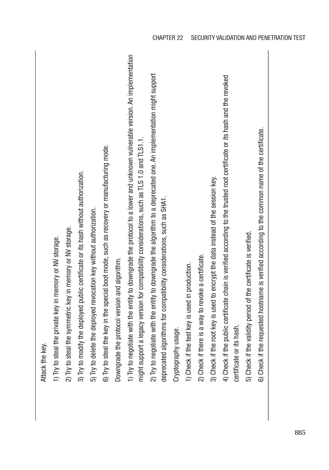
Cryptography����������������������������������������������������������������������������������������������������������������������� 558
Summary���������������������������������������������������������������������������������������������������������������������������������� 559
References�������������������������������������������������������������������������������������������������������������������������������� 559
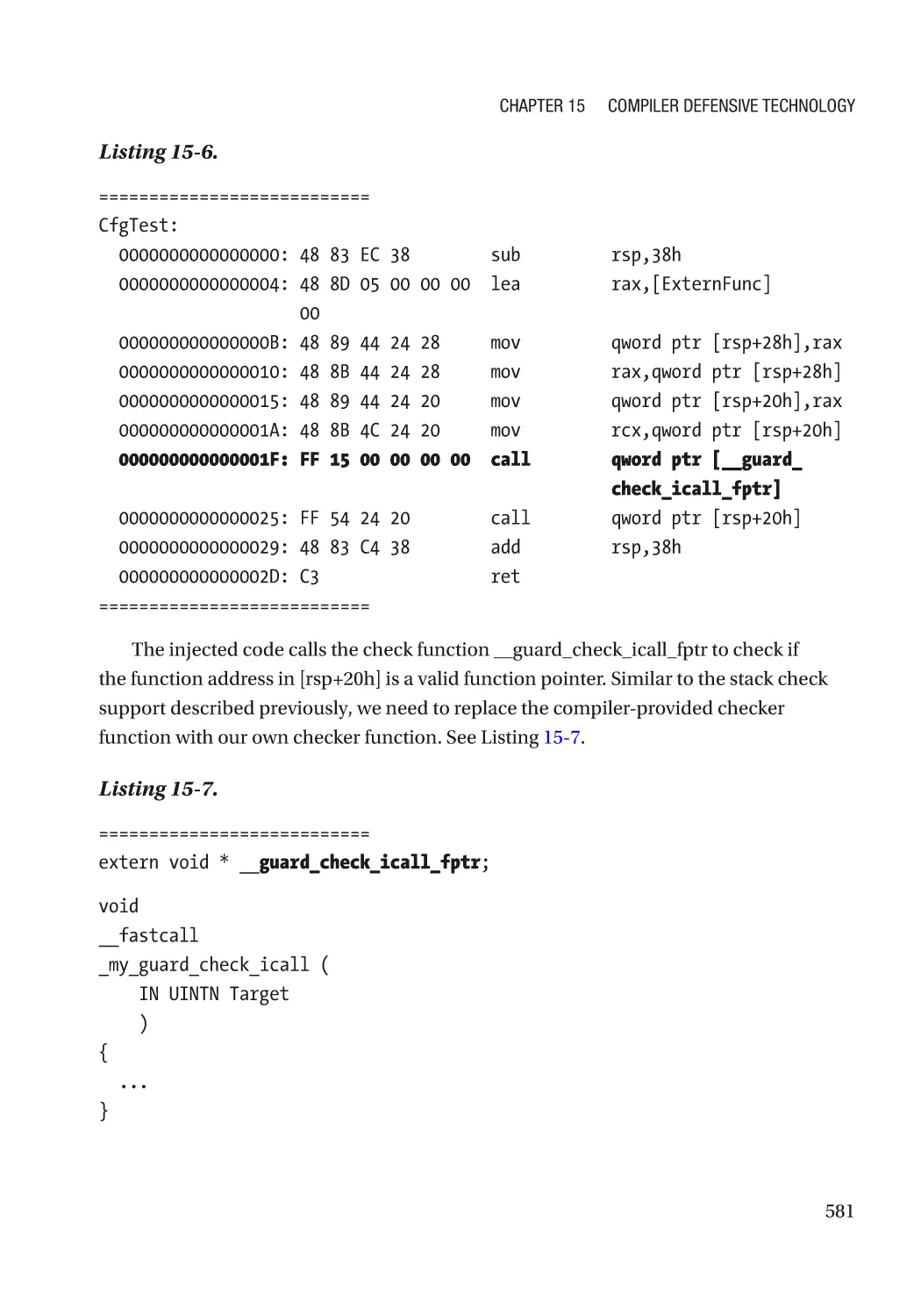
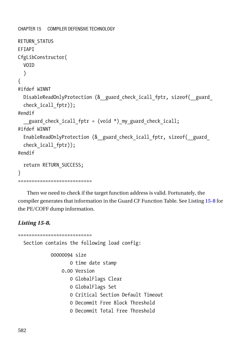
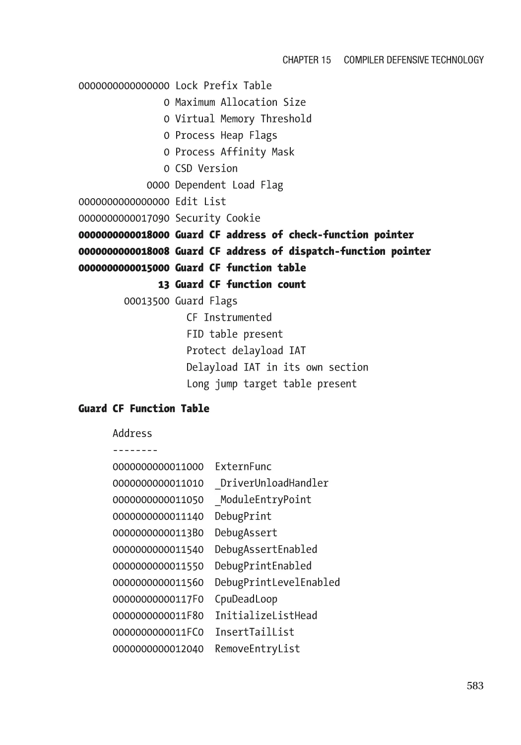
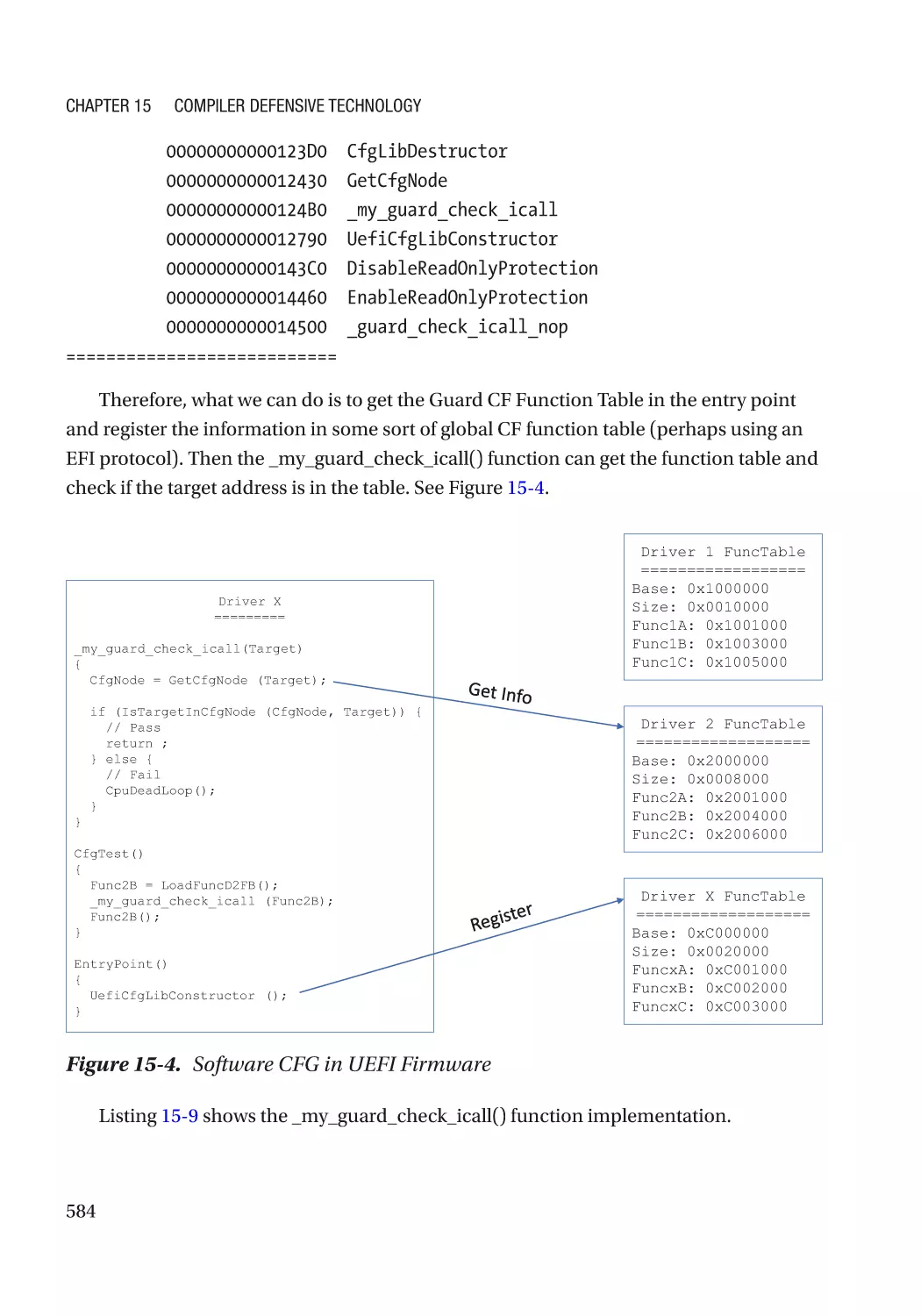
Chapter 15: Compiler Defensive Technology�������������������������������������������������������� 571
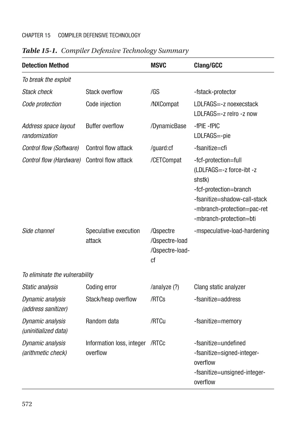
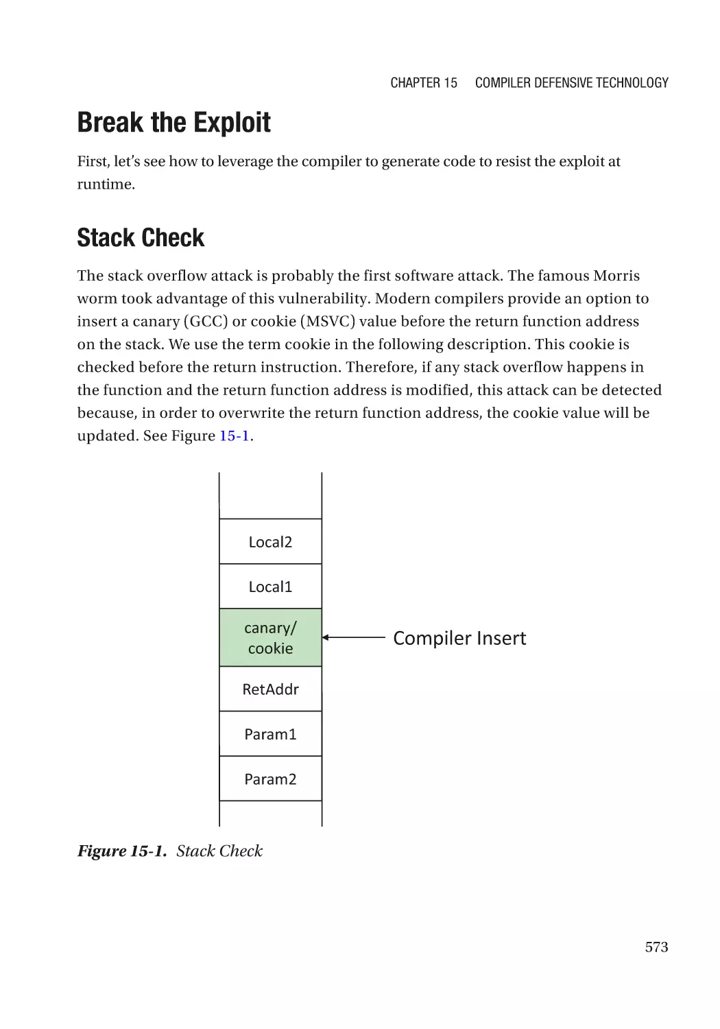
Break the Exploit����������������������������������������������������������������������������������������������������������������������� 573
Stack Check������������������������������������������������������������������������������������������������������������������������� 573
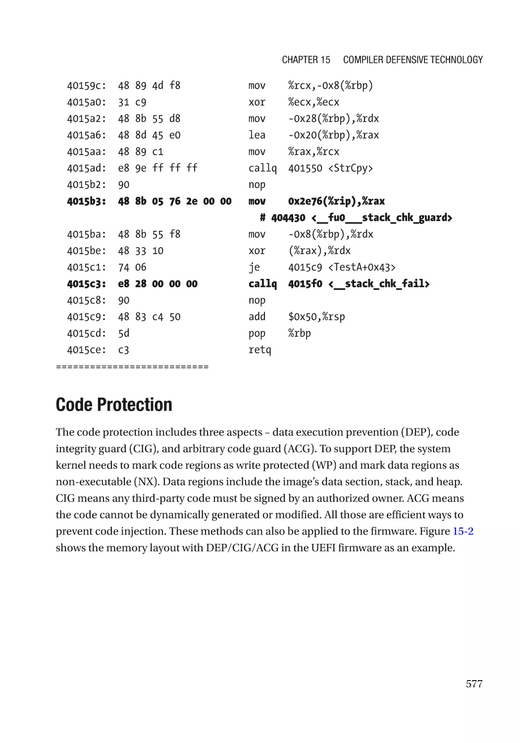
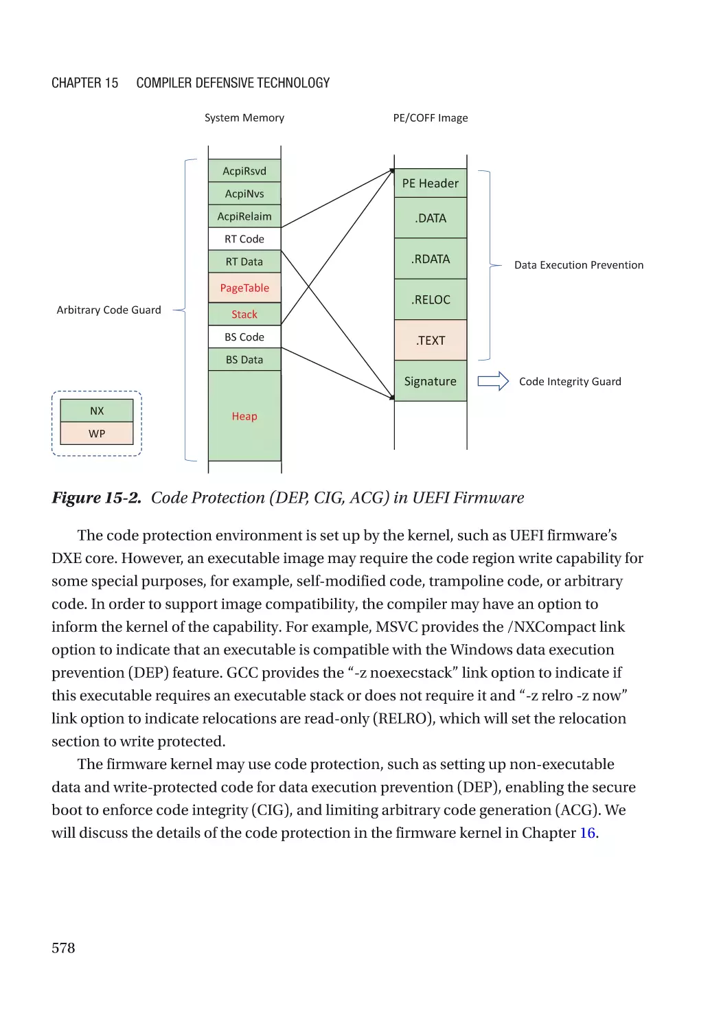
Code Protection������������������������������������������������������������������������������������������������������������������� 577
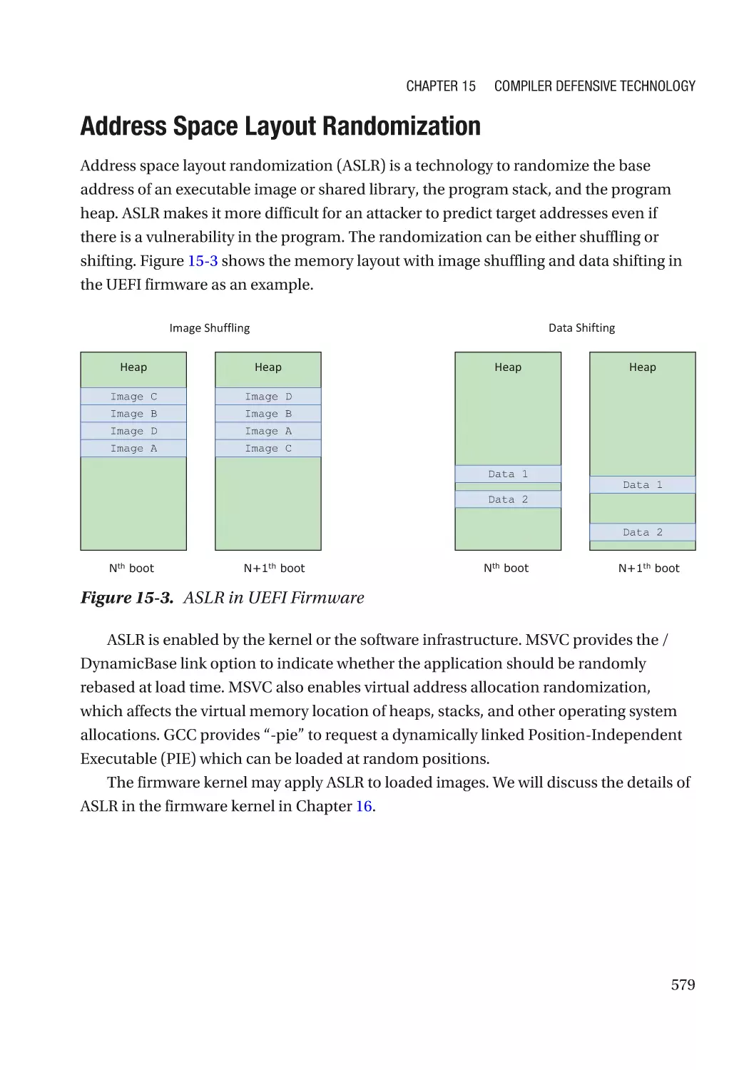
Address Space Layout Randomization�������������������������������������������������������������������������������� 579
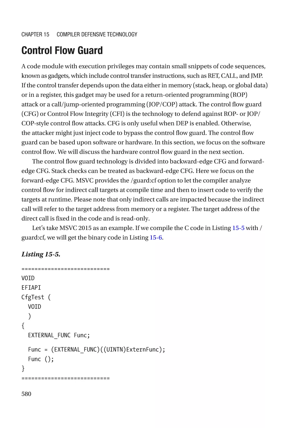
Control Flow Guard�������������������������������������������������������������������������������������������������������������� 580
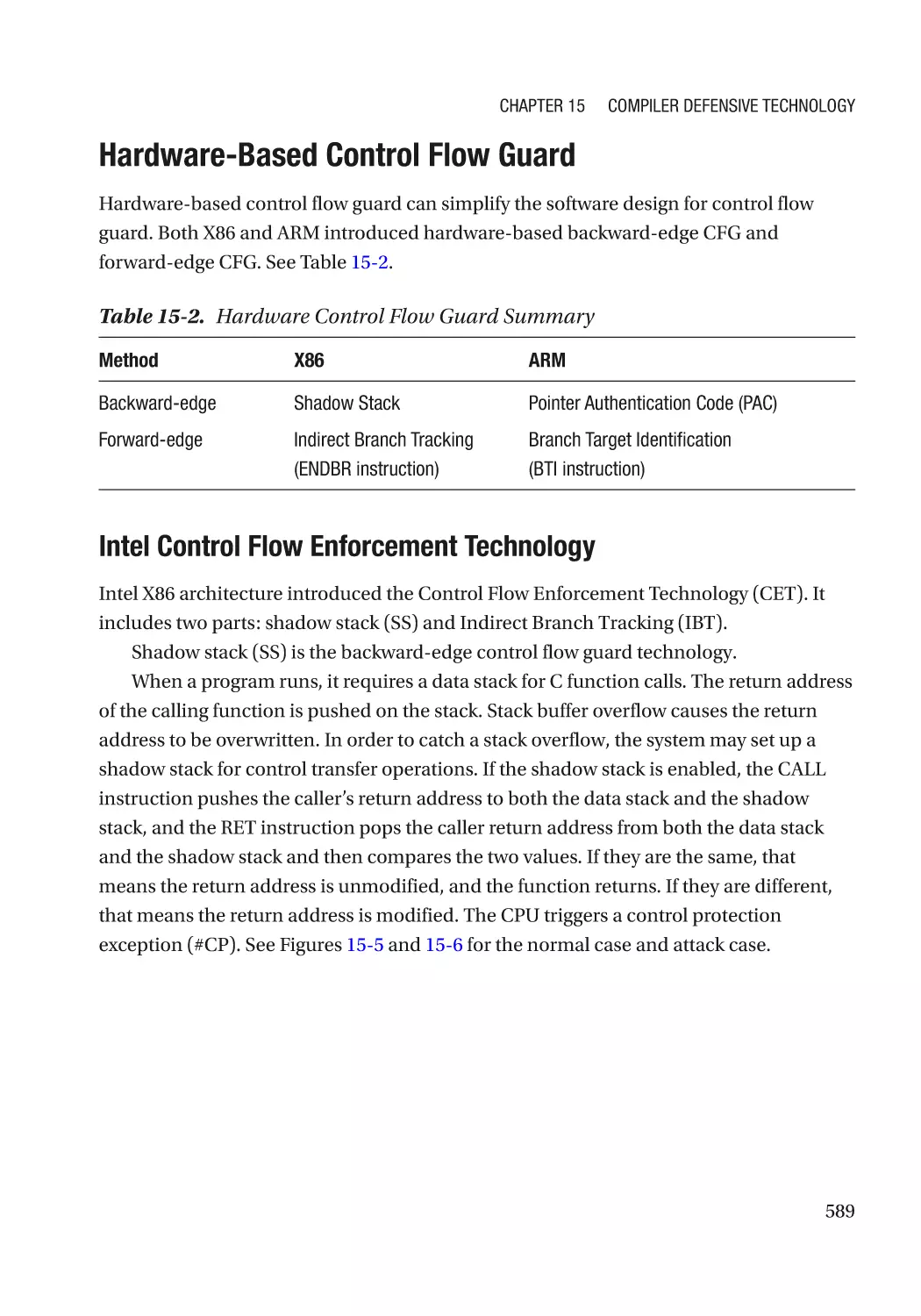
Hardware-Based Control Flow Guard���������������������������������������������������������������������������������� 589
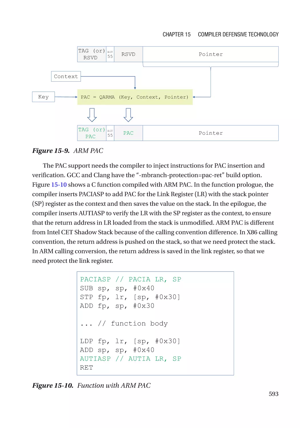
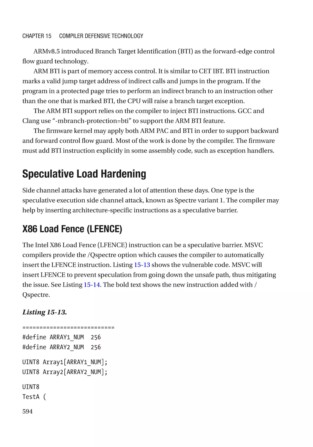
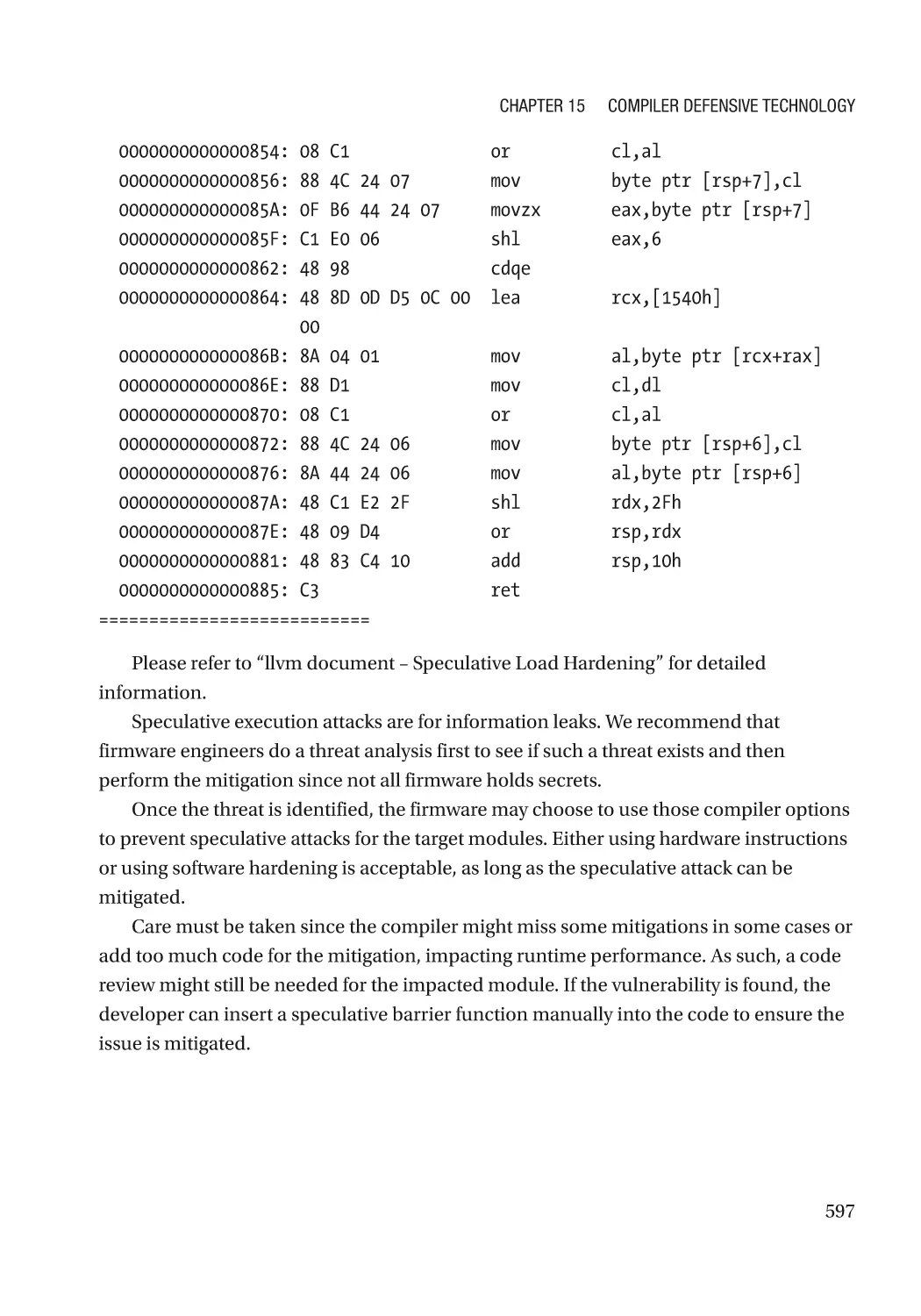
Speculative Load Hardening������������������������������������������������������������������������������������������������ 594
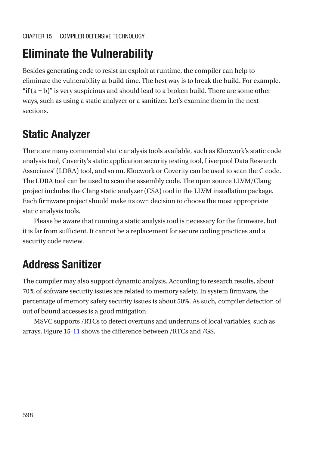
Eliminate the Vulnerability�������������������������������������������������������������������������������������������������������� 598
Static Analyzer��������������������������������������������������������������������������������������������������������������������� 598
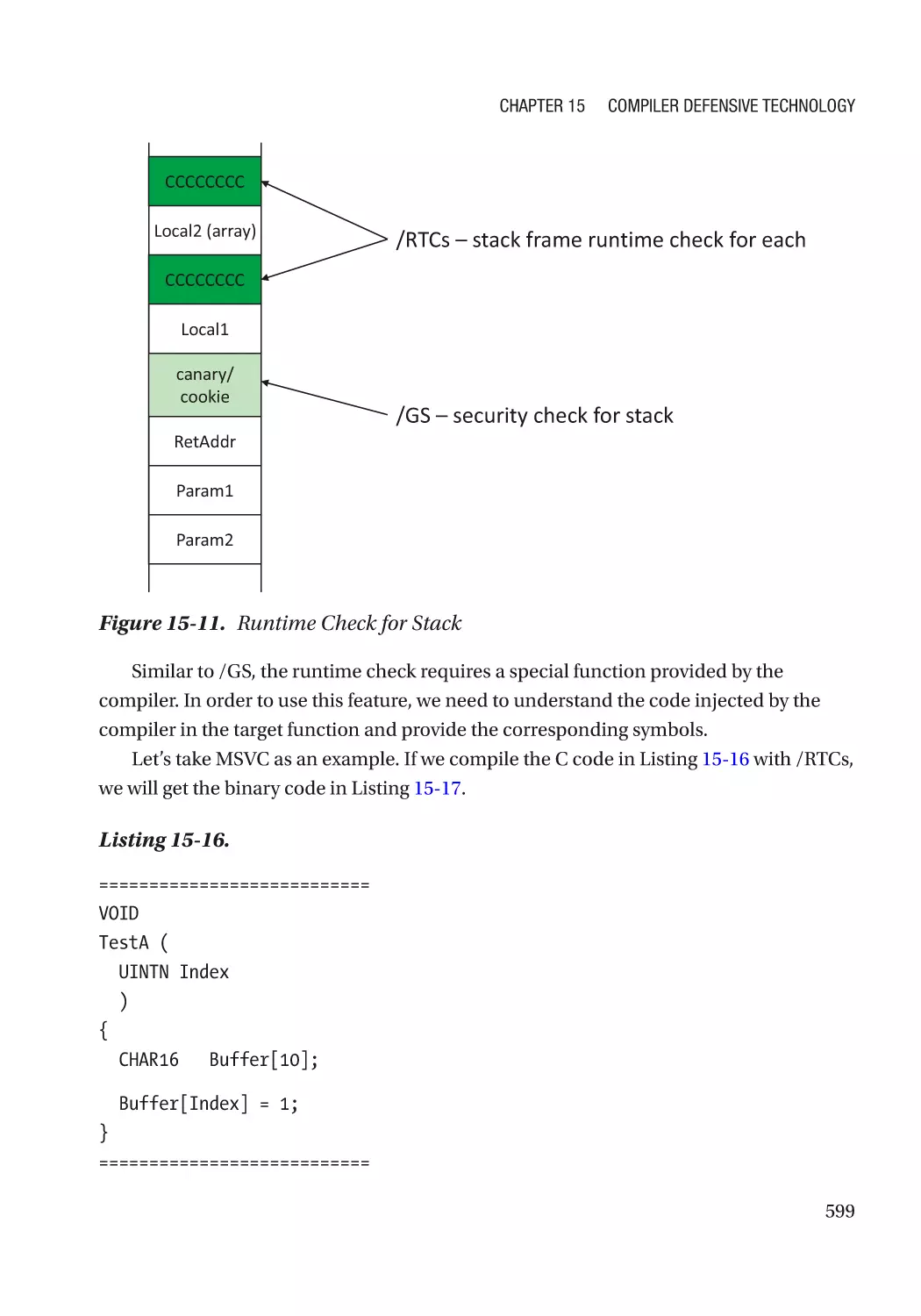
Address Sanitizer���������������������������������������������������������������������������������������������������������������� 598
xiii
Table of Contents
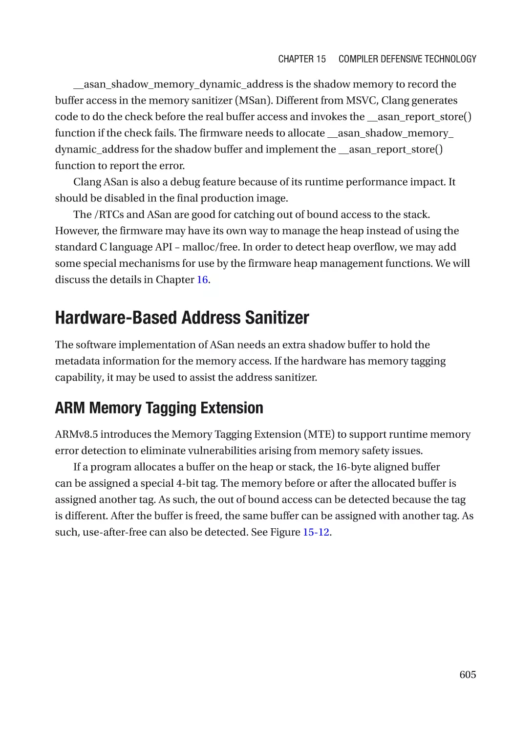
Hardware-Based Address Sanitizer������������������������������������������������������������������������������������� 605
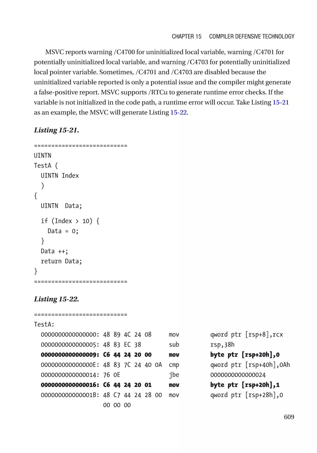
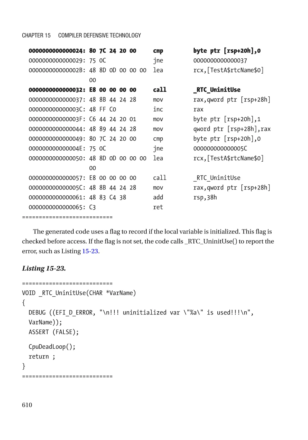
Uninitialized Data Check������������������������������������������������������������������������������������������������������ 608
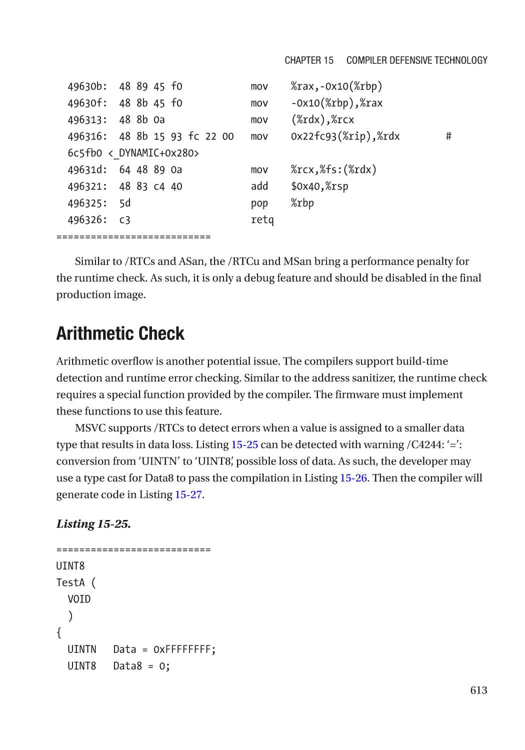
Arithmetic Check����������������������������������������������������������������������������������������������������������������� 613
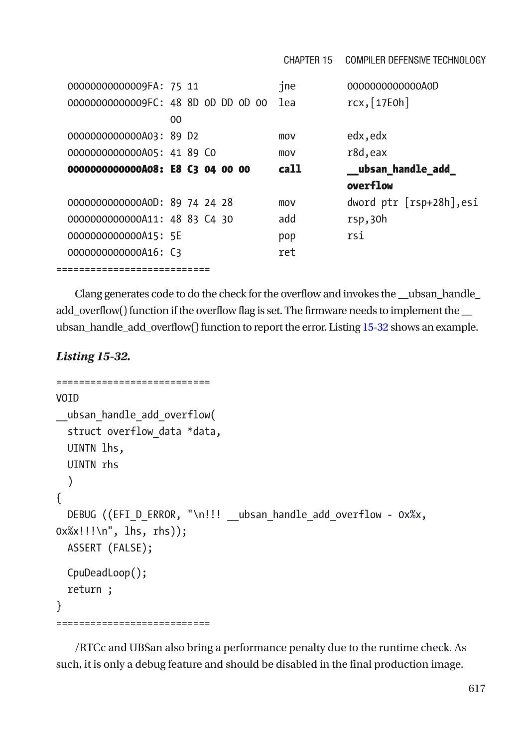
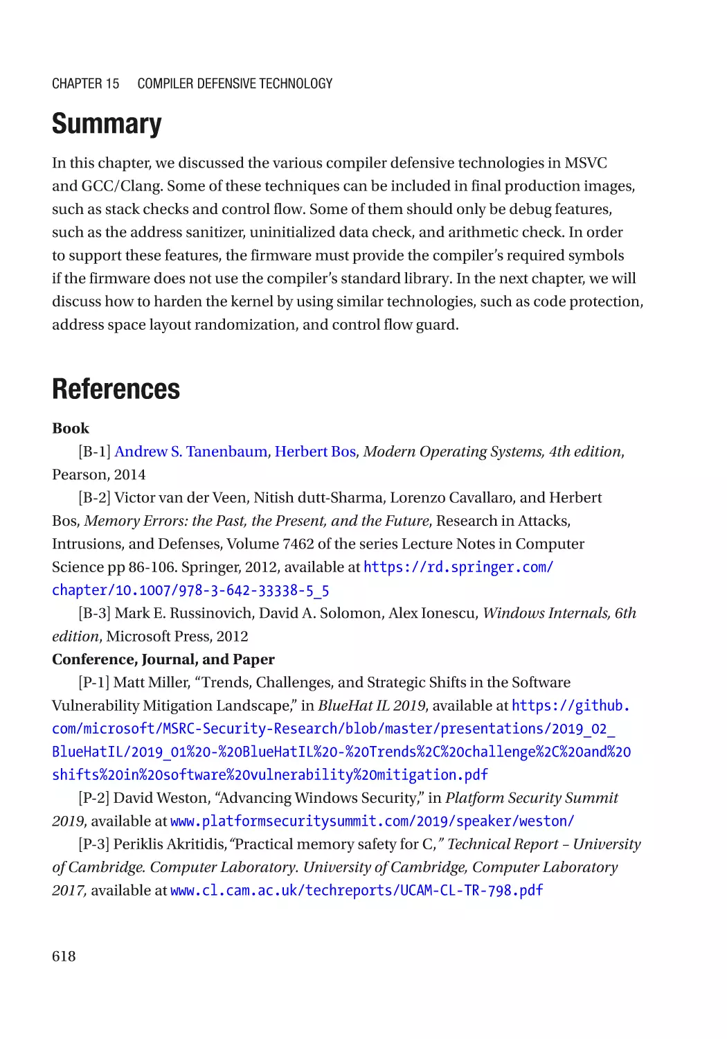
Summary���������������������������������������������������������������������������������������������������������������������������������� 618
References�������������������������������������������������������������������������������������������������������������������������������� 618
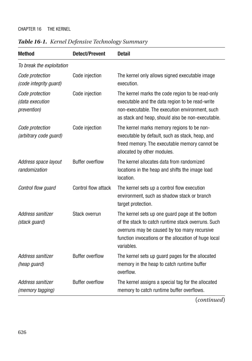
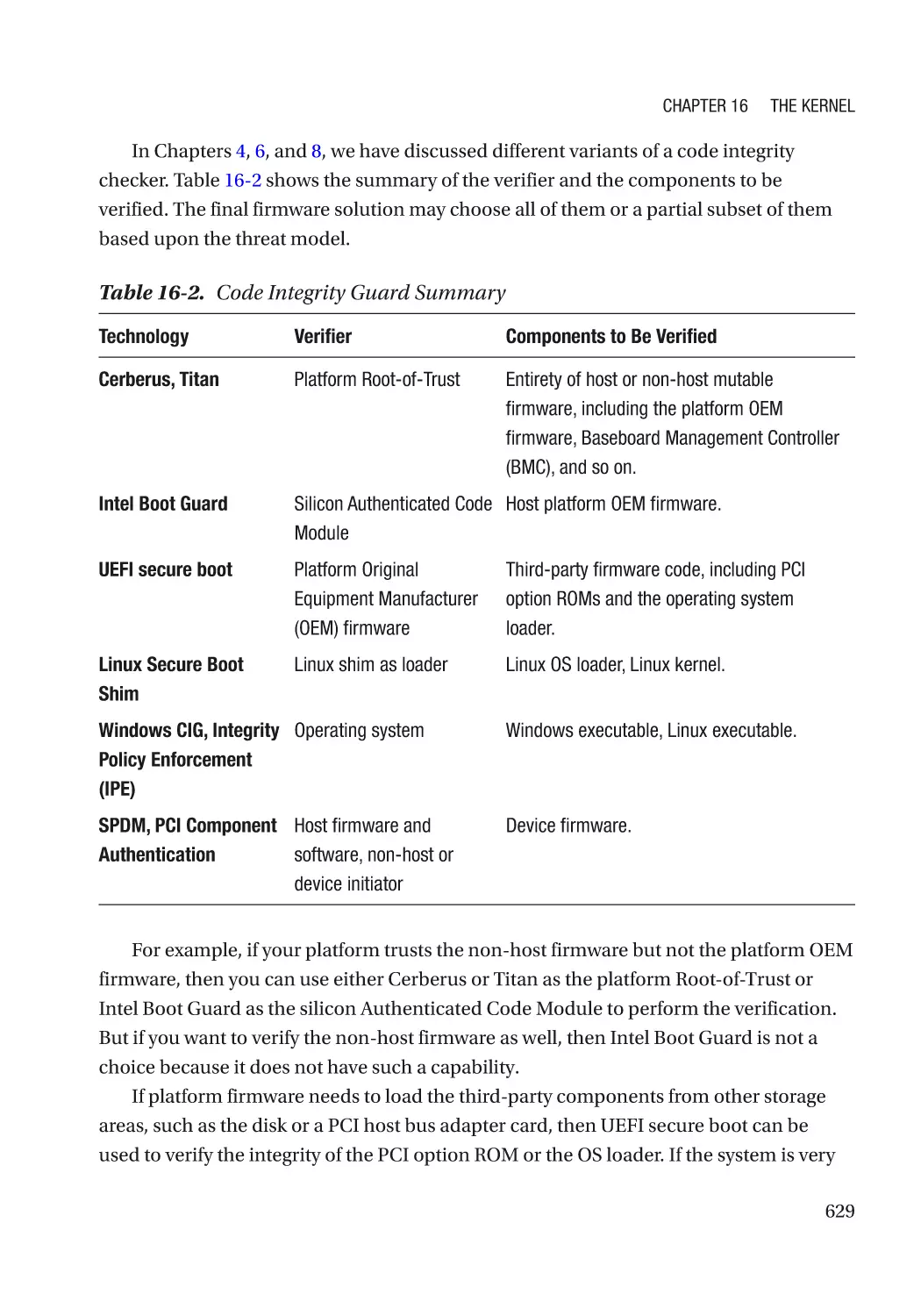
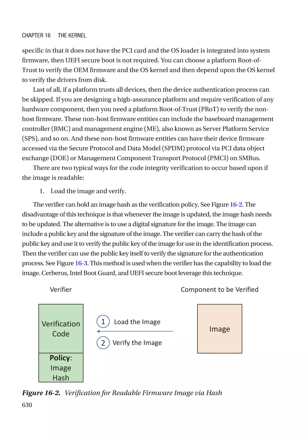
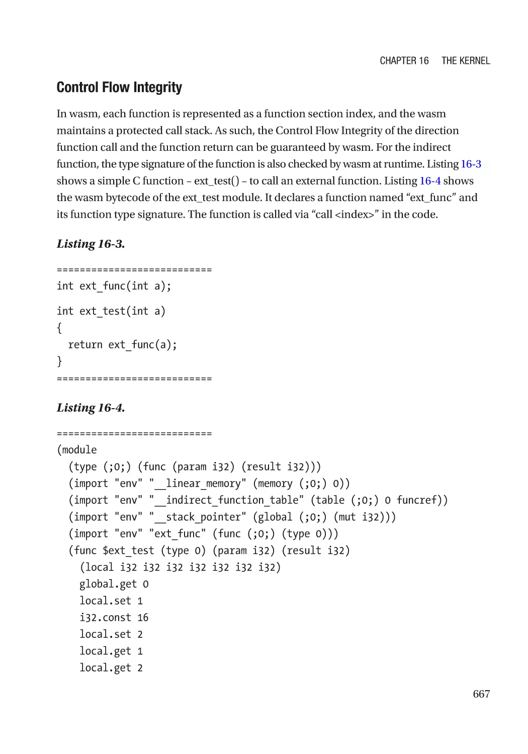
Chapter 16: The Kernel����������������������������������������������������������������������������������������� 625
Break the Exploitation��������������������������������������������������������������������������������������������������������������� 628
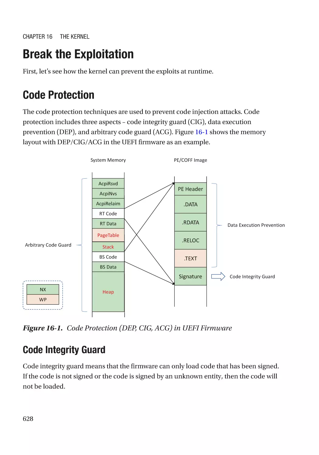
Code Protection������������������������������������������������������������������������������������������������������������������� 628
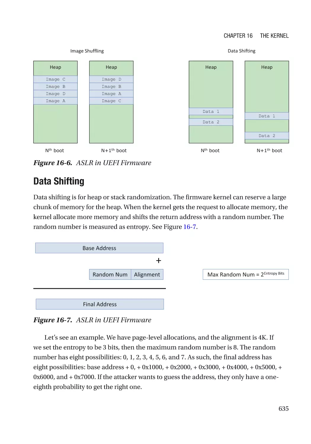
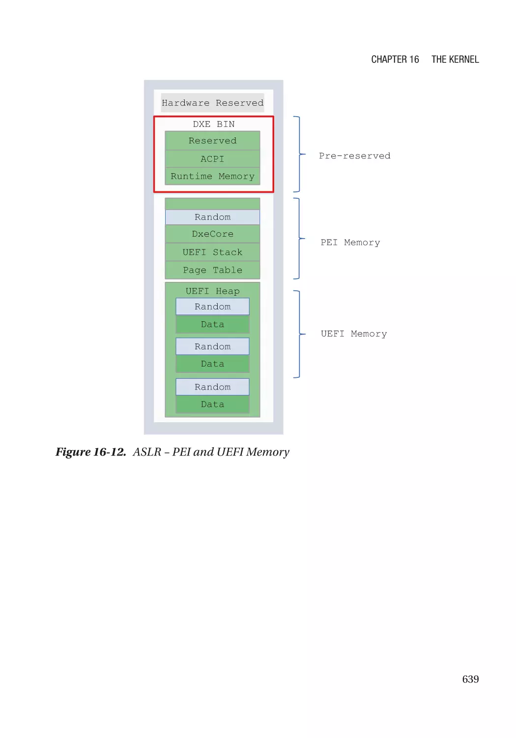
Address Space Layout Randomization�������������������������������������������������������������������������������� 634
Control Flow Guard�������������������������������������������������������������������������������������������������������������� 642
Address Sanitizer���������������������������������������������������������������������������������������������������������������� 644
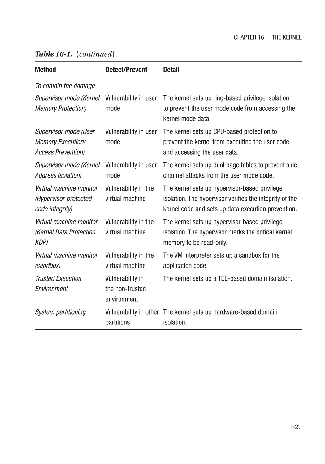
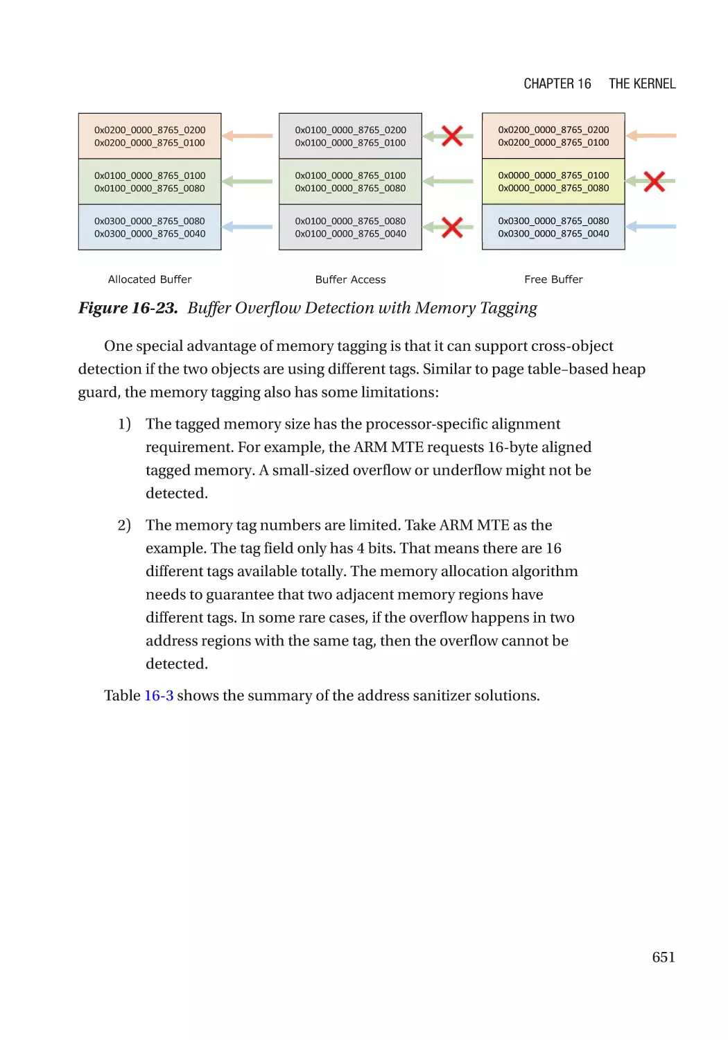
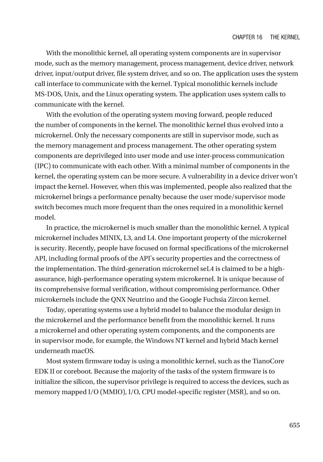
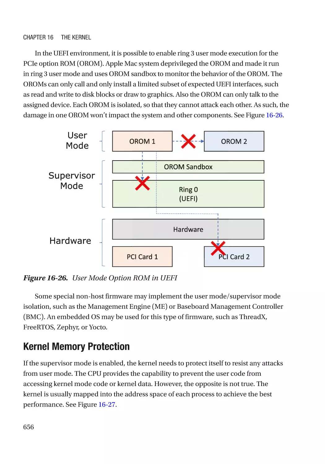
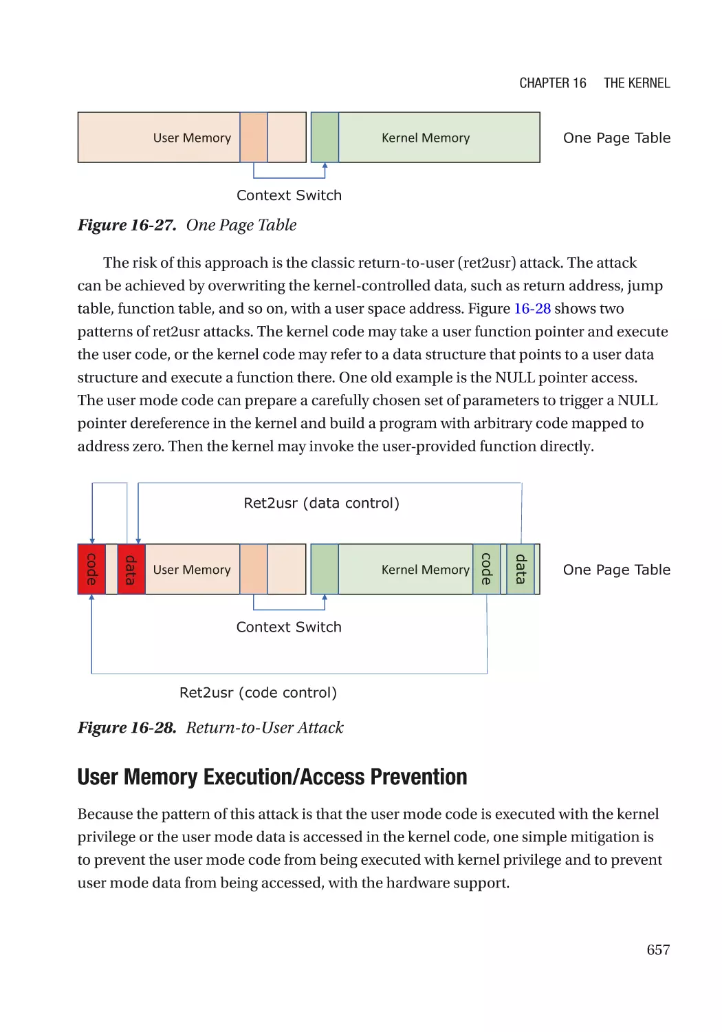
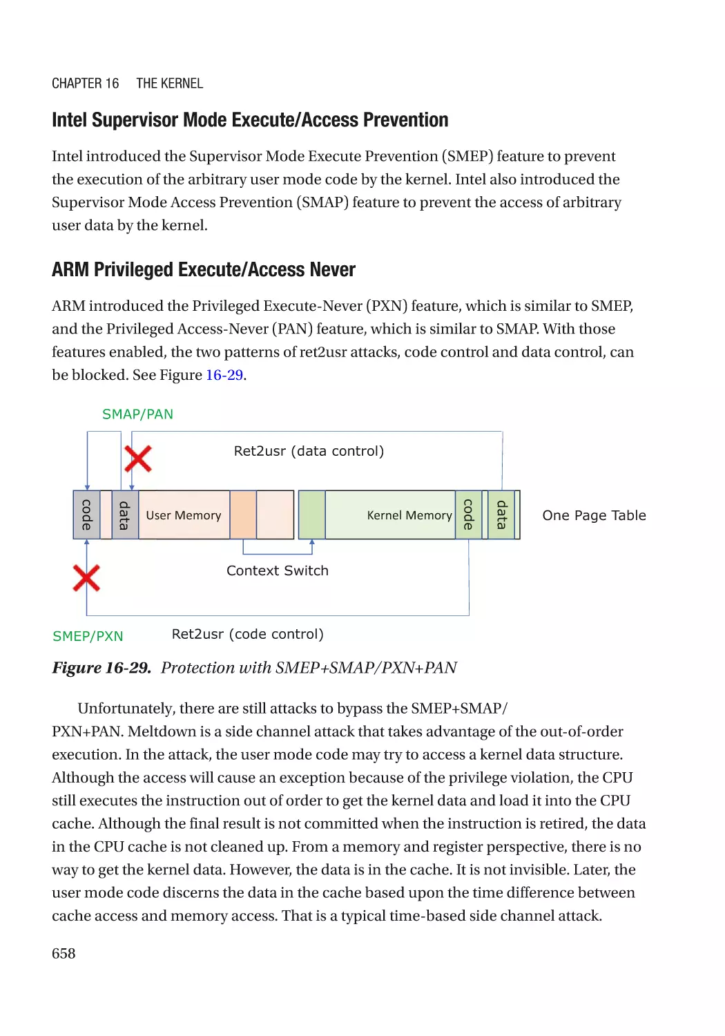
Contain the Damage������������������������������������������������������������������������������������������������������������������ 654
User Mode/Supervisor Mode����������������������������������������������������������������������������������������������� 654
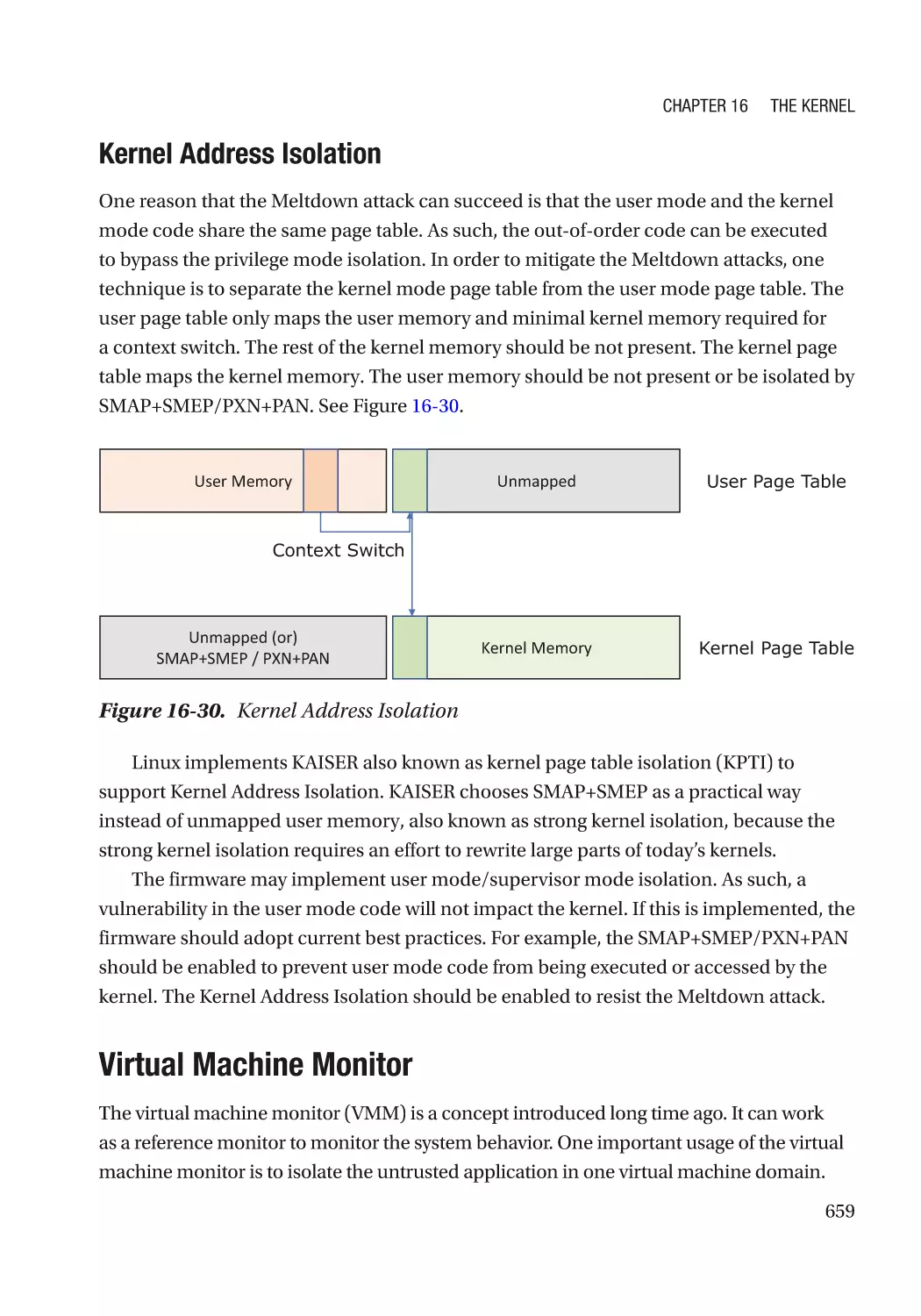
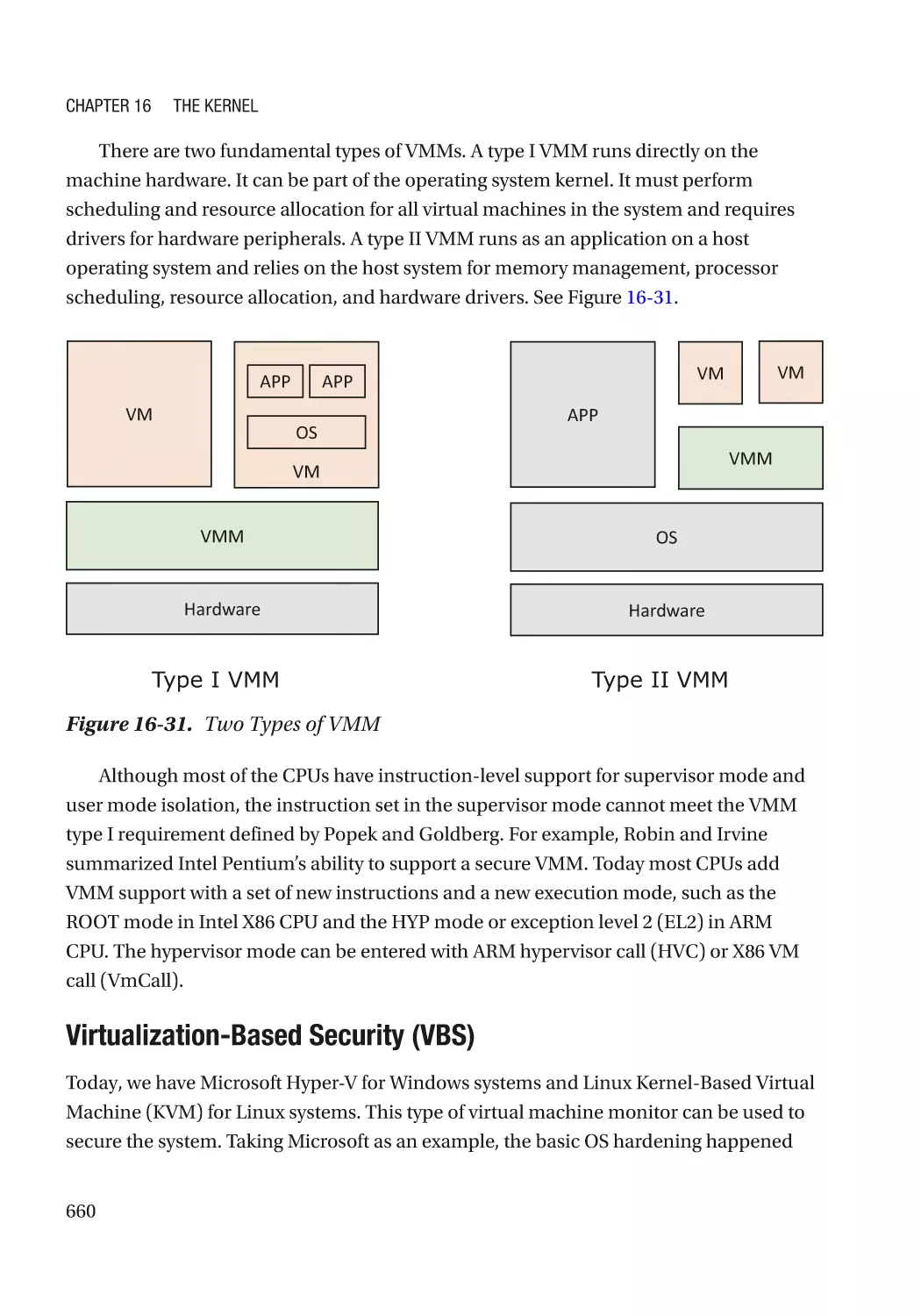
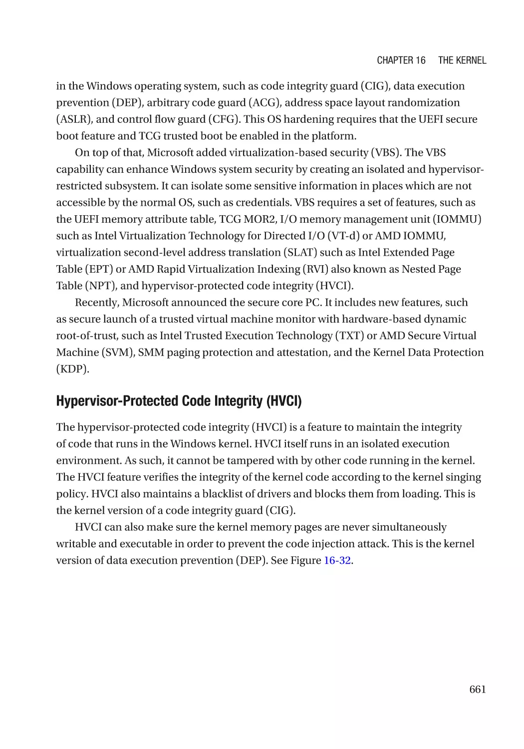
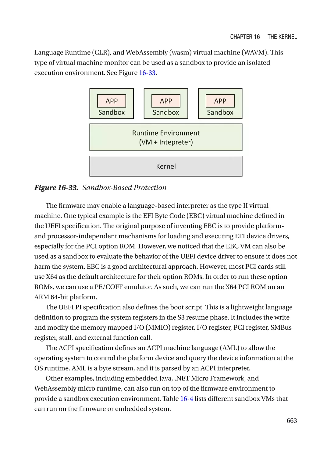
Virtual Machine Monitor������������������������������������������������������������������������������������������������������ 659
Trusted Execution Environment������������������������������������������������������������������������������������������� 669
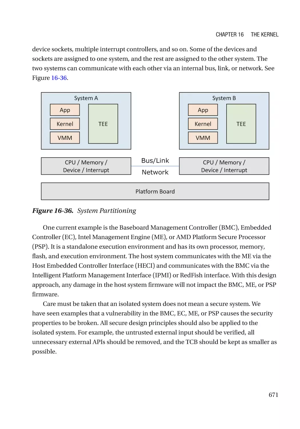
System Partitioning������������������������������������������������������������������������������������������������������������� 670
Summary���������������������������������������������������������������������������������������������������������������������������������� 672
References�������������������������������������������������������������������������������������������������������������������������������� 672
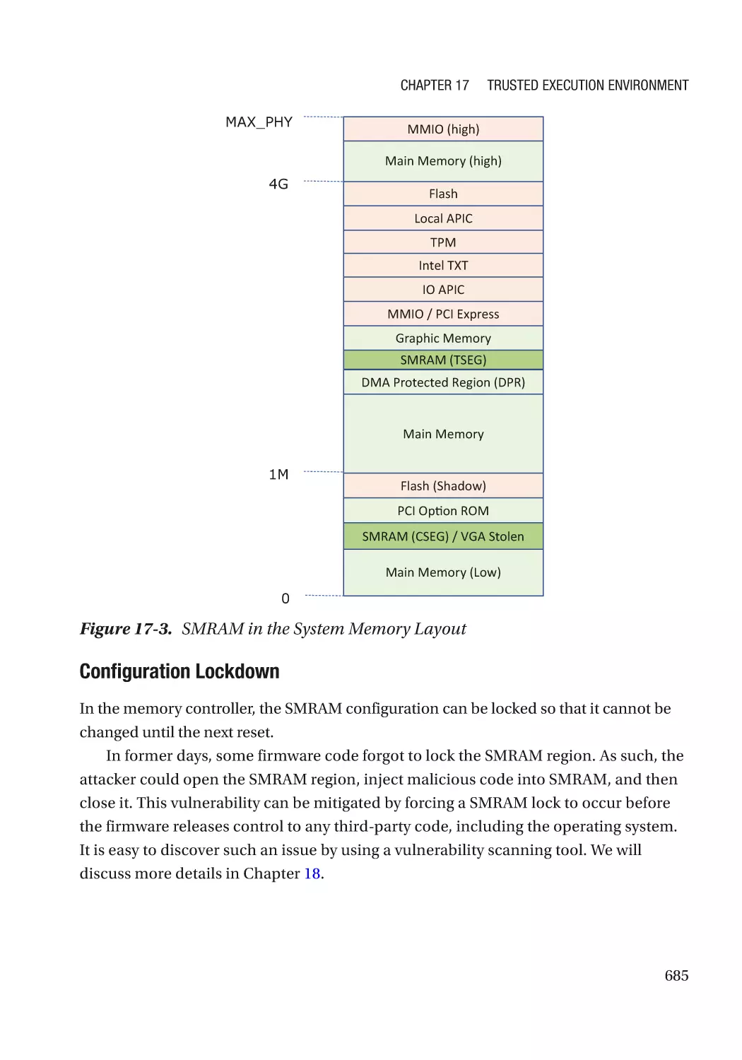
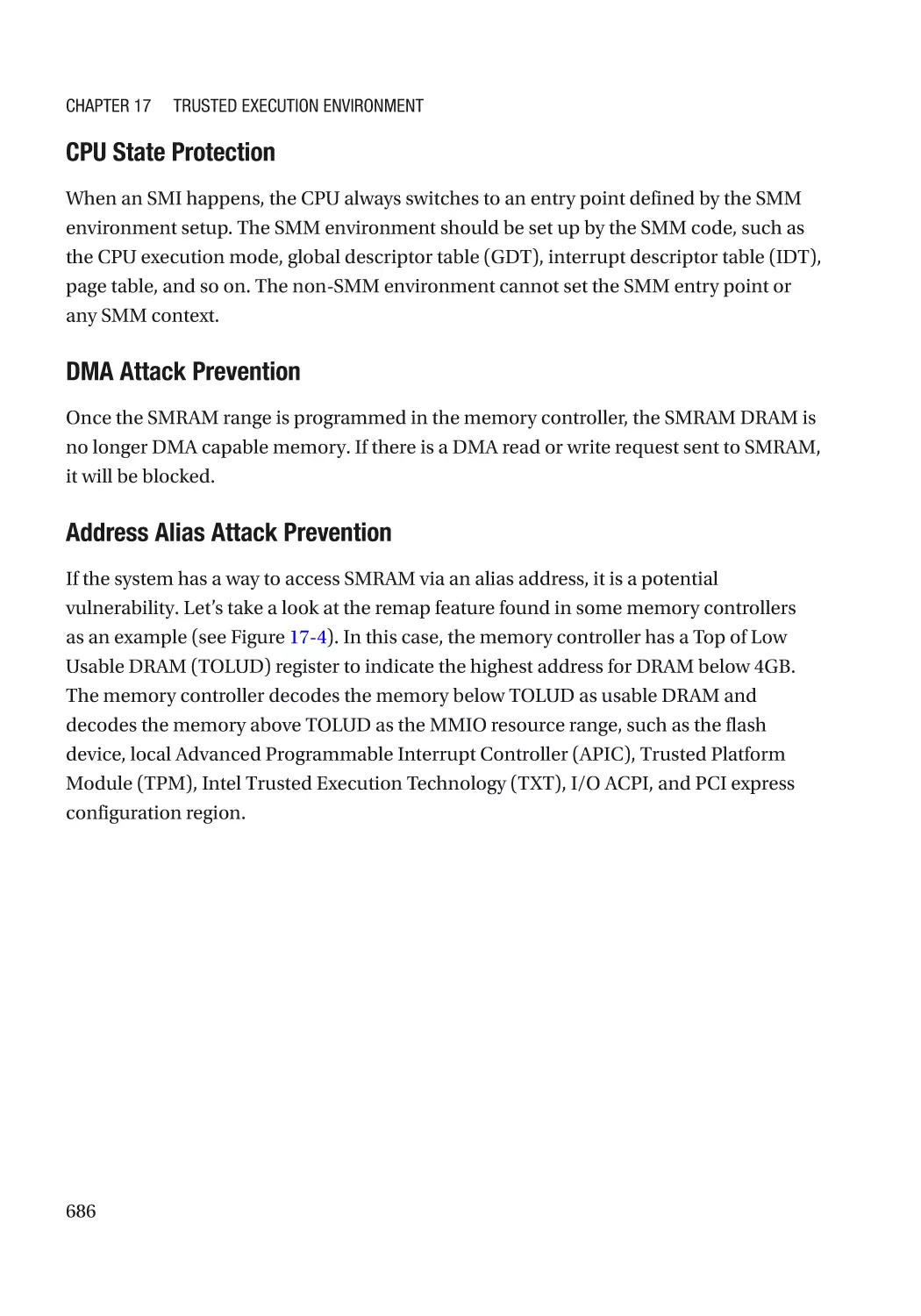
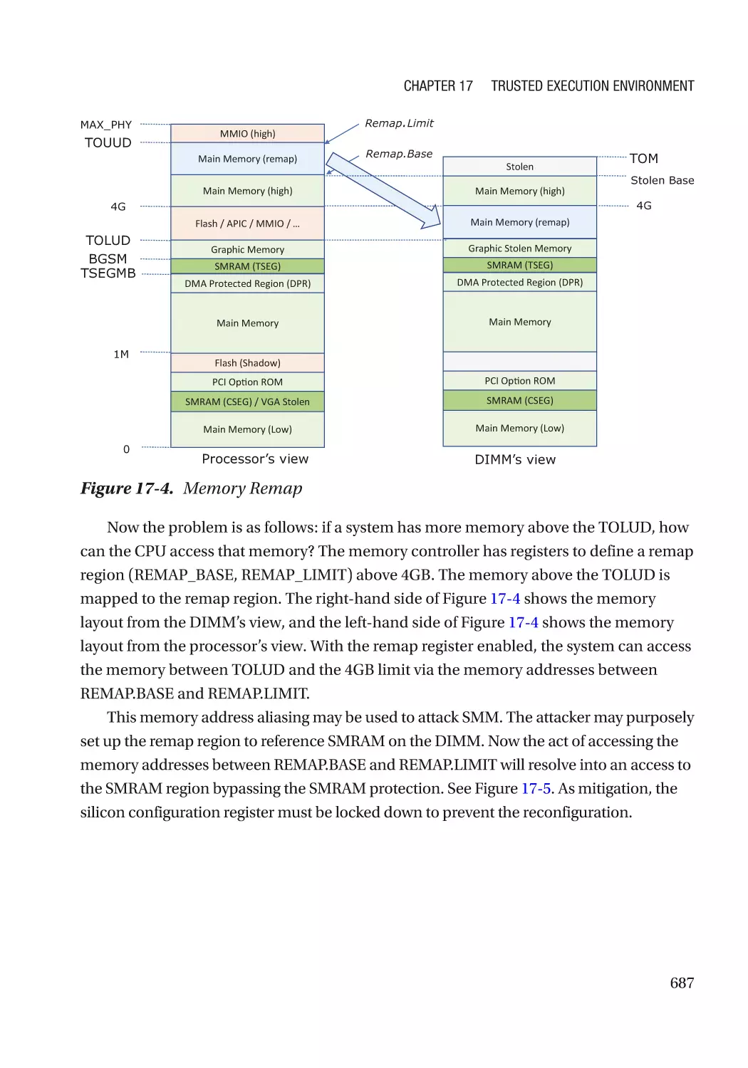
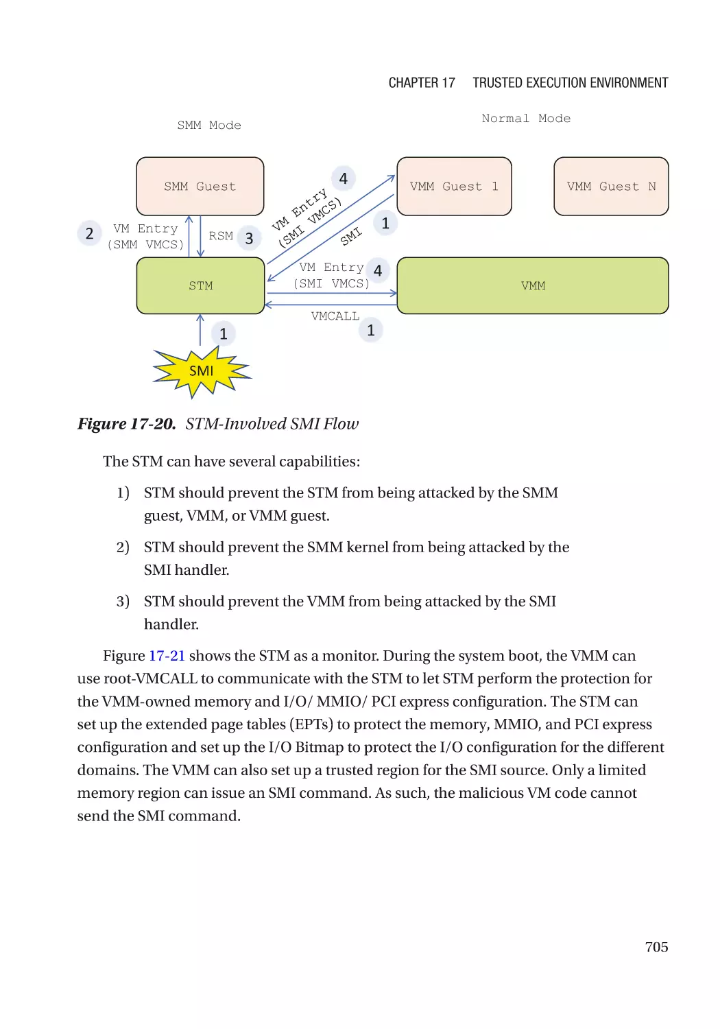
Chapter 17: Trusted Execution Environment�������������������������������������������������������� 681
CPU-Based TEE������������������������������������������������������������������������������������������������������������������������� 681
X86 SMM����������������������������������������������������������������������������������������������������������������������������� 681
ARM TrustZone�������������������������������������������������������������������������������������������������������������������� 707
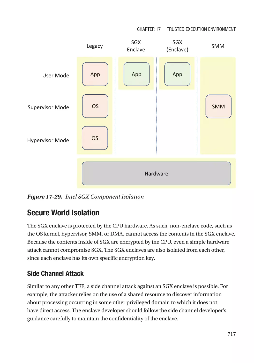
Intel SGX������������������������������������������������������������������������������������������������������������������������������ 716
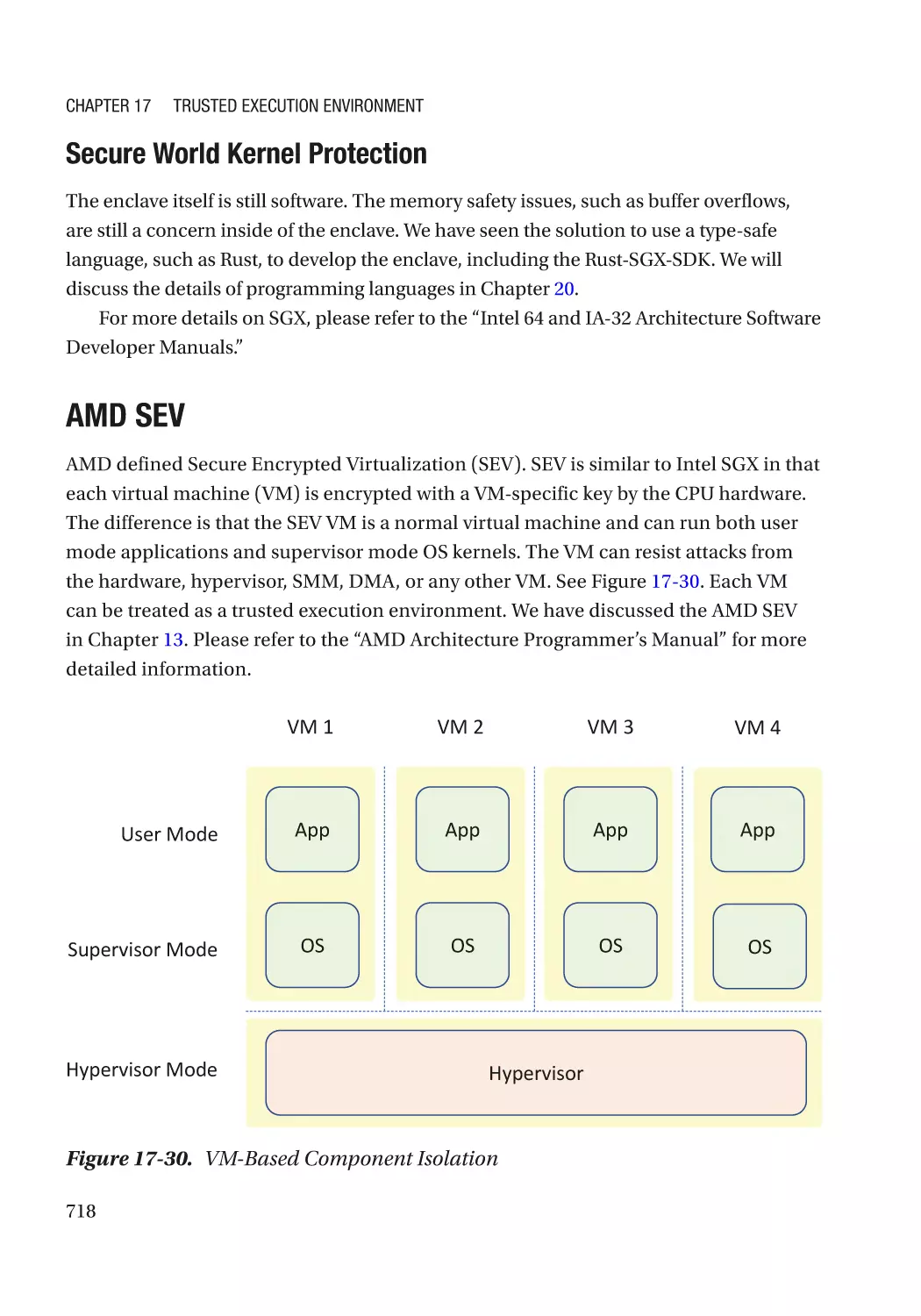
AMD SEV������������������������������������������������������������������������������������������������������������������������������ 718
Intel TDX������������������������������������������������������������������������������������������������������������������������������ 719
IBM Z����������������������������������������������������������������������������������������������������������������������������������� 719
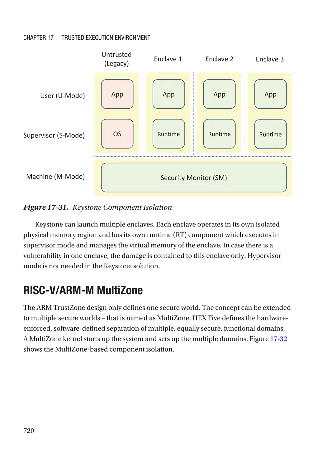
RISC-V Keystone������������������������������������������������������������������������������������������������������������������ 719
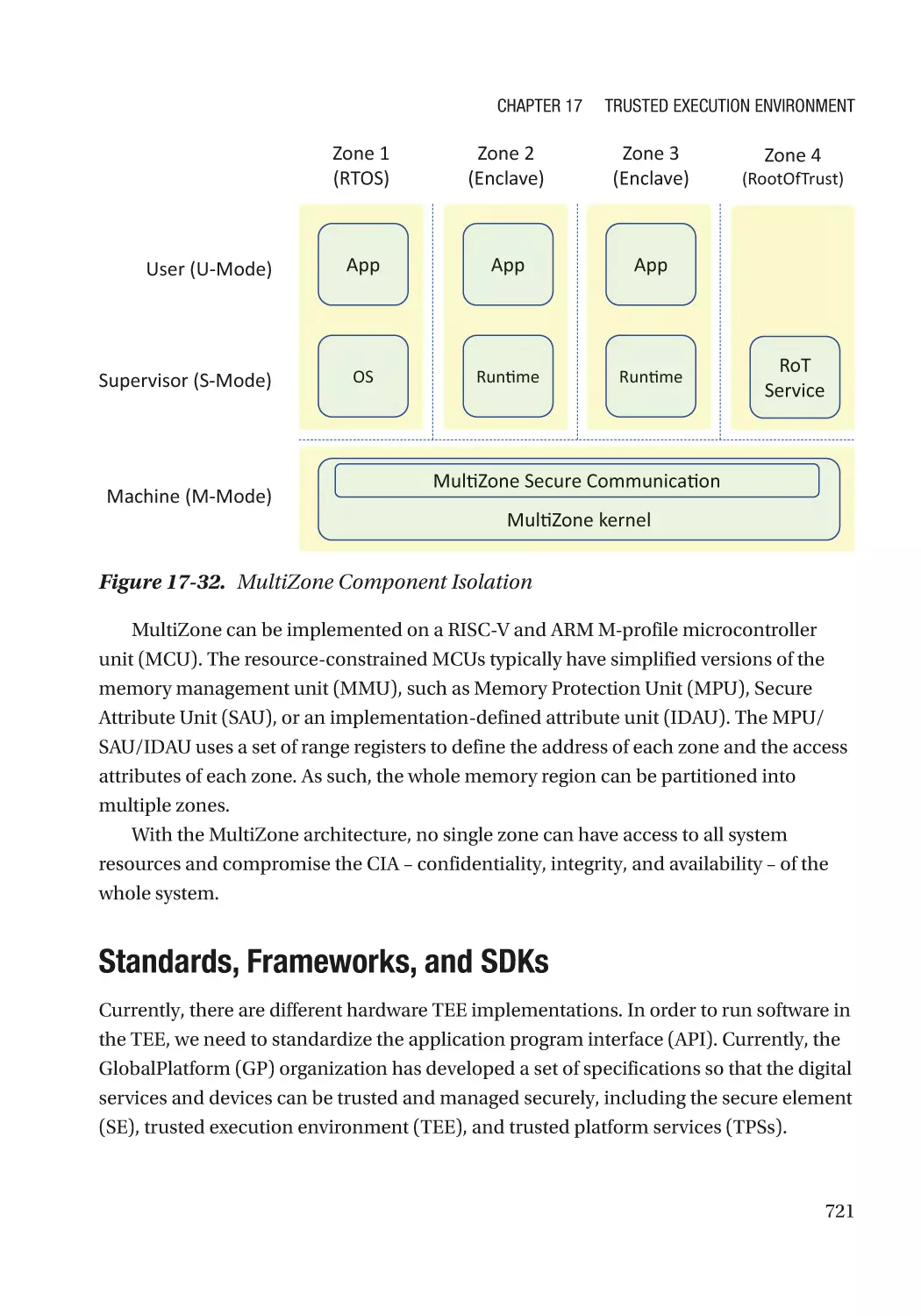
RISC-V/ARM-M MultiZone���������������������������������������������������������������������������������������������������� 720
Standards, Frameworks, and SDKs������������������������������������������������������������������������������������� 721
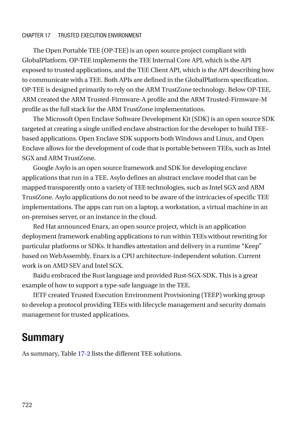
Summary����������������������������������������������������������������������������������������������������������������������������� 722
xiv
Table of Contents
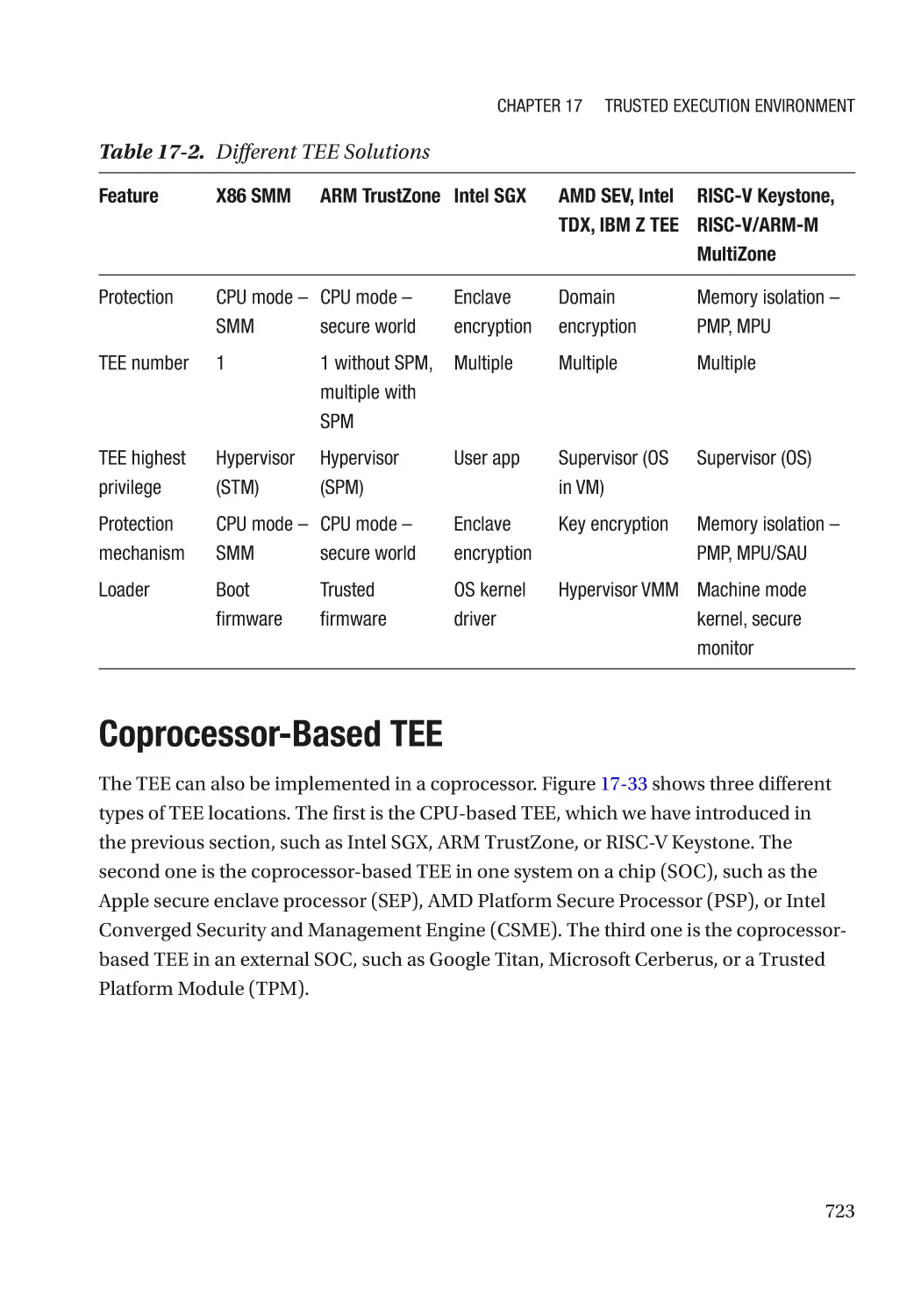
Coprocessor-Based TEE������������������������������������������������������������������������������������������������������������ 723
Intel Converged Security and Management Engine (CSME)������������������������������������������������ 724
Apple Secure Enclave Processor (SEP)�������������������������������������������������������������������������������� 727
Google Titan������������������������������������������������������������������������������������������������������������������������� 727
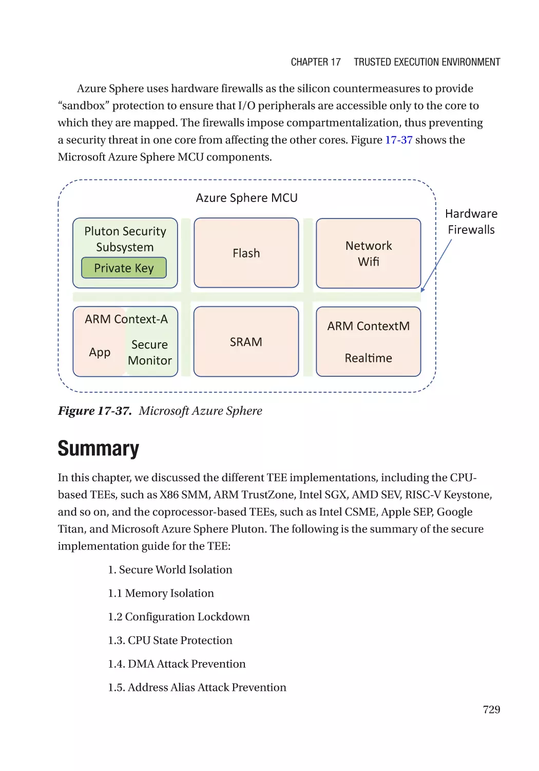
Microsoft Azure Sphere: Pluton������������������������������������������������������������������������������������������� 728
Summary���������������������������������������������������������������������������������������������������������������������������������� 729
References�������������������������������������������������������������������������������������������������������������������������������� 732
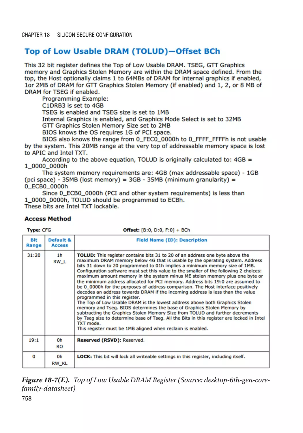
Chapter 18: Silicon Secure Configuration������������������������������������������������������������� 745
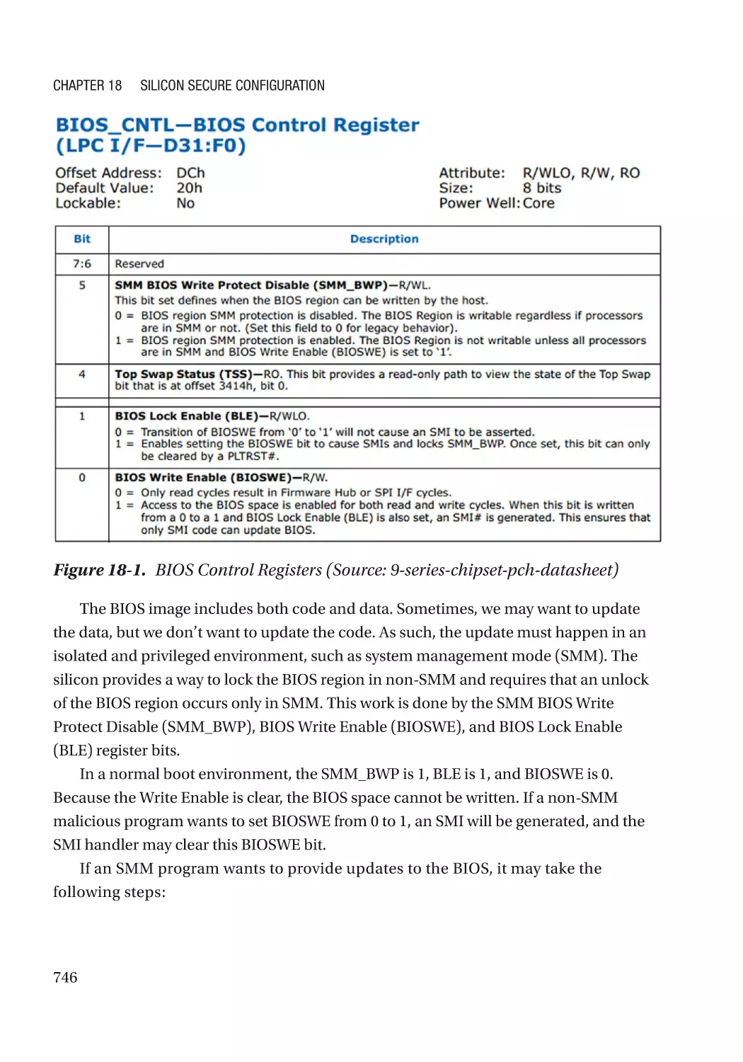
Flash Lock��������������������������������������������������������������������������������������������������������������������������������� 745
BIOS Write Protection���������������������������������������������������������������������������������������������������������� 745
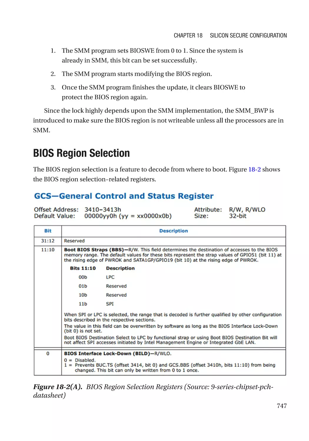
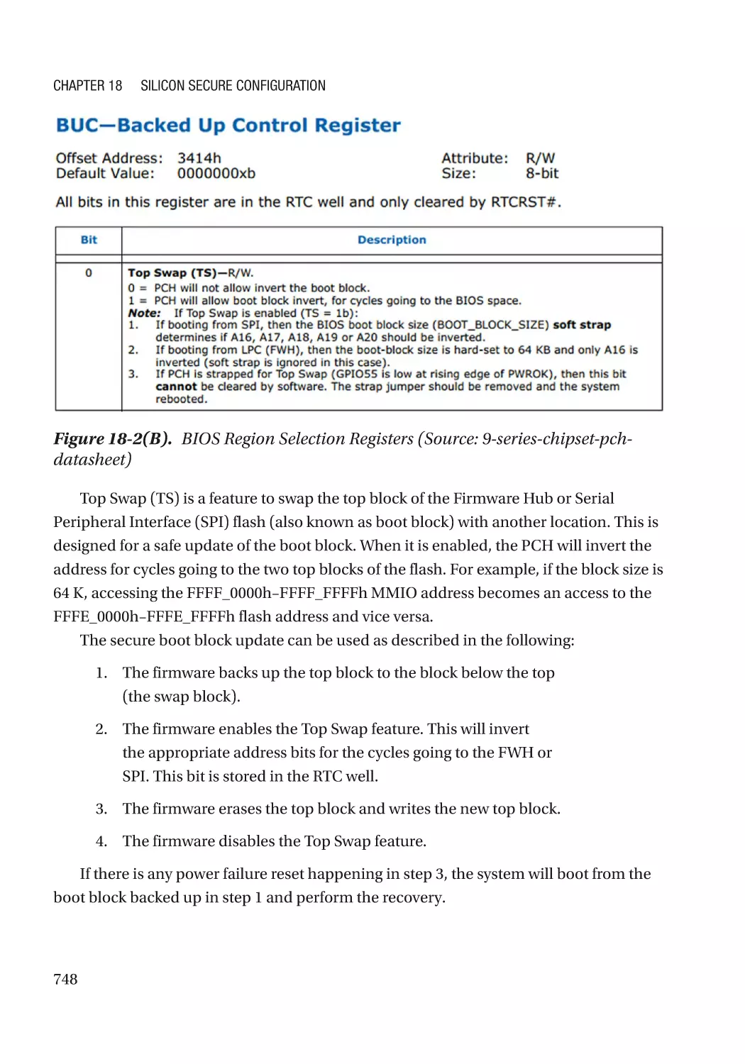
BIOS Region Selection��������������������������������������������������������������������������������������������������������� 747
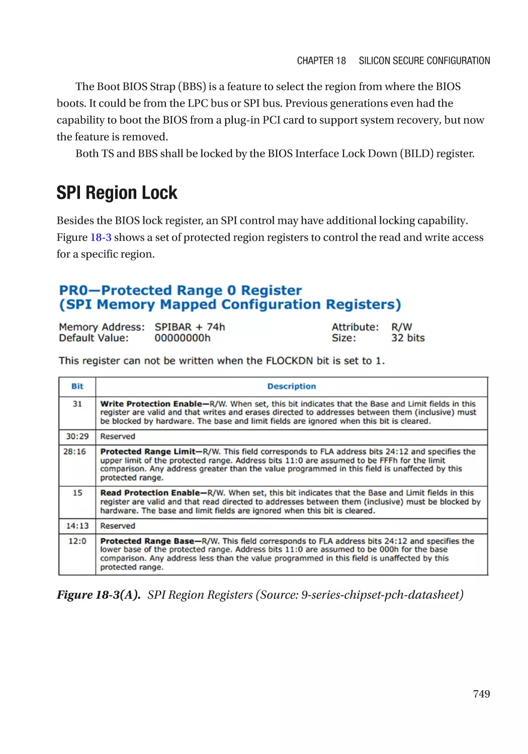
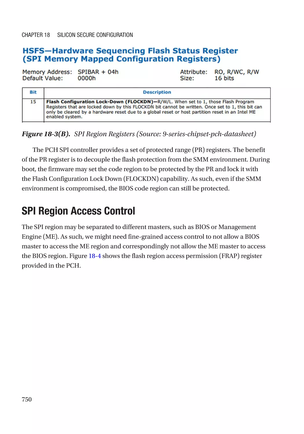
SPI Region Lock������������������������������������������������������������������������������������������������������������������� 749
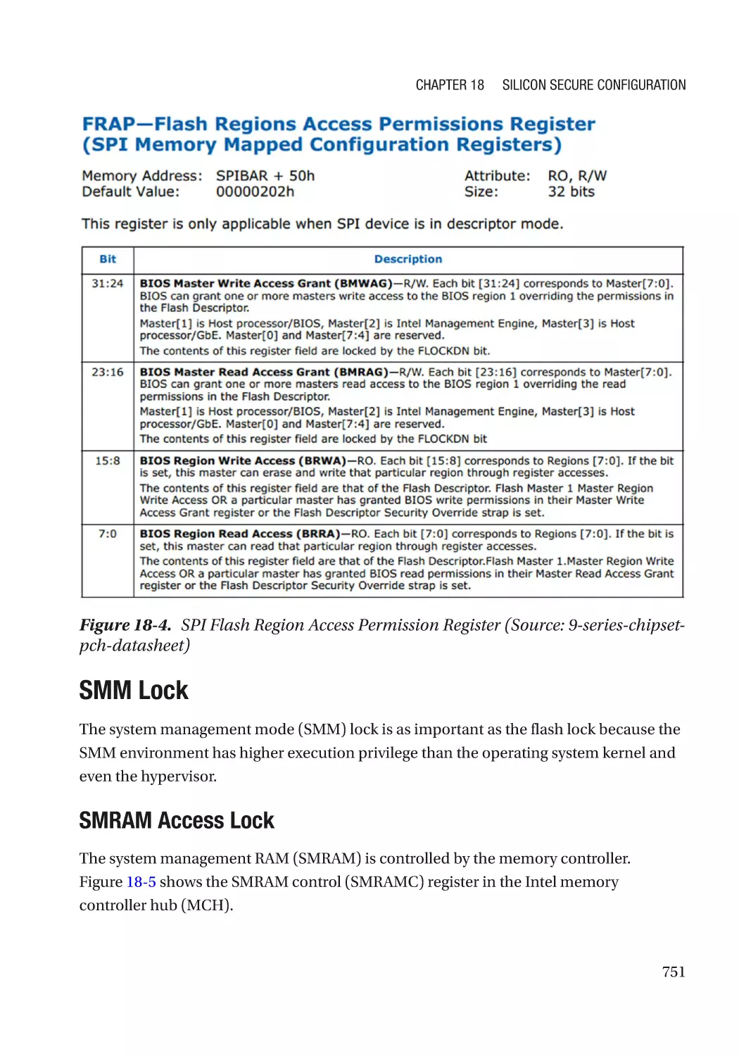
SPI Region Access Control��������������������������������������������������������������������������������������������������� 750
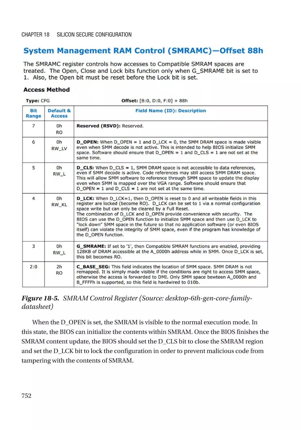
SMM Lock���������������������������������������������������������������������������������������������������������������������������� 751
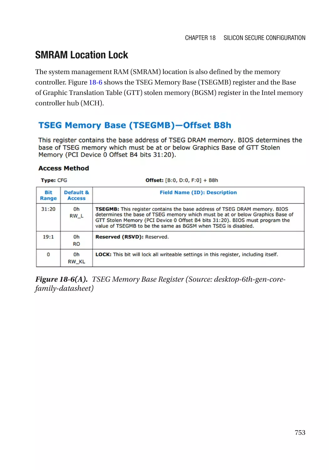
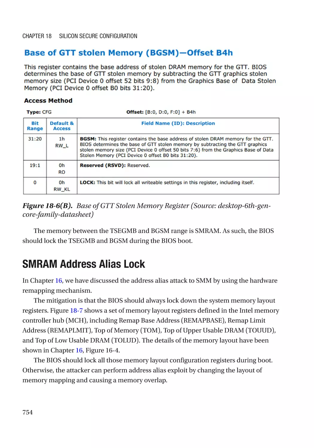
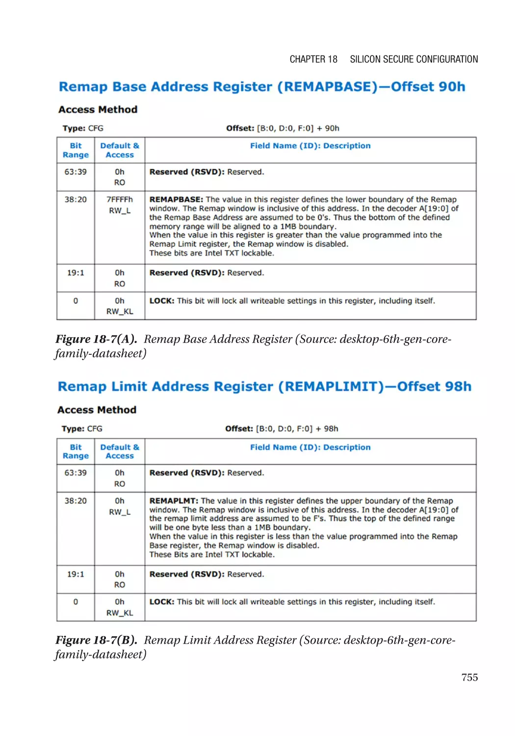
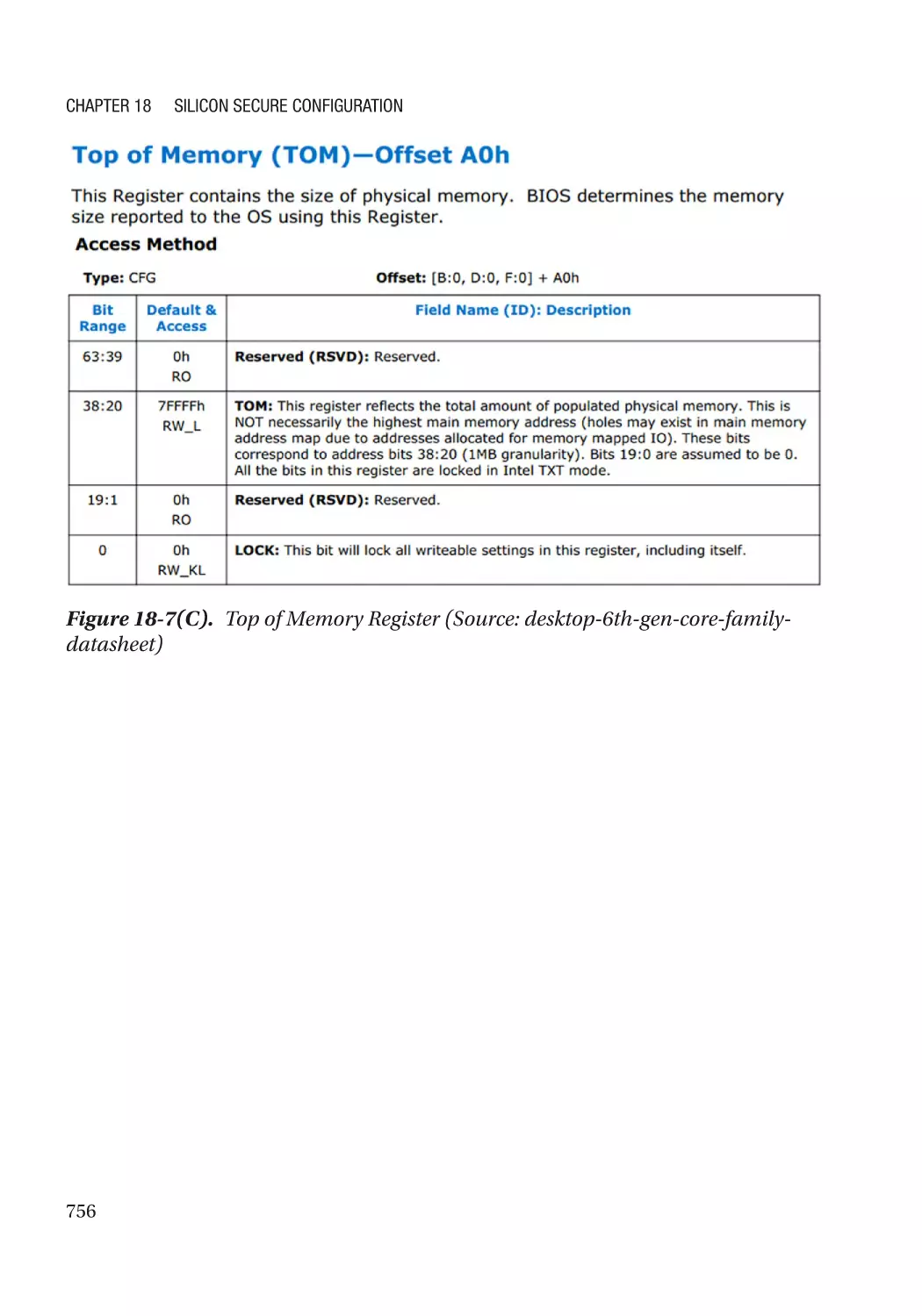
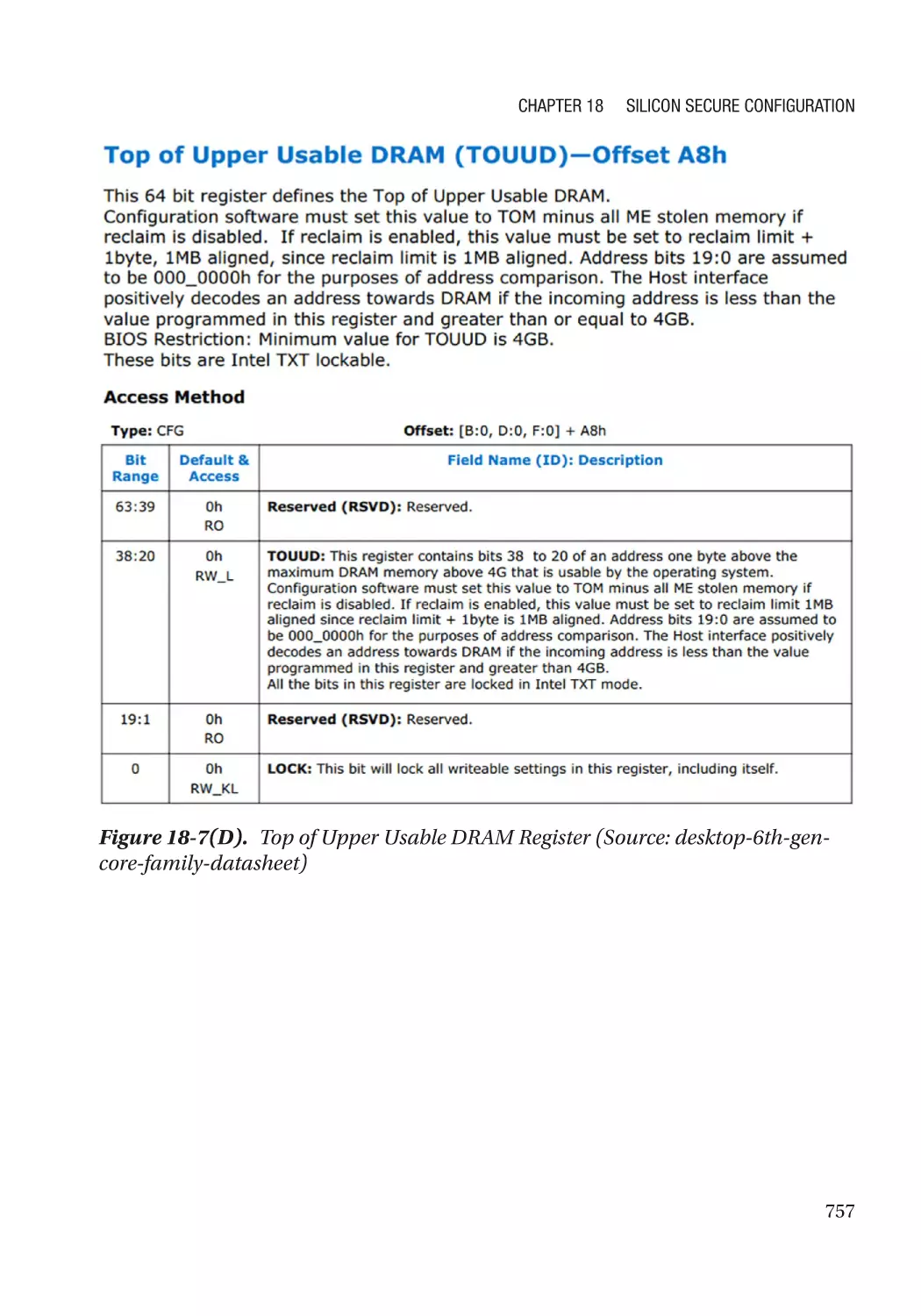
SMRAM Address Alias Lock������������������������������������������������������������������������������������������������� 754
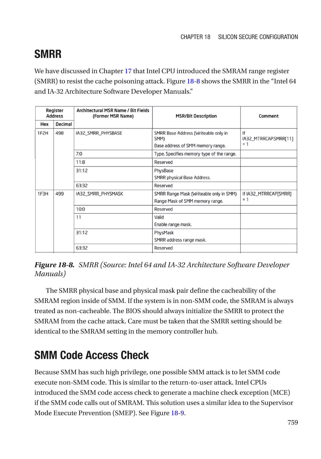
SMRR����������������������������������������������������������������������������������������������������������������������������������� 759
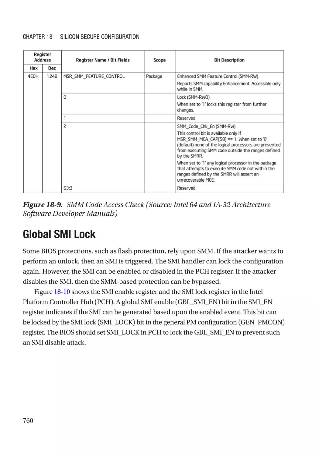
SMM Code Access Check���������������������������������������������������������������������������������������������������� 759
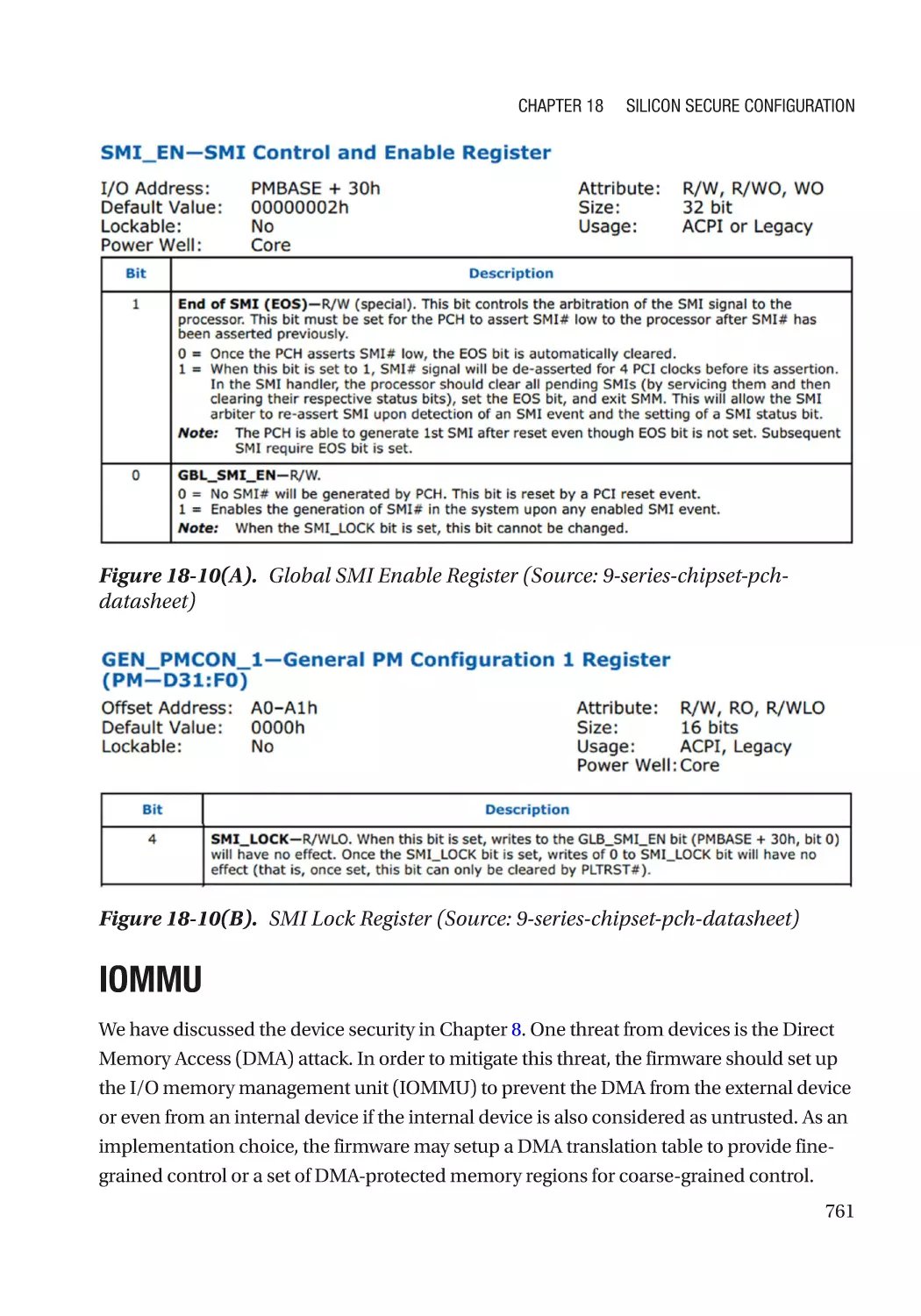
Global SMI Lock������������������������������������������������������������������������������������������������������������������� 760
IOMMU�������������������������������������������������������������������������������������������������������������������������������������� 761
IOMMU Protection for DRAM������������������������������������������������������������������������������������������������ 762
IOMMU Protection for SRAM������������������������������������������������������������������������������������������������ 762
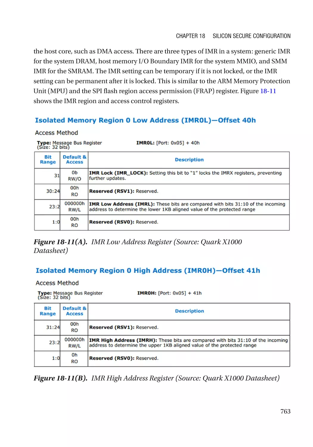
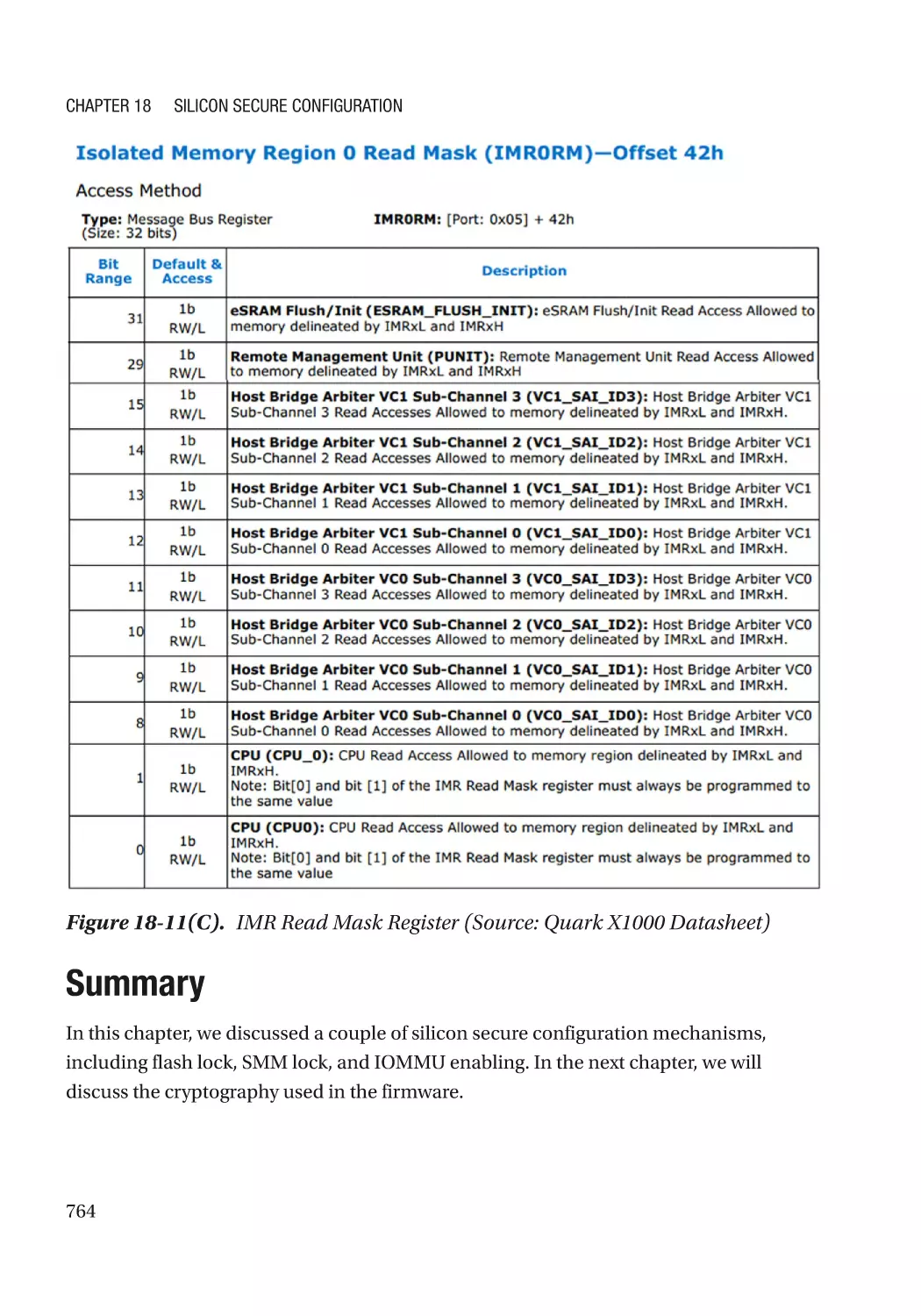
Silicon Support for DMA Prevention������������������������������������������������������������������������������������ 762
Summary���������������������������������������������������������������������������������������������������������������������������������� 764
References�������������������������������������������������������������������������������������������������������������������������������� 765
Chapter 19: Cryptography������������������������������������������������������������������������������������ 767
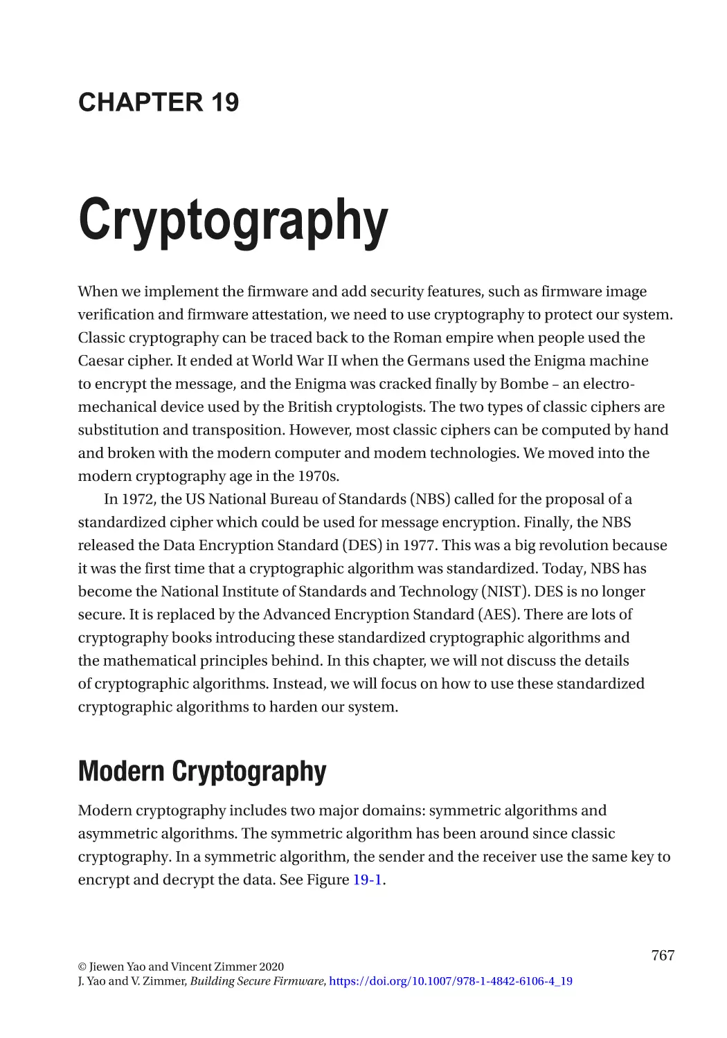
Modern Cryptography��������������������������������������������������������������������������������������������������������������� 767
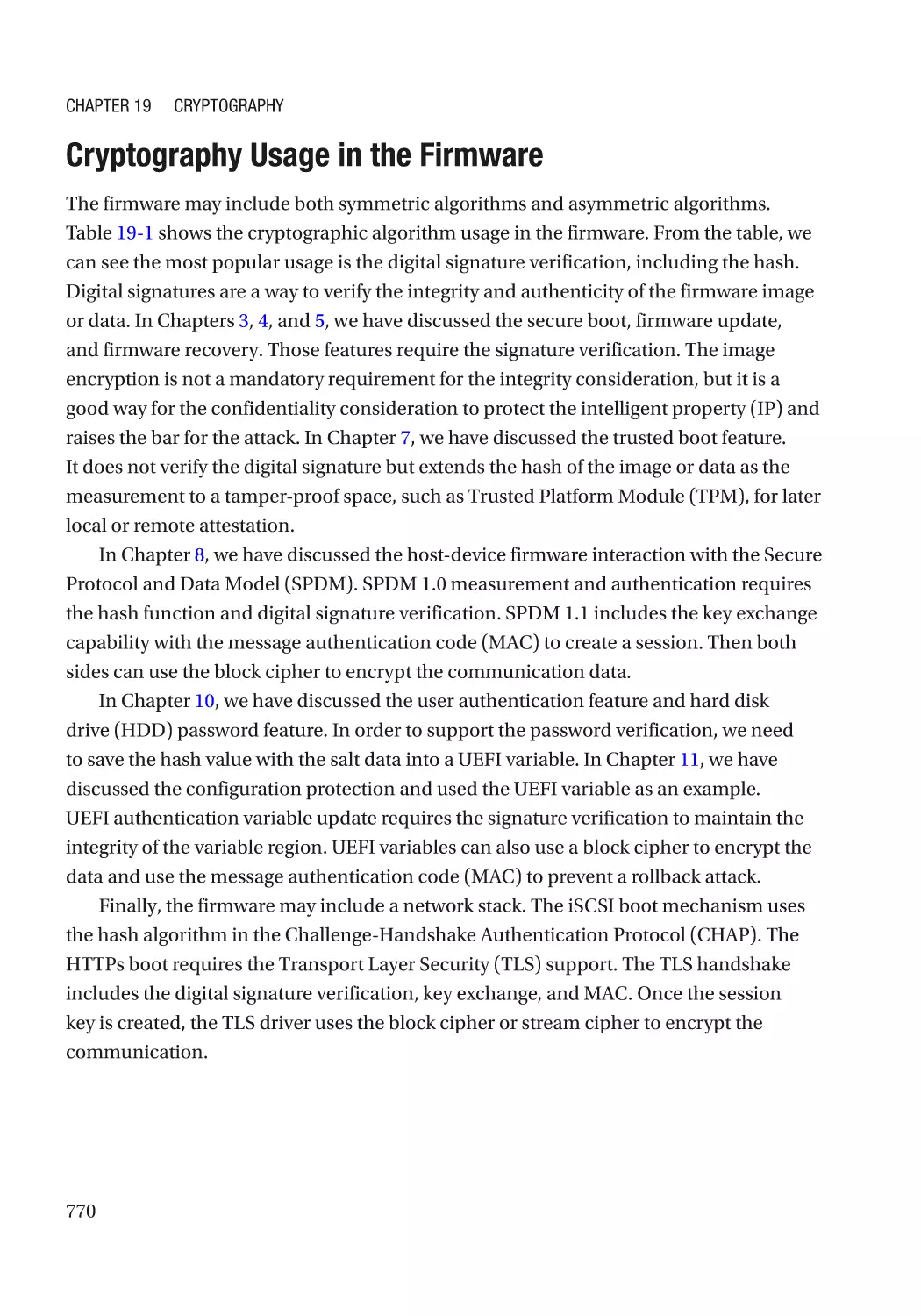
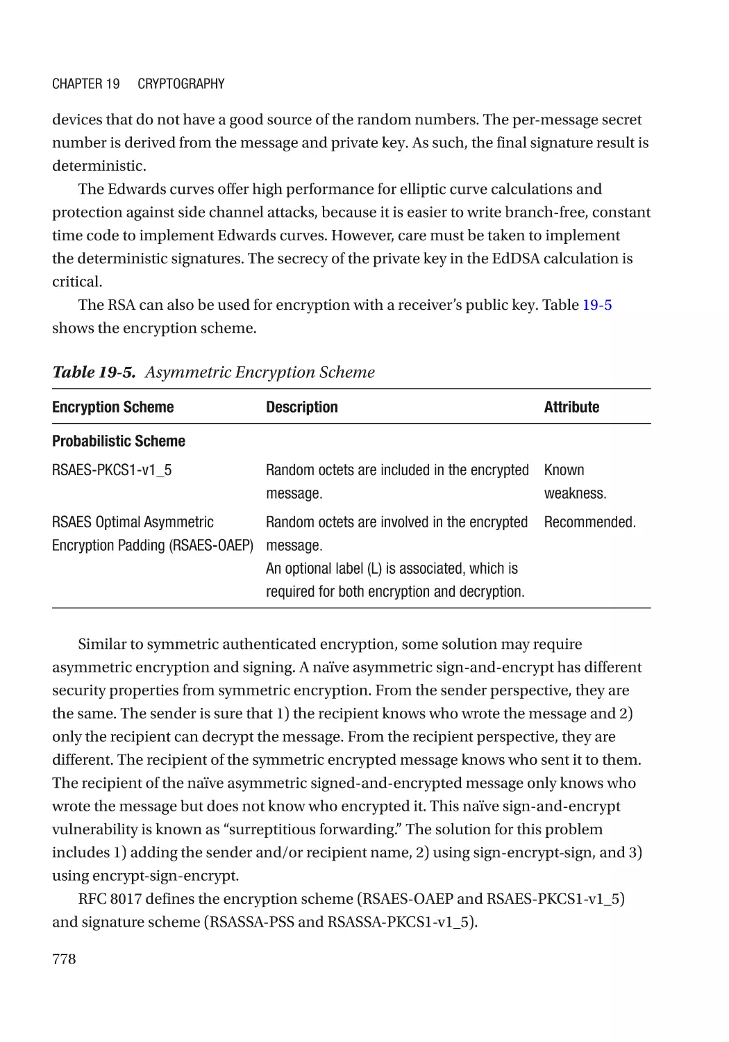
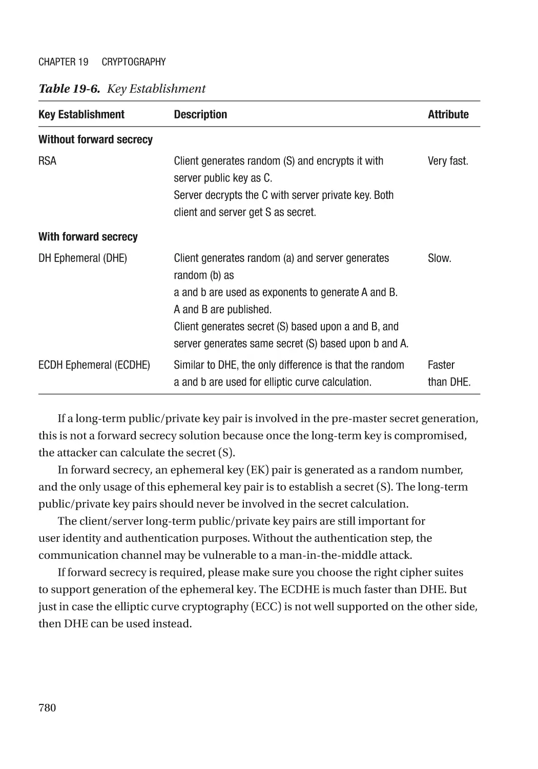
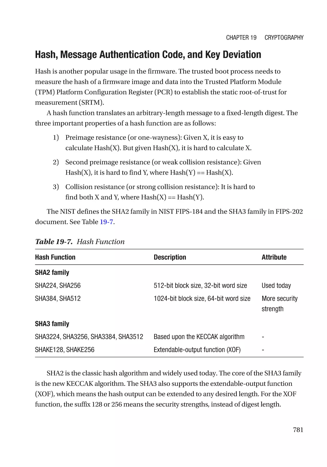
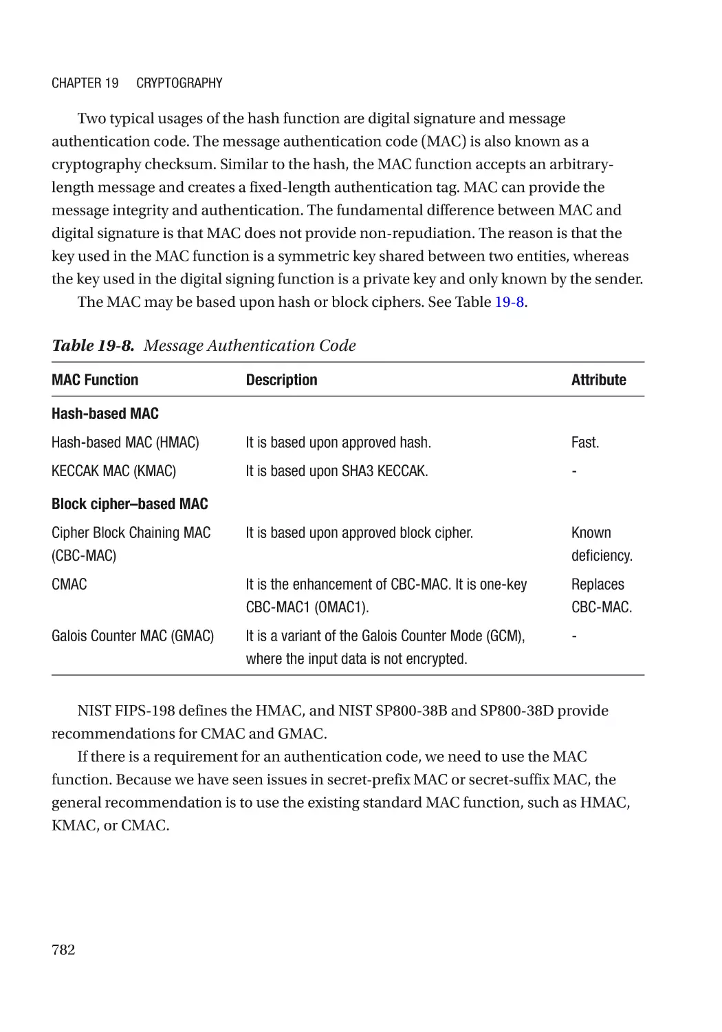
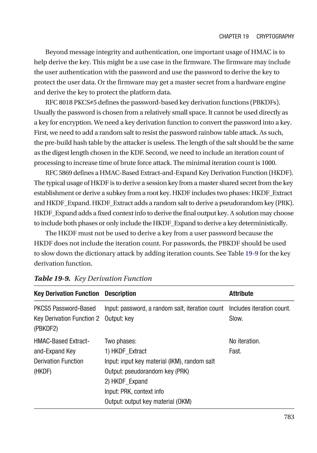
Cryptography Usage in the Firmware���������������������������������������������������������������������������������� 770
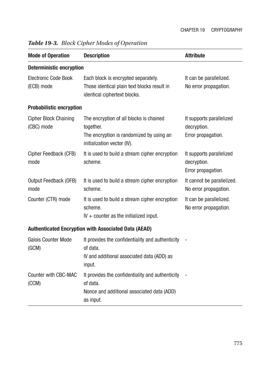
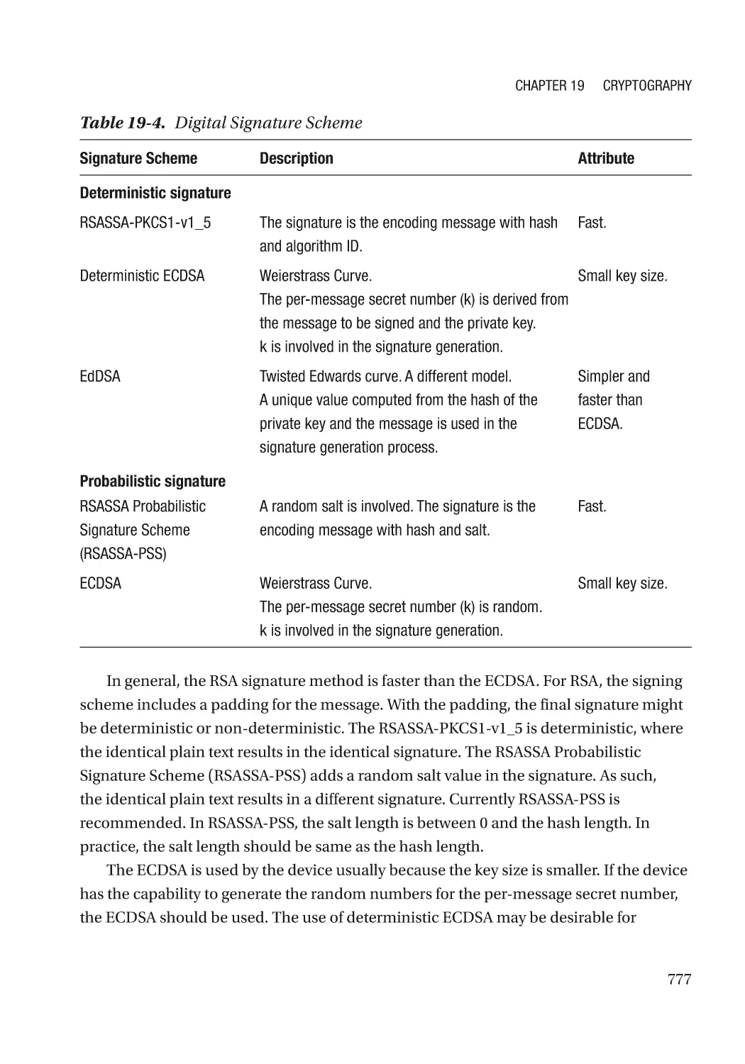
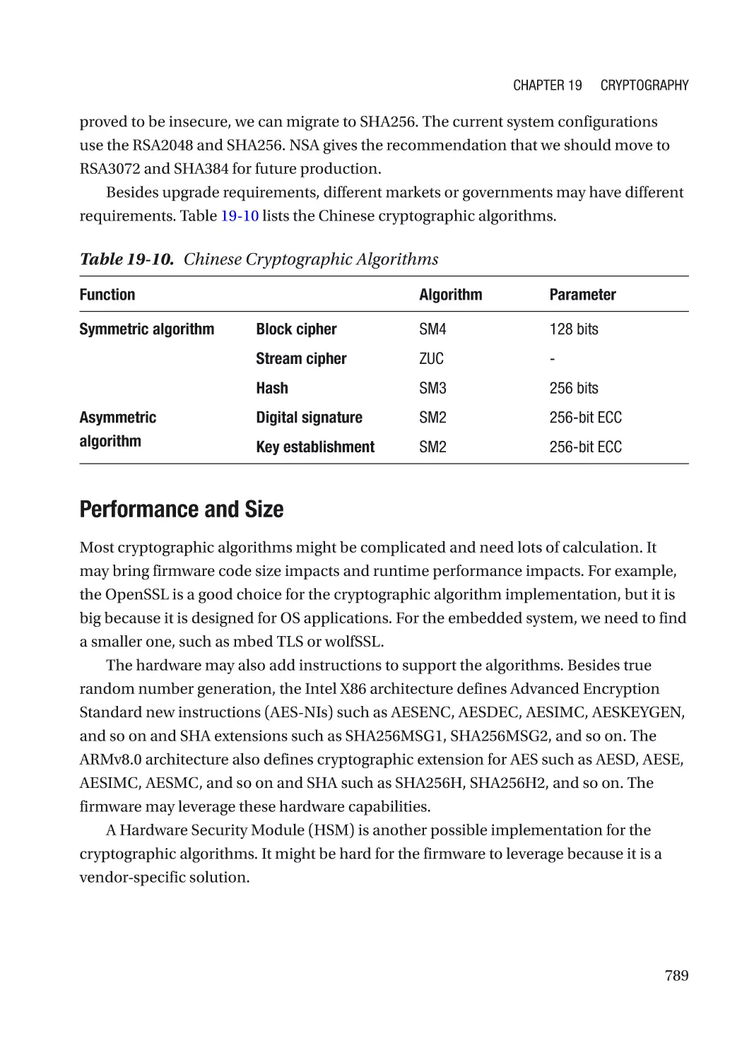
Algorithm Recommendation������������������������������������������������������������������������������������������������ 772
Some Concepts������������������������������������������������������������������������������������������������������������������� 772
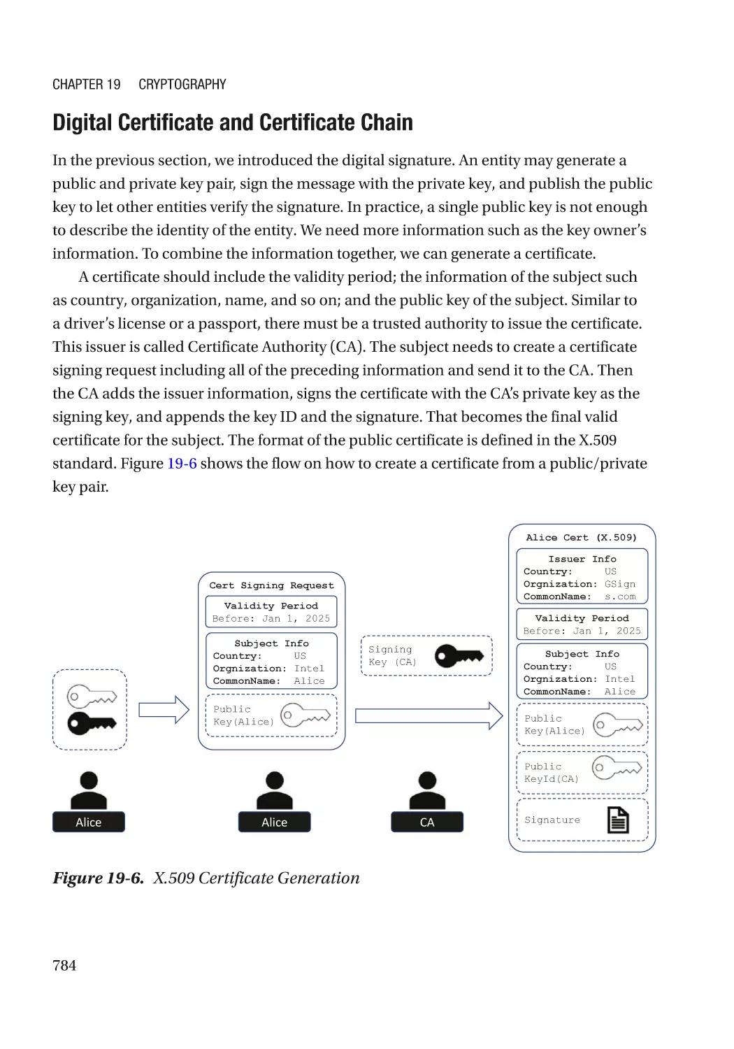
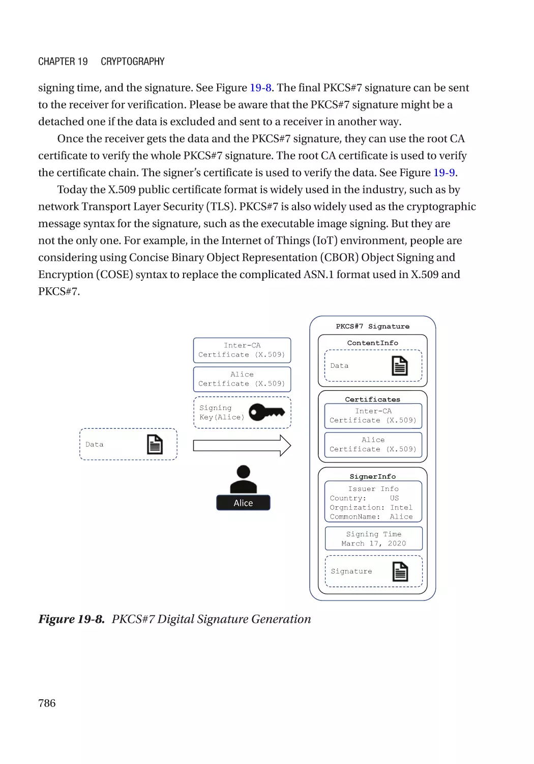
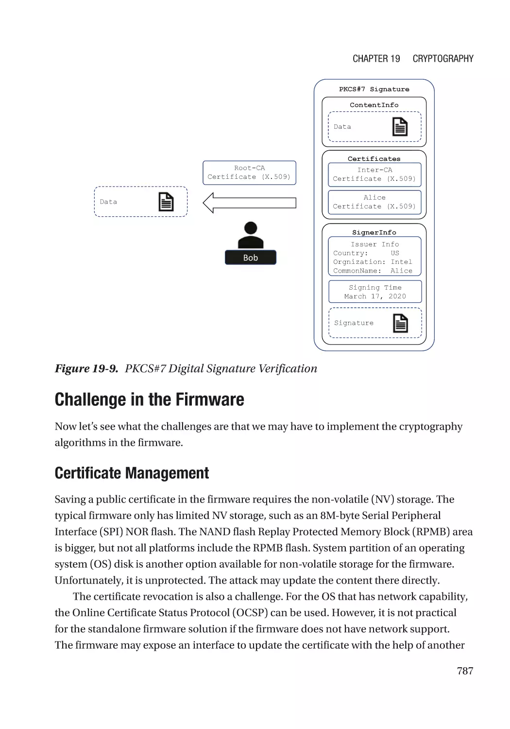
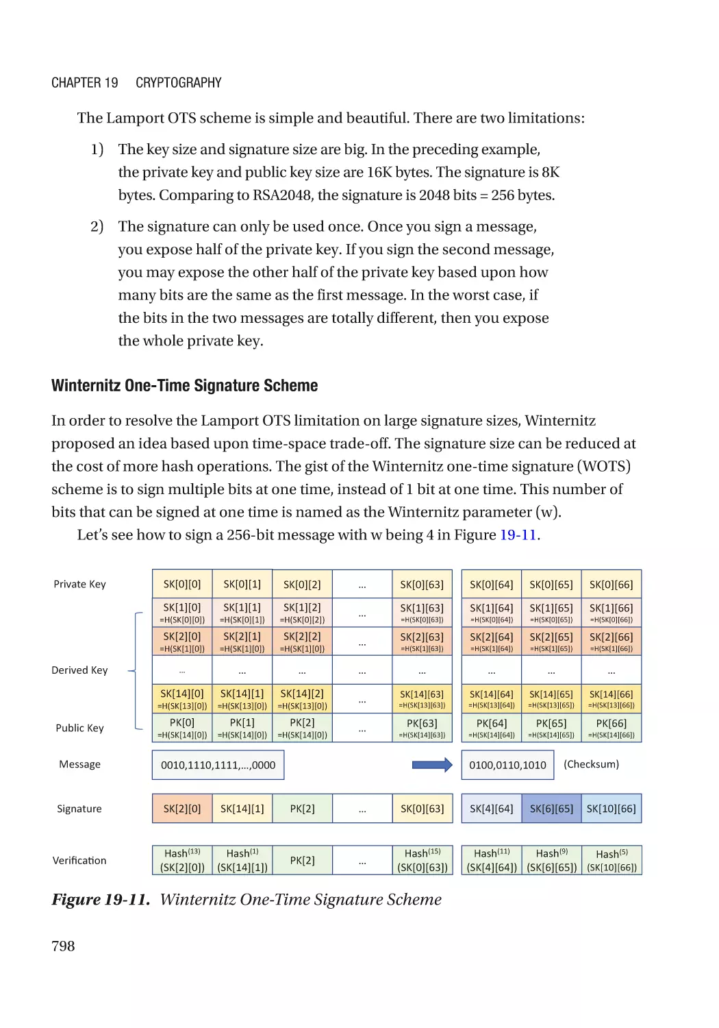
Challenge in the Firmware�������������������������������������������������������������������������������������������������� 787
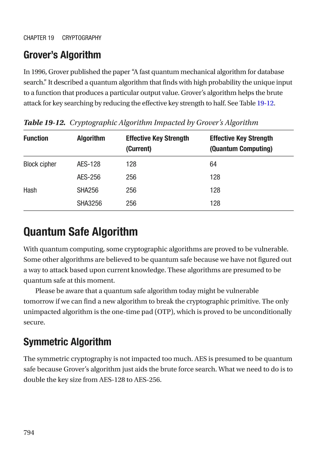
Attack and Mitigation���������������������������������������������������������������������������������������������������������� 790
xv
Table of Contents
Quantum Safe Cryptography����������������������������������������������������������������������������������������������������� 792
Security Challenge�������������������������������������������������������������������������������������������������������������� 792
Quantum Safe Algorithm����������������������������������������������������������������������������������������������������� 794
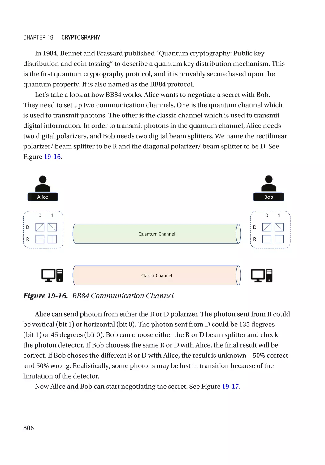
Quantum Cryptography������������������������������������������������������������������������������������������������������� 805
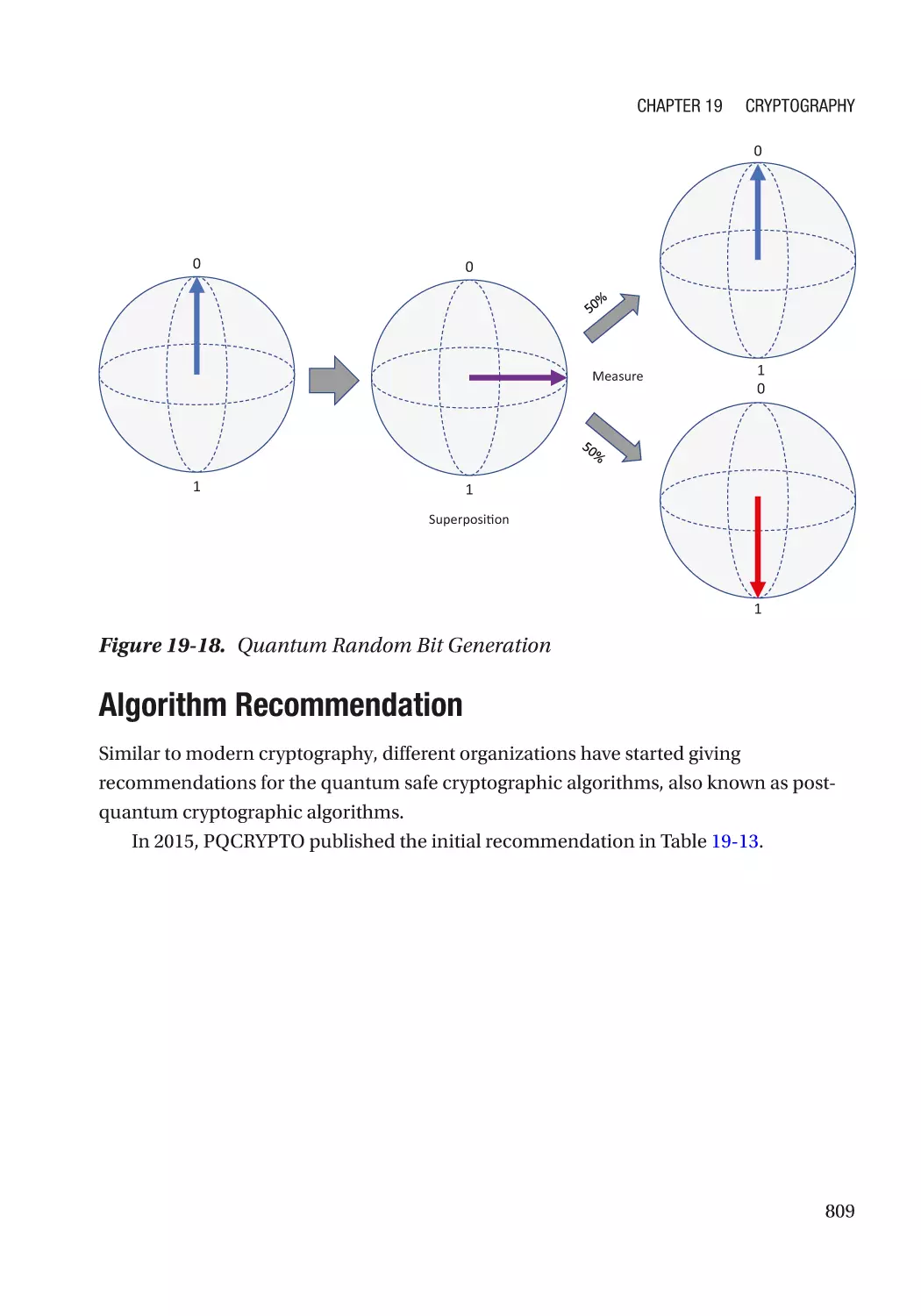
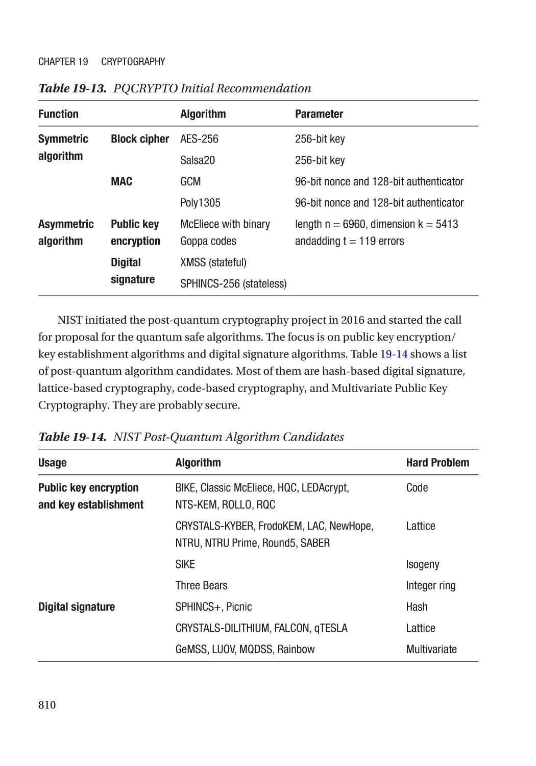
Algorithm Recommendation������������������������������������������������������������������������������������������������ 809
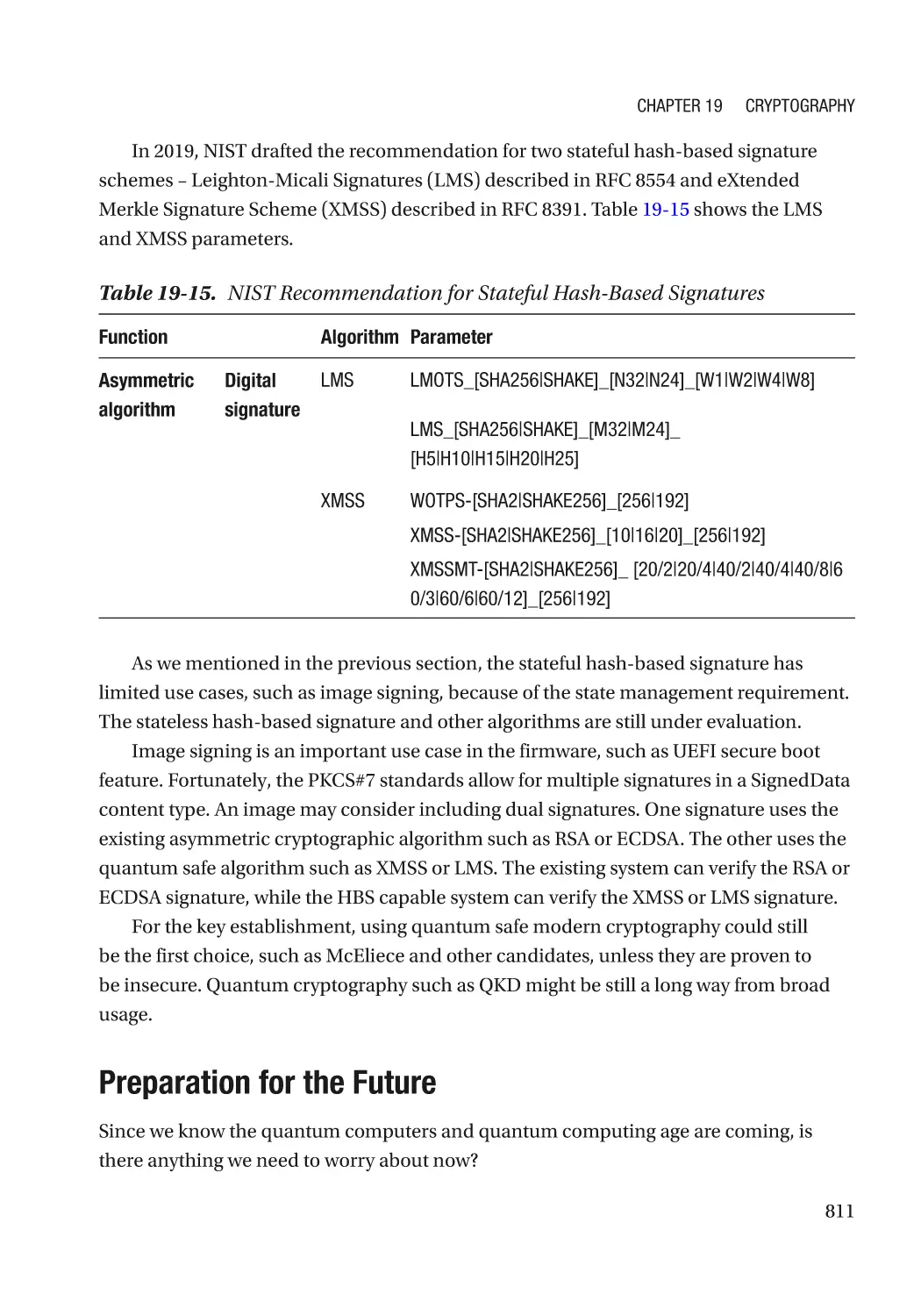
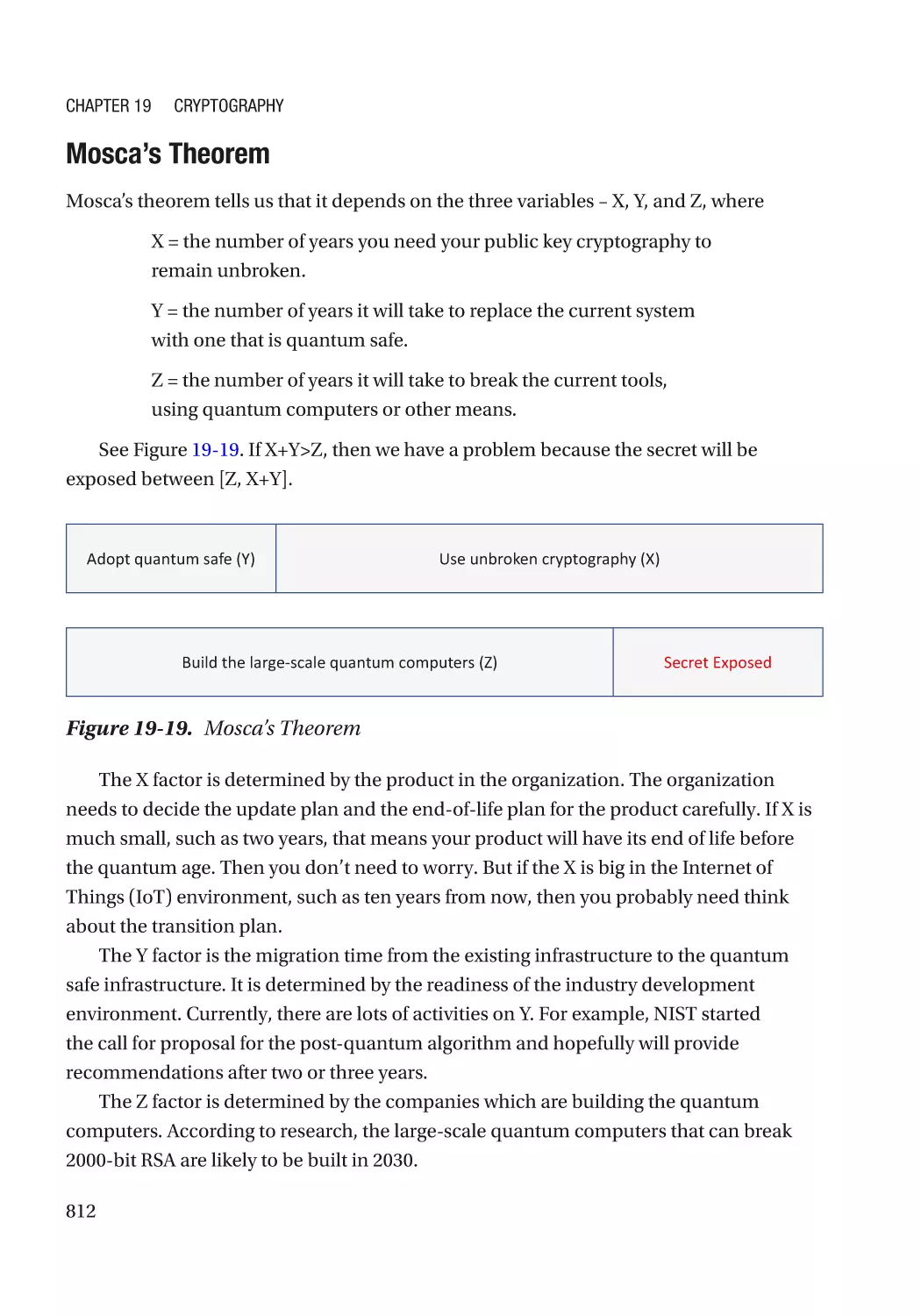
Preparation for the Future��������������������������������������������������������������������������������������������������� 811
Summary���������������������������������������������������������������������������������������������������������������������������������� 813
References�������������������������������������������������������������������������������������������������������������������������������� 814
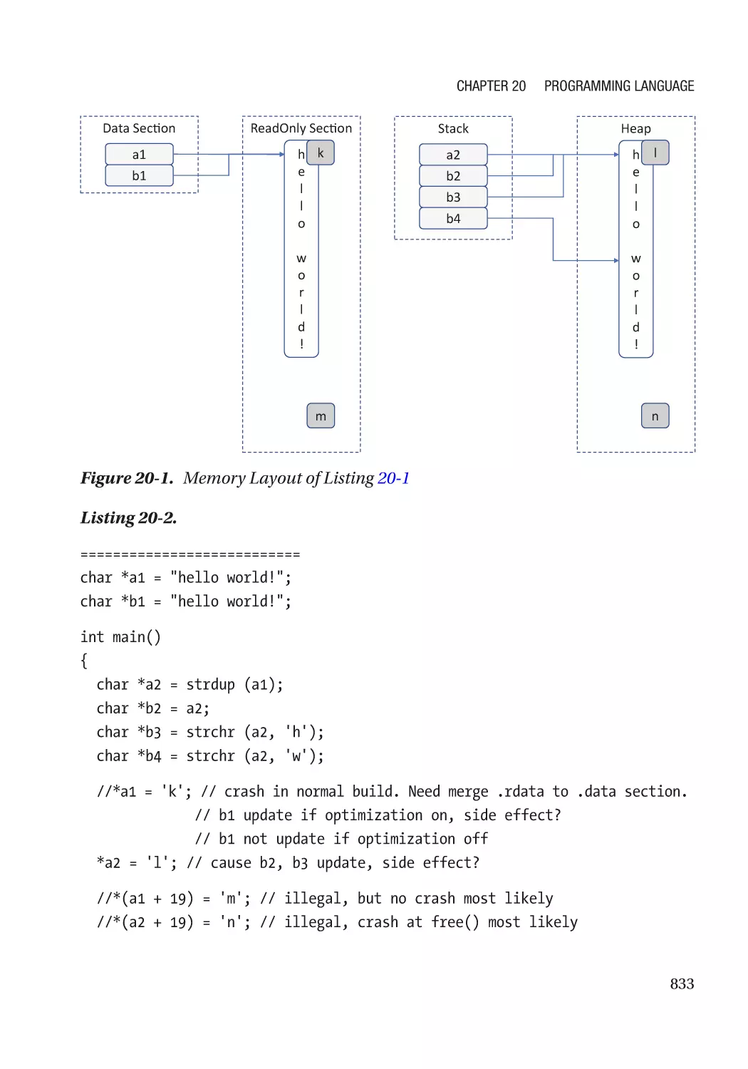
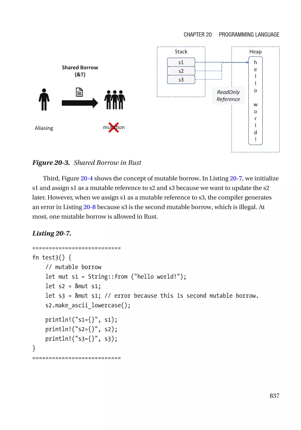
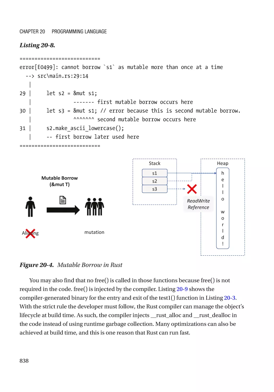
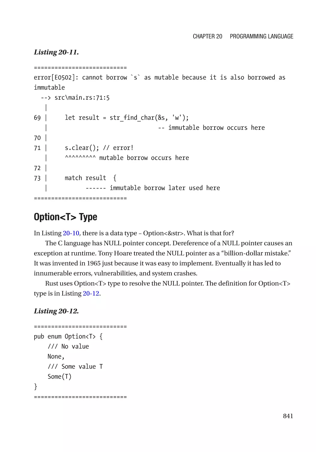
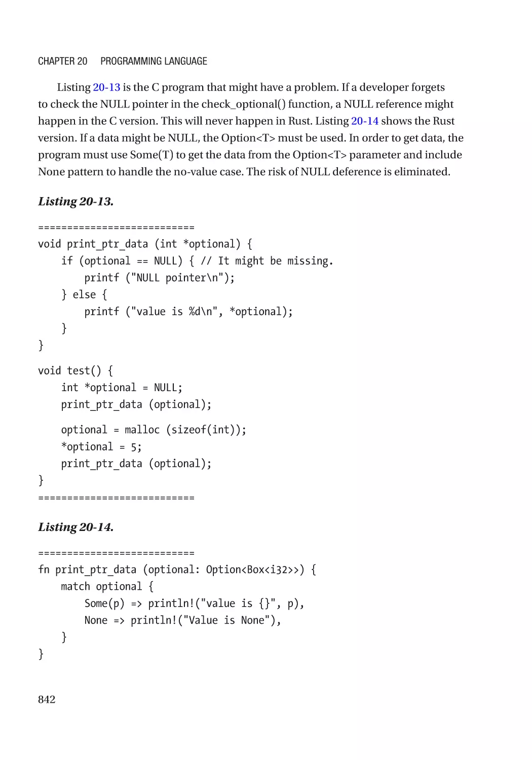
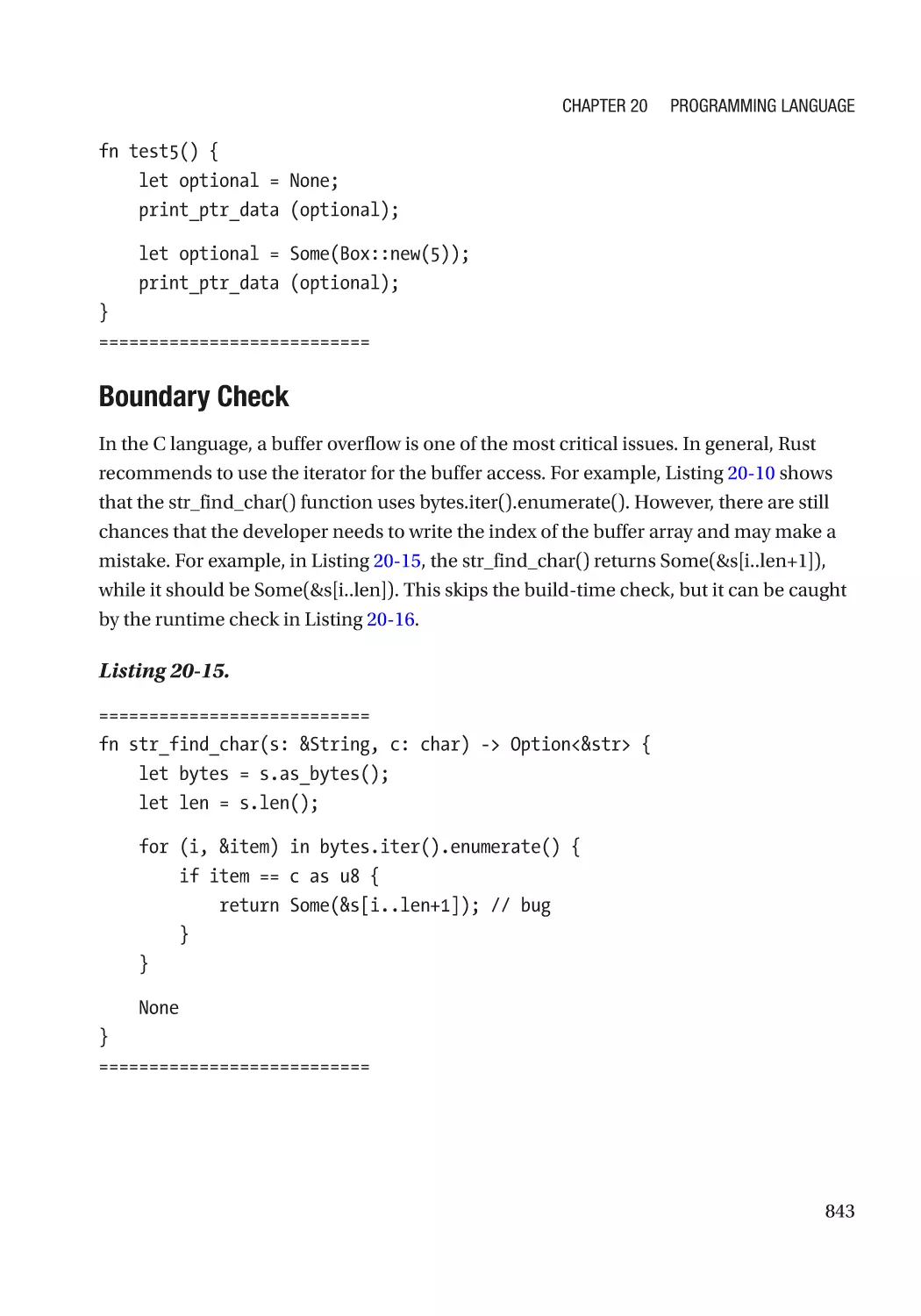
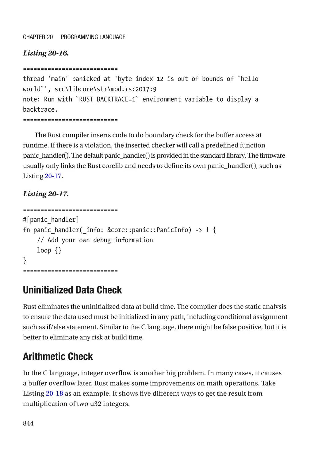
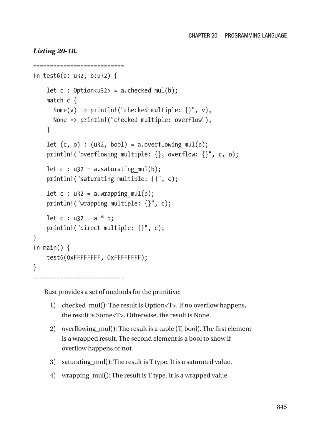
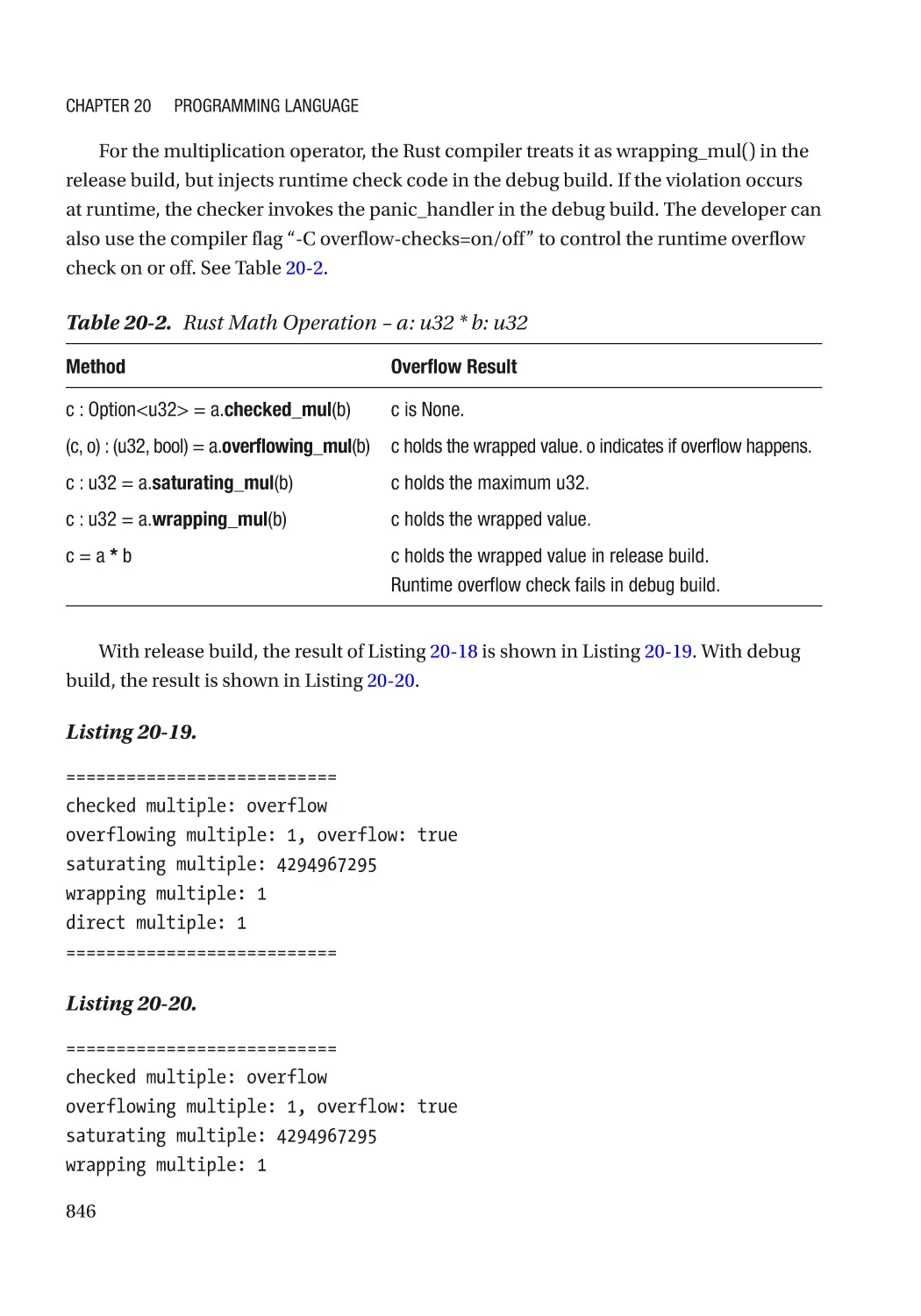
Chapter 20: Programming Language�������������������������������������������������������������������� 825
Assembly Language������������������������������������������������������������������������������������������������������������������ 825
C Language������������������������������������������������������������������������������������������������������������������������������� 828
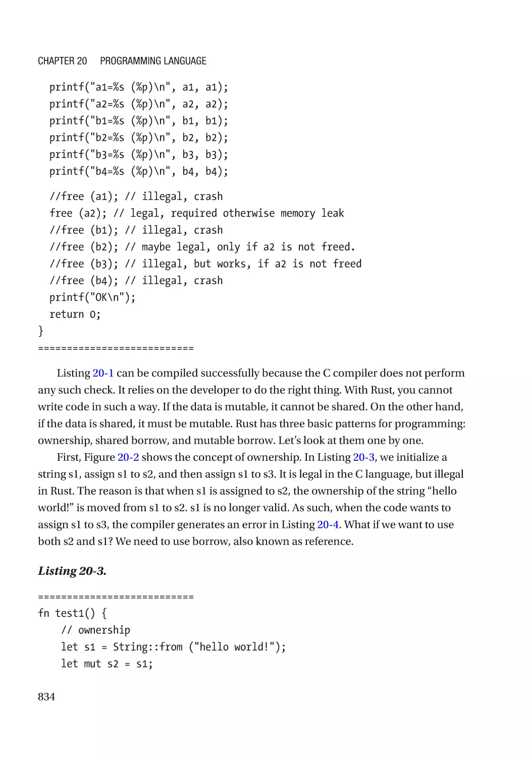
Rust������������������������������������������������������������������������������������������������������������������������������������������� 828
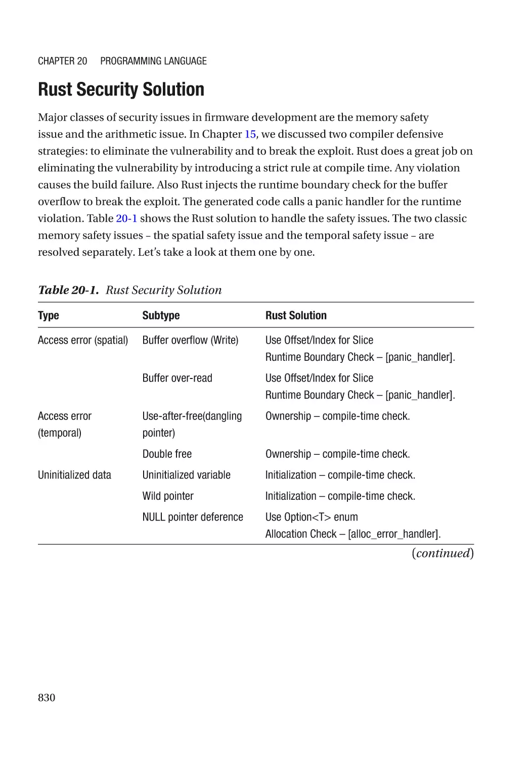
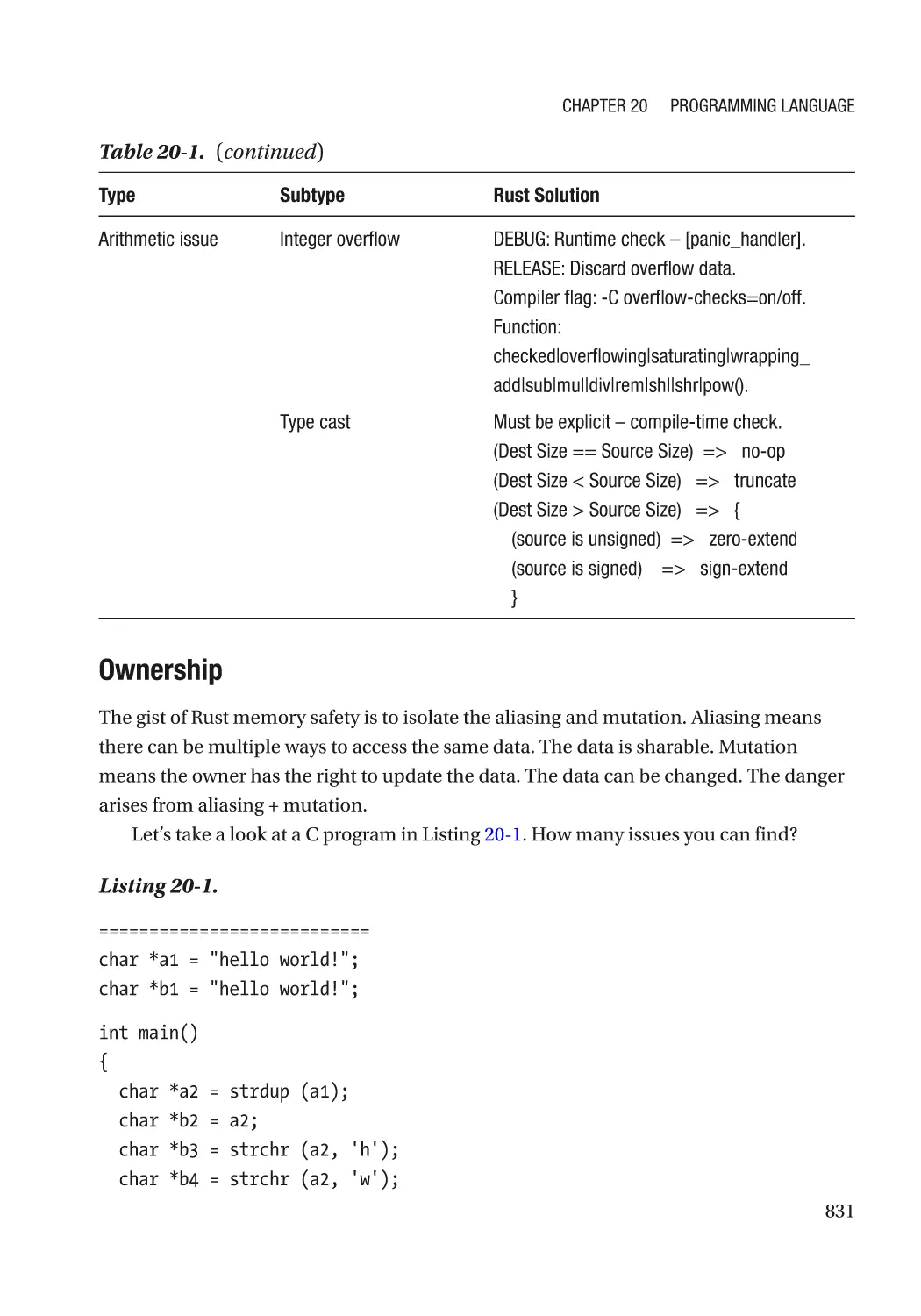
Rust Security Solution��������������������������������������������������������������������������������������������������������� 830
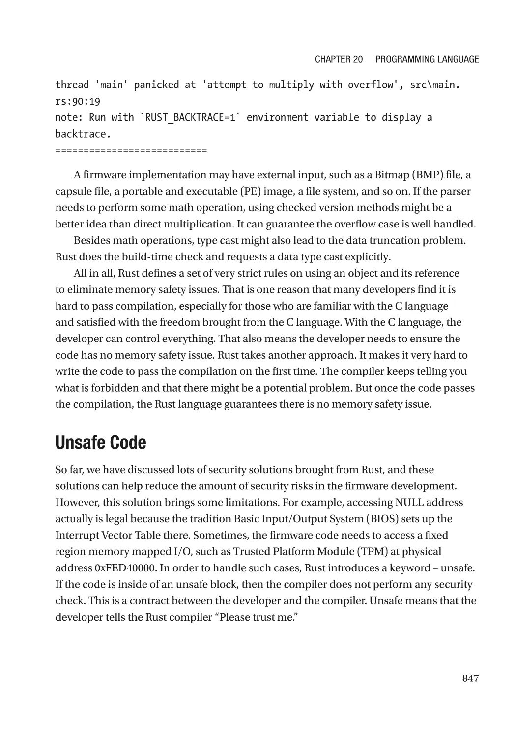
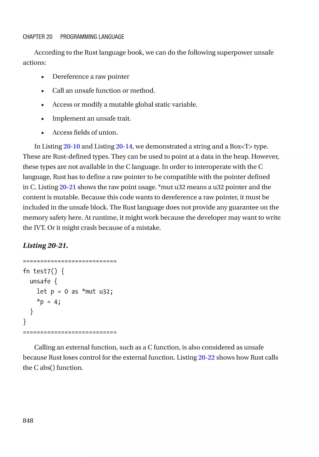
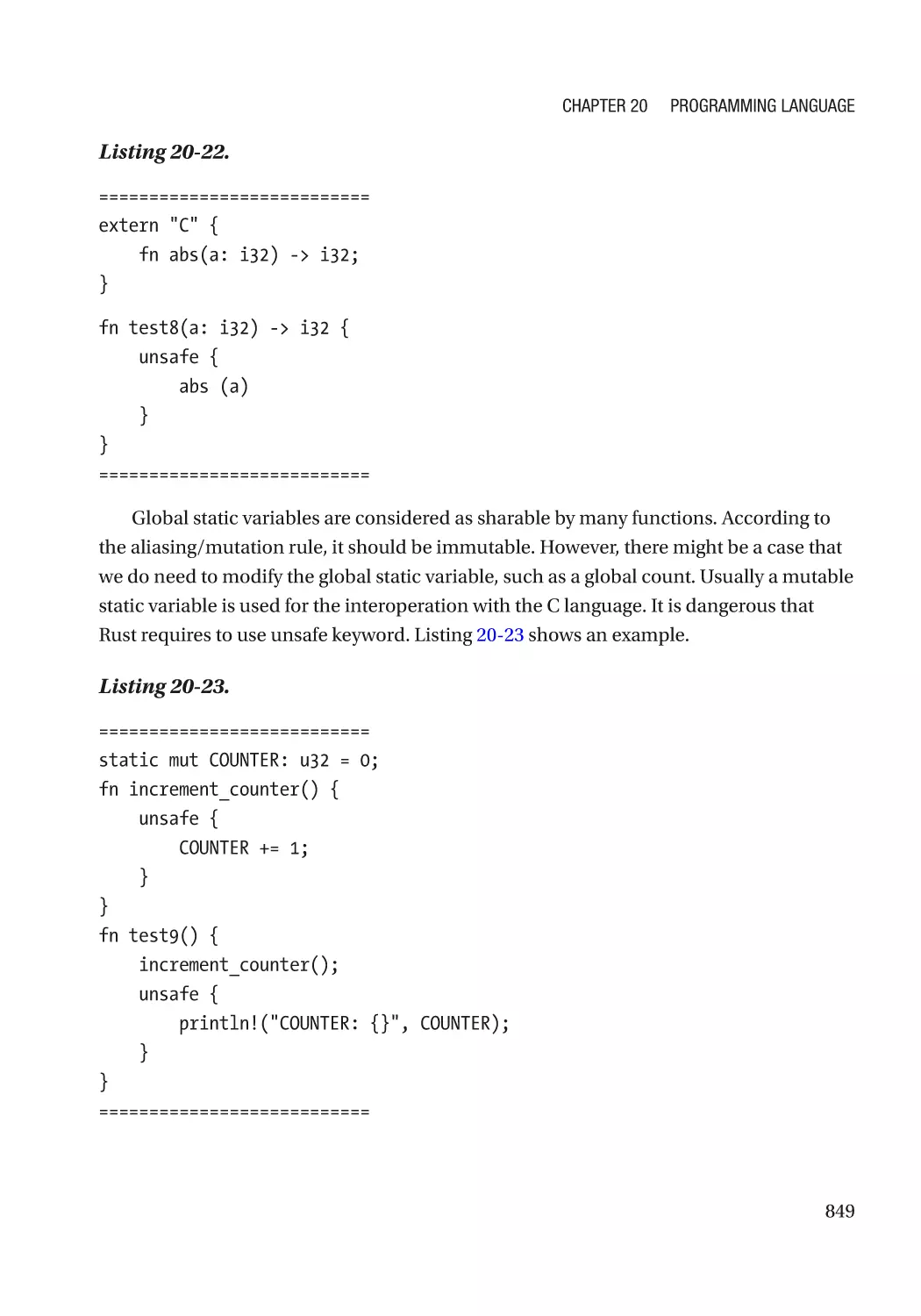
Unsafe Code������������������������������������������������������������������������������������������������������������������������ 847
Current Project�������������������������������������������������������������������������������������������������������������������� 850
Limitation����������������������������������������������������������������������������������������������������������������������������� 851
Others��������������������������������������������������������������������������������������������������������������������������������������� 852
Summary���������������������������������������������������������������������������������������������������������������������������������� 852
References�������������������������������������������������������������������������������������������������������������������������������� 852
Part IV: Security Test���������������������������������������������������������������������������������� 855
Chapter 21: Security Unit Test������������������������������������������������������������������������������ 857
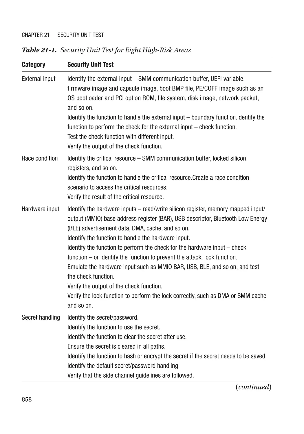
Security Unit Testing Plan��������������������������������������������������������������������������������������������������������� 857
Advanced Security Unit Testing������������������������������������������������������������������������������������������������� 860
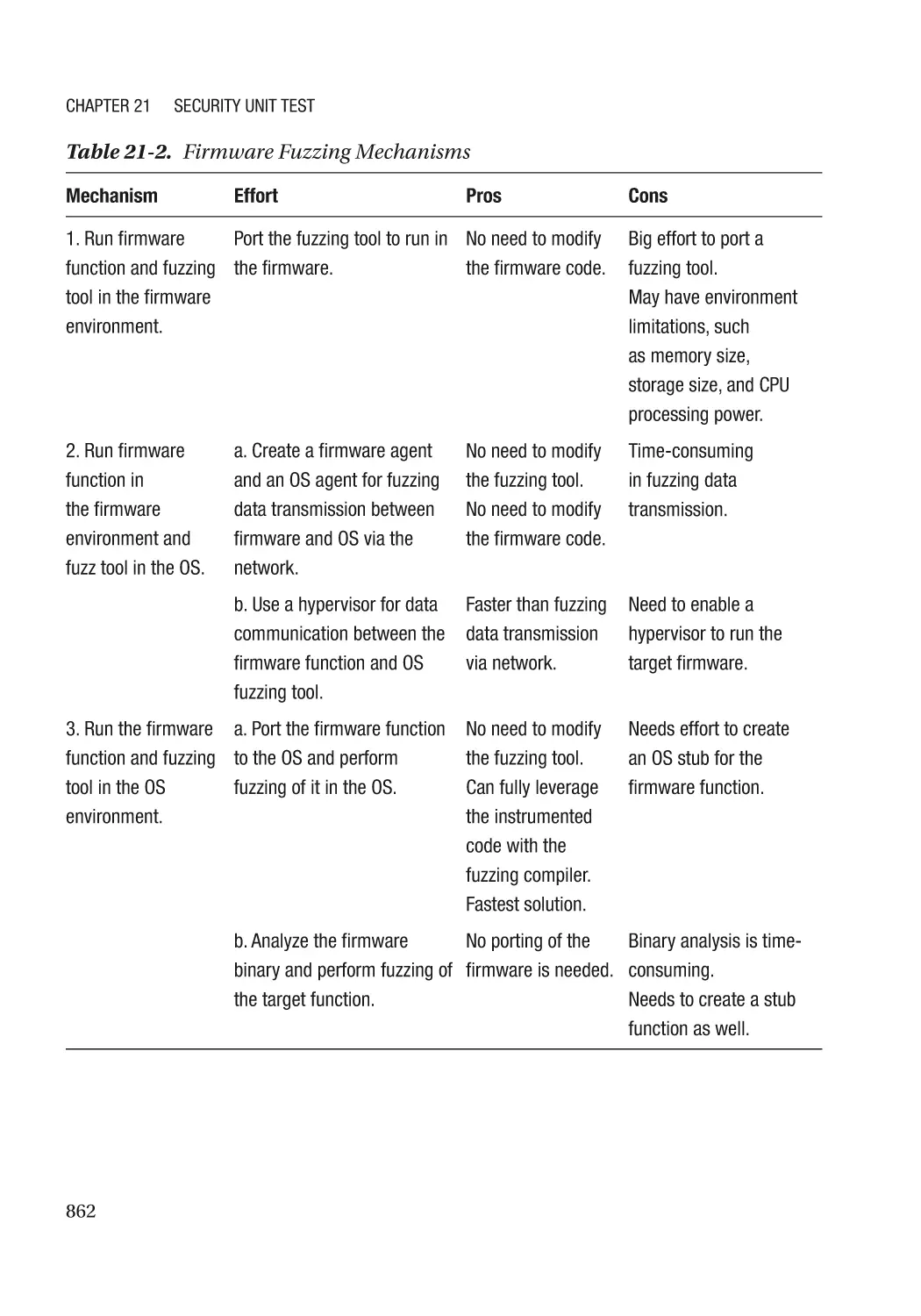
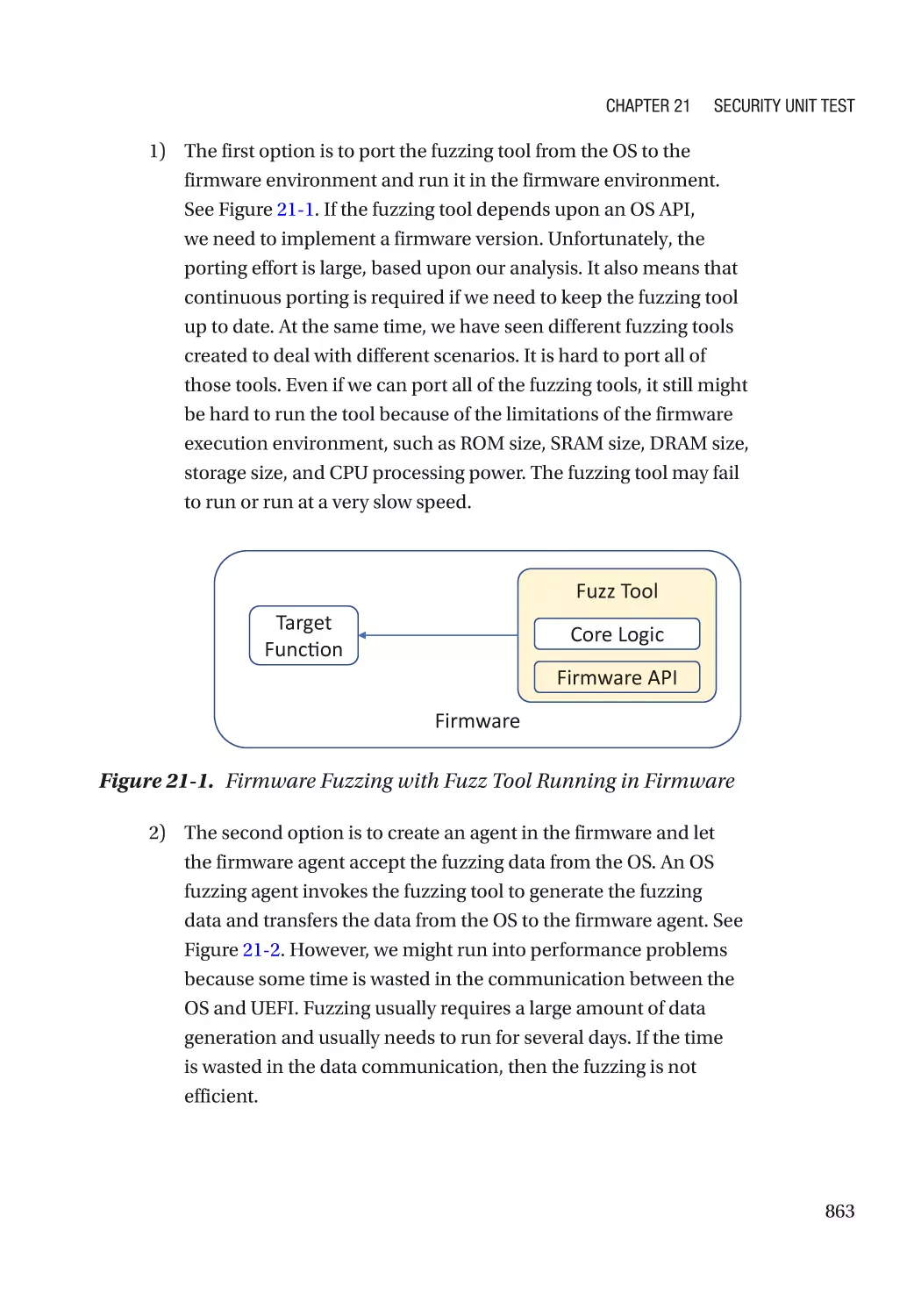
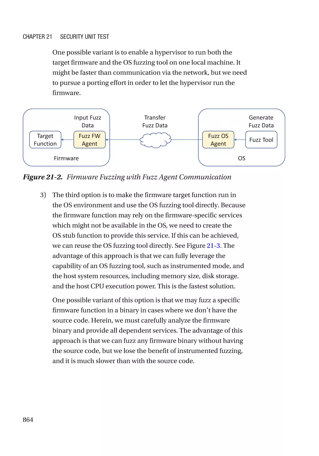
Fuzzing�������������������������������������������������������������������������������������������������������������������������������� 861
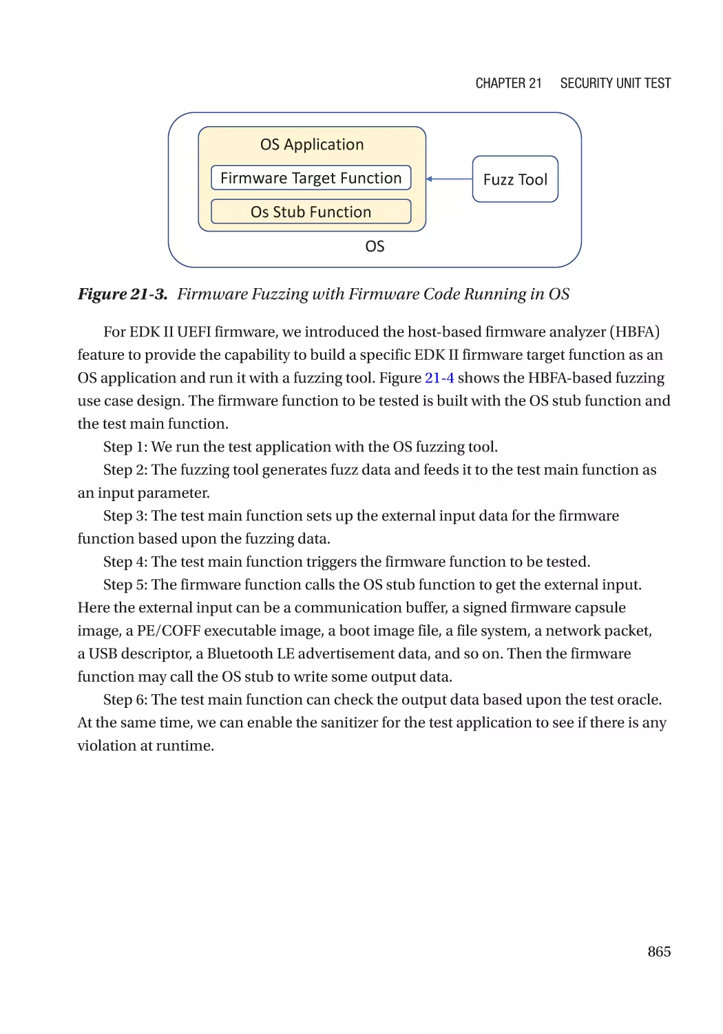
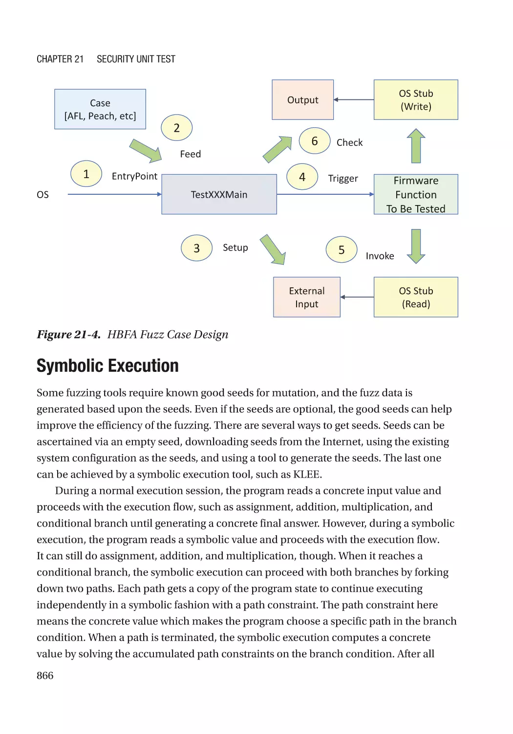
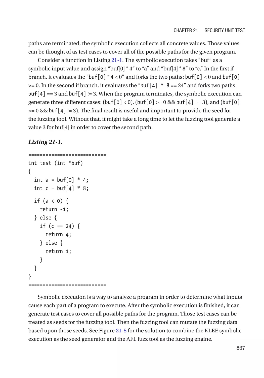
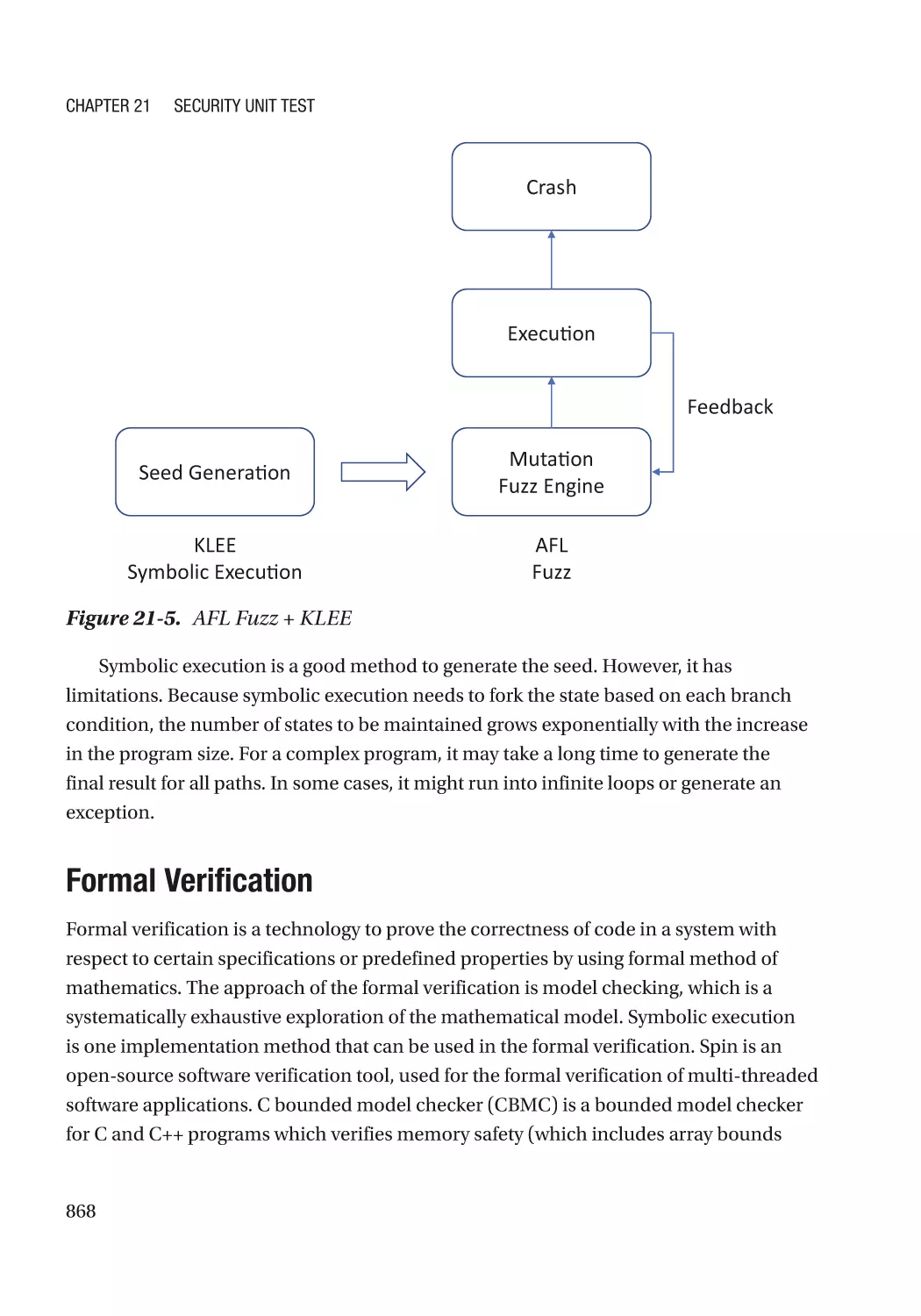
Symbolic Execution������������������������������������������������������������������������������������������������������������� 866
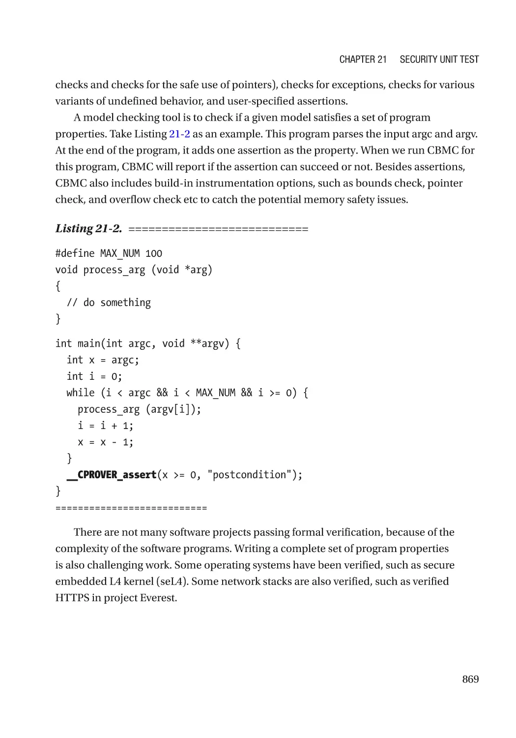
Formal Verification�������������������������������������������������������������������������������������������������������������� 868
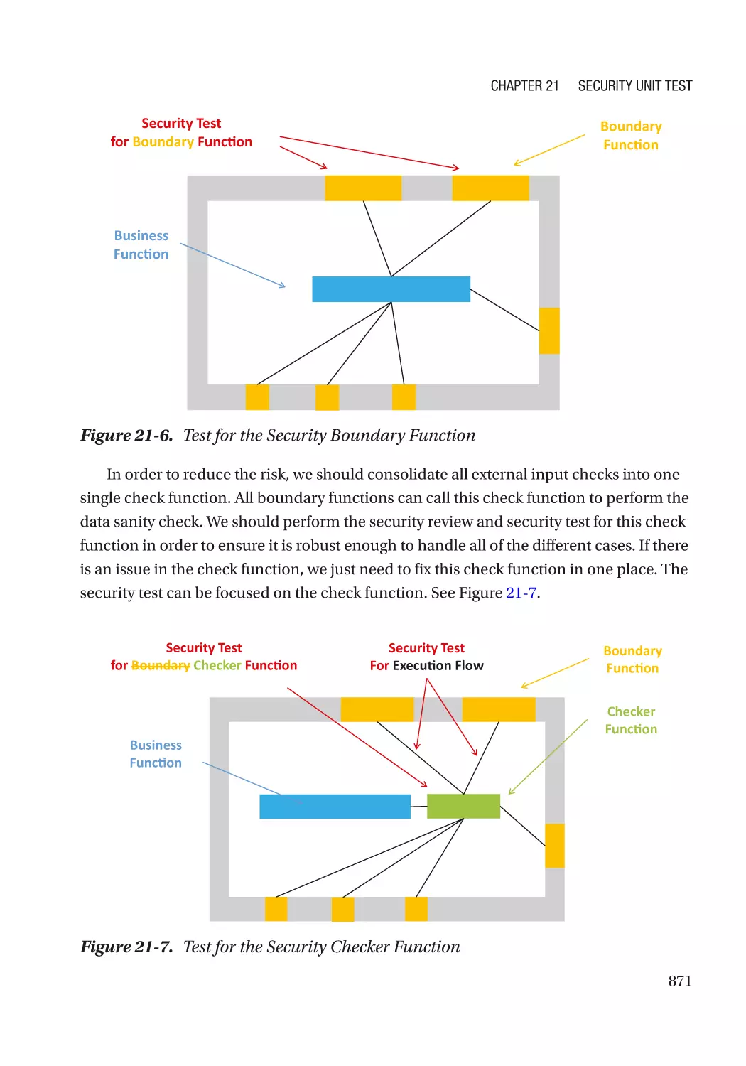
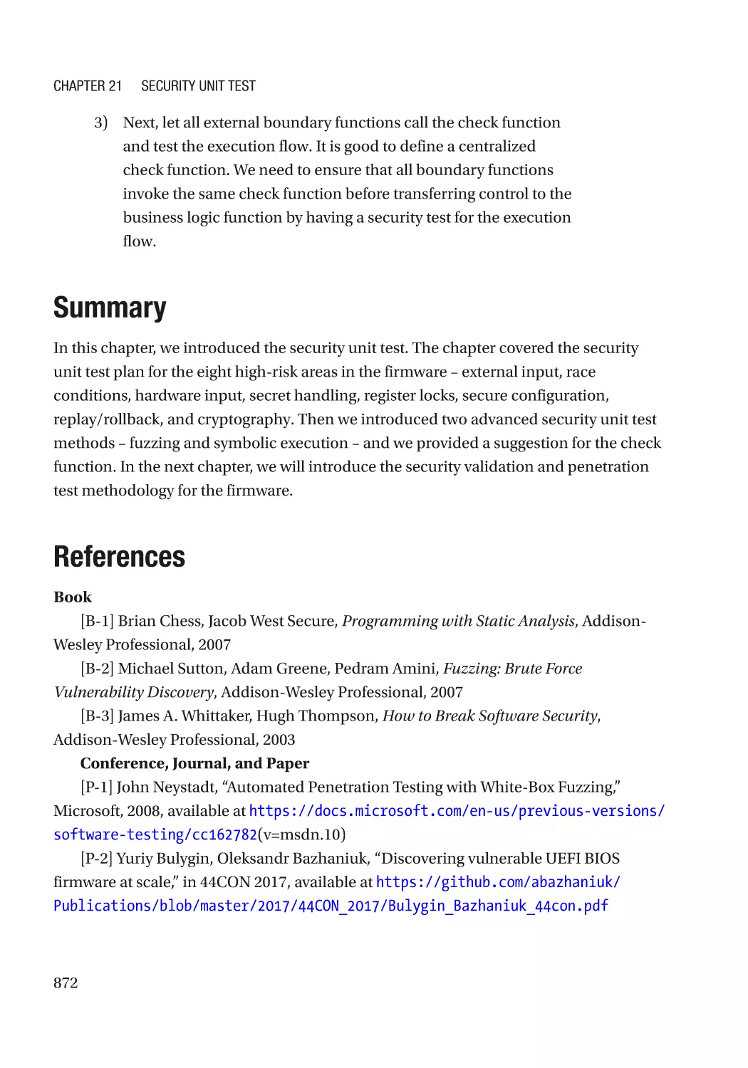
Design for Security Test������������������������������������������������������������������������������������������������������������ 870
Summary���������������������������������������������������������������������������������������������������������������������������������� 872
References�������������������������������������������������������������������������������������������������������������������������������� 872
xvi
Table of Contents
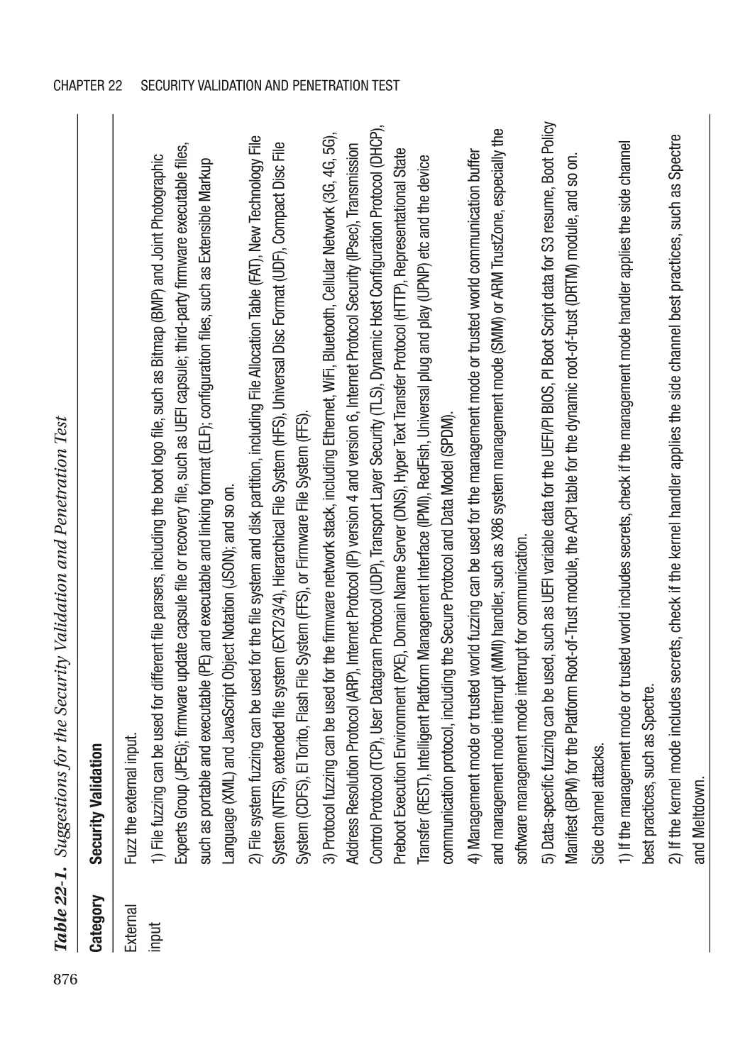
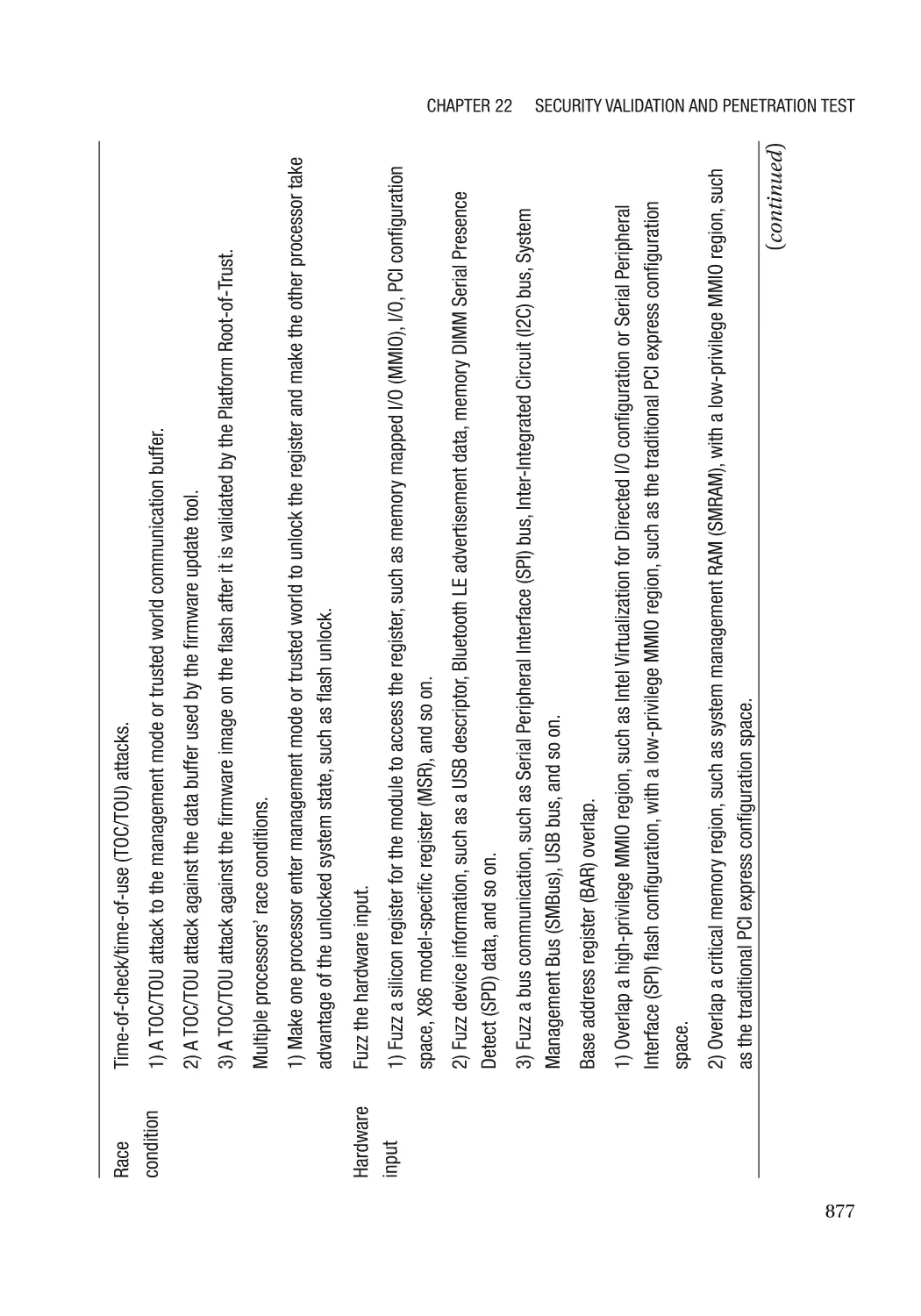
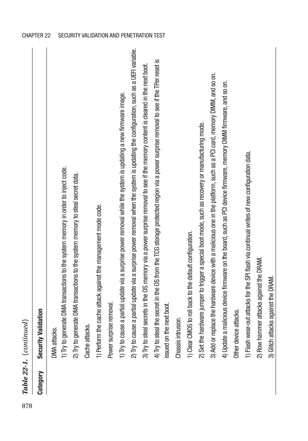
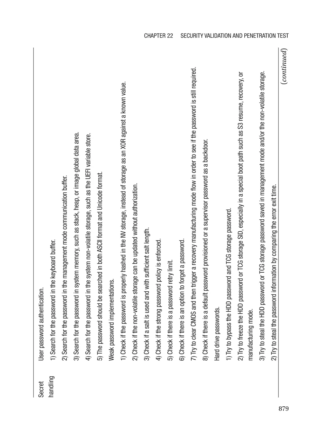
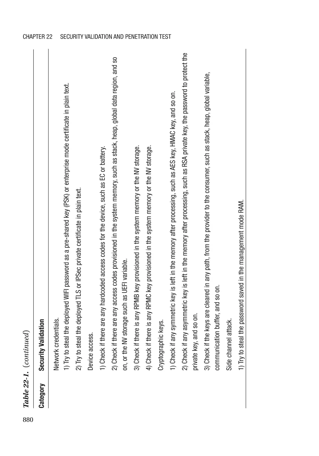
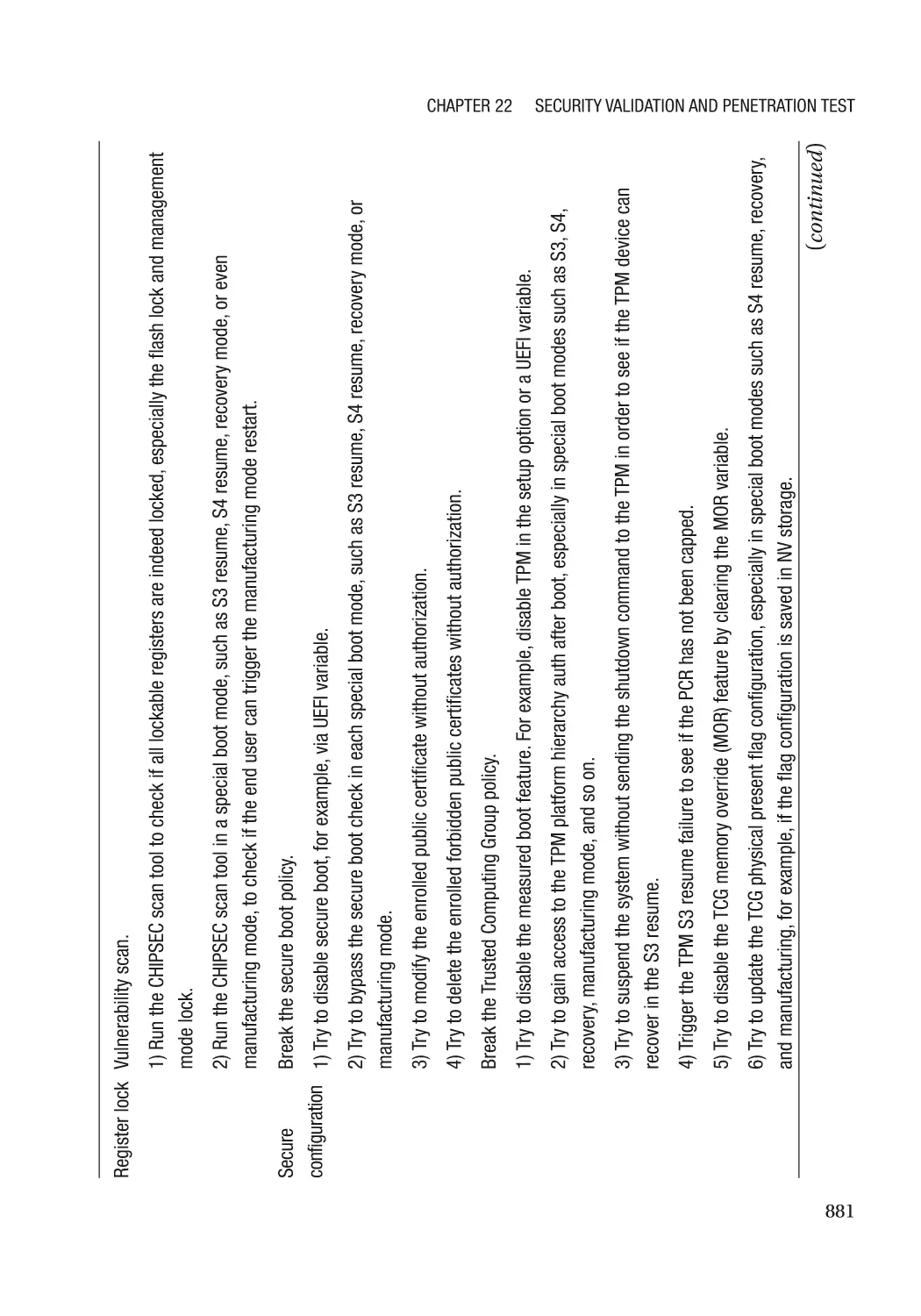
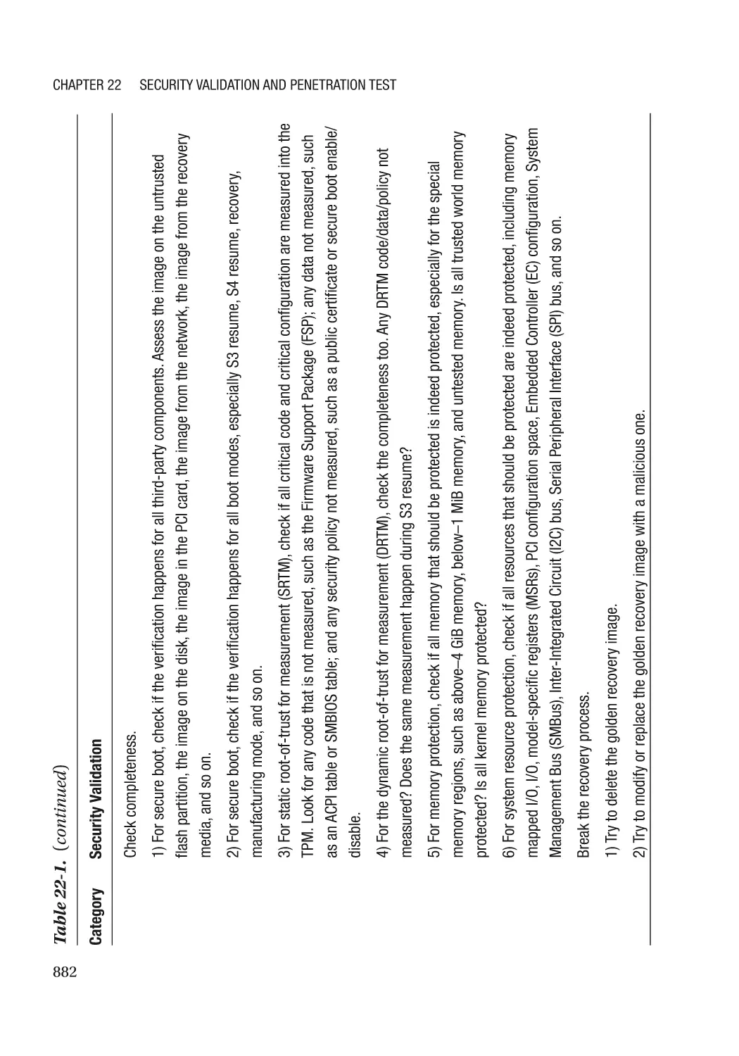
Chapter 22: Security Validation and Penetration Test������������������������������������������ 875
Security Validation Plan������������������������������������������������������������������������������������������������������������ 875
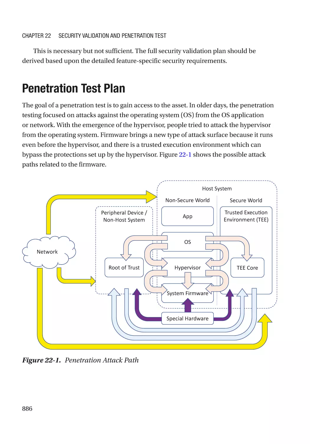
Penetration Test Plan���������������������������������������������������������������������������������������������������������������� 886
Summary���������������������������������������������������������������������������������������������������������������������������������� 888
References�������������������������������������������������������������������������������������������������������������������������������� 889
Chapter 23: Maintenance������������������������������������������������������������������������������������� 891
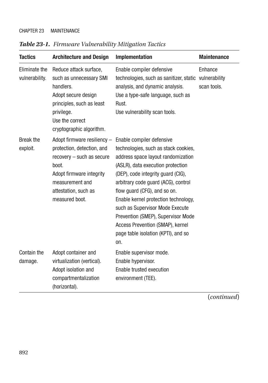
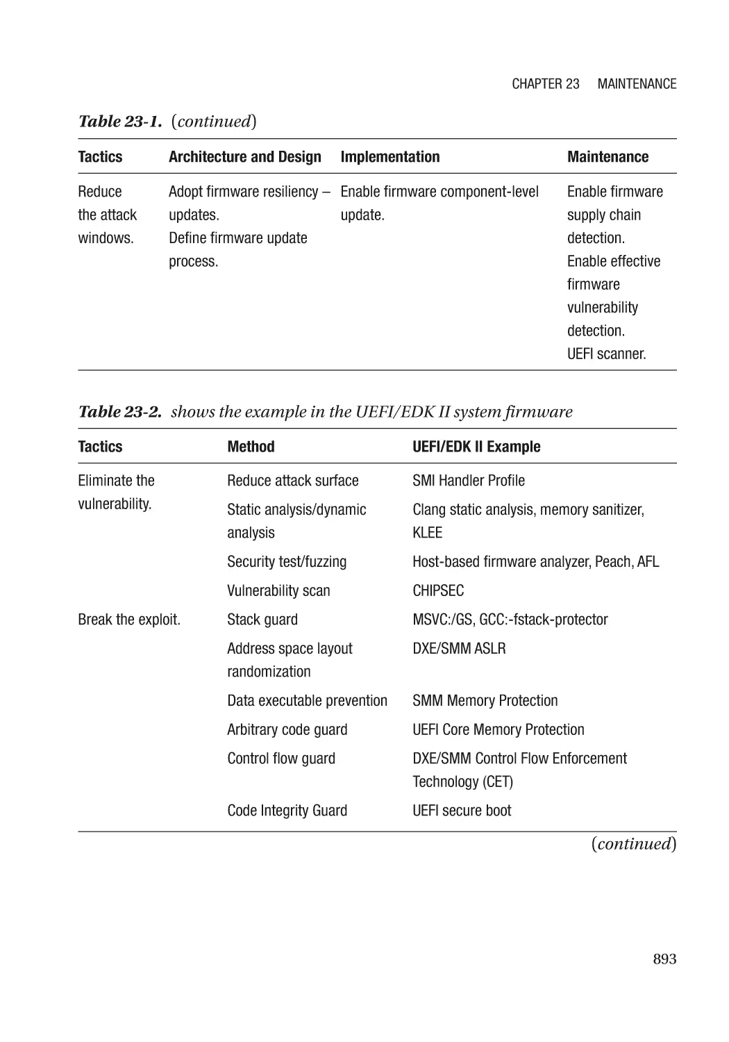
Mitigation Strategy and Tactics������������������������������������������������������������������������������������������������� 891
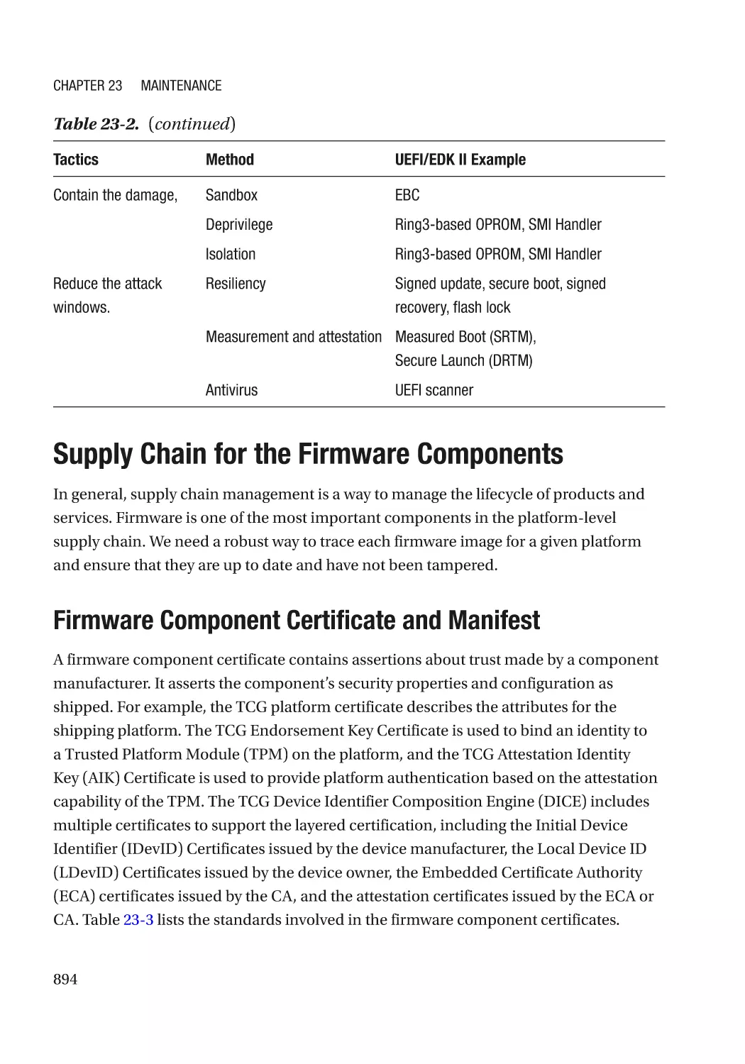
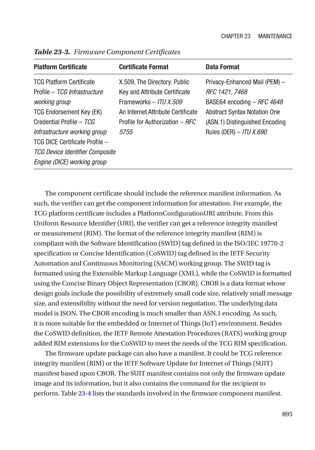
Supply Chain for the Firmware Components���������������������������������������������������������������������������� 894
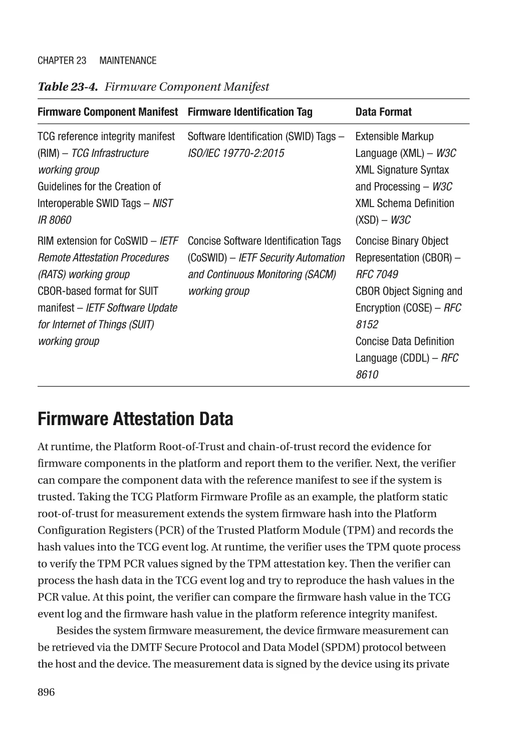
Firmware Component Certificate and Manifest������������������������������������������������������������������� 894
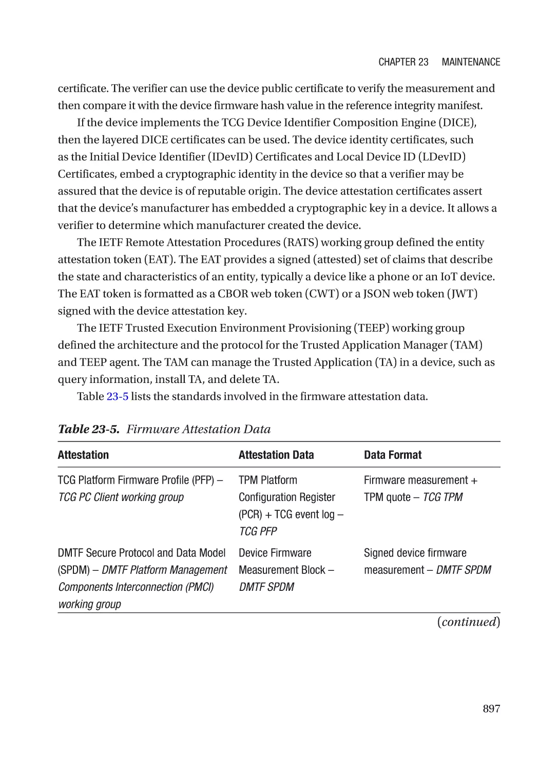
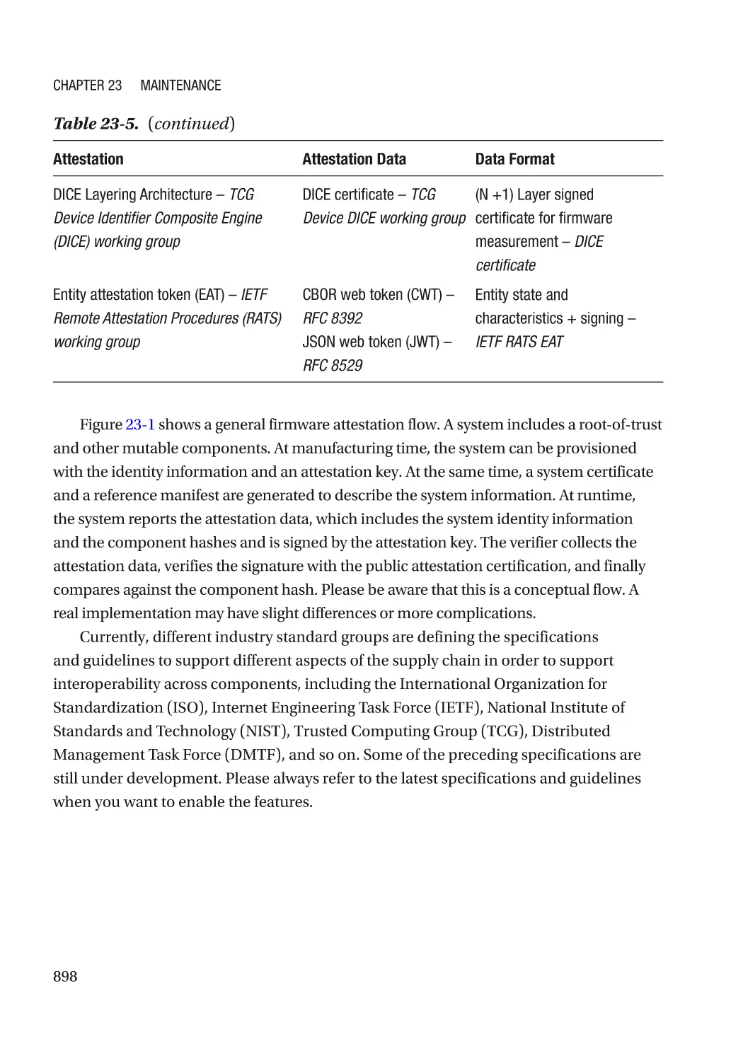
Firmware Attestation Data��������������������������������������������������������������������������������������������������� 896
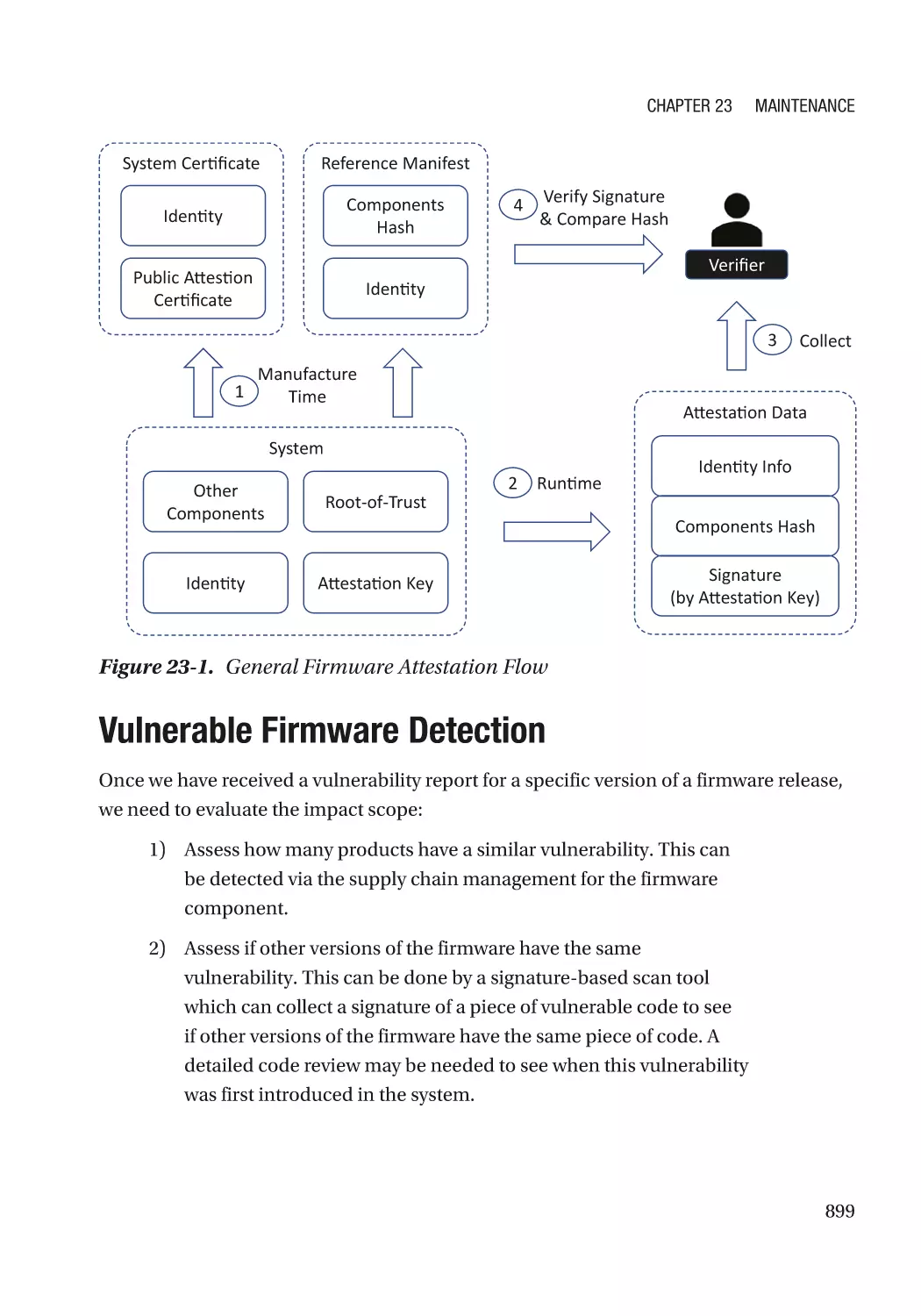
Vulnerable Firmware Detection������������������������������������������������������������������������������������������������� 899
Antivirus for Firmware�������������������������������������������������������������������������������������������������������������� 900
Firmware Update���������������������������������������������������������������������������������������������������������������������� 900
Summary���������������������������������������������������������������������������������������������������������������������������������� 901
References�������������������������������������������������������������������������������������������������������������������������������� 902
Index��������������������������������������������������������������������������������������������������������������������� 907
xvii
About the Authors
Jiewen Yao is a principal engineer in the Intel Architecture,
Graphics, and Software Group. He has been engaged as
a firmware developer for over 15 years. He is a member
of the UEFI Security Sub-Team (USST) and the Trusted
Computing Group (TCG) PC Client sub-working group. He
has presented at industry events such as the Intel Developer
Forum, UEFI Plugfest, and RSA Conference. He worked with
coauthor Vincent Zimmer to publish 30 “A Tour Beyond
BIOS” technical papers for tianocore.org and firmware.intel.
com. He holds 40 US patents.
Vincent Zimmer is a senior principal engineer in the Intel
Architecture, Graphics, and Software Group. He has been
engaged as a firmware developer for over 25 years and leads
the UEFI Security Sub-Team. He has presented at industry
events such as the Open Source Firmware Conference,
LinuxFest Northwest, Intel Developer Forum, UEFI Plugfest,
Open Compute Project Summit, Black Hat Las Vegas,
BSides Seattle, ToorCon, and CanSecWest. In addition to
collaborating with Jiewen Yao on many whitepapers, he has
coauthored several books on firmware, papers, and over 400
issued US patents.
xix
About the Technical Reviewer
Tim Lewis is the CTO and head of the Office of Security and Trust for Insyde Software.
With over 30 years of BIOS experience, he has served on the UEFI board of directors and
chaired the UEFI Security Sub-Team (USST). He is an active member of his local CS2AI
chapter near his home in Folsom, California.
xxi
Organization and What Is Covered
Currently, we already have books to separately introduce the topics of firmware and
security. The purpose of this book is to link these areas together and provide the best
practices in the security development of firmware.
The whole book consists of four parts:
Part I: Overview
Chapter 1 includes a brief overview of the firmware in a system.
Chapter 2 describes a proactive development lifecycle for the firmware. We will
introduce a general threat model for the firmware and use a real example to demonstrate
how to do threat model analysis.
Part II: Security Architecture
Chapter 3 describes the first aspect of the firmware resiliency – protection.
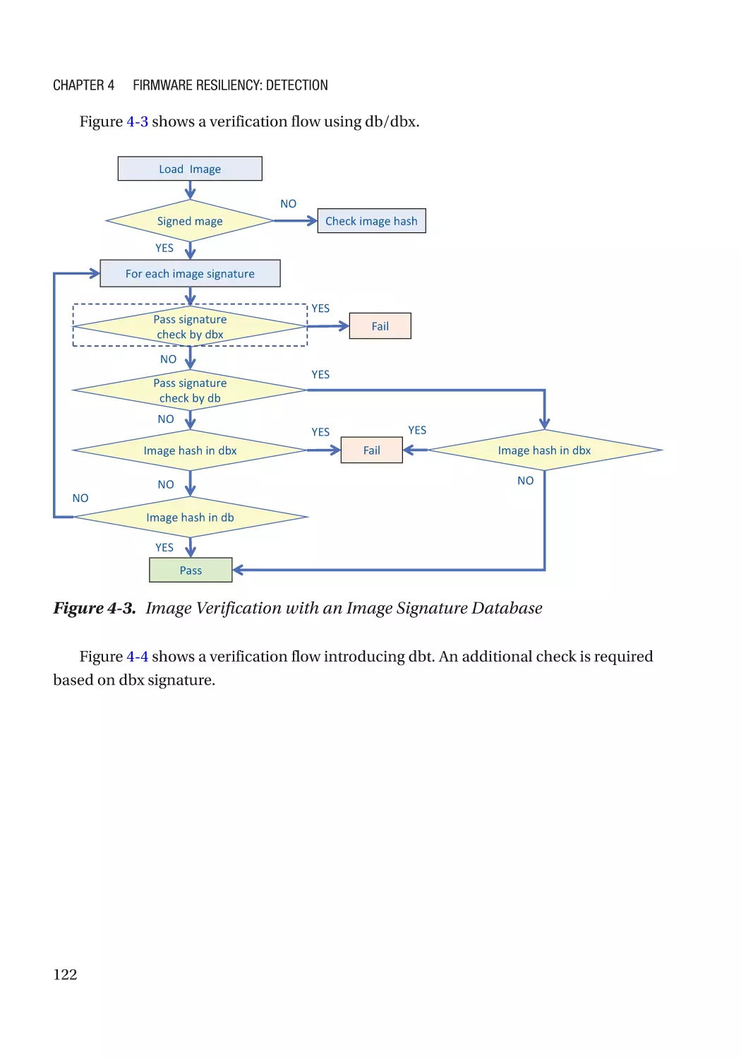
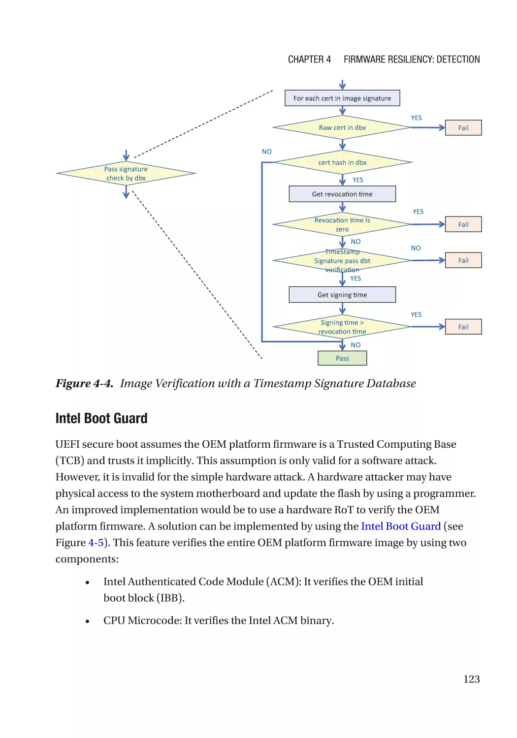
Chapter 4 describes the second aspect of the firmware resiliency – detection.
Chapter 5 describes the third aspect of the firmware resiliency – recovery.
Chapter 6 extends the resiliency concept from the firmware to the operating system
(OS).
Chapter 7 introduces the trusted boot concept, besides the firmware resiliency in
Chapters 3, 4, and 5.
Chapter 8 focuses on the security aspects of the device firmware, including secure
device communication and device attack prevention.
Chapter 9 discusses S3 resume – a special boot path in the system firmware.
Chapter 10 presents the access control technology in the firmware, including boot
access control, device access control, feature configuration control, and so on.
Chapter 11 examines the confidentiality, integrity, and availability of the firmware
configuration data.
Chapter 12 provides a brief introduction for the security model and maps the Clark-
Wilson model to existing firmware features.
Chapter 13 explains the virtual firmware, which may include a new threat model.
xxiii
Organization and What Is Covered
Part III: Security Development
Chapter 14 introduces the general secure coding practices for firmware.
Chapter 15 discusses the compiler defensive technologies which may be used in the
firmware.
Chapter 16 describes the possible firmware kernel hardening technologies.
Chapter 17 compares different trusted execution environments (TEEs), including
system management mode (SMM) and ARM TrustZone.
Chapter 18 shows the silicon secure configuration, such as flash lock and system
configuration lock.
Chapter 19 explains the cryptography usage in the firmware space, including an
introduction for post-quantum cryptography.
Chapter 20 introduces the Rust language – a type-safe language choice for firmware
development.
Part IV: Security Test
Chapter 21 discusses the security unit test, including fuzzing and symbolic
execution.
Chapter 22 describes the security validation and penetration test plan.
Chapter 23 recaps the mitigation strategies – eliminate the vulnerability, break the
exploitation, contain the damage, and reduce the attack window – and focuses on how to
maintain the firmware in the lifecycle.
Whom Is This Book For?
The target audience of this book includes firmware architects, developers, and validation
engineers. We assume the reader has basic knowledge on the following domains:
1) Computer system architecture, such as X86, ARM, PCI bus, and so on
2) Operating systems or embedded systems
3) Programming language – C language
4) Firmware design and development experience, such as EDK II,
coreboot, ARM Trusted Firmware, and so on
xxiv
Acknowledgments
We would like to acknowledge our technical reviewer and Apress editors. We would also
like to acknowledge the many engineers and collaborators with whom we have worked
in the industry, standards groups, and open source communities.
xxv
Preface
In 1988, the Morris worm was released from the lab onto the Internet. It was the first
time that a computer virus had gained significant mainstream media attention. People
started to realize that a software flaw was vital, which changed the perception of security
on the Internet. Ten years later, in 1999, the Chen Ing-hau (CIH) virus brought another
big impact because the Basic Input/Output System (BIOS) flash chip was attacked and
the impacted system could not boot at all. A technician was required to reprogram the
BIOS. This was probably the first wave of firmware security. The firmware developers
started to invent the idea of locking the flash region in response to CIH.
The second big wave was around 2009. Invisible Things Lab released a series of BIOS
attacks and presented in the Black Hat conference. These attacks included the REMAP
base address register (BAR) attack, Bitmap (BMP) file attack, system management
mode (SMM) callout, SMM cache poisoning, and Authenticated Code Module (ACM)
hijack. The firmware developers realized that locking the flash and system management
RAM (SMRAM) was far from enough. Similar to the software development process, the
firmware development domain also needs to apply the security development lifecycle
(SDL).
The third wave of firmware security commenced in 2014, where more and more
firmware attacks appeared in different hacking conferences. This next wave of attacks
included exploits against the capsule image, setup variable, SMM communication,
memory mapped input/output (MMIO) BAR in SMM, Speed Racer, Direct Memory
Access (DMA), S3 boot script, and Unified Extensible Firmware Interface (UEFI) secure
boot policy – lots of firmware features became the attack point. It is just like the old
saying, “If there is a will, there is a way.” The firmware engineers started to invent new
technologies and processes to harden the firmware design and development.
The war of defense and attack never ends. Today, firmware security has become
more and more important. The National Institute of Standards and Technology (NIST)
published the documents SP800-193 – Platform Firmware Resiliency Guidelines and
SP800-155 – BIOS Integrity Measurement Guidelines. The Trusted Computing Group
(TCG) created the Cyber Resilient (CyRes) workgroup to focus on three principles of
xxvii
Preface
resilience (protecting, detecting, and recovering), the Device Identifier Composition
Engine (DICE) workgroup to explore the security principles for the Internet of Things
(IoT) ecosystem, and the Attestation workgroup to provide a framework for attestation.
The Distributed Management Task Force (DMTF) created the Secure Protocol and Data
Model (SPDM) for device firmware authentication and measurement, as well as key
exchange. The Internet Engineering Task Force (IETF) created the Software Updates for
Internet of Things (suit) working group to define a firmware update solution for small
IoT devices and Remote Attestation Procedures (rats) working group to standardize
the formats and procedures for the assertions about the system components. The
cloud companies invented different platform Root-of-Trust (RoT) techniques, such
as Microsoft Cerberus, Google Titan, and Amazon Nitro. The device vendor started
building the device root-of-trust to report the device certificate. In this fourth wave, every
firmware engineer needs to understand the aspects of firmware security – from industry
standards, architecture, design, and implementation up to the final stages of test and
validation.
xxviii
Foreword
When Saudi Aramco was attacked in August 2012 by the Shamoon computer virus, it was
a wake-up call to the entire industry. Saudi Aramco is one of the largest companies in the
world and holds the second largest amount of crude oil reserves. A shutdown of Saudi
Aramco for a prolonged amount of time would have had a devastating impact on the oil
economy, and this could have plunged the world into an economic recession.
The Shamoon virus was by today’s standards a relatively simple virus. It overwrote
the master boot record on the hard disk with garbage, rendering the system unbootable.
While the infestation was effective – reportedly more than 30,000 systems got
impacted – the much-feared secondary effect of the global oil supply chain hiccup didn’t
materialize. That was in part because the hard disk is an “easy” to service component
and Aramco was able to replace the hard disks in time to avoid any serious impact.
However, this attack made folks in the industry and intelligence communities
around the world wonder: What would have happened if Shamoon went after a non-
serviceable component, like the flash chips where the system firmware is stored? This
is much harder to repair on-site, and it would have required the systems to be shipped
back to the manufacturer. This would have taken a lot more time, and in that case a
global oil supply shortage could not have been avoided, potentially even triggering a
global recession.
This incident prompted a cross-industry/cross-government collaboration that
eventually resulted in a set of recommendations from the National Institute of Standards
and Technology (NIST). The first set of recommendations, BIOS Protect Guidelines
(NIST SP800-147), described requirements such as
•
BIOS update authentication: The firmware needs to be signed by the
proper authority.
•
Integrity protection: The firmware cannot be modified, either
unintended or maliciously.
•
Non-bypassibility: There is no way to bypass the authenticated
firmware update mechanism.
xxix
Foreword
This specification was followed up in 2018 by another NIST publication, Platform
Firmware Resiliency Guidelines (NIST SP800-193). This specification extended the
previous one by focusing on recovery. Its central tenet was simple: providing protection
against unauthorized firmware updates is not enough. The firmware is a complex
piece of software, and it will, probabilistically, contain bugs that can be exploited by an
attacker. How do you quickly and seamlessly recover if this happens?
Before you consider this problem to be a PC-only threat, think again. With the
proliferation of IoT devices in homes and factories, and SCADA devices to control
the national grid, firmware security has become a key part of the world’s critical
infrastructure protection. Just imagine the harm a malicious attacker could do by taking
over the firmware of pipeline controllers in a gas line in Siberia, Russia, during the
winter. You’ll be hard-pressed to send someone out there to fix the problem.
The Saudi Aramco attack and its resulting NIST secure firmware recommendations
solidified the importance of firmware security in the industry. Those recommendations
built on years of academic and industrial research in this area. I was personally involved
in some of these efforts, ranging from IBM’s physical secure coprocessor (IBM 47xx)
projects and TCPA/TCG frameworks to secure hypervisor research and working with
other industry partners on the foundations of NIST SP800-147.
The authors Jiewen Yao and Vincent Zimmer have bundled together into this book
their combined years of experience in developing secure firmware and building resilient
systems. Every computer, big or small, starts with firmware, and if that’s compromised,
all is lost, so following the authors’ guidance is as relevant today as it was in 2012.
—Leendert van Doorn
Redmond, WA, USA
xxx
PART I
Overview
Firmware is a special type of software. There is a secure software development lifecycle
defined for software. These lifecycle practices can be applied to the firmware world.
CHAPTER 1
Introduction to Firmware
This chapter will provide an overview of system firmware. Although the space of
implementations of system firmware is quite broad, details that relate to the secure
construction of firmware will be discussed.
Similarity Between Firmware and Software
Firmware vs. Embedded System vs. OS Kernel vs. OS Application
Firmware is the lowest layer of software on the platform. Modern firmware, such
as UEFI Platform Initialization–based firmware, like EDK II, U-Boot (Universal Boot
Loader), coreboot, Open Power skiboot, and so on, are predominately written in C with
a small amount of assembly language code. This code is often stored in a non-volatile
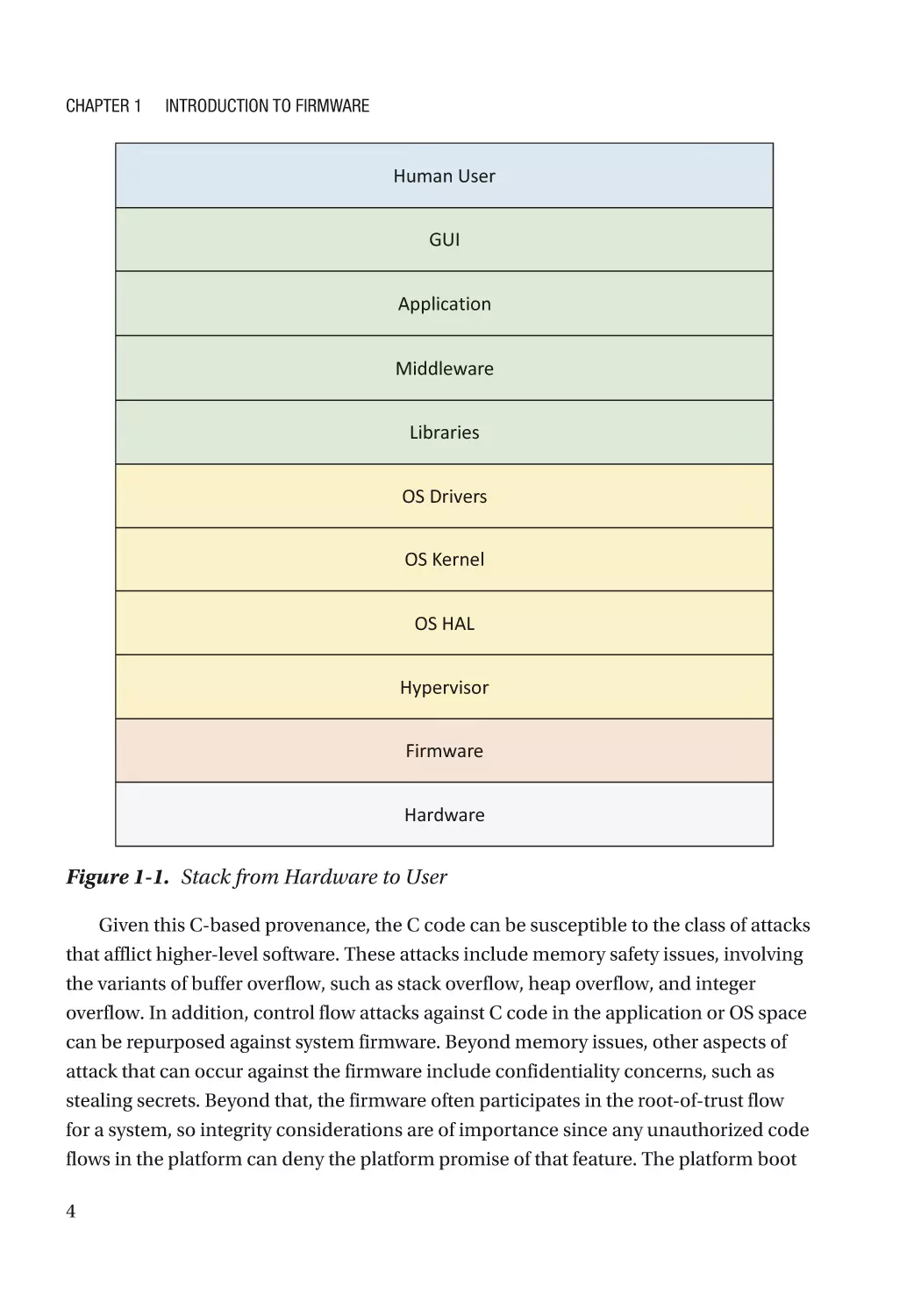
storage container bound to the platform. The relationship of firmware to the rest of a
platform stack is shown in Figure 1-1.
© Jiewen Yao and Vincent Zimmer 2020
J. Yao and V. Zimmer, Building Secure Firmware, https://doi.org/10.1007/978-1-4842-6106-4_1
3
Chapter 1
Introduction to Firmware
Human User
GUI
Application
Middleware
Libraries
OS Drivers
OS Kernel
OS HAL
Hypervisor
Firmware
Hardware
Figure 1-1. Stack from Hardware to User
Given this C-based provenance, the C code can be susceptible to the class of attacks
that afflict higher-level software. These attacks include memory safety issues, involving
the variants of buffer overflow, such as stack overflow, heap overflow, and integer
overflow. In addition, control flow attacks against C code in the application or OS space
can be repurposed against system firmware. Beyond memory issues, other aspects of
attack that can occur against the firmware include confidentiality concerns, such as
stealing secrets. Beyond that, the firmware often participates in the root-of-trust flow
for a system, so integrity considerations are of importance since any unauthorized code
flows in the platform can deny the platform promise of that feature. The platform boot
4
Chapter 1
Introduction to Firmware
can include accessing the network, so considerations of network security can also be
applied to the platform firmware. And there are few, if any, platforms that have only a
single central processing unit (CPU) core in the system on a chip (SOC), so the firmware
must support multiprocessing (MP) and defend against the various classes of attacks,
such as race conditions, that inhere in this application domain. Finally, the platform
firmware must also defend against other classes of attacks, such as side channels,
confused deputy, and time-of-check/time-of-use (TOC/TOU) attacks.
Given these exposure listed, the firmware may have similar platform hardening
strategies, albeit with implementations customized for the domain. These include
hardening tactics such as stack cookie checks, data execution protection (DEP),
address space layout randomization (ASLR), control flow guard/integrity (CFG/
CFI), code signing enforcement check, sandbox with interpreter, access control (user
authentication and authorization), network security, and cryptography suitable in the
firmware execution environment.
Beyond the defenses, the firmware may have similar software security validation
strategies, but with different implementations than higher-level software regimes. These
validation approaches can include static code analysis, dynamic code analysis (address
sanitizer, ASan), fuzzing, symbolic execution, and formal verification when possible.
Distinction Between Firmware and Software
Although firmware is typically written in a higher-level language like C, it often has
special requirements. These requirements begin with the environment. Specifically,
firmware has a size limitation that is driven by the small ROM size and small RAM size in
microcontrollers, only having SRAM or cache that can be used before the DRAM is ready,
Management Mode (MM) size leveraging stolen system memory, and limited stack and
heap size.
Additional limitations include the execution-in-place (XIP) code of early code.
Namely, some code executes in the ROM. One aspect of this is the ROM code, wherein
some code has no writable global variable in the data section. And for this early code,
such as the UEFI Platform Initialization PI, Slim Bootloader stage 1, and coreboot
romstage, there is no memory management, including no virtual memory, although
page tables may be used.
Beyond memory management, there are challenges with execution isolation in
early code flows. For example, ring separation might or might not be available. As such,
5
Chapter 1
Introduction to Firmware
some firmware implementations just run all code in supervisor mode. And although the
hardware may contain multiple CPU cores, multiprocessing (MP) may or may not be
enabling. In fact, most implementations of host firmware execute services on a single
processor. Alongside MP, other common capabilities like interrupts may be enabled, but
only for usages much simpler than those of operating systems. And unlike the OS, the
firmware usually interacts directly with the hardware. Finally, the firmware will have its
own executive infrastructure, such as a kernel and loader, distinct from those found in
high-level operating systems (HLOSs) like Windows or Linux or hypervisors.
Given these limitations, firmware may have a class of security issues about which
we are to be concerned that are not seen in HLOSs. These security concerns can include
attack from the hardware, such as registers, device Direct Memory Accesses (DMAs),
cache, and so on. Beyond those threat vectors, the host firmware must guard against a
permanent denial of service (PDoS) in the ROM which often necessitates complicated
and special recovery mechanisms. And if the PDoS concern were not enough, firmware
can be susceptible to a permanent root kit in the body of the ROM that is difficult to
discover by virus scanning art.
Introduction to Firmware Security
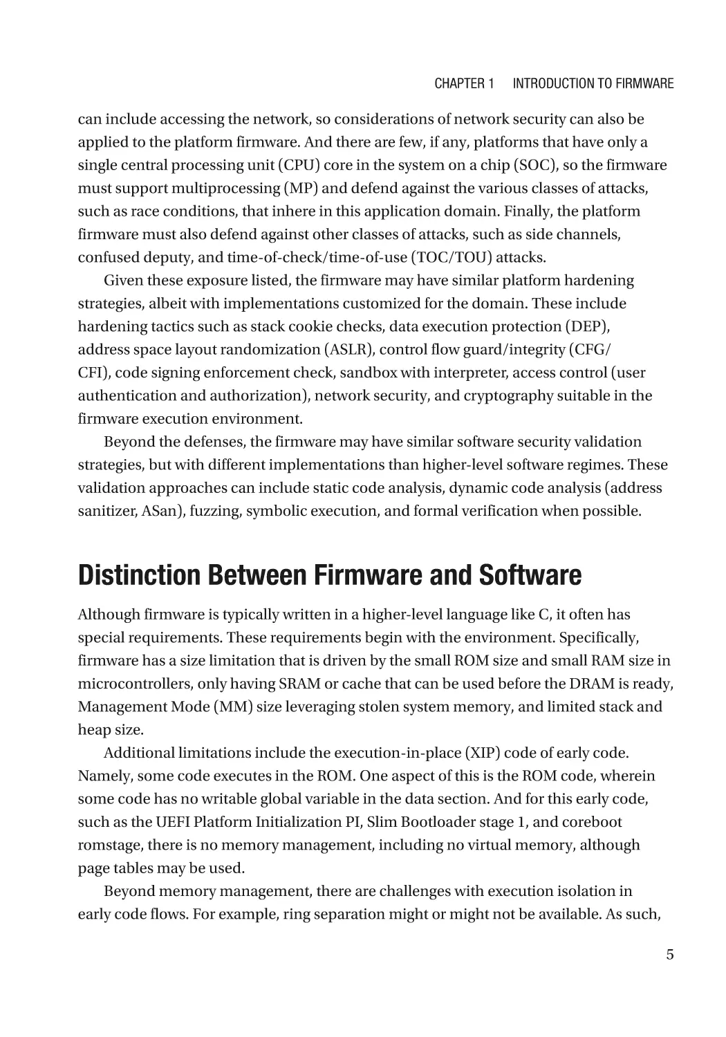
Firmware is the foundation of computer system security. There are more and more
hardware/firmware-assisted attacks against the system. In light of the domain-specific
aspects of firmware, there may need to be special hardening strategies. We summarized
three major directions: firmware resiliency, firmware measurement and attestation, and
secure device communication. See Figure 1-2.
Firmware Resiliency
Firmware Attestation
Secure Communication
A firmware need protect
itself, detect the tampering
and recover to a known
good state.
A firmware need report its
identity and allow a
remote agent to verify the
integrity state.
A firmware need have a
secure way to
communicate with other
firmware.
I need protect myself.
I need claim who I am.
I need talk to a trusted
person.
Figure 1-2. Three Pillars of Firmware Security
6
Chapter 1
Introduction to Firmware
F irmware Resiliency
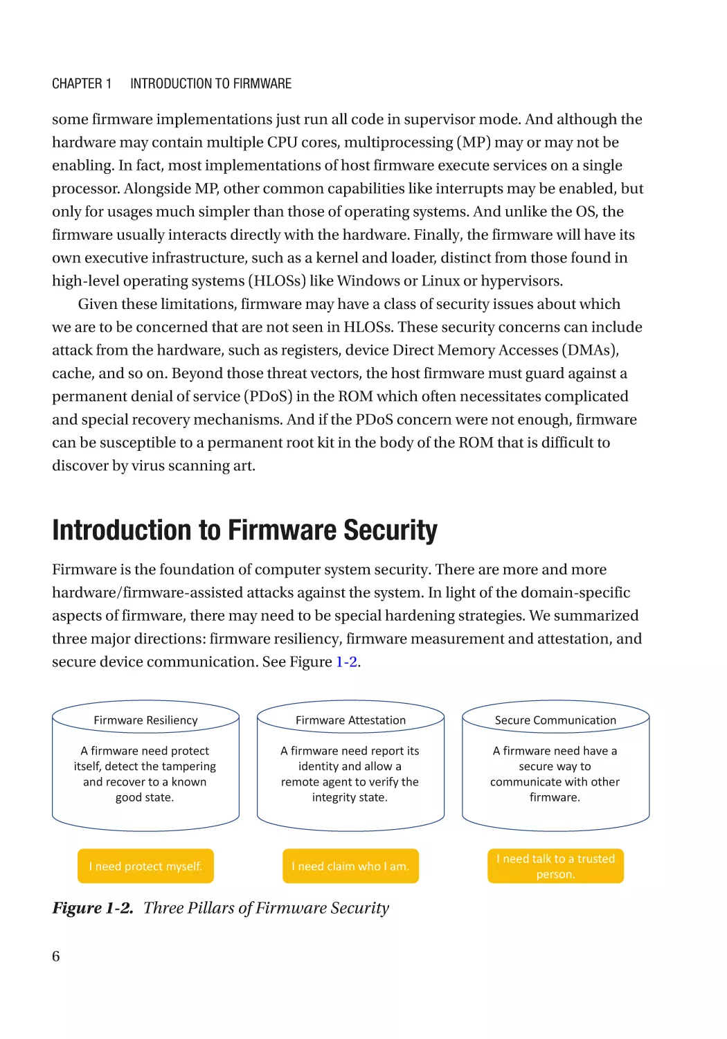
Firmware resiliency includes the triple of protection, detection, and recovery in
Figure 1-3. A platform firmware needs to protect itself, detect the tampering, and finally
recover to a known good state. Protection ensures that the firmware remains in a state of
integrity and is protected from corruption or an attack. Detection happens during system
boot to determine if the firmware has been corrupted or attacked. If such corruption or
attack is detected, the firmware root-of-trust recovers the firmware to a state of integrity
through an authorized mechanism. In addition, there are firmware domain-specific
checks including hardware register configuration checks, such as setting of lock bits, to
maintain the temporal isolation guarantees of the platform firmware. We will discuss the
details in Chapters 3, 4, and 5.
System
Protect
Firmware
Detect
Figure 1-3. Three Axes of Firmware Resiliency Capabilities
7
Chapter 1
Introduction to Firmware
Firmware Measurement and Attestation
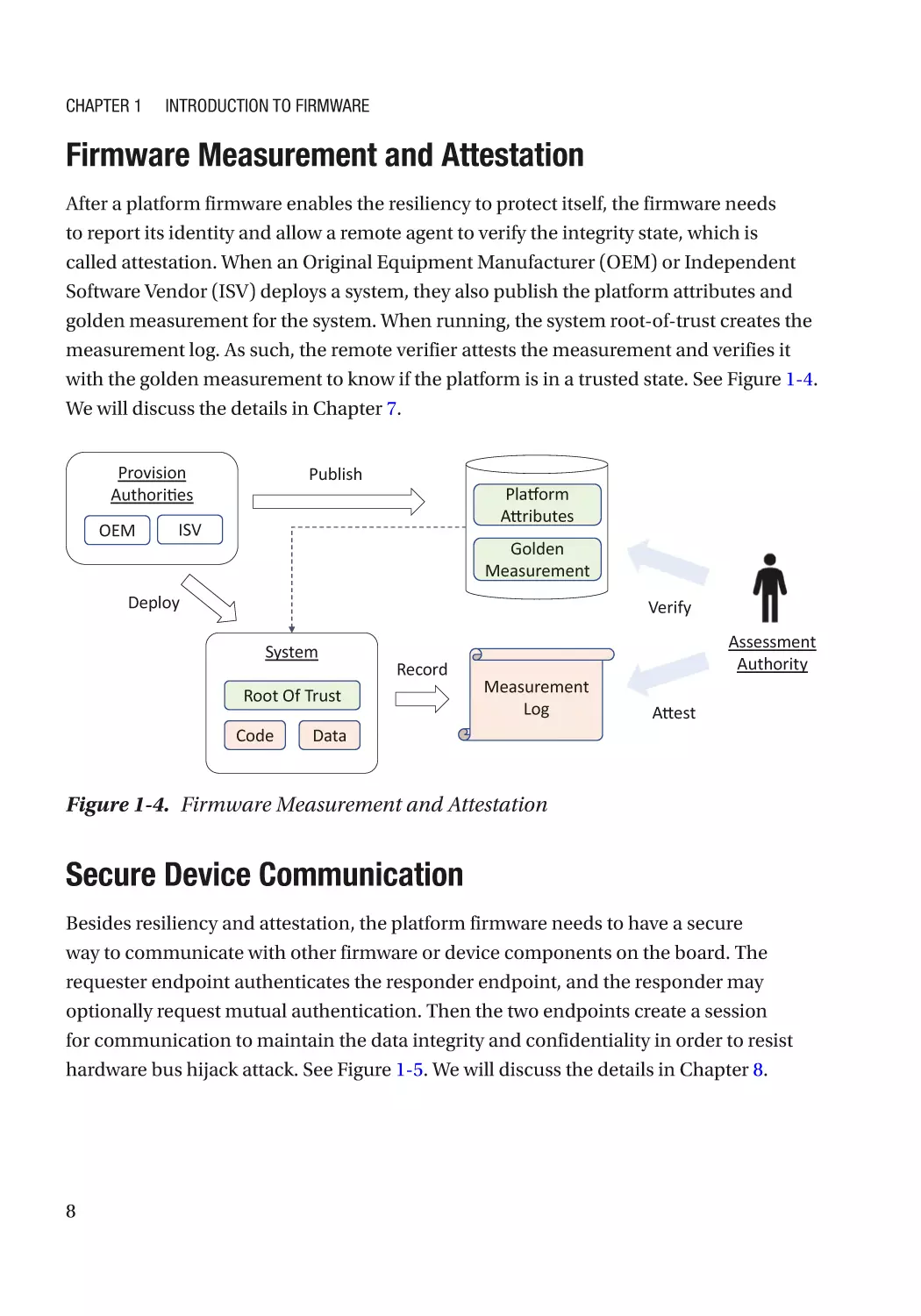
After a platform firmware enables the resiliency to protect itself, the firmware needs
to report its identity and allow a remote agent to verify the integrity state, which is
called attestation. When an Original Equipment Manufacturer (OEM) or Independent
Software Vendor (ISV) deploys a system, they also publish the platform attributes and
golden measurement for the system. When running, the system root-of-trust creates the
measurement log. As such, the remote verifier attests the measurement and verifies it
with the golden measurement to know if the platform is in a trusted state. See Figure 1-4.
We will discuss the details in Chapter 7.
Provision
Authori es
OEM
Publish
Pla
orm
A
ributes
ISV
Golden
Measurement
Deploy
Verify
System
Record
Root Of Trust
Code
Measurement
Log
Data
Assessment
Authority
A
est
Figure 1-4. Firmware Measurement and Attestation
Secure Device Communication
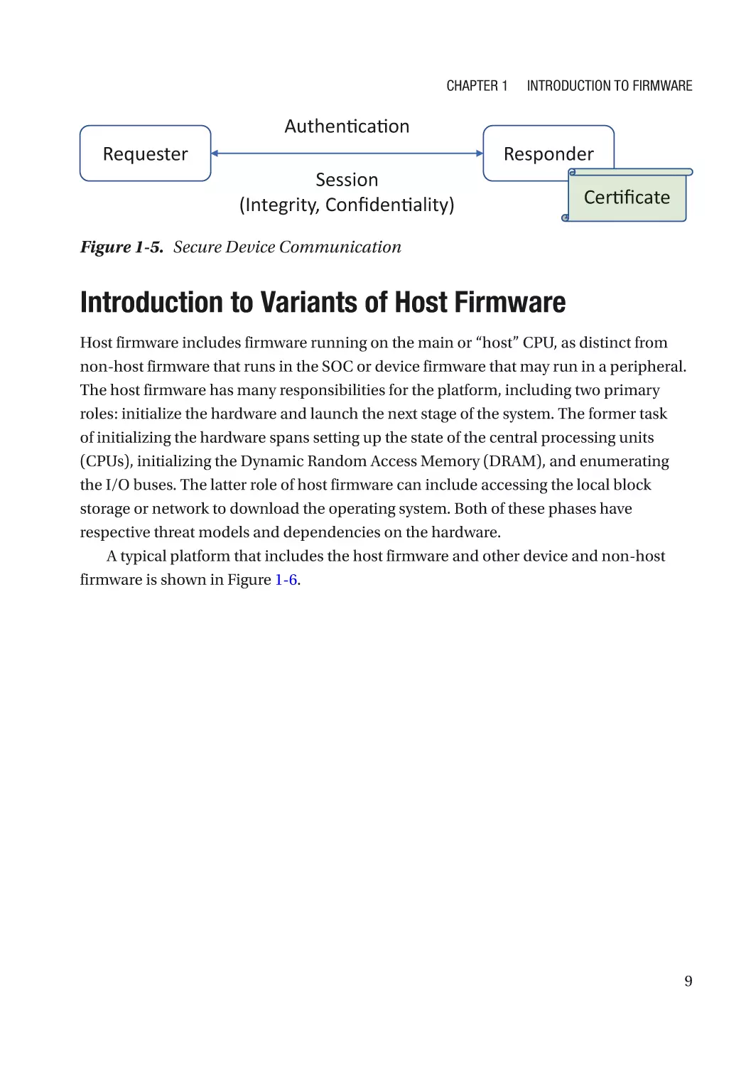
Besides resiliency and attestation, the platform firmware needs to have a secure
way to communicate with other firmware or device components on the board. The
requester endpoint authenticates the responder endpoint, and the responder may
optionally request mutual authentication. Then the two endpoints create a session
for communication to maintain the data integrity and confidentiality in order to resist
hardware bus hijack attack. See Figure 1-5. We will discuss the details in Chapter 8.
8
Chapter 1
Introduction to Firmware
Authen ca on
Requester
Session
(Integrity, Confiden ality)
Responder
Cer ficate
Figure 1-5. Secure Device Communication
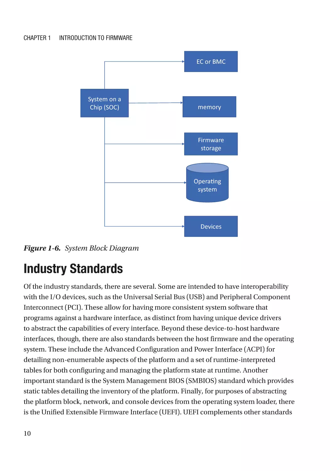
Introduction to Variants of Host Firmware
Host firmware includes firmware running on the main or “host” CPU, as distinct from
non-host firmware that runs in the SOC or device firmware that may run in a peripheral.
The host firmware has many responsibilities for the platform, including two primary
roles: initialize the hardware and launch the next stage of the system. The former task
of initializing the hardware spans setting up the state of the central processing units
(CPUs), initializing the Dynamic Random Access Memory (DRAM), and enumerating
the I/O buses. The latter role of host firmware can include accessing the local block
storage or network to download the operating system. Both of these phases have
respective threat models and dependencies on the hardware.
A typical platform that includes the host firmware and other device and non-host
firmware is shown in Figure 1-6.
9
Chapter 1
Introduction to Firmware
EC or BMC
System on a
Chip (SOC)
memory
Firmware
storage
Opera ng
system
Devices
Figure 1-6. System Block Diagram
Industry Standards
Of the industry standards, there are several. Some are intended to have interoperability
with the I/O devices, such as the Universal Serial Bus (USB) and Peripheral Component
Interconnect (PCI). These allow for having more consistent system software that
programs against a hardware interface, as distinct from having unique device drivers
to abstract the capabilities of every interface. Beyond these device-to-host hardware
interfaces, though, there are also standards between the host firmware and the operating
system. These include the Advanced Configuration and Power Interface (ACPI) for
detailing non-enumerable aspects of the platform and a set of runtime-interpreted
tables for both configuring and managing the platform state at runtime. Another
important standard is the System Management BIOS (SMBIOS) standard which provides
static tables detailing the inventory of the platform. Finally, for purposes of abstracting
the platform block, network, and console devices from the operating system loader, there
is the Unified Extensible Firmware Interface (UEFI). UEFI complements other standards
10
Chapter 1
Introduction to Firmware
like ACPI and SMBIOS by providing a well-known mechanism to discover the content,
but it goes further. Specifically, UEFI provides a rich set of capabilities and interfaces for
discovering executable content, or “.efi” files, in PCI adapter card option ROMs (OROMs)
and on storage devices. This allows for decoupling the manufacturer of the platform,
such as the Original Equipment Manufacturer (OEM) and the operating system
vendor (OSV).
Boot Flow and Phased Handoff
There are various means of restarting the system. These include a cold restart such as an
S5, a CPU-only reset such as warm start, a memory-preserving restart such as an S3, or a
hibernation-based restart such as ACPI S4.
In general, firmware has at least three phases, including providing a root-of-trust,
turning on the SOC and the system’s main memory, initializing the platform, and
booting the operating system.
There are typically some minimal firmware requirements, such as providing some
root-of-trust for measurement, verification, and update. This ensures that the firmware
can report the state of the firmware environment while booting and only update itself
with some platform manufacturer-approved content.
Typically, the boot of a platform is decomposed into three phases. The first includes
turning on the basic system on a chip complex, including system DRAM. This is also
where the core root-of-trust for measurement (CRTM) and the static update and
verification root-of-trust can commence. This early phase is represented in various
firmware architectures, such as the UEFI PI Security (SEC) and Pre-EFI Initialization
(PEI), coreboot boot block and romstage, Slim Bootloader stage 1, Open Power self-boot
engine (SBE) and hostboot, and U-Boot First Stage Boot Loader (FSBL). Ideally this phase
will be predominately SOC-specific code with little vendor code. An example of SOConly vendor code would be a SOC boot ROM, and a mixed board and SOC code solution
can include the Intel Firmware Support Package (FSP).
The next phase of execution can include richer software abstractions since the
firmware is guaranteed to have initialized system memory that will maintain its
configuration throughout the life of the platform. As such, the UEFI PI Driver Execution
Environment (DXE), U-Boot Secondary Program Loader (SPL), Open Power skiboot,
Slim Bootloader stage 2, and coreboot RAM stage can have richer algorithmic flows. This
stage typically hosts the setup application for a PC class system, creation of ACPI and
11
Chapter 1
Introduction to Firmware
SMBIOS tables, and programming of other board-specific capabilities. This phase, unlike
the prior one, is less SOC code specific and more system board and product specific.
This phase of execution must continue the root-of-trust logic for measurement, update,
and verification, though, and the code should be provisioned under the authority of
the platform manufacturer. This phase is typically the latest point during which the
runtime phase of the platform can be provisioned, including but not limited to allocating
memory for management mode, such as X86 system management mode (SMM) RAM
(SMRAM), data spaces for the runtime-accessible ACPI and SMBIOS tables, and, finally,
data and code spaces for the UEFI runtime services.
Following the board-specific initialization, the persona for operating booting
is entered. This persona can include the UEFI-conformant execution environment
which allows for third-party extensible executables from disk, PCI host bus adapters,
and network. The Boot Device Selection (BDS) is the traditional point at which policy
actions around these third-party codes begin and the phase of execution referred to
as the Transient System Load (TSL). For the coreboot and Slim Bootloader, this phase
of execution is characterized by the launching of a payload. The payload can contain
a UEFI-style environment, such as EDK II DXE, or it can contain a Linux-based boot
environment such as LinuxBoot. The payloads are typically considered part of the
firmware Trusted Computing Base (TCB), in addition to the former two phases.
The predominant role of this last phase of firmware execution is to discover and
potentially abstract services for the next phase of execution, or HLOS runtime. As such,
upon exiting this phase of execution, the pre-OS phases should quiesce most of the
hardware and prepare for the HLOS to take over. In the case of a UEFI system, the end of
the TSL is the invocation of ExitBootServices by the OS loader or OS kernel.
Once the HLOS has taken over from the payload and/or UEFI boot service
environment, the host firmware plays much less of a role. In fact, the OS kernel or
hypervisor will have its own driver stack to manage the state of the processors, SOC, and
I/O devices. The host firmware will be largely passive with only limited callbacks into
firmware via synchronous invocations from the OS, such as the UEFI runtime services,
synchronous traps into management mode via hardware mailbox access from agents
outside of the Trusted Execution Environment (TEE), or asynchronous invocation into
the TEE via TEE-specific timer sources or side effects of other SOC-specific hardware
activations. The integrity of the runtime TEE, such as Management Mode, is still part of
the host firmware TCB and should only be services by manufacturer-approved updates.
12
Chapter 1
Introduction to Firmware
A typical boot flow with mapping to representative firmware environments is shown
in Figure 1-7.
^KZĞƐĞƚ
h
&/W/͗^
KƉĞŶWŽǁĞƌ͗^
ŽƌĞƚ͗ŽŽƚďůŽĐŬ
dƵƌŶKŶ
ŵĞŵŽƌLJ
/ŶŝƟĂůŝnjĞ
WůĂƞŽƌŵ
ŽŽƚ
KƉĞƌĂƟŶŐ
^LJƐƚĞŵ
^ͲZdD
/ŶŝƚĐĂĐŚĞƐͬDdZZƐ
ĂĐŚĞͲĂƐͲZD;E
DͿ
ZĞĐŽǀĞƌLJ
dWD/Ŷŝƚ
h
&/W/͗W
/
KƉĞŶWŽǁĞƌ͗,ŽƐƚƚ
ŽƌĞƚ͗ƌŽŵƐƚĂŐĞ
^ͲZdD͗DĞĂƐƵƌĞy
ͬ^
ĂƌůLJWhͬ^ŝůŝĐŽŶ/Ŷŝƚ
DĞŵŽƌLJ;/DDƐ͕ZDͿ/Ŷŝƚ
h
&/W/͗y
KƉĞŶWŽǁĞƌ͗ƐŬŝƚ
ŽƌĞƚ͗ƌĂŵƐƚĂŐĞ
W/͕h
&/^LJƐƚĞŵdĂďůĞ͕^D/K^ƚĂďůĞ
ŽŶƟŶƵĞŝŶŝƟĂůŝnjĂƟŽŶŽĨƉůĂƞŽƌŵ
ŶƵŵ &s͕ĚŝƐƉĂƚĐŚĚƌŝǀĞƌƐ;ŶĞƚǁŽƌŬ͕/ͬKͿ
WƌŽĚƵĐĞŽŽƚĂŶĚZƵŶƟŵĞ^ĞƌǀŝĐĞƐ
h
&/W/͗^
KƉĞŶWŽǁĞƌ͗WĞƟƚĞƚ
ŽƌĞƚ͗ƉĂLJůŽĂĚ
džŝƚŽŽƚ^ĞƌǀŝĐĞƐ͘DŝŶŝŵĂůh
&/ƐĞƌǀŝĐĞƐ;sĂƌŝĂďůĞͿ
ŽŽƚDĂŶĂŐĞƌ;^ĞůĞĐƚŽŽƚĞǀŝĐĞͿ
&/^ŚĞůůͬƉƉƐ
K^ŽŽƚ>ŽĂĚĞƌ;ƐͿ
ZƵŶƟŵĞͬK^
Figure 1-7. Phased Firmware Initialization
Introduction to Non-host Firmware
The host firmware, such as EDK II or coreboot, are not the only firmware entities
on the platform. Other firmware that are typically under the control of the platform
manufacturer include the Baseboard Management Controller (BMC) on servers and
Embedded Controllers (ECs) on client platforms. These devices typically interact with
the host firmware during the early phases of execution and may in fact run prior to the
host firmware since they can provide a root-of-trust for the host firmware or sequence
the power capabilities of the platform.
These non-host firmware elements should be recorded by the host firmware root-
of-trust for measurement, if possible, and these non-host elements may have their
root-of-trust for update (RTU) and verification proxied through the host. In either case,
these elements are part of the platform manufacturer’s TCB typically and should not be
exposed to arbitrary third-party updates.
13
Chapter 1
Introduction to Firmware
The OpenBMC project and the Chrome EC are examples of open source non-host
platforms available in the market. Given the inclusion in the manufacturer’s TCB, following
the security practices for firmware development is key for having a robust product.
Introduction to Device Firmware
Beyond the manufacturer’s host firmware (sometimes known as BIOS) and non-host
platforms (EC, BMC, and so on), the PCI card, USB devices, and other components
such as Complex Programmable Logic Device (CPLD), Field Programmable Gate Array
(FPGA) or Digital Signal Processing (DSP) on the system board may have their own
firmware. In fact, a review of a modern client platform noted sixteen different firmware
elements, and a server example quoted a multiple of that figure.
There are some examples of device firmware, such as Open Sound Firmware, for
programmable audio devices, but in general the device firmware is opaque to and
independent of the host firmware. As such, there are protocols to query these devices
for their state and add them to security policy so that the host firmware can provide a
holistic view of the platform state to the HLOS.
And given that the device firmware reads in on the platform security posture,
construction of this firmware, just like the other non-host firmware devices, is imperative
for having a robust platform experience.
Summary
This chapter has described the various aspects of host firmware, including its role
in the platform. Given that contemporary firmware is written predominately in C,
various classes of security considerations that impact higher-level application software
are described. In the next chapter, we will discuss the proactive firmware security
development.
14
Chapter 1
Introduction to Firmware
R
eferences
Book
[B-1] Jiming Sun, Vincent Zimmer, Marc Jones, Stefan Reinauer, Embedded Firmware
Solutions, 2015, Apress
[B-2] Vincent Zimmer, Michael Rothman, Suresh Marisetty, Beyond BIOS:
Developing with the Unified Extensible Firmware Interface, 3rd edition, 2017, DeG
[B-3] Vincent Zimmer, Michael Rothman, Robert Hale, UEFI: From Reset Vector to
Operating System, in Chapter 3 of Hardware-Dependent Software, Springer, 2009
[B-4] Sunil Cheruvu, Anil Kumar, Ned Smith, David M. Wheeler, Demystifying
Internet of Things Security, 2020, Apress
Conference, Journal, and Paper
[P-1] David Weston, “Hardening With Hardware,” in BlueHat 2018
https://github.com/microsoft/MSRC-Security-Research/blob/master/presentations/
2018_01_BlueHatIL/BlueHatIL18_Weston_Hardening_With_Hardware.pdf
[P-2] David Weston, “Advanced Windows Security,” in Platform Security Summit
2019, www.platformsecuritysummit.com/2019/speaker/weston/
[P-3] Eclypsium, “Anatomy of a Firmware Attack,” 2019, https://eclypsium.com/
2019/12/20/anatomy-of-a-firmware-attack/
[P-4] Eclypsium, “FISMA compliance firmware security best practices,” 2019,
https://eclypsium.com/2019/05/13/fisma-compliance-firmware-security-best-
practices/
[P-5] NIST, “Hardware-Enabled Security for Server Platforms,” in NIST whitepaper,
2020, available at https://nvlpubs.nist.gov/nistpubs/CSWP/NIST.CSWP.04282020draft.pdf
Specification and Guideline
[S-1] UEFI Organization, “UEFI Specification,” 2019, available at www.uefi.org/
[S-2] UEFI Organization, “UEFI Platform Initialization Specification,” 2019, available
at www.uefi.org/
[S-3] UEFI Organization, “ACPI Specification,” 2019, available at www.uefi.org/
[S-4] PCI-SIG, “PCI Express Base Specification,” 2019, https://pcisig.com/
[S-5] CXL Org, “Compute Express Link Specification,” 2019,
www.computeexpresslink.org/
Web
[W-1] EDK II, www.tianocore.org/
[W-2] coreboot, www.coreboot.org/
15
Chapter 1
Introduction to Firmware
[W-3] Linux Boot, www.linuxboot.org
[W-4] Slim Bootloader, https://slimbootloader.github.io/
[W-5] U-Boot, www.denx.de/wiki/U-Boot
[W-6] Intel Firmware Support Package (FSP), www.intel.com/FSP
[W-7] Sound Open Firmware (SOF), https://github.com/thesofproject
[W-8] Open Baseboard Management Controller (openbmc), https://github.com/
openbmc/openbmc
[W-9] Open Power, https://github.com/open-power
16
CHAPTER 2
Proactive Firmware
Security Development
Firmware development is similar to software development. Almost all of the software
security development lifecycle (SDL) practices can be applied to firmware development.
Figure 2-1 shows the main activities that may be involved in the firmware development.
Requirement
Security
Requirement
Collection
Architecture
Development
Threat Model
Analysis
Secure Coding
Practice
Security
Architecture /
Design Review
Security Unit
Test
Security Code
Analysis
(Static / Dynamic)
Security Code
(Peer) Review
Security Code
(Formal/ External)
Review
Security Test
Strategy Planning
Test
Security Test
(Fuzzing)
Release and
Maintenance
Security
Incident
Response
Figure 2-1. Security Activities in the Software SDL
R
equirement Phase
Collecting the security requirement is the first step. Without the clear requirement, we
don’t know what to protect from whom in which condition.
S
ecurity Requirements
Any product has a set of requirements. One can view requirements as ‘any statement
of desire or need.’ These can include functional requirements, such as which behaviors
the product should perform. There can also be market requirements, such as when
© Jiewen Yao and Vincent Zimmer 2020
J. Yao and V. Zimmer, Building Secure Firmware, https://doi.org/10.1007/978-1-4842-6106-4_2
17
Chapter 2
Proactive Firmware Security Development
the product should be ready and how much it should cost. Finally, there are security
requirements, which can include to what security attributes the product must adhere,
including mitigations for various threats.
The security requirements should also include the industry standard requirement. If
it is production in the United States, it may need to follow NIST guidelines such as NIST
SP800-193 – Platform Firmware Resiliency Guidelines. If it is a production in China, it
may need to follow GB (mandatory) or GB/T (recommended) specifications such as
GB/T 36639 – Trusted Computing Specification: Trusted Support Platform for Server. If
it is an X86 personal computer or server platform, it may need to follow the Universal
Extensible Firmware Interface (UEFI) specification and the TCG standard such as the PC
Client Platform Firmware Profile (PFP) Specification or Device Identifier Composition
Engine (DICE) Architectures. If it is an ARM product, it may need to follow the ARM
platform security architecture (PSA) specification or Trusted Base System Architecture
(TBSA) for ARMv8M. For the vehicle product, it may need to follow the ISO 26262
functional safety requirement.
Threat Model and Architecture Phase
The threat model and security architecture are derived from the security requirement.
They map the customer’s language into the developer’s language.
Threat Model Analysis
Speaking of threats, threat model analysis is a process to identify a potential threat and
prioritize it from a hypothetical attacker’s point of view. Threat model analysis should
happen in the feature architecture phase. The feature architect should work with the
security architect to identify the asset, adversary, and threat (attack surface), then
prioritize the threat, and select mitigation. Before those steps, the architect needs to have
a clear understanding of how the system works.
There are existing books and tools to teach how to perform threat model analysis.
Most of this existing material starts from the control flow analysis (CFA) and the data flow
analysis (DFA). CFA focuses on how the code runs from one place to the other place. DFA,
on the other hand, focuses on how the data is moved from one place to the other place.
Finally, we need to prioritize the threats. Both the probability of the exploitation and
impact of the system should be considered. We may choose to only handle the threat
18
Chapter 2
Proactive Firmware Security Development
with critical, high priority and define the mitigation. We may choose to not handle the
threat with medium or low priority and leave it to future generations of the product.
For example, the threat from malicious hardware might not have been considered
previously, but now we need to consider it because there are more and more hardware
attacks. Some new attacks, such as the glitch attack, might be considered as a medium
priority for the commercial platform that is low cost, but they might be a high priority for
a high-assurance platform.
To get into specifics, let’s take the STRIDE threat model as an example. The threat
model discussed here is a general guide and serves as the baseline of the system
firmware. For each specific feature, there might be additional feature-based threat
models in addition to the general threat model (see Table 2-1).
Table 2-1. Threat and Desired Property
Threat
Desired Property
Spoofing
Authentication
Tampering
Integrity
Repudiation
Non-repudiation
Information disclosure
Confidentiality
Denial of service
Availability
Elevation of privilege
Authorization
In system firmware, the denial of service can be temporary in the current boot or
permanent, in which case the system never boots again. The latter is more serious, and it
is named as a permanent denial of service (PDoS).
19
Chapter 2
Proactive Firmware Security Development
For the firmware STRIDE model, we will consider the adversaries shown in Table 2-2.
Table 2-2. Adversary and Example
Adversary
Example
Network
attacker
The attacker may connect to the system by network in order to eavesdrop,
intercept, masquerade, or modify the network packet.
Unprivileged
software
attacker
The attacker may run ring 3 software in an OS application layer. The attacker may
perform a software-based side channel attack (such as using cache timing).
System
software
attacker
The attacker may run ring 0 software in the OS kernel or hypervisor. Or the attacker
may run third-party firmware code in the firmware boot phase. The attacker
may perform a software-based side channel attack (such as using cache timing,
performance counters, branch information, or power status).
Simple
hardware
attacker
The attacker may touch the platform hardware (such as the power button or
jumper) and attach/remove a simple malicious device (such as a hardware
debugger, PCILeech to the external port, PCIe (Peripheral Component
Interconnection Express) card to the PCIe slot, memory DIMM, NIC cable, hard
drive, keyboard, USB device, Bluetooth device). The attacker may hijack the simple
system bus (such as the Serial Peripheral Interface [SPI] bus or I2C bus).
Skilled
hardware
attacker
The attacker may hijack a complex system bus, such as the memory bus or PCI
express bus. The attacker may perform a hardware-based side channel attack,
such as power analysis, thermal analysis, or electromagnetic analysis. The attacker
may perform a glitch attack.
According to the National Institute of Standards and Technology (NIST) SP800-193,
the system firmware design needs to consider protection, detection, and recovery.
To match the requirement to BIOS, the main security objectives of the BIOS include
the following:
1) Prevent any unauthorized modification to the BIOS code and
critical data (protection).
2) Enable firmware components to be part of the Chain-of-Trust
(CoT) and provide the platform attestation (detection).
20
Chapter 2
Proactive Firmware Security Development
3) Restore BIOS to an authentic state after corruption or illegal
modification (recovery).
The three pillars – protection, detection, and recovery – are also considered as the main
mitigation. The assets we need to consider for the BIOS are flash content, boot flow, S3 resume,
Management Mode, and Build Tool. We need to perform an analysis for each asset.
F lash Content
NIST SP800-147 and SP800-147B provide system firmware protection guidelines,
including the detailed information on system firmware protection and update. NIST
SP800-193 provides platform firmware resiliency guidelines. It extends protection to
three principles: protection, detection, and recovery. It also enlarges the scope from
system firmware (BIOS) to all the firmware on the platform.
The flash content here includes both firmware code (e.g., Pre-EFI Initialization
(PEI), Driver Execution Environment (DXE), and Boot Device Selection (BDS), etc.) and
firmware data (e.g., UEFI variables, Microcode, etc.). See Tables 2-3, 2-4, and 2-5 for the
threat, adversary, and mitigation of the flash content.
Table 2-3. Threat for Asset – Flash Content
Threat
Example
Spoofing
N/A
Tampering
If the firmware is not protected or locked, the attacker might modify the firmware
directly.
If the firmware update process is not authenticated, the attacker might send a
malicious firmware update image for update.
Repudiation If the firmware does not implement the event logging correctly, the malicious program
may erase or truncate the log.
Information
disclosure
If the system software stores the secret in the firmware, the attacker may read the
firmware content and get the secret.
Denial of
service
If the attacker can modify the firmware content (code or data) and cause the firmware
to crash, the system might no longer boot. It becomes a permanent denial of service.
Elevation of
privilege
If the attacker can modify the firmware content (code or data) and store a Trojan in
firmware, the Trojan may hide itself and gain the higher privilege.
21
Chapter 2
Proactive Firmware Security Development
Table 2-4. Adversary for Asset – Flash Content
Adversary
Example
Network attacker
If the network is enabled before X86 system management mode
(SMM) lock and flash lock, the attacker may send malformed
network packets.
Unprivileged software attacker
The attacker may trigger a firmware update or write the UEFI
variable.
System software attacker
The attacker may access a silicon register to unlock the flash
access register.
The attacker may create a race condition to break the flash
write protection or flash update authentication.
Simple hardware attacker
The attacker may press the power button during flash update or
recovery, or the attacker may set a jumper to modify the system
boot mode from normal boot to recovery or even manufacturing
mode.The attacker may attach a PCILeech to perform DMA
attack during flash update or recovery.
The attacker may hijack the SPI bus to read or write to the
chip data.
Skilled hardware attacker
N/A
22
Chapter 2
Proactive Firmware Security Development
Table 2-5. Mitigation for Asset – Flash Content
Mitigation
Example
Protection
For the code region, the flash write protection must always be applied. During the
flash update, the new firmware image must be authenticated, and the version must
be checked to prevent a rollback attack. In order to mitigate time-of-check/time-of-use
(TOC/TOU) attacks, the new image must be copied to a secure environment before
the check. The DMA protection must be enabled during flash update.
For the data region, the UEFI authenticated variable write must happen in an isolated
execution environment. The authenticated variable data must be authenticated,
and the rollback protection must be applied. Just as in code region protection,
in order to mitigate TOC/TOU attacks, new variable content must be copied to a
secure environment before the check, and DMA protection must be applied to this
environment.
In addition, the secret must not be saved to the firmware code or data region.
Detection
The detection happens in the next boot.
For the code region, the industry may have different solutions to make sure the initial
boot code is unmodified, such as Project Cerberus, Intel Boot Guard, and so on.
For the data region, the UEFI variable driver needs to detect if the variable region is
modified without using UEFI variable services.
Recovery
If something wrong is detected, the entity which detects the failure needs to start
the recovery process, and the recovery data must be in a known good and secure
configuration and be delivered from a trusted and always available source.
Boot Flow
The main system firmware work is to initialize the silicon and then transfer control to
an operating system. Because the firmware is almost the first component running on
the system, another responsibility of the system firmware is to maintain the secure boot
chain defined in the Unified Extensible Firmware Interface (UEFI) specification and the
trusted boot chain defined by the Trusted Computing Group (TCG).
Here the secure boot chain means that the first entity needs to verify if the second
entity is good before running it and not run the second entity if the verification fails. The
trusted boot chain means that the first entity needs to measure the second entity before
23
Chapter 2
Proactive Firmware Security Development
running it and then always runs the second entity. The attestation may happen later.
The system firmware needs to maintain both boot flows carefully. The verification and
measurement must not be bypassed.
In addition, the system firmware may need to authenticate the end user to determine
if the user is authorized to perform some action. For example, the user may be asked to
input a hard drive password to continue the boot. Or the user may be asked to input an
administrator password to enter a setup page. Those actions must not be bypassed as well.
Table 2-6. Threat for Asset – Boot Flow
Threat
Example
Spoofing
If the firmware needs to authenticate the user, the attacker may spoof the identity or
bypass the authentication check.
Tampering
The attacker may want to modify the secure boot logic or trusted boot logic (either
code or configuration data) to bypass the verification or measurement.
Repudiation N/A
Information
disclosure
The user identity and device password are secret information. The attacker may want
to steal them.
Denial of
service
The attacker may modify the secure boot configuration data to cause a system crash
during verification.
Elevation of
privilege
If the attacker bypasses the user authentication, they may enter the firmware setup
page to modify the configuration. If the attacker bypasses the secure boot verification,
they may run the unauthorized third-party code in the ring 0 environment.
Table 2-7. Adversary for Asset – Boot Flow
Adversary
Example
Network attacker
The attacker may send malformed network packets to inject code into the
system.
The attacker may send a bad UEFI image to bypass or break the secure boot logic.
Unprivileged
software attacker
The attacker may write a malformed UEFI authenticated variable to break the
secure boot configuration.
(continued)
24
Chapter 2
Proactive Firmware Security Development
Table 2-7. (continued)
Adversary
Example
System software
attacker
The attacker may send a command to the isolated execution environment in
order to modify the secure boot configuration.
The attacker may enable a side channel to get secrets from memory.
Simple hardware
attacker
The attacker may attach PCILeech to perform DMA attack to read the secret
from memory or write the code region to bypass the verification.
Skilled hardware
attacker
The attacker may hijack the memory bus to read secrets from memory or write
the code region to bypass the verification.
Table 2-8. Mitigation for Asset – Boot Flow
Mitigation
Example
Protection
Check for untrusted external input before use (such as a network packet, option
ROM, OS loader, and UEFI authenticated variable). Do not run any untrusted thirdparty code before verification.
If a secret is generated, it must be cleared after use (such as temporary input from HII).
If a secret needs to be stored, the choices include to save secret to hardware directly
(such as TCG OPAL password), to save hash plus salt to a UEFI variable (such as user
password), or to save the secret in an isolated environment (such as TCG TPM MOR2).
Side channel prevention must be applied in this case.
DMA protection must be enabled. Memory encryption must be used if the memory
bus attack is in scope.
Detection
N/A
Recovery
N/A
See Tables 2-6, 2-7, and 2-8 for the threat, adversary, and mitigation of the boot flow.
S
3 Resume
S3 resume is a special boot flow. It is defined by the Advanced Configuration and Power
Interface (ACPI) specification. During S3 resume, the system restores the configuration
from a normal boot and jumps to the OS waking vector.
25
Chapter 2
Proactive Firmware Security Development
All protection applied to the normal boot must also be applied in an S3 resume boot flow.
See Tables 2-9, 2-10, and 2-11 for the threat, adversary, and mitigation of the S3 resume.
Table 2-9. Threat for Asset – S3 Resume
Threat
Example
Spoofing
N/A
Tampering
The attacker may try to modify the S3 configuration, also known as S3 boot
script.
Repudiation
N/A
Information
disclosure
If the S3 configuration includes a secret (such as Advanced Technology
Attachment [ATA] HDD password), the attacker may want to steal the secret.
Denial of service
The attacker may destroy the S3 configuration to prevent the system from
booting.
Elevation of
privilege
The attacker may disable the protections stored in the S3 configuration such as
register lock.
Table 2-10. Adversary for Asset – S3 Resume
Adversary
Example
Network attacker N/A
Unprivileged
The attacker may write a malformed UEFI variable to break the S3 configuration.
software attacker
System software
attacker
The attacker may send a command to the isolated execution environment
to modify the S3 configuration. If there is a secret saved in the isolated
environment, the attacker may send a command to get the secret or use a side
channel to steal the secret.
Simple hardware
attacker
N/A
Skilled hardware
attacker
N/A
26
Chapter 2
Proactive Firmware Security Development
Table 2-11. Mitigation for Asset – S3 Resume
Mitigation Example
Protection The S3 configuration data must be saved to a secure place. Examples of secure location for
storage may include embedded into a read-only code region, a read-only variable, an isolated
execution environment, or a LockBox.
If the S3 configuration data is secret, then it must be saved in an isolated execution
environment or a LockBox to prevent unauthorized reads.
Detection
N/A
Recovery
N/A
M
anagement Mode
Management mode is a special system execution environment. X86 systems have system
management mode (SMM), and ARM has ARM TrustZone. The firmware code in
management mode is considered as a secure world and having high privilege. See
Tables 2-12, 2-13, and 2-14 for the threat, adversary, and mitigation of the management mode.
Table 2-12. Threat for Asset – Management Mode
Threat
Example
Spoofing
N/A
Tampering
The attacker may update the management mode memory to inject code or data.
Repudiation
N/A
Information
disclosure
The management mode may contain a secret (such as password, TPM MOR2
entropy) or its own information (code and data structure location). This information
may be exposed to the normal world.
Denial of
service
The management mode only has limited resources (such as memory). The attacker
may send a command to management mode code to make it run out of resource.
Elevation of
privilege
The attacker may gain unauthorized execution rights in management mode.
For example, if the management code calls the normal world code, the attacker may
replace the original code with malicious code to gain privileged execution.
The attacker may construct a confused deputy attack for management mode. For
example, the OS kernel may send a command to management mode to let it modify
the hypervisor memory or management mode memory.
27
Chapter 2
Proactive Firmware Security Development
Table 2-13. Adversary for Asset – Management Mode
Adversary
Example
Network attacker
N/A
Unprivileged software attacker
N/A
System software attacker
The attacker may take advantage of an implementation
flaw in the management mode code to read or modify the
management mode content, or content of a higher-privilege
environment, such as a hypervisor.
The attacker may use a side channel to steal a secret in the
management mode memory.
Simple hardware attacker
N/A
Skilled hardware attacker
N/A
Table 2-14. Mitigation for Asset – Management Mode
Mitigation Example
Protection The management mode code must lock the management mode after it is constructed
no later than third-party code running.The management mode code must not call out to
the normal world code.
The system must remove unnecessary management mode handlers.The required
management mode handler must verify the untrusted external input before use,
including the communication buffer, the pointer inside of the communication buffer,
the general-purpose register serving as the communication buffer pointer, and the
hardware base address register. The checked content must be copied into management
mode memory to prevent TOC/TOU.
The management mode handler must prevent unauthorized access to itself and highly
privileged content such as hypervisor or OS kernel memory.
The management mode handler must prevent side channel attacks to ascertain any secrets.
The management mode handler must not allocate more resources to serve the request.
If additional sources are allocated, they must be freed before the handler returns to the
normal world.
(continued)
28
Chapter 2
Proactive Firmware Security Development
Table 2-14. (continued)
Mitigation Example
Detection
N/A
Recovery
N/A
B
uild Tool
In 1983, Ken Thompson received the Turing Award with Dennis Ritchie. There, he
delivered a speech – “Reflections on Trusting Trust” – and demonstrated how to inject a
Trojan Horse into the compiler. Afterward, the compiler generated a buggy binary. It is
not impossible to have attacks on tools. This is not a traditional attack to the final system,
but it represents an attack to the tool chain in the build environment.
The mitigation is to only trust the tool chain from a trusted source with the source
code and thereafter protect the tool chain in the build environment.
Note Not all firmware share the same threat model as in the preceding text.
Some host firmware might not support S3 resume. As such, the S3 resume asset
does not exist. Some device firmware might not support management mode. As
such, the management mode asset does not exist. For the non-host firmware, the
runtime service may become another asset.
Non-host Runtime Service
Runtime service is the service provided by the non-host firmware. It coexists with the
normal host OS environment, for example, the Baseboard Management Controller
(BMC) for server platform or Embedded Controller (EC) for client platform. The runtime
service may provide the local service to the host OS or provide the out-of-band (OOB)
service to the remote system.
See Tables 2-15, 2-16, and 2-17 for the threat, adversary, and mitigation of the BMC
as examples.
29
Chapter 2
Proactive Firmware Security Development
Table 2-15. Threat for Asset – Non-host Runtime Service
Threat
Example
Spoofing
The attacker may break the user authentication flow to access the BMC internal
data.
Tampering
The attacker may update the BMC internal memory to inject code or data.
Repudiation
The attacker may truncate the event log saved in BMC.
Information
disclosure
The BMC may include sensitive information (such as user management data).
This information may be exposed to the normal world.
Denial of service
The BMC OOB network service may have risk on network DOS.
Elevation of
privilege
The attacker may get the BMC internal privilege data in the memory or on the
SPI flash.
Table 2-16. Adversary for Asset – Non-host Runtime Service
Adversary
Example
Network attacker
The attacker may send a malformed packet to the BMC runtime
out-of-band (OOB) service via the RedFish interface and/or Intelligent Platform
Management Interface (IPMI).
Unprivileged
software attacker
N/A
System software
attacker
The attacker may send a malformed packet to the BMC runtime in-band
service via the RedFish interface and/or Intelligent Platform Management
Interface (IPMI) or via a special local bus between the host and the BMC.
Simple hardware
attacker
N/A
Skilled hardware
attacker
N/A
30
Chapter 2
Proactive Firmware Security Development
Table 2-17. Mitigation for Asset – Non-host Runtime Service
Mitigation
Example
Protection
All network packets from OOB or in-band shall be validated before use.
The network stack in BMC shall resist network DOS.
The user authentication shall be done before accessing a BMC resource. The
authentication shall not be bypassed in any way.
The privilege of administrator and normal user shall be separated. The management
work shall only be done with the administrator account.
Sensitive information shall not be saved to BMC flash in plain text.
The command from the local bus of the host shall also be validated.
Detection
N/A
Recovery
N/A
Security Architecture and Design
Once we have identified the threat and mitigation, we need to design the firmware. “The
protection of information in computer systems” provided the general security design
guideline, which can still be used today, such as economy of mechanism, fail-safe
defaults, complete mediation, open design, separation of privilege, least privilege, least
common mechanism, and psychological acceptability.
We can start with the trust region. Different trust regions are isolated by a trust
boundary. The trust boundary can be temporal or spatial. Let’s take a system firmware
boot flow shown in Figure 2-2 as an example. The vertical line shows a temporal trust
boundary, and the horizontal line shows a spatial trust boundary.
1) Recovery Trust Region: After the platform is out of reset, it
enters the Recovery Trust Region. It is treated as root-of-trust
for recovery (RTRec). The Recovery Trust Region does the basic
initialization and loads the next component – the Main Trust
Region. The Main Trust Region can be from the main flash area or
the recovery flash area based upon the boot mode.
2) Main Trust Region: This is the biggest trust region. All the system
initialization should be done in this trust region. This region only
executes the Original Equipment Manufacturer (OEM) code. No
31
Chapter 2
Proactive Firmware Security Development
third-party code should be executed in this region. Usually this
region is treated as root-of-trust for update. After this region exits,
the flash should be locked. The flash update shall be finished
inside of this region. This region loads the Boot Trust Region
as the next phase. A red line is put here, because it is the last
opportunity to lock down the required interface before any thirdparty code commences execution.
3) Boot Trust Region: After the system initialization is done, it starts
to boot to an operating system (OS). Third-party code may be
run here, such as the OS loader or a PCI option ROM. As a final
step, the OS loader transfers control to OS and enters the OS Trust
Region.
4) Management Mode (MM) Trust Region: All three preceding
trust regions are transient. The MM Trust Region is available at
runtime. It may be loaded by the Main Trust Region. Only the
management mode code may run in the MM Trust Region, such
as X86 system management mode (SMM) or ARM TrustZone. The
data processed in the MM may be trusted by the Recovery Trust
Region or the Main Trust Region because the MM Trust Region is
considered as a secure world. The secure world can be trusted by
the nonsecure world.
Recovery
Trust Region
MM Trust Region
Main
Trust Region
Boot Trust Region
Temporal Trust Boundary
Figure 2-2. Trust Region in Platform Firmware
32
OS Trust Region
Spatial
Trust
Boundary
Chapter 2
Proactive Firmware Security Development
To match the trust region to the UEFI/PI BIOS, we may see the picture flow shown
in Figure 2-3. The Security (SEC) and Pre-EFI Initialization (PEI) phase can be treated
as the Recovery Trust Region. It detects the boot mode and decides where to launch.
The Driver Execution Environment (DXE) is the Main Trust Region. It loads drivers and
initializes SMM, which is considered as a MM Trust Region. Later the system boots to the
Boot Device Selection (BDS) phase. The BDS chooses if to boot to a UEFI OS or a legacy
OS. We separate the Boot Trust Region and Legacy Trust Region because the UEFI secure
boot is enabled in the Boot Trust Region. As such, the chain-of-trust is maintained
during OS boot. In the Legacy Trust Region, no verification is performed, and the chain-
of-trust is broken. In Figure 2-3, we draw a red vertical line after the Main Trust Region.
This is an architecture point that the platform exits the manufacture’s auth state and
starts running the third-party code. In the UEFI PI specification, this event is named as
EndOfDxe. A horizontal line between the MM Trust Region and Boot Trust Region shows
the isolation of the high-privilege MM execution environment and normal execution
environment.
EndOfDxe
MM Trust Region
Main
Trust Region
Recovery
Trust Region
MM Runtime
Cache
Init
PEI
Core
Device,
Bus, or
Service
Driver
Memory
Init
Silicon
Init
Board
Init
EFI Driver
Dispatcher
Boot Trust Region
UEFI OS Boot
Loader
Boot
Manager
DXE
IPL
DXE Core
Security
(SEC)
Pre EFI
Initialization
(PEI)
Driver Execution
Environment (DXE)
EndOfPei
MM
Boundary
Boot Dev
Select
(BDS)
UEFI OS
Environment
Legacy
Trust Region
Legacy OS Boot
Loader
Legacy OS
Environment
Transient
System Load
(TSL)
Run Time
(RT)
After
Life
(AL)
ExitBootService
Figure 2-3. Trust Region Mapped to UEFI Firmware
33
Chapter 2
Proactive Firmware Security Development
Figure 2-3 is a typical system firmware boot flow, although different systems may
choose variants thereof. For example, the MM Trust Region may be loaded by the
Recovery Trust Region directly in the S3 resume phase or in StandaloneMM mode for
the X86 system.
Another example is that the system can have a special MM Recovery Trust Region
to load the MM Trust Region and a normal Recovery Trust Region. An ARM system with
trusted firmware may use this model. See Figures 2-4 and 2-5.
MM Trust Region
Recovery
Trust Region
Main
Trust Region
Boot Trust Region
OS Trust Region
Spatial
Trust
Boundary
Temporal Trust Boundary
Figure 2-4. Trust Region (Another Example)
MM Trust Region
MM Recovery
Trust Region
Recovery
Trust Region
Main
Trust Region
Boot Trust Region
OS Trust Region
Spatial
Trust
Boundary
Temporal Trust Boundary
Figure 2-5. Trust Region (Another Example)
Each trust region needs to consider the CIA properties: confidentiality, integrity, and
availability.
For confidentiality, the trust region shall not expose any secrets outside of the
region. For example, the password or a secret shall not be saved to the non-volatile
storage in plain text.
34
Chapter 2
Proactive Firmware Security Development
For integrity, each trust region shall only trust the input from the previous trust
region and the current trust region, but it cannot trust the input from other trust regions.
For example, the MM Trust Region cannot trust any input from the Boot Trust Region
or the Legacy Trust Region, such as the MM communication buffer. The Recovery Trust
Region cannot trust any input from the OS Trust Region, such as the UEFI variable
set in the OS. Verification is always required. The untrusted input includes but is not
limited to the new firmware image, the recovery image from the external storage, the
MM communication buffer, the network package, the third-party images such as the
OS loader and PCI option ROM, the file system and the disk partition, and, finally, the
hardware input such as a USB descriptor or a Bluetooth advertisement message.
Each trust region shall also lock the system configuration within the current trust
region and not expose the insecure configuration to the next trust region. For the MM
Trust Region as an example, if the Main Trust Region loads the MM Trust Region,
the Main Trust Region needs to lock MM configuration. If the Recovery Trust Region
loads the MM Trust Region, then the Recovery Trust Region needs to lock the MM
configuration. Another example is the flash content lock where the Recovery Trust
Region does the boot mode detection and shall lock the flash content in a normal boot
mode. If the system is in update mode, then the Recovery Trust Region leaves the flash
region open and transfers control to the Main Trust Region if the Main Trust Region
is the root-of-trust for update. The Main Trust Region performs the new flash image
authentication and updates the flash content. Finally, the Main Trust Region shall lock
the flash content.
For availability, each transient trust region shall make sure the system can continue
booting to the next trust region even if it receives unexpected input. The runtime
trust region shall make sure the provided service handler is always available. For
example, there is a system management mode (SMM) service handler in X86 systems, a
TrustZone service in ARM systems, or the management service in the server Baseboard
Management Controller (BMC). These service handlers need to make sure no resource
leaks exist in the implementation.
Beyond having the threat model and security architecture, there are the social
aspects of ensuring that the threat model and the security architecture are sufficient.
To that end, the threat model and security architecture review is part of the security
development lifecycle (SDL) that involves reviewing the specific mitigations for threats.
This process spans the range of formal to semiformal and to informal reviews. These
reviews are often led by the originator of a new security feature who presents details of
the design to some set of subject matter experts.
35
Chapter 2
Proactive Firmware Security Development
Security Test Strategy Planning
Once we have done the threat modeling and the security architecture, the next step
in the process includes defining a means by which to assess if the security-specific
components match the design intent. This can include system-level testing all the way
down to the components. The security test should be based upon the threat model
analysis and focus on the asset and the attack point. For example, the test method shown
in Figure 2-6 may be considered.
Static Test
Threat Model Review
Security Architecture Review
Security Code Review
Static Code Analysis
(Symbolic Execution)
Dynamic Test
Fuzzing
Vulnerabiltiy Scan
Penitration
Code Coverage Check
Fault/Error Injection
Dynamic Code Analysis
(AddressSanitizer)
Black Box Test
White Box Test
Figure 2-6. Security Test Classification
R
eal Example
Let’s see a real example. In EDK II UEFI firmware, we need support for the S3 resume
feature. From end users’ point of view, they can click OS Start Menu ➤ Sleep. Then the
machine enters sleep state. When they click the power button again, the system wakes
up quickly and goes back to its original state. How do we do threat model analysis?
36
Chapter 2
Proactive Firmware Security Development
tep 0: Do the Control Flow Analysis and Data Flow Analysis
S
for the Feature
In normal boot flow, when the silicon modules do the initialization, they also called
the BootScriptSave module to save the silicon register information. In S3 resume boot
flow, no silicon initialization modules are needed, because the S3 resume module calls
the BootScriptExecutor module and the latter replays the silicon register configuration.
Then the firmware jumps to OS waking vector to wake up the system. The purpose of
this design is to make sure the S3 resume can be done much faster than a normal boot.
Figure 2-7 shows the control flow analysis.
Normal
Boot Flow:
Reset
Vector
S3 Resume
Boot Flow:
Reset
Vector
Silicon Init
Module
S3 Resume
Module
Boot Script Save
Module
Boot Script Exec
Module
Device
Driver
Boot OS
loader
Jump to OS
Waking vector
Figure 2-7. S3 Resume – Control Flow Analysis
Figure 2-8 shows the data flow analysis in the first version of S3 resume
implementation. During normal boot, the SiliconInit module passes the BootScript
entry to the BootScriptSave module as the parameter in a function call. Each BootScript
entry includes register type, register address, and register value. Then the BootScriptSave
module collects all BootScript entries and saves them into a big BootScript table. The
BootScript table is in an ACPI NonVolatileStorage (NVS) memory, so that that it won’t
be overridden by the operating system. At the same time, the BootScriptSave module
saves the pointer of BootScriptTable into a UEFI variable. In S3 resume boot, the
S3Resume module can get the BootScriptTablePtr UEFI variable, know the address of the
BootScript table, and execute the BootScript from the ACPI NVS memory.
37
Chapter 2
Proactive Firmware Security Development
Function
Parameter
Silicon Init
Module
Boot script
Entry
Boot Script Save
Module
Set
UEFI
Variable
Boot script
Table Ptr
Save
Point to Boot script
Table
Get
S3 Resume
Module
ACPI NVS
Memory
Execute
Boot Script Exec
Module
Figure 2-8. S3 Resume – Data Flow Analysis
Then we scope them into different trust regions. See Figure 2-9. Here the SiliconInit
module and BootScriptSave module are in the Main Trust Region. The S3Resume
module and BootScriptExecutor module are in the Recovery Trust Region. The UEFI
variable BootScriptTable pointer and the BootScriptTable in ACPI memory are in the
Boot Trust Region or OS Trust Region, because the code in OS bootloader or OS may
modify the UEFI variable and ACPI NVS memory.
38
Chapter 2
Main Trust Region
Function
Parameter
Silicon Init
Module
Proactive Firmware Security Development
Boot script
Entry
Boot Script Save
Module
Save
Set
UEFI
Variable
Boot script
Table Ptr
Point to Boot script
Table
Execute
Get
S3 Resume
Module
ACPI NVS
Memory
Boot/OS Trust Region
Boot Script Exec
Module
Recovery Trust Region
Figure 2-9. S3 Resume – Trust Region Mapping
Step 1: Identify the Feature-Specific Asset
From the data flow analysis, we believe the BootScriptTablePtr UEFI variable and
BootScriptTable in ACPI NVS memory are the primary asset, because they hold the
silicon register setting information.
The code such as the SiliconInit module, BootScriptSave module, S3Resume
module, and BootScriptExecutor module are part of the firmware code. They are asset
from the whole UEFI firmware point of view. But they are NOT asset for this specific
feature. So we don’t need to consider them in this S3 resume threat model analysis. The
code module should be considered in the threat model of the whole UEFI firmware flash
protection.
39
Chapter 2
Proactive Firmware Security Development
Step 2: Identify the Adversary
The asset is in ACPI NVS memory and the UEFI variable. As such, we need to consider
the system software adversary, which has capability to modify ACPI NVS memory
directly and call the UEFI service to update the variable.
In this case, we don’t want to consider the simple hardware adversary. A simple
hardware adversary with variable modification capability should be considered in the
threat model of the whole UEFI variable protection.
A simple hardware adversary with memory content modification capability should
be considered in the threat model of the whole memory protection, by using device I/O
memory management unit (IOMMU) and Total Memory Encryption (TME).
Step 3: Identify the Threat
From previous discussion, we notice that the BootScriptTablePtr variable and
BootScriptTable in ACPI NVS are in the Boot Trust Region or OS Trust Region. As such,
they may be modified. The S3Resume module and BootScriptExecutor module in the
Recovery Trust Region shall not trust those data.
Now we use STRIDE modeling to perform the analysis (see Table 2-18).
Table 2-18. Threat for S3 Resume Implementation
Threat
Yes/No Comment
Spoofing
identity
No
Assume there is no user identity involved in S3.
The only user identity involved in BIOS is user authentication, which does
not happen in S3 resume.
Tampering with Yes
data
The attacker may modify BootScriptTable in ACPI NVS memory directly or
use UEFI variable services to modify the BootScriptTablePtr UEFI variable.
Repudiation
No
N/A
Information
disclosure
No
Assume there is no secret/password saved in the boot script.
The hard drive password unlock might be needed in S3 resume, but the
password should NOT be saved in the S3 script. It should be covered by
the threat model of hard drive password solution.
(continued)
40
Chapter 2
Proactive Firmware Security Development
Table 2-18. (continued)
Threat
Yes/No Comment
Denial of
service (DoS)
Yes
DOS could be the consequence of tampering with data. With the modified
BootScript data, the system cannot resume successfully.
It may cause permanent denial of service (PDoS), with a bad
implementation that performs the flash part locking in the BootScript. The
attacker may skip the lock setting and program a bad image in the flash.
Elevation of
privilege
Yes
It could be the consequence of tampering with data, with a bad
implementation of the system management mode (SMM) lock in the
BootScript. The attacker may skip the SMM lock and update the SMM
content to get execution privilege in SMM.
The Common Vulnerability Scoring System (CVSS) is a good way to decide the
priority of the vulnerability. The basic score includes the following areas:
Attack Vector (AV): Network(N), Adjacent(A), Local(L),
Physical(P)
Attack Complexity (AC): Low(L), High(H)
Privileges Required (PR): None(N), Low(L), High(H)
User Interaction (UI): None(N), Required(R)
Scope (S): Unchanged(U), Changed(C)
Confidentiality (C): None(N), Low(L), High(H)
Integrity (I): None(N), Low(L), High(H)
Availability (A): None(N), Low(L), High(H)
If we have an S3 boot script saved in ACPI NVS without any protection and the flash
lock and SMM lock relying on the boot script, then the CVSS score could be CVSS:3.0/
AV:L/AC:L/PR:H/UI:N/S:C/C:N/I:H/A:H: 7.9 (HIGH).
We do need a mitigation plan.
41
Chapter 2
Proactive Firmware Security Development
Step 4: Create the Mitigation
Creating a mitigation is the final step of the threat model analysis. We need to come up
with the basic idea on how to mitigate the threat and then figure out a detailed design for
the solution. Table 2-19 shows the basic idea.
Table 2-19. Security Objective for S3 Resume Implementation
Threat
Yes/No Security Objective
Spoofing identity
No
N/A
Tampering with data
Yes
1. Protect the BootScriptTable content in ACPI NVS memory.
2. Protect the BootScriptTablePtr UEFI variable.
Repudiation
No
N/A
Information disclosure No
N/A
Denial of service (DoS) Yes
3. Lock the flash part even if the boot script is tampered.
Elevation of privilege
4. Lock the SMM even if the boot script is tampered.
Yes
1. Protect the BootScriptTable content.
The ACPI NVS is an OS-accessible memory, and it cannot be marked as read-only
from BIOS. In order to protect the BootScriptTable, we can move the BootScriptTable
into the MM Trust Region where it is not accessible by the OS Trust Region. In X86
systems, it can be implemented by system management mode (SMM). There are two
possible ways to achieve that implementation solution:
1) Move BootScriptTable into SMRAM and let it stay there. The
BootScriptExecutor will execute the system management RAM
(SMRAM) copy of BootScriptTable.
2) Save BootScriptTable into SMRAM and restore the content from
SMRAM to ACPI NVS during S3 resume. The BootScriptExecutor
will execute the ACPI NVS copy of BootScriptTable.
We choose the second option because we need to follow the security design
principle of least privilege. Executing BootScriptTable does not require SMM privilege.
As such, there is no reason to execute that in SMRAM.
Care must be taken that just copying the BootScriptTable into SMRAM is sufficient
because the BootScriptTable may include a DISPATCH OPCODE. Figure 2-10 shows how
42
Chapter 2
Proactive Firmware Security Development
DISPATCH OPCODE works. The BootScriptExecutor will execute a function entry point
in the BootScript entry with a parameter. Both the entry point and parameter address are
in ACPI NVS memory too. They may be tampered with by an attacker. In order to achieve
the security goal, we need to also save the S3 image, which includes the code executed
by DISPATCH OPCODE and the associated parameter, into SMRAM and restore them
during the S3 resume boot.
ACPI NVS
Memory
Boot script
Table
S3 SiliconInit
Module
S3 Entry
DISPATCH
EntryPoint
Parameter
Parameter
Boot/OS Trust Region
Figure 2-10. S3 Resume – Boot Script DISPATCH OPCODE
Now we have multiple components that need to be saved into SMRAM and restored
thereafter. It is a burden if we let every module perform the save/restore by themselves.
We need to create a service for that – LockBox. See Figure 2-11.
43
Chapter 2
Proactive Firmware Security Development
Main Trust Region
Module
In Normal
Boot
MM Trust Region
Save
Boot/OS Trust Region
Data
Recovery Trust Region
Module
In S3 Boot
LockBox
Service
Data
restore
(Non Volatile in S3)
Figure 2-11. S3 Resume – LockBox Service
The purpose of the LockBox is to provide for the integrity of data across the S3
resume. The BootScriptSave module needs to call the LockBox service in order to save
the BootScriptTable into the LockBox. If a module registers a DISPATCH OPCODE in the
BootScriptTable, then the module needs to put the S3 image and the parameter in ACPI
NVS memory and save a copy to the LockBox too. In S3 boot, the S3resume module calls
the LockBox service to restore the LockBox contents into their original location. As such,
any modification of BootScriptTable and associated S3 image and parameter will be
reverted to the original known good copy.
The LockBox implementation uses system management mode (SMM) because SMM
may provide both integrity and confidentiality support.
2. Protect the BootScriptTablePtr variable.
We can use the Variable Lock service to make the BootScriptTablePtr variable to be
read-only.
3. Lock the flash part even if the boot script is tampered.
The flash lock action shall be moved from the boot script to early S3 silicon initialization
code. The purpose of the boot script is to reduce the silicon reinitialization time. Since
the flash lock is so simple, the writing of lock register in the code does not impact the S3
resume time. Locking the flash part shall happen before BootScript execution. As such, the
vulnerability in BootScript won’t impact the integrity of the flash part.
4. Lock the SMM even if the boot script is tampered.
44
Chapter 2
Proactive Firmware Security Development
The SMM lock action shall be moved from the boot script to early S3 silicon
initialization code. For the same reason as flash lock, it does not impact S3 resume time.
Locking SMM shall also happen before BootScript execution.
tep 5: Summarize the Final Threat Model and Security
S
Architecture
Table 2-20 shows the summary of S3 resume threat model analysis.
Table 2-20. Summary for S3 Resume Threat Model Analysis
Asset
1. BootScriptTable and associated S3 image and parameter
2. BootScriptTablePtr variable
Adversary
System software attack
Threat
1. Tampering with data: The attacker may modify BootScriptTable in ACPI NVS memory
directly or use the UEFI variable service to modify the BootScriptTablePtr variable.
2. Denial of service (DoS): It could be the consequence of tampering with data. With the
modified BootScript data, the system cannot resume successfully.
It may cause permanent denial of service (PDoS), with a bad implementation that
performs the flash part lock in BootScript. The attacker may skip the lock setting and
program a bad image in flash.
3. Elevation of privilege: It could be the consequence of tampering with data, with a
bad implementation of the system management mode (SMM) lock in BootScript. The
attacker may skip the SMM lock and update the SMM content to achieve privileged
execution in SMM.
Security
objective
1. Protect the BootScriptTable content in ACPI NVS memory.
2. Protect the BootScriptTablePtr variable.
3. Always lock the flash part in S3 resume.
4. Always lock the SMM even in S3 resume.
Mitigation
1. Design a LockBox, which can provide the integrity for data across S3 resume. Save
the BootScriptTable and associated S3 image and parameter to the LockBox, and
restore them during S3 resume.
2. Use the Variable Lock service to lock the BootScriptTablePtr variable to be read-only.
3. Lock the flash part in early S3 silicon initialization code before BootScriptExecution.
4. Lock the SMM in early S3 silicon initialization code before BootScriptExecution.
45
Chapter 2
Proactive Firmware Security Development
Figure 2-12 shows the final system architecture.
Main Trust Region
Function
Parameter
Silicon Init
Module
A4
Boot/OS Trust Region
Point to Boot script
Table
S3 Resume
Module
Flash Lock
SMM Lock
Get
Execute
Boot Script Exec
Module
Save
Boot script
Table
ACPI NVS
Memory
B4
B1
LockBox
Service
Save
A2
Boot script
Table Ptr
A3
Boot Script Save
Module
Set
UEFI Variable
(ReadOnly)
MM Trust Region
A1
Boot script
Entry
B3
restore
B2
LockBox
Service
Recovery Trust Region
Figure 2-12. S3 Resume – Final System Architecture
In normal boot, the silicon initialization module calls the BootScriptSave module to
save the BootScript entry. Once the BootScriptSave module collects all BootScriptEntry,
it saves to BootScriptTable in ACPI NVS memory and calls the LockBox service to save
a copy into the LockBox. The BootScriptSave module also saves the BootScriptTable
pointer to a UEFI variable and uses the variable service to lock it.
In a S3 resume boot, the S3 resume module locks the flash part and SMM. Then
it calls the BootScriptExecutor module to restore the silicon configuration.
BootScriptExecutor calls the LockBox service to restore all the LockBox content to the
original ACPI NVS memory. Then it calls the variable service to get the BootScriptTable
pointer and execute the BootScriptTable.
46
Chapter 2
Proactive Firmware Security Development
Note The flow in Figure 2-12 shows an example of how we do threat model
analysis and derive the security architecture for the boot script–based silicon
register restoration. In the full S3 resume, there will be more components involved.
We need to perform a similar analysis for all those components involved in S3,
such as LockBox, Variable Lock, Memory Configuration Restoration, hard drive
password unlock, and so on.
Step 6: Create Security Test Strategy
Now, let’s take a look at the picture from test engineer’s point of view. We start from the
asset and the attack surface:
1) BootScriptTable and associated S3 image and parameter
We need to make sure the code does save the BootScriptTable. The
whole table shall be saved, instead of a portion of the table. We
need to make sure the table is saved at the right time. The saving
shall be done in the Main Trust Region instead of the Boot Trust
Region. The save action shall be done during any boot mode, such
as normal boot, S4 resume, recovery, firmware update, or even
manufacturing mode. Just in case that the system may boot to the
OS and someone does an S3 suspend/resume, we also need to
make sure no code adds a new entry to the BootScriptTable in the
Boot Trust Region or OS Trust Region.
Besides the BootScriptTable, we need to test the S3-related image
and parameter. If some code adds a DISPATCH OPCODE in
BootScriptTable, the whole PE image providing the entry point
in the BootScript entry shall be saved into ACPI NVS memory
and synced to the LockBox. If the parameter for the entry point is
used, the whole parameter buffer and its reference shall be put in
the ACPI NVS memory and synced to the LockBox. Similar to the
normal boot script entry, the save action shall be done at the right
time and during any boot mode.
47
Chapter 2
Proactive Firmware Security Development
We did have a security issue before that a platform only saved the
normal BootScriptTable to SMM, but the implementation did not
save the S3 image from ACPI NVS to SMM.
2) BootScriptTablePtr variable
Whenever a UEFI variable is used in a solution, we need to think about the attribute.
According to the UEFI specification, the variable may have NON_VOLATILE, BOOT_
SERVICE, RUNTIME_SERVICE, and AUTHENTICATED attributes. The EDK II adds a
special feature to lock a variable as read-only in the Boot Trust Region and OS Trust
Region. According to the threat model analysis, this BootScriptTablePtr variable needs to
be set as read-only. As such, we need to make sure that the Variable Lock action is done
at the right time and during any boot mode.
We did have a security issue before that a platform only set the Variable Lock in
normal boot but skipped the action during a S4 resume.
Note There is no need to define a test strategy for LockBox, Variable Lock,
Memory Configuration Restoration, and hard drive password unlock in this S3
resume task, although they are related and involved in the S3 resume path. We
need to use a “Divide and Conquer” strategy. Each of these features shall have its
own threat model analysis, mitigation, and security test strategy. We don’t need to
combine all features together. Here we can assume that those features (LockBox,
Variable Lock) are well designed and can be used directly in the S3 resume. From
the final production BIOS point of view, all features involved in the BIOS shall have
a similar analysis.
In the real world, one big feature may involve several small features. As such, the
granularity of the feature shall be considered. On one side, we don’t want to put all small
features into one and review them. It may cost too much time, and it may bring some
distraction. On the other hand, we don’t want to split all features into small pieces. That
will make it hard to find the relationship for those features.
As an example, it might be possible to merge LockBox into the S3 resume feature
because LockBox is designed for S3 resume usage, although it is a standalone feature.
However, it does not make sense to merge the Variable Lock or hard drive password
feature into S3 resume because even if a platform does not support S3 resume, the
Variable Lock and hard drive password feature may still be required.
48
Chapter 2
Proactive Firmware Security Development
D
evelopment Phase
After we have clear architecture and design, we can start writing code to implement the
feature.
Secure Coding Practice
Most of the firmware is developed with the C programming language. As such, it inherits
the security vulnerabilities of C, such as buffer overflows and integer overflow. We need
to follow all the secure coding practices in C language.
The firmware may also have some specialties compared with general software
because of its own special execution environment. We will discuss more details in
Chapter 14.
Security Unit Test
Once we have finished the coding work, we need to perform some unit testing. Besides
the function unit test, a security unit test is preferred, such as fuzzing. Currently, we have
lots of existing tools running in the OS environment to test the OS application. We will
discuss more details in Chapter 21 on how to use this tool to perform the security unit
test in the OS.
Security Code Review
Secure code review is a special activity compared to normal code review. The
normal code review may focus on software quality, such as usability, reusability, and
maintainability, while the secure code review needs to focus on the software security,
such as confidentiality, integrity, and availability (CIA).
Usually when people perform the secure code review, there will be a checklist
regarding which area should be reviewed. Also, there will be a “top five” or “top ten” list
regarding where the review should be focused. According to “A Process for Performing
Security Code Reviews,” the priority of common software code is as follows:
1. Old code
2. Code that runs by default
49
Chapter 2
Proactive Firmware Security Development
3. Code that runs in an elevated context
4. Anonymously accessible code
5. Code listening on a globally accessible network interface
6. Code written in C/C++/assembly language
7. Code with a history of vulnerabilities
8. Code that handles sensitive data
9. Complex code
10. Code that changes frequently
We believe the preceding list is still valid for today’s firmware world.
Once we have identified the priority, we need to start reviewing the code. We may
take the following three steps:
1. Rerun all available code analysis tools.
2. Look for common vulnerability patterns, such as
a. Integer arithmetic vulnerabilities
b. Buffer overrun vulnerabilities
c. Cryptographic vulnerabilities
d. Structured Query Language (SQL) injection vulnerabilities (if it is database
related)
e. Cross-site scripting vulnerabilities (if it is web related)
3. Dig deep into risky code, such as the following:
a. Are there logic or off-by-one errors (e.g., “>” vs. “>=” or “||” vs. “&&”)?
b. Is the data correctly validated?
c. Are buffer lengths constrained correctly?
d. Are integer values range-checked correctly?
e. Are pointers validated?
50
Chapter 2
Proactive Firmware Security Development
f. Can the code become inefficient (e.g., O(N2)) due to some malformed data
(e.g., a hash table lookup becomes a list lookup)?
g. Are errors handled correctly?
Besides “A Process for Performing Security Code Reviews,” Ransome provided some
good suggestions in the book Core Software Security: Security at the Source on how to
perform the SDL activity, including a security code review.
The preceding list is from the software perspective. However, the firmware code has
some specialty. We performed an analysis from the previous firmware vulnerability list
and defined eight categories:
1) External input: External input describes data that can be
controlled by an attacker. Examples include UEFI capsule image,
boot logo in Bitmap (BMP) or Joint Photographic Experts Group
(JPEG) format, contents of file system partitions, read/write (RW)
variables, system management mode (SMM) communication
buffer, network packets, and so on.
2) Race conditions: There are two typical race conditions found in
firmware – race condition in a data buffer and race condition in a
register unlocking mechanism.
3) Hardware input: Hardware input is a special class of external
input. If an attacker controls hardware, the input from hardware
is considered to be untrusted. This includes, but is not limited to,
memory mapped input/output (MMIO), cache, Direct Memory
Access (DMA), Universal Serial Bus (USB) descriptors, and
Bluetooth Low Energy (BLE) advertisement data.
4) Secret handling: In some cases, the users are required to input
passwords in the firmware, such as setup administrator password,
hard drive password, and Trusted Computing Group (TCG) OPAL
password. Sometimes the firmware also includes some password
or access key. We need a good way to handle these secrets.
51
Chapter 2
Proactive Firmware Security Development
5) Register lock: When the system powers on, most of the silicon
registers are unlocked. The firmware code needs to configure the
system and lock the critical resources by setting the lock bit in a
silicon register. Examples include but are not limited to flash chip
lock, SMM lock, SMI lock, MMIO BAR configuration lock, modelspecific register (MSR) configuration lock, and so on.
6) Secure configuration: For security features, it is not a good idea to
use variables to control the behavior because they can be altered
by an attacker to bypass protection. The general configuration also
includes the system state, memory configuration, different boot
mode, and so on.
7) Replay/rollback: Replay is the ability to use a previously used
credential that was designed for one-time approval to access
protected content beyond the first instance. Typically, a
timestamp, nonce value, or monotonic counter can be used to
detect replay. Rollback is the ability to start at a newer level of
a release and go back to a forbidden earlier level of a release.
Typically, the firmware needs to use a lowest support version
(LSV) or secure version number (SVN) to control the update.
8) Cryptography: Cryptography is also an indicator we need to
consider when we design a proper solution. Choosing the right
cryptographic algorithm is important. A checksum or cyclic
redundancy check (CRC) value is no longer considered to be
strong protection. Cryptographic key management must be
considered as part of a complete security solution.
When doing the code review or design review, keep asking the questions shown in
Table 2-21.
52
Chapter 2
Proactive Firmware Security Development
Table 2-21. Security Review for Eight High-Risk Areas
Category
Review Detail
External input
What is the external input?
How is the external input checked?
Does the check happen in all possible paths?
What is the action if the check failed?
If SMM is involved, how does the SMI handler do the check for the
communication buffer?
If a variable is involved, how is it consumed?
Is ASSERT used?
Race condition
What is the critical resource?
If SMM is involved, can the BSP and AP access the same resource?
Does the trust region code access resources in the untrusted region?
Hardware input
What is the hardware input?
How is the hardware input checked?
Does the check happen in all possible paths?
If MMIO is involved, how is the MMIO bar checked?
Secret handling
Where is the secret?
How is the secret cleared after use?
Does the cleanup function clear all secrets in all places, such as stack,
heap, global data, communication buffer, ASCII < = > Unicode, Setup
Browser, and key buffer?
Is the secret saved into a variable?
Does the password follow the general rules, such as strong password
requirement, retry time, history, and so on?
What if the user forgets the password?
Is the default password/key used?
Is the password/key hardcoded?
Does the key comparison algorithm compare entire data?
Are side channel guidelines followed?
(continued)
53
Chapter 2
Proactive Firmware Security Development
Table 2-21. (continued)
Category
Review Detail
Register lock
What registers need to be locked?
When is the register locked?
Is the register lock controlled by some policy?
Is the register lock controlled by a variable?
Is there any way to bypass the lock?
Is the register locked in normal boot, S3, or S4?
Is the register locked in capsule or recovery?
Is the register locked in manufacturing mode?
Secure configuration
Is a variable used to control the policy?
Is a PCD used to control the policy? If so, what is the PCD type?
What is the default configuration?
What is the behavior in S3, S4, capsule, recovery, manufacturing, or debug
mode?
Replay/rollback
Is LSV or SVN used?
Where is the LSV or SVN stored?
How are timestamps, nonce, or monotonic counters used?
Cryptograph
Is a signing verification algorithm used?
Is a deprecated algorithm used?
Is cyclic redundancy check (CRC) or checksum used?
Should the solution use hash or hash-based message authentication code
(HMAC)?
Should the solution use symmetric encryption or asymmetric encryption?
When is the key deployed and destroyed?
Where is the key located?
How is the key protected?
Is the key root key or session key used to encrypt the data?
For the system firmware EDK II, we have detailed suggestion on how to handle these
areas in the development phase and in the testing phase described in “EDK II Secure
Code Review Guide.” We also suggest adding a decoration tag for the critical functions.
As such, the code review can identify the critical function easily.
54
Chapter 2
Proactive Firmware Security Development
ASSERTs are removed in release builds but exist in debug builds. An ASSERT is a
condition that should never happen in a released system. Some issues found in the past
included detection of errors in the ASSERT macro that were omitted during runtime,
thus allowing for the error to imperil the product.
Test Phase
Once the code passes the unit test and code review, the code is checked in. Now it is the
test engineer’s work.
Fortunately, most general software security testing techniques can be used in the
firmware area.
Fuzzing
Fuzzing is an automated test tool to provide invalid, unexpected, or random data as
input for the program. Because the fuzzing input is random, the fuzzing test design is
extremely simple.
However, fuzzing has a test oracle problem – a test must be able to distinguish
expected (normal) from unexpected (buggy) program behavior. Crash, hang, or
ASSERT is a simple and objective measurement for fuzzing. However, the absence does
not indicate the absence of a vulnerability. As such, sanitizers can be used to inject
assertions in fuzzing.
Some most widely used fuzzing tools include American Fuzzy Lop (AFL), LibFuzzer,
and Peach. All of them are open source tools.
Fuzzing is important for security testing. However, most of the fuzzing tools run
in the OS environment. In order to run a fuzzing tool for the firmware code, we have
different options:
•
Port the fuzzing tool from the OS to the firmware environment and
run it in the firmware environment. The porting effort is large, based
upon our analysis. It also means that continuous porting is required if
we need to keep the fuzzing tool up to date.
•
Create an agent in firmware and let the agent accept the mutated
data from the OS fuzzing tool. It is doable. However, we might run
into performance problems because some time is wasted in the
communication between OS and UEFI.
55
Chapter 2
•
Proactive Firmware Security Development
Make the firmware code run in the OS environment and use the OS
fuzzing tool directly. It is the easiest way. If we can build firmware
code and run it in the OS environment, we can reuse the OS fuzzing
tool directly.
Static Code Analysis
Static code analysis is to supplement secure code review. Static code analysis is
performed by an automated tool. Not all the security analysis tools are the same.
Different static code analysis tools may detect different problems. Static code analysis
may have false positives and false negatives because of the complexity of the program. In
that case, we still need humans to do the manual review.
If the firmware supports multiple tool chains and supports customization, then it can
be configured to support a static code analysis tool, such as Klocwork, Coverity, or Clang
Static Analyzer.
Dynamic Code Analysis
Dynamic code analysis entails performing the analysis when the code is running. It may
have the ability to identify the false negatives in static code analysis.
Address Sanitizer is a good tool to detect memory corruption bugs, such as heap
buffer overflow, stack buffer overflow, global buffer overflow, and heap use-after-free.
Currently it is implemented in Clang, GNU CC (GCC), and Xcode. Besides Address
Sanitizer (ASan), the compiler also supports Memory Sanitizer, Thread Sanitizer,
Undefined Behavior Sanitizer (UBSan), Leak Sanitizer, Data Flow Sanitizer, and Control
Flow Integrity Sanitizer.
Because dynamic code analysis may only cover part of the code, we need a code
coverage tool to know which code is covered. Currently there is some commercial code
coverage tools, such as Bullseye. Some compilers also add code coverage capability,
such as GCOV.
Based upon the result, the uncovered lines of code may be executed by fault
injection. The dynamic code analysis may require firmware code support. For example,
the EDK II BIOS code supports heap guard, stack guard feature, data execution
protection, memory leak detection, and SMI Profile feature.
56
Chapter 2
Proactive Firmware Security Development
Vulnerability Scan
Currently, CHIPSEC is a framework for analyzing the security of X86 platforms including
hardware, system firmware (BIOS/UEFI), and platform components.
Release and Maintenance Phase
Now the production is released. But the security work is not finished.
Security Incidence Response
After the production is released, we might get a security issue report. Security incidence
response is a process developed to handle the security report.
Take the EDK II community as an example. The EDK II community has a closed
version of Bugzilla. That is only accessible by a small group named the TianoCore
InfoSec group. This allows for reporting issues that are not publicly visible. Every month,
members of the EDK II Bugzilla InfoSec group scrub the issues. There is a flow where the
group decides if an issue is a security flaw in the EDK II code or a defect in an external
architecture specification, such as the UEFI specification. In the latter case, the issue
is sent to the UEFI Security Response Team (USRT). Examples of the latter include
monotonic counter-based authenticated variable interaction with UEFI secure boot
that ultimately led to the deprecation of this type of variable. Once the issue is deemed a
security issue in code, the Common Vulnerability Scoring System (CVSS) grading occurs,
and a patch is created. If the issue has a sufficiently low CVSS grading or is deemed not
a security flaw, it becomes a public Bugzilla. In the case that it is deemed sufficiently
severe from a security perspective, an embargo period occurs wherein the bug is held
in the closed list for some number of weeks or months. After the embargo expires, the
bug is made public; and an entry in the Tiano Security Advisory Document is created
that lists the location of the bug fix, its severity, the submitter, and a description of the
problem.
Existing tools such as CVSS provide a way to capture the principal characteristics of a
vulnerability and produce a numerical score reflecting its severity.
If a third-party module is used in the project, we need to keep eye on the Security
Advisory Document of this third-party module, such as the cryptography library –
openSSL or mbed TLS.
57
Chapter 2
Proactive Firmware Security Development
People Education
People are always the important resource in a software/firmware project. We need to
make sure the people involved in the project do understand security.
Before the Project Starts
Security is not a feature in the product. Security is part of every feature in the product, no
matter whether it is a security feature (e.g., UEFI secure boot) or a non-security feature
(e.g., the file system).
Security should not be assigned to one or two developers to finish. Security should
be considered by every developer during the development – architect who designs the
solution, developer who implements the solution, and test engineer who validates the
solution.
A culture of “security experts” who continually say “no” to certain features creates a
climate of us-vs.-them. Instead, security acumen should be instilled in each member of
the development team.
After the Project Release
Having a security issue after release means we need to spend a lot of resources to deploy
a fix. At the same time, please do use this opportunity to educate people again in order
for them to avoid making mistakes the next time.
The best thing is to learn from other people’s mistakes. The good thing is to learn
from our own mistakes. The worst thing is not to learn from mistakes.
Fallacy and Pitfall
In order to help other people avoid some common misbeliefs or misconceptions, we list
some fallacies (misbeliefs), and pitfalls (easily made mistakes).
Security Technology
Fallacy: We are using secure boot, so our firmware is secure.
58
Chapter 2
Proactive Firmware Security Development
The secure boot feature just provides a secure infrastructure from an architectural
point of view. The implementation of secure boot is also important. A bug in the secure
boot feature may cause a critical security issue.
Fallacy: We have a platform Root-of-Trust to perform resiliency and
measurement, so our platform is secure and trusted.
The platform Root-of-Trust (RoT) module must be properly implemented.
Otherwise, the hacker may attack the platform RoT to break the resiliency and
measurement, such as trust anchor attack.
Fallacy: We disable the secure boot feature by default, because people will enable
it if needed.
Most people just use the default configuration. Security by default should be
followed.
Fallacy: We are using standard cryptograph algorithm, so our firmware is secure.
Using standard cryptography is necessary but not sufficient. We also need to
consider if we use that cryptographic protocol correctly (see Applied Cryptography) or if
the key is stored correctly. The starbleed attack defeats the bitstream encryption. It uses
standard AES and standard HMAC algorithm, but builds a vulnerable solution.
Fallacy: We have done fuzz testing, so our firmware is secure.
Testing can only show the presence of a bug, not the absence. So do security testing
and fuzz testing. Fuzz testing is important, but it just finds some input issues. There are
also some security issues related to configuration, design, information leaks, and so on.
It is hard to expose that by fuzzing.
Security Process
Fallacy: Nobody cares about firmware. Most hackers focus on software.
Today we have seen more and more attacks against the firmware. All systems boot
from firmware, and having a rootkit in firmware is hard to detect.
Fallacy: We can trust my device on the board. Only software is insecure.
Today we have seen more and more attacks to devices, such as keyboard controller,
battery, printer, router, embedded controller (EC), baseboard management controller
(BMC), network interface card (NIC), Xbox 360, IP phone, automotive, supervisory
control and data acquisition (SCADA) device, even complex programmable logic device
(CPLD), field programmable gate array (FPGA), digital signal processing (DSP). There
59
Chapter 2
Proactive Firmware Security Development
are also more and more attacks from devices to the host system, such as PCI DMA attack
and USB attacks. We need to consider all the firmware on the board.
Fallacy: This feature is not a security feature, so we don’t need to care about
security.
Some security issues are exposed by a non-security feature. For example, ThinkPwn
used a vulnerability in a server management feature.
Pitfall: Having a dedicated security team can do all security work.
Having a dedicated security team is possible, but it is impossible to let them do all
the work. Everyone in the development team should acquire security knowledge. As
such, they can develop security bug-free features.
Pitfall: Have dedicated people to fix all security issues.
If a security bug is found in one feature, we need to let the original developer fix it. As
such, this developer learns and will not make the same mistake. If we ask another person
to fix, the original feature owner will not learn and may make the same mistake in the
future.
Pitfall: Close all SDL tasks one time before release.
SDL tasks should be done at the right time in the development lifecycle. It is far more
than letting some people check the box to mark it is done.
Fallacy: We have fixed this reported security issue, so our work is done.
A security issue is just reported in one place. But sometimes the similar issue may
exist in another place. Think of the Microsoft ANI bug issue (CVSS 9.3 HIGH). The first
issue (MS05-002) was found in 2005. But after the fix, the same issue (MS07-017) was
found in 2007.
Fallacy: This code worked for 10 years so it should be secure.
Legacy code works, maybe just because no one attacks them. We have seen some
examples of attacker finding issues more than 10 years ago, for example, the AMT
network issue was introduced in AMT2.0.
Summary
In this chapter, we discussed the overall proactive firmware security development
process – requirement phase, threat model and architecture phase, development phase,
test phase, and release and maintenance phase. The threat model analysis and security
architecture are the most importance activities because they give the direction for the
feature development. In Part II, we will introduce the security architecture and design for
the firmware features.
60
Chapter 2
Proactive Firmware Security Development
R
eferences
Book
[B-1] Tony UcedaVelez, Risk Centric Threat Modeling: Process for Attack Simulation
and Threat Analysis, Wiley, 2015
[B-2] Brook S. E. Schoenfield, Securing Systems: Applied Security Architecture and
Threat Models, CRC Press, 2015
[B-3] James Ransome and Anmol Misra, Core Software Security: Security at the
Source, CRC Press, 2014
[B-4] Adam Shostack, Threat Modeling: Designing for Security, Wiley, 2014
[B-5] David Kleidermacher, Embedded System Security – Practical Methods for Safe
and Secure Software and Systems Development, Newnes, 2012
[B-6] Gary McGraw, Software Security: Building Security In, Addison-Wesley
Professional, 2006
[B-7] Frank Swiderski, Window Snyder, Threat Modeling, Microsoft Press, 2004
[B-8] Michael Howard and David LeBlanc, Writing Secure Code (2nd), Microsoft
Press, 2003
[B-9] Ted Huffmire, Cynthia Irvine, Thuy D. Nguyen, Timothy Levin, Ryan Kastner,
Timothy Sherwood, Handbook of FPGA Design Security, 2010, Springer
Conference, Journal, and Paper
[P-1] Jerome Saltzer, Schroeder Michael, "The protection of information in computer
systems," Proceedings of the IEEE, 1975, vol. 63, no. 9, pp. 1278–1308, available at http://
web.mit.edu/Saltzer/www/publications/protection/
[P-2] Richard Smith, "A Contemporary Look at Saltzer and Schroeder's 1975 Design
Principles." IEEE Security Privacy (September 2012), pp. 20–25
[P-3] Michael Howard, “A Process for Performing Security Code Reviews.” IEEE
Security & Privacy (2006, July–August), pp. 74–79
[P-4] Jiewen Yao, Vincent Zimmer, “EDK II Secure Coding Guide,” Intel whitepaper,
2019, available at https://github.com/tianocore/tianocore.github.io/wiki/EDK-
II-Security-White-Papers
[P-5] Jiewen Yao, Vincent Zimmer, “EDK II Secure Code Review Guide,” Intel
whitepaper, 2019, available at https://github.com/tianocore/tianocore.github.io/
wiki/EDK-II-Security-White-Papers
[P-6] Jiewen Yao, Vincent Zimmer, “A Tour Beyond BIOS Security Design Guide
in EDK II,” Intel whitepaper, 2016, available at https://github.com/tianocore/
tianocore.github.io/wiki/EDK-II-Security-White-Papers
61
Chapter 2
Proactive Firmware Security Development
[P-7] Vincent Zimmer, Shiva Dasari, Sean Brogan, “Trusted Platforms: UEFI, PI, and
TCG-based firmware,” Intel/IBM whitepaper, 2009, available at
www.cs.berkeley.edu/~kubitron/courses/cs194-24-S14/hand-outs/SF09_EFIS001_
UEFI_PI_TCG_White_Paper.pdf
Specification and Guideline
[S-1] NIST SP800-193, “Platform Firmware Resiliency Guidelines,” 2018, available at
https://csrc.nist.gov/publications/sp800
[S-2] NIST SP800-147B, “BIOS Protection Guidelines for Servers,” 2014, available at
https://csrc.nist.gov/publications/sp800
[S-3] NIST SP800-147, “BIOS Protection Guidelines,” 2011, available at https://
csrc.nist.gov/publications/sp800
[S-4] Trusted Computing Group, “TCG PC Client Platform firmware Profile
Specification,” 2019, available at https://trustedcomputinggroup.org/
[S-5] Trusted Computing Group, “Trusted Platform Module Library,” 2016, available
at https://trustedcomputinggroup.org/
[S-6] Trusted Computing Group, “Device Identifier Composition Engine (DICE)
Architectures,” 2018, available at https://trustedcomputinggroup.org/
[S-7] GB/T 36639, “Trusted Computing Specification: Trusted Support Platform for
Server,” 2018, available at http://openstd.samr.gov.cn
[S-8] GB/T 29829, “Functionality and Interface Specification of Cryptographic Support
Platform for Trusted Computing,” 2013, available at http://openstd.samr.gov.cn
[S-9] GB/T 29827, “Trusted Computing Specification: Motherboard Function and
Interface of Trusted Platform,” 2013, available at http://openstd.samr.gov.cn
[S-10] UEFI Organization, “UEFI Specification,” 2019, available at www.uefi.org/
[S-11] UEFI Organization, “UEFI Platform Initialization Specification,” 2019, available
at www.uefi.org/
[S-12] UEFI Organization, “ACPI Specification,” 2019, available at www.uefi.org/
[S-13] ARM, “ARM Platform Security Architecture Security Model (PSA-SM),” 2019,
available at https://developer.arm.com/architectures/security-architectures/
platform-security-architecture
[S-14] ARM, “ARM Platform Security Architecture Firmware Framework (PSA-
FF),” 2019, available at https://developer.arm.com/architectures/security-
architectures/platform-security-architecture
[S-15] ARM, “ARM Platform Security Architecture Trusted Boot and Firmware
Update (PSA-TBFU),” 2019, available at https://developer.arm.com/architectures/
security-architectures/platform-security-architecture
62
Chapter 2
Proactive Firmware Security Development
[S-16] ARM, “ARM Trusted Base System Architecture for M (TBSA-M),” 2019,
available at https://developer.arm.com/architectures/security-architectures/
platform-security-architecture
[S-17] ISO, “ISO-26262: Road vehicles – Functional safety,” 2018
Web
[W-1] ARM Trusted Firmware, available at www.trustedfirmware.org/
[W-2] EDK II UEFI Firmware, available at www.tianocore.org/
[W-3] coreboot firmware, available at www.coreboot.org/
[W-4] U-Boot, available at www.denx.de/wiki/U-Boot
[W-5] CLANG Address Sanitizer, available at http://clang.llvm.org/docs/
AddressSanitizer.html
[W-6] CLANG Static Analyzer, available at http://clang-analyzer.llvm.org/
[W-7] LLVM LibFuzzer, available at https://llvm.org/docs/LibFuzzer.html
[W-8] KLEE – symbolic virtual machine, available at https://klee.github.io/
[W-9] AFL – American Fuzz Loop, available at http://lcamtuf.coredump.cx/afl/
[W-10] Peach Fuzzer, available at www.peach.tech/resources/peachcommunity/
[W-11] CHIPSEC – Platform Security Assessment Framework, available at
https://github.com/chipsec/chipsec
[W-12] Common Vulnerability Scoring System (CVSS), www.first.org/cvss/
calculator/3.0
[W-13] OpenSSL, available at www.openssl.org/
[W-14] mbed TLS, PolarSSL, available at https://tls.mbed.org/
[W-15] Microsoft Security Bulletin MS05-002, available at
https://docs.microsoft.com/en-us/security-updates/securitybulletins/2005/
ms05-002
[W-16] Microsoft Security Bulletin MS07-017, available at
https://docs.microsoft.com/en-us/security-updates/securitybulletins/2007/
ms07-017
[W-17] Starbleed, www.xilinx.com/support/answers/73541.html
63
PART II
Security Architecture
According to the secure software development lifecycle, we need to collect security
requirements, analyze the threat model, and derive a security architecture in the
architecture phase. Based upon the functional features and security policies required
in the system, we need to identify the trusted computing base (TCB) for these items
to enforce the security policies. Multiple design choices should be determined
immediately. The general principle is to minimize the TCB as much as possible.
Therefore, a thorough examination of the TCB is feasible later in the development phase
and testing phase, such as code inspection and formal verification.
CHAPTER 3
Firmware Resiliency:
Protection
Firmware resiliency includes three elements: protection, detection, and recovery.
Protection means the protection of the firmware components from attacks. Protection
is a proactive aspect of firmware resiliency, while detection and recovery are reactive
mechanisms. For resiliency, the main threat is from both the software attacker and the
hardware attacker.
Resiliency Building Block
The resiliency building block includes three parts:
1) Resiliency target: It is a mutable engine, which includes code and
data.
2) Resiliency engine: An immutable engine to provide service for
the resiliency target, such as protection, verification, update, or
recovery.
3) Resiliency authority: An entity that authorizes the resiliency
engine to perform the service on a resiliency target.
Inside of the resiliency engine, there are three major blocks:
1) Secure Execution Environment (SEE): This is a safe execution
place to stand to ensure that a compromised resiliency target
cannot affect the recovery.
2) Protection Latches such as write lock or read lock: This is to
ensure the persistent storage in the resiliency engine cannot be
tampered by a compromised resiliency target.
© Jiewen Yao and Vincent Zimmer 2020
J. Yao and V. Zimmer, Building Secure Firmware, https://doi.org/10.1007/978-1-4842-6106-4_3
67
Chapter 3
Firmware Resiliency: Protection
3) Watchdog Timers: This is to ensure the compromised resiliency
target cannot impact the resiliency engine to perform the recovery
action.
Figure 3-1 shows the resiliency building block.
ZĞƐŝůŝĞŶĐĞ
ŶŐŝŶĞ
ZĞƐŝůŝĞŶĐĞ
ƵƚŚŽƌŝƚLJ
ƵƚŚŽƌŝnjĞĞŶŐŝŶĞ
ƚŽĚŽƐĞƌǀŝĐŝŶŐ
^ĞĐƵƌĞ
džĞĐƵƟŽŶ
ŶǀŝŽƌŶŵĞŶƚ
WƌŽƚĞĐƚĞĚ
>ĂƚĐŚĞƐ
^ĞƌǀŝĐĞĂĐƟŽŶ
tĂƚĐŚĚŽŐ
dŝŵĞƌƐ
sĞƌŝĨLJ͕hƉĚĂƚĞ͕ZĞĐŽǀĞƌLJ
ZĞƐŝůŝĞŶĐĞdĂƌŐĞƚ
ĐŽĚĞ
ĚĂƚĂ
Figure 3-1. Resiliency Building Block
To support firmware resiliency, we need to define a set of roots-of-trust (RoTs). These
RoTs include a root-of-trust for update (RTU), root-of-trust for detection (RTD), and
root-of-trust for recovery (RTRec). Some of the functionality can also be implemented
in a chain-of-trust (CoT) anchored in the RoT. We also need to define the corresponding
chain-of-trust for update (CTU), chain-of-trust for detection (CTD), and chain-of-trust
for recovery (CTRec). Those roots-of-trust for resiliency (RTRes) are in the resiliency
engine and provide services such as protection and update, detection, and recovery. We
will discuss them one by one in Chapters 3, 4, and 5.
68
•
A platform may have different firmware components. We classify
them as follows:
•
Immutable ROM (including code and data)
•
Updatable firmware (including code and data)
Chapter 3
Firmware Resiliency: Protection
•
Configurable data
•
Based on these classifications, we may use different protection
mechanisms.
Immutable ROM
An Immutable ROM is the non-upgradable logic in the system. It is considered a root-of-
trust (RoT). The immutable ROM may include both code and data. Typically, the scope
of the immutable ROM should be small enough for review and audit in order to make
sure it is bug-free. The advantage is that the protection policy is simple – ROM must
always be locked. The disadvantage is that once there is a security issue found in the
immutable ROM, there is no chance to fix, and the device shall be discarded.
Integrity
The basic security requirement is the integrity of the ROM. Once the ROM is locked,
no one can write it. Usually, this protection is done from the hardware side to prevent a
software attack. But we also need to consider the hardware attack. The hardware attacker
may hijack the system bus on the platform to bypass the protection. The platform may
lock the Serial Peripheral Interface (SPI) flash part in the SPI controller. As such, no
one can send a command to the SPI devices, but a hardware attacker may add a flash
programmer to the SPI chip directly and burn the whole SPI chip. Or the hardware
attacker might attach a supplementary SPI chip that provides alternate code and data.
As a mitigation, the platform needs to make the ROM internal and not expose any
programmable interface.
Confidentiality
The confidentiality shall also be considered. If the immutable ROM includes a private
key, the key shall not be exposed at any time. According Kerckhoffs’s principle, the whole
immutable ROM can be exposed except the private key. For a highly critical device
or system, the whole immutable ROM may also be encrypted or may not be read out
because keeping the ROM secret may make it harder to break the device or the system.
The internal details may only be exposed for audit purposes.
69
Chapter 3
Firmware Resiliency: Protection
C
ase Study
Now, let’s take a look at some real cases for the immutable ROM.
Immutable ROM in Mobile, Desktop, and Server
The immutable ROM may exist in a personal computer or server. The X86 CPU
Microcode in the on-die ROM is immutable. There might be a CPU Microcode update to
patch the Microcode at runtime via patch RAM, but the basic CPU microcode inside of
the chip is immutable.
A platform may design a standalone chip as a root-of-trust (RoT). The immutable
ROM on the chip verifies the system firmware and some device firmware; thus, it is
creating a chain-of-trust (CoT). Examples include the Google-designed Titan chip,
Apple-designed T2 chip, AMD-designed AMD Platform Secure Processor, Open
Compute Project (OCP)-defined Cerberus Security Architecture, and Intel Platform
Firmware Resiliency (PFR). See Figure 3-2 for a traditional X86 system. This RoT
firmware verifies the main BIOS and boot-critical firmware such as management engine
(ME) firmware, baseboard management controller (BMC) firmware for a server system,
and embedded controller (EC) firmware for a client system. Then the main BIOS verifies
the non–boot-critical firmware (e.g., Non-Volatile Memory Express (NVMe) firmware,
sensor firmware, and audio firmware).
ZŽd
ŚŝƉ
sĞƌŝĨLJ
EsDĞ
ĮƌŵǁĂƌĞ
EsDĞ
^ĞŶƐŽƌ
ĮƌŵǁĂƌĞ
^ĞŶƐŽƌ
ƵĚŝŽ
ĮƌŵǁĂƌĞ
ƵĚŝŽ
sĞƌŝĨLJ
ZŽd
&ŝƌŵǁĂƌĞ
sĞƌŝĨLJ
/K^
Wh
;ƵŶĐŽƌĞͿ
D
D
ĮƌŵǁĂƌĞ
D
D
ĮƌŵǁĂƌĞ
ĮƌŵǁĂƌĞ
Figure 3-2. Platform Components in Mobile, Desktop, and Server
70
Chapter 3
Firmware Resiliency: Protection
We will discuss more details of the RoT and CoT in Chapter 4.
Immutable ROM in the Embedded and IoT Area
In the embedded area, ARM defines the platform security architecture (PSA) for
both A-profile (application processor, AP) and M-profile (microcontroller) to provide
guidance for Internet of Things (IoT) devices. The PSA Root-of-Trust (PSA-RoT)
includes the hardware and immutable firmware. Trusted-Firmware-A is the reference
implementation for the trusted firmware design for the ARM system A-profile (see
Figure 3-3). A trusted ROM is the immutable firmware. At power-on, the application
processor (AP) executes the trusted ROM at the reset vector. Then the trusted ROM
verifies and loads the trusted firmware. The trusted firmware verifies and loads the
additional portions of the runtime firmware and nonsecure firmware. The trusted
firmware may also verify the system control processor (SCP) firmware if it is present.
ƚƌƵƐƚĞĚ
ZKD
W
^W
sĞƌŝĨLJ
K^ͬ
ZƵŶƟŵĞ
EŽŶͲ
^ĞĐƵƌĞ
sĞƌŝĨLJ
ƚƌƵƐƚĞĚ
ĮƌŵǁĂƌĞ
sĞƌŝĨLJ
^W
ĮƌŵǁĂƌĞ
sĞƌŝĨLJ
Figure 3-3. Platform Components in ARM A-Profile
The Trusted-Firmware-M is the reference implementation for the trusted firmware
design for the ARM system M-profile (see Figure 3-4). Because the microcontroller
(MC) has a restricted execution environment, the boot flow is much simpler. The
microcontroller executes MCUBoot ROM at the reset vector. The MCUBoot verifies all
reset firmware including the secure firmware’s Secure Partition Manager (SPM) and the
non-secure firmware.
71
Chapter 3
Firmware Resiliency: Protection
D
Dhƚ
ZKD
sĞƌŝĨLJ
^WD
EŽŶͲ
^ĞĐƵƌĞ
sĞƌŝĨLJ
Figure 3-4. Platform Components in ARM M-Profile
We will discuss the PSA in more detail in Chapter 4.
Golden Recovery Image
Usually, the system firmware does not have an immutable part. To fix a security issue,
all firmware must be upgradable. The only possible exception is called the “golden”
recovery image. The golden recovery image is firmware that is only used in the recovery
phase in cases when the current system firmware is not bootable. However, making
an immutable “golden” recovery image is very risky. Any security hole in the golden
system firmware becomes an Achilles’ heel. If this kind of security hole is exposed, all
the attacker needs to do is to remove the power during the update process to trigger the
recovery process. Then they can attack the golden recovery image.
We will discuss more details of recovery handling in Chapter 5.
A
ttack and Mitigation
Now, let’s take a look at some real cases for the attacks against the immutable ROM and
possible mitigations.
S
ecret
The immutable ROM may include a secret – a platform root key that is used to derive the
rest of the keys or a private key used to prove identity. This secret must NOT be exposed
in any way. For example, if the secret is saved to an external non-volatile storage or
exposed on a bus such as the DRAM or SPI bus, it might represent a risk.
72
Chapter 3
Firmware Resiliency: Protection
Updatable Firmware
Usually, the system firmware is upgradable. The platform manufacturer may release new
firmware to fix a functional issue or security issue. The device firmware for one of the
on-board devices may be upgradable. This new device firmware may be a standalone
package released by the device manufacturer or integrated as part of a whole system
update package by the platform manufacturer.
According to NIST SP800-193, the protections for upgradable firmware are based
upon three principles:
•
Authenticated update mechanism
•
Integrity protection
•
Non-bypassability
Authenticated Update Mechanism
The guidelines for an authenticated update mechanism are as follows:
•
The update image shall be signed with an approved digital signature
algorithm.
•
The update image shall be signed by an authorized entity, such as a
device manufacturer, a platform manufacturer, or a trusted third party.
•
The update image shall be verified by a root-of-trust prior to the non-
volatile storage being updated.
When we choose a digital signature algorithm, we need to consider the algorithm
requirements and the key length requirements from the government. When we design
a solution, we need to consider crypto agility. As such, when the requirements are
changed, it is easy to migrate to a new algorithm. In practice, using PKCS#7 is a good
option because it defines a syntax for describing a cryptographic message. The different
algorithms, such as RSA2048/RSA3072 or SHA256/SHA384, can be described by the
PKCS#7 certificate. The code does not need to explicitly choose which algorithm to use.
However, PKCS#7 may include a X.509 certificate, and parsing the X.509 certificate is
complicated and needs a lot of memory. In a resource-constrained environment, such as
SRAM only or limited DRAM, it may be necessary to use the algorithm directly without
any wrapper.
73
Chapter 3
Firmware Resiliency: Protection
Note Checksums or CRCs mean nothing in the security world. They can only be
used to detect simple mistakes, not attacks.
Both authentication and update shall happen in a trusted execution environment.
The trusted execution environment may be in the early boot phase without executing
any third-party or untrusted code, or it may be a processor-specific isolated
environment, such as Intel system management mode (SMM) or ARM TrustZone, or it
might use a server’s Baseboard Management Controller (BMC). We will discuss more
details of a trusted execution environment and management mode in Chapter 17.
The firmware update may happen in the OS environment. For example, both
Windows and Linux provide guidance on how to initiate a system firmware update using
the UEFI-defined capsule format from the OS environment.
In addition to system firmware, device firmware might also need to support update.
IETF created the “Software Updates for Internet of Things (SUIT)” group to provide the
guidance for IOT devices which have ~10 KiB RAM and ~100 KiB flash. TCG embedded
working group provided “TCG Guidance for Secure Update of Software and Firmware on
Embedded Systems”. DMTF published “Platform Level Data Model (PLDM) for Firmware
Update Specification” to define the messages and data structures for updating firmware
components in a device of a platform management subsystem.
C
ase Study
Now, let’s take a look at some real cases for the authenticated update mechanism.
Signed UEFI Capsule Update
For security reasons, most system firmware supports updating flash, but it may lock
the flash to protect the flash from writes at some point during boot to provide integrity
protection (see Figure 3-5). As such, updating flash directly might not be possible.
&ůĂƐŚhƉĚĂƚĞ
Figure 3-5. Flash Update Forbidden in Normal Boot
74
Chapter 3
Firmware Resiliency: Protection
The UEFI specification defines the capsule mechanism to let the OS pass a new
firmware image capsule to the current firmware and issue a reset. A reset forces the
system to begin execution in the system firmware. On this next boot, the firmware
detects the pending firmware image capsule, and then it will keep the flash part
unlocked and process the update request (see Figure 3-6). The firmware image capsule
must be put in a read/write non-volatile storage because the content must be preserved
across a reset. Candidates include system memory, the hard drive, non-volatile dual in-
line memory modules (NVDIMMs), or even a temporary flash storage area. The integrity
of the non-volatile storage does not need to be guaranteed because the firmware must
validate the firmware image capsule before the update process.
EŽƌŵĂůŽŽƚ
ĂƉƐƵůĞhƉĚĂƚĞ
Figure 3-6. Flash Update Allowed in Update Mode
The following is the EDK II BIOS implementation of the UEFI capsule update. See
Figure 3-7 for the capsule image in memory.
75
Chapter 3
Firmware Resiliency: Protection
ϭ ŚĞĐŬĂƉƐƵůĞhƉĚĂƚĞ;Ϳ
WůĂƞŽƌŵWĞŝ
Ϯ
ŽĂůĞƐĐĞ;Ϳ
ƌĞĂƚĞ^ƚĂƚĞ;Ϳ
DĞŵŽƌLJ/Ŷŝƚ
ϯ
W^h>
ͺWW/
ĂƉƐƵůĞWĞŝ
W^h>
ͺ,K
WƌŽĐĞƐƐĂƉƐƵůĞ;Ϳ
WůĂƞŽƌŵĚƐ
džĞĂƉƐƵůĞ>ŝď
Ϭ
ĂƉƐƵůĞ
ĂƉƐƵůĞ
sĂƌŝĂďůĞ
hƉĚĂƚĞĂƉƐƵůĞ
K^
ĂƉƐƵůĞ
ZƵŶƟŵĞdžĞ
ZĞƐĞƚ^LJƐƚĞŵ
ZƵŶƟŵĞdžĞ
Figure 3-7. UEFI Capsule Update Flow (Capsule in Memory)
Step 0: During system boot, the CapsuleRuntimeDxe driver exposes the UEFI
runtime UpdateCapsule service. The OS agent loads the capsule image into memory,
and then it calls this runtime service to trigger the capsule update. Finally, it places the
capsule information to the UEFI variable and resets the system using the ResetSystem
runtime service.
Step 1: In the next boot, the PlatformPei module detects the presence of the firmware
image capsule and sets the boot mode to “capsule update.”
Step 2: After memory is initialized, the MemoryInit driver calls the capsule PEI
driver to coalesce the scattered capsule fragments. After the capsule is coalesced, the
new capsule location is reported in a capsule Handoff Block (HOB), which passes the
information forward to the DXE phase. Then the MemoryInit installs permanent system
memory.
Step 3: After all the drivers are dispatched in the Driver Execution Environment
(DXE) phase, the system enters the Boot Device Selection (BDS) phase. If the boot mode
is set to “capsule update,” the PlatformBds driver will process the capsule image reported
in the capsule HOB. Then, the new firmware image will be validated, and the flash part
will be updated.
The capsule-in-memory solution requires that the memory contents be preserved
across the reset. If a system supports S3 resume or a memory content–preserving warm
reset, we can use this method. However, some embedded systems and servers do not
support those options. In this case, we may put the capsule on the hard drive. This
method is sometimes referred as capsule on disk.
76
Chapter 3
Firmware Resiliency: Protection
See Figure 3-8 for the capsule image on disk.
ϭ ŚĞĐŬĂƉƐƵůĞhƉĚĂƚĞ;Ϳ
WůĂƞŽƌŵWĞŝ
Ϯ
>ŽĂĚĂƉƐƵůĞ
KŶŝƐŬ;Ϳ
džĞ/Ɖů
ϯ
&ĂƚWĞŝ
W^h>
ͺWW/
ĂƉƐƵůĞWĞŝ
W^h>
ͺKE
ͺ/^<ͺWW/
ĂƉƐƵůĞKŶŝƐŬ>ŽĂĚĞƌ
W^h>
ͺ,K
WƌŽĐĞƐƐĂƉƐƵůĞ;Ϳ
WůĂƞŽƌŵĚƐ
ĂƉƐƵůĞ
džĞĂƉƐƵůĞ>ŝď
Ϭ
ĂƉƐƵůĞ
sĂƌŝĂďůĞ
ĂƉƐƵůĞ
hƉĚĂƚĞĂƉƐƵůĞ
K^
ZĞƐĞƚ^LJƐƚĞŵ
ZƵŶƟŵĞdžĞ
Figure 3-8. UEFI Capsule Update Flow (Capsule on Disk)
Step 0: The OS agent puts the capsule image on the disk and sets a flag in a UEFI
variable to indicate there is a new capsule on the hard disk that is ready to process. Then
the OS agent calls the ResetSystem UEFI runtime service to reset the system.
Step 1: In the next boot, the PlatformPei detects the presence of the firmware image
capsule by reading the UEFI variable and sets the boot mode to “capsule update.”
Step 2: Because the capsule is not in memory, the memory initialization flow is not
impacted by the capsule-on-disk method. Before the Pre-EFI Initialization (PEI) phase
is done, the DxeIpl module calls the CapsuleOnDiskLoader function to load the capsule
from the disk to the memory. The new capsule location is reported in a capsule HOB.
Step 3: After all the drivers are dispatched, the system enters the BDS phase. In
“capsule update” boot mode, the PlatformBds driver will process the capsule image in
the capsule HOB. Then, the new firmware image will be validated, and the flash part will
be updated.
Whether the capsule-in-RAM or the capsule-on-disk approach is used, the capsule
(disk or RAM) and the capsule UEFI variable are considered as external input. As such,
the UEFI variable must be checked before use, and the capsule content must be signed.
The signed capsule format is defined in the UEFI specification.
The UEFI specification defines the EFI_FIRMWARE_MANAGEMENT_PROTOCOL
(FMP) as a standard interface for the system firmware or the device firmware update
77
Chapter 3
Firmware Resiliency: Protection
process. Figure 3-9 describes the data structure of the UEFI FMP capsule image.
If the UEFI FMP capsule–based update is used, the platform vendor or the device
vendor will release a new firmware image following the data structure defined in the
UEFI specification. Then the end user will use the OS interface to send the image to
the platform firmware to let it perform the update. The old firmware must verify the
firmware image authenticity to ensure it is from a trusted source.
&/ͺW^h>
ͺ,
Z
'ƵŝĚ
,ĞĂĚĞƌ^ŝnjĞ
&ůĂŐƐ
ĂƉƐƵůĞ^ŝnjĞ
&/ͺ&/ZDtZ
ͺDE'
D
Ed
ͺW^h>
ͺ,
Z
sĞƌƐŝŽŶ
ƌŝǀĞƌŽƵŶƚ
WĂLJůŽĂĚŽƵŶƚ
KīƐĞƚŵнŶ
ƌŝǀĞƌͺϭ;͘ĞĮͿ
ĂƉƐƵůĞŽĚLJ
&/ͺ&/ZDtZ
ͺDE'
D
Ed
ͺW^h>
ͺ/D'
ͺ,
Z
DŽŶŽƚŽŶŝĐŽƵŶƚĞƌ
sĞƌƐŝŽŶ
/ŵĂŐĞdLJƉĞ/Ě;'ƵŝĚͿ
/ŵĂŐĞ/ŶĚĞdž
/ŵĂŐĞ^ŝnjĞ
sĞŶĚŽƌŽĚĞ^ŝnjĞ
,ĂƌĚǁĂƌĞ/ŶƐƚĂŶĐĞ
t/Eͺ
Zd/&/d
ͺ
h
&/ͺ'h/
ŝŶĂƌLJhƉĚĂƚĞ/ŵĂŐĞ
ĞƉĞŶĚĞŶĐLJ
džƉƌĞƐƐŝŽŶ
&ŝƌŵǁĂƌĞ/ŵĂŐĞ
ƌŝǀĞƌͺŵ
WĂLJůŽĂĚͺϭ
&ŝƌŵǁĂƌĞ/ŵĂŐĞ
ƵƚŚĞŶƟĐĂƟŽŶ
sĞŶĚŽƌŽĚĞLJƚĞƐ
WĂLJůŽĂĚͺŶ
t/Eͺ
Zd/&/d
>ĞŶŐƚŚ
ZĞǀŝƐŝŽŶ
ĞƌƟĮĐĂƚĞdLJƉĞ
ĞƌƚdLJƉĞ;'ƵŝĚͿ
ĞƌƚĂƚĂ
&DWͺWz>K
ͺ,
Z
^ŝŐŶĂƚƵƌĞ
,ĞĂĚĞƌ^ŝnjĞ
&ǁsĞƌƐŝŽŶ
>ŽǁĞƐƚ^ƵƉƉŽƌƚĞĚ
sĞƐŝŽŶ
/ŵĂŐĞĂƚĂ
Figure 3-9. UEFI Capsule Data Structure
“A Tour Beyond BIOS: Capsule Update and Recovery in EDK II” describes the whole
update flow in more detail.
The security verification for the new firmware image shall consider two parts: signature
verification and version verification. The firmware update capsule must be signed so that
the update mechanism can check the integrity of the contents. The UEFI FMP capsule
expects the EFI_FIRMWARE_IMAGE_AUTHENTICATION structure before the actual
payload image, and it requires the certificate type to be EFI_CERT_TYPE_PKCS7_GUID. The
authentication information is the PKCS7 signature. The capsule update mechanism extracts
the “Trusted Cert” from the firmware and uses the “Trusted Cert” to verify the PKCS7
signature. If a capsule does not have the EFI_FIRMWARE_IMAGE_AUTHENTICATION
structure or the signing verification fails, this capsule must be ignored.
78
Chapter 3
Firmware Resiliency: Protection
Besides the signature verification, the update mechanism should also check the
capsule version to prevent a rollback attack. The version check requires that the Version
in the capsule image must be greater than or equal to the LowestSupportedImageVersion
in the current firmware. The current UEFI specification does not define how the Version
and LowestSupportedImageVersion values are stored in the capsule image. The EDK II
implementation defines FMP_PAYLOAD_HEADER before the image data. If the Version
in the FMP_PAYLOAD_HEADER is lower than the LowestSupportedImageVersion in the
current firmware, this capsule should be ignored.
OS Runtime Update
The previous capsule update flow needs to include a system reset. Sometimes the system
reset takes a long time. If the time is too long for the system’s use case, a runtime update
may be desired. To maintain the integrity, the authentication and update flow must be in
a trusted execution environment (TEE), such as the system management mode (SMM)
for X86 systems or the TrustZone secure world for ARM systems. Figure 3-10 shows the
SMM-based OS runtime update process.
^DD
ϭ
Ϭ
dƌŝŐŐĞƌ^D/
^D/ŝƐƉĂƚĐŚ
&ůĂƐŚhƉĚĂƚĞ
,ĂŶĚůĞƌ^ŵŵ
^ŵŝŝƐƉĂƚĐŚĞƌ
Ϯ
K^
ĂƉƐƵůĞ
ĂƉƐƵůĞ
>ŽĂĚĂƉƐƵůĞ
ĂƉƐƵůĞWƌŽĐĞƐƐ^ŵŵ
ϯ WƌŽĐĞƐƐĂƉƐƵůĞ;Ϳ
Figure 3-10. OS Runtime Update
Out-of-Band (OOB) Update
Server platforms are usually located in a server room. When the flash update is required,
we may want to use remote capabilities for the system-initiated update. The DMTF
RedFish specification provides the remote management capability and supports the
remote firmware update via the RedFish protocol over the network. If a server has a
79
Chapter 3
Firmware Resiliency: Protection
BMC which supports RedFish, the remote system may send the new firmware image to
the BMC via an out-of-band network port. The BMC saves the firmware image to local
BMC memory. The BMC may update the flash with the new image directly if the BMC
can access the system firmware flash part. Or the BMC may keep the firmware and wait
for the next boot of the BIOS. The BIOS RedFish driver may get the new firmware image
from the BMC via an in-band port and process the firmware image. Because the new
firmware image is from an untrusted source, the image authentication is required by
either the BMC or the BIOS before the flash part is updated with the new image.
Figure 3-11 shows the BMC-based OOB update for the BIOS.
>ŽĐĂů^LJƐƚĞŵ
ZĞĚ&ŝƐŚWƌŽƚŽĐŽů
KǀĞƌŶĞƚǁŽƌŬ
Ϭ
hƉĚĂƚĞ&ŝƌŵǁĂƌĞ
/K^
D
ZĞĚ&ŝƐŚ
KƵƚďĂŶĚ
^ĞƌǀŝĐĞ
ZĞĚ&ŝƐŚ
/ŶďĂŶĚ
^ĞƌǀŝĐĞ
^ĞƌǀŝĐĞŝƐƉĂƚĐŚ
ϭ
ŵĐWƌŽĐĞƐƐ
^LJƐƚĞŵ&ŝƌŵǁĂƌĞ
Ϯ
ZĞŵŽƚĞ
^LJƐƚĞŵ
&ŝƌŵǁĂƌĞ
ZĞĚ&ŝƐŚdžĞ
ϭ͛ ^ĞƌǀŝĐĞŝƐƉĂƚĐŚ
ŝŽƐWƌŽĐĞƐƐ
^LJƐƚĞŵ&ŝƌŵǁĂƌĞ
Ϯ͛ WƌŽĐĞƐƐ/ŵĂŐĞ
WƌŽĐĞƐƐ/ŵĂŐĞ
&ŝƌŵǁĂƌĞ
&ŝƌŵǁĂƌĞ
ϯ hƉĚĂƚĞ&ůĂƐŚ
ϯ͛ hƉĚĂƚĞ&ůĂƐŚ
&ůĂƐŚ
Figure 3-11. OOB Update
Intel BIOS Guard
In the preceding solution, the BIOS, the TEE (SMM, TrustZone), or the management
controller (BMC) is treated as a root-of-trust for update (RTU). However, they might be a
part of a much larger piece of code which might provide a large attack surface and, thus,
more potential vulnerabilities. A vulnerability in this RTU may impact the integrity of the
firmware. Unfortunately, there have already been actual examples of this happening. For
example, attackers broke the capsule coalesce process and updated the BIOS. Attackers
compromised the SMM protections and updated the BIOS (ThinkPwn). As such, a
smaller RTU is desired so that the attack surface is reduced.
80
Chapter 3
Firmware Resiliency: Protection
Intel BIOS Guard is a defense in-depth solution for firmware update. It only allows
the flash device to be programmed by the Intel BIOS Guard AC module (BGMod) in
the SMM environment. This module performs firmware verification and updates in an
Authenticated Code RAM (ACRAM) environment. This is designed to prevent issues
early in the firmware boot process or SMM from impacting the verification and update
flow (see Figure 3-12).
9HULI\
9HULI\
&38
%LRV*XDUG0RGXOH
&38
<ĞLJ
%LRV,PDJH
2(0
<ĞLJ
8SGDWH
&ůĂƐŚ
Figure 3-12. Intel BIOS Guard–Based Firmware Update
Intel BIOS Guard defines the following data structure (see Figure 3-13):
•
BIOS Guard Directory: This is a dynamically built data structure in
SMM. It records the address of the BiosGuard module, the BGPDT,
the BGUP, and the BGUPC.
•
BIOS Guard Platform Data Table (BGPDT): This is a dynamically built
data structure in SMM. It records the platform information, secure
version number (SVN), embedded controller (EC) descriptor, and
signed flash address map (SFAM). The EC descriptor is only required
for a platform with an embedded controller (EC).
•
BIOS Guard Update Package (BGUP): This includes the BIOS image
data and flash update script. It should be created at build time.
•
BIOS Guard Update Package Certificate (BGUPC): This is the signing
certificate of the BGUP. It should be created at build time.
81
Chapter 3
Firmware Resiliency: Protection
WůĂƞŽƌŵĂƚĂdĂďůĞ;'WdͿ
hƉĚĂƚĞWĂĐŬĂŐĞ;'hWͿ
WůĂƞŽƌŵ/
,ĞĂĚĞƌ
ŝŽƐ'ƵĂƌĚŝƌĞĐƚŽƌLJ
WƵď<ĞLJ^ůŽƚ;,ĂƐŚͿ
WůĂƞŽƌŵ/
'DŽĚĚĚƌĞƐƐ
'DŽĚ^ĞĐƵƌĞsĞƌƐŝŽŶ
EƵŵďĞƌ;^sEͿ
/K^^ĞĐƵƌĞsĞƌƐŝŽŶ
EƵŵďĞƌ;^sEͿ
'WdĚĚƌĞƐƐ
'hWĚĚƌĞƐƐ
ĞƐĐƌŝƉƚŽƌ
'hWĚĚƌĞƐƐ
WŽƌƚŵĚ
WŽƌƚĂƚĂ
ŵĚ'Ğƚ^sE
/K^^sE
^sE
hƉĚĂƚĞ^ĐƌŝƉƚ
/K^/ŵĂŐĞĂƚĂ
ŵĚůŽƐĞ
hƉĚĂƚĞWĂĐŬĂŐĞĞƌƟĮĐĂƚĞ
;'hWͿ
WhD^Z
ŵĚůŽƐĞ
WƵďůŝĐ<ĞLJ
WZKdͺ,^,
'ŝƌĞĐƚŽƌLJĚĚƌĞƐƐ
^ŝŐŶĞĚ&ůĂƐŚĚĚƌDĂƉ
;^&DͿ
džƉŽŶĞŶƚ
'hƉĚĂƚĞdƌŝŐŐĞƌ
^ŝŐŶĂƚƵƌĞ
^&DŽƵŶƚ
^&D;ϭΕŶͿ
&ŝƌƐƚLJƚĞͬ>ĂƐƚLJƚĞ
Figure 3-13. Intel BIOS Guard Diagram
Table 3-1. Key Usage in Intel BIOS Guard
Key
Verifies
Storage
Verified by
BG mod key
BIOS Guard module
CPU
Microcode
BIOS Guard public key
BGUP
CPU MSR PROT_HASH,
programmed during boot
BIOS Guard
module
Figure 3-14 shows the Intel BIOS Guard–based firmware update. Table 3-1 shows the
keys used in Intel BIOS Guard.
82
Chapter 3
Firmware Resiliency: Protection
ZD
^DD
ϭ
Ϭ
dƌŝŐŐĞƌ^D/
^D/ŝƐƉĂƚĐŚ
^ŵŝŝƐƉĂƚĐŚĞƌ
ŝŽƐ'ƵĂƌĚ
^DD
Ϯ
ŐĞŶƚ
&ŝƌŵǁĂƌĞ
ŐWŬŐ
ϯ
dƌŝŐŐĞƌD^Z
ŽƉLJdŽ^ŵƌĂŵ
ŝŽƐ'ƵĂƌĚ
DŽĚƵůĞ
ϰ
hƉĚĂƚĞ
&ŝƌŵǁĂƌĞ
ŐWŬŐ
Figure 3-14. Intel BIOS Guard Flow
Step 0: The flash update agent loads the BIOS Guard Update Package (BGUP) and
Certificate (BGUPC) into memory and triggers SMI.
Step 1: The SMI is processed by the BiosGuardSmm driver.
Step 2: The BiosGuardSmm driver copies the BGUP/BGUPC to SMM RAM (SMRAM)
and then creates the Platform Data Table (BGPDT) and BIOS Guard Directory. The BIOS
Guard Directory holds the pointers of BGMod/BGPDT/BGUP/BGUPC.
Step 3: The BiosGuardSmm puts the BG Directory to the BG parameter MSR and
writes to the BG Update trigger MSR.
Step 4: The CPU verifies the signature of the BiosGuard module. If the verification
passes, the CPU loads the BiosGuard module into Authenticated Code RAM (ACRAM).
The BiosGuardModule uses the BiosGuardDirectory to get the BGUP and the
BGUPC. The BiosGuardModule does the verification based upon the certificate and the
version information. Then the BiosGuardModule executes the update script to update
the flash region.
Because the final verification and flash update is performed by the BiosGuard
module in ACRAM, even if the SMM region is compromised, the verification cannot be
bypassed.
Microcode Update
X86 CPUs have on-die microcode and patch RAM that allows for microcode patching
or updating. This update can occur during the early boot via features like patch at
reset where the microcode patch is discovered by the Firmware Interface Table (FIT).
Alternately, the patch may be loaded by the BIOS using, for example, a DXE driver that
uses the PI multiprocessor protocol to apply the update for each CPU. Beyond applying
the patch from the BIOS, the OS may also apply the patch. As the patch RAM is volatile,
the patch update must be executed in all platform boot modes.
83
Chapter 3
Firmware Resiliency: Protection
ARM Trusted Firmware Update
In the embedded and IoT area, the flash update mechanism is different from the one
in traditional client or server platforms. ARM defines the platform security architecture
(PSA) for Trusted Boot and Firmware Update (TBFU). It provides the guidance for secure
firmware update for ARM systems. Besides the specification, the open source ARM
Trusted Firmware is the reference implementation for ARM PSA TBFU.
There are two types of ARM Trusted Firmware in GitHub. Trusted-Firmware-A is
for ARM A-profile application processor, and Trusted-Firmware-M is for ARM M-profile
microcontroller.
Trusted-Firmware-A defines a set of bootloaders:
•
BL1: AP Trusted ROM (S-EL3)
•
BL2: Trusted Boot Firmware (S-EL1)
•
BL31: EL3 Runtime Software (S-EL3)
•
BL32: Secure-EL1 Payload (Trusted OS) (S-EL1)
•
BL33: Non-Secure Firmware, such as UEFI or U-Boot
•
SCP_BL1: System Control Processor (SCP) Boot ROM
•
SCP_BL2: System Control Processor (SCP) RAM Firmware
It also defines a firmware update image:
•
BL2U: AP Firmware Update Config
•
NS_BL1U: AP Firmware Update Boot ROM
•
NS_BL2U: AP Firmware Updater
•
SCP_BL2U: System Control Processor (SCP) Firmware Update Config
The detailed trusted boot flow will be described in Chapter 4. Here we just discuss
the firmware update–related information.
In the Trusted-Firmware-A, the BL1 is the root-of-trust for update (RTU). The BL1
Boot ROM Secure Monitor Call (SMC) handler supports the firmware update. This
handler interacts with the NS_BL1U Non-Secure World Boot ROM to verify BL2U/
NS_BL2U/SCP_BL2U. After the verification passes, the BL1 Boot ROM loads the
corresponding BL2U to let BL2U do some configuration to complete the firmware update
84
Chapter 3
Firmware Resiliency: Protection
operation. The BL2U image also transfers the SCP_BL2U to SCP RAM and lets SCP_BL2U
do some configuration to complete the firmware update operation. Figure 3-15 shows
the Trusted-Firmware-A update flow.
^W;dƌƵƐƚĞĚtŽƌůĚͿ
^Wͺ>Ϯh
^W&ŝƌŵǁĂƌĞhƉĚĂƚĞ
W;dƌƵƐƚĞĚtŽƌůĚͿ
>Ϯh
&ŝƌŵǁĂƌĞhƉĚĂƚĞ
>ϭ
WŽŽƚZKD
;&th^D,ĂŶĚůĞƌͿ
E^ͺ>Ϯh
E^&ŝƌŵǁĂƌĞhƉĚĂƚĞ
>ϭ
sĞƌŝĨLJ
Θ>ŽĂĚ
sĞƌŝĨLJ
^Wͺ>ϭ
^WŽŽƚZKD
W;EŽƌŵĂůtŽƌůĚͿ
sĞƌŝĨLJ
>ϯ
>ŽĂĚ
E^ͺ>ϭh
E^ŽŽƚZKD
Figure 3-15. ARM Trusted-Firmware-A Update Support
The Trusted-Firmware-M uses a different method for firmware update. It defines the
following bootloaders:
•
BL2 MCUBoot: MCB Boot ROM
•
Secure Partition Manager (SPM): Secure World Firmware
•
Non-Secure World Firmware
The MCUBoot is the root-of-trust for update (RTU). The flash is divided into the
immutable ROM, Slot 0, Slot 1, and the scratch area (see Figure 3-16). The BL2 MCUBoot
is in an immutable area. The current image (secure firmware and non-secure firmware)
is in an active image – called Slot 0. The new image (secure firmware and non-secure
firmware) is put into a staging area – called Slot 1. During the system boot, the BL2
MCUBoot checks if there is a new image in Slot 1 and verifies the new image if it is
present. If the new image passes the authentication, the MCUBoot swaps Slot 0 and Slot
1 as the update process.
85
Chapter 3
Firmware Resiliency: Protection
^ƉĂƌĞůŽĐŬ
^ĐƌĂƚĐŚƌĞĂ
^ůŽƚϭ
^ĞĐƵƌĞ&ŝƌŵǁĂƌĞн
hŶƐĞĐƵƌĞĮƌŵǁĂƌĞ
^ůŽƚϬ
^ĞĐƵƌĞ&ŝƌŵǁĂƌĞн
hŶƐĞĐƵƌĞĮƌŵǁĂƌĞ
^ƚĂŐŝŶŐƌĞĂ
;ŶĞǁŝŵĂŐĞͿ
ĐƟǀĞƌĞĂ
;ƵƌƌĞŶƚŝŵĂŐĞͿ
/ŵŵƵƚĂďůĞ
ZKD
>Ϯ
DhŽŽƚ
Figure 3-16. ARM Trusted-Firmware-M Update Support
Microsoft Component Firmware Update (CFU)
When the device firmware needs to be updated, the new image should be signed, and
the update should happen in a trusted environment. Currently, there are different ways
to update a device component on the system (see Table 3-2).
Table 3-2. Component Update Mechanism
Mechanism
Pros
Cons
Standalone tool
Supports componentspecific protocol.
Requires the user to find and download the
tool and find out if the update is available
and applicable.
UEFI Update Capsule
driver
Can be pushed through
the OS update process
(Windows or Linux).
Can only update the components during
boot time, but the components might not be
available or attached at that time.
Component-specific
update drivers
Can run whenever the
device is enumerated.
Bring burden for writing a firmware update
driver for each component-specific protocol.
Microsoft defines the component firmware update (CFU) model to unify the
different ways to update the device firmware in the OS environment (see Figure 3-17).
86
Chapter 3
Firmware Resiliency: Protection
ŵďĞĚĚĞĚŽŵƉŽŶĞŶƚ
ŽŵƉŽŶĞŶƚ
&ŝƌŵǁĂƌĞ
tŝŶĚŽǁƐhƉĚĂƚĞ
&hƌŝǀĞƌ
;,ŽƐƚͿ
&h
WƌŽƚŽĐŽů
WƌŝŵĂƌLJ
ŽŵƉŽŶĞŶƚ
ŝƐƉĂƚĐŚ
^Ƶď
ŽŵƉŽŶĞŶƚ
^Ƶď
ŽŵƉŽŶĞŶƚ
^Ƶď
ŽŵƉŽŶĞŶƚ
Figure 3-17. Component Firmware Update
In CFU, the new component firmware is sent by Windows Update (WU) to the
primary component. The primary component may dispatch the new firmware image to
the subcomponents to which the component is connected.
The CFU protocol defines a set of commands for the firmware update, as shown in
Table 3-3.
Table 3-3. CFU Command List
Command
Description
GET_FIRMWARE_VERSION
Gets the current firmware versions of the primary component and its
subcomponents.
FIRMWARE_UPDATE_OFFER Determines whether the primary component accepts or rejects a firmware.
FIRMWARE_UPDATE_OFFER Offers information only from the host to the component.
(Information)
It allows the host to provide specific information to the device such as
START_OFFER_LIST, END_OFFER_LIST, and START_ENTIRE_TRANSACTION.
FIRMWARE_UPDATE_OFFER Offers command from the host to the device firmware.
(Extended)
It allows for extensibility and a way for the host to provide specific
information to the device.
FIRMWARE_UPDATE_
CONTENT
Provides the firmware content (i.e., the firmware image).
The entire image file is not expected to fit in a single command. The
host must split the image into smaller blocks, and each command
sends one block of the image at a time.
87
Chapter 3
Firmware Resiliency: Protection
The CFU command is based upon a Human Interface Device (HID) protocol, and it
can be transported via any interconnect buses. If the bus provides for reliable transport
in the protocol, such as with USB and Bluetooth, the higher layer can just transmit
the command directly. For other buses, where reliable transport is not guaranteed in
the protocol, such as with a Universal Asynchronous Receiver/Transmitter (UART),
Inter-Integrated Circuit (I2C), or Serial Peripheral Interface (SPI), the higher layer needs
to implement a reliable transport mechanism on top of the lower-level protocol.
The CPU does not specify the authentication policy, encryption policy, rollback
policy, or recovery of the bricked firmware. The firmware image verification must be
done by the component receiving the image instead of by the host CPU driver. Some
component firmware might have limited battery power, and downloading firmware
might draw a lot of current. As such, the CFU can specify specific properties of the
image as part of its offer, such as version, hardware platform, and so on, before it is
downloaded. If the component rejects the offer, the downloading can be avoided. But
even if the component accepts the offer, the downloaded image may be rejected later
due to integrity verification failure.
The whole update flow is shown in Figure 3-18.
,ŽƐƚ
WƌĞͲhƉĚĂƚĞ
ŽŵƉŽŶĞŶƚ
&/ZDtZ
ͺhWd
ͺK&&
Z
;/ŶĨŽƌŵĂƟŽŶ͗^dZdͺ
Ed/Z
ͺdZE^d/KEͿ
K&&
Zͺ
Wd
&/ZDtZ
ͺhWd
ͺK&&
Z
;/ŶĨŽƌŵĂƟŽŶ͗^dZdͺK&&
Zͺ>/^dͿ
K&&
Zͺ
Wd
&/ZDtZ
ͺhWd
ͺK&&
Z
K&&
Zͺ
Wd
&/ZDtZ
ͺhWd
KEd
Ed;&Z/^dͺ>K<Ϳ
ŽŶƚĞŶƚhƉĚĂƚĞ
&/ZDtZ
ͺhWd
KEd
Ed;>^d>K<Ϳ
hWd
ͺ^h
^^
&/ZDtZ
ͺhWd
ͺK&&
Z
;/ŶĨŽƌŵĂƟŽŶ͗
EͺK&&
Zͺ>/^dͿ
WŽƐƚͲhƉĚĂƚĞ
K&&
Zͺ
Wd
Figure 3-18. Component Firmware Update Flow
88
sĞƌŝĨLJĂŶĚhƉĚĂƚĞ
Chapter 3
Firmware Resiliency: Protection
P
roject Cerberus
On a server platform, Project Cerberus addresses the firmware protection, detection,
and recovery. With Cerberus solution, the firmware flash area is divided into three
areas: active, recovery, and staging areas (see Figure 3-19). The active area is to store
working firmware. The recovery area is to store the recovery image. The staging area is
a scratch buffer to put any new content. If the BIOS flash image or BMC image needs
to be updated, an update application puts the new image into the staging area and
triggers a platform reset. In the next boot, the Cerberus chip detects the new image in the
staging area. Then the Cerberus chip does the new firmware image authentication and
updates the new image to the active area if the authentication passes. That image update
happens before any BIOS or BMC code running when the Cerberus is the only master of
the flash chip.
&ůĂƐŚ;/K^Ϳ
^ƚĂŐŝŶŐ
ZĞĐŽǀĞƌLJ/ŵĂŐĞ
ZŽd&ŝƌŵǁĂƌĞ
^ƚĂŐŝŶŐ
ZĞĐŽǀĞƌLJ/ŵĂŐĞ
ĐƟǀĞ/ŵĂŐĞ
ĞƌďĞƌƵƐ
ŚŝƉ
ĐƟǀĞ/ŵĂŐĞ
&ůĂƐŚ;DͿ
^ƚĂŐŝŶŐ
ZĞĐŽǀĞƌLJ/ŵĂŐĞ
ĐƟǀĞ/ŵĂŐĞ
Figure 3-19. Cerberus Image Layout
89
Chapter 3
Firmware Resiliency: Protection
Besides the BIOS and BMC firmware, the Cerberus defines a set of root-of-trust
(RoT) commands that can be used to support device firmware update (see Table 3-4).
Table 3-4. Cerberus RoT Command List
Register Name
RoT
Description
Get PFM ID
PA
Get Platform Firmware Manifest (PFM) information.
Get PFM Supported
PA
Retrieve the PFM.
Prepare PFM
PA
Prepare PFM payload on Platform Active Root-of-Trust
(PA-RoT).
Update PFM
PA
Set the PFM.
Activate PFM
PA
Force activation of supplied PFM.
Get CFM ID
PA
Get Component Firmware Manifest (CFM) ID.
Prepare CFM
PA
Prepare component manifest update.
Update CFM
PA
Update component manifest.
Activate CFM
PA
Activate Component Firmware Manifest update.
Get CFM Supported
PA
Retrieve supported CFM IDs.
Get PCD ID
PA
Get Platform Configuration Data (PCD) ID.
Prepare PCD
PA
Prepare Platform Configuration Data (PCD) update.
Update PCD
PA
Update Platform Configuration Data.
Activate PCD
PA
Activate Platform Configuration Data update.
Prepare Firmware Update
PA
Prepare for receiving the firmware image.
Update Firmware
PA
Firmware update payload.
Update Status
PA
PFM/CFM/DFM status.
Activate Firmware Update
PA
Activate received FW update.
Get Config IDs
PA/AC
Get manifest IDs and signed digest of request nonce and
response IDs.
90
Chapter 3
Firmware Resiliency: Protection
The device firmware image update takes the following steps (see Figure 3-20):
1) Send new image: First, the new image must be put to the staging
area. This is done by RoT commands “Prepare Firmware Update”
and “Update Firmware.” Since the image verification will be done
later, no verification is required in these commands.
2) Activate update: This is done by the RoT command “Activate
Firmware Update.” After the image is put to staging area, the
device can be notified to use the new image. The device needs to
verify the new image in the staging area and copy the new image
into the active area only after the verification passes. After the
update is complete, the RoT will start running the new image.
The current context will be retained, and no reset is required
ideally. Any active session should still be active, and the boot-time
initialization will not be rerun.
Other component updates include these:
1) Signing certificate update: A firmware update may involve
a signing certificate update. If the certificate is revoked, the
firmware image must be signed with a new certificate. Care must
be taken for the recovery image. If the recovery image is signed
with an old certificate, this recovery image will become invalid
once the old certificate is revoked. As such, the recovery image
must also be updated when the certificate is revoked.
2) Recovery image update: A firmware update may carry some
additional options, for example, force updating the recovery
image. If this option is used, then the image in the recovery area
is updated. The recovery image can be updated via “Prepare
Recovery Image,” “Update Recovery Image,” and “Activate
Recovery Image” commands.
3) Platform Firmware Manifest (PFM) update: The Cerberus RoT
firmware accesses a manifest detailing the firmware allowed
for the other devices in the platform. That manifest is called
PFM. As new firmware becomes available for these components,
the PFM needs to be updated for those components, but there is
91
Chapter 3
Firmware Resiliency: Protection
no need to update the entire Cerberus firmware to achieve this
update. Therefore, Cerberus IoT provides commands to only
update PFM. Updating PFM is similar to updating the firmware
image. The new PFM must be sent via “Prepare PFM Update” and
“Update PFM” commands. After the device receives the “Activate
PFM” command, the device verifies the new PFM and copies it to
the active PFM area.
4) Component Firmware Manifest (CFM) update: To manage
attestation for component devices, a PA-RoT needs information
about these devices. The CFM is the configuration file that
provides this information. Management of CFMs happens in a
very similar way to PFM management.
5) Platform Configuration Data (PCD) update: The PCD provides
static information that is specific to a platform that Cerberus
RoT firmware needs to operate correctly. Management of this
configuration data is very similar to PFM management.
/ŶŝƟĂƚŽƌ
ZĞƐƉŽŶĚĞƌ
WƌĞƉĂƌĞ&ŝƌŵǁĂƌĞhƉĚĂƚĞ
'ĞƚhƉĚĂƚĞ^ƚĂƚƵƐ
ZĞƐƉŽŶƐĞ
^ĞŶĚEĞǁ/ŵĂŐĞ
hƉĚĂƚĞ&ŝƌŵǁĂƌĞ
'ĞƚhƉĚĂƚĞ^ƚĂƚƵƐ
ZĞƐƉŽŶƐĞ
'Ğƚ&ŝƌŵǁĂƌĞsĞƌƐŝŽŶ
ZĞƐƉŽŶƐĞ;KůĚsĞƌƐŝŽŶͿ
ĐƟǀĂƚĞ&ŝƌŵǁĂƌĞhƉĚĂƚĞ
ĐƟǀĂƚĞhƉĚĂƚĞ
'ĞƚhƉĚĂƚĞ^ƚĂƚƵƐ
ZĞƐƉŽŶƐĞ
'Ğƚ&ŝƌŵǁĂƌĞsĞƌƐŝŽŶ
ZĞƐƉŽŶƐĞ;EĞǁsĞƌƐŝŽŶͿ
Figure 3-20. Cerberus Firmware Update
92
sĞƌŝĨLJĂŶĚhƉĚĂƚĞ
Chapter 3
Firmware Resiliency: Protection
FPGA Bitstream Download
An Field Programmable Gate Array (FPGA) bitstream is a file that contains the
programming information for an FPGA. During the FPGA development phase, we need
to download a bitstream to an FPGA device to make it behave as the expected hardware
device. In order to maintain the confidentiality for the hardware intelligent property (IP)
and the integrity and authenticity of the FPGA device, the FPGA bitstream is encrypted
and appended with a message authentication code (MAC). The FPGA device includes a
configuration engine. This engine will decrypt the bitstream and check the MAC of the
bitstream and then program to the FPGA fabric. See Figure 3-21.
&W'ĚĞǀŝĐĞ
ŝƚƐƚƌĞĂŵ
ŶĐLJƉƚĞĚ
D
ŽŶĨŝŐƵƌĂƚŝŽŶ
ŶŐŝŶĞ
;ĞĐƌLJƉƚŝŽŶн
DsĞƌŝĨŝĐĂƚŝŽŶͿ
ŽŶĨŝŐƵƌĂƚŝŽŶ
ZĞŐŝƐƚĞƌ
/ŶƉƵƚ
KƵƚƉƵƚ
&W'
&ĂďƌŝĐ
^ƚĂƚƵƐ
ŽŶƚƌŽů
Figure 3-21. FPGA Bitstream Decryption and Verification
I ntegrity Protection
Integrity protection means to lock the flash part, protecting it from writes or erases if the
platform is not in the update boot mode or the recovery mode. The lock shall happen
as early as possible, at least no later than any third party’s code running. Today, flash
controllers and flash chips define sets of lock registers to lock the whole flash chip or
parts of a flash chip. Those lock registers shall be set during the system boot. The main
purpose of those lock registers is to resist the software attack.
The hardware attack to the updatable firmware should also be considered, and
it is even more challenging. In order to support local physical recovery, most system
firmware on a SPI chip can be updated with a flash programmer. As such, we may have
to leverage the detection and recovery to resist the hardware attack.
93
Chapter 3
Firmware Resiliency: Protection
C
ase Study
Now, let’s take a look at some real cases for protecting the flash part integrity.
BIOS Write Protection
Some silicon registers are locked at boot and only unlocked after the next system
reset. Some silicon registers are locked in the normal execution environment and can
be unlocked in a trusted execution environment, such as system management mode
(SMM) or Authenticated Code RAM (ACRAM). This update only in the trusted execution
environment (TEE) is designed for runtime update.
See Chapter 18 for details on silicon secure configuration.
N
on-bypassability
Non-bypassability applies to both authenticated update mechanism and integrity
protection. The following examples show how to bypass the authenticated update.
A
ttack and Mitigation
Now, let’s take a look at some actual cases for the attack to the updatable firmware and
mitigation.
No Lock, No Authentication
In early days, the firmware update was considered an advanced topic. Only a few people
knew how to do firmware updates. Updating firmware with the wrong firmware image
might brick the system. As such, the flash was not locked, and the firmware update was
not authenticated. We had seen lots of small IoT devices that took this approach, such
as Embedded Controllers (EC), Human Interface Device (HID) keyboards, printers,
routers, and so on. The device is not locked, and the device update may happen in any
environment. The reason might be to make it easy for update by the end user. But it also
makes it easy for an attacker. In some implementations, even a platform Root-of-Trust
with a Field Programmable Gate Array (FPGA) or Complex Programmable Logic Device
(CPLD) may be updated without authentication.
94
Chapter 3
Firmware Resiliency: Protection
Data Used Before Verification
Ideally, if there is a way to verify the data, the data should be verified before it is used.
In Xilinx 7-Series FPGAs, the bitstream is interpreted by the configuration engine
before the MAC validation. As such, the attacker can modify the bitstream to let the
configuration engine do something. Unfortunately, the Xilinx FPGA has a non-volatile
register – WBSTAR – which will not be cleared to 0 by the reset procedure. In the
starbleed attack, the attacker modified the bitstream to let FPGA write the decrypted
data into the WBSTAR content and then reset the FPGA. Then the malicious program
can read the decrypted data out from the WBSTAR register. With one reset, the attacker
can read out 32-bit decrypted data. When they repeat the attack, all decrypted data can
be read out. This is the first phase of the starbleed attack. See Figure 3-22.
&W'ĚĞǀŝĐĞ
ŝƚƐƚƌĞĂŵ
ŶĐLJƉƚĞĚ
tZt^dZ
ŽŶĨŝŐƵƌĂƚŝŽŶ
ŶŐŝŶĞ
ŽŶĨŝŐƵƌĂƚŝŽŶ
ZĞŐŝƐƚĞƌ
&W'
&ĂďƌŝĐ
/ŶƉƵƚ
;ĞĐƌLJƉƚŝŽŶн
DsĞƌŝĨŝĐĂƚŝŽŶͿ
KƵƚƉƵƚ
^ƚĂƚƵƐ
ŽŶƚƌŽů
t^dZ
ĂƚĂtƌŝƚĞ
EŽŶͲsŽůĂƚŝůĞZĞŐ
Figure 3-22. FPGA Starbleed Attack
In the second phase, the attack can get the MAC key because it is included in the
encrypted data. Once the data is decrypted, the MAC key is also exposed. Then the
attack can construct a valid bitstream with the correct MAC key to break the authenticity.
Authentication or Update in Non-TEE
Even if a vendor implemented authentication, the environment to do the authentication
might be wrong. Authentication or update in a non-secure environment is as bad as
no authentication. The reason is that the authentication can be bypassed easily or the
update may be vulnerable to a Time-of-Check/Time-of-Use (TOC/TOU) attack.
95
Chapter 3
Firmware Resiliency: Protection
For example, a vendor may implement an OS update tool and perform the
authentication in the OS and then send the command to the device to update the
firmware (see Figure 3-23). It is easy to enable such a solution without adding additional
complexity in the device.
K^
ĞǀŝĐĞ
&ŝƌŵǁĂƌĞhƉĚĂƚĞdŽŽů
dƌŝŐŐĞƌ
ŽŵŵƵŶŝĐĂƚŝŽŶ
ƵĨĨĞƌ
hƉĚĂƚĞ
ĞǀŝĐĞ&ŝƌŵǁĂƌĞ
ƵƚŚĞŶƚŝĐĂƚĞ
>ŽĂĚ
EĞǁ&ŝƌŵǁĂƌĞ
/ŵĂŐĞ&ŝůĞ
Figure 3-23. Firmware Update Tool
However, the attacker may write their own tool to bypass the authentication flow and
send the same command to the device to update the firmware but with a compromised
image (see Figure 3-24).
K^
ĞǀŝĐĞ
DĂůŝĐŝŽƵƐWƌŽŐƌĂŵ
dƌŝŐŐĞƌ
ŽŵŵƵŶŝĐĂƟŽŶ
ƵīĞƌ
DŽĚŝĨLJ
>ŽĂĚ
EĞǁ&ŝƌŵǁĂƌĞ
/ŵĂŐĞ&ŝůĞ
Figure 3-24. Firmware Update Tool Vulnerability
96
hƉĚĂƚĞ
ĞǀŝĐĞ&ŝƌŵǁĂƌĞ
Chapter 3
Firmware Resiliency: Protection
Unlock and Update Separation
Ideally, the device firmware should be locked by the root-of-trust and only be unlocked
by the root-of-trust. The authentication and update are an atomic operation from the
untrusted environment perspective. However, some implementations may separate the
unlock and update operations into two commands (see Figure 3-25).
K^
ĞǀŝĐĞ
;ϭͿhŶůŽĐŬ
&ŝƌŵǁĂƌĞhƉĚĂƚĞdŽŽů
;ϮͿdƌŝŐŐĞƌ
;ϯͿ>ŽĐŬ
EĞǁ&ŝƌŵǁĂƌĞ
/ŵĂŐĞ&ŝůĞ
hŶůŽĐŬ
ŽŵŵƵŶŝĐĂƟŽŶ ƵƚŚĞŶƟĐĂƚĞ
ƵīĞƌ
d
hƉĚĂƚĞ
ĞǀŝĐĞ&ŝƌŵǁĂƌĞ
>ŽĐŬ
>ŽĂĚ
Figure 3-25. Firmware Update Unlock API
That allows a possible attack where the attacker just sends the unlock command to
the device, which bypasses the authentication and then sends a malicious image to the
device to update the firmware in an untrusted environment (see Figure 3-26).
K^
ĞǀŝĐĞ
;ϭͿhŶůŽĐŬ
hŶůŽĐŬ
DĂůŝĐŝŽƵƐWƌŽŐƌĂŵ
d
;ϯͿ>ŽĐŬ
;ϮͿhƉĚĂƚĞ
EĞǁ&ŝƌŵǁĂƌĞ
/ŵĂŐĞ&ŝůĞ
ĞǀŝĐĞ&ŝƌŵǁĂƌĞ
>ŽĐŬ
ŽŵŵƵŶŝĐĂƟŽŶ
ƵīĞƌ
hƉĚĂƚĞ
>ŽĂĚ
Figure 3-26. Firmware Update Unlock API Vulnerability
97
Chapter 3
Firmware Resiliency: Protection
Weak Integrity Check
To verify the integrity of the firmware, the digital signature shall be present. However,
implementing a signature verification in the device might add additional hardware logic
and additional cost. Some vendors just use a single checksum verification or a cyclic
redundancy check (CRC) to verify the image. The problem is that checksums or CRCs are
meaningless from a security perspective, because it is trivial for the attacker to reproduce
the correct checksum or CRC for a malicious image.
No Certificate Revocation
Certificate revocation is a challenging topic, especially when a device might not
have Internet access. That makes it almost impossible to use the Online Certificate
Status Protocol (OCSP) to check the status of a certificate used to authorize an image.
Certificate Revocation Lists (CRLs) might be a possible way, but they may consume
too much non-volatile storage memory to store the whole list. These lists might also be
vulnerable to a configuration rollback attack. A passive update should be required in
order to keep the certification always up to date.
M
alformed Input
The update image is input from the OS. It might include the additional data structures
to describe the image. For example, UEFI capsule images are a data structure that
implements a scatter/gather list. It helps to restructure the image so that its layout in a
virtual address space (paged) can be mapped to the same layout in a physical address
space (non-paged) (see Figure 3-27).
98
Chapter 3
Firmware Resiliency: Protection
Figure 3-27. UEFI Capsule Layout in Memory (Source: UEFI Specification)
In runtime, the scattered list needs to be coalesced into a continuous memory (see
Figure 3-28). This work is performed by the PeiCapsulePei driver.
99
Chapter 3
Firmware Resiliency: Protection
6FDWWHU
*DWKHU/LVW
3(,0HPRU\
'5$0
'DWD
&DS%
&DS$
&DS$
&DS%
&DS$
'HVFULSWRU
18//
'HVF %
'HVF $
'HVF $
'HVF $
&DS$
'HVF $
'HVF $
1(;7
'HVF $
'HVF %
18//
'DWD
)LQDO%,269LHZ
'HVFULSWRU
269LHZ
Figure 3-28. UEFI Capsule Coalesce
The scatter/gather list is a good attack point because it includes the length field
and the address field. Giving an invalid address field may cause the CPU to generate
an exception. Giving an invalid length field may cause an integer overflow or buffer
overflow and get control from attack or shellcode. For example, Listing 3-1 from the
capsule coalesce has an integer overflow issue.
Listing 3-1.
==========================
EFI_STATUS
EFIAPI
CapsuleDataCoalesce (
IN EFI_PEI_SERVICES **PeiServices,
IN EFI_PHYSICAL_ADDRESS *BlockListBuffer,
IN MEMORY_RESOURCE_DESCRIPTOR *MemoryResource,
IN OUT VOID **MemoryBase,
IN OUT UINTN *MemorySize
)
100
Chapter 3
Firmware Resiliency: Protection
{
//...
if (*MemorySize <= (CapsuleSize + DescriptorsSize)) {
return EFI_BUFFER_TOO_SMALL;
}
//...
}
EFI_STATUS
GetCapsuleInfo (
IN EFI_CAPSULE_BLOCK_DESCRIPTOR *Desc,
IN OUT UINTN *NumDescriptors OPTIONAL,
IN OUT UINTN *CapsuleSize OPTIONAL,
IN OUT UINTN *CapsuleNumber OPTIONAL
)
{
// ...
} else {
Size += (UINTN) Desc->Length;
Count++;
...
}
==========================
With this vulnerability, the attacker may construct a malicious capsule block
descriptor and finally get control in the PEI phase (see Figure 3-29). The details of this
exploit are discussed in “Extreme Privilege Escalation on Windows 8/UEFI Systems.”
101
Chapter 3
Firmware Resiliency: Protection
&ŝƌŵǁĂƌĞŽĚĞ;&ůĂƐŚͿ
ϯ͘KǀĞƌǁƌŝƚĞĨƵŶĐƟŽŶƉŽŝŶƚĞƌ
^ƚĂĐŬ
DD/K
Ϯ͘ĚũƵƐƚEĞdžƚĞƐĐ
ϰ͘
džĞĐƵƚĞ
ZD
^ŚĞůůŽĚĞ
ŽĂůĞƐĐĞƌĞĂ
ϭ͘ŽƌƌƵƉƚĞƐĐƌŝƉƚŽƌ
ĞƐĐƌŝƉƚŽƌ
Figure 3-29. Attacking UEFI Capsule Coalesce
To mitigate this threat, before the code performs the addition, the code must use
the subtraction to check if the addition will cause an integer overflow (see Figure 3-30).
Also, we shall define a valid memory range and limit the capsule block descriptor only to
reference memory in the valid memory range.
102
Chapter 3
Firmware Resiliency: Protection
ŽĂůĞƐĐĞ;Ϳ
DĞŵŽƌLJ/Ŷŝƚ
W^h>
ͺWW/
Z
^KhZ
ͺ
^Z/Wd/KEͺ
,K
ĂƉƐƵůĞWĞŝ
/ŶǀĂůŝĚ
ZD
;sĂůŝĚͿ
/ŶǀĂůŝĚ
ZD
;sĂůŝĚͿ
/ŶǀĂůŝĚ
Figure 3-30. Mitigation in UEFI Capsule Coalesce
Malformed input is also a threat for ARM Trusted Firmware. For example, Trusted-
Firmware-A had a similar problem previously. The attacker may input a large value for
block_size, and this could result in an integer overflow, thus causing an unexpected
large memory copy from the nonsecure world into the secure world (see Listing 3-2).
Listing 3-2.
==========================
/*
* If last block is more than expected then
* clip the block to the required image size.
*/
if (image_desc->copied_size + block_size >
image_desc->image_info.image_size) {
block_size = image_desc->image_info.image_size image_desc->copied_size;
WARN("BL1-FWU: Copy argument block_size > remaining image size."
" Clipping block_size\n");
}
103
Chapter 3
Firmware Resiliency: Protection
/* Make sure the image src/size is mapped. */
if (bl1_plat_mem_check(image_src, block_size, flags)) {
WARN("BL1-FWU: Copy arguments source/size not mapped\n");
return -ENOMEM;
}
INFO("BL1-FWU: Continuing image copy in blocks\n");
/* Copy image for given block size. */
base_addr += image_desc->copied_size;
image_desc->copied_size += block_size;
memcpy((void *)base_addr, (const void *)image_src, block_size);
...
==========================
R
ollback Attack
Updating to an earlier firmware image is called rollback. The rollback attack entails an
update to an earlier firmware image which contains a known security issue. To mitigate a
rollback attack, the system needs to maintain a firmware security version number (SVN).
The SVN might be different from the normal firmware version. A new firmware image
always has a new version. If the new firmware does not include any security fixes, the
security version might be the same as the previous one. Once the new firmware fixes a
security issue, the security version must be increased. During the authentication update
process, the root-of-trust for update (RTU) code must validate the new firmware security
version. If the new security version is lower than the current security version, the update
request must be rejected (see Figure 3-31). The security version shall be included in the
firmware image with signing protected or be in trusted storage.
104
Chapter 3
Firmware Resiliency: Protection
Take Qualcomm Achilles vulnerability as example. The attacker can load an old
signed library to the Qualcomm Hexagon DSP device, because the DSP only performs
the signature verification but no version check or key revocation. Then the attacker can
send a malicious payload to the vulnerable library in DSP to gain the persistency.
y
^ĞĐƵƌĞsĞƌƐŝŽŶϯ
^ĞĐƵƌĞsĞƌƐŝŽŶϭ
sĞƌƐŝŽŶϭ
sĞƌƐŝŽŶϮ
sĞƌƐŝŽŶϯ
^ĞĐƵƌĞsĞƌƐŝŽŶϲ
sĞƌƐŝŽŶϰ
sĞƌƐŝŽŶϱ
sĞƌƐŝŽŶϲ
s
s
Figure 3-31. Mitigation for Rollback Attack
T OC/TOU Attack
Time-of-Check/Time-of-Use (TOC/TOU) is a typical attack to bypass the authentication
check. Some of the authentication checks may happen in a trusted execution
environment (such as SMM). If the check handler checks the image outside of the
trusted environment, the attacker may modify the image after the check and before the
new image is updated to non-volatile storage (see Figure 3-32).
WhϮ
Whϭ
;ϬͿdƌŝŐŐĞƌ
DĂůŝĐŝŽƵƐWƌŽŐƌĂŵ
;ϮͿDŽĚŝĨLJ
ŽŵŵƵŶŝĐĂƟŽŶ
ƵīĞƌ
;ϭͿŚĞĐŬ
;ϯͿhƐĞ
^DD
Figure 3-32. TOC/TOU Attack on SMM Communication Buffer
To mitigate this, the check handler must copy the image into the trusted
environment and then perform the check and update immediately (see Figure 3-33).
105
Chapter 3
Firmware Resiliency: Protection
Whϭ
WhϮ
;ϬͿdƌŝŐŐĞƌ
DĂůŝĐŝŽƵƐWƌŽŐƌĂŵ
;ϮͿDŽĚŝĨLJ
ŽŵŵƵŶŝĐĂƟŽŶ
ƵīĞƌ
;ϭĂͿŽƉLJ/Ŷ
;ϯďͿŽƉLJKƵƚ
^DD ;ϭďͿŚĞĐŬ
;sĞƌŝĨLJͿ
ŽŵŵƵŶŝĐĂƟŽŶ
ƵīĞƌ
;ϯĂͿhƐĞ
;hƉĚĂƚĞͿ
Figure 3-33. Mitigation for TOC/TOU Attack on SMM Communication Buffer
Flash update might be a time-consuming activity. As such, some implementations
may choose to update the flash using multiple software-generated system management
interrupts (SMIs). In each of the SMI activations, the flash update handler just updates
a portion of the flash area. An improper implementation may allow another TOC/TOU
attack. If the handler to check and the handler to use are separated, the malicious
program may modify the image in the communication buffer after it has been checked
and then trigger the second SMI. Then the handler will update the modified image to the
flash (see Figure 3-34).
Wh
Wh
;ϬͿdƌŝŐŐĞƌ
ŽŵŵƵŶŝĐĂƟŽŶ
ƵīĞƌ
DĂůŝĐŝŽƵƐWƌŽŐƌĂŵ
;ϭͿŚĞĐŬ
^DD
;ϮĂͿDŽĚŝĨLJ
DĂůŝĐŝŽƵƐWƌŽŐƌĂŵ
;ϮďͿdƌŝŐŐĞƌ
ŽŵŵƵŶŝĐĂƟŽŶ
ƵīĞƌ
;ϯͿhƐĞ
^DD
Figure 3-34. TOC/TOU Attack on Periodic SMI
To mitigate such an attack, the handler must copy the image to the trusted execution
environment (TEE) to do the check. Then in the rest of the SMI, the handler to update
the flash area shall always use the TEE internal copy. As such, the modification to the
communication buffer will not be used (see Figure 3-35).
106
Chapter 3
Firmware Resiliency: Protection
Wh
Wh
;ϬͿdƌŝŐŐĞƌ
ŽŵŵƵŶŝĐĂƚŝŽŶ
ƵĨĨĞƌ
DĂůŝĐŝŽƵƐWƌŽŐƌĂŵ
;ϭĂͿŽƉLJ/Ŷ
^DD ;ϭďͿŚĞĐŬ
;sĞƌŝĨLJͿ
ŽŵŵƵŶŝĐĂƚŝŽŶ
ƵĨĨĞƌ
^DD
;ϮĂͿDŽĚŝĨLJ
DĂůŝĐŝŽƵƐWƌŽŐƌĂŵ
;ϮďͿdƌŝŐŐĞƌ
ŽŵŵƵŶŝĐĂƚŝŽŶ
ƵĨĨĞƌ
ŽŵŵƵŶŝĐĂƚŝŽŶ
ƵĨĨĞƌ
^DD
;ϮĂͿDŽĚŝĨLJ
DĂůŝĐŝŽƵƐWƌŽŐƌĂŵ
;ϮďͿdƌŝŐŐĞƌ
;ϯĂͿhƐĞ
;hƉĚĂƚĞͿ
ŽŵŵƵŶŝĐĂƚŝŽŶ
ƵĨĨĞƌ
;ϯďͿŽƉLJKƵƚ
ŽŵŵƵŶŝĐĂƚŝŽŶ
ƵĨĨĞƌ
;ϯĂͿhƐĞ
;hƉĚĂƚĞͿ
Figure 3-35. Mitigation for TOC/TOU Attack on Periodic SMI
Race Condition Attack
The hardware lock register may have a race condition problem. In the trusted execution
environment, the lock register may be unlocked to perform runtime update. If another
CPU is running in the non-trusted execution environment, this CPU may run some code
to update the flash chip without authentication (see Figure 3-36). If we need to unlock a
register in a trusted environment, we need make sure all the processors are in the trusted
environment.
;ϭͿŝƐĂďůĞtƌŝƚĞ
WƌŽƚĞĐƟŽŶ
WhϮ
DĂůŝĐŝŽƵƐWƌŽŐƌĂŵ
;Ϯ͛ͿhƉĚĂƚĞ
&ůĂƐŚ
;ϮͿhƉĚĂƚĞ
Whϭ
^DD
;ϯͿ
ŶĂďůĞtƌŝƚĞ
WƌŽƚĞĐƟŽŶ
Figure 3-36. Race Condition Attack on SMM-Based Flash Protection
107
Chapter 3
Firmware Resiliency: Protection
Besides firmware, the hardware design also needs to guarantee the protection
cannot be bypassed. SpeedRacer is an example showing that the race condition may
happen on the hardware side if the flash protection is bypassed. Before the SMM_BWP
bit was introduced in some Intel chipsets, the SMM-based protection could be bypassed
because the attacker’s flash write access happened before the SMI handler cleared
BIOSWE (the flash write-enable control bit).
P
artial Update
An attacker may reset the system during update and cause a partial update. The update
process shall always record the current status, and this information is used for recovery
in the next boot.
We will discuss the detailed recovery support in Chapter 5.
D
MA Attack
Direct Memory Access (DMA) attacks are another way to bypass the update security.
After the host CPU authenticates the update image, the malicious device can generate
a DMA transaction to modify the memory of the update image before the CPU sends
the command to update the non-volatile storage with the new image. In the real world,
PCILeech is an open source tool to perform DMA attacks. The mitigation is to make sure
that the image is in DMA-protected memory or that all device DMA is blocked during the
update.
We will discuss the details of a DMA attack and mitigations in Chapter 8.
C
onfigurable Data
User-configurable data is designed to be updatable by the end user. We cannot protect it
by signing and verification, but we can do some other checks for it.
C
ase Study
Let’s take a look at some actual cases protecting configuration data.
108
Chapter 3
Firmware Resiliency: Protection
U
ser Authentication
The system BIOS setup configuration is probably the most common user-configurable
data. For example, a user may change the boot option from “boot from hard drive” to
“boot from USB device.” A user may set a password for entering the setup page. As such,
only the authenticated users may enter the setup page and modify the configuration.
We will discuss the details of the user authentication in Chapter 10.
U
ser Confirmation
User confirmation is a method to make sure the configuration is from a local user
instead of a remote user or a program. For example, the Trusted Platform Module (TPM)
owner clear is one possible configuration action in the OS environment. However, a
compromised OS may set the TPM owner clear. To protect the TPM from an attack in the
OS, the “TPM owner clear” command in the OS is just a request. The real TPM owner
clear action happens during the next boot. The firmware detects the request and shows
the detailed request information on the screen to let a local user confirm. If the local user
accepts the change request, the TPM owner clear happens. If the local user rejects the
change request, the TPM owner clear does not happen.
We will discuss the details of the TCG Physical Presence in Chapter 7.
Configuration Correctness Check
No matter whether user authentication is used or not, we may do a correctness check to
see if the format of the new setting is valid. The reason is that this configuration may be
saved in a normal UEFI variable and exposed in the OS or for the remote configuration
via an out-of-band (OOB) channel. For example, the user may set the hard drive
controller to disabled, legacy Integrated Drive Electronics (IDE) mode, Serial ATA
Advanced Host Controller Interface (AHCI) mode, or Redundant Arrays of Independent
Drives (RAID) mode. As such, the hard drive controller mode may only be configured as
an integer – 0 (disable), 1 (legacy IDE), 5 (AHCI), or 6 (RAID). Then setting the mode to 4
or a string is considered as an invalid configuration, and it must be rejected.
We will discuss the details of the UEFI variable configuration correctness check in
Chapter 11.
109
Chapter 3
Firmware Resiliency: Protection
Configuration Variable Lock
Besides user configuration variables, the system may need to record the current platform
data for the next boot, such as the memory initialization training data. Memory training
is time-consuming, and the training data is the same across the warm reset or S3 resume.
As such, there is no need to train the memory again. We may save the training data to
non-volatile storage and restore the configuration directly during a warm reset or S3
resume.
How can we make sure the configuration data is not modified by other entities? The
easiest way is just to lock the variable to make it unchangeable after some point in the
time.
We will discuss the details of the UEFI variable configuration lock in Chapter 11.
Secure by Default
Secure by default is one of the fundamental security principles. The system must be in a
secure state if the default configuration is used. As an example, review the TCG memory
override (MOR) feature. In this feature, the TCG group defined a UEFI variable – L"M
emoryOverwriteRequestControl": MEMORY_ONLY_RESET_CONTROL_GUID. This
variable indicates to the platform that secrets are present in memory and that the
platform firmware must clear memory upon a reset. In some corner cases, such as the
first boot after flash image update, the variable might not be present. The platform needs
to act as if a MOR request is present and always clear memory.
A
ttack and Mitigation
Now, let’s take a look at some real cases for the attack to the configuration data and
mitigation.
Flash Wear-Out Attack
Since the users are free to set the configuration at any time, the malicious attacker may
change the configuration in a dramatic way and trigger the flash erase again and again.
When the number of flash erases reaches the limit, the flash is unusable. In order to
prevent this from happening, the erase shall be disabled at OS runtime. As such, the
attacker has to boot the system again and again to perform the wear-out attack.
We will discuss the details of the flash wear-out protection in Chapter 11.
110
Chapter 3
Firmware Resiliency: Protection
S
ummary
In this chapter, we discussed the first part of the firmware resiliency – protection. We
described different types of protection for the immutable ROM, the updatable firmware,
and the configuration data. In the next chapter, we will continue the discussion on the
second part of the firmware resiliency – detection.
R
eferences
Conference, Journal, and Paper
[P-1] Rob Spiger, “TCG Cyber Resilient Technologies,” TCG 2019,
https://trustedcomputinggroup.org/wp-content/uploads/
TCG-Cyber-Resilient-Technologies-%E2%80%93-Rob-Spiger-Microsoft.pdf
[P-2] Ronald Aigner, Paul England, Andrey Marochko, Dennis Mattoon, Rob Spiger,
Stefan Thom, “Cyber-Resilient Platform Requirements,” Microsoft Whitepaper, 2017,
available at www.microsoft.com/en-us/research/publication/
cyber-resilient-platform-requirements/
[P-3] Paul England, Ronald Aigner, Andrey Marochko, Dennis Mattoon, Rob Spiger,
Stefan Thom, “Cyber-Resilient Platforms Overview,” Microsoft Whitepaper, 2017,
available at www.microsoft.com/en-us/research/publication/
cyber-resilient-platforms-overview/
[P-4] Zachary Bobroff, “Secure Firmware Update,” in UEFI Plugfest 2012, available at
https://uefi.org/learning_center/presentationsandvideos
[P-5] Jiewen Yao, Vincent Zimmer, “A Tour Beyond BIOS- Capsule Update and
Recovery in EDK II,” Intel whitepaper, 2016, available at https://github.com/
tianocore/tianocore.github.io/wiki/EDK-II-Security-White-Papers
[P-6] Bing Sun, “BIOS Boot Hijacking,” in Power of Community 2007, available at
http://powerofcommunity.net/poc2007/sunbing.pdf
[P-7] K. Chen, “Reversing and exploiting an Apple firmware update,” in Blackhat US
2009, available at www.blackhat.com/presentations/bh-usa-09/CHEN/
BHUSA09-Chen-RevAppleFirm-SLIDES.pdf
[P-8] Ralf-Philipp Weinmann, “The hidden nemesis,” in 27th Chaos Communication
Congress (27C3) 2010, available at https://comsecuris.com/slides/rpw-27c3-thmbec.pdf
[P-9] Ang Cui, Salvatore Stolfo, “Print me if you dare,” in COMMUNICATIVE EVENTS
2011, available at https://academiccommons.columbia.edu/doi/10.7916/D8QJ7RG3
111
Chapter 3
Firmware Resiliency: Protection
[P-10] Charlie Miller, “Battery Firmware Hacking,” in BlackHat US 2011,
available at https://media.blackhat.com/bh-us-11/Miller/
BH_US_11_Miller_Battery_Firmware_Public_Slides.pdf
[P-11] Mickey Shkatov, Jesse Michael, “Scared Poopless – LTE and *your* laptop,”
DEFCON 23, 2015, https://paper.seebug.org/papers/Security%20Conf/Defcon/2015/
DEFCON-23-Mickey-Shkatov-Jesse-Michael-Scared-poopless-LTE-a.pdf
[P-12] Corey Kallenberg, Xeno Kovah, John Butterworth, Sam Cornwell,
“Extreme Privilege Escalation on Windows 8 UEFI System,” in Blackhat US 2014,
available at www.mitre.org/sites/default/files/publications/
14-2221-extreme-escalation-presentation.pdf
[P-13] Corey Kallenberg, Rafal Wojtczuk, “Speed Racer: Exploiting an
Intel Flash Protection Race Condition,” in Congress 2014, available at
https://fahrplan.events.ccc.de/congress/2014/Fahrplan/system/
attachments/2565/original/speed_racer_whitepaper.pdf
[P-14] Alex Matrosov, Alexandre Gazet, “Breaking Through Another Side,” in
Blackhat US 2019, available at http://i.blackhat.com/USA-19/Thursday/us-19Matrosov-Breaking-Through-Another-Side-Bypassing-Firmware-SecurityBoundaries-From-Embedded-Controller.pdf
[P-15] Sheila Ayelen Berta , “Backdooring Hardware Devices by Injecting Malicious
Payloads on Microcontrollers,” in Blackhat US 2019, available at http://i.blackhat.
com/USA-19/Thursday/us-19-Berta-Backdooring-Hardware-Devices-By-Injecting-
Malicious-Payloads-On-Microcontrollers.pdf
[P-16] Jatin Kataria, Rick Housley, Joseph Pantoga, Ang Cui, “Defeating cisco
trust anchor: A case-study of recent advancements in direct FPGA bitstream
manipulation,” in USENIX, WOOT 2019, available at www.usenix.org/system/files/
woot19-paper_kataria_0.pdf
[P-17] Maik Ender, Amir Moradi, Christof Paar, “The Unpatchable Silicon: A Full
Break of the Bitstream Encryption of Xilinx 7-Series FPGAs,” in USENIX 2020, available
at www.usenix.org/system/files/sec20fall_ender_prepub.pdf, https://bit.ly/
Starbleed
[P-18] Trammell Hudson, “SPISPY: open source SPI flash emulator,” in CCC Camp
2019, https://trmm.net/Spispy, https://github.com/osresearch/spispy
[P-19] David Garske, Daniele Lacamera, “wolfSSL – Secure Bootloader,” in RISC-V
Workshop, 2019, https://riscv.org/wp-content/uploads/2019/06/13.55-RISC-VWorkshop-Secure-Bootloader.pdf
112
Chapter 3
Firmware Resiliency: Protection
Specification and Guideline
[S-1] NIST SP800-193, “Platform Firmware Resiliency Guidelines,” 2018, available at
https://csrc.nist.gov/publications/sp800
[S-2] NIST SP800-147B, “BIOS Protection Guidelines for Servers,” 2014, available at
https://csrc.nist.gov/publications/sp800
[S-3] NIST SP800-147, “BIOS Protection Guidelines,” 2011, available at
https://csrc.nist.gov/publications/sp800
[S-4] IETF, “Software Update for Internet of Things (SUIT) Architecture,” 2019,
available at https://datatracker.ietf.org/group/suit/documents/
[S-5] Trusted Computing Group, “TCG Guidance for Secure Update of Software and
Firmware on Embedded Systems,” 2019, available at https://trustedcomputinggroup.org/
resource/tcg-guidance-for-secure-update-of-software-and-firmware-on-embeddedsystems/
[S-6] DMTF org, “Platform Level Data Model (PLDM) for Firmware Update
Specification,” 2018, available at www.dmtf.org/standards/pmci
[S-7] OCP, “Project Cerberus Architecture Overview Specification,” 2018, available
at https://github.com/opencomputeproject/Project_Olympus/blob/master/
Project_Cerberus
[S-8] OCP, “Project Cerberus Firmware Challenge Specification,” 2019, available
at https://github.com/opencomputeproject/Project_Olympus/blob/master/
Project_Cerberus
[S-9] OCP, “Project Cerberus Firmware Update Specification,” 2019, available
at https://github.com/opencomputeproject/Project_Olympus/blob/master/
Project_Cerberus
[S-10] OCP, “Project Cerberus Processor Cryptography Specification,” 2018, available
at https://github.com/opencomputeproject/Project_Olympus/blob/master/
Project_Cerberus
Web
[W-1] “Windows UEFI firmware update platform,” available at https://docs.
microsoft.com/en-us/windows-hardware/drivers/bringup/windows-uefi-firmware-
update-platform
[W-2] “Microsoft Component Firmware Update,” available at https://github.com/
Microsoft/CFU
[W-3] Linux Vendor Firmware Service (LVFS), available at LVFS: https://fwupd.org
[W-4] The Update Framework (TUF): https://theupdateframework.github.io/
113
Chapter 3
Firmware Resiliency: Protection
[W-5] ThinkPwn, http://blog.cr4.sh/2016/06/
exploring-and-exploiting-lenovo.html
[W-6] ARM Trusted Firmware A, available at https://github.com/ARM-software/
arm-trusted-firmware/
[W-7] ARM Trusted Firmware M, available at https://git.trustedfirmware.org/
trusted-firmware-m.git/
[W-8] Xilinx, “Using Encryption to Secure a 7 Series FPGA Bitstream,”
2018, www.xilinx.com/support/documentation/application_notes/
xapp1239-fpga-bitstream-encryption.pdf
114
CHAPTER 4
Firmware
Resiliency: Detection
Detection is the second element in firmware resiliency. Even if we use multiple ways
to protect the firmware, a vulnerability in software or hardware may still cause the
firmware component to be modified or corrupted. As such, we need to have a way to
inform the root-of-trust for detection (RTD) to perform the integrity detection in the
boot flow. The detection may happen for the mutable code and data components or just
the configurable data. Similar to protection, the main threat is from both the software
attacker and the hardware attacker.
S
ecure Boot
The detection is done by the RTD or the Chain-of-Trust for detection (CTD). When
using the RTD, the RTD verifies all platform components at the same time. With the
CTD, the boot components are checked one by one. Every new component is verified
by the current component so that it is trusted. This flow is also called secure boot. If the
verification of a new component fails, the current component knows that the system
is under an attack. In this case, the current component will stop booting the new
component and may start the recovery process.
D
etectability
As a prerequisite, when the RTD or CTD does the verification check, it must protect itself
and the policy to identify the attack (such as hash value or public certificate) by using one of
the mechanisms introduced in the previous chapter. If the attack happens, the RTD or CTD
needs to have the capability to detect the attack. For example, if a hash is used to check the
layer X firmware component, this hash must be kept in a layer (x-1) firmware component.
© Jiewen Yao and Vincent Zimmer 2020
J. Yao and V. Zimmer, Building Secure Firmware, https://doi.org/10.1007/978-1-4842-6106-4_4
115
Chapter 4
Firmware Resiliency: Detection
The RTD or CTD must also have a way to distinguish the attacked state from the
good state. A digital signature (such as Rivest-Shamir-Adleman [RSA] or SM2) or a
cryptographic hash (such as SHA or SM3) is a good way, while a checksum or a cyclic
redundancy check (CRC) is a bad way. The attacker may be able to create a correct
checksum or CRC, but the hacker cannot easily create a digital signature without
knowing the private key or create the same hash value with the modified content.
Symmetric encryption (such as AES) is another good way to provide the detectability
proof. One downside compared with the digital signature and the hash is the encrypted
firmware code cannot support execution in place (XIP), which is a requirement for some
early boot code. As such, the encryption option only has limited usage. See Table 4-1 for
a more detailed comparison of these different options.
Table 4-1. Detectability for Secure Boot
Mechanism Pros
Cons
Digital
signature
It provides XIP
capability.
PKCS7 may provide
flexibility for crypto
agility.
New component
update requires no
RTD update.
If the PKCS7 schema
Verification code
is used, the algorithm + the public key
may require more
or its hash.
resources to perform the
verification task.
Hash
It supports XIP.
Hash value needs
Algorithm is simple. an update if the new
Suitable for the
component is updated.
resource-constrained
environment.
Verification
code + the hash
value of the new
component.
Intel Boot Guard
Encryption
It provides additional
confidentiality.
New component
update requires no
RTD update.
Verification code
+ the encryption
key
Intel microcode
patch
Intel BIOS Guard
module
Some IOT boot
firmware
FPGA bitstream
116
It cannot support XIP
code.
TCB
Example
UEFI secure boot
Project Cerberus
Google verified
boot
Apple secure boot
Intel Authenticated
Code Module
(ACM)
Chapter 4
Firmware Resiliency: Detection
Version
In order to prevent a rollback attack, the secure version number (SVN) check is required.
The SVN number of the new component must be equal to or greater than the current
SVN. The current SVN information must be stored in the non-volatile memory of the
RTD. It could be stored in the initial Boot ROM or some trusted storage, such as a TPM.
Policy Revocation
Sometimes there might be multiple secure boot policies stored in the RTD. For example,
the UEFI secure boot feature defines a signature certificate database. This database
includes a set of public certificates. If the certificate of the UEFI image matches any of
the certificates in this database, the verification passes. However, some certificates may
be considered as invalid later. In this case, we need a way to revoke an invalid certificate.
One possible way is just to remove the certificate from the original database. Removal
is complicated because we need to read the larger database out, remove the invalid
entry, and then write the new database. The UEFI specification defines another way:
a forbidden signature certificate database. This forbidden database holds any revoked
certificate. As such, when we need to revoke an old certificate, we just need to append
this to the forbidden database.
Non-bypassability
The detection process must not be bypassed. The detection must happen in all possible
boot paths, including normal boot, S3 resume, S4 resume, warm reboot, code reboot,
firmware update mode, recovery mode, and even manufacturing mode or “safe” mode.
During the detection phase, the protection shall be applied at the same time. For
example, the system must enable the IOMMU to prevent a DMA attack. Without DMA
protections, the attacker may attach a device such as the PCILeech device and update
the firmware code after it has passed the verification.
Another way to bypass the detection is to use a Time-of-Check/Time-of-Use (TOC/
TOU) attack against the firmware flash device. After the firmware code on the flash is
loaded to memory and passes verification, the attacker may attach a flash programmer
and update the code on the flash device. If there is a vulnerability in the code such that
117
Chapter 4
Firmware Resiliency: Detection
some code reads the flash content again, this code will read the modified content. The
modified content could be code or data, and it may impact the further boot flow.
A
dditional Capability
Besides the detectability, the RTD or CTD may provide additional capabilities, such as
informing the end user that the verification fails or recording this failure in the event log.
The event log may be saved as part of the RTD/CTD or be forwarded to a remote system
via some out-of-band (OOB) mechanism.
C
ase Study
Now, let’s take a look at some real cases of secure boot implementation.
UEFI Secure Boot
UEFI (Unified Extensible Firmware Interface) secure boot is a feature defined in the
UEFI specification. The platform system firmware needs to verify any third-party
firmware code before launching it. A system firmware image is created by the platform
manufacturer – the Original Equipment Manufacturer (OEM). It is treated as part of the
Trusted Computing Base (TCB). During boot, the system firmware may need to execute
a PCI option ROM created by an Independent Hardware Vendor (IHV) or an OS loader
created by an operating system vendor (OSV). Those other pieces of firmware are not
part of the TCB. The platform OEM will choose which OSVs and IHVs they want to trust
by enrolling the public certificate of the OSVs and IHVs in the firmware image signature
database. The end user may also choose to enroll and revoke entries in the security
database.
The UEFI specification supports the Portable Executable (PE) image format. The
signature of the image is appended to the same PE image with a signing tool (see
Figure 4-1).
118
Chapter 4
Firmware Resiliency: Detection
W
/ŵĂŐĞ
,ĞĂĚĞƌ
W
ͬK&&,ĞĂĚĞƌ
ŝƌĞĐƚŽƌLJ
ĞƌƚŝĨŝĐĂƚĞ
ZĞůŽĐĂƚŝŽŶ
ĞďƵŐ
^ĞĐƚŝŽŶ/ŶĨŽ
ŽĚĞĚĚƌĞƐƐͬƐŝnjĞ
ĂƚĂĚĚƌĞƐƐͬ^ŝnjĞ
ZĞůŽĐĚĚƌĞƐƐͬ^ŝnjĞ
ŽĚĞ^ĞĐƚŝŽŶ
ĂƚĂ^ĞĐƚŝŽŶ
ZĞůŽĐĂƚŝŽŶ^ĞĐƚŝŽŶ
ĞƌƚŝĨŝĐĂƚĞ
Figure 4-1. PE Image Layout
Figure 4-2 shows the UEFI secure boot verification flow. Table 4-2 shows the
key/Image Security Database used in UEFI secure boot.
119
Chapter 4
Firmware Resiliency: Detection
W
/&s
ϭ͘
ŶƌŽůů
ƵƚŚĞŶƟĐĂƚĞĚ
sĂƌŝĂďůĞ
W<
<
<
Ϯ͘
^ŝŐŶĞĚ
/ŵĂŐĞ
>ŽĂĚ
Ěď
ĞƌƟĮĐĂƚĞ
Ěďdž
ĞƌƟĮĐĂƚĞ
KƉZŽŵ͘ĞĮ
ĞƌƟĮĐĂƚĞ
н^ŝŐŶ/ŶĨŽ
Ϯ͘^ŝŐŶĞĚ/ŵĂŐĞ
ŝƐĐŽǀĞƌ
KƐ>ŽĂĚĞƌ͘ĞĮ
sĂƌŝĂďůĞ
Ϯ͘^ŝŐŶĂƚƵƌĞ
sĞƌŝĮĐĂƟŽŶ
ĞƌƟĮĐĂƚĞ
н^ŝŐŶ/ŶĨŽ
y
&s
/ŵĂŐĞsĞƌŝĨLJ
Figure 4-2. UEFI Secure Boot Verification Flow
Table 4-2. Key Usage in UEFI Secure Boot
Key
Verifies
Update Is Verified by
Comment
PK
New PK
New KEK
New db/dbx/dbt/dbr
New OsRecoveryOrder
New OsRecovery####
PK
Platform key
KEK
New db/dbx/dbt/dbr
New OsRecoveryOrder
New OsRecovery####
PK
Key exchange key
(continued)
120
Chapter 4
Firmware Resiliency: Detection
Table 4-2. (continued)
Key
Verifies
Update Is Verified by
Comment
db
UEFI image
(OS loader/option ROM)
PK/KEK
Authorized image database
dbx
UEFI image
(OS loader/option ROM)
PK/KEK
Forbidden image database
dbt
UEFI Image + dbx
PK/KEK
Timestamp database
dbr
New OsRecoveryOrder
New OsRecovery####
(OS recovery image)
PK/KEK
Recovery database
In UEFI secure boot, the untrusted data is any third-party firmware code, including
the OS bootloader, PCI option ROMs, or a tool such as the UEFI shell. The component
provider needs to sign these images with their private key and publish the public key to
let the OEM or the end user enroll it.
The OEM or the end user may enroll the public key as trusted data (UEFI Secure
Boot Image Security Database). The database is stored in a UEFI Authenticated Variable.
The database may be updated during boot time. It can be read by anyone but only
written using a signed updated value.
The UEFI specification defines multiple security databases. The detailed usage of
these databases is described in the UEFI specification:
•
db: The allowed image signature database
•
dbx: The forbidden image signature database
•
dbt: The timestamp signature database
•
dbr: The recovery image signature database
During boot, the Image Verification Procedure verifies the third-party firmware code,
checking their signatures against those in the preceding databases. If the verification
passes, the third-party firmware code is executed. If the verification fails, the third-party
firmware code is discarded.
121
Chapter 4
Firmware Resiliency: Detection
Figure 4-3 shows a verification flow using db/dbx.
>ŽĂĚ/ŵĂŐĞ
EK
^ŝŐŶĞĚŵĂŐĞ
ŚĞĐŬŝŵĂŐĞŚĂƐŚ
z
^
&ŽƌĞĂĐŚŝŵĂŐĞƐŝŐŶĂƚƵƌĞ
WĂƐƐƐŝŐŶĂƚƵƌĞ
ĐŚĞĐŬďLJĚďdž
EK
WĂƐƐƐŝŐŶĂƚƵƌĞ
ĐŚĞĐŬďLJĚď
EK
&Ăŝů
z
^
z
^
z
^
/ŵĂŐĞŚĂƐŚŝŶĚďdž
EK
z
^
&Ăŝů
/ŵĂŐĞŚĂƐŚŝŶĚďdž
EK
EK
/ŵĂŐĞŚĂƐŚŝŶĚď
z
^
WĂƐƐ
Figure 4-3. Image Verification with an Image Signature Database
Figure 4-4 shows a verification flow introducing dbt. An additional check is required
based on dbx signature.
122
Chapter 4
Firmware Resiliency: Detection
&ŽƌĞĂĐŚĐĞƌƚŝŶŝŵĂŐĞƐŝŐŶĂƚƵƌĞ
z
^
ZĂǁĐĞƌƚŝŶĚďdž
&Ăŝů
EK
WĂƐƐƐŝŐŶĂƚƵƌĞ
ĐŚĞĐŬďLJĚďdž
ĐĞƌƚŚĂƐŚŝŶĚďdž
z
^
'ĞƚƌĞǀŽĐĂƟŽŶƟŵĞ
ZĞǀŽĐĂƟŽŶƟŵĞ/Ɛ
njĞƌŽ
EK
dŝŵĞ^ƚĂŵƉ
^ŝŐŶĂƚƵƌĞƉĂƐƐĚďƚ
ǀĞƌŝĮĐĂƟŽŶ
z
^
z
^
&Ăŝů
EK
&Ăŝů
'ĞƚƐŝŐŶŝŶŐƟŵĞ
^ŝŐŶŝŶŐƟŵĞх
ƌĞǀŽĐĂƟŽŶƟŵĞ
z
^
&Ăŝů
EK
WĂƐƐ
Figure 4-4. Image Verification with a Timestamp Signature Database
Intel Boot Guard
UEFI secure boot assumes the OEM platform firmware is a Trusted Computing Base
(TCB) and trusts it implicitly. This assumption is only valid for a software attack.
However, it is invalid for the simple hardware attack. A hardware attacker may have
physical access to the system motherboard and update the flash by using a programmer.
An improved implementation would be to use a hardware RoT to verify the OEM
platform firmware. A solution can be implemented by using the Intel Boot Guard (see
Figure 4-5). This feature verifies the entire OEM platform firmware image by using two
components:
•
Intel Authenticated Code Module (ACM): It verifies the OEM initial
boot block (IBB).
•
CPU Microcode: It verifies the Intel ACM binary.
123
Chapter 4
Firmware Resiliency: Detection
9HULI\
9HULI\
&38
$&0
,%% 3(,
&38
<ĞLJ
%*
<ĞLJ
Figure 4-5. Intel Boot Guard Flow
Figures 4-6 and 4-7 show the components involved in Intel Boot Guard. Table 4-3
shows the key usage in Intel Boot Guard.
/K^
&ŝĞůĚWƌŽŐƌĂŵŵĂďůĞ&ƵƐĞ;&W&Ϳ
&/dWŽŝŶƚĞƌ;ϰ'ʹ ϬdžϰϬͿ
'WƵďůŝĐ<ĞLJ,ĂƐŚ
ŽŽƚ'ƵĂƌĚWƌŽĨŝůĞ
&ŝƌŵǁĂƌĞ/ŶƚĞƌĨĂĐĞdĂďůĞ;&/dͿ
&/d,ĞĂĚĞƌ
DŝĐƌŽĐŽĚĞĚĚƌĞƐƐ
DĚĚƌĞƐƐ
<DĚĚƌĞƐƐ
WDĚĚƌĞƐƐ
ŽŽƚWŽůŝĐLJDĂŶŝĨĞƐƚ;WDͿ
<ĞLJDĂŶŝĨĞƐƚ;<DͿ
D
/
K
sĂƌŝĂďůĞ
Figure 4-6. Intel Boot Guard Diagram (in Memory)
124
Chapter 4
Firmware Resiliency: Detection
ŽŽƚWŽůŝĐLJDĂŶŝĨĞƐƚ;WDͿ
&ŝĞůĚWƌŽŐƌĂŵŵĂďůĞ&ƵƐĞ;&W&Ϳ
'WƵďůŝĐ<ĞLJ,ĂƐŚ
<ĞLJDĂŶŝĨĞƐƚ;<DͿ
<D^ŝŐŶĂƚƵƌĞ
<D^ĞĐƵƌĞsĞƌƐŝŽŶ
EƵŵďĞƌ;^sEͿ
'WƌŽĮůĞ
W,ĞĂĚĞƌ
W^ĞĐƵƌĞsĞƌƐŝŽŶ
EƵŵďĞƌ;^sEͿ
D^ĞĐƵƌĞsĞƌƐŝŽŶ
EƵŵďĞƌ;^sEͿƵƚŚ
/K^
/
/Ŷ
<ĞLJDĂŶŝĨĞƐƚ/
<ĞLJDĂŶŝĨĞƐƚ/
sdĚWŽůŝĐLJ
WŽůŝĐLJ
ŶĨŽƌĐĞŵĞŶƚ
WD
WƵďůŝĐ<ĞLJ,ĂƐŚ
/
ŶƚƌLJƉŽŝŶƚ
sĞƌŝĮĞĚŽŽƚ;sͿ
/ϭ
/Ϯ
Kϭ
KϮ
/ŝŐĞƐƚ
<D^ŝŐŶĂƚƵƌĞ
KŶ
/^ĞŐŵĞŶƚŽƵŶƚ
/;ϭΕŶͿ
ĂƐĞͬ^ŝnjĞͬ&ůĂŐ
DĞĂƐƵƌĞĚŽŽƚ;DͿ
sĂƌŝĂďůĞ
WD^ŝŐŶĂƚƵƌĞ
WD^ŝŐŶĂƚƵƌĞ
Figure 4-7. Intel Boot Guard Diagram (Relationship)
Table 4-3. Key Usage in Intel Boot Guard
Key
Verifies
Storage
Verified by
ACM Key
ACM
CPU
Microcode
Key Hash
Boot Guard Key
PCH
ACM
Boot Guard Key
Key Manifest (KM)
Key Manifest (Flash)
ACM
Key Manifest Key
Boot Policy Manifest (BPM)
Key Manifest (Flash)
ACM
IBB Hash
IBB
Boot Policy Manifest (Flash)
ACM
Intel introduced the Intel Boot Guard Authenticated Code Module (ACM), which is
a module signed by Intel. The ACM’s responsibility is to verify OEM platform firmware
before the host CPU transfers control to OEM firmware. Because verifying the entire
image is time-consuming, the ACM only verifies the initial boot block (IBB) code. The
IBB is then responsible for verifying the OEM boot block (OBB).
125
Chapter 4
Firmware Resiliency: Detection
Intel Boot Guard defines a set of manifests to record the signature information:
•
Firmware Interface Table (FIT): This is a table in firmware image. The
FIT address is recorded in a 64-bit pointer at 0xFFFFFFC0 (4 GiB – 64
bytes). The FIT records the address of ACM, BPM, and KM.
•
Boot Policy Manifest (BPM): It records the hash of IBB and is signed
by the Key Manifest Key (KMK).
•
Key Manifest (KM): It records a set of hashes for the public key pair
which signs the Boot Policy Manifest, and it is signed by the Boot
Guard Key.
•
Boot Guard Key (BG Key): The key to sign the Key Manifest.
•
Key Hash: It records the hash for the public of Boot Guard Key. It is
provisioned into the PCH hardware.
The Key Hash is read-only. It cannot be updated. The Boot Policy Manifest and the
Key Manifest can be updated by the firmware. The hash of the ACM public key is inside
of the CPU. A debug ACM is signed with the debug key. A production ACM is signed with
the production key.
During runtime, the CPU Microcode finds the ACM location from the Firmware
Interface Table (FIT) and loads the ACM into an authenticated code execution area
in the CPU’s cache. Then the CPU Microcode performs the verification of the ACM. If
the verification passes, the ACM starts executing. The ACM IBB verification gets the
Key Hash from PCH and verifies the Key Manifest. If this verification passes, the ACM
gets the Key Hash from the Key Manifest and verifies the Boot Policy Manifest. If this
verification passes, the ACM gets the IBB Hash from the Boot Policy Manifest and verifies
the firmware’s IBB code. If the final verification passes, then the firmware’s IBB becomes
trusted, and the ACM transfers control to the IBB.
Intel Boot Guard only verifies the initial boot block (IBB) portion of the whole OEM
firmware. To make sure the whole OEM firmware is unmodified, the IBB then needs to
verify the rest of the OEM boot block (OBB). The OBB public key hash must be stored into
the IBB to make sure it is validated by the ACM. As an implementation choice, the OEM may
store the OBB hash directly in the IBB rather than using a public key. The OBB verification
code is inside of the IBB. If the OBB passes the verification, the OBB is invoked by the IBB. If
the OBB fails the verification, the OBB is skipped. Figure 4-8 shows a complete secure boot
chain constructed using Intel Boot Guard, OBB verification, and UEFI secure boot.
126
Chapter 4
Firmware Resiliency: Detection
9HULI\
9HULI\
&38
$&0
9HULI\
,%% 3(,
&38
<ĞLJ
2%% ';(8(),
%*
<ĞLJ
/ŶƚĞůŽŽƚ'ƵĂƌĚ
9HULI\
26/RDGHU
2(0
<ĞLJ
KsĞƌŝĮĐĂƟŽŶ
6%
<ĞLJ
h
&/^ĞĐƵƌĞŽŽƚ
Figure 4-8. Secure Boot Verification Flow
Project Cerberus
On a server platform, there are more firmware elements, such as the firmware for the
Baseboard Management Controller (BMC), the network interface card (NIC), Redundant
Arrays of Independent Drives (RAID) controllers, Non-Volatile Memory Express (NVMe)
storage devices, and so on. The existing secure boot solution cannot verify all these
devices’ firmware because the secure boot logic only verifies the integrity of the system
firmware. As such, we need a new solution to verify all firmware on a board in order
to meet the NIST SP800-193 requirement. The server BMC may have the capability to
access other firmware on the board. However, the BMC is too big, and it includes lots of
manageability functionality. As such, we need a smaller TCB.
The Open Compute Project (OCP) defines the Cerberus Security Architecture. It is a
hierarchical root-of-trust (RoT) architecture. In this architecture, a Cerberus chip is the
key element. It is a dedicated secure microprocessor with internal SRAM and flash. It can
access all the firmware on the board via various interfaces such as the Serial Peripheral
Interface (SPI) or the System Management Bus (SMBus)/Inter-Integrated Circuit (I2C).
It owns the reset control logic for the platform, so unless it is satisfied with the security
status of the platform, the platform cannot turn on. From a security perspective,
the Cerberus chip is a Device Identifier Composition Engine (DICE). It is physically
unclonable, and it is tamper-resistant.
127
Chapter 4
Firmware Resiliency: Detection
The Cerberus chip supports the NIST SP800-193 requirements in the areas listed here:
1) Protection: The Cerberus chip interposes itself between the
system and the SPI device. It enforces SPI region protection and
rejects invalid SPI accesses.
2) Detection: The Cerberus chip verifies the platform firmware, such
as that of the BIOS and BMC firmware. The Cerberus chip may
also verify the component firmware, such as that of the Power
Supply Unit (PSU). The Cerberus may also provide the attestation
capability. See Chapter 7 for details of the DICE-related attestation
concept.
3) Recovery: The Cerberus chip may automatically recover the BIOS
or BMC from a known good image if the corruption is detected.
See Chapter 5 for details of recovery.
Figure 4-9 describes the Cerberus components. When the system is powered on, the
Cerberus chip gets powered on first, and it holds the CPU and BMC in reset. Then the
Cerberus chip verifies the digital signature of the UEFI flash and the BMC flash. Only
after the verification passes will the Cerberus chip allow flash access, and it then releases
CPU and BMC reset.
128
Chapter 4
D
ĮƌŵǁĂƌĞ
/K^
ZĞƐĞƚ
WŽǁĞƌ
/Ϯ
ĞƌďĞƌƵƐ
;WͲZŽdͿ
/Ϯ
Firmware Resiliency: Detection
^W/
^W/
Wh
D
ZĞƐĞƚ
Dhy
ZĞƐĞƚ
ŽŵƉŽŶĞŶƚ
ŽŵƉŽŶĞŶƚ
ŽŵƉŽŶĞŶƚ
&ŝƌŵǁĂƌĞ
&ŝƌŵǁĂƌĞ
&ŝƌŵǁĂƌĞ
ZŽŵ
;ͲZŽdͿ
ZŽŵ
;ͲZŽdͿ
ZŽŵ
;ͲZŽdͿ
Figure 4-9. Cerberus Components
Figure 4-10 shows the Cerberus authentication flow inside of the Cerberus chip.
Cerberus internally has an immutable ROM acting as a RoT, a Key Manifest to describe
the image attributes, a Cerberus bootloader, and Cerberus firmware. During boot,
the immutable Cerberus ROM authenticates the Key Manifest, selects the key from
the manifest to verify the Cerberus bootloader, and passes control to the bootloader.
Then the Cerberus bootloader selects the key from the manifest to verify the Cerberus
firmware. This Cerberus firmware will do the rest of protection, detection, and recovery
work for the platform firmware. The platform firmware is described with a Platform
Firmware Manifest (PFM). The PFM includes the firmware information such as read-
only regions, read/write regions, version, digest of read-only regions, and public
certificates. The Cerberus maintains the PFM, verifies the firmware based upon the PFM,
and provides the secure update for the PFM.
129
Chapter 4
Firmware Resiliency: Detection
9HULI\
ĞƌďĞƌƵƐ
9HULI\
3ODWIRUP)LUPZDUH
%,26%0&
9HULI\
3)0
,PPXWDEOH520
3$5R7
%RRWORDGHU
<ĞLJ
DĂŶŝĨĞƐƚ
)LUPZDUH
<ĞLJ
DĂŶŝĨĞƐƚ
9HULI\
273
5RRW+DVK
ĞǀŝĐĞ
'HYLFH)LUPZDUH
&)0
,PPXWDEOH520
$&5R7
Figure 4-10. Cerberus Authentication Flow
The Cerberus is a root-of-trust for the platform. We call this solution a Platform Active
Root-of-Trust (PA-RoT). A platform may include different components, such as a Power
Supply Unit (PSU) and Non-Volatile Memory Express (NVMe) storage devices. In order to
verify the firmware in those components, the PA-RoT needs to communicate with a root-oftrust in the components to get the firmware information. The root-of-trust in the component
is named an Active Component Root-of-Trust (AC-RoT). The DMTF forum defines the
Management Component Transport Protocol (MCTP) for the communication between two
components. PA-RoT may use MCTP over SMBus or I2C to communicate with the AC-RoT
to get the device firmware digest or certificates. Similar to the PFM, the component firmware
information is also described in a manifest named the Component Firmware Manifest
(CFM). The Cerberus solution maintains the CFM, verifies the component firmware based
upon CFM, and provides secure update for the CFM. See Table 4-4 for the keys used in the
Cerberus. We will discuss the details of MCTP and device authentication in Chapter 8.
Table 4-4. Key Usage in Cerberus
Key
Verifies
Storage
Verified by
Root hash
Key Manifest
Cerberus OTP
Cerberus ROM
Key Manifest
Cerberus bootloader
Cerberus NV
Cerberus ROM
Key Manifest
Cerberus firmware
Cerberus NV
Cerberus bootloader
PFM
Platform firmware (BIOS, BMC)
Cerberus NV
Cerberus
CFM
Active components (NVMe, PSU, and so on)
Cerberus NV
Cerberus
130
Chapter 4
Firmware Resiliency: Detection
There might be several components on a platform. Not all firmware needs to be
verified by the Cerberus solution. The Cerberus solution may maintain a Chain-of-Trust
to let a verified firmware image or even a verified OS verify the rest of the component
firmware.
Intel Platform Firmware Resiliency (PFR)
To reduce firmware-related security risks, Intel developed Intel PFR for server platforms.
This feature protects critical firmware from attacks during boot and runtime. It is an
implementation of Project Cerberus for NIST SP800-193.
Now we have heard about Intel Boot Guard, Intel BIOS Guard, and Intel PFR.
Table 4-5 shows the difference between the three features.
Table 4-5. Comparison for Intel Boot Guard, Intel BIOS Guard, and Intel PFR
Feature
Intel Boot Guard
Intel BIOS Guard
Intel PFR
Standalone NO
coprocessor
NO
YES
Protection/
update
NO
YES. The Intel BIOS Guard
module updates the BIOS
image or EC image on SPI
flash. It is triggered by MSR
write in SMM.
YES. PFR CPLD updates the
whole BIOS image, Server
Platform Service (SPS)
image, or BMC image.
Detection
YES. Intel Boot Guard
ACM checks BPM/KM
and verifies the hash of
IBB.
NO
YES. PFR CPLD verifies the
whole BIOS image, SPS
image, and BMC image.
Intel PFR relies on Intel Boot
Guard ACM to do the check.
Recovery
NO. Intel Boot Guard
itself does not provide
recovery capability. It
may trigger Intel ME to
do the recovery.
NO
YES. PFR CPLD may recover
to a known good BIOS image,
SPS image, or BMC image.
131
Chapter 4
Firmware Resiliency: Detection
Intel PFR includes the following hardware components:
1) PFR CPLD (Complex Programmable Logic Device): The CPLD
is the root-of-trust in a system that is designed based on Intel’s
PFR. It is used to detect the integrity of other platform firmware
components.
2) Firmware connected to PCH SPI’s flash controller: This includes
the BIOS and Server Platform Service (SPS) image. This area
is protected by PFR. The SPS image is equivalent to the Intel
Management Engine (ME) image as used for clients’ platforms.
3) Firmware connected to BMC SPI flash: BMC image. This area is
protected by PFR.
4) Firmware connected via SMBus: Power Supply Unit (PSU), Digital
Voltage Regulator (VR), Hot Swap Back Plane (HSBP), Radio
Frequency (RF) NVRAM.
5) SPI Mux: Allows selection of the master of BMC SPI flash and PCH
SPI flash. In the platform’s preboot environment (T-1), the PFR
CPLD is the master of BMC flash and PCH flash because it needs
to read the flash content and do the check. In normal mode (T0),
BMC and PCH are the masters of their flash devices.
Figure 4-11 shows the Intel PFR system diagram.
132
Chapter 4
Firmware Resiliency: Detection
Wh
W,
ĮƌŵǁĂƌĞ
;/K^ͬ^W^Ϳ
Z&ZĂŵ
,^W
^DƵƐ
W^h
ŝŐŝƚĂůsZ
D
ĮƌŵǁĂƌĞ
Dhy
W,
^W/
W&Z
W>
^W/
D
Dhy
Figure 4-11. Intel PFR Component
Figure 4-12 shows the Intel PFR boot flow.
dͲϭ
dͲϬ
W&ZW>
W&ZĮƌŵǁĂƌĞ
ϭƐƚ ƵƚŚĞŶƟĐĂƟŽŶ͗D͕^W^͕/K^͕͙
&ŝƌŵǁĂƌĞhƉĚĂƚĞ͕ŝĨƌĞƋƵŝƌĞĚ͘
&ŝƌŵǁĂƌĞZĞĐŽǀĞƌLJ͕ŝĨƌĞƋƵŝƌĞĚ͘
DĮƌŵǁĂƌĞ
DK^ƌƵŶƟŵĞ
^W^ĮƌŵǁĂƌĞ
^W^ƌƵŶƟŵĞ
DŝĐƌĐŽĚĞ
D
/K^
K^
ϮŶĚ ƵƚŚĞŶƟĐĂƟŽŶ͗/K^ŽŶůLJ͘
&ĂůůďĂĐŬƚŽdͲϭ͕ŝĨĂƵƚŚĞŶƟĐĂƟŽŶĨĂŝůŽƌƚĨĂŝůƵƌĞ͘
ŽůĚWůĂƞŽƌŵZĞƚ
tĂƌŵZĞƚ
;ŽŶůLJŚŽƐƚ/ƌĞƚ͕Dͬ^W^ĚŽĞƐŶŽƚƌĞƚͿ
Figure 4-12. Intel PFR Boot Flow
133
Chapter 4
Firmware Resiliency: Detection
After AC power-on, the system enters the preboot environment (T-1). Only
PFR CPLD has power. All other components are quiesced. The PFR CPLD ROM
performs internal authentication and loads the PFR firmware. Then the PFR
firmware authenticates the BIOS, SPS firmware, and BMC firmware. If the PFR CPLD
authentication fails, the PFR will do the recovery. The PFR CPLD may also check if there
is any update request and perform the image update after the authentication for the new
image. Only after all the preceding security check passes the system transitions from T-1
to normal mode (T0). In this mode, the CPLD monitors the platform boot progress. If
any boot failure happens or the watchdog is triggered, the system switches back to T-1
mode to perform the recovery.
The Intel PFR feature needs the flash to be divided into three areas – active image,
recovery image, and staging areas (see Figure 4-13). The current working firmware is put
into the active image area, such as the current BIOS, SPS firmware, and BMC firmware.
The recovery backup image is put into the recovery image area. If the working firmware
cannot boot, the PFR CPLD can load the image from the recovery image to override the
corrupted working firmware. The staging area is to hold the new image for the update
purpose. The PFR CPLD needs to check if there is a new image in the staging area and
perform the authentication and version check. If all checks have passed, the PFR CPLD
will copy the new image from the staging area to the working area.
&ůĂƐŚ
^ƚĂŐŝŶŐ
ZĞĐŽǀĞƌLJ/ŵĂŐĞ
ĐƟǀĞ/ŵĂŐĞ
Figure 4-13. Intel PFR Flash Layout
G
oogle Titan
Google developed a hardware root-of-trust solution for Google Cloud Platform (GCP),
named Titan. The Titan is a low-power microcontroller. Titan provides first-instruction
integrity. After the platform has AC power, Titan is the first component to get power.
134
Chapter 4
Firmware Resiliency: Detection
During the boot time, Titan immutable Boot ROM code verifies the boot firmware on the
flash part. During runtime, Titan interposes the access between PCH/BMC and SPI flash.
Any illegal SPI command will be rejected. See Figure 4-14 for the Titan verified boot.
'ŽŽŐůĞdŝƚĂŶ
%RRW520
9HULI\
9HULI\
%RRWORDGHU
9HULI\
3ODWIRUP)LUPZDUH
8(),%0&
)LUPZDUH
Figure 4-14. Titan Verified Boot
The design of Titan is similar to the Cerberus Security Architecture. “Titan in depth:
Security in plaintext” and “Titan silicon root of trust for Google Cloud” provide more
detailed information on Titan.
Recently, Google created the OpenTitan project to make the silicon RoT design and
implementation more transparent, trustworthy, and secure for enterprises, platform
providers, and chip manufacturers.
A
pple T2
Apple developed a Secure Enclave coprocessor, named T2, to provide the foundation for
Apple File System (APFS) encrypted storage, secure boot, and Touch ID on Mac.
The T2 macOS secure boot chain is similar to other secure boot solutions. The chip
executes code from an immutable Boot ROM as the root-of-trust. Then the Boot ROM
verifies the iBoot bootloader. The latter verifies the T2 kernel, which subsequently
verifies the UEFI firmware. Figure 4-15 shows the T2 macOS secure boot chain.
ƉƉůĞdϮ
%RRW520
9HULI\
9HULI\
L%RRW
7.HUQHO
9HULI\
8(),)LUPZDUH
Figure 4-15. T2 macOS Secure Boot Chain
135
Chapter 4
Firmware Resiliency: Detection
“Apple T2 Security Chip Overview” and “Inside the Apple T2” provide more
information on the T2 chip.
Cisco Trust Anchor
Cisco uses Trust Anchor technology to provide the foundation for the Cisco trustworthy
system. Cisco secure boot chain uses a hardware anchor. The first CPU instruction
is stored in an immutable hardware anchor. When the device boots, the microloader
verifies the bootloader; then the bootloader verifies the OS. See Figure 4-16.
ŝƐĐŽdƌƵƐƚŶĐŚŽƌ
9HULI\
+DUGZDUH$QFKRU
9HULI\
0LFURORDGHU
%RRWORDGHU
Figure 4-16. Cisco Trust Anchor
Besides secure boot, Cisco Trust Anchor Module (TAm) can also be used to verify
that the hardware is authentic. The OS can check the TAm for a secure unique device
identifier (SUDI) that could have come only from Cisco.
Amazon Nitro RoT
Amazon developed the Nitro security chip as a hardware Root-of-Trust for its cloud
platforms. The Nitro security chip is a custom microcontroller that can trap all I/O to the
non-volatile storage area starting with the system’s power-on. Any unauthorized write
access to the non-volatile storage is blocked in the hardware. As such, EC2 servers can’t
update their firmware. The only way to update firmware is by Amazon Web Services
(AWS) through the Nitro System. When the Nitro System starts, it checks every firmware
system on the server to ensure that none of them have been modified.
136
Chapter 4
Firmware Resiliency: Detection
AMD Secure Boot
AMD introduced the Platform Security Processor (PSP) to the platform. The PSP is
based upon the ARM TrustZone architecture. It provides a hardware-based root-of-
trust and the trusted execution environment. The PSP includes an immutable on-chip
Boot ROM, and this Boot ROM verifies an off-chip bootloader. Then the PSP bootloader
authenticates the first block of the BIOS and transfers control to it. See Figure 4-17 for the
PSP verification flow.
DW^W
%RRW520
9HULI\
9HULI\
%RRW/RDGHU
8(),)LUPZDUH
Figure 4-17. AMD PSP Verification Flow
Besides boot verification, the PSP also manages the S3 power suspend and resume.
In S3 suspend, the PSP saves the context for CPU cores. During S3 resume, the PSP loads
and verifies the BIOS, restores the context for CPU cores directly, and then transfers
control to the BIOS.
OpenPOWER Secure Boot
IBM OpenPOWER servers implement secure boot to ensure the integrity of the platform
firmware image and the OS. The OpenPOWER secure boot function consists of two
security domains: the firmware domain and the operating system domain. The key
management and verification flow in the firmware domain are similar to the one in the
Intel Boot Guard. The key management and verification flow in the operating system
domain are similar to the one in the UEFI secure boot (see Table 4-6).
137
Chapter 4
Firmware Resiliency: Detection
Table 4-6. Key Usage in IBM OpenPOWER
Key
Verifies
Storage
Domain
Hardware (HW)
root keys
Hash
HW root keys
Serial electrically erasable
programmable read-only memory
(SEEPROM)
Firmware
(similar to Intel Boot
Guard – Boot Guard Key
Hash)
Hardware (HW)
root keys
FW keys
Firmware image (PNOR)
Firmware
(similar to Intel Boot
Guard – Boot Guard Key)
Firmware (FW)
keys
Firmware
Firmware image (PNOR)
components
(hostboot, OPAL,
Petitboot)
Firmware
(similar to Intel Boot
Guard – Key Manifest
Key)
Platform key (PK) KEK
TPM NVRAM
Operating system
(similar to UEFI secure
boot – platform key)
Key exchange
keys (KEK)
DB
Firmware image (PNOR)
Operating system
(similar to UEFI secure
boot – key exchange
key)
Software key
database (DB)
keys
Operating
system (Linux)
Firmware image (PNOR)
Operating system
(similar to UEFI secure
boot – image database
db)
The boot and verification flow of IBM OpenPOWER is shown in Figure 4-18.
1) After the system powers on, the first part of the processor’s
self-boot engine (SBE) code runs. The first SBE is stored in
the processor one-time programmable read-only memory
(OTPROM). It is considered as immutable. The first SBE initializes
the pervasive bus and jumps to the second part of SBE.
138
Chapter 4
Firmware Resiliency: Detection
2) The second part of the SBE is stored in the serial electrically
erasable programmable read-only memory (SEEPROM). The
SEEPROM also includes the hash of the hardware (HW) root keys.
The SBE initializes the processor and loads the Hostboot Base
(HBB) module from the processor NOR (PNOR) flash memory to
the L3 cache and executes the HBB. The SBE needs to verify the
HW RootKey reported in the firmware image with the HW root
key hash stored in the SEEPROM. Then it verifies the signature
of the FW keys signed by the HW root keys and the signature
of the loaded image signed by the FW keys. Only after all three
verification steps pass is the loaded image authorized to run.
3) The HBB module provides the general execution environment
such as task control, memory management, and interrupt
support. HBB then verifies and loads the hostboot extended
image.
4) The hostboot extended image performs the rest of system
initialization such as initializing the Powerbus, initializing the
memory controller, building the device tree, loading the Hostboot
Runtime (HBRT) Service, and so on. Finally, hostboot verifies and
loads the Open Power Abstraction Layer (OPAL).
5) The OPAL initializes the PCIe bus and provides a standard
interface to POWER platform services for the operating system.
Then the OPAL verifies and loads the Petitboot loader.
6) The Petitboot loader discovers the boot device and verifies and
loads the OS. Because the OS kernel is in the operating system
domain, the DB keys should be used in the verification instead of
FW keys.
139
Chapter 4
Firmware Resiliency: Detection
)LUPZDUH'RPDLQ
KdWZKD
^
WZKD
9HULI\
6(% VW
6(% QG
+:.H\
KDVK
26'RPDLQ
ŝƐŬ
WEKZ
9HULI\
9HULI\
9HULI\
+RVWERRW
23$/
([W
2SHQ32:(5ILUPZDUH
+%%
):
<ĞLJ
9HULI\
3HWLWERRW
dWD
/LQX[
GE
NH\
3.
Figure 4-18. IBM OpenPOWER Secure Boot Verification Flow
ARM Platform Security Architecture (PSA)
So far, we have discussed the different technologies used in the traditional mobile,
desktop, and server segments. For the embedded and IoT segments, the same challenges
exist. In order to address the needs of security, ARM defines a set of specifications for
the platform security architecture (PSA), such as Trusted Base System Architecture
(TBSA), Trusted Boot and Firmware Update (TBFU), and security model (SM). ARM also
provides the Trusted Board Boot Requirement (TBBR) client and Server Base Security
Guide (SBSG) for the ARM-based systems.
The PSA defines some terms:
•
140
Secure Processing Environment (SPE), which contains the following:
•
PSA Root-of-Trust (PSA-RoT) provides the root-of-trust in the
privileged mode. PSA-RoT acts as the Trusted Computing Base
(TCB) for the SPE. It may include the trusted hardware device,
the trusted firmware, the trusted bootloader, the trusted OS, or a
Secure Partition Manager (SPM).
•
Application Root-of-Trust (ARoT) provides the root-of-trust in
the non-privileged mode. It includes the application in the ARM
TrustZone system.
Chapter 4
•
Firmware Resiliency: Detection
Non-Secure Processing Environment (NSPE) is defined for the
general-purpose functionality that is not security critical. On an ARM
TrustZone system, the NSPE is the normal world. On other systems,
NSPE may be isolated from the SPE, and the NSPE may not access
any hardware or software resource owned by the SPE.
See Figure 4-19 for the ARM SPM prior to v8.4 and Figure 4-20 for the ARM
SPM after v8.4.
EŽƌŵĂůtŽƌůĚ
^W
;ƉƉͲZŽdͿ
E^W
>ͲϬ
^ĞĐƵƌĞtŽƌůĚ
ƉƉ
^ĞƌǀŝĐĞ
^
>ͲϬ
^W
;W^ͲZŽdͿ
>Ͳϭ
K^
^WDƐŚŝŵ
^WD
dƌƵƐƚĞĚŝƌŵǁĂƌĞ
^
>Ͳϭ
>Ͳϯ
Figure 4-19. ARM SPM (Prior to v8.4)
141
Chapter 4
Firmware Resiliency: Detection
EŽƌŵĂůtŽƌůĚ
^W
;ƉƉͲZŽdͿ
^W
;ƉƉͲZŽdͿ
E^W
>ͲϬ
^ĞĐƵƌĞtŽƌůĚ
ƉƉ
ƉƉ
>Ͳϭ
K^
>ͲϮ
,LJƉĞƌǀŝƐŽƌ
^ĞƌǀŝĐĞ
^W
;W^ͲZŽdͿ
^
>ͲϬ
^ĞƌǀŝĐĞ
K^
^ĞƌǀŝĐĞ
^ĞƌǀŝĐĞ
^
>Ͳϭ
^WD
^
>ͲϮ
dƌƵƐƚĞĚ&ŝƌŵǁĂƌĞ
>Ͳϯ
Figure 4-20. ARM SPM (After v8.4)
The PSA defines multiple levels of isolation:
•
Level 1: ARM TrustZone can provide the isolation between the SPE
(secure world) and NSPE (normal world).
•
Level 2: The Secure Partition Manager (SPM) is designed to provide
isolation between PSA-RoT and ARoT. This can be achieved by the
exception-level (EL) isolation.
•
Level 3: The SPM may also provide additional isolation for different
Security Partitions in ARoT. A virtual machine monitor may be
needed to support this.
The SPM is a concept. It can be in S-EL3 with a simple SPM-Shim in S-EL1 for ARM
prior to v8.4. Since ARMv8.4 with the virtualization extensions, SPM can be in S-EL2
directly. The details of SPM runtime will be discussed in Chapter 17. Here let’s focus on
how to create this secure environment in the firmware.
142
Chapter 4
Firmware Resiliency: Detection
ARM created trusted firmware projects, such as Trusted-Firmware-M and Trusted-
Firmware-A . These follow the TBFU standard. The “Trusted Boot” term in the TBFU
covers both verification and measurement. Similar to secure boot in X86 systems,
ARM systems have an immutable ROM as the root-of-trust. This ROM verifies the next
firmware component before executing it. Then a chain-of-trust is created.
Trusted-Firmware-A is for the ARM A-profile (application processors). It includes the
following bootloaders:
•
BL1: AP Trusted ROM (S-EL3)
•
BL2: Trusted Boot Firmware (S-EL1)
•
BL31: EL3 Runtime Software (S-EL3)
•
BL32: Secure-EL1 Payload (Trusted OS) (S-EL1)
•
BL33: Non-Secure Firmware, such as UEFI or U-Boot
•
SCP_BL1: System Control Processor (SCP) Boot ROM
•
SCP_BL2: System Control Processor (SCP) RAM Firmware
The boot flow of Trusted-Firmware-A is shown in Figure 4-21. The reset vector is in the
BL1 AP Trusted ROM. BL1 is executed at EL3. The data is copied to SRAM. BL1 verifies BL2
and loads BL2 to EL1. BL2 follows the same process to verify BL31, BL32, and BL33.
143
Chapter 4
Firmware Resiliency: Detection
W;dƌƵƐƚĞĚtŽƌůĚͿ
^W;dƌƵƐƚĞĚtŽƌůĚͿ
ƌĐŚ/Ŷŝƚ ;&ůŽĂƚWŽŝŶƚĞƌͿ
WůĂƞŽƌŵ/Ŷŝƚ ;DĞŵŽƌLJ͕ĞǀŝĐĞͿ
^Wͺ>Ϯ
^W&ŝƌŵǁĂƌĞ
>Ϯ
dƌƵƐƚĞĚŽŽƚ&ŝƌŵǁĂƌĞ
W;EŽƌŵĂůtŽƌůĚͿ
dƌƵƐƚĞĚK^
;KWͲd
Ϳ
>ϯϮ
^ĞĐƵƌĞͲ
>ϭWĂLJůŽĂĚ
>ϭ
EŽŶͲdƌƵƐƚĞĚK^
>ϯϭ
>ϯZƵŶƟŵĞ^ŽŌǁĂƌĞ
>ϯ
>ϯϯ
EŽŶͲdƌƵƐƚĞĚ&ŝƌŵǁĂƌĞ
sĞƌŝĨLJ
Θ>ŽĂĚ
^Wͺ>ϭ
^WŽŽƚZKD
>ϭ
WdƌƵƐƚĞĚZKD
ƌĐŚ/Ŷŝƚ ;
džĐĞƉƟŽŶ
sĞĐƚŽƌ͕ŽŶƚƌŽůZĞŐŝƐƚĞƌ͕
ZĞƐĞƚ&ůŽǁͿ
WůĂƞŽƌŵ/Ŷŝƚ;tĂƚĐŚĚŽŐ͕
ŽŶƐŽůĞ͕DDhͿ
ƌĐŚ/Ŷŝƚ ;WhZĞƐĞƚΘƉŽǁĞƌ
ĚŽǁŶ͕ĐƌĂƐŚďƵīĞƌͿ
WůĂƞŽƌŵ/Ŷŝƚ;'/͕WŽǁĞƌŽŶƚƌŽů
ĚĞǀŝĐĞ͕ƐLJƐƚĞŵƚŽƉŽůŽŐLJͿ
ZƵŶƟŵĞ^ĞƌǀŝĐĞ/Ŷŝƚ ;^D͕
WŽǁĞƌ^ƚĂƚĞŽŽƌĚŝŶĂƟŽŶ
/ŶƚĞƌĨĂĐĞʹ W^/͕tŽƌůĚ^ǁŝƚĐŚ͕
WĂLJůŽĂĚŝƐƉĂƚĐŚĞƌͿ
h
&/;
<ϮͿ͕
hͲŽŽƚ
Figure 4-21. ARM Trusted-Firmware-A Boot Flow
PSA-TBSA-M defines some special requirements for the ARM M-profile device. The
limitation of these devices includes 1) less than 1 M flash, 2) less than 256 K RAM, 3) no
MMU, and 4) limited power budget. To deal with these limitations, the boot flow of the
Trusted-Firmware-M is totally different from the Trusted-Firmware-A. It includes the
following bootloaders:
•
BL2 MCUBoot: MCB Boot ROM
•
Secure Partition Manager (SPM): Secure World Firmware
•
Non-Secure World Firmware
In the M-profile, the secure firmware and the nonsecure firmware are combined in
one slot. The BL2 MCUBoot verifies both firmware slots together and only loads the secure
firmware. Then the secure firmware loads the nonsecure firmware (see Figure 4-22).
144
Chapter 4
Firmware Resiliency: Detection
>ŽĂĚ
^ĞĐƵƌĞ&ŝƌŵǁĂƌĞ
;^WDͿ
>ŽĂĚ
EŽŶͲ^ĞĐƵƌĞ&ŝƌŵǁĂƌĞ
sĞƌŝĨLJ
>Ϯ
DhŽŽƚ
Figure 4-22. ARM Trusted-Firmware-M Boot Flow
c oreboot Security
EDK II is the implementation for the UEFI specification. Today many mobiles, desktops,
and servers are using EDK II-based BIOS. coreboot is another open source system
firmware implementation for embedded and some platforms. It also implements the
verified boot feature to make sure that all firmware is verified before being loaded.
The coreboot firmware includes two parts: the read-only (RO) section and the
read/write (RW) section.
The read-only section includes the reset vector, the boot block, the verification stage
code, and the Google Binary Block (GBB). The read/write section includes the ROM
stage code, the RAM stage code, the payload for OS-required interfaces, and the verified
boot block (VBLOCK). The read/write section also includes the components required for
silicon initialization, such as CPU Microcode and the firmware support package (FSP).
The root-of-trust is the read-only section. The read-only section needs to verify the
read/write section to build the Chain-of-Trust. See Figure 4-23 for the coreboot image
layout.
145
Chapter 4
Firmware Resiliency: Detection
/K^
ZĞĂĚKŶůLJ^ĞĐƟŽŶ
ZĞĐŽǀĞƌLJ&ŝƌŵǁĂƌĞůŽĐŬ
ŽŽƚůŽĐŬ;ZĞƐĞƚsĞĐƚŽƌͿ
ǀĞƌƐƚĂŐĞ
'ŽŽŐůĞŝŶĂƌLJůŽĐŬ;'Ϳ
ZĞĂĚͬtƌŝƚĞ^ĞĐƟŽŶ
&tͺD/Eͺ
ƌŽŵƐƚĂŐĞ
ƌĂŵƐƚĂŐĞ
ƉĂLJůŽĂĚ
WhDŝĐƌŽĐŽĚĞ
&ŝƌŵǁĂƌĞ^ƵƉƉŽƌƚ
WŬĂĐŬĂŐĞ;&^WͿ
sĞƌŝĮĞĚŽŽƚůŽĐŬ;s>K<Ϳ
ZĞĂĚͬtƌŝƚĞ^ĞĐƟŽŶ
&tͺD/Eͺ
Figure 4-23. coreboot Image Layout
The most important data structures involved in the verified boot are the GBB and
VBLOCK (see Figure 4-24). The GBB includes the public root key used to verify the
VBLOCK area. The VBLOCK area includes the key and signature used to verify the
read/write section.
146
Chapter 4
Firmware Resiliency: Detection
'ŽŽŐůĞŝŶĂƌLJůŽď;'Ϳ
sĞƌŝĮĞĚŽŽƚůŽĐŬ;s>K<Ϳ
ǀďϮͺŐďďͺŚĞĂĚĞƌ
^ŝŐŶĂƚƵƌĞ
sĞƌƐŝŽŶ
&ůĂŐƐ
,t/ŽīƐĞƚͬƐŝnjĞ
ZŽŽƚ<ĞLJŽīƐĞƚͬƐŝnjĞ
ZĞĐŽǀĞƌLJ<ĞLJŽīƐĞƚͬƐŝnjĞ
,t/ŝŐĞƐƚ
ǀďϮϭͺŬĞLJďůŽĐŬ
DĂŐŝĐ
sĞƌƐŝŽŶ
<ĞLJŽīƐĞƚͬƐŝnjĞ
^ŝŐŶĂƚƵƌĞůŐŽƌŝƚŚŵ
,ĂƐŚĂůŐŽƌŝƚŚŵ
<ĞLJsĞƌƐŝŽŶ
<ĞLJ/
,ĂƌĚǁĂƌĞ/;,t/Ϳ
ǀďϮϭͺƉĂĐŬĞĚͺŬĞLJ
ĂƚĂ<ĞLJ
ǀďϮϭͺƉĂĐŬĞĚͺŬĞLJ
ZŽŽƚ<ĞLJ
ǀďϮϭͺĨǁͺƉƌĞĂŵďůĞ
DĂŐŝĐ
sĞƌƐŝŽŶ
&ůĂŐƐ
&ŝƌŵǁĂƌĞsĞƌƐŝŽŶ
^ŝŐŶĂƚƵƌĞŽīƐĞƚ
,ĂƐŚĐŽƵŶƚͬŽīƐĞƚ
ǀďϮϭͺƉĂĐŬĞĚͺŬĞLJ
ZĞĐŽǀĞƌLJ<ĞLJ
Figure 4-24. coreboot Image GBB and VBLOCK
The whole verified boot flow is shown in Figure 4-25. Table 4-7 shows keys used in
the verified boot flow.
9HULI\
526HFWLRQ
9HULI\
5:6HFWLRQ
*%%
<ĞLJ
.HUQHO
9%/2&.
<ĞLJ
Figure 4-25. coreboot Verified Boot
147
Chapter 4
Firmware Resiliency: Detection
Table 4-7. Keys Used by coreboot Verified Boot
Key
Verifies
Storage
Versioned
Root key
Firmware data key
RO firmware (GBB)
NO
Firmware data key
RW firmware
RW FW header (VBLOCK)
YES
Kernel subkey
Kernel data key
RW firmware
YES (as FW)
Kernel data key
OS kernel
OS kernel header
YES
Recovery key
Recovery OS kernel
RO firmware
NO
When the system powers on, the CPU jumps to the reset vector in the boot block.
Then the boot block transfers to the verification stage (verstage). The verstage code reads
the root key from the GBB and uses that key to verify the VBLOCK in the
read/write section. If the verification passes, the verstage reads the key from VBLOCK
to verify the FW_MAIN firmware in the read/write section. If the verification passes,
coreboot transfers the control to the FW_MAIN firmware code. If the verification fails,
the coreboot enters recovery mode.
V
erified U-Boot
U-Boot (Universal Boot Loader) is another OS bootloader, targeting the embedded
system. It supports multiple system architectures, such as PowerPC, ARM, X86, and
MIPS.
Embedded systems have similar secure boot requirements. The root-of-trust needs
to have a way to verify the loaded software – such as the OS kernel. U-Boot introduced
verified boot. It is similar to UEFI secure boot. Since ARM Linux added device tree
support, U-Boot uses a Flattened Image Tree (FIT) image format to describe the kernel
image and a Flattened Device Tree (FDT). In order to support secure boot, the kernel,
the FDT, and the configuration must include a hash node or a signature node. When
U-Boot processes the FIT, then it can verify the kernel, FDT, and configuration. See
Figure 4-26 for the U-Boot FIT layout.
148
Chapter 4
Firmware Resiliency: Detection
&ůĂƩĞŶĞĚ/ŵĂŐĞdƌĞĞ;&/dͿ
^ŝŐŶĞĚĂƚĂ
/ŵĂŐĞƐ
ĚĂƚĂсф͙х
ŬĞƌŶĞůΛϭ
ŚĂƐŚΛϭ
ŬĞƌŶĞůΛϮ
ĂůŐŽс͞ƐŚĂϭ͟
&ůĂƩĞŶĞĚĞǀŝĐĞdƌĞĞ;ĨĚƚͿΛϭ
ǀĂůƵĞсф͙х
&ůĂƩĞŶĞĚĞǀŝĐĞdƌĞĞ;ĨĚƚͿΛϮ
ŽŶĮŐƵƌĂƟŽŶƐ
ĚĞĨĂƵůƚс͞ĐŽŶĨΛϭ͖͟
^ŝŐŶĞĚŽŶĮŐƵƌĂƟŽŶ
ĐŽŶĨΛϭ
ŬĞƌŶĞůс͞ŬĞƌŶĞůΛϭ͟
ĐŽŶĨΛϮ
ĨĚƚс͞ĨĚƚΛϭ͟
ƐŝŐŶĂƚƵƌĞΛϭ
ĂůŐŽс͞ƐŚĂϭ͕ƌƐĂϮϬϰϴ͟
ǀĂůƵĞсф͙х
Figure 4-26. U-Boot FIT Layout
A
ttack and Mitigation
Now, let’s take a look at some real cases for attacking secure boot and mitigation
strategies.
Secure Boot Configuration Attack
Probably the easiest way to attack secure boot is to disable this feature. In some
early implementations, the UEFI secure boot enable/disable setting was saved to an
unprotected UEFI non-volatile variable. As such, the attacker could just use a normal
UEFI runtime service to update this configuration to disable UEFI secure boot.
The mitigation is to remove the runtime setting or to use an authentication
mechanism to only allow authorized users to update the setting. We will discuss the user
authentication in Chapter 11.
Signature Database Attack
Signature verification is normally based upon a provisioned public key database. The
database may be static and include only one or more public keys. Or the database may
be dynamic and include a set of allowed public keys, which we call a signature database,
149
Chapter 4
Firmware Resiliency: Detection
and a set of revoked public keys, which we call a forbidden signature database. The static
database can only be updated when the whole firmware image is updated. The dynamic
database can employ a standalone authenticated update mechanism. The database
itself shall be protected and stored in a non-volatile storage. During the authentication
process, if the public key of the new image matches the forbidden signature database,
the new image shall be rejected immediately.
An attacker may try to modify the database to bypass the verification. To mitigate
this, the signature database must be kept in a read-only area (root-of-trust) or in a read/
write area with signed update protection (Chain-of-Trust). Besides those considerations,
care must be taken when reading the database. If there is device error that causes a
failure to read the database, the authentication shall be treated as a failure. For example,
we need to distinguish between a forbidden signature database failure to read because
of a device error and a forbidden signature database failure to read because there is no
forbidden signature database. The authentication shall continue for the latter, but it shall
stop and return fail for the former.
Malformed Input: Unsigned Data
In some implementations, only part of the update image might be signed. For example,
if the update uses the UEFI/PI-defined signed section (see Figure 4-27), then only the
data inside of the section is signed. The firmware volume (FV) header, the firmware file
system (FFS) header, and the section header are unsigned. UEFI/PI also defines a signed
firmware volume (see Figure 4-28). It is better than a signed section, but the firmware
volume header is still unsigned.
150
Chapter 4
hŶƐŝŐŶĞĚ
Firmware Resiliency: Detection
&s
&s
&s,ĞĂĚĞƌ
&s,ĞĂĚĞƌ
&&^
&&^
&&^,ĞĂĚĞƌ
&&^,ĞĂĚĞƌ
^ĞĐƟŽŶ
^ĞĐƟŽŶ
^ĞĐƟŽŶ,ĞĂĚĞƌ
^ĞĐƟŽŶ,ĞĂĚĞƌ
^ĞĐƟŽŶĂƚĂ
^ŝŐŶĂƚƵƌĞ
ZĞĂůĂƚĂ
^ŝŐŶĞĚ
Figure 4-27. PI Image with PI Signed Section
&s
hŶƐŝŐŶĞĚ
&s,ĞĂĚĞƌ
^ŝŐŶĂƚƵƌĞ
&&^
&&^,ĞĂĚĞƌ
^ĞĐƚŝŽŶ
^ŝŐŶĞĚ
^ĞĐƚŝŽŶ,ĞĂĚĞƌ
ZĞĂůĂƚĂ
Figure 4-28. PI Image with PI Signed FV
151
Chapter 4
Firmware Resiliency: Detection
The risks of partial signing are listed here:
1) Since the FV header, the FFS header, and the section header are
unsigned, then they might be tampered with. They are used by
core modules (such as the PEI core and DXE core). As such, we
require the core module to verify the unsigned part (such as the
FV header, FFS header, and section header). This requirement is
not explicit and may cause some potential risk.
2) The unsigned data must be detected. In the current UEFI/PI
definition, both signed data and unsigned data are legal input for
the PEI core and DXE core. As such, it is hard to enforce the signing
policy in the PEI core and DXE core. If we use another module (not
the PEI core or DXE core) to detect the existence of data signing,
there is a risk of a TOC/TOU attack because the attacker may
remove the data signature and mark the data as unsigned after the
verification passes. Then, when the PEI core or DXE core parses the
data later, it gets unsigned data. See Figure 4-29 for the TOC/TOU
attack.
&ŝƌŵǁĂƌĞ
&ůĂƐŚWƌŽŐƌĂŵŵĞƌ
;ϮͿZĞŵŽǀĞ
^ŝŐŶĂƚƵƌĞ
ĂƚĂ
^ŝŐŶ
džŝƐƚŚĞĐŬĞƌ
^ŝŐŶĂƚƵƌĞ
^ŝŐŶsĞƌŝĮĞƌн
ĂƚĂWƌŽĐĞƐƐ
Figure 4-29. Signature Removing TOC/TOU Attack
As such, the best and easiest way to mitigate such risk is just to make sure all data is
signed or hashed, including the FV header, the FFS header, and the section header.
Malformed Input: Use Unverified Data
This is another TOC/TOU attack wherein the attacker may modify the data after the
verification. For example, the Intel Boot Guard ACM loads the BIOS IBB data from
the flash to the cache before the memory is initialized and verifies the content in the
152
Chapter 4
Firmware Resiliency: Detection
cache. After the memory initialization is done, the data is migrated from cache to the
permanent memory. Then the cache is disabled and re-enabled for the permanent
memory only. See Figure 4-30 for the flow.
D
&ůĂƐŚ
/K^/
ůŽĂĚ
ĂĐŚĞ
DŝĐƌŽĐŽĚĞ
D
ǀĞƌŝĨLJ
DĞŵŽƌLJ
/K^K
ůŽĂĚ
ůŽĂĚ
/K^/
ƌĞůŽĂĚ
ǀĞƌŝĨLJ
/K^/
/K^K
ǀĞƌŝĨLJ
Figure 4-30. Intel Boot Guard Image Loading Flow
However, if a program still refers to the data in the flash region, this program may get
the malicious data because the content in the flash area may be updated by the attacker
after the verification. See Figure 4-31 for the TOC/TOU attack.
153
Chapter 4
Firmware Resiliency: Detection
D
&ůĂƐŚ
/K^/
/K^K
ĂĐĐĞƐƐ
ĂĐŚĞ
DĞŵŽƌLJ
DŝĐƌŽĐŽĚĞ
D
/K^/
/K^/
^ĞĐƵƌŝƚLJ
/ƐƐƵĞ
ĂĐĐĞƐƐ
/K^K
Figure 4-31. Intel Boot Guard Image TOC/TOU Attack
In order to mitigate such a threat, the BIOS needs to ensure that after the data is
migrated from flash to the memory, the flash content is never accessed again. In order to
catch such a violation, the BIOS may set up a page table to mark the flash region as not
present.
Malformed Input: Unsigned Storage
Although the data can be signed, the storage to hold the data might still be unsigned. For
example, if the BIOS needs to load an OS loader from a disk, the OS loader can be signed,
while the file system and the disk partition are unsigned. As such, the attacker may
choose to attack the file system or the disk partition.
Listing 4-1 is the old implementation for the GPT (GUIDed Partition Table) partition
driver. At first, the PartEntry is allocated with a fixed size – sizeof(EFI_PARTION_ENTRY).
But later, this fixed buffer is used to copy a buffer with a variable size – (PrimaryHeader>SizeOfPartitionEntry). As such, the attack may just change the SizeOfPartitionEntry
with a big size and cause buffer overflow in the firmware boot.
154
Chapter 4
Firmware Resiliency: Detection
Listing 4-1.
================
PartEntry = AllocatePool (PrimaryHeader->NumberOfPartitionEntries *
sizeof (EFI_PARTITION_ENTRY));
if (PartEntry == NULL) {
DEBUG ((EFI_D_ERROR, "Allocate pool error\n"));
goto Done;
}
Status = DiskIo->ReadDisk (
DiskIo,
MediaId,
MultU64x32(PrimaryHeader->PartitionEntryLBA, BlockSize),
PrimaryHeader->NumberOfPartitionEntries*
(PrimaryHeader->SizeOfPartitionEntry),
PartEntry
);
if (EFI_ERROR (Status)) {
GptValidStatus = Status;
DEBUG ((EFI_D_ERROR, " Partition Entry ReadDisk error\n"));
goto Done;
}
================
In order to mitigate this, the firmware code shall not trust any data from external
storage – not only the file itself but also the file system and partition. Verification for the
file system is required.
Secure Configuration
Secure boot can only verify code and read-only data. For the data that is designed to be
configurable by the end user, secure boot is not an option. We need some other way to
detect the integrity of the data.
155
Chapter 4
Firmware Resiliency: Detection
D
etectability
Similar to secure boot, we may use a different way to detect the configuration data
change (see Table 4-8).
Table 4-8. Detectability of Configuration
Mechanism Method
Limitation
Example
Digital
signature
Sign the configuration at
runtime. The signature and data
can be stored in the same place.
The signing private key cannot
be exposed as plain text.
We may rely on the other
secure coprocessor to do the
signing work or other secure
storage to hold the private key.
TPM, Hardware
Security
Module (HSM),
Management
Engine
Hash
Create a hash for the
configuration at runtime. The
hash of data cannot be stored in
the same place.
We need to save the hash
value to another secure place
to validate the integrity of
configuration. We may have
the secure storage size
limitation.
TPM non-volatile
storage
HMAC
Create an HMAC for the
configuration at runtime. The
HMAC can be stored in the same
place. The HMAC key cannot be
exposed as plain text.
We may rely on the other
secure coprocessor to
calculate the HMAC or other
secure storage to hold the
HMAC key.
Management
Engine
Encryption
Encrypt and decrypt the
configuration data at runtime. It
can support both integrity and
confidentiality. The encryption
key cannot be exposed as plain
text.
We may rely on the other
Management
secure coprocessor to encrypt Engine
the data and decrypt the data
or other secure storage to hold
the encryption key.
The detection mainly focuses on the threat introduced by the simple hardware
attacker, instead of the system software attacker. As such, we allow any program to modify
the configuration via exposed interface. We just do not allow the attacker to modify the
configuration by attaching a flash programmer to update the flash content directly.
156
Chapter 4
Firmware Resiliency: Detection
For the threat from the system software attacker, we need to add correctness checks
when the system updates the configuration; see Chapter 3.
A
ttack and Mitigation
Now, let’s take a look at some real cases for the attack to secure configuration and
mitigation.
R
ollback Attack
For configuration data, we need to prevent a rollback attack or replay attack. The attack
may save the current configuration as the known good configuration and restore the
good configuration sometime later.
A hardware-based monotonic counter can be used to mitigate such a threat. For
example, we may associate the whole configuration variable region with a monotonic
counter and increase the monotonic counter whenever there is configuration variable
update. As such, the old version configuration data does not match the latest monotonic
counter.
We will discuss the details of rollback protection in Chapter 11.
Partial Update Attack
An attacker may choose to power off the system during the configuration data update.
As such, the configuration is partially updated. The BIOS must have a way to detect
such a scenario based upon the hardware limitations. If the hardware can guarantee
the data update at the block level, the detection mechanism can be in the block-based
mechanism, such as a Replay Protected Memory Block (RPMB) device. If the hardware
can guarantee the data update at the byte level, the detection mechanism shall be at the
byte level, such as a Replay Protected Monotonic Counter (RPMC)–capable SPI device.
We will discuss the details of partial update detection in Chapter 11.
157
Chapter 4
Firmware Resiliency: Detection
S
ummary
In this chapter, we discussed the second part of the firmware resiliency – detection. We
showed the security property of the secure boot and secure configuration and explained
the real cases from the industry. In the next chapter, we will continue the discussion on
the third part of the firmware resiliency – recovery.
R
eferences
Conference, Journal, and Paper
[P-1] Jeff Bobzin, “UEFI Secure Boot,” in UEFI Plugfest 2011, available at
https://uefi.org/learning_center/presentationsandvideos
[P-2] Jiewen Yao, Vincent Zimmer, “Understanding the UEFI Secure Boot Chain,” in
EDKII Whitepaper 2019, available at https://legacy.gitbook.com/book/edk2-docs/
understanding-the-uefi-secure-boot-chain/details
[P-3] Jessie Frazelle, “Securing the Boot Process,” in ACM Queue November/
December 2019, available at https://queue.acm.org/detail.cfm?id=3382016
[P-4] Bryan Kelly, “Project Cerberus Hardware Security,” in OCP Summit 2018,
available at https://f990335bdbb4aebc3131-b23f11c2c6da826ceb51b46551bfafdc.
ssl.cf2.rackcdn.com/images/fbbdd5feceb6e6328373417e1ab7c06a13a2ef2c.pdf
[P-5] Scott Johnson, “Titan silicon root of trust for Google Cloud,” in Secure Enclaves
Workshop 2018, available at https://keystone-enclave.org/workshop-website-2018/
slides/Scott_Google_Titan.pdf
[P-6] Mikhail Davidov, Jeremy Erickson, “Inside the Apple T2,” in Blackhat US 2019,
available at http://i.blackhat.com/USA-19/Thursday/us-19-Davidov-Inside-The-
Apple-T2.pdf
[P-7] Doug Stiles, “The Hardware Security Platform Behind Azure Sphere,” in HC30,
www.hotchips.org/hc30/1conf/1.13_Microsoft_Hardware_Security_Platform_
Behind_Azure_Sphere.pdf
[P-8] Roger Lai, “AMD Secure and Server Innovation,” in UEFI Plugfest
2013, available at www.uefi.org/sites/default/files/resources/
UEFI_PlugFest_AMD_Security_and_Server_innovation_AMD_March_2013.pdf
[P-9] Dong Wei, “UEFI Updates and Secure Software Isolation on Arm,”
in UEFI Plugfest 2018, available at https://uefi.org/learning_center/
presentationsandvideos
158
Chapter 4
Firmware Resiliency: Detection
[P-10] Tamas Ban, “Trusted Firmware M – Trusted Boot,” in Linaro HKG18 2018,
available at http://connect.linaro.org.s3.amazonaws.com/hkg18/presentations/
hkg18-223.pdf.
[P-11] Simon Glass, “Verified boot in Chrome OS and how to make it work for
you,” in Embedded Linux Conference Europe 2013, available at https://static.
googleusercontent.com/media/research.google.com/en//pubs/archive/42038.pdf
[P-12] Randall Spangler, “Verified boot surviving in the internet of insecure things”,
in coreboot conference 2016, available at www.coreboot.org/images/c/ce/
Verified_Boot_-_Surviving_in_the_Internet_of_Insecure_Things.pdf
[P-13] JagannadhaSutradharudu Teki, “U-Boot: Verified RSA Boot on ARM
Target,” in U-Boot Mini Summit 2013, available www.denx.de/wiki/pub/U-Boot/
MiniSummitELCE2013/U-Boot_verified_RSA_boot_flow_on_arm_target.pdf
[P-14] Dave Heller, Nageswara Sastry, “OpenPOWER secure and trusted boot, Part
2: Protecting system firmware with OpenPOWER secure boot,” IBM Whitepaper, 2019,
https://developer.ibm.com/articles/protect-system-firmware-openpower/
[P-15] Leendert van Doorn, “Secure Hardware and the Creation of an Open Trusted
Ecosystem,” in Trusted Computing Conference 2013, available at https://classic.
regonline.com/custImages/360000/369552/TCC%20PPTs/TCC2013_VanDoorn.pdf
[P-16] Jim Mann, “System Firmware – The Emerging Malware Battlefront,” NIST
Computer Security Resource Center, 2015, available at https://csrc.nist.gov/CSRC/
media/Presentations/System-Firmware-The-Emerging-Malware-Battlefront/
images-media/day1_trusted-computing_100-150.pdf
[P-17] Anthony Ligouri, “Powering Next-Gen EC2 Instances: Deep Dive into the Nitro
System” in AWS re:Invent 2018, www.slideshare.net/AmazonWebServices/poweringnextgen-ec2-instances-deep-dive-into-the-nitro-system-cmp303r1-aws-reinvent-2018
[P-18] Nilo Redini, Aravind Machiry, Dipanjan Das, Yanick Fratantonio, Antonio
Bianchi, Eric Gustafson, Yan Shoshitaishvili, Christopher Kruegel, and Giovanni Vigna,
“BootStomp: On the Security of Bootloaders in Mobile Devices,” in the Proceedings of the
26th USENIX Security Symposium 2017, www.usenix.org/system/files/conference/
usenixsecurity17/sec17-redini.pdf
[P-19] John Heasman, “Hacking the Extensible Firmware Interface,” in Blackhat 2007,
available at www.blackhat.com/presentations/bh-usa-07/Heasman/Presentation/
bh-usa-07-heasman.pdf
[P-20] Alexander Ermolov, “Safeguarding Rootkits: Intel Boot Guard,” in Zeronights
2016, available at https://github.com/flothrone/bootguard/blob/master/
Intel%20BootGuard%20final.pdf
159
Chapter 4
Firmware Resiliency: Detection
[P-21] Alexander Ermolov, “Safeguarding Rootkits: Intel Boot Guard, (part2),” in DC
2017, available at https://github.com/flothrone/bootguard/blob/master/
Intel%20BG%20part2.pdf
[P-22] Alex Matrosov, “Betraying the BIOS,” in Blackhat 2017, available at
www.blackhat.com/docs/us-17/wednesday/us-17-Matrosov-Betraying-The-BIOSWhere-The-Guardians-Of-The-BIOS-Are-Failing.pdf
[P-23] Alex Matrosov, “Modern Secure Boot Attacks,” in Blackhat 2019,
available at http://i.blackhat.com/asia-19/Fri-March-29/
bh-asia-Matrosov-Modern-Secure-Boot-Attacks.pdf
[P-24] Trammell Hudson, Peter Bosch, “Now You See It: TOCTOU Attacks Against
Secure Boot and BootGuard,” in HITBSecConf 2019, https://conference.hitb.org/
hitbsecconf2019ams/materials/D1T1%20-%20Toctou%20Attacks%20Against%20
Secure%20Boot%20-%20Trammell%20Hudson%20&%20Peter%20Bosch.pdf
[P-25] Corey Kallenberg, Xeno Kovah, John Butterworth, Sam Cornwell, “All
your boot are belong to us,” in CSW 2014, available at https://cansecwest.com/
slides/2014/AllYourBoot_csw14-mitre-final.pdf
[P-26] Hao Xu, “Attack Secure Boot of SEP,” in MOSEC 2020, https://www.mosec.
org/en/2020/
Specification and Guideline
[S-1] NIST SP800-193, “Platform Firmware Resiliency Guidelines,” 2018, available at
https://csrc.nist.gov/publications/sp800
[S-2] UEFI Organization, “UEFI Specification,” 2019, available at www.uefi.org/
[S-3] OCP, “Project Cerberus Architecture Overview Specification,” 2018, available
at https://github.com/opencomputeproject/Project_Olympus/blob/master/
Project_Cerberus
[S-4] OCP, “Project Cerberus Firmware Challenge Specification,” 2019, available
at https://github.com/opencomputeproject/Project_Olympus/blob/master/
Project_Cerberus
[S-5] OCP, “Project Cerberus Firmware Update Specification,” 2019, available
at https://github.com/opencomputeproject/Project_Olympus/blob/master/
Project_Cerberus
[S-6] OCP, “Project Cerberus Processor Cryptography Specification,” 2018, available
at https://github.com/opencomputeproject/Project_Olympus/blob/master/
Project_Cerberus
160
Chapter 4
Firmware Resiliency: Detection
[S-7] Microsoft, “Microsoft Portable Executable and Common Object File Format
Specification,” 2019, available at https://docs.microsoft.com/en-us/windows/win32/
debug/pe-format
[S-8] Microsoft, “Windows Authenticode Portable Executable Signature Format,”
2008, available at https://download.microsoft.com/download/9/c/5/
9c5b2167-8017-4bae-9fde-d599bac8184a/Authenticode_PE.docx
Web
[W-1] Titan in depth security in plaintext, available at https://cloud.google.com/
blog/products/gcp/titan-in-depth-security-in-plaintext
[W-2] Google, “OpenTitan: Open source silicon root of trust (RoT),”
https://opentitan.org/
[W-3] Apple T2 Security Chip Overview, available at www.apple.com/mac/docs/
Apple_T2_Security_Chip_Overview.pdf
[W-4] Amazon, “AWS Nitro System,” https://perspectives.mvdirona.com/
2019/02/aws-nitro-system/
[W-5] Cisco Secure Boot and Trust Anchor Module Differentiation Solution
Overview, www.cisco.com/c/en/us/products/collateral/security/
cloud-access-security/secure-boot-trust.html
[W-6] What is Azure Sphere, https://docs.microsoft.com/en-us/azure-sphere/
product-overview/what-is-azure-sphere
[W-7] Microsoft, Anatomy of a secure MCU, https://azure.microsoft.com/en-us/
blog/anatomy-of-a-secured-mcu
[W-8] Intel Platform Firmware Resilience, https://blog.csdn.net/zdx19880830/
article/details/84190005
[W-9] IBM, “Open Power Firmware document,” https://github.com/open-power/docs/
[W-10] ARM Trusted Firmware: A trusted board boot, available at
https://github.com/ARM-software/arm-trusted-firmware/blob/
master/docs/design/trusted-board-boot.rst
[W-11] ARM Trusted Firmware M secure boot HW key integration, available
at https://git.trustedfirmware.org/trusted-firmware-m.git/tree/docs/
design_documents/secure_boot_hw_key_integration.rst
161
Chapter 4
Firmware Resiliency: Detection
[W-12] vboot – Verified Boot Support, available at https://doc.coreboot.org/
security/vboot/index.html
[W-13] Verified U-Boot, available at https://lwn.net/Articles/571031/
[W-14] U-Boot Signature, available at https://github.com/wowotechX/u-boot/
blob/x_integration/doc/uImage.FIT/signature.txt
[W-15] Checkm8, https://github.com/axi0mX/ipwndfu
162
CHAPTER 5
Firmware Resiliency:
Recovery
This chapter describes a critical aspect of platform resiliency – recovery. This supports
the availability aspect of the CIA triad of confidentiality, integrity, and availability. If the
platform detects that the integrity of components, including code or data, is broken, the
platform needs to restore the components to a known good state. This process is called
recovery. It is the last element in firmware resiliency. The recovery process is a variant
of the update process. It updates the system to an old state. As such, all guidelines for
the update should be followed in the recovery process, such as signature checking and
version checking.
I mage Recovery
The recovery process is performed by the root-of-trust for recovery (RTRec) or the
Chain-of-Trust for recovery (CTRec). The RTRec and CTRec shall be the immutable code
or the known good code. If the RTRec or CTRec cannot be established, then the end
user must perform a manual recovery. For example, if the whole flash chip is corrupt or
erased, even the first CPU instruction fetched is an invalid opcode. In this case, the end
user might have to attach a flash programmer to the flash chip and burn a new image or
be required to ship the machine back to the manufacturer for repair.
RTRec Selection and Recovery Policy
The RTRec and CTRec may be the same as the root-of-trust for detection (RTD)
and Chain-of-Trust for detection (CTD), or they may be different. Based upon the
relationship between the RTRec and RTD, the platform may use different ways to
perform the recovery (see Table 5-1).
© Jiewen Yao and Vincent Zimmer 2020
J. Yao and V. Zimmer, Building Secure Firmware, https://doi.org/10.1007/978-1-4842-6106-4_5
163
Chapter 5
Firmware Resiliency: Recovery
Table 5-1. Recovery Policy
Mechanism
RTRec/RTD Detail
Relationship
Example
Immediate
recovery
The RTRec
and RTD are
the same.
EDK II signed
recovery.
coreboot recovery.
HP Sure Start.
Project Cerberus.
Intel PFR cold reboot.
Reset
recovery
The RTRec
Once the RTD/CTD detects the unauthorized Intel PFR warm
runs before
change, the RTD/CTD sets the platform state reboot.
the RTD/CTD. to be “recovery mode” and resets the system.
On the next boot, the RTRec detects the
“recovery mode” and does the recovery.
Once the RTD detects the unauthorized
change, the RTD invokes the RTRec, and the
RTRec starts doing recovery immediately.
Downgrade The RTRec
Once the RTD/CTD detects the unauthorized
boot and late runs after the change, the RTD/CTD continues booting
recovery
RTD/CTD.
the system with a detectable indicator
on the verification failure, such as a TPM
measurement. The platform RTRec may have
a chance to recover the system to a normal
state later.
Intel Boot Guard with
the enforcement
policy set as timeout
shutdown.
Halt and
out-of-band
recovery
Intel Boot
Guard with the
enforcement policy
set as immediate
shutdown.
164
The RTD and
RTRec are
in different
domains.
Once the RTD/CTD detects the unauthorized
change, the RTD/CTD halts the system
immediately without any in-band recovery
capability. As such, only out-of-band (OOB)
RTRec can recover the system.
Chapter 5
Firmware Resiliency: Recovery
Recovery Image Selection
The recovery image might be an immutable ROM on the system, a last known good
image on the system provided by the manufacturer vendor, or an image saved by the end
user. If the recovery image is mutable, the recovery image update must follow the same
process as the normal image update, such as image protection, signature check, version
check, and so on (see Table 5-2).
Table 5-2. Recovery Image Selection
Mechanism
Pros
Cons
Immutable
ROM
There is no way to break the immutable
ROM.
If immutable ROM has a vulnerability,
this vulnerability is permanent.
Last known
good image
The platform keeps the recovery image
It is hard to define what the “good”
up to date automatically, and the platform means. Maybe the platform saves an
ensures there is no known security
image which has some functional issue.
vulnerability in the recovery image.
End user
saved image
End user has the freedom to decide
which image to use for recovery.
End user interaction is required. The end
user may select a vulnerable image.
The solution to automatically save the last known good image poses a challenge
because the definition of “good” cannot be precisely defined. Can we say the new image
is “good” when the firmware successfully transfers to the OS loader? Or when the OS is
fully booted up? Or when the OS device drivers are all started up? Or when the business
application starts working in the OS? Or when the OS has passed a certification test?
There is no universal answer, and the platform designer needs to make a decision to
balance the OS functionality needed to prove the system is in a good state.
Recovery Image Location
The recovery image might be in the system ROM such as a flash device, on a non-
removable disk such as a hard drive, or on a removable disk such as a USB key or
CDROM/DVDROM or transmitted from a remote location via a transport such as a serial
port or network or even from an out-of-band management device (see Table 5-3).
165
Chapter 5
Firmware Resiliency: Recovery
Table 5-3. Recovery Image Location
Mechanism Pros
Cons
Example
Flash ROM
The recovery image is
always present.
The cost is higher.
On the same flash device
or a different flash device.
Non-
removable
disk
There is no cost increase.
The recovery image itself
needs to be protected,
and only allow authorized
recovery image update.
Hard drive (hard disk
drive (HDD), solid-state
disk (SSD), NVMe, and so
on) – hidden partition or
system partition.
Removable
disk
The recovery image cannot
be attacked because it is
not attached to the system
in a normal boot.
User interaction is required.
End user guarantees the
correctness of the recovery
image.
CDROM/DVDROM,
USB key.
Transmitted There is no need to touch
from remote the local machine.
The network driver stack
Network (Ethernet, Wi-Fi,
must be in the RTRec. A
Bluetooth, and so on),
recovery server needs to be serial port.
set up.
Transmitted
via out-of-
band (OOB)
The OOB engine needs to
have flash access.
It is easy for remote
management.
Baseboard Management
Controller (BMC),
Manageability Engine (ME).
C
ase Study
Now, let’s take a look at some real cases for the image recovery.
PCH: Top Swap (TS)
During a normal boot, the silicon will map the two 64 KB top boot blocks of the flash
chip to the address [0xE0000, 0xFFFFF). When the CPU starts from the reset vector –
0xF000:0xFFF0 – the CPU can execute the instruction directly on the flash. These same
boot blocks are also mapped to [0xFFFE0000, 0xFFFFFFFF) because the typical 16-bit
real mode boot block code switches to the 32-bit protected mode immediately to access
the whole flash region, which may be bigger than 1 MB. See Figure 5-1.
166
Chapter 5
4G
Firmware Resiliency: Recovery
Boot Block A (64K)
Boot Block B (64K)
Boot Block A (64K)
1M
Boot Block A (64K)
Boot Block B (64K)
Boot Block B (64K)
Processor’s View
FlashChip’s View
Figure 5-1. Flash Chip Mapping
Top Swap (TS) is a feature which swaps the top block of the Firmware Hub or SPI
flash (also known as boot block) with another location (see Figure 5-2). This is designed
to allow safe update of the boot block. When it is enabled, the PCH will invert the
address for cycles going to the two top blocks of the flash. For example, if the block
size is 64 K, accessing FFFF_0000h–FFFF_FFFFh MMIO address becomes accessing
FFFE_0000h–FFFE_FFFFh flash address and vice versa.
167
Chapter 5
Firmware Resiliency: Recovery
Figure 5-2. Top Swap Register (Source: Intel 9 Series Chipset PCH Datasheet)
The secure boot block update can be used in the following ways:
1. The firmware backs up the top block to the block below the top
(the swap block).
2. The firmware enables Top Swap. This will invert the appropriate
address bits for the cycles going to the Low Pin Count (LPC) or Serial
Peripheral Interface (SPI) bus. This bit is stored in the RTC well.
3. The firmware erases the top block and writes the new top block.
4. The firmware disables Top Swap.
If there is any power failure reset during step 3, the system will boot from the boot
block backed up in step 1 and perform the recovery. See Figure 5-3.
168
Chapter 5
4G
Firmware Resiliency: Recovery
Boot Block B (64K)
Boot Block A (64K)
Boot Block A (64K)
1M
Boot Block B (64K)
Boot Block B (64K)
Boot Block A (64K)
Processor’s View
(with TopSwap on)
FlashChip’s View
Figure 5-3. Flash Chip Mapping with Top Swap Enabled
The BIOS may implement different ways for Top Swap–based recovery to work
because the boot block B may control the different code flows. For example, the
RTD (such as an ACM or Embedded Controller) may check the boot block A before
transferring control. If the RTD finds there is something wrong, the RTD may choose
to set the Top Swap and reset the system. On the next boot, the RTD may check the
boot block B. If the check passes this time, the boot block B owns the reset vector. It is
in recovery mode now. The boot block B may launch the main block B1 from the flash
image. The main block B1 may include an external storage driver and load the main
block B2 from there. Finally, the main block figures out a way to flash a known good
image to boot block A and main block A, clears the Top Swap, and resets the system.
Now the next boot becomes the normal boot again. See Figure 5-4 for the flash image
layout to support Top Swap recovery.
169
Chapter 5
Firmware Resiliency: Recovery
Boot Block B (64K)
Boot Block A (64K)
Main Block B2 (Backup)
Main Block A
Main Block B1 (Backup)
Configuration Block
Flash Image
Main Block A
(Known Good)
Boot Block A (64K)
(Known Good)
External Storage
Figure 5-4. Flash Image Layout to Support Top Swap Recovery
PCH: Boot BIOS Strap (BBS)
Boot BIOS Strap (BBS) is a feature to select where the BIOS boots from (see Figure 5-5).
It could be from the LPC bus or SPI bus. The platform manufacturer may choose
to connect the flash via the LPC bus or SPI bus. Previous generations even had the
capability to boot the BIOS from the PCI bus. If the PCI bus is selected, the top 16 MB of
the memory below 4GB (FF00_0000h to FFFF_FFFFh) is accepted by the primary side
of the PCI-to-PCI bridge and forwarded to the PCI bus. This allows the system recovery
from a plug-in PCI card. For example, if the platform owner finds the whole BIOS region
is corrupt, they can set a jumper and plug in a PCI card with a known good BIOS on the
card. The jumper may route BIOS accesses to the PCI bus. Once the system boots, the
platform owner may update a new image to the BIOS connected to the LPC or SPI bus.
This boot from the PCI feature is not present in more recent chipsets.
170
Chapter 5
Firmware Resiliency: Recovery
Figure 5-5. Boot BIOS Strap Register (Source: Intel 9 Series Chipset PCH
Datasheet)
c oreboot Recovery
The coreboot firmware has two partitions – read-only one (including boot block,
verstage, and a recovery image) and read-write one (including romstage + ramstage +
payload). The read-only partition is the RTD and RTRec. After the boot block sets up the
temporary RAM, the verstage tries to verify and load read/write firmware A. If it fails, the
firmware tries to verify and load firmware B. If it fails again, it tries to verify and load the
recovery firmware. The recovery image is included in the read-only portion; and it has
a full copy of romstage, ramstage, and payload for the recovery mode. See Figure 5-6 for
the coreboot recovery flash image layout.
171
Chapter 5
Firmware Resiliency: Recovery
Read only
bootblock
3
verstage
RecoveryFirmware
romstage
ramstage
payload
RW Firmware A
romstage
1
2
ramstage
payload
RW Firmware B
romstage
ramstage
payload
Figure 5-6. coreboot Recovery Flash Image Layout
EDK II Signed Recovery
In the EDK II signed recovery solution, the Pre-EFI Initialization (PEI) firmware
volume (FV) works as the RTRec. The PEI components check the Driver Execution
Environment (DXE) main FV and decide the boot mode. The PEI FV may load a recovery
version of the DXE main FV in the recovery boot mode. The recovery DXE main FV
can be loaded from external storage, such as HDD, USB key, CDROM, and so on. See
Figure 5-7 for EDK II signed recovery flow.
172
Chapter 5
PlatformPei
3
UsbBotPei
EmmcBlockIoPei
IdeBusPei
UfsBlockIoPei
BOOT_IN_RECOVERY_
MODE_PPI
2
Storage
4
RECOVERY_BLOCK_IO_PPI
CdExpress
0
Firmware Resiliency: Recovery
Load
Fat
DEVICE_RECOVERY_MODULE_PPI
5
Recovery
Image
Parse & Verify
RecoveryModule
FV_MAIN
6
1
Produce FV
RECOVERY_MODULE_PPI
DxeIpl
Figure 5-7. EDK II Signed Recovery Flow
Step 0: During system boot, a platform PEI module detects the boot mode and
sets BOOT_IN_RECOVERY_MODE if recovery is required. It also installs the EFI_PEI_
BOOT_IN_RECOVERY_MODE_PPI so that modules with the recovery dependency are
dispatched in recovery mode.
Step 1: As the final step of the PEI phase, the DxeIpl tries to load the recovery image
via EFI_PEI_RECOVERY_MODULE_PPI.LoadRecoveryCapsule if the system boot mode
is in BOOT_IN_RECOVERY_MODE.
Step 2: A RecoveryModule is the producer of EFI_PEI_RECOVERY_MODULE_PPI. It
consumes EFI_PEI_DEVICE_RECOVERY_MODULE_PPI.
Step 3: The PEI file system driver is the producer of the EFI_PEI_DEVICE_
RECOVERY_MODULE_PPI. In EDK II, these modules include CDROM/DVDROM
(CdExpressPei) and FAT file system (FatPei). They consume the EFI_PEI_RECOVERY_
BLOCK_IO2_PPI.
173
Chapter 5
Firmware Resiliency: Recovery
Step 4: The PEI block I/O storage driver is the producer of EFI_PEI_RECOVERY_
BLOCK_IO2_PPI. In EDK II, these modules are USB (UsbBotPei), HDD (IdeBusPei),
eMMC (EmmcBlockIoPei), and UFS (UfsBlockIoPei). These PEIMs are the modules to
load the recovery capsule image from a storage device into memory.
Step 5: Once the RecoveryModule retrieves the recovery image, it will parse and
verify the recovery image to check the integrity and extract the firmware volume for the
DXE phase.
Step 6: Finally, the RecoveryModule installs the extracted firmware volume (FV)
for DXE. It builds EFI_HOB_FIRMWARE_VOLUME and installs EFI_PEI_FIRMWARE_
VOLUME_INFO2_PPI.
Then DxeIpl can find the DXE core and DXE main FV and transfer control to
DXE. Later, the DXE phase flash update driver updates the DXE FV in the flash region to
finish the recovery.
HP Sure Start
The coreboot recovery and EDK II signed recovery solution assume that the RTD/RTRec
and other mutable images are in one single device. It simplifies the board design and
lowers the cost. However, in some cases, there is no guarantee that the boot block is
really read-only. It can still be updatable. As such, the previous solution does not work.
HP Sure Start technology includes a standalone chip as the root-of-trust for
protection, detection, and recovery. This chip has the self-healing capability, which
provides automatic recovery from the corruption of the whole BIOS as well as firmware
protection against permanent denial of service (PDoS) attacks. After power-on, the HP
Sure Start chip checks the boot block. If the boot block is corrupted, the HP Sure Start
chip recovers it from a known good image. The boot block then checks the rest of the
system BIOS image. See Figure 5-8 for the flow.
174
Chapter 5
Firmware Resiliency: Recovery
Verify & Recover
HP Sure Start
Chip
Boot Block (PEI)
Main Block (DXE)
Configuration Block
(Variable)
Flash Image
Figure 5-8. HP Sure Start Detection and Recovery Flow
P
roject Cerberus
Cerberus Security Architecture is a server platform solution for protection, detection,
and recovery defined by Open Compute Project (OCP). Its scope extends from the host
firmware to the baseboard management controller (BMC) firmware. As discussed in
Chapter 4, the Cerberus chip connects to the BIOS flash chip and the BMC flash chip.
Each flash chip includes three areas: active image, recovery image, and staging image
(see Figure 5-9). If the active firmware cannot boot, the Cerberus chip can trigger the
recovery process to load the image from the recovery image to overwrite the corrupted
active firmware. The recovery can be triggered via the “Recover Image” command as
well. See Table 5-4. Of course, the Cerberus chip needs to protect the recovery image
from tampering by the active image.
175
Chapter 5
Firmware Resiliency: Recovery
Flash (BIOS)
Staging
Recovery Image
RoT Firmware
Active Image
Staging
Cerberus
Chip
Recovery Image
Flash (BMC)
Active Image
Staging
Recovery Image
Active Image
Figure 5-9. Cerberus Image Layout
Besides the BIOS and BMC firmware, the Cerberus root-of-trust (RoT) commands
can be used to support device firmware update and recovery image update, once the
Cerberus finds the device component firmware has been corrupted.
Table 5-4. Cerberus RoT Command List
Register Name
RoT
Recovery firmware
Platform Active (PA) RoT/Active Restore Firmware Index using
Component (CA) RoT
backup.
Prepare Recovery Firmware
Platform Active (PA) RoT/Active Prepare storage for recovery image.
Component (CA) RoT
Update Recovery Firmware
Platform Active (PA) RoT
Updates the recovery image.
Activate Recovery Firmware
Platform Active (PA) RoT
Activates the received recovery
image.
176
Description
Chapter 5
Firmware Resiliency: Recovery
ARM Trusted Boot Firmware
The recovery implementation in ARM Trusted-Firmware-A is platform specific. A
platform may choose to boot to a valid flash image saved in the other position of the
flash image, if a recovery boot is required. This action may be combined with a firmware
update flow to use the recovery image to overwrite the active image region.
ARM Trusted-Firmware-M uses the swap mechanism for update, as we discussed in
Chapter 3. This swap mechanism is also used for recovery. If the new image boots fail,
the system does a reboot, reverts to an old stable image, and sets the rollback flag. See
Figure 5-10.
Spare Block
Spare Block
Slot 1
Secure Firmware +
Unsecure firmware
Slot 0
Secure Firmware +
Unsecure firmware
Slot 0
Secure Firmware +
Unsecure firmware
Slot 1
Secure Firmware +
Unsecure firmware
BL2
MCUBoot
BL2
MCUBoot
Figure 5-10. ARM Trusted-Firmware-M Swap Mechanism for Update and
Recovery
A
ttack and Mitigation
Now, let’s take a look at some real cases for the attacks to the image recovery and
mitigation of those attacks.
Recovery Image Attack
Since the recovery image is another BIOS image, all hardware attack for the working
image may also be applied to the recovery image. If the recovery image is in flash, the
flash region must be protected. If the recovery image is on the system partition of the
non-removable disk, it is more challenging. This partition must be a protected partition
or a hidden partition.
177
Chapter 5
Firmware Resiliency: Recovery
Updating the recovery image is another attack surface. All the rules applied to active
image update must be applied to recovery image update too, such as authentication
check, version check, non-bypassability, and so on.
Image Downgrade Attack
The recovery image must not have any known security vulnerability. It might be different
from the active image and not have the same full functionality as the active image since
the major function of the recovery image is to recover the system to a state that can
update to a new active image.
When an active image is updated, the platform owner must decide if the
vulnerability exists in the recovery image too. If the recovery image has a similar
security issue, the recovery image must also be updated along with the active image.
Without that, the attack may just trigger the recovery process and activate a vulnerable
environment.
Hardware Configuration Attack
The hardware configuration, such as Top Swap (TS) or Boot BIOS Strap (BBS), may
help the recovery process. However, the improper usage of this advanced setting may
become an attack surface. If those registers are not locked, the attacker can switch the
TS or BBS to let the system boot from the other source controlled by the malware. All
hardware settings related to security must be locked before the system exits the platform
manufacturer authentication phase.
C
onfiguration Recovery
Besides the executable code, the configuration data may also be tampered with or
corrupted. If that is detected, the configuration data also needs to perform recovery.
Recovery Configuration Selection
The configuration might be the manufacturer default, a last known good configuration
saved by the manufacturer/vendor, or a configuration saved by the end user. If the
recovery configuration is mutable, the recovery configuration update must follow the
same process as the normal configuration update process. See Table 5-5.
178
Chapter 5
Firmware Resiliency: Recovery
Table 5–5. Recovery Configuration Selection
Mechanism
Pros
Cons
Manufacture
default
There is no way to break the manufacturer
default value, which should be stored in the
immutable region or within the recovery
image region.
If the manufacturer default value is
not a secure configuration, it has to
be updated together with the whole
recovery image update.
Last known
good
configuration
The platform keeps the last configuration
data automatically.
Similar to the last known good
image, it is hard to define what the
“good” means.
End user saved End user has freedom to decide which
configuration
configuration to recover.
End user may save a non-bootable
configuration by mistake.
Usually, a manufacturer provides the default configuration value. If the configuration
is not end user changeable such as Vital Production Data (VPD), it should be treated as
a part of the recovery image instead of the recovery configuration. If the configuration
is end user changeable, such as setup variable policy data or secure boot configuration
data, there could be two sets of default values – one is platform manufacturer default,
and the other is the end user saved configuration in the setup page. The end user may
choose to load the end user saved configuration in the setup page or to load the platform
manufacturer default. Figure 5-11 shows the flow.
User Saved
Configuration
User Saved
Configuration
Current Configuration
Current Configuration
Current Configuration
Manufacturer Default
Configuration
Manufacturer Default
Configuration
Default Image
First Boot
Manufacturer Default
Configuration
Saved Default
Manufacturer Default
Configuration
Restore
Figure 5-11. Configuration Recovery
179
Chapter 5
Firmware Resiliency: Recovery
A
ttack and Mitigation
Now, let’s take a look at some real cases for the attacks to the configuration recovery and
mitigation of those attacks.
Configuration Data Attack
Most of the attacks to the recovery configuration are similar to the attacks to the recovery
image. The configuration data itself shall be protected.
Configuration Rollback Attack
If the default configuration is not secure enough and the current configuration
updates that, the attacker may choose to trigger a recovery to load the default insecure
configuration. For example, the default image may include a secure boot forbidden
database – dbx1. If the platform appends the new secure boot forbidden database into
dbx1, then the current forbidden database – dbx2 – includes more entries than the
default forbidden database, dbx1. In order to allow the vulnerable signed image to run,
the attacker needs to figure out a way to remove the new entry from the secure boot
forbidden database. With recovery enabled, they may trigger a platform recovery to load
the manufacturer’s default configuration – dbx1. Figure 5-12 shows the concept.
In order to mitigate such an attack, if a platform needs any configuration update
to a secure state, the platform must update the current configuration, the saved
configuration, and the default configuration.
180
Chapter 5
Firmware Resiliency: Recovery
New Configuration:
dbx2 (secure)
Active: dbx1
Active: dbx2
(secure)
Active: dbx1
(unsecure)
Default: dbx1
Default: dbx1
(unsecure)
Default: dbx1
(unsecure)
Default: dbx1
Default
Database
Platform Update
Secure Configuration
First Boot
Attacker Triggered
Recovery
Figure 5-12. Configuration Rollback Attack
W
atchdog
In the case of a normally operating environment, we expect that the root-of-trust for
detection (RTD) can detect instances of firmware corruption and subsequently trigger
or initiate the recovery process. However, in some special cases, the firmware may
hang due to a configuration data attack which is not detected by the RTD. In the latter
scenario, we still want to have an auto recovery mechanism. A watchdog is a hardware
device to assist the recovery process in such a case to resist the denial-of-service attack.
See Figure 5-13 for a typical watchdog design.
re-arm
Reset
System
start
count
timeout
Watchdog
init
Clock
Figure 5-13. Watchdog
In the resiliency solution, the watchdog should be part of the resiliency engine,
such as the platform Root-of-Trust. The watchdog should be started during the platform
181
Chapter 5
Firmware Resiliency: Recovery
root-of-trust and should not be stopped or tampered by any exposed vulnerability in
the system. In a normal scenario, the system should rearm the watchdog periodically
to prevent it from timing out. If the system runs into a corrupted state or hangs, then
the system will fail to rearm the watchdog. When the timer elapses, the watchdog will
generate a reset signal to initiate the recovery action. This is the firmware equivalent of a
“dead man’s switch.”
Currently, the watchdog is widely adopted in computer platforms, such as X86
systems or ARM systems. However, not all of them can be used in the resiliency usage
because of the special requirement that the watchdog should be tamper-resistant
against a vulnerable resiliency target. A cyber resiliency watchdog should be a latchable
watchdog or authenticated watchdog. Only the root-of-trust for resiliency (RTRes) can
control it.
S
ummary
In this chapter, we discussed the third part of the firmware resiliency – recovery. We
covered both image recovery and configuration recovery. In the next chapter, we will
discuss the OS/loader resiliency.
R
eferences
Conference, Journal, and Paper
[P-1] Jiewen Yao, Vincent Zimmer, “A Tour Beyond BIOS- Capsule Update and
Recovery in EDK II,” Intel whitepaper, 2016, available at https://github.com/
tianocore/tianocore.github.io/wiki/EDK-II-Security-White-Papers
[P-2] Jim Mann, “System Firmware – The Emerging Malware Battlefront,” NIST
Computer Security Resource Center, 2015, available at https://csrc.nist.gov/CSRC/
media/Presentations/System-Firmware-The-Emerging-Malware-Battlefront/
images-media/day1_trusted-computing_100-150.pdf
[P-3] Andrew Thoelke, “ARM Trusted Firmware for ARMv8-A,” Linaro
Connect US 2013, available at www.slideshare.net/linaroorg/arm-trustedfirmareforarmv8alcu13
[P-4] Andrew Thoelke, “Adopting ARM Trusted Firmware,” Linaro Connect Asia 2014,
available at www.slideshare.net/linaroorg/lca14-102-adoptingarmtrustedfirmware
182
Chapter 5
Firmware Resiliency: Recovery
[P-5] Dan Handley, “ARM Trusted Firmware – from Enterprise to Embedded,” Linaro
Connect Las Vegas 2016, available at http://s3.amazonaws.com/connect.linaro.org/
las16/Presentations/Thursday/LAS16-402%20-%20Arm-TF%20From%20Embedded%20
To%20Enterprise%20v1.0%20%281%29.pdf
[P-6] Dan Handley, Charles Garcia-Tobin, “Trusted Firmware Deep Dive,” available
at www.linaro.org/app/resources/Connect%20Events/Trusted_Firmware_Deep_Dive_
v1.0_.pdf
[P-7] Sun Bing, “BIOS Boot Hijacking and VMware Vulnerabilities Digging,” in Power
Of Community 2007, available at http://powerofcommunity.net/poc2007/sunbing.pdf
[P-8] Alexander Ermolov, “Safeguarding Rootkits: Intel Boot Guard,” in Zeronights
2016, available at https://github.com/flothrone/bootguard/blob/master/Intel%20
BootGuard%20final.pdf
[P-9] Alexander Ermolov, “Safeguarding Rootkits: Intel Boot Guard, (part2),” in DC
2017, available at https://github.com/flothrone/bootguard/blob/master/Intel%20
BG%20part2.pdf
[P-10] Ronald Aigner, Paul England, Andrey Marochko, Dennis Mattoon, Rob Spiger,
Stefan Thom, “Cyber-Resilient Platform Requirements,” Microsoft Whitepaper, 2017,
available at www.microsoft.com/en-us/research/publication/cyber-resilientplatform-requirements/
[P-11] Frank Stajano, Ross Anderson, “The Grenade Timer: Fortifying the Watchdog
Timer Against Malicious Mobile Code,” in Proceedings of 7th International Workshop
on Mobile Multimedia Communications, 2000 available at www.cl.cam.ac.uk/~rja14/
Papers/grenade.pdf
Specification and Guideline
[S-1] NIST SP800-193, “Platform Firmware Resiliency Guidelines,” 2018, available at
https://csrc.nist.gov/publications/sp800
[S-2] OCP, “Project Cerberus Architecture Overview Specification,” 2018, available at
https://github.com/opencomputeproject/Project_Olympus/blob/master/Project_
Cerberus
[S-3] OCP, “Project Cerberus Firmware Challenge Specification,” 2019, available at
https://github.com/opencomputeproject/Project_Olympus/blob/master/Project_
Cerberus
[S-4] OCP, “Project Cerberus Firmware Update Specification,” 2019, available at
https://github.com/opencomputeproject/Project_Olympus/blob/master/Project_
Cerberus
183
Chapter 5
Firmware Resiliency: Recovery
[S-5] OCP, “Project Cerberus Processor Cryptography Specification,” 2018, available
at https://github.com/opencomputeproject/Project_Olympus/blob/master/
Project_Cerberus
[S-6] Intel, “Intel® 9 Series Chipset Platform Controller Hub (PCH) Datasheet,” 2015,
available at www.intel.com/content/www/us/en/products/docs/chipsets/9-serieschipset-pch-datasheet.html
Web
[W-1] Google, “Firmware Boot and Recovery,” www.chromium.org/chromium-os/
chromiumos-design-docs/firmware-boot-and-recovery?tmpl=%2Fsystem%2Fapp%2F
templates%2Fprint%2F&showPrintDialog=1
[W-2] Checkm8, https://github.com/axi0mX/ipwndfu
184
CHAPTER 6
OS Resiliency
In a personal computer or server, when the host firmware finishes the initial boot, it
transfers the control to the host operating system (OS) loader. Then the host OS loader
transfers the control to the final operating system (OS). The OS may be installed by the
manufacturer, by the enterprise information technology (IT) department, or by the
end user. The typical OS is Windows or Linux. For mobile devices, there may be other
types of general-purpose OS, such as Chromium, Android, or iOS. They are created and
customized by the platform manufacturer as a part of the whole mobile device solution.
In an embedded system or microcontroller, the OS is tightly coupled with the firmware
or even a part of the firmware. Some of these solutions include a real-time OS (RTOS),
such as FreeRTOS, RT-Thread, Contiki OS, mbed OS, ThreadX, uC/OS, LiteOS, TinyOS,
and so on.
Because the OS is the environment which provides the real services, the OS is a
major target for attacks. If a Windows or Linux OS instance in a personal computer is
attacked, the end user may need to reinstall a new one. But if an Android or iOS instance
in a mobile phone is attacked, how can the user install a new one? Not to mention an
RTOS running in an embedded system, of which the end user is unaware. From the
whole solution perspective, the concept of “resiliency” should be extended from the
firmware to the OS.
Similar to firmware resiliency, the OS resiliency also includes three parts: protection,
detection, and recovery. Because this book focuses on firmware, we will not introduce all
aspects of resiliency in the OS but only focus on the firmware-related part.
© Jiewen Yao and Vincent Zimmer 2020
J. Yao and V. Zimmer, Building Secure Firmware, https://doi.org/10.1007/978-1-4842-6106-4_6
185
Chapter 6
OS Resiliency
Protection
Automated Update
Most of the current commercial OSs, such as Windows, Linux, Android, and iOS, support
automated component update. An update service is provided by the OS vendor, and it
runs in the background. Whenever the OS vendor provides a new release, the end user
will receive a notification, and the patch will be deployed automatically.
The benefit of automated update is that the OS software version is always up to date.
The vulnerability of the OS software can be fixed immediately once the patch is available.
Detection
Image Signing
Image signing verification is an effective detection mechanism. UEFI secure boot is
one of the solutions that use this mechanism in UEFI firmware. The image signing
verification is extended from the firmware to the OS kernel. Some OSs such as Windows
10 enforce the code signing policy to maintain the execution code integrity.
Case Study
Now, let’s take a look at some real cases of secure boot for the OS/loader.
Linux Machine Owner Key (MOK)
The UEFI secure boot defines the key hierarchy. A platform key (PK) is provided by the
platform owner. Here, the platform owner typically refers to the platform manufacturer
who creates the machine, although it might be someone else, such as the end user.
The PK is used to sign the key exchange key (KEK) which is provided by the operating
system vendor. The KEK is used to sign the allowed image database and forbidden image
database. Current platforms are typically required to enable UEFI secure boot by default.
Since the end user does not have the PK or KEK, they cannot enroll any new image into
the database. This design is good for an end user who just wants to use the OS. But in
the Linux world, a developer is considered as the owner of the machine. What if the
developer updates the OS loader or OS kernel and tests the update on their own machine
with UEFI secure boot enabled?
186
Chapter 6
OS Resiliency
The developer may disable UEFI secure boot. According to the Windows logo
requirements for using UEFI, UEFI secure boot can be disabled with physical user
presence. The UEFI specification itself is silent upon disabling the feature. However,
once UEFI secure boot is disabled, malware may be installed on the system before UEFI
secure boot is enabled again, which is a potential risk.
The minimum secure boot requirements for Linux are as follows: 1) The OS loader
must be signed with a key enrolled in the firmware and verified by the firmware. 2) The
OS kernel must be signed with a key trusted by the OS loader and verified by the OS
loader. One option is to enroll a Linux key for all firmware, similar to the one used by the
UEFI Certificate Authority (CA) and Microsoft that lets all other firmware enroll the UEFI
CA/Windows key. But that brings a scalability issue.
The other option is to let the UEFI Certificate Authority sign one Linux program as a
shim. Then this shim can be used to construct a new key hierarchy in the Linux world,
using what is known as the Machine Owner Key (MOK). The differences between MOK
and UEFI secure boot key are listed in Table 6-1.
Table 6-1. MOK and UEFI Secure Boot Key
Key
Provided by
Enrolled by
Signing
Storage
UEFI
secure
boot key
(PK)
Platform
owner – platform
manufacturer
Platform
owner – platform
manufacturer
KEK
UEFI
Authenticated
Variable
UEFI
Secure
Boot Key
(KEK)
OS vendor – UEFI
Certificate Authority
(CA), Microsoft
Platform
owner – platform
manufacturer
db/dbx
UEFI
Authenticated
Variable
UEFI
secure
boot key
(db/dbx)
OS vendor – UEFI
Certificate Authority
(CA), Microsoft
Platform
owner – platform
manufacturer
UEFI option ROM, UEFI
Loader (Windows OS
loader), Linux shim
UEFI
Authenticated
Variable
Linux MOK Machine owner – end Machine owner –
user
end user
Linux OS loader, Linux
OS kernel
UEFI Boot Service
Variable (not
authenticated)
187
Chapter 6
OS Resiliency
With Linux MOK, the boot flow is as shown in Figure 6-1. The UEFI firmware uses
the UEFI secure boot key – db – to verify the Linux shim. The shim can embed a default
Linux key database such as the SUSE key. As such, the Linux shim can verify a Linux’s
Grub2 loader and a Linux kernel signed with the SUSE key.
Windows
bootmgfw
db
Windows
winload
db
Windows
ntoskrnl
MSFT
UEFI
Auth Variable
PK
MSFT MSFT
KEK
db
Linux
grub2
Linux shim
SUSE
SUSE
Linux
kernel
SUSE
db
BS Variable
Linux
grub2
User
Linux
kernel
User
MOK List
(User Key)
Figure 6-1. Signing Verification with MOK
If a Linux developer wants to create a new Grub2 or Linux kernel, they can create
a Machine Owner Key (MOK) in the Linux environment and sign the Grub2 and Linux
kernel. The user needs to use a MOK utility to enroll the MOK with a password and
reboot the system. On the next boot, the MOK manager detects the change request and
lets the user input the password to confirm the MOK enrollment. Once the user confirms
the update, the MOK takes effect. The Linux shim uses the MOK list to verify the new
Linux Grub2 and Linux kernel.
The benefit of the Linux MOK system is that it maintains the secure boot chain from
the platform to the Linux kernel, with the flexibility that the end user can enroll the
secure boot key for the kernel development.
188
Chapter 6
OS Resiliency
Chromium OS Verified Boot
Secure boot security can also be implemented in a non-UEFI OS. Take Google Chrome,
for example, where the verified firmware solution is extended to the Chromium OS
verified boot. The goal of verified boot is to ensure that only a Google-signed Chromium
OS can be loaded by the firmware. Table 6-2 shows the keys used by the Chromium
verified boot.
Table 6-2. Keys Used by Chromium Verified Boot
Key
Verifies
Storage
Versioned
Root key
Firmware data key
RO firmware (GBB)
NO
Firmware data key
RW firmware
RW FW header (VBLOCK)
YES
Kernel subkey
Kernel data key
RW firmware
YES (as FW)
Kernel data key
OS kernel
OS kernel header
YES
Recovery key
Recovery OS kernel
RO firmware
NO
We discussed the coreboot secure boot flow in Chapter 4. Now let’s combine them
together. The read-only (RO) portion of the firmware works as the root-of-trust of the
platform. The RO firmware contains the boot block and a Google Binary Block (GBB),
which includes a root key. When the system boots, the boot block code finds the root
key in the GBB and uses the root key to verify the read/write (RW) firmware’s key block.
Inside of the firmware key block, there is a firmware data key which is used to verify the
RW firmware preamble. The firmware preamble includes the signature of the firmware
body, firmware version, and a subkey for the kernel. Once the firmware body passes
the signature verification, the RO firmware transfers control to the RW firmware body.
Then the firmware body uses the kernel subkey to verify the kernel’s key block. Inside
of the kernel key block, there is a kernel data key, which is used to verify the kernel
preamble. The kernel preamble includes the signature of the kernel body, kernel version,
and related bootloader information. Once the kernel body has passed the signature
verification, the RW firmware passes the control to the kernel. See Figure 6-2 for the
whole process.
189
Chapter 6
OS Resiliency
Verify
Verify
Firmware
Kernel
RO code
Keyblock
Keyblock
GBB
Firmware
Data key
Kernel
Data key
Preamble
Preamble
Kernel
Sub key
Kernel
Version
Firmware
Version
Bootloader
addr/size
Firmware
Body Sign
Kernel
Body Sign
Firmware
body
Kernel
body
RO firmware
Root key
Recovery
key
Figure 6-2. Signing Verification in Chromium Verified Boot
Besides the OS kernel, Chromium OS uses the device-mapper-verity (dm-verity)
to verify the read-only root file system. dm-verity performs integrity checking of block
devices and helps prevent persistent rootkits that can hold onto root privileges and
compromise devices. The Chromium kernel image also contains a rootfs hash which is
used to verify the bundle of disk block hashes. The bundle of disk block hashes is used to
verify the blocks of the rootfs when they are read from disk to memory. See Figure 6-3.
190
Chapter 6
OS Resiliency
rootfs
hash
hash
0
hash
0,0
block
0
…
hash
1
hash
0,127
…
block
127
block
16256
…
hash
1,0
block
16383
block
16384
…
hash
1,127
…
block
17511
block
32640
…
block
32767
Figure 6-3. rootfs Hash Verification in Chromium Verified Boot
The verified boot feature works well in normal boot mode for an end user. But what
if the kernel is under development? In order to make the development work easier,
Chromium OS supports a special developer mode. This is a built-in “jailbreak mode”
to turn verification off. In order to prevent unnecessary user mistakes, the user gets a
warning message on the screen if the verification is turned off. When the system switches
between the developer mode and normal verified boot mode, the device state is cleared.
For example, the Trusted Platform Module (TPM) ownership is cleared.
Chromium OS supports rollback protection. The firmware and kernel key versions
are stored in the TPM non-volatile RAM (NVRAM). An image is rejected if its version is
smaller than the one recorded in the TPM NVRAM.
Android Verified Boot
The Android system is widely used in mobile phone devices. Android versions 8.0 and
higher include Android Verified Boot (AVB) which is also known as the Verified Boot 2.0
reference implementation. The AVB’s goal is to ensure the integrity of the software code
running on the device. All executed code must come from a trusted source instead of an
attacker.
After the system is powered on, a hardware-protected bootloader uses the embedded
root key to verify the vbmeta partition. The vbmeta image includes the hash value of
the other partitions. For the small partitions, such as the boot partition (including the
kernel) and the dtbo partition (including the device tree), the entire content is loaded
191
Chapter 6
OS Resiliency
into memory, and the hash value can be calculated one time. As such, the hash value
of the partition is calculated in order to compare with the expected hash. For the large
partitions, such as a file system, it is hard to load the entire content into the memory.
Only the root hash of the hash tree is calculated to compare with the expected root hash
value. A special dm-verity driver is used to verify the large partitions. See Figure 6-4 for
the whole verification process.
Verify
Verify
Verify
Boot loader
RO code
OEM key
vbmeta.img
vbmeta
Hash of
boot
Boot
Partition
Boot
Payload
System
Vendor
Partition Partition
System
Payload
Vendor
Payload
Hashtree
of system
Hashtree
of vendor
Chain XYZ
Key 1
Tamper
Resistent
Rollback
Index: 0x3
XYZ Partition
XXX
Partition
User
Data
vbmeta
Hash of
XXX
Hashtree
of YYY
Hashtree
of ZZZ
Rollback
Index: 0x5
RIL #0(vbmeta): 0x3
RIL #1(XYZ): 0x5
Figure 6-4. Hash Verification in Android Verified Boot
The vbmeta structure supports the chained structure. For example, a user can define
an XYZ partition which includes the vbmeta structure (the hash of XXX partition, YYY
partition, and ZZZ partition) and is signed with key 1. The user includes the public of
key 1 in the vbmeta.img. During launch, once the vbmeta.img is verified, the chain XYZ
key 1 can be used to verify the vbmeta of the XYZ partition.
The Android Verified Boot also supports rollback protection. Each vbmeta structure
has a rollback index location (RIL) number, and each vbmeta structure includes the
rollback index number. The rollback index number increases for each image which has
a security fix. A system uses the tamper-resistant storage to store all the rollback index
numbers with the RIL number. During the runtime check, the vbmeta is rejected if the
rollback index is smaller than the stored rollback index in the tamper-resistant storage.
192
Chapter 6
OS Resiliency
R
ecovery
A
utomated Recovery
If the verification fails, the system needs to have a way to restore the known good
environment. Since the normal image cannot be used to continue the boot, a special
recovery image is used in this case. Ideally, this recovery process can be designed to run
automatically and requires minimal user interaction.
C
ase Study
Now, let’s take a look at some real cases for the recovery of the OS/loader.
UEFI Boot Option Recovery
The UEFI specification specifies normal boot options and recovery boot options. A UEFI
boot option is recorded in a UEFI variable. The variable contains the description of the
boot option, the attributes of the boot option, and, the most important part, the location
of the bootable image. The boot option variable name follows the “Boot####” format,
where # is a hexadecimal number. Because the typical boot image is provided by the
operating system (OS) vendor, the secure boot image verification is required for the boot
images.
UEFI recovery includes two parts: OS recovery and platform recovery. If the system
needs to perform the recovery, the boot manager will try the OS recovery options first
and then try to boot all normal boot options. OS recovery is performed first because
it may be necessary to recover boot options. If all normal boot options still fail, the
boot manager will try platform recovery as the last option. This platform recovery may
include the service reconfiguration and diagnostic options. In order to differentiate OS
recovery and platform recovery options from a normal boot, the UEFI specification has
separate UEFI variables for them. The OS recovery feature uses the “OSRecovery####”
variables, and the platform recovery feature uses the “PlatformRecovery####” variables.
One special feature of OS recovery is that the OS recovery image signature database is
NOT the standard image signature database (db) but rather a separate recovery image
signature database (dbr). The reason is that the recovery image is typically signed with a
different key. Table 6-3 shows different types of UEFI recovery.
193
Chapter 6
OS Resiliency
Table 6-3. UEFI Boot Option Recovery
Action
Provided by
Purpose
Normal
boot
Operating
Boot to OS.
system vendor
OS
Operating
Allow OS to recover
recovery system vendor boot options or
launch the full OS
recovery.
Platform Platform
recovery manufacturer
Image
Image Signature
Database
Defined in “Boot####”
variable.
db/dbx/KEK/PK.
Defined in
dbr/dbx/KEK/PK
“OSRecovery####” variable. (dbr is the
recovery image
signature
database).
Run the remediation Defined in
as the last resort
“PlatformRecovery####”
when no OS is found. variable.
N/A if it is internal
image.
Or follow the same
UEFI secure boot
rule – db/KEK/PK.
Chromium OS Recovery
OS recovery is also supported by non-UEFI OSs, such as Chromium OS. In these systems,
the recovery mode can be triggered when the verification fails during normal boot, or it
can be triggered when the end user pressed a recovery button.
In the recovery boot mode, the read-only firmware finds the recovery key in the GBB
instead of the root key. Since the read-only firmware includes fully functional recovery
firmware, the read/write firmware is skipped. The fully functional recovery image uses
the recovery key to verify the recovery kernel image. The verification flow is similar to
that of the normal boot. It includes the recovery kernel data key verification, the recovery
kernel preamble verification, and the recovery kernel body verification. The recovery
kernel image also includes a bundle of hashes to verify the rootfs from the recovery
media. See Figure 6-5 for the recovery mode boot.
194
Chapter 6
OS Resiliency
Verify
RO firmware
Recovery Kernel
RO code
Keyblock
GBB
Rec Kernel
Data key
Root key
Recovery
key
Preamble
Kernel
Version
Bootloader
addr/size
Kernel
Body Sign
Kernel
body
Figure 6-5. Signing Verification in Chromium Recovery Boot
S
ummary
In this chapter, we discussed the OS/loader resiliency including protection, detection,
and recovery. In the next chapter, we will discuss the trusted boot, which complements
the secure boot.
R
eferences
Conference, Journal, and Paper
[P-1] Murali Ravirala, “Windows Boot Environment,” in UEFI Plugfest 2007,
available at https://uefi.org/sites/default/files/resources/
UEFI-Plugfest-WindowsBootEnvironment.pdf
[P-2] Olaf Kirch, “UEFI Secure Boot,” SUSE presentation, available at www.suse.com/
media/presentation/uefi_secure_boot_webinar.pdf
195
Chapter 6
OS Resiliency
[P-3] “Chrome OS Verified Boot,” 2016, available at https://docs.google.com/
presentation/d/14haBMrbpc2zlgdWmiaTlp_iDG_A8t5PTTXFMz5kqHSM/
present?slide=id.g11a5e5b4cf_0_140#slide=id.g34551fb06_0121
[P-4] David Weston, “Advancing Windows Security,” in Platform Security Summit
2019, available at www.platformsecuritysummit.com/2019/speaker/weston/
[P-5] Yunhai Zhang, “Liar Game: The Secret of Mitigation Bypass Techniques,” in
Bluehat Shanghai 2019, available at www.microsoft.com/china/bluehatshanghai/2019/
[P-6] Tony Chen, “Guarding Against Physical Attacks: The Xbox
One Story,” in Bluehat Seattle 2019, www.slideshare.net/MSbluehat/
bluehat-seattle-2019-guarding-against-physical-attacks-the-xbox-one-story
Specification and Guideline
[S-1] UEFI Organization, “UEFI Specification,” 2019, available at www.uefi.org/
Web
[W-1] “Ubuntu Secure Boot,” https://wiki.ubuntu.com/UEFI/SecureBoot
[W-2] “Chromium OS Verified Boot,” www.chromium.org/chromium-os/
chromiumos-design-docs/verified-boot
[W-3] “Chromium OS Recovery Mode,” www.chromium.org/chromium-os/
chromiumos-design-docs/recovery-mode
[W-4] “Chromium firmware boot and recovery,” www.chromium.org/chromium-os/
chromiumos-design-docs/firmware-boot-and-recovery
[W-5] “Chromium OS verified boot data structures,” www.chromium.org/
chromium-os/chromiumos-design-docs/verified-boot-data-structures
[W-6] “Android A/B (Seamless) System Updates,” https://source.android.com/
devices/tech/ota/ab
[W-7] “Android Verified Boot,” https://source.android.com/security/
verifiedboot
[W-8] “Android Verified Boot 2.0,” https://android.googlesource.com/platform/
external/avb/+/master/README.md
[W-9] “Android Verified Boot 2.0,” https://blog.csdn.net/rikeyone/article/
details/80606147
[W-10] “Android dm-verity,” https://source.android.com/security/
verifiedboot/dm-verity
[W-11] “Practical Windows Code and Driver Signing,” www.davidegrayson.com/
signing/
196
CHAPTER 7
Trusted Boot
The CIA triad of confidentiality, integrity, and availability should always be of top
importance for the developer. Regarding “integrity,” secure boot is a valuable feature to
help maintain integrity claims of a platform. It is also called verified boot. When secure
boot is enabled, one component will verify the next component before it executes it. If
the verification fails, the next component will not be executed. It seems very useful. But
how does the other software know if the secure boot is enabled and enabled correctly?
How does the other software know if the secure boot was not disabled by mistake?
Today, even if we believe a system is secure, we still want to let other entities have a
way to confirm such secure attributes. Once the system has a way to prove it possesses
such attributes, we can say it is trusted.
NOTE The definition for “trust” is different from “secure.” From the Trusted
Computing Group (TCG) definition, an entity can be trusted if it always behaves in
the expected manner for the intended purpose. A trusted system might not be a
secure system. For example, if we know a system is infected by a virus and the
virus scans the C disk at 5 PM every day and uploads the all doc files to a specific
URL via http protocol, we can say this system is trusted and it is not secure.
TCG defines a way to let other software check if the system has booted into a trusted
environment. The process is called TCG trusted boot.
© Jiewen Yao and Vincent Zimmer 2020
J. Yao and V. Zimmer, Building Secure Firmware, https://doi.org/10.1007/978-1-4842-6106-4_7
197
Chapter 7
Trusted Boot
Static Root-of-Trust for Measurement (SRTM)
TCG specification defines special hardware – a Trusted Platform Module (TPM). A TPM has
a set of cryptographic engines, non-volatile memory, volatile memory, and a set of Platform
Configuration Registers (PCRs). The TCG specification defines a set of Roots-of-Trust (RoTs):
•
Root-of-Trust for measurement (RTM): The RTM does the initial
measurement process. The RTM is some code on the host side. In
the real implementation, we have two different types of RTM – static
RTM (SRTM) or dynamic RTM (DRTM). We will discuss them later.
The RTM may include many components. In those components, the
Core-RTM (CRTM) means the component to run the first code after
platform reset.
•
Root-of-Trust for reporting (RTR): The RTR reports the measured
information via a TPM PCR and provides the capability to attest to
the authenticity of the PCR based upon the TPM identities.
•
Root-of-Trust for storage (RTS): The RTS provides a protected storage
area for keys and data.
Trusted Platform Module (TPM)
A TPM includes all of the trusted capabilities except the root-of-trust for measurement. This
book focuses on how to use TPM in the firmware. Refer to the TPM specification or books
listed in the references for the detailed introduction to TPM hardware and its capabilities.
The TPM’s Platform Configuration Registers (PCRs) hold the value of the final
measurement. The measurement follows the equation given here. This operation is PCR
extend:
PCR (new) = HASH (PCR(old) || HASH(Data))
PCR extend is the only way to modify the PCR value. If a platform extends a PCR
multiple times, all data is hashed into the PCR.
When the platform uses the SRTM, the C-SRTM is the firmware boot block code.
Boot block firmware could be the PEI firmware volume in the UEFI/PI BIOS. It could also
be the ROM stage in a coreboot BIOS. Or it could be the Intel Boot Guard ACM if Intel
Boot Guard capability is enabled. See Figure 7-1. The RTM needs to measure all other
components based upon the TCG Platform Firmware Profile Specification.
198
Chapter 7
Trusted Boot
TPM
(RTS/RTR)
Measure
NVMe
firmware
NVMe
Sensor
firmware
Sensor
Audio
firmware
Audio
CRTM
Firmware
BIOS
CPU
Measure
ME
ME
firmware
BMC
BMC
firmware
EC
EC
firmware
Figure 7-1. Firmware Measurement with SRTM
This C-SRTM must measure itself into PCR0, and the rest of components (code or
data) must be measured into the corresponding PCRs by the chain-of-trust, based upon
the TCG Platform Firmware Profile Specification. See Table 7-1.
Table 7-1. SRTM PCR Measurement
PCR Index
Usage
0
SRTM, BIOS, Host Platform Extensions, embedded option ROMs, and PI Drivers
1
Host Platform Configuration
2
UEFI driver and application code
3
UEFI driver and application configuration and data
4
UEFI Boot Manager Code (or Initial Program Loader (IPL) in legacy Master Boot
Record (MBR)) and Boot Attempts
5
Boot Manager Code Configuration and Data (for use by the Boot Manager Code) and
GUID Partition Table (GPT) (or legacy MBR Partition Table)
6
Host Platform Manufacturer Specific
7
Secure boot policy
199
Chapter 7
Trusted Boot
Trusted boot is different from secure boot. In secure boot, one component needs
to authenticate the next component. Secure boot needs to check the signature or the
hash value before loading the next component. Secure boot will stop the platform
boot if the signature is invalid or the hash value has a mismatch. In trusted boot, one
component needs to measure the next component into a TPM PCR before loading the
next component. Measured boot will not fail because no verification is performed during
boot. Once the system finishes booting, other software will make a security decision
by using attestation to check if the current state is the same as the previous state. See
Figures 7-2 and 7-3 for the difference.
CPU
Secure Boot
Verify
ACM
Verify
PEI
Intel Boot Guard
CPU
Trusted Boot
DXE/UEFI
OBB Verification
Measure
ACM
Measure
PEI
Intel Boot Guard
Figure 7-2. Secure Boot and Trusted Boot Flow
200
Verify
UEFI Secure Boot
Measure
DXE/UEFI
TCG PEI
OS Loader
OS Loader
TCG DXE
Chapter 7
Secure Boot
VS
Trusted Boot
Trusted Boot
Verify
UEFI
OS Loader
Kernel
Drivers
measure in PCR
RoT
TPM
Apps
Figure 7-3. Secure Boot vs. Trusted Boot
TPM Device Type
The first TPM production followed TPM specification version 1.2, also known as TPM1.2.
However, overtime it became clear that the TPM1.2 specification had some limitations.
For example, TPM1.2 only supports the SHA1 hash algorithm and the RSA asymmetric
algorithms. Once the ownership of TPM1.2 is taken by OS, the platform BIOS may not
use the TPM.
In order to resolve those limitations, TCG defines the TPM specification family 2.0, also
known as TPM2.0. TPM2.0 supports cryptography agile. A TPM2.0 device may support
SHA1, SHA256, SM3_256, or future algorithms such as SHA3_256 or SHA3_384. TPM2.0
defines a dedicated platform hierarchy for the platform firmware usage. The OS manages
storage hierarchy which is independent from the platform hierarchy. TPM2.0 provides a
uniform framework for using authorization capabilities and expands the authorization
method – clear text password and hash-based message authentication code (HMAC).
Besides TPM1.2 and TPM2.0, the Chinese government defines Trusted Cryptography
Module (TCM). TCM provides the root-of-trust for report (RTR) and the root-of-trust for
storage (RTS) and supports the trusted boot. It is similar to TPM from the functionality
perspective. For example, TCM defines the Platform Configuration Register (PCR),
non-volatile memory, endorsement key, identity key, and so on. TCM only supports
Chinese cryptography – SM2, SM3, and SMS4.
201
Chapter 7
Trusted Boot
Similar to TPM, the Trusted Cryptography Module (TCM) is also a passive device.
In order to support active measurement, the Chinese government standard defines
the Trusted Platform Control Module (TPCM). In addition to RTR and RTS, the TPCM
provides the root-of-trust for measurement (RTM). After the system powers on, the
TPCM measures the platform BIOS and records the result to PCRs; then TPCM transfers
control to the host CPU.
M
easurement Report
The PCRs hold the final hash of the measured components (code and/or data). It can
be used to present the current platform state. However, it is infeasible to obtain the
individual measurements from the final PCR value. But there might be a situation
where the individual measurements are required. As such, the TCG defines the
integrity measurement event log to record the individual measurement hashes and the
description for the measurement. See Figure 7-4.
Measurement Event
PCR Index
Event Type
Measurement
Event Size
Event Data
PCR <=
Hash[PCR|Measurement]
Measurement
Figure 7-4. TCG Measurement Event and PCR
202
Chapter 7
Trusted Boot
During system boot, whenever the firmware records a measurement into a PCR, a
corresponding event is appended to the event log. Finally, the event log is passed to the
operating system (see Figure 7-5).
1. PCR <= InitValue
EventLog
EventLog
EventLog
Event 1
Event 1
Event 1
Event 1
Event 2
Event 2
Event 2
Event 2
Event 3
Event 3
Event 3
Event 4
Event 4
4. PCR <=
Hash[PCR|Measurement]
PCR =
Platform State
2. PCR <=
Hash[PCR|Measurement]
CPU
Trusted Boot
EventLog
Measure
ACM
3. PCR <=
Hash[PCR|Measurement]
Measure
PEI
Intel Boot Guard
Measure
DXE/UEFI
TCG PEI
OS Loader
TCG DXE
Figure 7-5. TCG Measurement Event Log Recording During Boot
Care must be taken since the event log cannot be trusted because the event log is
in volatile memory and this memory is not the root-of-trust for reporting or the root-
of-trust for storage. Only PCRs from the TPM chip can be trusted. While consuming the
event log, the verifier must extract each TCG event and reconstruct the PCR value from
the event log and then compare it with the PCR value from the TPM chip. If there is a
mismatch, the TCG event log cannot be trusted. If they match, the digest value from the
TCG event log can be trusted.
A
ttestation
Attestation is the presence of the evidence on the machine (the attester) for another
entity (appraiser or verifier) to verify. With a TPM, the evidence is the PCR values.
If a verifier wants to check if the system is in a known good state, it must trust the
authenticity of the PCR values. This may happen in the local platform or in the remote
203
Chapter 7
Trusted Boot
verifier. If the PCR value is transmitted through an untrusted environment, such as
a software stack or a network, then we need the TPM_Quote operation to provide
the protection. The TPM_Quote is a command to sign a set of PCR values with the
TPM private key and provide the digital signature. Then the verifier can perform the
verification of the digital signature and trust the collected PCR values. At this point, the
verifier can compare the collected PCR values with a set of reference PCR measurement
values to see if this is the expected platform.
Comparing the PCR values directly is a simple way. However, the TPM only provided
eight PCR values for the platform to use. There might be a case that a platform wants to
assert some of the measurement values in one PCR and skip some other measurement
values. As such, the TCG event log can be used.
In the TCG event log–based verification, the first step is also to verify the authenticity
of the PCR values. Then the verifier needs to reconstruct the PCR value from the event
log to verify the authenticity of the measurement in the event log. Finally, the verifier
may compare the collected integrity measurement event log with a list of golden
reference measurements. Now partial compare can be supported based upon the
verification policy.
Figure 7-6 shows the example of verification defined in NIST SP800-155. The
Measurement Assessment Authority (MAA) – the appraiser – collects the event log and
PCR from the endpoint device, the attester. The MAA also gets the golden measurement
derived from a set of supported provisioned authorities, such as the Original Equipment
Manufacturer (OEM) and Value-Added Reseller (VAR). Then the MAA compares the
event log with the golden measurement to see if they match. If there is a mismatch, the
MAA may let the endpoint device start the remediation.
204
Chapter 7
Measurement Assessment
Authority (MAA)
Endpoint Device
PCR
Signature
EventLog
Event 1
Event 2
Event 3
Reporting
Agent
Collection
Agent
Check Event Log
with PCR
Compare Event
Log with Golden
Measurement
Transmission
Agent
Trusted Boot
Supported Provision Authorities
OEM
Measurement
OEM Platform
Certificate
Measurement
Attribute
Signature
Match?
Signature
VAR
Measurement
VAR Platform
Certificate
Measurement
Attribute
Signature
Event 4
Remediation
Agent
Remediation
Trusted
Signature
Other
Measurement
Other Platform
Certificate
Measurement
Attribute
Signature
Signature
Figure 7-6. Measurement Assessment with Golden Reference Measurement
The detail of message exchange is shown in Figure 7-7. First, the MAA gets the Quote
from the endpoint device. The Quote is a list of TPM PCR values signed with the TPM
attestation key (AK). The Quote is proof of the current platform state. Once the MAA
gets the Quote, the MAA uses the public attestation key to verify the Quote value – this
is called remote attestation. Then the MAA collects the full event log from the client and
replays the event log to generate a list of PCRs. If the generated PCRs match the Quote
PCRs, that means the event log is not tampered. This event log can be used to compare
with the golden measurement.
205
Chapter 7
Trusted Boot
Measurement
Assessment
Authority (MAA)
Endpoint Device
Attestation
Key (Public)
TPM
Request Quote
Verify
PCR
Attestation
Key (Private)
Firmware / OS
EventLog
Event 1
Quote
PCR
Attestation
Key (Private)
Match?
Request Event Log
Event Log
EventLog
Event 2
Event 1
Event 3
Event 2
Event 4
Event 3
Replay
PCR
Event 4
Figure 7-7. TCG Remote Attestation Flow
The complete remote attestation also includes a process to verify the TPM by using
the TPM endorsement key (EK). Each TPM contains a unique EK pair in a shielded
location on the TPM. The public key of the EK is included in the EK certificate. An
EK Credential is to assist attestation CAs to issue the attestation key (AK) for signing
purposes only. The EK Credential can be used to provide evidence that the AK is on the
same TPM as the EK.
S3 Resume
In order to support power efficiency, a platform may support sleep, also known as S3
resume per the definition in the Advanced Configuration and Power Interface (ACPI)
specification. If the system needs to enter the S3 state, the operating system saves the
current system configuration, sets an OS waking vector, and writes a silicon-specific
register. Then the platform hardware enters the S3 state. The CPU and most devices are
off. The system memory is in a self-refresh state to keep the memory content viable. After
an end user wakes up the system, the SRTM – BIOS starts running. The BIOS initializes
the system according to the saved configuration and jumps to the OS waking vector.
In a normal system shutdown and system startup, the OS sends a
TPM_Shutdown(CLEAR) command to the TPM, and BIOS sends a
TPM_Startup(CLEAR) to the TPM which resets the TPM context to the default
206
Chapter 7
Trusted Boot
initialization state. S3 resume is different. In order to maintain the trust chain, the OS
needs to send a TPM_Shutdown(STATE) command before putting the system into S3.
Then the TPM saves the current context including all PCR values. When the BIOS starts
up, the BIOS sends a TPM_Startup(STATE) command to resume the TPM to the original
state before entering S3, including all PCR values. There is no requirement to perform a
PCR extend for the SRTM in a normal S3 resume.
However, if the TPM_Startup(STATE) fails due to some reason, the SRTM needs to try
TPM_Startup(CLEAR) to restart the TPM. If the TPM is restarted successfully, the SRTM
needs to extend an error code to the PCRs because the SRTM runs in a different boot
path in S3 and it is impossible to replay the normal boot flow to create the same PCR.
Device Identifier Composition Engine (DICE)
The TPM is widely adopted in personal computing, mobile, and server platforms.
However, the Internet of Things (IoT) market may have different solutions with
challenging power, security, resource, and other constraints. Not all IoT systems and
components adopt the TPM. As such, the TCG created the Device Identifier Composition
Engine (DICE) working group to develop new approaches to enhancing security and
privacy with minimal silicon requirements. Even the tiniest microcontrollers can
afford DICE support to establish the device identity and perform attestation and secure
firmware update.
Figure 7-8 shows the fundamental idea of the DICE. The immutable ROM – DICE
hardware engine combines a unique device secret (UDS) and the hash of the startup
code to create a hash-based message authentication code (HMAC). This HMAC is used
as the Compound Device Identity (CDI) of the device.
Startup Code
DICE Engine
SOC
Unique Device Secret (UDS)
Figure 7-8. DICE SOC
207
Chapter 7
Trusted Boot
The equation is
CDI = HMAC(UDS, Hash(Code))
If the firmware startup code is updated, a new CDI is automatically generated. This
may be a feature. However, if the old CDI is used for device identity, the new CDI on the
patched device will not be recognized. It may bring some manageability problems. A
better solution is to build the code into layers. See Figure 7-9.
OS
(Layer 2)
OS Key
OS
Alias Key
Cert (OS)
Alias Key
Firmware
(Layer 1)
Device
Firmware
Firmware
Key
Alias Key
DICE Core
(Layer 0)
Device ID Key
Startup
Alias Key
Cert (Firmware)
Device ID
Cert
CDI
SOC
Unique Device Secret (UDS)
Figure 7-9. Layered DICE Architecture
The CDI is generated from SOC hardware with the UDS and the hash of the startup
code. Then the DICE core (layer 0) uses the CDI to derive a device ID key pair. The device
ID key pair is the identifier of the device, and it should not be disclosed outside of the
DICE core. In order to prove knowledge of the private portion of the device ID without
exposing the device ID key, the DICE core needs to generate a new key pair for the next
layer. This key pair is referred to as the alias key. The alias key pair is derived from the
CDI and the identity of the next layer – the device firmware. This key can be passed to
the device firmware layer, and the private portion of the key can be used during the
device firmware lifetime. The device firmware needs to make sure the alias key is not
disclosed outside of the device firmware. The device firmware update will cause the alias
key pair update without impacting the device ID key pair. The DICE core also creates the
certificate for the alias key signed with the device ID private key and a self-signed device
208
Chapter 7
Trusted Boot
ID certificate. The device ID certificate does not change for the life of the device, while
the alias key certificate changes more frequently when the firmware is updated.
The DICE core implementation can be easily extended to a multilayered boot.
Each layer creates a new alias key and an alias certificate for the next layer. The alias
certificates issued to the next layer are signed with the alias key granted to the current
layer.
DICE and a TPM use different mechanisms for key protection. In a TPM solution,
the key is stored and used in an isolated environment provided by a combination of
hardware and software, and the key is available for use at any time. This is referred to
as spatial protection. The DICE design relies on temporal protection for keys. The key
is received from the previous component in the boot chain, used only in the current
component, and then deleted from memory before transferring control to the next
component. The crypto operations using the key can only be performed for a limited
time. Figures 7-10 and 7-11 show the difference.
External
TPM Crypto Func
Secret / Keys
Figure 7-10. TPM Key Protection
209
Chapter 7
Trusted Boot
Keys
Cypto
Func
Keys Not exposted
Keys
Cypto
Func
Keys Not exposted
Keys
Cypto
Func
Secret Not exposted
Unique Device Secret (UDS)
Figure 7-11. DICE Key Protection
The DICE specification is still under development. Please refer to the latest DICE
documentation for more details.
C
ase Study
Now, let’s take a look at some real cases for the SRTM implementation.
Measured Boot Support in UEFI BIOS
Current UEFI BIOS implementations, such as those based on EDK II, support TCG
trusted boot. The UEFI BIOS measures the required components, such as PEI modules,
DXE modules, SMM modules, UEFI drivers, and data such as setup variables, to the
appropriate PCR. Figure 7-12 and Table 7-2 show the components in the platform and
their corresponding PCR values.
210
Chapter 7
PCR2
PCR3
Firmware Code
PCR8+
Firmware Configuration
PCR2
OS Kernal
PCR3
Option ROM Driver
PCR4
OS Loader
Option ROM Configuration
OS
Device
PCR0
PCR0
Information
PCR0/2
UEFI Services (Boot, Runtime)
PCR1/3
Secure Boot Policy
PCR1
SMM
SMBIOS Table
PCR1
ACPI Table
PCR1
PCR0
PCR0
BoardInit
Boot Variable
PCR0
Embeded UEFI Drivers
Configuration
PCR7
PCR1
PCR0
Code
Trusted Boot
Firmware Support Pkg
Microcode
PCR1
Platform Configuration
System Firmware
NonHost Firmware
PCR1
PCR1
Table of Devices
Chassis
Hardware
PCR5
GPT System
Parition
Figure 7-12. PCR Mapping in UEFI BIOS
Table 7-2. PCR Measurement in UEFI BIOS
PCR Index
TCG Defined Usage
UEFI Example
0
CRTM, Host Platform Code
CRTM, platform firmware (PEI, DXE, SMM, UEFI Boot
Services, UEFI runtime services, Embedded Driver),
presence of non-host firmware (type, version)
1
Host Platform Configuration
CMOS configuration, UEFI boot variable, UEFI setup
variable, ACPI table, SMBIOS table, Microcode,
chassis
2
UEFI driver code
Option ROM, device firmware, non-host firmware
3
UEFI driver configuration
and data
Option ROM configuration, device firmware
configuration, non-host firmware configuration
4
UEFI Boot Manager Code
OS loader
(continued)
211
Chapter 7
Trusted Boot
Table 7-2. (continued)
PCR Index
TCG Defined Usage
UEFI Example
5
Boot Manager Code
Configuration and Data
UEFI Boot Action, GPT partition
6
Host Platform Manufacturer
Specific
N/A
7
Secure boot policy
UEFI secure boot policy (PK, KEK, db, dbx, dbt,
dbr, secure boot state, audit mode, deploy mode),
security state, debug state
The system firmware contributes most of the PCR measurements. Any running code
on the non-host firmware or device should also be measured. For a device, there might
be two different kinds of code – the system firmware and option ROMs. The system
firmware means the code running on the device which provides the services to the host.
The option ROMs are a special type of firmware that runs on the host side and works as
a device driver in the BIOS environment before the operating system driver is available.
Typically, PCI storage cards, PCI graphic cards, or PCI network cards may have an
option ROM.
After the system firmware finishes initialization, it measures the OS loader and
transfers control to the OS loader. Then the OS loader measures the OS kernel and the
boot parameters, and then the OS loader transfers control to the OS kernel. In order
to let the OS loader reuse the measurement code from the BIOS, the BIOS needs to
expose a measurement interface, such as the legacy INT 1A TCPA service, the
EFI_TCG_PROTOCOL for TPM1.2, or the EFI_TCG2_PROTOCOL for TPM2.0.
The BIOS also needs to provide a way to let the OS get the TCG event log. For
TPM1.2, the event log is passed in the TCPA ACPI table. TPM2.x supports multiple
hash algorithms, whereas a TPM1.2 only supports the SHA1 hash algorithm. When
TPM2.x was introduced, TCG added a second type of event log. One is compatible with
TPM1.2 and only supports SHA1. The other uses a new format and supports multiple
hash algorithms. Today, since SHA1 is deprecated, only the new format of the event log
is used. It can be retrieved by TCG2_PROTOCOL’s GetEventLog() function or from the
TPM2 ACPI table.
To map to the real world, Table 7-3 shows how the BIOS interacts with the operating
system during the TCG trusted boot flow.
212
Legacy OS
(Windows/Linux)
The legacy BIOS
measures the
Master Boot Record
(MBR) content.
INT 1A TCPA
(16-bit real mode)
for TPM1.2.
TCPA ACPI table
for TPM1.2.
Steps
The BIOS will
measure the
“OS bootloader.”
BIOS exposes “the
measurement
service” to the
OS bootloader.
BIOS exposes
the TCG event
log to OS.
TCPA ACPI table for TPM1.2
EFI_TCG2_PROTOCOL.
GetEventLog() and
FINAL_EVENTS_TABLE or
TPM2 ACPI table for TPM2.0.
EFI_TCG_PROTOCOL.
HashLogExtendEvent() for
TPM1.2
EFI_TCG2_PROTOCOL.
HashLogExtendEvent() for
TPM2.0.
The UEFI BIOS measures
bootmgr.efi.
UEFI Windows
Table 7-3. PCR Measurement Step During OS Boot
TCPA ACPI table for TPM1.2
EFI_TCG2_PROTOCOL.
GetEventLog() and
FINAL_EVENTS_TABLE or
TPM2 ACPI table for TPM2.0.
EFI_TCG_PROTOCOL.
HashLogExtendEvent()
for TPM1.2
EFI_TCG2_PROTOCOL.
HashLogExtendEvent()
for TPM2.0.
The UEFI BIOS measures
grub.efi.
UEFI Linux
(continued)
ACPI table or a private
interface may be used.
It might not be required,
if the OS loader knows
how to interact with the
measurement device.
BIOS internal behavior. It
should know where the
OS loader is and what
the format is. It needs to
measure it before passing
the control to it.
Customized BIOS/OS
Chapter 7
Trusted Boot
213
214
The legacy
bootloader (MBR
and extension)
measures the rest
of the OS kernel.
The OS bootloader
may use the BIOS
measurement
service to
“extend the OS
kernel” before
the OS driver is
ready to use.
Once the control is Legacy OS kernel
transferred to the
measures the rest.
OS, the BIOS service
is not available. The
OS will use its own
driver to extend
more components.
Legacy OS
(Windows/Linux)
Steps
Table 7-3. (continued)
Windows OS kernel
measures the rest.
bootmgr.efi measures the
Windows OS kernel.
UEFI Windows
Linux OS kernel measures
the rest.
grub.efi measures the
command and kernel file.
UEFI Linux
Kernel measures the rest.
The vendor-specific
loader measures the
vendor-specific kernel.
Customized BIOS/OS
Chapter 7
Trusted Boot
Chapter 7
Trusted Boot
“A Tour Beyond BIOS: Implementing TPM2 Support in EDKII” describes more
details about TPM support in the EDK II BIOS.
Intel Boot Guard
The UEFI implementation described earlier assumes that the PEI code is the root-of-trust
for measurement. If a platform enables Intel Boot Guard, the Boot Guard ACM is the
root-of-trust. The Boot Guard ACM not only verifies the initial boot block (IBB), but it also
measures the IBB into the TPM PCR. The PCRs extended by the Boot Guard ACM are listed
in Table 7-4. In brief, the PCR[0] records the details, and the PCR[7] records the authorities.
Table 7-4. PCR Measurement in Intel Boot Guard
PCR Index
TCG Defined Usage
Boot Guard ACM Example
0
CRTM, Host Platform Code
Detail:
ACM Policy Status (measured boot, verified boot),
ACM Secure Version Number (SVN),
ACM Signature,
KeyManifest Signature,
BootPolicyManifest Signature,
Initial Boot Block (IBB) Hash
1
Host Platform Configuration
N/A
2
UEFI driver code
N/A
3
UEFI driver configuration and data
N/A
4
UEFI Boot Manager Code
N/A
5
Boot Manager Code Configuration
and Data
N/A
6
Host Platform Manufacturer Specific N/A
7
Secure boot policy
Authorities:
ACM Policy Status (measured boot, verified boot),
ACM Secure Version Number (SVN),
ACM Public Key Hash,
KeyManifest Public Key Hash,
BootPolicyManifest Public Key Hash
215
Chapter 7
Trusted Boot
Since the Boot Guard ACM needs to use a TPM, it must start the TPM. If the Boot
Guard ACM starts the TPM in locality 3, a TCG_EFI_STARTUP_LOCALITY_EVENT must
be created to record such information.
Measured Boot Support in coreboot
coreboot also supports TCG trusted boot. However, the coreboot solution does not use
the TCG Platform Firmware Profile but instead uses the TPM in its own way. Table 7-5
shows the PCR usage in coreboot.
Table 7-5. PCR Measurement in coreboot
PCR Index
TCG Defined Usage
coreboot Example
0
CRTM, Host Platform Code
Google VBoot GBB flags
1
Host Platform Configuration
Google VBoot GBB HWID
2
UEFI driver code
Core root-of-trust for Measurement which includes
all stages, data, and blobs, such as COREBOOT
CBFS (boot block, fallback/verstage), FW_MAIN
CBFS (fallback/romstage, fspm, fallback/postcar,
fallback/ramstage, cpu_microcode_blob, fsps, vbt,
fallback/dsdt.aml, fallback/payload), RO_VPD, GBB,
SI_DESC, SI_GBE
3
UEFI driver configuration and data Runtime data like hwinfo.hex or MRC cache, such
as SI_ME, RW_NVRAM
4
UEFI Boot Manager Code
5
Boot Manager Code Configuration N/A
and Data
6
Host Platform Manufacture
Specific
N/A
7
Secure boot policy
N/A
216
N/A
Chapter 7
Trusted Boot
Similar to UEFI, the coreboot solution uses the ACPI table to pass the event log
information. The TCPA ACPI table includes the event log information for TPM1.2, and
the TPM2 ACPI table includes the event log information for TPM2.0.
W
indows BitLocker
BitLocker is a feature to provide the disk encryption in the Windows operating system.
The TPM is used as a hardware solution to assist the key protection without user
interaction. The TPM can store some data locked by PCRs and only unlock the data if the
PCRs match. This is called sealing. This sealing process is used to save the BootLocker
key encryption key during the provisioning phase. During each boot, the BitLocker tries
to unseal a key from the TPM and use that key to decrypt the disk encryption key. This
unsealing process guarantees that the key is decrypted if and only if the current system
state (as recorded in PCRs) is the same as the state when the key was provisioned. See
Figure 7-13.
Seal
TPM
Unseal
Data/Key
Storage Key
Auth
Material
PCR
TPM
Sealed
Data/Key
Storage Key
Auth
Material
PCR
Configuration
Configuration
Sealed
Data/Key
Data/Key
Figure 7-13. TPM Seal/Unseal with PCR
By default, BitLocker binds the key to PCRs 0, 2, and 4 which record the code
running on the platform. Because the system firmware update causes the PCR0 value to
change, BitLocker recovery will be triggered, and the end user needs to provide either
the recovery password or the recovery key to unlock the device. As such, BitLocker binds
the key to PCR7, if UEFI secure boot is enabled, and PCR7 is properly extended. The
BitLocker leverages the secure boot to do the integrity verification. Table 7-6 shows the
PCR usage in a Windows OS. For more details about BitLocker, please refer to Microsoft
BitLocker documentation.
217
Chapter 7
Trusted Boot
Table 7-6. PCR Measurement in BitLocker
218
PCR Index
Windows Operating System
0
Core System Firmware executable code
1
Core System Firmware data
2
Extended or pluggable executable code
3
Extended or pluggable firmware data
4
Boot manager/Legacy MBR
5
GPT/Partition Table/Legacy MBR Partition Table
6
Resume from S4 and S5 Power State Events
7
Secure boot state
8
Reserved/Legacy NTFS Boot Sector
9
Reserved/Legacy NTFS Boot Block
10
Reserved/Legacy Boot Manager
11
BitLocker access control
12
Data events and highly volatile events
13
Boot Module Details
14
Boot Authorities
15~23
Reserved
Chapter 7
Trusted Boot
G
rub
Grub is the default OS loader of most Linux systems. If a TPM is present in the system,
Grub measures the executed commands and files into TPM. Table 7-7 shows the PCR
usage in Grub.
Table 7-7. PCR Measurement in Grub
PCR Index
Grub
8
Grub command line:
All executed commands (including those from configuration files) will be logged and
measured as entered with a prefix of “grub_cmd:”
Kernel command line:
Any command line passed to a kernel will be logged and measured as entered with a
prefix of “kernel_cmdline:”
Module command line:
Any command line passed to a kernel module will be logged and measured as
entered with a prefix of “module_cmdline:”
9
Files:
Any file read by Grub will be logged and measured with a descriptive text
corresponding to the filename.
Linux Integrity Measurement Architecture
The Linux Integrity Measurement Architecture is designed for kernel integrity. The goal
of kernel integrity is to detect if files have been modified accidentally or maliciously,
compare a file’s measurement value to the golden value, and enforce local file integrity.
Integrity Measurement Architecture (IMA) was first introduced in Linux 2.6.30
kernel. It includes three components: IMA-measurement, IMA-appraisal, and IMA-
audit. IMA maintains a list of runtime measurements and the aggregated PCR values
in the TPM. The benefit of having the aggregated values in the TPM is that if the list is
modified, then the modification can be detected by reconstructing the PCR values. The
IMA uses the PCR[10] to record the measurement of the files.
219
Chapter 7
Trusted Boot
OpenPOWER Trusted Boot
IBM OpenPOWER servers implement the trusted boot process to let a customer
verify that the server is running only authorized firmware components from IBM or
another trusted vendor. The PCR usage in OpenPOWER is similar to the one defined by
TCG. PCR[0,1] are for the host platform; PCR[2,3] are for the add-in component; PCR[4,5]
are for the boot state transition. Table 7-8 shows the PCR usage in OpenPOWER.
Table 7-8. PCR Measurement in OpenPOWER
PCR Index
TCG Defined Usage
OpenPOWER Example
0
CRTM, Host Platform Code
Hostboot and other firmware components
1
Host Platform Configuration Configuration data and firmware container metadata
2
UEFI driver code
IBM Coherent Accelerator Processor Interface (CAPI)
code
3
UEFI driver configuration
and data
IBM Coherent Accelerator Processor Interface (CAPI)
data
4
UEFI Boot Manager Code
Open Power Abstraction Layer (OPAL) firmware, static
OS (Linux kernel and initramfs)
5
Boot Manager Code
Configuration and Data
TPM enabled flags, Open Power Abstraction Layer
(OPAL) container metadata, boot sequence, static OS
configuration (Linux kernel command line)
6
Host Platform Manufacturer Reserved
Specific
7
Secure boot policy
Reserved
Supply Chain Validation
A supply chain is a network between a company and its suppliers to produce and
distribute a specific product to the final buyer. An attacker may tamper with the
components (hardware, firmware, or software) after the supplier ships the product and
before the final buyer receives the product. How can the buyer make sure the product
received is the product shipped from the supplier?
220
Chapter 7
Trusted Boot
NIST SP800-155 provides guidelines for the BIOS integrity measurement, reporting,
collection, and transmission. The Measurement Assessment Authority (MAA) can judge
if the system is as expected, which has been discussed in the Verification and Attestation
section. Besides the reference measurements, TCG also defines the platform certificate
which should be provided by an OEM and/or VAR. This certificate describes the EK
certificate, platform attributes such as platform manufacture string, platform model,
platform version, and TPM and platform assertions such as MeasurementRootType.
That concept is shown in Figure 7-6.
The National Security Agency (NSA) open sourced a prototype named Host Integrity
at Runtime and Startup (HIRS) to illustrate the supply chain validation capability. The
platform manufacturer creates the Base Platform Certificate. The system integrators and
Value-Added Resellers create the Delta Platform Certificate. An Attestation Certificate
Authority (ACA) can provision the TPM with an Attestation Identity Credential (AIC).
At runtime, the ACA can perform the Endorsement Credential Certificate Chain
Validation to verify if the endorsement key used by the TPM is placed there by the
Original Equipment Manufacturer (OEM) and the Platform Credential Certificate Chain
Validation to verify the provenance of the system's hardware components, such as the
motherboard and chassis, by comparing measured component information against the
manufacturers, models, and serial numbers listed in the Platform Credential.
Intel Transparent Supply Chain is another implementation for supply chain
verification. It enables platform- and component-level traceability for Intel vPro systems.
P
roject Cerberus
The Cerberus platform requires the active components support a hardware and
firmware combined identity through the Device Identifier Composition Engine (DICE).
See Figure 7-14. The measurement of each DICE layer can be
Measurement = HMAC(Seed, Hash(Code))
221
Chapter 7
Trusted Boot
BMC
firmware
BIOS
SPI
MCTP over SMBUS/I2C
I2C
Cerberus
(PA-RoT)
SPI
CPU
BMC
MUX
Component
Component
Component
Firmware
Firmware
Firmware
DICE
(AC-RoT)
DICE
(AC-RoT)
DICE
(AC-RoT)
Figure 7-14. Cerberus Architecture
The seed is typically derived from the measurement of the previous layer or the
alias key certificate. As such, the final measurement is a chained measurement of all the
layers.
The Platform Active RoT (PA-RoT) may use attestation messages to communicate
with the Active Component RoT (AC-RoT). The attestation message interface uses the
Management Component Transport Protocol (MCTP) over the SMBus/I2C message
protocol. The PA-RoT is always the MCTP master. The AC-RoT can be configured as
endpoint or endpoint and master. By using MCTP RoT commands, the PA-RoT and
AC-RoT may establish a platform-level RoT. Table 7-9 lists a set of RoT commands that
can be used by PA or AC. For more detailed information, please refer to the Cerberus
specification. Part of the commands are also the same as the Security Protocol and Data
Model (SPDM) messages which we will discuss in Chapter 8.
222
Chapter 7
Trusted Boot
Table 7-9. Cerberus RoT Command List
Register Name
RoT
Description
Firmware Version
PA/AC
Retrieves firmware version information.
Device Capabilities
PA/AC
Retrieves device capabilities.
Device ID
PA/AC
Retrieves device ID.
Export Certificate
PA/AC
Exports certificate signing request (CSR).
GET_DIGESTS
PA/AC
PA-RoT retrieves session information.
GET_CERTIFICATE
PA/AC
PA-RoT sets session variables based on Session Query.
CHALLENGE
PA/AC
PA-RoT retrieves and verifies AC-RoT certificate.
Key Exchange
PA
Exchanges pre-master session keys.
Get Log
PA
Retrieves debug, attestation, and tamper log.
Platform Configuration Register PA
Returns the Platform Measurement.
Extend Platform Configuration
Register
PA
Extends Platform Measurements.
Unseal Message
PA/AC
Unseals attestation challenges.
Unseal Message Result
PA/AC
Gets unsealing status and result.
Microsoft Azure Sphere: Pluton
Microsoft Azure Sphere is a secured high-level application platform with built-in
communication and security features for Internet-connected devices. It comprises
a secured, connected, crossover microcontroller unit (MCU). The Pluton secure
subsystem is the tamper-resistant hardware-based root-of-trust for Azure Sphere. It has a
cryptographic engine and provides services for secure boot verification.
Besides secure boot, the Pluton secure subsystem also supports measured boot
and remote attestation in silicon. During boot, the Pluton records the hash of all boot
components. When an Azure Sphere device connects to the Azure Sphere Security Service
(AS3), the device verifies the server authentication by using a locally stored certificate.
At the same time, AS3 also authenticates the device itself via remote attestation. The
Pluton returns the hash value and the signature of the hash value with the attestation
key. Because AS3 has the device attestation key, then the AS3 can determine whether the
device is authentic and whether the device boots with genuine software.
223
Chapter 7
Trusted Boot
Cisco Trust Anchor
Cisco uses Trust Anchor technology to provide the foundation for the Cisco trustworthy
system. Besides secure boot, the Cisco Trust Anchor Module (TAm) can be used to
verify that the hardware is authentic. The OS can check the TAm for a secure unique
device identifier (SUDI) that could have come only from Cisco. The SUDI is permanently
programmed into the TAm in the manufacturing processes to support the supply chain
verification.
Attack and Mitigation
Now, let’s take a look at some real cases for the attacks to the SRTM and mitigation.
Attack on Completeness
Completeness is the biggest challenge of trusted computing. The final solution must
measure any mutable component and configuration for the verification. In practice,
some firmware might not measure all the firmware code. A change in that code would
not be detected. Also, some firmware might not measure all the security-related settings.
If the security settings were turned off, it would not be detected.
Non-host firmware is also problematic. Researchers have demonstrated the
capability to replace the keyboard firmware, embedded controller (EC) firmware,
baseboard management controller (BMC) firmware, battery firmware, and other system
board firmware. As such, the hacker may record the user’s keystrokes, remotely control
the system, or control the battery charging. However, those devices’ firmware might not
be measured in the most current systems.
Take Stuxnet as another example. The virus Stuxnet is typically introduced into the
supply network via an infected USB flash drive by a person with physical access to the
system. The worm then travels across the network, scanning software on computers
controlling a programmable logic controller (PLC). Stuxnet introduces the infected
rootkit onto the PLC modifying the code and giving unexpected commands to the PLC
while returning a loop of normal operation value feedback to the users. The questions
are as follows: Should we measure if the USB port is blocked? Should we measure the
USB flash device firmware? Should we measure the content on the USB flash device?
Should we measure the software which controls the PLC device? Should we measure the
PLC code?
224
Chapter 7
Trusted Boot
Any missing part of the measurement is a potential attack point.
Attack S3 Resume
As we discussed before, the normal S3 resume process includes TPM_Shutdown(STATE)
and TPM_Startup(STATE). If the OS is hacked, then the OS can skip the TPM_
Shutdown(STATE) command when it puts the system in S3 state. In S3 resume, when
the BIOS SRTM sends TPM_Startup(STATE) command to the TPM, the TPM fails. If a
bad SRTM implementation forgets to send TPM_Startup(CLEAR) or forgets to extend
the error code, then the TPM PCR is all zero when the system boots. Then the TPM PCR
value can be forged by the attacked OS later. Remote TPM quote operations will show
the system is trusted, based upon the PCR value. But actually, the system is already
attacked. See Figure 7-15 for the boot flow.
Measure
Normal Boot
PEI
Measure
Measure
DXE/UEFI
TPM
PCR
S3
PEI (S3)
OS Loader/Kernal
Unknown PCR,
OS is hacked
OS Loader/Kernal
TPM
PCR (forged)
Expected PCR,
OS is trusted
Figure 7-15. S3 Resume Attack
225
Chapter 7
Trusted Boot
H
ijack the Device
The TPM is attached to the platform board. It may be connected via the Low Pin Count
(LPC) bus, Serial Peripheral Interface (SPI) bus, or I2C bus. The TCG Platform TPM
Profile Specification describes the TPM hardware interface. Currently hackers have
demonstrated how to hijack the LPC bus or I2C bus between the TPM and the platform
board. A high-assurance platform may choose to not expose the TPM connection. Or
if the TPM connection is exposed, then all the commands need to use authorization
sessions, and the TPM EK certificate verification is required.
Attack the TPM Device
By definition, the TPM device should be tamper-resistant. However, the TPM
implementation may have security flow. For example, there have been examples of
firmware TPM (fTPM) implementations with security issues related to remote code
execution via crafted EK certificate. The fTPM or discrete TPM (dTPM) implementations
have timing and lattice vulnerabilities.
Dynamic Root-of-Trust for Measurement (DRTM)
The biggest problem for SRTM is that the platform must make sure every required
component is measured every time the platform boots. One missing measurement may
cause the trust chain to be broken.
In order to mitigate this, TCG introduced another type of RTM – dynamic RTM
(DRTM). With DRTM, the requirement to construct a RTM after platform reset no longer
exists. The DRTM can be created in the middle of the platform boot. In contrast, the
static root-of-trust for measurement (SRTM) requires a platform restart to build the
root-of-trust from the beginning. See Figure 7-16 for the differences between SRTM and
DRTM.
226
Chapter 7
Trusted Boot
SRTM V.S. DRTM
Measure
DRTM
Boot Flow
BIOS
OS Loader
C-DRTM
Measure
OS
MVMM
TPM
(RTS/RTR)
Measure
SRTM
Boot Flow
C-SRTM
Measure
BIOS
Measure
Measure
OS Loader
OS Loader
OS
Power On
Figure 7-16. DRTM vs. SRTM Boot Flow
CPU-Based Dynamic Root-of-Trust
TCG defines some new concepts for the dynamic root-of-trust for measurement
(DRTM). DRTM Configuration Environment (DCE) is the software that executes the
dynamic launch CPU instruction and transfers the control to a Dynamically Launched
Measured Environment (DLME). The DCE is launched by the DCE preamble, which
is the code that starts the DRTM process by calling a DRTM CPU instruction. The DCE
also checks if the current environment can meet the trusted execution requirement. If
this requirement cannot be satisfied, the DCE fails to enter DLME and returns back for
the remediation. If all checks pass, the DCE calls the DLME entry point. The DLME is
the software executed after the DCE checks and sets up the environment. The DLME
launches a measured virtual machine monitor (MVMM). Then the MVMM launches the
guest OS and monitors the system behavior. Figure 7-17 shows the DRTM launch flow.
Typically, the DCE is provided by the CPU silicon vendor, and the DLME is provided by
the operating system vendor.
227
Chapter 7
Trusted Boot
Gap
Untrusted
Code
DCE
Preamble
DRTM CPU
Instruction
DRTM Boot
DRTM Configuration
Environment (DCE)
DCE
(C-DRTM)
success
Dynamic Operating System
Environment
YES
DLME
DLME Exit
NO
Remediation
Extend
TPM
(RTS/RTR)
Extend
Figure 7-17. DRTM Launch Flow
After the system enters DLME, the BSP needs to wake up all APs to make them
rendezvous in the final execution environment. Figure 7-18 shows one implementation.
Once the BSP enters the DCE, the BSP pulls all the halted APs into DCE and waits
there. After the DCE transfers the control to the DLME, the DLME uses another CPU
instruction to wake up APs by giving an AP wakeup vector in the DLME. Once the APs in
the DCE receive the instruction, they jump to the new address to rendezvous with BSP in
the DLME.
Gap
BSP:
DCE
Preamble
AP:
halted
DRTM CPU
Instruction
AP Join
DRTM Configuration
Environment (DCE)
DCE
(C-DRTM)
success
YES
DCE
(C-DRTM)
Dynamic Operating System
Environment
DLME
DLME Exit
DLME
Figure 7-18. DRTM Application Processor Launch Flow
The TCG DRTM specification defines a set of special PCRs for DRTM usage (see
Table 7-10). Both DCE and DLME may extend to the TPM PCRs.
228
Chapter 7
Trusted Boot
Table 7-10. DRTM PCR Measurement
PCR Index TCG Defined Usage
17
Detail:
Used to record detailed measurements of all components involved in the DRTM
process, including components provided by the chipset manufacturer, the platform
manufacturer, and the operating system vendor.
18
Authorities:
Used to record the authority measurements of the chipset manufacturer components
and the platform manufacturer components.
19
DLME.Authority:
Used to record the authority of the DLME launched at the end of the DRTM process.
20~22
For the DLME/MVMM.
The measurement report and the verification flow of DRTM are similar to the ones of
SRTM. DRTM extends the TPM PCR value and generates the event log for future attestation.
A system may choose to use the SRTM solution or the DRTM solution based upon
need. In SRTM, the system needs to add the OEM BIOS into the TCB or Chain-of-Trust. If
the first instruction is the BIOS reset vector, then the initial boot block (IBB) of the BIOS
is the C-SRTM. In this case, the IBB needs to measure itself and the rest of the BIOS into a
PCR. If we don’t trust the OEM BIOS IBB, a processor-based C-SRTM may be used, such
as Intel Boot Guard or AMD secure boot.
If we don’t trust the OEM BIOS, then we may use DRTM. The DRTM solution
requires a measured virtual machine monitor (MVMM) and relies on the measured
VMM monitoring the system.
S3 Resume
The S3 resume in DRTM is different from SRTM. In SRTM, before a platform enters
S3 state, the OS sends TPM_Shutdown(STATE) to let the TPM save the context. When
resuming from S3, the BIOS sends the TPM_Startup(STATE) to let the TPM restore the
context. The TPM context includes all the SRTM PCRs, but does not include the DRTM
PCRs. After resume, all DRTM PCRs are reset to 0xFF.
229
Chapter 7
Trusted Boot
The DCE preamble must rerun the DRTM instruction to enter the DCE. The DCE
must recheck the environment and remeasure itself and the DLME into TPM. Later the
DLME must also remeasure the required components and restore the original execution
environment. The whole process is very similar to the normal boot.
Care must be taken when the dynamic OS calls DLME_Exit. The DLME_Exit does
not modify any PCR values. As such, the dynamic OS must extend some garbage value to
the DRTM PCR to prevent the untrusted environment from unsealing data protected by
DRTM PCR values.
The DLME must also make sure there is no secret in the memory. If there is a secret
that needs to be saved, the DLME may choose to seal the data to the TPM or encrypt the
data and seal the key into TPM.
DEC’s Execution Environment
The DCE is responsible for ensuring the platform is in a trustworthy state as defined by
the CPU, chipset, and platform manufacturer. For example, when the DCE is executed,
then all interrupts must be disabled, including external interrupts, non-maskable
interrupts, and the system management interrupt. Only the Boot Strap Processor (BSP)
is allowed to execute this dynamic launch instruction. All other application processors
(APs) must be halted. The Direct Memory Access (DMA) controller should be stopped,
and the DCE process will prohibit the DMA access to the critical memory involved in the
DCE state transition.
System management mode (SMM) is a special host CPU execution mode. In this
special mode, the SMM code may access all memory or I/O resources. The normal
VMM cannot trap any access from SMM. The SMM code must protect itself from being
tampered with by other hardware devices. The SMM code and the BIOS code that sets
up the SMM environment should be measured into a SRTM PCR. Then this SRTM PCR
should be referenced in the attestation phase. If we don’t want to rely on a SRTM PCR,
then the DCE may block the SMM code execution or let the DLME set up another special
VMM in the SMM environment, such as SMI Transfer Monitor (STM), to monitor the
SMM behavior (see Figure 7-19). This special SMM VMM should be treated as part of
MVMM and measured into a DRTM PCR. We will discuss the details of SMM and STM in
Chapter 17.
230
Chapter 7
Guest OS
Trusted Boot
SMM
monitor
monitor
DLME/MVMM
SMM VMM (STM)
communicate
Figure 7-19. DLME and STM
Direct Memory Access (DMA) devices are devices that can access the system
memory with DMA. The DMA device is outside of the Trust Computing Base (TCB)
in DRTM. The DCE should turn off the DMA for the device or set up a I/O memory
management unit (IOMMU) to block the DMA from the device.
If a hardware device can be restricted from accessing the platform, DCE, or DLME’s
memory or I/O resource, it is called a peripheral device. On the other hand, if a hardware
device cannot be restricted from accessing the platform, DCE, or DLME’s memory
or I/O resource, it is called a non-host platform (NHP). The NHP usually consists of
a separate CPU or microcontroller that executes the firmware and the software. If the
NHP is immutable, it is called fixed NHP. If the NHP is mutable, it is called an updatable
NHP. If the state of an updatable NHP can be reliably reported by the DCE, then it is
a DCE-verifiable NHP. If the DCE cannot reliably report on an NHP, then it is a DCE-
unverifiable NHP. The DCE shall measure or verify the DCE-verifiable NHP. If an NHP
is unverifiable, the DCE has to trust it, and the NHP update mechanism must include
signing verification.
H
ot Plug
By design, if DRTM is chosen, the BIOS is outside of the Trusted Computing Base (TCB),
and the BIOS measurement is not required. However, there might be some special
cases where we still need some BIOS code in the TCB. SMM is one of the examples.
Now let’s take a look at another example – CPU hot plug. The normal CPU may follow
the preceding flow to launch the MVMM. A hot added CPU cannot run the code in the
measured environment directly. The hot added CPU needs to run a CPU reset vector
like the normal CPU. As such, the initial boot block of the BIOS code must be trusted
and measured. More precisely, any code that the hot added CPU runs before it joins
the existing measured environment must be measured. See Figure 7-20. As such, both
231
Chapter 7
Trusted Boot
DRTM PCRs and SRTM PCRs need to be referenced for a hot plug capable system. For
example, a RAS server platform may choose to measure SMM and the initial BIOS code
into the SRTM PCR[0] and refer to the SRTM PCR[0]. A client platform without RAS
capability may choose to support VMM in SMM, and then no PCR[0] record needs to be
referred.
CPU Hot Plug
Measure
Normal
CPU
BIOS
OS Loader
C-DRTM
MVMM
Measure
OS
Measure
Join
Hot Added
C-SRTM
BIOS Init
Power On
Figure 7-20. DRTM Hot Plug Support
C
ase Study
Now, let’s take a look at some real cases for the DRTM implementation.
Intel Trusted Execution Technology (TXT)
Trusted Execution Technology (TXT) is a DRTM implementation on an Intel processor.
The DCE code is provided by the Intel SINIT Authenticated Code Module (ACM). The
CPU instruction to enter SINIT-ACM is SENTER. TXT names the DLME to be a Measured
Launch Environment (MLE). When the CPU executes the SENTER instruction, it verifies
the signature of SINIT-ACM and executes the code in the SINIT-ACM. The SINIT-ACM
validates the system state and transfers the control to the MLE. In a TXT launch, the
ACM measures the ACM information, STM, and MLE into the TPM PCRs 17 and 18.
Table 7-11 shows the PCR measurement in Intel TXT.
232
Chapter 7
Trusted Boot
Table 7-11. PCR Measurement in Intel TXT
PCR Index
TCG Defined Usage
Intel TXT Example
17
Detail
BIOS-ACM registration information, SCRTM status code,
platform owner (PO) policy PolicyControl field, all matching
elements of the policy, STM, OsSinit table capability field,
MLE
18
Authorities
Public key of SINIT-ACM, SCRTM status code, OsSinit
table capability field, platform owner (PO) policy
PolicyControl field, all matching elements of the Launch
Control Policy (LCP)
19
DLME.Authority
N/A
Besides platform hardware status check, the SINIT-ACM uses a Launch Control
Policy (LCP) to verify if the software launched meets the predefined criteria, such as
ACM version, STM enabling state, and MLE hash. The LCP is also extended to PCRs
17 and 18. The configuration of LCP is complicated. Please refer to Intel 64 and IA-32
Architectures Software Developer Manuals and Intel TXT software development guide
for details.
AMD Secure Virtual Machine (SVM) Architecture
Secure Virtual Machine (SVM) Architecture is a DRTM implementation on AMD
processors. The DCE code can be referred to as AMD Secure Loader (SL). The CPU
instruction to enter AMD-SL is SKINIT. When the CPU executes the SKINIT instruction,
it verifies the SL and executes the code in the SL. The SL is in the Security Loader Block
(SLB) memory. The SL validates the system state and initializes a secure kernel (SK).
Finally, the SL transfers the control to the SK. During SL launch, the contents of the SLB
are measured into PCR 17. Table 7-12 shows the PCR measurement in AMD SVM.
233
Chapter 7
Trusted Boot
Table 7-12. PCR Measurement in AMD SVM
PCR Index TCG Defined Usage
AMD SVM Example
17
Detail
Secure Loader Block (SLB)
18
Authorities
N/A
19
DLME.Authority
N/A
Please refer to AMD64 Architecture Programmer’s Manual for more detailed
information.
Both Intel TXT and AMD SVM implemented the dynamic launch (DL) event via a
CPU instruction. Table 7-13 shows the Intel TXT and AMD SVM mapping to the TCG
DRTM definition.
Table 7-13. DRTM Concept Mapping
TCG
Intel TXT
AMD SVM
Dynamic launch (DL) event
GETSEC[SENTER]
SKINIT
DRTM Configuration Environment (DCE) SINIT Authenticate Code Module (ACM) Secure Loader (SL)
Dynamically Launched Measured
Environment (DLME)
Measured Launch Environment (MLE) Secure kernel (SK)
t boot
Both Intel and AMD support the DRTM DCE component. Now the question is, where
is the DLME component? Trusted Boot (tboot) project is the first open source DLME
project that may be used in Xen or Linux.
During tboot launch, TPM PCRs are also extended by tboot. See Table 7-14.
234
Chapter 7
Trusted Boot
Table 7-14. PCR Measurement in tboot
PCR Index TCG Defined Usage
tboot Example
17
Detail
tboot policy control value, hash of tboot policy, hash of the
first module in grub.conf (e.g., Xen or Linux kernel), hash of all
modules (other than the first one)
18
Authorities
tboot policy control value, hash of tboot policy
19
DLME.Authority
N/A
Let’s take a Linux VMM system as an example. The BIOS boots using Grub as the OS
loader. The Grub loads a Xen hypervisor. Then the Xen hypervisor loads the guest Linux
OS. However, when the Xen hypervisor starts, there is no guarantee that Xen is running
in a trusted environment. tboot helps to bridge the gap. tboot runs between the Grub
and the Xen hypervisor. It helps to establish a trusted environment and transfer control
to the Xen hypervisor. The first stage of tboot is untrusted code. It is known as a gap
according to the TCG DRTM specification. Then the tboot code executes the SENTER
instruction to launch the SINIT-ACM. This ACM is the C-DRTM, and it measures the
tboot into TPM PCR and then transfers control to the tboot second stage – DLME,
which is considered to be trusted code. Then the tboot DLME code measures the Xen
hypervisor into TPM PCR again and transfers control to Xen. The Xen hypervisor or a
remote agent may use attestation to know if the Xen runs in a trusted environment later.
Figure 7-21 shows the tboot flow.
235
Chapter 7
Trusted Boot
tboot
Without tboot
BIOS
Grub
Xen Hypervisor (Hv)
Linux OS
tboot + TXT
Measure
With tboot
BIOS
Power On
Grub
tboot
(Gap)
SINIT
ACM
tboot
(MLE)
Measure
Xen Hv
Linux OS
SENTER
Figure 7-21. tboot Flow
Currently tboot only supports Intel TXT, but there are other open source projects
that support AMD SVM, such as OSLO – The Open Secure Loader – or TrenchBoot. tboot
only supports Linux and does not support Windows.
T renchBoot
tboot is a good reference implementation for DRTM. However, there are some
limitations when using tboot. For example, tboot only supports Intel TXT. TrenchBoot
is a secure launch project to support DRTM in Linux. It supports both Intel TXT and
AMD SVM. For example, in AMD’s SVM, the SKINIT instruction launches the SL module.
This SL module is the C-DRTM, and it measures the TrenchBoot LandingZone and then
transfers control to the LandingZone. Then the LandingZone code measures the trusted
bootloader into TPM PCR 17 and transfers control to the bootloader. Figure 7-22 shows
the TrenchBoot flow.
236
Chapter 7
Trusted Boot
TrenchBoot
Without
TrenchBoot
BIOS
Grub
Linux OS
TrenchBoot + SVM
Measure
With
TrenchBoot
BIOS
Grub
Power On
Gap
SL
Measure
Landing
Zone
Linux OS
SKINIT
Figure 7-22. TrenchBoot Flow
Windows Defender System Guard Secure Launch
In 2019, Microsoft announced the “Windows Defender System Guard Secure Launch”
in Windows 10 version 1809. This is the first official DRTM implementation on the
Windows operating system. It allows untrusted UEFI firmware code to boot the system
and securely transfer to the Windows OS in a trusted and measured state. This seems to
be the implementation for the Next-Generation Secure Computing Base (NGSCB), code
name Palladium, which was announced in 2003.
Attack and Mitigation
Now, let’s take a look at some real cases for the attack to the DRTM and related
mitigations.
Malicious Software Input for DCE
The DCE plays an important role in establishing the DRTM. It must check the current
running environment, and it must not trust any input from the system because it is the
DCE that creates the root-of-trust environment. However, since DCE is also software, it
may have vulnerabilities. It is an attack surface in DRTM.
237
Chapter 7
Trusted Boot
Take Intel SINIT-ACM as an example. The SINIT-ACM needs to parse the DMA
remapping (DMAR) ACPI table to set up the I/O memory management unit (IOMMU)
to protect the memory from DMA attack. The DMAR ACPI table is untrusted input, and
it may be modified by the malicious attacker. However, the DMAR table is used before
validating the address. As such, the attacker may control the copied memory length and
override the Intel Trusted Executable Technology (TXT) heap and SINIT-ACM itself.
See Figure 7-23. The left-hand side is the normal flow. The BiosData, OsMleData,
OsSinitData, and SinitToMleData are all in the TXT heap region. The first three are
set up by the DCE gap code, and SINIT-ACM sets up the SinitToMleData to pass the
verified data to the MLE. At runtime, the SINIT-ACM needs to copy the DMAR table into
SinitToMleData and verify it. As such, the MLE can use the verified DMAR table in the
SinitToMleData region, instead of the DMAR ACPI table, which is untrusted.
DMAR
Low
Memory
SINIT
ACM
Malicious
DMAR
OsMleData
OsSinitData
SinitToMleData
TXT
Heap
BiosData
Malicious
DMAR
OsMleData
Shellcode
SINIT ACM
OsSinitData
SinitToMleData
Verified
DMAR
High
Memory
Malicious
BiosData
Figure 7-23. SINIT-ACM Attack via the DMAR ACPI Table
The right-hand side is how the flow is attacked. Because the BiosData, OsMleData,
and OsSinitData on the TXT heap are untrusted, the attacker may give a negative
value for the BiosData size. It makes the SINIT-ACM calculate that the OsMleData and
238
Chapter 7
Trusted Boot
OsSinitData are above the SINIT-ACM. SINIT-ACM also puts the SinitToMleData above
the SINIT-ACM. With the DMAR table hacked, the SINIT-ACM copies the malicious
DMAR into SinitToMleData, because the check of the DMAR table’s length is missing.
The SINIT-ACM copies the big chunk of the DMAR table and overwrites the beginning of
the SINIT-ACM with shellcode.
In order to prevent this software attack, the DCE must carefully check all external input.
Malicious Hardware Configuration for DCE
In addition to software input, malicious hardware configuration for the DCE might also
be fatal. Here is one more example of an attack on SINIT-ACM. Because the SINIT-ACM
needs to make sure the IOMMU engine in the DMAR table is reported correctly, the
SINIT-ACM checks the hardware configuration – including the memory controller hub
(MCH) base address register (BAR) value. See the left-hand side of Figure 7-24.
DMAR Table
DMAR Table
IOMMU Engine
Address
IOMMU Engine
Address (Fake)
IOMMU Engine (Fake)
IOMMU Engine
IOMMU Engine (Real)
MCH Configuration
MCH Configuration
IOMMU Engine
Address
4G
IOMMU Engine
Address (Fake)
MCH BAR
MCH BAR
[31:0]
4G
MCH Configuration
IOMMU Engine
Address (Real)
MCH BAR
Figure 7-24. SINIT-ACM Attack via MCH-BAR Reconfiguration
The MCH-BAR is 36 bits according to the silicon definition. In most systems, this
MCH-BAR is configured below 4GB because the early boot code runs in 32-bit protected
mode. Unfortunately, the SINIT-ACM only checks the lower 32 bits of the MCH-BAR. If the
attacker assigns some real value above 4GB but allocates a fake IOMMU engine and reports
it in the fake MCH configuration below 4GB, then the check may pass, but the IOMMU
engine does not work to prevent DMA attack. See the right-hand side of Figure 7-24.
239
Chapter 7
Trusted Boot
The DCE must not make any assumptions on the hardware configuration, and it
must read the full register value to do the check.
Attack the DLME Completeness
The completeness problem may also exist in DRTM. It is a little better because DRTM
measures less components than SRTM. But if some critical component is missing, the
trust chain is also broken.
Take tboot for example. The tboot image is a typical executable image which includes
code section, read-only data sections, initialized data sections, and uninitialized data
sections. However, the attacker may find that only the code section and the read-only data
sections are measured. However, the initialized data section is not measured, but there
may be function pointers in the initialized data section. As such, the hacker may overwrite
the function pointer to the shellcode to forge the measurement. See Figure 7-25.
tboot image
Memory layout
header
Measured
Code
(.text)
ReadOnly Data
(.rodata)
Initialized Data
(.data)
struct tpm_if *g_tpm
struct tpm_if tpm_12_if
struct tpm_if tpm_20_if
Uninitialized Data
(.bss)
…
Figure 7-25. tboot Attack – Image Layout
240
Function
Pointer
Chapter 7
Trusted Boot
The hash value extended to TPM can be forged, instead of the real hash value from
the measured data. This is not detectable by the TPM attestation process because TPM
quotes the PCR value in the hardware, instead of recreating how the hash value is
calculated from the data. See Figure 7-26. The left-hand side is the expected flow. The
right-hand side shows how the measurement is forged in S3 resume boot path.
Data
Data
Calculate
Calculate
Code
Hash
Hash (real)
Hash (forged)
Extend
Malicious
Code
Extend
TPM
TPM
PCR
PCR (forged)
Figure 7-26. tboot Attack – PCR Forge
Attack via SMM
As we discussed in the DCE’s execution environment, a DRTM solution may choose to
monitor the SMM or trust the SMM. In most current platforms, the SMM monitor is not
present. As such, trusting SMM is the only choice. However, a vulnerability in SMM may
break the trust chain. For example, the Grub OS loader may take advantage of an SMM
vulnerability to inject shellcode into SMM. After the tboot measures the Xen and loads
it into memory, the SMM may inject the evil code into the Xen hypervisor. This is not
detectable because the SMM code is measured during boot before Grub infects SMM and
the Xen code is also measured by tboot before the SMM infects the Xen. All measurements
show the correct value, but the real content is not expected. See Figure 7-27.
241
Chapter 7
Trusted Boot
SMM attack
tboot + TXT
Measure
Grub
tboot
(Gap)
SINIT
ACM
tboot
(DLME)
Measure
Evil
Xen Hv
SMM
shellcode
Figure 7-27. Intel TXT Attack Via SMM
Attack via Hardware Configuration
We will discuss malicious hardware configuration in Chapter 18.
The DCE must check the hardware configuration and register
locks.
Attack via Peripheral or NHP
We will discuss the DMA attack in Chapter 8.
The DCE must enable DMA protection when it executes.
TCG Memory Overwrite
Many people assume that a computer’s memory is erased immediately when it loses
power. However, typical DRAMs lose their contents gradually over a period of seconds,
even for minutes or hours if the chips are kept at low temperatures. As such, the attackers
may suddenly reset the system, giving the trusted OS no opportunity to clear the secrets
in the memory. Then on the next boot, after the memory controller is initialized, a
malicious program may read the contents of the memory to steal the secret.
242
Chapter 7
Trusted Boot
In order to mitigate the reset attack, the TCG defines a memory overwrite
mechanism. When the BIOS boots, the BIOS sets a UEFI variable MOR as 0 to indicate
no memory overwrite request. If the OS wants to create the secret in the memory, the
OS writes the MOR variable to 1 to indicate that there is a secret and the memory needs
to be overwritten on the next boot. If the system shuts down normally, the OS needs to
remove the secret from the memory and reset the MOR variable to 0. This is to save the
boot time since overwriting all system memory may be time-consuming work.
However, if the attacker triggers a malicious reset with a secret in memory, the BIOS
will find there is memory override request in the MOR variable. Then the BIOS clears all
the system memory after the DRAM controller is initialized, giving a later program no
chance to dump the secret from the DRAM. Once the BIOS clears the secret, the BIOS
resets the MOR variable to 0, same as the normal boot flow. Figure 7-28 shows the boot
flow with or without secret in the memory.
Memory Attack
Normal
Boot flow
No Secret
BIOS
Reset
OS
MOR = 0
MOR = 1
MOR = 0
No Secret in
Memory
Secret in Memory
No Secret in Memory
Malicious Reset
Boot with
Secret
BIOS
MOR = 1
Secret in
Memory
OS
MOR = 0
No Secret
in Memory
MOR = 1
Reset
MOR = 0
Secret in Memory
No Secret in
Memory
Clear Memory
Figure 7-28. MOR Flow
243
Chapter 7
Trusted Boot
S
ecure MOR
If the system includes a hypervisor and an OS, things become more complicated. The
secret might be set up by the hypervisor, but the OS may have capability to read and
write the UEFI variable, including the MOR variable. Even if the hypervisor sets the MOR
variable to indicate a memory overwrite request, the malicious OS may clear the MOR
variable later and trigger a reset to read the secret from the hypervisor.
In order to mitigate this, a MOR control variable is introduced. This MOR control
variable is used to lock the MOR variable. The hypervisor sets a random value as the key
to the MOR control variable, to indicate lock action. Once MOR is locked, no one can
modify the value. Later after the hypervisor clears the secret, it may want to clear the MOR
value. The hypervisor sets the same random value again to the MOR control variable, to
indicate unlock action. Then the MOR becomes read/write again. Since the malicious OS
does not know the random value from the hypervisor, the malicious OS cannot control
the MOR variable unlock and cannot write to the MOR variable. Figure 7-29 shows the
secure MOR flow.
Secure MOR
Boot flow
BIOS
MOR = 0
No Secret in Memory
Hypervisor
Reset
MOR = 1
MOR Ctrl = [RANDOM]
MOR Ctrl = [RANDOM]
MOR = 0
Secret in Memory
No Secret in
Memory
Figure 7-29. Secure MOR Flow
M
OR for Storage
If there is an MOR request, the BIOS needs to not only clear the memory but also send
the TCG Trusted Peripheral (TPer) Reset command to the storage device through
the IEEE 1667 protocol or through the native TCG storage protocol. This TPer Reset
command is to make sure the protected ranges are locked on the abnormal reset.
244
Chapter 7
Trusted Boot
Putting them all together, please see Figure 7-30. The memory initialization module
gets the MOR variable and clears the memory if the MOR was requested. The TCG MOR
module gets the MOR variable and sends the TPer reset if MOR is requested. The OS may
set or clear the MOR request via the ACPI ASL interface. The hypervisor can control the
MOR setting via the MOR control variable.
Hypervisor
Set MOR
Disk
Memory
ACPI ASL
Tper Reset
Clear Memory
Memory Init
Module
Set
MOR Control
TCG MOR
Module
Get MOR
Get MOR
PEI Variable
Service
OS
Set MOR
TCG SMM
Module
Set MOR
UEFI Variable
Service
SMM Variable
Service
MOR Control Variable
Flash
MOR Variable
Figure 7-30. Memory Overwrite Component
A
ttack and Mitigation
Now, let’s take a look at some real cases for the attack to the TCG memory overwrite and
mitigation.
Default MOR Policy
The BIOS code needs to read the MOR variable to figure out if there is memory overwrite
request or not. There might be a case that the BIOS code cannot find any MOR variable.
A bad BIOS implementation may interpret this as no memory overwrite request. That
gives the attacker a chance to manipulate the flash region to make the variable not
available to the BIOS. Then the memory overwrite will not happen. The right behavior
shall be to always treat the MOR request as present if the MOR variable is not available.
245
Chapter 7
Trusted Boot
TCG Physical Presence Configuration
The TCG specification defines the physical presence interface, which lets the user
configure the TPM. We will discuss this in Chapter 10.
T CG Storage
TCG defines a set of storage extensions to allow a physical presence interface which lets
users configure the TCG storage. We will discuss this in Chapter 10.
S
ummary
In this chapter, we discussed the two forms of trusted boot – static root-of-trust and
dynamic root-of-trust. Both of them are implemented in the industry. We compared
trusted boot with secure boot. They are used for different purposes. In the next chapter,
we will discuss device firmware security.
R
eferences
Book
[B-1] Sean W. Smith, Trusted Computing Platforms: Design and Applications,
Springer, 2004
[B-2] Graeme Proudler, Liqun Chen, Chris Dalton, Trusted Computing Platforms:
TPM2.0 in Context, Springer, 2016
[B-3] Ariel Segall, Trusted Platform Modules: Why, when and how to use them, The
Institution of Engineering and Technology, 2016
[B-4] Will Arthur, David Challener, A Practical Guide to TPM2.0, Apress, 2015
[B-5] David Challener, Kent Yoder, Ryan Catherman, David Safford, Leendert Van
Doom, A Practical Guide to Trusted Computing, IBM Press, 2008
[B-6] William Futral, James Greene, Intel Trusted Execution Technology for Server
Platforms: A Guide to More Secure Datacenters, Apress, 2013
[B-7] David Grawrock, Dynamics of a trusted platform: a building block approach,
Intel Press, 2009
246
Chapter 7
Trusted Boot
[B-8] David Grawrock, The Intel Safer Computing Initiative Building Blocks for
Trusted Computing, Intel Press, 2006
Conference, Journal, and Paper
[P-1] David Safford, Mimi Zohar, Reiner Sailer, “Using IMA for Integrity Measurement
and Attestation,” IBM 2009, available at https://blog.linuxplumbersconf.org/2009/
slides/David-Stafford-IMA_LPC.pdf
[P-2] Jiewen Yao, Vincent Zimmer, “A Tour Beyond BIOS with the UEFI TPM2
Support in EDKII,” Intel whitepaper, 2014, available at https://github.com/tianocore/
tianocore.github.io/wiki/EDK-II-Security-White-Papers
[P-3] Tom Dodson, “Intel Transparent Supply Chain process,” in Software and
Supply Chain Assurance Forum 2017, available at https://csrc.nist.gov/CSRC/
media/Projects/Supply-Chain-Risk-Management/documents/ssca/2017-winter/
TuePM1_3_%20Intel.pdf
[P-4] Eduardo Cabre, Tom Dodson, “Secure Your Business: End-to-End Supply Chain
Traceability,” Intel Whitepaper 2019, available at https://tsc.intel.com/documents/
TSCBlockchain_white_paperFINAL.PDF
[P-5] Paul England, Andrey Marochko, Dennis Mattoon, Rob Spiger, Stefan Thom,
David Wooten, “RIoT – A Foundation for Trust in the Internet of Things,” Microsoft
Whitepaper 2016, available at www.microsoft.com/en-us/research/publication/
riot-a-foundation-for-trust-in-the-internet-of-things/
[P-6] Ronald Aigner, Paul England, Kevin Kane, Andrey Marochko, Dennis Mattoon,
Rob Spiger, Stefan Thom, and Greg Zaverucha, “Device Identity with DICE and RIoT:
Keys and Certificates,” Microsoft Whitepaper 2017, available at www.microsoft.com/
en-us/research/publication/device-identity-dice-riot-keys-certificates/
[P-7] Rob Spiger, Stefan Thom, “Trusted Computing and Securing Devices,” in
International Trusted Computing and Security Innovation Summit 2017, available
https://trustedcomputinggroup.org/wp-content/uploads/3.4_Trusted-Computing-
and-Securing-Devices-2017.04.06-Final.pdf
[P-8] Bryan Kelly, “Project Cerberus Hardware Security,” in OCP Summit 2018,
available at https://f990335bdbb4aebc3131-b23f11c2c6da826ceb51b46551bfafdc.
ssl.cf2.rackcdn.com/images/fbbdd5feceb6e6328373417e1ab7c06a13a2ef2c.pdf
[P-9] Doug Stiles, “The Hardware Security Platform Behind Azure Sphere,” in HC30,
www.hotchips.org/hc30/1conf/1.13_Microsoft_Hardware_Security_Platform_
Behind_Azure_Sphere.pdf
247
Chapter 7
Trusted Boot
[P-10] Dave Heller, Tim Block, “OpenPOWER secure and trusted boot , Part 1: Using
trusted boot on IBM OpenPOWER servers,” IBM Whitepaper, 2017, https://developer.
ibm.com/articles/trusted-boot-openpower/
[P-11] Joseph Cihula, “Trusted Boot: Verifying the Xen Launch,” in Xen
Summit 2007, available at www-archive.xenproject.org/files/xensummit_fall07/
23_JosephCihula.pdf
[P-12] Bernhard Kauer, “OSLO: Improving the security of Trusted Computing,”
in USENIX Security 2007, available at http://os.inf.tu-dresden.de/papers_ps/
kauer07-oslo.pdf
[P-13] Piotr Krol, “TrenchBoot – Open DRTM implementation for AMD platforms,”
in OSFC 2019, https://osfc.io/talks/trenchboot-open-drtm-implementation-for-
amd-platforms
[P-14] Daniel Kiper, Daniel P. Smith, “TrenchBoot How to nicely boot system with
Intel TXT and AMD SVM,” in Linux Security Summit 2019, https://static.sched.com/
hosted_files/lssna19/75/trenchboot_ot_lss_20190815.final.ds.dk.pdf
[P-15] Seunghun Han, Jun-Hyeok Park, “I don’t want to sleep tonight: Subverting
Intel TXT with S3 Sleep,” in Blackhat 2018, available at https://i.blackhat.com/
briefings/asia/2018/asia-18-Seunghun-I_Dont_Want_to_Sleep_Tonight_
Subverting_Intel_TXT_with_S3_Sleep.pdf
[P-16] Seunghun Han, Jun-Hyeok Park, “Finally I can sleep tonight: catching
sleep mode vulnerabilities of the TPM with the napper,” in Blackhat 2019, available at
http://i.blackhat.com/asia-19/Thu-March-28/bh-asia-Seunghun-Finally-I-CanSleep-Tonight-Catching-Sleep-Mode-Vulnerabilities-of-the-TPM-with-the-
Napper.pdf
[P-17] Seunghun Han, Wook Shin, Jun-Hyeok Park, and HyoungChun Kim,
“A Bad Dream: Subverting Trusted Platform Module While You Are Sleeping,” in
USENIX Security 2018, available at www.usenix.org/system/files/conference/
usenixsecurity18/sec18-han.pdf
[P-18] Seunghun Han, Jun-Hyeok Park “BitLeaker: Subverting BitLocker with One
Vulnerability,” in Blackhat EU 2019, available at https://i.blackhat.com/eu-19/
Thursday/eu-19-Han-BitLeaker-Subverting-BitLocker-With-One-Vulnerability.pdf
[P-19] Sven Turpe, Andreas Poller, Jan Steffan, Jan-Peter Stotz, Jan Trukenmuller,
“Attacking the BitLocker Boot Process,” International Conference on Trusted Computing,
Trust 2009 Trusted Computing, pp 183-196 available at http://citeseerx.ist.psu.edu/
viewdoc/download?doi=10.1.1.149.5116&rep=rep1&type=pdf
248
Chapter 7
Trusted Boot
[P-20] Evan R. Sparks, “A Security Assessment of Trusted Platform Modules,” Computer
Science Technical Report TR2007-597, Dartmouth College, 2007, available at https://pdfs.
semanticscholar.org/b6a1/802e356f7f900bbbe8b5dc0d8d3aa7fb0ad9.pdf
[P-21] Johannes Winter, Kurt Dietrich, “A Hijacker's Guide to the LPC bus,” in
EuroPKI'11 Proceedings of the 8th European conference on Public Key Infrastructures,
Services, and Applications, 2011, Pages 176-193, available at https://link.springer.com/
content/pdf/10.1007/978-3-642-29804-2_12.pdf, PPT available at https://online.
tugraz.at/tug_online/voe_main2.getvolltext?pCurrPk=59565
[P-22] Johannes Winter, Kurt Dietrich, “A hijacker's guide to communication
interfaces of the trusted platform module,” in Journal Computers & Mathematics
with Applications Volume 65 Issue 5, March, 2013, Pages 748-761, available at
www.sciencedirect.com/science/article/pii/S0898122112004634
[P-23] Johannes Winter, “Eavesdropping Trusted Platform Module Communication,”
in 4th European Trusted Infrastructure Summerschool, ETISS, 2009, available at http://
citeseerx.ist.psu.edu/viewdoc/download?doi=10.1.1.464.6048&rep=rep1&type=pdf
[P-24] Jeremy Boone, “TPM Genie,” in CanSecWest 2018, available at https://
github.com/nccgroup/TPMGenie/blob/master/docs/CanSecWest_2018_-_TPM_
Genie_-_Jeremy_Boone.pdf
[P-25] Denis Andzakovic, “Extracting BitLocker Keys From a TPM,” in 2019, available
at https://pulsesecurity.co.nz/articles/TPM-sniffing
[P-26] K. Chen, “Reversing and exploiting an Apple firmware update,” in
Blackhat US 2009, available at www.blackhat.com/presentations/bh-usa-09/CHEN/
BHUSA09-Chen-RevAppleFirm-SLIDES.pdf
[P-27] Ralf-Philipp Weinmann , “The hidden nemesis,” in 27th Chaos
Communication Congress (27C3) 2010, available at https://comsecuris.com/slides/
rpw-27c3-thmbec.pdf
[P-28] Charlie Miller, “Battery Firmware Hacking,” in BlackHat US 2011, available
at https://media.blackhat.com/bh-us-11/Miller/BH_US_11_Miller_Battery_
Firmware_Public_Slides.pdf
[P-29] Nico Waisman, Matias Sebastian Soler, “The Unbearable Lightness of BMCs,”
in BlackHat US 2018, available at http://i.blackhat.com/us-18/Wed-August-8/
us-18-Waisman-Soler-The-Unbearable-Lightness-of-BMC.pdf
[P-30] Joanna Rutkowska, Rafal Wojtczuk, “Preventing and Detecting Xen Hypervisor
Subversions,” in BlackHat US 2008, available at https://invisiblethingslab.com/
resources/bh08/part2-full.pdf
249
Chapter 7
Trusted Boot
[P-31] Rafal Wojtczuk, Joanna Rutkowska, “Attack Intel TXT,” in BlackHat DC 2009,
available at www.blackhat.com/presentations/bh-dc-09/Wojtczuk_Rutkowska/
BlackHat-DC-09-Rutkowska-Attacking-Intel-TXT-slides.pdf
[P-32] Rafal Wojtczuk, Joanna Rutkowska, Alexander Tereshkin, “Another Way to
Circumvent Intel® Trusted Execution Technology,” in invisiblethingslab whitepaper 2009,
available at https://invisiblethingslab.com/resources/misc09/Another%20TXT%20
Attack.pdf
[P-33] Rafal Wojtczuk, Joanna Rutkowska, “Attacking Intel TXT via SINIT Hijacking,”
in invisiblethingslab whitepaper 2011, available at https://invisiblethingslab.com/
resources/2011/Attacking_Intel_TXT_via_SINIT_hijacking.pdf
[P-34] Joseph Sharkey, “Breaking Hardware-Enforced Security with Hypervisors,”
in BlackHat US 2016, available at www.blackhat.com/docs/us-16/materials/
us-16-Sharkey-Breaking-Hardware-Enforced-Security-With-Hypervisors.pdf
[P-35] J. Alex Halderman, Seth D. Schoen, Nadia Heninger, William Clarkson,
William Paul, Joseph A. Calandrino, Ariel J. Feldman, Jacob Appelbaum, and Edward
W. Felten, “Lest We Remember: Cold Boot Attacks on Encryption Keys,” in Proc. 17th
USENIX Security Symposium 2008, available at www.usenix.org/legacy/event/sec08/
tech/full_papers/halderman/halderman.pdf
[P-36] Yuriy Bulygin, “Evil Maid Just Got Angrier: Why Full-Disk Encryption With
TPM is Insecure on Many Systems,” in CanSecWest 2013, available at www.c7zero.info/
stuff/Evil%20Maid%20Just%20Got%20Angrier.pdf
[P-37] “AMD PSP: fTPM Remote Code Execution via crafted EK certificate,” 2018,
https://seclists.org/fulldisclosure/2018/Jan/12
[P-38] Daniel Moghimi, Berk Sunar, Thomas Eisenbarth, Nadia Heninger, “TPM-FAIL:
TPM meets Timing and Lattice Attacks,” in 29th USENIX Security Symposium 2020,
available at https://arxiv.org/abs/1911.05673
[P-39] Matus Nemec, Marek Sys, Petr Svenda, Dusan Klinec, Vashek Matyas, “The
Return of Coppersmith’s Attack: Practical Factorization of Widely Used RSA Moduli,”
in ACM CCS 2017, available at https://crocs.fi.muni.cz/_media/public/papers/
nemec_roca_ccs17_preprint.pdf, https://crocs.fi.muni.cz/_media/public/
papers/ccs-nemec-handout.pdf
[P-40] Paul England, Butler Lampson, John Manferdelli, Marcus Peinado, Bryan
Willman, “A Trusted Open Platform,” in IEEE Computer Society 2003, available
at www.microsoft.com/en-us/research/wp-content/uploads/2016/11/
68-TrustedOpenPlatform.pdf
250
Chapter 7
Trusted Boot
[P-41] Magnus Nystrom, Martin Nicholes, Vincent Zimmer, “UEFI Networking
and Pre-OS Security,” in Intel Technology Journal – UEFI Today: Bootstrapping the
Continuum, Volume 15, Issue 1, available at https://www.techonline.com/electricalengineers/education-training/tech-papers/4231173/UEFI-Networking-and-PreOS-Security
Specification and Guideline
[S-1] NIST SP800-155, “BIOS Integrity Measurement Guidelines,” 2011, available at
https://csrc.nist.gov/publications/sp800
[S-2] Trusted Computing Group, “Trusted Platform Module Library,” 2016, available
at https://trustedcomputinggroup.org/resource/tpm-library-specification/
[S-3] Trusted Computing Group, “TCG PC Client Platform firmware Profile
Specification,” 2019, available at https://trustedcomputinggroup.org/resource/
pc-client-specific-platform-firmware-profile-specification/
[S-4] Trusted Computing Group, “TCG PC Client Platform TPM Profile (PTP)
Specification,” 2019, available at https://trustedcomputinggroup.org/resource/
pc-client-platform-tpm-profile-ptp-specification/
[S-5] Trusted Computing Group, “TCG Server Management Domain Firmware
Profile,” 2020, available at https://trustedcomputinggroup.org/wp-content/uploads/
TCG_ServerManagementDomainFirmwareProfile_v1p00_11aug2020.pdf
[S-6] Trusted Computing Group, “TCG PC Client Platform Reset Attack Mitigation
Specification,” 2019, available at https://trustedcomputinggroup.org/resource/
pc-client-work-group-platform-reset-attack-mitigation-specification/
[S-7] Trusted Computing Group, “TCG EFI Protocol Specification,” 2016, available at
https://trustedcomputinggroup.org/resource/tcg-efi-protocol-specification/
[S-8] Trusted Computing Group, “TCG ACPI Specification,” 2017, available at
https://trustedcomputinggroup.org/resource/tcg-acpi-specification/
[S-9] Trusted Computing Group, “TCG Trusted Attestation Protocol (TAP)
Information Model,” 2019, available at https://trustedcomputinggroup.org/
resource/tcg-tap-information-model/
[S-10] Trusted Computing Group, “TCG Platform Certificate Profile,” 2018, available
at https://trustedcomputinggroup.org/resource/tcg-platform-attribute-
credential-profile/
[S-11] Trusted Computing Group, “TCG EK Credential Profile,” 2018, available at
https://trustedcomputinggroup.org/resource/tcg-ek-credential-profile-for-
tpm-family-2-0/
251
Chapter 7
Trusted Boot
[S-12] Trusted Computing Group, “TCG Reference Integrity Manifest (RIM)
Information Model,” 2019, available at https://trustedcomputinggroup.org/
wp-content/uploads/TCG_RIM_Model_v1-r13_2feb20.pdf
[S-13] Trusted Computing Group, “TCG PC Client Reference Integrity Manifest,”
2020, available at https://trustedcomputinggroup.org/wp-content/uploads/TCG_PC_
Client_RIM_r0p15_15june2020.pdf
[S-14] Trusted Computing Group, “TCG PC Client Platform Firmware Integrity
Measurement,” 2019, available at https://trustedcomputinggroup.org/wp-content/
uploads/TCG_PC_Client-FIM_v1r24_3feb20.pdf
[S-15] Trusted Computing Group, “Hardware Requirements for a Device Identifier
Composition Engine,” 2018, available at https://trustedcomputinggroup.org/
resource/hardware-requirements-for-a-device-identifier-composition-engine/
[S-16] Trusted Computing Group, “Implicit Identity Based Device Attestation,” 2018,
available at https://trustedcomputinggroup.org/resource/implicit-identity-
based-device-attestation/
[S-17] Trusted Computing Group, “Symmetric Identity Based Device Attestation,”
2020, available at https://trustedcomputinggroup.org/resource/symmetricidentity-based-device-attestation/
[S-18] Trusted Computing Group, “TCG DICE Layering Architecture,” 2020, available
at https://trustedcomputinggroup.org/resource/dice-layering-architecture/
[S-19] Trusted Computing Group, “TCG DICE Certificate Profile,” 2020, available at
https://trustedcomputinggroup.org/resource/dice-certificate-profiles/
[S-20] Trusted Computing Group, “TCG Mobile Trusted Module Specification,” 2010,
available at https://trustedcomputinggroup.org/resource/mobile-phone-work-
group-mobile-trusted-module-specification/
[S-21] Trusted Computing Group, “TPM 2.0 Mobile Reference Architecture
Specification,” 2014, available at https://trustedcomputinggroup.org/
tpm-2-0-mobile-reference-architecture-specification/
[S-22] Trusted Computing Group, “TPM 2.0 Mobile Common Profile,” 2015, available
at https://trustedcomputinggroup.org/tcg-tpm-2-0-mobile-common-profile/
[S-23] Trusted Computing Group, “TCG TPM 2.0 Mobile Command Response Buffer
Interface Specification,” 2014, available at https://trustedcomputinggroup.org/
resource/tpm-2-0-mobile-command-response-buffer-interface-specification/
[S-24] Trusted Computing Group, “TCG Runtime Integrity Preservation in Mobile
Devices,” 2019, available at https://trustedcomputinggroup.org/wp-content/
uploads/TCG_MPWG_RIP_r105_pubrev.pdf
252
Chapter 7
Trusted Boot
[S-25] Trusted Computing Group, “TCG Remote Integrity Verification:
Network Equipment Remote Attestation System,” 2019, available at https://
trustedcomputinggroup.org/wp-content/uploads/TCG-NetEq-Attestation-
Workflow-Outline_v1r9b_pubrev.pdf
[S-26] Trusted Computing Group, “TCG D-RTM Architecture,” 2013, available
at https://trustedcomputinggroup.org/resource/d-rtm-architecture-
specification/
[S-27] GB/T 36639, “Trusted Computing Specification: Trusted Support Platform for
Server,” 2018, available at http://openstd.samr.gov.cn
[S-28] GB/T 29829, “Functionality and Interface Specification of Cryptographic Support
Platform for Trusted Computing,” 2013, available at http://openstd.samr.gov.cn
[S-29] GB/T 29827, “Trusted Computing Specification: Motherboard Function and
Interface of Trusted Platform,” 2013, available at http://openstd.samr.gov.cn
[S-30] NISTIR 8060, “Guidelines for the Creation of Interoperable Software
Identification (SWID) Tags,” 2016, available at https://csrc.nist.gov/publications/
nistir
[S-31] AMD, “AMD Architecture Programmer’s Manual,” 2019, available at
www.amd.com/en/support/tech-docs
[S-32] Intel, “Intel 64 and IA-32 Architecture Software Developer Manuals,” 2019,
available at https://software.intel.com/en-us/articles/intel-sdm
[S-33] Intel, “Intel TXT Software Development Guide,” 2017, available at
www.intel.com/content/www/us/en/software-developers/intel-txt-software-
development-guide.html
[S-34] Microsoft, “Secure MOR implementation,” 2017, available at
https://docs.microsoft.com/en-us/windows-hardware/drivers/bringup/
device-guard-requirements
[S-35] Microsoft, “DICE – Device Identifier Composition Engine,” 2015, available
at www.microsoft.com/en-us/research/project/dice-device-identifier-
composition-engine
[S-36] OCP, “Project Cerberus Architecture Overview Specification,” 2018, available
at https://github.com/opencomputeproject/Project_Olympus/blob/master/
Project_Cerberus
[S-37] OCP, “Project Cerberus Firmware Challenge Specification,” 2019, available
at https://github.com/opencomputeproject/Project_Olympus/blob/master/
Project_Cerberus
253
Chapter 7
Trusted Boot
[S-38] DMTF org, “MCTP Base Specification,” 2016, available at www.dmtf.org/
standards/pmci
[S-39] DMTF org, “Management Component Transport Protocol (MCTP) SMBus/I2C
Transport Binding Specification,” 2017, available at www.dmtf.org/standards/pmci
[S-40] DMTF org, “Security Protocol and Data Model Specification,” 2019, available
at www.dmtf.org/standards/pmci
[S-41] DMTF org, “SPDM over MCTP Binding Specification,” 2019, available at
www.dmtf.org/standards/pmci
[S-42] DMTF org, “Secure MCTP Message over MCTP Binding Specification,” 2020,
available at https://www.dmtf.org/standards/pmci
[S-43] DMTF org, “Secure Messages using SPDM Specification,” 2020, available at
https://www.dmtf.org/standards/pmci
Web
[W-1] BitLocker Group Policy settings, https://docs.microsoft.com/en-us/
windows/security/information-protection/bitlocker/bitlocker-group-policy-
settings
[W-2] Secure the Windows 10 boot process, https://docs.microsoft.com/en-us/
windows/security/information-protection/secure-the-windows-10-boot-process
[W-3] Windows Defender System Guard Secure Launch, https://docs.microsoft.
com/en-us/windows/security/threat-protection/windows-defender-system-guard/
system-guard-how-hardware-based-root-of-trust-helps-protect-windows
[W-4] Microsoft Discusses Details of Next-Generation Secure Computing Base,
https://news.microsoft.com/2003/05/07/at-winhec-microsoft-discussesdetails-of-next-generation-secure-computing-base/
[W-5] What is Azure Sphere, https://docs.microsoft.com/en-us/azure-sphere/
product-overview/what-is-azure-sphere
[W-6] Microsoft, Anatomy of a secure MCU, https://azure.microsoft.com/en-us/
blog/anatomy-of-a-secured-mcu
[W-7] Cisco Secure Boot and Trust Anchor Module Differentiation Solution
Overview, www.cisco.com/c/en/us/products/collateral/security/
cloud-access-security/secure-boot-trust.html
[W-8] Intel® Trusted Execution Technology (Intel® TXT) Enabling Guide, https://
software.intel.com/en-us/articles/intel-trusted-execution-technology-intel-
txt-enabling-guide
[W-9] Intel Security Libraries for Data Center, www.intel.com/content/www/us/en/
architecture-and-technology/security-libraries-for-data-center-article.html
254
Chapter 7
Trusted Boot
[W-10] coreboot measured boot, https://doc.coreboot.org/security/vboot/
measured_boot.html
[W-11] GNU GRUB Manual, www.gnu.org/software/grub/manual/grub/grub.html
[W-12] Trusted GRUB2, https://github.com/Rohde-Schwarz/TrustedGRUB2
[W-13] Linux Integrity Measurement Architecture, http://linux-ima.sourceforge.net/
[W-14] Trusted Computing Supply Chain Validation – Host Integrity at Runtime and
Startup, https://github.com/nsacyber/hirs
[W-15] RIoT Reference Architecture, https://github.com/Microsoft/RIoT
[W-16] Google, “OpenTitan: Open source silicon root of trust (RoT),”
https://opentitan.org/
[W-17] tboot, https://sourceforge.net/p/tboot
[W-18] TrenchBoot, https://github.com/TrenchBoot
[W-19] OSLO – The Open Secure LOader, http://os.inf.tu-dresden.de/
~kauer/oslo/
[W-20] the real story of Stuxnet, https://spectrum.ieee.org/telecom/security/
the-real-story-of-stuxnet
255
CHAPTER 8
Device Security
A hardware device is an important component in the solution. It can be one part of
a platform with other devices on a board, such as a Trusted Platform Module (TPM)
device, a Baseboard Management Controller (BMC), a Power Supply Unit (PSU), and so
on. Or it can be a standalone one, such as a Universal Serial Bus (USB) device, graphic
card device, network card device, hard disk drive, and so on.
Device Firmware Resiliency
The “Seven Properties of Highly Secured Devices” introduces the following design
principles:
1. Hardware-based root-of-trust
2. Small trusted computing base
3. Defense in depth
4. Compartmentalization
5. Certificate-based authentication
6. Renewable security
7. Failure reporting
Principles 3 and 4 are similar to the general secure software design principles. Principles
1, 2, 5, 6, and 7 are hardware/firmware resiliency related. The device firmware resiliency
should follow the same rules as host firmware resiliency. The protection, detection, and
recovery should be considered. This has been discussed in Chapters 3, 4, and 5.
© Jiewen Yao and Vincent Zimmer 2020
J. Yao and V. Zimmer, Building Secure Firmware, https://doi.org/10.1007/978-1-4842-6106-4_8
257
Chapter 8
Device Security
Secure Device Communication
During system boot, the host needs to communicate with the device in order to
exchange information. This communication channel might be attacked by a hardware
adversary. The attack mechanisms might include but are not limited to interception,
modification, eavesdropping, and masquerading.
A
uthentication and Measurement
Similar to host firmware, a platform may want to define a way to perform attestation for
the device, not just support device firmware resiliency. This includes the authentication
of the device hardware identity and the measurement of the device firmware identity.
Figure 8-1 shows an example of how to use asymmetric cryptography to achieve
that. Each device is provisioned with a certificate. The public portion of the certificate
is known by the Platform Active Root-of-Trust (PA-RoT). The private portion of the
certificate is kept as a secret in the device immutable ROM, acting as the Active
Component Root-of-Trust (AC-RoT). During the system boot, the platform RoT works as
the initiator to send a message to the device RoT (the responder), and the device sends a
response back.
WůĂƚĨŽƌŵZŽd
;/ŶŝƚŝĂƚŽƌͿ
ĐƚŝǀĞŽŵƉŽŶƚZŽd
;ZĞƐƉŽŶĚĞƌͿ
ZĞƋƵĞƐƚĞƌƚŝĨŝĐĂƚĞ
/ĚĞŶƚŝĨŝĐĂƚŝŽŶ
ĞƌƚŝĨŝĐĂƚĞ
ŚĂůůĞŶŐĞ
ƵƚŚĞŶƚŝĐĂƚŝŽŶ
ZĞƐƉŽŶƐĞ
ZĞƋƵĞƐƚDĞĂƐƵƌĞŵĞŶƚ
DĞĂƐƵƌĞŵĞŶƚ
DĞĂƐƵƌĞŵĞŶƚ
Figure 8-1. Device Authentication and Measurement Flow
258
Chapter 8
Device Security
During the identification phase, the platform RoT requests the device certificate, and
the device RoT returns the public certificate of the device. Then the platform RoT can
know which device is on the platform.
Next, during the authentication phase, the platform RoT sends a challenge message
to the device RoT, and the device RoT encrypts the challenge value with its private
certificate as a response. With challenge/response, the platform RoT can know that the
device is genuine.
Finally, during the measurement phase, the platform RoT requests the device
measurement, including the measurements of the immutable ROM, mutable firmware,
hardware configuration, and firmware configuration. Once the device RoT returns this
information back, the platform RoT may save that information to a TPM device (root-of-
trust for storage and reporting) for further platform attestation.
Secure Communication Channel
Once the platform RoT authenticates the device, it may need to exchange messages. The
platform RoT trusts the device, but the platform RoT might not trust the link between
them. An attacker might hijack the hardware bus to attack the link between the platform
RoT and the device. The connection on the platform motherboard is similar to today’s
Internet – two endpoints need to create a secure channel in an untrusted world. The
most famous secure channel for the Internet is Transport Layer Security (TLS). TLS
can provide authentication during the handshake phase and provide confidentiality
and integrity during the application phase. The original TLS is a protocol on top of a
connection-oriented protocol such as Transmission Control Protocol (TCP). The TLS
concept can also be used in other protocols such as Extensible Authentication Protocol
(EAP). A variant of TLS – Datagram TLS (DTLS) – can be used on top of a connectionless
protocol such as User Datagram Protocol (UDP).
The secure channel may include three phases: handshake, application, and
termination (see Figure 8-2). In the handshake phase, the initiator and responder need
to exchange the key and crypto parameters and do the authentication. At the end of the
handshake phase, both the initiator and responder can calculate a set of session keys
used to encrypt the message and calculate the message authentication code (MAC) of
the message. In the application phase, the initiator and the responder can exchange the
application layer messages, encrypted by the session encryption key and MACed by the
session MAC key. Later when the communication is finished, the session is closed.
259
Chapter 8
Device Security
Platform RoT
(Initiator)
Active Compont RoT
(Responder)
KeyExchange/Parameter/Authentication
Handshake Phase
KeyExchange/Parameter/Authentication
Encrypted Data + MAC
Application Phase
Encrypted Data + MAC
Session Close
Termination
Session Close
Figure 8-2. Device Secure Communication
Device Identifier Composition Engine (DICE)
We have discussed the DICE in Chapter 7. Here the Active Component RoT (AC-RoT) could
be a DICE device. Each DICE device includes a unique device secret (UDS), and the DICE
core generates the DICE certificate based upon the UDS. This DICE certificate can be used
as the identity of the device. Figure 7-9 in Chapter 7 shows the DICE certificate generation.
C
ase Study
Now, let’s take a look at some real cases for secure device communication.
Security Protocol and Data Model (SPDM)
The Distributed Management Task Force (DMTF) Platform Management Components
Intercommunication Working Group published the “Security Protocol and Data Model
(SPDM) Specification” to define messaging between two entities, including how to
exchange information for device authentication and device measurement. Table 8-1
260
Chapter 8
Device Security
shows the commands defined in the SPDM 1.0 specification. With these commands, the
host can authenticate the device and extend the device measurement to TPM PCRs.
Table 8-1. SPDM 1.0 Command List for Authentication and Measurement
Command/Response
Category
GET_VERSION/VERSION
Capability discovery Retrieves an endpoint’s SPDM version.
and negotiation
Retrieves an endpoint’s security
capabilities.
GET_CAPABILITIES/CAPABILITIES
NEGOTIATE_ALGORITHMS/
ALGORITHMS
GET_DIGESTS/DIGEST
GET_CERTIFICATE/ CERTIFICATE
Negotiates cryptographic algorithms.
Hardware identity
authentication
CHALLENGE/ CHALLENGE_AUTH
GET_MEASUREMENTS/
MEASUREMENTS
Description
Retrieves the certificate chain digests.
Retrieve the certificate chains.
Authenticates an endpoint through the
challenge-response protocol.
Firmware
measurement
Retrieves firmware measurements.
TLS is a good protocol to provide a secure channel on the Internet. However, it
might be overcomplicated for the link on a platform board. As such, the SPDM 1.1
specification adds a special command for a secure communication channel on the
platform. These commands model TLS 1.3 in a simplified way by assuming that the
transport layer provides reliability in transmission and reception of data and that
either the transmission of data is in order or the order of data can be reconstructed at
reception. See Table 8-2. In the handshake phase, the two entities may use certificate-
based asymmetric key session creation or pre-shared key (PSK)–based session creation.
Because the embedded device may be in a resource-constrained environment, the
PSK can be used for endpoints that do not support asymmetric key cryptography or
certificate processing. In the application phase, the two entities can maintain the session
by sending a heartbeat message or updating the session key message. Once the session is
no longer needed, the two entities use an “end session” message to close the session.
261
Chapter 8
Device Security
Table 8-2. SPDM 1.1 Command List for Secure Communication Channel
Command/Response
Category
Description
KEY_EXCHANGE/
KEY_EXCHANGE
Session Handshake:
Asymmetric key–
based session
creation
Initiates the handshake between the requester
and the responder intended to authenticate the
responder, negotiate cryptographic parameters
(Diffie-Hellman Ephemeral), and establish
shared keying material.
FINISH/FINISH
PSK_BASED_EXCHANGE/
PSK_BASED_EXCHANGE
Completes the handshake between the requester
and responder initiated by a KEY_EXCHANGE.
Session Handshake:
Symmetric key–
based session
creation
PSK_BASED_FINISH/
PSK_BASED_FINISH
HEARTBEAT/HEARTBEAT
KEY_UPDATE
Allows a requester and a responder to
performmutual authentication and session key
establishment with symmetric key cryptography,
based upon pre-shared key (PSK).
Proves to the responder that the requester knows
the PSK and has derived the correct session keys.
Session Application: Keeps a session alive.
Session maintenance Updates session keys, especially when the
per-record nonce will soon reach its maximum
value and rollover.
GET_ENCAPSULATED_
Session Application:
REQUEST/ ENCAPSULATED_ Message initiated
REQUEST
by the responder
DELIVER_ENCAPSULATED_ (Potential Mutual
Authentication)
RESPONSE/
Retrieves an SPDM request message from the
responder.
Provides a response to a responder’s request.
ENCAPSULATED_
RESPONSE_ACK
END_SESSION/ENS_
SESSION_ACK
262
Session Application:
Session termination
Terminates a session.
Chapter 8
Device Security
SPDM 1.0 can only support one-way authentication – the requester to authenticate
the responder. SPDM 1.1’s encapsulated message can be used for mutual authentication.
The responder can send messages to the requester, such as GET_DIGEST/GET_
CERTIFICATE or even CHALLENGE, to verify the identity of the requester.
USB Authentication
The SPDM defines the data exchange model. The SPDM messages can be sent via
different hardware interfaces. The USB Organization published the “USB Authentication
Specification” to describe how to exchange SPDM messages for a USB device on top of
the USB bus.
PCI Express Component Measurement and Authentication
SPDM messages can also be sent via a PCIe device. Intel published the “PCIe Device
Security Enhancements Specification” as one approach. The PCI-SIG is augmenting that
material with the “ECN - Component Measurement and Authentication (CMA)” and
“ECN - Data Object Exchange (DOE)” specifications to describe how to exchange SPDM
messages for PCIe devices on top of the PCI express bus and provide a mechanism to
verify the component configuration and firmware/executables (Measurement) and
hardware identities (Authentication).
PCI Express Integrity and Data Encryption
The PCI-SIG published “ECN - Integrity and Data Encryption (IDE)” specifications to
describe how to provide confidentiality, integrity, and replay protection for Transaction
Layer Packets (TLPs) transmitted and received between two ports. The security model
considers threats from physical attacks on links, including cases where an adversary uses
lab equipment, purpose-built interposers, malicious extension devices, etc. to examine
data intended to be confidential, modify TLP contents, reorder and/or delete TLPs.
The IDE document defines IDE stream, which is a port to port connection to secure
TLP traffic between the two ports. There are two types of IDE stream. Selective IDE
Stream means that the IDE TLPs flow through switches without affecting their security,
while Link IDE Streams means that the two ports must be connected without intervening
switches. The SPDM secure session messages are used to establish IDE stream and
programming keys.
Other hardware interfaces, such as Computer Express Link (CXL), are also adopting
SPDM messages.
263
Chapter 8
Device Security
SPDM over Management Component Transport Protocol (MCTP)
The DMTF organization defines the Management Component Transport Protocol
(MCTP). It is used for the intercommunication between intelligent devices within the
platform management subsystem of a managed computer system. For example, MCTP
provides for communication between management controllers, intelligent management
devices, network controllers, and system firmware. MTCP may be transported over
SMBus/I2C, USB, PCIe Vendor Defined Message, and so on. SPDM messages can also
be transported over MTCP. As such, MCTP devices can exchange SPDM messages. As
we discussed in Chapter 7, the Cerberus project uses this mechanism to let the Platform
Active Root-of-Trust (PA-RoT) authenticate the device Active Component Root-of-Trust
(AC-RoT).
EDK II Device Security
The EDK II project is adding device firmware security features to its UEFI BIOS
implementation. The device authentication and measurement activities are similar to
the UEFI image authentication and measurement. See Figures 8-3 and 8-4.
ŝƐĐŽǀĞƌĂĞǀŝĐĞ
EK
EK
hĞĮĞǀŝĐĞ
ƵƚŚĞŶƟĐĂƟŽŶ
ŶĂďůĞĚ͍
ZĞƚƌŝĞǀĞĞƌŝƟĮĐĂƚĞŝŐĞƐƚ
WůĂƞŽƌŵWŽůŝĐLJ
z
^
ĞǀŝĐĞEĞĞĚ
ƵƚŚĞŶƟĐĂƚĞ͍
z
^
ĞǀŝĐĞ,ĂƐ
hd,ĂƉ͍
z
^
ĞǀŝĐĞƵƚŚ
WĂƐƐ͍
z
^
ůůŽǁƚŚĞĞǀŝĐĞ
ĞǀŝĐĞ
ƵƚŚĞŶƟĐĂƟŽŶ
EK
ĞǀŝĐĞĂƉĂďŝůŝƚLJ
EK
ĞŶLJƚŚĞĞǀŝĐĞ
Figure 8-3. EDK II Device Authentication
264
^ĞŶĚŚĂůůĞŶŐĞΘ
'ĞƚZĞƐƉŽŶƐĞ
sĞƌŝĨLJ^ŝŐŶĂƚƵƌĞ
ǁŝƚŚZŽŽƚ
Chapter 8
Device Security
ŝƐĐŽǀĞƌĂĞǀŝĐĞ
EK
EK
hĞĨŝĞǀŝĐĞ
DĞĂƐƵƌĞŵĞŶƚ
ŶĂďůĞĚ͍
z
^
WůĂƚĨŽƌŵWŽůŝĐLJ
ĞǀŝĐĞ^ŚŽƵůĚ
Ğ
džƚĞŶĚĞĚ͍
z
^
ĞǀŝĐĞ,ĂƐ
D
^hZ
͍
z
^
EK
ĞǀŝĐĞĂƉĂďŝůŝƚLJ
džƚĞŶĚƚŚĞĞǀŝĐĞ
ůůŽǁƚŚĞĞǀŝĐĞ
ĞŶLJƚŚĞĞǀŝĐĞ
Figure 8-4. EDK II Device Measurement
Take the PCI bus as an example. After the PCI enumeration process discovers a
device, the PCI bus driver checks if UEFI device authentication or measurement is
enabled. If it is enabled, then the PCI bus driver leverages platform policy to determine
if this device needs to be authenticated or measured. This step is required to maintain
compatibility since only a limited number of devices support such a feature in the
market today. If the platform policy requires authentication or measurement of this
device, the PCI bus driver checks the device’s capabilities and then performs the
authentication or measurement. Only after the device authentication passes and
measurements are collected will the PCI bus driver allow the device to be enabled or
used. If the device does not have the required capability or the authentication fails, the
PCI bus treats it as a policy violation and will deny the device. Here the “allow” means
the PCI bus driver allocates resources (MMIO, I/O, bus) for the device and makes it
discoverable via EFI_PCI_IO_PROTOCOL, and “deny” means the PCI bus driver does
not allocate resources and does not install the EFI_PCI_IO_PROTOCOL.
The Trusted Computing Group (TCG) PC Client working group is adding the device
firmware measurement into its “TCG PC Client Platform Firmware Profile Specification”
to describe how the measurement of the device is collected, the measurement is
extended into the TPM, and the measurement is recorded in the event log.
265
Chapter 8
Device Security
Putting all involved components together, we get Figure 8-5. The NIST SP800-193
provides the general platform firmware resiliency guide. The NIST SP800-155
specification provides the general platform integrity measurement guideline. The host
CPU may communicate with the device to do the authentication and measurement via
SPDM messages over PCIe or USB. The measurement of the device is extended to a TPM,
and the corresponding event log is created. A standalone platform Root-of-Trust device
may communicate with boot-critical devices to do the authentication and measurement
via SPDM messages over MCTP on top of SMBus or I2C.
E/^d^WϴϬϬͲϭϵϯ
E/^d^WϴϬϬͲϭϱϱ
;'ĞŶĞƌĂů'ƵŝĚĞͿ
dWD
d'W&W
;
ǀĞŶƚ>ŽŐͿ
,ŽƐƚWh
^WD
;^ŽŌǁĂƌĞĂƚĂDŽĚĞůͿ
W/ͬh^͙ͬ
;,ĂƌĚǁĂƌĞ/ŶƚĞƌĨĂĐĞͿ
WůĂƞŽƌŵZŽd
Figure 8-5. Platform Device Security Summary
266
^WDͬĞƌďĞƌƵƐŽǀĞƌDdW
;^ŽŌǁĂƌĞĂƚĂDŽĚĞůͿ
DdWŽǀĞƌ^ŵďƵƐͬ/Ϯ
;KK/ŶƚĞƌĨĂĐĞͿ
ĞǀŝĐĞ
Chapter 8
Device Security
A
ttack and Mitigation
Now, let’s take a look at some real cases of secure communication attacks and mitigation.
Security Policy Configuration Attack
In UEFI secure boot, one attack is just to disable the UEFI secure boot capability. This
can also be applied to device security. The platform policy to enable/disable device
authentication or measurement should be a static setting or else a runtime setting
requiring physical user confirmation.
The device signature database in device authentication is similar to the image
signature database in UEFI’s secure boot. It is a database to record the allowed device
certificates and the forbidden device certificates. This database is saved in UEFI
variables, and records can be enrolled or revoked. When a user wants to update the
device signature database, the new database must be signed or updated with the
physical user presence.
Device selection is a new attack surface. Because device authentication is a new
concept, not all existing devices support it. A platform may choose to use a policy to
only authenticate some devices but not all devices. As such, the platform needs to have
a way to record which devices need to be authenticated or which devices can be left
unauthenticated. If this information is saved as a UEFI variable, it must be locked, or the
attacker may just update the device selection configuration to bypass the authentication
flow.
Malformed Input: SPDM Response
Before the device is authenticated, we don’t know if the device is good or malicious. A
compromised device or a malicious device may send malformed response messages to
the initiator, including a malformed header, malformed certificate, malformed signature,
malformed measurement, and so on. See Figure 8-6. Those attacks may cause buffer
overflow in the initiator’s software. Care must be taken when parsing the response from
the device.
267
Chapter 8
Device Security
WůĂƚĨŽƌŵZŽd
;/ŶŝƚŝĂƚŽƌͿ
ĞǀŝĐĞ
;ZĞƐƉŽŶĚĞƌͿ
ZĞƋƵĞƐƚĞƌƚŝĨŝĐĂƚĞ
/ĚĞŶƚŝĨŝĐĂƚŝŽŶ
ĞƌƚŝĨŝĐĂƚĞ
DĂůĨŽƌŵĞĚŚĞĂĚĞƌ
DĂůĨŽƌŵĞĚĐĞƌƚŝĨŝĐĂƚĞ
ŚĂůůĞŶŐĞ
ƵƚŚĞŶƚŝĐĂƚŝŽŶ
ZĞƐƉŽŶƐĞ
DĂůĨŽƌŵĞĚŚĞĂĚĞƌ
DĂůĨŽƌŵĞĚƐŝŐŶĂƚƵƌĞ
ZĞƋƵĞƐƚDĞĂƐƵƌĞŵĞŶƚ
DĞĂƐƵƌĞŵĞŶƚ
DĞĂƐƵƌĞŵĞŶƚ
DĂůĨŽƌŵĞĚŚĞĂĚĞƌ
DĂůĨŽƌŵĞĚŵĞĂƐƵƌĞŵĞŶƚ
Figure 8-6. Attack Surface for SPDM Message
Device Attack Prevention
Before secure communication is established, basic, insecure communication might
already have happened. As such, it is important to be careful to prevent the attacks to the
device.
Device Identifier Data
Device authentication and measurement are new technologies. The existing devices
might not support those features. As such, all messages from the device should be
checked to make sure their format is correct. When the host software discovers a new
device, the host software needs to know which device it is, what the supported features
are, and what the attributes are. The information is typically defined in the device
specification and reported in a type-length-value (TLV) format. However, malicious
devices do not follow the specification and may send out malformed TLV data in order to
cause a buffer overflow or other parsing-based vulnerabilities in the host software.
268
Chapter 8
Device Security
A
ttack and Mitigation
Now, let’s take a look at some real cases of device identifier data attacks and mitigation.
USB Descriptor Attack
A USB descriptor is used to report the USB device attributes. The USB specification
defines a set of standard descriptors, including device descriptor, binary device object
store (BOS) descriptor, configuration descriptor, interface descriptor, and endpoint
descriptor. A length field in the beginning of each indicates the total size of the
descriptor.
If a software just follows the structures defined in the USB specification to allocate a
buffer for the descriptor data structures, a malicious USB device may provide a very large
length field value and cause a buffer overflow in the software (see Figure 8-7).
^ƉĞĐŝĨŝĐĂƚŝŽŶĚĞĨŝŶĞĚ
ŶĚĞdžƉĞĐƚĞĚ
DĂůŝĐŝŽƵƐ
h^ĞƐĐƌŝƉƚŽƌ
h^ĞƐĐƌŝƉƚŽƌ
ď>ĞŶŐƚŚ
ď>ĞŶŐƚŚ
ďdLJƉĞ
ďdLJƉĞ
ĂƚĂ
ĂƚĂ
Figure 8-7. USB Descriptor Attack
269
Chapter 8
Device Security
Bluetooth Advertisement Attack
Bluetooth advertisement is a message sent by a Bluetooth slave device to report
information to a Bluetooth master device. The advertising data (AD) starts with a length
field followed by a type and data. If the host software makes assumptions about the AD
structure and just copies the data based on the length field, a malicious Bluetooth device
may inject bad advertising data by using large length field values in order to cause a
buffer overflow in the host software (see Figure 8-8).
^ƉĞĐŝĨŝĐĂƚŝŽŶĚĞĨŝŶĞĚ
ŶĚĞdžƉĞĐƚĞĚ
DĂůŝĐŝŽƵƐ
ůƵĞƚŽŽƚŚĚǀĞƌƚŝƐŝŶŐĂƚĂ
ůƵĞƚŽŽƚŚĚǀĞƌƚŝƐŝŶŐĂƚĂ
>ĞŶŐƚŚ
>ĞŶŐƚŚ
dLJƉĞ
dLJƉĞ
ĂƚĂ
ĂƚĂ
Figure 8-8. BLE Advertising Data Attack
Direct Memory Access (DMA)
Direct Memory Access (DMA) is one mechanism to let a device communicate with
the host. With permission from the host, a device may access any system memory to
exchange the information, independent of the host CPU. In the host environment, most
architectures support a memory management unit (MMU) to provide virtual address/
270
Chapter 8
Device Security
physical address translation for the CPU. For the device, the system may use an I/O
memory management unit (IOMMU) to perform the device address/physical address
translation. See Figure 8-9.
Wh
sŝƌƚƵĂů
ĚĚƌĞƐƐ
DDh
WŚLJƐŝĐĂů
ĚĚƌĞƐƐ
^LJƐƚĞŵDĞŵŽƌLJ
ĞǀŝĐĞ
ĞǀŝĐĞ
ĚĚƌĞƐƐ
/KDDh
WŚLJƐŝĐĂů
ĚĚƌĞƐƐ
Figure 8-9. MMU and IOMMU Translation
The IOMMU is an optional feature. Without an IOMMU, the system may treat the
device address to be the same as the memory physical address. An IOMMU provides two
features:
1) Address translation: Remap the device address to a different
physical address. For example, a device may only support 32bit device addresses, with a maximum address of 4 GiB. With
an IOMMU, the device addresses can be mapped to an above–4
GiB 64-bit physical address. If the system does not have a large
contiguous physical address, the IOMMU can map a contiguous
device address to fragmented physical addresses.
2) Access control: The IOMMU can control which system memory
can be read or written by which device. This is important to
prevent a malicious device from attacking the system memory.
With the MMU, a page table translates the virtual address to a physical address. Take
Figure 8-10 as an example, where a page table pointer is the address of a page directory.
The CPU uses the upper part of the virtual address as the index of the page directory
271
Chapter 8
Device Security
to retrieve an address of a page table. Then, the CPU uses the middle part of the virtual
address as the index of the page table to retrieve the physical page address, plus the
lower part of the virtual address as the physical page offset. That is the final physical
address. Each page table entry has precise privilege control as to whether the page is
readable, writable, or executable. In actual implementations, the number of levels of a
page table is flexible, based upon the virtual address size. It could be two or three levels
for a 32-bit architecture or four or five levels for a 64-bit architecture.
sŝƌƚƵĂůĚĚƌĞƐƐ
WĂŐĞdĂďůĞ
WŽŝŶƚĞƌ
/ŶĚĞdž
/ŶĚĞdž
KĨĨƐĞƚ
WĂŐĞŝƌĞĐƚŽƌLJ
WĂŐĞdĂďůĞ
WŚLJƐŝĐĂůĚĚƌĞƐƐ
WĂŐĞdĂďůĞĚĚƌ
WŚLJƐŝĐĂůWĂŐĞ
WĂŐĞdĂďůĞĚĚƌ
WŚLJƐŝĐĂůWĂŐĞ
͙͙
͙͙
WŚLJƐŝĐĂůĚĚƌĞƐƐ
WĂŐĞdĂďůĞ
Figure 8-10. MMU Address Translation
If a hypervisor is enabled in a platform, the hypervisor controls the final physical
address access (see Figure 8-11). Modern virtualization technology supports two
different translation tables. One translation table is in the guest operating system. It
is controlled by a guest OS to translate the guest virtual address to the guest physical
address. This guest translation table is the same as the one without virtualization. The
other translation table is in the virtual machine monitor. It is controlled by the hypervisor
to translate the guest physical address to the host physical address. The advantage of the
two-layers translation is to enable different controls in different domains.
272
Chapter 8
Device Security
sŝƌƚƵĂůĚĚƌĞƐƐ
'ƵĞƐƚsŝƌƚWĂŐĞ
'ƵĞƐƚdƌĂŶƐůĂƚŝŽŶ
dĂďůĞ
,ŽƐƚdƌĂŶƐůĂƚŝŽŶ
dĂďůĞ
KĨĨƐĞƚ
'ƵĞƐƚdƌĂŶƐůĂƚŝŽŶ
,ŽƐƚdƌĂŶƐůĂƚŝŽŶ
'ƵĞƐƚWŚLJƐWĂŐĞ
,ŽƐƚWŚLJƐWĂŐĞ
'ƵĞƐƚWŚLJƐWĂŐĞ
,ŽƐƚWŚLJƐWĂŐĞ
͙͙
͙͙
WŚLJƐŝĐĂůĚĚƌĞƐƐ
WŚLJƐŝĐĂůĚĚƌĞƐƐ
Figure 8-11. MMU Address Translation in the Hypervisor
The translation process for an IOMMU is more complicated because an IOMMU
needs to consider more things:
1) IOMMU engine
A platform may have multiple IOMMU engines. Each IOMMU engine manages a set
of PCI devices. In most cases, each PCI segment has its own IOMMU engine. Within one
PCI segment, there can also be multiple IOMMU engines. For example, on X86 client
systems, the graphic controller may have a dedicated IOMMU engine. All other PCI
devices are managed by another IOMMU engine. This is determined by the hardware
design. A platform needs to report PCI device scope information in an IOMMU ACPI
table. For the non-PCI system, each device has a unique ID, and the ID is also reported
in the IOMMU ACPI table. Each IOMMU engine has a device table base address.
2) Device source identifier
Each device should have its own translation table. The two devices may refer to
the same device address, but the IOMMU should be able to set up different physical
addresses for the two devices. In an IOMMU, the device source identifier is used to
identify the device. A PCI device can be identified with segment number, bus number,
device number, and function number (see Figure 8-12). If each segment has its own
IOMMU engine, the bus/device/function number can be used as the device source
identifier for the current device in this segment. The whole source identifier is 16 bits,
including an 8-bit bus number, a 5-bit device number, and a 3-bit function number.
Although this is designed for a PCI device, a non-PCI device also has the identifier
273
Chapter 8
Device Security
number. The IOMMU uses the device identifier as the index of the device table to
retrieve the translation table or Process Address Space ID (PASID) table.
ƵƐ
;ϴďŝƚͿ
ĞǀŝĐĞ
;ϱďŝƚͿ
&ƵŶĐƚŝŽŶ
;ϯďŝƚͿ
Figure 8-12. Device Source Identifier
3) Process Address Space ID (PASID)
PASID is a feature defined in the PCI express specification. With PASID, a device can
be shared with multiple processes and provides each process a complete 64-bit virtual
address space. The implementation of PASID requires that a PCIe Transaction Layer
Packet’s (TLP) prefix contain a 20-bit PASID that is added to memory transaction TLPs.
If a system supports PASID, the address in the device table is the PASID table address.
The IOMMU uses the PASID as the index of the PASID table to retrieve the address of the
translation table. The non-PCI system also has similar concepts. Each process can use a
unique ID to indicate its own translation table.
4) Nested translation table
Each device has a unique translation table. The data structure of the translation
table is similar to the one in the MMU. The upper part of the device address is used as
the index to find the next-level page table. The IOMMU uses the address of the leaf page
table as the final physical page address, plus the lower part of the device address as the
final physical page offset.
In a hypervisor environment, the IOMMU engine may choose to use two translation
tables. This optional feature is called nested translation. One guest translation table set
for the guest OS is to translate the device address to the guest physical address. Then the
other host translation table for the hypervisor is to translate the guest physical address
to the host physical address. The advantage of this two-layer translation in an IOMMU
is that it aligns with current virtualization design in most hypervisors where different
domains have different controls.
Similar to the MMU, each page table entry has precise privilege control if the page is
readable, writable, and executable or even not present. If the device access violates the
predefined policy control in the translation table, the access will be denied, and an error
will be generated by the IOMMU engine.
274
Chapter 8
Device Security
Figure 8-13 shows the full IOMMU address translation flow.
/KDDh
/ĚĞŶƚŝĨŝĞƌ
Ğǀ
ŶƵŵ
ĞǀŝĐĞ/ĚĞŶƚŝĨŝĞƌ
ƵƐ
ĞǀŝĐĞ
&ƵŶĐƚŝŽŶ
W^/
ĞǀŝĐĞĚĚƌĞƐƐ
/
'ƵĞƐƚWĂŐĞ
'ƵĞƐƚ
dƌĂŶƐůĂƚŝŽŶ
dĂďůĞ
,ŽƐƚ
dƌĂŶƐůĂƚŝŽŶ
dĂďůĞ
KĨĨƐĞƚ
/KDDh
ŶŐŝŶĞ
ĞǀŝĐĞdĂďůĞ
ĚĚƌ
ĞǀŝĐĞdĂďůĞ
W^/dĂďůĞ
W^/
dĂďůĞĚĚƌ
W^/
dĂďůĞĚĚƌ
dƌĂŶƐůĂƚŝŽŶ
dĂďůĞĚĚƌ
dƌĂŶƐůĂƚŝŽŶ
dĂďůĞĚĚƌ
WŚLJƐŝĐĂů
WĂŐĞ;'ƵĞƐƚͿ
WŚLJƐŝĐĂů
WĂŐĞ;,ŽƐƚͿ
/KDDh
ŶŐŝŶĞ
ĞǀŝĐĞdĂďůĞ
ĚĚƌ
͙͙
͙͙
͙͙
͙͙
ĞǀŝĐĞdĂďůĞ
W^/dĂďůĞ
'ƵĞƐƚ
dƌĂŶƐůĂƚŝŽŶ
dĂďůĞ
,ŽƐƚ
dƌĂŶƐůĂƚŝŽŶ
dĂďůĞ
WŚLJƐŝĐĂů
ĚĚƌĞƐƐ
WŚLJƐŝĐĂů
ĚĚƌĞƐƐ
Figure 8-13. IOMMU Address Translation
C
ase Study
Now, let’s take a look at some real cases of DMA protection.
I ntel VT-d
Intel Virtualization Technology for Directed I/O (VT-d) is an IOMMU implementation.
It supports the DMA address translation feature. The VT-d engine uses two-level device
tables. Each VT-d engine has only one root table. When doing the address translation,
the VT-d uses the upper 8 bits (bus number) as the index to a root table to retrieve
an address of the context table. Then the VT-d uses the lower 8 bits (device number
and function number) as the index to the context table to retrieve an address of the
next translation table. It could be a PASID table or device translation table if PASID is
unsupported.
If a system supports PASID, the address in the context table is the PASID directory.
If the device sends the memory access request with 20-bit PASID, VT-d uses the
PASID[19:6] as the index of the PASID directory to retrieve the address of the PASID
table. Then VT-d uses the PASID[5:0] as the index of the PASID table to retrieve the
address of the device translation table.
275
Chapter 8
Device Security
VT-d supports nested translation. The guest translation table is called the first-level
translation table. The host translation table is called the second-level translation table.
Both addresses of translation tables are included in the PASID table entry. The structures
of the first-level translation table and the second-level translation table are similar to
any other page table. The VT-d engine uses the upper bits of the address as the index to
retrieve the next-level page table until the leaf page where it contains the final physical
page address.
Figure 8-14 shows the address translation with Intel VT-D. Please refer to the Intel
VT-d specification for more detailed information.
sdĚ
ŶŐŝŶĞ
DdƚĂďůĞ
ĞǀŝĐĞ/ĚĞŶƚŝĨŝĞƌ
W^/
Ğǀ
ŶƵŵ
ƵƐ
sdĚ
ŶŐŝŶĞ
ZŽŽƚdĂďůĞ
ŽŶƚĞdžƚdĂďůĞ
ŽŶƚĞdžƚ
dĂďůĞĚĚƌ
ŽŶƚĞdžƚ
dĂďůĞĚĚƌ
W^/
ŝƌĚĚƌ
W^/
ŝƌĚĚƌ
͙͙
ZŽŽƚdĂďůĞ
ĚĚƌ
ĞǀŝĐĞ
ĞǀŝĐĞĚĚƌĞƐƐ
W^/ϱ͗Ϭ
'ƵĞƐƚWĂŐĞ
W^/ŝƌĞĐƚŽƌLJ
W^/dĂďůĞ
W^/
dĂďůĞĚĚƌ
W^/
dĂďůĞĚĚƌ
dƌĂŶƐůĂƚŝŽŶ
dĂďůĞĚĚƌ
dƌĂŶƐůĂƚŝŽŶ
dĂďůĞĚĚƌ
&ŝƌƐƚ>ĞǀĞů
dƌĂŶƐůĂƚŝŽŶ
dĂďůĞ
^ĞĐŽŶĚ>ĞǀĞů
dƌĂŶƐůĂƚŝŽŶ
dĂďůĞ
WŚLJƐŝĐĂů
WĂŐĞ;'ƵĞƐƚͿ
WŚLJƐŝĐĂů
WĂŐĞ;,ŽƐƚͿ
͙͙
͙͙
͙͙
͙͙
͙͙
ŽŶƚĞdžƚdĂďůĞ
W^/ŝƌĞƚŽƌLJ
W^/dĂďůĞ
&ŝƌƐƚ>ĞǀĞů
dƌĂŶƐůĂƚŝŽŶ
dĂďůĞ
^ĞĐŽŶĚ>ĞǀĞů
dƌĂŶƐůĂƚŝŽŶ
dĂďůĞ
&ƵŶĐƚŝŽŶ
W^/ϭϵ͗ϲ
KĨĨƐĞƚ
WŚLJƐŝĐĂů
ĚĚƌĞƐƐ
WŚLJƐŝĐĂů
ĚĚƌĞƐƐ
Figure 8-14. Intel VT-d Address Translation
In general, the DMA access can be blocked by two ways: translation and exclusion.
Besides the translation page table, VT-d includes two sets of registers to provide the
DMA exclusion. The register is called the Protected Memory Register (PMR). One
register set is below 4GB – Protected Low Memory Register (PLMR). The other is above
4GB – Protected High Memory Register (PHMR). A region covered by the PMR is not
a DMA capable region (see Figure 8-15). This DMA exclusion mechanism is useful in
a simple and resource-constrained environment, such as an early boot phase in the
system firmware or in the Authenticated Code Module (ACM).
276
Chapter 8
Device Security
DĞŵŽƌLJ
DĂƉĂďůĞ
DEKdĂƉĂďůĞ
WƌŽƚĞĐƚĞĚ,ŝŐŚ
DĞŵŽƌLJ>ŝŵŝƚ
DĂƉĂďůĞ
WƌŽƚĞĐƚĞĚ,ŝŐŚ
DĞŵŽƌLJĂƐĞ
DEKdĂƉĂďůĞ
WƌŽƚĞĐƚĞĚ>Žǁ
DĞŵŽƌLJ>ŝŵŝƚ
DĂƉĂďůĞ
WƌŽƚĞĐƚĞĚ>Žǁ
DĞŵŽƌLJĂƐĞ
ϰ'
Figure 8-15. Intel VT-d PMR
AMD I/O Virtualization
An AMD IOMMU has the DMA translation capability but with a different data structure.
The IOMMU engine may have multiple device table segments. Each device table is just
a one-level table. Nested translation is supported. Each device table entry includes two
translation table addresses: Guest CR3 (GCR3) table and host page table. The Guest
CR3 table is for the PASID translation, and it can be multilevel. The IOMMU uses the
PASID as the index to retrieve a guest page table address in the final Guest CR3 level 1
table. Then the IOMMU uses the guest page table to translate the guest device address
to the guest physical address and uses the host page table to translate the guest physical
address to the system physical address.
Besides the DMA translation, AMD also supports DMA protection via the DMA
exclusion – Device Exclusion Vector (DEV). The DEV table is a contiguous array of bits in
the physical memory, and each bit corresponds to one 4 K page.
Figure 8-16 shows the address translation with AMD IOMMU. Please refer to the
AMD IOMMU specification for more detailed information.
277
Chapter 8
Device Security
/KDDh
/sZ^ƚĂďůĞ
Ğǀ
ŶƵŵ
/KDDh
ŶŐŝŶĞ
ĞǀŝĐĞdĂďůĞ
ĚĚƌ
ĞǀŝĐĞdĂďůĞ
ĚĚƌ
͙͙
ĞǀŝĐĞ/ĚĞŶƟĮĞƌ
ƵƐ
ĞǀŝĐĞ
W^/
ĞǀŝĐĞĚĚƌĞƐƐ
W^/ϭϵ͗ϭϴ
W^/ϭϳ͗ϵ
W^/ϴ͗Ϭ
'ƵĞƐƚWĂŐĞ
ĞǀŝĐĞdĂďůĞ
'ƵĞƐƚZϯdďů
'Zϯ>ĞǀĞůϮ
'Zϯ>ĞǀĞůϭ
/KWĂŐĞ
dĂďůĞ
/KWĂŐĞ
dĂďůĞ
>ĞǀĞůϮ
dĂďůĞĚĚƌ
>ĞǀĞůϮ
dĂďůĞĚĚƌ
>ĞǀĞůϭ
dĂďůĞĚĚƌ
>ĞǀĞůϭ
dĂďůĞĚĚƌ
WĂŐĞ
dĂďůĞĚĚƌ
WĂŐĞ
dĂďůĞĚĚƌ
'ƵĞƐƚWĂŐĞ
dĂďůĞ
,ŽƐƚWĂŐĞ
dĂďůĞ
WŚLJƐŝĐĂů
WĂŐĞ;'ƵĞƐƚͿ
WŚLJƐŝĐĂů
WĂŐĞ;,ŽƐƚͿ
͙͙
͙͙
͙͙
͙͙
͙͙
͙͙
ĞǀŝĐĞdĂďůĞ
'ƵĞƐƚZϯdďů
'Zϯ>ĞǀĞůϮ
dĂďůĞ
'Zϯ>ĞǀĞůϭ
dĂďůĞ
'ƵĞƐƚWĂŐĞ
dĂďůĞ
,ŽƐƚWĂŐĞ
dĂďůĞ
&ƵŶĐƟŽŶ
KīƐĞƚ
WŚLJƐŝĐĂů
ĚĚƌĞƐƐ
WŚLJƐŝĐĂů
ĚĚƌĞƐƐ
Figure 8-16. AMD IOMMU Address Translation
ARM System MMU
ARM systems use the System Memory Management Unit (SMMU) for DMA remapping.
Because most ARM systems do not support PCI devices, they use the StreamID as the
device identifier and the SubStreamID as the PASID. The StreamID namespace is perSMMU. Devices behind different SMMUs may be assigned with the same StreamID.
A device might emit traffic with more than one StreamID, which represents that the
data streams are differentiated by device-specific state. SubStreamID differentiates
streams of traffic originating from the same logical block in order to associate different
application address translations to each. Each SMMU has a stream table. The SMMU
uses the StreamID as the index to get the Stream Table Entry (STE) from the stream table.
The Stream Table Entry includes an address of a Stage 1 Context Table (S1ContextPtr)
and an address of a Stage 2 Translation Table (S2TTB). Then the SMMU uses the
SubStreamID as the index to get the Context Descriptor (CD) from the Stage 1 Context
Table. The Context Descriptor includes the address of the Stage 1 Translation Table
(TTB0/TTB1). The Stage 1 and Stage 2 Translation Tables support the nested translation
as we discussed before. The Stage 1 Translation Table translates the guest virtual address
to an intermediate physical address, and the Stage 2 Translation Table translates the
intermediate physical address to the final physical address.
Figure 8-17 shows the address translation with ARM SMMU. Please refer to the ARM
SMMU specification for more detailed information.
278
Chapter 8
^DDh
/KZdƚĂďůĞ
ĞǀŝĐĞ/ĚĞŶƟĮĞƌ
W^/
Ğǀ
ŶƵŵ
^ƚƌĞĂŵ/ϯϭ͗Ϭ
^Ƶď^ƚƌĞĂŵ/ϭϵ͗Ϭ
sŝƌƚƵĂůĚĚƌ
^DDh
ŶŐŝŶĞ
^ƚƌĞĂŵdĂďůĞ
^ƚĂŐĞϭ
ŽŶƚĞdžƚdĂďůĞ
^ƚƌĞĂŵ
dĂďůĞĚĚƌ
dƌĂŶƐůĂƟŽŶ
dĂďůĞ
dƌĂŶƐůĂƟŽŶ
dĂďůĞ
^ƚĂŐĞϭ
dƌĂŶƐůĂƟŽŶ
dĂďůĞ
^ƚĂŐĞϮ
dƌĂŶƐůĂƟŽŶ
dĂďůĞ
dƌĂŶƐůĂƟŽŶ
dĂďůĞĚĚƌ
/ŶƚĞƌŵĞĚŝĂƚĞ
WŚLJƐŝĐĂůWĂŐĞ
WŚLJƐŝĐĂů
WĂŐĞ
͙͙
͙͙
͙͙
^ƚĂŐĞϭ
ŽŶƚĞdžƚdĂďůĞ
^ƚĂŐĞϭ
dƌĂŶƐůĂƟŽŶ
dĂďůĞ
^ƚĂŐĞϮ
dƌĂŶƐůĂƟŽŶ
dĂďůĞ
^ƚƌĞĂŵ/
DĂƉƉŝŶŐ
͙͙
Device Security
ĞǀŝĐĞĚĚƌĞƐƐ
KīƐĞƚ
WŚLJƐŝĐĂů
ĚĚƌĞƐƐ
WŚLJƐŝĐĂů
ĚĚƌĞƐƐ
Figure 8-17. ARM SMMU Address Translation
EDK II IOMMU Support
EDK II implemented an IOMMU protocol for system firmware (see Figure 8-18). The
IOMMU protocol abstracts IOMMU access. A typical IOMMU driver includes the four
components:
1) IOMMU ACPI table parser: The platform reports the presence of
an IOMMU via the ACPI table. A platform-agnostic IOMMU driver
parses the ACPI table for the IOMMU location and the devices
managed by the IOMMU.
2) IOMMU engine manager: The driver needs to control the IOMMU,
enabling it, disabling it, and flushing the translation table.
3) Translation table manager: The driver also needs to update the
translation table based upon the request from the device. By
default, no memory should be DMA capable after the IOMMU
is initialized. When a device requests a DMA buffer, the IOMMU
driver allows DMA access in the IOMMU’s translation table. Once
the DMA buffer is released, the IOMMU driver needs to revoke the
access rights in the IOMMU’s translation table.
4) IOMMU protocol services: The driver provides a software
interface in order to let other device drivers submit DMA requests.
279
Chapter 8
Device Security
W/ͺZKKdͺZ/'
ͺ/K ŽŶƐƵŵĞ
;DĂƉͬhŶŵĂƉͿ
;ůůŽĐĂƚĞͬ&ƌĞĞͿ
W/ĞǀŝĐĞ
W/ͺ/K
;^ĞƚƩƌŝďƵƚĞͿ
>W^^W/
ĞǀŝĐĞ
ĞǀŝĐĞ/K
/KDDhďĂƐĞĚDWƌŽƚĞĐƟŽŶ
/KDDh
W/dĂďůĞ
WĂƌƐĞƌ
/KDDh
WƌŽƚŽĐŽů
^ĞƚdĂďůĞ
dƌĂŶƐůĂƟŽŶ
dĂďůĞ
WĂƌƐĞ
'Ğƚ
ŶŐŝŶĞ
hƉĚĂƚĞ
/KDDh
ŶŐŝŶĞ ŽŶƚƌŽů
DĂŶĂŐĞŵĞŶƚ
/KDDh
dĂďůĞ
ZĞƉŽƌƚ
/KDDh
ŶŐŝŶĞ
Figure 8-18. IOMMU-Based DMA Protection in EDK II
The device that submits the DMA request could be a PCI device which uses the
EFI_PCI_IO_PROTOCOL. It could also be a Low-Power Subsystem (LPSS) ACPI device,
such as a Universal Asynchronous Receiver/Transmitter (UART), or a device connected
via the Serial Peripheral Interface (SPI) or Inter-Integrated Circuit (I2C) bus or Secure
Digital Input and Output (SDIO) bus. These use a device-specific I/O interface. Take a
PCI driver as an example in Figure 8-19. Here, the PCI driver uses the AllocateBuffer/
FreeBuffer to manage a common DMA buffer for both reads and writes, or it may
allocate system memory and then use Map/Unmap to use it as a read DMA buffer or a
write DMA buffer. All those actions are hooked by the IOMMU driver. The IOMMU driver
allocates the DMA buffer in the AllocateBuffer/FreeBuffer/Map/Unmap function. Later
the PCI driver uses the SetAttributes function in the IOMMU protocol to inform the
IOMMU driver of the access rights and modifies the access right in the DMA translation
table. The translation table is per device so that the IOMMU driver can identify the
device by the device handle. The IOMMU translation table is set up for fine-grained
protection. Since the IOMMU driver can identify the device by the UEFI device handle,
each device will be assigned a translation table.
280
Chapter 8
,/
ƌŝǀĞƌ
WĐŝ/ŽͲхWĐŝ͘ZĞĂĚ;Ϳ
WĐŝ/ŽͲхWĐŝ͘tƌŝƚĞ;Ϳ
͘͘͘͘͘͘
y,/
ƌŝǀĞƌ
͘͘͘
Device Security
dWĂƐƐdŚƌƵ
ƌŝǀĞƌ
WĐŝ/ŽͲхůůŽĐĂƚĞƵīĞƌ;Ϳ
WĐŝ/ŽͲх&ƌĞĞƵīĞƌ;Ϳ
WĐŝ/ŽͲхDĂƉ;Ϳ
WĐŝ/ŽͲхhŶŵĂƉ;Ϳ
/KDDhͲхůůŽĐĂƚĞƵīĞƌͬ&ƌĞĞƵīĞƌ
/KDDhͲхDĂƉͬhŶŵĂƉ
/KDDhͲх^ĞƚƩƌŝďƵƚĞ;Ϳ
,/
ŽŶƚƌŽůůĞƌ
y,/
ŽŶƚƌŽůůĞƌ
͘͘͘
,/ͬ/
ŽŶƚƌŽůůĞƌ
Figure 8-19. IOMMU Hook in EDK II
The UEFI environment does not enable virtualization by default, and it does not
enable PASID for PCI devices. As such, the IOMMU engine only needs to use the device
table and host translation table. The PASID table and guest translation table are not
required.
Before the UEFI environment is set up, the Pre-UEFI Initialization (PEI) phase can
also use the IOMMU after the memory is initialized (see Figure 8-20). The PEI phase is
a simple and resource-constrained execution environment. There is no device handle
concept. As such, all the devices share one single translation table. Some architectures
may provide a set of registers to define a global DMA capable region or a global DMA
non-capable region. Those registers can be used to set the protected region and leave
a small region as a DMA buffer. That simplifies the firmware code. Taking Intel VT-d
as an example, the Protected High Memory Base and Limit Register (PHMB/PHML)
and the Protected Low Memory Base and Limit Register (PLMB/PLML) can be used in
the PEI phase. The PEI IOMMU driver can set the PHMB/PHML registers to cover the
region from the 4 GiB to the Top of Upper Usable DRAM (TOUUD). For the below–4
GiB memory, some MMIO regions are naturally not DMA capable, such as the flash,
Advanced Programmable Interrupt Controller (APIC), and PCI express configuration
space. Even below the Top of Low Usable DRAM (TOLUD), some special regions are
also not DMA capable, such as system management Ram (SMRAM). As such, the PEI
281
Chapter 8
Device Security
IOMMU driver can leave a DMA capable memory region below the DMA non-capable
region and set PLMB/PLML to cover the rest of memory.
DĞŵŽƌLJ
dKhh
ϰ'
dK>h
DEKdĂƉĂďůĞ
DD/K
;&ůĂƐŚ͕W/͕W/ĞͿ
W,D>
W,D
DEKdĂƉĂďůĞ
;^DZDͿ
DĂƉĂďůĞ
DEKdĂƉĂďůĞ
Ϭ
W>D>
W>D
Figure 8-20. Protected Memory Solution in PEI
Figure 8-21 shows the DMA protection mechanism in EDK II. There might be a
gap between the firmware exit (ExitBootServices event in normal boot and EndOfPei
in S3 resume) and the OS IOMMU driver taking control. If the OS cannot take control
of the IOMMU directly from the firmware, the firmware must disable IOMMU-based
protection. If the OS can seamlessly take control of the IOMMU, the firmware may keep
IOMMU enabled.
282
Chapter 8
EŽƌŵĂůŽŽƚ
sdĚWDZ
EŽDĞŵŽƌLJ
sdĚ/ŶĨŽWƉŝ
sdĚ/ŶĨŽWƉŝ
ZĞŝŶƐƚĂůů
DĞŵŽƌLJ
ŝƐĐŽǀĞƌĞĚ
sdĚdƌĂŶƐůĂƚŝŽŶdĂďůĞ
ŶĚKĨWĞŝ
DZdĂďůĞ
/ŶƐƚĂůů
W/
ŶƵŵ
ĞǀŝĐĞ
ƌŝǀĞƌ
ŽŵƉůĞƚĞ
W
/
^ϯZĞƐƵŵĞ
sdĚWŽůŝĐLJ;ΎͿ
sdĚWDZ
sdĚ/ŶĨŽWƉŝ
ZĞŝŶƐƚĂůů
DĞŵŽƌLJ
ŝƐĐŽǀĞƌĞĚ
K^sdĚĚƌŝǀĞƌ
džŝƚŽŽƚ^ĞƌǀŝĐĞ
ZƵŶƚŝŵĞ
y
EŽDĞŵŽƌLJ
sdĚ/ŶĨŽWƉŝ
ĞǀŝĐĞ
ƌŝǀĞƌ
Device Security
sdĚWŽůŝĐLJ;ΎͿ
K^sdĚĚƌŝǀĞƌ
ŶĚKĨWĞŝ
ĞǀŝĐĞ
ƌŝǀĞƌ
W
/
ZƵŶƚŝŵĞ
Figure 8-21. DMA Protection in EDK II
“Using IOMMU for DMA Protection in UEFI Firmware” describes the IOMMU design
in EDK II in more detail.
A
ttack and Mitigation
Now, let’s take a look at some real cases of DMA attacks and their mitigation.
DMA Attack from Device
A Direct Memory Access (DMA) attack is one way to bypass firmware security features
such as secure boot or authenticated update. After the host CPU authenticates the
image, the malicious device may generate DMA traffic to modify the memory of the
image before the CPU executes the image or reads the image. DMA attacks may also be
used to steal secrets in memory, such as the BIOS password and hard disk drive (HDD)
password. PCILeech and microblaze are an open source tool that can perform just such
a DMA attack. Figure 8-22 shows the possible DMA attack.
283
Chapter 8
Device Security
DĞŵŽƌLJ
DŽĚŝĨLJ
/K^ŽĚĞ
D
ĞǀŝĐĞ
DŽĚŝĨLJ
ŚĞĐŬ
hƐĞ
/ŵĂŐĞĂƚĂ
ZĞĂĚ
^ĞĐƌĞƚ
Figure 8-22. Possible DMA Attack
Because the malicious DMA is generated from a malicious device, the first thought of
mitigation is to disable the DMA from the device. A PCI device has a Bus Master Enable
(BME) bit in the PCI configuration space. This bit can be used to control whether DMA is
allowed for this PCI device. Ideally, the firmware can prevent DMA attack by not setting
the BME bit. However, there are limitations:
1) Some internal PCI devices or non-PCI devices do not have the
BME bit. DMA is always enabled.
2) If a device under a bridge needs DMA, all bridges on the path
need to set the BME enable bit.
3) The EDK II PCI bus driver needs to enable the BME bit to test
whether BME can be enabled or disabled. This allows the device
driver to know if it needs to set BME to enable DMA.
4) A platform may choose to only enable the BME for the devices
which are required in the boot, such as one storage and one graphic
device. But the device must be present and work first before the end
user selects them. If there are multiple devices present, the BME
bits of those devices are already enabled by the device driver. If one
device is malicious, it is useless to clear the BME bit after enabling
the BME bit because the attack has already happened.
284
Chapter 8
Device Security
Usually, the IOMMU engine is set up by the OS to prevent DMA attacks on the OS
kernel (see Figure 8-23). Here the firmware can use the IOMMU to resist DMA attacks as
well. The system memory is not DMA capable by default. Only after a device driver sends
a request for a DMA buffer will this DMA buffer be allocated by the IOMMU for this
particular device. Once the DMA is finished, the IOMMU resets the memory to not DMA
capable.
/KDDh
DŽĚŝĨLJ
D
ĞǀŝĐĞ
DŽĚŝĨLJ
ĐĐĞƐƐ
D
ĞǀŝĐĞ
y
y
y
y
s
DĞŵŽƌLJ
/K^ŽĚĞ
hƐĞ
ŚĞĐŬ
/ŵĂŐĞĂƚĂ
^ĞĐƌĞƚ
DƵĨĨĞƌ
Figure 8-23. DMA Attack Mitigated by IOMMU
ACPI Table Bypass
As we have seen, the IOMMU is an efficient way to prevent DMA attacks to a device. For
a platform that has already adopted IOMMU-based protection, one possible attack is to
remove the IOMMU ACPI table reporting. As such, the host software thinks that there is
no IOMMU available on the system.
This attack can be mitigated by enabling UEFI secure boot. As such, there is no way
to run untrusted third-party code. Another option is to enable TCG trusted boot. For
285
Chapter 8
Device Security
example, with DRTM, Intel TXT enabled, the SINIT-ACM will verify the DMAR ACPI
table. If the DMAR ACPI table is missing or the information in the DMAR table is not
expected, the SINIT-ACM will trigger TXT reset for the platform. If the expected DMAR
table is created, the SINIT-ACM will copy the DMAR table to the TXT heap’s SINIT-to-
MLE region. Then the hypervisor can get the verified DMAR table from the TXT heap
instead of from the normal ACPI table region.
Message Signaled Interrupt (MSI)
A message signaled interrupt (MSI) is one mechanism to let a PCI express device send an
interrupt to the CPU. Before MSI was introduced, the legacy PCI device used a dedicated
interrupt line – pins and wires on the motherboard – to signal legacy interrupts. This is
an out-of-band mechanism. Legacy PCI devices are limited to four interrupt pins per
card. The new MSI-based interrupts are an in-band interrupt delivery mechanism. From
the device’s point of view, the MSI is just a PCIe memory write transaction to a special
destination address. With MSI, the PCI device can have 32 vectors. With MSI-X, the
number of vectors is increased to 2048.
In the old days, an X86 platform only had one CPU. The operation system needed
to set up an interrupt descriptor table (IDT) to describe the interrupt handler address
of each interrupt vector. An X86 system defines 256 interrupt vectors. The first 32
vectors are reserved exceptions, such as divide by zero, debug, breakpoint, and page
fault exception. The rest is for hardware interrupts or software-generated interrupts.
These older platforms used a programmable interrupt controller (PIC), also known
as an 8259. A typical system had two 8259 controllers – one as a master device and the
other as a slave device. Each 8259 chip has eight Interrupt Request (IRQ) inputs. This
gives a system 16 IRQ inputs. Each 8259 chip can be programmed with an interrupt
vector base by the software. As such, each IRQ can be mapped to interrupt vectors by
the PIC. Unfortunately, legacy systems had already assigned certain IRQs to specific
devices. For example, IRQ0 is for the Timer, IRQ1 is for the PS2 Keyboard, IRQ2 is for
the 8259 Slave, IRQ3 is for Serial Port A, IRQ4 is for Serial Port B, IRQ5 is for Parallel Port
A, IRQ6 is for the Floppy Disk, IRQ7 is for Parallel Port B, IRQ8 is for the CMOS/RTC
Alarm, IRQ12 is for the PS2 Mouse, IRQ13 is for the Arithmetic Processor, IRQ14 is for the
Legacy Primary IDE Controller, and IRQ15 is for the Legacy Secondary IDE Controller.
That leaves only a limited number of IRQs which can be assigned to the PCI devices.
According to the PCI specification, each PCI device may have four interrupt pins (INTA#,
286
Chapter 8
Device Security
INTB#, INTC#, INTD#). Each function of a PCI device has one pin. Now we need a way to
map the PCI device interrupt pins to the limited IRQs. This is done by the Programmable
Interrupt Router. A system typically had eight PCI Interrupt Request (PIRQ) routing
control registers (PIRQA, PIRQB, PIRQC, PIRQD, PIRQE, PIRQF, PIRQG, PIRQH) in the
Low Pin Count (LPC) controller. For a PCI device, INTA/B/C/D was usually hardcoded.
The PIRQ registers mapped the pin on the chipset to a specific IRQ. The wires on the
board determined whether INTA/INTB/INTC/INTD mapped to PIRQA/PIRQB/PIRQC/
PIRQD/PIRQE/PIRQF/PIRQG/PIRQH except for built-in devices. Figure 8-24 shows the
interrupt flow with 8259.
W/ĞǀŝĐĞ
W/E >ŝŶĞ
;ΎͿ ϭϭ
ϭϮ
ϭϯ
ϭϬ
W/ĞǀŝĐĞ
WƌŽŐƌĂŵŵĂďůĞ
/ŶƚĞƌƌƵƉƚ
ZŽƵƚĞƌ
ϴϮϱϵ;W/Ϳ
/ZY sĞĐƚŽƌ
/ZY
Ϭ
ϭϬ
ϭ
Ϭdžϳϵ
sĞĐƚŽƌ
ĚĚƌĞƐƐ
ϭϭ
͙
͙
Ϭ
ϬdžϳĞϯϵϬϬϬϬ
ϭϮ
ϳ
ϬdžϳĨ
ϭ
ϬdžϳĞϯϵϬϬϬϴ
ϭϰ
/ZY sĞĐƚŽƌ
͙
͙
ϴ
ϬdžϴϬ
Ϭdž&
ϬdžϳĞϯϵϬϳ&Ϭ
Ϭdž&&
ϬdžϳĞϯϵϬϳ&ϴ
ϭϱ
Ϭdžϳϴ
&
ϭϰ
͙
͙
ϭϰ
'
ϭϱ
ϭϰ
Ϭdžϴϲ
;ΎͿ ϭϮ
,
ϭϰ
ϭϱ
Ϭdžϴϳ
ϭϭ
ϭϬ
/dʹ Wh
W/ZY
W/E >ŝŶĞ
/ŶƚĞƌƌƵƉƚ
,ĂŶĚůĞƌ
Figure 8-24. Interrupt Flow with PIC/8259
A single CPU is no longer the trend. Most of today’s systems include multiple CPUs.
Each CPU has its own IDT table. The PIC is not enough because it cannot indicate
which interrupt vector is for which CPU. The X86 system introduced the Advanced
Programmable Interrupt Controller (APIC). The APIC is divided into various parts – a
local APIC which is inside of a CPU and IOAPIC which serves the similar purpose as the
legacy PIC. Let’s focus on the IOAPIC first. An IOAPIC supports 24 APIC interrupts. Each
interrupt has a unique vector assigned by the software in an interrupt redirection table.
The first 16 interrupts are mapped to the 16 legacy IRQs (IRQ0 ~ IRQ15). The next eight
interrupts (indexes 16 ~ 23) are dedicated for the eight PCI IRQs (PIRQA ~ PIRQH). One
advantage of an IOAPIC is that we don’t need to struggle to assign IRQ numbers for PCI
IRQs. The other advantage of an IOAPIC is that we can specify which IRQ is delivered
287
Chapter 8
Device Security
to which CPU in the interrupt redirection table. Each entry in the interrupt redirection
table has a destination ID. The destination ID matches the APIC ID in the local APIC of
the CPU. The APIC ID is also an identifier for a CPU in a multiple-CPU system. In APIC
mode, the PCI device just needs to indicate which APIC index (16 ~ 23) is the interrupt
line. Of course, if a system needs to support many PCI devices, it may include multiple
IOAPICs. With a second IOAPIC, all 24 interrupts can be used for PCI IRQs. Figure 8-25
shows the interrupt flow with IOAPIC.
/dʹ Wh;W//ϬͿ
W/ĞǀŝĐĞ
/KW/
W/E >ŝŶĞ
/Ědž ĞƐƚ/Ě
sĞĐƚŽƌ
dLJƉĞ
;ΎͿ ϭϳ
Ϭ
Ϭ
ϬdžϰϬ
Ϭ
ϭϴ
ϭ
ϭ
ϬdžϮϬ
Ϭ
ϭϵ
͙
͙
͙
͙
ϭϲ
ϭϱ
Ϭ
Ϭdžϰϭ
Ϭ
sĞĐƚŽƌ
ĚĚƌĞƐƐ
Ϭ
ϬdžϳĞϯϵϬϬϬϬ
ϭ
ϬdžϳĞϯϵϬϬϬϴ
͙
͙
Ϭdž&
ϬdžϳĞϯϵϬϳ&Ϭ
Ϭdž&&
ϬdžϳĞϯϵϬϳ&ϴ
/Ědž
ĞƐƚ/Ě sĞĐƚŽƌ
dLJƉĞ
W/ĞǀŝĐĞ
ϭϲ
Ϭ
ϬdžϰϮ
Ϭ
W/E >ŝŶĞ
͙
͙
͙
sĞĐƚŽƌ
ĚĚƌĞƐƐ
ϭϵ
ϮϮ
ϬdžϮϬ
Ϭ
Ϭ
ϬdžϳĞϯϬϬϬϬ
;ΎͿ ϭϴ
Ϯϯ
Ϭ
ϭ
ϬdžϳĞϯϬϬϬϴ
͙
͙
Ϭdž&
ϬdžϳĞϯϬϳ&Ϭ
Ϭdž&&
ϬdžϳĞϯϬϳ&ϴ
ϭϳ
ϭϲ
Ϭ
ϭ
ϬdžϮϭ
/ŶƚĞƌƌƵƉƚ
,ĂŶĚůĞƌ
/dʹ Wh;W//ϭͿ
Figure 8-25. Interrupt Flow with IOAPIC
Besides PCI devices, CPUs may need to talk to each other via inter-processor
interrupts (IPIs) in a multiple-CPU environment. This can be done using the local
APIC. Each local APIC has an interrupt command register (ICR). Accessing the ICR is
just a memory write operation. Software can fill the destination ID and vector number of
other CPUs by writing to the ICR. Then the hardware will send the interrupt via the local
APIC bus to the other CPU. Figure 8-26 shows the interrupt flow with a local APIC.
288
Chapter 8
Device Security
/dʹ Wh;W//ϬͿ
>ŽĐĂůW/;ϬͿ
ĞƐƚ/Ě sĞĐƚŽƌ
dLJƉĞ
ϭ
Ϭ
ϬdžϴϬ
sĞĐƚŽƌ ĚĚƌĞƐƐ
Ϭ
ϬdžϳĞϯϵϬϬϬϬ
ϭ
ϬdžϳĞϯϵϬϬϬϴ
͙
͙
Ϭdž&
ϬdžϳĞϯϵϬϳ&Ϭ
Ϭdž&&
ϬdžϳĞϯϵϬϳ&ϴ
/ŶƚĞƌƌƵƉƚ
,ĂŶĚůĞƌ
/dʹ Wh;W//ϭͿ
>ŽĐĂůW/;ϭͿ
ĞƐƚ/Ě sĞĐƚŽƌ dLJƉĞ
Ϭ
Ϭdžϴϭ
Ϭ
sĞĐƚŽƌ ĚĚƌĞƐƐ
Ϭ
ϬdžϳĞϯϬϬϬϬ
ϭ
ϬdžϳĞϯϬϬϬϴ
͙
͙
Ϭdž&
ϬdžϳĞϯϬϳ&Ϭ
Ϭdž&&
ϬdžϳĞϯϬϳ&ϴ
Figure 8-26. Interrupt Flow with Local APIC
With the local APIC, software can write an address to trigger an interrupt. Can we
use a similar mechanism for the PCI device? The answer is yes, with message signaled
interrupts (MSIs). A PCI device may provide the message address register and message
data register in the PCI configuration space. The software programs the destination
ID in the message address register and vector in the message data register. Once the
PCI device requests an interrupt, the device just needs to write the message data to
the message address. Then the local APIC can interpret this message and invoke the
corresponding interrupt handler. This operation does not rely on any interrupt pins. This
design removes the pin number limitations and provides low latency and high efficiency.
See Figure 8-27.
289
Chapter 8
Device Security
/dʹ Wh;W//ϬͿ
D^/ʹ ĞǀŝĐĞ;ϬͿ
W/
ĞǀŝĐĞ;ϬͿ
ĞƐƚ/Ě sĞĐƚŽƌ dLJƉĞ
Ϭ
ϬdžϰϬ
Ϭ
D^/ʹ ĞǀŝĐĞ;ϭͿ
W/
ĞǀŝĐĞ;ϭͿ
ĞƐƚ/Ě sĞĐƚŽƌ dLJƉĞ
ϭ
ϬdžϮϬ
Ϭ
sĞĐƚŽƌ ĚĚƌĞƐƐ
Ϭ
ϬdžϳĞϯϵϬϬϬϬ
ϭ
ϬdžϳĞϯϵϬϬϬϴ
͙
͙
Ϭdž&
ϬdžϳĞϯϵϬϳ&Ϭ
Ϭdž&&
ϬdžϳĞϯϵϬϳ&ϴ
/ŶƚĞƌƌƵƉƚ
,ĂŶĚůĞƌ
/dʹ Wh;W//ϭͿ
sĞĐƚŽƌ ĚĚƌĞƐƐ
Ϭ
D^/ʹ ĞǀŝĐĞ;ϮͿ
W/
ĞǀŝĐĞ;ϮͿ
ĞƐƚ/Ě sĞĐƚŽƌ dLJƉĞ
Ϭ
Ϭdžϰϭ
Ϭ
ϬdžϳĞϯϬϬϬϬ
ϭ
ϬdžϳĞϯϬϬϬϴ
͙
͙
Ϭdž&
ϬdžϳĞϯϬϳ&Ϭ
Ϭdž&&
ϬdžϳĞϯϬϳ&ϴ
Figure 8-27. Interrupt Flow with MSI
MSI provides flexibility. However, a device may send a malicious interrupt message
directly to the system bus and break the system, such as a startup message, system
interrupt call, or Alignment Check (#AC) exception. As such, we need a way to prevent
this from happening.
The basic mitigation idea is borrowed from the protection mechanism of privilege
ring switches from user mode to supervisor mode. The supervisor mode code sets up
a call gate or interrupt gate with the service handler address and the gate number. The
user mode can only invoke the gate to switch to the service handler code, instead of
arbitrarily selecting which piece of code to invoke.
The new MSI interrupt format is called remappable format. The key difference
between the remappable format and the original compatible format is that the
remappable format does allow specifying various detailed properties such as destination
ID and vector number. The information is programmed in the interrupt remapping table
(IRT). The remappable MSI format only allows the programming of the index of the
interrupt remapping table. See Figure 8-28.
290
Chapter 8
Device Security
/dʹ Wh;W//ϬͿ
D^/ʹ ĞǀŝĐĞ;ϬͿ
W/
ĞǀŝĐĞ;ϬͿ
Index
/ŶƚĞƌƌƵƉƚZĞŵĂƉƉŝŶŐ
dĂďůĞ;/ZdͿ
Ϭ
D^/ʹ ĞǀŝĐĞ;ϭͿ
W/
ĞǀŝĐĞ;ϭͿ
Index
ϭ
Ϭ
ϬdžϳĞϯϵϬϬϬϬ
DestId Vector Type
ϭ
ϬdžϳĞϯϵϬϬϬϴ
Ϭ
Ϭ
͙
͙
ϬdžϳĞϯϵϬϳ&Ϭ
ϬdžϳĞϯϵϬϳ&ϴ
ϬdžϰϬ
ϭ
ϬdžϮϬ
Ϭ
Ϭdž&
ϭ
ϬdžϮϭ
Ϭ
Ϭdž&&
Ϭ
Ϭdžϰϭ
Ϭ
͙
͙
͙
/KDDh
D^/ʹ ĞǀŝĐĞ;ϮͿ
W/
ĞǀŝĐĞ;ϮͿ
Vector Address
Index
ϯ
/ŶƚĞƌƌƵƉƚ
,ĂŶĚůĞƌ
/dʹ Wh;W//ϭͿ
Vector Address
Ϭ
ϬdžϳĞϯϬϬϬϬ
ϭ
ϬdžϳĞϯϬϬϬϴ
͙
͙
Ϭdž&
ϬdžϳĞϯϬϳ&Ϭ
Ϭdž&&
ϬdžϳĞϯϬϳ&ϴ
Figure 8-28. Interrupt Flow with MSI and IOMMU
The IRT can be supported by a system IOMMU engine as well. It provides the
interrupt isolation and interrupt migration capability.
Case Study
Now, let’s take a look at some real cases for the interrupt protection.
Intel VT-d
The Intel VT-d engine supports interrupt remapping. Each VT-d engine has one
interrupt remapping table. When an MSI is generated, the MSR address and MSR
data field include the handle and sub-handle information. The IOMMU uses those
two fields as the index of the remapping entry in the remapping table. The remapping
entry includes the destination ID and vector information. The IOMMU generates a new
Interrupt Request according to the information in the remapping entry.
Besides normal interrupt remapping, the VT-d engine also has support for posted
interrupt remapping. The posted interrupt is a feature in virtualization technology. It
allows the APIC to inject the interrupt to the guest OS directly without a VM exit. During
the initialization phase, the hypervisor sets up a posted interrupt descriptor (PID) for
291
Chapter 8
Device Security
each virtual CPU in the guest OS. The PID includes the Posted Interrupt Request (PIR),
suppressed bit, notification destination (NDST), and notification vectors (NVs). Each
bit in the PIR maps to an interrupt vector. When the guest OS configures the interrupt,
the hypervisor allocates the Interrupt Remapping Entry and fills in the posted interrupt
descriptor, urgent bit, and virtual vector. When the interrupt fires, the IOMMU checks
if the remapping entry is a remapped interrupt or a posted interrupt. If it is a posted
interrupt, the IOMMU checks the posted interrupt’s entry flags (such as suppressed
and urgent) to see if the hypervisor wants to process it immediately. If not, the IOMMU
updates the Posted Interrupt Request bit and lets the guest OS handle it later. If the
hypervisor wants to handle it, the IOMMU signals an interrupt to the notification vector
at the notification destination.
The posted interrupt feature improves the virtualization efficiency and supports
virtual interrupt migration. For the PCI device that supports single-root I/O
virtualization (SR-IOV), this feature allows the hypervisor to assign the virtual interrupt
to a virtual function (VF) directly. It resolves the interrupt vector scalability problem,
because each VF can have its own virtual vector number.
Figure 8-29 shows the interrupt remapping in Intel VT-d. Please refer to the Intel
VT-d specification for more detailed information.
sdĚDZ
ƚĂďůĞ
Ğǀ
ŶƵŵ
ĞǀŝĐĞ/ĚĞŶƚŝĨŝĞƌ
ƵƐ
ĞǀŝĐĞ
&ƵŶĐƚŝŽŶ
D^/
ĚĚƌ͘,ĂŶĚůĞϭϱ͗Ϭ
sdĚ
ŶŐŝŶĞ
ZĞŵĂƉƉŝŶŐ
/ŶƚĞƌƌƵƉƚ
dĂďůĞĚĚƌ
ŶƚƌLJ
ŶƚƌLJ
͙͙
ĂƚĂ͘^Ƶď,ĂŶĚůĞϭϱ͗Ϭ
ZĞŵĂƉƉĞĚ/ŶƚĞƌƌƵƉƚ
ĞǀŝĐĞ/ĚĞŶƚŝĨŝĞƌ
ĞƐƚ/Ě
sĞĐƚŽƌ
ĞůŝǀĞƌLJDŽĚĞ
WŽƐƚĞĚ/ŶƚĞƌƌƵƉƚ
ĞǀŝĐĞ/ĚĞŶƚŝĨŝĞƌ
WŽƐƚĞĚĞƐĐƌŝƉƚŽƌ sŝƌƚƵĂůsĞĐƚŽƌ
WŽƐƚĞĚ/ŶƚĞƌƌƵƉƚZĞƋƵĞƐƚ
EŽƚŝĨŝĐĂƚŝŽŶĞƐƚ/Ě
EŽƚŝĨŝĐĂƚŝŽŶsĞĐƚŽƌ
Figure 8-29. Interrupt Remapping in Intel VT-d
292
Chapter 8
Device Security
AMD I/O Virtualization
AMD IOMMU supports the interrupt remapping in the device level. Each device table
entry includes an interrupt remapping table address. The IOMMU uses the MSI data bits
10~0 as the index of the interrupt remapping table to get an entry. The remapping entry
includes destination ID and vector information. Finally, the IOMMU regenerates the
Interrupt Request and sends it out.
Figure 8-30 shows the interrupt remapping in AMD IOMMU. Please refer to the AMD
IOMMU specification for more detailed information.
/KDDh
/sZ^ƚĂďůĞ
Ğǀ
ŶƵŵ
/KDDh
ŶŐŝŶĞ
ĞǀŝĐĞdĂďůĞ
ĚĚƌ
ĞǀŝĐĞdĂďůĞ
ĚĚƌ
͙͙
ĞǀŝĐĞ/ĚĞŶƚŝĨŝĞƌ
ƵƐ
ĞǀŝĐĞ
&ƵŶĐƚŝŽŶ
ĞǀŝĐĞdĂďůĞ
/ŶƚĞƌƌƵƉƚ
dĂďůĞĚĚƌ
/ŶƚĞƌƌƵƉƚ
dĂďůĞĚĚƌ
D^/
ĂƚĂϭϬ͗ϴ
ĂƚĂϳ͗Ϭ
ZĞŵĂƉƉŝŶŐ
ĞƐƚ/Ě sĞĐƚŽƌ dLJƉĞ
ŶƚƌLJ
ŶƚƌLJ
͙͙
͙͙
ĞǀŝĐĞdĂďůĞ
/ŶƚĞƌƌƵƉƚ
ZĞŵĂƉƉŝŶŐ
dĂďůĞ
Figure 8-30. Interrupt Remapping in AMD IOMMU
ARM Generic Interrupt Controller (GIC)
Different from X86 systems, the ARM system uses a different architecture for interrupt
controller, following the Generic Interrupt Controller (GIC) specification. See
Figure 8-31. The GICv2 supports 1024 interrupt number (INTID). The INTID 0~15 is for
software-generated interrupt (SGI). The INTID 16~32 is for Private Peripheral Interrupt
(PPI). Both SGI and PPI are local to a CPU interface. The INTID 1020~1023 is for special
purposes. The rest is for Shared Peripheral Interrupt (SPI). This is a hardware pin-based
mechanism. The PPI and SPI are managed by the Distributor component in the GICv2.
The PPIs are CPU core specific. The SPIs are sharable, and the Distributor provides the
293
Chapter 8
Device Security
routing configuration of SPIs. Once arbitration is finished, the Distributor sends the
interrupt to the corresponding CPU interface in the GICv2. The CPU interface sends
interrupt messages via IRQ (Interrupt Request) or FIQ (Fast Interrupt Request) to the
corresponding CPU core. The GICv2 supports a maximum of eight processing elements
(PEs). It might be enough for client systems, but the server platform may need to support
more cores.
ŝƐƚƌŝďƵƚŽƌ
>ŽĐĂů
ĞǀŝĐĞ
Wh;ϬͿ
WW/
/Ŷƚ/
ϭϲΕϯϭ
WhϬ
/ŶƚĞƌĨĂĐĞ
>ŽĐĂů
ĞǀŝĐĞ
Wh;džͿ
WW/
/Ŷƚ/
ϭϲΕϯϭ
Whdž
/ŶƚĞƌĨĂĐĞ
>ŽĐĂů
ĞǀŝĐĞ
Wh;ϳͿ
WW/
/Ŷƚ/
ϭϲΕϯϭ
Whϳ
/ŶƚĞƌĨĂĐĞ
WĞƌŝƉŚĞƌĂů
ĞǀŝĐĞ
^W/
/Ŷƚ/
ϯϮ͙
ϭϬϭϵ
/ZY
&/Y
WhϬŽƌĞ
/ZY
&/Y
WhdžŽƌĞ
/ZY
&/Y
WhϳŽƌĞ
/ŶƚĞƌƌƵƉƚ
,ĂŶĚůĞƌ
'/ǀϮ
Figure 8-31. Interrupt Flow with ARM GICv2
The GICv3 defines an affinity hierarchy to support more cores, separates the CPU
interfaces, and adds a Redistributor between the Distributor and the CPU interface (see
Figure 8-32). Each CPU interface has an associated Redistributor. Now the Distributor
manages SPIs and sends them to the Redistributor. The Redistributors manages the PPIs
and sends the interrupt to the CPU interface via the Interrupt Routing Infrastructure
(IRI) command. Finally, the CPU interface sends IRQs and FIQs to the CPU core.
294
Chapter 8
>ŽĐĂů
ĞǀŝĐĞ
Wh;ϬͿ
WW/
ZĞĚŝƐƚƌŝďƵƚŽƌ
/Ŷƚ/
/Z/
WhϬ
/ŶƚĞƌĨĂĐĞ
>ŽĐĂů
ĞǀŝĐĞ
Wh;džͿ
WW/
ZĞĚŝƐƚƌŝďƵƚŽƌ
/Ŷƚ/
/Z/
Whdž
/ŶƚĞƌĨĂĐĞ
>ŽĐĂů
ĞǀŝĐĞ
Wh;LJͿ
WW/
ZĞĚŝƐƚƌŝďƵƚŽƌ
/Ŷƚ/
/Z/
WhLJ
/ŶƚĞƌĨĂĐĞ
WĞƌŝƉŚĞƌĂů
ĞǀŝĐĞ
^W/
>W/
WĞƌŝƉŚĞƌĂů
ĞǀŝĐĞ
>W/
/ZY
&/Y
WhϬŽƌĞ
/ZY
&/Y
WhdžŽƌĞ
/ZY
&/Y
WhLJŽƌĞ
Device Security
/ŶƚĞƌƌƵƉƚ
,ĂŶĚůĞƌ
ŝƐƚƌŝďƵƚŽƌ
/Ŷƚ/
/Ŷƚ/
'/ǀϯ
Figure 8-32. Interrupt Flow with ARM GICv3
The GICv3 introduces a new message-based interrupt – Locality-Specific
Peripheral Interrupt (LPI). It can reduce the number of wires in the system. Similar to
MSI, a memory-based Set LPI Pending Register (GICR_SETLPIR) is provided by the
Redistributor in the GICv3. An LPI-capable device can write the IntID message to the
register to trigger the LPI. Then the LPI is delivered to the Redistributor.
The GICv3 also introduces Interrupt Translation Service (ITS). See Figure 8-33. The
LPI device can send an EventID information to the ITS Translation Register (GITS_
TRANSLATER) instead of IntID. Then the ITS translates the EventID to the final IntID
and sends the IntID to the final Redistributor. In ARM system the interrupt remapping is
done by the ITS in the GIC.
295
Chapter 8
Device Security
>ŽĐĂů
ĞǀŝĐĞ
Wh;ϬͿ
WW/
ZĞĚŝƐƚƌŝďƵƚŽƌ
/Ŷƚ/
/Z/
WhϬ
/ŶƚĞƌĨĂĐĞ
>ŽĐĂů
ĞǀŝĐĞ
Wh;džͿ
WW/
ZĞĚŝƐƚƌŝďƵƚŽƌ
/Ŷƚ/
/Z/
Whdž
/ŶƚĞƌĨĂĐĞ
>ŽĐĂů
ĞǀŝĐĞ
Wh;LJͿ
WW/
ZĞĚŝƐƚƌŝďƵƚŽƌ
/Ŷƚ/
/Z/
WhLJ
/ŶƚĞƌĨĂĐĞ
WĞƌŝƉŚĞƌĂů
ĞǀŝĐĞ
^W/
ŝƐƚƌŝďƵƚŽƌ
/Ŷƚ/
>W/
WĞƌŝƉŚĞƌĂů
ĞǀŝĐĞ
>W/
/d^
/ZY
&/Y
WhϬŽƌĞ
/ZY
&/Y
WhdžŽƌĞ
/ZY
&/Y
WhLJŽƌĞ
/ŶƚĞƌƌƵƉƚ
,ĂŶĚůĞƌ
/Ŷƚ/
ǀĞŶƚ/
ZĞŵĂƉ
'/ǀϯ
Figure 8-33. Interrupt Flow with ARM GICv3 ITS
The ITS includes an address of a device table. When a device sends the LPI, the ITS
uses the DeviceID as the index of the device table to retrieve the address of the Interrupt
Translation Table (ITT). Then the ITS uses the EventID as the index of the ITT to retrieve
the interrupt translation entry (ITE). For the physical interrupt, ITE includes IntID and
the Interrupt Collection Number (ICID). The ITS derives a Collection TableID from the
ICID and uses the TableID as index to select a Collection Table (CT) entry that describes
the target Redistributor. Finally, the ITS delivers the IntID to the Redistributor. For the
virtual interrupt supported in GICv4, the ITE includes virtual IntID (vIntID) and the
virtual Processing Element ID (vPEID). The ITS uses the vPEID as index of a vPEID table
to get the real Redistributor and delivers the vIntID to the Redistributor.
Figure 8-34 shows the interrupt remapping in ARM GIC. Please refer to the ARM GIC
specification for more detailed information.
296
Chapter 8
^DDh
/KZdƚĂďůĞ
'//d^
W/ƚĂďůĞ
Ğǀ
ŶƵŵ
Device Security
/Ŷƚ/
/d^
ŶƵŵ
ĞǀŝĐĞ/ĚĞŶƟĮĞƌ
ĞǀŝĐĞ/
>W/
ǀĞŶƚ/
^DDh
ŶŐŝŶĞ
/d^
ĞǀŝĐĞdĂďůĞ
/dddĂďůĞ
ĞǀŝĐĞ/
DĂƉƉŝŶŐ
ĞǀŝĐĞdĂďůĞ
ĚĚƌĞƐƐ
ŽůůĞĐƟŽŶ
dĂďůĞĚĚƌ
ǀW
dĂďůĞ
ĚĚƌĞƐƐ
/dddĂďůĞ
ĚĚƌĞƐƐ
/dddĂďůĞ
ĚĚƌĞƐƐ
͙͙
/d^
//
ddĂďůĞ
ZĞĚŝƐƚƌŝďƵƚŽƌ
͙͙
ŶƚƌLJ
ŶƚƌLJ
͙͙
ǀ/Ŷƚ/ ǀW
/
ǀW
dĂďůĞ
/dd
ZĞĚŝƐƚƌŝďƵƚŽƌ
͙͙
Figure 8-34. Interrupt Remapping in ARM GIC
Attack and Mitigation
Now, let’s take a look at some real cases for the interrupt attack and mitigation.
MSI Attack
Because the MSI is generated by the device, a malicious device may generate a malicious
MSI on the system bus to attack the system. If there is no interrupt remapping, the device
has the capability to decide the CPU destination ID and interrupt vector. Just generating
a normal interrupt is not interesting. It can be handled by the normal interrupt handler.
However, there are some special interrupt handlers that can be used to attack the
system, such as the startup inter-processor interrupt (SIPI), the syscall INT service, and
Alignment Check (#AC) exception. Those special interrupt handlers can be used to
attack a trusted domain from an untrusted domain. Let’s take a look one by one:
1) SIPI attack
In X86 systems with multiple processors, the CPU needs to send special interrupts
such as the system management interrupt, non-maskable interrupt, INIT, an startup.
This information is included in the interrupt command register (ICR) of a local APIC.
297
Chapter 8
Device Security
It is named as Delivery Mode (DM). For example, if the bootstrap processor (BSP) wants
to restart the application processor (AP), the BSP can send an INIT message in the ICR
followed by a startup IPI (SIPI) message in the ICR. The SIPI message includes a startup
vector which points to a 4 K aligned address below 1 MiB. When the AP received the
message, the AP will be reset and restart at that address.
The MSI message type for X86 systems takes the same design. Specifically, the MSI
address register contains the destination ID, and the MSI data register contains the
interrupt vector. Besides that, the MSI data register also contains the Delivery Mode
(DM). That means the device may send some special interrupts. Startup IPI (SPI) is one
of them. If the attacker managed to write the 1 MiB memory and put a shellcode there,
they can let the device send an MSI message to let one of the CPUs start executing the
shellcode without any constraints. See Figure 8-35.
Wh
^/W/
DĞŵŽƌLJ
D^/
ĞǀŝĐĞ
ϬdžssϬϬϬ
^ŚĞůůĐŽĚĞ
hŶƚƌƵƐƚĞĚ
ŽŵĂŝŶ
Figure 8-35. MSI SIPI Attack
2) Syscall injection attack
The hypervisor usually provides the hypercall (a software interrupt, such as INT 0x80
or 0x82) for the trusted domain to provide the services. In order to prevent the hypercall
from the untrusted domain, the hypervisor checks the execution context. If the current
context is not the trusted domain, the hypercall will be rejected. If the attacker managed
298
Chapter 8
Device Security
to let the device send MSI (the hypercall software interrupt) when the trusted domain
is active, then the hypervisor thinks the hypercall is sent by the trusted domain. With a
carefully prepared parameter, the attacker can take advantage of the hypercall to let the
hypervisor grant more privilege to the untrusted domain. See Figure 8-36.
/Ed
ϬdžϴϮ
Wh
,LJƉĞƌǀŝƐŽƌ
D^/
ĞǀŝĐĞ
ŚLJƉĞƌĐĂůů
hŶƚƌƵƐƚĞĚ
ŽŵĂŝŶ
dƌƵƐƚĞĚ
ŽŵĂŝŶ
Figure 8-36. MSI Syscall Injection Attack
3) Alignment Check (#AC) exception injection attack
The MSI data message includes the interrupt vector. The vector number can be from
0x10 to 0xFF. However, the vector number from 0x10 to 0x1F is the exception number.
When the exception happens, the CPU may put an error code to the top of the stack to
provide additional information for the exception. The error code is exception specific.
Some exceptions have the error code, and some exceptions do not. Unfortunately, the
Alignment Check exception (#AC, vector 0x11) has the error code. The #AC handler
assumes there is error code on the top and parses the data structure. However, the CPU
never puts the error code for the hardware interrupt. If a device indicates to generate
MSI with vector number 0x11, there is no error code on the top of the stack. When the
#AC exception handler parses the data and returns, it treats the CS to be the RIP and
RFLAGS to be the CS. If the attacker managed to control the RFLAGS and CS and put a
299
Chapter 8
Device Security
shellcode to the low memory pointed by the RFLAGS:CS, then they can control the code
execution in the privileged environment. See Figure 8-37.
Wh
ĐƚƵĂů^ƚĂĐŬ
džƉĞĐƚĞĚ^ƚĂĐŬ
Z/W
ƌƌŽƌŽĚĞ
^
Z/W
Z&>'^
^
Z^W
Z&>'^
^^
Z^W
^^
η
DĞŵŽƌLJ
D^/
ĞǀŝĐĞ
Z&>'^͗^
^ŚĞůůĐŽĚĞ
hŶƚƌƵƐƚĞĚ
ŽŵĂŝŶ
Figure 8-37. MSI #AC Injection Attack
All MSI attacks are demonstrated in the hypervisor environment. The firmware
usually does not enable a hypervisor. And the firmware usually does not enable device
interrupt. However, the MSI can be enabled in the firmware. For example, the EDK
II High-Precision Event Timer (HPET) can be configured to deliver the interrupt via
IOAPIC or MSI. Just in case more privileged control is enabled in the firmware, care must
be taken to prevent the untrusted domain from enabling device MSI to attack the trusted
domain.
Server RAS (Reliability, Availability, and Serviceability)
The reliability, availability, and serviceability (RAS) are the term that describes the
robustness of a server platform. Originally, it comes from the IBM mainframe computers.
And now it is an important attribute in server computers. The RAS capability is a system-
level concept including hardware, software, and firmware. Each server provider may
have its own RAS solution. Introducing full RAS features is out of the scope of this book.
Here we just focus on the security impact with the advanced RAS features.
300
Chapter 8
Device Security
C
ase Study
Now, let’s take a look at some real cases for the server RAS.
CPU Hot Add
CPU Hot Add (as known as CPU on-lining) is a RAS feature to add a new CPU hardware
to a running system without shutting down the machine. The CPU Hot Add needs
1) Hardware support: The hardware internal logic needs to support
the transaction with the newly added CPU.
2) Firmware support: The firmware need to provide initialization
routing in the BIOS, CPU synchronization routing in the system
management mode (SMM), and ACPI routing to help the
operating system (OS) bring up the machine.
3) Software support: The OS needs to support the ability to add a
new CPU.
We have described the CPU Hot Add high-level flow in Chapter 7. When the normal
CPU is running in the OS, it receives the Hot Plug event and quiesce. The hot added
CPU needs to run a CPU reset vector like the normal CPU to finish the CPU initialization
and memory configuration. Then the normal CPU releases the quiesce and brings
the hot added CPU into the OS environment. The details of CPU rendezvous might be
implementation specific. Figure 8-38 shows one example.
301
Chapter 8
Device Security
K^
Wh
ƌŝǀĞƌ
ϰ
&ŝƌŵǁĂƌĞ
ϯ
W/
Wh
ĞǀŝĐĞ
DĞŵŽƌLJ
ĞǀŝĐĞ
^DD
^DDZĞďĂƐĞ
/K^
W/
ƌŝǀĞƌ
DĞŵŽƌLJ
ƌŝǀĞƌ
ZĞƐĞƚsĞĐƚŽƌ
^/ͬ'W
,ĂŶĚůĞƌ
ZĞŶĚĞnjǀŽƵƐ
,ŽƚWůƵŐ
,ĂŶĚůĞƌ
DĞŵŽƌLJ
ŽŶĮŐ
WůĂƞŽƌŵ
^/ͬ'W
Wh
KE&/
Ed/>
,ŽƚWůƵŐ
Figure 8-38. CPU Hot Add Flow
From the host existing CPU side:
Step 1: The platform generates a System Control Interrupt (SCI)
or General-Purpose Event (GPE). The event is captured by the OS
ACPI driver.
Step 2: The OS ACPI driver runs the SCI/GPE handler provided
by the firmware. And ACPI code triggers a system management
interrupt (SMI) to wait for the rendezvous in system management
mode (SMM).
302
Ϯ
ϭ
Chapter 8
Device Security
From the newly added CPU side:
Step A: The newly added CPU executes the system reset vector as
the normal flow and does the basic memory configuration.
Step B: The newly added CPU performs the SMM rebase to change
the default SMI handler address from 0x38000 to the system
management Ram (SMRAM).
Step C: The newly added CPU does SMM rendezvous with other
existing CPUs in SMM. Then the new CPU waits for the wakeup
message from the OS.
From the host existing CPU side:
Step 3: When the SMM rendezvous finishes, the host CPU returns
to the ACPI code. The ACPI handler notifies the OS CPU driver
that the new CPU is added.
Step 4: The OS sends out the startup message to the new CPU and
brings the new CPU into the OS. Now all the CPUs can work in the
OS environment.
Memory Online Sparing and Memory Hot Plug Mirroring
The memory subsystem is also involved in the server RAS design. For example, the Error
Correcting Code (ECC) technology can detect and correct single-bit or multi-bit memory
error in the DRAM chip. Some advanced memory protection technologies require
firmware support, such as Online Spare Memory and Hot Plug Mirror Memory.
The Online Spare Memory is the complement of the ECC (see Figure 8-39). The
DIMM can design a special rank as the Online Spare rank. If one of the DIMMs exceeds a
threshold rate of the correctable memory errors, the affected rank of memory within the
DIMM is taken offline, and the data is copied to the Online Spare rank. This technology
maintains the availability of the server and the reliability of the memory without a server
shutdown.
303
Chapter 8
Device Security
K^DĞŵŽƌLJĂŶŬ;ϭͿ
K^DĞŵŽƌLJĂŶŬ;ϭͿ
K^DĞŵŽƌLJĂŶŬ;ϮͿ
K^DĞŵŽƌLJĂŶŬ;ϮͿ
K^DĞŵŽƌLJĂŶŬ;ϯͿ
EŽƚhƐĞĚ
K^DĞŵŽƌLJĂŶŬ;ϰͿ
K^DĞŵŽƌLJĂŶŬ;ϰͿ
ŽƉLJ
^ƉĂƌĞDĞŵŽƌLJĂŶŬ
K^DĞŵŽƌLJĂŶŬ;ϯͿ
Figure 8-39. Online Spare Memory
The Mirror Memory is a fault-tolerant solution which provides more availability than
the Online Spare Memory (see Figure 8-40). The basic idea is that the user designates half
of the memory as the system memory and the other half of the memory to be mirrored
memory. The same data is written to both system memory and mirrored memory, and
the data is read only from the system memory. But if the DIMM reaches the predefined
threshold of memory error, the system will read the data from the mirrored memory. The
Mirror Memory can be Non-Hot Plug or Hot Plug. If the Hot Plug Mirror Memory is used,
the user can hot-replace the failed DIMM without shutting down the server.
K^DĞŵŽƌLJ/DD;ϭͿ
K^DĞŵŽƌLJ/DD;ϭͿ
K^DĞŵŽƌLJ/DD;ϭͿ
K^DĞŵŽƌLJ/DD;ϭͿ
K^DĞŵŽƌLJ/DD;ϮͿ
/DDKĨĨůŝŶĞ
EĞǁ/DDKŶůŝŶĞ
K^DĞŵŽƌLJ/DD;ϮͿ
K^DŝƌƌŽƌ/DD;ϭͿ
K^DŝƌƌŽƌ/DD;ϭͿ
K^DŝƌƌŽƌ/DD;ϭͿ
K^DŝƌƌŽƌ/DD;ϭͿ
K^DŝƌƌŽƌ/DD;ϮͿ
K^DŝƌƌŽƌ/DD;ϮͿ
K^DŝƌƌŽƌ/DD;ϮͿ
Figure 8-40. Hot Plug Mirror Memory
304
ŽƉLJ
K^DŝƌƌŽƌ/DD;ϮͿ
Chapter 8
Device Security
Both Online Spare Memory and Hot Plug Mirror Memory are supported by the
hardware and the system firmware. No operating system or special software support is
required.
A
ttack and Mitigation
Now, let’s take a look at some real cases for the server RAS attack and mitigation.
CPU Hot Plug Attack
In an X86 system, if a CPU is hot added, it executes the instruction from the BIOS reset
vector and initial boot block. It also needs to perform the SMM rebase from the default
SMI handler at 0x38000 to the SMRAM top segment (TSEG). This action is mandatory
because the 0x38000 is the normal DRAM region. It is not the SMRAM, and it is not
protected by the system architecture. Now, if the attacker owns the system, they can
write a shellcode and copy to the 0x38000 region or use a malicious device to generate a
DMA transaction to write data into 0x38000 (see Figure 8-41). Once the hot added CPU
does the SMM rebase, the CPU runs the malicious code in the SMM. This is dangerous
because the shellcode in SMM owns the whole system including updating the flash
region or injecting a Trojan Horse into protected SMRAM.
džŝƐƚŝŶŐ
Wh
ϬdžϯϴϬϬϬ
DĂůŝĐŝŽƵƐWƌŽŐƌĂŵ
ϮͿDŽĚŝĨLJ
;ϭͿŽƉLJ
/K^
/ŶŝƚŝĂůŽŽƚůŽĐŬ
ĞĨĂƵůƚ^D^
DĂůŝĐŝŽƐ
D
,ŽƚĚĚĞĚ
Wh
;ϯͿZĞďĂƐĞ
ĞǀŝĐĞ
Figure 8-41. CPU Hot Add Attack to SMM Rebase
In order to prevent the SMM rebase attack, the platform needs to rendezvous all
active CPUs in SMM and then let this hot added CPU reinitialize the handler in the
default SMBASE and then perform the SMM rebase. A DMA attack should also be
305
Chapter 8
Device Security
considered. Server silicon introduced the GENPROTRANGE register. The firmware
needs to set 0x38000 into GENPROTRANGE to make it a non-DMA capable region (see
Figure 8-42). With those protections, no malicious program can run, and no malicious
DMA can attack the default SMBASE.
džŝƐƚŝŶŐ
Wh
^DD
DĂůŝĐŝŽƐ
D
ϬdžϯϴϬϬϬ
y
'
E
WZKd
ZE'
;ϭͿŽƉLJ
,ŽƚĚĚĞĚ
Wh
/K^
/ŶŝƚŝĂůŽŽƚůŽĐŬ
ĞĨĂƵůƚ^D^
;ϯͿZĞďĂƐĞ
ĞǀŝĐĞ
Figure 8-42. CPU Hot Add Attack Prevention
Another attack point is the wakeup vector. When the OS brings the new CPU into the
environment, the OS sends out a startup IPI message with vector number 0xE2 which
means to let the new CPU execute the code at address 0xE2000. The similar protection
mechanism can be used to maintain the integrity of the system, including DMA
protection and integrity verification. See Figure 8-43.
džŝƐƚŝŶŐ
Wh
DĂůŝĐŝŽƵƐWƌŽŐƌĂŵ
DĂůŝĐŝŽƐ
D
Ϭdž
ϮϬϬϬ
Wh^ƚĂƌƚƵƉ
,ĂŶĚůĞƌ
ĞǀŝĐĞ
Figure 8-43. CPU Hot Add Attack to SIPI Handler
306
,ŽƚĚĚĞĚ
Wh
džĞĐƵƚĞ
/K^
Chapter 8
Device Security
Memory RAS Threat
The system firmware is a key element to support the Online Spare Memory and Hot Plug
Mirror Memory. This work is done by the system management mode (SMM) during
the OS runtime. Because the SMM code needs to help to copy the OS memory to a
good DIMM bank, the SMM code needs 1) to read the OS memory and 2) write to the
OS memory. The read action may break the confidentiality, and the write action may
break the integrity. As such, the SMM RAS handler must be carefully reviewed, and the
platform manufacturer needs to ensure there is no vulnerability there.
For more details on the SMM security, please refer to Chapter 17.
S
ummary
In this chapter, we discussed the device security–related topics including secure device
design principle, secure communication, and device attack prevention, such as DMA
and interrupt. In next chapter, we will move our focus to the system firmware and
discuss the S3 resume boot path.
R
eferences
Conference, Journal, and Paper
[P-1] Galen Hunt, George Letey, Edmund B. Nightingale, “The Seven
Properties of Highly Secure Devices,” in Microsoft Whitepaper 2017, available
at www.microsoft.com/en-us/research/wp-content/uploads/2017/03/
SevenPropertiesofHighlySecureDevices.pdf
[P-2] Jiewen Yao, Vincent Zimmer, “A Tour Beyond BIOS Using IOMMU for DMA
Protection,” Intel Whitepaper 2017, available at https://firmware.intel.com/sites/
default/files/Intel_WhitePaper_Using_IOMMU_for_DMA_Protection_in_UEFI.pdf
[P-3] Anthony Ligouri, “Powering Next-Gen EC2 Instances: Deep Dive into the Nitro
System,” in AWS re:Invent 2018, available at www.slideshare.net/AmazonWebServices/
powering-nextgen-ec2-instances-deep-dive-into-the-nitro-system-cmp303r1-
aws-reinvent-2018
307
Chapter 8
Device Security
[P-4] Shelia Berta, “Backdooring Hardware Devices By Injecting Malicious Payloads
On Microcontrollers,” in Blackhat US 2019, available at http://i.blackhat.com/
USA-19/Thursday/us-19-Berta-Backdooring-Hardware-Devices-By-Injecting-
Malicious-Payloads-On-Microcontrollers.pdf
[P-5] Damien Aumaitre, Christophe Devine, “Subverting Windows 7 x64 Kernel with
DMA attacks,” in HITB SecConf 2010, available at https://conference.hitb.org/
hitbsecconf2010ams/materials/D2T2%20-%20Devine%20&%20Aumaitre%20-%20
Subverting%20Windows%207%20x64%20Kernel%20with%20DMA%20Attacks.pdf
[P-6] Jeff Forristal, “Hardware Involved Software Attacks,” Whitepaper 2011, http://
forristal.com/material/Forristal_Hardware_Involved_Software_Attacks.pdf
[P-7] Fernand Lone Sang, Vincent Nicomette, Yves Deswarte, “I/O Attacks in Intel-
PC Architectures and Countermeasures,” in LAAS-CNRS 2011, available at www.syssec-
project.eu/media/page-media/23/syssec2011-s1.4-sang.pdf
[P-8] P. Stewin and I. Bystrov. “Understanding DMA Malware,” in Detection of Intrusions
and Malware, and Vulnerability Assessment (DIMVA’12), 2012, available at https://pdfs.
semanticscholar.org/88ad/913424405ac32657a8557f74003b22e9be3c.pdf
[P-9] Russ Sevinsky, “Funderbolt – Adventures in thunderbolt DMA attacks,” in
Blackhat US 2013, available at https://media.blackhat.com/us-13/US-13-Sevinsky-
Funderbolt-Adventures-in-Thunderbolt-DMA-Attacks-Slides.pdf
[P-10] Sergej Schumilo, “Don’t trust your USB,” in Blackhat 2014, available at
www.blackhat.com/docs/eu-14/materials/eu-14-Schumilo-Dont-Trust-Your-USBHow-To-Find-Bugs-In-USB-Device-Drivers.pdf
[P-11] Trammell Hudson, “Thunderstrike,” in 31C3 2015, available at https://trmm.
net/Thunderstrike_31c3
[P-12] Trammell Hudson, Xeno Kovah, Corey Kallenberg, “Thunderstrike 2,” in
Blackhat 2015, available at www.blackhat.com/docs/us-15/materials/us-15-Hudson-
Thunderstrike-2-Sith-Strike.pdf
[P-13] Mickey Shkatov, Jesse Michael, “Scared Poopless – LTE and *your* laptop,” in
DEFCON23 2015, available at https://paper.seebug.org/papers/Security%20Conf/
Defcon/2015/DEFCON-23-Mickey-Shkatov-Jesse-Michael-Scared-poopless-LTE-a.pdf
[P-14] Alex Ionescu, “Getting Physical With USB Type-C – Windows 10 RAM
Forensics and UEFI Attacks,” in Recon 2017, available at http://alexionescu.com/
publications/Recon/recon2017-bru.pdf
[P-15] Ben Blaxil, Joel Sandin, “PicoDMA: DMA Attacks at Your Fingertips,” in
Blackhat US 2019, available at http://i.blackhat.com/USA-19/Wednesday/us-19-
Sandin-PicoDMA-DMA-Attacks-At-Your-Fingertips.pdf
308
Chapter 8
Device Security
[P-16] Rafal Wojtczuk, Joanna Rutkowska, “Following the White Rabbit: Software
attacks against Intel(R) VT-d technology,” invisiblethingslab whitepaper 2011,
https://invisiblethingslab.com/resources/2011/Software%20Attacks%20on%20
Intel%20VT-d.pdf
[P-17] Cuauhtemoc Chavez-Corona, Jorge Gonzalez-Diaz, Rene Henriquez-Garcia,
Laura Fuentes-Castaneda, Jan Seidl, “Abusing CPU Hot-Add weaknesses to escalate
privileges in Server Datacenters,” in CanSecWest 2017, available at https://cansecwest.
com/slides/2017/CSW2017_Cuauhtemoc-Rene_CPU_Hot-Add_flow.pdf
[P-18] HPE, “Memory technology evolution: an overview of system memory
technologies Technology brief,” HPE Whitepaper, available at https://support.hpe.
com/hpsc/doc/public/display?docId=emr_na-c01552458
[P-19] HPE, “HP Advanced Memory Protection technologies,” HPE Whitepaper,
available at http://service1.pcconnection.com/PDF/AdvMemoryProtection.pdf
[P-20] Daniel Henderson, “POWER8® Processor-Based Systems RAS,” IBM
Whitepaper 2016, available at www.digitaltrend.it/wp-content/uploads/2017/05/
Il-processore-RAS-del-Power8.pdf
[P-21] Galen Hunt, George Letey, Edmund B. Nightingale, “The Seven Properties
of Highly Secure Devices,” Microsoft Whitepaper 2017, www.microsoft.com/en-us/
research/wp-content/uploads/2017/03/SevenPropertiesofHighlySecureDevices.pdf
Specification and Guideline
[S-1] DMTF org, “MCTP Base Specification,” 2016, available at www.dmtf.org/
standards/pmci
[S-2] DMTF org, “Security Protocol and Data Model Specification,” 2019, available at
www.dmtf.org/standards/pmci
[S-3] DMTF org, “SPDM over MCTP Binding Specification,” 2019, available at
www.dmtf.org/standards/pmci
[S-4] DMTF org, “Secured MCTP Messages over MCTP Binding Specification,” 2019,
available at www.dmtf.org/standards/pmci
[S-5] DMTF org, “Platform Level Data Model (PLDM) for Firmware Update
Specification,” 2018, available at www.dmtf.org/standards/pmci
[S-6] IETF, “RFC 8446 – The Transport Layer Security (TLS) Protocol Version 1.3,”
2018, available at https://tools.ietf.org/html/rfc8446
[S-7] IETF, “RFC 6347 – Datagram Transport Layer Security Version 1.2,” 2012,
available at https://tools.ietf.org/html/rfc6347
[S-8] USB org, “USB Authentication Specification,” 2019 available at www.usb.org/
documents
309
Chapter 8
Device Security
[S-9] PCI-SIG, “PCI Local Bus Specification,” 2004, available at https://pcisig.com/
specifications
[S-10] PCI-SIG, “PCI Express Base Specification,” 2019, available at https://pcisig.
com/specifications
[S-11] PCI-SIG, “Data Object Exchange (DOE) ECN,” 2019, available at https://
pcisig.com/specifications/review-zone
[S-12] PCI-SIG, “Component Measurement and Authentication (CMA) ECN,” 2019,
available at https://pcisig.com/specifications/review-zone
[S-13] PCI-SIG, “Integrity and Data Encryption (IDE) ECN,” 2020, available at
https://pcisig.com/specifications/review-zone
[S-14] CXL org, “The CXL Specification,” 2019, available at www.
computeexpresslink.org/
[S-15] Trusted Computing Group, “TCG Guidance for Secure Update of Software and
Firmware on Embedded Systems,” 2019, available at https://trustedcomputinggroup.org/
[S-16] Trusted Computing Group, “TCG Runtime Integrity Protections in Mobile
Devices,” 2019, available at https://trustedcomputinggroup.org/
[S-17] OCP, “Project Cerberus Architecture Overview Specification,” 2018, available
at https://github.com/opencomputeproject/Project_Olympus/blob/master/
Project_Cerberus
[S-18] OCP, “Project Cerberus Firmware Update Specification,” 2019, available at
https://github.com/opencomputeproject/Project_Olympus/blob/master/Project_
Cerberus
[S-19] UEFI Organization, “ACPI Specification,” 2019, available at www.uefi.org/
[S-20] AMD, “AMD Architecture Programmer’s Manual,” 2019, available at www.amd.
com/en/support/tech-docs
[S-21] AMD, “AMD I/O Virtualization Technology,” 2016, available at https://
support.amd.com/TechDocs/48882_IOMMU.pdf
[S-22] ARM, “ARM® System Memory Management Unit Architecture Specification,”
2017, available at https://static.docs.arm.com/ihi0070/b/SMMUv3_architecture_
specification_IHI0070B.pdf
[S-23] ARM, “I/O Remapping Table,” 2018, available at https://static.docs.arm.
com/den0049/d/DEN0049D_IO_Remapping_Table.pdf
[S-24] ARM, “ARM® Generic Interrupt Controller Architecture Specification,” 2017,
available at https://static.docs.arm.com/ihi0069/d/IHI0069D_gic_architecture_
specification.pdf
310
Chapter 8
Device Security
[S-25] Intel, “Intel 64 and IA-32 Architecture Software Developer Manuals,” 2019,
available at https://software.intel.com/en-us/articles/intel-sdm
[S-26] Intel, “Intel Scalable I/O Virtualization Specification,” 2018, available at
https://software.intel.com/en-us/download/intel-scalable-io-virtualizationtechnical-specification
[S-27] Intel, “Virtualization Technology for Directed I/O specification,” 2019,
available at https://software.intel.com/en-us/download/intel-virtualization-
technology-for-directed-io-architecture-specification
[S-28] Intel, “PCIe Device Security Enhancements Specification,” 2018, available
at www.intel.com/content/www/us/en/io/pci-express/pcie-device-security-
enhancements-spec.html
[S-29] Intel, “Intel® 9 Series Chipset Platform Controller Hub (PCH) Datasheet,” 2015,
available at www.intel.com/content/www/us/en/products/docs/chipsets/9-series-
chipset-pch-datasheet.html
[S-30] Intel, “Multi Processor Specification,” 1997, available at https://pdos.csail.
mit.edu/6.828/2018/readings/ia32/MPspec.pdf
Web
[W-1] Microsoft, “Hardware Compatibility Specification for Systems for Windows 10,”
https://docs.microsoft.com/en-us/windows-hardware/design/compatibility/
systems
[W-2] Microsoft, “Blocking the SBP-2 driver and Thunderbolt controllers to reduce
1394 DMA and Thunderbolt DMA threats to BitLocker,” http://support.microsoft.
com/kb/2516445
[W-3] Microsoft, “Kernel DMA Protection for Thunderbolt,” https://docs.
microsoft.com/en-us/windows/security/information-protection/kernel-dma-
protection-for-thunderbolt
[W-4] Microsoft, “Windows Hardware Error Architecture (WHEA) design guide,”
https://docs.microsoft.com/en-us/windows-hardware/drivers/whea/
[W-5] Microsoft, “Component Firmware Update,” https://github.com/Microsoft/CFU
[W-6] Microsoft, “Component Firmware Update Protocol Specification,” https://
github.com/microsoft/CFU/blob/master/Documentation/CFU-Protocol/
Component%20Firmware%20Update%20Protocol%20Specification.docx
[W-7] Microsoft, “Introducing Component Firmware Update,” 2018, https://blogs.
windows.com/windowsdeveloper/2018/10/17/introducing-component-firmware-
update/
311
Chapter 8
Device Security
[W-8] EDKII, “SPDM based Device Firmware Security in EDKII,” 2019, https://
edk2.groups.io/g/devel/files/Designs/2019/1018/EDKII-Device%20Firmware%20
Security%20v2.pdf, https://github.com/jyao1/openspdm
[W-9] Amazon, “AWS Nitro System,” https://aws.amazon.com/ec2/nitro/
[W-10] Nigel Edwards, Theo Koulouris, Michael Krause, “PCIe Component
Authentication,” 2019, https://pcisig.com/pcie%C2%AE-component-authentication
[W-11] Intel, “Intel® Virtualization Technology for Directed I/O (VT-d): Enhancing
Intel platforms for efficient virtualization of I/O devices,” https://software.intel.com/
en-us/articles/intel-virtualization-technology-for-directed-io-vt-d-
enhancing-intel-platforms-for-efficient-virtualization-of-io-devices
[W-12] “Thunderbolt™ 3 and Security on Microsoft Windows® 10 Operating system,”
https://thunderbolttechnology.net/security/Thunderbolt%203%20and%20
Security.pdf
[W-13] Ulf Frisk, “Attacking UEFI and Linux,” 2017, http://blog.frizk.net/
2017/01/attacking-uefi-and-linux.html
[W-14] Ulf Frisk, “DMA attacking over USB-C and Thunderbolt 3,” 2016, http://
blog.frizk.net/2016/10/dma-attacking-over-usb-c-and.html
[W-15] Ulf Frisk, “macOS FileVault2 Password Retrieval,” 2016, http://blog.frizk.
net/2016/12/filevault-password-retrieval.html
[W-16] “PCILeech,” https://github.com/ufrisk/pcileech
[W-17] Microblaze, https://github.com/Cr4sh/s6_pcie_microblaze
[W-18] “Facedancer,” http://goodfet.sourceforge.net/hardware/facedancer21/
312
CHAPTER 9
S3 Resume
The Advanced Configuration and Power Interface (ACPI) specification defines a set of
power states (see Figure 9-1). These power states include the following:
•
G0 (S0) – the working state: The running firmware or OS is in S0 state.
•
G1 – the sleep state
•
S1 – standby: All system context is preserved, except the CPU
cache. All CPUs are halted. Other devices are still in a working
state. The system resumes from the next instruction when the
system is suspended.
•
S2 – similar to S1: Not used today.
•
S3 – suspend to memory: The system context is saved into
the platform memory. The devices stop working. Only DRAM
is flushed to preserve the content. The system resumes from
the firmware reset vector and jumps to the OS waking vector.
Afterward, the OS restores the context from memory. When a
user chooses the “sleep” option, the system enters S3 state. This
can also be initiated by actions such as closing the lid in a laptop.
•
S4 – suspend to disk: The system context is saved into the disk.
All devices stop working. The system resumes from the firmware
reset vector and boots the OS as normal boot. Afterward, the
OS restores the context from disk. When a user chooses the
“hibernation” option, the system enters the S4 state.
© Jiewen Yao and Vincent Zimmer 2020
J. Yao and V. Zimmer, Building Secure Firmware, https://doi.org/10.1007/978-1-4842-6106-4_9
313
Chapter 9
S3 Resume
•
There is one option named S4 BIOS, which means the BIOS saves
a copy of memory to disk and then initiates the hardware S4.
When the system wakes, the firmware restores memory from disk
and wakes the OS by transferring control to the OS waking vector.
Today this is not used in most platforms since this is an OSindependent art from early advanced power management (APM)
that predates ACPI.
•
G2 (S5) – the soft off state: When a user chooses the “shutdown”
option, the system enters S5 state.
•
G3 – the power off state: When a user powers off the machine, the
machine is in G3 state.
Figure 9-1. Global System Power States and Transitions (Source: ACPI Specification)
314
Chapter 9
S3 Resume
The system firmware is involved in the Sx suspend and resume. S1 resume is handled
inside the OS directly. S4 resume and S5 resume are similar to a normal boot. S3 resume
is a special boot path and has significant differences from the normal boot path. These
differences create unique security challenges that we will focus on in this chapter.
T hreat Model
S3 means “suspend to memory.” The OS context is in memory, and some firmware S3
context is also in memory. If malicious code can access the OS or firmware S3 context used
in an S3 resume, it may impact the system’s confidentiality, integrity, and availability.
The assets of the S3 resume are shown in Table 9-1. The assets include but are not
limited to the flash content, memory content, silicon register settings, TPM device
state, and storage device configuration. The assets may require integrity, availability, or
confidentiality properties.
Table 9-1. S3 Resume Asset
Asset
Integrity
Availability
Confidentiality
Flash
Firmware code
Firmware configuration
Firmware code
Firmware configuration
N/A
Memory
SMRAM
OS waking vector
SMRAM
Silicon
Locked Register
Silicon register
Memory configuration data
N/A
TPM state
TPM2 platform hierarchy
TPM device state
N/A
Storage disk
TCG storage BlockSID
HDD Freeze
N/A
Disk password
The S3 resume attacker could use a software attack (such as writing code to modify
the system context) or hardware attack (such as using a flash programmer to access the
flash area, using a device to perform DMA attack and trigger power failure). The attack
surface could be flash access, memory access, silicon register, or a TPM command. See
Table 9-2 for the S3 attack surface.
315
Chapter 9
S3 Resume
Table 9-2. S3 Attack Surface
Attack Surface
Software Attack
Hardware Attack
Flash access
Read/write configuration (variable)
Firmware code
Firmware configuration
Memory access
ACPI non-volatile storage (NVS)
ACPI reserved memory
ACPI non-volatile storage (NVS)
ACPI reserved memory
Silicon register
Read/write silicon register (I/O, MMIO, PCI)
N/A
TPM command
TPM device state (shutdown command)
N/A
The attack may be performed during S3 suspend (such as modifying ACPI memory
in the OS, sending malicious TPM command, or not sending a specific TPM command),
in S3 state (such as updating the firmware code using a flash programmer), or during S3
resume (such as attaching a malicious PCI device for DMA access).
In order to mitigate these attacks, the S3 resume implementation should implement
defenses. See Table 9-3. Some S3 mitigations are similar to the ones used in normal
boot, such as flash image verification in S3 and setting up the IOMMU or another DMA
protection to resist DMA attacks in S3. Some S3 mitigations are device specific, such as
preserving the TPM device state. These technologies have been discussed in previous
chapters. One major category of S3 mitigation is secure storage to save the settings
used during S3 resume, including 1) CPU configuration data in memory such as CPU
state, SMM environment – page table, and SMBASE, 2) silicon register configuration
data such as the register settings of the chipset and PCI express device, and 3) the
device configuration data such as TCG storage BlockSID state and the hard disk unlock
password. We refer to this type of secure storage as the LockBox.
316
Chapter 9
S3 Resume
Table 9-3. S3 Attack Mitigation
Asset
Prevention
Detection
Recovery
Flash
Flash Device Lock.
Variable Lock/Authentication.
Flash image verification Switch to normal
in S3.
boot for recovery.
Variable Check/RPMC.
Memory
IOMMU in S3.
Save data to LockBox(*).
Power loss detection.
Silicon
Save configuration data to the LockBox(*). N/A
Register lock in the code.
TPM state
Send TPM2_HierarchyChangeAuth().
Check TPM2_Startup(). Cap PCRs.
Storage
disk
Save configuration data to LockBox(*).
N/A
Switch to normal
boot.
N/A
N/A
L ockBox
The LockBox is an abstraction of secure storage for usage during S3 resume. In a normal
boot or during the S3 suspend phase, the authorized firmware component saves the
current configuration to the LockBox. In the S3 resume phase, the authorized firmware
component retrieves the configuration from the LockBox, configures the system, and
boots to the OS waking vector. See Figure 9-2.
317
Chapter 9
S3 Resume
DĂŝŶdƌƵƐƚZĞŐŝŽŶ
DŽĚƵůĞ
/ŶEŽƌŵĂů
ŽŽƚ
DDdƌƵƐƚZĞŐŝŽŶ
^ĂǀĞ
ŽŽƚͬK^dƌƵƐƚZĞŐŝŽŶ
ĂƚĂ
ZĞĐŽǀĞƌLJdƌƵƐƚZĞŐŝŽŶ
DŽĚƵůĞ
/Ŷ^ϯŽŽƚ
>ŽĐŬďŽdž
^ĞƌǀŝĐĞ
ĂƚĂ
ƌĞƐƚŽƌĞ
;EŽŶsŽůĂƚŝůĞŝŶ^ϯͿ
Figure 9-2. LockBox Usage in S3 Resume
The LockBox may provide confidentiality, integrity, and availability support.
For confidentiality considerations, only an authorized entity can read the LockBox
content. For integrity, only an authorized entity can write the LockBox content. For
the availability concern, the LockBox should always be present. It is difficult to prevent
hardware attacks because the hardware attack may include just removing power to
destroy the contents of the memory or using a flash programmer to erase the contents of
the flash.
Platforms have many options to implement the LockBox, including but not
limited to a Trusted Execution Environment (TEE) such as system management mode
(SMM), UEFI variables (with Variable Lock for integrity and variable encryption for
confidentiality), TPM non-volatile storage, or coprocessor-based mechanisms such as
the Intel Converged Security and Management Engine (CSME), AMD Platform Secure
Processor (PSP), server Baseboard Management Controllers (BMCs), and so on. See
Table 9-4 for the summary of LockBox implementation choices.
318
Chapter 9
S3 Resume
Table 9-4. S3 LockBox Implementation
Mechanism Integrity
Availability
Confidentiality
Comment
TEE (SMM)
Yes
Yes, for software
attacks. No, for
hardware attack.
Yes
Maybe unsupported
before memory
initialization.
Variable
Requires
Variable Lock or
authentication.
Yes, for software
attacks. No, for
hardware attack.
Requires variable
encryption.
Flash size limitation.
TPM NV
Requires auth
session or lock.
Yes
Requires auth
session.
TPM device
dependency, NV size
limitation.
Yes
Yes
Coprocessor device
dependency.
Coprocessor Yes
C
ase Study
Now, let’s take a look at some real use cases for the LockBox implementation.
T EE-Based LockBox
The goal of the S3 resume process is to restore the platform to its preboot configuration.
The UEFI PI Architecture still needs to restore the platform in a phased fashion just as it
does in a normal boot path. Figure 9-3 shows the phases in an S3 resume boot path.
EŽƌŵĂů
ŽŽƚ&ůŽǁ͗
ZĞƐĞƚ
sĞĐƚŽƌ
^ŝůŝĐŽŶ/Ŷŝƚ
DŽĚƵůĞ
ŽŽƚ^ĐƌŝƉƚ^ĂǀĞ
DŽĚƵůĞ
ĞǀŝĐĞ
ƌŝǀĞƌ
K^
^ϯ
ŶƚƌLJ
^DDDŽĚƵůĞ
^ĂǀĞ
ŽŽƚƐĐƌŝƉƚ
dĂďůĞ
^ϯZĞƐƵŵĞ
ŽŽƚ&ůŽǁ͗
ZĞƐĞƚ
sĞĐƚŽƌ
^ϯZĞƐƵŵĞ
DŽĚƵůĞ
džĞĐƵƚĞ
ŽŽƚ^ĐƌŝƉƚ
džĞĐ
DŽĚƵůĞ
W/Es^
DĞŵŽƌLJ
:ƵŵƉƚŽK^
tĂŬŝŶŐǀĞĐƚŽƌ
Figure 9-3. PI Architecture S3 Resume Boot Path
319
Chapter 9
S3 Resume
In a normal boot, the PEI phase is responsible for initializing enough of the
platform’s resources to enable the execution of the DXE phase, which is where the
majority of platform configuration is performed by different DXE drivers.
In the S3 resume phase, bringing DXE in and making a DXE driver boot path aware is
very risky for the following reasons:
•
The DXE phase hosts numerous services, which makes it rather large.
•
Loading DXE from flash is very time-consuming.
Instead, the PI Architecture provides a boot script that lets the S3 resume boot path
avoid the DXE phase altogether, which helps to maximize S3 resume performance. The
boot script is a set of entries such as IO_WRITE(Port, Data), MMIO_WRITE(Address,
Data), and PCI_WRITE(Segment, Bus, Device, Function, Register, Data). It is a
lightweight way to configure the silicon registers. During a normal boot, such as
powering on from S5, DXE drivers record the platform’s configuration in the boot script,
which is saved in NVS. During the S3 resume boot path, a boot script engine executes the
script, thereby restoring the configuration.
The ACPI specification only requires the BIOS to restore chipset and processor
configuration. The chipset configuration can be viewed as a series of memory, I/O,
and PCI configuration operations which DXE drivers record in the PI Architecture boot
script. During an S3 resume, a boot script engine executes the boot script to restore the
chipset settings.
In a normal boot, the boot script is saved in the following fashion:
1) In the DXE phase, the silicon/platform driver saves the register
configuration to the boot script. This is the boot-time S3 script.
2) In SMM, the silicon/platform driver can continue saving the
register configuration to the table, even during OS runtime. A
typical implementation is that when the OS triggers entry into
S3, the system enters SMM. A special SMI handler collects the
runtime silicon register settings such as PCI configuration and
saves the information to the boot script. This is the runtime S3
script.
320
Chapter 9
S3 Resume
During S3 resume, the boot script is executed as follows:
3) In PEI, a boot script execution engine gets the boot script and
replays the saved boot scripts to restore the system configuration.
Both the boot-time S3 scripts and runtime S3 scripts are executed.
In practice, the boot script is large because it contains all of the silicon settings from
the chipset as well as PCI express devices. Saving the boot script to a UEFI variable or
TPM NV is not always practical because of limitations in the storage available in the TPM
or in flash. Using the SMM environment is one architectural solution used by the EDK II
BIOS to implement the SMM-based LockBox as the default one for boot script.
Besides the boot script usage, we also need to save the hard disk password to the
LockBox to unlock the disk automatically. As such, the SMM-based LockBox needs to
consider both integrity and confidentiality.
The integrity rules for an SMM-based LockBox are as follows:
•
Before the SmmReadyToLock event, any driver can use the DXE
LockBox or SMM LockBox interface to save information into the
LockBox. Restoring information from the LockBox is also supported,
although it is seldom used.
•
After the SmmReadyToLock event, the DXE code is no longer trusted.
Attempts to save information into the LockBox by DXE code are
rejected. The SMM code is already available, and the SMM code can
use the SMM LockBox to save the runtime boot script.
•
During S3 resume, there is no need to save information to the
LockBox. Therefore, the PEI LockBox does not provide the ability to
save information into the LockBox.
With these rules, only the platform manufacturer’s code can save information into
the LockBox. Third-party code cannot save information into the LockBox.
The confidentiality rules for an SMM-based LockBox are as follows:
•
By default, the LockBox does not provide any confidentiality support.
The DXE/PEI/SMM instances can restore the LockBox contents.
•
If a LockBox requires confidentiality, the creator needs to set the
LOCK_BOX_ATTRIBUTE_RESTORE_IN_S3_ONLY attribute for the
LockBox.
321
Chapter 9
•
S3 Resume
If the LOCK_BOX_ATTRIBUTE_RESTORE_IN_S3_ONLY attribute is
set, this LockBox can only be restored
•
Before the SmmReadyToLock event (or)
•
Between the time that the system enters S3 (S3Entry event) and
the end of S3 resume (EndOfS3Resume event)
With this rule, secrets can only be restored before the platform exits the platform
manufacturer’s authentication phase or during the firmware S3 resume phase.
Third-party code cannot restore a secret from the LockBox.
In EDK II, the LockBox provides the following services:
1) SaveLockBox(): Send data to the LockBox. A LockBox can be
uniquely identified by a Globally Unique Identifier (GUID).
2) UpdateLockBox(): Update data in the LockBox.
3) SetLockBoxAttributes(): Set LockBox attributes.
a) LOCK_BOX_ATTRIBUTE_RESTORE_IN_PLACE means this LockBox can
be restored to its original address with RestoreAllLockBoxInPlace().
b) LOCK_BOX_ATTRIBUTE_RESTORE_IN_S3_ONLY means this LockBox
can be restored in the S3 resume path only. This is used to provide
confidentiality support.
4) RestoreLockBox(): Get data from the LockBox to a caller-provided
buffer address or the original buffer address.
5) RestoreAllLockBoxInPlace(): Restore data from all LockBoxes
which have the LOCK_BOX_ATTRIBUTE_RESTORE_IN_PLACE
attribute.
Not all LockBox services are available in all BIOS phases. A full summary is shown in
Figure 9-4.
322
Chapter 9
EŽ>ŽĐŬďŽdž
y
>ŽĐŬďŽdž;^ͮZͮZ^Ϳ
S3 Resume
y
>ŽĐŬďŽdž;ZͿ
^ŵŵZĞĂĚLJdŽ>ŽĐŬ
ŶĚKĨdžĞ
>ŽĐŬďŽdž/ŶƐƚĂůů
W
/
^ϯ
ŶƚƌLJ
džŝƚŽŽƚ^ĞƌǀŝĐĞ
y
ZƵŶƚŝŵĞ
^DD
^DD>ŽĐŬďŽdž;^ͮZͮZ^Ϳ
^DD>ŽĐŬďŽdž;^ͮZͿ
Figure 9-4(1). SMM-Based LockBox Features in Each Phase (Normal Boot)
W
/>ŽĐŬďŽdž;ZͮZ^Ϳ
EŽ>ŽĐŬďŽdž
ŶĚKĨWĞŝ
^ŵŵZĞďĂƐĞ
DĞŵŽƌLJ/Ŷŝƚ
ŶĚKĨ^ϯZĞƐƵŵĞ
>ŽĐŬďŽdž/ŶƐƚĂůů
W
/
K^
^DD
^DD>ŽĐŬďŽdž;^ͮZͮZ^Ϳ
^DD>ŽĐŬďŽdž;^ͮZͿ
Figure 9-4(2). SMM-Based LockBox Features in Each Phase (S3)
S means LockBox Save.
R means LockBox Restore.
RS means LockBox Restore for the Secret.
The SMM-based LockBox implementation saves all LockBox contents inside of
SMRAM. See Figure 9-5.
323
Chapter 9
S3 Resume
&RQILJXUDWLRQ
7DEOH
/RFN%R[
&RQWH[W
/RFN%R[
4XHXH
605$0
600/RFN%R[
600/RFN%R[
*8,'
*8,'
%XIIHU
%XIIHU
6067
$WWULEXWH
$WWULEXWH
600B6
5(680(B67$7(
'DWD
'DWD
$&3,B9$5,$%/(
B+2%
'DWD
'DWD
&RQILJXUDWLRQ
7DEOH
/HQJWK
6PUDP%XI
/HQJWK
6PUDP%XI
6067
Figure 9-5. SMM-Based LockBox: Internal Data Structure
The LockBoxQueue is the head of the SmmLockBox’s linked list. Every LockBox uses
the following data structure:
1) GUID: Identifies the LockBox.
2) Buffer: A pointer to the original data buffer. This is used when a
caller requests to restore to the original buffer address.
3) Length: The size of data in the LockBox.
4) Attribute: The attributes of the LockBox.
5) SmramBuffer: The data buffer in SMRAM.
The address of the LockBoxQueue is also saved as an SMM configuration table
pointed to by the SMST. The reason is that if the SMI is not enabled yet, the PEI phase
LockBox library can search the SMRAM region to get the LockBoxQueue and get all of
the LockBox content. This makes the PEI LockBox service available before SMM is ready
in the S3 resume phase.
The DXE phase LockBox library calls the SMM_COMMUNICATION protocol
to communicate with the SMM LockBox service provider. The SmmLockBox driver
provides the LockBox software SMI handler to service the request from the DXE
instance.
324
Chapter 9
S3 Resume
Let’s take the boot script as an example (see Figure 9-6): When an SMM version boot
script library requests a LockBox service, the code calls into the LockBoxSmmLib. The
SMM instance allocates SMRAM, saves the data, and returns immediately. When the
DXE version of the boot script library requests a LockBox service, the code calls SMM_
COMMUNICATE.Communicate(). Then a software SMI is triggered. The SmmCore
dispatches to the handler registered by the SmmLockBox driver. The LockBox SMM
handler calls into the SMM LockBox instance to allocate SMRAM and save the data, and
then the handler returns from SMM.
6003KDVH
%RRW6FULSW
6DYH
';(3KDVH
%RRW6FULSW
([HFXWRU
%RRW6FULSW
6DYH
605$0
/RFN%R[
6PP/LE
/RFN%R[
'DWD
/RFN%R[
'DWD
/RFN%R[
'DWD
600B&21752/
600B&20081,&$7,21
SURWRFRO
SURWRFRO
/RFN%R[
6PP,SO
'[H/LE
6PP/RFN%R[
+DQGOHU
6PP&RUH
Figure 9-6. SMM-Based LockBox: DXE/SMM Phase Usage
The DXE LockBox library supports five LockBox services before the
SmmReadyToLock event. After the signaling of the SmmReadyToLock event,
SaveLockBox(), UpdateLockBox(), and SetLockBoxAttribute() are closed and will reject
further calls for security reasons. RestoreLockBox() can only restore the LockBoxes that
do not have the LOCK_BOX_ATTRIBUTE_RESTORE_IN_S3_ONLY attribute. Otherwise,
the call is also rejected.
The SMM LockBox library supports five LockBox services as well. It also records
the current execution phase. After the SmmReadyToLock event, the firmware exits
the platform manufacturer’s auth state. The LockBox save request from the DXE
325
Chapter 9
S3 Resume
environment will be rejected after SmmReadyToLock. Before the system enters the S3,
the platform signals the S3Entry event via the EFI_SMM_SX_DISPATCH2 protocol. Then
the system goes into the S3 state. After the system wakes up, the PEI S3 resume drivers
restore the environment. Before the firmware calls the OS waking vector, it signals an
EndOfS3Resume event. The SMM LockBox only allows the LockBox secret restoration
between the S3Entry event and EndOfS3Resume event.
The PEI LockBox library has two ways to communicate with the LockBox in SMRAM:
1) Using the SMM_COMMUNICATION PPI to communicate with the
SmmLockBox service provider, similar to the behavior of the DXE
LockBox library (see Figure 9-7).
6003KDVH
%RRW6FULSW
6DYH
3(,3KDVH
65HVXPH
3(,0
605$0
/RFN%R[
6PP/LE
/RFN%R[
'DWD
/RFN%R[
'DWD
/RFN%R[
'DWD
6PP/RFN%R[
+DQGOHU
6067!
6PL0DQDJHU
6PP
&RPPXQLFDWLRQ
+DQGOHU
600B&21752/
600B&20081,&$7,21
33,
33,
6PP
/RFN%R[
&RPPXQLFDWLRQ
3HL/LE
3(,0
6PP&RUH
Figure 9-7. SMM-Based LockBox: PEI Phase Usage
2) If the PEI LockBox library is used before SMM is ready, the
SMM_COMMUNICATION PPI will return EFI_NOT_STARTED. In
this case, the PEI LockBox library can search the SMRAM region
directly to find the LockBox content. The LockBox internal data
structure is shown in Figure 9-5. The PEI LockBox library can
find the ACPI_VARIABLE_HOB to get the SMM_S3_RESUME_
STATE location and then retrieve the SMM System Table (SMST)
pointer. The address of the LockBoxQueue is saved as the
326
Chapter 9
S3 Resume
SmmConfigurationTable entry in the SMM System Table (SMST).
Care must be taken when PEI is 32 bits while SMM/DXE is 64
bits – all UINTN/VOID * defined in SMST must be parsed as
UINT64 even in a 32-bit PEI execution environment.
The PEI LockBox library only supports two LockBox services in the S3 phase –
RestoreLockBox() and RestoreAllLockBoxInPlace().
Secure Boot Script Implementation
Once we have the LockBox, the boot script implementation should use the lock to
protect the silicon configuration data and the boot script execution engine itself. The
following content must be saved into the LockBox:
1) Boot script execution engine
The boot script engine executes the S3 boot script in S3 the resume phase.
The boot script engine may be in the TEE such as SMM. If so, there is no need to save
it to the LockBox. Since SMM is a high-privilege environment, a platform might not want
to give this level of privilege to the boot script engine.
Therefore, the current implementation lets the boot script be executed in the normal
execution environment. During the normal boot, the boot script engine is loaded into
the reserved memory. During S3 resume, the boot script engine executes from the
reserved memory.
Reserved memory is not a secure place because the OS may modify its contents.
Therefore, the boot script engine should save the boot script itself into a LockBox during
normal boot and restore it from the LockBox to the reserved memory during S3 resume.
The LockBox for the boot script engine needs to use the LOCK_BOX_ATTRIBUTE_
RESTORE_IN_PLACE. As such, the contents can be restored automatically when the S3
resume module calls RestoreAllLockBoxInPlace().
2) Boot-time S3 script and runtime S3 script
Conceptually, a platform may have two boot scripts – a boot-time S3 script and a
runtime S3 script. A boot-time S3 script includes the silicon settings recorded during the
BIOS boot. The information must be collected before the EndOfDxe event. The runtime
S3 script provides additional silicon configuration when the OS triggers the S3 suspend.
A special SMI handler traps the S3 suspend action and saves the runtime silicon settings
as additional data to the runtime S3 script.
327
Chapter 9
S3 Resume
The boot script driver implementation may choose to separate the two tables or
combine them into one table. Both the boot-time S3 script and runtime S3 script are in
ACPI non-volatile storage (NVS) memory and should be saved into the LockBox.
The LockBox for the S3 script should also have the LOCK_BOX_ATTRIBUTE_
RESTORE_IN_PLACE attribute. As such, it can be automatically restored in the S3
resume phase. Then the boot script engine just needs to execute the boot script content
in the ACPI NVS memory.
3) S3 script metadata
The boot script implementation may allocate additional memory to record the
metadata of the boot-time S3 script and runtime S3 script, including the table address,
the table length, the last boot script entry, and so on. The metadata is in ACPI NVS
memory and should also be saved into the LockBox. Figure 9-8 shows the S3 script and
metadata in EDK II.
6&5,37B7$%/(
0(7$B'$7$
7DEOH%DVH
7DEOH/HQJWK
,Q6PP
$W5XQWLPH
6PP/RFNHG %DFN)URP6
(),B%227B6&5,37
7$%/(B+($'(5
7DEOH/HQJWK
(QWU\
(QWU\
7(50,1$7(
Figure 9-8. Boot Script and Metadata
4) Special handling for DISPATCH OPCODE
328
Chapter 9
S3 Resume
The boot script defines a set of opcodes for register access such as IO_WRITE,
IO_READ_WRITE, IO_POLL, MEM_WRITE, MEM_READ_WRITE, MEM_POLL, PCI_
CONFIG_WRITE, PCI_CONFIG_READ_WRITE, PCI_CONFIG_POLL, and so on. The
boot script also supports two special opcodes: DISPATCH_OPCODE and DISPATCH_2_
OPCODE. These two DISPATCH OPCODEs support the ability to run arbitrary code
during boot script execution. These code objects include an EntryPoint and a Context
parameter. The EntryPoint is just a pointer to the code to be run, and the Context is the
argument to be passed into the EntryPoint. See Figure 9-9.
6&5,37B7$%/(
0(7$B'$7$
7DEOH%DVH
7DEOH/HQJWK
,Q6PP
$W5XQWLPH
6PP/RFNHG %DFN)URP6
(),B%227B6&5,37
7$%/(B+($'(5
7DEOH/HQJWK
',63$7&+
(QWU\3RLQW
&RQWH[W
7(50,1$7(
&2'(
(QWU\3RLQW
&$//)XQF
5(7
&2'(
)XQF
5(7
&RQWH[W
'DWD;
&RQWH[W
&RQWH[W
'DWD<
'DWD=
Figure 9-9. Boot Script: DISPATCH_2_OPCODE
The EntryPoint associated with the DISPATCH_2_OPCODE is an 8-byte address in
the boot script. Saving the 8-byte EntryPoint in the LockBox cannot protect all of the
code used by the EntryPoint function. Therefore, the driver that produces the 8-byte
EntryPoint must use the LockBox services to protect the code used by the EntryPoint. If
329
Chapter 9
S3 Resume
that function calls other functions, all code of the other functions must also be protected
by the LockBox.
The Context associated with the DISPATCH_2_OPCODE is also an 8-byte address in
the boot script. For the same reason, the driver that produces the 8-byte EntryPoint must
use the LockBox services to protect the data referred to by the Context parameter. If the
Context contains another data pointer, all the data referenced must also be protected by
the LockBox.
This is described in more detail in the article “Implementing S3 Resume in EDK II”
which describes the LockBox and S3 resume design in EDK II.
V
ariable-Based LockBox
The SMM-based LockBox can be used to protect data in most cases, but not in all
cases. It depends on when the LockBox is ready. The SMM-based LockBox can only be
consumed after the memory is initialized. If the S3 resume module needs to consume
data before the memory is initialized, then we need to devise another solution. UEFI
read-only variables are a good candidate because they are available before memory
initialization. If the LockBox does not require confidentiality, the read-only variable can
be used to store the data.
In most IA platforms, the memory reference code (MRC) is the component that
initializes the system memory. The SMM-based LockBox cannot be used in the MRC
before memory initialization because SMM is not ready. However, the MRC module in
the S3 path depends on the memory configuration data, and the memory configuration
data must be saved in a secure place. The solution is to save the configuration to a
UEFI variable and lock it by using the EDKII_VARIABLE_LOCK_PROTOCOL. Since this
variable is read-only after EndOfDxe, the integrity of the memory configuration data is
maintained. See Figure 9-10.
330
Chapter 9
+RE
0UF:UDSSHU
3(,0
3ODWIRUP
0HPRU\'[H
0HPRU\
&RQILJ
5HDG2QO\
9DULDEOH
0HPRU\
&RQILJ
1RUPDO%RRW
S3 Resume
0UF:UDSSHU
3(,0
6%RRW
Figure 9-10. Read-Only Variable Usage for Memory Configuration Data
C
oprocessor-Based LockBox
Besides a local TEE-based LockBox, a secure coprocessor such as an AMD Platform
Secure Processor (PSP) may also help to save and restore the silicon configuration.
The AMD PSP is an ARM-based processor that resides in the same chipset as the
AMD64 cores. In the S3 suspend action, after an SMI handler traps the S3 command, the
SMI handler notifies the PSP of the S3 entry event. The PSP saves the CPU core context.
Then the SMI handler sends the S3 command to the system. During S3 resume, the PSP
restores the S3 save state of the CPU core and then transfers control to the BIOS and
continues the S3 resume path. Figure 9-11 shows the AMD PSP–assisted S3 resume flow.
^ϯ^ƵƐƉĞŶĚ
^DD
K^
ϭ ^ϯ
ŶƚƌLJ
^ϯ
ŶƚƌLJ
,ĂŶĚůĞƌ
ϰ ^ϯ
^ƵƐƉĞŶĚ
Ϯ ^ϯ
ŶƚƌLJ
^ϯZĞƐƵŵĞ
DW^W
ϭ ZĞƐƚŽƌĞ
^ϯZĞƐƵŵĞ
ϯ
ŽƌĞ
ŽŶƚĞdžƚ
^ĂǀĞ
^ϯ
ŶƚƌLJ
,ĂŶĚůĞƌ
Ϯ ZĞƐƵŵĞ
ϯ :ƵŵƉ
/K^^ϯ
ZĞƐĞƚsĞĐƚŽƌ
^ϯ
ZĞƐƵŵĞ
K^
Figure 9-11. AMD PSP–Assisted S3 Resume
331
Chapter 9
S3 Resume
Attack and Mitigation
Now, let’s take a look at some real cases for the LockBox attack and mitigation.
Missing LockBox Protection
Some firmware implementations include the register lock in the S3 boot script. If the
script is not protected, the attacker may modify the boot script to inject some malicious
opcode or remove the lock register access in the S3 resume. The boot script must be
saved into the LockBox.
Besides the boot script, if the firmware uses the DISPATCH OPCODE, the firmware
should also save the image that produces the DISPATCH EntryPoint to the LockBox and
save the context data to the LockBox. Otherwise, the attacker can modify the DISPATCH
function to inject malicious code.
Incorrect LockBox Attribute
The LockBox should also be used to save secrets used during S3 resume, such as hard
disk storage passwords. For secrets like these, the LockBox must use the LOCK_BOX_
ATTRIBUTE_RESTORE_IN_S3_ONLY attribute. Otherwise, the attacker may dump the
LockBox content during normal boot.
Missing Register Lock
During normal boot, some silicon registers are locked to maintain the system integrity
such as SMRAM lock and flash lock. The same registers must be locked during S3
resume as well. Otherwise, the attacker can trigger a S3 resume to put the system into an
unsafe state.
A platform may use the PEI S3 resume code to lock the registers or put the lock
action in the boot script. Using the code in the flash to lock the register is highly
recommended because it does not depend on boot script protection.
332
Chapter 9
S3 Resume
S
ummary
In this chapter, we discussed the S3 resume path and focused on LockBox design. In the
next chapter, we will discuss access control in the firmware.
R
eferences
Conference, Journal, and Paper
[P-1] Jiewen Yao, Vincent Zimmer, “A Tour Beyond BIOS Implementing S3 Resume
with EDK II,” Intel Whitepaper 2015, https://github.com/tianocore-docs/Docs/raw/
master/White_Papers/A_Tour_Beyond_BIOS_Implementing_S3_resume_with_EDKII_
V2.pdf
[P-2] Roger Lai, “AMD Secure and Server Innovation,” in UEFI Plugfest 2013,
available at www.uefi.org/sites/default/files/resources/UEFI_PlugFest_AMD_
Security_and_Server_innovation_AMD_March_2013.pdf
[P-3] Rafal Wojtczuk, Corey Kallenberg, “Attacks on UEFI Security,” in CanSecWest
2015, available at https://cansecwest.com/slides/2015/AttacksOnUEFI_Rafal.pptx
[P-4] Oleksandr Bazhaniuk, Yuriy Bulygin, Andrew Furtak, Mikhail Gorobets, John
Loucaides, Alex Matrosov, Mickey Shkatov, “Attacking and Defending BIOS in 2015,”
in RECon 2015, available at www.c7zero.info/stuff/AttackingAndDefendingBIOS-
RECon2015.pdf
[P-5] Yuriy Bulygin, Mikhail Gorobets, Oleksandr Bazhaniuk, Andrew Furtak,
“FRACTURED BACKBONE: BREAKING MODERN OS DEFENSES WITH FIRMWARE
ATTACKS,” in BlackHat US 2017, www.blackhat.com/docs/us-17/wednesday/us-17-
Bulygin-Fractured-Backbone-Breaking-Modern-OS-Defenses-With-Firmware-
Attacks.pdf
Specification and Guideline
[S-1] UEFI Organization, “ACPI Specification,” 2019, available at www.uefi.org/
[S-2] UEFI Organization, “UEFI Platform Initialization Specification,” 2019, available
at www.uefi.org/
333
CHAPTER 10
Access Control
Access control is an important security mechanism to control how the subject accesses
the object. The subject here usually means an end user, but the subject could also be a
computer or a running process. The object means the computer systems or services. The
object could be the hardware, such as a network or a storage device. The object could
also be the software, such as an operating system or a database. Finally, the object could
be data, such as a file, a registry entry, or memory content. The typical access means to
read, write, or execute. The access taxonomy also includes other actions, such as modify,
create, delete, append, extend, and so on. Access control can protect the system and
resources from unauthorized usage. That is also true in the firmware area.
Figure 10-1 shows the potential subject and object sets in the BIOS. For example,
the user is asked to input the user password to continue the boot or input the admin
password to enter the setup User Interface (UI) page. The user needs to input the WIFI
password in order to enable the wireless network usage in the BIOS. The platform BIOS
extends the firmware component measurement into Platform Configuration Registers
(PCRs) so that Microsoft BitLocker can unseal a disk encryption key from the Trusted
Platform Module (TPM) device. Only after the correct PCR value is extended to the TPM
can the platform access the storage device. The Trusted Execution Environment (TEE)
may only be accessed by the early firmware which creates the TEE. This early-boot open
access is sometimes referred to as temporal isolation. Once the TEE is constructed, non-
TEE code cannot access the TEE environment anymore.
© Jiewen Yao and Vincent Zimmer 2020
J. Yao and V. Zimmer, Building Secure Firmware, https://doi.org/10.1007/978-1-4842-6106-4_10
335
Chapter 10
Access Control
^ƵďũĞĐƚ
KďũĞĐƚ
ŽŽƚWƌŽĐĞƐƐ
d
&ĞĂƚƵƌĞ
ŽŶĨŝŐƵƌĂƚŝŽŶ
;^ĞĐƵƌĞŽŽƚͿ
ĞǀŝĐĞ
ŽŶĨŝŐƵƌĂƚŝŽŶ
;d'Ϳ
^ƚŽƌĂŐĞͬĂƚĂ
;d͕KW>Ϳ
EĞƚǁŽƌŬ
;t/&/͕DͿ
ĂƚĂ
;sĂƌŝĂďůĞͿ
ĞǀŝĐĞ
;dWD͕
Ϳ
ŶĚhƐĞƌ
WůĂƚĨŽƌŵ
ĐĐĞƐƐ
WƌŽŐƌĂŵ
Figure 10-1. Subject and Object in Firmware
For the object, the three major security principles are CIA – confidentiality, integrity,
and availability. For this topic, what we need to consider is IAA – identification,
authentication, and authorization. Identification is the means by which a subject claims
to have a specific identity. For example, a user possesses the username, email address, or
cellphone number as the identity. Authentication is a process that a system employs to
verify the identity of the subject. The three typical means of authentication include (1) use
what subject knows, such as a password; (2) use what subject has, such as a smart card;
and (3) use what subject is, such as a fingerprint. The identification and the authentication
information make up the credentials of the subject. The credentials are compared to the
pre-saved credential for this subject. If they match, the subject is authenticated.
Once the subject passes authentication, the system needs to determine which object
resources can be accessed by the subject. It can be a predefined access matrix or the
security label of the object. If the system determines the subject can access the object, it
authorizes the subject.
The identification, authentication, and authorization in firmware may be simplified.
For example, if the system only supports one user, user identification can be skipped,
and only authentication is required. The authorization can also be simple – just continue
the boot.
In the next sections, we will discuss the access control capabilities one by one from
the object’s perspective.
336
Chapter 10
Access Control
Boot Access Control
One of the main roles and responsibilities of a BIOS is to boot the system. The BIOS may
add some boot access control to only allow some people to boot the system.
What a User Knows: Password
The BIOS password was introduced early in the history of the PC. Typically, the BIOS
supports a user password and administrator (admin) password. When the system boots
up, it pops up a dialog to let the end user input a user password. If the user password
is correct, the system continues to boot; if not, the system rejects the boot request and
resets or shuts down the system. When the end user wants to enter the BIOS setup User
Interface (UI) page, the BIOS may pop up a dialog and require the end user to input
an admin password. If the admin password is correct, the BIOS shows the setup page
to let the user modify the BIOS configuration. If the admin password is not correct, the
BIOS does not enter the setup page. This feature is called BIOS password or BIOS user
authentication.
Password Storage
The password information must be stored in non-volatile storage. The legacy BIOS
typically uses the CMOS RAM as the non-volatile storage (NVS). The standard CMOS
RAM only has 128 bytes, and the extended CMOS RAM has another 128 bytes. The
CMOS RAM can be read/written via I/O port 70/71 and I/O port 72/73. The memory of
the CMOS RAM is maintained by the CMOS battery. If an end user removes the CMOS
battery, the CMOS contents are cleared.
The CMOS region is not tamper-resistant. If the password is stored in CMOS, it
can easily be attacked. The attacker may write to port 70/71 to update the CMOS RAM
directly or clear the CMOS contents by removing the CMOS battery.
Today, the UEFI BIOS no longer uses CMOS RAM for non-volatile storage because of
the above-listed security issues. A tamper-resistant storage device must be used to store
the encrypted password. Most UEFI BIOS implementations use the flash device as the
non-volatile storage for storing the password in UEFI variables. The integrity protection
must be guaranteed for the portion of the flash device used for the password.
337
Chapter 10
Access Control
P
assword Encryption
The password should not be stored in the non-volatile storage directly as plain text.
Rather, it must be encrypted to maintain its confidentiality so that the password cannot
be guessed from the value stored in the non-volatile storage. Typically, the password
is encrypted using a one-way function – a hash. This hash (not the password) is stored
in the NV storage. The password verification process calculates the hash of the input
password with the same one-way function and compares the results between the
calculated value and the stored value.
However, just storing the hash of the password is vulnerable to a rainbow table
attack. The rainbow table is a database of precalculated hash values for common
passwords. With a rainbow table, the attacker just needs to compare the value in the
rainbow table and the stored value, which is much faster than hash calculation.
In order to mitigate the rainbow table attack, a salt value should be appended to the
password before performing the hash calculation. The password verification process
is as follows: get the salt value from the stored area, calculate the hash of the input
password and salt, and then compare the calculated value with the stored value. When
using the salt value, the fixed rainbow table is useless. The salt should not be a fixed
value. It must be as random as possible. For example, each platform should generate the
salt value at runtime to make sure it is different between platforms. When a user changes
the password, a new salt value can be generated.
The purpose of adding the salt is to make sure that the hash reverse calculation time
is closer to that of a brute force attack rather than the much lower time required when
using rainbow table lookups.
Another method to increase hash reverse calculation time is to increase the hash
iteration count. The hash iteration count is the number of times that the output of the hash
function is then used as input and the result is calculated again and again. With a large
iteration count such as 1000, the attacker needs to spend much more time to calculate
the final result for each password in the dictionary. But the impact to one password
calculation is negligible compared to the time the user spends to input the password.
When choosing the one-way function for calculating the hash, a slow hash function
should be used, for example, Password-Based Key Derivation Function 2 (PBKDF2). The
slower time means that an attacker must spend more time to create the rainbow table to
perform the attack.
The recommended encryption algorithm is shown in Figure 10-2. The BIOS should
adopt all good practices for a BIOS password solution.
338
Chapter 10
WĂƐƐǁŽƌĚ
Access Control
^Ăůƚ
;^ůŽǁ,ĂƐŚͿ/ƚĞƌĂƚŝŽŶ
,ĂƐŚ
EŽŶͲsŽůĂƚŝůĞ^ƚŽƌĂŐĞ
ƐƚŽƌĞ
,ĂƐŚ
^Ăůƚ
Figure 10-2. Password Encryption
Strong Password Enforcement
Even today, people are still inclined to use a simple password, such as 123456. When
inputting or provisioning the password, the BIOS should enforce strong password
requirements. Examples include the length of the password must be greater than or
equal to eight, and also there must be at least one lowercase/uppercase letter, number,
and symbol in the password. The BIOS should enforce the strong password requirements
and reject weak passwords during provisioning.
Password Update Enforcement
Some computer systems have mandatory password change requests. The user is required
to change the password of the system after a period of time, such as three months. This
requirement may also be implemented in the BIOS. For example, the BIOS can save the
date when the password is created along with the password storage and compare the
current date with the stored value. However, it might be a burden for an end user to keep
changing the BIOS password. Also, the PC typically doesn’t support a trusted time source,
so enforcement of this requirement could be bypassed by an attacker.
Password History
Password history is the hash of previous passwords, such as the three latest passwords
or five latest passwords. If the user is asked to change to a new password, some systems
check if the new password has been used before by comparing the hash to the previous
339
Chapter 10
Access Control
ones. This is a way to prevent a user from using an old password again. The BIOS may
also implement this feature by saving the old password hash and salt data in order to
compare the new password hash with them.
Password Retry Limit
In the normal OS or web login pages, the user is only allowed to attempt the password entry
a limited number of times, such as three times or five times. After failing the predefined
number of iterations, the account will be locked for a while to prevent further attempts.
BIOS password design should use a similar mechanism. If the maximum trying
count is reached, the BIOS should stop accepting any further password input. The user
needs to reset the system before trying again.
Password Lost
Sometimes the user really forgets their password. Most web pages support the reset
password option. After a user clicks the forget password link, the system sends a new link
to the end user’s registered email or cellphone. However, it is hard to implement such
a solution in the BIOS because it requires a full network stack in the BIOS, a full user
registration process, and a dedicated database for BIOS user management. Those are
huge burdens for a BIOS implementation and the system manufacturer.
The platform designer must balance between the usability and security of the
system. A high-assurance platform may request the platform be sent back to the
manufacturer to unlock, such as with a return merchandise authorization (RMA)
process. An alternative solution is to let the user submit a password reset request via
another machine with the proper user identification and allow the remote administrator
to clear password via an out-of-band (OOB) method. A low-end platform may allow
the end user to press a special key combination or enter a recovery mode to clear a new
password with the assertion of physical user presence if the person who touches the
machine is assumed to be the owner of the machine.
Password Verification
Password verification or update must be in a trusted execution environment, for
example, system management mode (SMM) or the early UEFI environment before any
third-party code is running. If the password needs to be updated, the old password
verification and new password update must happen in the same trusted execution
environment, and there must be no interruption between them.
340
Chapter 10
Access Control
Password Management
The typical BIOS password is stored in the local NV storage area. However, the system
password may be managed by a dedicated key server in an enterprise environment. For
example, Kerberos is a network authentication protocol used in operating systems such
as Windows or Linux. With Kerberos, the client sends the user identity and credential
to the remote Kerberos server. The user information and password are stored in the
Kerberos server, and the authentication happens in the Kerberos server.
The BIOS may implement the Kerberos client. Once a user inputs the password
credential, the BIOS Kerberos client communicates with the remote Kerberos server
to finish the user authentication. Care must be taken for the location of the remote
Kerberos server. If the server location is saved in the UEFI NV storage region, this data
must be protected. Otherwise, the attacker may try to modify the location of the Kerberos
server and redirect the action to a fake server.
BIOS Update Mode
If the encrypted user password is saved in the NV storage area, this password
information should be preserved during the BIOS update process.
S3 Resume Mode
S3 resume is a resource-constrained execution environment because the primary goal
of a S3 resume boot mode is to restore the system configuration and return to the OS
as soon as possible. As such, a typical S3 environment does not have the keyboard
device driver or the graphic device driver. It is hard to authenticate a user in the S3
resume phase.
Recovery Boot Mode
Recovery boot is another special environment where the UEFI variables might not be
available. If the user information and credential are saved to the UEFI NV storage area,
they cannot be retrieved during recovery mode. As such, the user authentication may
be skipped. If the user authentication is important for an authorized capability, such as
continuing to boot, then the authorized capability will be disabled in recovery mode.
341
Chapter 10
Access Control
What a User Has: Token
Besides passwords, a BIOS may support the device token–based authentication, such
as a smart card or a cellphone. The BIOS may include a smart card driver to retrieve the
information from the card or include a Bluetooth Low Energy (BLE) driver to exchange
messages with a cellphone.
With a password and token, a BIOS may support multifactor authentication (MFA).
What a User Is: Biometrics
The BIOS may also support biometrics-based authentication, such as the fingerprint, if
the BIOS includes a fingerprint reader. Or the BIOS may include the ability to perform
voice recognition or facial recognition. The issue that needs to be resolved for biometrics
is that the BIOS needs to have a way for data sampling, which is not an easy task in the
BIOS environment.
Other Considerations
Besides user authentication, the BIOS may consider some other aspects of user
management.
User Enroll Enforcement
Some systems or web pages may enforce the enrollment of a username and password
at the first boot or at the first web visit. The BIOS password may use this policy as well to
enforce user input of a password during the first boot.
Multiple-User Management
A typical BIOS may support the user password and the administrator password. To
support multiple users requires more work because the BIOS needs to save the user
identity. The purpose of enabling multiple users is to assign different privileges for
different users. For example, user A can boot Windows, and user B can boot Linux. If all
users have the same authority to boot the OS, then multiple-user support is not required.
342
Chapter 10
Access Control
S
ingle Sign-On
Single Sign-On (SSO) may be a use case for the multiple users in the BIOS. Once the user
authentication is done in the BIOS, the BIOS may pass the user identity and credential to
the OS. There are a couple of technical issues that need to be considered. For example,
how does the BIOS protect the credential in the memory when the BIOS passes the
information to the OS? How does the BIOS handle the situation when the user changes
the password in the OS environment? How does the OS trust the information from the
OEM BIOS?
C
ase Study
Now, let’s take a look at some real use cases for boot access control.
EDK II User Authentication
The EDK II BIOS provides a reference implementation for user authentication. A user
needs to input a password to enter the BIOS setup UI page to change the BIOS settings,
for example, to change the boot option from “boot from hard drive” to “boot from USB
device.” As such, only the authorized user is allowed to change such settings.
The EDK II user authentication solution includes two parts. The first part is a
password User Interface (UI). It accepts the end user input, puts the password into the
SMM communication buffer, and triggers the system management interrupt (SMI).
The second part is the password verification. It is inside of the trusted execution
environment – the system management mode (SMM). Once the SMI is triggered to
call the password verification handler, the handler copies the password from the SMM
communication buffer into the SMM environment. Then the password verification
handler reads the password salt value and stored hash value from the UEFI variable.
Next, the verification handler calculates the real hash value from the salt and the real
password. Finally, the password verification handler compares the real hash with the
stored hash. If they are the same, then the password verification passes. If they are
different, the password verification fails. See Figure 10-3.
The password update follows a similar process. The user needs to input an old
password and a new password twice. All of these passwords need to be put into the SMM
communication buffer. The password verification handler copies these passwords to
the SMM environment and verifies the old password. Once the verification passes, the
343
Chapter 10
Access Control
password driver creates a new salt and calculates the new password hash based upon
the new salt and new password. Finally, the new salt and new password hash are saved
to the NV storage area. The old salt and password hash are moved to the history variable.
See Figure 10-4.
^DD
ϭ
dƌŝŐŐĞƌ^D/
ŽƉLJdŽ^ŵŵ
Ϯ
Ϭ /ŶƉƵƚ
WĂƐƐǁŽƌĚ
WĂƐƐǁŽƌĚ
h/
WĂƐƐǁŽƌĚ
sĞƌŝĨŝĐĂƚŝŽŶ
WĂƐƐǁŽƌĚ
ϯ
ĂůĐ,ĂƐŚ
;WĂƐƐǁŽƌĚн^ĂůƚͿ
WĂƐƐǁŽƌĚ
,ĂƐŚ
WĂƐƐǁŽƌĚ
ϰ ŽŵƉĂƌĞ
WĂƐƐǁŽƌĚ
,ĂƐŚн^Ăůƚ
Figure 10-3. EDK II User Authentication
^DD
ϭ
dƌŝŐŐĞƌ^D/
Ϯ
Ϭ /ŶƉƵƚ
WĂƐƐǁŽƌĚ
WĂƐƐǁŽƌĚ
h/
WĂƐƐǁŽƌĚ
sĞƌŝĨŝĐĂƚŝŽŶ
ŽƉLJdŽ^ŵŵ
KůĚWǁĚ
EĞǁWǁĚ
EĞǁWǁĚ
KůĚWǁĚ
EĞǁWǁĚ
EĞǁWǁĚ
ϯ
ϱ
EĞǁ^Ăůƚн
EĞǁWǁĚ,ĂƐŚ
ĂůĐ,ĂƐŚ
;KůĚWǁĚн^ĂůƚͿ
KůĚWǁĚ
,ĂƐŚ
ϰ
ŽŵƉĂƌĞ
KůĚWǁĚ
,ĂƐŚн^Ăůƚ
Figure 10-4. EDK II User Password Update
344
EĞǁWǁĚ
,ĂƐŚн^Ăůƚ
Chapter 10
Access Control
EDK II User Authorization
In the traditional BIOS, a user is authorized to boot the system, and an administrator is
authorized to enter the BIOS setup page and modify the setup options. It is also possible
that a BIOS may authorize the user to view the BIOS setup page information or authorize
the user to modify some basic BIOS settings, such as the boot options.
Attack and Mitigation
Now, let’s take a look at some real cases for the password attack and mitigation.
Traditional Password Attack
The traditional password attacks include brute force attack against a weak password,
dictionary attacks, and a rainbow table attack. There might also be a non-standard
password encryption algorithm attack.
The following best practices must be followed for passwords:
1) The password update MUST be in a secure environment, such as
SMM, or before EndOfDxe.
2) The password in firmware MUST meet common best password
criteria (strength, update, algorithm, retry time, old password
check, password lost, and so on).
3) The password in memory MUST be cleared after use. The secret
MAY be in a global data region, stack, or heap.
4) The password MUST NOT be hardcoded in the code.
5) If the code needs to compare the plain text password, the code
MUST always compare all characters of the string, instead of
breaking on the first mismatch. This guarantees that comparison
times are always identical whether it is a match or mismatch,
preventing timing-based password attacks.
6) Salt MUST be added to the password to resist rainbow table
attacks.
345
Chapter 10
Access Control
7) Hash generation MUST add enough iterations to make sure the
hash calculation is slow.
8) Password encryption MUST use a standard encryption algorithm
such as PBKDF2, bcrypt. Do not use XOR or any weak hash
algorithm.
Some firmware-specific attacks are as follows.
Password Memory
The password is input from the end user via a keyboard. The keystroke is saved in the
keyboard-specific memory. If the keyboard memory is not cleared, the attacker can read
the whole keyboard memory. In legacy systems, the keystroke is saved in a fixed BIOS
data area (BDA). That key buffer in the BDA must be cleared.
The UEFI BIOS does not use BDA. The keystroke is saved in the keyboard driver
directly. However, the UEFI BIOS uses Unicode to save the key data. The Unicode buffer
needs to be converted to an ASCII buffer and input to the SMM communication buffer.
When the final code clears the key buffer, both the Unicode buffer and the ASCII buffer
need to be cleared. It could be in a global data region, stack, or heap.
Encrypted Password Storage
The password storage must be tamper-resistant. If the legacy BIOS uses the non–tamper-
resistant storage, such as the CMOS region, then the attacker can easily modify the
password storage area or clear the password area in order to log into the system.
The UEFI variable storage is tamper-resistant. When the variable is deleted, though,
the UEFI variable implementation does not erase the whole variable buffer but instead
sets a bit to indicate that the variable is deleted. This is designed because of the hardware
attribute of NOR SPI flash. The NOR flash can easily write a bit value of 1 to 0 but cannot
write a bit location of value 0 to 1. If the NOR flash needs to set a bit value of 0 to 1, it
needs to send an erase command to erase the flash section or block whose size is 4 K or
64 K instead of 1 bit or 1 byte.
If the UEFI solution needs to save the password plain text in the variable region and
then delete it, the password content will be in the variable region. As a mitigation, the
password plain text should never be put in the variable region.
346
Chapter 10
Access Control
TEE Access Control
The trusted execution environment (TEE) needs access control. Otherwise, any module
can update the TEE content. The details of the TEE will be discussed in Chapter 17.
Feature Configuration Control
The BIOS may allow a user to update the feature configuration. Some features are
security related and require special control for the configuration update.
User Physical Presence
In firmware, some feature configuration is saved in a UEFI variable. The update for the
configuration requires the user to assert physical presence. This is designed to prevent
the configuration being updated by a malicious program automatically.
However, the evidence of the user’s physical presence is a platform-specific design
element. Normally, user presence is detected by console input. If there is input from the
console, that is good enough to prove a physically present user. For example, the user
inputs a password and enters the setup page.
The console could be local or remote. The local console output could be a local
graphic device such as Video Graphics Array (VGA), Digital Visual Interface (DVI),
High-Definition Multimedia Interface (HDMI), or a local serial port such as a COM
port. The remote console output could be via a remote serial port such as Intel Active
Management Technology (AMT) Serial Over LAN (SOL) or a remote graphic device such
as KVM (Keyboard Video Mouse) redirection. The platform can decide to only treat the
local console input as valid for determining physical user presence or both local and
remote console inputs as valid. Other implementations of user presence can include a
special jumper setting, a special hot key, or a chassis intrusion detection circuit.
U
EFI Variable
The UEFI variable is the architectural non-volatile storage that holds firmware
configuration settings. In order to prevent malicious access to the UEFI variable, we
introduce several ways to control the access to the UEFI variable region. We will discuss
these in detail in Chapter 11.
347
Chapter 10
Access Control
C
ase Study
Now, let’s take a look at some real cases for the feature configuration control.
UEFI Secure Boot
The UEFI secure boot feature requires executable image verification using an image
signature database. The image signature database can be updated with authorization.
According to the UEFI specification, the update of the image signature database needs to
be signed by the platform key (PK) provided by the platform vendor or the key exchange
key (KEK) provided by the operating system vendor. Otherwise, the platform needs to
have a secure platform-specific implementation of this update. The EDK II uses the
physical user presence as the secure platform-specific means by which to authorize the
update of the secure boot image signature database. See Figure 10-5 for the two update
methods.
WůĂƚĨŽƌŵ<ĞLJ
;W<Ϳ
<ĞLJ
džĐŚĂŶŐĞ
<ĞLJ;<
<Ϳ
EĞǁ
<ĞLJͬĚĂƚĂďĂƐĞ
^ŝŐŶĂƚƵƌĞ
/ŵĂŐĞ^ŝŐŶĂƚƵƌĞĂƚĂďĂƐĞ
;Ěď͕Ěďdž͕Ěďƚ͕Ěďƌ͕ĞƚĐͿ
EĞǁ
<ĞLJͬĚĂƚĂďĂƐĞ
hƐĞƌWŚLJƐŝĐĂů
WƌĞƐĞŶĐĞ
Figure 10-5. UEFI Secure Boot Signature Database Update
In EDK II, the variable driver uses the AuthVariableLib to control the secure boot–
related authentication variable update (see Figure 10-6). The AuthVariableLib invokes
the PlatformSecureLib UserPhysicalPresence() function to determine if the physical
presence is asserted or not.
348
Chapter 10
Access Control
^DDsĂƌŝĂďůĞ
ƵƚŚsĂƌŝĂďůĞ>ŝď
h
&/sĂƌŝĂďůĞ
WůĂƚĨŽƌŵ^ĞĐƵƌŝƚLJ>ŝď
hƐĞƌWŚLJƐŝĐĂůWƌĞƐĞŶĐĞ;Ϳ
&ůĂƐŚ
W<
<
<
Ěď
Ěďdž
͙
Figure 10-6. UEFI Secure Boot Variable Component
Attack and Mitigation
Now, let’s take a look at some real cases for the feature configuration attack and
mitigation.
PCD-Based Attack
The physical user presence check may happen in the trusted execution environment
(TEE), such as system management mode (SMM). As such, the physical user presence
function in SMM must not refer to any non-TEE data or function, such as the UEFI
Platform Initialization (PI) specification–defined Platform Configuration Database
(PCD). The PCD interface is a DXE service only. Referencing the PCD service at SMM
runtime causes the typical SMM callout issue. The one possible mitigation is to get the
PCD value at the SMM driver entry point and save it as a global variable. Afterward, this
global variable can be used during the SMM runtime.
Device Configuration Control
The BIOS may allow a user to update the device configuration. Some features are
security related and require special controls for the configuration update.
349
Chapter 10
Access Control
Physical Presence
As another example of physical presence usage, a device may be configured in the
firmware environment only and require access control, such as that provided by a
Trusted Platform Module (TPM)’s device configuration and Trusted Computing Group
(TCG) storage device configuration. The TPM device may need to be configured in the
OS environment, such as clearing the TPM or changing the Platform Configuration
Register (PCR) bank. However, making such configuration change in the TPM device
requires the platform manufacturer authorization value. This authorization value is only
set by the platform firmware. The OS does not know the auth value.
A typical way to achieve this operation is called user confirmation. The end user
needs to send the TPM configuration request in the OS, and the platform firmware
records this request in non-volatile storage. After the system resets, when the platform
firmware finds there is a pending request from the OS, the firmware pops up a User
Interface (UI) page to let the end user confirm if this was a real request submitted by the
end user. After the end user confirms the request, the platform firmware performs the
configuration of the device and resets the system to make the new configuration take
effect.
Care must be taken regarding the difference between the physical presence as
defined by UEFI secure boot and as defined by TCG TPM devices and TCG storage. A
platform may use different ways to implement the physical presence feature for each
although the name is the same. For UEFI secure boot, the solution needs proof that
the user is present – a simple GPIO setting or a keystroke. For TCG’s physical presence
feature, the solution requires that the end user confirm that this is exactly the request
submitted from the OS.
Secure Console
If user confirmation is required, the output device and input device must be trusted. A
trusted console means the console device connected by the platform BIOS runs before
any third-party code, such as that provided by a PCI option ROM or OS application. All
the code must be provided by the platform manufacturer. A trusted console might be an
1) integrated device such as a PS2/USB keyboard/mouse without any option ROM, 2) a
chipset-integrated video device which is soldered to the system board and whose driver
is inside of the BIOS instead of in a separate PCI option ROM flash container, and 3) a
350
Chapter 10
Access Control
third-party video device which is soldered to the system board and whose driver is inside
of the BIOS instead of in a PCI option ROM flash container. 4) If a remote console is used
as a trusted console, additional authentication may be used, such as a request for an
administrator password.
C
ase Study
Now, let’s take a look at some real use cases for the device configuration control.
TCG Physical Presence
The TCG Physical Presence (PP) configuration is defined in the TCG specification.
Table 10-1 shows the possible operation code of the TCG PP feature for the TPM2.0
device and TCG storage device.
Table 10-1. TCG Physical Presence for TPM2.0 and TCG Storage
Opcode Operation Name
0
Device Management
Flags
When PP Confirmation Is
Required (SetPPRequired
XXX Is Set)
No option
1~95 for TPM2 management
1
Enable
TPM
TurnOn
2
Disable
TPM
TurnOff
5
Clear
TPM
Clear
14
Enable + Clear
TPM
Clear or TurnOn
17
SetPPRequiredFor Clear_True
TPM Flags
18
SetPPRequiredFor Clear_False
TPM Flags
21
Enable + Clear
TPM
Clear or TurnOn
22
Enable + Clear
TPM
Clear or TurnOn
Always
(continued)
351
Chapter 10
Access Control
Table 10-1. (continued)
Opcode Operation Name
Device Management
Flags
When PP Confirmation Is
Required (SetPPRequired
XXX Is Set)
23
SetPCRBanks
TPM
ChangePCRs
24
ChangeEPS
TPM
ChangeEPS
25
SetPPRequiredFor
ChangePCRs_False
TPM Flags
26
SetPPRequiredFor
ChangePCRs_True
TPM Flags
27
SetPPRequiredFor TurnOn_False
TPM Flags
28
SetPPRequiredFor TurnOn_True
TPM Flags
29
SetPPRequiredFor TurnOff_False
TPM Flags
30
SetPPRequiredFor TurnOff_True
TPM Flags
31
SetPPRequiredFor
ChangeEPS_False
TPM Flags
32
SetPPRequiredFor
ChangeEPS_True
TPM Flags
33
LogAllDigests
TPM
34
DisableEndorsement
EnableStorageHierarchy
TPM
TurnOn or TurnOff
Always
Always
Always
Always
96~127 for TCG storage management
96
Enable_BlockSIDFunc
Storage
EnableBlockSIDFunc
97
Disable_BlockSIDFunc
Storage
DisableBlockSIDFunc
98
SetPPRequiredFor
Enable_BlockSIDFunc_True
Storage Flags
(continued)
352
Chapter 10
Access Control
Table 10-1. (continued)
Opcode Operation Name
Device Management
Flags
99
SetPPRequiredFor
Enable_BlockSIDFunc_False
Storage Flags
100
SetPPRequiredFor
Disable_BlockSIDFunc_True
Storage Flags
101
SetPPRequiredFor
Disable_BlockSIDFunc_False
Storage Flags
When PP Confirmation Is
Required (SetPPRequired
XXX Is Set)
Always
Always
>=128 for TCG vendor-specific extension
Operations 1~95 are for TPM2 management. All of these commands need platform
auth and must be executed by the platform firmware. The physical presence check can
prevent the TPM2 device from being compromised by a malicious program.
Operations 96~127 are for TCG storage devices. The physical presence check can
prevent a malicious entity from taking ownership of a SID credential that is still set to its
default value of MSID.
TCG defines two ways to control the device state configuration:
1) Physical presence control: A platform operator who is physically
present at the platform must press a key to authorize an action.
2) Software control: An OS or other software controlling the system
manages the device without the need for a physically present
operator to approve changes.
The pros and cons for each option are obvious. With physical presence control, a
malicious software entity cannot control the system. It is proper for a high-assurance
system. Software control, on the other hand, makes it easier for configuration
automation. See Figure 10-7 for the two update methods.
The TCG Physical Presence (PP) also defines a set of operations to control the two
options. For example, the user may perform the SetPPRequiredForClear_False operation
and confirm the action. Then, the next time the software sends the TPM clear command,
no user confirmation is required.
353
Chapter 10
Access Control
hƉĚĂƚĞ
ŽŵŵĂŶĚ
dWDĞǀŝĐĞ^ƚĂƚĞ
d'^ƚŽƌĂŐĞĞǀŝĐĞ^ƚĂƚĞ
hƉĚĂƚĞ
ŽŵŵĂŶĚ
hƐĞƌ
ŽŶĮƌŵĂƟŽŶ
Figure 10-7. TCG PP Configuration Update
In EDK II, the TCG2PhysicalPresenceLib uses the PP variable to manage the TPM2
or TCG storage (such as OPAL, Opalite, Pyrite, or Ruby) device state. There are two PP
variables – one is PP request variable that records the PP request and PP parameters,
and the other is PP flags variable that records the PP management flags and the device
states. The PP request variable is a read/write variable because everyone can send the
PP request. The PP flags variable is a read-only variable because it records the final
user-confirmed flags or states, which is used to set the TPM2 or TCG storage device
state. Figure 10-8 shows the TCG PP Configuration Component Design.
KW>
ĞǀŝĐĞ
hƐĞƌŽŶĮƌŵĂƟŽŶ
^ĞƚůŽĐŬ^/
KW>^ϯ
d'ϮW
/
W
/sĂƌŝĂďůĞ
KW>y
WůĂƞŽƌŵ
^
'ĞƚWW&ůĂŐƐ
dĐŐϮWŚLJƐŝĐĂůWƌĞƐĞŶĐĞ>ŝď
'ĞƚWW&ůĂŐƐ
^ĞƚWWZĞƋƵĞƐƚͬWĂƌĂŵĞƚĞƌ
^ĞƚdWDϮ
ĞǀŝĐĞ^ƚĂƚĞ
'ĞƚWW&ůĂŐƐ
dĐŐϮWŚLJƐŝĐĂůWƌĞƐĞŶĐĞ>ŝď
dWDϮ
ĞǀŝĐĞ
'ĞƚWWZĞƋƵĞƐƚͬWĂƌĂŵĞƚĞƌ
^ĞƚWW&ůĂŐƐ
h
&/sĂƌŝĂďůĞ
&ůĂƐŚ
WWDĂŶĂŐĞŵĞŶƚ
WWZĞƋƵĞƐƚ
&ůĂŐƐ
WWWĂƌĂŵĞƚĞƌ
Figure 10-8. TCG PP Configuration Component Design
354
K^
W/^>
^ĞƚWWZĞƋƵĞƐƚͬWĂƌĂŵĞƚĞƌ
d'Ϯ^DD
^ĞƚWWZĞƋƵĞƐƚͬWĂƌĂŵĞƚĞƌ
dĐŐϮWŚLJƐŝĐĂůWƌĞƐĞŶĐĞ>ŝď
^ĞƚWWZĞƋƵĞƐƚͬWĂƌĂŵĞƚĞƌ
^DDsĂƌŝĂďůĞ
Chapter 10
Access Control
According to the TCG PP specification, the PP request is submitted from the
OS via the ACPI ASL interface. Typically, the ASL generates a software SMI whose
handler records the PP request and its parameters to the PP request variable. On the
next boot, BDS processes the TCG PP request via the Tcg2PhysicalPresenceLib. The
Tcg2PhysicalPresenceLib pops up a UI to let the user confirm the request based upon
the request. Once the PP request is confirmed, the Tcg2PhysicalPresenceLib has two
ways to process the PP request. 1) If the request takes effect once, such as to clear TPM
or set the TPM PCR bank, the PP library sends the command to the device immediately.
2) If the request takes effect on every boot, such as setting the BlockSID auth, disabling
the TPM, or changing PPRequiredForXXX flags, the PP library records the information
in the PP flags variable. Whether or not there has been a PP request, the PP flags variable
should always be locked. On every subsequent boot, the TCG2 PEIM and the OPAL
storage driver consume the PP flags variable information in order to set the TPM2 device
state and set the BlockSID auth.
Attack and Mitigation
Now, let’s take a look at some real use cases for the device configuration attack and
mitigation.
PP Flags Variable Attack
The PP flags variable records the expected device state and the need to request user
confirmation. An attack may try to update the variable to bypass the user confirmation.
Ideally the PP flags variable should be locked on every system boot.
One vulnerability we have seen before is when the PP flags variable is not locked
during S4 resume. Because the TCG PP specification requires skipping the TCG PP
process on the S4 resume path, the PP library might accidentally skip everything during
S4 resume including locking the TCG PP flags variable.
Another vulnerability is during S3 resume. The OPAL PEI S3 driver uses a special
read/write variable to record the TCG BlockSID request. As such, the attacker may
change that variable to cause the driver to modify the TCG OPAL device state.
The mitigation is to make any TCG PP variable a read-only variable and lock the PP
variable in every possible boot mode.
355
Chapter 10
Access Control
Storage Access Control
Today, data is one of the most important resources for both end users and enterprises.
Storage device access controls are an important way to prevent data leakage. From the
endpoint device perspective, the storage devices such as the hard disk drive (HDD),
solid-state disk (SSD), and Non-Volatile Memory Express (NVMe) drives are attached to
a platform device and used by an end user. As such, we may bind the storage device to
the platform or the end user. Table 10-2 shows the difference between the two solutions.
Table 10-2. Storage Device Binding
Mechanism
PROs
Bind to a
platform
(provided by
TPM)
User interaction Any user can access
is not required to the storage if they can
unlock the disk. touch the platform
hardware.
Bind to an end Different users
user
cannot access
(provided by
the disk.
the storage
device)
CONs
User interaction is
required.
Solution
Example
The OS supports full
disk encryption with
the key sealed in the
TPM with PCR.
Microsoft
TPM-based
BitLocker.
The storage device
supports the
password-based
unlock.
ATA password,
TCG OPAL
password.
We have discussed the Windows BitLocker solution for binding the storage to the
platform in Chapter 7. Now we will focus on the second part – binding the storage to the
end user.
Hard Drive Password
The hard drive password solution must follow all the same password best practices as
the user password authentication solution. For example, the solution should not save
the password plain text in the NV storage area. The password memory must be cleared
after verification. If the password verification fails, the system should reset instead of
continuing to boot. The only difference is that the entity that does the verification is the
hard drive hardware rather than the platform firmware.
356
Chapter 10
Access Control
Fast Boot Impact
The hard drive password unlock should happen in the BIOS. As such, all locked hard
drives should be unlocked; then all hard drives should be discovered and connected in
the BIOS.
Because the BIOS does not know if a hard drive needs to be unlocked or not, the
BIOS has to connect all hard drives in the system irrespective of whether a password
unlock is needed. That brings a burden for the BIOS fast boot feature because the BIOS
fast boot requires that it only connect the devices required for the OS boot. Connecting
any additional device adds unnecessary additional boot time.
Unlock in a Warm Reset
Ideally the hard drive is locked after reset, and password verification is required during
the next boot. However, if a platform reset is a warm reset, the hard drive might or might
not be reset. Without reset, the hard drive remains in the unlocked state. In this case,
there is no way to let hardware verify the password.
On the other hand, there does need to be a way to verify the password because the
password needs to be saved by the BIOS in order to unlock the drive during S3 resume.
This is due to the fact that there is no console during S3 resume by default. As such,
asking a user to input a password during S3 resume is not a desired option.
In order to achieve this, we have two options depending upon the device’s capability:
1) Hardware solution: If the device can support the lock command,
the BIOS can send the lock command at first; then try to use the
new password to unlock.
2) Software solution: If the device does not support the lock
command, the BIOS can save the encrypted verified hard drive
password to the NV storage and compare the encrypted new
password with the stored value in the NV storage.
Auto Unlock in S3
Most platform BIOS do not have a User Interface during S3 resume. However, the hard
drive is locked in the S3 state because of the power loss. As such, the BIOS needs to
have a secure way to save the hard drive password during the normal boot and send the
357
Chapter 10
Access Control
unlock command during S3 resume. In order to achieve this, the solution needs to do the
following: 1) always get the password during a normal boot, and 2) save the password in
a secure place with confidentiality and integrity protection.
We have discussed the solution to always get the password in a normal boot in a
previous section. Even if the hard drive is unlocked, we still have a way to verify the
password.
The secure place to store the password could be the Trusted Execution Environment
(TEE) or any other environment. EDK II BIOS designed the “LockBox” concept
to abstract such a secure place. Any driver can put some data into the LockBox
during a normal boot and restore the same content during S3 resume. The LockBox
implementation can guarantee the data integrity (no lower-privilege driver is allowed to
modify the contents) and the data confidentiality (no lower-privilege driver is allowed to
read the contents). We have discussed LockBox in Chapter 9.
Runtime D3 impact
A storage device may support the runtime D3 feature. Runtime D3 means putting the
device into the D3 hot/cold low-power state while the rest of the system is still in the
S0 working state. If the hard drive is in a D3 cold state, it loses power and it is locked. If
the system needs to bring the hard drive back to the D0 working state, there must be an
entity to input the password and unlock it.
This work can be done by the BIOS or by the operating system. But both solutions
have limitations. If the BIOS needs to unlock the hard drive, the runtime BIOS code
(SMM) needs to access the device registers. There is a potential MMIO resource conflict
between the BIOS and the OS because the OS owns all system resources at runtime,
including the MMIO resources. Another potential conflict is DMA access because
sending a command to the hard drive needs to use DMA. However, the OS owns the
DMA/IOMMU controller. If the OS needs to unlock the hard drive, then the end user is
required to input the hard drive password again at OS runtime because the OS does not
know the password that the user input while in the BIOS. This adds an extra burden on
the end user.
Maybe the best solution is to disable the hard drive password feature for the devices
that support runtime D3.
358
Chapter 10
Access Control
Password Update
The user may update the hard drive password. This work must be done in a trusted
execution environment. If the system BIOS does not treat the BIOS setup User Interface
(UI) as a trusted execution environment, the system BIOS cannot let the user perform
the password update there.
One possible solution is to let the user submit the password update request in the
BIOS setup UI and then reboot the system. During the next boot, the password driver can
pop up a dialog box to let the end user change the password.
User Password vs. Master Password
An end user needs to set a hard drive user password. With the user password, the hard
drive is unlocked, and the end user can use the data on the disk.
An administrator may set a hard drive master password as well. With the master
password, the administrator can delete the user password and erase the data on the
disk. But the administrator cannot read the disk data with the master password. This is
purposely designed for the scenario that a user returns the disk to an administrator in
the enterprise still locked with the user password.
Retry Count
The hard disk drive maintains a password attempt count internally. Once the retry count
is reached, the device will return a command abort for any further access to the device
until next boot.
Hard Drive Freeze
Sometimes, the BIOS does not want to set a hard drive password and also does not want
the password to be set by the operating system. As such, the BIOS needs to send a Freeze
Lock command to freeze the disk security features, thus preventing a malicious program
in the OS from setting a random password to the hard drive.
Secure Console
Hard drive unlock has similar strict secure console requirements.
359
Chapter 10
Access Control
C
ase Study
Now, let’s take a look at some real use cases for storage access control.
A
TA Password
The Advanced Technology Attachment (ATA)/AT Attachment with Packet Interface
(ATAPI) Command Set Standard defines the security features. The security-related ATA
commands are shown in Table 10-3.
Table 10-3. ATA/ATAPI Security Commands
ATA/ATAPI Command
Usage
SECURITY SET PASSWORD
Set a new user/master password for the hard drive.
SECURITY UNLOCK
Unlock the hard drive.
SECURITY ERASE PREPARE
Erase the user content.
SECURITY ERASE UNIT
Prepare for the erase command.
SECURITY FREEZE LOCK
Freeze the disk and prevent password setting attack.
SECURITY DISABLE PASSWORD
Disable hard drive password.
This feature is implemented in EDK II. Once the hard disk drive (HDD) is discovered,
the HddPassword driver pops up a dialog to let the end user input the password. The
HddPassword driver uses the password to unlock the hard drive and then saves the
password hash and salt into the UEFI variable for a warm reset. The password and
the device information are also saved into the LockBox for use during S3 resume. See
Figure 10-9.
If the hard disk drive is already unlocked by the warm reset, the HddPassword driver
needs to encrypt the password and compare it with the encrypted password stored in the
UEFI variable. Then the password and the device information are also saved in the same
LockBox for S3 resume. See Figure 10-10.
During S3 resume, the PEI HddPassword driver retrieves the password from the
LockBox and uses it to unlock the hard drive. This action does not need any user
interaction. See Figure 10-11.
360
Chapter 10
Access Control
^DD
>ŽĐŬŽdž
ϯ
Ϭ /ŶƉƵƚ
WĂƐƐǁŽƌĚ
,ĚĚ
WĂƐƐǁŽƌĚ
ϭ hŶůŽĐŬ
WĂƐƐǁŽƌĚн
ĞǀŝĐĞ/ŶĨŽ
Ϯ
,ĂƌĚƌŝǀĞ
^ĂǀĞdŽ
>ŽĐŬŽdž
>ŽĐŬŽdž^ƚŽƌĂŐĞ
WĂƐƐǁŽƌĚн
ĞǀŝĐĞ/ŶĨŽ
^ĂǀĞdŽ
sĂƌŝĂďůĞ
WĂƐƐǁŽƌĚ
,ĂƐŚн^Ăůƚ
Figure 10-9. HDD Password Solution in Cold Reboot
^DD
>ŽĐŬŽdž
ϯ
Ϭ /ŶƉƵƚ
WĂƐƐǁŽƌĚ
ϭ
,ĚĚ
WĂƐƐǁŽƌĚ
ŚĞĐŬ
hŶůŽĐŬĞĚ
,ĂƌĚƌŝǀĞ
^ĂǀĞdŽ
>ŽĐŬŽdž
WĂƐƐǁŽƌĚн
ĞǀŝĐĞ/ŶĨŽ
Ϯ
>ŽĐŬŽdž^ƚŽƌĂŐĞ
WĂƐƐǁŽƌĚн
ĞǀŝĐĞ/ŶĨŽ
sĞƌŝĨLJ
WĂƐƐǁŽƌĚ
,ĂƐŚн^Ăůƚ
Figure 10-10. HDD Password Solution in Warm Reboot
361
Chapter 10
Access Control
^DD
>ŽĐŬŽdž
ϭ
WĞŝ,ĚĚ
WĂƐƐǁŽƌĚ
ZĞĂĚ
>ŽĐŬŽdž
WĂƐƐǁŽƌĚн
ĞǀŝĐĞ/ŶĨŽ
>ŽĐŬŽdž^ƚŽƌĂŐĞ
WĂƐƐǁŽƌĚн
ĞǀŝĐĞ/ŶĨŽ
Ϯ hŶůŽĐŬ
,ĂƌĚƌŝǀĞ
Figure 10-11. HDD Password Solution in S3 Resume
ŶĚKĨdžĞ
ǀĞŶƚ
WůĂƞŽƌŵDĂŶƵĨĂĐƚƵƌĞ
ƵƚŚĞŶǀŝƌŽŶŵĞŶƚ
,ĚĚ
WĂƐƐǁŽƌĚ
Ϭ
ZĞƋƵĞƐƚ
hƉĚĂƚĞ
WĂƐƐǁŽƌĚ
,ĚĚWĂƐƐǁŽƌĚ
hƉĚĂƚĞh/
Ϭ
^LJƐƚĞŵZĞƐĞƚ
ƵƌƌĞŶƚWĂƐƐǁŽƌĚ
EĞǁWĂƐƐǁŽƌĚ
ϭ hŶůŽĐŬ
Ϯ
^ĞƚEĞǁ
WĂƐƐǁŽƌĚ
,ĂƌĚƌŝǀĞ
ϯ
^ĂǀĞdŽ
sĂƌŝĂďůĞ
WĂƐƐǁŽƌĚ
,ĂƐŚн^Ăůƚ
Figure 10-12. HDD Password Update
The user may want to update the HDD password in the BIOS setup page. Because
the BIOS setup UI is not in the platform manufacturer auth environment, setting a new
HDD password is not allowed. As such, the user can only send the password update
request and reset the system. During the next boot, the HddPassword driver detects
362
Chapter 10
Access Control
the password update request and processes it. It shows a dialog to let the user input the
current password and the new password. The current password is used to unlock the
device. The new password is used to lock the device. Once that is done, the encrypted
new password is saved into a UEFI variable, and the new password is saved into the
LockBox. See Figure 10-12.
TCG Storage Password
The ATA/ATAPI command set is only for ATA/ATAPI devices. However, there are other
storage devices such as those attached to other buses, such as the Small Computer
System Interface (SCSI), Universal Serial Bus (USB), Non-Volatile Memory Express
(NVMe), and so on. How can we support the similar security features on those storage
devices? The Trusted Computing Group (TCG) storage group defines common security
services that allow all storage devices to support the storage device password.
The TCG-defined storage device includes the Trusted Peripheral (TPer). The TPer
manages trusted storage-related functions and data structures. Two main aspects of the
TPer use cases are
1) Data confidentiality and access control over TPer features and
capabilities, including the data area readability and writability
2) TPers and hosts’ bilateral enrollment and connection for the
permissions and authorizations
The TPer may contain one or more Security Providers (SPs). A Security Provider is a
set of tables and methods that control the persistent trust state of the SP or TPer. Each SP
has its own storage, functional scope, and security domain. A Security Provider includes
tables, table content, methods, authorities, access control lists (ACLs), and access
control elements (ACEs). See Figure 10-13.
363
Chapter 10
Access Control
Storage Device
Trusted Peripheral (Tper)
Method
Host
Program
Session
Hardware Interface
Security Provider (SP)
Table Object
Table
Method
Authority Object
Table
Method
SP Method
Security Provider (SP)
Session Manager
Method
Figure 10-13. TCG Storage Device Architecture
The only way to communicate with an SP is via a session. Only the host is able to
open a session. Methods are invoked within sessions. In order to start a session, the host
needs to indicate the 8-byte SP Unique Identifier (UID) – which SP the host wants to
communicate – the 8-byte Host Signing Authority UID, and the host challenge data for
the Host Signing Authority. Within the session, the host may invoke the method provided
by the SP, and the host needs to indicate the 8-byte invoking ID (such as session
manager, this SP, table UID, object UID) and 8-byte method ID – the method provided by
the invoking ID and the method parameters.
Let’s take a look at some examples:
1) TCG storage unlocks.
See Figure 10-14. In order to unlock the TCG storage, the TcgOpalPassword driver
needs to create a session for communication with OPAL_UID_LOCKING_SP with
the Signing Authority being OPAL_LOCKING_SP_ADMIN1_AUTHORITY and host
challenge data being the user input password. To start a session, the TcgOpal driver
sends a CALL method with the invoking ID being TCG_UID_SMUID and the method
being TCG_UID_SM_START_SESSION. The parameters of the start session method are
SP UID, Signing Authority ID, host challenge, and so on. After the session is created,
the TcgOpalPassword sends the second CALL method with the invoking ID being
364
Chapter 10
Access Control
OPAL_LOCKING_SP_LOCKING_GLOBALRANGE and method ID being TCG_UID_
METHOD_SET. The parameter is ReadLocked=FALSE and WriteLocked=FALSE. After
this command is received by the device, the device is unlocked. Finally, the
TcgOpalPassword driver sends the ENDSESSION token to the device to close the session.
Compared with ATA security features, the TCG defines a more complicated method
of host/device communication. The benefit of this approach is that device functionality
is abstracted as the method within the SP.
^ĞƐƐŝŽŶ
^Wh/
^ŝŐŶŝŶŐƵƚŚŽƌŝƚLJ/
,ŽƐƚŚĂůůĞŶŐĞ
KW>ƐƚŽƌĂŐĞƵŶůŽĐŬƐ
KW>ͺh/ͺ>K</E'ͺ^W
KW>ͺ>K</E'ͺ^WͺD/Eϭͮh^
Zϭ
ͺhd,KZ/dz
WĂƐƐǁŽƌĚ
KƉĞƌĂƟŽŶ
dŽŬĞŶ
/ŶǀŽŬŝŶŐ/
DĞƚŚŽĚ/
DĞƚŚŽĚWĂƌĂŵĞƚĞƌ
^ƚĂƌƚ^ĞƐƐŝŽŶ
>>
;DĞƚŚŽĚͿ
d'ͺh/ͺ^Dh/
d'ͺh/ͺ^Dͺ^dZdͺ^
^^/KE
^Wh/͕
^ŝŐŶŝŶŐƵƚŚŽƌŝƚLJ/͕
,ŽƐƚŚĂůůĞŶŐĞ
KW>ͺ>K</E'ͺ^Wͺ>K<
/E'ͺ'>K>ZE'
d'ͺh/ͺD
d,Kͺ^
d
ZĞĂĚ>ŽĐŬĞĚ͕
tƌŝƚĞ>ŽĐŬĞĚ
^Ğƚ>ŽĐŬŝŶŐ
>>
'ůŽďĂůZĂŶŐĞ ;DĞƚŚŽĚͿ
ŶĚ^ĞƐƐŝŽŶ
E^
^^/KE
Figure 10-14. TCG Storage Unlock
2) TCG storage set admin password.
Figure 10-15 shows the second example, to set a new admin password. This is a more
complicated case. Totally three sessions are involved. First, the TcgOpalPassword driver
creates a session with OPAL_UID_LOCKING_SP with OPAL_LOCKING_SP_ADMIN1_
AUTHORITY and old password. The purpose of this step is to verify the password. If the
password verification fails, the driver will stop and pop up an error message to the end user.
Second, after the verification passes, the TcgOpalPassword driver creates the second
session with OPAL_UID_ADMIN_SP with the OPAL_ADMIN_SP_SID_AUTHRITY and
the old password. After the session is created, the TcgOpalPassword driver invokes the
CALL method with invoking ID being OPAL_UID_ADMIN_SP_C_PIN_SID and the
method ID being TCG_UID_METHOD_SET. The parameter is the PIN column number
and the new password. This session is to update the PIN in the ADMIN_SP.
Third, the TcgOpalPassword driver updates the PIN for the LOCKING_SP. It creates
a session with OPAL_UID_LOCKING_SP again and invokes a new CALL method with
invoking ID being OPAL_LOCKING_SP_C_PIN_ADMIN1 and method ID being TCG_
UID_METHOD_SET. The parameter is the PIN column number and the new password.
365
Chapter 10
Access Control
After those steps, the PIN is updated in both the ADMIN_SP and the LOCKING_SP.
^ĞƐƐŝŽŶ
^Wh/
^ŝŐŶŝŶŐƵƚŚŽƌŝƚLJ/
,ŽƐƚŚĂůůĞŶŐĞ
ǀĞƌŝĨLJƉĂƐƐǁŽƌĚ
KW>ͺh/ͺ>K</E'ͺ^W
KW>ͺ>K</E'ͺ^WͺD/Eϭͺhd,KZ/dz
KůĚWĂƐƐǁŽƌĚ
KƉĞƌĂƟŽŶ
dŽŬĞŶ
/ŶǀŽŬŝŶŐ/
DĞƚŚŽĚ/
DĞƚŚŽĚWĂƌĂŵĞƚĞƌ
^ƚĂƌƚ^ĞƐƐŝŽŶ
>>;DĞƚŚŽĚͿ
d'ͺh/ͺ^Dh/
d'ͺh/ͺ^Dͺ^dZdͺ^
^^/KE
^W͕ƵƚŚŽƌŝƚLJ͕ŚĂůůĞŶŐĞ
ŶĚ^ĞƐƐŝŽŶ
E^
^^/KE
^ĞƚĚŵŝŶWĂƐƐǁŽƌĚ
KW>ͺh/ͺD/Eͺ^W
KW>ͺD/Eͺ^Wͺ^/ͺhd,KZ/dz
KůĚWĂƐƐǁŽƌĚ
DĞƚŚŽĚ
dŽŬĞŶ
/ŶǀŽŬŝŶŐ/
DĞƚŚŽĚ/
DĞƚŚŽĚWĂƌĂŵĞƚĞƌ
^ƚĂƌƚ^ĞƐƐŝŽŶ
>>;DĞƚŚŽĚͿ
d'ͺh/ͺ^Dh/
d'ͺh/ͺ^Dͺ^dZdͺ^
^^/KE
^W͕ƵƚŚŽƌŝƚLJ͕ŚĂůůĞŶŐĞ
^ĞƚĚŵŝŶ
WĂƐƐǁŽƌĚ
>>;DĞƚŚŽĚͿ
KW>ͺh/ͺD/Eͺ^Wͺ
ͺW/Eͺ^/;ZŽǁͿ
d'ͺh/ͺD
d,Kͺ^
d
ŽůƵŵĞ͗W/E
EĞǁWĂƐƐǁŽƌĚ
ŶĚ^ĞƐƐŝŽŶ
E^
^^/KE
^Ğƚ>ŽĐŬŝŶŐWĂƐƐǁŽƌĚ
KW>ͺh/ͺ>K</E'ͺ^W
KW>ͺ>K</E'ͺ^WͺD/Eϭͺhd,KZ/dz
KůĚWĂƐƐǁŽƌĚ
DĞƚŚŽĚ
dŽŬĞŶ
/ŶǀŽŬŝŶŐ/
DĞƚŚŽĚ/
DĞƚŚŽĚWĂƌĂŵĞƚĞƌ
^ƚĂƌƚ^ĞƐƐŝŽŶ
>>;DĞƚŚŽĚͿ
d'ͺh/ͺ^Dh/
d'ͺh/ͺ^Dͺ^dZdͺ^
^^/KE
^W͕ƵƚŚŽƌŝƚLJ͕ŚĂůůĞŶŐĞ
^Ğƚ>ŽĐŬŝŶŐ
WĂƐƐǁŽƌĚ
>>;DĞƚŚŽĚͿ
KW>ͺ>K</E'ͺ^WͺͺW/Eͺ
D/Eϭ;ZŽǁͿ
d'ͺh/ͺD
d,Kͺ^
d
ŽůƵŵĞ͗W/E
EĞǁWĂƐƐǁŽƌĚ
ŶĚ^ĞƐƐŝŽŶ
E^
^^/KE
Figure 10-15. TCG Storage Set Admin Password
The CALL method or the ENDSESSION are the token in the data buffer. The
OpalPassword driver adds three headers – TcgComPacket, TcgPacket and TcgSubPacket
before the data buffer and constructs the whole data block. Once the data block is passed
to the storage driver, the storage driver adds the storage secure command block (IF-
SEND or IF-RECV, Security Protocol ID 0x1, ComId) and sends the whole message to the
TPer device. See Figure 10-16.
366
Chapter 10
Access Control
ĂƚĂůŽĐŬ
,ŽƐƚ
dWĞƌ
ŽŵŵĂŶĚůŽĐŬ
/&Ͳ^
Eͬ
/&ͲZ
s
WƌŽƚŽĐŽů/
;ϬdžϭͿ
Žŵ/
dĐŐŽŵWĂĐŬĞƚ
dĐŐWĂĐŬĞƚ
dĐŐ^ƵďWĂĐŬĞƚ
ĂƚĂƵīĞƌ
Žŵ/Ě
džƚĞŶƐŝŽŶ
dƉĞƌ
^ĞƐƐŝŽŶ
,ŽƐƚ
^ĞƐƐŝŽŶ
<ŝŶĚ
;ĂƚĂͿ
dK<
E
;>>Ϳ
WĂLJůŽĂĚ
WĂLJůŽĂĚ
WĂLJůŽĂĚ
Žŵ/Ě
/ŶǀŽŬŝŶŐ/
DĞƚŚŽĚ/
DĞƚŚŽĚ
WĂƌĂŵĞƚĞƌ;ƐͿ
Figure 10-16. TCG Storage Interface Data Block
TCG Storage – SID (Secure Identifier)
The Security Identifier (SID) authority is used by TPer owner, also known as the storage
device owner, to authenticate to the Admin SP. After getting the device, the user may take
the ownership by changing the SID Personal Identification Number (PIN). Figure 10-15
shows how to set the admin password.
TCG Storage – MSID (Manufactured SID)
When a TCG Storage device is shipped, it may carry a Manufactured SID (MSID)
credential set at the manufacturing time by the storage device vendor. The MSID does
not have any associated authority and it may be read by anybody. The MSID value can
be used as the device initial SID value – the device owner’s password. Once the user
takes ownership, the user may input the MSID value to the SID authority in the admin SP
then set a new SID value to replace the default MSID value.
See Figure 10-17. To perform the MSID read, the OpalPassword driver communicates
with OPAL_UID_ADMIN_SP with NULL authority and NULL host challenge, and then
the driver invokes the OPAL_UID_ADMIN_SP_C_PIN_MSID read method with column
OPAL_ADMIN_SP_PIN_COL to read the MSID data from the device.
367
Chapter 10
Access Control
^ĞƐƐŝŽŶ
^Wh/
^ŝŐŶŝŶŐƵƚŚŽƌŝƚLJ/
,ŽƐƚŚĂůůĞŶŐĞ
ZĞĂĚD^/
KW>ͺh/ͺD/Eͺ^W
d'ͺh/ͺEh>>
Eh>>
KƉĞƌĂƟŽŶ
dŽŬĞŶ
/ŶǀŽŬŝŶŐ/
DĞƚŚŽĚ/
DĞƚŚŽĚWĂƌĂŵĞƚĞƌ
^ƚĂƌƚ^ĞƐƐŝŽŶ
>>
;DĞƚŚŽĚͿ
d'ͺh/ͺ^Dh/
d'ͺh/ͺ^Dͺ^dZdͺ^
^^/KE
^Wh/͕
^ŝŐŶŝŶŐƵƚŚŽƌŝƚLJ/͕
,ŽƐƚŚĂůůĞŶŐĞ
ZĞǀĞƌƚ
>>
;DĞƚŚŽĚͿ
KW>ͺh/ͺD/Eͺ^Wͺͺ d'ͺh/ͺD
d,Kͺ'
d
W/EͺD^/
ŶĚ^ĞƐƐŝŽŶ
E^
^^/KE
KW>ͺD/Eͺ^WͺW/E
ͺK>
Figure 10-17. TCG Storage Read MSID
At this point we can enable the admin password for the first time by using the MSID
credential (See Figure 10-18). The OpalPassword driver communicates with OPAL_UID_
ADMIN_SP with OPAL_ADMIN_SP_SID_AUTHORITY and MSID as the host challenge.
Then the OpalPassword driver invokes the CALL method with invoking ID being OPAL_
UID_ADMIN_SP_C_PIN_SID and method ID being TCG_UID_METHOD_SET. The
parameter is the PIN column number and the new password. This session is to update
the PIN in the ADMIN_SP.
After that, in the same session the OpalPassword invokes the CALL method with
invoking ID being OPAL_UID_LOCKING_SP and method ID being OPAL_ADMIN_SP_
ACTIVATE_METHOD, to activate the locking SP.
^ĞƐƐŝŽŶ
^Wh/
^ŝŐŶŝŶŐƵƚŚŽƌŝƚLJ/
,ŽƐƚŚĂůůĞŶŐĞ
^ĞƚĚŵŝŶWĂƐƐǁŽƌĚ
;&ŝƌƐƚͿ
KW>ͺh/ͺD/Eͺ^W
KW>ͺD/Eͺ^Wͺ^/ͺhd,KZ/dz
D^/
DĞƚŚŽĚ
dŽŬĞŶ
/ŶǀŽŬŝŶŐ/
DĞƚŚŽĚ/
DĞƚŚŽĚWĂƌĂŵĞƚĞƌ
^ƚĂƌƚ^ĞƐƐŝŽŶ
>>;DĞƚŚŽĚͿ
d'ͺh/ͺ^Dh/
d'ͺh/ͺ^Dͺ^dZdͺ^
^^/KE
^W͕ƵƚŚŽƌŝƚLJ͕ŚĂůůĞŶŐĞ
^ĞƚĚŵŝŶ
WĂƐƐǁŽƌĚ
>>;DĞƚŚŽĚͿ
KW>ͺh/ͺD/Eͺ^Wͺ
ͺW/Eͺ^/;ZŽǁͿ
d'ͺh/ͺD
d,Kͺ^
d
ŽůƵŵĞ͗W/E
EĞǁWĂƐƐǁŽƌĚ
ĐƚŝǀĂƚĞ
ůŽĐŬŝŶŐ^W
>>;DĞƚŚŽĚͿ
KW>ͺh/ͺ>K</E'ͺ^ KW>ͺD/Eͺ^Wͺd/sd
ͺD
W
d,K
ŶĚ^ĞƐƐŝŽŶ
E^
^^/KE
Figure 10-18. TCG Storage use MSID to set first Admin password
368
Chapter 10
Access Control
TCG Storage – BlockSID
Sometimes, the ownership of the TCG storage device is not taken. The SID PIN is the
default MSID. In order to prevent a malicious program from taking ownership with default
MSID, the BIOS needs to block SID setting. The storage driver uses the storage secure
command block (IF-SEND or IF-RECV, Security Protocol ID 0x2, ComId 0x0005 BlockSID)
and sends the message to the TPer device to enable the BlockSID. See Figure 10-19.
ĂƚĂůŽĐŬ
,ŽƐƚ
dWĞƌ
ŽŵŵĂŶĚůŽĐŬ
ůĞĂƌ
ǀĞŶƚ
/&Ͳ^
Eͬ
/&ͲZ
s
,ĂƌĚǁĂƌĞ
ZĞƐĞƚ
WƌŽƚŽĐŽů/
;ϬdžϮͿ
Žŵ/
;ϬdžϬϬϬϱͿ
Figure 10-19. TCG Storage BlockSID
From the BIOS perspective, there is a policy that determines whether the BIOS needs
to send the BlockSID command or not. TCG storage reuses the TCG Physical Presence
solution to process the BlockSID enable/disable request from the OS and uses a read-
only variable to store the policy information. See Table 10-1.
TCG Storage – PSID (Physical Presence SID)
If a user or an admin forgets the TCG storage password and still wants to use the
device, he or she may use the Physical Presence SID (PSID) revert. The PSID revert
resets the SID PIN to the default MSID and may erase all media encryption keys. As a
consequence, the user data is destroyed. The PSID feature was designed so that if the
369
Chapter 10
Access Control
user forgets the password, the user may input the PSID credential value to revert the
device. The PSID delivery method is vendor specific. One simple solution is to print the
PSID credential value on the device label. Any physical user who can touch the device
can get the PSID value.
See Figure 10-20. To perform the PSID revert, the OpalPassword driver
communicates with OPAL_UID_ADMIN_SP with OPAL_ADMIN_SP_PSID_AUTHORITY
and PSID as the host challenge, then sends the OPAL_ADMIN_SP_REVERT_METHOD to
revert the data on the device.
^ĞƐƐŝŽŶ
^Wh/
^ŝŐŶŝŶŐƵƚŚŽƌŝƚLJ/
,ŽƐƚŚĂůůĞŶŐĞ
W^/ƌĞǀĞƌƚ
KW>ͺh/ͺD/Eͺ^W
KW>ͺD/Eͺ^WͺW^/ͺhd,KZ/dz
W^/
KƉĞƌĂƚŝŽŶ
dŽŬĞŶ
/ŶǀŽŬŝŶŐ/
DĞƚŚŽĚ/
DĞƚŚŽĚWĂƌĂŵĞƚĞƌ
^ƚĂƌƚ^ĞƐƐŝŽŶ
>>
;DĞƚŚŽĚͿ
d'ͺh/ͺ^Dh/
d'ͺh/ͺ^Dͺ^dZdͺ^
^^/KE
^Wh/͕
^ŝŐŶŝŶŐƵƚŚŽƌŝƚLJ/͕
,ŽƐƚŚĂůůĞŶŐĞ
ZĞǀĞƌƚ
>>
;DĞƚŚŽĚͿ
KW>ͺh/ͺD/Eͺ^W
KW>ͺD/Eͺ^WͺZ
s
ZdͺD
d,K
ŶĚ^ĞƐƐŝŽŶ
E^
^^/KE
Figure 10-20. TCG Storage PSID revert
TCG Storage – TPer Reset
The platform reset attack may get the secret in the memory. In order to mitigate the reset
attack to memory, the TCG defines the Memory-Only Reset (MOR) feature to inform
the BIOS to clear memory after an abnormal reset. We have discussed that feature in
Chapter 7. The storage device may experience a similar platform reset attack because the
protected region may be unlocked after the platform reset. In order to mitigate the attack
to the storage device, the BIOS needs to issue a TPer Reset command once the BIOS
detects the MOR request. After TPer reset, all protected regions are locked again.
The storage driver uses the storage secure command block (IF-SEND or IF-RECV,
Security Protocol ID 0x2, ComId 0x0004 TPerReset) and sends the message to the TPer
device to issue TPerReset. See Figure 10-21.
370
Chapter 10
Access Control
ĂƚĂůŽĐŬ
,ŽƐƚ
dWĞƌ
ŽŵŵĂŶĚůŽĐŬ
ZĞƐĞƌǀĞĚ
/&Ͳ^
Eͬ
/&ͲZ
s
WƌŽƚŽĐŽů/
;ϬdžϮͿ
Žŵ/
;ϬdžϬϬϬϰͿ
Figure 10-21. TCG Storage TPer Reset
Attack & Mitigation
Now, let’s take a look at some real use cases for the attack for the storage access control
and mitigation.
No HDD Freeze Lock / TCG BlockSID
The HDD Freeze Lock and the TCG BlockSID feature are designed to prevent the attack
by a malicious program in the operating system (OS) to take ownership of a device.
The OS may want to take ownership of the storage device, or the OS might not take
ownership by setting a new password to the storage device. This is a policy set by the
OS. The TCG defines the physical presence (PP) interface for the policy passing from
the OS to the BIOS via the ACPI method. Similar to the TPM PP interface, the storage PP
interface also saves the storage management flag to a UEFI variable. This UEFI variable
must be locked in any boot mode, including normal boot and S3 resume.
One vulnerability we have found before is that the BlockSID command is only sent
in a normal boot, but not sent during S3 resume. Then the malicious program just needs
to trigger an S3 resume then takes owner control of the device. The TCG storage driver
should consume this storage management flag variable to send the BlockSID command
in S3 resume as well if necessary.
371
Chapter 10
Access Control
No TCG TPer Reset
TPer Reset commands should be sent when the BIOS detects the MOR request. In order
to issue a TPer reset to all hard drives, the platform needs to detect all the hard disks
and restart all of them. However, some BIOSes may implement a fast boot path and only
connect the boot device. That brings the risk that the TPer reset is not sent to the rest
of the devices. The mitigation is that once the platform BIOS detects the MOR request,
the platform BIOS quits the fast boot path and enumerates all the hard drives. Then the
MOR driver discovers all hard drives and sends the TPer reset to all of them.
Network Access Control
A UEFI BIOS may include a full TCP/IP network stack to support the Preboot Execution
Environment (PXE) boot or HTTP boot. Network access control may be needed in this
case.
Case Study
Now, let’s take a look at some real cases for network access control.
WIFI network
The physical layer of the network could be a wired network device or a wireless
network such as Wireless-Fidelity (WIFI). In order to support connecting to a WIFI
network, the user may be asked to input credentials for authentication. In client
mode, the WIFI network uses the pre-shared key (PSK), also known as WIFI password,
for authentication. In enterprise mode, the WIFI network uses IEEE 802.1X port
authentication and the Extensible Authentication Protocol (EAP) authentication
method.
For the PSK use-case, the user needs to input the WIFI password to connect the
network. The question is if the BIOS needs to store the WIFI password. On the one hand,
if the BIOS does not store any WIFI password, then the user is required to input the WIFI
password whenever he or she wants to connect to the same WIFI network. That is a
different user experience compared with the OS environment. On the other hand, if the
BIOS stores the WIFI password in a UEFI variable or a configuration file, the plain text
data may be exposed to any program. This solution may bring a security concern. The
372
Chapter 10
Access Control
BIOS may choose to encrypt the WIFI password with a key. Now the problem is how to
get the key in the boot. If the user is asked to input the key, we go back to the original
problem – user interaction is required.
There is no simple answer on how to handle a WIFI password in the BIOS. The
solution must balance the usability and the security.
B
luetooth
A UEFI BIOS may include Bluetooth support, such as a Bluetooth keyboard or mouse.
Bluetooth device connection may also require authentication, such as numeric comparison,
passkey entry, or an out-of-band mechanism. Once the device and host pairing is successful,
a pairing key is generated. The UEFI implementation may choose to save the pairing key
for future use. However, the integrity and the confidentiality of the pairing key might be a
concern if the platform saves the pairing key plain text to a UEFI variable. That should be
considered when implementing a Bluetooth auto-reconnection feature.
TCP/IP Network Security
Because the firmware may include the TCP/IP network stack, the network security
features could also be implemented, such as Transport Layer Security (TLS) or Internet
Protocol Security (IPSec). For the TLS example in Figure 10-22, the UEFI BIOS acts as a
TLS client and initiates the connection with a remote server via a normal TLS session.
The UEFI implementation may choose no-authentication, one-way authentication
or mutual authentication. 1) If the TLS session uses no-authentication, the client and
server won’t send any certification to each other. 2) If the TLS session uses one-way
authentication – the client needs to authenticate the server. The UEFI client needs to
provision the server public certificate in the UEFI authenticated variable. After the
server sends the server certification and signing data in the handshake, the client will
compare the server certificate and verify the server signature in order to finish the
server authentication. 3) If the TLS session needs mutual authentication, things become
complicated because the UEFI BIOS does not have an architectural way to save the client
private certificate to sign the data. The UEFI variable cannot be used because the UEFI
variable does not provide confidentiality support. One possible solution is that the client
needs a special Trusted Execution Environment (TEE) feature to save the client private
certificate. Then the BIOS gets the private certificate from the TEE at boot time and signs
the client data to allow the server to authenticate. The TEE needs to close the service to
return the private certificate after the BIOS boot.
373
Chapter 10
Access Control
h
&/ůŝĞŶƚ
^ĞƌǀĞƌ
ůŝĞŶƚ,ĞůůŽ
^ĞƌǀĞƌ,ĞůůŽ
^ĞƌǀĞƌĞƌƚ
^ĞƌǀĞƌ<ĞLJ
džĐŚĂŶŐĞ
^ĞƌǀĞƌ,ĞůůŽŽŶĞ
h
&/sĂƌŝĂďůĞ
^ĞƌǀĞƌWƵďůŝĐĞƌƚ
ůŝĞŶƚĞƌƚ
,ĂŶĚ^ŚĂŬĞ
ůŝĞŶƚ<ĞLJ
džĐŚĂŶŐĞ
ĞƌƚŝĨŝĐĂƚĞsĞƌŝĨLJ
ŚĂŶŐĞŝƉŚĞƌ^ƉĞĐ
&ŝŶŝƐŚĞĚ
d
ŚĂŶŐĞŝƉŚĞƌ^ƉĞĐ
ůŝĞŶƚWƌŝǀĂƚĞĞƌƚ
&ŝŶŝƐŚĞĚ
ƉƉůŝĐĂƚŝŽŶĂƚĂ
ƉƉůŝĐĂƚŝŽŶĂƚĂ
ƉƉůŝĐĂƚŝŽŶ
Figure 10-22. TLS Handshake
Attack & Mitigation
Now, let’s take a look at some real use cases for the attack for the network access control
and mitigation.
Private Certificate Storage Attack
The management of the private certificate or private key in the UEFI BIOS is always a
big challenge. If it is saved in the UEFI Variable region, it becomes a problem because
the UEFI Variable only provides the integrity support but not confidentiality support
according to the UEFI Specification. Adding the certification management in the UEFI
Variable might be an overhead because we may enable data encryption with the user
password, which means user interaction is required. As an alternative, we can leverage
the TPM non-volatile storage and key hierarchy to manage the private key, with the
option to bind to a platform instead of a user. Another choice is to let a TEE maintain the
private key, such as the Intel Converged Security and Management Engine (CSME). Care
must be taken to keep the key service in the BIOS only accessible before any third-party
code running and close the service before booting into the OS.
374
Chapter 10
Access Control
TLS Hostname Attack
The network security in the UEFI BIOS supports peer authentication. The UEFI client
side may need to authenticate the server. One TLS issue in EDK II that has arisen before
is about the peer hostname verification. Here is the issue: The server certificate has
a Common Name (CN) for the subject. This name is used to match the hostname of
the server site. The expected behavior from the client side is 1) to verify the hostname
(identification), 2) to verify the certificate (authentication). The early version of UEFI TLS
only verified the server certificate, but not the hostname, which brings in the potential of
a man-in-the-middle attack.
Device Access Control
One of the main roles and responsibilities of a BIOS is to initialize the devices on the
motherboard. Different devices may have different mechanisms for the device access
control.
Case Study
Now, let’s take a look at some real use cases for the device access control.
TPM2 Hierarchy Auth Value
The TPM2 specification defines three hierarchies. Each hierarchy has its own
authorization policy and authorization value. The hierarchy can be enabled or disable
independently.
1) Platform hierarchy – Controlled by the platform manufacturer. It is
used by the platform BIOS.
2) Storage Hierarchy – Controlled by the platform owner. The owner
could be an end user or the IT administrator. It is used for the key
or data storage.
3) Endorsement Hierarchy – Controlled by the privacy administrator,
who might be an end user. It is used for privacy sensitive actions,
such as providing device attestation.
375
Chapter 10
Access Control
During system boot, the platform BIOS needs to take over the platform hierarchy
by sending TPM2_HierarchyChangeAuth (TPM_RH_PLATFORM) command with a
platform auth value. After this command is executed, the further access to the platform
hierarchy requires the platform auth value. Usually the BIOS just creates a random
value whose length is the same as the size of the TPM supported hash algorithm, uses
this random value as the platform auth value, and discards the random value after the
command is sent. This is to prevent a malicious program from controlling the platform
hierarchy at the OS runtime.
EC Access Passcode
An Embedded Controller (EC) is a microcontroller in a system to control various devices
such as keyboard, thermal, battery, Light Emitting Diode (LED), and so on. Some EC
implementations require a passcode to unlock the EC to allow the EC firmware update
(see Figure 10-23). This is designed to prevent the malicious program from performing
an EC firmware update directly. Ideally, the platform BIOS generates an ephemeral value
and programs the value to the EC as the passcode. The passcode should be discarded
in the BIOS environment but saved in a TEE environment. Later when there is a need to
update the EC, the TEE should use the saved passcode to unlock the EC and perform the
update.
/K^
Ϯ
ϭ WĂƐƐĐŽĚĞсϬdž
WĂƐƐĐŽĚĞсϬdž
/K^ŽŽƚ
K^ƌƵŶƚŝŵĞ
d
ϯ WĂƐƐĐŽĚĞсϬdž
ϰ hƉĚĂƚĞ
ĨŝƌŵǁĂƌĞ
Figure 10-23. EC Firmware Update with Passcode
376
Chapter 10
Access Control
Smart Battery Access Code
Battery systems provide the power for a laptop. The smart battery system (SBS)
specification defines the interface to let other programs communicate with the battery
device. A battery device may have different access modes:
1) sealed mode: support standard SBS read-only command. This
should be default mode when the device is shipped.
2) unsealed mode: support some SBS read/write command.
Firmware update should be performed in this mode.
3) full access mode: support all read/write commands. With this
mode, the program can enter BootROM and configuration mode.
Then the program can tell the battery what level of current,
voltage, temp and so on.
In order to prevent malicious access to the device, the smart battery requires an
access code to switch the battery mode from sealed mode to unsealed mode, and from
unsealed mode to full access mode. Only after the program sends out the right access
code can the battery mode can be switched.
Attack & Mitigation
Now, let’s take a look at some real use cases for the attack for the device access control
and mitigation.
Default Password or Static Password
If a platform uses the default manufacturer password or a hardcoded static password
to unlock the device, the password can be easily retrieved by the attacker if the attacker
searches the device data sheet or reverse engineers the firmware code. A platform
should always apply the best practices for the device password, such as not hardcoding
a password in the firmware, do not use the same manufacturer password for the device,
use different passwords for different devices and different platforms.
377
Chapter 10
Access Control
S3 Resume Attack
The platform BIOS needs to send a TPM2_HierarchyChangeAuth (TPM_RH_
PLATFORM) command to take over the TPM2 platform hierarchy in the normal boot
to prevent a malicious program from controlling the platform hierarchy. This action
should also be considered in the S3 resume because the malicious program may perform
the S3 attack against the TPM2 device. If the TPM2 device is suspended successfully,
the BIOS uses the TPM2_Startup(State) to resume the TPM2 state. However, if the
attack performs the system reset without letting the OS suspend the TPM2 device, the
TPM2_Startup(State) will fail in the BIOS S3 resume. A typical BIOS will send TPM2_
Startup(CLEAR) to restart the TPM2. Then the platform auth is reset to NULL. In this
case, the BIOS must send the TPM2_HierarchyChangeAuth (TPM_RH_PLATFORM)
again to initiate a random platform auth value.
S
ummary
In this chapter, we discussed the access control methods in the firmware, including the
boot access control, feature configuration control, device configuration control, storage
access control, network access control, device access control. In the next chapter we will
discuss the firmware configuration.
R
eferences
Conference, Journal, and Paper
[P-1] Jonathan Brossard, “Bypassing Pre-boot Authentication Passwords”,
in DEFCON16 2008, available at www.defcon.org/images/defcon-16/dc16-
presentations/brossard/defcon-16-brossard-wp.pdf
[P-2] Charlie Miller, “Battery Firmware Hacking”, in BlackHat US 2011, available
at https://media.blackhat.com/bh-us-11/Miller/BH_US_11_Miller_Battery_
Firmware_Public_Slides.pdf
[P-3] Alex Matrosov, Alexandre Gazet, “Breaking Through Another Side”, in Blackhat
US 2019, available at http://i.blackhat.com/USA-19/Thursday/us-19-Matrosov-
Breaking-Through-Another-Side-Bypassing-Firmware-Security-Boundaries-FromEmbedded-Controller.pdf
378
Chapter 10
Access Control
[P-4] Jeff Bobzin, “Strategies for Firmware Support of Self-Encrypting Drives”, in
UEFI Plugfest 2011, available at https://members.uefi.org/learning_center/UEFI_
Plugfest_JBOBZIN_2012Q1_V2.pdf
[P-5] Trusted Computing Group, “TCG Storage Integration Guide”, 2016, available
at https://trustedcomputinggroup.org/wp-content/uploads/TCG_Storage_
ReferenceDocument_Opal_Integration_Guidelines_v1.00_r1.00.pdf
[P-6] Trusted Computing Group, “TCG TPM v2.0 Provisioning Guidance”, 2017,
available at https://trustedcomputinggroup.org/wp-content/uploads/TCG-TPM-
v2.0-Provisioning-Guidance-Published-v1r1.pdf
[P-7] sata-io, “Serial ATA Device Sleep (DevSleep) and Runtime D3 (RTD3)”, sata-io
whitepaper 2012, available at https://sata-io.org/sites/default/files/documents/
SATADevSleep-and-RTD3-WP-037-20120102-2_final.pdf
[P-8] Microsoft, “Encrypted Hard Drive Device Guide”, 2011, available at http://
download.microsoft.com/download/8/9/1/891EB055-F1FA-4601-82B4-5FEC784A69EA/
encrypted-hard-drive-device-guide.docx
[P-9] Frederick Knight, Sridhar Balasubramanian, “TCG SSC: Key Per IO,” in USENIX
Vault ’20, https://www.usenix.org/sites/default/files/conference/protectedfiles/vault20_slides_balasubramanian_0.pdf
Specification and Guideline
[S-1] NIST SP800-56A, “Recommendation for Pair-Wise Key-Establishment Schemes
Using Discrete Logarithm Cryptography”, 2018, available at https://csrc.nist.gov/
publications/sp800
[S-2] NIST SP800-56B, “Recommendation for Pair-Wise Key-Establishment Using
Integer Factorization Cryptography”, 2019, available at https://csrc.nist.gov/
publications/sp800
[S-3] NIST SP800-56C, “Recommendation for Key-Derivation Methods in Key-
Establishment Schemes”, 2018, available at https://csrc.nist.gov/publications/
sp800
[S-4] NIST SP800-57 Part1, “Recommendation for Key Management, Part 1: General”,
2019, available at https://csrc.nist.gov/publications/sp800
[S-5] NIST SP800-57 Part2, “Recommendation for Key Management: Part 2 – Best
Practices for Key Management Organizations”, 2019, available at https://csrc.nist.
gov/publications/sp800
[S-6] NIST SP800-57 Part3, “Recommendation for Key Management, Part 3:
Application-Specific Key Management Guidance”, 2015, available at https://csrc.
nist.gov/publications/sp800
379
Chapter 10
Access Control
[S-7] NIST SP800-63-3, “Digital Identity Guidelines”, 2017, available at https://
csrc.nist.gov/publications/sp800
[S-8] NIST SP800-63A, “Digital Identity Guidelines: Enrollment and Identity
Proofing”, 2017, available at https://csrc.nist.gov/publications/sp800
[S-9] NIST SP800-63B, “Digital Identity Guidelines: Authentication and Lifecycle
Management”, 2017, available at https://csrc.nist.gov/publications/sp800
[S-10] NIST SP800-63C, “Digital Identity Guidelines: Federation and Assertions”,
2017, available at https://csrc.nist.gov/publications/sp800
[S-11] NIST SP800-90A, “Recommendation for Random Number Generation Using
Deterministic Random Bit Generators”, 2015, available at https://csrc.nist.gov/
publications/sp800
[S-12] NIST SP800-90B, “Recommendation for the Entropy Sources Used for Random
Bit Generation”, 2018, available at https://csrc.nist.gov/publications/sp800
[S-13] NIST SP800-90C, “Recommendation for Random Bit Generator (RBG)
Constructions”, 2016, available at https://csrc.nist.gov/publications/sp800
[S-14] NIST SP800-107, “Recommendation for Applications Using Approved Hash
Algorithms”, 2012, available at https://csrc.nist.gov/publications/sp800
[S-15] NIST SP800-108, “Recommendation for Key Derivation Using Pseudorandom
Functions”, 2009, available at https://csrc.nist.gov/publications/sp800
[S-16] NIST SP800-131A, “Recommendation for Transitioning the Use of
Cryptographic Algorithms and Key Lengths”, 2019, available at https://csrc.nist.gov/
publications/sp800
[S-17] NIST SP800-132, “Recommendation for Password-Based Key Derivation”,
2010, available at https://csrc.nist.gov/publications/sp800
[S-18] NIST SP800-133, “Recommendation for Cryptographic Key Generation”, 2019,
available at https://csrc.nist.gov/publications/sp800
[S-19] NIST SP800-135, “Recommendation for Existing Application-Specific Key
Derivation Functions”, 2011, available at https://csrc.nist.gov/publications/sp800
[S-20] FIPS 140-3, “Security Requirements for Cryptographic Modules”, 2019,
available at https://csrc.nist.gov/publications/fips
[S-21] Trusted Computing Group, “TCG PC Client Platform Physical Presence
Interface Specification”, 2015, available at https://trustedcomputinggroup.org/
resource/tcg-physical-presence-interface-specification/
[S-22] Trusted Computing Group, “TCG Storage Architecture Core Specification”,
2015, available at https://trustedcomputinggroup.org/resource/tcg-storage-
architecture-core-specification/
380
Chapter 10
Access Control
[S-23] Trusted Computing Group, “TCG Storage Interface Interactions Specification”,
2018, available at https://trustedcomputinggroup.org/resource/storage-work-
group-storage-interface-interactions-specification/
[S-24] Trusted Computing Group, “TCG Storage Work Group Storage Security
Subsystem Class: Opal”, 2015, available at https://trustedcomputinggroup.org/
resource/storage-work-group-storage-security-subsystem-class-opal/
[S-25] Trusted Computing Group, “TCG Storage Work Group Storage Security
Subsystem Class: Opalite”, 2015, available at https://trustedcomputinggroup.org/
resource/tcg-storage-security-subsystem-class-opalite/
[S-26] Trusted Computing Group, “TCG Storage Work Group Storage Security
Subsystem Class: Pyrite”, 2018, available at https://trustedcomputinggroup.org/
resource/tcg-storage-security-subsystem-class-pyrite/
[S-27] Trusted Computing Group, “TCG Storage Work Group Storage Security
Subsystem Class: Enterprise”, 2015, available at https://trustedcomputinggroup.org/
resource/storage-work-group-storage-security-subsystem-class-enterprise-
specification/
[S-28] Trusted Computing Group, “TCG Storage Work Group Storage Security
Subsystem Class: Ruby”, 2020, available at https://trustedcomputinggroup.org/
resource/tcg-storage-security-subsystem-class-ruby-specification/
[S-29] Trusted Computing Group, “TCG Storage Feature Set: Block SID
Authentication”, 2015, available at https://trustedcomputinggroup.org/resource/
tcg-storage-feature-set-block-sid-authentication-specification/
[S-30] Trusted Computing Group, “TCG Storage Opal SSC Feature Set: PSID”, 2015,
available at https://trustedcomputinggroup.org/resource/tcg-storage-opal-
feature-set-psid/
[S-31] Trusted Computing Group, “TCG Storage Opal SSC Feature Set: PSK Secure
Messaging”, 2015, available at https://trustedcomputinggroup.org/resource/tcg-
storage-opal-ssc-feature-set-psk-secure-messaging/
[S-32] Trusted Computing Group, “TCG Storage Opal SSC Feature Set: Configurable
Namespace Locking”, 2019, available at https://trustedcomputinggroup.org/
resource/tcg-storage-opal-ssc-feature-set-configurable-namespace-locking/
[S-33] Trusted Computing Group, “TCG Storage Opal SSC Feature Set: Single
User Mode”, 2015, available at https://trustedcomputinggroup.org/resource/tcg-
storage-opal-ssc-feature-set-single-user-mode/
381
Chapter 10
Access Control
[S-34] Trusted Computing Group, “TCG Storage Opal SSC Feature Set: Additional
DataStore Tables”, 2012, available at https://trustedcomputinggroup.org/resource/
tcg-storage-opal-ssc-feature-set-additional-datastore-tables/
[S-35] Trusted Computing Group, “TCG Storage Enterprise SSC Feature Set: Locking
LBA Ranges Control Specification”, 2014, available at https://trustedcomputinggroup.
org/resource/tcg-storage-opal-ssc-feature-set-additional-datastore-tables/
[S-36] Trusted Computing Group, “TCG Storage Opal Family Feature Set: Shadow
MBR for Multiple Namespaces”, 2019, available at https://trustedcomputinggroup.
org/wp-content/uploads/TCG_SWG_Feature_Set_ShadowMBR_for_Multiple_
Namespaces_v1p00_r1p06_pubrev.pdf
[S-37] IEEE 1667, "Standard Protocol for Authentication in Host Attachments of
Transient Storage Devices", 2018, https://standards.ieee.org/standard/1667-2018.
html
[S-38] T13 org, “Information technology – ATA Command Set – 4 (ACS-4)”, 2016,
www.t13.org/
[S-39] UEFI Organization, “ACPI Specification”, 2019, available at www.uefi.org/
[S-40] PCI-SIG, “PCI Express Base Specification”, 2019, available at https://pcisig.
com/specifications
[S-41] IEEE 802.11i, “Wi-Fi Protected Access II”, 2004, available at http://
standards.ieee.org/getieee802/download/802.11i-2004.pdf
[S-42] IEEE 802.1X, “Port Based Network Access Control”, 2010, available at
http://standards.ieee.org/getieee802/download/802.1X-2010.pdf
[S-43] Bluetooth Org, “Bluetooth Core Specification”, 2019, available at www.
bluetooth.com/specifications/bluetooth-core-specification/
[S-44] IETF, “RFC 8446 – The Transport Layer Security (TLS) Protocol Version 1.3”,
2018, available at https://tools.ietf.org/html/rfc8446
[S-45] IETF, “RFC 6347 – Datagram Transport Layer Security Version 1.2”, 2012,
available at https://tools.ietf.org/html/rfc6347
[S-46] Trusted Computing Group, “Trusted Platform Module Library”, 2016, available
at https://trustedcomputinggroup.org/resource/tpm-library-specification/
[S-47] SBS forum, “Smart Battery Data Specification”, 1998, available at http://sbs-
forum.org/specs/
Web
[W-1] “server certificate with invalid domain name (CN) accepted in HTTPS-over-
IPv6 boot”, https://bugzilla.tianocore.org/show_bug.cgi?id=960
382
CHAPTER 11
Configuration
User-configurable data can be used to control the firmware behavior with the same
firmware code. The configuration data is designed to be updatable and mutated by
the end user, whereas the firmware code is typically only editable by the platform
manufacturer. As such, the protection of configuration data is different from the
protection of the firmware code.
A UEFI variable is a way to store the UEFI firmware configuration. Let’s take UEFI
variables as an example to describe the different protection mechanisms. These
mechanisms can be used for alternate implementation choices to implement the
firmware configuration data.
U
EFI Variables
According to the UEFI specification, UEFI variables are intended to store the data
that is passed between the UEFI components, such as components from the platform
manufacturer, UEFI applications, or UEFI OS loaders. The classic CIA (confidentiality,
integrity, availability) security attributes should be considered properties of UEFI
variables. The adversaries attacking UEFI variables can be categorized as software
attackers and hardware attackers. Software attack can be performed via calling UEFI
SetVariable/GetVariable API and using code to directly read/write the area where the
variables are stored or cached, and hardware attack can be performed via powering off
the system during variable update or using a flash programmer to read/write the flash
region where the variables are stored. See Table 11-1 for the UEFI variable protection
mechanisms. We will describe them one by one.
© Jiewen Yao and Vincent Zimmer 2020
J. Yao and V. Zimmer, Building Secure Firmware, https://doi.org/10.1007/978-1-4842-6106-4_11
383
Chapter 11
Configuration
Table 11-1. UEFI Variable Protection Mechanisms
Mechanism
Resist Software Attack
Resist Hardware Attack
Integrity protection
Variable authentication
Trusted Execution Environment
Variable Lock
Variable Sanity Check
Variable with RPMB
Variable with RPMC
Variable with TPM storage
Availability protection
Variable quota management
Flash wear-out protection
Variable atomicity
Fault-tolerant write (FTW)
Confidentiality protection User Key Encrypted Variable
Platform Key Encrypted Variable
User Key Encrypted Variable
Integrity Protection
Variable Authentication
The purpose of variable authentication is to ensure the entity that calls the SetVariable()
API to update the UEFI variable has the authority to update the variable. According to
the UEFI specification, the caller needs to provide the updated variable with the signed
certificate in order to update an authenticated variable.
There are three kinds of authenticated variable formats:
1) Count-based authenticated variable, if the EFI_VARIABLE_
AUTHENTICATED_WRITE_ACCESS attribute is set (this is
deprecated)
2) Time-based authenticated variable, if the EFI_VARIABLE_TIME_
BASED_AUTHENTICATED_WRITE_ACCESS attribute is set
(currently used)
3) Extensible authenticated variable (time based or nonce based),
if the EFI_VARIABLE_ENHANCED_AUTHENTICATED_WRITE_
ACCESS attribute is set (new)
384
Chapter 11
Configuration
When a user calls the SetVariable() API, the authenticated variable input data format
is used. There is a timestamp or a nonce associated with the authentication descriptor.
For the certificate type field, only PKCS7 is accepted for a time-based authenticated
variable or extensible authenticated variable. The certificate is DER-encoded PKCS#7
version 1.5 SignedData. The most important fields are the signer’s DER-encoded X.509
certificate, SHA256 hash of the metadata (VariableName, VariableGuid, Attributes),
second descriptor (timestamp or nonce), optional additional nonce, optional additional
certificate, and new variable data content. The descriptor is an extensible structure to
identify a unique X.509 cert associated with a given variable. It could be a timestamp or a
nonce value. The Authenticated Variable driver will check the authentication descriptor
before updating the variable content. Figures 11-1 and 11-2 show the format of a time-
based auth variable input and a nonce-based authenticated variable input. (* means the
field is optional.)
dŝŵĞͲďĂƐĞĚ
ƵƚŚĞŶƚŝĐĂƚĞĚsĂƌŝĂďůĞ
DĞƚĂĂƚĂ
W<^ηϳ
ŽŶƚĞŶƚ/ŶĨŽ
/ŶƉƵƚsĂƌŝĂďůĞĂƚĂ
ƵƚŚĞŶƚŝĐĂƚŝŽŶ
dŝŵĞƐƚĂŵƉ
EĞǁĞƌƚΎ
^ŝŐŶŝŶŐĞƌƚ
ĂƚĂŽŶƚĞŶƚ
sĂƌŝĂďůĞEĂŵĞͮͮ
sĂƌŝĂďůĞ'ƵŝĚͮͮ
ƚƚƌŝďƵƚĞƐ
Eͬ
ĞƌƚŝĨŝĐĂƚĞ
y͘ϱϬϵ
^ĞĐŽŶĚĂƌLJĞƐĐƌŝƉƚŽƌ
^ŝŐŶ/ŶĨŽ
^ŝŐŶ,ĂƐŚ;
DĞƚĂĂƚĂͮͮ
^ĞĐŽŶĚĞƐĐͮͮ
ĚĚŝƚŝŽŶĂůĞƌƚΎͮͮ
ĂƚĂŽŶƚĞŶƚͿ
dŝŵĞƐƚĂŵƉ
ĚĚŝƚŝŽŶĂůĞƌƚΎ
EĞǁĞƌƚ
Figure 11-1. Authenticated Variable Input Format (Time Based)
385
Chapter 11
Configuration
EŽŶĐĞͲďĂƐĞĚ
ƵƚŚĞŶƚŝĐĂƚĞĚsĂƌŝĂďůĞ
DĞƚĂĂƚĂ
W<^ηϳ
ŽŶƚĞŶƚ/ŶĨŽ
/ŶƉƵƚsĂƌŝĂďůĞĂƚĂ
ƵƚŚĞŶƚŝĐĂƚŝŽŶ
EŽŶĐĞ
EĞǁĞƌƚΎ
^ŝŐŶŝŶŐĞƌƚ
ĂƚĂŽŶƚĞŶƚ
sĂƌŝĂďůĞEĂŵĞͮͮ
sĂƌŝĂďůĞ'ƵŝĚͮͮ
ƚƚƌŝďƵƚĞƐ
Eͬ
ĞƌƚŝĨŝĐĂƚĞ
y͘ϱϬϵ
^ĞĐŽŶĚĂƌLJĞƐĐƌŝƉƚŽƌ
EŽŶĐĞ
^ŝŐŶ/ŶĨŽ
^ŝŐŶ,ĂƐŚ;
DĞƚĂĂƚĂͮͮ
^ĞĐŽŶĚĞƐĐͮͮ
ĚĚŝƚŝŽŶĂůEŽŶĐĞΎͮͮ
ĚĚŝƚŝŽŶĂůĞƌƚΎͮͮ
ĂƚĂŽŶƚĞŶƚͿ
ĚĚŝƚŝŽŶĂůEŽŶĐĞΎ
ƵƌƌĞŶƚEŽŶĐĞ
ĚĚŝƚŝŽŶĂůĞƌƚΎ
EĞǁĞƌƚ
Figure 11-2. Authenticated Variable Input Format (Nonce Based)
As we discussed in Chapter 4, the secure boot–related keys, such as PK, KEK, db/dbx,
and so on, are authenticated variables. When the system firmware is created, these keys
might not be provisioned. According to the UEFI specification, the system is in setup
mode when a PK is NOT enrolled, whereas the system is in user mode when a PK is
enrolled. The secure boot feature can only be enabled in user mode. See Figure 11-3.
386
Chapter 11
Configuration
ŶƌŽůůW<
^
dhW
DŽĚĞ
h^
Z
DŽĚĞ
ĞůĞƚĞW<
WůĂƞŽƌŵ^ƉĞĐŝĮĐW<ĐůĞĂƌ
Figure 11-3. UEFI Secure Boot Setup Mode vs. User Mode
In the UEFI 2.5 specification, two additional modes were added – deployed mode
and audit mode (see Figure 11-4). Audit mode is an extension for setup mode. Audit
mode enables programmatic discovery of signature list combinations that successfully
authenticate installed EFI images without the risk of rendering a system unbootable.
Chosen signature list configurations can be tested to ensure the system will continue to
boot after the system is transitioned out of audit mode. After transitioning to audit mode,
signature enforcement is disabled such that all images are initialized and enhanced
Image Execution Information Table (IEIT) logging is performed including recursive
validation for multi-signed images.
Deployed mode is an extension for user mode. Deployed mode is the most secure
mode. By design, both user mode and audit mode support unauthenticated transitions
to Deployed Mode. However, to move from deployed mode to any other mode requires a
secure platform-specific method, or deleting the PK, which is authenticated.
387
Chapter 11
Configuration
Figure 11-4. UEFI2.5 Secure Boot Modes (Source: UEFI Specification)
Updating the secure boot keys (PK, KEK, db/dbx, etc.) requires signing verification.
However, it prevents the end user from updating the secure boot keys because the end
user does not have the PK or KEK. As such, EDK II introduced two special secure boot
modes (see Figure 11-5):
1) Standard secure boot mode: The default mode to follow the UEFI
specification
388
Chapter 11
Configuration
2) Custom secure boot mode: Allows more flexibility as specified in
the following:
•
PK variable update need NOT be signed by an old PK.
•
KEK variable update need NOT be signed by a PK.
•
Image signature database (db/dbx), timestamp database (dbt),
and recovery database (dbr) update need NOT be signed by
PK or KEK.
The switch between standard mode and custom mode needs user physical presence,
as we discussed in Chapter 10. There must be a platform-specific way to detect if a
physical user is present in order to perform such an action.
hƐĞƌWŚLJƐŝĐĂůWƌĞƐĞŶƚ
^ƚĂŶĚĂƌĚ
^ĞĐƵƌĞŽŽƚ
DŽĚĞ
ƵƐƚŽŵ
^ĞĐƵƌĞŽŽƚ
DŽĚĞ
y
EŽhƐĞƌWŚLJƐŝĐĂůWƌĞƐĞŶƚ
Figure 11-5. Standard Secure Boot Mode vs. Custom Secure Boot Mode
In order to update the PK or KEK, the following authentication flow is used. First, if
the system is in CustomMode with UserPhysicalPresent, no authentication is needed.
Second, if the system is in setup mode, no authentication is needed with the PK. Third, if
the system is in user mode, authentication with the PK is performed. Last, if the system
is in setup mode to enroll the PK, authentication with this payload is performed. See
Figure 11-6.
389
Chapter 11
Configuration
WƌŽĐĞƌƐƐsĂƌtŝƚŚWŬ
/ƐƵƐƚŽŵDŽĚĞ;ͿΘΘ
hƐĞƌWŚLJƐŝĐĂůWƌĞƐĞŶƚ;Ϳ
EK
^
dhWͺDK
ΘΘ
EKW<
EK
z
^
WĂƐƐ
z
^
z
^
h^
ZDK
z
^
EK
sĞƌŝĨLJ;W<Ϳ
sĞƌŝĨLJ;WĂLJůŽĂĚͿ
EK
z
^
WĂƐƐ
&Ăŝů
Figure 11-6. Variable Authentication Flow – ProcessVarWithPk
In order to update the image signature database (db/dbx), timestamp database
(dbt), or recovery database (dbr), the system will invoke ProcessVarWithPk at first. If
this routine fails, the system will invoke ProcessVarWithKek. First, if the system is in
CustomMode with UserPhysicalPresent, no authentication is needed. Second, if the
system is in setup mode, no authentication is needed. Last, authentication with KEK is
performed. See Figure 11-7.
WƌŽĐĞƌƐƐsĂƌtŝƚŚ<ĞŬ
/ƐƵƐƚŽŵDŽĚĞ;ͿΘΘ
hƐĞƌWŚLJƐŝĐĂůWƌĞƐĞŶƚ;Ϳ
EK
^
dhWͺDK
EK
z
^
WĂƐƐ
z
^
z
^
sĞƌŝĨLJ;WĂLJůŽĂĚͿ
EK
&Ăŝů
Figure 11-7. Variable Authentication Flow – ProcessVarWithKek
390
Chapter 11
Configuration
Other authenticated variables (other than those secure boot related) do not require
the PK/KEK verification. The verification flow is different. First, if the variable requires
physical presence, but the user is not physically present, the update request is rejected.
Second, if the variable is a time-based authenticated variable, authentication with time
and the creator’s key is performed. Last, if an old variable has an AUTHENTICATED
attribute which does not patch the current one, the update request is rejected. Or it
means no authentication is needed. See Figure 11-8.
WƌŽĐĞƌƐƐsĂƌŝĂďůĞ
EK
z
^
EĞĞĚWŚLJƐŝĐĂůWƌĞƐĞŶƚ
hƐĞƌWŚLJƐŝĐĂůWƌĞƐĞŶƚ;Ϳ
z
^
EK
dŝŵĞĂƐĞĚƵƚŚ͍
z
^
&Ăŝů
sĞƌŝĨLJ;WƌŝǀͿ
EK
EK
z
^
KůĚsĂƌtŝƚŚƵƚŚ͍
EK
WĂƐƐ
z
^
&Ăŝů
WĂƐƐ
Figure 11-8. Variable Authentication Flow – ProcessVariable
Trusted Execution Environment
Similar to firmware image signing verification, the variable authentication and update
requires a trusted execution environment. That achieves the non-bypassability of the
capability.
The UEFI or OS runtime is not a trusted execution environment. For X86 systems,
system management mode (SMM) is used for the implementation of the variable
authentication services. The UEFI runtime service SetVariable puts the variable data
and signature into an SMM communication buffer and triggers an SMI. Then the
SetVariableHandler is invoked. It copies the communication buffer data into SMM
and then processes the variable by performing the authentication and update. See
Figure 11-9.
391
Chapter 11
Configuration
^DD
ϭ
Ϭ
dƌŝŐŐĞƌ^D/
^D/ŝƐƉĂƚĐŚ
^ĞƚsĂƌŝĂďůĞ
,ĂŶĚůĞƌ^ŵŵ
^ŵŝŝƐƉĂƚĐŚĞƌ
Ϯ
^ĞƚsĂƌŝĂďůĞ
sĂƌŝĂďůĞĂƚĂ
н^ŝŐŶĂƚƵƌĞ
sĂƌŝĂďůĞĂƚĂ
н^ŝŐŶĂƚƵƌĞ
ŽƉLJĂƚĂ
ŝŶƚŽ^DD
WƌŽĐĞƐƐsĂƌŝĂďůĞ
ϯ
WƌŽĐĞƐƐsĂƌŝĂďůĞ
;ƵƚŚĞŶƚŝĐĂƚŝŽŶнhƉĚĂƚĞͿ
Figure 11-9. TEE-Based Auth Variable Update
Variable Lock
In addition to user configuration variables, the system may need to record the current
platform data at runtime. For example, it can include the memory initialization training
data. Memory training is time-consuming, and the training data is the same across a
warm reset or S3 resume. As such, there is no need to train the memory again. We may
save the training data to the non-volatile storage and restore the configuration directly
after a warm reset or during a S3 resume.
How can we can make sure the configuration data is not modified by another entity?
The easiest way is just to lock the variable and make it unchangeable at some point in
time.
EDK II implements the EDKII_VARIABLE_LOCK_PROTOCOL to support marking
some variables READ ONLY, by adopting the following rules:
392
•
Before the EndOfDxe event, the EDKII_VARIABLE_LOCK_
PROTOCOL.RequestToLock() API is used to submit a Variable Lock
request.
•
This lock request itself is volatile. That means RequestToLock() must
be called each boot.
•
After the EndOfDxe event, the RequestToLock() API is closed.
Chapter 11
Configuration
Variable Lock policy rules are as follows:
•
Before the EndOfDxe event, Variable Lock does not take effect
because only the OEM BIOS code is executed and trusted.
•
After the EndOfDxe event, Variable Lock takes effect in the DXE or OS
runtime phase because the third-party code is not trusted. A locked
variable cannot be deleted or updated. A locked variable cannot be
created if it has not existed before.
•
Variable Lock does not have any effect in SMM because SMM is
constructed by the OEM BIOS and there is no non-platform code in
SMM. Inside SMM, the variable can still be updated.
A full summary is shown in Figure 11-10.
ZĞĂĚtƌŝƚĞ
sĂƌŝĂďůĞ
ZĞĂĚKŶůLJ
sĂƌŝĂďůĞ
ĂƌůLJWĞŝ
ZKsĂƌŝĂďůĞ
ĂƌůLJdžĞ
ZKsĂƌŝĂďůĞ
ZĞĂĚKŶůLJ
sĂƌŝĂďůĞWƉŝ
ZtsĂƌŝĂďůĞ
sĂƌŝĂďůĞtƌŝƚĞ
ƌĐŚWƌŽƚŽĐŽů
sĂƌŝĂďůĞ
ƌĐŚWƌŽƚŽĐŽů
W
/
sĂƌŝĂďůĞ>ŽĐŬ
EŽZĞĐůĂŝŵ
Zt>sĂƌŝĂďůĞ
džŝƚŽŽƚ^ĞƌǀŝĐĞ
ŶĚKĨdžĞ
y
ZƵŶƚŝŵĞ
^DD
ZKsĂƌŝĂďůĞ
ZtsĂƌŝĂďůĞ
ZtsĂƌŝĂďůĞ
Figure 11-10. Variable Features in Each Phase
RO means read-only.
RW means read/write.
RWC means read/write, with reclaim feature.
RWL means read/write, with lock feature.
The UEFI specification also defined other attributes such as RUNTIME (RT).
Variables with the RT attribute are not accessible after the Exit Boot Service event.
393
Chapter 11
Configuration
Variable Sanity Check
A platform may define a setup variable that can be used by the UEFI Human Interface
Infrastructure (HII) so that users can control the platform settings by updating a setup
User Interface (UI). For example, a user can configure a SATA controller to be in IDE
mode or AHCI mode or RAID mode. A setup variable field SataMode is used. 1 means
IDE mode, 5 means AHCI mode, and 6 means RAID mode. Other values, such as 0, 2, 3,
4, or 7, are considered as invalid input.
The problem is that there is no way to check if some variable fields are valid
and reject invalid variable updates. In the preceding example, when the code calls
SetVariable() to update a setup variable, we hope the variable driver can check
SataMode to see if the setting is valid (1, 5, or 6) and reject the variable update if the
setting is invalid.
In order to resolve this problem, EDK II introduced “Variable Check” – the capability
of checking variable contents based on a predefined policy.
In order to check a variable, a driver can register a SetVariable check handler to
define properties for a specific variable:
•
Attributes: UEFI-defined variable attributes (BS, RT, NV, etc.)
•
Property: Non–UEFI-defined variable attributes (READ_ONLY)
•
MinSize: The minimum size of the variable data
•
MaxSize: The maximum size of the variable data
A system can have multiple variable checkers. Two examples of checkers are a UEFI
Human Interface Infrastructure (HII)–based checker and a UEFI Platform Initialization
(PI) Platform Configuration Database (PCD)–based checker:
1) HII-based checker
The UEFI specification’s HII section defines HII opcodes that allow the setting UI
to be linked with UEFI variable storage. Some other setup options go through the HII_
CONFIG_ACCESS_PROTOCOL. They could link to a variable or some other storages.
If a variable is associated with a setup option, we can use data in HII IFR opcode to
check the legal configuration of variable content. For example, the variable mapped to
the ONE_OF_OP, NUMERIC_OP, ORDERED_LIST_OP, or CHECKBOX_OP must be in a
predefined range.
394
Chapter 11
Configuration
In order to achieve preceding checks, the VarCheckHii handler needs to get HII data
from two sources:
•
Static HII data: HII data built inside of the firmware volume.
The EDK II build tool generates HII information into an FFS raw
section (see Figure 11-11) or a UEFI-specific PE/COFF resource.
The typical usage is setup configuration data. The information can
be retrieved even if some special setup data is not installed into the
HII database due to the current hardware configuration.
))6
5$:
9)5B$775$&7B*8,'
3(&2)) RIIVHW
9)5B$775$&7B*8,'
3(&2)) RIIVHW
81,B675B$775$&7B*8,'
3(&2)) RIIVHW
3(&2))
3(&2))
2EMHFW1DPH!9IU%LQ
+,,3$&.$*(+($'(5
+,,3$&.$*('$7$
2EMHFW1DPH!9IU%LQ
+,,3$&.$*(+($'(5
+,,3$&.$*('$7$
0RGXOH1DPH!6WULQJV
+,,3$&.$*(+($'(5
+,,3$&.$*('$7$
+,,3$&.$*(+($'(5
+,,3$&.$*('$7$
Figure 11-11. HII Build Time Info
•
Dynamic HII data: HII data exposed by the HII_DATABASE_
PROTOCOL. This is the UEFI-defined way to get HII data from the
HII database. The platform code or third-party option ROM may
construct HII data dynamically from C code. All HII data is exposed
by the HII_DATABASE_PROTOCOL.
395
Chapter 11
Configuration
Figure 11-12 shows the VarCheckHii process during system boot. During
initialization, VarCheckHiiGen() collects HII information from the FV and HII_
DATABASE_PROTOCOL and generates VarCheckHiiBin – a compact data structure
to store the ONE_OF, NUMERIC, and CHECKBOX information. During runtime,
SetVariableCheckHandlerHii() refers to VarCheckHiiBin to check if the variable content
is legal. If variable attributes are different, data size is different, or the content does not
satisfy the HII question, the variable content is treated as illegal, and EFI_SECURITY_
VIOLATION is returned to the SetVariable() call to reject the variable update.
)9
+,,3DFNDJH
605$0
+,,3DFNDJH
6PP9DULDEOH
+,,B'$7$%$6(
35272&2/
9DU&KHFN
+LL*HQ
6HW9DULDEOH
&KHFN+DQGOHU+LL
9DU&KHFN+LL%LQ
+,,'DWD%DVH
Figure 11-12. Variable Check HII
The EDK II VarCheckHii handler just uses a simple policy for ONE_OF, NUMERIC,
and CHECKBOX opcodes because they are the most popular questions used for
platform setup. A known limitation is that the inconsistent error checking opcodes are
not supported, because evaluating these opcodes would require IFR expression parser
support or reading other variable storage or buffer storage. The implementation might
be too complicated.
396
Chapter 11
Configuration
2) PCD-based checker
EDK II PCDs are mapped to a UEFI variable if it is instantiated using the
PcdDynamicHii access type. The EDK II PCD implementation also supports defining a
set of valid configurations for a specific PCD in a DEC file, for example:
•
@ValidList: Variable data must be in the list.
•
@ValidRange: Variable data must be in the range.
Therefore, we have a way to check if the PCD-mapped variable is legal.
The EDK II build tool generates the information, and the information may be
encoded in binary form in an FFS raw section. See Figure 11-13. During initialization,
LocateVarCheckPcdBin () gets the VarCheckPcdBin binary from the FFS raw section.
During runtime, SetVariableCheckHandlerPcd() refers to VarCheckPcdBin to check if the
variable contents are legal. If variable attributes are different, variable size is too small,
or the content does not satisfy the valid list or valid range for the PCD, then the variable
content is treated as illegal, and the EFI_SECURITY_VIOLATION status code is returned.
)9
605$0
9DU&KHFN
3FG%LQ
6PP9DULDEOH
/RFDWH9DU&KHFN
3FG%LQ
6HW9DULDEOH
&KHFN+DQGOHU3FG
9DU&KHFN3FG%LQ
Figure 11-13. Variable Check PCD
397
Chapter 11
Configuration
PCDs include the offset in the variable but not the variable’s size. We can only check
if a variable is too small, but we cannot determine if a variable is too large. This is a
known limitation of VarCheckPcd.
The EDK II VarCheckPcd handler uses a simple policy for @ValidList and @
ValidRange. A known limitation is that PCD’s @Expression validity check is unsupported,
since this needs expression parser support. The implementation might be too
complicated.
The variable checker only checks the variable format in SetVariable() API. It does not
check variable format in GetVariable() API, assuming that if variable data is checked on
Set, it must be correct on Get.
This assumption is true if our adversary is a software attacker, but it is not true for the
hardware attacker, which we will discuss in the following section.
Variable with Replay Protected Memory Block (RPMB)
Some storage devices support Replay Protected Memory Block (RPMB) capability,
such as those conforming to the Non-Volatile Memory Express (NVMe), Embedded
Multimedia Card (eMMC), or Universal Flash Storage (UFS) specifications. In such
devices, there is a special partition named the RPMB partition. Writing to the RPMB
partition requires special hardware authentication. Reading from a RPMB partition
returns the signature of the data for authentication.
Two key elements are involved in RPMB:
•
A RPMB key only known by the device and the host Trusted
Execution Environment (TEE) for write protection.
•
A monotonic counter to resist replay attack
The variable implementation may use the RPMB partition (see Figure 11-14). In the
manufacturing phase, each device has a unique RPMB key generated, and that key is
programmed into the device’s one-time programmable (OTP) area. The RPMB key is
only known by the host TEE.
When writing, the host TEE needs to read the device monotonic counter, calculate
the hash-based message authentication code – HMAC(RPMB key, data || monotonic
counter) – and send data, monotonic counter, and HMAC to the device. The device will
check if the monotonic counter is the same as the current one. If they are the same,
then the device will verify the HMAC value. Only after the HMAC verification passes the
device writes the data into the RPMB area and increases the monotonic counter.
398
Chapter 11
Configuration
When reading, the host TEE generates a random value and sends the read request
to the device. The device reads out the data, calculates the HMAC(RPMB key, data ||
random value), and sends the data, random value, and HMAC to the host. After the host
gets the data, the host will check whether the random value is the same as the current
one. If they are the same, then the host will verify the HMAC value. Only after the HMAC
verification passes the host can then make sure the data is from the real RPMB device.
One RPMB-capable device may have multiple RPMB partitions. Each RPMB
partition can only have one owner. If we save UEFI variables into a RPMB partition, the
BIOS is the owner for this partition. The SMM and Management Engine (ME) can be
used as a TEE. In the manufacturing phase, the ME can generate a unique RPMB key and
provision it to the RPMB device. During runtime, the SMM variable driver can get the
RPMB key from the ME and get the monotonic counter from the RPMB device. When a
UEFI runtime service is used to set a new variable, it sends a request to the SMM variable
driver. The SMM variable driver then calculates the HMAC and sends both data and
HMAC to the RPMB device. Then the RPMB device verifies the HMAC and writes the
data onto the RPMB storage area.
h
&/sĂƌŝĂďůĞŝŶZWD
d
DĂŶĂŐĞŵĞŶƚ
ŶŐŝŶĞ
ZWD<ĞLJ
^ĞĐƌĞƚ<ĞLJ
h
&/
ZƵŶƟŵĞ
^ĞƌǀŝĐĞ
^ĞƚsĂƌŝĂďůĞ
;EĞǁĂƚĂͿ
DŽŶŽƚŽŶŝĐ
ŽƵŶƚĞƌ
ZWD<ĞLJ
DŽŶŽƚŽŶŝĐ
ŽƵŶƚĞƌ
^DD
tƌŝƚĞĂƚĂ;EĞǁĂƚĂ͕
DͿ
Dс,ŵĂĐ;ZWD<ĞLJ͕
EĞǁĂƚĂͮͮDŽŶŽƚŽŶŝĐ
ŽƵŶƚĞƌͿ
sĂƌĂŝďůĞ
EĞǁĂƚĂ
ZWD
Figure 11-14. Variable with RPMB
399
Chapter 11
Configuration
The hardware attack to the variable won’t succeed since the attacker does not know
the RPMB key. As such, they cannot create a HMAC for the new variable data.
The replay attack can also be mitigated based upon the fact that the HMAC includes
a monotonic counter. Writing old data will be rejected because the counter in the old
HMAC does not match the current one.
Variable with Replay Protected Monotonic Counter (RPMC)
RPMB requires special storage devices. If a system does not have such a RPMB-capable
device but only has a traditional SSD and SPI flash, then the enhanced SPI flash with
Replay Protected Monotonic Counter (RPMC) capability can be used.
The RPMC device has a monotonic counter. A unique RPMC key is required to
increment the monotonic counter. In the manufacturing phase, each RPMC device has a
unique RPMC key generated and programmed into the device’s one-time programmable
(OTP) area. The RPMC key is only known by the host TEE. As such, the host TEE can
increment the monotonic counter with the MAC-based authentication.
RPMC SPI devices have no flash write authentication capability. The host TEE can
access the RPMC-capable SPI device like a normal SPI device. The value of the RPMC
SPI device that it provides a monotonic counter which can help to resist the replay
attack.
The variable implementation may leverage the RPMC counter and a platform key in
the ME (see Figure 11-15). In the manufacturing phase, the ME can generate a unique
RPMC root key and provision the key into the RPMC device. During system initialization,
the ME can generate a random RPMC HMAC key and program the RPMC HMAC key to
the RPMC device via the UpdateHmacKey() command with HMAC(RPMC root key, new
HMAC key data).
During runtime, the SMM variable driver can get the platform key from the ME
for variable data MAC and get the RPMC HMAC key from the ME to increment the
monotonic counter of the RPMC device. The SMM variable driver also gets the monotonic
counter from the RPMC device. When the SMM variable driver gets a request to update
a variable, it uses the platform key and the monotonic counter to create a HMAC for the
variable region – HMAC(platform key, Variable1 || Variable2 || … || VariableN || Monotonic
Counter), with VariableX = Name || Guid || Attributes || DataSize || Data. Then the SMM
variable driver saves both the data and the HMAC to the flash device. This HMAC is
400
Chapter 11
Configuration
saved as the variable metadata. Because the HMAC is calculated with the platform key,
the attacker cannot tamper with the HMAC. Finally, the SMM variable driver sends
the IncrementCounter() command to the RPMC device with HMAC(RPMC Hmac Key,
monotonic counter). On the next boot, the variable driver reads all of the variable data
and the metadata. The variable driver calculates the HMAC with the platform key,
all variable data, and the monotonic counter. Then the variable driver compares the
calculated HMAC with the variable metadata. If they are the same, then the variable
region is good. Otherwise, the variable region has been updated by an unauthorized
entity. After such a mismatch is found, the recovery process is triggered.
h
&/sĂƌŝĂďůĞŝŶZWD
d
DĂŶĂŐĞŵĞŶƚ
ŶŐŝŶĞ
ZWDZŽŽƚ<ĞLJ
^W/&ůĂƐŚǁŝƚŚ
ZWD
hƉĚĂƚĞ,ŵĂĐ<ĞLJ;,ŵĂĐ<ĞLJ͕DͿ
Dс,ŵĂĐ;ZŽŽƚ<ĞLJ͕,ŵĂĐ<ĞLJͿ
ZWD,ŵĂĐ<ĞLJ
DŽŶŽƚŽŶŝĐ
ŽƵŶƚĞƌ
WůĂƞŽƌŵ<ĞLJ
h
&/
ZƵŶƟŵĞ
^ĞƌǀŝĐĞ
^ĞƚsĂƌŝĂďůĞ
;EĞǁĂƚĂͿ
ZWD
sĂƌĂŝďůĞ
ZWD,ŵĂĐ<ĞLJ
WůĂƞŽƌŵ<ĞLJ
DŽŶŽƚŽŶŝĐ
ŽƵŶƚĞƌ
^DD
EĞǁĂƚĂ
tƌŝƚĞĂƚĂ;EĞǁĂƚĂͿ
tƌŝƚĞĂƚĂ;DĞƚĂĂƚĂͿ
DĞƚĂĂƚĂс,ŵĂĐ
;WůĂƞŽƌŵ<ĞLJ͕sĂƌϭͮͮsĂƌϮ
͙ͮͮͮͮsĂƌEͮͮEĞǁsĂƌͮͮ
DŽŶŽŽƵŶƚĞƌͿ
sĂƌĂŝďůĞ
DĞƚĂĂƚĂ
&ůĂƐŚ
sĂƌсEĂŵĞͮͮ'ƵŝĚͮͮƩƌŝďƵƚĞƐͮͮĂƚĂ^ŝnjĞͮͮĂƚĂ
Figure 11-15. Variable with RPMC
Hardware writes to the variable region will succeed. However, this attack will
be detected on the next boot based upon the variable’s metadata and based upon
the fact that the attacker does not have the platform key and cannot create the valid
HMAC. Once the attack is detected, the system firmware must trigger the variable
recovery process. The firmware settings for recovery have been discussed in Chapter 5.
401
Chapter 11
Configuration
The replay attack can also be mitigated based upon the fact that the HMAC includes
a monotonic counter. Writing the same old data will be rejected because the counter
in the old HMAC does not match the current one. Also, the attacker cannot send the
command to increment the RPMC monotonic counter, based upon the fact that the
attacker does not have the RPMC root key and RPMC HMAC key.
Compared with RPMB, the RPMC solution is more difficult to implement because
the SMM variable driver needs to calculate a metadata variable to store the MAC for
the variable region and also needs increment the monotonic counter. The advantage of
the RPMC solution is that there is no flash device dependency – the SPI device can be
used. The difference between RPMC-based SPI flash solution and RPMB-based NVMe/
eMMC/UFS flash storage solution is in Table 11-2.
Table 11-2. Variable with RPMB vs. RPMC
Property
RPMB
RPMC
Flash device
NVMe/eMMC/UFS.
SPI.
Monotonic
counter
Stored in the RPMB device. Stored in the RPMC device.
Counter increased for every Counter increased for every write.
write.
Secret key
RPMB key:
RPMC root key:
One time non-volatile.
Provisioned into RPMB
during manufacture.
Host TEE gets the key from
the ME during runtime.
One time non-volatile.
Provisioned into RPMC during manufacture.
RPMC HMAC key:
Generated during boot time.
Host TEE gets the key from the ME during runtime.
Platform key:
One time non-volatile.
Host TEE gets the key from the ME during runtime.
Content storage
In RPMB device.
In SPI flash device.
(continued)
402
Chapter 11
Configuration
Table 11-2. (continued)
Property
RPMB
RPMC
Security property Integrity, confidentiality,
availability.
Integrity.
Protection (write
authentication)
Done by the RPMB device.
Write MAC is calculated by
the host TEE and verified by
RPMB.
No. RPMC SPI flash does not have capability for
write authentication.
MAC is calculated by the host TEE and stored on
the flash device.
Detection (read
verification)
Done by the host TEE.
Read MAC is calculated
by the RPMB device and
verified by the host TEE.
Done by the host TEE.
MAC is calculated by the host TEE at write
operation and verified once during initialization in
next boot.
Recovery
Not required.
Required, if the hardware modification is detected
on the next boot.
Variable with TPM Storage
Besides the flash device, the TPM non-volatile storage may be used to hold the variable
data (see Figure 11-16). Because the TPM chip is tamper proof, the simple hardware
attacker may not modify the data in TPM directly. However, the limitation is that because
of the TPM non-volatile storage size, we are not able to write very big non-volatile data
into TPM.
The alternative is to record a hash of the variable data. As such, the unauthorized
modification can be detected later if the attacker updated the variable region directly.
403
Chapter 11
Configuration
sĂƌŝĂďůĞZĞŐŝŽŶ
dWDEs
sĂƌĂŝďůĞ
EĂŵĞ
'h/
ƩƌŝďƵƚĞ
dWDEs
ĂƚĂ/ŶĚĞdž
sĂƌŝĂďůĞĂƚĂ
yyy
^ĞĂůĞĚKďũ
K^
^ƚŽƌĂŐĞ
<ĞLJ
<ĞLJ
ŽŶĮŐĂƚĂ
sĂƌĂŝďůĞ
EĂŵĞ
'h/
ƩƌŝďƵƚĞ
^sE
sĂƌŝĂďůĞ,ĂƐŚ
WŽůŝĐLJ
sĞƌƐŝŽŶ
ŽŶĮŐ,ĂƐŚ
WŽůŝĐLJ
ĂƚĂ
dWDEs
,ĂƐŚ/ŶĚĞdž
&ŝůĞ^LJƐƚĞŵ
WŽůŝĐLJ,ĂƐŚ
Figure 11-16. Variable with TPM NV Storage
The TPM NV storage can be used to save UEFI variable data. It can also be used to
save UEFI variable–independent data. As such, the caller needs to use the TPM interface
to access the variable data, instead of the UEFI interface. If the TPM NV storage stores
the hash, the variable data can be in the UEFI variable or other storage such as the file
system, as long as the caller knows where to get the data.
The TPM non-volatile storage can be an NV index or a sealed object.
We have discussed sealing usage in Chapter 7. Here are the steps of sealed object
usage. The VariableData is sealed to be a TPM object by the TPM2_Create command
with AuthPolicyHash. The output is the public area (outPublic) and the encrypted
sensitive area (outPrivate). The PCR value may be used as AuthPolicy. The outPublic and
outPrivate are saved in UEFI NV. The outPublic and outPrivate can be used to unseal to
the VariableData by the TPM2_Load and TPM2_Unseal commands.
The TPM NV index variable should be defined before it is used. A TPM NV variable
must have an index, and index-specific authorization policies, which can be used to
authorize reading and writing to the TPM NV. The policy includes a password/key, PCR
404
Chapter 11
Configuration
value, locality value, read/write lock, and so on. These policies can be defined by the
TPM2 Enhanced Authorization (EA) commands in a policy session. For a policy session,
some commands require checking something at execution time. For example, TPM2_
PolicyCounterTimer checks the TPMS_TIME_INFO structure, TPM2_PolicyLocality
checks the locality information, TPM2_PolicyPCR checks the PCR value, and TPM2_
PolicyPassword checks the password value. TPM2 provides a more flexible policy control
via EA, which can be used to create the policy AND or policy OR. For example, one
object may be accessed when the PCR value matches and the locality value matches.
Another object may be accessed when the PCR value matches or the password value
matches. We can store the VariableData into TPM NV with EA command PolicySession
for access control. Table 11-3 shows the TPM storage usage. Besides integrity, the TPM
storage solution can also provide confidentiality.
Table 11-3. Variable with TPM Storage
Property
TPM NV Index
(Data)
TPM NV Index
(Hash)
TPM Sealed
Object
(Data)
TPM
access
control
The TPM NV index has flexible attributes, such as read The sealed object is bound to
lock, write lock, write once, and increment-only.
TPM PCRs.
The TPM NV can use policy session for access control,
such as PCRs, locality, and user password.
Security
property
Integrity, confidentiality,
availability.
Integrity.
Use case
Intel ACM/SGX secure version
number (SVN).
coreboot firmware version
number.
Intel TXT Launch
Windows
Control Policy
BitLocker key.
(LCP) – policy hash.
Integrity,
confidentiality.
TPM
Sealed
Object
(Hash)
Integrity.
405
Chapter 11
Configuration
A
vailability Protection
Variable Quota Management
Any system resource is limited, including variable storage. A typical platform may
allocate around a 128K~256K region for variable storage. Sometimes the variable region
may be full, and SetVariable() returns OUT_OF_RESOURCE. It might happen when a QA
engineer runs a test in the UEFI shell or a hacker tries to attack the system in the OS. How
do we handle that?
Most modern OSs (Linux and Windows) have disk quota management to set a limit
for disk storage for a special user or group, give notification if the disk is nearly full, and
let the user clean up. In EDK II, we enabled a similar mechanism for variable quota
management.
EDK II defines a set of variable size–related PCDs:
•
PcdFlashNvStorageVariableSize: The whole variable storage region
size on flash
•
PcdMaxVariableSize: The maximum size of a single non–HwErr-type
variable
•
PcdMaxAuthVariableSize: The maximum size of a single
authenticated variable
•
PcdMaxHardwareErrorVariableSize: The maximum size of a single
hardware error record variable
•
PcdVariableStoreSize: The size of a volatile buffer
•
PcdHwErrStorageSize: The size of reserved HwErr variable space
•
PcdBoottimeReservedNvVariableSpaceSize: The size of NV variable
space reserved at UEFI boot time
•
PcdMaxUserNvVariableSpaceSize: The size of maximum user NV
variable space
The last three PCDs are used for quota management (see Figure 11-17).
PcdHwErrStorageSize indicates the space reserved for the UEFI hardware error
logging variable only.
406
Chapter 11
Configuration
PcdBoottimeReservedNvVariableSpaceSize indicates the space reserved for UEFI
boot time. Even if a malicious code writes into the variable space until out of resource
state at OS runtime, the BIOS can still write a new variable at boot time.
PcdMaxUserNvVariableSpaceSize indicates the maximum space that can be used for
a user NV variable. The EDK II variable driver divides variables into two groups: system
variables and user variables. The following types of variables will be regarded as a system
variable after EndOfDxe:
•
UEFI-defined variables (gEfiGlobalVariableGuid and
gEfiImageSecurityDatabaseGuid variables at least), for example,
L“ConIn”, L“ConOut”, L“db”, and L“dbx”
•
Variables managed by the variable driver internally, for example,
L“CustomMode” and L“VendorKeysNv”
•
Variables that need to be locked and MUST be set by the
Variable Lock protocol, for example, L“PhysicalPresenceFlags”
•
Important variables during platform boot – their properties
SHOULD be set by the VarCheck protocol – for example,
L“MemoryOverwriteRequestControl”, L“MemoryOverwriteRequestC
ontrolLock”, and platform setup variable for system configuration
If a variable is not a system variable, it is a user variable.
System variables can be authenticated variables or non-auth variables. User
variables can also be authenticated variables or non-auth variables.
The reason the EDK II variable driver supports a limit for user NV variables is that
the variable driver wants to make sure there is enough space for system variables. System
variables are critical for system boot. User variables are less important.
407
Chapter 11
Configuration
3FG0D[8VHU
1Y9DULDEOH
6SDFH6L]H
196WRUDJH
+GU
1RUPDO$8
6\VWHP 9DULDEOH
8VHU 9DULDEOH
+5
3FG%RRWWLPH
3FG+Z(UU
5HVHUYHG
6WRUDJH
1Y9DULDEOH
6L]H
6SDFH6L]H
3FG)ODVK1Y6WRUDJH9DULDEOH6L]H
Figure 11-17. Variable Quota Allocation
When the quota limitation is hit, the EDK II variable driver needs to record the error.
Then a platform owner may take action to recover the system to a good state.
This error information is recorded in the L“VarErrorFlag” variable. The EDK II
variable driver uses 1 byte to record the error. 0xFF means no error. 0xEF means system
variable out of space. 0xFE means user variable out of space. If the system gets a 0xEE
later, it means both system variable and user variable are out of space.
On the next boot, if a platform detects L“VarErrorFlag” is in an error state, it may use
a platform-specific way to clean up some unused variables. The system variables can be
handled differently than user variables. The possible implementation could be
408
•
System variable out of space: Enter Setup to let the user load default
settings; or force clear the variable region and treat as a first boot.
•
User variable out of space: Prompt a setup page and list all user
variables to let the user select which user variables to be deleted or
just delete all user variables.
Chapter 11
Configuration
Flash Wear-Out Protection
The SPI is a NOR flash device. In order to change a bit from 1 to 0, the code can send a
WRITE command to the device to update 1 byte. However, in order to change a bit from
0 to 1, the code must send an ERASE command to the device to erase a 4 KiB or 64 KiB
block to all 1s and then send a write command to update 1 byte. Ideally, the user is free
to set configuration at any time. However, the SPI flash device has the ERASE limitation.
When the number of flash ERASE actions reaches the limit, the flash is no longer usable.
The variable driver takes this into account on the variable storage design. The
variable exists in a special variable firmware volume (FV). The variable FV can be
identified by gEfiSystemNvDataFvGuid in the File System GUID field of the FV header.
The Authenticated Variable can be identified by gEfiAuthenticatedVariableGuid in
the GUID field of the variable store header. 0x5A in the Format field of a variable store
header means this region is formatted. 0xFE in the State field of the variable store header
means healthy. Figure 11-18 shows the variable storage format and the individual
variable formats.
Each individual variable is saved after the variable storage header. 0x55AA in StartId
of a variable header means there is a new variable storage. 0x3F in the State field means
it is a valid variable added. 0x3D in the State field means it is deleted. In some rare case,
system reset during variable update, a 0x7F in the State field means only the header is
valid and no real variable data written. 0x3E in the State field means this variable is in
delete transition.
409
Chapter 11
Configuration
sĂƌŝĂďůĞ&s
&/ͺ&/ZDtZ
ͺsK>hD
ͺ,
Z
sZ/>
ͺ,
Z
&ŝůĞ^LJƐƚĞŵ'h/
^ƚĂƌƚ/Ě;ϱϱͿ
^ƚĂƚĞ;ϯ&͕ϯͿ
ƚƚƌŝďƵƚĞƐ
sZ/>
ͺ^dKZ
ͺ,
Z
ƵƚŚ/ŶĨŽ
;dŝŵĞƐƚĂŵƉ͕WƵď<ĞLJ/ŶĚĞdžͿ
'h/
^ŝnjĞ
&ŽƌŵĂƚ;ϱͿ
^ƚĂƚĞ;&
Ϳ
sĂƌŝĂďůĞϭ
EĂŵĞ^ŝnjĞ
ĂƚĂ^ŝnjĞ
sĂƌŝĂďůĞ'ƵŝĚ
sĂƌŝĂďůĞEĂŵĞ
sĂƌŝĂďůĞĂƚĂ
sĂƌŝĂďůĞE
Figure 11-18. Variable Storage Format
The State field is extremely useful on variable updates. Figure 11-19 shows the
variable update flow:
1) The old variable state is marked as InDeleted.
2) The new variable full header is added with state unchanged
(0xFF).
3) The new variable state is changed to Header Valid state.
4) New variable full data is added.
5) The new variable state is changed to Added.
6) The old variable state is marked as deleted.
410
Chapter 11
Configuration
KůĚsĂƌ
KůĚsĂƌ
^ƚĂƚĞ
/ŶĞůĞƚĞĚ
;ϯ
Ϳ
^ƚĂƚĞ
ĞůĞƚĞĚ
;ϯͿ
EĞǁsĂƌ
&Ƶůů,ĞĂĚĞƌ
EĞǁsĂƌ
&Ƶůů,ĞĂĚĞƌ
EĞǁsĂƌ
&ƵůůĂƚĂ
EĞǁsĂƌ
&ƵůůĂƚĂ
^ƚĂƚĞ
;&&Ϳ
^ƚĂƚĞ
,ĚƌsĂůŝĚ
;ϳ&Ϳ
^ƚĂƚĞ
,ĚƌsĂůŝĚ
;ϳ&Ϳ
^ƚĂƚĞ
ĚĚĞĚ
;ϯ&Ϳ
Figure 11-19. Variable Update Flow
From the preceding variable update flow, when a variable is updated, it is actually
not UPDATED in the original place, but marked as DELETED in the original place and
then ADDED in a new place. If a user updates the variable several times, the non-volatile
storage will have many DELETED variables which are useless but occupy storage space.
In this case, there is a mechanism called reclaim to reorganize the variable region
(see Figure 11-20). Reclaim removes the DELETED variables to save space. Reclaim is
triggered in the following conditions:
1) When updating a variable or adding a new variable and there is
not enough free space
2) On exiting the OEM phase (EndOfDxe event) and there is not
enough remaining free space
3) On initialization and the variable storage free space is not all 0xFF
(there must be something wrong)
&s,Ěƌ
^ƚŽƌĂŐĞ,Ěƌ
sĂƌϭ
&s,Ěƌ
^ƚŽƌĂŐĞ,Ěƌ
sĂƌϭ
sĂƌϮ;Ϳ sĂƌϮ;Ϳ
sĂƌϮ
sĂƌϮ
sĂƌϯ;Ϳ
sĂƌϰ
sĂƌϰ
Figure 11-20. Variable Reclaim
411
Chapter 11
Configuration
Ideally the variable reclaim should not happen frequently. However, the malicious
attacker may manipulate a variable update service in a dramatic way and trigger variable
reclaim again and again. Then the flash ERASE command is sent again and again, and
finally that action causes the flash device to become broken.
To prevent this from happening, the ERASE command shall be only allowed at boot
time within the OEM manufacture code. The ERASE command should be disabled at
runtime. Only flash write is allowed to support a limited number of configurations. As
such, the attacker has to boot the system again and again to perform the wear-out attack.
Because the system reboot needs time, this can reduce the risk of flash wear-out.
V
ariable Atomicity
As we discussed how to update variable in the preceding section, only 1-byte write from
bit 1 to bit 0 can be atomic for the NOR flash device from the hardware perspective.
This state is designed to maintain atomicity of individual variables from the software
perspective. Each variable exists in ALL-or-NONE state. A partial variable is not allowed.
See Figure 11-19.
F ault-Tolerant Write
Individual variable atomicity is maintained by the variable update flow. However, during
variable reclaim, the flash block will be erased and written again. In that period of time,
if there is a power loss or system shutdown due to a user mistake, the variable firmware
volume will be partially destroyed. That means if a variable crosses a flash block, it might
be partially correct. The atomicity is broken in this scenario, which is not acceptable.
Fault-tolerant write (FTW) is designed to handle this situation. The EDK II FTW
driver is not included in the variable driver. It is a standalone driver to provide the
capability of fault-tolerant write. Every flash update driver can consume the FTW
protocol API to update the flash part in a safe manner.
The following is a high-level picture of the fault-tolerant write flash layout. An FTW
driver requires two flash parts:
1) FTW working block: This is a block to record a write action. It is
the record block, not the data block.
2) FTW spare block: This is a real data block to save the data. It
must be bigger than the size of the block required to perform the
update. In this case, it must be bigger than the variable region.
412
Chapter 11
Configuration
In the FTW working block, the FTW driver puts a data structure to record the write
request and write status. Figure 11-21 shows the fault-tolerant write flash layout.
The signature field of the WORKING_BLOCK_HEADER is used to identify if it is the
FTW working block. After the header, there will be multiple WriteQueueEntry’s. Each
WriteQueueEntry has one WRITE_HEADER and one or more WRITE_RECORDs. The
number of WRITE_RECORDs is recorded as the NumberOfWrites fields of the WRITE_
HEADER. The most important fields are the Complete field of the WRITE_HEADER,
the SpareComplete, and the DestinationComplete of the WRITE_RECORD. Those fields
record the status of writes and guarantee the fault tolerance.
&dttŽƌŬŝŶŐ
sĂƌŝĂďůĞ&s
;ϭ
ϬϬϬͿ
&dttŽƌŬŝŶŐ
;ϮϬϬϬͿ
&dt^ƉĂƌĞ
;ϮϬϬϬϬͿ
tƌŝƚĞYƵĞƵĞ
ŶƚƌLJ
tKZ</E'ͺ>K<ͺ,
Z
tZ/d
ͺ,
Z
^ŝŐŶĂƚƵƌĞ;'h/Ϳ
Z
tŽƌŬŝŶŐůŽĐŬsĂůŝĚ
tŽƌŬŝŶŐůŽĐŬ/ŶǀĂůŝĚ
tƌŝƚĞYƵĞƵĞ^ŝnjĞ
,ĞĂĚĞƌůůŽĐĂƚĞĚ
tƌŝƚĞƐůůŽĐĂƚĞĚ
ŽŵƉůĞƚĞ
ĂůůĞƌ/Ě
EƵŵďĞƌKĨtƌŝƚĞƐ
WƌŝǀĂƚĞĂƚĂ^ŝnjĞ
tƌŝƚĞYƵĞƵĞ
ŶƚƌLJϭ
tZ/d
ͺ,
Z
tZ/d
ͺZ
KZϭ
tZ/d
ͺZ
KZE
tƌŝƚĞYƵĞƵĞ
ŶƚƌLJE
tZ/d
ͺZ
KZ
ŽŽƚůŽĐŬhƉĚĂƚĞ
^ƉĂƌĞŽŵƉůĞƚĞ
ĞƐƟŶĂƟŽŶŽŵƉůĞƚĞ
>ďĂ
KīƐĞƚ
>ĞŶŐƚŚ
ZĞůĂƟǀĞKīƐĞƚ
WƌŝǀĂƚĞĂƚĂ
Figure 11-21. Fault-Tolerant Write Flash Layout
Now, let’s see how FTW->Write() works. Figure 11-22 shows the detailed steps:
1) Step 1: When FTW->Write() is invoked, this API will record the
request in the FTW working block.
2) Step 2: This API finds SpareBuf on the FTW spare flash area and
backs it up to memory.
3) Step 3: This API writes NewData to the FTW spare block, instead
of the variable FV.
4) Step 4: After that, it sets the SpareComplete flag in the FTW
working block.
413
Chapter 11
Configuration
5) Step 5. This API writes NewData from the FTW spare block to the
variable FV.
6) Step 6: After that, it sets the DestinationComplete flag in the FTW
working block.
7) Step 7: If it is the last WRITE_RECORD associated with WRITE_
HEADER, this API sets the Complete flag in WRITE_HEADER.
8) Step 8: SpareBuf is restored in the FTW spare block. Then
FTW->Write() finishes.
Step 5 is the most important step, and we want to make sure it is fault tolerant.
If system reset occurs during step 5, then the SpareComplete flag is set, but the
DestinationComplete flag is not set. On the next boot, the FTW driver will detect this
situation and try to perform recovery. The data is inside of the FTW spare block, and all
the LBA/size information is in the FTW working block. As such, the corrupted variable
region will be recovered on the next boot.
EĞǁĂƚĂ
EĞǁĂƚĂ
sĂƌŝĂďůĞ&s
;ϭ
ϬϬϬͿ
sĂƌŝĂďůĞ&s
;ϭ
ϬϬϬͿ
KůĚĂƚĂ
KůĚĂƚĂ
tZ/d
ͺZ
KZ
&dttŽƌŬŝŶŐ
;ϮϬϬϬͿ
ZĞĐŽƌĚ
&dt^ƉĂƌĞ
;ϮϬϬϬϬͿ
^ƉĂƌĞƵĨ
ŽŽƚůŽĐŬhƉĚĂƚĞ
^ƉĂƌĞŽŵƉůĞƚĞ
ĞƐƟŶĂƟŽŶŽŵƉůĞƚĞ
>ďĂ
KīƐĞƚ
>ĞŶŐƚŚ
ZĞůĂƟǀĞKīƐĞƚ
WƌŝǀĂƚĞĂƚĂ
&dttŽƌŬŝŶŐ
;ϮϬϬϬͿ
ZĞĐŽƌĚ
&dt^ƉĂƌĞ
;ϮϬϬϬϬͿ
^ƉĂƌĞƵĨ
^ƉĂƌĞƵĨ
^ƚĞƉϭ
Figure 11-22(1). FTW Steps 1 and 2
414
^ƚĞƉϮ
Chapter 11
EĞǁĂƚĂ
EĞǁĂƚĂ
sĂƌŝĂďůĞ&s
;ϭ
ϬϬϬͿ
sĂƌŝĂďůĞ&s
;ϭ
ϬϬϬͿ
KůĚĂƚĂ
KůĚĂƚĂ
Configuration
tZ/d
ͺZ
KZ
&dttŽƌŬŝŶŐ
;ϮϬϬϬͿ
&dttŽƌŬŝŶŐ
;ϮϬϬϬͿ
ZĞĐŽƌĚ
ZĞĐŽƌĚ
&dt^ƉĂƌĞ
;ϮϬϬϬϬͿ
&dt^ƉĂƌĞ
;ϮϬϬϬϬͿ
EĞǁĂƚĂ
EĞǁĂƚĂ
^ƉĂƌĞƵĨ
^ƉĂƌĞƵĨ
^ƚĞƉϯ
^ƚĞƉϰ
ŽŽƚůŽĐŬhƉĚĂƚĞ
^ƉĂƌĞŽŵƉůĞƚĞ
ĞƐƟŶĂƟŽŶŽŵƉůĞƚĞ
>ďĂ
KīƐĞƚ
>ĞŶŐƚŚ
ZĞůĂƟǀĞKīƐĞƚ
WƌŝǀĂƚĞĂƚĂ
Figure 11-22(2). FTW Steps 3 and 4
sĂƌŝĂďůĞ&s
;ϭ
ϬϬϬͿ
sĂƌŝĂďůĞ&s
;ϭ
ϬϬϬͿ
EĞǁĂƚĂ
KůĚĂƚĂ
tZ/d
ͺZ
KZ
&dttŽƌŬŝŶŐ
;ϮϬϬϬͿ
&dttŽƌŬŝŶŐ
;ϮϬϬϬͿ
ZĞĐŽƌĚ
ZĞĐŽƌĚ
&dt^ƉĂƌĞ
;ϮϬϬϬϬͿ
&dt^ƉĂƌĞ
;ϮϬϬϬϬͿ
EĞǁĂƚĂ
EĞǁĂƚĂ
^ƉĂƌĞƵĨ
^ƉĂƌĞƵĨ
^ƚĞƉϱ
^ƚĞƉϲ
ŽŽƚůŽĐŬhƉĚĂƚĞ
^ƉĂƌĞŽŵƉůĞƚĞ
ĞƐƟŶĂƟŽŶŽŵƉůĞƚĞ
>ďĂ
KīƐĞƚ
>ĞŶŐƚŚ
ZĞůĂƟǀĞKīƐĞƚ
WƌŝǀĂƚĞĂƚĂ
Figure 11-22(3). FTW Steps 5 and 6
415
Chapter 11
Configuration
sĂƌŝĂďůĞ&s
;ϭ
ϬϬϬͿ
sĂƌŝĂďůĞ&s
;ϭ
ϬϬϬͿ
EĞǁĂƚĂ
EĞǁĂƚĂ
tZ/d
ͺ,
Z
&dttŽƌŬŝŶŐ
;ϮϬϬϬͿ
ZĞĐŽƌĚ
&dt^ƉĂƌĞ
;ϮϬϬϬϬͿ
,ĞĂĚĞƌůůŽĐĂƚĞĚ
tƌŝƚĞƐůůŽĐĂƚĞĚ
ŽŵƉůĞƚĞ
ĂůůĞƌ/Ě
EƵŵďĞƌKĨtƌŝƚĞƐ
WƌŝǀĂƚĞĂƚĂ^ŝnjĞ
EĞǁĂƚĂ
&dttŽƌŬŝŶŐ
;ϮϬϬϬͿ
ZĞĐŽƌĚ
&dt^ƉĂƌĞ
;ϮϬϬϬϬͿ
^ƉĂƌĞƵĨ
^ƉĂƌĞƵĨ
^ƚĞƉϳ
^ƚĞƉϴ
Figure 11-22(4). FTW Steps 7 and 8
Confidentiality Protection
The UEFI specification defines the variable interface for authenticated variables, which
provides integrity protection against a software attacker. However, there might be some
variable usage that requires the confidentiality protection, such as a WIFI pre-shared
key (PSK) in the preboot phase to support further reconnection, a Bluetooth pairing key
information for reconnection, and a storage volume key to decrypt the disk. A platform
firmware may choose a different authority – a user or a platform hardware entity based
upon the use case.
User Key Encrypted Variable
If a user is required to provide the authorization for the variable access, the variable data
is bound to a user. If another person takes the machine, they cannot decrypt the variable
content. The data migration is easy. If a user copies the data to another machine, they
can still access the same data. The only disadvantage is that the physical user must be
present to perform the user authentication.
416
Chapter 11
Configuration
We have discussed the three types of user authentication in Chapter 10: 1) what
the user knows, such as password; 2) what the user has, such as hardware token; and
3) what the user is, such as biometrics. Take the user password as an example. In this
case, the password itself can be used as a root key to derive the encryption key. Then the
encryption key can be used to encrypt or decrypt the variable data.
Platform Key Encrypted Variable
If a platform is required to provide the authorization for the variable access, the variable
data is bound to a platform. It is different from the user binding. If another person takes
the machine, they may get the decrypted content because the platform authority has
zero knowledge on which user is using the machine. If data migration is needed, the user
must use the old platform authority to decrypt the data, copy data to a new machine, and
use the new platform authority to encrypt the data.
In practice, there could be different platform authorities. For example, the Trusted
Platform Module (TPM) Platform Configuration Register (PCR) could be used to seal
the variable data or the key to encrypt the variable data. The sealed object is saved in
the TPM non-volatile storage. When the firmware wants to get the variable, it just sends
an unseal command to the TPM device. It is the TPM hardware that checks and returns
the data if the PCR policy matches. We have discussed this in Chapter 7 and previous
sections – variable with TPM storage.
The other example is to use a platform key (see Figure 11-23). During the
manufacturing phase, each platform can generate a unique platform key and save the
key to a secure coprocessor, such as Intel Converged Security and Management Engine
(CSME). The platform system firmware can get the platform key at initialization time and
save the key in the trusted execution environment. Then this platform key can be used to
encrypt and decrypt the variable data.
417
Chapter 11
Configuration
h
&/sĂƌŝĂďůĞ
ŶĐƌLJƉƟŽŶ
d
DĂŶĂŐĞŵĞŶƚ
ŶŐŝŶĞ
WůĂƞŽƌŵ<ĞLJ
sĂƌĂŝďůĞ
h
&/
ZƵŶƟŵĞ
^ĞƌǀŝĐĞ
^ĞƚsĂƌŝĂďůĞ
;EĞǁĂƚĂͿ
ŶĐ;ĂƚĂͿ
WůĂƞŽƌŵ<ĞLJ
tƌŝƚĞĂƚĂ;
ŶĐ;EĞǁĂƚĂͿͿ
EĞǁĂƚĂ
^DD
sĂƌĂŝďůĞ
ŶĐ;EĞǁĂƚĂͿ
&ůĂƐŚ
Figure 11-23. Variable Encryption
The platform key–based encryption might not able to resist the software attacker
because an attacker may just write a software program to call the GetVariable service
to ascertain the decrypted data. If this is a threat, the solution needs to use another
mechanism to prevent the GetVariable service from being invoked.
The user authority and the platform authority can be combined together to provide
more security. For example, a solution can use the TPM NV index to save the variable
data with the policy PCR (platform authority) and policy password (user authority). If
the PCR matches and the user provides the correct password, only then the variable can
be decrypted.
Table 11-4 shows the difference between the user authority and platform authority.
418
Chapter 11
Configuration
Table 11-4. Authority of the Confidential Variable
Property
User
Platform
Authentication
mechanism
User authentication, such as what a
user knows, what a user has, and
what a user is.
Platform property, such as
TPM Platform Configuration Register
(PCR) and platform key – from a
secure coprocessor.
Binding
Bind to a user.
If another person takes the machine,
they cannot decrypt the variable
content.
Bind to a platform.
If another person takes the machine,
they may get the decrypted content.
User interaction
Required.
Not required.
Data Migration
Easy.
Hard.
Adversary
Software attack, hardware attack
Hardware attack
Example
User inputs password as encryption
key.
Management Engine provides the
RPMB key.
CSME provides the variable
encryption key.
TPM PCR seals the variable
encryption key.
It is possible that we can use a user password or a platform PCR to seal the data
encryption key directly. However, a better way is to use a key encryption key (KEK)
to protect the encryption key and only bind the KEK to the user or the platform (see
Figure 11-24). The data encryption key might be backed up to another source, such as a
USB key device, just in case that the user forgets the password or the platform PCRs are
changed.
419
Chapter 11
Configuration
.(.
(QFU\SWLRQ
.H\
'DWD
.(.
Figure 11-24. Key Encryption Key
The key from the user or the platform can also be used as the root key to create a key
hierarchy (see Figure 11-25). The root key can be used to encrypt the subkey. It is the
subkey that encrypts the final secret variable data. The subkey can be created by the user
and saved into the NV storage area. The subkey can also be derived from the root key
automatically by using a key deviation function such as the HMAC-based key deviation
function (HKDF), for example:
VarEncKey = HKDF_Expand (SHA256, RootKey,
VarName||VarGuid||Attributes||“VAR_ENC_KEY”)
420
Chapter 11
Configuration
5RRW.H\
6XE.H\
6XE.H\
ZŽŽƚ<ĞLJ
ZŽŽƚ<ĞLJ
6XE.H\
^Ƶď<ĞLJϭ
6HFUHW
^Ƶď<ĞLJϮ
6HFUHW
^Ƶď<ĞLJϭ
<ĞLJ^ƚŽƌĂŐĞ
6HFUHW
^Ƶď<ĞLJϯ
^ĞĐƌĞƚ^ƚŽƌĂŐĞ
sĂƌŝĂďůĞ
Figure 11-25. Key Hierarchy
The encrypted variable data is only on the flash region. For performance
considerations, the variable data may save a copy of the decrypted variable data in
the memory as a cache to support GetVariable() API. In this case, we need other
technologies to resist the hardware attack to the system memory, such as Total Memory
Encryption (TME).
Attack and Mitigation
Now, let’s take a look at some real use cases for the attack against UEFI variables and
mitigation.
Malformed Input
The authenticated variable requires the signature verification. The attacker may construct
a malformed variable input data, such as no signing data or bad signing data. The signing
verification code should reject the no signing data as well as the bad signing data.
421
Chapter 11
Configuration
Bypass the Protection: TOC/TOU Attack
Similar to the image signing verification, the variable authentication and update must
happen in a trusted execution environment, such as SMM. Both authentication and
update must be in one SMI handler.
Bypass the Protection: Authentication Disabled
When UEFI secure boot was introduced, some firmware used another read/write
variable to control the secure boot on/off. As such, the attacker just needed to control
this read/write variable to disable the secure boot feature to turn off all the signing
verification. This is not a secure implementation. The secure boot disable capability
must be a platform policy and require physical user presence. Also, this disable action
must be recorded to a measurement log to provide the attestation that the platform
configuration is NOT secure.
Bypass the Protection: Variable Lock Disabled
Ideally, the read-only variable should be locked in any possible boot path, such as
normal boot, S3 resume, capsule update, and so on. If this read-only variable is not
locked in a special boot path, then the attack may trigger this patch and modify the
variable content.
Replay Attack: Software
The software replay attack means to save a valid variable input data and try to call it later.
See Figure 11-26.
422
Chapter 11
Configuration
sĂƌŝĂďůĞZĞŐŝŽŶĂƚĂ
sĂƌŝĂďůĞZĞŐŝŽŶ
d;ŶͿ
sĂƌŝĂďůĞZĞŐŝŽŶ
d;ŶнϭͿ
sĂƌŝĂďůĞZĞŐŝŽŶ
d;ŶнϮͿ
sĂƌŝĂďůĞZĞŐŝŽŶ
d;ŶͿ
^ĞƚsĂƌŝĂďůĞ;Ϳ
sĂƌŝĂďůĞĂƚĂ
d;ŶͿ
sĂƌŝĂďůĞĂƚĂ
d;ŶнϭͿ
sĂƌŝĂďůĞĂƚĂ
d;ŶнϮͿ
sĂƌŝĂďůĞĂƚĂ
d;ŶͿ
ƵŵƉ
/ŶƉƵƚ
DĂůŝĐŝŽƵƐĐƟŽŶ
sĂƌŝĂďůĞĂƚĂ
d;ŶͿ
sĂƌŝĂďůĞĂƚĂ
d;ŶͿ
Figure 11-26. Replay Attack – Software
In order to prevent the software replay attack, the UEFI authentication variable
must be used. It could be a time-based auth variable or nonce-based auth variable.
For the time-based auth variable, the new timestamp must be greater than the old one.
As such, the signature is invalid because the timestamp is older. For the nonce-based
auth variable, the new nonce data must be different from current nonce. As such, the
signature is invalid because the nonce value is changed. See Figure 11-27.
sĂƌŝĂďůĞZĞŐŝŽŶĂƚĂ
sĂƌŝĂďůĞZĞŐŝŽŶ
d;ŶͿ
sĂƌŝĂďůĞZĞŐŝŽŶ
d;ŶнϭͿ
sĂƌŝĂďůĞZĞŐŝŽŶ
d;ŶнϮͿ
sĂƌŝĂďůĞZĞŐŝŽŶ
d;ŶнϮͿ
y
^ĞƚsĂƌŝĂďůĞ;Ϳ
sĂƌŝĂďůĞĂƚĂ
d;ŶͿ
ƵŵƉ
sĂƌŝĂďůĞĂƚĂ
d;ŶнϭͿ
sĂƌŝĂďůĞĂƚĂ
d;ŶнϮͿ
dŝŵĞƐƚĂŵƉͬ
EŽŶĐĞĐŚĞĐŬĨĂŝů
&ŽƌƵƚŚsĂƌŝĂďůĞ
sĂƌŝĂďůĞĂƚĂ
d;ŶͿ
KǀĞƌƌŝĚĞ
DĂůŝĐŝŽƵƐĐƚŝŽŶ
sĂƌŝĂďůĞĂƚĂ
d;ŶͿ
sĂƌŝĂďůĞĂƚĂ
d;ŶͿ
Figure 11-27. Replay Attack Prevention – Time-Based/Nonce-Based Auth Variable
423
Chapter 11
Configuration
Replay Attack: Hardware
The hardware replay attack means to save a valid copy of current variable configuration
and restore the same configuration later via a flash programmer to update the flash
content directly. See Figure 11-28.
sĂƌŝĂďůĞZĞŐŝŽŶĂƚĂ
sĂƌŝĂďůĞZĞŐŝŽŶ
d;ŶͿ
sĂƌŝĂďůĞZĞŐŝŽŶ
d;ŶнϭͿ
ƵŵƉ
sĂƌŝĂďůĞZĞŐŝŽŶ
d;ŶнϮͿ
sĂƌŝĂďůĞZĞŐŝŽŶ
d;ŶͿ
KǀĞƌƌŝĚĞ
DĂůŝĐŝŽƵƐĐƟŽŶ
sĂƌŝĂďůĞZĞŐŝŽŶ
d;ŶͿ
sĂƌŝĂďůĞZĞŐŝŽŶ
d;ŶͿ
Figure 11-28. Replay Attack – Hardware
In order to prevent the hardware replay attack, the UEFI variable may use a
hardware-based monotonic counter, such as RPMB or RPMC. For the RPMB-based
variable, the flash data write will fail, because the old monotonic counter is smaller than
the current RPMB device monotonic counter (see Figure 11-29). For the RPMC-based
variable, the flash data write will succeed because of the absence of flash protection. But
on the next boot, the attack will be detected. The MAC of the variable region is invalid
because the monotonic counter in the RPMC device is different from the one involved
in the MAC calculation (see Figure 11-30). Then the system firmware will trigger the
recovery process.
424
Chapter 11
ZWD
D
;ŶͿ
D
;ŶнϭͿ
D
;ŶнϮͿ
sĂƌŝĂďůĞZĞŐŝŽŶĂƚĂ
sĂƌŝĂďůĞZĞŐŝŽŶ
d;ŶͿ
sĂƌŝĂďůĞZĞŐŝŽŶ
d;ŶнϭͿ
sĂƌŝĂďůĞZĞŐŝŽŶ
d;ŶнϮͿ
y
ƵŵƉ
DĂůŝĐŝŽƵƐĐƟŽŶ
sĂƌŝĂďůĞZĞŐŝŽŶ
d;ŶͿ
Configuration
DĐŚĞĐŬĨĂŝů
ŽŶŽǀĞƌƌŝĚĞ
sĂƌŝĂďůĞZĞŐŝŽŶ
d;ŶͿ
Figure 11-29. Replay Attack Prevention with RPMB
ZWD
D
;ŶͿ
D
;ŶнϭͿ
D
;ŶнϮͿ
sĂƌŝĂďůĞZĞŐŝŽŶĂƚĂ
sĂƌŝĂďůĞZĞŐŝŽŶ
d;ŶͿ
sĂƌŝĂďůĞZĞŐŝŽŶ
d;ŶнϭͿ
sĂƌŝĂďůĞZĞŐŝŽŶ
d;ŶнϮͿ
D
;ŶнϯͿ
y
sĂƌŝĂďůĞZĞŐŝŽŶ
d;ŶͿ
DĐŚĞĐŬĨĂŝů
KŶ/ŶŝƟĂůŝnjĂƟŽŶ
ƵŵƉ
DĂůŝĐŝŽƵƐĐƟŽŶ
sĂƌŝĂďůĞZĞŐŝŽŶ
d;ŶͿ
sĂƌŝĂďůĞZĞŐŝŽŶ
d;ŶͿ
Figure 11-30. Replay Attack Prevention with RPMC
R
ollback Attack
In the preceding section, we know that the hardware replay attack can be detected with
RPMC, with the consequence of variable recovery. This can be used as a special attack
to roll back the current UEFI secure boot variable to the old manufacture version (see
Figure 11-31). This is very dangerous for UEFI secure boot because the UEFI secure boot
variable policy may be updated to add the latest image forbidden database (dbx). The
recommendation is that the platform system firmware should update the manufacturer
default forbidden database along with the current used forbidden database.
425
Chapter 11
Configuration
ZWD
D
;ŶͿ
D
;ŶнϭͿ
D
;ŶнϮͿ
sĂƌŝĂďůĞZĞŐŝŽŶĂƚĂ
sĂƌŝĂďůĞZĞŐŝŽŶ
d;ŶͿ
sĂƌŝĂďůĞZĞŐŝŽŶ
d;ŶнϭͿ
sĂƌŝĂďůĞZĞŐŝŽŶ
d;ŶнϮͿ
D
;ŶнϯͿ
y
sĂƌŝĂďůĞZĞŐŝŽŶ
d;ŶͿ
D
;ŶнϯͿ
sĂƌŝĂďůĞZĞŐŝŽŶ
d;ϬͿ
ZĞĐŽǀĞƌLJ
ƵŵƉ
DĂůŝĐŝŽƵƐĐƟŽŶ
sĂƌŝĂďůĞZĞŐŝŽŶ
d;ŶͿ
sĂƌŝĂďůĞZĞŐŝŽŶ
d;ŶͿ
Figure 11-31. Rollback Attack – RPMC-Based Variable
Flash Wear-Out Attack
We have discussed the flash wear-out protection in the previous section. The key is to
lock the flash erase action after OEM platform manufacture code. Care must be taken
that this lock must happen in any boot mode, such as normal boot, S4 resume, S3
resume, flash update, recovery, manufacturing mode, and so on.
Partial Update Attack
An attacker may power off the system during the variable data update. One possibility
is that an individual variable is partially updated with the flash WRITE command. The
other possibility is that the variable block region is partially updated with the flash
ERASE command. The BIOS must have ways to detect both scenarios based upon the
hardware limitation. If the hardware can guarantee the data updating at the block level,
the detection mechanism shall be in the block-based mechanism, such as a Replay
Protected Memory Block (RPMB) device. If the hardware can guarantee the data
updating at the byte level, the detection mechanism shall be at the byte level, such as a
Replay Protected Monotonic Counter (RPMC)–capable SPI device.
For the individual variable update, the variable atomicity must be guaranteed, which
we have discussed in the previous section. Each variable exists in ALL-or-NONE state.
For the variable block region update, the fault-tolerant write must be used, which we
have also discussed in the previous section. The variable region can be recovered on the
next boot if the corruption is detected.
426
Chapter 11
Configuration
UEFI PI Firmware Volume
Besides UEFI variable, the configuration data can be saved to a UEFI PI firmware
volume (FV). See Table 11-5 for the UEFI PI configuration FV protection mechanisms.
If a key is used to verify the integrity of the configuration FV data in the update or boot,
the key itself must be protected as well to resist the same attack. Otherwise, the attacker
can modify the verification key to bypass the protection.
Table 11-5. UEFI PI Configuration FV Protection Mechanism
Mechanism
Resist Software Attack
Resist Hardware Attack
Integrity Protection
Flash region lock
Signed Update, such as UEFI
signed capsule update.
Hardware root-of-trust based
verification, such as Intel Boot Guard,
Intel Platform Firmware Resilience
Availability Protection
Flash Wear-out Protection
Update Version Check
Fault Tolerant Write
Default/Golden Configuration Recovery
Confidentiality Protection
User-Key Encryption
Platform-Key Encryption
User-Key Encryption
UEFI PI PCD (Platform Configuration Data)
UEFI variables provide read/write configuration data support based upon a name/GUID
pair. Besides UEFI variables, the UEFI Platform Initialization (PI) specification defines
the Platform Configuration Database (PCD) concept to abstract the configuration
data with a token ID. The PCD could be static data fixed at build time or dynamic data
editable at runtime.
Static PCD:
•
PcdsFeatureFlag: This type of PCD only supports 1/0. The caller uses
FeaturePcdGet() to retrieve the value. This type of PCD is mapped to
be a MACRO so that a compiler optimization can remove the code
scoped by “if(FALSE)”. It is not allowed to set as a PcdsFeatureFlag.
•
PcdsFixedAtBuild: This type of PCD can be mapped to a global
variable if the caller uses PcdGet() or a MACRO if the caller uses
FixedPcdGet(). As such, this type of PCD can be used in a data
structure definition. It is not allowed to set as a PcdsFixedAtBuild.
427
Chapter 11
•
Configuration
PcdsPatchableInModule: This type of PCD is mapped to a global
variable. It is allowed for use by both PcdGet and PcdSet. If PcdSet
is called, it only changes the module-level PCD value instead of
the system-level PCD value. Only the current module sees the PCD
change. Other modules still see the original value.
Dynamic PCD:
428
•
PcdsDynamicDefault: PcdsDynamicDefault is mapped to a PPI or
protocol. It is allowed for both PcdGet and PcdSet. PcdSet changes
the system-level PCD value immediately. This type of PCD value is
volatile. The changed value will not be saved on the next boot.
•
PcdsDynamicHii: PcdsDynamicHii is mapped to a UEFI variable.
It is non-volatile. As such, the changed value can be saved on the
next boot. However, the tricky thing is that this PCD value depends
on the readiness of the UEFI variable services. If PcdGet is called
before UEFI variable services are ready, the default PCD value will
be returned instead of the updated PCD value. We suggest that the
platform owner be very careful of this trap. If DXE PcdGet is required
before the UEFI variable services are ready, we suggest that the
platform define the PCD with the access type of PcdsDynamicDefault
and then use the value returned by GetVariable in the PEI phase. A
nonsecure bootrelated variable can be set in this PCD’s value.
•
PcdsDynamicVpd: PcdsDynamicVpd is used to map configuration
data to a static flash region so that a tool can modify the values after
the flash image is generated. This is used by a BIOS that needs to
support binary configuration after build. Intel Firmware Support
Package (FSP) is an example that uses PcdsDynamicVpd. The
dynamic VPD can also be map to a configuration FV and updated via
UEFI signed capsule.
•
PcdsDynamicEx: PcdsDynamicEx supports external modules for
binary build. If a UEFI module (DXE driver or PEIM) is not built
with the system firmware, the dynamic PCD must be declared as
PcdsDynamicEx. If a platform wants to include this binary EFI
module, the binary module INF must be included in the DSC file. As
Chapter 11
Configuration
such, the PCD database will include the external PCDs declared in
this binary module. This is important since the PCD database only
includes PCDs that are used by a module.
Special PCD concepts:
•
SkuIds: SkuIds allow the building of one UEFI firmware image that
boots on multiple boards with a different configuration in each
board. It can support multiple board configurations generated
at build time and then support runtime selection to make one
configuration active.
•
DefaultStores: DefaultStores is a special usage of PCD
(gEfiMdeModulePkgTokenSpaceGuid.PcdSetNvStoreDefaultId).
The use case of DefaultStores is to create different default
stores in different boot modes, such as standard boot
mode, manufacturing boot mode, or safe boot mode. The
configuration data is set to (gEfiMdeModulePkgTokenSpaceGuid.
PcdNvStoreDefaultValueBuffer). All those default stores are
configured at build time and selected at runtime according to the
boot mode. The default store PCD can be consumed by the HII
database to support a BIOS setup “load default” operation.
Static (FeatureFlag or FixedAtBuild) PCD is built in the code. The
PcdsDynamicDefault is implemented as a standard PPI or protocol in memory. They
have no attack surface. From a security perspective, the only potential attack surface is
PcdsDynamicVpd and PcdsDynamicHii.
VPD is used to provide the static configuration data in a flash region. Because the
data is not runtime updatable, it is similar to the firmware code. As such, signing-based
verification can be used for the VPD region.
Dynamic HII PCDs can be mapped to the UEFI variables. All the protection
mechanisms for UEFI variables can also be used for dynamic HII PCDs.
Summary
In this chapter, we discussed firmware configuration. We use UEFI variables as an
example. In the next chapter, we will discuss the non-host firmware.
429
Chapter 11
Configuration
R
eferences
Conference, Journal, and Paper
[P-1] Jiewen Yao, Vincent Zimmer, Star Zeng, “A Tour Beyond BIOS Implementing
UEFI Authenticated Variables in SMM with EDK II,” Intel Whitepaper, https://
github.com/tianocore-docs/Docs/raw/master/White_Papers/A_Tour_Beyond_BIOS_
Implementing_UEFI_Authenticated_Variables_in_SMM_with_EDKII_V2.pdf
[P-2] Yuriy Bulygin, Andrew Furtak, Oleksandr Bazhaniuk, John Loucaides, Corey
Kallenberg, Xeno Kovah, John Butterworth, Sam Cornwell, “All your boot are belong
to us,” in CanSecWest 2014, available at https://cansecwest.com/slides/2014/
AllYourBoot_csw14-mitre-final.pdf, and www.c7zero.info/stuff/AllYourBoot_
csw14-intel-final.pdf
[P-3] Yuriy Bulygin, Andrew Furtak, Oleksandr Bazhaniuk, “A Tale of One Software
Bypass of Windows 8 Secure Boot,” in BlackHat US 2013, available at www.c7zero.info/
stuff/Windows8SecureBoot_Bulygin-Furtak-Bazhniuk_BHUSA2013.pdf
[P-4] Yuriy Bulygin, John Loucaides, Andrew Furtak, Oleksandr Bazhaniuk,
Alexander Matrosov, “Summary of Attacks Against BIOS and Secure Boot,” in DEF CON
22, available at www.c7zero.info/stuff/DEFCON22-BIOSAttacks.pdf
[P-5] Yoongu Kim, Ross Daly, Jeremie Kim, Chris Fallin, Ji Hye Lee, Donghyuk Lee,
Chris Wilkerson, Konrad Lai, Onur Mutlu, “Flipping Bits in Memory Without Accessing
Them: An Experimental Study of DRAM Disturbance Errors,” in IEEE 2014, available at
http://users.ece.cmu.edu/~yoonguk/papers/kim-isca14.pdf
[P-6] Mark Seaborn, Thomas Dullien, “Exploiting the DRAM rowhammer bug to
gain kernel privileges,” in project zero 2015, available at https://googleprojectzero.
blogspot.com/2015/03/exploiting-dram-rowhammer-bug-to-gain.html
[P-7] Anil Kurmus, Nikolas Ioannou, Matthias Neugschwandtner, Nikolaos
Papandreou, Thomas Parnell, “From random block corruption to privilege escalation: A
filesystem attack vector for rowhammer-like attacks,” in USENIX 2017, available at www.
usenix.org/system/files/conference/woot17/woot17-paper-kurmus.pdf
Specification and Guideline
[S-1] NVM Express Org, “NVM Express Specification,” 2019, available at https://
nvmexpress.org/resources/specifications/
[S-2] JEDEC Org, “Universal Flash Storage,” 2018, available at www.jedec.org/
standards-documents/focus/flash/universal-flash-storage-ufs
[S-3] JEDEC Org, “e-MMC,” 2019, available at www.jedec.org/standards-
documents/technology-focus-areas/flash-memory-ssds-ufs-emmc/e-mmc
430
Chapter 11
Configuration
[S-4] Intel, “Serial Flash Hardening Product External Architecture Specification,”
2013, available at www.intel.com/content/www/us/en/support/articles/000020984/
software/chipset-software.html
[S-5] Trusted Computing Group, “Trusted Platform Module Library,” 2016, available
at https://trustedcomputinggroup.org/resource/tpm-library-specification/
[S-6] UEFI Organization, “UEFI Specification,” 2019, available at www.uefi.org/
[S-7] UEFI Organization, “UEFI Platform Initialization Specification,” 2019, available
at www.uefi.org/
[S-8] Intel, “Intel TXT Software Development Guide,” 2017, available at
www.intel.com/content/www/us/en/software-developers/intel-txt-software-
development-guide.html
[S-9] IETF, “RFC 5869 – HMAC-based Extract-and-Expand Key Derivation Function
(HKDF),” 2010, available at https://tools.ietf.org/html/rfc5869
Web
[W-1] Chromium TPM usage, www.chromium.org/developers/design-documents/
tpm-usage
[W-2] BitLocker Drive Encryption Overview, https://docs.microsoft.com/en-
us/windows/security/information-protection/bitlocker/bitlocker-device-
encryption-overview-windows-10
[W-3] eCryptfs: An Enterprise-class Encrypted Filesystem for Linux, www.kernel.
org/doc/ols/2005/ols2005v1-pages-209-226.pdf
[W-4] Windows Quota, https://docs.microsoft.com/en-us/windows-server/
storage/fsrm/quota-management
[W-5] Linux Disk Quota, https://access.redhat.com/documentation/en-us/red_
hat_enterprise_linux/6/html/storage_administration_guide/ch-disk-quotas
431
CHAPTER 12
Security Model
In the previous chapter, we described different security architectures and designs to
meet a set of security goals. We may have several questions at the end of that design
and architecture discussion. Specifically, how do I know if the design is good enough?
Is there any existing framework or scheme that can help me verify the security design
works? For those types of questions, a security model can help. A security model is a
methodology used to describe the system and a set of security policies to satisfy the
security requirements. For example, there is a security requirement for a third-party
PCI option ROM – the system firmware cannot trust it. We need to authenticate the
PCI option ROM and authorize the execution rights to the PCI option ROM. We found
that the Clark-Wilson integrity model can be applied to this security policy. This model
defines nine rules for different security properties, such as integrity, access control,
auditing, and accountability. Using this model, we can then design a secure solution and
adopt those rules to provide the necessary security properties.
Today we have many computer security models. Each security model is developed
and used in a particular environment based upon specific security policies. In this
chapter, we will introduce some security models and apply them to the firmware security
features.
C
onfidentiality
Confidentiality is an important security property in information technology. For
example, in a multilevel security (MLS) system, the information can be at different levels:
top secret, secret, confidential, and unclassified. How can we ensure that information
remains at the right level and does not flow to a less secure level?
© Jiewen Yao and Vincent Zimmer 2020
J. Yao and V. Zimmer, Building Secure Firmware, https://doi.org/10.1007/978-1-4842-6106-4_12
433
Chapter 12
Security Model
B
ell-LaPadula
In the 1970s, David Elliott Bell and Leonard J. LaPadula formalized the US Department
of Defense (DoD) multilevel security (MLS) policy and developed the Bell-LaPadula
model.
In the Bell-LaPadula model, a subject and an object are associated with a security
level or sensitivity level, such as top secret, secret, confidential, and unclassified. The
maximum-security level for a subject is known as the clearance level. The security level
for an object is known as the data classification level. A subject can view an object (read)
or alter an object (write). The main rules defined in the Bell-LaPadula model are as
follows:
1) Simple security property: A subject in a clearance level cannot
read an object in a higher classification level. This is known as “no
read-up” (NRU). See Figure 12-1, left side.
2) * (Star) security property: A subject in a security level cannot write
an object in a lower classification level. This is known as “no writedown” (NWD). See Figure 12-1, right side.
There is a strong star security property which means a subject
who has read and write access to an object can only perform both
functions at the same security level.
3) Discretionary security property: A subject can access an object
based upon the access control matrix.
4) Tranquility Principle: A subject cannot change the security level of
an object. This rule appeared in the first Bell-LaPadula model but
was removed later. In a real environment, the object security level
control varies from system to system.
434
Chapter 12
KďũĞĐƚ
KďũĞĐƚ
y
Security Model
KďũĞĐƚ
^ƵďũĞĐƚ
KďũĞĐƚ
KďũĞĐƚ
KďũĞĐƚ
ZĞĂĚ
;^ŝŵƉůĞ^ĞĐƵƌŝƚLJWƌŽƉĞƌƚLJͿ
^ƵďũĞĐƚ
y
tƌŝƚĞ
;^ƚĂƌ^ĞĐƵƌŝƚLJWƌŽƉĞƌƚLJͿ
Figure 12-1. Bell-LaPadula Model
The Bell-LaPadula model prevents the flow of data from a high-security level to a
low-security level, but it only focuses on the confidentiality property. The model does
not consider the integrity of the data. For example, the star property has no write-down,
but write-up is allowed, which means the integrity of an object might be tampered. We
will discuss that part in the integrity model in the next section.
These properties can be expressed more formally. We begin with the preliminary
terms
allow : subjects x access x objects ® boolean
dominates : labels x labels ® boolean
where the no read-up (NRU) and no write-down (NWD) are as follows:
NRU : "s Î subjects, o Î objects
allow(s,o,read) if and only if label(s) dominates label (o)
and
NWD : "s Î subjects, o Î objects
allow(s,o,write) if and only if label(o) dominates label(s)
where
labels = levels x P(categories)
435
Chapter 12
Security Model
Examples can include
levels = {confidential, secret}
categories = {user, owner}
P(categories) = {NULL, {user}, {owner}, {users, owner}}
and
labels =
{(confidential, {user}), (secret, {user}), (confidential, {owner}),
(secret, {owner}), (confidential, (user, owner)},
(secret, {users, owner}), (confidential, NULL), (secret, NULL)}
I ntegrity
Integrity is the most important security property for the firmware. NIST SP800-193
provides the guidelines for firmware resiliency in order to maintain firmware integrity.
NIST SP800-155 provides the guidelines for the integrity measurement and attestation.
Now let’s see how to apply the integrity model to them.
B
iba Model
In 1975, Kenneth J. Biba developed the Biba integrity model which describes a set of
access control policies and rules to ensure the integrity of data.
In the Biba model, a subject and an object are associated with an integrity level. For
a subject, it is determined by the permitted integrity level range to maintain the minimal
integrity level necessary to access the object. For an object, it means the importance of
data, such as crucial, very important, and important. A subject can observe an object
(read) or modify an object (write). The main rules defined in the Biba model are as follows:
1) Simple integrity property: A subject in an integrity level cannot
read an object in a lower-integrity level. This is known as “no readdown.” See Figure 12-2, left side.
2) * (Star) integrity property: A subject in an integrity level cannot
write an object in a higher-integrity level. This is known as “no
write-up.” See Figure 12-2, right side.
436
Chapter 12
Security Model
3) Invocation property: A subject cannot invoke any other subject at
a higher-integrity level.
KďũĞĐƚ
KďũĞĐƚ
KďũĞĐƚ
KďũĞĐƚ
^ƵďũĞĐƚ
y
ZĞĂĚ
;^ŝŵƉůĞ^ĞĐƵƌŝƚLJWƌŽƉĞƌƚLJͿ
KďũĞĐƚ
y
^ƵďũĞĐƚ
KďũĞĐƚ
tƌŝƚĞ
;^ƚĂƌ^ĞĐƵƌŝƚLJWƌŽƉĞƌƚLJͿ
Figure 12-2. Biba Model
The Biba model prevents a data flow from a high-integrity level to a low-integrity
level, but it only focuses on the integrity. It does not consider confidentiality. At some
levels, the Biba model is the reverse of the Bell-LaPadula model. For the simple security
property, the Bell-LaPadula model requires no read-up, and the Biba model requires
no read-down. In the star security property, the Bell-LaPadula model requires no write-
down, and the Biba model requires no read-up.
Security models provide a framework to guide you on how to think about a security
property. A specific security model may have limitations. It might be unnecessary
because some rules might be too strict or conflict with others. It might be inadequate
because it does not cover some real use cases. For example, if a modern commercial
system requires both confidentiality and integrity with policy control, then it needs to
apply the Biba model and Bell-LaPadula model at the same time. Assuming the security
level is aligned with the integrity level, then the rules become read-equal only and write-
equal only. Isolation is probably the best way to achieve this.
437
Chapter 12
Security Model
Clark-Wilson Model
In 1987, David D. Clark and David R. Wilson developed the Clark-Wilson commercial
policy, in contrast to the military security policy listed earlier. It focuses on the
commercial security policy for the data integrity problem. The Clark-Wilson model
includes the following concepts:
1) Data item:
A) Constrained Data Item (CDI)
B) Unconstrained Data Item (UDI)
2) Procedure:
A) Integrity Verification Procedure (IVP)
B) Transformation procedures (TPs)
3) Rule:
A) Certification rule (CR): Integrity monitoring
C1 – (Basic: IVP Certification): All IVPs must properly ensure
that all CDIs are in a valid state.
C2 – (Basic: Validity): All TPs must be certified to be valid.
For each TP and each set of CDIs that it may manipulate,
the security officer must specify a “relation” of the form
(TP, {CDI}).
C3 – (Separation of Duty Certification): The list of relations
in E2 must be certified to meet the separation of duty
requirement.
C4 – (Journal Certification): All TPs must be certified to write
to an append-only CDI (the log), all information necessary to
permit the nature of the operation to be reconstructed.
C5 – (Transformation Certification): Any TP that takes a UDI
as an input value must be certified to perform only valid
transformations, or no transformations, for any possible value
of the UDI. The transformation should take the input from a
UDI to a CDI, or the UDI is rejected.
438
Chapter 12
Security Model
B) Enforcement rule (ER): Integrity preserving
E1 – (Basic: Enforcement of Validity): The system must
maintain the list of relations specified in C2 and must ensure
that only TPs certified to run on a CDI manipulate that CDI.
E2 – (Enforcement of Separation of Duty): The system must
associate a user with each TP and set of CDIs in a list of
relations of the form (User, TP, {CDI}). It must ensure that only
executions described in one of the relations are performed.
E3 – (User Identity): The system must authenticate the identity
of each user attempting to execute a TP.
E4 – (Initiation): Only the agent permitted to certify entities
may change the list of such entities associated with other
entities, specifically the one associated with a TP. An agent
that can certify an entity may not have any execute rights
concerning that entity.
Figure 12-3 shows the certification rules and enforcement rules in the Clark-Wilson
model.
Ϯ͗hƐĞƌŝƐĂƵƚŚŽƌŝnjĞĚĨŽƌdW
/sW
ϯ͗hƐĞƌŝƐĂƵƚŚĞŶƟĐĂƚĞĚ
^ĞĐKĸĐĞƌ
ϭ͗/sWǀĂůŝĚĂƚĞƐ
/ƐƚĂƚĞ
/>ŝƐƚ
ϰ͗ƵƚŚ>ŝƐƚŝƐ
ĐŚĂŶŐĞĚďLJ
ƐĞĐƵƌŝƚLJŽĸĐĞƌ
/
Ϯ͗dWƉƌĞƐĞƌǀĞƐ
ǀĂůŝĚƐƚĂƚĞ
/
ϭ͗/ĐŚĂŶŐĞĚ
ďLJdW
:ŽƵƌŶĂů
dW
ƵƚŚ
>ŝƐƚ
ϯ͗dWŵĞĞƚƐ
^ĞƉĂƌĂƟŽŶŽĨ
ƵƚLJ
͙
/:ŽƵƌŶĂů
ŶĚhƐĞƌ
ϰ͗dWǁƌŝƚĞƐ
ƚŽ:ŽƵƌŶĂů
ϱ͗dWǀĂůŝĚĂƚĞƐ
h/
h/>ŝƐƚ
h/
h/
͙
Figure 12-3. Clark-Wilson model
439
Chapter 12
Security Model
This model is based on the relationship between an authenticated principal, a
program, and data items. The elements of this relationship are referred to as the “Clark-
Wilson Triple” (User, TP, {CDI}). The Clark-Wilson model shows the rules required to
meet the security properties of integrity in Table 12-1.
Table 12-1. Clark-Wilson Model
Property
Description
Rule
Integrity
An assurance that CDIs can only be modified in constrained
ways to produce valid CDIs.
C1, C2, C5, E1,
E4
Access control
The ability to control access to resources.
C3, E2, E3
Auditing
The ability to ascertain the changes made to CDIs and
ensure that the system is in a valid state.
C1, C4
Accountability
The ability to uniquely associate users with their actions.
E3
Because the Clark-Wilson model focuses on duty and transaction, it is more
applicable to business and industry processes. Currently, some papers describe how to
apply the Clark-Wilson integrity model to existing systems, such as Windows, Java, or
Trusted Computing Group (TCG) security.
Schematically, the Clark-Wilson rules can be shown as follows for data, D
D = CDI È UDI
CDI Ç UDI = Æ
and a transformation procedure (TP)
TP : subjects x D ® D
for a given subject and its data.
O
thers
Besides Bell-LaPadula, Biba, and Clark-Wilson, there are some other security models,
such as the Brewer-Nash Model (as known as Chinese Wall Model), the Graham-
Denning Model, the Harrison-Ruzzo-Ullman Model, the Take-Grant Model, the
440
Chapter 12
Security Model
Noninterference Model, the Lattice Model of Secure Information Flow, and many
more. We will not introduce all of them in this chapter and instead just list them in the
reference section.
A
pplication
Let’s see how to apply the security model to the firmware security features.
Trusted Computing Group Security Model
The Trusted Computing Group (TCG) defines the security model to address the system
integrity concerns. A TCG-defined Trusted Platform Module (TPM) is a root-of-trust in
the hardware and provides the foundation of the security. The paper “A Comparison
of the Trusted Computing Group Security Model with Clark-Wilson” provides a
comparison analysis in Table 12-2.
Table 12-2. Comparison Between Clark-Wilson and TCG Security
Rule Clark-Wilson
TCG Security
C1
The system will have an IVP The TPM implements protected capabilities for keys,
for validating the integrity of authorization data, sessions, embedded keys, platform
any CDI.
configuration registers (PCRs), and flags.
The core root-of-trust for measurement (CRTM) and other
processes produce measurements of data items. Integrity
may be verified using PCRs (in protected capabilities) and an
external IVP function.
Measurement transforms data into partially controlled data
items (PDIs). Data exists outside shielded locations and a hash
of the data inside shielded locations.
C2
The application of a TP to
any CDI must maintain the
integrity of that CDI.
All TPM-managed CDIs are encrypted or signed prior to
transferring objects outside the physical boundary of the TPM.
Hash values of partially controlled data items (PDIs) are
maintained within the TPM. Corruption is detectable, but
external TP is needed to recover from corruption of CDI.
(continued)
441
Chapter 12
Security Model
Table 12-2. (continued)
Rule Clark-Wilson
TCG Security
C3
A CDI can only be changed
by a certified TP. Separation
of duties/least privilege.
TPMs may be evaluated to ISO-15408 guidelines.
Application-level CDI is certified based on external TPs.
The TCG distinguishes between key loading (into the TPM) and
key usage (signing/encryption).
Data can be “sealed” to the operational state establishing an
operational least privilege.
C4
TP actions are logged.
The TPM audits TPM command invocations and protects audit
record integrity using digital signatures.
C5
TP actions on UDIs result in
valid CDIs.
Transitive trust uses TPs to measure UDI containing
measurement code. The code measures other UDIs. This
inductive process may transform all UDIs to PDIs.
Application-level TP transforms PDI to CDI.
TPM migration keys are transformed into CDI via TPM storage
protected capabilities.
Digital signatures applied to UDI produce signed UDI, which
can be regarded as CDI for the signing transformation.
TPM session protocols use nonce to prevent man-in-the-
middle between the TPM and caller.
E1
Only certified TPs may act
on CDIs.
Data intended for a particular TPM can be sealed to the TPM
key and platform configuration such that only a particular
instance of a TPM-implemented protected capability (TP) may
be used to unseal.
TPM-managed keys can be sealed to a particular TPM ensuring
only that instance of the TPM may recover the key.
E2
Subjects may access CDIs
only through TPs for which
they are authorized.
Subject-owned objects (keys, secrets, passwords, etc.) have
associated shared secret authorization data that is managed
by the TPM. Knowledge of the secret implies authorization to
access the key.
Key-Cache-Manager subjects may possess auth data that
enables key load/unload into TPM.
(continued)
442
Chapter 12
Security Model
Table 12-2. (continued)
Rule Clark-Wilson
TCG Security
E3
Subjects attempting to
execute a TP must first be
authenticated.
TPM-managed CDIs are authenticated by the TPM.
TPM-managed PDIs are authenticated by an external TP.
TPM owner and management operations require session
authentication.
E4
Only administrators can
specify TP authorizations.
The TCG defines an owner that controls privileged commands,
including the ability to change the owner.
Physical access implies owner privilege is intrinsic.
Firmware Resiliency (Protection, Detection, Recovery)
According to NIST SP800-193, the system needs to maintain integrity and availability
for the firmware. The firmware resiliency includes the protection, detection, and
recovery capabilities. Firmware protection means to lock the firmware and only allow
for an authenticated firmware update. Firmware detection (as known as secure boot or
verified boot) means to use a set of policy objects to verify the next firmware component
before execution. Firmware recovery means to launch a recovery firmware image if
the verification fails. For example, to match C5, the system uses the TP (verification
procedure) to verify the UDI (untrusted firmware component), transforms the UDI into
a CDI (trusted firmware component), and performs the proper action such as updating,
executing, or recovering.
In contrast, a TCG trusted boot (also known as measured boot) process does not
verify the next entity. It only records the digest of the next boot entity to a trusted
location, such as a Platform Configuration Register (PCR) in the Trusted Platform
Module (TPM). This allows a trusted boot chain to be verified later in the boot process.
Many security models use secure boot and trusted boot capabilities in combination
for maximum effectiveness. For example, if the system enables secure boot and
trusted boot, the secure boot policy is measured into PCR7. Whenever the secure boot
verification handler verifies a subsequent component, the policy authority is also
measured into PCR7. At a later time, the verifier can know all secure boot policies and
know which one is used to verify the firmware component. Table 12-3 lists the Clark-
Wilson model in firmware resiliency.
443
Chapter 12
Security Model
Table 12-3. Clark-Wilson Model in Firmware Resiliency
Property
Description
Integrity
An assurance that CDIs
C1, C2, C5,
can only be modified in
E1, E4
constrained ways to produce
valid CDIs.
Access control The ability to control access
to resources.
Rule
C3, E2, E3
Firmware Resiliency
Firmware needs to verify the next
loaded component, new firmware
component, recovery component,
policy data, and so on.
There is no user concept in firmware
resiliency. Root-of-trust or chain-of-
trust can access the resource.
Auditing
The ability to ascertain the
C1, C4
changes made to CDIs and
ensure that the system is in a
valid state.
TCG trusted boot may record the
verification information in the TCG
event log such as authority.
Accountability
The ability to uniquely
associate users with their
actions.
There is no user concept in firmware
resiliency. Root-of-trust or chain-of-
trust can perform the action.
E3
Patterns in the Firmware Resiliency
Definition:
1) Firmware[N]: The N-level firmware binary. Any firmware layer is
updatable.
Firmware[0] means the component verified by hardware.
Firmware[N] means the component verified by firmware[N-1].
It may include both code (Firmware[N].Code) and data
(Firmware[N].Data).
2) Firmware[N].Code: The code of the N-level firmware binary.
It may include the verifier (Firmware[N].Code.Verifier).
444
Chapter 12
Security Model
3) Firmware[N].Data: The data of the N-level firmware binary.
It may include the verification policy (Firmware[N].Data.Policy).
4) Firmware[N].Code.Verifier: The verification function of the N-level
firmware binary.
5) Firmware[N].Data.Policy: The policy data inside of the N-level
firmware binary.
This data is used by the verification function. Both the verification
function and policy data have the following subcategory:
A) Boot: The firmware boot.
B) PolicyUpdate: The policy update. It may or may not exist.
C) FirmwareUpdate: The firmware update (it may or may not
include policy data).
D) Recovery: The firmware recovery.
E) Communication: The firmware runtime communication.
6) Hardware: The hardware, including Register Transfer Level (RTL)
and registers. The hardware is not updatable. The hardware must
be fused when it is shipped to the end user.
There are two types of verification:
1) The verifier for boot (verified boot): The read-only code and
read-only data are in this category. This category includes both
initial installation and upgrade. For example, UEFI secure boot
is for code installation, UEFI Authenticated Variables are for data
policy update, signed capsule update is for code/data upgrade,
and signed recovery is for code/data reinstallation. In most
cases, the verification is based upon a crypto-algorithm, such as
Secure Hash Algorithm (SHA) or Rivest-Shamir-Adleman (RSA)
Algorithm. The policy data can be the hash value of the firmware
or the public key hash of the firmware. Above 5.A, 5.B, 5.C, and
5.D belong to this type.
445
Chapter 12
Security Model
2) The verifier for communication (verified communication): The
read/write data are in this category. This category is for crossboundary data passing, such as trusted execution environment
(TEE) communication, including the UEFI non-volatile variables.
In most cases, the verification is based upon a boundary check,
valid range check, and so on. Above 5.E belongs to this type.
Patterns for Verified Boot
Table 12-4 shows the patterns for the verified boot. NOTE: If N == 0, Firmware[-1] means
the hardware.
Table 12-4. Patterns for Verified Boot
Item
Entity
Provider
Location
TP
Firmware[N].Code.Verifier.Boot
(Firmware[N].Data.Policy.Boot,
Firmware[N+1])
Firmware[N] owner
Same as Firmware[N]
CDI
Firmware[N]
Firmware[N] owner
Originally on flash, loaded
into RAM by Firmware[N-1]
UDI
Firmware[N+1]
Firmware[N+1] owner
Originally on flash, loaded
into RAM by Firmware[N]
Patterns for Verified Policy Update
Table 12-5 shows the patterns for the verified policy update.
446
Chapter 12
Security Model
Table 12-5. Patterns for Verified Policy Update
Item
Entity
Provider
Location
TP
Firmware[N].Code.Verifier.
PolicyUpdate
(Firmware[N].Data.Policy.
PolicyUpdate,
Firmware[N].Data.Policy:New)
Firmware[N] owner
See in the following.
CDI
Firmware[N].Code.Verifier.
PolicyUpdate +
Firmware[N].Data.Policy.
PolicyUpdate
Firmware[N] owner
In a trusted execution
environment. As such, the rest
of Firmware[N] cannot tamper
with it.
UDI
Firmware[N].Data.Policy:New
Policy data owner
RAM, loaded into the trusted
execution environment, by
Firmware[N]. Code.Verifier.
PolicyUpdate.
Patterns for Verified Firmware Update
Table 12-6 shows the patterns for the verified firmware update.
Table 12-6. Patterns for Verified Firmware Update
Item
Entity
Provider
Location
TP
Firmware[N].Code.Verifier.FirmwareUpdate
(Firmware[N].Data.Policy.FirmwareUpdate,
Firmware[N]:New)
Firmware[N]
owner
See in the following.
CDI
Firmware[N]
Firmware[N]
owner
Flash unlockable
environment, loaded by
Firmware[N-1].
UDI
Firmware[N]:New
Firmware[N]
owner
Flash unlockable
environment, loaded by
original Firmware[N].
447
Chapter 12
Security Model
Patterns for Verified Recovery
Table 12-7 shows the patterns for the verified firmware recovery.
Table 12-7. Patterns for Verified Recovery
Item Entity
Provider
Location
TP
Firmware[N].Code.Verifier.Recovery
(Firmware[N].Data.Policy.Recovery,
Firmware[N+1]:Recovery)
Firmware[N] owner
See in the following.
CDI
Firmware[N]
Firmware[N] owner
Originally on flash, loaded into
RAM by Firmware[N-1].
UDI
Firmware[N+1]:Recovery
Firmware[N+1]
owner
Originally on recovery storage
(such as flash, USB, hard
drive, etc.), loaded into RAM by
Firmware[N].
Patterns for Verified Runtime Communication
Table 12-8 shows the patterns for the verified runtime communication.
Table 12-8. Patterns for Verified Runtime Communication
Item
Entity
Provider
TP
Firmware[N].Code.Verifier.
Firmware[N] owner
RuntimeCommunication
(Firmware[N].Data.Policy.
RuntimeCommunication, Data:New)
See in the following.
CDI
Firmware[N].Code.Verifier.
RuntimeCommunication +
Firmware[N].Data.Policy.
RuntimeCommunication
In a trusted execution
environment. As such, the
rest of Firmware[N] cannot
tamper it.
Firmware[N] owner
Location
(continued)
448
Chapter 12
Security Model
Table 12-8. (continued)
Item
Entity
Provider
Location
UDI
Data:New
Any
RAM, loaded into a trusted
execution environment by
Firmware[N]. Code.Verifier.
PolicyUpdate.
This can be any data,
as long as the format is
known by the producer and
consumer.
Comparing Clark-Wilson and Firmware Resiliency
Table 12-9 illustrates how the firmware resiliency is mapped to Clark-Wilson certification
and enforcement rules.
Table 12-9. Comparison Between Clark-Wilson and Firmware Resiliency
Rule
Clark-Wilson
Firmware Resiliency
C1
The system will have an IVP for
validating the integrity of any CDI.
The integrity may be verified based upon the
firmware signature or firmware hash.
C2
The application of a TP to any CDI must
maintain the integrity of that CDI.
The firmware flash region should be locked to
prevent unauthorized update.
C3
A CDI can only be changed by a certified If the flash needs to be unlocked for update, the
TP. Separation of duties/least privilege. action should be done in a trusted execution
environment (TEE).
C4
TP actions are logged.
The firmware resiliency does not include a logging
mechanism. The TCG event log can be used here.
(continued)
449
Chapter 12
Security Model
Table 12-9. (continued)
Rule
Clark-Wilson
Firmware Resiliency
C5
TP actions on UDIs result in valid CDIs.
The firmware needs to verify the next component
in secure boot.
The firmware needs to verify the new firmware in
a secure update.
The firmware needs to verify the recovery image
in the secure recovery process.
The firmware needs to verify the policy data in the
secure policy update, such as a UEFI authenticated
variable.
E1
Only certified TPs may act on CDIs.
The verification is in the trusted execution
environment or an environment without any third-
party code.
E2
Subjects may access CDIs only through
TPs for which they are authorized.
No user concept in firmware resiliency.
CDI can be accessed by the root-of-trust (RoT) or
chain-of-trust (CoT).
E3
Subjects attempting to execute a TP
must first be authenticated.
No user concept in firmware resiliency.
TP is executed by the root-of-trust (RoT) or chain-
of-trust (CoT).
E4
Only administrators can specify TP
authorizations.
The platform policy is created by the manufacturer
owner when the system is in the manufacturing
phase.
The owner policy is updatable by the machine
owner with the assertion of physical presence.
UEFI Secure Boot Image Verification
In Chapter 4, we have introduced the UEFI secure boot. Here we map the secure boot
activity to the Clark-Wilson model in Table 12-10.
450
Chapter 12
Security Model
Table 12-10. UEFI Secure Boot Image Verification
Item
Entity
Provider
Location
TP
UEFI Secure Boot Image
Verification
Original Equipment
Manufacturer (OEM)
Originally on flash, loaded into
DRAM.
CDI
Manufacturer Firmware
Code
OEM
Originally on flash, loaded into
DRAM.
UEFI Secure Boot Image
Security Database (Policy)
End user (or OEM
default)
Originally on flash, authenticated
variable region, loaded into DRAM.
Third-party firmware code
(OS bootloader)
Operating system
vendor (OSV)
Originally on external storage (e.g.,
hard drive, USB), loaded into DRAM.
Third-party firmware code
(PCI option ROM)
Independent Hardware
Vendor (IHV)
Originally on PCI card, loaded into
DRAM.
Third-party firmware code
(UEFI shell tool)
Any
External storage (e.g., hard drive,
USB), loaded into DRAM.
UDI
Signing
In UEFI secure boot, the UDI is any third-party firmware code, including the OS
bootloader, PCI option ROMs, or a UEFI shell tool. The component provider needs to
sign these components with a private key and publish the public key.
Public Key Storage
The OEM or end user may enroll the public key as a CDI (i.e., UEFI Secure Boot Image
Security Database). The database is in a UEFI Authenticated Variable region. The
database can also be updated during runtime. It can be read by anyone but only be
written after data authentication. See Table 12-11.
451
Chapter 12
Security Model
Verification
During boot, the TP (Image Verification Procedure) verifies the UDI (third-party
firmware code), according to the CDI (UEFI Secure Boot Image Security Database) as
policy. If the verification passes, the UDI is transformed into a CDI, and the third-party
firmware code is executed. If the verification fails, the third-party firmware code is
discarded.
UEFI Authenticated Variable Verification (Policy Update)
In Table 12-10, the CDI (UEFI Secure Boot Image Security Database) is updatable. The
database itself is in the UEFI Authenticated Variable region. Table 12-11 shows the
component involved in the UEFI Authenticated Variable Verification.
Table 12-11. UEFI Authenticated Variable Verification
Item Entity
Provider
Location
TP
UEFI Authenticated Variable
Verification
OEM
Originally on flash, loaded into
TEE-specific RAM.
CDI
Manufacturer Firmware Code in a
OEM
trusted execution environment (TEE)
Originally on flash, loaded into
TEE-specific RAM.
UEFI Secure Boot Image Security
Database (Policy)
End user (or OEM
default)
Originally on flash, loaded into
TEE-specific RAM.
New UEFI Secure Boot Image
Security Database
End user
Originally in normal DRAM,
loaded into TEE-specific RAM.
UDI
Signing
To update the existing image security database (CDI), the new image security database
(UDI) needs to be signed if UEFI secure boot is enabled.
Public Key Storage
The signer’s public key must be enrolled in system firmware. It is the same as the public
key used for UEFI Secure Boot Image Verification. The database is stored in a UEFI
Authenticated Variable region.
452
Chapter 12
Security Model
Verification
During runtime update, the TP (Authenticated Variable Verification Procedure) verifies
the UDI (new image security database), according to the CDI (UEFI Secure Boot Image
Security Database) as policy. If verification passes, then the UDI is transformed into a
CDI, and the new image security database takes effect on the next boot. If verification
fails, the new image security data is discarded.
Signed Capsule Update
Platform firmware often requires an update. NIST SP800-193 provides multiple
guidelines for authenticated updates. We have introduced the authenticated firmware
update mechanism in Chapter 3. Table 12-12 shows firmware update components.
Table 12-12. Firmware Update Verification
Item
Entity
Provider
Location
TP
Firmware Update Verification
OEM
Originally on flash, loaded into the flash
unlockable environment. (It could be DRAM
before the flash is locked or TEE-specific RAM.)
CDI
Firmware Update TCB Code
OEM
Originally on flash, loaded into the flash
unlockable environment.
Firmware Update Signature
Database (Policy)
OEM
Originally on flash, loaded into the flash
unlockable environment.
Firmware update package
OEM
Originally on external storage (e.g., hard drive,
USB, memory, or read-write flash), loaded into
the flash unlockable environment.
UDI
Signing
The UDI is the whole new firmware image. As such, the whole firmware binary needs to
be signed by the OEM private key.
453
Chapter 12
Security Model
Public Key Storage
The OEM public key should be embedded in the original firmware. As such, it can be
used to verify the new firmware binary.
A policy may be updated along with the new firmware image.
Verification
During the firmware update process, the TP is inside of the original firmware image. The
TP will load the new firmware image from external storage into memory. The memory
can be normal DRAM (if the update happens before any third-party code is executed) or
flash (in an unlocked state). If the update must occur after third-party code execution,
the update must occur in a trusted execution environment, such as X86 system
management mode (SMM). Care must be taken that both verification and update occur
in the same environment, and also ensure that there are no Time-of-Check/Time-of-Use
threats or Direct Memory Access (DMA) attacks. If the TP passes verification, the new
firmware image is programmed into flash. If verification fails, the flash update process is
aborted.
S
igned Recovery
If firmware corruption is detected, the firmware can perform recovery to prevent a
permanent denial of service (PDoS) attack. We have introduced the authenticated
firmware recovery mechanism in Chapter 5. Table 12-13 shows the firmware recovery
components.
Table 12-13. Firmware Recovery Verification
Item
Entity
Provider Location
TP
Firmware Recovery Verification
OEM
Originally on flash, loaded into DRAM.
CDI
Firmware Recovery TCB Code
OEM
Originally on flash, loaded into DRAM.
Firmware Recovery Signature
Database (Policy)
OEM
Originally on flash, loaded into DRAM.
Firmware Recovery Package
OEM
Originally on external storage (e.g., hard drive,
USB, memory, or flash), loaded into DRAM.
UDI
454
Chapter 12
Security Model
Signing
The UDI is provided a new firmware image in the same fashion as the UEFI capsule
update implementation. The entire firmware binary must be signed using the OEM
private key.
Public Key Storage
The OEM public key should be embedded in the original firmware and recovery
launcher module.
Verification
If firmware corruption is detected during boot, the recovery boot path is triggered. In
this scenario, the TP is the firmware recovery launcher module. This module loads
the recovery image from a known source and verifies the signature. If the TP passes
verification, the recovery image is loaded, and the recovery launcher module transfers
control to the recovery image. If the recovery verification fails, the recovery image is
discarded, and the recovery launcher attempts to locate additional recovery images. If all
recovery images fail verification, then the recovery process is aborted.
Note The signed recovery image itself may be updatable even if it is on the flash
region.
Trusted Execution Environment (TEE) Runtime Communication
A trusted execution environment (TEE) is an isolated execution environment. It could be
a special highly privileged processor execution mode, such as X86 system management
mode (SMM). One usage of a TEE is that the firmware may provide some special
services in TEE, which is referred to as a TEE handler. The TEE handler uses a shared
TEE communication buffer to convey information to the service consumer during OS
runtime. The TEE handler may assist the firmware resiliency, such as protection or
update. As such, maintaining the integrity of TEE is of great importance. Table 12-14
describes TEE Runtime Communication Verification.
455
Chapter 12
Security Model
Table 12-14. TEE Runtime Communication Verification
Item
Entity
Provider
Location
TP
TEE Communication Verifier
Code
OEM
Originally on flash, loaded in TEE-specific
RAM.
CDI
TEE handler
OEM
Originally on flash, loaded in TEE-specific
RAM.
UDI
TEE communication buffer
Any
DRAM.
The TEE communication buffer is not signed because any program may use the
buffer to invoke TEE services. TEE communication is treated as an attack surface, so the
TEE handler must verify the contents of the TEE communication buffer. Since there is no
signature, common verification is limited to prevent TEE attacks since it cannot verify
the originator. We will introduce more details on the TEE in Chapter 17.
S
ummary
In this chapter, we introduced three basic secure models: Bell-LaPadula model, Biba
integrity model, and Clark-Wilson integrity model. Then we used the Clark-Wilson
model as an example and mapped the firmware security features to it, including the TCG
security model and firmware resiliency (protection, detection, and recovery). In the next
chapter, we will introduce the firmware in the virtualization world.
R
eferences
Book
[B-1] Matt Bishop, Computer Security: Art and Science, 2nd edition, Wiley, 2018
[B-2] Edward Amoroso, Fundamentals of Computer Security Technology, Prentice
Hall, 1994
[B-3] Dieter Gollmann, Computer Security, 3rd edition, Wiley, 2011
[B-4] Ross J. Anderson, Security Engineering: A Guide to Building Dependable
Distributed Systems, 2nd edition, Wiley, 2008
[B-5] Charles P. Pfleeger, Shari Lawrence Pfleeger, Jonathan Margulies, Security in
Computing, 5th edition, Prentice Hall, 2015
456
Chapter 12
Security Model
[B-6] Henry M. Levy, Capability-Based Computer Systems, Digital Press, 1984,
available at https://homes.cs.washington.edu/~levy/capabook/
Conference, Journal, and Paper
[P-1] E. Stewart Lee. “Essays about Computer Security,” Centre for Communications
Systems Research, Cambridge, 1999, available at www.cl.cam.ac.uk/~mgk25/lee-
essays.pdf
[P-2] David Elliott Bell, Leonard J. LaPadula, “Secure Computer Systems:
Mathematical Foundations,” in MITRE Technical Report 1973, available at www-
personal.umich.edu/~cja/LPS12b/refs/belllapadula1.pdf
[P-3] David Elliott Bell, Leonard J. LaPadula, “Secure Computer Systems: A
Mathematical Model,” in MITRE Technical Report 1973, available at http://citeseerx.
ist.psu.edu/viewdoc/download?doi=10.1.1.20.6361&rep=rep1&type=pdf
[P-4] David Elliott Bell, Leonard J. LaPadula, “Secure Computer Systems: A
Refinement of the Mathematical Model,” in MITRE Technical Report 1974, available at
https://apps.dtic.mil/dtic/tr/fulltext/u2/780528.pdf
[P-5] David Elliott Bell, Leonard J. LaPadula, “Secure Computer System: Unified
Exposition and Multics Interpretation,” in in MITRE Technical Report 1976, available at
https://csrc.nist.gov/csrc/media/publications/conference-paper/1998/10/08/
proceedings-of-the-21st-nissc-1998/documents/early-cs-papers/bell76.pdf
[P-6] David Elliott Bell, “Looking Back at the Bell-La Padula Model,” 2005, available at
www.acsac.org/2005/papers/Bell.pdf
[P-7] K. J. Biba, “Integrity Considerations for Secure Computer Systems,” 1975,
available at http://seclab.cs.ucdavis.edu/projects/history/papers/biba75.pdf
[P-8] David D. Clark, David R. Wilson, “A Comparison of Commercial and
Military Computer Security Policies,” 1987, available at http://theory.stanford.
edu/~ninghui/courses/Fall03/papers/clark_wilson.pdf
[P-9] Sonya Q. Blake, “The Clark-Wilson Security Model,” SANS Institute Information,
May 17, 2000, available at www.giac.org/paper/gsec/835/clark-wilson-security-
model/101747
[P-10] Ian Welch, Robert Stroud, “Supporting real world security models in Java,” in
IEEE 1999, available at http://citeseerx.ist.psu.edu/viewdoc/download?doi=10.1.
1.103.7386&rep=rep1&type=pdf
[P-11] Ned Smith, “A Comparison of the trusted Computing Group Security
Model with Clark-Wilson,” 2004, available at www.semanticscholar.org/
paper/A-Comparison-of-the-trustedComputing-Group-Model-Smith/
fa82426d99b86d1040f80b8bd8e0ac4f785b29a6
457
Chapter 12
Security Model
[P-12] Xiaocheng Ge, Fiona Polack, Regine Laleau, “Secure Databases: An Analysis of
Clark-Wilson Model in a Database Environment,” 2004, available at www.researchgate.
net/publication/220920890_Secure_Databases_An_Analysis_of_Clark-Wilson_
Model_in_a_Database_Environment
[P-13] Umesh Shankar, Trent Jaeger, Reiner Sailer, “Toward Automated Information-
Flow Integrity Verification for Security-Critical Applications,” 2006, available at www.cse.
psu.edu/~trj1/papers/ndss06.pdf, http://www.cse.psu.edu/~trj1/cse544-s10/
slides/Info-Flow-NDSS-2006.pdf
[P-14] David F.C. Brewer, Michael J. Nash, “The Chinese Wall Security Policy,” 1989,
available at www.cs.purdue.edu/homes/ninghui/readings/AccessControl/brewer_
nash_89.pdf
[P-15] Dorothy E. Denning, “A Lattice Model of Secure Information Flow,” in ACM
1976, available at https://courses.cs.washington.edu/courses/cse590s/02sp/
secure-information-flow.pdf
[P-16] Michael A. Harrison, Walter L. Ruzzo, Jeffrey D. Ullman, “Protection in
operating systems,” in ACM 1976, www.cs.unibo.it/babaoglu/courses/security/
resources/documents/harrison-ruzzo-ullman.pdf
[P-17] Butler W. Lampson, “Protection,” in Princeton Conf. on Information Sciences
and Systems 1971, available at https://cseweb.ucsd.edu/classes/fa01/cse221/
papers/lampson-protection-osr74.pdf
[P-18] G. Scott Graham, Peter J. Denning, “Protection – principles and practice,” in
1972, available at https://dl.acm.org/doi/pdf/10.1145/1478873.1478928
[P-19] J. A. Goguen, J. Meseguer, “Security Policies and Security Models,” in 1982,
available at www.cs.purdue.edu/homes/ninghui/readings/AccessControl/goguen_
meseguer_82.pdf
[P-20] R. J. Lipton, L. Snyder, “A Linear Time Algorithm for Deciding Subject
Security,” in ACM 1977, available at www.cs.nmt.edu/~doshin/t/s06/cs589/pub/2.JLS-
TG.pdf
[P-21] Butler W. Lampson, Howard E. Sturgis, “Reflections on an operating system
design,” in ACM 1976, available at www.microsoft.com/en-us/research/wp-content/
uploads/2016/02/acrobat-22.pdf
[P-22] James P. Anderson, “Computer Security Technology Planning Study,” 1972,
available at http://seclab.cs.ucdavis.edu/projects/history/papers/ande72.pdf
[P-23] Mark S. Miller, Ka-Ping Yee, Jonathan Shapiro, “Capability Myths Demolished,”
2003, available at https://srl.cs.jhu.edu/pubs/SRL2003-02.pdf
458
CHAPTER 13
Virtual Firmware
In previous chapters, we talked about the security design for the real firmware in
the system. Now let’s take a look at the virtual firmware. Figure 13-1 is a typical
type-I virtualization architecture. When the system firmware finishes the platform
initialization, it launches a hypervisor. Then the hypervisor creates four domains and
launches them. Each guest domain has its own virtual firmware. The virtual firmware
prepares the required interface for the guest OS and launches the guest OS.
In the real machine, the purpose of the firmware is to initialize the hardware and
provide a common interface to the operating system (OS). As such, the OS can be
platform agnostic. In the virtual machine, the virtual firmware serves the same purpose.
The virtual firmware provides the same common interface to the guest OS. For example,
if the guest OS is a UEFI Windows or UEFI Linux, the virtual firmware needs to create the
UEFI environment for the guest UEFI OS.
Guest Domain
Guest Domain
Guest Domain
Guest Domain
Guest OS
Guest OS
Guest OS
Guest OS
Virtual Firmware
Virtual Firmware
Virtual Firmware
Virtual Firmware
Virtual Machine
Virtual Machine
Virtual Machine
Virtual Machine
Hypervisor
System Firmware
Hardware
Figure 13-1. Virtualization Architecture
© Jiewen Yao and Vincent Zimmer 2020
J. Yao and V. Zimmer, Building Secure Firmware, https://doi.org/10.1007/978-1-4842-6106-4_13
459
Chapter 13
Virtual Firmware
New Threats in the Guest Domain
When we talk about security, the first step is to understand the threat model. There are
two different threat models for the virtual firmware based upon two different use cases:
1) The guest domain trusts the hypervisor.
In 1972, Anderson mentioned the concept of a “reference monitor” in the technical
report “Computer Security Technology Planning Study.” The reference monitor is
an abstract machine which controls the access from the subjects to the objects. The
reference monitor ensures the subjects have the access rights to the objects and protects
the objects from unauthorized access. In 1974, Popek and Goldberg published the
“Formal Requirements for Virtualizable Third Generation Architectures” and mentioned
three properties of a virtual machine monitor (VMM), also known as the hypervisor:
1) efficiency, 2) resource control, and 3) equivalency. Because the VMM could control
the system resource, it is a good candidate as the reference monitor. In most of the
current virtualization architectures, the VMM can access and control the behavior of
guest domains. For example, an IT person may install a hypervisor to protect the guest
operating system on a laptop machine sent to the enterprise user. When the end user
uses the operating system, they trust the hypervisor.
In this case, the guest relies on the hypervisor to provide for its protection. The
virtual firmware can trust the hardware device and the software service provided by
the hypervisor. The hypervisor controls everything. No special new threat needs to be
considered by the virtual firmware.
2) The guest domain does not trust the hypervisor.
However, things are changed in the cloud world. In the Infrastructure as a Service (IaaS)
model, the cloud service provider (CSP) builds a virtual machine monitor on physical
machines and provides a virtual machine as the service to rent. Now the question is: Does
the tenant trust the cloud service provider? Let’s consider the CIA triad of confidentiality,
integrity, and availability one by one. First is confidentiality. The tenant probably does not
want to share the secret company data with the CSP. Second is integrity. The tenant probably
does not want to let the CSP modify any company data. Third is availability. The tenant
probably does not want service from the CSP interrupted unexpectedly.
The availability should be maintained by the CSP. The CSP shall adopt reliability,
availability, and serviceability (RAS) when providing the cloud service. The
untrusted input should be verified before use, such as a network packet or disk
460
Chapter 13
Virtual Firmware
image, which is similar to the real system firmware. But if the service is stopped by
the CSP due to network disconnection or hypervisor shutdown, the virtual firmware
can do nothing.
The confidentiality and integrity are special in this case because the CSP is treated as
malicious and the CSP may try to attack the guest domain. For example, the attacker may
put a scanner in the hypervisor to scan the guest memory to get the secret. The attacker
may put a rootkit in the virtual firmware to control the guest operating system. As such,
the guest domain needs a way to protect its data from being attacked by the hypervisor.
At a high level, the VM data can be in three categories: 1) data at rest, 2) data in
transition, and 3) data in use. The data at rest can be protected with encryption. The data
in transition can be protected by the network protocol such as Transport Layer Security
(TLS). The protection of the data in use needs hardware assistance with the help from
the virtual firmware.
C
ase Study
Now, let’s take a look at some real cases for the security extension in virtualization.
AMD Secure Encrypted Virtualization (SEV)
When the CPU executes the code or refers to the data, it needs to access the memory in
plain text. In most of the current architectures, the data in DRAM is also plain text. That
brings a potential risk that if the attacker can hijack the memory bus, they can read the
data and modify the data. In order to mitigate this attack, AMD uses Secure Memory
Encryption (SME) which encrypts the data sent to DRAM (see Figure 13-2). As such, the
data on the memory bus or in the DRAM is ciphertext. Each CPU system on a chip (SOC)
includes an AMD Secure Processor (AMD-SP) with an Advanced Encryption Standard
(AES) engine to encrypt and decrypt the data. The AES key is randomly generated on
each system reset and unavailable outside of the SOC.
This SME feature can be partially enabled based upon the page table. The physical
address in the page table has an enCrypted Bit (C-bit) to indicate if this page needs
encryption or not. As such, the OS can decide which memory range needs encryption.
In order to provide the support for OS which has no knowledge of the new C-bit, the
CPU can instead use Transparent SME (TSME). In the TSME mode, all the memory is
encrypted regardless of whether the C-bit is set or clear.
461
Chapter 13
Virtual Firmware
DRAM
Unique
Key
Cipher
text
Secure
Processor
Plain
text
CPU
Core
SOC
Figure 13-2. AMD SME Architecture
The SME feature is good, but it does not resolve all problems in the cloud world
because the hypervisor can still access the memory of the guest domain. There is only
one key used in SME.
AMD Secure Encrypted Virtualization (SEV) technology uses SME and adds
an extension with multiple encryption keys (see Figure 13-3). During launch, each
guest domain has a unique virtual machine (VM) address space ID (ASID). The SEV
hardware assigns a tag for the data or code with its VM ASID. When the data enters
or leaves the SOC, the data is encrypted or decrypted with a unique key based upon
the associated tag. As such, the hypervisor or other domains cannot access the
memory in a domain.
462
Chapter 13
Domain 1
Domain 0
Virtual Firmware
Domain 2
Hypervisor
Unique
Key (1)
Unique
Key (0)
DRAM
Cipher
text
Secure
Processor
Plain
text
Unique
Key (2)
CPU
Core
SOC
Figure 13-3. AMD SEV Architecture
In some cases, the guest domain needs to communicate with the hypervisor for
sharing information. As such, the guest may choose to disable encryption for the
communication buffer as the share page while leaving other pages encrypted as private
pages (see Figure 13-4).
Guest Domain
Private
Memory
Shared Data
Memory
Private
Memory
Shared Data
Memory
Hypervisor
Figure 13-4. AMD SEV Communication
463
Chapter 13
Virtual Firmware
One example of the shared memory is memory used for Direct Memory Access (DMA).
DMA is not allowed to be encrypted. If the guest device driver needs to use DMA to
communicate with a device emulated by the hypervisor or a real hardware device, the
device driver needs to allocate a DMA buffer and clear the C-bit. When the DMA buffer is
reclaimed to as a normal memory page, this driver needs to clear the C-bit to mark it as a
private page.
The security of SEV is based upon the security of the encryption key. Because each
VM needs to have one unique key, the SEV firmware needs to provide a key management
interface to enforce three security properties: 1) the authenticity of the platform, 2) the
attestation of a launched guest, and 3) the confidentiality of the guest data.
The authenticity of the platform can be proven with an identity key in the SEV
firmware. Each SEV platform includes an identity key assigned by AMD and the platform
owner. The attestation of the guest can be proven by the measurement of the guest image.
When the SEV firmware launches the guest firmware, it also measures the guest image.
Later, the SEV firmware can provide the measurement to the owner of the guest. Because
the SEV firmware is authenticated with the identity key, the guest owner trusts the SEV
firmware. Only after the guest owner verifies the measurement and decides to trust this
guest image will the guest owner transfer more data to the guest image, such as a disk
encryption key to decrypt the VM disk. The confidentiality of the guest data is based upon
the memory encryption key which is known by the SEV firmware. The SEV firmware must
not expose the encryption key or expose any clue about the encryption key.
AMD SEV provides the encryption of guest memory. But the hypervisor may tamper
with the guest execution by modifying the guest registers such as RAX/RBX/RCX/
RDX. The AMD SEV Encrypted State (SEV-ES) provides additional protection for the
guest register state. During launch, the guest registers are initialized to a known state,
and they are encrypted and measured as part of the SEV launch process. The integrity
check is done for each VMRUN. A dedicated Virtual Machine Save Area (VMSA) is
allocated for the virtual machine with SEV-ES, with information such as the segment
state, the control state, the general-purpose register (GPR) state, and the float point unit
(FPU) state.
If the guest domain needs to communicate with the hypervisor using a GPR, then
the hypervisor must access the guest register area. As such, the guest needs to copy
the register to the dedicated Guest Hypervisor Communication Block (GHCB). See
Figure 13-5.
464
Chapter 13
Virtual Firmware
Guest Domain
Private
Memory
Shared Data
Memory
Private
Memory
Shared Data
Memory
Shared GHCB
Hypervisor
Figure 13-5. AMD SEV-ES Communication with GHCB
Let’s take one example – the CPUID instruction. The CPUID instruction uses the
EAX register for the input and uses the EAX, EBX, ECX, and EDX registers for the output.
In the virtualization environment without SEV-ES, when the guest domain executes
the CPUID instruction, it triggers a VmExit. The hypervisor parses the VmExit reason
to know it was a CPUID instruction that triggered the VmExit. Then the hypervisor gets
the EAX value as the CPUID index and sets EAX/EBX/ECX/EDX in the guest general-
purpose register fields and resumes the guest.
However, this flow does not work with SEV-ES because the hypervisor is not allowed
to read EAX from the guest or write EAX/EBX/ECD/EDX to the guest directly. There
are two ways to resolve this problem: 1) The guest software can replace the CPUID
instruction with an alternate operation which writes to EAX in the GHCB, triggers
VmExit, and reads EAX/EBX/ECX/EDX from the GHCB. This brings compatibility
problems with existing guest software binaries. 2) Another way is to leverage a new
VMM communication exception (#VC). See Figure 13-6. When the guest software
executes CPUID, the CPU hardware triggers a #VC exception with an error code to
indicate what the instruction is. Then the guest #VC exception handler can write the
instruction (CPUID) and its input parameters (EAX) to the GHCB and trigger VmExit.
The corresponding hypervisor handler parses the instruction and input data in the
GHCB, writes the output data for the instruction to the GHCB, and resumes to the guest.
Then the guest #VC handler reads the output parameters (EAX/EBX/ECX/EDX) of the
instruction (CPUID) into the CPU registers. With the help of the new #VC handler, the
compatibility is maintained.
465
Chapter 13
Virtual Firmware
Guest Domain
#VC handler
2
GHCB
Write GHCB
vmexit
Read GHCB
iret
Stack
Instruction: CPUID
GPR: EAX/EBX/ECX/EDX
1
4
ErrorCode: CPUID
software
mov EAX, 1
CPUID
bt ECX, 12
Arch State
GPR: EAX, EBX, ECX, EDX
Hv handler
3
Read GHCB
CPUID
Write GHCB
vmentry
Hypervisor
Figure 13-6. AMD SEV-ES Communication with GHCB and #VC
This GHCB communication mechanism can be used for instructions that require
the hypervisor to parse the guest state, such as CPUID, read MSR, write MSR, I/O read,
I/O write, and so on. With SEV-ES, the guest memory and the guest state cannot be
tampered by the hypervisor. The guest firmware needs to enable this feature to provide
its execution environment.
Please refer to the “AMD Architecture Programmer’s Manual” for more detailed
information.
Intel Trust Domain Executions (TDX)
Intel provides the memory encryption feature. The Total Memory Encryption (TME)
provides the basic memory encryption capability. It is similar to AMD SME. It encrypts
the entire physical memory of a system with one ephemeral key. In order to support
the guest memory security in the virtualization environment, Intel provides Multi-key
Total Memory Encryption (MKTME) in a flexible way. With MKTME, each page can be
tagged with a KeyID. During runtime, the different VM is assigned with different KeyIDs
466
Chapter 13
Virtual Firmware
by the hypervisor to achieve the domain isolation. Take Figure 13-7 as an example. The
hypervisor has a shared KeyID 0 and a private KeyID 1. The guest domain 0 has a shared
KeyID 0 with hypervisor, a shared KeyID 4 with domain 1, and a private KeyID 2. The
guest domain 1 has a shared KeyID 0 with hypervisor, a shared KeyID 4 with domain 1,
and a private KeyID 3.
Guest Domain 0
Private Memory
(KeyID 2)
Private Memory
(KeyID 1)
Guest Domain 1
Share Memory
(KeyID 4)
Share Memory
(KeyID 4)
Share Memory
(KeyID 0)
Share Memory
(KeyID 0)
Private Memory
(KeyID 3)
Share Memory
(KeyID 0)
Hypervisor
Figure 13-7. Intel MKTME Communication with KeyID
For the DMA, the hypervisor can set the KeyID in the IOMMU page table, similar to
the way of setting the KeyID in the external page table (EPT) – the host page table. For
the physical DMA, the KeyID can be applied to the physical address directly. This design
can simplify the guest software.
Please refer to the Intel MKTME specification for more detailed information.
Building upon Intel MKTME and virtualization technology, Intel introduced Trust
Domain Executions (TDX). Intel TDX is similar to AMD SEV. It can provide a hardware
isolated virtual machine (VM), which is called trust domain (TD). The TD has two
capabilities:
1) The confidentiality and integrity of the memory and CPU states.
The TD only trusts: Intel TDX module which is executed in the
Secure Arbitration Mode (SEAM) mode, Intel Authenticated Code
Module (ACM) also known as SEAM loader (SEAMLDR), Intel
TD Quoting Enclave (QE) and Intel CPU hardware. The data in a
TD is protected to resist an attack from software, such as another
467
Chapter 13
Virtual Firmware
VM or TD, hypervisor, BIOS system management mode (SMM),
integrated devices, etc. It also resists attack from hardware, such
as offline memory analysis and active memory attacks, including
capturing, modifying, relocating, splicing, and aliasing. But a
memory replay attack is out of scope. The TD still relies on the
hypervisor to setup the resources. The availability of the memory
and CPU state is out of scope.
The TDX module is a key concept in Intel TDX. It is loaded into the
SEAM memory by the SEAM loader and protected by the SEAM
range register (SEAMRR). It manages the transition between a TD
and the hypervisor. If there is a VM exit event causing a TD guest
to exit, the CPU is switched to the Intel TDX module instead of
the hypervisor. The Intel TDX module then uses the SEAMRET
instruction to switch to the hypervisor. After the hypervisor
handles the VM exit event, it uses the SEAMCALL instruction to
switch to the Intel TDX module. Then the Intel TDX module does
a VM entry to resume the TD guest. Figure 13-8 shows the Intel
TDX module flow.
dƌƵƐƚĞĚŽŵĂŝŶ
sD
džŝƚ
^
DZ
d
,LJƉĞƌǀŝƐŽƌ
^
D>>
sD
ŶƚƌLJ
/ŶƚĞůdyDŽĚƵůĞ
;^
DͿ
Figure 13-8. Intel TDX Module Flow
Figure 13-9 shows how the Intel TDX memory protection works.
The TD may access two classes of memory – private memory that
contains the confidential data inside of the TD; shared memory
that is used to communicate with an untrusted agent outside of
468
Chapter 13
Virtual Firmware
the TD, such as a hypervisor service or a device driver’s DMA or
I/O. With TDX, the highest bit in the guest physical address (GPA) is
designated as a “shared” bit. The private memory has the shared bit
as 0, and the shared memory has the shared bit as 1. When the TD
is executing, there are two different extended page tables (EPT) – a
shared EPT is setup by the hypervisor and manages the shared
GPA translations with shared keyID; a secure EPT is setup by the
Intel TDX module and manages the private GPA translations with
private keyID.
Besides the secure EPT, the Intel TDX module also maintains
the confidentiality and integrity of the CPU-state. When a TD is
created, the Intel TDX module requires additional memory to
setup the virtual machine control state (VMCS) and TD state save
area etc. These data structures are protected by the TD private key.
As such, they cannot be tampered by the hypervisor.
dƌƵƐƚĞĚŽŵĂŝŶ
^ŚĂƌĞDĞŵŽƌLJ
WƌŝǀĂƚĞDĞŵŽƌLJ
^ŚĂƌĞĚ'W
WƌŝǀĂƚĞ'W
^ŚĂƌĞĚ
džƚĞŶĚĞĚWĂŐĞdĂďůĞ
;^ŚĂƌĞĚ
WdͿ
^ŚĂƌĞĚ<ĞLJ/
нW
^ĞĐƵƌĞ
džƚĞŶĚĞĚWĂŐĞdĂďůĞ
;^ĞĐƵƌĞ
WdͿ
DĂŶĂŐĞ
DĂŶĂŐĞ
/ŶƚĞůdyDŽĚƵůĞ
;^
DͿ
WƌŝǀĂƚĞ<ĞLJ/
нW
,LJƉĞƌǀŝƐŽƌ
ZD
ŝƉŚĞƌƚĞdžƚ
DĞŵŽƌLJŽŶƚƌŽůůĞƌ
;
ŶĐƌLJƉƟŽŶĂŶĚ/ŶƚĞŐƌŝƚLJͿ
^K
WůĂŝŶƚĞdžƚ
WhŽƌĞ
Figure 13-9. Intel TDX Memory Protection
469
Chapter 13
Virtual Firmware
2) Remote attestation allows the owner of TD and the consumers
of the services in TD to determine the version of the trusted
computing base (TCB) in a TD which they are relying on to protect
the data. It brings confidence that the service is running inside of
a TD on a genuine Intel TDX system.
During a TD creation, the hypervisor allocates private memory and asks Intel TDX
module to load the initial memory content. The Intel TDX module also extends the initial
memory content and its metadata, such as memory addresses, into a TD measurement
register (TDMR). After the TD is launched by the Intel TDX module, the initial TD can
continue extending more information, such as additional code and configuration data to
a set of runtime extendable measurement registers (RTMR). Both TDMR and RTMR are
used in the remote attestation for the TD.
Figure 13-10 shows the remote attestation architecture flow.
Step 1: A challenger sends the challenge request to a TD.
Step 2: The TD asks the Intel TDX module to get a report for the TD.
Step 3: The Intel TDX module invokes SEAMREPORT instruction.
Step 4: The TDX CPU hardware generates a report with message authentication
code (MAC) from the CPU hardware and returns it to Intel TDX module. The report
includes the secure version number (SVN), such as CPU SVN and SEAMLDR SVN, and
the hash of the TD information. The TD information includes the measurement register,
such as TDMR and RTMR, and the TD attribute such as TD owner (MROWNER).
Step 5: The Intel TDX module gets the report from hardware, combines the TD
information, and reports the full report to the TD.
Step 6: Now the TD gets the report. But it is hard to use because it only uses MAC for
the integrity. The TD needs to convert the report into a quote for the attestation. As such,
the TD sends the report to the hypervisor and asks for a quote for the report.
Step 7: The hypervisor finds a TD quote enclave (QE) and sends a quote request with
the TD report.
Step 8: When the TD quote enclave gets the TD report, it uses the EVERIFYREPORT
instruction to let CPU verify the integrity of the report.
Step 9: If the MAC of the report is correct, it means the report is genuine. The CPU
hardware returns the information back to quote enclave.
Step 10: Then the TD quote enclave signs the report with an attestation key and
returns the quote to the hypervisor.
470
Chapter 13
Virtual Firmware
The attestation key can be verified with the attestation infrastructure. An Intel
provisioning certification enclave (PCE) is designed to act as a local certificate authority
for the local TD quote enclave. During TD quote enclave launch, it generates its own
attestation key and submits to PCE. Then the PCE authenticates the request and issues a
certificate like structure for the TD quote enclave and the attestation key. This structure
is signed by the provisioning certification key (PCK), which is maintained by Intel.
Step 11: The hypervisor returns the quote back to the TD.
Step 12: The TD now responses the challenge and return the TD quote to the
challenger.
Step 13: The challenger can verify the quote by using attestation key certification and
verify the attestation key certification with an Intel provision certificate key (PCK). If the
verification passes, it means the quote is genuine.
Step 14: The challenger can parse the TD report and get the TD information, such as
TD measurement (TDMR and RTMR), to see if they meet the expectation.
ϭϰͿWĂƌƐĞdZ
WKZdƚŽ
ŐĞƚdŝŶĨŽƌŵĂƟŽŶ
/ŶƚĞůW<
ĞƌƟĮĐĂƚĞ
ϭϯͿhƐĞ/ŶƚĞůW<ƚŽǀĞƌŝĨLJYhKd
ŚĂůůĞŶŐĞƌ
ϭͿŚĂůůĞŶŐĞ
ϭϮͿYhKd
ϲͿ'ĞƚYhKd
;dZ
WKZdͿ
,LJƉĞƌǀŝƐŽƌ
WƌŽǀŝƐŝŽŶŝŶŐ
ĞƌƟĮĐĂƟŽŶ
ŶĐůĂǀĞ
WƌŽǀŝƐŝŽŶŝŶŐ
ĞƌƟĮĐĂƚĞ<
z
ϳͿ'ĞƚYhKd
;dZ
WKZdͿ
dƌƵƐƚĞĚŽŵĂŝŶ
ϭϬͿYhKd
;dZ
WKZdͿ
ϭϭͿYhKd
ϮͿ'Ğƚ
dZ
WKZd
dYƵŽƚĞ
ŶĐůĂǀĞ
ϱͿdZ
WKZd
;^
DZ
WKZd н
dŝŶĨŽƌŵĂƟŽŶͿ
/ŶƚĞůdyDŽĚƵůĞ
;^
DͿ
ƩĞƐƚĂƟŽŶ<
z
ϯͿ'Ğƚ
^
DZ
WKZd
ϵͿWĂƐƐ
ϰͿ^
DZ
WKZd
;^sE͕,ĂƐŚŽĨd
ŝŶĨŽƌŵĂƟŽŶĞƚĐͿ
/ŶƚĞůdyWh
D<
z
ϴͿ
s
Z/&zZ
WKZd;dZ
WKZdͿ
Figure 13-10. Intel TDX Remote Attestation
471
Chapter 13
Virtual Firmware
IBM Secure Virtual Machine (SVM)
Similar to AMD Secure Encrypted Virtualization (SEV), IBM enabled Secure Virtual
Machine (SVM) on IBM Power Systems. A new mode - ultravisor mode – is introduced
to support the SVM. The ultravisor mode has higher privilege than the hypervisor mode.
The memory is partitioned into secure memory and normal memory. As part of the
secure boot process, the Protected Execution Ultravisor (or Ultravisor) is loaded into
secure memory. When the SVM starts, the software in the SVM calls the Ultravisor to
move the SVM to secure memory where execution resumes. An SVM uses hypervisor
calls (h-calls) to obtain services from the hypervisor and ultravisor calls (u-calls) to the
Ultravisor. The Ultravisor filters all calls between an SVM and the hypervisor to assure
that only the information required to perform the call is passed to the hypervisor. It
also makes sure that only the response from the hypervisor goes back to the SVM. The
hardware prevents unauthorized system software and hardware from referencing the
secure memory.
An SVM can run only on systems that support the IBM Protected Execution
Facility (PEF). The IBM PEF has a public/private key pair. The private key is known only
to the system (not be exposed to the owner of the system) and is useable only if the
correct, verified, firmware has been launched. The public key of the target system is
used to wrap the encryption key of the secure VM when it is created.
The Ultravisor makes an encrypted version of the requested SVM memory page
available to the hypervisor. The cryptographic mode used to protect the SVMs is
an extension of the Advanced Encryption Standard (AES) called Integrity Aware
Parallelizable Mode (IAPM), which can detect any modifications of the encrypted
representation of an SVM page by the hypervisor. For device I/O, the virtual I/O bounce
buffer is used. The SVM need specify to the Ultravisor that specific pages of its memory
are to be shared with the hypervisor without protection.
EDK II Support
EDK II implemented the Open Virtual Machine Firmware (OVMF). In order to support
SEV, the OVMF sets the guest page table with C-bit for the private memory. When the
guest requires the DMA, the OVMF code needs to clear the C-bit for the shared DMA
buffer and set the C-bit again when the DMA buffer is reclaimed to be private memory.
In order to support SEV-ES, the OVMF implements the #VC handler to convert the
special instruction with the GHCB access.
472
Chapter 13
Virtual Firmware
A
ttack and Mitigation
One Infrastructure as a Service (IaaS) use case is shown in Figure 13-11. A tenant
provides a guest disk which contains an operating system and the application data to the
cloud service provider (CSP). Then the CSP allocates memory for the tenant and uses
the hypervisor to launch the guest disk image. Now let’s assume the CSP/hypervisor is
malicious and take a look at the attack point.
Guest Memory (Tenant)
Server (Tenant)
Guest Disk
Guest Disk
Internet
Hypervisor (CSP)
Figure 13-11. An IaaS Use Case
Attack Guest Data at Rest
The data at rest is the guest disk image. The hypervisor may read the data on the disk or
tamper the data. There are at least two possible ways for the protection:
1) Encryption: If the full disk image is encrypted, then the hypervisor
cannot read the content without the key. If the hypervisor
modifies the disk image, the decrypted data will be invalid.
2) Measurement: Once the disk image is loaded into memory, the
tenant uses a hardware assistant mechanism to measure the disk
image. The limitation of measurement is that it cannot prevent
the hypervisor from reading the disk content. The process to
measure for the whole image in memory is complicated, and it
also requires additional root-of-trust for measurement support.
473
Chapter 13
Virtual Firmware
As such, let’s assume that the encryption solution is chosen for the disk. Now the
question is who does the decryption and how the disk encryption key is transported.
Besides the disk image, the tenant may choose to transmit a guest loader to the
hypervisor. The guest loader is so simple that it does not have any secret. As such, the
guest loader can be in plain text. The guest loader has a way to communicate with the
tenant server to get the disk encryption key, which is used to decrypt the disk. Because
the disk loader is simple and has no secret, it is possible to use the measurement
and attestation mechanism for the disk loader. During launch, a root-of-trust for
measurement, such as SEV firmware, may measure the disk loader. Later, the tenant
server can use remote attestation for the guest loader to ensure that the guest loader is
not tampered by the hypervisor.
Attack Guest Data in Transition
The data in transition is the disk encryption key. The key should be transmitted from
the tenant key server to the guest loader to decrypt the guest disk image. This is a typical
network security usage. The Transport Layer Security (TLS) can be used here, to ensure
that the key is protected. Before the tenant server and the guest loader create a session to
transport the key, a mutual authentication must be done to prevent man-in-the-middle
attack. The guest loader may include a server public certificate to verify the key server in
the TLS handshake. The tenant key server may use the remote attestation result as the
evidence that the guest loader is not tampered.
Attack Guest Data in Use
In order to protect the data in use, memory encryption must be used. Either SEV or
MKTME can be used here. As such, the hypervisor cannot access the guest memory.
Putting them all together, the solution is in Figure 13-12. The assumption is that the
tenant trusts themself and the Independent Hardware Vendor (IHV) and the tenant does
not trust the cloud service provider (CSP).
474
Chapter 13
Virtual Firmware
Guest Memory (Tenant)
Server (Tenant)
Guest Disk
(Decrypted)
Guest Disk
(Encrypted)
4
Guest Loader
Guest Loader
2
Internet
1
Hypervisor (CSP)
3
3
Disk Encryption Key
3
Attestation
Measurement
Hardware (IHV)
Memory Encryption Engine
Root-of-Trust for Measurement
Figure 13-12. An IaaS Use Case – Protected Guest Domain
Step 1: The tenant server transmits a guest loader and a guest disk image to the CSP
hypervisor.
Step 2: The CSP hypervisor creates a guest environment for the tenant and launches
the guest loader. The hardware component is involved in this launch process. The
hardware measures the guest load and enables the memory encryption for the guest
memory.
Step 3: The guest loader communicates with the tenant server to get the disk
encryption key. Before the key is transmitted by the tenant key server, the key server uses
remote attestation to communicate with the hardware to ensure that the guest loader is
unmodified.
Step 4: The guest loader gets the key, decrypts the guest disk image, and loads it.
Attack the Hardware root-of-trust
In the preceding process, the hardware root-of-trust is one key component. It maintains
the memory encryption key for the guest and provides the measurement for the guest
domain. If the hardware root-of-trust is broken, the preceding protection does not take
effect.
475
Chapter 13
Virtual Firmware
Lacking integrity protection is a weakness of the memory encryption technology.
The researcher already demonstrated the SEVered attack to extract the VM data
protected with the AMD SEV by remapping the entire memory region to arbitrary pages
in the VM in plain text.
If the hardware provides the key management service, this interface is a good attack
point. For example, the old AMD SEV elliptic curve (ECC) implementation was found
to be vulnerable to an invalid curve attack, which results in the exposure of the platform
Diffie-Hellman (PDH) private key. With the PDH, the attacker can recover the whole
session key and VM launch key.
Key collision is another potential risk in the multiple key–based memory encryption
technology. If the hardware just supports limited key numbers or uses a weak
randomization to derive the key and the hypervisor launches the multiple guest domains at
same time, there might be a very little chance that two VMs use the same encryption key.
Device Interface
The guest domain runs on top of the hardware emulated by the hypervisor. The virtual
device interface varies based upon the implementation, for example:
1) Emulated hardware
The virtual hardware can have the same interface as the real hardware, and the
virtual hardware is fully emulated by the hypervisor. This device should be in a full
virtualization environment.
2) Synthetic hardware
The virtual hardware can be a hypervisor-specific standard interface, such as
the Virtual I/O Device (virtio) with Linux Kernel–Based Virtual Machine (KVM) and
Quick Emulator (QEMU) and the Virtual Machine Bus (vmbus) with the Microsoft
Hyper-V. This device should be in the para-virtualization environment for better
performance.
3) Physical hardware (passthru)
The virtual hardware can be a physical device assigned by the hypervisor in passthru
mode, such as the graphic device. This can be supported with hardware partitioning.
The hypervisor just lets the guest manage the device with the help of IOMMU.
4) Virtual device interface of a physical hardware (passthru)
476
Chapter 13
Virtual Firmware
The virtual hardware can be a virtual device interface on the physical device and
passthru to the physical device, such as the PCI express Single Root I/O Virtualization
(SR-IOV) and Intel Scalable I/O Virtualization.
C
ase Study
Now, let’s take a look at some real cases for the device interface support in virtualization.
Single Root I/O Virtualization (SR-IOV)
A SR-IOV device can have one physical function (PF) and multiple virtual functions (VFs).
See Figure 13-13. The virtual function is a lightweight PCI express function, and it is
assigned with a unique routing ID. The VF has its own dedicated PCI configuration
space, base address register (BAR), memory mapped I/O (MMIO) resource, message
signaled interrupt (MSI) storage table, function-level reset (FLR), advanced error
reporting (AER), power management (PM), and so on. The virtual function must have
the same device type as the physical function. Each virtual function can be assigned to
a dedicated guest domain by the host VMM. As such, the guest domain can control and
use the device directly without the interrupt from VMM. This design can improve the
performance and resolve the physical device limitation.
A network interface card may implement the SR-IOV to increase the throughput of the
network traffic in the virtualization environment. The Non-Volatile Memory Express (NVMe)
also added SR-IOV support in the NVMe specification for the flexible resource management.
Guest Domain 0
Guest Domain 1
Device
Driver
Device
Driver
SRIOV Device
VF 0 (MMIO, MSI-X)
VF 1 (MMIO, MSI-X)
Device
Driver
PF (MMIO, MSI-X)
Hypervisor
Figure 13-13. Virtual Function Allocation with SR-IOV
477
Chapter 13
Virtual Firmware
Scalable I/O Virtualization (Scalable IOV)
The SR-IOV is realized by replicating the hardware/software interface for each virtual
function, such as memory mapped I/O (MMIO) resources and message signaled
interrupts (MSIs). This replication adds complexity to the device and brings limitations
when scaling to large numbers of virtual functions. In order to resolve this problem, Intel
brings the Scalable I/O Virtualization (IOV) technology.
The Intel Scalable IOV device organizes the hardware/software interface into two
categories: fast path and slow path. The fast-path access focuses on the data transmission at
runtime. The slow-path access focuses on initialization, configuration, reset, error handling,
and so on. With these categories, the fast-path accesses are mapped to the physical device
directly, and the slow-path accesses are emulated by the device-specific host software.
In SR-IOV, the fast-path category is implemented using virtual functions. However,
what is really needed is dedicated MMIO resources and interrupt resources. The Intel
Scalable IOV uses the Assignable Device Interface (ADI) for the MMIO resources
to replace the MMIO base address register (BAR) in the virtual function and the
Interrupt Message Storage (IMS) to replace the MSI-X table storage (see Figure 13-14)
for interrupts. The ADI is in the physical function’s MMIO BAR instead of the virtual
function’s. All ADIs share the same physical BAR and share the same requester ID
(RID) – bus/device/function of the physical function. Each ADI must be assigned with a
Process Address Space Identifier (PASID). The difference between RID and PASID is that
the RID is used for transaction routing to an I/O fabric, while PASID is used to convey the
address space targeted by the memory transaction. The ADI uses the IMS for interrupt
storage. The IMS is similar to virtual MSI-X, except that it is realized in the physical
function instead of a virtual function.
Guest Domain 0
Guest Domain 1
Device
Driver
Device
Driver
Scalable IOV device
ADI(1) MMIO
ADI(0) MMIO
Device
Driver
Figure 13-14. Assignable Device Interface with SR-IOV
478
PF ISM
Slow-Path
Access Trap
Hypervisor
ADI(1) ISM
ADI(0) ISM
PF MMIO
PF MSI-X
Chapter 13
Virtual Firmware
The benefit of this approach is that the high-performance I/O can still be achieved
by the fast path (ADI and ISM) and the scalability is achieved by the simpler hardware
design with the help of device emulation for the slow path.
Virtual I/O Device (virtio)
With full virtualization, the hypervisor must intercept all the commands to the hardware
device and emulate the hardware behavior to send the response back to the guest. It
brings a performance impact because of VM exit costs and emulation costs. It also
brings a hardware compatibility risk because the hypervisor must emulate all supported
hardware. Para-virtualization requires small modifications for the guest OS with the
benefit of big performance improvements because it simplifies the hypervisor. With
para-virtualization, the guest needs to implement the front side of the device to consume
the function, and the hypervisor needs to implement the backend of the device to
provide the service.
In order to support interoperability and compatibility, there is a need to define a
standard interface between the hypervisor and the guest. The interface just needs to
focus on the function of the device, such as storage, network, input, output, and so on.
virtio is one of the standard interfaces on the Linux side (see Figure 13-15). It defines
the network device, block device, console device, entropy device, memory balloon
device, SCSI host device, GPU device, input device, crypto device, and socket device. The
virtio device can be discovered by the guest via standard PCI bus, MMIO, or channel I/O.
The EDK II Open Virtual Machine Firmware (OVMF) implements the virtio device
driver and supports transport via the virtio PCI interface. OVMF prepares the data in the
shared buffer and sends the I/O request which is intercepted by the Linux Kernel–Based
Virtual Machine (KVM). Then the KVM notifies the Quick Emulator (QEMU) about the
virtio request. It is QEMU that implements the virtio backend, which parses the data in
the shared buffer and sends the response back via the shared buffer.
479
Chapter 13
Virtual Firmware
QEMU
Guest Domain
virtio
block
emulator
virtio backend
Share
Ring
Buffer
virtio
network
virtio
scsi
virtio PCI
virtio
gpu
Virtio
entropy
virtio MMIO
KVM
Linux
Figure 13-15. virtio device
Virtual Machine Bus (vmbus)
vmbus is the guest hypervisor communication channel in the Microsoft Hyper-V (see
Figure 13-16). The guest domain can have multiple Virtual Service Clients (VSCs) such
as network, video, storage, and Human Interface Device (HID). The VSC can use vmbus
to communicate with the Virtual Service Provider (VSP) in the root partition directly to
improve the virtualization performance.
With the standard vmbus, a Linux guest may include a vmbus driver (VSC) and
run in the Microsoft Hyper-V environment. Vice versa, it is possible that a Windows
guest may use the vmbus driver and run in the Linux KVM/QEMU with vmbus and VSP
support.
480
Chapter 13
Root Partition
VSP
Virtual Firmware
Guest Domain
Share
Ring
Buffer
Network
VSC
vmbus
Video
VSC
Storage
VSC
HID
VSC
vmbus
Hyper-V
Figure 13-16. vmbus Device
A
ttack and Mitigation
Now, let’s take a look at some real cases for the attack from the virtual device or physical
device and mitigation.
D
evice Input
No matter whether the device is physical (direct passthru, SR-IOV, or Scalable IOV) or
virtual (virtio or vmbus), it can be used to attack the guest domain. For example, the
device identifier data or the DMA input buffer can provide spurious device input. A
malicious device may fill the data buffer with malformed data.
Hackers have already demonstrated attacks from the guest domain to the hypervisor
by using the shared ring buffer VM escape to cause. The hypervisor may use a similar
technique to attack the guest domain.
Similar to what we have discussed in Chapter 8, the guest device driver should
1) Verify the device with the help of the platform Root-of-Trust and
set up a secure communication channel.
2) Parse the device data carefully and reject any invalid data.
481
Chapter 13
Virtual Firmware
In order to prevent Time-of-Check/Time-of-Use (TOC/TOU) attacks, the guest driver
should copy the shared buffer into private memory before performing the check.
Device Hot Plug
A virtual machine may support runtime resource updates, such as when supporting
CPU and memory hot plug. We have discussed the CPU hot plug and memory hot plug
features and threats in Chapter 8. Threats to the physical machine can also be applied to
the virtual machine, such as attacks on system management mode (SMM). If the guest
domain implemented SMM, the guest should use similar protection mechanisms to
protect SMM.
C
rypto Device
In a real environment, hardware may implement accelerated cryptographic functions.
For example, ARMv8 CPUs implement symmetric encryption (AES, SM4), hash (SHA,
SHA2, SHA3, SM3), and randomization (RNDR) instructions. Intel CPUs implement
randomization (RDSEED, RDRAND), hash (SHA, SHA2), and symmetric encryption
(AES) instructions.
In the virtualization world, a virtual device may also provide such support. For
example, virtio provides the entropy device to return random data and the crypto
device to provide the crypto services, such as symmetric encryption services (ARC4,
AES, 3DES), hash services (MD5, SHA1, SHA2, SHA3), message authentication code
(MAC) services (HMAC, CMAC, GMAC, CBCMAC), and Authenticated Encryption with
Associated Data (AEAD) services (GCM, CCM, ChaCha20-Poly1305).
If the guest treats the hypervisor as malicious, those virtual cryptographic devices
should not be used. If the guest trusts the hardware which provides protection for the
guest, the guest may choose to use the services provided by the trusted hardware.
S
pecial Feature
Besides booting to a guest OS, virtual firmware may implement some special features.
Each feature may have its own special threat model.
482
Chapter 13
Virtual Firmware
C
ase Study
Now, let’s take a look at some real cases for security features.
T rusted Boot
We have discussed the trusted boot implementation in the real world in Chapter 7. The
trusted boot can also be used in the virtualization environment to provide the evidence
that the boot flow of the guest is unmodified.
In the physical world, the trusted boot can rely on a Trusted Platform Module (TPM),
which provides a set of Platform Configuration Registers (PCRs). These act as the root-oftrust for reporting (RTR) to record the system state and support the remote attestation.
The TPM also provides the protected storage area as the root-of-trust for storage (RTS)
for keys and data. The TPM cannot provide the root-of-trust for measurement (RTM).
The RTM should be some code on the host side, on which the Core-RTM (CRTM)
measures the component to run after the platform reset.
The guest domain may have a virtual TPM (vTPM) to provide virtual RTR (vRTR) and
virtual RTS (vRTS), with a virtual RTM (vRTM) to do the measurement. The vTPM and
vRTM must be in the Trusted Computing Base (TCB).
If the guest can trust the hypervisor, the vTPM (vRTR and vRTS) and vRTM can be
provided by the hypervisor. Figure 13-17 shows one possible implementation. When the
hypervisor launches the virtual firmware, the vRTM may measure the virtual firmware
into the vTPM. The measurement process in the guest domain is the same as the process
in the physical environment. When a remote challenger wants to use remote attestation
to check if the guest environment is trusted, the challenge can use the standard remote
attestation process to communicate with an attestation service in the guest domain and
get the vTPM PCR quote. In order to verify the authenticity of the vTPM, the challenger
also needs to use remote attestation for the hypervisor who provides the vTPM.
483
Chapter 13
Virtual Firmware
Guest Domain
Remote
Attestation
for Guest
Remote
Attestation for
Hypervisor
Virtual OS loader
Virtual Firmware
Hypervisor
Attestation
Service
vRTR
vRTS
vTPM
Hypervisor
vRTM
RTS
RTM
RTR
Measure
Remote Challenger
Virtual OS
Guest
Attestation
Service
TPM
Hardware
Figure 13-17. Virtual TPM from the Hypervisor
If the guest cannot trust the hypervisor, the vTPM (vRTR and vRTS) and
vRTM cannot be provided by the hypervisor. Figure 13-18 shows another possible
implementation. The vRTR, vRTS, and vRTM are provided by the system on a chip
(SOC). When the hypervisor wants to launch a guest domain, the SOC assists the guest
launch process. The vRTM records the measurement into vRTR inside of the SOC. The
guest may use the measurement service provided by the SOC to extend the data in the
guest domain. The SOC must maintain the isolation between the guest domain and the
hypervisor as we discussed in the first section of this chapter. As such, the malicious
hypervisor cannot tamper the guest execution environment and the guest execution
context recorded in the SOC. The vRTR, vRTS, and vRTM must be domain specific and
must not be accessed by the hypervisor or other guest domains. When the challenger
wants to verify the guest domain, the challenger uses the remote attestation for the guest
at first. Then the challenger needs to do the remote attestation for the SOC as well to
ensure the authenticity of the SOC.
484
Chapter 13
Virtual Firmware
Guest Domain
Remote
Attestation
for Guest
Virtual OS loader
Virtual Firmware
Remote
Attestation
for SOC
Measure
Remote Challenger
Virtual OS
Guest
Attestation
Service
Hypervisor
SOC
Attestation
Service
vRTR
vRTS
vRTM
SOC
Figure 13-18. Virtual TPM from SOC
S
ecure Boot
The secure boot is used when one component loads the next boot component. If the
next component is from a different vendor and it is not trusted, the secure boot can help
verify if the next component is unmodified before it is loaded. This is also true in the
guest domain. The virtual firmware can use UEFI secure boot to ensure that only the
verified guest OS can be loaded. That can mitigate some attacks on the guest OS.
Similar to the one in the real environment, the guest secure boot policy should
be stored in a protected storage, and it should only be updated in a trusted execution
environment. As such, the other guest software cannot update the secure boot policy
without authorization. The secure boot policy may be updated by the root-of-trust,
which could either be the hypervisor or the SOC based upon the threat model. If the
guest domain trusts the hypervisor, the guest firmware can rely on the hypervisor to
emulate the flash device and store the secure boot policy there. The guest firmware
should lock the guest flash device so that no other guest software can update it. The
hypervisor also needs to emulate a trusted execution environment (TEE) such as system
management mode (SMM) and only allows the flash update in the SMM environment.
See Figure 13-19.
485
Chapter 13
Virtual Firmware
Guest Domain
Virtual OS
Trusted Execution
Environment
Virtual Firmware (RO)
Verify
Virtual Flash
(Policy)
Virtual OS loader
Hypervisor
Figure 13-19. Secure Boot from the Hypervisor
However, if the guest domain does not trust the hypervisor, the guest domain may
store the secure boot policy in a read-only flash device. The secure boot solution needs
to work with the trusted boot in this case. When the SOC launches the guest domain, the
SOC measures both the code in the virtual firmware and the policy in the virtual flash
configuration area. Care must be taken so that if the trusted execution environment
(TEE) is emulated by the hypervisor, the TEE cannot be trusted by the guest domain.
The TEE for the guest domain can only be trusted if the TEE is provided by the SOC. See
Figure 13-20.
486
Chapter 13
Virtual Firmware
Guest Domain
Virtual OS
Trusted Execution
Environment
Virtual OS loader
Virtual Firmware (RO)
Verify
Virtual Flash (RO)
(Policy)
Hypervisor
SOC
Figure 13-20. Secure Boot from SOC
Summary
In this chapter, we discussed virtual firmware security design including hardware
security extensions, device interface support, and special security features implemented
in the virtual firmware. In Part III, we will introduce the security implementation in the
firmware.
References
Book
[B-1] Jim Smith, Ravi Nair, Virtual Machines: Versatile Platforms for Systems and
Processes, Morgan Kaufmann, 2005
[B-2] Edouard Bugnion, Jason Nieh, Dan Tsafrir, Hardware and Software Support for
Virtualization, Morgan & Claypool Publishers, 2017
487
Chapter 13
Virtual Firmware
Conference, Journal, and Paper
[P-1] J. P. Anderson, “Computer security technology planning study,” in Technical
Report ESD-TR-73-51, vols I & II, AD-758 206, USAF Electronic Systems Division. 1972.
[P-2] Gerald J. Popek, Robert P. Goldberg, “Formal Requirements for Virtualizable
Third Generation Architectures,” in ACM SIGOPS Operating Systems Review 17:412-421,
January 1974.
[P-3] Robert P. Goldberg, “Survey of Virtual Machines Research,” in IEEE Computer,
Volume: 7, Issue: 6, June 1974.
[P-4] David Kaplan, Jeremy Powell, Tom Woller, “AMD Memory Encryption,” AMD
Whitepaper 2016, available at http://developer.amd.com/wordpress/media/2013/12/
AMD_Memory_Encryption_Whitepaper_v7-Public.pdf
[P-5] David Kaplan, “Protecting VM Register State with SEV-ES,” AMD Whitepaper
2017, available at www.amd.com/system/files/TechDocs/Protecting%20VM%20
Register%20State%20with%20SEV-ES.pdf
[P-6] David Kaplan, “AMD x86 Memory Encryption Technologies,” in 25th
Usenix Security Symposium 2016, available at www.usenix.org/conference/
usenixsecurity16/technical-sessions/presentation/kaplan
[P-7] Kai Huang, “Protect Data of Virtual Machines with MKTME on KVM,” in KVM
Forum 2018, available at www.linux-kvm.org/images/d/d7/Mktme_kvm_forum_2018.pdf
[P-8] “Intel Trust Domain Extensions,” Intel whitepaper 2020, available at https://
software.intel.com/content/www/us/en/develop/articles/intel-trust-domain-
extensions.html
[P-9] Guerney D. H. Hunt, “Protected Execution Facility – Secure computing for
Linux on OpenPOWER,” in 2018, https://events19.linuxfoundation.org/wp-
content/uploads/2017/12/Protected-Execution-Facility-Guerney-D.-H.-Hunt-
IBM-Research.pdf
[P-10] Guerney Hunt, Richard (Rick) Boivie, Eric Hall, Elaine Palmer, Dimitrios
Pendarakis, Enriquillo (Ray) Valdez, “Supporting protected computing on IBM Power
Architecture,” in IBM whitepaper 2018, available at https://developer.ibm.com/
articles/l-support-protected-computing/
[P-11] Rodrigo Branco, Shay Gueron, “Blinded random corruption attacks,” in IEEE
International Symposium on Hardware Oriented Security and Trust (HOST), 2016
[P-12] Mathias Morbitzer, Manual Huber, Julian Horsch, Sascha Wessel, “SEVered:
Subverting AMD’s Virtual Machine Encryption,” in Proceedings of the 11th European
Workshop on Systems Security, 2018
488
Chapter 13
Virtual Firmware
[P-13] “AMD-SEV: Platform DH key recovery via invalid curve attack,” 2019, available
at https://seclists.org/fulldisclosure/2019/Jun/46
[P-14] Roman Kagan, “VMBus (Hyper-V) devices in QEMU/KVM,” in Linux
Foundation Event 2017, available at http://events17.linuxfoundation.org/sites/
events/files/slides/VMBus%20%28Hyper-V%29%20devices%20in%20QEMU%252FKVM_0.pdf
[P-15] Alex Ionescu, “Ring 0 to Ring -1 Attacks – Hyper-V IPC Internals,” in SYSCAN
2015, available at www.alex-ionescu.com/syscan2015.pdf
[P-16] Andrea Allievi, “Hyper-V and its Memory Manager,” in Recon 2017, available at
www.andrea-allievi.com/files/Recon_2017_Montreal_HyperV_public.pptx
[P-17] Joe Bialek, Nicolas Joly, “A Dive in to Hyper-V Architecture & Vulnerabilities,”
in Blackhat US 2018, available at http://i.blackhat.com/us-18/Wed-August-8/us-18-
Joly-Bialek-A-Dive-in-to-Hyper-V-Architecture-and-Vulnerabilities.pdf
[P-18] Somnath Chakrabarti, Brandon Baker, Mona Vij, “Intel® SGX Enabled Key
Manager Service with OpenStack Barbican,” 2017, https://arxiv.org/ftp/arxiv/
papers/1712/1712.07694.pdf
[P-19] Jordan Rabet, “Hardening Hyper-V through Offensive Security Research,” in
Blackhat US 2018, available at http://i.blackhat.com/us-18/Thu-August-9/us-18-
Rabet-Hardening-Hyper-V-Through-Offensive-Security-Research.pdf
[P-20] Stefan Berger, Ramon Caceres, Kenneth A. Goldman, Ronald Perez, Reiner
Sailer, Leendert van Doorn, “vTPM: Virtualizing the Trusted Platform Module,” in
15th Usenix Security Symposium, available at www.usenix.org/legacy/event/sec06/
tech/full_papers/berger/berger.pdf
[P-21] Joshua Schiffman, “vTPM: Virtualizing the Trusted Platform Module,” in
Systems and Internet Infrastructure Security, www.cse.psu.edu/~pdm12/cse544/
slides/cse544-schiffman-vTPM.pdf
Specification and Guideline
[S-1] AMD, “AMD Architecture Programmer’s Manual,” 2019, available at www.amd.
com/en/support/tech-docs
[S-2] AMD, “Secure Encrypted Virtualization API,” 2019, available at https://
developer.amd.com/wp-content/resources/55766.PDF
[S-3] AMD, “Guest Hypervisor Communication Block (GHCB) Standardization,”
2019, available at https://developer.amd.com/wp-content/resources/56421.pdf
[S-4] AMD, “SEV Secure Nested Paging Firmware ABI Specification,” 2020, available
at https://www.amd.com/system/files/TechDocs/56860.pdf
489
Chapter 13
Virtual Firmware
[S-5] Intel, “Intel 64 and IA-32 Architecture Software Developer Manuals,” 2019,
available at https://software.intel.com/en-us/articles/intel-sdm
[S-6] Intel, “Intel Architecture Memory Encryption Technologies Specification,” 2019,
available at https://software.intel.com/sites/default/files/managed/a5/16/
Multi-Key-Total-Memory-Encryption-Spec.pdf
[S-7] Intel, “Intel Scalable I/O Virtualization Specification,” 2018, available at
https://software.intel.com/en-us/download/intel-scalable-io-virtualizationtechnical-specification
[S-8] Intel, “Virtualization Technology for Directed I/O specification,” 2019,
available at https://software.intel.com/en-us/download/intel-virtualization-
technology-for-directed-io-architecture-specification
[S-9] OASIS, “Virtual I/O Device (VIRTIO) Version 1.1,” 2019, available at http://
docs.oasis-open.org/virtio/virtio/v1.1/virtio-v1.1.html
[S-10] Microsoft, “Hypervisor Specification,” 2018, https://docs.microsoft.com/
en-us/virtualization/hyper-v-on-windows/reference/tlfs
[S-11] Trusted Computing Group, “Virtualized Trusted Platform Architecture
Specification,” 2011, available at https://trustedcomputinggroup.org/resource/
virtualized-trusted-platform-architecture-specification/
[S-12] PCI-SIG, “PCI Express Base Specification,” 2019, available at https://pcisig.
com/specifications
[S-13] CXL org, “The CXL Specification,” 2019, available at
www.computeexpresslink.org/
Web
[W-1] Amit Singh, “An Introduction to Virtualization,” 2004, www.kernelthread.com/
publications/virtualization/
[W-2] “AMD Secure Encrypted Virtualization,” https://developer.amd.com/sev/
[W-3] “Windows VirtIo Drivers,” www.linux-kvm.org/page/WindowsGuestDrivers/
Download_Drivers
[W-4] Microsoft, “Hyper-V Architecture,” 2018, https://docs.microsoft.com/en-
us/virtualization/hyper-v-on-windows/reference/hyper-v-architecture
[W-5] Nirmal Sharma, “Understanding Hyper-V VSP/VSC and VMBUS Design,”
2013, www.serverwatch.com/server-tutorials/understanding-hyper-v-vspvsc-andvmbus-design.html
[W-6] Gerhart, “Hyper-V Internals,” 2015, http://hvinternals.blogspot.
com/2015/10/hyper-v-internals.html
490
Chapter 13
Virtual Firmware
[W-7] “Hyper-V / VMBus device emulation in Qemu,” https://src.openvz.org/
projects/UP/repos/edk2/browse
[W-8] “Hyper-V enlightenments,” https://github.com/qemu/qemu/blob/master/
docs/hyperv.txt
[W-9] “TPM 2.0 Simulator for Linux/TEE,” https://develop.
trustedcomputinggroup.org/2019/05/08/tpm-2-0-simulator-for-linux-tee/,
https://github.com/stwagnr/tpm2simulator
[W-10] “TSS.MSR: The TPM Software Stack from Microsoft Research,” www.
microsoft.com/en-us/download/details.aspx?id=52507, https://github.com/
microsoft/TSS.MSR
[W-11] “IBM’s Software TPM 2.0,” https://sourceforge.net/projects/ibmswtpm2/
[W-12] “QEMU TPM Device,” https://github.com/qemu/qemu/blob/master/docs/
specs/tpm.txt
[W-13] Miriam Zimmerman, “Virtual Trusted Platform Module for Shielded VMs:
security in plaintext,” 2018, https://cloud.google.com/blog/products/gcp/virtualtrusted-platform-module-for-shielded-vms-security-in-plaintext
[W-14] Jason Geffner, “VENOM – Virtualized Environment Neglected Operations
Manipulation,” available at https://venom.crowdstrike.com/, https://www.
crowdstrike.com/blog/venom-vulnerability-details/
[W-15] Vishnu Dev, “QEMU VM escape,” 2019, available at https://blog.bi0s.
in/2019/08/24/Pwn/VM-Escape/2019-07-29-qemu-vm-escape-cve-2019-14378/,
https://www.secpod.com/blog/qemu-vm-escape/
[W-16] Tencent Blade Team, “V-gHost : QEMU-KVM VM Escape in vhost/vhost-net,”
available at https://blade.tencent.com/en/advisories/v-ghost/
491
PART III
Security Development
Being a good security architect is a good start, but it is insufficient to ensure the delivery
of a secure system. When we implement the security features or policies, we need to
follow the security development best practices to reduce the risk of the vulnerabilities
being introduced in the implementation. For example, memory safety issues contribute
more than 50% of vulnerabilities in the software and firmware. There are multiple
technologies introduced to mitigate those issues, such as compiler defenses, hardware
enhancements, new languages, and so on. These items can also be used in the firmware
development phase.
CHAPTER 14
Firmware Secure Coding
Practice
After we finish the security architecture and design, we need to bring security into the
development phase. On the one hand, firmware is still a type of software that is written in
a software programming language, such as the C language. Most software secure coding
practices are also applicable for firmware development. On the other hand, firmware is a
special class of software. Its work is to initialize the silicon to boot the operating system,
such as a system firmware, or to provide special runtime services in a hidden execution
environment, such as device firmware. Firmware has unique security requirements
based upon those usages. Today, there are lots of books introducing software secure
coding. Two classic books, Code Complete by Steve McConnell and Writing Solid Code
by Steve Maguire, are highly recommended for C programmers. Newer books, such
as Writing Secure Code by Michael Howard and David Le Blanc and Building Secure
Software by John Viega and Gary McGraw, are excellent resources for the secure
programming practices in Windows and Linux. We will not duplicate the details of those
parts but instead will give examples on how that guidance impacts the firmware. After
that, we will introduce the firmware-specific secure coding practices.
Basic Security Practice
First, let’s look at the basic secure coding practice and secure design practice.
Secure Coding Practice
The general secure coding practice in the firmware is similar to the one in the software.
© Jiewen Yao and Vincent Zimmer 2020
J. Yao and V. Zimmer, Building Secure Firmware, https://doi.org/10.1007/978-1-4842-6106-4_14
495
Chapter 14
Firmware Secure Coding Practice
Prevent Buffer Overrun
Buffer overrun is one of the top security issues in software. It is also one of the top security
issues in the firmware. One cause of the buffer overrun is that the program reads a length
field from an untrusted external input and uses it without any checks. Listing 14-1 shows
a classic buffer issue in the old implementation of the GUIDed Partition Table (GPT)
partition driver in EDK II firmware. At first, the PartEntry is allocated with a fixed size –
sizeof(EFI_PARTION_ENTRY). But later, this fixed buffer is used to copy a buffer with a
variable size – (PrimaryHeader->SizeOfPartitionEntry). The PrimaryHeader->
SizeOfPartitionEntry is the external data on the disk image, such as a hard disk driver or a
USB disk driver. As such, the attack may just change the SizeOfPartitionEntry with a large
size and cause a buffer overflow in the firmware boot.
Listing 14-1.
================
PartEntry = AllocatePool (PrimaryHeader->NumberOfPartitionEntries *
sizeof (EFI_PARTITION_ENTRY));
if (PartEntry == NULL) {
DEBUG ((EFI_D_ERROR, "Allocate pool error\n"));
goto Done;
}
Status = DiskIo->ReadDisk (
DiskIo,
MediaId,
MultU64x32(PrimaryHeader->PartitionEntryLBA, BlockSize),
PrimaryHeader->NumberOfPartitionEntries* (PrimaryHeader>SizeOfPartitionEntry),
PartEntry
);
if (EFI_ERROR (Status)) {
GptValidStatus = Status;
DEBUG ((EFI_D_ERROR, " Partition Entry ReadDisk error\n"));
goto Done;
}
================
496
Chapter 14
Firmware Secure Coding Practice
In order to prevent buffer overrun, we need to check the data from external inputs
and ensure that the allocated buffer is of sufficient size to contain all of the external data.
See Listing 14-2.
Listing 14-2.
================
PartEntry = AllocatePool (PrimaryHeader->NumberOfPartitionEntries *
PrimaryHeader->SizeOfPartitionEntry);
if (PartEntry == NULL) {
DEBUG ((EFI_D_ERROR, "Allocate pool error\n"));
goto Done;
}
Status = DiskIo->ReadDisk (
DiskIo,
MediaId,
MultU64x32(PrimaryHeader->PartitionEntryLBA, BlockSize),
PrimaryHeader->NumberOfPartitionEntries* (PrimaryHeader>SizeOfPartitionEntry),
PartEntry
);
if (EFI_ERROR (Status)) {
GptValidStatus = Status;
DEBUG ((EFI_D_ERROR, " Partition Entry ReadDisk error\n"));
goto Done;
}
================
Listing 14-3 shows another example in the old ACPI table processing of the Intel
Authenticated Code Module (ACM), with the reserved pseudo C code. The BiosData and
AcpiTable are the external untrusted input for the ACM. Without checks for the BiosData
and AcpiTable, the attacker can control DmarDest by giving a malicious variant of the
BiosData->Size field and control the AcpiTable and its length. As such, the attacker has
the capability to override the ACM memory in the TxtHeap.
497
Chapter 14
Firmware Secure Coding Practice
Listing 14-3.
================
BiosData = TxtHeapPtr;
OsMleData = BiosData + BiosData->Size;
OsSinitData = OsMleData + OsMleData->Size;
SinitMleData = OsSinitData + OsSinitData->Size;
DmarDest = SinitMleData + DMAR_OFFSET;
if (AcpiTable->Header.Signature == 'DMAR') {
CopyMem (DmarDest, AcpiTable, AcpiTable->Header.Length);
}
================
To mitigate this, the code should check BiosData->Size to ensure it points to the
correct TxtHeap and also check the AcpiTable->Header.Length to ensure that there is no
buffer overrun in the memory copy.
If the firmware has capability to process network packets, care must be taken to
parse the network packet, especially for the type-length-value (TLV) format structure.
There are many real cases showing that missing length check in memory copy function
causes the buffer overrun, such as openssl heartbleed, BroadPwn, QualPwn, LoRaDawn
etc. Listing 14-4 shows the BroadPwn issue. The current_wmm_ie (information element)
is allocated with a fixed size 0x2C, but memcpy() function copies ie->len which has the
255 bytes as the maximum size. It overflows 211 bytes.
Listing 14-4.
================
pm = wlc_calloc(0x78);
wlc->pm = pm;
current_wmm_ie = wlc_calloc(0x2C);
wlc->current_wmm_ie = current_wmm_ie;
...
if ( frame_type == FC_ASSOC_RESP ) {
...
if ( wlc->pub->_wme )
{
498
Chapter 14
Firmware Secure Coding Practice
cfg->flags |= 0x100u;
memcpy(current_wmm_ie, ie->data, ie->len);
}
================
Prevent Arbitrary Buffer Access and Execution
Sometimes the external buffer includes not only the data but also a pointer or an offset to
additional data. In this case, the attack may coerce the pointer to reference an arbitrary
location in order to override the data. Listing 14-5 shows a classic arbitrary buffer access
issue in the old implementation of the UEFI SMM variable driver in EDK II firmware. The
attacker can create a variable buffer read request in the CommBuffer and then request
that the system management interrupt (SMI) handler return the variable. Because the
attacker can control the CommBuffer address, they can control to which the data is
written. For example, if the CommBuffer points to highly privileged system management
RAM (SMRAM) or the hypervisor memory, then this is a typical confused deputy attack.
Listing 14-5.
================
SmmVariableHandler ()
{
// ...
SmmVariableFunctionHeader = (SMM_VARIABLE_COMMUNICATE_HEADER *)CommBuffer;
switch (SmmVariableFunctionHeader->Function) {
case SMM_VARIABLE_FUNCTION_GET_VARIABLE:
SmmVariableHeader = (SMM_VARIABLE_COMMUNICATE_ACCESS_VARIABLE *)
SmmVariableFunctionHeader->Data;
Status = VariableServiceGetVariable (
SmmVariableHeader->Name,
&SmmVariableHeader->Guid,
&SmmVariableHeader->Attributes,
&SmmVariableHeader->DataSize,
(UINT8 *)SmmVariableHeader->Name + SmmVariableHeader
->NameSize
);
}
499
Chapter 14
Firmware Secure Coding Practice
VariableServiceGetVariable (
IN CHAR16 *VariableName,
IN EFI_GUID
*VendorGuid,
OUT UINT32 *Attributes OPTIONAL,
IN OUT UINTN *DataSize ,
OUT VOID
*Data OPTIONAL
)
{
// ...
CopyMem (Data, GetVariableDataPtr (Variable.CurrPtr), VarDataSize);
}
================
In order to prevent this arbitrary buffer access, the SMI handler code should check
the location of the communication buffer pointer in addition to the buffer overflow
check. Listing 14-6 shows the full check of address and size used for the communication
buffer before the code invokes the GetVariable() service.
Listing 14-6.
================
SmmVariableHandler ()
{
// ...
if (!VariableSmmIsBufferOutsideSmmValid ((UINTN)CommBuffer,
TempCommBufferSize)) {
DEBUG ((EFI_D_ERROR, "SmmVariableHandler: SMM communication buffer in
SMRAM or overflow!\n"));
return EFI_SUCCESS;
}
SmmVariableFunctionHeader = (SMM_VARIABLE_COMMUNICATE_HEADER *)CommBuffer;
switch (SmmVariableFunctionHeader->Function) {
case SMM_VARIABLE_FUNCTION_GET_VARIABLE:
if (CommBufferPayloadSize < OFFSET_OF(SMM_VARIABLE_COMMUNICATE_
ACCESS_VARIABLE, Name)) {
DEBUG ((EFI_D_ERROR, "GetVariable: SMM communication buffer size
invalid!\n"));
500
Chapter 14
Firmware Secure Coding Practice
return EFI_SUCCESS;
}
//
// Copy the input communicate buffer payload to pre-allocated SMM
variable buffer payload.
//
CopyMem (mVariableBufferPayload, SmmVariableFunctionHeader->Data,
CommBufferPayloadSize);
SmmVariableHeader = (SMM_VARIABLE_COMMUNICATE_ACCESS_VARIABLE *)
mVariableBufferPayload;
if (((UINTN)(~0) - SmmVariableHeader->DataSize < OFFSET_OF(SMM_
VARIABLE_COMMUNICATE_ACCESS_VARIABLE, Name)) ||
((UINTN)(~0) - SmmVariableHeader->NameSize < OFFSET_OF(SMM_
VARIABLE_COMMUNICATE_ACCESS_VARIABLE, Name) + SmmVariableHeader>DataSize)) {
//
// Prevent InfoSize overflow happen
//
Status = EFI_ACCESS_DENIED;
goto EXIT;
}
InfoSize = OFFSET_OF(SMM_VARIABLE_COMMUNICATE_ACCESS_VARIABLE, Name)
+ SmmVariableHeader->DataSize + SmmVariableHeader->NameSize;
//
// SMRAM range check already covered before
//
if (InfoSize > CommBufferPayloadSize) {
DEBUG ((EFI_D_ERROR, "GetVariable: Data size exceed communication
buffer size limit!\n"));
Status = EFI_ACCESS_DENIED;
goto EXIT;
}
//
501
Chapter 14
Firmware Secure Coding Practice
// The VariableSpeculationBarrier() call here is to ensure the
previous
// range/content checks for the CommBuffer have been completed before
the
// subsequent consumption of the CommBuffer content.
//
VariableSpeculationBarrier ();
if (SmmVariableHeader->NameSize < sizeof (CHAR16) || SmmVariableHeader->
Name[SmmVariableHeader->NameSize/sizeof (CHAR16) - 1] != L'\0') {
//
// Make sure VariableName is A Null-terminated string.
//
Status = EFI_ACCESS_DENIED;
goto EXIT;
}
Status = VariableServiceGetVariable (
SmmVariableHeader->Name,
&SmmVariableHeader->Guid,
&SmmVariableHeader->Attributes,
&SmmVariableHeader->DataSize,
(UINT8 *)SmmVariableHeader->Name + SmmVariableHeader
->NameSize
);
}
================
Besides an X86 SMI handler, the ARM TrustZone system may include a secure
monitor call (SMC) for the same purpose. Listing 14-7 shows the reverse engineering
result of an old implementation of the time querying interface in TEEGlobalTask. The
dword_5E2E0 is the TrustZone SMC communication buffer. The attacker may control
the operation_phys and let the SMC handler write data there.
502
Chapter 14
Firmware Secure Coding Practice
Listing 14-7.
==========================
int get_sys_time()
{
int result; // r0@1
tag_TC_NS_Operation *v1; // r3@1
unsigned int v2; // [sp+0h] [bp-10h]@1
int v3; // [sp+4h] [bp-Ch]@1
get_time((int)&v2);
result = 0;
operation_phys = dword_5E2E0->operation_phys;
*(int*)(operation_phys+4) = v2;
*(int*)(operation_phys+8) = 1000 * v3;
return result;
}
================
As a mitigation, the SMC handler should perform the similar check for the TrustZone
communication buffer.
Besides arbitrary buffer access, the attacker may also control the arbitrary buffer
execution. ThinkPwn is one of the examples. Listing 14-8 shows one of the vulnerabilities
exposed in the ThinkPwn attack. The SMI handler sub_AD3AFA54 gets the structure
pointer v3 from the communication data and invokes the function at (v3 + 0x8). Since
the attacker may control all data in the communication buffer, the attacker achieves
execution rights inside of SMM, the highest-privilege mode of the firmware at runtime.
Listing 14-8.
==========================
EFI_STATUS __fastcall sub_AD3AFA54(EFI_HANDLE SmmImageHandle, VOID
*CommunicationBuffer, UINTN *SourceSize)
{
VOID *v3; // rax@1
VOID *v4; // rbx@1
// get some structure pointer from EFI_SMM_COMMUNICATE_HEADER.Data
v3 = *(VOID **)(CommunicationBuffer + 0x20);
503
Chapter 14
Firmware Secure Coding Practice
v4 = CommunicationBuffer;
if (v3)
{
/*
Vulnarability is here:
this code calls some function by address from obtained v3
structure field.
*/
*(v3 + 0x8)(*(VOID **)v3, &dword_AD002290, CommunicationBuffer +
0x18);
// set zero value in EFI_SMM_COMMUNICATE_HEADER.Data to indicate
successful operation
*(VOID **)(v4 + 0x20) = 0;
}
return 0;
}
================
As a mitigation, the SMI handler should never refer to a function pointer from
an untrusted source. A design change is required to let the SMI handler retrieve the
function pointer from inside of SMRAM.
Avoid Arithmetic Error
The cause of buffer overruns varies. One of the most important is an integer overflow. A
typical integer overflow might be caused by multiplication or addition.
Listing 14-9 shows an example of multiplication overflow in the old Bitmap (BMP)
parser in the EDK I BIOS. The attacker may input a malicious BMP image file with a large
32-bit PixelWidth and 32-bit PixelHeight in order to cause the BltBufferSize overflow. At
that time, a very small GopBlt buffer is allocated. When the code copies the whole BMP
buffer to the BltBuffer, the BltBuffer overflows.
504
Chapter 14
Firmware Secure Coding Practice
Listing 14-9.
==========================
EFI_STATUS ConvertBmpToGopBlt ()
{
/// ...
if (BmpHeader->CharB != 'B' || BmpHeader->CharM != 'M') {
return EFI_UNSUPPORTED;
}
BltBufferSize = BmpHeader->PixelWidth * BmpHeader->PixelHeight * sizeof
(EFI_GRAPHICS_OUTPUT_BLT_PIXEL);
IsAllocated = FALSE;
if (*GopBlt == NULL) {
*GopBltSize = BltBufferSize;
*GopBlt = EfiLibAllocatePool (*GopBltSize);
}
BltBuffer = *GopBlt;
......
for (Height = 0; Height < BmpHeader->PixelHeight; Height++) {
Blt = &BltBuffer[(BmpHeader->PixelHeight-Height-1) * BmpHeader>PixelWidth];
for (Width = 0; Width < BmpHeader->PixelWidth; Width++, Image++, Blt++) {
/* 24bit bmp case */
Blt->Blue = *Image++;
Blt->Green = *Image++;
Blt->Red = *Image;
}
==========================
In order to mitigate this integer overflow, we need to check the input data in order to
see if there is any chance to cause an overflow in the final result. Listing 14-10 shows the
check for multiplication overflow by using division.
505
Chapter 14
Firmware Secure Coding Practice
Listing 14-10.
==========================
if (BmpHeader->PixelWidth > MAX_UINT / sizeof (EFI_GRAPHICS_OUTPUT_BLT_
PIXEL) / BmpHeader->PixelHeight) {
return EFI_INVALID_PARAMETER;
}
==========================
Listing 14-11 shows an example of addition overflow in the old ARM TrustedFirmware-A. The attacker may input a large value for block_size, and this could
result in an integer overflow, thus causing an unexpected large memory copy from the
nonsecure world into the secure world.
Listing 14-11.
==========================
/*
* If last block is more than expected then
* clip the block to the required image size.
*/
if (image_desc->copied_size + block_size >
image_desc->image_info.image_size) {
block_size = image_desc->image_info.image_size image_desc->copied_size;
WARN("BL1-FWU: Copy argument block_size > remaining image size."
" Clipping block_size\n");
}
/* Make sure the image src/size is mapped. */
if (bl1_plat_mem_check(image_src, block_size, flags)) {
WARN("BL1-FWU: Copy arguments source/size not mapped\n");
return -ENOMEM;
}
INFO("BL1-FWU: Continuing image copy in blocks\n");
/* Copy image for given block size. */
base_addr += image_desc->copied_size;
506
Chapter 14
Firmware Secure Coding Practice
image_desc->copied_size += block_size;
memcpy((void *)base_addr, (const void *)image_src, block_size);
...
==========================
Listing 14-12 shows the check added for the block_size by using subtraction.
Listing 14-12.
=========================
/*
* If the given block size is more than the total image size
* then clip the former to the latter.
*/
remaining = image_size - desc->copied_size;
if (block_size > remaining) {
WARN("BL1-FWU: Block size is too big, clipping it.\n");
block_size = remaining;
}
==========================
Type casting is another potential arithmetic operation. Listing 14-13 shows the Xbox
360 King Kong attack which is an example wherein an improper integer comparison was
used by the hypervisor syscall handler.
Listing 14-13.
==========================
extern u32 syscall_table[0x61]
void syscall_handler(r0, r3, r4, ...) {
if((u32)r0 >= 0x61) {
goto bad_syscall;
}
r1 = (void*)syscall_table[(u64)r0];
r1();
}
==========================
507
Chapter 14
Firmware Secure Coding Practice
We need to make sure that the data used is the same as the data checked. It could be
the data without any type cast or the data with the same type cast. See Listing 14-14.
Listing 14-14.
==========================
extern u32 syscall_table[0x61]
void syscall_handler(r0, r3, r4, ...) {
if((u32)r0 >= 0x61) {
goto bad_syscall;
}
r1 = (void*)syscall_table[(u32)r0];
r1();
}
==========================
Eliminate Banned Functions
In the C language, there are some notorious unsafe functions, also known as “banned
functions.” If the firmware code uses those banned functions, there might be a security
risk. Listing 14-15 shows an old web server in the HP iLO4 baseboard management
controller (BMC). The sscanf() is a banned function because there is no parameter to
indicate the length of the destination buffer https_connection->connection. Unfortunately,
the actual buffer implementation of https_connection->connection is very small. As such,
the attacker can send a long http_header to override the https_connection buffer.
Listing 14-15.
==========================
else if (!strnicmp (request, http_header , "Content - length :", 0xFu) )
{
content_length = 0;
sscanf (http_header, "%*s %d", &content_length);
state_set_content_length (global_struct_, content_length);
}
else if (!strnicmp (request, http_header, "Cookie :", 7u) )
{
508
Chapter 14
Firmware Secure Coding Practice
cookie_buffer = state_get_cookie_buffer (global_struct_);
parse_cookie (request, http_header, cookie_buffer);
}
else if (!strnicmp (request, http_header, "Connection :", 0xBu) )
{
sscanf (http_header, "%*s %s", https_connection->connection);
}
==========================
As a mitigation, the safe version of sscanf_s() should be used with the size of https_
connection->connection as the last parameter.
Microsoft listed the banned functions in MSDN. The new C standard provides the
safe version of the C standard library, such as strcpy_s, strcat_s, strncpy_s, strncat_s, and
so on. Please be aware that the strncpy() and strlcpy() services are not recommended
for use. There are many debates on if they are secure or not. It might be secure if they are
used properly, but the biggest concern for strncpy() is that it is not NULL terminated.
strlcpy() is better since it is NULL terminated, but it is not in any standard. As such, using
strlcpy() is not portable.
The general guideline is that the firmware should NOT need any banned unsafe
version of a function. The firmware may create its own specific safe version of the
associated function. Some lessons we learned are as follows:
1) The safe version of a function shall include a size of the
destination buffer so that the callee can check the buffer size to
ensure there is not a buffer overrun.
2) The safe version of a function shall return a NULL-terminated
destination buffer for a string so that the caller can use the buffer
for the string operation directly.
3) The safe version of a function shall return the error status in case
of a runtime verification failure so that the caller can check the
return status to know if it has succeeded or not.
4) The safe version of a function should include the source size.
5) The safe version of a function may return the filled destination
size.
509
Chapter 14
Firmware Secure Coding Practice
String operations are always dangerous. Even if a safe function is used, we need to
ensure it is used in the correct manner. Listing 14-16 is the old web authorization check
in the Intel Active Management Technology (AMT). strncmp() is not a banned function,
but it is used in an incorrect fashion. Because the following code takes the user input
response length as the length for the string compare, the attacker can just input an
empty string to bypass this check.
Listing 14-16.
==========================
if (strncmp(computed_response, response.value, response.length))
{
goto error;
}
return 0;
==========================
The length should also be compared with the expected one. See Listing 14-17.
Listing 14-17.
==========================
if (computed_response_length != response.length)
{
goto error;
}
==========================
Care must be taken that the safe version of the C standard library is used correctly.
Otherwise the program is still unsafe and exploitable. Listing 14-18 shows the vulnerable
pseudocode with memcpy_s() in a modern Smartphone Baseband. Ideally, the caller
need ensure the second parameters (destination size) of memcpy_s() be correct and not
controllable by the attacker. However, in Listing 14-18 the destination size is same as the
source size and it is controlled by the attacker, then the check in the memcpy_s() can be
bypassed.
510
Chapter 14
Firmware Secure Coding Practice
Listing 14-18.
================
byte_pos = 0;
for (index = 1; index < 20; index++) {
memcpy_s (parsedDst + byte_pos, someControlledLen,
smsInput + someControlledOffset, someControlledLen);
byte_pos += someControlledLen;
}
================
Be Aware of Race Conditions
Race conditions may occur in the firmware as well, including race conditions for a data
buffer and a race condition in a register unlock function.
The classic race condition for a data buffer is the time-of-check/time-of-use (TOC/
TOU) issue. We have discussed this in Chapter 3. Figure 3-29 shows the classic TOC/TOU
attack on the SMM communication buffer. The mitigation is to copy the untrusted input
buffer to the trusted execution environment and perform the check and usage. Figure 3-30
shows that concept.
Because the firmware may use an isolated trusted execution environment to unlock the
flash region and perform a runtime update, there is another race condition on flash region
unlock. We have also discussed that in Chapter 3. Figure 3-33 shows the race condition
attack on an SMM-based flash protection implementation. The mitigation is to rendezvous
all processors in the trusted execution environment before performing the unlock action.
Take Care of Information Leaks
The firmware may need to handle secret information, such as BIOS password. The secret
cannot be stored in plain text anywhere, including stack, heap, global variable, and any
communication buffer in the code path. After the password is used, the program should
clear the temporary buffer used to store the password by using a non-optimized zero
memory function.
One common mistake is that the password is not cleared in the key buffer. The legacy
BIOS saved the keystroke in the fixed BIOS data area (BDA), which is at 0x400 physical
memory. If that region is not cleared before boot, then the attacker in the operating
system may steal the password by dumping the BDA region.
511
Chapter 14
Firmware Secure Coding Practice
The flash region may be used as a temporary buffer as well. Similar to the file system,
the delete action for the flash region might not erase the content, but only set a flag to
indicate the content is invalid. In that case, the real content is still in the flash region. As
such, we cannot use the flash region as the temporary buffer to store any secret data.
If the password needs to be stored in the flash region, then we should follow the best
practices for the password to add a salt value and use a time-consuming hash-based
algorithm to generate the digest.
Sometimes the device access requires a special passcode. We have seen examples
that used a hardcoded passcode comparison in the code. That is not a good idea because
the hardcoded passcode can easily be discovered by reverse engineering.
Besides the secrets, such as password or passcode, the firmware should define
the secret information in the execution context, such as the important data structure
locations in the kernel, hypervisor, or trusted execution environment (TEE). If the
address space layout randomization (ALSR) technique is used to prevent the control flow
attack, then the content information shall also be treated as secret and not exposed.
A random number may be required in the firmware. The implementation should
try to use the hardware-generated random seed, if supported, such as the X86 RDSEED
and RDRNG instruction or ARM RNDR and RNDRRS instruction. The RTC is not a good
random seed.
Know Bad Compiler Optimizations
For firmware, it is good to enable the compiler optimizations to build a small-sized
firmware image. At the same time, we should be aware of the possible side effects.
One common concern in the compiler optimization process is about zero memory
for the local variable. Usually, this is used before the function return, and the purpose
is to clear the secret in the local buffer. However, the compiler may believe it is useless
to zero the local buffer because it is not accessed afterward. Then the compiler just
skips the zeroing memory operation and returns directly. That behavior leaves the
secret in the local stack. The typical mitigation is to create a non-optimizable version
of a zeroing memory function to clear the secret in order to ensure that the secret clear
operation always happens, such as memset_s() in C11 extension, SecureZeroMemory()
in Windows, and explicit_bzero() in Linux.
Another problem with compiler optimizations is to reorder for the hardware
accesses. Consider Listing 14-19 as a simple example. The purpose is to issue a memory
mapped I/O (MMIO) command to let the system perform some sanity checking and fill
512
Chapter 14
Firmware Secure Coding Practice
in the Result and then check if the Result is satisfied. However, a compiler may think the
MMIO address assignment has no relationship with the Result comparison. In that case,
the compiler may optimize the code, as shown in Listing 14-20. In this case, the check is
bypassed.
Listing 14-19.
==========================
*(UINT32 *)(TARGET_MMIO_ADDRESS + 4) = Data;
*(UINT32 *)(TARGET_MMIO_ADDRESS) = Command;
Status = (Result == 0x1);
If (Status) {
// pass
} else {
// fail
}
==========================
Listing 14-20.
==========================
Status = (Result == 0x1);
*(UINT32 *)(TARGET_MMIO_ADDRESS + 4) = Data;
*(UINT32 *)(TARGET_MMIO_ADDRESS) = Command;
If (Status) {
// pass
} else {
// fail
}
==========================
If the memory access order is important, the code should tell the compiler the
order by using the compiler memory barrier. For example, Microsoft Visual Studio has
the _ReadWriteBarrier() function and Linux GCC has asm volatile("" ::: "memory"). See
Listing 14-21.
513
Chapter 14
Firmware Secure Coding Practice
Listing 14-21.
==========================
*(UINT32 *)(TARGET_MMIO_ADDRESS + 4) = Data;
*(UINT32 *)(TARGET_MMIO_ADDRESS) = Command;
ReadWriteBarrier();
Status = (Result == 0x1);
If (Status) {
// pass
} else {
// fail
}
==========================
Please do not confuse these actions with the hardware memory barrier actions
which need the CPU-specific instructions, such as X86 LFENCE, SFENCE, MFENCE or
ARM DMB, DSB, ISB.
Use ASSERT the Right Way
ASSERT is very helpful to catch program mistakes. However, the ASSERT macro only
exists in the debug build, and it is removed in the release build. As such, the ASSERT is
not a replacement for the error checking and error handling.
Code Complete discusses several guidelines for ASSERT usage:
1) Use error handling code for conditions you expect to occur; use
assertions for conditions that should never occur.
2) Avoid putting executable code into assertions.
3) Use assertions to document and verify preconditions and
postconditions.
4) For highly robust code, assert and then handle the error anyway.
These rules can be used in a UEFI BIOS as well. For the condition that is “expected to
occur,” the BIOS must use error handling; for the condition that should “never occur,” the
BIOS can use ASSERT to ensure that condition is satisfied.
In the early boot phase, such as the Security (SEC) phase or Pre-EFI Initialization
(PEI) phase, an error might mean a system configuration error or a hardware error.
514
Chapter 14
Firmware Secure Coding Practice
It might be unrecoverable and should never occur. For example, the memory
initialization module may fail to find any valid dual in-line memory module (DIMM). In
that case, the best way to handle the scenario is to use the ReportStatusCode to inform
the end user of the situation via an LED activation or audible BEEP code. ASSERT() can
be used here to let the developer check if the memory initialization module is using the
wrong parameters. In another condition, the memory initialization module may find
two valid DIMMs wherein one of them passed self-test, while the other did not. Then
we should not use ASSERT(). Instead, we should disable the bad DIMM in the error
handling logic and boot the system with the good DIMM and then report the DIMM
error to the end user via some console message or error log entry.
The UEFI shell environment receives external input from the end user, such as to
list a nonexistent file or to copy a file to a read-only location. These actions should be
handled by the error handler instead of ASSERT(). The network driver receives network
packets from the Internet. It cannot assume the packet is always the correct one. The
network driver should not use ASSERT to handle the errant packets. Instead, the proper
way is to check the packets and drop malformed ones.
The following are some other examples of ASSERT usage in the system firmware,
such as UEFI.
1) For UEFI Variable API
1.1) GetVariable() with non-volatile (NV) and runtime (RT)
attributes without the authentication (AU) or read-only (RO)
attribute: We should not use ASSERT() but use error handling
because the attacker may delete it.
1.2) GetVariable() with the AU or RO attribute: We may use
ASSERT() if the driver assumes the variable must exist
because the attacker may not modify it.
1.3) SetVariable() with the NV attribute: We should not use
ASSERT() but use error handling because the attacker may
write the full variable region and trigger an out of resource
condition.
1.4) SetVariable() without the NV attribute: We may use ASSERT()
before exiting the manufacture auth phase because the
attacker cannot control the environment at that time.
515
Chapter 14
Firmware Secure Coding Practice
2) For resource allocation
2.1) Memory allocation should not use ASSERT() after exiting the
manufacture auth phase because the attacker may allocate
all memory.
2.2) Memory allocation may use ASSERT() before exiting the
manufacture auth phase if the allocation failure is critical and
prevents the system from booting or processing the next step.
2.3) Memory mapped I/O (MMIO)/IO allocation for external
devices should not use ASSERT() because we never know how
many external devices the attacker may choose to plug in.
2.4) MMIO/IO allocation for the onboard devices may use
ASSERT() before exiting the manufacture auth phase because
the resources can be precalculated for a given platform. It
might be a critical error, and the system may not be able to
boot without this critical resource.
3) For the trusted execution environment (TEE), such as SMM or
TrustZone
3.1) The TEE handler should not use ASSERT() for the external
input check after exiting the manufacture auth phase
because the attacker may inject malicious data in the external
input.
3.2) The TEE driver may use ASSERT() in the entry point to
construct the TEE. A failure may be a critical issue and block
the system from booting.
ASSERT may be used in the library functions, such as BaseLib, BaseMemoryLib,
IoLib, PciLib, and HobLib in EDK II UEFI firmware. If a library accepts the external
input, ASSERT must not be used, such as a signature verification function in a
CryptoLib. Writing Solid Code mentioned a good way for self-test: Once you’ve written
a function, review it and ask yourself, “What am I assuming?” If you find an assumption,
either assert that your assumption is always valid, or rewrite the code to remove the
assumption. For the former, the caller needs to guarantee the input data is correct; for
the latter, the callee needs to guarantee the input data is correct.
516
Chapter 14
Firmware Secure Coding Practice
Secure Design Practice
Besides the secure coding practice, there are secure design practices in the firmware
which are also similar to the ones in software.
Check Input Cross Trust Boundary
In Chapter 2, we discussed the trust boundary definition in firmware. If there is a data
flow across the trust boundary, then this data must be validated before use, including
data type, length, range, format, and so on. Remember the secure coding practices, such
as preventing buffer overrun, preventing arbitrary buffer access and execution, avoiding
arithmetic error, eliminating banned functions, being aware of race conditions, and
using ASSERT in the correct manner.
F ail Intelligently
If the input validation fails, then the program should fail intelligently. Listing 14-22
shows an old signature verification flow in the HP iLO5. The problem with this code
is that the load_signature() function returns SUCCESS if load_legacy_key failed in the
index2. The signature fields are left untouched.
Listing 14-22.
==========================
load_signature()
{
steps_mask = 0;
if ( load_legacy_key(hdr->index1 , &pkey , 0x804) )
{
steps_mask = 1;
if ( decrypt_hash(hdr->sig1 , &sig_size , hdr->sig1 , sig_size , &pkey) )
goto EXIT_FAILED;
}
if ( !load_legacy_key(hdr->index2 , &pkey , 0x804) )
goto FUCK_YEAH; // <------ !!! NO FFS !!!
steps = steps_mask | 2;
517
Chapter 14
Firmware Secure Coding Practice
if ( decrypt_hash(hdr->sig2 , &sig_size , hdr->sig2 , sig_size , &pkey) )
goto EXIT_FAILED;
if ( steps == 2 )
memcpy(hdr->sig1 , sig2 , sig_size); // only sig2 , overwrite sig1
// two sigs ? ensure they match
if ( steps == 3 && memcmp(img_hdr_ ->sig1 , sig2 , sig_size) )
EXIT_FAILED:
return ERROR;
FUCK_YEAH:
return SUCCESS;
==========================
The right way is to send any unexpected error to the failure case.
A similar issue also exists in the old EDK II image verification function. See
Listing 14-23. Ideally, the image verification logic is to initially check the forbidden
image database to see if there is a match and then check the allowed image database.
However, the problem is that if there are some other errors in the function that prohibit
assessing the forbidden database, then the IsSignatureFoundInDatabase() function just
returns NOT_FOUND. At this point, the attacker may just trigger this failure condition
and bypass the forbidden database check.
Listing 14-23.
==========================
BOOLEAN
IsSignatureFoundInDatabase (
)
{
Status = gRT->GetVariable (VariableName, &gEfiImageSecurityDatabaseGuid,
NULL, &DataSize, NULL);
if (Status != EFI_BUFFER_TOO_SMALL) {
return FALSE;
}
518
Chapter 14
Firmware Secure Coding Practice
Data = (UINT8 *) AllocateZeroPool (DataSize);
if (Data == NULL) {
return FALSE;
}
...
}
DxeImageVerificationHandler ()
{
...
// Check forbidden database
if (IsSignatureFoundInDatabase (EFI_IMAGE_SECURITY_DATABASE1,
mImageDigest, &mCertType, mImageDigestSize)) {
Action = EFI_IMAGE_EXECUTION_AUTH_SIG_FOUND;
IsVerified = FALSE;
break;
}
...
}
==========================
The boothole issue in GRUB2 OS loader is also an example that a vulnerability in
error handling causes buffer overflow and the arbitrary code execution. Because Grub2
need parse the input configuration file grub.conf, it uses flex and bison to generate a
parsing engine. The parser engine generated by flex includes this define as part of the
token processing code. See Listing 14-24. If the code detects that a token is too large
to fit into the internal buffer, it calls YY_FATAL_ERROR(). However, the YY_FATAL_
ERROR() implementation provided in the GRUB2 just prints an error to the console and
returns, instead of aborting the function or halting the system. As the consequence, the
flex starts to copy the large buffer to internal and overflow the internal buffer.
Listing 14-24.
==========================
#define YY_DO_BEFORE_ACTION \
yyg->yytext_ptr = yy_bp; \
yyleng = (int) (yy_cp - yy_bp); \
519
Chapter 14
Firmware Secure Coding Practice
yyg->yy_hold_char = *yy_cp; \
*yy_cp = ‘\0’; \
if ( yyleng >= YYLMAX ) \
YY_FATAL_ERROR( “token too large, exceeds YYLMAX” ); \
yy_flex_strncpy( yytext, yyg->yytext_ptr, yyleng + 1 , yyscanner); \
yyg->yy_c_buf_p = yy_cp;
#define YY_FATAL_ERROR(msg) \
do { \
grub_printf (_(“fatal error: %s\n”), _(msg)); \
} while (0)
==========================
Reduce Attack Surfaces
The firmware may have attack surfaces. Take the trusted execution environment (TEE) as
an example. This example includes the system management interrupt (SMI) handler in
an X86 system or the secure monitor call (SMC) handler in an ARM system. Usually, the
attacker may use fuzz testing to trigger all possible software SMI handlers or SMC handlers
in the TEE to see if there is any vulnerability. If a handler in the TEE is not required, it
might not be validated. As such, we should remove these unused and unvalidated TEE
handlers. It is highly recommended that a firmware implementation should implement a
profile feature to list all possible TEE handlers for evaluation purposes.
Use Least Privilege
The firmware may implement features within different privilege levels. For example,
normal data processing, such as a Bitmap (BMP) file parser, requires the user mode –
ring 3. Modifying the system status, such as a page table or a PCI device configuration
state, requires the supervisor privilege – ring 0. Unlocking the flash region and
performing a UEFI variable update or BIOS update may require TEE privilege, such as
X86 system management mode (SMM) because the flash is protected in the TEE. The
best design is to put different functions in different privilege levels. In case there is a
vulnerability, the damage is limited to that privilege level only. For example, we can
use the TEE handler profiling feature to list all TEE handlers to see if each is really
520
Chapter 14
Firmware Secure Coding Practice
needed to be implemented inside of the TEE. Or if we can have some other way to
implement it in a non-TEE. If the TEE privilege is not required, then we should move
the feature out of the TEE.
Defense in Depth
Defense in depth is a general way to protect the most critical assets. Take Intel BIOS
Guard as the example. In a general X86 system, the flash is protected by the system
management mode (SMM) environment. However, if there is an SMM vulnerability, then
the attacker may break SMM and thus break the flash protection, such as the ThinkPwn
attack. Intel BIOS Guard brings one more layer of protection. In order to update the
BIOS, the SMM code must launch a special BIOS Guard module to perform the BIOS
flash update. The new BIOS image signature check and flash unlock are performed
inside of the BIOS Guard module. Even if the SMM environment is broken, the malicious
code cannot update the flash region freely. As such, the platforms which adopt Intel
BIOS Guard can resist the flash update attack from the ThinkPwn-style attack.
Another example is the PCI option ROM loading. Because the PCI option ROM is
third-party code, it must be signed to meet the UEFI secure boot requirements. However,
signing can only guarantee the code is from a trusted source but cannot guarantee
there are no bugs. As such, the PCI option ROM is loaded after the platform exits the
manufacture auth phase. At that time, the BIOS flash is locked. Even if there is bug in an
option ROM code, the attacker cannot take advantage of this flaw to attack the system
BIOS flash before it is locked.
Open Design
Open design is based upon the basic cryptography principle – Kerckhoffs’s principle:
The security of a system should be based upon the key instead of the algorithm. The
algorithm should be public. The key should be the only secret. Today, this is referred
to as “Obscurity != Security.” The security architecture and implementation should be
open to the public. We should not rely on hidden design and implementation details
to provide the security, such as hiding private keys or passcodes in the firmware image.
Results show that the attackers have used reverse engineering to uncover security issues
introduced more than ten years ago.
521
Chapter 14
Firmware Secure Coding Practice
R
emove Backdoors
A backdoor refers to an undocumented interface which may be used for special
purposes, such as maintenance. The existence of a backdoor violates the secure design
practices of reducing attack surfaces and open design. One example is that in Black
Hat 2018, Domas demonstrated how to find a hidden instruction to gain supervisor
privileges in user mode. He used fuzzing to scan the system and found a special “God
Mode Bit” (MSR 1107, BIT 0). Toggling this bit activated a launch instruction (0F03).
By using a co-located core with unrestricted access to the core register file, software
can send content via Ring 3 to modify a Ring 0 register and obtain hardware privilege
escalation.
Keep Code Simple
Simple code makes it easy for testing and code review. The general guideline is that a file
should have less than 1000 lines of code and a function should have less than 100 lines
of code. One bad example is that in the EDK II UEFI variable driver – MdeModulePkg/
Universal/Variable/RuntimeDxe/Variable.c. The UpdateVariable() routine has more
than 600 lines of code and 65 “if” branches. One of the “if” branches misses the “else”
branch handling and causes the timestamp field to be filled with a wrong value. This
issue had been there for several years. We performed several rounds of code reviews and
testing, but no one found this problem. Sixty-five“if” branches in one function is overly
complicated.
Boot Firmware Secure Design Practice
Besides general design practices, we list some boot firmware-specific secure design
practices.
Firmware Resiliency: Protection, Detection, and Recovery
The firmware should take firmware resiliency into account, such as integrity protection,
secure update, secure boot, and secure recovery. We have discussed the firmware
resiliency solutions in Chapters 3, 4, and 5.
522
Chapter 14
Firmware Secure Coding Practice
Firmware Measurement and Attestation
The firmware should report firmware integrity measurements and support attestation. It
can use the Trusted Platform Module (TPM)–style measurement and attestation or the
Device Identifier Composition Engine (DICE)–style measurement and attestation. We
have discussed the firmware trusted boot in Chapter 7.
D
evice Security
Devices have become a threat these days. On the one hand, the system firmware should
authenticate and measure the device firmware, such as using the Secure Protocol and
Data Model (SPDM) protocol. On the other hand, the system firmware should not trust
the input from the device. For example, it should set up protection for DMA attack and
validate the input from the device. We have discussed device security in Chapter 8.
S
3 Script
S3 script is used to restore the system configuration in an S3 resume phase. The
recommendation is the following:
1) Enable a LockBox for S3 data storage.
2) Save the S3 script itself into the LockBox.
3) Save the S3 script executor into the LockBox.
4) If the S3 script includes a function pointer, save the full function
into the LockBox.
5) If the S3 script includes a function parameter, save the full
parameter into the LockBox.
6) If a LockBox is not available, use a read-only variable as an
alternative.
7) If there is a confidentiality requirement, use the TEE directly, such
as X86 SMM RAM (SMRAM).
More details of the S3 resume are discussed in Chapter 9.
523
Chapter 14
Firmware Secure Coding Practice
S
ecure Configuration
Sometimes the BIOS provides an option to let the end user enable or disable some
feature in the BIOS setup configuration page. The recommendation for the secure
configuration includes the following:
1) Do not provide an option to control the protection managed by
the manufacturer owner, such as flash protection. It should always
be enabled.
2) Require user physical presence to control the protections
managed by the machine owner, such as UEFI secure boot or
TPM.
More details of system access control are discussed in Chapter 10.
UEFI Variable Use and Misuse
UEFI variables are used to store the non-volatile configuration for the boot firmware.
Most UEFI secure variables are read/write. As such, the UEFI variable should also be
treated as untrusted input. We should verify the variable data before accessing it. For
example, an expected string in the UEFI variable might not be NULL terminated. An
expected 8-byte data might only have 1 byte stored, and the remaining 7 bytes contain a
random value. The system configuration in the variable might be garbage.
The general recommendation is that
1) If the variable data is not required to be persistent across a reboot,
then we should remove the non-volatile (NV) attribute.
2) If the variable data is not required to be accessed at OS runtime,
then we should remove the runtime (RT) attribute.
3) If the variable data is critical and we do not expect anyone to
modify the data at OS runtime, then we should lock this variable
at boot time.
More details of the system configuration are discussed in Chapter 11.
524
Chapter 14
Firmware Secure Coding Practice
Trusted Execution Environment
Usually, the trusted execution environment (TEE) has the highest privilege to access a
system resource, such as X86 system management mode (SMM) or ARM TrustZone. The
TEE design should meet the following requirements:
1) The TEE should protect itself from access by the code and I/O out
of the TEE.
2) The TEE should not trust any data from outside of the TEE and
perform input validation.
3) The TEE should not call any code outside of the TEE.
4) The TEE should not act as a confused deputy to assist the lowprivilege nonsecure world to attack the high-privilege secure
world.
We will introduce more on the TEE subject in Chapter 17.
Silicon Register Lock
The role of the system firmware is to initialize the silicon and boot to the OS. After the
silicon is initialized, the system firmware should lock the configuration to resist any
further attack, such as corruption or modification of assets like flash storage, the TEE,
and memory mapped I/O (MMIO) configuration base address registers (BARs). This lock
action is silicon specific. Chapter 18 provides some examples for the X86 system.
Advanced Secure Coding Topic
Now let’s take a look at the advanced secure coding topic. We will discuss the side
channel attack and fault injection, followed by the software mitigation.
Side Channel Attack
There is an interesting puzzle named 3 Bulbs and 3 Switches. The puzzle proceeds as follows:
“There is a room with a door (closed) and three light bulbs. Outside the room, there are three
switches, connected to the bulbs. You may manipulate the switches as you wish, but once
you open the door, you can’t change them. Please identify each switch with its bulb.”
525
Chapter 14
Firmware Secure Coding Practice
The solution of this puzzle cannot be reduced to a mathematical model. Logically,
it seems impossible to identify which switch controls which bulb by entering the room
only once because each bulb can only have one of two states – ON or OFF. There is not
enough mathematical information to distinguish the different states of three bulbs. In
practice, the bulb can have more than two states because of the heat. If we turn on a
switch for a while, the bulb becomes hot. Even after we turn off the switch, the bulb is
still hot for a while.
The final solution of the puzzle is “Turn on switch X for 5–10 minutes. Turn it off and
turn on switch Y. Open the door and touch the light bulb:
1 If the light is on, it is Y.
2 If the light is off and hot, it is X.
3 If the light is off and cold, it is Z.”
The heat of the bulb is a typical example of side channel information which is used
to distinguish X and Z.
Another side channel example includes the classic numeric keypad wear-out issue.
See Figure 14-1 which shows a worn-out numeric keypad. The numbers 3 and 7 are
heavily worn out, and the numbers 4 and 8 are slightly worn out. From this, we know
that 3, 4, 7, and 8 should be included in the passcode. There is a high probability that
multiples of 3 or 7 exist. The wear-out is a typical example of side channel information.
1
2
3
4
5
6
7
8
9
*
0
#
Figure 14-1. Worn-Out Numeric Keypad
526
Chapter 14
Firmware Secure Coding Practice
Traditional Side Channel Attack
The traditional side channel attack can be pure software or hardware assisted. The
software side channel attack includes a timing attack and a cache attack. The hardware
side channel attack includes simple power analysis (SPA), simple electromagnetic
analysis (SEMA), differential power analysis (DPA), differential electromagnetic
analysis (DEMA), and so on. Some of these are used to attack the cryptographic library
implementation.
Marc Witteman’s whitepaper “Secure Application Programming in the Presence of
Side Channel Attacks” provides good information on this topic.
Timing Attack
Listing 14-25 shows a typical example of passcode memory compare which can be used
to compare the input passcode with the expected passcode.
Listing 14-25.
==========================
bool compare_mem(byte *a, size_t a_len, byte *b, size_t b_len) {
if (a_len != b_len) { // data dependent!
return false;
}
for (size_t i = 0; i < a_len; i++) {
if (a[i] != b[i]) { // data dependent!
return false;
}
}
return true;
}
==========================
The problem with this approach is that the function execution time is proportional
to the number of chars matched in the passcode. In the first round, the attacker can
construct a set of strings “a*******”, “b*******”, “c*******”, and so on as input and measure
the function execution time. They may observe a significant timing difference between
“P*******” and “Q*******” and then conclude the first char is “P.” In the second round, the
attacker constructs a set of strings “Pa******”, “Pb******”, “Pc******”, and so on as input and
527
Chapter 14
Firmware Secure Coding Practice
measures the function execution time. A significant timing difference can be observed
between “P@******” and “P#******”. Then they know the second char is “@”. Using a
similar technique, the attacker uses linear time to attack all chars in the passcode one by
one. See Figure 14-2.
P
@
s
s
w
0
r
d
Round 1
P
*
*
*
*
*
*
*
Round 2
P
@
*
*
*
*
*
*
Round 3
P
@
s
*
*
*
*
*
Round 4
P
@
s
s
*
*
*
*
Round 5
P
@
s
s
w
*
*
*
Round 6
P
@
s
s
w
0
*
*
Round 7
P
@
s
s
w
0
r
*
Round 8
P
@
s
s
w
0
r
d
Figure 14-2. Timing Attack
The mitigation is to let the for-loop’s execution time become independent of the
number of character matches. See Listing 14-26.
Listing 14-26.
==========================
bool compare_mem (byte *a, size_t a_len, byte *b, size_t b_len) {
volatile size_t x = a_len ^ b_len;
for (size_t i = 0; ((i < a_len) & (i < b_len)); i++) {
x |= a[i] ^ b[i];
}
return (x==0);
}
==========================
528
Chapter 14
Firmware Secure Coding Practice
Cache Attack
A cache side channel attack is based upon the fact that the cache access time is much
faster than the memory access time. Figure 14-3 shows a single level of a set-associated
cache. Each row in a memory block (memory line) is mapped to the corresponding row
in the cache block (cache line). The cache line holds a copy of a subset of the memory
line in cases where the memory line is accessed by the CPU. For a new memory line
access, if the CPU finds the data in the cache (also known as cache hit), the CPU accesses
the data in the cache directly. Otherwise, if the CPU cannot find data in the cache (also
known as cache miss), the CPU loads the content from memory to the cache by evicting
its previous content. The CPU also provides an instruction to flush the content out of the
cache. In this case, it will always cause a cache miss during the next access. There are two
common techniques used in last-level cache (LLC)–based attacks: PRIME+PROBE and
FLUSH+RELOAD. Let’s see them one by one.
ways
sets
Cache
Memory
Figure 14-3. A Single Level of Set-Associated Cache
529
Chapter 14
Firmware Secure Coding Practice
Prime+Probe
The PRIME+PROBE attack exploits resource contention between two processes, thus
allowing an attacker process to measure the cache usage of a victim process. A round of
attack includes three phases:
1) For phase PRIME, the attacker primes the targeted cache set by
accessing the cache lines in its eviction buffer. The monitored
cache set is filled with the attacker’s data. See Figure 14-4.
2) For phase IDLE, the attacker waits for a while to allow the victim
to access the target cache line.
3) For phase PROBE, the attacker probes the cache set by measuring
the time to access the cache lines in the eviction buffer. If the
victim accesses the target cache line in phase 2, the target cache
line will evict an attacker line from the cache; then the PROBE
operation will take a longer time. See Figure 14-5.
ways
sets
Cache
Figure 14-4. Prime+Probe Attack – PRIME Phase
530
Memory
Chapter 14
Firmware Secure Coding Practice
ways
sets
Cache
Memory
Figure 14-5. Prime+Probe Attack – PROBE Phase
One example of the Prime+Probe attack is to monitor the lookup table usage in a bad
AES crypto implementation and then derive the key value based upon the side channel
information.
The mitigation includes removing the lookup table, using a dynamic lookup
table, disabling the cache, hiding timing, and using hardware-assisted cryptographic
algorithms.
Flush+Reload
The FLUSH+RELOAD attack relies on a share page between the attacker and victim
processes. Both processes must have access to the same resource. A round of attack
includes three phases.
1) For phase FLUSH, the attacker flushes the target cache line from
the cache hierarchy. For example, this flush can be accomplished
by using the clflush instruction. See Figure 14-6.
2) For phase IDLE, the attacker waits for a while to allow the victim
to access the target cache line.
531
Chapter 14
Firmware Secure Coding Practice
3) For phase RELOAD, the attacker reloads the target cache line and
measures the time to load. If the victim accesses the target cache
line in phase 2, then the RELOAD operation will take a short
time. Otherwise, the RELOAD operation takes a longer time. See
Figure 14-7.
ways
sets
Cache
Figure 14-6. Flush+Reload Attack – FLUSH Phase
532
Memory
Chapter 14
Firmware Secure Coding Practice
ways
sets
Cache
Memory
Figure 14-7. Flush+Reload Attack – RELOAD Phase
There are some other cache attacks, such as Evict+Time and Evict+Reload. With
a cache attack, the attacker can know if the content in a specific memory location is
accessed by measuring the time difference between a cache hit and a cache miss.
One example of the Flush+Reload attack is to recognize the Square-ReduceMultiply-Reduce pattern in the bad GnuPG crypto implementation. With the side
channel information, the attacker may recover the bits of the exponent.
The mitigations include but are not limited to preventing page sharing, not using
special data-dependent algorithm, disabling the cache, hiding timing, and using
hardware-assisted cryptographic algorithms.
Simple Analysis
Simple analysis includes simple power analysis (SPA) and simple electromagnetic
analysis (SEMA). The attacker can observe the power consumption difference or the
electromagnetic signal difference to distinguish different instruction executions. Special
measurement equipment is required to collect such information. ChipWhisperer is one
of the open-source toolchains for side-channel power analysis and glitching attacks.
533
Chapter 14
Firmware Secure Coding Practice
Differential Analysis
Differential analysis includes differential power analysis (DPA) and differential
electromagnetic analysis (DEMA). The attacker needs to collect a large number of trace
data sets and use statistical analysis to figure out their relationships and then to derive
secrets. Similar to the simple analysis, special measurement equipment is required to
collect such information.
Principle of Traditional Side Channel–Resistant Coding
Intel’s whitepaper “Guidelines for Mitigating Timing Side Channels Against
Cryptographic Implementations” describes the principles for the traditional side
channel attacks – timing side channel and cache side channel:
1) Secret-independent runtime (SIR)
Timing side channels take advantage of the smallest differences in execution time,
sometimes at the resolution of a single clock cycle. We need to ensure algorithms
consistently process secret data and only use instructions whose latency is invariant to
the data values. The compare_mem() implementation is a typical example.
2) Secret-independent code access (SIC)
The value of a secret, or values derived from a secret, must not affect a conditional
branch or the target of an indirect branch. The address sequence of executed
instructions must be independent of secret values. For example, if there is special
squaring code for the square calculation, then the attacker can deduce the data pattern
by using Flush+Reload to monitor if the squaring code has been executed. Using general
multiplication to replace square calculation can mitigate this concern.
3) Secret-independent data access (SID)
Secret values should not cause a change to the order of accessed addresses or the
data size of loads/stores. For example, don’t use a secret value to load a specific location
from a table representing an S-box without taking appropriate precautions. Care must be
taken for any lookup table usage in the crypto library.
534
Chapter 14
Firmware Secure Coding Practice
Speculative Execution Attack
Modern CPUs have introduced some advanced techniques to achieve maximum
performance, such as branch prediction, speculative execution, out-of-order execution, and
so on. The basic idea is to execute the next instruction in the instruction pipeline whenever
it is possible and prepare the result. If this instruction needs to be executed finally, the result
can be committed directly. If this instruction is not needed, then the result is discarded.
Ideally, once the result is discarded, there will be no impact to the security of the
system. Unfortunately, this intermediate result may impact the cache state. Then
the cache state can be exposed via the cache side channel attack we discussed in the
preceding text, such as the Flush+Reload attack. Spectre and Meltdown are two famous
side channel attacks. Let’s discuss them one by one.
Spectre Variant 1: Bounds Check Bypass
Spectre breaks the isolation between different applications. It allows an attacker to trick
error-free programs, which follow best practices, into leaking their secrets.
The Spectre attack variant 1 is named bounds check bypass. Consider the code
example in Listing 14-27 of a function receiving an untrusted input x. The code fragment
uses a bound check on x to prevent the buffer overflow access because there might be
sensitive information after the array1.
Listing 14-27.
==========================
uint8 array1[ARRAY1_SIZE];
int array1_size = sizeof(array1);
uint8 array2[ARRAY2_SIZE];
uint8 secret[SECRET_SIZE];
DataProcess (int x)
{
if (x < array1_size) {
y = array2[array1[x] * 256];
}
}
==========================
535
Chapter 14
Firmware Secure Coding Practice
If the attacker gives x = &secret[0] - &array1, then k = array1[x] = secret[0] is the
first byte of secret. With speculative execution, the CPU will read the k from the secret,
calculate the y, and save the value k and array2[k * 256] to the cache before the if
statement is evaluated. Later after the CPU notices that the value x is out of bound, then
it will discard the value y. However, the secret k and the value array2[k * 256] are still in
the cache.
Now, the attacker can use the Flush+Reload attack to get the k if the array2 is
readable from the attacker’s process. In phase FLUSH, the attacker flushes the cache
line for the array2. Then they trigger the data process. In phase RELOAD, the attacker
can try to load each byte at array2[n* 256], where n is from 0 to 255. When n == k, the
reload time is very short because the data is from the cache. Otherwise, the reload time is
significantly longer because the data is from memory.
The main mitigation of bounds check bypass is to use a speculation barrier
instruction, such as LFENCE instruction in the X86 platform and CSDB instruction in
the ARM platform when the code needs to reference the untrusted input as the index.
Ideally, we hope the compiler can be smart enough to insert the speculation barrier
instruction into the correct location. However, there might be false-positive or falsenegative cases. As such, if possible, the developer should be aware of this issue and insert
a speculation barrier instruction directly. See Listing 14-28.
Listing 14-28.
==========================
uint8 array1[ARRAY1_SIZE];
int array1_size = sizeof(array1);
uint8 array2[ARRAY2_SIZE];
uint8 secret[SECRET_SIZE];
DataProcess (int x)
{
if (x < array1_size) {
SpeculationBarrier ();
y = array2[array1[x] * 256];
}
}
==========================
536
Chapter 14
Firmware Secure Coding Practice
For the host firmware, the system management mode (SMM) code might be
impacted by the bounds check bypass. As such, the speculation barrier instruction is
required for the SMM handler if it accepts any untrusted external input as array index.
Spectre Variant 2: Branch Target Injection
The Spectre attack variant 2 is named branch target injection. An indirect branch means
the target address of the branch is from a register (such as jmp eax), a memory location
(such as jmp [eax] or jmp [0x12345678]), or a stack location (such as ret). Listing 14-29
shows a typical indirect branch in the UEFI firmware.
Listing 14-29.
==========================
gBS->LocateProtocol (&gEfiPciIoProtocol, NULL, &PciIo);
PciIo->AllocateBuffer (
PciIo,
AlloateAnyPages,
EfiBootServicedData,
1,
&HostAddress,
0
);
==========================
The branch target injection takes advantage of the indirect branch predictors that
are used to direct what operations are speculatively executed. By influencing how the
indirect branch predictors operate, a malicious attacker can cause malicious code to
be speculatively executed and then measure the effects such code has on the processor
cache/system memory to infer data values.
According to Intel’s whitepaper, an exploit using a branch target injection is
composed of five specific elements, all of which are required for successful exploitation.
Traditional application software which is not security sensitive needs to be carefully
evaluated for all five elements before applying the mitigation:
537
Chapter 14
Firmware Secure Coding Practice
1) The target of the exploit (the victim) must have some secret data
that an exploit wants to obtain. In the case of an OS kernel, this
includes any data outside of the user’s permissions, such as
memory in the kernel memory map.
2) The exploit needs to have some method of referring to the secret.
Typically, this is a pointer within the victim’s address space that
can be made to reference the memory location of the secret data.
Passing a pointer of an overt communication channel between
the exploit and the victim is a straightforward way to satisfy this
condition.
3) The exploit’s reference must be usable during execution of a
portion of the victim’s code which contains an indirect branch that
is vulnerable to exploitation. For example, if the exploit pointer
value is stored in a register, the attacker’s goal is for speculation
to jump to a code sequence where that register is used as a source
address for a move operation.
4) The exploit must successfully influence this indirect branch to
speculatively mis-predict and execute a gadget. This gadget,
chosen by the exploit, leaks the secret data via a side channel,
typically by cache timing.
5) The gadget must execute during the “speculation window” which
closes when the processor determines that the gadget execution
was mis-predicted.
The mitigation of branch target injection can be accomplished in two ways:
1) The first mitigation entails directly manipulating the speculation
hardware. This requires a CPU microcode update and
manipulation of hardware registers.
2) The second mitigation involves indirectly controlling speculation
behavior. Retpoline is a software construct for preventing branch
target injection. It only impacts element 4 in the preceding five
elements, but it is sufficient to stop the branch target injection
exploit.
538
Chapter 14
Firmware Secure Coding Practice
What does retpoline mean? First, let’s see Figure 14-8 – speculative execution
without retpoline. If the attacker can poison the predicted target address, they can
control the speculative path execution to a gadget.
Predicated Target Address
Speculative Path
Actual Address
Indirect Call
Execution Path
Indirect Branch Predictor
Indirect Branch Predictor
is invisible to software
Predicated Target Address
Poisoned
Figure 14-8. Speculative Execution Without Retpoline
The indirect branch predictor is an internal CPU structure which is invisible to
software. Even operating systems cannot control the behavior of the indirect branch
predictor. As such, we need a way to bypass the indirect branch predictor. We know
that the prediction of RET instructions differs from that of JMP and CALL instructions
because the RET instruction relies on the Return Stack Buffer (RSB). The RSB is a typical
last-in-first-out (LIFO) stack which is also a CPU internal structure different from the
stack in the memory. The RSB can be controlled by software. The CALL instruction
pushes entries, and the RET instruction pops entries. As such, we can convert a JMP or
CALL instruction to a RET instruction to force the hardware to use the RSB instead of an
indirect branch predictor. See Figure 14-9.
539
Chapter 14
Firmware Secure Coding Practice
Address to lfence loop
Speculative Path
Indirect Call
Actual Address
Execution Path
Return Stack Buffer (RSB)
RSB can be controled
by software
Address to lfence
Inserted by compiler
Figure 14-9. Speculative Execution with Retpoline
Usually the retpoline is generated by the compiler. In some rare case, we may need to
write assembly code directly. As such, we need to know how to write retpoline code.
Listing 14-30 shows a simple JMP indirect branch. Listing 14-31 shows its retpoline
replacement.
Listing 14-30.
==========================
jmp [rax]
==========================
Listing 14-31.
==========================
call load_label
capture_ret_spec:
lfence
jmp capture_ret_spec
load_label:
540
Chapter 14
Firmware Secure Coding Practice
mov [rsp], rax
ret
==========================
Listing 14-32 shows a simple CALL indirect branch. Listing 14-33 shows its retpoline
replacement.
Listing 14-32.
==========================
call [rax]
next_instruction:
==========================
Listing 14-33.
==========================
jmp label2
label0:
call label1
capture_ret_spec:
lfense
jmp capture_ret_spec
label1:
mov [rsp], rax
ret
label2:
call label0
next_instruction:
==========================
When the CALL instruction is executed, the next instruction address is pushed to
the stack and the RSB, which is capture_ret_spec. The “mov [rsp], rax” instruction only
modifies the content in the stack, but not the RSB. This is very important because the
memory stack and RSB differ at this point. Just in case the speculation happens at RET, it
will execute the entry in the RSB, which is capture_ret_spec, instead of the rax, and then
run into a dead loop. See Figure 14-10.
541
Chapter 14
Firmware Secure Coding Practice
Memory Stack
Return Stack Buffer (RSB)
capture_ret_spec => rax
capture_ret_spec
next_instruction
next_instruction
Figure 14-10. Memory Stack and RSB
The RSB is a fixed-size stack implemented in hardware. It can underflow in certain
conditions, thus causing undesirable behavior. When the RSB stack is empty on some
processors, a RET instruction may speculate based upon the contents of the indirect
branch predictor. This latter case is the situation that retpoline is designed to avoid.
According to the Intel whitepaper, there are also a number of events that
happen asynchronously from normal program execution that can result in an empty
RSB. Software may use a “RSB stuffing” sequence whenever these asynchronous events
occur:
1) Interrupts/NMIs/traps/aborts/exceptions which increase call
depth
2) System management interrupts (SMIs)
3) Host VMEXIT/VMRESUME/VMENTER
4) Microcode update load (WRMSR 0x79) on another logical
processor of the same core
Listing 14-34 shows an example of RSB stuffing sequences.
Listing 14-34.
==========================
void rsb_stuff(void)
{
asm(".rept 16\n"
"call 1f\n"
"pause ; LFENCE\n"
"1: \n"
542
Chapter 14
Firmware Secure Coding Practice
".endr\n"
"addq $(8 * 16), %rsp\n");
}
==========================
The host firmware might not be impacted by the branch target injection if all codes
run at the same privilege. On processors with different empty RSB behaviors, SMM
code should stuff the RSB with CALL instructions before returning from SMM to avoid
interfering with non-SMM usage of the retpoline technique.
Meltdown Variant 3
Meltdown breaks the most fundamental isolation between user applications and the
operating system. This attack allows a program to access the memory, and thus also the
secrets, of other programs and the operating system.
Meltdown attack takes three steps:
1) Secret read: The attacker accesses a kernel address and loads
the content into a register, such as using a MOV instruction. This
address is inaccessible because of the privilege. Most modern
operating systems use a single page table to map the application
space and the kernel space. As such, the kernel space address
is present in the page table. Because of out-of-order execution,
the CPU loads the kernel data internally at first regardless of the
privilege. Later when the MOV instruction retires, the exception is
triggered. However, there is a race condition between the raising
of the exception and the secret transmit step.
2) Secret transmit: The attacker uses a transient instruction
sequence to access a cache line based on the secret content of
the register. If this transient instruction sequence is executed
before the MOV instruction is retired in the race condition and the
transient instruction sequence performed computations based on
the secret, it can be utilized to transmit the secret to the attacker.
3) Secret receive: The attacker uses the Flush+Reload attack to
determine the accessed cache line and then gets the secret
content.
543
Chapter 14
Firmware Secure Coding Practice
Listing 14-35 shows the code example of the Meltdown attack. With this approach,
the application can dump the whole kernel memory content.
Listing 14-35.
==========================
; rcx = kernel address
; rbx = probe array
retry:
mov al, byte [rcx]
shl rax, 0xc
jz retry
mov rbx, qword [rbx + rax]
==========================
The mitigation of Meltdown is to set up dual page tables, also known as kernel page
table isolation (KPTI). One page table is designated for the user-level application, with a
minimal kernel page for the context switch only. The other page table is only for the OS
kernel usage. With the dual page tables, the Meltdown attack will fail in the secret read
because the user mode paging does not have a valid address for the OS kernel. There is
no way to read the OS kernel content. We will introduce more details in Chapter 16.
If the firmware enables the kernel mode and user mode isolation, the dual page
tables should be used to resist the Meltdown attack.
Others
Besides the original Spectre variant 1 and variant 2 and Meltdown variant 3, there
are more and more side channel attacks appearing, such as variant 3a, Rogue System
Register Read; variant 4, Speculative Store Bypass; SpectreRSB; BranchScope; and so on.
The Spectre and Meltdown website lists all impacted products, including the
processors, such as X86 and ARM, and operating systems, such as Linux and Windows.
The following documents describe some technical details of the issue and the mitigation:
Intel, “Host Firmware Speculative Execution Side Channel
Mitigation”
Intel, “Deep Dive: Analyzing Potential Bounds Check Bypass
Vulnerabilities”
544
Chapter 14
Firmware Secure Coding Practice
Intel, “Deep Dive: Retpoline – A Branch Target Injection
Mitigation”
Intel, “Security Best Practices for Side Channel Resistance”
ARM, “Cache Speculation Side-channels”
Google, “Retpoline: a software construct for preventing branchtarget-injection”
Linux, “KAISER: hiding the kernel from user space”
Microsoft, “Spectre mitigations in MSVC”
Microsoft, “Mitigating Spectre variant 2 with Retpoline on
Windows”
Besides the cache, other micro-architecture may also be vulnerable to the speculative
attack, such as Intel Microarchitecture Data Sampling (MDS). Intel MDS involves
Microarchitecture Store Buffer Data Sampling (MSBDS), Microarchitecture Fill Buffer
Data Sampling (MFBDS), Microarchitecture Load Port Data Sampling (MLPDS), and
Microarchitecture Data Sampling Uncacheable Memory (MDSUM). The key concept
of MDS is that the CPU microarchitecture includes one or more special data buffer in
the memory pipeline besides the CPU cache. These special data buffers are vulnerable
to cache speculative attack, such as FLASH+RELOAD. The Rogue In-Flight Data Load
(RIDL) showed the attack to leak in-flight data from the line-fill buffer. The fallout
demonstrated the attack the data leakage from the store buffer. Those attacks can bypass
the existing cache speculative mitigation. Intel whitepaper “Deep Dive: Intel Analysis of
Microarchitectural Data Sampling” provides more detailed information on MDS.
Please always refer to the latest side channel mitigation guidelines.
F ault Injection
Fault injection entails the generation of unexpected conditions and triggering of a fault.
In general, it includes software fault injection and hardware fault injection. The software
fault injection can be compiler time or runtime. The compiler-time fault injection is to
add some stub functions to trigger the error path. Usually, it is used to test the robustness
and error handling code. The runtime software fault injection is similar to the untrusted
external input. It can be used in both the penetration test and real attack. It is already
covered in the previous section – “Check Input Cross Trust Boundary.”
545
Chapter 14
Firmware Secure Coding Practice
Hardware fault injection involves the modification of the physical environment
by placing the hardware chip in an unusual situation. It could be overvoltage, undervoltage, voltage glitch, electromagnetic pulse, high-energy radiation, high temperature,
low temperature, and so on. A typical hardware fault injection brings a transient effect,
such as flipping a single bit or a few bits, to skip an instruction or control a branch path.
It is very effective to bypass the security check. In the real world, we have seen row
hammer attacks or glitch attacks to bypass the security checking and gain privilege. The
real open source example includes ChipWhisperer and SySS iCEstick Glitcher, etc. Our
focus in this section is to discuss the mitigation for the hardware fault injection.
Let’s take a look at Listing 14-36. It is a typical enum definition and the function to
use this enum.
Listing 14-36.
==========================
typedef enum {
EfiDriverConfigurationActionNone = 0,
EfiDriverConfigurationActionStopController = 1,
EfiDriverConfigurationActionRestartController = 2,
EfiDriverConfigurationActionRestartPlatform = 3,
EfiDriverConfigurationActionMaximum
} EFI_DRIVER_CONFIGURATION_ACTION_REQUIRED;
TestDriver ()
{
EFI_DRIVER_CONFIGURATION_ACTION_REQUIRED Action;
Test (&Action);
// Test and decide action
switch (Action) {
case EfiDriverConfigurationActionStopController:
StopController ();
break;
case EfiDriverConfigurationActionRestartController:
RestartController ();
break;
546
Chapter 14
Firmware Secure Coding Practice
case EfiDriverConfigurationActionRestartPlatform:
ResetPlatform ();
break;
default:
// continue;
break;
}
==========================
This function is vulnerable to the glitch attack if the attack can flip 1 bit between “Test
(&Action)” and “switch (Action).” In cases wherein the test function finds some errors and
sets Action to be an abnormal one, such as EfiDriverConfigurationActionStopController
(1), the attacker can flip the Action bit0 to 0 in order to let this code just continue running.
If the test function sets the Action to be EfiDriverConfigurationActionRestartController
(2), the attacker can flip the Action bit1 to 0. If the Action is set to
EfiDriverConfigurationActionRestartPlatform (3), then the attacker cannot flip the Action to
0. However, the attacker can flip the Action bit31 to 1 to make it invalid. Because the default
path in the switch is continued, this code just continues running with the invalid action.
To resist the glitch attack, we need to write code in a more robust fashion. See
Listing 14-37.
Listing 14-37.
==========================
typedef enum {
EfiDriverConfigurationActionNone =
EfiDriverConfigurationActionStopController =
EfiDriverConfigurationActionRestartController =
EfiDriverConfigurationActionRestartPlatform =
} EFI_DRIVER_CONFIGURATION_ACTION_REQUIRED;
0x5AC33CA5,
0xA53CC35A,
0xC35AA53C,
0x3CA55AC3,
TestDriver ()
{
EFI_DRIVER_CONFIGURATION_ACTION_REQUIRED Action;
Test (&Action);
// Test and decide action
547
Chapter 14
Firmware Secure Coding Practice
switch (Action) {
case EfiDriverConfigurationActionStopController:
StopController ();
break;
case EfiDriverConfigurationActionRestartController:
RestartController ();
break;
case EfiDriverConfigurationActionRestartPlatform:
ResetPlatform ();
break;
case EfiDriverConfigurationActionNone:
// continue
break;
default:
// impossible case
ASSERT(FALSE);
ResetPlatform ();
break;
}
==========================
First, the enum definition should use a non-trivial value with a large Hamming
distance. The Hamming distance between two numbers is defined as the number of bits
that differ for those numbers. For example, the pair (0, 1) has a Hamming distance 1.
(0x5A=0101_1010b, 0x3C=0011_1100b) has a Hamming distance 4. (0x5A=0101_1010b,
0xA5=1010_0101b) has a Hamming distance 8. A large Hamming distance makes it
hard for the attacker to change from one value to the other value. Second, we handle
the undefined state in the default path and treat it as a failure condition. This makes it
difficult for the attacker to take advantage of success by default.
Let’s see another example in Listing 14-38. This is a typical flow in authentication
routines.
548
Chapter 14
Firmware Secure Coding Practice
Listing 14-38.
==========================
BOOLEAN Authentication ()
{
BOOLEAN Result = FALSE;
Result = ReadPolicyData ();
if (!Result) {
return FALSE;
}
Result = ReadPublicKey ();
if (!Result) {
return FALSE;
}
Result = ComparePublicKey ();
if (!Result) {
return FALSE;
}
Result = VerifySignature ();
if (!Result) {
return FALSE;
}
return TRUE;
}
==========================
This function is also vulnerable to the glitch attack. First, the Result is a BOOLEAN,
where zero means FALSE and any other non-zero value means TRUE. As such, the
attacker can flip 1 bit in the result to make it pass the verification stage. Second, all
checks happen in a fixed order. Ideally the timing is also fixed. It is easy for the attack to
hit the data.
549
Chapter 14
Firmware Secure Coding Practice
Listing 14-39.
==========================
typedef enum {
AuthStateFail = 0x5AC33CA5,
AuthStateSuccess = 0xA53CC35A,
} AUTH_STATE;
AUTH_STATE Authentication ()
{
AUTH_STATE Result1 = AuthenticationIteration();
AUTH_STATE Result2 = AuthenticationIteration(); // redundancy
if (Result1 != Result2) {
return AuthStateFail;
}
if ((Result1 != AuthStateSuccess) ||
(Result2 != AuthStateSuccess)) {
return AuthStateFail;
}
}
AUTH_STATE AuthenticationIteration ()
{
AUTH_STATE Result1 = AuthStateFail;
AUTH_STATE Result2 = AuthStateFail;
AUTH_STATE Result3 = AuthStateFail;
AUTH_STATE Result4 = AuthStateFail;
Delay (GetRandom() & MAX_DELAY);
Result1 = ReadPolicyData ();
Delay (GetRandom() & MAX_DELAY);
Result2 = ReadPublicKey ();
Delay (GetRandom() & MAX_DELAY);
Result3 = ComparePublicKey ();
Delay (GetRandom() & MAX_DELAY);
Result4 = VerifySignature ();
550
Chapter 14
if ((Result1 != AuthStateSuccess)
(Result2 != AuthStateSuccess)
(Result3 != AuthStateSuccess)
(Result4 != AuthStateSuccess)
return AuthStateFail;
}
return AuthStateSuccess;
}
==========================
Firmware Secure Coding Practice
||
||
||
) {
Listing 14-39 shows the improvement. First, it uses the non-trivial definition for the
final result instead of a BOOLEAN. As such, it is hard for the attacker to flip the result.
Second, it adds a redundancy check. For example, the authentication function is called
twice as a double check. The attacker must flip bits in two different places. Third, it uses
a random delay before any check function, which makes it hard for the time-based fault
injection.
M
itigation Summary
The basic mitigation for fault injection is the following:
1) Use non-trivial code with a large Hamming distance.
2) Fail the default path in a switch case explicitly.
3) Add redundancy checks.
4) Add random delay in the code.
High-Risk Area in Firmware
In Chapter 2, we mentioned eight high-risk areas in firmware. Now let’s revisit to see how
to apply the secure coding practice to those areas.
551
Chapter 14
Firmware Secure Coding Practice
E xternal Input
Checking the untrusted external input across the trust boundary is rule number 1.
What entails untrusted external input should be defined clearly based upon the
threat model. You may ask yourself, can the attacker control and modify the data? If yes,
then it is untrusted external input. If no, then it is probably trusted data. Some external
input data are very clear, such as a BIOS logo Bitmap (BMP) file or Joint Photographic
Experts Group JPEG file, a BIOS update image, content in the file system, the trusted
execution environment (TEE) communication buffer, network packet, and so on.
Some external input data may be trusted or untrusted, such as a recovery image. If the
system designer puts the recovery image into an immutable location and only allows
manufacturing mode update, then this image could be treated as trusted. If the system
designer allows the end user to put a recovery image in any allowed recovery media,
such as the hard disk or USB disk, then the input is untrusted. Another example is the
flash content. If the threat model includes the simple hardware adversary and assumes
the attacker may use a flash programmer to update the flash content directly, then it is
untrusted and should be validated by a platform Root-of-Trust. If the threat model does
not include simple hardware adversary but only includes a system software adversary,
then we can just apply flash write protection in the TEE. The flash content can be treated
as trusted in the boot.
The concept of trusted internal input and untrusted external input may change in
the production. For example, in old days, the BMP logo file was treated as the internal
input. The end user cannot modify the BMP BIOS boot logo file. Later, some BIOS
treated it as a feature to allow an end user to customize the BIOS boot logo. Then the
BMP logo file becomes an untrusted external input. The universal plug and play (UPnP)
protocol is designed to be used in a trusted local area network (LAN) and the protocol
does not implement any form of authentication or verification. However, many common
Internet-connected devices support UPnP. The attacker found the vulnerabilities, such
as CallStranger. Then the Open Connectivity Foundation (OCF) has updated the UPnP
specification to address this issue. If the previous assumption is changed, the external
input for the production must be reevaluated.
When we perform the input check, the secure coding practices should be followed.
Per our observation, buffer overflow, arbitrary buffer access, and arithmetic error such as
integer overflow are the top three issues. Care must be taken for them. If the input check
is missing or incomplete, there is a high risk of privilege escalation. This usually happens
during the firmware update process or in a trusted execution environment (TEE) handler,
552
Chapter 14
Firmware Secure Coding Practice
such as X86 system management interrupt (SMI) handler or ARM secure monitor call
(SMC) handler. The input validation is critical for the TEE to resist the confused deputy
attack because of the high privilege of the TEE.
Correct error handling is also important. For example, if the check function fails
to find the policy, it should return a verification failure instead of a verification pass.
Especially in cases where the check function fails to find the revocation policy or denied
image policy due to expected system error or hardware error, it should still also return
verification fail. Only if the check function fails to find the revocation policy or denied
image policy because the policy is valid but empty should it return a verification pass.
Missing error handling is not a good choice. ASSERT may be used to define the contract
clearly. Before using ASSERT, please always ask yourself: Might this occur when the
attacker tries to attack the system and modify the software or hardware state? Or is this
a case that never occurs because it is guaranteed by the other code logic or hardware
restriction? ASSERT should only be used in the latter case. Error handling should be
used for the former case.
The compatibility support might be a burden because the old image format or
signature format might be different from the latest one. It is highly recommended to use
a different function and different code path to cover the compatibility support instead
of mixing the logic with the latest format. We have seen bad examples where the code
combines both logic flows together and thus makes it very complicated. With such
complexity, a small mistake in the compatibility support logic brings a security hole in
the checking function.
The deprecated or banned API should not be used because it may miss a length
parameter. Even if you use a safe version of API, you still need to pay much attention
to the input parameter, especially the length of the buffer. We have seen bad examples
when the project tried to clean up the banned API usage. The developer filled a wrong
length parameter to a safe string function, which makes the boundary check in the safe
string function useless.
Race Condition
In general, there are two typical race conditions in firmware.
The first one is the race condition for the external data buffer for the check
function. This brings a typical time-of-check/time-of-use (TOC/TOU) issue. The
right way to handle this type of race condition is as follows: 1) copy the data from
an untrusted environment to a trusted environment, 2) verify the data in the trusted
553
Chapter 14
Firmware Secure Coding Practice
environment, and 3) use the data in the trusted environment. The data in the untrusted
environment should never be used in steps 2 and 3. One example is the trusted
execution environment (TEE) communication buffer. The TEE handler should copy
the communication buffer into TEE and then verify and use the data inside of the
TEE. Another example is the boot flash content, where a root-of-trust should copy the
boot flash to a trusted memory, such as cache, and then verify and use the content in the
trusted memory. If the external flash cannot be trusted, then it should not be accessed
anymore after verification.
The second one is the race condition for the critical register unlock in the TEE. This
is a typical TEE-based protection. The X86 system management mode (SMM)–based
flash protection is one example. The flash region is locked, and no flash write is allowed
after boot. The flash region can only be unlocked inside of SMM. The normal process
is as follows: 1) enter SMM, 2) unlock the flash region, 3) write flash content, 4) lock the
flash region again, and 5) exit SMM. These five steps must be in one system management
interrupt (SMI). Before the CPU performs the unlock action, this CPU must check the
state of other CPUs to see if they are also in SMM running trusted code. If there is one
CPU not inside of SMM, then this malicious CPU can perform the flash content write after
the flash region is unlocked by the CPU in SMM. As such, if we need to unlock the critical
register in the TEE, we must check that all CPUs are in the TEE and running trusted code.
Hardware Input
Hardware input is an extension for the external input class of concern. We list it here
independently because it is a new threat and it is easily ignored when we design a
solution.
The device-specific data is the hardware input, such as the USB descriptor or
Bluetooth Low Energy (BLE) advertisement data. The attacker can easily create malicious
data and send the malformed data, such as the USB FaceDancer tool. At the same time,
we have seen some implementations just follow the specification and assume that the
device sends the data according to the specification. Eventually, the malformed data
caused a buffer overflow. The same attack can be on the Serial Peripheral Interface (SPI)
bus, Inter-Integrated Circuit (I2C) bus, System Management Bus (SMBus), and so on.
The silicon register is another hardware input because the attacker may program
it to a malicious state and attack the TEE. The remap register reprogramming and the
memory mapped I/O (MMIO) base address register (BAR) overlapping are two common
554
Chapter 14
Firmware Secure Coding Practice
techniques in the address alias attack. As such, if possible, we should lock the configured
silicon register. For the unlockable MMIO BAR register, an overlap check is always
required before accessing any data in the MMIO region. The overlap check should cover
the TEE, such as SMM, the high-privilege environment such as the hypervisor, or any
other high-privilege assets to potentially overlap the MMIO region.
DMA attacks have become more and more popular. The PCI Leech is a tool to
generate DMA from a PCI device to attack the system. It could run in both the OS phase
and the pre-OS firmware phase. If a DMA attack is included in the threat model, then
DMA protection should be included. The time to enable DMA protection should also
depend upon the threat model. If only external DMA threats need to be considered, the
DMA protection can be enabled before we connect the external device. If the internal
DMA threat needs to also be considered, the DMA protection should be enabled before
the DRAM initialization. If the internal DMA can access the SRAM, then the DMA
protection should be enabled by default when the system powers on.
Secret Handling
If the firmware needs to deal with a secret, such as a password, then the best practices
for secret handling must be followed. A common mistake is that the secret is left in the
memory, such as the key buffer, temporary local variable to convert the format of the
secret from ASCII to Unicode or vice versa, or communication buffer to pass the secret
from one environment to the other environment. The secret should be cleared after use
in all those places.
When clearing the secret, please pay attention to the compiler optimization. The
zeroing memory function might be optimized by the compiler. Please always doublecheck the final generated binary to confirm the zeroing action is still there.
If the secret needs to be stored in the non-volatile memory, then we should not use
plain text. The best practice is to use a slow hash function with salt data. Please pay
attention to the special data management attribute of the non-volatile memory because
the removal operation might simply be a flag setting on the volatile memory storage to
achieve the best performance. One example is the file system. Even after a file is deleted,
the content of the file is still on the disk. Saving the secret in such a file system is not a
good idea, even as temporary storage.
555
Chapter 14
Firmware Secure Coding Practice
Register Lock
After the system boots, the firmware should lock down the configuration as much as
possible. The most important ones include the flash region lock, the TEE lock such as
SMM, and system configuration lock, such as MMIO BAR. A simple check you can do is
to read the datasheet to see if there is a lock register. If there is, then probably you need to
lock it, unless you are told not to lock with a good justification.
Care must be taken that the lock action might not be a register setting. It might
be a command, such as the End Of Post (EOP) command transmitted as an Intel
Management Engine (ME) EOP message; a freeze command, such as the ATA
SECURITY_FREEZE_LOCK command; or a block command, such as the TCG OPAL
BLOCK_SID command.
Secure Configuration
In firmware, some security features are configurable, for example, the secure boot and
TPM capability. The configuration can be static or dynamic. For the static configuration,
it should be locked by the firmware to prevent any malicious reconfiguration, such as
the flash lock, TEE lock, or MMIO BAR lock. For the dynamic configuration, the platform
should use an access control mechanism to prevent the malicious configuration, such as
the secure boot policy change requiring the authenticated variable update and the TPM
configuration change requiring physical user presence.
An attacker may enable the recovery mode or manufacturing mode to bypass some
security checks. We should design the solution carefully to apply the same security
policy in the special boot modes. For example, skipping the secure boot verification in
manufacturing mode is probably not a good idea.
A production implementation should not include any debug-related code or data.
A debug message may cause an information leak in the TEE. A debug service handler
may expose an unnecessary attack surface. A debug key or test key in the production
platform may lead to a bypass of the authentication via a debug tool. All of those should
be removed in final production.
An attacker may attach a debugger to the product in order to steal information in
order to tamper with the system. The telemetry information is allowed for sending to
the debugger, but the private key should never be exposed. Also, a root-of-trust module
should detect this behavior and report a different firmware measurement to distinguish
556
Chapter 14
Firmware Secure Coding Practice
a debugger-attached boot from a normal boot. As such, the verifier can know the system
is under debug and assert a different trust level.
In the TCG trusted boot solution, the completeness is the most important thing. The
firmware must measure all required data into the right Trusted Platform Module (TPM)
Platform Configuration Register (PCR). If a firmware forgets to measure one component,
the tampering of this component will not be discovered. People have demonstrated
how to use this missing measurement in tboot to attack the Intel Trusted Execution
Technology (TXT) in S3 resume phase.
S3 resume is another perfect attack point because the system needs to be
reconfigured in the S3 phase. All the secure configuration policy in the normal boot
should be applied to S3 resume as well.
Replay/Rollback
The firmware usually needs to be updated. One threat in the firmware update is that the
attacker may roll back the current firmware to an old known vulnerable version. As such,
the version check in the firmware update is as important as the firmware integrity check,
such as digital signature. The firmware version must be signed as part of the firmware
image. The new firmware image version must not be smaller than the lowest supported
version number (LSN) of the current firmware image.
If the firmware supports a data communication protocol, then the old vulnerable
communication protocol must be excluded in the implementation. Otherwise, the
attacker may try to negotiate with the firmware and downgrade the communication
protocol to the older vulnerable one. The SSL Padding Oracle on Downgraded Legacy
Encryption (POODLE) attack is such an example. It downgrades the TLS to SSL3.0.
Another example is the Qualcomm Achilles vulnerability. When a Digital Signal
Processor (DSP) chip loads a library, the signature of the library is verified. However,
there is no version check in the loader of the DSP and there is no device limitation. The
attacker may find an old known vulnerable signed library from an old device and load it
on a new DSP device. This is a typical downgrade vulnerability.
557
Chapter 14
Firmware Secure Coding Practice
Cryptography
Assuming most developers are not cryptographic experts, the general recommendations
are as follows:
1) Do not invent any cryptographic algorithm or protocol but instead
follow the industry standards and guidelines. For example, don’t
invent a new algorithm to support encryption and MAC. Please
use the standard Authenticated Encryption with Associated Data
(AEAD) instead.
2) Do not write your own cryptographic library and instead use
the existing one, such as openSSL and mbed TLS. The reason
is that there were lots of implementation flaws observed in
previous implementations and fixed, especially the side channel
vulnerability. A new implementation may have the same mistake
unless all existing vulnerabilities are well known by the developer.
3) Always ask a cryptography expert to review the crypto-related
architecture and implementation.
One important consideration in cryptography is the random number. The common
mistakes are
1) Insufficient entropy in the random number seed
2) Weak pseudo random number generation function
As such, if the hardware provides the random seed or random number, we should
use the hardware-generated one.
The developer should also be aware of the randomness requirement in different
algorithms and protocols, such as initialization vector, nonce, counter, sequence
number, and so on. The initialization vector must be uniformly random. Using a fixed
value for the initialization vector is a bad idea. A sequence number might not need to be
random, but an incremental value needs to be synchronized between the sender and the
receiver.
Similar to secret handling, the symmetric key and the private key must be cleared
after use.
558
Chapter 14
Firmware Secure Coding Practice
Summary
In this chapter, we introduced the secure coding practice in firmware. It covers the basic
secure coding practice and secure design practice. We also introduced the advanced
secure coding topic, including the traditional side channel attacks, such as timing side
channel and cache side channel, the speculative execution attack, and the fault injection
attack, as well as the mitigations. Finally, we summarized the recommendations for
firmware development in the high-risk areas. In the next chapter, we will introduce
the compiler defensive technologies to see how we can use those in the firmware
development.
References
Book
[B-1] Steve McConnell, Code Complete: A Practical Handbook of Software
Construction, 2nd Edition, Microsoft, 2004
[B-2] Steve Maguire, Writing Solid Code: Microsoft’s Techniques for Developing BugFree C Programs, Microsoft, 1993
[B-3] Michael Howard, David LeBlanc, Writing Secure Code: Practical Strategies and
Proven Techniques for Building Secure Applications in a Networked World, 2nd Edition,
Microsoft, 2004
[B-4] Michael Howard, David LeBlanc, John Viega, 24 Deadly Sins of Software
Security: Programming Flaws and How to Fix Them, McGraw-Hill, 2009
[B-5] M.G. Graff and K.R. van Wyk, Secure Coding: Principles and Practices,
O’Reilly, 2002
[B-6] John Viega, Matt Messier, Secure Programming Cookbook for C and C++: Recipes
for Cryptography, Authentication, Input Validation and More, O’Reilly Media, 2003
[B-7] John Viega, Gary McGraw, Building Secure Software: How to Avoid Security
Problems the Right Way, Addison-Wesley Professional, 2001
[B-8] Greg Hoglund, Gary McGraw, Exploiting Software: How to Break Code,
Addison-Wesley Professional, 2004
[B-9] Jon Erickson, Hacking: The Art of Exploitation, 2nd Edition, No Starch
Press, 2008
559
Chapter 14
Firmware Secure Coding Practice
[B-10] Christian Collberg, Jasvir Nagra, Surreptitious Software: Obfuscation,
Watermarking, and Tamperproofing for Software Protection, Addison-Wesley
Professional, 2009
[B-11] Wenliang Du, Computer and Internet Security: A Hands-on Approach,
CreateSpace Independent Publishing Platform, 2019
[B-12] Brian W. Kernighan, Rob Pike, The Practice of Programming,
Addison-Wesley, 1999
[B-13] Gary Stringham, Hardware/Firmware Interface Design: Best Practices for
Improving Embedded Systems Development, Newnes, 2009
[B-14] Jacob Beningo, Reusable Firmware Development: A Practical Approach to
APIs, HALs and Drivers, Apress, 2017
[B-15] Jason Cohen, Best Kept Secrets of Peer Code Review, Smart Bear Inc., 2006
[B-16] Daniel P. Freedman and Gerald M. Weinberg, Handbook of Walkthroughs,
Inspections, and Technical Reviews: Evaluating Programs, Projects, and Products, Dorset
House, 1990
[B-17] Tom Gilb and Dorothy Graham, Software Inspection, Addison-Wesley
Professional, 1994
[B-18] Karl Wiegers, Peer Reviews in Software: A Practical Guide, Addison-Wesley
Professional, 2001
Conference, Journal, and Paper
[P-1] Rafal Wojtczuk, Alexander Tereshkin, “Attack Intel BIOS,” in BlackHat 2009,
available at www.blackhat.com/presentations/bh-usa-09/WOJTCZUK/BHUSA09Wojtczuk-AtkIntelBios-SLIDES.pdf
[P-2] Rafal Wojtczuk, Joanna Rutkowska, “Attacking Intel TXT via SINIT Hijacking,”
in invisiblethingslab whitepaper 2011, available at https://invisiblethingslab.com/
resources/2011/Attacking_Intel_TXT_via_SINIT_hijacking.pdf
[P-3] Di Shen, “Attacking your Trusted Core – Exploiting Trustzone on Android,” in
BlackHat US 2015, www.blackhat.com/docs/us-15/materials/us-15-Shen-AttackingYour-Trusted-Core-Exploiting-Trustzone-On-Android.pdf
[P-4] Oleksandr Bazhaniuk, Yuriy Bulygin, “Blue Pill for Your Phone,” in BlackHat
2017, available at www.blackhat.com/docs/us-17/wednesday/us-17-BazhaniukBluePill-For-Your-Phone.pdf
[P-5] Dmitriy Evdokimov, Alexander Ermolov, Maksim Malyutin, “Intel AMT
Stealth Breakthrough,” in BlackHat 2017, available at www.blackhat.com/docs/us-17/
thursday/us-17-Evdokimov-Intel-AMT-Stealth-Breakthrough.pdf
560
Chapter 14
Firmware Secure Coding Practice
[P-6] Fabien Perigaud, Alexandre Gazet, Joffrey Czarny, “Backdooring your server
through its BMC,” in SSTIC 2018, available at www.sstic.org/media/SSTIC2018/SSTICactes/subverting_your_server_through_its_bmc_the_hpe_ilo/SSTIC2018-Slidessubverting_your_server_through_its_bmc_the_hpe_ilo4_case-gazet_perigaud_
czarny.pdf
[P-7] Nico Waisman, Matias Sebastian Soler, “The Unbearable Lightness of BMCs,”
in BlackHat 2018, available at http://i.blackhat.com/us-18/Wed-August-8/us-18Waisman-Soler-The-Unbearable-Lightness-of-BMC.pdf
[P-8] Fabien Perigaud, Alexandre Gazet, Joffrey Czarny, “Turning your BMC into
a revolving door,” in ZeroNight 2018, https://airbus-seclab.github.io/ilo/
ZERONIGHTS2018-Slides-EN-Turning_your_BMC_into_a_revolving_door-perigaudgazet-czarny.pdf
[P-9] Vincent Lee, “Hardware Reversing with the BELKIN SURF N300 Router,” 2019,
available at www.thezdi.com/blog/2019/6/6/mindshare-hardware-reversing-withthe-belkin-surf-n300-router
[P-10] Vincent Lee, “Wipe Out! Hanging (More Than) Ten On Your Old Belkin Surf
Router,” 2019, available at www.thezdi.com/blog/2019/8/1/wipe-out-hanging-morethan-ten-on-your-old-belkin-surf-router
[P-11] Vincent Lee, “Hardware Reversing with the TP-LINK TL-WR841N Router,”
2019, available at www.thezdi.com/blog/2019/9/2/mindshare-hardware-reversingwith-the-tp-link-tl-wr841n-router
[P-12] Vincent Lee, “Hardware Reversing with the TP-LINK TL-WR841N Router –
Part 2,” 2019, available at www.zerodayinitiative.com/blog/2019/12/2/mindsharehardware-reversing-with-the-tp-link-tl-wr841n-router-part-2
[P-13] Gal Beniamini, “Over The Air: Exploiting Broadcom’s Wi-Fi Stack,” in
2017, available at https://googleprojectzero.blogspot.com/2017/04/over-airexploiting-broadcoms-wi-fi_4.html, https://googleprojectzero.blogspot.
com/2017/04/over-air-exploiting-broadcoms-wi-fi_11.html
[P-14] Nitay Artenstein, “Broadpwn: Remotely Compromising Android and IOS
via a Bug in Broadcom’s Wi-Fi Chipsets,” in BlackHat US 2017, available at https://
www.blackhat.com/docs/us-17/thursday/us-17-Artenstein-Broadpwn-RemotelyCompromising-Android-And-iOS-Via-A-Bug-In-Broadcoms-Wifi-Chipsets.pdf
[P-15] Denis Selyanin, “Researching Marvell Avastar Wi-Fi: From zero knowledge to
over-the-air zero-touch RCE,” in Zero Nights 2018, available at https://www.youtube.
com/watch?v=Him_Lf5ZJ38
561
Chapter 14
Firmware Secure Coding Practice
[P-16] Xiling Gong, Peter Pi, “QualPwn – Exploiting Qualcomm WLAN and Modem
Over the Air,” in Blackhat US 2019, available at http://i.blackhat.com/USA-19/
Thursday/us-19-Pi-Exploiting-Qualcomm-WLAN-And-Modem-Over-The-Air.pdf
[P-17] Hugues Anguelkov, “Reverse-engineering Broadcom wireless chipsets,” 2019,
available at https://blog.quarkslab.com/reverse-engineering-broadcom-wirelesschipsets.html
[P-18] Charlie Miller, Collin Mulliner, “Fuzzing the Phone in Your Phone,” in Blackhat
US 2009, available at https://www.blackhat.com/presentations/bh-usa-09/MILLER/
BHUSA09-Miller-FuzzingPhone-SLIDES.pdf
[P-19] Ralf-Philipp Weinmann, “Baseband Attacks: Remote Exploitation of Memory
Corruptions in Cellular Protocol Stacks,” in USENIX WOOT 2012, available at https://
www.usenix.org/system/files/conference/woot12/woot12-final24.pdf
[P-20] Nico Golde, Daniel Komaromy, “Breaking Band: Reverse engineering and
exploiting the shannon baseband,” in recon 2016, available at https://comsecuris.com/
slides/recon2016-breaking_band.pdf
[P-21] Gyorgy Miru, “Path of Least Resistance: Cellular Baseband to Application
Processor Escalation on Mediatek Devices,” in 2017, available at https://comsecuris.
com/blog/posts/path_of_least_resistance/
[P-22] Amat Cama, “A walk with Shannon Walkthrough of a pwn2own baseband
exploit,” in 2018, available at https://downloads.immunityinc.com/infiltrate2018slidepacks/amat-cama-a-walk-with-shannon/presentation.pdf
[P-23] Marco Grassi, Muqing Liu, Tianyi Xie, “Exploitation of a Modern Smartphone
Baseband,” in BlackHat US 2018, available at http://i.blackhat.com/us-18/ThuAugust-9/us-18-Grassi-Exploitation-of-a-Modern-Smartphone-Baseband.pdf
[P-24] Jonathan Brossard, “Bypassing Pre-boot Authentication Passwords,”
in DEFCON162008, available at www.defcon.org/images/defcon-16/dc16presentations/brossard/defcon-16-brossard-wp.pdf
[P-25] Charlie Miller, “Battery Firmware Hacking,” in BlackHat US 2011, available
at https://media.blackhat.com/bh-us-11/Miller/BH_US_11_Miller_Battery_
Firmware_Public_Slides.pdf
[P-26] Alex Matrosov, Alexandre Gazet, “Breaking Through Another Side,” in Blackhat
US 2019, available at http://i.blackhat.com/USA-19/Thursday/us-19-MatrosovBreaking-Through-Another-Side-Bypassing-Firmware-Security-Boundaries-FromEmbedded-Controller.pdf
562
Chapter 14
Firmware Secure Coding Practice
[P-27] Marc Witteman, “Secure Application Programming in the presence of
Side Channel Attack,” Riscure Whitepaper 2017, available at www.riscure.com/
uploads/2018/11/201708_Riscure_Whitepaper_Side_Channel_Patterns.pdf
[P-28] Dag Arne Osvik, Adi Shamir, Eran Tromer, “Cache attacks and
countermeasures: the case of AES,” 2005, available at www.cs.tau.ac.il/~tromer/
papers/cache.pdf.
[P-29] Eran Tromer, Dag Arne Osvik, Adi Shamir, “Efficient cache attacks in AES,
and countermeasures,” In Journal of Cryptology 23, 2010, available at www.cs.tau.
ac.il/~tromer/papers/cache-joc-official.pdf
[P-30] Colin Pecival, “Cache missing for fun and profit,” in Proceedings of BSDCan
2005, available at www.daemonology.net/papers/htt.pdf
[P-31] Yuval Yarom, Katrina Falkner, “FLUSH+RELOAD: a High Resolution, Low
Noise, L3 Cache Side-Channel Attack,” in USENIX Security Symposium 2014, available at
https://eprint.iacr.org/2013/448.pdf
[P-32] Fangfei Liu, Yuval Yarom, Qian Ge, Gernot Heiser, Ruby B. Lee, “Last-level
cache side-channel attacks are practical,” in IEEE Symposium on Security and Privacy
2015, available at http://palms.ee.princeton.edu/system/files/SP_vfinal.pdf
[P-33] Fangfei Liu, Qian Ge, Yuval Yarom, Frank Mckeen, Carlos Rozas, Gernot
Heiser, Ruby B. Lee, “CATalyst: Defeating Last-LevelCache Side Channel Attacks in
Cloud Computing,” 22nd IEEE Symposium onHigh Performance Computer Architecture,
2016, available at http://palms.ee.princeton.edu/system/files/CATalyst_vfinal_
correct.pdf
[P-34] Zirak Allaf, Mo Adda, Alexander Gegov, “A Comparison Study on
Flush+Reload and Prime+Probe Attacks on AES Using Machine Learning Approaches,”
in UKCI 2017, available at https://link.springer.com/content/pdf/10.1007%
2F978-3-319-66939-7_17.pdf
[P-35] Paul Kocher, Jann Horn, Anders Fogh, Daniel Genkin, Daniel Gruss, Werner
Haas, Mike Hamburg, Moritz Lipp, Stefan Mangard, Thomas Prescher, Michael Schwarz,
Yuval Yarom, “Spectre Attacks: Exploiting Speculative Execution,” 2018, available at
https://spectreattack.com/spectre.pdf
[P-36] Moritz Lipp, Michael Schwarz, Daniel Gruss, Thomas Prescher, Werner Haas,
Anders Fogh, Jann Horn, Stefan Mangard, Paul Kocher, Daniel Genkin, Yuval Yarom,
Mike Hamburg, “Meltdown: Reading Kernel Memory from User Space,” 2018, available
at https://meltdownattack.com/meltdown.pdf
563
Chapter 14
Firmware Secure Coding Practice
[P-37] Caroline Trippel, Daniel Lustig, Margaret Martonosi, “MeltdownPrime
and SpectrePrime: Automatically-Synthesized Attacks Exploiting Invalidation-Based
Coherence Protocols,” 2018, available at https://arxiv.org/pdf/1802.03802
[P-38] Esmaeil Mohammadian Koruyeh, Khaled N. Khasawneh, Chengyu Song
and Nael Abu-Ghazaleh, “Spectre Returns! Speculation Attacks using the Return Stack
Buffer,” in USENIX 2018, available at www.usenix.org/system/files/conference/
woot18/woot18-paper-koruyeh.pdf
[P-39] Dmitry Evtyushkin, Ryan Riley, Nael Abu-Ghazaleh, Dmitry Ponomarev,
“BranchScope : A New Side-Channel Attack on Directional Branch Predictor,” in ASPLOS
2018, available at www.cs.ucr.edu/~nael/pubs/asplos18.pdf
[P-40] Jann Horn, “Reading Privileged Memory With Side-Channel,” in Project Zero
2018, available at https://googleprojectzero.blogspot.com/2018/01/readingprivileged-memory-with-side.html
[P-41] Michael Schwarz, Moritz Lipp, Daniel Moghimi, Jo Van Bulck, Julian
Stecklina, Thomas Prescher, Daniel Gruss, “ZombieLoad: Cross-Privilege-Boundary
Data Sampling,” in ACM Conference on Computer and Communications Security 2019,
available at https://zombieloadattack.com/zombieload.pdf
[P-42] Jo Van Bulck, Marina Minkin, Ofir Weisse, Daniel Genkin, Baris Kasikci,
Frank Piessens, Mark Silberstein, Thomas F. Wenisch, Yuval Yarom, Raoul Strackx,
“FORESHADOW: Extracting the Keys to the Intel SGX Kingdom with Transient Out-ofOrder Execution,” in USENIX, available at https://foreshadowattack.eu/foreshadow.pdf
[P-43] Ofir Weisse, Jo Van Bulck, Marina Minkin, Daniel Genkin, Baris Kasikci,
Frank Piessens, Mark Silberstein, Raoul Strackx, Thomas F. Wenisch, Yuval Yarom,
“Foreshadow-NG: Breaking the Virtual Memory Abstraction with Transient Out-of-Order
Execution,” available at https://foreshadowattack.eu/foreshadow-NG.pdf
[P-44] Stephan van Schaik, Alyssa Milburn, Sebastian Osterlund, Pietro Frigo, Giorgi
Maisuradze, Kaveh Razavi, Herbert Bos, Cristiano Giuffrida, “RIDL: Rogue In-Flight
Data Load,” in IEEE Symposium on Security and Privacy 2019, available at https://
mdsattacks.com/files/ridl.pdf
[P-45] Claudio Canella, Daniel Genkin, Lukas Giner, Daniel Gruss, Moritz Lipp,
Marina Minkin, Daniel Moghimi, Frank Piessens, Michael Schwarz, Berk Sunar, Jo
Van Bulck, Yuval Yarom, “Fallout: Leaking Data on Meltdown-resistant CPUs,” in ACM
Conference on Computer and Communications Security 2019, available at https://
mdsattacks.com/files/fallout.pdf
564
Chapter 14
Firmware Secure Coding Practice
[P-46] Brett Giller, “Implementing Practical Electrical Glitching Attacks,” in
Blackhat 2015, available at www.blackhat.com/docs/eu-15/materials/eu-15-GillerImplementing-Electrical-Glitching-Attacks.pdf
[P-47] Alyssa Milburn, Niek Timmers, “There will be Glitches,” in Blackat 2018,
available at http://i.blackhat.com/us-18/Wed-August-8/us-18-Milburn-ThereWill-Be-Glitches-Extracting-And-Analyzing-Automotive-Firmware-Efficiently.pdf
[P-48] Claudio Bozzato, Riccardo Focardi and Francesco Palmarini, “Shaping
the Glitch: Optimizing Voltage Fault Injection Attacks,” in IACR Transactions on
Cryptographic Hardware and Embedded Systems, 2019(2), 199-224, available at https://
tches.iacr.org/index.php/TCHES/article/download/7390/6562/
[P-49] Sergei Skorobogatov, “Fault attacks on secure chips: from glitch to flash,” in
ECRYPT 2011, available at www.cl.cam.ac.uk/~sps32/ECRYPT2011_1.pdf
[P-50] Yoongu Kim, Ross Daly, Jeremie Kim, Chris Fallin, Ji Hye Lee, Donghyuk Lee,
Chris Wilkerson, Konrad Lai, Onur Mutlu, “Flipping Bits in Memory Without Accessing
Them: An Experimental Study of DRAM Disturbance Errors,” in IEEE 2014, available at
http://users.ece.cmu.edu/~yoonguk/papers/kim-isca14.pdf
[P-51] Yoongu Kim, Ross Daly, Jeremie Kim, Chris Fallin, Ji Hye Lee, Donghyuk
Lee, Chris Wilkerson, Konrad Lai, Onur Mutlu, “RowHammer: Reliability Analysis and
Security Implications,” 2015, available at http://users.ece.cmu.edu/~omutlu/pub/
rowhammer-summary.pdf
[P-52] Adrian Tang, Simha Sethumadhavan, and Salvatore Stolfo, “CLKSCREW:
Exposing the Perils of Security Oblivious Energy Management,” in USENIX 2017,
available at www.usenix.org/system/files/conference/usenixsecurity17/sec17tang.pdf
[P-53] Tony Chen, “Guarding Against Physical Attacks: The Xbox One Story,” in
Bluehat Seattle 2019, www.slideshare.net/MSbluehat/bluehat-seattle-2019guarding-against-physical-attacks-the-xbox-one-story
[P-54] Ang Cui, Rick Housley. “BADFET: Defeating modern secure boot using
second-order pulsed electromagnetic fault injection,” In USENIX, WOOT 2017, available
at www.usenix.org/system/files/conference/woot17/woot17-paper-cui.pdf
[P-55] Daniel Genkin, Lev Pachmanov, Itamar Pipman, “ECDSA Key Extraction from
Mobile Devices via Nonintrusive Physical Side Channels,” 2016, available at https://
eprint.iacr.org/2016/230.pdf
565
Chapter 14
Firmware Secure Coding Practice
[P-56] Ryad Benadjila, Mathieu Renard, “Security offense and defense strategies:
Video-game consoles architecture under microscope,” in Hack in Paris 2016, available
at www.researchgate.net/publication/305154898_Security_offense_and_defense_
strategies_Video-game_consoles_architecture_under_microscope
[P-57] Daniel Gruss, “software based microarchitectural attacks,” 2018, available at
https://gruss.cc/files/oecg_2018.pdf
[P-58] Christopher Domas, “God Mode Unlocked Hardware Backdoors in X86 CPUs,”
in BlackHat 2018, available at http://i.blackhat.com/us-18/Thu-August-9/us-18Domas-God-Mode-Unlocked-Hardware-Backdoors-In-x86-CPUs.pdf
[P-59] Thomas Wollinger, Jorge Guajardo, Christof Paar, “Security on FPGAs: Stateof-the-Art Implementations and Attacks,” in ACM transactions on embedded computing
system 2003, https://perso.univ-st-etienne.fr/bl16388h/salware/Bibliography_
Salware/FPGA%20Bistream%20Security/Article/Wollinger2003.pdf
[P-60] Jonathan Shimonovich, Glen Deskin, “Achilles: Small Chip, Big Peril,” in Check
Point 2020, https://blog.checkpoint.com/2020/08/06/achilles-small-chip-bigperil/, https://www.brighttalk.com/webcast/16731/431234
Specification and Guideline
[S-1] CMU SEI, “SEI CERT C Coding Standard,” 2018 available at https://wiki.sei.
cmu.edu/confluence/display/c/SEI+CERT+C+Coding+Standard
[S-2] MITRE, “The MITRE System Engineering Guide,” 2014, available at www.mitre.
org/publications/technical-papers/the-mitre-systems-engineering-guide
[S-3] OWASP org, “OWASP Secure Coding Practices – Quick Reference Guide,” 2010,
available at www.owasp.org/index.php/OWASP_Secure_Coding_Practices_-_Quick_
Reference_Guide
Web
[W-1] OWASP, “How to write insecure code,” www.owasp.org/index.php/How_to_
write_insecure_code
[W-2] Microsoft, “What are the Microsoft SDL practices?,” www.microsoft.com/enus/securityengineering/sdl/practices
[W-3] Microsoft, “Security Development Lifecycle (SDL) Banned Function Calls,”
2012, https://msdn.microsoft.com/en-us/library/bb288454.aspx
[W-4] David Wheeler, “Secure Programming for Linux and Unix HOWTO – Creating
Secure Software,” 2015, www.dwheeler.com/secure-programs/
[W-5] RedHat Secure Coding, https://developers.redhat.com/topics/
secure-coding/
566
Chapter 14
Firmware Secure Coding Practice
[W-6] Apple, “Secure Coding Guide,” https://developer.apple.com/library/mac/
documentation/Security/Conceptual/SecureCodingGuide/Introduction.html
[W-7] Mozilla, “Secure Development Guidelines,” https://developer.mozilla.
org/en-US/docs/Mozilla/Security/Secure_Development_Guidelines
[W-8] “Spectre and Meltdown,” https://meltdownattack.com/
[W-9] “ZombieLoad,” https://zombieloadattack.com/
[W-10] “Foreshadow,” https://foreshadowattack.eu/
[W-11] “MDS: Microarchitectural Data Sampling,” https://mdsattacks.com/
[W-12] Intel, “Host Firmware Speculative Execution Side Channel Mitigation,”
https://software.intel.com/security-software-guidance/insights/hostfirmware-speculative-execution-side-channel-mitigation
[W-13] Intel, “Deep Dive: Intel Analysis of Microarchitectural Data Sampling,”
https://software.intel.com/security-software-guidance/insights/deep-diveintel-analysis-microarchitectural-data-sampling
[W-14] Intel, “Deep Dive: Analyzing Potential Bounds Check Bypass Vulnerabilities,”
https://software.intel.com/security-software-guidance/insights/deep-diveanalyzing-potential-bounds-check-bypass-vulnerabilities
[W-15] Intel, “Deep Dive: Retpoline: A Branch Target Injection Mitigation,” https://
software.intel.com/security-software-guidance/insights/deep-dive-retpolinebranch-target-injection-mitigation
[W-16] Intel, “Security Best Practices for Side Channel Resistance,” https://
software.intel.com/security-software-guidance/insights/security-bestpractices-side-channel-resistance
[W-17] Intel, “Guidelines for Mitigating Timing Side Channels Against Cryptographic
Implementations,” https://software.intel.com/security-software-guidance/
insights/guidelines-mitigating-timing-side-channels-against-cryptographicimplementations
[W-18] AMD, “AMD Product Security,” www.amd.com/en/corporate/productsecurity
[W-19] “AMD PSP: fTPM Remote Code Execution via crafted EK certificate,” 2018,
https://seclists.org/fulldisclosure/2018/Jan/12
[W-20] ARM, “ARM Security Updates,” https://developer.arm.com/support/armsecurity-updates
[W-21] ARM, “Cache Speculation Side-channels Whitepaper,” https://developer.
arm.com/support/arm-security-updates/speculative-processor-vulnerability/
download-the-whitepaper
567
Chapter 14
Firmware Secure Coding Practice
[W-22] Paul Turner, “Retpoline: a software construct for preventing branch-targetinjection,” available at https://support.google.com/faqs/answer/7625886
[W-23] Jonathan Corbet, “KAISER: hiding the kernel from user space,” https://lwn.
net/Articles/738975/
[W-24] Microsoft, “Protect your Windows devices against speculative execution sidechannel attacks,” https://support.microsoft.com/en-us/help/4073757/protectwindows-devices-from-speculative-execution-side-channel-attack
[W-25] Microsoft, “Windows Server guidance to protect against speculative
execution side-channel vulnerabilities,” https://support.microsoft.com/enus/help/4072698/windows-server-speculative-execution-side-channelvulnerabilities-prot
[W-26] Andrew Pardoe, “Spectre Mitigations in MSVC,” https://devblogs.
microsoft.com/cppblog/spectre-mitigations-in-msvc/
[W-27] Mehmet Iyigun, “Mitigating Spectre variant 2 with Retpoline on Windows,”
https://techcommunity.microsoft.com/t5/windows-kernel-internals/mitigatingspectre-variant-2-with-retpoline-on-windows/ba-p/295618#
[W-28] Terry Myerson, “Understanding the performance impact of Spectre
and Meltdown mitigations on Windows Systems,” www.microsoft.com/security/
blog/2018/01/09/understanding-the-performance-impact-of-spectre-andmeltdown-mitigations-on-windows-systems/
[W-29] Dan Farmer, “IPMI: freight train to hell,” at http://fish2.com/ipmi/
[W-30] OpenSSL heartbleed, https://heartbleed.com/
[W-31] LoRaDawn – Multiple LoRaWAN Security Vulnerabilities, https://blade.
tencent.com/en/advisories/loradawn/
[W-32] UPnP CallStranger, http://callstranger.com/, https://kb.cert.org/
vuls/id/339275
[W-33] ThinkPwn, http://blog.cr4.sh/2016/06/exploring-and-exploitinglenovo.html
[W-34] 3 bulbs and 3 switches, www.geeksforgeeks.org/puzzle-7-3-bulbs-and-3switches/
[W-35] USB FaceDancer, https://int3.cc/products/facedancer21
[W-36] PCI Leech, www.kitploit.com/2016/10/pcileech-direct-memory-accessdma.html
[W-37] Microblaze, https://github.com/Cr4sh/s6_pcie_microblaze
[W-38] Openssl POODLE, www.openssl.org/~bodo/ssl-poodle.pdf
568
Chapter 14
Firmware Secure Coding Practice
[W-39] GRUB2 boothole, https://eclypsium.com/wp-content/uploads/2020/07/
Theres-a-Hole-in-the-Boot.pdf
[W-40] ChipWhisperer, https://wiki.newae.com/CW1173_ChipWhisperer-Lite,
https://github.com/newaetech/chipwhisperer
[W-41] SySS iCEstick Glitcher, https://github.com/SySS-Research/icestickglitcher
569
CHAPTER 15
Compiler Defensive
Technology
Today, most firmware implementations are written in the C language. At the same time,
the C compiler provides rich compiler options to harden the software. Some of the
compiler options can also be applied to the firmware. This chapter only focuses on the C
language and C compiler. If the firmware is written in another language, such as Rust or
Forth, we will discuss those details in Chapter 20.
There are two major types of compiler defensive methods – to eliminate the
vulnerability and to thwart the exploit. To support eliminating the vulnerability, the
compiler may provide a static analysis or a dynamic analysis capability, such as a static
analyzer, address sanitizer, uninitialized data check, and arithmetic check. As such, the
developer or test engineer may find issues at build time or debug the image at runtime.
Then they can fix the issue before the production firmware is released. The compiler
options are NOT used in the final production image for various reasons, such as not
applicable, too much performance impact, or too much runtime memory consumed.
In contrast, to support thwarting the exploit, the compiler may inject some code into
the final production image, such as stack checking, code protection (non-executable
[NX] data), address space layout randomization, or control flow guard. Table 15-1
summarizes these compiler defensive technologies in the Microsoft Visual C++ (MSVC),
GNU CC (GCC), and Clang compilers.
© Jiewen Yao and Vincent Zimmer 2020
J. Yao and V. Zimmer, Building Secure Firmware, https://doi.org/10.1007/978-1-4842-6106-4_15
571
Chapter 15
Compiler Defensive Technology
Table 15-1. Compiler Defensive Technology Summary
Detection Method
MSVC
Clang/GCC
To break the exploit
Stack check
Stack overflow
/GS
-fstack-protector
Code protection
Code injection
/NXCompat
LDLFAGS=-z noexecstack
LDLFAGS=-z relro -z now
Address space layout
randomization
Buffer overflow
/DynamicBase
-fPIE -fPIC
LDLFAGS=-pie
Control flow (Software)
Control flow attack
/guard:cf
-fsanitize=cfi
Control flow (Hardware) Control flow attack
/CETCompat
-fcf-protection=full
(LDLFAGS=-z force-ibt -z
shstk)
-fcf-protection=branch
-fsanitize=shadow-call-stack
-mbranch-protection=pac-ret
-mbranch-protection=bti
Side channel
/Qspectre
-mspeculative-load-hardening
/Qspectre-load
/Qspectre-loadcf
Speculative execution
attack
To eliminate the vulnerability
Static analysis
Coding error
/analyze (?)
Clang static analyzer
Dynamic analysis
(address sanitizer)
Stack/heap overflow
/RTCs
-fsanitize=address
Dynamic analysis
(uninitialized data)
Random data
/RTCu
-fsanitize=memory
Dynamic analysis
(arithmetic check)
Information loss, integer /RTCc
overflow
572
-fsanitize=undefined
-fsanitize=signed-integeroverflow
-fsanitize=unsigned-integeroverflow
Chapter 15
Compiler Defensive Technology
B
reak the Exploit
First, let’s see how to leverage the compiler to generate code to resist the exploit at
runtime.
S
tack Check
The stack overflow attack is probably the first software attack. The famous Morris
worm took advantage of this vulnerability. Modern compilers provide an option to
insert a canary (GCC) or cookie (MSVC) value before the return function address
on the stack. We use the term cookie in the following description. This cookie is
checked before the return instruction. Therefore, if any stack overflow happens in
the function and the return function address is modified, this attack can be detected
because, in order to overwrite the return function address, the cookie value will be
updated. See Figure 15-1.
Local2
Local1
canary/
cookie
Compiler Insert
RetAddr
Param1
Param2
Figure 15-1. Stack Check
573
Chapter 15
Compiler Defensive Technology
If the firmware uses this compiler option directly, a build will fail in the link phase.
The reason is that the firmware usually does not link with the compiler’s standard
library, which provides the special function used by the compiler. In order to use this
feature, we need to understand the code injected by the compiler in the target function
and provide the corresponding canary.
Let’s take MSVC 2019 as an example. If we compile the C code in Listing 15-1 with /
GS, we will get the binary code in Listing 15-2.
Listing 15-1.
===========================
VOID
TestA (
IN CHAR16 *Test
)
{
CHAR16 Buffer[10];
StrCpy (Buffer, Test);
}
===========================
Listing 15-2.
===========================
TestA:
0000000000000000: 48 89 4C 24 08 mov
qword ptr [rsp+8],rcx
0000000000000005: 48 83 EC 48 sub rsp,48h
0000000000000009: 48 8B 05 00 00 00 mov rax,qword ptr [__
security_cookie]
00
0000000000000010: 48 33 C4 xor rax,rsp
0000000000000013: 48 89 44 24 38 mov
qword ptr [rsp+38h],rax
0000000000000018: 48 8B 54 24 50 mov
rdx,qword ptr [rsp+50h]
000000000000001D: 48 8D 4C 24 20 lea
rcx,[rsp+20h]
0000000000000022: E8 00 00 00 00 call
StrCpy
0000000000000027: 48 8B 4C 24 38 mov
rcx,qword ptr [rsp+38h]
574
Chapter 15
Compiler Defensive Technology
000000000000002C: 48 33 CC xor rcx,rsp
000000000000002F: E8 00 00 00 00 call
__security_check_cookie
0000000000000034: 48 83 C4 48 add rsp,48h
0000000000000038: C3 ret
===========================
The new injected code requires two symbols – __security_cookie and __security_
check_cookie(). The first one is a global variable, and it will be XORed with the current
stack pointer (RSP) and pushed on the stack. The second one is a checking function that
is called before returning from the function to see if the cookie is modified. Listing 15-3
shows a sample implementation. __security_cookie is initialized as a random value in
the module entry point. The __security_check_cookie() function checks the input value
to see if it matches the global __security_cookie. If they are the same, that means the
cookie on the stack is unmodified. The function can return normally. If they are different,
then a stack overflow has occurred, and the function triggers a dead loop.
Listing 15-3.
===========================
UINTN __security_cookie = 0;
void __security_init_cookie(void)
{
UINT64 Cookie;
GetRandomNumber64(&Cookie);
__security_cookie = (UINTN)Cookie;
}
RETURN_STATUS
EFIAPI
StackCheckLibConstructor(
VOID
)
{
__security_init_cookie();
return RETURN_SUCCESS;
}
575
Chapter 15
Compiler Defensive Technology
__declspec(noreturn) void __cdecl __report_rangecheckfailure()
{
DEBUG((EFI_D_ERROR, "\n!!! range check check failed in cookie
checker!!!\n"));
ASSERT(FALSE);
CpuDeadLoop();
}
void __fastcall __security_check_cookie(UINTN cookie)
{
if (cookie == __security_cookie) {
return;
}
__report_gsfailure(cookie);
return ;
}
===========================
GCC “-fstack-protector” and “-fstack-protector-strong” use a similar mechanism but
with different symbols. __stack_chk_guard is the global variable where the canary value
is stored. Different from MSVC, GCC generates the code which checks the canary value
and invokes the __stack_chk_fail() function if the check fails. The firmware needs to
implement the _stack_chk_guard global variable and the __stack_chk_fail() function to
report an error. Taking Listing 15-1 as an example, GCC will generate code in Listing 15-4.
Listing 15-4.
===========================
0000000000401586 <TestA>:
401586: 55 push %rbp
401587: 48 89 e5 mov %rsp,%rbp
40158a: 48 83 ec 50 sub $0x50,%rsp
40158e: 48 89 4d d8 mov %rcx,-0x28(%rbp)
401592: 48 8b 05 97 2e 00 00 mov 0x2e97(%rip),%rax
# 404430 <__fu0___stack_chk_guard>
401599: 48 8b 08 mov (%rax),%rcx
576
Chapter 15
Compiler Defensive Technology
40159c: 48 89 4d f8 mov %rcx,-0x8(%rbp)
4015a0: 31 c9 xor %ecx,%ecx
4015a2: 48 8b 55 d8 mov -0x28(%rbp),%rdx
4015a6: 48 8d 45 e0 lea -0x20(%rbp),%rax
4015aa: 48 89 c1 mov %rax,%rcx
4015ad: e8 9e ff ff ff callq 401550 <StrCpy>
4015b2: 90 nop
4015b3: 48 8b 05 76 2e 00 00 mov 0x2e76(%rip),%rax
# 404430 <__fu0___stack_chk_guard>
4015ba: 48 8b 55 f8 mov -0x8(%rbp),%rdx
4015be: 48 33 10 xor (%rax),%rdx
4015c1: 74 06 je 4015c9 <TestA+0x43>
4015c3: e8 28 00 00 00 callq 4015f0 <__stack_chk_fail>
4015c8: 90 nop
4015c9: 48 83 c4 50 add $0x50,%rsp
4015cd: 5d pop %rbp
4015ce: c3 retq
===========================
C
ode Protection
The code protection includes three aspects – data execution prevention (DEP), code
integrity guard (CIG), and arbitrary code guard (ACG). To support DEP, the system
kernel needs to mark code regions as write protected (WP) and mark data regions as
non-executable (NX). Data regions include the image’s data section, stack, and heap.
CIG means any third-party code must be signed by an authorized owner. ACG means
the code cannot be dynamically generated or modified. All those are efficient ways to
prevent code injection. These methods can also be applied to the firmware. Figure 15-2
shows the memory layout with DEP/CIG/ACG in the UEFI firmware as an example.
577
Chapter 15
Compiler Defensive Technology
System Memory
AcpiRsvd
AcpiNvs
AcpiRelaim
PE/COFF Image
PE Header
.DATA
RT Code
RT Data
PageTable
Arbitrary Code Guard
Stack
BS Code
.RDATA
Data Execution Prevention
.RELOC
.TEXT
BS Data
Signature
NX
Code Integrity Guard
Heap
WP
Figure 15-2. Code Protection (DEP, CIG, ACG) in UEFI Firmware
The code protection environment is set up by the kernel, such as UEFI firmware’s
DXE core. However, an executable image may require the code region write capability for
some special purposes, for example, self-modified code, trampoline code, or arbitrary
code. In order to support image compatibility, the compiler may have an option to
inform the kernel of the capability. For example, MSVC provides the /NXCompact link
option to indicate that an executable is compatible with the Windows data execution
prevention (DEP) feature. GCC provides the “-z noexecstack” link option to indicate if
this executable requires an executable stack or does not require it and “-z relro -z now”
link option to indicate relocations are read-only (RELRO), which will set the relocation
section to write protected.
The firmware kernel may use code protection, such as setting up non-executable
data and write-protected code for data execution prevention (DEP), enabling the secure
boot to enforce code integrity (CIG), and limiting arbitrary code generation (ACG). We
will discuss the details of the code protection in the firmware kernel in Chapter 16.
578
Chapter 15
Compiler Defensive Technology
Address Space Layout Randomization
Address space layout randomization (ASLR) is a technology to randomize the base
address of an executable image or shared library, the program stack, and the program
heap. ASLR makes it more difficult for an attacker to predict target addresses even if
there is a vulnerability in the program. The randomization can be either shuffling or
shifting. Figure 15-3 shows the memory layout with image shuffling and data shifting in
the UEFI firmware as an example.
Data Shifting
Image Shuffling
Heap
Heap
Image C
Image D
Image D
Image A
Image B
Image A
Heap
Heap
Image B
Image C
Data 1
Data 2
Data 1
Data 2
Nth boot
N+1th boot
Nth boot
N+1th boot
Figure 15-3. ASLR in UEFI Firmware
ASLR is enabled by the kernel or the software infrastructure. MSVC provides the /
DynamicBase link option to indicate whether the application should be randomly
rebased at load time. MSVC also enables virtual address allocation randomization,
which affects the virtual memory location of heaps, stacks, and other operating system
allocations. GCC provides “-pie” to request a dynamically linked Position-Independent
Executable (PIE) which can be loaded at random positions.
The firmware kernel may apply ASLR to loaded images. We will discuss the details of
ASLR in the firmware kernel in Chapter 16.
579
Chapter 15
Compiler Defensive Technology
Control Flow Guard
A code module with execution privileges may contain small snippets of code sequences,
known as gadgets, which include control transfer instructions, such as RET, CALL, and JMP.
If the control transfer depends upon the data either in memory (stack, heap, or global data)
or in a register, this gadget may be used for a return-oriented programming (ROP)
attack or a call/jump-oriented programming (JOP/COP) attack. The control flow guard
(CFG) or Control Flow Integrity (CFI) is the technology to defend against ROP- or JOP/
COP-style control flow attacks. CFG is only useful when DEP is enabled. Otherwise,
the attacker might just inject code to bypass the control flow guard. The control flow
guard can be based upon software or hardware. In this section, we focus on the software
control flow. We will discuss the hardware control flow guard in the next section.
The control flow guard technology is divided into backward-edge CFG and forwardedge CFG. Stack checks can be treated as backward-edge CFG. Here we focus on the
forward-edge CFG. MSVC provides the /guard:cf option to let the compiler analyze
control flow for indirect call targets at compile time and then to insert code to verify the
targets at runtime. Please note that only indirect calls are impacted because the indirect
call will refer to the target address from memory or a register. The target address of the
direct call is fixed in the code and is read-only.
Let’s take MSVC 2015 as an example. If we compile the C code in Listing 15-5 with /
guard:cf, we will get the binary code in Listing 15-6.
Listing 15-5.
===========================
VOID
EFIAPI
CfgTest (
VOID
)
{
EXTERNAL_FUNC Func;
Func = (EXTERNAL_FUNC)((UINTN)ExternFunc);
Func ();
}
===========================
580
Chapter 15
Compiler Defensive Technology
Listing 15-6.
===========================
CfgTest:
0000000000000000: 48 83 EC
0000000000000004: 48 8D 05
00
000000000000000B: 48 89 44
0000000000000010: 48 8B 44
0000000000000015: 48 89 44
000000000000001A: 48 8B 4C
000000000000001F: FF 15 00
38 sub rsp,38h
00 00 00 lea rax,[ExternFunc]
24
24
24
24
00
28 mov
qword ptr [rsp+28h],rax
28 mov
rax,qword ptr [rsp+28h]
20 mov
qword ptr [rsp+20h],rax
20 mov
rcx,qword ptr [rsp+20h]
00 00 call qword ptr [__guard_
check_icall_fptr]
0000000000000025: FF 54 24 20 call qword ptr [rsp+20h]
0000000000000029: 48 83 C4 38 add rsp,38h
000000000000002D: C3 ret
===========================
The injected code calls the check function __guard_check_icall_fptr to check if
the function address in [rsp+20h] is a valid function pointer. Similar to the stack check
support described previously, we need to replace the compiler-provided checker
function with our own checker function. See Listing 15-7.
Listing 15-7.
===========================
extern void * __guard_check_icall_fptr;
void
__fastcall
_my_guard_check_icall (
IN UINTN Target
)
{
...
}
581
Chapter 15
Compiler Defensive Technology
RETURN_STATUS
EFIAPI
CfgLibConstructor(
VOID
)
{
#ifdef WINNT
DisableReadOnlyProtection (&__guard_check_icall_fptr, sizeof(__guard_
check_icall_fptr));
#endif
__guard_check_icall_fptr = (void *)_my_guard_check_icall;
#ifdef WINNT
EnableReadOnlyProtection (&__guard_check_icall_fptr, sizeof(__guard_
check_icall_fptr));
#endif
return RETURN_SUCCESS;
}
===========================
Then we need to check if the target function address is valid. Fortunately, the
compiler generates that information in the Guard CF Function Table. See Listing 15-8 for
the PE/COFF dump information.
Listing 15-8.
===========================
Section contains the following load config:
00000094
0
0.00
0
0
0
0
0
582
size
time date stamp
Version
GlobalFlags Clear
GlobalFlags Set
Critical Section Default Timeout
Decommit Free Block Threshold
Decommit Total Free Threshold
Chapter 15
Compiler Defensive Technology
0000000000000000 Lock Prefix Table
0 Maximum Allocation Size
0 Virtual Memory Threshold
0 Process Heap Flags
0 Process Affinity Mask
0 CSD Version
0000 Dependent Load Flag
0000000000000000 Edit List
0000000000017090 Security Cookie
0000000000018000 Guard CF address of check-function pointer
0000000000018008 Guard CF address of dispatch-function pointer
0000000000015000 Guard CF function table
13 Guard CF function count
00013500 Guard Flags
CF Instrumented
FID table present
Protect delayload IAT
Delayload IAT in its own section
Long jump target table present
Guard CF Function Table
Address
------- 0000000000011000 ExternFunc
0000000000011010 _DriverUnloadHandler
0000000000011050 _ModuleEntryPoint
0000000000011140 DebugPrint
00000000000113B0 DebugAssert
0000000000011540 DebugAssertEnabled
0000000000011550 DebugPrintEnabled
0000000000011560 DebugPrintLevelEnabled
00000000000117F0 CpuDeadLoop
0000000000011F80 InitializeListHead
0000000000011FC0 InsertTailList
0000000000012040 RemoveEntryList
583
Chapter 15
Compiler Defensive Technology
00000000000123D0 CfgLibDestructor
0000000000012430 GetCfgNode
00000000000124B0 _my_guard_check_icall
0000000000012790 UefiCfgLibConstructor
00000000000143C0 DisableReadOnlyProtection
0000000000014460 EnableReadOnlyProtection
0000000000014500 _guard_check_icall_nop
===========================
Therefore, what we can do is to get the Guard CF Function Table in the entry point
and register the information in some sort of global CF function table (perhaps using an
EFI protocol). Then the _my_guard_check_icall() function can get the function table and
check if the target address is in the table. See Figure 15-4.
Driver X
=========
_my_guard_check_icall(Target)
{
CfgNode = GetCfgNode (Target);
}
if (IsTargetInCfgNode (CfgNode, Target)) {
// Pass
return ;
} else {
// Fail
CpuDeadLoop();
}
CfgTest()
{
Func2B = LoadFuncD2FB();
_my_guard_check_icall (Func2B);
Func2B();
}
EntryPoint()
{
UefiCfgLibConstructor ();
}
Driver 1 FuncTable
==================
Base: 0x1000000
Size: 0x0010000
Func1A: 0x1001000
Func1B: 0x1003000
Func1C: 0x1005000
Driver 2 FuncTable
===================
Base: 0x2000000
Size: 0x0008000
Func2A: 0x2001000
Func2B: 0x2004000
Func2C: 0x2006000
Driver X FuncTable
===================
Base: 0xC000000
Size: 0x0020000
FuncxA: 0xC001000
FuncxB: 0xC002000
FuncxC: 0xC003000
Figure 15-4. Software CFG in UEFI Firmware
Listing 15-9 shows the _my_guard_check_icall() function implementation.
584
Chapter 15
Compiler Defensive Technology
Listing 15-9.
===========================
void
__fastcall
_my_guard_check_icall (
IN UINTN Target
)
{
UINTN Index;
UINTN *Ptr;
CFG_NODE *CfgNode;
CfgNode = GetCfgNode (Target);
if (CfgNode != NULL) {
for (Index = 0; Index < CfgNode->GuardCFFunctionCount; Index++) {
if ((CfgNode->GuardCFFunctionTable[Index] + CfgNode->ImageBase) ==
Target) {
// found, pass
return;
}
}
}
DEBUG ((DEBUG_ERROR, "\n!!! guard check fail !!!\n"));
ASSERT (FALSE);
CpuDeadLoop();
}
===========================
However, with this solution, the final image links a big control flow check function
provided by the compiler even if this function is not used by the firmware. This causes a
big size impact for the final image.
Recently, MSVC added XFG as an extension to CFG, providing a finer granularity of
control flow guard support including type signature checks. Basically, each function is
assigned a type signature–based tag. For C functions, the tag is a hash of (type(return
value), type(arg1), type(arg2), …). Besides checking the function address, the tag of the
function is also checked in the runtime function call.
585
Chapter 15
Compiler Defensive Technology
The Clang compiler provides “-fsanitize=cfi” for Control Flow Integrity (CFI) to abort
the program upon detecting certain forms of undefined behavior that can potentially
allow attackers to subvert the program’s control flow. Taking Listing 15-5 as an example,
Clang will generate code in Listing 15-10.
Listing 15-10.
===========================
CfgTest:
00000000000007D0: 48 83 EC 28 sub rsp,28h
00000000000007D4: 48 8D 0D 75 05 00 lea rcx,[__typeid_?6AXXZ_
global_addr]
00
00000000000007DB: 48 89 4C 24 20 mov
qword ptr [rsp+20h],rcx
00000000000007E0: 48 8B 44 24 20 mov
rax,qword ptr [rsp+20h]
00000000000007E5: 48 89 C2 mov rdx,rax
00000000000007E8: 48 29 CA sub rdx,rcx
00000000000007EB: 48 89 D1 mov rcx,rdx
00000000000007EE: 48 C1 E9 03 shr rcx,3
00000000000007F2: 48 C1 E2 3D shl rdx,3Dh
00000000000007F6: 48 09 D1 or rcx,rdx
00000000000007F9: 48 83 F9 01 cmp rcx,1
00000000000007FD: 76 07 jbe 0000000000000806
00000000000007FF: E8 6C 05 00 00 call
MyTrap
0000000000000804: 0F 0B ud2
0000000000000806: FF D0 call rax
0000000000000808: 48 83 C4 28 add rsp,28h
000000000000080C: C3 ret
...
__typeid_?6AXXZ_global_addr:
0000000000000D50: E9 CB F4 FF FF jmp
ExternFunc
0000000000000D55: CC int 3
0000000000000D56: CC int 3
0000000000000D57: CC int 3
0000000000000D58: E9 C5 F4 FF FF jmp
ExternFunc2
0000000000000D5D: CC int 3
0000000000000D5E: CC int 3
586
Chapter 15
Compiler Defensive Technology
0000000000000D5F: CC int 3
0000000000000D60: 0F 0B ud2
===========================
The Clang compiler generates the __typeid_?6AXXZ_global_addr symbol and
puts the possible indirect call address there. If the address of an indirect call is not in
__typeid_?6AXXZ_global_addr, then this function will call a trap function specified by
“-ftrap-function flag,” such as “-ftrap-function=MyTrap.” The MyTrap() function can
dump some information. However, if the firmware has an implementation-specific
dynamic link, such as those found in UEFI Boot Services or in a UEFI protocol function
pointer, this solution does not work because the compiler does not have knowledge of
the address of the dynamic function pointer. For example, for Listing 15-11, the Clang
CFI will generate code in Listing 15-12. It always calls the trap function.
Listing 15-11.
===========================
EFI_STATUS
EFIAPI
CfgTestInitialize(
IN EFI_HANDLE ImageHandle,
IN EFI_SYSTEM_TABLE *SystemTable
)
{
EFI_STATUS Status;
EFI_HANDLE Handle;
Handle = NULL;
Status = gBS->InstallProtocolInterface (
&Handle,
&gCfgTestProtocolGuid,
EFI_NATIVE_INTERFACE,
&mCfgTestProtocol
);
return EFI_SUCCESS;
}
===========================
587
Chapter 15
Compiler Defensive Technology
Listing 15-12.
===========================
CfgTestInitialize:
00000000000007D0: 48 83 EC 48 sub rsp,48h
00000000000007D4: 45 31 C0 xor r8d,r8d
00000000000007D7: 48 89 54 24 40 mov
qword ptr [rsp+40h],rdx
00000000000007DC: 48 89 4C 24 38 mov
qword ptr [rsp+38h],rcx
00000000000007E1: 48 C7 44 24 28 00 mov qword ptr [rsp+28h],0
00 00 00
00000000000007EA: 48 8B 05 7F 0B 00 mov rax,qword ptr [1370h]
00
00000000000007F1: 48 8B 80 80 00 00 mov rax,qword ptr [rax+80h]
00
00000000000007F8: 41 F6 C0 01 test r8b,1
00000000000007FC: 75 07 jne 0000000000000805
00000000000007FE: E8 FD 04 00 00 call
MyTrap
0000000000000803: 0F 0B ud2
0000000000000805: 4C 8D 0D 44 0B 00 lea r9,[1350h]
00
000000000000080C: 48 8D 4C 24 28 lea
rcx,[rsp+28h]
0000000000000811: 48 8D 15 28 0B 00 lea rdx,[1340h]
00
0000000000000818: 45 31 C0 xor r8d,r8d
000000000000081B: FF D0 call rax
000000000000081D: 48 89 44 24 30 mov
qword ptr [rsp+30h],rax
0000000000000822: 48 83 C4 48 add rsp,48h
0000000000000826: C3 ret
===========================
Software control flow is a good feature. However, it is hard for it to handle dynamic
function pointers. This limitation can be resolved by using hardware support for control
flow guard.
588
Chapter 15
Compiler Defensive Technology
Hardware-Based Control Flow Guard
Hardware-based control flow guard can simplify the software design for control flow
guard. Both X86 and ARM introduced hardware-based backward-edge CFG and
forward-edge CFG. See Table 15-2.
Table 15-2. Hardware Control Flow Guard Summary
Method
X86
ARM
Backward-edge
Shadow Stack
Pointer Authentication Code (PAC)
Forward-edge
Indirect Branch Tracking
(ENDBR instruction)
Branch Target Identification
(BTI instruction)
Intel Control Flow Enforcement Technology
Intel X86 architecture introduced the Control Flow Enforcement Technology (CET). It
includes two parts: shadow stack (SS) and Indirect Branch Tracking (IBT).
Shadow stack (SS) is the backward-edge control flow guard technology.
When a program runs, it requires a data stack for C function calls. The return address
of the calling function is pushed on the stack. Stack buffer overflow causes the return
address to be overwritten. In order to catch a stack overflow, the system may set up a
shadow stack for control transfer operations. If the shadow stack is enabled, the CALL
instruction pushes the caller’s return address to both the data stack and the shadow
stack, and the RET instruction pops the caller return address from both the data stack
and the shadow stack and then compares the two values. If they are the same, that
means the return address is unmodified, and the function returns. If they are different,
that means the return address is modified. The CPU triggers a control protection
exception (#CP). See Figures 15-5 and 15-6 for the normal case and attack case.
589
Chapter 15
Compiler Defensive Technology
…
0xABCD (addr)
0x1111 (data)
0x2222 (data)
0x3333 (data)
0x4444 (data)
0xCDEF (addr)
0x5555 (data)
0x6666 (data)
0xEFAB (addr)
…
…
0xABCD (addr)
0xCDEF (addr)
0xEFAB (addr)
…
Data Stack
Shadow Stack
Figure 15-5. CET-SS – Normal Case
…
0xABCD (addr)
0x1111 (data)
0x2222 (data)
0x3333 (data)
0x4444 (data)
0xDEAD (addr)
0x5555 (data)
0x6666 (data)
0xEFAB (addr)
…
…
0xABCD (addr)
0xCDEF (addr)
0xEFAB (addr)
…
Data Stack
Shadow Stack
#CP
(RET)
Figure 15-6. CET-SS – Under Attack
The shadow stack itself is set up by the kernel. The shadow stack is marked as
read-only in the page table. As such, no software program can modify the contents of
the shadow stack. Only a CPU internal instruction can update this memory via a push
content to and pop content from the shadow stack.
MSVC provides the /CETCompat link option to indicate whether the executable
image is compatible with Control Flow Enforcement Technology (CET) for shadow stack.
590
Chapter 15
Compiler Defensive Technology
The firmware kernel may apply CET ShadowStack to support stack checking. We will
discuss the details of the CET ShadowStack in the firmware kernel in Chapter 16.
Indirect Branch Tracking (IBT) is the forward-edge control flow guard technology.
Intel X86 architecture adds a new instruction – EndBranch (ENDBR32/ENDBR64) – to
mark a valid jump target address of indirect calls and jumps in the program. Internally,
the CPU implements a state machine to track the indirect calls or jump instructions. If
these instructions are seen, the state machine is moved from IDLE state to WAIT_FOR_
ENDBRANCH state. If the next instruction is EndBranch, the state machine is moved
back to IDLE state. If the next instruction is NOT EndBranch, the CPU triggers a control
protection exception (#CP). See Figures 15-7 and 15-8 for the normal case and attack case.
CALL RM[0xBBBB]
mov XXX
[0xBBBB]:
EndBranch
mov YYY
mov ZZZ
RET
JMP RM[0xAAAA]
[0xCCCC]:
EndBranch
mov XXX
[0xAAAA]:
EndBranch
mov YYY
JMP RM[0xCCCC]
Interrupt/
Exception
==========
[Handler]:
EndBranch
mov XXX
...
IRET
Figure 15-7. CET IBT – Normal Case
CALL RM[0xBEEF]
mov XXX
[0xBBBB]:
EndBranch
mov YYY
[0xBEEF]:
mov ZZZ
RET
#CP
(ENDBR)
JMP RM[0xAAAA]
[0xCCCC]:
EndBranch
mov XXX
[0xAAAA]:
EndBranch
mov YYY
JMP RM[0xCCCC]
Interrupt/
Exception
==========
[Handler]:
EndBranch
mov XXX
...
IRET
Figure 15-8. CET IBT – Under Attack
591
Chapter 15
Compiler Defensive Technology
The CET IBT support relies on the compiler because only the compiler knows where
to inject the EndBranch instruction at the beginning of a C function. GCC and Clang use
the “-fcf-protection=branch” option to support the CET IBT feature.
The firmware kernel may use the CET IBT support also to support forward control
flow guard. Most of the work is done by the compiler. The firmware must add EndBranch
instructions explicitly in some assembly code, such as exception handlers. We will
discuss the details of the CET IBT in the firmware kernel in Chapter 16.
ARM Pointer Authentication and Memory Access Control
ARMv8.3 introduces Pointer Authentication Code (PAC) as the backward-edge control
flow guard technology.
ARM added new capabilities to enable the pointer authentication feature:
1) A set of instructions (PACxxx) to compute and insert a Pointer
Authentication Code (PAC) for an instruction address or a data
address using a specific key. The address is in a general-purpose
register. The PAC value is in the upper bits of a register. These
bits are extension bits that do not hold valid address bits. See
Figure 15-9.
2) A set of instructions (AUTxxx) to extract the PAC from the register
and authenticate the PAC value using a specific key. If the check
passes, the instruction replaces PAC with the extension bits. If the
check fails, the instruction replaces the PAC with the extension
bits except that 2 bits of the extension are set to a fixed unique
number. This action marks the address to be an invalid virtual
address. Any reference to this address will cause a translation
fault.
3) A set of instructions (XPACxxx) to strip the PAC value from
an address and replace it with the extension bits without any
verification.
592
Chapter 15
TAG (or) BIT
55
RSVD
RSVD
Compiler Defensive Technology
Pointer
Context
Key
PAC = QARMA (Key, Context, Pointer)
TAG (or) BIT
55
PAC
PAC
Pointer
Figure 15-9. ARM PAC
The PAC support needs the compiler to inject instructions for PAC insertion and
verification. GCC and Clang have the “-mbranch-protection=pac-ret” build option.
Figure 15-10 shows a C function compiled with ARM PAC. In the function prologue, the
compiler inserts PACIASP to add PAC for the Link Register (LR) with the stack pointer
(SP) register as the context and then saves the value on the stack. In the epilogue, the
compiler inserts AUTIASP to verify the LR with the SP register as the context, to ensure
that the return address in LR loaded from the stack is unmodified. ARM PAC is different
from Intel CET Shadow Stack because of the calling convention difference. In X86 calling
convention, the return address is pushed on the stack, so that we need protect the stack.
In ARM calling conversion, the return address is saved in the link register, so that we
need protect the link register.
PACIASP
SUB sp,
STP fp,
ADD fp,
// PACIA LR, SP
sp, #0x40
lr, [sp, #0x30]
sp, #0x30
... // function body
LDP fp, lr, [sp, #0x30]
ADD sp, sp, #0x40
AUTIASP // AUTIA LR, SP
RET
Figure 15-10. Function with ARM PAC
593
Chapter 15
Compiler Defensive Technology
ARMv8.5 introduced Branch Target Identification (BTI) as the forward-edge control
flow guard technology.
ARM BTI is part of memory access control. It is similar to CET IBT. BTI instruction
marks a valid jump target address of indirect calls and jumps in the program. If the
program in a protected page tries to perform an indirect branch to an instruction other
than the one that is marked BTI, the CPU will raise a branch target exception.
The ARM BTI support relies on the compiler to inject BTI instructions. GCC and
Clang use “-mbranch-protection=bti” to support the ARM BTI feature.
The firmware kernel may apply both ARM PAC and BTI in order to support backward
and forward control flow guard. Most of the work is done by the compiler. The firmware
must add BTI instruction explicitly in some assembly code, such as exception handlers.
Speculative Load Hardening
Side channel attacks have generated a lot of attention these days. One type is the
speculative execution side channel attack, known as Spectre variant 1. The compiler may
help by inserting architecture-specific instructions as a speculative barrier.
X86 Load Fence (LFENCE)
The Intel X86 Load Fence (LFENCE) instruction can be a speculative barrier. MSVC
compilers provide the /Qspectre option which causes the compiler to automatically
insert the LFENCE instruction. Listing 15-13 shows the vulnerable code. MSVC will
insert LFENCE to prevent speculation from going down the unsafe path, thus mitigating
the issue. See Listing 15-14. The bold text shows the new instruction added with /
Qspectre.
Listing 15-13.
===========================
#define ARRAY1_NUM 256
#define ARRAY2_NUM 256
UINT8 Array1[ARRAY1_NUM];
UINT8 Array2[ARRAY2_NUM];
UINT8
TestA (
594
Chapter 15
Compiler Defensive Technology
IN UINTN UntrustedIndex
)
{
UINT8 Value;
UINT8 Value2 = 0;
if (UntrustedIndex < ARRAY1_NUM) {
Value = Array1[UntrustedIndex];
Value2 = Array2[Value * 64];
}
return Value2;
}
===========================
Listing 15-14.
===========================
TestA:
0000000000000000: 32 C0 xor al,al
0000000000000002: 48 81 F9 00 01 00 cmp rcx,100h
00
0000000000000009: 73 1D jae 0000000000000028
000000000000000B: 0F AE E8 lfence
000000000000000E: 48 8D 15 00 00 00 lea rdx,[__ImageBase]
00
0000000000000015: 0F B6 84 11 00 00 movzx eax,byte ptr
Array1[rcx+rdx]
00 00
000000000000001D: 48 C1 E0 06 shl rax,6
0000000000000021: 8A 84 10 00 00 00 mov al,byte ptr
Array2[rax+rdx]
00
0000000000000028: C3 ret
===========================
Please refer to “Intel Analysis of Speculative Execution Side Channels” for detailed
information.
595
Chapter 15
Compiler Defensive Technology
ARM Consumption of Speculative Data Barrier (CSDB)
The ARM architecture introduced the Consumption of Speculative Data Barrier (CSDB)
instruction. This instruction can be inserted by the compiler as a speculative barrier.
Please refer to ARM’s “Cache Speculation Side channels” for detailed information.
Software Speculative Hardening
The Clang compiler provides the “-mspeculative-load-hardening” flag with the same
purpose. Instead of inserting a speculation barrier instruction, Clang uses a software
mechanism to prevent speculative execution attacks. The bold text in Listing 15-15 is the
new instruction added with this build option.
Listing 15-15.
===========================
TestA:
0000000000000810: 48 83 EC 10 sub rsp,10h
0000000000000814: 48 C7 C0 FF FF FF mov rax,0FFFFFFFFFFFFFFFFh
FF
000000000000081B: 48 89 E2 mov rdx,rsp
000000000000081E: 48 C1 FA 3F sar rdx,3Fh
0000000000000822: 48 89 4C 24 08 mov
qword ptr [rsp+8],rcx
0000000000000827: C6 44 24 06 00 mov
byte ptr [rsp+6],0
000000000000082C: 48 81 7C 24 08 00 cmp qword ptr [rsp+8],100h
01 00 00
0000000000000835: 73 02 jae 0000000000000839
0000000000000837: EB 06 jmp 000000000000083F
0000000000000839: 48 0F 42 D0 cmovb rdx,rax
000000000000083D: EB 37 jmp 0000000000000876
000000000000083F: 48 0F 43 D0 cmovae rdx,rax
0000000000000843: 48 8B 44 24 08 mov
rax,qword ptr [rsp+8]
0000000000000848: 48 8D 0D F1 0B 00 lea rcx,[1440h]
00
000000000000084F: 8A 04 01 mov al,byte ptr [rcx+rax]
0000000000000852: 88 D1 mov cl,dl
596
Chapter 15
Compiler Defensive Technology
0000000000000854: 08 C1 or cl,al
0000000000000856: 88 4C 24 07 mov byte ptr [rsp+7],cl
000000000000085A: 0F B6 44 24 07 movzx eax,byte ptr [rsp+7]
000000000000085F: C1 E0 06 shl eax,6
0000000000000862: 48 98 cdqe
0000000000000864: 48 8D 0D D5 0C 00 lea rcx,[1540h]
00
000000000000086B: 8A 04 01 mov al,byte ptr [rcx+rax]
000000000000086E: 88 D1 mov cl,dl
0000000000000870: 08 C1 or cl,al
0000000000000872: 88 4C 24 06 mov byte ptr [rsp+6],cl
0000000000000876: 8A 44 24 06 mov al,byte ptr [rsp+6]
000000000000087A: 48 C1 E2 2F shl rdx,2Fh
000000000000087E: 48 09 D4 or rsp,rdx
0000000000000881: 48 83 C4 10 add rsp,10h
0000000000000885: C3 ret
===========================
Please refer to “llvm document – Speculative Load Hardening” for detailed
information.
Speculative execution attacks are for information leaks. We recommend that
firmware engineers do a threat analysis first to see if such a threat exists and then
perform the mitigation since not all firmware holds secrets.
Once the threat is identified, the firmware may choose to use those compiler options
to prevent speculative attacks for the target modules. Either using hardware instructions
or using software hardening is acceptable, as long as the speculative attack can be
mitigated.
Care must be taken since the compiler might miss some mitigations in some cases or
add too much code for the mitigation, impacting runtime performance. As such, a code
review might still be needed for the impacted module. If the vulnerability is found, the
developer can insert a speculative barrier function manually into the code to ensure the
issue is mitigated.
597
Chapter 15
Compiler Defensive Technology
E liminate the Vulnerability
Besides generating code to resist an exploit at runtime, the compiler can help to
eliminate the vulnerability at build time. The best way is to break the build. For example,
“if (a = b)” is very suspicious and should lead to a broken build. There are some other
ways, such as using a static analyzer or a sanitizer. Let’s examine them in the next
sections.
S
tatic Analyzer
There are many commercial static analysis tools available, such as Klocwork’s static code
analysis tool, Coverity’s static application security testing tool, Liverpool Data Research
Associates’ (LDRA) tool, and so on. Klocwork or Coverity can be used to scan the C code.
The LDRA tool can be used to scan the assembly code. The open source LLVM/Clang
project includes the Clang static analyzer (CSA) tool in the LLVM installation package.
Each firmware project should make its own decision to choose the most appropriate
static analysis tools.
Please be aware that running a static analysis tool is necessary for the firmware, but
it is far from sufficient. It cannot be a replacement for secure coding practices and a
security code review.
A
ddress Sanitizer
The compiler may also support dynamic analysis. According to research results, about
70% of software security issues are related to memory safety. In system firmware, the
percentage of memory safety security issues is about 50%. As such, compiler detection of
out of bound accesses is a good mitigation.
MSVC supports /RTCs to detect overruns and underruns of local variables, such as
arrays. Figure 15-11 shows the difference between /RTCs and /GS.
598
Chapter 15
Compiler Defensive Technology
CCCCCCCC
Local2 (array)
/RTCs – stack frame runtime check for each
CCCCCCCC
Local1
canary/
cookie
RetAddr
/GS – security check for stack
Param1
Param2
Figure 15-11. Runtime Check for Stack
Similar to /GS, the runtime check requires a special function provided by the
compiler. In order to use this feature, we need to understand the code injected by the
compiler in the target function and provide the corresponding symbols.
Let’s take MSVC as an example. If we compile the C code in Listing 15-16 with /RTCs,
we will get the binary code in Listing 15-17.
Listing 15-16.
===========================
VOID
TestA (
UINTN Index
)
{
CHAR16 Buffer[10];
Buffer[Index] = 1;
}
===========================
599
Chapter 15
Compiler Defensive Technology
Listing 15-17.
===========================
TestA:
0000000000000000: 48 89 4C 24 08 mov
qword ptr [rsp+8],rcx
0000000000000005: 57 push rdi
0000000000000006: 48 83 EC 50 sub rsp,50h
000000000000000A: 48 8B FC mov rdi,rsp
000000000000000D: B9 14 00 00 00 mov
ecx,14h
0000000000000012: B8 CC CC CC CC mov
eax,0CCCCCCCCh
0000000000000017: F3 AB rep stos dword ptr [rdi]
0000000000000019: 48 8B 4C 24 60 mov
rcx,qword ptr [rsp+60h]
000000000000001E: B8 01 00 00 00 mov
eax,1
0000000000000023: 48 8B 4C 24 60 mov
rcx,qword ptr [rsp+60h]
0000000000000028: 66 89 44 4C 28 mov
word ptr
[rsp+rcx*2+28h],ax
000000000000002D: 48 8B CC mov rcx,rsp
0000000000000030: 48 8D 15 00 00 00 lea rdx,[TestA$rtcFrameData]
00
0000000000000037: E8 00 00 00 00 call
_RTC_CheckStackVars
000000000000003C: 48 83 C4 50 add rsp,50h
0000000000000040: 5F pop rdi
0000000000000041: C3 ret
===========================
The new injected code requires one symbol – _RTC_CheckStackVars(). Listing 15-18
shows a sample implementation of the _RTC_CheckStackVars() function that checks the
data before and after the local variable. If the data is not the cookie value 0xCCCCCCCC,
that means the local variable was overwritten, and this function triggers a dead loop.
Listing 15-18.
===========================
typedef struct _RTC_vardesc {
int addr;
int size;
600
Chapter 15
Compiler Defensive Technology
char *name;
} _RTC_vardesc;
typedef struct _RTC_framedesc {
int varCount;
_RTC_vardesc *variables;
} _RTC_framedesc;
#define RTC_STACK_CHECK_COOKIE 0xCCCCCCCC
static void _RTC_StackFailure (char *name)
{
DEBUG ((EFI_D_ERROR, "\n!!! stack variable check failed in
StackChecker!!!\n"));
ASSERT (FALSE);
CpuDeadLoop();
return ;
}
void __fastcall _RTC_CheckStackVars (void *_Esp, _RTC_framedesc *_Fd)
{
int Index;
UINT8 *Addr;
for (Index = 0; Index < _Fd->varCount; Index++) {
Addr = (UINT8 *)_Esp + _Fd->variables[Index].addr - sizeof(UINT32);
if (*(int *)Addr != RTC_STACK_CHECK_COOKIE) {
_RTC_StackFailure (_Fd->variables[Index].name);
}
Addr = (UINT8 *)_Esp + _Fd->variables[Index].addr + _Fd>variables[Index].size;
if (*(int *)Addr != RTC_STACK_CHECK_COOKIE) {
_RTC_StackFailure (_Fd->variables[Index].name);
}
}
}
===========================
601
Chapter 15
Compiler Defensive Technology
/RTCs can also help to initialize local variables to a non-zero value (0xCC), which
can help to identify random corruption issues. Because this runtime check adds a cookie
value around all local variables and initializes them with 0xCC, it introduces significant
overhead compared to /GS. As such, this is only considered a debug feature and should
be disabled in final production.
The Clang compiler provides the “-fsanitize=address” option for the address
sanitizer (ASan), which can detect out of bound accesses to stack, heap, and global
variables, use-after-free, use-after-return, use-after-scope, double-free, and invalid-free.
Take Listing 15-16 as an example. Clang will generate code in Listing 15-19.
Listing 15-19.
===========================
TestA:
0000000000000A70: 55 push rbp
0000000000000A71: 53 push rbx
0000000000000A72: 48 83 EC 28 sub rsp,28h
0000000000000A76: 48 8D 6C 24 20 lea
rbp,[rsp+20h]
0000000000000A7B: 48 83 E4 E0 and rsp,0FFFFFFFFFFFFFFE0h
0000000000000A7F: 48 89 E3 mov rbx,rsp
0000000000000A82: 49 89 C8 mov r8,rcx
0000000000000A85: 4C 8B 0D EC 10 00 mov r9,qword ptr
[__asan_shadow_
memory_dynamic_
address]
00
0000000000000A8C: EB 00 jmp 0000000000000A8E
0000000000000A8E: B8 60 00 00 00 mov
eax,60h
0000000000000A93: 48 29 C4 sub rsp,rax
0000000000000A96: 49 89 E2 mov r10,rsp
0000000000000A99: 49 83 E2 E0 and r10,0FFFFFFFFFFFFFFE0h
0000000000000A9D: 4C 89 D4 mov rsp,r10
0000000000000AA0: 4C 89 53 18 mov qword ptr [rbx+18h],r10
0000000000000AA4: 4C 89 D1 mov rcx,r10
0000000000000AA7: 48 81 C1 20 00 00 add rcx,20h
00
602
Chapter 15
Compiler Defensive Technology
0000000000000AAE: 49 C7 02 B3 8A B5 mov qword ptr
[r10],41B58AB3h
41
0000000000000AB5: 48 8D 15 C4 06 00 lea rdx,[1180h]
00
0000000000000ABC: 49 89 52 08 mov qword ptr [r10+8],rdx
0000000000000AC0: 48 8D 15 A9 FF FF lea rdx,[0A70h]
FF
0000000000000AC7: 49 89 52 10 mov qword ptr [r10+10h],rdx
0000000000000ACB: 4C 89 D2 mov rdx,r10
0000000000000ACE: 48 C1 EA 03 shr rdx,3
0000000000000AD2: 4C 01 CA add rdx,r9
0000000000000AD5: 48 B8 F1 F1 F1 F1 mov rax,0F3F8F8F8F1F1F1F1h
F8 F8 F8 F3
0000000000000ADF: 48 89 02 mov qword ptr [rdx],rax
0000000000000AE2: C7 42 08 F3 F3 F3 mov dword ptr [rdx+8],
0F3F3F3F3h
F3
0000000000000AE9: 4C 89 43 10 mov qword ptr [rbx+10h],r8
0000000000000AED: 66 C7 42 04 00 00 mov word ptr [rdx+4],0
0000000000000AF3: C6 42 06 04 mov byte ptr [rdx+6],4
0000000000000AF7: 48 8B 43 10 mov rax,qword ptr [rbx+10h]
0000000000000AFB: 48 C1 E0 01 shl rax,1
0000000000000AFF: 48 01 C1 add rcx,rax
0000000000000B02: 48 89 C8 mov rax,rcx
0000000000000B05: 48 C1 E8 03 shr rax,3
0000000000000B09: 4C 01 C8 add rax,r9
0000000000000B0C: 44 8A 00 mov r8b,byte ptr [rax]
0000000000000B0F: 41 80 F8 00 cmp r8b,0
0000000000000B13: 74 23 je 0000000000000B38
0000000000000B15: 48 89 C8 mov rax,rcx
0000000000000B18: 48 25 07 00 00 00 and rax,7
0000000000000B1E: 48 05 01 00 00 00 add rax,1
0000000000000B24: 44 38 C0 cmp al,r8b
0000000000000B27: 7C 0F jl 0000000000000B38
603
Chapter 15
Compiler Defensive Technology
0000000000000B29:
0000000000000B2D:
0000000000000B32:
0000000000000B36:
0000000000000B38:
0000000000000B3D:
0000000000000B43:
0000000000000B47:
48
E8
48
0F
66
66
C6
49
83 EC 20 sub
7E 00 00 00 call
83 C4 20 add
0B ud2
C7 01 01 00 mov
C7 42 04 F8 F8 mov
42 06 F8 mov
C7 02 0E 36 E0 mov
rsp,20h
__asan_report_store2
rsp,20h
word ptr [rcx],1
word ptr [rdx+4],0F8F8h
byte ptr [rdx+6],0F8h
qword ptr [r10],
45E0360Eh
45
0000000000000B4E: 48 C7 02 00 00 00 mov qword ptr [rdx],0
00
0000000000000B55: C7 42 08 00 00 00 mov dword ptr [rdx+8],0
00
0000000000000B5C: 48 8D 65 08 lea rsp,[rbp+8]
0000000000000B60: 5B pop rbx
0000000000000B61: 5D pop rbp
0000000000000B62: C3 ret
===========================
Only the instruction at 0000000000000B38 actually changes the 1 byte of the local
variable. The rest of the code is to set up the buffer checking environment. The pseudo
code is shown in Listing 15-20.
Listing 15-20.
===========================
Address = &Buffer[Index];
ShadowAddress = (Address >> 3) + __asan_shadow_memory_dynamic_address;
if (ShadowIsPoisoned(ShadowAddress)) {
__asan_report_store2 (Address);
}
*Address = 1;
===========================
604
Chapter 15
Compiler Defensive Technology
__asan_shadow_memory_dynamic_address is the shadow memory to record the
buffer access in the memory sanitizer (MSan). Different from MSVC, Clang generates
code to do the check before the real buffer access and invokes the __asan_report_store()
function if the check fails. The firmware needs to allocate __asan_shadow_memory_
dynamic_address for the shadow buffer and implement the __asan_report_store()
function to report the error.
Clang ASan is also a debug feature because of its runtime performance impact. It
should be disabled in the final production image.
The /RTCs and ASan are good for catching out of bound access to the stack.
However, the firmware may have its own way to manage the heap instead of using the
standard C language API – malloc/free. In order to detect heap overflow, we may add
some special mechanisms for use by the firmware heap management functions. We will
discuss the details in Chapter 16.
Hardware-Based Address Sanitizer
The software implementation of ASan needs an extra shadow buffer to hold the
metadata information for the memory access. If the hardware has memory tagging
capability, it may be used to assist the address sanitizer.
ARM Memory Tagging Extension
ARMv8.5 introduces the Memory Tagging Extension (MTE) to support runtime memory
error detection to eliminate vulnerabilities arising from memory safety issues.
If a program allocates a buffer on the heap or stack, the 16-byte aligned buffer
can be assigned a special 4-bit tag. The memory before or after the allocated buffer is
assigned another tag. As such, the out of bound access can be detected because the tag
is different. After the buffer is freed, the same buffer can be assigned with another tag. As
such, use-after-free can also be detected. See Figure 15-12.
605
Chapter 15
Compiler Defensive Technology
Invalid
Access
Underflow
Buffer
Valid
Invalid
Access
Allocated Buffer
(16 bytes aligned)
Overflow
Buffer
free()
Underflow
Buffer
Use After Free Buffer
Overflow
Buffer
Invalid
Access
Figure 15-12. MTE Capability
In MTE, the tag is in the upper part of the 64-bit address. See Figure 15-13. ARM
added a set of instructions to Insert Random Tag (IRG), Tag Mask Insert (GMI), Load
Allocation Tag (LDG), Store Allocation Tag (STG), Store Allocation Tag and Zeroing
(STZG), Store Allocation Tag and Pair (STGP), and so on. Figure 15-14 shows an example
of how to add a tag for a function. First, the function calls IRG to copy SP to X0 and insert
a random tag for X0. Then the function uses STGP to fill the data value on the stack and
zero the rest of the 16 bytes. After SubFunc returns, the function uses STG to restore the
default tag before exit.
RSVD (or)
PAC
BIT
55
RSVD (or)
PAC
Pointer
Add TAG
TAG
4bit
BIT
55
RSVD (or)
PAC
Figure 15-13. MTE Tagging for Allocated Buffer
606
Pointer
Chapter 15
Compiler Defensive Technology
VOID
Func ()
{
UINTN Data = 1;
SubFunc(&Data);
}
...
SUB
IRG
MOV
STGP
BL
STG
...
sp, sp, #16
x0, sp
// Insert Random Tag
x8, #1
x8, xzr, [x0] // Store Allocation Tag and Pair
SubFunc
[sp], #16
// Store Allocation Tag
Figure 15-14. Function with ARM MTE
The Clang compiler provides “-fsanitize=hwaddress” for ARM to insert MTE
instructions for stack, heap, and global variables. The firmware may enable this feature
for the memory sanitizer if the hardware supports such a mechanism.
Intel Multi-key Total Memory Encryption
Intel Multi-key Total Memory Encryption (MKTME) uses the KeyID as the tag for the
physical memory address. The concept of KeyID in the MKTME is similar to the tag in
the ARM MTE. The difference is that the KeyID is always used along with the platform
physical address instead of the virtual address. If the virtualization is not enabled,
the KeyID is in the upper bits of the CPU page table. If the virtualization is enabled,
the KeyID is in the upper bits of the virtual machine monitor (VMM) external page
table (EPT). See Figure 15-15. The KeyID size can be determined by the IA32_TME_
CAPABILITY MSR, such as 4 bits or 6 bits.
607
Chapter 15
RSVD
Compiler Defensive Technology
Virtual Page Address
Offset
Page Table
N
X
R
S
V
D
Key
ID
Physical Page Address
Attribute
Figure 15-15. MKTME KeyID
The firmware may leverage the hardware-based address sanitizer mechanism to
catch a buffer overflow. There are two limitations:
1) The tag size: A system has only a limited number of tags. There
might be a case in which the overflow happens, but the adjacent
memory may have the same tag ID.
2) The tagged memory unit size” There might be a case in which the
overflow is too small to be caught because it does not exceed the
tagged memory unit size.
For the same reason that the firmware may have its own way to manage the heap
instead of using standard C language API – malloc/free, we must update the firmware
heap management function with such memory tagging support. We will discuss details
in Chapter 16.
Uninitialized Data Check
Uninitialized data reads are a potential issue. The compilers support build-time
detection and runtime error checking, such as MSVC or Clang. The firmware may
use the compiler option. Similar to the address sanitizer, the runtime check requires
a special function provided by the compiler. The firmware must implement these
functions to use this feature.
608
Chapter 15
Compiler Defensive Technology
MSVC reports warning /C4700 for uninitialized local variable, warning /C4701 for
potentially uninitialized local variable, and warning /C4703 for potentially uninitialized
local pointer variable. Sometimes, /C4701 and /C4703 are disabled because the
uninitialized variable reported is only a potential issue and the compiler might generate
a false-positive report. MSVC supports /RTCu to generate runtime error checks. If the
variable is not initialized in the code path, a runtime error will occur. Take Listing 15-21
as an example, the MSVC will generate Listing 15-22.
Listing 15-21.
===========================
UINTN
TestA (
UINTN Index
)
{
UINTN Data;
if (Index > 10) {
Data = 0;
}
Data ++;
return Data;
}
===========================
Listing 15-22.
===========================
TestA:
0000000000000000: 48 89 4C 24 08 mov
qword ptr [rsp+8],rcx
0000000000000005: 48 83 EC 38 sub rsp,38h
0000000000000009: C6 44 24 20 00 mov
byte ptr [rsp+20h],0
000000000000000E: 48 83 7C 24 40 0A cmp qword ptr [rsp+40h],0Ah
0000000000000014: 76 0E jbe 0000000000000024
0000000000000016: C6 44 24 20 01 mov
byte ptr [rsp+20h],1
000000000000001B: 48 C7 44 24 28 00 mov qword ptr [rsp+28h],0
00 00 00
609
Chapter 15
Compiler Defensive Technology
0000000000000024: 80 7C 24 20 00 cmp
byte ptr [rsp+20h],0
0000000000000029: 75 0C jne 0000000000000037
000000000000002B: 48 8D 0D 00 00 00 lea rcx,[TestA$rtcName$0]
00
0000000000000032: E8 00 00 00 00 call
_RTC_UninitUse
0000000000000037: 48 8B 44 24 28 mov
rax,qword ptr [rsp+28h]
000000000000003C: 48 FF C0 inc rax
000000000000003F: C6 44 24 20 01 mov
byte ptr [rsp+20h],1
0000000000000044: 48 89 44 24 28 mov
qword ptr [rsp+28h],rax
0000000000000049: 80 7C 24 20 00 cmp
byte ptr [rsp+20h],0
000000000000004E: 75 0C jne 000000000000005C
0000000000000050: 48 8D 0D 00 00 00 lea rcx,[TestA$rtcName$0]
00
0000000000000057: E8 00 00 00 00 call
_RTC_UninitUse
000000000000005C: 48 8B 44 24 28 mov
rax,qword ptr [rsp+28h]
0000000000000061: 48 83 C4 38 add rsp,38h
0000000000000065: C3 ret
===========================
The generated code uses a flag to record if the local variable is initialized. This flag is
checked before access. If the flag is not set, the code calls _RTC_UninitUse() to report the
error, such as Listing 15-23.
Listing 15-23.
===========================
VOID _RTC_UninitUse(CHAR *VarName)
{
DEBUG ((EFI_D_ERROR, "\n!!! uninitialized var \"%a\" is used!!!\n",
VarName));
ASSERT (FALSE);
CpuDeadLoop();
return ;
}
===========================
610
Chapter 15
Compiler Defensive Technology
The Clang compiler provides “-fsanitize=memory” for memory sanitizer (MSan),
which can detect uninitialized reads on the stack or heap. Taking Listing 15-16 as an
example, Clang will generate code like Listing 15-24. The code checks if the data is
initialized before read and calls __msan_warning_noreturn() if the check fails. The
firmware needs to implement the __msan_warning_noreturn() function to report an error.
Unfortunately, the Windows targets are not supported by MSan. This feature can
only be used for *nix platforms. Because EDK II firmware is using the *-unknownwindows target to generate the PE/COFF image, it cannot be used so far.
Listing 15-24.
===========================
0000000000496220 <TestA>:
496220: 55 push %rbp
496221: 48 89 e5 mov %rsp,%rbp
496224: 48 83 ec 40 sub $0x40,%rsp
496228: 48 8b 05 b1 fd 22 00 mov 0x22fdb1(%rip),%rax #
6c5fe0 <_DYNAMIC+0x2b0>
49622f: 64 48 8b 00 mov %fs:(%rax),%rax
496233: 48 b9 00 00 00 00 00 movabs $0x500000000000,%rcx
49623a: 50 00 00
49623d: 48 8d 55 f8 lea -0x8(%rbp),%rdx
496241: 48 31 ca xor %rcx,%rdx
496244: 48 c7 02 ff ff ff ff movq $0xffffffffffffffff,(%rdx)
49624b: 48 8d 75 f0 lea -0x10(%rbp),%rsi
49624f: 48 31 ce xor %rcx,%rsi
496252: 48 c7 06 ff ff ff ff movq $0xffffffffffffffff,(%rsi)
496259: 48 89 02 mov %rax,(%rdx)
49625c: 48 89 7d f8 mov %rdi,-0x8(%rbp)
496260: 48 8b 45 f8 mov -0x8(%rbp),%rax
496264: 48 8b 0a mov (%rdx),%rcx
496267: 48 89 ca mov %rcx,%rdx
49626a: 48 f7 d2 not %rdx
49626d: 48 89 c6 mov %rax,%rsi
496270: 48 21 d6 and %rdx,%rsi
496273: 48 83 ee 0a sub $0xa,%rsi
611
Chapter 15
Compiler Defensive Technology
496277: 41
49627b: 48
49627e: 48
496281: 48
496285: 41
496289: 45
49628c: 45
49628f: 48
496293: 41
496297: 45
49629a: 44
49629e: 44
4962a2: 48
4962a6: 48
4962aa: 44
4962ae: 48
4962b2: 0f
4962b8: e9
4962bd: e8
4962c2: 8a
4962c5: a8
4962c7: 0f
4962cd: e9
4962d2: 48
4962d9: 50
4962dc: 48
4962e0: 48
4962e3: 48
4962ea: 48
4962f1: 00
4962f2: 48
4962f6: 48
4962fd: 50
496300: 48
496304: 48
496307: 48
612
0f 92 c0 setb %r8b
89 c2 mov %rax,%rdx
09 ca or %rcx,%rdx
83 ea 0a sub $0xa,%rdx
0f 92 c1 setb %r9b
88 c2 mov %r8b,%r10b
30 ca xor %r9b,%r10b
83 e8 0a sub $0xa,%rax
0f 92 c3 setb %r11b
28 c8 sub %r9b,%r8b
88 55 ef mov %r10b,-0x11(%rbp)
88 5d ee mov %r11b,-0x12(%rbp)
89 75 e0 mov %rsi,-0x20(%rbp)
89 55 d8 mov %rdx,-0x28(%rbp)
88 45 d7 mov %r8b,-0x29(%rbp)
89 45 c8 mov %rax,-0x38(%rbp)
84 0a 00 00 00 je 4962c2 <TestA+0xa2>
00 00 00 00 jmpq 4962bd <TestA+0x9d>
ae 5c f8 ff callq 41bf70 <__msan_warning_noreturn>
45 ee mov -0x12(%rbp),%al
01 test $0x1,%al
85 05 00 00 00 jne 4962d2 <TestA+0xb2>
20 00 00 00 jmpq 4962f2 <TestA+0xd2>
b8 00 00 00 00 00 movabs $0x500000000000,%rax
00 00
8d 4d f0 lea -0x10(%rbp),%rcx
31 c1 xor %rax,%rcx
c7 01 00 00 00 00 movq $0x0,(%rcx)
c7 45 f0 00 00 00 movq $0x0,-0x10(%rbp)
8b
b9
00
8d
31
83
45 f0 mov -0x10(%rbp),%rax
00 00 00 00 00 movabs $0x500000000000,%rcx
00
55 f0 lea -0x10(%rbp),%rdx
ca xor %rcx,%rdx
c0 01 add $0x1,%rax
Chapter 15
Compiler Defensive Technology
49630b: 48 89 45 f0 mov %rax,-0x10(%rbp)
49630f: 48 8b 45 f0 mov -0x10(%rbp),%rax
496313: 48 8b 0a mov (%rdx),%rcx
496316: 48 8b 15 93 fc 22 00 mov 0x22fc93(%rip),%rdx #
6c5fb0 <_DYNAMIC+0x280>
49631d: 64 48 89 0a mov %rcx,%fs:(%rdx)
496321: 48 83 c4 40 add $0x40,%rsp
496325: 5d pop %rbp
496326: c3 retq
===========================
Similar to /RTCs and ASan, the /RTCu and MSan bring a performance penalty for
the runtime check. As such, it is only a debug feature and should be disabled in the final
production image.
A
rithmetic Check
Arithmetic overflow is another potential issue. The compilers support build-time
detection and runtime error checking. Similar to the address sanitizer, the runtime check
requires a special function provided by the compiler. The firmware must implement
these functions to use this feature.
MSVC supports /RTCs to detect errors when a value is assigned to a smaller data
type that results in data loss. Listing 15-25 can be detected with warning /C4244: ‘=’:
conversion from ‘UINTN’ to ‘UINT8’, possible loss of data. As such, the developer may
use a type cast for Data8 to pass the compilation in Listing 15-26. Then the compiler will
generate code in Listing 15-27.
Listing 15-25.
===========================
UINT8
TestA (
VOID
)
{
UINTN Data = 0xFFFFFFFF;
UINT8 Data8 = 0;
613
Chapter 15
Compiler Defensive Technology
Data8 = (Data >> 8);
return Data8;
}
===========================
Listing 15-26.
===========================
UINT8
TestA (
VOID
)
{
UINTN Data = 0xFFFFFFFF;
UINT8 Data8 = 0;
Data8 = (CHAR8)(Data >> 8);
return Data8;
}
===========================
Listing 15-27.
===========================
TestA:
0000000000000000: 48 83 EC 38 sub rsp,38h
0000000000000004: B8 FF FF FF FF mov
eax,0FFFFFFFFh
0000000000000009: 48 89 44 24 28 mov
qword ptr [rsp+28h],rax
000000000000000E: C6 44 24 20 00 mov
byte ptr [rsp+20h],0
0000000000000013: 48 8B 44 24 28 mov
rax,qword ptr [rsp+28h]
0000000000000018: 48 C1 E8 08 shr rax,8
000000000000001C: 48 8B C8 mov rcx,rax
000000000000001F: E8 00 00 00 00 call
_RTC_Check_8_to_1
0000000000000024: 88 44 24 20 mov byte ptr [rsp+20h],al
0000000000000028: 8A 44 24 20 mov al,byte ptr [rsp+20h]
000000000000002C: 48 83 C4 38 add rsp,38h
0000000000000030: C3 ret
===========================
614
Chapter 15
Compiler Defensive Technology
The generated code calls _RTC_Check_8_to_1 () to check if the data is truncated.
The firmware may implement a handler such as Listing 15-28 to do a similar check to
detect such an error. In order to avoid this data loss check failure, the developer must use
explicit data truncation, as shown in Listing 15-29.
Listing 15-28.
===========================
void _RTCc_Failure () {
DEBUG ((EFI_D_ERROR, "\n!!! small type check failed!!!\n"));
ASSERT (FALSE);
CpuDeadLoop();
return ;
}
char __fastcall _RTC_Check_8_to_1(__int64 _Src)
{
if ((_Src & 0xFFFFFFFFFFFFFF00) != 0) {
_RTCc_Failure ();
}
return (char)(_Src & 0xFF);
}
===========================
Listing 15-29.
===========================
UINT8
TestA (
VOID
)
{
UINTN Data = 0xFFFFFFFF;
UINT8 Data8 = 0;
Data8 = (CHAR8)((Data >> 8) & 0xFF);
return Data8;
}
===========================
615
Chapter 15
Compiler Defensive Technology
The Clang compiler provides “-fsanitize=undefined” for the Undefined Behavior
Sanitizer (UBSan), which can detect various undefined behaviors such as using
misaligned data access, null pointers, and signed integer overflow. Taking Listing 15-30
as an example, Clang will generate the code in Listing 15-31.
Listing 15-30.
===========================
INT32
TestB (
INT32 Test
)
{
INT32 Data = 0x7fffffff;
Data += Test;
return Data;
}
===========================
Listing 15-31.
===========================
TestB:
00000000000009D0: 56 push rsi
00000000000009D1: 48 83 EC 30 sub rsp,30h
00000000000009D5: C7 44 24 2C 03 00 mov dword ptr
00 00
00000000000009DD: C7 44 24 28 FF FF mov dword ptr
7FFFFFFFh
FF 7F
00000000000009E5: 8B 44 24 2C mov eax,dword
00000000000009E9: 8B 54 24 28 mov edx,dword
00000000000009ED: 89 D6 mov esi,edx
00000000000009EF: 01 C6 add esi,eax
00000000000009F1: 0F 90 C1 seto cl
00000000000009F4: 80 F1 FF xor cl,0FFh
00000000000009F7: F6 C1 01 test cl,1
616
[rsp+2Ch],3
[rsp+28h],
ptr [rsp+2Ch]
ptr [rsp+28h]
Chapter 15
00000000000009FA: 75
00000000000009FC: 48
00
0000000000000A03: 89
0000000000000A05: 41
0000000000000A08: E8
Compiler Defensive Technology
11 jne 0000000000000A0D
8D 0D DD 0D 00 lea rcx,[17E0h]
D2 mov edx,edx
89 C0 mov r8d,eax
C3 04 00 00 call
__ubsan_handle_add_
overflow
0000000000000A0D: 89 74 24 28 mov dword ptr [rsp+28h],esi
0000000000000A11: 48 83 C4 30 add rsp,30h
0000000000000A15: 5E pop rsi
0000000000000A16: C3 ret
===========================
Clang generates code to do the check for the overflow and invokes the __ubsan_handle_
add_overflow() function if the overflow flag is set. The firmware needs to implement the __
ubsan_handle_add_overflow() function to report the error. Listing 15-32 shows an example.
Listing 15-32.
===========================
VOID
__ubsan_handle_add_overflow(
struct overflow_data *data,
UINTN lhs,
UINTN rhs
)
{
DEBUG ((EFI_D_ERROR, "\n!!! __ubsan_handle_add_overflow - 0x%x,
0x%x!!!\n", lhs, rhs));
ASSERT (FALSE);
CpuDeadLoop();
return ;
}
===========================
/RTCc and UBSan also bring a performance penalty due to the runtime check. As
such, it is only a debug feature and should be disabled in the final production image.
617
Chapter 15
Compiler Defensive Technology
S
ummary
In this chapter, we discussed the various compiler defensive technologies in MSVC
and GCC/Clang. Some of these techniques can be included in final production images,
such as stack checks and control flow. Some of them should only be debug features,
such as the address sanitizer, uninitialized data check, and arithmetic check. In order
to support these features, the firmware must provide the compiler’s required symbols
if the firmware does not use the compiler’s standard library. In the next chapter, we will
discuss how to harden the kernel by using similar technologies, such as code protection,
address space layout randomization, and control flow guard.
R
eferences
Book
[B-1] Andrew S. Tanenbaum, Herbert Bos, Modern Operating Systems, 4th edition,
Pearson, 2014
[B-2] Victor van der Veen, Nitish dutt-Sharma, Lorenzo Cavallaro, and Herbert
Bos, Memory Errors: the Past, the Present, and the Future, Research in Attacks,
Intrusions, and Defenses, Volume 7462 of the series Lecture Notes in Computer
Science pp 86-106. Springer, 2012, available at https://rd.springer.com/
chapter/10.1007/978-3-642-33338-5_5
[B-3] Mark E. Russinovich, David A. Solomon, Alex Ionescu, Windows Internals, 6th
edition, Microsoft Press, 2012
Conference, Journal, and Paper
[P-1] Matt Miller, “Trends, Challenges, and Strategic Shifts in the Software
Vulnerability Mitigation Landscape,” in BlueHat IL 2019, available at https://github.
com/microsoft/MSRC-Security-Research/blob/master/presentations/2019_02_
BlueHatIL/2019_01%20-%20BlueHatIL%20-%20Trends%2C%20challenge%2C%20and%20
shifts%20in%20software%20vulnerability%20mitigation.pdf
[P-2] David Weston, “Advancing Windows Security,” in Platform Security Summit
2019, available at www.platformsecuritysummit.com/2019/speaker/weston/
[P-3] Periklis Akritidis,“Practical memory safety for C,” Technical Report – University
of Cambridge. Computer Laboratory. University of Cambridge, Computer Laboratory
2017, available at www.cl.cam.ac.uk/techreports/UCAM-CL-TR-798.pdf
618
Chapter 15
Compiler Defensive Technology
[P-4] Kees Cook, “Security Feature Parity: GCC and Clang,” in Linux Plumbers
Conference 2019, https://outflux.net/slides/2019/lpc/gcc-and-clang.pdf
[P-5] Kees Cook, “Making-C-Less-Dangerous-3,” in Linux Security Summit 2018,
https://events19.linuxfoundation.org/wp-content/uploads/2017/11/Making-CLess-Dangerous-3.pdf
[P-6] Jiewen Yao, Vincent Zimmer, “A Tour Beyond BIOS Security Enhancement to
Mitigate Buffer Overflow in UEFI,” EDKII whitepaper 2018, available at www.gitbook.
com/book/edk2-docs/a-tour-beyond-bios-mitigate-buffer-overflow-in-ue/
details
[P-7] Ken Johnson, Ma, Miller, “Exploit Mitigation Improvements in Windows 8,” in
Blackhat US 2012, available at http://media.blackhat.com/bh-us-12/Briefings/M_
Miller/BH_US_12_Miller_Exploit_Mitigation_Slides.pdf
[P-8] Aleph, “Smashing The Stack For Fun And Profit,” in Phrack Magazine November
1996, available at http://phrack.org/issues/49/14.html
[P-9] Crispan Cowan, Calton Pu, Dave Maier, Jonathan Walpole, Peat Bakke, Steve
Beattie, Aaron Grier, Perry Wagle, Qian Zhang, “StackGuard: Automatic Adaptive
Detection and Prevention of Buffer-Overflow Attacks,” in Proceedings of the 7th USENIX
Security Symposium, January 1998, available at www.usenix.org/legacy/publications/
library/proceedings/sec98/full_papers/cowan/cowan.pdf
[P-10] Jonathan Afek, Adi Sharabani, “Dangling Pointer, Smashing the Pointer for
Fun and Profit,” in Blackhat USA 2007, available at www.blackhat.com/presentations/
bh-usa-07/Afek/Whitepaper/bh-usa-07-afek-WP.pdf
[P-11] Mauro Conti, Stephen Crane, Tommaso Frassetto, Andrei Homescu, Georg
Koppen, Per Larsen, Christopher Liebchen, Mike Perry, and Ahmad-Reza Sadeghi,
“Selfrando: Securing the Tor Browser against De-anonymization Exploits,” in Proceedings
on Privacy Enhancing Technologies 2016, available at www.ics.uci.edu/~perl/pets16_
selfrando.pdf
[P-12] Nergal, “The advanced return-into-lib(c) exploits: PaX case study,” in Phrack
Magazine December 2001, available at http://phrack.org/issues/58/4.html
[P-13] Martin Abadi, Mihai Budiu, Ulfar Erlingsson, Jay Ligatti, “Control-Flow
Integrity – Principles, Implementations, and Applications,” in CCS05, ACM 2005, available
at www.microsoft.com/en-us/research/wp-content/uploads/2005/11/ccs05.pdf
[P-14] Hovav Shacham, “The geometry of innocent flesh on the bone: Returnintolibc without function calls (on the x86),” in Proceedings of ACM Conference on Computer
and Communications Security (CCS), 2007, available at https://hovav.net/ucsd/dist/
geometry.pdf
619
Chapter 15
Compiler Defensive Technology
[P-15] FFRI, “Windows New Security Features – Control Flow Guard,” FFRI report
2014, available at www.ffri.jp/assets/files/monthly_research/MR201412_Control_
Flow_Guard_ENG.pdf
[P-16] Felix Schuster, Thomas Tendyck, Christopher Liebcheny, Lucas Daviy,
Ahmad-Reza Sadeghiy, Thorsten Holz, “Counterfeit Object-oriented Programming,”
in 2015 IEEE Symposium on Security and Privacy, available at www.syssec.ruhr-unibochum.de/media/emma/veroeffentlichungen/2015/03/28/COOP-Oakland15.pdf
[P-17] PaX Team, “RAP: RIP ROP,” in H2HC 2015, available at https://pax.
grsecurity.net/docs/PaXTeam-H2HC15-RAP-RIP-ROP.pdf
[P-18] Dean Sullivan, Orlando Arias, Ahmad-Reza Sadeghi, Lucas Davi, Yier Jin,
“Policy-Agnostic-Control-Flow-Integrity-Implementation,” in Blackhat 2016, www.
blackhat.com/docs/eu-16/materials/eu-16-Sullivan-Towards-A-Policy-AgnosticControl-Flow-Integrity-Implementation.pdf
[P-19] Joao Moreira, “Drop the Rop: Fine Grained Control Flow Integrity for the
Linux Kernel,” in Blackhat Asia 2017, available at www.blackhat.com/docs/asia-17/
materials/asia-17-Moreira-Drop-The-Rop-Fine-Grained-Control-Flow-IntegrityFor-The-Linux-Kernel.pdf
[P-20] Joe Bialek, “The Evolution of CFI Attacks and Defenses,” in Offensive Con
2018, available at https://github.com/Microsoft/MSRC-Security-Research/blob/
master/presentations/2018_02_OffensiveCon/The%20Evolution%20of%20CFI%20
Attacks%20and%20Defenses.pdf
[P-21] Mark Rutland, “ARMv8.3 Pointer Authentication,” in Linux Security Summit
2017, available at https://events.static.linuxfound.org/sites/events/files/
slides/slides_23.pdf
[P-22] Qualcomm, “Pointer Authentication on ARMv8.3,” Qualcomm Whitepaper
2017, www.qualcomm.com/media/documents/files/whitepaper-pointerauthentication-on-armv8-3.pdf
[P-23] Bing Sun, Jin Liu, Chong Xu, “How to Survive the Hardware Assisted Control
Flow Integrity Enforcement,” in Blackhat Asia 2019, https://i.blackhat.com/asia-19/
Thu-March-28/bh-asia-Sun-How-to-Survive-the-Hardware-Assisted-Control-FlowIntegrity-Enforcement.pdf
[P-24] Intel, “Intel Analysis of Speculative Execution Side Channels,” 2018, https://
newsroom.intel.com/wp-content/uploads/sites/11/2018/01/Intel-Analysis-ofSpeculative-Execution-Side-Channels.pdf
620
Chapter 15
Compiler Defensive Technology
[P-25] ARM, “Cache Speculation Side-channels,” 2018, https://developer.
arm.com/-/media/Files/pdf/Cache_Speculation_Side-channels.
pdf?revision=966364ce-10aa-4580-8431-7e4ed42fb90b&la=en
[P-26] Paul Kocher, Jann Horn, Anders Fogh, Daniel Genkin, Daniel Gruss, Werner
Haas, Mike Hamburg, Moritz Lipp, Stefan Mangard, Thomas Prescher, Michael Schwarz,
Yuval Yarom, “Spectre Attacks: Exploiting Speculative Execution,” 2018, available at
https://spectreattack.com/spectre.pdf
[P-27] Moritz Lipp, Michael Schwarz, Daniel Gruss, Thomas Prescher, Werner Haas,
Anders Fogh, Jann Horn, Stefan Mangard, Paul Kocher, Daniel Genkin, Yuval Yarom,
Mike Hamburg, “Meltdown: Reading Kernel Memory from User Space,” 2018, available
at https://meltdownattack.com/meltdown.pdf
[P-28] Kostya Serebryany, Evgenii Stepanov, Vlad Tsyrklevich, “Memory Tagging:
how it improves C/C++ memory safety,” LLVM 2018, available at https://llvm.org/
devmtg/2018-10/slides/Serebryany-Stepanov-Tsyrklevich-Memory-TaggingSlides-LLVM-2018.pdf
[P-29] Alexander Popov, “KASan in a Bare-Metal Hypervisor,” LinuxCon Japan 2016,
available at www.slideshare.net/lfevents/kasan-in-a-baremetal-hypervisor
Specification and Guideline
[S-1] Intel, “Intel 64 and IA-32 Architecture Software Developer Manuals,” 2019,
available at https://software.intel.com/en-us/articles/intel-sdm
[S-2] Intel, “Control Flow Enforcement Technology Specification,” 2019, available at
https://software.intel.com/sites/default/files/managed/4d/2a/control-flowenforcement-technology-preview.pdf
[S-3] Intel, “Intel Architecture Memory Encryption Technologies Specification,” 2019,
available at https://software.intel.com/sites/default/files/managed/a5/16/
Multi-Key-Total-Memory-Encryption-Spec.pdf
[S-4] ARM, “ARM Architecture Reference Manual,” 2019, available at https://
static.docs.arm.com/ddi0487/ea/DDI0487E_a_armv8_arm.pdf
[S-5] Microsoft, “Microsoft Portable Executable and Common Object File Format
Specification,” 2019, available at https://docs.microsoft.com/en-us/windows/win32/
debug/pe-format
[S-6] Linux, “Tool Interface Standard (TIS) Executable and Linking Format (ELF)
Specification,” available at https://refspecs.linuxfoundation.org/
621
Chapter 15
Compiler Defensive Technology
Web
[W-1] MSVC – Compiler Security Checks In Depth, https://msdn.microsoft.com/
library/aa290051.aspx
[W-2] MSVC – /GS (Buffer Security Check), https://msdn.microsoft.com/en-us/
library/8dbf701c.aspx
[W-3] MSVC – /RTC (Run-Time Error Checks), https://msdn.microsoft.com/enUS/library/8wtf2dfz.aspx
[W-4] MSVC – _fastfail, https://msdn.microsoft.com/en-us/library/dn774154.aspx
[W-5] MSCV – Control Flow Guard, https://docs.microsoft.com/en-us/windows/
win32/secbp/control-flow-guard?redirectedfrom=MSDN
[W-6] Clang – Shadow Call Stack, https://clang.llvm.org/docs/
ShadowCallStack.html
[W-7] Clang – Safe Stack, http://clang.llvm.org/docs/SafeStack.html
[W-8] Clang – Control Flow Integrity, https://clang.llvm.org/docs/
ControlFlowIntegrity.html
[W-9] Clang – Control Flow Integrity Design, https://clang.llvm.org/docs/
ControlFlowIntegrityDesign.html
[W-10] Clang – Speculative Load Hardening, https://llvm.org/docs/
SpeculativeLoadHardening.html
[W-11] Clang – Address Sanitizer, https://clang.llvm.org/docs/
AddressSanitizer.html
[W-12] Clang – Hardware Assisted Address Sanitizer, https://clang.llvm.org/
docs/HardwareAssistedAddressSanitizerDesign.html
[W-13] Clang – Memory Sanitizer, https://clang.llvm.org/docs/
MemorySanitizer.html
[W-14] Clang – Undefined Behavior Sanitizer, https://clang.llvm.org/docs/
UndefinedBehaviorSanitizer.html
[W-15] GCC – Proposal to add a new stack-smashing-attack protection mechanism
“-fstack-protector-strong,” https://docs.google.com/document/d/1xXBH6rRZue4f296v
Gt9YQcuLVQHeE516stHwt8M9xyU/edit
[W-16] Address Sanitizer, https://github.com/google/sanitizers/wiki/
AddressSanitizer
[W-17] Address Sanitizer Algorithm, https://github.com/google/sanitizers/
wiki/AddressSanitizerAlgorithm
[W-18] Memory Sanitizer, https://github.com/google/sanitizers/wiki/
MemorySanitizer
622
Chapter 15
Compiler Defensive Technology
[W-19] Kernel Address Sanitizer, www.kernel.org/doc/html/latest/dev-tools/
kasan.html
[W-20] Comparing GCC and Clang security features, https://lwn.net/
Articles/798913/
[W-21] Raph Levien, With Undefined Behavior, Anything is Possible, https://
raphlinus.github.io/programming/rust/2018/08/17/undefined-behavior.html
[W-22] Enhance Memory Protections in IE10, http://blogs.msdn.com/b/ie/
archive/2012/03/12/enhanced-memory-protections-in-ie10.aspx
[W-23] Preventing the exploitation of user mode heap corruption vulnerabilities,
2009, https://blogs.technet.microsoft.com/srd/2009/08/04/preventing-theexploitation-of-user-mode-heap-corruption-vulnerabilities/
[W-24] PaX Home Page, https://pax.grsecurity.net/
[W-25] Mitigating Arbitrary Native Code Execution, https://blogs.windows.com/
msedgedev/2017/02/23/mitigating-arbitrary-native-code-execution/
[W-26] Hardening ELF binaries using relocation read-only, www.redhat.com/en/
blog/hardening-elf-binaries-using-relocation-read-only-relro
[W-27] Position Independent Executable, https://access.redhat.com/
blogs/766093/posts/1975793
[W-28] Spectre and meltdown, https://spectreattack.com/ or https://
meltdownattack.com/
[W-29] Spectre mitigations in MSVC, https://devblogs.microsoft.com/cppblog/
spectre-mitigations-in-msvc/
[W-30] EDKII Security Extension Package, https://github.com/jyao1/SecurityEx
[W-31] Klocwork static code analysis tool, www.perforce.com/products/klocwork
[W-32] Coverity static application security testing tool, www.synopsys.com/
software-integrity/security-testing/static-analysis-sast.html
[W-33] LDRA tool, https://ldra.com/
623
CHAPTER 16
The Kernel
A firmware implementation is similar to an embedded operating system. It has a kernel
to manage resources, such as the system memory, and the kernel is also responsible for
the dispatching of tasks. The operating system can defend against software attacks in two
ways – break the exploit and contain the damage. Similar to the list of compiler defensive
technologies, the OS can break the exploitation by forcing the code protection, such as
data execution prevention (DEP), code integrity guard (CIG), and arbitrary code guard
(ACG). Address space layout randomization (ALSR) can make it harder for the attacker
to predict the target address. The control flow guard (CFG) becomes more and more
important today, because the control flow–based attack can bypass the fundamental
hardening such as DEP.
If the kernel cannot break the exploitation, the kernel should contain the damage in
a limited domain and prevent any persistent damage. Privilege isolation is one strategy
for this containment. With the appropriate hardware support, we can use ring-based
user mode/supervisor mode isolation and virtual machine monitor (VMM)–based
isolation. Encrypted domain technology includes Intel Software Guard Extension (SGX),
AMD Secure Encrypted Virtualization (SEV), and Intel Trust Domain Extensions (TDX).
Domain isolation is another strategy too. A Trusted Execution Environment (TEE)
is another good candidate, such as ARM TrustZone technology and Intel system
management mode (SMM). If the hardware supports domain partitioning, a platform
may run two or more systems independently. Table 16-1 lists the summary of kernel
defensive technologies.
© Jiewen Yao and Vincent Zimmer 2020
J. Yao and V. Zimmer, Building Secure Firmware, https://doi.org/10.1007/978-1-4842-6106-4_16
625
Chapter 16
The Kernel
Table 16-1. Kernel Defensive Technology Summary
Method
Detect/Prevent
Detail
Code protection
(code integrity guard)
Code injection
The kernel only allows signed executable image
execution.
Code protection
(data execution
prevention)
Code injection
The kernel marks the code region to be read-only
executable and the data region to be read-write
non-executable. The execution environment, such
as stack and heap, should also be non-executable.
Code protection
(arbitrary code guard)
Code injection
The kernel marks memory regions to be nonexecutable by default, such as stack, heap, and
freed memory. The executable memory cannot be
allocated by other modules.
Address space layout
randomization
Buffer overflow
The kernel allocates data from randomized
locations in the heap and shifts the image load
location.
Control flow guard
Control flow attack
The kernel sets up a control flow execution
environment, such as shadow stack or branch
target protection.
Address sanitizer
(stack guard)
Stack overrun
The kernel sets up one guard page at the bottom
of the stack to catch runtime stack overruns. Such
overruns may be caused by too many recursive
function invocations or the allocation of huge local
variables.
Address sanitizer
(heap guard)
Buffer overflow
The kernel sets up guard pages for the allocated
memory in the heap to catch runtime buffer
overflow.
Address sanitizer
(memory tagging)
Buffer overflow
The kernel assigns a special tag for the allocated
memory to catch runtime buffer overflows.
To break the exploitation
(continued)
626
Chapter 16
The Kernel
Table 16-1. (continued)
Method
Detect/Prevent
Detail
To contain the damage
Supervisor mode (Kernel Vulnerability in user The kernel sets up ring-based privilege isolation
Memory Protection)
mode
to prevent the user mode code from accessing the
kernel mode data.
Supervisor mode (User
Memory Execution/
Access Prevention)
Vulnerability in user The kernel sets up CPU-based protection to
mode
prevent the kernel from executing the user code
and accessing the user data.
Supervisor mode (Kernel Vulnerability in user The kernel sets up dual page tables to prevent side
Address Isolation)
mode
channel attacks from the user mode code.
Virtual machine monitor
(Hypervisor-protected
code integrity)
Vulnerability in the
virtual machine
The kernel sets up hypervisor-based privilege
isolation. The hypervisor verifies the integrity of the
kernel code and sets up data execution prevention.
Virtual machine monitor
(Kernel Data Protection,
KDP)
Vulnerability in the
virtual machine
The kernel sets up hypervisor-based privilege
isolation. The hypervisor marks the critical kernel
memory to be read-only.
Virtual machine monitor
(sandbox)
Vulnerability in the
virtual machine
The VM interpreter sets up a sandbox for the
application code.
Trusted Execution
Environment
Vulnerability in
the non-trusted
environment
The kernel sets up a TEE-based domain isolation.
System partitioning
Vulnerability in other The kernel sets up hardware-based domain
partitions
isolation.
627
Chapter 16
The Kernel
B
reak the Exploitation
First, let’s see how the kernel can prevent the exploits at runtime.
C
ode Protection
The code protection techniques are used to prevent code injection attacks. Code
protection includes three aspects – code integrity guard (CIG), data execution
prevention (DEP), and arbitrary code guard (ACG). Figure 16-1 shows the memory
layout with DEP/CIG/ACG in the UEFI firmware as an example.
System Memory
AcpiRsvd
AcpiNvs
AcpiRelaim
PE/COFF Image
PE Header
.DATA
RT Code
RT Data
PageTable
Arbitrary Code Guard
Stack
BS Code
.RDATA
Data Execution Prevention
.RELOC
.TEXT
BS Data
Signature
NX
Code Integrity Guard
Heap
WP
Figure 16-1. Code Protection (DEP, CIG, ACG) in UEFI Firmware
Code Integrity Guard
Code integrity guard means that the firmware can only load code that has been signed.
If the code is not signed or the code is signed by an unknown entity, then the code will
not be loaded.
628
Chapter 16
The Kernel
In Chapters 4, 6, and 8, we have discussed different variants of a code integrity
checker. Table 16-2 shows the summary of the verifier and the components to be
verified. The final firmware solution may choose all of them or a partial subset of them
based upon the threat model.
Table 16-2. Code Integrity Guard Summary
Technology
Verifier
Components to Be Verified
Cerberus, Titan
Platform Root-of-Trust
Entirety of host or non-host mutable
firmware, including the platform OEM
firmware, Baseboard Management Controller
(BMC), and so on.
Intel Boot Guard
Silicon Authenticated Code Host platform OEM firmware.
Module
UEFI secure boot
Platform Original
Equipment Manufacturer
(OEM) firmware
Third-party firmware code, including PCI
option ROMs and the operating system
loader.
Linux Secure Boot
Shim
Linux shim as loader
Linux OS loader, Linux kernel.
Windows CIG, Integrity Operating system
Policy Enforcement
(IPE)
Windows executable, Linux executable.
SPDM, PCI Component Host firmware and
Authentication
software, non-host or
device initiator
Device firmware.
For example, if your platform trusts the non-host firmware but not the platform OEM
firmware, then you can use either Cerberus or Titan as the platform Root-of-Trust or
Intel Boot Guard as the silicon Authenticated Code Module to perform the verification.
But if you want to verify the non-host firmware as well, then Intel Boot Guard is not a
choice because it does not have such a capability.
If platform firmware needs to load the third-party components from other storage
areas, such as the disk or a PCI host bus adapter card, then UEFI secure boot can be
used to verify the integrity of the PCI option ROM or the OS loader. If the system is very
629
Chapter 16
The Kernel
specific in that it does not have the PCI card and the OS loader is integrated into system
firmware, then UEFI secure boot is not required. You can choose a platform Root-ofTrust to verify the OEM firmware and the OS kernel and then depend upon the OS kernel
to verify the drivers from disk.
Last of all, if a platform trusts all devices, then the device authentication process can
be skipped. If you are designing a high-assurance platform and require verification of any
hardware component, then you need a platform Root-of-Trust (PRoT) to verify the nonhost firmware. These non-host firmware entities can include the baseboard management
controller (BMC) and management engine (ME), also known as Server Platform Service
(SPS), and so on. And these non-host firmware entities can have their device firmware
accessed via the Secure Protocol and Data Model (SPDM) protocol via PCI data object
exchange (DOE) or Management Component Transport Protocol (PMCI) on SMBus.
There are two typical ways for the code integrity verification to occur based upon if
the image is readable:
1. Load the image and verify.
The verifier can hold an image hash as the verification policy. See Figure 16-2. The
disadvantage of this technique is that whenever the image is updated, the image hash needs
to be updated. The alternative is to use a digital signature for the image. The image can
include a public key and the signature of the image. The verifier can carry the hash of the
public key and use it to verify the public key of the image for use in the identification process.
Then the verifier can use the public key itself to verify the signature for the authentication
process. See Figure 16-3. This method is used when the verifier has the capability to load the
image. Cerberus, Intel Boot Guard, and UEFI secure boot leverage this technique.
Verifier
Verification
Code
Component to be Verified
1
Load the Image
Image
2 Verify the Image
Policy:
Image
Hash
Figure 16-2. Verification for Readable Firmware Image via Hash
630
Chapter 16
Verifier
The Kernel
Component to be Verified
Verification
Code
1
Policy:
Public Key
(Hash)
3 Verify the Image
Read the Image
Image
2 Verify the pub key
Public Key
Signature
Figure 16-3. Verification for Readable Firmware Image via Digital Signature
2. Read the key and challenge/response.
Sometimes the verifier does not have capability to read the image. For example,
the host system firmware cannot access the device firmware. As such, we can rely on a
device root-of-trust to verify the device firmware image and depend upon the device
root-of-trust to provide verification evidence to the host system firmware. The host
verifier can ask for a device public key and then send a challenge to the device with a
random number. Then the host will verify the response based upon the signature of
the random number signed with the private key by the device. See Figure 16-4. This
technique is different from solution #1 to verify the image directly since herein we verify
the identity of the device root-of-trust. Since it is a root-of-trust, we trust that it will verify
the device firmware image. This protocol is defined in the Secure Protocol and Data
Model (SPDM) specification and used for the device measurement, authentication, and
session creation. It is also adopted by hardware device standards such as Peripheral
Component Interconnection Express (PCIe), Compute Express Link (CXL), and
Universal Serial Bus (USB).
631
Chapter 16
The Kernel
Verifier
Verification
Code
Policy:
Public Key
(Hash)
Device to be Verified
1
Read the Public Key
2
Verify the public key
3
Challenge Auth
4
Auth Response
Device RoT
Private Key
0 Verify the Image
Image
Public Key
Signature
Figure 16-4. Verification for Device Firmware Image via Challenge/Response
Data Execution Prevention
Data execution prevention (DEP) means that the system kernel marks the code region
to be write protected (WP) and marks the data region to be non-executable (NX). This
rule could be applied to any executable images, such as the portable and executable (PE)
common object file format (COFF) image or the executable and linkable format (ELF)
image. It should also be applied to the execution environment, such as the stack or the
heap. See Figure 16-5.
DEP is supported by the operating system directly. There are some firmware special
enabling areas we need to take care of:
1) Most firmware has strict size requirements. As such, the link
script might combine the code region to the data region and use
minimal alignment settings, such as 32 bytes. The DEP technique
cannot be applied to this configuration. The minimal requirement
for DEP is to separate the code region from the data region and to
use a minimal page size as alignment, such as 4K bytes.
2) Some firmware images may include self-modification code,
especially mode switch code, because the segment location
can only be determined at runtime. This is generally not
recommended. The stack or global data region can be used to
hold such information.
632
Chapter 16
The Kernel
3) The execute in place (XIP) image on the flash region may be used
in the early firmware boot phase before the permanent DRAM
is initialized. The system may only have limited space for the
page table. If we still need to apply the rule, we need to combine
the multiple images into one big image. As such, we reduce the
required entry numbers in the page table for the executable
region.
System Memory
PE/COFF Image
PE Header
.DATA
.RDATA
Stack
Image Code
.RELOC
.TEXT
Signature
NX
Heap
WP
Figure 16-5. Firmware DEP Environment
633
Chapter 16
The Kernel
Arbitrary Code Guard
The arbitrary code guard means that the system kernel marks all memory regions to be
non-executable, including the stack, the heap, and any unused pages. The system kernel
is the only entity that can allocate executable memory when it dispatches the images.
Other modules cannot allocate the executable memory themselves.
The ACG technique is an extension of DEP. It blocks code injection because other
modules cannot allocate code pages and all existing code pages are marked as read-only.
In practice, we do see some usages wherein a driver may allocate executable code.
For example, a 64-bit mode UEFI code module may need to switch into 32-bit mode in
order to call 32-bit Firmware Support Package (FSP) APIs. If this module detects itself to
be located in above–4 GB memory, it will allocate an executable code region in memory
below 4 GB in order to perform the mode switch. As such, a kernel can choose to lock
down the code region allocation after it dispatches all modules to prevent arbitrary code
executing.
A standalone firmware implementation can apply this rule easily because no
additional images need to be loaded and no executable memory is required after all
images are dispatched. However, things get complicated when the firmware needs to
load the components from another domain, such as the operating system. Taking UEFI
firmware as an example, after the UEFI kernel loads the OS loader, the OS loader can
allocate the memory with the LoaderCode memory type for the OS kernel and jump to
the OS kernel. The OS loader must have the capability to allocate executable memory
for the OS kernel. The kernel needs to have knowledge of the new loaded modules and
verify the code integrity before granting execution capability. Otherwise, the arbitrary
code should not be executed.
Address Space Layout Randomization
Address space layout randomization (ASLR) is a technology to randomize the memory
for the execution environment, such as the base address of an executable image or
shared library, the program stack, and the program heap. ASLR makes it more difficult
for an attacker to predict target addresses even if there is vulnerability in the program.
The randomization technology can include shuffling, most likely for the image, or
shifting, most likely for the data. Figure 16-6 shows the memory layout with image
shuffling and data shifting in UEFI firmware as an example.
634
Chapter 16
Data Shifting
Image Shuffling
Heap
Heap
Image C
Image D
Image D
Image A
Image B
The Kernel
Heap
Heap
Image B
Image A
Image C
Data 1
Data 2
Data 1
Data 2
Nth boot
Nth boot
N+1th boot
N+1th boot
Figure 16-6. ASLR in UEFI Firmware
D
ata Shifting
Data shifting is for heap or stack randomization. The firmware kernel can reserve a large
chunk of memory for the heap. When the kernel gets the request to allocate memory, the
kernel allocate more memory and shifts the return address with a random number. The
random number is measured as entropy. See Figure 16-7.
Base Address
+
Random Num
Alignment
Max Random Num = 2Entropy Bits
Final Address
Figure 16-7. ASLR in UEFI Firmware
Let’s see an example. We have page-level allocations, and the alignment is 4K. If
we set the entropy to be 3 bits, then the maximum random number is 8. The random
number has eight possibilities: 0, 1, 2, 3, 4, 5, 6, and 7. As such, the final address has
eight possibilities: base address + 0, + 0x1000, + 0x2000, + 0x3000, + 0x4000, + 0x5000, +
0x6000, and + 0x7000. If the attacker wants to guess the address, they only have a oneeighth probability to get the right one.
635
Chapter 16
The Kernel
In the OS, the entropy can be quite large because the OS uses virtual memory
management and multiple processes. The firmware may only have limited resources
for simple memory management and a single process. As such, we might consider a
different randomization strategy for firmware.
1) Random shift once.
The kernel can allocate an unused memory region with a random size at the top
and always allocate the exact size. See Figure 16-8. It assumes the memory allocation
algorithm is top-down. If the memory allocation algorithm is bottom-up, then the
unusable memory is at the bottom. This is the simplest strategy. The risk is that if the
attacker knows the delta, they can calculate the rest.
2(DRAM Entropy)
Unusable
Unusable
Unusable
Final Data
Real Data Size
Final Data
Final Data
System
Memory
System
Memory
System
Memory
Figure 16-8. ASLR – Random Shift Once
2) Set the randomized bar.
The kernel can shift with a random size and set a bar for the free memory search.
Then the kernel allocates the exact size. See Figure 16-9. With this approach, the entropy
must be a big number because a small number may cause the bar setting to be very close
and to not bring too much randomness. However, there might be a case that the system
has enough memory, but the bar is set too low to let the kernel find any freed memory
there.
636
Chapter 16
The Kernel
2(Heap Entropy)
Final Data
Real Data Size
Final Data
Final Data
System
Memory
System
Memory
System
Memory
Figure 16-9. ASLR – Set the Randomized Bar
3) Enlarge to a fixed allocation size.
The kernel can enlarge the allocation size based upon the entropy bit – the
maximum random number. Then the kernel shifts a random size and returns the final
data. See Figure 16-10. The good part of this approach is that the memory allocation
is deterministic. The risk of this approach is that if the entropy is too large, then it may
cause an out of resource condition for the larger memory allocations.
2(Heap Entropy)
Full Data
Full Data
Full Data
Final Data
Real Data Size
Final Data
Final Data
System
Memory
Figure 16-10. ASLR – Enlarge to a Fixed Allocation Size
637
Chapter 16
The Kernel
4) Enlarge to a randomized allocation size.
A better solution for #3 is to let the kernel enlarge the allocation size based upon a
random number. Then the kernel returns the final data and frees the rest of the allocated
memory. See Figure 16-11.
2(Heap Entropy)
Full Data
Full Data
Full Data
Final Data
Real Data Size
Final Data
Final Data
System
Memory
Figure 16-11. ASLR – Enlarge to a Randomized Allocation Size
Different firmware components may use different strategies. Take UEFI firmware
as an example. The reserved memory, ACPI memory, and runtime memory cannot
be randomized because we must maintain the same memory layout for the S4 resume
process. As such, we need to pre-allocate a big bin for these usages at the top. In the
pre-EFI Initialization (PEI) phase, the memory is quite limited, and the PEI core does
not support the memory-free operation. As such, we may use #1 – random shift once. In
the UEFI environment, the whole of system memory is available. Then we can use #4 –
enlarge to a randomized allocation size. While the system management mode exists until
OS runtime, we had better use a deterministic technique, such as #3. See Figures 16-12
and 16-13.
638
Chapter 16
The Kernel
Hardware Reserved
DXE BIN
Reserved
ACPI
Pre-reserved
Runtime Memory
Random
DxeCore
UEFI Stack
PEI Memory
Page Table
UEFI Heap
Random
Data
Random
UEFI Memory
Data
Random
Data
Figure 16-12. ASLR – PEI and UEFI Memory
639
Chapter 16
The Kernel
Random
SmmCore
MAX - Random
Random
SMM Heap
Random
Stack
MAX-Random
Random
SMM Memory
(Fixed Length)
PageTable
MAX-Random
Random
Data
MAX-Random
MAX - Random
Figure 16-13. ASLR – SMM Memory
The biggest challenge of ALSR is the entropy selection. A small entropy number
may result in a weakness in the protection. A small entropy number may also cause
the address to be predictable within several system reboots. Taking the preceding
example, the attacker can reboot the system eight times, and then they may get the
right address once and attack the system successfully. However, a big entropy number
may impact the stability of the system. The firmware usually runs in a resourceconstrained environment. For example, X86 system management mode (SMM) only has
4~8 MB memory. A microcontroller may only have several kilobytes. A very aggressive
randomization may waste the system memory too much and cause an out of resource
condition in some special cases. It is also hard to debug these situations because of the
randomness.
640
Chapter 16
The Kernel
D
ata Shuffling
In order to achieve the randomization with limited resources, we can use data shuffling
without shifting. This is a better solution because data shuffling can guarantee the
memory reserved for the usage and eliminate the random out of resource problem.
Figure 16-14 shows an example of a system employing image shuffling.
Heap
Heap
Heap
Image A
Image C
Image D
Image B
Image D
Image A
Image C
Image D
Image B
Image A
Image B
Image C
Data A.1
Data C.1
Data D.1
Data A.2
Data D.1
Data A.1
Data C.1
Data A.1
Data A.2
Data D.1
Data A.2
Data C.1
1st boot
2nd boot
3rd boot
Memory for
All Images
Data allocated
by Imagex
Figure 16-14. ASLR – Image Shuffling
The kernel may calculate the required space for all images and allocate a big chunk
at one time. Then the kernel uses a random order to load the images one by one. Besides
the image location being random, the kernel may choose a random order to execute the
images. The benefit of this approach is that the data allocated by the image can also be
shuffled automatically.
641
Chapter 16
The Kernel
Control Flow Guard
Control flow guard can be enabled by compiler defensive technology, which has been
discussed in Chapter 15. Here we discuss some control flow defenses that need to be set
up by the kernel.
Backward-Edge Control Flow
The compiler may insert a checker in the target function for the stack cookie or ARM
Pointer Authentication Code (PAC) to support backward control flow guard. Intel
Control Flow Enforcement Technology (CET) uses another approach. With CET, the
kernel can set up a shadow stack to catch the stack overflow. There is no need to have the
compiler inject any checker in the target function. We have discussed the shadow stack
concept in Chapter 15, section “Intel Control Flow Enforcement Technology.”
Because the kernel needs to set up the stack, the kernel may set up a shadow stack
at the same time. At runtime, the shadow stack holds the function return address.
This function return address in the shadow stack will be popped to compare with the
function return address in the normal stack to see if the return address is modified by the
malicious code. See Figure 16-15.
…
0xABCD (addr)
0x1111 (data)
0x2222 (data)
0x3333 (data)
0x4444 (data)
0xCDEF (addr)
0x5555 (data)
0x6666 (data)
0xEFAB (addr)
…
…
0xABCD (addr)
0xCDEF (addr)
0xEFAB (addr)
…
Data Stack
Shadow Stack
Figure 16-15. Intel CET – Shadow Stack
642
Chapter 16
The Kernel
A firmware implementation may implement a C standard library function –
setjump() and longjump(). If so, the implementation must be updated to support the
shadow stack. Besides saving the normal volatile registers (RBX, RSP, RBP, RDI, RSI,
R12, R13, R14, R15, XMM6~XMM15, MXCSR) in the jump buffer context, the setjump()
implementation must add the shadow stack pointer (SSP) into the jump buffer. As such,
the longjump() can restore the original SSP to match the original stack pointer (RSP).
Because CET relies upon the page table, if a firmware implementation needs to
disable paging, such as a mode switch from X64 long mode to IA32 protected mode, the
CET feature must be disabled before the paging is disabled. And CET can be reenabled
after the paging is reenabled.
When the firmware implements the CET shadow stack, it must ensure the shadow
stack is implemented securely with adherence to the following listed guidelines:
1) The shadow stack must be in a read-only page, with the dirty (D)
bit set in the page table entry. As such, the CPU knows this is a
valid shadow stack memory location and writes the content into
the shadow stack. At the same time, the kernel must clear the dirty
(D) bit for the normal read-only page to prevent the CPU writing
any data to the normal read-only page by mistake.
2) The shadow stack contains both the segment value and return
address. The valid segment value in X86 is 16 bits. As such, the
kernel needs to ensure that the first 64K-byte memory is nonexecutable to prevent the CPU from popping the segment value as
the return address and executing the code there.
3) Although CET supports the shadow stack write instruction, it is
highly recommended to disable this write-shadow-stack (WRSS)
feature.
Forward-Edge Control Flow
The compiler also supports the ability to insert a checker for the forward-edge control
flow, such as the Clang Control Flow Integrity (CFI) and Microsoft Visual Studio Control
Flow Guard (CFG). The compiler also supports the hardware-based control flow, such as
Intel CET Indirect Branch Tracking (IBT) and ARM Branch Target Identification (BTI).
643
Chapter 16
The Kernel
We have discussed those features in Chapter 15, sections “Intel Control Flow
Enforcement Technology” and “ARM Pointer Authentication and Memory Access
Control.”
Besides the compiler inserting the ENDBRANCH or BTI instruction at the target
function, the kernel implementation needs to explicitly add the ENDBRANCH or BTI
instruction to the assembly code which might be used for an indirect branch. See
Figure 16-16. One example is the exception handler, and the other example is the mode
switch code. Both of them are implemented in assembly code usually.
CALL RM[0xBBBB]
mov XXX
[0xBBBB]:
EndBranch
mov YYY
mov ZZZ
RET
JMP RM[0xAAAA]
[0xCCCC]:
EndBranch
mov XXX
[0xAAAA]:
EndBranch
mov YYY
JMP RM[0xCCCC]
Interrupt/
Exception
==========
[Handler]:
EndBranch
mov XXX
...
IRET
Figure 16-16. Intel CET – Indirect Branch Tracking
A
ddress Sanitizer
The address sanitizer is supported in the Clang compiler to detect buffer overflows. But
the compiler needs to insert a checker to each function, which will increase the firmware
code size. This might be a problem in firmware, because the firmware may load thirdparty binary modules. Similarly, the kernel can support the address sanitizer at some
level which is independent of the compiler feature. The advantage of this approach is
that only the kernel needs to be updated and other drivers can work as is.
Page Table–Based Heap Guard
The basic idea to detect the buffer overflow in a heap is to add a tag before and after the
target buffer. Most memory management libraries already have such a tag, but the tag is
only checked when the buffer is freed. We hope to do more to detect the buffer overflow
644
Chapter 16
The Kernel
at runtime, instead of just at the time of freeing the buffer. The compiler sanitizer inserts
the checker for the tag when the buffer is accessed. This cannot be applied for the kernel
because the kernel cannot modify the module code. What the kernel can do, though, is
to leverage the hardware capability to mark the tag region to be not accessible. The page
table is one option. The tag can be a not-present page. It is also called a guard page. See
Figure 16-17.
POOL_HEAD
Allocated
Buffer
Guard Page
(Not Present)
Allocated
Buffer
POOL_TAIL
Guard Page
(Not Present)
Normal Buffer
Buffer with Guard
Figure 16-17. Guard Page
Page table–based heap guard is to add a not-present page before and after an allocated
buffer. Whenever the kernel memory management module gets the buffer allocation
request, it allocates more memory for the guard pages, updates the page table to mark the
two guard pages to be not present, and returns the allocated buffer in the middle. If the
buffer overflow happens and the guard page is accessed, the CPU will generate a page fault
exception because the guard page is marked as not-present memory.
In practice, the buffer allocation can be page-level allocation or pool-level allocation.
For the page-level allocation, the guard page can be just before and after the allocated
pages. See Figure 16-18. One special feature for the page-level allocation is that the
allocated page can be partially freed. Figure 16-19 shows an example. There are three
pages allocated at the beginning. Then the caller frees the second page in the middle
and leaves a hole. In order to support the heap guard capability, the kernel memory
management module needs to put the guard page in the middle to ensure the first and
third pages are still guarded.
645
Chapter 16
The Kernel
For the pool-level allocation, the guard page design is a little different. One problem
with the pool-level allocation is that the allocated buffer size might not be a multiple of
the page size. As such, the guard page could not catch the buffer overflow and underflow
at the same time. The kernel memory management module may choose to add a guard
page after the buffer to catch overflow or add a guard page before the buffer to catch
underflow. See Figure 16-20. In most cases, we have seen the issues are caused by buffer
overflow. As such, the guard page after the buffer can catch more issues.
Guard Page
(Not Present)
Allocated
Pages
One Allocation for
AllocatePages()
2 guard pages (8K)x
Guard Page
(Not Present)
Figure 16-18. Guard Page for Page-Level Allocation
646
Chapter 16
Guard Page
(Not Present)
Guard Page
(Not Present)
Guard Page
(Not Present)
Allocated
Pages
Allocated
Pages
Guard Page
(Not Present)
Allocated
Pages
Guard Page
(Not Present)
The Kernel
Allocated
Pages
Allocated
Pages
Guard Page
(Not Present)
Guard Page
(Not Present)
Figure 16-19. Guard Page for Page-Level Allocation with Partial Free
Guard Page
(Not Present)
(POOL_HEAD
POOL_HEAD)
Guard Page
(Not Present)
Allocated
Pool
POOL_TAIL
POOL_HEAD
Allocated
Pool
Guard Page
(Not Present)
POOL_TAIL
(POOL_TAIL)
Guard Page
(Not Present)
Check Underflow
Check Overflow
One Allocation for
AllocatePool()
2 guard pages (8K)
+ 4K page alignment
Figure 16-20. Guard Page for Pool-Level Allocation
647
Chapter 16
The Kernel
The heap guard solution is a simple way to catch the buffer overflows. The page table
is a mature technology and available in almost all processors. However, there are some
limitations:
1) The biggest problem is the size overhead. When the heap page
guard is enabled, any page allocation causes two more pages to
be allocated. When the heap pool guard is enabled, each pool
allocation becomes a page allocation. Even a 1-byte allocation
needs three pages of memory. For a resource-constrained
environment, it may cause a memory out of resource condition.
2) We also observed the performance downgrade when the page
table–based heap guard is enabled. For each allocation and free,
the kernel must reload the page table and flush the page table
catch – Translation Lookaside Buffer (TLB). In a multiprocessor
environment, the kernel must synchronize the page tables and
flush the TLB for all processors to make sure the buffer overflow
can be caught in all CPU environments.
3) Some firmware solutions use a ROMed page table, such as the
early initial phase of an X86 firmware. The page table itself is on
the flash memory mapped I/O space, and it is not writable. We
also observed that there are firmware solutions to lock down the
page table at some level, such as the Intel BIOS runtime resiliency
feature. As such, we cannot use the heap guard feature.
M
emory Tagging
Compared to page-level protection, the memory tagging technique can be a lightweight
choice. We have discussed ARM Memory Tagging Extension (MTE) in Chapter 15. See
Figure 16-21.
648
Chapter 16
Invalid
Access
Underflow
Buffer
The Kernel
Invalid
Access
Valid
Allocated Buffer
Overflow
Buffer
free()
Underflow
Buffer
Use After Free Buffer
Overflow
Buffer
Invalid
Access
Figure 16-21. Memory Tagging
When the kernel gets the memory allocation request, the kernel assigns a new tag
for the allocated buffer and returns to the requester. The memory before or after the
allocated buffer is assigned with other tags. As such, if the out of bound access occurs, it
can be detected because the tag is different. After the buffer is freed, the same buffer can
be assigned with another tag. As such, the use-after-free can also be detected.
The tag is actually the high bits in the memory address. From the processor
perspective, the address space is expanded. Figure 16-22 shows an example that a
system has 2 bits for the tag and four tags totally.
649
Chapter 16
The Kernel
System Memory
(Tag: 3)
System Memory
(Tag: 2)
System Memory
(Tag: 1)
System Memory
System Memory
(Tag: 0)
Physical Memory Space
Shadow Memory Space
Figure 16-22. Shadow Memory Space with Tagging
Figure 16-23 shows a buffer allocation case. For example, a requester invokes a
service to allocate 0x60 bytes of memory. The kernel finds a free memory chunk at
the address 0x8765_0080 ~ 0x8765_0100. The memory after this buffer (0x8765_0100
~ 0x8765_0200) is marked as tag 2; then the final address after the buffer is
0x0200_0000_8765_0100 ~ 0x0200_0000_8765_0200. The memory before this buffer
(0x8765_00040 ~ 0x8765_0080) is marked as tag 3; then the final address before the buffer
is 0x0300_0000_8765_0080 ~ 0x0300_0000_8765_0040. The kernel chooses tag 1 for this
buffer and returns 0x0100_0000_8765_0100 ~ 0x0100_0000_8765_0080. If the program
has an overflow access to the memory after the buffer, then the pointer will be between
0x0100_0000_8765_0100 and 0x0100_0000_8765_0200. Because the tag of this address
range is different from the valid one 0x0300_0000_8765_0100 ~ 0x0300_0000_8765_0200,
the access is blocked by the CPU, and an exception is generated.
After the memory is used, the kernel needs to free the memory. The kernel changes
the memory to tag 0. The valid address is switched to 0x0000_0000_8765_0100 ~
0x0000_0000_8765_0080. Then if the program has a use-after-free issue and still accesses
this region with address between 0x0100_0000_8765_0100 and 0x0100_0000_8765_0080,
then the tag mismatch can be caught again.
650
Chapter 16
The Kernel
0x0200_0000_8765_0200
0x0200_0000_8765_0100
0x0100_0000_8765_0200
0x0100_0000_8765_0100
0x0200_0000_8765_0200
0x0200_0000_8765_0100
0x0100_0000_8765_0100
0x0100_0000_8765_0080
0x0100_0000_8765_0100
0x0100_0000_8765_0080
0x0000_0000_8765_0100
0x0000_0000_8765_0080
0x0300_0000_8765_0080
0x0300_0000_8765_0040
0x0100_0000_8765_0080
0x0100_0000_8765_0040
0x0300_0000_8765_0080
0x0300_0000_8765_0040
Allocated Buffer
Buffer Access
Free Buffer
Figure 16-23. Buffer Overflow Detection with Memory Tagging
One special advantage of memory tagging is that it can support cross-object
detection if the two objects are using different tags. Similar to page table–based heap
guard, the memory tagging also has some limitations:
1) The tagged memory size has the processor-specific alignment
requirement. For example, the ARM MTE requests 16-byte aligned
tagged memory. A small-sized overflow or underflow might not be
detected.
2) The memory tag numbers are limited. Take ARM MTE as the
example. The tag field only has 4 bits. That means there are 16
different tags available totally. The memory allocation algorithm
needs to guarantee that two adjacent memory regions have
different tags. In some rare cases, if the overflow happens in two
address regions with the same tag, then the overflow cannot be
detected.
Table 16-3 shows the summary of the address sanitizer solutions.
651
Chapter 16
The Kernel
Table 16-3. Summary of Address Sanitizer Solutions
Runtime
Checker
Address Sanitizer Heap
Guard
Memory Tagging
Stack
Stack, heap, global Heap
variable
Stack, heap, global variable
Hardware dependency NO
NO
Paging
Hardware tagging (ARM
MTE)
Compiler dependency MSVC
Clang, GCC
NO
NO for heap, YES for stack
and global variable
Alignment
8 bytes
Page
Processor specific (16 bytes
for ARM)
Cross-object detection NO
NO
NO
YES
Production build
NO
NO
YES
Overflow detection
capability
4 bytes
NO
S
tack Guard
The firmware kernel usually sets up the stack and heap for other drivers and
applications. For the resource-constrained environment, we need to calculate the
required stack size and required heap size precisely. One potential risk is stack overrun.
If the allocated stack is too small, the stack may overlap with the heap memory which
causes heap corruption. See the left-hand side of Figure 16-24.
652
Chapter 16
Stack
Stack Overrun
The Kernel
Stack
Guard Page
Stack
For Exception
Shadow Stack
Heap
Guard Page
Shadow Stack
For Exception
Heap
Figure 16-24. Stack Without Guard and with Guard
In order to detect a stack overrun, we can allocate a guard page – a not-present page
in the page table – at the bottom of the stack. As such, when the stack overrun occurs,
the CPU generates the page fault exception because of a not-present page access.
Besides the guard page, we also need to allocate a known good page as the stack for
the exception handler because we don’t have any space in the normal stack. The stack
switch is processor specific. For example, an IA32 processor needs to set up a task and
use task switching for the exception. An X64 processor can use the stack switch directly
as indicated in the exception handler. If we enable the shadow stack feature, then we
can use the same mechanism for shadow stack as well. This is for the potential case
wherein the shadow stack overrun occurs at the same time as for the normal stack. The
final memory layout of the stack guard capability is shown in the right-hand side of
Figure 16-24.
653
Chapter 16
The Kernel
C
ontain the Damage
If the kernel cannot break the exploit, then the kernel should try to contain the damage
and prevent the persistence of the attack. Domain isolation is a common way to achieve
this containment. The domain here means a collection of resources, including physical
memory, hardware devices, device input/output, software process, software services,
and so on.
User Mode/Supervisor Mode
Modern CPU architectures support the concept of user mode and supervisor mode
isolation. The operating system kernel runs in supervisor mode, and the normal
application runs in user mode. The user mode application can use the ARM supervisor
call (SVC) or X86 system call (sysCall) to enter into supervisor mode. Ideally, a
vulnerability in a user mode application cannot impact the kernel because the kernel
has its own execution domain. A vulnerability in one user mode application cannot
impact the other user mode applications because the kernel provides different execution
domains for different applications.
There are two basic designs for the operating system architecture – the monolithic
kernel and the microkernel. See Figure 16-25.
Application
Application
System Call
Operating
System
File System
Input/Output
Device Driver
Network
Memory
Managment
Process
Management
Application
User
Mode
Input/Output
Device Driver
Network
Supervisor
Mode
Kernel
Monolithic Kernel
Figure 16-25. Operating System Architecture
654
File System
Operating
System
IPC
Memory
Managment
Application
Process
Management
Kernel
Micro-kernel
Chapter 16
The Kernel
With the monolithic kernel, all operating system components are in supervisor
mode, such as the memory management, process management, device driver, network
driver, input/output driver, file system driver, and so on. The application uses the system
call interface to communicate with the kernel. Typical monolithic kernels include
MS-DOS, Unix, and the Linux operating system. The application uses system calls to
communicate with the kernel.
With the evolution of the operating system moving forward, people reduced
the number of components in the kernel. The monolithic kernel thus evolved into a
microkernel. Only the necessary components are still in supervisor mode, such as
the memory management and process management. The other operating system
components are deprivileged into user mode and use inter-process communication
(IPC) to communicate with each other. With a minimal number of components in the
kernel, the operating system can be more secure. A vulnerability in a device driver won’t
impact the kernel. However, when this was implemented, people also realized that the
microkernel brings a performance penalty because the user mode/supervisor mode
switch becomes much more frequent than the ones required in a monolithic kernel
model.
In practice, the microkernel is much smaller than the monolithic kernel. A typical
microkernel includes MINIX, L3, and L4. One important property of the microkernel
is security. Recently, people have focused on formal specifications of the microkernel
API, including formal proofs of the API's security properties and the correctness of
the implementation. The third-generation microkernel seL4 is claimed to be a highassurance, high-performance operating system microkernel. It is unique because of
its comprehensive formal verification, without compromising performance. Other
microkernels include the QNX Neutrino and the Google Fuchsia Zircon kernel.
Today, operating systems use a hybrid model to balance the modular design in
the microkernel and the performance benefit from the monolithic kernel. It runs
a microkernel and other operating system components, and the components are
in supervisor mode, for example, the Windows NT kernel and hybrid Mach kernel
underneath macOS.
Most system firmware today is using a monolithic kernel, such as the TianoCore
EDK II or coreboot. Because the majority of the tasks of the system firmware is to
initialize the silicon, the supervisor privilege is required to access the devices, such as
memory mapped I/O (MMIO), I/O, CPU model-specific register (MSR), and so on.
655
Chapter 16
The Kernel
In the UEFI environment, it is possible to enable ring 3 user mode execution for the
PCIe option ROM (OROM). Apple Mac system deprivileged the OROM and made it run
in ring 3 user mode and uses OROM sandbox to monitor the behavior of the OROM. The
OROMs can only call and only install a limited subset of expected UEFI interfaces, such
as read and write to disk blocks or draw to graphics. Also the OROM can only talk to the
assigned device. Each OROM is isolated, so that they cannot attack each other. As such, the
damage in one OROM won’t impact the system and other components. See Figure 16-26.
Figure 16-26. User Mode Option ROM in UEFI
Some special non-host firmware may implement the user mode/supervisor mode
isolation, such as the Management Engine (ME) or Baseboard Management Controller
(BMC). An embedded OS may be used for this type of firmware, such as ThreadX,
FreeRTOS, Zephyr, or Yocto.
Kernel Memory Protection
If the supervisor mode is enabled, the kernel needs to protect itself to resist any attacks
from user mode. The CPU provides the capability to prevent the user code from
accessing kernel mode code or kernel data. However, the opposite is not true. The
kernel is usually mapped into the address space of each process to achieve the best
performance. See Figure 16-27.
656
Chapter 16
User Memory
The Kernel
One Page Table
Kernel Memory
Context Switch
Figure 16-27. One Page Table
The risk of this approach is the classic return-to-user (ret2usr) attack. The attack
can be achieved by overwriting the kernel-controlled data, such as return address, jump
table, function table, and so on, with a user space address. Figure 16-28 shows two
patterns of ret2usr attacks. The kernel code may take a user function pointer and execute
the user code, or the kernel code may refer to a data structure that points to a user data
structure and execute a function there. One old example is the NULL pointer access.
The user mode code can prepare a carefully chosen set of parameters to trigger a NULL
pointer dereference in the kernel and build a program with arbitrary code mapped to
address zero. Then the kernel may invoke the user-provided function directly.
Ret2usr (data control)
data
Kernel Memory
code
data
code
User Memory
One Page Table
Context Switch
Ret2usr (code control)
Figure 16-28. Return-to-User Attack
User Memory Execution/Access Prevention
Because the pattern of this attack is that the user mode code is executed with the kernel
privilege or the user mode data is accessed in the kernel code, one simple mitigation is
to prevent the user mode code from being executed with kernel privilege and to prevent
user mode data from being accessed, with the hardware support.
657
Chapter 16
The Kernel
Intel Supervisor Mode Execute/Access Prevention
Intel introduced the Supervisor Mode Execute Prevention (SMEP) feature to prevent
the execution of the arbitrary user mode code by the kernel. Intel also introduced the
Supervisor Mode Access Prevention (SMAP) feature to prevent the access of arbitrary
user data by the kernel.
ARM Privileged Execute/Access Never
ARM introduced the Privileged Execute-Never (PXN) feature, which is similar to SMEP,
and the Privileged Access-Never (PAN) feature, which is similar to SMAP. With those
features enabled, the two patterns of ret2usr attacks, code control and data control, can
be blocked. See Figure 16-29.
SMAP/PAN
Ret2usr (data control)
data
Kernel Memory
code
data
code
User Memory
Us
One Page Table
Context Switch
SMEP/PXN
Ret2usr (code control)
Figure 16-29. Protection with SMEP+SMAP/PXN+PAN
Unfortunately, there are still attacks to bypass the SMEP+SMAP/
PXN+PAN. Meltdown is a side channel attack that takes advantage of the out-of-order
execution. In the attack, the user mode code may try to access a kernel data structure.
Although the access will cause an exception because of the privilege violation, the CPU
still executes the instruction out of order to get the kernel data and load it into the CPU
cache. Although the final result is not committed when the instruction is retired, the data
in the CPU cache is not cleaned up. From a memory and register perspective, there is no
way to get the kernel data. However, the data is in the cache. It is not invisible. Later, the
user mode code discerns the data in the cache based upon the time difference between
cache access and memory access. That is a typical time-based side channel attack.
658
Chapter 16
The Kernel
Kernel Address Isolation
One reason that the Meltdown attack can succeed is that the user mode and the kernel
mode code share the same page table. As such, the out-of-order code can be executed
to bypass the privilege mode isolation. In order to mitigate the Meltdown attacks, one
technique is to separate the kernel mode page table from the user mode page table. The
user page table only maps the user memory and minimal kernel memory required for
a context switch. The rest of the kernel memory should be not present. The kernel page
table maps the kernel memory. The user memory should be not present or be isolated by
SMAP+SMEP/PXN+PAN. See Figure 16-30.
User Memory
Unmapped
User Page Table
Kernel Memory
Kernel Page Table
Context Switch
Unmapped (or)
SMAP+SMEP / PXN+PAN
Figure 16-30. Kernel Address Isolation
Linux implements KAISER also known as kernel page table isolation (KPTI) to
support Kernel Address Isolation. KAISER chooses SMAP+SMEP as a practical way
instead of unmapped user memory, also known as strong kernel isolation, because the
strong kernel isolation requires an effort to rewrite large parts of today’s kernels.
The firmware may implement user mode/supervisor mode isolation. As such, a
vulnerability in the user mode code will not impact the kernel. If this is implemented, the
firmware should adopt current best practices. For example, the SMAP+SMEP/PXN+PAN
should be enabled to prevent user mode code from being executed or accessed by the
kernel. The Kernel Address Isolation should be enabled to resist the Meltdown attack.
Virtual Machine Monitor
The virtual machine monitor (VMM) is a concept introduced long time ago. It can work
as a reference monitor to monitor the system behavior. One important usage of the virtual
machine monitor is to isolate the untrusted application in one virtual machine domain.
659
Chapter 16
The Kernel
There are two fundamental types of VMMs. A type I VMM runs directly on the
machine hardware. It can be part of the operating system kernel. It must perform
scheduling and resource allocation for all virtual machines in the system and requires
drivers for hardware peripherals. A type II VMM runs as an application on a host
operating system and relies on the host system for memory management, processor
scheduling, resource allocation, and hardware drivers. See Figure 16-31.
APP
VM
OS
APP
VMM
VM
VMM
OS
Hardware
Hardware
Type I VMM
VM
VM
APP
Type II VMM
Figure 16-31. Two Types of VMM
Although most of the CPUs have instruction-level support for supervisor mode and
user mode isolation, the instruction set in the supervisor mode cannot meet the VMM
type I requirement defined by Popek and Goldberg. For example, Robin and Irvine
summarized Intel Pentium’s ability to support a secure VMM. Today most CPUs add
VMM support with a set of new instructions and a new execution mode, such as the
ROOT mode in Intel X86 CPU and the HYP mode or exception level 2 (EL2) in ARM
CPU. The hypervisor mode can be entered with ARM hypervisor call (HVC) or X86 VM
call (VmCall).
Virtualization-Based Security (VBS)
Today, we have Microsoft Hyper-V for Windows systems and Linux Kernel-Based Virtual
Machine (KVM) for Linux systems. This type of virtual machine monitor can be used to
secure the system. Taking Microsoft as an example, the basic OS hardening happened
660
Chapter 16
The Kernel
in the Windows operating system, such as code integrity guard (CIG), data execution
prevention (DEP), arbitrary code guard (ACG), address space layout randomization
(ASLR), and control flow guard (CFG). This OS hardening requires that the UEFI secure
boot feature and TCG trusted boot be enabled in the platform.
On top of that, Microsoft added virtualization-based security (VBS). The VBS
capability can enhance Windows system security by creating an isolated and hypervisorrestricted subsystem. It can isolate some sensitive information in places which are not
accessible by the normal OS, such as credentials. VBS requires a set of features, such as
the UEFI memory attribute table, TCG MOR2, I/O memory management unit (IOMMU)
such as Intel Virtualization Technology for Directed I/O (VT-d) or AMD IOMMU,
virtualization second-level address translation (SLAT) such as Intel Extended Page
Table (EPT) or AMD Rapid Virtualization Indexing (RVI) also known as Nested Page
Table (NPT), and hypervisor-protected code integrity (HVCI).
Recently, Microsoft announced the secure core PC. It includes new features, such
as secure launch of a trusted virtual machine monitor with hardware-based dynamic
root-of-trust, such as Intel Trusted Execution Technology (TXT) or AMD Secure Virtual
Machine (SVM), SMM paging protection and attestation, and the Kernel Data Protection
(KDP).
Hypervisor-Protected Code Integrity (HVCI)
The hypervisor-protected code integrity (HVCI) is a feature to maintain the integrity
of code that runs in the Windows kernel. HVCI itself runs in an isolated execution
environment. As such, it cannot be tampered with by other code running in the kernel.
The HVCI feature verifies the integrity of the kernel code according to the kernel singing
policy. HVCI also maintains a blacklist of drivers and blocks them from loading. This is
the kernel version of a code integrity guard (CIG).
HVCI can also make sure the kernel memory pages are never simultaneously
writable and executable in order to prevent the code injection attack. This is the kernel
version of data execution prevention (DEP). See Figure 16-32.
661
Chapter 16
The Kernel
APP
Code
APP
RO Data
APP
RW Data Kernel
Hypervisor
Hardware
Figure 16-32. Hypervisor-Based Protection
Kernel Data Protection (KDP)
Kernel Data Protection (KDP) provides software running in the OS kernel with the ability
to mark some kernel memory to be read-only protected. Many kernel components set
the data only once during boot, and the setting remains unchanged for the rest of the
boot cycle. That is a good candidate for the protection. The hypervisor uses the secondlevel address translation (SLAT) tables to protect the kernel data. As such, it cannot be
tampered with by other code running in the kernel. See Figure 16-31.
The fundamental idea of the virtualization-based security is that the kernel protects
the application and tries to protect itself. The hypervisor enforces the kernel protection
policy, protects the kernel, and protects itself.
As we discussed in the previous section, most firmware just uses the supervisor
mode to run all code. If it is hard to deprivilege the existing applications to user mode,
the firmware may enable a type I bare metal hypervisor to protect the kernel. The bare
metal hypervisor could be very simple, and it is unnecessary to include an operating
system. This bare metal one is also called type 0 hypervisor. Today we have seen the
hypervisor running in the UEFI firmware environment, such as Firmware Reference
Monitor (FRM), Bareflank Hypervisor Software Development Kit (SDK), and MiniVisor.
S
andbox
A language-specific interpreter is a typical type II virtual machine embodiment.
Examples of such an interpreter include the Java virtual machine (JVM), .NET Common
662
Chapter 16
The Kernel
Language Runtime (CLR), and WebAssembly (wasm) virtual machine (WAVM). This
type of virtual machine monitor can be used as a sandbox to provide an isolated
execution environment. See Figure 16-33.
APP
Sandbox
APP
Sandbox
APP
Sandbox
Runtime Environment
(VM + Intepreter)
Kernel
Figure 16-33. Sandbox-Based Protection
The firmware may enable a language-based interpreter as the type II virtual
machine. One typical example is the EFI Byte Code (EBC) virtual machine defined in
the UEFI specification. The original purpose of inventing EBC is to provide platformand processor-independent mechanisms for loading and executing EFI device drivers,
especially for the PCI option ROM. However, we noticed that the EBC VM can also be
used as a sandbox to evaluate the behavior of the UEFI device driver to ensure it does not
harm the system. EBC is a good architectural approach. However, most PCI cards still
use X64 as the default architecture for their option ROMs. In order to run these option
ROMs, we can use a PE/COFF emulator. As such, we can run the X64 PCI ROM on an
ARM 64-bit platform.
The UEFI PI specification also defines the boot script. This is a lightweight language
definition to program the system registers in the S3 resume phase. It includes the write
and modify the memory mapped I/O (MMIO) register, I/O register, PCI register, SMBus
register, stall, and external function call.
The ACPI specification defines an ACPI machine language (AML) to allow the
operating system to control the platform device and query the device information at the
OS runtime. AML is a byte stream, and it is parsed by an ACPI interpreter.
Other examples, including embedded Java, .NET Micro Framework, and
WebAssembly micro runtime, can also run on top of the firmware environment to
provide a sandbox execution environment. Table 16-4 lists different sandbox VMs that
can run on the firmware or embedded system.
663
Chapter 16
The Kernel
Table 16-4. Sandbox Solution Example
Technology
Source Code
Binary Format
Usage
EFI Byte Code
(EBC)
C
PE/COFF (EFI Byte
Code)
Firmware runs the EBC version PCI
option ROM in a processor-independent
environment.
PE/COFF
emulator
C
PE/COFF (Native
Instruction)
Firmware runs the X64 version PCI
option ROM on an ARM system.
UEFI PI Boot
Script
Boot script
Boot script
Firmware executes the boot script in S3
resume to restore the silicon register,
such as MMIO, I/O, PCI, SMBus, and so
on.
ACPI control
method
ACPI Source
Language
(ASL)
ACPI machine
language (AML)
The operating system ACPI module runs
the AML code to configure the device
or get the device information in OS
runtime.
Embedded Java Java
Java Bytecode
Run Java program on an embedded
system.
.NET Micro
Framework
C#
Common
Intermediate
Language (CIL)
Run .NET program on an embedded
system.
WebAssembly
C/C++
WebAssembly
(wasm)
Run C/C++ program on an embedded
system.
There are lots of books introducing the security of Java and .NET Common Language
Runtime (CLR), so we will not discuss those languages. Instead, we will focus on the new
technology – WebAssembly.
WebAssembly (wasm) is a binary instruction format for a stack-based virtual
machine. It is designed to be encoded in a size- and load-time–efficient binary format.
WebAssembly describes a memory-safe, sandboxed execution environment. Originally,
WebAssembly is designed to improve the portability, performance, and security of
JavaScript used in the web browser. Since it is another type of virtual machine, it can
also be used in other areas, such as embedded systems. The modular system interface is
defined by the WebAssembly System Interface (WASI).
664
Chapter 16
The Kernel
Memory Safety
The traditional C programming language has memory safety issues. Two major
categories of memory safety issues are spatial safety issues, such as buffer overflow, and
temporal safety issues, such as use-after-free.
In wasm, each function has a fixed, pre-declared number of local variables which
occupy a single index space local to the function. Each local variable has a value type.
Parameters are addressed as local variables. A global variable stores a single value of
a fixed value type. Global variables are accessed via an integer index into the moduledefined global index space. Both local variables and global variables are represented
as fixed-type values stored by index instead of the linear memory address. References
to these memory regions can be detected to avoid out of bound accesses. Listing 16-1
shows a simple C function – add(). Listing 16-2 shows the wasm bytecode of the add()
function. “local.set <index>,” “local.get <index>,” “global.set <index>,” and “global.get
<index>” are the syntax to access a local variable or global variable via index.
Listing 16-1.
===========================
int add (int a, int b)
{
return a + b;
}
===========================
Listing 16-2.
===========================
(module
(type (;0;) (func (param i32 i32) (result i32)))
(import "env" "__linear_memory" (memory (;0;) 0))
(import "env" "__indirect_function_table" (table (;0;) 0 funcref))
(import "env" "__stack_pointer" (global (;0;) (mut i32)))
(func $add (type 0) (param i32 i32) (result i32)
(local i32 i32 i32 i32 i32 i32)
global.get 0
665
Chapter 16
The Kernel
local.set 2
i32.const 16
local.set 3
local.get 2
local.get 3
i32.sub
local.set 4
local.get 4
local.get 0
i32.store offset=12
local.get 4
local.get 1
i32.store offset=8
local.get 4
i32.load offset=12
local.set 5
local.get 4
i32.load offset=8
local.set 6
local.get 5
local.get 6
i32.add
local.set 7
local.get 7
return))
===========================
However, the heap is not managed by the wasm. It is implemented as a runtime
environment–specific behavior. For example, a wasm runtime needs to implement
a platform-specific C standard library for common C programs, including malloc()
and free(). At the same time, the wasm runtime may implement other non-standard
functions for the firmware environment, such as UEFI AllocatePages(), C11 aligned_
alloc(), Windows _aligned_malloc(), or posix_memalign(). The memory safety of the
heap is not guaranteed by the wasm architecture.
666
Chapter 16
The Kernel
Control Flow Integrity
In wasm, each function is represented as a function section index, and the wasm
maintains a protected call stack. As such, the Control Flow Integrity of the direction
function call and the function return can be guaranteed by wasm. For the indirect
function, the type signature of the function is also checked by wasm at runtime. Listing 16-3
shows a simple C function – ext_test() – to call an external function. Listing 16-4 shows
the wasm bytecode of the ext_test module. It declares a function named “ext_func” and
its function type signature. The function is called via “call <index>” in the code.
Listing 16-3.
===========================
int ext_func(int a);
int ext_test(int a)
{
return ext_func(a);
}
===========================
Listing 16-4.
===========================
(module
(type (;0;) (func (param i32) (result i32)))
(import "env" "__linear_memory" (memory (;0;) 0))
(import "env" "__indirect_function_table" (table (;0;) 0 funcref))
(import "env" "__stack_pointer" (global (;0;) (mut i32)))
(import "env" "ext_func" (func (;0;) (type 0)))
(func $ext_test (type 0) (param i32) (result i32)
(local i32 i32 i32 i32 i32 i32 i32)
global.get 0
local.set 1
i32.const 16
local.set 2
local.get 1
local.get 2
667
Chapter 16
The Kernel
i32.sub
local.set 3
local.get 3
global.set 0
local.get 3
local.get 0
i32.store offset=12
local.get 3
i32.load offset=12
local.set 4
local.get 4
call 0
local.set 5
i32.const 16
local.set 6
local.get 3
local.get 6
i32.add
local.set 7
local.get 7
global.set 0
local.get 5
return))
===========================
The wasm may be used in the firmware environment, as long as the firmware
includes a wasm interpreter. For example, WebAssembly Micro Runtime (WAMR) is a
standalone WebAssembly (WASM) runtime with a small footprint. It can be enabled in
vxworkd, zephyr or even UEFI/EDK II environment.
668
Chapter 16
The Kernel
Resource Access Control
Sandbox solutions may include a resource access control mechanism to precisely control
which subject can access which object. Depending upon the different security models, the
access control policy can be an access control list (ACL), capability, or security label (SL)
enforced by the platform. Figure 16-34 shows an example of the policy for two subjects and
two objects. The firmware may have a security manager to control all access policies.
Security Manager
Subject
Subject
R/W
R/W/X
Object
(data)
Object
(code)
Figure 16-34. Sandbox-Based Access Control
Trusted Execution Environment
A trusted execution environment is independent of the normal execution environment.
ARM TrustZone is one example. It runs in the secure world, which is independent of the
normal world. The secure world is entered when the system receives a secure monitor
call (SMC). The system management mode (SMM) in X86 architecture can also be an
example. The system management interrupt (SMI) brings the system into SMM code
and runs the code in system management RAM (SMRAM). Figure 16-35 shows a full
picture of the rich execution environment (REE), also known as the normal world, and
the trusted execution environment (TEE), also known as the secure world.
669
Chapter 16
The Kernel
Rich Execution Environment
Trusted Execution Environment
User Mode Application
User Mode
SVC
SysCall
Supervisor Mode Kernel
HVC
VmCall
Hypervisor Mode VMM
Supervisor Mode
SMC
SMI
Hypervisor Mode
Hardware
Figure 16-35. Trusted Execution Environment Architecture
The TEE can protect itself from being tampered by the REE. The firmware may use
the TEE for security storage and secure processing, such as credential management or
signature verification.
Please note that the trusted execution environment is a concept. There might be
other implementations, such as Intel Software Guard Extension (SGX), RISC-V HEX Five
MultiZone TEE, and RISC-V Keystone TEE. The GlobalPlatform organization has created
a TEE committee to define an open security architecture for consumer and connected
devices. Recently researchers invented the Capability Hardware Enhanced RISC
Instructions (CHERI) which extend conventional hardware Instruction-Set Architectures
(ISAs) with new architectural features to enable fine-grained memory protection and
highly scalable software compartmentalization. CHERI supports ARM and RISC-V. We
will discuss the details of TEEs in Chapter 17.
S
ystem Partitioning
The last option to contain the damage is partitioning. With partitioning,, we can run
multiple logical systems on one physical system. On one motherboard, we can put
multiple CPU sockets, multiple DIMM sockets, multiple flash sockets, multiple PCI
670
Chapter 16
The Kernel
device sockets, multiple interrupt controllers, and so on. Some of the devices and
sockets are assigned to one system, and the rest are assigned to the other system. The
two systems can communicate with each other via an internal bus, link, or network. See
Figure 16-36.
System A
System B
App
Kernel
App
TEE
Kernel
VMM
TEE
VMM
Bus/Link
CPU / Memory /
Device / Interrupt
Network
CPU / Memory /
Device / Interrupt
Platform Board
Figure 16-36. System Partitioning
One current example is the Baseboard Management Controller (BMC), Embedded
Controller (EC), Intel Management Engine (ME), or AMD Platform Secure Processor
(PSP). It is a standalone execution environment and has its own processor, memory,
flash, and execution environment. The host system communicates with the ME via the
Host Embedded Controller Interface (HECI) and communicates with the BMC via the
Intelligent Platform Management Interface (IPMI) or RedFish interface. With this design
approach, any damage in the host system firmware will not impact the BMC, ME, or PSP
firmware.
Care must be taken that an isolated system does not mean a secure system. We
have seen examples that a vulnerability in the BMC, EC, ME, or PSP causes the security
properties to be broken. All secure design principles should also be applied to the
isolated system. For example, the untrusted external input should be verified, all
unnecessary external APIs should be removed, and the TCB should be kept as smaller as
possible.
671
Chapter 16
The Kernel
S
ummary
In this chapter, we discussed the design of the firmware kernel. The kernel can use
code protection, address space layout randomization, and control flow guard to break
exploits. The kernel may choose to implement the supervisor mode, hypervisor, trusted
execution environment, or even system partitioning to contain the damage to a limited
scope. In the next chapter, we will focus on the trusted execution environment design
and usage for the firmware.
R
eferences
Book
[B-1] Andrew S. Tanenbaum, Herbert Bos, Modern Operating Systems, 4th edition,
Pearson, 2014
[B-2] Victor van der Veen, Nitish dutt-Sharma, Lorenzo Cavallaro, and Herbert
Bos, Memory Errors: the Past, the Present, and the Future, Research in Attacks,
Intrusions, and Defenses, Volume 7462 of the series Lecture Notes in Computer
Science pp 86-106. Springer, 2012, available at https://rd.springer.com/
chapter/10.1007/978-3-642-33338-5_5
[B-3] Mark E. Russinovich, David A. Solomon, Alex Ionescu, Windows Internals, 6th
edition, Microsoft Press, 2012
[B-4] Jim Smith, Ravi Nair, Virtual Machines: Versatile Platforms for Systems and
Processes, Morgan Kaufmann, 2005
[B-5] Xiaoyu Ruan, Platform Embedded Security Technology Revealed: Safeguarding
the Future of Computing with Intel Embedded Security and Management Engine,
Apress, 2014
Conference, Journal, and Paper
[P-1] Matt Miller, “Trends, Challenges, and Strategic Shifts in the Software
Vulnerability Mitigation Landscape,” in BlueHat IL 2019, available at https://github.
com/microsoft/MSRC-Security-Research/blob/master/presentations/2019_02_
BlueHatIL/2019_01%20-%20BlueHatIL%20-%20Trends%2C%20challenge%2C%20and%20
shifts%20in%20software%20vulnerability%20mitigation.pdf
[P-2] David Weston, “Advancing Windows Security,” in Platform Security Summit
2019, available at www.platformsecuritysummit.com/2019/speaker/weston/
672
Chapter 16
The Kernel
[P-3] Yunhai Zhang, “Liar Game: The Secret of Mitigation Bypass Techniques,” in
Bluehat Shanghai 2019, available at www.microsoft.com/china/bluehatshanghai/2019/
[P-4] Ken Johnson, Ma, Miller, “Exploit Mitigation Improvements in Windows 8,” in
Blackhat US 2012, available at http://media.blackhat.com/bh-us-12/Briefings/M_
Miller/BH_US_12_Miller_Exploit_Mitigation_Slides.pdf
[P-5] Theo de Raadt, “Exploit Mitigation Techniques in OpenBSD,” in Tokyo PC Users
Group, 2006, available at www.openbsd.org/papers/ven05-deraadt
[P-6] Brad Spengler, “PaX presentation,” https://grsecurity.net/PaXpresentation.ppt
[P-7] Dan Rosenberg, Jon Oberheide, “Stackjacking Your Way to grsecurity/
PaX Bypass,” in Infiltrate 2011, available at https://jon.oberheide.org/files/
stackjacking-hes11.pdf
[P-8] Jiewen Yao, Vincent Zimmer, “A Tour Beyond BIOS Memory Map And
Practices in UEFI BIOS,” EDKII whitepaper 2016, available at https://github.com/
tianocoredocs/Docs/raw/master/White_Papers/A_Tour_Beyond_BIOS_Memory_Map_
And_Practices_in_UEFI_BIOS_V2.pdf
[P-9] Jiewen Yao, Vincent Zimmer, “A Tour Beyond BIOS- Memory Protection in UEFI
BIOS,” EDKII whitepaper 2017, available at www.gitbook.com/book/edk2-docs/a-tourbeyond-bios-memory-protection-in-uefi-bios/details
[P-10] Jiewen Yao, Vincent Zimmer, “A Tour Beyond BIOS Security Enhancement to
Mitigate Buffer Overflow in UEFI,” EDKII whitepaper 2018, available at www.gitbook.
com/book/edk2-docs/a-tour-beyond-bios-mitigate-buffer-overflow-in-ue/
details
[P-11] Tyler Durden, “Bypassing PaX ASLR Protection,” in Phrack Magazine July
2002, available at http://phrack.org/issues/59/9.html
[P-12] Kurt Miller, “OpenBSD’s Position Independent Executable (PIE)
Implementation,” in DCBSDCon 2009, available at www.openbsd.org/papers/
nycbsdcon08-pie/
[P-13] Nergal, “The advanced return-into-lib(c) exploits: PaX case study,” in Phrack
Magazine December 2001, available at http://phrack.org/issues/58/4.html
[P-14] Martin Abadi, Mihai Budiu, Ulfar Erlingsson, Jay Ligatti, “Control-Flow
Integrity – Principles, Implementations, and Applications,” in CCS05, ACM 2005,
available at www.microsoft.com/en-us/research/wp-content/uploads/2005/11/
ccs05.pdf
673
Chapter 16
The Kernel
[P-15] Shacham Hovav, “The geometry of innocent flesh on the bone: Returnintolibc without function calls (on the x86),” in Proceedings of ACM Conference on Computer
and Communications Security (CCS), 2007, available at https://hovav.net/ucsd/dist/
geometry.pdf
[P-16] FFRI, “Windows New Security Features – Control Flow Guard,” FFRI report
2014, available at www.ffri.jp/assets/files/monthly_research/MR201412_Control_
Flow_Guard_ENG.pdf
[P-17] PaX Team, “RAP: RIP ROP,” in H2HC 2015, available at https://pax.
grsecurity.net/docs/PaXTeam-H2HC15-RAP-RIP-ROP.pdf
[P-18] Dean Sullivan, Orlando Arias, Ahmad-Reza Sadeghi, Lucas Davi, Yier Jin,
“Policy-Agnostic-Control-Flow-Integrity-Implementation,” in Blackhat 2016, www.
blackhat.com/docs/eu-16/materials/eu-16-Sullivan-Towards-A-Policy-AgnosticControl-Flow-Integrity-Implementation.pdf
[P-19] Joao Moreira, “Drop the Rop: Fine Grained Control Flow Integrity for the
Linux Kernel,” in Blackhat Asia 2017, available at www.blackhat.com/docs/asia-17/
materials/asia-17-Moreira-Drop-The-Rop-Fine-Grained-Control-Flow-IntegrityFor-The-Linux-Kernel.pdf
[P-20] Jack Tang, “Exploring Control Flow Guard in Windows 10,” https://documents.
trendmicro.com/assets/wp/exploring-control-flow-guard-in-windows10.pdf
[P-21] Alexander Anisimov, “Defeating Microsoft Windows XP SP2 Heap protection
and DEP bypass,” 2004, available at www.ptsecurity.com/ww-en/download/defeatingxpsp2-heap-protection.pdf
[P-22] Ben Hawkes, “Attacking the Vista Heap,” in Blackhat US 2008, available at
www.blackhat.com/presentations/bh-usa-08/Hawkes/BH_US_08_Hawkes_Attacking_
Vista_Heap.pdf
[P-23] John McDonald, Christopher Valasek, “Practical Windows XPSP3/2003 Heap
Exploitation,” in Blackhat US 2009, available at www.blackhat.com/presentations/bhusa-09/MCDONALD/BHUSA09-McDonald-WindowsHeap-PAPER.pdf
[P-24] Paul Kocher, Jann Horn, Anders Fogh, Daniel Genkin, Daniel Gruss, Werner
Haas, Mike Hamburg, Moritz Lipp, Stefan Mangard, Thomas Prescher, Michael Schwarz,
Yuval Yarom, “Spectre Attacks: Exploiting Speculative Execution,” 2018, available at
https://spectreattack.com/spectre.pdf
[P-25] Moritz Lipp, Michael Schwarz, Daniel Gruss, Thomas Prescher, Werner Haas,
Anders Fogh, Jann Horn, Stefan Mangard, Paul Kocher, Daniel Genkin, Yuval Yarom,
Mike Hamburg, “Meltdown: Reading Kernel Memory from User Space,” 2018, available
at https://meltdownattack.com/meltdown.pdf
674
Chapter 16
The Kernel
[P-26] Daniel Gruss, Moritz Lipp, Michael Schwarz, Richard Fellner, Clementine
Maurice, Stefan Mangard, “KASLR is Dead: Long Live KASLR,” in ESSoS 2017, https://
gruss.cc/files/kaiser.pdf
[P-27] Vasileios P. Kemerlis, Michalis Polychronakis, Angelos D. Keromytis, “ret2dir:
Rethinking kernel isolation,” in USENIX Security Symposium 2014, available at www.
usenix.org/system/files/conference/usenixsecurity14/sec14-paper-kemerlis.pdf
[P-28] Vasileios P. Kemerlis, Georgios Portokalidis, Angelos D. Keromytis, “kGuard:
Lightweight Kernel Protection against Return-to-user Attacks,” in Proc. of USENIX Sec,
2012, available at www.usenix.org/system/files/conference/usenixsecurity12/
sec12-final143.pdf
[P-29] Andrew S. Tanenbaum, “Lessons Learned from 30 Years of MINIX,”
in Communications of the ACM 2016, available at https://cacm.acm.org/
magazines/2016/3/198874-lessons-learned-from-30-years-of-minix/fulltext
[P-30] Ronald Aigner, “Communication in Microkernel-Based Operating
Systems,” 2010, available at https://pdfs.semanticscholar.org/1cd7/
edefcdd4cec5babb6b5b2d9e6572aa27a046.pdf
[P-31] Hermann Hartig, Jork Loser, Frank Mehnert, Lars Reuther, Martin
Pohlack, Alexander Warg, “An I/O Architecture for Microkernel-Based Operating
Systems,” 2003, available at https://pdfs.semanticscholar.org/8559/
e6c101b14511002dd5178097f7d2d2acb247.pdf
[P-32] Kevin Elphinstone, Gernot Heiser, “From L3 to seL4: What Have We Learnt
in 20 Years of L4 Microkernels?” in SOSP '13 Proceedings of the Twenty-Fourth ACM
Symposium on Operating Systems Principles, 2013, available at http://sigops.org/s/
conferences/sosp/2013/papers/p133-elphinstone.pdf
[P-33] Gernot Heiser, Kevin Elphinstone, “L4 Microkernels: The Lessons from 20
Years of Research and Deployment,” in ACM Transactions on Computer Systems, 2016,
available at https://dl.acm.org/doi/pdf/10.1145/2893177
[P-34] Geoffrey Lee, Charles Gray, “L4/Darwin: Evolving UNIX,” 2016, https://
ts.data61.csiro.au/publications/papers/Lee_Gray_06.pdf
[P-35] Ivan Krstic, “Behind the scenes of iOS and Mac Security,” in Blackhat US 2019,
available at https://i.blackhat.com/USA-19/Thursday/us-19-Krstic-Behind-TheScenes-Of-IOS-And-Mas-Security.pdf
[P-36] Chia-Che Tsai, “Library OS is the New Container,” the Linux foundation
open source summit 2017, https://events19.linuxfoundation.org/wp-content/
uploads/2017/12/Library-OS-is-the-New-Container-Why-is-Library-OS-A-BetterOption-for-Compatibility-and-Sandboxing-Chia-Che-Tsai-UC-Berkeley.pdf
675
Chapter 16
The Kernel
[P-37] J. P. Anderson, “Computer security technology planning study,” in Technical
Report ESD-TR-73-51, vols I & II, AD-758 206, USAF Electronic Systems Division, 1972
[P-38] Gerald J. Popek, Robert P. Goldberg, “Formal Requirements for Virtualizable
Third Generation Architectures,” in ACM SIGOPS Operating Systems Review 17:412-421,
January 1974
[P-39] John Scott Robin, Cynthia E. Irvine, “Analysis of the Intel Pentium's Ability to
Support a Secure Virtual Machine Monitor,” in Proc. 9th USENIX Security Symposium
2000, available at www.usenix.org/legacy/events/sec2000/full_papers/robin/
robin.pdf
[P-40] Jiewen Yao, Vincent Zimmer, “A Tour Beyond BIOS – Launching a VMM in
EDK II,” Intel Whitepaper 2015,
https://software.intel.com/sites/default/files/managed/7a/3c/a_tour_
beyond_bios_launching_vmm_in_efi_developer_kit_ii_0.pdf
[P-41] Craig Disselkoen, John Renner, Conrad Watt, Tal Garfnkel, Amit Levy, Deian
Stefan, “Progressive Memory Safety for WebAssembly,” in Association for Computing
Machinery, 2019, available at https://dl.acm.org/doi/pdf/10.1145/3337167.3337171
[P-42] Dayeol Lee, David Kohlbrenner, Shweta Shinde, Krste Asanovic, Dawn Song,
“Keystone: An Open Framework for Architecting TEEs,” in OSEW 2019, available at
https://arxiv.org/pdf/1907.10119.pdf, https://keystone-enclave.org/opensource-enclaves-workshop/slides/OSEW19_DayeolLee_UCBerkeley.pdf
[P-43] Cesare Garlati, “Multi Zone Trusted Execution Environment Free And Open
API,” in RISC-V Workshop, 2019, available at https://content.riscv.org/wp-content/
uploads/2019/06/15.20-An-open-source-API-proposal-for-a-multi-domain-RISCV-TEE-Cesare-Garlati-Hex-Five-12-JUN-19.pdf
[P-44] Robert N. M. Watson, Jonathan Woodruff, Peter G. Neumann, Simon
W. Moore, Jonathan Anderson, David Chisnall, Nirav Dave, Brooks Davis, Khilan
Gudka, Ben Laurie, Steven J. Murdoch, Robert Norton, Michael Roe, Stacey Son,
Munraj Vadera, “CHERI: A Hybrid Capability-System Architecture for Scalable Software
Compartmentalization,” in IEEE Symposium on Security and Privacy SP, 2015, available
at www.cl.cam.ac.uk/research/security/ctsrd/pdfs/201505-oakland2015-chericompartmentalization.pdf
[P-45] Shai Hasarfaty, Yanai Moyal, “Behind the Scenes of Intel Security and
Manageability Engine,” in BlackHat US 2019, http://i.blackhat.com/USA-19/
Wednesday/us-19-Hasarfaty-Behind-The-Scenes-Of-Intel-Security-AndManageability-Engine.pdf
676
Chapter 16
The Kernel
[P-46] Dmitriy Evdokimov, Alexander Ermolov, Maksim Malyutin, “Intel AMT
Stealth Breakthrough,” in BlackHat 2017, available at www.blackhat.com/docs/us-17/
thursday/us-17-Evdokimov-Intel-AMT-Stealth-Breakthrough.pdf
[P-47] Fabien Périgaud, Alexandre Gazet, Joffrey Czarny, “Backdooring your server
through its BMC,” in SSTIC 2018, available at www.sstic.org/media/SSTIC2018/SSTICactes/subverting_your_server_through_its_bmc_the_hpe_ilo/SSTIC2018-Slidessubverting_your_server_through_its_bmc_the_hpe_ilo4_case-gazet_perigaud_
czarny.pdf
[P-48] Nico Waisman, Matias Sebastian Soler, “The Unbearable Lightness of BMCs,”
in BlackHat US 2018, available at http://i.blackhat.com/us-18/Wed-August-8/us-18Waisman-Soler-The-Unbearable-Lightness-of-BMC.pdf
[P-49] Fabien Perigaud, Alexandre Gazet, Joffrey Czarny, “Turning your BMC
into a revolving door,” in ZeroNight 2018, https://airbus-seclab.github.io/ilo/
ZERONIGHTS2018-Slides-EN-Turning_your_BMC_into_a_revolving_door-perigaudgazet-czarny.pdf
[P-50] Ralf-Philipp Weinmann , “The hidden nemesis,” in 27th Chaos
Communication Congress (27C3) 2010, available at https://comsecuris.com/slides/
rpw-27c3-thmbec.pdf
[P-51] Alex Matrosov, Alexandre Gazet, “Breaking Through Another Side,” in Blackhat
US 2019, available at http://i.blackhat.com/USA-19/Thursday/us-19-MatrosovBreaking-Through-Another-Side-Bypassing-Firmware-Security-Boundaries-FromEmbedded-Controller.pdf
[P-52] Sheila Ayelen Berta , “Backdooring Hardware Devices by Injecting Malicious
Payloads on Microcontrollers,” in Blackhat US 2019, available at http://i.blackhat.
com/USA-19/Thursday/us-19-Berta-Backdooring-Hardware-Devices-By-InjectingMalicious-Payloads-On-Microcontrollers.pdf
Specification and Guideline
[S-1] Intel, “Control Flow Enforcement Technology Specification,” 2019, available at
https://software.intel.com/sites/default/files/managed/4d/2a/control-flowenforcement-technology-preview.pdf
[S-2] Intel, “Intel 64 and IA-32 Architecture Software Developer Manuals,” 2019,
available at https://software.intel.com/en-us/articles/intel-sdm
[S-3] AMD, “AMD Architecture Programmer’s Manual,” 2019, available at www.amd.
com/en/support/tech-docs
[S-4] GlobalPlatform, “TEE System Architecture,” 2018, available at https://
globalplatform.org/specs-library/?filter-committee=tee
677
Chapter 16
The Kernel
[S-5] Intel, “IPMI Specification,” 2013, available at www.intel.com/content/www/us/
en/products/docs/servers/ipmi/ipmi-second-gen-interface-spec-v2-rev1-1.html
[S-6] DMTF, “RedFish Specification,” 2019, available at www.dmtf.org/
standards/redfish
Web
[W-1] Secured-core PCs: A brief showcase of chip-to-cloud security against kernel
attacks, www.microsoft.com/security/blog/2020/03/17/secured-core-pcs-a-briefshowcase-of-chip-to-cloud-security-against-kernel-attacks/
[W-2] Enhance Memory Protections in IE10, http://blogs.msdn.com/b/ie/
archive/2012/03/12/enhanced-memory-protections-in-ie10.aspx
[W-3] Microsoft Integrity Policy Enforcement, https://microsoft.github.io/ipe/,
https://github.com/microsoft/ipe
[W-4] Preventing the exploitation of user mode heap corruption vulnerabilities,
2009, https://blogs.technet.microsoft.com/srd/2009/08/04/preventing-theexploitation-of-user-mode-heap-corruption-vulnerabilities/
[W-5] Mitigating Arbitrary Native Code Execution, https://blogs.windows.com/
msedgedev/2017/02/23/mitigating-arbitrary-native-code-execution/
[W-6] PaX Home Page, https://pax.grsecurity.net/
[W-7] EDKII Security Extension Package, https://github.com/jyao1/SecurityEx
[W-8] seL4, https://sel4.systems/
[W-9] Microsoft Singularity OS, www.microsoft.com/en-us/research/
project/singularity/
[W-10] Mirage OS, https://mirage.io/
[W-11] TianoCore EDK II, https://github.com/tianocore
[W-12] coreboot, www.coreboot.org/
[W-13] ThreadX, https://github.com/azure-rtos/threadx
[W-14] FreeRTOS, https://github.com/aws/amazon-freertos
[W-15] Zephyr, www.zephyrproject.org/
[W-16] Yocto, www.yoctoproject.org/
[W-17] OpenBmc, www.openbmc.org/
[W-18] Chromium EC, https://chromium.googlesource.com/chromiumos/
platform/ec/+/master/README.md
[W-19] ACRN, https://projectacrn.org/
[W-20] STM and FRM, https://github.com/jyao1/STM
[W-21] Bareflank, https://github.com/Bareflank/hypervisor
678
Chapter 16
The Kernel
[W-22] MiniVisor, https://github.com/tandasat/MiniVisorPkg
[W-23] ACPICA, www.acpica.org/
[W-24] x86 emulator, https://github.com/ardbiesheuvel/X86EmulatorPkg
[W-25] embedded java, www.oracle.com/java/technologies/java-embedded.html
[W-26] .Net Micro Framework, http://informatix.miloush.net/microframework/
[W-27] WebAssembly, https://webassembly.org/
[W-28] WebAssembly System Interface, https://wasi.dev/
[W-29] WebAssembly Security, https://webassembly.org/docs/security/
[W-30] wasm micro runtime, https://github.com/bytecodealliance/
wasm-micro-runtime
[W-31] wasm micro runtime in UEFI/EDKII, https://github.com/jyao1/
EfiSandbox
[W-32] ARM TrustZone, https://developer.arm.com/ip-products/
security-ip/trustzone
[W-33] Global Platform TEE, https://globalplatform.org/technicalcommittees/trusted-execution-environment-tee-committee/
[W-34] Keystone Enclave, https://keystone-enclave.org/
[W-35] HEX Five, https://hex-five.com/
[W-36] CHERI, www.cl.cam.ac.uk/research/security/ctsrd/cheri/
679
CHAPTER 17
Trusted Execution
Environment
A trusted execution environment (TEE) means a secure area which can guarantee the
confidentiality and integrity of the code and data inside of this area. Usually a TEE is an
isolated execution environment. It may be implemented as a special secure mode of the
main processor, or a TEE could be maintained by a secure coprocessor.
C
PU-Based TEE
First, let’s take a look at the CPU-based TEE.
X
86 SMM
Dating back to 1990, system management mode (SMM) was introduced in the
Intel 386SL processor. Just like its name, SMM is designed for system management,
such as system event handling, deeper sleep power management, voltage regulator
management, and special wakeup support. Later, people found this isolated
environment to be useful for security features, such as flash lock, UEFI secure boot
authenticated variables, and TCG MOR2.
© Jiewen Yao and Vincent Zimmer 2020
J. Yao and V. Zimmer, Building Secure Firmware, https://doi.org/10.1007/978-1-4842-6106-4_17
681
Chapter 17
Trusted Execution Environment
ZŝĐŚ
džĞĐƵƟŽŶ
ŶǀŝƌŽŶŵĞŶƚ
dƌƵƐƚĞĚ
džĞĐƵƟŽŶ
ŶǀŝƌŽŶŵĞŶƚ
hƐĞƌDŽĚĞƉƉůŝĐĂƟŽŶ
6\V&DOO
^ƵƉĞƌǀŝƐŽƌDŽĚĞ<ĞƌŶĞů
9P&DOO
^DD
6\QF60,
,LJƉĞƌǀŝƐŽƌDŽĚĞsDD
$V\QF60,
,ĂƌĚǁĂƌĞ
Figure 17-1. SMM TEE
Figure 17-1 shows the SMM TEE. The SMM execution environment is in a special
portion of memory known as system management RAM (SMRAM). When the CPU
receives a system management interrupt (SMI), it switches from the normal execution
mode to the SMM. The normal world can trigger a synchronous SMI. For example,
writing a value to the I/O port 0xB2 can trigger a synchronous SMI, also called a
software SMI. Similarly, writing a value to the power control register can trigger a sleep
control SMI when entering the S1, S3, S4, or S5 sleep state. The hardware can generate
asynchronous SMIs based upon system events. For example, a general-purpose input
(GPI) can be configured as a source of an SMI. In a normal operating system, when a
user presses the power button, it triggers an ACPI System Control Interrupt (SCI) and
is handled by the operating system ACPI power management subsystem. However, in
the pre-OS boot phase, the ACPI SCI has not been enabled yet. In this phase, the power
button event is configured as an SMI event. When a user presses the power button while
booting the firmware, the event is delivered to SMM, and the handler for that event will
shut down the machine.
682
Chapter 17
Trusted Execution Environment
^DZD
^DDŽƌĞ
^DD^ĂǀĞ^ƚĂƚĞ;WhŶͿ
͙
^DD^ĂǀĞ^ƚĂƚĞ;WhϭͿ
^DD^ĂǀĞ^ƚĂƚĞ;WhϬͿ
^DD
ŶƚƌLJƉŽŝŶƚ;WhŶͿ
͙
^DD
ŶƚƌLJƉŽŝŶƚ;WhϭͿ
^DD
ŶƚƌLJƉŽŝŶƚ;WhϬͿ
^DD^ƚĂĐŬ
^D/,ĂŶĚůĞƌ
^D/,ĂŶĚůĞƌ
͙
^D/,ĂŶĚůĞƌ
^DD,ĞĂƉ
Figure 17-2. SMM Memory Layout
Figure 17-2 shows a typical memory layout. Each CPU has its own SMM entry point
code and SMM save state inside of SMRAM.
The general flow for an SMI is shown here:
1) When the CPU receives an SMI, it saves the current context into
the SMM SaveState buffer, such as RAX, RBX, RCD, RDX, RSP
(stack pointer), RIP (instruction pointer), CS (code segment),
GDT, IDT, and so on.
2) The CPU switches to the SMM entry point.
3) All CPUs rendezvous, and only a single processor is selected to
continue.
4) The selected processor enters the SMM core.
683
Chapter 17
Trusted Execution Environment
5) All of the remaining application processors are in a wait loop.
6) The SMM core checks the system state and determines the source
of the SMI, for example, if the SMI is triggered by a software SMI,
such as the I/O port 0xB2 write, or if the SMI is triggered by a
hardware event such as the power button press.
7) The SMM core dispatches an SMI handler based upon the source
of the SMI and lets the corresponding SMI handler commence
execution to finish the work.
8) When the SMI handler finishes the work, it clears the SMI source
indicator and sets the End-of-SMI (EOS) to unblock the next SMI.
9) All waiting CPUs exit the wait loop, and all exit the SMM
environment via the RSM instruction.
10) The CPU restores the context from the SMM save state buffer and
continues executing the next instruction available after the SMI.
Because SMM is an isolated execution environment and it can touch all system
resources, including the normal world rich execution environment, people usually think
SMM has a higher privilege than the VMM. In order to implement SMM correctly, we
need to follow the following SMM security guidance.
Secure World Isolation
The SMM environment must be isolated from the non-SMM environment.
Memory Isolation
The SMM environment execution occurs in a special memory location named system
management RAM (SMRAM). The SMRAM region is part of normal DRAM. In X86
systems, there are two regions that can be used as SMRAM. One is at the 0xA0000 –
0xBFFFF low memory region, which is called the compatibility segment (CSEG). The
other is at the top of the DRAM via memory sequestered from OS or normal world usage,
which is called the top segment (TSEG). The memory controller has a SMRAM base
register and SMRAM control register. Once SMRAM is closed, the SMRAM can only be
accessed while in the CPU SMM. If the CPU is in normal mode, the memory controller
will ignore SMRAM write requests and always return all one’s for SMRAM read requests.
Figure 17-3 shows the SMRAM TSEG and CSEG location in the system memory map.
684
Chapter 17
0$;B3+<
Trusted Execution Environment
DD/K;ŚŝŐŚͿ
DĂŝŶDĞŵŽƌLJ;ŚŝŐŚͿ
*
&ůĂƐŚ
>ŽĐĂůW/
dWD
/ŶƚĞůdyd
/KW/
DD/KͬW/
džƉƌĞƐƐ
'ƌĂƉŚŝĐDĞŵŽƌLJ
^DZD;d^
'Ϳ
DWƌŽƚĞĐƚĞĚZĞŐŝŽŶ;WZͿ
DĂŝŶDĞŵŽƌLJ
0
&ůĂƐŚ;^ŚĂĚŽǁͿ
W/KƉƟŽŶZKD
^DZD;^
'Ϳͬs'^ƚŽůĞŶ
DĂŝŶDĞŵŽƌLJ;>ŽǁͿ
Figure 17-3. SMRAM in the System Memory Layout
Configuration Lockdown
In the memory controller, the SMRAM configuration can be locked so that it cannot be
changed until the next reset.
In former days, some firmware code forgot to lock the SMRAM region. As such, the
attacker could open the SMRAM region, inject malicious code into SMRAM, and then
close it. This vulnerability can be mitigated by forcing a SMRAM lock to occur before
the firmware releases control to any third-party code, including the operating system.
It is easy to discover such an issue by using a vulnerability scanning tool. We will
discuss more details in Chapter 18.
685
Chapter 17
Trusted Execution Environment
CPU State Protection
When an SMI happens, the CPU always switches to an entry point defined by the SMM
environment setup. The SMM environment should be set up by the SMM code, such as
the CPU execution mode, global descriptor table (GDT), interrupt descriptor table (IDT),
page table, and so on. The non-SMM environment cannot set the SMM entry point or
any SMM context.
DMA Attack Prevention
Once the SMRAM range is programmed in the memory controller, the SMRAM DRAM is
no longer DMA capable memory. If there is a DMA read or write request sent to SMRAM,
it will be blocked.
Address Alias Attack Prevention
If the system has a way to access SMRAM via an alias address, it is a potential
vulnerability. Let’s take a look at the remap feature found in some memory controllers
as an example (see Figure 17-4). In this case, the memory controller has a Top of Low
Usable DRAM (TOLUD) register to indicate the highest address for DRAM below 4GB.
The memory controller decodes the memory below TOLUD as usable DRAM and
decodes the memory above TOLUD as the MMIO resource range, such as the flash
device, local Advanced Programmable Interrupt Controller (APIC), Trusted Platform
Module (TPM), Intel Trusted Execution Technology (TXT), I/O ACPI, and PCI express
configuration region.
686
Chapter 17
0$;B3+<
7288'
DD/K;ŚŝŐŚͿ
DĂŝŶDĞŵŽƌLJ;ƌĞŵĂƉͿ
Trusted Execution Environment
5HPDS/LPLW
5HPDS%DVH
^ƚŽůĞŶ
DĂŝŶDĞŵŽƌLJ;ŚŝŐŚͿ
DĂŝŶDĞŵŽƌLJ;ŚŝŐŚͿ
&ůĂƐŚͬW/ͬDD/K͙ͬ
DĂŝŶDĞŵŽƌLJ;ƌĞŵĂƉͿ
'ƌĂƉŚŝĐDĞŵŽƌLJ
'ƌĂƉŚŝĐ^ƚŽůĞŶDĞŵŽƌLJ
0
6WROHQ%DVH
*
*
72/8'
%*60
76(*0%
720
^DZD;d^
'Ϳ
^DZD;d^
'Ϳ
DWƌŽƚĞĐƚĞĚZĞŐŝŽŶ;WZͿ
DWƌŽƚĞĐƚĞĚZĞŐŝŽŶ;WZͿ
DĂŝŶDĞŵŽƌLJ
DĂŝŶDĞŵŽƌLJ
&ůĂƐŚ;^ŚĂĚŽǁͿ
W/KƉƟŽŶZKD
W/KƉƟŽŶZKD
^DZD;^
'Ϳͬs'^ƚŽůĞŶ
^DZD;^
'Ϳ
DĂŝŶDĞŵŽƌLJ;>ŽǁͿ
DĂŝŶDĞŵŽƌLJ;>ŽǁͿ
3URFHVVRU¶VYLHZ
',00¶VYLHZ
Figure 17-4. Memory Remap
Now the problem is as follows: if a system has more memory above the TOLUD, how
can the CPU access that memory? The memory controller has registers to define a remap
region (REMAP_BASE, REMAP_LIMIT) above 4GB. The memory above the TOLUD is
mapped to the remap region. The right-hand side of Figure 17-4 shows the memory
layout from the DIMM’s view, and the left-hand side of Figure 17-4 shows the memory
layout from the processor’s view. With the remap register enabled, the system can access
the memory between TOLUD and the 4GB limit via the memory addresses between
REMAP.BASE and REMAP.LIMIT.
This memory address aliasing may be used to attack SMM. The attacker may purposely
set up the remap region to reference SMRAM on the DIMM. Now the act of accessing the
memory addresses between REMAP.BASE and REMAP.LIMIT will resolve into an access to
the SMRAM region bypassing the SMRAM protection. See Figure 17-5. As mitigation, the
silicon configuration register must be locked down to prevent the reconfiguration.
687
Chapter 17
0$;B3+<
7288'
Trusted Execution Environment
DD/K;ŚŝŐŚͿ
^DZD;d^
'Ϳ
5HPDS/LPLW
5HPDS%DVH
DĂŝŶDĞŵŽƌLJ;ŚŝŐŚͿ
^ƚŽůĞŶ
DĂŝŶDĞŵŽƌLJ;ŚŝŐŚͿ
720
6WROHQ%DVH
*
*
&ůĂƐŚͬW/ͬDD/K͙ͬ
'ƌĂƉŚŝĐDĞŵŽƌLJ
72/8'
0
'ƌĂƉŚŝĐ^ƚŽůĞŶDĞŵŽƌLJ
^DZD;d^
'Ϳ
^DZD;d^
'Ϳ
DWƌŽƚĞĐƚĞĚZĞŐŝŽŶ;WZͿ
DWƌŽƚĞĐƚĞĚZĞŐŝŽŶ;WZͿ
DĂŝŶDĞŵŽƌLJ
DĂŝŶDĞŵŽƌLJ
&ůĂƐŚ;^ŚĂĚŽǁͿ
W/KƉƟŽŶZKD
W/KƉƟŽŶZKD
^DZD;^
'Ϳͬs'^ƚŽůĞŶ
^DZD;^
'Ϳ
DĂŝŶDĞŵŽƌLJ;>ŽǁͿ
DĂŝŶDĞŵŽƌLJ;>ŽǁͿ
3URFHVVRU¶VYLHZ
',00¶VYLHZ
Figure 17-5. Memory Remap Attack
Cache Poisoning Attack Prevention
In the old days, the SMM environment and normal world shared the same memory
cache setting registers, namely, the Memory Type Range Registers (MTRRs). This design
is vulnerable to the cache poisoning attack. See Figure 17-6.
The steps to attack a platform with just MTRRs are as follows:
1) The attacker sets up the MTRRs to mark the SMRAM region to be
of write-back cache type.
2) The attacker writes malicious SMM code to the SMRAM address.
Because the address range is write-back cacheable, the code
is written into the cache. NOTE: The memory controller only
controls data writes to SMRAM in the DRAM, but the memory
controller cannot control data writes into the cache because the
cache is managed by the CPU.
3) The attacker triggers an SMI immediately. Now the CPU needs
to execute the code in SMRAM. The CPU finds the data in the
cache and just executes the data in the cache. Thus, the SMRAM
protection is bypassed.
688
Chapter 17
&DFKH
Trusted Execution Environment
0HPRU\
^DZD;d^
'Ϳ
DĂůŝĐŝŽƵƐ^DDŽĚĞ
DĂůŝĐŝŽƵƐ^DDŽĚĞ
^DZD;^
'Ϳ
DĂůŝĐŝŽƵƐ^DDŽĚĞ
DĂůŝĐŝŽƵƐ^DDŽĚĞ
Figure 17-6. SMRAM Cache Poisoning Attack
In order to mitigate this attack, the hardware introduced a new SMRAM range
register (SMRR) for SMRAM. This SMRR can only be accessed from inside of
SMRAM. The cache ability of SMRAM is managed by the SMRR instead of the MTRR. If
the system is in non-SMM, no matter what the MTRR value is, the SMRAM is always
treated as not cacheable. During the firmware boot, the SMM code must set up the
SMRR to cover the whole TSEG region. Care must be taken to ensure that the SMRR is
similar to MTRR and uses the same base and mask for the memory range. That means
the SMRAM size must be a power of two and the SMRAM base address must be a power
of two aligned. Each CPU only has one SMRR, and this SMRR covers the TSEG region. As
such, the CSEG region must not be used for SMRAM because it is vulnerable to a cache
poisoning attack.
Debugger Attack Prevention
The non-SMM environment may set up debug registers, performance monitoring,
branch profiling, processor trace (PT), and so on. All those advanced feature registers
will be disabled at the entry point of SMM. If a special SMI handler wants to use these
registers, it should save the current OS context, use the resource in the SMM context, and
then restore the original OS context prior to exiting SMM.
Care must be taken when using these advanced features to avoid information leaks
or integrity tampering issues in SMM. We will discuss more in a future section.
689
Chapter 17
Trusted Execution Environment
Non-production Mode Prevention
The systems are shipped with production mode. However, in some cases, the system
allows to activate manufacturing mode. In this manufacturing mode, some special lock
registers might not be initialized to their secure settings in order to support the system
provision. This is an extremely dangerous configuration. If the manufacturing mode
does not enforce the TEE isolation, then the platform should not allow the user to trigger
booting in manufacturing mode. Otherwise, the attacker could perform a physical attack
to activate the manufacturing mode and break the system.
If the system really wants to support the manufacturing mode to recover the system
or to maintain the system, then the platform should ensure all hardware security settings
are still set up correctly and do not leave any backdoors.
Secure World Enabling Enforcement
The SMI can be configured to be enabled or disabled. There is a global SMI enable (GBL_
SMI_EN) control in some chipsets. The attacker may disable GBL_SMI_EN to disable the
ability to generate SMIs and therefore remove access to features that take advantage of
SMM-based protection, such as flash lock protection. As such, the BIOS needs to set the
SMI lock (SMI_LOCK) in the chipset to prevent modification of GBL_SMI_EN in order to
prevent such an SMI disable attack.
Hot Plug Consideration
The SMM implementation needs to support hot plug features. We have discussed the
details of CPU and memory hot plug support in Chapter 8. To maintain the integrity of
SMM, the newly added CPU should never execute any code from the untrusted world.
Side Channel Attack Prevention
Side channel attacks in SMRAM are also possible. For example, if an SMI handler
contains the code pattern (index-based array size validation) from the Spectre variant 1,
the speculative cache load can be exploited to read secrets from SMRAM. The software
in SMM must follow the generic side channel mitigation guidelines to prevent the
attacks, such as Spectre and Meltdown. Last but not least, the SMM implementation
should stuff the Return Stack Buffer (RSB) before returning from SMM.
690
Chapter 17
Trusted Execution Environment
Secure Normal World Interaction
The SMM environment needs to interact with the non-SMM environment.
Normal World Code Execution Prevention
The SMM code must never call into the non-SMM code after the SMRAM environment
is locked. Otherwise, the attacker can prepare code in the non-SMM environment that
the SMM code calls and then trigger the SMI handler to escalate the privilege for that
code. In older days, we relied upon each SMI handler to follow the rule of “no callout,”
but we kept observing the appearance of vulnerable SMI handlers. For example,
invisiblethingslab demonstrated how to use an SMI to attack the hypervisor in 2019. The
ThinkPwn attack demonstrated how to use SMI to burn a new flash image in 2016.
A good mitigation for code injection attacks against SMM is to use the SMM page table
to mark the non-SMM region as non-executable. As such, an SMM callout will trigger the
page fault exception. The page table management might be complicated. Today, newer
CPUs have the SMM_CODE_CHECK feature. The SMM environment just needs to set a
CPU model-specific register (MSR) to enable the SMM_CODE_CHECK capability. The
CPU can determine the boundaries of the SMM region by the SMRR, and the SMM callout
will trigger the machine check exception by the CPU. This is similar to the Supervisor
Mode Execute Prevention (SMEP) or Privileged Execute-Never (PXN) feature – the higher
privilege code should not execute the code in the lower-privilege region.
Normal World Data Access Prevention
The SMM environment has the capability to access any memory region by default.
That means that a vulnerable SMI handler may access any OS memory or hypervisor
memory during runtime, including that which contains secrets. In order to mitigate such
risks, the SMM kernel should set the OS or hypervisor memory to be non-present in the
SMM page table. This is similar to the Supervisor Mode Access Prevention (SMAP) or
Privileged Access-Never (PAN) feature.
Normal World Communication Verification
A software SMI handler needs to exchange data with the non-SMM environment. The
software SMI is similar to a system call (from a user application into the OS kernel) or
a hyper call (from the OS into the hypervisor). The parameters of the software SMI can
691
Chapter 17
Trusted Execution Environment
be in a global SMM communication area, a general-purpose register (GPR), or a scratch
silicon register. Because this data is from an untrusted source, the SMI handler must
verify the data before using it. For example, the SMI handler must verify the data length
to prevent a buffer overflow. The SMI handler must verify the data location to prevent a
confused deputy attack. We will discuss more details in the next section.
Normal World System Resource Access Check
The SMI handler may also need to access system resources, including but not limited to
memory mapped I/O (MMIO), I/O, PCI configuration space, and CPU model-specific
registers (MSRs).
Figure 17-7 shows the SMM page table setup for the non-SMM memory.
1RQ600
DD/KͬW/
džƉƌĞƐƐ
^DDŽŵŵƵŶŝĐĂƟŽŶƌĞĂ
;ZĞƐĞƌǀĞĚͬW/EǀƐͬZƵŶƟŵĞĂƚĂͿ
600
1RW([HFXWDEOH
1RW([HFXWDEOH
^D/,ĂŶĚůĞƌ
1RW3UHVHQW
K^DĞŵŽƌLJ
Figure 17-7. SMM Page Table Setup for non-SMM
Confused Deputy Attack Prevention
In the context of computer security, a confused deputy means the more privileged
program is tricked by another program into misusing its authority on the system.
Because of the high privilege of the SMM environment, an SMI handler might be a
confused deputy. An attacker may take advantage of an SMI vulnerability to escalate the
attacker’s privilege.
692
Chapter 17
Trusted Execution Environment
Pointer in the Communication Buffer
The communication buffer is used for the parameter passing between the SMI handler
and the OS agent. According to Figure 17-8, the valid SMM communication buffer should
be in the global SMM communication area. This area should only be in OS reserved
memory, ACPI non-volatile storage (NVS) memory, or UEFI runtime memory. For a
given SMI handler, the data structure of the SMM communication buffer is predefined.
Usually it contains a Globally Unique Identifier (GUID) to identify the buffer owner, a
buffer length, a function identifier (ID), a return status, and a payload. There might be a
case that the payload contains a buffer pointer or an offset to indicate the location of the
next-level data structure. Ideally, the next-level communication buffer should also be in
the global SMM communication area. See Figure 17-8.
600&RPPXQLFDWLRQ
DD/KͬW/
džƉƌĞƐƐ
DD/KZ
600
^D/,ĂŶĚůĞƌ
DD/K^ƉĂĐĞ
^DDŽŵŵƵŶŝĐĂƚŝŽŶƌĞĂ
ƵĨĨĞƌWŽŝŶƚĞƌ
ƵĨĨĞƌ
'ĞŶĞƌĂůWƵƌƉŽƐĞZĞŐŝƐƚĞƌ
ZyĂƐĂWŽŝŶƚĞƌ
Figure 17-8. Normal SMM Communication
However, because the communication buffer is controlled by the non-SMM
environment, the attacker may conduct a confused deputy attack by creating a buffer
pointer to point to a target SMRAM. See Figure 17-9. If the buffer is used to hold the
693
Chapter 17
Trusted Execution Environment
returned data from the SMM, the SMM needs to write the data to the location pointed –
that is, the target SMRAM. The OS agent in the non-SMM environment cannot write the
target SMRAM, but the SMI handler can. This SMI handler acts like a confused deputy.
600&RPPXQLFDWLRQ
DD/KͬW/
džƉƌĞƐƐ
DD/KZ
600
^D/,ĂŶĚůĞƌ
^DDŽŵŵƵŶŝĐĂƚŝŽŶƌĞĂ
ƵĨĨĞƌWŽŝŶƚĞƌ
dĂƌŐĞƚ^DZD
'ĞŶĞƌĂůWƵƌƉŽƐĞZĞŐŝƐƚĞƌ
ZyĂƐĂWŽŝŶƚĞƌ
Figure 17-9. SMM Confused Deputy Attack
In order to mitigate the confused deputy attack, the SMI handler should validate
the buffer pointer before accessing the data in the buffer. If the buffer pointer is not in
the global SMM communication area, such as OS memory or the MMIO space, the SMI
handler should return with an error status immediately.
General-Purpose Register
Sometimes the communication buffer pointer is indicated by a general-purpose register
(GPR), such as RAX or RDX. The SMM confused deputy attack can also be applied in this
case. The SMI handler should perform the same check for the GPR before accessing the
data indicated by the GPR and return an error if the buffer pointer is not in the global
SMM communication area. Figures 17-8 and 17-9 also show the concept.
694
Chapter 17
Trusted Execution Environment
MMIO Base Address Register
Besides the pointer in the communication buffer and the general-purpose register
technique, the memory mapped I/O (MMIO) base address registers (BARs) can also be
used for the confused deputy attack. For example, the flash update SMI handler may
need to access the Serial Peripheral Interface (SPI) BAR to unlock and lock the flash
region access. The attacker may modify the SPI BAR to target SMRAM and trigger a flash
write request, such as the UEFI variable write. Then the flash update SMI handler will
write the SPI configuration to target SMRAM instead of the MMIO of the flash part. The
mitigation should be to check if the MMIO BAR is a valid MMIO address. If it is not, then
this request should be aborted. Figures 17-8 and 17-9 also show the concept.
Critical Resource Protection
In the preceding example, the attack target is the SMRAM region because the OS agent
cannot normally access it. Another attack target is critical MMIO regions, such as the
Intel Virtualization Technology for Directed I/O (VT-d) configuration space. Usually,
VT-d is set up by the OS kernel or the hypervisor to resist DMA attacks. As such, the VT-d
region is protected. The malicious OS agent may modify the SPI BAR to let it point to the
VT-d configuration space to perform the confused deputy attack. See Figure 17-10.
600&RPPXQLFDWLRQ
600
DD/KͬW/
džƉƌĞƐƐ
^D/,ĂŶĚůĞƌ
DD/KZ
dĂƌŐĞƚDD/K
Figure 17-10. SMM Confused Deputy Attack for MMIO
695
Chapter 17
Trusted Execution Environment
In order to mitigate such an attack, the SMI handler must have knowledge regarding
the ownership of the MMIO or PCI express configuration space:
1) SMM-owned configuration space: For this case, the configuration
space should only be accessed in SMM. The SMM environment
may choose to lock the MMIO space to prevent the attack from
the OS. The possible mitigation includes to lock the SMM access
control policy, lock the BIOS flash access, and lock the TOLUD
register and remap register.
2) OS-owned configuration space: For this case, the configuration
space should not be accessed in SMM to prevent a confused
deputy attack. The SMI handler needs to perform the check
for every configuration access to make sure it does not overlap
with OS-owned configuration space. For example, the VT-d
configuration space should be owned by the OS. When the SMM
environment accesses any MMIO region, it needs to ensure that
the MMIO region does not overlap with the VT-d configuration
space.
3) Shared configuration space: For this case, the configuration space
can be accessed by both SMM and the OS. There is no security
risk, but there is functionality risk. The SMM should ensure that
configuration updates from SMM will not impact the OS after
returning from SMM.
Special Feature Registers
Besides general-purpose registers, the CPU includes special feature registers, such as
branch profile or processor trace. A trace of taken branches is useful for debugging the
code. To use this branch profile feature, the software needs to set up a debug store (DS)
save area to let the CPU hardware collect the branch records in a branch trace store
(BTS) buffer and a processor event-based sampling (PEBS) record in a PEBS buffer.
See Figure 17-11 for the debug store save area layout. The IA32_DS_AREA MSR register
indicates a base address of a DS save area. The DS save area includes address pointers
to the BTS buffer and the PEBS buffer. The SMM environment may set up the DS save
area for profiling and debugging purposes. Because the BTS buffer and PEBS buffer need
to be large enough to hold all useful information, SMM may use non-SMRAM memory
696
Chapter 17
Trusted Execution Environment
for this storage. However, if the DS area is in non-SMRAM, the attacker may change the
BTS buffer base and PEBS buffer base to point to SMRAM as a confused deputy attack.
If the BTS buffer or PEBS buffer is in non-SMRAM, the attacker may collect branch
information regarding SMM execution which might lead to an information leak.
/ϯϮͺ^ͺZ
D^Z
^ƵĨĨĞƌDĂŶĂŐĞŵĞŶƚƌĞĂ
d^ƵĨĨĞƌ
d^ƵĨĨĞƌĂƐĞ
ƌĂŶĐŚZĞĐŽƌĚϬ
d^/ŶĚĞdž
ƌĂŶĐŚZĞĐŽƌĚϭ
d^DĂdž
ƌĂŶĐŚZĞĐŽƌĚŶ
W
^ƵĨĨĞƌĂƐĞ
W
^/ŶĚĞdž
W
^ƵĨĨĞƌ
W
^DĂdž
W
^ ZĞĐŽƌĚϬ
W
^ ZĞĐŽƌĚϭ
W
^ ZĞĐŽƌĚŶ
Figure 17-11. Debug Store Save Area
Processor trace (PT) is an advanced feature to trace the program flow information,
such as branch targets and branch taken/not taken indications, and the programinduced mode-related information, such as CR3 changes. PT uses physical address
directly, and the trace output stores bypass the caches and the TLBs to minimize the
performance impact. See Figure 17-12 for the process trace required memory layout.
The IA32_RTIT_OUTPUT_BASE MSR indicates the base address of the Table of Physical
Addresses (ToPA). The ToPA entry indicates a set of output regions used by the CPU
hardware to collect the trace information. The ToPA is a linked list. The last entry of the
ToPA is the base address of the next ToPA. Similar to BTS, the SMM environment may
also use PT for tracing or debugging purposes. The ToPA and the output region should
be set up correctly to prevent a confused deputy attack or information leak.
697
Chapter 17
Trusted Execution Environment
/ϯϮͺZd/dͺKhdWhdͺ^
dŽWdĂďůĞ
KƵƚƉƵƚZĞŐŝŽŶϬ
KƵƚƉƵƚZĞŐŝŽŶϬ
KƵƚƉƵƚZĞŐŝŽŶϭ
KƵƚƉƵƚZĞŐŝŽŶŶ
KƵƚƉƵƚZĞŐŝŽŶϭ
KƵƚƉƵƚZĞŐŝŽŶŶ
dĂďůĞ;
EсϭͿ
dŽWdĂďůĞ
KƵƚƉƵƚZĞŐŝŽŶϬ
KƵƚƉƵƚZĞŐŝŽŶϬ
KƵƚƉƵƚZĞŐŝŽŶŵ
KƵƚƉƵƚZĞŐŝŽŶŵ
;^dKWсϭͿ
Figure 17-12. Processor Trace ToPA
Race Condition Attack Prevention
Race conditions are another type of common attack on SMM communication.
Communication Buffer Process
Because the communication buffer is provided by an untrusted OS agent, the SMI
handler needs to perform a sanity check before processing the communication buffer
contents. For example, if the communication buffer contains a new BIOS image and the
OS agent requests the SMI handler to update the BIOS, the SMI handler must verify the
digital signature of the BIOS image before it updates the BIOS flash.
When an SMI handler processes the communication buffer, the Time-of-Check/
Time-of-Use (TOC/TOU) attack should be considered. See Figure 17-13. The SMI
handler checks the communication buffer and uses the communication buffer. Between
those two steps, a malicious OS agent or a DMA agent may modify the communication
buffer because it is visible to the normal world. As such, the contents used may be
different from the contents checked by the SMI handler.
698
Chapter 17
Trusted Execution Environment
SMM Communication
SMM
OS Agent
SMI Handler
SMM Communica on Area
2) Modify
Buffer Pointer
1) Check
3) Use
Buffer
DMA Agent
Figure 17-13. SMM Communication TOC/TOU
As a mitigation, the SMI handler should copy all the communication buffer contents
from the SMM communication area to the SMRAM region, perform the check, use the
data inside of the SMRAM immediately, and then copy the results back to the SMM
communication area. The gist is that the check and use action happens in one SMI
and the content that is both checked and used resides inside of SMRAM. As such,
the OS agent and DMA agent cannot modify the SMRAM variant of the buffer. If the
communication buffer includes a pointer, the pointed data should be copied into
SMRAM too. See Figure 17-14.
600&RPPXQLFDWLRQ
K^ŐĞŶƚ
600
y
^D/,ĂŶĚůĞƌ
^DDŽŵŵƵŶŝĐĂƟŽŶƌĞĂ
ƵīĞƌWŽŝŶƚĞƌ
ƵīĞƌ
DŐĞŶƚ
&KHFNDQG8VH
&RS\,Q
&RS\2XW
ƵīĞƌWŽŝŶƚĞƌ
ƵīĞƌ
y
Figure 17-14. SMM Communication Process
699
Chapter 17
Trusted Execution Environment
Register Unlock Process
The SMM environment can be used to perform a secure action, such as flash update.
The flash area is locked in the non-SMM environment and can only be unlocked in the
SMM environment. In order to update the flash region, the SMI handler needs to unlock
the flash access, update the flash content, and lock the flash access again. Before the SMI
handler locks the flash access again, there is a small window that the flash device is in
the unlocked state. If there is another CPU in the non-SMM environment, then this CPU
may execute malicious code to modify the flash content. This is a typical race condition
attack. See Figure 17-15.
600&RPPXQLFDWLRQ
&38%
&38$
K^ŐĞŶƚ
^D/,ĂŶĚůĞƌ
DD/KͬW/
džƉƌĞƐƐ
0RGLI\
DD/KZ
8QORFN
8VH
DD/K^ƉĂĐĞ
/RFN
Figure 17-15. SMM Register Unlock Race Condition
In order to mitigate this attack, the SMM kernel should try to pull all CPUs into the
SMM environment before the SMI handler process that performs the unlock action. Also,
the SMI handler should check if all CPUs are in SMM and abort the unlock action if there
is any CPU not in SMM. See Figure 17-16.
y
600&RPPXQLFDWLRQ
&38
&38$%«
K^ŐĞŶƚ
^D/,ĂŶĚůĞƌ
y
DD/KͬW/
džƉƌĞƐƐ
DD/KZ
8QORFN
8VH
DD/K^ƉĂĐĞ
Figure 17-16. SMM Register Unlock Process
700
/RFN
Chapter 17
Trusted Execution Environment
Information Leak Prevention
As a TEE, the SMM environment should prevent any information leaks. Besides side
channels, the potential information leak may have two sources:
1) Software-based information leaks: The SMI handler should not
copy arbitrary SMRAM content to regions outside of SMM. The
SMI handler should not expose any SMM address information to
agents outside of SMM, including the address of a global variable,
the address of a critical data structure in the heap, and the address
of a function pointer. This profiling information may be used for
debug purposes in the development phase, but this should be
removed in the final production image.
2) Hardware-based information leaks: If an SMI handler needs
to collect the profile information, then this information should
be kept inside of SMRAM by default. If the SMM environment
needs to use non-SMRAM for the profile information storage
temporarily, the SMM environment should ensure that the profile
information is cleared before SMM exits.
Secure World Kernel Protection
Current SMM implementations run all code in the supervisor mode of the CPU. All
kernel protection techniques we discussed in Chapter 16, Table 16-1, could be applied to
the SMM kernel.
Kernel Load-Time Protection
During boot, the boot firmware needs to load the image into SMRAM to construct the
SMM environment.
Code Integrity Guard
The SMM code should be signed and verified before launch. Because the SMM code is
provided by the OEM, the OEM may choose to combine SMM code with normal BIOS
boot code and sign them together. The existing system firmware secure boot can be used
701
Chapter 17
Trusted Execution Environment
to verify the integrity of the SMM code, such as that provided by Intel Boot Guard. After
the system exits the OEM phase (EndOfDxe event), when third-party code might be
executed, the services to load an SMM image should be closed.
Rollback Prevention
Care must be taken that the version check should also be included in addition to
signature verification. Otherwise, the attacker may perform a rollback attack to update
the image to an old one containing known vulnerabilities. A secure version number
(SVN) or lowest support version (LSV) should always be checked when a system
performs the SMM image update.
Kernel Runtime Protection
The SMM kernel should implement various protections. To begin with, data execution
prevention (DEP) protection should be applied, including a non-executable SMM image
data region, read-only SMM image code region, non-executable SMM save state, and
read-only SMM entry point. In addition to DEP, guards should be applied, including the
arbitrary code guards (ACGs) (such as a non-executable stack and heap) and control
flow guards (CFGs) (such as shadow stack, address space layout randomization (ALSR),
and stack cookies) to break the potential exploitation. See Figure 17-17 for SMM kernel
protection.
702
Chapter 17
^DZD
Trusted Execution Environment
W
ͬK&&/ŵĂŐĞ
^DDŽĚĞ
^DDĂƚĂ
W
,ĞĂĚĞƌ
WĂŐĞdĂďůĞ
͘d
^ƚĂĐŬ
͘Zd
^ŚĂĚŽǁ^ƚĂĐŬ
ĂƚĂ
džĞĐƵƚŝŽŶWƌĞǀĞŶƚŝŽŶ
^ĂǀĞ^ƚĂƚĞ;ŶͿ
ƌďŝƚƌĂƌLJŽĚĞ'ƵĂƌĚ
͘Z
>K
ŶƚƌLJWŽŝŶƚ;ŶͿ
͙͙
͘d
yd
^ĂǀĞ^ƚĂƚĞ;ϭͿ
ŶƚƌLJWŽŝŶƚ;ϭͿ
Ey
tW
,ĞĂƉ
Figure 17-17. SMM Kernel Protection
To limit the damage, the SMM kernel may choose to deprivilege the SMI handler to
ring 3 and set up the page table to only allow ring 3 handlers to access limited resources.
For example, Intel Hardware Shield component and AMD SMM protection component
run itself in supervisor mode and run SMI handler in user mode. Figure 17-18 shows the
concept.
8VHU
0RGH
6XSHUYLVRU
0RGH
^D/,ĂŶĚůĞƌ
^D/,ĂŶĚůĞƌ
^D/,ĂŶĚůĞƌ
^D/,ĂŶĚůĞƌ
džĐĞƉƚŝŽŶ,ĂŶĚůĞƌ
^LJƐĂůů^ĞƌǀŝĐĞ
^ƚĂĐŬͬ,ĞĂƉ
^DD
ŶƚƌLJƉŽŝŶƚ
^DD^ĂǀĞ^ƚĂƚĞ
WĂŐĞdĂďůĞ
^DD<ĞƌŶĞů
^D/
Figure 17-18. SMM User Mode SMI Handler
703
Chapter 17
Trusted Execution Environment
SMI Transfer Monitor
As another implementation choice, a hypervisor may be implemented inside of SMM to
deprivilege the SMI handler together with the existing SMM kernel. This hypervisor is
named the SMI Transfer Monitor (STM). See Figure 17-19.
^D/,ĂŶĚůĞƌ
1RQ5RRW
0RGH
5RRW
0RGH
^D/,ĂŶĚůĞƌ
^D/,ĂŶĚůĞƌ
^DD
džĐĞƉƟŽŶ,ŶĚ
^DD<ĞƌŶĞů^ĞƌǀŝĐĞ
^DD^ƚĂĐŬͬ,ĞĂƉ
^DD
ŶƚƌLJƉŽŝŶƚ
^DD^ĂǀĞ^ƚĂƚĞ
^DDWĂŐĞdĂďůĞ
^DD
Wd
^DDsD^
^DDsŵĂůů^ĞƌǀŝĐĞ
ŽŶƚĞdžƚ^ǁŝƚĐŚ
^dD^ƚĂĐŬͬ,ĞĂƉ
^D/sD^
^D/sŵĂůů^ĞƌǀŝĐĞ
^D/,ĂŶĚůĞƌ
^DD<ĞƌŶĞů
^DD,LJƉĞǀŝƐŽƌ
^dD
džĐĞƉƟŽŶ,ŶĚ
;^dDͿ
^D/,ŽƐƚ
ŶƚƌLJƉŽŝŶƚ
^D/
Figure 17-19. SMM Non-Root Mode SMI Handler
The STM works as a hypervisor. Different from the normal hypervisor, the STM
needs to have two virtual machine control spaces (VMCSs) – one is the SMI VMCS and
the other is the SMM VMCS. When a hardware SMI or software SMI occurs, the CPU
performs a VmExit based upon the SMI VMCS and switches to the STM SMI entry point.
Then the STM switches from the SMI VMCS to the SMM VMCS and performs a VmEntry
to the SMM guest, which is the SMM kernel. After the SMM kernel dispatches the SMI
handler, the SMM kernel executes a RSM to finish the SMM. The RSM instruction
triggers the VmExit into the STM. Then the STM switches from the SMM VMCS to the
SMI VMCS and performs a VmEntry to the original place, either a VMM or a VMM guest.
Figure 17-20 shows the SMI flow with a STM. Besides the SMI, the VMM can invoke the
VMCALL instruction in root mode to enter the STM. This special root mode VMCALL is
a way to let two hypervisors communicate with each other.
704
Chapter 17
1RUPDO0RGH
6000RGH
ϰ
600*XHVW
Ϯ
90(QWU\
60090&6
560
ϭ
900*XHVW
900*XHVW1
ϭ
ϯ
90(QWU\
60,90&6
670
Trusted Execution Environment
90&$//
ϰ
900
ϭ
^D/
Figure 17-20. STM-Involved SMI Flow
The STM can have several capabilities:
1) STM should prevent the STM from being attacked by the SMM
guest, VMM, or VMM guest.
2) STM should prevent the SMM kernel from being attacked by the
SMI handler.
3) STM should prevent the VMM from being attacked by the SMI
handler.
Figure 17-21 shows the STM as a monitor. During the system boot, the VMM can
use root-VMCALL to communicate with the STM to let STM perform the protection for
the VMM-owned memory and I/O/ MMIO/ PCI express configuration. The STM can
set up the extended page tables (EPTs) to protect the memory, MMIO, and PCI express
configuration and set up the I/O Bitmap to protect the I/O configuration for the different
domains. The VMM can also set up a trusted region for the SMI source. Only a limited
memory region can issue an SMI command. As such, the malicious VM code cannot
send the SMI command.
705
Chapter 17
Trusted Execution Environment
600*XHVW
6006HUYLFH
*XHVW
;
0HPRU\
(37
,2%LWPDS
900
90&6
'DWD9LRODWLRQ
5,3'DWD$GGUHVV
;
900*XHVW
7UXVWHG5HJLRQ
&RGH9LRODWLRQ
6RXUFH5LS'HVW5LS
60,9LRODWLRQ
6RXUFH5LS
(UURU/RJJLQJ
670
Figure 17-21. STM as a Monitor
Because the STM is a hypervisor, the STM has the capability to launch multiple
SMM guests. For example, one SMM guest can be created to handle the SMI request and
another SMM service guest to monitor the VMM state periodically.
Figure 17-22 shows the overall system resource and components.
1) The SMM domain owns the SMRAM- and SMM-owned
configuration. The memory should be invisible to the OS/
hypervisor, and the configuration should be locked. This is
designed to maintain the integrity and confidentiality of SMM.
2) The OS/hypervisor owns the OS/hypervisor memory. The
SMM should not touch the OS memory or configuration. This is
designed to maintain the integrity of the OS/hypervisor to prevent
a confused deputy attack.
3) The SMM communication buffer and shared configuration space
can be accessed by both SMM and the OS/hypervisor. This is
designed to provide a means of communication between two
domains.
706
Chapter 17
Trusted Execution Environment
DD/KͬW/
džƉƌĞƐƐ
^DDKǁŶĞĚŽŶĮŐƵƌĂƟŽŶ
^ŚĂƌĞĚŽŶĮŐƵƌĂƟŽŶ
K^ͬ,LJƉĞƌǀŝƐŽƌKǁŶĞĚŽŶĮŐƵƌĂƟŽŶ
^DZD
^D/,ĂŶĚůĞƌ
ZKĂƚĂ ZtĂƚĂ
^DD<ĞƌŶĞů
^dD
^DDŽŵŵƵŶŝĐĂƟŽŶƌĞĂ
;ZĞƐĞƌǀĞĚͬW/EǀƐͬZƵŶƟŵĞĂƚĂͿ
K^ͬ,LJƉĞƌǀŝƐŽƌDĞŵŽƌLJ
,LJƉĞƌǀŝƐŽƌ
Figure 17-22. System Resource and Components with STM
A
RM TrustZone
SMM is a good design for the isolated execution environment. However, the biggest
problem is that it is controlled by the Original Equipment Manufacturer (OEM). The
SMM environment is invisible to most software developers, and the normal software
developer cannot load any code into SMM.
ARM announced TrustZone technology in 2005. It is similar to X86 SMM,
but TrustZone defines the concept of the secure world officially and extends the
environment for user extension. Figure 17-23 shows a typical TrustZone architecture.
In the normal world, we have user mode applications and a supervisor mode operating
system. The secure world is an isolated environment. It includes a small trusted firmware
component in the monitor mode, a trusted kernel running in the supervisor mode,
and user mode applications known as trustlets. The normal world can use the secure
monitor call (SMC) to switch to the secure world.
707
Chapter 17
Trusted Execution Environment
EŽƌŵĂůtŽƌůĚ
^ĞĐƵƌĞtŽƌůĚ
hƐĞƌDŽĚĞ
ƉƉ
dƌƵƐƚůĞƚ
^ƵƉĞƌǀŝƐŽƌDŽĚĞ
K^
dƌƵƐƚĞĚŬĞƌŶĞů
^D
dƌƵƐƚĞĚ&ŝƌŵǁĂƌĞ
hƐĞƌDŽĚĞ
^ƵƉĞƌǀŝƐŽƌDŽĚĞ
DŽŶŝƚŽƌDŽĚĞ
Figure 17-23. ARM TrustZone Architecture
Besides the ARM A-profile, ARMv8 M-profile also adopted the TrustZone as an
optional security extension. Because the M-profile describes a resource-constrained
environment, the secure world may use a monolithic kernel or application. Table 17-1
shows the TrustZone features for ARMv8 A-profile and M-profile.
708
Chapter 17
Trusted Execution Environment
Table 17-1. TrustZone Features for ARMv8 A-Profile and M-Profile
Feature
A-Profile
M-Profile
Additional security SEL0 – Trusted apps
Secure thread – trusted code/data
states
SEL1 – Trusted OS
Secure handler – trusted device drivers,
EL3 – Trusted-Firmware-A real-time OS (RTOS)
Secure interrupt
Yes
Yes (fast)
State transition
(boundary
crossing)
Software transition
Hardware transition (fast)
Memory
management
Virtual memory – memory
management unit (MMU)
with secure attributes
Secure Attribution Unit (SAU) and Memory
Protection Unit (MPU) memory partitions
System
interconnect
security
Yes
Yes
Secure code,
Yes
data, and memory
Yes
Trusted boot
Yes
Yes
Software
Trusted-Firmware-A (and
third-party TEEs)
Arm Keil Microcontroller Development Kit (MDK),
Cortex Microcontroller Software Interface Standard
(CMSIS), Arm Mbed OS, Trusted-Firmware-M, and
third-party software
Currently TrustZone is not only used in a standalone ARM processor solution, but
TrustZone is also used as a secure coprocessor. For example, Microsoft used TrustZone
to implement the firmware Trusted Platform Module (fTPM). AMD used TrustZone to
implement the Platform Secure Processor (PSP).
Similar to X86 SMM, the security of ARM TrustZone relies on the proper
implementation of the software in the TrustZone area. Lots of attack methods against
X86 SMM can be applied to attack ARM TrustZone. As such, the security guidelines for
X86 SMM can be applied to harden the ARM TrustZone implementation.
709
Chapter 17
Trusted Execution Environment
Secure World Isolation
The fundamental requirement for TrustZone is to partition the memory into a secure
world memory and non-secure world memory. This includes the system firmware,
system DRAM, system SRAM, device memory, and so on. The DMA attack and cache
poisoning attack should also be prevented.
Side Channel Attack
Unfortunately, side channel attacks in TrustZone are possible. For example, the
TrustZone kernel should implement the Kernel Address Isolation to resist a Meltdownstyle attack. The TrustZone firmware, kernel, and applications must follow the generic
side channel mitigation guidelines to prevent the attack, such as bounds check bypass
and branch target injection. Last but not least, the secure world should flush the shared
microarchitectural structures when switching to the non-secure world.
Secure Normal World Interaction
The secure world needs to interact with the non-secure world. This communication is
a perfect attack surface. Similar to SMM, the majority of TrustZone attacks target the
TrustZone communication infrastructure.
In the normal world, the user mode application can set up a trustlet communication
area to communicate with the trustlet in the secure world. The operating system can
set up the kernel communication area to communicate with the trusted kernel. Once
the communication buffer is set up, the normal world uses a secure monitor call (SMC)
to switch to the secure world. Then the trusted kernel or the trustlet can check the
command identifier in the communication buffer and do the corresponding work. See
Figure 17-24.
710
Chapter 17
EŽƌŵĂůtŽƌůĚ
Trusted Execution Environment
^ĞĐƵƌĞtŽƌůĚ
dƌƵƐƚůĞƚŽŵŵƵŶŝĐĂƟŽŶƌĞĂ
ƵīĞƌWŽŝŶƚĞƌ
hƐĞƌDŽĚĞ
ƉƉ
ƵīĞƌ
dƌƵƐƚůĞƚ
hƐĞƌDŽĚĞ
<ĞƌŶĞůŽŵŵƵŶŝĐĂƟŽŶƌĞĂ
^ƵƉĞƌǀŝƐŽƌDŽĚĞ
K^
ƵīĞƌWŽŝŶƚĞƌ
dƌƵƐƚĞĚŬĞƌŶĞů
^ƵƉĞƌǀŝƐŽƌDŽĚĞ
ƵīĞƌ
^D
dƌƵƐƚĞĚ&ŝƌŵǁĂƌĞ
DŽŶŝƚŽƌDŽĚĞ
Figure 17-24. ARM TrustZone Communication
Normal World Communication Verification
Because the content in the communication buffer is from the non-secure world, the
secure world SMC handler must verify the length of the communication buffer to
prevent an input or output buffer overflow attack.
Confused Deputy Attack Prevention
The malicious normal world application or kernel can prepare a modified
communication buffer and let it point to the secure world memory. If the code in the
secure world does not check the buffer location, then the attacker may use this confused
deputy attack to modify the target memory in the secure world or even inject shellcode
into the secure world. Figure 17-25 shows how the normal world program modifies the
target memory in the secure world. The kernel communication buffer can be used to
attack the trusted kernel directly. The trustlet communication buffer attack is also useful
because the attacker may use the trustlet to attack the trusted kernel as the next step
such as ret2libc.
711
Chapter 17
Trusted Execution Environment
Normal World
Secure World
Trustlet Communica on Area
Buffer Pointer
User Mode
App
Kernel Communica on Area
Supervisor Mode
OS
Trustlet
Target Mem
Buffer Pointer
Trusted kernel
Target Mem
SMC
Trusted Firmware
Target Mem
User Mode
Supervisor Mode
Monitor Mode
Figure 17-25. ARM TrustZone Confused Deputy Attack
Here the communication area is a general term. It could be a DRAM communication
buffer, a general-purpose register as a pointer, a memory mapped I/O (MMIO) area, and
even a debug or trace buffer. In order to mitigate such attacks, the SMC handler in the
secure world must check the buffer pointer inside of the communication area.
Race Condition Attack Prevention
A race condition attack on the communication buffer is also possible if the secure world
allows some CPUs into the secure world and leaves other CPUs in the non-secure world.
As a mitigation, the communication buffer check actions must be done on the buffer
inside of the trusted world.
Secure World Kernel Protection
The secure world software infrastructure is similar to the general software
infrastructure – OS and application. All kernel protection techniques we discussed in
Chapter 16, Table 16-1, should be applied to the TrustZone kernel.
712
Chapter 17
Trusted Execution Environment
Kernel Load-Time Protection
During the boot, the system starts in the secure world. The trusted firmware loads
the trusted kernel, and the kernel loads the trustlet. A secure boot mechanism should
be enabled to check the integrity of the code. The rollback protection should also be
considered to prevent loading an old image with a known vulnerability.
Kernel Runtime Protection
At runtime, the trusted kernel should implement data execution prevention (DEP), such
as non-executable data region and read-only code region, arbitrary code guard (ACG)
such as non-executable stack and heap, and control flow guard (CFG) such as shadow
stack, address space layout randomization (ALSR), and stack cookies to break the
potential exploitation.
TrustZone Secure Partition Manager
The challenge for the ARM TrustZone deployment is the integration of trusted code from
different vendors. A trusted OS needs to access trusted hardware resources to provide its
services. In some cases, a silicon vendor provides a driver to access the trusted resource.
In other cases, the silicon vendor provides its own trusted OS. Besides the security
services, the silicon vendor also provides the platform services, such as Power State
Coordination Interface (PSCI), which need to be integrated into the trusted firmware.
Figure 17-26 shows the components integrated in different areas.
713
Chapter 17
Trusted Execution Environment
EŽƌŵĂůtŽƌůĚ
hƐĞƌDŽĚĞ
;W>ϬͿ
ƉƉ
^ƵƉĞƌǀŝƐŽƌDŽĚĞ
;W>ϭͿ
K^
^ĞĐƵƌĞtŽƌůĚ
dƌƵƐƚůĞƚ
dƌƵƐƚĞĚŬĞƌŶĞů
^D
dƌƵƐƚĞĚ&ŝƌŵǁĂƌĞ
ŽŵŵŽŶ
hƐĞƌDŽĚĞ
;^W>ϬͿ
dƌƵƐƚK^
^ŝůŝĐŽŶsĞŶĚŽƌ
^ƵƉĞƌǀŝƐŽƌDŽĚĞ
;^W>ϭͿ
DŽŶŝƚŽƌDŽĚĞ
Figure 17-26. ARM TrustZone Component Integration
This design brings difficulty for the OS to integrate the features. It also violates
the least privilege design principle because there is no hardware isolation between
supervisor mode and monitor mode and there is no isolation between different
components.
ARMv8.4 adds hypervisor mode in the secure world and changes the original
privilege level (PL) to exception level (EL). The trusted firmware still runs in the
monitor mode – EL3. A new Secure Partition Manager (SPM) runs in the hypervisor
mode – secure EL2 (SEL2). The trusted OS kernel runs in the supervisor mode – secure
EL1 (SLE1). Besides the trusted OS, the SPM enables another secure partition runtime
(SPRT) to run the silicon vendor services at the supervisor mode privilege – secure EL1
(SEL1). See Figure 17-27.
With this new architecture, the SPM enables
1) The isolation of SEL3 software from SEL1 software
2) The isolation of normal world software from SEL1 software
3) The isolation of distinct SEL1 software components from each
other
714
Chapter 17
EŽƌŵĂůtŽƌůĚ
Trusted Execution Environment
ŽŵŵŽŶ
^ĞĐƵƌĞtŽƌůĚ
dƌƵƐƚK^
dƌƵƐƚK^WĂƌƟƟŽŶ
hƐĞƌDŽĚĞ
;
>ϬͿ
ƉƉ
dƌƵƐƚůĞƚ
hƐĞƌDŽĚĞ
;^
>ϬͿ
^ŝůŝĐŽŶsĞŶĚŽƌ
^ŝůŝĐŽŶ^ĞƌǀŝĐĞWĂƌƟƟŽŶ
^ƵƉĞƌǀŝƐŽƌDŽĚĞ
;
>ϭͿ
K^
,LJƉĞƌǀŝƐŽƌDŽĚĞ
;
>ϮͿ
,LJƉĞƌǀŝƐŽƌ
dƌƵƐƚĞĚŬĞƌŶĞů
^WZd
^WD
^D
dƌƵƐƚĞĚ&ŝƌŵǁĂƌĞ
^ƵƉĞƌǀŝƐŽƌDŽĚĞ
;^
>ϭͿ
,LJƉĞƌǀŝƐŽƌDŽĚĞ
;^
>ϮͿ
DŽŶŝƚŽƌDŽĚĞ
;
>ϯͿ
Figure 17-27. ARM TrustZone Component Integration with SPM
The ARM platform security architecture (PSA) defines multiple levels of isolation:
•
Level 1: ARM TrustZone can provide the isolation between the secure
world and normal world.
•
Level 2: The Secure Partition Manager (SPM) is designed to provide
isolation between PSA Root-of-Trust (PSA-RoT) and Application
Root-of-Trust (ARoT). This can be achieved by the exception-level
(EL) isolation.
•
Level 3: The SPM may also provide additional isolation for different
Security Partitions in ARoT. A virtual machine monitor may be
needed to support this. See Figure 17-28.
715
Chapter 17
Trusted Execution Environment
EŽƌŵĂůtŽƌůĚ
^ĞĐƵƌĞtŽƌůĚ
ƉƉͲZŽd
ƉƉͲZŽd
>ͲϬ
ƉƉ
ƉƉ
>Ͳϭ
K^
>ͲϮ
,LJƉĞƌǀŝƐŽƌ
dƌƵƐƚůĞƚ
^
>ͲϬ
dƌƵƐƚůĞƚ
dƌƵƐƚĞĚ<ĞƌŶĞů
^D
W^ͲZŽd
dƌƵƐƚůĞƚ
^ŝůŝĐŽŶ
^ĞƌǀŝĐĞ
^
>Ͳϭ
^WD
^
>ͲϮ
dƌƵƐƚĞĚ&ŝƌŵǁĂƌĞ
>Ͳϯ
Figure 17-28. ARM TrustZone Component Isolation with SPM
The Secure Partition Manager concept can be applied to both the ARM A-profile and
M-profile. For a high-assurance platform, the level 3 isolation should be implemented.
In case any trustlet is tampered with, the SPM can ensure the damage is contained in this
specific ARoT domain and that such damage won’t impact any other RoT domain.
Please refer to the ARM TrustZone technology whitepaper for more detailed
information.
I ntel SGX
Intel defined Software Guard Extension (SGX) as an official solution for a trusted
execution environment. Different from SMM or TrustZone, an SGX enclave can only run
in user mode. No supervisor mode or hypervisor mode code is allowed to run inside of
the SGX enclave. See Figure 17-29.
716
Chapter 17
Trusted Execution Environment
>ĞŐĂĐLJ
^'y
ŶĐůĂǀĞ
^'y
;
ŶĐůĂǀĞͿ
hƐĞƌDŽĚĞ
ƉƉ
ƉƉ
ƉƉ
^ƵƉĞƌǀŝƐŽƌDŽĚĞ
K^
,LJƉĞƌǀŝƐŽƌDŽĚĞ
K^
^DD
^DD
,ĂƌĚǁĂƌĞ
Figure 17-29. Intel SGX Component Isolation
Secure World Isolation
The SGX enclave is protected by the CPU hardware. As such, non-enclave code, such as
the OS kernel, hypervisor, SMM, or DMA, cannot access the contents in the SGX enclave.
Because the contents inside of SGX are encrypted by the CPU, even a simple hardware
attack cannot compromise SGX. The SGX enclaves are also isolated from each other,
since each enclave has its own specific encryption key.
Side Channel Attack
Similar to any other TEE, a side channel attack against an SGX enclave is possible. For
example, the attacker relies on the use of a shared resource to discover information
about processing occurring in some other privileged domain to which it does not
have direct access. The enclave developer should follow the side channel developer’s
guidance carefully to maintain the confidentiality of the enclave.
717
Chapter 17
Trusted Execution Environment
Secure World Kernel Protection
The enclave itself is still software. The memory safety issues, such as buffer overflows,
are still a concern inside of the enclave. We have seen the solution to use a type-safe
language, such as Rust, to develop the enclave, including the Rust-SGX-SDK. We will
discuss the details of programming languages in Chapter 20.
For more details on SGX, please refer to the “Intel 64 and IA-32 Architecture Software
Developer Manuals.”
A
MD SEV
AMD defined Secure Encrypted Virtualization (SEV). SEV is similar to Intel SGX in that
each virtual machine (VM) is encrypted with a VM-specific key by the CPU hardware.
The difference is that the SEV VM is a normal virtual machine and can run both user
mode applications and supervisor mode OS kernels. The VM can resist attacks from
the hardware, hypervisor, SMM, DMA, or any other VM. See Figure 17-30. Each VM
can be treated as a trusted execution environment. We have discussed the AMD SEV
in Chapter 13. Please refer to the “AMD Architecture Programmer’s Manual” for more
detailed information.
sDϭ
sDϮ
sDϯ
sDϰ
hƐĞƌDŽĚĞ
ƉƉ
ƉƉ
ƉƉ
ƉƉ
^ƵƉĞƌǀŝƐŽƌDŽĚĞ
K^
K^
K^
K^
,LJƉĞƌǀŝƐŽƌDŽĚĞ
,LJƉĞƌǀŝƐŽƌ
Figure 17-30. VM-Based Component Isolation
718
Chapter 17
Trusted Execution Environment
I ntel TDX
Intel extended the SGX enclave concept from a single user mode application to the
virtual machine domain by the Trust Domain Extensions (TDX) capability. Similar
to AMD SEV, Intel TDX can be enabled by a hypervisor and achieve virtual machine
domain–level isolation. Figure 17-30 can be applied to Intel TDX. We have discussed the
Intel TDX in Chapter 13.
I BM Z
IBM announced secure execution on IBM Z. Secure execution is an IBM LinuxONE
and Linux on IBM Z exclusive trusted execution environment (TEE) technology that is
designed to protect and isolate workloads from both internal and external threats.
The secure execution on IBM Z provides a Linux Kernel-Based Virtual Machine
(KVM) that is fully isolated and protected from the hypervisor, with encryption keys that
are only accessed by the IBM Z hardware and firmware. Figure 17-30 can also be applied
to the IBM Z secure execution TEE.
R
ISC-V Keystone
Keystone is an open source project for building trusted execution environments (TEEs)
with secure hardware enclaves, based on the RISC-V architecture. Keystone is based
upon the RISC-V physical memory protection (PMP) – a primitive which allows a
machine mode security monitor (SM) underneath the OS to specify arbitrary protections
on physical memory regions. See Figure 17-31.
719
Chapter 17
Trusted Execution Environment
hŶƚƌƵƐƚĞĚ
;>ĞŐĂĐLJͿ
ŶĐůĂǀĞ ϭ
ŶĐůĂǀĞ Ϯ
ŶĐůĂǀĞ ϯ
hƐĞƌ;hͲDŽĚĞͿ
ƉƉ
ƉƉ
ƉƉ
ƉƉ
^ƵƉĞƌǀŝƐŽƌ;^ͲDŽĚĞͿ
K^
ZƵŶƟŵĞ
ZƵŶƟŵĞ
ZƵŶƟŵĞ
DĂĐŚŝŶĞ;DͲDŽĚĞͿ
^ĞĐƵƌŝƚLJDŽŶŝƚŽƌ;^DͿ
Figure 17-31. Keystone Component Isolation
Keystone can launch multiple enclaves. Each enclave operates in its own isolated
physical memory region and has its own runtime (RT) component which executes in
supervisor mode and manages the virtual memory of the enclave. In case there is a
vulnerability in one enclave, the damage is contained to this enclave only. Hypervisor
mode is not needed in the Keystone solution.
R
ISC-V/ARM-M MultiZone
The ARM TrustZone design only defines one secure world. The concept can be extended
to multiple secure worlds – that is named as MultiZone. HEX Five defines the hardwareenforced, software-defined separation of multiple, equally secure, functional domains.
A MultiZone kernel starts up the system and sets up the multiple domains. Figure 17-32
shows the MultiZone-based component isolation.
720
Chapter 17
hƐĞƌ;hͲDŽĚĞͿ
^ƵƉĞƌǀŝƐŽƌ;^ͲDŽĚĞͿ
DĂĐŚŝŶĞ;DͲDŽĚĞͿ
Trusted Execution Environment
ŽŶĞϭ
;ZdK^Ϳ
ŽŶĞϮ
;
ŶĐůĂǀĞͿ
ŽŶĞϯ
;
ŶĐůĂǀĞͿ
ƉƉ
ƉƉ
ƉƉ
K^
ZƵŶƟŵĞ
ZƵŶƟŵĞ
ŽŶĞϰ
;ZŽŽƚKĨdƌƵƐƚͿ
ZŽd
^ĞƌǀŝĐĞ
DƵůƟŽŶĞ^ĞĐƵƌĞŽŵŵƵŶŝĐĂƟŽŶ
DƵůƟŽŶĞŬĞƌŶĞů
Figure 17-32. MultiZone Component Isolation
MultiZone can be implemented on a RISC-V and ARM M-profile microcontroller
unit (MCU). The resource-constrained MCUs typically have simplified versions of the
memory management unit (MMU), such as Memory Protection Unit (MPU), Secure
Attribute Unit (SAU), or an implementation-defined attribute unit (IDAU). The MPU/
SAU/IDAU uses a set of range registers to define the address of each zone and the access
attributes of each zone. As such, the whole memory region can be partitioned into
multiple zones.
With the MultiZone architecture, no single zone can have access to all system
resources and compromise the CIA – confidentiality, integrity, and availability – of the
whole system.
Standards, Frameworks, and SDKs
Currently, there are different hardware TEE implementations. In order to run software in
the TEE, we need to standardize the application program interface (API). Currently, the
GlobalPlatform (GP) organization has developed a set of specifications so that the digital
services and devices can be trusted and managed securely, including the secure element
(SE), trusted execution environment (TEE), and trusted platform services (TPSs).
721
Chapter 17
Trusted Execution Environment
The Open Portable TEE (OP-TEE) is an open source project compliant with
GlobalPlatform. OP-TEE implements the TEE Internal Core API, which is the API
exposed to trusted applications, and the TEE Client API, which is the API describing how
to communicate with a TEE. Both APIs are defined in the GlobalPlatform specification.
OP-TEE is designed primarily to rely on the ARM TrustZone technology. Below OP-TEE,
ARM created the ARM Trusted-Firmware-A profile and the ARM Trusted-Firmware-M
profile as the full stack for the ARM TrustZone implementations.
The Microsoft Open Enclave Software Development Kit (SDK) is an open source SDK
targeted at creating a single unified enclave abstraction for the developer to build TEEbased applications. Open Enclave SDK supports both Windows and Linux, and Open
Enclave allows for the development of code that is portable between TEEs, such as Intel
SGX and ARM TrustZone.
Google Asylo is an open source framework and SDK for developing enclave
applications that run in a TEE. Asylo defines an abstract enclave model that can be
mapped transparently onto a variety of TEE technologies, such as Intel SGX and ARM
TrustZone. Asylo applications do not need to be aware of the intricacies of specific TEE
implementations. The apps can run on a laptop, a workstation, a virtual machine in an
on-premises server, or an instance in the cloud.
Red Hat announced Enarx, an open source project, which is an application
deployment framework enabling applications to run within TEEs without rewriting for
particular platforms or SDKs. It handles attestation and delivery in a runtime “Keep”
based on WebAssembly. Enarx is a CPU architecture-independent solution. Current
work is on AMD SEV and Intel SGX.
Baidu embraced the Rust language and provided Rust-SGX-SDK. This is a great
example of how to support a type-safe language in the TEE.
IETF created Trusted Execution Environment Provisioning (TEEP) working group
to develop a protocol providing TEEs with lifecycle management and security domain
management for trusted applications.
S
ummary
As summary, Table 17-2 lists the different TEE solutions.
722
Chapter 17
Trusted Execution Environment
Table 17-2. Different TEE Solutions
Feature
X86 SMM
ARM TrustZone Intel SGX
Protection
CPU mode – CPU mode –
SMM
secure world
Enclave
encryption
Domain
encryption
Memory isolation –
PMP, MPU
TEE number
1
1 without SPM,
multiple with
SPM
Multiple
Multiple
Multiple
TEE highest
privilege
Hypervisor
(STM)
Hypervisor
(SPM)
User app
Supervisor (OS
in VM)
Supervisor (OS)
Protection
mechanism
CPU mode – CPU mode –
SMM
secure world
Enclave
encryption
Key encryption
Memory isolation –
PMP, MPU/SAU
Loader
Boot
firmware
OS kernel
driver
Hypervisor VMM Machine mode
kernel, secure
monitor
Trusted
firmware
AMD SEV, Intel RISC-V Keystone,
TDX, IBM Z TEE RISC-V/ARM-M
MultiZone
C
oprocessor-Based TEE
The TEE can also be implemented in a coprocessor. Figure 17-33 shows three different
types of TEE locations. The first is the CPU-based TEE, which we have introduced in
the previous section, such as Intel SGX, ARM TrustZone, or RISC-V Keystone. The
second one is the coprocessor-based TEE in one system on a chip (SOC), such as the
Apple secure enclave processor (SEP), AMD Platform Secure Processor (PSP), or Intel
Converged Security and Management Engine (CSME). The third one is the coprocessorbased TEE in an external SOC, such as Google Titan, Microsoft Cerberus, or a Trusted
Platform Module (TPM).
723
Chapter 17
Trusted Execution Environment
ZD
ZD
ZD
^K
^K
^K
WĞƌŝƉŚĞƌĂů
Wh
Wh
^ZD
ƌLJƉƚŽ
^ZD
^ĞĐƵƌĞ
Wh
WĞƌŝƉŚĞƌĂů
WĞƌŝƉŚĞƌĂů
Wh
ƌLJƉƚŽ
ƌLJƉƚŽ
^ĞĐƵƌĞ
Wh
WhĂƐĞĚd
ŽƉƌŽĐĞƐƐŽƌĂƐĞĚd
(KŶĞ^KͿ
^ZD
^ZD
ƌLJƉƚŽ
ŽƉƌŽĐĞƐƐŽƌĂƐĞĚd
;
džƚĞƌŶĂůͿ
Figure 17-33. TEE Location
Intel Converged Security and Management Engine (CSME)
Intel Active Management Technology (AMT) relied on the Intel Management Engine
(ME), which is a coprocessor in the Platform Control Hub (PCH). Later people added
security features into ME and made it to be Intel Converged Security and Management
Engine (CSME). It is also named as Trusted Execution Engine (TXE) in the small core
system or Server Platform Services (SPS) in the server system.
Intel CSME includes a crypto engine and implements a firmware Trusted Platform
Module (fTPM), which has the same functions as a discrete TPM attached to the
motherboard. The TPM is defined by the Trusted Computing Group (TCG). We have
discussed the details of TPMs in Chapter 7.
Intel CSME also implements Enhanced Privacy ID (EPID). EPID is a procedure for
remote attestation of trusted systems that allows identifying individual computers while
preserving privacy. Intel EPID addresses two device-level security issues: anonymity and
membership revocation. The Intel EPID scheme works with three types of keys: the group
public key, the group private key, and the member EPID private key. The issuer generates
the group public/private key pair, publishes the group public key, and keeps the group
724
Chapter 17
Trusted Execution Environment
private key in local. Based upon the request, the issuer creates the member EPID private
key and deploys the member EPID private key to the device. Later, the verifier gets the
group public key and verifies the member device and then uses a challenge/response
to verify the signature generated by the member device with the member EPID key. The
verifier only knows the member device belongs to a group but does not know which
specific device it is. Figure 17-34 shows the Intel EPID solution in CSME.
ϯͿ<ĞĞƉŵĞŵďĞƌ
W/ƉƌŝǀĂƚĞŬĞLJ
ŝŶĚĞǀŝĐĞƐĞĐƵƌĞůLJ͘
ϭͿ'ĞŶĞƌĂƚĞŐƌŽƵƉƉƌŝǀĂƚĞͬƉƵďůŝĐŬĞLJ͕
<ĞĞƉŐƌŽƵƉƉƌŝǀĂƚĞŬĞLJŝŶůŽĐĂů͘
/ƐƐƵĞƌ
ĞƉůŽLJ
sĞƌŝĨLJ
'ƌŽƵƉ
WƌŝǀĂƚĞ<ĞLJ
ϮͿƌĞĂƚĞDĞŵďĞƌ
W/<ĞLJ͕
ĚĞƉůŽLJĂŶĚĚĞƐƚƌLJůŽĐĂůĐŽƉLJ͘
DĞŵďĞƌ;^D
Ϳ
DĞŵďĞƌ
W/<ĞLJ
'ƌŽƵƉ
WƵďůŝĐ<ĞLJ
ZĞǀŽĐĂƟŽŶ
>ŝƐƚ
ϰͿ'ĞƚŐƌŽƵƉƉƵďůŝĐŬĞLJĂŶĚ
ƌĞǀŽĐĂƟŽŶůŝƐƚ͘
sĞƌŝĮĞƌ
ϱͿhƐĞĐŚĂůůĞŶŐĞͬƌĞƐƉŽŶƐĞ
ƉƌŽƚŽĐŽůƚŽǀĞƌŝĨLJŝĨƚŚĞ
ŵĞŵďĞƌďĞůŽŶŐƐƚŽƚŚĞŐƌŽƵƉ͘
Figure 17-34. Intel EPID Solution
Secure World Isolation
Intel CSME runs on a different processor, and it is fully isolated from the software
perspective. However, other hardware may still have a way to communicate with the
CSME.
DMA Attack Prevention
Intel CSME has an isolated SRAM. A minute system agent allows the CPU to securely
access the SRAM and enforce access control to the SRAM from internal/external devices
by using IOMMU. In order to prevent the attack from other devices, the IOMMU should
be set up and enabled by default.
725
Chapter 17
Trusted Execution Environment
Debugger Attack Prevention
Intel CSME can be accessed by attaching an Intel Direct Connect Interface (DCI) USB
device. The DCI USB works as a JTAG device. The attacker may use it to trace the internal
logic for debug purposes. A production CSME should keep all security enforcement even
if a debugger is attached. A JTAG password is required to fully access the CSME internal
state. This JTAG password must be kept as a secret for the platform.
Non-production Mode Prevention
Manufacturing mode is a special boot mode which is intended for configuring and
testing the target platform during the manufacturing phase. In manufacturing mode,
the CSME might not lock down all of its configuration. For example, the CSME firmware
region in the SPI flash is not fully locked, and the BIOS can send Host ME Region Flash
Protection Override (HMR FPO) commands to CSME at any time. Then the attacker can
flash a vulnerable CSME image and send another HECI command to reset the CSME
only without resetting the host platform to activate the vulnerable CSME image.
Since the CSME manufacturing mode is not a proper production mode, it should
always be disabled in the final production.
Secure Normal World Interaction
The host CPU has a couple of ways to communicate with the CSME, such as the hostembedded communication interface (HECI), network packets, and the firmware SPI
flash. Any untrusted external data must be verified carefully before use to avoid the
buffer overflows, integer overflows, and so on.
Secure World Kernel Protection
The CSME is part of the firmware on the flash part. The flash part must be locked
correctly. The CSME update must perform the signature check and rollback check. The
CSME kernel is still software. All general kernel protection techniques should be applied
such as firmware boot verification, kernel supervisor mode protection, data execution
prevention, stack cookie, and so on.
726
Chapter 17
Trusted Execution Environment
Apple Secure Enclave Processor (SEP)
The Apple secure enclave processor (SEP) is a secure coprocessor that includes a
hardware-based key manager. The key data is encrypted in the secure enclave SOC,
which includes a random number generator.
The secure enclave also maintains the integrity of its cryptographic operations, even
if the device kernel has been compromised. Figure 17-35 shows the usage of the secure
enclave processor.
^ĞĐƵƌĞ
ŶĐůĂǀĞWƌŽĐĞƐƐŽƌ
,ĂƌĚǁĂƌĞh/
WĂƐƐǁŽƌĚ
DĞĚŝĂ<ĞLJ
hƐĞƌZĞĐŽƌĚ
ůĂƐƐ<ĞLJ
sŽůƵŵĞ<ĞLJ
sŽůƵŵĞĂƚĂ
Figure 17-35. Apple SEP
The secure enclave is also used in Touch ID – a fingerprint sensing system. The
fingerprint data is encrypted, stored on the device, and protected with a key available
only to the secure enclave. When the fingerprint sensor detects the touch of a finger, it
triggers the advanced imaging array to scan the finger and sends the scan to the secure
enclave for the verification.
G
oogle Titan
The Google Titan design is a Platform Root-of-Trust. Besides the verified boot and the
first instruction integrity, Titan can also work as a secure enclave to provide the trusted
identity and the physical tamper-resistant security capabilities.
The Titan chip manufacturing process generates a unique identity for each chip.
The identity is derived from secrets delivered by different silicon technologies and the
firmware. The benefit of adding the firmware is to ensure that only a patched Titan chip
gets the certificate. The identity is exported to a registry via a secure channel and signed
by a Titan Certification Authority (CA). Individual Titan chips can generate certificate
signing requests (CSRs) directed at the Titan CA and get the certificate for installation
727
Chapter 17
Trusted Execution Environment
and attestation later. The identity is generated in the secure enclave environment and
cannot be tampered with by any other device. Figure 17-36 shows the trusted identity of
the Titan chip.
dŝƚĂŶ
&ŝƌŵǁĂƌĞ
^ĞĐƌĞƚƐ
/ĚĞŶƚŝƚLJ
ĞƌƚŝĨŝĐĂƚĞ
Figure 17-36. Google Titan
Microsoft Azure Sphere: Pluton
Microsoft Azure Sphere is a secured, high-level application platform with built-in
communication and security features for Internet-connected devices. Azure Sphere
includes an ARM Context-A–based high-level application core. The user application runs
in the normal world, and a Microsoft security monitor runs in the secure world.
The Azure Sphere microcontroller unit also includes an isolated security subsystem –
known as Pluton. Pluton includes a true random number generator and cryptographic
helpers. Besides secure boot, Pluton implements the measured boot and remote
attestation in silicon. Pluton generates its own elliptic curve cryptography (ECC) key
pairs in silicon during the manufacturing process. The private keys are never visible
to software. Even the most trusted firmware on the device does not have access to the
private keys. The chips’ public keys are sent to Microsoft from the silicon manufacturer,
which means Microsoft knows about and establishes a trust relationship with every
Azure Sphere chip from the point the chip is manufactured. If remote attestation
is required, Pluton can sign the boot measurement with the Pluton’s private ECC
attestation key and send it back to Azure Sphere Security Service (AS3). AS3 already has
the device’s public ECC attestation key and can therefore determine whether the device
is authentic and was booted with genuine software and if the genuine software is trusted.
728
Chapter 17
Trusted Execution Environment
Azure Sphere uses hardware firewalls as the silicon countermeasures to provide
“sandbox” protection to ensure that I/O peripherals are accessible only to the core to
which they are mapped. The firewalls impose compartmentalization, thus preventing
a security threat in one core from affecting the other cores. Figure 17-37 shows the
Microsoft Azure Sphere MCU components.
njƵƌĞ^ƉŚĞƌĞDh
WůƵƚŽŶ^ĞĐƵƌŝƚLJ
^ƵďƐLJƐƚĞŵ
WƌŝǀĂƚĞ<ĞLJ
&ůĂƐŚ
ZDŽŶƚĞdžƚͲ
ƉƉ
^ĞĐƵƌĞ
DŽŶŝƚŽƌ
^ZD
EĞƚǁŽƌŬ
tŝĮ
,ĂƌĚǁĂƌĞ
&ŝƌĞǁĂůůƐ
ZDŽŶƚĞdžƚD
ZĞĂůƟŵĞ
Figure 17-37. Microsoft Azure Sphere
S
ummary
In this chapter, we discussed the different TEE implementations, including the CPUbased TEEs, such as X86 SMM, ARM TrustZone, Intel SGX, AMD SEV, RISC-V Keystone,
and so on, and the coprocessor-based TEEs, such as Intel CSME, Apple SEP, Google
Titan, and Microsoft Azure Sphere Pluton. The following is the summary of the secure
implementation guide for the TEE:
1. Secure World Isolation
1.1 Memory Isolation
1.2 Configuration Lockdown
1.3. CPU State Protection
1.4. DMA Attack Prevention
1.5. Address Alias Attack Prevention
729
Chapter 17
Trusted Execution Environment
1.6. Cache Poisoning Attack Prevention
1.7. Debugger Attack Prevention
1.8. Non-production Mode Prevention
1.9. Hot Plug Consideration
1.10. Side Channel Attack Prevention
2. Secure Normal World Interaction
2.1. Normal World Code Execution Prevention
2.2. Normal World Data Access Prevention
2.3. Normal World Communication Verification
2.4. Normal World System Resource Access Check
2.5. Confused Deputy Attack Prevention
2.5.1. Pointer in the Communication Buffer
2.5.2. General-Purpose Register
2.5.3. MMIO Base Address Register
2.5.4. Critical Resource Protection
2.5.5. Special Feature Registers
2.6. Race Condition Attack Prevention
2.6.1. Communication Buffer Process
2.6.2. Register Unlock Process
2.7. Information Leak Prevention
3. Secure World Kernel Protection
3.1. Secure Boot and Secure Update
3.1.1. Code Integrity Guard
3.1.2. Rollback Prevention
3.2. Kernel Runtime Protection
3.2.1. Data Execution Prevention
730
Chapter 17
Trusted Execution Environment
3.2.2. Address Space Layout Randomization
3.2.3. Control Flow Guard
3.2.4. Stack Cookie
3.3. Domain Isolation
3.3.1. User Memory Execution/Access Prevention
3.3.2. Kernel Address Isolation
3.3.3. Hardware Domain Isolation or Software Secure Partition
Manager
From our observation, the majority of TEE attacks focus on the normal world
communication attacks for integrity and side channel attacks for confidentiality.
Care must be taken for those areas where the TEE is implemented in order to prevent
vulnerabilities, especially those that can lead to a confused deputy attack. The
coprocessor-based TEE is a fully isolated system, and it may be vulnerable to DMA attacks,
debugger attacks, or manufacturing mode attacks. All firmware resiliency protection
should be applied, such as secure boot and secure update. The TEE kernel should enable
existing mature technologies to mitigate attacks, such as data execution prevention, user
memory execution/access prevention, address space layout randomization, stack cookies,
and so on. As always, domain isolation is the best choice to limit the damage.
The Azure Sphere team has summarized seven properties of highly secured devices:
1. Hardware-based root-of-trust: A hardware-based root-of-trust
ensures that the device and its identity cannot be separated,
thus preventing device forgery or spoofing. Every secured device
should be identified by an unforgeable cryptographic key that is
generated and protected by the hardware. This ensures a tamperresistant, secured hardware root-of-trust from factory to end user.
2. Small trusted computing base: Most of the device’s software
remains outside the trusted computing base, thus reducing the
surface area for attacks. Only the secured security monitor runs on
the trusted computing base.
3. Defense in depth: Defense in depth provides for multiple layers of
security and thus multiple mitigations against each threat. Each
layer of software verifies that the layer above it is secured.
731
Chapter 17
Trusted Execution Environment
4. Compartmentalization: Compartmentalization limits the reach
of any single failure. The secured device should contain silicon
countermeasures, including hardware firewalls, to prevent a
security breach in one component from propagating to other
components. A constrained, “sandboxed” runtime environment
prevents applications from corrupting secured code or data.
5. Certificate-based authentication: The use of signed certificates,
validated by an unforgeable cryptographic key, provides
much stronger authentication than passwords. Every software
element should be signed. Device-to-cloud and cloud-to-device
communications require further certificate-based authentication.
6. Renewable security: The device software is automatically updated
to correct known vulnerabilities or security breaches, requiring no
intervention from the product manufacturer or the end user.
7. Failure reporting: Failures in device software or hardware
are typical in emerging security attacks; device failure by
itself constitutes a denial-of-service attack. Device-to-cloud
communication provides early warning of potential failures. The
secured device should have capability to automatically report
operational data and failures to a cloud-based analysis system,
and updates and servicing can be performed remotely.
In the next chapter, we will discuss the silicon secure configuration.
R
eferences
Conference, Journal, and Paper
[P-1] Jiewen Yao, “SMM Protection in EDK II,” in UEFI Plugfest 2017, www.uefi.org/
sites/default/files/resources/Jiewen%20Yao%20-%20SMM%20Protection%20in%20
%20EDKII_Intel.pdf
[P-2] Jiewen Yao, Vincent Zimmer, Star Zeng, “A Tour Beyond BIOS Secure SMM
Communication,” Intel Whitepaper 2016, https://github.com/tianocore-docs/Docs/
raw/master/White_Papers/A_Tour_Beyond_BIOS_Secure_SMM_Communication.pdf
732
Chapter 17
Trusted Execution Environment
[P-3] Jiewen Yao, Vincent Zimmer, “A Tour Beyond BIOS – Launching STM to
Monitor SMM in EDK II,” Intel Whitepaper 2015, https://software.intel.com/sites/
default/files/managed/f0/46/a_tour_beyond_bios_launching_stm_to_monitor_
smm_in_efi_developer_kit_ii.pdf
[P-4] Jiewen Yao, Vincent Zimmer, “A Tour Beyond BIOS – Supporting SMM Resource
Monitor using EDK II,” Intel Whitepaper 2015,
https://software.intel.com/sites/default/files/managed/85/7d/a_tour_beyond_
bios_supporting_smm_resource_monitor_using_the_efi_developer_kit_ii.pdf
[P-5] Justin Johnson, “Dell Firmware Security,” in Platform Security Summit 2018,
www.platformsecuritysummit.com/2018/speaker/johnson/PSEC2018-Dell-FirmwareSecurity-Justin-Johnson.pdf
[P-6] Loic Duflot, Daniel Etiemble, Olivier Grumelard, “Using CPU system management
mode to Circumvent Operating System Security Function,” 2006, available at https://pdfs.
semanticscholar.org/62be/ba49b7a9eb50c0a860547cceb2863e994aa2.pdf
[P-7] Joanna Rutkowska, Rafal Wojtczuk, “Preventing and Detecting Xen Hypervisor
Subversions,” in BlackHat US 2008, available at https://invisiblethingslab.com/
resources/bh08/part2-full.pdf
[P-8] Rafal Wojtczuk, Joanna Rutkowska, “Attack Intel TXT,” in BlackHat DC 2009,
available at www.blackhat.com/presentations/bh-dc-09/Wojtczuk_Rutkowska/
BlackHat-DC-09-Rutkowska-Attacking-Intel-TXT-slides.pdf
[P-9] Loic Duflot, Olivier Levillain, Benjamin Morin, Olivier Grumelard, “Getting into
the SMRAM: SMM Reloaded,” in CanSecWest 2009, available at https://cansecwest.
com/csw09/csw09-duflot.pdf
[P-10] Rafal Wojtczuk, Joanna Rutkowska, “Attacking SMM Memory via Intel® CPU
Cache Poisoning,” in invisiblethingslab 2009, available at http://invisiblethingslab.
com/resources/misc09/smm_cache_fun.pdf
[P-11] Joanna Rutkowska, “Quest to the Core,” in Intel Security Summit 2009,
available at http://invisiblethingslab.com/resources/misc09/Quest%20To%20
The%20Core%20(public).pdf
[P-12] Oleksandr Bazhaniuk, Yuriy Bulygin, Andrew Furtak, Mikhail
Gorobets, John Loucaides, Alexander Matrosov, Mickey Shkatov, “A New Class
of Vulnerability in SMI handlers,” CanSecWest 2015, www.c7zero.info/stuff/
ANewClassOfVulnInSMIHandlers_csw2015.pdf
733
Chapter 17
Trusted Execution Environment
[P-13] Mikhail Gorobets, Oleksandr Bazhaniuk, Alex Matrosov, Andrew Furtak, Yuriy
Bulygin, “Attacking Hypervisors Through Firmware and Hardware,” in BlackHat US 2015,
available at www.c7zero.info/stuff/AttackingHypervisorsViaFirmware_bhusa15_
dc23.pdf
[P-14] Exploring Lenovo, http://blog.cr4.sh/2016/06/exploring-andexploiting-lenovo.html
[P-15] Yuriy Bulygin, Oleksandr Bazhaniuk, “BARing the system: New vulnerabilities
in SMM of Coreboot and UEFI based systems,” RECon 2017, available at www.c7zero.
info/stuff/REConBrussels2017_BARing_the_system.pdf
[P-16] Oleksandr Bazhaniuk, Mikhail Gorobets, Andrew Furtak, Yuriy Bulygin,
“Exploring your system deeper is not naughty,” CanSecWest 2017, available at www.
c7zero.info/stuff/csw2017_ExploringYourSystemDeeper_updated.pdf
[P-17] Ryan P Nakamoto, “Secure Boot and Image Authentication Technical
Overview,” Qualcomm Whitepaper, 2016, www.qualcomm.com/media/documents/files/
secure-boot-and-image-authentication-technical-overview-v1-0.pdf
[P-18] Thomas Rothm, “Next Generation Mobile Rootkits,” in Blackhat EU 2013,
https://media.blackhat.com/eu-13/videos/eu-13-Roth-mobile-rootkits.mp4
[P-19] Dan Rosenberg, “Unlocking the Motorola Bootloader,” 2013, http://blog.
azimuthsecurity.com/2013/04/unlocking-motorola-bootloader.html
[P-20] Dan Rosenberg, “Reflections on Trusting TrustZone,” in BlackHat US 2014,
www.blackhat.com/docs/us-14/materials/us-14-Rosenberg-Reflections-onTrusting-TrustZone.pdf
[P-21] laginimaineb, “Exploring Qualcomm’s TrustZone implementation,” 2015,
http://bits-please.blogspot.com/2015/03/getting-arbitrary-code-executionin.html, http://bits-please.blogspot.com/2015/08/exploring-qualcommstrustzone.html
[P-22] Di Shen, “Attacking your Trusted Core – Exploiting Trustzone on Android,” in
BlackHat US 2015, www.blackhat.com/docs/us-15/materials/us-15-Shen-AttackingYour-Trusted-Core-Exploiting-Trustzone-On-Android.pdf
[P-23] Moritz Lipp, Daniel Gruss, Raphael Spreitzer, Clémentine Maurice, Stefan
Mangard. “Armageddon: Cache attacks on mobile devices,” in 25th USENIX Security
Symposium 2016, www.usenix.org/system/files/conference/usenixsecurity16/
sec16_paper_lipp.pdf
[P-24] Ning Zhang, Kun Sun, Deborah Shands, Wenjing Lou, and Y Thomas Hou,s
“TruSpy: Cache sidechannel information leakage from the secure world on ARM
devices,” 2016, https://eprint.iacr.org/2016/980.pdf
734
Chapter 17
Trusted Execution Environment
[P-25] Adrian Tang, Simha Sethumadhavan, and Salvatore Stolfo. “CLKSCREW:
Exposing the perils of security-oblivious energy management,” in 26th USENIX Security
Symposium 2017, www.usenix.org/system/files/conference/usenixsecurity17/
sec17-tang.pdf
[P-26] Oleksandr Bazhaniuk, Yuriy Bulygin, “Blue Pill for Your Phone,” in BlackHat
2017, available at www.blackhat.com/docs/us-17/wednesday/us-17-BazhaniukBluePill-For-Your-Phone.pdf
[P-27] Gal Beniamini, “Trust Issues: Exploiting TrustZone TEEs,” 2017, https://
googleprojectzero.blogspot.com/2017/07/trust-issues-exploiting-trustzonetees.html
[P-28] Fernand Lone Sang, “Reverse Engineering Samsung S6 SBOOT,” 2017, https://
blog.quarkslab.com/reverse-engineering-samsung-s6-sboot-part-i.html, https://
blog.quarkslab.com/reverse-engineering-samsung-s6-sboot-part-ii.html
[P-29] Daniel Komaromy, “Unbox Your Phone – Exploring and Breaking Samsung’s
TrustZone Sandboxes,” in EKOPARTY 2017, www.youtube.com/watch?v=L2Mo8WcmmZo
[P-30] Joffrey Guilbon, “Attacking the ARM’s TrustZone,” 2018, https://blog.
quarkslab.com/attacking-the-arms-trustzone.html
[P-31] Maxime Peterlin, Alexandre Adamski, Joffrey Guilbon, “Breaking Samsung’s
ARM TrustZone,” in Blackhat US 2019, http://i.blackhat.com/USA-19/Thursday/us19-Peterlin-Breaking-Samsungs-ARM-TrustZone.pdf
[P-32] Keegan Ryan, “Hardware-Backed Heist: Extracting ECDSA Keys from
Qualcomm’s TrustZone,” NCC Group Whitepaper, 2019, www.nccgroup.trust/
globalassets/our-research/us/whitepapers/2019/hardwarebackedhesit.pdf
[P-33] Yogesh Prem Swami, “SGX Remote Attestation is not sufficient,” in Blackhat
US 2017, www.blackhat.com/docs/us-17/thursday/us-17-Swami-SGX-RemoteAttestation-Is-Not-Sufficient.pdf
[P-34] Ahmad Moghimi, Gorka Irazoqui, Thomas Eisenbarth, “Cachezoom: How
SGX amplifies the power of cache attacks,” in International Conference on Cryptographic
Hardware and Embedded Systems, 2017, https://eprint.iacr.org/2017/618.pdf
[P-35] Jo Van Bulck, Frank Piessens, Raoul Strackx, “Nemesis: Studying
microarchitectural timing leaks in rudimentary CPU interrupt logic,” in Proceedings of
the 2018 ACM SIGSAC Conference on Computer and Communications Security, https://
people.cs.kuleuven.be/~jo.vanbulck/ccs18.pdf
[P-36] ARM, “Arm Platform Security Architecture Overview,” whitepaper 2018,
https://pages.arm.com/rs/312-SAX-488/images/Arm_Platform_Security_
Architecture_Overview_WhitePaper.pdf
735
Chapter 17
Trusted Execution Environment
[P-37] ARM, “Isolation using virtualization in the Secure World,” whitepaper 2018,
https://armkeil.blob.core.windows.net/developer/Files/pdf/Isolation%20
using%20virtualization%20in%20the%20Secure%20World_Whitepaper.pdf
[P-38] Sandrine Bailleux, “Trusted Firmware-A Secure Partitions,” in OSFC 2018,
https://2018.osfc.io/uploads/talk/paper/18/osfc_secure_partitions.pdf
[P-39] Miklos Balint, Ken Liu, “Compartmentalization in IoT Trusted Firmware
M Secure Partitioning,” in OpenIoT Summit Europe 2018, https://elinux.
org/images/4/4b/Trusted-Firmware-M-Secure-Partitioning-%E2%80%93Compartmentalization-in-IoT-Miklos-Balint-Ken-Liu-Arm.pdf
[P-40] Dayeol Lee, David Kohlbrenner, Shweta Shinde, Krste Asanovic, Dawn Song,
“Keystone: An Open Framework for Architecting TEEs,” in OSEW 2019, available at
https://arxiv.org/pdf/1907.10119.pdf, https://keystone-enclave.org/opensource-enclaves-workshop/slides/OSEW19_DayeolLee_UCBerkeley.pdf
[P-41] Cesare Garlati, “Multi Zone Trusted Execution Environment Free And Open
API,” in RISC-V Workshop, 2019, available at https://content.riscv.org/wp-content/
uploads/2019/06/15.20-An-open-source-API-proposal-for-a-multi-domain-RISCV-TEE-Cesare-Garlati-Hex-Five-12-JUN-19.pdf
[P-42] Robert N. M. Watson, Jonathan Woodruff, Peter G. Neumann, Simon
W. Moore, Jonathan Anderson, David Chisnall, Nirav Dave, Brooks Davis, Khilan
Gudka, Ben Laurie, Steven J. Murdoch, Robert Norton, Michael Roe, Stacey Son,
Munraj Vadera, “CHERI: A Hybrid Capability-System Architecture for Scalable Software
Compartmentalization,” in IEEE Symposium on Security and Privacy SP, 2015, available
at www.cl.cam.ac.uk/research/security/ctsrd/pdfs/201505-oakland2015-chericompartmentalization.pdf
[P-43] Intel, “Intel Software Guard Extensions,” 2015, https://software.intel.com/
sites/default/files/332680-001.pdf
[P-44] Chia-Che Tsai, “Library OS is the New Container,” the Linux foundation
open source summit 2017, https://events19.linuxfoundation.org/wp-content/
uploads/2017/12/Library-OS-is-the-New-Container-Why-is-Library-OS-A-BetterOption-for-Compatibility-and-Sandboxing-Chia-Che-Tsai-UC-Berkeley.pdf
[P-45] Marcela S. Melara, Michael J. Freedman, Mic Bowman, “EnclaveDom:
Privilege Separation for Large-TCB Applications in Trusted Execution Environments,”
https://arxiv.org/pdf/1907.13245.pdf
736
Chapter 17
Trusted Execution Environment
[P-46] Sangho Lee, Ming-Wei Shih, Prasun Gera, Taesoo Kim, Hyesoon Kim, and
Marcus Peinado, “Inferring fine-grained control flow inside SGX enclaves with branch
shadowing,” in 26th USENIX Security Symposium 2017, www.usenix.org/system/files/
conference/usenixsecurity17/sec17-lee-sangho.pdf
[P-47] Jo Van Bulck, Marina Minkin, Ofir Weisse, Daniel Genkin, and Baris Kasikci,
Frank Piessens, Mark Silberstein, Thomas F. Wenisch, Yuval Yarom, Raoul Strackx,
“Foreshadow: Extracting the Keys to the Intel SGX Kingdom with Transient Out-of-Order
Execution,” in 27th USENIX Security Symposium 2018, available at www.usenix.org/
system/files/conference/usenixsecurity18/sec18-van_bulck.pdf
[P-48] Ofir Weisse, Jo Van Bulck, Marina Minkin, Daniel Genkin, Baris Kasikci,
Frank Piessens, Mark Silberstein, Raoul Strackx, Thomas F. Wenisch, Yuval Yarom,
“Foreshadow-NG: Breaking the Virtual Memory Abstraction with Transient Out-of-Order
Execution,” 2018 https://foreshadowattack.eu/foreshadow-NG.pdf
[P-49] Michael Schwarz, Moritz Lipp, Daniel Moghimi, Jo Van Bulck, Julian Stecklina,
Thomas Prescher, Daniel Gruss, “ZombieLoad: Cross-Privilege-Boundary Data
Sampling,” 2019, https://zombieloadattack.com/zombieload.pdf
[P-50] Kit Murdock, David Oswald, Flavio D. Garcia, Jo Van Bulck, Daniel Gruss,
Frank Piessens “Pludervolt: Software-based Fault Injection Attacks against Intel SGX,”
2019, https://plundervolt.com/doc/plundervolt.pdf
[P-51] Rodrigo Branco, Shay Gueron, “Blinded random corruption attacks,” in IEEE
International Symposium on Hardware Oriented Security and Trust (HOST), 2016
[P-52] Mathias Morbitzer, Manuel Huber, Julian Horsch, Sascha Wessel, “SEVered:
Subverting AMD’s Virtual Machine Encryption,” in Proceedings of the 11th European
Workshop on Systems Security 2018, https://arxiv.org/pdf/1805.09604
[P-53] “AMD-SEV: Platform DH key recovery via invalid curve attack,” 2019, available
at https://seclists.org/fulldisclosure/2019/Jun/46
[P-54] Mengyuan Li, Yinqian Zhang, Zhiqiang Lin, Yan Solihin, “Exploiting
Unprotected I/O Operations in AMD’s Secure Encrypted Virtualization,” in Proceedings
of the 28th USENIX Security Symposium 2019, www.usenix.org/system/files/sec19li-mengyuan_0.pdf
[P-55] “AMD PSP: fTPM Remote Code Execution via crafted EK certificate,” 2018,
https://seclists.org/fulldisclosure/2018/Jan/12
[P-56] CTS Labs, “Severe Security Advisory on AMD Processors,” CTS whitepaper
2018, available at https://safefirmware.com/amdflaws_whitepaper.pdf
737
Chapter 17
Trusted Execution Environment
[P-57] P. Stewin and I. Bystrov, “Understanding DMA Malware,” in Detection of
Intrusions and Malware, and Vulnerability Assessment (DIMVA’12), 2012, available at
https://pdfs.semanticscholar.org/88ad/913424405ac32657a8557f74003b22e9be3c.
pdf.
[P-58] Hervé Sibert, “Le TEE, nouvelle ligne de défense dans les mobiles,” in SSTIC
2013, available at www.sstic.org/media/SSTIC2013/SSTIC-actes/conf_invit1_
j3_2013/SSTIC2013-Slides-conf_invit1_j3_2013-sibert.pdf
[P-59] Shai Hasarfaty, Yanai Moyal, “Behind the Scenes of Intel Security and
Manageability Engine,” in BlackHat US 2019, http://i.blackhat.com/USA-19/
Wednesday/us-19-Hasarfaty-Behind-The-Scenes-Of-Intel-Security-AndManageability-Engine.pdf
[P-60] Tarjei Mandt, Mathew Solnik, David Wang, “Demystifying the Secure
Enclave Processor,” in Blackhat US 2016, available at www.blackhat.com/docs/us-16/
materials/us-16-Mandt-Demystifying-The-Secure-Enclave-Processor.pdf
[P-61] Mikhail Davidov, Jeremy Erickson, “Inside the Apple T2,” in Blackhat US 2019,
available at http://i.blackhat.com/USA-19/Thursday/us-19-Davidov-Inside-TheApple-T2.pdf
[P-62] Alexander Tereshkin, Rafal Wojtczuk, “A Ring -3 Rootkits,” in BlackHat US
2009, available at https://invisiblethingslab.com/resources/bh09usa/
Ring%20-3%20Rootkits.pdf
[P-63] Vassilios Ververis, “Security Evaluation of Intel’s Active Management
Technology,” in TRITA-ICT-EX 2010, https://people.kth.se/~maguire/DEGREEPROJECT-REPORTS/100402-Vassilios_Ververis-with-cover.pdf
[P-64] Igor Skochinsky, “Intel ME Secrets,” in RECON 2014, https://recon.cx/2014/
slides/Recon%202014%20Skochinsky.pdf
[P-65] Maxim Goryachy, Mark Ermalov, “Tapping into the Core,” in 33C3 2016, www.
slideshare.net/phdays/tapping-into-the-core
[P-66] Maxim Goryachy, Mark Ermalov, “Intel DCI,” in hibseconf 2017, https://
conference.hitb.org/hitbsecconf2017ams/materials/D2T4%20-%20Maxim%20
Goryachy%20and%20Mark%20Ermalov%20-%20Intel%20DCI%20Secrets.pdf
[P-67] Maxim Goryachy, Mark Ermolov, “Intel ME: The Way of the. Static Analysis,” in
troopers 2017, www.troopers.de/downloads/troopers17/TR17_ME11_Static.pdf
[P-68] Dmitry Sklyarov, “Intel ME: Flash File System Explained,” in BlackHat EU 2017,
available at www.blackhat.com/docs/eu-17/materials/eu-17-Sklyarov-Intel-MEFlash-File-System-Explained.pdf
738
Chapter 17
Trusted Execution Environment
[P-69] Dmitriy Evdokimov, Alexander Ermolov, Maksim Malyutin, “Intel AMT Stealth
Breakthrough,” in BlackHat US 2017, available at www.blackhat.com/docs/us-17/
thursday/us-17-Evdokimov-Intel-AMT-Stealth-Breakthrough.pdf
[P-70] Mark Ermolov, Maxim Goryachy, “How to Hack a Turned-Off Computer,
or Running Unsigned Code in Intel Management Engine,” in BlackHat EU 2017, www.
blackhat.com/docs/eu-17/materials/eu-17-Goryachy-How-To-Hack-A-Turned-OffComputer-Or-Running-Unsigned-Code-In-Intel-Management-Engine.pdf
[P-71] Mark Ermolov, Maxim Goryachy, “Inside Intel Management Engine,” in 34c3
2017, www.youtube.com/watch?v=JMEJCLX2dtw
[P-72] Maxim Goryachy, Mark Ermolov, “Intel ME Manufacturing Mode: obscured
dangers and their relationship to Apple MacBook,” 2018, http://blog.ptsecurity.
com/2018/10/intel-me-manufacturing-mode-macbook.html
[P-73] Dmitry Sklyarov, Maxim Goryachy, “Intel ME Security keys Genealogy,
Obfuscation and other Magic,” in CONFidence 2018, https://github.com/ptresearch/
IntelME-Crypto/blob/master/Intel%20ME%20Security%20keys%20Genealogy%2C%20
Obfuscation%20and%20other%20Magic.pdf
[P-74] Mark Ermolov, Maxim Goryachy, “Intel VISA: Through the Rabbit Hole,” in
BlackHat Asia 2019, available at https://i.blackhat.com/asia-19/Thu-March-28/bhasia-Goryachy-Ermolov-Intel-Visa-Through-the-Rabbit-Hole.pdf
[P-75] Shai Hasarfaty, Yanai Moyal, “Behind the Scenes of Intel Security and
Manageability Engine,” in Blackhat US 2019, available at https://i.blackhat.com/
USA-19/Wednesday/us-19-Hasarfaty-Behind-The-Scenes-Of-Intel-Security-AndManageability-Engine.pdf
[P-76] Mark Ermolov, “Intel x86 Root of Trust: loss of trust,” in 2020, available at in
hihttps://blog.ptsecurity.com/2020/03/intelx86-root-of-trust-loss-of-trust.
html
[P-77] Intel, “The Intel Converged Security and Management Engine IOMMU
Hardware Issue – CVE-2019-0090,” 2020, www.intel.com/content/dam/www/public/us/
en/security-advisory/documents/cve-2019-0090-whitepaper.pdf
[P-78] Scott Johnson, “Titan silicon root of trust for Google Cloud,” in Secure Enclaves
Workshop 2018, available at https://keystone-enclave.org/workshop-website-2018/
slides/Scott_Google_Titan.pdf
[P-79] Doug Stiles, “The Hardware Security Platform Behind Azure Sphere,” in HC30,
www.hotchips.org/hc30/1conf/1.13_Microsoft_Hardware_Security_Platform_
Behind_Azure_Sphere.pdf
739
Chapter 17
Trusted Execution Environment
[P-80] Galen Hunt, George Letey, Edmund B. Nightingale, “The Seven Properties
of Highly Secure Devices,” Microsoft Whitepaper 2017, www.microsoft.com/en-us/
research/wp-content/uploads/2017/03/SevenPropertiesofHighlySecureDevices.pdf
[P-81] Fengwei Zhang and Hongwei Zhang, “SoK: A Study of Using Hardware
Assisted Isolated Execution,” in Proceedings of the Hardware and Architectural Support
for Security and Privacy 2016, https://pdfs.semanticscholar.org/9e44/9c2fa294112
2fd3b93fc9c7ef28ec588829f.pdf
https://caslab.csl.yale.edu/workshops/hasp2016/HASP16-09_slides.pdf
[P-82] “seTPM: Towards Flexible Trusted Computing on Mobile Devices
Based on GlobalPlatform Secure Elements,” https://rd.springer.com/
chapter/10.1007/978-3-319-31271-2_4
[P-83] Jeremy Boone, “TPM Genie,” in CanSecWest 2018, available at https://
github.com/nccgroup/TPMGenie/blob/master/docs/CanSecWest_2018_-_TPM_
Genie_-_Jeremy_Boone.pdf
[P-84] Daniel Moghimi, Berk Sunar, Thomas Eisenbarth, Nadia Heninger, “TPM fail:
TPM meets Timing and Lattice Attacks,” https://tpm.fail/tpmfail.pdf
[P-85] Nemec, Matus; Sys, Marek; Svenda, Petr; Klinec, Dusan; Matyas, Vashek, “The
Return of Coppersmith’s Attack: Practical Factorization of Widely Used RSA Moduli,”
in Proceedings of the 2017 ACM SIGSAC Conference on Computer and Communications
Security. https://crocs.fi.muni.cz/_media/public/papers/nemec_roca_ccs17_
preprint.pdf
[P-86] Ang Cui, Rick Housley “BADFET: Defeating modern secure boot using
second-order pulsed electromagnetic fault injection,” n USENIX, WOOT 2017, available
at www.usenix.org/system/files/conference/woot17/woot17-paper-cui.pdf
Specification and Guideline
[S-1] AMD, “AMD Architecture Programmer’s Manual,” 2019, available at www.amd.
com/en/support/tech-docs
[S-2] AMD, “Secure Encrypted Virtualization API,” 2019, available at https://
developer.amd.com/wp-content/resources/55766.PDF
[S-3] ARM, “ARM Architecture Reference Manual,” 2019, available at https://
static.docs.arm.com/ddi0487/ea/DDI0487E_a_armv8_arm.pdf
[S-4] ARM, “Armv8-M Architecture Reference Manual,” 2019, available at https://
static.docs.arm.com/ddi0553/bi/DDI0553B_i_armv8m_arm.pdf
740
Chapter 17
Trusted Execution Environment
[S-5] ARM, “ARM Security Technology – Building a Secure System using TrustZone
Technology,” 2009, available at http://infocenter.arm.com/help/topic/com.arm.doc.
prd29-genc-009492c/PRD29-GENC-009492C_trustzone_security_whitepaper.pdf
[S-6] ARM, “ARM Security Technology – Building a Secure System using TrustZone
Technology,” 2009, available at http://infocenter.arm.com/help/topic/com.arm.doc.
prd29-genc-009492c/PRD29-GENC-009492C_trustzone_security_whitepaper.pdf
[S-7] ARM, “Memory Protection Unit (MPU),” 2016, available at https://
static.docs.arm.com/100699/0100/armv8m_architecture_memory_protection_
unit_100699_0100_00_en.pdf
[S-8] ARM, “TrustZone technology for the ARMv8-M architecture,” 2017,
available at https://static.docs.arm.com/100690/0200/armv8m_trustzone_
technology_100690_0200.pdf
[S-9] ARM, “Arm Platform Security Architecture Firmware Framework,” 2019,
available at https://armkeil.blob.core.windows.net/developer/Files/
pdf/PlatformSecurityArchitecture/Architect/DEN0063-PSA_Firmware_
Framework-1.0.0-2.pdf
[S-10] ARM, “Arm Platform Security Architecture Trusted Boot and Firmware
Update,” 2018, available at https://pages.arm.com/rs/312-SAX-488/images/DEN0072PSA_TBFU_1.0-bet1.pdf
[S-11] ARM, “Arm Platform Security Architecture Security Model,” 2019,
available at https://armkeil.blob.core.windows.net/developer/Files/pdf/
PlatformSecurityArchitecture/Architect/DEN0079-PSA_SM_ALPHA-02.pdf
[S-12] ARM, “Arm® Platform Security Architecture Trusted Base System Architecture
for Arm®v6-M, Arm®v7-M and Arm®v8-M,” 2019, available at https://pages.arm.com/
psa-resources-tbsa-m.html
[S-13] Intel, “Intel 64 and IA-32 Architecture Software Developer Manuals,” 2019,
available at https://software.intel.com/en-us/articles/intel-sdm
[S-14] Intel, “Intel Architecture Memory Encryption Technologies Specification,”
2019, available at https://software.intel.com/sites/default/files/managed/
a5/16/Multi-Key-Total-Memory-Encryption-Spec.pdf
[S-15] Intel, “STM User Guide,” 2015, https://software.intel.com/sites/
default/files/managed/0c/92/STM_User_Guide-001.pdf
[S-16] RISC-V, “The RISC-V Instruction Set Manual,” 2017, https://riscv.org/
specifications/
741
Chapter 17
Trusted Execution Environment
[S-17] Global Platform, “TEE System Architecture,” 2018, available at https://
globalplatform.org/specs-library/
[S-18] IETF, “TEEP: Trusted Execution Environment Provisioning (TEEP) Architecture,”
2020, https://datatracker.ietf.org/doc/draft-ietf-teep-architecture/
Web
[W-1] STM source, https://software.intel.com/en-us/articles/smi-transfermonitor-stm
[W-2] STM sample implementation, https://github.com/jyao1/stm
[W-3] ThinkPwn, https://github.com/Cr4sh/ThinkPwn
[W-4] eclypsium, SMM speculative execution attacks, https://eclypsium.
com/2018/05/17/system-management-mode-speculative-execution-attacks/
[W-5] ARM TrustZone, https://developer.arm.com/ip-products/security-ip/
trustzone
[W-6] Keystone, https://keystone-enclave.org/
[W-7] Hex-five, https://hex-five.com/
[W-8] Joakim Bech, Joakim Bech, Ard Biesheuvel, Mark Brown, Daniel Thompson,
“Implications of Meltdown and Spectre,” www.linaro.org/blog/meltdown-spectre/,
www.linaro.org/blog/meltdown-spectre-2/
[W-9] SERECA: Hardware-Assisted Cloud Security, https://lsds.doc.ic.ac.uk/
projects/sereca
[W-10] Global Platform, https://globalplatform.org/
[W-11] op-tee, www.op-tee.org/
[W-12] op-tee, www.linaro.org/blog/op-tee-open-source-security-massmarket/
[W-13] openenclave, https://github.com/openenclave/openenclave
[W-14] Google asylo, https://github.com/google/asylo
[W-15] Google asylo, https://cloud.google.com/blog/products/gcp/
introducing-asylo-an-open-source-framework-for-confidential-computing
[W-16] Intel SGX SDK, https://software.intel.com/en-us/sgx/sdk
[W-17] Remote Attestation, Overall View of Intel SGX Infrastructure Services,
www.sgx101.com/portfolio/remote_attestation/
[W-18] Spectre attack SGX, https://github.com/lsds/spectre-attack-sgx
[W-19] rust sgx sdk, https://github.com/apache/incubator-teaclave-sgx-sdk
[W-20] Graphene, https://grapheneproject.io/, https://github.com/oscarlab/
graphene
742
Chapter 17
Trusted Execution Environment
[W-21] enarx, https://github.com/enarx/enarx
[W-22] https://courses.cs.ut.ee/MTAT.07.022/2017_spring/uploads/Main/
hiie-report-s16-17.pdf
[W-23] Architecting more secure world with isolation and virtualization, https://
community.arm.com/developer/ip-products/processors/b/processors-ip-blog/
posts/architecting-more-secure-world-with-isolation-and-virtualization
[W-24] IBM, technical overview of secure execution for Linux on IBM Z, https://
developer.ibm.com/blogs/technical-overview-of-secure-execution-for-linuxon-ibm-z/
[W-25] Digital Security by Design, www.arm.com/blogs/blueprint/digitalsecurity-by-design
[W-26] Matt Chandler, “Intel Enhanced Privacy ID (EPID) Security Technology,”
2017, https://software.intel.com/en-us/articles/intel-enhanced-privacy-idepid-security-technology
[W-27] Dynamic Application Loader (DAL), https://software.intel.com/en-us/
dal-developer-guide
[W-28] Titan in depth security in plaintext, available at https://cloud.google.com/
blog/products/gcp/titan-in-depth-security-in-plaintext
[W-29] Google, “OpenTitan: Open source silicon root of trust (RoT),” https://
opentitan.org/
[W-30] Apple T2 Security Chip Overview, available at www.apple.com/mac/docs/
Apple_T2_Security_Chip_Overview.pdf
[W-31] Apple Secure Enclave Overview, https://support.apple.com/guide/
security/secure-enclave-overview-sec59b0b31ff/web
[W-32] About Touch ID advanced security technology, https://support.apple.
com/en-us/HT204587
[W-33] MS TPM 2.0 Reference Implementation, https://github.com/microsoft/
ms-tpm-20-ref
[W-34] What is Azure Sphere, https://docs.microsoft.com/en-us/azure-sphere/
product-overview/what-is-azure-sphere
[W-35] Microsoft, Anatomy of a secure MCU, https://azure.microsoft.com/enus/blog/anatomy-of-a-secured-mcu
[W-36] Microsoft, Force firmware code to be measured and attested by Secure Launch
on Windows 10, https://www.microsoft.com/security/blog/2020/09/01/forcefirmware-code-to-be-measured-and-attested-by-secure-launch-on-windows-10/
743
CHAPTER 18
Silicon Secure
Configuration
The role and responsibility of the system firmware is to initialize the silicon and boot
the operating system. One important task in the silicon initialization is to configure
the system registers into a secure state. We cannot touch all possible silicon security
lock registers in this chapter. As such, we will only discuss some of the more important
register settings as examples.
F lash Lock
The system firmware is located on the flash part. It should be locked and only have the
firmware allowed to perform the secure unlock and update.
BIOS Write Protection
Silicon may define a set of registers to lock the firmware. Figure 18-1 shows the BIOS
lock–related registers in the Intel Platform Controller Hub (PCH).
© Jiewen Yao and Vincent Zimmer 2020
J. Yao and V. Zimmer, Building Secure Firmware, https://doi.org/10.1007/978-1-4842-6106-4_18
745
Chapter 18
Silicon Secure Configuration
Figure 18-1. BIOS Control Registers (Source: 9-series-chipset-pch-datasheet)
The BIOS image includes both code and data. Sometimes, we may want to update
the data, but we don’t want to update the code. As such, the update must happen in an
isolated and privileged environment, such as system management mode (SMM). The
silicon provides a way to lock the BIOS region in non-SMM and requires that an unlock
of the BIOS region occurs only in SMM. This work is done by the SMM BIOS Write
Protect Disable (SMM_BWP), BIOS Write Enable (BIOSWE), and BIOS Lock Enable
(BLE) register bits.
In a normal boot environment, the SMM_BWP is 1, BLE is 1, and BIOSWE is 0.
Because the Write Enable is clear, the BIOS space cannot be written. If a non-SMM
malicious program wants to set BIOSWE from 0 to 1, an SMI will be generated, and the
SMI handler may clear this BIOSWE bit.
If an SMM program wants to provide updates to the BIOS, it may take the
following steps:
746
Chapter 18
Silicon Secure Configuration
1. The SMM program sets BIOSWE from 0 to 1. Since the system is
already in SMM, this bit can be set successfully.
2. The SMM program starts modifying the BIOS region.
3. Once the SMM program finishes the update, it clears BIOSWE to
protect the BIOS region again.
Since the lock highly depends upon the SMM implementation, the SMM_BWP is
introduced to make sure the BIOS region is not writeable unless all the processors are in
SMM.
BIOS Region Selection
The BIOS region selection is a feature to decode from where to boot. Figure 18-2 shows
the BIOS region selection–related registers.
Figure 18-2(A). BIOS Region Selection Registers (Source: 9-series-chipset-pchdatasheet)
747
Chapter 18
Silicon Secure Configuration
Figure 18-2(B). BIOS Region Selection Registers (Source: 9-series-chipset-pchdatasheet)
Top Swap (TS) is a feature to swap the top block of the Firmware Hub or Serial
Peripheral Interface (SPI) flash (also known as boot block) with another location. This is
designed for a safe update of the boot block. When it is enabled, the PCH will invert the
address for cycles going to the two top blocks of the flash. For example, if the block size is
64 K, accessing the FFFF_0000h–FFFF_FFFFh MMIO address becomes an access to the
FFFE_0000h–FFFE_FFFFh flash address and vice versa.
The secure boot block update can be used as described in the following:
1. The firmware backs up the top block to the block below the top
(the swap block).
2. The firmware enables the Top Swap feature. This will invert
the appropriate address bits for the cycles going to the FWH or
SPI. This bit is stored in the RTC well.
3. The firmware erases the top block and writes the new top block.
4. The firmware disables the Top Swap feature.
If there is any power failure reset happening in step 3, the system will boot from the
boot block backed up in step 1 and perform the recovery.
748
Chapter 18
Silicon Secure Configuration
The Boot BIOS Strap (BBS) is a feature to select the region from where the BIOS
boots. It could be from the LPC bus or SPI bus. Previous generations even had the
capability to boot the BIOS from a plug-in PCI card to support system recovery, but now
the feature is removed.
Both TS and BBS shall be locked by the BIOS Interface Lock Down (BILD) register.
SPI Region Lock
Besides the BIOS lock register, an SPI control may have additional locking capability.
Figure 18-3 shows a set of protected region registers to control the read and write access
for a specific region.
Figure 18-3(A). SPI Region Registers (Source: 9-series-chipset-pch-datasheet)
749
Chapter 18
Silicon Secure Configuration
Figure 18-3(B). SPI Region Registers (Source: 9-series-chipset-pch-datasheet)
The PCH SPI controller provides a set of protected range (PR) registers. The benefit
of the PR register is to decouple the flash protection from the SMM environment. During
boot, the firmware may set the code region to be protected by the PR and lock it with
the Flash Configuration Lock Down (FLOCKDN) capability. As such, even if the SMM
environment is compromised, the BIOS code region can still be protected.
SPI Region Access Control
The SPI region may be separated to different masters, such as BIOS or Management
Engine (ME). As such, we might need fine-grained access control to not allow a BIOS
master to access the ME region and correspondingly not allow the ME master to access
the BIOS region. Figure 18-4 shows the flash region access permission (FRAP) register
provided in the PCH.
750
Chapter 18
Silicon Secure Configuration
Figure 18-4. SPI Flash Region Access Permission Register (Source: 9-series-chipsetpch-datasheet)
S
MM Lock
The system management mode (SMM) lock is as important as the flash lock because the
SMM environment has higher execution privilege than the operating system kernel and
even the hypervisor.
SMRAM Access Lock
The system management RAM (SMRAM) is controlled by the memory controller.
Figure 18-5 shows the SMRAM control (SMRAMC) register in the Intel memory
controller hub (MCH).
751
Chapter 18
Silicon Secure Configuration
Figure 18-5. SMRAM Control Register (Source: desktop-6th-gen-core-familydatasheet)
When the D_OPEN is set, the SMRAM is visible to the normal execution mode. In
this state, the BIOS can initialize the contents within SMRAM. Once the BIOS finishes the
SMRAM content update, the BIOS should set the D_CLS bit to close the SMRAM region
and set the D_LCK bit to lock the configuration in order to prevent malicious code from
tampering with the contents of SMRAM.
752
Chapter 18
Silicon Secure Configuration
SMRAM Location Lock
The system management RAM (SMRAM) location is also defined by the memory
controller. Figure 18-6 shows the TSEG Memory Base (TSEGMB) register and the Base
of Graphic Translation Table (GTT) stolen memory (BGSM) register in the Intel memory
controller hub (MCH).
Figure 18-6(A). TSEG Memory Base Register (Source: desktop-6th-gen-corefamily-datasheet)
753
Chapter 18
Silicon Secure Configuration
Figure 18-6(B). Base of GTT Stolen Memory Register (Source: desktop-6th-gencore-family-datasheet)
The memory between the TSEGMB and BGSM range is SMRAM. As such, the BIOS
should lock the TSEGMB and BGSM during the BIOS boot.
SMRAM Address Alias Lock
In Chapter 16, we have discussed the address alias attack to SMM by using the hardware
remapping mechanism.
The mitigation is that the BIOS should always lock down the system memory layout
registers. Figure 18-7 shows a set of memory layout registers defined in the Intel memory
controller hub (MCH), including Remap Base Address (REMAPBASE), Remap Limit
Address (REMAPLMIT), Top of Memory (TOM), Top of Upper Usable DRAM (TOUUD),
and Top of Low Usable DRAM (TOLUD). The details of the memory layout have been
shown in Chapter 16, Figure 16-4.
The BIOS should lock all those memory layout configuration registers during boot.
Otherwise, the attacker can perform address alias exploit by changing the layout of
memory mapping and causing a memory overlap.
754
Chapter 18
Silicon Secure Configuration
Figure 18-7(A). Remap Base Address Register (Source: desktop-6th-gen-corefamily-datasheet)
Figure 18-7(B). Remap Limit Address Register (Source: desktop-6th-gen-corefamily-datasheet)
755
Chapter 18
Silicon Secure Configuration
Figure 18-7(C). Top of Memory Register (Source: desktop-6th-gen-core-familydatasheet)
756
Chapter 18
Silicon Secure Configuration
Figure 18-7(D). Top of Upper Usable DRAM Register (Source: desktop-6th-gencore-family-datasheet)
757
Chapter 18
Silicon Secure Configuration
Figure 18-7(E). Top of Low Usable DRAM Register (Source: desktop-6th-gen-corefamily-datasheet)
758
Chapter 18
Silicon Secure Configuration
SMRR
We have discussed in Chapter 17 that Intel CPU introduced the SMRAM range register
(SMRR) to resist the cache poisoning attack. Figure 18-8 shows the SMRR in the “Intel 64
and IA-32 Architecture Software Developer Manuals.”
Figure 18-8. SMRR (Source: Intel 64 and IA-32 Architecture Software Developer
Manuals)
The SMRR physical base and physical mask pair define the cacheability of the
SMRAM region inside of SMM. If the system is in non-SMM code, the SMRAM is always
treated as non-cacheable. The BIOS should always initialize the SMRR to protect the
SMRAM from the cache attack. Care must be taken that the SMRR setting should be
identical to the SMRAM setting in the memory controller hub.
SMM Code Access Check
Because SMM has such high privilege, one possible SMM attack is to let SMM code
execute non-SMM code. This is similar to the return-to-user attack. Intel CPUs
introduced the SMM code access check to generate a machine check exception (MCE)
if the SMM code calls out of SMRAM. This solution uses a similar idea to the Supervisor
Mode Execute Prevention (SMEP). See Figure 18-9.
759
Chapter 18
Silicon Secure Configuration
Figure 18-9. SMM Code Access Check (Source: Intel 64 and IA-32 Architecture
Software Developer Manuals)
Global SMI Lock
Some BIOS protections, such as flash protection, rely upon SMM. If the attacker wants to
perform an unlock, then an SMI is triggered. The SMI handler can lock the configuration
again. However, the SMI can be enabled or disabled in the PCH register. If the attacker
disables the SMI, then the SMM-based protection can be bypassed.
Figure 18-10 shows the SMI enable register and the SMI lock register in the Intel
Platform Controller Hub (PCH). A global SMI enable (GBL_SMI_EN) bit in the SMI_EN
register indicates if the SMI can be generated based upon the enabled event. This bit can
be locked by the SMI lock (SMI_LOCK) bit in the general PM configuration (GEN_PMCON)
register. The BIOS should set SMI_LOCK in PCH to lock the GBL_SMI_EN to prevent such
an SMI disable attack.
760
Chapter 18
Silicon Secure Configuration
Figure 18-10(A). Global SMI Enable Register (Source: 9-series-chipset-pchdatasheet)
Figure 18-10(B). SMI Lock Register (Source: 9-series-chipset-pch-datasheet)
I OMMU
We have discussed the device security in Chapter 8. One threat from devices is the Direct
Memory Access (DMA) attack. In order to mitigate this threat, the firmware should set up
the I/O memory management unit (IOMMU) to prevent the DMA from the external device
or even from an internal device if the internal device is also considered as untrusted. As an
implementation choice, the firmware may setup a DMA translation table to provide finegrained control or a set of DMA-protected memory regions for coarse-grained control.
761
Chapter 18
Silicon Secure Configuration
IOMMU Protection for DRAM
The time to set up the IOMMU is important. Usually, the external Peripheral Component
Interconnect (PCI) device has the Bus Master Enable (BME) control in the PCI
configuration space, and the BME bit is disabled by default. However, some internal
devices can always perform as a bus master. And there is no way to disable the bus
master, or the BME is enabled by default. Also, a rogue PCI device, such as an attack
FPGA, could claim to support BME but in fact not honor the control. As such, the BIOS
should set up the IOMMU to protect the dynamic RAM (DRAM) before the DRAM is
initialized by the memory controller in order to prevent the DMA attack from the internal
devices.
IOMMU Protection for SRAM
The internal device may also perform DMA to the static RAM (SRAM). For example,
the IOMMU mechanisms of Minute IA System Agent (MISA) provides access to SRAM
of the Intel Converged Security and Management Engine (CSME) for external DMA
agents. The hardware should enable the IOMMU by default to prevent DMA attack to
the SRAM. Afterward, the firmware can grant the DMA access rights to some devices per
request.
Silicon Support for DMA Prevention
Different hardware may support different ways to enable/disable the DMA capability.
For example, a standard PCI device includes a Bus Master Enable (BME) bit in the
command register. If the host software enables the BME on a specific PCI device, then
the PCI device has the capability to generate DMA to the host memory.
The host system may use different ways to set up DMA capable memory or the DMA
non-capable memory. We have discussed some techniques in Chapter 8, such as the I/O
memory management unit (IOMMU) translation table, Intel VT-d Protected Memory
Region (PMR), Intel DMA Protected Region (DPA), and Intel Generic Protected Memory
Range (GENPROTRANGE).
Intel Quark X1000 SOC contains a set of range registers called Isolated Memory
Region (IMR). IMR can be used to protect memory from unwanted access by specific
system agents. For example, some I/O peripheral devices may attempt to write to a
portion of memory that contains execution code and that should only be accessible to
762
Chapter 18
Silicon Secure Configuration
the host core, such as DMA access. There are three types of IMR in a system: generic IMR
for the system DRAM, host memory I/O Boundary IMR for the system MMIO, and SMM
IMR for the SMRAM. The IMR setting can be temporary if it is not locked, or the IMR
setting can be permanent after it is locked. This is similar to the ARM Memory Protection
Unit (MPU) and the SPI flash region access permission (FRAP) register. Figure 18-11
shows the IMR region and access control registers.
Figure 18-11(A). IMR Low Address Register (Source: Quark X1000
Datasheet)
Figure 18-11(B). IMR High Address Register (Source: Quark X1000 Datasheet)
763
Chapter 18
Silicon Secure Configuration
Figure 18-11(C). IMR Read Mask Register (Source: Quark X1000 Datasheet)
Summary
In this chapter, we discussed a couple of silicon secure configuration mechanisms,
including flash lock, SMM lock, and IOMMU enabling. In the next chapter, we will
discuss the cryptography used in the firmware.
764
Chapter 18
Silicon Secure Configuration
R
eferences
Conference, Journal, and Paper
[P-1] Bing Sun, “BIOS Boot Hijacking,” in Power of Community 2007, available at
http://powerofcommunity.net/poc2007/sunbing.pdf
[P-2] Rafal Wojtczuk, Joanna Rutkowska, Alexander Tereshkin, “Another Way to
Circumvent Intel® Trusted Execution Technology,” in invisiblethingslab whitepaper 2009,
available at https://invisiblethingslab.com/resources/misc09/Another%20TXT%20
Attack.pdf
[P-3] Joanna Rutkowska, Rafal Wojtczuk, “Preventing and Detecting Xen Hypervisor
Subversions,” in BlackHat US 2008, available at https://invisiblethingslab.com/
resources/bh08/part2-full.pdf
[P-4] Shai Hasarfaty, Yanai Moyal, “Behind the Scenes of Intel Security and
Manageability Engine,” in Blackhat US 2019, https://i.blackhat.com/USA-19/
Wednesday/us-19-Hasarfaty-Behind-The-Scenes-Of-Intel-Security-AndManageability-Engine.pdf
[P-5] Mark Ermolov, “Intel x86 Root of Trust: loss of trust,” in 2020, https://blog.
ptsecurity.com/2020/03/intelx86-root-of-trust-loss-of-trust.html
[P-6] Cuauhtemoc Chavez-Corona, Jorge Gonzalez-Diaz, Rene Henriquez-Garcia,
Laura Fuentes-Castaneda, Jan Seidl, “Abusing CPU Hot-Add weaknesses to escalate
privileges in Server Datacenters,” in CanSecWest 2017, available at https://cansecwest.
com/slides/2017/CSW2017_Cuauhtemoc-Rene_CPU_Hot-Add_flow.pdf
[P-7] Intel, “The Intel Converged Security and Management Engine IOMMU
Hardware Issue – CVE-2019-0090,” 2020, www.intel.com/content/dam/www/public/us/
en/security-advisory/documents/cve-2019-0090-whitepaper.pdf
Specification and Guideline
[S-1] Intel, “Intel 64 and IA-32 Architecture Software Developer Manuals,” 2019,
available at https://software.intel.com/en-us/articles/intel-sdm
[S-2] Intel, “6th Generation Intel® Processor Datasheet for S-Platforms,” 2016, www.
intel.com/content/dam/www/public/us/en/documents/datasheets/desktop-6thgen-core-family-datasheet-vol-1.pdf, www.intel.com/content/dam/www/public/
us/en/documents/datasheets/desktop-6th-gen-core-family-datasheet-vol-2.pdf
[S-3] Intel, “Intel 9 Series Chipset Family Platform Controller Hub,” 2015, www.intel.
com/content/dam/www/public/us/en/documents/datasheets/9-series-chipset-pchdatasheet.pdf
765
Chapter 18
Silicon Secure Configuration
[S-4] Intel, “Intel® Quark SoC X1000 Data Sheet,” 2015, www.intel.com/content/www/
us/en/embedded/products/quark/quark-x1000-datasheet.html
[S-5] Intel, “Intel® Quark SoC X1000 Secure Boot – Programmer’s Reference Manual
(PRM),” 2014, www.intel.com/content/dam/support/us/en/documents/processors/
quark/sb/quark_securebootprm_330234_001.pdf
[S-6] Microsoft, “Hardware Security Testability Specification,” 2018, https://docs.
microsoft.com/en-us/windows-hardware/test/hlk/testref/hardware-securitytestability-specification
766
CHAPTER 19
Cryptography
When we implement the firmware and add security features, such as firmware image
verification and firmware attestation, we need to use cryptography to protect our system.
Classic cryptography can be traced back to the Roman empire when people used the
Caesar cipher. It ended at World War II when the Germans used the Enigma machine
to encrypt the message, and the Enigma was cracked finally by Bombe – an electromechanical device used by the British cryptologists. The two types of classic ciphers are
substitution and transposition. However, most classic ciphers can be computed by hand
and broken with the modern computer and modem technologies. We moved into the
modern cryptography age in the 1970s.
In 1972, the US National Bureau of Standards (NBS) called for the proposal of a
standardized cipher which could be used for message encryption. Finally, the NBS
released the Data Encryption Standard (DES) in 1977. This was a big revolution because
it was the first time that a cryptographic algorithm was standardized. Today, NBS has
become the National Institute of Standards and Technology (NIST). DES is no longer
secure. It is replaced by the Advanced Encryption Standard (AES). There are lots of
cryptography books introducing these standardized cryptographic algorithms and
the mathematical principles behind. In this chapter, we will not discuss the details
of cryptographic algorithms. Instead, we will focus on how to use these standardized
cryptographic algorithms to harden our system.
M
odern Cryptography
Modern cryptography includes two major domains: symmetric algorithms and
asymmetric algorithms. The symmetric algorithm has been around since classic
cryptography. In a symmetric algorithm, the sender and the receiver use the same key to
encrypt and decrypt the data. See Figure 19-1.
© Jiewen Yao and Vincent Zimmer 2020
J. Yao and V. Zimmer, Building Secure Firmware, https://doi.org/10.1007/978-1-4842-6106-4_19
767
Chapter 19
Cryptography
$OLFHDQG%REVKDUHDVHFUHWDVDNH\
1RRQHHOVHNQRZVWKHNH\
$OLFHHQFU\SWVWKHGDWD
ZLWKWKHNH\
%REGHFU\SWVWKHGDWD
ZLWKWKHNH\
ůŝĐĞ
Žď
$OLFHWUDQVIHUVWKHGDWDWR%RE
1RERG\FDQVHHWKHGDWD
Figure 19-1. Symmetric Cryptography
For a long time, this was considered as the only way for encryption and decryption.
The breakthrough was in 1976 when Whitfield Diffie and Martin Hellman published
“New Directions in Cryptography” and proposed the public key cryptography, also
known as asymmetric cryptography. With asymmetric cryptography, we can achieve
more capabilities besides data encryption, such as the digital signatures and key
establishments. See Figures 19-2, 19-3, and 19-4.
%RESXEOLVKVWKHSXEOLFNH\
EXWNHHSVWKHSULYDWHNH\
$OLFHHQFU\SWVWKHGDWD
ZLWKWKH%RE¶VSXEOLFNH\
%REGHFU\SWVWKHGDWD
ZLWKWKH%RE¶VSULYDWHNH\
ůŝĐĞ
Žď
$OLFHWUDQVIHUVWKHGDWDWR%RE
1RERG\FDQVHHWKHGDWD
Figure 19-2. Asymmetric Cryptography – Data Encryption
768
Chapter 19
Cryptography
$OLFHSXEOLVKVWKHSXEOLFNH\
EXWNHHSVWKHSULYDWHNH\
$OLFHHQFU\SWVWKHGDWD
ZLWKWKH$OLFH¶VSULYDWHNH\
%REGHFU\SWVWKHGDWD
ZLWKWKH$OLFH¶VSXEOLFNH\
ůŝĐĞ
Žď
$OLFHWUDQVIHUVWKHGDWDWR%RE
(YHU\ERG\FDQVHHWKHGDWD
%XWWKHGDWDFDQRQO\EHIURP$OLFH
Figure 19-3. Asymmetric Cryptography – Digital Signature
$OLFHDQG%REDJUHHXSRQDVHWRISDUDPHWHUV
$OLFHDQG%REJHQHUDWHDNH\SDLU
SXEOLVKWKHSXEOLFNH\
EXWNHHSWKHSULYDWHNH\
$OLFHFDOFXODWHVWKHVKDUHGVHFUHW
ZLWK%RE¶VSXEOLFNH\DQG
$OLFH¶VWKHSULYDWHNH\
ůŝĐĞ
%REFDOFXODWHVWKHVKDUHGVHFUHW
ZLWK$OLFH¶VSXEOLFNH\DQG
%RE¶VWKHSULYDWHNH\
Žď
$OLFHDQG%REJHWWKHVDPHVKDUHGVHFUHW
DVDQHZNH\
Figure 19-4. Asymmetric Cryptography – Key Establishment
769
Chapter 19
Cryptography
Cryptography Usage in the Firmware
The firmware may include both symmetric algorithms and asymmetric algorithms.
Table 19-1 shows the cryptographic algorithm usage in the firmware. From the table, we
can see the most popular usage is the digital signature verification, including the hash.
Digital signatures are a way to verify the integrity and authenticity of the firmware image
or data. In Chapters 3, 4, and 5, we have discussed the secure boot, firmware update,
and firmware recovery. Those features require the signature verification. The image
encryption is not a mandatory requirement for the integrity consideration, but it is a
good way for the confidentiality consideration to protect the intelligent property (IP) and
raises the bar for the attack. In Chapter 7, we have discussed the trusted boot feature.
It does not verify the digital signature but extends the hash of the image or data as the
measurement to a tamper-proof space, such as Trusted Platform Module (TPM), for later
local or remote attestation.
In Chapter 8, we have discussed the host-device firmware interaction with the Secure
Protocol and Data Model (SPDM). SPDM 1.0 measurement and authentication requires
the hash function and digital signature verification. SPDM 1.1 includes the key exchange
capability with the message authentication code (MAC) to create a session. Then both
sides can use the block cipher to encrypt the communication data.
In Chapter 10, we have discussed the user authentication feature and hard disk
drive (HDD) password feature. In order to support the password verification, we need
to save the hash value with the salt data into a UEFI variable. In Chapter 11, we have
discussed the configuration protection and used the UEFI variable as an example.
UEFI authentication variable update requires the signature verification to maintain the
integrity of the variable region. UEFI variables can also use a block cipher to encrypt the
data and use the message authentication code (MAC) to prevent a rollback attack.
Finally, the firmware may include a network stack. The iSCSI boot mechanism uses
the hash algorithm in the Challenge-Handshake Authentication Protocol (CHAP). The
HTTPs boot requires the Transport Layer Security (TLS) support. The TLS handshake
includes the digital signature verification, key exchange, and MAC. Once the session
key is created, the TLS driver uses the block cipher or stream cipher to encrypt the
communication.
770
Chapter 19
Cryptography
Table 19-1. Cryptographic Algorithm Usage in Firmware
Function
Symmetric Algorithm
Asymmetric Algorithm
Block
Digital Digital
Signing Signature
Verification
Stream Hash Message
Cipher
Authentication
Cipher
Code
Secure boot
(image
verification)
V
V
Firmware
update
V
V
Firmware
recovery
V
V
Image
encryption
V
Trusted boot
(measurement)
SPDM
V
V
V
User
authentication
V
HDD password
V
Authenticated
Variable update
V
Variable
encryption
and rollback
prevention
V
iSCSI boot
HTTPs boot
Key
Exchange
V
(V)
V
V
V
V
V
V
V
V
(V)
V
V
771
Chapter 19
Cryptography
A
lgorithm Recommendation
The cryptographic algorithm can be from different sources, including the Internet
Engineering Task Force (IETF), International Organization for Standardization (ISO), and
National Institute of Standards and Technology (NIST) Federal Information Processing
Standards (FIPS). The NIST also publishes the SP800 serial document to provide the
recommendation or guidance for the cryptographic algorithm usage. The National
Security Agency (NSA) published the Commercial National Security Algorithm (CNSA)
suite for the recommended algorithm to protect the top-secret information. See Table 19-2.
Table 19-2. Cryptographic Algorithm Recommendation
Function
Algorithm NIST Recommendation NSA Recommendation
(NIST SP800-131A)
(NSA CNSA)
Symmetric
algorithm
Block cipher
AES
AES-128
AES-256
Hash
SHA
SHA256
SHA384
Asymmetric
algorithm
Digital
signature
RSA
RSA-2048
RSA-3072
ECDSA
P-256
P-384
RSA-2048
RSA-3072
DH 2048bit
DH 3072bit
P-256
P-384
Key
RSA
establishment DH
EC-DH
S
ome Concepts
Besides choosing the right algorithm, we also need to understand some basic concepts
in cryptography to design a proper solution for production.
K
erckhoffs’s Principle
In 1883, Kerckhoffs published a paper and stated the security of a system should be
based upon the key instead of the algorithm. The algorithm should be public. The key
should be the only secret.
Today, most cryptographers agree with Kerckhoffs’s principle. They believe that we
should publish the algorithm and open source the implementation so that more people
can have the chance to review and find the vulnerability earlier.
772
Chapter 19
Cryptography
On the other hand, hiding the algorithm may have some advantages. Because the
enemy does not know the design, they need to spend more time and more resources to
break the system.
Taking firmware as an example, most of the firmware binaries are write protected
but not encrypted. Once the attacker dumps the binary, they can do reverse engineering.
We also observed some firmware binaries are encrypted. Even if an attacker gets the
binary, the binary analysis is not feasible. Maybe this is valuable for intellectual property
protection, but it also raises the bar of attacking the system.
Random Number and One-Time Pad
A random number may be required in the firmware, such as a salt for the password
hash or a random number in the TLS handshake. Fundamentally, there are two ways to
generate a random number:
1) To generate a random number based upon an unpredictable
physical source, such as noise: This is named as a nondeterministic random number generator (NDRNG) or true
random number generator (TRNG).
2) To generate a random number based upon a predefined
algorithm: This is called a deterministic random number
generator (DRNG) or pseudo random number generator (PRNG).
Because the TRNG is slow while the PRNG is comparatively fast, a typical
implementation combines them together. As John von Neumann quipped, “Anyone who
considers arithmetical methods of producing random digits is, of course, in a state of
sin.” As such, the TRNG is used to generate the first random number as a seed. Then the
PRNG is used to create the rest of the random numbers. See Figure 19-5.
ZE'
^ĞĞĚ
ZE'
ZĂŶĚŽŵ
ZE'
ZĂŶĚŽŵ
ZĂŶĚŽŵ
Figure 19-5. Random Number Generator
773
Chapter 19
Cryptography
The random number generator can be supported by software or hardware. NIST
SP800-90 provides the detailed requirements on the random number generation. The
software implementation for the pseudo random generation shall follow NIST SP80090 recommendations, such as hash-based PRNG, HMAC-based PRNG, or block cipher
counter (CTR) mode–based RRNG. Currently the Intel X86 architecture defines two
random number instructions: RDSEED and RDRNG. RDSEED returns random numbers
that are supplied by a cryptographically secure, enhanced non-deterministic random
bit generator (NDRBG). RDRAND returns random numbers that are supplied by a
cryptographically secure, deterministic random bit generator (DRBG). ARMv8.5 also
defines the RNDR and RNDRRS instruction. If possible, the software needs to use the
hardware instructions as the TRNG.
The random number may be used in a one-time pad (OTP). The one-time pad is
an example of perfect security or unconditional security. It cannot be broken if it is
implemented correctly. The gist of OTP is 1) the key is generated with TRNG, 2) the key is
only known by the sender and receiver, 3) the key must be only used once, and 4) the key
must be as long as the message.
However, it is impractical in most situations because of those hard requirements.
The one-time key distribution and storage is a big problem for the firmware usage.
Block Cipher and Modes of Operation
Block cipher may be used in firmware to encrypt and decrypt the messages between
two entities. It is required in secure communication protocols such as Transport Layer
Security (TLS) in the network stack or Secure Protocol and Data Model (SPDM) in device
communication.
Currently, the Advanced Encryption Standard (AES) defined in NIST FIPS-197 is
the recommended block cipher algorithm. The block cipher has different modes of
operation. You should choose the correct modes of operation for the data encryption.
Otherwise, the solution might be vulnerable. Let’s take a look at them in Table 19-3.
774
Chapter 19
Cryptography
Table 19-3. Block Cipher Modes of Operation
Mode of Operation
Description
Attribute
Deterministic encryption
Electronic Code Book
(ECB) mode
Each block is encrypted separately.
Those identical plain text blocks result in
identical ciphertext blocks.
It can be parallelized.
No error propagation.
Cipher Block Chaining
(CBC) mode
The encryption of all blocks is chained
together.
The encryption is randomized by using an
initialization vector (IV).
It supports parallelized
decryption.
Error propagation.
Cipher Feedback (CFB)
mode
It is used to build a stream cipher encryption
scheme.
It supports parallelized
decryption.
Error propagation.
Output Feedback (OFB)
mode
It is used to build a stream cipher encryption
scheme.
It cannot be parallelized.
No error propagation.
Counter (CTR) mode
It is used to build a stream cipher encryption
scheme.
IV + counter as the initialized input.
It can be parallelized.
No error propagation.
Probabilistic encryption
Authenticated Encryption with Associated Data (AEAD)
Galois Counter Mode
(GCM)
It provides the confidentiality and authenticity
of data.
IV and additional associated data (ADD) as
input.
-
Counter with CBC-MAC
(CCM)
It provides the confidentiality and authenticity
of data.
Nonce and additional associated data (ADD)
as input.
-
775
Chapter 19
Cryptography
NIST SP800-38 provides the detailed recommendations for each mode. The
deterministic encryption has a weakness that the identical plain text results in identical
ciphertext block. Also, the reordering of a valid plain text cannot be detected.
In general, if there is only a confidentiality requirement, a probabilistic encryption
method should be used. The randomness in the probabilistic encryption is based upon
the initialization vector (IV). They must be random at each encryption.
If there is a requirement for both data confidentiality and data authenticity, we
need to include both encryption and message authentication code (MAC). Because
we have seen issues in Encrypt-and-MAC (E&M), Encrypt-then-MAC (EtM), and
MAC-then-Encrypt (MtE), the general recommendation is to use the existing standard
Authenticated Encryption with Associated Data (AEAD) algorithm, such as GCM or
ChaCha20Poly1305.
The different modes may require different input. The IV, which stands for
initialization vector, must be uniformly generated in a random fashion. The nonce,
which means “number used once,” must be unrepeatable and unpredictable. The
counter is incremented in each message, and it is predictable. Semantically, an IV
is different from a nonce. If an IV is not uniformly random, the solution may have a
vulnerability.
Digital Signature and Signature Scheme
The digital signature is probably the most popular usage of cryptography in the firmware.
The NIST SP800-193 standard requires firmware resiliency. Both update protection and
detection rely upon the digital signature.
NIST FIPS-186 describes the approved digital signature standards, including RSA
(Rivest-Shamir-Adleman), Elliptic Curve Digital Signature Algorithm (ECDSA), and
Edwards-Curve Digital Signature Algorithm (EdDSA).
Similar to the block cipher encryption, the digital signature can be deterministic or
probabilistic. Table 19-4 shows the three examples – RSA, ECDSA, and EdDSA.
776
Chapter 19
Cryptography
Table 19-4. Digital Signature Scheme
Signature Scheme
Description
Attribute
RSASSA-PKCS1-v1_5
The signature is the encoding message with hash
and algorithm ID.
Fast.
Deterministic ECDSA
Weierstrass Curve.
Small key size.
The per-message secret number (k) is derived from
the message to be signed and the private key.
k is involved in the signature generation.
EdDSA
Twisted Edwards curve. A different model.
A unique value computed from the hash of the
private key and the message is used in the
signature generation process.
Simpler and
faster than
ECDSA.
RSASSA Probabilistic
Signature Scheme
(RSASSA-PSS)
A random salt is involved. The signature is the
encoding message with hash and salt.
Fast.
ECDSA
Weierstrass Curve.
The per-message secret number (k) is random.
k is involved in the signature generation.
Small key size.
Deterministic signature
Probabilistic signature
In general, the RSA signature method is faster than the ECDSA. For RSA, the signing
scheme includes a padding for the message. With the padding, the final signature might
be deterministic or non-deterministic. The RSASSA-PKCS1-v1_5 is deterministic, where
the identical plain text results in the identical signature. The RSASSA Probabilistic
Signature Scheme (RSASSA-PSS) adds a random salt value in the signature. As such,
the identical plain text results in a different signature. Currently RSASSA-PSS is
recommended. In RSASSA-PSS, the salt length is between 0 and the hash length. In
practice, the salt length should be same as the hash length.
The ECDSA is used by the device usually because the key size is smaller. If the device
has the capability to generate the random numbers for the per-message secret number,
the ECDSA should be used. The use of deterministic ECDSA may be desirable for
777
Chapter 19
Cryptography
devices that do not have a good source of the random numbers. The per-message secret
number is derived from the message and private key. As such, the final signature result is
deterministic.
The Edwards curves offer high performance for elliptic curve calculations and
protection against side channel attacks, because it is easier to write branch-free, constant
time code to implement Edwards curves. However, care must be taken to implement
the deterministic signatures. The secrecy of the private key in the EdDSA calculation is
critical.
The RSA can also be used for encryption with a receiver’s public key. Table 19-5
shows the encryption scheme.
Table 19-5. Asymmetric Encryption Scheme
Encryption Scheme
Description
Attribute
Probabilistic Scheme
RSAES-PKCS1-v1_5
Random octets are included in the encrypted Known
message.
weakness.
RSAES Optimal Asymmetric
Random octets are involved in the encrypted
Encryption Padding (RSAES-OAEP) message.
An optional label (L) is associated, which is
required for both encryption and decryption.
Recommended.
Similar to symmetric authenticated encryption, some solution may require
asymmetric encryption and signing. A naïve asymmetric sign-and-encrypt has different
security properties from symmetric encryption. From the sender perspective, they are
the same. The sender is sure that 1) the recipient knows who wrote the message and 2)
only the recipient can decrypt the message. From the recipient perspective, they are
different. The recipient of the symmetric encrypted message knows who sent it to them.
The recipient of the naïve asymmetric signed-and-encrypted message only knows who
wrote the message but does not know who encrypted it. This naïve sign-and-encrypt
vulnerability is known as “surreptitious forwarding.” The solution for this problem
includes 1) adding the sender and/or recipient name, 2) using sign-encrypt-sign, and 3)
using encrypt-sign-encrypt.
RFC 8017 defines the encryption scheme (RSAES-OAEP and RSAES-PKCS1-v1_5)
and signature scheme (RSASSA-PSS and RSASSA-PKCS1-v1_5).
778
Chapter 19
Cryptography
Key Establishment and Forward Secrecy
Key exchange may be used in firmware to exchange a pre-master key or shared secret
between two entities. It is required in the secure communication handshake, such
Transport Layer Security (TLS) in the network stack or Secure Protocol and Data Model
(SPDM) in the device communication.
From the cryptography perspective, the key establishment can use the symmetric
algorithm. For example, a trusted key distribution center (KDC) can be set up to share
the secret key with each user. The key is named as the key encryption key (KEK) and
used to encrypt the session key. In practice, there are lots of problems in the solution,
such as establishing a secure channel during initialization, a single point of failure,
and no forward security. As such, the practical key establishment usages employ the
asymmetric algorithm.
NIST SP800-56 provides the recommendations for the discrete logarithm-based key
establishment, such as Diffie-Hellman (DH), Elliptic Curve Diffie-Hellman (ECDH), and
so on, and integer factorization–based key establishment such as RSA.
One important security assurance in key establishment is forward secrecy (FS).
Forward secrecy means even if the long-term private keys of one or two parties are
compromised in the future, the session key derived from these long-term public/
private key pairs before will not be compromised. Think of failures such as the OpenSSL
heartbleed security bug. If the forward secrecy is used, the data in the previous session
is still secure and cannot be decrypted. Forward secrecy only provides for confidentiality
protection, but not integrity. Also forward secrecy can only protect the established
session key, but not the private keys themselves. Table 19-6 shows key establishment
examples with and without forward secrecy.
779
Chapter 19
Cryptography
Table 19-6. Key Establishment
Key Establishment
Description
Attribute
Client generates random (S) and encrypts it with
server public key as C.
Server decrypts the C with server private key. Both
client and server get S as secret.
Very fast.
DH Ephemeral (DHE)
Client generates random (a) and server generates
random (b) as
a and b are used as exponents to generate A and B.
A and B are published.
Client generates secret (S) based upon a and B, and
server generates same secret (S) based upon b and A.
Slow.
ECDH Ephemeral (ECDHE)
Similar to DHE, the only difference is that the random
a and b are used for elliptic curve calculation.
Faster
than DHE.
Without forward secrecy
RSA
With forward secrecy
If a long-term public/private key pair is involved in the pre-master secret generation,
this is not a forward secrecy solution because once the long-term key is compromised,
the attacker can calculate the secret (S).
In forward secrecy, an ephemeral key (EK) pair is generated as a random number,
and the only usage of this ephemeral key pair is to establish a secret (S). The long-term
public/private key pairs should never be involved in the secret calculation.
The client/server long-term public/private key pairs are still important for
user identity and authentication purposes. Without the authentication step, the
communication channel may be vulnerable to a man-in-the-middle attack.
If forward secrecy is required, please make sure you choose the right cipher suites
to support generation of the ephemeral key. The ECDHE is much faster than DHE. But
just in case the elliptic curve cryptography (ECC) is not well supported on the other side,
then DHE can be used instead.
780
Chapter 19
Cryptography
Hash, Message Authentication Code, and Key Deviation
Hash is another popular usage in the firmware. The trusted boot process needs to
measure the hash of a firmware image and data into the Trusted Platform Module
(TPM) Platform Configuration Register (PCR) to establish the static root-of-trust for
measurement (SRTM).
A hash function translates an arbitrary-length message to a fixed-length digest. The
three important properties of a hash function are as follows:
1) Preimage resistance (or one-wayness): Given X, it is easy to
calculate Hash(X). But given Hash(X), it is hard to calculate X.
2) Second preimage resistance (or weak collision resistance): Given
Hash(X), it is hard to find Y, where Hash(Y) == Hash(X).
3) Collision resistance (or strong collision resistance): It is hard to
find both X and Y, where Hash(X) == Hash(Y).
The NIST defines the SHA2 family in NIST FIPS-184 and the SHA3 family in FIPS-202
document. See Table 19-7.
Table 19-7. Hash Function
Hash Function
Description
Attribute
SHA224, SHA256
512-bit block size, 32-bit word size
Used today
SHA384, SHA512
1024-bit block size, 64-bit word size
More security
strength
SHA3224, SHA3256, SHA3384, SHA3512
Based upon the KECCAK algorithm
-
SHAKE128, SHAKE256
Extendable-output function (XOF)
-
SHA2 family
SHA3 family
SHA2 is the classic hash algorithm and widely used today. The core of the SHA3 family
is the new KECCAK algorithm. The SHA3 also supports the extendable-output function
(XOF), which means the hash output can be extended to any desired length. For the XOF
function, the suffix 128 or 256 means the security strengths, instead of digest length.
781
Chapter 19
Cryptography
Two typical usages of the hash function are digital signature and message
authentication code. The message authentication code (MAC) is also known as a
cryptography checksum. Similar to the hash, the MAC function accepts an arbitrarylength message and creates a fixed-length authentication tag. MAC can provide the
message integrity and authentication. The fundamental difference between MAC and
digital signature is that MAC does not provide non-repudiation. The reason is that the
key used in the MAC function is a symmetric key shared between two entities, whereas
the key used in the digital signing function is a private key and only known by the sender.
The MAC may be based upon hash or block ciphers. See Table 19-8.
Table 19-8. Message Authentication Code
MAC Function
Description
Attribute
Hash-based MAC (HMAC)
It is based upon approved hash.
Fast.
KECCAK MAC (KMAC)
It is based upon SHA3 KECCAK.
-
Cipher Block Chaining MAC
(CBC-MAC)
It is based upon approved block cipher.
Known
deficiency.
CMAC
It is the enhancement of CBC-MAC. It is one-key
CBC-MAC1 (OMAC1).
Replaces
CBC-MAC.
Galois Counter MAC (GMAC)
It is a variant of the Galois Counter Mode (GCM),
where the input data is not encrypted.
-
Hash-based MAC
Block cipher–based MAC
NIST FIPS-198 defines the HMAC, and NIST SP800-38B and SP800-38D provide
recommendations for CMAC and GMAC.
If there is a requirement for an authentication code, we need to use the MAC
function. Because we have seen issues in secret-prefix MAC or secret-suffix MAC, the
general recommendation is to use the existing standard MAC function, such as HMAC,
KMAC, or CMAC.
782
Chapter 19
Cryptography
Beyond message integrity and authentication, one important usage of HMAC is to
help derive the key. This might be a use case in the firmware. The firmware may include
the user authentication with the password and use the password to derive the key to
protect the user data. Or the firmware may get a master secret from a hardware engine
and derive the key to protect the platform data.
RFC 8018 PKCS#5 defines the password-based key derivation functions (PBKDFs).
Usually the password is chosen from a relatively small space. It cannot be used directly as
a key for encryption. We need a key derivation function to convert the password into a key.
First, we need to add a random salt to resist the password rainbow table attack. As such,
the pre-build hash table by the attacker is useless. The length of the salt should be the same
as the digest length chosen in the KDF. Second, we need to include an iteration count of
processing to increase time of brute force attack. The minimal iteration count is 1000.
RFC 5869 defines a HMAC-Based Extract-and-Expand Key Derivation Function (HKDF).
The typical usage of HKDF is to derive a session key from a master shared secret from the key
establishment or derive a subkey from a root key. HKDF includes two phases: HKDF_Extract
and HKDF_Expand. HKDF_Extract adds a random salt to derive a pseudorandom key (PRK).
HKDF_Expand adds a fixed context info to derive the final output key. A solution may choose
to include both phases or only include the HKDF_Expand to derive a key deterministically.
The HKDF must not be used to derive a key from a user password because the
HKDF does not include the iteration count. For passwords, the PBKDF should be used
to slow down the dictionary attack by adding iteration counts. See Table 19-9 for the key
derivation function.
Table 19-9. Key Derivation Function
Key Derivation Function Description
Attribute
PKCS5 Password-Based Input: password, a random salt, iteration count Includes iteration count.
Key Derivation Function 2 Output: key
Slow.
(PBKDF2)
HMAC-Based Extractand-Expand Key
Derivation Function
(HKDF)
Two phases:
1) HKDF_Extract
Input: input key material (IKM), random salt
Output: pseudorandom key (PRK)
2) HKDF_Expand
Input: PRK, context info
Output: output key material (OKM)
No iteration.
Fast.
783
Chapter 19
Cryptography
Digital Certificate and Certificate Chain
In the previous section, we introduced the digital signature. An entity may generate a
public and private key pair, sign the message with the private key, and publish the public
key to let other entities verify the signature. In practice, a single public key is not enough
to describe the identity of the entity. We need more information such as the key owner’s
information. To combine the information together, we can generate a certificate.
A certificate should include the validity period; the information of the subject such
as country, organization, name, and so on; and the public key of the subject. Similar to
a driver’s license or a passport, there must be a trusted authority to issue the certificate.
This issuer is called Certificate Authority (CA). The subject needs to create a certificate
signing request including all of the preceding information and send it to the CA. Then
the CA adds the issuer information, signs the certificate with the CA’s private key as the
signing key, and appends the key ID and the signature. That becomes the final valid
certificate for the subject. The format of the public certificate is defined in the X.509
standard. Figure 19-6 shows the flow on how to create a certificate from a public/private
key pair.
$OLFH&HUW ;
,VVXHU,QIR
&RXQWU\
86
2UJQL]DWLRQ
*6LJQ
&RPPRQ1DPH
VFRP
&HUW6LJQLQJ5HTXHVW
9DOLGLW\3HULRG
%HIRUH
-DQ
6XEMHFW,QIR
&RXQWU\
86
2UJQL]DWLRQ
,QWHO
&RPPRQ1DPH
$OLFH
9DOLGLW\3HULRG
%HIRUH
-DQ
6LJQLQJ
.H\ &$
6XEMHFW,QIR
&RXQWU\
86
2UJQL]DWLRQ
,QWHO
&RPPRQ1DPH
$OLFH
3XEOLF
.H\ $OLFH
3XEOLF
.H\ $OLFH
3XEOLF
.H\,G &$
ůŝĐĞ
ůŝĐĞ
Figure 19-6. X.509 Certificate Generation
784
6LJQDWXUH
Chapter 19
Cryptography
In order to verify if a certificate of the subject is valid, the verifier can check the
digital signature of the certificate with the CA’s public certificate. Because the CA itself is
always trusted, the certificate of the CA is a self-signed certificate. The subject and issuer
are the same. This is called root CA. In practice, we cannot have a root CA to sign every
certificate. The root CA can sign an intermediate CA and let the intermediate CA to do
the rest of the signing work. Now we create a certificate chain. See Figure 19-7.
Once the certificate chain is created, the verification process needs additional
steps. The verifier needs to discover the issuer of the certificate – the intermediate
CA – and verify if the certificate of the subject is valid based upon the certificate of the
intermediate CA. Then the verifier needs to find out the issuer of the intermediate CA’s
certificate – the root CA – and verify if the certificate of the intermediate CA is valid based
upon the certificate of the root CA.
5RRW&$&HUW
,QWHU&$&HUW
$OLFH&HUW ;
,VVXHU,QIR
&RXQWU\
86
2UJQL]DWLRQ
5RRW
&RPPRQ1DPH
UFRP
,VVXHU,QIR
&RXQWU\
86
2UJQL]DWLRQ
5RRW
&RPPRQ1DPH
UFRP
,VVXHU,QIR
&RXQWU\
86
2UJQL]DWLRQ
*6LJQ
&RPPRQ1DPH
VFRP
9DOLGLW\3HULRG
%HIRUH
-DQ
9DOLGLW\3HULRG
%HIRUH
-DQ
9DOLGLW\3HULRG
%HIRUH
-DQ
6XEMHFW,QIR
,QIR
&RXQWU\
86
86
2UJQL]DWLRQ
5RRW
Q
5RRW
UFRP
&RPPRQ1DPH
UFRP
6LJQLQJ
.H\ 5RRW
6XEMHFW ,QIR
6XEMHFW,QIR
&RXQWU\
86
&RXQWU\
86
2UJQL]DWLRQ
*6LJQ
2UJQL]DWLRQ
*6LJQ
&RPP
P RQ1DPH
P
$OLFH
&RPPRQ1DPH
$OLFH
6LJQLQJ
.H\ ,&$
6XEMHFW,QIR
6XEMHFW
,QIR
&RXQWU\
&RXQWU\
86
86
2UJQL]DWLRQ
,QWHO
2UJQL]DWLRQ
,QWHO
&RPP
P RQ1DPH
$OLFH
&RPPRQ1DPH
$OLFH
3XEOLF
.H\ 5RRW
3XEOLF
.H\ ,&$
3XEOLF
.H\ $OLFH
3XEOLF
.H\,G 5RRW
3XEOLF
.H\,G 5RRW
3XEOLF
.H\,G ,&$
6LJQDWXUH
6LJQDWXUH
6LJQDWXUH
Figure 19-7. X.509 Certificate Chain
We have created the subject certificate and the certificate chain. Now we can sign the
data with the private key. The RFC2315 PKCS#7 defines cryptographic message syntax
for the digital signature and digital envelopes. The signer needs to add certificates in
the certificate chain and use the private key as the signing key to generate the digital
signature. The final PKCS#7 signed data may include the original data as the content
information, the certificates and the signer information such as the issuer info, the
785
Chapter 19
Cryptography
signing time, and the signature. See Figure 19-8. The final PKCS#7 signature can be sent
to the receiver for verification. Please be aware that the PKCS#7 signature might be a
detached one if the data is excluded and sent to a receiver in another way.
Once the receiver gets the data and the PKCS#7 signature, they can use the root CA
certificate to verify the whole PKCS#7 signature. The root CA certificate is used to verify
the certificate chain. The signer’s certificate is used to verify the data. See Figure 19-9.
Today the X.509 public certificate format is widely used in the industry, such as by
network Transport Layer Security (TLS). PKCS#7 is also widely used as the cryptographic
message syntax for the signature, such as the executable image signing. But they are
not the only one. For example, in the Internet of Things (IoT) environment, people are
considering using Concise Binary Object Representation (CBOR) Object Signing and
Encryption (COSE) syntax to replace the complicated ASN.1 format used in X.509 and
PKCS#7.
3.&66LJQDWXUH
,QWHU&$
&HUWLILFDWH ;
$OLFH
&HUWLILFDWH ;
6LJQLQJ
.H\ $OLFH
&RQWHQW,QIR
'DWD
&HUWLILFDWHV
,QWHU&$
,QWHU&$
&HUWLILFDWH ;
$OLFH
&HUWLILFDWH ;
'DWD
6LJQHU,QIR
ůŝĐĞ
,VVXHU ,QIR
,VVXHU,QIR
&RXQWU\
86
&RXQWU\
86
2UJQL]DWLRQ
,QWHO
2UJQL]DWLRQ
,QWHO
&RPPRQ1DPH
$OLFH
&RPPRQ1DPH
$OLFH
6LJQLQJ7LPH
0DUFK
0DUFK
6LJQDWXUH
Figure 19-8. PKCS#7 Digital Signature Generation
786
Chapter 19
Cryptography
3.&66LJQDWXUH
&RQWHQW,QIR
'DWD
5RRW&$
&HUWLILFDWH ;
&HUWLILFDWHV
,QWHU&$
,QWHU&$
&HUWLILFDWH ;
$OLFH
&HUWLILFDWH ;
'DWD
6LJQHU,QIR
Žď
,VVXHU ,QIR
,VVXHU,QIR
&RXQWU\
86
&RXQWU\
86
2UJQL]DWLRQ
,QWHO
2UJQL]DWLRQ
,QWHO
&RPPRQ1DPH
$OLFH
&RPPRQ1DPH
$OLFH
6LJQLQJ7LPH
0DUFK
0DUFK
6LJQDWXUH
Figure 19-9. PKCS#7 Digital Signature Verification
Challenge in the Firmware
Now let’s see what the challenges are that we may have to implement the cryptography
algorithms in the firmware.
Certificate Management
Saving a public certificate in the firmware requires the non-volatile (NV) storage. The
typical firmware only has limited NV storage, such as an 8M-byte Serial Peripheral
Interface (SPI) NOR flash. The NAND flash Replay Protected Memory Block (RPMB) area
is bigger, but not all platforms include the RPMB flash. System partition of an operating
system (OS) disk is another option available for non-volatile storage for the firmware.
Unfortunately, it is unprotected. The attack may update the content there directly.
The certificate revocation is also a challenge. For the OS that has network capability,
the Online Certificate Status Protocol (OCSP) can be used. However, it is not practical
for the standalone firmware solution if the firmware does not have network support.
The firmware may expose an interface to update the certificate with the help of another
787
Chapter 19
Cryptography
authorized entity. The UEFI specification defines UEFI authenticated variables as the
UEFI image signature database. Any user may read it, but only an authenticated user can
write it. The OS can update the allowed certificate or add the revoked certificate to the
forbidden signature database if it has an entry in the KEK. The Cerberus specification
defines a set of root-of-trust (RoT) commands to update the platform manifest and the
component manifest. Some of them became part of the Secure Protocol and Data Model
(SPDM) specification for the device management.
One reminder is that when the final production image is generated, the preproduction certificate or test certificate must be removed from the production image.
Otherwise, any developer can generate a new signed image. The firmware may
implement a built-in self-detection mechanism. We can standardize the pre-production
certificate and test certificate and let firmware display a warning message to tell people
that this firmware is only for test purpose and should not be released, in hopes that the
validation engineers will report issues in case that they see this message.
Not all firmware has confidentiality support. In that case, the firmware may not
include a private certificate for the data signing purpose. This might become a limitation
for the mutual authentication use case, such as the handshake phase of the Transport
Layer Security (TLS) or Secure Protocol and Data Model (SPDM). In order to achieve
that, we can use some other mechanisms. For example, we can let the firmware get
the private certificate from another security coprocessor such as the management
engine (ME) and use it once and discard it afterward. With this solution, the security
coprocessor should implement an interface to lock down the private certificate
retrieving. Another solution is to leverage the hardware to generate the certificate such
as Software Guard Extension (SGX).
Cryptographic Algorithm Agility
There are lots of cryptographic algorithms in the world, and there is no need to support
all of them in a single firmware. Taking the Trusted Platform Module (TPM) as an
example, a TPM chip may support three different hash algorithms – SHA1 for the legacy
system, SHA256 for the current system, and SM3 for the Chinese market. The final
platform may just choose one of them. On the one hand, the system firmware should
only enable one hash algorithm for the firmware hash calculation to save the system
boot time. On the other hand, the system firmware should be designed with multiple
hash capabilities. This is important because it will help to migrate from one hash
algorithm to the other. For example, SHA1 was used in the old system. After it has been
788
Chapter 19
Cryptography
proved to be insecure, we can migrate to SHA256. The current system configurations
use the RSA2048 and SHA256. NSA gives the recommendation that we should move to
RSA3072 and SHA384 for future production.
Besides upgrade requirements, different markets or governments may have different
requirements. Table 19-10 lists the Chinese cryptographic algorithms.
Table 19-10. Chinese Cryptographic Algorithms
Function
Symmetric algorithm
Asymmetric
algorithm
Algorithm
Parameter
Block cipher
SM4
128 bits
Stream cipher
ZUC
-
Hash
SM3
256 bits
Digital signature
SM2
256-bit ECC
Key establishment
SM2
256-bit ECC
P
erformance and Size
Most cryptographic algorithms might be complicated and need lots of calculation. It
may bring firmware code size impacts and runtime performance impacts. For example,
the OpenSSL is a good choice for the cryptographic algorithm implementation, but it is
big because it is designed for OS applications. For the embedded system, we need to find
a smaller one, such as mbed TLS or wolfSSL.
The hardware may also add instructions to support the algorithms. Besides true
random number generation, the Intel X86 architecture defines Advanced Encryption
Standard new instructions (AES-NIs) such as AESENC, AESDEC, AESIMC, AESKEYGEN,
and so on and SHA extensions such as SHA256MSG1, SHA256MSG2, and so on. The
ARMv8.0 architecture also defines cryptographic extension for AES such as AESD, AESE,
AESIMC, AESMC, and so on and SHA such as SHA256H, SHA256H2, and so on. The
firmware may leverage these hardware capabilities.
A Hardware Security Module (HSM) is another possible implementation for the
cryptographic algorithms. It might be hard for the firmware to leverage because it is a
vendor-specific solution.
789
Chapter 19
Cryptography
Attack and Mitigation
The attacks against the cryptographic algorithms can be separated into two parts:
cryptanalysis and implementation attack.
Cryptanalysis
Most likely, cryptanalysis is done by the cryptography expert. What we need to pay
attention to is
1) To keep the product aligned with the latest approved,
recommended algorithm and its parameters. The deprecated
algorithms must not be used, such as SHA1 or MD5.
2) To ensure that the algorithm is used in the right place. For
example, using HKDF on the user password is a bad choice.
Instead, the PBKDF should be used.
3) To follow the industry best practice. For example, the ephemeral
key (EK) should be used in the key exchange for the forward
secrecy consideration.
Last but not least of importance, please do not try to invent a cryptographic
algorithm or protocol without a review with a cryptography expert. For example, if there
is encryption and authentication requirement, the standard AEAD should be used
instead of a customized E&M, EtM, or MtE.
Implementation Attack
Implementation attack means there is no problem with the cryptographic algorithm and
the usage, but a coding error caused the security claims to be broken.
Untrusted External Input
Untrusted external input is still the most potent attack in practice because of the memory
safety issue in the software. Take OpenSSL heartbleed as an example, wherein an
unchecked memcpy() exposes the memory which may contain the secret. A similar case
can be found in the AMD PSP fTPM wherein a stack overflow in EkCheckCurrentCert
may cause remote code execution. Any external input must be validated.
790
Chapter 19
Cryptography
Data Used Before Verified
The cryptographic algorithm may be used for data verification. In such case, the data
cannot be used before it is verified. Violations may cause a security issue. Take FPGA
starbleed as an example. The Xilinx FPGA bitstream is interpreted before HMAC
validation, so it causes the whole decrypted bitstream data being exposed.
Key Included in Data
The second issue of FPGA starbleed is that the HMAC key is stored inside of the
bitstream data. Once the bitstream data is exposed, the key is exposed as well. Then the
attacker may construct a valid bitstream to pass the HMAC verification.
Downgrade Attack
The industry standards are moving forward. An old implementation might be insecure
and deprecated. However, an implementation may support the ability to download
an old version for the compatibility considerations. Take SSL Padding Oracle on
Downgraded Legacy Encryption (POODLE) as an example. If the solution supports to
downgrade from TLS1.0 to SSL3.0, then the POODLE attack may steal “secure” HTTP
cookies. Qualcomm DSP Achilles is another example of downgrade vulnerability. The
signature of binary is verified but not the version of the binary. The insecure downgrade
must be prohibited.
Technologies such as security version numbers (SVNs) or lowest support version
number (LSN) can be used to note which successive versions are security related so
that we can create “fences” that allow downgrades of versions without security fixes but
prohibit a downgrade that crosses an SVN or LSN.
Security Policy
Security policy is the enforcement to ensure that the security check must happen and
includes all necessary steps, such as public key comparison, version comparison, and
signature comparison. We have seen that UEFI secure boot is bypassed because of bad
policy control. Another example is the HP iLO BMC secure boot. It is broken because the
attacker finds a path to bypass the signature check by triggering a failure on load_legacy_
key(). If the verifier fails to get enough information or policy such as public key or hash
for the verification, the result must be failure instead of success.
791
Chapter 19
Cryptography
Quantum Safe Cryptography
Today’s computers are built based upon classical physics. However, at the nanoscopic
level, everything follows quantum physics instead of classical physics. More and more
researchers have figured out it is possible to build a machine based upon quantum
mechanics, which is known as the quantum computer.
In classical computing, the fundamental unit of information storage is the bit. A
bit can be either 0 or 1, and it can only be 0 or 1. However, in quantum computing, the
fundamental unit can hold both 0 and 1 at the same time. This unit is called “qubit.”
The state is named as “superposition.” Once we measure the qubit state, the action
will disturb the superposition and cause the qubit to collapse into either 0 or 1. These
characteristics of the qubit change the way of computing. Multiple dimensions of
processing can occur in 1 qubit. The computing power can grow exponentially.
Recently, more and more companies have started building quantum computers.
For supercomputing, D-Wave released the D-Wave 2000Q computer with 2048 qubits in
2017 and announced a next-generation Pegasus which will have 5640 qubits. For smaller
computers, IBM prototyped a 50-qubit system. Intel delivered the Tangle Lake prototype
in 2018, which has 49 qubits. Google announced a 72-qubit system Bristlecone in 2018.
Security Challenge
According to Shannon’s theory, there are different kinds of security:
Unconditional security: It means that the cryptosystem cannot
be broken, even if the attacker has unlimited computational
resources. This is the strongest cryptographic algorithm. One
example is the one-time pad (OTP) cipher, also known as
Vernam’s cipher.
Computational security: It means that the cryptosystem can be
broken with a fixed number of operations. However, because
the number is very large, this cannot be achieved with current
computational resources. For example, the brute force attack may
take a long time. In reality, it is hard to prove that we only need a
fixed number of operations to break the system. Maybe it is not
broken just because we have not figured out a good algorithm.
792
Chapter 19
Cryptography
Provable security: It means that the cryptosystem is built based
upon well-studied hard mathematical problems, such as large
integer factorization, discrete logarithm, elliptic curve discrete
logarithm, and so on. Again, if someone can figure out a way to
resolve the mathematical problem, then this cryptosystem can
be broken. Today, most pervasive asymmetric cryptographies are
built upon this, such as Rivest-Shamir-Adleman (RSA), elliptic
curve cryptography (ECC), and Diffie-Hellman (DH).
Now let’s see how the quantum algorithm can break the security.
S
hor’s Algorithm
In 1994, Shor published the paper “Algorithms for quantum computation:
Discrete logarithms and factoring.” It described a polynomial-time quantum
computer algorithm for the integer factorization problem and discrete logarithm
problem. With Shor’s algorithm, the Rivest-Shamir-Adleman (RSA), elliptic curve
cryptography (ECC), and Diffie-Hellman (DH) become vulnerable in the quantum
computing world because the attacker can use Shor’s algorithm to resolve the hard
mathematical problem in polynomial time and reconstruct the private key easily.
See Table 19-11.
Table 19-11. Cryptographic Algorithm Impacted by Shor’s Algorithm
Function
Algorithm
Hard Problem
Digital signature
RSA
Integer factorization
DSA
Finite field cryptography
ECDSA
Elliptic curve discrete logarithm
RSA
Integer factorization
DH
Discrete logarithm
ECDH
Elliptic curve discrete logarithm
Key establishment
793
Chapter 19
Cryptography
G
rover’s Algorithm
In 1996, Grover published the paper “A fast quantum mechanical algorithm for database
search.” It described a quantum algorithm that finds with high probability the unique input
to a function that produces a particular output value. Grover’s algorithm helps the brute
attack for key searching by reducing the effective key strength to half. See Table 19-12.
Table 19-12. Cryptographic Algorithm Impacted by Grover’s Algorithm
Function
Algorithm
Effective Key Strength
(Current)
Effective Key Strength
(Quantum Computing)
Block cipher
AES-128
128
64
AES-256
256
128
SHA256
256
128
SHA3256
256
128
Hash
Quantum Safe Algorithm
With quantum computing, some cryptographic algorithms are proved to be vulnerable.
Some other algorithms are believed to be quantum safe because we have not figured out
a way to attack based upon current knowledge. These algorithms are presumed to be
quantum safe at this moment.
Please be aware that a quantum safe algorithm today might be vulnerable
tomorrow if we can find a new algorithm to break the cryptographic primitive. The only
unimpacted algorithm is the one-time pad (OTP), which is proved to be unconditionally
secure.
S
ymmetric Algorithm
The symmetric cryptography is not impacted too much. AES is presumed to be quantum
safe because Grover’s algorithm just aids the brute force search. What we need to do is to
double the key size from AES-128 to AES-256.
794
Chapter 19
Cryptography
A
symmetric Algorithm
The asymmetric cryptography is heavily impacted, though. RSA/ECC/DH and their
derivatives are not quantum safe because of Shor’s algorithm. As such, we have to figure
out the replacement. Fortunately, there are some other asymmetric algorithms that
are presumed to be quantum safe, such as hash-based digital signature, lattice-based
cryptography, code-based cryptography, Multivariate Public Key Cryptography, and so
on. Before a new asymmetric algorithm is used, the RSA and DH are preferred than the
ECDSA and ECDH, because the ECC uses a smaller key size and is considered to be an
easier target for quantum computers.
Because the majority of cryptographic algorithm usage in firmware is the digital
signature, it is important to know the basic principle of the quantum safe algorithms. In
the following sections, we will give a brief introduction to the hash-based signature.
Hash-Based Signature
In 1979, Lamport published “Constructing digital signatures from a one-way function”
and invented the hash-based signature. The gist of the digital signature is to provide
evidence that the message data is created by the known sender and the message is not
modified in transit. Because the hash is a one-way function, we can create the digital
signature only with the hash function. The security of the hash-based signature is based
upon the collision resistance of the hash function.
Lamport One-Time Signature Scheme
Let’s see how to sign a 256-bit message in Lamport’s paper in Figure 19-10.
795
Chapter 19
WƌŝǀĂƚĞ<ĞLJ
WƵďůŝĐ<ĞLJ
Cryptography
^<ϬϬ
^<Ϭϭ
^<ϬϮ
͙
^<ϬϮϱϱ
^<ϭϬ
^<ϭϭ
^<ϭϮ
͙
^<ϭϮϱϱ
W<ϬϬ
W<Ϭϭ
W<ϬϮ
͙
W<ϬϮϱϱ
W<ϭϬ
W<ϭϭ
W<ϭϮ
͙
W<ϭϮϱϱ
^<ϬϮϱϱ
DĞƐƐĂŐĞ
Ϭϭϭ͙Ϭ
^ŝŐŶĂƚƵƌĞ
^<ϬϬ
^<ϭϭ
^<ϭϮ
͙
sĞƌŝĮĐĂƟŽŶ
,ĂƐŚ
;^<ϬϬͿ
,ĂƐŚ
;^<ϭϭͿ
,ĂƐŚ
;^<ϭϮͿ
͙
,ĂƐŚ
;^<ϬϮϱϱͿ
Figure 19-10. Lamport One-Time Signature Scheme
1) First, we need to generate the key. In order to sign the 256-bit
message, we need to generate 512 bit strings. Each bit string has
256 bits. The private key is SK where
SK = SK[0] || SK[1]
SK[0] = SK[0][0] || SK[0][1] || SK[0][2] || ... || SK[0][255]
SK[1] = SK[1][0] || SK[0][1] || SK[0][2] || ... || SK[0][255]
SK[x][y] = Random, (x=0,1; y=0,1,2,...,255)
Each SK[x][y] is a 256-bit random data. The total private key length
is 512*256 bits =128K bits = 16K bytes.
The public key is PK where
PK = PK[0] || PK[1]
PK[0] = PK[0][0] || PK[0][1] || PK[0][2] || ... || PK[0][255]
PK[1] = PK[1][0] || PK[0][1] || PK[0][2] || ... || PK[0][255]
PK[x][y] = HASH (SK[x][y]), (x=0,1; y=0,1,2,...,255)
Each PK[x][y] is the hash of the SK[x][y]. Assuming we are using
SHA256 as the hash function, then each PK[x][y] is 256 bits. The
total public key size is also 16K bytes.
796
Chapter 19
Cryptography
2) Second, we need to sign the message. Assuming the 256-bit
message is M where
M=m[0] || m[1] || m[2] || ... || m[255]
m[i] (i=0,1,2,...,255) = 0 or 1.
then the message signature is Sig(M) where
Sig(M) = s[0] || s[1] || s[2] || ... || s[255]
s[i] = SK[m[i]][i], (i=0,1,2,...,255)
Each s[i] is SK[0][i] or SK[1][i] based upon the m[i] value 0 or 1. As such, the total
signature length is 256 * 256 bits = 64K bits = 8K bytes.
Now, the sender transmits the message M, with the signature Sig(M). How does the
receiver verify the message?
1) First, the receiver needs to generate the verification data Ver(M)
with the message Sig(M):
Sig(M) = s[0] || s[1] || s[2] || ... || s[255]
Ver(M) = v[0] || v[1] || v[2] || ... || v[255]
v[i] = HASH(s[i]), (i=0,1,2,...,255)
Each v[i] is the hash of the s[i]. The verification data is also 256 *
256 bits = 8K bytes.
2) Second, the receiver can verify the message M with PK:
M=m[0] || m[1] || m[2] || ... || m[255]
PK = PK[0] || PK[1]
PK[0] = PK[0][0] || PK[0][1] || PK[0][2] || ... || PK[0][255]
PK[1] = PK[1][0] || PK[0][1] || PK[0][2] || ... || PK[0][255]
VerificationResult = (v[i] == PK[m[i]][i]), (i=0,1,2,...,255)
Each v[i] should be checked with PK[0][i] or PK[1][i] based upon the m[i] value 0 or 1.
If all v[i] are the same as the corresponding PK[][i] value, then the verification passes.
Otherwise, the verification fails.
The security of this hash-based signature is based upon the hash function. Because
of preimage resistance and collision resistance properties, the attacker cannot calculate
the SK and cannot calculate the Sig(M).
797
Chapter 19
Cryptography
The Lamport OTS scheme is simple and beautiful. There are two limitations:
1) The key size and signature size are big. In the preceding example,
the private key and public key size are 16K bytes. The signature is 8K
bytes. Comparing to RSA2048, the signature is 2048 bits = 256 bytes.
2) The signature can only be used once. Once you sign a message,
you expose half of the private key. If you sign the second message,
you may expose the other half of the private key based upon how
many bits are the same as the first message. In the worst case, if
the bits in the two messages are totally different, then you expose
the whole private key.
Winternitz One-Time Signature Scheme
In order to resolve the Lamport OTS limitation on large signature sizes, Winternitz
proposed an idea based upon time-space trade-off. The signature size can be reduced at
the cost of more hash operations. The gist of the Winternitz one-time signature (WOTS)
scheme is to sign multiple bits at one time, instead of 1 bit at one time. This number of
bits that can be signed at one time is named as the Winternitz parameter (w).
Let’s see how to sign a 256-bit message with w being 4 in Figure 19-11.
WƌŝǀĂƚĞ<ĞLJ
^<ϬϬ
^<ϭϬ
с,;^<ϬϬͿ
^<ϮϬ
ĞƌŝǀĞĚ<ĞLJ
^<ϭϭ
с,;^<ϬϭͿ
^<Ϯϭ
^<ϬϮ
͙
^<Ϭϲϯ
^<Ϭϲϰ
^<Ϭϲϱ
^<Ϭϲϲ
^<ϭϮ
͙
^<ϭϲϯ
^<ϭϲϰ
^<ϭϲϱ
^<ϭϲϲ
͙
^<Ϯϲϯ
^<Ϯϲϰ
^<Ϯϲϱ
^<Ϯϲϲ
͙
͙
͙
с,;^<ϬϮͿ
^<ϮϮ
с,;^<ϬϲϯͿ
с,;^<ϭϬͿ
с,;^<ϭϬͿ
с,;^<ϭϬͿ
͙
͙
͙
͙
͙
^<ϭϰϮ
͙
с,;^<ϭϯϲϯͿ
W<Ϯ
͙
^<ϭϰϬ
с,;^<ϭϯϬͿ
WƵďůŝĐ<ĞLJ
^<Ϭϭ
W<Ϭ
с,;^<ϭϰϬͿ
^<ϭϰϭ
с,;^<ϭϯϬͿ
W<ϭ
с,;^<ϭϰϬͿ
с,;^<ϭϯϬͿ
с,;^<ϭϰϬͿ
с,;^<ϭϲϯͿ
^<ϭϰϲϯ
W<ϲϯ
с,;^<ϭϰϲϯͿ
DĞƐƐĂŐĞ
ϬϬϭϬ͕ϭϭϭϬ͕ϭϭϭϭ͕͙͕ϬϬϬϬ
^ŝŐŶĂƚƵƌĞ
^<ϮϬ
^<ϭϰϭ
W<Ϯ
͙
^<Ϭϲϯ
sĞƌŝĮĐĂƟŽŶ
,ĂƐŚ;ϭϯͿ
;^<ϮϬͿ
,ĂƐŚ;ϭͿ
;^<ϭϰϭͿ
W<Ϯ
͙
,ĂƐŚ;ϭϱͿ
;^<ϬϲϯͿ
с,;^<ϭϲϰͿ
^<ϭϰϲϰ
с,;^<ϭϯϲϰͿ
W<ϲϰ
с,;^<ϭϰϲϰͿ
с,;^<ϬϲϱͿ
с,;^<ϭϲϱͿ
^<ϭϰϲϱ
с,;^<ϭϯϲϱͿ
W<ϲϱ
с,;^<ϭϰϲϱͿ
ϬϭϬϬ͕ϬϭϭϬ͕ϭϬϭϬ
Figure 19-11. Winternitz One-Time Signature Scheme
798
с,;^<ϬϲϰͿ
^<ϰϲϰ
с,;^<ϬϲϲͿ
с,;^<ϭϲϲͿ
^<ϭϰϲϲ
с,;^<ϭϯϲϲͿ
W<ϲϲ
с,;^<ϭϰϲϲͿ
;ŚĞĐŬƐƵŵͿ
^<ϲϲϱ
^<ϭϬϲϲ
,ĂƐŚ;ϭϭͿ
,ĂƐŚ;ϵͿ
,ĂƐŚ;ϱͿ
;^<ϰϲϰͿ ;^<ϲϲϱͿ ;^<ϭϬϲϲͿ
Chapter 19
Cryptography
1) First, we need to generate the key. If we divide the 256-bit message
by 4 bits, we can get 64 chunk messages. In order to sign the 64
chunk messages, we need to generate 64 bit strings. Each bit string
has 256 bits. The private key is SK where
SK = SK[0]
SK[0] = SK[0][0] || SK[0][1] || SK[0][2] || ... || SK[0][63]
SK[0][y] = Random, (y=0,1,2,...,63)
Each SK[0][y] is a 256-bit random data. The total key size is
reduced to 64*256 bits =16K bits = 2K bytes.
Because each chunk message is 4 bits, we need 2^4 = 16 possible
signing keys. Instead of generating other random bit strings, we
can hash the SK[0] and use the result as SK[1]. Then we can hash
the SK[1] and use the result as SK[2]. Finally we can hash SK[14]
and use the result as SK[15]. The public key PK is SK[15]:
SK[x] = SK[x][0] || SK[x][1] || SK[x][2] || ... || SK[x][63],
(x=1,2,...,15)
SK[x][y] = HASH (SK[x-1][y]), (x=1,2,...,15; y=0,1,2,...,63)
PK = SK[15]
PK[y] = SK[15][y], (y=0,1,2,...,63)
With this method, all the signing keys can be derived from the
original SK.
2) Second, we need to sign the message. Assuming the 256-bit
message is M where
M=m[0] || m[1] || m[2] || ... || m[63]
m[i] (i=0,1,2,...,63) = 0,1,2,...15.
then the message signature is Sig(M) where
Sig(M) = s[0] || s[1] || s[2] || ... || s[63]
s[i] = SK[m[i]][i], (i=0,1,2,...,63)
Each s[i] is SK[x][i] based upon the m[i] value. As such, the total signature length is
2K bytes.
799
Chapter 19
Cryptography
Now, the sender transmits the message M, with the signature Sig(M). How does the
receiver verify the message?
1) First, the receiver needs to generate the verification data Ver(M)
with the message Sig(M):
M=m[0]
Sig(M)
Ver(M)
v[i] =
|| m[1] || m[2] || ... || m[63]
= s[0] || s[1] || s[2] || ... || s[63]
= v[0] || v[1] || v[2] || ... || v[63]
HASH (2^w – 1 – m[i], s[i]), (i=0,1,2,...,63)
Each v[i] is the hash of the s[i]. Given a message chunk m[i], the
hash operation should be repeated with (2^w – 1 – m[i]) times.
For example, if m[i] is 1, then we need to call the hash function
14 times. If the m[i] is 10, then we need to call the hash function
5 times. If m[i] is 15, then we don’t need to call the hash function
because the SK[15] is PK itself.
2) Second, the receiver can verify the message M with PK:
PK = PK[0] || PK[1] || PK[2] || ... || PK[63]
VerificationResult = (v[i] == PK[i]), (i=0,1,2,...,63)
Each v[i] should be checked with PK[i]. If all v[i] are the same as the corresponding
PK[][i] value, then the verification passes. Otherwise, the verification fails.
The preceding method looks like a good way to reduce the key size and signature
size. However, there is a vulnerability. An attacker may change the message chunk
to a bigger value and calculate the next derived key SK with the hash function. In
order to detect such a modification, we need to calculate the checksum of the original
message and append the signature for the checksum as additional verification data. The
checksum is C where
C = (16 – m[0]) + (16 – m[1]) + (16 – m[2]) + ... + (16 – m[63])
Then we need to add an additional SK for the checksum – SK[64], SK[65], SK[66].
In the verification phase, the receiver needs to reconstruct the checksum and verify the
signature of the checksum. The right side of Figure 19-6 shows the checksum signing and
verification. Even with the additional signing key for the checksum, the final key size in
Winternitz OTS is still much smaller than the key size in Lamport OTS.
800
Chapter 19
Cryptography
Merkle Signature Scheme
The second limitation of Lamport OTS is the one-time usage. This is an even bigger
problem because of the key management requirements. Exchanging a public key is
complicated. If a new public key is always required for a new signature, the OTS scheme
is hard to be used in practice. In order to make OTS feasible, Merkle introduced the
Merkle Signature Scheme (MSS). With MSS, one public key can be used to verify many
messages signed by the private key. The user may choose a height value h, and the MSS
can help to generate the private key to sign N = 2^h messages.
Let’s see how to sign a 256-bit message with h being 3.
1) First, we need to generate the keys – a Merkle tree. See Figure 19-12.
DĂŝŶ
WƵďůŝĐ
<ĞLJ
sϯϬ
sϮϬ
ĞƌŝǀĞĚ
dƌĞĞ
sϮϭ
sϭϬ
sϭϭ
sϭϮ
sϭϯ
sϬϬ
sϬϭ
sϬϮ
sϬϯ
sϬϰ
sϬϱ
sϬϲ
sϬϳ
WƵďůŝĐ
<ĞLJ
W<Ϭ
W<ϭ
W<Ϯ
W<ϯ
W<ϰ
W<ϱ
W<ϲ
W<ϳ
WƌŝǀĂƚĞ
<ĞLJ
^<Ϭ
^<ϭ
^<Ϯ
^<ϯ
^<ϰ
^<ϱ
^<ϲ
^<ϳ
Figure 19-12. Merkle Hash Tree
In order to generate the main public key, we need to generate 2^h private/public key
pairs. Here h is 3, so we need to generate eight key pairs where
SK[0], SK[1], ..., SK[7]
PK[0], PK[1], ..., PK[7]
Then we start building the leaf nodes of a Merkle tree based upon the PK:
v[0][0], v[0][1], ..., v[0][7]
v[0][i] = HASH (PK[i])
801
Chapter 19
Cryptography
Then we calculate the non-root node at level h based upon the node at level h-1.
The parent node is the hash of the concatenation of its left child and right child. The root
node of the tree hash is the main public key:
v[h][i] = HASH (v[h - 1][2 * i] || v[h - 1][2 * j + 1])
RootNode = v[3][0]
The main public key is the only public key which needs to be published. The SK/PK
pairs and the other parts of the Merkle tree do not need to be published. This single main
public key can be used to verify the N = 2^h messages in MSS:
2) Second, we need to sign the message. We choose the SK[s] to sign
the message M and generate Sig(M). This is same as OTS. Then we
need to calculate a Path(s), which is the sequence of nodes in the
Merkle tree, from the leaf node to the root node. From the Path(s)
we can get an authentication path – AuthPath(s) – which is the
sequence of nodes in the Merkle tree to help the node in Path(s) to
create the main public key.
DĂŝŶ
WƵďůŝĐ
<ĞLJ
sϯϬ
sϮϬ
ĞƌŝǀĞĚ
dƌĞĞ
sϮϭ
sϭϬ
sϭϭ
sϭϮ
sϭϯ
sϬϬ
sϬϭ
sϬϮ
sϬϯ
sϬϰ
sϬϱ
sϬϲ
sϬϳ
WƵďůŝĐ
<ĞLJ
W<Ϭ
W<ϭ
W<Ϯ
W<ϯ
W<ϰ
W<ϱ
W<ϲ
W<ϳ
WƌŝǀĂƚĞ
<ĞLJ
^<Ϭ
^<ϭ
^<Ϯ
^<ϯ
^<ϰ
^<ϱ
^<ϲ
^<ϳ
Figure 19-13. Path in the Merkle Hash Tree
See Figure 19-13. The s is 3. We choose SK[3] and PK[3] as the signing key and
verification key. The arrow indicates the Path[3] - (v[0][3], v[1][1], v[2][0]). The dashed
node denotes the AuthPath[3] - (v[0][2], v[1][0], v[2][1]).
802
Chapter 19
Cryptography
The final signature is SigMerkle (M, s) = (s, Sig(M), PK[s], AuthPath[s]). AuthPath
adds the additional size of the final signature, and it highly depends upon the h value.
Here the h is 3, and then the AuthPath size is 3 * 256 bits = 768 bits. In practice, the h will
be much bigger to support signing more messages with one main public key.
Now, the sender transmits the message M, with the signature SigMerkle (M). How
does the receiver verify the message?
1) First, the receiver uses PK[s] in the SigMerkle to verify the Sig(M).
This step is the same as OTS.
2) Second, the receiver needs to verify the PK[s] with the main public
key. This can be achieved to reconstruct the Path[s] with the help
of AuthPath[s]. Here, the verifier needs to calculate the following:
v[0][3]
v[1][1]
v[2][0]
v[3][0]
=
=
=
=
HASH(PK[3])
HASH(v[0][2] || v[0][3]), where v[0][2] is from AuthPath[3]
HASH(v[1][0] || v[1][1]), where v[1][0] is from AuthPath[3]
HASH(v[2][0] || v[2][1]), where v[2][1] is from AuthPath[3]
If the final calculated v[3][0] is same as the published main public key, then the
verification passes. Otherwise, the verification fails.
Once s = 3 is selected, then Path[3] cannot be used anymore. In the next time, we
need to choose another path.
Current Status
The key concept of hash-based signature (HBS) schemes is based upon the one-time
signature and hash tree scheme in Figure 19-14. The OTS is used to sign the message,
and the hash tree is used to create the main public key. The authentication path is
included in the final signature to help the verification. Because those schemes need
to record the state of the private keys, they are called stateful hash-based signature
schemes.
803
Chapter 19
Cryptography
Main
Public
Key
Tree
OTS
Message
Figure 19-14. Hash-Based Signature Scheme (OTS + Merkle Tree)
Today, we have other OTS variants, such as Winternitz OTS+ (WOTS+), Hash to
Obtain Random Subset (HORS), Forest of Random Subsets (FORS), and so on, with the
purpose to shorten the signature size and accelerate signing and verification. Some of
them can be used for more than one time. They are called few-times signature (FTS)
schemes. People build other hash-based signature (HBS) schemes, such eXtended
Merkle Signature Scheme (XMSS)/Multi-tree XMSS (XMSS-MT) and Leighton-Micali
Signatures (LMS). Take XMSS as an example. The big difference is the leaf node. It is not
a hash of the OTS public key, but the root node of another tree called L-tree. The L-tree is
similar to the Merkle tree. The WOTS+ public key is stored in the leaf node of the L-tree.
Unfortunately, stateful HBS schemes are easy to be misused. Because they are
one-time signatures, any private key cannot be used on two or more messages. The
implementation must maintain the state to keep track of the one-time private key usage
in order to prevent the reuse. The stateful HBS may be used for image signing in the
firmware security area. Assuming we choose h to be 10 in a Merkle tree, we can sign 1024
images with one main public key. If the firmware image is released every month, this
main public key will cover 85 years.
At the same time, the stateless hash-based signature (HBS) scheme is also created.
Take SPHINCS+ as an example. It creates a hyper tree structure in Figure 19-15. Each
layer of SPHINCS+ uses a XMSS WOTS+ L-tree as a node. This WOTS+ L-tree is used to
sign to its children WOTS+ L-tree in the next level. The leaf node of the SPHINCS+ uses
the Forest of Random Subsets (FORS) tree to sign the message.
804
Chapter 19
Cryptography
The benefit of stateless HBS is to eliminate the state maintenance requirement.
Since it is also hash based, the security is based upon the hash algorithm. However, the
disadvantage of SPHINCS+ is the signature size and speed, because it eliminates the
state by using the components from XMSS and working with larger keys and signatures.
DĂŝŶ
WƵďůŝĐ
<ĞLJ
tKd^н
tKd^н
dƌĞĞ
tKd^н
Kd^
tKd^н
tKd^н
tKd^н
tKd^н
tKd^н
tKd^н
tKd^н
tKd^н
tKd^н
tKd^н
tKd^н
&KZ^
&KZ^
&KZ^
&KZ^
&KZ^
&KZ^
&KZ^
&KZ^
DĞƐƐĂŐĞ
Figure 19-15. SPHINCS+ Hyper Tree
For more details of XMSS, LMS, and SPHINCS+, please refer to the RFC 8391, RFC
8554, and the SPHINCS specifications.
Quantum Cryptography
In the previous section, we introduced some cryptographic algorithms which are
presumed to be quantum safe. But they are still modern cryptographic algorithms
and do not use any quantum mechanism. In this section, we will introduce some
cryptographic algorithms which use quantum mechanics as a cryptographic solution.
Quantum Key Distribution (QKD)
Quantum key distribution (QKD) is an advanced secure communication method for
key exchange. With QKD, two parties can produce and share a common secret for
encryption and decryption. QKD is tamper-proof naturally because it is based upon the
properties of quantum mechanics. If there is a third party trying to eavesdrop upon the
communication, this action will disturb the system. If the modification is detected, then
the key distribution can be aborted.
805
Chapter 19
Cryptography
In 1984, Bennet and Brassard published “Quantum cryptography: Public key
distribution and coin tossing” to describe a quantum key distribution mechanism. This
is the first quantum cryptography protocol, and it is provably secure based upon the
quantum property. It is also named as the BB84 protocol.
Let’s take a look at how BB84 works. Alice wants to negotiate a secret with Bob.
They need to set up two communication channels. One is the quantum channel which
is used to transmit photons. The other is the classic channel which is used to transmit
digital information. In order to transmit photons in the quantum channel, Alice needs
two digital polarizers, and Bob needs two digital beam splitters. We name the rectilinear
polarizer/ beam splitter to be R and the diagonal polarizer/ beam splitter to be D. See
Figure 19-16.
Alice
0
D
R
Bob
1
0
Quantum Channel
1
D
R
Classic Channel
Figure 19-16. BB84 Communication Channel
Alice can send photon from either the R or D polarizer. The photon sent from R could
be vertical (bit 1) or horizontal (bit 0). The photon sent from D could be 135 degrees
(bit 1) or 45 degrees (bit 0). Bob can choose either the R or D beam splitter and check
the photon detector. If Bob chooses the same R or D with Alice, the final result will be
correct. If Bob choses the different R or D with Alice, the result is unknown – 50% correct
and 50% wrong. Realistically, some photons may be lost in transition because of the
limitation of the detector.
Now Alice and Bob can start negotiating the secret. See Figure 19-17.
806
Chapter 19
Cryptography
Step 1: Quantum qommunication phase
1) Alice generates a random bit string.
2) Alice chooses a random sequence of sending base – D or R.
3) Alice encodes each bit 0 or 1 in the bit string and sends the
photons in the quantum channel. There are four types of photons
in the quantum channel.
4) Bob chooses a random sequence of receiving base – D or R.
5) Bob receives the photon sent from Alice and decodes it to 0 or 1.
Because some photons might be lost in transition, some bits
might be missing in the final result. Because Bob may choose a
different receiving base, some bits might be incorrect.
Step 2: Classic communication phase
6) Bob reports the sequence of bases which receive the bit. This step
filters the bits lost in transition.
7) Alice checks the sequence and tells Bob which one is correct.
This step filters the bits which are decoded with a different base D
or R. At this time, both Alice and Bob know the correct bits. This
correct bit sequence can be treated as a presumably shared secret
if there is eavesdropping on the quantum channel. We call it preshared secret.
8) Bob reveals some random bits in the pre-shared secret and sends
to Alice. This step is to test for eavesdrops. If it happens, the
photon state will be disturbed. The bit value might be incorrect.
9) Alice checks the random bits from Bob by comparing them with
the original random bits generated. If they are different, that
means eavesdrops happened and the communication must be
aborted. If they are the same, Alice sends the confirmation to Bob.
Step 3: Shared secret generation phase
10) Alice and Bob remove the revealed bits from the pre-shared secret
and use the rest of the bits as the shared secret. Now Alice and Bob
finish the negotiation and have a common secret.
807
Chapter 19
Cryptography
ůŝĐĞ
Žď
YƵĂŶƚƵŵŚĂŶŶĞů
Ϭ
Ϭ
ϭ
Ϭ
ůŝĐĞ͛ƐƌĂŶĚŽŵďŝƚƐ
Ϭ
ϭ
ϭ
Ϭ
ϭ
ϭ
ϭ
ϭ
Ϭ
Ϭ
ϭ
ZĂŶĚŽŵƐĞŶĚŝŶŐďĂƐĞƐ
Z
Z
Z
Z
Z
Z
Z
Z
Z
Z
Z
Z
Z
Z
ZĂŶĚŽŵƌĞĐĞŝǀŝŶŐďĂƐĞƐ
ϭ
Ϭ
Ϭ
ϭ
ϭ
ϭ
Ϭ
ϭ
ŝƚƐƌĞĐĞŝǀĞĚďLJŽď
ůĂƐƐŝĐŚĂŶŶĞů
Z
Ϭ
Z
Z
ŽďƌĞƉŽƌƚƐďĂƐĞƐ
WŚŽƚŽŶƐůŝĐĞƐĞŶĚƐ
ϭ
Z
ϭ
Z
ůŝĐĞƐĂLJƐĐŽƌƌĞĐƚŶĞƐƐ
s
s
s
s
s
s
WƌĞͲƐŚĂƌĞĚƐĞĐƌĞƚ
ϭ
ϭ
Ϭ
ϭ
Ϭ
ϭ
ůŝĐĞĐŽŶĮƌŵƐƚŚĞŵ
^ŚĂƌĞĚ^ĞĐƌĞƚ
ϭ
Ϭ
s
s
ϭ
Ϭ
ϭ
WƌĞͲƐŚĂƌĞĚƐĞĐƌĞƚ
ŽďƌĞǀĞĂůƐƌĂŶĚŽŵďŝƚƐ
ϭ
^ŚĂƌĞĚ^ĞĐƌĞƚ
Figure 19-17. BB84 Communication Protocol
The QKD process can help to generate the one-time pad (OTP) password. It must be
used one time, and its length must be as long as the message itself.
Quantum Random Number Generation (QRNG)
The quantum mechanism can be used to produce a random number. Figure 19-18 uses
a Bloch sphere to show the concept. The north pole of the Bloch sphere presents the
classic value 0, and the south pole presents the classic value 1. Any other point on the
Bloch sphere presents the superposition. The closer point to a pole means the higher
probability when the qubit collapses into the classical value. We can use the following
steps to get a random bit:
1) We initialize the qubit to state 0.
2) We put the qubit in the superposition in which the probabilities
for 0 and 1 are the same.
3) We measure the value and record the output. Because the output
is random – 50% 0 and 50% 1 – we get a random bit.
4) We can repeat steps 1–3 and get a random bit stream.
808
Chapter 19
Cryptography
Ϭ
Ϭ
Ϭ
DĞĂƐƵƌĞ
ϭ
ϭ
Ϭ
ϭ
^ƵƉĞƌƉŽƐŝƟŽŶ
ϭ
Figure 19-18. Quantum Random Bit Generation
A
lgorithm Recommendation
Similar to modern cryptography, different organizations have started giving
recommendations for the quantum safe cryptographic algorithms, also known as postquantum cryptographic algorithms.
In 2015, PQCRYPTO published the initial recommendation in Table 19-13.
809
Chapter 19
Cryptography
Table 19-13. PQCRYPTO Initial Recommendation
Function
Symmetric
algorithm
Algorithm
Block cipher AES-256
256-bit key
Salsa20
256-bit key
GCM
96-bit nonce and 128-bit authenticator
Poly1305
96-bit nonce and 128-bit authenticator
Public key
encryption
McEliece with binary
Goppa codes
length n = 6960, dimension k = 5413
andadding t = 119 errors
Digital
signature
XMSS (stateful)
MAC
Asymmetric
algorithm
Parameter
SPHINCS-256 (stateless)
NIST initiated the post-quantum cryptography project in 2016 and started the call
for proposal for the quantum safe algorithms. The focus is on public key encryption/
key establishment algorithms and digital signature algorithms. Table 19-14 shows a list
of post-quantum algorithm candidates. Most of them are hash-based digital signature,
lattice-based cryptography, code-based cryptography, and Multivariate Public Key
Cryptography. They are probably secure.
Table 19-14. NIST Post-Quantum Algorithm Candidates
Usage
Algorithm
Hard Problem
Public key encryption
and key establishment
BIKE, Classic McEliece, HQC, LEDAcrypt,
NTS-KEM, ROLLO, RQC
Code
CRYSTALS-KYBER, FrodoKEM, LAC, NewHope,
NTRU, NTRU Prime, Round5, SABER
Lattice
SIKE
Isogeny
Three Bears
Integer ring
SPHINCS+, Picnic
Hash
CRYSTALS-DILITHIUM, FALCON, qTESLA
Lattice
GeMSS, LUOV, MQDSS, Rainbow
Multivariate
Digital signature
810
Chapter 19
Cryptography
In 2019, NIST drafted the recommendation for two stateful hash-based signature
schemes – Leighton-Micali Signatures (LMS) described in RFC 8554 and eXtended
Merkle Signature Scheme (XMSS) described in RFC 8391. Table 19-15 shows the LMS
and XMSS parameters.
Table 19-15. NIST Recommendation for Stateful Hash-Based Signatures
Function
Asymmetric
algorithm
Algorithm Parameter
Digital
signature
LMS
LMOTS_[SHA256|SHAKE]_[N32|N24]_[W1|W2|W4|W8]
LMS_[SHA256|SHAKE]_[M32|M24]_
[H5|H10|H15|H20|H25]
XMSS
WOTPS-[SHA2|SHAKE256]_[256|192]
XMSS-[SHA2|SHAKE256]_[10|16|20]_[256|192]
XMSSMT-[SHA2|SHAKE256]_ [20/2|20/4|40/2|40/4|40/8|6
0/3|60/6|60/12]_[256|192]
As we mentioned in the previous section, the stateful hash-based signature has
limited use cases, such as image signing, because of the state management requirement.
The stateless hash-based signature and other algorithms are still under evaluation.
Image signing is an important use case in the firmware, such as UEFI secure boot
feature. Fortunately, the PKCS#7 standards allow for multiple signatures in a SignedData
content type. An image may consider including dual signatures. One signature uses the
existing asymmetric cryptographic algorithm such as RSA or ECDSA. The other uses the
quantum safe algorithm such as XMSS or LMS. The existing system can verify the RSA or
ECDSA signature, while the HBS capable system can verify the XMSS or LMS signature.
For the key establishment, using quantum safe modern cryptography could still
be the first choice, such as McEliece and other candidates, unless they are proven to
be insecure. Quantum cryptography such as QKD might be still a long way from broad
usage.
P
reparation for the Future
Since we know the quantum computers and quantum computing age are coming, is
there anything we need to worry about now?
811
Chapter 19
Cryptography
M
osca’s Theorem
Mosca’s theorem tells us that it depends on the three variables – X, Y, and Z, where
X = the number of years you need your public key cryptography to
remain unbroken.
Y = the number of years it will take to replace the current system
with one that is quantum safe.
Z = the number of years it will take to break the current tools,
using quantum computers or other means.
See Figure 19-19. If X+Y>Z, then we have a problem because the secret will be
exposed between [Z, X+Y].
ĚŽƉƚƋƵĂŶƚƵŵƐĂĨĞ;zͿ
hƐĞƵŶďƌŽŬĞŶĐƌLJƉƚŽŐƌĂƉŚLJ;yͿ
ƵŝůĚƚŚĞůĂƌŐĞͲƐĐĂůĞƋƵĂŶƚƵŵĐŽŵƉƵƚĞƌƐ;Ϳ
^ĞĐƌĞƚ
džƉŽƐĞĚ
Figure 19-19. Mosca’s Theorem
The X factor is determined by the product in the organization. The organization
needs to decide the update plan and the end-of-life plan for the product carefully. If X is
much small, such as two years, that means your product will have its end of life before
the quantum age. Then you don’t need to worry. But if the X is big in the Internet of
Things (IoT) environment, such as ten years from now, then you probably need think
about the transition plan.
The Y factor is the migration time from the existing infrastructure to the quantum
safe infrastructure. It is determined by the readiness of the industry development
environment. Currently, there are lots of activities on Y. For example, NIST started
the call for proposal for the post-quantum algorithm and hopefully will provide
recommendations after two or three years.
The Z factor is determined by the companies which are building the quantum
computers. According to research, the large-scale quantum computers that can break
2000-bit RSA are likely to be built in 2030.
812
Chapter 19
Cryptography
Post-Quantum Cryptography Project
Currently, there is an open quantum safe (OQS) project created on GitHub. The goal
is to provide an open source library for the quantum safe cryptographic algorithms.
It includes a set of key establishment algorithms and digital signature algorithms.
liboqs is the open source version quantum safe API. Open quantum safe OpenSSL
(OQS-OpenSSL) is a fork of the OpenSSL and adds quantum safe key exchange and
authentication algorithms using liboqs for the network Transport Layer Security (TLS)
protocol. This prototype can help people understand the quantum safe cryptography
and prepare for the migration.
Care must be taken when we include a quantum safe algorithm implementation in
the firmware. Most firmware only has limited stack and heap, while we observed that
some quantum safe implementations use a large stack during runtime, which may cause
the program crash. It is recommended to enable the stack guard feature to detect such
stack overrun issue.
Quantum Cryptography Project
At the same time, the industry companies are creating quantum programming projects.
For example, Microsoft introduced a Q# programming language and Microsoft Quantum
Development Kit. People can write quantum programming code and run on a quantum
platform simulation, such as quantum random number generation, BB84 protocol,
Grover search, and so on. ProjectQ is an open source software framework for quantum
computing with the Python language. It includes examples such as Shor’s algorithm,
Grover’s algorithm, and so on. Qiskit is a rich open source framework for working with
noisy quantum computers at the level of pulses, circuits, and algorithms. It includes
four elements: Aer, a high-performance simulator for quantum circuit with noise; Terra,
a set of tools to compose a quantum program at the level of circuits and pulses; Ignis,
a framework to understand and mitigate noise in quantum circuits and systems; and
Aqua, quantum algorithms and applications.
Summary
In this chapter, we introduced some important concepts in modern cryptography, such
as the random number, mode of operation, signature scheme, forward security, and
certificate chain, as well as the challenges in the firmware implementation. In the second
813
Chapter 19
Cryptography
half, we introduced the advances in quantum safe cryptography, with the hash-based
signature (HBS) and quantum key distribution (QKD) as examples, and how we should
prepare for the future according to Mosca’s theorem. Figure 19-20 shows the overall
progress in cryptography. In the next chapter, we will discuss the language choice in the
firmware development.
ůĂƐƐŝĐ
ƌLJƉƚŽŐƌĂƉŚLJ
YƵĂŶƚƵŵ
ƌLJƉƚŽŐƌĂƉŚLJ
DŽĚĞƌŵ
ƌLJƉƚŽŐƌĂƉŚLJ
WŽƐƚYƵĂŶƚƵŵ
^
^
^ͲϮϱϲ
ŝŐŝƚĂů
^ŝŐŶĂƚƵƌĞ
Z^
^
Z^
Ͳ^
yD^^͕>D^
^W,/E^;͍Ϳ
͙͙
<ĞLJ
ƐƚĂďůŝƐŚŵĞŶƚ
Z^
,
Z^
,
Ͳ,
DĐ
ůŝĞĐĞ;͍Ϳ
͙͙
ŶĐƌLJƉƟŽŶ
ĂĞƐĂƌ
ŶŝŐŵĂ
ϴϰ
tĞĂƌĞŚĞƌĞ͊
Figure 19-20. Progress in Cryptography
R
eferences
Book
[B-1] Ross J. Anderson, Security Engineering: A Guide to Building Dependable
Distributed Systems, 2nd edition, Wiley, 2008
[B-2] Bruce Schneier, Applied Cryptography: Protocols, Algorithms and Source Code
in C, 2nd edition, Wiley, 1996
[B-3] Bruce Schneier, Secrets and Lies: Digital Security in a Networked World, Wiley,
2004
[B-4] Niels Ferguson, Bruce Schneier, Tadayoshi Kohno, Cryptography Engineering:
Design Principles and Practical Applications, Wiley 2010
[B-5] Oded Goldreich, Foundations of Cryptography, volume I & volume II,
Cambridge University Press, 2001
814
Chapter 19
Cryptography
[B-6] Jean-Philippe Aumasson, Serious Cryptography: A Practical Introduction to
Modern Encryption, No Starch Press, 2017
[B-7] David Johnston, Random Number Generators – Principles and Practices, DeG
Press, 2018
[B-8] David Kleidermacher, Embedded System Security – Practical Methods for Safe
and Secure Software and Systems Development, Newnes, 2012.
[B-9] Daniel J. Bernstein, Johannes Buchmann, Erik Dahmen, Post-Quantum
Cryptography, Springer, 2009
[B-10] Michael A. Nielsen, Isaac L. Chuang, Quantum Computation and Quantum
Information, Cambridge University Press, 2011
[B-11] Scott Aaronson, Quantum Computing since Democritus, Cambridge University
Press, 2013
[B-12] Eleanor G. Rieffel, Wolfgang Polak, Quantum Computing: A Gentle
Introduction, MIT Press, 2014
Conference, Journal, and Paper
[P-1] Auguste Kerckhoffs, “La cryptographie militaire,” Journal des sciences
militaires, vol. IX, 1883, www.petitcolas.net/kerckhoffs/index.html
[P-2] Claude Shannon. “Communication Theory of Secrecy Systems,” Bell System
Technical Journal, 1949. http://netlab.cs.ucla.edu/wiki/files/shannon1949.pdf
[P-3] Whitfield Diffie, Martin E Hellman, “New Directions in Cryptography,” in
IEEE Transactions on Information Theory, 1976, available at https://ee.stanford.
edu/~hellman/publications/24.pdf
[P-5] Mihir Bellare, Chanathip Namprempre, “Authenticated Encryption: Relations
among notions and analysis of the generic composition paradigm,” in Extended
Abstract in Advances in Cryptology: Asiacrypt 2007 Proceedings, http://cseweb.ucsd.
edu/~mihir/papers/oem.pdf
[P-6] Hugo Krawczyk, “The Order of Encryption and Authentication for Protecting
Communications (Or: How Secure is SSL?),” in Crypto 2001, available at www.iacr.org/
archive/crypto2001/21390309.pdf
[P-7] Don Davis, “Defective Sign & Encrypt in S/MIME, PKCS#7, MOSS, PEM, PGP,
and XML,” 2001 http://world.std.com/~dtd/sign_encrypt/sign_encrypt7.html
[P-8] Phillip Rogaway, “Evaluation of Some Blockcipher Modes of Operation,” in
Cryptography Research and Evaluation Committees (CRYPTREC), 2011, available at
https://web.cs.ucdavis.edu/~rogaway/papers/modes.pdf
815
Chapter 19
Cryptography
[P-9] Chanathip Namprempre, Phillip Rogaway, Thomas Shrimpton, “Reconsidering
Generic Composition,” in EUROCRYPT 2014, available at https://eprint.iacr.
org/2014/206.pdf
[P-10] Pierre L’Ecuyer, “Random Number Generators: Design Principles and
Statistical Testing,” Mixmax Workshop CERN, 2016, available at www.iro.umontreal.
ca/~lecuyer/myftp/slides/mixmax-cern16.pdf
[P-11] FailOverflow, “Console Hacking – PS3 Epic Fail,” in 27C3 2010, available at
www.cs.cmu.edu/~dst/GeoHot/1780_27c3_console_hacking_2010.pdf
[P-12] Bodo Möller, Thai Duong, Krzysztof Kotowicz, “This POODLE Bites: Exploiting
The SSL 3.0 Fallback,” google 2014, www.openssl.org/~bodo/ssl-poodle.pdf
[P-13] David Adrian, Karthikeyan Bhargavan, Zakir Durumeric, Pierrick Gaudry,
Matthew Green, J. Alex Halderman, Nadia Heninger, Drew Springall, Emmanuel Thomé,
Luke Valenta, Benjamin VanderSloot, Eric Wustrow, Santiago Zanella-Béguelin, and Paul
Zimmermann, “Imperfect Forward Secrecy: How Diffie-Hellman Fails in Practice,” in
22nd ACM Conference on Computer and Communications Security (CCS ’15), https://
weakdh.org/imperfect-forward-secrecy-ccs15.pdf
[P-14] Fabien Perigaud, Alexandre Gazet, Joffrey Czarny, “Turning your BMC
into a revolving door,” in ZeroNight 2018, https://airbus-seclab.github.io/ilo/
ZERONIGHTS2018-Slides-EN-Turning_your_BMC_into_a_revolving_door-perigaudgazet-czarny.pdf
[P-15] Maik Ender, Amir Moradi, Christof Paar, “The Unpatchable Silicon: A Full
Break of the Bitstream Encryption of Xilinx 7-Series FPGAs,” in USENIX 2020, available
at www.usenix.org/system/files/sec20fall_ender_prepub.pdf, https://bit.ly/
Starbleed
[P-16] Vincent Lee, “Dealing With Encrypted Router Firmware,” 2020, www.thezdi.
com/blog/2020/2/6/mindshare-dealing-with-encrypted-router-firmware
[P-17] “AMD PSP: fTPM Remote Code Execution via crafted EK certificate,” 2018,
https://seclists.org/fulldisclosure/2018/Jan/12
[P-18] “AMD-SEV: Platform DH key recovery via invalid curve attack,” 2019, https://
seclists.org/fulldisclosure/2019/Jun/46
[P-19] Daniel Moghimi, Berk Sunar, Thomas Eisenbarth, Nadia Heninger, “TPMFAIL: TPM meets Timing and Lattice Attacks,” in 29th USENIX Security Symposium 2020,
available at https://arxiv.org/abs/1911.05673
816
Chapter 19
Cryptography
[P-20] Matus Nemec, Marek Sys, Petr Svenda, Dusan Klinec, Vashek Matyas, “The
Return of Coppersmith’s Attack: Practical Factorization of Widely Used RSA Moduli,”
in ACM CCS 2017, available at https://crocs.fi.muni.cz/_media/public/papers/
nemec_roca_ccs17_preprint.pdf, https://crocs.fi.muni.cz/_media/public/
papers/ccs-nemec-handout.pdf
[P-21] Leslie B. Lamport, “Constructing digital signatures from a one-way function,”
in Technical Report SRI-CSL-98, SRI International Computer Science Laboratory,
1979. available at www.microsoft.com/en-us/research/uploads/prod/2016/12/
Constructing-Digital-Signatures-from-a-One-Way-Function.pdf
[P-22] Charles H. Bennett and Gilles Brassard, “Quantum cryptography: Public
key distribution and coin tossing,” in Proceedings of IEEE International Conference
on Computers, Systems and Signal Processing, 1984, available at http://researcher.
watson.ibm.com/researcher/files/us-bennetc/BB84highest.pdf
[P-23] Ralph C. Merkle, “A Digital Signature Based on a Conventional Encryption
Function,” in Proceeding of CRYPTO '87, 1987, available at https://people.eecs.
berkeley.edu/~raluca/cs261-f15/readings/merkle.pdf
[P-24] Peter W. Shor, “Algorithms for quantum computation: discrete logarithms
and factoring,” in Proceedings 35th Annual Symposium on Foundations of
Computer Science, 1994, available at https://pdfs.semanticscholar.org/6902/
cb196ec032852ff31cc178ca822a5f67b2f2.pdf
[P-25] Peter. W. Shor, “Polynomial-time algorithms for prime factorization and
discrete logarithms on a quantum computer,” in SIAM Journal of Computing 1997,
available at https://arxiv.org/pdf/quant-ph/9508027
[P-26] Lov K. Grover, “A fast quantum mechanical algorithm for database search,” in
Proceedings 28th Annual ACM Symposium on the Theory of Computing, 1996, available at
https://arxiv.org/pdf/quant-ph/9605043.pdf
[P-27] John Proos, Christof Zalka, “Shor’s discrete logarithm quantum algorithm for
elliptic curves,” in Quantum Information & Computation 2003, available at https://
arxiv.org/pdf/quant-ph/0301141.pdf
[P-28] Martin Roetteler, Michael Naehrig, Krysta M. Svore, Kristin Lauter, “Quantum
resource estimates for computing elliptic curve discrete logarithms,” in ASIACRYPT
2017, available at https://arxiv.org/pdf/1706.06752
[P-29] Georg Becker, “Merkle Signature Schemes, Merkle Trees and Their
Cryptanalysis,” Seminararbeit Ruhr-Universität Bochum, 2008, available at www.emsec.
ruhr-uni-bochum.de/media/crypto/attachments/files/2011/04/becker_1.pdf
817
Chapter 19
Cryptography
[P-30] Mosca M, “Setting the Scene for the ETSI Quantum-safe Cryptography
Workshop,” in e-proceedings of 1st Quantum-Safe-Crypto Workshop, 2013, available
at http://docbox.etsi.org/Workshop/2013/201309_CRYPTO/e-proceedings_
Crypto_2013.pdf
[P-31] European Telecommunications Standards Institute, “Quantum Safe
Cryptography and Security: An Introduction, Benefits, Enablers and Challenges,” ETSI
Whitepaper 2015, available at https://portal.etsi.org/Portals/0/TBpages/QSC/
Docs/Quantum_Safe_Whitepaper_1_0_0.pdf
[P-32] NIST NISTIR-8105, “Report on Post-Quantum Cryptography,” 2016, available
at https://csrc.nist.gov/publications/nistir
[P-33] Daniel J. Bernstein, Tanja Lange, “Post-quantum cryptography – dealing with
the fallout of physics success,” in Nature 2017, available at https://cr.yp.to/papers/
fallout-20170409.pdf
[P-34] Konstantinos Karagiannis, “Quantum Computing Is Here, Powered by Open
Source,” 2018, www.rsaconference.com/industry-topics/presentation/quantumcomputing-is-here-powered-by-open-source
[P-35] Panos Kampanakis, Dimitrios Sikeridis, “Two Post-Quantum Signature Usecases: Non-issues, Challenges and Potential Solutions,” in 7th ETSI/IQC Quantum Safe
Cryptography Workshop, 2019, available at https://eprint.iacr.org/2019/1276.pdf
[P-36] Leon Groot Bruinderink, Andreas Hulsing, “Oops, I did it again – Security of
One-Time Signatures under Two-Message Attacks,” in Selected Areas in Cryptography –
SAC 2017, https://leongb.nl/wp-content/uploads/2016/03/SAC2017.pdf
Specification and Guideline
[S-1] IETF, “RFC 8708 – Use of the HSS/LMS Hash-Based Signature Algorithm in the
Cryptographic Message Syntax (CMS),” 2020, available at https://tools.ietf.org/
html/rfc8708
[S-2] IETF, “RFC 8554 – Leighton-Micali Hash-Based Signatures,” 2019, available at
https://tools.ietf.org/html/rfc8554
[S-3] IETF, “RFC 8512 – CBOR Object Signing and Encryption (COSE),” 2017,
available at https://tools.ietf.org/html/rfc8512
[S-4] IETF, “RFC 8439 – ChaCha20 and Poly1305 for IETF Protocols,” 2018, available
at https://tools.ietf.org/html/rfc8439
[S-5] IETF, “RFC 8422 – Elliptic Curve Cryptography (ECC) Cipher Suites
for Transport Layer Security (TLS) Versions 1.2 and Earlier,” 2018, available at
https://tools.ietf.org/html/rfc8422
818
Chapter 19
Cryptography
[S-6] IETF, “RFC 8391 – XMSS eXtended Merkle Signature Scheme,” 2018, available at
https://tools.ietf.org/html/rfc8391
[S-7] IETF, “RFC 8018: PKCS #5: Password-Based Cryptography Specification Version
2.1,” 2017, available at https://tools.ietf.org/html/rfc8018
[S-8] IETF, “RFC 8017 – PKCS #1: RSA Cryptography Specifications Version 2.2,” 2016,
available at https://tools.ietf.org/html/rfc8017
[S-9] IETF, “RFC 7919 – Negotiated Finite Field Diffie-Hellman Ephemeral (FFDHE)
Parameters for Transport Layer Security (TLS),” 2016, available at https://tools.ietf.
org/html/rfc7919
[S-10] IETF, “RFC 7049 – Concise Binary Object Representation (CBOR),” 2013,
available at https://tools.ietf.org/html/rfc7049
[S-11] IETF, “RFC 6979: Deterministic Usage of the Digital Signature Algorithm
(DSA) and Elliptic Curve Digital Signature Algorithm (ECDSA),” 2013, available at
https://tools.ietf.org/html/rfc6979
[S-12] IETF, “RFC 5869: HMAC-based Extract-and-Expand Key Derivation Function
(HKDF),” 2010, available at https://tools.ietf.org/html/rfc5869
[S-13] IETF, “RFC 5116 – An Interface and Algorithms for Authenticated Encryption,”
2008, available at https://tools.ietf.org/html/rfc5116
[S-14] IETF, “RFC 3526 – More Modular Exponential (MODP) Diffie-Hellman groups
for Internet Key Exchange (IKE),” 2003, available at https://tools.ietf.org/html/
rfc3526
[S-15] IETF, “RFC 2315 – PKCS #7: Cryptographic Message Syntax Version 1.5,” 1998,
available at https://tools.ietf.org/html/rfc2315
[S-16] ITU, “X.509 : Information technology – Open Systems Interconnection – The
Directory: Public-key and attribute certificate frameworks,” 2019, www.itu.int/rec/
T-REC-X.509
[S-17] ITU, “X.680 : Information technology – Abstract Syntax Notation One (ASN.1):
Specification of basic notation,” 2015, www.itu.int/rec/T-REC-X.680-201508-I/
[S-18] NIST SP800-208, “Recommendation for Stateful Hash-Based Signature
Schemes,” 2015, available at https://csrc.nist.gov/publications/sp800
[S-19] NIST SP800-186, “Recommendations for Discrete Logarithm-Based
Cryptography: Elliptic Curve Domain Parameters,” 2019, available at https://csrc.
nist.gov/publications/sp800
[S-20] NIST SP800-185, “SHA-3 Derived Functions: cSHAKE, KMAC, TupleHash, and
ParallelHash,” 2016, available at https://csrc.nist.gov/publications/sp800
819
Chapter 19
Cryptography
[S-21] NIST SP800-132, “Recommendation for Password-Based Key Derivation,”
2010, available at https://csrc.nist.gov/publications/sp800
[S-22] NIST SP800-131A, “Transitioning the Use of Cryptographic Algorithms and
Key Lengths,” 2019, available at https://csrc.nist.gov/publications/sp800
[S-23] NIST SP800-108, “Recommendation for Key Derivation Using Pseudorandom
Functions,” 2009, available at https://csrc.nist.gov/publications/sp800
[S-24] NIST SP800-90C, “Recommendation for Random Bit Generator (RBG)
Constructions,” 2016, available at https://csrc.nist.gov/publications/sp800
[S-25] NIST SP800-90B, “Recommendation for the Entropy Sources Used for Random
Bit Generation,” 2018, available at https://csrc.nist.gov/publications/sp800
[S-26] NIST SP800-90A, “Recommendation for Random Number Generation Using
Deterministic Random Bit Generators,” 2015, available at https://csrc.nist.gov/
publications/sp800
[S-27] NIST SP800-67, “Recommendation for the Triple Data Encryption Algorithm
(TDEA) Block Cipher,” 2017, available at https://csrc.nist.gov/publications/sp800
[S-28] NIST SP800-56C, “Recommendation for Key-Derivation Methods in KeyEstablishment Schemes,” 2018, available at https://csrc.nist.gov/publications/sp800
[S-29] NIST SP800-56B, “Recommendation for Pair-Wise Key-Establishment Using
Integer Factorization Cryptography,” 2019, available at https://csrc.nist.gov/
publications/sp800
[S-30] NIST SP800-56A, “Recommendation for Pair-Wise Key-Establishment
Schemes Using Discrete Logarithm Cryptography,” 2018, available at https://csrc.
nist.gov/publications/sp800
[S-31] NIST SP800-38G, “Recommendation for Block Cipher Modes of Operation:
Methods for Format-Preserving Encryption,” 2016, available at https://csrc.nist.gov/
publications/sp800
[S-32] NIST SP800-38F, “Recommendation for Block Cipher Modes of Operation:
Methods for Key Wrapping,” 2012, available at https://csrc.nist.gov/publications/
sp800
[S-33] NIST SP800-38E, “Recommendation for Block Cipher Modes of Operation: the
XTS-AES Mode for Confidentiality on Storage Devices,” 2010, available at https://csrc.
nist.gov/publications/sp800
[S-34] NIST SP800-38D, “Cipher Modes of Operation: Galois / Counter Mode (GCM)
and GMAC,” 2007, available at https://csrc.nist.gov/publications/sp800
820
Chapter 19
Cryptography
[S-35] NIST SP800-38C, “Cipher Modes of Operation: The CCM Mode for
Authentication and Confidentiality,” 2007, available at https://csrc.nist.gov/
publications/sp800
[S-36] NIST SP800-38B, “Recommendation for Block Cipher Modes of Operation:
the CMAC Mode for Authentication,” 2016, available at https://csrc.nist.gov/
publications/sp800
[S-37] NIST SP800-38A Addendum, “Recommendation for Block Cipher Modes
of Operation: Three Variants of Ciphertext Stealing for CBC Mode,” 2010, available at
https://csrc.nist.gov/publications/sp800
[S-38] NIST SP800-38A, “Recommendation for Block Cipher Modes of Operation:
Methods and Techniques,” 2001, available at https://csrc.nist.gov/publications/
sp800
[S-39] NIST FIPS 202, “SHA-3 Standard: Permutation-Based Hash and ExtendableOutput Functions,” 2015, https://csrc.nist.gov/publications/fips
[S-40] NIST FIPS 198-1, “The Keyed-Hash Message Authentication Code (HMAC),”
2008, https://csrc.nist.gov/publications/fips
[S-41] NIST FIPS 197, “Advanced Encryption Standard (AES),” 2001, https://csrc.
nist.gov/publications/fips
[S-42] NIST FIPS 186-5, “Digital Signature Standard (DSS),” 2019, https://csrc.
nist.gov/publications/fips
[S-43] NIST FIPS 180-4, “Secure Hash Standard (SHS),” 2015, https://csrc.nist.
gov/publications/fips
[S-44] NIST FIPS 140-3, “Security Requirements for Cryptographic Modules,” 2019,
https://csrc.nist.gov/publications/fips
[S-45] SPHINCS org, “SPHINCS+ specification,” 2019, available at https://sphincs.
org/resources.html
[S-46] GB/T 35276, “SM2 cryptographic algorithm usage specification,” 2017,
available at http://openstd.samr.gov.cn
[S-47] GB/T 35275, “SM2 cryptographic algorithm encrypted signature message
syntax specification,” 2017, available at http://openstd.samr.gov.cn
[S-48] GB/T 33133, “ZUC stream cipher algorithm,” 2016, available at http://
openstd.samr.gov.cn
[S-49] GB/T 32918, “Public key cryptographic algorithm SM2 based on elliptic
curves,” 2016, available at http://openstd.samr.gov.cn
821
Chapter 19
Cryptography
[S-50] GB/T 32907, “SM4 block cipher algorithm,” 2016, available at http://
openstd.samr.gov.cn
[S-51] GB/T 32905, “SM3 cryptographic hash algorithm,” 2016, available at http://
openstd.samr.gov.cn
[S-52] Intel, “Intel 64 and IA-32 Architecture Software Developer Manuals,” 2019,
available at https://software.intel.com/en-us/articles/intel-sdm
[S-53] ARM, “ARM TrustZone True Random Number Generator Technical Reference
Manual,” 2017, available at http://infocenter.arm.com/help/topic/com.arm.
doc.100976_0000_00_en/trustzone_true_random_number_generator_technical_
reference_manual_100976_0000_00_en.pdf
Web
[W-1] NSA Commercial National Security Algorithm Suite, https://apps.nsa.gov/
iaarchive/programs/iad-initiatives/cnsa-suite.cfm
[W-2] NIST Random Bit Generation, https://csrc.nist.gov/Projects/RandomBit-Generation
[W-3] NIST Block Cipher Techniques, https://csrc.nist.gov/Projects/blockcipher-techniques
[W-4] NIST Elliptic Curve Cryptography, https://csrc.nist.gov/Projects/
elliptic-curve-cryptography
[W-5] NIST Digital Signatures, https://csrc.nist.gov/Projects/digitalsignatures
[W-6] NIST Key Establishment, https://csrc.nist.gov/Projects/KeyManagement/key-establishment
[W-7] NIST Hash Functions, https://csrc.nist.gov/Projects/Hash-Functions
[W-8] NIST Message Authentication Codes, https://csrc.nist.gov/Projects/
Message-Authentication-Codes
[W-9] Cryptographic Key Length Recommendation, https://www.keylength.com/en/4/
[W-10] OpenSSL vulnerabilities, www.openssl.org/news/vulnerabilities.html
[W-11] OpenSSL heartbleed, https://heartbleed.com/
[W-12] ROCA, https://crocs.fi.muni.cz/public/papers/rsa_ccs17,
https://github.com/crocs-muni/roca
[W-13] NIST Post Quantum Cryptography, https://csrc.nist.gov/Projects/
Post-Quantum-Cryptography
[W-14] NIST Stateful Hash-Based Signature, https://csrc.nist.gov/news/2019/
stateful-hbs-request-for-public-comments
822
Chapter 19
Cryptography
[W-15] PQCRYPTO, “Post-Quantum Cryptography for Long-Term Security – Initial
recommendations of long-term secure post-quantum systems,” https://pqcrypto.
eu.org/docs/initial-recommendations.pdf
[W-16] Hash-Based Signature, https://cryptoservices.github.io/
quantum/2015/12/04/one-time-signatures.html, https://cryptoservices.github.
io/quantum/2015/12/07/few-times-signatures.html, https://cryptoservices.
github.io/quantum/2015/12/07/many-times-signatures.html, https://
cryptoservices.github.io/quantum/2015/12/08/XMSS-and-SPHINCS.html
[W-17] Quantum Safe Cryptography, https://wizardforcel.gitbooks.io/
practical-cryptography-for-developers-book/quantum-safe-cryptography.html
[W-18] Quantum-Safe Cryptographic Algorithms, https://github.com/openquantum-safe/liboqs
[W-19] Quantum-Safe Key Exchange and Authentication Algorithms Using liboqs,
https://github.com/open-quantum-safe/openssl
[W-20] hash-sigs (RFC-8554), https://github.com/cisco/hash-sigs
[W-21] xmss-reference (RFC-8391), https://github.com/XMSS/xmss-reference
[W-22] EDKII Crypto Extension Package, https://github.com/jyao1/CryptoEx
[W-23] Microsoft Quantum Development Kit, https://docs.microsoft.com/en-us/
quantum/
[W-24] ProjectQ, https://github.com/ProjectQ-Framework/ProjectQ
[W-25] Qiskit, https://github.com/Qiskit
823
CHAPTER 20
Programming Language
In this last chapter of the development part, we will discuss language selection for
firmware development. Since there are lots of textbooks introducing the languages
themselves, we will not discuss the details of the languages. Instead, we will focus on the
security aspects of different languages which may be used in the firmware development.
The main categories of languages are machine language, assembly language, and
high-level language. Today probably no one uses the first-generation machine language
which has the binary format 0 and 1 to present the machine code. Let’s start from the
assembly language.
A
ssembly Language
Assembly language is the second-generation programming language. It is low-level
language because it uses a symbol to replace the binary 0 and 1 to represent the machine
code. Assembly language is hard to write, debug, review, and maintain. Some common
issues in the assembly language are listed here:
1) Non-volatile register access: The non-volatile registers should
be preserved in the function call. For example, the RBX is a nonvolatile register according to the calling convention. It should be
saved in the entry of the function and used and restored upon exit
from the function, or it should never be used in the function. If the
RBX is used in the function without being saved and restored, the
contract between caller and callee is broken.
2) Wrong stack offset: The function uses the stack for the local
variable storage and the function parameter. Usually, these data
can be accessed with an offset to the stack, such as [RBP – 0x20]
or [RSP + 0x38]. RBP is the stack base register. RSP is the stack
pointer register. Usually, RBP should be used because it will not be
© Jiewen Yao and Vincent Zimmer 2020
J. Yao and V. Zimmer, Building Secure Firmware, https://doi.org/10.1007/978-1-4842-6106-4_20
825
Chapter 20
Programming Language
changed once it is set in the entry of the function. It is dangerous
to use RSP and offset because RSP is impacted by the stack PUSH
and POP instruction. The data may be accessed correctly with
[RSP + 0x38]. But after PUSH, the same data should be accessed
with [RSP + 0x40].
3) Register misuse: The instruction set only provides a limited
number of registers. With assembly language, the programmer
must be very clear on which register is used for what purpose.
Sometimes an instruction shall use the register RDX, but the
code uses another register RAX. It is typical copy-paste error. The
programmer copies a chunk of code from somewhere else but
forgets to update all places.
4) Loop counter off by one: An instruction set includes a loop
counter register, such as RCX in the IA instruction set. The LOOP
instruction will cause RCX decrement. Similar to for loop in the C
language, the wrong counter may cause off-by-one error (OBOE)
and result in the buffer overflow.
5) Confusing syntax: The assembly language does not have standard.
Different assembly syntax may have different ways to translate to
the machine code. Take IA instruction as an example. The GNU
assembly (GSA) uses the AT&T syntax. The Microsoft assembly
(MASM) uses the Intel syntax. The biggest problem is that the
source and destination order is different between those two
syntaxes. If you want to put the value in RCX register to RAX
register, you can write “MOV RAX, RCX” in Intel syntax or “MOVQ
%RCX, %RAX” in AT&T syntax. We have seen many cases that a
developer uses the wrong order because they are only familiar
with one of the syntaxes and copy some code and then translate to
another syntax.
These assembly language issues cannot be detected by the assembler because the
assembler just follows the instruction to translate to the machine code without knowing
the real purpose. In general, the use of the assembly language should be limited to some
special areas:
826
Chapter 20
Programming Language
1) Startup code: This is the first instruction when the CPU powers on.
The startup code should set up the environment for the high-level
language as soon as possible, such as a stack for the C language.
2) Mode switch: An instruction set may define different CPU
execution modes, such as 16-bit real mode, 32-bit protected
mode, and 64-bit long mode. Switching between different modes
needs some special handling, such as setting up a control register
or mode-specific register and switching to a different segment.
The high-level language usually does not provide such support.
3) Exception handler: If the system runs into a soft exception or
hardware interrupt, the CPU switches to the exception handler.
The entry of the exception handler is usually written with
assembly language because a high-level language does not handle
the CPU context save and restore.
4) Set jump and long jump: Those are two standard C functions.
setjump() remembers the current position and longjump() jumps
to this position later. Because the current position includes the
CPU context, those two functions are implemented in assembly
languages.
5) Special instructions: Taking the IA instruction set as an example,
it includes special register access such as control register (CR),
model-specific register (MSR), streaming SIMD extension (SSE),
advanced vector extension (AVX), and so on and a special
instruction such as serialize load operations (LFENCE), flash
cache line (CFLUSH), performance-improved spin-wait loops
(PAUSE), and non-temporal store of data into memory (MOVNTI).
It is recommended to provide a library in the high-level language for the abstraction
of those actions. As such, the other code should also call the library to do the work. The
assembly language is still useful in these limited areas, but the usage should only be
limited in those areas. The rest should belong to the high-level language.
827
Chapter 20
Programming Language
C
Language
The C language is probably the most popular and successful language since it was
born with the Unix operating system. It is a high-level language, but it can also do the
low-level work such as modifying memory content or memory mapped I/O registers
in a special address. It is the most suitable language in the firmware area because the
firmware needs to access the hardware-related content such as memory or memory
mapped I/O register directly, and the C language is good and powerful in this area. With
the C language, the developer can fully control the machine’s hardware. We believe it is
because of the nature of the C language – C was born to write the Unix operating system.
Now let’s take a look at the C language from the security perspective. According to
the Microsoft research, memory safety contributes 70% of the security vulnerabilities
in C and C++. We also observed similar data in that the buffer overflow and integer
overflow caused 50% of security issues in the firmware area. The reason is that the
firmware is also one type of software. Firmware also has the similar memory safety
issue including the memory access error such as buffer overflow, use-after-free, and
uninitialized data error such as wild pointer, null pointer reference, and so on.
In Chapter 14, we discussed the best practices and guidelines for C programming.
In Chapter 15, we discussed the C compiler defensive technology. In Chapter 16, we
discussed the firmware kernel enhancements. On the one hand, all of the industry has
provided the guidance and tools to address those flaws. On the other hand, people are
also looking for a better type-safe language that can help to prevent the developer from
introducing the flaws in the first place.
R
ust
Rust is a new language. If we treat the C language as portable assembly, then Rust is
a safe C language. The Rust language is designed to empower the developer to build
reliable and efficient software. It offers
1) Performance: Rust is blazingly fast and memory efficient. It
does not have a runtime or garbage collector. It can power
performance-critical services and run on embedded devices.
Runtime performance and runtime memory consumption are
extremely important to the firmware because a typical firmware
runs in a resource-constrained environment. Even for the Intel
828
Chapter 20
Programming Language
Architecture (IA) system firmware, it needs to run code in the
system management mode (SMM) which only has limited system
management RAM (SMRAM), such as 1 MB or 8 MB. Similar
constraints are observed by embedded devices. Rust embedded
offers flexible memory management, where the dynamic memory
allocation is optional. You may choose to use a global allocator
and dynamic data structures or statically allocate everything. This
is required because the firmware code may run on the flash device
without DRAM.
2) Reliability: Rust introduces a rich type system and an ownership
model that guarantees memory safety and thread safety, which
enables you to eliminate many classes of bugs at compile time.
This is probably the most attractive feature. Rust is not the first
language to introduce the type safety concept. One big concern of
the type-safe language is the performance degradation because
of the runtime type check. The performance impact is hard to
accept for embedded system or firmware. The advantage of Rust
is that many checks have been done at compile time. As such,
the final generated binary does not include such checks. With
strict rules of syntax, Rust can trace the lifecycle of a data object.
As such, no runtime garbage collection is required. This design
not only reduces the binary size but also improves the runtime
performance.
3) Productivity: Rust has a friendly compiler with useful error
messages. The compiler not only shows what is wrong but
also gives suggestions on how to fix the error. It teaches you
how to write the Rust language. Rust has provided a unit test
framework. You can write a set of unit tests just after the function
implementation. Rust also considers the interoperability with
other languages with the foreign function interface (FFI). Rust can
generate a C language–compatible application binary interface
(ABI). You can let Rust call the C language or call Rust from the C
language.
829
Chapter 20
Programming Language
Rust Security Solution
Major classes of security issues in firmware development are the memory safety
issue and the arithmetic issue. In Chapter 15, we discussed two compiler defensive
strategies: to eliminate the vulnerability and to break the exploit. Rust does a great job on
eliminating the vulnerability by introducing a strict rule at compile time. Any violation
causes the build failure. Also Rust injects the runtime boundary check for the buffer
overflow to break the exploit. The generated code calls a panic handler for the runtime
violation. Table 20-1 shows the Rust solution to handle the safety issues. The two classic
memory safety issues – the spatial safety issue and the temporal safety issue – are
resolved separately. Let’s take a look at them one by one.
Table 20-1. Rust Security Solution
Type
Subtype
Rust Solution
Access error (spatial)
Buffer overflow (Write)
Use Offset/Index for Slice
Runtime Boundary Check – [panic_handler].
Buffer over-read
Use Offset/Index for Slice
Runtime Boundary Check – [panic_handler].
Use-after-free(dangling
pointer)
Ownership – compile-time check.
Double free
Ownership – compile-time check.
Uninitialized variable
Initialization – compile-time check.
Wild pointer
Initialization – compile-time check.
NULL pointer deference
Use Option<T> enum
Allocation Check – [alloc_error_handler].
Access error
(temporal)
Uninitialized data
(continued)
830
Chapter 20
Programming Language
Table 20-1. (continued)
Type
Subtype
Rust Solution
Arithmetic issue
Integer overflow
DEBUG: Runtime check – [panic_handler].
RELEASE: Discard overflow data.
Compiler flag: -C overflow-checks=on/off.
Function:
checked|overflowing|saturating|wrapping_
add|sub|mul|div|rem|shl|shr|pow().
Type cast
Must be explicit – compile-time check.
(Dest Size == Source Size) => no-op
(Dest Size < Source Size) => truncate
(Dest Size > Source Size) => {
(source is unsigned) => zero-extend
(source is signed) => sign-extend
}
O
wnership
The gist of Rust memory safety is to isolate the aliasing and mutation. Aliasing means
there can be multiple ways to access the same data. The data is sharable. Mutation
means the owner has the right to update the data. The data can be changed. The danger
arises from aliasing + mutation.
Let’s take a look at a C program in Listing 20-1. How many issues you can find?
Listing 20-1.
===========================
char *a1 = "hello world!";
char *b1 = "hello world!";
int main()
{
char *a2
char *b2
char *b3
char *b4
=
=
=
=
strdup (a1);
a2;
strchr (a2, 'h');
strchr (a2, 'w');
831
Chapter 20
Programming Language
*a1 = 'k';
*a2 = 'l';
*(a1 + 19) = 'm';
*(a2 + 19) = 'n';
printf("a1=%s
printf("a2=%s
printf("b1=%s
printf("b2=%s
printf("b3=%s
printf("b4=%s
(%p)\n",
(%p)\n",
(%p)\n",
(%p)\n",
(%p)\n",
(%p)\n",
a1,
a2,
b1,
b2,
b3,
b4,
a1);
a2);
b1);
b2);
b3);
b4);
free (a1);
free (a2);
free (b1);
free (b2);
free (b3);
free (b4);
printf("OK\n");
return 0;
}
===========================
The memory layout in this program is shown in Figure 20-1. Both a1 and b1 are
in the global data section. They point to a string “hello world!” in the read-only data
section. With the optimization on, the a1 and b1 point to the same location. If we turn
off the optimization, the a1 and b1 point to different locations. The a2, b2, b3, and b4
are on the stack. a2, b2, and b3 point to a “hello world!” string in the heap, and b4 points
to the middle of the “hello world!” Although the program updates the string pointed by
a1 and a2, the string pointed by b1, b2, and b3 is also updated. It might be a side effect.
Updating a1 may also cause a runtime crash because the read-only section is marked
protected unless the program merges the read-only data section into the normal data
section at link phase. The string update also has a buffer overflow access for m and n.
Last of all, the free is only required for the data in the heap and only required once. b2,
b3, and b4 point to same string as a2. As such, only free(a2) is required. See Listing 20-2
for the comment of the program.
832
Chapter 20
ĂƚĂ^ĞĐƟŽŶ
ZĞĂĚKŶůLJ^ĞĐƟŽŶ
Ś Ŭ
Ğ
ů
ů
Ž
Ăϭ
ďϭ
Programming Language
^ƚĂĐŬ
ĂϮ
ďϮ
ďϯ
ďϰ
ǁ
Ž
ƌ
ů
Ě
͊
,ĞĂƉ
Ś ů
Ğ
ů
ů
Ž
ǁ
Ž
ƌ
ů
Ě
͊
ŵ
Ŷ
Figure 20-1. Memory Layout of Listing 20-1
Listing 20-2.
===========================
char *a1 = "hello world!";
char *b1 = "hello world!";
int main()
{
char *a2
char *b2
char *b3
char *b4
=
=
=
=
strdup (a1);
a2;
strchr (a2, 'h');
strchr (a2, 'w');
//*a1 = 'k'; // crash in normal build. Need merge .rdata to .data section.
// b1 update if optimization on, side effect?
// b1 not update if optimization off
*a2 = 'l'; // cause b2, b3 update, side effect?
//*(a1 + 19) = 'm'; // illegal, but no crash most likely
//*(a2 + 19) = 'n'; // illegal, crash at free() most likely
833
Chapter 20
Programming Language
printf("a1=%s
printf("a2=%s
printf("b1=%s
printf("b2=%s
printf("b3=%s
printf("b4=%s
(%p)\n",
(%p)\n",
(%p)\n",
(%p)\n",
(%p)\n",
(%p)\n",
a1,
a2,
b1,
b2,
b3,
b4,
a1);
a2);
b1);
b2);
b3);
b4);
//free (a1); // illegal, crash
free (a2); // legal, required otherwise memory leak
//free (b1); // illegal, crash
//free (b2); // maybe legal, only if a2 is not freed.
//free (b3); // illegal, but works, if a2 is not freed
//free (b4); // illegal, crash
printf("OK\n");
return 0;
}
===========================
Listing 20-1 can be compiled successfully because the C compiler does not perform
any such check. It relies on the developer to do the right thing. With Rust, you cannot
write code in such a way. If the data is mutable, it cannot be shared. On the other hand,
if the data is shared, it must be mutable. Rust has three basic patterns for programming:
ownership, shared borrow, and mutable borrow. Let’s look at them one by one.
First, Figure 20-2 shows the concept of ownership. In Listing 20-3, we initialize a
string s1, assign s1 to s2, and then assign s1 to s3. It is legal in the C language, but illegal
in Rust. The reason is that when s1 is assigned to s2, the ownership of the string “hello
world!” is moved from s1 to s2. s1 is no longer valid. As such, when the code wants to
assign s1 to s3, the compiler generates an error in Listing 20-4. What if we want to use
both s2 and s1? We need to use borrow, also known as reference.
Listing 20-3.
===========================
fn test1() {
// ownership
let s1 = String::from ("hello world!");
let mut s2 = s1;
834
Chapter 20
Programming Language
let mut s3 = s1; // error because the ownership is moved to s2
s2.make_ascii_lowercase();
println!("s1={}", s1);
println!("s2={}", s2);
println!("s3={}", s3);
}
===========================
Listing 20-4.
===========================
error[E0382]: use of moved value: `s1`
--> src\main.rs:6:14
|
4 | let s1 = String::from ("hello world!");
| -- move occurs because `s1` has type `std::string::String`,
which does not implement the `Copy` trait
5 | let mut s2 = s1;
| -- value moved here
6 | let mut s3 = s1; // error because the ownership is moved to s2
| ^^ value used here after move
===========================
KǁŶĞƌƐŚŝƉ
;dͿ
ůŝĂƐŝŶŐ
ŵƵƚĂƚŝŽŶ
^ƚĂĐŬ
,ĞĂƉ
Ɛϭ
ƐϮ
Ɛϯ
Ś
Ğ
ů
ů
Ž
ǁ
Ž
ƌ
ů
Ě
͊
Figure 20-2. Ownership in Rust
835
Chapter 20
Programming Language
Second, Figure 20-3 shows the concept of shared borrow. In Listing 20-5, we
initialize s1 and assign s1 as a reference to s2 and s3 without any problem. However, if we
want to update the string referenced by s2, the compiler generates error in Listing 20-6,
because both s2 and s3 are immutable borrow. What if we want to update s2? We need to
use mutable borrow.
Listing 20-5.
===========================
fn test2() {
// immutable borrow
let s1 = String::from ("hello world!");
let s2 = &s1;
let s3 = &s1;
s2.make_ascii_lowercase(); // error because s2 is immutable borrow.
println!("s1={}", s1);
println!("s2={}", s2);
println!("s3={}", s3);
}
===========================
Listing 20-6.
===========================
error[E0596]: cannot borrow `*s2` as mutable, as it is behind a `&` reference
--> src\main.rs:18:5
|
17 | let s2 = &s1;
| --- help: consider changing this to be a mutable
reference: `&mut s1`
17 | let s3 = &s1;
19 | s2.make_ascii_lowercase(); // error because s2 is immutable
borrow.
| ^^ `s2` is a `&` reference, so the data it refers to cannot be
borrowed as mutable
===========================
836
Chapter 20
^ŚĂƌĞĚŽƌƌŽǁ
;ΘdͿ
Programming Language
^ƚĂĐŬ
,ĞĂƉ
Ɛϭ
ƐϮ
Ɛϯ
Ś
Ğ
ů
ů
Ž
ZĞĂĚKŶůLJ
ZĞĨĞƌĞŶĐĞ
ůŝĂƐŝŶŐ
ŵƵƚĂƟŽŶ
ǁ
Ž
ƌ
ů
Ě
͊
Figure 20-3. Shared Borrow in Rust
Third, Figure 20-4 shows the concept of mutable borrow. In Listing 20-7, we initialize
s1 and assign s1 as a mutable reference to s2 and s3 because we want to update the s2
later. However, when we assign s1 as a mutable reference to s3, the compiler generates
an error in Listing 20-8 because s3 is the second mutable borrow, which is illegal. At
most, one mutable borrow is allowed in Rust.
Listing 20-7.
===========================
fn test3() {
// mutable borrow
let mut s1 = String::from ("hello world!");
let s2 = &mut s1;
let s3 = &mut s1; // error because this is second mutable borrow.
s2.make_ascii_lowercase();
println!("s1={}", s1);
println!("s2={}", s2);
println!("s3={}", s3);
}
===========================
837
Chapter 20
Programming Language
Listing 20-8.
===========================
error[E0499]: cannot borrow `s1` as mutable more than once at a time
--> src\main.rs:29:14
|
29 | let s2 = &mut s1;
| ------- first mutable borrow occurs here
30 | let s3 = &mut s1; // error because this is second mutable borrow.
| ^^^^^^^ second mutable borrow occurs here
31 | s2.make_ascii_lowercase();
| -- first borrow later used here
===========================
DƵƚĂďůĞŽƌƌŽǁ
;ΘŵƵƚdͿ
^ƚĂĐŬ
,ĞĂƉ
Ɛϭ
ƐϮ
Ɛϯ
Ś
Ğ
ů
ů
Ž
ZĞĂĚtƌŝƚĞ
ZĞĨĞƌĞŶĐĞ
ůŝĂƐŝŶŐ
ŵƵƚĂƚŝŽŶ
ǁ
Ž
ƌ
ů
Ě
͊
Figure 20-4. Mutable Borrow in Rust
You may also find that no free() is called in those functions because free() is not
required in the code. free() is injected by the compiler. Listing 20-9 shows the
compiler-generated binary for the entry and exit of the test1() function in Listing 20-3.
With the strict rule the developer must follow, the Rust compiler can manage the object’s
lifecycle at build time. As such, the compiler injects __rust_alloc and __rust_dealloc in
the code instead of using runtime garbage collection. Many optimizations can also be
achieved at build time, and this is one reason that Rust can run fast.
838
Chapter 20
Programming Language
Listing 20-9.
===========================
0000000140001140: 55 push rbp
0000000140001141: 56 push rsi
0000000140001142: 48 81 EC A8 00 00 sub rsp,0A8h
00
0000000140001149: 48 8D AC 24 80 00 lea rbp,[rsp+80h]
00 00
0000000140001151: 48 C7 45 20 FE FF mov qword ptr [rbp+20h],
0FFFFFFFFFFFFFFFEh
FF FF
0000000140001159: BE 0C 00 00 00 mov
esi,0Ch
000000014000115E: B9 0C 00 00 00 mov
ecx,0Ch
0000000140001163: BA 01 00 00 00 mov
edx,1
0000000140001168: E8 93 08 00 00 call
__rust_alloc
000000014000116D: 48 85 C0 test rax,rax
0000000140001170: 0F 84 D9 00 00 00 je 000000014000124F
0000000140001176: 48 89 45 F0 mov qword ptr [rbp-10h],rax
...
00000001400011C4: 0F 10 45 F0 movups xmm0,xmmword ptr [rbp-10h]
00000001400011C8: 0F 29 45 A0 movaps xmmword ptr [rbp-60h],xmm0
00000001400011CC: 0F 28 45 A0 movaps xmm0,xmmword ptr [rbp-60h]
00000001400011D0: 0F 29 45 D0 movaps xmmword ptr [rbp-30h],xmm0
...
0000000140001235: 48 8B 4D D0 mov rcx,qword ptr [rbp-30h]
0000000140001239: 41 B8 01 00 00 00 mov r8d,1
000000014000123F: E8 CC 07 00 00 call
__rust_dealloc
0000000140001244: 90 nop
0000000140001245: 48 81 C4 A8 00 00 add rsp,0A8h
00
000000014000124C: 5E pop rsi
000000014000124D: 5D pop rbp
000000014000124E: C3 ret
===========================
839
Chapter 20
Programming Language
Finally, let’s see one more example to show how Rust catches an issue in Listing
20-10. The purpose of str_find_char() is to locate the first occurrence of a character in
a string, similar to strchr() in the C language. The s.clear() is followed by the means to
truncate this string. Because the result of str_find_char() is a reference to the original
string s, this truncation impacts the result. The next println cannot print the expected
content. Fortunately, the Rust compiler does a great job to catch this issue and show the
error message in Listing 20-11. It notices that there is an immutable reference for s, so
the s cannot have a mutable borrow to truncate the content.
Listing 20-10.
===========================
fn str_find_char(s: &String, c: char) -> Option<&str> {
let bytes = s.as_bytes();
let len = s.len();
for (i, &item) in bytes.iter().enumerate() {
if item == c as u8 {
return Some(&s[i..len]);
}
}
None
}
fn test4() {
let mut s = String::from("hello world");
let result = str_find_char(&s, 'w');
s.clear(); // error!
match result {
Some(word) => println!("found: {}", word),
None => println!("not found"),
}
}
===========================
840
Chapter 20
Programming Language
Listing 20-11.
===========================
error[E0502]: cannot borrow `s` as mutable because it is also borrowed as
immutable
--> src\main.rs:71:5
|
69 | let result = str_find_char(&s, 'w');
| -- immutable borrow occurs here
70 |
71 | s.clear(); // error!
| ^^^^^^^^^ mutable borrow occurs here
72 |
73 | match result {
| ------ immutable borrow later used here
===========================
O
ption<T> Type
In Listing 20-10, there is a data type – Option<&str>. What is that for?
The C language has NULL pointer concept. Dereference of a NULL pointer causes an
exception at runtime. Tony Hoare treated the NULL pointer as a “billion-dollar mistake.”
It was invented in 1965 just because it was easy to implement. Eventually it has led to
innumerable errors, vulnerabilities, and system crashes.
Rust uses Option<T> type to resolve the NULL pointer. The definition for Option<T>
type is in Listing 20-12.
Listing 20-12.
===========================
pub enum Option<T> {
/// No value
None,
/// Some value T
Some(T)
}
===========================
841
Chapter 20
Programming Language
Listing 20-13 is the C program that might have a problem. If a developer forgets
to check the NULL pointer in the check_optional() function, a NULL reference might
happen in the C version. This will never happen in Rust. Listing 20-14 shows the Rust
version. If a data might be NULL, the Option<T> must be used. In order to get data, the
program must use Some(T) to get the data from the Option<T> parameter and include
None pattern to handle the no-value case. The risk of NULL deference is eliminated.
Listing 20-13.
===========================
void print_ptr_data (int *optional) {
if (optional == NULL) { // It might be missing.
printf ("NULL pointer\n");
} else {
printf ("value is %d\n", *optional);
}
}
void test() {
int *optional = NULL;
print_ptr_data (optional);
optional = malloc (sizeof(int));
*optional = 5;
print_ptr_data (optional);
}
===========================
Listing 20-14.
===========================
fn print_ptr_data (optional: Option<Box<i32>>) {
match optional {
Some(p) => println!("value is {}", p),
None => println!("Value is None"),
}
}
842
Chapter 20
Programming Language
fn test5() {
let optional = None;
print_ptr_data (optional);
let optional = Some(Box::new(5));
print_ptr_data (optional);
}
===========================
B
oundary Check
In the C language, a buffer overflow is one of the most critical issues. In general, Rust
recommends to use the iterator for the buffer access. For example, Listing 20-10 shows
that the str_find_char() function uses bytes.iter().enumerate(). However, there are still
chances that the developer needs to write the index of the buffer array and may make a
mistake. For example, in Listing 20-15, the str_find_char() returns Some(&s[i..len+1]),
while it should be Some(&s[i..len]). This skips the build-time check, but it can be caught
by the runtime check in Listing 20-16.
Listing 20-15.
===========================
fn str_find_char(s: &String, c: char) -> Option<&str> {
let bytes = s.as_bytes();
let len = s.len();
for (i, &item) in bytes.iter().enumerate() {
if item == c as u8 {
return Some(&s[i..len+1]); // bug
}
}
None
}
===========================
843
Chapter 20
Programming Language
Listing 20-16.
===========================
thread 'main' panicked at 'byte index 12 is out of bounds of `hello
world`', src\libcore\str\mod.rs:2017:9
note: Run with `RUST_BACKTRACE=1` environment variable to display a
backtrace.
===========================
The Rust compiler inserts code to do boundary check for the buffer access at
runtime. If there is a violation, the inserted checker will call a predefined function
panic_handler(). The default panic_handler() is provided in the standard library. The firmware
usually only links the Rust corelib and needs to define its own panic_handler(), such as
Listing 20-17.
Listing 20-17.
===========================
#[panic_handler]
fn panic_handler(_info: &core::panic::PanicInfo) -> ! {
// Add your own debug information
loop {}
}
===========================
Uninitialized Data Check
Rust eliminates the uninitialized data at build time. The compiler does the static analysis
to ensure the data used must be initialized in any path, including conditional assignment
such as if/else statement. Similar to the C language, there might be false positive, but it is
better to eliminate any risk at build time.
A
rithmetic Check
In the C language, integer overflow is another big problem. In many cases, it causes
a buffer overflow later. Rust makes some improvements on math operations. Take
Listing 20-18 as an example. It shows five different ways to get the result from
multiplication of two u32 integers.
844
Chapter 20
Programming Language
Listing 20-18.
===========================
fn test6(a: u32, b:u32) {
let c : Option<u32> = a.checked_mul(b);
match c {
Some(v) => println!("checked multiple: {}", v),
None => println!("checked multiple: overflow"),
}
let (c, o) : (u32, bool) = a.overflowing_mul(b);
println!("overflowing multiple: {}, overflow: {}", c, o);
let c : u32 = a.saturating_mul(b);
println!("saturating multiple: {}", c);
let c : u32 = a.wrapping_mul(b);
println!("wrapping multiple: {}", c);
let c : u32 = a * b;
println!("direct multiple: {}", c);
}
fn main() {
test6(0xFFFFFFFF, 0xFFFFFFFF);
}
===========================
Rust provides a set of methods for the primitive:
1) checked_mul(): The result is Option<T>. If no overflow happens,
the result is Some<T>. Otherwise, the result is None.
2) overflowing_mul(): The result is a tuple (T, bool). The first element
is a wrapped result. The second element is a bool to show if
overflow happens or not.
3) saturating_mul(): The result is T type. It is a saturated value.
4) wrapping_mul(): The result is T type. It is a wrapped value.
845
Chapter 20
Programming Language
For the multiplication operator, the Rust compiler treats it as wrapping_mul() in the
release build, but injects runtime check code in the debug build. If the violation occurs
at runtime, the checker invokes the panic_handler in the debug build. The developer can
also use the compiler flag “-C overflow-checks=on/off” to control the runtime overflow
check on or off. See Table 20-2.
Table 20-2. Rust Math Operation – a: u32 * b: u32
Method
Overflow Result
c : Option<u32> = a.checked_mul(b)
c is None.
(c, o) : (u32, bool) = a.overflowing_mul(b)
c holds the wrapped value. o indicates if overflow happens.
c : u32 = a.saturating_mul(b)
c holds the maximum u32.
c : u32 = a.wrapping_mul(b)
c holds the wrapped value.
c=a*b
c holds the wrapped value in release build.
Runtime overflow check fails in debug build.
With release build, the result of Listing 20-18 is shown in Listing 20-19. With debug
build, the result is shown in Listing 20-20.
Listing 20-19.
===========================
checked multiple: overflow
overflowing multiple: 1, overflow: true
saturating multiple: 4294967295
wrapping multiple: 1
direct multiple: 1
===========================
Listing 20-20.
===========================
checked multiple: overflow
overflowing multiple: 1, overflow: true
saturating multiple: 4294967295
wrapping multiple: 1
846
Chapter 20
Programming Language
thread 'main' panicked at 'attempt to multiply with overflow', src\main.
rs:90:19
note: Run with `RUST_BACKTRACE=1` environment variable to display a
backtrace.
===========================
A firmware implementation may have external input, such as a Bitmap (BMP) file, a
capsule file, a portable and executable (PE) image, a file system, and so on. If the parser
needs to perform some math operation, using checked version methods might be a
better idea than direct multiplication. It can guarantee the overflow case is well handled.
Besides math operations, type cast might also lead to the data truncation problem.
Rust does the build-time check and requests a data type cast explicitly.
All in all, Rust defines a set of very strict rules on using an object and its reference
to eliminate memory safety issues. That is one reason that many developers find it is
hard to pass compilation, especially for those who are familiar with the C language
and satisfied with the freedom brought from the C language. With the C language, the
developer can control everything. That also means the developer needs to ensure the
code has no memory safety issue. Rust takes another approach. It makes it very hard to
write the code to pass the compilation on the first time. The compiler keeps telling you
what is forbidden and that there might be a potential problem. But once the code passes
the compilation, the Rust language guarantees there is no memory safety issue.
Unsafe Code
So far, we have discussed lots of security solutions brought from Rust, and these
solutions can help reduce the amount of security risks in the firmware development.
However, this solution brings some limitations. For example, accessing NULL address
actually is legal because the tradition Basic Input/Output System (BIOS) sets up the
Interrupt Vector Table there. Sometimes, the firmware code needs to access a fixed
region memory mapped I/O, such as Trusted Platform Module (TPM) at physical
address 0xFED40000. In order to handle such cases, Rust introduces a keyword – unsafe.
If the code is inside of an unsafe block, then the compiler does not perform any security
check. This is a contract between the developer and the compiler. Unsafe means that the
developer tells the Rust compiler “Please trust me.”
847
Chapter 20
Programming Language
According to the Rust language book, we can do the following superpower unsafe
actions:
•
Dereference a raw pointer
•
Call an unsafe function or method.
•
Access or modify a mutable global static variable.
•
Implement an unsafe trait.
•
Access fields of union.
In Listing 20-10 and Listing 20-14, we demonstrated a string and a Box<T> type.
These are Rust-defined types. They can be used to point at a data in the heap. However,
these types are not available in the C language. In order to interoperate with the C
language, Rust has to define a raw pointer to be compatible with the pointer defined
in C. Listing 20-21 shows the raw point usage. *mut u32 means a u32 pointer and the
content is mutable. Because this code wants to dereference a raw pointer, it must be
included in the unsafe block. The Rust language does not provide any guarantee on the
memory safety here. At runtime, it might work because the developer may want to write
the IVT. Or it might crash because of a mistake.
Listing 20-21.
===========================
fn test7() {
unsafe {
let p = 0 as *mut u32;
*p = 4;
}
}
===========================
Calling an external function, such as a C function, is also considered as unsafe
because Rust loses control for the external function. Listing 20-22 shows how Rust calls
the C abs() function.
848
Chapter 20
Programming Language
Listing 20-22.
===========================
extern "C" {
fn abs(a: i32) -> i32;
}
fn test8(a: i32) -> i32 {
unsafe {
abs (a)
}
}
===========================
Global static variables are considered as sharable by many functions. According to
the aliasing/mutation rule, it should be immutable. However, there might be a case that
we do need to modify the global static variable, such as a global count. Usually a mutable
static variable is used for the interoperation with the C language. It is dangerous that
Rust requires to use unsafe keyword. Listing 20-23 shows an example.
Listing 20-23.
===========================
static mut COUNTER: u32 = 0;
fn increment_counter() {
unsafe {
COUNTER += 1;
}
}
fn test9() {
increment_counter();
unsafe {
println!("COUNTER: {}", COUNTER);
}
}
===========================
849
Chapter 20
Programming Language
Rust supports union type, with the same reason to interoperate with the C language.
Union is dangerous because the type of data is undetermined. It violates type safety and
may cause problems, such as partial initialization. See Listing 20-24. It outputs garbage
at runtime.
Listing 20-24.
===========================
#[repr(C)]
union U {
d8 : u8,
d32: u32,
}
fn test10() {
let dataU = U { d8 : 1 };
unsafe {
let data32 = dataU.d32;
println!("get data {}", data32);
}
}
===========================
C
urrent Project
Rust is still a young language. It was designed by Mozilla Graydon Hoare, and the first release
is at 2014. Because of its security properties, more and more projects are adopting Rust. For
example, c2rust can help you convert the C language to the unsafe Rust language. Then
people can do refactoring for the unsafe version and turn it into a safe version. Mozilla uses
rust for Firefox. Amazon Firecracker is a Rust-based hypervisor. Baidu released Rust-SGXSDK for the secure enclave and Rust OP-TEE TrustZone SDK as part of MesaTEE. Facebook
uses Rust to develop Libra – a decentralized financial infrastructure. Google Fuchsia uses
Rust in some components. The OpenTitan hardware root-of-trust uses the Tock OS, which is
written in Rust. OpenSK – a Fast Identity Online 2 (FIDO2) authenticator is written in Rust as
a Tock OS application. In 2019, Microsoft announced that they would adopt Rust as a systems
programming language. In 2020, Microsoft has introduced open source project Verona, a
new research language for safe infrastructure programming, which is inspired by Rust.
850
Chapter 20
Programming Language
Firmware projects are including Rust. A rust hypervisor firmware can boot the cloud
hypervisor. oreboot is the downstream fork of coreboot – a coreboot without C. EDK II is
also adding support to build Rust module in the full UEFI firmware.
Cryptographic algorithms are also being developed in Rust, such as RustCrypto,
MesaLink, rusttls, ring, webpki, and so on. The rusttls project includes a security review
and audit report by Cure53, which shows the high quality of the code. Hope they can
be the replacement for openSSL or mbed TLS in the future. Currently, the ring/webpki
depend upon the OS provided random number generation. In order to use the
ring/webpki in the firmware, we need a firmware based random number library. For
example, the efi-random crate uses the RDRAND and RDSEED instruction in the
UEFI/EDK II environment.
Limitation
Rust brings great enhancements to eliminate memory safety issues in the firmware, but
there are still some non–language-specific firmware security issues that need to be taken
care of, such as
1) Silicon register lock: We need to use a vulnerability scan tool, such
as CHIPSEC.
2) Security policy: We need to perform a policy check to ensure the
firmware is configured correctly.
3) Time-of-check/time-of-use (TOC/TOU) issue: We need to
carefully perform an architecture review and design review.
4) X86 system management mode (SMM) callout: We need hardware
restrictions, such as the SMM_CODE_CHECK feature.
Last but not of least importance, the unsafe code in Rust is always a risk. The Baidu
Rust-SGX-SDK project has summarized the rules of Rust unsafe code:
•
Unsafe components should be appropriately isolated and
modularized, and the size should be small (or minimized).
•
Unsafe components should not weaken the safety, especially of
public APIs and data structures.
•
Unsafe components should be clearly identified and easily upgraded
851
Chapter 20
Programming Language
Writing unsafe code in Rust is same as writing C code. There is no safety guarantee
from Rust. Please isolate them, minimize them, and review them carefully.
O
thers
Other languages are also used in firmware projects. For example, Forth is a language
defined in IEEE 1275-1994. It is used for open firmware projects. Some embedded
devices use Java Embedded, MicroPython, or the .NET Compact Framework. Those
languages require a runtime interpreter. They might be a good candidate as an
application language, but they are hard to use as a system language for the firmware
development. We also observe that other type safety languages such as Ada or OCaml
are used for embedded system, such as the Mirage OS, but they are not widely used.
S
ummary
In this chapter, we introduced the languages used in firmware development. Because we
already introduced a lot on C language in previous chapters, the focus in this chapter is
to introduce a new promising language – Rust – including the benefit brought from Rust
and its limitation in the firmware security area. This is the last chapter of Part III. In Part
IV, we will introduce security testing.
R
eferences
Book
[B-1] Peter van der Linden, Expert C Programming: Deep C Secrets, Prentice Hall, 1994
[B-2] Jim Blandy, Jason Orendorff, Programming Rust: Fast, Safe Systems
Development, O'Reilly Media, 2017
[B-3] Brian L. Troutwine, Hands-On Concurrency with Rust: Confidently build
memory-safe, parallel, and efficient software in Rust, Packt Publishing, 2018
[B-4] Steve Klabnik , Carol Nichols, The Rust Programming Language (Covers Rust
2018), No Starch Press, 2019, https://doc.rust-lang.org/book/
852
Chapter 20
Programming Language
Conference, Journal, and Paper
[P-1] Nicholas Matsakis, “Rust,” Mozilla Research, http://design.inf.unisi.ch/
sites/default/files/seminar-niko-matsiakis-rustoverview.pdf
[P-2] Tony Hoare, “Null References: The Billion Dollar Mistake,” in QCon 2009,
available at www.infoq.com/presentations/Null-References-The-Billion-DollarMistake-Tony-Hoare
[P-3] Yu Ding, Ran Duan, Long Li, Yueqiang Cheng, Yulong Zhang, Tanghui Chen,
Tao Wei, Huibo Wang, “POSTER: Rust SGX SDK: Towards Memory Safety in Intel SGX
Enclave,” Computer and Communications Security 2017, https://github.com/apache/
incubator-teaclave-sgx-sdk/blob/master/documents/ccsp17.pdf
[P-4] Florian Gilcher, Robin Randhawa, “The Rust Programming Language: Origin,
History and Why it's so important for Arm today,” in Linaro Connect 2020, www.youtube.
com/watch?v=yE55ZpQmw9Q
[P-5] Bryan Cantrill, “The Soul of a New Machine: Rethinking the Computer,”
Stanford Seminar 2020, www.youtube.com/watch?v=vvZA9n3e5pc&list=PLoROMvodv4rMW
w6rRoeSpkiseTHzWj6vu&index=4&t=0s
[P-6] Ryan O’Leary, “oreboot,” in Open Source Firmware Conference 2019, available
at https://www.youtube.com/watch?v=xJ6zI8MmcUQ
[P-7] Jiewen Yao, Vincent Zimmer, “Enabling Rust for UEFI Firmware,” in UEFI
webinar 2020, https://www.brighttalk.com/webcast/18206/428896,
https://uefi.org/sites/default/files/resources/Enabling%20RUST%20for%20
UEFI%20Firmware_8.19.2020.pdf
Specification and Guideline
[S-1] IEEE, “IEEE Standard for Boot (Initialization Configuration) Firmware: Core
Requirements and Practices,” IEEE 1275-1994, available at www.openbios.org/data/
docs/of1275.pdf
Web
[W-1] Rust, www.rust-lang.org/
[W-2] Rust Unsafe code guideline, https://github.com/rust-lang/unsafe-codeguidelines
[W-3] c2rust, https://c2rust.com/
[W-4x] Amazon Firecracker, https://github.com/firecracker-microvm/
firecracker
[W-5] Rust SGX SDK, https://github.com/apache/incubator-teaclave-sgx-sdk
853
Chapter 20
Programming Language
[W-6] Rust OP-TEE TrustZone SDK, https://github.com/mesalock-linux/rustoptee-trustzone-sdk
[W-7] Facebook Libra, https://github.com/libra/libra
[W-8] Google fuchsia, https://fuchsia.googlesource.com/fuchsia/
[W-9] Tock OS, https://github.com/tock/tock
[W-10] OpenTitan, https://github.com/lowRISC/opentitan
[W-11] OpenSK, https://github.com/google/OpenSK
[W-12] oreboot, https://github.com/oreboot/oreboot
[W-13] EDKII rust support, https://github.com/tianocore/edk2-staging/
tree/edkii-rust, https://github.com/jyao1/edk2/tree/edkii-rust/RustPkg,
https://github.com/jyao1/ring/tree/uefi_support, https://github.com/jyao1/
webpki/tree/uefi_support, https://github.com/jyao1/edk2/tree/edkii-rust/
RustPkg/External/efi-random
[W-14] Rust hypervisor firmware, https://github.com/cloud-hypervisor/rusthypervisor-firmware
[W-15] r-efi, UEFI Reference Specification, https://github.com/r-util/r-efi
[W-16] Rust wrapper for UEFI, https://github.com/rust-osdev/uefi-rs
[W-17] Rust Crypto, https://github.com/RustCrypto
[W-18] MesaLink, https://github.com/mesalock-linux/mesalink
[W-19] RustTls, https://github.com/ctz/rustls/
[W-20] ring – cryptographic operations, https://github.com/briansmith/ring
[W-21] webpki, https://github.com/briansmith/webpki
[W-22] Microsoft – A proactive approach to more secure code, https://msrc-blog.
microsoft.com/2019/07/16/a-proactive-approach-to-more-secure-code/
[W-22] Microsoft – why rust for safe systems programming, https://msrc-blog.
microsoft.com/2019/07/22/why-rust-for-safe-systems-programming/
[W-23] Open Firmware, www.openfirmware.info/Welcome_to_OpenBIOS
[W-24] mirage OS, https://mirage.io/
[W-25] Cure53, “Security Review and Audit Report RUST TLS,” https://github.com/
ctz/rustls/blob/master/audit/TLS-01-report.pdf
[W-26] Project Verona, www.microsoft.com/en-us/research/project/projectverona/, https://github.com/microsoft/verona
854
PART IV
Security Test
Testing is the last step before we deliver the system product to the customer. Different
from functional testing, security testing focuses on if the security properties are satisfied.
The process may include vulnerability scans for known issues, security assessments on
the response of the system, penetration tests to simulate an attack, security reviews for
the code and documentation, and security audit for the compliance issues.
CHAPTER 21
Security Unit Test
After we finish all of the code development work, we need to perform security testing.
Usually, the developers need to perform security unit testing and then deliver the
code to the test team. At this point, the test team needs to perform more thorough
system-level security testing. There are many books that introduce software testing
techniques. We will not repeat those contents here. Instead, in this chapter, we will focus
on the firmware-specific security unit testing from a developer’s perspective. In the
next chapter, we will focus on the firmware-specific system security testing from a test
engineer’s perspective.
Security Unit Testing Plan
In Chapter 2, we discussed the whole idea of proactive firmware secure development
and described the threat model. The security unit test should focus on the threat model
to see if the identified threats are properly mitigated. We also described eight high-risk
areas in the firmware and provided guidance for security code review. Table 21-1 shows
the security unit test for those areas.
© Jiewen Yao and Vincent Zimmer 2020
J. Yao and V. Zimmer, Building Secure Firmware, https://doi.org/10.1007/978-1-4842-6106-4_21
857
Chapter 21
Security Unit Test
Table 21-1. Security Unit Test for Eight High-Risk Areas
Category
Security Unit Test
External input
Identify the external input – SMM communication buffer, UEFI variable,
firmware image and capsule image, boot BMP file, PE/COFF image such as an
OS bootloader and PCI option ROM, file system, disk image, network packet,
and so on.
Identify the function to handle the external input – boundary function.Identify the
function to perform the check for the external input – check function.
Test the check function with different input.
Verify the output of the check function.
Race condition
Identify the critical resource – SMM communication buffer, locked silicon
registers, and so on.
Identify the function to handle the critical resource.Create a race condition
scenario to access the critical resources.
Verify the result of the critical resource.
Hardware input
Identify the hardware inputs – read/write silicon register, memory mapped input/
output (MMIO) base address register (BAR), USB descriptor, Bluetooth Low Energy
(BLE) advertisement data, DMA, cache, and so on.
Identify the function to handle the hardware input.
Identify the function to perform the check for the hardware input – check
function – or identify the function to prevent the attack, lock function.
Emulate the hardware input such as MMIO BAR, USB, BLE, and so on; and test
the check function.
Verify the output of the check function.
Verify the lock function to perform the lock correctly, such as DMA or SMM cache
and so on.
Secret handling
Identify the secret/password.
Identify the function to use the secret.
Identify the function to clear the secret after use.
Ensure the secret is cleared in all paths.
Identify the function to hash or encrypt the secret if the secret needs to be saved.
Identify the default secret/password handling.
Verify that the side channel guidelines are followed.
(continued)
858
Chapter 21
Security Unit Test
Table 21-1. (continued)
Category
Security Unit Test
Register lock
Identify the registers to be locked, such as flash lock and SMM lock.
Identify the function to lock the register.
Identify the policy to control the lock, such as a policy protocol or variable.
Ensure the end user cannot control the policy.
Ensure the lock happens in all boot paths.
Ensure the lock happens before any third-party code runs.
Secure
configuration
Identify the policy to control the security configuration, such as secure boot and
measured boot.
Ensure that the unauthorized end user cannot update the secure configuration.
Ensure the default configuration is secure.
Replay/rollback
Identify the secure version number (SVN) or lowest supported version number
(LSN).
Identify the storage for the SVN or LSN.
Ensure the unauthorized end user cannot update the SVN or LSN.Identify the
function to perform the version check.
Cryptography
Identify the cryptographic usages in the firmware, such as signature verification
or data encryption.
Identify the cryptographic algorithm used in the firmware.
Ensure that the cryptographic algorithm follows the latest guidelines from the
government and corporations. Do not use any deprecated algorithm.
Ensure the key length follows the latest guidelines from the government and
corporations. Do not use small lengths.
Identify the key provision function and the key revocation function.
Identify the key storage.
Identify the function to protect the key storage for integrity and/or confidentiality.
Only authorized users can update the key.
Verify if the side channel guideline is followed for the confidentiality of the key.
Ensure the signature verification function can handle cases for a missing key or
signature.
859
Chapter 21
Security Unit Test
Care must be taken for solutions that may involve multiple high-risk areas. Taking
SMM-based firmware update as an example, the firmware update image is an external
input (#1). The image is put into an SMM communication buffer which may have a
potential Time-of-Check/Time-of-Use attack (#2). The flash update function needs to
unlock the flash, which leaves open the possibility of a race condition attack (#2). The
SMM environment should be protected to prevent a DMA or SMM cache attack (#3). The
flash device should be locked during boot to prevent any unauthorized updates (#5). The
firmware update function should check the SVN of the firmware to prevent a rollback
attack (#7). The new firmware image must be signed with a proper cryptographic
algorithm with proper length key (#8).
In order to verify if the developed code follows the general secure coding practices,
which we introduced in Chapter 14, static code analysis or dynamic code analysis can
be used. In Chapter 16, we introduced the different compiler defensive technologies to
eliminate potential vulnerabilities, including Klocwork and Coverity static analysis tools,
and we also described the address sanitizer and Undefined Behavior Sanitizer.
Advanced Security Unit Testing
In general, for security unit testing, we may need to write a test function to call the target
function with different input in order to assess if the target function works properly,
especially to test the target function’s ability to handle both external input (#1) and
hardware input (#3). One of the biggest problems with this approach is that we don’t
know if we have created enough input to cover all cases.
Traditionally, equivalence class partitioning (ECP) is a good approach to remove
the redundancy by dividing the input data into a reasonable number of partitions.
Then we only need to design test cases to cover all partitions. However, although ECP is
necessary, it is not sufficient for the security unit testing because the perquisite of ECP
is that we are able to define a set of partitions that cover all cases. This is true for simple
functions, but in practice, it might be hard to define a complete set of ECP partitions for a
complicated data structure, such as a file system, an executable file format, or a network
packet. Therefore, we need some other approach.
860
Chapter 21
Security Unit Test
F uzzing
Fuzzing, also known as fuzz testing, is an automated testing technique. The fuzzing tool
can generate invalid, unexpected, or random data automatically as the input value for
a target function invocation. One of the greatest advantages of fuzzing is that it frees the
developer from creating equivalent class partitions or test cases. However, fuzzing has a
test oracle problem – a test must be able to distinguish expected (normal) from unexpected
(buggy) program behavior. The unexpected behavior includes the following items:
1) Crash, hang, or ASSERT is a simple and objective measurement
for fuzzing. If those behaviors are observed, then there must be
something wrong in the target function.
2) Fuzzing might also trigger some other hard-to-detect problems,
such as a buffer out of bound access, use-after-free, or memory
leak. In order to catch those failures, fuzzing is usually enabled
together with other sanitizers, such as address sanitizer, undefined
behavior sanitizer, memory sanitizer, or leak sanitizer.
3) Last but not least, fuzzing may cause the program to return
unexpected or wrong results. As such, the developer may need to
write assertions for the final result or the final state of the program.
Fuzzing is a testing technique. It is independent of the execution environment.
It can be applied to OS applications, OS kernels, or even firmware. Today, most of
the fuzzing tools, such as Peach, American Fuzzy Lop (AFL), and LibFuzzer, run in
the OS environment. But firmware runs in a special execution environment, and this
environment does not provide the same OS-level application program interface (API)
or standard C library. This begs the question: How do we run the fuzzing tool to test the
firmware code?
Table 21-2 lists different firmware fuzzing mechanisms.
861
Chapter 21
Security Unit Test
Table 21-2. Firmware Fuzzing Mechanisms
Mechanism
Effort
Pros
Cons
1. Run firmware
Port the fuzzing tool to run in No need to modify
function and fuzzing the firmware.
the firmware code.
tool in the firmware
environment.
Big effort to port a
fuzzing tool.
May have environment
limitations, such
as memory size,
storage size, and CPU
processing power.
2. Run firmware
function in
the firmware
environment and
fuzz tool in the OS.
a. Create a firmware agent
and an OS agent for fuzzing
data transmission between
firmware and OS via the
network.
No need to modify
the fuzzing tool.
No need to modify
the firmware code.
Time-consuming
in fuzzing data
transmission.
b. Use a hypervisor for data
communication between the
firmware function and OS
fuzzing tool.
Faster than fuzzing
data transmission
via network.
Need to enable a
hypervisor to run the
target firmware.
3. Run the firmware a. Port the firmware function
function and fuzzing to the OS and perform
tool in the OS
fuzzing of it in the OS.
environment.
No need to modify
the fuzzing tool.
Can fully leverage
the instrumented
code with the
fuzzing compiler.
Fastest solution.
Needs effort to create
an OS stub for the
firmware function.
b. Analyze the firmware
No porting of the
Binary analysis is timebinary and perform fuzzing of firmware is needed. consuming.
the target function.
Needs to create a stub
function as well.
862
Chapter 21
Security Unit Test
1) The first option is to port the fuzzing tool from the OS to the
firmware environment and run it in the firmware environment.
See Figure 21-1. If the fuzzing tool depends upon an OS API,
we need to implement a firmware version. Unfortunately, the
porting effort is large, based upon our analysis. It also means that
continuous porting is required if we need to keep the fuzzing tool
up to date. At the same time, we have seen different fuzzing tools
created to deal with different scenarios. It is hard to port all of
those tools. Even if we can port all of the fuzzing tools, it still might
be hard to run the tool because of the limitations of the firmware
execution environment, such as ROM size, SRAM size, DRAM size,
storage size, and CPU processing power. The fuzzing tool may fail
to run or run at a very slow speed.
&ƵnjnjdŽŽů
dĂƌŐĞƚ
&ƵŶĐƟŽŶ
ŽƌĞ>ŽŐŝĐ
&ŝƌŵǁĂƌĞW/
&ŝƌŵǁĂƌĞ
Figure 21-1. Firmware Fuzzing with Fuzz Tool Running in Firmware
2) The second option is to create an agent in the firmware and let
the firmware agent accept the fuzzing data from the OS. An OS
fuzzing agent invokes the fuzzing tool to generate the fuzzing
data and transfers the data from the OS to the firmware agent. See
Figure 21-2. However, we might run into performance problems
because some time is wasted in the communication between the
OS and UEFI. Fuzzing usually requires a large amount of data
generation and usually needs to run for several days. If the time
is wasted in the data communication, then the fuzzing is not
efficient.
863
Chapter 21
Security Unit Test
One possible variant is to enable a hypervisor to run both the
target firmware and the OS fuzzing tool on one local machine. It
might be faster than communication via the network, but we need
to pursue a porting effort in order to let the hypervisor run the
firmware.
/ŶƉƵƚ&Ƶnjnj
ĂƚĂ
dĂƌŐĞƚ
&ƵŶĐƚŝŽŶ
&Ƶnjnj&t
ŐĞŶƚ
dƌĂŶƐĨĞƌ
&ƵnjnjĂƚĂ
'ĞŶĞƌĂƚĞ
&ƵnjnjĂƚĂ
&ƵnjnjK^
ŐĞŶƚ
&ŝƌŵǁĂƌĞ
&ƵnjnjdŽŽů
K^
Figure 21-2. Firmware Fuzzing with Fuzz Agent Communication
3) The third option is to make the firmware target function run in
the OS environment and use the OS fuzzing tool directly. Because
the firmware function may rely on the firmware-specific services
which might not be available in the OS, we need to create the
OS stub function to provide this service. If this can be achieved,
we can reuse the OS fuzzing tool directly. See Figure 21-3. The
advantage of this approach is that we can fully leverage the
capability of an OS fuzzing tool, such as instrumented mode, and
the host system resources, including memory size, disk storage.
and the host CPU execution power. This is the fastest solution.
One possible variant of this option is that we may fuzz a specific
firmware function in a binary in cases where we don’t have the
source code. Herein, we must carefully analyze the firmware
binary and provide all dependent services. The advantage of this
approach is that we can fuzz any firmware binary without having
the source code, but we lose the benefit of instrumented fuzzing,
and it is much slower than with the source code.
864
Chapter 21
Security Unit Test
K^ƉƉůŝĐĂƚŝŽŶ
&ŝƌŵǁĂƌĞdĂƌŐĞƚ&ƵŶĐƚŝŽŶ
&ƵnjnjdŽŽů
KƐ^ƚƵď&ƵŶĐƚŝŽŶ
K^
Figure 21-3. Firmware Fuzzing with Firmware Code Running in OS
For EDK II UEFI firmware, we introduced the host-based firmware analyzer (HBFA)
feature to provide the capability to build a specific EDK II firmware target function as an
OS application and run it with a fuzzing tool. Figure 21-4 shows the HBFA-based fuzzing
use case design. The firmware function to be tested is built with the OS stub function and
the test main function.
Step 1: We run the test application with the OS fuzzing tool.
Step 2: The fuzzing tool generates fuzz data and feeds it to the test main function as
an input parameter.
Step 3: The test main function sets up the external input data for the firmware
function based upon the fuzzing data.
Step 4: The test main function triggers the firmware function to be tested.
Step 5: The firmware function calls the OS stub function to get the external input.
Here the external input can be a communication buffer, a signed firmware capsule
image, a PE/COFF executable image, a boot image file, a file system, a network packet,
a USB descriptor, a Bluetooth LE advertisement data, and so on. Then the firmware
function may call the OS stub to write some output data.
Step 6: The test main function can check the output data based upon the test oracle.
At the same time, we can enable the sanitizer for the test application to see if there is any
violation at runtime.
865
Chapter 21
Security Unit Test
ĂƐĞ
&>͕WĞĂĐŚ͕ĞƚĐ
Ϯ
ϲ
&ĞĞĚ
ϭ
K^^ƚƵď
;tƌŝƚĞͿ
KƵƚƉƵƚ
ϰ
ŶƚƌLJWŽŝŶƚ
K^
ŚĞĐŬ
dƌŝŐŐĞƌ
dĞƐƚyyyDĂŝŶ
ϯ
^ĞƚƵƉ
ϱ
džƚĞƌŶĂů
/ŶƉƵƚ
&ŝƌŵǁĂƌĞ
&ƵŶĐƚŝŽŶ
dŽĞdĞƐƚĞĚ
/ŶǀŽŬĞ
K^^ƚƵď
;ZĞĂĚͿ
Figure 21-4. HBFA Fuzz Case Design
Symbolic Execution
Some fuzzing tools require known good seeds for mutation, and the fuzz data is
generated based upon the seeds. Even if the seeds are optional, the good seeds can help
improve the efficiency of the fuzzing. There are several ways to get seeds. Seeds can be
ascertained via an empty seed, downloading seeds from the Internet, using the existing
system configuration as the seeds, and using a tool to generate the seeds. The last one
can be achieved by a symbolic execution tool, such as KLEE.
During a normal execution session, the program reads a concrete input value and
proceeds with the execution flow, such as assignment, addition, multiplication, and
conditional branch until generating a concrete final answer. However, during a symbolic
execution, the program reads a symbolic value and proceeds with the execution flow.
It can still do assignment, addition, and multiplication, though. When it reaches a
conditional branch, the symbolic execution can proceed with both branches by forking
down two paths. Each path gets a copy of the program state to continue executing
independently in a symbolic fashion with a path constraint. The path constraint here
means the concrete value which makes the program choose a specific path in the branch
condition. When a path is terminated, the symbolic execution computes a concrete
value by solving the accumulated path constraints on the branch condition. After all
866
Chapter 21
Security Unit Test
paths are terminated, the symbolic execution collects all concrete values. Those values
can be thought of as test cases to cover all of the possible paths for the given program.
Consider a function in Listing 21-1. The symbolic execution takes “buf” as a
symbolic input value and assign “buf[0] * 4” to “a” and “buf[4] * 8” to “c.” In the first if
branch, it evaluates the “buf[0] * 4 < 0” and forks the two paths: buf[0] < 0 and buf[0]
>= 0. In the second if branch, it evaluates the “buf[4] * 8 == 24” and forks two paths:
buf[4] == 3 and buf[4] != 3. When the program terminates, the symbolic execution can
generate three different cases: (buf[0] < 0), (buf[0] >= 0 && buf[4] == 3), and (buf[0]
>= 0 && buf[4] != 3). The final result is useful and important to provide the seed for
the fuzzing tool. Without that, it might take a long time to let the fuzzing tool generate a
value 3 for buf[4] in order to cover the second path.
Listing 21-1.
===========================
int test (int *buf)
{
int a = buf[0] * 4;
int c = buf[4] * 8;
if (a < 0) {
return -1;
} else {
if (c == 24) {
return 4;
} else {
return 1;
}
}
}
===========================
Symbolic execution is a way to analyze a program in order to determine what inputs
cause each part of a program to execute. After the symbolic execution is finished, it can
generate test cases to cover all possible paths for the program. Those test cases can be
treated as seeds for the fuzzing tool. Then the fuzzing tool can mutate the fuzzing data
based upon those seeds. See Figure 21-5 for the solution to combine the KLEE symbolic
execution as the seed generator and the AFL fuzz tool as the fuzzing engine.
867
Chapter 21
Security Unit Test
ƌĂƐŚ
džĞĐƵƟŽŶ
&ĞĞĚďĂĐŬ
^ĞĞĚ'ĞŶĞƌĂƟŽŶ
DƵƚĂƟŽŶ
&Ƶnjnj
ŶŐŝŶĞ
<>
^LJŵďŽůŝĐ
džĞĐƵƟŽŶ
&>
&Ƶnjnj
Figure 21-5. AFL Fuzz + KLEE
Symbolic execution is a good method to generate the seed. However, it has
limitations. Because symbolic execution needs to fork the state based on each branch
condition, the number of states to be maintained grows exponentially with the increase
in the program size. For a complex program, it may take a long time to generate the
final result for all paths. In some cases, it might run into infinite loops or generate an
exception.
Formal Verification
Formal verification is a technology to prove the correctness of code in a system with
respect to certain specifications or predefined properties by using formal method of
mathematics. The approach of the formal verification is model checking, which is a
systematically exhaustive exploration of the mathematical model. Symbolic execution
is one implementation method that can be used in the formal verification. Spin is an
open-source software verification tool, used for the formal verification of multi-threaded
software applications. C bounded model checker (CBMC) is a bounded model checker
for C and C++ programs which verifies memory safety (which includes array bounds
868
Chapter 21
Security Unit Test
checks and checks for the safe use of pointers), checks for exceptions, checks for various
variants of undefined behavior, and user-specified assertions.
A model checking tool is to check if a given model satisfies a set of program
properties. Take Listing 21-2 as an example. This program parses the input argc and argv.
At the end of the program, it adds one assertion as the property. When we run CBMC for
this program, CBMC will report if the assertion can succeed or not. Besides assertions,
CBMC also includes build-in instrumentation options, such as bounds check, pointer
check, and overflow check etc to catch the potential memory safety issues.
Listing 21-2. ===========================
#define MAX_NUM 100
void process_arg (void *arg)
{
// do something
}
int main(int argc, void **argv) {
int x = argc;
int i = 0;
while (i < argc && i < MAX_NUM && i >= 0) {
process_arg (argv[i]);
i = i + 1;
x = x - 1;
}
__CPROVER_assert(x >= 0, "postcondition");
}
===========================
There are not many software projects passing formal verification, because of the
complexity of the software programs. Writing a complete set of program properties
is also challenging work. Some operating systems have been verified, such as secure
embedded L4 kernel (seL4). Some network stacks are also verified, such as verified
HTTPS in project Everest.
869
Chapter 21
Security Unit Test
Design for Security Test
In order to make the symbolic execution and fuzzing more efficient, we need to consider
how we should write a program:
1) We begin by writing small functions and testing the small
functions. A small function is easy for code review and testing.
For example, in the EDK II UEFI variable driver MdeModulePkg/
Universal/Variable/RuntimeDxe/Variable.c, the UpdateVariable()
routine has 600 lines of code and 65 “if” branches. One of the
“if” branches misses the “else” branch handling and causes the
timestamp field to be filled with a wrong value. This issue had
been there for several years. We performed several rounds of code
reviews and testing, but no one found this problem. Sixty-five “if”
branches in one function is overly complicated.
2) Next, consider combining all input data verifications into one
check function and testing the check function itself. Some
programs have multiple functions to accept the external input.
We refer to those functions as boundary functions. We notice that
the boundary function may perform some sanity checks against
the external input and subsequently pass control to the business
logic function for data processing. See Figure 21-6. A potential
risk of this approach is that each boundary function does the
check in its own function. If there is one security issue exposed
in one boundary function, we have to review all other boundary
functions to see if there is a similar issue. Unfortunately, that is
time-consuming and people may make mistakes. For example,
the first Microsoft ANI bug issue (CVSS 9.3 HIGH, MS05-002)
was found in 2005. But after the fix, the same issue (MS07-017)
was found in 2007. They shared the same root cause, and it
coincidentally happened in two different functions.
870
Chapter 21
^ĞĐƵƌŝƚLJdĞƐƚ
ĨŽƌŽƵŶĚĂƌLJ&ƵŶĐƟŽŶ
Security Unit Test
ŽƵŶĚĂƌLJ
&ƵŶĐƟŽŶ
ƵƐŝŶĞƐƐ
&ƵŶĐƟŽŶ
Figure 21-6. Test for the Security Boundary Function
In order to reduce the risk, we should consolidate all external input checks into one
single check function. All boundary functions can call this check function to perform the
data sanity check. We should perform the security review and security test for this check
function in order to ensure it is robust enough to handle all of the different cases. If there
is an issue in the check function, we just need to fix this check function in one place. The
security test can be focused on the check function. See Figure 21-7.
^ĞĐƵƌŝƚLJdĞƐƚ
ĨŽƌŽƵŶĚĂƌLJ ŚĞĐŬĞƌ &ƵŶĐƟŽŶ
^ĞĐƵƌŝƚLJdĞƐƚ
&Žƌ
džĞĐƵƟŽŶ&ůŽǁ
ƵƐŝŶĞƐƐ
&ƵŶĐƟŽŶ
ŽƵŶĚĂƌLJ
&ƵŶĐƟŽŶ
ŚĞĐŬĞƌ
&ƵŶĐƟŽŶ
Figure 21-7. Test for the Security Checker Function
871
Chapter 21
Security Unit Test
3) Next, let all external boundary functions call the check function
and test the execution flow. It is good to define a centralized
check function. We need to ensure that all boundary functions
invoke the same check function before transferring control to the
business logic function by having a security test for the execution
flow.
S
ummary
In this chapter, we introduced the security unit test. The chapter covered the security
unit test plan for the eight high-risk areas in the firmware – external input, race
conditions, hardware input, secret handling, register locks, secure configuration,
replay/rollback, and cryptography. Then we introduced two advanced security unit test
methods – fuzzing and symbolic execution – and we provided a suggestion for the check
function. In the next chapter, we will introduce the security validation and penetration
test methodology for the firmware.
R
eferences
Book
[B-1] Brian Chess, Jacob West Secure, Programming with Static Analysis, AddisonWesley Professional, 2007
[B-2] Michael Sutton, Adam Greene, Pedram Amini, Fuzzing: Brute Force
Vulnerability Discovery, Addison-Wesley Professional, 2007
[B-3] James A. Whittaker, Hugh Thompson, How to Break Software Security,
Addison-Wesley Professional, 2003
Conference, Journal, and Paper
[P-1] John Neystadt, “Automated Penetration Testing with White-Box Fuzzing,”
Microsoft, 2008, available at https://docs.microsoft.com/en-us/previous-versions/
software-testing/cc162782(v=msdn.10)
[P-2] Yuriy Bulygin, Oleksandr Bazhaniuk, “Discovering vulnerable UEFI BIOS
firmware at scale,” in 44CON 2017, available at https://github.com/abazhaniuk/
Publications/blob/master/2017/44CON_2017/Bulygin_Bazhaniuk_44con.pdf
872
Chapter 21
Security Unit Test
[P-3] Sugumar Govindarajan, John Loucaides, “The Whole is Greater,” in NIST CSRC
2015, https://csrc.nist.gov/CSRC/media/Presentations/The-Whole-is-Greater/
images-media/day1_trusted-computing_200-250.pdf
[P-4] Brian Richardson, Chris Wu, Jiewen Yao, Vincent J. Zimmer, “Using
HBFA to Improve Platform Resiliency,” Intel White paper, 2019, https://
software.intel.com/sites/default/files/managed/6a/4c/Intel_
UsingHBFAtoImprovePlatformResiliency.pdf
[P-5] Marek Zmysłowski, “Feeding the Fuzzers with KLEE,” in KLEE workshop 2018,
available at https://srg.doc.ic.ac.uk/klee18/talks/Zmyslowski-Feeding-theFuzzers-with-KLEE.pdf
[P-6] Oleksandr Bazhaniuk, John Loucaides, Lee Rosenbaum, Mark R. Tuttle, Vincent
Zimmer, “Symbolic execution for BIOS security,” in USENIX WOOT 2015, available
at www.markrtuttle.com/data/papers/bazhaniuk-loucaides-rosenbaum-tuttlezimmer-woot15.pdf
[P-7] Zhenkun Yang, Yuriy Viktorov, Jin Yang, Jiewen Yao, Vincent Zimmer, “UEFI
Firmware Fuzzing with Simics Virtual Platform,” in DAC 2020, available at http://web.
cecs.pdx.edu/~zhenkun/pub/uefi-fuzzing-dac20.pdf
[P-8] Christopher Domas, “God Mode Unlocked Hardware Backdoors in X86 CPUs,”
in BlackHat 2018, available at http://i.blackhat.com/us-18/Thu-August-9/us-18Domas-God-Mode-Unlocked-Hardware-Backdoors-In-x86-CPUs.pdf
[P-9] Byron Cook, Kareem Khazem, Daniel Kroening, Serdar Tasiran, Michael
Tautschnig, Mark R. Tuttle, “Model checking boot code from AWS data centers,” Formal
Methods in System Design, 2020, https://link.springer.com/content/pdf/10.1007/
s10703-020-00344-2.pdf
Web
[W-1] Using HBFA to Improve Platform Resiliency,
https://software.intel.com/en-us/blogs/2019/02/25/using-host-basedanalysis-to-improve-firmware-resiliency
[W-2] HBFA, https://github.com/tianocore/edk2-staging/tree/HBFA
[W-3] libfuzzer, https://llvm.org/docs/LibFuzzer.html
[W-4] Peach fuzzer, http://community.peachfuzzer.com/v3/Test.html
[W-5] AFL fuzzer, http://lcamtuf.coredump.cx/afl/
[W-6] KLEE, https://klee.github.io/
[W-7] STP, http://stp.github.io/
[W-8] Z3, https://github.com/z3prover/z3
873
Chapter 21
Security Unit Test
[W-9] metaSMT, https://www.informatik.uni-bremen.de/agra/eng/metasmt.php
[W-10] mini SAT, http://minisat.se/
[W-11] Verifying Multi-threaded Software with Spin, http://spinroot.com/spin/
whatispin.html
[W-12] Bounded Model Checking for Software, https://www.cprover.org/cbmc/
[W-13] Low-Level Bounded Model Checker (LLBMC), http://llbmc.org/
[W-14] Symbiotic, https://github.com/staticafi/symbiotic
[W-15] seL4, https://sel4.systems/
[W-16] Project Everest, www.microsoft.com/en-us/research/project/projecteverest-verified-secure-implementations-https-ecosystem/, https://projecteverest.github.io/
[W-17] Microsoft Security Bulletin MS05-002, available at https://docs.microsoft.
com/en-us/security-updates/securitybulletins/2005/ms05-002
[W-18] Microsoft Security Bulletin MS07-017, available at https://docs.microsoft.
com/en-us/security-updates/securitybulletins/2007/ms07-017
874
CHAPTER 22
Security Validation
and Penetration Test
After we have done the development, secure code review, and security unit test, the
firmware code is checked in. At this point, the validation team can perform the security
validation and penetration activities. The real secure validation work starts much
earlier, namely, during the threat modeling phase. At that time, the security validation
team needs to be involved in the threat model discussion and prepare both the security
validation plan and the penetration test plan.
Security Validation Plan
In Chapter 2, we have discussed proactive secure firmware development, especially
the threat model. The security validation plan should focus on the threat model. The
validation team or penetration team should treat themselves as the defined adversary
and in turn attack the system.
In previous chapters, we introduced the various attacks and mitigations, along with
the secure design and implementation. There are eight high-risk areas in the firmware.
Those areas will be the first choice of the attacker. Combining this information together,
we listed some suggestions for the security validation or penetration test in Table 22-1.
© Jiewen Yao and Vincent Zimmer 2020
J. Yao and V. Zimmer, Building Secure Firmware, https://doi.org/10.1007/978-1-4842-6106-4_22
875
876
Fuzz the external input.
External
input
2) If the kernel mode includes secrets, check if the kernel handler applies the side channel best practices, such as Spectre
and Meltdown.
1) If the management mode or trusted world includes secrets, check if the management mode handler applies the side channel
best practices, such as Spectre.
Side channel attacks.
5) Data-specific fuzzing can be used, such as UEFI variable data for the UEFI/PI BIOS, PI Boot Script data for S3 resume, Boot Policy
Manifest (BPM) for the Platform Root-of-Trust module, the ACPI table for the dynamic root-of-trust (DRTM) module, and so on.
4) Management mode or trusted world fuzzing can be used for the management mode or trusted world communication buffer
and management mode interrupt (MMI) handler, such as X86 system management mode (SMM) or ARM TrustZone, especially the
software management mode interrupt for communication.
3) Protocol fuzzing can be used for the firmware network stack, including Ethernet, WiFi, Bluetooth, Cellular Network (3G, 4G, 5G),
Address Resolution Protocol (ARP), Internet Protocol (IP) version 4 and version 6, Internet Protocol Security (IPsec), Transmission
Control Protocol (TCP), User Datagram Protocol (UDP), Transport Layer Security (TLS), Dynamic Host Configuration Protocol (DHCP),
Preboot Execution Environment (PXE), Domain Name Server (DNS), Hyper Text Transfer Protocol (HTTP), Representational State
Transfer (REST), Intelligent Platform Management Interface (IPMI), RedFish, Universal plug and play (UPNP) etc and the device
communication protocol, including the Secure Protocol and Data Model (SPDM).
2) File system fuzzing can be used for the file system and disk partition, including File Allocation Table (FAT), New Technology File
System (NTFS), extended file system (EXT2/3/4), Hierarchical File System (HFS), Universal Disc Format (UDF), Compact Disc File
System (CDFS), El Torito, Flash File System (FFS), or Firmware File System (FFS).
1) File fuzzing can be used for different file parsers, including the boot logo file, such as Bitmap (BMP) and Joint Photographic
Experts Group (JPEG); firmware update capsule file or recovery file, such as UEFI capsule; third-party firmware executable files,
such as portable and executable (PE) and executable and linking format (ELF); configuration files, such as Extensible Markup
Language (XML) and JavaScript Object Notation (JSON); and so on.
Security Validation
Category
Table 22-1. Suggestions for the Security Validation and Penetration Test
Chapter 22
Security Validation and Penetration Test
Hardware
input
Race
condition
(continued)
2) Overlap a critical memory region, such as system management RAM (SMRAM), with a low-privilege MMIO region, such
as the traditional PCI express configuration space.
1) Overlap a high-privilege MMIO region, such as Intel Virtualization for Directed I/O configuration or Serial Peripheral
Interface (SPI) flash configuration, with a low-privilege MMIO region, such as the traditional PCI express configuration
space.
Base address register (BAR) overlap.
3) Fuzz a bus communication, such as Serial Peripheral Interface (SPI) bus, Inter-Integrated Circuit (I2C) bus, System
Management Bus (SMBus), USB bus, and so on.
2) Fuzz device information, such as a USB descriptor, Bluetooth LE advertisement data, memory DIMM Serial Presence
Detect (SPD) data, and so on.
1) Fuzz a silicon register for the module to access the register, such as memory mapped I/O (MMIO), I/O, PCI configuration
space, X86 model-specific register (MSR), and so on.
Fuzz the hardware input.
1) Make one processor enter management mode or trusted world to unlock the register and make the other processor take
advantage of the unlocked system state, such as flash unlock.
Multiple processors’ race conditions.
3) A TOC/TOU attack against the firmware image on the flash after it is validated by the Platform Root-of-Trust.
2) A TOC/TOU attack against the data buffer used by the firmware update tool.
1) A TOC/TOU attack to the management mode or trusted world communication buffer.
Time-of-check/time-of-use (TOC/TOU) attacks.
Chapter 22
Security Validation and Penetration Test
877
878
Category
3) Glitch attacks against the DRAM.
2) Row hammer attacks against the DRAM.
1) Flash wear-out attacks for the SPI flash via continual writes of new configuration data.
Other device attacks.
4) Update a malicious device firmware on the board, such as PCI device firmware, memory DIMM firmware, and so on.
3) Add or replace the hardware device with a malicious one in the platform, such as a PCI card, memory DIMM, and so on.
2) Set the hardware jumper to trigger a special boot mode, such as recovery or manufacturing mode.
1) Clear CMOS to roll back to the default configuration.
Chassis intrusion.
4) Try to steal the secret in the OS from the TCG storage protected region via a power surprise removal to see if the TPer reset is
issued on the next boot.
3) Try to steal secrets in the OS memory via a power surprise removal to see if the memory content is cleared in the next boot.
2) Try to cause a partial update via a surprise power removal when the system is updating the configuration, such as a UEFI variable.
1) Try to cause a partial update via a surprise power removal while the system is updating a new firmware image.
Power surprise removal.
1) Perform the cache attack against the management mode code.
Cache attacks.
2) Try to generate DMA transactions to the system memory to steal secret data.
DMA attacks.
1) Try to generate DMA transactions to the system memory in order to inject code.
Security Validation
Table 22-1. (continued)
Chapter 22
Security Validation and Penetration Test
Secret
handling
2) Try to steal the password information by comparing the error exit time.
(continued)
3) Try to steal the HDD password or TCG storage password saved in management mode and/or the non-volatile storage.
2) Try to freeze the HDD password or TCG storage SID, especially in a special boot path such as S3 resume, recovery, or
manufacturing mode.
1) Try to bypass the HDD password and TCG storage password.
Hard drive passwords.
8) Check if there is a default password provisioned or a supervisor password as a backdoor.
7) Try to clear CMOS and then trigger a recovery manufacturing mode flow in order to see if the password is still required.
6) Check if there is an option to forget a password.
5) Check if there is a password retry limit.
4) Check if the strong password policy is enforced.
3) Check if a salt is used and with sufficient salt length.
2) Check if the non-volatile storage can be updated without authorization.
1) Check if the password is properly hashed in the NV storage, instead of storage as an XOR against a known value.
Weak password implementations.
5) The password should be searched in both ASCII format and Unicode format.
4) Search for the password in the system non-volatile storage, such as the UEFI variable store.
3) Search for the password in system memory, such as stack, heap, or image global data area.
2) Search for the password in the management mode communication buffer.
1) Search for the password in the keyboard buffer.
User password authentication.
Chapter 22
Security Validation and Penetration Test
879
880
Category
1) Try to steal the password saved in the management mode RAM.
Side channel attack.
3) Check if the keys are cleared in any path, from the provider to the consumer, such as stack, heap, global variable,
communication buffer, and so on.
2) Check if any asymmetric key is left in the memory after processing, such as RSA private key, the password to protect the
private key, and so on.
1) Check if any symmetric key is left in the memory after processing, such as AES key, HMAC key, and so on.
Cryptographic keys.
4) Check if there is any RPMC key provisioned in the system memory or the NV storage.
3) Check if there is any RPMB key provisioned in the system memory or the NV storage.
2) Check if there are any access codes provisioned in the system memory, such as stack, heap, global data region, and so
on, or the NV storage such as UEFI variable.
1) Check if there are any hardcoded access codes for the device, such as EC or battery.
Device access.
2) Try to steal the deployed TLS or IPSec private certificate in plain text.
Network credentials.
1) Try to steal the deployed WIFI password as a pre-shared key (PSK) or enterprise mode certificate in plain text.
Security Validation
Table 22-1. (continued)
Chapter 22
Security Validation and Penetration Test
(continued)
6) Try to update the TCG physical present flag configuration, especially in special boot modes such as S4 resume, recovery,
and manufacturing, for example, if the flag configuration is saved in NV storage.
5) Try to disable the TCG memory override (MOR) feature by clearing the MOR variable.
4) Trigger the TPM S3 resume failure to see if the PCR has not been capped.
3) Try to suspend the system without sending the shutdown command to the TPM in order to see if the TPM device can
recover in the S3 resume.
2) Try to gain access to the TPM platform hierarchy auth after boot, especially in special boot modes such as S3, S4,
recovery, manufacturing mode, and so on.
1) Try to disable the measured boot feature. For example, disable TPM in the setup option or a UEFI variable.
Break the Trusted Computing Group policy.
4) Try to delete the enrolled forbidden public certificates without authorization.
3) Try to modify the enrolled public certificate without authorization.
2) Try to bypass the secure boot check in each special boot mode, such as S3 resume, S4 resume, recovery mode, or
manufacturing mode.
Secure
Break the secure boot policy.
configuration 1) Try to disable secure boot, for example, via UEFI variable.
2) Run the CHIPSEC scan tool in a special boot mode, such as S3 resume, S4 resume, recovery mode, or even
manufacturing mode, to check if the end user can trigger the manufacturing mode restart.
1) Run the CHIPSEC scan tool to check if all lockable registers are indeed locked, especially the flash lock and management
mode lock.
Register lock Vulnerability scan.
Chapter 22
Security Validation and Penetration Test
881
882
Category
2) Try to modify or replace the golden recovery image with a malicious one.
1) Try to delete the golden recovery image.
Break the recovery process.
6) For system resource protection, check if all resources that should be protected are indeed protected, including memory
mapped I/O, I/O, model-specific registers (MSRs), PCI configuration space, Embedded Controller (EC) configuration, System
Management Bus (SMBus), Inter-Integrated Circuit (I2C) bus, Serial Peripheral Interface (SPI) bus, and so on.
5) For memory protection, check if all memory that should be protected is indeed protected, especially for the special
memory regions, such as above–4 GiB memory, below–1 MiB memory, and untested memory. Is all trusted world memory
protected? Is all kernel memory protected?
4) For the dynamic root-of-trust for measurement (DRTM), check the completeness too. Any DRTM code/data/policy not
measured? Does the same measurement happen during S3 resume?
3) For static root-of-trust for measurement (SRTM), check if all critical code and critical configuration are measured into the
TPM. Look for any code that is not measured, such as the Firmware Support Package (FSP); any data not measured, such
as an ACPI table or SMBIOS table; and any security policy not measured, such as a public certificate or secure boot enable/
disable.
2) For secure boot, check if the verification happens for all boot modes, especially S3 resume, S4 resume, recovery,
manufacturing mode, and so on.
1) For secure boot, check if the verification happens for all third-party components. Assess the image on the untrusted
flash partition, the image on the disk, the image in the PCI card, the image from the network, the image from the recovery
media, and so on.
Check completeness.
Security Validation
Table 22-1. (continued)
Chapter 22
Security Validation and Penetration Test
Replay/
rollback
4) Capture old configuration data and replay this older configuration data at a later time.
(continued)
3) Trigger a special boot mode, such as recovery or manufacturing mode, to see if the configuration is rolled back to an
insecure one, such as an older secure boot key.
2) Roll back to some insecure older system configuration via a direct SPI flash update to see if it can be detected.
1) Try to roll back to some insecure older system configuration data during the configuration data update process.
Roll back the firmware configuration.
3) Try to roll back the golden recovery image to a version with a smaller SVN.
2) Roll back to an old firmware image with a smaller SVN during SPI flash update to see if it can be detected by the secure
boot process.
1) Try to roll back to an older firmware image with a smaller secure version number (SVN) during the firmware update
process.
Roll back the firmware code.
2) Try to disable the kernel hardening policy, such as address space layout randomization and data execution protection.
1) Try to disable DMA protection or downgrade the DMA protection level, for example, via a setup option or a UEFI variable.
Break other advanced protections.
1) Try to see if any protections can be disabled in manufacturing mode, including but not limited to secure boot, measured
boot, user authentication, UEFI variable protection, and so on.
Trigger manufacturing mode.
Chapter 22
Security Validation and Penetration Test
883
884
Security Validation
8) Check if the random number generation function is standard one.
7) Check if the sequence number, counter, nonce value, and initialization vectors are used properly. For example, the sequence
number or counter can start with 0. and an initialization vector must be random.
6) Check if the random seed is really uniformly random.
5) Check if forward security is considered in the key exchange algorithm.
4) Check if the key length is large enough.
3) Check if any non-standard cryptographic algorithm or protocol is used, such as a customized Encrypt-and-MAC (E&M), Encryptthen-MAC (EtM), and MAC-then-Encrypt (MtE), instead of a standard Authenticated Encryption with Associated Data (AEAD).
2) Check if any deprecated algorithms are used, such as MD5, SHA1, DES, ECC, and P256K1.
2) Check if the device firmware update uses cryptographic algorithms for verification, including but not limited to the Baseboard
Management Controller (BMC) firmware, Embedded Controller (EC) firmware, management engine (ME) firmware, PCI device
firmware, memory DIMM firmware, and so on.
1) Check if a non-cryptographic algorithm is used for the firmware image update and recovery, such as XOR, cyclic redundancy
check (CRC), or checksum.
Cryptographic algorithm.
3) Fuzz the protocol, such as Transport Layer Security (TLS) and Secure Protocol and Data Model (SPDM).
2) Fuzz the data structure wrapping the signature, such as PE image before the certificate field, the firmware volume (FV) header
before the signed section, and the UEFI capsule header before the Firmware Management Protocol (FMP) capsule auth info.
1) Fuzz the digital signature, including malformed signatures and the case of no signature. A certificate fuzzing tool can be used for
cryptographic encodings, such as X.509 certificate, Abstract Syntax Notation One (ANS.1), Concise Binary Object Representation
(CBOR), and so on.
Cryptography Fuzz the input.
Category
Table 22-1. (continued)
Chapter 22
Security Validation and Penetration Test
6) Check if the requested hostname is verified according to the common name of the certificate.
5) Check if the validity period of the certificate is verified.
4) Check if the public certificate chain is verified according to the trusted root certificate or its hash and the revoked
certificate or its hash.
3) Check if the root key is used to encrypt the data instead of the session key.
2) Check if there is a way to revoke a certificate.
1) Check if the test key is used in production.
Cryptography usage.
2) Try to negotiate with the entity to downgrade the algorithm to a deprecated one. An implementation might support
deprecated algorithms for compatibility considerations, such as SHA1.
1) Try to negotiate with the entity to downgrade the protocol to a lower and unknown vulnerable version. An implementation
might support a legacy version for compatibility considerations, such as TLS 1.0 and TLS1.1.
Downgrade the protocol version and algorithm.
6) Try to steal the key in the special boot mode, such as recovery or manufacturing mode.
5) Try to delete the deployed revocation key without authorization.
3) Try to modify the deployed public certificate or its hash without authorization.
2) Try to steal the symmetric key in memory or NV storage.
1) Try to steal the private key in memory or NV storage.
Attack the key.
Chapter 22
Security Validation and Penetration Test
885
Chapter 22
Security Validation and Penetration Test
This is necessary but not sufficient. The full security validation plan should be
derived based upon the detailed feature-specific security requirements.
Penetration Test Plan
The goal of a penetration test is to gain access to the asset. In older days, the penetration
testing focused on attacks against the operating system (OS) from the OS application
or network. With the emergence of the hypervisor, people tried to attack the hypervisor
from the operating system. Firmware brings a new type of attack surface because it runs
even before the hypervisor, and there is a trusted execution environment which can
bypass the protections set up by the hypervisor. Figure 22-1 shows the possible attack
paths related to the firmware.
,ŽƐƚ^LJƐƚĞŵ
WĞƌŝƉŚĞƌĂůĞǀŝĐĞͬ
EŽŶͲ,ŽƐƚ^LJƐƚĞŵ
EŽŶͲ^ĞĐƵƌĞtŽƌůĚ
^ĞĐƵƌĞtŽƌůĚ
ƉƉ
dƌƵƐƚĞĚ
džĞĐƵƟŽŶ
ŶǀŝƌŽŶŵĞŶƚ;d
Ϳ
K^
EĞƚǁŽƌŬ
ZŽŽƚŽĨdƌƵƐƚ
,LJƉĞƌǀŝƐŽƌ
^LJƐƚĞŵ&ŝƌŵǁĂƌĞ
^ƉĞĐŝĂů,ĂƌĚǁĂƌĞ
Figure 22-1. Penetration Attack Path
886
d
ŽƌĞ
Chapter 22
Security Validation and Penetration Test
1) Network attack
If the system firmware or the non-host system supports access to
the network, then the network attack vector should be considered,
such as the BMC Intelligent Platform Management Interface
(IPMI) or RedFish remote management or Intel ME Active
Management Technology (AMT). If the device firmware has the
capability to process network packets, such as ethernet, WiFi,
Bluetooth, or cellular networks (3G, 4G, 5G), then a dedicated
network protocol attack can be considered.
2) System software attack
In a host system, the non-secure world operating system may
attack the system firmware directly by inputting malicious data
to the firmware to process the data, such as OS loader, firmware
update capsule image, UEFI configuration variable, and so on.
The non-secure world operating system may take advantage of the
vulnerability of the secure world to attack the trusted execution
environment, such as TEE communication and TEE management
handler, and implant a shellcode in the TEE. Because of the high
privilege of the TEE, the shellcode can consequently be used
to attack the hypervisor or the system firmware, such as code
injection for the hypervisor or the system firmware image update.
The host non-secure world can also attack the firmware in the
peripheral device or the non-host system, such as a PCI card,
baseboard management controller (BMC), or management
engine (ME). If the host system trusts the input from the
peripheral device or the non-host system, then this input can be
used to attack the system firmware. For example, the device can
generate the Direct Memory Access (DMA) to the host system
in order to inject code or steal a password. A keylogger can
be implemented for the input device to record all keystrokes,
including bank account information and passwords.
887
Chapter 22
Security Validation and Penetration Test
3) Non-host software attack
The non-host environment is different from the host environment.
As such, a shellcode in the non-host system may attack the host
TEE to gain more privileges. For example, a malicious PCI card or
BMC may attack the system firmware during boot and impact the
TEE setup.
4) TEE software attack
The trusted execution environment (TEE) is an isolated execution
environment. Ideally, it should protect itself. In case there is a
vulnerability in the TEE, then it may be attacked. For example, a
shellcode in the TEE may update the BMC firmware or the system
firmware on the SPI flash directly.
5) Hardware attack
Last but not of least importance, the attacker may bring a special
attack device to attack the system, such as a glitch attack, device
DMA attack, SPI bus or I2C bus hijack, JTAG debugger, and so on.
They can be used to attack system firmware, device firmware, or
even the secure world TEE.
Summary
In this chapter, we introduced the security validation and penetration test
methodologies. The chapter covered the security validation test plan for the eight
high-risk areas in the firmware – external input, race condition, hardware input, secret
handling, register lock, secure configuration, replay/rollback, and cryptography. Then
we introduced the possible attack paths for the penetration test. In the next chapter, we
will introduce the steps for firmware maintenance after the release.
888
Chapter 22
Security Validation and Penetration Test
R
eferences
Book
[B-1] Alex Matrosov, Eugene Rodionov, Sergey Bratus, Rootkits and Bootkits:
Reversing Modern Malware and Next Generation Threats, No Starch Press, 2019
[B-2] Darmawan Salihun, BIOS Disassembly Ninjutsu Uncovered, A-List
Publishing, 2006
[B-3] Bill Blunden, The Rootkit Arsenal: Escape and Evasion in the Dark Corners of
the System, 2nd Ed, Jones & Bartlett Learning, 2012
[B-4] Greg Hoglund, Jamie Butler, Rootkits: Subverting the Windows Kernel:
Subverting the Windows Kernel, Addison-Wesley Professional, 2005
[B-5] Kris Kaspersky, Hacker Disassembling Uncovered, 2nd Ed, A-List Publishing, 2007
[B-6] Kris Kaspersky, Hacker Debugging Uncovered, A-List Publishing, 2005
[B-7] Kris Kaspersky, Shellcoder's Programming Uncovered, A-List Publishing, 2005
[B-8] Bruce Dang, Alexandre Gazet, Elias Bachaalany, Practical Reverse Engineering:
x86, x64, ARM, Windows Kernel, Reversing Tools, and Obfuscation, Wiley, 2014
[B-9] Eldad Eilam, Reversing: Secrets of Reverse Engineering, Wiley, 2005
[B-10] Dennis Andriesse, Practical Binary Analysis: Build Your Own Linux Tools for
Binary Instrumentation, Analysis, and Disassembly, No Starch Press, 2018
[B-11] Michael Sikorski, Andrew Honig, Practical Malware Analysis: The Hands-On
Guide to Dissecting Malicious Software, No Starch Press, 2012
[B-12] James A. Whittaker, Hugh Thompson, How to Break Software Security,
Addison-Wesley Professional, 2003
[B-13] Frank van Gilluwe, The Undocumented PC: A Programmer's Guide to I/O,
CPUs, and Fixed Memory Areas, 2nd Ed, Addison-Wesley Professional, 2001
[B-14] Hans-Peter Messmer, The Indispensable PC Hardware Book, 4th Ed, AddisonWesley Professional, 1996
Conference, Journal, and Paper
[C-1] Yuriy Bulygin, Oleksandr Bazhaniuk, “Discovering vulnerable UEFI BIOS
firmware at scale,” in 44CON 2017, available at https://github.com/abazhaniuk/
Publications/blob/master/2017/44CON_2017/Bulygin_Bazhaniuk_44con.pdf
889
Chapter 22
Security Validation and Penetration Test
[C-2] Sugumar Govindarajan, John Loucaides, “The Whole is Greater,” in NIST CSRC
2015, https://csrc.nist.gov/CSRC/media/Presentations/The-Whole-is-Greater/
images-media/day1_trusted-computing_200-250.pdf
Web
[W-1] chipsec, https://github.com/chipsec/chipsec
[W-2] UEFI Firmware Parser, https://github.com/theopolis/uefi-firmware-parser
890
CHAPTER 23
Maintenance
After the product is shipped, we enter the product maintenance phase. We might
subsequently receive a security issue report from either an external or internal
customer. Once the issue is identified, we need to fix the issue and prepare a
firmware update that can be deployed to all existing products in the field. The time
to fix the security issue is important because between the time when the issue is
discovered and the time when the issue is fixed, the product is under the risk of
being attacked.
Mitigation Strategy and Tactics
Microsoft described the software vulnerability mitigation strategy – make it difficult
and costly to find, exploit, and leverage the vulnerabilities – and four tactics (eliminate
the vulnerabilities, break the exploitation, contain the damage, and limit the window
of time to perform the exploit). These strategies and tactics can be used for firmware
vulnerability mitigation as well. Table 23-1 shows the firmware vulnerability mitigation
tactics.
© Jiewen Yao and Vincent Zimmer 2020
J. Yao and V. Zimmer, Building Secure Firmware, https://doi.org/10.1007/978-1-4842-6106-4_23
891
Chapter 23
Maintenance
Table 23-1. Firmware Vulnerability Mitigation Tactics
Tactics
Architecture and Design
Implementation
Maintenance
Eliminate the Reduce attack surface,
vulnerability. such as unnecessary SMI
handlers.
Adopt secure design
principles, such as least
privilege.
Use the correct
cryptographic algorithm.
Enable compiler defensive
Enhance
technologies, such as sanitizer, static vulnerability
analysis, and dynamic analysis.
scan tools.
Use a type-safe language, such as
Rust.
Use vulnerability scan tools.
Break the
exploit.
Adopt firmware resiliency –
protection, detection, and
recovery – such as secure
boot.
Adopt firmware integrity
measurement and
attestation, such as
measured boot.
Enable compiler defensive
technologies, such as stack cookies,
address space layout randomization
(ASLR), data execution protection
(DEP), code integrity guard (CIG),
arbitrary code guard (ACG), control
flow guard (CFG), and so on.
Enable kernel protection technology,
such as Supervisor Mode Execute
Prevention (SMEP), Supervisor Mode
Access Prevention (SMAP), kernel
page table isolation (KPTI), and so
on.
Contain the
damage.
Adopt container and
virtualization (vertical).
Adopt isolation and
compartmentalization
(horizontal).
Enable supervisor mode.
Enable hypervisor.
Enable trusted execution
environment (TEE).
(continued)
892
Chapter 23
Maintenance
Table 23-1. (continued)
Tactics
Architecture and Design
Implementation
Reduce
the attack
windows.
Adopt firmware resiliency – Enable firmware component-level
updates.
update.
Define firmware update
process.
Maintenance
Enable firmware
supply chain
detection.
Enable effective
firmware
vulnerability
detection.
UEFI scanner.
Table 23-2. shows the example in the UEFI/EDK II system firmware
Tactics
Method
UEFI/EDK II Example
Eliminate the
vulnerability.
Reduce attack surface
SMI Handler Profile
Static analysis/dynamic
analysis
Clang static analysis, memory sanitizer,
KLEE
Security test/fuzzing
Host-based firmware analyzer, Peach, AFL
Vulnerability scan
CHIPSEC
Stack guard
MSVC:/GS, GCC:-fstack-protector
Address space layout
randomization
DXE/SMM ASLR
Data executable prevention
SMM Memory Protection
Arbitrary code guard
UEFI Core Memory Protection
Control flow guard
DXE/SMM Control Flow Enforcement
Technology (CET)
Code Integrity Guard
UEFI secure boot
Break the exploit.
(continued)
893
Chapter 23
Maintenance
Table 23-2. (continued)
Tactics
Method
UEFI/EDK II Example
Contain the damage,
Sandbox
EBC
Deprivilege
Ring3-based OPROM, SMI Handler
Isolation
Ring3-based OPROM, SMI Handler
Resiliency
Signed update, secure boot, signed
recovery, flash lock
Reduce the attack
windows.
Measurement and attestation Measured Boot (SRTM),
Secure Launch (DRTM)
Antivirus
UEFI scanner
Supply Chain for the Firmware Components
In general, supply chain management is a way to manage the lifecycle of products and
services. Firmware is one of the most important components in the platform-level
supply chain. We need a robust way to trace each firmware image for a given platform
and ensure that they are up to date and have not been tampered.
Firmware Component Certificate and Manifest
A firmware component certificate contains assertions about trust made by a component
manufacturer. It asserts the component’s security properties and configuration as
shipped. For example, the TCG platform certificate describes the attributes for the
shipping platform. The TCG Endorsement Key Certificate is used to bind an identity to
a Trusted Platform Module (TPM) on the platform, and the TCG Attestation Identity
Key (AIK) Certificate is used to provide platform authentication based on the attestation
capability of the TPM. The TCG Device Identifier Composition Engine (DICE) includes
multiple certificates to support the layered certification, including the Initial Device
Identifier (IDevID) Certificates issued by the device manufacturer, the Local Device ID
(LDevID) Certificates issued by the device owner, the Embedded Certificate Authority
(ECA) certificates issued by the CA, and the attestation certificates issued by the ECA or
CA. Table 23-3 lists the standards involved in the firmware component certificates.
894
Chapter 23
Maintenance
Table 23-3. Firmware Component Certificates
Platform Certificate
Certificate Format
Data Format
TCG Platform Certificate
Profile – TCG Infrastructure
working group
TCG Endorsement Key (EK)
Credential Profile – TCG
Infrastructure working group
TCG DICE Certificate Profile –
TCG Device Identifier Composite
Engine (DICE) working group
X.509, The Directory: Public
Key and Attribute Certificate
Frameworks – ITU X.509
An Internet Attribute Certificate
Profile for Authorization – RFC
5755
Privacy-Enhanced Mail (PEM) –
RFC 1421, 7468
BASE64 encoding – RFC 4648
Abstract Syntax Notation One
(ASN.1) Distinguished Encoding
Rules (DER) – ITU X.690
The component certificate should include the reference manifest information. As
such, the verifier can get the component information for attestation. For example, the
TCG platform certificate includes a PlatformConfigurationURI attribute. From this
Uniform Resource Identifier (URI), the verifier can get a reference integrity manifest
or measurement (RIM). The format of the reference integrity manifest (RIM) is
compliant with the Software Identification (SWID) tag defined in the ISO/IEC 19770-2
specification or Concise Identification (CoSWID) tag defined in the IETF Security
Automation and Continuous Monitoring (SACM) working group. The SWID tag is
formatted using the Extensible Markup Language (XML), while the CoSWID is formatted
using the Concise Binary Object Representation (CBOR). CBOR is a data format whose
design goals include the possibility of extremely small code size, relatively small message
size, and extensibility without the need for version negotiation. The underlying data
model is JSON. The CBOR encoding is much smaller than ASN.1 encoding. As such,
it is more suitable for the embedded or Internet of Things (IoT) environment. Besides
the CoSWID definition, the IETF Remote Attestation Procedures (RATS) working group
added RIM extensions for the CoSWID to meet the needs of the TCG RIM specification.
The firmware update package can also have a manifest. It could be TCG reference
integrity manifest (RIM) or the IETF Software Update for Internet of Things (SUIT)
manifest based upon CBOR. The SUIT manifest contains not only the firmware update
image and its information, but it also contains the command for the recipient to
perform. Table 23-4 lists the standards involved in the firmware component manifest.
895
Chapter 23
Maintenance
Table 23-4. Firmware Component Manifest
Firmware Component Manifest Firmware Identification Tag
Data Format
TCG reference integrity manifest
(RIM) – TCG Infrastructure
working group
Guidelines for the Creation of
Interoperable SWID Tags – NIST
IR 8060
Software Identification (SWID) Tags – Extensible Markup
ISO/IEC 19770-2:2015
Language (XML) – W3C
XML Signature Syntax
and Processing – W3C
XML Schema Definition
(XSD) – W3C
RIM extension for CoSWID – IETF
Remote Attestation Procedures
(RATS) working group
CBOR-based format for SUIT
manifest – IETF Software Update
for Internet of Things (SUIT)
working group
Concise Software Identification Tags
(CoSWID) – IETF Security Automation
and Continuous Monitoring (SACM)
working group
Concise Binary Object
Representation (CBOR) –
RFC 7049
CBOR Object Signing and
Encryption (COSE) – RFC
8152
Concise Data Definition
Language (CDDL) – RFC
8610
Firmware Attestation Data
At runtime, the Platform Root-of-Trust and chain-of-trust record the evidence for
firmware components in the platform and report them to the verifier. Next, the verifier
can compare the component data with the reference manifest to see if the system is
trusted. Taking the TCG Platform Firmware Profile as an example, the platform static
root-of-trust for measurement extends the system firmware hash into the Platform
Configuration Registers (PCR) of the Trusted Platform Module (TPM) and records the
hash values into the TCG event log. At runtime, the verifier uses the TPM quote process
to verify the TPM PCR values signed by the TPM attestation key. Then the verifier can
process the hash data in the TCG event log and try to reproduce the hash values in the
PCR value. At this point, the verifier can compare the firmware hash value in the TCG
event log and the firmware hash value in the platform reference integrity manifest.
Besides the system firmware measurement, the device firmware measurement can
be retrieved via the DMTF Secure Protocol and Data Model (SPDM) protocol between
the host and the device. The measurement data is signed by the device using its private
896
Chapter 23
Maintenance
certificate. The verifier can use the device public certificate to verify the measurement and
then compare it with the device firmware hash value in the reference integrity manifest.
If the device implements the TCG Device Identifier Composition Engine (DICE),
then the layered DICE certificates can be used. The device identity certificates, such
as the Initial Device Identifier (IDevID) Certificates and Local Device ID (LDevID)
Certificates, embed a cryptographic identity in the device so that a verifier may be
assured that the device is of reputable origin. The device attestation certificates assert
that the device’s manufacturer has embedded a cryptographic key in a device. It allows a
verifier to determine which manufacturer created the device.
The IETF Remote Attestation Procedures (RATS) working group defined the entity
attestation token (EAT). The EAT provides a signed (attested) set of claims that describe
the state and characteristics of an entity, typically a device like a phone or an IoT device.
The EAT token is formatted as a CBOR web token (CWT) or a JSON web token (JWT)
signed with the device attestation key.
The IETF Trusted Execution Environment Provisioning (TEEP) working group
defined the architecture and the protocol for the Trusted Application Manager (TAM)
and TEEP agent. The TAM can manage the Trusted Application (TA) in a device, such as
query information, install TA, and delete TA.
Table 23-5 lists the standards involved in the firmware attestation data.
Table 23-5. Firmware Attestation Data
Attestation
Attestation Data
Data Format
TCG Platform Firmware Profile (PFP) –
TCG PC Client working group
TPM Platform
Configuration Register
(PCR) + TCG event log –
TCG PFP
Firmware measurement +
TPM quote – TCG TPM
DMTF Secure Protocol and Data Model
(SPDM) – DMTF Platform Management
Components Interconnection (PMCI)
working group
Device Firmware
Measurement Block –
DMTF SPDM
Signed device firmware
measurement – DMTF SPDM
(continued)
897
Chapter 23
Maintenance
Table 23-5. (continued)
Attestation
Attestation Data
Data Format
DICE Layering Architecture – TCG
Device Identifier Composite Engine
(DICE) working group
DICE certificate – TCG
(N +1) Layer signed
Device DICE working group certificate for firmware
measurement – DICE
certificate
Entity attestation token (EAT) – IETF
Remote Attestation Procedures (RATS)
working group
CBOR web token (CWT) –
RFC 8392
JSON web token (JWT) –
RFC 8529
Entity state and
characteristics + signing –
IETF RATS EAT
Figure 23-1 shows a general firmware attestation flow. A system includes a root-of-trust
and other mutable components. At manufacturing time, the system can be provisioned
with the identity information and an attestation key. At the same time, a system certificate
and a reference manifest are generated to describe the system information. At runtime,
the system reports the attestation data, which includes the system identity information
and the component hashes and is signed by the attestation key. The verifier collects the
attestation data, verifies the signature with the public attestation certification, and finally
compares against the component hash. Please be aware that this is a conceptual flow. A
real implementation may have slight differences or more complications.
Currently, different industry standard groups are defining the specifications
and guidelines to support different aspects of the supply chain in order to support
interoperability across components, including the International Organization for
Standardization (ISO), Internet Engineering Task Force (IETF), National Institute of
Standards and Technology (NIST), Trusted Computing Group (TCG), Distributed
Management Task Force (DMTF), and so on. Some of the preceding specifications are
still under development. Please always refer to the latest specifications and guidelines
when you want to enable the features.
898
Chapter 23
^LJƐƚĞŵĞƌƟĮĐĂƚĞ
ZĞĨĞƌĞŶĐĞDĂŶŝĨĞƐƚ
/ĚĞŶƟƚLJ
ŽŵƉŽŶĞŶƚƐ
,ĂƐŚ
WƵďůŝĐƩĞƐƟŽŶ
ĞƌƟĮĐĂƚĞ
/ĚĞŶƟƚLJ
ϰ
Maintenance
sĞƌŝĨLJ^ŝŐŶĂƚƵƌĞ
ΘŽŵƉĂƌĞ,ĂƐŚ
sĞƌŝĮĞƌ
ϯ
ϭ
DĂŶƵĨĂĐƚƵƌĞ
dŝŵĞ
ƩĞƐƚĂƟŽŶĂƚĂ
^LJƐƚĞŵ
KƚŚĞƌ
ŽŵƉŽŶĞŶƚƐ
ZŽŽƚͲŽĨͲdƌƵƐƚ
/ĚĞŶƟƚLJ
ƩĞƐƚĂƟŽŶ<ĞLJ
ŽůůĞĐƚ
Ϯ
ZƵŶƟŵĞ
/ĚĞŶƟƚLJ/ŶĨŽ
ŽŵƉŽŶĞŶƚƐ,ĂƐŚ
^ŝŐŶĂƚƵƌĞ
;ďLJƩĞƐƚĂƟŽŶ<ĞLJͿ
Figure 23-1. General Firmware Attestation Flow
Vulnerable Firmware Detection
Once we have received a vulnerability report for a specific version of a firmware release,
we need to evaluate the impact scope:
1) Assess how many products have a similar vulnerability. This can
be detected via the supply chain management for the firmware
component.
2) Assess if other versions of the firmware have the same
vulnerability. This can be done by a signature-based scan tool
which can collect a signature of a piece of vulnerable code to see
if other versions of the firmware have the same piece of code. A
detailed code review may be needed to see when this vulnerability
was first introduced in the system.
899
Chapter 23
Maintenance
3) Assess if a similar vulnerability exists in another place besides the
reported one. This can be done by a vulnerability-based scan tool
which can leverage the vulnerability to attack the system. We may
use this tool to test different interfaces and different versions of
the firmware. Also, a detailed code review for the similar interface
is helpful to catch the similar vulnerability.
Antivirus for Firmware
Besides the firmware vulnerability detection in the firmware release, we can use an
antivirus component to detect firmware runtime binary status. This can be considered as
a complement for the firmware resiliency – detection. For example, Microsoft announced
the UEFI scanner, which is a new component of the built-in antivirus solution on Windows
10. It can scan the insides of the firmware and perform the security assessment. The UEFI
scanner can detect a known vulnerable component in the firmware or a misconfigured
chipset register in the system. The limitation is that the scanner must read the whole
firmware. This can be achieved when the firmware is on a Serial Peripheral Interface (SPI)
flash. However, if the firmware is on a Non-Volatile Memory Express (NVMe) flash, the
scanner cannot read the firmware content. The alternative is to let the scanner check the
firmware component measurement to know what the corresponding component is.
Firmware Update
Once we have identified all vulnerable firmware, we need to prepare the firmware
update package. In order to reduce the attack windows, the firmware update frequency is
a key indicator. If it is too long, then we may give the attacker too much time to attack the
known vulnerable system. If it is too short, then we may bring too much burden to the
validation team wherein they need to validate the new firmware release again and again.
The firmware update can be done in different ways:
1) We can update the full firmware image, such as the whole SPI flash
update including the system BIOS and the management engine
(ME), together with the non-host firmware such as the embedded
controller (EC) or baseboard management controller (BMC). The
benefit is that the system will be in a clean, well-known state.
900
Chapter 23
Maintenance
2) We can enable a component-level firmware update. For
example, we can update with system BIOS or the management
engine (ME) separately. The “Intel 64 and IA-32 Architecture
Software Developer Manuals” also defines a way to update
the CPU Microcode independent of the system BIOS. Ideally,
the component-level firmware update can accelerate the
firmware update process and reduce the validation effort. In
practice, we need to do necessary validation for the various
possible combinations. There might be a case that two different
component versions cannot work with each other, for example.
3) We can enable the firmware configuration update. For example,
the UEFI specification defines a way to update the UEFI secure
boot key in the UEFI authenticated variable region.
Besides the working image, the system recovery image and the system default
configuration data should be updated as well. This is to address the case of the
vulnerability also existing in the recovery image or the system default configuration data.
For example, if we need to update the forbidden database for the UEFI secure boot key,
then the manufacturer’s default forbidden database should also be updated. Otherwise,
we may expose a rollback attack against the configuration.
Last but not of least importance, in order to track how many firmware updates are
deployed, we need to prepare a new reference manifest for the firmware update package.
Then the verifier can collect the firmware information and check with the latest platform
certificate and reference manifest. If possible, the automated firmware update should
be designed to push the latest firmware image to the system if the verifier detects the
existence of some vulnerable firmware.
Summary
In this chapter, we introduced the activities for firmware maintenance after the release.
We revisited the vulnerability mitigation strategy and tactics, namely, reduce the
attack window in the maintenance phase. We went through the supply chain–related
industry standards, including the firmware component certificate, such as TCG platform
certificate, TPM EK endorsement certificate, and DICE certificate; firmware reference
901
Chapter 23
Maintenance
manifest such as TCG RIM using SWID or CoSWID; IETF RIM extension for CoSWID
and IETF SUIT manifest; firmware attestation data such as the TCG Platform Firmware
Profile; DMTF SPDM device measurement; DICE layered certificate profile; and the
IETF EAT token. Finally, we discussed the vulnerable firmware detection techniques and
firmware update methods.
R
eferences
Book
[B-1] James Ransome and Anmol Misra, Core Software Security: Security at the
Source, CRC Press, 2014
Conference, Journal, and Paper
[P-1] Matt Miller, “Trends, Challenges, and Strategic Shifts in the Software
Vulnerability Mitigation Landscape,” in BlueHat IL 2019, available at https://github.
com/microsoft/MSRC-Security-Research/blob/master/presentations/2019_02_
BlueHatIL/2019_01%20-%20BlueHatIL%20-%20Trends%2C%20challenge%2C%20and%20
shifts%20in%20software%20vulnerability%20mitigation.pdf
Specification and Guideline
[S-1] ISO/IEC 19770-2, “Information Technology – Software Asset Management –
Part 2: Software Identification Tag,” 2015
[S-2] NIST SP800-193, “Platform Firmware Resiliency Guidelines,” 2018, available at
https://csrc.nist.gov/publications/sp800
[S-3] NIST SP800-155, “BIOS Integrity Measurement Guidelines,” 2011, available at
https://csrc.nist.gov/publications/sp800
[S-4] NISTIR 8060, “Guidelines for the Creation of Interoperable Software
Identification (SWID) Tags,” 2016, https://csrc.nist.gov/publications/nistir
[S-5] TagVault org, “SWID Tag Signing Guidelines,” 2017, https://tagvault.org/
swid-tags/guidelines/
[S-6] TCG, “TCG PC Client Platform Firmware Integrity Measurement,” 2019,
https://trustedcomputinggroup.org/wp-content/uploads/TCG_PC_Client-FIM_
v1r24_3feb20.pdf
[S-7] TCG, “TCG PC Client Reference Integrity Manifest Specification,” 2020,
https://trustedcomputinggroup.org/wp-content/uploads/TCG_PC_Client_RIM_
r0p15_15june2020.pdf
902
Chapter 23
Maintenance
[S-8] TCG, “TCG Reference Integrity Manifest (RIM) Information Model,” 2020,
https://trustedcomputinggroup.org/wp-content/uploads/TCG_RIM_Model_v1r13_2feb20.pdf
[S-9] TCG, “TCG Trusted Attestation Protocol (TAP) Information Model,” 2019,
https://trustedcomputinggroup.org/resource/tcg-tap-information-model/
[S-10] TCG, “TCG Platform Certificate Profile,” 2020, https://
trustedcomputinggroup.org/resource/tcg-platform-certificate-profile/
[S-11] TCG, “TCG EK Credential Profile,” 2014, https://trustedcomputinggroup.
org/resource/tcg-ek-credential-profile-for-tpm-family-2-0/
[S-12] TCG, “Implicit Identity Based Device Attestation,” 2018, available at https://
trustedcomputinggroup.org/resource/implicit-identity-based-deviceattestation/
[S-13] TCG, “Symmetric Identity Based Device Attestation,” 2020, available at
https://trustedcomputinggroup.org/resource/symmetric-identity-based-deviceattestation/
[S-14] TCG, “DICE Layering Architecture,” 2020, available at https://
trustedcomputinggroup.org/wp-content/uploads/DICE-Layering-Architecturer19_3june2020.pdf
[S-15] TCG, “DICE Certificate Profiles,” 2020, https://trustedcomputinggroup.org/
wp-content/uploads/DICE-Certificate-Profiles-r01_3june2020-1.pdf
[S-16] DMTF, “Security Protocol and Data Model Specification,” 2020, available at
www.dmtf.org/standards/pmci
[S-17] IETF, “RFC 5755 – An Internet Attribute Certificate Profile for Authorization,”
2010, https://tools.ietf.org/html/rfc5755
[S-18] IETF, “RFC 7049 – Concise Binary Object Representation (CBOR),” 2013,
https://tools.ietf.org/html/rfc7049
[S-19] IETF, “RFC 7519 – JSON Web Token (JWT),” 2015, https://tools.ietf.org/
html/rfc7519
[S-20] IETF, “RFC 8152 – CBOR Object Signing and Encryption (COSE),” 2017,
https://tools.ietf.org/html/rfc8152
[S-21] IETF, “RFC 8322 – Resource-Oriented Lightweight Information Exchange
(ROLIE),” 2018, https://tools.ietf.org/html/rfc8322
[S-22] IETF, “RFC 8392 – CBOR Web Token (CWT),” 2018, https://tools.ietf.org/
html/rfc8392
903
Chapter 23
Maintenance
[S-23] IETF, “RFC 8412 – Software Inventory Message and Attributes (SWIMA) for PATNC,” 2018, https://tools.ietf.org/html/rfc8412
[S-24] IETF, “RFC 8610 – Concise Data Definition Language (CDDL): A Notational
Convention to Express Concise Binary Object Representation (CBOR) and JSON Data
Structures,” 2019, https://tools.ietf.org/html/rfc8610
[S-25] IETF, “SUIT: A Firmware Update Architecture for Internet of Things,” 2019,
https://datatracker.ietf.org/doc/draft-ietf-suit-architecture/
[S-26] IETF, “SUIT: An Information Model for Firmware Updates in IoT Devices,”
2020, https://datatracker.ietf.org/doc/draft-ietf-suit-information-model/
[S-27] IETF, “SUIT: A Concise Binary Object Representation (CBOR)-based
Serialization Format for the Software Updates for Internet of Things (SUIT) Manifest,”
2020, https://datatracker.ietf.org/doc/draft-ietf-suit-manifest/
[S-28] IETF, “SACM: Security Automation and Continuous Monitoring (SACM)
Architecture,” 2019, https://datatracker.ietf.org/doc/draft-ietf-sacm-arch/
[S-29] IETF, “SACM: Concise Software Identification Tags,” 2019, https://
datatracker.ietf.org/doc/draft-ietf-sacm-coswid/
[S-30] IETF, “SACM: Definition of the ROLIE Software Descriptor Extension,” 2020,
https://datatracker.ietf.org/doc/draft-ietf-sacm-rolie-softwaredescriptor/
[S-31] IETF, “RATS: Remote Attestation Procedures Architecture,” 2020, https://
datatracker.ietf.org/doc/draft-ietf-rats-architecture/
[S-32] IETF, “RATS: The Entity Attestation Token (EAT),” 2020, https://
datatracker.ietf.org/doc/draft-ietf-rats-eat/
[S-33] IETF, “RATS: Reference Integrity Measurement Extension for Concise Software
Identities,” 2020, https://datatracker.ietf.org/doc/draft-birkholz-rats-coswidrim/
[S-34] IETF, “RATS: Reference Interaction Models for Remote Attestation
Procedures,” 2020, https://datatracker.ietf.org/doc/draft-birkholz-ratsreference-interaction-model/
[S-35] IETF, “RATS: Arm's Platform Security Architecture (PSA) Attestation Token,”
2020, https://datatracker.ietf.org/doc/draft-tschofenig-rats-psa-token/
[S-36] IETF, “TEEP: Trusted Execution Environment Provisioning (TEEP) Architecture,”
2020, https://datatracker.ietf.org/doc/draft-ietf-teep-architecture/
[S-37] IETF, “TEEP: Trusted Execution Environment Provisioning (TEEP) Protocol,”
2020, https://datatracker.ietf.org/doc/draft-ietf-teep-protocol/
904
Chapter 23
Maintenance
[S-38] W3C, “XML Signature Syntax and Processing,” 2013, www.w3.org/TR/xmldsigcore1/
[S-39] Microsoft, “PE format Authenticode,” 2019, https://docs.microsoft.com/
en-us/windows/win32/debug/pe-format#appendix-a-calculating-authenticode-peimage-hash
Web
[W-1] NIST, Software Identification (SWID) Tagging, https://csrc.nist.gov/projects/
Software-Identification-SWID, https://github.com/usnistgov/swid-tools
[W-2] CBOR, http://cbor.io/
[W-3] “Rough Guide to IETF 102: Internet of Things,” www.internetsociety.org/
blog/2018/07/rough-guide-to-ietf-102-internet-of-things/
[W-4] Intel Compute Lifecycle Assurance, www.intel.com/content/www/us/en/
security/compute-lifecycle-assurance.html
[W-5] Intel Transparent Supply Chain, www.intel.com/content/www/us/
en/products/docs/servers/transparent-supply-chain.html, https://
servermarketinglibrary.intel.com/intel-transparent-supply-chain
[W-6] Intel Key Generation Facility, https://intel-epid-sdk.github.io/
ecosystem/
[W-7] Microsoft, “UEFI scanner brings Microsoft Defender ATP protection to a
new level,” www.microsoft.com/security/blog/2020/06/17/uefi-scanner-bringsmicrosoft-defender-atp-protection-to-a-new-level/
[W-8] Microsoft, “Modern Service Management for Azure v1.1,” https://azure.
microsoft.com/en-us/resources/msm-for-azure/
905
Index
A
Access control
BIOS, 335
device configuration (see Device
configuration)
feature configuration (see Feature
configuration)
identification, 336
object, 335
PCRs, 335
security mechanism, 335
subject/object, 336
TEE, 335, 347
TPM, 335
unauthorized usage, 335
Active Component Root-of-Trust
(AC-RoT), 130, 222, 258, 260, 264
Active Management Technology (AMT),
347, 510, 887
Address sanitizer
definition, 644
memory tagging, 648–651
page table-based heap guard,
644–646, 648
stack guard, 652, 653
Address sanitizer (Asan)
binary code, 599
buffer checking
environment, 604
Clang compiler, 602, 603
dead loop, 600
MKTME, 607
Msan, 605
MTE, 605–607
/RTCs vs. /GS, 598
uninitialized data
reads, 608, 610–613
0xCC, 602
Address space layout randomization
(ASLR), 5, 512, 579, 625, 713
data shifting, 635–638, 640
data shuffling, 641
definition, 634
UEFI firmware, 634
Advanced Configuration and Power
Interface (ACPI), 25, 206
global system power states and
transitions, 314
power states, 313
S3 (suspend to memory), 313
security challenges, 315
Advanced Encryption Standard
(AES), 767
Advanced error reporting (AER), 477
Advanced Host Controller Interface
(AHCI), 109
Advanced Programmable Interrupt
Controller (APIC), 281, 287
© Jiewen Yao and Vincent Zimmer 2020
J. Yao and V. Zimmer, Building Secure Firmware, https://doi.org/10.1007/978-1-4842-6106-4
907
Index
Advanced secure coding
fault injection (see Fault injection)
side channel attack (see Side channel
attack)
speculative execution attack (see
Speculative execution attack)
Advanced Technology Attachment
(ATA), 26, 360
Advertising data (AD), 270
Amazon Nitro RoT, 136
Amazon Web Services (AWS), 136
AMD secure boot, 137
AMD Secure Encrypted
Virtualization-Encrypted State
(SEV-ES), 464–466
AMD Secure Encrypted Virtualization
(SEV), 461, 462, 464
American Fuzzy Lop (AFL), 55
Android Verified Boot (AVB), 191
Apple File System (APFS), 135
Apple secure enclave processor
(SEP), 727
Apple T2, 135
Application processor (AP), 71, 298
Application Root-of-Trust (ARoT), 140
Arbitrary code generation (ACG), 578
Arbitrary code guard (ACG), 577, 625, 628,
661, 702, 713
Arithmetic overflow
build-time detection and runtime
error checking, 613
Data8, 613
data loss check failure, 615
UBSan, 616, 617
ARM TrustZone
architecture, 708
features, 709
908
secure normal world interaction,
710–712
secure world isolation, 710
secure world kernel protection,
712–716
Assembly language, 825, 827
Assignable Device Interface (ADI), 478
AT Attachment with Packet Interface
(ATAPI), 360
Attack/mitigation
authentication/update,
Non-TEE, 95, 96
certificate revocation, 98
data verification, 95
DMA, 108
integrity verification, 98
malformed input
integer overflow, 100, 101, 103, 104
scatter/gather list, 100
UEFI capsule coalesce, 99, 100,
102, 103
UEFI capsule layout, 98, 99
no lock/no authentication, 94
partial update, 108
race condition, 107, 108
rollback, 104, 105
TOC/TOU, 105–107
unlock/update separation, 97
Attestation Certificate Authority
(ACA), 221
Attestation Identity Credential (AIC), 221
Attestation Identity Key (AIK), 894
Attestation key (AK), 205
Authenticated Code Module (ACM), 116,
123, 125, 232, 234, 276, 497
Authenticated Code RAM
(ACRAM), 81, 94
Index
Availability protection, UEFI
disk quota management, 406–408
flash wear-out protection, 409–412
FTW, 412–416
variable atomicity, 412
Azure Sphere Security Service (AS3), 223
B
Base address registers (BARs), 695
Baseboard management controller
(BMC), 13, 29, 35, 70, 74, 127, 166,
175, 257, 318, 630, 656, 671
Bell-LaPadula model, 434
Biba integrity model
access control policies, 436
main rules, 436, 437
Binary device object store (BOS), 269
BIOS data area (BDA), 346
BIOS Guard AC module (BGMod), 81
BIOS Guard Platform Data Table
(BGPDT), 81, 83
BIOS Guard Update Package (BGUP), 83
BIOS Guard Update Package Certificate
(BGUPC), 81
BIOS Interface Lock Down (BILD)
register, 749
BIOS Lock Enable (BLE), 746
BIOS password
encryption, 338, 339
enforcement, 339
history, 339, 340
management, 341
recovery boot, 341
retry limit, 340
RMA, 340
S3 resume mode, 341
storage, 337
update enforcement, 339
update mode, 341
verification/update, 340
BIOS Write Enable (BIOSWE), 746
BitLocker, 217, 218
Bitmap (BMP), 51
Block cipher, 774
Bluetooth Low Energy (BLE), 51, 342
Boot access control
biometrics-based authentication, 342
EDKII
user authentication, 343, 344
user authorization, 345
encrypted password storage, 346
multiple-user management, 342
password (see BIOS password)
password memory, 346
SSO, 343
token, 342
traditional password attacks, 345, 346
user enroll enforcement, 342
Boot BIOS Strap (BBS), 170, 178, 749
Boot Device Selection (BDS), 12, 21, 33, 76
Boot firmware secure design practice
configuration, 524
device security, 523
measurement/attestation, 523
protection, 522
S3 script, 523
silicon register lock, 525
TEE, 525
UEFI variables, 524
Boot script implementation
DISPATCH OPCODE, 329
execution engine, 327
metadata, 328
S3 script, 327
Bootstrap processor (BSP), 230, 298
909
Index
BOS Guard Update Package (BGUP), 81
Bot Guard Key (BG Key), 126
Bot Policy Manifest (BPM), 126
Branch Target Identification (BTI), 594
Branch target injection
CALL indirect branch, 541
JMP indirect branch, 540
memory stack/RSB, 542, 543
mitigation, 537, 538
retpoline, 539
RSB, 539
UEFI firmware, 537
Branch trace store (BTS), 696
Break the exploit attack
address sanitizer, 644
ASLR, 634
code protection techniques, 628
control flow guard
backward-edge, 642, 643
forward-edge, 643, 644
C
Central processing unit (CPU), 5
Certificate Authority (CA), 187, 784
Certificate Revocation Lists (CRLs), 98
Certificate signing request (CSR), 223
Chain-of-trust (CoT), 20, 68, 70
Chain-of-trust for detection
(CTD), 68, 115, 163
Chain-of-trust for recovery
(CTRec)., 68, 163
Chain-of-trust for update (CTU), 68
Checksum or cyclic redundancy check
(CRC), 52
Cisco Trust Anchor, 136
Clang, GNU CC (GCC), 56
Clang static analyzer (CSA), 598
910
C language, 828
Clark-Wilson model
certification/enforcement rules, 439
concepts, 438
military security policy, 438
security properties, 440
TCG, 440
Cloud service provider (CSP), 460
Component Firmware Manifest (CFM), 92
Code integrity guard (CIG), 577, 578, 625,
628, 661
Code protection techniques
ACG, 634
CID, 628–630, 632
definition, 628
DEP, 632, 633
Coherent Accelerator Processor Interface
(CAPI), 220
Collection Table (CT), 296
Common Name (CN), 375
Common Vulnerability Scoring System
(CVSS), 41, 57
Compiler defensive methods
Asan (see Address sanitizer (Asan))
ASLR, 579
CFG (see Control flow guard (CFG))
code protection, 577, 578
CSA, 598
speculative load hardening (see
Speculative load hardening)
stack overflow attack, 573–576
static/ dynamic analysis, 571
technology, 572
Complex Programmable Logic Device
(CPLD), 94, 132
Component Firmware Manifest (CFM),
90, 130
Component firmware update (CFU), 86–88
Index
Component Measurement and
Authentication (CMA), 263
Compound Device Identity (CDI), 207
Computer Express Link (CXL), 263
Concise Identification (CoSWID), 895
Confidentiality, integrity, and availability
(CIA), 49
Confidentiality protection
platform key encrypted variable,
417–421
user key encrypted variable, 416, 417
Configuration recovery
data attack, 180
rollback attack, 180, 181
selection, 178, 179
watchdog, 181, 182
Confused deputy attack, 712
Consumption of Speculative Data Barrier
(CSDB), 596
Contain the damage attack
system partitioning, 670, 671
trusted execution
environment, 669, 670
user mode/supervisor mode, 654
VMM, 659
Context Descriptor (CD), 278
Control flow analysis (CFA), 18
Control Flow Enforcement Technology
(CET), 589
Control flow guard (CFG), 625
backward-edge, 580
binary code, 580
Clang compiler, 586
Guard CF function table, 583
hardware based (see
Hardware-based, CFG)
injected code, 581
_my_guard_check_icall() function, 584
MyTrap() function, 587, 588
PE/COFF dump information, 582
Control flow guard/integrity (CFG/CFI), 5
Control Flow Integrity (CFI), 580
Converged Security and Management
Engine (CSME), 374, 417
Coprocessor bases TEE
Apple SEP, 727
CSME, 724
Google Titan, 727
location types, 723, 724
Microsoft Azure Sphere, Pluton,
728–732
Core root-of-trust for measurement
(CRTM), 11
CPU-based TEE
ARM TrustZone, 707
X86 SMM, 681
Cyclic redundancy check (CRC), 54, 116
D
Data Encryption Standard (DES), 767
Data execution prevention (DEP), 5, 577,
578, 625, 628, 632, 661, 702, 713
Data flow analysis (DFA), 18
Datagram TLS (DTLS), 259
Data Object Exchange (DOE), 263
Delivery Mode (DM), 298
Denial of service (DoS), 42, 45
Detection
secure boot (see Secure boot)
Device access control
default/static password, 377
EC access passcode, 376
S3 resume attack, 378
smart battery, 377
TPM2 Hierarchy Auth Value, 375
911
Index
Device attack prevention
Bluetooth advertisement attack, 270
DMA (see Direct Memory
Access (DMA))
DMA protection (see DMA protection)
identifier data, 268
interrupt protection (see Interrupt
protection)
server RAS (see Server RAS)
USB descriptor attack, 269
Device configuration
physical presence, 350
secure console, 350
TCG Physical Presence, 351–353
Device configuration LPP flags variable
attack, 355
Device Exclusion Vector (DEV), 277
Device firmware, 14
Device Identity Component Engine
(DICE), 18, 127, 207, 221, 523, 894
architecture, 208
CDI, 208
key protection, 210
SOC, 207
TPM key protection, 209
Device interface
crypto device, 482
device hot plug, 482
device input, 481, 482
emulated hardware, 476
scalable-IOV, 478, 479
secure boot, 485–487
SR-IOV, 477
synthetic hardware, 476, 477
trusted boot, 483–485
virtual I/O device (virtio), 479, 480
virtual machine bus (vmbus), 480, 481
912
Differential electromagnetic analysis
(DEMA), 527, 534
Differential power analysis
(DPA), 527, 534
Digital Visual Interface (DVI), 347
Direct Memory Access (DMA), 51, 108,
230, 231, 270
device source identifier, 273, 274
features, 271
hypervisor, 272
IOMMU address translation, 273–275
IOMMU translation, 271
MMU address translation, 271–273
MMU/IOMMU translation, 271
MMU translation, 271
Direct Memory Access (DMA)
attack, 6, 761
discrete TPM (dTPM), 226
Distributed Management Task Force
(DMTF), 260, 898
DMA protection
ACPI table bypass, 285
AMD IO virtualization, 277, 278
ARM system MMU, 278, 279
device attack, 283–285
EDKII IOMMU, 280
AllocateBuffer/FreeBuffer, 280
components, 279
EFI_PCI_IO_PROTOCOL, 280
IOMMU Hook, 281
Map/Unmap, 280
mechanism, 282, 283
memory solution, 282
PEI, 281
UEFI environment, 281
Intel Virtualization Technology (VT-d),
275–277
Index
MSI (see Message signaled
interrupt (MSI))
DMA remapping (DMAR), 238
Driver Execution Environment (DXE), 11,
21, 33, 76, 172
DRTM Configuration Environment (DCE),
227, 234
Dynamically Launched Measured
Environment (DLME), 227, 234
Dynamic code analysis, 56
Dynamic launch (DL), 234
Dynamic root-of-trust for measurement
(DRTM)
application processer, 228
attack/mitigation
DLME completeness, 240, 241
hardware configuration, 242
malicious hardware configuration,
DCE, 239, 240
malicious software input,
DCE, 237, 239
peripheral, 242
SMM, 241, 242
DCE, 230, 231
hot plug, 231, 232
launch flow, 227, 228
OEM BIOS, 229
PCR measurement, 228, 229
vs. SRTM boot flow, 226, 227
S3 resume, 229
SVM architecture, 233, 234
tboot, 234–236
TrenchBoot, 236, 237
TXT, 232, 233
Windows Defender System Guard
Secure Launch, 237
Dynamic Root-of-Trust for measurement
(DRTM), 198, 227
E
EDKII UEFI firmware
adversary identification, 40
control flow analysis, 37
data flow analysis, 37, 38
feature-specific asset, 39
mitigation
DISPATCH OPCODE, 43
implementation, 42
lockbox, 44
security objective, S3 Resume, 42
S3Resume, 38, 39
S3 resume threat model, 45, 46
security test strategy, 47, 48
threat identification, 40, 41
EDKII_VARIABLE_LOCK_PROTOCOL, 330
EFI Byte Code (EBC), 663
EFI_FIRMWARE_MANAGEMENT_
PROTOCOL (FMP), 77
Elliptic curve cryptography (ECC), 793
Elliptic Curve Digital Signature Algorithm
(ECDSA), 776
Elliptic curve (ECC), 476
Embedded controller (EC), 13, 29, 70, 81,
94, 224, 376, 671
Embedded Multimedia Card (eMMC), 398
End Of Post (EOP), 556
Endorsement key (EK), 206
Enhanced Privacy ID (EPID), 724
Equivalence class partitioning (ECP), 860
Error Correcting Code (ECC), 303
Exception-level (EL), 142
Executable and linkable format (ELF), 632
Execution-in-place (XIP), 5
Extensible Authentication Protocol (EAP),
259, 372
External page table (EPT), 607
913
Index
F
Fault injection
authentication routines, 548
compiler time, 545
default path, 547
hardware, 546
mitigation, 551
runtime, 545
typical enum, 546
verification stage, 549, 551
Fault-tolerant write (FTW), 412
Feature configuration
PCD-based attack, 349
physical presence, 347
UEFI secure boot, 348
UEFI variable, 347
Federal Information Processing Standards
(FIPS), 772
Field Programmable Gate Array
(FPGA), 93, 94
Firmware
boot flow/phased handoff, 11–13
definition, 3
industry standards, 10
platform stack, 3–5
software, difference, 5, 6
validation approaches, 5
Firmware file system (FFS), 150
Firmware fuzzing mechanisms, 861–866
Firmware Interface Table (FIT), 83, 126
Firmware resiliency
boot image, UEFI, 451
public key storage, 451
signing, 451
verification, 452
914
Clark-Wilson model, 444, 449, 450
configuration recovery (see
Configuration recovery)
definition, 444
detection (see Detection)
pattern for verified
boot, 446
firmware update, 447
policy update, 447
recovery, 448
runtime communication, 448
production (see Production)
protection, 443
recovery (see Image recovery)
signed capsule update, 453
public key storage, 454
signing, 453
verification, 454
signed recovery, 454
public key storage, 455
signing, 455
verification, 455
TEE runtime communication
verification, 455, 456
UEFI authenticated variable, 452
public key storage, 452
signing, 452
verification, 453
verification, 445
Firmware support package
(FSP), 11, 145, 428
firmware Trusted Platform Module
(fTPM), 226, 709, 724
Firmware volume (FV), 150, 172, 174
First Stage Boot Loader (FSBL), 11
Index
Flash lock
BIOS register selection, 747, 748
BIOS write protection, 745–747
SPI region, 749, 750
Flash wear-out protection, 409–412, 426
Flattened Device Tree (FDT), 148
Flattened Image Tree (FIT), 148
FLUSH+RELOAD attack, 531–533
Function-level reset (FLR), 477
Fuzzing, 55, 56
Fuzz testing, 861
G
General-Purpose Event (GPE), 302
General-purpose input (GPI), 682
General-purpose register (GPR), 464, 694
Generic Interrupt Controller (GIC), 293
GNU assembly (GSA), 826
Google Asylo, 722
Google Binary Block (GBB), 145
Google Cloud Platform (GCP), 134
Google Titan, 134, 135
Guest CR3 (GCR3), 277
Guest domain
attack guest data
at rest, 473
in transition, 474
in use, 474
CSP, 460
hardware root-of-trust, 475
MKTME, 466, 467
OVMF, 472
RAS, 460
SEV, 461
SEV-ES, 464
use cases, 460
GUIDed Partition Table (GPT), 154, 496
H
Handoff Block (HOB), 76
Hard disk drive (HDD), 166, 283, 356
Hardware-based, CFG
Intel X86 architecture, 589–591
PAC, 592–594
Hardware Security Module (HSM), 156
Hash-based message authentication code
(HMAC), 54, 201, 207
Hash-based signature (HBS) schemes, 803
heck_optional() function, 842
High-Definition Multimedia Interface
(HDMI), 347
High-Precision Event Timer (HPET), 300
High-risk areas
configuration, 556
crytography, 558
external input, 552, 553
hardware input, 554, 555
race conditions, 553, 554
register lock, 556
replay/rollback, 557
secret handling, 555
Hostboot Base (HBB), 139
Hostboot Runtime (HBRT), 139
Host Embedded Controller Interface
(HECI), 671
Host firmware, 9, 10
Host Integrity at Runtime and Startup
(HIRS), 221
Host ME Region Flash Protection Override
(HMR FPO), 726
Hot Swap Back Plane (HSBP), 132
HP Sure Start, 174
Human Interface Device (HID), 88, 94, 480
Human Interface Infrastructure (HII), 394
Hypervisor-protected code integrity
(HVCI), 661
915
Index
I
Image Execution Information Table
(IEIT), 387
Image recovery
ARM trusted-firmware, 177
attack/mitigation
hardware configuration, 178
image downgrade, 178
recovery image, 177
BBS, PCH
layout, 170, 171
coreboot, 171, 172
EDKII signed recovery, 172–174
HP Sure Start, 174, 175
location, 165, 166
Project Cerberus, 175, 176
RTRec selection/recovery
policy, 163, 164
selection, 165
TS, PCH
flash chip mapping, 166, 167
layout, 169, 170
register, 167, 168
secure boot block, 168, 169
Immutable ROM
attack/mitigation, 72
confidentiality, 69
embedded/IoT area, 71, 72
golden recovery image, 72
integrity, 69
mobile/desktop/server, 70
Incorrect LockBox attribute, 332
Independent Hardware Vendor (IHV), 118
Independent Software Vendor (ISV), 8
Indirect Branch Tracking (IBT), 589, 643
Infrastructure as a Service (IaaS), 473
916
Initial boot block (IBB), 123, 125,
126, 215, 229
Initial Device Identifier (IDevID), 897
Insert Random Tag (IRG), 606
Integrated Drive Electronics (IDE), 109
Integration protection, UEFI
authentication (see Variable
authentication)
Integrity Measurement Architecture
(IMA), 219
Integrity protection, UEFI
RPMB, 398, 400
RPMC, 400–403
sanity check, 394, 396–398
TEE, 391
TPM, 403–405
variable lock, 392, 393
Intel Converged Security and
Management Engine (CSME), 724
fTPM, 724, 725
secure normal world interaction, 726
secure world isolation
debugger attack, 726
DMA attack, 725
non-production mode
prevention, 726
secure world kernel protection, 726
Intelligent Platform Management
Interface (IPMI), 30, 887
Intelligent property (IP), 93
Intel SGX
AMD SEV, 718
component isolation, 717
IBM Z, 719
MKTME, 719
RISC-V/ARM-M Multizone, 720, 721
Index
RISC-V keystone, 719, 720
secure world isolation, 717
secure world kernel protection, 718
side channel attacks, 717
standards/frameworks/SDKs, 721, 722
Inter-Integrated Circuit (I2C), 88, 127, 280
Internet Engineering Task Force (IETF),
772, 898
Internet of Things (IoT), 71, 207
Internet Protocol Security (IPSec), 373
Inter-process communication (IPC), 655
inter-processor interrupts (IPIs), 288
Interrupt Collection Number (ICID), 296
Interrupt command register
(ICR), 288, 297
Interrupt descriptor table (IDT), 286
Interrupt protection
AMD IO virtualization, 293
ARM GIC, 296, 297
ARM GICv2, 293, 294
ARM GICv3, 294, 295
ARM GICv3 ITS, 296
Intel VT-d, 291, 292
MSI
alignment Check (#AC) exception
injection attack, 299, 300
SIPI attack, 297, 298
syscall injection attack, 298, 299
Interrupt remapping table (IRT), 290
Interrupt Request (IRQ), 286
Interrupt Routing Infrastructure (IRI), 294
Interrupt translation entry (ITE), 296
Interrupt Translation Service (ITS), 295
Interrupt Translation Table (ITT), 296
IO memory management unit (IOMMU),
40, 231, 238, 271
DMA prevention, silicon
support, 762, 764
DRAM, 762
SRAM, 762
Isolated Memory Region (IMR), 762
IsSignatureFoundInDatabase()
function, 518
J
Joint Photographic Experts Group
(JPEG), 51
K
Kerckhoffs’s principle, 521
Kernel
attacks
break the exploit (see Break the
exploit attack)
contain the damage (see Contain
the damage attack)
defensive technology, 626, 627
Kernel-Based Virtual Machine
(KVM), 479, 719
Kernel Data Protection (KDP), 662
Kernel page table isolation (KPTI), 544
Keyboard Video Mouse (KVM), 347
Key exchange key (KEK), 138, 186, 348
Key Manifest Key (KMK), 126
L
Last-in-first-out (LIFO), 539
Launch Control Policy (LCP), 233, 405
Light Emitting Diode (LED), 376
Liverpool Data Research Associates’
(LDRA), 598
Local Device ID (LDevID), 894, 897
917
Index
Locality-Specific Peripheral Interrupt
(LPI), 295
LockBox, S3
authorized firmware component, 317
coprocessor, 331
implementation, 319
incorrect LockBox attribute, 332
integrity, 318
missing LockBox protection, 332
missing register lock, 332
usage, 318
Lowest support version (LSV), 52
Low Pin Count (LPC), 168, 287
Low-Power Subsystem (LPSS), 280
M
Machine check exception (MCE), 759
Machine Owner Key (MOK), 187, 188
Management Component Transport
Protocol (MCTP), 130, 222, 264
Management engine (ME), 70,
132, 166, 630
Management Mode (MM), 5, 32
Manufactured SID (MSID), 367
Measured Launch Environment
(MLE), 232, 234
Measured virtual machine monitor
(MVMM), 227, 229
Measurement Assessment Authority
(MAA), 204, 221
Memory controller hub (MCH), 239, 754
Memory management unit (MMU), 270
Memory mapped input/output (MMIO),
51, 477, 512, 525, 655, 663, 695
Memory-Only Reset (MOR), 370
Memory reference code (MRC), 330
918
Memory Tagging Extension (MTE), 648
Memory Type Range Registers
(MTRRs), 688
Merkle Signature Scheme
(MSS), 801–803
Message authentication code
(MAC), 93, 259
Message signaled interrupt (MSI), 289,
290, 477
APIC, 287–289
IOMMU, 291
IRQ, 286
mitigation, 290
PCI, 286
PIC/8259, 287
remappable format, 290
X86, 286
Microcontroller (MC), 71
Microcontroller unit (MCU), 223, 721
MicroPython, 852
Microsoft assembly (MASM), 826
Microsoft Azure Sphere, 223, 728
Missing register lock, 332
Model-specific register (MSR), 52
Modern cryptography
algorithm, 771, 772
asymmetric, 768, 769
attacks/mitiation, 790, 791
Block cipher, 774–776
digital certificate, 784, 785, 787
digital signature/signature scheme,
776–778
domains, 767
firmware, 770, 787–789
hash/message authentication
code/key deviation, 781–783
Kerckhoffs principle, 772
Index
key established/forward
secrecy, 779, 780
random number/one-time
pad, 773, 774
Mosca’s theorem, 812
Multifactor authentication (MFA), 342
Multi-key Total Memory Encryption
(MKTME), 466, 607
Multilevel security (MLS) system, 433
Multiprocessing (MP), 6
N
National Bureau of Standards (NBS), 767
National Institute of Standards and
Technology (NIST), 20, 767, 898
National Security Agency (NSA), 221
Network access control
Bluetooth, 373
private certification storage attack, 374
TCP/IP network stack, 373, 374
TLS hostname attack, 375
WIFI, 372, 373
Network interface card (NIC), 127
Next-Generation Secure Computing Base
(NGSCB), 237
Non-host firmware, 13
Non-host platform (NHP), 231
Non-Secure Processing Environment
(NSPE), 141
Non-volatile dual in-line memory
modules (NVDIMMs), 75
Non-Volatile Memory Express (NVMe),
70, 127, 130, 356, 363, 398
Non-volatile RAM (NVRAM), 191
Non-volatile storage (NVS), 37, 337, 693
NOR flash, 346
Notification destination (NDST), 292
Notification vectors (NVs), 292
O
OEM boot block (OBB), 125, 126
One-time programmable (OTP), 398
One-time programmable read-only
memory (OTPROM), 138
Online Certificate Status Protocol
(OCSP), 98
Open Compute Project (OCP), 70, 127
Open Portable TEE (OP-TEE), 722
Open Power Abstraction Layer (OPAL), 25,
139, 220
OpenPOWER secure boot, 137–140
Open Virtual Machine Firmware (OVMF),
472, 479
Operating system (OS) loader, 459
AVB, 191, 192
Chromium verified boot
kernel preamble, 189
keys, 189
RO firmware, 189
rootfs verification, 190, 191
signature verification, 189, 190
detection, 186
MOK, Linux
boot flow, 188
Grub2, 188
KEK, 186
secure boot key, 187
UEFI secure boot, 186
protection, 186
recovery
automated, 193
Chromium OS, 194, 195
UEFI boot option, 193, 194
Operating system vendor (OSV), 11, 118
Original Equipment Manufacturer (OEM),
8, 11, 31, 118, 204, 221, 707
Out-of-band (OOB), 29, 30, 109, 118, 340
919
Index
P
panic_handler(), 844
Patform Configuration Data (PCD), 92
Patform Firmware Manifest (PFM), 91
PCI Interrupt Request (PIRQ), 287
Penetration testing, 886
Peripheral Component Interconnect
(PCI), 10, 762
Permanent denial of service (PDoS), 6, 19,
41, 45, 174
Personal Identification Number (PIN), 367
Physical function (PF), 477
Physical memory protection (PMP), 719
Physical Presence SID (PSID), 369
Platform Active Root-of-Trust (PA-RoT),
90, 130, 258
Platform Configuration Database (PCD),
90, 349, 394
Platform Configuration Register
(PCR), 198, 201, 335, 350, 417,
443, 557, 896
Platform Controller Hub (PCH), 745
Platform Diffie-Hellman (PDH), 476
Platform Firmware Manifest
(PFM), 90, 129
Platform Firmware Profile (PFP), 18
Platform Firmware Resiliency (PFR), 70,
131, 132, 134
Platform key (PK), 138, 186
Platform Secure Processor (PSP), 318,
331, 709
Platform security architecture (PSA), 18,
71, 84, 140–145
Platform Security Processor (PSP), 137
Pointer Authentication Code
(PAC), 592, 642
Portable Executable (PE), 118
920
Posted interrupt descriptor (PID), 291
Posted Interrupt Request (PIR), 292
Power management (PM), 477
Power State Coordination Interface
(PSCI), 713
Power Supply Unit (PSU), 128, 130,
132, 257
Preboot Execution Environment
(PXE), 372
Pre-EFI Initialization (PEI), 21, 33, 77, 172
Pre-shared key (PSK), 261, 372, 416
Pre-UEFI Initialization (PEI), 281
PRIME+PROBE attack, 530
Privileged Access-Never (PAN), 658, 691
Process Address Space ID (PASID), 274
Processor event-based sampling
(PEBS), 696
Processor NOR (PNOR), 139
Production
building block, 67–69
configurable data
attack/mitigation, 110
correctness check, 109
secure by default, 110
user authentication, 109
user confirmation, 109
variable lock, 110
Immutable ROM (see Immutable
ROM)
upgradable firmware (see Upgradable
firmware)
Product maintenance phase
antivirus, 900
firmware component
attestation data, 896–898
certificate/manifest, 894–896
firmware detection, 899, 900
Index
firmware update, 900, 901
mitigation, 892
UEFI/EDKII system firmware, 893, 894
Programmable interrupt controller
(PIC), 286
Programmable logic controller (PLC), 224
Project Cerberus, 175, 176
Protected High Memory Base and Limit
Register (PHMB/PHML), 281
Protected High Memory Register
(PHMR), 276
Protected Low Memory Base and Limit
Register (PLMB/PLML), 281
Protected Low Memory Register
(PLMR), 276
Protected Memory Register (PMR), 276
PSA root-of-trust (PSA-RoT), 71, 140
Q
Quantum key distribution (QKD), 805
Quantum Random Number Generation
(QRNG), 808
Quantum safe cryptography
algorithms, 810, 811
Mosca’s theorem, 812
post-quantum project, 813
QKD, 805, 807, 808
QRNG, 808, 809
quantum safe algorithm, 794, 795,
797–800, 804
security challenges
Grover algorithm, 794
Shor’s algorithm, 793
R
Race condition attack, 712
Radio Frequency (RF), 132
Redundant Arrays of Independent Drives
(RAID), 109, 127
Reference integrity manifest (RIM), 895
Reliability, availability, and serviceability
(RAS), 300, 460
Remote Attestation Procedures
(RATS), 897
Replay Protected Memory Block (RPMB),
157, 398
Replay Protected Monotonic Counter
(RPMC), 157, 400
Return merchandise authorization
(RMA), 340
Return-oriented programming (ROP), 580
Return Stack Buffer (RSB), 539
Rich execution environment (REE), 669
Rivest-Shamir-Adleman (RSA), 793
Rollback index location (RIL), 192
Root-of-trust for detection (RTD), 68, 115,
163, 181
Root-of-trust for measurement (RTM),
198, 202
Root-of-Trust for recovery (RTRec), 31
Root-of-trust for report (RTR), 198, 201
Root-of-trust for resiliency (RTRes), 68, 182
Root-of-trust for storage (RTS), 198, 201
Root-of-trust for update (RTU), 68, 80, 84,
85, 104
Root-of-trust (RoT), 59, 68–70, 90, 127, 176
RSB stuffing sequence, 542
_RTC_CheckStackVars() function, 600
Rust
definition, 828
limitation, 851
performance, 828
productivity, 829
project, 850, 851
reliability, 829
921
Index
Rust (cont.)
security solution, 830, 831
arithmetic check, 844, 846–850
boundary check, 843, 844
Option<T> type, 841, 842
ownership, 831–838, 840, 841
uninitialized data check, 844
S
S3 resume
asset, 315
implementation, 316
LockBox (see LockBox, S3)
mitigation, 317
OS context, 315
software attack, 315, 316
suspend to memory, 315
Secondary Program Loader (SPL), 11
Secret-independent code (SIC), 534
Secret-independent data access (SID), 534
Secret-independent runtime (SIR), 534
Secure boot
additional capabilities, 118
Amazon Nitro RoT, 136
AMD, 137
Apple T2, 135
Cisco Trust Anchor, 136
configuration
detectability, 156
partial update attack, 157
rollback attack, 157
coreboot
GBB/VBLOCK, 146, 147
image layout, 145, 146
keys, 148
read-only section, 145
read/write section, 145
922
verified boot flow, 147
databases, 121
detectability, 115, 116
Google Titan, 134, 135
image verification, 122, 123
Intel boot guard
components, 124, 125
flow, 124
key usage, 125
manifests, 126
Intel PFR
boot flow, 133
diagram, 132, 133
flash layout, 134
hardware components, 132
vs. Intel boot guard vs. Intel
BIOS, 131
key usage, 120
Malformed input
unsigned data, 150–152
unsigned storage, 154, 155
use unverified data, 152–154
non-bypassability, 117
OpenPOWER, 137–140
PE image layout, 118, 119
policy revocation, 117
Project Cerberus
authentication flow, 129, 130
components, 128, 129
key usage, 130
NIST SP800-193
requirement, 127, 128
PSA, 140
ARM SPM, 141, 142
ARM Trusted-Firmware, 143–145
bootloaders, 143, 144
projects, 143
signature database attack, 149
Index
U-Boot, 148, 149
verification flow, 119, 120, 127
version, 117
Secure boot, key usage, 121
Secure boot configuration attack, 149
Secure coding practice
arbitrary buffer access and execution,
499–503
ASSERT, 514–516
avoid arithmetic error, 504–506, 508
bad compiler optimizations, 512, 513
banned functions, 508–510
buffer overrun, 496–498
information leaks, 511
race conditions, 511
Secure design practices
attack surfaces, 520
backdoor, 522
defense in depth, 521
least privilege, 520
old signature verification flow, 517–519
open principle, 521
simple code, 522
trust boundary, 517
Secure device communication
attack/mitigation
malformed input, SPDM, 267
security policy configuration, 267
authentication/measurement, 258
channel, 259, 260
DICE, 260
EDKII device security
authentication, 264
measurement, 264, 265
PCI bus, 265
platform, 266
TCG, 265
MCTP, 264
PCI express authentication, 263
SPDM, 260, 262, 263
USB authentication, 263
Secure Digital Input and Output
(SDIO), 280
Secure embedded L4 kernel (seL4), 869
Secure Encrypted Virtualization (SEV),
625, 718
Secure Execution Environment (SEE), 67
Secure kernel (SK), 233, 234
Secure Loader (SL), 233, 234
Secure monitor call (SMC), 84, 520
Secure Partition Manager (SPM), 71, 140,
142, 144
Secure Processing Environment (SPE), 140
Secure Protocol and Data Model (SPDM),
523, 630, 774
Secure unique device identifier (SUDI),
136, 224
Secure version number (SVN), 52, 81,
117, 215
Secure Virtual Machine (SVM), 233, 234
Security
measurement/attestation, 8
resiliency, 7
secure device communication, 8, 9
Security architecture/design
availability, 35
boot trust region, 32
confidentiality, 34
integrity, 35
main trust region, 31
management mode region, 32
mapping, 33
MM recovery trust region, 34
MM trust region, 34
recovery trust region, 31
security test classification, 36
923
Index
Security Automation and Continuous
Monitoring (SACM), 895
Security development
Fallacy/pitfall
security process, 59, 60
security technology, 59
main activities, 17
people education, 58
requirements, 17
security code review, 49–55
security coding practice, 49
security incidence response, 57
security unit test, 49
test phase
dynamic code analysis, 56
fuzzing, 55, 56
static code analysis, 56
vulnerability scan, 57
threat model (see Threat model)
Security Identifier (SID), 367
Security Loader Block (SLB), 233
Security model
Bell-LaPadula model, 434–436
confidentiality, 433
integrity (see Integrity)
methodology, 433
Security model (SM), 140
Security penetration plan, 876–882,
884, 885
attack path, 886
hardware attack, 888
network attack, 887
system software attack, 887
TEE software attack, 888
Security Protocol and Data Model
(SPDM), 260, 262, 263
Security unit test
design, 870–872
924
formal verification, 868
fuzzing, 861, 863–866
plan, 858, 860
symbolic execution, 866–868
Security validation plan, 876–882, 884, 885
Security version number (SVN), 104
Self-boot engine (SBE), 11, 138
Serial electrically erasable programmable
read-only memory (SEEPROM),
138, 139
Serial Over LAN (SOL), 347
Serial Peripheral Interface (SPI), 20, 69,
88, 127, 168, 226, 280, 695, 748
Server Base Security Guide (SBSG), 140
Server Platform Service (SPS), 131,
132, 630
Server RAS
CPU Hot add, 301–303
CPU Hot plug attack
prevention, 306
SIPI handler, 306
SMM rebase, 305
Hot plug mirror memory, 304
memory threat, 307
online spare memory, 303, 304
setjump() and longjump(), 643
Set of Roots-of-Trust (RoTs), 198
Shadow stack (SS), 589
Shared Peripheral Interrupt (SPI), 293
Side channel attack
cache attack, 529
FLUSH+RELOAD, 531–533
PRIME+PROBE, 530, 531
SIC, 534
SID, 534
simple analysis, 533, 534
SIR, 534
timing attack, 527, 528
Index
worn-out numeric keypad, 526
Side channel attacks, 710
Signed flash address map (SFAM), 81
Simple electromagnetic analysis (SEMA),
527, 533
Simple power analysis (SPA), 527, 533
Single-root IO virtualization
(SR-IOV), 292
Single Sign-On (SSO), 343
SkuIds, 429
Small Computer System Interface
(SCSI), 363
Smart battery system (SBS), 377
SMI Transfer Monitor (STM), 230, 704
SMM BIOS Write Protect Disable
(SMM_BWP), 746
SMM_COMMUNICATE.
Communicate(), 325
SMRAM range register (SMRR), 759
Software Development Kit (SDK), 722
Software development lifecycle (SDL), 35
Software-generated interrupt (SGI), 293
Software Guard Extension
(SGX), 625, 716
Software Identification (SWID) tag, 895
Software Updates for Internet of Things
(SUIT), 74
Solid-state disk (SSD), 166, 356
Speculative execution attack
bounds check bypass, 535, 536
branch target injection (see Branch
target injection)
meltdown variant 3, 543, 544
Speculative load hardening
CSDB, 596
Intel X86 Load Fence
(LFENCE), 594, 595
-mspeculative-load-hardening,
596, 597
Square-Reduce-Multiply-Reduce
pattern, 533
Stack overflow attack, 573
Stage 2 Translation Table (S2TTB), 278
Startup IPI (SIPI), 298
Startup IPI (SPI), 298
Static code analysis, 56
Static RAM (SRAM), 762
Static root-of-trust for measurement
(SRTM)
attack/mitigation
completeness, 224
hijack, 226
S3 resume, 225
TPM device, 226
attestation, 203, 204, 206
BitLocker, 217, 218
Cerberus
architecture, 222
measurement, 221
PA-RoT, 222
RoT commands, 222, 223
Cisco Trust Anchor, 224
coreboot, 216, 217
DICE (see Device identity component
engine (DICE))
Grub, 219
IMA, Linux, 219
measurement report, 202, 203
Microsoft Azure Sphere, 223
OpenPOWER trusted boot, 220
S3 resume, 206, 207
supply chain validation, 220, 221
TPM (see Trusted Platform
Module (TPM))
925
Index
Static root-of-trust for measurement
(SRTM) (cont.)
UEFI BIOS
GetEventLog() function, 212
Intel boot guard, 215, 216
OS loader, 212
PCR mapping, 211, 212
PCR measurement, 211–214
Static Root-of-Trust for Measurement
(SRTM), 198, 226
Storage access control
ATA/ATAPI security commands,
360–363
auto unlock, S3, 357
binding, 356
data leakage, 356
fast boot impact, 357
hard disk freeze, 359
hard drive password, 356
HDD Freeze Lock/TCG BlockSID, 371
password update, 359
retry count, 359
runtime, S3, 358
secure console, 359
TCG storage
BlockSID, 369
MSID, 367, 368
password, 363–366
PSID, 369, 370
SID, 367
TPer reset, 370, 371
TCG TPer Reset, 372
user vs. master password, 359
warm reset, 357
Store Allocation Tag (STG), 606
Store Allocation Tag and Pair (STGP), 606
Store Allocation Tag and Zeroing
(STZG), 606
926
Stream Table Entry (STE), 278
str_find_char() function, 840, 843
STRIDE threat model, 19
Structured Query Language (SQL), 50
Supervisor Mode Access Prevention
(SMAP), 658, 691
Supervisor Mode Execute Protection
(SMEP), 658, 759
System Control Interrupt (SCI), 302, 682
System control processor
(SCP), 71, 84, 143
System Management BIOS (SMBIOS), 10
System Management Bus (SMBus), 127
System management interrupt (SMI), 106,
302, 343, 499, 520
System management mode (SMM), 22, 27,
32, 35, 41, 42, 45, 51, 74, 79, 94, 230,
301, 302, 307, 318, 343, 349, 391,
482, 485, 625, 669, 681
address alias lock, 754, 758
code access check, 759
global SMI, 760, 761
SMRAM access, 751, 752
SMRAM location, 753, 754
SMRR, 759
System management RAM (SMRAM), 42,
281, 303, 669, 682, 751
System Memory Management Unit
(SMMU), 278
System on a chip (SOC), 5
T
Tag Mask Insert (GMI), 606
TCG Physical Presence (PP)
ACPI ASL interface, 355
configuration update, 354
control, 353
Index
TCG2 PEIM, 355
TPM2.0 and TCG Storage, 351, 352
TCG trusted boot, 197
TEE-Based LockBox
ACPI specification, 320
BIOS phases, 322
boot script, 320, 321
confidentiality rules, 321
DXE phase, 320
DXE/SMM Phase Usage, 325
integrity rules, 321
internal data structure, 324
PEI Phase Usage, 326
PI architecture, 319
preboot configuration, 319
server, 322
SMM_COMMUNICATION
protocol, 324
SmmLockBox driver, 324
SMRAM, 326
TEE-Based LockBox, internal data
structure, 324
Threat model
adversaries, 20
BIOS, 20
boot flow
adversary, 24, 25
mitigation, 25
threat, 24
build tool, 29
EDKII UEFI firmware (see EDKII UEFI
firmware)
flash content, 21
adversary, 22
migration, 23
threat, 21
management mode, 27
adversary, 28
mitigation, 28, 29
threat, 27
non-host runtime service
adversary, 30
mitigation, 31
threat, 30
S3 resume, 25
adversary, 26
mitigation, 27
threat, 26
threat/desired properties, 19
Time-of-check/time-of-use
(TOC/TOU), 5, 23
Time-of-Check/Time-of-Use (TOC/TOU),
95, 105, 117, 482, 698
Top of Low Usable DRAM (TOLUD), 281
Top of Upper Usable DRAM
(TOUUD), 281
Top Swap (TS), 167, 178
Total Memory Encryption (TME), 40
TPM_Shutdown(CLEAR) command, 206
TPM_Startup(STATE) command, 207
Traditional password attacks, 345, 346
Transaction Layer Packet’s (TLP), 274
Translation Lookaside Buffer (TLB), 648
Transmission Control Protocol (TCP), 259
Transport Layer Security (TLS), 259,
373, 774
Trust Anchor Module (TAm), 136, 224
Trust Computing Base (TCB), 231
Trusted Base System Architecture
(TBSA), 18, 140
Trusted Board Boot Requirement
(TBBR), 140
Trusted Boot and Firmware Update
(TBFU), 84, 140
Trusted computing base (TCB), 12, 65,
118, 123, 140, 231
927
Index
Trusted Computing Group (TCG), 23, 51,
197, 265, 350, 363, 440, 898
vs. Clark-Wilson, 441–443
MOR
flow, 243
policy, 245
secure, 244
storage, 244, 245
physical presence configuration, 246
storage, 246
Trusted Cryptography Module
(TCM), 201, 202
Trusted Executable Technology (TXT), 238
Trusted execution environment (TEE), 79,
94, 106, 318, 335, 347, 349, 373,
485, 520, 525, 625, 669
Trusted Execution Technology
(TXT), 232, 233
Trusted Peripheral (TPer), 363
Trusted Platform Control Module
(TPCM), 202
Trusted Platform Module (TPM), 109, 191,
198, 257, 335, 417, 441, 443, 523,
894, 896
device type, 201, 202
firmware measurement, SRTM, 198, 199
PCR, 198
SRTM PCR measurement, 199
trusted boot vs. secure boot, 200, 201
TSEG Memory Base (TSEGMB)
register, 753
Type-length-value (TLV), 268
U
__ubsan_handle_add_overflow()
function, 617
UEFI PI PCD
928
DefaultStores, 429
dynamic, 428
static, 427
UEFI Security Response Team (USRT), 57
UEFI variables
availability (see Availability
protection, UEFI)
bypass the protection
authentication disabled, 422
TOC/TOU attack, 422
variable lock disabled, 422
CIA, 383
confidentiality (see Confidentiality
protection, UEFI)
flash wear-out protection, 426
hardware replay attack, 424, 425
integration (see Integration
protection, UEFI)
malformed input, 421
partial update attack, 426
protection mechanisms, 384
rollback attack, 425, 426
SetVariable/GetVariable API, 383
software replay attack, 422, 423
Undefined Behavior Sanitizer (UBSan),
56, 616
Unified Extensible Firmware Interface
(UEFI), 10, 23, 118
Unique device secret (UDS), 207, 260
Unique Identifier (UID), 364
Universal Asynchronous Receiver/
Transmitter (UART), 88, 280
Universal Boot Loader (U-Boot), 148, 149
Universal Extensible Firmware Interface
(UEFI), 18
Universal Flash Storage (UFS), 398
Universal Serial Bus (USB), 10, 51,
257, 363
Index
Upgratable firmware
ARM trusted firmware update, 84–86
attack/mitigation (see Attack/
mitigation)
authenticated update
mechanism, 73, 74
BIOS write protection, 94
CFU, 86–88
FPGA bitstream, 93
integrity protection, 93
Intel BIOS guard, 82
data structure, 81
definition, 81
flow, 83
key usage, 82
verification/update flow, 81
microcode update, 83
non-bypass ability, 94
OOB, 79, 80
OS runtime update, 79
principles, 73
Project Cerberus
commands, 90
components, 91, 92
image layout, 89
update, 91, 92
signed UEFI capsule update
data structure, 78
disk/RAM, 77
EDKII BIOS implementation, 75
flash, 74
flow, 76, 77
mechanism, 75
memory, 76
process, 75
security verification, 78
signature verification, 79
User Datagram Protocol (UDP), 259
User Interface (UI), 335, 337
User/supervisor mode
ARM privileged execute/access never,
658
CPU architectures, 654, 655
kernel address isolation, 659
kernel memory protection, 656, 657
microkernel, 655
OROM, 656
user memory execution/access
prevention, 657
V
Value-Added Reseller (VAR), 204
Variable atomicity, 412
Variable authentication
formats, 384
IEIT, 387
nonce based, 386
physical user, 389
ProcessVariable, 391
ProcessVarWithKek, 390
ProcessVarWithPk, 390
secure boot keys, 388
setup mode vs. user mode, 387
SetVariable() API, 385
time based, 385
Variable-B based LockBox
memory configuration data, 331
MRC, 330
S3 resume module, 330
Verified boot block (VBLOCK), 145
Video Graphics Array (VGA), 347
Virtual firmware
guest domain (see Guest domain)
OS, 459
virtualization architecture, 459
929
Index
Virtual function (VF), 292
virtual IntID (vIntID), 296
Virtualization-based security (VBS), 661
Virtual machine monitor (VMM), 607,
625, 659
control flow integrity, 667, 668
definition, 659
HVCI, 661, 662
KDP, 662
memory safety, 665, 666
resource access control, 669
sandbox, 662–664
types, 660
VSB, 660, 661
virtual Processing Element ID
(vPEID), 296
Virtual Service Provider (VSP), 480
Vital Production Data (VPD), 179
Voltage Regulator (VR), 132
W
WebAssembly (wasm), 664
Windows Update (WU), 87
Winternitz one-time signature (WOTS)
scheme, 798–800
Wireless-Fidelity (WIFI), 372
X, Y, Z
XE86 SMM
ACPI, 682
930
memory layout, 683, 684
race condition attack prevention,
698–701
secure normal world interaction
code execution prevention, 691
communication
verification, 691, 692
confused deputy attack prevention,
692–697
data access prevention, 691
secure word isolation
address alias attack prevention,
686–688
cache poisoning attack prevention,
688, 689
configuration lockdown, 685
CPU state protection, 686
debugger attack
prevention, 689
DMA attack prevention, 686
memory, 684
non-production mode
prevention, 690
secure word kernel
protection, 701
load time, 701
runtime, 702, 703
STM, 704–707
secure world enabling enforcement
hot plug consideration, 690
side channel attacks, 690
SMM TEE, 682