/


Text
V* \
IF?
*
''■ .V .'\\I>
**■-**
v./
A. »
' ^^
Heinz J. owarra
0t
1 A -
.<
*<8?»
*<9>
X
_. ..!•"
<\*v
.**
/
^
X
*•-,#
■fvT
k^i
*?,*.»
*•*
V.
■€
ft/.
Schiflfer
Military
History
VOL.es
German
Guided
Missiles
Heinz J. Nowarra
Schiffer Military/Aviation History
Atglen, PA
Sources
Trenkle, Die deutschen Funklenkverfahren bis 1945
Hahn, Deutsche Geheimwaffen 1939-1945
Lusar, Die deutschen Waffen und Geheimwaffen des II. Weltkreiges und xhre Weiteren-
twicklung
Schliephake, Flugzeugbewaffnung
Nowarra, Die deutschen Flugzeuge 1933-45
Photo Credits
Trenkle archives
Hahn archives,
Nowarra archives,
Petrick archives,
Shleiphake archives,
National Air and Space Museum, Smithsonian Institution
Translated from the German by James C. Cable
Copyright ® 1993 by Schiffer Publishing Ltd.
All rights reserved. No part of this work may be reproduced or used in any forms or by any
means — graphic, electronic or mechanical, including photocopying or information
storage and retrieval systems — without written permission from the copyright holder.
Printed in the United States of America.
ISBN: 0-88740-475-8
This book was originally published under the title,
Deutsche Flugkorper,
by Podzun-Pallas Verlag, Friedberg.
We are interested in hearing from authors with book ideas on related topics.
Published by Schiffer Publishing, Ltd.
77 Lower Valley Road
Atglen, PA 19310
Please write for a free catalog.
This book may be purchased from the publisher.
Please include $2.95 postage.
Try your bookstore first.
We are Interested in hearing from authors
with book ideas on related subjects.
\
W
/*
/'
/
/
*"#
« \
V
:t
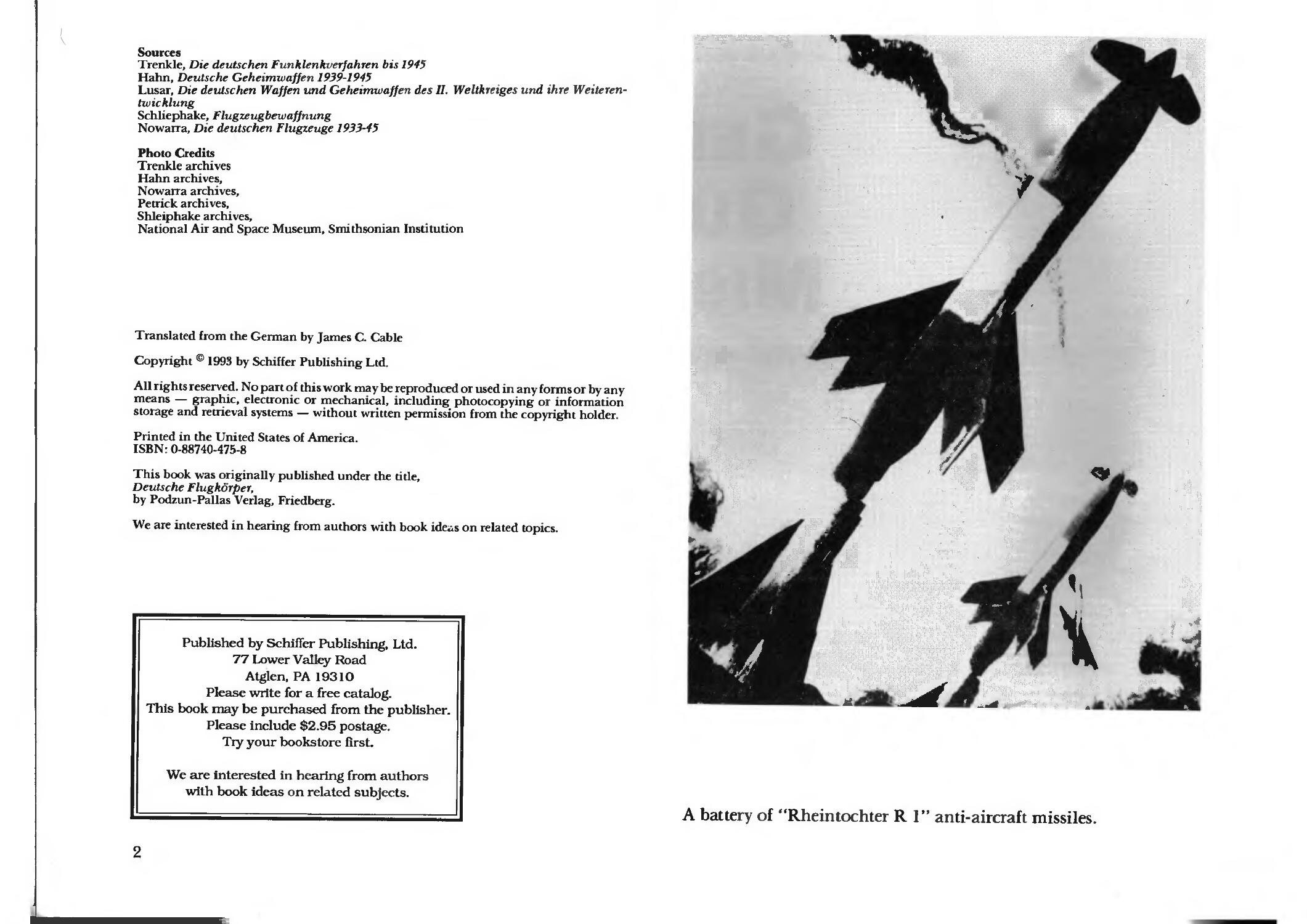
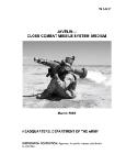
A battery of "Rheintochter R 1" anti-aircraft missiles.
German Guides Missiles
Neither the German "Flugkorper" nor the
English-American phrase "guided missiles"
accurately reflects the application of these
devices which today play such a large role in
the arms inventory of all countries. There
were (and still are) five groups of these
weapons, each serving quite different
purposes.
1. medium- and long-range missiles
2. air-launched missiles
3. glider bombs
4. glider torpedoes
5. anti-aircraft missiles
,, \
I*
* \
y
\
What today is considered the most modern
branch of service is, in reality, the
continuation of ancient ideas. In China rockets
with solid fuel engines were utilized for as
incendiary devices as early as the year 1130. In
1916, French single-seat Nieuport fighters
were toting 16 incendiary rockets which were
employed against German airships with great
success. The Zeppelin airship LZ 77
(commanded by Hauptmann Horn) was shot
down over France on February 21st 1916 with
just such rockets. On the German side,
attempts were made to develop a similar
weapon by mounting captured rockets on a
Halberstadt DII single-seat fighter, but these
attempts were not successful. As early as 1910,
Wilhelm von Siemens, a son of the firms
founding father Werner von Siemens, was
occupying himself with preliminary research
into gliding bombs fins by dropping them
from balloons and airships. After the start of
the war in 1914, this idea was rekindled. In
early 1915, small glider models which could
guided by electrical wire to a distance of 3000
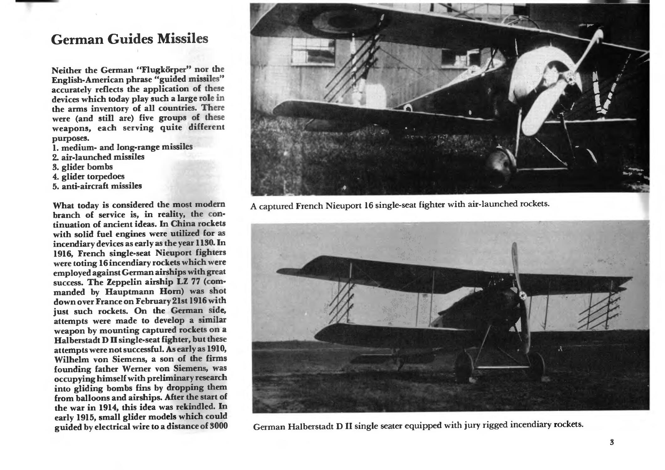
A captured French Nieuport 16 single-seat fighter with air-launched rockets.
/ i
1 4
'A "
German Halberstadt D II single seater equipped with jury rigged incendiary rockets.
meters, were dropped from barrage balloons.
In 1916 further successful drops from airships
were conducted. In 1917, Siemens presented
the Reichsmarine-Amt with gliding
torpedoes which were tested aboard the airships
Z XIII, L 25 and L 35. On 27 April 1918,
however, a glider crashed at Juterbog airfield,
after which time all further testing was
stopped. The last drop was conducted on
August 2nd 1918 by the airship L 35 from an
altitude of 1,500 meters near Potsdam. But
because the airships proved to be too slow for
these purposes, the sentiment was to utilize
huge airplanes such as the Zeppelin-Staaken
R IV (see: Nowarra, Die Flugzeuge des
Alexander Baumann, Podzun-Verlag) for
these purposes. A total of 100 of these
torpedoes were built up to November of 1918.
Despite the ban imposed by the 1919 Treaty
of Versailles, the Heeres- Waffenamt awarded
developmental contracts in 1926 and 1927 for
flight control and remote control systems. By
1929 there was already a flight remote control
station in existence for aircraft. In 1930 the
related testing was begun.
It was some time after the National
Socialists (Nazis) came into power, specifically not
until 1938, that the Wehrmacht began to take
interest in the development of guidance
methods, air-launched rockets, gliding
bombs, torpedoes and other such weapons.
An intensive development, however, did not
take place until the middle of the Second
World War.
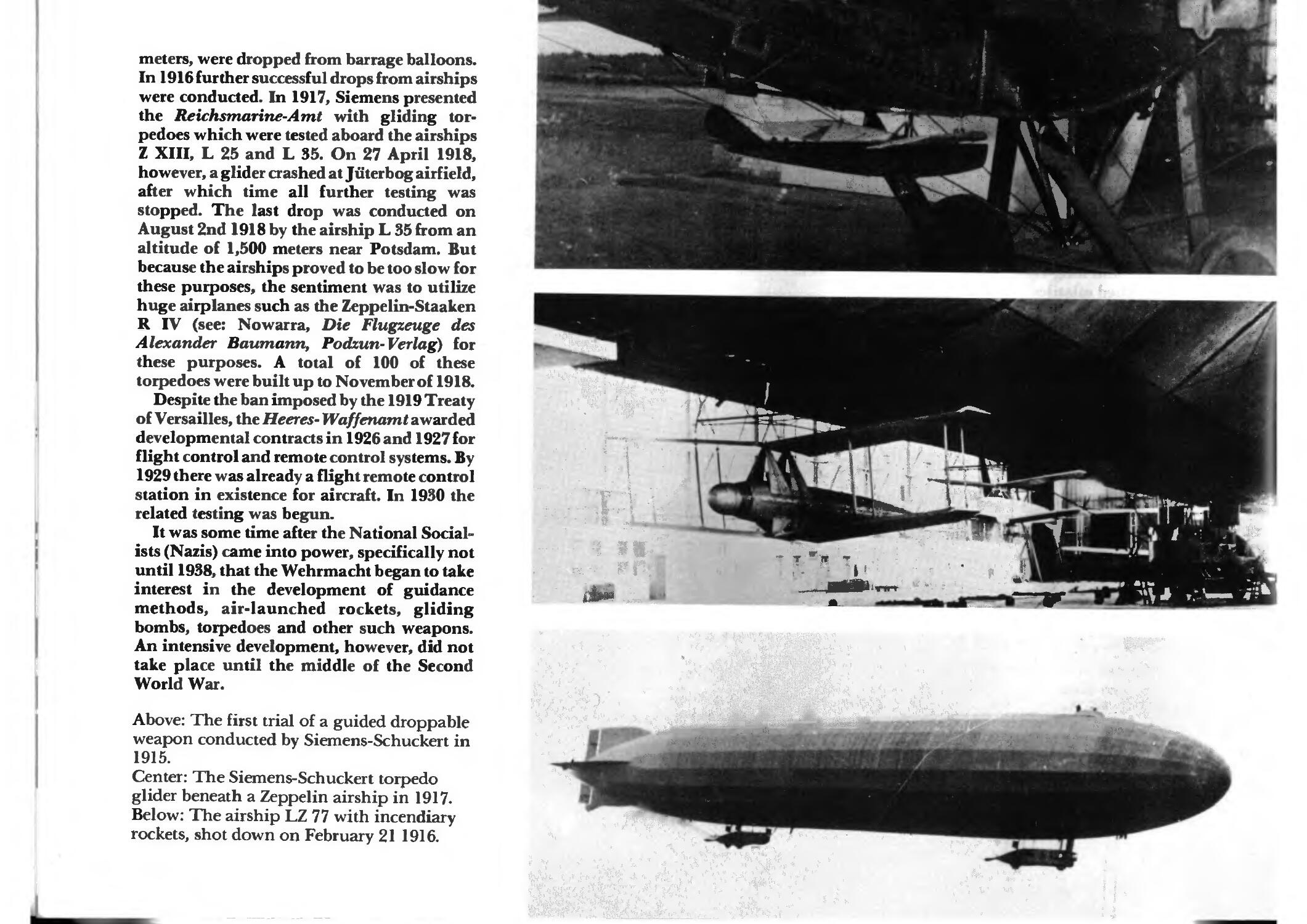
Above: The first trial of a guided droppable
weapon conducted by Siemens-Schuckert in
1915.
Center: The Siemens-Schuckert torpedo
glider beneath a Zeppelin airship in 1917.
Below: The airship LZ 77 with incendiary
rockets, shot down on February 21 1916.
• <■
\
A 1*
"V. - '.
'%}
/."-• -w^'VwiH-
T;"Tf ■•»
■»•■
•" > is
■. r *«
11~r
■•-■r
fc^'
**•—..
• IR-'.
i *►•
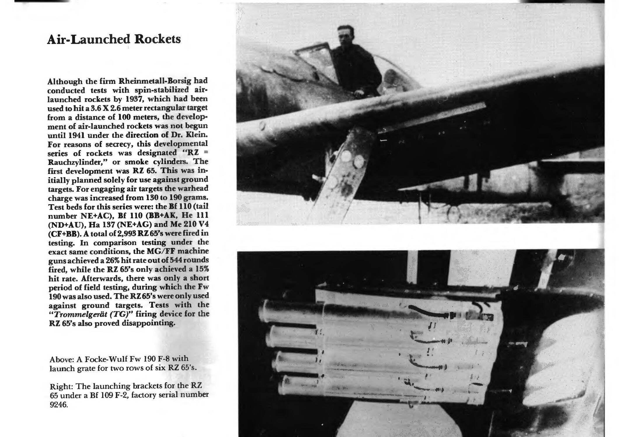
Air-Launched Rockets
Although the firm Rheinmetall-Borsig had
conducted tests with spin-stabilized air-
launched rockets by 1937, which had been
used to hit a 3.6 X 2.6 meter rectangular target
from a distance of 100 meters, the develop-
ment of air-launched rockets was not begun
until 1941 under the direction of Dr. Klein.
For reasons of secrecy, this developmental
series of rockets was designated "RZ =
Rauchzylinder," or smoke cylinders. The
first development was RZ 65. This was in-
itially planned solely for use against ground
targets. For engaging air targets the warhead
charge was increased from 130 to 190 grams.
Test beds for this series were: the Bf 110 (tail
number NE+AC), Bf 110 (BB+AK, He 111
(ND+AU), Ha 137 (NE+AG) and Me 210 V4
(CF+BB). A total of 2,993 RZ 65's were fired in
testing. In comparison testing under the
exact same conditions, the MC/FF machine
guns achieved a 26% hit rate out of 544 rounds
fired, while the RZ 65's only achieved a 15%
hit rate. Afterwards, there was only a short
period of field testing, during which the Fw
190 was also used. The RZ 65's were only used
against ground targets. Tests with the
"Trommelgerat (TG)" firing device for the
RZ 65's also proved disappointing.
Above: A Focke-Wulf Fw 190 F-8 with
launch grate for two rows of six RZ 65's.
Right: The launching brackets for the RZ
65 under a Bf 109 F-2, factory serial number
9246.
*df»*»
.t.fc
t=ss^
r+ *»$'
• **"^*»sS!J. -*&- »*
..;*£■■■.
'.*&&&
■, fcj*
H
"*
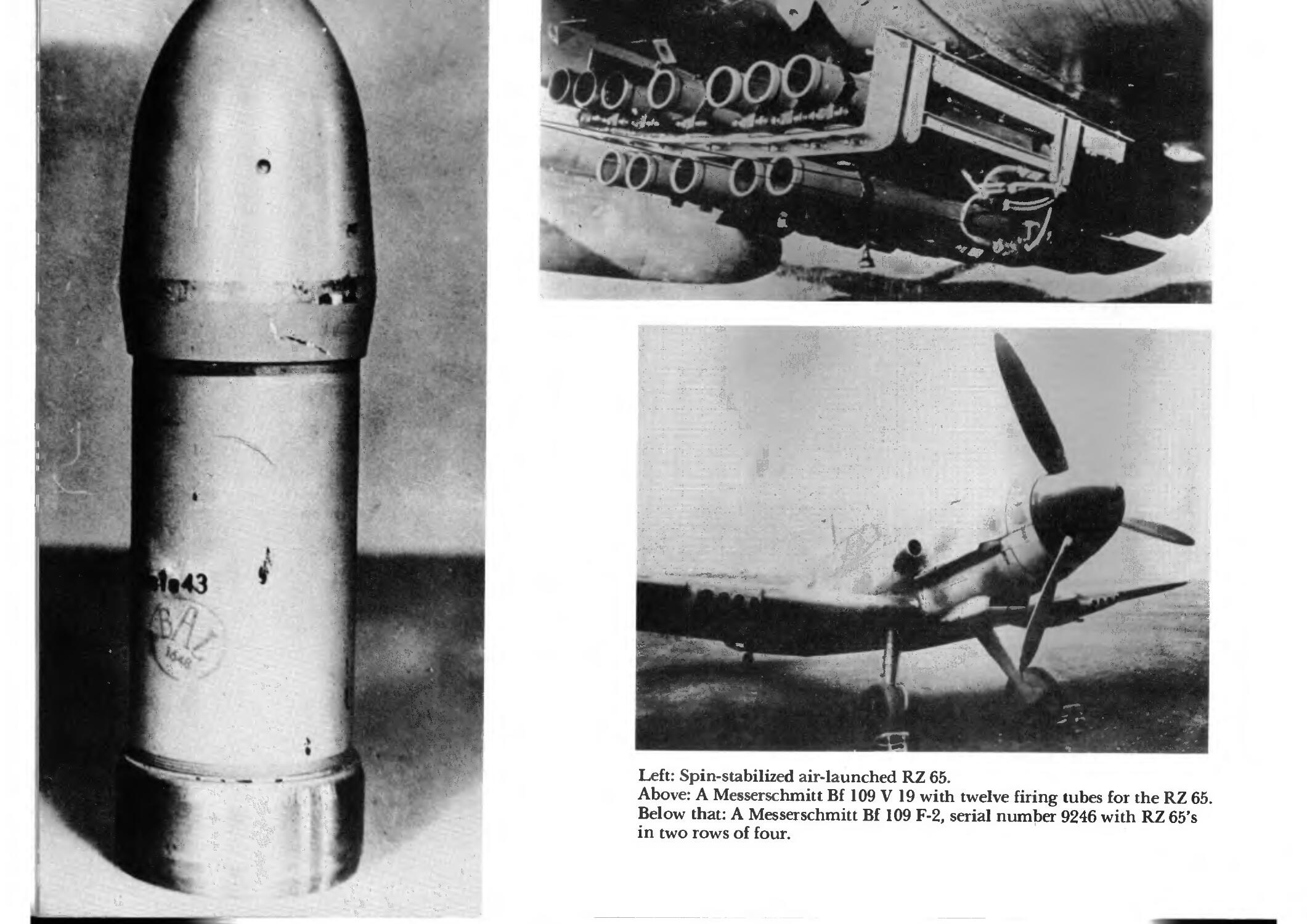
Left: Spin-stabilized air-launched RZ 65.
Above: A Messerschmitt Bf 109 V 19 with twelve firing tubes for the RZ 65.
Below that: A Messerschmitt Bf 109 F-2, serial number 9246 with RZ 65's
in two rows of four.
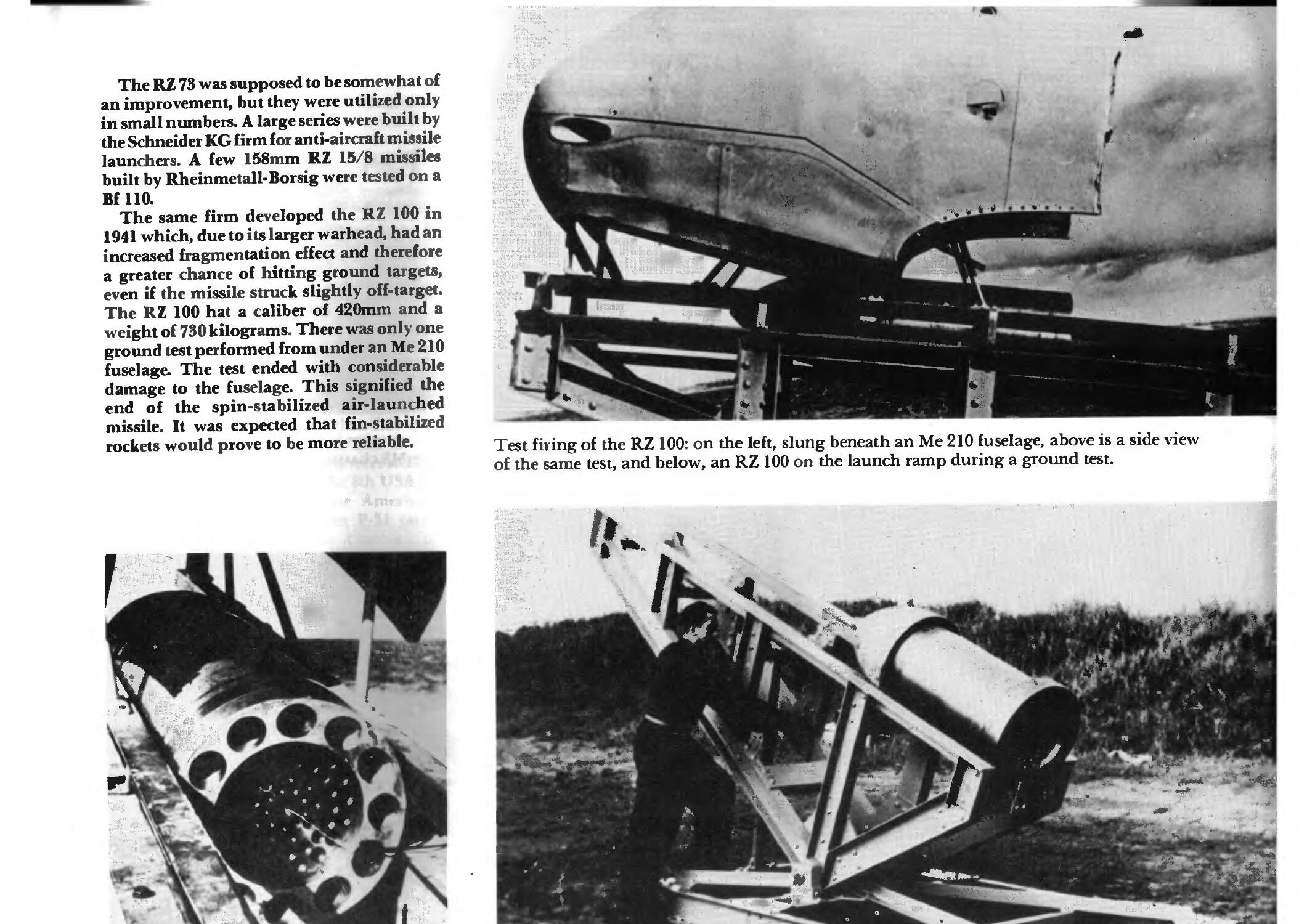
The RZ 73 was supposed to be somewhat of
an improvement, but they were utilized only
in small numbers. A large series were built by
the Schneider KG firm for anti-aircraft missile
launchers. A few 158mm RZ 15/8 missiles
built by Rheinmetall-Borsig were tested on a
Bf 110.
The same firm developed the RZ 100 in
1941 which, due to its larger warhead, had an
increased fragmentation effect and therefore
a greater chance of hitting ground targets,
even if the missile struck slightly off-target.
The RZ 100 hat a caliber of 420mm and a
weight of 730 kilograms. There was only one
ground test performed from under an Me 210
fuselage. The test ended with considerable
damage to the fuselage. This signified the
end of the spin-stabilized air-launched
missile. It was expected that fin-stabilized
rockets would prove to be more reliable.
i %
r Ajrttt:
[
S
* * §
-* It > v 0 •
*
>:m
I
I.
Test firing of the RZ 100: on the left, slung beneath an Me 210 fuselage, above is a side view
of the same test, and below, an RZ 100 on the launch ramp during a ground test.
■;■'»•. : ■:•;-
x I <
- k *
40 . ."V
. •-.■-■■/:
w ^
K
■■fa;
vWi^
ifS***"*'"
'" "' "r
"r- . *.- .''".
1 ..'
- - , ■
"1 ' I
-#*■
~.&
/ V,
t j
, -^f^
**■ * ■ s
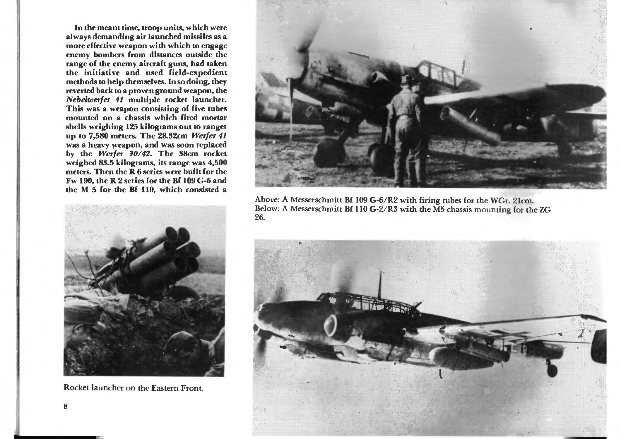
In the meant time, troop units, which were
always demanding air launched missiles as a
more effective weapon with which to engage
enemy bombers from distances outside the
range of the enemy aircraft guns, had taken
the initiative and used field-expedient
methods to help themselves. In so doing, they
reverted back to a proven ground weapon, the
Nebelwerfer 41 multiple rocket launcher.
This was a weapon consisting of five tubes
mounted on a chassis which fired mortar
shells weighing 125 kilograms out to ranges
up to 7,580 meters. The 28.32cm Werfer 41
was a heavy weapon, and was soon replaced
by the Werfer 30/42. The 38cm rocket
weighed 83.5 kilograms, its range was 4,500
meters. Then the R 6 series were built for the
Fw 190, the R 2 series for the Bf 109 G-6 and
the M 5 for the Bf 110, which consisted a
W^,,^"
^ ' t'j
* * >
>rf
■^\ «.
Rocket launcher on the Eastern Front.
8
'f
%.
J''t
*1r
-** -.,#•
■#
1
~2+S>
SviiP* - '•*"*«!
7f*
Above: A Messerschmitt Bf 109 G-6/R2 with firing tubes for the WGr. 21cm.
Below: A Messerschmitt Bf 110 G-2/R3 with the M5 chassis mounting for the ZG
26.
■ V,
«" *1P
%& - «■>
"^s-u;
t--:r
; jfe " md
••=5x-
..;-*•"
A;
■x;-
. • ::_■ • ».
-:-:fi-?" •
•'^ .
.. fu* .
£4».;-7;
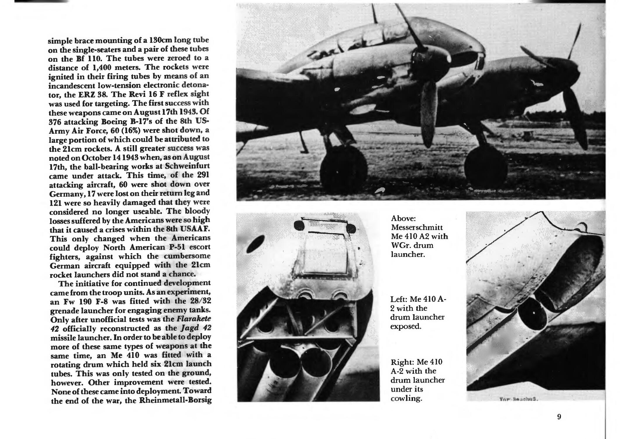
simple brace mounting of a 130cm long tube
on the single-seaters and a pair of these tubes
on the Bf 110. The tubes were zeroed to a
distance of 1,400 meters. The rockets were
ignited in their firing tubes by means of an
incandescent low-tension electronic
detonator, the ERZ 38. The Revi 16 F reflex sight
was used for targeting. The first success with
these weapons came on August 17th 1943. Of
376 attacking Boeing B-17's of the 8th US-
Army Air Force, 60 (16%) were shot down, a
large portion of which could be attributed to
the 21cm rockets. A still greater success was
noted on October 141943 when, as on August
17th, the ball-bearing works at Schweinfurt
came under attack. This time, of the 291
attacking aircraft, 60 were shot down over
Germany, 17 were lost on their return leg and
121 were so heavily damaged that they were
considered no longer useable. The bloody
losses suffered by the Americans were so high
that it caused a crises within the 8th USAAF.
This only changed when the Americans
could deploy North American P-51 escort
fighters, against which the cumbersome
German aircraft equipped with the 21cm
rocket launchers did not stand a chance.
The initiative for continued development
came from the troop units. As an experiment,
an Fw 190 F-8 was fitted with the 28/32
grenade launcher for engaging enemy tanks.
Only after unofficial tests was the Flarakete
42 officially reconstructed as the Jagd 42
missile launcher. In order to be able to deploy
more of these same types of weapons at the
same time, an Me 410 was fitted with a
rotating drum which held six 21cm launch
tubes. This was only tested on the ground,
however. Other improvement were tested.
None of these came into deployment. Toward
the end of the war, the Rheinmetall-Borsig
•*"% ,
<^"1 "#U."W^ V!? *■*»**■*
*.*«•• t'f
* \
Above:
Messerschmitt
Me 410 A2 with
WGr. drum
launcher.
CI
j0\
Left: Me 410 A-
2 with the
drum launcher
exposed.
Right: Me 410
A-2 with the
drum launcher
under its
cowling.
I
%1
'i, ■=•%.'
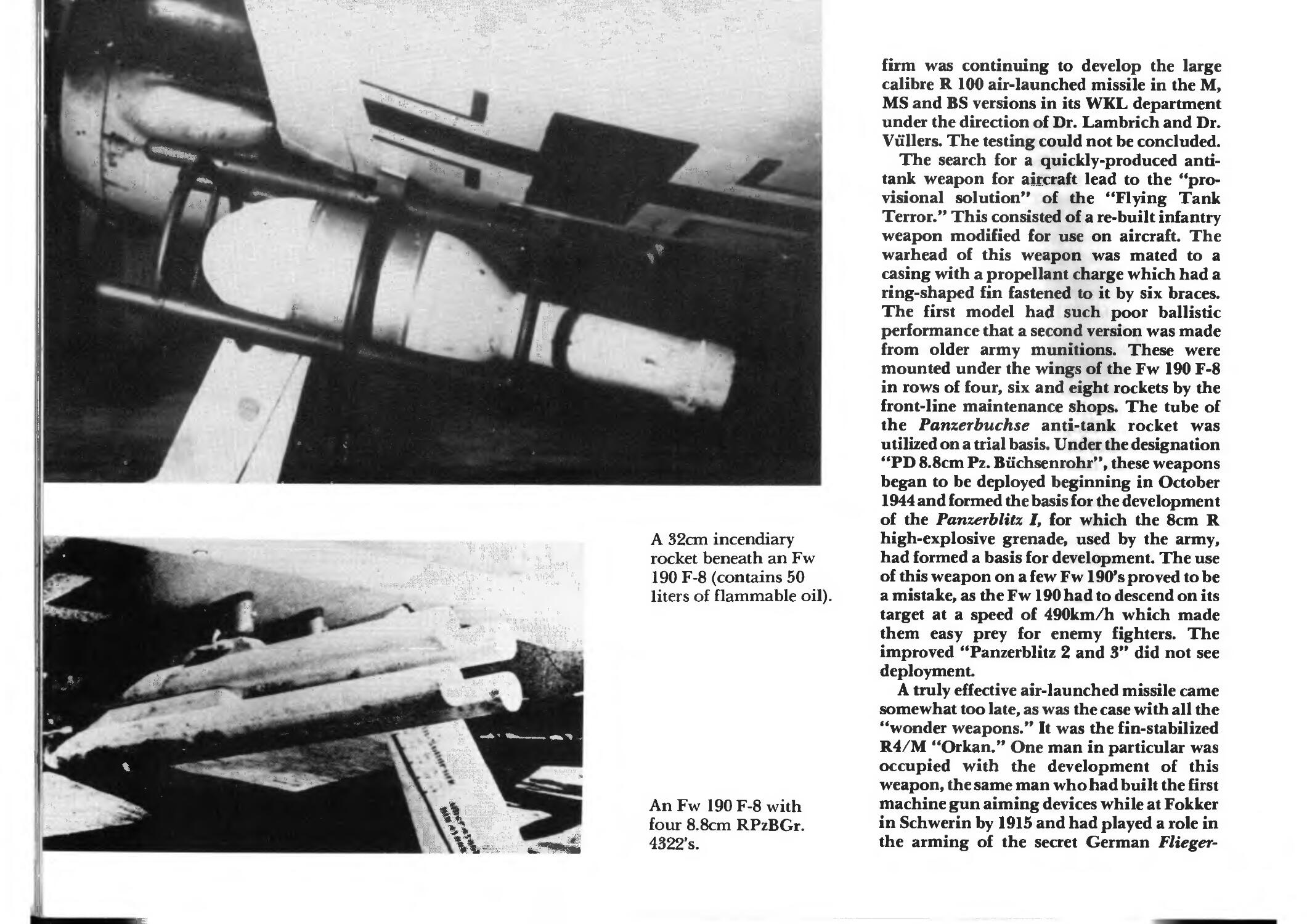
A 32cm incendiary
rocket beneath an Fw
190 F-8 (contains 50
liters of flammable oil).
An Fw 190 F-8 with
four 8.8cm RPzBGr.
4322's.
firm was continuing to develop the large
calibre R 100 air-launched missile in the M,
MS and BS versions in its WKL department
under the direction of Dr. Lambrich and Dr.
Vullers. The testing could not be concluded.
The search for a quickly-produced
antitank weapon for aircraft lead to the
"provisional solution" of the "Flying Tank
Terror." This consisted of a re-built infantry
weapon modified for use on aircraft. The
warhead of this weapon was mated to a
casing with a propellant charge which had a
ring-shaped fin fastened to it by six braces.
The first model had such poor ballistic
performance that a second version was made
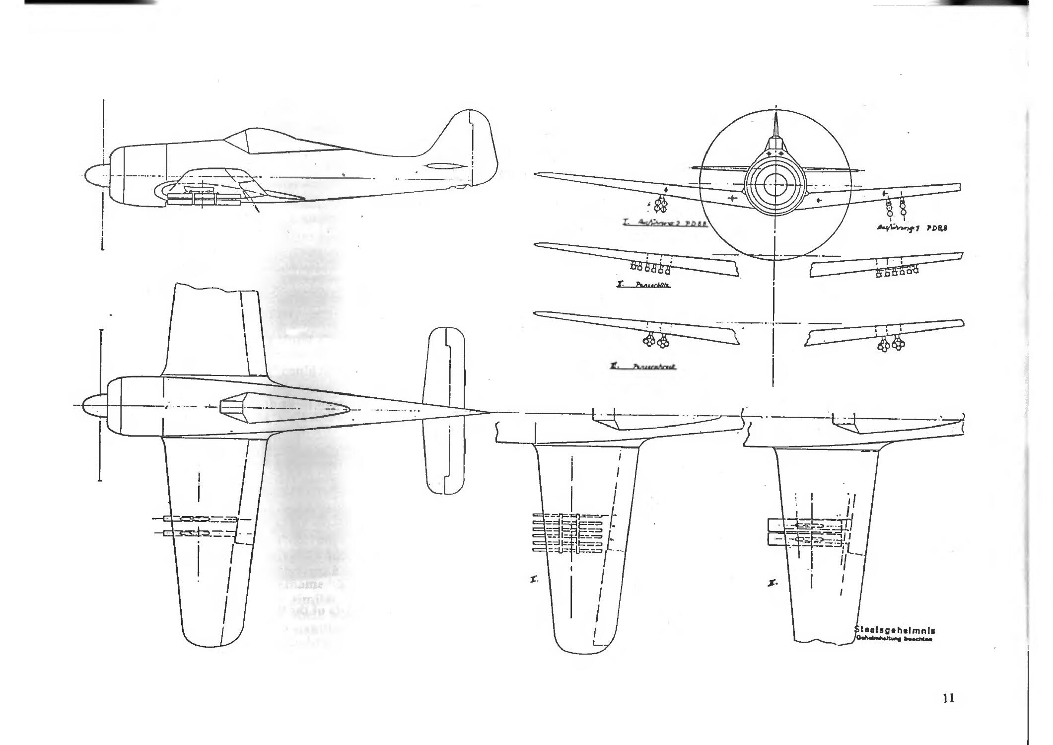
from older army munitions. These were
mounted under the wings of the Fw 190 F-8
in rows of four, six and eight rockets by the
front-line maintenance shops. The tube of
the Panzerbuchse anti-tank rocket was
utilized on a trial basis. Under the designation
"PD 8.8cm Pz. Buchsenrohr", these weapons
began to be deployed beginning in October
1944 and formed the basis for the development
of the Panzerblitz I, for which the 8cm R
high-explosive grenade, used by the army,
had formed a basis for development. The use
of this weapon on a few Fw 190's proved to be
a mistake, as the Fw 190 had to descend on its
target at a speed of 490km/h which made
them easy prey for enemy fighters. The
improved "Panzerblitz 2 and 3" did not see
deployment.
A truly effective air-launched missile came
somewhat too late, as was the case with all the
"wonder weapons." It was the fin-stabilized
R4/M "Orkan." One man in particular was
occupied with the development of this
weapon, the same man who had built the first
machine gun aiming devices while at Fokker
in Schwerin by 1915 and had played a role in
the arming of the secret German Flieger-
laatsgahalmnls
11
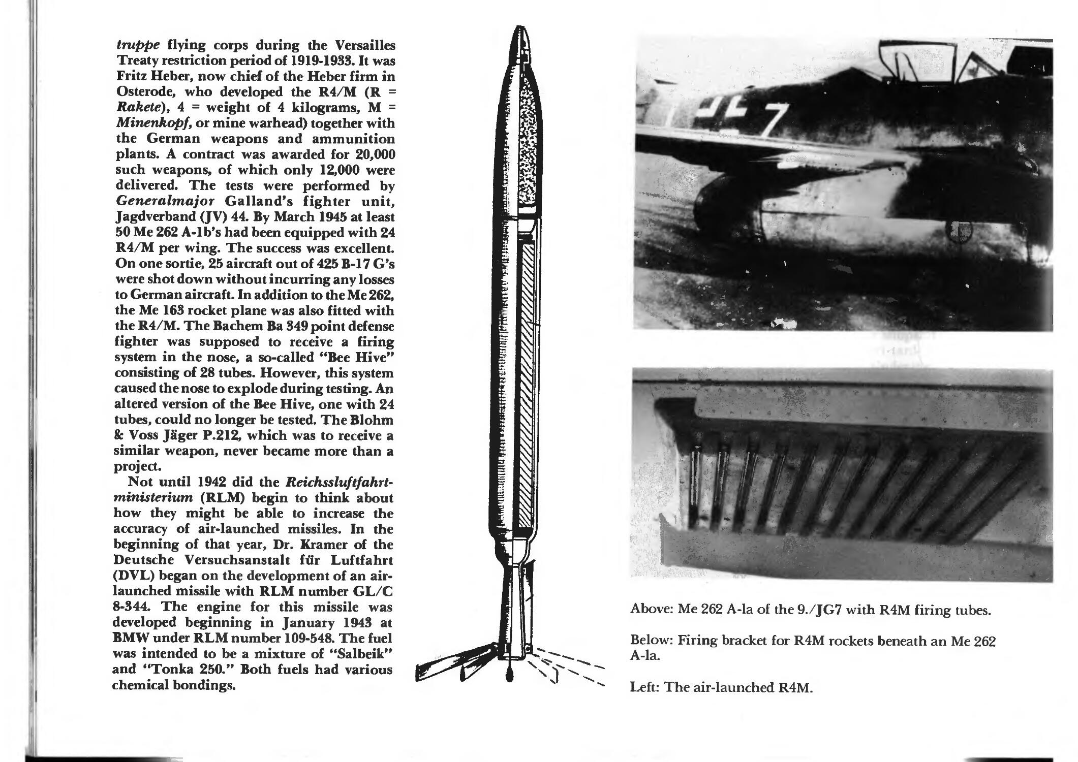
truppe flying corps during the Versailles
Treaty restriction period of 1919-1933. It was
Fritz Heber, now chief of the Heber firm in
Osterode, who developed the R4/M (R =
Rakete), 4 = weight of 4 kilograms, M =
Minenkopf, or mine warhead) together with
the German weapons and ammunition
plants. A contract was awarded for 20,000
such weapons, of which only 12,000 were
delivered. The tests were performed by
Generalmajor Galland's fighter unit,
Jagdverband (JV) 44. By March 1945 at least
50 Me 262 A-lb's had been equipped with 24
R4/M per wing. The success was excellent.
On one sortie, 25 aircraft out of 425 B-17 G's
were shot down without incurring any losses
to German aircraft. In addition to the Me 262,
the Me 163 rocket plane was also fitted with
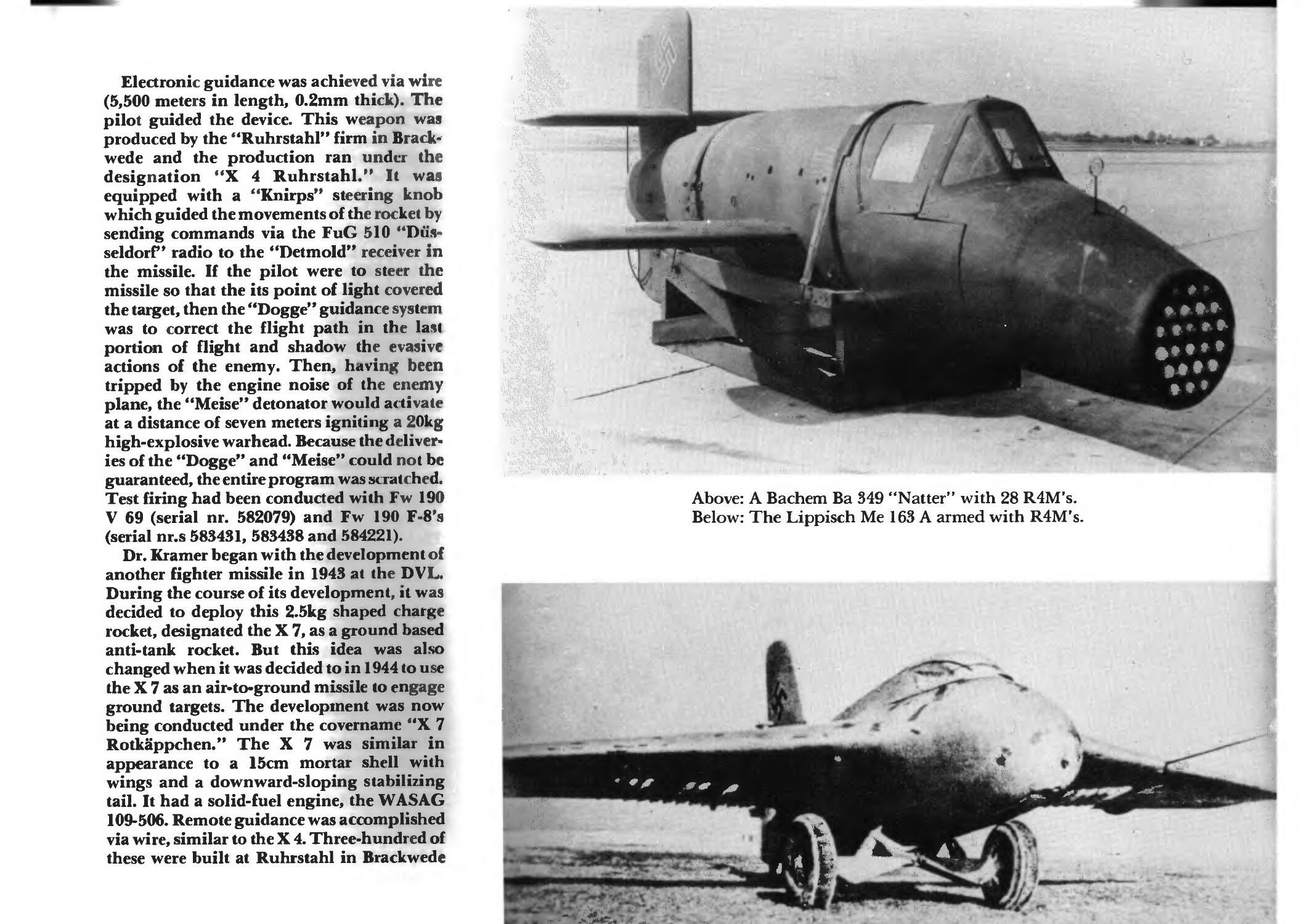
the R4/M. The Bachem Ba 349 point defense
fighter was supposed to receive a firing
system in the nose, a so-called "Bee Hive"
consisting of 28 tubes. However, this system
caused the nose to explode during testing. An
altered version of the Bee Hive, one with 24
tubes, could no longer be tested. The Blohm
& Voss Jager P.212, which was to receive a
similar weapon, never became more than a
project.
Not until 1942 did the Reichssluftfahrt-
ministerium (RLM) begin to think about
how they might be able to increase the
accuracy of air-launched missiles. In the
beginning of that year, Dr. Kramer of the
Deutsche Versuchsanstalt fiir Luftfahrt
(DVL) began on the development of an air-
launched missile with RLM number GL/C
8-344. The engine for this missile was
developed beginning in January 1943 at
BMW under RLM number 109-548. The fuel
was intended to be a mixture of "Salbeik"
and "Tonka 250." Both fuels had various
chemical bondings.
• *****.,',
*^
*"%
■\: »* v-;
- 7%
,*^y$
7?l.
*1
\
1 *****"
^~:£et mrev-r **
"&;
Above: Me 262 A-la of the 9./JG7 with R4M firing tubes.
Below: Firing bracket for R4M rockets beneath an Me 262
A-la.
Left: The air-launched R4M.
Electronic guidance was achieved via wire
(5,500 meters in length, 0.2mm thick). The
pilot guided the device. This weapon waa
produced by the "Ruhrstahl" firm in
Brackwede and the production ran under the
designation "X 4 Ruhrstahl." It was
equipped with a "Knirps" steering knob
which guided the movements of the rocket by
sending commands via the FuC 510 "Diis-
seldorf" radio to the "Detmold" receiver in
the missile. If the pilot were to steer the
missile so that the its point of light covered
the target, then the "Dogge" guidance system
was to correct the flight path in the last
portion of flight and shadow the evasive
actions of the enemy. Then, having been
tripped by the engine noise of the enemy
plane, the "Meise" detonator would activate
at a distance of seven meters igniting a 20kg
high-explosive warhead. Because the deliver*
ies of the "Dogge" and "Meise" could not be
guaranteed, the entire program was scratched.
Test firing had been conducted with Fw 190
V 69 (serial nr. 582079) and Fw 190 F-8's
(serial nr.s 583431, 583438 and 584221).
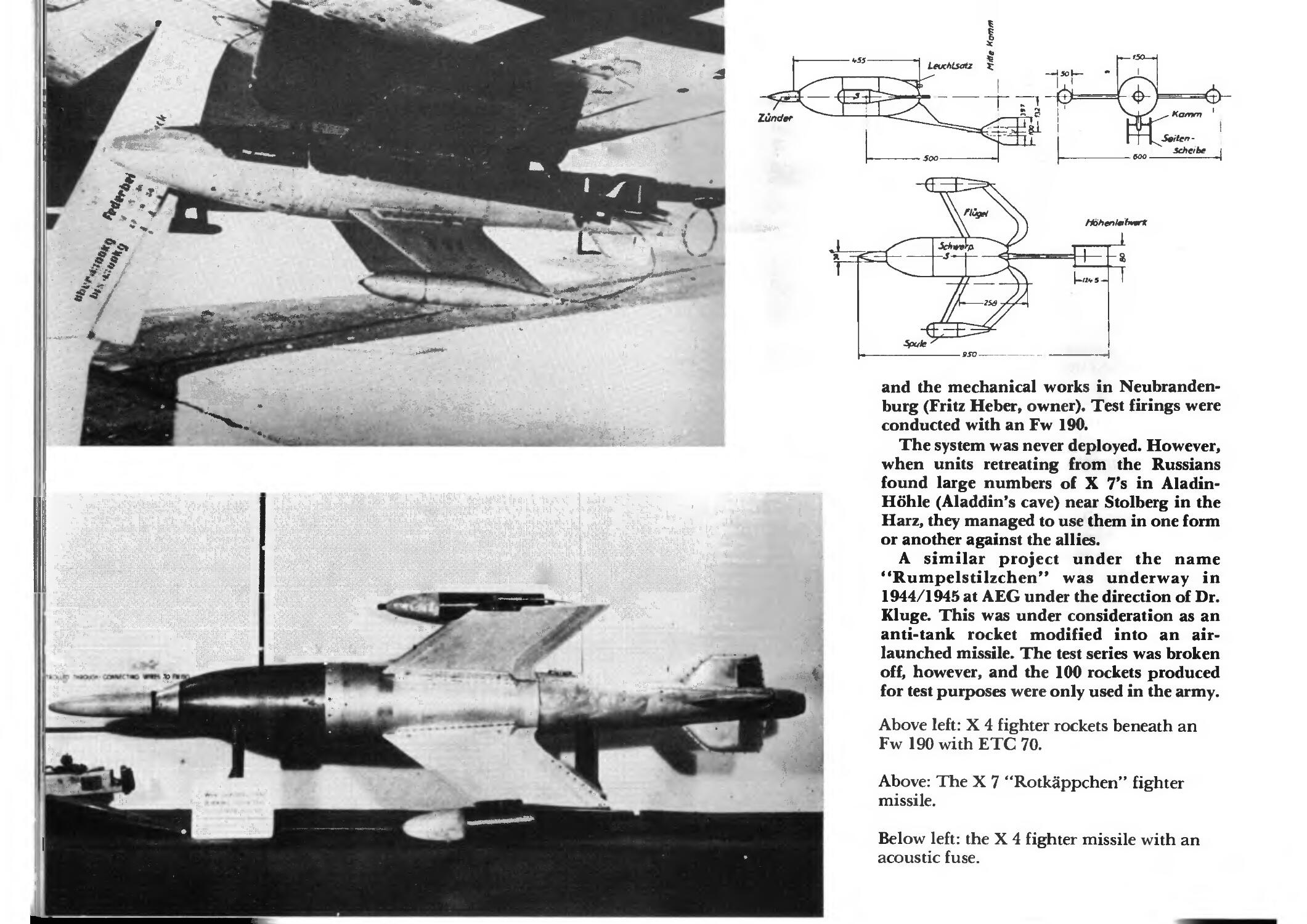
Dr. Kramer began with the development of
another fighter missile in 1943 at the DVL,
During the course of its development, it was
decided to deploy this 2.5kg shaped charge
rocket, designated the X 7, as a ground based
anti-tank rocket. But this idea was also
changed when it was decided to in 1944 to use
the X 7 as an air-to-ground missile to engage
ground targets. The development was now
being conducted under the covername "X 7
Rotkappchen." The X 7 was similar in
appearance to a 15cm mortar shell with
wings and a downward-sloping stabilizing
tail. It had a solid-fuel engine, the WASAG
109-506. Remote guidance was accomplished
via wire, similar to the X 4. Three-hundred of
these were built at Ruhrstahl in Brackwede
§f t * •
Above: A Bachem Ba 349 "Natter" with 28 R4M's.
Below: The Lippisch Me 163 A armed with R4M's.
* ** jnr
lit
'JShu*.^
■" - - ■-"ifc..
s.- .■
.-;,•■. i J
7
-at
-«"
1 'l
. „*%*£*%'
.-' rf_ -_■=■
BSO »j
and the mechanical works in Neubranden-
burg (Fritz Heber, owner). Test firings were
conducted with an Fw 190.
The system was never deployed. However,
when units retreating from the Russians
found large numbers of X 7's in Aladin-
Hohle (Aladdin's cave) near Stolberg in the
Harz, they managed to use them in one form
or another against the allies.
A similar project under the name
"Rumpelstilzchen" was underway in
1944/1945 at AEG under the direction of Dr.
Kluge. This was under consideration as an
anti-tank rocket modified into an air-
launched missile. The test series was broken
4 off, however, and the 100 rockets produced
for test purposes were only used in the army.
Above left: X 4 fighter rockets beneath an
Fw 190 with ETC 70.
Above: The X 7 "Rotkappchen" fighter
missile.
Below left: the X 4 fighter missile with an
acoustic fuse.
Anyone who, at the beginning of the war,
had the opportunity to travel along the street
which led past the western side of the
Henschel factory airfield in Schonefeld near
Berlin had to have noticed the systems from
companies such as Siemens, Askania, Lorenz,
AEG and others there on the southern side of
the field all occupied in radio guidance work.
Night fighters with radio locating systems,
high-altitude fighters as well as aircraft with
airplane-like devices slung under their wings
could all be seen here. This is where, under
the direction of Professor Wagner, remotely*
controlled rockets, bombs and other missiles
were developed. Professor Wagner had
already projected a guided missile by 1941,
one which the RLM rejected because at that
point in time, it was believed the Soviets had
been defeated and this type weapon was
superfluous. In 1943, however, it was
mandated that these missiles go into urgent
mass-production, and be conducted at the
AEG firm under the direction of Dipl.Ing.
Hesky. The planned propulsion unit was a
double-chambered Schmidding SG 32 (109-
543) using diglycol for fuel. Production ran
into difficulties because the proximity fuse
which was to be installed in the "snout" in
front of the rocket body could not be delivered
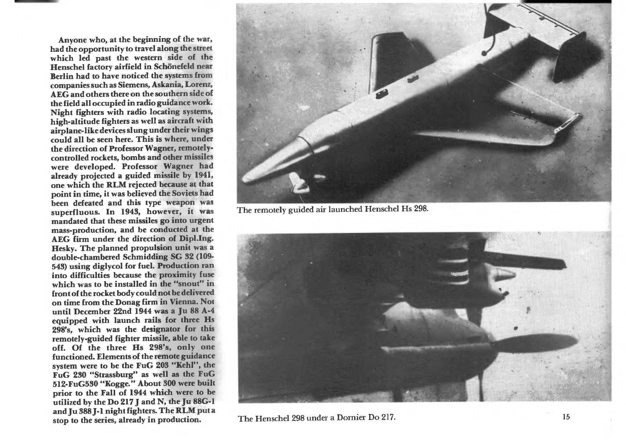
on time from the Donag firm in Vienna. Not
until December 22nd 1944 was a Ju 88 A-4
equipped with launch rails for three Hs
298's, which was the designator for this
remotely-guided fighter missile, able to take
off. Of the three Hs 298's, only one
functioned. Elements of the remote guidance
system were to be the FuG 203 "Kehl", the
FuG 230 "Strassburg" as well as the FuG
512-FuG5S0 "Kogge." About 300 were built
prior to the Fall of 1944 which were to be
utilized by the Do 217 J and N, the Ju 88G-1
and Ju 388 J-1 night fighters. The RLM put a
stop to the series, already in production.
"*%'
* %
■■.If.
■:.£
•y&
■■**..*>"! .}.
'.^. >.;*% .*r..'.' - ■'■ - ■-
- • \ - » - ; -.!*
The remotely guided air launched Henschel Hs 298.
■l&Ei^
'•T
■Ji
* "V*tf-=»
■£.
£t»*j
•--"%»-'■ ;-'*'
. /* fafeJUSK'-*
The Henschel 298 under a Dornier Do 217.
15
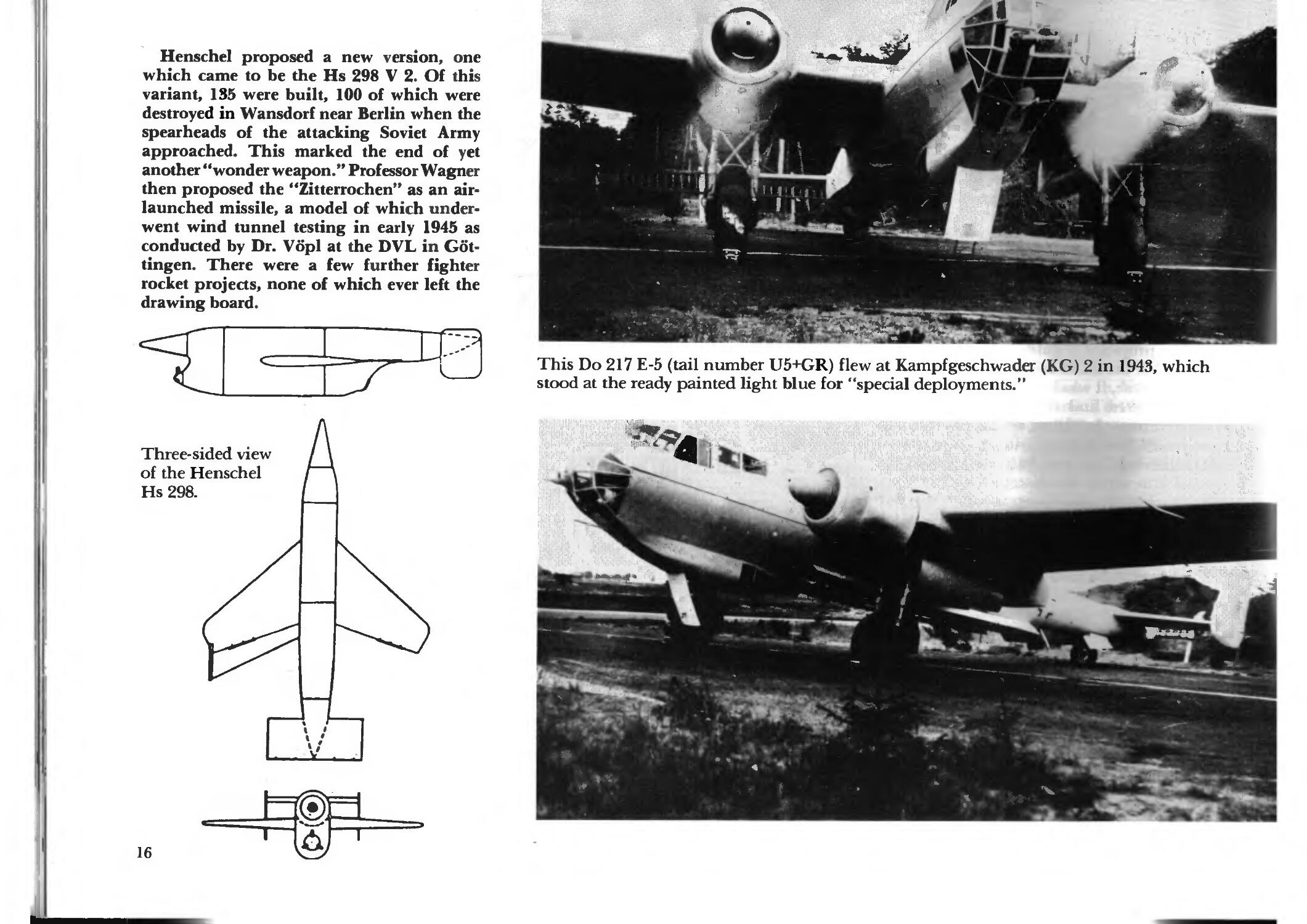
Henschel proposed a new version, one
which came to be the Hs 298 V 2. Of this
variant, 135 were built, 100 of which were
destroyed in Wansdorf near Berlin when die
spearheads of the attacking Soviet Army
approached. This marked the end of yet
another "wonder weapon." Professor Wagner
then proposed the "Zitterrochen" as an air-
launched missile, a model of which
underwent wind tunnel testing in early 1945 as
conducted by Dr. Vopl at the DVL in Got-
tingen. There were a few furdier fighter
rocket projects, none of which ever left the
drawing board.
Three-sided view
of the Henschel
Hs 298.
?
- \
:-. i si
>■ V|,,|
4 - »
' Y
J M
t, '■
et^
A
I
<»
This Do 217 E-5 (tail number U5+GR) flew at Kampfgeschwader (KG) 2 in 1943, which
stood at the ready painted light blue for "special deployments." |
"i^t^
NX1
Mf ' ■'
f /
%h>..^
16
J(»t"
Guided Bombs
Several guidance systems had already been
demonstrated on the X 4 and Hs 298 air-
launched missiles. Originally, the
development of these systems was begun in
conjunction with the first attempt to create
guided bombs and torpedoes. The inspiration
for this development lay in the unsettling
lack of accuracy demonstrated by units when
making horizontal attacks. The limited range
and speed of the Ju 87 dive-bomber showed
that they would also not provide a satisfactory
answer to the problem. When dropped from
horizontal flight as conducted by the Lehr-
geschwader (LG) 1 from altitudes of 8-9000
meters on the Hessen target ship, only 0.6%
were on target.
By 1938, Dr. Max Kramer was working at
the DVL on the development of self- and
remotely-guided missiles in the X-series,
while Prof. H. Wagner was working on the
290-series missiles at the Henschel firm.
In 1938, the wireless receiver C 192 was
created at the Drahtlos-Luftelektrischen
Versuchsanstalt (an aviation radio research
institute) in Grafelfing based on the results of
these efforts, and then in 1940 and improved
system was produced, the C 202/203, while
the appropriate antenna systems had been
developed under the direction of Dr. Zisler at
the Flugfunk-forschungsinstitut Oberpfaf-
fenhofen (FFO). The testing which was
conducted in the summer of 1940 at the test site in
Peenemunde produced no satisfactory results,
however, so the devices from the Grafelfing
facility did not enter production.
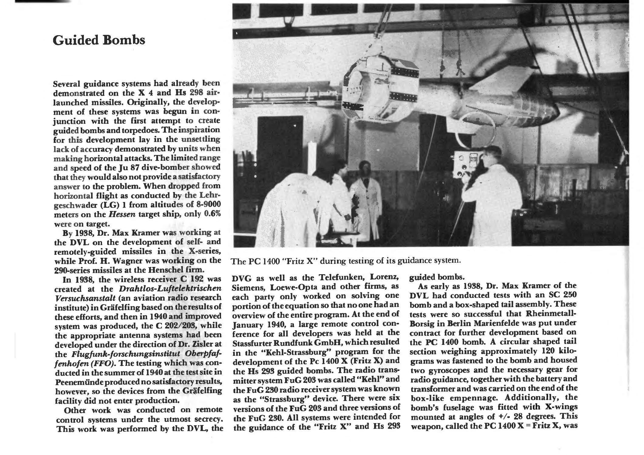
Other work was conducted on remote
control systems under the utmost secrecy.
This work was performed by the DVL, the
A
■ I
r1'.*!
*
4
M
#
The PC 1400 "Fritz X" during testing of its guidance system.
DVG as well as the Telefunken, Lorenz,
Siemens, Loewe-Opta and other firms, as
each party only worked on solving one
portion of the equation so that no one had an
overview of the entire program. At the end of
January 1940, a large remote control
conference for all developers was held at the
Stassfurter Rundf unk GmbH, which resulted
in the "Kehl-Strassburg" program for the
development of the Pc 1400 X (Fritz X) and
the Hs 293 guided bombs. The radio
transmitter system FuG 203 was called "Kehl" and
the FuG 230 radio receiver system was known
as the "Strassburg" device. There were six
versions of the FuG 203 and three versions of
the FuG 230. All systems were intended for
the guidance of the "Fritz X" and Hs 293
guided bombs.
As early as 1938, Dr. Max Kramer of the
DVL had conducted tests with an SC 250
bomb and a box-shaped tail assembly. These
tests were so successful that Rheinmetall-
Borsig in Berlin Marienfelde was put under
contract for further development based on
the PC 1400 bomb. A circular shaped tail
section weighing approximately 120
kilograms was fastened to the bomb and housed
two gyroscopes and the necessary gear for
radio guidance, together with the battery and
transformer and was carried on the end of the
box-like empennage. Additionally, the
bomb's fuselage was fitted with X-wings
mounted at angles of +/• 28 degrees. This
weapon, called the PC 1400 X = Fritz X, was
\
'•• ■.- ' •
~- ii
a
txuy
Alt
18
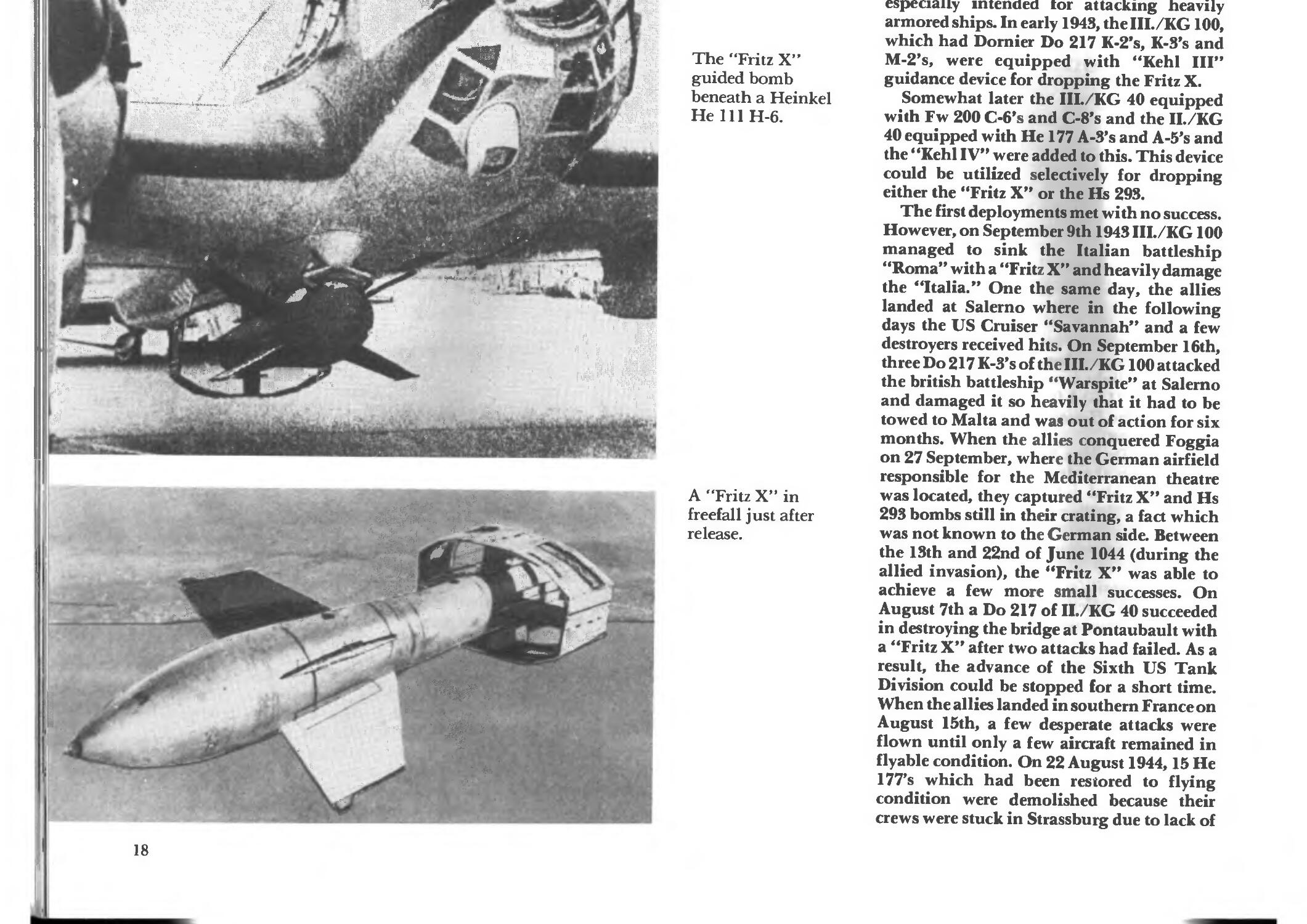
The "Fritz X"
guided bomb
beneath a Heinkel
HelllH-6.
A "Fritz X" in
freefall just after
release.
especially intended tor attacking heavily
armored ships. In early 1943, the III./KG 100,
which had Dornier Do 217 K-2*s, K-S's and
M-2's, were equipped with "Kehl III"
guidance device for dropping the Fritz X.
Somewhat later the III./KG 40 equipped
with Fw 200 C-6's and C-8's and the II. KG
40 equipped with He 177 A-S's and A-5's and
the "Kehl IV" were added to this. This device
could be utilized selectively for dropping
either the "Fritz X" or the Hs 293.
The first deployments met with no success.
However, on September 9th 1943 III./KG 100
managed to sink the Italian battleship
"Roma" with a "Fritz X" and heavily damage
the "Italia." One the same day, die allies
landed at Salerno where in the following
days the US Cruiser "Savannah" and a few
destroyers received hits. On September 16th,
three Do 217 K-3's of the III. KG 100 attacked
the british battleship "Warspite" at Salerno
and damaged it so heavily that it had to be
towed to Malta and was out of action for six
months. When the allies conquered Foggia
on 27 September, where the German airfield
responsible for the Mediterranean theatre
was located, they captured "Fritz X" and Hs
293 bombs still in their crating, a fact which
was not known to the German side. Between
the 13th and 22nd of June 1044 (during the
allied invasion), the "Fritz X" was able to
achieve a few more small successes. On
August 7th a Do 217 of II./KG 40 succeeded
in destroying the bridge at Pontaubault with
a "Fritz X" after two attacks had failed. As a
result, the advance of the Sixth US Tank
Division could be stopped for a short time.
When the allies landed in southern France on
August 15th, a few desperate attacks were
flown until only a few aircraft remained in
flyable condition. On 22 August 1944,15 He
177's which had been restored to flying
condition were demolished because their
crews were stuck in Strassburg due to lack of
transportation. This was the end of the "Fritz
X."
The Henschel firm at Schonefeld near
Berlin (at the time of writing the airport of
the GDR's airline INTERFLUG) Prof.
Wagner worked on a flying bomb based on
an SC 500 bomb. The first successful tests
were conducted with an Hs 293 V 2 model,
the first unguided drop on September 51940,
the first guided drop with model W 12 on
December 16 1940. Model W 13 was a
complete success only two days later and
became the initial model for the first Hs 293
A-0 series. In early 1941, the Luftwaffe's E-4
test facility at Peenemunde conducted a test
during which a large target ship struck from
a distance of 7,500 meters.
The Hs 293 A-0 began mass production in
November 1941. It was followed in January
1942 by the Hs 293 A-l, of which about 1,250
were built. These guided bombs used the
HWK109-507B rocket engine for propulsion.
The Heinkel He 111 H-12 was the aircraft
which carried this weapon. Guidance was
achieved via the "Kehl III" and FuG 230b
"Strassburg." The first deployment occurred
on August 25 1943 during which 12 Do 217's
of KG 100 operated against enemy submarine
hunters in the Gulf of Biscaya. On September
301943, eleven Do 217's attacked the Ajacdo
harbor on Corsica. Seven aircraft were lost in
the attack. The worst was, however, that two
Hs 293's glided onto the harbor waterfront
i nd were re-constructed by the enemy.
Due to errors in production, there were
numerous failures. Nevertheless, Fw 200's
and He 177s of the II. and HI. KG 40 still
flew numerous successful missions which
resulted in a 28% dud rate and a 31% hit rate.
II./KG 100 was able to achieve a 25% dud rate
and a 55% hit rate.
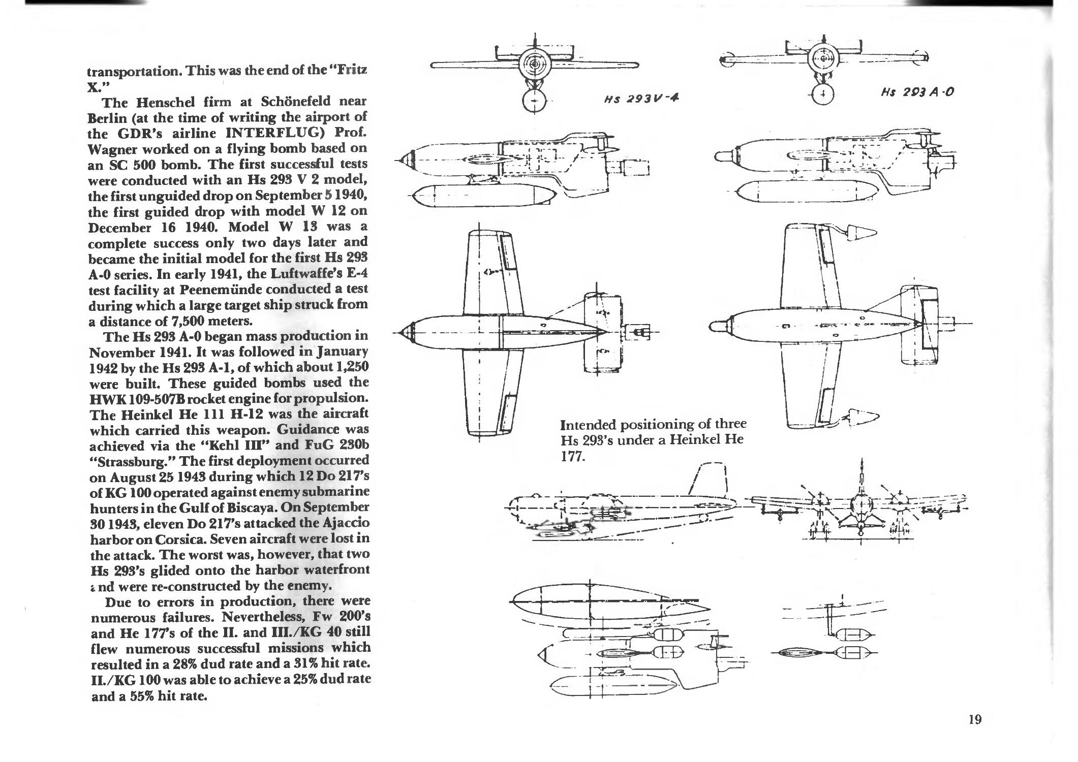
HS 293 V-4-
=£*
Hs 293 A O
=\
D>--
Intended positioning of three
Hs 293's under a Heinkel He
177.
r i
_/_j £ • ;
«4£
_>\
KS>
19
;'V.
*'f J'- "" -'J9» . " j»-
15>
Hi ^
bit
;.jsI5L
^ ™
: ■ »A;
i'y V.,.:i'.;.'';
* ' , ' "1
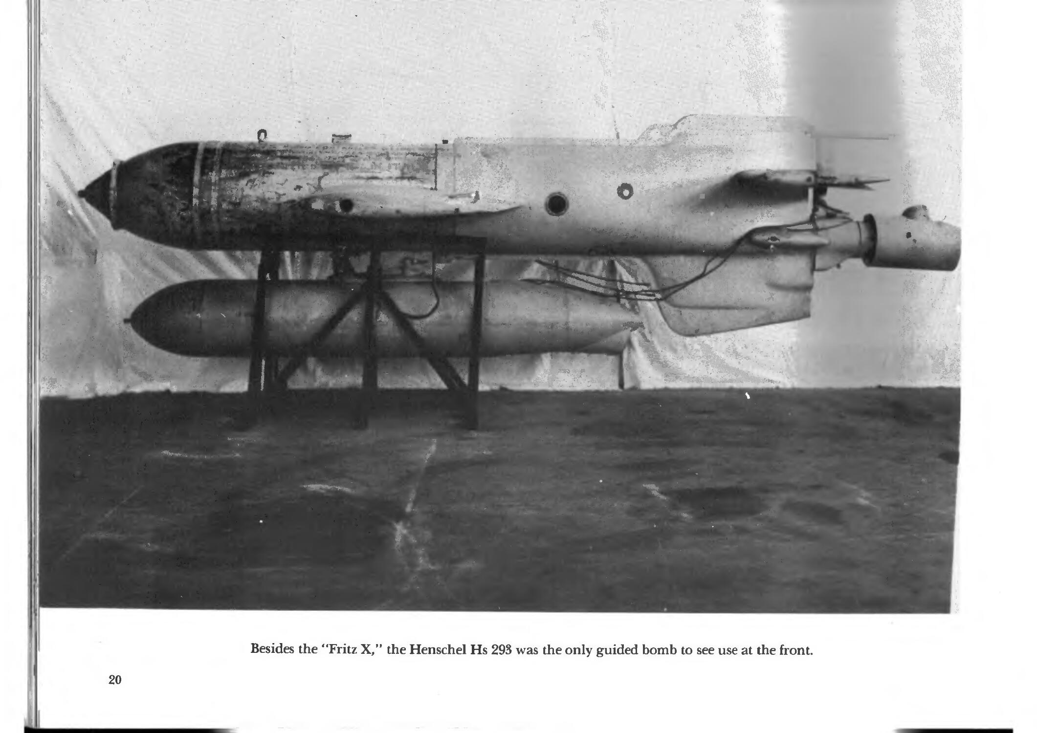
Besides the "Fritz X," the Henschel Hs 293 was the only guided bomb to see use at the front.
20
In order to avoid eventual disruption to
radio guidance, the Hs 293 B was created in
1944, of which 200 were built. This was wire-
guided. The wires were twelve kilometers
long. The FuG 207 "Dortmund" (a
transmitter) and the FuGz237 "Duisburg" (a
receiver) were the guidance system. A second
model had 16-kilometer wires. Attempts to
jam them by the allies in early 1944 were only
marginally successful. A weapon very similar
to the Hs 293 B was built and tested in the
summer of 1958 in Argentina.
About 60 Hs 293 C's were developed as
underwater bombs, which were produced in
various models and were intended to strike
ships below the water line. They were not
deployed. The Hs 293 C can be considered the
predecessor to the Hs 294.
The Hs 293 D was the first guided bomb to
be fitted with a television camera, which was
intended to enable the bomb to hide in the
clouds to avoid anti-aircraft defenses. The
first unsuccessful attempts were conducted in
the Fall of 1943 at Madusee, near Stargard in
Pommern. Other attempts at Jesau in Ost-
preussen were not successful. The best results
were obtained in the middle of August 1944
with a new guidance system combination of
the "Tonne 4a" and "Seedorf 3" with which
one direct hit and a few near misses were
achieved out of five drops. As a result, a new
research contract was awarded in October
1944 which was intended to result in a
perfected guided bomb equipped with
television guidance. Two hundred and fifty-five
were produce which, however, were not
deployed.
Only 18 Hs 293 E's of the developed and
improved C model were produced before the
program was deleted. Project Hs 293 F,
which was supposed to be a delta-wing
model, was abandoned at the end of 1943. An
Hs 293 G was to be used to attack targets like a
dive bomber. Ten test models were built.
.,* *
jUtSf* •■>.;,*■„ (^
'-" ";-*
^P . .ASF
'»P
iftf'%
¥
*!•** A
^WJ
.**H - ••>--1--'-
'j&4 j>
J- * : -*^ . J. ''
; ^Mfci*"'.'". ,
t*k.. " *
31'
mm <•*•»
^p
. •»».
»•«
*
ti
»
,,,, .,'>
!'••• . ;.;•'((.„*'.,!
! J!.'1''.
.
.■
.. a
'< • - ",
%
t
'<
*. %■'
n
»\:t
^v
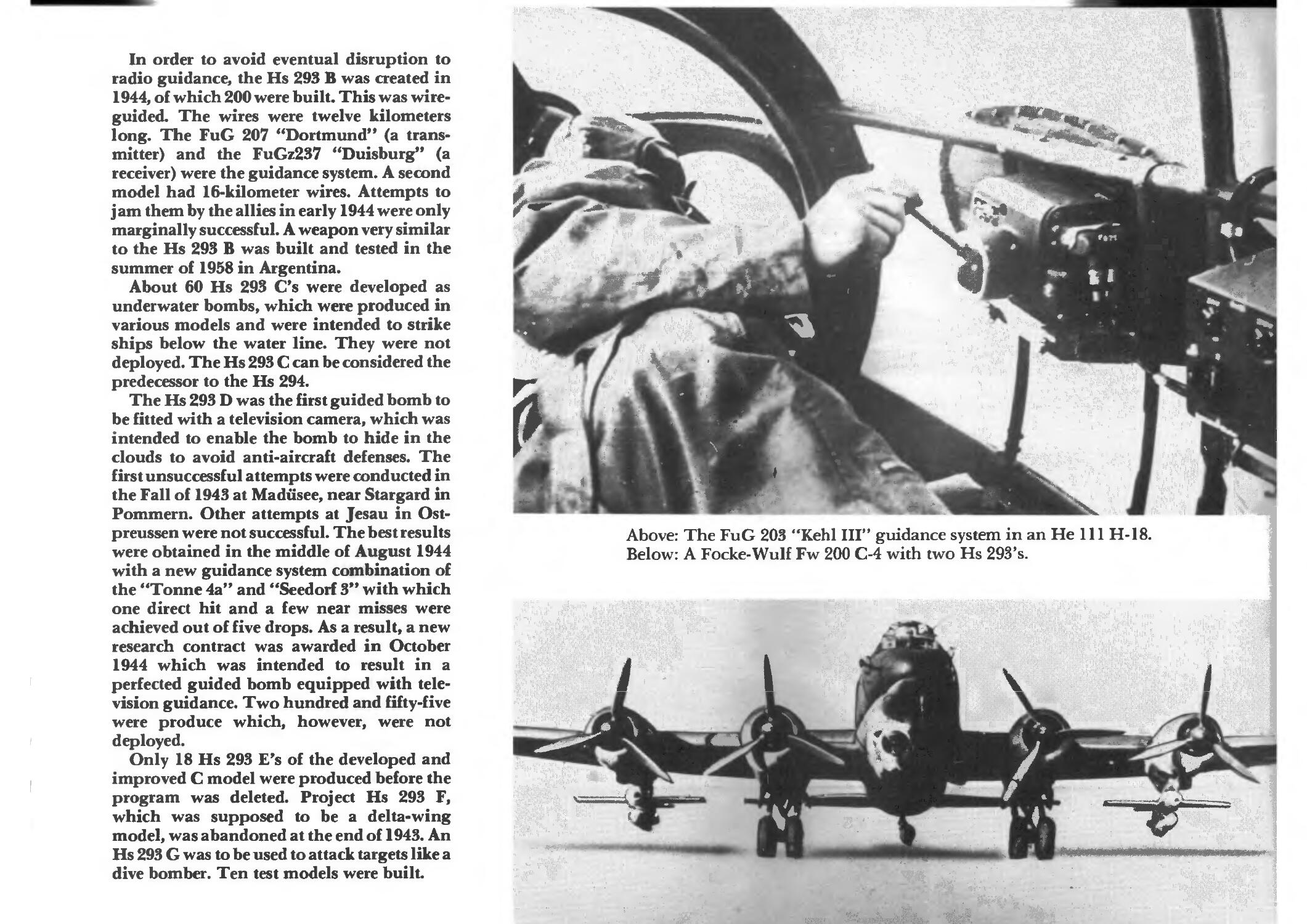
Above: The FuG 203 "Kehl III" guidance system in an He 111 H-18.
Below: A Focke-Wulf Fw 200 C-4 with two Hs 293's.
I
V
=^
i
iA
i j-^
7.
; t
pf%*
\
t
:1
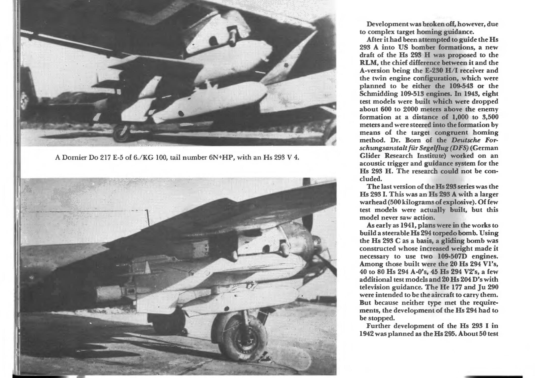
A Dornier Do 217 E-5 of 6./KG 100, tail number 6N+HP, with an Hs 293 V 4.
**■■
„<» "or
I
V,.
^
"3P
•■*:■'
■- "' • 4ia
'■C. SS^jr^
v . ■ • -
i ■
•*V i
Development was broken off, however, due
to complex target homing guidance.
After it had been attempted to guide the Hs
293 A into US bomber formations, a new
draft of the Hs 293 H was proposed to the
RLM, the chief difference between it and the
A-version being the E-230 H/I receiver and
the twin engine configuration, which were
planned to be either the 109-543 or the
Schmidding 109-513 engines. In 1943, eight
test models were built which were dropped
about 600 to 2000 meters above the enemy
formation at a distance of 1,000 to 3,500
meters and were steered into the formation by
means of the target congruent homing
method. Dr. Born of the Deutsche For-
schungsanstaltfur Segelflug (DFS) (German
Glider Research Institute) worked on an
acoustic trigger and guidance system for the
Hs 293 H. The research could not be
concluded.
The last version of the Hs 293 series was the
Hs 2931. This was an Hs 293 A with a larger
warhead (500 kilograms of explosive). Of few
test models were actually built, but this
model never saw action.
As early as 1941, plans were in the works to
build a steerable Hs 294 torpedo bomb. Using
the Hs 293 C as a basis, a gliding bomb was
constructed whose increased weight made it
necessary to use two 109-507D engines.
Among those built were the 20 Hs 294 Vl's,
40 to 80 Hs 294 A-0's, 45 Hs 294 V2's, a few
additional test models and 20 Hs 204 D's with
television guidance. The He 177 and Ju 290
were intended to be the aircraft to carry them.
But because neither type met the
requirements, the development of the Hs 294 had to
be stopped.
Further development of the Hs 293 I in
1942 was planned as the Hs 295. About 50 test
models were produced, but this development
also had to be halted due to a lack of aircraft
capable of carrying them.
The Hs 296 was externally similar to it
predecessors, but was to be utilized as a
combination gliding/diving bomb. A few
test models were built. But because only one
test model of the Me 262 aircraft which was to
carry it was built, this development also
reached a dead end. A project under the name
"Peter X" was proposed on June 23rd 1943 as
a replacement for the "Fritz X" gliding
bomb. Four versions of this were proposed,
which were to weigh between 1,775 and 1,943
kilograms. This project went on file at the
RLM with the remark, "... production is to
be accelerated by all available means to
match the Hs 294 for use against armored
targets." The fate of the Hs 294 was already
determined.
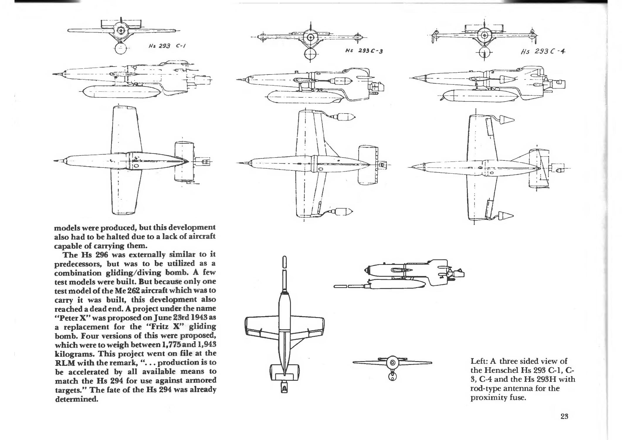
Left: A three sided view of
the Henschel Hs 293 C-l, C-
3, C-4 and the Hs 293H with
rod-type antenna for the
proximity fuse.
23
p*_ -*% *~*m#~
v»r, v
17
e ■ oskw:^?
#" ." -TSSms!^-
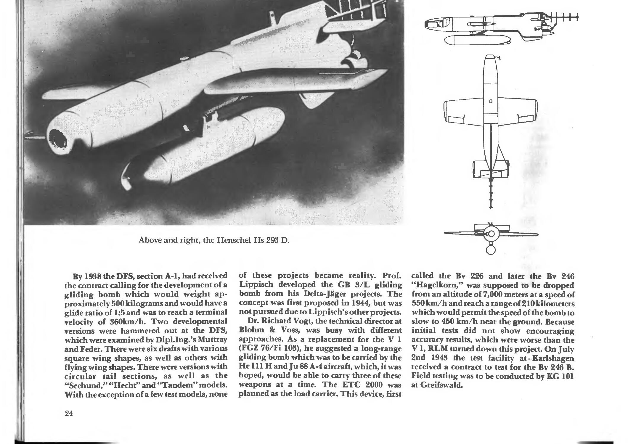
Above and right, the Henschel Hs 293 D.
By 1938 the DFS, section A-l, had received
the contract calling for the development of a
gliding bomb which would weight
approximately 500 kilograms and would have a
glide ratio of 1:5 and was to reach a terminal
velocity of 360km/h. Two developmental
versions were hammered out at the DFS,
which were examined by Dipl.Ing.'s Muttray
and Feder. There were six drafts with various
square wing shapes, as well as others with
flying wing shapes. There were versions with
circular tail sections, as well as the
"Seehund," "Hecht" and "Tandem" models.
With the exception of a few test models, none
of these projects became reality. Prof.
Lippisch developed the GB 3/L gliding
bomb from his Delta-Jager projects. The
concept was first proposed in 1944, but was
not pursued due to Lippisch's other projects.
Dr. Richard Vogt, the technical director at
Blohm & Voss, was busy with different
approaches. As a replacement for the V 1
(FGZ 76/Fi 103), he suggested a long-range
gliding bomb which was to be carried by the
He 111H and Ju 88 A-4 aircraft, which, it was
hoped, would be able to carry three of these
weapons at a time. The ETC 2000 was
planned as the load carrier. This device, first
called the Bv 226 and later the Bv 246
"Hagelkorn," was supposed to be dropped
from an altitude of 7,000 meters at a speed of
550 km/h and reach a range of 210 kilometers
which would permit the speed of the bomb to
slow to 450 km/h near the ground. Because
initial tests did not show encouraging
accuracy results, which were worse than the
V 1, RLM turned down this project. On July
2nd 1943 the test facility at - Karlshagen
received a contract to test for the Bv 246 B.
Field testing was to be conducted by KG 101
at Greifswald.
24
O »_J >•">
ry^i
*+**■
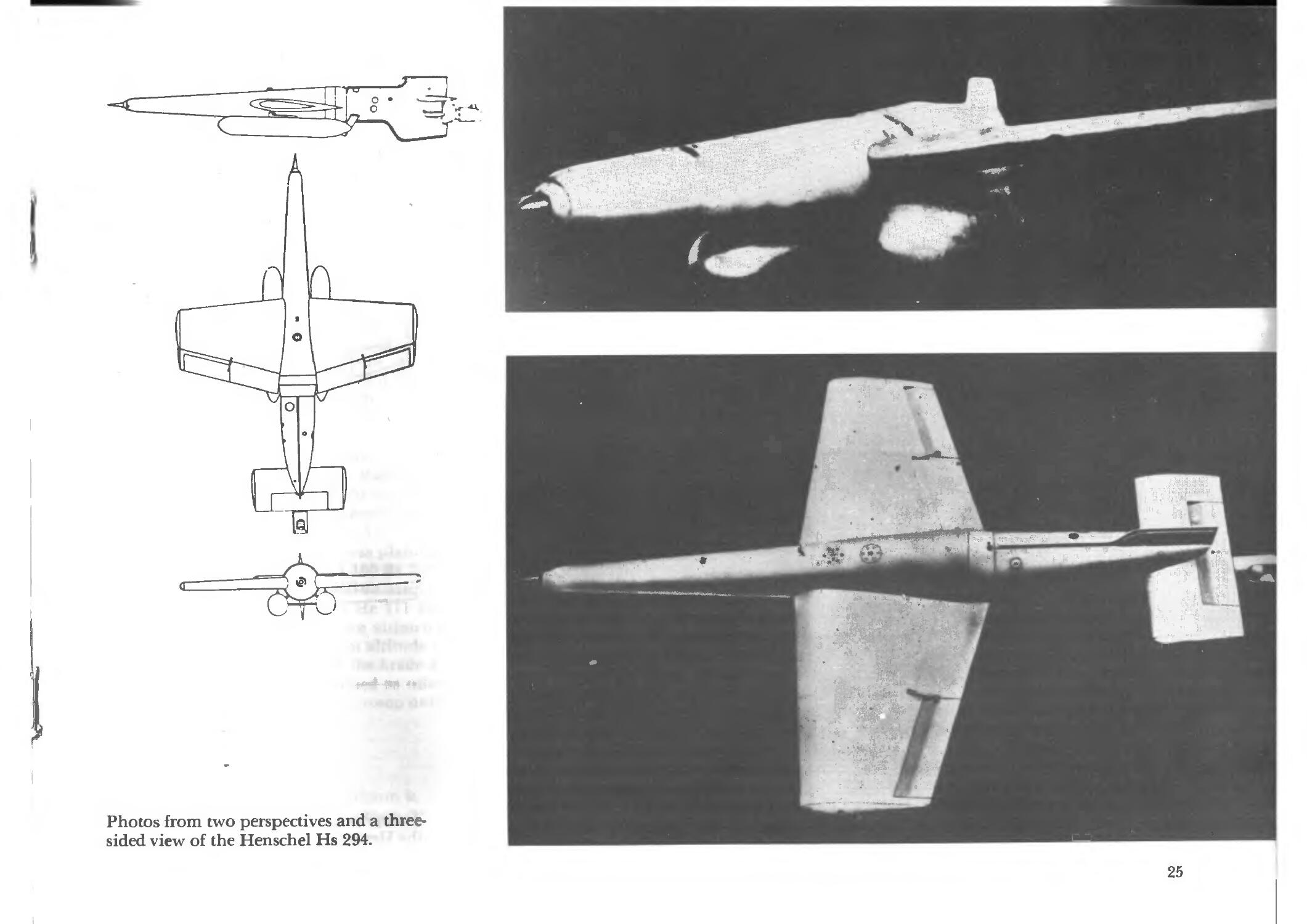
Photos from two perspectives and a three-
sided view of the Henschel Hs 294.
;n
fH#^
-~4
h
'-]^m^:M
>X- #:;^/:/-^
Hf
+ 1
25
i 'j I j'
*
* 4 4 *
M
■* ' ■"» y
V?
M u 0.
26
x i-
'" - in
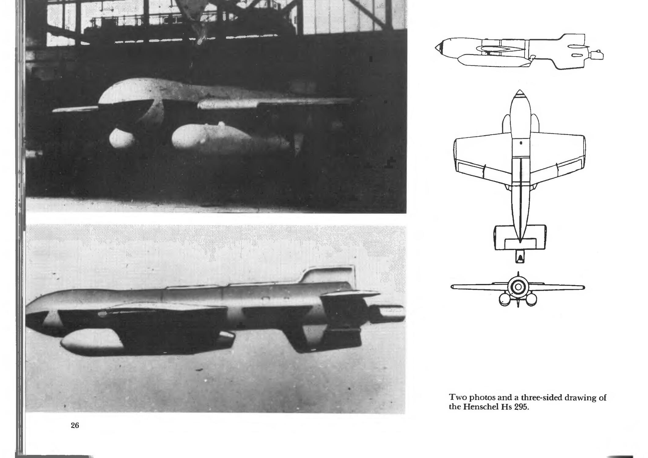
Two photos and a three-sided drawing of
the Henschel Hs 295.
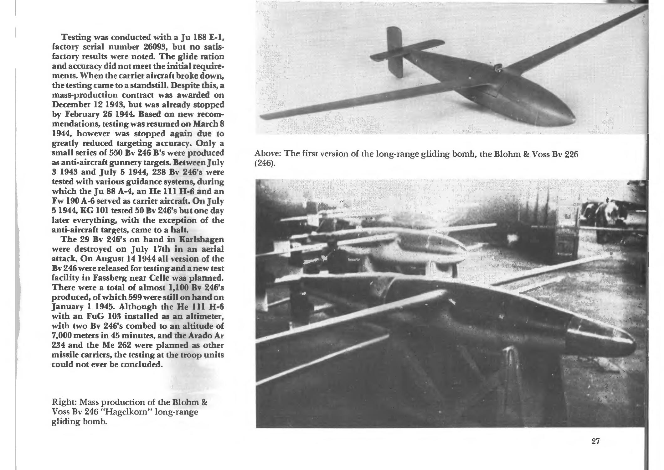
Testing was conducted with a Ju 188 E-l,
factory serial number 26093, but no
satisfactory results were noted. The glide ration
and accuracy did not meet the initial require*
ments. When the carrier aircraft broke down,
the testing came to a standstill. Despite this, a
mass-production contract was awarded on
December 12 1943, but was already stopped
by February 26 1944. Based on new
recommendations, testing was resumed on March 8
1944, however was stopped again due to
greatly reduced targeting accuracy. Only a
small series of 550 Bv 246 B's were produced
as anti-aircraft gunnery targets. Between July
3 1943 and July 5 1944, 238 Bv 246's were
tested with various guidance systems, during
which the Ju 88 A-4, an He 111 H-6 and an
Fw 190 A-6 served as carrier aircraft. On July
5 1944, KG 101 tested 50 Bv 246's but one day
later everything, with the exception of the
anti-aircraft targets, came to a halt.
The 29 Bv 246's on hand in Karlshagen
were destroyed on July 17th in an aerial
attack. On August 14 1944 all version of the
Bv 246 were released for testing and a new test
facility in Fassberg near Celle was planned.
There were a total of almost 1,100 Bv 246's
produced, of which 599 were still on hand on
January 1 1945. Although the He 111 H-6
with an FuG 103 installed as an altimeter,
with two Bv 246's combed to an altitude of
7,000 meters in 45 minutes, and the Arado Ar
234 and the Me 262 were planned as other
missile carriers, the testing at the troop units
could not ever be concluded.
Right: Mass production of the Blohm &
Voss Bv 246 "Hagelkorn" long-range
gliding bomb.
mi of the long-range gliding bomb, the Blohm & Voss Bv 226
**t£'.' "'"iy
vttd^Mjpq
:W<
;--.::&i$|
^f^
,5rv
'kw 'SKj
m
; S[ *
6, ■ 4
27
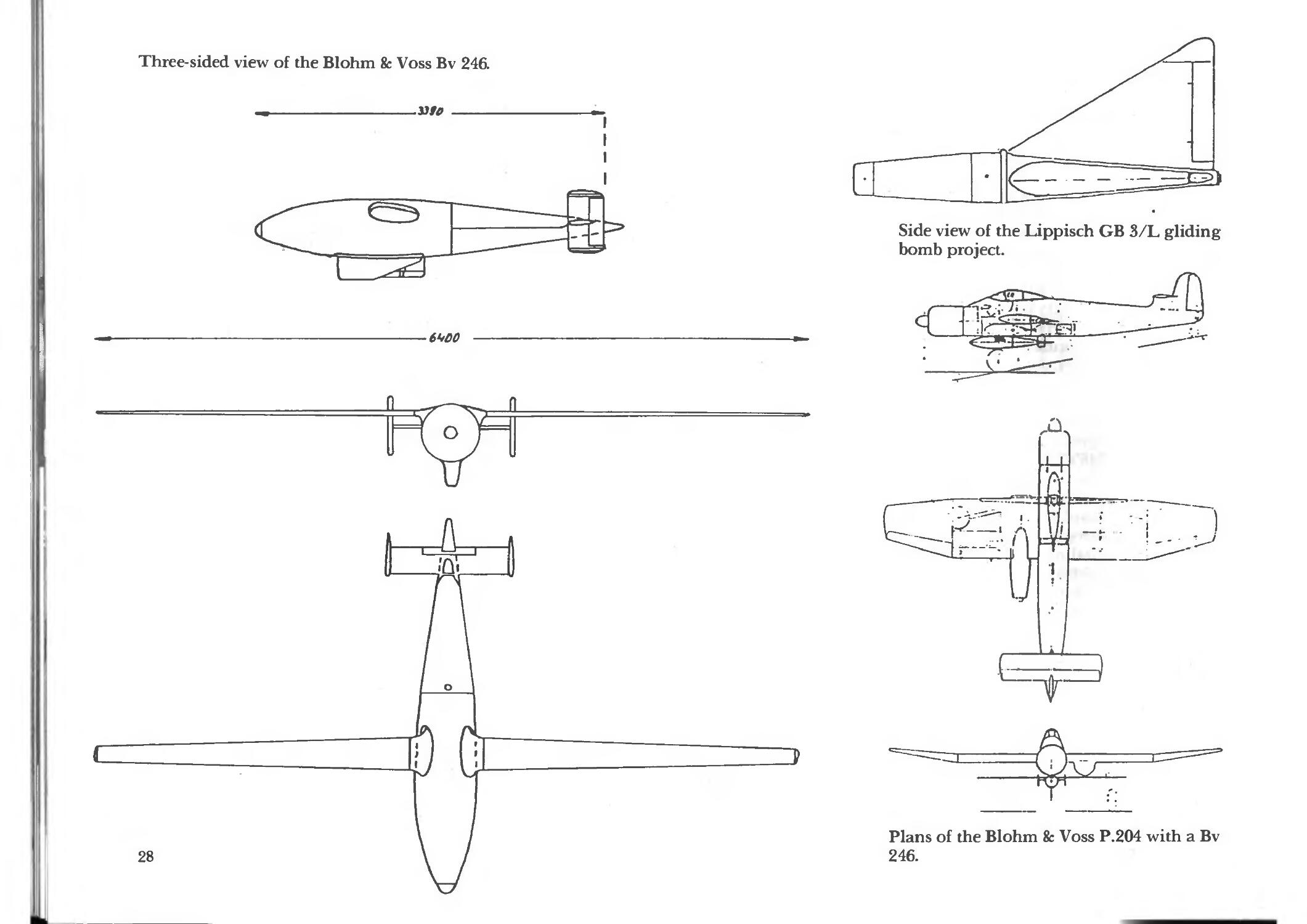
Three-sided view of the Blohm fe Voss Bv 246.
.vu
■6W0
Side view of the Lippisch GB 3/L gliding
bomb project.
-~j_
-£j£
xy
Plans of the Blohm fe Voss P.204 with a Bv
246.
%
V?W-
; ; ■;;.:■£■ ^r *■-;[
;:.■;';.-j>:-.v.: -.■-■■
i
I 1>
'im «• *mB&**m** <*$ jt"**
™-r"*(»tfl':- -*-,«-■- p ."*■*"%
■■*■■ :i -
*• :■ , , j , ^,. - ,- ... - ••' .
A Heinkel He 111 H-6 with three Bv 246's.
,%-="*■
irt
" ■*• t.
/
/
' '* J. J
\
^%
" R-» ■ ''•'" •"
V ¥ +""t
M Hi
fV J
1u.ffl
A Focke-Wulf Fw 190 F-8 with a Bv 246.
During testing, the Fw 190 proved itself to be particularly suited
for the deployment of this weapon.
29
Gliding Torpedoes and
Torpedo Gliders
In October 1940 a torpedo LT 5 F with wings
and a tail section was tested in the wind
tunnel at the Deutsche Versuchsanstalt fur
Luftfahrt (DVL). Afterwards, plans were
made for the DT 1 and 2 gliding torpedoes.
Instead, a gliding torpedo called the LT 9.2
"Frosch" (frog) was developed at the
Luftfahrt-Forschungsanstalt at
Braunschweig- Volkenrode, which was later
abandoned in favor of the Blohm & Voss L10
"Friedensengel" (angel of peace). This was a
torpedo carrier which would permit the
torpedo to be launched at greater distances
than the LT 950 C. This glider was to be
dropped from an altitude of 2,500 meters and
have a range of 8,500 meters. Only three
seconds after launch, a small kite was
deployed from a container under the left
wing which was towed along on a 25 meter
cable. When the L 10 was about ten meters
above the surface of the water, the kite sensed
this and sent an electronic signal via a
forward-mounted membrane to set off the
explosive bolts which held the LT to the L
10. The LT released from the L 10 and took
an underwater trajectory in route to its target.
Fifty-four of these were manufactured, which
were used during test drops beginning in
September 1942.
Afterwards, 330 were planned for
production in various forms, of which 270 were
actually built. Of those, 136 were used in
testing, and 34 were delivered to KG 26 for
field testing. On December 21st 1943, test
weapon subject number 58 was dropped from
an He 111 H-6, tail number ND+AS, from an
altitude of 428 meters at a speed of 281 km/h
SchniHA-B
The LT 9.2 "Frosch" gliding torpedo.
and, with a glide angle of 16 degrees, covered
a distance of 1,448 meters in a flight time of
18.9 seconds. Another He 111, tail number
PB+PJ, was able to achieve a range of 3,276
meters with a different test weapon.
Up to the end of the war, about 450 L 10's
were built which were tested in Peenemiinde
and Gotenhafen-Hexengrund, wherein Ar
234's, Fi 167's, Fw 190F's, He 111 H and J's,
He 177s, Ju 88 A-4's Ju 188 E's, Ju 388 L-0's
and Me 410's were utilized as carrier aircraft.
The L 10's were not used at the front.
A further development of the L10 was the
L 11 torpedo carrier called the "Schnee*
wittchen" (Snow White) which carried the
torpedo in two sections of its fuselage and
dropped the torpedo in a similar manner as
the L 10. The aircraft to carry this was
intended to be the Blohm & Voss P.204
project. The RLM turned down this concept
due to its heavy price of RM 15,000 per item
and the project never reached the testing
stage.
In early 1945, the L 50 torpedo glider was
proposed by the Geratwerk Stargard in
Pommern as a special weapon to combat the
allied gliders in the North Sea which were
supplying the USSR with highly valued war
materiel. The actual torpedo was intended to
be the "Geyer" which in many respects had
similar qualities as the T-5 "Zaunkonig" in
use with the Kriegsmarine. This was
supposed to receive delta-shaped wings and
stabilizers and work with a towed sonde in
the same manner as the L 10 and L 11.
Because the project was originally planned to
be finished in March of 1946, not even the
necessary wind tunnel testing of this weapon
could be completed.
The Blohm & Voss firm had already
suggested a steerable above-water torpedo in the
Fall of 1940, which was hoped to not only
double the accuracy, but also triple the range
of a normal LT. The torpedo was to be
dropped from a 1,500 meter altitude and,
driven by a rocket engine, glide down to the
surface of the water and continue on a level
♦ J
'%,\
V
t
%
fUSf
.
*** %
:*a
,^t«iSw|ji
'il-
m ■
f^.-^E^x'^m^m
««Bi»r" "^
»:!?-*,.« -
.*<^
a.
\-~l
TSt>i ■'..
,*:
f,
3f,
.1,
>k ■.-:■■* '
»*»•*;,
'•*.---'.!
I*
"ft,
■VAJ
i' * ■ •
- *__
... ^ . sj;.
?i :■'■ :~a
ybS 3
^j»
First version of the L.10 "Friedensengel" torpedo glider with the Lt 950 torpedo.
31
. ■ mmsmmmmg» " 9gil^,dmWu ;;^
:mmmmmmmmmmi; •■ ■ m^mmrm< : .*
Wummmw <mmm^' ■■•■■■• ■ ;aM:- ■"• -m&s>m
',. i
■^mm ,ii§t;iir
mmmm,.
s:,mw ' 'w "^" ,:
HIS
fc -;•'■'
':;»
"■'*•'" -J-" ^Hl '.- ■■'"'■V---
. My .™ '^Klmm., k • ,
II f
f „ .#
111?
V
till
I2S
I t* '■■ ■ • *
:yS%.uw
i
,v^7.^^r-':'JX ^f lfe),y
: *: -,,, • - .. ■. ---..<.;?ftp. ■>^:tim~- f u£l , w,. *- > ; •
.-.■'-•-'&.1
■,:\::o.;ny,v..' ;:■.<;"!'*.':. , '■■ *',?.'''V:.'-
ii#f;V'---
Vi'#'" l
*>■ ife ■?>"■■'"■■.:■
:;>,,»>: -'-ri. r-'W-! -
^ :'Cf- ummmMm-:; :^.-u ■-,•
The L.IO, model LT 950 D, with its forward section exposed, showing the installation of its elctronic
systems.
32
¥ -. '
■ f--t.:>,r
"*"•
«
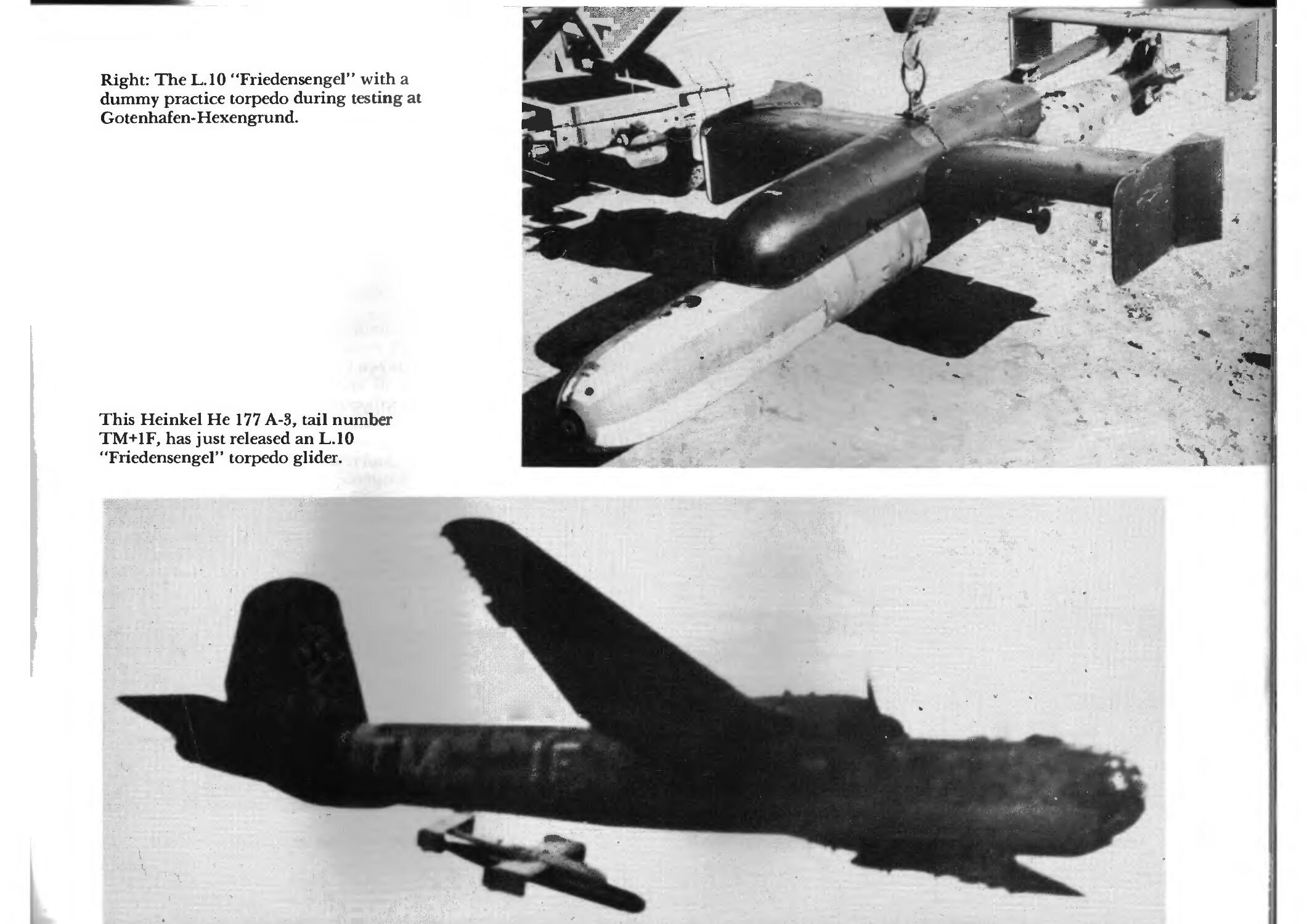
Right: The L.10 "Friedensengel" with a
dummy practice torpedo during testing at
Gotenhafen-Hexengrund.
This Heinkel He 177 A-3, tail number
TM+1F, has just released an L.10
"Friedensengel" torpedo glider.
•
m
#»
t '■■■•£■■
s i -
""•:: "-" 'ij-^^-js-
^I^S i^i.
."V' WJ
. Si' »"
•!^->-
■■o-
~'ipr'Ss '■""._. .«■ "- ■':";'-,■'--' '«-tf-^> :1S'^S!
c *«
'..-Htffii^*«:
II
"•..'-. .'•''.• •,!,'!,'.-
,,;:'t!v::f '•■■ii."
——flp -
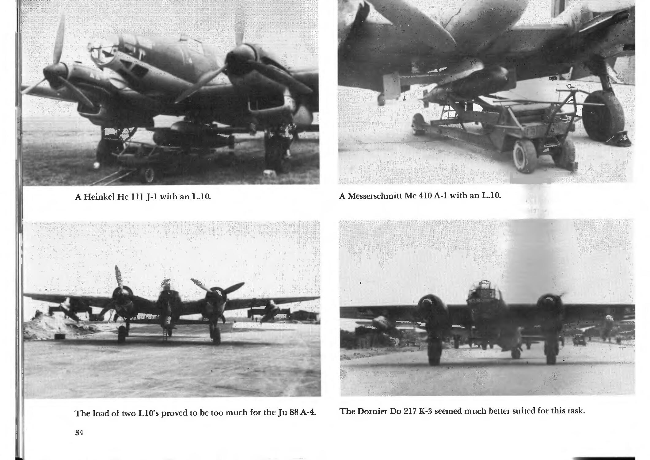
A Heinkel He 111 J-1 with an L.IO.
m0m:
\
Mv
m >
:, ■■
.«<,
-,- ,
, . , :' ■ ■■■■•<■■■<<, ■>;:>;
-,. • ■ ,1-.''-1
M ' l- •!•'• ,-* la...
<***
„i'i:',: <. ■ ■,"„,..
The load of two LlO's proved to be too much for the Ju 88 A-4.
34
"** ! '&:■:
.*" 3.
V
x. -■■■
«?:
jfr-
■■*»■■*.
v«; - .'i|
erf-
"""^kg^
OP'- '*
1 iS» -
■;■#;
->'v\*
' -- • ! -
. '■' •-.
:-M~.
X -*
;^-^^
A Messerschmitt Me 410 A-1 with an L.IO.
3 t-
>.. <S
V
*■•-*-.
PflC"'.
®c „■*
*:#
' '^jifiMpi
?.' ►«¥»
pr '■.;■;■"
The Dornier Do 217 K-3 seemed much better suited for this task.
flight path. Only 0.5 seconds after launch, a
sensor was deployed which, when sensing the
water, opened a compressed air vent which
operated first the flaps and then the elevator,
making Bv 143 climb from two to 12 meters.
This maneuver was repeated several times en
route to the target, until, in the final phase,
the "Hamburg" target acquisition device
assumed the guidance duties.
The Walter-Startrakete 109-501 was to be
the engine. Two hundred were originally
built, this number later being increased to
250. The testing with an He 111 H-6 as the
carrier aircraft was conducted beginning in
February 1941 in Zinnowitz, east of Peene-
munde. Although the Bv 143 V17 was able to
attain a range of 24 kilometers in three
minutes and 40 seconds after an engine burn
time of only 70 seconds, a continuing problem
was the rocket's ability to sustain altitude
above the water's surface. Therefore, after
only a small number had been produced, the
entire project was stricken.
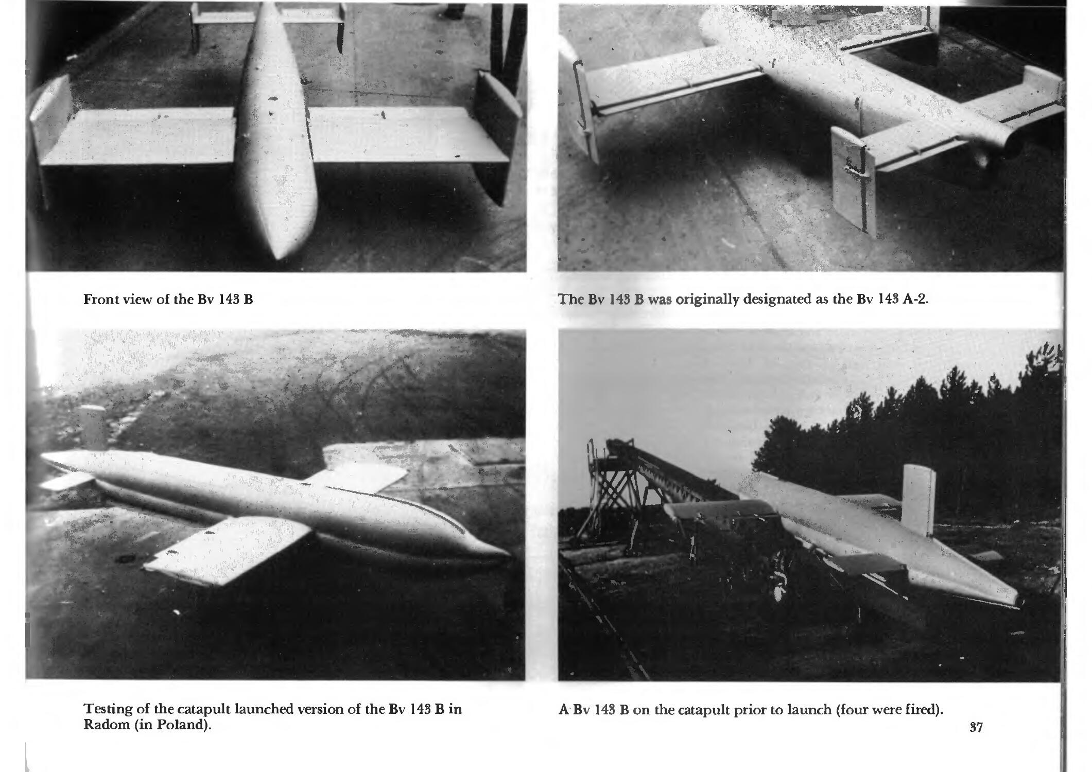
Because the Kriegsmarine had begun to
show interest when the Bv 143 was presented
as a catapult-launched weapon, Dr. Vogt
began to re-built the weapon accordingly at
the Blohm & Voss firm. And so the Bv 143 B
came into being, despite the fact that the Bv
142 A-2 had already been call the "B" version.
The wings and stabilizers had small end-
surfaces which small rudders, causing the
wingspan of the rudder to be not very much
smaller than the wings themselves. At least
one example of this catapult-launched
weapon was tested. It was not deployed at the
front.
w
2
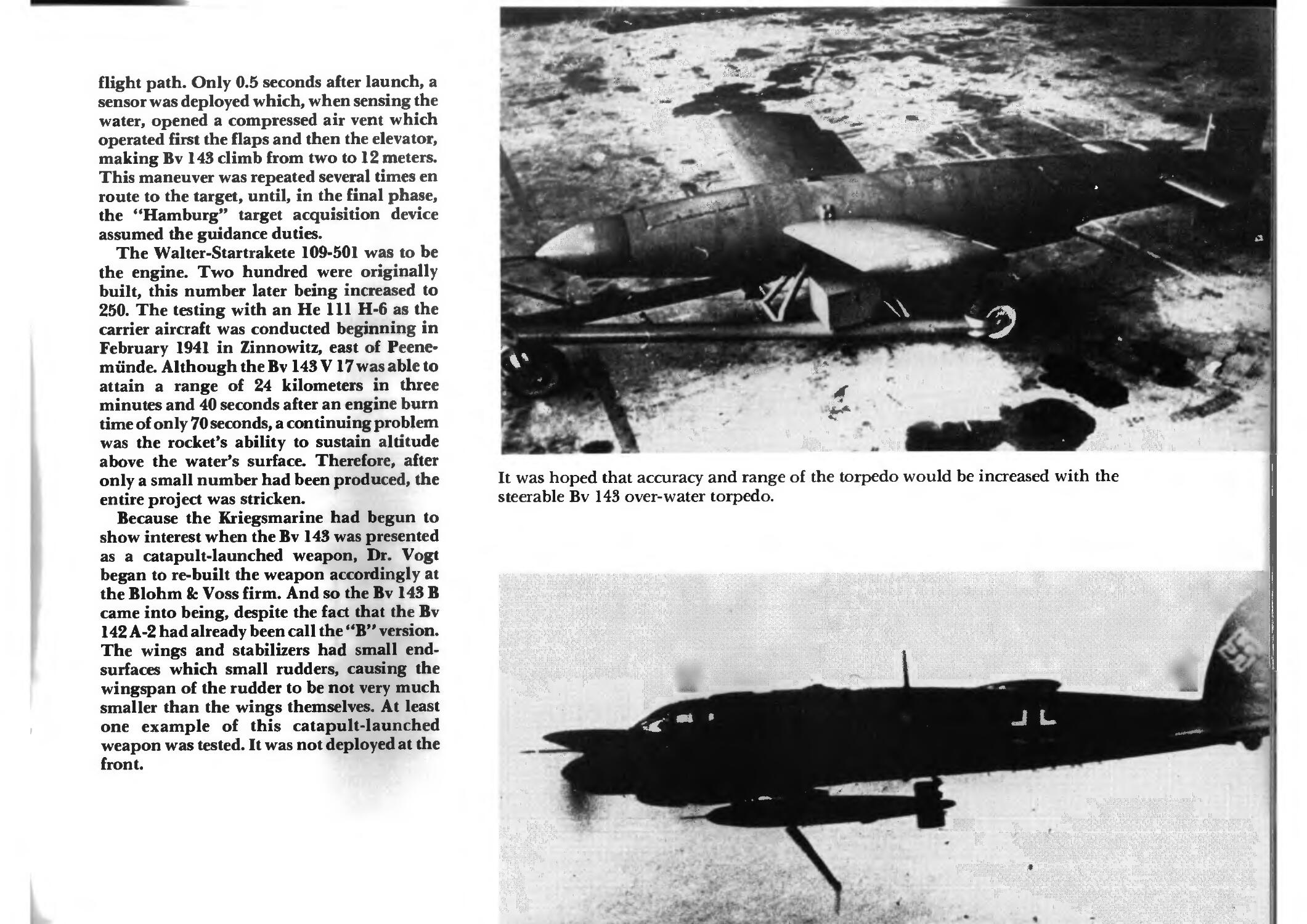
It was hoped that accuracy and range of the torpedo would be increased with the
steerable Bv 143 over-water torpedo.
"**
■
5980
»»
*.
-3/30-
O
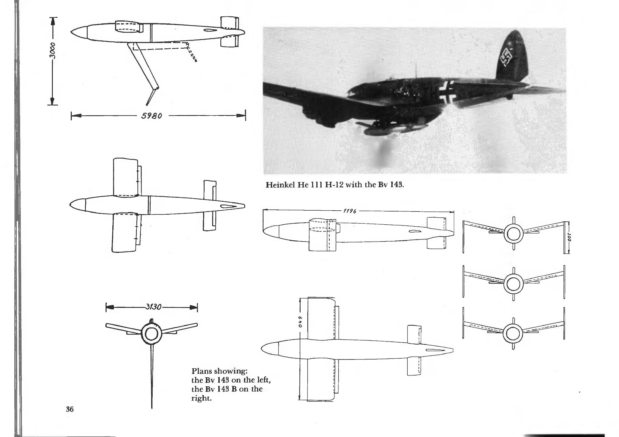
Heinkel He 111 H-12 with the Bv 143.
Plans showing:
theBv 143 on the left,
theBv 143 Bon the
right.
,-. Jt
■ -1 —> s
f
'"r -
f
Front view of the Bv 143 B
Testing of the catapult launched version of the Bv 143 B in
Radom (in Poland).
.•■■ j;
.-t--*-"*^ *•
*v
%
..7*3fc
-^Agl
The Bv 143 B was originally designated as the Bv 143 A-2.
4
^
:L/.*•■-■■
V
w
%
it'
t
\
UK
A Bv 143 B on the catapult prior to launch (four were fired).
37
Air Defense Missiles
'm.
^ttt
* * >
» *:-.y-
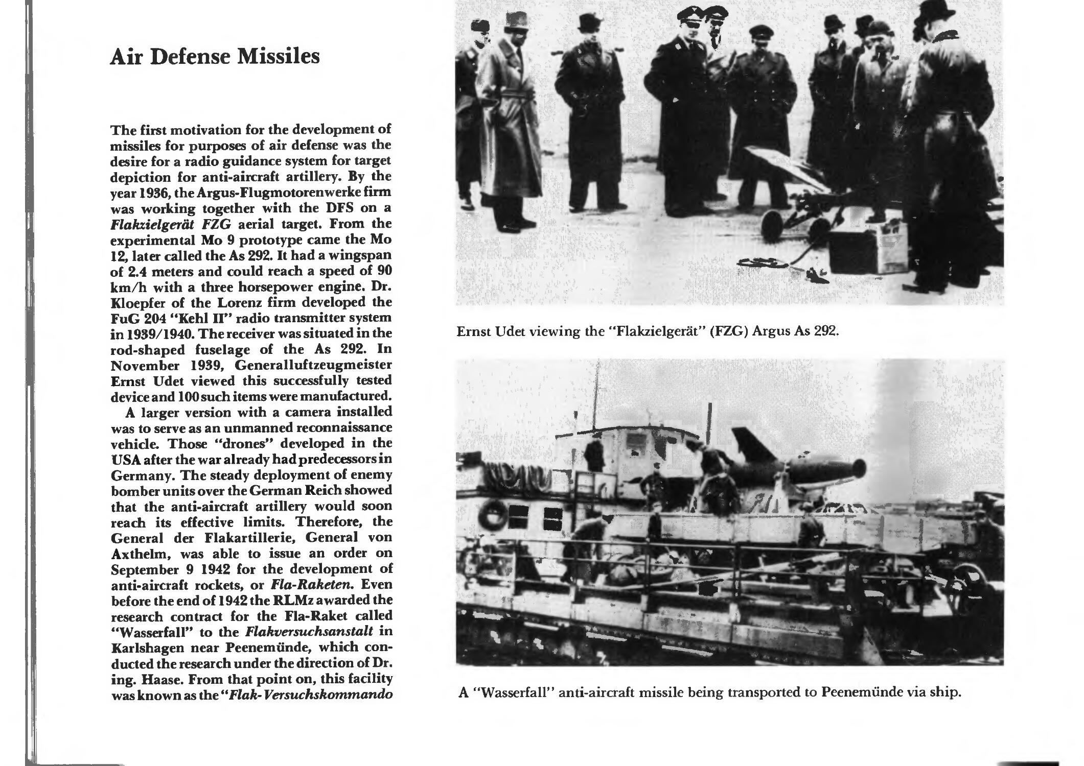
The first motivation for the development of
missiles for purposes of air defense was the
desire for a radio guidance system for target
depiction for anti-aircraft artillery. By the
year 1936, the Argus-Flugmotorenwerke firm
was working together with the DFS on a
Flakzielgerat FZG aerial target. From the
experimental Mo 9 prototype came the Mo
12, later called the As 292. It had a wingspan
of 2.4 meters and could reach a speed of 90
km/h with a three horsepower engine. Dr.
Kloepfer of the Lorenz firm developed the
FuG 204 "Kehl II" radio transmitter system
in 1939/1940. The receiver was situated in the
rod-shaped fuselage of the As 292. In
November 1939, General luftzeugmeister
Ernst Udet viewed this successfully tested
device and 100 such items were manufactured.
A larger version with a camera installed
was to serve as an unmanned reconnaissance
vehicle. Those "drones" developed in the
USA after the war already had predecessors in
Germany. The steady deployment of enemy
bomber units over the German Reich showed
that the anti-aircraft artillery would soon
reach its effective limits. Therefore, the
General der Flakartillerie, General von
Axthelm, was able to issue an order on
September 9 1942 for the development of
anti-aircraft rockets, or Fla-Raketen. Even
before the end of 1942 the RLMz awarded the
research contract for the Fla-Raket called
"Wasserfall" to the Flakversuchsanstalt in
Karlshagen near Peenemiinde, which
conducted the research under the direction of Dr.
ing. Haase. From that point on, this facility
was known as the "Flak- Versuchskomtnando
:%l
Ernst Udet viewing the "Flakzielgerat" (FZG) Argus As 292.
*Vv ■
m
~*
!
•\>>:
^&4^
1
<*■.: ,*%.^
A "Wasserfall" anti-aircraft missile being transported to Peenemiinde via ship.
,.« «*i. *<TL •«•?•
:?s«
^ *& -
at
s
i
*
t
*>*
V
s , * **
ttr*^
; j ,
>,,,{;
. V-" -.!■!■ I
**B*
Ve.'^S^Sii*,*
lit? *%-*V- "■ ■ -^idP.-..- ■-
M* «t
.-if'
#1^
t
*** *■* [
\
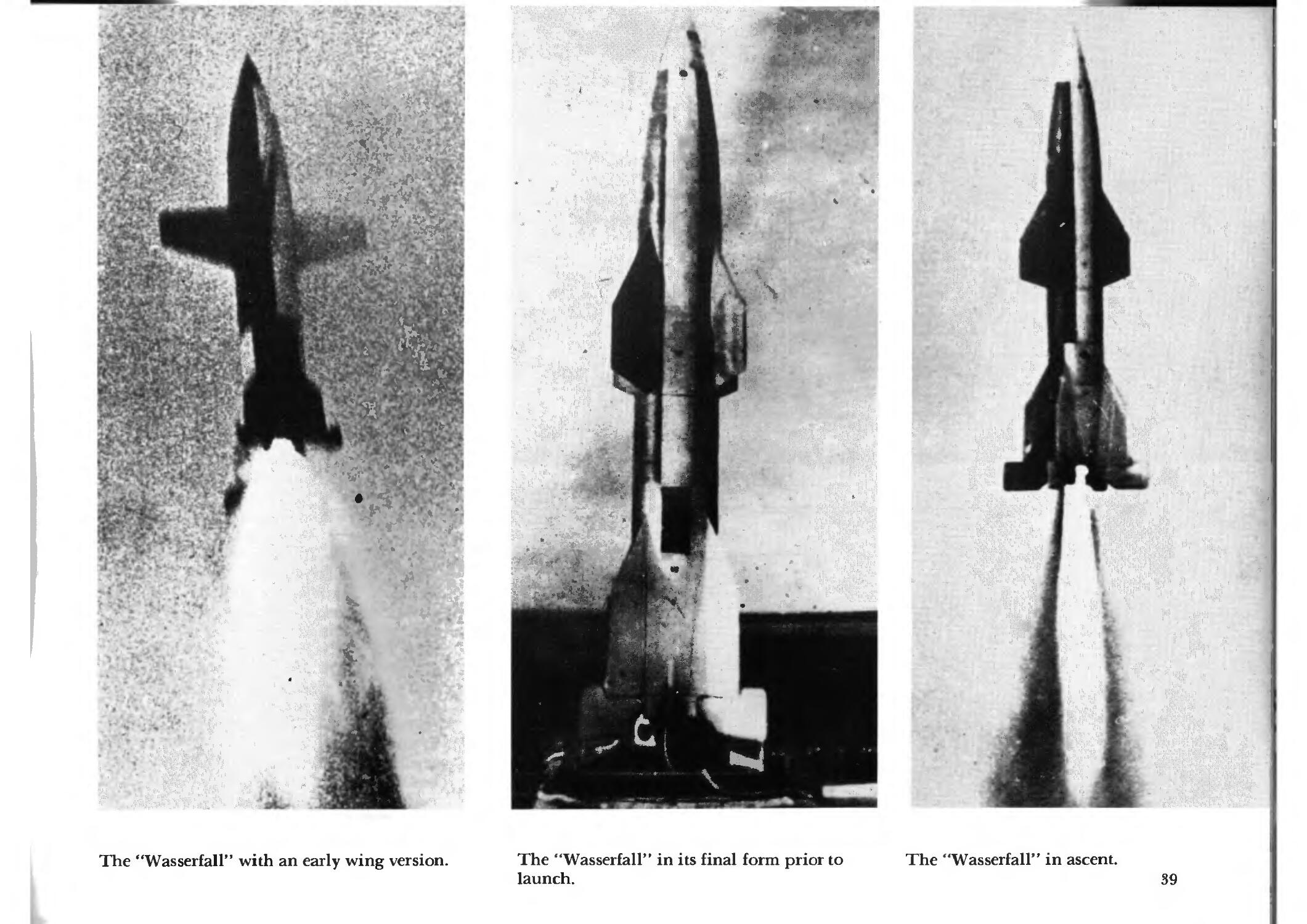
'Wasserfall" with an early wing version.
The "Wasserfall" in its final form prior to
launch.
The "Wasserfall" in ascent.
39
Nord" and was technically subordinate to
Dr. von Braun. Although the expansion of a
new test facility P IX had been ordered in
November of 1942, the actual expansion and
work on the "Wasserfall" project did not
begin until the Summer of 1942, after Goring
had given his clearance for the project on
December 17th 1943. The final production
work on the "Wasserfall" could not begin
until April 20 1943 as the necessary
technicians had to be called back from front-line
units one by one.
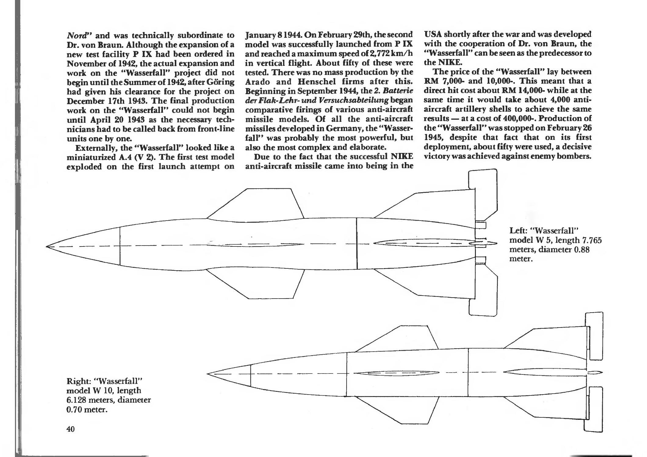
Externally, the "Wasserfall" looked like a
miniaturized A.4 (V 2). The first test model
exploded on the first launch attempt on
January 81944. On February 29th, the second
model was successfully launched from P IX
and reached a maximum speed of 2,772 km/h
in vertical flight. About fifty of these were
tested. There was no mass production by the
Arado and Henschel firms after this.
Beginning in September 1944, the 2. Batterie
der Flak-Lehr- und Versuchsabteilung began
comparative firings of various anti-aircraft
missile models. Of all the anti-aircraft
missiles developed in Germany, the
"Wasserfall" was probably the most powerful, but
also the most complex and elaborate.
Due to the fact that the successful NIKE
anti-aircraft missile came into being in the
USA shortly after the war and was developed
with the cooperation of Dr. von Braun, the
"Wasserfall" can be seen as the predecessor to
the NIKE.
The price of the "Wasserfall" lay between
RM 7,000- and 10,000-. This meant that a
direct hit cost about RM 14,000- while at the
same time it would take about 4,000
antiaircraft artillery shells to achieve the same
results — at a cost of 400,000-. Production of
the "Wasserfall" was stopped on February 26
1945, despite that fact that on its first
deployment, about fifty were used, a decisive
victory was achieved against enemy bombers.
Left: "Wasserfall"
model W 5, length 7.765
meters, diameter 0.88
meter.
Right: "Wasserfall"
model W 10, length
6.128 meters, diameter
0.70 meter.
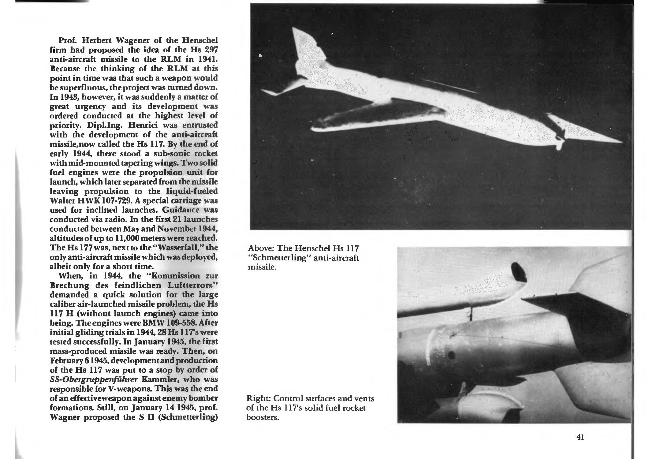
Prof. Herbert Wagener of the Henschel
firm had proposed the idea of the Hs 297
anti-aircraft missile to the RLM in 1941.
Because the thinking of the RLM at this
point in time was that such a weapon would
be superfluous, the project was turned down.
In 1943, however, it was suddenly a matter of
great urgency and its development was
ordered conducted at the highest level of
priority. DipLIng. Henrici was entrusted
with the development of the anti-aircraft
missile,now called the Hs 117. By the end of
early 1944, there stood a sub-sonic rocket
with mid-mounted tapering wings. Two solid
fuel engines were the propulsion unit for
launch, which later separated from the missile
leaving propulsion to the liquid-fueled
Walter HWK107-729. A special carriage was
used for inclined launches. Guidance was
conducted via radio. In the first 21 launches
conducted between May and November 1944,
altitudes of up to 11,000 meters were reached.
The Hs 177 was, next to the "Wasserfall," the
only anti-aircraft missile which was deployed,
albeit only for a short time.
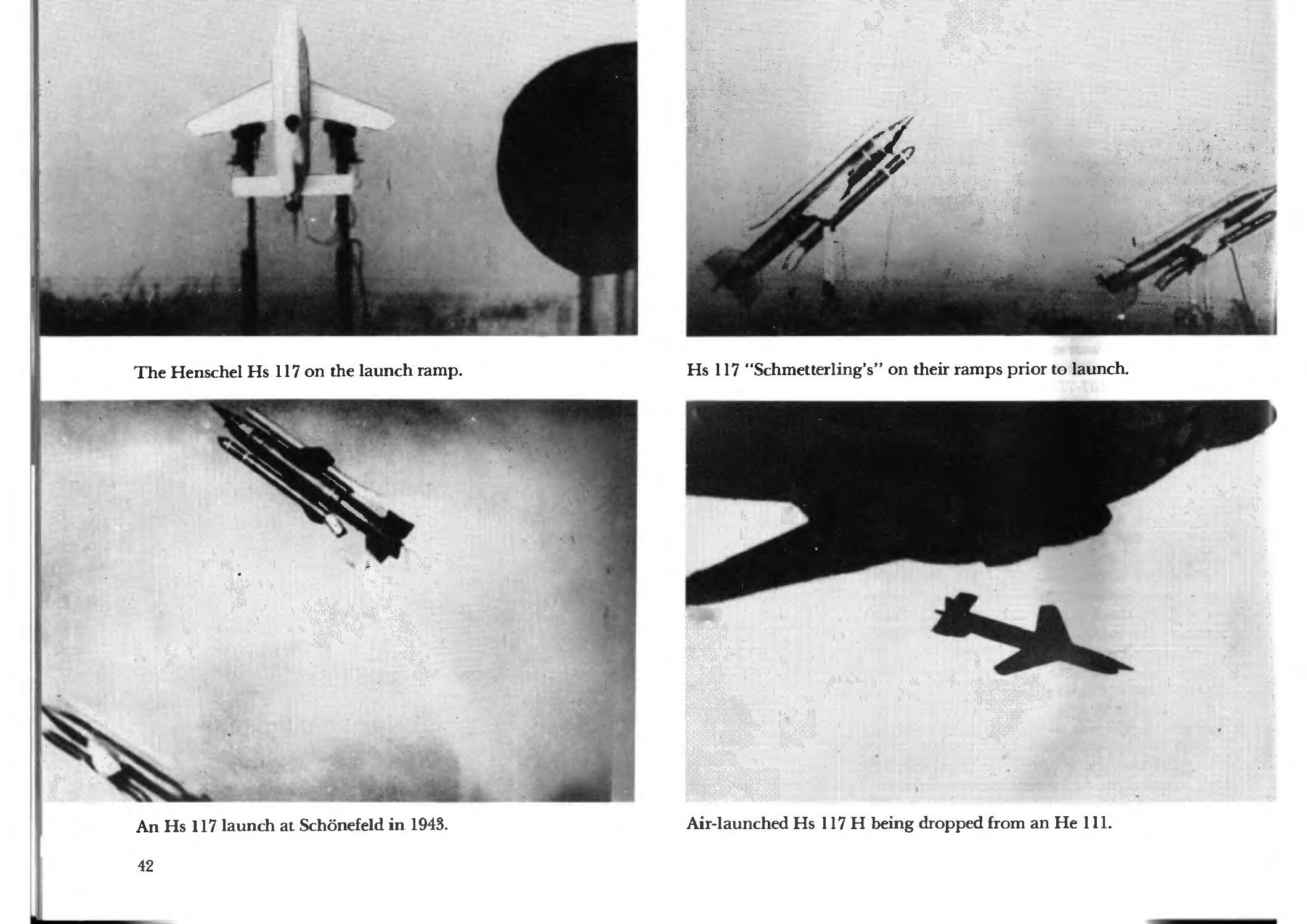
When, in 1944, the "Kommission zur
Brechung des feindlichen Luftterrors"
demanded a quick solution for the large
caliber air-launched missile problem, the Hs
117 H (without launch engines) came into
being. The engines were BMW 109-558. After
initial gliding trials in 1944,28 Hs 117s were
tested successfully. In January 1945, the first
mass-produced missile was ready. Then, on
February 61945, development and production
of the Hs 117 was put to a stop by order of
SS-Obergruppenfuhrer Kammler, who was
responsible for V-weapons. This was the end
of an ef f ectiveweapon against enemy bomber
formations. Still, on January 14 1945, prof.
Wagner proposed the S II (Schmetterling)
Above: The Henschel Hs 117
"Schmetterling" anti-aircraft
missile.
Right: Control surfaces and vents
of the Hs 117's solid fuel rocket
boosters.
41
The Henschel Hs 117 on the launch ramp.
X . """
W: -•
An Hs 117 launch at Schonefeld in 1943.
42
Hs 117 "Schmetterling's" on their ramps prior to launch.
Air-launched Hs 117 H being dropped from an He 111.
3
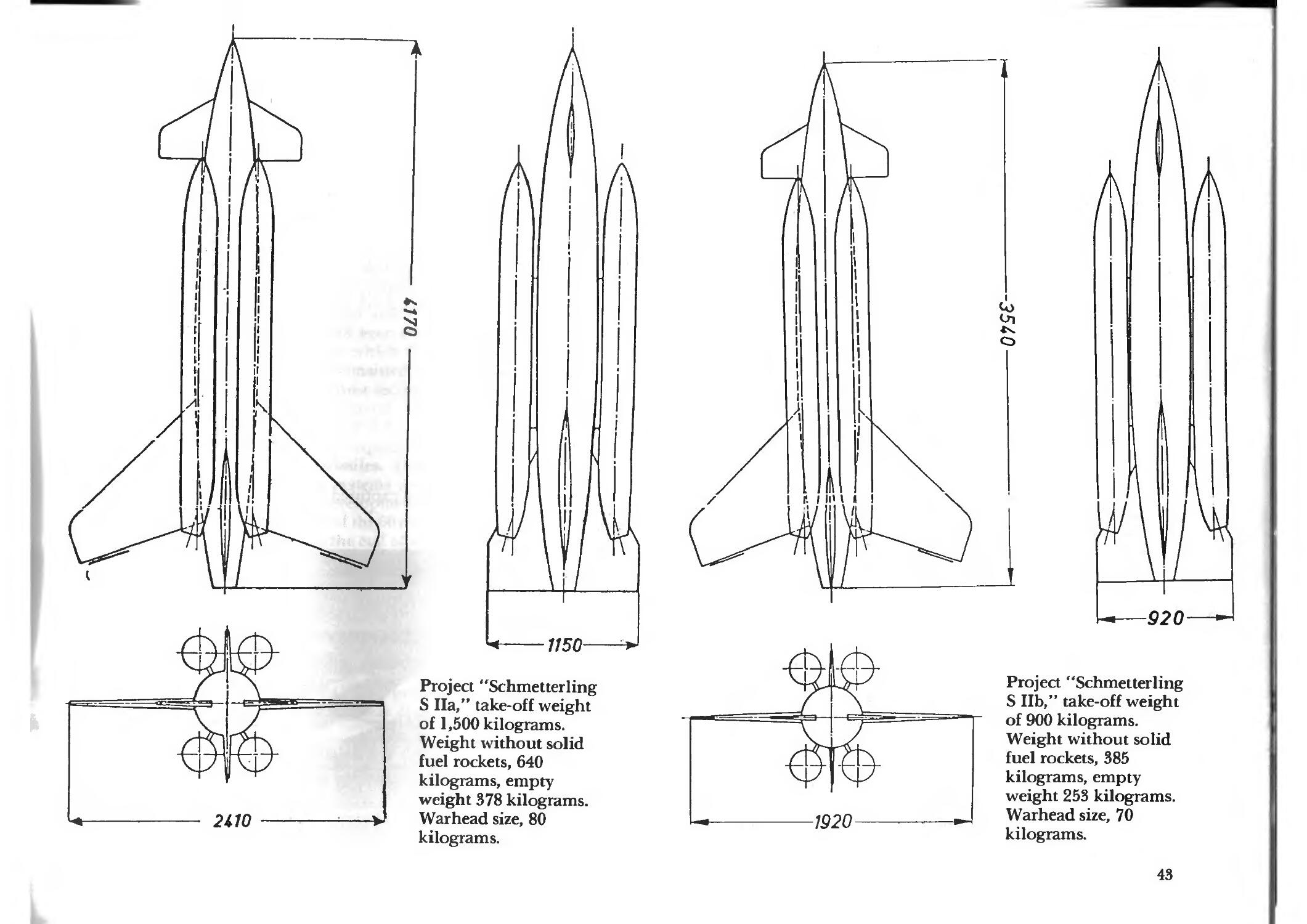
1150-
Project "Schmetterling
S Ha," take-off weight
of 1,500 kilograms.
Weight without solid
fuel rockets, 640
kilograms, empty
weight 378 kilograms.
Warhead size, 80
kilograms.
-920-
1920
Project "Schmetterling
S lib," take-off weight
of 900 kilograms.
Weight without solid
fuel rockets, 385
kilograms, empty
weight 253 kilograms.
Warhead size, 70
kilograms.
43
project as a further development of the Hs
117 "Schmetterling." Two days later it was
adopted at the anti-aircraft test facility.
However, the continuation of this project by
the Oberkommando der Luftwaffe, as
explained above, was not to be.
The Rheinmetall-Borsig AGzfirm in
Berlin-Marienfelde, which was a leader in
many areas of arms manufacture, began
testing solid fuel (gun powder) rockets before
1939 under the leadership of Direktor Kelin
and Dr. Vullers, and intensively worked on
rocket launches and engines. The first
attempts at an anti-aircraft missile were based
on the gK-1750 "Hecht" gliding bomb, of
which a couple of test models were built in
1941. This model was changed twice, and
then cut due to the run-up of the Hs 293 A-l
series. Later, the FK "Hecht 2700" came from
this model. This test model was the basis for
the "Feuerlilie" anti-aircraft missile, from
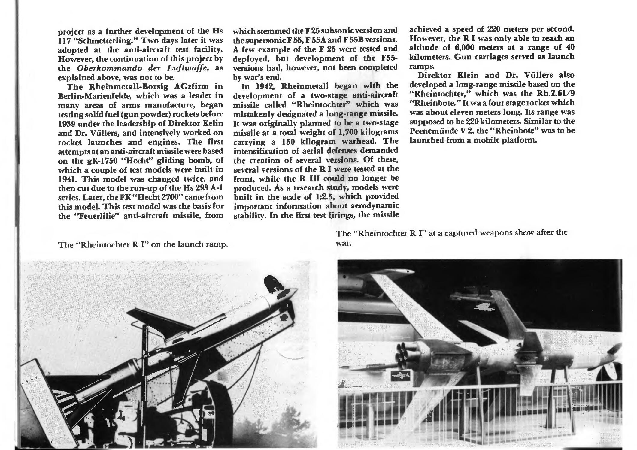
The "Rheintochter R I" on the launch ramp.
which stemmed the F 25 subsonic version and
the supersonic F 55, F 55 A and F 55B versions.
A few example of the F 25 were tested and
deployed, but development of the F55-
versions had, however, not been completed
by war's end.
In 1942, Rheinmetall began with the
development of a two-stage anti-aircraft
missile called "Rheintochter" which was
mistakenly designated a long-range missile.
It was originally planned to be a two-stage
missile at a total weight of 1,700 kilograms
carrying a 150 kilogram warhead. The
intensification of aerial defenses demanded
the creation of several versions. Of these,
several versions of the RI were tested at the
front, while the R III could no longer be
produced. As a research study, models were
built in the scale of 1:2.5, which provided
important information about aerodynamic
stability. In the first test firings, the missile
achieved a speed of 220 meters per second.
However, the R I was only able to reach an
altitude of 6,000 meters at a range of 40
kilometers. Gun carriages served as launch
ramps.
Direktor Klein and Dr. Vullers also
developed a long-range missile based on the
"Rheintochter," which was the Rh.Z.61/9
"Rheinbote." It wa a four stage rocket which
was about eleven meters long. Its range was
supposed to be 220 kilometers. Similar to the
Peenemiinde V 2, the "Rheinbote" was to be
launched from a mobile platform.
The "Rheintochter R I" at a captured weapons show after the
war.
%
._JLimi-i.
M
1
The main difference between the V2 and
the "Rheinbote" lay in the engine, because
each stage was a solid fuel motor (diglycol
powder). In comparison with the V2, the
performance was decidedly more modest,
because while the V 2 missile carried a
warhead of 975 kilograms, the warhead on
the "Rheinbote" was only 20 kilograms!
At the Oberbayerischen Forschungsanstalt
Oberammergau, which was a sister company
of the Messerschmitt plant, the "Enzian"
anti-aircraft missile was created in 1944. The
requirement for a simple weapon and one
which was cheap to produce had been met:
the entire fuselage, the form of which
followed the Lippisch Me 163, consisted of
wood, with the exception of the nose section,
which was made of 20mm sheet metal. The
propulsion unit was the VfK-Triebwerk
Zg.613 A 01, the most primitive liquid fuel
engine of all anti-aircraft missiles. Only
proven ground and on-board systems were
used so that no additional developmental
time was necessary. Production of the 60 or so
"Enzian" missiles built before the end of the
war was done by the Holzbau Sonthofen
firm.
The "Enzian" used four jettisonable solid
fuel rocket booster for launch, after which the
liquid fuel engine assumed the propulsion,
bringing the missile to a height of 15,000
meters. The first launching of the "Enzian"
took place in August of 1944. The polar
guidance of only a pair of rudders was done
via radio remote control.
In addition to those radio systems already
outlined, the following methods were tested
and utilized: "Rheinland," "Du'ren-
Detmold," Dusseldorf-Detmold," FB-
transmission method and the FZ 11, NY and
DFS transmission methods. The leadership
/
I
S
s
•i
i.
An anti-aircraft missile, the Rheinmetall
"Feuerlilie F 25," prior to launch.
\
\
\
\ .-
A
V
>
Long-range Rheinmetall "Rheinbote"
Rh.Z. 61/9 on the launch ramp.
for the development of radio guidance
technology was provided by Dr.Ing. W.T.
Runge and the GBN-Entwicklungsgruppe
10 "Femlenktechnik" developmental team.
45
<**v
V
^
>#*>
?•
«■* 5!*-
^Ftf&n^
•^
. Lw»
The Messerschmitt "Enzian" anti-aircraft missile on an Flak
8.8cm gun chassis.
/
I
The "Enzian" lifts off.
46
■*?■*%.•
_te*'
■•"I
?.
/
—v.' .
%•
,*i
?>jr»»..
•c • -.
n»i»?'
rw" ^^ ** 1
An "Enzian" on the launch ramp with the "Wiirzburg-Riese"
guidance system. §
.... ^ is "
"Enzian" shortly after take-off.
Technical Data
TYPE
length (mm)
fuselage diameter (mm)
wingspan (mm)
wing area (cubic meters)
total weight (kg)
fuel load (kg)
explosive weight (kg)
thrust (kiloponds)
speed (meters per second)
range (meters)
TYPE
length (mm)
fuselage diameter (mm)
wingspan (mm)
wing area (cubic meters)
total weight (kg)
fuel load (kg)
explosive weight (kg)
thrust (kilopounds)
speed (meters per second)
range (meters)
TYPE
length (mm)
fuselage diameter (mm)
wingspan (mm)
wing area (cubic meters)
total weight (kg)
fuel load (kg)
explosive weight (kg)
thrust (kiloponds)
speed (meters per second)
range (meters)
RZ65
262
73
-
-
2.780
0.685
0.130
300
260
250
Hs298
2003
415
1290
0.42
95.0
9.5
25.0
150/50
234
1600
Lll
6345 m.LT
-
3430
3.9
1048 m.LT
-
-
-
120
1100
RZ73
330
73
-
-
3.167
0.583
0.280
680
360
400
Fritz X
3262
562
1352
-
1570
-
320
-
343
LT9.2
5100
-
2000
2.0
-
-
-
-
-
-
RZ100
1650
420
-
-
730
85
245
-
-
Hs293A
3818
470
3100
1.92
975
66
295
600
265
Bvl43
5980
585
3130
2.46
1058
162
180
500
115
-
W.Gr.21
1177
210
-
-
111
18.4
38.6
1720
315
2200
Hs293F
3200
470
1600
1.92
-
-
-
-
-
Wasserfall
7450
680
1890
-
3500
1860
150
-
770
-
R100BS
1840
282
320
1.06
110
20.0
40.0
3200
450
2000
Hs294
6114
620
4025
5.30
2170
—
630
1300
245
Hsll7
4030
-
2000
-
420
-
23
375
23
-
Panzer-
schreck
800
100
230
-
8.0
-
-
—
135
Hs295
5443
579
4087
5.40
2090
-
585
1300
235
F25
2080
250
-
-
120
-
17
-
-
-
Panzer-
blitz I
705
93
200
0.43
6.54
1.030
2.10
440
374
Peter X
3290
536
1630
-
1775
-
—
-
-
Rheinbote
11020
535
-
-
1750
2240
20
9800
-
220 km
Panzer-
blitz II
815
130
-
-
5.10
-
2.10
-
370
Hecht
1750
177
588
-
-
-
-
-
-
Rhein-
R4/M
812
55
242
-
3.85
0.815
0.520
245
525
1500
Bg3/L
3000
-
1500
2.25
250
105
100
-
-
530
Rhein-
tochterRl tochterR3
10300
510
2750
-
1750
460
100
-
1750
40
4750
510
-
-
976
536
415
-
-
-
X4
2001
222
725
4.4
60.5
8.8
20.0
140
248
5000
Bv246
3525
542
6408
1.47
730
-
435
-
-
210
Enzian
3750
-
4050
4.9
1800
-
320
-
1000
25
X7
758
148
600
-
9.0
6.5
0.130
68/5.5
98
1200
L10
3894
440
2500
2.06
218o.LT
-
-
-
87
9000
47
Drawings of the "Rheintochter R I" on the left, the "Rheintochter R III" in the
center, and the "Rheinbote" on the right.
CI
3
%
J?
Cutaway view of the "Wasserfall," which clearly shows how much room was required for the radio controlled
guidance system.
21
1. proximity fuse
2. nitrogen tank
3. reduction vent
4. fuel container
5. reinforcing cross braces
6. oxygen tank
7. fuel mixing chamber
8. gyroscope
9. control surface servo
10. combustion chamber
11. push and pull rods
12. graphite guidance vents
13. aerodynamic control surfaces
14. expansion tube
15. radio receiver
16. moveable vent pipe
17. oxygen purge (forward)
18. main wings
19. moveable vent pipe
20. explosives vent
21. warhead
/ '
13
12
The Ajax missile display near San Pedro, south of Los Angeles California. The Ajax surface-to-air missile is
based on the "Rheintochter R III."
^^"I
♦ *
.*
»^* i *■ •
•«'
It
• •• \V
»•
* » *
.„ * «* •♦v\grifif
The "Fritz X" was an anti-ship weapon, its penetration power was sufficient
enough to sink a ship. The enemy was curious as to why the Luftwaffe did
not build thousands of these guided bombs.
9 780887 404757
ISBN: 0-88740-475-8
1. warhead with 300 kg of amatol
2. suspension points
11 3. main fuse receptacle
4. 7-pin flange
5. hot air regulator
6. outer tail section ring
7. control interrupter
8. main control device (Wagner-Riegel
above and below)
9. exhaust jets
10. main control chamber and radio
systems
11. access panel for the control chamber
12. four wings
13. central explosive tubes
14. armor piercing warhead