/

Tags: military affairs military equipment
Year: 1944


Text
й'у)
WAR DEPARTMENT FIELD MANUAL
TANK DESTROYER
PIONEER PLATOON
WAR DEPARTMENT
rssqindsd
NOVEMBER 1944
WAR DEPARTMENT FIELD MANUAL
FM 18-24
TANK DESTROYER
PIONEER PLATOON
WAR DEPARTMENT NOVEMBER 1944
United States Government Printing Office
Washington: 2944
WAR DEPARTMENT,
Washington 25, D. С., 1 November 1944.
FM 18-24, War Department Field Manual, Tank De-
stroyer Pioneer Platoon, is published for the information
and guidance of all concerned.
By order of the Secretary of War:
G. C. MARSHALL,
Chief of Staff.
Official:
J. A. ULIO,
Major General,
The Adjutant General.
Distribution:
T of Opns (2); All SvC(2); Depts(2); Island
C (2); Base C (2) ; Def C (2), Sectors (2), Sub-
sectors (2) ; Base Sectors (2) ; HD (2) ; В 18 (1) ;
R 18 (1); Bn 7, 18 (5), except I Bn 18 (20).
I Bn 18-.T/O&E 18-25.
For explanation of symbols, see FM 21-6.
ii
CONTENTS
Paragraphs Pages
Section I. General___________________________________ 1-3 1
IJ. Pioneer reconnaissance__________________ 4-7 3
111. Movements______________________________ 8-14 9
IV. Bivouacs__._________________________ IS—21 19
V. Position in readiness----------------- 22-24 30
VI. Combat area___________________________ 25—28 32
VII. Technical training___________________ 29-30 36
VIII. Safe strength of equipment___________ 31—33 38
IX. Road expedients_______________________ 34-37 41
X. Stream crossing expedients____________ 38-41 46
XI. Bridge strengthening------------------ 42—47 52
XII. Determining capacity of bridges___ 48-50 64
XIII. Deceptive measures____________________ 51—53 76
XIV. Mine removal 54-56 80
XV. Bomb and artillery dud disposal----- 57-58 87
XVI. Estimation of demolition charges____ 59-63 90
INDEX__________________________________________________ 97
iii
Section I
GENERAL
1. Scope
This manual covers the tactical employment of
the self-propelled tank destroyer pioneer platoon.
It is designed to be used as a guide only and does
not provide inflexible rules. All commanders
must be encouraged to solve each situation ac-
cording to the various factors involved.
2. Equipment
The pioneer platoon is organized and equipped to
accomplish small construction and demolition
tasks. The text and illustrations contained here-
in are based on tables of organization and equip-
ment in effect at the date of writing. These tables
may change at any time; however, the methods
and principles described in 'this manual will still be
applicable.
3. Mission
a. The pioneer platoon 'has two general mis-
sions :
(1) To prevent the movement of the battalion
from being delayed by natural or artificial ob-
stacles.
(2) To impede or canalize the movement of
the enemy by the creation of obstacles.
b. Quickly executed field expedients, rather
than extensive works or improvements, are the
normal tasks assigned the platoon.
Note. For military terms not defined in this manual see
TM 20-205.
1
c. The personnel of the pioneer platoon are
trained to accomplish many tasks, some of the
more common being—
Strengthening bridges.
Improving fords.
Making minor road repairs.
Clearing road blocks.
Making passages through mine fields.
Neutralizing booby traps.
Assisting in the preparation of gun posi-
tions. ’
Improving fields of fire.
Constructing road blocks.
Increasing the effectiveness of natural
obstacles.
Laying or removing hasty mine fields.
Performing limited demolitions.
d. In addition to the above tasks, they are also
trained to fight. They must know their weapons
and be able to use them. At times, it may be
necessary to fight in order to accomplish the pri-
mary mission; in emergencies, the platoon may be
called on to cover by fire obstacles it has prepared
or to reinforce the small arms fire of other ground
troops.
2
Section II
pioneer reconnaissance
4. General
Selected members 'of the pioneer platoon usually
accompany elements of the reconnaissance com-
pany on route reconnaissance. The reconnais-
sance elements report the location of the roads,
bridges, obstacles, and similar items; the members
of the pioneer platoon report the condition of
these items. All obstructions are investigated
and reported to the reconnaissance company
commander.
5. Missions
a. Some of the more common technical matters
to be investigated and reported by pioneer recon-
naissance elements are enumerated in the follow-
ing paragraphs. These lists are to be used as
guides and should be modified as experience
warrants.
b. Roads (FM 5-10). (1) Capacity, includ-
ing possible effects of rain or snow. Can the road
support the heavy vehicles o'f the battalion under
all probable conditions?
(2) Obstacles and an estimate of the work re-
quired to reduce them (FM 5—30).
(3) Wood, gravel, rock, or other materials in
the vicinity which could be used to repair the road.
(4) By-passes around obstacles if the road can-
not be cleared or repaired in a reasonable length
of time.
c. Bridges (FM 5-10). (1) Construction,
3
to determine the weight the bridge will bear.
Bridge cards (par. 49) will be of assistance.
(2) Conditions of the approaches, to deter-
mine whether or not they can be used safely by
the vehicles of the battalion.
(3) Repairs needed to the bridge or the ap-
proaches before the battalion can safely travel on
it. (sec. XI).
(4) Materials in the vicinity which may be
used for repairs.
(5) Presence of demolitions and booby traps
and an estimate of the work required to neutralize
them. This mission is especially important in ter-
ritory which has been occupied by the enemy.
(6) Possible effect of a swollen stream or a
heavy rain on the bridge and its approaches.
(7) By-passes that may be used even though
the bridge will carry the battalion; enemy action
or weather might render the bridge impassable
before the battalion has used it.
(8) Time and material needed to destroy the
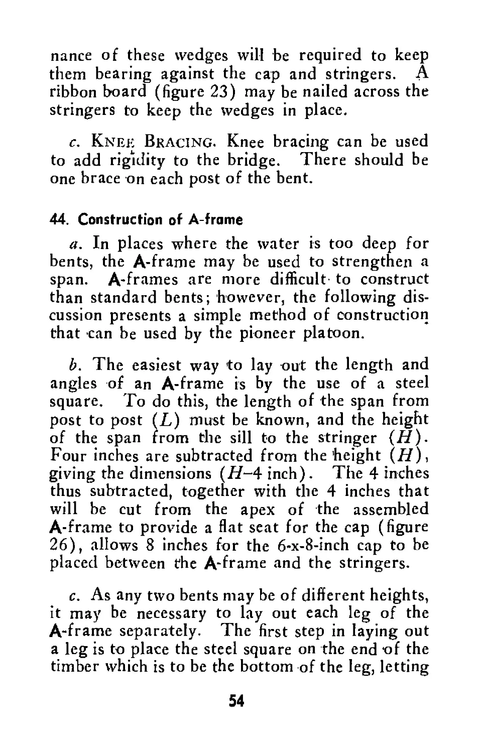
bridge in the event this action should later become
necessary (sec. XVI).
d. Fords. (1) Approaches to ford sites, to
determine whether or not they will support the
vehicles of the battalion. If possible, the ap-
proaches should be perpendicular to the stream
for at least fifty yards and should provide cover
and concealment for the vehicles if there is any
possibility of enemy observation. The exit need
not be exactly opposite the entrance but may be
a distance up or down the stream.
(2) Depth of the water in relation to the ford-
ability of the vehicles of the battalion (par. 38).
(3) Condition of the stream bed to determine
4
whether or not it will bear the vehicles of the
battalion.
(4) Work necessary to prepare 'the approaches
and the stream bed for use (par. 38).
(5) Materials in the vicinity which can be
used for necessary repairs.
(6) Possible effect of changing weather condi-
tions on the stream bed and approaches.
e. Cross-country Routes. (1) All barriers
to the movement of the battalion such as wooded
areas, soft ground, streams, mined areas, traps,
etc.
(2) Work required to make the route passable
for all vehicles of the battalion.
(3) By-passes around any barriers requiring
an excessive amount of work to reduce.
(4) All opportunities to impede enemy at-
tacks, such as the possibilities of mining or con-
structing obstacles in likely avenues of approach.
/. Mined Areas. (1) Location and extent of
mined areas.
(2) The presence of booby traps in and around
the mine fields.
(3) An estimate of the work necessary to clear
a path through the mined area or the possibility
of by-passing the mine field (sec. XIV).
6. Road and Bridge Guards
a. The capacity of bridges, fords, and other
critical road sections is substantially increased and
the required maintenance greatly reduced by con-
trolling the speed and interval of vehicles at these
points.
b. When tank destroyer vehicles cross points
5
which have a capacity equal to or only slightly
greater than the weight of the vehicles, the maxi-
mum speed should be five miles per hour; the in-
terval between vehicles should be at least 50
yards. A constant speed should be maintained.
c. Bridge guards should be stationed at critical
points to enforce orders necessary for safe pas-
sage. The pioneer element of the reconnaissance
party reports the number and locations of guards
needed.
7. Pioneer Reconnaissance Reports
a. To be of value, the information secured by
pioneer reconnaissance elements must be returned
to the appropriate headquarters in sufficient time
to be used. This information must be clear, con-
cise, and accurate. Information obtained by
pioneer reconnaissance will ordinarily be incor-
porated into the regular reconnaissance report.
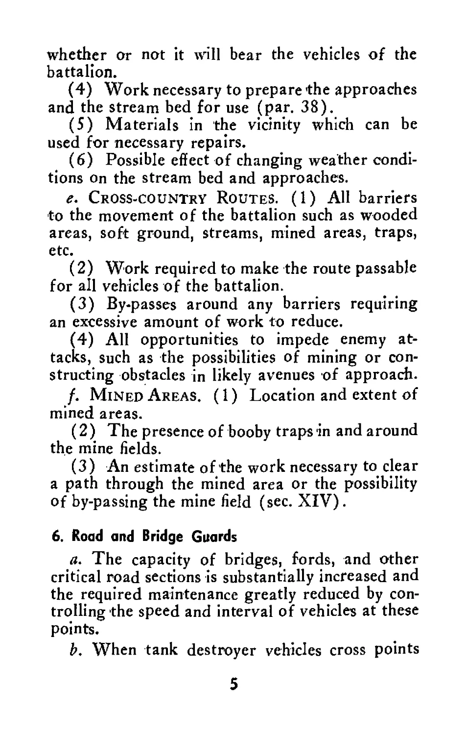
b. A common means of reporting information
is by overlays on maps or aerial photos to show
the location of roads, bridges, mined areas, and
other items. Notes-on technical information may
be placed on the overlays. When maps are not
available, sketches may be used. An accurate
sketch can be made by the use of a compass and
the odometer of a vehicle.
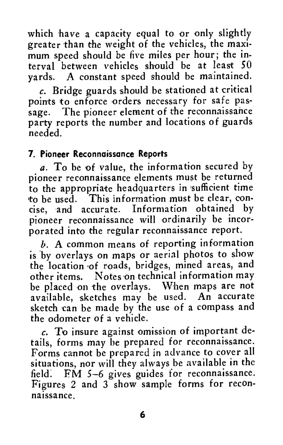
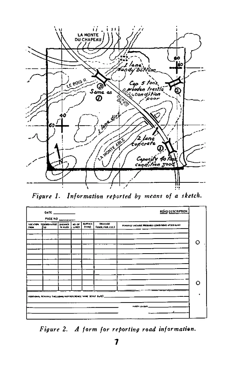
c. To insure against omission of important de-
tails, forms may be prepared for reconnaissance.
Forms cannot be prepared in advance to cover all
situations, nor will they always be available in the
fieldi FM 5-6 gives guides for reconnaissance.
Figures 2 and 3 show sample forms for recon-
naissance.
6
Figure 1. Information reported by means of a sketch.
P*TE рдмко ROIODESCRIPTION
<ттм> fsoce, «CMMtJ UMClUM HOUMI СМЫЙН1 «Л»»»»»)
r*Oi* «0
О
О
Figure 2. A form for reporting road information.
7
Figure 3. A form for reporting bridge information.
8
Section III
MOVEMENTS
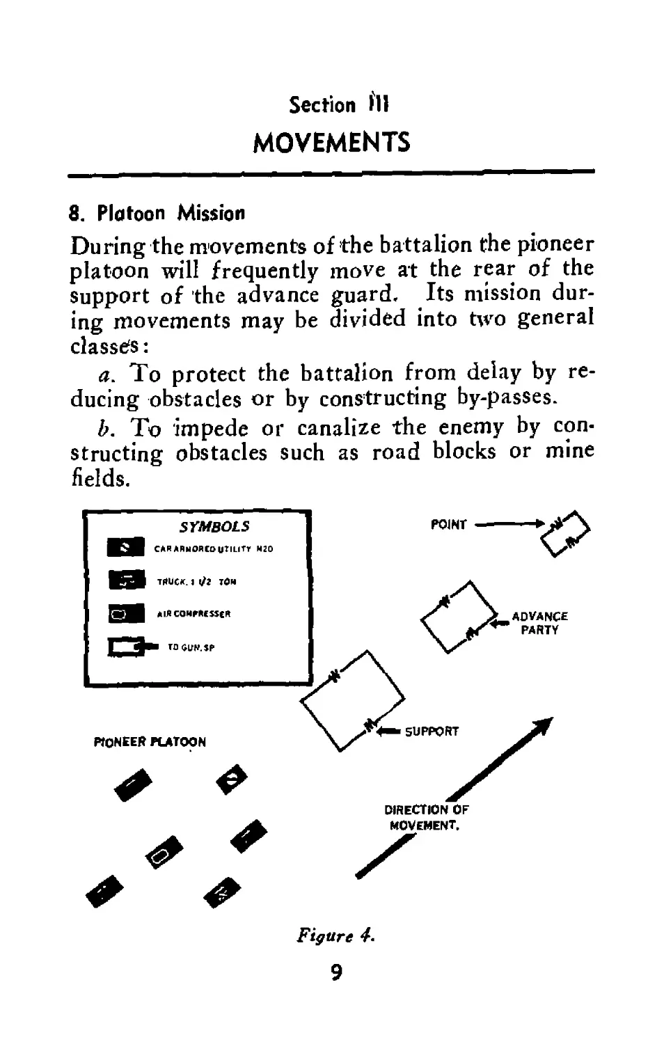
8. Platoon Mission
During the movements of the battalion the pioneer
platoon will frequently move at the rear of the
support of the advance guard. Its mission dur-
ing movements may be divided into two general
classes:
a. To protect the battalion from delay by re-
ducing obstacles or by constructing by-passes.
b. To impede or canalize the enemy by con-
structing obstacles such as road blocks or mine
fields.
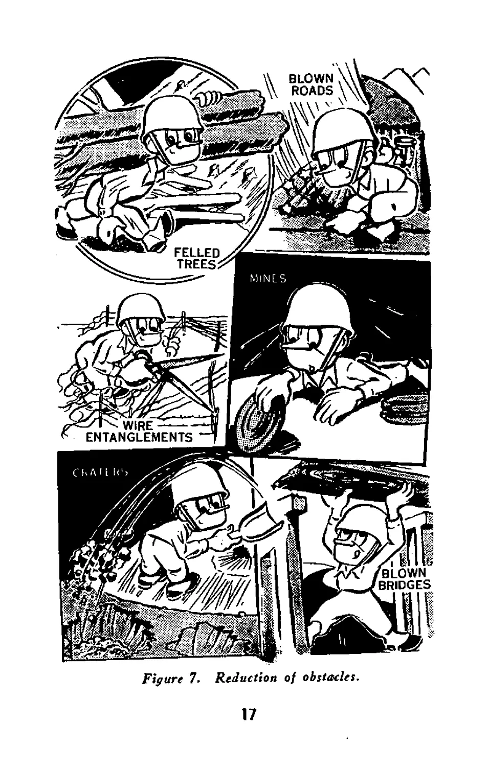
Figure 4.
9
9. Duties
The following check lists for duties performed
prior to and during movements are given as
guides. They should be amplified or modified as
experience warrants.
a. Platoon Commander. (1) Alerts the pla-
toon and issues warning order.
(2) Supervises the maintenance of vehicles
and the checking and storage of weapons, ammu-
nition, mines, tools, equipment, fuel supply, and
rations. (These duties are continuous before,
during, and after movements.)
(3) Checks radio net.
(.4) Inspects the platoon and issues the final
order. Insures that all know the situation, route,
and destination; issues overlays or sketches of
routes when time is available for their prepara-
tion.
(5) Checks intervehicular distance in both col-
umn and dispersed formations.
(6) Keeps oriented at all times by observation
of terrain and map, and by noting odometer dis-
tances.
(7) Checks maintenance of prescribed speed.
(8) Checks observance of blackout instruc-
tions.
(9) Checks clearing of roads and proper use
of cover and concealment at halts.
(10) At unscheduled halts, investigates the
cause and reports it to the company or. advance
guard commander.
(11) Sees that all vehicles move at resumption
of march—especially at night.
(12) Maintains prescribed contact.
10
(13) Reports mine fields.
b. Platoon Sergeant. Assists the platoon
commander as directed.
c. Section Leader. (1) Alerts section.
(2) Sees that all members of the section are
thoroughly familiar with their specific assign-
ments.
(3) Passes on to the members of the section
all instructions from the platoon commander.
(4) Relays all prearranged signals.
(5) Checks weapons, explosives, mines, and
equipment for completeness and stowage; checks
machine guns for adjustment, serviceability, and
ammunition.
(6) Checks vehicles for maintenance, fuel,
equipment, and rations.
(7) Checks radios.
(8) Maintains control over section during
movement.
(9) Maintains blackout discipline.
(10) Provides security on march and at halts
as directed by the platoon commander.
(11) Sees that vehicles are properly dispersed
and camouflaged at halts.
(12) Sees that one man in each vehicle is
awake during halts at night.
(13) Maintains contact with adjacent section
when prescribed.
(14) Rotates duties of personnel to provide
sufficient rest for all.
d. Assistant Section Leader. Assists the
section leader as directed.
e. Air Compressor Operator. (1) Checks
vehicle for maintenance, fuel, and equipment.
II
(2) Checks air compressor tools for complete-
ness, serviceability, and stowage.
f. Radio Operator. (1) Sees that radio is
property netted and in operating condition.
(2) Operates and maintains radio.
(3) Assists in other duties as prescribed by the
platoon commander.
g. Driver. (1) Operates vehicle and per-
forms first echelon maintenance.
(2) Utilizes maximum cover and concealment
in movement.
(3) Keeps vehicle in proper gear so maximum
acceleration can be obtained when necessary.
(4) Remains with vehicle when halted, and
dismounts only when directed.
(5) Mans the vehicular weapon when alone
with vehicle during halts.
(6) Assists in other duties as prescribed.
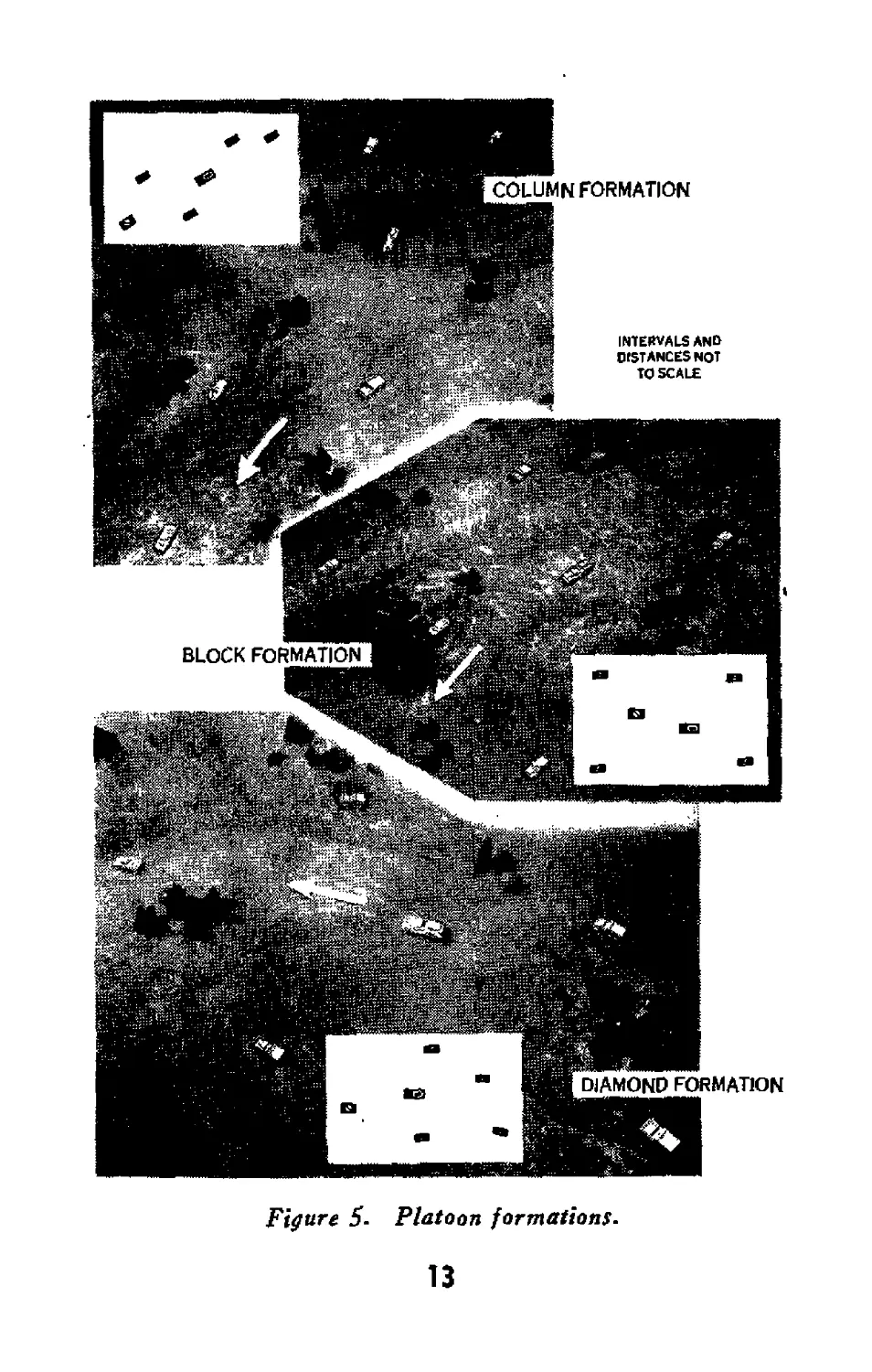
10. Formations
Normally the platoon will move in a column for-
mation with the air compressor in the middle of
the platoon column. During movements across
country, the formations used are adapted to the
ground and will vary according to whether other
troops are in the area and to the proximity of the
enemy. Two standard formations used by the
platoon are the block and the diamond. These
formations are designed for security and control.
The air compressor will take a position in the in-
terior of the formation. The platoon may also
use other formations, such as the line of sections
and echeloned sections. Units that have need for
12
Figure 5- Platoon formations.
13
other formations should not hesitate to design
them. Formations should be practiced until the
platoon is perfect in their execution.
11. Security during Movement
a. March Security. While on the march the
platoon commander provides for the security of
his unit by the dispersal of vehicles, observation,
the use of covered and concealed routes, avoid-
ance of dust, detouring defiles where possible,
camouflage discipline, blackout discipline, main-
tenance of radio silence, and the elimination of all
unnecessary noise and traffic.
b. Security against Air Attacks. Security
against air attacks on the march is gained by dis-
persion and alertness. When road space is avail-
able and control can be effectively maintained, in-
tervehicular distance of about 175 yards is de-
sirable. Movement cannot cease every time
enemy planes appear, because such halting would
enable a few enemy planes to keep a unit from
performing its mission on time. For this reason,
instructions as to whether to halt or keep moving
in the event of air attack will be issued prior to
the beginning of the march. The platoon takes
immediate measures for protection against low-
flying aircraft by using its own weapons which are
suitable for fire against aircraft. Carbines, sub-
machine guns, and pistols are not considered suit-
able weapons. All men must be prepared con-
stantly for immediate action, but will fire only
upon the order of an officer or responsible non-
commissioned officer. No aircraft will be fired
upon unless it has been recognized clearly as hos-
14
tile or is positively identified as hostile, or attacks
with bombs or gun fire.
(1 ) When troops halt during an air attack,
vehicles leave the road, when terrain and time
permit, and halt under available concealment.
Troops not manning antiaircraft weapons dis-
mount and disperse; personnel fire all effective
weapons at the attacking aircraft.
(2 ) When movement continues during an air
attack, vehicles maintain distances on the road, or,
15
if the terrain permits, disperse laterally while con-
tinuing the forward movement. The fire of all
effective weapons is brought against the attacking
planes.
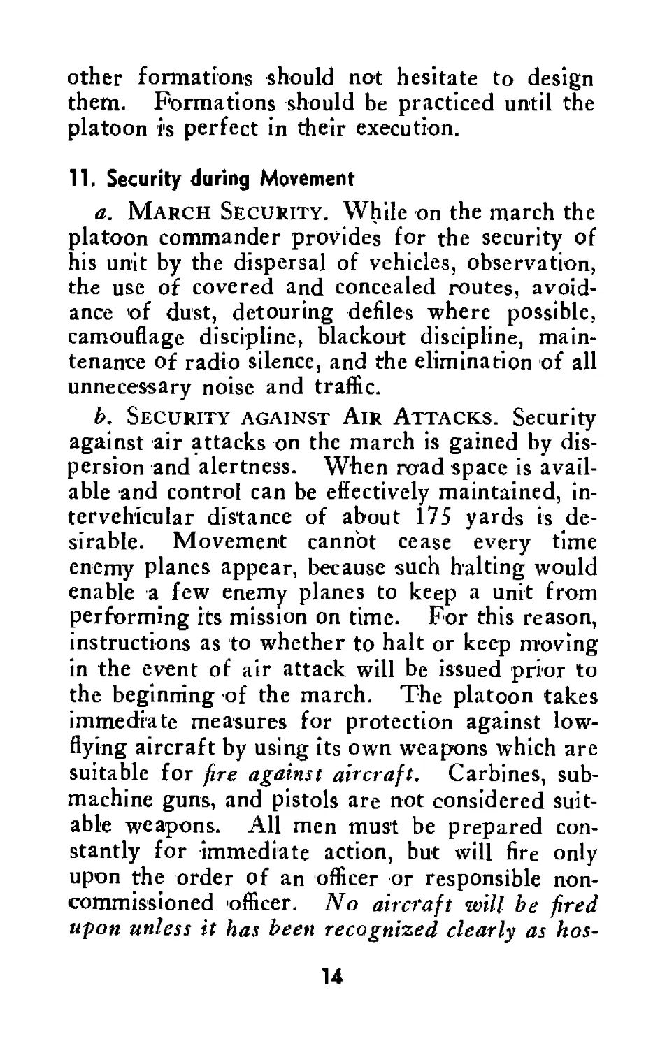
12. Flank Guard
The platoon or section may be attached to a flank
guard. In such a case it may construct road
blocks and lay hasty mine fields (with permission
of higher authority) to assist in preventing the
enemy from striking the flank of the moving col-
umn. The location of such obstacles is governed
by the most likely approaches of the enemy. The
platoon will remove the mines after the column
has passed. Mine fields and road blocks will
usually be covered by fire, and the platoon may
be called on to help provide this fire.
13. Halts
a. Unscheduled halts may be the result of un-
expected obstacles in the route. In such cases the
pioneer platoon may be sent forward to reduce
these obstacles. Speed in the execution of these
tasks must be attained so the least possible delay
in the movement of the column will result.
b. During normally scheduled halts the platoon
commander ascertains that proper security meas-
ures, such as the dispersion and concealment of
vehicles and personnel, are taken. He then
checks the condition of vehicles and sees that
proper maintenance is being executed. Normally,
all personnel will be busy during halts. Resting
is usually done only in bivouacs.
16
17
14. Rail and Water Movements
Personnel from the platoon will be trained to as-
sist the other units of the battalion in the loading,
blocking, and securing of vehicles for movement
by rail 'or water. The special pioneer equipment
may be used to cut blocks and for whatever other
purposes are found necessary. The platoon com-
mander, assisted by some of his noncommissioned
officers, may be detailed to inspect the work per-
formed by the loading crews of the various com-
panies.
Id
Section IV
BIVOUACS
15. General
a. Entering Bivouacs. When the situation
permits, at least part, and preferably all of the
pioneer platoon will precede the main body of the
battalion to the selected bivouac area, accompany-
ing the advance reconnaissance element or the
quartering party. This gives time to make neces-
sary improvements before the arrival of the main
body. During movement into bivouac the essen-
tial requirement is 'speed in clearing the road and
in finding cover and concealment. The platoon
commander or a selected noncommissioned officer
should precede the platoon into the area and be
prepared to point out the section areas to the sec-
tion leaders. After the road has been cleared
and all the vehicles of the main body are under
cover, the original platoon positions may be im-
proved.
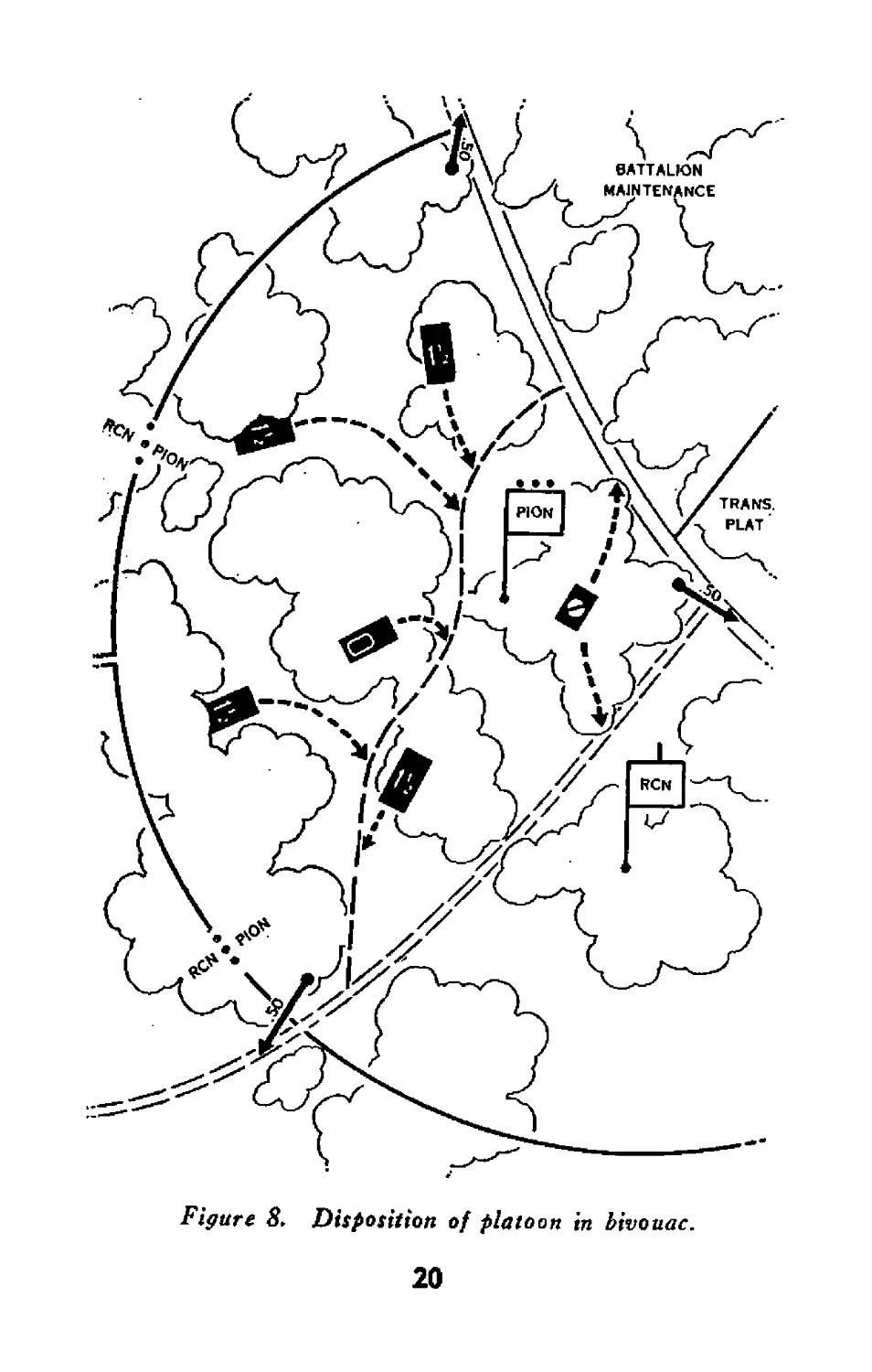
b. Platoon Plan. A platoon plan facilitates
the occupation of a bivouac area. Under ordi-
nary circumstances the platoon will occupy an in-
terior position; all vehicles halt faced toward the
route of egress. In rare instances, when the pla-
toon occupies a portion of the battalion perimeter,
the machine guns are dismounted and placed on
the perimeter; vehicles again face the route of
egress. The air compressor will be kept well to-
ward the rear where it will receive the most
protection.
19
Figure 8> Disposition of platoon tn bivouac.
20
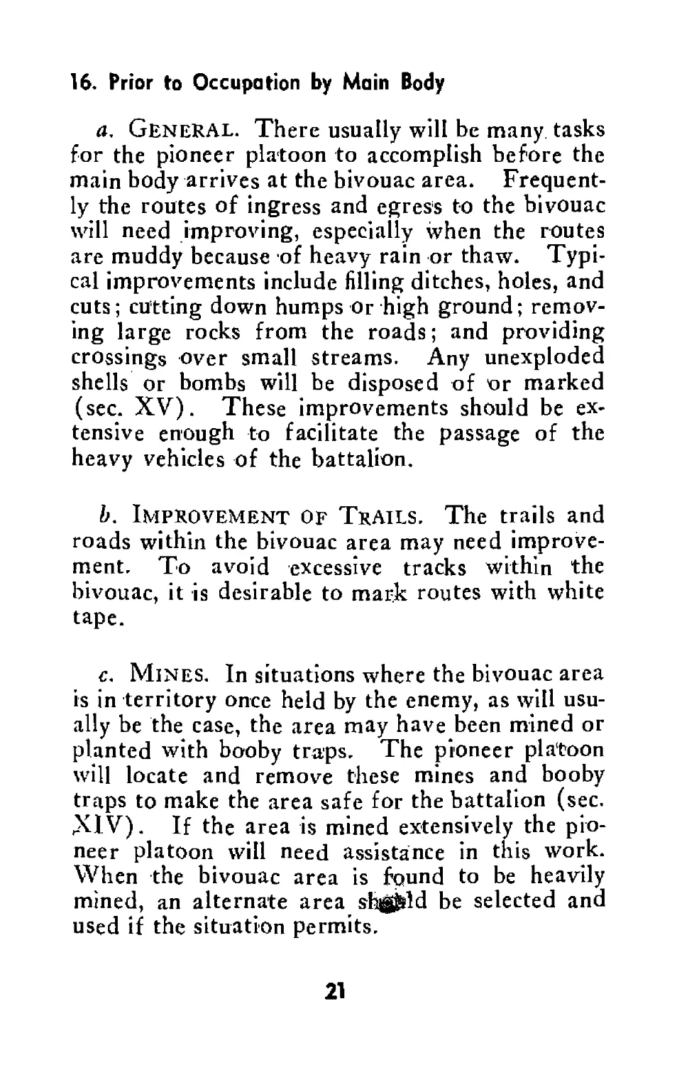
16. Prior to Occupation by Main Body
a. General. There usually will be many tasks
for the pioneer platoon to accomplish before the
main body arrives at the bivouac area. Frequent-
ly the routes of ingress and egress to the bivouac
will need improving, especially when the routes
are muddy because of heavy rain or thaw. Typi-
cal improvements include filling ditches, holes, and
cuts; cutting down humps Or high ground; remov-
ing large rocks from the roads; and providing
crossings over small streams. Any unexploded
shells or bombs will be disposed of or marked
(sec. XV). These improvements should be ex-
tensive enough to facilitate the passage of the
heavy vehicles of the battalion.
b. Improvement of Trails. The trails and
roads within the bivouac area may need improve-
ment. To avoid excessive tracks within the
bivouac, it is desirable to mark routes with white
tape.
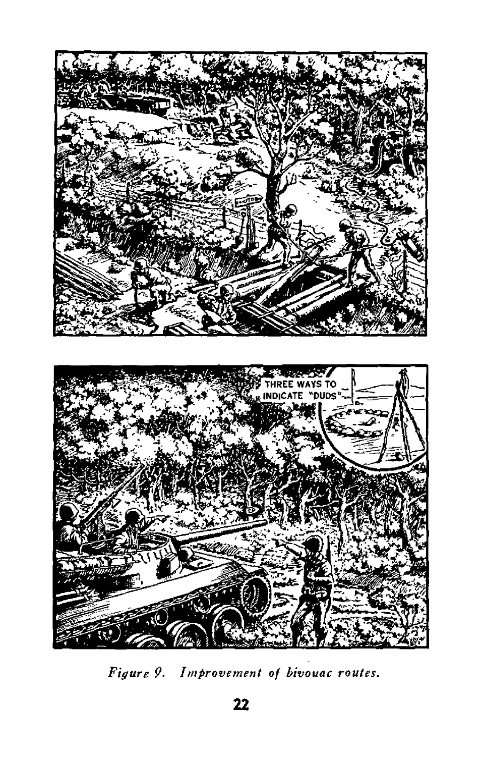
c. Mines. In situations where the bivouac area
is in territory once held by the enemy, as will usu-
ally be the case, the area may have been mined or
planted with booby traps. The pioneer platoon
will locate and remove these mines and booby
traps to make the area safe for the battalion (sec.
XIV). If the area is mined extensively the pio-
neer platoon will need assistance in this work.
When the bivouac area is found to be heavily
mined, an alternate area shgjsld be selected and
used if the situation permits.
21
Figure 9- I mprovement of bivouac routes.
22
17. During Occupation
a. General. During the actual occupation of
the bivouac one of the principal duties of the pla-
toon will be to assist the CP group and companies
of the battalion in camouflaging and digging in.
Whe re the ground is hard, demolitions may be
used for emplacements and other protective meas-
ures. The platoon is equipped to do this work,
but is limited by the amount of explosives carried.
b. Protection for Area. To provide protec-
tion for the bivouac area, the platoon can be
utilized to prepare obstacles along the main ave-
nues of approach. Road blocks, mined areas, or
other prepared obstacles may be used. Permis-
sion from higher headquarters will be obtained
before mines are laid or road blocks constructed.
Mine fields laid will be marked and reported.
The improvement of natural barriers usually is
more effective and involves less work than the
construction of new obstacles.
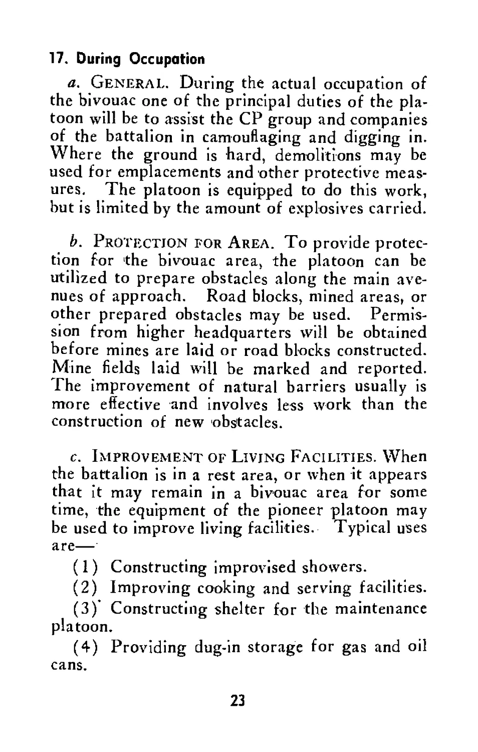
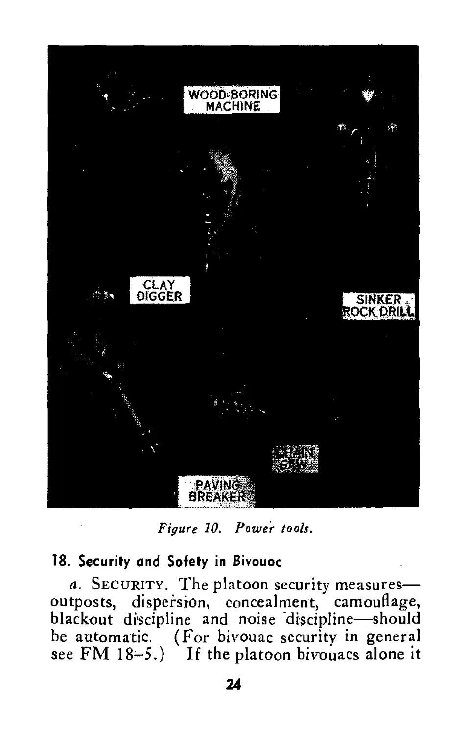
c. Improvement of Living Facilities. When
the battalion is in a rest area, or when it appears
that it may remain in a bivouac area for some
time, the equipment of the pioneer platoon may
be used to improve living facilities. Typical uses
are—
(1) Constructing improvised showers.
(2) Improving cooking and serving facilities.
(3) Constructing shelter for the maintenance
platoon.
(4) Providing dug-in storage for gas and oil
cans.
23
18. Security and Safety in Bivouoc
a. Security. The platoon security measures—
outposts, dispersion, concealment, camouflage,
blackout discipline and noise discipline—should
be automatic. (For bivouac security in general
see FM 18-5.) If the platoon bivouacs alone it
24
establishes outposts for all-round security. In
those rare instances when the platoon occupies a
portion of the perimeter of a bivouac of a higher
unit, it will be assigned a security sector and will
establish outposts. The mission of the outposts
is to warn of surprise attack, to stop any attack
by enemy troops, and to prevent infiltration into
the area. Outposts maintain liaison, whenever
possible, with more advanced observation and lis-
tening posts established by other units and co-
ordinate their fields of fire with those of adjacent
units. An adequate warning system is estab-
lished.
b. Blackout Precautions Camouflage and
noise discipline and the enforcement of blackout
instructions are essential. Some common-sense
blackout safety precautions are—
(1) Individual vehicles moving within the
bivouac in blackout are preceded by a dismounted
guide.
(2) Sleeping personnel are checked to see that
none are near an engine exhaust or in front of or
under a vehicle.
(3) When the platoon moves from bivouac in
blackout, men are carefully checked to see that
none are left behind.
19. Routine Duties in Bivouac
a. General. Besides the specific missions as-
signed to the platoon, there are certain general
duties which will be performed after the bivouac
has been occupied and organizeAfor defense and
security. Primary attention should be given to
25
the combat readiness of the vehicles, to the fight-
ing and working equipment, and to 'the comfort
and security of the men. Men take care of their
vehicles and equipment before they take care of
themselves. The platoon leader and noncom-
missoned officers see that vehicles, equipment, and
men are taken care of before they make them-
selves comfortable. A check list for the platoon
in bivouac is given below. It should be modified
and amplified as experience warrants.
b. Security.
Are the vehicles dispersed and camou-
flaged?
Are the machine guns sighted for mutual
support and manned?
Is the air compressor placed in the best
protected location?
Have blackout instructions been issued?
Have prone shelters or fox holes been
dug?
Are sentries posted?
Is there relief for men on outposts?
Are antitank warning system signals un-
derstood ?
Do the men know the challenge, password,
and reply?
Are provisions made for proper action in
case of air attack?
c. Combat Readiness.
Are the friendly and enemy situations
known by all?
Is first echelon maintenance being per-
formed?
Have all vehicles been refueled?
26
Is the air compressor in good operating
condition ?
Have the tools been checked and found
ready for use?
Have the weapons been cleaned and
checked for operations?
Do all vehicles and personnel have basic
ammunition loads?
Have all radios been checked?
Are reserve rations on hand?
Is the platoon ready to move on a mo-
ment’s notice?
d. Contact.
Has contact been established with adjacent
units ?
Has a messenger been sent to the company
CP?
Has the company commander been in-
formed of the disposition of the pla-
toon?
Do members of the platoon know the lo-
cation of the platoon CP? The com-
pany CP? The battalion CP? The
battalion aid station?
Do the members of the platoon know the
location and general disposition of the
other platoons of the company? Do
the key personnel of the platoon know
the location of the men in bivouac?
e. Living in and Leaving the Bivouac.
Do the vehicles have firm standing?
Have latrine facilities been provided?
Have the men the best available shelter?
Is water available?
27
Have routes of egress been reconnoitered
and suitably marked for night move-
ment?
Is good camouflage discipline maintained?
20. Air attack
a. In Bivouac. In the bivouac area all per-
sonnel of the pioneer platoon will dig prone shel-
ters or fox holes. When hostile planes are sight-
ed, fire will be withheld until it is determined that
they have located tank destroyer units. Careless
firing frequently discloses positions that would
otherwise be unobserved. Enemy planes may
attempt to draw fire for that purpose. If the
planes have located tank destroyer units, fire pow-
er of all effective weapons will be used (par. 11£).
b. Moving from Bivouac. Units are particu-
larly vulnerable to air attack when moving out of
bivouac. To avoid any possible congestion the
platoon commander coordinates the egress of his
unit with other troops in the area. All vehicles
must be dispersed as they move out, not closed in
with the idea of taking distance on the march.
21. Defense against Bivouac Raids
a. Platoon Plan. Each platoon should de-
velop and practive a plan to execute in the event
of a surprise raid, especially at night. Regard-
less of how far back a bivouac is, a sudden raid
by infiltrating or airborne troops is always a pos-
sibility, and there may be no friendly troops be-
tween the tank destroyers and the enemy. In
making defense plans the platoon area should be
considered as a defense area and the weapons and
28
individual arms of the platoon employed to or-
ganize it.
b. Action during Raids. (1) Adequate de-
fensive action during a night raid requires thor-
ough training and rigid discipline. Each unit
should adopt a standing operating procedure for
defense at night. One method is to prescribe two
alert signals, as follows:
(л) First signal is sounded when an enemy at-
tack or infiltration appears imminent. All per-
sonnel occupy prepared positions with 50 percent
on alert and others resting.
(b) Second signal is sounded when an enemy
attack or infiltration is made. All personnel are
alerted and remain in prepared positions. All
movement within the area is assumed to be hostile
and subject to immediate attack.
(2) The primary weapons for defense against
close-in night attacks are -antitank and antiper-
sonnel mines, flares, grenades, bayonets and
knives. The firing of weapons is rigidly con-
trolled as their flash discloses the location of the
firer. There is no withdrawal from a position
during a night attack. All men must understand
that they are “frozen” to their positions regard-
less of xvhat happens.
29
Section V
POSITION IN READINESS
22. General
A position in readiness is an area which an or-
ganization occupies while the battle situation is
developing. There will, in all probability, be sev-
eral possible combat areas in which the action
might take place. During the period of waiting
for developments the pioneer platoon is prepared
to move rapidly to execute any missions assigned.
23. Reconnaissance of Combat Area
While the position in readiness is occupied, pis-
sible combat areas are reconnoitered. Usually
the pioneer platoon commander and the two sec-
tion sergeants go forward, one with each gun
company commander, to estimate the extent of
work required in missions which they may be
called upon to execute within the different areas.
24. Occupation and Duties
Dispositions of troops and vehicles in a position
in readiness are similar to those in bivouac (sec.
IV). While the battalion occupies the position
in readiness the pioneer platoon executes the mis-
sions assigned after the reconnaissance of the
combat area. Principal missions at this time are
to see that routes to the selected combat areas are
free from obstacles, both natural and man-made
(FM 5—30). When time permits, the platoon
may assist in improving gun positions. The mis-
sions of the platoon may be numerous: therefore
the battalion plan of action determines the prior-
ity of such tasks.
30
Section VI
COMBAT AREA
25. Obstacles
a. Removal of Obstacles. It is a function of
the pioneer platoon to remove or assist in remov-
ing obstacles, both natural and artificial, including
mine fields and booby traps (FM 5-30).
b. Construction of Obstacles. When time
permits the deliberate occupation of positions, all
possible means of forcing the enemy to fight on
ground chosen by the tank destroyers should be
used. The pioneer platoon will often be directed
to move forward to execute demolitions, lay
mines, build road blocks, and construct other ob-
stacles with which to canalize the movement of
the enemy (FM 5—30). In selecting gun posi-
tions there may be approaches which cannot be
covered by fire from the destroyers. Obstacles
will be constructed to deny the enemy the use of
such approaches. The pioneer platoon may be
required to assist the security sections of the gun
platoons in covering these obstacles by fire.
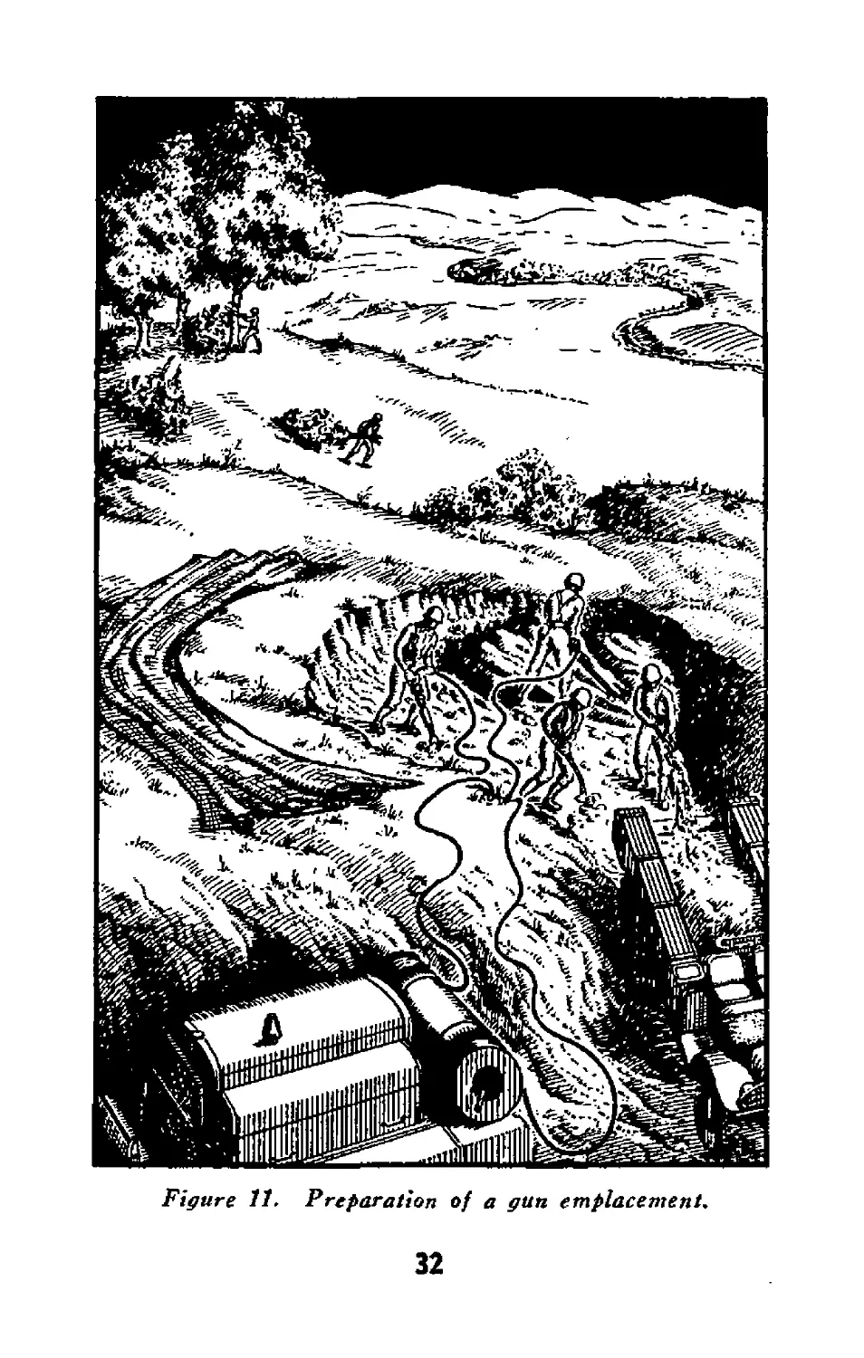
26. Preparation of Gun Positions
Frequently the pioneer platoon will be employed
to assist gun crews in preparing gun positions.
The equipment and training of the personnel
adapt them to jobs such as assisting in digging
gun positions, preparing camouflage, clearing
fields of fire, and improving routes into and out
of position. The platoon also may be employed
31
Figure 11. Preparation of a gun emplacement.
32
to assist in the preparation of alternate and dum-
my gun positions. To add realism to dummy
positions the platoon may equip them with ex-
plosive charges called fougasses (par. S3).
27. Fire Fight
During the fire fight the pioneer platoon reor-
ganizes, if necessary, and assists in the defense of
the command post. It will be prepared at all
times to move forward and perform new missions.
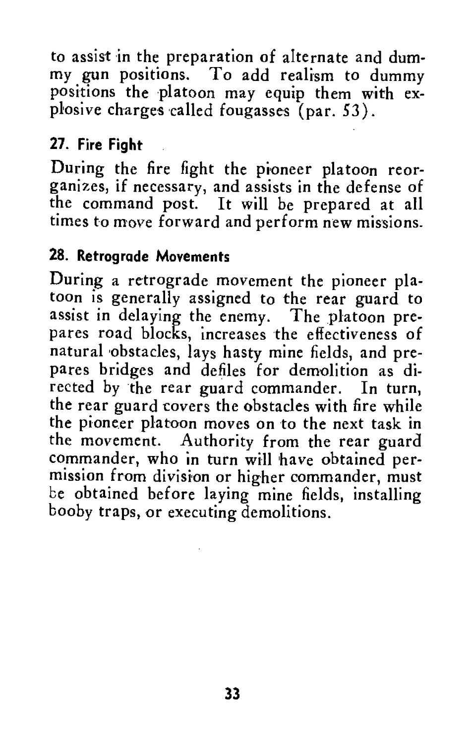
28. Retrograde Movements
During a retrograde movement the pioneer pla-
toon is generally assigned to the rear guard to
assist in delaying the enemy. The platoon pre-
pares road blocks, increases the effectiveness of
natural obstacles, lays hasty mine fields, and pre-
pares bridges and defiles for demolition as di-
rected by the rear guard commander. In turn,
the rear guard covers the obstacles with fire while
the pioneer platoon moves on to the next task in
the movement. Authority from the rear guard
commander, who in turn will have obtained per-
mission from division or higher commander, must
be obtained before laying mine fields, installing
booby traps, or executing demolitions.
33
ENEMY
34
Section VII
TECHNICAL TRAINING
29. Mission
From the previous discussion of the two general
missions it will be noted that the tasks of the pio-
neer platoon are similar to those of a platoon of
combat engineers. The technical training of the
platoon must therefore be similar to that of en-
gineers. The personnel should be trained thor-
oughly in the technique of constructing and
removing obstacles and in at least the elementary
engineering tasks commonly assigned to the
platoon.
30. References
a. In addition to the techniques described in this
manual, the personnel of the pioneer platoon
should be trained in all the techniques given in
FM 5-10, Construction and Routes of Communi-
cations, FM 5-30, Obstacle Technique, FM 5-31,
Land Mines and Booby Traps, and in the follow-
ing subjects in FM 21-105, Engineer Soldiers’
Handbook:
Engineer tools and common engineer
tasks.
Elementary rigging.
Camouflage.
Explosives and demolitions.
Bridges.
Engineer reconnaissance.
Combat weapons.
35
b. In using FM 5-10, FM 5-30, FM 5-31,
FM 21—105, and other manuals .referred to in
this text, the subject material must be adapted to
the organization and equipment of the platoon.
Figure 13. Technical references for the pioneer platoon.
36
Section VIII
SAFE STRENGTH OF EQUIPMENT
31. General
As members of the pioneer platoon will frequent-
ly be working with ropes, chains, winches, and
like equipment, they must know the safe working
strength of this equipment. Should the equip-
ment break while being used, personnel may be
injured and the mission may not be performed.
To satisfactorily complete a mission with the least
danger to personnel, the load should always be
kept within the safe working strength of the
equipment being used.
32. Rope, Wire, and Chain (FM 5-10).
The following simple rules are applied to deter-
mine the safe working load of rope, wire rope,
and chain:
a. Rope. Working strength (in tons) equals
the diameter (in inches) squared (T = D2).
Example: The safe working strength of а y2
inch rope is % ton—
T (tons) = D2 (diameter in inches
squared)
T = У X У = У ton.
b. Wire Rope. Working strength (in tons)
equals eight times the diameter (in inches)
squared (T“=8D2).
Example: The safe working strength of a %
inch wire rope is 2 tons—
T (tons) = 8D2 (diameter in inches
squared^ ,;i
T = 8 Х^У X У — 2 tons.
37
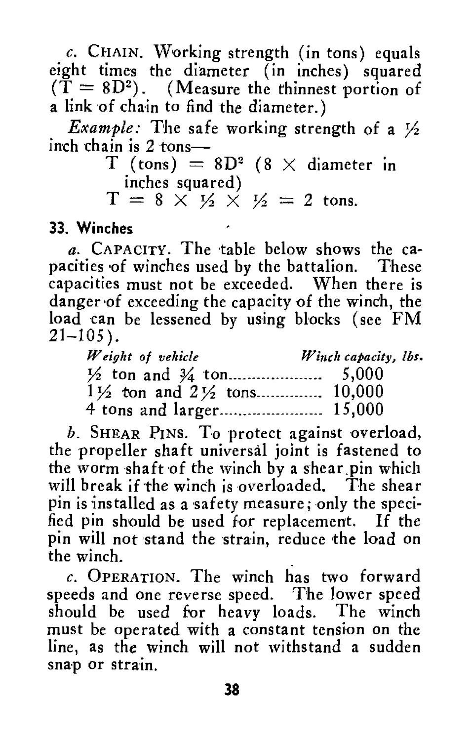
c. Chain. Working strength (in tons) equals
eight times the diameter (in inches) squared
(T = 8D2). (Measure the thinnest portion of
a link of chain to find the diameter.)
Example: The safe working strength of a )4
inch chain is 2 tons—
T (tons) = 8D2 (8 X diameter in
inches squared)
T - 8 X У X )4 = 2 tons.
33. Winches
a. Capacity. The table below shows the ca-
pacities 'of winches used by the battalion. These
capacities must not be exceeded. When there is
danger of exceeding the capacity of the winch, the
load can be lessened by using blocks (see FM
21-105).
Weight of vehicle Winch capacity, lbs.
У ton and У ton..............— 5,000
\y ton and 2)4 tons----------- 10,000
4 tons and larger------------- 15,000
b. Shear Pins. To protect against overload,
the propeller shaft universal joint is fastened to
the worm shaft of the winch by a shear.pin which
will break if the winch is overloaded. The shear
pin is installed as a safety measure; only the speci-
fied pin should be used for replacement. If the
pin will not stand the strain, reduce the load on
the winch.
c. Operation. The winch has two forward
speeds and one reverse speed. The lower speed
should be used for heavy loads. The winch
must be operated with a constant tension on the
line, as the winch will not withstand a sudden
snap or strain.
38
Section IX
ROAD EXPEDIENTS
34. General
The pioneer platoon ordinarily is not called upon
to make permanent road repairs, but is expected
to employ expedient methods for hasty road re-
pairs and construction. The type of road built
depends on the time available and the usable ma-
terials near the road site. (FM 5—10 presents
additional road expedients.)
35. Corduroy Roads
a. Usage. The corduroy road is one of the
most reliable and widely used expedient roads.
It may be constructed easily and rapidly when
timber is conveniently available. The platoon
may construct corduroy roads to improve soft ap-
proaches to fords and bridges and to negotiate
mud holes and short stretches of swampy ground.
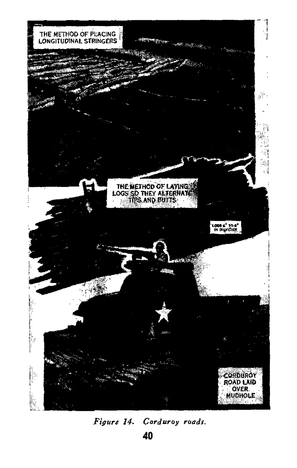
b. Construction. The corduroy road is built
by laying logs, split or round, crosswise to the axis
of the road. The logs should have a mean diam-
eter of 6 inches, be as nearly the same size as pos-
sible, and be laid by alternating tips and butts. If
the logs are large, the spaces may be filled with
smaller poles. These poles should be trimmed to
fill the gaps closely. To make the road smoother
for traveling, the entire structure may be covered
with a layer of hay or same similar material which
39
'1
THE METHOD OF PLACING f
LONGITUDINAL stringers 1
1H£ METHOD OF LAYlNGp
LOGS я> they ащкяа^
ано sum *
Figure 14. Corduroy roads.
40
(дев’!»*'
|_Й Pty
(кй»Й5Ййд¥
ROAD LAID
OVER.
. MUDHOLE ,
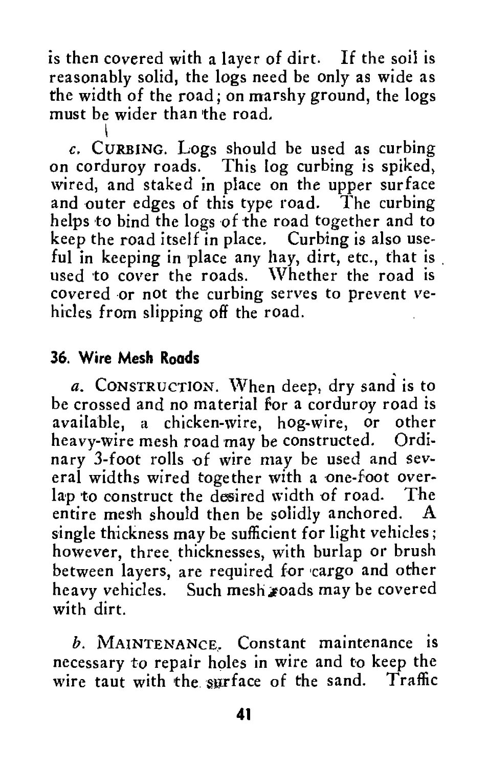
is then covered with a layer of dirt. If the soil is
reasonably solid, the logs need be only as wide as
the width of the road; on marshy ground, the logs
must be wider than the road.
I
c. Curbing. Logs should be used as curbing
on corduroy roads. This log curbing is spiked,
wired, and staked in place on the upper surface
and outer edges of this type road. The curbing
helps to bind the logs of the road together and to
keep the road itself in place. Curbing is also use-
ful in keeping in place any hay, dirt, etc., that is
used to cover the roads. Whether the road is
covered or not the curbing serves to prevent ve-
hicles from slipping off the road.
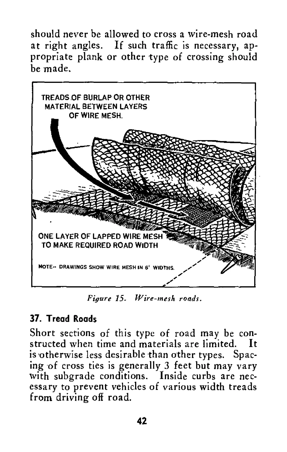
36. Wire Mesh Roads
a. Construction. When deep, dry sand is to
be crossed and no material for a corduroy road is
available, a chicken-wire, hog-wire, or other
heavy-wire mesh road may be constructed. Ordi-
nary 3-foot rolls of wire may be used and sev-
eral widths wired together with a one-foot over-
lap to construct the desired width of road. The
entire mesh should then be solidly anchored. A
single thickness may be sufficient for light vehicles;
however, three thicknesses, with burlap or brush
between layers, are required for cargo and other
heavy vehicles. Such meshjtoads may be covered
with dirt.
b. Maintenance.. Constant maintenance is
necessary to repair holes in wire and to keep the
wire taut with the surface of the sand. Traffic
41
should never be allowed to cross a wire-mesh road
at right angles. If such traffic is necessary, ap-
propriate plank or other type of crossing should
be made.
Figure 15- Wire-mesh roads.
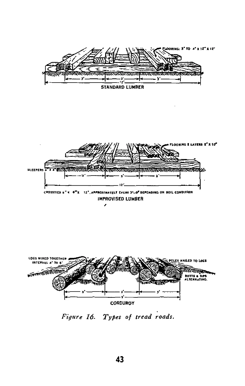
37. Tread Roads
Short sections of this type of road may be con-
structed when time and materials are limited. It
is otherwise less desirable than other types. Spac-
ing of cross ties is generally 3 feet but may vary
with subgrade conditions. Inside curbs are nec-
essary to prevent vehicles of various width treads
from driving off road.
42
STANDARD LUMBER
CROSSTIES b'< «**« 12*.4FRR01flMTEL< EVERT J'-O'DEPENDING ON SOIL C0NPIT1ON
IMPROVISED LUMBER
CORDUROY
Figure 16- Types of tread roads.
43
Section X
STREAM CROSSING EXPEDIENTS
38. Fords
a. General. If a bridge is not available, ford-
ing a stream is ordinarily the quickest and easiest
way to cross it. Even though there may be a
bridge, a ford should be located in the event the
bridge is rendered unserviceable by enemy action.
If the selected ford site needs improvements, the
pioneer platoon will be called on to do the work
if the job is not too extensive.
b. Fordability of Vehicles. The depth of
water that normally can be forded by the vehicles
of the battalion is shown in the table below:
Normal
Vehicle fordability
in inches
Truck, %-ton............................... 18
Truck, j^-ton, weapons carrier and com-
mand ................................... 34
Truck, Ij^-ton, 6x6, cargo, w/winch.... 34
Truck, 2^-ton, cargo, w/winch................ 36
Compressor, air, motorized................... 36
Truck, heavy wrecker, w/winch.............. 40
Car, armored, light, M8.......___1________ 34
Car, armored, utility, M20—.................. 34
Vehicle, tank, recovery................... 36
Carrier, personnel, half-track M3-—.......... 32
Carriage, motor, 76-mm gun................... 48
Carriage, motor, 3-inch gun.................. 36
44
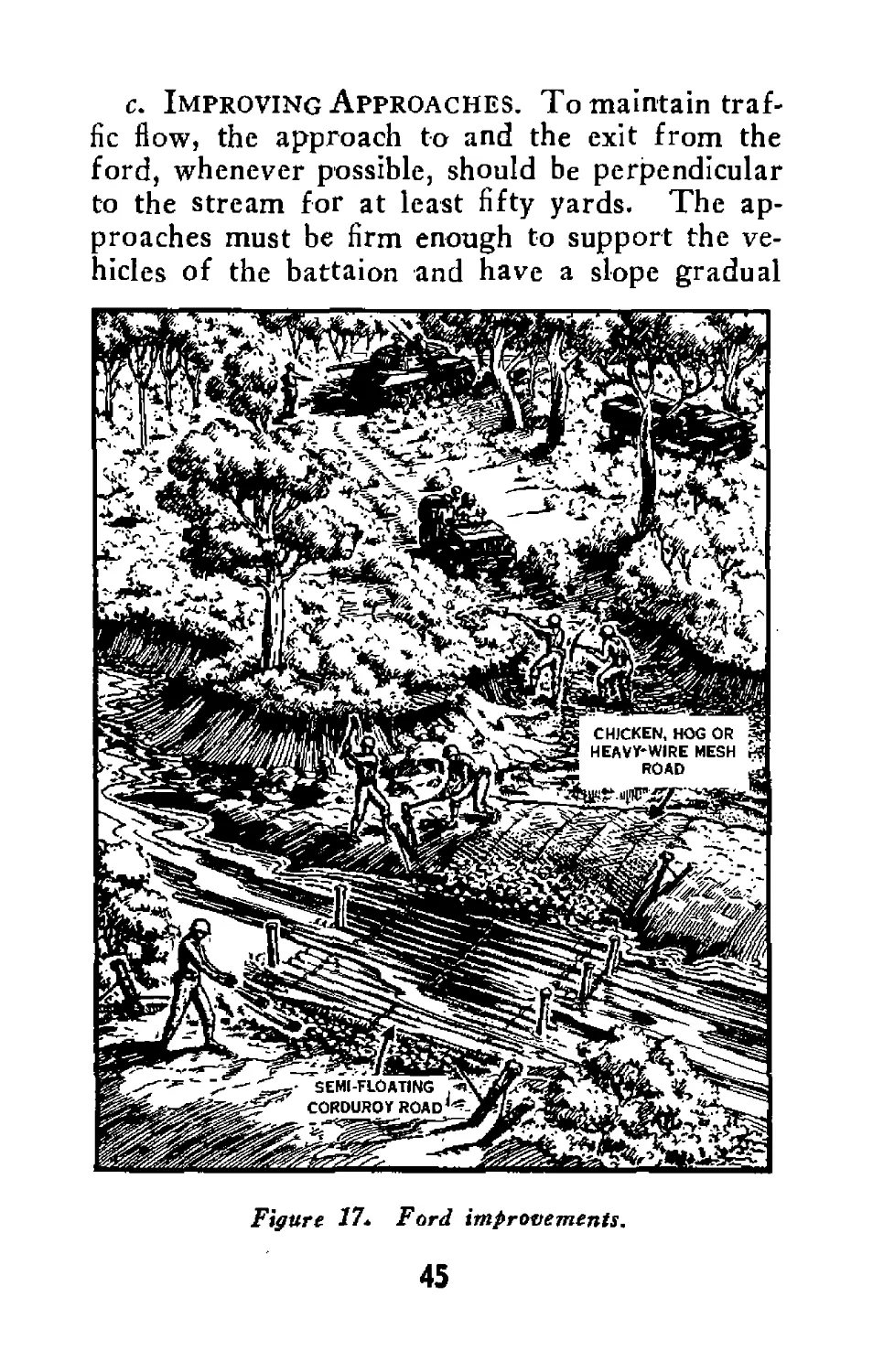
c. Improving Approaches. To maintain traf-
fic flow, the approach to and the exit from the
ford, whenever possible, should be perpendicular
to the stream for at least fifty yards. The ap-
proaches must be firm enough to support the ve-
hicles of the battaion and have a slope gradual
Figure 17л Ford improvements.
45
enough for the vehicles to enter and exit easily.
Soft approaches may be improved by the construc-
tion of cordutoy roads or other road expedients.
Steep approaches may be cut down either by hand
labor or by the use of explosives.
d. Improving Stream Bed. If the stream bed
is not firm enough to support the vehicles, it may
be improved by constructing a semi-floating cordu-
roy road with the logs wired together and an-
chored at each end to keep the current from
shifting the road. The stream bed may also be
improved by placing sand bags or heavy-wire mesh
to form a roadway. On a dry sand bar a chicken-
wire or hog-wire road may be constructed.
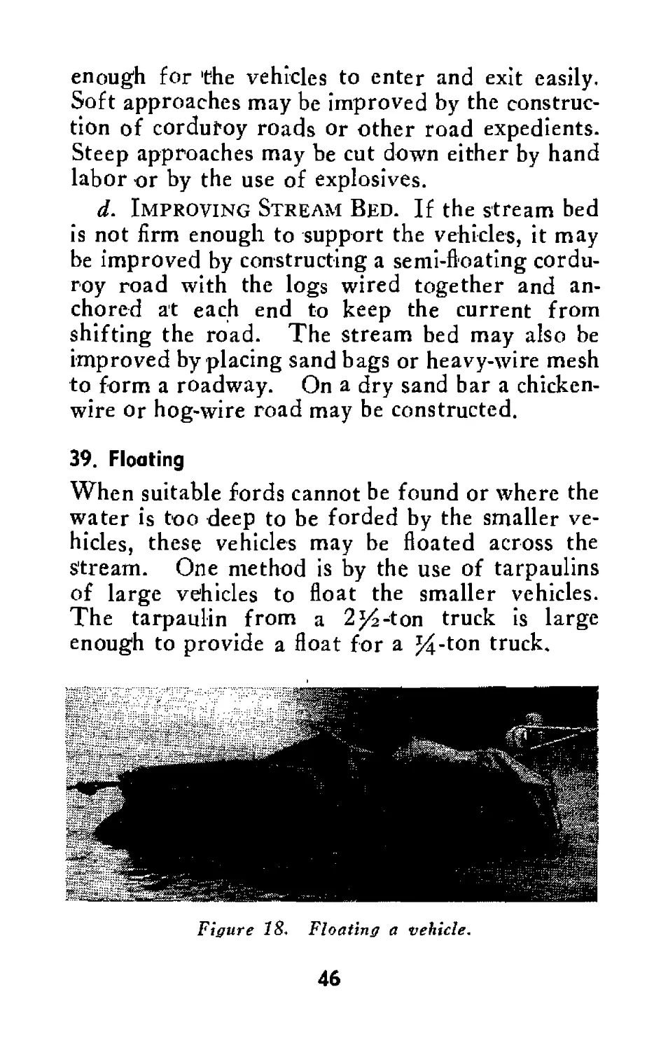
39. Floating
When suitable fords cannot be found or where the
water is too deep to be forded by the smaller ve-
hicles, these vehicles may be floated across the
stream. One method is by the use of tarpaulins
of large vehicles to float the smaller vehicles.
The tarpaulin from a 2 %-ton truck is large
enough to provide a float for a %-ton truck.
Figure Floating a vehicle.
46
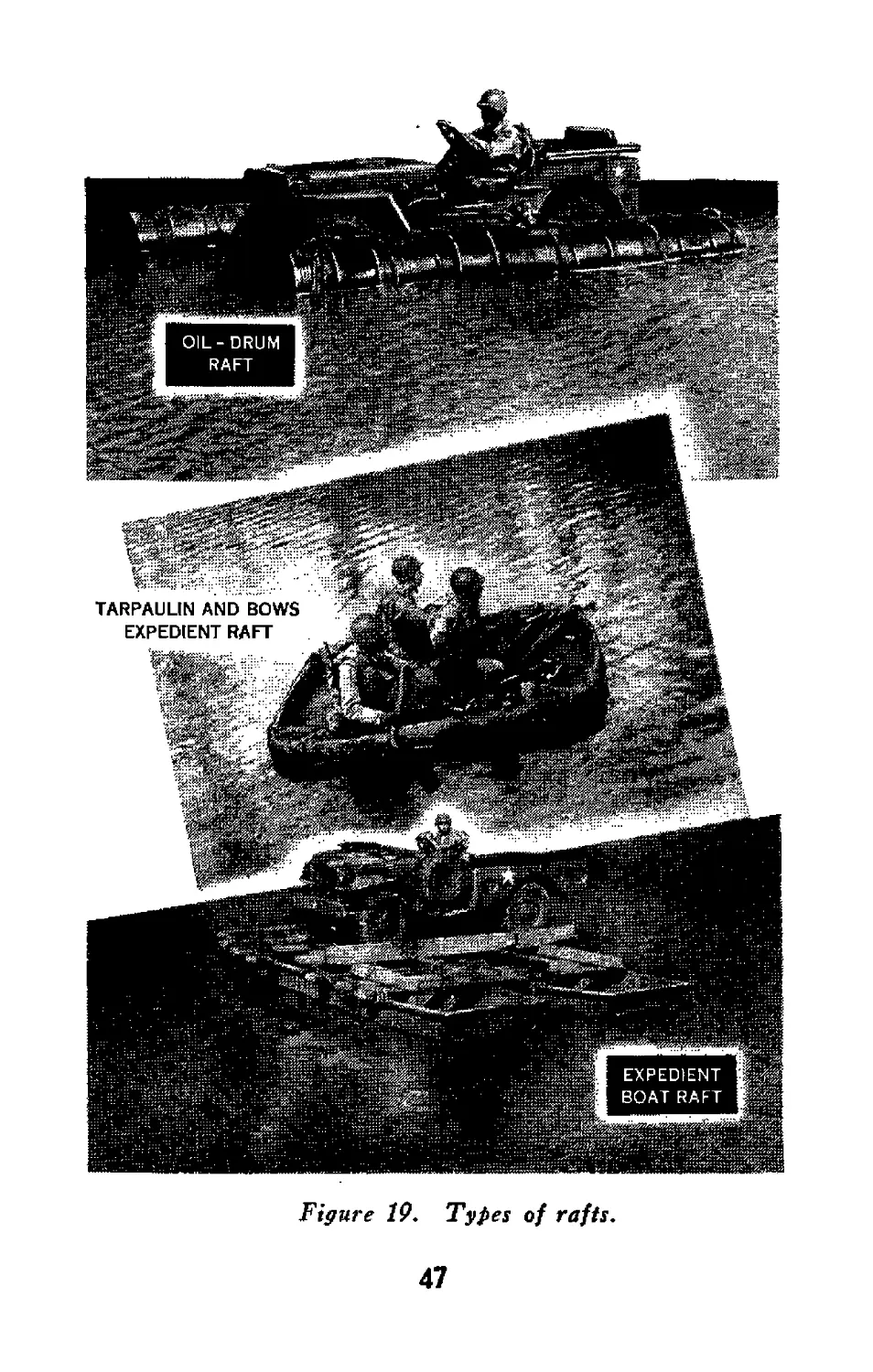
Figure 19. Types of rafts.
47
40. Rafts
The lighter vehicles may also be transported on
rafts constructed from oil drums, logs, or boats.
Rafts made from vehicle tarpaulins on a frame-
work of saplings, boards, or truck bows can be
used to transport men and light equipment.
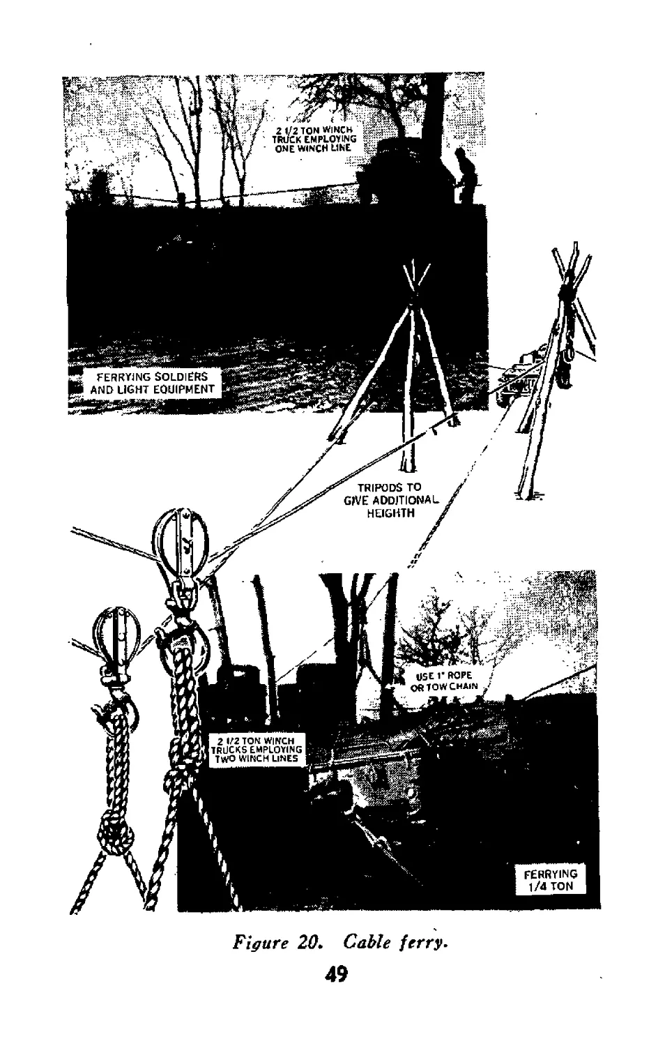
41. Cable Ferry
When the banks are steep, the water too dee-p for
fording, or the current too swift for floating, per-
sonnel and light equipment can be ferried by using
the winch cable of a vehicle. Heavier equipment
up to a %-ton truck can be ferried by using two
2%-ton truck winch cables (ch. 11, sec. IV, FM
5-10).
48
Fiffure 20. Cable ferry.
49
Section XI
BRIDGE STRENGTHENING
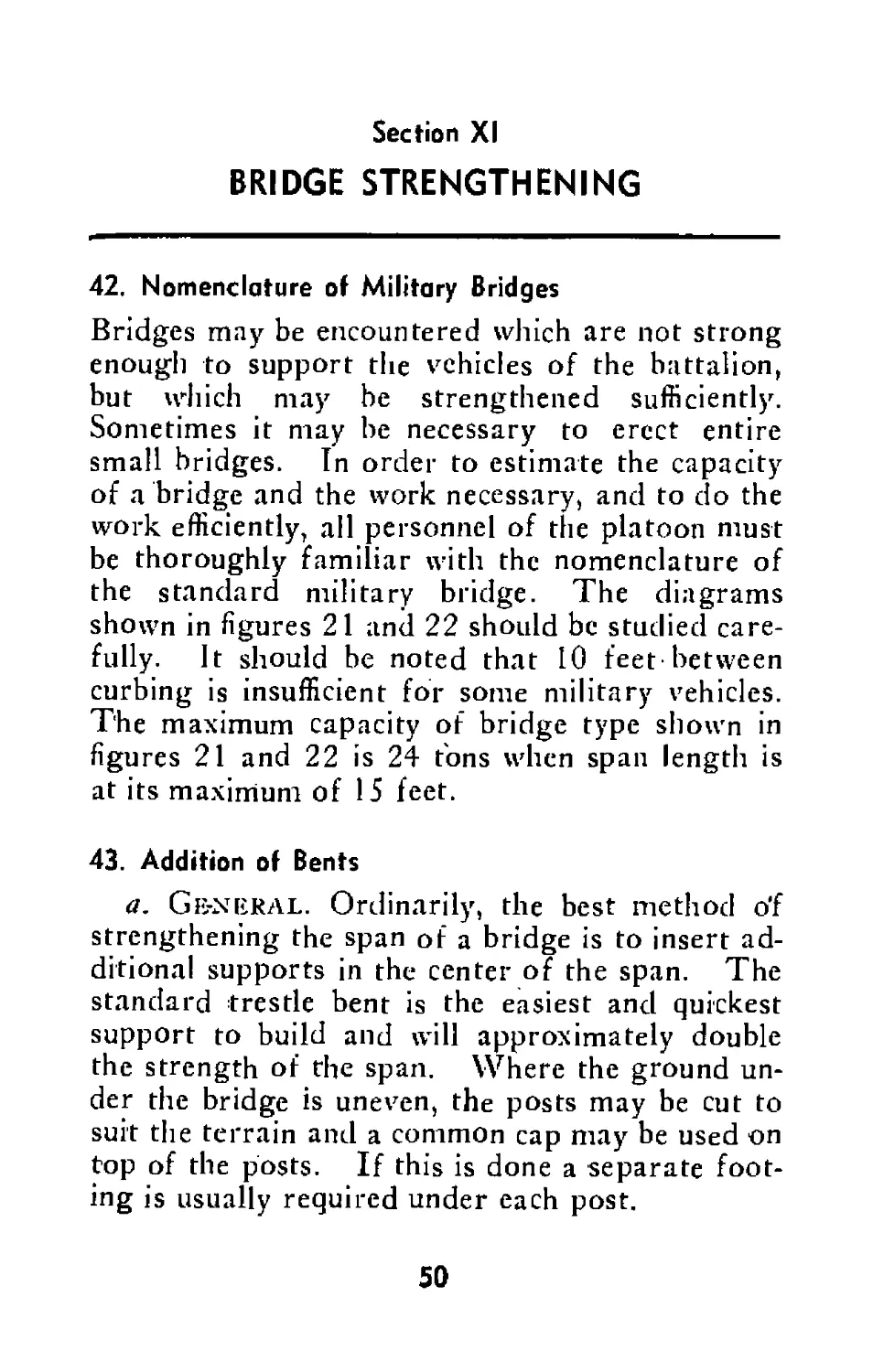
42. Nomenclature of Military Bridges
Bridges may be encountered which are not strong
enough to support the vehicles of the battalion,
but which may be strengthened sufficiently.
Sometimes it may be necessary to erect entire
small bridges. In order to estimate the capacity
of a bridge and the work necessary, and to do the
work efficiently, all personnel of the platoon must
be thoroughly familiar with the nomenclature of
the standard military bridge. The diagrams
shown in figures 21 anil 22 should be studied care-
fully. It should be noted that 10 feet between
curbing is insufficient for some military vehicles.
The maximum capacity of bridge type shown in
figures 21 and 22 is 24 tons when span length is
at its maximum of 15 feet.
43. Addition of Bents
a. Ge-NERAL. Ordinarily, the best method o'f
strengthening the span of a bridge is to insert ad-
ditional supports in the center of the span. The
standard trestle bent is the easiest and quickest
support to build and will approximately double
the strength of the span. Where the ground un-
der the bridge is uneven, the posts may be cut to
suit the terrain and a common cap may be used on
top of the posts. If this is done a separate foot-
ing is usually required under each post.
50
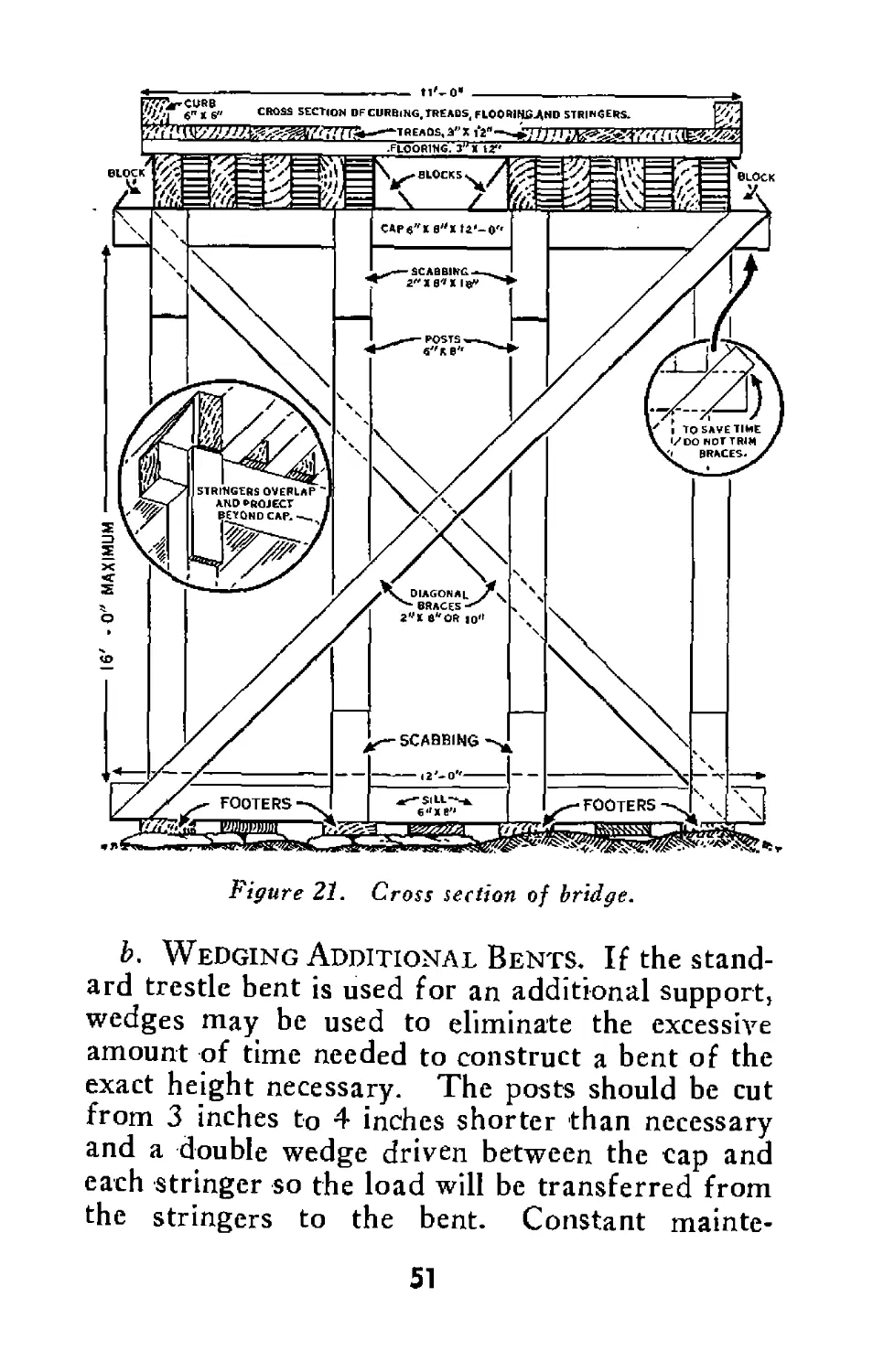
Figure 21. Cross section of bridge.
b. Wedging Additional Bents. If the stand-
ard trestle bent is used for an additional support,
wedges may be used to eliminate the excessive
amount of time needed to construct a bent of the
exact height necessary. The posts should be cut
from 3 inches to 4 inches shorter than necessary
and a double wedge driven between the cap and
each stringer so the load will be transferred from
the stringers to the bent. Constant mainte-
51
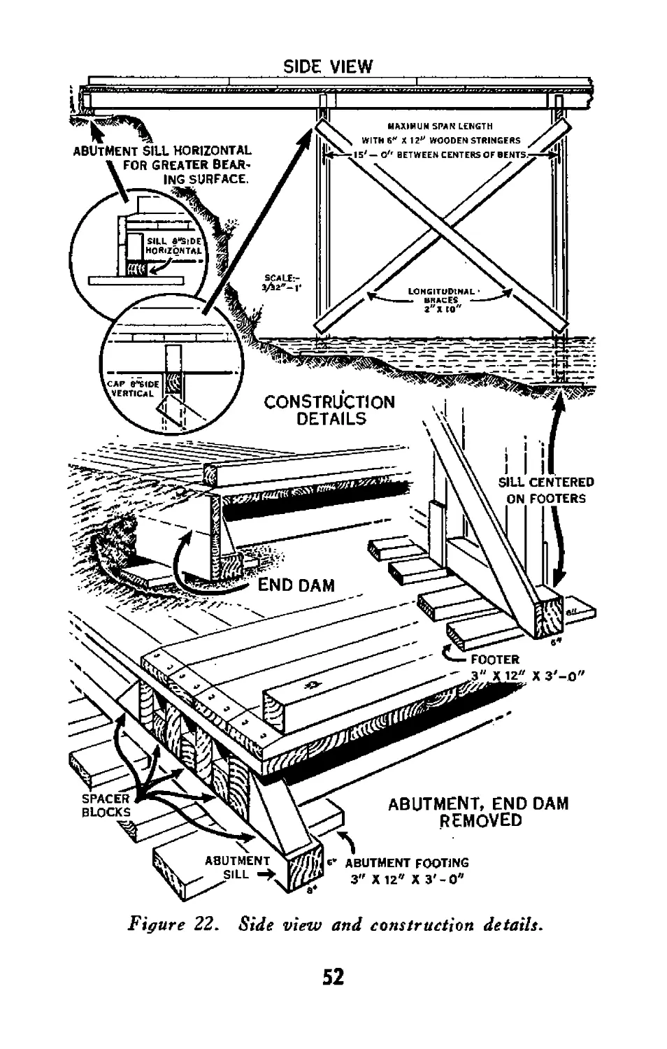
SIDE VIEW
Figure 22. Side view and construction details.
52
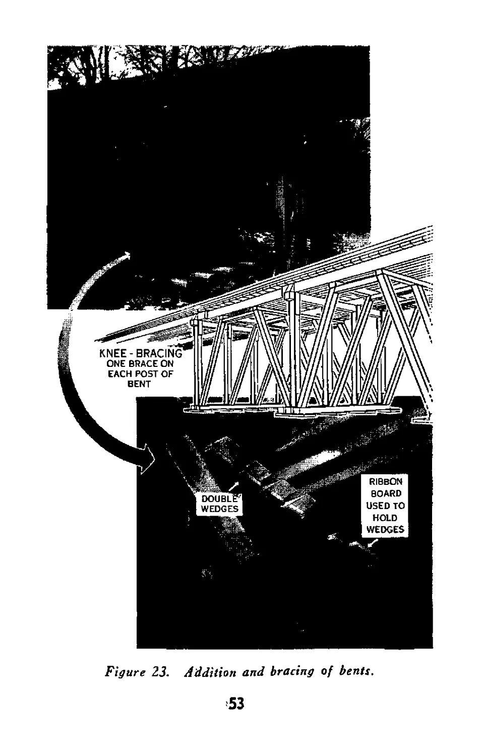
Figure 23. Addition and bracing of bents.
53
nance of these wedges will be required to keep
them bearing against the cap and stringers. A
ribbon board (figure 23) may be nailed across the
stringers to keep the wedges in place.
c. Knee Bracing. Knee bracing can be used
to add rigidity to the bridge. There should be
one brace on each post of the bent.
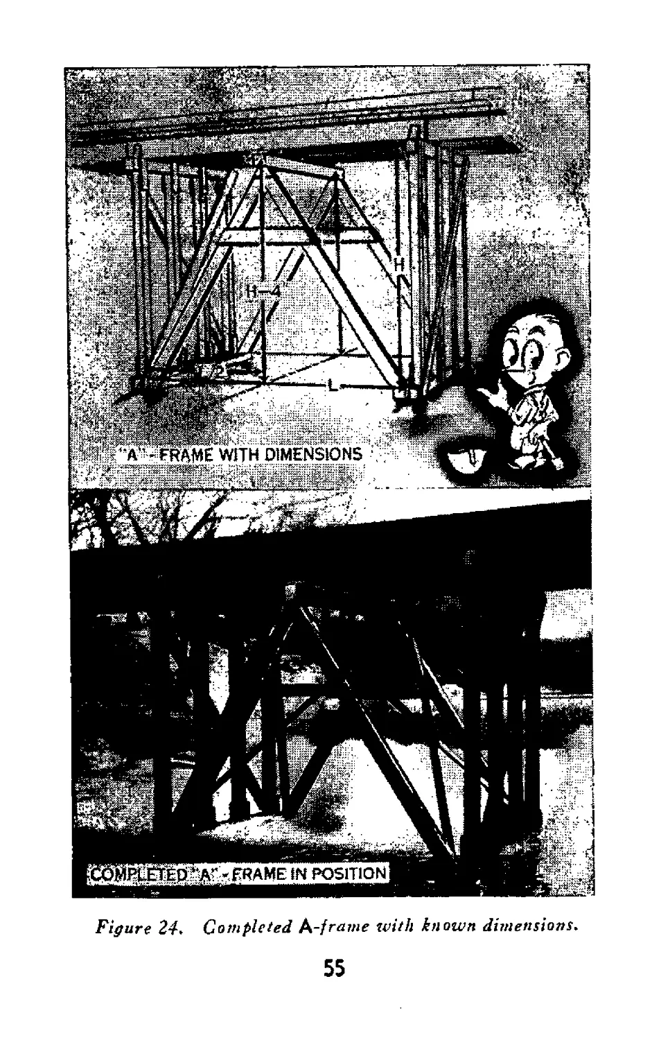
44. Construction of A-frame
a. In places where the water is too deep for
bents, the A-frame may be used to strengthen a
span. A-frames are more difficult to construct
than standard bents; however, the following dis-
cussion presents a simple method of construction
that can be used by the pioneer platoon.
b. The easiest way to lay out the length and
angles of an A-frame is by the use of a steel
square. To do this, the length of the span from
post to post (L) must be known, and the height
of the span from the sill to the stringer (H).
Four inches are subtracted from the height (77),
giving the dimensions (77-4 inch). The 4 inches
thus subtracted, together with the 4 inches that
will be cut from the apex of the assembled
A-frame to provide a flat seat for the cap (figure
26), allows 8 inches for the 6-x-8-inch cap to be
placed between the A-frame and the stringers.
c. As any two bents may be of different heights,
it may be necessary to lay out each leg of the
A-frame separately. The first step in laying out
a leg is to place the steel square on the end of the
timber which is to be the bottom of the leg, letting
54
Figure 24. Completed A-frame with known dimensions.
55
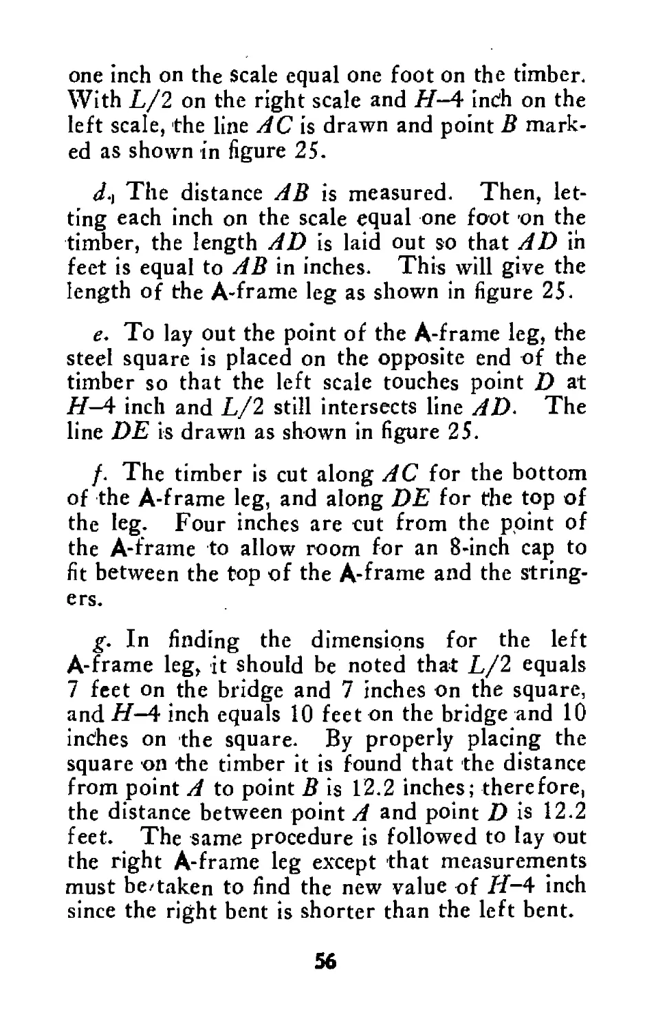
one inch on the scale equal one foot on the timber.
With L/2 on the right scale and H—4 indh on the
left scale, the line AC is drawn and point В mark-
ed as shown in figure 25.
J.) The distance AB is measured. Then, let-
ting each inch on the scale equal one foot on the
timber, the length AD is laid out so that AD in
feet is equal to AB in inches. This will give the
length of the A-frame leg as shown in figure 25.
e. To lay out the point of the A-frame leg, the
steel square is placed on the opposite end of the
timber so that the left scale touches point D at
H—4 inch and L/2 still intersects line AD. The
line DE is drawn as shown in figure 25.
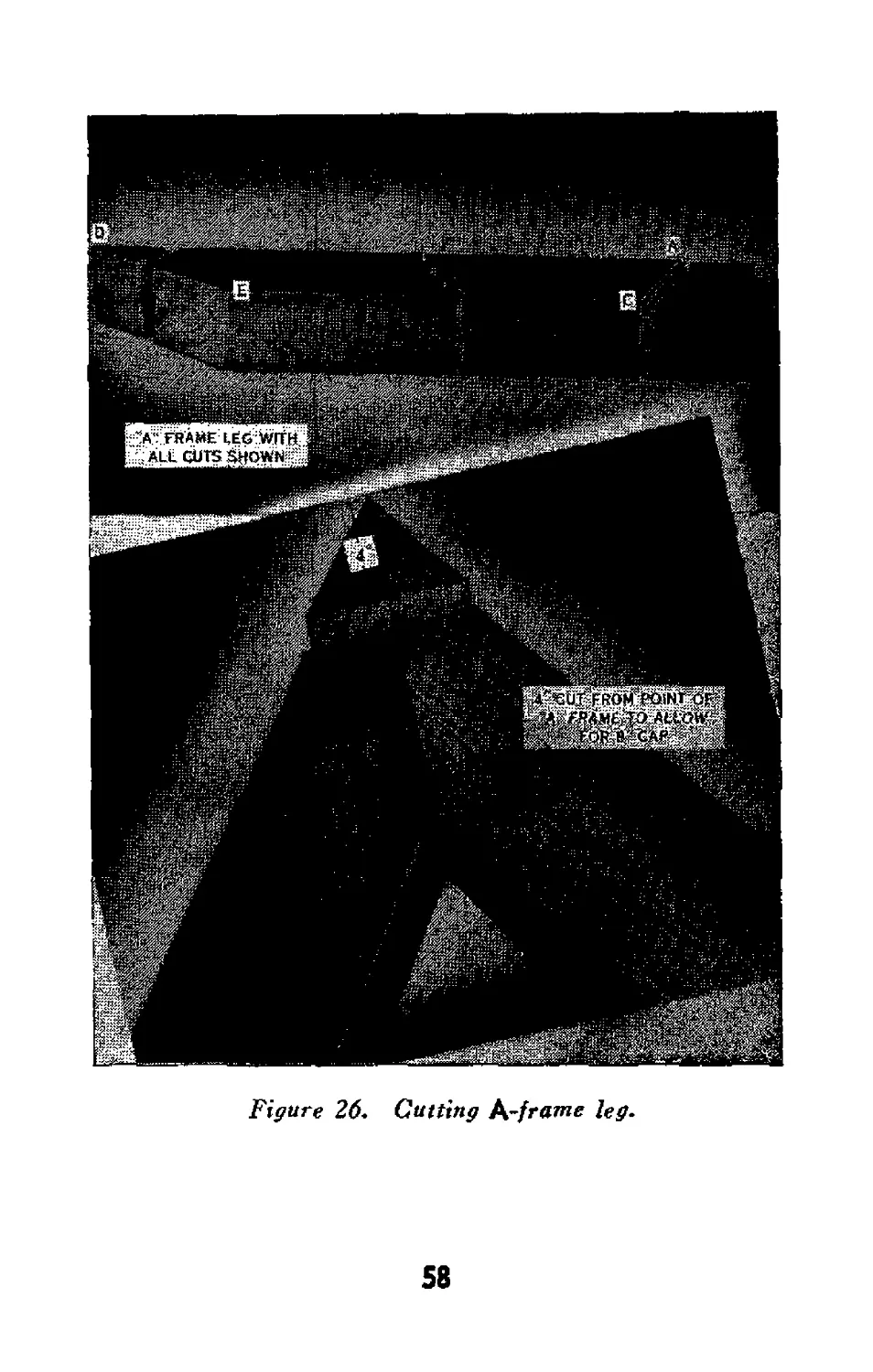
/. The timber is cut along AC for the bottom
of the A-frame leg, and along DE for the top of
the leg. Four inches are cut from the point of
the A-frame to allow room for an 8-inch cap to
fit between the top of the A-frame and the string-
ers.
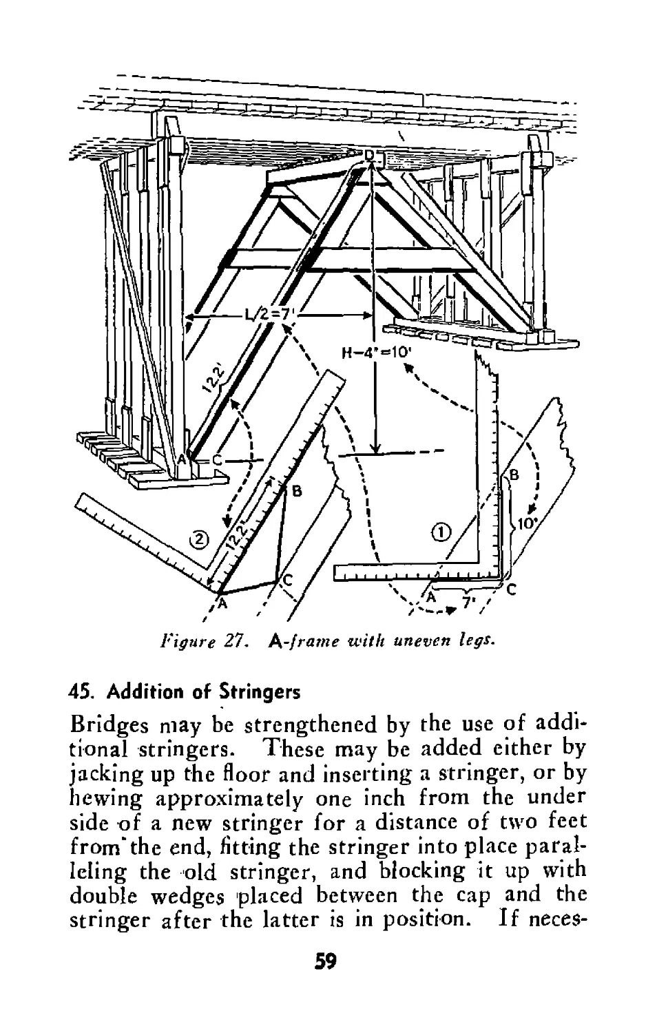
g. In finding the dimensions for the left
A-frame leg, it should be noted that L/2 equals
7 feet on the bridge and 7 inches on the square,
and H—4 inch equals 10 feet on the bridge and 10
indhes on the square. By properly placing the
square on the timber it is found that the distance
from point A to point В is 12.2 inches; therefore,
the distance between point A and point D is 12.2
feet. The same procedure is followed to lay out
the right A-frame leg except that measurements
must be/taken to find the new value of /L-4 inch
since the right bent is shorter than the left bent.
56
Figure 25. Laying out leg of K-frame.
57
Figure 26. Cutting h-frame leg.
58
Figure 27. t^-frame with uneven legs.
45. Addition of Stringers
Bridges may be strengthened by the use of addi-
tional stringers. These may be added either by
jacking up the floor and inserting a stringer, or by
hewing approximately one inch from the under
side of a new stringer for a distance of two feet
from’the end, fitting the stringer into place paral-
leling the old stringer, and blocking it up with
double wedges placed between the cap and the
stringer after the latter is in position. If neces-
59
sary, all the flooring may be removed to expedite
the placing of extra stringers.
46. Replacing Posts
It may be possible to repair broken posts by nail-
ing scabs over the breaks. If a broken post can-
not be repaired, another post is cut and slid into
place beside the broken one. To cut and place a
new post that exactly fits is a tedious job. The
posts should, therefore, be cut slightly shorter
than the required elength and tightened in place
with wedges.
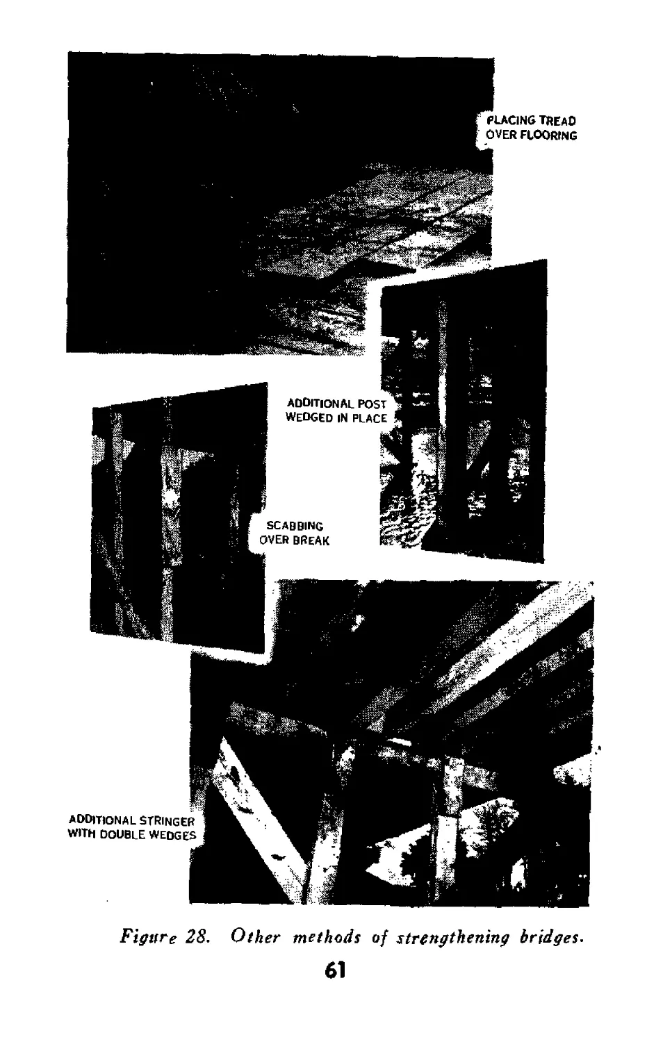
47. Other Strengthening Methods
The impact load of a bridge can be reduced and
the capacity of the span increased by smoothing
the flooring. Loose boards are nailed down and
rough spots chipped off. All broken planks are
replaced. The addition of a tread will distribute
the load on the flooring more evenly and increase
the bridge capacity. If the material is available
and if the bents are in good condition, a new set
of stringers and a new floor can be laid directly
over the old floor.
60
Figure 28. Other methods of strengthening bridges.
61
Section XII
DETERMINING CAPACITY OF BRIDGES
48. Weight of Vehicles
a. General. To be able to determine whether
or not a bridge will support the vehicles of the
battalion and the amount and kind of repairs
needed to strengthen the bridge, members of the
pioneer platoon must be thoroughly familiar with
the weights and types of the various vehicles of
the battalion.
b. Normal Weights. The following table
gives the gross weights of the battalion vehicles
with a normal load. A system of using the equiv-
alent weight of vehicles for various span lengths
of stringer-type bridges (FM 5—10) may be used
to determine passability of vehicles across bridges
having load capacity posted.
Gross weight
Vehicle with normal
load
Truck, }4-ton.......................... 3,125
Truck, 34-ton, weapons carrier or com-
mand ............................ 6,800
Truck, 1%-ton, 6 x 6, cargo, w/winch.. 10,225
Truck, 2%-ton, cargo, w/winch.......... 15,000
Compressor, air, motorized............. 13,000
Truck, heavy wrecker, w/winch__________ 37,000
Vehicle, tank, recovery............... 70,000
Car, armored, light, M8.............. 16,000
Car, armored, utility, M20........... 15,500
Carriage, motor, 90-mm gun, M36________ 63,500
62
Carriage, motor, 76-mm gun.............. 38,500
Carriage, motor, 3-inch gun............. 64,000
Carrier, personnel, half-track, М3...... 19,000
Trailer, %-ton...................—..... 1,060
Trailer, 1-ton...................... 3,300
Trailer, ammunition, M10.............—. 4,000
Gun, 3-inch, M5 and carriage, gun
3-inch, Ml........................... 5,100
Gun, 3-inch, M5 and carriage, gun
3-inch, M6......................... 5,900
c. Passage with Caution. It should be re-
membered that when the weight of a vehicle is
near the capacity of the bridge, extreme caution
must be used in crossing. Ordinarily a bridge
will carry a 25 percent overload if the following
precautions are taken: Vehicle must stay on cen-
ter line of bridge. Speed not over 5 miles per
hour. Distance between vehicles, at least 50
yards. No braking or gear shifting on bridge.
While the 25 percent overload does not apply to
floating bridges, passage with caution means the
same as on fixed bridges except that speed must
be reduced to 3 miles per hour.
49. Bridge Cords
a. General. A rapid means of determining
the capacity of bridges and the amount of repairs
needed is by the use of bridge cards. Each pio-
neer platoon leader and at least the members of
the platoon who will be sent on the reconnais-
sance missions should have copies of the bridge
cards that apply to the vehicles of the battalion.
The use of these cards should be practiced so all
members of the platoon can use them rapidly and
63
accurately. Structures must be examined for
soundness of timber and steel deterioration and
appropriate reductions in capacity made accord-
ingly. For special cases involving towed loads
see paragraph 50.
b. Bridges of more than One Lane. (1)
General rule. The bridge cards present a method
of determining the capacity of a span of one lane
only. To find the capacity of each lane of a two-
lane span, count the stringers under each lane and
solve for each lane separately. Thus, the span
may be found to have a capacity of two 10-ton
vehicles (one in each lane), but this does not mean
it will carry one 20-ton vehicle.
(2) Emergency passage. In an emergency the
capacity of a two-lane bridge may be exceeded by
observing the following procedure—count the
stringers in both lanes of the span and multiply
this number by % ; then, using this result as a total
number of stringers in a span of a 1-lane bridge,
find the capacity of the span. When this method
is used only one vehicle should be on any one span
at one time, and it must be driven along the center
line of the bridge.
c. Wheeled Vehicles and Half-Tracks.
Half-tracked vehicles can safely cross all bridges
capable of carrying wheeled vehicles of the same
weight. The following bridge cards may be used
to determine the weight of wheeled vehicles or
half-tracks which a one-lane bridge will support.
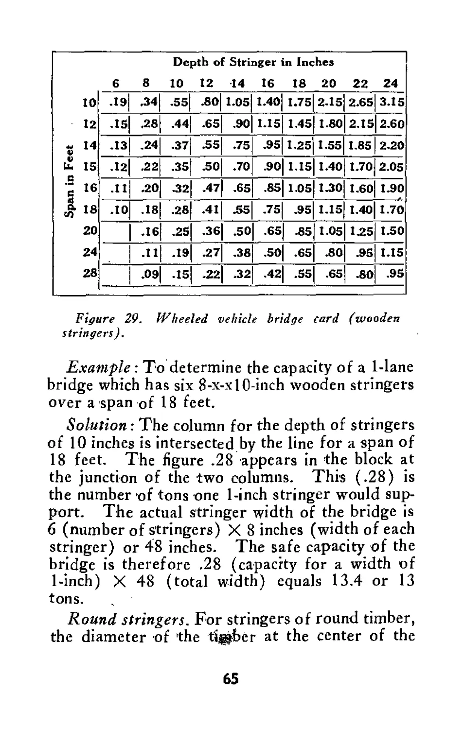
( 1) Rectangular wooden stringers with, timber
flooring. The card below shows the safe gross
load in tons for stringers one inch wide.
64
Depth of Stringer in Inches 6 8 10 12 14 16 18 20 22 24
10 12 - 14 V V U. 15 c - 16 4 °* ТЯ 20 24 28 .19 .34 .55 .80 1.05 1.40 1.75 2-15 2.65 3.15
-IS .28 .44 .65 .90 1.15 1.45 1.80 2.15 2.60
.13 .24 .37 .55 .75 .95 1.25 1.55 1.85 2-20
.12 .22 .35 .50 .70 .90 1.15 1.40 1.70 2.05
.11 .20 .32 .47 .65 .85 1.05 1.30 1.60 1.90
.10 .18 -28 .41 .55 .75 .95 1.15 1.40 1.70
.16 .25 .36 .50 .65 .85 1.05 1.25 1.50
.11 .19 .27 .38 .50 .65 .80 .95 1.15
.09 .15 .22 .32 .42 .55 .65 .80 .95
Figure 29. Wheeled vehicle bridge Card (wooden
stringers).
Example: To determine the capacity of a 1-lane
bridge which has six 8-x-xlO-inch wooden stringers
over a span of 18 feet.
Solution: The column for the depth of stringers
of 10 inches is intersected by the line for a span of
18 feet. The figure .28 appears in the block at
the junction of the two columns. This (.28) is
the number of tons one 1-inch stringer would sup-
port. The actual stringer width of the bridge is
6 (number of stringers) X 8 inches (width of each
stringer) or 48 inches. The safe capacity of the
bridge is therefore .28 (capacity for a width of
1-inch) X 48 (total width) equals 13.4 or 13
tons.
Round stringers. For stringers of round timber,
the diameter of the timber at the center of the
65
span is used as the depth, 0.4 of the diameter as
the width, and the above bridge card is applied.
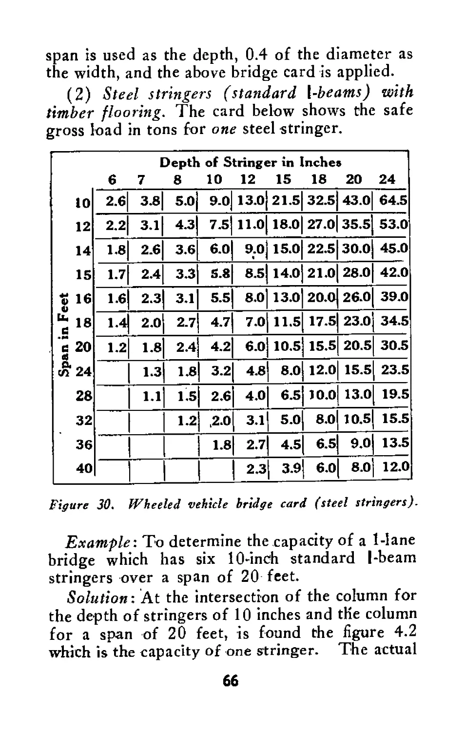
(2) Steel stringers (standard l-beams) with
timber flooring. The card below shows the safe
gross load in tons for one steel stringer.
Depth of Stringer in Inches
6 7 8 10 12 15 18 20 24
10 2.6 3.8 5.0 9.0 13.0 21.5 32.5 43.0 64.5
12 2.2 3.1 4.3 7.5 11.0 18.0 27.0 35.5 53.0
14 1.8 2.6 3.6 6.0 9.0 15.0 22.5 30.0 45.0
15 1.7 2.4 3.3 5.8 8.5 14.0 21.0 28.0 42.0
t 16 и 1.6 2.3 3.1 5.5 8.0 13.0 20.0 26.0 39.0
*18 1.4 2.0 2.7 4.7 7.0 11.5 17.5 23.0 34.5
20 4 1.2 1.8 2.4 4.2 6.0 10.5 15.5 20.5 30.5
& «24 1.3 1.8 3.2 4.8 8.0 12.0 15.5 23.5
28 1.1 1'5 2.6 4.0 6.5 10.0 13.0 19.5
32 1.2 ,2.0 3.1 5.0 8.0 10.5 15.5
36 1.8 2.7 4.5 6.5 9.0 13.5
40 2.3 3.9 6.0 8.0 12.0
Figure 30. Wheeled vehicle bridge card (steel stringers).
Example'. To determine the capacity of a 1-lane
bridge which has six 10-inch standard I-beam
stringers over a span of 20 feet.
Solution-. At the intersection of the column for
the depth of stringers of 10 inches and the column
for a span of 20 feet, is found the figure 4.2
which is the capacity of one stringer. The actual
66
number of stringers is 6; therefore, the safe ca-
pacity of the bridge is 6 X 4.2 equals 25.2 or 25
tons.
Railroad rails. Standard railroad rails should
be considered as 6-inch I-beams.
d. Data used for Computing Wheeled Ve-
hicle Bridge Cards. Safe unit bending stresses
—2,100 p.s.i. for wood, 24,000 p.s.i. for steel.
(For'other data see FM 5-10.)
e. 3-iNcii Gun Motor Carriage. The fol-
lowing bridge cards may be used to determine the
stringer requirements to carry the 3-inch gun mo-
tor carriage, M10, (weight 64,000 pounds) on a
1-lane bridge. They may also be used for the
tank recovery vehicle.
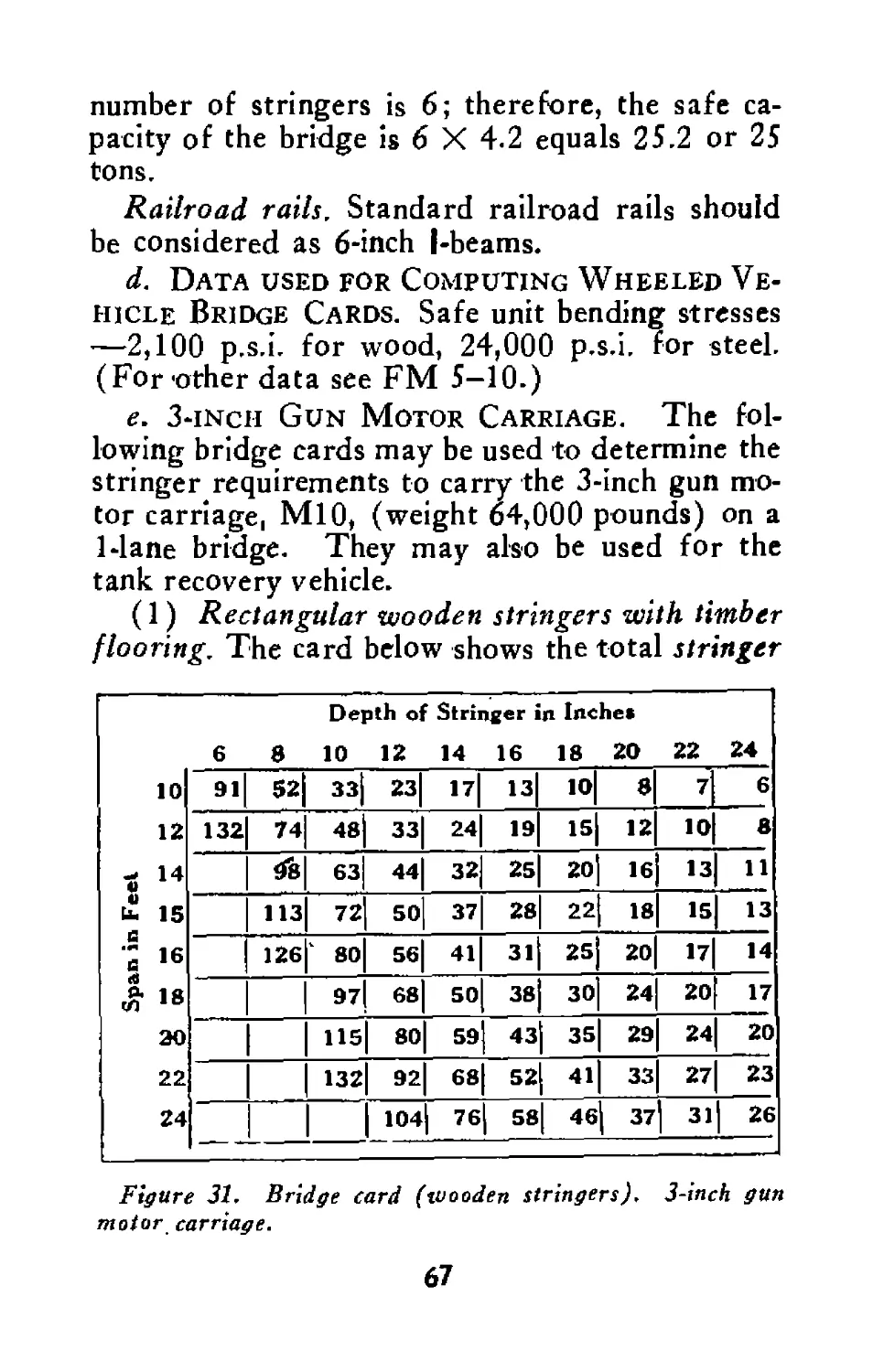
(1) Rectangular wooden stringers with- timber
flooring. The card below shows the total stringer
Depth of Stringer in Inches
6 8 10 12 14 16 18 20 22 24
10 91 52 33 23| 17 13 10 8 7 6
12 132 74 48 зз| 24 19 15 12 10 8
t 14 <8 63 44| 32 25 20 16 13 И
15 113 72 so] 37 28 22 18 15 13
•; 16 126 ‘ 80 5б| 41 31 25 20 17 14
#18 97 68] 50 38 30 24 20 17
20 115 80| 59 43 35 29 24 20
22 132 92| 68 52 41 33 27 23
24 104| 76 58 | 46 37 31 26
Figure 31. Bridge card (wooden stringers). 3-inch gun
motor carriage.
67
width in inches required to carry the 3-inch gun
motor carriage, or the tank recovery vehicle.
Example: A 1-lane bridge has six б-х-12-inch
wooden stringers over a span of 14 feet. Will it
carry the 3-inch gun motor carriage?
Solution: At the intersection of the column for
the depth of stringers of 12 inches and the column
for a span of 14 feet is found the figure 44 which
is the total stringer width in inches required.
The actual stringer width is 6 (number of string-
ers) X 6 inches (width of each stringer) equals
36 inches total width. Therefore, the bridge will
not carry the vehicle. (To strengthen the bridge,
two stringers are added or the span is shortened
by adding a trestle bent or A-frame.)
Round stringers. For stringers of round timber,
the diameter of the timber at the center of the
span is considered as the depth, 0.4 of the diame-
ter as the width, and the above card is applied.
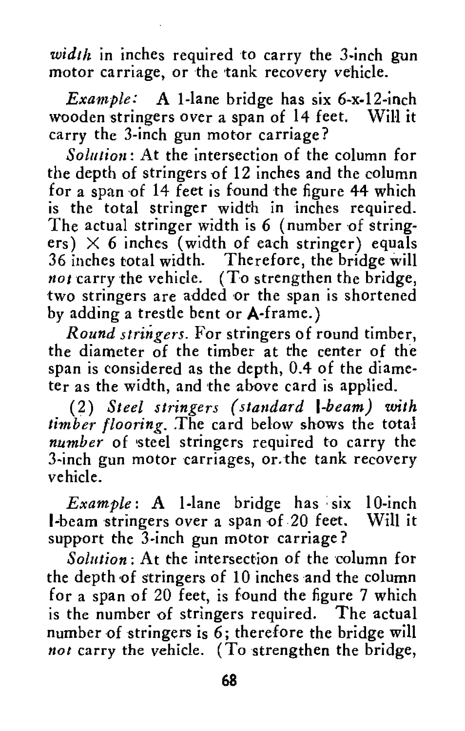
(2) Steel stringers (standard \-beam) with
timber flooring. The card below shows the total
number of 'steel stringers required to carry the
3-inch gun motor carriages, or. the tank recovery
vehicle.
Example: A 1-lane bridge has six 10-inch
I-beam stringers over a span of 20 feet. Will it
support the 3-inch gun motor carriage?
Solution; At the intersection of the column for
the depth of stringers of 10 inches and the column
for a span of 20 feet, is found the figure 7 which
is the number of stringers required. The actual
number of stringers is 6; therefore the bridge will
not carry the vehicle. (To strengthen the bridge,
68
Depth of Stringer in Inches 6 8 10 12 14 16 18 20 24
10 12 14 IS о 16 и g 18 c 20 «24 28 32 36 40 S 3 2 2
8 4 3 2 2
10 6 4 3 2 2
11 7 4 3 2 2
13 7 S 3 3 2 2
16 9 6 4 3 2 2
19 10 7 S 4 3 2
14 9 6 S 4 3 2 2
17 11 8 6 4 3 3 2
20 13 9 7 S 4 3 2
IS 10 8 6 5 4 3
17 12 9 7 5 4 3
Figure 32. Bridge card (steel stringers). 3-inch gun
motor carriage.
one stringer is added or the span is shortened by
adding a trestle bent or A-frame.)
Railroad rails. Standard railroad rails are con-
sidered as 6-inch I-beams.
/. 76-mm Gun Motor Carriage. The fol-
lowing bridge cards may be used to determine the
stringer requirements to carry the 76-mm gun mo-
tor carriage (weight 38,500 pounds) on a 1-lane
bridge.
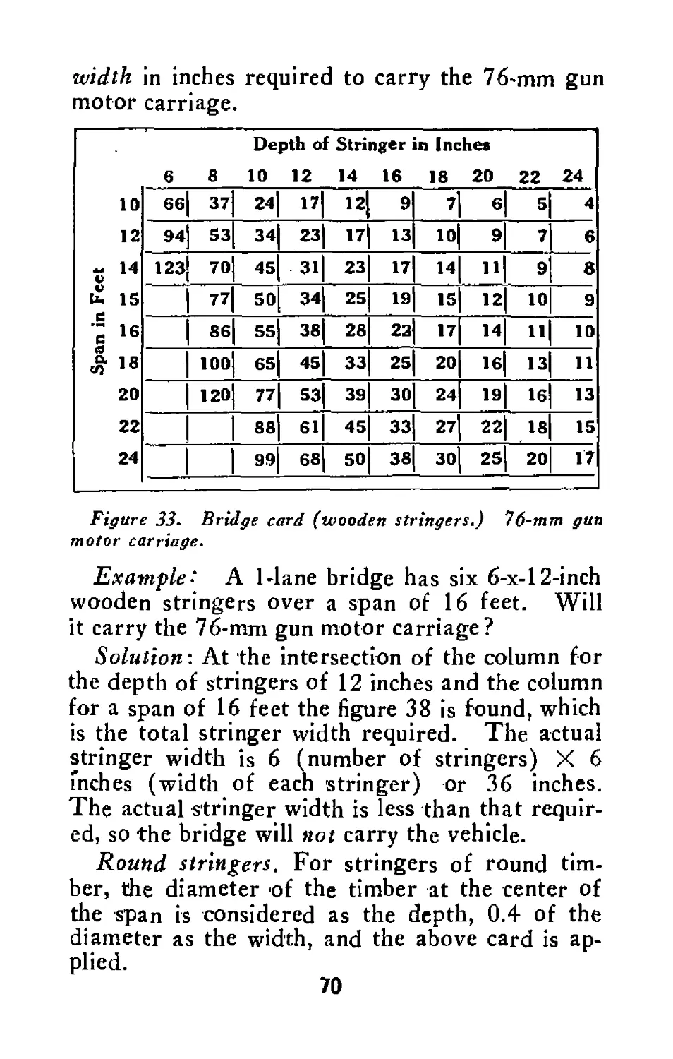
(1) Rectangular wooden stringers with timber
flooring. The card below shows the total string er
69
width in inches required to carry the 76-mm gun
motor carriage.
Depth of Stringer in Inches 6 8 10 12 14 16 18 20 22 24
10 12 ~ 14 V £ 15 e s 16 (9 °* 1 8 10 20 22 24 66 37 24 17 12 9 7 6 5 4
94 S3 34 23 17 13 10 9 7 6
123 70 45 31 23 17 14 11 9 8
77 50 34 25 19 15 12 10 9
86 55 38 28 23 17 14 11 10
100 65 45 33 25 20 16 13 11
120 77 53 39 30 24 19 16 13
88 61 45 33 27 22 18 15
99 68 50 38 30 25 20 17
Figure 33. Bridge card (wooden stringers.) 76-mm gun
motor carriage.
Example: A 1-lane bridge has six б-х-12-inch
wooden stringers over a span of 16 feet. Will
it carry the 76-mm gun motor carriage?
Solution- At the intersection of the column for
the depth of stringers of 12 inches and the column
for a span of 16 feet the figure 38 is found, which
is the total stringer width required. The actual
stringer width is 6 (number of stringers) X 6
inches (width of each stringer) or 36 inches.
The actual stringer width is less than that requir-
ed, so the bridge will not carry the vehicle.
Round stringers. For stringers of round tim-
ber, the diameter of the timber at the center of
the span is considered as the depth, 0.4 of the
diameter as the width, and the above card is ap-
plied.
70
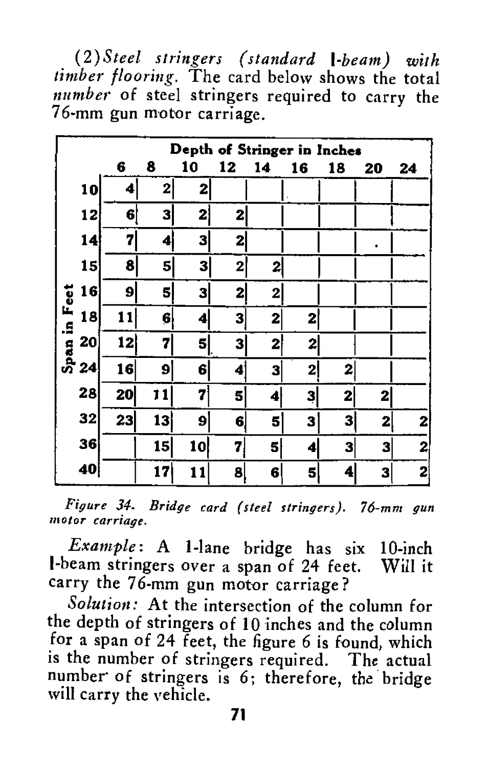
(2)Steel stringers (standard l-beam) with
timber flooring. The card below shows the total
number of steel stringers required to carry the
Figure 34. Bridge card (steel stringers). 76-mm gun
motor carriage.
Example-. A 1-lane bridge has six 10-inch
I-beam stringers over a span of 24 feet. Will it
carry the 76-mm gun motor carriage?
Solution: At the intersection of the column for
the depth of stringers of 10 inches and the column
for a span of 24 feet, the figure 6 is found, which
is the number of stringers required. The actual
number of stringers is 6; therefore, the bridge
will carry the vehicle.
71
Railroad rails. Standard railroad rails are con-
sidered as 6-inch I-beams.
g. Data Used for Computing 3-inch and
76-mm Gun Motor Carriage Bridge Cards.
Safe unit bending stresses—2,100 p.s.i for wood,
24,000 p.s.i. for steel; stringer efficiency 80 per-
cent; impact 25 percent; dead load of 220 pounds
per foot (weight of stringers neglected).
50. Towed Loads
a. General. In calculating the ability of a
bridge to carry a towed load, two factors must be
considered:
(1) The weight of each part of the load, that
is, the weight of the towing vehicle and of the
towed vehicle.
(2) The length of the two parts of the load
in relation to the length of the span of the bridge.
b. Short Spans. If the span of the bridge is
short enough so that only One part of the load is
over the span at one time, each part of the load
may be considered as a separate vehicle.
c. Long Spans. When the span of the bridge
is long enough so that both parts of the load will
be on it at the same time, two rules apply:
(1) Vehicles loaded to rated capacity. The
total weight consists of the weight of the heavier
vehicle plus One-half the weight of the lighter ve-
hicle. This principle applies because the two
parts of the load will not be on the same spot at
the same time.
(2) Vehicles overloaded. The combined
weight of both vehicles should be Considered as
the load on the span.
72
Section XIII
DECEPTIVE MEASURES
51. General
a. Deceptive measures are frequently used in
combat to mislead the enemy and to cause him to
dissipate his fire. For example: chains, brush, or
other improvised drags may be pulled behind ve-
hicles to create a dust cloud resembling the move-
ment of a large column. Bivouac areas may be
simulated by creating tracks and signs of activity
normally associated with such areas. Dummy
installations and decoy positions may be con-
structed.
b. In the employment of deceptive measures it
must be remembered that the enemy is smart.
The positions must be logical, they must be con-
stantly maintained, and the construction should
be simple. The success of the work will depend
on the resourcefulness and ingenuity of the men
and their ability to use the materials available.
52. Dummy Gun Positions
One of the most effective deceptive measures is
the dummy gun position. To construct such a
position a log may be used to simulate the tube
of a gun. The tracks, blast marks, and other
signs of activity characteristic of a gun position
should be created. The dummy should be placed
in a logical firing position and should be partially
concealed, leaving only those tracks and signs of
activity which usually disclose ‘position. It must
73
Figure 35. Deception as to size of moving column.
be remembered that it is not the indivdual decoy
but the activity and characteristics of an actual
position that will deceive the enemy.
53. Fougasse
Dummy gun positions may be made more realistic
by simulating muzzle blast through the use of a
fougasse. A fougasse that creates a fake muzzle
blast similar to that of a 3-inch gun may be con-
structed by the use of two pounds of TNT to
give a sound and flash similar to the gun firing
and an additional % pound of TNT to blow dust
out of a hole in the ground to give the effect of
the muzzle blast. A fougasse is most effective
if it is located in a logical gun position and should
be fired while actual guns are firing.
Figure 36. Dummy gun.
75
Figure 37. Dummy gun positions and fougasses.
76
Section XIV
MINE REMOVAL
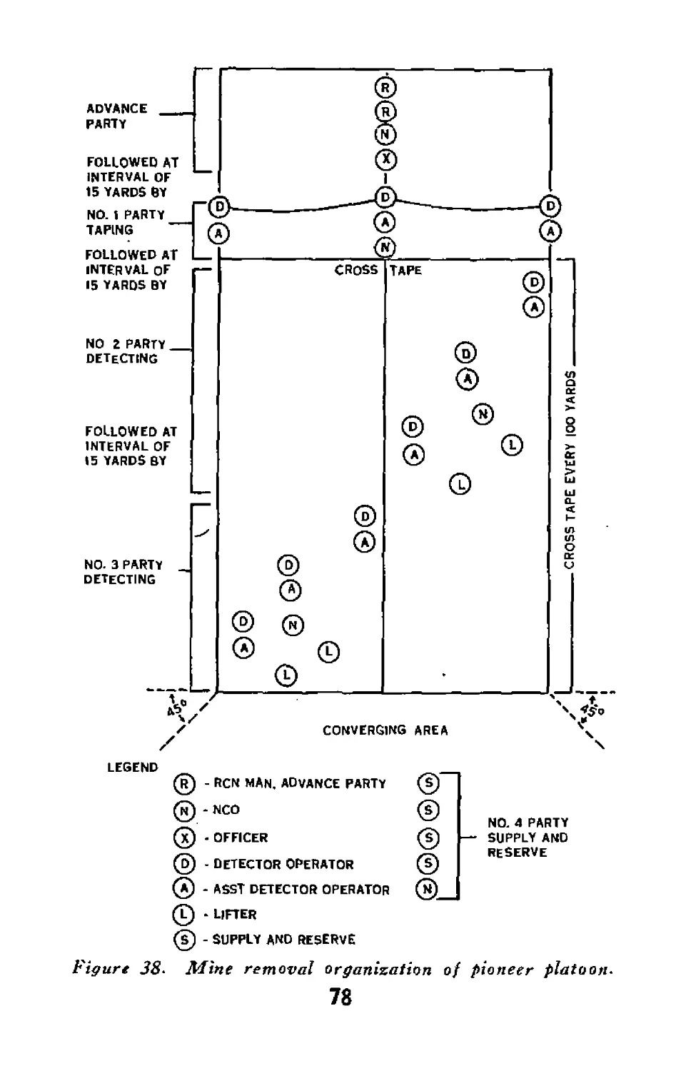
54. Orgonizotion
a. When mines are encountered the pioneer
platoon usually will be charged with breaching
mine fields or removing scattered mines. How-
ever, it must be prepared to lift entire mine fields.
These operations must be done rapidly and always
with great care or excessive casualties will result.
Therefore, all personnel must be organized and
thoroughly trained and drilled in mine removal to
further the rapid movement of the battalion.
b. The basic principles of mine field removal
organization are contained in FM 5-31. The
pioneer platoon, however, does not have as large
an organization as is shown. Figures 38 and 39
outline an organization which is readily adapted
for use by the pioneer platoon.
c. The breaching party is organized as follows:
Officer NCO Men
Advance party............................ 112
No. 1 party—taping............. 16
No. 2 party—detecting.......... 1 . 8
No. 3 party—detecting..,. .. 1 8
No. 4 party—reserve & supply ..14
1 5 28
Party duties. (1) The advau^party indicates
to the taping party the locatiorvof the starting
tape and lays out the direction of the center tape
77
FOLLOWED AT
INTERVAL OF
15 YARDS BY
NO. 3 PARTY
DETECTING
NO Z PARTY
DETECTING
FOLLOWED AT
INTERVAL OF
15 YARDS BY
FOLLOWED AT
INTERVAL OF
15 YARDS BY
ADVANCE
PARTY
NO. 1 PARTY
TAPING
CONVERGING
NO. 4 PARTY
SUPPLY AND
RESERVE
CROSS
CROSS TAPE EVERY |OO YARDS
LEGEND
® - RCN MAN. ADVANCE PARTY
® *NCO
® - OFFICER
© - DETECTOR OPERATOR
@ - ASST DETECTOR OPERATOR
© * lifter
@ - supply and reserve
Figure 38* Mine removal organization of pioneer platoon*
78
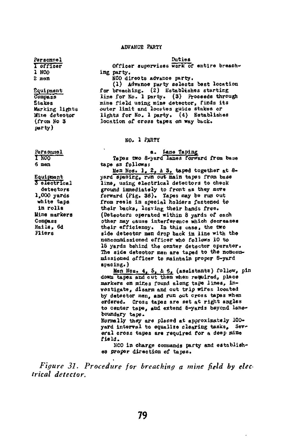
ADVANCE PARTY
Personnel
1 officer
1 NCO
2 men
Equipment
Compass
Stakes
Marking lights
Mine detector
(from No 3
party)
Personnel
I Yeo
6 men
Equipment
S electrical
detectors
1,000 yards
white tape
in rolls
Hine markers
Compass
Nails, 6d
Fliers
Duties
Officer supervises work’of entire breach-
ing party.
NCO directs advance party.
(1) Advance party selects best location
for breaching. (2) Establishes starting
line for No. 1 party» (3) Proceeds through
mine field using mine detector, finds its
outer limit and locates guide stakes cr
lights for No. 1 party, (4) Establishes
location of cross tapes on way back.
NO# 1 PARTY
a. lane Taping
Tepes two 8-yard lanes forward from baae
tape as followsi
Men Nos, 1, 2, & 3, taped together at fi-
yard spacing, run out main tapes from base
line, using electrical detectors to check
ground immediately to front as they move
forward (Fig, 3$), Tapes may be run out
from reels in special holders fastened io
their backs, leaving their hands free.
(Detectors operated within в yards of each
other may cause interference which decreases
their efficiency. Io this case, the two
side detector men drop back in line with the
noncommissioned officer who follows 10 to
lb yards behind the center detector operator.
The side detector men are taped to the noncom-
missioned officer to maintain proper 5-yard
spacing.)
Men Nos. 4, 5, 1 6, (assistants) follow, pin
down tapes and cut them when required, place
markers on mires found along tape lines, in-
vestigate, disarm and cut trip wires located
by detector men, and run out cross tapes when
ordered. Cross tapes are set at right angles
to center tape, and extend Б-yards beyond lane*
boundary tape.
Normally they are placed at approximately 100*
yard interval to equalise clearing tasks. Sev-
eral cross tapes are required for a deep mine
field.
NCO in charge commands party and establish-
es proper direction of tapes.
Figure 31. Procedure for breaching a mine field by elec-
trical detector.
79
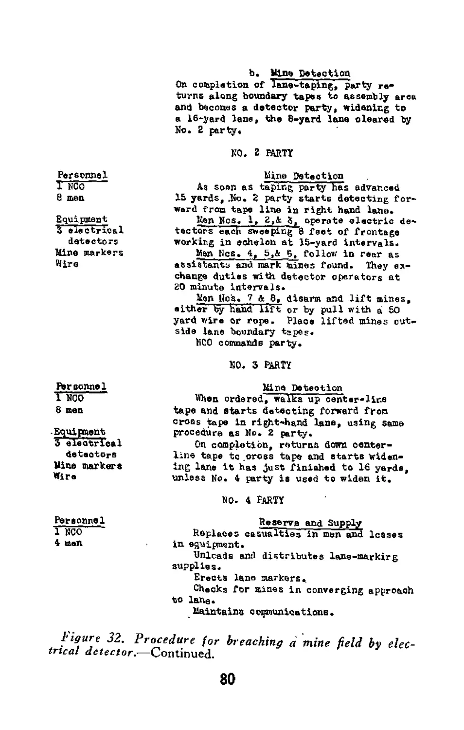
b. Min» De te cti on
On completion of 1 an»* t a ping, ”par ty re-
turns along boundary tapes to assembly area
and becomes a detector party, widening to
a 16-yard lane, the 8-yard lane cleared by
No. 2 party.
NO. 2 PARTY
Personnel
I NCO
8 men
Equipment
electrical
detectorc
Mine markers
Wire
ftrsonnol
Tnco
8 men
-Equipment
3^ electrical
detectors
Mine markers
Wire
Personnel
1 NCO
4 men
Mine Detection
As soon as taping party has advanced
15 yards, .No* 2 party starte detecting for-
ward from tape line in right hand lane.
Uen Nos. 1, 3_>&_j5, operate electric de*
tectors each sweeping"8 feet of frontage
working in echelon at 15-yard intervals.
Men Res. 4, follow in rear as
assistants and mark mines found. They ex-
change duties with detector operators at
20 minute intervals*
Mon Nojs. 7 & 8, disarm and lift mines,
either ty hand' lift or by pull with a So
yard wire or rope. Place lifted mines cut-
side lane boundary tapes.
NCO commande party.
NO. 3 PARTY
Mine Detection
Wen ordered, walks up center-lire
tape and starts detecting forward from
cross tape in right-hand lane, using same
procedure as No. 2 party.
On completion, returns down center-
line tape tc .oross tape and starts widen-
ing lane it has just finished to Id yards,
unless No. 4 party is used to widen it.
no. 4 party
Reserve and Supply
Replaces casualties irf men and leases
in equipment.
Unloads and distributes lane-markirg
supplies.
Erects lane markers.
Checks for mines in converging approach
to lane.
Maintains communications.
figure 32. Procedure for breaching a mine field by elec-
trical detector.—Continued.
80
by magnetic azimuth. This detail also locates
all cross tapes.
(2) No. 1 party, using tape, marks out two
8-yard lanes from the base tape. It becomes a
detector party on completion of lane taping. •
(3) No. 2 and No. 3 parties each clear a single
8-yard lane.
(4) No. 4 party is in reserve and assembles
supplies.
55. Location of Mines
The mine removal organization uses the mine de-
tector to locate individual mines. If mine detec-
tors are not available or are out of order, the
hand search method is employed. Definite or-
ganizations for this method will be found in FM
5-31 and may be varied for use by the pioneer
platoon. In the event that non-metallic mines
have been buried in the mine field, a probe must
be used to locate them. The probing should be
done gently and at an angle of 45 degrees, being
certain to cover every six inches of ground.
56. Removal of Mines
A simple method of mine removal is to pull them
out by means of ropes. When the mines are lo-
cated, the removers attach short lead ropes to the
handle, fuze, or cover of each mine. The short
lead ropes are then attached to a main rope so
that several mines may be pulled at once. Lead
ropes should be of such length that when main
rope is pulled the most distant mines will be pulled
first, followed successively by those toward the
pullers. This method prevents cutting of ropes
81
Figure 40. Locating and retnavinfi mines.
82
leading to more distant mines by the explosion of
mines closer in. Care should be taken to allow
sufficient slack in each lead rope so no mines will
be actuated while the ropes are being attached.
The main rope should be at least 150 feet long
so that the mines may be pulled from a safe dis-
tance either by hand from a sandbagged prone
shelter or other suitable cover, or by tying the
rope to an armored vehicle.
83
Section XV
BOMB AND ARTILLERY DUD DISPOSAL
57. General
a. Unexploded shells or aerial bombs may be
found in areas occupied or to be occupied by the
battalion or on routes where they cannot be de-
toured. When possible, the bombs, or shells will
be left undisturbed. When a possible time bomb
is located in a position which cannot be detoured,
the bomb is marked and a safe area of 300 yards in
diameter designated. No personnel or vehicles
will enter the area until the bomb is disposed of.
b. If necessary, shells and bombs may be de-
stroyed in place by the pioneer platoon. All ve-
hicles and personnel will be moved to cover, or,
if no cover is available, to a distance of at least
500 yards from the dud. One man will then
place a small explosive charge against the dud,
being careful not to move or disturb the projectile
in any way.
58. Explosives Needed
The amounts of explosives necessary to destroy
various sizes of artillery shells are given below.
The same figures can be applied to the destruction
of bombs or mortar shells by comparing the diam-
eter of the dud with that of the artillery shell and
using the corresponding amount of explosive.
Pounds of
Caliber of Shell TNT
37-nun, 2.24-inch.......................................... 1
75-mm, 2.95-inch, 3-inch.................................... 1
155-mm, 4.7-inch, 6-inch..................................... 2
244-mm, 8-inch, 9.2-inch.....‘............................... 2
10-inch, 12-inch........................................... 3
14-inch, 16-inch........................................... 3
84
Figure 41. Placing charge to destroy dud shell.
Note. Three j4-pound blocks of TNT are shown. If
1-pound blocks are issued, use two.
85
Section XVI
ESTIMATION OF DEMOLITION CHARGES
59. General
a. The pioneer platoon may be called on to ex-
ecute demolitions. These projects .will vary be-
cause of the material, structure, weather condi-
tions, and similar factors; therefore it is not pos-
sible to provide a set of rules that will cover all
possible conditions. Any rules may be considered
as guides and should be tempered by the results of
test shots, past demolition experience, and existing
conditions.
b. While formulas (FM 5-25) are used to de-
termine accurately the amount of explosive neces-
sary to accomplish demolition tasks, it is not in-
tended for the pioneer platoon to execute large
scale demolitions. For this reason simple rules
that can be easily remembered and applied are
better suited to pioneer platoon work even though
somewhat excessive amounts of explosion may be
used in some instances. The following para-
graphs present some general information on de-
molitions relative to tasks that the platoon will
normally perform. It supplements the elemen-
tary principles on the use of explosives in FM
21-105. For information on more extensive de-
molition tasks, see FM 5—25.
c. When TNT is issued in 1-pound blocks in-
stead of %-pound blocks they can be sawed in
half and used according to figure 42 and the rules
given below. If the 1-pound blocks can be made
86
up into a charge of approximately the same di-
mensions as that required when using %-pound
blocks, the 1-pound blocks can be used without
cutting.
60. Steel
To cut steel members by the use of explosives the
most important principle to remember is that the
explosive charges must be held in close contact
with each other and with the steel to be cut. The
amounts of explosive required to cut the various
shapes of steel can be determined roughly by the
simple rules outlined below—
(1) Rods. One pound of explosive is used for
each inch of diameter. This rule applies for rods
up to four inches in diameter.
(2) Small rectangular bars. One pound of ex-
plosive is used for each inch of thickness and each
two inches of width of the widest side of the bar.
The explosive is placed on the wide side. For
example, a bar 1 inch x 4 inches x 10 feet requires
two pounds of explosives placed on the 4-inch side.
(3) Small built-up box girders. The inside
portion of the girder is filled with a tier of explo-
sives.
(4) \-beams. One side of the I-beam is filled
between the flanges with a tier of explosives.
61. Timber
The amount of explosive necessary to cut timber
is obtained by using the formula—
P — D~
40
87
Figure 42. Cutting steel members with explosives.
Note. This figure shows use of %-pound blocks of TNT.
When TNT is issued in 1-pound blocks they may be sawed
in half and made up in charges as illustrated above.
88
P equals the number of 1-pound blocks of TNT.
D equals the diameter of round timbers or the
smallest dimension of rectangular timber in
inches.
(1) Example: How many 1-pound blocks of
TNT are required to cut a log 10 inches in diam-
eter?
(2) Solution: P = 12 X 12 = 3.6pounds.
40 (Use four 1-
pound blocks
of TNT.)
62. Concrete
The amount of explosive necessary to destroy one
reinforced concrete stringer in a span of a rein-
forced concrete bridge is obtained by using the
formula:
P = 3H2T
P equals the number of 1-pound blocks of
TNT.
H equals the height in feet. Minimum
T equals the thickness in value of one
feet. (1) foot.
(1) Example: How many 1-pound blocks of
TNT are required to destroy a reinforced con-
crete stringer 2 feet high and 10 inches thick?
(2) Solution: P —3X2X2X1 = 12 (twelve
1-pound
blocks
of
TNT)
89
90
63. Craters
a. To form a crater in a road, holes are dug in
a line across the road extending to natural bar-
riers on both sides. The holes should be 5 feet
apart from center to center. The charge neces-
sarily will vary with the condition of the ground;
a normal charge is 10 pounds of explosive per
foot of depth in each hole. For example, 50
pounds of explosive will be placed in the bottom
of a hole 5 feet deep.
b. The explosive should be tamped well with
earth, mud, or water. The charge should be
primed by two methods to insure simultaneous de-
tonation of all charges. This will avoid the ne-
cessity of digging up the charges or placing new
charges in case the charge fails to detonate.
c. At times culverts will be found in locations
advantageous for road craters. A culvert may
be utilized in blowing a crater by observing the
spacing of charges and the amount of explosives
per charge as outlined in a above. This proce-
dure is effective where the distance from the sur-
face of the road to the top of the culvert does not
exceed five feet. When distances greater than
five feet are encountered, other considerations en-
ter which make the amount of explosives required
too great for use by the pioneer platoon. The
ends of the culvert must be blocked and well
tamped.
91
DOUBLE PRIMING
PRkMACORD
Figure 44. Preparation of craters.
92
INDEX
Paragraph Page
Advance guard.......................
A-frame ......................—!....
Air attack..........................
Air compressor operator.............
Approaches to fords.................
Bars, demolition of steel..............
Bed, stream............................
Bents .................................
Bivouacs:
Air attack........................
Duties of personnel...............
Leaving...........................
Living in.........................
Occupation .......................
Prior to occupation...............
Protection........................
Raids ............................
Security.......'...................................
Blackout precautions...................
Booby traps............................
Brace, knee............................
8 9
44 56
11,20 14,28
8 9
38 46
60
38
43
20
1.9
19
19
15-17
15,16
17
21
18, 19
18
16,28
43
91
46
52
28
25
25
25
19-23
19,21
23
28
24, 25
24
21,34
52
Bridge:
Capacity ............................... 48, 49
Cards .......-.....-............... 6, 49
Check list............................. 5
Lanes............................... 49
Nomenclature ......................... 42
Passage .......-................... 48, 49
Post .................................. 45
Reconnaissance...................v 5
Report forms........................... 7
Strengthening....................42-45, 47
Stringers ..................... 1,45,49
Support .............................. 43
64,65
5,65
3
65
52
64,65
61
3
6
52-61,62
1,61,65
52
Cable ferry..........................
41 50
93
Paragraph Page
Capacity:
Bridge .................-................ 48,49 64,65
Winch ................................ 33 39
Cards:
Bridge ............................. 6,49 5,65
Road .................................... 6 5
Chain, safe working load of................. 32 38
Check list:
Bridges ................................. 5 3
Combat readiness........................ 19 25
Contacts ............................... 19 25
Cross-country routes..................... 5 3
Duties on movement:
Air compressor operator......... 8 9
Assistant section leader...— 8 9
Driver .........-.................... 8 9
Platoon commander................... 8 9
Platoon sergeant..................... 8 9
Radio operator...................... 8 9
Section leader....................... 8 9
Fords.................................... 5 3
Leaving a bivouac....................... 19 25
Living in a bivouac............... 19 25
Mined areas.............................. 5 3
Roads ...........................- 5 3
Security in bivouac.—................... 19 25
Combat areas:
Occupation of............................... 24 . 30
Reconnaissance of....................... 23 30
Combat readiness.......................... 19 25
Concrete, demolition of..................... 62 93
Construction of obstacles................... 25 32
Contacts ................................. 19 25
Corduroy roads.............................. 35 41
Crater ..................................... 63 95
Cross-country route reconnaissance.... 5 3
Crossing, stream............................ 38 46
Deception ................................ 51 76
94
Page
Paragraph
Demolition:
Concrete ......................................... 62
General................................ 59
Steel ................................. 60
Timber ................................ 61
Drivers, duties on movements................ 8
Dud, disposal of.......................16,52, 58
Dummy position.........................26, 52, 53
Duties of personnel:
Bivouac ....................................... 19
Movement ................................ 8
Equipment .................................. 2
Expedient:
Road ...................................... 34
Stream crossing...-.................. 38
Explosives:
Demolition .................................... 59-63
Dud disposal......................... 58
Ferry, cable........................... 41
Fire fight............................... 27
Flank guard................................ 12
Floating ................................ 39
Fordability ............................... 38
Fords:
Approaches to....................-..... 5,38
General .....................— 5, 38
Reconnaissance of..................... 3
Stream, bed of......................... 38
Formations ............................ 19
Forms:
Bridge report........................... 7
Road report............................. 7
Technical report........................ 7
Fougasse ................................ 53
Frame, A-........................-......... 44
Girders, demolition of steel............... 60
93
90
91
91
9
21,76,87
32, 76, 78
25
9
1
41
46
90-95
87
50
34
16
48
46
3,46
3,46
3
46
25
6
6
6
78
56
91
95
Paragraph Page
Guard:
Advance ................*.................. 8 9
Bridge ................................ 6 5
Flank................................. 12 16
Rear -..........-..................... 28 34
Road .................................. 6 5
Halts .................................... 13 16
I-Beams, demolition of.................... 60 91
Information, reconnaissance................ 7 6
Knee brace..........................- 43 52
Lanes, bridge............................. 50 74
Location of mines......................... 55 84
Loads:
Chain ................................ 32 38
Towed................................. 50 74
Rope ................................. 32 38
Vehicle ........................... 48,50 64,74
Mined areas................................ 5 3
Mines:
Bivouac .............-..........- 16 21
Location of........................... 55 84
Removal of......................... 54-56 80-84
Mission:
Bivouac ................—.......... — 15-17 19-23
Demolition ......................... 59 90
Flank guard........................... 12 16
General........................... 2-5,29 1-3,36
Mines ............................. 54-56 80-84
Movements ..................-... 8, 13,14 9,16,18
Occupation of combat area............. 24 30
Movements:
Formation ............................ 10 12
General................................ 8 9
Halts ................................ 13 16
Rail ................................. 14 18
Retrograde ........................... 28 34
Security............................ 11 14
Water ................................ 14 18
Nomenclature, bridge...................... 42 52
96
Paragraph Page
Obstacles:
Construction of....................... 25 32
General ............................... 3 1
Reduction of..................... 13,25 16,32
Occupation:
Bivouac ......................... 15, 16 19, 21
Combat area........................... 24 30
Operation of winch..............-......... 32 38
Overlays ................................ 7 6
Passage, bridge...................... 48,49 64,65
Platoon commander on movement...... 8 9
Platoon sergeant on movement.............. 8 9
Position:
Dummy ............................26, 52, 53 32, 76, 78
Gun .................................. 26 32
In readiness..................... 22, 24 30
Post, bridge.............................. 45 61
Preparation of gun positions.............. 26 32
Protection in bivouac...........-......... 17 23
Radio operator, duties on movement.... 8
Rafts .................................. 40
Raids, bivouac............-..........- 21
Rail movements............................. 14
Readiness:
Combat ..........................’........ 19
Position in...................... 22, 24
Rear guard................................ 28
Reconnaissance:
Bridge ................................ 5
Cross-country route.................... 5
Combat area......................... 23
Ford ............................. 5
General................................ 4
Mined area............................. 5
Reports on............................. 7
Road .................................. 5
Reduction of obstacles..................13,25
References, platoon training.....30
Removal of mines....................... 54-56
9
50
28
18
25
30
34
3
3
30
3
3
3
6
3
16, 32
36
80-84
97
Paragraph Page
Reports:
Forms ................................ 7 6
Reconnaissance ......................... 7 6
Retrograde movements....................... 28 34
Roads:
Cards for............................... 6 5
Corduroy .................*............ 35 41
Expedients ...................-.... 34 41
General ................................ 5 3
Guards ................................. 6 5
Reconnaissance of....................... 5 3
Report forms............................ 7 6
Tread ............................... 37 44
Wire mesh.....-......-....:............ 36 43
Rods, demolition of steel.................. 60 91
Rope:
Safe working load of................... 32 38
Wire .................................. 32 38
Routes, cross-country.-..................... 5 3
Safe working strength:
General.................................... 31 38
Chain ................................. 32 38
Rope ................................ 32 38
Winches ............................ 33 39
Wire rope.............................. 32 38
Section leader:
Duties on movement.......................... 8 9
Duties of assistant section leader. 8 9
Security: ’
Against air attack..................... 11 14
Bivouac.......................... 18, 19 24, 25
On march.............-....-............ 11 14
Shear pins, winch.......................... 33 39
Sketches ................................... 7 6
Spans:
Long .................................. 50 74
Short .......—......................... 50 74
Steel:
Bridge stringers....................... 49 65
Demolition of.......................... 60 91
98
Paragraph Page
Stream:
Bed ........................................ 38 46
Crossing .............................. 38 46
Strengthening bridge................ 42-45, 47 52-61, 62
Stringers:
Bridge ......................... 1,45,49 1,61,65
Corduroy road.......................... 35 ' 41
Support, bridge.......................... 43 52
Technical references....................... 30 36
Timber, demolition of...................... 61 91
Towed loads................................ 50 74
Training of personnel................. 3,29,30 1,26,36
Training references...................... 30 36
Trap, booby........................... 16,25 21,32
Tread, road................................ 37 44
Trestle bents............................ 43 52
Vehicle:
Loads ............................ 48, 50 64, 74
Weights ............................. 48 64
Wedging ................................... 43 52
Weights of vehicles....................... 48 64
Winches:
Capacity ................................... 33 39
Operation ............................. 33 39
Shear pin.............................. 33 39
Water movements........................ 14 18
Wire-mesh roads.........:.................. 36 43
Wire rope, safe working strength of... 32 38
U. S. GOVERNMENT PRINTING OFFICE; 1944-«13937
99