/


Tags: the gas mask means of protection
Year: 1942


Text
7^7
ТМ 3-230
WAR DEPARTMENT
*
TECHNICAL MANUAL
THE HORSE GAS MASK, M4 AND M5
November 13, 1942
I *MAR2? 1946 *J
\.A *
* *4si^AltalthbssU^4^addle.
7 И -У. S3 О ТМ 3-230
с 1
^CHNICAL MANUAL
THE HORSE GAS MASK, M4 AND M5
Changes! ^AR DEPARTMENT
No. 1 Washington 25, ^е^1р&уч1946
TM 3-230,13 November 1942, is changejPas^foYlows:
5. General
♦ ♦ ♦ ♦
b. Components.
♦ ♦ ♦ ♦
(6 ) Harness. A special harness
If properly adjusted, the mask harness does not interfere with
normal movement of the animal. Be sure that straps of the mask
harness are not pulled so tightly that they cause discomfort
to the animal and unnecessary strain on the mask.
c. Principle of Operation.
*******
(2) The muzzlepiece provides * * ♦ upon the animal. Muz-
zlepieces must be removed to allow animals to eat and drink
but masked animals who thrust their muzzles into water suf-
fer neither discomfort nor difficulty in breathing after muz-
zlepiece has been withdrawn from water.
d. Limitations. (1) In wearing time. The M4 and M5 * * ♦
at any gate. Animals suffer little discomfort and their efficiency
is unimpaired when masks are worn for periods up to 5 minutes
at a hard gallop, 4% hours at lesser gaits, and 5 hours while
standing. Most animals do not require special training to
become accustomed to wearing masks. Difficulty in masking
partially trained animals may be overcome by having two
men adjust the masks. The mask can * * * about 45 seconds.
*******
(4) In canister life. Life of the * * ♦ fail to protect. Ex-
cept in case of mechanical damage or displacement of the canister
filling, any failure of the canisters occurs gradually. Another factor
influencing * * * becomes excessively damp.
6. Horse Gas Mask M4. (See fig. 4.)
*******
a. Muzzlepiece. (See figs. 5 and 6.)
♦ * * * * * *
i
AGO 3104C—Feb. в81721°-^46
M55RR11
(5) The muzzlepiece is * * * and two keepers. When ad-
justing the mask to a small animal, muzzle straps should not
be drawn so tightly that they press the rubber against the
animal’s nostrils. When adjusting muzzlepiece to a horse
equipped with a bridle having curb bit and lip thong, loosen
the lip thong .before adjustment and refasten after muzzle-
piece is in place.
*******
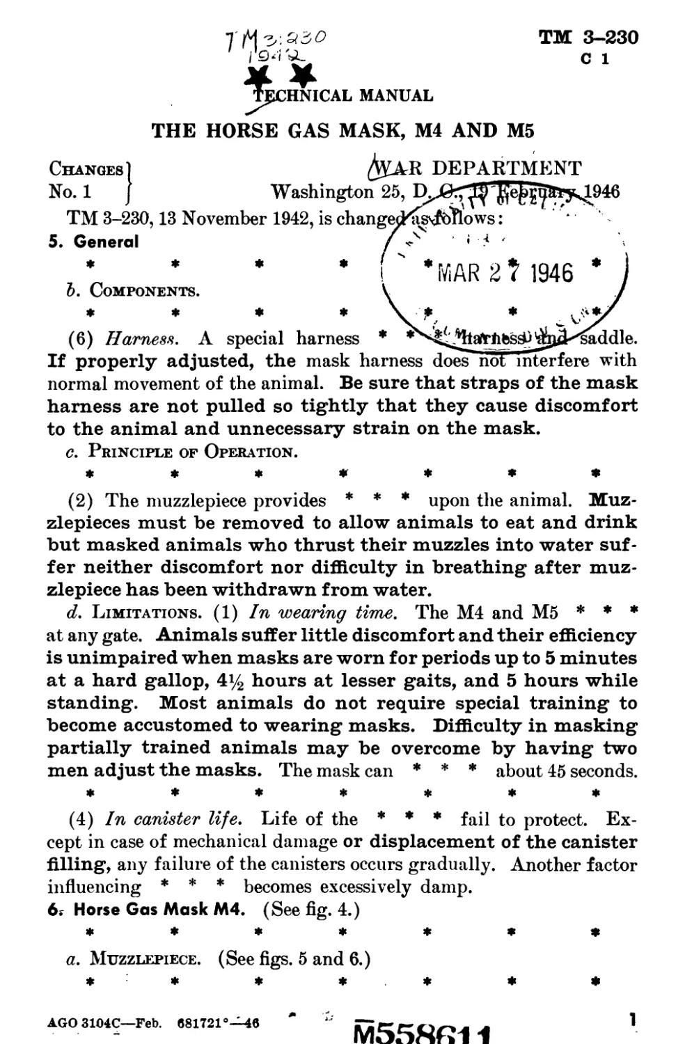
c. Muzzlepiece Carrier. (1) Although made of * * * 9% 6
inches deep. The cover flap, which bears the CWS insignia, is gen-
erally triangular in shaj>e and equipped with three lift-the-dot fas-
Figure 9.1. Masked mule with Phillips cargo pack saddle and pack. Right and
left side straps of horse gas mask, M'h are attached through holes cut in
saddle pad.
2
AGO 3104C
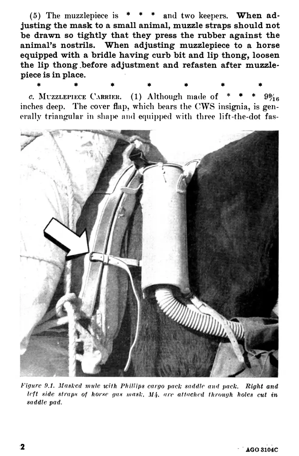
Figure 9.2. Neck strap of horse gas mask, MJh with keeper resewed to prevent
lateral movement of strap from turning neek pad over.
AGO 3104C
3
teners for closing the carrier when the muzzlepiece is being carried
and after muzzlepiece is adjusted to the muzzle.
*******
(3) The girth strap ♦ ♦ ♦ buckle and keeper. Fastening of
girth strap is simplified, when animals are always assigned
the same saddles and masks, by leaving strap attached to
cinch of saddle instead of to mask.
*******
e. Canister Carriers.
*******
(2) Three inches below ♦ * * pommel with snaps. Baling
wire may be used to secure pommel straps to pack saddles
which do not have pommel rings. Straps should be carefully
adjusted so that canisters are suspended high enough to pre-
vent their weight from being borne on the point of the withers.
Side straps are * * * of dee rings. Their opposite ends are fas-
tened to the girth or to holes cut in each side of the Phillips
cargo pack saddle pad. (See fig. 9.1.)
Figure 13.1. Team of masked draft horses, icith mask on nearside horse and
M5 mask on offside horse.
4
AGO 3104C
(3) The two canister * * * the right canister. Before fas-
tening the snap, turn it one-half turn clockwise, with respect
to the nearside of the animal. This helps to keep the neck pad
from turning over, which would cause the buckle to cut into
the animal’s neck. Excessive lateral movement of neck strap,
which also tends to turn the neck pad over, may be corrected
by sewing keepers % inch closer to center of each side of neck
pad. (See fig 9.2.) The neck pad is * * * 2% inches wide.
Figure 13.2. Center pommel strap of M5 mask arranged to alleviate chafing.
Cover of forward canister has been pierced and the strap passed through
the hole.
AGO 3104C
5
7. Horse Gas Mask M5. (See fig. 10.) Individual components of
* * * as described below. The M5 mask may be fitted to off-
side animals of draft teams with little or no rearrangement
of harness. (See fig. 13.1.) Some alteration of harness be-
comes necessary when this mask is used with the Phillips
cargo pack saddle, packer’s saddle, and officer’s training sad-
dle. The M5 mask is not designed for use on nearside horses
of draft teams, nor on animals equipped only with surcingle
and halter.
*******
e. Harness.
*******
(2) (Superseded.) The canister carrier is suspended from the sad-
dle by three straps, each equipped with a buckle, two keepers, and a
snap. The center pommel strap, 26 inches long and % inch wide, leads
from the upper forward corner of the canister carrier to the center
pommel on the saddle. Any tendency of the canister carrier to chafe
the animal’s hide may be alleviated by cutting a hole in the forward
cover of the canister carrier and passing the center pommel strap
Figure 13.3. Method of attaching right pommel strap of M5 mask to rope of pack
on mule equipped with Phillips cargo pack saddle.
AGO 3104C
through it. (See fig. 13.2.) The right pommel strap, located at the
upper rear corner of the canister carrier, is usually attached to the
right side of the pommel, but when the mask is fitted to an animal with
a Phillips cargo pack saddle, this strap may be attached to the rope
which secures the pack. (See fig. 13.3.) The side strap leads from
the lower rear corner of the canister carrier to the girth, or to the
spider ring on the saddle if one is provided, or to a hole cut in saddle
Figure 13.4. Side strap of M5 mask attached through hole cut in pad of Phillips
cargo pack saddle.
AGO8104C
7
pad of the Phillips cargo pack saddle. (See fig. 13.4.) The side strap
is 26 inches long by % inch wide.
[AG 300.7 (22 Jan 46)]
By order of the Secretary of War :
Official :
EDWARD F. WITSELL
Major General
The Adjutant General
DWIGHT D. EISENHOWER
Chief of Staff
Distribution :
AAF (5); AGF (10); ASF (2); T (Cml O) (5); Def Comd
(Cml O) (4); Arm & Sv Bd (1); S Div ASF (1); Tech Sv
(2) except CWS (45); SvC (Cml O) (2); PE (Cml O) (1) ;
Sub-PE (Cml O) (1); Ars, 3 (1); ASF Dep (CW Sec) (1) ;
Dep 3 (1); Pro Dist, 3(1); Tech Sv C (1); Gen & Sp Sv Sch
(CW Instr) (2); Tng C (4); A (Cml O) (4); CHQ (Cml O)
(1); D (2); Bn 2 (2); C 2,3 (2); AF (CmlO) (1).
Refer to FM 21-6 for explanation of distribution formula.
U. S. GOVERNMENT PRINTING OFFICE: 1946
8
AGO 3104Q
TECHNICAL MANUAL)
NO. 3-230 )
TM 3-230
1
WAR DEPARTMENT,
Washington, November 13, 1942.
THE HORSE GAS MASKS, МЦ AND 16
Paragraphs
SECTION I. General................................ 1- 4
П. Description.......................... 5 - 7
Ш. Packing, storage, and shipment........ 8-12
IV. Care and maintenance, repair and
inspection................................13-16
Page
APPENDIX. List of references........................ 39
SECTION I
GENERAL
1. PURPOSE. This manual is published for the informa-
tion and guidance of personnel charged with the issue, use, alter-
ation, repair, and testing of horse gas masks M4 and M5 in the
field. These masks are designed to protect the respiratory or-
gans of horses and mules against field concentrations of chem-
ical warfare agents.
1
ТМ 3-230
1
CHEMICAL WARFARE SERVICE
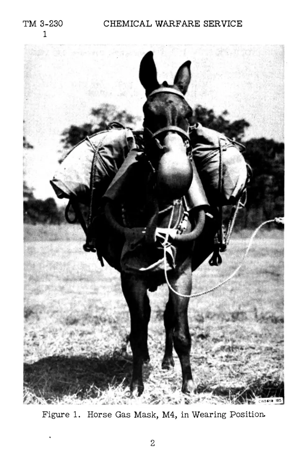
Figure 1. Horse Gas Mask, M4, in Wearing Position.
2
TM 3-230
2-5
THE HORSE GAS MASKS, Mil AND M?
2. SCOPE. The manual covers construction, mainten-
ance, care, inspection, and repair of both the M4 and M5 masks.
Directions for packing, storage, and shipment are also dis-
cussed.
3. REFERENCES. A list of references regarding the
horse gas mask appears in the Appendix.
4. BASIS OF ISSUE. The basis for issue of horse gas
masks will be found in appropriate tables of basic allowances.
SECTION II
DESCRIPTION
5. GENERAL. Horse gas masks discussed in this man-
ual serve the same general purpose as masks used by men,
except that no provision is made for protection of the animal’s
eyes. The purpose of the mask is to purify air which the ani-
mal breathes while in an atmosphere contaminated with toxic
or irritating gases, vapors, or smokes. Since the horse breathes
through its nostrils only, and never through its mouth, the mask
affords protection primarily for the muzzle.
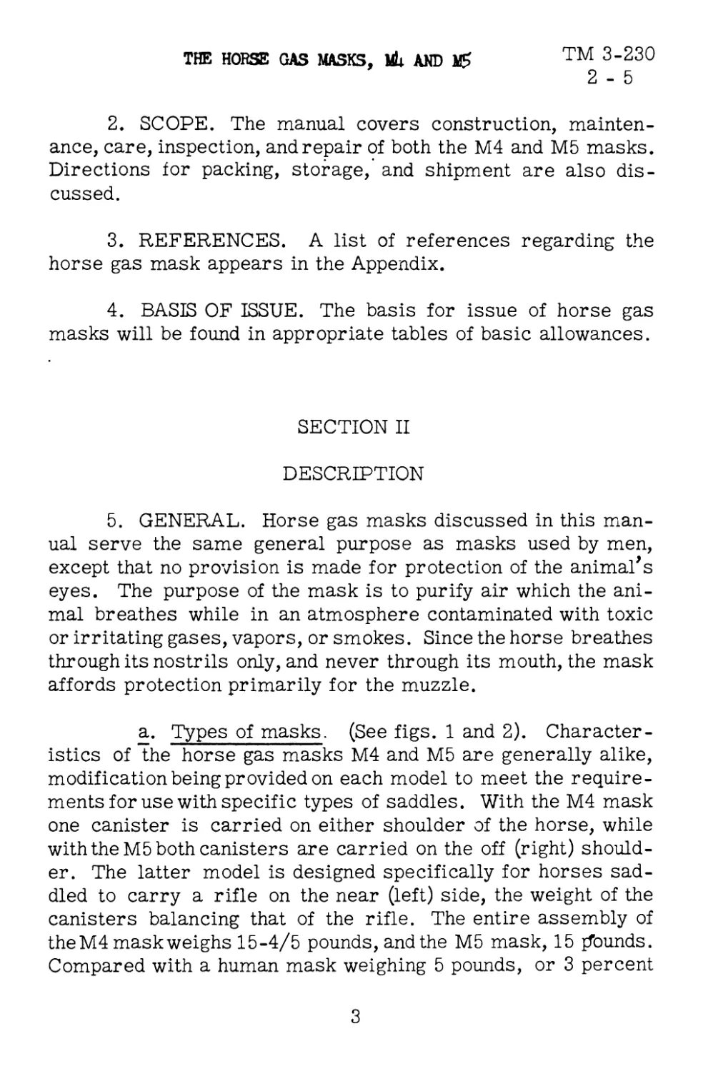
a. Types of masks. (See figs. 1 and 2). Character-
istics of the horse gas masks M4 and M5 are generally alike,
modification being provided on each model to meet the require-
ments for use with specific types of saddles. With the M4 mask
one canister is carried on either shoulder of the horse, while
with the M5 both canisters are carried on the off (right) should-
er. The latter model is designed specifically for horses sad-
dled to carry a rifle on the near (left) side, the weight of the
canisters balancing that of the rifle. The entire assembly of
the M4 mask weighs 15-4/5 pounds, and the M5 mask, 15 {founds.
Compared with a human mask weighing 5 pounds, or 3 percent
3
ТМ 3-230
5
CHEMICAL WARFARE SERVICE
Figure 2. Horse Gas Mask, M5, in Carry Position.
4
TM 3-230
5
THE HORSE GAS MASKS, Uk ANT
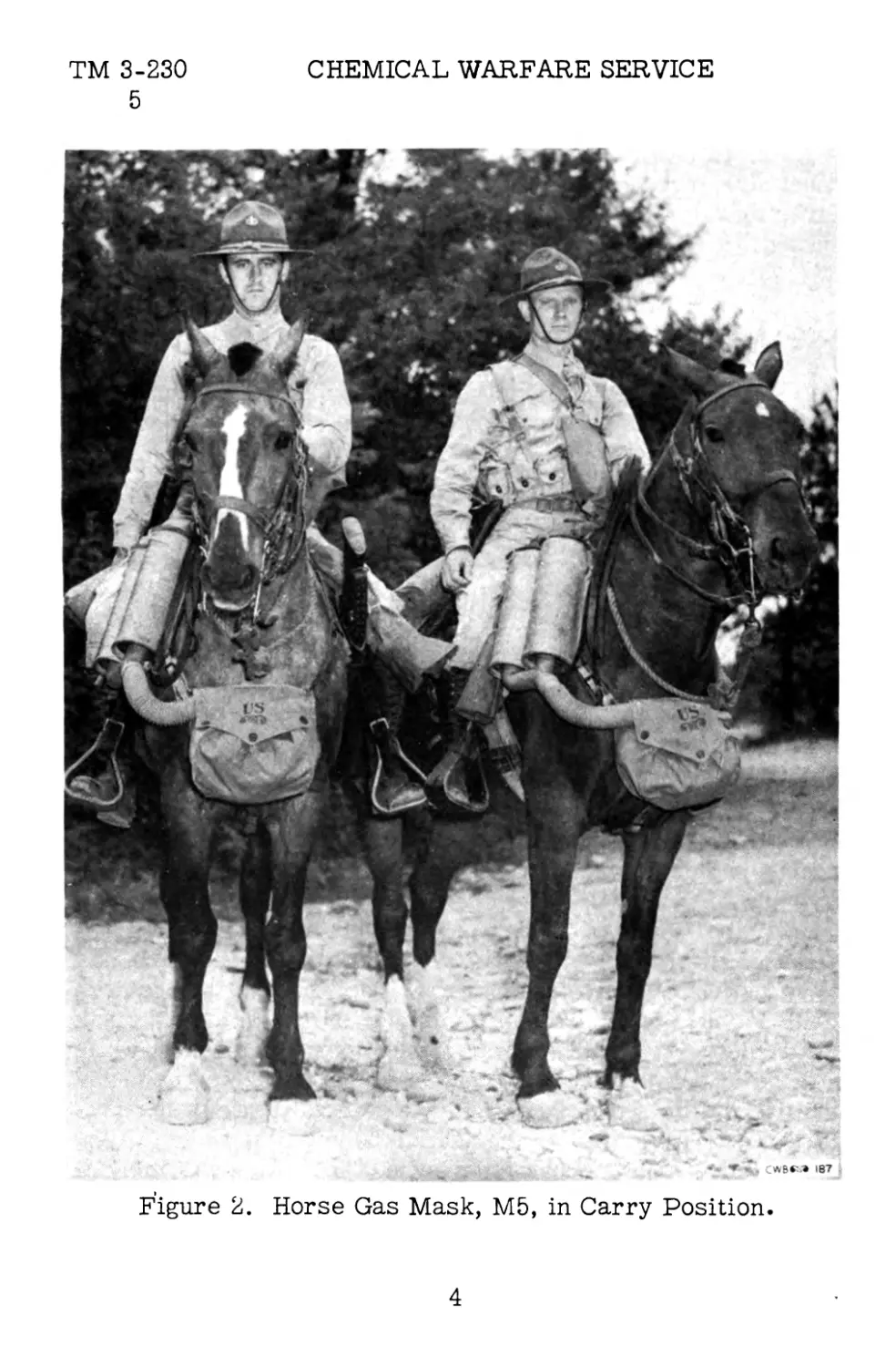
of the weight of a 160-pound man, the horse mask weighs only
1.3 percent of the weight of a 1,200-pound horse.
b. Components. In either model, M4 or Mb, the com-
plete gas mask consists of six principal parts--the canisters,
canister carriers, hose, muzzlepiece bag, muzzlepiece, and
harness.
(1) Canisters. These are provided for purifying
air before it is breathed by the horse. The canisters contain
absorbents and filters for cleansing air of gaseous agents and
minutely divided solids.
(2) Canister Carriers. Special carriers are pro-
vided because of the unusual size of the canisters, necessitated
by the large lung capacity of the horse.
(3) Hose. Flexible tubing provides a channel
through which purified air passes from the canisters to the
muzzlepiece.
(4) Muzzlepiece Carrier. The carrier accommo-
dates both the muzzlepiece and that portion of the hose which--
when the mask is worn--extends from the muzzlepiece back to
the carrier.
(5) Muzzlepiece. This device, fitting over the ani-
mal's muzzle, is equipped with inlet and outlet valves to permit
free inhalation and exhalation.
(6) Harness. A special harness, fitted with appro-
priate buckles and snaps, facilitates firm fastening of the mask
assembly to the regular harness and saddle. The mask harness
does not interfere with normal movement of the animal.
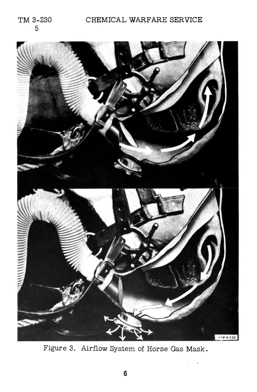
c. Principle of operation (See fig. 3). (1) Air is
drawn into the mask assembly as the animal inhales. It first
5
ТМ 3-230
5
CHEMICAL WARFARE SERVICE
Figure 3. Airflow System of Horse Gas Mask.
6
TM 3-230
5
THE HORSE GAS MASKS, MU AND 16
passes through the canister, which contains a filtration system
consisting of both mechanical and chemical filters, the former
filteringout solid and liquid particles (smoke and dust) and the
latter adsorbing toxic and irritating gases and vapors. After
being purified, the air is drawn to the animal’s muzzle for in-
halation. Upon exhalation the breath is expelled from the mask
through an outlet valve. The inlet valve is equipped with a flap
which closes during exhalation to prevent used air from return-
ing to the canisters, while the outlet valve is drawn closed dur-
ing inhalation.
(2) The muzzlepiece provides a gastight seal over
the muzzle, at the same time making adequate provision for the
animal’s comfort. Unlike their predecessor, the М3 mask, the
M4 and Mb masks have no plate to fit in the mouth. Although a
small amount of gas sometimes penetrates between the bits of
the double bridle, especially on small, thin-lipped horses, such
penetration exerts no ill effect upon the animal.
d. Limitations. (1) In wearing time. The M4 and M5
masks can be worn by animals traveling at any gait. In tests,
the masks have been left in place for periods ranging from 5
minutes at a hard gallop to 2 hours at lesser gaits, and 5 hours
while standing. The mask can be adjusted from the carry to the
gas position in about 45 seconds.
(2) In protection. Respiratory protection provided
by the M4 and M5 masks is approximately the same as that pro-
vided for human beings. (See TM 3-205). Horses’ eyes, which
are not protected, are affected only by vesicant agents and toxic
dusts.
(3) In breathing resistance. Tested at an air flow
of 450 liters per minute, the masks produced the following re-
sults :
7
оо
RIGHT CANISTE
CARRIER
RIGHT-
POMMEL
STRAP
SIDE^
STRAP
BRANCH HOSE
GIRTH
STRAP'
MUZZLEPIECE7'
CARRIER
HOSE
R
NECK
PAD-
NECK STRAP
SHOULDER
-STRAPS^,
LEFT CANISTER
CARRIER
-LEFT
POMMEL
STRAP
-SIDE STRAP
BRANCH
^HOSE
MUZZLE*
PIECE
STRAPS
СЛ
HOSE
SUPPORT
OUTLET
'VALVE
MUZZLEPIECE
’ CWB*r»l2O3
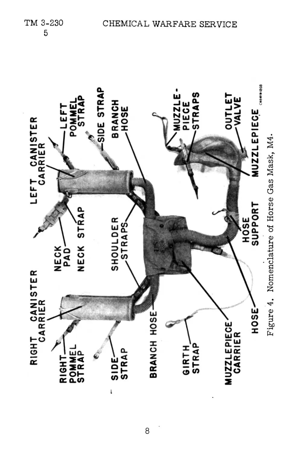
Figure 4. Nomenclature of Horse Gas Mask, M4-
TM 3-230 CHEMICAL WARFARE SERVICE
TM 3-230
5-6
THE HORSE GAS MASKS, Mh AND M5
M4 M5
mm water
Muzzlepiece, including inlet valve . . . 2.5 2.5
Hose, including fittings.............. 7.5 11.5
Canisters............................ 35.0 35.0
Total inhalation resistance.......... 45.0 49.0
Exhalation resistance.................13.0 13.0
(4) In canister life. Life of the canisters depends
largely upon the quantity of gas they are required to filter from
the air. In very high concentrations the life may therefore be
short, while in low concentrations several months may pass be-
fore the canisters become so saturated that they fail to protect.
Except in case of mechanical damage, any failure of the canis-
ters occurs gradually. Another factor influencing canister life
is "channelizing," which usually occurs when the filter becomes
excessively damp.
6. HORSE GAS MASK, M4 (See fig. 4). This model is
designed for use with the McClellan saddle, officers’ field sad-
dle, Phillips pack saddle, Quartermaster stock saddle, the var-
ious types of draft harness, and for horses equipped only with
a halter and surcingle. A corrugated rubber hose extends from
the bottom of each shoulder canister, joining at a T-shaped
metal connection inside the canister carrier. From this point
a single rubber hose extends to the muzzlepiece. Air enters
through a series of holes in the bottom of each canister, is pur-
ified within the canister, then passes through the rubber hose
to the muzzlepiece where it is breathed by the animal. Exhaled
air and saliva are emitted through a rubber outlet valve at the
bottom of the muzzlepiece.
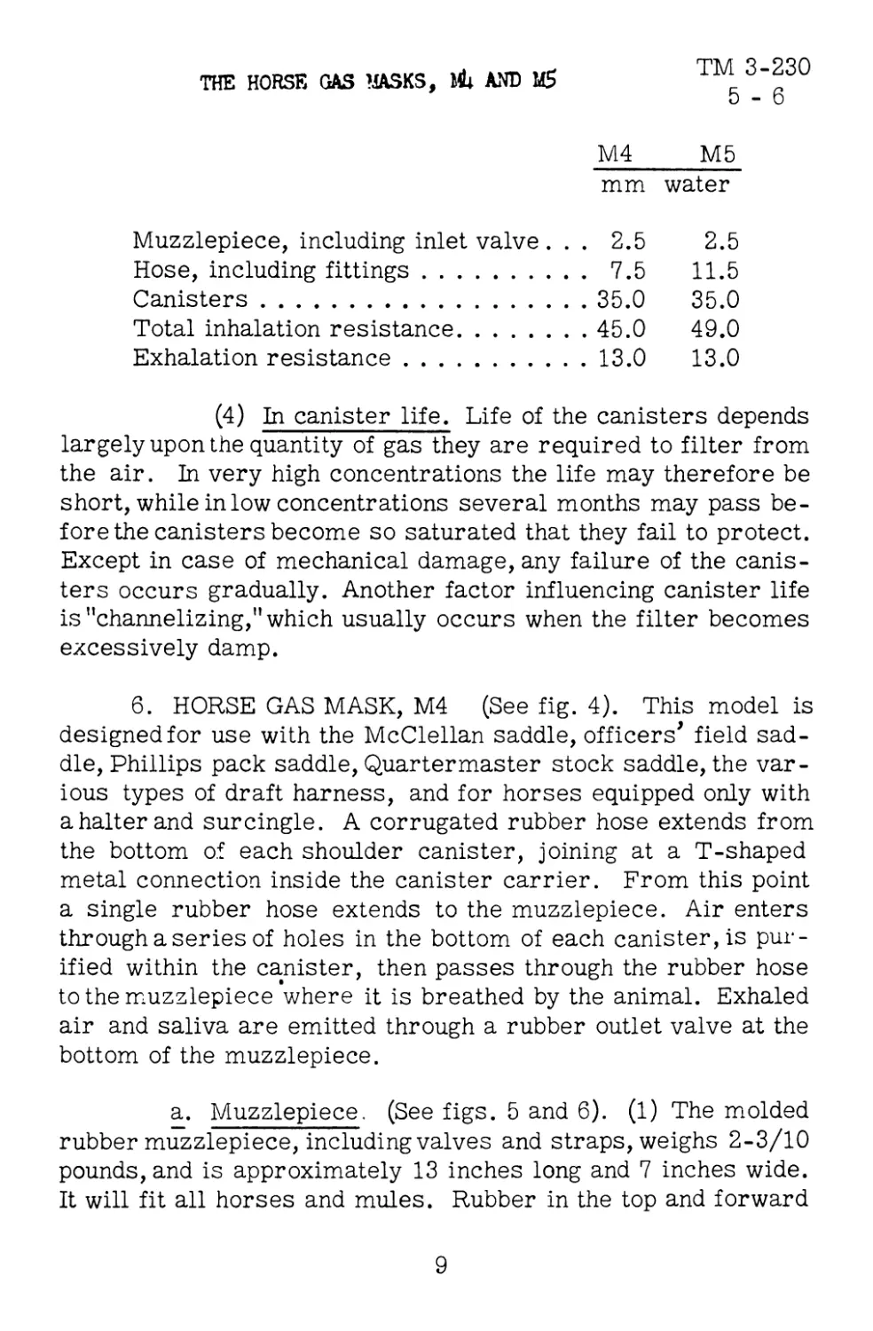
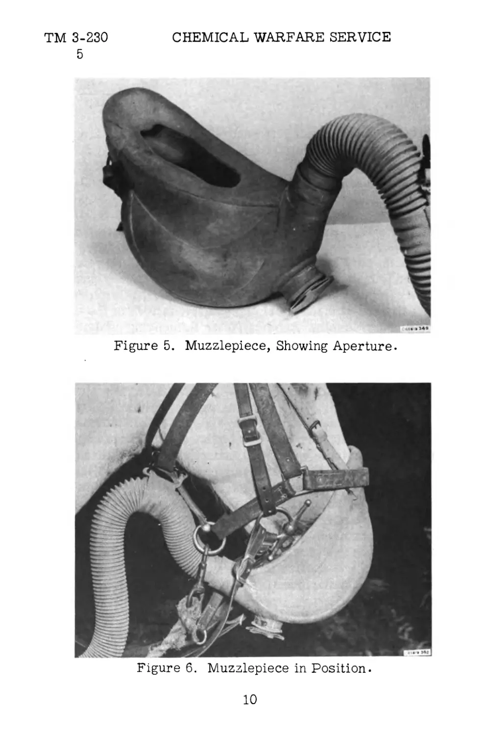
a. Muzzlepiece. (See figs. 5 and 6). (1) The molded
rubber muzzlepiece, including valves and straps, weighs 2-3/10
pounds, and is approximately 13 inches long and 7 inches wide.
It will fit all horses and mules. Rubber in the top and forward
9
ТМ 3-230
5
CHEMICAL WARFARE SERVICE
* »34«
Figure 5. Muzzlepiece, Showing Aperture.
Figure 6. Muzzlepiece in Position.
10
TM 3-230
6
THE HORSE GAS MASKS, MU AND
portions of the muzzlepiece is about 5/32 of an inch thick, and
in the lower and rear parts about 7/32 of an inch. Thus the
muzzlepiece is stiffened over the nostrils to prevent collapse,
but is made thinner elsewhere to decrease the weight. A slight
amount of flexing may occur during inhalation, especially when
the horse is breathing hard.
(2) The rear portion is drawn into an inlet tube
with an inner diameter of 1-3/4 inches, into which an inlet valve
ferrule is inserted. The ferrule is made of seamless brass
tubing. It is 1-13/16 inches in diameter and 4-1/16 inches long,
being cut on a 45-degree angle at the muzzlepiece end. This
end is divided horizontally and vertically into four sections for
a depth of 1/4 inch by brass supports which prevent the thin
rubber inlet valve from being drawn into the ferrule during ex-
halation. The valve is made of molded rubber and is fastened
to the ferrule by two brass holders at the top. It is tongue-
shaped, being 1-3/4 inches wide and 2-1/2 inches long. Wire,
friction tape, and rubber cement are used to assemble the hose,
inlet valve, and muzzlepiece connection, as described in para-
graph 14.
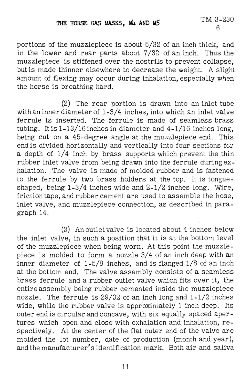
(3) An outlet valve is located about 4 inches below
the inlet valve, in such a position that it is at the bottom level
of the muzzlepiece when being worn. At this point the muzzle-
piece is molded to form a nozzle 3/4 of an inch deep with an
inner diameter of 1-5/8 inches, and is flanged 1/8 of an inch
at the bottom end. The valve assembly consists of a seamless
brass ferrule and a rubber outlet valve which fits over it, the
entire assembly being rubber cemented inside the muzzlepiece
nozzle. The ferrule is 29/32 of an inch long and 1-1/2 inches
wide, while the rubber valve is approximately 1 inch deep. Its
outer end is circular and concave, with six equally spaced aper-
tures which open and close with exhalation and inhalation, re-
spectively. At the center of the flat outer end of the valve are
molded the lot number, date of production (month and year),
and the manufacturer's identification mark. Both air and saliva
11
TM 3-230 CHEMICAL WARFARE SERVICE
6
are disposed of through the valve. It is fastened to the muzzle-
piece with wire, friction tape, and rubber cement, as described
in paragraph 14.
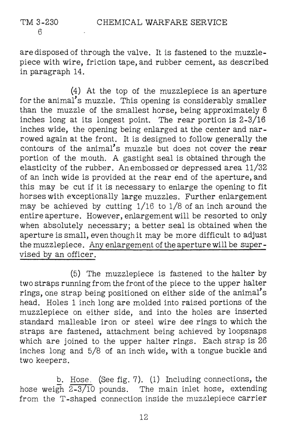
(4) At the top of the muzzlepiece is an aperture
for the animal’s muzzle. This opening is considerably smaller
than the muzzle of the smallest horse, being approximately 6
inches long at its longest point. The rear portion is 2-3/16
inches wide, the opening being enlarged at the center and nar-
rowed again at the front. It is designed to follow generally the
contours of the animal’s muzzle but does not cover the rear
portion of the mouth. A gastight seal is obtained through the
elasticity of the rubber. An embossed or depressed area 11/32
of an inch wide is provided at the rear end of the aperture, and
this may be cut if it is necessary to enlarge the opening to fit
horses with exceptionally large muzzles. Further enlargement
may be achieved by cutting 1/16 to 1/8 of an inch around the
entire aperture. However, enlargement will be resorted to only
when absolutely necessary; a better seal is obtained when the
aperture is small, even though it may be more difficult to adjust
the muzzlepiece. Any enlargement of the aperture will be super-
vised by an officer.
(5) The muzzlepiece is fastened to the halter by
two straps running from the front of the piece to the upper halter
rings, one strap being positioned on either side of the animal’s
head. Holes 1 inch long are molded into raised portions of the
muzzlepiece on either side, and into the holes are inserted
standard malleable iron or steel wire dee rings to which the
straps are fastened, attachment being achieved by loopsnaps
which are joined to the upper halter rings. Each strap is 26
inches long and 5/8 of an inch wide, with a tongue buckle and
two keepers.
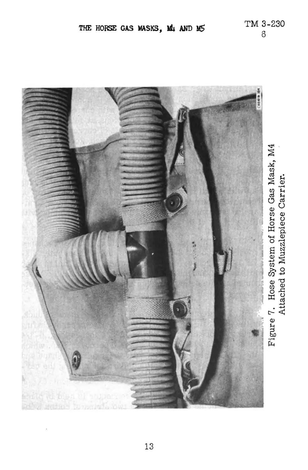
b. Hose. (See fig. 7). (1) Including connections, the
hose weigh 2-3/10 pounds. The main inlet hose, extending
from the T-shaped connection inside the muzzlepiece carrier
12
Figure 7. Hose System of Horse Gas Mask, M4
Attached to Muzzlepiece Carrier.
В
$
ОЭ co
co
00
ТМ 3-230 CHEMICAL WARFARE SERVICE
6
to the muzzlepiece proper, is approximately 28 inches long. It
has an inner diameter of 1-5/8 inches, with corrugation 11/32
of an inch thick. Uncorrugated connection pieces at either end
are 7/8 of an inch long. Each of the extension hose leading from
the T-shaped connection to the canisters is approximately 15
inches long and 1-1/4 inches in diameter with corrugation 11/32
of an inch thick. Uncorrugated connections at either end are
7/8 of an inch long. All hose are made of corrugated rubber
.055 of an inch thick, covered with rubberized stockinet.
(2) A hose support, made of 2-inch cotton webbing,
is attached to the hose approximately 8 inches behind the inlet
valve of the muzzlepiece. The support is equipped with a ring
and snap with which it is attached to the halter throat strap on
the harness when the mask is in use. This keeps the hose firm-
ly in place, at the same time preventing it from interfering with
normal movement of the animal's head.
(3) The top, or cross section, of the T-shaped
brass connector tube is 3-15/16 inches long with an outer dia-
meter of 1-1/2 inches. The connector is 2-5/8 inches deep
from top to bottom, and the outlet to which the muzzlepiece hose
is connected has an outer diameter of 1-3/4 inches. For met-
hod of connection see paragraph 14.
c. Muzzlepiece Carrier. (1) Although made of duck,
the muzzlepiece carrier has a leather back to prevent chafing
of the animal's breast. The bag is 12-3/4 inches long, 6-3/4
inches wide, and 9-9/16 inches deep. The cover flap, which
bears the CWS insignia, is generally triangular in shape and
equipped with three lift-the-dot fasteners for closing the car-
rier when the muzzlepiece is being carried.
(2) The T-shaped hose connector is held in place
in the upper rear of the carrier bag by two strips of cotton web-
bing 3/4 of an inch wide by 5-3/4 inches long. The upper ends
of both strips are sewed to the carrier, while the lower ends
14
TM 3-230
6
THE HORSE GAS MASKS, MU AND 16
are equipped with lift-the-dot fasteners. One strip is fastened
over either side of the connector.
(3) The girth strap is attached at the bottom of the
leather backing of the muzzlepiece carrier. This strap is 50
inches long, equipped at either end with a buckle and keeper.
(4) At both upper rear corners of the muzzlepiece
carrier bag are attached shoulder straps fastened at their op-
posite ends to the lower front corners of the two canisters.
Each strap is 18 inches long by 5/8 of an inch wide, with a
buckle and two keepers. The straps are attached at both ends
by means of rings. Each strap is fitted with a shoulder pad
8-3/4 inches long, graduated in width from 2 inches at the bot-
tom to 1-1/4 inches at the top.
d. Canisters. Each canister is 4-1/2 inches in dia-
meter by 12-7/8 inches long and weighs 3-2/5 pounds. Air is
received through 10 round holes, each 5/8 of an inch in dia-
meter, spaced equally in a flat metal plate which fits at the bot-
tom of the canister. The hose outlet is located in the center of
this plate.
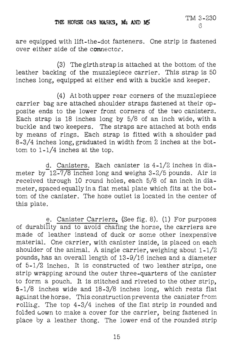
e. Canister Carriers, (See fig. 8). (1) For purposes
of durability and to avoid chafing the horse, the carriers are
made of leather instead of duck or some other inexpensive
material. One carrier, with canister inside, is placed on each
shoulder of the animal. A single carrier, weighing about 1-1/2
pounds, has an overall length of 13-9/16 inches and a diameter
of 5-1/2 inches. It is constructed of two leather strips, one
strip wrapping around the outer three-quarters of the canister
to form a pouch. It is stitched and riveted to the other strip,
5-1/8 inches wide and 18-3/8 inches long, which rests flat
against the horse. This construction prevents the canister from
rolling. The top 4-3/4 inches of the flat strip is rounded and
folded uown to make a cover for the carrier, being fastened in
place by a leather thong. The lower end of the rounded strip
15
Figure 8. Canister Hose Connection on Horse Gas Mask, M4.
CWBCH* 181
TM 3-230 CHEMICAL WARFARE SERVICE
TM 3-230
6 - 7
THE HORSE GAS MASKS, Ml; ANT) М5
is turned under and sewed, forming a guard which prevents the
canister from dropping out the bottom of the carrier.
(2) Three inches below the upper rear corner of
each carrier is located a pommel strap 18 inches long by 5/8
of an inch wide, equipped with a buckle and two keepers. The
straps are fastened to the carrier with dee rings, and to the
pommel with snaps. Side straps are similarly attached 3 inches
from the bottom rear corner of each carrier. Each of these
straps is equipped with a buckle and two keepers and are fast-
ened to the carriers by means of dee rings. Their opposite
ends are fastened to the girth.
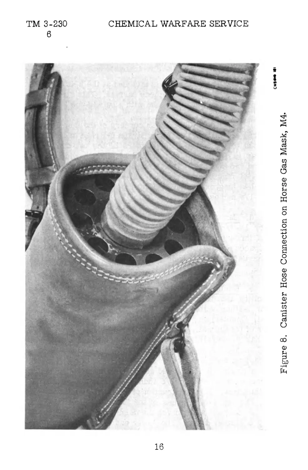
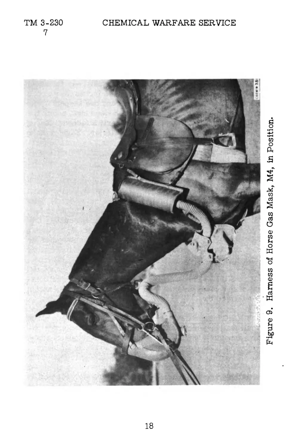
(3) The two canister carriers are joined over the
neck of the horse, immediately in front of the saddle, by means
of a neck strap assembly fitted with a pad. (See fig. 9.) The
assembly consists of two separate straps, each 11 inches long
by 7/8 of an inch wide, joined by a reverse strap buckle. One
strap is connected by a dee ring to the left canister; the other
strap is connected to a snap, which is in turn fastened to the
dee ring on the right canister. The neck pad is 6 inches long
by 2-5/8 inches wide.
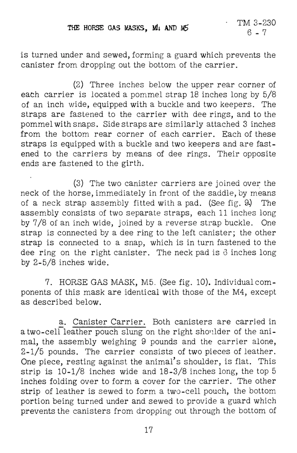
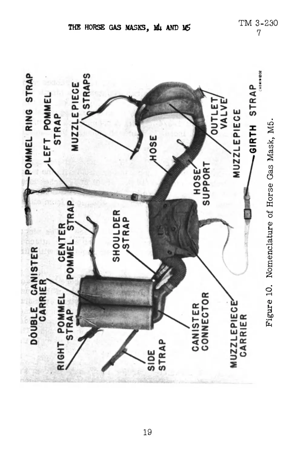
7. HORSE GAS MASK, M5. (See fig. 10). Individual com-
ponents of this mask are identical with those of the M4, except
as described below.
a. Canister Carrier. Both canisters are carried in
a two-cell leather pouch slung on the right shoulder of the ani-
mal, the assembly weighing 9 pounds and the carrier alone,
2-1/5 pounds. The carrier consists of two pieces of leather.
One piece, resting against the animal’s shoulder, is flat. This
strip is 10-1/8 inches wide and 18-3/8 inches long, the top 5
inches folding over to form a cover for the carrier. The other
strip of leather is sewed to form a two-cell pouch, the bottom
portion being turned under and sewed to provide a guard which
prevents the canisters from dropping out through the bottom of
17
оо
Figure 9. Hamess of Horse Gas Mask, M4, in Position.
TM 3-230 CHEMICAL WARFARE SERVICE
POMMEL RING STRAP
Figure 10. Nomenclature of Horse Gas Mask, M5.
I
g
I
к
F
I
co
co
ТМ 3-230 CHEMICAL WARFARE SERVICE
7
the carrier. The cover for each cell is fastened individually
with a leather thong.
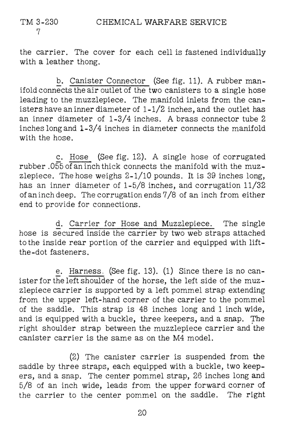
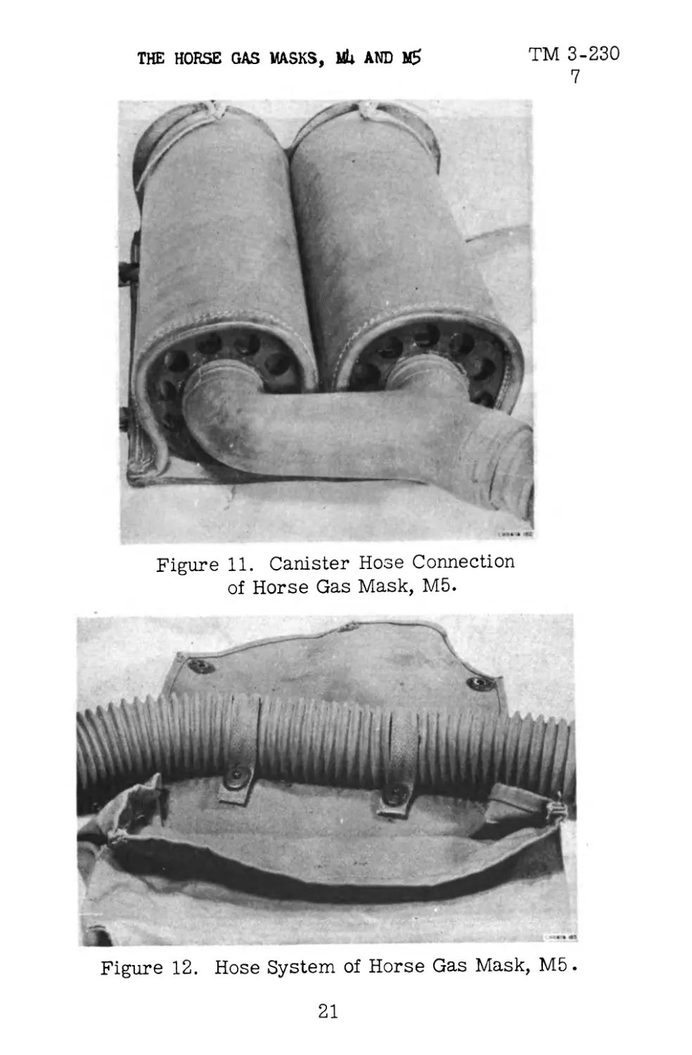
b. Canister Connector (See fig. 11). A rubber man-
ifold connects the air outlet of the two canisters to a single hose
leading to the muzzlepiece. The manifold inlets from the can-
isters have an inner diameter of 1-1/2 inches, and the outlet has
an inner diameter of 1-3/4 inches. A brass connector tube 2
inches long and 1-3/4 inches in diameter connects the manifold
with the hose.
c. Hose (See fig. 12). A single hose of corrugated
rubber .055 of an inch thick connects the manifold with the muz-
zlepiece. The hose weighs 2-1/10 pounds. It is 39 inches long,
has an inner diameter of 1-5/8 inches, and corrugation 11/32
of an inch deep. The corrugation ends 7/8 of an inch from either
end to provide for connections.
d. Carrier for Hose and Muzzlepiece. The single
hose is secured inside the carrier by two web straps attached
to the inside rear portion of the carrier and equipped with lift-
the-dot fasteners.
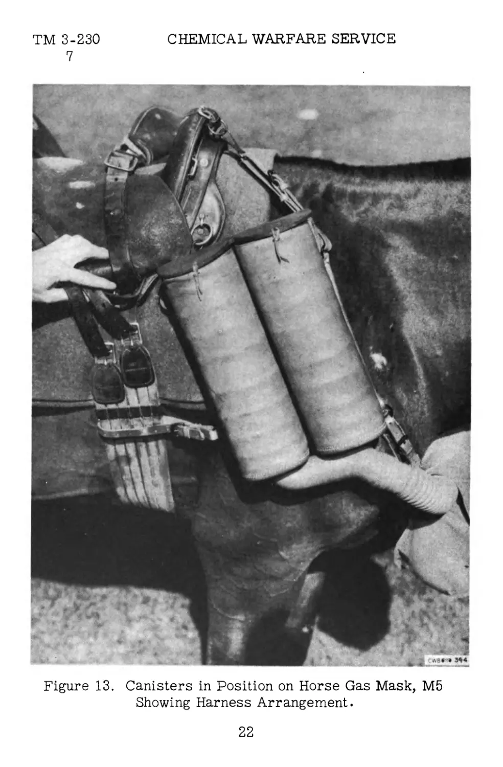
e. Harness. (See fig. 13). (1) Since there is no can-
ister for the left shoulder of the horse, the left side of the muz-
zlepiece carrier is supported by a left pommel strap extending
from the upper left-hand corner of the carrier to the pommel
of the saddle. This strap is 48 inches long and 1 inch wide,
and is equipped with a buckle, three keepers, and a snap. The
right shoulder strap between the muzzlepiece carrier and the
canister carrier is the same as on the M4 model.
(2) The canister carrier is suspended from the
saddle by three straps, each equipped with a buckle, two keep-
ers, and a snap. The center pommel strap, 26 inches long and
5/8 of an inch wide, leads from the upper forward corner of
the carrier to the center pommel on the saddle. The right
20
TM 3-230
7
THE HORSE GAS MASKS, MU AND MS
Figure 11. Canister Hose Connection
of Horse Gas Mask, M5.
Figure 12. Hose System of Horse Gas Mask, M5.
21
CHEMICAL WARFARE SERVICE
TM 3-230
7
Figure 13. Canisters in Position on Horse Gas Mask, M5
Showing Harness Arrangement.
22
THE HORSE GAS MASKS, MU AND MS ™ 3-230
7-8
pommel strap, located at the upper rear corner of the carrier,
is attached to the right side of the pommel. The right side
strap leads from the lower rear corner of the carrier to the
girth or to the spider ring on the saddle, depending on the type
of saddle being used. The side strap is 26 inches long by 5/8
of an inch wide.
SECTION III
PACKING, STORAGE, AND SHIPMENT
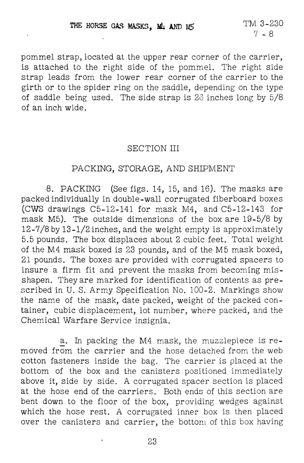
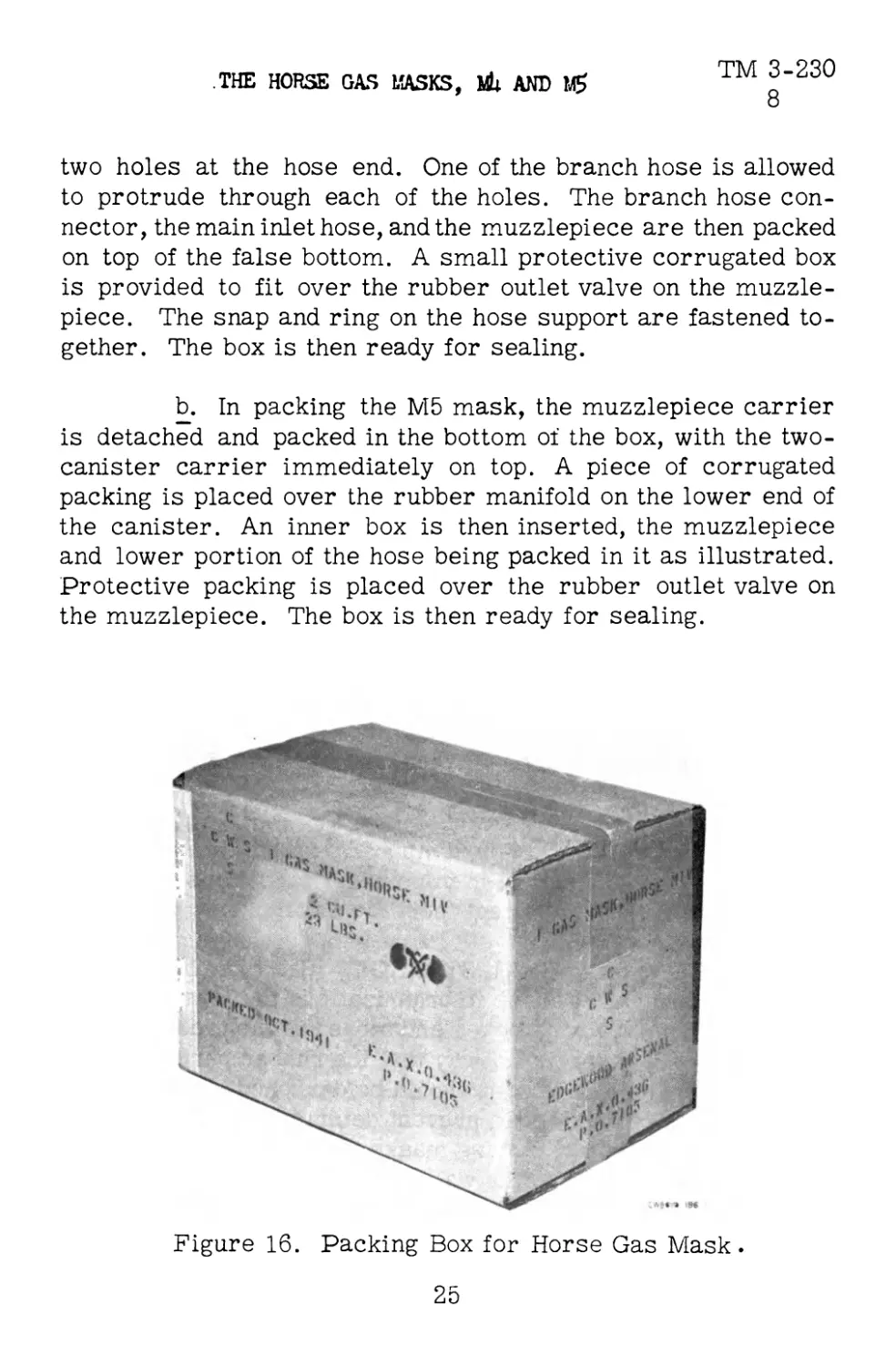
8. PACKING (See figs. 14, 15, and 16). The masks are
packed individually in double-wall corrugated fiberboard boxes
(CWS drawings C5-12-141 for mask M4, and C5-12-143 for
mask M5). The outside dimensions of the box are 19-5/8 by
12-7/8by 13-1/2 inches, and the weight empty is approximately
5.5 pounds. The box displaces about 2 cubic feet. Total weight
of the M4 mask boxed is 23 pounds, and of the M5 mask boxed,
21 pounds. The boxes are provided with corrugated spacers to
insure a firm fit and prevent the masks from becoming mis-
shapen. They are marked for identification of contents as pre-
scribed in U. S. Army Specification No. 100-2. Markings show
the name of the mask, date packed, weight of the packed con-
tainer, cubic displacement, lot number, where packed, and the
Chemical Warfare Service insignia.
a. In packing the M4 mask, the muzzlepiece is re-
moved from the carrier and the hose detached from the web
cotton fasteners inside the bag. The carrier is placed at the
bottom of the box and the canisters positioned immediately
above it, side by side. A corrugated spacer section is placed
at the hose end of the carriers. Both ends of this section are
bent down to the floor of the box, providing wedges against
which the hose rest. A corrugated inner box is then placed
over the canisters and carrier, the bottom of this box having
23
CHEMICAL WARFARE SERVICE
TM 3-230
8
Figure 14. Method of Packing Horse Gas Mask, M4.
CW888B 78Э
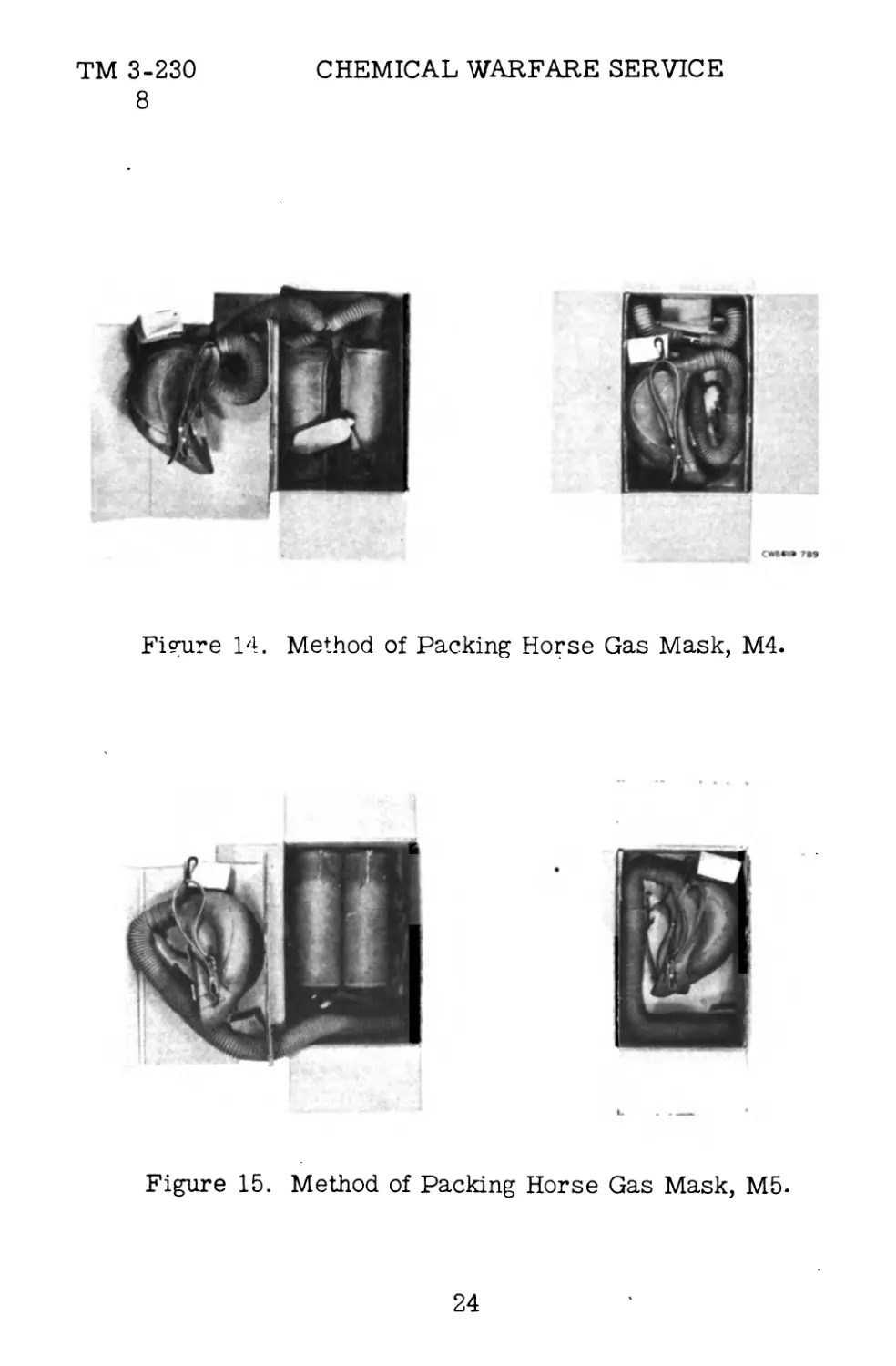
Figure 15. Method of Packing Horse Gas Mask, M5.
24
TM 3-230
8
THE HORSE GAS MASKS, MU AND
two holes at the hose end. One of the branch hose is allowed
to protrude through each of the holes. The branch hose con-
nector, the main inlet hose, and the muzzlepiece are then packed
on top of the false bottom. A small protective corrugated box
is provided to fit over the rubber outlet valve on the muzzle-
piece. The snap and ring on the hose support are fastened to-
gether. The box is then ready for sealing.
b. In packing the Mb mask, the muzzlepiece carrier
is detached and packed in the bottom of the box, with the two-
canister carrier immediately on top. A piece of corrugated
packing is placed over the rubber manifold on the lower end of
the canister. An inner box is then inserted, the muzzlepiece
and lower portion of the hose being packed in it as illustrated.
Protective packing is placed over the rubber outlet valve on
the muzzlepiece. The box is then ready for sealing.
Figure 16. Packing Box for Horse Gas Mask.
25
TM 3-230
9-10
CHEMICAL WARFARE SERVICE
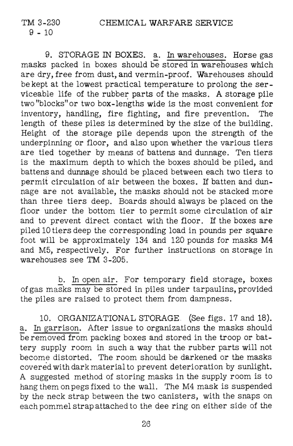
9. STORAGE IN BOXES, a. In warehouses. Horse gas
masks packed in boxes should be stored in warehouses which
are dry, free from dust, and vermin-proof. Warehouses should
be kept at the lowest practical temperature to prolong the ser-
viceable life of the rubber parts of the masks. A storage pile
two "blocks" or two box-lengths wide is the most convenient for
inventory, handling, fire fighting, and fire prevention. The
length of these piles is determined by the size of the building.
Height of the storage pile depends upon the strength of the
underpinning or floor, and also upon whether the various tiers
are tied together by means of battens and dunnage. Ten tiers
is the maximum depth to which the boxes should be piled, and
battens and dunnage should be placed between each two tiers to
permit circulation of air between the boxes. If batten and dun-
nage are not available, the masks should not be stacked more
than three tiers deep. Boards should always be placed on the
floor under the bottom tier to permit some circulation of air
and to prevent direct contact with the floor. If the boxes are
piled 10 tiers deep the corresponding load in pounds per square
foot will be approximately 134 and 120 pounds for masks M4
and M5, respectively. For further instructions on storage in
warehouses see TM 3-205.
b. In open air. For temporary field storage, boxes
of gas masks may be stored in piles under tarpaulins, provided
the piles are raised to protect them from dampness.
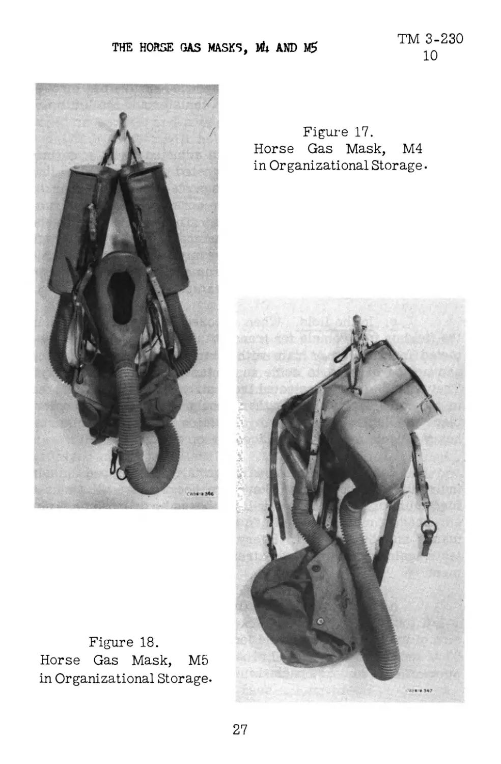
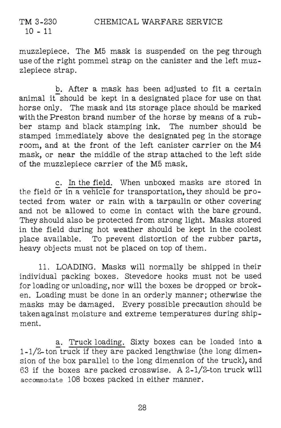
10. ORGANIZATIONAL STORAGE. (See figs. 17 and 18).
a. In garrison. After issue to organizations the masks should
be removed from packing boxes and stored in the troop or bat-
tery supply room in such a way that the rubber parts will not
become distorted. The room should be darkened or the masks
covered with dark material to prevent deterioration by sunlight.
A suggested method of storing masks in the supply room is to
hang them on pegs fixed to the wall. The M4 mask is suspended
by the neck strap between the two canisters, with the snaps on
each pommel strap attached to the dee ring on either side of the
26
TM 3-230
10
THE HORSE GAS MASKS, Ж AND
Figure 17.
Horse Gas Mask, M4
in Organizational Storage-
Figure 18.
Horse Gas Mask, M5
in Organizational Storage-
27
TM 3-230 CHEMICAL WARFARE SERVICE
10 - 11
muzzlepiece. The M5 mask is suspended' on the peg through
use of the right pommel strap on the canister and the left muz-
zlepiece strap.
b. After a mask has been adjusted to fit a certain
animal it should be kept in a designated place for use on that
horse only. The mask and its storage place should be marked
with the Preston brand number of the horse by means of a rub-
ber stamp and black stamping ink. The number should be
stamped immediately above the designated peg in the storage
room, and at the front of the left canister carrier on the M4
mask, or near the middle of the strap attached to the left side
of the muzzlepiece carrier of the M5 mask.
c. In the field. When unboxed masks are stored in
the field or in a vehicle for transportation, they should be pro-
tected from water or rain with a tarpaulin or other covering
and not be allowed to come in contact with the bare ground.
They should also be protected from strong light. Masks stored
in the field during hot weather should be kept in the coolest
place available. To prevent distortion of the rubber parts,
heavy objects must not be placed on top of them.
11. LOADING. Masks will normally be shipped in their
individual packing boxes. Stevedore hooks must not be used
for loading or unloading, nor will the boxes be dropped or brok-
en. Loading must be done in an orderly manner; otherwise the
masks may be damaged. Every possible precaution should be
taken against moisture and extreme temperatures during ship-
ment.
a. Truck loading. Sixty boxes can be loaded into a
1-1/2-ton truck if they are packed lengthwise (the long dimen-
sion of the box parallel to the long dimension of the truck), and
63 if the boxes are packed crosswise. A 2-1/2-ton truck will
accommodate 108 boxes packed in either manner.
28
TM 3-230
11 - 13
THE HORSE GAS MASKS, MU AND MS
b. Railroad carloadings. A railroad box car with in-
side dimensions of 36 by 8-1/2 by 8 feet will hold 1,078 boxes
packed crosswise, and a car with inside dimensions of 40-1/2
by 8-1/2 by 9 feet will hold 1,344 boxes lengthwise, or 1,480
boxes crosswise.
c. Loading unboxed masks. Loading of unboxed masks
is not recommended, but where absolutely necessary it may be
done if great care is exercised to prevent distortion of rubber
parts The masks will not be piled more than three tiers deep,
and no canisters will be permitted to rest on top of the hose or
muzzlepieces. Hose must be kept in as nearly normal a posi-
tion as possible. Corrugated board should be used to separate
fragile parts.
12. DESTRUCTION. Where, masks must be abandoned
during a retrograde movement, they should be destroyed to pre-
vent their falling into enemy hands. This may be accomplished
quickly with oil or gasoline and incendiary grenades, M14. If
the masks are unboxed they may be thrown into a pile and sprayed
with fuel. If boxed they should be piled to leave some air space
between the boxes, thus providing a draft. The boxes will then
be sprayed and the grenades fired. All parts of the mask except
the canisters will burn readily and heat from the fire will destroy
the protective effectiveness of the canisters, even though they
remain intact. For a description and method of using the incen-
diary grenade, M14, see FM 23-30.
SECTION IV
CARE AND MAINTENANCE, REPAIR AND INSPECTION
13. CARE AND MAINTENANCE, a. General precautions.
The mask has been designed to withstand ordinary field wear
and with reasonable care will have a long life. To prevent
29
TM 3-230 CHEMICAL WARFARE SERVICE
13
breakage or distortion of fragile parts, it should not be handled
carelessly, packed incorrectly, or placed under heavy objects.
Care should be exercised in harnessing the mask assembly to
the animal, following a standard procedure which is outlined in
FM 21-40. Undue exposure to moisture should be avoided to
prevent the stockinet fabric from rotting. However, the mask
may be carried in the rain for extended periods if necessary,
but it should not be placed near a hot stove or radiator for dry-
ing.
b. Leather parts. The leather should be cleaned daily
when the mask is in use, and periodically when in storage. When
necessary, the harness should be completely disassembled and
a damp sponge used to remove surface dust, mud, and other for-
eign substances. The sponge will then be rinsed and rubbed on
castile or saddle soap until a creamy lather is developed. The
leather should be cleaned thoroughly by drawing each strap
through the lathered sponge. When the straps are partially dry
they should be rubbed vigorously with a soft cloth. At infrequent
intervals the leather should be treated with neat1 з-foot oil, but
the application must be made sparingly because excessive oil
is injurious.
c. Rubber parts. The muzzlepiece should be cleaned
with a sponge and water after the mask has been used and per-
iodically when in storage. After washing, the rubber must be
wiped dry with a cloth. Although normal deterioration of rubber
may be expected over an extended period, it may be delayed by
storing the masks in dark, cool rooms.
d. Metal parts. All buckles, snaps, ferrules, and
other metal parts should be wiped periodically with an oiled rag
to prevent rust and corrosion. Special care should be taken to
keep the inlet and outlet valves of the muzzlepiece free of de-
bris. All metal parts on the harness must be dried thoroughly
after the harness has been cleaned.
30
TM 3-230
13 - 14
THE HORSE GAS MASKS, Mb AND 16
e. Muzzlepiece Carrier. Dirt, stones, twigs, and
other debris should be removed from the carrier daily, since
foreign material may damage the muzzlepiece and hose. The
leather back of the carrier will be cleaned in the same manner
as other leather parts of the mask. Holes and tears in the can-
vas portion of the bag should be patched.
f. Canister Carriers. The canisters cannot be re-
moved from their carriers while the leather is being cleaned.
Therefore care must be taken to keep moisture out of the can-
isters while the carriers are being rubbed with the wet sponge.
14. REPAIR, a. General. Unit gas officers and organi-
zation commanders will arrange for the prompt repair or re-
placement of unserviceable parts, and all men will be trained
to report damage which might render the masks in their care
ineffective. All repairs except those to the canisters can be
made by the using services, replacement parts being secured
from the chemical depot. Another horse gas mask should be
used as a model when parts are being replaced.
b. Standard manipulation. (1) When it is necessary
to remove old parts from a mask to make repairs, new parts
should be installed wherever the old ones appear to be near the
end of their usefulness.
(2) Rubber cement used for patching or for fasten-
ing hose to a connector may best be applied with a small brush
or with the index finger.
(3) Binding wires wrapped around connections
should be tightened carefully by twisting, after which all excess
wire except three twists should be cut off. The turns are then
bent down against the connection so that adhesive plaster may
be wrapped around the wire. The plaster strip should be started
by placing one end on top of the twisted portion of the wire, after
which the plaster is wrapped completely around the connector
31
TM 3-230
. 14
CHEMICAL WARFARE SERVICE
piece so that the wire twist is covered by two thicknesses of
tape.
c. Canisters. Crushed canisters or those which have
been wet or used in long or high concentrations of gas should
be replaced at the earliest opportunity. Replacements should
also be provided for canisters which have developed a very
high breathing resistance. Canisters must be detached from
their hose connections before being removed from the carriers.
This is done by pulling off the adhesive plaster and breaking the
wire fastener underneath, and then by simultaneously prying the
hose with a screw driver and pulling it off. The new canister
is then fitted inside the carrier, rubber cement is placed in-
side the hose (or manifold, on the M5 mask ), and the hose or
connector slipped over the canister outlet. Two strands of wire
are wrapped around the connection and tightened, after which
adhesive plaster is wrapped around the connection on top of the
wire.
d. Tee-connector. Hose are detached from and fast-
ened to the tee-connector on the M4 mask in the same manner
as outlined above for hose-canister connections.
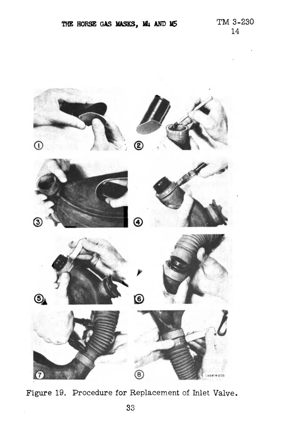
e. Inlet valve, (See fig. 19). (1) To replace the in-
let valve, the muzzlepiece is first detached from the inlet hose
by removing the adhesive plaster and wire, and by pulling the
connection apart. The old inlet valve assembly is then detached
from the muzzlepiece by removing the adhesive tape and wire
at the rear end of the muzzlepiece. The inlet valve is removed
by pulling it into the interior of the muzzlepiece and out through
the aperture.
(2) The new inlet valve is inserted by reversing
the procedure described above. The rubber valve flap must
first be attached to the inner end of the brass ferrule with the
concave side of the flap facing toward the ferrule. For lubrica-
ting purposes and to strengthen the connection once it is in
32
TM 3-230
14
THE HORSE GAS MASKS, Mb AND M5
Figure 19. Procedure for Replacement of Inlet Valve.
33
TM 3-230
14
CHEMICAL WARFARE SERVICE
place, rubber cement is placed on the inside surface of the muz-
zlepiece inlet and on the outer surface of the brass inlet valve
assembly. The valve is then pushed into the muzzlepiece inlet
from the inside. It should be pushed out far enough to leave
room for a hose connection on the rear end of the ferrule. The
valve is then fastened to the muzzlepiece with wire and adhesive
plaster as described above, and the inlet hose attached to the
ferrule in the same manner.
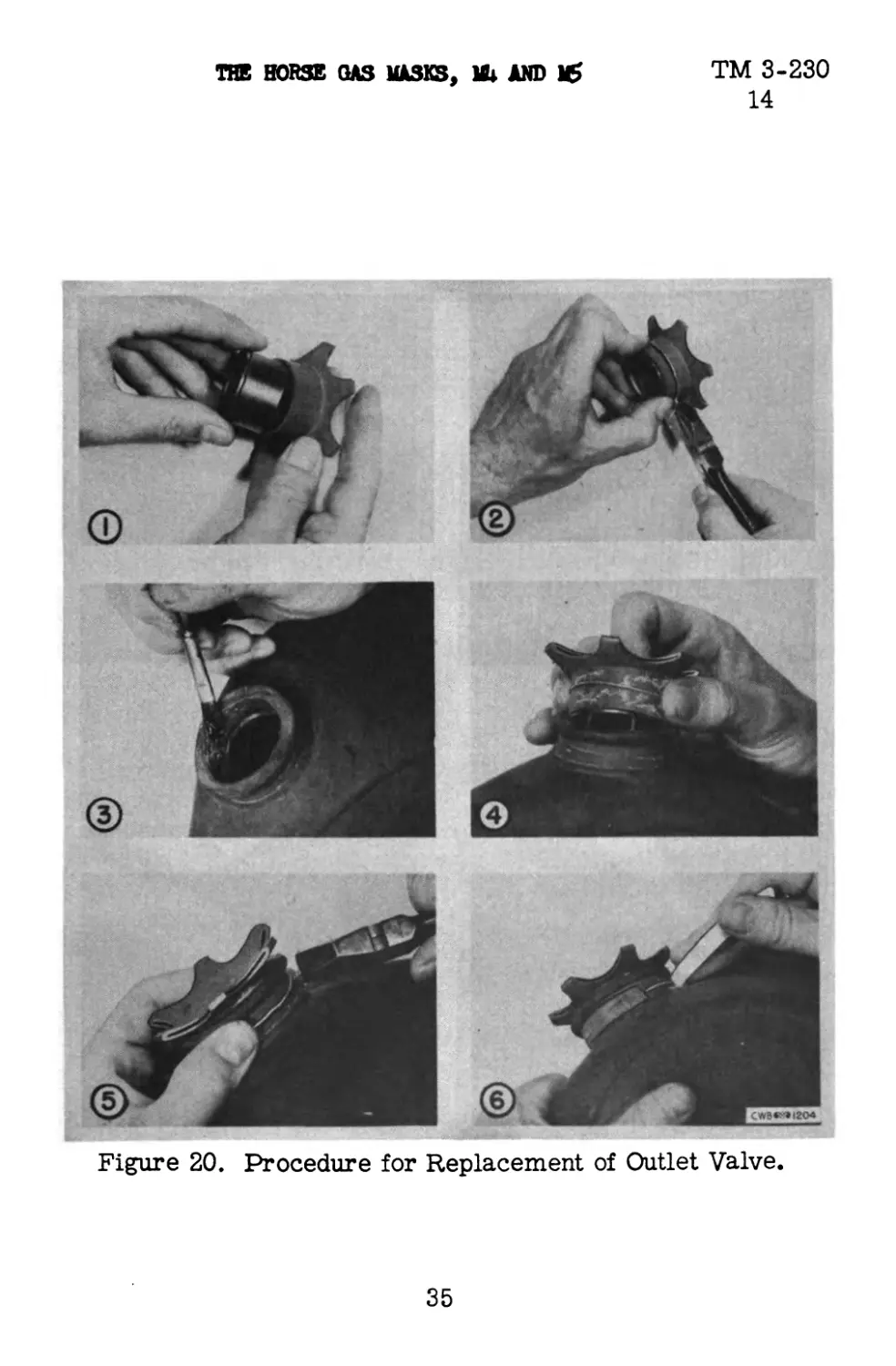
f. Outlet valve. (See fig. 20). (1) The outlet valve
assembly is removed from the muzzlepiece by unwrapping the
adhesive plaster and removing the wire clamp, after which the
assembly may be pried loose from the muzzlepiece. The as-
sembly is then dismantled by removing the wire which holds the
rubber valve proper to the outlet ferrule.
(2) In preparing the new inlet valve assembly, the
rubber valve is slipped over the ferrule so that the upper end of
the valve fits snugly against the ferrule shoulder. Thus the
valve seat will be in proper adjustment with respect to the fer-
rule. Galvanized wire, 0.032 inch in diameter, is next wrapped
around the valve (near the middle of the ferrule) and twisted
to hold the ferrule in place. The twisted end is cut off and bent
down at an angle of 45 degrees from the coil. Rubber cement
is then applied to the outside of the valve and the inside of the
muzzlepiece outlet, and the valve inserted before the cement
dries. It is fastened in place with binding wire, which is then
covered with adhesive plaster.
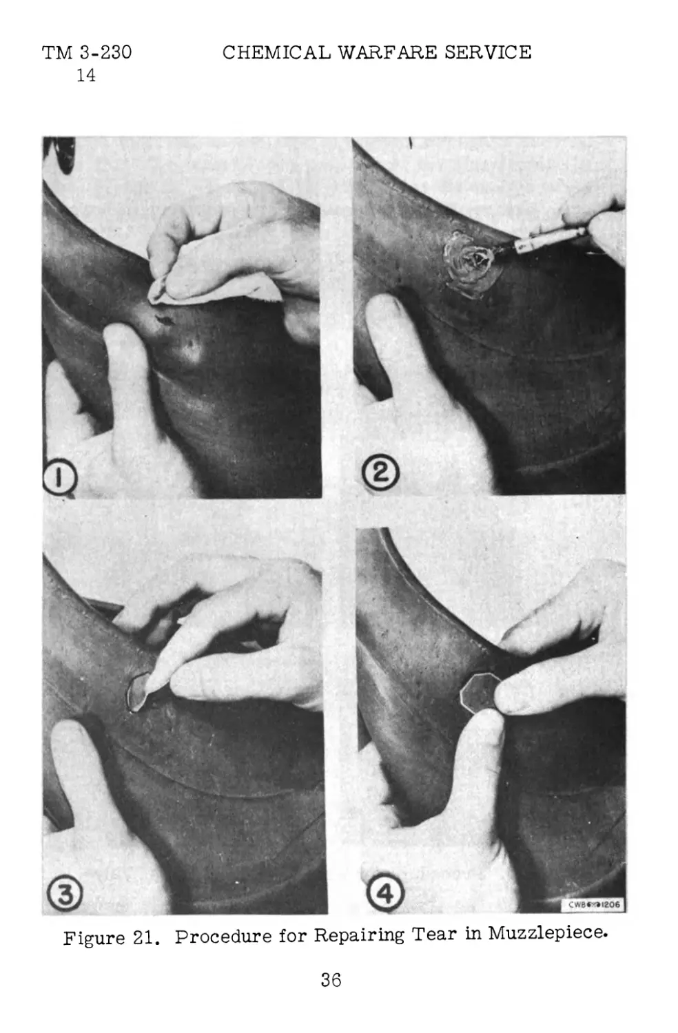
g. Muzzlepiece (See fig. 21). (1) Small holes in the
muzzlepiece may be repaired by applying patches on the inner
and outer surfaces over the cut, tear, or puncture. Rubber
around the hole should be cleaned thoroughly with a solvent
(benzene, straight gasoline, or dry-cleaning fluid). A thin, even
coat of rubber cement is then applied to the cleaned area and
allowed to dry about 15 minutes. A second thin coat of cement
is next applied and allowed to dry, after which a patch is placed
34
TM 3-230
14
THE HORSE GAS MASKS, Ш AND 16
Figure 20. Procedure for Replacement of Outlet Valve.
35
TM 3-230
14
CHEMICAL WARFARE SERVICE
Figure 21. Procedure for Repairing Tear in Muzzlepiece.
36
THE HORSE GAS MASKS, MU AND MS TM 3-230
14 - 15
on the area and pressed down with the fingers.
(2) As a rule, a tear in the muzzlepiece extending
to the muzzle aperture cannot be repaired successfully because
of the strain incident to adjustment. Except in an emergency
a muzzlepiece with a defect of this nature will be replaced.
h. Hose. Damaged hose must be replaced immediately
since it cannot be patched.
i_. Metal parts. Damaged metal parts, such as buck-
les, snaps, ferrules, or tee connectors, should be replaced.
j_. Carrier. Tears in the muzzlepiece carrier should
be sewed immediately, before they become enlarged.
k. Harness. Straps will be patched or replaced as
needed under supervision of the organization saddler.
15. INSPECTION. Every mounted trooper whose horse
is equipped with a gas mask should be taught to make an
habitual inspection of the assembly each day, while commanders
of mounted organizations which are equipped with masks should
inspect them at frequent intervals for serviceability. The unit
inspection routine is outlinedin FM 21-40. Points of inspection
are as follows:
a. Muzzlepieces. Careful check should be made to
detect holes and tears. The muzzlepiece will be placed on the
animal's muzzle to make certain there is a gas-tight seal and
that the muzzlepiece, fits comfortably. The outlet and inlet
valveswill be opened manually to make certain they do not ad-
here to the valve seat. Both valves should be securely fastened
in place. Holes in which the dee rings are inserted for the
muzzlepiece straps should be checked to see if they are strong
enough to support the straps. The rubber should also be checked
for flexibility and to make certain it has not deteriorated.
37
TM 3-230 CHEMICAL WARFARE SERVICE
15 - 16
b. Hose. All hose should be stretched and examined
for holes and abrasions. Connections to the canisters and muz-
zlepiece are checked for leaks. Any permanent abnormal set
of the hose will be investigated to determine whether it prevents
normal functioning of the mask. OntheM5 mask careful inspec-
tion will be made of the rubber manifold at the bottom of the
canister. The most thorough method of checking hose is by
applying internal air pressure while the hose is immersed in
water. This method, however, requires apparatus not available
to the using arms.
c. Canisters. Outside examination will not usually
reveal the condition of canisters. Replacements should be pro-
vided for canisters which are broken or crushed, which have
been soaked in water, or have been used for a long period in
high concentrations of gas. Excessive laboring by the animal
when wearing the muzzlepiece usually indicates a faulty can-
ister, but in such cases the mask in question should be tried
by other men on other horses. It can thus be determined whether
a high-resistance canister is responsible.
d. Straps and hardware. All straps, buckles, snaps,
and rings should be checked to make certain they are properly
attached, properly adjusted to fit the horse, and in serviceable
condition.
e. Muzzlepiece Carrier. Debris should not be per-
mitted to collect inside the carrier. Straps which hold the hose
in position should be inspected, as should all lift-the-dot fast-
eners.
16. INSPECTION BY CHEMICAL SERVICE UNITS. See
TM 3-205 for inspection functions of chemical maintenance and
chemical depot companies.
38
THE HORSE GAS MASKS, Mb AND 16
TM 3-230
APPENDIX
LIST OF REFERENCES
FM 21-40 "Defense Against Chemical Attack"
FM 23-30 "Grenades"
TM 3-205 "The Gas Mask"
CWS Specification 197-51-163, Mask, Gas, Horse, M4
CWS Specification 197-51-168, Mask, Gas, Horse, M5
(A. G. 062.11 (10-15-42).)
By order of the Secretary of War:
G. C. MARSHALL,
Chief of Staff.
Official:
J. А. Ш0,
Major General,
The Adjutant General.
Distribution:
D (2); IB 2,6(10); IR 2,6(10); IBn 2,6(5); IC 2,6,10(5).
(For explanation of symbols see Я4 21-6.)
☆ U. 8. GOVERNMENT PRINTING OFFICE : 1942 О - 494277
39