/
Tags: weapons military affairs machine gun
Year: 1952

Text
REGRADED .«Л ....../
(Appropriate c1a«s''fication) /
NOTES ON
DEVELOPMENT TYPE MATERIEL
Gun, Machine, Light, Cal. .30 T-52-E3
There is no copyrighted matter contained
in this report.
ORDNANCE DEPARTMENT
Philadelphia Ordnance District
Philadelphia, Pennsylvania
Prepared by
BRIDGE TOOL AND DIE WORKS
738 South Forty-second Street
Philadelphia 4, Pennsylvania
Government Contract No. DA-36-034-Ord-87
February 1952
NOTES ON
DEVELOPMENT TYPE MATERIEL
for
GUN. MACHINE, LIGHT, CAL. .30 T-52-E-3
TABLE OF CONTENTS
Chapter I - INTRODUCTION
1. Scope. . .............................................................. 1
2 . Sources............................................................ 1
3 Characteristics....................................................... 1
4 References .. . 1
Chapter II DESCRIPTION AND OPERATION
5 Receiver Group...................................................... 2
6 Front Sight ........................................................... 2
7 Gas Cylinder Group.................................................... 2
8 Operating Rod and Bolt Group........................................... 3
9.. Driving Spring Group.................................................. 4
10 . Recoil Buffer Group................................................... 4
11 . Feeding Mechanism Group............................................... 6
12 Trigger Mechanism Group.................................................. 6
13 Barrel and Barrel Lock Group............................................. 6
14 Stock Group.. .......................................................... 9
15 . Tripod Mount.......................................................... 9
Chapter III - DISASSEMBLY AND ASSEMBLY
16 General............................................................... 11
17 . Disassembly into Major Parts and Subassemblies....................... 11
18 Cover, Feed Mechanism Group............................................. 11
19 . Feed Plate Removal................................................... 11
20 Stock Removal.......................................................... 11
21 Recoil Buffer Group.................................................... 11
22 . Driving Spring....................................................... 12
23 Operating Rod and Bolt.................................................. 12
24 Cocking Handle Removal................................................. 12
25 Barrel Removal Group................................................... 12
26 Forearm and Carrying Handle............................................ 12
27 . Trigger Mechanism Group.............................................. 12
28 Barrel Lock Group.................................................... 13
29 . Disassembly of Subassemblies (Para. 30 to 39 Inc.)................... 13
30 - Operating Rod and Bolt............................................... 13
31 . Operating Rod Group.................................................. 13
32 . Bolt Group........................................................... 13
33 Cover, Feed Mechanism Group............................................ 17
34 . Rear Sight........................................................... 17
35 Recoil Buffer Group.................................................... 19
36 . Trigger Mechanism Group.............................................. 19
i
Chapter III - DISASSEMBLY AND ASSEMBLY (Continued)
37 . Barrel Group. . ......................................................... 21
38 . Bipod Group............................................................ 21
39 . Receiver Housing Group..................................................... 24
40 . Assembly of Subassemblies (Para. 41 to 48 Inc.)............................ 24
41 Bolt Group.............................................................. 24
42 Operating Rod Group......................................................... 24
43 Operating Rod and Bolt Group............................................... 24
44 - Trigger Mechanism Group........................................... ........ 25
45 . Recoil Buffer Group........................................................ 25
46 Rear Sight................................................................. 26
47 Cover, Feed Mechanism Group.................................................. 29
48 Barrel Group. ............................................................... 29
49 Gun Assembly from Subassemblies and Major Parts (Para. 50 to 59 Inc.)......... 30
50 Receiver Housing Group..................................................... 30
51 . Trigger. Carrying Handle and Forearm Group................................. 33
52 Barrel Group................................................................. 33
53 . Cocking Handle........................................................... 33
54 - Operating Rod and Bolt..................................................... 33
55 . Driving Spring Assembly.................................................... 33
56 . Recoil Buffer Group........................................................ 33
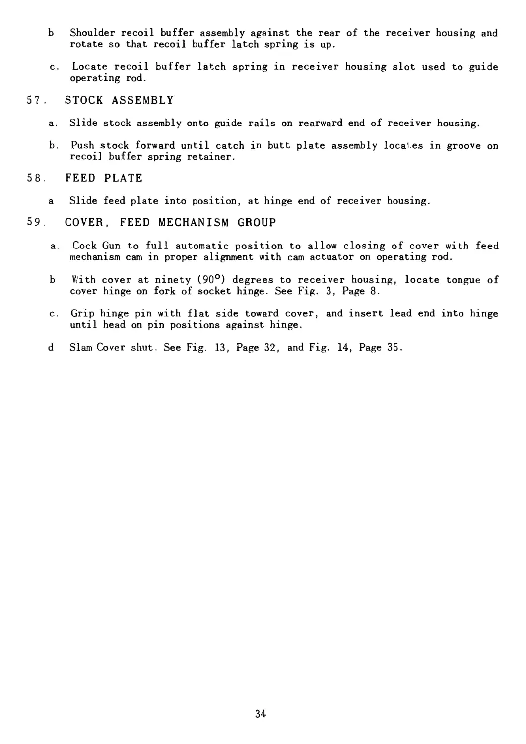
57 Stock Assembly... ........................................................... 34
58 . Feed Plate................................................................. 34
59 Cover, Feed Mechanism Group................................................ 34
60 . Loading of Gun............................................................ 36
61 Alternate Method of Gun Loading.............................................. 36
APPENDIX
a. List of Drawings............................................................38
b. Spare Parts................................................................ 43
c. Photographs and Prints
1.
2
3.
4.
5
6-
7-
8.
9
10.
IL
12
13.
14.
15.
16.
17.
Fig. 1 - Recoil Buffer Assembly......................................
Fig. 2 - Cover Assembly..............................................
Fig. 3 Cover Open and Barrel Removed.................................
Fig. 4 Disassembled View.............................................
Fig. 5 • Operating Rod and Bolt Assembly.............................
Fig. 6 Operating Rod Assembly........................................
Fig. 7 - Bolt Assembly...............................................
Fig. 8 - Rear Sight Assembly.........................................
Fig. 9 - Trigger Mechanism Assembly..................................
Fig. 10 - Barrel Final Assembly.......................................
Fig. 11 Bipod Assembly, Std............................................
Chart 1 - Elevation Data for Rear Sight...............................
Chart 2 - Windage Data for Rear Sight.................................
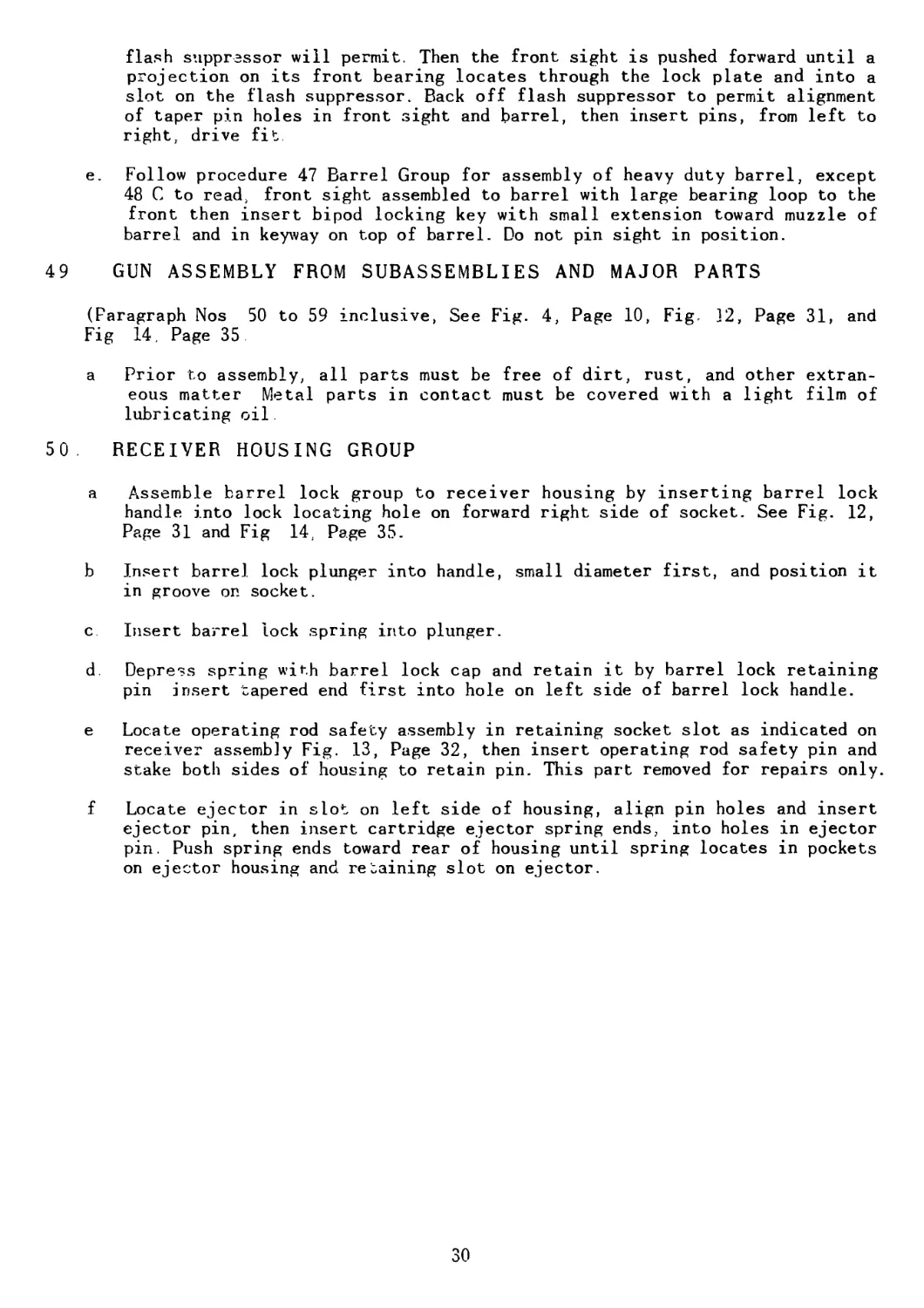
Fig. 12 ~ Gun, Main Assembly ’.......................................
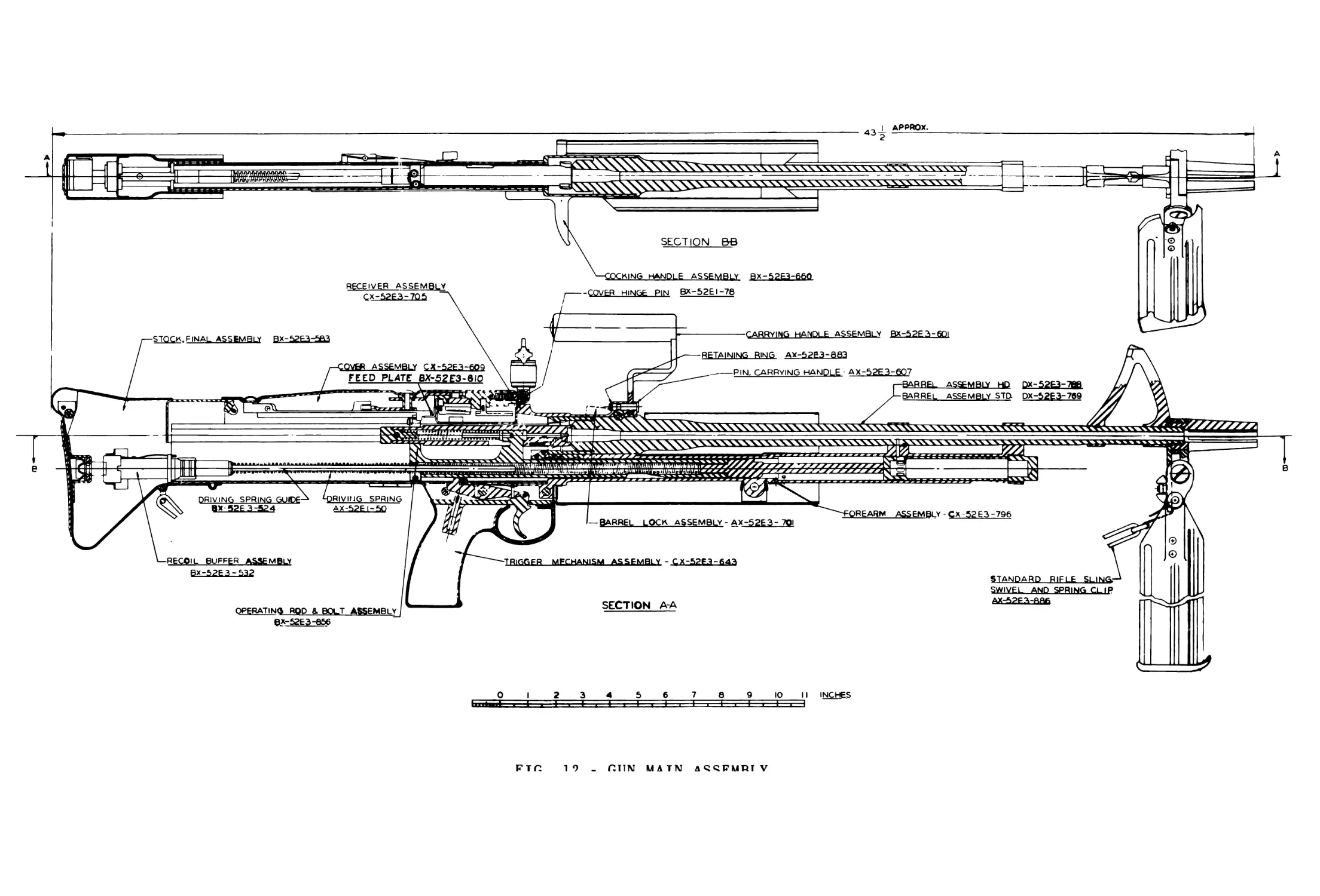
Fig. 13 - Receiver Assembly................................. ........
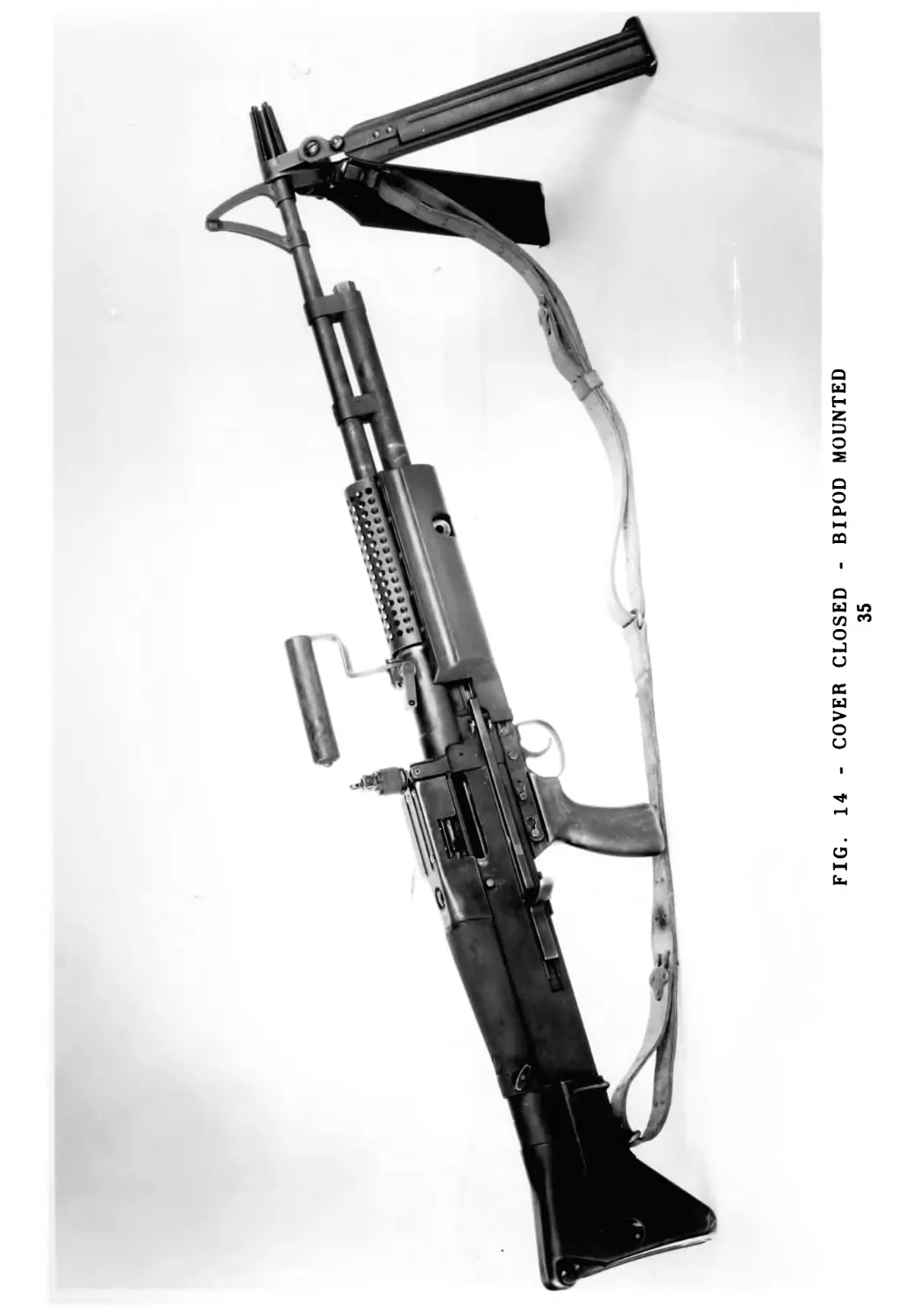
Fig. 14 - Cover Closed - Bipod Mounted...............................
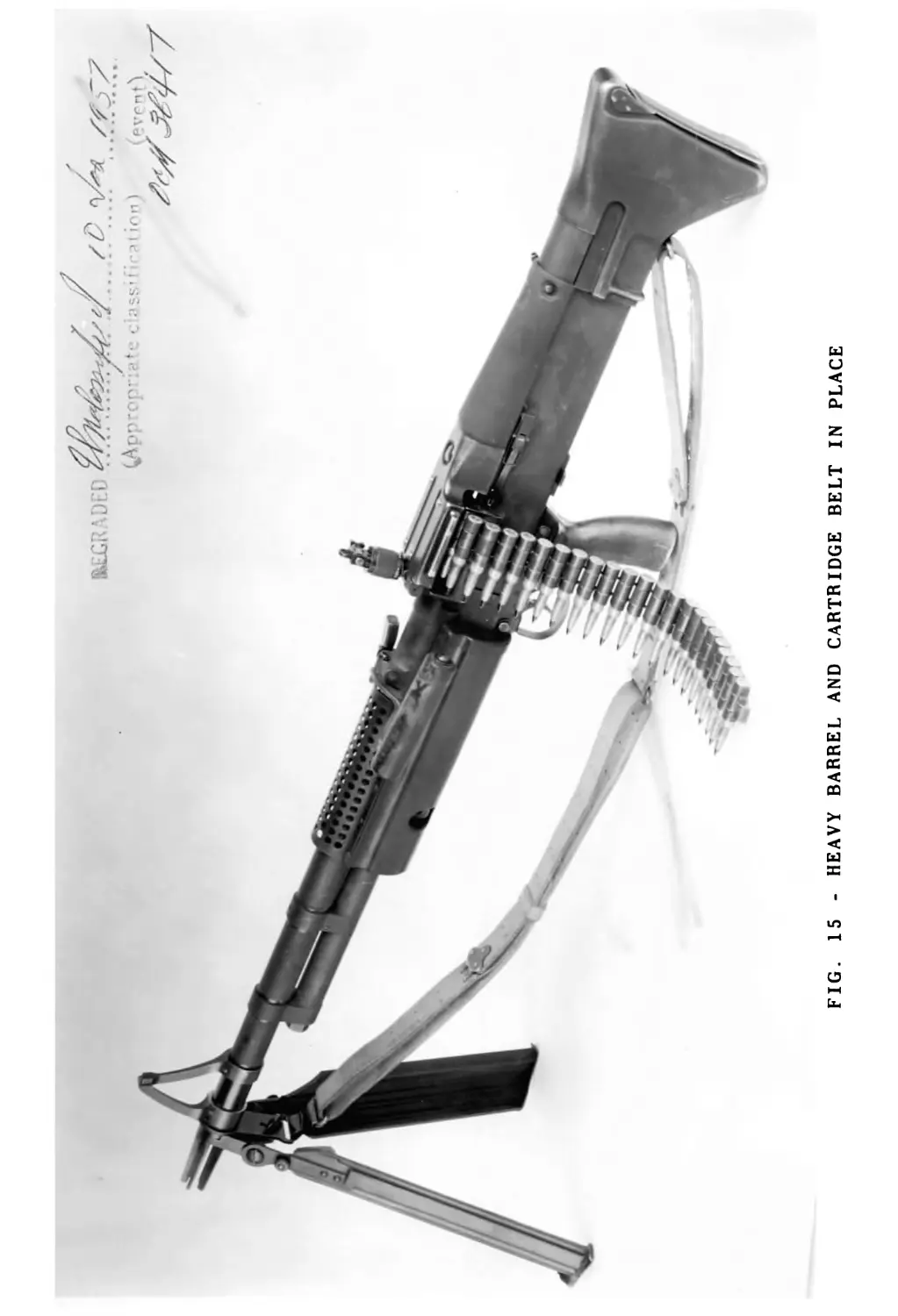
Fig. 15 • Heavy Barrel- and Cartridge Belt in Place..................
5
7
8
10
14
15
16
18
20
22
23
27
28
31
32
35
37
ii
CHAPTER I
INTRODUCTION
1. SCOPE
a. These Notes on Materiel are for the purpose of describing for Ordnance and
Service Personnel the source, operation, and parts of the Model of the Light,
Automatic Machine Gun Cal .30 T-52-E3 which will hereinafter be referred
to as the Gun.
2. SOURCES
a. The Gun is a progressively improved model based upon the Cal. 7 92 Ш T-44
experimental gun, the further modified Cal. .30 T-52 experimental gun, and
the further modified Cal 30 T-52-E1 Experimental gun., with varying modifi-
cations as requested by the Office Chief of Ordnance. Research and Develop-
ment Service, Artillery Small Arms Branch, Washington, D. C.
b. The Gun was developed by Bridge Tool and Die Works, Engineering Division,
Philadelphia, Pennsylvania, for the Office Chief of Ordnance, Research and
Development Service, Artillery Small Arms Branch, Washington, D. C.
3. CHARACTERISTICS
a. Gas Cutoff and Expansion System of Operation.
b. Aircooled
c. Fast Change Barrel
d. Bipod Supported.
e. Provisions made for Tripod Mount
f. Employs T-65 Cartridge with disintegrating Link-
g. Cyclic rate of fire approx. 700 per min.
h. Total weight 20 lbs
’ i. Light Barrel Weight bare 3*4 lbs.
. j. Heavy Barrel Weight bare - 7 lbs
k. Length - 431/2n with flash suppressor.
4. REFERENCES
a. Photographs and line drawings, taken in various positions to aid in identi-
fying parts, are inserted throughout the book.
b. In the appendix is listed the assemblies, detailed drawings, and spare parts
of the Gun.
CHAPTER II
DESCRIPTION AND OPERATION
5 . RECEIVER GROUP
a. The receiver body, in which the essential parts of the Gun operate, is of
spot welded, sheetmetal construction, consisting of an inner and outer hous-
ing, one bridge member, and a machined socket The forward end of the socket
supports the barrel retaining pin
b. The inner and outer housings, spot welded together, form a channel-shaped
section, which supports the operating rod and bolt. The receiver has a longi-
tudinal opening l/2; wide along the top side, through which the operating
rod protrudes to operate the feeding cam The 1/2” wide opening is maintained
by welding the assembled housings in the machined socket and spot welding the
bridge member spanning the opening.
c. Holding the receiver in a normal firing position, on the right side is a
formed metal track in the outer housing, running from the socket in the front
to within 5 1/4” from the rear of the receiver housing, which contains, the
cocking handle The cocking handle, on being drawn rearward, engages the op-
erating rod and cocks the Gun. It is then free to move forward and to be held
in a forward position by a spring contained in the cocking handle.
d. The trigger mechanism group is mounted on the underneath side of the receiver
and interrupts the operating rod to control firing.
e. The sheet metal, rubber coated, forearm group is mounted on the forward end
of the receiver housing and is retained in position by the same pin that
locks the trigger mechanism group in its position.
6. FRONT SIGHT
a. The muzzle end of the barrel accommodates the assembly of the front sight.
b. The front sight is rigid and held in radial and longitudinal alignment with
barrel, by taper pins.
c. A protrusion on front loop of sight extends through bipod mount and engages
slots on flash suppressor to lock it in place.
7. GAS CYLINDER GROUP
a. The gas cylinder is tubular in appearance and is mounted beneath the forward
end of the barrel. Two (2) loops are provided which slip over the barrel and
retain the entire assembly. The cylinder is ported through to the barrel with
a .120 diameter hole mating with an .093 diameter orifice in the barrel. On
the underneath side and in the center of the gas cylinder is a row of four
(4) equally spaced exhaust port openings to exhaust the gases before the
action returns the piston to the firing position. There are three (3) holes
located 3/8’ from rear end of gas cylinder for drainage purposes.
b. The rearward end of the gas cylinder has a small diameter pin to retain the
piston when barrel is out of the Gun.
2
c The forward end of the gas cylinder is threaded for a plug, which permits
assembly and the cleaning of the cylinder and piston
d. The piston is a true diameter for its full length, unguided and floats when
in operation It is hollowed out to reduce its weight and to provide space
for gas expansion Gas enters the piston through seven port holes connected
by an annular ring
e. The gas cylinder group receives a metered quantity of gas from the barrel
into the hollow piston which when full, moves rearward, thus cutting off the
port opening between the piston and cylinder This trapped gas then expands
imparting movement to the piston operating rod and bolt group.
8. OPERATING ROD AND BOLT GROUP
a The operating rod is tubular in appearance, closed on the forward end. The
rear end has two (2) projections upward The extreme rear projection pro-
vides for guiding the bolt ard imparting motion to the feed mechanism cam.
The other projection extends into the bolt, through the cam opening, to con-
trol the bolt movement and rotation It also has a locating hole to accommo-
date the firing pin spring guide The underneath side of the operating rod is
machined in such a manner that the sear will either lock it and hold back, or
permit it to ride over depending upon the position of the trigger. The for-
ward end of the operating rod is machined smaller in diameter to extend into
the rear of the gas cylinder to position the piston. The operating rod has
two (2) shallow retaining ledges machined on the forward end to accommodate
the cocking handle and operating rod safety lever, thus supplying the means
for cocking the Gun and fo* preventing the operating rod and bolt assembly
from going forward and damaging the feed plate when the barrel assembly is
removed from the receiver, and ;he trigger pulled accidently.
b. The operating rod and bolt assembly are inserted into the rear of the receiv
er housing with the bolf in the top guide rails of the housing. It is po-
sitioned radially by cams, protruding from the forward end of the bolt, which
ride in rectangular sections of the receiver housing, thereby permitting the
bolt a guided forward movement
c. Motion is imparted to the bolt by inserting the operating rod projection into
a cam opening through the side of the bolt, at its midsection, and by acting
against this cam surface, rotates the bolt in the locking rings of the barrel
By this rotary action the protruding cams on the forward end of the bolt lock
and inversely unlock in the barrel locking rings
d The firing pin is retained in the forward end of the bolt. It is actuated by
a hammer blow imparted to it by the projection on the operating rod. The fir-
ing pin spring is confined by the firing pin spring guide located on pro-
jection of operating rod, and the rear end of the firing pin spring is se-
cured to the rear portion of the bolt by the bolt extension and bolt exten-
sion pin.
e. The function of the firing pin spring is to impart energy into the firing
pin. The firing pin spring causes the operating rod to move forward striking
the firing pin. thus firing the primer.
f. The extractor parts are fitted into a milled slot located on the side and
forward portion of the bolt The cartridge extractor, by spring pressure, en
gages the rim on the cartridge case, and as the bolt is moving rearward,
withdraws the cartridge case from the barrel.
g„ Ejection is accomplished by a spring loaded ejector, mounted on the left side
of the receiver housing, riding into a slot on the side of the bolt striking
the base of the cartridge case as the bolt moves rearward and forcing the
fired case out an opening in the right side of the receiver housing.
9 DRIVING SPRING GROUP
a Insert round end of driving spring guide into driving spring then the free
end of spring into the hole in the rear of operating rod Compress and retain
driving spring within operating rod by assembling recoil buffer on rear pro
jection of driving spring guide. Its function is to store energy developed
during the rearward travel of the bolt to be used to drive the bolt forward,
thus starting the firing cycle
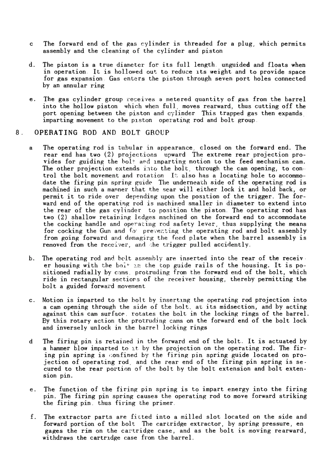
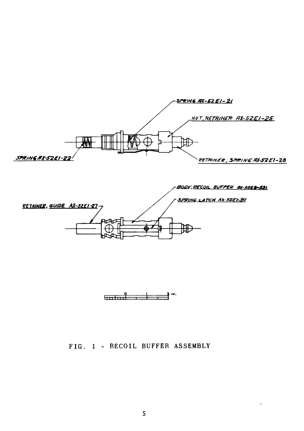
10. RECOIL BUFFER GROUP
a. The recoil buffer group is mounted into the lower portion of the rear end of
the receiver housing its position being directly rearward of the operating
rod, thereby, confining between the two, the driving spring The recoil buffer
is inserted into the receiver housing and rotated through ninety (90°) degrees
to lock in position. The recoil buffer latch spring then positions itself into
the receiver body, resisting any turning movement of the recoil buffer, unless
the recoil buffer latch spring is, in turn depressed.
b. The recoil buffer body houses the driving spring guide retainer which is
shouldered against the forward end of the recoil buffer body, thereby re-
stricting its movement The driving spring guide retainer is shouldered on its
rearward end and in turn is inserted into the recoil buffer body, and retained
in its forward movement by means of this shoulder.
c. The shock from the operating rod during recoil is absorbed by the recoil buf
fer through its inner and outer recoil buffer springs which are guided and
retained within the recoil buffer body by means of the recoil buffer spring
guide retainer, recoil buffer spring retainer and recoil buffer retainer nut.
The recoil buffer retainer nut is secured by threading it onto an external
diameter of the recoil buffer body and prevented from loosening itself by a
detent on the rear end of the recoil buffer latch spring See Fig. 1 Page 5.
4
о
FIG. 1 - RECOIL BUFFER ASSEMBLY
5
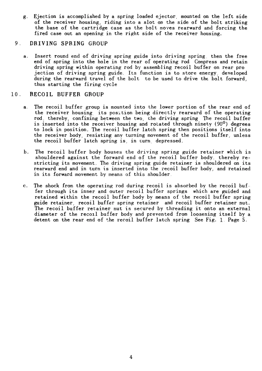
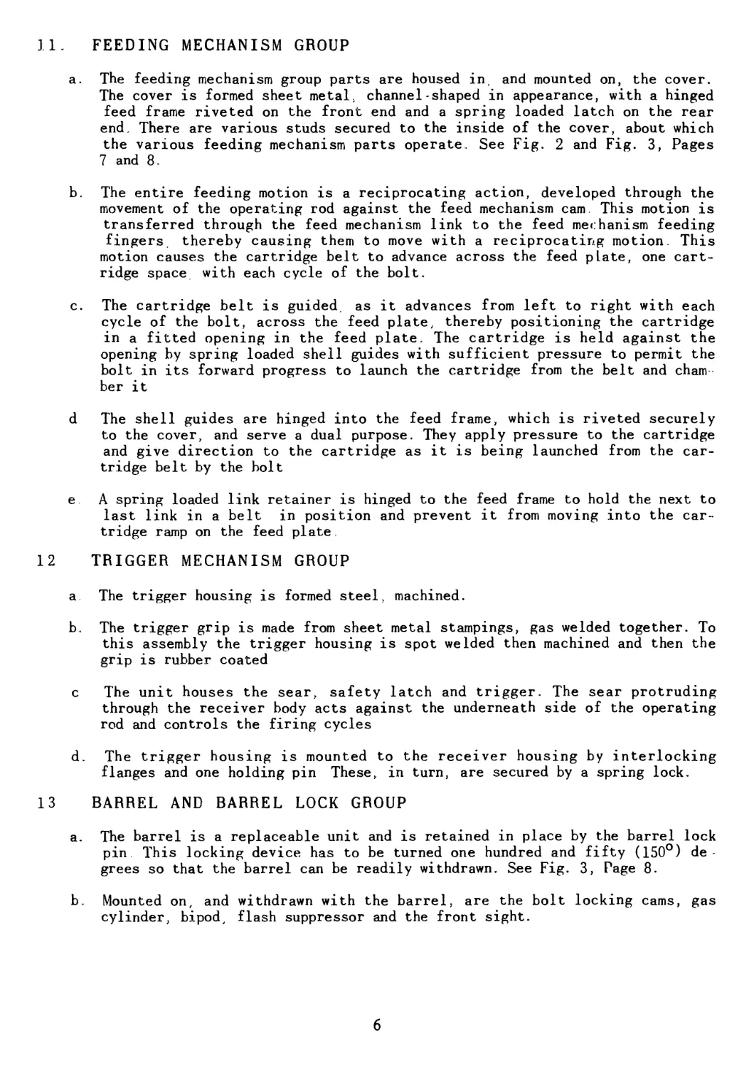
11. FEEDING MECHANISM GROUP
a. The feeding mechanism group parts are housed in, and mounted on, the cover.
The cover is formed sheet metal, channel-shaped in appearance, with a hinged
feed frame riveted on the front end and a spring loaded latch on the rear
end There are various studs secured to the inside of the cover, about which
the various feeding mechanism parts operate See Fig. 2 and Fig. 3, Pages
7 and 8.
b. The entire feeding motion is a reciprocating action, developed through the
movement of the operating rod against the feed mechanism cam. This motion is
transferred through the feed mechanism link to the feed mechanism feeding
fingers thereby causing them to move with a reciprocating motion. This
motion causes the cartridge belt to advance across the feed plate, one cart-
ridge space with each cycle of the bolt.
c. The cartridge belt is guided, as it advances from left to right with each
cycle of the bolt, across the feed plate, thereby positioning the cartridge
in a fitted opening in the feed plate. The cartridge is held against the
opening by spring loaded shell guides with sufficient pressure to permit the
bolt in its forward progress to launch the cartridge from the belt and cham
ber it
d The shell guides are hinged into the feed frame, which is riveted securely
to the cover, and serve a dual purpose. They apply pressure to the cartridge
and give direction to the cartridge as it is being launched from the car-
tridge belt by the bolt
e A spring loaded link retainer is hinged to the feed frame to hold the next to
last link in a belt in position and prevent it from moving into the car-
tridge ramp on the feed plate.
12 TRIGGER MECHANISM GROUP
a. The trigger housing is formed steel, machined.
b. The trigger grip is made from sheet metal stampings, gas welded together. To
this assembly the trigger housing is spot welded then machined and then the
grip is rubber coated
c The unit houses the sear, safety latch and trigger. The sear protruding
through the receiver body acts against the underneath side of the operating
rod and controls the firing cycles
d. The trigger housing is mounted to the receiver housing by interlocking
flanges and one holding pin These, in turn, are secured by a spring lock.
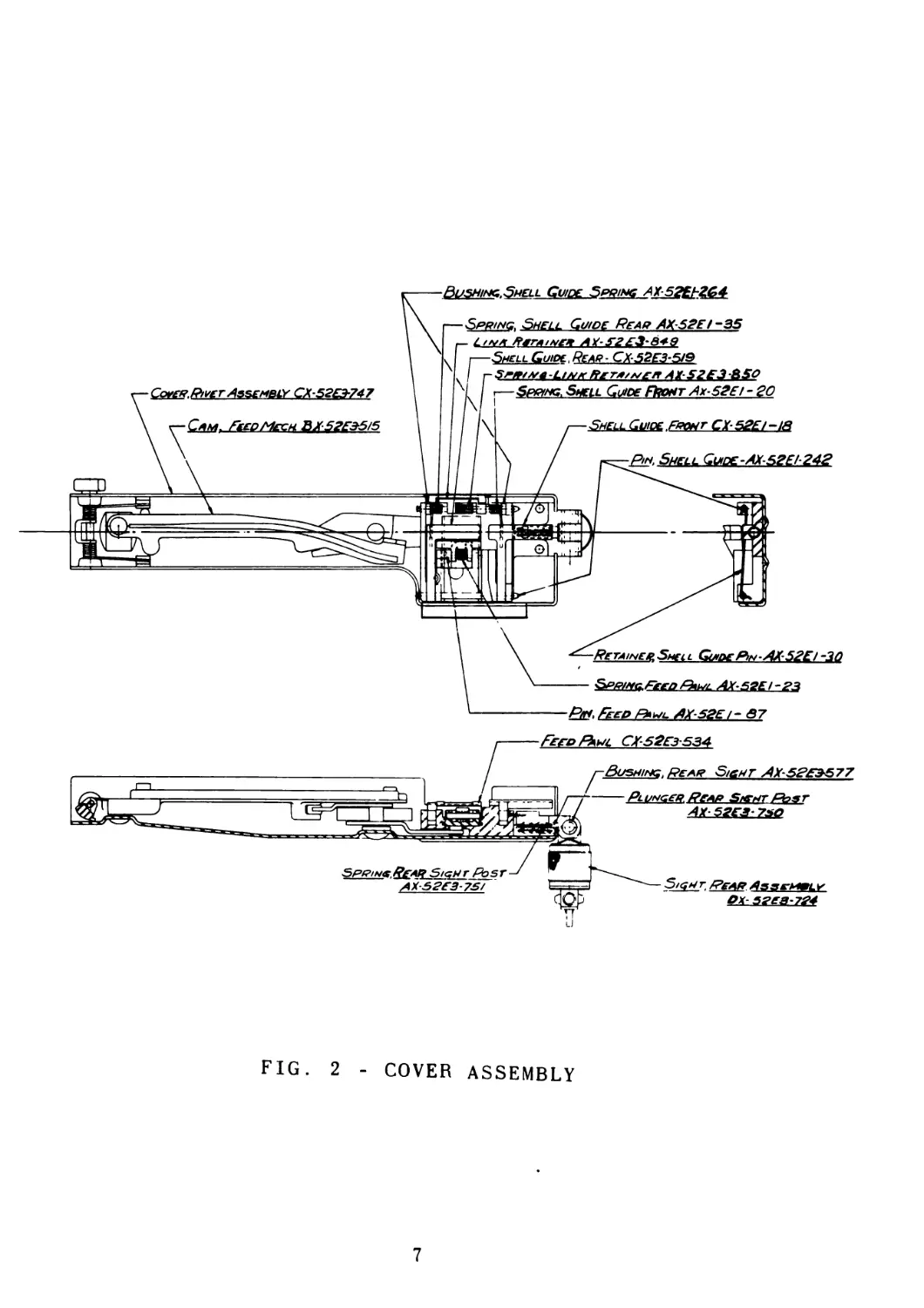
13 BARREL AND BARREL LOCK GROUP
a. The barrel is a replaceable unit and is retained in place by the barrel lock
pin This locking device has to be turned one hundred and fifty (150°) de-
grees so that the barrel can be readily withdrawn. See Fig. 3, Page 8.
b. Mounted on, and withdrawn with the barrel, are the bolt locking cams, gas
cylinder, bipod, flash suppressor and the front sight.
6
—Spring. Shell Guide Rear АХ-52Е! -35
r ^l^Reeaineit AX-F££^‘^4ff
J I—ShellJGuiPc,ReaR.-.CX^?E^51&
\ I i- Swam.link Пета,„er AX S2E3 8SO
Spring, Shell Guide Rioht Ax-52Ef-20
CoverPnet Assembly GX52E3-747
Cam. Feed Мес h ВХ52ЕЭ-5/5
ShellGuiqe Front CX-52El-i8
Pin. Shell Gude-AXS2E 1-242
RetaineelSmeil Guide R>n AX-52E/-3Q
SpringFeed AX-S2EI-23
P»ft&»l AX-52EM 87
FIG. 2 - COVER ASSEMBLY
7
FIG. 3 - COVER OPEN AND BARREL REMOVED
8
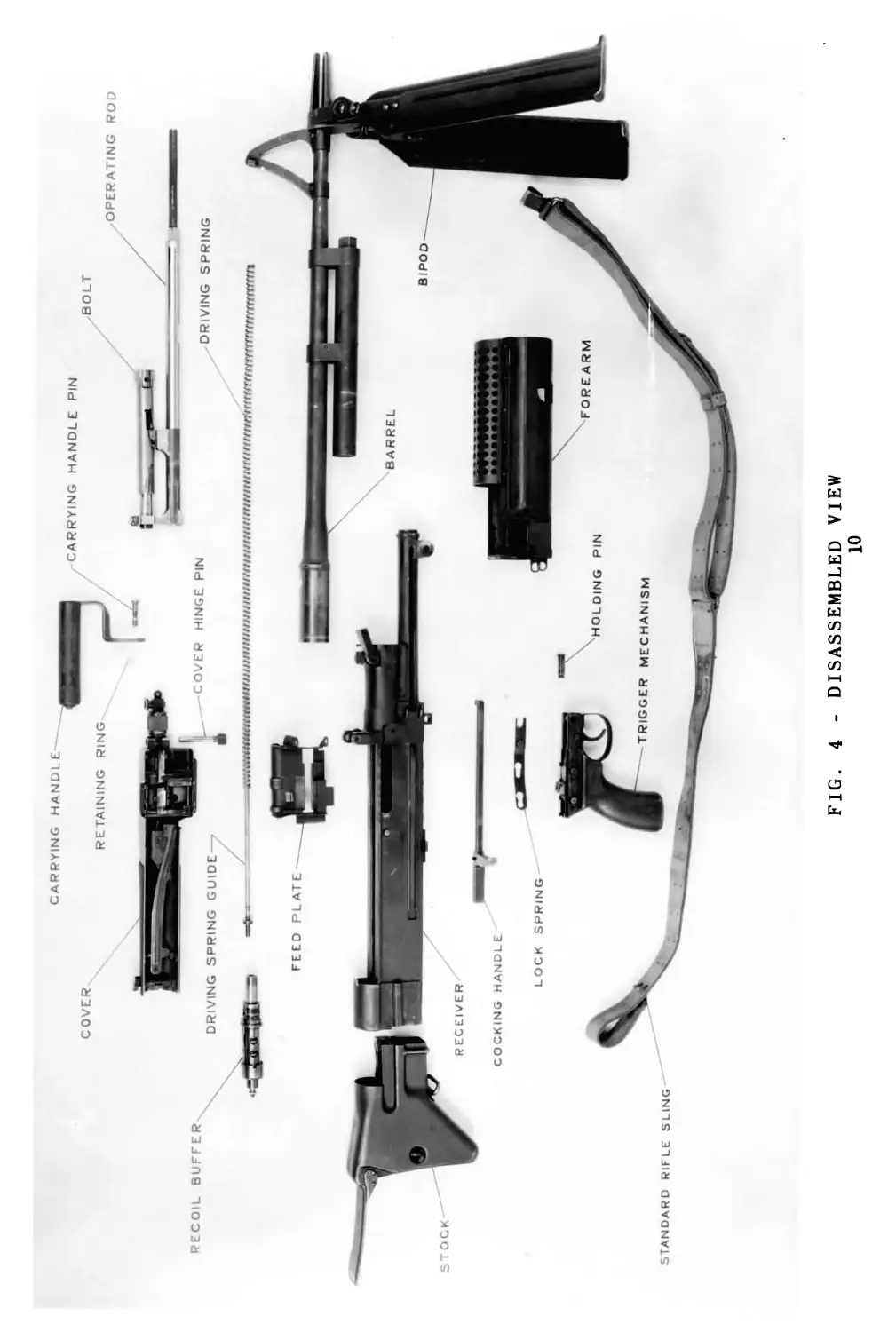
FIG. 4 - DISASSEMBLED VIEW
10
CHAPTER III
DISASSEMBLY AND ASSEMBLY
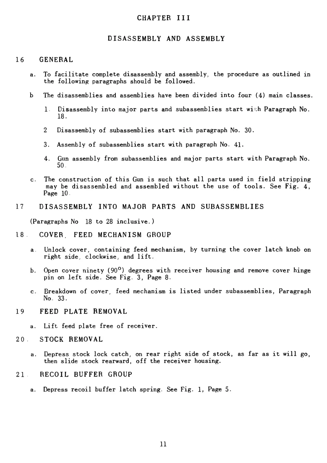
16 GENERAL
a. To facilitate complete disassembly and assembly, the procedure as outlined in
the following paragraphs should be followed.
b The disassemblies and assemblies have been divided into four (4) main classes.
1 Disassembly into major parts and subassemblies start with Paragraph No.
18.
2 Disassembly of subassemblies start with paragraph No. 30.
3 . Assembly of subassemblies start with paragraph No. 41.
4 . Gun assembly from subassemblies and major parts start with Paragraph No.
50.
c. The construction of this Gun is such that all parts used in field stripping
may be disassembled and assembled without the use of tools. See Fig. 4,
Page 10.
17 DISASSEMBLY INTO MAJOR PARTS AND SUBASSEMBLIES
(Paragraphs No 18 to 28 inclusive.)
18 COVER, FEED MECHANISM GROUP
a. Unlock cover, containing feed mechanism, by turning the cover latch knob on
right side., clockwise, and lift.
b. Open cover ninety (90°) degrees with receiver housing and remove cover hinge
pin on left side. See Fig. 3, Page 8-
c. Breakdown of cover, feed mechanism is listed under subassemblies, Paragraph
No. 33.
19 FEED PLATE REMOVAL
a. Lift feed plate free of receiver.
20 . STOCK REMOVAL
a. Depress stock lock catch, on rear right side of stock, as far as it will go,
then slide stock rearward, off the receiver housing.
21 RECOIL BUFFER GROUP
a. Depress recoil buffer latch spring. See Fig. 1, Page 5.
11
b Apply pressure to recoil buffer, latch spring before rotating ninety (90°) de-
grees to remove it from receiver housing. Do not release pressure on recoil
buffer at any time during above operation, or driving spring and guide will
fly out
c. Breakdown of recoil buffer is listed under subassemblies, Paragraph No. 35.
22. DRIVING SPRING
a. Remove recoil buffer group. Paragraph No. 21.
b Elevate forward end of Gun to permit driving spring and driving spring guide
to fall free.
23 OPERATING ROD AND BOLT
a. Draw the cocking handle to the rear for its complete stroke.
b Remove the operating rod and bolt by pulling it out of the receiver housing.
c Disassembly of operating rod from bolt is treated under subassemblies, Para-
graph Nos 30, 31 and 32
24 . COCKING HANDLE REMOVAL
a Slide cocking handle rearward to end of slot in socket, lift front end of
cocking handle from slot and continue to slide handle to rear of receiver
housing track until handle is free to remove from track.
25 BARREL REMOVAL GROUP
a. Push barrel lock handle forward to opening position, and with bipod legs in
closed position, grip them, then pull barrel from Gun socket. See Fig. 3,
Page 8.
26 FOREARM AND CARRYING HANDLE
a Remove trigger mechanism locking spring by depressing spring at safety latch
end and pushing spring away from the barrel toward rear of Gun until slot is
free from the front holding pin. See Fig. 9. Page 20.
b. Remove front trigger mechanism holding pin.
c Remove forearm by moving it forward until it is free of the tripod mounting
lugs on front end of the Gun socket. See Fig. 12, Page 31.
d. Io remove carrying handle from socket, first release retaining spring washer
from groove on carrying handle pin, then, with barrel lock handle in locked
position, the carrying handle pin can be taken out, allowing the handle to be
lifted free from socket. See Fig. 12, Page 31.
27 TRIGGER MECHANISM GROUP
a. Since the trigger mechanism locking spring and the front trigger mechanism
holding pin were removed to take off the forearm, the next step in disassem-
12
ly of the trigger mechanism group is to push the group forward one-quarter
(1/4) inch
b. Pull trigger group away from receiver housing.
c Disassembly of trigger mechanism group will be listed under subassemblies,
Paragraph No. 36
28 BARREL LOCK GROUP
a. To remove the barrel lock group, depress barrel lock cap to permit removal of
barrel lock retaining pin, then being careful, remove barrel lock cap, spring
and plunger Then pull handle horizontally to the right, and barrel lock
handle assembly will slide out of socket.
29 DISASSEMBLY OF SUBASSEMBLIES
(Paragraph Nos 30 to 39 inclusive.)
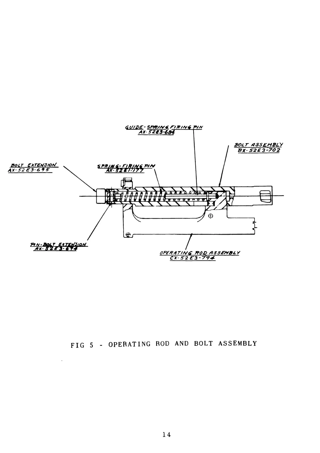
30 OPERATING ROD AND BOLT
a Grip operating rod and bolt assembly in one hand so that bolt extension can
be placed against some stationary object and depressed. With bolt extension
depressed, then with the nose of a cartridge, held in other hand, push bolt
extension pin out of hole as far as cartridge will go, then pull pin free of
bolt Do not release pressure until taking hold of bolt extension with free
hand and ease bolt extension out of bolt being careful not to allow extension
and firing pin spring to fly free. See Fig. 5, Page 14.
b. Remove firing pin spring and then turn operating rod and bolt assembly so
that the rear end is downward to allow the firing pin spring guide to fall
free.
c. Grip operating rod in one hand and the bolt in the other, slide bolt forward
for its full travel on operating rod projection, then lift upward and forward
to free bolt of operating rod projection and guide hole on extreme rear pro-
jection of operating rod.
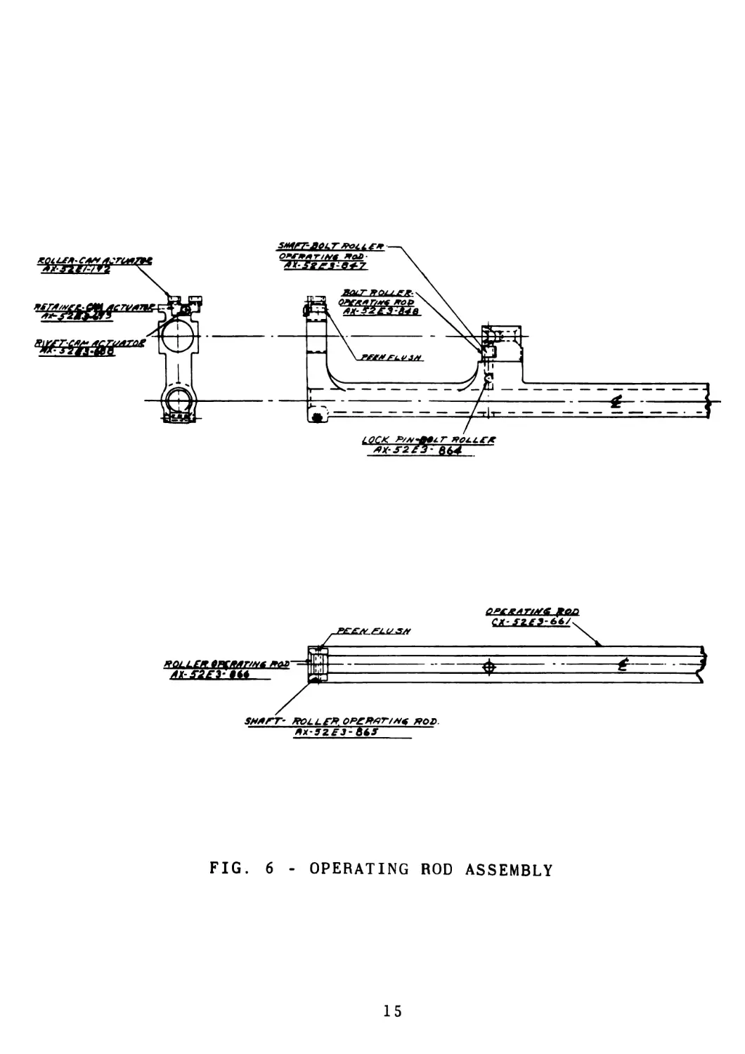
31 , OPERATING ROD GROUP
a. Operating rod assembly including rollers and operating rod extension, is con-
sidered a fixed assembly, and to be disassembled only to replace worn parts.
See Fig 6, Page 15.
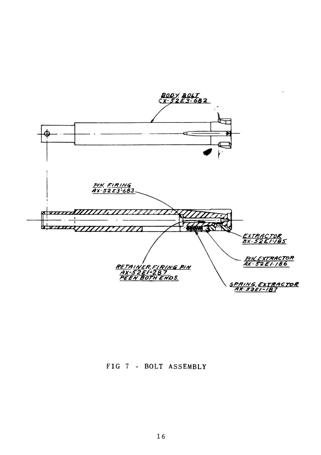
32 BOLT GROUP
a Remove retainer firing pin; elevate forward end of bolt to allow firing pin
to fall free See Fig. 7, Page 16.
b. Remove spring loaded cartridge extractor by inserting nose of cartridge into
hole in extractor. Then, apply pressure to the cartridge case in the direc-
tion of rear end of bolt to release keeper in recess of bolt. Be careful not
to allow extractor spring and pin to fly free.
c. Elevate rear end of bolt to allow extractor pin and extractor spring to fall
free.
13
FIG 5 - OPERATING ROD AND BOLT ASSEMBLY
14
FIG. 6 - OPERATING ROD ASSEMBLY
15
X
+
P/M FlRINt;
Px-52£3'~683
atZZZZZZ2ZZZZZZZZZ
VZZZZZZ/ZZ^ZT
££ZSd£ZQ£.
ВХУ2£/-/8У
FYZ/ ЕХТКЛСТОЯ
z9X-ne/-/86
eer/1/A/l£Krr//?//YS P/H
z9X-S2£/-2B7
P££H ВОГН EMDS
SPR/HG EX ГК* * C TO К
*X.T2£f-/&7
FIG 7 - BOLT ASSEMBLY
16
33 COVER, FEED MECHANISM GROUP
a Place feed mechanism cover group so that the interior is in full view and
cover hinge to the right See Fig. 2, Page 7.
b. With feed mechanism cam against near side of cover and a cartridge held ver-
tical in right hand, with its nose in depression on top of cam buffer, de-
press cam buffer toward near side; then, with another cartridge in left hand,
insert its nose under lug on feed mechanism cam opposite cam buffer and pry
up to free it from cam buffer retainer. Then, lift feed mechanism cam free of
cover.
c. To remove shell guides, shell guide springs, link retainer, and link retainer
spring remove retainer of shell guide pins, release shell guide springs from
under shell guides, then remove shell guide pins, guides, link and springs
can then be taken out
d Position feed pawl slide so that feed pawl pin can be removed through hole in
feed frame thus releasing feed pawl and feed pawl spring.
e. To remove rear sight assembly from cover, hold cover and with cartridge in
other hand insert nose of cartridge into hole in bushing, rear sight, push
through as far as possible, leave cartridge in cover hinge, grasp bushing on
opposite side and remove. Take hold of rear sight and remove cartridge, being
careful not to allow rear sight plunger, rear sight spring, and elevation
knob spring to fall free of cover.
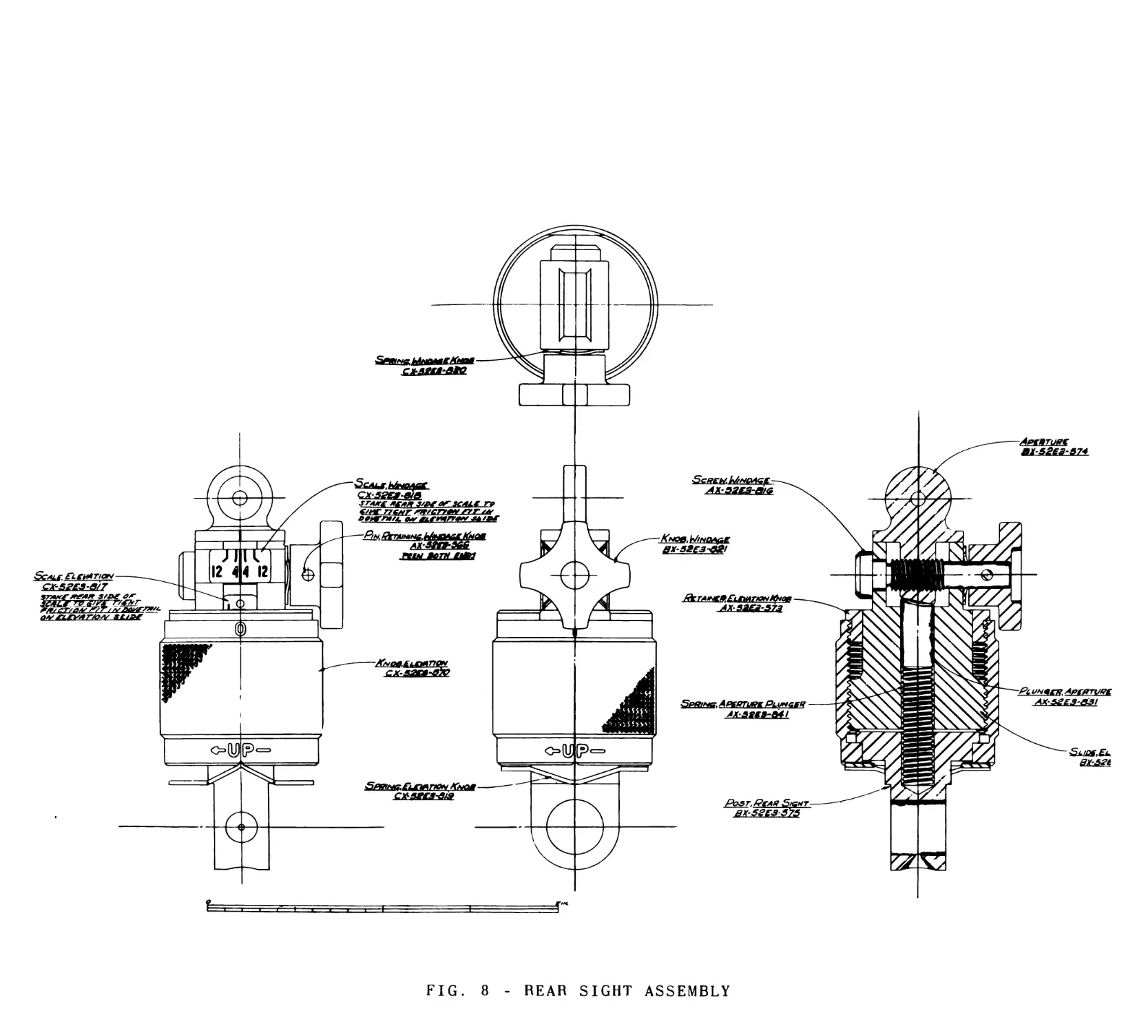
34 REAR SIGHT
a The rear sight is a unit assembly, to be taken apart only for repairs. See
Fig. 8. Page 18
b Grip knurled elevation knob and with a small open end wrench turn elevation
knob retainer counter clockwise until it is free of knob.
c Hold elevation knob in one hand, then with other hand, turn elevation slide
and aperture assembly, counter clockwise until it is free of knob, being
careful not to drop aperture plunger out of hole in elevation slide.
d Turn elevation knob upside down and aperture plunger spring and rear sight
post will fall free
e To take elevation slide and aperture assembly apart, remove press fit windage
knob retaining pin, then slide off windage knob and windage knob spring.
f. Turn windage screw counter clockwise until it is free of aperture, then pull
it free of elevation slide.
g Lift aperture then elevation knob retainer free of elevation slide.
17
FIG. 8
REAR SIGHT ASSEMBLY
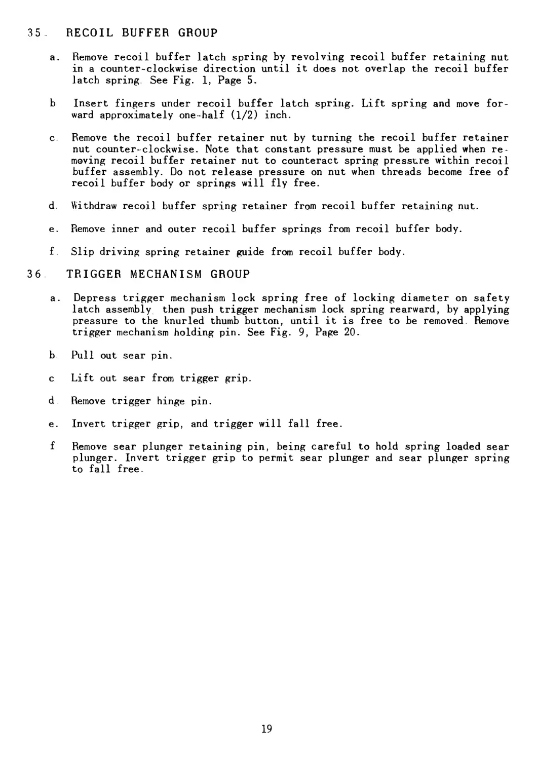
35 . RECOIL BUFFER GROUP
a. Remove recoil buffer latch spring by revolving recoil buffer retaining nut
in a counter-clockwise direction until it does not overlap the recoil buffer
latch spring. See Fig. 1, Page 5.
b Insert fingers under recoil buffer latch spring. Lift spring and move for-
ward approximately one-half (1/2) inch.
c. Remove the recoil buffer retainer nut by turning the recoil buffer retainer
nut counter-clockwise. Note that constant pressure must be applied when re-
moving recoil buffer retainer nut to counteract spring pressure within recoil
buffer assembly. Do not release pressure on nut when threads become free of
recoil buffer body or springs will fly free.
d. Withdraw recoil buffer spring retainer from recoil buffer retaining nut.
e. Remove inner and outer recoil buffer springs from recoil buffer body.
f. Slip driving spring retainer guide from recoil buffer body.
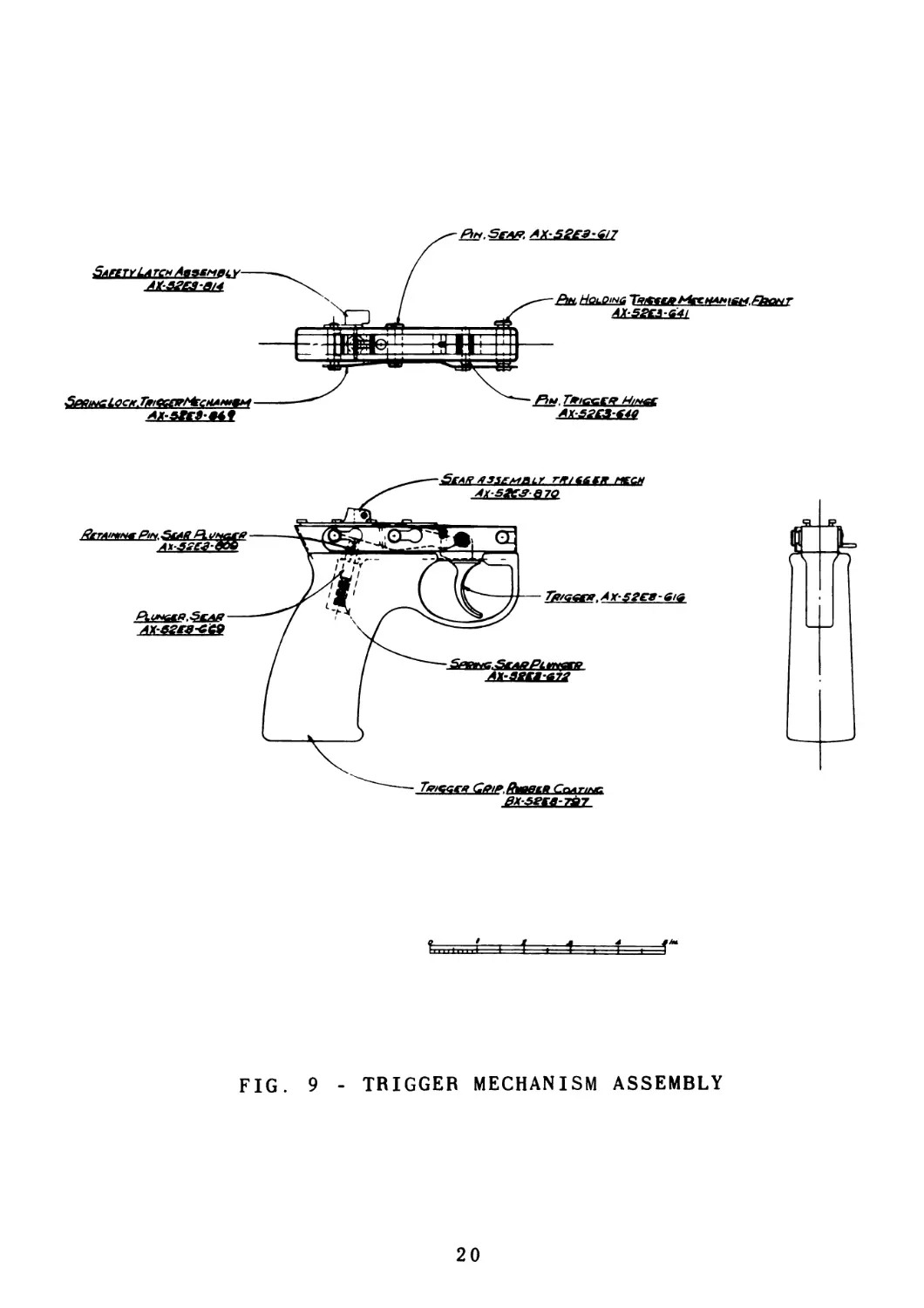
36 TRIGGER MECHANISM GROUP
a. Depress trigger mechanism lock spring free of locking diameter on safety
latch assembly then push trigger mechanism lock spring rearward, by applying
pressure to the knurled thumb button, until it is free to be removed. Remove
trigger mechanism holding pin. See Fig. 9, Page 20.
b Pull out sear pin.
c Lift out sear from trigger grip.
d Remove trigger hinge pin.
e. Invert trigger grip, and trigger will fall free.
f Remove sear plunger retaining pin, being careful to hold spring loaded sear
plunger. Invert trigger grip to permit sear plunger and sear plunger spring
to fall free.
19
POl.Sga*. AX-S^-S/7
1.....f i -I . 1 f =Г
FIG. 9 - TRIGGER MECHANISM ASSEMBLY
20
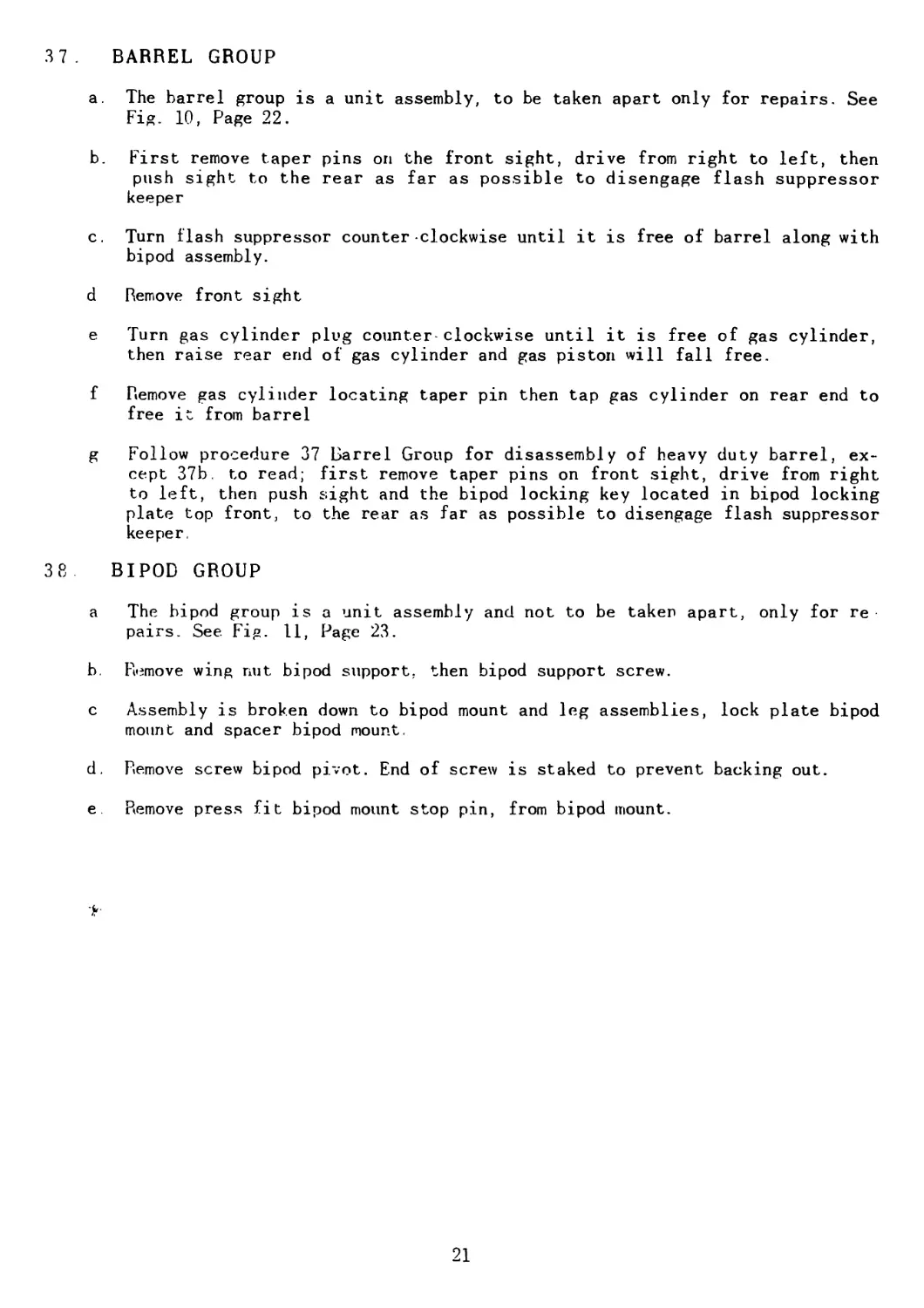
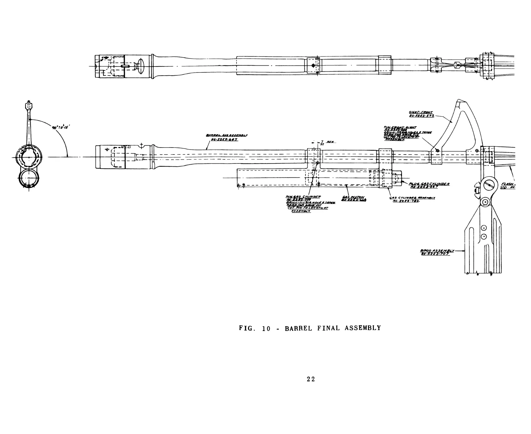
37. BARREL GROUP
a. The barrel group is a unit assembly, to be taken apart only for repairs. See
Fig. 10, Page 22.
b. First remove taper pins on the front sight, drive from right to left, then
push sight to the rear as far as possible to disengage flash suppressor
keeper
c. Turn flash suppressor counter clockwise until it is free of barrel along with
bipod assembly.
d Remove front sight
e Turn gas cylinder plug counter clockwise until it is free of gas cylinder,
then raise rear end of gas cylinder and gas piston will fall free.
f Remove gas cylinder locating taper pin then tap gas cylinder on rear end to
free it from barrel
g Follow procedure 37 Barrel Group for disassembly of heavy duty barrel, ex-
cept 37b. to read; first remove taper pins on front sight, drive from right
to left, then push sight and the bipod locking key located in bipod locking
plate top front, to the rear as far as possible to disengage flash suppressor
keeper.
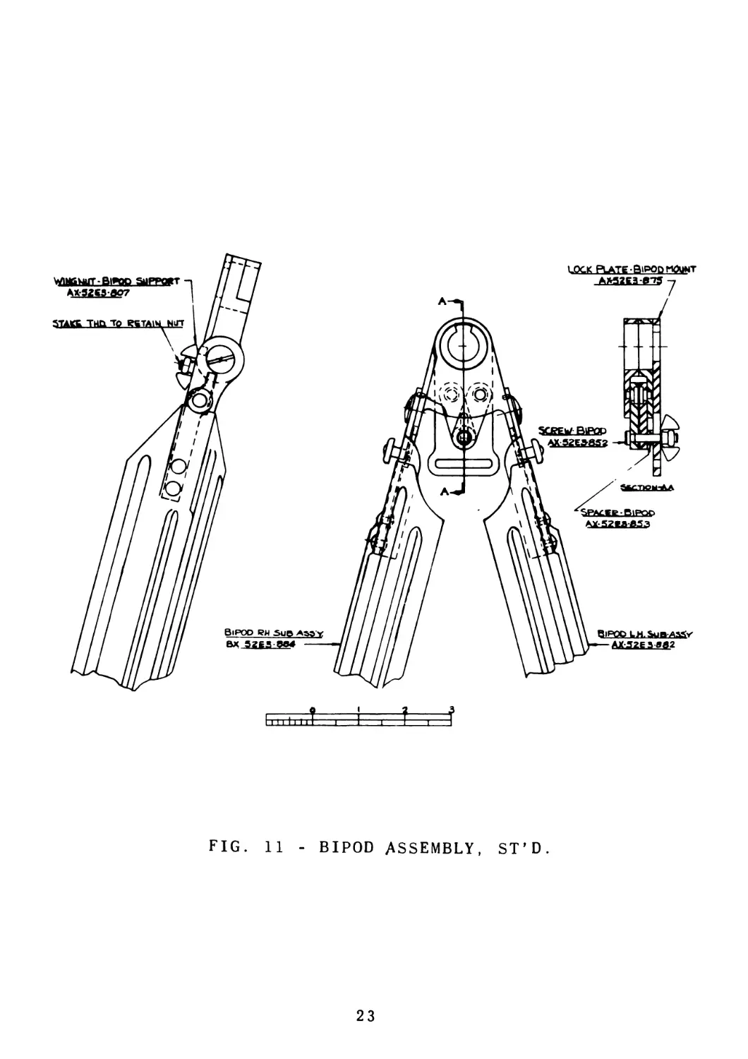
38. BIPOD GROUP
a The bipod group is a unit assembly and not to be taken apart, only for re
pairs. See Fig. 11, Page 23.
b. Remove wing nut bipod support, then bipod support screw.
c Assembly is broken down to bipod mount and leg assemblies, lock plate bipod
mount and spacer bipod mount.
d. Remove screw bipod pivot. End of screw is staked to prevent backing out.
e Remove press fit bipod mount stop pin, from bipod mount.
21
FIG. 10 - BARREL FINAL ASSEMBLY
22
23
39 RECEIVER HOUSING GROUP
a. Operating rod safety assembly to be removed only for repairs. To remove op-
erating rod safety assembly, drive out operating rod safety pin, since the
housing was staked over both ends of the pin at assembly, then raise rear end
of receiver housing and the operating rod safety assembly will fall out. See
Fig. 13; Page 32.
b To remove ejector on left side of receiver housing, first raise closed end of
cartridge ejector spring out of retaining slot on ejector, then slide spring
toward socket until it is free of ejector pin holes. See Fig 13. Page 32.
c. Remove ejector pin and lift ejector out of retaining slot in receiver housing.
40 ASSEMBLY OF SUBASSEMBLIES
(Paragraph Nos 41 to 48, inclusive )
a. Prior to assembly, all parts must be free of dirt, rust, and other extraneous
matter Metal parts in contact must be covered with a light film of lubri-
cating oil
41 . BOLT GROUP
a Insert extractor spring, then extractor pin, small diameter first, into hole
in recess on forwzrd end of bolt. See Fig. 7, Page 16.
b Place extractor into recess in bolt so that extractor pin fits groove in ex-
tractor Apply pressure to forward end of extractor to compress extractor
spring, and also press extractor down until it drops into retaining recess in
bolt.
c Insert point of firing pin into hole, rear center of the bolt body; then ro-
tate firing pin until retaining groove lines up with firing pin retaining
hole in bolt to permit assembly of press fit firing pin retainer.
42 OPERATING ROD GROUP
a Insert bolt roller shaft through hole in bottom side of operating rod., and
through bolt roller as far as it will go, then assemble bolt roller lock pin,
in hole on side of operating rod projection, and peen both ends See Fig. 6,
Page 15
b On lower rear end of operating rod, assemble operating rod roller and oper-
ating rod roller shaft then peen both ends.
c On upper rear operating rod projection assemble two (2) cam actuator rollers
with retaining grooves down, then cam actuator retainer with retainers in
grooves on rollers, then insert cam actuator rivet through holes in retainer
and operating ^od and peen flush on operating rod.
43 . OPERATING ROD AND BOLT GROUP
a Insert rear end of bolt assembly through hole on rear operating rod pro-
jection so that the cam track in bolt will drop over the other projection on
the operating rod Rotace bolt to rearmost position. See Fig. 5, Page 14
24
b Insert firing pin spring guide, shouldered end first into hole in rear end of
bolt then firing pin spring
c Holding operating rod and bolt so that bolt extension, small end inside of
firing pin spring, can be placed against some stationary object to compress
firing pin spring, rotate extension until holes in extension and bolt are in
line, then insert bolt extension pin until the extension drops into small
diameter on pin. This assembly is correct if there is a one-thirty second
(1/32) of an inch gap between the extension and bolt
44 . TRIGGER MECHANISM GROUP
a Insert sear plunger spring, then sear plunger, flat end first and plunger
slot in line with retaining pin hole in grip. Compress spring and plunger un-
til sear plunger retaining pin can be pressed into position. See Fig. 9,
Page 20
b. Drop trigger, small end first into trigger grip body, align trigger hinge
hole with hole in grip and insert trigger hinge pin on right side of trigger
grip
c Drop sear assembly into trigger grip body with large end to rear of grip,
align sear pin hole with hole in grip, by compressing sear plunger and hold-
ing it in position till sear pin is inserted on left side of trigger grip.
d Insert safety latch on left side of trigger grip with lever to the trigger
end of grip
e Insert trigger mechanism holding pin on left front side of trigger grip.
f Holding, safety latch pin sear pin, and trigger mechanism holding pins in
position, on right side of grip, assemble trigger mechanism lock spring on
left side by inserting open end of spring in groove on holding pin and drop-
ping spring over the other pins. Next depress lock spring to clear locking
diameter on safety latch and slide lock spring forward, with the aid of
knurled button on trigger end of spring, until it can go no further, release
spring pressure at safety latch and spring will be locked in position.
45 . RECOIL BUFFER GROUP
a Place the small end of the driving spring guide retainer through the large
bore ot the recoil buffer body until it is seated against the shoulder. See
Fig 1, Page 5.
b. Push the outer recoil buffer spring into the hole in the recoil buffer body
until it contacts the driving spring guide retainer.
c Insert inner recoil buffer spring inside the outer recoil buffer spring un-
til it seats against the driving soring guide retainer.
d Insert the recoil buffer spring retainer, with the smaller cylindrical sec-
tions entering first, through the locating hole and resting against the
shoulder in the recoil buffer retaining nut.
e Place the recoil buffer retainer nut over the inner and outer recoil buffer
springs, compressing the springs and revolving the recoil buffer retainer nut
25
clockwise with the recoil buffer body facing away from the operator.
f Retain recoil buffer nut by recoil buffer latch spring. Insert recoil buffer
latch spring in slot of flange, and latch spring rivet in retaining hole, on
buffer recoil body
g Depress recoil buffer latch spring, end with detent adjacent to recoil buffer
retainer nut then tighten nut until the slotted retaining flange overlaps
the spring detent.
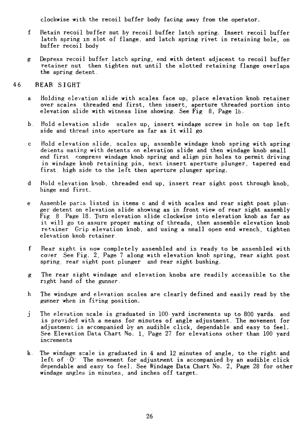
46 REAR SIGHT
a Holding elevation slide with scales face up, place elevation knob retainer
over scales threaded end first, then insert, aperture threaded portion into
elevation slide with witness line showing. See Fig 8, Page lb.
b. Hold elevation slide scales up, insert windage screw in hole on top left
side and thread into aperture as far as it will go.
c Hold elevation slide, scales up, assemble windage knob spring with spring
detents mating with detents on elevation slide and then windage knob small
end first compress windage knob spring and align pin holes to permit driving
in windage knob retaining pin, next insert aperture plunger, tapered end
first, high side to the left then aperture plunger spring.
d Hold elevation knob, threaded end up, insert rear sight post through knob,
hinge end first.
e Assemble parts listed in items c and d with scales and rear sight post plun-
ger detent on elevation slide showing as in front view of rear sight assembly
Fig 8 Page 18. Turn elevation slide clockwise into elevation knob as far as
it will go to assure proper mating of threads, then assemble elevation knob
retainer Grip elevation knob, and using a small open end wrench, tighten
elevation knob retainer.
f Rear sight is now completely assembled and is ready to be assembled with
cover See Fig. 2, Page 7 along with elevation knob spring, rear sight post
spring, rear sight post plunger and rear sight bushing.
g The rear sight windage and elevation knobs are readily accessible to the
right band of the gunner.
h The windage and elevation scales are clearly defined and easily read by the
gunner when in firing position.
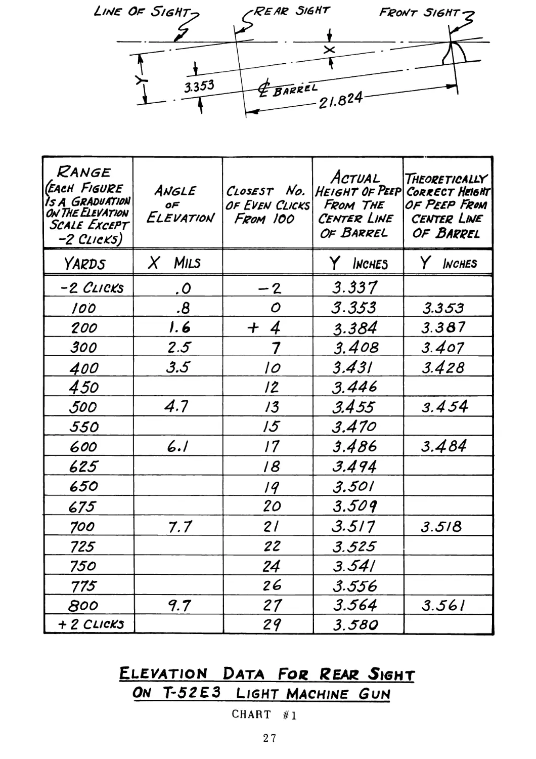
j The elevation scale is graduated in 100 yard increments up to 800 yards, and
is provided with a means for minutes of angle adjustment. The movement for
adjustment is accompanied by an audible click, dependable and easy to feel.
See Elevation Data Chart No. 1, Page 27 for elevations other than 100 yard
increments
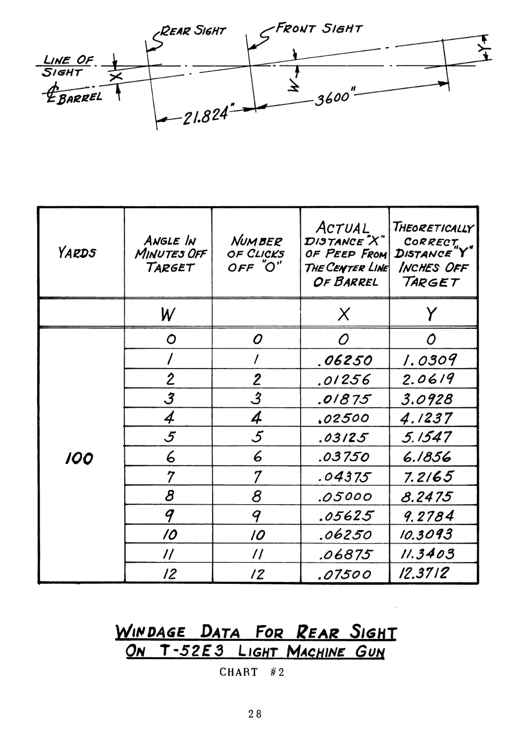
k. The windage scale is graduated in 4 and 12 minutes of angle, to the right and
left of O’ The movement for adjustment is accompanied by an audible click
dependable and easy to feel. See Windage Data Chart No. 2, Page 28 for other
windage angles in minutes, and inches off target.
26
£ang e (EACH FIGURE ISA GRADUATION ONlllE ELEVATION Scale Except -2 Clicks) Angle OF Elevation Closest No. of Even Clicks F/гом /00 Actual Height Of Peep From The Center Line Of Barrel THEORETICALiy Correct Height of Peep From center Line of Barrel
Yards X Mils Y tafS Y Inches
-2 Clicks .0 -2 3.337
/00 .8 0 3.353 3.353
200 1.6 + 4 3.384 3.387
300 2.5 7 3.408 3.4o7
400 3.5 lo 3.43! 3.428
450 /2 3.446
500 4.1 /3 3.455 3.454
550 /5 3.470
600 GJ 17 3.486 3.484
625 /8 3.474
650 /7 3.50/
675 20 3.503
700 7.7 21 3.5/7 3.5/8
725 22 3.525
750 24 3.54/
775 26 3556
800 7.7 27 3.504 3.56/
+ 2 CLICKS 21 3.580
Elevation Data Fog Rear Sight
On T-52E3 light Machine Gun
CHART #1
27
Bear Sight
Front Sight
YARDS Angle In Minutes Off Target Мим вер of Clicks OFF "O” Actual distance "Xn Of Peep From The Сергее Line Of Barrel Theoretically Correct, Distance Y Inches Off Target
IV X Y
/00 0 0 0 0
/ / . 06250 J. 030Я
2 2 .0/256 2.06/Я
£ 3 .0/875 3.0728
4 4 .02500 4./237
5 £ .03/25 5. /547
6 6 .03 750 6./856
7 7 .04375 7.2/65
8 8 .05000 8.2475
Я Я .05625 7.2784
/0 Ю .06250 /О.ЗО 73
// // .06875 П.3403
12 iz .07500 12.3712
Windage Data For Rear Sight
On T-52E3 Light Machine Gun
CHART #2
28
m The rear sight is constructed to permit the Gun to be zeroed in, by adjusting
the elevation and windage scales against friction interference, to their
proper locations The 100 yard marking on the elevation scale to be aligned
with the nearest elevation knob click and in line with the top of the eleva-
tion slide The zero on the windage scale to be aligned with the nearest
click of the windage knob and the witness line on the aperture.
n The aperture (peep) is large enough to afford clear vision in poor light.
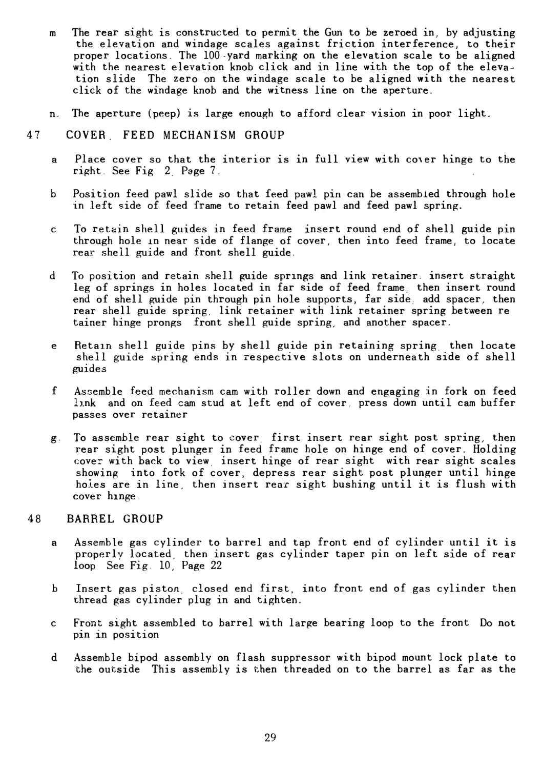
47 COVER. FEED MECHANISM GROUP
a Place cover so that the interior is in full view with солег hinge to the
right See Fig 2 Page 7
b Position feed pawl slide so that feed pawl pin can be assembled through hole
in left side of feed frame to retain feed pawl and feed pawl spring.
c To retain shell guides in feed frame insert round end of shell guide pin
through hole in near side of flange of cover, then into feed frame, to locate
rear shell guide and front shell guide.
d To position and retain shell guide springs and link retainer, insert straight
leg of springs in holes located in far side of feed frame., then insert round
end of shell guide pin through pin hole supports, far side, add spacer, then
rear shell guide spring, link retainer with link retainer spring between re
tainer hinge prongs front shell guide spring, and another spacer
e Retain shell guide pins by shell guide pin retaining spring then locate
shell guide spring ends in respective slots on underneath side of shell
guides
f Assemble feed mechanism cam with roller down and engaging in fork on feed
link and on feed cam stud at left end of cover, press down until cam buffer
passes over retainer
g. To assemble rear sight to cover first insert rear sight post spring, then
rear sight post plunger in feed frame hole on hinge end of cover. Holding
cover with back to view insert hinge of rear sight with rear sight scales
showing into fork of cover, depress rear sight post plunger until hinge
holes are in line, then insert rear sight bushing until it is flush with
cover hinge
48 BARREL GROUP
a Assemble gas cylinder to barrel and tap front end of cylinder until it is
properly located, then insert gas cylinder taper pin on left side of rear
loop See Fig. 10, Page 22
b Insert gas piston, closed end first, into front end of gas cylinder then
thread gas cylinder plug in and tighten..
c Front sight assembled to barrel with large bearing loop to the front Do not
pin in position
d Assemble bipod assembly on flash suppressor with bipod mount lock plate to
the outside This assembly is then threaded on to the barrel as far as the
29
flash suppressor will permit. Then the front sight is pushed forward until a
projection on its front bearing locates through the lock plate and into a
slot on the flash suppressor. Back off flash suppressor to permit alignment
of taper pin holes in front sight and barrel, then insert pins, from left to
right, drive fit.
e. Follow procedure 47 Barrel Group for assembly of heavy duty barrel, except
48 C to read, front sight assembled to barrel with large bearing loop to the
front then insert bipod locking key with small extension toward muzzle of
barrel and in keyway on top of barrel. Do not pin sight in position.
49 GUN ASSEMBLY FBOM SUBASSEMBLIES AND MAJOR PARTS
(Paragraph Nos 50 to 59 inclusive, See Fig. 4, Page 10, Fig, 12, Page 31, and
Fig 14, Page 35
a Prior to assembly, all parts must be free of dirt, rust, and other extran-
eous matter Metal parts in contact must be covered with a light film of
lubricating oil.
50 . RECEIVER HOUSING GROUP
a Assemble barrel lock group to receiver housing by inserting barrel lock
handle into lock locating hole on forward right side of socket. See Fig. 12,
Page 31 and Fig 14, Page 35.
b Insert barrel lock plunger into handle, small diameter first, and position it
in groove on socket.
c Insert barrel lock spring into plunger.
d. Depress spring with barrel lock cap and retain it by barrel lock retaining
pin insert tapered end first into hole on left side of barrel lock handle.
e Locate operating rod safety assembly in retaining socket slot as indicated on
receiver assembly Fig. 13, Page 32, then insert operating rod safety pin and
stake both sides of housing to retain pin. This part removed for repairs only
f Locate ejector in slot on left side of housing, align pin holes and insert
ejector pin, then insert cartridge ejector spring ends, into holes in ejector
pin. Push spring ends toward rear of housing until spring locates in pockets
on ejector housing and retaining slot on ejector.
30
GX-52E3-7Q5
OPERATING ROD & BOLT ASSEMBLY
BX-52E3-856
I approx.
43^ ---------
OREARM ASSEMBLY-CX-52E3-796
I—BARREL LOCK ASSEMBLY- AX-52E3- 7QI
SECTION A-A
//7//7
STANDARD RIFLE SLING;
SWIVEL AND SPRING CLIP
AX-52E3-fi8fi
DRIVING SPRING GUIDE-
8X52E 3-524
RECOIL BUFFER ASSEMBLY
BX-52E3-532
FEED PLATE BX-52E3-6I0
STOCK.FINAL ASSEMBLY
OVER ASSEMBLY CX-52E3-609
RIVING SPRING
AX-52EI-5Q
SECTION BB
°
© '
KING HANDLE ASSEMBLY BX-52E3-660
-COVER HINGE PIN BX-52EI-78
•CARRYING HANDLE ASSEMBLY ВХ-52ЕЭ-601
RETAINING RING AX-52E3-863
PIN, CARRYING HANDLE - AX-52E3-607
BARREL ASSEMBLY HD DX-52E3-7BB
BARREL ASSEMBLY STD DX-52E3-769
гшшушксдицмта J •
TRIGGER MECHANISM ASSEMBLY - CX-52E3-643
О I 2 3 4 5 6 7 6 9 10 II INCHES
FTP,
1 9
ППЫ МАТЫ AQQPMRIV
Ясля Въ&нс.Мссгню? BX-S2C3-S44
Сгыг№ B»iD№.f?£cEw£V AX- 52E3-542
NX* gllf<LFUQ^
НИМ»
R/vet. Center Bridge AX-52ES-GOT
Housing AdQEMBLY. Machining CX-S2E3-G78
Rivet. Cover Retaining Jarring AX:52£l-!35
Слстое Птшег АЬ52£3-б4б^
-I
4
Pin.Safety -Operating Rbo AX-S2E3-Q05
СтАНЕ.&ОГН StDES AF TER HaROEN/NR.
Socket OX-SSC3-6S3
С**ГЯф*£ case ищете* л*т*9*
COVER gtYAfUt^ 5 PE IMO AX-SZEf-ZZl
Cover Retaining Spring L eafAXSEE/- 230
Lap To .375! toSSo PtA AFTER HrD N/NG
—ZOO tg£S Honk To S/^e
AeTEP HARDENINIj
’Remove This Ssctiqn In Line
V/fTH Slots, Aetep Hardening-
Safety. Acsemblv
Rivet Flush
XfffTiBT.
AKSMMM
Rivet Tripod Plate
Lar To Dta. For з" True
Lenqth Аегер Haroen/ng
Pin.CoverRetain/n^ SPRfN^AX-32£‘i-l39
SFortvELO As /ndioated----------By£_5jZi*l
Both 3/Des
Ni^iEa^Q
ШЕСТОЕ -J
A^C№lgf
plug- socket
AX 52E3-S74
ARC U/E4-D IN 3-PMCC5
UOC47/Na AS SNOtf/A^ f
File Flush #irn воск
AFTSJt HAfeD£>4INd.
AFTtr Machism 4 AiSMBLX
Remove all Spot Welhn* Знатпе
Im /ННЕЯ Hous/pc Ans Polish.
R A/ectsgary. Then F^rrdEvpriee
In Accordance ^Ath Spec.
XXo 5P&2C 7\npeif СсаяяА Fwon
FIG. 13 - RECEIVER ASSEMBLY
51 . TRIGGER. CARRYING HANDLE AND FOREARM GROUP
a. Holding the receiver housing firmly, push the trigger mechanism grip, up in-
to flange interlocking position and over the locating lug connected to the
receiver housing, then push trigger mechanism grip rearward one-quarter (1/4)
inch. See Fig. 12, Page 31.
b Assemble carrying handle assembly on socket, line up hole in handle arm with
hole in socket, then insert carrying handle pin up to shoulder and add re-
taining ring. See Fig.. 12, Page 31.
c Next assemble forearm on forward end of receiver housing until holes in yoke
on forearm locate over trigger mechanism grip front mounting hole, then in-
sert front trigger mechanism holding pin, from left to right.
d Retaining the trigger mechanism holding pin, and with the trigger grip to the
left and hand grip pointing toward the operator, assemble the trigger mechan-
ism lock spring so that the grooves in it slip around the recesses cut into
the trigger mechanism housing locating pin, sear pin and safety latch, thus
locking the assembly in position
52 BARREL GROUP
a. Slide subassembly of barrel into receiver housing with rearward end of gas
cylinder seating over forward end of socket. See Fig. 12, Page 31.
b. Pull barrel lock handle rearward to locking position.
53 COCKING HANDLE
a. Assemble cocking handle on right side of Gun by locating roller end of cock-
ing handle in track on side of receiver housing and pushing handle forward
until hook end drops into opening on socket; then, push forward until cocking
handle spring pin rests on retainers on socket. See Fig. 3. Page 8.
54 . OPERATING ROD AND BOLT
a. Insert bolt group, with cartridge extractor end first, and operating rod
pushed rearward in bolt cam slot to position bolt locking lugs into rear end
of receiver housing.
b. Push operating rod and bolt assembly forward until bolt locking lugs engage
cam locks in barrel assembly.
55 DRIVING SPRING ASSEMBLY
a. Insert driving spring in hole in rear end of operating rod, then into the
exposed end of spring, insert the driving spring guide, round end first.
56 . RECOIL BUFFER GROUP
a. Holding Gun horizontally, with the muzzle pointing to the left, and the trig-
ger mechanism assembly pointing down, locate hole in buffer spring retainer
over driving spring guide. Then, apply pressure to the rear of the recoil
buffer assembly, to compress the driving spring, making sure to hold the re-
coil buffer assembly with the recoil buffer latch spring depressed.
33
b Shoulder recoil buffer assembly against the rear of the receiver housing and
rotate so that recoil buffer latch spring is up.
c_ Locate recoil buffer latch spring in receiver housing slot used to guide
operating rod.
57 . STOCK ASSEMBLY
a. Slide stock assembly onto guide rails on rearward end of receiver housing.
b. Push stock forward until catch in butt plate assembly locates in groove on
recoil buffer spring retainer.
58 FEED PLATE
a Slide feed plate into position, at hinge end of receiver housing.
59 COVER, FEED MECHANISM GROUP
a Cock Gun to full automatic position to allow closing of cover with feed
mechanism cam in proper alignment with cam actuator on operating rod.
b With cover at ninety (90°) degrees to receiver housing, locate tongue of
cover hinge on fork of socket hinge. See Fig. 3, Page 8.
c. Grip hinge pin with flat side toward cover, and insert lead end into hinge
until head on pin positions against hinge.
d Slam Cover shut. See Fig. 13, Page 32, and Fig. 14, Page 35.
34
FIG. 14 - COVER CLOSED - BIPOD MOUNTED
35
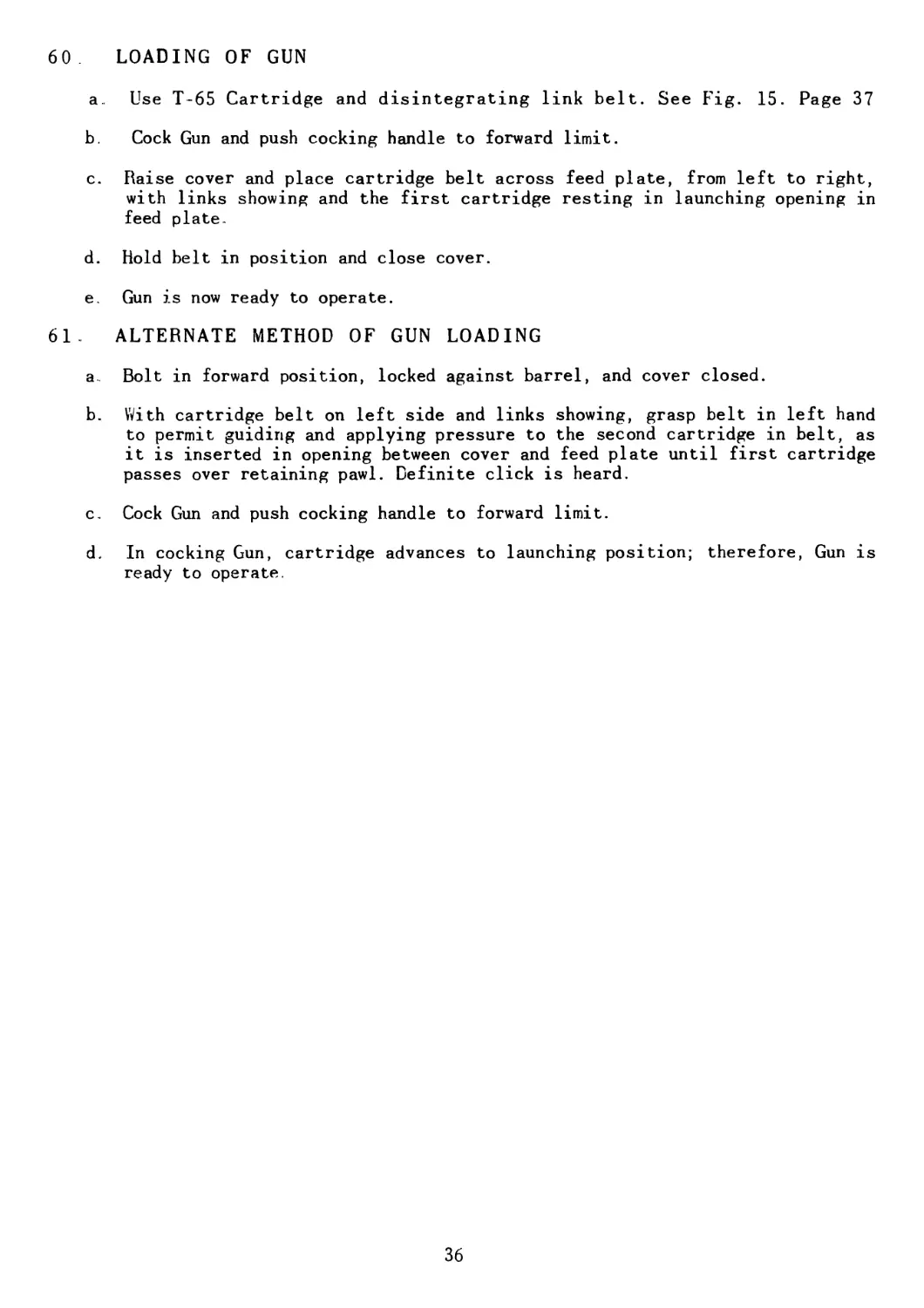
60 LOADING OF GUN
a. Use T-65 Cartridge and disintegrating link belt. See Fig. 15. Page 37
b. Cock Gun and push cocking handle to forward limit.
c. Raise cover and place cartridge belt across feed plate, from left to right,
with links showing and the first cartridge resting in launching opening in
feed plate-
d. Hold belt in position and close cover.
e Gun is now ready to operate.
61 ALTERNATE METHOD OF GUN LOADING
a Bolt in forward position, locked against barrel, and cover closed.
b. With cartridge belt on left side and links showing, grasp belt in left hand
to permit guiding and applying pressure to the second cartridge in belt, as
it is inserted in opening between cover and feed plate until first cartridge
passes over retaining pawl. Definite click is heard.
c. Cock Gun and push cocking handle to forward limit.
d. In cocking Gun, cartridge advances to launching position; therefore, Gun is
ready to operate.
36
R££F ’ ЭED №№г/ /р 'V'b
^Appropriate cassification) (evenf^
FIG. 15
HEAVY BARREL AND CARTRIDGE BELT IN PLACE
APPENDIX
LIST OF DRAWINGS
Master Drawing List DX-52E3-1000
Assemblies
Barrel, Final H. D......................................................DX-52E3-788
Barrel, Final St’d......................................................DX-52E3-769
Barrel, Subassembly H. D................................................DX-52E3-756
Barrel, Subassembly St d. .. ..........................................LX--52E3-647
Bipod H D. ......................................................... AX-52E3-885
Bipod St'd...............................................................BX-52E3-707
Bipod L. H. Subassembly ................................................AX-52E3-882
Bipod В H. Subassembly.................................................BX-52E3-884
Bolt.....................................................................BX-52E3-702
Buffer, Recoil ..........................................................BX-52E3-532
Cam, Feed Mechanism.................................................... BX-52E3-515
Carrying Handle .....................................................?. .. .BX-52E3-601
Cocking Handle ..........................................................BX-52E3-660
Cover .................................................................. CX-52E3-609
Cover, Riveting...........................................................CX- 52E3-747
Cover, Riveting and Rubber Coating........................................CX-52E3-790
Feed Frame ...............................................................BX-52E3-631
Feed Plate ...............................................................BX 52E3-610
Forearm . CX-52E3-796
Forearm Spot Welding......................................................CX-52E3-858
Gas Cylinder H D.........................................................AX-52E3-784
Gas Cylinder St;d....................................................... AX-52E3-782
Gun, Main ................................................................DX-52E3-741
Handle Barrel Lock.......................................................AX-52E3-760
Housing, Machining........................................................CX-52E3-678
Leg, Bipod L. H...........................................................AX-52E3-711
Leg, Bipod R. H..................................................;.......CX-52E3-710
Lock, Barrel .............................................................AX-52E3-701
Operating Rod.............................................................CX.- 52E3-794
Operating Rod and Bolt....................................................BX-52E3-856
Rivet, Spring Latch, Recoil Buffer........................................AX-52E1-30
Receiver, Machining ......................................................CX-52E3-705
Safety Latch .. ..........................................................AX- 52E3-814
Safety, Operating Rod.....................................................AX-52E3-801
Sear, Trigger Mechanism...................................................AX-52E3-870
Sight,. Rear .............................................................DX- 52E3-724
Spring Lock, Trigger Mechanism ...........................................AX-52E3-869
Stock, Final ....................................................... ....BX-52E3-583
Stock, Left Half, Welding ..............................................BX-52E3-843
Stock Right Half, Welding..............................................AX-52E3-887
Stock Welding........................................................ EX-52E3-829
Trigger Grip, Welding and Drilling........................................BX-52E3-636
Trigger Mechanism .............. 1.................................... CX-52E3-643
38
Guard Trigger .............................................................AX-52E3-625
Guide, Buffer ...............................................................AX-52E3-845
Guide, Driving Spring......................................................BX-52E3-524
Guide. Spring, Firing Pin .................................................AX-52E3-684
Handle Barrel Lock ........................................................AX-52E1-162
Hinge Pin. Cover ......... ................................................BX-52E1-78
Hinge Plate, Bipod Leg L. H................................................AX-52E3-835
Hinge Plate, Bipod Leg В. H................................................BX-52E3-828
Key, Front Sight IL D..................................................... AX-52E3-881
Key Locking Cam ...........................................................AX- 52E1-152
Knob, Cover Latch..........................................................AX-52E1-3
Knob. Elevation ...........................................................CX-52E3-570
Knoo, Windage .............................................................BX-52E3-821
Latch, Spring Recoil Buffer ..............................................AX-52E1-29
Leg, Bipod L H...........................................................AX-52E3-717
Leg Bipod R H...........................................................CX-52E3-718
Link, Belt (T 65) .......................................................DX-52E1--255
Link, Bipod Mount L. H....................................................AX-52E3-878
Link Bipod Mount R. H................................................... AX-52E3-877
Link Retainer ......................... ’................................. .AX-52E3-849
Locater, Forearm ..........................................................AX-52E3-815
Lock Pin Bolt Roller .....................................................AX-52E3-864
Lock Plate Bipod Mount H. D..............................................AX-52E3-876
Lock Plate Bipod Mount St’d...............................................AX-52E3-875
Nut Buffer Recoil Retainer .............................................. .AX-52E1-25
Operating Rod .............................................................CX-52E3-661
Pin, Barrel Lock ........................................................ AX-52E3-654
Fin Bolt Extension..................................................... AX-52E3--694
Pin, Cam Buffer ..........................................................AX-52E1-10
Pin, Carrying Handle .. . ................................................AX 52E3-607
Pin, Cocking Handle ......................................................AX-52E1-157
Pin. Cocking Handle Spring . .............................................AX-52E1-121
Pin, Cover Latch .........................................................AX--52E1-90
Pin, Cover Retaining Spring............................................. AX-52E1-159
Pin, Ejector .............................................................AX-52E3-690
Pin, Extractor............................................................AX-52E1-186
Pin. Feed Pawl ...........................................................AX-52E1-87
Pin Firing . . ..........................................................AX- 52E3-683
Pin, Front Sight Support .................................................AX-52E3-600
Pin, Gas Cylinder ....................................................... AX-52E3-599
Pin, Gas Cylinder H. D...................................................AX--52E3 789
Pin, Holding, Trigger Mechanism, Front ...................................AX-52E3- 641
Pin Locking Cams ........................................................AX-52E1-151
Pin Piston Retainer....... ..............................................AX-52E3-792
Pin Retaining Barrel Lock ..............................................AX-52E1-259
Pin Retaining Pawl ............................................... ......AX- 52E1-243
Pin, Retaining, Windage Knob..............................................AX- 52E3--569
Pin Safety Operating Rod ...............................................AX-52E3- 805
Pin, Sear ................................................................AX-52E3-617
Pin Shell Guide .........................................................AX-52E1-242
Pin, Trigger Hinge .......................................................AX-52E3-640
Pin Trigger Spring .................................................... AX-52E3-873
Piston Gas ...............................................................BX--52E3-664
Plate, Tripod ........................................................... AX-52E3-838
Plug Gas Cylinder .........................................................AX-52E3-667
Plug, Socket .............................................................AX-52E3--874
40
Plunger, Aperture ........................................................AX-52E3-831
Plunger, Barrel Lock .....................................................AX-52E1-163
Plunger, Rear Sight Post .................................................AX-52E3-750
Plunger, Sear.............................................................AX-52E3-669
Plunger, Shoulder Rest ...................................................AX-52E3-811
Post, Rear Sight .........................................................БХ-52ЕЗ-575
Push Button. Spring Lock, Trigger Meeh....................................AX-52E3-868
Push Rod. Bipod Leg.......................................................AX-52E3-825
Rear Bridge, Receiver ....................................................BX-52E3-544
Retainer, Buffer, Spring..................................................AX-52E1-28
Retainer, Cam Actuator Roller.............................................AX-52E3-693
Retainer, Elevation Knob..................................................AX-52E3-573
Retainer, Feed Cam .......................................................BX-52E1-41
Retainer, Firing Pin .....................................................AX-52E1-287
Retainer, Shell Guide Pin ................................................AX-52E1-130
Retainer, Shoulder Rest Plunger ..........................................AX-52E3-808
Retainer Spring Guide ....................................................AX-52E1-27
Retainer Stock Lock Catch.................................................AX-52E3-561
Retaining Pawl Feed Plate ................................................BX-52E3-538
Retaining Pin. Sear Plunger ..............................................AX 52E3-809
Retaining Ring............................................................AX-52E3-883
Rifle Sling Std ..........................................................AX-52E3-886
Rivet, Barrel Lock .......................................................AX-52E1-261
Rivet, Bipod Leg Spring...................................................AX-52E3 851
Rivet. Cam Actuator Roller ...............................................AX-52E3-688
Rivet, Center Bridge .....................................................AX-52E3-681
Rivet Cover Forearm ......................................................AX-52E3-863
Rivet Ccver Retaining Spring .............................................AX-52E1-135
Rivet, Feed Frame ........................................................AX-52E1-197
Rivet, Feed Pawl Slide ...................................................AX-52E1-245
Rivet, Feed Plate ........................................................AX-52E1-65
Rivet. Operating Rod .....................................................AX-52E1-293
Rivet Operating Rod Safety................................................AX-52E3-804
Rivet, Recoil Buffer.......................................................AX-52E1-26
Rivet, Shoulder Rest .....................................................AX-52E3-567
Rivet, Stud Feed Cam .....................................................AX-52E1-198
Rivet, Stud Feed Link ....................................................AX-52E1-199
Rivet, Trigger Spring.....................................................AX-52E3-872
Rivet, Tripod Plate ......................................................AX-52E3-839
Roller, Cam...............................................................AX-52E1-9
Roller Cam Actuator ......................................................AX-52E1-192
Roller, Cocking Handle ...................................................AX-52E1-156
Roller, Feed Pawl Slide ..................................................AX-52E1-244
Roller, Feed Plate .......................................................AX-52E1-276
Roller. Feed Plate .......................................................AX-52E1-277
Roller. Operating Rod................................................... AX-52E3-866
Safety Latch .............................................................AX-52E3-622
Safety, Latch Lever ......................................................AX-52E3-620
Safety, Operating Rod ....................................................AX-52E3-802
Scale, Elevation .........................................................CX-52E3-817
Scale, Windage ...........................................................CX-52E3-818
Screw, Bipod Pivot .......................................................AX-52E3-675
Screw, Bipod Support .....................................................AX-52E3-852
Screw, Windage ...........................................................AX-52E3-816
Sear Plunger, Housing.....................................................AX-52E3-812
Sear Trigger Mechanism....................................................AX-52E3-642
41
Seat. Buffer .............................................................AX-52E3-844
'Shaft, Bolt Roller Operating Rod ........................................AX-52E3-847
Shaft, Cam Roller ........................................................AX-52E1-13
Shaft, Cover Latch .......................................................AX-52E1-5
Shaft. Feed Plate ........................................................AX--52E1-278
Shaft, Roller, Operating Bod .............................................AX-52E3-865
Shaft, Sear Roller .......................................................AX-52E3-880
Shell Guide, Front .......................................................CX-52E1-18
Shell Guide, Rear ........................................................CX-52E3-519
Shield, Forearm ..........................................................AX-52E3-859
Shoulder Rest, Stock......................................................BX-52E3-559
Shoulder Rivet, Bipod Mount ......................................... ....AX-52E3-879
Sight, Front, St‘d . .....................................................BX-52E3-592
Sight Front. Heavy Barrel ................................................BX-52E3-762
Slide Elevation . ........................................................EX-52E3-576
Slide, Feed Pawl .........................................................CX-52E1-36
Socket, Receiver..........................................................DX-52E3-653
Spacer, Beveled...........................................................AX-52E3-746
Spacer, Bipod Support ...................................................... AX-52E3-853
Spacer, Cover Latch ....................................................... .AX-52E1-2
Spacer, Long .............................................................AX-52E3-748
Spacer, Short......... ... ...............................................AX-52E3-749
Spring.. Aperture Plunger ................................................AX-52E3-841
Spring, Barrel Lock .....................................................AX-52E1-176
Spring, Bipod Leg L H....................................................AX-52E3-833
Spring, Cam Buffer ......................................................AX-52E1-12
Spring, Carrying Handle .................................................AX-52E3-606
Spring, Cartridge Ejector ...............................................AX-52E3-689
Spring, Bipod Leg R. H...................................................AX 52E3-823
Spring. Cocking Handle ..................................................AX-52E1-158
Spring. Cover Latch .....................................................AX-52E1-6
Spring. Driving...........................................................AX-52E1-50
Spring, Elevation Knob ..................................................CX-52E3-819
Spring, Extractor .......................................................AX-52E1-187
Spring. Feed Link .......................................................EX-52E1-14
Spring, Feed Pawl .......................................................AX-52E1-23
Spring, Firing Pin . ....................................................AX-52E1-177
Spring, Inner Buffer ..... . ............................................. AX-52E1-22
Spring Link Retainer .. . ........................................... .AX-52E3-850
Spring, Lock, Trigger Mechanism..........................................AX-52E3-645
Spring, Outer Buffer ....................................................AX-52E1-21
Spring, Rear Sight Post .................................................AX-52E3-751
Spring Safety, Operating Rod.............................................. . AX-52E3-803
Spring, Sear Plunger.................................................... AX-52E3-672
Spring, Shell Guide Front ............................................... AX-52E1-20
Spring. Shell Guide Rear ................................................AX-52E1-35
Spring. Shoulder Rest Plunger ...........................................AX 52E3-564
। Spring, Stock Lock Catch........................................... AX-52E3-553
Spring, Retaining Pawl ..................................................AX-52E1-63
Spring, Windage Knob.....................................................CX-52E3-820
Stock, L. H.............................................................AX-52E3-832
Stock, R. H.............................................................CX-52E3-830
Stock, Rubber Coating ...................................................BX- 52E3-798
Stop Pin, Bipod ......................................................... AX-52E3-867
Strap.. Swivel Retainer ..................................................AX-52E3-810
Stud, Carrying Handle .................................................. AX-52E3-603
42
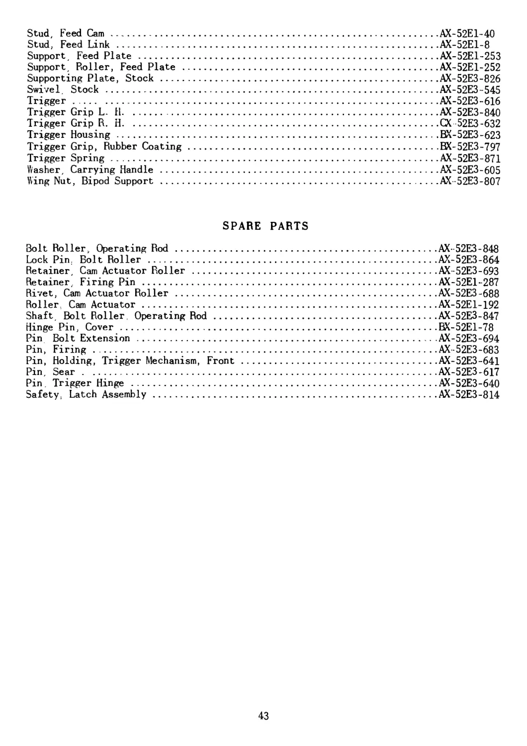
Stud, Feed Cam ............................................................AX-52E1-40
Stud, Feed Link ...........................................................AX-52E1-8
Support, Feed Plate .......................................................AX-52E1-253
Support, Roller, Feed Plate ...............................................AX-52E1-252
Supporting Plate, Stock....................................................AX-52E3-826
Swivel. Stock .............................................................AX-52E3-545
Trigger................................................................... AX-52E3-616
Trigger Grip L. H..........................................................AX-52E3-840
Trigger Grip R. H..........................................................CX 52E3-632
Trigger Housing............................................................BX-52E3-623
Trigger Grip, Rubber Coating...............................................BX-52E3-797
Trigger Spring.............................................................AX-52E3-871
Washer, Carrying Handle ...................................................AX-52E3-605
Wing Nut, Bipod Support .................................................. .AX -52E3-807
SPARE PARTS
Bolt Roller, Operating Rod.................................................AX- 52E3-848
Lock Pin. Bolt Roller .....................................................AX-52E3-864
Retainer, Cam Actuator Roller .............................................AX-52E3-693
Retainer, Firing Pin ......................................................AX-52E1-287
Rivet, Cam Actuator Roller ................................................AX-52E3-688
Roller, Cam Actuator.......................................................AX-52E1-192
Shaft Bolt Roller, Operating Rod...........................................AX-52E3-847
Hinge Pin, Cover...........................................................BX-52E1-78
Pin Bolt Extension ........................................................AX-52E3-694
Pin, Firing . .............................................................AX-52E3-683
Pin, Holding, Trigger Mechanism, Front ....................................AX-52E3-641
Pin, Sear .................................................................AX-52E3-617
Pin, Trigger Hinge ........................................................AX-52E3-640
Safety. Latch Assembly.....................................................AX-52E3-814
43