/


Tags: military affairs engineering design handbook
Year: 1963
Similar


Text
1ECRET
ЛИС CONTROL (S> 13690-63
AMC PAMPHLET
AMCP 706-212
RESEARCH AND DEVELOPMENT
OF MATERIEL
ENGINEERING DESIGN HANDBOOK
AMMUNITION SERIES
FUZES, PROXIMITY, ELECTRICAL
PART TWO (U)
degraded UNCLASSIFIED
By Authority of Letter DRCSS-1,
Huskerson, Dtd/УMay 7b z’.-У
Signaturd-'' 'Date^
See inside back cover for information on previous publications.
HEADQUARTERS U. S. ARMY MATERIEL COMMAND
JULY 1963
This material contain! information
affecting the national detente of the
United State* within the meaning
of th* Eapionag* Law*. Title 18.
U.S.C., See 793 and 794. the trani>
minion or revelation of which in
any manner to an unauthorized per*
on it prohibited by law.
SECRET
GROUP 3
Downgraded at 12 year
intervals; not automat-
ically declassified.
SECRET
HEADQUARTERS
UNITED STATES ARMY MATERIEL COMMAND
WASHINGTON 25, D. C.
18 July 1963
AMCP 7O6-212CS), Fuzes, Proximity, Electrical, Part Two (U),
forming part of the Ammunition Series of the Army Materiel Command
Engineering Design Handbook Series, is published for the information
and guidance of all concerned.
(AMCRD)
FOR THE COMMANDER:
SELWYN D. SMITH, JR.
Brigadier General, USA
Chief of Staff
OFFICIAL:
RJ 0. DAVID
Colonel, Gb
Chief, Admi
istrative Office
DISTRIBUTION:
Special
SECRET
SECRET
FOREWORD
The Ammunition Series is part of a group of
handbooks covering the engineering principles
and fundamental data needed in the develop-
ment of Army materiel, which (as a group)
constitutes the Engineering Design Handbook
Series.
Fuzes, Proximity, Electrical comprises five
numbered Parts, each of which is published as
a separate volume and assigned an Army Mate-
riel Command Pamphlet (AMCP) number. Ar-
rangement into Parts and Chapters, with
Chapter titles, is as follows:
AMCP 706-211(0, Fuzes, Proximity, Electri-
cal—Part One (U)
Chapter 1 —Introduction
Chapter 2 —Philosophy of Fuze Design
Glossary
Index
AMCP 706-212(S), Fuzes, Proximity, Electri-
cal—Part Two (U)
Chapter 3 —VHF and UHF Radio Systems
AMCP 706-213(S), Fuzes, Proximity, Electri-
cal—Part Three (U)
Chapter 4 —Microwave Radio Systems
AMCP 706-214 (S), Fuzes, Proximity, Electri-
cal—Part Four (U)
Chapter 5 —Nonradio Systems
Chapter 6 —Multiple Fuzing
AMCP 706-215(C), Fuzes, Proximity, Electri-
cal—Part Five (U)
Chapter 7 —Power Supplies
Chapter 8 —Safety and Arming Devices
Chapter 9 —Components
Chapter 10—Materials
Chapter 11—Construction Techniques
Chapter 12—Industrial Engineering
Chapter 13—Testing
The purpose of these handbooks is twofold:
(1) to provide basic design data for the expe-
rienced fuze designer, and (2) to acquaint new
engineers in the fuze field with the basic prin-
ciples and techniques of modern fuze design.
These handbooks present fundamental oper-
ating principles and design considerations for
electrical fuzes and their components, with par-
ticular emphasis on proximity fuzes. Informa-
tion on mechanical fuzes, and other general
information on fuzes, is contained in ORDP 20-
210, Fuzes, General and Mechanical.
As indicated by the Tattle of Contents, the ar-
rangement of material is primarily topical. This
permits ready reference to the area in which the
user desires information.
Some subjects are covered in considerable de-
tail, whereas others are covered only superfi-
cially. Generally, the amount of coverage is an
indication of the state of development of a sys-
tem. There are exceptions to this, however. For
example, although the section on optical fuzing
is comparatively extensive, this type of fuzing
is not as far advanced as other methods of fuz-
ing. Much of the information in this section,
however, is based on an unpublished report.
Rather than risk the loss of this information,
and to disseminate it more widely, the informa-
tion is included in these handbooks.
A Glossary is included in which terms that
are unique to the fuze field, or that have special
meaning in the fuze field, are defined.
References at the end of a chapter indicate
the documents on which the chapter is based.
They also furnish additional sources of infor-
mation.
Titles and identifying numbers of specifica-
tions, standards, regulations and other official
publications are given for the purpose of in-
forming the user of the existence of these docu-
ments, however, he should make certain that he
obtains editions that are current at the time of
use.
Defense classifications are indicated for chap-
ters, paragraphs, illustrations and tables. The
degree of classification of the contents of each
illustration or table is indicated by the appro-
priate initial symbol immediately preceding the
title. In the case of classified illustrations or ta-
bles the classification of the title itself is indi-
cated by appropriate initial symbol immediately
after such title.
SECRET i
SECRET
These handbooks were prepared under the
joint direction of the Harry Diamond Labora-
tories (formerly Diamond Ordnance Fuze Labo-
ratories) and the Engineering Handbook Office,
Duke University. Text material was prepared
by Training Materials & Information Services,
McGraw-Hill Book Company, Inc., under con-
tracts with both of these organizations. Mate-
rial for text and illustrations was made avail-
able through the cooperation of personnel of the
Harry Diamond Laboratories. The operation of
the Engineering Handbook Office of Duke Uni-
versity is by prime contract with the U. S. Army
Research Office, Durham.
Comments on these handbooks should be ad-
dressed to Commanding Officer, Army Research
Office, Durham, Box CM, Duke Station, Dur-
ham, N. C.
11
SECRET
SECRET
PREFACE
Part Two of this handbook, consisting of Chapter 3, covers the basic principles and design
considerations for radio proximity fuzes operating in the VHF and UHF bands. A Table of
Contents for all Parts is also included. The Index and a Glossary, defining terms that are unique
to, or that have special meaning in, the fuze field are included in Part One. Fuzing systems
considered in this volume include continuous-wave Doppler, pulsed Doppler, frequency-modu-
lated, pulsed frequency-modulated, radio induction field, capacity, and pulsed radar.
SECRET
SECRET
TABLE OF CONTENTS
Paragraph Page
PART ONE
FOREWORD'................................ ii
PREFACE.................................. iv
LIST OF ILLUSTRATIONS ...................... xviil
CHAPTER 1 <C) INTRODUCTION
l-l(C) Types of Fuzes............................ 1-1
1-1.1 (U) Proximity Fuzes......................... 1-1
1-1.2(U) Contact Fuzes........................... 1-1
1-1.3(C) Computer Fuzes ......................... 1-3
1-1.4(U) Guidance Fuzes.......................... 1-3
1-1.5 (U) Command Fuzes........................... 1-3
1-2 (U) Fuze Requirements......................... 1-3
1-3 (C) History................................... 1-4
1-3.1 (U) World War II............................ 1-4
1-3.2(C) World War II to Korean War.............. 1-7
1-3.3(C) Korean War to 1960 ..................... 1-9
(U) REFERENCES ............................ 1-10
CHAPTER 2 (C) PHILOSOPHY OF FUZE DESIGN
2-1 (U) Introduction.............................. 2-1
2-2(C) Requirements for Any Fuze................ 2-1
2-2.1 (U) Safety..................................... 2-1
2-2.2(U) Detonation ................ 2-1
2-2.2.1(U) Terminal Considerations................ 2-2
2-2.2.2(U) Recognizing Proper Time for Detonation .... 2-3
2-2.3(U) Reliability ............................ 2-3
2-2.4(C) Other Fuze Requirements..................... 2-4
2-2.4.1(U) Environmental Requirements.............. 2-4
2-2.4.2(C) Countermeasures ................... 2-5
2-2.4.3(U) Compatibility With Weapon.............. 2-6
2-2.4.4(U) Human Engineering.................. 2-6
2-2.4.5(U) Production and Cost................. 2-6
(C) GLOSSARY ............................ G-l
(U) INDEX ............................... 1-1
PART TWO
FOREWORD................................. i
PREFACE ................................. ill
LIST OF ILLUSTRATIONS ................... xvii
LIST OF TABLES........................... xxi
iv SECRET
SECRET
TABLE OF CONTENTS (cont’d)
Paragraph Page
CHAPTER 3 (S) VHF AND UHF RADIO SYSTEMS
3-1 (S) cw Doppler Fuzing..................................... 3-1
3-1.1 (U) Basic Operation ............................ 3-1
3-1.2(U) Basic Parameters............................ 3-1
3-1.2.1(U) Doppler Shift and Radiation Resistance...... 3-1
3-1.2.2(U) Sensitivity ................................ 3-3
3-1.2.3(U) Doppler Signal Amplitude.................... 3-3
3-1.2.4(U) M Wave .............................. ...... 3-3
3-1.3(S) Antenna Systems ............................ 3-4
3-1.3.1(U) Loop Antennas ..................................... 3-4
3-1.3.2(U) Characteristics of All Loop Antennas........ 3-4
3-1.3.3(U) Transverse Loop Antennas.................... 3-6
3-1.3.4(S) Slotted, Wide Cylinder Loop Oscillator...... 3-6
3-1.3.5(S) Push-Pull Loop Oscillator................... 3-7
3-1.3.6(S) Slotted, Narrow Cylinder Loop Oscillator .... 3-7
3-1.3.7(S) Wire Loop Oscillator........................ 3-8
3-1.3.8(S) Small-Diameter, Narrow Cylinder Loop
Oscillator .............................. 3-8
3-1.3.9(S) Longitudinal Loop Antennas ................. 3-8
3-1.3.10(U) Loop Antenna Design Considerations.......... 3-12
3-1.4 (U) Oscillator-Detector Systems .................. 3-12
3-1.4.1(U) Basic RF System ................................... 3-13
3-1.4.2(U) Oscillator-Diode ........................... 3-13
3-1.4.3 (U) Reaction Grid Detector...................... 3-14
3-1.4.4(U) Plate Detection ................................... 3-20
3-1.5(S) Amplifier Systems........................... 3-20
3-1.5.1(U) Frequency Selection Circuits for Ground
Approach Applications ................... 3-23
3-1.5.2(U) Longitudinal Antenna ....................... 3-23
3-1.5.3(U) Transverse Antenna.......................... 3-23
3-1.5.4(U) Frequency Selection Circuits for Air Target
Applications ............................ 3-24
3-1.5.5(U) М-Wave Selection Circuits................... 3-24
3-1.5.6(U) Integrating Amplifiers...................... 3-26
3-1.5.7(U) Principles of Integrating Amplifiers........ 3-26
3-1.5.8(S) Progressive-Time System .................... 3-26
3-1.5.9(S) PTTB Amplifier (Progression Time,
Transverse Bomb) ........................ 3-29
3-1.5.10(S) FLAH Amplifier.............................. 3-29
3-1.5.11 (S) FLAF Circuit ............................... 3-31
3-1.5.12(S) FLAJ Circuit ............................... 3-31
3-1.5.13(S) Summary of Integrating Amplifier
Characteristics ......................... 3-32
3-1.6(U) Firing Circuits ..................................... 3-33
3-1.6.1(U) Electrical Detonator ....................... 3-33
3-1.6.2(U) Firing Capacitor............................ 3-34
SECRET
V
SECRET
TABLE OF CONTENTS (cont’d)
Paragraph Page
3-1.6.3(U) Thyratron .................................... 3-34
3-1.6.4(U) Firing Circuit Operation...................... 3-35
3-1.6.5(U) RC Arming .................................... 3-35
3-1.6.6(U) Time Delay ................................... 3-35
3-1.6.7(U) Component Selection for Firing Circuits.... 3-36
3-2(S) Pulsed-Doppler Fuzing .................................... 3-36
3-2.1 (S) Basic Operation................................. 3-37
3-2.2 (S) Design Considerations........................... 3-38
3-2.2.1(S) Pulse Width Limits............................ 3-38
3-2.2.2(S) Repetition Rate Limits........................ 3-39
3-2.2.3(S) Pulsed Doppler Detectors...................... 3-40
3-2.2.4(C) Pulsed Doppler Fuzes.......................... 3-40
3-2.2.5(C) SPD Fuze System............................... 3-40
3-2.2.6(C) MPD Fuze System............................... 3-41
3-3(S) Frequency Modulated Fuzing................................ 3-41
3-3.1 (S) Possible Methods of Obtaining Frequency
Deviation at VHF................................................ 3-42
3-3.1.1(C) Reactance Tube................................ 3-42
3-3.1.2(C) Mechanical Systems............................ 3-42
3-3.1.3(C) Voltage-sensitive Capacitors (Varactors) .... 3-42
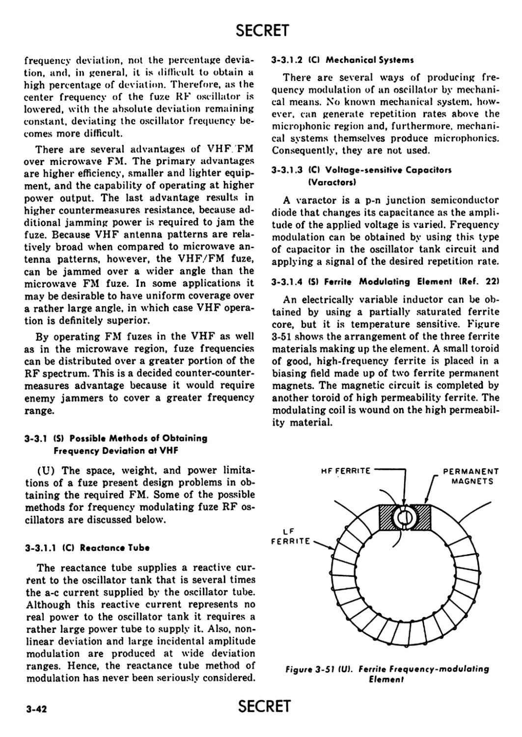
3-3.1.4(S) Ferrite Modulating Element.................... 3-42
3-3.2(S) Reduction of Microphonic Effects............. 3-43
3-3.3 (S) Signal Shaping Versus Range Characteristics .. 3-43
3-3.4 (S) Typical VHF/FM System........................ 3-45
3-3.4.1(S) Modulating Oscillator......................... 3-45
3-3.4.2(S) RF Oscillator................................. 3-45
3-3.4.3(S) Detector ..................................... 3-46
3-4(S) Pulsed Frequency Modulated Fuzing.................. 3-46
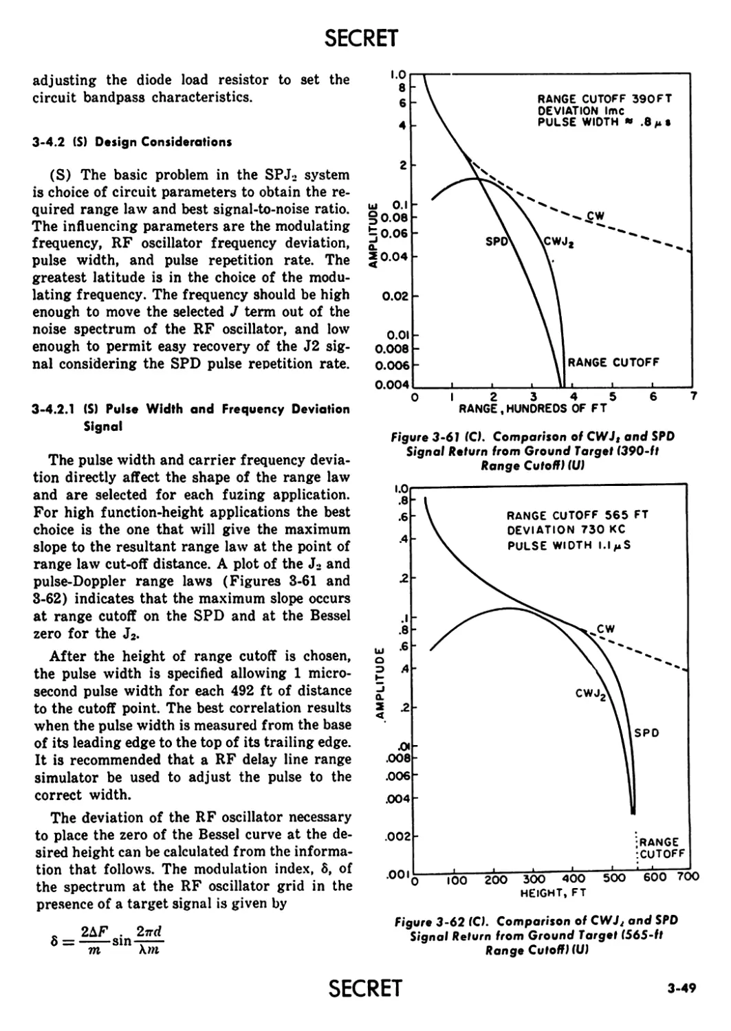
3-4.1 (S) Operation of SPJ2 Fuze System.......................... 3-48
3-4.2(S) Design Considerations......................... 3-49
3-4.2.1(S) Pulse Width and Frequency Deviation......... 3-49
3-4.2.2(S) Calculation of Recovered Doppler Signal 3-50
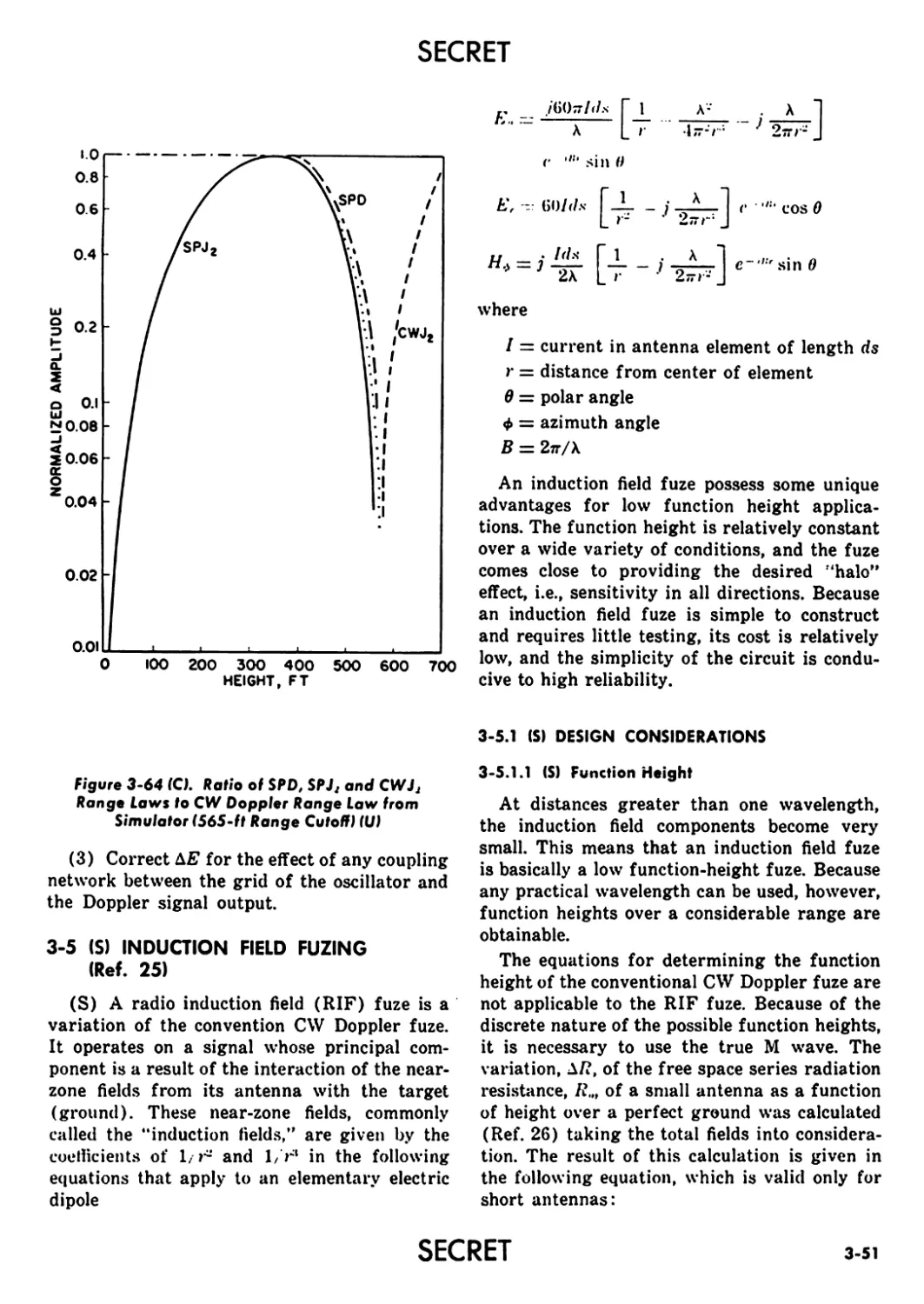
3-5(S) Induction Field Fuzing........................... 3-51
3-5.1 (S) Design Considerations......................... 3-51
3-5.1.1(S) Function Height.......................... 3-51
3-5.1.2(S) Range of Function Height................. 3-52
3-5.1.3(S) Variation of Height With Approach Angle ... 3-53
3-5.1.4(S) Variation of Height With Signal Amplitude .. 3-53
3-5.1.5(S) Signal-to-Noise Considerations........... 3-53
3-5.1.6(S) Countermeasures Resistance............... 3-54
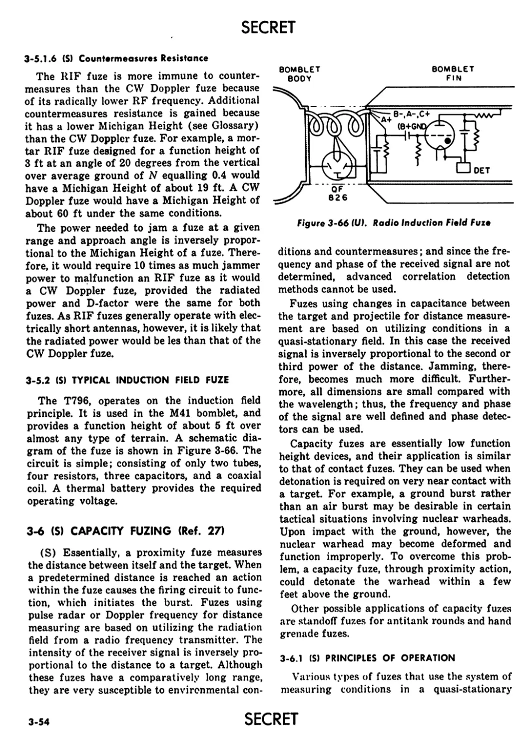
3-5.2 (S) Typical Induction Field Fuze.................... 3-54
3-6 (S) Capacity Fuzing.................................... 3-54
3-6.1 (S) Principles of Operation..........................>... 3-54
3-6.2(S) Circuit Design.......................................... 3-57
3-6.2.1(S) Neutralization ............................... 3-57
3-6.2.2(S) Velocity Discrimination....................... 3-58
vi SECRET
SECRET
TABLE OF CONTENTS (cont’d)
Paragraph Page
3-6.2.3(S) Bandwidth and Detection ................ 3-59
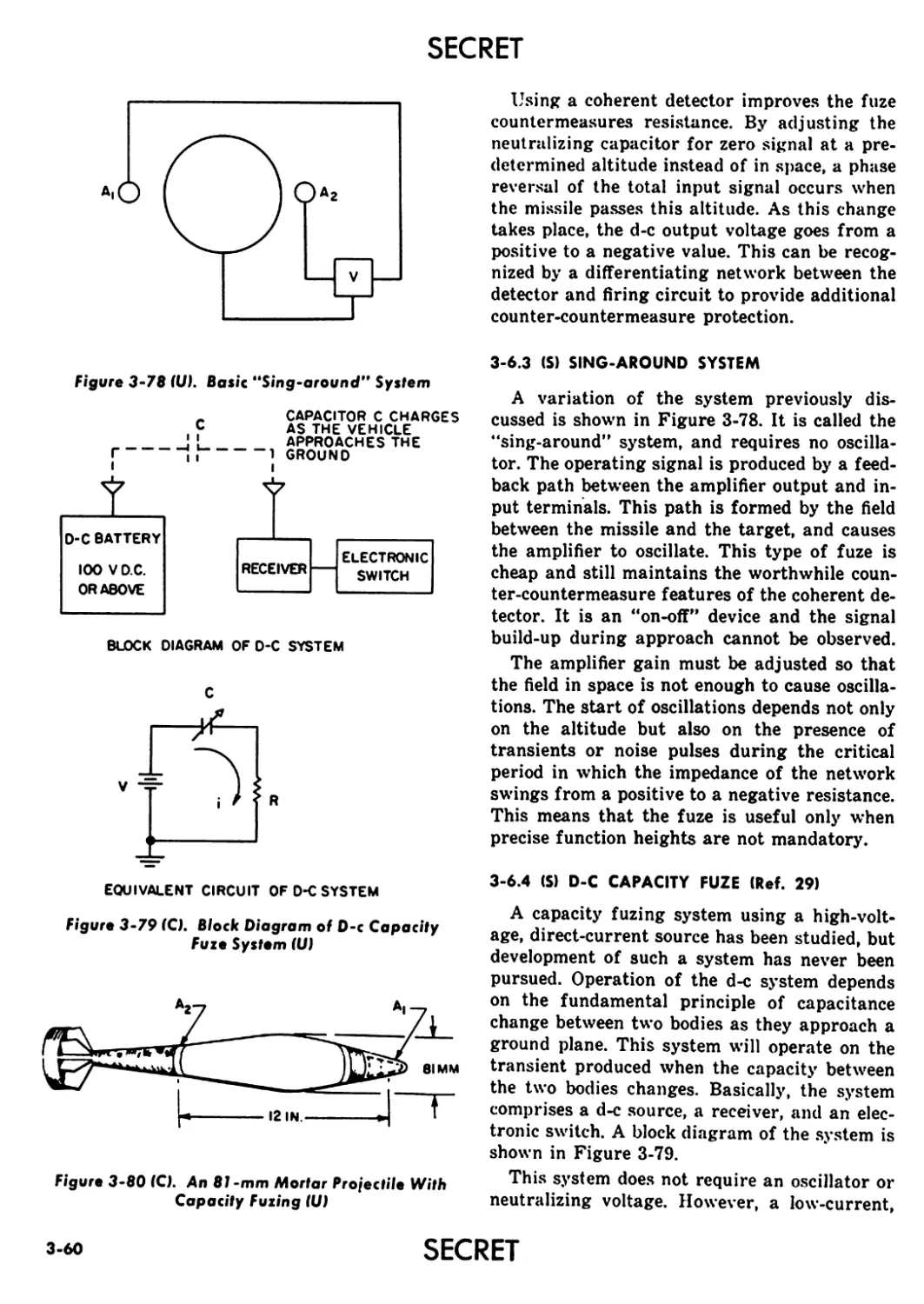
3-6.3 (S) Sing-Around System ....................... 3-60
3-6.4 (S) D-C Capacity Fuze......................... 3-60
3-6.5 (S) Specific Fuzing Applications................ 3-61
3-6.5.1(S) Mortar Fuzing........................... 3-61
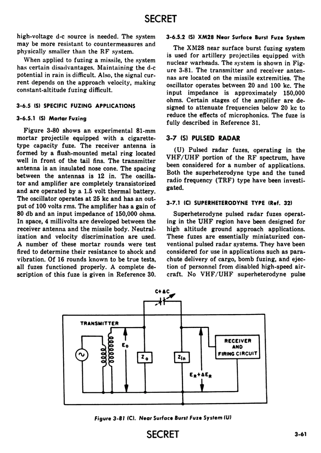
3-6.5.2(S) XM28 Near Surface Burst Fuze System.... 3-61
3-7 (S) Pulsed Radar..................................... 3-61
3-7.1 (C) Superheterodyne Type...................... 3-61
3-7.2(S) TRF Type ................................. 3-62
3-7.2.1(S) Basic Operation ........................ 3-63
3-7.2.2(U) Loop Sensitivity and Signal Return............ 3-63
(U) REFERENCES ............................. 3-64
PART THREE
FOREWORD ................................... ii
PREFACE..................................... iv
LIST OF ILLUSTRATIONS ...................... xviii
LIST OF TABLES.............................. xxii
CHAPTER 4 (S) MICROWAVE RADIO SYSTEMS
4-1 (S) FM/CW Systems .............................. 4-1
4-1.1 (S) Alpha System .................... ............. 4-1
4-l.l.l(S) Operation of the Alpha System........... 4-1
4-1.1.2 (S) Alpha System Components................. 4-5
4-1.1.3(S) Design Considerations for Alpha Fuzing
System .............................. 4-16
4-1.1.4 (S) General Limits on Design Parameters..... 4-17
4-1.1.5 (S) Limitation on Maximum Peak Deviation
(Less Than or Equal to 3 Megacycles) .... 4-17
4-1.1.6(S) Limitations on Modulation Frequency.......... 4-18
4-1.1.7(S) Limitations on Modulation Index......... 4-19
4-1.1.8(C) Limitation on Arbitrary Fuze-Firing
Distance ............................ 4-19
4-1.1.9 (S) Maximum to Minimum Fuze-Firing Distance
(0o/9.) ............................. 4-19
4-1.1.10(S) Amplitude Ratio of Largest to Second-Largest
Response Peak........................ 4-23
4-1.1.11 (S) Typical Calculations for a Specific System
Design .............................. 4-26
4-1.2 (S) Delta Fuzing System............................ 4-29
4-1.2.1(S) Operation of the Delta Fuzing System.... 4-29
4-1.2.2(S) System Components....................... 4-31
4-1.2.3(S) Divided-Channel, Spectrum-Ratio Fuzing
System .............................. 4-45
SECRET vii
SECRET
TABLE OF CONTENTS (cont’d)
Paragraph Page
4-1.3(S) Cobra Fuzing System......................... 4-46
4-1.3.1(S) Operation of the Cobra Fuzing System....... 4-47
4-1.3.2(S) System Components........................... 4-50
4-1.3.3(C) System Design............................... 4-64
4-1.3.4(S) Mixer Output Spectrum....................... 4-64
4-1.3.5(S) IF Amplifier ............................... 4-67
4-1.3.6(S) Discriminator ..........................., 4-68
4-1.3.7(S) Integrator ................................. 4-73
4-1.3.8(S) Decision Circuit ........................... 4-77
4-1.3.9(S) Modulation.................................. 4-77
4-1.3.10(S) Amplitude Modulation........................ 4-77
4-1.3.11 (S) Spurious Signals Caused by Leakage......... 4-84
4-1.3.12 (S) Resolution ................................. 4-86
4-1.4 (S) Coral Fuzing System......................... 4-87
4-2 (S) Pulsed Radar Fuzing Systems................... 4-88
4-2.1 (U) Typical Pulsed Radar Fuze.................. 4-88
4-2.2 (S) Pulsed Radar Fuze Design................... 4-88
4-2.2.1(S) Antennas ................................... 4-88
4-2.2.2(C) Transmitter and Modulator................... 4-91
4-2.2.3(C) AFC and Local Oscillator.................... 4-93
4-2.2.4(C) Mixer ...................................... 4-93
4-2.2.5(S) IF Amplifier and Detector................... 4-94
4-2J.6(C) Decision and Firing Circuits................ 4-95
4-2.3(C) Short Pulsed Radar Fuzes................... 4-97
4-2.4 (C) Pulse Radar Performance.................... 4-97
4-3(S) CW Doppler Fuzing System...................... 4-100
4-4 (S) Pulsed Doppler Fuzing Systems................. 4-100
4-4.1 (S) Basic Pulsed Doppler Operation............. 4-101
4-4.2(S) Pulsed Doppler With Delay Line............. 4-101
4-4.3(S) Pulsed Doppler With Delay Line and Crystal
Switch ................................. 4-103
4-4.4(S) Pulsed Doppler Ferrite Alternate........... 4-103
4-5(S) Sin x/x (Zero) Fuzing System ....................... 4-104
4-6(C) Computer Fuzing Systems....................... 4-105
4-6.1 (C) Predictor-Type Computer Fuze............... 4-106
4-6.2(C) Computer Fuze Using Continuous Range Data 4-107
4-7(C) Guidance-Fuze Systems......................... 4-108
4-8(S) Command Fuzing Systems ....................... 4-109
(U) REFERENCES ............................... 4-111
PART FOUR
FOREWORD .................................... ii
PREFACE..................................... iv
LIST OF ILLUSTRATIONS ........................ xviii
LIST OF TABLES.............................. xxii
vlli
SECRET
SECRET
TABLE OF CONTENTS (cont’d)
Paragraph Page
CHAPTER 5 (S) NONRADIO SYSTEMS
5-1 (S) Optical Fuzing Systems................................... 5-1
5-1.1 (C) Target Characteristics....................... 5-2
5-l.l.l(U) Ground Targets................................ .5-2
5-1.1.2(C) Air Targets.................................... 5-2
5-1.2 (C) Background Radiation......................... 5-4
5-1.2.1(C) Sunlight and Skylight.......................... 5-4
5-1.2.2(C) Other Types of Background Radiation........ 5-4
5-1.3 (U) Properties of the Atmosphere................. 5-5
5-1.4(U) Optical Fuze System Components............... 5-7
5-1.4.1(U) Optical Detectors ......................... 5-7
5-1.4.2(U) Radiation Sources............................. 5-14
5-1.4.3(U) Filters ...................................... 5-15
5-1.4.4(U), Optical Windows, Lenses and Reflectors..... 5-15
5-1.5 (C) Optical Ground Approach Fuzes................... 5-17
5-1.5.1(C) Contrast Optical Fuze......................... 5-18
5-1.5.2(U) Modulated Optical Fuze........................ 5-18
5-1.5.3(U) Pulsed Optical Fuze......................... 5-19
5-1.6(S) Optical Fuzing Systems for Use Against Air
Targets.................................... 5-19
5-1.6.1(C) Problems Associated With Optical Air Target
Fuzing Systems............................. 5-19
5-1.6.2(U) Passive Infrared Fuze System.................. 5-19
5-1.6.3(S) Dual-Channel Passive Infrared Fuze......... 5-20
5-1.6.4(C) Active Optical Fuzes.......................... 5-21
5-2(S) Barometric Fuzing Systems......................... 5-23
5-2.1 (C) General Theory of Barometric Devices......... 5-24
5-2.2(C) Location and Description of Pressure Orifices... 5-25
5-2.3(C) Types of Probes................................. 5-27
5-2.3.1(C) Fixed-Angle Nose Probe........................ 5-27
5-2.3.2(C) Free-Swiveling-Vane Nose Probe................ 5-30
5-2.3.3(C) Body-Trailing Probe........................... 5-30
5-2.3.4(C) Use of Orifices Located on the Surface Contour
of a Vehicle............................... 5-30
5-2.4 (C) Use of Barometric Devices at High Supersonic
and Hypersonic Speeds.......................................... 5-32
5-2.5 (S) Barometric Switch Element............................. 5-33
5-2.6(C) Wind Tunnel and Laboratory Simulation of
Flight Conditions ............................................. 5-34
5-2.7(C) Meteorologic Effects on Altitude Determination. 5-36
5-3(C) Acoustic Fuzing Systems.................................. 5-39
5-3.1 (U) Electroacoustic Transducers for Fuzes........ 5-39
5-3.1.1(U) General Considerations With Respect to
Fuzing Moving Missiles..................... 5-39
5-3.1.2(U) Classification of Possible Transducers............ 5-39
SECRET
SECRET
TABLE OF CONTENTS (cont’d)
Paragraph Page
5-3.2(C) Considerations for an Active Acoustic Fuze .... 5-40
5-3.2.1(C) Nature of the Target........................... 5-41
5-3.2.2(C) Required Function Distance..................... 5-41
5-3.2.3(U) Flight Characteristics of the Missile......... 5-41
5-3.2.4(C) Required Physical Properties of the Trans-
ducer and Associated Waveguides.......... 5-41
5-3.2.5(C) Self-noise at the Transducer......................... 5-41
5-3.2.6(C) Required Properties of the Sound Source and
Its Location................................................... 5-42
5-3.2.7(U) Environmental Effects.......................... 5-42
5-3.3(C) Considerations for a Passive Acoustic Fuze .... 5-42
5-3.3.1(C) Characteristics of the Target.................. 5-43
5-3.3.2(C) Propeller-Driven Aircraft as a Sound Source.. 5-43
5-3.3.3(C) Jet Aircraft as a Sound Source................. 5-43
5-4 (S) Shock Wave Fuzing Systems......................... 5-43
5-5 (C) Magnetic Fuzing Systems........................... 5-44
5-6 (S) Radioactive Fuzing Systems........................ 5-45
5-7(S) Inertial Fuzing Systems........................... 5-46
5-7.1(S) Picatinny Arsenal Fuze......................... 5-46
5-7.2(S) Ratio Inertial Fuze............................ 5-47
5-7.3 (S) Vertical Accelerometer Fuze.................... 5-47
5-8 (C) Thermal Fuzing Systems............................ 5-47
5-8.1 (C) Ratio Thermal Fuze............................. 5-48
5-8.2(C) Null Thermal Fuze.............................. 5-48
5-9 (S) Electrostatic Fuzing.............................. 5-49
5-9.1 (S) Basic Operation................................ 5-49
5-9.2(S) Element Configuration.......................... 5-51
5-9.3(S) Passive Fuzing................................. 5-52
5-9.3.1(S) Transverse-Cut PEF ............................ 5-52
5-9.3.2(S) Longitudinal-Cut PEF........................... 5-53
5-9.4(S) Active Electrostatic Fuzing (AEF) ............. 5-53
5-9.4.1(S) Transverse-Cut AEF ............................ 5-53
5-9.4.2(S) Longitudinal-Cut AEF........................... 5-53
5-9.5(S) Charging Methods .............................. 5-57
5-9.6 (S) Electrostatic Fuze Circuits.................... 5-57
5-9.6.1(S) One-tube, Cold-cathode Circuit................ 5-58
5-9.6.2(S) Two-tube, Hot-cathode Circuit................ 5-58
5-9.6.3(S) Comparisons of One- and Two-tube Circuits.. 5-60
5-9.6.4(C) Power Supply .................................. 5-60
5-10(C) Contact Fuzing Systems............................ 5-61
5-10.1(C) Piezoelectric (Lucky) Fuze..................... 5-61
5-10.2(0 Trembler Switches.............................. 5-63
5-10.3(C) Bridging Systems............................... 5-63
5-10.4(C) Inertial Generators............................ 5-64
5-11 (S) Antivehicular Land Mine Fuzes..................... 5-65
5-11.1 (S) Influences for Mine Fuzes...................... 5-65
x
SECRET
SECRET
TABLE OF CONTENTS (cont’d)
Paragraph Page
5-ll.l.l(S) Magnetic Field Activation................... 5-66
5-11.1.2(S) Vibration Field Activation.................. 5-66
5-11.1.3(S) Pressure Activation ........................ 5-66
5-11.1.4 (S) Radiation Activation ....................... 5-66
5-11.1.5(8) Heat Activation............................. 5-67
5-11.1.6(S) Eddy Current Activation..................... 5-67
5-11.2(S) Basic Operation of Mine Fuzes........................ 5-67
5-11.2.1 (S) Alert Circuit............................... 5-67
5-11.2.2(S) Localizer Circuit .......................... 5-67
5-11.2.3(S) Detector Circuit ........................... 5-67
5-11.2.4(S) Safety and Arming Device.................... 5-67
5-11.2.5 (S) Power Supply Circuit ....................... 5-67
5-11.2.6(S) Sterilizer Circuit.......................... 5-67
5-11.2.7(C) Forget Circuit..................................... 5-68
5-11.2.8(0 Failure Circuit ............................ 5-68
5-11.2.9(S) Command Arming.............................. 5-68
5-11.3(S) Magnetic Influence Mine Fuzes.................. 5-68
5-11.3.1 (S) Interpretation of Contour Charts............ 5-70
5-11.3.2(S) Countermeasures Against Magnetic Land
Mines ................................... 5-75
5-11.3.3(S) Magnetic Sensing Elements................... 5-76
5-11.4(S) Vibration Influence Mine Fuzes................. 5-78
5-11.4.1 (S) Interpretation of Vibration Signatures...... 5-79
5-11.4.2(S) Vibration-Sensing Elements.................. 5-82
5-11.5(S) Pressure Influence Mine Fuzes.................. 5-90
5-11.6(S) Radioactive Influence Mine Fuze................ 5-91
5-11.6.1(S) Basic Operation............................. 5-91
5-11.6.2(S) Radioactive Fuze Signature Data............. 5-92
(U) REFERENCES ................................. 5-96
CHAPTER 6 (C) MULTIPLE FUZING
6-1(0 Introduction..................................... 6-1
6-2(C) Types of Multiple Fuzing Systems................. 6-2
6-3(C) Analysis of Simple Multiple Fuzing Systems....... 6-2
6-3.1 (C) Parallel Fuzing Systems (Two Fuzes)........... 6-2
6-3.2(C) Series Fuzing System (Two Fuzes) .............. 6-2
6-3.3(C) Series-Parallel Arrangements................... 6-3
6-4(0 Reliabilities of Multiple Fuzing Systems......... 6-4
6-4.1 (C) Multiple Fuze Data................................... 6-4
6-4.2(C) Choice of Fuze Arrangements.................... 6-4
6-5(C) Effects of Memory Spans on Multiple Fuzing....... 6-8
6-6(0 Other Factors Affecting Multiple Fuze Design 6-10
(U) REFERENCES ................................. 6-13
SECRET
X1
SECRET
TABLE OF CONTENTS (confd)
Paragraph, Page
PART FIVE
FOREWORD....................................... ii
PREFACE...................................... iv
LIST OF ILLUSTRATIONS......................... xviii
LIST OF TABLES............................... xx
CHAPTER 7 (C) POWER SUPPLIES
7-1 (U) Requirements for Fuze Power Supplies.......... 7-1
7-2(U) Types of Power Supplies....................... 7-1
7-3(U) Generators ................................... 7-2
7-3.1 (U) Wind-Driven Generators..................... 7-2
7-3.2 (U) Gas-Driven Generators...................... 7-2
7-3.3 (U) Piezoelectric Generators .................. 7-3
7-3.4(U) Inertia Generators ............................... 7-3
7-3.5 (U) Spring-Driven Generators................... 7-3
7-4(C) Batteries..................................... 7-3
7-4.1 (C) Batteries for Guided Missile Applications.. 7-3
7-4.1.1(C) Thermal Batteries......................... 7-3
7-4.1.2(U) Silver-Oxide Zinc Batteries............... 7-6
7-4.1.3(U) Liquid Ammonia Batteries.................. 7-9
7-4.2(C) Batteries for Rotating Projectiles......... 7-9
7-4.2.1(C) Operating Temperature..................... 7-10
7-4.2.2(C) Activation Time and Active Life........... 7-10
7-4.2.3(C) Voltage and Current Capacity.............. 7-10
7-4.2.4(C) Noise .................................... 7-11
7-4.2.Б(C) Minimum Spin and Setback Required for
Activation ........................... 7-11
7-4.3 (U) Batteries for Nonrotating Projectiles...... 7-11
7-4.4(C) Batteries for Land Mine Fuze Applications .... 7-11
7-4.4.1(C) Radioactive Batteries..................... 7-12
7-4.4.2(C) Zamboni Pile.............................. 7-12
7-4.4.3(C) Mercury Batteries......................... 7-13
(C) REFERENCES .............................. 7-14
CHAPTER 8 (C) SAFETY AND ARMING DEVICES
8-1 (U) Introduction ...................................... 8-1
8-1.1 (U) Design Requirements for Safety and Arming
Devices .................................................. 8-2
8-1.2(U) Safety and Arming Devices for Missile Fuzes ... 8-3
8-1.3(U) Design Factors for Guided Missiles S & A Devices 8-3
8-2(U) Mechanical Safety and Arming Devices 8-4
8-2.1 (U) Devices Based on Deformation of Materials .... 8-4
8-2.2(U) Detents 8-4
8-2.3 (U) Springs 8-4
8-2.4(U) Sliders 8-5
xi. i
SECRET
SECRET
TABLE OF CONTENTS (cont’d)
Paragraph Page
8-2.5(U) Rotary Devices............................. 8-5
8-2.6(U) Sequential Events Setback Mechanisms....... 8-5
8-2.6.1(U) Applications, Advantages, and Limitations ... 8-5
8-2.6.2(U) Equations of Motion........................ 8-6
8-2.6.3(U) Equations for Minimal Velocity Change for
Operation ................................................... 8-7
8-2.6.4(U) Relationship between Minimal Velocity and
Drop Safety............................ 8-8
8-2.6.5(U) Construction and Design Details............ 8-8
8-2.7 (U) Clockwork ................................. 8-9
8-2.7.1(U) Tuned Watchspring Escapements.............. 8-9
8-2.7.2(U) Untuned Escapements ....................... 8-11
8-2.8 (U) Acceleration-Time Devices ................. 8-14
8-2.8.1(U) Single or Double Integration............... 8-15
8-2.8.2(U) Single Integration......................... 8-15
8-2.8.3(U) Pseudo-Integrators ........................ 8-16
8-2.8.4(U) Pseudo-Integrators With Spring Bias........ 8-17
8-3 (U) Electrical Safety and Arming Devices................ 8-17
8-3.1 (U) Switches................................... 8-17
8-3.1.1(U) Trembler Switches ......................... 8-19
8-3.1.2(U) Mercury-Type Centrifugal Switch............ 8-19
8-3.1.3(U) Fusible-Link Thermal Switches.............. 8-19
8-3.2(U) Explosive Motors ..................... 8-20
8-3.3 (U) Electron Tubes .............................. 8-20
8-3.4(U) Electrical Generators...................... 8-21
8-3.5 (U) RC Circuits ............................... 8-21
8-3.5.1(U) Basic RC Delay Circuits.................... 8-21
8-3.5.2(U) Tank Capacitor RC Delay Circuit............ 8-22
8-3.5.3(U) Triode RC Delay Circuit.................... 8-22
8-3.5.4(U) Three-Wire RC Delay Circuit................ 8-23
8-3.5.5(U) Cascade RC Delay Circuit................... 8-23
8-3.5.6(U) Ruehlmann RC Delay Circuit................. 8-24
8-3.5.7(U) Accuracy of RC Delays...................... 8-25
8-3.5.8(U) Application of Delay-Error Theory to Fuze
Design ...................................................... 8-26
8-4(U) Magnetic Safety and Arming Devices............. 8-26
8-5(U) Fluid-Operated Safety and Arming Devices....... 8-27
8-6(C) Arming Programmers............................. 8-27
8-6.1 (U) Types of Arming Programmers....................... 8-27
8-6.2(C) Operation of Arming Programmer............. 8-28
8-6.3 (U) Design Considerations for Arming Programmers 8-29
(U) REFERENCES ............................... 8-30
SECRET
xiii
SECRET
TABLE OF CONTENTS (cont’d)
Paragraph Page
CHAPTER 9 (U) COMPONENTS
9-1 (U) Introduction .................................. 9-1
9-2(U) Selection of Components........................ 9-1
9-3 (U) Environmental Problems......................... 9-1
9-4(U) Application Data............................... 9-2
9-5 (U) Detonators..................................... 9-2
CHAPTER 10 (U) MATERIALS
10-1 (U) Introduction ................................. 10-1
10-2(U) Potting Compounds for Electronic Components ... 10-1
10-2.1 (U) Advantages of Potting Electronic Components.. 10-1
10-2.2(U) Disadvantages of Potting Electronic Components 10-1
10-2.3 (U) Types of Potting Compounds................... 10-2
10-2.4 (U) Effects of Temperature Changes on Potting
Compounds ............................. 10-3
10-2.5(U) Effects of Weather on Potting Compounds..... 10-3
10-2.6 (U) Corrosive Effects of Potting Resins on Bare
Copper Wire ........................... 10-5
10-2.7(U) Compatibility of Potting Compounds With
Explosives ............................ 10-5
10-2.8(U) Mechanical and Electrical Properties of Potting
Compounds ............................. 10-5
10-2.9 (U) Selecting Potting Compounds................. 10-14
10-2.10(U) Fabricating the Circuit..................... 10-14
10-2.11 (U) Recovery of Potted Components............... 10-15
10-3(U) Sealants and Sealing Materials............... 10-15
10-3.1 (U) Considerations in Selecting a Sealant or Sealing
Material .............................. 10-15
10-3.2(U) Sealants ................................... 10-15
10-3.3(U) Sealing Materials .......................... 10-16
10-3.4(U) Ceramic-to-Metal Seals ..................... 10-16
10-3.5(U) Polyethylene-to-Metal Seals................. 10-16
10-4(U) Solders and Fluxes........................... 10-17
104. 1 (U) Solders .................................... 10-17
104. 2(U) Fluxes...................................... 10-20
104. 3 (U) Conductive Adhesives........................ 10-21
(U) REFERENCES .............................. 10-21
CHAPTER 11 (U) CONSTRUCTION TECHNIQUES
ll-l(U) Mechanical Considerations .................... 11-1
11-1.1 (U) Structural .................................. 11-1
11-1.2(U) Shock and Vibration Isolation..................... 11-2
11-1.2.1 (U) General Considerations ........................ 11-2
11-1.2.2(U) Considerations for Guided Missile Fuzes .... 11-3
11-2(U) Encapsulation ...................................... 11-6
xiv SECRET
SECRET
TABLE OF CONTENTS (cont’d)
Paragraph Page
11-2.1 (U) Encapsulating Methods...................... 11-6
11-2.2(U) Design Considerations...................... 11-7
11-3(U) Sealing ..................................... 11-8
11-3.1 (U) Component Sealing Versus Unit Sealing...... 11-8
11-3.2(U) Fillers for Hermetically Sealed Units...... 11-9
11-3.3(U) Sealing and Maintenance.................... 11-10
11-4(U) Heat Transfer................ ............... 11-10
11-4.1(U) Methods of Heat Transfer................... 11-10
11-4.1.1 (U) Conduction............................... 11-10
11-4.1.2(U) Convection .............................. 11-10
11-4.1.3(U) Radiation ...........rr:z-:................... 11-11
11-4.2(U) Techniques for Heat Transfer.................... 11-11
11-4.2.1 (U) Cooling of Components.................... 11-11
11-4.2.2(U) Electron Tubes .......................... 11-11
11-4.2.3(U) Iron-Core Inductors...................... 11-12
11-4.2.4 (U) Resistors................................ 11-12
11-4.2.5(U) Cooling of Assemblies.................... 11-12
(U) REFERENCES .............................. 11-13
CHAPTER 12 (U) INDUSTRIAL ENGINEERING
12-1 (U) Introduction ............. 12-1
12-2 (U) Functions of an Industrial Engineering Program.. 12-1
12-2.1 (U) Study and Familiarization Phase During R & D. 12-1
12-2.2(U) Product and Process Engineering............. 12-1
12-2.3 (U) Modeling and Testing of Product-Engineered
Fuze ................................. 12-2
12-2.4(U) Technical Data Package..................... 12-2
12-2.4.1 (U) Types of Technical Data Packages......... 12-2
12-2.4.2(U) Development of a Technical Data Package ... 12-3
12-2.4.3(U) Contents of a Technical Data Package..... 12-3
12-3 (U) Industrial Engineering Methods .................." 12-5
12-3.1 (U) Minimum Program (No Product or Process
Engineering) ......................... 12-5
12-3.2(U) Engineering Evaluation..................... 12-6
12-3.3(U) Pilot Lot Manufacturing.................... 12-6
12-3.4 (U) Comprehensive Study After R & D Engineering
Tests................................. 12-6
12-3.5(U) Comprehensive Study Concurrent With R & D
Phase ................................ 12-6
12-3.6(U) Comparison of Industrial Engineering Methods. 12-6
12-4(U) Phasing of R & D and Industrial Engineering .... 12-6
(U) REFERENCES .............................. 12-9
SECRET
xv
SECRET
TABLE OF CONTENTS (cont’d)
Paragraph Page
CHAPTER 13 (U) TESTING
13-1 (U) Introduction ................................... 13-1
13-1.1 (U) Test Program ................................ 13-1
13-1.2(U) Validity of Test Program..................... 13-1
13-2(U) Types of Tests.................................. 13-1
13-2.1 (U) Developmental Tests ......................... 13-2
13-2.2(U) Tests Governed by Military Standards......... 13-2
13-2.3 (U) Accelerated Storage Tests.................... 13-3
13-2.4(U) S & A System Tests........................... 13-3
13-2.4.1 (U) Group I Tests ............................. 13-5
13-2.4.2(U) Group II Tests............................. 13-5
13-2.4.3(U) Field Tests................................ 13-5
13-3(U) Test Programming for Economy.................... 13-5
13-3.1 (U) Reject Approach.............................. 13-5
13-3.2 (U) Cost-per-Test Approach....................... 13-5
13-3.3(U) Least-Cost Sequence Method................... 13-5
13-4 (U) Test Facilities................................. 13-6
13-4.1 (U) Air Gun Test Facilities...................... 13-7
13-4.2(U) Centrifuge Test Facilities................... 13-7
13.4.3(U) Rocket Sled Test Facilities.................. 13-7
13-4.4 (U) Parachute Recovery Test Facilities........... 13-9
13-4.5(U) Rain Test Facilities......................... 13-9
13-4.6(U) Nuclear Environment Test Facilities.......... 13-10
13-4.7(U) Explosive Atmosphere Test Facilities......... 13-10
13-4.8(U) Flyover Test Facilities...................... 13-10
13-4.9(U) Rocket Target Range Facilities............... 13-10
13-4.10(U) Gun Target Range Facilities.................. 13-11
13-4.11(U) Vertical-Firing Range Test Facilities........ 13-11
13-4.12(U) Drop Tower Test Facilities................... 13-11
(U) REFERENCES ................................ 13-12
xvi
SECRET
SECRET
LIST OF ILLUSTRATIONS
Fig. No. Title Page
3-1 (U). Block Diagram of Basic CW Doppler Fuze . 3-1
3-2 (U). Determining Doppler Frequency for Ground
Approach Case................................... 3-2
3-3 (U). Determining Doppler Frequency for Air Target
Case ........................................................ 3-2
3-4 (U). Vector Diagram for Changes in Antenna Current 3-3
3-5 (U). M Wave for Ground Approach Case............. 3-4
3-6 (U). M Wave for Air Target Case.................. 3-4
3-7 (C). Transverse Loop Antenna. Pattern Obtainable for
Different Orientations of Projectile and Pickup
Antenna (Example 1) (U) ........................ 3-5
3-8 (C). Transverse Loop Antenna. Pattern Obtainable for
Different Orientations of Projectile and Pickup
Antenna (Example 2) (U) ........................ 3-6
3-9 (C). Longitudinal Loop Antenna. Pattern Obtained for
Different Orientations of Projectile and Pickup
Antenna (Example 1) (U) ..................................... 3-7
3-10(C). Longitudinal Loop Antenna. Pattern Obtained for
Different Orientations of Projectile and Pickup
Antenna (Example 2) (U) ..................................... 3-8
3-11 (S). Transverse Loop Oscillator with Wide Cylinder
Resonant Circuit (U) ........................................ 3-9
3-12 (S). Radiation Pattern for Transverse Loop Antenna
(Oscillator, Figure 3-11) (U) ..................... 3-9
3-13 (S). Radiation Patterns for Transverse Loop Antenna
(Oscillator, Figure 3-11) as Spacing Between Loop
and Body is Changed (U) .......................... 3-10
3-14 (S). Transverse Loop Push-Pull Oscillator with Narrow
Cylinder Resonant Circuit (U) .................... 3-10
3-15(S). Radiation Pattern for Transverse Loop Antenna
(Oscillator, Figure 3-14) (U) .................... 3-11
3-16 (S). Transverse Loop Oscillator with Narrow Cylinder
Resonant Circuit (U) ............................. 3-11
3-17 (S). Radiation Patterns for Transverse Loop Antenna
(Oscillator, Figure 3-16) as Spacing Between Loop
and Body is Changed (U) ..................................... 3-12
3-18 (S). Radiation Patterns for Transverse Loop Antenna
(Oscillator, Figure 3-14) Showing Effect of Disc
Size Behind Loop (U) ........................................ 3-13
3-19 (S). Variation of Angle of Maximum Radiation for
Change of Disc Diameter (U) ...................... 3-14
3-20 (S). Radiation Pattern for Transverse Loop Antenna
(Oscillator, Figure 3-14) Mounted on Cylinder
Closed at Ends (U)................................ 3-15
3-21 (S). Transverse Loop Oscillator with Wire Resonant
Circuit (U) .................. 3-15
SECRET
xvi i
SECRET
LIST OF ILLUSTRATIONS (cont’d)
Fig. No. Title Page
3-22 (S). Radiation Patterns for Transverse Loop Antenna
(Oscillator, Figure 3-21) as Spacing Between Loop
and Body Changes (U) .......................................... 3-16
3-23 (S). Transverse Loop Oscillator with Small Diameter
Cylindrical Resonant Circuit (U) ................ 3-16
3-24 (S). Radiation Pattern for Transverse Loop Antenna
(Oscillator, Figure 3-23) (U) ................... 3-17
3-25 (S). Longitudinal Loop Oscillator with Wire Resonant
Circuit (U) ..................................... 3-17
3-26 (S). Radiation Pattern for Longitudinal Loop Antenna
(Oscillator, Figure 3-25) (U) ................................. 3-18
3-27 (S). Radiation Patterns for Longitudinal Loop Antenna
(Oscillator, Figure 3-25); Test Model Vertical, with
Nose Uppermost (U) ............................................ 3-19
3-28 (S). Radiation Pattern for Longitudinal Loop Antenna
(Oscillator, Figure 3-25), Horizontal Polarization
(U) ........................................................... 3-21
3-29 (U). Oscillator-diode Circuit.......................... 3-22
3-30 (U). Reaction Grid Detector Circuit................... 3-22
3-31 (U). Radiation Pattern of Longitudinal Fuze Antenna
(A) and Transverse Fuze Antenna (B) ............. 3-23
3-32 (U). Response Curve of Peaked Amplifier ............... 3-23
3-33 (U). Schematic of Peaked Amplifier .................... 3-24
3-34 (U). Response Curve of Bandpass-type Amplifier........ 3-25
3-35 (U). Schematic of Bandpass-type Amplifier.............. 3-25
3-36 (S). Block Diagrams of PTTB, FLAH, FLAJ, and FLAF
Integrating Amplifiers (U) ...................... 3-27
3-37 (U). Ideal Operation of Progressive-time System....... 3-28
3-38 (U). Effects of Large Detector Filter, and use of Ripple
for Circuit Desensitization ..................... 3-29
3-39 (C). Simplified Schematic of PTTB Circuit (U) ......... 3-30
3-40 (S). Simplified Schematic of FLAH Circuit (U) ......... 3-30
3-41 (S). Function Height Vs Relative Signal Amplitude for
Various Bomb Velocities and Settings; T750 Fuze
(U) ............................................. 3-31
3-42(S). Simplified Schematic of FLAF Circuit (U) ......... 3-32
3-43 (S). Simplified Schematic for FLAJ Circuit (U) ........ 3-33
3-44 (U). Effect of Series Inductance on Peak Surge Current
of Firing Capacitor.............................. 3-34
3-45 (U). Effect of Series Inductance on Time-to-peak Surge
Current of Firing Capacitor...................... 3-34
3-46 (U). Basic Firing Circuit . 3-35
3-47 (U). Firing Circuit for a Fuze, Showing RC Arming . . 3-36
3-48(U). Pulsed-Doppler Fuze Waveforms..................... 3-37
3-49 (U). Doppler Signal Reconstruction .................... 3-39
xviii
SECRET
SECRET
LIST OF ILLUSTRATIONS (cont’d)
Fig. No. Title Page
3-50(C). SPD Oscillator-detector (U) 3-41
3-51 (U). Ferrite Frequency-modulating Element 3-42
3-52 (S). Modulation Characteristic of Ferrite Modulating
Element (U) .................................................. 3-43
3-53 (U). Microphonic Reduction Mechanism............ 3-44
3-54 (C). Range Characteristics of VHF/FM Fuze (U) ... 3-44
3-55 (U). Block Diagram of VHF/FM Fuze............... 3-45
3-56 (C). Schematic Diagram of Typical Modulating Oscilla-
tor, RF Oscillator, and Detector (U) 3-46
3-57 (U). Typical Range Law Curves for J-, SPD, and SPJ3
Fuze Systems.................................................. 3-46
3-58 (S). Experimental Pulsed VHF/FM (SPJ)3 Fuze
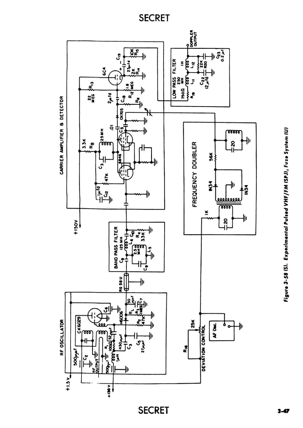
System (U) ................................................... 3-47
3-59 (S). Signal Noise Vs Detector Load Resistor (U) ......... 3-48
3-60 (C). RF-Oscillator Grid Signal-to-noise Ratio at 320 ft
(U) .......................................................... 3-48
3-61 (C). Comparison of CWJS and SPD Signal Return from
Ground Target (390-ft Range Cutoff) (U) ...... 3-49
3-62 (C). Comparison of CWJ» and SPD Signal Return from
Ground Target (565-ft Range Cutoff) (U)....................... 3-49
3-63 (C). Ratio of SPD, SPJ2 and CWJ- Range Laws to CW
Doppler Range Law from Simulator (390-ft Range
Cutoff) (U) .................................... 3-50
3-64 (C). Ratio of SPD, SPJ2 and CWJ2 Range Laws to CW
Doppler Range Law from Simulator (565-ft Range
Cutoff) (U) .................................... 3-51
3-65 (С). A R/R<> Vs Л/X Over Perfect Ground, When 0 Equals
6 Degrees (U) .................................. 3-52
3-66 (U). Radio Induction Field Fuze........................ 3-54
3-67 (C). Vertical Antenna Configuration for Fuze (U) .... 3-55
3-68 (C). Operating Conditions of Fuze. (A) Missile in Space,
(B) Missile Close to Ground (U) .............................. 3-55
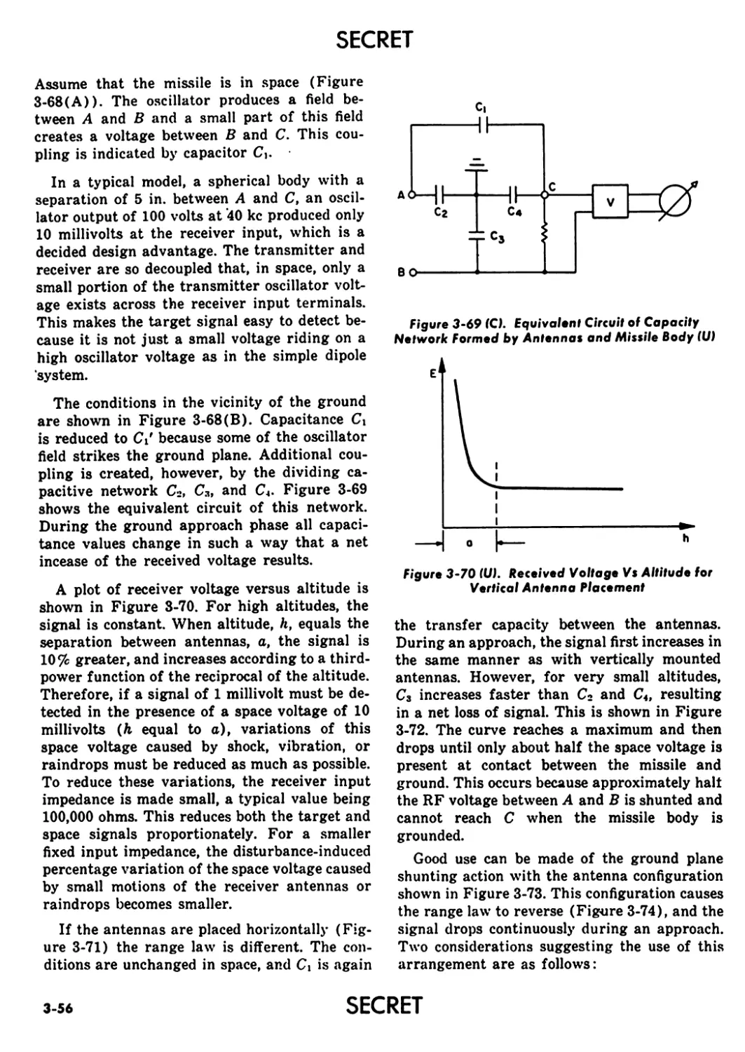
3-69 (C). Equivalent Circuit of Capacity Network Formed
by Antennas and Missile Body (U)................ 3-56
3-70 (U). Received Voltage Vs Altitude for Vertical Antenna
Placement ...................................... 3-56
3-71 (C). Horizontal Antenna Configuration for Fuze (U).. 3-57
3-72 (U). Received Signal Vs Altitude for Horizontal An-
tenna Placement .............................................. 3-57
3-73 (C). Horizontal Antenna Configuration, Rear Mounted
(U) .......................................................... 3-58
3-74 (U). Received Voltage Vs Altitude for Horizontal An-
tenna Configuration, Rear Mounted............... 3-58
3-75 (C). Typical Neutralization Circuit Using Center-
Tapped Tank Coil and Neutralizing Capacitor (U) 3-58
SECRET xix
SECRET
LIST OF ILLUSTRATIONS (cont’d)
Fig. No. Title Page
3-76(C). Refined Neutralization Method Using Additional
Antenna to Form Neutralizing Capacitor (U) ... 3-59
3-77(C). Simplified Coherent Detector (U) ............... 3-59
3-78(U). Basic “Sing-around” System ..................... 3-60
3-79 (C). Block Diagram of D-c Capacity Fuze System (U).. 3-60
3-80(C). An 81-mm Mortar Projectile With.Capacity Fuzing
(U) ........................................... 3-60
3-81 (C). Near Surface Burst Fuze System (U) ............. 3-61
3-82 (C). Block Diagram of Bomb Fuze (U) ................. 3-62
3-83 (C). Block Diagram of a Typical TRF Pulsed-Radar
Fuze (U) ...................................... 3-63
xx
SECRET
SECRET
LIST OF TABLES
Table No. Title Page
3-1 (S) Summary of Integrating Amplifier Characteristics (U) 3-32
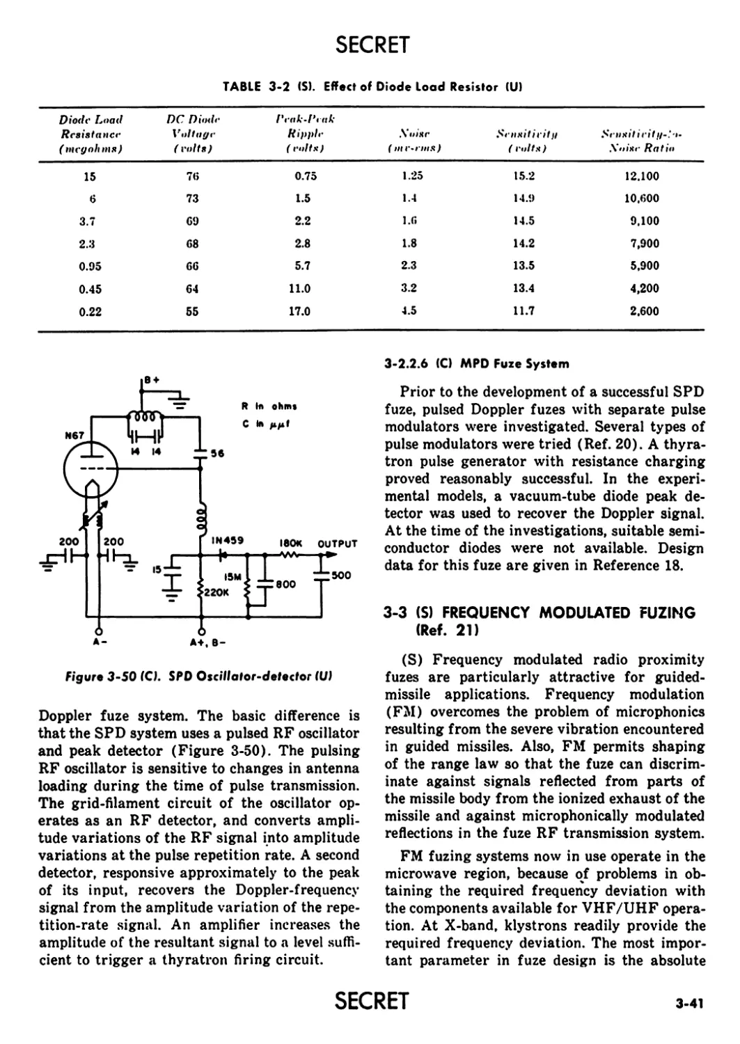
3-2 (S) 3-3 (S) Effect of Diode Load Resistors (U) 3-41 Variation of Function Height With Approach Angle (U) 3-53
3-4 (S) Variation in Function Height, Л/X for Various Coefficients and Approach Angles (U) . 3-53
SECRET
XXI
SECRET
CHAPTER 3
(S) VHF AND UHF RADIO SYSTEMS
3-1 (S) CW DOPPLER FUZING
(U) The CW Doppler fuze was developed
early in World War II. It still has many advan-
tages over later radio-type proximity fuzes,
particularly in simplicity, cost, and construc-
tion ease. Although it was the first radio-type
proximity fuze developed, it is still considered
satisfactory, with only minor refinements, for
many present-day fuzing applications. This is
especially true in mortar, bomb, and artillery
fuzing where very high reliability and accuracy
are normally not specified.
This section of the handbook presents the
basic principles of the CW Doppler fuze, and
briefly discusses some of its design considera-
tions. Reference 1 gives a detailed analysis of
operation and design of the CW Doppler fuze.
3-1.1 (U) BASIC OPERATION
The intelligence system of a CW Doppler
proximity fuze (Figure 3-1) consists of an an-
tenna, an oscillator-detector, a Doppler ampli-
fier, and a firing circuit. The oscillator-detector
generates an RF signal, which is coupled to the
antenna and radiated into space. If the radiated
signal strikes a target, a small portion of the
signal is reflected back to the antenna. The time
required for the signal to travel to*the target
and back results in a phase difference between
transmitted and reflected wave. As the distance
between the fuze and target decreases, the rela-
tive phase between the radiated and reflected
signal changes and appears as a change in fre-
quency of the reflected signal. The difference
in frequency between the radiated signal and
received signal, because of relative motion be-
tween the target and fuze, is called the differ-
ence frequency or Doppler frequency (Ref. 2).
For a typical fuze design, the difference or Dop-
pler frequency is in the audio frequency range
and of the order of a few hundred cycles per
second.
The Doppler signal is detected by the oscilla-
tor-detector, and coupled to the input of the
Doppler amplifier. Amplification is required be-
cause the detected signal is of the order of a
fraction of a volt. The output of the Doppler
amplifier is applied to the firing circuit, which
consists essentially of a thyratron, a detonator,
and a capacitor in series. When the output of
the amplifier exceeds a predetermined level, the
capacitor discharges through the thyratron to
trigger the detonator.
Because detonation occurs when the output
of the amplifier reaches a predetermined level,
the distance from the target at which detona-
tion occurs can be controlled. For a given orien-
tation of the fuze and target, the detector signal
amplitude is a function of the distance between
the fuze and target. Therefore, the distance of
operation can be set properly by setting the
amplifier gain and the thyratron holding bias.
3-1.2 (U> BASIC PARAMETERS
3-1.2.1 (U) Doppler Shift and Radiation
Resistance (Ref. 3)
The effect of radiation from a target may be
considered in two ways: the Doppler frequency
concept or the radiation resistance concept. The
radiation resistance concept is more commonly
used because it lends itself more readily to
mathematical treatment.
The Doppler frequency concept may be con-
sidered in the following manner (Ref. 4): be-
cause the fuze moves toward the target, the
frequency of radiation striking the target is
slightly higher than that emitted by the fuze
by an amount V/X; where V is the relative
ANTENNA
TO DETONATOR
Figure 3-1 (III. Block Diagram of Basic CW Doppler Fuze
SECRET
3-1
SECRET
velocity of the fuze and target, and X is the
wavelength of the radiated wave. Similarly, the
wave reflected back to the fuze from the target
is higher than that at the target by an amount
V/X. Therefore, the reflected radiation returns
to the fuze with a higher frequency than that
of the fuze oscillator by an amount 2V/X, which
is the Doppler frequency. The frequency of the
reflected signal, as seen by the fuze is
where
f = fuze oscillator frequency
2V
—— = Doppler frequency
A
The closing velocity between the fuze and tar-
get, and not simply the velocity of the fuze, de-
termines the Doppler frequency output of the
oscillator detector. Therefore, in the case of the
ground target approach (Figure 3-2), the
Doppler frequency is modified and becomes
ом,
Л
where
0 = fuze angle of approach with respect
to earth
V sin 0 = closing velocity of fuze with re-
spect to earth
In Figure 3-3, the air target case, both tar-
get and fuze are traveling in the same direction.
This is a typical encounter between a target and
an air-to-air rocket. The Doppler frequency is
modified to become
f _ 2(V,-V2) cos g
where
Vi = fuze velocity
Va = target velocity
в = angle between fuze trajec-
tory and line connecting
fuze and target
(Vt — V2) cos 0 = closing velocity of fuze with
respect to target
As stated above, the radiation resistance
concept is usually used because it lends itself
more readily to mathematical treatment. In this
analysis, the current, I (Figure 3-4), produced
in the fuze antenna by the oscillator is con-
sidered. This current sets up radiation and
dissipates energy into space as if the antenna
had a resistance, RA, called the radiation re-
sistance. In the presence of a target, the an-
tenna current differs from I by the amount in-
duced by the reflected wave. The incremental
Figure 3-2 (U). Determining Doppler Frequency for
Ground Approach Case
Figure 3-31Ш. Determining Doppler Frequency for Air Target Case
SECRET
3-2
SECRET
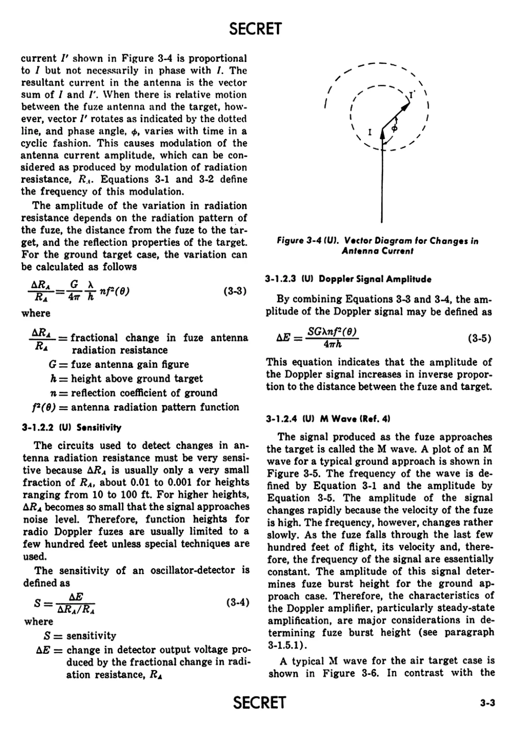
current V shown in Figure 3-4 is proportional
to I but not necessarily in phase with I. The
resultant current in the antenna is the vector
sum of I and Г. When there is relative motion
between the fuze antenna and the target, how-
ever, vector I' rotates as indicated by the dotted
line, and phase angle, Ф, varies with time in a
cyclic fashion. This causes modulation of the
antenna current amplitude, which can be con-
sidered as produced by modulation of radiation
resistance, RA. Equations 3-1 and 3-2 define
the frequency of this modulation.
The amplitude of the variation in radiation
resistance depends on the radiation pattern of
the fuze, the distance from the fuze to the tar-
get, and the reflection properties of the target.
For the ground target case, the variation can
be calculated as follows
Т?Г=£т« <3-3>
where
- . x = fractional change in fuze antenna
radiation resistance
G = fuze antenna gain figure
h = height above ground target
n = reflection coefficient of ground
f2(6) = antenna radiation pattern function
3-1.2.2 (U) Sensitivity
The circuits used to detect changes in an-
tenna radiation resistance must be very sensi-
tive because Д7?л is usually only a very small
fraction of Ra, about 0.01 to 0.001 for heights
ranging from 10 to 100 ft. For higher heights,
Д/?л becomes so small that the signal approaches
noise level. Therefore, function heights for
radio Doppler fuzes are usually limited to a
few hundred feet unless special techniques are
used.
The sensitivity of an oscillator-detector is
defined as
S= (3-4)
ДЛд/Лл
where
S = sensitivity
ДЕ = change in detector output voltage pro-
duced by the fractional change in radi-
ation resistance, RA
Figure 3-4 (U). Vector Diagram for Changes in
Antenna Current
3-1.2.3 (U) Doppler Signal Amplitude
By combining Equations 3-3 and 3-4, the am-
plitude of the Doppler signal may be defined as
SGXnP(6)
4trh
(3-5)
This equation indicates that the amplitude of
the Doppler signal increases in inverse propor-
tion to the distance between the fuze and target.
3-1.2.4 (U) M Wave (Ref. 4)
The signal produced as the fuze approaches
the target is called the M wave. A plot of an M
wave for a typical ground approach is shown in
Figure 3-5. The frequency of the wave is de-
fined by Equation 3-1 and the amplitude by
Equation 3-5. The amplitude of the signal
changes rapidly because the velocity of the fuze
is high. The frequency, however, changes rather
slowly. As the fuze falls through the last few
hundred feet of flight, its velocity and, there-
fore, the frequency of the signal are essentially
constant. The amplitude of this signal deter-
mines fuze burst height for the ground ap-
proach case. Therefore, the characteristics of
the Doppler amplifier, particularly steady-state
amplification, are major considerations in de-
termining fuze burst height (see paragraph
3-1.5.1).
A typical M wave for the air target case is
shown in Figure 3-6. In contrast with the
SECRET
3-3
SECRET
Figure 3-5 (Ul. M Wove for Ground Approach Cose
Figure 3-6 IU). M Wave for Air Target Case
ground target case, the frequency of the Dop-
pler signal decreases rapidly as the fuze ap-
proaches the target. This decrease is a result
of the rapid change in 6 (Equation 3-2) as the
fuze moves along its trajectory. For ground
targets, 9 (Equation 3-1) remains essentially
constant during the last few hundred feet of
fuze trajectory. Both the frequency and the am-
plitude of the signal are used to control burst
position for the air target fuze, and amplifier
shaping as well as amplifier gain must be con-
sidered (see paragraph 3-1.5.4).
3-1.3 (S) ANTENNA SYSTEMS
(U) The fuze designer must understand the
various properties of antennas to select the cor-
rect one for the intended fuzing application.
Detailed discussions of antennas, except loop
antennas, are presented in References 1 and 4.
Loop antennas, are discussed in the following
paragraphs.
3-1.3.1 (U) Loop Antennas (Ref. 5)
The loop antenna used for fuze application is
part of the oscillator tank circuit. It was de-
veloped primarily to make the fuze action and
performance substantially independent of the
missile on which the fuze is mounted. This per-
mits the same fuze design to be used in fuzing
a variety of similar missiles. Also, loop an-
tennas allow fuze operation during rocket en-
gine burning.
Other types of antennas using the missile
structure itself as an antenna are influenced
by the ionized gases from the rocket motor.
These gases, in effect, change the electrical
length of the missile and, consequently, its radi-
ation pattern. The physical requirements im-
posed on fuze design make it desirable to in-
clude the fuze transmitting and receiving an-
tennas as integral parts of the fuze assembly
itself.
The loop antenna is essentially a wide copper
strip or cylinder with a distributed capacitance
mechanically integral with it. The relatively
small physical size of the antennas results in an
inefficient radiation system, and introduces spe-
cial circuit problems. These problems relate to
obtaining satisfactory sensitivity, power out-
put, and other characteristics.
Because the loop antenna is the oscillator
tank and, conversely, the tank circuit forms the
antenna, compromises are required in the over-
all design. The closeness of the one-turn tank
to other fuze parts results in considerable loss
of RF power. Special demands are placed on
the oscillator tube to supply the high current
requirements of the tank-loop for adequate
power output.
Basically, there are two types of loop an-
tennas; transverse and longitudinal. In trans-
verse loops, the plane of the loop is perpen-
dicular to the axis of the missile body, in longi-
tudinal loops, the plane of the loop is parallel
to the axis of the missile body. The following
paragraphs discuss general characteristics of
transverse and longitudinal loop antennas.
3-1.3.2 (U> Characteristics of All Loop Antennas
Loop antenna radiation is produced by:
(1) Loop excitation
(2) Dipole excitation
(3) Longitudinal excitation from the pro-
jectile body.
3-4
SECRET
SECRET
Loop excitation (1) is desirable; (2) and (3),
undesirable.
Loop excitation produces an almost sym-
metrical pattern with zero field strength along
the axis passing through the center of the loop
and a maximum field strength approximately
on a circle in the plane of the loop.
Dipole excitation is produced by the loop that
simulates a small dipole with elements in the
plane of the loop between the points of maxi-
mum RF voltage difference. Dipole radiation
can be eliminated by using a push-pull oscilla-
tor. In this case, two dipoles oppositely excited
are produced. These are close enough for their
radiations to cancel. With loops of more than
one turn, stronger dipole radiations are pro-
duced.
Longitudinal excitation from the projectile
body is always present to some extent because
of stray capacity between the high potential
parts of the oscillator and the body. Longitu-
dinal excitation is reduced by grounding the
oscillator circuits at, or near, the center of the
loop. This balances out the effects of the cou-
pling between the front end of the projectile
body and the two high potential points of op-
posite phase on the oscillator. Probably the
most convenient method of doing this is to ad-
just the capacity at one end of the loop. It can
also be done by moving the grounding point on
the loop but the balance adjustment is very
critical.
Figures 3-7 through 3-10 show how the three
sources of radiation combine for various orien-
tations of projectile and pickup antennas. In the
figures, constant signals and varying signals
from the particular source of radiation being
considered are denoted by c and v, respectively.
Where one source of radiation was much
Figure 3-7 (C). Transverse Loop Antenna. Pattern Obtained for Different
Orientations of Projectile and Pickup Antenna (Example 1I(UI
SECRET
3-5
SECRET
Figure 3-8 (C). Transverse Loop Antenna. Pattern Obtained for Different
Orientations of Projectile and Pickup Antenna (Example 2) (U)
stronger and in a different plane of polariza-
tion than another, it is difficult to obtain a true
pattern of the weaker signal because of limita-
tions on the discrimination between the differ-
ently polarized waves in the pickup system.
3-1.3.3 (U) Transverse Loop Antennas
The following paragraphs discuss radiation
characteristcis of transverse loop antennas. The
systems discussed were designed specifically for
investigating loop antennas and not for any
particular fuzing application.
3-1.3.4 (S) Slotted, Wide-Cylinder Loop
Oscillator
Figure 3-11 shows a slotted wide-cylinder
loop oscillator with a slotted brass cylinder 1
in. in diameter and 1-1/2 in. long. Polar dia-
grams for the system, obtained by using the
arrangements shown in Figure 3-7(C) and (D),
are shown in Figure 3-12. The presence of di-
pole radiation is shown by curve a where the
field strength does not fall to zero at 0 and 180
degrees. In this case the slot is at the side and the
dipole radiation is in the same plane at the
pickup antenna. With the slot at the top or bot-
tom, the dipole radiation is in a plane at right
angles to the pickup antenna and does not com-
bine with the loop radiation (curve b). Curve a
is displaced by approximately 90 degrees be-
cause the plane of the mean current in the loop
is not parallel to the geometrical plane of the
loop. By distributing the tuning capacity along
the slot (Figure 3-11 (B)) the condition is cor-
rected. The 4.7 micro-microfarad capacitor at
one end of the slot balances the tube plate-to-
grid capacity, and the stray capacity at the
other end. A polar diagram taken with the ar-
rangement shown in Figure 3-7(A) produces
a circle within 0.5 db. The strongest field is
3-6
SECRET
SECRET
obtained when the slot in the loop is towards the
pickup antenna. Zero field strength is obtained
for the arrangement in Figure 3-7(B).
As the spacing between the bottom of the
loop and the body (Figure 3-11 (B)) is varied,
the radiated field strength changes (Figure
3-13). As the loop is brought closer to the body,
radiation is reduced but the angle of maximum
radiation remains approximately the same.
3-1.3.5 (S) Push-Pull Loop Oscillator
Figure 3-14 shows a push-pull loop oscillator
with a loop 2 in. in diameter and 3/4 in. wide,
and two opposite slots. Polar diagrams indicate
that the radiation pattern is essentially the
same for any position of the slots. The dia-
grams show zero radiation at 0 and 180 de-
grees, indicating an absence of dipole radiation.
A typical polar diagram for this type of an-
tenna is shown in Figure 3-15.
3-1.3.6 (SI Slotted, Narrow-Cylinder Loop
Oscillator
Figure 3-16 shows a slotted, narrow-cylinder
loop oscillator in which the spacing between the
loop and body can be easily varied. It is basic-
ally a loop 2 in. in diameter and 3/4 in. wide,
and is supported from the midpoint opposite
the slot by a tube through which the power
suply leads run. Plate and grid blocking ca-
pacitors are provided by foils placed against
the loop, and insulated from it by a mica sheet.
Direct current connections to the loop are made
at the point of zero RF voltage. Polar diagrams
for several different spacings (Figure 3-17)
show that the radiation angle is similar for all
spacings, although the field strength varies.
The effect of a large ground plane can be seen
by placing an aluminum disc behind the loop.
Figures 3-18 and 3-19 show how the angle of
PICKUP
ANTENNA
DIAGRAM
OBTAINED
SHELL
AXIS OF
LOOP ♦ OIPOLE
EXCITATION
v* c
DIAGRAM
SHAPE
NOTHING
BOOY
EXCITATION
V
Ix.7X
LOOP, BOOY a OIPOLE
EXCITATION
C v ♦ v
C DENOTES CONSTANT OR NEARLY CONSTANT PICKUP. v DENOTES VARYING PICKUP.
Figure 3-9 (C). Longitudinal Loop Antenna. Pattern Obtained for Different
Orientations of Projectile and Pickup Antenna (Example 1HU)
SECRET
3-7
SECRET
maximum radiation increases as the disc diam-
eter decreases. The effect of placing a flat-ended
cylinder 24-1/2 in. long and 12 in. in diameter
behind the loop is shown in Figure 3-20. The
pattern is similar to the one for a 12-in. disc
shown in Figure 3-18.
3-1.3.7 <S) Wire Loop Oscillator
An oscillator made with a loop of #14 copper
wire is shown in Figure 3-21. By making the
position of the loop adjustable, the effects of
spacing between the loop and the body can be
shown. These effects are plotted in Figure 3-22
and show that the radiation angle is indepen-
dent of the spacing.
3-1.3.8 (S) Small-Diameter, Narrow-Cylinder
Loop Oscillator
Figure 3-23 shows an oscillator with dimen-
sions more suitable for use in a fuze. It uses a
brass cylinder, 1-1/4 in. in diameter and 1/2
in. wide, as the tank. In a test-model, longi-
tudinal excitation of the projectile body was
reduced to a low level by the method described
in paragraph 3-1.3.2. The radiation pattern is
shown in Figure 3-24. There is a marked sim-
ilarity in the radiation pattern between this and
the previous loops discussed.
3-1.3.9 (SI Longitudinal Loop Antennas
Figure 3-25 shows an oscillator used to de-
termine the radiation pattern of a longitudinal
loop antenna. The oscillator is basically a one-
turn wire tank with a diameter of 1-3/4 in.
The entire oscillator is supported from the
front end of the test model by a plastic tube.
Radiation patterns for various arrangements
of the test model and pickup antenna (Figures
3-9 and 3-10) are shown in Figures 3-26
PICKUP DIAGRAM
ANTENNA OBTAINED
(K)
HORIZONTAL
DIPOLE
EXCITATION
V
THIS PLANE IF X = ABOUT .7Л
NO SIGNAL
LOOP
EXCITATION
v
C DENOTES CONSTANT OR NEARLY CONSTANT PICKUP. v DENOTES VARYING PICKUP.
Figure 3-10 (C). Longitudinal Loop Antenna. Pattern Obtained for Different
Orientations of Projectile and Pickup Antenna (Example 2) (U)
3-8
SECRET
SECRET
CIRCUIT
4-160 V
S= VARIABLE SPACING
FREQUENCY - 300 MC
Figure 3-11 (Sk Transverse Loop Oscillator with Wide Cylinder
Resonant Circuit (111
0е
Figure 3-12 (Sk Radiation Pattern for Transverse Loop Antenna
(Oscillator, Figure 3-11HU)
SECRET
3-9
SECRET
oe
180*
Figure 3-13 (SI. Radiation Patterns for Transverse Loop Antenna
(Oscillator, Figure 3-11) as Spacing Between Loop and Body is Changed (HI
DIMENSIONS
FREQUENCY-300 MC
Figure 3-14 (SI. Transverse Loop Push-Pull Oscillator with Narrow Cylinder
Resonant Circuit (U)
3-10
SECRET
SECRET
180е
Figure 3-15 (SI. Radiation Pattern for Transverse Loop Antenna
(Oscillator, Figure 3-14) (U)
Figure 3-16 (SI. Transverse Loop Oscillator with Narrow Cylinder
Resonant Circuit (III
SECRET
3-11
SECRET
о*
IW
Figure 3-17 (S). Radiation Patterns for Transverse Loop Antenna
(Oscillator, Figure 3-16) as Spacing Between Loop and Body is Changed (U)
through 3-28. The predominant radiation pat-
tern is shown in Figure 3-26. The plane of radi-
ation rotates with the test model, so that if the
pickup antenna is kept in the vertical plane
the measured field strength falls to zero when
the plane of the loop is at right angles to the
pickup antenna (Figure 3-9(H)).
3-1.3.10 (U> Loop Antenna Design Considerations
Because the loop performs the dual function
of being the oscillator tank and the radiating
element, design problems are complicated. The
value of tank inductance, for instance, is de-
termined by frequency, tuning capacity, tube
interelectrode capacity, and stray capacities.
For a required inductance value, the physical
dimensions can vary because different size con-
ductors and loop diameters can give the same
value. The physical diameter of the loop, how-
ever, and its relationship to other oscillator
components have a marked effect on the opera-
tion of the tube, output power, and radiation
pattern.
Experiments indicate that little control of the
radiation pattern can be obtained by changing
the distance between the loop and the missile,
unless the flat part of the missile nose is of a
dimension approaching a quarter or half wave-
length. Efficient matching between the oscilla-
tor tube and loop can be obtained by finding a
suitable loop dimension and operating fre-
quency. In some cases it may be necessary to
design an electron tube to work in the desired
circuit.
In general, loop design is best accomplished
by empirical methods because there are many
factors to be considered. Tailoring is usually
required to obtain proper overall functioning
of the loop antenna. Design of a suitable an-
tenna usually requires the use of a test model.
3-1.4 (U) OSCILLATOR-DETECTOR SYSTEMS
(Ref. 1)
Oscillator-detector circuit design is made
easier by regarding fuze signal behavior as a
two-terminal variable impedance. Practically,
this impedance can be considered as the parallel
combination of constant reactance and a vari-
able radiation resistance. The design problem
3-12
SECRET
SECRtl
Figure 3-18 (SI. Radiation Patterns for Transverse Loop Antenna
(Oscillator, Figure 3-141 Showing Effect of Disc Size Behind Loop (U1
can be simplified to that of an oscillator feed-
ing a variable resistance load.
The operating frequency as well as the fuze
and missile dimensions determine the net radia-
tion resistance. Early fuze and missile combina-
tions had radiation loads from about 1,500 to
150,000 ohms. Larger missile-fuze combinations
have lower radiation resistances; smaller pro-
jectiles, mortar projectiles for example, present
a radiation resistance from about 6,000 to
100,000 ohms to the oscillator.
3-1.4.1 (U) Basic RF System
The most elementary RF system considered
for a proximity fuze can be considered as an
oscillating detector. Essentially, it is a heavily
loaded, low-power oscillator that operates under
class A grid conditions. It develops its own
grid bias across a grid leak resistor of about 1
megohm, and the output voltage is developed
across a plate load resistor of about 50 К ohms.
The antenna must be coupled tight enough to
place the oscillator on the verge of instability
from overload. Under these conditions the plate
current is a sensitive function of the load re-
sistance. Such a circuit converts radiation re-
sistance variation into an audio signal across
the plate resistor. Unfortunately this circuit is
considered unsuitable for fuzes because it has
a small range of radiation load for satisfactory
operation and requires critical load coupling
adjustment.
3-1.4.2 (U) Oscillator-Diode
This type of system separates the function
of RF generation and detection. A stable power
oscillator is inductively coupled to the antenna
circuit. A tuned diode detector is also coupled
to the antenna circuit for detecting the Doppler
frequency beats. The circuit can be simplified
by combining the tuned diode and antenna cou-
pling functions as shown in Figure 3-29.
The oscillator-diode system has several dis-
advantages, primarily that it is sensitive to
SECRET
3->3
SECRET
Figure 3-19 IS). Variation of Angle of Maximum
Radiation for Change of Disc Diameter (U)
microphonics. Unless the diode circuit is tuned
exactly to the oscillator frequency, its response
makes it a frequency discriminator by slope
detection. This can result in spurious fuzing
signals from any microphonic variation of the
oscillator tube interelectrode capacitances.
Other disadvantages are that very precise tun-
ing of the diode-antenna circuit is necessary,
which results in production problems; and com-
ponent aging sometimes detunes the system,
with attendant fuze malfunction.
3-1.4.3 (U) Reaction Grid Detector
The reaction grid detector (RGD) is used
extensively in ’ proximity fuzes for bombs,
rockets, mortars and projectiles. The grid volt-
age for this type of oscillator is dependent on
the oscillator load, and the oscillator is capable
of operation over a wide range of loads. By
operating the oscillator (Figure 3-30) under
certain grid current and grid bias conditions,
its plate current is insensitive to load. Its grid
bias, however, shows a smooth reproducible
curve based on the load. The bias developed is
almost exactly proportional to the voltage de-
veloped on the antenna. Tightly coupling the
oscillator to the antenna broadens the selectiv-
ity of the coupling circuits and makes the sys-
tem insensitive to small antenna reactance dif-
ferences. This also makes frequency differences
among individual oscillators of little conse-
quence.
There are many critical factors involved in
the design of an RGD. Setting the oscillator
parameters so that its behavior approaches that
of an ideal generator results in the greatest
stability and reproducibility of operation. At-
tempts to obtain maximum power output or
maximum sensitivity, however, usually result
in unstable operation. Often, final adjustment
of oscillator parameters may require empirical
methods.
Generally, within the range of operating
conditions, increasing the grid drive gives high
grid bias and high plate current with lower in-
ternal resistance. Increasing the bias, however,
tends to increase the sensitivity, whereas the
decrease of internal resistance usually tends to
lower the sensitivity. This effect, arising be-
cause of the high-shunt radiation resistances
encountered, leads to an increase of mismatch
with decreased internal resistance. This high
bias decays exponentially with time at a rate
determined by the RC time constant of the grid
resistance value and the grid storage capacitor.
When the bias goes down to a value at which
oscillation will start, the cycle repeats and the
tube stops oscillating. This starting and stop-
ping is called squegging.
The instability that appears as self-modula-
tion is of the same nature, but of a lesser de-
gree. Here, too, the oscillation amplitude and
grid bias increase with time, but before the
tube stops oscillating, a temporary equilibrium
between amplitude and bias is reached. Because
of the time lag betwen an amplitude change
and the resulting bias change, this equilibrium
3-14
SECRET
SECRET
О*
180е
Figure 3-20 (SJ. Radiation Pattern for Transverse Loop Antenna
(Oscillator, Figure 3-14) Mounted on Cylinder Closed at Ends (U)
DIMENSIONS
1-5
VARIABLE SPACING ’S*
j BRASS TUBE
I INSULATING SHEET
supporting
OSCILLATOR
ASSEMBLY
—14 S.W.G. CU.
WIRE LOOP IfoiA.
FREQUENCY 300 MC
Figure 3*21 (Si. Transverse Loop Oscillator with Wire Retonant Circuit (U>
SECRET
3-15
SECRET
О*
180*
Figure 3-22 (S). Radiation Patterns for Transverse Loop Antenna
(Oscillator, Figure 3-21) as Spacing Between Loop and Body Changes (U)
FREQUENCY 300 MC
Figure 3-23 (S>. Transverse Loop Oscillator with Small Diameter Cylindrical
Resonant Circuit (U)
3-16
SECRET
SECRET
I во*
Figure 3-24 (St. Radiation Pattern for Transverse Loop Antenna
(Oscillator, Figure 3-23) (U)
FREQUENCY 300 MC
Figure 3-25 (SI. Longitudinal Loop Oscillator with Wire Resonant Circuit (U)
SECRET
3-17
SECRET
Figure 3-26 (S>. Radiation Pattern for Longitudinal Loop Antenna
(Oscillator, Figure 3-25) (U)
3-18
SECRET
SECRET
Figure 3-27 (S). Radiation Patterns for Longitudinal Loop Antenna
(Oscillator, Figure 3-25); Test Model Vertical, with Nose Uppermost (U)
SECRET
3-19
SECRET
is not stable but is a condition where the oscil-
lation amplitude is not sufficient to maintain
the bias. Both start to decrease and continue
decreasing until a lower temporary equilibrium
state is reached. At this point the oscillation
amplitude is more than enough to maintain the
bias, so the amplitude and bias go up to the
previous value. This cyclic action continues,
with a resulting self-modulation frequency de-
pending on the time period of an individual
cycle.
Both types of instability are due to the pres-
ence of an operating point that is in a state of
unstable equilibrium. This state is one in which
any small deviation of the operating point pr<
duces conditions that force the operating point
still further from equilibrium. If no restoring
force is met by the operating point, intermit-
tent oscillations result If sufficient restoring
force is met on both sides of the unstable equi-
librium point, the operating point shifts back
and forth over a range.
Operating point stability depends on the re-
lation between oscillation amplitude and grid
bias, and on the time required for the bias
variation to follow a corresponding amplitude
variation. An operating point is statically stable
if a small induced change in oscillation ampli-
tude causes a greater bias change than neces-
sary to keep the bias in equilibrium with the
amplitude. A statically stable operating point
is dynamically unstable if the bias change doe»
not occur fast enough. Dynamic instability can
be caused by too large a time constant in the
grid-bias circuit.
Static and dynamic stability of an oscillator
can be achieved in several ways. Each circuit
requires a different method. Essentially, the
technique consists of introducing an amplitude-
derived voltage onto the grid.
Selecting the optimum grid resistance value
is simple. Other factors being equal, variation
of grid resistance results in a parallel variation
of grid bias and an opposite variation in plate
current. Large grid resistances give higher
bias with less plate current, resulting in higher
internal resistance, until a plateau is reached.
Increasing the grid resistance beyond a certain
point gives negligible improvement and even-
tually leads to instability, or squegging. A de-
tailed analysis of RGD design is given in Refer-
ence 1.
3-1.4.4 (U) Plate Detection
Another type of oscillator capable of accom-
modating a wide load range is the power oscil-
lating detector (POD). The circuit is somewhat
similar to the RGD circuit (paragraph 3-1.4.3),
with the plate resistor replaced by the winding
of an audio transformer. The operating condi-
tions for the POD are different from those of
the RGD, and its available power is consider-
ably higher. Variation of plate current with
load is used as the means of generating an audio
signal. The signal voltage generated by the load
resistance variation is the equivalent plate cir-
cuit voltage that would produce the current
variations through the transformer impedance
and plate resistance. The grid operates under
class A conditions, instead of the class C condi-
tions used in the RGD circuit.
3-1.5 (SI AMPLIFIER SYSTEMS (Ref. 61
(U) In a Doppler fuze the amplifier must
select the Doppler signal from among the other
signals at its input, and amplify the signal so
it will trigger the thyratron in the firing cir-
cuit. The amplification required depends on the
input signal amplitude and on the signal am-
plitude at the desired burst point, because the
thyratron bias is determined by the tube char-
acteristics. Signal amplitude at the burst point
varies with approach conditions. Therefore,
fuze amplifiers have circuits that vary amplifier
gain to compensate for differences in signal
amplitude at the fuze functioning point. These
circuits, which also reject spurious signals, are
of two types: frequency selection circuits and
M-wave selection circuits.
All specified requirements must be met by an
amplifier that is compact and not affected by
either supply voltages or component variation.
The amplifier must be insensitive to wide am-
bient temperature and humidity conditions,
both during the short time of use and for long
periods of storage. Also, it must be sufficiently
rugged not to generate, noise voltages when
subjected to severe vibration, and in some cases
to withstand very high accelerations.
3-20
SECRET
SECRET
Figure 3-28 (SI. Radiation Pattern for Longitudinal Loop Antenna
(Oscillator, Figure 3-25), Horizontal Polarization (U)
SECRET
3-21
SECRET
TEST LEAD
Figure 3-30 (U). Reaction Grid Detector Circuit
3-22
SECRET
SECRET
A more detailed discussion of amplifier re-
quirements and characteristics can be found in
Reference 1.
3-1.5.1 (U) Frequency Selection Circuits for
Ground Approach Applications
In ground approach applications, both sig-
nal frequency and amplitude are partially de-
pendent on the missile trajectory. A steep tra-
jectory gives a greater missile-to-target ve-
locity and the signal frequency is always higher
than for a low-angle approach. The signal am-
plitude depends on whether a longitudinal or a
transverse antenna is used. Each antenna re-
quires different types of frequency selection
circuits.
3-1.5.2 (U) Longitudinal Antenna
A longitudinal fuze antenna uses the body of
the missile as the radiating element. This type
of antenna makes the fuze least sensitive to
targets in front of the missile (Figure 3-31),
resulting in smaller signal amplitudes for a
steep trajectory as compared to those obtained
during a low-angle approach. The steep tra-
jectory, however, always gives a high signal
frequency. Dependence of burst height on tra-
jectory is minimized by designing the amplifier
to give approximately the same output voltage
for both types of signal. This is done by peak-
ing the amplifier response at the high end of the
Doppler frequency band where the signal is
weaker (Figure 3-32).
Figure 3-33 is a schematic of a typical peaked
amplifier used with longitudinal antennas.
Values of the RC feedback network, composed
of C2, C3, C4, C5, C7, R4, and R5, are such
that a phase shift of 180 degrees takes place
near the upper end of the Doppler frequency
band. For an input signal at this frequency,
plate-to-grid feedback is regenerative, peaking
the amplifier response. Above or below the peak
frequency, regeneration decreases because of
either decreased or increased phase shift in the
feedback. Spurious signals outside the Doppler
frequency band are attenuated. Adjustment of
C2, connected betwen plate and grid of the
amplifier tube, controls the amount of regenera-
tion provided by the RC network. Degenerative
feedback through C2 cancels part of the re-
Figure 3-31 (U). Radiation Pattern of Longitudinal
Fuze Antenna (Al and Transverse Fuze Antenna IB)
Figure 3-32 III). Response Curve of
Peaked Amplifier
generative signal, providing a fine gain ad-
justment.
3-1.5.3 (Ul Transverse Antenna
A transverse antenna using a bar as a dipole
is shown in Figure 3-31 (B). The bar is posi-
tioned at right angles to the missile axis. Trans-
verse antennas are most sensitive to targets
ahead of the missile. Steep trajectories result
in high-frequency, large amplitude signals.
Low-angle approaches produce low-frequency,
small amplitude signals. In surface bombing ap-
plications. where most trajectories are at 45-
degree angles or less with respect to the verti-
cal, bar-type fuzes are used. Normally, with
transverse patterns, a change in trajectory that
causes an appreciable difference in signal fre-
quency results in small variations in signal am-
plitude. For this reason a bandpass-type ampli-
fier with a relatively flat response over most of
SECRET
3-23
SECRET
Figure 3-33 (U). Schematic of Peaked Amplifier
the Doppler frequency band is used in the bar-
type fuze. This response is obtained by peaking
the amplifier at both the low and high ends of
the Doppler frequency band (Figure 3-34). The
schematic for a typical bandpass-type amplifier
for transverse antennas is given in Figure 3-35.
High-frequency peaking is effected by the RC
feedback network, consisting of C3, C4, C5, R6,
and R7, connected between plate and grid of
the tube. The series resonant LC network (Ll-
Cl) gives low-frequency peaking in the input
circuit and is resonant at low Doppler fre-
quency.
3-1.5.4 (U) Frequency Selection Circuits for Air
Target Applications
Air target applications usually require that
the missile function as it passes the target. This
requires a fuze with a radiation pattern similar
to that in Figure 3-31 (A). By comparing Fig-
ure 3-5 and Figure 3-6, it can be seen that the
characteristics of the M wave developed in a
fuze during a passing attack on an air target
differ from those of the ground approach M
wave. In the passing attack, the Doppler fre-
quency is highest at long ranges when the mis-
sile-to-target relative velocity is greatest, and
decreases rapidly as the fuze nears the target,
assuming that the flight paths are not on a com-
mon axis. At the function point, the signal fre-
quency may be equal to or less than half the
head-on Doppler frequency. If the fuze func-
tions on the basis of target signal frequency,
the amplifier response curve is peaked at ap-
proximately the middle of the Doppler band.
3-1.5.5 (U) М-Wave Selection Circuits
M-wave selection circuits vary the amplifier
gain in accordance with buildup characteristics
of the input signal and attenuate all spurious
signals. These “intelligent amplifiers,” by a
process of integration, are able to determine
whether or not a signal has the buildup prop-
erties of the M wave. A signal will not pass
through such an amplifier to the firing circuit
unless it possesses certain predetermined char-
acteristics. An M-wave selection amplifier is
complicated and usually involves diode-dou-
bling, filtering, clamping, integrating, and dif-
ferentiating circuits. Such amplifiers, often
3-24
SECRET
SECRET
GAIN
Figure 3-34 (UL Response Curve of Bandpass-type Amplifier
Figure 3-35 (U). Schematic of Bandpass-type Amplifier
SECRET
3-25
SECRET
called integrating amplifiers, intelligent ampli-
fiers, are described in the following paragraphs.
3-1.5.6 (U) Integrating Amplifiers
Integrating amplifiers, or “intelligent ampli-
fiers,” vary amplifier gain in accordance with
buildup characteristics of the input signal and
attenuate all spurious signals. Because a great
deal of development work on these amplifiers
was performed at the University of Florida,
they are sometimes called Florida amplifiers.
Compared with conventional amplitude-oper-
ated fuze amplifiers, these circuits provide im-
proved protection against countermeasures, im-
proved reliability in the presence of electrical
noise caused by vibration and rain, and more
uniform functioning under various field condi-
tion. By a simple modification some amplifiers
are able to serve a dual function by providing
effective operation against both air targets and
ground targets.
A description of every integrating amplifier
circuit is beyond the scope of this handbook.
Many circuits and variations are described in
References 7 through 13. These references
should be consulted for application, component
values, operation, and test results. The ampli-
fiers discussed in this section are basic, and are
included primarily to illustrate the principles
of operation.
3-1.5.7 (U) Principles of Integrating Amplifiers
(Ref. 14)
Integrating amplifiers use the rate of rise of
the Doppler signal envelope to discriminate be-
tween spurious signals and true target signals.
The amplifier is made insensitive to any signal
that rises at too great a rate. It must be capable
of rapid recovery from undesired signals so the
fuze will function on the target signal.
3-1.5.8 (S) Progressive-Time System
The progressive-time system incorporated
into integrating amplifiers uses more of the in-
formation contained in the Doppler signal than
do conventional amplifiers. It makes use of the
fundamental difference between the normal tar-
get signal and most of the conventional counter-
measures signals or spurious signals that may
be encountered. The normal target signal has a
characteristic and well-defined amplitude build-
up.
Block diagrams of four amplifiers employing
the progressive-time system are shown in Fig-
ure 3-36. The system involves the following
sequence of operation: envelope detection, filter-
ing, differentiation, limiting, and integration.
In the FLAF amplifier (University of Florida
amplifier, type F) shown in Figure 3-36, en-
velope detection is performed by the differential
integrator circuit.
Envelope detection produces a time-varying
direct voltage proportional to the Doppler sig-
nal amplitude. Frequently, a voltage doubler
circuit is used. An important design feature of
the system is the detector filter characteristic,
which is discussed below. Differentiation pro-
vides an output voltage proportional to the rate
of change of the envelope detector output. The
limiter clamps the differentiator output, reduc-
ing the effect of spurious signals with abnorm-
ally high rise rates. Certain types of jamming
also produce signals of this type. The integrator
serves as a time delay circuit. Its function is to
prevent the thyratron from firing until the
differentiator output remains above a minimum
level for a predetermined length of time.
Missile ground-approach velocity affects both
the differentiator output at any given height
and the distance traveled by the missile during
the time delay provided by the integrator. As to
function height, these effects are opposite and
may be nullified over about a 3-to-l velocity
range by properl}' selecting the differentiator
and integrator time constants. In some fuze
applications, a greater range in velocity can be
compensated for by other means.
The operating sequence just described pri-
marily minimizes prefunctioning. But if only
these special features are included in the fuze,
it will show a spread in function height because
of variations in target reflectivity, antenna
orientation, and possible other effects. By mak-
ing the audio amplifier output proportional to
the logarithm of its input, this spread can be
greatly reduced. In fuzes designed primarily
for use against surface targets, a fast-acting
gain-compression circuit in the amplifier
achieves this result.
Figure 3-37 shows idealized waveforms to
3-26
SECRET
SECRET з-27
(VELOCITY COMPENSATING)
FLAJ
(VELOCITY COMPENSATING)
Figure 3-36 IS). Block Diagrams of PTTB, FLAH, FLAJ, and FLAF
Integrating Amplifiers (U)
FIRING
TUBE
FIRING
TUBE
FIRING
TUBE
FIRING
TUBE
SECRET
SECRET
INPUT
DOPPLER SIGNAL
NOT TO
SCALE
TONE BURST
INPUT
DETECTOR
OUTPUT
DETECTOR
OUTPUT
DIFFERENTIATOR
OUTPUT
INTEGRATOR
OUTPUT
TIME—►
Figure 3-37 (U). Ideal Operation of Progressive-time System (Ul
illustrate operation of the progressive-time sys-
tem with respect to the Doppler signal and a
spurious signal. The Doppler signal is repre-
sented by an ideal ground-approach waveform;
the spurious signal by a tone burst The enve-
lopes of the amplified audio signals appear at
the detector output. The Doppler signal envelope
has a continuously increasing slope, whereas the
tone burst envelope has zero slope following the
initial rise. Hence, the differentiator output
typical of the normal Doppler signal is main-
tained at the clamping level for a sufficient time
to allow the integrator output to rise to a level
required to fire the thyratron. On the other
hand, the differentiator output level from the
tone burst rises instantly to clamping level.
Then it decays exponentially before the integra-
tor output can rise to the firing level. The dotted
waveforms show that without a limiter the fuze
would be functioned by a large tone burst.
If the detector output is adequately filtered
without increasing the rise time of a suddenly
applied signal envelope, immunity can be pro-
vided against suddenly applied signals. Prac-
tically, the ripple cannot be eliminated, but use
can be made of it. This is illustrated by the
waveforms in Figure 3-38. Those on the left
side show the effect of using a large filter to
eliminate ripple. In this case, a suddenly applied
signal would fire the thyratron because the rise
time of the detected envelope maintains the
differentiator output at the clamping level for
an excessive time. The waveforms on the right
side show that excessive ripple desensitizes the
fuze because the limiter clamps on the positive
peaks and the integrator output cannot reach
the firing level. In practice, a signal of improper
characteristics can be made to decrease the filter
time constant. This gives an increased ripple
percentage in the detector output and desensi-
tizes the fuze. Interfering signals that are not
sinusoidal, such as spikes and sweep „ mming,
further increase the rippie percentage.
3-28
SECRET
SECRET
DETECTOR FILTER
TOO LARGE
NOT TO
USE OF RIPPLE FOR
CIRCUIT DESENSITIZATION
INPUT
SCALE
DETECTOR
OUTPUT
DETECTOR
OUTPUT
----CLAMPING LEVEL-
----BIAS LEVEL------
--•BIAS LEVEL--
-CLAMPING LEVEL
--FIRING LEVEL---
ж
DIFFERENTIATOR
OUTPUT
INTEGRATOR
OUTPUT
TIME
Figure 3-38 (U). Effects of Largo Detector Filter, and use of Ripple for
Circuit Desensitizalion
3-1.5.9 (S) PTTB Amplifier (Progression Time,
Transverse Bomb)
The PTTB amplifier (Figure 3-39), one of
the earliest applications of the progressive-time
system, was designed for the T766 bomb fuze.
The primary objective was to provide a high
degree of immunity to interfering signals. This
was achieved with the basic elements of the
progression-time system, implemented by a con-
trol amplifier and a filter control network. The
pentode control tube performs a dual function;
from control grid to screen grid it provides d-c
amplification for the output of the envelope de-
tector, and the plate senses the application of
an interfering signal. The network between the
plate and grid modifies the filtering efficiency to
increase the ripple percentage in the presence
of spurious signals. A tone burst of any ampli-
tude or frequency cannot prefunction this cir-
cuit, nor can a signal voltage step of either
polarity.
3-1.5.10 (SI FLAH Amplifier
The FLAH circuit (Figure 3-40) is another
example of the progression-time principle ap-
plied to the bomb fuze (T750). Compared to
the PTTB, the FLAH circuit provides a more
uniform function height as well as high resist-
ance to prefunctioning. The control amplifier in
this circuit is followed by the envelope detec-
tor, differentiator, limiter, and integrator. The
envelope detector consists of an electron-cou-
pled voltage doubler that uses grid detection
and a selenium diode in the screen circuit. Both
the detector filter capacitor and the integrator
are connected to the control amplifier plate.
This permits the efficiency of the detector filter
to be reduced, and the integrator time delay to
increase when an interfering signal is received.
If the interfering signal persists, the compres-
sion circuit normally reduces its effect so that
target signals may be received. Function-height
spread (Figure 3-41) is reduced by this fast
SECRET
3-29
SECRET
Figure 3-39 (CL Simplified Schematic'©! PTTB Circuit (U)
+ I45V
+65 V
Figure 3-40 (SL Simplified Schematic of FLAH Circuit (U)
3-30
SECRET
SECRET
Figure 3-41 (SI. Function Height Vs Relative Signal Amplitude for Various
Bomb Velocities and Settings; T750 Fuze IU)
acting compression circuit. The circuit also com-
pensates for a wide range in velocity, because it
is frequency sensitive. The T750 fuze has a
switch to change the amount of gain compres-
sion. This adjusts for performance within the
height ranges shown by the curves.
3-1.5.11 (SI FLAF Circuit
The FLAF circuit (Figure 3-42) is used with
T2061 rocket fuze. This fuze is designed pri-
marily for air-to-air operation, and collaterally
for air-to-ground operation. A novel differen-
tial-integrator combines the functions of enve-
lope detection, differentiation, and time-delayed
automatic gain control. The differential-integra-
tor has two outputs: a differentiated or slope-
sensitive output that, being limited and inte-
grated, triggers the firing circuits; and an
integrated or amplitude-sensitive output that
controls the gain compression circuit. These
outputs are made to interact so that fuze sensi-
tivity is maximum when an air target is ap-
proached and minimum for the low-angle
ground approach condition. This provides effec-
tive operation against both types of targets.
Operation of the FLAF in the presence of a
wide variety of air target signals makes it nec-
essarily responsive to a tone burst of the proper
amplitude, frequency, and duration. Neverthe-
less, it cannot be triggered by a step voltage or
by a continuous steady-state signal.
3-1.5.12 (SI FLAJ Circuit (Ref. 15)
The FLAJ circuit (Figure 3-43) is considered
for use against ground targets only. Basically,
the circuit has fast cycle-by-cycle compression
obtained by a biased diode and feedback from
the second-stage plate. It is compensated to
have a relatively small amount of spread in
function height with change in reflection co-
efficient. This relatively flat function height is
obtained by the combined use of compression at
the input of the second stage and differentiation
followed by integration of the d-c envelope out
of the doubler following the second stage of am-
plification. The circuit is further compensated
SECRET
3-31
SECRET
-8.4 V
Figure 3-42 (SI. Simplified Schematic of FLAP Circuit (U)
so that changes in bias, filament, and plate volt-
age have little effect on the function height.
The FLAJ circuit will desensitize to half-
height function with a 3-millivolt interfering
signal. If the interfering signal is 5 millivolts
or more, however, it will dud completely. The
recovery time, or more specifically the limit in
number of feet of travel, for removing the in-
terfering signal just before functioning is de-
pendent on the magnitude of the interfering
signal. For instance, a 17-millivolt interfering
signal requires 200 ft of travel for recovery; a
350-millivolt signal requires 400 ft.
3-1.5.13 (SI Summary of Integrating Amplifier
Characteristics
Table 3-1 is a summary of amplifier charac-
teristics discussed in the previous paragraphs.
The column headed “Signal Ratio’’ gives the
range of signal amplitudes over which the am-
plifiers will produce approximately constant
burst height. These amplitude variations might
TABLE 3-1 (SI. Summary of Integrating Amplifier Characteristics (U)
AmpK- fier Fuze Circuit Signal Ratio for “Constant" Height CCM Qualities CW Sweep Jammer
PTTB T766 (Bomb) Variable Det. Diff.-Limi- ter Integrator 2:1 1. Cannot prefunction 2. D-factor 400 for dudding
FLAH T750 (Bomb) AGC-Det. Variable Inte- grator 10:1 1. Cannot prefunction 2. D-factor 200 for dudding (as- sumed)
FLAF T2031E1 (Rocket) AGC-Limiter DiflF.-Inte- grator 4:1 D-factor = 200.000 for functioning (approx.)
FLAJ T293 (Mortar) AGC-Det. Diff. Integrator 8:1 D-factor = 200,000 for functioning (assumed)
3-32
SECRET
SECRET
Figure 3-43 (S). Simplified Schematic for FLAJ Circuit lUf
be due to variations in target reflection co-
efficient, oscillator sensitivity, or to antenna
pattern orientation. The D-factor is a measure
of fuze ability to reject a jamming signal. It
is the ratio of the power required to jam the
fuze compared with the fuze output power.
3-1.6 <U> FIRING CIRCUITS (Ref. 16)
The purpose of the fuze firing circuit is to
detonate the missile warhead at the proper in-
stant. The firing circuit for a typical CW Dop-
pler fuze consists basically of a thyratron, a
capacitor, resistors, and a detonator. The thyra-
tron, capacitor, and detonator are connected in
series.
The detonator is fired by discharging the ca-
pacitor through the detonator bridge wire. The
thyratron is used as the electronic switch to dis-
charge the capacitor through the detonator.
Bias for the thyratron is set so that it will fire
when a proper signal from the amplifier is ap-
plied to its grid.
To prevent the firing circuit from functioning
prematurely, both electrical means and mechan-
ical means are used to make it inoperable before
arming. In the unarmed state the detonator
bridge is not connected to the circuit, and no
current can flow through it regardless of what
happens to the fuze. Also before arming, the
detonator is positioned out of line with, and
isolated from, the explosive train. Should the
detonator explode, the resulting shock wave
will not be great enough to initiate the explo-
sive train.
3-1.6.1 (U) Electrical Detonator
There are two basic types of electrical detona-
tors: the carbon-bridge and the wire-bridge.
Both types are used in present fuzing systems.
The one used depends on the requirements and
characteristics of a particular fuze. Detailed in-
formation on construction, performance charac-
teristics, and other pertinent details is given in
Reference 1 and in Chapter 9 of this handbook.
Detonators commonly used in fuzing systems
have three elements assembled in one container:
an upper (spot) charge of lead styphanate or
lead azide; an intermediate charge of lead
azide; and a lower (base) charge of PETN.
This construction permits a very compact as-
’ sembly for the explosive powder train leading
SECRET
3-33
SECRET
to the tetryl booster charge. The bridge, when
heated electrically, supplies the energy to ignite
the mercury fulminate and initiates the ex*
plosion.
Carbon-bridge resistance is approximately
750 to 15,000 ohms, and typical wire-bridge re-
sistance is 6 to 12 ohms. The insulation between
the detonator lead wires and the projectile shell
is important. If the resistance is low there is a
possibility of firing by a voltage developed be-
tween the case and one lead, or by leakage that
may affect the proper operation of the detonator
circuit. The resistance between the leads and
the case ranges from 10,000 to 50,000 megohms.
During high humidity conditions the resistance
should not fall below the low-limit value.
3-1.6.2 (U) Firing Capacitor
The capacitor in the firing circuit stores the
energy to fire the detonator and represents a
very low impedance power source. When the
thyratron is triggered, the effect is the same as
placing a resistor of approximately 18 ohms
across the capacitor. For a given capacity, the
firing capacitor must be very small physically
because of the limited space in the fuze. Paper
capacitors are usually used for this purpose.
Other capacitors such as mylar, Teflon, and
polystyrene, however, are available for special
applications. Electrolytic capacitors are unsat-
isfactory for this application.
The effectiveness of the firing circuit capaci-
tor is determined by its capacitance, inductance,
and internal series resistance. For a single dis-
charge, the dielectric absorption is negligible in
paper capacitors. One type of test that can be
performed to determine the effect of inductance
and series resistance on capacitor discharge is
to charge the capacitdl- to approximately 135
volts d.c. and then discharge it through a 15-
ohm resistor. The peak current must be at least
seven amperes. If either the series resistance or
series inductance is excessive the peak current
will be lower than this value. The effect of series
inductance on peak current is shown in Figure
3-44. A 1.5 microfarad capacitor was used for
obtaining the data.
The time lag for current buildup has a bear-
ing on the overall fuze function. The effect of
series inductance on the time to reach peak
current is shown in Figure 3-45. Other effects
of series inductance are given in Reference 1.
3-1.6.3 (U) Thyratron
Although the thyratron in the fuze needs to
operate only once, or at most a few times if
testing is required, stringent requirements are
placed on it by the physical size of the fuze, the
available power, the oscillator and amplifier
sections, the detonator and firing capacitor, and
the ultimate use of the fuze.
The highest negative bias at which a thyrr
tron will fire is called the effective critical gi
Figure 3-44 (U). Effect of Series Inductance on
Peak Surge Current of Firing Capacitor
Figure 3-45 (Uf. Effect of Series Inductance on
Time-to-peak Surge Current of Firing Capacitor
3-34
SECRET
SECRET
voltage. The critical grid voltage of the thyra-
tron should be as insensitive as possible to
change in operating voltage, both from the
standpoint of magnitude and the ability of the
grid to maintain control.
Required surge characteristics are deter-
mined by the properties of the detonator and
firing capacitor. After triggering, the thyratron
must be able to pass peak surge currents of
approximately 7 amperes in 0.001 sec. This is
necessary so the burst will take place as close as
possible to the point in space at which the trig-
gering signal is received. Because of the high
speed of most missiles, the time to pass the peak
current must be exceedingly short
Direct-current leakage between plate and
grid contributes to unstable critical grid volt-
ages and must be minimized. The insulation re-
sistance between the plate and grid should be
of the order of 1,000 megohms. When RC arm-
ing is used in addition to mechanical arming,
d-c leakage between plate and filament becomes
a factor and must also be minimized. Since the
tube is subjected to shock and vibration during
operation in a missile, it must be mechanically
rugged to prevent premature operation due to
electrode movement.
As already mentioned, the thyratron need op-
erate only once in fulfilling its mission; never-
theless, it generally undergoes a certain amount
of testing prior to use, and must retain a suf-
ficient amount of reserve emission to assure
proper operation after testing.
3-1.6.4 (U) Firing Circuit Operation (Ref. 1)
After a missile is launched or released, the
sequence of events in the fuze is such that it is
ready to operate as soon as arming is com-
pleted. To complete arming, an arming switch
connects the detonator bridge in a typical firing
circuit (Figure 3-46) in series with the firing
capacitor and the thyratron. A positive volt-
age step is applied to the thyratron plate by
this switching action. The amplitude of the
voltage pulse induced on the thyratron grid is
in the ratio of grid-to filament impedance to
plate-to-filament impedance. To prevent this
pulse from triggering the thyratron, a capacitor
is connected from grid to ground. Once the fuze
is armed, a positive signal of sufficient ampli-
tude applied to the thyratron grid will fire the
thyratron, discharging the firing capacitor
through the detonator, and thus initiating the
explosion.
3-1.6.5 <U> RC Arming
After mechanical arming has occurred, a de-
lay in electrical arming can be provided by
using a resistance-capacitor network in the
high voltage line in series with the firing ca-
pacitor. When mechanical arming is completed
the firing capacitor begins charging. The fuze
cannot operate until the potential on the firing
capacitor is high enough to set off the detonator
if the thyratron should fire. The firing capacitor
is permanently shunted by a very large safety
resistor so that no charge can build up on the
capacitor prior to mechanical arming. An RC
arming circuit for a fuze is shown in Figure
3-47. A detailed discussion of RC arming is
given in Chapter 8 of this handbook.
3-1.6.6 (U) Time Delay
There is a finite time delay between applica-
tion of the triggering signal on the thyratron
grid and the firing of the detonator. This delay
is due almost entirely to the detonator. A typical
value of the delay is approximately 1 milli-
second. The delay in the thyratron is usually
less than 150 microseconds, and in the capacitor
discharge circuit is less than 60 microseconds.
Since one millijoule of energy dissipated in the
detonator in one millisecond will set it off, the
SECRET
3-35
SECRET
B+(I4OV)
Figure 3-47 (U). Firing Circuit for a Fuze, Showing RC Arming
time delay in this case could be decreased by
dissipating more energy in less time in the
detonator. For instance, the 1 millisecond de-
lay could be reduced by a factor of 5 by dissi-
pating 3.6 millijoules through this detonator
in that time.
3-1.6.7 (U> Component Selection for Firing
Circuits
To determine if a given capacitance value
can fire a detonator, a capacitor of this value
is used to fire detonators in test firing circuits.
Initially, the capacitor is charged to a poten-
tial that is too low to set off the detonator when
the thyratron is triggered. The potential on the
capacitor is gradually increased until the deton-
ator fires. By causing several thyratrons, deton-
ators, and capacitors, the spread in firing volt-
age due to variations in these components is
determined. From these data the minimum
capacitance needed to fire the detonator can be
found.
The firing circuit must be capable of operat-
ing over a wide temperature range, normally
—65° to 160°F is specified. Low temperatures
tend to decrease the available filament and
plate voltages.
The lowered filament voltage is* advantageous.
The'decreased filament emission increases the
thyratron delay by an insignificant amount.
But the lower filament operating temperature
results in less filament resistance. The de-
creased series resistance permits a greater por-
tion of the capacitor energy to be dissipated
in the detonator. Typically, about 40% of the
energy in the capacitor is transferred to the
detonator.
3-2 (S) PULSED DOPPLER FUZING
(Refs. 17, 18)
(S) The pulsed Doppler fuze is a refinement
of the conventional CW Doppler fuze (para-
graph 3-1). There are two types of pulsed
Doppler fuzes: self-pulsed Doppler (SPD) and
modulated-pulsed Doppler (MPD). The self-
pulsed oscillator used in the SPD fuze system
is of the squegging or intermittent type. Squeg-
ging is dependent on the relative grid-circuit
and tank-circuit time constants of the RF oscil-
lator. The MPD oscillator is pulsed with a sepa-
rate modulator designed to give the desired RF
output characteristics.
The advantages of pulsed Doppler operation
are:
(a) High peak power output with low
average power supply drain.
(b) Good control of burst height by vary-
ing pulse width (range cutoff).
(c) High countermeasures resistance as a
result of range cutoff.
High countermeasures resistance to repeater
jamming is probably the greatest advantage of
the pulsed Doppler fuze. Present practical re-
peater jammers in the VHF range are pulsed
to permit time sharing of the receiving and
transmitting functions. When the jammer is lo-
cated beyond the cutoff distance of the pulsed
3-36
SECRET
SECRET
Doppler fuze, the fuze is as blind to the jam-
mer as it is to a distant target. Therefore, the
repeater jammer must receive, amplify, and re-
transmit the fuze signal before the fuze oscilla-
tor is turned off. A repeater jammer can pre-
function the fuze only when the fuze is within
the upper range cutoff distance from the jam-
mer. By setting this distance to approximately
the desired function height, repeater jammer
prefunctions become highly improbable. In ad-
dition, repeater jammers are not highly effec-
tive at close range because they incorporate
intentional time delay between receiving and
transmitting. When the range is such that the
jammer energy reaches the fuze during a suc-
ceeding fuze oscillator transmission, however,
some jamming is possible.
A CW jammer can induce a signal in pulsed
Doppler detectors. Two factors, however, tend
to reduce the potency of the jammer. First, the
high peak radiated power of the fuze drastically
limits the effect of the jammer. Second, a highly
discriminating amplifier (integrating amplifier,
paragraph 3-1.5.6) can be used in pulsed Dop-
pler fuzes.
3-2.1 (S> BASIC OPERATION
Except for making the RF oscillator squeg
(SPD) or adding a pulse modulator (MPD), the
pulsed Doppler oscillator consists of the same
elements as the conventional CW Doppler fuze.
Operation during any given pulse is essentially
the same as that of the CW Doppler fuze except
that a repetition rate diode detector is used.
Figure 3-48 illustrates the principal wave-
forms for the pulsed Doppler fuze. The oscilla-
tor generates a series of short pulses, the width
and repetition of which are controlled by cer-
tain oscillator time constants or by the pulse
modulator. Any signal reflected from a target
is applied to the oscillator grid. Relative motion
between the fuze and target causes the ampli-
tude of the pulse on the grid to vary in a Dop-
pler manner.
The pulsed Doppler fuze is quite different
from the conventional pulse radar. In pulse
radar, a pulse is transmitted, the transmitter
is turned off, and a receiver is turned on to
receive the return pulse from a target. In the
pulsed Doppler fuze, however, the time of re-
TRANSMITTED RF
RETURNED RF
TOTAL RF
TOTAL RF -
COMPRESSED
DETECTED
DOPPLER SIGNAL
Figure 3-48 IUI. Pulsed-Doppler Fuze Waveformz
ception is during the transmission period be-
cause the RF oscillator detects signals efficiently
only while it is oscillating. Hence, if the first
part of the transmitted pulse from the fuze
does not travel the distance to the target and
back before the pulse is completed, the fuze
does not detect the presence of the target. This
characteristic of the pulsed Doppler system re-
sults in an upper range cutoff, because for a
given pulse duration there is a finite distance
beyond which a target-return signal cannot be
detected. This upper range cutoff characteristic
provides additional height information that
the fuze can use. By proper selection of pulse
width, the range cutoff point may be posi-
tioned at any desired height above the target,
and can be used to set the fuze function height.
The pulse shapes that are generated, radiated
and returned from a target are far from ideal,
however, which results in some degradation of
the height determination accuracy. Also, there
are practical limitations in generating short
pulses and in recovering information from very
short pulses. This establishes a lower pulse-
width limit and, consequently, a minimum
height cutoff.
In the pulsed Doppler fuze, as in the CW fuze,
the Doppler signal appears as a modulation on
the RF carrier. The Doppler cycle, however, is
SECRET
3-37
SECRET
broken into a number of samples; one for each
pulse. Normally, the pulse repetition rate is
much higher than the Doppler frequency.
The RF return signal is detected by the oscil-
lator tube in the SPD fuze (as in the CW fuze),
and generally by a separate detector in the
MPD fuze. In the SPD fuze a repetition rate
voltage appears at the oscillator grid in the
form of a sawtooth waveform. The target signal
appears on the negative side of the waveform
and is detected by a separate detector. This de-
tector is discussed later in this section. The
Doppler signal is then amplified and applied to
the firing circuit, as in the CW Doppler fuze.
3-2.2 (S> DESIGN CONSIDERATIONS
3-2.2.1 (S) Pulse Width Limits
Neglecting practical modifying factors, the
minimum pulse width is determined by the
maximum function height desired, because the
signal must have time to reach the target and
be reflected back to the fuze during each pulse
period. Thus, if T is the pulse width
у
c
where
h„ = maximum desired function height
c = velocity of propagation of the RF signal
(3 x 10” meters per second)
The use of extremely narrow pulses leads to
difficulty in detection and the need for extreme-
ly low circuit Q.
To determine maximum pulse width, changes
in Doppler signal amplitude and the effects of
repeater jamming may be considered. The pulse
should be narrow enough so that the Doppler
amplitude does not change appreciably during
the time that it is being sampled by the pulse.
The voltage being sampled, E, is assumed to
be sinusoidal or
E = E.e'-'d'
where
E„ = maximum value of E
w« = 2irft
c = base of Naperian logarithm
i = \/— 1
t = time in seconds
and
(3-6)
where
/„ = Doppler frequency (cps)
v = velocity of fuze relative to target (me-
ters per second)
f0 = oscillator frequency (cps)
Differentiating to obtain the voltage change
with respect to time
dE = Eaiw^d'dt
and taking the maximum value of dE, to obtain
the maximum rate of change E
dE = E0wtdt
Substituting the pulse width T for dt, &E for
dE, and combining with Equation 3-6
_ ^irEaVfaT
c
or
ДЕ 4тг^Т (37)
This is the relation among the percentage
change in E, the Doppler frequency, and the
pulse width. If AF is less than 5% of Ea, the
voltage during the pulse is practically constant.
Therefore, by arbitrarily choosing &E/E0 to be
less than 0.05, and solving Equation 3-7 for T,
the restriction on the pulse width is
„ 0.05c
4ttv/o
When considering the effect of repeater jam-
ming, the time At, for the fuze transmitted sig-
nal to reach the jammer and be returned, plus
the time delay within the repeater itself, limits
the maximum pulse width. If At exceeds T, a
repeater jammer signal canot prefunction the
fuze since the fuze can detect a signal only dur-
ing its on-time. Thus, the maximum pulse width
is defined as
T At = — + 6
c
where
R = distance from fuze to repeater
6 = inherent delay in repeater
If R does not exceed maximum function height,
h„, a repeater jammer cannot prefunction the
fuze except under special conditions.
3-38
SECRET
SECRET
Experiments indicate that, at VHF, repeater
jammers that simply pick up, amplify, and im-
mediately retransmit the fuze signal tend to
go into self-oscillation under high-sensitivity
conditions. This makes high-power jammers of
this type somewhat impractical, and the em-
phasis in countermeasure work has been de-
voted to repeaters of the gated delay type. In a
typical gated delay repeater, delay, 8, between
the time the signal is received and time at which
it is retransmitted is from a few microseconds
to a few milliseconds. Hence, if a pulse width
of about two microseconds or less is used in the
pulsed Doppler system, the returned pulse from
such a repeater jammer cannot interact with
the initiating pulse at the fuze, even at short
jammer-to-fuze range. Random interaction of
the repeater jammer on succeeding fuze oscil-
lator pulses is possible, however.
3-2.2.2 (S) Repetition Rate Limits
Because the pulsed Doppler fuze is essentially
a sampling device, the number of pulses, or
samples, required to convey information to re-
construct the Doppler frequency must be con-
sidered. Referring to Figure 3-49, if three
pulses are equally spaced over the first half-
cycle; one at the start, one at the peak, and one
at the end, a curve is defined. For the second
half-cycle, a pulse at the peak and another at
the end of the cycle define a curve that, when
connected with the first half-cycle, gives the
minimum representation of a complete cycle of
a sine wave. Therefore, as shown in Figure 3-49,
the minimum time between pulses must not e*
ceed one-quarter of the period of the sine wave.
This is expressed by
* 4
where
Tn = time between pulses
T/» = period of sine wave
As the number of pulses is increased, the sine
wave is more accurately reconstructed.
T
By combining Tlt — with Equation 3-6,
the maximum permissible time between pulses
can be related to the fuze oscillator frequency
and fuze velocity relative to the target. This is
expressed by
T« C
where
c = velocity of propagation of RF signal (3
x 10“ meters/second)
v = velocity of fuze relative to target (me-
ters/second)
f„ = oscillator frequency (cps)
The effects of repeater jamming must also be
considered when determining the time between
pulses for a pulsed Doppler fuze. As discussed
in paragraph 3-2.2.1, the maximum pulse width
should be less than the time required for the
fuze signal to reach the jammer and be trans-
mitted back. The possibility exists, however,
that the jammer could return a pulse during
the next transmitting period of the fuze, unless
the fuze repetition rate is jittered. The range
at which this jamming occurs is
In considering the effect of this jamming sig-
nal, only orders of magnitude are of interest
for a first approximation. Therefore, half-wave
dipoles are considered as the fuze and jammer
antennas. With this assumption, the maximum
field strength at the fuze from its own reflected
signal, Eh at function height, Л„, is given by
7\/P,
2Л,
(3-8)
SECRET
3-39
SECRET
where
P, = radiated power of fuze
The field strength at the fuze from a jammer,
Eit at range h' is
Et = (3-9)
where
Pf = transmitting power level of jammer
In order that the signal from the jammer does
not function the fuze
E, < Ef (3-10)
Combining Equations 3-8, 3-9, and 3-10
and
y/ P,2h
3-2.2.3 (SI Pulsed Doppler Detectors
The detection system for the pulsed Doppler
fuze presents a problem that differs from that
of the conventional CW Doppler fuze. The grid
voltage output of either a SPD or MPD oscilla-
tor is a series of pulses of one type or another.
If the fuze is moving toward or away from a
target, the amplitude of the grid pulses will
vary slightly with distance at a Doppler rate.
The changes in amplitude between the minimum
and maximum peaks of the Doppler cycle, how-
ever, are very small compared with the total
pulse amplitude, even when the target is as
close as a few wavelengths.
For example, assume a 150-mc RGD fuze
oscillator with a sensitivity of 20 volts and a
free-space grid voltage of 70 volts. If the fuze
is at a mean height of 100 ft above a perfect
reflector and moves through a distance of X/2
relative to the reflector, the change in grid
voltage would be only 0.35 volt peak-to-peak.
This change is only one-half percent of the total
grid voltage and may be considered as the per-
centage of modulation of the pulses due to the
reflected signal. To recover the Doppler fre-
quency, the pulses would have to be demodulated
in some manner to properly recover the ampli-
tude changes of the pulses. While this can be
done using an oscillator-detector system, it is
more feasible to use a separate detector that
rectifies the RF and removes most of the un-
wanted pulse signal at the same time.
For several reasons it is desirable that the
pulsed Doppler fuze detector be sensitive only
to the peaks of the pulses. The use of a peak
signal detector requires that the amplitude of
any between-pulse interference be comparable
with that of the puse, in order to appear at the
detector output. Further, the variation of the
target signal ampliude with range would be
altered from that of the typical proximity fuze
signal, if the output were proportional to the
average instead of the peak of the signal.
The maximum degree of peak detection in a
simple circuit is limited by the amplitude and
frequency of the Doppler signal received. The
detector output must decay enough between
pulses to be responsive to the changing Doppler
amplitude. Furthermore, the higher the Dop-
pler frequency in relation to the pulse repeti-
tion rate, the more difficult is the filtering. The
percentage of repetition-rate ripple in the de-
tector output is a measure of the degree of peak
detection. Table 3-2 shows the effect of diode
load resistor (degree of peak detection) on the
sensitivity, noise, and ripple voltage of the
pulsed Doppler oscillator.
There are other detection systems that can
be used. A vacuum-tube diode in either the plate
or grid circuit could operate as a combined RF
and repetition-rate detector. A diode at the
plate should give a higher output signal than
the grid-cathode detector. Vacuum-tube diodes,
however, introduce practical difficulties because
of the need for aboveground filaments in these
circuits.
3-2.2.4 (C) Pulsed Doppler Fuzes
The following paragraphs briefly discuss a
typical SPD and a typical MPD fuze. The MPD
system described was strictly an experimental
model to prove the feasibility of the MPD sys-
tem.
3-2.2.5 (C) SPD Fuze System
The general arrangement of a typical SPD
fuze system is similar to that of a normal CW
3-40
SECRET
SECRET
TABLE 3-2 (S). Effect of Diode Load Resistor (U)
Diode Load Resistance ( megohms) DC Diode Voltage ( volts) Peak-Prak Ripple ( volts) Xoise (llir-rilis) Sensitivity (volts) Sensitivity-!»- Xoise Ratio
15 76 0.75 1.25 15.2 12.100
6 73 1.5 1.4 14.9 10,600
3.7 69 2.2 1.6 14.5 9,100
2.3 68 2.8 1.8 14.2 7,900
0.95 66 5.7 2.3 13.5 5,900
0.45 64 11.0 3.2 13.4 4,200
0.22 55 17.0 4.5 11.7 2,600
Figure 3-50 (Cl. SPD Oscillator-detector (U)
Doppler fuze system. The basic difference is
that the SPD system uses a pulsed RF oscillator
and peak detector (Figure 3-50). The pulsing
RF oscillator is sensitive to changes in antenna
loading during the time of pulse transmission.
The grid-filament circuit of the oscillator op-
erates as an RF detector, and converts ampli-
tude variations of the RF signal into amplitude
variations at the pulse repetition rate. A second
detector, responsive approximately to the peak
of its input, recovers the Doppler-frequency
signal from the amplitude variation of the repe-
tition-rate signal. An amplifier increases the
amplitude of the resultant signal to a level suffi-
cient to trigger a thyratron firing circuit.
3-2.2.6 (Cl MPD Fuze System
Prior to the development of a successful SPD
fuze, pulsed Doppler fuzes with separate pulse
modulators were investigated. Several types of
pulse modulators were tried (Ref. 20). A thyra-
tron pulse generator with resistance charging
proved reasonably successful. In the experi-
mental models, a vacuum-tube diode peak de-
tector was used to recover the Doppler signal.
At the time of the investigations, suitable semi-
conductor diodes were not available. Design
data for this fuze are given in Reference 18.
3-3 (S) FREQUENCY MODULATED FUZING
(Ref. 21)
(S) Frequency modulated radio proximity
fuzes are particularly attractive for guided-
missile applications. Frequency modulation
(FM) overcomes the problem of microphonics
resulting from the severe vibration encountered
in guided missiles. Also, FM permits shaping
of the range law so that the fuze can discrim-
inate against signals reflected from parts of
the missile body from the ionized exhaust of the
missile and against microphonically modulated
reflections in the fuze RF transmission system.
FM fuzing systems now in use operate in the
microwave region, because of problems in ob-
taining the required frequency deviation with
the components available for VHF/UHF opera-
tion. At X-band, klystrons readily provide the
required frequency deviation. The most impor-
tant parameter in fuze design is the absolute
SECRET
3-41
SECRET
frequency deviation, not the percentage devia-
tion, and, in general, it is difficult to obtain a
high percentage of deviation. Therefore, as the
center frequency of the fuze RE oscillator is
lowered, with the absolute deviation remaining
constant, deviating the oscillator frequency be-
comes more difficult.
There are several advantages of VHF.'FM
over microwave FM. The primary advantages
are higher efficiency, smaller and lighter equip-
ment, and the capability of operating at higher
power output. The last advantage results in
higher countermeasures resistance, because ad-
ditional jamming power is required to jam the
fuze. Because VHF antenna patterns are rela-
tively broad when compared to microwave an-
tenna patterns, however, the VHF/FM fuze,
can be jammed over a wider angle than the
microwave FM fuze. In some applications it
may be desirable to have uniform coverage over
a rather large angle, in which case VHF opera-
tion is definitely superior.
By operating FM fuzes in the VHF as well
as in the microwave region, fuze frequencies
can be distributed over a greater portion of the
RF spectrum. This is a decided counter-counter-
measures advantage because it would require
enemy jammers to cover a greater frequency
range.
3-3.1 (SI Possible Methods of Obtaining
Frequency Deviation at VHF
(U) The space, weight, and power limita-
tions of a fuze present design problems in ob-
taining the required FM. Some of the possible
methods for frequency modulating fuze RF os-
cillators are discussed below.
3-3.1.1 (Cl Reactance Tube
The reactance tube supplies a reactive cur-
rent to the oscillator tank that is several times
the a-c current supplied by the oscillator tube.
Although this reactive current represents no
real power to the oscillator tank it requires a
rather large power tube to supply it. Also, non-
linear deviation and large incidental amplitude
modulation are produced at wide deviation
ranges. Hence, the reactance tube method of
modulation has never been seriously considered.
3-3.1.2 (C) Mechanical Systems
There are several ways of producing fre-
quency modulation of an oscillator by mechani-
cal means. No known mechanical system, how-
ever, can generate repetition rates above the
microphonic region and, furthermore, mechani-
cal systems themselves produce microphonics.
Consequently, they are not used.
3-3.1.3 (Cl Voltage-sensitive Capacitors
(Varactors)
A varactor is a p-n junction semiconductor
diode that changes its capacitance as the ampli-
tude of the applied voltage is varied. Frequency
modulation can be obtained by using this type
of capacitor in the oscillator tank circuit and
applying a signal of the desired repetition rate.
3-3.1.4 (SI Ferrite Modulating Element (Ref. 22)
An electrically variable inductor can be ob-
tained by using a partially saturated ferrite
core, but it is temperature sensitive. Figure
3-51 shows the arrangement of the three ferrite
materials making up the element. A small toroid
of good, high-frequency ferrite is placed in a
biasing field made up of two ferrite permanent
magnets. The magnetic circuit is completed by
another toroid of high permeability ferrite. The
modulating coil is wound on the high permeabil-
ity material.
Figure 3-51 IUI. Ferrite Frequency-modulating
Element
3-42
SECRET
SECRET
The tank inductance of the RF oscillator is
wound on the small toroid, and the inductance
is varied by varying the incremental permeabil-
ity of the ferrite. This is accomplished by par-
tially saturating the high-frequency ferrite in
the field produced by the permanent magnets
and the low-frequency winding. A typical
change in frequency with variation of incre-
mental permeability is shown in Figure 3-52.
The permanent magnet bias is chosen to set the
operating point at the appoximate center of the
linear portion of the frequency characteristic.
This assures that the frequency modulation will
be a faithful reproduction of the modulating
current.
The low-frequency ferrite is quite lossy at
high frequencies, so the high-frequency field
must be kept out of the low-frequency ferrite
to obtain a high-Q tank. The permanent mag-
nets act as an effective air gap between the two
ferrite materials, and have a very low loss at
VHF.
3-3.2 (S) Reduction of Microphonic Effects
To understand how FM reduces the effects of
microphonics, consider first the effects of micro-
phonics on CW fuzes. Figure 3-53(A) shows
the typical manner in which the Doppler signal
is recovered from a CW fuze. The Doppler sig-
nal appears as a low-frequency modulation on
the RF signal at the oscillator grid. This RF
signal is rectified at the grid and the Doppler
signal appears across the grid-leak resistor.
Any microphonic modulation of the oscillator
output also appears at this point. A typical CW
Doppler fuze oscillator can generate a 60-volt
signal at the grid, which results in 60 volts d.c.
at the grid. If a micophonic disturbance pro-
duces a 1 percent modulation of the fuze RF
carrier, there is a change of 0.6 volt in signal
at the grid. The signal from a target must com-
pete with this signal if they are in the same
frequency range. By frequency-modulating the
fuze RF oscillator at a high repetition rate,
however, the Doppler signal can be recovered
at a frequency much higher than the micro-
phonic frequencies. This suppresses the effects
of the microphonics. As shown in Figure
3-53(B). a tuned circuit is inserted in series
with the oscillator grid leak. This circuit is
MODULATING FIELD, AMPERE-TURNS
FREQUENCY, MC
figure 3-52 (5). Modulation Characteristic of
Ferrite Modulating Element IUI
tuned to the repetition-rate frequency or one of
its harmonics. Because this frequency is high
compared to any microphonic frequencies, the
microphonics do not appear across the tuned
circuit.
As the RF oscillator is frequency modulated,
some amplitude modulation at the repetition
rate is produced and appears across the tuned
circuit. Assume that 0.1 volt at the repetition
rate frequency appears across the tuned circuit
because of the amplitude modulation. This sig-
nal will also be modulated by the microphonics
by the same amount (1 percent) and the RF
carrier. Because it has only 1/60 the amplitude
of the RF carrier, however, the microphonic
signal amplitude will be only 0.01 volt. The de-
sired signal appears as a Doppler-modulated
voltage at the resonant frequency of the tuned
circuit, and is recovered with little loss if the
impedance at resonance of the tuned circuit is
made high. Improvements in microphonic noise-
to-signal ratios by factors of 200 have been
achieved.
3-3.3 (S) Signal Shaping versus Range
Characteristics
Frequency modulation produces some shap-
ing of the signal-vs-range characteristic of the
fuze, reducing the effect of very close-in targets.
Three different cases are illustrated in Figure
3-54. For these curves,
SECRET
3-43
SECRET
4 /Z \ \ \ к \ 1 л ( 0
i 1 X\7 / \\ \ V
t / / / 4J \ \ \ \ \ \ 1 \
/ / / / 1 \ \ \ \
/ / \ zz>4' * 7 7^
X = f(d)
Figure 3-53 (U). Microphonic Reduction Mechanism
Figure 3-54 (CJ. Range Characteristics of VHF/FM Fuze (U)
3-44
SECRET
SECRET
J, = Bessel function of first kind, order n
у = (2AF//л) sin fir
bF = peak deviation
p, = modulation frequency
r = — = time for signal to reach target
c and return
The curves labeled уЛ(у) and-^-Л(у) show
the trend to be expected in the signal from
a fuze approaching a surface target, using
the fundamental and the second harmonic of
the repetition rate, respectively. In the first case
-i- Л(у), the signal approaches a maximum
relative amplitude of 1.0, whereas the signal
from a CW fuze follows a hyperbola to small
distances from the target and increases be-
yond the maximum value shown in Figure 3-54.
When the second harmonic of the repetition
rate frequency is used, the signal follows the
curve labeled-^-J-(у) and actually falls to zero
at zero range.
If the approach is to an air target, the curve
labeled Дг J2(y) shows the approximate shape
of the signal-vs-range characteristic. This is
approximate because for very close targets the
signal will actually go to zero since it can no
longer be assumed that the target is evenly
illuminated by the fuze signal and the target
may not be small compared to the range. (The
range law for air targets approaches 1/Л at
short ranges.)
3-3.4 (5) Typical VHF/FM System
A block diagram of a typical VHF/FM fuze
is shown in Figure 3-55. The recovery circuit
and the first amplifier are tuned to the second
harmonic, Л, of the repetition rate. Less am-
plitude modulation is produced by operating in
this mode. The second amplifier, which is a
Doppler amplifier, and the firing circuit are the
same as those used in the conventional CW
Doppler fuze.
3-3.4.1 (S> Modulating Oscillator
The tank coil for the modulating oscillator
(Figure 3-56) is wound on the low-frequency
ferrite toroid (Figure 3-51). The capacitors
across this coil tune it to the required repeti-
tion rate. The alternating voltage produced by
the oscillator varies the incremental perme-
ability of the ferrite. This, in turn, varies the
permeability of the high-frequency ferrite
toroid on which is wound the tank coil for the
RF oscillator.
3-3.4.2 (SI RF Oscillator (Ref. 22)
The RF oscillator (Figure 3-56) is a conven-
tional Colpitts circuit with the tube and stray
capacities tuning the tank to the desired center
frequency. The 1,000-ohm resistor in the B-|-
line reduces the tendency of the oscillator to
squeg. The grid circuit, besides the usual grid
choke and resistor, contains a circuit that can
Figure 3-55 (U). Block Diagram of VHF/FM Fuze
SECRET
3-45
SECRET
be tuned to the fundamental or one of the har-
monics of the repetition rate. The change in
incremental permeability of the small toroid
(Figure 3-51) results in frequency modulation
of the RF oscillator by the modulating oscilla-
tor.
3-3.4.3 (S) Detector
The detector (Figure 3-56) is a semiconduc-
tor diode connected at the junction of the grid
resistor and the tuned circuit that is in series
with the grid circuit. A resistance-capacitance
filter shunts the repetition rate frequency to
ground, and the Doppler frequency is fed to the
input of the low frequency amplifier.
3-4 (S) PULSED FREQUENCY MODULATED
FUZING (Ref. 23)
(S) A simple radio proximity fuze having a
high function height can be made by combining
the self-pulsed Doppler (SPD) and the CW/FM
fuze (J-). This combination results in a low-
noise system with a range law better than that
of either fuze by itself. As shown in Figure
3-57, combining results in a range law without
the secondary peaks of the Bessel curve char-
acteristic of the J- fuze, and with an increased
slope over that of the SPD. Furthermore, be-
cause of the range law cutoff characteristics of
the SPD, the effects of frequency deviation
changes for the Jj fuze can be reduced almost
completely to amplitude variations. Another
possible advantage is an increase in the slope
of the range law that should result in an im-
proved function-height stability.
Several experimental self-pulsed FM, SPJ-,
fuzes have been constructed, and the system
B*
TO DOPPLER
AMPLIFIER
Figure 3-57 IUI. Typical Range Law Curves for J2, SPD, and SPJt Fuze Systems
HEIGHT
Figure 3-56 (C). Schematic Diagram of Typical
Modulating Oscillator, RF Oscillator, and
Detector (U)
3-46
SECRET
SECRET
RF OSCILLATOR
CARRIER AMPLIFIER 8 DETECTOR
SECRET
Figure 3-58 ($). Experimental Pulsed VHF/FM (SPJh Fuse System (U)
SECRET
appears feasible. It is believed, however, that
the system will be more susceptible to random
and microphonic noise than the CW/FM sys-
tem. The applicability of a pulsed FM fuzing
system depends on the details of a particular
fuzing requirement, and on future develop-
ments in Doppler amplifiers to use the pulsed
Jr range law most efficiently. It is believed that
the amplifier developed by the University of
Florida for the CWJ2 fuze (Ref. 24) will work
as well in the SPJ2 system, and perhaps better
because of elimination of the secondary peaks
of the Bessel curve. A slope-sensitive amplifier
or a counter-type amplifier may prove advan-
tageous in certain SPJ2 applications.
3-4.1 ($) Operation of SPJs Fuze System
Operation of the SPJa fuze system is similar
to that of the SPD (paragraph 3-2), except that
instead of recovering the Doppler frequency
directly, the Ja signal is reconstructed from the
pulse samples. The Doppler frequency is then
recovered from the reconstructed J- signal as in
the VHF/FM system (paragraph 3-3).
An SPJ2 fuze system is shown in Figure 3-58.
Only the RF oscillator and detector are of inter-
est. The remaining circuits are incorporated
only to provide a means of measuring the char-
acteristics of the signal appearing at the grid
of the RF oscillator.
The RF oscillator is a modification of the
one used in VHF/FM, CWJ2, fuzes and has
a sensitivity of 15 volts. The grid resistor
value is increased to make the oscillator self-
pulse, and shunting this resistor with a capaci-
tor shortens the pulse rise time. Adjustments
are provided to vary the repetition rate and
pulse width.
A diode detects the signal at the oscillator
grid. The diode detector circuit serves as a low-
pass filter and, as shown in Figures 3-59 and
3-60, signal-to-noise ratio can be controlled by
Figure 3-59 (St. Signal Noise Vs Detector
Load Resistor fUI
Figure 3-60 (Cl. RF Oscillator Grid Signal-lo-noiso
Ratio at 320 ft (U)
3-48
SECRET
SECRET
adjusting the diode load resistor to set the
circuit bandpass characteristics.
3*4.2 (S> Design Considerations
(S) The basic problem in the SPJ2 system
is choice of circuit parameters to obtain the re-
quired range law and best signal-to-noise ratio.
The influencing parameters are the modulating
frequency, RF oscillator frequency deviation,
pulse width, and pulse repetition rate. The
greatest latitude is in the choice of the modu-
lating frequency. The frequency should be high
enough to move the selected J term out of the
noise spectrum of the RF oscillator, and low
enough to permit easy recovery of the J2 sig-
nal considering the SPD pulse repetition rate.
3-4.2.1 (SI Pulse Width and Frequency Deviation
Signal
Figure 3-61 (Cl. Comparison of CWJt and SPD
Signal Return from Ground Target (390-ft
Range Cutoff) (U)
The pulse width and carrier frequency devia-
tion directly affect the shape of the range law
and are selected for each fuzing application.
For high function-height applications the best
choice is the one that will give the maximum
slope to the resultant range law at the point of
range law cut-off distance. A plot of the J2 and
pulse-Doppler range laws (Figures 3-61 and
3-62) indicates that the maximum slope occurs
at range cutoff on the SPD and at the Bessel
zero for the J2.
After the height of range cutoff is chosen,
the pulse width is specified allowing 1 micro-
second pulse width for each 492 ft of distance
to the cutoff point. The best correlation results
when the pulse width is measured from the base
of its leading edge to the top of its trailing edge.
It is recommended that a RF delay line range
simulator be used to adjust the pulse to the
correct width.
The deviation of the RF oscillator necessary
to place the zero of the Bessel curve at the de-
sired height can be calculated from the informa-
tion that follows. The modulation index, 6, of
the spectrum at the RF oscillator grid in the
presence of a target signal is given by
Figure 3-62 (Cl. Comparison of CWJj and SPD
Signal Return from Ground Target (565-ft
Range Cutoff) (U)
e 2ДГ . 2nd
6 =---sin——
m km
SECRET
3-49
SECRET
where
F = peak deviation of transmitted signal
m = modulation frequency
km = modulation wavelength in free space
d = height above ground
For small angles, the sine of the angle can be
replaced by the angle in radians*, and the equa-
tion can be rewritten as
? _ / 2AF \ ( 2nd \
\ m / \ m /
_ 4&Fnd
~ mkm
_ 4&Fnd
~ C
where
C = mkm (velocity of propagation)
Solving the above equation for ДГ gives
sc
4nd
Thus, if de is the desired range cutoff, then
5.135C
bF- 4nde ’
since J2(6) equals zero when 6 equals 5.135.
*For a function height of 1,000 ft and a modulation
frequency of 10 kc, the error introduced by this ap-
proximation is less than 0.2%.
3-4.2.2 (SI Calculation of Recovered Doppler
The recovered Doppler signal amplitude can
be found by performing the following three
steps:
(1) Calculate the CWJ2 signal for which,
with unity reflection coefficient and a dipole
antenna, the peak signal voltage after detec-
tion is equal to
0.13AS1 Г 2J2(5.135A) "1
. к JL ho J
0.26AS1 Г Л(5.135Л) ‘
h JL hu
where
0.13 AS
h
is the CW Doppler signal
5 135Л
2Ja —4:---is the J2 envelope function
A = free space RF wavelength
S = sensitivity of fuze oscillator
h = height above ground
he = desired height for range cutoff (height
at which J2(X) has first zero above X
equals 0)
X = 5.135 for J2X equals 0
(2) Correct ДЕ1 for the effect of the pulse.
The best way at present is on the basis of ex-
perimental results of the pulsed Doppler system
(Figures 3-63 and 3-64).
HEIGHT, FT
Figure 3-63 (CL Range of SPD, SPJ, and CWJ,
Range laws to CIV Doppler Range Low from
Simulator (390-ft Range Cutoff) (U)
3-50
SECRET
SECRET
О IOO 200 300 400 500 600 700
HEIGHT, FT
where
1 = current in antenna element of length (is
r = distance from center of element
0 = polar angle
Ф = azimuth angle
В = 2ir/X
An induction field fuze possess some unique
advantages for low function height applica-
tions. The function height is relatively constant
over a wide variety of conditions, and the fuze
comes close to providing the desired “halo”
effect, i.e., sensitivity in all directions. Because
an induction field fuze is simple to construct
and requires little testing, its cost is relatively
low, and the simplicity of the circuit is condu-
cive to high reliability.
Figure 3-64 (C). Ratio of SPD, SPJt and CWJ2
Kongo Laws to CW Doppler Range Law from
Simulator (565-ft Range Cutoff! (Ul
(3) Correct ДЕ for the effect of any coupling
network between the grid of the oscillator and
the Doppler signal output.
3-5 (S) INDUCTION FIELD FUZING
(Ref. 25)
(S) A radio induction held (RIF) fuze is a
variation of the convention CW Doppler fuze.
It operates on a signal whose principal com-
ponent is a result of the interaction of the near-
zone fields from its antenna with the target
(ground). These near-zone fields, commonly
called the “induction fields,” are given by the
coefficients of l/r“ and 1/r* in the following
equations that apply to an elementary electric
dipole
3-5.1 (5) DESIGN CONSIDERATIONS
3-5.1.1 (S) Function Height
At distances greater than one wavelength,
the induction field components become very
small. This means that an induction field fuze
is basically a low function-height fuze. Because
any practical wavelength can be used, however,
function heights over a considerable range are
obtainable.
The equations for determining the function
height of the conventional CW Doppler fuze are
not applicable to the RIF fuze. Because of the
discrete nature of the possible function heights,
it is necessary to use the true M wave. The
variation, A/?, of the free space series radiation
resistance, R.„ of a small antenna as a function
of height over a perfect ground was calculated
(Ref. 26) taking the total fields into considera-
tion. The result of this calculation is given in
the following equation, which is valid only for
short antennas:
SECRET
3-51
SECRET
д/г з (
/г. “ 8тг (
4ггЛ Л ... д
—— -г- sin- 6 —
Л h
1
16я-
(1 + cos- 0)
4nh
cos----
Л
J- 2^-(1 + cos^ в)
4тт п
where
Л = height of element above a perfect re-
flecting plane
6 = angle betwen axis of element and the
normal to the plane
The result is also plotted in Figure 3-65 for
0 equal to 0 degrees. By deflnition of sensitivity,
the signal voltage dV from a fuze oscillator of
sensitivity S is
Therefore, if the sensitivity is known the ordi-
nate of Figure 3-65 can be converted to volt-
age, which will vary as a function of height.
For example, if S equals 20, dV will equal 3
volts for Л/X equal to 0.3. This corresponds to
a 3-volt signal at a height of 3 ft when the
oscillator wavelength, X, equals 10 ft (ap-
proximately 100 megacj’cles). It is apparent
that a signal large enough to fire a thyratron is
available at the operating function height.
3-5.1.2 (S) Range of Function Heights
The obtainable function heights of an RIF
fuze are limited only by the choice of oscillator
wavelength, X. By making the oscillator wave-
length sufficiently short, extremely low func-
tion heights can be obtained.
When high function heights are desired, cer-
tain practical difficulties arise. As X is made
very long compared with the dimensions of the
Figure 3-65 (C). AR/R„ vs h/X Over Perfect Ground,
When 0 Equals 0 Degrees (U)
3-52
SECRET
SECRET
antenna (missile), the parallel radiation re-
sistances become very large compared with the
loss resistances and the internal impedance of
the oscillator. Under these conditions the oscil-
lator becomes very difficult to load and the an-
tenna cannot be excited efficiently. This results
in a decrease in the value of S and, although
the value of at a given height in feet
increases, a compromise must be made to ob-
tain the maximum signal.
Wavelengths as high as 20 times the length
of the antenna may be feasible by the use of
special oscillators having a high internal im-
pedance. It is possible that a X of 16 ft (60 me)
could be used with an 81-mm mortar projectile,
giving a function height of 5 ft.
3-5.1.3 (S) Variation of Height With Approach
Angle
The information in Table 3-3 is compiled di-
rectly from Reference 26 and assumes that
function occurs when AR/Re equals 0.15. The
variation in function height given in the table
is typical, and would vary slightly if a differ-
ent critical value of AR//?„ were chosen.
3-5.1.4 (S) Variation of Height With Signal
Amplitude
Function height of a CW Doppler fuze is а
direct function of oscillator sensitivity and
ground reflection coefficient. The RIF fuze,
however, experiences a rapid increase of signal
amplitude as height above ground decerases.
Thus, the function height of this fuze is rela-
tively independent of sensitivity. Assuming
that the signal from an RIF fuze is directly de-
pendent on the target reflection coefficient only,
the function height, Л/X, of such a fuze will
vary at different approach angles as shown in
Table 3-4. The factor N in the table includes
relative variations in sensitivity as well as re-
flection coefficient. The values in the table are
not unique and the range of values can be shifted
depending on the firing equipment. The range
of function heights over the values given for
N and 6 is less than 8 to 1, except where 0 equals
45 degrees and N equals 0.2. Also, if the values
resulting from a combination of a large 0 and
a high .V are excluded, the range of function
heights is less than 2 to 1. These values are
listed below the dashed line.
TABLE 3-3 (S>. Variation of Function Height
With Approach Angle (U)
A pproach A nglc, 9 (from normal) Function Height, h/Л
0е 0.300
20* 0.305
30е 0.315
60е 0.410
90е 0.440
TABLE 3-4 ($). Variation in Function Height,
h/X, for Various Coefficients and Approach
Angles <U)
Approach
Angle, 9 (from normal) Target Reflection Coefficient, N
0.2 04 0.6 0.8 1.0
0е 0.27 0.31 0.32 0.33 0.33
20е 0.27 0.32 0.34 0.35 0.35
30е 0.26 0.33 0.35 0.37 0.38
45е * 0.38 0.41x X* ,^(X89 0.91
60* 0.35 0.42^ -"ОЛИ 1.40 1.42
90е 0.40^ *0.90 0.94 1.40 1.92
° Over a theoretically lossless flat ground with the
specified N, this condition would result in zero function
height. Over any natural terrain, however, an air burst
would probably occur.
3-5.1.5 (5) Signal-to-Noise Considerations
Because of the large signal available from
the oscillator at the function height, the ef-
fects of oscillator self-noise and microphonics
are considerably reduced. The worst oscilla-
tor tubes in use have considerably less than one
volt of noise output, so it may be possible to
relax tube specifications for the RIF fuze, re-
ducing the fuze cost. Similarly, the effect of
power supply noise might be reduced. As the
RIF fuze requires a relatively large change in
antenna impedance for functioning, it should
have improved immunity to interference from
changes in the electrical dimensions of the an-
tenna, such as might result from loose bomb
fins.
SECRET
3-53
SECRET
3-5.1.6 (S) Countermeasures Resistance
The RIF fuze is more immune to counter-
measures than the CW Doppler fuze because
of its radically lower RF frequency. Additional
countermeasures resistance is gained because
it has a lower Michigan Height (see Glossary)
than the CW Doppler fuze. For example, a mor-
tar RIF fuze designed for a function height of
3 ft at an angle of 20 degrees from the vertical
over average ground of N equalling 0.4 would
have a Michigan Height of about 19 ft. A CW
Doppler fuze would have a Michigan Height of
about 60 ft under the same conditions.
The power needed to jam a fuze at a given
range and approach angle is inversely propor-
tional to the Michigan Height of a fuze. There-
fore, it would require 10 times as much jammer
power to malfunction an RIF fuze as it would
a CW Doppler fuze, provided the radiated
power and D-factor were the same for both
fuzes. As RIF fuzes generally operate with elec-
trically short antennas, however, it is likely that
the radiated power would be les than that of the
CW Doppler fuze.
3-5.2 (5) TYPICAL INDUCTION FIELD FUZE
The T796, operates on the induction field
principle. It is used in the M41 bomblet, and
provides a function height of about 5 ft over
almost any type of terrain. A schematic dia-
gram of the fuze is shown in Figure 3-66. The
circuit is simple; consisting of only two tubes,
four resistors, three capacitors, and a coaxial
coil. A thermal battery provides the required
operating voltage.
3-6 (S) CAPACITY FUZING (Ref. 27)
(S) Essentially, a proximity fuze measures
the distance between itself and the target. When
a predetermined distance is reached an action
within the fuze causes the firing circuit to func-
tion, which initiates the burst. Fuzes using
pulse radar or Doppler frequency for distance
measuring are based on utilizing the radiation
field from a radio frequency transmitter. The
intensity of the receiver signal is inversely pro-
portional to the distance to a target. Although
these fuzes have a comparatively long range,
they are very susceptible to environmental con-
figure 3-66 (UK Radio Induction Field Fuze
ditions and countermeasures; and since the fre-
quency and phase of the received signal are not
determined, advanced correlation detection
methods cannot be used.
Fuzes using changes in capacitance between
the target and projectile for distance measure-
ment are based on utilizing conditions in a
quasi-stationary field. In this case the received
signal is inversely proportional to the second or
third power of the distance. Jamming, there-
fore, becomes much more difficult. Further-
more, all dimensions are small compared with
the wavelength; thus, the frequency and phase
of the signal are well defined and phase detec-
tors can be used.
Capacity fuzes are essentially low function
height devices, and their application is similar
to that of contact fuzes. They can be used when
detonation is required on very near contact with
a target. For example, a ground burst rather
than an air burst may be desirable in certain
tactical situations involving nuclear warheads.
Upon impact with the ground, however, the
nuclear warhead may become deformed and
function improperly. To overcome this prob-
lem, a capacity fuze, through proximity action,
could detonate the warhead within a few
feet above the ground.
Other possible applications of capacity fuzes
are standoff fuzes for antitank rounds and hand
grenade fuzes.
3-6.1 (S) PRINCIPLES OF OPERATION
Various types of fuzes that use the system of
measuring conditions in a quasi-stationary
3-54
SECRET
SECRET
field have been developed. Operation of such
distance measuring devices can be explained by
the Monopole and Dipole principles. A detailed
discussion of these principles is given in Refer-
ence 27. The cigarette fuze, currently being de-
veloped, has received the most interest. Its
principle of operation is discussed in the fol-
lowing paragraphs. Other types of capacity
fuzes are described briefly at the end of this
section.
The cigarette fuze is a miniaturized capacity
fuze for use with artillery ammunition. The
fuze comprises a transmitter (oscillator), re-
ceiver (amplifier), battery, and safety and arm-
ing device built into a space no larger than a
cigarette. This type of fuze has two advantages
over conventional contact fuzes:
(1) The total length of the missile can be
reduced by the use of electronic in-
stead of physical means for achieving
the most desirable burst distance or
standoff.
(2) There is no problem connected with
encounters on oblique surfaces.
While this small-size fuze is feasible, there
are still problems in developing it as a useful
military item. One major problem is the power
supply, which contains several wafer dry cells
that have limited shelf life and temperature
characteristics.
As shown in Figure 3-67, the transmitter and
receiver antennas are separated by the missile
body. In the illustration, A is the transmitter
antenna, В is the missile body, and C is the re-
ceiver antenna. An alternating voltage is pro-
duced between A and В by an oscillator. The
frequency of this voltage is such that the wave-
length is large compared to the missile dimen-
sions and to any distance at which function
is desired.
The oscillator, using a single tube or tran-
sistor, generates about 100 volts rms between
A and B. Because the output impedance of the
oscillator is low compared with any shunt ca-
pacitance, dimensional changes and raindrop
effects are negligible. The operating conditions
of the fuze RF section are shown in Figure 3-68.
Figure 3-67 (C). Vertical Antenna Configuration
for Fuze (U)
SECRET
3-55
SECRET
Assume that the missile is in space (Figure
3-68(A)). The oscillator produces a field be-
tween A and В and a small part of this field
creates a voltage between В and C. This cou-
pling is indicated by capacitor C>.
In a typical model, a spherical body with a
separation of 5 in. between A and C, an oscil-
lator output of 100 volts at ’40 kc produced only
10 millivolts at the receiver input, which is a
decided design advantage. The transmitter and
receiver are so decoupled that, in space, only a
small portion of the transmitter oscillator volt-
age exists across the receiver input terminals.
This makes the target signal easy to detect be-
cause it is not just a small voltage riding on a
high oscillator voltage as in the simple dipole
‘system.
The conditions in the vicinity of the ground
are shown in Figure 3-68(B). Capacitance Ci
is reduced to С/ because some of the oscillator
field strikes the ground plane. Additional cou-
pling is created, however, by the dividing ca-
pacitive network С», C3, and C4. Figure 3-69
shows the equivalent circuit of this network.
During the ground approach phase all capaci-
tance values change in such a way that a net
incease of the received voltage results.
A plot of receiver voltage versus altitude is
shown in Figure 3-70. For high altitudes, the
signal is constant. When altitude, h, equals the
separation between antennas, a, the signal is
10% greater, and increases according to a third-
power function of the reciprocal of the altitude.
Therefore, if a signal of 1 millivolt must be de-
tected in the presence of a space voltage of 10
millivolts (h equal to a), variations of this
space voltage caused by shock, vibration, or
raindrops must be reduced as much as possible.
To reduce these variations, the receiver input
impedance is made small, a typical value being
100,000 ohms. This reduces both the target and
space signals proportionately. For a smaller
fixed input impedance, the disturbance-induced
percentage variation of the space voltage caused
by small motions of the receiver antennas or
raindrops becomes smaller.
If the antennas are placed horizontally (Fig-
ure 3-71) the range law is different. The con-
ditions are unchanged in space, and C> is again
Figure 3-69 (Cl. Equivalent Circuit of Capacity
Network Formed by Antennas and Missile Body III)
Figure 3-70 (Ul. Received Voltage Vs Altitude for
Vortical Antenna Placement
the transfer capacity between the antennas.
During an approach, the signal first increases in
the same manner as with vertically mounted
antennas. However, for very small altitudes,
C3 increases faster than C* and Ct, resulting
in a net loss of signal. This is shown in Figure
3-72. The curve reaches a maximum and then
drops until only about half the space voltage is
present at contact between the missile and
ground. This occurs because approximately halt
the RF voltage between A and В is shunted and
cannot reach C when the missile body is
grounded.
Good use can be made of the ground plane
shunting action with the antenna configuration
shown in Figure 3-73. This configuration causes
the range law to reverse (Figure 3-74), and the
signal drops continuously during an approach.
Two considerations suggesting the use of this
arrangement are as follows:
3-56
SECRET
SECRET
Figure 3-71 (C). Horizontal Antenna Configuration for Fuze tUl
(1) With high velocity reentry, the front
end of a missile nose cone becomes hot,
and therefore it is advantageous to
mount the antennas at the rear end.
(2) Rear mounted antennas can be used to
improve neutralization (paragraph
3-6.2.1).
3-6.2 (S> CIRCUIT DESIGN
(S) When the spacing between the antennas
is larger than the desired function height, the
signal increases rapidly as the desired height is
approached. Because of this, a simple receiver
consisting of a tuned amplifier and a linear or
square-law detector can be used. For greater
function heights, where the signal from the tar-
get is only a small portion of the space-signal,
special methods are needed to recognize the
target signal. Two methods that can be used
individually or in combination are discussed
in the following paragraphs.
3-6.2.1 (SI Neutralization
The use of a center-tapped oscillator tank coil
is shown in Figure 3-75. A constant-voltage gen-
erator feeding the tank coil is represented by
G. By connecting the center tap to the missile
body, the voltages at either end of the coil and
the missile body are 180 degrees out of phase.
One end of the coil is connected to the transmit-
Figure 3-72 (Ul. Received Signal Vs Altitude for
Horizontal Antenna Placement
ting antenna, A(. The amplifier (receiver) is
connected to the other antenna, A >. The ca-
pacitor, C., represents the space-coupling and
CT is the additional capacitance produced be-
cause of proximity to ground. A neutralizing
capacitor, C., adjusted to approximately C„
greatly reduces the amplifier input signal when
the missile is in space. Because of shock, vibra-
tion, and other environmental changes, com-
plete neutralization cannot be obtained. How-
ever, a reduction of the space signal to 10%
of its unneutralized value can be maintained
indefinitely without readjustments. By this
means, a function height equal to the antenna
spacing can be obtained because the signal
caused by the ground approach is a larger per-
centage at the total signal and can, therefore,
be determined with greater reliability.
A more refined neutralization method is
SECRET
3-57
SECRET
Figure 3-73 (О. Horizontal Antenna Configuration, Rear Mounted tUl
shown in Figure 3-76. A third antenna, A3, is
placed at the rear of the missile and is connected
to the tank circuit as shown. The neutralizing
capacitor is now formed by A- and A3. As pre-
viously mentioned, this capacitance decreases
as the missile approaches the ground. Hence,
the out-of-phase neutralization voltage at the
receiver decreases, and the target signal is rein-
forced. Because this increases the sensitivity,
either a higher function height is obtained or,
for the same function height, the neutralizing
capacitance adjustment is less critical.
3-6.2.2 (S) Velocity Discrimination
The other method of increasing target-signal
recognition reliability is by incorporating a fil-
ter network after the receiver detector. The
filter responds chiefly to the envelope compo-
nents produced during the approach to the tar-
get. The received signal is constant while the
missile is in space. As the missile approaches
the ground, the signal increases according to
the range law and the approach velocity. The
voltage build-up may occur very rapidly. Dur-
ing the time it takes to go 2 ft at a velocity
of 2000 ft per second, the target signal in-
creases from zero to triggering value within
one millisecond. Therefore, if the filter net-
work has its maximum peak at 1000 cycles per
second, it will discriminate in favor of the tar-
get signal. However, modulation frequencies in
the pass-band of the filter may be produced by
shock and vibration, decreasing the signal-to-
noise ratio. Using neutralization to reduce the
Figure 3-74 (Ul. Received Voltage Vs Altitude for
Horizontal Antenna Configuration, Rear Mounted
Figure 3-75 (Cl. Typical Neutralization Circuit
Using Center Tapped Tank Coil and Neutralizing
Capacitor (Ul
3-58
SECRET
SECRET
space signal and its microphonic envelope about
20 db gives an improvement in this ratio. Func-
tion heights considerably higher than the an-
tenna spacing could be obtained by this method.
3-6.2.3 (S) Bandwidth and Detection
To make the fuze resistant to countermeas-
ures, the bandwidth of the amplifier should be
greatly restricted. Still, it must be wide enough
to accommodate the amplitude envelope during
the approach. For example, if the signal build-
up occurs in one millisecond, a minimum band-
width of 2,000 cycles per second is needed. If
predetection selectivity is desired, the receiver
must be tuned accurately to the oscillator fre-
quency. Thus, the receiver must be free from
drift or must drift with the oscillator so that
the fuze can be used without retuning after long
storage periods. Furthermore, the frequency-
determining components must be sufficiently
rugged to eliminate frequency modulation due
to vibration and shock.
The use of a coherent detector (Figure 3-77)
obviates these stringent requirements. In the
illustration, Ai and A- are the transmitting and
receiving antennas. The oscillator is repre-
sented by two batteries and a switch, Si. With
this switch the voltage at Ai can be changed
periodically between positive and negative val-
ues. The receiving antenna, A2, is connected to
a wide-band amplifier, whose output is switched
by St, in synchronism with Si, alternately to
capacitors C and C'. The indicating instrument
is a d-c voltmeter connected between the ca-
pacitors. The time constant and the bandwidth
are determined by the mechanical inertia of the
meter movement and by the values of C and R.
The synchronous operation of Si and S2
charges C positively and C negatively, and the
meter indicates the voltage difference between
C and C'. Only voltage at the transmitter fre-
quency can produce a steady d-c output. Other
signals only cause fluctuations of the meter
around its zero point. Maximum output is ob-
tained if the two signals are in phase; there is
no output for phase quadrature conditions.
In actual design, Si is the oscillator and S-
the electronic gate that is controlled by the os-
cillator. The.selectivity is determined by the
time constant of the post detection network.
An important advantage of using a coherent
detector is that the signal-to-noise ratio is the
same after detection for a predetection signal
with a S/N ratio of less than one (Ref. 28). In
a conventional detector the ratio is reduced to
(S/N)2.
Figure 3-76 tCJ. Refined Neutralization Method
Using Additional Antenna to Form Neutralizing
Capacitor (U)
Figure 3-77 (Cl. Simplified Coherent Detector (U>
SECRET
3-59
SECRET
Figure 3-78 (U>. Basic “Sing-around” System
CAPACITOR C CHARGES
AS THE VEHICLE
APPROACHES THE
-----1 GROUND
BLOCK DIAGRAM OF D-C SYSTEM
EQUIVALENT CIRCUIT OF D-C SYSTEM
Figure 3-79 (C). Block Diagram of D-c Capacity
Fuze System fitI
Figure 3-80 (C). An 81-mm Mortar Projectile With
Capacity Fuzing IU)
Using a coherent detector improves the fuze
countermeasures resistance. By adjusting the
neutralizing capacitor for zero signal at a pre*
determined altitude instead of in space, a phase
reversal of the total input signal occurs when
the missile passes this altitude. As this change
takes place, the d-c output voltage goes from a
positive to a negative value. This can be recog-
nized by a differentiating network between the
detector and firing circuit to provide additional
counter-countermeasure protection.
3-6.3 (S) SING-AROUND SYSTEM
A variation of the system previously dis-
cussed is shown in Figure 3-78. It is called the
“sing-around” system, and requires no oscilla-
tor. The operating signal is produced by a feed-
back path between the amplifier output and in-
put terminals. This path is formed by the field
between the missile and the target, and causes
the amplifier to oscillate. This type of fuze is
cheap and still maintains the worthwhile coun-
ter-countermeasure features of the coherent de-
tector. It is an “on-off” device and the signal
build-up during approach cannot be observed.
The amplifier gain must be adjusted so that
the field in space is not enough to cause oscilla-
tions. The start of oscillations depends not only
on the altitude but also on the presence of
transients or noise pulses during the critical
period in which the impedance of the network
swings from a positive to a negative resistance.
This means that the fuze is useful only when
precise function heights are not mandatory.
3-6.4 (S) D-C CAPACITY FUZE (Ref. 29)
A capacity fuzing system using a high-volt-
age, direct-current source has been studied, but
development of such a system has never been
pursued. Operation of the d-c system depends
on the fundamental principle of capacitance
change between two bodies as they approach a
ground plane. This system will operate on the
transient produced when the capacity between
the two bodies changes. Basically, the system
comprises a d-c source, a receiver, and an elec-
tronic switch. A block diagram of the system is
shown in Figure 3-79.
This system does not require an oscillator or
neutralizing voltage. However, a low-current,
3-60
SECRET
SECRET
high-voltage d-c source is needed. The system
may be more resistant to countermeasures and
physically smaller than the RF system.
When applied to fuzing a missile, the system
has certain disadvantages. Maintaining the d-c
potential in rain is difficult. Also, the signal cur-
rent depends on the approach velocity, making
constant-altitude fuzing difficult.
3-6.5 (S) SPECIFIC FUZING APPLICATIONS
3-6.5.1 (SI Mortar Fuzing
Figure 3-80 shows an experimental 81-mm
mortar projectile equipped with a cigarette-
type capacity fuze. The receiver antenna is
formed by a flush-mounted metal ring located
well in front of the tail fins. The transmitter
antenna is an insulated nose cone. The spacing
between the antennas is 12 in. The oscilla-
tor and amplifier are completely transistorized
and are operated by a 1.5 volt thermal battery.
The oscillator operates at 25 kc and has an out-
put of 100 volts rms. The amplifier has a gain of
80 db and an input impedance of 150,000 ohms.
In space, 4 millivolts are developed between the
receiver antenna and the missile body. Neutral-
ization and velocity discrimination are used.
A number of these mortar rounds were test
fired to determine their resistance to shock and
vibration. Of 16 rounds known to be true tests,
all fuzes functioned properly. A complete de-
scription of this fuze is given in Reference 30.
3-6.5.2 (SI XM28 Near Surface Burst Fuze System
The XM28 near surface burst fuzing system
is used for artillery projectiles equipped with
nuclear warheads. The system is shown in Fig-
ure 3-81. The transmitter and receiver anten-
nas are located on the missile extremities. The
oscillator operates between 20 and 100 kc. The
input impedance is approximately 150,000
ohms. Certain stages of the amplifier are de-
signed to attenuate frequencies below 20 kc to
reduce the effects of microphonics. The fuze is
fully described in Reference 31.
3-7 (S) PULSED RADAR
(U) Pulsed radar fuzes, operating in the
VHF/UHF portion of the RF spectrum, have
been considered for a number of applications.
Both the superheterodyne type and the tuned
radio frequency (TRF) type have been investi-
gated.
3-7.1 (C) SUPERHETERODYNE TYPE (Ref. 32)
Superheterodyne pulsed radar fuzes operat-
ing in the UHF region have been designed for
high altitude ground approach applications.
These fuzes are essentially miniaturized con-
ventional pulsed radar systems. They have been
considered for use in applications such as para-
chute delivery of cargo, bomb fuzing, and ejec-
tion of personnel from disabled high-speed air-
craft. No VHF/UHF superheterodyne pulse
Figure 3-81 (C). Near Surface Burtt Fuze System (Ul
SECRET
3-61
SECRET
ANTENNA
Figure 3-82 (C). Block Diagram af Bomb fuit (U)
radar systems are in use (1961); however, a
great deal of development work has been done
and the system appears feasible.
The operation of a typical VHF/UHF super-
heterodyne system is given below. Further in-
formation is given in References 32, 33 and 34.
A block diagram of the T1301 fuze, which is a
typical VHF/UHF pulsed radar fuze is shown
in Figure 3-82. The basic principles upon which
the fuze operates are those generally associated
with conventional pulsed radar systems where-
in range is measured by determining the time
interval between the transmission of pulses and
the reception of echoes from a target. Short
pulses of RF energy are emitted by the trans-
mitter and directed toward earth by a directive
antenna. Upon striking the earth, a minute
portion of the energy is reflected back to the
fuze antenna and coupled to the receiver, where
the signal is converted to an IF signal, ampli-
fied, and converted to a video signal. The video
signal is then matched with a timed video gat-
ing pulse. When the video signal and the video
gating pulse are coincident, the fuze actuates
the detonator. The length of the gating pulse
is adjusted to cause the fuze to function at a
predetermined height above the terrain.
3-7.2 (S) TRF TYPE (Refs. 35, 36)
(C) Although superheterodyne systems are
generally considered superior to TRF systems,
there are applications in which a TRF fuzing
system may be desirable. For example, if a fuze
function height of a few thousand feet is speci-
fied, the use of a pulsed radar fuze is usually
dictated because of the high loop-gain required.
If there are severe weight and size restrictions
on the fuze, however, a TRF system rather than
a superheterodyne system might be used. The
TRF system results in considerable savings in
3-62
SECRET
SECRET
weight and complexity because a local oscil-
lator, mixer, and AFC circuit are not required.
3-7.2.1 (S) Basic Operation
A block diagram of a typical TRF pulse radar
fuze is shown in Figure 3-83. This particular
arrangement was designed for air burst at
about 2,500 ft above the ground. The transmit-
ter is a light-house type triode oscillator. Typi-
cal operating parameters of the system are
peak pulse power, 1 kw; repetition rate 20,000
ppps; pulse length, 0.3р. sec. Modulation is ac-
complished by an hard-tube modulator, with
prf jitter included for counter-counter measure
purposes. The receiver is a TRF amplifier cen-
tered at the transmitter frequency. Air burst is
accomplished by gating a coincidence tube at
the desired altitude. The coincidence tube drives
a one-tube jittered, high prf, integration-type
decision circuit, which delivers a bring signal
consistent with a programmed false alarm rate
and probability of detection.
3-7.2.2 (U) Loop Sensitivity and Signal Return
For a ground target that reacts as partially
diffuse and partially specular, the power re-
turned due to the diffuse return is
n ClPipk'C p p
P'-_32t7^ GiG'
where
Pr = peak power returned
P( = peak power transmitted
R = height above ground
r = pulse width
c = velocity of light
p = reflection coefficient of target
X = wavelength
Gt = gain of transmitting antenna
Gr = gain of receiving antenna
a = fraction of total reflected power that is
diffusely reradiated
and all dimensions being consistent.
Figure 3-83 (Cl. Block Diagram of a Typical TRF
Pulsed Radar Fuze IUI
The power returned due to the specular return
is
p ftPtpX2GtGr
T ~ 64тт2Л2
.where
Д = fraction of total reflected power that is
specular
For almost all practical cases, a is much
greater than /3. The equation for the diffuse re-
turn assumes a pulse width limited case; i.e.,
only that energy returned within the pulse
width time is considered. This limitation will
determine the illuminated area.
SECRET
3-63
SECRET
REFERENCES
1. Radio Proximity Fuzes for Fin-Stabilized
Projectiles, Summary Technical Report,
National Defense Research Committee,
Division 4, 1946.
2. H. P. Kalmus, The Doppler Effect, Report
No. TR-162, Diamond Ordnance Fuze
Laboratories, 20 April 1956.
3. Unless otherwise noted, this section based
on P. E. Landis, Introduction to VT Fuz-
ing, Proximity Fuze Symposium, Diamond
Ordnance Fuze Laboratories, 18 April
1956. (SECRET)
4. VT Fuzes for Rockets and Bombs, Train-
ing Lectures, Ordnance Development, Divi-
sion 13, National Bureau of Standards,
January 1945. (SECRET)
5. J. B. Lovell Foot and E. G. Hamer, Pre-
liminary Investigation of Radiation Pat-
terns Obtained From Loop Aerials for
Shell Fuses, Report No. S.L. 026, Stan-
more Research Laboratories, The General
Electric Company, Ltd., England, 28
November 1952. (SECRET)
6. Frankford Arsenal Fuze Manual, Fuze,
VT, Doppler-type Nonrotated, Report No.
VE-FM-1 Rev. 0. (SECRET)
7. P. M. Tedder, A Preliminary Report on the
T-20S1/FAF-3 Audio Section, Report No.
ST-52-13, University of Florida, 1 July
1952. (SECRET)
8. 0. R. Gano, The FLAF-Type Audio Sec-
tion: Construction and Testing Notes
(Part 1), Report No. SR-53-16, University
of Florida, 18 September 1953. (SECRET)
9. R. C. Johnson, Jr., Evaluation of T-750
Bomb Fuze Audio Systems, Report No.
SR-53-18, University of Florida, 20 Octo-
ber 1953. (SECRET)
10. D. Eadie, Laboratory Data on Four FLAF-
SA Audio Sections, Report No. SR-54-7,
University of Florida, 11 May 1954.
(SECRET)
11. O. R. Gano and С. V. Shaffer, The FLAF6
Audio Section, Report No. SR-54-5, Uni-
versity of Florida, 19 April 1954. (SE-
CRET)
12. С. V. Shaffer, Effect of Random Noise on
the FLAH7 Audio Circuit, Report No. SR-
57-1, University of Florida, 30 January
1957. (SECRET)
13. R. C. Johnson, Jr., The FLAL2 Audio Cir-
cuit for the T361 J2 FM Fuze System, Re-
port No. SR-57-7, University of Florida,
20 December 1957. (SECRET)
14. P. E. Tedder, Intelligence Circuits for VT
Fuzes, Proximity Fuze Symposium, Dia-
mond Ordnance Fuze Laboratories, 18
April 1956. (SECRET)
15. R. C. Johnson, Jr., and D. Eadie, Compar
son of Proposed Audio Systems for the
T-20S1E1 Rocket Fuze, Report No. SR-
53-11, University of Florida, 16 June 1953.
(SECRET)
16. Firing Circuits, Manuscript prepared by
Diamond Ordnance Fuze Laboratories.
(SECRET)
17. A. M. Epstein, A Self-Pulsed Doppler VHF
Fuzing System (C), Report No. TR-529,
Diamond Ordnance Fuze Laboratories, 1
April 1958. (SECRET)
18. G. E. Neville, The Pulsed Doppler Fuze,
Report No. TR-491, Diamond Ordnance
Fuze Laboratories, A s t i a Document
AD308034, 8 August 1957. (SECRET)
19. University of Florida, Department of En-
gineering Report No. SR-54-10, Contract
DAI-149-186-502-ORD(P)-41, 16 August
1954. (SECRET)
20. A. M. Epstein, Pulse Generators for Pulsed
Doppler Fuzes, Report No. 13/6-112R,
Ordnance Development Division, National
Bureau of Standard, 2 May 1951. (SE-
CRET)
3-64
SECRET
SECRET
21. A. L. Hedrieh, The VHF-FM Fuze, in Pres-
entation on Guided Missile Fuzes, Special
Components, and Design Techniques held
at DOFL 4. 5, 6 December 1956. (SE-
CRET) also, L. M. Tozzi, An F.W Fuze Sys-
tem Using Synchronous Detection. DOFL
TR-415. (SECRET)
22. A. L. Hedrieh and R. J. Paradis, A Fre-
quency Modulated VHF Fuze, DOFL Re-
port No. TR-254, Diamond Ordnance Fuze
Laboratories, 7 November 1955. (SE-
CRET)
23. Unless otherwise noted, this section is
based on J. W. Caldwell, A Pulsed F-M
Fuzing System, Report No. DOFL TR-620,
Diamond Ordnance Fuze Laboratories, 27
April 1959. (SECRET)
24. R. C. Johnson, Jr., The FLAL-2 Audio Cir-
cuit for the TS61, Report No. SR-57-7, Uni-
versity of Florida, 20 December 1957. (SE-
CRET)
25. Unless otherwise noted, this section is
based on H. Sommer, Induction Field
Fuzing, DOFL Report No. R21-56-10,
Diamond Ordnance Fuze Laboratories, 6
March 1956. (SECRET)
26. J. Herman, Loading Effect of an Infinite
Perfect Ground on a Small Dipole and on
a Small Loop, DOFL Report No. R21-55-
21, Diamond Ordnance Fuze Laboratorie
27. Unless otherwise noted, this section is
based on H. P. Kalmus, The Cigarette
Fuze, Report No. TR-734, Diamond Ord-
nance Fuze Laboratories, 15 July 1959.
(SECRET)
28. R. A. Smith, The Relative Advantages of
Coherent and Incoherent Detectors, IEE,
15 August 1951.
29. A. J. Vercillo, “Cigarette" Miniature Fuze,
Progress Report No. 3, Report No. LK-
192, Zenith Radio Corporation, Contract
No. DA-49-186-502-ORD-578, October
1957. (SECRET)
30. L. R. Crump, Electronic Circuitry for
Electrostatic Capacity Fuze for Mortar
Firing, Report No. R-100-59-1, Diamond
Ordnance Fuze Laboratories, 12 February
1959. (CONFIDENTIAL)
31. Interim Design Status of XM28 NSB
(A-C Capacitance) Fuze Receiver, Dia-
mond Ordnance Fuze Laboratories. (SE-
CRET)
32. W. S. Wamsley, Fuze, Bomb, Nose, VT,
T1301, Report No. TR-337, Diamond Ord-
nance Fuze Laboratories, 2 March 1956.
(SECRET)
33. C. N. Julian, T726 Development and Status
Report, Report No. 13/6.2R, Ordnance De-
velopment Division, National Bureau of
Standards, 23 August 1950. (SECRET)
34. A Precision High-Function Proximity
Fuze for Ground Targets, Report No. 13.0-
F-32R, Ordnance Development Division,
National Bureau of Standards, 3 Novem-
ber 1949. (SECRET)
35. F. Weiss and C. D. Hardin, A TRF Pulse
Radar Surface Target Fuze, Report No.
TM-58-2, Diamond Ordnance Fuze Labora-
tories, 13 June 1958. (SECRET)
36. I. N. Flyer et al., Proposal for Fuzing the
Pershing Missile, Report No. TR-643, Dia-
mond Ordnance Fuze Laboratories, 28
August 1958. (SECRET)
SECRET
3-65
SECRET
ENGINEERING DESIGN HANDBOOK SERIES
The Engineering Design Handbook Series is intended to provide a compilation of principles and fundamental data
to supplement experience in assisting engineers in the evolution of new designs which will meet tactical and technical
needs while also embodying satisfactory producibility and maintainability.
Handbooks dated through July 1962 were designated Ordnance Engineering Design Handbooks and published as
Ordnance Corps Pamphlets (ORDP 20-). Handbooks dated after July 1962 are designated Engineering Design Hand-
books and published as Army Mate.’iel Command Pamphlets IAMCP 706-). A final three-digit number is added in
each case to provide individual numerical designation for each handbook. Assignment of final numbers under both
numbering systems is consistent. Hence, a handbook previously announced for publication or cited as a reference
under the former system may be identified by the final number, even though published under the present system.
As of the date of this publication the handbooks listed below have been published or publication is pending:
ORDP 20-21U
ORDP 20-244
ORDP 20-245 (C)
ORDP 20-246
ORDP 20-247 (C)
ORDP 20-248
ORDP 20-249 (C)
AMMUNITION SERIES
Fuzes, General and Mechanical
Section 1, Artillery Ammunition--
General, with Table of Contents,
Glossary and Index for Series
Section 2. Design for Terminal
Effects <U)
Section 3, Design for Control of
Flight Characteristics
Section 4, De sign for Projection (U)
Section 5, Inspection Aspects of
Artillery Ammunition Design
Section 6, Manufacture of Metallic
ORDP 20-134
ORDP 20-135
ORDP 20-136
ORDP 20-137
ORDP 20-138
ORDP 20-139
GENERAL (continued)
Components of Artillery Ammunition
<U)
Maintenance Engineering Guide
for Ordnance Design
Inventions. Patents, and Related
Matters
Servomechanisms. Section 1.
Theory
Servomechanisms, Section 2.
Measurement and Signal Con-
verters
Servomechanisms, Section 3,
Amplification
Servomechanisms, Section 4.
BALLISTIC MISSILE SERIES
ORDP 20-281 (S-RD) Weapon System Effectiveness (U)
ORDP 20-282 Propulsion and Propellants
ORDP 20-284 (C) Trajectories (U)
ORDP 20-286 Structures CARRIAGES AND MOUNTS SERIES
ORDP 20-341 Cradles
ORDP 20-342 Recoil Systems
ORDP 20-343 Top Carriages
AMCP 706-344 Bottom Carriages
ORDP 20-345 Equilibrators
ORDP 20-346 Elevating Mechanisms
ORDP 20-347 Traversing Mechanisms
ORDP 20-170 (C)
ORDP 20-270
ORDP 20 - 290 (C)
AMCP 706-355
Power Elements and System
Design
Armor and Its Application to
Vehicles (U)
Propellant Actuated Devices
Warheads--General (U)
The Automotive Assembly
EXPLOSIVES SERIES
20-175
20-176 (C)
ORDP
ORDP
ORDP 20-177
ORDP
20-178 (C>
Solid Propellants. Part One
Solid Propellants, Part Two (U)
Properties of Explosives of Mili-
tary Interest. Section 1
Properties of Explosives of Mili-
tary Interest, Section 2 (U)
EXTERIOR BALLISTICS SERIES
20-140 Trajectories, Differential Effects,
and Data for Projectiles
FIRE CONTROL SERIES
20-331 Compensating Elements
GENERAL
ORDP 20-301
ORDP 20-302
ORDP 20-303
ORDP 20-305
ORDP 20-306
ORDP 20-307
ORDP 20-308
ORDP 20-309
ORDP 20-310
ORDP 20-311
ORDNANCE MATERIALS HANDBOOKS
Aluminum and Aluminum Alloys
Copper and Copper Alloys
Magnesium and Magnesium
Alloys
Titanium and Titanium Alloys
Adhesives
Gasket Materials (Nonmetallic)
Glass
Plastics
Rubber and Rubber-Like
Materials
Corrosion and Corrosion Pro-
tection of Metals
ORDP
ORDP
ORDP 20-291
ORDP 20-292
ORDP 20-293
ORDP 20-294 (S)
ORDP 20-295 (S)
ORDP 20-296
SURFACE-TO-AIR MISSILE SERIES
ORDP 20-106
ORDP 20-107
ORDP 20-108
ORDP 20-110
ORDP 20-111
ORDP 20-112
ORDP 20-113
ORDP 20-114
Elements of Armament Engineering,
Part I. Sources of Energy
Elements of Armament Engineering,
Part 2, Ballistics
Elements of Armament Engineering,
Part 3, Weapon Systems and Com-
ponents
Experimental Statistics, Section 1,
Basic Concepts and Analysis of
Measurement Data
Experimental Statistics, Section 2,
Analysis of Enumerative and Classi-
ficatory Data
Experimental Statistics, Section 3,
Planning and Analysis of Compara-
tive Experiments
Experimental Statistics, Section 4,
Special Topics
Experimental Statistics, Section 5,
Tables
Part One, System Integration
Part Two, Weapon Control
Part Three, Computers
Part Four. Missile Armament(U)
Part Five, Countermeasures (U)
Part Six. Structures and Power
Sources
ORDP 20-297 (S-RD) Part Seven. Sample Problem (U)
TERMINAL BALLISTICS SERIES
AMCP 706-160 (S)
AMCP 706-161 (S)
AMCP 706-162 (S-RD)
Elements of Terminal Ballistics.
Part One, Introduction, Kill
Mechanisms, and Vulnerability (U)
Elements of Terminal Ballistics.
Part Two, Collection and Analysis
of Data Concerning Targets (U)
Elements of Terminal Ballistics.
Part Three, Application to
Missile and Space Targets (U)
SECRET