/


Tags: weapons military affairs machine gun
Year: 1943


Text
SUPERSEDED л
c W>\Sb
FM 23-45
WAR DEPARTMENT
BASIC FIELD MANUAL
BROWNING MACHINE GUN,
CALIBER .30, НВ, M1919A4,
GROUND
April 12, 1943
FM 23-45
BASIC FIELD MANUAL
BROWNING MACHINE GUN,
CALIBER .30, НВ, M1919A4,
GROUND
Prepared under direction of
Commanding General, Army Ground Forces
UNITED STATES
GOVERNMENT PRINTING OFFICE
WASHINGTON : 1943
WAR DEPARTMENT,
Washington, April 12, 1943.
PM 23-45, Browning Machine Gun, Caliber .30, M1919A4,
Ground, is published for the information and guidance of
all concerned.
[A. G. 062.11 (1-29-43).]
By order of the Secretary of War :
G. C. MARSHALL,
Chief of Staff.
Official :
J. A. ULIO,
Major General,
The Adjutant General.
Distribution:
Bn and H (5); IC 2, 5-7, 17, 19 (15); C 9 (2).
(For explanation of symbols see FM 21-6.)
TABLE OF CONTENTS
Chapter 1. Mechanical training. Paragraphs Page
Section I. Description___________________________ 1-8 1
II. Disassembling, assembling, and
changing parts___________________________ 9-21 9
Ш. Care and cleaning___________________ 22-32 20
IV. Mechanical functioning______________ 33-45 33
V. Stoppages and immediate action. _ 46-48 38
VI. Tripod mounting_________________ ’ 49-50 44
VII. Accessories_________________________ 51-58 48
VIII. Fire control instruments____________ 59-60 53
IX. Individual safety precautions___ 61-64 58
X. Ammunition__________________________ 65-72 58
XI. Caliber .22 training equipment__ 73-78 64
Chapter 2. Training for placing light machine gun
in action___________________________________________ 79-95 72
Chapter 3. Marksmanship.
Section I. General__________________________________ 96-99 87
II. Preparatory exercises_____________ 100-110 89
III. Range practice____________________ 111-112 104
IV. Conduct of range practice_________ 113-124 106
V. Construction of targets, ranges,
and equipment_________________________ 125-126 121
VI. Long-range observation and ad-
justment practice______________________ 127-129 123
VII. Safety precautions____________________ 130 126
Chapter 4. Marksmanship, moving ground targets. 131-139 127
Chapter 5. Marksmanship, aerial targets.
Section I. Antiaircraft gunnery______________ 140-149 139
II. Preparatory exercises_____________ 150-156 149
III. Miniature range practice__________ 157-160 151
IV. Radio-controlled airplane or
towed-target firing___________________ 161-167 154
V. Targets, ranges, and range precau-
tions ______________________________ 168-173 158
Chapter 6. Technique of fire.
Section I. General_________________________ 174 17b 168
II. Characteristics of fire_________ 17' 1 ° 169
П1. Classes of fire___________________ 181-185 172
IV. Range determination and wind-
age__________________________________ 186-190 176
V. Target designation________________ 191-192 180
VI. Fire distribution_________________ 193-199 182
VH. Fire control____________________ 200-202 190
VIII. Fire orders_____________________ 203-213 \n2
IX. Overhead fire___________________ 214-215 ^1
X. Final protective lines__________ 216-222 206
XI. Range cards_____________________ 223-226 208
XII Firing from defiladed positions_ 227-231 213
XIII. Firing at field targets_________ 232-234 219
Chapter 7. Advice to instructors.
Section I. General_________________________ 235-236 225
П. Mechanical training_____________ 237 243 227
III. Training for placing machine gun
in action_______________________... - 244 241
IV. Marksmanship____________________ 245-248 242
V. Technique of fire_______________ 249-255 246
Index_____________________________________________________ 259
1П
FM 23-45
BASIC FIELD MANUAL
BROWNING MACHINE GUN, CALIBER .30, НВ M1919A4,
GROUND
(This manual supersedes FM 23-45, August 14, 1940; С 1, August
19, 1941; and C 2, July 13, 1942.)
Caliber .30 Browning Machine Guns, НВ, M1919A4, Ground, are
being replaced by Browning Machine Guns, Caliber .30, HB,
M1919A6, which are the M1919A4 guns with bipods, shoulder stocks,
and carrying handles. Instructions and the necessary materials
for modifying the weapons now in service will be issued. FM 23-45
will be revised accordingly.
Attention is directed to FM 21-7, for details as to how appro-
priate training films and film strips are intended to be used and
how they are made available for use during training with the
Browning Machine Gun, Caliber .30, M1919A4.
CHAPTER I
MECHANICAL TRAINING
Paragraphs
Section I. Description____________________________________ 1-8
II. Disassembling, assembling, and changing parts_ 9-21
III. Care and cleaning_____________________________22-32
IV. Mechanical functioning_________________________33-45
V. Stoppages and immediate action_________________46-48
VI. Tripod mounting________________________________49-50
VII. Accessories___________________________________51-58
VIII. Fire control instruments______________________59-60
IX. Individual safety precautions_________________61-64
X. Ammunition____________________________________65-72
XI. Caliber .22 training equipment________________73-78
Section I
DESCRIPTION
1. Principle of Operation.—The machine gun, caliber .30,
M1919A4, is recoil-operated, belt-fed, and air-cooled. In
recoil operation, the rearward force of the expanding powder
gas (kick) furnishes the operating energy. The purpose of
the front barrel bearing plug (see note on p. 2) is to insure
the positive recoil of the barrel and barrel extension. The
principle of operation is that gases expand equally in all
directions. The front barrel bearing plug traps a certain
1
1-3
BASIC FIELD MANUAL
amount of gas in front of the muzzle. The force of the
expanding gas acts on the muzzle, helping to force the heavy
barrel to the rear. The moving parts, while locked together
at the moment of the explosion, are left free within the
receiver to be forced to the rear by the recoil. This move-
ment is controlled by means of various springs, cams, and
levers, and is utilized to perform the necessary mechanical
operations of unlocking the breech, extracting and ejecting
the empty case, feeding in a new round and loading, as well
as cocking, locking, and firing the mechanism. The receiver
mechanism is for all practical purposes the receiver of the
Browning machine gun, M1917. (See fig. 1.)
Note.—Front Barrel Bearing Plugs. There are three types of
front barrel bearing plugs in use.
a. The M2-06 plug was made for the old gun for firing М2 or 06
ammunition. Identified by marking “M2-06.”
b. The caliber .30, Ml plug with a slightly larger escape hole
than the M2-06 plug, was made for the old gun for firing Ml am-
munition. Identified by marking “cal. .30 Ml.’’
c. The .718 plug was designed for the new (1941) gun with the
stronger driving spring. Identified by marking “DIA. .718.’’
BELT FEED SLIDE
Figure 1.—Browning
machine gun, M1919A4.
2. Cooling System.—The machine gun, caliber .30,
M1919A4, is provided with a heavy barrel which is exposed
to the air. This factor serves to keep the gun at operating
temperatures under normal conditions which is at the rate
of about 60 rounds per minute for about 30 minutes.
3. Ammunition Belt.—Woven fabric belts of a capacity of
250 rounds (equipped with brass strips at each end to fa-
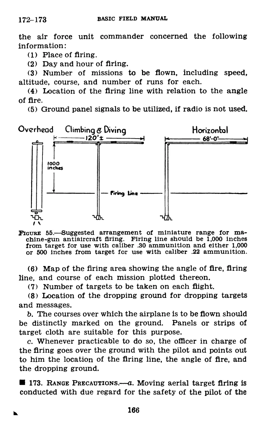
cilitate loading the gun) are normally used with the ground
light machine gun.
2
BROWNING MACHINE GUN, CAL. .30
4-5
4. Mountings.—a. The ground light machine gun nor-
mally is mounted on the light machine gun tripod М2, a de-
scription of which is given in section VI.
b. In motorized or mechanized units, the light machine
gun is mounted on vehicular mounts of several types, but a
light machine-gun tripod М2 is usually carried for each gun
so that it may be fired from the ground.
5. General Data.—General data for the light machine
gun and mount are as follows:
Weight of gun______________________pounds______ 31. 50
Weight of gun (with pintle and combined ele-
vating and traversing mechanism, approxi-
mate weight 4.75 pounds)___________pounds__ 36. 25
Weight of gun and tripod mount_________do__ 48. 00
Weight of tripod mount М2______________do__ 16. 50
Weight of tripod (less pintle and elevating-
traversing mechanism________________pounds__ 11. 75
Length (over-all)__________________inches._ 41.11
Length of barrel________________________do_ 24.
Caliber_________________________________do_ . 30
Rifling:
Number of grooves__________________________ 4
R. H. twist, 1 turn in 33.3 cal. or_inches_ 10.
Depth of grooves___________________do .004
Trigger pull_______________________pounds______ 7. 7
Sights graduated to________________yards._ 2,400
Cyclic rate of fire____rounds per minute. _ 450-625
Maximum usable rate of fire____________do__ 150
Muzzle velocity, М2 ball cartridge
feet per second 2, 800
Muzzle velocity, Ml ball cartridge_____do 2, 600
Capacity of ammunition chest, wooden
rounds_____________________________________ 250
Capacity of ammunition chest Ml________do__ 300
Weight of ammunition chest, wooden (empty)
pounds 5. 5
Weight of ammunition chest Ml (empty)
do____________________________________ 2. 43
3
5-6
BASIC FIELD MANUAL
Weight of spare parts and accessory chest M5
(with contents)____________________pounds 18.93
Characteristics of tripod mount М2:
Length extended________________inches 32. 5
Length folded for transportation. _do___ 27.
Maximum search:
With elevating mechanism attached:
Above zero graduation____mils 4-265
Below zero graduation______do —200
(Elevating handwheel gradu-
ated every mil.)
Without elevating mechanism at-
tached: Variable, but in excess of
mil figures given above.
Maximum traverse:
With traversing handwheel____mils__ 61
Additional on traversing bar:
Right from zero graduation
mils____ 450
Left from zero graduation
mils____ 425
As a free gun________________do____ 6, 400
Note.—The above figures on search and traverse may vary slightly
for different sets of equipment.
6. Sights.—a. Front.—The front sight consists of a front
sight blade, a front sight body, a front sight post, and a
plunger mechanism. The front sight post pivots on the
front sight bearing screw when folded for convenience in
packing. The plunger mechanism provides a locking device
to keep the front sight post in its upright position when the
gun is being fired. The front sight is attached to the front
end of the receiver by means of a screw. The height of the
front sight is such that when the rear sight slide is set at
an elevation a bullet fired from the gun will strike a target at
a distance corresponding to the elevation set on the rear
sight.
b. Rear.—(1) The rear sight (fig. 2) is of conventional
type. It consists of a rear sight leaf, carrying a peep in the
slide mounting, pivoted on the rear sight base, and adjust-
able for windage. The rear sight base mounts the rear sight
4
BROWNING MACHINE GUN, CAL. .30
6
Q Front sight.
@ Rear sight.
Figure 2.—Sights.
5
6-8 ЕлЫС FIELD MANUAL
leaf and rear sight leaf spring. It is secured to the left side
plate of the receiver by three screws in the flange of the
base.
(2) The rear sight leaf is graduated for elevation in 100-
yard divisions up to 2,400 yards. The peep of the rear sight
slide is 0.081 inch in diameter. Motion of the rear sight
slide is accomplished by rotation of the elevating screw knob.
This elevating screw mechanism is equipped with a mil click
device which may be used in conjunction with a mil scale
engraved on the left side of the rear sight leaf to measure or
establish angles of elevation in mils.
(3) The windage screw mechanism also incorporates a mil
click device. Adjustment of the rear sight leaf in windage
is accomplished by rotation of the windage screw knob.
Amount of motion permitted is 10 mils right or left from
zero.
(4) The sight radius is 13.94 inches.
7. Pintle.—The pintle of the light machine gun
(ground), although technically not a part of the gun, is
permanently assembled thereto by a bolt through the trun-
nions of the pintle and the trunnion hole of the receiver of
the gun. Failure to keep this bolt reasonably tight will pro-
duce inaccurate fire. This pintle is tapered and mates with
the corresponding tapered pintle bushing of the head of
the tripod mount М2. This tapered pintle thus serves as a
tight bearing union between the receiver of the gun and its
mounting. The pintle is secured in its mounting by the
engagement of a spring actuated pintle latch of the mount-
ing in a corresponding annular groove of the pintle.
8. Elevating and Traversing Mechanism.—a. As with the
pintle, the elevating and traversing mechanism is not techni-
cally a part of the gun. However, the elevating and travers-
ing mechanism is permanently secured to the receiver of the
gun by a bolt through the head of this mechanism and the
elevating bracket of the gun. In guns of new manufacture,
the elevating bracket is integral with the bottom plate.
b. The elevating and traversing mechanism, when used
with the tripod М2 consists of an upper elevating screw; a
6
BROWNING MACHINE GUN, CAL. .30
8
lower elevating screw; an elevating handwheel assembly
secured to the head of the lower elevating screw; a housing
mating with the lower elevating screw; a traversing slide
mounted to the lower elevating screw housing. The new type
traversing mechanism also includes a traversing screw, hand-
wheel, and micrometer. This mechanism incorporates a mil
click device.
(1) The upper elevating screw terminates at its upper end
in an offset head which incorporates a recess for the bolt
which assembles the entire elevating and traversing mecha-
nism to the gun. The mechanism is properly assembled to
the gun when the offset head points to the rear, thus per-
mitting the mechanism to be folded to the rear and seated in
its recess in the duralumin grip. The upper elevating screw
is externally threaded to mate with the internal threads of
the lower elevating screw. It is equipped with a longitudinal
slot in which is seated an engraved scale. This scale is uti-
lized to indicate plus or minus increments of elevation given
the mounted gun. It is subdivided into 50-mil graduations
and is read by noting the position of the upper edge of the
lug of the click ring which moves in the longitudinal slot as
the elevating handwheel is rotated.
(2) The lower elevating screw is threaded internally to
mate with the externally threaded upper elevating screw and
is threaded externally to mate with the lower elevating screw
housing. Secured to its upper end is the elevating handwheel
assembly.
(3) The elevating handwheel assembly incorporates a mil
click device. The handwheel is of light duralumin alloy and
carries around its outer periphery ten notches, each notch
indicating a 5-mil increment of elevation. Engraved on the
upper surface of the hand wheel is a mil scale which is read
directly from the indicator attached to the click ring. This
scale is of 50-mil amplitude and is divided and numbered in
5-mil major divisions and single-mil subdivisions. The click
ring which is carried in the elevating handwheel does not
rotate with the hand wheel, being prevented therefrom by
engagement of a lug in the longitudinal slot of the upper
elevating screw.
7
8
BASIC FIELD MANUAL
(4) The lower elevating screw sleeve is threaded internally
to engage the external threads of the lower elevating screw.
This sleeve carries at its front portion a spring actuated
plunger which serves to prevent disassembly of the lower ele-
vating screw from its sleeve. At the upper rear portion of
the lower elevating screw sleeve is the male portion of a
swivel joint, attaching the traversing slide to the elevating
and traversing mechanism.
(5) The traversing slide mounts the traversing slide lock
lever assembly. This assembly consists of the traversing slide
lock lever, the traversing slide lock lever screw, the traversing
slide lock lever positioning the traversing slide lock spring,
the traversing slide locking screw and washer. Adjustment
of the lever to the clamping screw is provided for by a spline
assembly, in turn secured by a locking screw and washer.
Adjustment is correct when the clamping screw is in firm con-
tact with the traversing bar, the lever being about 45° above
the right horizontal position.
(6) Movement of the gun in elevation, when mounted on
the tripod М2 is accomplished by rotation of the elevating
handwheel, the traversing slide being in firm contact with the
traversing bar, with the traversing slide lock lever preferably
engaged. (When firing on rapidly moving ground targets,
the traversing slide lock is not engaged, although the travers-
ing slide must be retained in firm contact with the traversing
bar.)
(7) When mounted on the М2 tripod, the light machine
gun may be traversed—
(a) When equipped with the old type traversing mechan-
ism, by moving the gun right or left as desired, the traversing
clamp being disengaged from the traversing bar, while the
traversing slide is retained in firm contact with the traversing
bar.
(b) When equipped with the new type mechanism: beyond
50 mils, as stated above; under 50 mils, by using the travers-
ing hand wheel.
8
BROWNING MACHINE GUN, CAL. .30
9-10
Section II
DISASSEMBLING, ASSEMBLING, AND CHANGING
PARTS
9. General.—a. Disassembling may be considered under
two general headings: first, removal of groups to the extent
required for ordinary cleaning and minor repairs; and,
second, detailed disassembling, involving removal of all
components from each group.
b. A group is a number of parts, contained in a common
housing, which function as a unit.
c. The removal of the different groups from the gun and
complete disassembling of the groups to be disassembled by
the using services can be accomplished with the tools
provided.
10. Removal of Groups From Gun.—a. Blackplate.—(1)
Pull back on latch and raise cover. With the left hand pull
back bolt handle and hold it in the rearmost position.
(2) Insert rim of a cartridge in slit in end of driving spring
rod. With slit horizontal, push in driving spring rod as far
as it will go and turn it clockwise one-quarter turn until slit
is vertical. In this position the lugs on it will engage in their
recesses in the bolt.
(3) Push bolt handle forward about an inch to free the
rear end of driving spring rod from backplate.
(4) Push latch forward and lift out backplate.
b. Bolt handle.—Pull bolt all the way back and remove bolt
handle.
c. Bolt.—Remove bolt from rear end of receiver being care-
ful not to handle driving spring rod.
d. Lock frame.—Insert nose of cartridge through hole in
the right side of receiver and push in on trigger pin. Grasp
trigger and pull lock frame, barrel extension, and barrel out
of receiver. Hold barrel in one hand, lock frame in the other,
and push forward on accelerator. This separates lock frame
and barrel extension.
e. Barrel extension and barrel.—Unscrew barrel extension
from barrel.
9
10-11
BASIC FIELD MANUAL
/. Latch.—With the left hand, palm up, against the rear
of the receiver to prevent dropping the latch spring, pull
latch to rear until it separates from the plate. Guns of recent
manufacture have the latch spring riveted to the latch.
g. Latch spring.—If not riveted lift the latch spring from
its pin in the latch.
h. Cover.—(1) Guns of early manufacture.—(a) Turn
cover pin spring up and remove pin.
(b) Remove cover.
(2) Guns of new manufacture.—(a) Remove cotter pin
from cover bolt.
(b) Place screwdriver blade of combination tool in slot in
cover bolt to prevent it from turning and with a wrench re-
move the nut.
(c) Remove cover bolt, cover catch spring, and fixed and
movable plates.
(d) Remove cover.
Note.—To prevent undue wear, the cover and latch should not
be removed except when necessary for cleaning or replacement of
parts.
11. Replacing Groups in Gun.—In general, the groups are
replaced in the gun in reverse order.
a. (1) Guns of early manufacture.—Replace cover. Insert
cover pin and lock it by turning cover pin spring forward
into its seat in trunnion block. Some models have a cover
pin which is locked by inserting and spreading a cotter pin
through a hole in the cover pin.
(2) Guns of new manufacture.—Replace cover. Place
cover latch spring on bolt and position the fixed and movable
plates. Insert cover bolt into cover hole. Place screwdriver
blade of combination tool in slot in cover bolt to prevent it
from turning, and assemble nut to cover bolt using a wrench
until the desired tension is obtained. Replace cotter pin.
b. Seat rounded end of latch spring in latch seat, placing
hole in spring over pin, bent side of spring away from latch.
Holding spring in place with the fingers, push latch onto
top plate from the rear, free end of the spring to the front,
then force the latch home. If the spring is allowed to slip
from its seat, the latch will not function, and the spring will
jam the latch so that it cannot be removed without breaking.
10
BROWNING MACHINE GUN, CAL. .30
11
c. Screw barrel into barrel extension until the rear end
of the barrel is flush with the inside of the barrel extension.
d. Insert barrel and barrel extension into receiver until
the forward end of barrel extension is opposite the rear end
of receiver.
e. Holding barrel extension with one hand, take lock
frame in other hand, with index finger beneath and support-
ing accelerator. Place claws of accelerator in front of and
against T-lug. Insert front projections of lock frame into
slots of barrel extension and push forward until accelerator
turns backward, locking lock frame to barrel extension.
Push down tips of accelerator to insure positive locking.
/. Push parts into gun, forcing trigger pin inward to clear
it from right side plate, and push forward until a click is
heard as trigger pin springs out into its seat in the right
side plate. (If barrel hangs on front barrel bearing, reach
forward under jacket and aline it.)
g. Push cocking lever forward and insert bolt, pushing
down on rear end of trigger to prevent ejector from tripping
accelerator.
h. Insert bolt handle through large opening at rear of
slot and push it forward about 1 inch, being sure that collar
on handle is inside right side plate.
i. Push forward on latch and replace backplate.
j. Hold bolt handle fully back with left hand. Place rim
of cartridge in slit in end of driving spring rod, and turn
rod one-quarter turn counterclockwise until slit is horizontal.
This releases driving spring. Allow bolt to go forward.
k. Make head space adjustment as follows:
(1) Pull bolt to rear about % inch.
(2) Screw barrel into barrel extension (by using point of
a cartridge or the combination tool in barrel notches) until
the action will just close (recoiling parts will go fully for-
ward) without being forced.
(3) Unscrew the barrel one notch.
Caution: Care must be exercised to avoid roughening the
barrel surface during the adjustment.
Z. Position belt feed lever stud over cam groove in bolt
and close cover.
m. Pull trigger.
11
11
BASIC FIELD MANUAL
Notes.—1. Head Space.—a. The head space of a military weapon,
with a cartridge fully seated in the chamber is the distance between
the base of the cartridge and the face of the bolt, when the bolt
is in its locked position.
b. In Browning machine guns, the head space is adjusted by
obtaining the proper distance between the forward part of the
bolt and the rear end of the barrel. The head space adjustment
must be checked before firing.
2. Effect of Head Space Adjustment.—a. General.—The head
space adjustment of the machine gun is the most important ad-
justment to be made. To insure continued operation of the gun,
to obtain the best uniformity of shot patterns, and to prevent
damage to the gun, the head space adjustment should be made
as prescribed in paragraph 11/c above, or note 4 below.
b. Tight head space (fig. 3).—When the head space adjustment
is tight, poor functioning will result, as the breech lock will not
fully enter its recess in the bolt. This condition may damage the
barrel extension, bolt, or breech lock. Extraction trouble may also
occur because of improper timing of locking and unlocking. Fur-
thermore, with a tight head space adjustment the gun operates
sluggishly because of the binding of the moving parts. If the
head space adjustment is very tight, the notches on the rear end
of the barrel can be seen, the bolt handle will not be fully forward,
and the firing pin cannot be released by pressing the trigger.
c. Loose head space (fig. 4).—If the head space is loose, a ruptured
cartridge may occur; also if there is a weakness in the cartridge
case itself, such as a split case, the possibility of a ruptured cart-
ridge is increased. If the head space adjustment is loose, the bolt
can be moved slightly from front to rear independently of the barrel
and barrel extension.
3. Quick Head Space Adjustment.—After the head space adjust-
ment has been determined by the method described in paragraph
life, or by the alternate method described in paragraph 4 below,
the notch in which the barrel locking spring is engaged may be
marked with a center punch. Thereafter, to make the correct head
space adjustment during the assembly of the gun, screw the barrel
all cf the way into the barrel extension and then unscrew the barrel
until the barrel locking spring is in the marked notch.
4. Alternate Head Space Adjustment.—Head space adjustment
can be made before the moving parts are assembled in the receiver.
Screw the barrel into the barrel extension until the rear of the
barrel is flush with the Inside of the barrel extension. Remove the
extractor from the bolt. Place the bolt into the bolt guides in the
barrel extension. Push the bolt fully forward. Turn the assembly
so that the bolt is down. Lock the bolt to the barrel extension
by pushing the breech lock fully into its seat in the bolt. Hold it
firmly in that position with the thumb. Screw the barrel into the
barrel extension until it is stopped by contact with the forward
face of the bolt. Be certain that the barrel does not force the
breech lock out of its fully locked position. Turn the assembly
so that the bolt is up. Unscrew the barrel from the barrel extension
just enough to cause the breech lock to fall from its recess in the
bolt. Remove the bolt. Screw the barrel into the barrel extension
one notch, or, if the nose of the barrel locking spring is between
two notches, screw the barrel into the barrel extension one and the
fraction notches. Assemble the gun.
12
BROWNING MACHINE GUN, CAL. .30
11
Figure 3.—Tight head space.
Figure 4.—Loose head space.
514913°—43
2
13
12
BASIC FIELD MANUAL
12. Detailed Disassembling of Bolt.—a. Turn the extrac-
tor up and remove it to the left (fig. 5).
b. Great care should be exercised in removing the driving
spring rod from the bolt as the force of the driving spring
when released can easily cause the rod to slip away from the
hand and possibly result in serious injury. To remove driv-
ing spring rod, place protruding end of rod on the table or a
block of wood. With bolt firmly grasped by the right hand
(palm of the hand over face of bolt), press down and at the
SEAR SPRING PIN
SEAR SPRING
DRIVING SPRING c- - rp^---COCKING LEVER PIN
COCKING LEVER
Figure 5.—Bolt group.
same time turn bolt one-fourth turn to the left until lugs
on rod leave their recess in bolt. Slowly release pressure on
bolt, allowing it to rise under the action of driving spring
until about 3 inches of rod protrude. With the left hand
grasp protruding portion of rod and spring; raise both hands
and the bolt from the table, keeping rod and spring in their
same position relative to bolt. Separate rod and spring from
bolt with a quick jerk. The quick, separating jerk will not
allow spring to kink. Separate driving spring rod and driv-
ing spring.
14
BROWNING MACHINE GUN, CAL. .30
12-13
c. Turn the top of cocking lever to the rear of bolt and
withdraw cocking lever pin to the left of bolt.
d. Lift out cocking lever.
e. Release firing pin by pushing down on sear. Hold bolt
in the left hand, the front end toward the body, top up, with
the index finger of the left hand beneath and supporting the
sear. Use the nose of a cartridge, placed near the end of
sear spring, to push downward and to the right on spring to
seat it in cut in bolt. This releases sear which is removed
at the bottom of bolt.
/. Turn sear spring back to the left to clear the cut. Push
nose of a cartridge into the hole in the bottom of bolt to
start sear spring pin moving. To complete the removing
of sear spring, place the top end of cocking lever well under
sear spring and pry down against the edge of bolt.
Place the palm of the right hand over the rear of bolt,
tilt the rear end of bolt down, and firing pin will drop out.
13. Assembling Bolt.—a. Place firing pin in bolt, striker
downward and to the front, and tilt the front of bolt down-
ward until striker projects through the small hole in the front
of bolt.
b. Replace sear spring by pushing with a cartridge on top
of pin, avoiding pressure on spring proper.
c. Hold bolt in the left hand, front end toward the body,
top up. With point of a cartridge placed near the end of
sear spring, push downward and to the right to seat it in
cut in bolt.
d. Push sear upward from the bottom, notched projection
toward the front of bolt, and hold with first finger of the
left hand while pressing downward and to the left on sear
spring with a cartridge to engage the end of sear spring in
sear.
e. Replace cocking lever, making certain that the rounded
nose on the lower end is to the rear of bolt so that it will
properly engage in the recess in firing pin.
/. Insert cocking lever pin on the left side of the bolt. The
upper end of the cocking lever should be to the rear of the
bolt before inserting the pin. This alines the hole in the
15
13-14
BASIC FIELD MANUAL
cocking lever with the hole on either side of the bolt for
the return of the cocking lever pin.
g. Cock by pressing forward on cocking lever. Turn cock-
ing lever to the rear and press down on sear with a car-
tridge to release firing pin and test the correctness of the
assembly. Recock the assembly.
h. The same care should be exercised in assembling the
driving spring rod to the bolt that is exercised in removing it.
Place driving spring on driving spring rod. With the back
end of the rod resting on a table or a block of wood, gather
as much of the spring on the rod as can be held compressed
by the thumb and fingers of the left hand. With bolt
securely held in the right hand, the front end of bolt in
the palm of the hand, slip bolt over the end of spring. Push
downward to compress spring and allow lugs on rod to enter
LOCK FRAME
TRIGGER PIN SPRING
TRIGGER PIN
BARREL PLUNGER
Figure 6.—Lock frame group.
slot in bolt. Turn bolt slowly 90° clockwise until slit in rod
is crosswise to slot in bolt.
i. Insert pin on extractor into the rear one of the two large
holes in the left side of bolt, extractor pointing up. Turn
extractor downward toward the front to engage collar on
extractor under collar cut in bolt.
14. Detailed Disassembling of Lock Frame (fig. 6).—a.
Grasp head of trigger pin between the thumb and first finger
of the right hand and remove it to the right. Lift out trig-
ger. If pin is too tight to permit its removal in this manner,
16
BROWNING MACHINE GUN, CAL. .30
14-17
it must be drifted out. Do not remove trigger pin spring
except when necessary.
b. Push out accelerator pin and remove accelerator.
c. Hold lock frame with the left hand, projections pointing
upward, slot to the left, separator between the second and
third fingers, first and second fingers gripping barrel plunger
spring. With the thumb of the right hand, press down and
out on barrel plunger to disengage plunger guide pin from
slot. Allow spring, with plunger, to rise slowly. Lift out
spring and remove it from barrel plunger.
15. Assembling Lock Frame.—a. Assemble barrel plunger
spring to barrel plunger, being careful that the more tightly
fitting end of barrel plunger spring is pushed up against the
head of barrel plunger. Hold lock frame with the left hand,
projections pointing upward, slot to the left, lock frame sep-
arator between the second and third fingers. Seat the end
of barrel plunger spring in the recess in lock frame sepa-
rator, barrel plunger guide pin facing the slot in lock frame.
Using the first and second fingers of the left hand to prevent
spring from buckling, press down with the thumb of the
right hand on the end of barrel plunger until barrel plunger
guide pin can be seated in the slot. Care should be taken
that the action of the spring does not cause the plunger to
slip out of the hand.
b. Replace accelerator with the tips up and the rounded
surface to the front. Insert accelerator pin, taking care that
both ends of pin are flush with the sides of lock frame.
c. Push the front end of trigger up between separator and
spacer, placing the center in its square seating. If trigger
pin spring has been removed, seat spring on trigger pin, plac-
ing the small end of spring toward the head of pin. Replace
pin from the right.
16. Detailed Disassembling of Barrel Extension (fig.
7).—a. Insert the rim of a cartridge under the front edge
of barrel locking spring and pull it out to the front.
b. Push out breech lock pin and remove breech lock.
17. Assembling Barrel Extension.—a. Place breech lock
in its slot, taking care that the double beveled surface is up
17
17-18
BASIC FIELD MANUAL
and to the front. Insert breech lock pin and insure that
both ends of pin are flush with the sides of barrel extension.
b. Insert barrel locking spring in the seating in the left
side of barrel extension, hook inward, and force home as far
as it will go.
BREECH LOCK PIN BREECH LOCK
BARREL
Figure 7.—Barrel and barrel extension group.
Figure 8.—Feed group.
18. Detailed Disassembling of Cover (fig. 8).—a. Remove
cap or plug from belt feed lever pivot bushing nut. Remove
belt feed lever pivot.
b. Withdraw belt feed lever from belt feed slide and
remove slide.
18
BROWNING MACHINE GUN, CAL. .30
18-20
c. Insert the nose of a cartridge between cover extractor
spring and the notch in cover extractor cam. With the
thumb of the left hand over spring, pry out on spring to
disengage from cut. Lift out spring from its seat against
stud.
19. Assembling Cover.—a. Place the forked end of cover
extractor spring under stud on cover. Press downward with
the thumb on the other end of spring, at the same time
pushing toward stud, and seat projection of spring in the
notch of cover extractor cam.
b. Replace belt feed slide in its grooves in cover, taking
care that pawl is pointing to the right as cover goes on the
gun.
c. Place front end of belt feed lever in the cut, stud on
lever away from cover and to the rear. Insert belt feed lever
pivot pin. Replace cotter pin or cap.
20. Disassembling and Assembling of Parts Dismounted
Only for Repair.—a. Shock-absorbing group.—(1) Disas-
sembly.—Unscrew the adjusting screw; remove the adjusting
screw plunger and screw.
(a) Disk type.—Remove the buffer disks, buffer plug, buf-
fer ring, and the buffer plate through the rear end of the
grip.
(b) Spring type.—Remove the buffer disk, stop, spring,
filler, and buffer plate.
(2) Assembly.—(a) Disk type.—In assembling the shock-
absorbing group, it must be kept in mind that part of the
recoil energy of the bolt is transmitted to the buffer pile
in the form of metal to metal impact of approximately 5,600
pounds. This force is absorbed by the fiber buffer disks. In
order that the buffer pile may perform this function prop-
erly, the following precautions must be observed:
1. The disks must form a compact column or stack
from the face of the buffer plate to the adjusting
screw.
2. The disks should be clean and free from rough
edges and surfaces, and should be assembled in
the tube one at a time. Be sure that each disk
19
20-22
BASIC FIELD MANUAL
is firmly seated and use sufficient disks (normally
16) so that when the adjusting screw is inserted
and tightened its rear face will be flush with or
protrude slightly from the rear face of the grip.
3. After assembly, adjust the buffer by tightening the
adjusting screw until the buffer plate can just
be turned by grasping it by the end which extends
through the backplate. When the gun is assem-
bled, this adjustment can be made approximately
without removing the backplate by tightening
the adjusting screw as far as it will go and then
loosening one-half turn.
4. These disks are used for their shock-absorbing ca-
pacity, and substitution of other material for or
removal of the disks is prohibited (par. 247b(2)).
(b) Spring type.—Assemble in reverse order. Tighten the
adjusting screw as far as possible with the combination tool
and then loosen turns. For additional data on assem-
bling groups see paragraph 239.
b. Belt holding pawl.—(1) Hold down belt holding pawl
and withdraw belt holding pawl split pin to the rear.
(2) Lift off belt holding pawl.
(3 > Lift belt holding pawl spring from its seating.
(4) Replace in the reverse order.
21. Changing Parts.—If the time element is important, a
broken minor part should be replaced by substituting a com-
plete spare group which contains it. Thus a broken firing
pin would be remedied by changing bolts. Replacement
parts in the spare parts chest should be replaced as soon
as opportunity permits. In the event that either the bolt,
barrel, or barrel extension is changed, readjust the head
space.
Section 1П
CARE AND CLEANING
22. Importance.—The care and cleaning of the machine
gun, tripod, and accessories are a vital duty. Experience has
shown that most machine guns become unserviceable from
lack of proper care rather than from use.
20
BROWNING MACHINE GUN, CAL. .30
23
23. Lubricants, Cleaning Materials, and Rust Preven-
tives.—a. General.—The use of unauthorized materials, such
as abrasives, is forbidden. The following are the only ma-
terials authorized and issued for cleaning these machine
guns:
Cleaner, rifle bore.
Soda ash.
Soap.
Oil, lubricating, preservative, light.
Oil, lubricating for aircraft instruments and machine
guns.
Compound, rust-preventive, light.
Solvent, dry-cleaning.
Decontaminating agents.
Water.
b. Rifle bore cleaner.—(1) Rifle bore cleaner is issued for
cleaning the bore of the machine gun after firing. This ma-
terial possesses rust-preventive properties and provides tem-
porary protection against rust. It is better practice, how-
ever, to dry the bore immediately after cleaning it with rifle
bore cleaner and then coat it lightly with light preservative
lubricating oil.
(2) Rifle bore cleaner freezes at temperatures below 32° F.
If frozen, it must be thawed and shaken well before using.
To prevent bursting, containers should not be filled more
than three-fourths full in freezing weather.
c. Soda ash.—Soda ash is a white, odorless powder which
is soluble in water. For use, it is dissolved in water in the
proportion of У2 to 1 pound of sode ash to 1 gallon of boiling
water. If boiling water is not available, hot or cold water
may be used. This solution can be used to clean the gun
bore when rifle bore cleaner is not available.
d. Soap.—A soap solution may be used to clean the bore
and mechanism, if neither rifle bore cleaner nor soda ash is
available. The solution is prepared by dissolving soap chips
in hot water in the proportion of V4 pound to 1 gallon of
water. When possible, the solution should be used while it
is hot.
e. Light preservative lubricating oil.—This oil has both
rust-preventive and lubricating properties but cannot be
21
23-24
BASIC FIELD MANUAL
depended upon to provide protection from rust for long
periods. It is used for the lubrication of all moving parts
and for short term protection against rust. Preservative
action results partly from the oily film on the metal parts
and partly from the chemical combination of inhibitors in
the oil with the metal. It will protect the metal surfaces
from rust even though no appreciable film of oil is present
on the metal parts. When used on moving parts, however,
it is necessary to maintain a thin film of oil to provide the
necessary lubrication.
/. Lubricating oil for aircraft instruments and machine
guns.—This oil, which is a lubricant rather than a rust-
preventive agent, may be used for lubricating the machine
gun when light preservative lubricating oil is not available.
It is an extremely light oil which relies entirely upon the
maintenance of the oil film to protect metal surfaces from
rusting. When it is used as a preservative, the parts must
be inspected daily for rust. Following this inspection, the
metal parts should be wiped clean and again lightly coated
with the oil.
g. Light rust-preventive compound.—This compound is
issued for the protection of metal parts for long-time storage
while the parts are boxed. It is a sluggish liquid at about
60° F. It can usually be applied with a brush.
h. Dry-cleaning solvent.—This is a noncorrosive, petroleum
solvent which is used to remove grease, oil, or rust-preventive
compound. Dry-cleaning solvent is highly inflammable and
should not be used near open flames. Smoking is prohibited
where dry-cleaning solvent is used. The solvent is generally
applied with rag swabs to large parts of the gun and used
as a bath for the small parts. All surfaces must be
thoroughly dried with clean rags immediately after use of
the solvent. Gloves should be worn when handling parts
that have been cleaned, in order to avoid leaving finger
marks which are usually acid and therefore induce corrosion.
Cleaning solvent attacks and discolors rubber.
24. Care and Cleaning When No Firing Is Done.—a. Gen-
eral.—(1) This includes the care necessary to preserve the
22
BROWNING MACHINE GUN, CAL. .30
24
condition of the machine gun and mount during the time
when no firing is being done.
(2) The gun must be completely disassembled for proper
inspection, cleaning, and lubrication.
(3) Machine guns in the hands of troops should be in-
spected daily during periods of use to insure proper condition
and cleanliness. Training schedules should allow time for
supervised cleaning on each day that guns are used.
b. Bore and chamber.—(1) To clean the bore and chamber,
assemble a cloth patch to the cleaning rod and insert the
rod into the bore at the breech end. Move it forward and
backward several times and replace it with a fresh new
patch. Make sure that the patch goes all the way through
the bore before the direction is reversed. This cleaning re-
moves accumulations of dust, dirt, and thickened oil. Be
sure that the chamber as well as the bore is throughly
cleaned.
(2) Continue this operation until a patch comes out clean.
(3) After thoroughly cleaning, saturate a patch with light
preservative lubricating oil and push it through the chamber
and bore.
(4; When issue patches are not available, patches should
be cut approximately 2% inches square to permit their pas-
sage through the bore without bending the cleaning rod.
c. Receiver.—(1) Disassemble, clean, and oil all moving
parts of the receiver.
(2) Clean the screw heads and crevices with a small
cleaning brush or small stick.
(3) Clean moisture and dirt from the metal surfaces with
a dry cloth, then wipe them with a cloth that has been dipped
in light preservative lubricating oil. This protective film
must be maintained at all times.
(4) Clean the dirt from outer surfaces of the machine gun
With a slightly oiled cloth and then wipe with a soft dry one.
d. Accessories.—(1) The mount, spare parts, and all ac-
cessories of the gun must be cared for and cleaned as care-
fully as the gun itself.
(2) Ammunition must be kept clean and dry.
(3) Guns mounted in vehicles are usually locked in travel-
ing position.
23
24-26
BASIC FIELD MANUAL
(4) Muzzle covers are provided to prevent dirt from enter-
ing the gun through the muzzle.
25. Preparatory to Firing.—The following steps are taken
before firing to insure efficient functioning of the gun:
a. Dismount the main groups.
b. Clean the bore and chamber with a clean dry patch.
Do not oil the bore and chamber before firing.
c. Thoroughly clean and lightly oil all other metal parts
with light preservative lubricating oil. Do not use grease.
Be sure to apply a thin coating of oil to the following:
(1) All parts of bolt group.
(2) All parts of the lock frame group.
(3) All parts of the barrel extension group.
(4) All parts of the feed group.
d. Assemble the machine gun and rub all outer surfaces
with a lightly oiled rag to remove dust.
e. Check head space.
f. Clean and prepare for firing all parts of tripod and
other equipment necessary for firing.
26. After Firing.—a. General.—(1) The bores of all ma-
chine guns must be thoroughly cleaned by the evening of
the day on which they are fired. They should be cleaned in
the same manner for the next 3 days.
(2) Firing the machine gun causes powder and primer
fouling to form in the bore and chamber. This fouling
absorbs and retains moisture from the air, thereby causing
rust. These deposits can be removed by cleaning with rifle
bore cleaner, soda ash solution, soap solution, or water.
b. Cleaning procedure after firing.—(1) Unload the gun
and replace the belt in the ammunition chest.
(2) Clean the bore (c or d below) and all working parts.
If this cannot be done at once, apply oil to prevent rust.
(3) Release the firing pin spring.
(4) At the first opportunity, entirely disassemble the gun,
clean, oil, and inspect all parts, and make needed repairs and
replacements.
(5) On assembly, check operation with dummy cartridges
and release the firing pin spring after making sure that
functioning and adjustment are correct.
24
BROWNING MACHINE GUN, CAL. .30
26
c. Cleaning the barrel with rifle bore cleaner,—(1) Saturate
a clean patch with rifle bore cleaner, attach it to the clean-
ing rod, insert it at the breech end of the barrel, and push
back and forth through the bore of the barrel.
(2) Repeat this operation two or three times with clean
patches. Be sure that the patch goes completely through
the bore before the direction is reversed.
(3) Repeat this procedure with dry patches until a patch
comes out clean and dry.
(4) Examine the bore and chamber carefully for cleanli-
ness. If they are not free of all residue, repeat the cleaning
process.
(5) If clean, saturate a patch in light preservative lubri-
cating oil and push it through the chamber and bore.
d. Cleaning the barrel with soda ash or soap solution.—
(1) Use soda ash solution if rifle bore cleaner is not available
Use soap solution or plain water if neither rifle bore cleaner
nor soda ash is available.
(2) Place the barrel, muzzle down, in a vessel containing
soda ash or soap solution. (If these are not available use
plain hot or cold water.)
(3) Insert the cleaning rod and flannel patch into the
breech end. Move the rod up and down for about 1 minute,
pumping the solution in and out of the bore.
(4) Run a brass or bronze wire brush forward and back
through the barrel three or four times while the bore is wet.
The brush must be pushed entirely through the barrel before
it is reversed, otherwise the brush will be ruined.
(5) Using the cleaning rod and a clean patch, pump clean
water through the bore as in (3) above to remove the washing
material.
(6) Remove the barrel from the water and dry it with
clean flannel patches.
(7) If the bore and chamber are clean, saturate a patch
in light preservative lubricating oil and push it through the
bore to oil the bore and chamber.
e. Cleaning parts other than barrel.—(1) Wipe the re-
ceiver clean, taking care to remove dirt from all crevices.
Thoroughly clean the cover, bolt, barrel extension, lock
frame, and backplate, using a small stick covered with a
25
26-27
BASIC FIELD MANUAL
flannel patch. Remove dirt and oil from all recesses and
springs.
(2) Wipe all parts with an oily rag.
f. Front barrel bearing.—(1) Carbon is deposited in the
front barrel bearing during firing. If this deposit is not
removed periodically, it will eventually cause the barrel to
bind.
(2) Unscrew the front plug with the combination tool.
(3) Soften carbon with dry-cleaning solvent.
(4) Scrape out the carbon.
(5) Replace the plug.
g. Exterior surfaces.—(1) Wipe off the exterior of the gun
with a dry cloth to remove moisture and dirt.
(2) Wipe all metal surfaces with light preservative lubri-
cating oil.
h. Accessories.—(1) Clean and oil the mount, spare parts,
and all accessories with light preservative lubricating oil.
(2) Avoid leaving excess oil in the interior of the tripod
head, since this will collect dirt and sand.
(3) The pintle bushing should be cleaned and lightly oiled.
(4) Oil should not be placed in the seating of the travers-
ing dial, since this will collect dirt and interfere with easy
dial adjustment.
i. Frequency of cleaning.—Machine guns should be cleaned
as soon after firing as possible. If the gun is not to be fired
in the next few days, repeat the procedure outlined above for
3 consecutive days following firing.
27. On the Range or in the Field.—Machine guns must
be kept clean and properly lubricated at all times. To obtain
the maximum efficiency of the gun on the range and in the
field, the following points must be observed:
a. Never fire a gun with any dust, dirt, mud, or snow in the
bore.
b. Keep the chamber free from oil and dirt when firing.
c. Never leave a patch, plug, or other obstruction in the
chamber or bore. Failure to observe this precaution may
result in serious injury.
d. If the gun gives indication of lack of lubrication and of
26
BROWNING MACHINE GUN, CAL. .30
27-28
excessive friction, apply additional oil to the parts subjected
to this friction.
e. Keep a light coating of light preservative lubricating oil
on all metal parts.
/. When in the field, the gun must be disassembled to the
extent necessary for proper cleaning and lubrication. Upon
opportunity, and as necessary, the gun should be disassembled
into its main groups, all parts thoroughly cleaned, and the
operating parts lubricated before the gun is reassembled.
g. During firing, oil frequently but sparingly those parts
where actual friction exists. These include the cam groove
and the cocking lever. Excess oil on the moving parts gen-
erates smoke which interferes with observation and may
disclose the position of the gun.
h. When the prescribed lubricants are not available, any
clean, light mineral oil, such as engine oil, may be used. For
cleaning the bore and chamber, clean water may be used when
no other cleaner is available.
28. Preparation for Storage.—a. Light preservative lubri-
cating oil is the most suitable oil for short-term preservation
of the mechanism of the machine gun. It is effective for
storage for periods ranging from 2 to 6 weeks, depending on
climatic conditions. However, guns which are stored and
protected with light preservative lubricating oil must be in-
spected every 4 or 5 days, and the preservation film renewed
if necessary. For longer periods of time, guns must be pro-
tected with light rust-preventive compound.
b. Light rust-preventive compound is efficient for preserv-
ing the polished surfaces, the bore, and the chamber up to
1 year, depending upon climatic and storage conditions.
c. Machine guns that are to be placed in storage should
be cleaned and prepared with particular care. The bore, all
parts of the mechanism, and the exterior of the gun should
be thoroughly cleaned with dry-cleaning solvent and then
dried completely with rags. In damp climates, particular
care must be taken to see that the rags are dry. After drying
a metal part, the bare hands should not touch that part. All
metal parts should then be coated with either light preserva-
tive lubricating oil or light rust-preventive compound, de-
27
28-30
BASIC FIELD MANUAL
pending on the length of storage required. Application of
the rust-preventive compound through the bore of the gun
is best done by dipping the cleaning brush in the compound
and running it entirely through the bore two or three times.
The brush must be cleaned before use. Before placing the
weapon in storage, the bolt should be in the forward position
with the firing pin released. It is good practice to release
the firing pin tension whenever the weapon is not in use.
The wooden supports of the packing box must be painted
with rust-preventive compound before storing the gun. Place
the gun in the wooden packing box, handling it with oiled
rags. Under no circumstances will a gun be placed in storage
while contained in a cloth or other cover, or with a plug in
the bore. Such articles collect moisture and cause the
weapon to rust.
29. Cleaning Weapons Received From Storage.—Weapons
which have been stored in accordance with preceding para-
graphs will be coated either with light preservative lubri-
cating oil or with light rust-preventive compound. Weapons
received from ordnance storage will, in general, be coated
with rust-preventive compound. Use dry-cleaning solvent to
dissolve and remove all traces of the compound or oil. Take
particular care to see that all recesses in which springs or
plungers operate are thoroughly cleaned. Failure to do this
may cause malfunctioning at normal temperatures and will
certainly do so when the rust-preventive compound congeals
at low temperatures. After using the cleaning solvent, be
sure to dry all parts with dry, clean cloths. Then follow the
instructions in paragraph 24.
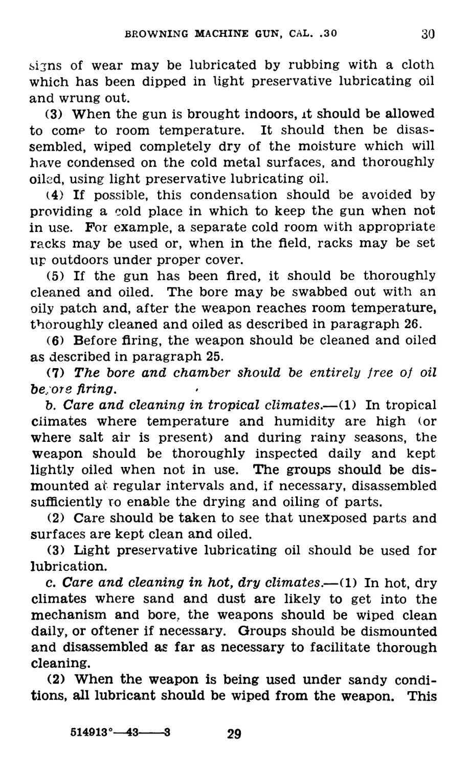
30. Care and Cleaning Under Unusual Conditions.—a.
Care and cleaning in cold climates.—(1) In extreme cold, the
moving parts of the weapon must be kept absolutely free of
moisture. Excess oil or rust-preventive compound on the
working parts will solidify to such an extent as to cause
sluggish operation or complete failure.
(2) Completely disassemble and clean all parts of the gun
thoroughly with dry-cleaning solvent before use in tempera-
ture below 0° F. The working surfaces or parts which show
28
BROWNING MACHINE GUN, CAL. .30
30
signs of wear may be lubricated by rubbing with a cloth
which has been dipped in light preservative lubricating oil
and wrung out.
(3) When the gun is brought indoors, it should be allowed
to come to room temperature. It should then be disas-
sembled, wiped completely dry of the moisture which will
have condensed on the cold metal surfaces, and thoroughly
oiled, using light preservative lubricating oil.
(4) If possible, this condensation should be avoided by
providing a cold place in which to keep the gun when not
in use. For example, a separate cold room with appropriate
racks may be used or, when in the field, racks may be set
up outdoors under proper cover.
(5) If the gun has been fired, it should be thoroughly
cleaned and oiled. The bore may be swabbed out with an
oily patch and, after the weapon reaches room temperature,
thoroughly cleaned and oiled as described in paragraph 26.
(6) Before firing, the weapon should be cleaned and oiled
as described in paragraph 25.
(7) The bore and chamber should be entirely free of oil
be., ore firing.
b. Care and cleaning in tropical climates.—(1) In tropical
climates where temperature and humidity are high (or
where salt air is present) and during rainy seasons, the
weapon should be thoroughly inspected daily and kept
lightly oiled when not in use. The groups should be dis-
mounted at regular intervals and, if necessary, disassembled
sufficiently ro enable the drying and oiling of parts.
(2) Care should be taken to see that unexposed parts and
surfaces are kept clean and oiled.
(3) Light preservative lubricating oil should be used for
lubrication.
c. Care and cleaning in hot, dry climates.—(1) In hot, dry
climates where sand and dust are likely to get into the
mechanism and bore, the weapons should be wiped clean
daily, or oftener if necessary. Groups should be dismounted
and disassembled as far as necessary to facilitate thorough
cleaning.
(2) When the weapon is being used under sandy condi-
tions, all lubricant should be wiped from the weapon. This
514913°—43-
В
29
30-31
BASIC FIELD MANUAL
will prevent sand from sticking to the lubricant and form-
ing an abrasive compound which will ruin the mechanism.
(3) Immediately upon leaving sandy terrain, the weapon
must be cleaned and relubricated with light preservative
lubricating oil.
(4) Perspiration from the hands is a contributing factor
to rust because it contains acid. Therefore, metal parts
should be frequently wiped dry.
(5) During sand or dust storms, breech and muzzle should
be kept covered if possible.
31. Care During Gas Attack.—a. General.—(1) It is im-
portant to prevent the chemicals used in a gas attack from
getting in or on the gun and ammunition. When a gas
attack is anticipated, steps are taken to cover and protect the
gun, ammunition, mount, spare parts, and accessories.
(2) Apply oil to the surfaces of all the parts of the weapon,
to the mount, ammunition, and spare parts.
(3) If the gun need not be used during the gas attack,
cover the oiled gun with canvas gun covers or place it in a
container so that it cannot come into contact with any con-
taminating chemicals.
(4) After the attack, clean the materiel with dry-cleaning
solvent, if uncontaminated.
(5) Prepare for use as described in paragraph 25 or 26, as
required.
b. Decontamination.—(1) A complete suit of impermeable
clothing and a service gas mask must be worn during decon-
tamination operations.
(2) Materiel contaminated with chemicals other than mus-
tard or lewisite must be cleaned as soon as possible with
dry-cleaning solvent or denatured alcohol.
(3) If the surface of the materiel is coated with grease or
oil and has been in a mustard or lewisite attack, first remove
the grease or oil by wiping with rags wet with dry-cleaning
solvent.
(4) Decontaminate unpainted metal surfaces with a solu-
tion of noncorrosive decontaminating agent. Prepare this by
mixing one part of agent to six and one-fourth parts of
solvent, or 2 quarts of agent to 3 gallons of solvent. This
30
BROWNING MACHINE GUN, CAL. .30
31-32
agent acts within 15 minutes, and a second application is
recommended.
(5) Decontaminate painted surfaces with a bleaching solu-
tion. Prepare this by mixing three parts of the bleaching
powder (chloride of lime) with two parts of water by volume.
The chloride of lime is allowed to remain 24 hours; a second
application is made, to insure complete covering, within a
brief period after the first application.
(6) After decontamination, clean the materiel thoroughly
and prepare for use as described in paragraph 25 or 26,
as required.
(7) Do not allow the chemical agents to come into contact
with the skin. Always burn or bury all rags or wiping
materials used for decontamination.
c. References.—Detailed information on decontamination
is contained in FM 21-40 and TM 3-220.
32. Points to be Observed Before, During, and After
Firing.—The following list of points to be observed before,
during, and after firing will be found useful as a guide for
the proper care of the gun. It may also be used as a guide
for inspection.
31
Before During
Bore Moving parts _ Head space Rear sight and Ca5 wind gage. M Tripod Belts and am- munition. OU Spare parts and tools. Look through and clean Oil and test for worn or broken parts. See that parts func- tion without excessive fric- tion. Make correct adjustment and test (note, par. 11). Examine barrel locking spring. Clean and free from grease. See that sight is in good mechan- ical condition. Set sight at 700 and wind gage at zero. Set tripod firmly with no lost motion. Verify that travers- ing bar sleeve latch is properly seated. Secure sufficient supply of am- munition. Inspect ammuni- tion. Keep belts dry. See that oilcan is full Keep clean and oiled. See that kits are complete. Keep oiled Tighten if several sepa- rated cases occur. Keep properly set Keep firmly set Keep belt in line with feed opening. Watch ammunition supply. - - Keep within reach
During temporary
cessation
After
Clean bore (dean and lightly oil bore with a patch.
Inspect and oil; clean dirt from belt holding pawl. Remove bolt, lock frame, bar- rel extension, and barrel; clean, oil, and release firing
Test pin. Adjust correctly and test. Examine barrel locking
Keep properly set spring. Clean and oil. Set sight at 700 and wind gage at zero.
Examine.. Clean and oil.
Refill oilcan __ Make repairs. Replace broken or worn parts. Clean, repair, and refill all belts. Separate live rounds from empty cases. Inspect ammunition. Refill oilcan. Check, replace broken or missing parts, clean, and oil.
BASIC FIELD MANUAL
BROWNING MACHINE GUN, CAL. .30
33-35
Section IV
MECHANICAL FUNCTIONING
33. General.—The soldier should have a practical working
knowledge of the mechanical operation of the machine gun
so that he will be able to keep it in action during combat.
Although many parts of the gun operate simultaneously, the
subject of functioning is divided into phases to facilitate
instruction. The explanation of mechanical functioning be-
gins with the gun assumed to be loaded and ready to fire.
a. To half load.—With cover open or closed, enter belt
through feedway from left to right. Pull belt through feed-
way until the first round is in place on the right of belt
holding pawl. Close cover if open. Pull bolt fully to the rear
and release it.
b. To load.—Load is executed the same as half load except
that bolt is pulled to the rear and released twice.
c. To unload.—Raise cover, remove belt, pull bolt to the
rear and hold it, look or feel to see that there is no ammuni-
tion in the gun, lower extractor, release bolt, lower cover, and
then pull trigger.
d. To clear gun.—Raise cover, remove belt, pull bolt to
the rear and hang it in its rearmost position by engaging
extractor cam plunger in rear of extractor feed cam, and
inspect the gun to see that there is no ammunition in it.
e. Division of functioning into phases.—For a method of
dividing functioning into phases and demonstrating each
phase, see paragraph 241.
V 34, Trigger Action.—Since the trigger is pivoted, its for-
ward end is lowered as its rear end is raised. The trigger
cams on the front end of trigger, through their engagement
with earns on sear, force sear down against the action of
sear spring until the shoulder of firing pin is released by
sear notch. The firing pin spring then forces firing pin
forward to strike primer.
35, Backward Movement of Recoiling Parts (figs. 9 and
10).—The explosion forces the recoiling parts (barrel, bar-
rel extension, and bolt) backward about % inch. During the
33
35-36
BASIC FIELD MANUAL
first half of this movement the parts are locked together.
When the breech lock clears the breech lock cam, it is forced
down by the front projections of the lock frame acting on the
breech lock pin. This unlocks the bolt from the barrel ex-
tension, permitting the bolt to continue to the rear. As the
barrel extension comes to the rear, the barrel plunger spring
DRIVING SPRING
COCKING LEVER
EXTRACTOR
BOLT
тагах
ACCELERATOR
LOCK FRAME
^222222222777772
BARREL / firing PIN
BARREL EXTENSION
FIRING PIN SPRING
BREECH LOCK CAM
Figure 9.—Relation of parts in forward position.
BACK PLATE
TRIGGER
is compressed, and the rear of the barrel extension strikes
the accelerator and turns it backward.
36. Backward Action of Accelerator (figs. 9 and 10).—
As the accelerator turns backward its tips strike the bottom
Figure 10.—Barrel, bolt, lock frame, and barrel extension in firing
position.
projections on the bolt and accelerate it to the rear. The
claws of the accelerator engage the shoulder of the T -lug and
lock the barrel extension to the lock frame. The barrel
plunger spring is thus held compressed. The accelerator stop
prevents the accelerator from turning backward too far.
34
BROWNING MACHINE GUN, CAL. .30
37-38
37. Backward Movement of Bolt (figs. 9 and 11л—As the
bolt moves backward the driving spring is compressed. The
bolt brings with it a cartridge from the belt, held by the
extractor, and an empty case from the chamber, held in
the T-slot. The extractor cam plunger rides along the top
of the extractor cam and extractor feed cam until forced in
by the beveled part of the extractor feed cam. This permits
the extractor to be forced down by the cover extractor cam,
and the plunger springs out behind the extractor feed cam.
Figure 12.—Belt feed mechanism.
38. First Act of Feeding (fig. 12).—As the bolt moves
backward, the stud on the pivoted belt feed lever moves to
the right in the cam groove, thus forcing the belt feed slide
to the left. The belt feed pawl engages on the left of the
first cartridge which is held in position by the belt holding
pawl. In the event the extractor fails to withdraw the lead-
35
38-41
BASIC FIELD MANUAL
ing round from the belt, the finger of the belt feed pawl,
riding on the top of this unextracted round, will hold the feed
pawl raised in a position where it cannot engage on the left
of the next cartridge. It thus prevents attempted double
feeding.
39. Cocking Action (fig. 13).—As the bolt moves back-
ward, the upper end of the cocking lever is forced forward
in the cocking lever recess, bringing the lower end to the
rear. The lower end brings with it the firing pin, thus com-
pressing the firing pin spring against the sear spring pin.
Figure 13.—Cocking mechanism.
The shoulder of the firing pin engages the notch in the sear,
which is pulled upward by the action of the sear spring, the
trigger cams now being disengaged from the sear.
40. Action of Driving Spring (fig. 14).—When the rear of
the bolt strikes the buffer plate, its remaining force is ab-
sorbed in the coiled spiral spring and the buffer disks. The
force of the rearward motion of the bolt being absorbed by
the buffer mechanism, the driving spring then forces the
bolt forward.
41. Forward Movement of Bolt (figs. 11 and 13).—When
the bolt starts forward, the extractor is guided downward by
36
BROWNING MACHINE GUN, UAL. .30
41-43
the action of the extractor feed cam on the extractor cam
plunger. This causes the extractor to force the cartridge
down the T-slot in line with the chamber. The ejector
knocks the empty case from the T-slot and holds the cart-
ridge in line with the chamber. The upper end of the cock-
ing lever is forced backward, causing the lower end to move
forward away from the rear of the firing pin. If the firing
pin is prematurely released, it is reengaged by the cocking
lever and eased forward so that the striker cannot contact
the cartridge primer until after the breech has been locked.
42. Release of Recoiling Parts (fig. 14).—As the bolt goes
forward its bottom projections strike the accelerator and turn
it forward. This unlocks the barrel extension from the lock
TOP plate
BARREL EXTENSION
Figure 14.—Relation of parts in backward position.
frame and releases the barrel plunger spring. When the
accelerator has been tripped, the barrel extension and the
barrel are moved forward by the forward force of the bolt
acting through the accelerator and by the expansion of the
barrel plunger spring.
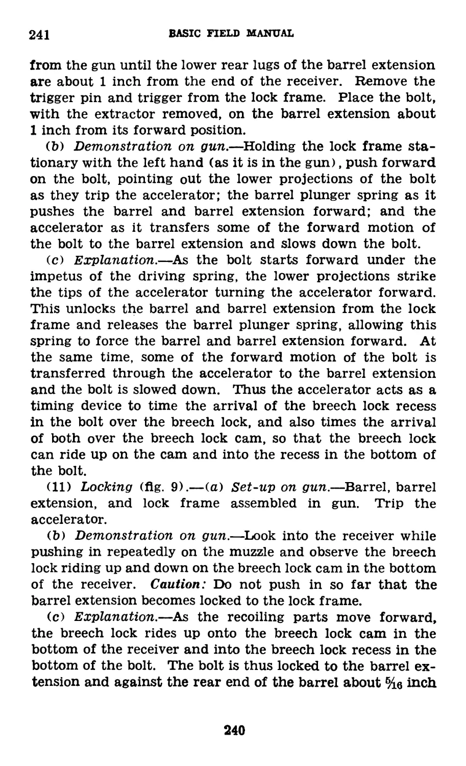
43. Loading and Locking Action (figs. 11 and 14).—During
the latter part of the forward movement of the bolt, the ex-
tractor rises as the plunger moves along the top of the ex-
tractor cam. When the extractor rises, the ejector is
cammed outward, into the half-moon-shaped recess, leaving
the cartridge in the chamber gripped by the T-slot. The
extractor grips the first round in the belt and is held down
firmly by the cover extractor spring, ready to extract the
37
*3-47
BASIC FIELD MANUAL
round. The breech lock is forced upward by the breech lock
cam and locks the breech just before the recoiling parts
reach the firing position. The breech lock engages in a
recess cut in the bottom of the bolt and thus locks the bolt
firmly to the barrel extension and against the rear end of
the barrel.
44. Second Act of Feeding (fig. 12).—As the bolt goes for-
ward the stud on the pivoted belt feed lever moves to the left
in the cam groove, forcing the slide to the right. The belt
feed pawl carries the first cartridge to the right against the
cartridge stops, ready to be gripped by the extractor. The
next cartridge is carried over the belt holding pawl which
rises behind it and holds it in position to be engaged by the
belt feed pawl on its next movement to the left.
45. Trigger Action in Automatic Fire (figs. 9, 13, and
14).—If the trigger is held raised, as the sear moves forward
with the bolt the trigger cams engage the sear cams and
force the sear down, releasing the firing pin. The gun thus
fires automatically, repeating the operations of functioning
already described. The release of the firing pin actually
takes place about He inch before the recoiling parts reach
the forward position but after the breech is locked.
Section V
STOPPAGES AND IMMEDIATE ACTION
46. Definitions.—a. A “stoppage” is any unintentional
cessation of fire.
b. “Immediate action” is the procedure used for the prompt
reduction of usual stoppages.
47. Stoppages.—a. Prevention.—Stoppages will be reduced
to the minimum if the gunner has a practical working
knowledge of his weapon and applies the points which should
be observed before firing. Prevention is the best remedy for
all stoppages.
b. Causes.—(1) A stoppage will occur if the gun fails to
feed, fails to load, fails to fire, or fails to function freely.
38
BROWNING MACHINE GUN, CAL. .30
47
(a) If the gun fails to feed, the cause for the stoppage will
be found in the ammunition belt or in the feed mechanism.
(b) If the gun feeds but fails to load, the cause will be
found in the receiver. A broken part or an obstruction on
the T-slot or in the chamber is the usual cause.
(c) If the gun feeds and loads but fails to fire, the cause
will be found in the firing mechanism unless the primer of
the cartridge is defective.
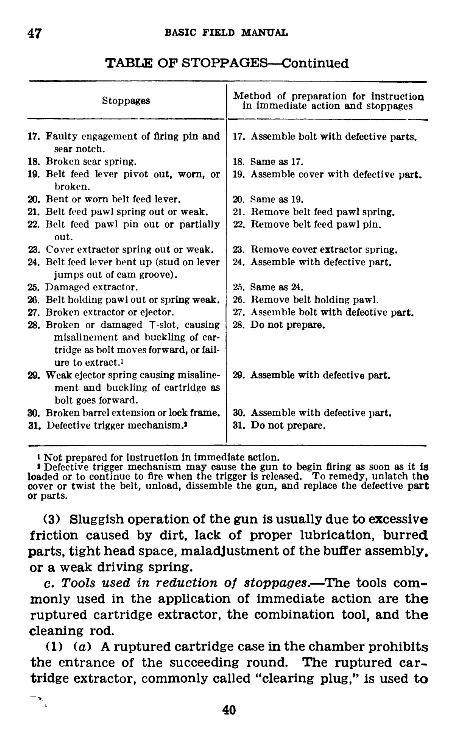
(2) The table following includes a comprehensive list of
possible stoppages. It will serve as a guide during instruction
in stoppages or immediate action.
TABLE OF STOPPAGES
Stoppages
1. Misfire due to defective primer.
2. Short round.
3. Bulged round.
4. Tight loop in belt.1 11
5. Empty loop in belt.
6. Stretched or torn belt.1
7. Thin rim, permitting nose of bullet
to drop below chamber.1
8. Belt imporperly loaded.
9. Battered or thick rim of cartridge.
10. Failure to remove round from cham-
ber.
11. Set back primer.1
12. Separated case which is removed
from chamber by new round when
bolt is pulled to the rear.
13. Separated case, which stays in cham-
ber when bolt is pulled to the rear.
(Do not set up loose head space.)
14. Bullet loose in cartridge case. Car-
tridge case extracted from belt but
bullet remains in belt.1
15. Short or broken firing pin.
16. Weak or broken firing pin spring.
Method of preparation for instruction
in immediate action and stoppages
1. Place a dummy cartridge in belt.
2. Place a short round in belt.
3. Insert bulged round in belt.
4. Do not prepare.
5. Leave an empty loop in belt.
6. Do not prepare.
7. Do not prepare.
8. Pull a cartridge partially out of belt.
9. Place a battered or a thick-rimmed
cartridge in belt.
10. Place a dummy cartridge with rim
filed off in the chamber.
11. Do not prepare.
12. Drive the front portion of a cartridge
securely on a dummy cartridge.
Pull bolt to the rear and place car-
tridge properly on the face of bolt.
Ease bolt forward.
13. Insert the front end of a separated
case in chamber and load.
14. Do not prepare.
15. Assemble bolt with a defective firing
pin or place 5 or 6 successive range
dummy cartridges in belt for in-
struction in immediate action.
16. Same as 15.
QO
BASIC FIELD MANUAL
47
TABLE OF STOPPAGES—Continued
Stoppages Method of preparation for instruction in immediate action and stoppages
17. Faulty engagement of firing pin and sear notch. 17. Assemble bolt with defective parts.
18. Broken sear spring. 18. Same as 17.
19. Belt feed lever pivot out, worn, or broken. 19. Assemble cover with defective part.
20. Bent or worn belt feed lever. 20. Same as 19.
21. Belt feed pawl spring out or weak. 21. Remove belt feed pawl spring.
22. Belt feed pawl pin out or partially out. 22. Remove belt feed pawl pin.
23. Cover extractor spring out or weak. 23. Remove cover extractor spring.
24. Belt feed lever bent up (stud on lever jumps out of cam groove). 24. Assemble with defective part.
25. Damaged extractor. 25. Same as 24.
26. Belt holding pawl out or spring weak. 26. Remove belt holding pawl.
27. Broken extractor or ejector. 27. Assemble bolt with defective part.
28. Broken or damaged T-slot, causing misalinement and buckling of car- tridge as bolt moves forward, or fail- ure to extract.1 28. Do not prepare.
29. Weak ejector spring causing misaline- ment and buckling of cartridge as bolt goes forward. 29. Assemble with defective part.
30. Broken barrel extension or lock frame. 30. Assemble with defective part.
31. Defective trigger mechanism.» 31. Do not prepare.
i Not prepared for instruction in immediate action.
» Defective trigger mechanism may cause the gun to begin firing as soon as it is
loaded or to continue to fire when the trigger is released. To remedy, unlatch the
cover or twist the belt, unload, dissemble the gun, and replace the defective part
or parts.
(3) Sluggish operation of the gun is usually due to excessive
friction caused by dirt, lack of proper lubrication, burred
parts, tight head space, maladjustment of the buffer assembly,
or a weak driving spring.
c. Tools used in reduction of stoppages.—The tools com-
monly used in the application of immediate action are the
ruptured cartridge extractor, the combination tool, and the
cleaning rod.
(1) (a) A ruptured cartridge case in the chamber prohibits
the entrance of the succeeding round. The ruptured car-
tridge extractor, commonly called “clearing plug,” is used to
40
BROWNING MACHINE GUN, CAL. .30
47
remove the ruptured case. This tool is furnished in two types,
the cartridge form and the Mk. IV.
1. To use the cartridge form, open cover, place rup-
tured cartridge extractor on feedway against car-
tridge stops, and engage it with extractor on bolt.
Holding down on extractor, load it slowly and
smoothly into chamber, being careful to see that
the shoulder does not strike and bur the edge of
chamber. Strike forward on bolt handle to be
sure that ruptured cartridge extractor is seated in
ruptured case. Pull bolt to the rear and catch
ruptured cartridge extractor in the left hand as it
is ejected.
2. To use the Mk. IV, draw bolt handle to the rear and
hang it. Insert nose of ruptured cartridge ex-
tractor in chamber, handle up, push it forward
to seat it firmly in the separated case, then pull
backward on handle.
(b) Separated cases should be removed from the ruptured
cartridge extractor so that it will again be ready for use.
To do this, the end of the ruptured cartridge extractor must
be unscrewed, the separated case taken off, and the end
screwed on again.
(2) The use of the combination tool facilitates the re-
moval of a round which is stuck on the T-slot. To remove
a round from the T-slot, pull bolt fully to the rear and raise
extractor. If the round does not fall out, remove it with
the combination tool. If the round is above the bolt handle
slot, insert screw driver end of tool through slot and under
the rear end of cartridge and pry it up. If the round is
below the slot, place screw driver end of tool through top
of receiver into cannelure of cartridge and drive it down.
(3) The cleaning rod is used to remove a case from the
chamber which has not been extracted by the bolt. To
remove the case from the chamber, pull bolt fully to the
rear and hold it. Remove the following round from the
T-slot. Grasp cleaning rod about 6 inches from the end,
insert it into muzzle, and force case from chamber. Care
should be used not to damage the face of the bolt by striking
it as the rod is shoved through the bore.
41
47-48
BASIC FIELD MANUAL
d. Inspection of feed mechanism.—In event of recurrent
or permanent failure to feed, the feed mechanism must be
inspected and the defective part replaced. This inspection
should include the following:
(1) Belt feed lever and slide.—(a) With the bolt forward,
lower cover, making sure that stud on feed lever is in cam
groove in the top of bolt.
(b) Press to the left on belt feed slide to remove the play
and note whether or not the slide protrudes to the right of
the cover about ^2 inch.
1. If it does not, change belt feed lever and pivot.
2. If it does, and the gun has occasionally failed to
feed, examine belt feed lever for excessive wear at
the pivot and stud. Also see that stud projects a
sufficient distance from cover to insure that it is
positively positioned in cam groove in the top of
bolt when cover is closed. Replace defective parts.
Note.—If the belt feed slide does not extend inch beyond the
right side of the cover, the cartridge may not be correctly posi-
tioned and the extractor may strike the base of the cartridge,
force the bullet into the case, and cause a short round. The
resulting failure to load the cartridge is thus caused by a worn
or bent belt feed lever, or a defective slide. The base of such a
Cartridge will show evidence of having been hit by the extractor.
(2) Other parts.—If the slide positions properly and no
excessive play exists, examine cover extractor spring; belt
feed pawl, spring, and pin; belt holding pawl and spring;
extractor including ejector; spring and cam plunger; and
T-slot, to see that these parts are there, in good condition,
and that springs are sufficiently strong to actuate the parts
properly.
48. Immediate Action.—a. General.—The procedure pre-
scribed in immediate action for the reduction of stoppages
is based on the frequency with which the various types of
stoppages occur. Execution of this procedure by the gunner
will enable him to remedy the majority of stoppages imme-
diately without attempting to analyze the cause. Immediate
action is performed by the gunner. All personnel required
to fire the machine gun should be proficient in immediate
action. Immediate action must be carried out quickly and,
with practice, should become instinctive.
42
BROWNING MACHINE GUN, CAL. .30
48
b. Procedure.—The procedure for immediate action is
shown in the following diagram:
IMMEDIATE ACTION
The gun fails to fire
Pull the bolt to the rear, release it, re-lay, and attempt to fire.
If the gun st
11 fails to fire
Tap the cover, pull the belt to the right, hold the left hand on the
belt at the point where the cartridges enter the feedway, and pull
the bolt to the rear and release it.
If the belt feeds
If the belt does not feed
Re-lay
Attempt to fire
Raise the cover, remove the first
round from the belt, and look
or feel for a cartridge in the
gun
If the gun still fails to fire
If the cartridge is
Change the bolt
Reload, re-lay and fire.
In the gun
Not in the gun
Remove it
Reload, re-lay,
and fire.
Reload, re-lay,
and fire.
Notes.—1. If the procedure outlined above does not place the gun
in action, the gunner must inspect the feed mechanism and the
working parts of the gun to include inspecting the chamber for a
ruptured case in order to locate and reduce the stoppage.
2. If the bolt stops just short of home, frequently it can be pushed
fully forward and firing continued without application of immedi-
ate action. Caution: Release the trigger before pushing the bolt
forward.
3. Stoppages caused by defective feed mechanism can sometimes
be remedied temporarily by pulling the belt to the right with just
sufficient force to assist the feed mechanism in positioning the
leading round.
4. Immediate action is not complete until the gun has been
re-layed and fired.
43
49
BASIC FIELD MANUAL
Section Vl
TRIPOD MOUNTING
49. Light Machine Gun Tripod Mount М2.—a. This tripod
(fig. 15) is a simple mount for the light machine gun and is
designed to furnish the gun with a stable mount embodying
the maximum strength and rigidity consistent with desired
light weight. It is portable, easily packed, and may be used
for the delivery of accurate fire on ground targets.
b. The tripod consists of three tubular steel legs articulat-
ing in a tripod head, the two trail legs being joined and addi-
tionally supported by a traversing bar, forming a simple A-
truss, and serving as a rear support for the mounted gun.
The tripod head furnishes a front support for the mounted
gun, it being in turn supported by the short front leg.
c. Incorporated in the tripod head (fig. 16) is a bronze
bushing, mating with the tapered steel pintle permanently
secured to the receiver of the light machine gun. The pintle
is secured in its union with the bushing by engagement of the
pintle latch of the tripod in its corresponding annular groove
of the pintle (upper groove). The pintle latch is spring actu-
ated and is seated in its housing on the lower right surface
of the tripod head.
d. Tripods manufactured prior to the summer of 1942 have
a traversing dial graduated in major divisions of 100 mils
and minor subdivisions of 25 mils, from zero to 3,200 mils
in both directions, fitted to the head of the tripod by the
flange of the bronze pintle bushing. This dial is free to
rotate but may be clamped in any desired position by the
traversing dial clamp. This clamp is actuated by the
knurled head of the traversing dial clamp which is located
under the left lower surface of the tripod head. A zero
index engraved on the left rear quadrant of the pintle is
utilized in conjunction with the traversing dial to establish
or measure horizontal angles.
44
BROWNING MACHINE GUN, CAL. .30
49
(D Early type machine-gun tripod М2.
® Early type machine-gun tripod М2—schematic.
Figure 15.
514913°—43
4
45
L
BASIC FIELD MANUAL
® Late type, machine-gun tripod М2.
Figure 16.
BROWNING MACHINE GUN, CAL. .30
49
e. The traversing bar provides a rear support for the
mounted gun, the traversing slide of the elevating and trav-
ersing mechanism mating with the bar. An additional
device for measuring or establishing horizontal angles is
incorporated in the scale engraved on the traversing bar.
This scale is divided into 100-mil major divisions and 5-mil
PINTLE
BUSHING
PINTLE LATCH LEVER
TRIPOD HEAD
SLEEVE
TRAVERSING BAR
SLEEVE LATCH
(UNDERNEATH)
SCALE
© Late type, machine-gun tripod М2—schematic.
Figure 16—Continued.
TRAIL LEGS
TRAVERSING BAR
minor subdivisions. It has a range of 450 mils to the right
and 425 left of the zero graduation.
/. The traversing bar articulates in sliding sleeve devices at
each end, the sleeves moving along the trail legs in mounting
and dismounting the tripod. Positioning stops are incorpo-
47
49-51
BASIC FIELD MANUAL
rated on the trail legs, positively positioning the traversing
bar in both the mounted and dismounted positions of the
tripod. The traversing bar sleeve latch, mounted on the
right trail leg, secures the traversing bar in its proper position
when the tripod is mounted.
50. Disassembling and Assembling of Light Machine Gun
Tripod М2.—a. The disassembly and assembly of the parts
of the light machine gun tripod are not essential except to
replace broken or damaged parts.
b. The front leg articulation with the tripod head, the rear
leg articulations with the tripod head, and the articulations
of the traversing bar with its sleeves are standard commercial
bolts with lock washers and nuts to fit. Spare bolts, nuts,
and washers are carried in the spare parts chest. All these
unions must be kept tight to insure accurate firing.
c. The pintle latch housing is secured to the tripod head
by standard commercial cap screws and suitable lock washers.
Spare cap screw and washer and pintle latch spring are
carried in spare parts chest.
d. The traversing bar-sleeve latch is pivoted on the right
trail leg by rivet assembly.
e. The pintle bushing is of bronze and is a pressed fit into
the tripod head. It may be removed by pressing it out and
may be replaced by new bushing. Removal of the pintle
bushing frees the traversing dial. This disassembly is
preferably done by Ordnance Department personnel.
/. The traversing dial clamping mechanism, seated in its
recess in the tripod head, may be removed by first removing
the small hexagonal lock nut on the foot of the clamp, then
the knurled clamp nut. This permits the clamp being re-
moved from the top of the tripod head. This disassembly is
preferably done by Ordnance Department personnel.
Section VII
ACCESSORIES
51. Pack Equipment.—Special pack equipment for use
with the light machine gun consists of—
1 tripod and gun hanger
48
BROWNING MACHINE GUN, CAL. .30
51-54
1 ammunition hanger
3 ammunition chests
1 spare parts chest
1 gun cover, canvas
1 spare barrel canvas case.
52. Hangers.—a. Tripod and gun hanger.—(1) This pack
hanger is a light duralumin and steel hanger, accommodat-
ing the tripod, the light machine gun, and the spare parts
chest. It fits the standard Phillips cavalry pack saddle and is
carried on the right side, hung on the horizontal supporting
member of the saddle by steel reinforced hooks of the main
supporting members of the hanger and secured by two
hold-down straps.
(2) The spare barrel canvas case with contents is habitually
carried strapped to the lower horizontal member of the
hanger to balance the pack load laterally. The case should
be carried with the opening to the rear. When ammunition
has been expended, the case with contents may be strapped
to the lower horizontal member of the ammunition hanger
on the left side to retain lateral balance of the pack load.
b. Ammunition hanger.—This hanger is of duralumin and
steel construction, accommodating three ammunition chests,
and is habitually carried on the left side of the standard
Phillips cavalry pack saddle. The hanger is symmetrical
longitudinally and may be used on either side of the Phillips
cavalry pack saddle in case an extra ammunition pack horse
is utilized to transport ammunition for the light machine
guns of a horse cavalry organization.
53. Chests.—a. Ammunition chests.—The ground light
machine gun is provided with ammunition chest Ml, or the
same chest adopted for use with the machine gun M1917A1.
b. Spare parts chest.—The authorized contents of the
spare parts chest are listed in SNL No. A-6.
54. Covers.—a. The canvas gun cover is provided to pro-
tect the gun.
b. The spare barrel canvas cover is designed to accomo-
date an assembled barrel and barrel extension assembly.
49
55
BASIC FIELD MANUAL
55. Belt Filling Machine (fig. 17).—a. General.—This
machine is for the rapid filling of fabric (web) belts. It is
normally fastened to a table or bench while in use.
b. To fill a web ammunition belt with cartridges.—(1)
Figure 17.—Belt filling machine (web belts).
Fasten machine to a table or bench and turn crank (10) to
the right until it is straight down.
(2) Release tension spring hook (28) and raise upper feed
wheel (18) as far as it will go.
(3) Turn belt guide cover (56) to the right far enough to
50
BROWNING MACHINE GUN, CAL. .30
55-56
admit belt into belt guide (53) and raise upper needle bar
(45) as far as it will go.
(4) A black thread running along the side of the belt in-
dicates the side for the entrance of the cartridge. Put two
cartridges by hand into the two loops of the belt nearest the
end with the brass tip, and place belt in machine with first
cartridge resting in top groove of lower feed wheel (22), belt
passing out at back through belt guide.
(5) Return belt guide cover to place over belt (being care-
ful to see that the belt is free to pass under it), and lower
needle bar.
(6) Turn upper feed wheel down upon belt and secure
tension spring under hook.
(7) Fill feed guide with cartridges by stripping ten at a
time from the paper boxes in which they are packed.
(8) Turn crank to the right and the cartridges will be fed
into the belt ready for use in the gun.
(9) Place a feed box ready to receive the filled belt and
at such a height that not more than 2 feet of filled belt will
be suspended from the feed wheels of the machine.
c. Precautions for using the belt filling machine for web
belts.—(1) Before using the machine, see that it is well
oiled, that all screws are tight, and that the needles are
properly set. See that the points of the upper needles are
about 0.01 inch vertically above the points of the lower
needles.
(2) In case of a miss in loading the belt, stop and open up
machine and remove belt. Turn crank to the right until
straight down, as in starting, and replace belt in machine
with the next to the last cartridge in top groove of lower
feed wheel. Close machine and proceed as before.
(3) After use, the machine should be cleaned, oiled, ad-
justed, and replaced in its wooden box.
56. Blank Ammunition Attachments (fig. 18).—a. Gen-
eral.—The blank ammunition attachments for use with the
machine gun have been developed in order to simulate fire.
The attachments are designed to fire blank ammunition
Na-.909.
51
56
BASIC FIELD MANUAL
(1) The cartridge stop attachment is inserted by with-
drawing the belt holding pawl split pin about J/2 inch and
sliding the attachment over the cartridge stop, lining up the
small hole with the belt holding pawl split pin and replacing
this pin. The cartridge stop attachment acts as a guide for
the blank cartridge and also as a cartridge stop. Its chief
use is to hold the cartridge in position in feedway so that the
extractor may engage its cannelure; it also prevents the
entrance of a live round into the feed way.
(2) The muzzle attachment is assembled to the gun by
removing the front barrel bearing, sliding the threaded end
of the attachment over the barrel, and screwing it into the
barrel jacket.
Figure 18.—Blank firing attachments.
b. Precautions,—(1) Never attempt to use the muzzle at-
tachment unless the cartridge stop attachment is in its
proper place in the feedway.
(2) Always remove the muzzle attachment before remov-
ing the cartridge stop attachment in order to eliminate t_ie
possibility of firing ball ammunition with the muzzle attach-
ment still in position.
(3) See that the muzzle attachment is clean inside before
using.
(4) After firing blank ammunition, clean the barrel and
muzzle attachment. It is absolutely essential that this be
done before firing any other type of ammunition.
к
52
BROWNING MACHINE GUN, CAL. .30
57-59
57. Spare Barrel.—A spare barrel is issued for each light
machine gun. In pack, this barrel is carried on the gun and
tripod hanger. Under field conditions the barrel, barrel ex-
tension assembly, barrel locking spring, breech lock, and
breech lock pin assembly should be assembled into one unit
and carried in the spare barrel cover.
58. Asbestos Mittens.—One pair of asbestos mittens is
issued for use with each machine gun to facilitate the han-
dling of the gun when hot, particularly when moving to a
new position by hand, and in changing barrels.
Section VIII
FIRE CONTROL INSTRUMENTS
59. Binoculars.—There are two binoculars in use in the
service: the М3 (fig. 19 ®) and the type EE (fig. 19 ©).
The М3 will eventually replace the type EE. The paragraphs
below apply to both models. Each model consists of the
binocular with its carrying case.
a. Description.—(1) The binocular consists of two compact
prismatic telescopes pivoted about a common hinge which
permits adjustment for interpupillary distances. A scale,
graduated every 2 millimeters from 56 to 74, permits the
observer to set the telescope rapidly to suit his eye distance
when the spacing of his eyes is known. The eyepieces can be
focused independently for each eye by screwing them in or
out. Each eyepiece is provided with a diopter scale for rapid
setting when the observer knows the correction for his eye.
The zero graduations indicate the settings for normal eyes.
(2) The left telescope is fitted with a glass reticle (fig. 20)
upon which are etched a vertical mil scale, a horizontal mil
scale, and a stadia graduated similarly to the sight leaf
graduation on the service rifle, but inverted.
b. Use.—The binocular is used for observations and the
measurement of small horizontal and verticle angles in
mils. The vertical stadia scale is used to pick up auxiliary
aiming marks in direct laying and to determine troop safety
for overhead fire.
53
сл
ф»
BASIC FIELD MANUAL
(D Binocular М3.
Figure 19.—Fire control instruments.
ел
ел
n
BROWNING MACHINE GUN
(j) Binocular type ЕЕ.
Figure 19.—Fire control instruments—Continued.
59
BASIC FIELD MANUAL
c. Preliminary adjustments.—(1) Interpupillary dis-
tances.—To adjust the binocular so that the eyepieces are
the same distance apart as the pupils of the observer’s eyes,
point the binocular at the sky and open or close the hinged
joint until the field of view ceases to be two overlapping
circles and appears as one sharply defined circle. Note the
reading on the scale which indicates the spacing of the
eyes. This setting will be the same on any other М3 or type
EE binocular for the same individual.
(2) Focus of eyepiece.—Look through the binocular, with
both eyes open, at an object several hundred yards away.
Place the hand over the front of one telescope and screw the
eyepiece of the other in or out until the object is sharply
defined. Repeat this operation for the other eye, and note
the reading on each diopter scale. This setting will be the
same on any other М3 or type EE binocular for a given
indivual.
d. Operation.—(1) In using the binocular, it should be held
in both hands and pressed lightly to the eyes so as to keep
the relation with the eyes constant without transmitting
tremors from the body. The bent thumb should fit into the
outer edges of the eye sockets in such a manner as to prevent
light from entering in rear of the eyepieces. When possible
it is best to use a rest for the binocular or for the elbows.
(2) The mil scales are seen when looking through the
binocular end, by superimposing them upon the selected
objects, the horizontal and vertical angles between these
objects may be read.
(3) The inverted sight leaf scale of the type EE binocular
is used to secure range settings on sharply defined auxiliary
aiming points when the target is not clear enough for direct
aiming. This procedure is described in paragraph 199.
e. Care.—The binocular is a rugged, serviceable instrument
but it should not be abused or roughly handled. Do not wipe
the lenses with the fingers. Use only clean lens tissue paper
to wipe the lenses if they become dirty. No substitute should
ever be used for this purpose. The use of polishing liquids
or pastes for polishing lenses is forbidden.
56
Figure 20.—Reticles.
BROWNING MACHINE GUN, CAL. .30
Сл
60-65
BASIC FIELD MANUAL
60. Wrist Watch.—The wrist watch is a timepiece of the
usual construction supplied with a strap for fastening to the
wrist.
Section IX
INDIVIDUAL SAFETY PRECAUTIONS
61. Precautions for Disassembling and Assembling Gun.—
Paragraphs 12 and 13 outline the procedure for disassembly
and assembly of the driving spring rod to the bolt. In order
to avoid serious injury to personnel, the precautions outlined
should be carefully observed.
62. Blank Firing Attachment.—a. Never attempt to use
the muzzle attachment unless the cartridge stop attachment
is in its proper place in the feedway.
b. Always remove the muzzle attachment before removing
the cartridge stop attachment in order to eliminate the possi-
bility of firing ball ammunition with the muzzle attachment
still in position.
c. See that the muzzle attachment is cleaned inside before
using.
63. Hot Gun.—a. To avoid serious burns, care must be
exercised that the barrel and jacket are not touched with
bare hands. For moving the gun or disassembling a hot
barrel, the asbestos mittens should be used.
b. If the barrel becomes overheated after protracted periods
of firing, the gun should be cleared immediately on suspending
or ceasing fire. The heat of the barrel will cause the gun to
fire without pulling the trigger, if a round is left a short time
in the chamber of an overheated barrel.
64. Safety Precautions on the Range.—Safety precau-
tions for range firing are included elsewhere in this manual
(pars. 130, 173, 252e) and are not repeated here.
Section X
AMMUNITION
65. General.—The information in this section pertaining
to the several types of cartridges authorized for use in the
Browning machine gun, caliber .30, M1919A4, includes a de-
58
BROWNING MACHINE GUN, CAL. .30
65-68
scription of the cartridges, means of identification, care, use,
and ballistic data.
66. Classification.—a. Based upon use, the principal clas-
sification of the ammunition for this machine gun is—
(1) Ball, for use against personnel and light materiel
targets.
(2) Tracer, for observation of fire and incendiary pur-
poses.
(3) Armor-piercing, for use against armored vehicles, con-
crete shelters, and similar bullet-resisting targets.
b. Other types provided for special purposes are—
(1) Blank, for simulated fire.
(2) Dummy, for training (cartridges are inert).
67. Lot Number.—When ammunition is manufactured, an
ammunition lot number which becomes an essential part
of the marking is assigned in accordance with pertinent
specifications. This lot number is marked on all packing con-
tainers and on the identification card inclosed in each pack-
ing box. It is required for all purposes of record, including
grading and use, and reports on condition, functioning, and
accidents in which the ammunition might be involved. Only
those lots of grades appropriate for the weapon will be fired.
Since it is impractical to mark the ammunition lot number
on each individual cartridge, every effort will be made to
maintain the ammunition lot number with the cartridges
once they are removed from their original packing. Car-
tridges which have been removed from the original packing
and for which the ammunition lot number has been lost are
placed in grade 3. It is therefore obvious that when car-
tridges are removed from their original packings they should
be so marked that the ammunition lot number is preserved.
68. Grade.—Ordnance Field Service Bulletin No. 3-5 ex-
plains the meaning of grading for caliber .30 ammunition.
This bulletin also lists numerically every lot of ammunition
with its correct grade as established by the office of the Chief
of Ordnance. Only lots of proper grade will be fired. Grade
3 ammunition may be fired only under special provisions of
Ordnance Department Circular No. 205, 1942.
59
69
BASIC FIELD MANUAL
69. Identification.—a. Markings.—The contents of origi-
nal boxes are readily identified by the markings on the box.
Similar markings on the carton label identify the contents of
each carton.
b. CoZor bands.—Color bands painted on the sides and ends
of the packing boxes further identify the various types of
ammunition. The following color bands are used:
Cartridge, ball_____________ Red.
Cartridge, ball, and cartridge, Composite band of yellow,
tracer, in metallic link belts.1 red, and green stripes (yel-
low on left, red in center,
green on right).
Cartridge, tracer___________Green on yellow.
Cartridge, armor-piercing---Blue on yellow.
Cartridge, blank____________Blue.
Cartridge, dummy____________Green.
1 Special packing for Army Air Forces, not for use in the Browning
machine gun, caliber .30, M1919A4.
c. Types and models of caliber .30 cartridges.—When re-
moved from their original packing containers, the cartridges
may be identified, except as to ammunition lot number and
grade, by physical characteristics described below:
(1) Ball.—All models of caliber .30 ball ammunition, except
М2 of 1940 and earlier, and M1906, have bullets with gilding
metal packets. The jacket of the M1906 bullet is cupro-
nickel which has a silvery appearance. The gilding metal
jacket of the early М2 ammunition is tin coated and hence
resembles the M1906 bullet in appearance. The gilding
metal jacket of the present М2 bullet is copper-colored.
(2) Tracer.—Caliber .30 tracer ammunition maybe iden-
tified by the nose of the bullet, which is painted red for a
distance of approximately % inch from the tip.
(3) Armor-piercing.—All models of caliber .30 armor-
piercing ammunition may be distinguished by the nose of
the bullet, which is painted black for a distance of approxi-
mately % inch from the tip. The bullets have gilding metal
jackets.
(4) Blank.—Blank ammunition may be identified by the
absence of a bullet in the cartridge case.
(5) Dummy.—The caliber .30 corrugated dummy cartridge
60
BROWNING MACHINE GUN, CAL. .30
69-71
may be identified by six longitudinal corrugations and a hole
in the cartridge case.
70. Care, Handling, and Preservation.—a. Small arms
ammunition, as compared with other types, is not dangerous
to handle. Care, however, must be observed to keep the
boxes from becoming broken or damaged. All broken boxes
must be immediately repaired and careful attention given so
that all markings are transferred to the new parts of the
box. The metal liner should be air-tested and sealed if
equipment for this work is available.
b. Ammunition boxes should not be opened until the am-
munition is required for use. Ammunition removed from the
airtight container, particularly in damp climates, is likely
to corrode, thereby becoming unserviceable.
c. Protect the ammunition carefully from mud, sand, dirt,
and water. If it gets wet or dirty, wipe it off at once. Ver-
digris or light corrosion, if it forms on cartridges, should be
wiped off. However, cartridges should not be polished to
make them look better or brighter.
d. The use of oil or grease on cartridges is dangerous and
is prohibited.
e. De not fire dented cartridges, cartridges with loose
bullets, or otherwise defective rounds.
/. Do not allow the ammunition to be exposed to the direct
rays of the sun for any length of time. This is likely to affect
its firing qualities seriously.
71. Storage.—a. Whenever practicable, small arms am-
munition should be stored under cover. This applies par-
ticularly to tracer ammunition which is subject to rapid
deterioration if it becomes damp. It may even ignite spon-
taneously. Should it become necessary to leave small-arms
ammunition in the open, it should be raised at least 6 inches
from the ground, and the pile covered with a tarpaulin. Suit-
able trenches should be dug to prevent water flowing under
the pile.
b. If practicable, tracer ammunition should be stored
separately from other ammunition.
c. If fired into or placed in a fire, small arms ammunition
514913 е—43-
5
61
71-72
BASIC FIELD MANUAL
does not explode violently. There are small individual ex-
plosions of each cartridge, the case flying in one direction
and the bullet in another. In case of fire, it is advisable to
keep those not engaged in fighting the fire at least 200 yards
from the fire and have them lie on the ground. It is unlikely
that the bullets and cases will fly over 200 yards. Small arms
ammunition of all classes should be stored away from radia-
tors, hot water pipes, and other sources of heat, since heat
not only deteriorates ammunition, but also creates a fire
hazard.
72. Ballistic Data.—The approximate maximum ranges
and average velocities for the several types and models of
caliber .30 ammunition authorized for use in the machine
gun, caliber .30, Browning, M1919A4, are shown below:
Type and model of caliber .30 cartridges Average ve- locity 78 feet from muzzle (feet per second) Approximate maximum range (yards)
Ball, М2 2,800 4,000
Ball, Ml 2,600 5,500
Ball, M1906 2, 640 3, 450
Tracer, Ml 2,700 3, 500
Armor-piercing, М2 2, 800 4,000
Blank, M1909. . 20
Dummy, M1906 (corrugated)
62
BROWNING MACHINE GUN, CAL. .30
72
ARMOR PIERCING-BLACK —
TRACER-RED—
GILDING METAI
CAL. .30 ARMOR PIERCING AND TRACER CARTRIDGES
M1906-CUPRONICKEL
Ml-GILDING METAL
M2-TIN COATED GILDING METAL (Prior to 194»
М2—GILDING METAL (After 1940)
CAL. .30 BALL CARTRIDGES
CARTRIDGE, BLANK, CAL. .30, M1909
CARTRIDGE, DUMMY, CAL. .30 M1906 (Corrugated)
Figure 21.—Caliber .30 cartridges.
63
73
BASIC FIELD MANUAL
Section XI
CALIBER .22 TRAINING EQUIPMENT
73. Design and Data.—The caliber .22 machine-gun trainer
M4 is provided for training purposes. It is used for firing the
caliber .22 long rifle cartridge without modification or in any
way affecting the standard gun. The caliber .22 trainer does
not interfere with the mounting of the caliber .30 machine
gun on the tripod М2.
a. Parts and accessories.—(1) The complete unit consists
of a group of components and assemblies so designed that
the caliber .30 gun may be converted to accommodate the
caliber .22 long rifle cartridge merely by changing the main
group assemblies (fig. 22). The following is a complete list
of the component parts of the trainer and accessories for its
use:
(a) Parts.
Bolt, assembly.
Firing pin, assembly.
Driving spring.
Cartridge stop.
Barrel.
Piston, actuating.
Cylinder, barrel.
Bearing, barrel, front.
Nut, barrel adjusting.
Nut, barrel locking.
(b) Accessories.
Belt, ammunition, including adapters and clips (par.
78).
Holders, cartridge.
Chute, cartridge holder.
Bag, metallic belt link.
Fixture, cartridge seating.
Tool, cartridge seating and ejecting.
Wrench, adjustable, 4-inch.
Note.—Safety of personnel is assured because the design is such
that it is impossible to fire the caliber .30 cartridge with the caliber
.22 trainer M4, assembly.
(2) Belt, adapters, and holders are loaded into a standard
caliber .30 ammunition belt chest. A bag and chute are pro-
64
BROWNING MACHINE GUN, CAL. .30
73
vided to catch ejected holders for the purpose of reducing
the accumulation of foreign matter.
b. Data.
Weight of caliber .22 gun assembly, M1919A4 (ap-
prox.) pounds______________________________________ 27. 0
Length of barrel_____________________________inches__ 22.5.
Length of bore___________________________________do__ 22. 5
Rate of fire_____________________rounds per minute. _ 500-600
Type of mechanism—recoil, barrel fixed.
65
74-75
BASIC FIELD MANUAL
74. Operation and Functioning.—a. Operation of caliber
.30 gun with caliber .22 trainer.—The operation of the Brown-
ing machine gun equipped with the caliber .22 trainer is
identical with the operation of the corresponding caliber .30
gun in every respect.
b. Recoil.—When a cartridge is fired in the ammunition
holder and the bullet has passed from the ammunition holder
through the actuating piston and into the bore, the expanding
gases, acting on the face of the actuating piston, force it to
the rear approximately % inch. The actuating piston, which
is screwed into the barrel extension, actuates the recoiling
parts in exactly the same manner as the barrel when the
caliber .30 assembly is used.
c. Counterrecoil.—The counterrecoil action is the same as
the action of the caliber .30 assembly.
75. Assembly and Disassembly.—a. Assembly.—(1) Con-
version from caliber .30 gun to caliber .22 trainer.—(a) Re-
move the backplate, bolt handle, bolt, lock frame, barrel ex-
tension, and barrel from the caliber .30 gun as prescribed in
paragraph 10.
(b) Unscrew the barrel bearing from the caliber .30 gun
and replace with the barrel bearing provided.
(c) Remove the caliber .30 barrel from the barrel exten-
sion.
(d) Screw the actuating piston in the barrel extension as
far as it will go. Back it off five or six notches.
(e) Screw barrel cylinder onto the caliber .22 barrel.
Tighten with wrench.
(/) Screw barrel adjusting nut FULLY TO THE REAR
on forward part of caliber .22 barrel.
(g) Disassemble the caliber .30 bolt (par. 12). Reassem-
ble the parts of the bolt group to the caliber .22 bolt,
using the firing pin assembly and driving spring provided
with the trainer (par. 13).
(M Assemble caliber .22 barrel assembly to the gun, using
care that the adjusting nut stop is on top of the barrel.
(i) Assemble remaining caliber .22 groups to the gun as
prescribed for the assembly of caliber .30 groups (par. 11).
(?) Pull out belt holding pawl split pin approximately %
66
BROWNING MACHINE GUN, CAL. .30
75
inch, insert cartridge stop provided with the trainer, and
push belt holding pawl split pin forward into position.
(2) Final head space adjustment.—(a) Insert empty
holder into feed way.
(b) Operate action once to load.
(c) If bolt closes easily, screw in the actuating piston one
notch (by using the point of a caliber .30 cartridge or the
combination tool in piston notches).
(d) Repeat above until bolt fails to close on empty holder.
(e) Back off one notch on actuating piston.
(/) Repeat (a) and (b) above. The bolt should just close
on the holder, thereby obtaining correct head space.
Note.—When holder is first inserted and bolt fails to close, in-
stead of turning actuating piston in, back actuating piston off
one notch at a time and repeat above until proper head space
adjustment is obtained.
(3) Chamber space adjustment.-—(a) With the bolt closed,
rotate the barrel clockwise with the adjustable wrench pro-
vided until the barrel extension is seen to move to the rear,
away from the trunnion block, for a distance of approxi-
mately %2 inch. Then rotate barrel one complete turn
counterclockwise or until the barrel extension touches the
trunnion block. Now make a half turn in the same direc-
tion (counterclockwise). The half turn will give a chamber
space of about %4 inch, which is correct for a clean gun.
(b) If, with this adjustment, the gun fails to function be-
cause of insufficient recoil, it may be necessary to reduce the
chamber space back to the flush position.
Note.—When chamber spacing or whenever loosening the barrel
locking nut, it is important that the barrel adjusting nut be pre-
vented from turning. This is accomplished by inserting a screw
driver or other small rod through the holes in the barrel jacket
in line with the barrel adjusting nut.
(4) Barrel adjustment.—Screw on barrel locking nut, mak-
ing sure that barrel does not rotate (fig. 23).
b. Disassembly.—Conversion from caliber .22 trainer to
caliber .30 gun is accomplished as follows:
(1) Remove backplate, bolt handle, and bolt assembly
from gun as prescribed in paragraph 10.
(2) Unscrew and remove barrel locking nut.
67
75-76
BASIC FIELD MANUAL
(3) Press in on trigger pin; at the same time, with the
palm of the hand push on the muzzle of the barrel, forcing
it to the rear as far as it will go.
(4) Pull out lock frame and barrel extension.
(5) Remove actuating piston from barrel extension.
(6) Remove barrel assembly from gun.
(7) Remove barrel bearing.
(8) Remove cartridge stop.
(9) Disassemble bolt group and reassemble caliber .30
bolt, using original parts.
(10) Replace groups in gun as prescribed in paragraph 11.
rBUSHING-Al529l5
r₽IST0N-C64324
-SPRING*BI47553
(ЧС64327-CAL.22 TRAINER AMMUNITION BELT)
Figure 23.—Caliber .22 machine-gun trainer M4—sectionalized view.
76. Adjustments and Malfunctions.—a. Adjustments.—
In the event that a residue accumulates and causes a stick-
ing condition, the chamber space should be increased slightly
in accordance with the following procedure:
(1) Raise cover.
(2) Pull bolt back and secure in usual manner. This is
important; otherwise the head space will be disturbed.
(3) Loosen barrel locking nut.
(4) Open chamber space one-half turn by turning barrel
counterclockwise.
(5) Tighten barrel locking nut.
(6) Resume firing.
68
BROWNING MACHINE GUN, CAL. .30 76-77
Note.—The chamber space should be Increased by one-half turn
only, and then only when sticking becomes so great as to result
in malfunctions.
b. Malfunctions.
Malfunction
Failure to extract.
Short recoil
(notes, par. 75a
(2) and 76a).
Cause
Extractor badly
worn; will not
withdraw
round from belt.
Insufficient recoil
power due to in-
creased accumu-
lation of carbon
in front of actu-
ator piston.
Remedy
Assemble new ex-
tractor.
If the holder has
become lodged
in the feed way,
pull the bolt to
the rear and
dislodge it. The
chamber space
may be in-
creased but only
by one-half turn
(see note in a
above). If mal-
functions с о n -
tinue, clean and
oil the bore as
prescribed for
the caliber .30
machine gun.
77. Care and Cleaning.—a. The same care as used with
the caliber .30 gun should be exercised with the caliber .22
trainer. Particular care should be paid to thorough and com-
plete lubrication at all times. Improper head space will re-
sult in eventual injury to the holders. The head space there-
fore should be accurately determined, as previously pre-
scribed, before any firing is contemplated.
b. At the conclusion of the day’s firing, remove the groups,
including the barrel, carefully wipe off all parts, remove all
carbon deposits, and apply a light coat of lubricating oil.
Wipe out the bore of the barrel, and swab the bore with oil.
The same oils are to be used as are used on the caliber .30
machine gun. Carefully remove the carbon deposit from the
69
77-78
BASIC FIELD MANUAL
face of the actuating piston. Thoroughly clean the actuat-
ing piston and barrel cylinder.
Caution: Special care must be taken to see that the actuat-
ing piston and barrel cylinder are free from oil. Oil on these
components results in excessive carbon deposits, causing the
gun to stick, resulting in a malfunction. Avoid excessive
use of oil on weapon that may get on holder bag or holders.
This is necessary to prevent oil and foreign matter from
being carried into the weapon by the holders.
78. Method of Loading and Seating Caliber .22 Ammuni-
tion Into Cartridge Belts.—a. Preparation of belts.—Insert
the belt adapters into the belt so that the tip protrudes far
enough to clear the groove. The belt adapter clips are then
snapped into place in the grooves, connecting the adapters
in pairs, as shown in figure 24. The adapters thus fastened
BELT ADAPTER CUPJ
RA PD 26;5A
Figure 24.—Seating cartridges by hand.
70
BROWNING MACHINE GUN, CAL. .30
78
together remain in the belt for use only with the caliber .22
trainer.
b. Loading ammunition into holders.—(1) The holders
should be prepared for loading by removing the empty cases
and cleaning, if necessary, to remove any grit or foreign
matter which may cause the cases to stick in the holders or
the holders to stick in the chamber of the actuating piston.
The cartridge seating and ejecting tool or any small-diameter
rod may be used to push out the empty cases.
(2) With the holders empty and clean, insert the ammuni-
tion into holders by hand as far as possible.
Caution: Pressure only should be applied to the cartridges.
Never strike them.
c. Cartridge seating fixture.—(1) To use the cartridge
seating fixture, hold the loaded holder in left hand with
cartridge head to right, place holder against the stop pins
and then move the arm to the left, bringing the arm to
bear on the cartridge.
(2) Moving the arm to the right will allow the loaded
holders to fall into the box, where they may be allowed to
accumulate until a number of holders sufficient for contem-
plated firing have been loaded.
(3) The holders with cartridges properly seated are then
inserted into the adapters in the ammunition belt with a
slight push, making sure that the shoulder on the holder is
seated solidly against the adapter.
d. Seating cartridges by hand.—(1) Coil the belt with
adapters inserted and fastened with clips as shown in figure
24 with the open end of adapters upward. (The outside coil
of the belt, as shown in fig. 24, has been turned over to show
the clips.)
(2) Insert the loaded holders in the belted adapters, seat-
ing them with a slight push.
(3) Seat the cartridges fully by pressure on the base of
the cartridge, using the handle of the cartridge seating and
ejecting tool or any wooden handle. Do not strike cartridges.
71
79-80
BASIC FIELD MANUAL
CHAPTER 2
TRAINING FOR PLACING LIGHT MACHINE GUN IN
ACTION
79. General.—a. The object of gun drill is to give the
squad complete confidence in its ability as a team to put its
light machine gun into action with precision and speed.
b. Teamwork is assured by a rotation in duties during drill
so that each member by practice becomes thoroughly ac-
quainted with the duties of every other member, particularly
with the more detailed actions of the numbered members of
the gun crew.
c. Precision is attained by strict adherence to the pre-
scribed procedure. Exactness is the first objective. When it
has been developed, speed is emphasized.
d. No. 1 repeats all commands of the corporal, and No. 2
transmits all signals to No. 1.
e. At the completion of any ordered movements, the mem-
ber of the team responsible for its correct execution calls
“Up,” and No. 2 signals ready.
/. Unless otherwise stated, individuals move from one
position to another at a rim.
g. In the field, the drill procedure of movements, such as
action and our of action, are followed as closely as the
situation permits.
80. To Secure Equipment to Put Gun in Action.—For drill,
the command is: SECURE EQUIPMENT FOR GUN DRILL
In the field, the command is: ACTION or OFF TRUCK
(pack). At the appropriate command, the men secure
equipment as follows:
Corporal------------None. When there is no am-
munition bearer (No. 3), he
secures the spare parts chest
and spare barrel.
Gunner (No. 1)______Tripod. When need for addi-
tional ammunition is indi-
cated, he also secures one
chest of ammunition.
72
FROWNING MACHINE GUN, CAL. .30
80-82
Assistant gunner (No.
2).
Ammunition bearer
(No. 3).
Additional numbered
members.
Gun. Where there is no am-
munition bearer (No. 3), he
also secures one chest of
ammunition.
One chest of ammunition,
spare parts chest, and spare
barrel.
Act as assistant ammunition
bearers, carrying chests of
ammunition.
For additional organizational equipment carried by members
of the squad, see current Tables of Basic Allowances and
SNL A-6.
81. To Form Crew (Squad) With Equipment (fig. 25).—
a. For drill, the crew (squad) forms in column at five paces
distance, with No. 1 five paces in front of and facing the
corporal, and takes the prone position. Each man grounds
his load as follows:
(1) No. 1 with the tripod on his right, trails to the rear.
(2) No. 2 with the gun to his front, muzzle to the left,
bolt handle up.
(3) No. 3 with ammunition chest, spare parts chest, and
spare barrel to his front, chests 1 foot apart, ammunition
chest on the right, latch to the front, spare barrel on the
left of the ammunition chest.
(4) Other members, if present, with chests in front, 1
foot apart, latches to the front.
b. In the field the squad, after securing its equipment, re-
forms as directed. Loads are grounded as explained in a
above and taken up at the preparatory command for a
movement.
82. To Change Numbers and Duties During Drill.—The
command is: FALL OUT ONE.
a. At the command—
(1) No. 2 moves to the position of No. 1 and calls “One.”
(2) No. 3 moves to the position of No. 2 and calls “Two.”
(3) Higher numbered members move up one position as
described above. No. 1 then becomes the highest number
present.
73
Figure 25.—Corporal (instructor) and gun crew with equipment.
К5
BASIC FIELD MANUAL
BROWNING MACHINE GUN, CAL. .30
82-83
b. As soon as each member has become thoroughly familiar
with the duties involved, the command is given during the
progress of a movement to cause each man to cease the execu-
tion of his duty and to take up the duty of his new number.
c. The command may be given to the squad while in any
formation and is executed in a manner similar to that
prescribed for the crew.
83. To Examine Gun Equipment.—The equipment being
grounded, the corporal commands: EXAMINE EQUIPMENT
BEFORE FIRING.
a. At this command each man, keeping well down, ex-
amines the equipment constituting his load as indicated
below, and reports to the corporal, naming the deficiencies,
if any, which he cannot correct. The same procedure is fol-
lowed both in drill and in the field, except that in drill ball
ammunition is assumed.
(1) No. 1 examines the tripod and—
(a) Sees that the front leg and trails are closely folded.
(b) Tests traversing bar sleeve latch and pintle latch.
(c) Tests traversing dial and clamps dial on older type
tripods.
(d) Sees that pintle socket is free from dirt.
(2) No. 2 examines the gun. He pulls back the latch,
raises the front sight and the cover, pulls the bolt to its
rearmost position, engages the extractor cam plunger in
rear of the extractor feed cam, and—
(a) Sees that barrel is clear.
(b) Sees that the gun pintle is clean.
(c) Lets the bolt go forward and ascertains that—
I. The head space is correct, making any necessary
adjustment.
2. The barrel-locking spring functions correctly.
3. The moving parts are oiled and function without
excessive friction.
(d) No. 2 lowers and latches the cover, lowers the front
sight, sets the rear sight at 700 (two clicks below 800, on Ml
sight), lowers the sight leaf, sets the wind gage at zero, and
pulls the trigger.
75
83
BASIC FIELD MANUAL
(3) No. 3 examines the spare barrel, ammunition chest,
and spare parts chest, and sees that the—
(a) Bore is clear.
(b) Front and rear bearings are free from dirt.
(c) Barrel and barrel extension are properly assembled.
(d) Contents of spare parts chest are as prescribed and
properly packed.
(e) The cartridges are spaced and alined correctly in the
belt (if at drill, that no live ammunition is present).
(/) The ammunition belt is clean and dry.
(g) The belt is packed correctly in its chest.
(h) Covers of the chests are closed and latched.
(4) Other numbered members, if present, check complete-
ness of ammunition loads.
b. Upon completing this examination of the equipment,
Nos. 1, 2, and 3 take post and No. 3 reports, “Ammunition
correct (or the deficiencies)”; No. 2 reports, “Gun and am-
munition correct (or the deficiencies)”; and No. 1 reports,
“All correct (or all the deficiencies which cannot be cor-
rected) .” A thorough examination of the gun equipment is
made at the beginning and at the end of each drill period.
When at drill or when live ammunition is not authorized, the
initial inspection must assure that the ammunition belts
are free of live rounds. Upon a change of numbers, such
examination of the equipment, without report, is made as
will determine that it is in proper condition for the execution
of the drill.
c. As soon as each member has become thoroughly familiar
with the duties involved, the command fall out one is given
(par. 82).
d. Equipment is examined immediately after the squad
is formed, upon each change of numbers, and just prior to
dismissing the squad at the completion of the drill, in order
to familiarize the men with the equipment so that they will
know when it is complete.
e. Training in examination of equipment required by the
commands examine equipment during (after) firing will also
be conducted.
76
BROWNING MACHINE GUN, CAL. .30
84
84. To Put Gun Into Action.—The corporal indicates the
point where the gun will be mounted and the general direc-
tion of fire, and commands or signals: ACTION.
a. At the command, Nos. 1 and 2 proceed as follows:
No. 1 (tripod)
In the prone position:
Grasps the right trail
near the tripod head
with the right hand.
Springs up.
Carries the tripod at a run,
left trail leg uppermost,
to the designated point.
Rests the shoes of the trail
legs on the ground.
Steadies the tripod so that
it is in a vertical position
with the front leg to the
front.
Lifts the front leg forward
and upward into posi-
tion with his left hand.
Grasps the left trail leg
near the shoe with his
left hand and the right
trail leg near the shoe
with his right hand.
Lifts the tripod from the
ground and separates
the trail legs until the
sleeve latch engages the
traversing bar sleeve.
Drops the tripod to the
ground
Lies down and in rear of the
traversing bar:
Grasps the grip with his
left hand and assists No.
No. 2 (gun)
In the prone position:
Grasps the grip with the
right hand and passes
the left hand over and
under the barrel jacket.
Springs to his feet.
Places the gun under his
left arm, muzzle to the
rear.
Runs to a position on the left
of and facing tripod.
Places his left foot in the
space between the left
trail leg and the front
leg.
Assisted by No. 1, places the
gun in position.
€
514913-43
77
84
BASIC FIELD MANUAL
No. 1 (tripod)
2 in placing the gun in
position.
Disengages the elevating
mechanism from the slot
in the grip by striking
the end of the mechan-
ism a forward and down-
ward blow with the heel
of his right hand.
Turns the lower half of the
elevating mechanism
through 180°, assembles
it to the traversing bar,
and clamps it at zero de-
flection.
Advances his right hand to
a point opposite the belt
feed exit and holds it in
position ready to grasp
the brass strip at the
end of the belt.
Grasps the strip as it is
pushed from the belt
exit and gives it a quick
jerk to the right.
Pulls the bolt handle to its
rearmost position and
releases it. (This half
loads the gun. It may
be fully loaded by pull-
ing the bolt handle to
the rear a second time.)
Grasps the grip firmly
with the right hand, the
forefinger extended to
engage the trigger.
Grasps the elevating hand-
wheel with the left hand.
No. 2 (gun)
Inserts the gun pintle in
the gun pintle socket,
raises the gun pintle
latch lever with his right
hand and then lowers it
when the pintle is fully
seated.
Lies down at the left of the
gun, head in rear of the
feedway.
Opens the ammunition
chest placed for him by
No. 3.
Grasps between the thumb
and forefinger of his
right hand a fold of the
belt at the point where
the brass strip joins the
fabric and pushes the
brass strip through the
feed opening as far as
possible. (He is re-
sponsible that the belt is
straight and will feed
properly, and that the
cover of the gun is
latched.)
78
BROWNING MACHINE GUN, CAL. .30
84-85
No. 1 (tripod)
Upper part of the body
rests on the elbows. The
right elbow is drawn in
close to the body, the
left elbow inside of but
not touching the left
trail shoe.
Body is in prone position so
that a line in prolonga-
tion of the axis of the
bore will pass through
his right shoulder and
right hip pocket. Legs
apart as in rifle marks-
manship and heels down.
Eyes focused on the tar-
get.
When in this position: No. 1 calls “Up.”
b. Just as No. 2 is lying down, No. 3 arrives at the gun
position with his load (ammunition chest, spare parts chest,
and spare barrel).
(1) Places the ammunition chest, latch to the right, in
line with the feedway, ready for loading.
(2) Places the spare barrel and spare parts chest on the
left of the ammunition chest.
(3) Turns left about and returns to his original position.
c. When higher numbered members of the squad are pres-
ent, they pass their ammunition chests forward to No. 4. No.
4 alines them at the position of No. 3, latches to the front.
85. To Clear Gun.—The command is: CLEAR GUN. At
this command No. 1 pulls back the latch and raises the cover.
No. 2 lifts and removes the belt from the feedway (so as to
avoid getting sand into the mechanism). No. 1 then pulls the
bolt handle to its rearmost position and engages the extractor
cam plunger behind the extractor feed cam and sees that
the cartridge is ejected. No. 2 replaces any loose rounds in
the belt and returns the belt to the chest.
79
BASIC FIELD MANUAL
b6
86. To Take Gun Out of Action.—The gun being in action,
to take it out of action the corporal commands or signals:
OUT OF ACTION.
a. At the command, Nos. 1 and 2 proceed as follows:
No. 1 (tripod)
In the gunner’s position:
Pulls back the latch with
his right hand.
Raises the cover to the
half-open position with
his left hand.
Brushes his left hand
across the top of the
bolt to make sure the ex-
tractor is down.
Lowers the cover with his
left hand.
Pulls the bolt handle to its
rearmost position with
his right hand and re-
leases it.
Presses the trigger with
with his right forefinger.
Grasps the grip with his
left hand and, with his
right hand, disengages
the elevating mecha-
nism from the travers-
ing bar, turns the lower
half through 180°, and
secures it in the recess
in the grip.
Places both hands on the
trail legs near the shoes
and presses «downward
until No. 2 has removed
the gun.
Grasps the sleeve latch
with his right hand and
releases it.
No. 2 (gun)
Lying on the left of and fac-
ing the gun, legs to the
rear.
(As soon as No. 1 raises
the cover)
Lifts the belt and removes
it from the feedway.
Packs the belt in the am-
munition chest and
latches the cover.
Springs to his feet.
Places his left foot on the
front leg shoe.
With his left hand over
and around the barrel
jacket and his right
hand at the grip, raises
the gun pintle latch
lever and removes the
80
BROWNING MACHINE GUN, CAL. .30
86
No. 1 (tripod)
Springs to his feet.
Grasps the tripod head
with his right hand,
knocking down the gun
pintle latch lever.
Lifts the front of the tri-
pod to the vertical posi-
tion.
Grasps the front leg of the
tripod with the left hand
and folds it to the front
and down.
Tilts the tripod to the right
and closes the trail legs
with the left hand.
Grasps the right trail leg
near the tripod head
with the right hand and,
with the left trail leg
upppermost, turns to the
left about, returns to his
original position.
Lays the tripod on the
ground, trail legs to the
rear.
Returns to the prone position
on the left of the tripod
and calls “Up.”
No. 2 (gun)
gun from the tripod.
Turns to the left about and
runs to his original po-
sition.
Lays the gun down, muzzle
to the left, bolt handle
up.
Returns to the prone posi-
tion.
Inspects the gun to see
that——
It is unloaded, by pull-
ing the bolt to the rear
several times and re-
leasing it.
The trigger is pulled.
The rear sight is set at
700 yards.
The sight leaf is lowered.
The windage gage is set
at zero.
b. Just as No. 2 is closing the ammunition chest, No. 3
arrives at the gun position, picks up the spare parts chest
and the spare barrel in his left hand and the ammunition
chest in his right hand, turns left about and returns them
to their original location. No. 3 then resumes the prone
position and inspects his ammunition chest to see that—
(1) The cartridges are spaced and alined correctly.
(2) The ammunition belt is clean and dry.
(3) The belt is packed correctly in its chest.
(4) The chest is latched.
81
87-89
BASIC FIELD MANUAL
87. To Put Gun in Action on a Slope.—The machine-gun
tripod mount М2 is not adjustable for more than one position.
Therefore, members of the gun crew must level the ground
by cutting away the soil at the location of the trail shoes.
The front leg is always pointed in the general direction of
the target.
88. To Move Gun.—The gun being mounted upon the
tripod in firing position, the command is: TWO-MAN LOAD.
At this command the gun is unloaded by Nos. 1 and 2. No. 1
seizes the right trail leg with his right hand and the left
trail leg with his left hand. No. 2 seizes the front leg with
his right hand and the ammunition chest in his left hand.
When both are ready, No. 1 calls “Up” and they both spring
to their feet and move off. The remainder of the equipment
is carried by No. 3 and other members if present.
89. Manipulation of Gun.—a. By making use of the dial
and the elevating and traversing mechanisms, the gunner
can measure and lay off horizontal and vertical angles.
b. Habitually before each manipulation of the gun, the
traversing gear housing (new style mechanism only) is
moved to the center of the traversing screw. The gunner
grasps the grip with his right hand and the elevating hand-
wheel with his left hand (par. 106). In traversing over 50
mils with the new mechanism and in all traversing with the
old type mechanism, the gun is moved in the desired direc-
tion by pushing or pulling with the left hand at the elevating
handwheel assisted by the right hand at the grip (par. 8).
The slide clamp is manipulated with the thumb of the left
hand. In traversing under 50 mils with the new type mech-
anism, the gun is moved entirely by means of the traversing
hand wheel, operated by the left hand.
c. Changes in elevation are read in mils on the micrometer
dial on top of the elevating handwheel, and/or on the ele-
vating screw scale, or by counting the number of 1-mil clicks
as the wheel is turned. Changes in deflection are read from
the traversing dial, or on the mil scale on the traversing
bar, or by counting the number of 1-mil clicks of the
traversing hand wheel.
82
BROWNING MACHINE GUN, CAL. .30
89-91
d. The traversing bar of the tripod М2 permits readings of
450 mils to the right or 425 mils to the left of the zero gradua-
tion. Likewise the elevating screw scale permits readings of
plus 250 mils and minus 200 mils.
90. To Zero Traversing Dial.—a. The gun being laid on a
designated point, the command is: ZERO DIAL. No. 2 (or
the corporal) unclamps the traversing dial, turns the dial
until the zero graduation is exactly opposite the index on the
pintle block, then clamps the dial.
b. М2 tripods of 1942 and later manufacture are not
equipped with a traversing dial.
91. To Use the Gun for Laying Off Horizontal Angles.—
The gun being laid on a designated point—
a. To lay off to the right (left) an angle which is an exact
multiple of 25 mils, the command is, for example, RIGHT
(LEFT) 600, ADD 0. No. 2 (or the corporal) zeros the dial.
No. 1 loosens the traversing bar clamp, and No. 2 (or the
corporal) rotates the muzzle of the gun in the desired direc-
tion until the index on the pintle block is opposite the 600
graduation of the traversing dial. The traversing bar clamp
is then tightened.
b. To lay off to the right (left) an angle which is an inexact
multiple of 25 mils (such as right (left) 612 mils), the com-
mand is, RIGHT (LEFT) 600, ADD 12.
(1) Using the traversing mechanism with traversing hand-
wheel, No. 2 (or the corporal) executes right (left) eoo in
the manner prescribed in a above. No. 1 then moves the
muzzle an additional 12 mils to the right (left) by means of
the traversing handwheel, counting the clicks as he does so.
(2) Using traversing mechanism without traversing hand-
wheel, No. 2 (or the corporal) executes right <left) 600 in
the manner prescribed in a, above. The fractions of 25 mils
may be approximately laid off by—
(a) No. 1 on the windage arc.
(b) No. 1 on the traversing bar.
(c) No. 2 (or the corporal) interpolating between the grad-
uations on the traversing dial.
c. If the size of the angle to be laid off is less than 450 mils
83
91-92
BASIC FIELD MANUAL
right or 425 mils left, it can be done similarly by No. 1 on the
traversing bar.
92. To Use Gun for Measuring Horizontal Angles.—
Assume that the angle is to be measured between two hori-
zontal points A and B. The command is MEASURE THE
ANGLE FROM A(B) TO B(A).
a. Using the traversing dial.—No. 1 lays on point A (B) and
tightens the traversing bar clamp. No. 2 (or the corporal)
zeros the dial. No. 1 loosens the traversing bar clamp, turns
the muzzle of the gun to the right (left) until he is laid on
point В (A), and tightens the traversing bar clamp.
(1) If the angle being measured is an exact multiple of 25
mils, the index will rest exactly opposite one of the gradu-
ations on the dial. No. 2 (or the corporal) reads the angle
from the dial and announces it, for example, “Right (left)
400, add 0.”
(2) However, if the angle being measured is an inexact
multiple of 25 mils, the index will rest between two gradu-
ations of the dial when the gun is laid on the second point.
For example, assume that the index rests between the 400
and 375 graduations on the dial. To measure this angle,
No. 1 loosens the traversing bar clamp and No. 2 (or the
corporal) turns the gun back until the index is opposite the
lesser of the two graduations, 375 in this case. No. 1 tightens
the traversing bar clamp and No. 2 (or the corporal) directs
No. 1, “Complete the lay.” No. 1 turns the traversing hand-
wheel until he is again laid on point В (A), counting the
clicks as he does so. Assume the count to be 10. No. 2 (or
the corporal) announces the angle measured by the dial
and traversing handwheel, as, “Right (left) 375, add 10.”
If the gun does not have the traversing handwheel, the frac-
tions of 25 mils may be approximately measured by—
(a) No. 2 (or the corporal) interpolating between the
graduations on the traversing dial.
(b) No. 1 on the traversing bar.
(c> No. 1 on the windage gage.
b. Using the traversing bar.—If the angle to be measured
is less than 450 mils right or 425 mils left (total 875 mils),
No. 1 can read the angle from the scale on the traversing bar.
84
BROWNING MACHINE GUN, CAL. .30
92-94
c. Using the traversing handwheel.—If the angle to be
measured is approximately 50 mils or less, No. 1 can read
this angle from the scale on the traversing micrometer.
d. Using the windage gage.—If the angle to be measured
is less than 20 mils, No. 1 can read this angle from the scale
on the windage gage.
93. To Put Out Base and Aiming Stakes.—a. Distinctive
stakes are often used to mark the direction of the gun with
reference to its respective targets. The base stake, usually
painted with alternate black and white stripes, marks the
direction of the primary target. Aiming stakes, each painted
preferably with a different color, mark the direction of other
targets.
b. The gun being pointed in the desired direction, the
command is: BASE (RED) (WHITE) (BLUE) STAKE OUT.
No. 1 sets the rear sight at its maximum elevation and the
windage gage at zero. No. 3 with a shovel and the desig-
nated stake moves to the front about 20 yards. Under the
direction of No. 1, he places the stake in the line of aim,
with the narrow edge toward the gun, drives it into the
ground, and then moves to his original position in rear of
the gun. The stake is driven below the lowest probable ele-
vation for firing so that it will not be shot down during the
delivery of fire.
c. The base stake having been put out, the gun may be laid
on it at any time by the command: LAY ON BASE LINE.
The gun is laid on any other aiming stake by the command:
LAY ON RED (WHITE, BLUE > STAKE. When gun is re-laid
on any stake, the sight is again set at the maximum elevation
and the windage gage at zero.
94. To Use Gw for Layixg Off Vertical Angles.—The gun
being laid on the designated point, the command is: UP
(DOWN) (so many) (5. 10, or any other appropriate number
of mils). No. 1 turns the elevating handwheel until the
muzzle has been elevated < depressed) the required number
of mils. He lays off the vertical angle as follows:
a. For a small angle: Counts the number of clicks (mils)
through which he turns the elevating handwheel.
85
94-95
BASIC FIELD MANUAL
b. For a large angle: Turns the elevating handwheel suffi-
ciently to provide for changes in multiples of 50 mils which
are observed on the scale on the upper elevating screw; addi-
tional changes up to 50 mils are then added as described in a
above. In either case, he verifies the angle set off by checking
the reading shown by the scale on the elevating screw and
elevating micrometer dial, before and after making the
change. The range of the possible changes in elevation is
from —200 mils to +265 mils (200 on the scale of the
elevating screw, plus 50, plus approximately 15 obtainable
by using the micrometer scale), giving a total of approxi-
mately 465 mils; larger angles should not be prescribed.
95. To Use Gun for Measuring Vertical Angles.—The gun
being laid on a point C, to measure the angle to another
point D, the command is: MEASURE THE ANGLE FROM
C TO D. No. 1 turns the elevating handwheel until he is
laid on point D. He measures the angle as follows:
a. For small angles.—Counts the number of clicks through
which the elevating handwheel was turned.
b. For large angles.—Reads the changes on the scale of
the elevating screw for multiples of 50 mils and counts the
number of additional clicks (mils) through which the elevat-
ing handwheel must be turned, as described in a above. In
either case, he verifies the measured angle by checking the
reading shown on the scale of the elevating screw and the
elevating micrometer dial both when laid on points C and D.
The difference in these readings is the desired measurement.
He announces the angle, for example, “Up (down) 18.”
Note.—On the elevating handwheel is the micrometer dial. A
recess in the upper elevating screw contains a scale, which Is
divided into 50-mil graduations reading from +200 to —200.
To record the reading on the elevating screw scale and the microm-
eter dial, proceed as follows: Put down the sign and the first number
whose graduation is visible above the elevating handwheel on the
elevating screw scale. Follow this number by an oblique character
(diagonal line) and the number on the elevating micrometer dial
toward which the indicator is pointing; for example, +50/25 or
— 100/25. This is not to be confused with the method of repre-
senting QE as described in paragraph 230, and in FM 23-55.
86
BROWNING MACHINE GUN, CAL. .30
96-97
CHAPTER 3
MARKSMANSHIP
Paragraphs
Section I. General_______________________________________ 96-99
II. Preparatory exercises_________________________100-110
III. Range practice________________________________ 111-112
IV. Conduct of range practice_____________________113-124
V. Construction of targets, ranges, and equipment. 125-126
VI. Long-range observation and adjustment prac-
tice_____________________________________________ 127-129
VII. Safety precautions_______________________________ 130
Section I
GENERAL
96. Scope.—This chapter prescribes courses of instruction,
rules, and regulations for the conduct of machine-gun
marksmanship. If marksmanship is to be followed immedi-
ately by instruction in direct laying, the long-range observa-
tion and adjustment phase should be held in connection with
direct laying.
97. Fundamentals.—a. To become a good machine-gun
shot the soldier must be thoroughly trained in the following
fundamentals of machine-gun marksmanship:
(1) Accurate delivery of the initial shot or burst of fire.
(2) Mechanical skill in manipulating the gun to obtain
proper distribution of fire over targets requiring distribution.
(3) Adjustment of fire by the following methods:
(a) Observation of strike.
(b) Observation of the flight of tracer bullets.
(c) Frequent re-laying of the gun during firing.
(4) Speed in combining the above-mentioned three ele-
ments in delivering fire.
b. Throughout the period of marksmanship training, the
importance of fundamentals is emphasized. The machine
gun reacts in direct proportion to the mechanical skill with
which it is operated, and anyone who is physically and
mentally fit to be a soldier can learn to fire the machine gun
Я7
97-98-
BASIC FIELD MANUAL
well if properly instructed. Before the men are permitted
to fire they must be instructed and drilled thoroughly in the
mechanism of correct firing. When they begin firing, they
must be coached properly; otherwise they instinctively com-
mit errors such as an incorrect hold or riding the gun, and
thus begin the development of faulty habits.
98. Method of Instruction.—a. The officer in direct charge
of conducting the training acts as instructor. Each exer-
cise is first explained and demonstrated to all of the men
undergoing instruction. The demonstration should be per-
formed by a group which has been previously trained to
perform the exercise. Each man is then given practical
work in the exercise. Finally, the men are examined in order
to determine their progress or proficiency.
b. Upon completion of the explanation and demonstration
by the instructor, in which the exact manner of conducting
the exercise is covered in detail, the assistant instructors
carry out the practical work phase under the supervision of
the instructor. Assistant instructors usually are the various
leaders of the units undergoing instruction; however, spe-
cially selected men may be used for this duty. Platoon and
section leaders usually act as assistant instructors to organ-
ize and supervise the instruction within their respective units.
The squad leaders usually act as squad instructors and are
assigned to conduct the instruction at each gun. It is an
advantage to have the assistant instructors trained in ad-
vance.
c. The instruction must be individual and thorough. A
squad is the largest unit in which careful individual instruc-
tion can be supervised closely. If guns are available, it is
preferable to assign a squad instructor and three men to
each gun, because this assignment facilitates the use of the
coach and pupil method. Each man must be brought to as
high a state of proficiency as the time permits.
d. The coach and pupii method is used wherever applica-
ble. Under this method the men are grouped in pairs and
take turns in coaching each other. The man undergoing
instruction is called the pupil; the man giving instruction is
called the coach. When the men of a pair change places, the
pupi becomes the coach and the coach becomes the pupil.
88
BROWNING MACHINE GUN, CAL. .30
198-10
e. Upon the completion of the explanation and demon-
stration of any of the various exercises used in instruction
in marksmanship, the instructor sends the men to their guns
or equipment where the assigned squad instructors (or
coaches) conduct the practical work.
99. Prior Training.—The soldier should be proficient in
mechanical training and drill (chs. 1 and 2) before he
receives instruction in machine-gun marksmanship.
Section II
PREPARATORY EXERCISES
100. General.—a. The purpose of the preparatory exer-
cises is to develop in the soldier fixed and correct habits of
marksmanship before he begins range practice. A thorough,
carefully supervised course in the preparatory exercises
conserves time and ammunition during range practice.
b. The preparatory exercises consist of the following five
distinct steps:
Sighting and aiming exercises.
Position exercise.
Sight setting and laying exercises.
Manipulation exercises.
Examination of men before starting range practice.
These exercises should be taught in the sequence listed above.
c. Every man who is to fire on the range, including those
who have previously qualified, receive instruction in the
preparatory exercises from the beginning. The instructor
causes each man to be tested thoroughly in the exercises
shown on the progress chart before he is allowed to fire. Men
whose ratings are unsatisfactory are given additional
instruction until their ratings are satisfactory.
101. Equipment Required.—a. The following equipment is
required for each group:
1 sighting bar complete (fig. 26).
1 sighting target (fig. 28).
89
101
BASIC FIELD MANUAL
1 frame, 3 by 5 feet, covered with blank paper and
braced for mounting on the ground, to be used
in making triangles.
1 light machine-gun target A (fig. 31).
Materials for blackening sights.
Pencils.
Tissue paper for copying triangles.
1 light machine gun and tripod.
Target
1 Front sight, painted black
Movable
General View
Wooden bar
painted black
TopView
h-6'
SideView
э
M
Front .fight
Peep Sight
(b)
Open Siqhr
Eyepiece
(e>
fold on dotted lines
folded'C Shape ®
(q»
F] HoleJ" from
^1 top center
Figure 26.—Sighting bar.
90
BROWNING MACHINE GUN, CAL. .30
101
b. The equipment should be carefully inspected for ac-
curacy and serviceability before it is used. The shoes of the
tripod should be firmly pressed into the ground, but the use
of sandbags or other steadying devices or materials for
holding the tripod down is prohibited.
c. The sighting bar and sighting target are constructed
as shown in figures 26 and 28.
d. The progress made by each nian in the preparatory
exercises should be recorded on the following form:
FORM FOR RECORDING PROGRESS OF MEN IN
PREPARATORY EXERCISES
Names Subjects
First sighting and aim- ing exercise Second sighting and aiming exercise Third sighting and aiming exercise Fourth sighting and aiming exercise Position exercise Sight setting and lay- ing exercise Manipulating exercise, traversing Manipulating exercise, searching Manipulating exercise, combined traversing and searching
Grades
Method of grading:
X
X
X
Unsatisfactory
Satisfactory
Satisfactory and has
instructional ability
91
102
BASIC FIELD MANUAL
102. First Sighting and Aiming Exercise.—a. The purpose
of the first sighting and aiming exercise is to teach the cor-
rect alinement of the sights on a target.
b. The instructor shows a sighting bar to the assembled
men, points out its parts, and explains its use as follows:
(1) The sighting bar is used because it assists in detecting
Figure 27.—Correct alinement of sights on an aiming paster.
small errors and in explaining them to the man undergoing
Instruction.
(2) The front and rear sights on the sighting bar represent
enlarged machine-gun sights.
(3) The eyepiece causes the soldier to place his eye in such
a position that he sees the sights in exactly the same aline-
ment as they are observed by the squad instructor or coach.
Although there is no eyepiece on the machine gun, the use
of an eyepiece on the sighting bar assists the soldier in learn-
ing how to aline his sights properly when using the machine
gun.
(4) The attachment of the removable target to the end
92
BROWNING MACHINE GUN, CAL. .30
102-103
of the sighting bar provides a simple method of readily
alining the sights on the target.
(5) The instructor then explains and illustrates by black-
board or chart the correct sight alinement (fig. 27 ).
c. Upon the completion of the explanation of the sighting
bar, the instructor has a group of four men demonstrate the
exercise as follows:
(1) One man as squad instructor (or coach) describes a
correct aim, showing figure 27 to each member of the group.
He explains that the top of the front sight is seen through
the center of the circle and that it just touches the bottom
of the target so that all of the target can be seen clearly.
(2) He explains that the eye should be focused on the top
of the front sight, in order to insure that the line of sighting
established is a line through the center of the peep sight and
over the top of the center of the front sight. The instruc-
tor explains how a slight error in centering the front sight
in the peep sight will cause the line of sighting, when it
reaches the target, to diverge greatly from the desired posi-
tion of the target.
(3) He so adjusts the sights of the sighting bar and the
movable target as to illustrate a correct aim and then has
each member of the group look through the eyepiece to
observe this correct aim.
(4) fie then adjusts the sights of the sighting bar so as
to illustrate various small errors and has each member of
the group attempt to determine them.
d. The duties of the squad instructor (or coach) are to see
that the pupil understands the purpose of the exercise and
to test him in making a correct sight alinement.
103. Second Sighting and Aiming Exercise.—a. The pur-
pose of the second sighting and aiming exercise is to apply
the preceding lesson to the actual alinement of the machine-
gun sights on a target.
b. The instructor makes the following explanation which
is demonstrated simultaneously by a demonstration group.
(1) Onq man as squad instructor (or coach) takes the
normal position at the gun, keeping his body and hands clear
514913°—43
7
93
103
BASIC FIELD MANUAL
of the gun so that the eye is in the correct position for aim-
ing (fig. 29).
(2) A second man who is to be instructed as gunner takes
position near the gun where he can observe the squad in-
structor (or coach). ♦
(3) A third man is posted near the gun to transmit signals
to the fourth man.
(4) The fourth man is provided with the 3-inch sighting
target and is posted as marker at the blank target which is
placed 100 yards from the gun.
(5) The squad instructor (or coach) by improvised signals
transmitted through the signal man directs the marker to
Figure 28.—Sighting target.
move the sighting target until it is in correct alinement with
the sights, and then commands: HOLD.
(6) The marker complies, holding the sighting target in
place on the blank target.
(7) The squad instructor (or coach) has the gunner take
position at the gun and look through the sights.
(8) The instructor explains that, in aiming, the gunner’s
eye should be first focused on the target in order to ascertain
that he is aiming at the proper target. His eye is then
focused on the top of the front sight, in order to insure that
the line of sighting established is a line through the center
of the peep sight and over the top of the center of the front
sight. He also demonstrates how a slight error in centering
the front sight in the peep sight will cause the line of sight-
ing, when it reaches the target, to diverge greatly from the
desired portion of the target.
(9) After the gunner has looked through the sights, the
squad instructor (or coach) directs the marker to move the
sighting target slightly out of alinement and then requires
the gunner to direct the marker to move the sighting target
until it is in correct alinement with the sights.
94
BROWNING MACHINE GUN, CAL. .30
103-104
(10) The squad instructor (or coach) checks the aline-
ment made by the gunner and points out any errors.
(11) The squad instructor (or coach) repeats the exercise,
rotating the members of the group until each man has acted
as gunner.
104. Third Sighting and Aiming Exercise.—a. The pur-
pose of the third sighting and aiming exercise is to show the
95
104
BASIC FIELD MANUAL
importance of uniform and correct aiming and to instill into
the mind of the soldier a sense of exactness.
b. The instructor emphasizes the importance of exact and
uniform aiming and makes the following explanation which
is demonstrated simultaneously by a demonstration group:
(1) One man as squad instructor organizes the demonstra-
tion group as for the second sighting and aiming exercise,
with the gunner in position at the gun (fig. 29).
(2) The squad instructor (or coach) has the gunner look
through the sights, direct the marker to move the sighting
target until it is in correct alinement with the sights, and
then command: HOLD.
(3) The marker complies, holding the sighting target in
place on the blank target.
(4) The squad instructor (or coach) looks through the
sights to see if the alinement is correct or incorrect and then,
without saying anything to the gunner, commands: MARK.
(5) The marker, without moving the sighting target,
makes a dot on the blank target with a sharpened pencil in-
serted through the hole in the center of the sighting target.
He numbers this dot “1.” He then moves the sighting target
to change the alinement.
(6) The gunner and squad instructor (or coach), without
touching the gun or mount, repeat the operation described
above until three dots have been made and numbered.
(7) The squad instructor (or coach) now explains the
errors noted in the three sight alinements and the probable
shape of the shot group formed by joining the three dots.
(8) The marker traces the three dots on a sheet of tissue
paper, connects them with lines, writes the gunner’s name
at the bottom of the sheet, and hands the paper to the squad
instructor (or coach).
(9) The squad instructor (or coach) discusses with the
members of his group the size and shape of the shot group.
He points out the errors, explaining that at 100 yards with
the 3-inch sighting target a gunner should be able to place all
three dots so that they can be inclosed in a circle having a
diameter of 1 inch.
(10) The squad instructor (or coach) repeats the exercise,
rotating the members of the group, until each man has made
a satisfactory shot group.
96
BROWNING MACHINE GUN, CAL. .30
105-106
105. Fourth Sighting and Aiming Exercise.—a. The pur-
pose of this exercise is to demonstrate the effect of canting
the gun, which may be caused by mounting the tripod on
uneven or sloping ground.
b. The instructor explains that if the gun is canted to the
right, the bullet will strike to the right and below the point
aimed at, even though the gun is otherwise correctly aimed
and the sights correctly set. Similarly, if the gun is canted
to the left, the bullet will strike low and to the left.
c. The men return to their equipment, where the squad
instructor mounts the tripod on uneven ground so that when
the gun is traversed the traverse will not be in a horizontal
plane. He then requires each soldier to point out the error,
explain its effect on the fire of the gun, and then make the
necessary corrections in mounting the tripod.
106. Position.—All firing with the light machine gun is
done from the prone position. This position is essentially
the same as that used in firing the service rifle except that
the body is extended directly to the rear from the machine
gun. The inside of the feet are flat on the ground, toes
pointing outward and legs well separated. The eye is in
position in rear of the sight. Both elbows are habitually on
the ground, the right elbow close to the body. The right
hand grasps the grip firmly, forefinger on the trigger. The
left hand grasps the elevating handwheel firmly. Manipula-
tion of the gun in elevation is obtained by rotating the ele-
vating handwTheel with the left hand. On guns equipped
with a traversing handwheel, manipulation in traverse is
obtained by turning the handwheel with the left hand. On
guns without a traversing handwheel, traverse is obtained
by releasing the traversing slide clamp with the thumb of
the left hand and pushing the gun to the right or left, pri-
marily with the left hand, assisted by the right hand on the
grip, both elbows remaining on the ground. The lay of the
gun is always completed and maintained with the right
hand, the right arm being held rigid. The firing of strings
(individually aimed shots) is facilitated by a snapping move-
ment of the right forefinger, while firmly grasping the grip
with the remainder of the right hand. In precision firing
Э7
BASIC FIELD MANUAL
98
co
co
(!)
Figure 30.—Position—Continued.
BROWNING MACHINE GUN
о
Ы
о
s
i06-107
BASIC FIELD MANUAL
of bursts, pressure exerted forward and downward with the
left hand, while laying and firing the gun, will materially
reduce the size of the beaten zone or shot group of such bursts.
However, no pressure need be applied while firing at the aver-
age area target (par. 178).
107. Sight Setting and Laying.—a. The instructor explains
that the sight slide is set at the desired range so that the
gun will have the proper elevation when it is aimed and
that the windage gage is set at the announced deflection.
b. The instructor has a man take his position at the gun,
then explains and demonstrates the sight-setting exercise.
He announces a range and a deflection as “Range 600, sight,
right 4.” The man at the gun sets the sight at 600 yards
and turns the windage screw until the index is set at right 4.
The instructor checks the sight setting. The men then,
working in pairs, go through the exercise until all are profi-
cient in rapid and accurate sight setting.
c. The instructor then explains and demonstrates the fol-
lowing sight-setting and laying exercise:
(1) The light machine-gun target A (fig. 31) is set up
1,000 inches from the gun position.
(2) The instructor sees that the gun is laid on the target,
but that it is not aimed at the aiming point he intends to
designate.
(3) A man is then placed at the gun to perform the
exercise as directed by the instructor.
(4) The instructor announces the range and the aiming
point as follows: “Range 800, paster No. 3 under traversing
target.” As soon as the range is announced, the gunner sets
the sight. While he is doing this, the aiming point is an-
nounced, and he proceeds to traverse the gun and adjust the
elevating handwheel until the line of aim is on the designated
aiming point. As soon as he has laid the gun he announces,
“Up.” The instructor notes the time used in laying the
gun, taken from the announcement of the range until the
announcement, “Up.” The instructor then checks the sight
setting and the aim and points out errors, if any.
(5) The men working in pairs under the supervision of the
squad instructor go through the exercise until they become
proficient in sight setting and laying the gun on a designated
190
BROWNING MACHINE GUN, CAL. .30
107-108
aiming point within a time limit of 10 seconds. Each exer-
cise starts with the sight leaf down and the slide set at 700
yards, the windage gage at zero.
d. During these exercises, the coach sees that the proper
position is maintained at the gun and pays particular atten-
tion to the hold used by the pupil. The coach checks the
manipulation of the gun to see that it is done smoothly and
without hesitation. He checks the sight setting and the aim
at the completion of the exercise and notes the time taken.
108. Manipulation of Gun.—Fire in combat is not limited
to a point target. Targets usually have breadth or depth and
frequently both. It is therefore necessary for the light
machine gunner to be able to manipulate his gun so as to
place accurate fire on targets having both breadth and depth.
a. Manipulation exercise.—The following manipulation
exercises are designed to develop speed and accuracy in shift-
ing from one target to another, and also in manipulating the
gun so as effectively to cover a target having breadth or depth
or both. For these exercises the light machine-gun target
A is mounted 1,000 inches from the gun position.
(1) The instructor explains that in firing at a target hav-
ing breadth or depth, or both, the gunner aims at some
convenient point on the target, usually at one end of the
target, and covers the target by firing a shot or group of
shots, and then changing the elevation or direction of the
gun, or both the direction and the elevation, and fring
another shot or group of shots, then continuing his pro-
cedure until the target has been covered.
(2) He shows the light machine-gun target A to the groups,
pointing out that the arrangement of pasters is such that a
target having breadth can be represented by the traversing
target, one with depth by the searching target, and a line
target oblique to the front can be represented by the oblique
traverse target.
b. Searching exercise.—The instructor assembles the
groups and has a soldier take his position at the gun for
demonstrating the exercise, as follows:
(1) The instructor announces the range, the aiming point,
and the amount and direction of search, as “Range 400,
101
108
BASIC FIELD MANUAL
searching target, search up to top of target.” When the gun
is properly laid, he commands: 1. strings of three, 2. COM-
MENCE FIRING.
(2) When the gunner has set the sights and laid the gun
on the designated aiming point, he announces, “Up.” At the
command commence firing, he simulates the firing of three
shots, checking his aim between shots, then elevates to the
next scoring space above, repeating the procedure until all
scoring spaces have been covered or until directed to cease
firing by the instructor. The instructor calls attention to
each operation as it is performed by the gunner. He may
stop firing while the gun is laid on any intermediate scoring
space for the purpose of checking the accuracy of the gun-
ner’s aim, pointing out any errors that have been made.
(3) Each squad then performs the exercise described above
under the supervision of the squad instructor until all are
proficient in manipulating the gun in searching.
c. Traversing exercise.—The instructor explains to the
groups that the exercise is executed in a manner similar to
the searching exercise, except that the direction is changed
instead of the elevation. He has a man take his position at
the gun to demonstrate the exercise.
(1) The instructor announces a range, an aiming point,
and the direction and amount of traverse, as, “Range 700,
paster under right scoring space, traverse left to paster under
left scoring space.” When the gun is properly laid he com-
mands: 1. strings of three, 2. COMMENCE FIRING.
(2) The gunner sets the sight, lays the gun, and announces,
“Up.” At the command commence firing he simulates the
firing of three shots at the paster under the right scoring
space, checking his aim between shots, then traverses the
gun to the left, repeats the firing, and so continues until three
shots are fired at each scoring space, or until directed to cease
firing by the instructor. The instructor calls attention to
each operation as it is performed by the gunner, stopping
the exercise at any point to point out errors or to check the
accuracy of the gunner’s aim.
(3) Each squad then goes through the exercise as de-
scribed above under the supervision of the squad instructor
until all are proficient.
102
BROWNING MACHINE GUN, CAL. .30
108-110
d. Combined searching and traversing exercise.—The pur-
pose of this exercise is to develop speed and accuracy in en-
gaging a target requiring a change in both elevation and
direction between shots or groups of shots.
(1) The instructor explains that this exercise is simply a
combination of the two preceding exercises. He has a man
take a position at the gun to demonstrate the exercise.
(2) The instructor announces the range and the target as,
“Range 400, oblique group, traverse right (left), search up
(down).” When the gun is properly laid he commands: 1.
string of three, 2. COMMENCE FIRING.
(3) The gunner sets the sight at the announced range,
lays the gun, and announces, “Up.” At the command com-
mence firing he simulates the firing of three shots, checking
his aim between shots, then traverses right and elevates his
gun until it is laid on the next scoring space above and to
the right. He then continues the operation until three shots
have been simulated at each scoring space or until directed
to cease firing by the instructor. The instructor calls atten-
tion to the operations of the gunner, pointing out errors,
or requiring other members of the group to criticize the
operations of the gunner.
(4) Each squad then performs the combined searching
and traversing exercise under the supervision of the squad
instructor, practicing manipulating the gun to the right and
up and to the left and down, until every man is proficient.
109. Examination.—Each man who is required to fire the
marksmanship course must be examined and rated as pro-
ficient in all mechanical and preparatory training before he
is allpwed to fire a shot. The platoon leader examines and
rates each soldier on each phase of training so that at the
completion of this training he can give each man a final
rating on the individual progress report. Men who are unable
to pass a satisfactory final examination are given additional
instruction until able to pass.
110. Preliminary Gunners' Test.—a. Preliminary gunners’
tests are held from time to time, keeping pace with the in-
struction, at the discretion of organization commanders,
subject to such instructions as are given by higher authority.
103
110-111
BASIC FIELD MANUAL
Organization commanders prescribe methods of procedure.
Orders announcing satisfactory completion of preliminary
gunners’ tests and the scores attained are issued by the
organization commanders. Higher commanders exercise
such supervision as will insure the maintenance of a proper
standard in the conduct of these tests.
b. The test includes 16 subjects, each of which is graded on
a basis of 6 or 7 points as shown below; total possible score
is 100. A total score of 80 is required for satisfactory com-
pletion.
c. The test is as follows:
Subject Score
Removal of groups to the extent required for ordinary
cleaning and minor repairs in the field______________ 6
Disassemble and assemble the bolt____________________ 6
Disassemble and assemble the cover__________________ 6
Disassemble and assemble the lock frame______________ 6
Disassemble and assemble the barrel extension_______ 6
Assemble the machine gun_______________________________ 6
Demonstrate and explain the making of proper head
space adjustment_____________________________________ 6
Demonstrate the application of immediate action________ 7
Explain why the gun will not fire with the cover un-
latched______________________________________________ 7
Explain why the belt is pulled and jerked in the first
phase of immediate action____________________________ 7
Explain why the first round in the belt is removed as
part of the second phase in immediate action_________ 7
Demonstrate and explain how to use the ruptured cart-
ridge extractor______________________________________ в
Demonstrate the points to be observed before firing__ 6
Clean and oil the bore as it should be done after firing.
(Assume no metal fouling is present.)______________ 6
Explain the care and cleaning of the remainder of the
gun-------------------------------------------------- 6
Inspect a loaded belt and make any corrections necessary
to prepare it for firing. (Belt to have at least one each
of the following: short round, deformed round, loose
bullet, round pushed too far into belt loop, round not
pushed far enough into the belt loop, empty loop.)___ 6
Section HI
RANGE PRACTICE
111. Instruction, Preliminary, and Record Practice.—a.
Instruction practice teaches the accurate delivery of fire,
mechanical skill in manipulating the gun to cover all classes
104
BROWNING MACHINE GUN, CAL. .30
111-112
of targets, and observation and adjustment of fire. It is
conducted without time limits.
b. Preliminary practice develops speed in handling the gun
and prepares the gunner for record practice. It is conducted
under the same time limits as record practice.
c. Record practice is the final test of the gunner’s efficiency
in all phases of instruction in light machine-gun qualification
marksmanship and furnishes the means for classifying him
according to the proficiency he has attained.
H 112. Marksmanship Course.—a. Instruction practice con-
sists of the firing outlined in table I, subject to the provisions
of d below.
Table I
Range Time limit Num- ber of shots Target Type of fire
1,000 inches 1,000 inches None None 48 48 Light machine gun A__._ Light machine gun A Strings of 3 rapid single shots. Bursts of 3.
b. Preliminary practice consists of the firing outlined in
table П subject to the provisions of d below.
Table П
Range Time limit Num- ber of shots Target Type of fire
1,000 inches... 1,000 inches 2 minutes. 2 minutes... 48 48 Light machine gun A . Light machine gun A.. Strings of 3 rapid single shots. Bursts of 3.
c. Record practice consists of firing once the course out-
lined in table II.
d. The number of times each man may fire the instruction
and preliminary practice outlined in tables I and II is gov-
erned by the ammunition allowance. To economize in am-
munition allowances, part of instruction practice may be
105
112-115
BASIC FIELD MANUAL
fired with the caliber .22 machine gun mounted on the light
machine-gun tripod. Ranges of 500 and 250 inches can be
used for caliber .22 practice, with corresponding reduction in
the size of the targets.
Section IV
CONDUCT OF RANGE PRACTICE
113. Officer in Charge of Firing.—The efficient conduct
of 1,000-inch range practice is the responsibility of the officer
in charge of firing. This officer is detailed by the regimental
or other commander of the troops being trained. His princi-
pal duties are as follows:
a. To arrange, coordinate, and supervise the details with
reference to the assignment of firing points.
b. To insure the application of safety precautions by all
units firing in accordance with AR 750-10 and this manual.
c. To make decisions upon interpretation of the rules gov-
erning record practice which may be referred to him.
d. To make all decisions relative to the action on stoppages.
114. Range Officer.—The successful operation of the
range is the responsibility of the range officer. He should be
appointed well in advance of range practice. The principal
duties of the range officer are as follows:
a. To make timely estimates for material and labor in
order to place the range in proper condition for firing.
b. To supervise and direct repairs to installations.
c. To regulate the distribution of ranges and targets.
d. To maintain a supply of the materials required.
e. When safety demands, to instruct and supervise range
guards.
/. To assist the officer in charge of firing in matters of
safety.
115. Uniform and Equipment.—a. The uniform and indi-
vidual equipment to be worn during range practice are pre-
scribed by the regimental or other commander of the units
to be trained.
b. Each squad should be equipped with at least one ma-
106
BROWNING MACHINE GUN, CAL. .30
115-116
chine gun and tripod mount, complete, prepared for firing.
If available, two machine guns and tripod mounts, complete,
similarly mounted and prepared for firing facilitate the
conduct of the exercises.
c. The number of targets, the amounts of ammunition, and
other equipment as prescribed for the practices should be
readily available for use.
d. The use of a T-base, sandbags, or other devices for
steadying the tripod is prohibited. The tripod is placed on
the ground at the firing point, the spades pushed firmly into
the ground, and firing started without further efforts to
steady the gun.
e. The sight leaf is kept raised during all firing. Both
sights of the machine gun should be blackened to overcome
the glare. This is done by holding each sight for a few sec-
onds in the point of a small flame which produces a smooth,
uniform coating of lampblack on the metal. Among the
most commonly used flames are those produced by a candle,
a piece of camphor, shoe paste, a rag saturated with oil, or a
carbide lamp.
/. Before firing, the gunner is allowed a reasonable time
to prepare and inspect his gun, ammunition, and other equip-
ment. He is required to make this inspection as a matter of
training.
g. The 1,000-inch course is not suitable for teaching ad-
justment by observation of tracer bullets. When observation
of strike is possible, however, the gunner must be trained to
take advantage of it, bearing in mind that this training will
be important when the gunner takes up field firing. Each
burst and each shot in a string should be accurately aimed.
Required changes in elevation are placed on the rear sight
leaf by counting clicks, and for direction by movement of
itfre windage gage in the desired direction. The gun is then
re-layed. When observation of strike is not possible, the
gunner depends entirely upon his sights.
|i 116. Targeting the Gun.—Before any barrel is used in
1,000-inch firing, it is targeted with the gun in which it is to
Jbe used. The targeting process is for the purpose of deter-
jninin^ and correcting for, the mechanical error of the gun
107
116
BASIC FIELD MANUAL
and barrel. The zero of a particular gun and barrel is the
sight setting which causes the center of impact of shot groups
made by it to coincide with the exact aiming point used. The
procedure is as follows:
a. Check the gun and tripod and see that the—
(1) Clamping screw and the bracket screw of the front
sight are tight.
(2) Head space adjustment is correct.
(3) Gun pintle bolt and the pin through the bracket are
tight (they should not be tight enough to bind).
(4) Leg shoes are stamped or pounded into the ground
until the tripod is well settled.
b. Proceed with targeting as follows:
(1) Set the windage gage on zero, the rear sight at a
range of 400 yards, and fire a string of one to three shots at
an aiming paster on a 1,000-inch machine-gun target placed
1,000 inches from the gun pintle.
(2) Cleat the gun, being careful not to alter the laying
of the gun.
(3) Determine by inspection the center of the shot group.
(4) When the gun is properly targeted, the center of the
shot group should be at the middle point of the lower edge
of the aiming paster. Whenever the center of the shot group
is not properly located, place the middle point of the lower
edge of another aiming paster at the center of the shot group.
(5) Lower the cover, being careful not to disturb the laying
of the gun. An assistant loosens the screws on the front sight
and, as directed by the gunner, manipulates the front sight
bracket in elevation and the blade in deflection until the
line of sighting is on the middle point of the lower edge of
the new aiming paster. (Changes in deflection may also be
made by moving the windage screw.)
(6) Lay the gun on another aiming paster and fire a con-
firming string of one to three shots. The center of impact
should be exactly at the point of aim.
(7) Note and record the elevation and deflection zero.
c. To ascertain the sight setting to engage the fixed and
horizontal groups, proceed as follows:
(1) With the zero as found above, lay the gun on the center
of the fixed fire scoring space.
108
BROWNING MACHINE GUN, CAL. .30
116-117
(2) Without disturbing the laying of the gun, raise the
rear sight slide and manipulate the windage screw until the
line of sighting is on the center of the bottom edge of the
aiming paster. This will require raising the rear sight slide
six mils from the 400-yard setting, and will result in a slight
setting of 800 yards on the Ml sights.
(3) Note and record the elevation and deflection zero.
117. Conduct of Exercises.—a. All firing is initiated by
definite fire orders as given in the description of the exercises.
The gunner is required to repeat all fire orders.
b. During instruction and preliminary practice the squad
instructor as coach, the gunner, and the assistant gunner are
allowed at the gun. The instructor or any assistant instruc-
tor may be at the gun when his presence is needed.
c. The success of the instruction during instruction and
preliminary practice depends to a great extent upon the thor-
oughness and exactness with which the squad instructor or
coach performs his duties. These duties are as follows:
(1) To require the gunner to inspect and prepare his gun
and equipment.
(2) To require the gunner to explain the practice he is
about to perform.
(3) To require the gunner to check the traversing bar
and the traversing and elevating mechanisms to insure that
he has sufficient space for the total amount of manipulation
required, and after laying the gun to insure that the travers-
ing slide clamp is tight.
(4) To check the sight setting and laying, requiring them
to be correct, and to lay the gun off in both elevation and
deflection not less than 5 nor more than 10 mils.
(5) To observe the gunner’s position, holding, and manipu-
lation during firing; if necessary he may stop the firing to
correct errors.
(6) To require the gunner to fire single shots or bursts as
required for each target. (A burst is a series of shots fired by
one pressure on the trigger mechanism.)
(7) To require the gunner to observe his target between
shots or bursts to determine whether or not sight adjustment
is necessary.
109
—43----Я
117-118
BASIC FIELD MANUAL
(8) To prevent the gunner from adjusting fire without
looking through the sights and alining them on the aiming
paster or scoring space.
(9) To point out errors and explain their effect upon the
exercise.
118. Instruction Practice, Fixed.—a. The purpose of in-
struction practice, fixed, is to teach skill in the correct
method of delivering the initial fire.
b. The instructor demonstrates this practice using a dem-
onstration group of four men. The equipment required is a
machine gun, ammunition for one exercise, and two 1,000-
inch machine-gun targets. The machine gun with sights
blackened is properly mounted in front of the assembled men
so that it can be fired. One of the targets is set up 1,000
inches from the gun (measured from the gun pintle). The
other target is placed where the instructor can point to it.
c. The instructor makes the following explanation: The
upper left-hand scoring space represents a target in the field
which requires fixed fire accurately delivered with the initial
shot or burst of fire (par. 97a(l)). If the gunner sets the
rear sight at proper elevation, lays the gun accurately on the
aiming paster, takes the correct position, and fires a shot
or burst, that shot or burst should strike in the 2-inch by
2-inch scoring space.
d. To demonstrate the exercise the instructor has one man
take position at the gun as gunner, one man to the right of
the gun as squad instructor (or coach), and one man to the
left of the gun as assistant gunner. The fourth man takes
position in rear of the gun as observer. The instructor
demonstrates the exercise as follows:
(1) The instructor directs the gunner to inspect and pre-
pare the gun and ammunition for the exercise and then ex-
plains the exercise he is about to perform.
(2) The instructor then commands: 1. space three, half
load, 2. range 800 (the predetermined zero sight setting for
this exercise), 3 FIXED AIMING PASTER.
(3) The gunner repeats the command, half loads, sets the
sight, lays on the designated aiming paster, insures that the
traversing bar clamp is tight, takes the correct gunner’s
110
BROWNING MACHINE GUN, CAL. .30
118-119
position, and reports, “UP.”
(4) The squad instructor (or coach) checks these opera-
tions, particularly the sight setting and laying, requiring
them to be correct. He then lays the gun off not less than 5
and not more than 10 mils in deflection and elevation.
(5) The instructor then commands: 1. string (burst) of
three, 2. COMMENCE FIRING.
(6) The gunner repeats the command and after the last
word of the command given by the instructor fully loads, re-
lays the gun, takes the correct gunner’s position, and fires.
(7) Prior to the firing, the squad instructor (or coach)
checks the action of the gunner and the sight setting and
laying, requiring the immediate correction of any errors he
finds. He then directs the gunner to fire. During the firing
he notes any errors in position and holds.
(8) The squad instructor (or coach) and gunner then
examine the shot group. The former points out any errors
in size and location and explains that any shot group to be
effective must be contained within a scoring space. He
further explains how the errors that appear may be over-
come.
e. As soon as each man has fired one or more exercises with
the squad instructor the coach and pupil method may be
used.
119. Instruction Practice, Traversing.—a. The purpose
of instruction practice, traversing is to teach the proper dis-
tribution of fire over a wide target.
b. Instruction practice, traversing, consists of firing on the
horizontal scoring group. This scoring group represents a
wide target in the field, such as a line of skirmishers. The
exercise gives instruction in the first three fundamentals of
marksmanship prescribed in paragraph 97a—the accurate
delivery of the initial fire; mechanical skill in manipulating
the gun to obtain proper distribution of fire over targets
requiring distribution; and adjustment of fire by frequent
re-laying of the gun during firing, assisted by observation
if the shot group can be observed. The same sight setting
is used as for the fixed-fire exercise, and the aim is directed
at the pasters below the scoring spaces.
Ill
119
BASIC FIELD MANUAL
c. To demonstrate the exercise the instructor uses four
men as for the demonstration of instruction practice, fixed.
He demonstrates the exercise as follows:
(1) The instructor directs the gunner to inspect and pre-
pare his gun and ammunition for the exercise and then ex-
plain the exercise he is about to perform.
(2) The instructor then commands: 1. space is, half load,
2. RANGE 800, 3. HORIZONTAL GROUP, 4. TRAVERSE RIGHT
(LEFT).
(3) The gunner repeats the command, half loads, sets the
sight, insures that he has sufficient space on the traversing
mechanism or bar for the exercise, lays on the designated
aiming paster, insures that the traversing slide clamp is
tight, takes the correct gunner’s position, and reports, “Up.”
(4) The squad instructor checks these operations, partic-
ularly the sight setting and laying, requiring them to be
correct. He then lays the gun off not less than 5 and not
more than 10 mils in deflection and elevation.
(5) The instructor commands: 1. strings (bursts) of
three, 2. COMMENCE FIRING.
(6) The gunner repeats the command and, after the last
word of the command given by the instructor, fully loads,
re-lays the gun, takes the correct gunner’s position, and fires.
(7) Prior to the firing of the first shot, the squad instruc-
tor (or coach) checks the actions of the gunner and the sight
setting and laying, requiring the immediate correction of any
errors he finds. He then directs the gunner to fire.
(8) If the first string or burst of shots strikes within
the initial scoring space, the gunner observes that fact,
traverses right (left) 2 mils, sees that the sights are alined
on the aiming paster, and fires another string or burst of
three shots. He continues this process until he has fired
five strings or bursts. If the gunner notes that the initial
string (burst) did not strike within the initial scoring space,
he re-lays accurately on the next paster and fires a string
(burst). If this second string (burst) is displaced the same
distance and in the same direction as the first, the gunner
makes the necessary corrections on his rear sight and lays
on the next aiming paster. After proficiency has been dem-
112
BROWNING MACHINE GUN, CAL. .30
119-120
onstrated by the gunner, he may make corrections after the
first shot (burst).
(9) During the firing, the squad instructor (or coach)
observes the gunner’s position, holding, and manipulation
and, if necessary, stops the firing to correct errors. Upon
the completion of firing, he and the gunner examine the
target. He points out the errors made by the gunner
and their effect upon the exercise.
120. Instruction Practice, Searching.—a. The purpose of
instruction practice, searching, is to teach the proper
distribution of fire over a deep target.
b. Instruction practice, searching, consists of firing on the
vertical scoring group. This scoring group represents a deep
target in the field, such as a column of troops or a drainage
line suitable for communication and movement. The exer-
cise gives instruction in the first three fundamentals of
markmanship prescribed in paragraph 97a—the accurate
delivery of the initial fire; mechanical skill in manipulating
the gun to obtain proper distribution of fire over targets
requiring distribution; and adjustment of fire by frequent
re-laying of the gun during firing, assisted by observation
if the shot group can be observed.
c. To demonstrate the exercise, the instructor uses four
men as for the demonstration of instruction practice, fixed.
He demonstrates the exercise as follows:
(1) The instructor directs the gunner to inspect and pre-
pare his gun and ammunition for the exercise and then to
explain the exercise he is about to perform.
(2) The instructor then commands: 1. space is, half load,
2. RANGE 400, 3. VERTICAL GROUP, 4. SEARCH UP (DOWN).
(3) The gunner repeats the command, half loads, sets the
sight, insures that he has sufficient space on the elevating
screw for the exercise, lays on the center of the designated
scoring space, insures that the traversing slide clamp is
tight, takes the correct gunner’s position, and reports, “Up.”
(4) The squad instructor checks these operations, par-
ticularly the sight setting and laying, requiring them to be
correct. He then lays the gun off not less than 5 and not
more than 10 mils in deflection and elevation.
113
120-121
BASIC FIELD MANUAL
(5) The instructor then commands: 1. strings (bursts)
of three, 2. COMMENCE FIRING.
(6) The gunner repeats the command and, after the last
word of the command given by the instructor, fully loads,
re-lays the gun, takes the correct gunner’s position, and fires.
(7) Prior to the firing of the first shot, the squad instructor
(or coach) checks the actions of the gunner and the sight
setting and laying, requiring the immediate correction of any
errors he finds. He then directs the gunner to fire.
(8) If the first string or burst of shots strikes within the
initial scoring space, the gunner observes that fact, searches
up (down) 2 mils, sees that the sights are alined on the scor-
ing space, and fires another string or burst of three shots. He
continues this process until he has fired five strings or bursts.
If the gunner notes that the initial string (burst) did not
strike within the initial scoring space, he re-lays accurately
on the next scoring space and fires a string (burst). If this
second string (burst) is displaced the same distance and in
the same direction as the first, the gunner makes the neces-
sary correction on his rear sight and lays on the next scoring
space. After proficiency has been demonstrated by the
gunner, he may make corrections after the first shot (burst).
(9) During the firing the squad instructor (or coach) ob-
serves the gunner’s position, holding, and manipulation, and,
if necessary, stops the firing to correct errors. Upon the
completion of firing he and the gunner examine the target.
He points out the errors made by the gunner and their effect
upon the exercise.
121. Instruction Practice, Combined Traversing and
Searching.—a. The purpose of the combined traversing and
searching practice is to teach the proper distribution of fire
over a target which cannot be covered by traversing alone
or by searching alone.
b. This practice consists in firing at the oblique group of
scoring spaces. This scoring group represents targets in the
field requiring combined traversing and searching, such as
may be presented, for example, by the edge of a woods. This
group has a slope which requires a 2-mil traverse and a 1-mil
search after each group of shots.
114
BROWNING MACHINE GUN, CAL. .30
121
c. To demonstrate the practice the instructor has the men
of the demonstration group take the same position as for the
demonstration of instruction practice, fixed. He demon-
strates the exercise as follows:
(1) The instructor directs the gunner to inspect and pre-
pare his gun and ammunition for the exercise he is about to
perform.
(2) The instructor then commands: 1. space is, half load,
2. range 400, 3. oblique group, 4. TRAVERSE RIGHT (LEFT),
SEARCH UP (DOWN).
(3) The gunner repeats the command, half loads, sets
the sight, insures that he has sufficient space on the traversing
mechanism or bar and elevating screw for the exercise, lays
on the center of the designated scoring space, insures that
the traversing slide clamp is tight, takes the correct gunner’s
position, and reports, “Up.”
(4) The squad instructor (or coach) checks these opera-
tions, particularly the sight setting and laying, requiring them
to be correct. He then lays the gun off not less than 5 and
not more than 10 mils in deflection and elevation.
(5) The instructor then commands: 1. strings (bursts) of
THREE, 2. COMMENCE FIRING.
(6) The gunner repeats the command and, after the last
word of the command given by the instructor, fully loads,
re-lays the gun, takes the correct gunner’s position, and
fires.
(7) Prior to the firing of the first shot, the squad instructor
(or coach) checks the actions of the gunner and the sight
setting and laying, requiring the immediate correction of
any errors he finds. He then directs the gunner to fire.
(8) If the first string or burst of shots strikes within the
initial scoring space, the gunner observes that fact, traverses
right (left) 2 mils, searches up (down) 1 mil, sees that the
sights are alined on the center of the next scoring space, and
fires another string or burst of three shots. He continues
this process until he has fired five strings or bursts. If the
gunner notes that the initial string (burst) did not strike
within the initial scoring space, he re-lays accurately on the
next scoring space and fires a string (burst). If this second
string (burst) is displaced the same distance and in the
115
121-124
BASIC FIELD MANUAL
same direction as the first, the gunner makes the necessary
correction on his rear sight and lays on the center of the next
scoring space. After proficiency has been demonstrated by
the gunner, he may make corrections after the first shot
(burst).
(9) During the firing, the squad instructor (or coach) ob-
serves the gunner’s position, holding, and manipulation and,
if necessary, stops the firing to correct errors. Upon the
completion of firing, he and the gunner examine the target.
He points out the errors made by the gunner and their effect
upon the exercise.
d. Upon completion of the explanation and demonstration,
the instructor explains that this oblique target may be
engaged by firing initially at the center of the upper right-
hand scoring space and then, by traversing left and searching
down, firing at successive scoring spaces in a similar man-
ner. As soon as each man has fired one exercise with the
squad instructor, the coach and pupil method may be used.
122. Repetition of Instruction Practice.—a. The exercises
described in paragraphs 118 to 121, inclusive, may be re-
peated one or more times, depending on the time and ammu-
nition available.
b. If time is available, the gunner should be required to
repeat the exercises a number of times by simulated fire prior
to the firing prescribed in a above.
123. Preliminary Practice.—Preliminary practice consi ts
of the firing prescribed in paragraph 112. The manner cf
engaging the target is optional with the gunner, that is, he
may start at the left and traverse right, or start at the right
and traverse left. Similarly, a searching target may be en-
gaged by starting either at the top or bottom. The rules
governing record practice are followed, except that the duties
prescribed for the assistant to the officer in charge of firing
are executed by the squad instructor (or coach) and that the
officer in charge of firing may designate assistant instructors
to make decisions with reference to stoppages.
124. Record Practice.—a. Record practice consists of the
firing prescribed in paragraph 112. Except as hereinafter
116
BROWNING MACHINE GUN, CAL. .30 124
specifically stated, the rules for instruction and preliminary
practice as set forth in section Ш and in this section apply
to record practice as well. Any departure from the manda-
tory provisions governing record practice disqualifies a man
for classification purposes.
b. In record practice, the gunner takes his place alone at
the gun to fire the exercise with the prescribed amount of
ammunition. There is a definite time limit for each target.
During this practice, he must perform all of the operations
required in firing, such as setting the sight, laying and ma-
nipulating the gun, and firing, without any coaching, aid, or
assistance whatever.
c. The presence of an assistant gunner, a coach, or any
other person except the officer in charge of firing or his
assistant at or near the gun while a soldier is firing or pre-
paring to fire record practice is prohibited.
d. When record practice is once begun, it is carried to com-
pletion before any other practice is permitted. As a rule
record practice is not fired by any soldier on the same day
that he fires any part of instruction or preliminary practice.
However, when the time allotted to range practice is very
limited, the officer in charge of firing may authorize record
firing on the same day. Instruction ап! preliminary prac-
tice are not conducted simultaneously with record practice,
except on ranges where firing takes place on a different part
of the range.
e. The machine gun and tripod as issued by the Ordnance
Department are used in all firing. The use of additional
clamps or appliances of any kind on the gun or tiopt ct is
prohibited. The use of metal shims or washers is prohibited.
This provision is not construed to prohibit the use of cloth
patches or similar soft material for the purpose of keeping
the gun or tripod in proper adjustment. The sights may be
blackened. The ammunition used is that issued by the Ord-
nance Department. It is examined carefully and defective
cartridges eliminated. The use of tracer ammunition dur-
ing 1,000-inch range practice is prohibited.
/. The prescribed aiming point is used in laying the gun.
g. Sighting or ranging-in shots are prohibited.
h. After the gunner has taken his place at the gun for an
117
124
BASIC FIELD MANUAL
exercise, all shots fired by him count as a part of that exer-
cise. The total amount of ammunition used in any exercise,
including shots fired accidentally, must not exceed the amount
authorized for that exercise.
i. (1) Before firing any exercise, the gunner is allowed a
reasonable time to examine the gun, ammunition, and equip-
ment.
(2) In all firing with a time limit, the gun is half loaded
prior to the command or signal commence firing, the sight is
raised and set correctly for the target to be engaged, and the
gun is laid off the aiming point not less than 5 mils or more
than 10 mils in both direction and elevation. The comple-
tion of the loading is effected after the command or signal
commence firing. A warning signal may be given 5 seconds
before the expiration of the time limit. Firing ceases
promptly at the command or signal cease firing.
(3) In record practice, two points are deducted from the
firer’s score for each round fired after the command or signal
CEASE FIRING.
j. During record practice when a stoppage occurs, the gun-
ner pulls the bolt handle once to the rear, releases it, and
attempts to fire.
(1) If the gun fires, the gunner continues with the exercise.
He is allowed an additional 2 seconds for each stoppage of this
type during the exercises.
(2) If the gun fails to fire, the gunner holds up his hand,
calls “time,” and without touching the gun awaits further
instructions from the assistant to the officer in charge of
firing. This officer notes the time at which the signal of the
gunner occurs and determines the remaining time for the
exercise by deducting the elapsed time from the allotted time.
He then inspects the gun to determine the cause of the
stoppage.
(a) In making this inspection he notes the scoring group
upon which the gun is laid and counts the ammunition
remaining for the particular exercise being fired. He then
lays the gun off of the scoring group upon which it is laid
and presses the trigger to determine if an actual stoppage
exists. If an actual stoppage exists he directs the gunner to
reduce the stoppage.
118
BROWNING MACHINE GUN, CAL. .30
124
(b) He then reports the nature of the stoppage to the officer
in charge of firing, who gives instructions as to whether or not
the gunner will be permitted to complete the exercise. If the
cause of the stoppage was manifestly the fault of the gunner,
the exercise is not completed and the score stands. If the
cause of the stoppage was not the fault of the gunner, he is
permitted to complete the exercise. To complete the exercise
the gunner fully loads and lays on the same scoring group
that he was firing on when the stoppage occurred. At the
command commence firing, given by the assistant to the
officer in charge of firing, he fires the ammunition that re-
mained for the particular exercise in the time remaining to
complete the exercise plus 2 seconds for one stoppage. In no
case is any exercise refired. Should a breakage occur, the gun
is retargeted or replaced before firing to complete the exercise.
When, as a result of pulling the bolt handle to the rear when a
stoppage occurs, any unfired or damaged rounds are ejected
from the gun, the gunner is allowed to fire the equivalent of
these rounds as soon as the exercise is completed. To fire the
ejected rounds, the gunner fully loads and lays on the exer-
cise (at record practice, the entire target is one exercise) on
which he was firing when the round or rounds were ejected.
At the command commence firing, given by the assistant to
the officer in charge of firing, the gunner fires on the basis
of 1 second for each ejected round. This allowance of 1
second is in addition to the allowance of 2 seconds for a
stoppage.
k. The rules governing the scoring of the 1,000-inch ma-
chine-gun target are as follows:
(1) Five points are scored for each scoring space hit; one
point is scored for each hit in a scoring space, but not more
than three hits are counted in any one scoring space. Hits
touching the boundary line of a scoring space are counted.
A hit touching the line between two scoring spaces is counted
in only one space, but the space selected is that which gives
the greater score to the gunner. The total possible score is
128 points for each exercise, making a maximum score for
firing the two exercises 256 points.
(2) A score card is kept for each person firing as a record
119
124
BASIC FIELD MANUAL
of the scores made in each part of the preliminary practice
and record practice at 1,000 inches and of the total score
made in each of these practices. The date of the firing is
also recorded. Entries are made in ink or indelible pencil.
No erasures are made on score cards. Alterations may be
made only by the organization commander or an officer act-
ing as scorer, and each alteration is authenticated by the
initials of the officer who made it.
(3) In record practice the target is scored by an assistant
to the officer in charge of firing. This officer enters the score
on the score card and authenticates the entry.
(4) If a man fires on another man’s target in any exercise,
he receives a score for such hits as are shown on the scoring
group of his own target at which he was required to fire, but
he is not allowed to fire the exercise again. The man on
whose target he fired in error is required to fire the exercise
again.
I. A number of officers sufficient to supervise record prac-
tice in strict accordance with the rules governing this prac-
tice are detailed as assistants to the officer in charge of
firing. Officers for this duty are selected from companies
other than the one firing. A maximum of two guns can be
supervised by one officer. He performs the following duties
in person:
(1) Counts the ammunition of the gunner after he talres
his place at the gun.
(2) Lays the gun off in deflection and elevation not less
than 5 and not more than 10 mils.
(3) Sees that the gunner does not touch the sight or alter
the laying of the gun until after the command or signal to
commence firing is given.
(4) Sees that the gun is not fully loaded until after the
command or signal commence firing.
(5) Is watchful for the occurrence of stoppages and per-
forms the duties in connection therewith as prescribed in j
above.
(6) Makes the deduction described in i above for firing
after the command cease firing.
(7) Counts and records the score as prescribed in к above.
120
BROWNING MACHINE GUN, CAL. .30
125-126
Section V
CONSTRUCTION OF TARGETS, RANGES, AND
EQUIPMENT
125. 1,000-Inch Light Machine-Gun Target.—In all firing
on the 1,000-inch range, the 1,000-inch light machine-gun
target A is used.
This target must conform exactly to the specifications set
forth in figure 31. The dimensions of the groups are
measured from the outer edges of the line. When regular
printed targets are not available, suitable substitutes can
be made on large sheets of wrapping paper.
126. Construction of 1,000-Inch Range.—a. The number
of firing points depends upon the terrain available and the
number of guns which will probably be firing at the same
time. The interval between guns should be approximately 5
yards. .
b. AR 750-10 prescribes the danger areas for target ranges.
On account of the small size of the 1,000-inch range a loca-
tion for it can usually be found easily. For each target there
is required a level open space about 40 yards in length (in
the direction of the line of fire) and about 5 yards in width.
121
126
BASIC FIELD MANUAL
If the range can be located so that the fire is delivered into
a steep bank, such as the side of a ravine or an artificial bullet
stop, it eliminates the necessity for range guards. On this
range the interval between guns may be reduced to 3 yards
when necessary.
c. On the 1,000-inch range the target frame may be carried
on a car which runs on a light track leading from the firing
point to the position of the target, a distance of 1,000 inches
Figure 32.—Plan of 1,000-inch machine-gun range.
(83 feet 4 inches), measured from the gun pintle. The car
and track are furnished by the Ordnance Department. Rope
is furnished so that the carriage may be drawn back and
forth by a man standing at the firing point. This facilitates
target changes and observation of results. Carriages and
tracks are not a necessity and may be dispensed with, the
targets being supported by stakes driven in the ground at
the required distance from the firing point. In either case,
the stakes supporting the target on the carriage or on the
ground should be placed at the ends of the target frame.
When placed back of the target, they are soon shot out.
122
BROWNING MACHINE GUN, CAL. .30
127-128
Section VI
LONG-RANGE OBSERVATION AND ADJUSTMENT
PRACTICE
127. Purpose and Scope.—a. The purpose of long-range
observation and adjustment practice is to teach the soldier
the adjustment of fire by the observation of strike, and by
the observation of the flight of tracer bullets.
b. This practice consists of preparatory instruction and
firing exercises. It is not given the soldier until after he
has completed the 1,000-inch marksmanship training, and
the instruction follows the procedure outlined for that train-
ing (par. 96).
128. Preparatory Instruction.—a. Preparatory instruction
consists of instruction in the nature of the cone of fire and
the manipulation required to move the center of impact of
the beaten zone at key ranges. It is given prior to the firing
exercises.
b. The instructor first explains the essential characteristics
of the cone of fire and the beaten zone at the key ranges,
using a sand table, charts, or actual firing on the ground for
the purpose. He then explains, and, if practicable, has a
gunner demonstrate by firing tracer ammunition, the manip-
ulation required to move the center of impact of the beaten
zone at the key ranges. He bases this latter explanation and
demonstration on the following rules of thumb which are
based on conditions where the gun and target are on level
ground:
(1) A 1-mil change of direction changes the beaten zone
as follows:
¥2 yard at a range of 500 yards.
1 yard at a range of 1,000 yards.
l¥z yards at a range of 1,500 yards.
(2) A 1-mil change of elevation varies the center of im-
pact approximately as follows:
100 yards (120-80) at ranges from 100 to 500 yards.
60 yards (80-40) at ranges from 500 to 1,000 yards.
30 yards (40-20) at ranges from 1,000 to 1,500 yards.
123
128-129
BASIC FIELD MANUAL
(3) To shift the center of impact approximately 100 yards
requires the following change in elevation:
1 mil at ranges of 100 to 500 yards.
2 mils at ranges of 600 to 800 yards.
3 mils at ranges of 900 to 1,200 yards.
c. Upon the completion of the explanations and demon-
strations the instructor gives exercises in theoretical adjust-
ments based on the rules of thumb either on a sand table, a
chart, or the ground.
d. As soon as the men understand and can apply the rules
of thumb for conditions where the gun and target are on level
ground, the instructor explains and demonstrates modifica-
tions in the rules due to conditions where the ground slopes
in the vicinity of the target. The effect of slope upon the
unit value of a 1-mil change in elevation can be demonstrated
upon a sand table, upon any other short-range method of
representing relief, or upon the ground. This explanation
and demonstration is followed by exercises involving condi-
tions requiring the use of modifications in the rules of thumb.
e. The preparatory instruction is sufficiently detailed and
thorough that by the time the firing exercises are begun,
the application of the rules of thumb is reduced to a routine
and the firing exercises can be devoted principally to sensing.
129. Firing Exercises.—a. There are three firing exercises.
In the first exercise, the gunner is required to adjust fire
by observation of strikes; in the second he is required to
adjust fire by the observation of the flight of tracer bullets;
and in the third exercise, he is required to use speed in ad-
justing fire by either or both of the above-mentioned
methods.
b. These exercises can be fired on any terrain available
from ranges of 300 to 1,000 yards. They can be fired over
water. If very short ranges are used, the guns should be
raised about 10 feet above the general ground level. This
serves to make the beaten zone more compact and renders
sensing easier for the beginner. Elaborate facilities are not
needed. The degree of training received is in direct propor-
tion to the ingenuity of the officer conducting the firing. It
must be constantly borne in mind that marksmanship train-
124
BROWNING MACHINE GUN, CAL. .30
129
ing of a gunner is not complete until he has learned sensing
and adjustment of fire by observation of strike and observa-
tion of the flight of tracer bullets.
c. The number of exercises to be fired depends on the am-
munition allowance. After each man has fired the first and
second exercises once, the remaining ammunition should be
used in firing the third exercise.
d. The first firing exercise is as follows:
(1) Four to eight machine guns are mounted on the firing
line with an interval of 5 yards between guns. At each gun
are a No. 1 undergoing the instruction, a No. 2, and a squad
instructor (or coach).
(2) The instructor directs the first gunner on the right to
fire the exercise. All other gunners execute the fire order,
except that they simulate load. He gives an appropriate fire
order such as, 1. space 20 ball, 2. load, range eoo, 3. SCREEN
TARGET. He then directs the squad instructor (or coach)
to lay the gun off 5 to 20 mils in deflection and 5 to 10 mils in
elevation. He th$n commands: 1. burst of ten, 2. COM-
MENCE FIRING. The gunner fires as laid.
(3) Each gunner then estimates from the strike the
amount of traverse and search required to place the next
string or burst of shots on the target. He explains to the
squad instructor (or coach) in his own words the corrections
and actually executes them for his gun.
(4) When this step is complete the gunner on the right on
order from the squad instructor (or coach) fires his second
string or burst. Each gunner repeats the process of sensing
and applying the corrections necessary to place the fire on
the target. Well-trained gunners are able to “roll” a short
string of rapid single shots into the targets without varying
the rate of fire.
e. The second firing exercise is conducted in a manner
similar to the first, except that the ammunition used is in
the proportion of one tracer to four balls and the gunner
adjusts his fire by observation of the flight of the tracer
bullets.
/. The third firing exercise is conducted in a manner simi-
lar to the first and second exercises, except that two gunners
fire simultaneously in competition and on separate targets.
125
5149130—43---9
129-130
BASIC FIELD MANUAL
Either ball or tracer ammunition may be used. For this
exercise various types of targets may be used as follows:
(1) Falling targets may be made of heavy steel plates
propped up by a stick or board.
(2) Small balloons make excellent targets and permit of a
wide variety of arrangements.
(3) If pits are available or time permits their construction,
standard rifle or machine-gun targets may be used. When
struck they may be tripped by the pit operator.
(4) If a standard rifle range is available, intermittent or
bobbing targets may be used. This introduces a time element
and puts a premium on rapid and accurate sensing.
(5) Moving targets operated by the pit detail may also be
used.
Section VII
SAFETY PRECAUTIONS
130. Safety Precautions.—a. General.—General safety
measures necessary for firing caliber .30 machine-gun ammu-
nition are contained in AR 750-10.
b. Additional.—Additional safety precautions pertaining to
personnel immediately at the guns are as follows:
(1) Firing must not begin on any range until the officer in
charge of firing has ascertained that the range is clear and
has given his authority to fire.
(2) No firing is done except under the direct supervision
of an officer.
(3) No gun is loaded or half loaded until a command to do
so has been given.
(4) After machine guns are fired, and prior to dismounting
or removing them from firing positions, each gun is inspected
by an officer to see that it is unloaded. As part of this
inspection, a cleaning rod is passed through the barrel of each
gun from the muzzle and immediately removed.
(5) During range firing, no person is allowed in front of
the gun for any purpose until directed by an officer who has
ordered that all guns be cleared by having a wooden block
which protrudes a visible height above the gun inserted in
each receiver and has ascertained that the order has been
completely carried out.
126
BROWNING MACHINE GUN, CAL. .30
131
CHAPTER 4
MARKMANSHIP, MOVING GROUND TARGETS
131. Method of Engaging Rapidly Moving Targets.—a.
General.—Fire at rapidly moving targets, such as scout cars,
reconnaissance cars, truck convoys, armored cars, and tanks,
requires a different technique from that used against station-
ary or slow-moving targets, due to the relatively high rates
of speed of such targets. In order to hit a target which is
moving, the bore of a gun must be laid in direction and
elevation so that the bullet and the target will meet.
b. Fundamentals.—To become expert at firing at moving
targets, soldiers must understand that the following funda-
mental principles are the basis for any technique which may
be developed for specific weapons:
(1) Accurate delivery of fire with the axis of the bore
laid in order to compensate for the range to the target, the
speed of the target, and the time of flight of the bullet.
(2) Mechanical skill in manipulating the gun in order to
lay the axis of the bore correctly.
(3) Adjustment of fire from observation of strike or
tracers.
(4) Maintenance of an adequate volume of fire in order
to destroy the target in the shortest possible time.
(5) Rapid shifting of fire to new targets.
c. Technique of fire.—In order to become proficient
gunners, men must be trained—
(1) To track fast-moving targets in elevation by means of
the elevating handwheel and in traverse by sliding the
traversing block along the traversing bar.
(2) To swing ahead of the target to the required lead and
fire a string of shots or a burst.
(3) To continue the swing, or follow through, while firing.
(4) To re-aim rapidly on the target, if necessary, and
swing out to the corrected lead.
(5) To correct the lead by observation of strike and the
flight of tracers.
127
131-134
BASIC FIELD MANUAL
(6) To maintain fire on the target until it is obviously dis-
abled or until ordered to shift.
(7) To shift the fire rapidly to new targets.
d. Methods of training.—Training in firing at moving tar-
gets should include—
(1) Preparatory training.
(2) 1,000-inch range practice.
(3) Long-range practice.
132. Type of Fire.—a. Automatic fire against moving tar-
gets has very little effect when used as fixed fire, because
when the cone of fire is fixed on a point in the path of a
rapidly moving target, the target may pass through the cone
without being hit, due to the time interval between the strikes
of successive shots. Proper use of the cone of machine-gun
fire is to manipulate the gun so that the cone of fire moves
with the target, the gunner maintaining the correct lead for
the target during delivery of fire. The machine gun must
be “free” in traverse for firing on moving ground targets.
The mechanical elevation of the gun permits sufficiently
rapid manipulation in elevation.
b. In the delivery of fire on rapidly moving ground targets,
the gunner uses automatic fire or the maximum rate of aimed
single shot fire, adjusting his lead as observation of strike and
tracers indicate. In the final stages of an assault by hostile
mechanized vehicles, the maximum concentration of auto-
matic fire is habitual.
133. Position.—The position of the gunner for firing at
rapidly moving ground targets is the same as prescribed for
firing at stationary ground targets (par. 106).
134. Leads.—a. General.—(1) Before proceeding with the
lead exercises, the instructor should explain the theory and
use of leads in firing against moving targets.
(2) In order to hit a moving target, the axis of the bore
of the weapon must be pointed ahead of the target at a point
in line with the movement of the target. The distance that
the weapon must be pointed ahead of the target is the dis-
tance which the target will travel during the time the bullet
is in flight from the weapon to the target. This distance is
128
BROWNING MACHINE GUN, CAL. .30
134
measured in target lengths—one target length, as seen by the
gunner, being called one lead.
(3) When the distance the bullet travels from the gun to
the target is so great that there is an appreciable drop in the
trajectory, the axis of the bore must be given sufficient eleva-
tion to compensate for the drop of the bullet.
b. Computation of leads.—The computation of the correct
lead for a moving target is a mathematical calculation based
upon the speed of the target, the time of flight of the bullet,
and the movement of the target with relation to the gun.
Such computations are not feasible under field conditions.
Leads vary greatly and it is not practicable to give a complete
table of leads for all possible variations. However, the lead
table shown below covers the great majority of targets:
LEAD TABLE
Speed in miles per hour Range of the target in yards
300 500 900
15 Уь lead 1 lead 2 leads.
For a speed of 7Уг miles an hour, divide the lead by 2; of 30
miles an hour, multiply by 2.
c. Use of lead table.—The leads shown in the lead table are
based on a target approximately 5 yards in length and 2y2
yards high, crossing the line of fire at 90°. The lead varies
with the movement of the target with respect to the gun and
is decreased from that indicated above as the movement
varies from 90°. If the angle between the line of fire and the
line of travel of the target is less than 45°, use one-half of
the lead shown in the table. For a target moving directly
toward the gun, the line of aim is placed on the center or the
lower edge of the target depending on the range and slope
of the ground, the lower edge being used for the longer ranges
and for broken ground. For a target moving directly away
from the gun, the line of aim is placed similarly on the center
or upper edge of the target. For a receding target, too much
129
134
BASIC FIELD MANUAL
lead is better than too little because the target will run into
the fire.
d. Initial estimation of leads.—The initial estimation of
leads for any moving ground target is based upon the applica-
tion of the leads indicated in the lead table. It must be
understood that these leads are only a rough approximation
but that owing to the size of the target and the limited time
available for firing against rapidly moving targets, the intel-
ligent and immediate application of fire based on the lead
table is absolutely essential.
e. Tracking.—Tracking consists of maintaining the correct
alinement of the sights, with or without a lead, on a moving
target by moving the gun at the same angular speed as that
of the target.
/. Duties of gun crew.—(1) The squad leader estimates the
range and speed of the target and announces the range and
lead to the gunner. He observes the effect of the fire and an-
nounces corrections in lead. He switches the gunner to new
targets when necessary.
(2) The gunner habitually sets his sight at 600 yards for
all firing at moving ground targets. He looks through the
sight and locates the target. If the range to the target is
less than 300 yards, he lays on the rear end at the lower edge
of the target, swings straight through to the front at the lower
edge, then past the target until he arrives at the announced
or estimated lead; he then opens fire. He continues to fire,
maintaining the required lead until the target disappears or
is disabled. If the range to the target is greater than 300
yards but less than 500 yards, the gunner proceeds in the
same manner as indicated above, except that he lays on the
rear center edge of the target and swings straight through
the center out to the front center edge and then on out to the
correct lead. If the range to the target is greater than 500
yards and less than 900 yards, the gunner proceeds as indi-
cated above, except that he lays on the rear top edge of the
target and swings straight across the top to the correct lead.
(3) No. 2 observes the feeding and functioning of the gun
and watches the squad leader for signals and commands.
g. Rate of fire.—The rate of fire depends upon the range
^30
BROWNING MACHINE GUN, CAL. .30
134-135
to the target and its speed. The maximum rate, consistent
with efficient tracking, is employed.
h. Adjustment of fire.—Gunners should be trained to fire
with an ordered or estimated lead in the manner described
in /(2) above. Fire may then be adjusted by—
(1) The squad leader, who “senses” the burst and orders
a new lead.
(2) The gunner, who, when observation of strike is clearly
discernible, automatically adjusts the lead and lays from
such observation.
(3) The squad leader and the gunner, who adjust the lead
and lay from the observation of the tracers when tracer am-
munition is used. The proportion of tracer should be one
round of tracer to every four rounds of ball or armor-pierc-
ing ammunition.
i. Distribution of fire.—Single guns or pairs of guns should
engage the leading vehicle of the group. Groups of four or
more guns should engage the leading vehicles, respectively,
in the ratio of two guns to each vehicle.
j. Accuracy.—The greatest accuracy possible in manipu-
lating the gun, in establishing the correct lead, and in firing
is to be desired. Due to the nature of the targets, speed in
opening fire and a rapid rate of fire are essential. Moving-
target firing is not “bull’s-eye” shooting. The size of the
target makes it possible to make errors in range, speed, and
lead estimations and still hit the target. Too much lead is
better than too little lead. If too little lead is used the strike
is behind, but if it is too great there is the possibility that
the target will run into the strike. Also bullet strike is easier
to observe in front of the target.
135. Leading Exercises, 1,000-Inch.—a. The gunner is re-
quired to take a position at the gun (fig. 33), swing the gun
through the announced target silhouette on the 1,000-inch
antitank target (fig. 34), and aim with the prescribed lead
(par. 134a).
b. He then directs an assistant to move the marking sil-
houette (fig. 35) until the forward edge is at the point of aim.
c. The assistant then places a pencil dot at this point.
The exercise is repeated, making triangles by marking the
131
135-136
BASIC FIELD MANUAL
point at the forward edge of the marking silhouette for each
adjustment until the gunner can make at least two out of
three triangles, each of which can be inclosed in a circle
1 inch in diameter.
d. This exercise should be conducted for varying leads both
right and left.
136. Tracking Exercises.—The gunner is required to aim
at a described point on the silhouette target and to maintain
that aim during the uniform movement of the target. As
instruction progresses, the speeds used should differ during
successive runs of the target and finally the target should
be moved at erratic speeds. Speeds at which 1,000-inch
132
Рюивк 34.—Antitank target, 1,000 inches.
BROWNING MACHINE GUN,
136-138
BASIC FIELD MANUAL
targets should be run to represent speeds at various ranges
are shown in the following table:
TARGET SPEEDS, 1,000-INCH MOVING TARGET
Target speeds (miles per hour) Target speeds in inches per second, corresponding to ranges of —
300 yards 500 yards 900 yards
7Ц 12 7 5
15 24 15 8
30 48 30 16
Light rnehat pointed Ьккк
Figure 35.—Marking silhouette for leading exercises.
137. Combined Leading and Tracking .Exercises.—When
the gunner has gained facility in tracking the target, he is
required to repeat the tracking exercise using a designated
lead and to simulate firing with his sights properly alined.
138. Preliminary Firing, 1,000-Inch.—a. The following
table is suggested as suitable preliminary 1,000-inch firing,
subject to ammunition allowances:
134
BROWNING MACHINE GUN, CAL. .30
138-139
Course of aiming target Speed of target in feet per second Lead Rounds per run of target Number of runs
R to L_._ 5 0 10 1
L to R 5 0 10 1
R to L 12 0 10 1
L to R 12 0 10 1
R to L 15 1TL 10 1
L to R 15 1TL 10 1
R to L 24 1TL 10 1
L to R 24 1TL 10 1
R to L 30 2TL 10 1
LtoR . 30 2TL 10 1
R to L 48 2TL 10 1
L to R 48 2TL 10 1
b. All guns should be targeted prior to firing so that the
point of aim and point of hit are coincident.
139. Field Firing; Targets and Ranges.—a. General.—(1)
Quns are placed on the firing line with at least 5-yard inter-
vals. All firing commences and ceases on order of the officer
in charge of firing. Fire should be delivered at the maximum
rate consistent with accuracy until the command or signal
CEASE FIRING is given.
(2) In order to obtain the maximum training with the am-
munition available, the first few runs of the target should be
made with only one gun firing. All other guns simulate
firing.
(3) As training progresses, two or more guns should be
fired at the same target. If range facilities permit, fire
should then be conducted with all the guns firing at an
equal number of targets.
(4) Targets are scored after each run and the results
should be posted.
b. Moving targets.—Targets for field firing should be con-
structed of target cloth, covering a frame of approximate size
of a combat vehicle. Frames should be of light-weight mate-
rial. Targets are placed on a sled that can be towed by a
truck, or upon a narrow-gage, gravity-operated railroad
135
139
BASIC FIELD MANUAL
track. Figure 36 illustrates a suitable sled and target. Suf-
ficient targets should be available so that firing is not delayed
unduly by returning targets to the starting point.
c. Ranges.—(1) Ranges for field firing should permit firing
up to 800 yards and should be sufficiently extensive so that
safety rules can be complied with (AR 750-10).
TARGET FRAME
FRONT VIEW OF TARGET
EDGE COVERED WITH SHEET METAL
ELEVATION OF BASE
Figure 36.—Ground-towed target.
(2) Local facilities dictate to a large measure the actual
range installation. A narrow-gage, gravity-operated rail-
road is an excellent arrangement but limits the number of
targets that can be fired upon simultaneously. Motor-vehicle
towed sleds are more practicable. A suggested range is
illustrated in figure 37. Changing the positions of the
pulleys permits variations in direction of movement of the
target. Changes in direction of the target may be accom-
plished by setting pulleys at desired locations (fig. 38). A
large knot or wooden ball fixed to the tow line about 15 feet
in front of the sled disengages the line from the pulley,
136
BROWNING MACHINE GUN, CAL. .30
139
thereby changing the direction of the target. The tow line
should be %-inch wire cable or of %-inch rope.
(3) Flags indicating the limits of safety should be in-
stalled and officers or noncommissioned officers should be
detailed to insure that no gun fires beyond the safety limit.
GROUND MOVING - TARGET RANGE
FIRING LINK
Figure 37.—Ground-towed target range, towing vehicle on the flank.
(4) The speed of the target should approximate the speed
which might be expected of combat vehicles. Usually better
speeds are obtained if the towing truck operates on a road
and is not required to make changes in direction. One
method of obtaining greater speed is to anchor the end of
the tow line, thread it through a pulley or drum attached
to the truck, and attach the other end to the sled. With this
arrangement the speed of the target will be twice that of
the truck.
137
139
BASIC FIELD MANUAL
WOODEN BALL OR KNOT 8*DIA. TO CAUSQ
P1GURE 38.—Pulley lay-out for ground-towed target range shown In
figure 37.
138
BROWNING MACHINE GUN, CAL. .30
140-141
CHAPTER 5
MARKSMANSHIP, AERIAL TARGETS
Paragraphs
Section I. Antiaircraft gunnery__________________________ 140-149
II. Preparatory exercises------------------------ 150-156
III. Miniature range practice--------------------- 157-160
IV. Radio-controlled airplane or towed-target
firing____________________________________________ 161-167
V. Targets, ranges, and range precautions_________168-173
Section I
ANTIAIRCRAFT GUNNERY
140. Types of Combat Targets.—Aircraft present two dis-
tinct types of targets to the gunner; either type may be flying
at a constant altitude or decreasing or gaining in altitude.
a. Overhead.—Those that pass directly over the gun.
b. Nonoverhead.—Those that do not pass directly over
the gun.
141. To Put the Light Machine Gun Into Action for Anti-
aircraft Fire.—a. General.—The light machine gun M1919A4,
mounted on the tripod М2, is not well suited for antiaircraft
fire. However, if a decision is made to engage hostile air-
craft with light machine guns, the command is: 1. anti-
aircraft, 2. ACTION. The following expedients may be used:
(1) First method.—No. 2 assumes the sitting position with
his left leg fiat on the ground and his right knee flexed ap-
proximately to a half bend. No. 1 places the tripod head on
No. 2’s right knee with the trail leg shoes resting on the
ground. No. 2 grasps the front leg of the tripod with his left
hand and keeps the ammunition belt in line with the feedway
with his right hand. No. 1 releases the traversing slide
clamp, secures the elevating mechanism in the grip, and
kneels on his right knee directly behind the gun, placing his
left heel on the left trail leg shoe. The buttocks are dropped
well down with the right buttock resting on the right heel.
139
141-142
BASIC FIELD MANUAL
The right hand grasps the pistol grip firmly with the right
forefinger on the trigger; the left hand rests on top of the
grip. The body is crouched well forward and the left arm
rests on or around the left knee for support. From this posi-
tion, No. 1 changes the direction of aim by twisting his body
while pivoting on his right knee and left foot following the
direction of the moving air target. If necessary, he may
move either his left foot or right knee so as to follow the
target. The position of the eyes may vary from 2 to 9 inches
from the rear sight (fig. 39).
(2) Second method.—Place the front leg of the tripod on
the spare parts chest. No. 2 then grasps the front leg with
his left hand and holds it in place while No. 1 proceeds as
described in (1) above (fig. 40).
(3) Third method.—If the barrel is not too hot, No. 1 loads
the gun, releases the traversing bar clamp, and seats the
elevating mechanism in its carrying recess. He then kneels
on his right knee with his left leg bent so that the lower
leg is approximately vertical, toe pointing in the general
direction of the target. Having an asbestos mitten on his
left hand, he grasps the barrel jacket with his left hand and
the pistol grip with his right hand. He pivots the tripod on
the trail leg shoes, raising the gun to the desired position
to engage the target. No. 2 supports and guides the belt with
his right hand (fig. 41). To change direction to the rear,
No. 1 tilts the tripod to the right on the right trail leg
and turns the gun and tripod to the right about. The gun
normally should be turned to the right as that prevents the
muzzle of the gun from turning toward No. 2 and permits
No. 2 to follow the gun. However, the gun may be turned
to the left about providing No. 2 moves prior to No. 1 (fig. 42).
b. Under varying conditions in battle, other expedients,
such as resting the barrel jacket in a notch in a wall, may
be useful. Other possible expedients are shown in figures 81
and 82.
142. Observation of Fire.—a. Machine-gun antiaircraft
fire generally employs individual tracer control. In this
method the gunner controls his own firing as the result of
his own observation of the tracers.
140
ЪР-----оЫОРШ
Figure 39.—Antiaircraft position.
w
BROWNING MACHINE GUN,
142
Figure 40.—First alternate method.
142 BASIC FIELD
BROWNING MACHINE GUN, CAL. .30
142
b. The gunner can observe his own firing in one or two
ways.
(1) By observing the tracers in the vicinity of the target.
In this method the gunner is conscious of the entire tracer
stream which seems to curve sharply into the target. Con-
siderable training is necessary to adjust fire by this method
as an optical illusion must be taken into account.
Figure 41.—Second alternate method.
(2) By observing the tracers close to the gun. Gunners
using this method observe the first part of the trajectory
of the tracer bullets which appears to them as a straight
and bright white streak. This method of observation is pre-
scribed for troops whose training is primarily with ground
machine guns.
143
142
BASIC FIELD MANUAL
c. While the length of the white tracer streak is about 90
yards, the gunner is not conscious of this length but sees
the streak as extending out toward the target. The eye
position of the gunner can vary from about 2 inches to 8 or
9 inches above the receiver without materially affecting the
Figure 42.—Second alternate method, changing direction to the
rear.
accuracy of fire. When using the white tracer streak, the
gunner is in effect using a line extending the axis of the bore
of his weapon. By means of this streak he can manipulate
the axis of the bore of his weapon to set off the required
lateral lead and visual elevation. If the gunner sees the
tracer as red, he is observing the farther part of the tra-
jectory and is not applying the white tracer streak method
of tracer control.
144
BROWNING MACHINE GUN, CAL. .30
143-144
143. Visual Elevation.—Visual elevation is simply the dis-
tance above the target that the white tracer streak must
appear in order to compensate for the drop in the trajectory.
This visual elevation is expressed in target heights.
Note.—The data shown in tables I and П are based upon the
following types of targets:
a. Airplanes—30-47 feet long with a height of 6 feet.
b. Towed-sleeve targets—15 feet long with a diameter of 3 feet.
c. Towed-flag targets—40 feet by 9 feet, equipped with weights
so that the width (9 feet) is displayed to the gunner as width and
height, respectively, when the target is moving directly toward
(away from) the gun, across the front.
d. Radio-controlled airplane targets—10 feet long with a height
of 2 feet.
Table I
VISUAL ELEVATION IN TARGET HEIGHTS
Slant range (yards) Target heights above 6-foot plane Target heights above 2- foot radio- controlled target plane Target heights above 3-foot sleeve Target heights above 9-foot flag
200 0 1 1 0
300 to 500. 1 3 2 И
500 to 700. 2 6 4 1
1,000 6 18 12 4
144. Leads.—a. In order to hit a rapidly moving nonover-
head target it is necessary to direct the axis of the bore of
the weapon an appropriate distance ahead of the target so
that the bullet and target meet in space. The distance of
the aim ahead of the target is called the “lead.” It is ex-
pressed in target lengths.
b. The following lead table shows the target length leads at
certain speeds for firing at airplanes and targets as far out
as 700 yards in range.
145
145
BASIC FIELD MANUAL
Table П
LEADS IN TARGET LENGTHS
Slant range (yards) Target length leads ahead of airplane (airplane speed 300 mph) Target length leads of radio- controlled airplane (10-ft.) 100 mph Target length leads of towed- sleeve target (15-ft.) 150 mph Target length leads of towed- flag target (40-(t.) 150 mph
30-foot airplane 47-foot airplane
100 2 1 2 2 И
200 4 2 4 4 1
300 6 4 6 6 2
400 8 5 8 8 3
500 10 7 10 10 4
600 13 8 13 13 5
700 16 10 16 16 6
145. Technique of Fire.—a. General.—An airplane travel-
ing at 300 miles per hour covers a distance of 1,000 yards in
about 7 seconds. All of this time should be utilized for
tracking and firing; the gunner fires in one continuous burst.
Airplanes whose course will not bring them within 1,000 yards
of the gun are not engaged.
b. Nonoverhead airplanes.—Airplanes whose course will
bring them within 1,000 yards of the gun position become
remunerative targets at a range of approximately 700 yards.
Consequently, all gunners should commence tracking such
an airplane and open fire immediately with a lead of 16
target lengths, directed at a point estimated to be at 700
yards slant range. As the range to the airplane decreases,
the gunner reduces the lateral leads and visual elevations,
until the airplane is at its closest range. Lateral leads and
visual elevations are then increased to correspond to the
increasing range to the airplane. If the airplane appears at
a lesser range than 700 yards, fire is immediately opened with
a lead based on the estimated range and the process is the
same.
146
BROWNING MACHINE GUN, CAL. .30
145-148
c. Overhead airplanes.—The variable lead method of firing
as described in b above does not apply to overhead airplanes.
Such targets are engaged as follows:
(1) Incoming targets.—The tracers must appear to pass
just over the nose of the target.
(2) Departing targets.—The tracers must appear to pass
just under the target.
146. Estimation of Ranges.—Gunners should be trained
to estimate the approximate range to hostile airplanes.
Whenever possible, such training should be given by having
an airplane fly at known ranges until all are familiar with
the appearance of the airplane at key ranges.
Table III
Range
Yards
1,000
700
500
200
Details seen
General outline of the airplane.
Rudder, cockpit.
Small projections, guns, etc.
Symbols and numbers. Letters on the airplane
can be seen and read plainly.
147. Ammunition Loadings for Antiaircraft Firing.—All-
tracer ammunition is the most desirable loading for anti-
aircraft firing with machine guns. However, ammunition
loaded in proportions of one tracer and one ball (armor-
piercing) up to one tracer and four ball (armor-piercing)
gives effective results. The white tracer streak is apparent
with these mixed loadings. When the proportion of tracer
to ball is below one to four rounds, the effectiveness of the
fire is reduced. Loadings for the field are in accordance
with the tactical and supply situation. Loadings for train-
ing purposes are in accordance with available ammunition
allowances.
148. All Ball or Armor-Piercing Ammunition.—The use
of all ball or AP ammunition, while giving somewhat lower
hit percentages than the tracer control method, is practica-
147
148-149
BASIC FIELD MANUAL
ble and desirable for use by troops in the field in circum-
stances where the tracer loadings are not readily available.
149. Firing With All Ball or Armor-Piercing Ammuni-
tion Loading.—The method of firing with all ball or AP
(D Overhead, decreasing and increasing in altitude.
LEGEND:
" LINE OF TRACE
PLANE IN FLIGHT
AT INSTANT iT
INTERCEPTS BULLET
FIRED AT SOLID FIGURE
® Diving, head-on.
Figure 43.—Types of airplane targets.
ammunition loading is generally the same as for tracer con-
trol. The eyes look over the receiver and barrel jacket. Lat-
eral leads are established by sighting over the rear sights
and the muzzle plug to lay the axis of the bore the desired
lead ahead of the target. Visual elevation is obtained by
laying the muzzle plug the desired height above the line of
flight of the target.
148
BROWNING MACHINE GUN, CAL. .30
150-154
Section П
150. Purpose.—The purpose of preliminary training is to
train the gunner to—
a, Pire the gun, free in direction, in one continuous burst.
b. Use the white tracer streak.
c. Open fire and swing out to the correct lead as quickly as
possible.
d. Use the lead and visual elevation tables.
e. Estimate the range to a plane by its appearance.
/. Open fire without command with the proper lead for
the range to the target.
151. Position Exercise.—a. The purpose of this exercise is
to teach the gunner to assume the antiaircraft firing position
quickly and correctly.
b. The exercise consists in having the men assume the
positions described in paragraph 141 expeditiously and cor-
rectly. Care must be taken by the instructor to see that
the position assumed is comfortable and stable for each man.
Speed in assuming the position will not be obtained at the
expense of detail. The position of each man will be tested
by having him swing the “free” gun in high elevation and
in wide traverse without reference to any target.
152. Short-Range Training.—Indoor and outdoor short-
range training, as described in section 1П, provides excellent
training for the gunner in using the correct position, in the
use of the white tracer streak, and in tracking.
153. Long-Range Practice.—With proper range facili-
ties, antiaircraft gunners can be trained on ground-towed
targets within the limitations of their speed.
154. Long-Range Practice Against Stationary Targets.—
Special targets need not be constructed for this exercise. A
column of silhouette targets facing a gun on a hillside is
satisfactory for practicing vertical manipulation, and a line
of silhouette targets is suitable for traversing practice. Gun-
ners should be required to fire individually at first so that
the effectiveness of their fire can be more readily observed.
149
154-156
BASIC FIELD MANUAL
It is advisable to start with vertical manipulation. Each
gunner is required to open fire, direct the white tracer streak
at the base of the target, search up to the top smoothly, and
then search down without ceasing fire until the ammunition
is exhausted. Following this, gunners should be required to
direct the white tracer streak at a designated flank of a line
target and traverse to the other flank.
155. Long-Range Practice Against Moving Targets.—a.
Practice on long-range moving targets is the most effective
type of training which can be employed. Units undergoing
instruction should receive the maximum training on this type
of target. Any suitable high-speed moving ground target
may be used (ch. 4). The target path must be level and free
of obstructions. It is desirable that the target move in a
straight line at a constant speed.
b. If possible, the range should be so located that the target
course is on the top of a hill so that the target appears against
the sky.
c. It is desirable that the run at full speed be not less than
150 yards. In general, firing should start at close ranges and
slow speeds. As skill in firing is attained by the gunner, the
range and speed should be increased. The final stages of
training should be conducted at a range of 700 yards at the
top speed of the target.
d. It is usually necessary to fire several guns simultane-
ously in long-range moving-target firing. An instructor in
rear of each gunner, observing over the gunner’s right shoul-
der, sees the white tracer streak as it is seen by the gunner.
Following each exercise the instructor should point out any
errors that were made and suggest means of improving the
fire.
156. Alternate Types of Targets.—When the type of
range discussed in paragraph 155 cannot be constructed,
practice can be had by firing at free ballons, kites, and
parachute flares.
150
BROWNING MACHINE GUN, CAL. .30
157-159
Section III
MINIATURE RANGE PRACTICE
157. Indoor Practice.—a. Indoor practice in tracking and
leading may be conducted on miniature stationary or moving-
target ranges. For such practice a flashlight may be fastened
to the machine gun, the rays of the light being directed
through an ordinary magnifying glass to reduce the size of
the beam. The beam should be adjusted so that it strikes
the target at the point of aim of the gun. Targets similar to
those prescribed for outdoor range practice can be used.
Gunners are taught positions, to open fire correctly, to swing
out to a lead, and to continue to swing while decreasing or
increasing the lead. Miniature airplanes, which can be made
to move back and forth in front of a recording screen, may
be used.
b. When caliber .22 ranges are available, firing with the
caliber .22 machine gun trainers M4 on tripods М2 can be
used (par. 73). Targets may be of the stationary type,
though moving targets are preferable. The table in para-
graph 160 gives the proportionate speeds in inches per second
for such targets to simultate airplanes at various ranges and
speeds.
158. Outdoor Short-Range Practice.—Outdoor short-
range practice may be held at 1,000 inches, 500 inches, or 250
inches. The caliber .22 machine gun may be used. When-
ever possible, however, such practice should be held with the
caliber .30 machine gun. Gunners can learn positions and
how to fire the “free” machine gun at these short ranges.
When moving targets are available, practice can be obtained
in opening fire, attaining a correct lead, and firing in one
continuous burst. Whenever possible, solid tracer should
be used for this practice.
159. Outdoor Short-Range Practice Against Stationary
Targets.—a. Figure 45 shows a set of stationary targets.
These may be used for either caliber .22 or caliber .30 firing.
By firing against these targets, the gunner learns to fire with
the gun “free” in direction and elevation and to fire at each
151
159-160
BASIC FIELD MANUAL
target in one continuous burst. While tracking and leading
cannot be taught by means of these targets, they will be
found a valuable aid in teaching gunners to manipulate the
gun while it is firing.
b. Each squad should be equipped with four stationary
A-A targets as shown in figure 47; those having parallel
panels can be placed on end and used as vertical targets.
Also, each squad should be equipped with one machine gun
and tripod—two, if available.
c. The targets to be used represent the path traveled by
an airplane in parallel, climbing or diving, and maneuvering
flight. If printed targets are not available, a satisfactory
substitute can be made by drawing with black crayon on the
reverse side of standard 1,000-inch targets.
d. The targets are set up as shown in figure 47. The guns
are mounted 1,000 inches from the target.
e. The instructor explains the use of the target as described
in c above. He has a man take position at each of the guns.
He directs the men to traverse across the parallel target from
left to right and back to their original positions, simulating
fire and pointing the gun by looking over the receiver and
jacket. The sight leaf will be down. The same exercise is
repeated on the remainder of the targets of this series using
search, and combinations of searching and traversing.
/. During these exercises the squad leader corrects the
positions of the men at the guns and checks on the coaches.
g. The instructor will have these exercises repeated without
firing by commands as follows:
(1) 1. SPACE 50, 2. SIMULATE LOAD, 3. TARGET, PARALLEL, LEFT
TO RIGHT AND RETURN, 4. COMMENCE FIRING.
(2) 1. SPACE 50, 2. SIMULATE LOAD, 3. TARGET, VERTICAL, BOTTOM
TO top and return, 4. COMMENCE FIRING.
(3) 1. SPACE 50, 2. SIMULATE LOAD, 3. TARGET, DIAGONAL, LEFT TO
RIGHT AND RETURN, 4. COMMENCE FIRING.
(4) 1. SPACE, 2. SIMULATE LOAD, 3. TARGET, MANEUVERING,
LEFT TO RIGHT AND RETURN, 4. COMMENCE FIRING.
160. Outdoor Short-Range Practice Against Moving
Targets.—a. Any simple means by which targets can be
152
BROWNING MACHINE GUN, CAL. .30
160
moved across a range is satisfactory. A more elaborate
set-up includes some means of producing an overhead target.
The following table shows the comparative speeds to be used
in order to simulate the actual speed of the plane traveling
at 200 miles an hour at various ranges:
TARGET SPEEDS IN INCHES PER SECOND CORRE-
SPONDING TO VARIOUS DISTANCES
Corresponding speed (miles per hour) 1,000 inches Corresponding range in yards 500 inches Corresponding range in yards
200 300 500 600 800 1,000 200 300 500 600 800 1,000
100 245 163 98 81 61 48 122 81 48 40 30 24
150 367 245 144 108 90 73 184 122 72 54 45 36
200 489 325 195 163 122 98 245 162 98 81 61 48
250 612 408 245 204 153 122 306 204 122 102 76 61
Note.—For 45° targets reduce speeds by 25 percent; for 10° targets ieduce speeds
by 50 percent.
Firing may be conducted with the caliber .22 or caliber .30
machine gun, the latter being preferable since the gunner
is subjected to the full shock of recoil and the noise and
flash of the weapon.
b. Lateral leads should be taken on the figures based on
their visual appearance. Since it is impossible to produce
miniature leads, it is necessary to use artificial leads at these
short ranges. At 1,000 inches with caliber .30 ammunition
and at 500 inches with caliber .22 ammunition, consideration
must be given to the time of flight of the bullet when the
target speed exceeds 200 inches per second. At speeds less
than 200 inches per second, bullet “lag” can be generally
disregarded in machine-gun fire. At the higher speeds,
recording silhouettes must be located according to the speed
of the target. The time of flight of the caliber .30 bullet is
approximately 0.04 second at 1,000 inches. The time of
flight of the caliber .22 bullet is about the same at 500
inches. Based on the above times of flight, the target will
153
160-162
BASIC FIELD MANUAL
travel during the flight of a bullet the distances shown in
the following table:
1,000 inches caliber .30, М2 500 inches caliber .22 500 inches caliber .30, М2 250 inches caliber .22
Target speed in inches per second Target travel in inches, dur- ing flight of bullet Target speed in inches per second Target travel in inches, dur- ing flight of bullet
500 20 500 10
400 16 400 8
.no 12 300 6
230 8 200 4
100 4 100 2
c. Figure 46 shows silhouettes for use in firing at nonover-
head and overhead targets. The latter may be used as
either approaching or receding targets.
d. As range facilities permit, the length of target travel
during which the gunner may fire should be as near 1,000
inches as can be obtained. Special recording targets 3 feet
high and 10 feet long may be constructed, or two standard 3-
by 5-foot machine-gun target frames may be joined together.
Aiming silhouettes may be blacked in by any simple means
available. The accuracy of fire is easily determined by laying
off the number of ordered target lengths. A thin line out-
lining the aiming target may be used to indicate the actual
number of hits obtained.
Section IV
RADIO-CONTROLLED AIRPLANE OR TOWED-TARGET
FIRING
161. General.—Firing on radio-controlled airplane tar-
gets or towed sleeve or flag targets follows the preliminary
training presented in the preceding sections. In the event
that this training cannot be included, the total antiaircraft
ammunition allowance must be utilized in preliminary
training exercises.
162. Courses to be Fired.—a. Units authorized to fire, fire
one or more of the courses outlined in the tables below. If
154
BROWNING MACHINE GUN, CAL. .30
162
radio-controlled airplanes are available, they should be used
in preference to sleeve or flag targets. The firing is done by
groups of four or more guns. The amount of ammunition
to be fired on each run varies with the range—about 35
rounds per gun at 350 yards to 60 rounds per gun at the
longer ranges. Ammunition should be issued to the gunners
not to exceed this amount, as a safety precaution.
(1) Sleeve or flag targets at 1,200 feet altitude:
Type of flight (course) Ground range (to nearest 25 yards) Slant range (yards) Speed (mph) Number of runs
Nonoverhead. 375 300 375 Range variation 550- 500-550 150 One to two runs, al- ternating from right to left and left to right.
Do. 575 450 575 Range variation 700- 600-700 __.do__. Do.
Overhead. 700 150 Range variation 800- 425 150 One or two runs from the front.
Maneuvering To be flown within the angle of fire on a course at the discretion of the pilot but unknown to the firing line. One to two runs.
(2) Radio-controlled airplane target:
Type of flight (course) Ground range (to nearest 25 yards) Alti- tude (to nearest 25 feet) Slant range (yards) Speed (mph) Number of runs
Nonoverhead 300 200 300 100 Two, left to right and right to left.
Do 300 800 400 100 Do.
Do 300 1,200 500 100 Do.
Do 500 200 500 100 Do.
Do 500 675 550 100 Do.
Do 500 1,000 600 100 Do.
Overhead 700-150 150-700 800 800 750-300 300-750 100 Two, one incoming and one outgoing.
Note: Nonoverhead courses to be flown on an arc at a constant
range, elevation, and speed.
155
162
BASIC FIELD MANUAL
(3) For further training the following courses may be fired,
using the radio-controlled airplane target (fig. 44):
Type of flight (course) Ground range (to nearest 25 yards) Altitude (to nearest 25 feet) Slant range (yards) Speed (mph) Number of runs
Nonoverhead—. 500-225 1,000-600 600-300 100 Two, left to right in- coming and right to left incoming.
Overhead 650-125 800-250 700-150 100 One, incoming.
Do 150-700 775-250 300-700 100 One, outgoing.
airplane target firing.
156
BROWNL..G MACHINE GUN, CnL. .30
162-164
b. When the authorized ammunition is sufficient for firing
only one mission, the overhead mission is recommended.
c. During the final courses, gunners should not be given
the correct amount of leads but should be required to fire on
their own estimations. Excellent training may be obtained
by permitting the pilot to fly such courses at his own discre-
tion.
163. Leads for Moving Aerial Target Firing.—Leads for
moving aerial target firing should be computed from the
leads shown in the table in paragraph 144, based upon the
actual speed, length, and height of the target. A 15-foot
sleeve target at a slant range of 400 yards traveling 140
miles per hour would require 14?4б()Х8 (leads for same range
and target at 150 miles per hour) =7.47 or 8 leads (par.
134c). The number of leads required varies directly at the
speed and inversely as the target length for any given slant
range.
164. Procedure on the Firing Line.—a. The guns are
put in position at about 5 yards’ interval on the firing line.
The officer in charge of firing announces the direction from
which the target will approach and gives the command to
load on the approach of the target. As the target passes
the safety limit, one of the safety officers stationed at the
opposite end of the firing line from which the target ap-
proaches gives the signal to commence firing. All firing
ceases on a similar signal from the safety officer stationed
at the other end of the firing line. The signal to cease firing
is given as the target leaves the ground sector of fire. The
lines indicating this sector on the ground must be located
far enough inside the fiank limits of fire (fig. 73) to include
the maximum lateral leads for the shortest slant range to be
used. A hit on certain parts of the radio-controlled target
will cause the parachute to open. Firing is stopped imme-
diately upon the opening of the parachute.
b. When the mission is completed, the signal for dropping
the target is displayed, or the radio-controlled airplane tar-
get is brought in.
514913е—43
11
157
165-168
BASIC FIELD MANUAL
165. Fire Orders.—Fire orders are used initially in aerial
target firing, including the maximum and minimum lateral
leads and the visual elevation. Examples:
a. Nonoverhead target,
HALF LOAD
RADIO-CONTROLLED (TOWED) TARGET FROM
LEFT TO RIGHT
LEADS 12, 10, 8, 7-8, 10, 12
VISUAL ELEVATION—2, 1, 2
LOAD
COMMENCE FIRING
CEASE FIRING
CLEAR GUN
b, Overhead target,
HALF LOAD
OVERHEAD, RADIO-CONTROLLED (TOWED) TAR-
GET
LOAD
COMMENCE FIRING
CEASE FIRING
CLEAR GUNS
166. Scoring.—The number of hits made on a double-sur-
face target is computed by dividing the number of bullet
holes in such a target by two. The score for firing on a
single-surface target is the number of bullet holes shown
thereon. As each bullet hole is counted, it is clearly marked
so that it will not be used as a part of a subsequent score.
167. Analysis of Fire.—The officer in charge of firing
records the number of hits, rounds of ammunition expended,
and the actual time of firing for each run. From these data
he computes the percentage of hits and the number of hits
per gun per second. Hits per gun per second are based on
the total firing time for each run.
Section V
TARGETS, RANGES, AND RANGE PRECAUTIONS
168. Towed Targets or Radio-Controlled Airplane Tar-
gets.—Towed sleeve or flag targets are furnished by the air
force unit performing the air missions; radio-controlled air-
158
BROWNING MACHINE GUN, CAL. .30
168-172
plane targets are furnished by the division or other higher
commanders.
169. Short-Range Targets.—a. Stationary.—Figure 45
shows a set of stationary targets.
b. Moving.—(1) Figure 46 shows the standard 1,000-inch
nonoverhead and overhead targets. The guns are mounted
1,000 inches from the targets, except for the overhead course
where they are placed in the most convenient location.
(2) The range facilities shown in figures 48 to 55, inclu-
sive, are simply constructed and are entirely adequate for
this training.
(3) For 500-inch and 250-inch firing, the size of the
targets should be reduced proportionally.
Note.—500-inch and 250-inch A-A targets are not issued by the
Ordnance Department at present but may be easily improvised.
170. Miniature Ranges.—500-inch and 1,000-inch ranges
for firing at stationary and moving targets should, in general,
have the characteristics of ranges for towed-target firing.
If a suitable back stop is available and targets are about at
the same height as the gun, the safety limits may be
correspondingly reduced (AR 750-1°) •
171. Radio-Controlled Airplane or Towed-Target Range.—
a. The range for firing on moving aerial targets should
have a field of fire sufficiently extensive to accommodate
at least four machine guns deployed in line with 5 yards’
interval between guns.
b. The field of fire should include a sector with a minimum
angle of 75°. The depth of the area must extend 500 yards
beyond the maximum ground impact range of the ammuni-
tion used. In addition to the limits of fire, the danger area
must include sectors of 10° and 5° flanking, respectively, the
right and left limits of fire (AR 750-10).
172. Instructions to Pilots for Towing Missions.—a.
Missions for towed-target firing should be carefully and
specifically stated. The commanding officer requesting air-
planes for towed-target firing should furnish in writing to
159
172
BASIC FIELD MANUAL
160
BROWNING MACHINE GUN: CAL. .30
172
(D Nonoverhead
® Overhead.
Figure 46.—Targets.
161
172
BASIC FIELD MANUAL
Figure 47.—Stationary A—A range.
Figure 48.—Horizontal range.
162
BROWNING MACHINE GUN, CAL. .30
172
Figure 49.—Climbing and diving horizontal range.
Figure 50.—Overhead range.
163
Oi
to
60
Figure 51.—Details of nonoverhead target carrier.
BASIC
Figure 52.—Details of overhead target carrier.
BROWNING MACHINE GUN, CAL. .30
172
Figure 53.—Moving target drum; one complete turn moves target
15 feet.
Figure 54.—Rear view of climbing and diving target and method
of securing target to frame.
165
172-173
BASIC FIELD MANUAL
the air force unit commander concerned the following
information:
(1) Place of firing.
(2) Day and hour of firing.
(3) Number of missions to be flown, including speed,
altitude, course, and number of runs for each.
(4) Location of the firing line with relation to the angle
of fire.
(5) Ground panel signals to be utilized, if radio is not used.
Figure 55.—Suggested arrangement of miniature range for ma-
chine-gun antiaircraft firing. Firing line should be 1,000 inches
from target for use with caliber .30 ammunition and either 1,000
or 500 inches from target for use with caliber .22 ammunition.
(6) Map of the firing area showing the angle of fire, firing
line, and course of each mission plotted thereon.
(7) Number of targets to be taken on each flight.
(8) Location of the dropping ground for dropping targets
and messages.
b. The courses over which the airplane is to be flown should
be distinctly marked on the ground. Panels or strips of
target cloth are suitable for this purpose.
c. Whenever practicable to do so, the officer in charge of
the firing goes over the ground with the pilot and points out
to him the location of the firing line, the angle of fire, and
the dropping ground.
173. Range Precautions.—a. Moving aerial target firing is
conducted with due regard for the safety of the pilot of the
166
BROWNING MACHINE GUN, CAL. .30
173
towing airplane, when used, the personnel engaged in firing,
and all spectators.
b. All firing is controlled by appropriate instruction, orders,
and signals. Visual signals are used for commence firing
and CEASE FIRING.
c. The signals commence firing and cease firing are given
at such time as to prevent stray bullets from falling outside
the prescribed limits of fire.
d. For all overhead flights the signal commence firing is
not given until the towing airplane is within 50 yards of the
position of the firing line and there is no danger of stray
bullets striking the airplane. The signal cease firing is given
before the target passes over the position of the ground firing
line and there is no danger of bullets dropping outside the
ground angle of fire.
e. Whenever a towing cable breaks during an overhead
or close passage of the airplane, all men engaged in the
firing and all spectators are warned to lie fiat on the ground
until danger from the loose cable and the release has passed.
Where practicable, pits should be provided at the firing line
as a safety precaution against broken cables. Solid masonry
barriers may be provided on permanent ranges.
/. A gun must not be pointed at or near the airplane. All
tracking is done on the towed target.
g. At least two safety officers are designated to assist the
officer in charge of firing in carrying out the safety
precautions.
h. In addition to the above, to provide for the safety of
the towing plane, firing is permitted only when the angle
target-gun-aircraft exceeds 300 mils or 17°.
i. Additional safety precautions are covered in paragraph
254c and in AR 750-10.
167
174-176
BASIC FIELD MANUAL
CHAPTER 6
TECHNIQUE OF FIRE
Paragraphs
Section I. General________________________________________ 174—176
II. Characteristics of fire________________________177-180
III. Classes of fire________________________________181-185
IV. Range determination and windage_______________ 186-190
V. Target designation_____________________________191-192
VI. Fire distribution_____________________________ 193-199
VII. Fire control__________________________________ 200—202
VIII. Fire orders___________________________________ 203-213
IX. Overhead fire__________________________________214—215
X. Final protective lines_________________________216-222
XI. Range cards___________________________________ 223-226
XII. Firing from defiladed positions_______________ 227-231
XIII. Firing at field targets_______________________ 232-234
Section I
GENERAL
174. General.—Direct laying is pointing a machine gun
for direction and elevation by directing the line of sighting
on a point visible to the gunner. It is the simplest, most
rapid, and most effective method of engaging a machine-gun
target.
175. Scope.—Direct laying involves a knowledge of the fol-
lowing subjects:
a. Characteristics of fire.
b. Classes of fire.
c. Range determination and windage.
d. Target designation.
e. Fire distribution.
f. Fire control.
ff. Fire orders.
h. Overhead fire.
i. Final protective lines.
1. Range cards.
176. Relation to Marksmanship.—Training in machine-
gun marksmanship is a prerequisite to instruction in direct
168
BROWNING MACHINE GUN, CAL. .30
176-178
laying. In marksmanship the soldier is taught to fire and
serve a single gun at known ranges. Direct laying instruc-
tion gives him further practice in firing a single gun and, in
addition, training in the technique and teamwork employed
in the use of two or more machine guns as a unit to engage
combat targets at unknown ranges.
Section II
CHARACTERISTICS OF FIRE
177. Trajectory.—The trajectory is the path of a bullet in
its flight through the air. Two forces, gravity and air re-
sistance, cause it to follow a curved path. The curvature
of this path becomes greater the farther the bullet travels.
Figure 56.—Maximum ordinate.
As a result of these forces, the highest point on the trajectory
(maximum ordinate) is at a point approximately two-thirds
of the range from gun to target (fig. 56).
178. Burst or Spring of Fire.—There are two methods of
firing the machine gun. One method is to press the trigger,
continue the pressure until a number of shots have been
fired automatically, and then release the trigger to stop the
firing. This series of shots fired automatically with a single
pressure of the trigger is called a “burst of fire.” The other
method is to press the trigger, quickly release the pressure so
that only one shot is fired, and then repeat the procedure
until a series of single, individually aimed shots have been
fired in rapid succession. This series of rapid single shots is
called a “string of fire.” The number of shots in a burst
or string is dependent upon the desired rate of fire, which is
169
178-180
BASIC FIELD MANUAL
affected by such factors as the nature of the target, the am-
munition supply, the condition of the gun, and range to the
target.
179. Cone of Fire (fig. 57).—a. When a burst is fired,
the vibrations of the gun and tripod, the variations in the
ammunition, and the changes occurring in atmospheric con-
ditions cause each bullet to trace a trajectory differing
slightly from that of the others. The resultant group of
trajectories is known as the “cone of fire.” This cone may
be compared to the stream of water from a hose. At ranges
up to 750 yards over level or uniformly sloping ground, the
center of the cone of fire does not rise above the height of a
man standing (2 yards).
b. The light machine gun may be fired as a single shot
weapon, or automatic fire may be used as circumstances war-
rant. The same variations in trajectories of different shots,
except those due to vibrations of the gun on its mount, are
present in single shot fire as in automatic fire. While the
bullets do not follow each other as closely in single shot fire,
they follow more nearly the same path. The single-shot
cone, therefore, contains fewer shots at any given instant
but is smaller in dimensions than the automatic fire cone.
180. Beaten Zone.—a. The intersection of the surface of
the ground with the cone of fire forms a pattern known as the
“beaten zone” (fig. 58). This pattern is elliptical with its
long axis parallel to the direction of fire. The major axis
170
BROWNING MACHINE GUN, CAL. .30
180
of the ellipse is shortened or lengthened on sloping ground
(fig. 59).
b. The center of the beaten zone is called the “center of
impact.” It has been found that most of the shots are
Range in yards
"Table of Approximate Effective
Beaten Zones on Level Ground—М2 Bullet
500
150 yds. long— I yd. wide
1000
90 yds. long — 2 yds. wide
1500
65
yds. long —3 yds. wide
2000
55
Beaten zone
EFFECTIVE
yds. long — 4 yds. wide
at various ranges.
..._ DEATEN ZONE.
(65f> ZONE)
CENTER OF IMPACT
beaten zone.
zone.
lOO^oZONE
® Distribution of shots in
Figure 58.—Beaten
of impact, and that the
uniformly grouped about the center
number in a given area smaller than the beaten zone de-
creases gradually as the outer limits of the beaten zone are
approached. The shots are so scattered along the outer
edges of the beaten zone that the entire pattern is not re-
garded as effective. Only that part of the beaten zone in
171
180-182
BASIC FIELD MANUAL
which 85 percent of the shots fall is considered effective
against machine-gun targets; this area is known as the “85
percent” or “effective” beaten zone. It is obvious that maxi-
mum effectiveness can be obtained only when the center of
impact is on the target. The light machine-gun sights are
graduated so that when the gun is laid on a point with the
correct sight setting the mean trajectory or center of impact
should strike that point. The gunner is taught to do this
in marksmanship.
Figure 59.—Effect of ground slopes on beaten zone.
c. Exact figures of the dimensions of the beaten zone of
the light machine gun delivering single-shot fire are not
known, but the dimensions of the beaten zone in rapid single-
shot fire are approximately half of the beaten zone in full
automatic fire.
d. Throughout this chapter whenever reference is made to
the beaten zone it means the effective beaten zone unless
otherwise specifically indicated.
Section 1П
CLASSES OF FIRE
181. General.—Machine-gun fire is classified with respect
to the—
a. Gun.
b. Target.
c. Ground.
182. Classes of Fire With Respect to Gun.—a. Fixed
fire.—Fixed fire is fire delivered on a point target. It is
employed against small targets, such as machine guns defi-
172
BROWNING MACHINE GUN, CAL. .30
182
nitely located, when it is possible to determine the range
accurately. The depth of the beaten zone must be sufficient
to include the target. Fixed fire may be employed success-
fully on small columns, groups of men, areas, bridges, and on
moving targets whose direction of movement is restricted to
roads, defiles, and trenches (fig. 60).
Figure 60.—Classes of fire.
b. Searching fire.—Searching fire is fire distributed in
depth by successive changes of elevation of the gun. Changes
in elevation are made by manipulating the elevating mecha-
nism. Searching fire is used when it is desired to deepen the
beaten zone. It should be employed against targets too deep
to be included in the beaten zone of fixed fire, such as columns
and trenches taken in enfilade. Ordinarily a burst or string
of fire of from 6 to 20 rounds, depending on the rate of fire,
is delivered after each change of elevation. Although the
amount of change depends on the observation of strike^ on
level ground, with the target at the same elevation as the
173
182
BASIC FIELD MANUAL
gun, a change of 2 mils is usually employed, because it causes
the successive beaten zones to overlap.
c. Traversing fire.—(1) Traversing fire is fire distributed in
width by successive changes in the direction of the gun. It is
used when it is desired to widen the beaten zone, and it should
invariably be used to engage targets too wide to be included
in the beaten zone of fixed fire, such as lines, trenches, edges
of woods, and areas presenting frontal targets. It may be
used also on oblique targets when the difference in range to
the near and far ends is not greater than the depth of the
effective beaten zone. To engage such an oblique target, a
sight setting at a range midway between the ranges to its far
and near ends is used, and the gun is laid initially on one
flank. Usually in applying traversing fire, a burst or string
of fire of from 6 to 20 rounds, depending on the rate of fire,
is delivered after each change of direction. Although the
exact amount of change in direction depends on the observa-
tion of strike, as in searching fire, a change of 2 mils will
usually cause sufficient overlap of the beaten zones.
(2) At close range, dense targets of considerable extent
moving rapidly toward the gun, such as infantry in relatively
dense formations or cavalry attacking mounted, should be
engaged by the swinging traverse method. The traversing
clamp is loosened to permit the gunner to move the gun by
placing the weight of the body against the grip. The gun is
laid on any portion of the target and traversed while firing
continuously. This method is wasteful of ammunition and
should be used only under the conditions indicated above.
d. Combined traversing and searching fire.—Combined tra-
versing and searching fire is fire distributed both in width
and depth by changes in direction and elevation of the gun.
It is employed against targets whose longer axes are oblique
to the direction of the fire, when the difference in range to the
far and near ends is greater than the depth of the beaten zone
on the ground on which the target is located. Changes in
direction and elevation are made successively after each burst
or string of single shots. The amount of traverse and search
depends on the observation of strike. The traverse is usually
2 mils; the amount of search depends on the obliquity of the
target.
174
BROWNING MACHINE GUN, CAL. .30
183-184
183. Classes of Fire With Respect to Target.—a. Frontal
fire.—Frontal fire is fire delivered at right angles to the front
of the objective. It is least effective against a shallow target,
such as a line of skirmishers, because full advantage is not
taken of the depth of the beaten zone, and is employed only
when available gun positions or other restrictions make it
necessary. It is most effective against narrow, deep targets;
for example, a column of squads approaching the guns, thus
presenting an enfilade target.
b. Flanking fire.—Fire delivered against the flank of a
target is called “flanking fire.” This type of fire is not very
effective against column targets of little width, since very
little of the target can be covered by the long, narrow beaten
zone of the machine gun. It is very effective, however,
against such a target as a skirmish line taken in flank, for
here the long axis of the target coincides with the long axis
of the beaten zone.
c. Oblique fire.—Oblique fire is that delivered from a direc-
tion oblique to the long axis of the target.
d. Enfilade fire.—Enfilade fire is fire, either frontal or
flanking, in which the long axis of the beaten zone coincides
with the long axis of the target. It is the most effective type
of fire. Columns of troops approaching the gun, or lines en-
gaged from positions on their flanks, are said to be taken in
enfilade.
184. Classes of Fire With Respect to Ground.—a. Plung-
ing fire.—Plunging fire is fire in which the angle of fall of
the bullets with reference to the slope of the ground is such
that the danger space is practically confined to the beaten
zone and the length of the beaten zone is materially lessened.
Fires delivered from high ground on ground lying nearly at
right angles to the cone of fire or against ground rising
abruptly to the front with respect to the position of the gun
are examples of plunging fire. As the range increases, fire
becomes increasingly plunging because the angle of fall of
the bullets becomes greater.
b. Grazing fire.—Grazing fire is that fire which does not
rise above the height of a man standing (2 yards). Where
the gun is mounted on the ground, clamped, and fired, the
175
184-188
BASIC FIELD MANUAL
trajectories of the bullets at ranges up to 750 yards over
level or uniformly sloping ground produce grazing fire.
185. Effect of Proper Location of Guns.—Ordinarily, the
position of the target with respect to the gun rather than
the shape of the target determines its vulnerability to fire.
For example, a skirmish line engaged by frontal fire is a poor
target, whereas if attacked from a position on the flank, it
may be a good target. As the enemy never knowingly pre-
sents deep enfilade targets, it must be expected that these
usually are obtained by skillful selection of gun positions.
Section IV
RANGE DETERMINATION AND WINDAGE
186. General.—a. Correct range determination is highly
important for efficient machine-gun fire, since it is often
impossible for the gunner or observer near the gun to adjust
his fire in the event of damp ground or poor visibility. In
such cases the cone of fire may miss the target completely
though an error in range no greater than 100 yards exists.
b. Extreme usable ranges are governed by the visibility and
by the tactical purpose of the fire.
187. Methods of Range Determination.—a. Ranges may be
determined for the light machine gun by any of the following
methods:
(1) Estimating distance by eye.
(2) Firing the gun.
(3) Taking the range from a map.
(4) Obtaining the range from other units.
b. Although other means may be used, the usual method of
determination of ranges for light machine-gun fire is esti-
mation by eye with verification by fire for adjustment. The
latter is possible by observation of strike of the bullet on suit-
able soil. If observation of strike is not possible, the use of
tracer ammunition is necessary.
188. Training in Range Estimation.—a. General.—(1) All
personnel of light machine-gun organization will be trained
to estimate distance with a fair degree of accuracy. Meas-
176
BROWMNG MACHINE GUN, CAL. .30
188
urement on the ground is practicable only in specially pre-
pared defensive positions and in the absence of the enemy.
Accurate maps are good but require more time than is usually
available. Ranges may be secured from other troops par-
ticularly when making a relief.
(2) In combat, the exact range required to hit a target is
seldom known prior to the opening of fire, and a material
saving of time and ammunition is effected by accurate range
estimation. If fire is opened with an incorrect sight setting,
the position of the gun is often disclosed before fire falls on
the target, thus increasing the probability of casualties in
the gun crew; and ammunition is wasted.
b. Necessity for training.—(1) As estimation by eye must
be depended upon in combat, all men, and especially gun
commanders, should be trained in this method.
(2) The estimation by eye of untrained men is little better
than a guess, and the average errors of such men will be at
least 12 percent of the range. A definite system of range
estimation, frequently practiced, is the only way to make
estimation by eye sufficiently reliable.
c. Method of estimation by eye.—(1) Estimation by eye
consists in measuring the range by applying to it a unit of
measure 100 yards long. The method is the same as that
employed in measuring the length of a board with a ruler.
The only difference is that the soldier’s unit of measure is
applied mentally. Thorough familiarity with the 100-yard
unit and its appearance on different kinds of ground and at
different distances enables the estimator to apply it with a
fair degree of accuracy.
(2) Knowledge of terrain, life in the open, and training
in scouting and patrolling are helpful in range estimation.
(3) Application of the unit of measure beyond 500 yards
is difficult. For this reason, in ranges over 500 yards it is
better to select a point halfway to the target, apply the
100-yard unit up to this halfway point, and multiply the
estimated distance by two.
(4) The average of a number of estimates by different men
is generally more accurate than a single estimate. However,
in combat the gun commander must usually rely on his own
estimation.
177
188-189
BASIC FIELD MANUAL
d. Conditions affecting appearance of objects.—(1) Con-
ditions of light and terrain have considerable effect upon the
appearance of objects, making them seem sometimes much
nearer and at other times much more distant than they
really are. The effect of these conditions on the appearance
of the 100-yard unit of measure is negligible.
(2) In some cases much of the ground between the observer
and the target is hidden from view, and the application of
the unit of measure to the hidden portion of the ground is
impossible. In such cases the appearance of objects is the
only guide.
(3) If there is a considerable stretch of visible ground ex-
tending from the far edge of the depression to the target, it
is best to estimate the distance to the far edge of the depres-
sion judging by the appearance of objects and then to apply
the unit of measure over the remaining distance to the
target.
(4) Whenever the appearance of objects is used as a basis
for range estimation the observer must make allowance for
the effect noted below:
(a) Objects seem nearer—
1. When the object is in a bright light.
2. When the color of the object contrasts sharply with
the color of the background.
3. When looking over water, snow, or uniform surface
like a wheat field.
4. When looking from a height downward.
5. In the clear atmosphere of high altitudes.
6. When looking over a depression most of which is
hidden.
(b) Objects seem more distant—
1. When looking over a depression all of which is
visible.
2. When there is a poor light or fog.
3. When only a small part of the object can be seen.
4. When looking from low ground toward higher
ground.
189. Firing the Gun.—a. General.—(1) To use the gun to
determine the range, the gunner opens fire at the estimated
178
BROWNING MACHINE GUN, CAL. .30
189-190
range, moves the center of impact into the target by means
of the elevating and traversing mechanism, resets the rear
sight so that the line of sighting is on the target, notes the
sight setting on the rear sight, and announces it as the range
to the target. All guns are then laid and fire is opened by
command of the unit leader.
(2) When the ground in the vicinity of the target for any
reason permits no observation or when it is desired to surprise
the target with fire, the gunner adjusts on a point which does
offer observation and which is the same distance away as the
target by proceeding as explained above. The gunner swings
his gun on the target when ordered.
(3) When engaging targets in trees or buildings, fire is
adjusted on the ground at the foot of the tree or building
where the strike of the bullets will be visible. The range thus
determined is taken as the range to the target. The gunner
announces the range and elevates his gun until it is laid on
the target.
b. Limitations.—It must be borne in mind that firing the
gun to determine the range may remove the element of
surprise and cause a betrayal of position and intention.
190. Windage Correction.—a. The amount by which the
wind deflects the cone of fire from its normal path depends
upon the force and direction of the wind and the range to
the target. The amount of windage required to correct for a
3 o’clock or 9 o’clock wind having a velocity of 10 miles an
hour, when using caliber .30 М2 ammunition, is shown in
the following table:
Key range
(yards)
500—.
800—
1,000—.
1,200___
Correction
(mils)
_______ 1
_______ 3
_______ 4
_______ 5
b. The effect of winds of other velocities or at other ranges
can be approximated by using this table. For practical pur-
poses the effect of wind varies directly as its force. For ex-
ample, a 20-mile wind requires twice the correction shown
for the various ranges. Winds that are 1 hour from 3 o’clock
179
190-192
BASIC FIELD MANUAL
or 9 o’clock (considering 12 o’clock to be the direction of the
target) require slightly less windage correction than 3 o’clock
or 9 o’clock winds. Winds that are 1 hour from 6 o’clock or
12 o’clock require slightly less than one-half as much windage
correction as 3 o’clock or 9 o’clock winds.
c. In the fire order, windage correction is announced im-
mediately after range, as, “Sight right (left) 5.”
Section V
TARGET DESIGNATION
191. Preliminary Training.—As a preliminary to practical
work in target designation, light machine gunners must have
a knowledge of the military and topographical terms em-
ployed in designating targets; for example, crest, hill, cut,
ridge, crossroads, right, left, flank, skirmishers, column, and
patrol. They will also be instructed in the meaning and use
of such terms as horizontal, vertical, above, below, rectangle,
square, triangle, mil, yard, and pace. Finally, a thorough
course in visual training and range estimation will be given.
The light machine gunner must be taught to use his eyes
and retain mental pictures of what he sees.
192. Methods of Designating Targets.—The following
methods are used to designate targets:
Oral designation.
Firing the gun.
Laying the gun.
The method used should be the one best calculated to permit
laying of the guns on the target in the shortest possible time.
a. Oral designation.—By the oral designation method the
information of the target designation element is given orally;
however, arm signals and pointing, where applicable, take
the place of or supplement the spoken word. The essent al
parts of an oral designation are announced in the following
sequence:
Range.
Direction.
Description of target.
(1) Range.—The range is followed immediately by windage
180
BROWNING M. .CHINE GUN, CAL. .30
192
correction, if necessary. Windage is announced, “Sight right
(left), 2 (3).”
(2) Direction.—Wherever practicable, the direction will be
given simply by pointing, using only such words as are neces-
sary. Squad, section, and platoon leaders can often use the
arm to assist in pointing out the limits of targets. When
necessary, the direction in which the front leg of his tripod
points is used as a basis in indicating directions to a gunner.
“Front” is understood as the direction in which the front leg
points, and directions varying therefrom by successive angles
of 45° are designated as “right (left) front,” “right deft)
flank,” “right (left) rear,” and “rear.” One of the best
methods of designating very obscure targets is to use suc-
cessive reference points. A clearly distinguishable reference
point is first designated. Rapid recognition of such refer-
ences is facilitated by previous indication of certain land-
marks within the sector of fire, together with an understand-
ing of the descriptive term to be applied to designate the
landmark. This can be done conveniently during the prepa-
ration of the range card. The gunner is then led step by
step to the target by naming successive reference points until
his line of sighting is brought on the target; for example:
Range 700;
Reference: red-roofed house;
To right of house, a hedge;
Center of hedge, gate;
Just above gate, target: edge of wheat field.
The word “reference” precedes the first point announced.
(3) Description of target.—Usually a word or two is enough
to describe the target; for example, “enemy column,” “that
hedge,” “combat group.” If reference points are included
in the order, the word “target” precedes the descriptive
words.
b. Firing the gun.—Designating a target by firing the gun
is a quick, sure, and simple method. However, its use may
disclose the gun position. To designate a target by this
method the leader goes to a gun, loads it with ball or both
ball and tracer ammunition, sets the sight at the estimated
range to the target, and lays the gun on the target. He then
announces to his unit orally the range and type of fire; for
181
192-194
BASIC FIELD MANUAL
example, “Range 500, watch my strike (or watch my
tracers).” He may make this announcement before going
to the gun. He next fires a few rounds on the target and
completes the designation orally. For instance, in designat-
ing a wide or deep target he may fire successively at both
extremities, announcing the flank or end of the target hit.
In some situations reference may be made to the tracers
fired by riflemen and it is not necessary to fire the guns.
c. Laying the gun.—Laying the gun on a target is another
quick, sure, and simple method, and does not sacrifice sur-
prise effect. To use this method the leader announces the
range and direction and then goes to each gun, lays it on
the target, and completes the designation orally.
Section VI
FIRE DISTRIBUTION
193. General.—a. Fire, to be effective, must be distributed
over the entire target. Improper distribution results in gaps
between beaten zones and allows a part of the enemy to
escape or to use their weapons unhindered. Moreover, be-
cause of the compactness and density of the cone, improper
distribution causes wastage of ammunition by firing too many
bullets into a portion of the target while the remainder of it
is untouched.
b. Light machine guns may be employed singly, in pairs,
or in larger groups. Whenever practicable at least two guns
should be assigned the same mission. This assignment in-
sures continuous fire if either gun is put out of action, pro-
vides a greater volume of fire on the target, and reduces the
time required to cover the target.
c. No general rule as to width of target that may be en-
gaged by a single light machine gun can be given, although
targets of less than 50 mils width are preferable. This favor-
able condition rarely exists in battle.
194. Method of Engaging Point Targets, Fixed Fire.—
Targets having a width or depth no greater than the beaten
zone for the ground on which they are located should be en-
gaged by fixed fire. Gun crews are trained to follow any
182
BROWNING MACHINE GUN, CAL. .30
194 195
movement or change in formation made by the enemy after
fire is opened.
195. Method of Engaging Wide Targets, Traversing
Fire.—a. By a single gun.—A single light machine gun en-
gages a line target by delivering a burst or string of fire
and shifting the point of aim between bursts or strings
progressively to the right or to the left so that the entire
target is covered. A burst or string of shots is delivered
at each point of aim, adjustment being made on strike or
tracer, if available, without slowing down the rate of fire.
If the first shot of the string is a very close miss, no adjust-
ment is necessary, as the variations in the trajectories of
the different shots will probably produce at least one hit.
Shifts to the right and left to other aiming points may be
approximately 2 to 5 mils each, depending upon the density
of fire desired. This in turn is dependent upon the nature
of the target. If engaging an enemy skirmish line where the
individuals of the target are visible, each visible target is
actually aimed at. If the individuals are not plainly visible
and a dense fire over the assigned front is desired, the amount
of traverse may be reduced to 2 mils for each string. If a
dense fire is not desired, for example fire delivered on an area,
such fire being of harassing nature primarily, one shot or a
short burst or string may be fired at each point of aim and
the amount of traverse increased.
b. By a pair of guns.—(1) Targets less than 50 mils in
width (fig. 61).—When a pair of guns engages frontal tar-
gets which are less than 50 mils in width and less than the
length of the beaten zone in depth, the normal traversing
method is used. By this method, if the flanks of the target
are visible to the gunners, each gun is laid just outside its
corresponding flank of the target and traversed across to a
point just outside the other flank and back, each gun cover-
ing the entire target. If the flanks of the target are invisible
to the gunner, the target may be designated as extending
so many mils from a point which is visible to the gunner.
Each gun is laid on the visible point and traversed to a point
just outside its corresponding flank and back to the other
flank, as described above. This is the habitual method to
183
195
BASIC FIELD MANUAL
ф Both flanks visible to gunners.
® Both flanks invisible to gunners. Target extends from point
visible to gunners.
Figure 61.—Traversing method by a pair of guns.
BROWNING MACHINE GUN, CAL. .30
195-196
be used in covering a wide and shallow target and it is used
when no mention is made of the method of fire distribution
in the fire order.
(2) Targets 50 mils or more in width (fig. 62).—When the
target measures 50 mils or more in width and is less than the
length of the beaten zone in depth, the leader assigns one
gun to cover one-half (or any other portion) of the target
and assigns the other gun to cover the remaining half (or the
remaining portion). The half or portion may or may not
correspond to the position of the gun in the section. In
either case the gun lays on and covers its target as described
Figure 62.—Traversing method by a pair of guns (each gun assigned
a portion of the target).
in (1) above. This method may facilitate the placing of
dense fire on a particular portion of the target and of firing
through gaps in the line of riflemen.
c. Swinging - traverse method.—The swinging - traverse
method which is used against massed or rapidly moving tar-
gets at short range is described in paragraph 182c.
196. Method of Engaging Deep Targets.—Any method of
engaging enfilade targets, to be efficient, must be one which
can be applied quickly and readily. Narrow targets which
have greater depth than the length of the beaten zone for
the ground on which they are located are engaged by search-
ing fire.
a. Searching fire.—(1) By a single gun.—The gun is laid
initially on either end of the target and the whole target
is covered by searching fire.
185
196
BASIC FIELD MANUAL
(2) By a pair of guns.—Figure 63 illustrates a method of
engaging a deep, narrow target by a pair of guns.
(a) If the target is stationary, has limited mobility, or is
moving slowly, and the ends are visible to the gunners, No. 1
gun is laid on the near end and is searched up, and No. 2 gun
is laid on the far end and searched down. If the depth of the
target is estimated to be 200 yards or less, the range given
to both guns is that to the middle of the target. When the
target engaged is over 200 yards in depth a different range
is announced for each gun. If the target is moving rapidly
away from the guns, both guns are laid on the far end with
the range to that point and searched down? Similarly, if the
target is moving rapidly toward the guns, the range an-
nounced is to the near end and both guns search up.
(b) If the ends of the target are invisible to the gunner
and the target has been designated as extending so many
mils from a point which is visible to the gunner, each gun is
laid on that point and searched to the end which would have
been initially engaged had the latter been visible. Thereafter
each gun is searched as described in (a) above.
b. Amount of search.—Changes in elevation (amount of
search) are made in 2-mil increments. If gunners or ob-
servers are able to see the strike of the bullets, the total
amount of search is determined by the gun crews. The
gunners keep their fire on the target by means of observation
of strike. If, however, the strike cannot be seen, the amount
of search may be prescribed. The total number of mils of
search is computed as follows:
(1) Measure or estimate the depth of the target in yards.
(2) Divide this by the number of yards the center of im-
pact is moved by a 1-mil change in elevation at the range
186
BROWNING MACHINE GUN, CAL. .30
196-198
to the center of the target. This divisor can be estimated
from the following table:
Range Change
600 yards---------------------------------1 mil equals 65 yards.
800 yards-------------------------------- 1 mil equals 50 yards.
1,000 yards------------------------------ 1 mil equals 35 yards.
1,200 yards------------------------------ 1 mil equals 25 yards.
Example: A search of 10 mils is required to cover a column
350 yards long at a range of 1,000 yards to the center (350
yards divided by 35 yards equals 10 mils).
197. Method of Engaging Oblique Targets (fig. 64).—When
the difference in range to the near and far end of an oblique
target is greater than the depth of the beaten zone on the
ground on which the target is located, combined traversing
and searching fire is used. The target is assigned as de-
scribed in paragraph 195, and the command to traverse and
search is given. If the difference in range to the near and
far end is 200 yards or less, the guns are given the range to
the middle of the target. If the difference in range to the
near and far ends is greater than 200 yards, the guns are
given different ranges.
198. Method of Engaging Area Targets.—a. Targets which
cannot be covered by either traversing fire or searching fire
alone, or by combined traversing and searching fire as in
the case of an oblique target, are called area targets. An
area which can be effectively covered by a light machine-gun
squad or section is small because of the time and ammunition
required for this type of distribution.
187
198-199
BASIC FIELD MANUAL
b. Area targets are covered in the following manner:
(1) The area is assigned as described in paragraph 195.
(2) If the flanks of the target are visible to the gunners,
the guns are laid just outside their corresponding flanks as
described in paragraph 195. Each gun then fires traversing
fire across its portion of the target, changes elevation the
total amount prescribed in the initial fire command, and
traverses back to the flank from which traversing fire was
started, and ceases firing. Further firing over the area is on
order of the leader. A quick method of determining elevation
changes for area targets follows: For ranges less than 1,000
yards, change the elevation 2 mils; if the range is between
1,000 and 1,200 yards, change the elevation 3 mils. If the
fire is plunging, the elevation change must be increased.
(3) If the flanks of the target are invisible to the gunners,
the leader indicates the flanks of the target and the point at
which each gun will open fire—by firing one gun, by laying
the guns, or by use of a reference point. When the flanks
and the point on which fire will be opened have been desig-
nated, the procedure to cover the area is as indicated in
(2) above.
199. Use of Auxiliary Aiming Point (fig. 65).—a. In some
cases where the target is invisible to the gunner or is excep-
tionally difficult to see, fire may be directed by use of an
auxiliary aiming point.
(1) Inverted sight leaf method.—The leader selects a
clearly defined object in the vicinity of the target. Us:ng
the binocular with the inverted sight leaf, he alines on the
target that graduation which corresponds to the estimated
range to the target. Keeping the binocular in that position,
he reads the graduation on the scale opposite the object
selected. If the auxiliary aiming point is not on the line
gun-target, the deflection may be read on the horizontal mil
scale of the binocular. Using these readings as the sight
setting and windage—for example, Range 1,050, Sight left
10, as shown in figure 65—the gunner lays on the object se-
lected as the auxiliary aiming point and fires, distributing the
fire as ordered by the unit leader. If the reading of the
scale and the original range determination are correct, the
fire should strike the target.
188
BROWNING MACHINE GUN, CAL. .30
199
(2) Mil scale method.—The leader announces the range to
the target and the gunner sets the announced range on the
Figure 65.—View through binocular; use of auxiliary aiming point.
sight. The leader then selects a clearly defined object in
the vicinity of the target, and with the binocular mil scale
determines the vertical difference in mils between the target
514913—43
13
189
199-200
BASIC FIELD MANUAL
and the auxiliary aiming point. Assume the reading to be
10 mils. If the auxiliary aiming point is below the target,
the gunner is directed to raise the elevation 10 mils by
means of the mil scale on the left side of the sight leaf. If
the auxiliary aiming point is above the target, the elevation
is lowered 10 mils. With the adjusted sight setting, the
gunner lays on the auxiliary aiming point and fires, distribut-
ing his fire as ordered. If the readings of the mil angle, the
announced range, and sight settings are correct, the fire
should strike the target. Similarly, auxiliary aiming points
to the right or left of the target may be selected and the
proper amount of mil deflection set off on the windage gage.
If the target is to the left of the auxiliary aiming point,
deflection correction is announced as “Sight left” (fig. 65);
if to the right, deflection correction is announced as “Sight
right.”
b. Similarly, data for auxiliary aiming points may be de-
termined by means of the rear sight slide and the windage
screw, thus using the gun instead of the binocular.
Section VII
FIRE CONTROL
200. General.—a. Fire control of machine guns implies
the ability of the leader to open fire at the instant he desires,
adjust the fire of his guns upon the target, shift it from one
target to another, regulate its rate, and cease firing at will.
He must be able to do all of these things promptly if the fire
is to be effective. Lack of proper fire control results in loss
of surprise effect, premature disclosure of position, misappli-
cation of fire on unimportant targets, loss of time in securing
adjustment, and wastage of ammunition. Fire control is
therefore a highly important phase in the technique of
direct laying.
b. Fire control is based primarily on discipline and sec-
ondarily on correct technical training. Inasmuch as machine
guns are frequently separated by wide intervals, control
must often be decentralized. To this difficulty are added the
excitement and noise incident to firing an automatic weapon.
190
BROWNING MACHINE GUN, CAL. .30
200-202
Under these conditions, good fire control can be had only
if all men are well disciplined and have the proper technical
training to carry out fire orders promptly and efficiently.
201. Chain of Fire Control.—a. In the attack, the rifle
company commander gives his orders directly to the weapons
platoon leader or his representative, or transmits them by
messenger. In the defense, in order to coordinate their
action with the battalion plan of defensive fires, these orders
will come directly from the battalion commander or the
heavy weapons company commander acting for the battalion
commander (pars. 177 and 182, FM 7-10). These are tactical
orders which rarely prescribe the technique to be employed
in carrying them out. The actual control of fire is left to
the platoon or section leaders. Squad leaders may be as-
sembled under cover for this purpose or the section or
platoon leader may go to each and give him individual
orders. If the squads are widely separated, as they may be
in the defense, it may be necessary for the platoon or section
leader to send instructions to the squad leaders.
b. Platoon or section leaders may assemble their squad
leaders to issue oral fire orders, but usually go to the guns
where squad leaders may be used to assist in designating
targets. As soon as orders have been issued, squad leaders
post themselves in a position from which they can observe
the fire and where they can be seen by the No. 2 at each
gun. While firing is in progress, signals (alone or combined
with oral orders) are usually necessary for the control of fire.
c. Within the squad the squad leader is responsible for
fire control. He concentrates on the observation and adjust-
ment of fire. In addition to assisting in the service of the
gun, it is the duty of No. 2 to watch the squad, section, or
platoon leader for signals; he cannot do this if he observes
the fire. He transmits all orders to the gunner or the squad
leader.
202. Adjustment of Fire.—a. Fire is adjusted by the fol-
lowing methods:
(1) By observation of strike.
(2) By observation of tracers.
(3) By frequently re-laying or checking the aim.
191
202-204
BASIC FIELD MANUAL
Observation and adjustment of fire is the most important
phase of fire control. It must be continuous throughout the
action. The gunner must be trained to observe and correct
his own fire without command and to check his laying from
time to time. He should also be instructed to anticipate the
action of the enemy after fire is opened, shifting his fire to
cover any changes in the formation or location of his target.
If he fails to do these things the squad leader must promptly
check him. This responsibility continues up through the
platoon leader.
b. Corrections are announced or signaled as, “Up,” “Down,”
“Right,” or “Left,” so many mils. Small changes in eleva-
tion and deflection such as “Up 5” or “Right 2” are set off by
the elevating and traversing mechanisms. Large range cor-
rections are made by announcing or signaling a new range.
Signals are prescribed in FM 22-5.
c. Where it is not possible to observe the strike, tracer am-
munition may be used or a small search and traverse pre-
scribed to insure that the target is included in the beaten
zone.
Section VIII
FIRE ORDERS
203. General.—A light machine-gun leader, having made
a tactical decision to fire on a target from a certain position,
conveys this information to his subordinates in a brief order.
This order includes certain technical instructions as to how
the target is to be engaged. The technical data by which the
fire of a squad, section, or platoon is directed on targets form
the fire order.
204. Basic Elements of Fire Order.—A correct fire order
is one which is as brief as clarity permits and which conveys,
in the sequence they must be performed, the actions neces-
sary for its accomplishment. Three basic elements are an-
nounced or implied in every case. Although only such parts
of these as are essential are included, the sequence must
always be as follows:
Target designation element.
192
BROWNING MACHINE GUN, CAL. .30
204
Fire distribution element.
Fire control element.
These elements are more fully treated in sections V, VI, and
VII.
a. Target designation element.—The target designation
element includes the following information as to the target:
Range.
Direction.
Description of target.
This information is always given in the sequence listed above.
Although the target designation element may be conveyed by
different methods, as described in section V, each method in-
cludes the information listed above. For example, the target
designation element of a fire order might be given orally as
follows:
RANGE 900
RIGHT FRONT
SKIRMISH LINE
b. Fire distribution element.—The fire distribution element
includes the subdivision of the target, if necessary, and the
type of distribution. For example, the light machine-gun
squad or section leader desires to cross the fire of his guns
on a frontal target, using the traversing method; the distri-
bution element of his order might be given orally as follows:
NO. 1, LEFT HALF
NO. 2, RIGHT HALF
TRAVERSE
c. Fire control element.—Depending on the situation, the
fire control element may include the following:
Instructions as to overhead fire.
Rate of fire.
Time of opening fire.
Commands or signals to commence firing and to cease
firing.
The inclusion of instructions as to overhead fire and the
rate of fire depends on the situation. The rate of fire is
usually given, but if omitted, the medium rate is implied.
The commands or signals to commence firing and to cease
193
204-205
BASIC FIELD MANUAL
firing must be included. In a situation not involving over-
head fire, the fire control element might be given as follows:
RAPID
UPON COMMAND
COMMENCE FIRING
(1) Rate of fire.—The following are the prescribed rates
of fire; when automatic fire is used, these rates may be in-
creased by about 50 percent for short periods.
(a) Slow, about 40 rounds per minute.
(b) Medium, about 75 rounds per minute.
(c) Rapid, about 150 rounds per minute.
(2) Time of opening fire.—(a) It is often of great im-
portance that light machine-gun fire be withheld until the
proper moment to secure maximum effect and that all guns
open at the same instant. The greatest surprise and shock
effect are thus obtained. To insure this condition, the leader
may preface the command or signal for commencing fire by
the words “Upon signal” or “Upon command,” depending on
which method he desires to use. Either method permits him
to check all guns to see that they are properly laid or, in case
of overhead fire, that there is sufficient clearance, and
enables him to hold the fire until the critical moment.
(b) If fire is to be opened immediately, the command or
signal commence firing is given immediately after the other
elements of the order. Gunners open fire individually as
soon as guns are laid.
205. Examples of Fire Orders.—In fire orders for squads
equipped with one gun, the term “No. 1” refers to the gun
assigned to the first squad; the term “No. 2” refers to the
gun assigned to the second squad. For squads equipped with
two guns, the terms “No. 1” and “No. 2” refer, respectively,
to the first and second gun in each squad. A fire order may
consist of the simple statement of one or more of the three
basic elements that constitute a fire order as given in para-
graph 204, or it may require a lengthy order, depending on
the difficulty in describing the target.
a. Examples of simple orders,
(1) RANGE 700
COMMENCE FIRING
194
BROWNING MACHINE GUN, CAL. .30
205-206
(2) RANGE 600
LEFT FRONT
ANTITANK GUN
COMMENCE FIRING
b. Example of a lengthy order.—An order of this length
is very unusual in the field.
RANGE 700
SIGHT LEFT 5
RIGHT FRONT
reference: lone pine
TO LEFT, SMALL OAK
LEFT 20 MILS
CORNER OF DITCH
target: machine gun
FIXED
RAPID
UPON COMMAND
COMMENCE FIRING
206. Orders for Wide Targets.—Orders for firing on wide
targets may be as follows when—
a. The target measures less than 50 mils in width.
(1) RANGE 600
RIGHT FRONT
NEAR EDGE OF WOODS
TRAVERSE
MEDIUM
UPON SIGNAL
(Signal for commence firing?
(2) RANGE 600
WATCH MY STRIKE (OR TRACERS)
RIGHT FLANK
LEFT FLANK
HEDGE
TRAVERSE
MEDIUM
COMMENCE FIRING
195
206
BASIC FIELD MANUAL
(3) RANGE 600
FRONT
reference: lone tree
TARGET: SKIRMISH LINE EXTENDING RIGHT 20 MILS AND LEFT
24 MILS
TRAVERSE
RAPID
UPON COMMAND
COMMENCE FIRING
Ъ. The target measures 50 mils or more in width, the flanks
are visible to the gunners:
RANGE 700
FRONT
SKIRMISH LINE, SHED EXTENDING RIGHT TO HEDGE
NO. 1, RIGHT (LEFT) HALF
NO. 2, LEFT (RIGHT) HALF
TRAVERSE
MEDIUM
UPON SIGNAL
(Signal to commence firing)
c. The target measures 50 mils or more in width, the flanks
are not visible to the gunners, and it is desired to place the
heavier fire on the right portion of the target:
RANGE 800
RIGHT FRONT
reference: bare spot
target: skirmish LINE, EXTENDING RIGHT 20 MILS and
LEFT 40 MILS
NO. 1, RIGHT THIRD
NO. 2, LEFT TWO-THIRDS
TRAVERSE
RAPID
COMMENCE FIRING
d. The target is dense and moving rapidly toward the gun
at short range:
LEFT FRONT
SWINGING TRAVERSE
COMMENCE FIRING
196
BROWNING MACHINE GUN, CAL. .30
207-208
207. Order for Point Target.—If the target has width
and depth no greater than the beaten zone, the order may
be given as follows:
RANGE 700
FRONT
MACHINE GUN
FIXED
RAPID
UPON SIGNAL
(Signal to commence firing)
208. Orders for Deep Targets.—Orders for firing on deep
targets may be as follows when—
a. The target is 200 yards or less in depth:
(1) RANGE 800
RIGHT FRONT
reference: lone bush
target: DITCH, EXTENDING SHORT 2 MILS AND OVER 4 MILS
SEARCH
MEDIUM
COMMENCE FIRING
(2) RANGE 900
FRONT
COLUMN
SEARCH
RAPID
UPON SIGNAL
(Signal to commence firing)
Or, if the target is moving rapidly away from (or toward)
the guns:
BOTH GUNS ON FAR (NEAR) END, SEARCH
RAPID
UPON COMMAND
COMMENCE FIRING
b. The target is more than 200 yards in depth:
NO. 1, 500
NO. 2, 900
197
208-210
BASIC FIELD MANUAL
LEFT FRONT
RIGHT EDGE OF WOODS
SEARCH
RAPID
COMMENCE FIRING
209. Orders for Oblique Targets.—Orders for firing on
oblique targets may be as follows when—
a. The target measures less than 50 mils in width and has
more depth than the beaten zone but less than 200 yards:
RANGE 500
RIGHT FRONT
EDGE OF ORCHARD
TRAVERSE AND SEARCH
MEDIUM
COMMENCE FIRING
b. The target measures 50 mils or more in width, has more
depth than the beaten zone but less than 200 yards:
RANGE 600
FRONT
RED BANK
NO. 1, RIGHT HALF
NO. 2, LEFT HALF
TRAVERSE AND SEARCH
MEDIUM
COMMENCE FIRING
c. The target measures 50 mils or more in width, and has
a depth greater than 200 yards:
NO. 1, 600
NO. 2, 900
FRONT
RIGHT EDGE OF WOODS
NO. 1, RIGHT HALF ’
NO. 2, LEFT HALF
TRAVERSE AND SEARCH
RAPID
COMMENCE FIRING
210. Orders for Area Targets.—Orders for firing on areas
may be as follows when—
a. The area measures less than 50 mils in width:
198
BROWNING MACHINE GUN, CAL. .30
210-212
(1) RANGE 800
FRONT
reference: black stump
target: area extending right 20 mils and left 24 mils
traverse; search down 2
MEDIUM
COMMENCE FIRING
(2) If there is no reference point along the near or far
edge of the target, the leader must lay the guns for the initial
burst and complete the fire order orally.
(3) range 900
FRONT
area: ploughed field
traverse; search up 2
SLOW
COMMENCE FIRING
b. The area measures 50 mils or more in width:
range 500
FRONT
area: red clay bank
NO. 1, RIGHT HALF
NO. 2, LEFT HALF
traverse; search up 2
MEDIUM
COMMENCE FIRING
211. Order Requiring Use of Auxiliary Aiming Point.—
Order for firing on targets using an auxiliary aiming point
may be as follows:
RANGE 1,000, SIGHT RIGHT 8
RIGHT FRONT AT DISTANCE OF 600 YARDS, BLACK STUMP
AIMING POINT
FIXED
RAPID
COMMENCE FIRING
212. Orders Requiring Overhead Fire.—Orders for firing
over the heads of friendly troops may be as follows:
a. If the range is 900 yards or less:
range 850
LEFT FRONT
199
212-213
BASIC FIELD MANUAL
CREST OF SMALL KNOLL
TRAVERSE
OVERHEAD
TROOPS IN DITCH TO FRONT
TEST FOR SAFETY
(Gunners report)
MEDIUM
COMMENCE FIRING
b. If the range is greater than 900 yards:
range 1,200
FRONT
EDGE OF WOODS
NO. 1, RIGHT HALF
NO. 2, LEFT HALF
TRAVERSE
OVERHEAD
TROOPS IN DRAW TO FRONT
SAFETY LIMIT, THAT LINE OF SCRUB BRUSH
MEDIUM
COMMENCE FIRING
213. Order Requiring Fire to Determine Range.—An order
requiring fire to determine range, preparatory to engaging
a target, may be as follows:
NO. 1, 600
SIGHT RIGHT 3
FRONT
POINT WHERE ROAD ENTERS WOODS
ADJUST
COMMENCE FIRING
(Gunner reports range to target (par. 189))
ALL GUNS 700
EDGE OF WOODS
TRAVERSE
MEDIUM
COMMENCE FIRING
200
BROWNING MACHINE GUN, CAL. .30
214
Section IX
OVERHEAD FIRE
214. Employment.—a. General.—Overhead fire is fire de-
livered over the heads of friendly troops. A machine gun is
capable of delivering this type of fire because of the small
and uniform dispersion of the cone of fire resulting from the
use of a fixed mount. The use of overhead fire increases the
radius of action of the machine gun, and since the latter is
not confined to positions on line with the troops that it is
supporting it can utilize positions in rear which afford a
greater use of the fire power of the weapon. In the attack,
the use of overhead fire permits the machine gun to give
support during the advance of rifle units.
b. Limitations.—Use of the light machine gun in the de-
livery of overhead fire has decided limitations, inherent in the
characteristics of the weapon. Being an air-cooled weapon,
overheating of the gun results in considerable dispersion in
range. If the weapon is used after reaching this condition
for the delivery of overhead fire, it endangers friendly troops.
However, due to its being equipped with a relatively stable
mount, the gun may be used for this type of fire without
danger and will deliver accurate and effective overhead fire up
to the time overheating occurs. When employed in the deliv-
ery of overhead fire, single shot fire is habitual. In this case,
the size of the strings of shots employed should follow the
general rule: number of shots in the string equals the number
of hundreds of yards in range. To further preclude over-
heating, the rate of fire should not exceed medium rate.
Firing tests have indicated that the light machine gun will
retain accuracy at the rate of 60 rounds per minute for a
period of approximately 30 minutes, or for the expenditure
of about 1,800 rounds. Further tests indicate that accuracy
is lost more rapidly as the rate of fire increases, the gun
becoming inaccurate from overheating at approximately 800
rounds’ continuous automatic fire. To insure against accu-
racy decreasing to the extent that friendly troops may be
endangered, it is a mandatory provision that any light
machine gun delivering overhead fire shall change barrels
at every 750 rounds fired, regardless of the rate of fire.
201
214
BASIC FIELD MANUAL
c. Means of delivering overhead fire.—Overhead fire with
the light machine gun should be delivered only when the
gunner or observer can see the friendly troops being fired
over.
d. Minimum clearance.—The center of the cone of fire
must clear the friendly troops by a prescribed distance. This
distance, known as “minimum clearance” and usually ex-
pressed in mils, is found by adding together the following
elements:
(1) The height of a man standing, taken as 2 yards.
(2) Half the vertical dimension of the 100 percent cone
of fire at the range to the troops (Firing Tables 0.30-A-4,
firing ball ammunition М2 (150-grain bullet).
MINIMUM CLEARANCE**
►ALLOWANCE FOR 15% ERROR
IN RANGE
SAFETY MARGIN, 5 MILS Ю FT.
^VERTICAL DIMEN5ION?IOO%CONE
HEIGHT OF A MAN \
TROOPS
Figure 66.—Components of minimum clearance.
(3) An additional allowance to compensate for a 15 percent
error in range determination. This may be disregarded when
fire has been adjusted.
(4) A margin of safety of 5 mils, or the number of mils
subtended by 10 feet, whichever is greater.
e. Safety angles and corresponding ranges.—(1) In order
to obtain this minimum clearance, the center of the cone
of fire which will strike at the feet of the friendly troops
must be elevated through an angle equal to the minimum
clearance expressed in mils. This required angle is known
as the “safety angle.” Thus the safety angle for direct lay-
ing is the difference between the angle of elevation required
to obtain minimum clearance and the angle of elevation
required to hit at the feet of the friendly troops.
(2) The point where the trajectory giving minimum clear-
ance will strike on level or uniformly sloping ground marks
the shortest range on such ground at which fire can safely
be delivered over the head of troops located at the point for
202
BROWNING MACHINE GUN, CAL. .30
214
which minimum clearance was computed. This range is
known as the “corresponding range.” Another way of ex-
pressing the safety angle is to say that it is the difference
between the angle of elevation for the corresponding range
and the angle of elevation to hit the feet of the troops.
(3) The safety angles for all ranges on level or uniformly
sloping ground have been computed and are contained in
Firing Tables 0.30-A-4.
(4) To permit overhead fire on any target, the cone of fire
must pass over the heads of friendly troops by at least the
minimum clearance. In order to have a quick and simple
means of insuring this condition, two rules of thumb have
been devised by means of which safety angles may be meas-
ured with the rear sight. However, the application of these
two rules will be useless if the feet of the friendly troops are
on or above the line gun-target.
/. Gunner's rule.—The gunner’s rule is used when the range
to the target is 900 yards or less. It is applied by the gunner
unless the safety limit has been determined and announced
by the platoon or section leader. The rule is as follows:
(1) Lay the gun on the target with the correct sight setting
to hit the target.
(2) Without disturbing the laying of the gun, set the rear
sight at 1,500 yards.
(3) Look through the sights and note the point where this
new line of sighting strikes the ground.
(4) If this point is beyond the feet of the friendly troops,
overhead fire can be delivered safely until the troops reach it.
(5) If this point does not clear the feet of the friendly
troops, it is not safe to fire (fig. 67).
g. Leader's rule.—The leader’s rule is used by the platoon
or section leader only in case the range to the target is
greater than 900 yards. The rule is as follows:
(1) Select a point on the ground to which it is believed
friendly troops can advance with safety.
(2) Determine the range to this point by the most ac-
curate means available.
(3) Lay the gun on the target with the correct sight set-
ting to hit the target.
203
214
BASIC FIELD MANUAL
(4) Without disturbing the laying of the gun, set the rear
sight at 1,500 or the range to the selected point plus 600,
whichever is greater. Under no conditions should this sight
setting be less than 1,500 yards.
(5) Note the point where the new line of aim strikes the
ground.
(a) If it strikes short of the selected point, it is safe for
troops to advance to the point where the line of aim strikes
the ground and to an unknown point beyond. This point
must be determined by testing new selected points until the
line of aim and the selected point coincide.
(b) If it strikes at the selected point, the selected point
marks the limit of safety.
(c) If it clears the selected point, it is safe for the troops
to advance to the selected point and to an unknown point
beyond. This point must be determined by testing new
selected points until the line of aim and the selected point
coincide. This point of coincidence marks the limit of
safety (fig. 68).
h. Procedure before friendly troops reach limit of safety.—
(1) Safety limit identified on the ground.—The safety limit
having been determined, the gunners and all leaders must
note some terrain feature by means of which the limit may
be identified on the ground. In case safety has been deter-
mined by the platoon or section leader, the limit of safety
is announced so that the gunners and squad leaders are able
to identify it. If necessary, the limit is indicated with the
204
BROWNING MACHINE GUN, CAL. .30
214-215
rear sight of each gun, care being taken not to change the
laying of the gun on the target.
(2) Report by gunners.—In case the gunner’s rule is ap-
plied, gunners report “Clear” or “Not clear” to indicate
whether or not it is safe to fire.
(3) Checking laying while firing.—After determining or
noting the safety limit, the gunner moves the sight back to
the range to the target in order, while firing, to check the
laying on the target.
i. Procedure after friendly troops reach limit safety.—
When the friendly troops reach the limit of safety, gunners
cease firing.
j. Use of binoculars in applying safety rules.—It is fre-
quently desirable to determine safety for overhead fire before
Figure 68.—Application of leader’s rule.
guns are placed in position. Safety may be approximately
determined by means of the inverted sight leaf in the type
EE or М3 binocular. After the guns are emplaced, safety
should be checked where possible with the gun sights.
215. Precautions.—The following precautions must always
be observed when overhead fire is used:
a. If safety has been checked only by application of the
leader’s or gunner’s rule, overhead fire is not delivered if
the troops are less than 300 yards from the guns, unless the
vertical interval of the troops below the line gun-target is
such as to make safety obvious.
b. A barrel which gives evidence of excessive muzzle flash
is not used for overhead fire (par. 214b).
514913—43
14
205
215—219 BASIC FIELD MANUAL
c. The tripod is firmly mounted.
d. Except when time and where facilities in combat do not
permit, depression stops are used to prevent the muzzle of
the gun being accidentally lowered below the limit of safety.
e. Overhead fire is not delivered through woods which are
likely to deflect bullets into friendly troops.
/. Tracer ammunition will not be fired in overhead fire at
ranges greater than 900 yards.
g. Friendly troops are informed when fire is to be directed
over them, except when impractical in combat.
h. The rate of fire employed in the delivery of overhead
fire does not exceed medium rate (75 rounds per minute).
Section X
FINAL PROTECTIVE LINES
216. Definition.—A final protective line (FPL) is defined
as a predetermined line along which, in order to stop assaults,
is placed grazing fire, often fixed as to direction and eleva-
tion, and capable of delivery under any condition of visi-
bility. Some searching or traversing may be employed when
it is desirable to cover more ground than is possible with
fixed fire.
217. Assignment of Final Protective Lines.—When final
protective lines are assigned, the light machine guns are
sited so as to deliver grazing fire over terrain where the
entire continuous danger space may be utilized to advantage.
218. Sectors of Fire.—Front-line machine guns on the
defensive are assigned sectors of fire, the inner limits of
which are usually, but not always, the bands of grazing fire
placed along the final protective lines. The machine-gun
fire unit is responsible for engaging the enemy within its
sector, subjecting him to fire as he approaches, and finally
forcing him to pass through coordinated bands of grazing
fire before he can deliver his assault.
219. Influence of Terrain.—On level or uniformly sloping
ground up to a range of 750 yards, the center of the cone does
not rise above the height of a standing man (2 yards) at any
206
BROWNING MACHINE GUN, CAL. .30
219-221
point from the muzzle of the gun to the point of impact. The
length of the forward half of the beaten zone should be added
to the range 750 yards, making the total possible danger
space on level or uniformly sloping ground approximately
800 yards. The great length of danger space on such terrain
is the most important characteristic of machine-gun fire with
reference to the final protective line. However, ground that
slopes uniformly for 750 yards or level stretches of that
length are not often found. Two cases are given in paragraph
220 to illustrate the different types of terrain on winch final
protective lines may be placed and the methods of laying the
gun for elevation and direction in order to get the maximum
amount of grazing fire in each case.
220. Methods of Laying on Final Protective Lines.—a. Lay
the gun for direction by sighting in the desired directiqp.
b. Obtain proper elevation as follows:
(1) Case 1.—If the ground is level or slopes uniformly for
a distance of 750 yards or more from the gun, select an
aiming point on the ground at a range of approximately 750
yards and with a sight setting of 750 yards (800 yards minus
1 click on Ml sights) lay the gun on this point.
(2) Case 2.—If the ground slopes uniformly for a distance
less than 750 yards, select an aiming point on the ground
near the break in the uniform slope. Then with a sight
setting to hit the selected point lay the gun on that point
and elevate it 2 mils by means of the elevating handwheel.
c. Whenever the tactical situation permits, the laying
should be verified by firing.
d. If a depression exists between the gun and the ground
on which the final protective line is placed, the depression
is dead space in the band of machine-gun fire and must be
covered by other weapons.
221. Procedure in Firing.—a. Prior to switching to a final
protective line mission, light machine guns deliver aimed fire
at visible enemy targets or at locations where the enemy is
thought to be concealed within their assigned sector. At-
tempts to cover areas with fire to deny it to the enemy are not
a proper use of the weapon and result in an exorbitant ex-
207
221-223
BASIC FIELD MANUAL
penditure of ammunition. However, in case smoke is used
by the enemy, harassing fire over small areas may be used,
the fire being delivered within the limiting boundaries of the
sector assigned each gun as checked by previously recorded
data on the tripod. When this is done, ammunition must be
conserved for the final phase of the action.
b. When light machine guns switch to final protective line
missions, the fire is in the nature of an emergency. Its
usual duration is such as to cause overheating of the gun,
if automatic fire is used. If it is observed that the enemy
is advancing to cross the final protective line and by such
a maneuver will present a dense target for enfilade fire, full
automatic fire may be used. For low visibility firing, the
battalion order may specify the rate of fire. In the absence
of such instructions the normal section rate is 150 rounds per
minftte for the first 2 minutes and 60 rounds per minute
thereafter. Fire on the final protective line mission, when
there is visibility, is aimed and adjusted fire covering the
general locality of the final protective line. When there is
no visibility, such fire is fixed, the gun being clamped in
elevation and traverse (par. 190a, FM 7-10).
222. Laying Gun at Night and During Fog or Darkness.—
The gun having been laid by any of the foregoing methods
of direct laying, provision must be made to enable the crew
to lay the gun during darkness, smoke, or fog. The gun
having been properly laid for elevation and direction, place
an aiming stake at a short distance in front but offset slightly
from the line of fire. Without disturbing the laying, manip-
ulate the rear sight until a line of sighting is obtained on a
designated mark on the aiming stake. To lay the gun
properly at any time, set the sights according to the readings
previously recorded and aim at the mark on the aiming
stake.
Section XI
RANGE CARDS
223. General.—a. The range card is an oriented sketch
of a sector of fire showing predetermined data which will
facilitate the accurate delivery of fire, especially during
208
BROWNING MACHINE GUN, CAL. .30
223-224
periods of poor visibility and at night. Cards are prepared
for each gun covering its own sector of fire. One limit of
the sector in a defensive situation will usually comprise a
final protective line. Within the sector, firing data is de-
termined to all probable targets and keypoints, such as road
junctions, high ground, streams, woods, and other land-
marks. The data consist of a simple drawing or description
of each object, with notations as to direction, range, and ele-
vation necessary to place fire on them. Cards are prepared
in duplicate immediately upon occupying a primary gun
position, and are made subsequently for alternate and sup-
plementary positions. One card is kept at the gun position,
the duplicate being provided for the higher commander
who consolidates the essential information on his tactical
map.
b. The employment of range cards permits decentraliza-
tion of command without loss of fire control, an advantage
which is important in highly organized defensive positions
where guns may be widely separated. They are used by the
higher commander in planning coordination of defensive
fires since they show what he can expect his guns to do and
indicate where rearrangement and the placing of fires by
other weapons are necessary. The cards also form a record
for relieving gun crews and are always considered a part
of the orders for a position.
224. Preparation.—The following information is habitu-
ally noted on the range card (see fig. 69).
a. The designation of the squad, section, platoon, and com-
pany of the occupying gun (this may be in code) ®; the
date of occupation ®; and the location of the gun @.
b. (1) If the sector includes a final protective line, it will
be drawn on the card and that part of the line which pro-
vides grazing fire will be shown by means of a wide line ®.
The setting of the traversing block on the traversing bar
scale is noted, and the elevation is determined and recorded
from the settings on the scale on the elevating screw and the
micrometer on the elevating handwheel ®.
(2) If the sector of fire does not include an FPL, a broken
“zero” line is put on the card. It is desirable that this line
209
224^225
BASIC FIELD MANUAL
approximately bisect the sector, and that it point toward a
clearly defined landmark in the area. In case there is no
satisfactory landmark in the area, the line is pointed on an
aiming stake. The gun is so laid on this line that the trav-
ersing block is set at zero on the traversing bar scale.
c. Targets are numbered from right to left. The direction
to each target within the normal sector of fire is indicated
by the proper reading on the traversing bar scale. The di-
rection to the target is lined in on the card; the conventional
sign, or sketch and name, of the object is entered at the
Figure 69.—Range card, 1st squad, LMG section, Company “A.”
proper range ®. These directional lines extend only from
the gun to the target.
d. If the target has width, the traversing bar scale and
elevation readings for both flanks are shown ®, or the exact
amount of traverse can be indicated. If it is desired to
search an area, the direction and amount of search are
shown ®.
e. The range card can be oriented by indicating the
azimuth of the FPL or the “zero” line or by indicating the
angle between the FPL or the “zero” line and a prominent
landmark or a cardinal direction ® ®.
225. Obtaining Data.—The tactical situation permitting,
the data for range cards are obtained by firing the gun
210
BROWNING MACHINE GUN, CAL. .30
225
along the FPL and at the various targets, the recordings
being determined from the sight settings, traversing bar
and micrometer scale readings, and elevating screw and
micrometer scale readings. Otherwise, the data are obtained
by laying the gun for direction and elevation with correct
sight settings and recording the data.
a. To obtain the data for the FPL, the gunner centers
the traversing handwheel mechanism and zeroes the trav-
ersing micrometer. Upon determining which limit of the
sector is to comprise the final protective line, the gunner
sets the traversing block toward that end of the traversing
bar opposite to the direction of the FPL; he then lifts the
rear legs of the tripod and alines the muzzle in the approxi-
mate direction of the line. By so doing he obtains the
maximum angle of traverse away from the FPL in the direc-
tion of the targets in his sector. (Observe that directional
layings of the gun to the left require that the traversing
block be set to the right of the zero mark on the traversing
bar, and vice versa; that is, when the block is set on the
400 mark to the right of zero the muzzle of the gun is to
the left, and the reading is recorded as “Left 400.” For all
readings of the traversing bar scale, the left edge of the
traversing block is used.) To lay the gun for elevation so
as to obtain the maximum of grazing fire, the range is
determined by firing, or is estimated with the rear sight
properly set, and the elevation is read from the elevating
screw scale and micrometer. For example, if the first major
graduation and index mark below the graduation on the
elevating screw scale, which can be seen above the top of
the elevating handwheel, is the 100 above the zero mark,
and the indicator on the elevating handwheel is pointing
to 7, the setting is recorded as “+100/7” (read as “plus
100 diagonal 7”).
b. If a “zero” line is used instead of a final protective line,
the gunner centers the traversing mechanism and sets the
traversing block at zero on the traversing bar scale; he then
lifts the rear legs of the tripod and alines the gun on the
designated line. The traversing bar reading of zero is indi-
cated on the range cards.
c. To obtain the data to the targets, the gunner centers
211
225-226
BASIC FIELD MANUAL
the traversing handwheel mechanism and slides the block
along the traversing bar until the target is alined through
the sights. If the left edge of the block falls on a graduation
on the bar, it is clamped. If it does not fall on a graduation,
the gunner moves the block until the left edge falls on the
next minor graduation, clamps it, and adds the necessary
mils with the traversing handwheel to aline the gun on the
target (par. 92). The traversing bar scale reading plus the
added mils are recorded on the card. Range and elevation
are then determined and recorded.
d. To orient the card, the corporal may move back of
the gun far enough so that the metal will not affect the
compass needle and take the azimuth of the FPL or the
“zero” line, which will then be entered along the line. If a
cardinal direction is used for orientation, the corporal deter-
mines this line with his compass and identifies some object
on this line which is visible to the gunner. The gunner then
points his gun on the object and measures the angle from
the FPL or “zero” line by means of the traversing bar scale.
When a prominent landmark is used for orientation, the
angle between this and the FPL or “zero” line is measured
in the same manner.
e. To indicate the gun position, the distance and azimuth
from some feature which will appear on the commander’s
map (CR, RJ, woods) are measured and recorded.
226. Use of the Card at the Gun Position.—a. When the
card is used to direct fire on a target, the bar scale reading
and the setting of the elevating screw scale and micrometer
may be announced, for example, “Left 160, —50/43,” or the
target number only may be given.
b. Every precaution should be taken to insure the useful-
ness of the card by identifying the gun position on the
ground and pointing out the direction of fire. The gun posi-
tion should be marked with a stake or similar device, and
aiming stakes may be used to indicate the final protective
line and principal targets.
c. When the gun is not being fired, it is habitually laid on
its FPL, with the proper data to deliver fire on this line.
212
BROWNING MACHINE GUN, CAL. .30
226-228
If the gun is moved or replaced by another gun, the range
card for its sector is left at the old position.
Section XII
FIRING FROM DEFILADED POSITIONS
227. General.—Light machine-gun positions are selected
to permit direct fire on the target or targets assigned, or to
cover an assigned sector of fire. If possible, locations for light
machine guns should permit fire, with only a slight change of
position, on actual or suspected locations of hostile machine
guns sited to take advancing units of the company under
cross fires. The location of the front-line troops and the
target must be visible from the firing positions (par. 173,
FM 7-10). However, this does not preclude fire from def-
iladed positions where an observer at or near the gun can
directly observe the fire with respect to the target and the
safety of friendly troops. In such a position, because of high
weeds, grass, or intervening ground, hostile troops can see
little or none of the gun and its crew, yet the effectiveness
of the machine-gun supporting fire is not reduced nor is the
safety of friendly troops impaired. Vegetation, such as high
weeds, grass, or grain, provides concealment defilade; whereas
intervening ground provides concealment, and, in addition,
protection from hostile flat-trajectory fires.
228. Firing Positions.—a. Partial defilade.—If the inter-
vening vegetation or ground hides all parts of the gun except
the sight from the target, partial defilade is obtained. For
example, a gun can be moved uphill until the target is just
visible through the sights. Since the target can then be
used as an aiming point, the technique employed is that of
direct laying.
b. Position defilade.—A gun is in position defilade when the
gun and its crew are hidden from the target (preferably from
all enemy view), but an observer at or near the gun position,
or the gunner sitting upright, kneeling, or standing in the
immediate rear of the gun, can see the target. Such firing
positions, which normally imply protection from flat-trajec-
tory fire as well as concealment, may be on a reverse slope,
213
228-230
BASIC FIELD MANUAL
or on the forward slope of the next crest in rear, or may be
behind small folds in the ground. Firing from position def-
ilade requires the use of simple indirect laying methods.
229. Fundamentals.—In order to engage a target with
the light machine gun by simple indirect laying methods,
four essentials must be considered—direction, elevation, mask
clearance (if the mask is sufficient to stop or deflect the
bullets), and adjustment of fire.
230. Position Defilade Procedure.—a. To establish direc-
tion.—The gun is dragged into position, pointed generally
at the target by shifting the trail legs, and seating the trail
leg shoes well into the ground. If time permits, the tripod
is leveled.
(1) Direct alinement method (fig. 70).—The traversing
bar slide is unclamped, and, under the direction of an ob-
server stationed behind the gun on the line gun-target and
so located that he can see the target, the gun is tapped right
or left until it is alined on the target. This alinement may be
made by the gunner if he can see the target by half rising
at his position behind the gun.
(2) Aiming point method (fig. 71).—If an aiming point
(top of tree, spire, etc.) can be located which is visible to the
gunner through the sights and on the line gun-target, the
gun can be laid initially for direction by aiming at that
point. Such an aiming point should preferably be at or
beyond the target. When using the binocular for measuring
deflection, the aiming point may be off the line gun-target.
In this case, the gunner sets off the measured deflection on
his windage gage and lays on the aiming point.
(3) Aiming stake method.—In the event no natural aim-
ing point is available, an artificial point such as an aiming
stake may be placed near the gun, on or near the line gun-
target. The gun is then laid for direction by aiming at the
aiming stake.
b. To establish mask clearance.—Mask clearance is estab-
lished when the gun is laid so that the prolongation of the
axis of the bore clears the mask by at least 2 mils. With the
gun laid for elevation, this can be verified by depressing
the muzzle two mils, then sighting along the right side of
214
BROWNING MACHINE GUN, CAL. .30
230
the barrel jacket, or more accurately, if time is available,
by “bore sighting” the gun. If by looking along this line,
or by looking through the bore, the mask is not visible,
mask clearance was established. To re-lay, elevate the
muzzle 2 mils. Where the mask consists only of vegetation,
and such vegetation will not deflect the bullets, this detailed
procedure is not necessary.
c. To establish elevation.—Initial elevation may be estab-
lished by one or a combination of the following methods:
(1) Measured QE method.—When speed is paramount and
especially when concealment is available on the mask, the
gun may be dragged into the concealed position on the mask
and laid on the target with the proper sight setting to hit
the target. The angle of quadrant elevation (QE) is then
measured by depressing (elevating) the muzzle until the
gun is leveled, counting the change in mils (clicks). The
QE is the vertical angle between the horizontal and the axis
of the bore with the gun laid to hit the target. The gun
may be leveled under the direction of an observer who takes
a quartering view from the right (left) rear of the gun and
directs the gunner to elevate or depress the muzzle until
the gun appears to be horizontal. Another means of level-
ing the gun is to place a clean empty cartridge case across
the cleaned cover of the gun, then elevate or depress the
muzzle until the cartridge case remains stationary. The
gun is then dragged down into position defilade, again leveled,
and the measured QE is placed on the gun by elevating (de-
pressing) the number of mils measured. The muzzle is then
elevated one or two additional mils to compensate for the
difference in elevation between the firing position and
measuring position on the mask. The gunner then verifies
mask clearance and re-lays. This is a quick method of
laying the gun in elevation to fire on a target from position
defilade and is practicable on most terrain.
(2) Aiming point method (fig. 71).—If an aiming point,
visible to the gunner through the sights, can be located on
the line gun-target, the gunner lays on that point with a
sight setting corresponding to the range to the target. An
observer, so located that he can see the target, measures with
his binocular the vertical angle from the aiming point down
215
230
BASIC FIELD MANUAL
(up) to the target and then directs the gunner to depress
(elevate) the muzzle the corresponding number of mils by
means of the elevating handwheel. The gunner then verifies
TO DISTANT HORIZON
HORIZONTAL THROUGH CUN POSITION
A.S
TARGET
(distance above gun--equals--distance above target
EXAMPLE: RANGE 900 VANOS. (ESTIMATED!.
AS “ -• MILS. (MEASURED with binoculars from
distant horizon to point above target i.
AS - + IS MILS. (FROM REAR SIGHT LEAF I.
OS “ MILS.
OUN LAID FOR DIRECTION. LEVELED. THEN ELEVATED S MILS.
Figure 70.—Direct alinement (direction) and calculated
QE (elevation) method.
EXAMFLEi RANOS BOO YARDS. I ESTIMATED >.
VERTICAL ANOLE -12 MILS. < MSASURSO WITH
BINOCULARS FROM TOP OF TREE TO TARGET!.
SIGHT SET AT BOO YARDS. GUN AIMSO AT TOP OF
TRES ANO THSN DEPRESSED IS MILS.
EXAMPLE: RANGE S BOO VAROS. (ESTIMATED I.
TARGET 4 MILS LEFT OF AIMING POINT. (MSASURSO
WITH BINOCULARS!.
SIGHT SET AT BOO YARDS. WINDAGE GAGE AT LEFT 4.
GUN AIMED AT TOP OP TREE. ANO THEN DEPRESSED
12 MILS.
Figure 71.—Aiming point method (elevation and/or direction).
mask clearance. The aiming point used in this method
should preferably be at or beyond the target.
(3) Calculated QE method (fig. 70).—(a) The angle of site
(AS) is the vertical angle between the horizontal and the line
216
BROWNING MACHINE GUN, CAL. .30
230
gun-target. If the gun and target are at the same elevation,
the AS is zero. If the difference in elevation between the
gun and target is appreciable, the AS must be determined.
An observer, equipped with a binocular, moves to a position
where he can see the target, estimates the vertical distance
his eye is above the gun, and selects a point which is the
same distance above the target. This compensates for the
difference in elevation between his eye and the gun. The AS
is then measured down (up) from the horizontal to the
selected point above the target by means of the mil scale in
the binocular.
(b) The angle of elevation (AE) is the vertical angle
through which the axis of the bore must be elevated above the
line gun-target to compensate for the drop in trajectory
caused by gravity and air resistance. The observer estimates
the range to the target and causes that range to be set on the
rear sight leaf of the gun so that the AE corresponding to
the estimated range to the target can be read directly on the
mil scale on the left-hand side of the rear sight leaf. The
gunner announces the AE.
(c) The observer then adds algebraically the AS and the
AE to obtain the QE which is used to lay the gun in elevation
(fig. 70). For example, if the AS is —6 and the AE is +12
(range 900 yards), the QE is +6 (—6+12). The gun is leveled
as described in (1) above, and the required QE is then put
on by elevating (depressing) the muzzle the corresponding
number of mils by means of the elevating handwheel. The
gunner then verifies mask clearance and re-lays.
(4) Minimum clearance method.—With the gun placed on
a reverse slope in minimum position defilade with respect to
the target, initial elevation may be approximated by laying
the gun so that the prolongation of the axis of the bore just
clears the mask, then elevating the muzzle two mils. This
establishes the AE to hit a target at about 700 yards. For
ranges beyond 700 yards, the muzzle should be elevated
through an additional angle equal to the difference between
the AE for the range to the target and the AE for 700 yards
(gun as laid). There are other practicable minimum clear-
ance methods which can be used by experienced gun crews.
217
230-231
BASIC FIELD MANUAL
d. Adjustment of fire.—Fire, opened with the initial lay-
ing, is adjusted immediately for both range and direction
by the observer (squad leader, section leader), and there-
after controlled by observation of strike or tracer flight.
The gunner may also be able to adjust his own fire by rising
slightly from his position.
e. Fire orders.—Initial fire orders will contain the infor-
mation necessary to lay the gun for direction and elevation;
for example, direction as laid, qe, plus 6 (fig. 70); range 900,
(sight left 4), top of tall tree, down 12 (fig. 71). When
mask clearance has been checked and the gun re-laid, No. 2
signals ready, and the command or signal is given: as laid,
FIXED (TRAVERSE 20), RAPID (MEDIUM), COMMENCE FIRING.
Fire, once opened, is adjusted by announcing or signaling
the necessary corrections; for example, up (down) two
(four), right (left) four (six). Extensive use is made of
arm-and-hand signals in transmitting fire orders and sub-
sequent corrections thereto.
f. New targets.—New targets may be engaged by any of
the preceding methods or by the following method: The
angle of shift from the old target to the new target is meas-
ured in mils by means of the binocular or approximated by
the finger. The corresponding angle is set off on the tra-
versing bar scale. Changes in elevation are estimated and
applied to the gun.
g. Theory of indirect laying.—The light machine gun may
be fired from the heavy machine-gun tripod. Under such
circumstances it can readily be used for more involved in-
direct fire missions. For the theory of indirect laying and
further refinement of methods, refer to FM 23-55.
231. To Supplement Direct Laying by Indirect Laying
Methods.—a. When light machine guns are assigned mis-
sions which may be interfered with by smoke, dust, or dark-
ness, the targets that may be expected in the assigned sec-
tors of fire should be engaged by direct fire methods when
possible, but precautions must be taken to insure that they
may be engaged by indirect methods if this becomes neces-
sary. Ordinarily, if it is feasible to adjust fire on such
targets during daylight hours, this is done. The deflection
218
BROWNING MACHINE GUN, CAL. .30
231-233
and elevation data are recorded for each target. These
data in elevation and deflection, being reset for any par-
ticular target, provided the tripod has not been moved since
fire was originally adjusted on the target, will obviously be
accurate. To insure that the tripod has not moved or
settled in firing, it should be firmly staked at all three shoes.
b. If data have been obtained in daylight but have not been
checked by firing, the gunner should fire at the estimated
elevation, as well as 1 mil more and 1 mil less, and with the
measured deflection, as well as 2 mils right and 2 mils left.
Where time and facilities permit, aiming stakes correspond-
ing to the different targets that are to be engaged by indirect
methods may be installed, supplementing other means of
establishing direction.
Section ХП1
FIRING AT FIELD TARGETS
232. General.—a. Purpose.—The purpose of this phase of
training is to instruct leaders in the control of their units
under simulated battle conditions and the individual soldier
in the performance of his duties as a member of a fighting
team, so as to secure the maximum fire efficiency.
b. Place in training.—Before a unit receives training in
firing at field targets, all men should be given instruction in
mechanical training, gun drill, marksmanship, and the tech-
nique of machine-gun fire.
c. Scope.—Training in firing at field targets includes in-
struction in range estimation, selection and occupation of
positions, the use of cover and concealment, and firing
exercises.
233. Preparatory Exercises.—a. General.—(1) Before a
unit is presented a field firing exercise, it should receive
preparatory instruction. This instruction may include con-
ferences, demonstrations, and practical work using nonfiring
exercises. These exercises are valuable because they elimi-
nate to a great degree the question of safety and allow the
troops to give undivided attention to the instruction.
(2) Officers conducting preparatory exercises receive valu-
219
233
BASIC FIELD MANUAL
able experience. They learn quickly to present and conduct
exercises, to judge solutions, and to conduct critiques. They
may give their entire attention to these important points by
the elimination of the distraction caused by enforcing neces-
sary safety precautions when ball ammunition is used.
b. Range determination.—The effectiveness of machine-
gun fire depends largely on range determination. In the
firing exercises economy of time and ammunition is greatly
enhanced by correct range determination. It is, therefore,
advisable during this phase of instruction to review the
methods of range determination described in section IV.
c. Selection of gun position.—(1) The selection of a gun
position is governed by the mission, field of fire, cover and
concealment while firing, routes of approach, fire control, and
time available for occupancy.
(2) These factors may be pointed out in a demonstration
showing several different positions and discussing the favor-
able and unfavorable points of each position.
(3) This should be followed by exercises in which the in-
structor designates a number of possible gun positions and
requires the men to choose one of the positions designated
and to state the reason for their selection. The advantages
and disadvantages of each position are discussed to insure
that the men consider all of the important factors before
deciding which position to occupy.
d. Use of natural cover and concealment.—(1) When a
machine gun can be located definitely by the enemy, it is
soon put out of action. It is necessary, therefore, that the
gun crew take advantage of all natural cover and conceal-
ment available both in approaching and occupying the gun
position.
(2) In training men in the use of natural cover and con-
cealment, the following rules are stressed:
(a) Unnecessary movement after getting into position is
eliminated.
(b) Shiny articles or sharply contrasting colors are not
worn.
(c) Steel helmets are camouflaged so as to break the regu-
lar curved outline of the helmet.
(d) When crawling into a position in sight of the enemy,
220
BROWNING MACHINE GUN, CAL. .30
233-234
move straight toward him. Do not move sideways or zigzag.
(e) When crawling keep the body well down. Do not let
the arms and legs wave around.
(/) Avoid quick or jerky movements.
234. Firing Exercises.—a. Units to fire.—Each light ma-
chine-gun squad or section engages in field firing exercises
when local facilities permit.
b. Terrain.—(1) The availability of ground and considera-
tion for safety determine the selection of terrain for field
firing. Where possible, varied ground suitable for the em-
ployment of light machine-gun fire should be selected. It is
a great advantage from the instructional standpoint to use
ground that is unfamiliar to the unit to be trained.
(2) In the absence of other facilities, a known-distance
range may be used by arranging the exercises so that they
begin off the range, and require the delivery of fire on the
range, in a safe direction.
c. Targets.—(1) Field targets may be improvised from
available material or they may be obtained from the Ord-
nance Department.
(2) With the field targets furnished by the Ordnance De-
partment, a stationary target may be represented by E or F
targets placed on staves and driven into the ground.
(3) A surprise target that can appear and disappear may
be made by using either E or F targets fastened to an I-beam
and operated by a man in a pit.
(4) A movable field target may be made by fastening E or F
targets to a sled (fig. 72).
(5) In the field, targets should be placed in locations that
would be used by an intelligent enemy. They should not be
exposed prominently nor placed in a regular line. The expo-
sure of targets kept out of sight at the beginning of an exer-
cise may be indicated by the firing of blank ammunition or
the operation of other noise- or smoke-producing equipment
in the vicinity of the target when it appears. Targets may
be placed so as to be visible with a binocular but entirely
invisible to the naked eye so that skill is necessary in desig-
nating the target and adjusting fire.
(6) The appearance of targets to the gunners depends
514913°—43-
15
221
234
BASIC FIELD MANUAL
to a great extent upon their location with regard to the
direction of the sun, the background of the targets, and the
angle at which the targets are placed. These factors should
be taken into consideration when placing the targets for an
exercise.
d. Shelter.—(1) Ranges for field firing exercises can be
operated efficiently without an elaborate system of shelters
and dugouts. Simple pits to accommodate the target oper-
ators are sufficient.
(2) Every effort should be made to avoid altering the nat-
ural appearance of the terrain when locating and construct-
ing pits.
(3) When targets are placed in the rear or to one side of a
pit, the likelihood of ricochets falling into the pit is mini-
mized.
e. Safety.—(1) AR 750-10 states the general safety meas-
ures to be observed when firing live ammunition.
(2) The officer in charge of a field firing exercise is respon-
sible for the safe conduct thereof. He insures that the guns
are not loaded or that firing is not begun before the range is
clear. He also sees that the direction of fire conforms to local
requirements for safety and that firing ceases immediately
upon appearance of a signal from the pits.
(3) Pit details should be cautioned to keep close to the for-
ward protecting wall and well down below the parapet of the
pit.
f. Communication.—(1) The officer in charge of a field
firing exercise should take the necessary steps to insure proper
communication between the firing positions and the pits, so
as to facilitate the expeditious conduct of the exercise.
(2) On extemporized ranges the communication between
the firing positions and the pits may be by temporary wire
lines, by flags, by rocket signals, or by bugle signals.
g. Administrative arrangements.—(1) Instruction in field
firing requires ranges, equipment, and supplies that must be
prepared or obtained in advance. The time required for this
preparation depends largely on the conditions and facilities
at the post or camp where the instruction is to be given.
(2) Necessary supplies and ranges should be requisitioned
222
BROWNING MACHINE GUN, CAL. .30
234
E TARGET
F TARGET
E TARGETS ON I BEAM
E TARGETS ON SLED
TOP VIEW OF SLED
Figure 72.—Field targets.
223
234
BASIC FIELD MANUAL
early enough to prevent any interruption in the training
schedule.
h. Suggested exercises (par. 255).—These exercises may be
amplified as conditions permit.
i. Critique.—At the completion of all exercises the in-
structor should conduct a critique covering the following
points:
(1) Use of cover and concealment.
(2) Actions of the platoon, section, and squad leaders in
getting their units on the ground without delay.
(3) Reconnaissance by the platoon, section, and squad
leaders.
(4) Orders of platoon, section, and squad leaders.
(5) Suitability of firing positions.
(6) Fire action of unit (all elements of technique used in
delivering fire).
j. Ammunition.—Ammunition allowances for field firing
are prescribed in AR 775-10.
224
BROWNING MACHINE GUN, CAL. .30
235-236
CHAPTER 7
ADVICE TO INSTRUCTORS
Paragraphs
Section I. General-_______________________________ 235-236
II. Mechanical training____________________ 237-243
III. Training for placing machine gun in action_ 244
IV. Marksmanship____________________________ 245-248
V. Technique of fire_______________________ 249-255
Section I
GENERAL
235. Provisions Not Mandatory.—The information and
suggestions contained in this chapter are not mandatory
unless so specifically stated. They are furnished as a guide
for the personnel responsible for the instruction of troops
in the subjects contained herein.
236. Method of Instruction.—The applicatory system of
instruction is normally used for instruction in subjects of
the nature found in this manual. This system consists of
explanation, demonstration, application (practical work),
and examination.
a. Explanation.—The initial explanation and demonstra-
tion of any particular phase of the instruction are presented
to the assembled units by the instructor, assisted by essential
demonstration personnel. The general purpose of the en-
tire course or period of instruction should be explained first.
The various phases or steps of the course should then be
presented in a series of explanations and demonstrations.
b. Demonstration.—(1) Demonstrations which are skill-
fully conceived and executed expedite and simplify instruc-
tion as well as stimulate interest. Successful demonstrations
are usually short and concise. They leave the student with
an exact impression stripped of superfluous details. The
demonstrations incident to all subjects should be arranged
in progressive sequence and, where practicable, should alter-
nate with practical work to permit the student to fix these
successive phases of instruction in his mind.
225
236
BASIC FIELD MANUAL
(2) The men who constitute the demonstration unit should
be carefully selected for their intelligence, ability, and ap-
pearance. They should be thoroughly trained and rehearsed
in the duties they are to perform so that the demonstration
will proceed smoothly and illustrate clearly and simply the
phase of instruction being presented.
(3) The equipment used for demonstrations should be the
best available. A demonstration platform or an area in
which the students can be assembled quickly in a position
from which they can see and hear every part of the demon-
stration is essential.
(4) Interest is added and valuable instruction given by
repeating demonstrations, including common errors and
requiring the students to detect these errors.
c. Application (practical work).—(1) This phase of in-
struction is of primary importance since it gives the students
an opportunity actually to do that which has been previously
explained and demonstrated.
(2) During this phase best results are obtained if the unit
is divided into groups. Each group is provided with a set of
equipment and placed under the direct supervision of a
trained assistant instructor. The group then executes the
previously demonstrated phase of instruction, and individuals
rotate within the group until all men have mastered the
instruction.
(3) The initial allotment of time and equipment should be
made carefully. However, the instructor should not hesitate
to alter this allotment if the majority of the men fail to
master the instruction within the allotted time or are kept
at one exercise to the point of boredom. The frequent rota-
tion of duties within each group is preferable to keeping each
man in one position for a long time.
d. Examination.—Informal oral or practical examination
should be conducted upon completion of each phase of in-
struction. In addition to the required preliminary gunner’s
test, organization commanders should conduct such addi-
tional examinations as are necessary to insure that all men
are satisfactorily trained.
e. Critique.—Upon the completion of each practical exer-
cise, the instructor should conduct a critique, during which
226
BROWNING MACHINE GUN, CAL. .30
236-238
he covers all the details of the exercise. All groups under-
going instruction should be assembled. The instructor calls
attention to errors which have been committed and explains
how they should be corrected or avoided. He should not fail
to commend work well done.
Section П
MECHANICAL TRAINING
237. General.—Mechanical training lends itself readily to
the use of the applicatory system. The groups of the entire
unit, each with its set of equipment and under the direct
supervision of an assistant instructor, are assembled in a suit-
able area. The unit instructor supervises the instruction of
the groups. Explanation and demonstration are concurrent,
each assistant instructor demonstrating the elements of the
phase of instruction as the instructor explains it. For short
periods of practical work the instruction is decentralized
under the assistant instructors. Groups should consist of
from 3 to 6 men, depending upon the number of men under-
going instruction, the number of assistant instructors, and
the equipment available.
238. Disassembly and Assembly of Gun.—a. Equipment
necessary for each group.
1 gun.
1 tripod.
1 ammunition belt.
1 combination tool.
Several dummy cartridges.
b. Procedure.—(1) Have assistant instructors disassemble
and assemble the gun while the instructor is explaining the
procedure.
(2) Turn the guns over to the students for practical work.
(3) Ask questions.
c. Head space adjustment.—The necessity for making
227
238-240
BASIC FIELD MANUAL
proper head space adjustment can be shown in the following
manner:
(1) For loose head space adjustment—
(a) Screw the barrel into the barrel extension until the
breech end is flush with the inside of the barrel extension.
(b) Place the bolt in its guides, push it fully forward, and
lock by holding up on the breech lock.
(c) Holding the parts locked together, work the bolt back-
ward and forward and notice the independent movement of
the bolt.
(2) For tight head space adjustment—
(a) Release the breech lock and screw the barrel in as
far as it will go.
(b) Push the bolt as far forward as possible and attempt
to push up the lock.
(c) Notice that the bolt does not go far enough forward
to permit the lock to rise into its recess in the bolt.
239. Disassembly and Assembly of Groups.—a. Equip-
ment.—Same as in paragraph 238a. Spare bolts, lock
frames, shock-absorbing groups, and covers are desirable, if
available.
b. Procedure.—(1) Explain and demonstrate the disas-
sembly and assembly of all the groups.
(2) During the practical work, distribute the groups
among the men so that four can work simultaneously. After
one individual has completed the disassembly and assembly
of a group, he should pass it to the next man.
(3) Ask questions.
240. Care and Cleaning.—a. Equipment.—Same as in
paragraph 238a, plus additional equipment necessary for spe-
cial demonstrations.
b. Procedure.—(1) Explain and demonstrate the cleaning
of the gun, including accessories.
(2) Turn the gun over to the students for practical work.
(3) Ask questions.
c. A conference accompanied by a demonstration of the
points to be observed before, during, and after firing should
prove valuable.
228
BROWNING MACHINE GUN, CAL. .30
240
LOOSE TIGHT
CORRECT
©
Figure 73.—Head space adjustment.
229
м
со
Figure 75.—Buffer assembly.
BROWNING MACHINE GUN,
£
241
BASIC FIELD MANUAL
241. Functioning.—Although the application of imme-
diate action will remedy the majority of stoppages, the
gunner must have a practical working knowledge of the
functioning of the gun if he is to exact its best performance.
Men should be encouraged to visualize the functioning of
the parts rather than to memorize the text. The student’s
ability to visualize the continuity of the functioning can be
tested by asking questions which require answers combining
parts of several phases of functioning, for example: “The
first cartridge is positioned against the cartridge stop, the
bolt is forward. What is the functioning of the parts in-
volved in loading this round into the chamber?” Other
similar questions may be asked.
a. Equipment.—Same as in paragraph 238a plus a 12- or
14-inch square piece of beaver board, heavy cardboard, or
plywood on which to make set-ups. A “cutaway” gun or a
functioning board, if available, facilitates instruction.
b. A method of dividing functioning into phases and
demonstrating each phase is given below. (Any reference to
the gun as partly assembled means less backplate, cover
latch, driving spring, and driving spring rod.)
(1) Trigger action, first shot (fig. 76).—(a) Set-up on
gun.—Gun partly assembled, bolt all the way forward, muzzle
depressed.
(b) Demonstration on gun.—Observe the sear cams being
cammed down by the trigger cams as the trigger is raised-
(c) Set-up on the board.—Trigger, trigger pin, sear, sear
spring and pin, and the firing pin (firing pin spring removed)
placed in correct relative position as they would be in the
gun, with the bolt forward, gun cocked.
(d) Demonstration on board.—Hold the trigger pin in
place and pull up on the rear end of the trigger until the
sear notch is lowered away from the firing pin shoulder.
Move the firing pin forward until the shoulder is on the
edge of the sear platform.
(e) Explanation.—Since the trigger pivots, if its rear end
is raised, its forward end is lowered. The trigger cams on
the front end of the trigger, through their engagement with
the cams on the sear, force the sear down against the action
of the sear spring, until the shoulder of the firing pin is
232
BROWNING MACHINE GUN, CAL. .30
241
Figure 76.—Working model, trigger action.
233
241
BASIC FIELD MANUAL
released by the sear notch. The firing pin spring acting
against the sear spring pin then forces the firing pin for-
ward to strike the primer.
(2) Unlocking of breech (figs. 9, 1G, and 74).—(a) Set-up
on gun.—Barrel, barrel extension, and lock frame pulled
from the gun until the lower rear lugs of the barrel exten-
sion are just in rear of the bottom of the receiver. Separate
the lock frame from the barrel extension. Remove the
trigger pin and trigger from the lock frame. Place the bolt,
less the extractor, all the way forward on the barrel extension.
(b) Demonstration on gun.—Hold up on the breach lock
with one finger. For demonstration purposes, allow the
accelerator to hang down, place the lock frame in its relative
position behind the barrel extension, and push forward.
Observe the front projections of the lock frame camming
down the breech lock pin, thus forcing the breech lock
downward.
(c) Explanation.—The explosion forces the recoiling parts
(barrel, barrel extension, and bolt) backward about % inch.
During the first half of this movement, the parts are locked
together. When the breech lock clears the breech lock
cam, it is forced down by the front projections of the lock
frame acting on the breech lock pin. This unlocks the bolt
from the barrel extension, permitting the bolt to continue
to the rear.
(3) Extraction.—(a) First set-up on gun.—Same as set-up
in (2) (a) above.
(b) Demonstration on gun.—With accelerator in normal
position, hold the barrel extension stationary and push for-
ward on the lock frame. Observe how the accelerator, act-
ing on the lower projections of the bolt, accelerates the bolt
to the rear and accomplishes the initial extraction of the
empty case from the chamber. Also observe that the barrel
plunger spring is compressed and that the accelerator stop
prevents the accelerator from turning too far to the rear.
(c) Explanation.—As the barrel extension comes to the
rear, the rear end stxikes the accelerator and turns it to the
rear. This slows down the barrel and barrel extension. The
tips of the accelerator strike the rear projections on the
bottom of the bolt and accelerate it to the rear. This added
234
BROWNING MACHINE GUN, CAL. .30
241
impetus to the bolt thus accomplishes the initial extraction
of the empty case from the chamber. The barrel plunger
spring is compressed by the barrel plunger stud and is held
compressed as the claws of the accelerator engage the T-lug
and lock the barrel extension to the lock frame. The accel-
erator stop prevents the accelerator from turning too far to
the rear.
(d) Second set-up on gun,—Gun partly assembled with
bolt all the way forward. One dummy round in the chamber
and one on the feedway gripped by the extractor.
(e) Demonstration on gun (fig. 77).—Holding down on the
EXTRACTION - LOADING
Figure 77.—Extraction and loading.
extractor, pull the bolt slowly to the rear about an inch.
Observe how the extractor brings a cartridge with it from the
belt. Notice the empty case being drawn from the chamber
by the T-slot. Also observe how the extractor cam plunger
rides over the top of the extractor cam onto the extractor
feed cam. Move bolt to rear until the extractor cam plunger
is forced in by the beveled portion of the extractor feed
cam. Observe the cover extractor cam, seeing by its shape
that it would now be pressing the extractor down. Holding
down on the extractor, move the bolt all the way to the rear
235
241
BASIC FIELD MANUAL
showing how the extractor cam plunger springs out below
the ramp on the bottom of the extractor feed cam.
(/) Explanation.—As the bolt moves backward, the driving
spring is compressed. The bolt brings with it the cartridge
from the belt, held by the extractor, and an empty case from
the chamber, held in the T-slot. The extractor cam plunger
rides along the top of the extractor cam and extractor feed
cam until it is forced in by the beveled surface of the
extractor feed cam. This permits the extractor to be forced
downward slightly by the cover extractor cam, and the
plunger springs out behind the ramp of the extractor feed
cam.
(4) Ejection.—(a) Set-up on gun.—Gun partly assembled,
bolt all the way to the rear, one dummy round held by the
extractor.
(b) Demonstration on gun.—Move the bolt forward about
1 inch. Observe how the extractor cam plunger rides down
under the ramp of the extractor feed cam, forcing the ex-
tractor down so that it places the rim of a new round in the
T-slot. Observe the action of the ejector on the empty case,
if it has not already fallen out.
(c) Explanation.—As the bolt starts forward, the extractor
cam plunger rides down the ramp under the extractor feed
cam, and the extractor places the rim of the cartridge in the
T-slot. At the same time, the ejector kicks out the empty
case, if it has not already fallen out.
(5) Action of the driving spring (fig. 14).—As the bolt
moves to the rear, the driving spring is compressed. The
remaining force of the bolt is absorbed by the buffer mech-
anism as the bolt strikes the buffer plate. The driving spring
then forces the bolt forward.
(6) Loading (fig. 11).—(a) Set-up on gun.—With gun
partly assembled, pull bolt to the rear. Then push bolt
forward approximately 1 inch, one dummy round in the
T-slot and another on the feed-way against the cartridge
stop.
(b) Demonstration on gun.—Push the bolt forward show-
ing the action of the ejector as it holds the new round up
in line with the chamber. Then, as the extractor cam
plunger rides up over the extractor cam, observe the ejector
236
BROWNING MACHINE GUN, CAL. .30
241
being cammed out into the half-moon-shaped section of
the barrel extension by the cartridge case. Also observe the
action of the cover extractor spring after the extractor has
gripped the leading round in the belt.
(c) Explanation.—As the bolt goes forward, the ejector
holds the new round up in line with the chamber. The ex-
tractor rises as the extractor cam plunger is forced upward
by the extractor cam. As the extractor rises, the ejector is
cammed outward by the cartridge case, leaving the new
round in the chamber gripped by the T-slot. When the
bolt reaches its forward position, the extractor grips the
first round in the belt and is held down firmly by the cover
extractor spring, ready to extract the round.
(7) Feeding in a new round (fig. 12).—(a) First act of
feeding.
1. Set-up on gun.—Gun partly assembled, with bolt
forward. With stud of belt feed lever to the
left, close the cover, being sure that the stud on
the belt feed lever is engaged in the belt feed lever
cam groove.
2. Demonstration on gun.—Pull the belt, with two
dummy rounds, through the feedway. Jerk to
the right to place first round to the right of the
belt holding pawl. Hold the cover down with the
left hand. With right hand, pull bolt slowly
to the rear and look on left side of the receiver
to observe the action of the belt feed slide. Raise
the cover and observe the position of the stud
on the belt feed lever and the position of the belt
feed pawl.
3. Explanation.—As the bolt moves backward, the
stud on the pivoted belt feed lever moves to the
right in the cam groove, thus forcing the belt
feed slide to the left. The belt feed pawl engages
on the left of the first cartridge, which is held in
position by the belt holding pawl.
(b) Second act of feeding.
1. Set-up on gun.—Same as last set-up except the
bolt is to the rear.
2. Demonstration on gun.—Hold cover down with left
514913"—43-
16
237
241
BASIC FIELD MANUAL
hand. Push the bolt forward with the right hand
and watch the belt feed slide and ammunition
belt. Raise the cover and observe the position of
the stud on the belt lever, the belt feed pawl,
first round, and second round.
3. Explanation.—As the bolt moves forward, the stud
on the pivoted belt feed lever moves to the left
in the belt feed lever cam groove, forcing the
slide to the right. The belt feed pawl carries the
first cartridge to the right against the cartridge
stop, ready to be gripped by the extractor. The
next cartridge is carried over the belt holding
pawl, which rises behind it and holds it in posi-
tion to be engaged by the belt feed pawl on its
next movement to the left.
(c) Function of the finger on the belt feed pawl.
1. Set-up on gun.—Gun partly assembled. Extractor
removed from the bolt. Bolt forward. Cover
closed. Pull belt with two dummy rounds into
the feedway. Jerk the belt to the right to posi-
tion the first round on the right of the belt holding
pawl.
2. Demonstration on gun.—Pull bolt to rear and push
it forward several times, observing that the belt
does not move.
3. Explanation.—In event the extractor fails to with-
draw the leading round from the belt, the finger
of the belt feed pawl riding on top of the unex-
tracted round holds the belt feed pawl in a raised
position where it cannot engage on the left of the
next cartridge. It thus prevents attempted double
feeding.
(8) Cocking (fig. 13).—(a) Set-up on gun.—Gun partly
assembled with bolt all the way forward.
(b) Demonstration on gun.—Pull bolt slowly to the rear,
showing how the top of the cocking lever is forced forward
in the cocking lever recess. With the bolt to the rear, point
out the sear cams, showing that when the gun is being
cocked the sear cams cannot be engaged by the trigger cams.
(c) Set-up on board.—Same as for trigger action, first
238
BROWNING MACHINE GUN, CAL. .30
241
shot, with addition of cocking lever and cocking lever pin.
The sear cams engaged with the trigger cams and the
shoulder of the firing pin disengaged from the sear notch.
Top of cocking lever to the rear.
(d) Demonstration on board.—To simulate movement of
bolt to the rear, hold down on the cocking lever pin and
move the top of the cocking lever forward so as to bring the
firing pin to the rear and engage the shoulder of the firing
pin in the sear notch. Also, disengage trigger cams from
sear cams. (Trigger actually is stationary in the gun.)
(e) Explanation.—As the bolt moves backward, the top of
the cocking lever is forced forward in the cocking lever re-
cess, bringing the lower end to the rear. The lower end
brings with it the firing pin, thus compressing the firing
pin spring against the sear spring pin. The shoulder of the
firing pin engages in the notch of the sear which is pulled
upward by the action of the sear spring, the trigger cams
now being disengaged from the sear cams.
(9) Safety action of cocking lever (fig. 13).—(a) Set-up
on gun.—Gun partly assembled, bolt to the rear.
(b) Demonstration on gun.—Push the bolt forward, show-
ing how the top of the cocking lever is forced to the rear.
(c) Set-up on board.—Same as trigger action, first shot,
with addition of cocking lever and cocking lever pin, shoul-
der of the firing pin engaged in the sear notch, top of cock-
ing lever forward, and trigg ?r cams disengaged from sear
cams.
(d) Demonstration on board.—To simulate movement of
the bolt forward, turn the top of the cocking lever to the
rear and also engage trigger cams in the sear cams.
(e) Explanation.—When the bolt moves forward, the top
of the cocking lever is forced to the rear, causing the lower
end to move forward away from the rear of the firing pin,
leaving the shoulder of the firing pin engaged by the sear
notch. However, if the firing pin is prematurely released, it
is re-engaged by the cocking lever, and eased forward so
that the striker cannot engage the primer until after the
breach has been locked.
(10) Timing action of accelerator (fig. 14).—(a) Set-up
on gun.—Barrel, barrel extension, and lock frame removed
239
241
BASIC FIELD MANUAL
from the gun until the lower rear lugs of the barrel extension
are about 1 inch from the end of the receiver. Remove the
trigger pin and trigger from the lock frame. Place the bolt,
with the extractor removed, on the barrel extension about
1 inch from its forward position.
(b) Demonstration on gun.—Holding the lock frame sta-
tionary with the left hand (as it is in the gun), push forward
on the bolt, pointing out the lower projections of the bolt
as they trip the accelerator; the barrel plunger spring as it
pushes the barrel and barrel extension forward; and the
accelerator as it transfers some of the forward motion of
the bolt to the barrel extension and slows down the bolt.
(c) Explanation.—As the bolt starts forward under the
impetus of the driving spring, the lower projections strike
the tips of the accelerator turning the accelerator forward.
This unlocks the barrel and barrel extension from the lock
frame and releases the barrel plunger spring, allowing this
spring to force the barrel and barrel extension forward. At
the same time, some of the forward motion of the bolt is
transferred through the accelerator to the barrel extension
and the bolt is slowed down. Thus the accelerator acts as a
timing device to time the arrival of the breech lock recess
in the bolt over the breech lock, and also times the arrival
of both over the breech lock cam, so that the breech lock
can ride up on the cam and into the recess in the bottom of
the bolt.
(11) Locking (fig. 9).—(a) Set-up on gun.—Barrel, barrel
extension, and lock frame assembled in gun. Trip the
accelerator.
(b) Demonstration on gun.—Look into the receiver while
pushing in repeatedly on the muzzle and observe the breech
lock riding up and down on the breech lock cam in the bottom
of the receiver. Caution: Do not push in so far that the
barrel extension becomes locked to the lock frame.
(c) Explanation.—As the recoiling parts move forward,
the breech lock rides up onto the breech lock cam in the
bottom of the receiver and into the breech lock recess in the
bottom of the bolt. The bolt is thus locked to the barrel ex-
tension and against the rear end of the barrel about inch
240
BROWNING MACHINE GUN, CAL. .30
241-244
before the recoiling parts (barrel, barrel extension, and bolt)
are fully forward.
(12) Firing automatic.—(a) Set-up on gun.—Gun partly
assembled with bolt forward and muzzle depressed.
(b) Demonstration on gun.—Draw bolt to the rear. Hold
up on trigger and slowly push bolt forward, showing the trig-
ger cams as they engage the sear cams and cam down the
sear.
(c) Explanation.—If the trigger is held raised, as the sear
moves forward, the trigger cams engage the sear cams and
force down the sear, releasing the firing pin. The gun thus
fires automatically, repeating the operation of functioning
already described. The release of the firing pin actually
takes place about Ую inch before the recoiling parts reach
the forward position, but after the breech is locked.
242. Stoppages and Immediate Action.—a. Equipment.—
Same as in paragraph 238a, plus ruptured cartridge extractors
and cleaning rods.
b. Speed, so essential in the application of immediate ac-
tion, is largely the result of smooth teamwork by the gun
crew, particularly the gunner and assistant gunner. Conse-
quently all members of the gun crew should be given training
both as gunner and assistant gunner.
c. Whenever it is impracticable to prepare actual stop-
pages, the gun crew should be required to perform the proper
phase of immediate action, simulating the use of ammunition.
Immediate action is practiced slowly and accurately at first.
The element of speed must be allowed to enter only when it
can naturally follow as a result of familiarity gained by
repetition of accurate practice. It is desirable to conclude
the training in immediate action with actual firing of a belt
containing a number of prepared stoppages.
243. Accessories.—Instruction in the use of accessories is
accomplished in the same manner as in preceding instruction.
Section HI
TRAINING FOR PLACING MACHINE GUN IN ACTION
244. Procedure.—a. Squad equipment is indicated in par-
agraph 80.
241
244-246
BASIC FIELD MANUAL
b. It is advisable to start the training with a lecture ex-
plaining the purpose and scope of the training in gun drill,
followed by an explanation and demonstration with a trained
demonstration gun crew. Training of individuals is con-
ducted in groups with assistant instructors in charge. Indi-
viduals should be assigned a number and should become
thoroughly acquainted with the duties of that number before
rotating to a different number. As training progresses num-
bers should be changed frequently.
c. This training may be conducted concurrently with train-
ing in technique of fire.
Section IV
MARKSMANSHIP
245. General.—a. Marksmanship is the basic step in train-
ing the gunner successfully to employ his weapon in combat.
A gunner will subconsciously apply in combat the funda-
mentals he has been taught in marksmanship, hence these
fundamentals must be sound. This fact should be kept
uppermost in the mind of the instructor, and constant effort
made to eliminate artificialities which tend to creep in for
the purpose of obtaining scores.
b. During instruction in the preparatory exercises, the en-
tire unit is initially assembled and attention focused on the
instructor and a single demonstration unit. Following the
demonstration, the groups move to their individual sets of
equipment for practical work under the direct supervision of
the assistant instructors.
c. Firing exercises on the 1,000-inch range are best con-
ducted under centralized control.
246. Preparatory Range Training.—a. General.—A thor-
ough course in preparatory range training is essential. Dur-
ing this period the gunner learns all of the mechanics of
engaging a target (except actually firing). All preparatory
training, except actually targeting the gun, may be done in
barrack or other nonfiring areas. Adequate time should be
allowed and ample supervision provided for the preparatory
training to insure that each man has thoroughly mastered the
instruction before he is permitted to fire.
242
BROWNING MACHINE GUN, CAL. .30
246-247
b. Equipment per group.—
1 sighting bar complete.
1 sighting target (spotter).
1 leading target (silhouette).
1 3-foot by 5-foot target covered with blank paper,
with rack or braces for mounting.
1 1,000-inch machine-gun target of each type used.
1 machine gun complete with mount.
1 1,000-inch moving target range for leading and
tracking exercises.
Material for blackening sights.
Tissue paper for copying shot groups (triangles).
Pencils.
Additional equipment, such as blackboard, charts, and
drawings, at the option of the instructor.
c. Methods for targeting the gun.—(1) Guns may be tar-
geted for field ranges by using a target 1,000 inches from the
gun with a spotter offset from the center of impact so that
the line of aim and the trajectory will intersect at the field
target. The amount of offset of the spotter from the scoring
space varies with the range and the lateral and vertical dis-
tances of the axis of the sight from the axis of the bore.
(2) To establish the offset necessary for a particular gun
mount and sight—
(a) Accurately target the gun at the desired field range.
(b) Place a spotter on a screen target 1,000 inches from
the gun.
(c) Aim at the spotter and fire several rounds, single shot.
(d) Measure the offset from the spotter to the center of
impact.
(3) Guns may then be targeted for the same field range
on targets 1,000 inches from the gun as follows:
(a) Establish an aiming point by placing an aiming spotter
on a blank target.
(b) Using the aiming spotter as the point of aim, target
the gun so that the point of strike is at the desired offset
point of impact.
247. Firing of Courses.—a. General.—Local conditions, in-
cluding the number of men to fire and the range facilities
243
247
BASIC FIELD MANUAL
available, will determine to a great extent the details of ad-
ministration and supply incident to firing the courses. These
matters should be anticipated so that men who are engaged
in firing are not distracted. Men who are waiting to fire may
be perfecting their preparatory exercises by using nonfiring
guns. They may also derive valuable instruction from watch-
ing others fire and listening to the critiques on the firing
exercises of other men.
b. Equipment.—(1) Guns and mounts.—Instruction in
marksmanship is facilitated by having the guns and mounts
in perfect mechanical condition, since this simplifies the de-
tection and correction of individual errors. Full advantage
should be taken of the facilities of the local Ordnance De-
partment representatives for repair and adjustment of this
equipment.
(2) Adjustment.—An unusually slow or rapid cyclic rate
of fire may increase or decrease the dispersion of a particu-
lar gun. Changes in the cyclic rate obtained by adjusting
the shock-absorbing group should be made only when all
factors tending to affect dispersion have been eliminated.
Adjustment of the buffer is made by turning the adjusting
screw in the rear end of the grip. Adjustment of the buffer
to a point where the recoil of the bolt is sustained by the
backplate rather than the buffer plate must be carefully
avoided in order to prevent injury to the backplate (par.
20a). Adjustment by removal of or substitutiion of other
material for a portion of the disks or for part of the spring
type assembly is prohibited.
(3) Ammunition.—(a) Ammunition should be carefully
inspected so as to save time and to secure best training
results.
(b) During moving target firing at field ranges, the num-
ber of men who can fire on any one target simultaneously
can be increased by “painting” about y2 inch of the tips of
the bullets with a material of different colors so that the
shots fired by different men on the same target can be iden-
tified. Any material which is noninjurious to the guns and
which leaves a definite record of identification on the target
is suitable for this purpose. Mixtures containing litho-
graphic ink have been found satisfactory (see T/A, Targets
244
BROWNING MACHINE GUN, CAL. .30
247-248
and Target Equipment). Complete instructions are found
in “Instructions for Marking AAMG Bullets With Printer’s
Ink for Identification of Hits on Aerial Towed Targets,” pub-
lished by the Office, Chief of Coast Artillery. When large
amounts of ammunition are to be used, “painting” is facili-
tated by rolling the belts up and dipping the tips of the
bullets in a shallow pan containing about V2 inch of the
coloring material.
248. Construction of Targets and Ranges.—a. General.—
For detailed information relative to targets and target acces-
sories, see AR 760-400.
b. Targets.—When regular printed targets are not avail-
able, suitable substitutes can be made on large sheets of
wrapping paper. The dimensions must compare accurately
with those prescribed. These targets can be made in large
numbers with the aid of an improvised stencil or a stamp cut
out from heavy linoleum.
c. Ranges.—(1) 1,000-inch.—(a) The length of the firing
line is determined by the terrain available and the number of
guns to be fired simultaneously. The gun interval should be
about 5 yards. The depth should be not less than 40 yards.
The area should be open and level. When practicable the
range should be located so that fire is delivered into a steep
bank. There should be adequate space in rear of the firing
line to permit supplementary instruction in preparatory
training and to accommodate conveniently the details
incident to administration and supply.
(b) Changing targets is facilitated by placing the targets in
a frame carried on a car which runs on a light track from the
firing point to the target position. A rope attached to the
target carriage and run through a pulley on the target line
permits the target to be operated from behind the firing line.
Material may be drawn from the Ordnance Department.
(2) Combat ranges.—(a) An approximately level or gently
rising piece of ground should be selected for the moving target
range. It should be at least 800 yards in depth and of suffi-
cient length to permit convenient operation of the moving
target. A suggested lay-out for a moving target range, in-
cluding two methods of towing the target, is shown in
figure 37. Other methods may prove equally satisfactory.
245
248-249
BASIC FIELD MANTJ/21
(b) Pits conveniently placed for the scoring and target
details, with telephone communication with the firing point,
and targets which are rapidly mounted and dismounted from
the sled or carriage, facilitate scoring and changing targets.
These pits must be constructed so that they are impervious to
the type and caliber ammunition used. A sufficient number
of pits should be provided to permit efficient functioning of
the scoring details.
Section V
TECHNIQUE OF FIRE
249. General.—a. Paragraph 248 describes range lay-outs
and matters pertinent thereto. However, where these facili-
ties do not exist, a limited firing course may be conducted
on the standard rifle range, using the space between the
500- and 300-yard firing points for ground-towed-target
firing to avoid damage to permanent firing points.
b. Paragraph 255 contains suggested exercises. Innumer-
able modifications of these exercises serve as well and should
be used where more suitable or to supplement those listed.
c. Advantage should be taken of all suitable exercises to
practice the control of fire by the issuance of initial and
fragmentary fire orders. Feasible use should be made of
code designations, signals, and other means of fire control.
d. The ammunition allowances for training in the technique
of fire are contained in AR 775-10.
e. The safety precautions for the firing of service ammu-
nition, contained in AR 750-10 and in other sections of this
manual, are supplemented in this section only to the extent
deemed necessary.
/. Where firing is done with service ammunition, the tar-
gets are examined, and in all applicable cases scored, and
scores are posted on bulletin boards. Interest is stimulated
greatly by letting gunners know the results of their markman-
ship and fire distribution. A number of exercises lend them-
selves to competitive firing between the crews of different
guns.
p. In scoring the competitive and other appropriate exer-
246
BROWNING MACHINE GUN, CAL. .30
249-251
cises, the following formula provides a means of evaluating
the results:
h 1
V=aX — XTX —
s t
V=score value.
a= arbitrary value assigned to the particular type of
target to indicate its importance in comparison
with others used in the exercise.
h= number of hits on the particular type of target.
s= number of rounds fired in the exercise.
T= number of targets of each type.
1= minimum time used, estimated proper time, or 1.
t=time used by the particular gunner or crew.
h. As a step between marksmanship and field firing, the
use of landscape targets on the 1,000-inch range is beneficial
in conducting instruction in target designation, fire distribu-
tion, and fire control. Numerous exercises can be fired on
these targets to determine the gunner’s application of the
technique of fire.
i. To save time, the firing of more than one gun simul-
taneously on the same target, such as in towed-target firing,
may be accomplished by painting the tips of the bullets a
different color for each gun, care being exercised to see that
the coloring substance does not cover enough of the bullet
to foul the bore.
250. Free Firing Range Lay-out (fig. 78).—This range
permits each gun to engage all designated targets within the
target area by various prescribed methods of fire distribu-
tion. This range may be combined, if the terrain is suita-
ble, with the ground-towed-target range described in para-
graph 139.
251. Ground-Towed-Target Firing.—Firing at ground-
towed targets at the ranges expected in combat may be ac-
complished by towing the target or by operating it on a
narrow-gage track under the force of gravity. Motor-oper-
ated targets are preferable generally in order to give variety
to target speeds and courses. Ricochet bullets from tracks
require the use of larger danger areas. For ground-towed
247
251-252
BASIC FIELD MANUAL
targets, the towing vehicle may be placed at a safe distance
on the flank of the firing line or operated in rear of it.
Where adequate shelter exists a stationary motor and drum
may be installed on the flank of a straight target course, the
target being moved back and forth along its course by the
forward and reverse gears of the motor.
Figure 78.—Free firing range lay-out.
252. Range Lay-out Using a Flank Towing Vehicle (see
figs. 36, 37, and 38).—a. Course.—The terrain must permit
target changes in elevation as well as direction. In laying
out such a course, special emphasis should be given to firing
at ranges below 500 yards.
b. Towrope and accessories.—(1) A ^-inch wire cable may
be used for towing; however, it is difficult to splice. Unless
the ground is rocky, a %-inch manila hemp rope is better.
(2) Figure 38 shows the pulley lay-out to create changes
in the direction of the target. In the absence of pulleys, a
piece of 4-inch pipe, driven into the ground until 5 or 6
inches protrude, will serve. With the pulley arrangement,
248
BROWNING MACHINE GUN, CAL. .30
252
the towrope is attached to the top edge of the target sled,
and a large knot about 8 inches in diameter, or preferably a
wooden ball, is placed in the rope approximately 15 feet
ahead of the target to cause the towrope to jump off the
pulley. If the pipe is used, the towrope is attached to the
target on a special bracket about 18 inches from the ground.
(3) A drum similar to that shown in figure 80 is installed
at each curve in the road traveled by the towing vehicle.
c. Operation of the range.—(1) After the personnel has
been trained, an exercise can be fired every 6 or 8 minutes
provided two towing trucks with crews and targets, respec-
tively, are used. This assumes that the first truck will be
used for towing the target after it has been placed on the
range and that the operator of this truck will disconnect
the tow rope on successive target runs from the truck imme-
diately after a run has been completed. Also, it assumes that
the second truck will proceed from the safety line to the
point where the used target comes to rest after a given rim
and carries with it a new target to be used for the next
run.
(2) Thus, the second truck, as soon as safety permits after
a run has been made, is moved to the old target (fig. 37), the
towrope is unhooked from the old target and fastened to
the new target. The second truck is then driven around
the course in reverse order while personnel following in rear
of the truck engage the towrope over the successive pulleys.
Upon arrival at the starting point for the target, it is
removed from the truck and placed in position for being
towed. The truck is moved to the starting position, the
forward end of the tow is hooked on to the truck, and the
firing line is notified that all is ready for that run.
(3) In the meantime, the first truck is returned to the
point where the old target was stopped; this target is placed
in the body of the truck and taken to the scoring point after
which it then may be used for a third run. The truck is
returned to the starting point and the procedure is repeated.
(4) The starting and finishing positions of the towing
vehicle are marked by flags.
d. Additional safety precautions.—(1) The permissible
extent of the firing angle must be determined accurately by
249
252-253
BASIC FIELD MANUAL
laying off a line from the left gun through the extreme right
of the target course and another line from the right gun
to the extreme left of the target course (fig. 37). Then add
the safety angles and the ricochet danger areas on the right
and left of the established firing angle as shown in figure 78.
The ricochet angles should be determined by test firing in
doubtful cases.
(2) Markers are placed so as to define clearly the right
and left limits of fire.
(3) The starting point of the towing vehicle must be at a
safe distance on the flank opposite to that on which the
target appears.
(4) Vehicles and personnel working on the course are
equipped with red flags and must be directed by definite
signals or commands.
(5) There must be a safety officer or noncommissioned
officer for each firing point who sees that the gunner—
(a) Never endangers the target detail.
(b) Never fires outside the prescribed safety limits.
(c) Ceases firing upon command.
(d) Clears his gun and stands away from it before the
target detail moves onto the range.
(e) Does not load until the range is clear.
253. Range Lay-out With Towing Vehicle in Rear (fig.
79).—a. (1) This lay-out permits firing only at targets mov-
ing parallel to the firing line. For this reason, the target
placed on the target sled may be a vertical screen. The
target sled moves back and forth opposite the direction of
movement of the towing vehicle. Two or even more sleds
may be coupled in tandem. The ends of the towrope are un-
hooked and refastened, respectively, to the towing vehicle,
before and after it turns around at the end of each run.
(2) The length of the target run, the range to the target,
and the frontage of the firing line depend on the limits of
the firing and on safety angles.
(3) The safest, quickest firing instruction can be con-
ducted with the guns grouped with minimum intervals in
a stationary position near the middle of the firing line.
b. Where adequate shelter exists on one flank of the tar-
250
BROWNING MACHINE GUN, CAL. .30
253
get course, the continuous cable may run only on the two
corner pulleys (near the target) (fig. 79). For this lay-out,
К - CORNER PULLEY FOR TOWROPE
1 • I INCH TOWROPE
J . TOWING VEHICLE
F - FIRING LINE
Figure 79.—Ground-towed-target range, towing vehicle in rear,
one end of the cable is attached to the target sled; the cable
is then passed around a motor-operated drum, through one
251
253-254
BASIC FIELD MANUAL
pulley, under the sled, through the second pulley at the
other end of the target course, and thence to the opposite
end of the sled where it is tied. The target sled is moved
back and forth along its course by the forward and reverse
Tow QOPE
Abound pipe
PERMIT DPAlbJAGE.
Figure 80.—Roadway drum, ground-moving-target range.
gears of a stationary motor which operates the drum. The
targets should be detachable from the sled to facilitate
scoring.
254. Antiaircraft Firing (AR 750-10).—a. For effective
training the lateral firing angle should not be less than 75°.
The safety angles added on the right and left of the firing
angle must be wide enough to cover the maximum lateral
leads used, or firing must be stopped at an appropriate point
inside the pertinent flank of the firing angle.
b. (1) Radio-controlled airplane target courses laid across
a firing sector of 75°, on an arc from the firing line at ground
distances of approximately 300 and 500 yards, require the
252
BROWNING MACHINE GUN, CAL. .30
254
following lateral leads for a 10-foot airplane target traveling
at the speeds and the vertical heights indicated.
Ground range (nearest 25 yards) Altitude (nearest 25 feet) Slant range (yards) Lateral leads at 100 mph
275 350 300 6
475 475 500 10
300 800 400 8
500 675 550 12
300 1,200 500 10
475 1,100 600 13
Note.—A field of fire greater than a 75° sector may be used with
the radio-controlled airplane target. However, safety on the firing
line and the ground safety limits must govern the size of any sector
used.
(2) Leads are computed, as shown in paragraph 163, to
compensate for the actual speed, length, and height of the
target.
c. Additional safety precautions.—(1) All firing is con-
trolled by appropriate instructions, orders, and signals.
(2) (a) In training, the control of firing on nonoverhead
targets is effected by fire orders which include the maximum
and minimum lateral leads and the target-height elevation.
Example:
HALFLOAD
RADIO-CONTROLLED (TOWED) TARGET FROM LEFT TO RIGHT
LEADS 15, 13, 15.
ELEVATION 2, 1, 2.
load (as target is about to enter firing zone)
cease firing (as target leaves the ground sector of fire)
(Have assistant on the alert to stop each gunner by
slapping his back.)
CLEAR GUNS
(b) For the overhead towed target, a fire order similar
to the following will serve:
HALFLOAD
OVERHEAD, TOWED (RADIO-CONTROLLED) TARGET, FRONT TO
REAR
514913°—43-
17
253
254—255
BASIC FIELD MANUAL
load (as the towing airplane is about 100 yards from
the firing line)
commence firing (as the towing airplane is within 50
yards of the firing line)
cease firing (as the target is about 50 yards from the
firing line)
CLEAR GUNS
(3) A gun on the firing line must not be pointed in the
direction of the towing airplane.
(4) Should the towline break during the close passage
of the airplane, all personnel lie fiat until the danger of the
dangling towline has passed.
(5) Two safety officers or noncommissioned officers assist
the officer in charge of firing. One signals the arrival of
the target within the firing angle and the other its approach
to the exit flank.
255. Exercises.—a. No. 1.—(1) Purpose.—To show tra-
jectories.
(2) Method.—Fire a few tracer bullets over comparatively
level ground at targets at suitable ranges, such as 300, 600,
and 800 yards. Point out the flatness of the trajectories and
the danger space.
b. No. 2.—(1) Purpose.—To show determination of the
range by firing the gun.
(2) Method.—-Mount the machine gun with the sight set at
a range known to be at least 100 yards more or less than
that of the target. Fire a burst or a string of shots with the
gun on the target as to direction. By observation of strike
or tracer, place the strike on the target by operating the
traversing and elevating mechanism. Then, without dis-
turbing the laying of the gun, adjust the sight leaf slide and
the windage screw so that the line of aim is on the target at
the point of strike. Announce the range for the gun to the
target by giving the range set on the sight leaf. Explain that
the windage correction is that necessary to zero the gun for
direction or to compensate for the deflection of the bullet by
the prevailing wind.
c. No. 3.—(1) Purpose.—To familiarize men with the 100-
yard unit of measure for use in estimating distances by eye.
254
BROWNING MACHINE GUN, CAL. .30
255
(2) Method.—Stake out previously, on diversified terrain,
markers which will be visible up to 500 yards. Impress men
with the appearance of the unit of measure at various ranges
from the prone, crouching, and standing positions. To do
this, move the men away from and in prolongation of the
units staked out and cause them to study the appearance of
the unit of measure from distances of 100, 200, 300, and 400
yards.
d. No. 4.—(1) Purpose.—To apply the unit of measure in
estimating distance by eye.
(2) Method.—(a) Mark ranges up to 900 yards by placing
large markers or target frames at every 100 yards of the
distance, each marker bearing a number to indicate its range.
Place the soldiers undergoing instruction about 25 yards to
one side of the prolonged line of markers and have each man
hold a blind beside his eyes so as to hide all the markers from
his view. Then direct the men to apply the unit of measure
three times along a straight line in the general direction,
but slightly to one side, of the markers. Have the eye cover
removed as soon as the man has applied the unit of measure
to the ground the required number of times by mental proc-
ess. Check the estimations of the successive 100-yard points
and the final 300-yard point against the markers. Repeat
the exercise to gain accuracy.
(b) Next use ranges over 300 yards. Have the men first de-
termine the 300-yard range, then apply it as a unit to the
total range. Stress the 300-yard point because of its use in
the table of leads for moving ground targets, and the 900-
yard point because of its use in the table of leads and because
of its application to the gunner’s rule for overhead fire.
(c) Require estimations from the prone, crouching, and
standing positions.
e. No. 5.—(1) Purpose.—To give practice in range estima-
tion after accomplishing exercises Nos. 3 and 4.
(2) Method.—From a suitable point, measure the range
to objects within 900 yards. Conduct the men to the selected
point and require them to write on paper their estimates
of the ranges. Allow 30 seconds for each estimate with the
men standing, sitting, and prone. Collect the papers and
255
255
BASIC FIELD MANUAL
announce the true ranges. Post individual and crew av-
erages on a bulletin board accessible to all participants.
/. No. 6.—(1) Purpose.—To teach the recognition of distinct
and indistinct targets in their logical locations under varying
conditions of combat.
(2) Method.—(a) Select two or more pieces of terrain,
suitable as infantry rifle company or battalion defense areas.
One piece should be comparatively open and another cov-
ered with diversified vegetation and trees. Indicate several
combat groups with prone silhouettes, and put at least four
machine guns and two antitank guns with crews in their
probable forward and rear locations. In one exercise have
targets and guns indistinct by use of natural or artificial
concealment.
(b) Have the gunners locate and point out the targets.
g. No. 7.—(1) Purpose.—To point out the military and
topographical terms used in designating targets.
(2) Method.—Assemble the personnel undergoing instruc-
tion at a suitable point or points where the greatest number
of terrain features and terms can be pointed out or applied.
The use of set-ups for exercises Nos. 9 and 11 will add to
the training in the meaning of military terms.
h. No. 8.—(1) Purpose.—To teach oral target designation.
(2) Method.—Use the set-up for exercise No. 7. Have
each man designate various targets.
i. No. 9.—(1) Purpose.—To illustrate target designation by
firing, and pointing a gun; and by using stakes.
(2) Method.—Use the set-up of exercise No. 2. Demon-
strate the three methods and test the men in their use by
having them convey the information pointed out by means of
oral designation.
j. No. 10.—(1) Purpose.—To show the proper engagement
of a point target.
(2) Method.—Set up silhouette targets at 300 and 600 yards.
Fire for adjustment, then place a concentration of rapid
single-shot fire on the targets using tracer or ball and tracer
ammunition.
k. No. 11.—(1) Purpose.—To practice the delivery of fire in
appropriate sequence on known targets within an area.
(2) Method.—Use comparatively open, level terrain with
256
BROWNING MACHINE GUN, CAL. .30
255
several groups of appropriate field targets. First fire by gun,
later by platoon.
I. No. 12.—(1) Purpose.—To illustrate methods of conduct-
ing a unit forward by covered routes, the use of cover, and
orders for the occupation of the initial firing position.
(2) Method.—Use various types of terrain with limited
cover. Place several groups of appropriate field targets. The
initial targets are indicated to the platoon (section) leader.
As soon as he determines the general location in which the
guns are to be placed, he sends for the squad leaders and di-
rects that the platoon (section) move forward to a location
near by. Upon arrival of the squad leaders, the platoon (sec-
tion) leader issues his order, assigning targets and position
areas. Squad leaders reconnoiter for definite gun positions,
conduct their units forward under cover, and issue orders for
the occupation of the firing positions. The guns are placed in
position.
m. No. 13.—(1) Purpose.—To demonstrate and practice
the estimation of vehicle speeds, ranges, and leads.
(2) Method.—On a fairly level piece of ground, place the
soldiers undergoing instruction so that they can observe
vehicles moving on cross courses 300, 500, and 900 yards away,
on oblique courses from respective far corners to opposite
near corners and vice versa, and on a perpendicular course
from front to rear and vice versa. Have a vehicle move over
each course a sufficient number of times at speeds of 7У2, 15,
and 30 miles an hour. Initially, announce each speed prior
to the run; later, diversify the runs and speeds unannounced.
Stress the importance of estimating speeds, direction of
movement, and ranges. Have estimates of unannounced
speeds recorded and published as prescribed for exercise No. 5.
n. No. 14.—(1) Purpose.—To practice the delivery of fire
on moving targets.
(2) Method.—See the suggested set-ups and procedures
outlined in paragraph 139.
o. No. 15.— (1) Purpose.—To practice the determination
of slant ranges to aircraft.
(2) Method.—Where an antiaircraft range is available,
the cooperating airplane should fly at known distances from
the men in order that the instructor may determine the
257
525
BASIC FIELD MANUAL
accuracy of the estimates. The distinguishable parts of the
airplane should be pointed out at the various ranges.
p. No. 16.—(1) Purpose.—To practice the application of
visual leads and elevations and to fire at sleeve targets.
(2) Method.—Use a range lay-out similar to that sug-
gested in paragraph 250. First, conduct a sufficient number
of nonfiring exercises in which the gunners estimate the
ranges and apply appropriate leads and elevations by sighting
along the top of the gun. Follow with controlled firing
exercises.
q. No. 17.—(1) Purpose.—To teach the application of the
gunner’s rule in overhead fire.
(2) Method.—Set up, on diversified terrain, silhouette and
screen targets at various ranges from 600 to 1,200 yards.
Place flags to mark the assumed location of friendly troops
at different distances between the gun position and the
targets, with some locations safe and some unsafe for over-
head fire. Require an understanding of the limiting 900-
yard range, and have an adequate amount of firing on targets
under 900 yards where the gunner’s rule permits the fire.
r. No. 18.—(1) Purpose.—To teach the preparation of
range cards and the use of the card in laying the gun.
(2) Method.—Place a gun in a defensive or outpost posi-
tion. Designate points which may become targets. Show
the method of preparing and require the preparation of the
range card. Have the men apply the range card data to the
gun and fire under the following conditions:
(a) Good visibility.
(b) Smoke on the target.
(c) Smoke on the gun position.
s. No. 19.—(1) Purpose.—To demonstrate the use of an
auxiliary aiming point.
(2) Use a target set-up similar to that suggested in exercise
No. 17. Determine sight settings and have fire delivered on
several targets using auxiliary aiming points. Explain the
method to men undergoing instruction.
258
INDEX Paragraph Page
Accessories________________________________________ 243 241
Accelerator, backward action________________________ 36 34
Action, loading and locking_________________________ 43 37
Action of driving spring---------------------------- 40 36
Adjustment of fire________________________________ 202 191
Aiming stakes, to put out--------------------------- 93 85
All ball or AP ammunition_________________________ 148 147
Alternate types of targets________________________ 156 150
Ammunition--------------------------------------- 65 58
All ball or AP------------------------------ 148 147
All ball loading, firing with----------------- 149 148
Ballistic data_________________________________ 72 62
Belt____________________________________________ 3 2
Care, handling, and preservation_______________ 70 61
Chest__________________________________________ 53 49
Classification_________________________________ 66 59
Grade__________________________________________ 68 59
Identification_________________________________ 69 59
Loadings for antiaircraft fire---------------- 147 147
Lot number_____________________________________ 67 59
Storage______________________________________ 71 61
Analysis of fire_________________________________ 167 158
Antiaircraft fire, put gun into action for________ 141 139
Antiaircraft firing, advice to instructors________ 254 252
Antiaircraft gunnery__________________________ 140-149 139
Area targets:
Methods of engaging___________________________ 198 187
Orders for____________________________________ 210 198
Asbestos mittens___________________________________ 58 53
Assembling—
Barrel extension_______________________________ 17 17
Bolt__________________________________________ 13 15
Cover__________________________________________ 19 19
Light machine gun tripod, М2------------------- 50 48
Lock frame_____________________________________ 15 17
Assembling and disassembling gun__________________ 238 227
Assignment of final protective lines______________ 217 206
Automatic fire, trigger action in__________________ 45 38
Auxiliary aiming point, use_______________________ 199 188
Orders requiring______________________________ 211 199
Backward action of accelerator_____________________ 36 34
Backward movement, recoiling parts_________________ 35 33
Backward movement of bolt__________________________ 37 35
Ballistic data__________________________’------- 72 62
Barrel, spare------------------------------------- 57 53
Barrel extension:
Assembling_____________________________________ 17 17
Disassembling__________________________________ 16 17
Base and aiming stakes, to put out_________________ 93 85
Basic elements of fire order______________________ 204 192
Beaten zone_______________________________________ 180 170
Belt loading machine_______________________________ 55 50
Binocular__________________________________________ 59 53
Blank ammunition attachments_______________________ 56 51
Blank firing attachment____________________________ 62 58
Bolt:
Assembling___________________________________ 13 15
Backward movement______________________________ 37 35
Forward movement_______________________________ 41 36
Disassembling__________________________________ 12 14
Burst of fire_____________________________________ 178 169
INDEX
Paragraph
Caliber .22 training equipment (see Training
equipment)
Care of ammunition______________________________ 70
Care and cleaning when no firing is done________ 24
Care of gun_________________________________ 22-32, 240
During cold weather__________________________ 30
During gas attack____________________________ 31
Points to be observed before, during, and
after firing_________________________________ 32
Change numbers and duties during drill____________ 82
Chain of fire control____________________________ 201
Changing parts____________________________________ 21
Chests, ammunition and spare parts_____________ 53
Classes of fire__________________________________ 181
With respect to—
Ground____________________________________________ 184
Gun_____________________________________ 182
Target__________________________________ 183
Classification of ammunition______________________ 66
Clear gun_________________________________________ 85
Cocking action____________________________________ 39
Combat targets, types____________________________ 140
Combined leading and tracking exercises__________ 137
Combined traversing and searching Instruction
practice_________________________________________ 121
Conduct of exercises_____________________________ 117
Cone of fire_____________________________________ 179
Construction of 1.000-inch range_________________ 126
Construction of targets and ranges_______________ 248
Cooling system_____________________________________ 2
Course, marksmanship_____________________________ 112
Courses:
Firing of___________________________________ 247
To be fired_________________________________ 162
Cover:
Assembling_____________________________________ 19
Disassembling__________________________________ 18
Covers____________________________________________ 54
Crew, to form with equipment________________________ 81
Page
61
22
20, 228
28
30
31
73
191
20
49
172
175
172
175
59
79
36
139
134
114
109
170
121
245
2
105
243
154
19
18
49
73
Data:
Ballistic_________________________________ 72 62
General___________________________________ 5 3
Deep targets:
Method of engaging__________________________ 196 185
Orders for__________________________________ 208 197
Designating targets______________________________ 192 180
Direct laying, to supplement by indirect laying
methods__________________________________________ 231 218
Disassembling—
Barrel extension__________________________________ 16 17
Bolt_________________________________________ 12 14
Cover________________________________________ 18 18
Light machine gun tripod, М2_________________ 50 48
Lock frame___________________________________ 14 16
Parts dismounted only for repair_____________ 20 19
Disassembling and assembling_______________________ 9 9
Gun, precautions for_________________________ 61 58
Disassembly and assembly of—
Groups___________________________________________ 239 228
Gun----------------------------------------- 238 227
9RA
INDEX
Paragraph Page
brill, to change numbers and duties during___ 82 73
Driving spring, action of____________________ 40 36
Elevation mechanism_______________________________ 8
Elevation, visual_______________________________ 142
Engaging targets_________________________131,194-198
Equipment_______________________________________ 115
Gun, to examine______________________________ 83
Pack_________________________________________ 51
Required for group, marksmanship------------ 101
To form crew with____________________________ 81
Estimation of ranges____________________________ 146
Examinations, preparatory marksmanship______109,110
Examine gun equipment____________________________ 83
Examples of fire orders_________________________ 205
Exercises_______________________________________ 255
Combined leading and tracking_______________ 137
Conduct of__________________________________ 117
Firing__________________________________ 129, 234
Leading, 1,000-inch_________________________ 135
Preparatory__________________________ 233, 100-110
Purpose of__________________________________ 150
Sighting and aiming______________________102-105
Tracking____________________________________ 136
Feed belt_________________________________________ 3
Feeding:
First act_____________________________________________ 38
Second act___________________________________ 44
Field firing___________________________________ 139
Field targets, firing at________________________ 232
Final protective lines__________________________ 216
Assignment__________________________________ 217
Methods of laying on________________________ 220
Fire:
Adjustment__________________________________ 202
Analysis____________________________________ 167
Burst_______________________________________ 178
Classes__________________________________181-185
6
140
127,182
106
75
48
89
73
147
103
75
194
254
134
109
124, 221
131
219, 89
149
92
132
2
35
38
135
219
206
206
207
191
158
169
172
179 170
200 190
201 191
193 182
142 140
Cone_______________________________________
Control____________________________________
Chain__________________________________
Distribution_______________________________
Observation________________________________
Orders 165,203 158,192
Basic elements 204 192
Examples 205 194
Rate 204, 215, 221 192,205, 207
String 178 169
Technique 145,174 146,168
To determine range, orders requiring 213 200
Type Firing: 132 128
Antiaircraft 254 252
At field targets 232 219
At moving ground targets 251 247
Exercises 118-124, 129, 255 110, 124, 254
Field____________________________________ 139, 232 135, 219
Gun, use of( determining range______________ 189 178
Line, procedure on__________________________ 164 157
INDEX
Firing—Continued. Paragraph Page
Moving ground targets________________________ 251 247
Of courses__________________________________ 247 243
Officer In charge___________________________ 113 106
Preliminary, 1,000-inch_____________________ 138 134
Procedure in FPL____________________________ 221 207
With all ball or AP ammunition loading____ 148 147
First act of feeding_____________________________ 38 35
First sighting and aiming exercise_______________ 102 92
Form crew with equipment_________________________ 81 73
Forward movement of bolt_________________________ 41 36
Fourth sighting and aiming exercise_____________ 105 97
Free firing lay-out_____________________________ 250 247
Functioning of gun________________________ 33-45, 241 33, 232
General data______________________________ _ __ 5 3
Grade of ammunition------------------------------ 68 59
Groups:
Disassembling and assembling________________ 239 228
Removal from gun_____________________________ 10 9
Replacing in gun_____________________________ 11 10
Gun:
Care and cleaning______________________ 22-32, 240 20, 228
Clear_____________________________________ 85 79
Disassembly and assembly_________________9-21, 238
Precautions for assembling and disas-
sembling________________________________ 61
Effect of proper location___________________ 185
Functioning______________________________ 33-45, 241
Laying at night or during fog or darkness___ 222
Manipulation________________________________89, 108
Move___________________________________________ 88
Procedure for placing in action_____________ 84, 244
For antiaircraft fire_____________________ 141
On a slope_________________________________ 87
Take out of action_____________________________ 86
Targeting_____________________________________ 116
Use to lay off horizontal angles_______________ 91
Use to lay off vertical angles_________________ 94
Use to measure horizontal angles_______________ 92
Use to measure vertical angles_________________ 95
Gunners’ test, preliminary________________________ 110
Handling of ammunition----------------------------- 70
Hangers____________________________________________ 52
Horizontal angles, use of gun for
Laying off------------------------------------- 94
Measuring______________________________________ 95
Hot gun____________________________________________ 63
Identification of ammunition_______________________ 69
Immediate action________________________________ 48, 242
Indirect methods of fire__________________________ 227
Procedure_____________________________________ 230
Indoor practice, miniature range__________________ 157
Influence of terrain______________________________ 219
Instruction:
Method of___________________________________ 98, 236
Preparatory, long-range observation and ad-
justment_____________________________________ 128
Instruction practice______________________________ 111
Combined traversing and searching___________ 121
9,227
58
176
33, 232
208
82,101
82
77,241
139
82
80
107
83
85
84
86
103
61
49
85
86
58
59
42, 241
213
214
151
206
88,225
123
104
114
INDEX
Instruction practice—Continued. Paragraph Page
Fixed______________________________________ 118 110
Repetition of_________________________________ 122 116
Searching------------------------------------- 120 113
Traversing____________________________________ 119 111
Instructions to pilots for towing missions_____ 172 159
Laying, preparatory exercises_____________________ 107 100
Laying gun at night or during fog or darkness_______ 222 208
Lay-out, free firing______________________________ 250 247
Lay-out, range—
Using flank towing vehicle____________________ 252 248
With towing vehicle in'rear------------------- 253 250
Leading exercises, 1,000-inch_____________________ 135 131
Leads---------------------------------------- 134, 144 128,145
For moving aerial target firing_______________ 163 157
For ground-towed-target firing________________ 134 128
Light machine gun tripod, М2:
Disassembling and assembling______________________ 50 48
Mount__________________________________________ 49 44
Loading and locking action_________________________ 43 37
Lock frame:
Assembling_____________________________________ 15 17
Disassembling__________________________________ 14 16
Long-range practice_____________________________ 153 149
Against moving targets_______________________ 155 150
Against stationary targets___________________ 154 149
Observation and adjustment____________________ 127 123
Lot number of ammunition_________________________ 67 59
Manipulation of gun 89,108 82, 101
Marksmanship 96—130,245 87, 242
Course 112 105
Fundamentals 97 87
Relation of technique of fire to 176 168
Scope of 96 87
Mechanical functioning 33-45 33
Mechanical training _ 9-21, 33—45, 237 9,33,227
Mechanism, elevating and traversing._ 8 в
Methods of—
Designating targets__________________________ 192 180
Engaging targets:
Area_____________________________________ 198 187
Deep_____________________________________ 196 185
Oblique__________________________________ 197 187
Point, fixed fire________________________ 194 182
Rapidly moving___________________________ 131 127
Wide, traversing fire____________________ 195 183
Instruction__________________________________ 236 225
Laying on final protective lines_____________ 220 207
Marksmanship instruction______________________ 98 88
Miniature ranges_________________________________ 170 159
Mittens, asbestos_________________________________ 58 53
Mountings__________________________________________ 4 3
Move gun__________________________________________ 88 82
Moving-ground-target firing______________________ 251 247
Oblique targets:
Methods of engaging Orders for 197 209 187 198
Observation of fire 142 140
Officer in charge of firing 113 106
1,000-inch light machinge-gun target 125 121
INDEX
Paragraph Page
1,000-inch range, construction____________________ 126 121
Operation, principle of_____________________________ 1 1
Orders for targets:
Area______________________________________________ 210 198
Deep__________________________________________ 208 197
Oblique_______________________________________ 209 198
Point_________________________________________ 207 197
Wide__________________________________________ 206 195
Orders requiring—
Fire to determine range___________________________ 213 200
Overhead fire_________________________________ 212 199
Use of auxiliary aiming point_________________ 211 199
Outdoor short-range practice______________________ 158 151
Against moving targets________________________ 160 152
Against stationary targets____________________ 159 151
Overhead fire:
Employment____________________________________ 214 201
Orders requiring______________________________ 212 199
Precautions when using________________________ 215 205
Pack equipment_____________________________________ 51 48
Pintle______________________________________________ 7 6
Placing light machine gun in action, training for__ 79 72
Point target:
Fixed fire, method of engaging________________ 194 182
Orders for____________________________________ 207 197
Points to be observed before, during, and after
firing---------------------------------------------- 32 31
Position______________________________________ 106, 133 97, 128
Practice:
Indoor---------------------------------------- 157 151
Instruction, preliminary, and record___________ 111 104
Long-range_____________________________________ 153 149
Against moving targets____________________ 155 150
Against stationary targets----------------- 154 149
Precautions for disassembling and assembling gun_ 61 58
Precautions when using overhead fire_______________ 215 205
Preliminary—
Firing, 1,000-inch________________________ 112,138 105, 134
Gunners’ test_________________________________ 110 103
Practice__________________________________111, 123 104, 116
Training, target designation__________________ 191 180
Preparation of range cards________________________ 224 209
Preparatory—
Exercises___________________________ 100, 150, 233 89, 149,
219
Instruction, long-range observation adjust-
ment__________________________________________ 128 123
Range training________________________________ 246 242
Preservation of ammunition_________________________ 70 61
Principle of operation______________________________ 1 1
Prior training for marksmanship____________________ 99 89
Put gun into action for antiaircraft fire_________ 141 139
On a slope_____________________________________ 87 82
Put out base and aiming stakes_____________________ 93 85
Radio-controlled target airplane______ 143-144,161-167 145, 154
Range—
Cards, preparation____________________________ 224 209
Determination_________________________________ 186 176
Methods of________________________________ 187 176
ПСА
INDEX
Range—Continued. Paragraph Page
Estimation, training in---------------------- 188 176
Lay-out—
Using flank towing vehicle------------------- 252 248
With towing vehicle in rear-------------- 253 250
Officer______________________________________ 114 106
Orders requiring fire to determine 213 Precautions 130, 173 Towed-target 171 Training, preparatory 246 Ranges 125, 126, 139, 171 200 126,166 159 242 121, 135, 159
Construction 126, 248 Estimation 146 Miniature 170 Towed-target 171 Rapidly moving targets, methods of engaging 131 Rate of fire 204, 215, 221 121,245 147 159 159 127 192, 205, 207
Recoiling parts: Backward action 35 Release 42 Record practice 111, 112,124 33 37 104, 105, 116
Release of recoiling parts 42 Removal of groups from gun 10 Replacing groups in gun 11 37 9 10
Safety precautions 61, 130 On the range 64, 173, 252, 254 58, 126 58, 166, 248, 252
Scope of marksmanship 96 Scoring, antiaircraft firing 166 Searching instruction practice 120 Second act of feeding 44 Second sighting and aiming exercise 103 Secure equipment to put gun into action 80 Short-range practice, outdoor 158 Against moving targets 160 Against stationary targets 159 Short-range targets . 169 Short-range training 152 Sighting and aiming exercises 102-105 Sight setting and laying 107 Sights 6 Spare barrel 57 Spare parts, care and cleaning 24 Spare parts chest 53 Stoppages 47, 242 Storage of ammunition 71 String of fire 178 87 158 113 38 93 72 151 152 151 159 149 92 100 4 53 22 49 38, 241 61 169
Take gun out of action 86 Targeting the gun 116 Targets 139 Alternate types 156 Combat, types, aerial 140 Construction 248 Designating 192 Engaging 131, 194-198 Field firing 139 80 107 135 150 139 245 180 127,182 135
265
INDEX
Targets—Continued. Paragraph Page
Methods of designating________________________ 192 180
1,000-inch light machine gun__________________ 125 121
Short-range___________________________________ 169 159
Towed_________________________________________ 168 158
Technique of fire____________________ 145, 174, 175, 249 146,168,
246
Relation to marksmanship_____________________ 176 168
Third sighting and aiming exercise_______________ 104 95
Towed—
Sleeve firing, leads for_____________________ 163 157
Target—
Firing____________________________________ 161 154
Range_____________________________________ 171 159
Targets_______________________________________ 168 158
Towing missions, Instructions to pilots for_______ 172 159
Tracking exercises________________________________ 136 132
Training—
For placing light machine gun in action____ 79 72
In range estimation___________________________ 188 176
Preliminary, target designation_______________ 191 180
Prior, for marksmanship_______________________ 99 89
Short-range___________________________________ 152 149
Training equipment, caliber .22:
Adjustments and malfunctions_______________________ 76 68
Assembly and disassembly______________________ 75 66
Care and cleaning_____________________________ 77 69
Design and data_______________________________ 73 64
Method of loading ammunition__________________ 78 70
Operation and functioning_____________________ 74 66
Trajectory_______________________________________ 177 169
Traversing—
Dial, to zero_________________________________ 90 83
Instruction practice_________________________ 119 111
Mechanism______________________________________ 8 6
Trigger action____________________________________ 34 33
In automatic fire_____________________________ 45 38
Tripod, care and cleaning_________________________ 24 22
Tripod mount, М2__________________________________ 49 44
Type of fire_____________________________________ 132 128
Types of combat targets, aerial------------------ 140 139
Uniform, for range practice______________________ 115 106
Use of gun for—
Laying off—
Horizontal angles-------------------------- 91 83
Vertical angles________________________ 94 85
Measuring—
Horizontal angles----------------------------- 92 84
Vertical angles___________________________ 94 85
Use of auxiliary aiming point-------------------- 199 188
Orders requiring_____________________________ 211 199
Visual elevation_________________________________ 143 145
Wide targets:
Orders for___________________________________ 206 195
Traversing fire, method of engaging---------- 195 183
Windage__________________________________________ 186 176
Corrections__________________________________ 190 179
Wrist watch_______________________________________ 60 58
Zero traversing dial______________________________ 90 83
266
BROWNING MACHINE GUN, CAL. .30, M1919A4, FIRING DATA FOR М2
BALL AMMUNITION
Range AE Tr Safe Msk Clear Drift Right Center of impact moved by Im search Max ords Beaten zones Windage correction 10 mph at 3 or 9 o’clock Antiaircraft
Appx. 1th. Wth. 6' plane target 47' plane 300 mph
yd m m m m yd yd yd m m Heights Leads
100 1 86 9 134 0 1
200 2 44 3 118 0 2
300 2 32 4 105 1 4
400 3 27 5 . 1 91 1 5
500 5 25 6 . 1 77 1 150 2 1 1 7
600 6 24 8 . 2 65 1 2 8
700 8 25 10 .2 56 2 — — 2 10
800 10 27 12 . 2 48 2 Troop
900 12 31 14 .3 40 4 . _ _ . _ Safety Zone
1000 15 35 17 .4 34 5 90 2 4 Troops on or
1100 18 40 20 .5 30 7 below line G-T
1200 21 45 24 .6 26 9 Yd.
1300 25 51 28 .8 24 12 500 to 700
1400 30 58 33 .9 21 16 400 to 800
1500 35 66 38 1.1 19 20 65 2 7 300 to 1000
1600 40 75 44 1.3 17 25 300 to 1100
1700 47 86 50 1.5 15 31 200 to 1200
1800 53 97 57 1.8 14 39 200 to 1300
1900 61 111 65 2.2 13 47 200 to 1400
2000 69 126 74 2.6 11 57 55 2 10 200 to 1500
2100 79 144 85 3.0 10 68 RATES OF FIRE
2200 89 165 96 3.6 9 82 (per minute)
7 .00 101 190 109 4.2 8 97 Rds.
2400 114 218 123 5.0 7 116 per
2500 128 252 139 5.8 7 137 75 2 13 Rds. Bursts Burst
2600 144 157 6 163
2700 162 178 5 193 S 40 10 3 to 5
2800 183 202 5 228 M 75 15 4 to 6
2900 206 230 4 270 R150 15 8 to 12
3000 233 262 4 320 110 2 18
267
BROWNING MACHINE GUN, CAL. .30
GUNNER’S RULE: RANGE TO TARGET 900 YARDS OR LESS.—(1)
Lay on target with correct sight setting; (2) W/o disturbing lay. set
sight at 1500; (3) Note point where new line of sighting strikes
ground; (4) This point must be beyond feet of friendly troops for safe
overhead fire.
LEADER’S RULE: RANGE TO TARGET GREATER THAN 900
YARDS.—(1) Lay on target with correct sight setting; (2) Select
farthest point on ground believed safe; (3) Determine accurately range
to selected point; (4) W/o disturbing lay, set sight at 1500 or range
selected point plus 500 (600 for Ml sight) whichever is greater; (5)
Note where new line of sighting strikes ground reference selected
point; (a) If short, troops safe to sighting point plus; (b) If on,
troops safe there; (c) If beyond, troops safe selected point plus; (6)
Except (5) (b), to determine exact limit of safety, test new selected
points.
AUXILIARY AIMING POINT: WITH GUN.— (1) Lay on target with
sight setting to hit target; (2) W/o disturbing lay of gun, manipulate
rear sight and windage until line of sight is on AAP.
WITH BINOCULAR.— (1) Aline on target graduation of inverted
sight leaf scale which corresponds range to target; (2) Keep binocular
in position; read graduation on scale opposite AAP and announce as
range; (3) Measure deflection by horizontal mil scale and announce
as deflection. If target is right of AAP, windage deflection is right,
and vice versa.
MIL FORMULA: (WhereM = AS, W=VI),
_ RxM „ WxlOOO
w-----iooo- : M=-----к----
COMPUTE SEARCH: (1) Estimate depth of target in yards. (2) Divide
this by number of yards center of impact will be moved by lm search
for range to center of target.
NOTE: The letter m denotes mils.
268