/


Text
Page1of16
Service News
AT06310
1. Purpose
Caution (1):
Caution (2):
2. Setting procedure (For dump truck)
Set them in accordance with the following procedures:
2.1
It is impossible to set smaller values than the present values for "Service
Meter", "Travel Distance Integrated Value", and "Reverse Travel Distance
Integrated Value (dump track only)".
Before replacing the machine monitor, record the "Service Meter", "Travel Distance
Integrated Value", and "Reverse Travel Distance Integrated Value (dump track only)"
on the machine monitor.
For the checking method of "Service Meter", "Travel Distance Integrated Value", and
"Reverse Travel Distance Integrated Value", refer to "Explanation of Each Device,
Machine Monitor in Part: Operation in the Operation and Maintenance Manual" of the
machine.
Though it is necessary to set the "Service Meter", "Travel Distance Integrated Value", and
"Reverse Travel Distance Integrated Value (dump track only)" which are displayed on the
machine monitor when the machine monitor is replaced, the setting procedures of these
important information are not detailed in the Shop Manual so that they are not set
incorrectly, and this Service News introduces the setting procedures.
Since the execution items at the replacement of the machine monitor are detailed in Part:
Inspection and Adjustment in the Shop Manual be sure to refer to the Shop Manual.
This Service News describes about "Service Meter", "Travel Distance Integrated Value",
and "Reverse Travel Distance Integrated Value (dump track only)" out of the execution
items when the machine monitor is replaced.
When VHMS and KOMTRAX are installed, their data cannot be obtained
correctly unless the service meter is set.
AT06310
Page2of16
Service News
AT06310
(Note)
Checking method of Service Meter by data from the KOMTRAX
1) Login from the KOMTRAX Operation Screen.
2) Select the machine check list.
3) Record the "Latest Service Meter (H)" of the relevant machine.
For anything unclear about the KOMTRAX Operation Screen, contact
KOMTRAX Service Hot Line
Toll-free Number: 81-120-649-300 or mail address: cs_kom@komatsu.co.jp.
When the machine monitor is out of order and these values cannot be checked,
check the Service Meter by the VHMS and KOMTRAX data.
Since "Travel Distance Integrated Value" and "Reverse Travel Distance Integrated
Value" cannot be checked by data from the VHMS and KOMTRAX, record the value
that was checked by asking the machine controller.
When Service Meter cannot be checked because the VHMS and KOMTRAX are not
installed, record the value checked by asking the machine controller.
Machine search list
Optional machine search
Applicable machine group
Private machine
User name
User code
(Management)
charge point
Not specified
Not specified
All machines
Machine mode
and type
Serial No.
Inventory point
Machine
type
Current location
Management No.
List display
Machine report preparation
Monitoring report
Monthly operation/
fuel consumption report
Select 1 machine.
Select 1 or more machines.
Layout editing
Display
Registration
Sort
Applicable machine group
Machine model
All machines
Select
Machine type
Machine
model
User name Maker
Type
User
code
Management
No.
(Management)
charge point
Inventory
point
The latest
location
The latest
Serial No.
Communication
state
The latest
receipt date
Unclassified
Normal
Unclassified
KOMATSU
service meter
(H)
Top menu
Dump
AT06310
Page3of16
Service News
AT06310
Checking method of Service Meter by data from the VHMS
1) Login from the WebCARE Screen.
2)
3) Record the values of the service meter on the Service Meter Progress screen.
Select the desired model and data receiving status on the machine monitoring
screen.
For the WebCARE screen, contact Komatsu Construction Equipment Headquarters,
Product Support Headquarters, R & M Division, Engineering Support Team
(telephone: 81-3-5561-2765 or mail address: webcare@komatsu.co.jp).
Home
Fleet monitoring
Tool used
Machine
monitoring
Selection conditions
Place of operation
Machine model and Serial No.
Administration No.
Maker
Product group
Class
Machine model
Serial No.
Unit
Reset
Select
Data receiving status
Air code history
Machine operation
information
Trend analysis
Map analysis
Component history
Payload meter
Bulletin-board site
management
Service meter progress
Machine information
User name:
Product group:
Field name:
Machine model:
Maker:
Serial No.:
AT06310
Page4of16
Service News
AT06310
4)
4-1) Set up the VHMS setting tool and select [Setup].
4-2) Record the service meter value displayed on the SMR.
If you cannot check the latest data of the service meter on the WebCARE
screen, use the VHMS initialization tool to record the service meter value
recognized by VHMS.
To use the VHMS initialization tool, refer to the "Initialization of VHMS
Controller" in the "Inspection, Adjustment and Troubleshooting" section of the
Shop Manual.
AT06310
Page5of16
Service News
AT06310
2.2 Replacement of Machine Monitor
1)
2)
3)
Pull out the screws (56B-54-15932) and washers (01245-00616) fixing the dashboard
cover (01643-70623), and remove the dashboard cover.
To enable the user to access connectors connected to the machine monitor, remove
the air conditioner duct on the rear of the machine monitor once, and disconnect all the
connectors of the machine monitor.
Replace the machine monitor fixed to the bracket (56B-54-15560) by bolts with a new
one.
Screw
AT06310
Page6of16
Service News
AT06310
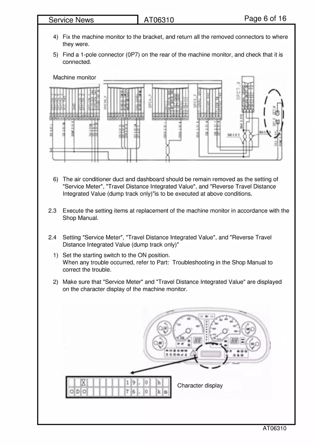
4)
5)
6)
2.3
2.4
1)
2)
Setting "Service Meter", "Travel Distance Integrated Value", and "Reverse Travel
Distance Integrated Value (dump track only)"
Set the starting switch to the ON position.
When any trouble occurred, refer to Part: Troubleshooting in the Shop Manual to
correct the trouble.
Make sure that "Service Meter" and "Travel Distance Integrated Value" are displayed
on the character display of the machine monitor.
Fix the machine monitor to the bracket, and return all the removed connectors to where
they were.
Find a 1-pole connector (0P7) on the rear of the machine monitor, and check that it is
connected.
The air conditioner duct and dashboard should be remain removed as the setting of
"Service Meter", "Travel Distance Integrated Value", and "Reverse Travel Distance
Integrated Value (dump track only)"is to be executed at above conditions.
Execute the setting items at replacement of the machine monitor in accordance with the
Shop Manual.
Character display
Machine monitor
AT06310
Page7of16
Service News
AT06310
3)
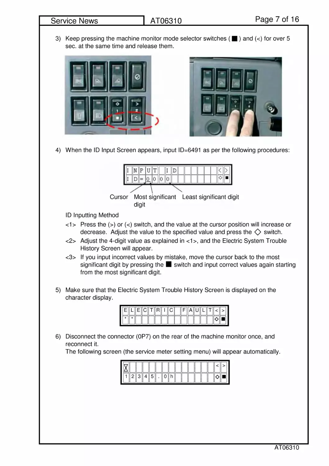
4) When the ID Input Screen appears, input ID=6491 as per the following procedures:
ID Inputting Method
<1>
<2>
<3>
5)
6)
Make sure that the Electric System Trouble History Screen is displayed on the
character display.
Disconnect the connector (0P7) on the rear of the machine monitor once, and
reconnect it.
The following screen (the service meter setting menu) will appear automatically.
Keep pressing the machine monitor mode selector switches ( ) and (<) for over 5
sec. at the same time and release them.
Press the (>) or (<) switch, and the value at the cursor position will increase or
decrease. Adjust the value to the specified value and press the switch.
Adjust the 4-digit value as explained in <1>, and the Electric System Trouble
History Screen will appear.
If you input incorrect values by mistake, move the cursor back to the most
significant digit by pressing the switch and input correct values again starting
from the most significant digit.
ELECTRIC FAULT<>
**
<>
12345.0h
Cursor Most significant
digit
Least significant digit
AT06310
Page8of16
Service News
AT06310
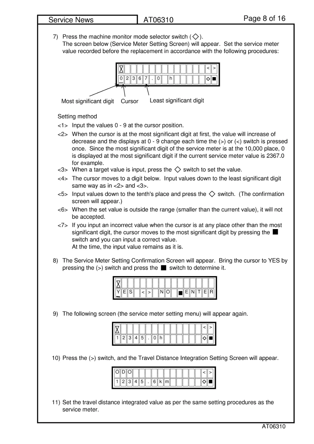
7)
Setting method
<1> Input the values 0 - 9 at the cursor position.
<2>
<3> When a target value is input, press the switch to set the value.
<4>
<5>
<6>
<7>
8)
9) The following screen (the service meter setting menu) will appear again.
10) Press the (>) switch, and the Travel Distance Integration Setting Screen will appear.
11)
Press the machine monitor mode selector switch ( ).
The screen below (Service Meter Setting Screen) will appear. Set the service meter
value recorded before the replacement in accordance with the following procedures:
When the cursor is at the most significant digit at first, the value will increase of
decrease and the displays at 0 - 9 change each time the (>) or (<) switch is pressed
once. Since the most significant digit of the service meter is at the 10,000 place, 0
is displayed at the most significant digit if the current service meter value is 2367.0
for example.
The cursor moves to a digit below. Input values down to the least significant digit
same way as in <2> and <3>.
Input values down to the tenth's place and press the switch. (The confirmation
screen will appear.)
When the set value is outside the range (smaller than the current value), it will not
be accepted.
If you input an incorrect value when the cursor is at any place other than the most
significant digit, the cursor moves to the most significant digit by pressing the
switch and you can input a correct value.
At the time, the input value remains as it is.
The Service Meter Setting Confirmation Screen will appear. Bring the cursor to YES by
pressing the (>) switch and press the switch to determine it.
Set the travel distance integrated value as per the same setting procedures as the
service meter.
<>
0236
h
Cursor
Most significant digit
7.0
Least significant digit
YES<>NO
ENTER
<>
12345.0h
DO
<>
12345.6km
O
AT06310
Page9of16
Service News
AT06310
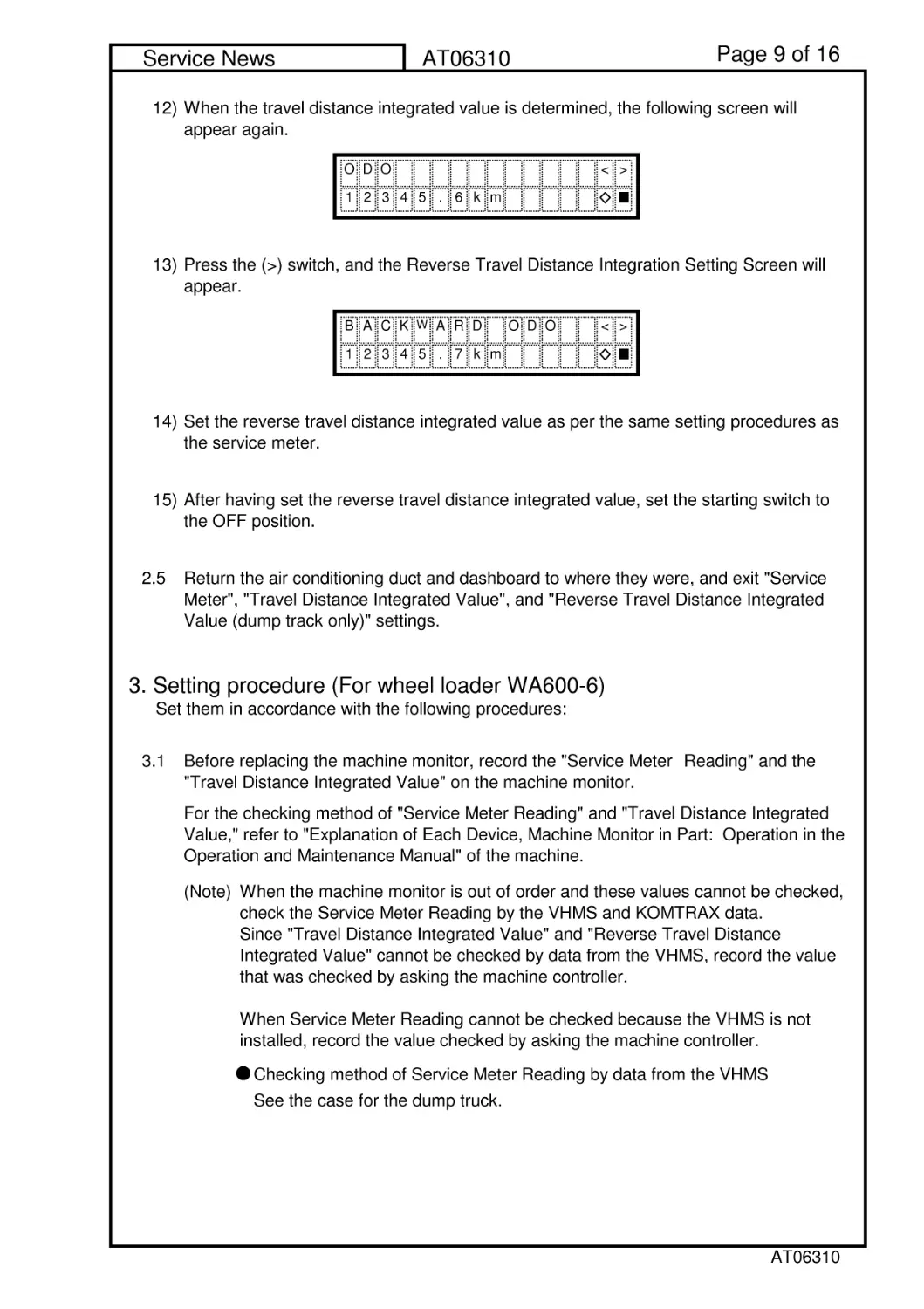
12)
13)
14)
15)
2.5
3. Setting procedure (For wheel loader WA600-6)
Set them in accordance with the following procedures:
3.1
(Note)
Checking method of Service Meter Reading by data from the VHMS
See the case for the dump truck.
Before replacing the machine monitor, record the "Service Meter Reading" and the
"Travel Distance Integrated Value" on the machine monitor.
For the checking method of "Service Meter Reading" and "Travel Distance Integrated
Value," refer to "Explanation of Each Device, Machine Monitor in Part: Operation in the
Operation and Maintenance Manual" of the machine.
When the machine monitor is out of order and these values cannot be checked,
check the Service Meter Reading by the VHMS and KOMTRAX data.
Since "Travel Distance Integrated Value" and "Reverse Travel Distance
Integrated Value" cannot be checked by data from the VHMS, record the value
that was checked by asking the machine controller.
When Service Meter Reading cannot be checked because the VHMS is not
installed, record the value checked by asking the machine controller.
When the travel distance integrated value is determined, the following screen will
appear again.
Press the (>) switch, and the Reverse Travel Distance Integration Setting Screen will
appear.
Set the reverse travel distance integrated value as per the same setting procedures as
the service meter.
After having set the reverse travel distance integrated value, set the starting switch to
the OFF position.
Return the air conditioning duct and dashboard to where they were, and exit "Service
Meter", "Travel Distance Integrated Value", and "Reverse Travel Distance Integrated
Value (dump track only)" settings.
DO
<>
12345.6km
O
ACK
W
ARD ODO
<>
12345.7km
B
AT06310
Page 10 of 16
Service News
AT06310
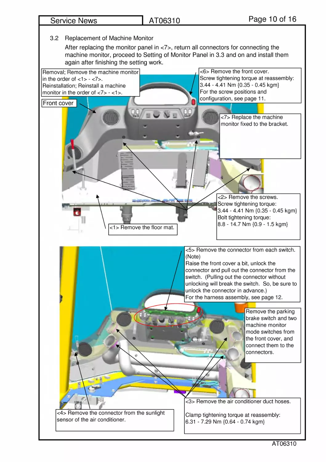
3.2 Replacement of Machine Monitor
After replacing the monitor panel in <7>, return all connectors for connecting the
machine monitor, proceed to Setting of Monitor Panel in 3.3 and on and install them
again after finishing the setting work.
<6> Remove the front cover.
Screw tightening torque at reassembly:
3.44 - 4.41 Nm {0.35 - 0.45 kgm}
For the screw positions and
configuration, see page 11.
<1> Remove the floor mat.
Front cover
Removal; Remove the machine monitor
in the order of <1> - <7>.
Reinstallation; Reinstall a machine
monitor in the order of <7> - <1>.
<2> Remove the screws.
Screw tightening torque:
3.44 - 4.41 Nm {0.35 - 0.45 kgm}
Bolt tightening torque:
8.8 - 14.7 Nm {0.9 - 1.5 kgm}
<5> Remove the connector from each switch.
(Note)
Raise the front cover a bit, unlock the
connector and pull out the connector from the
switch. (Pulling out the connector without
unlocking will break the switch. So, be sure to
unlock the connector in advance.)
For the harness assembly, see page 12.
Remove the parking
brake switch and two
machine monitor
mode switches from
the front cover, and
connect them to the
connectors.
<7> Replace the machine
monitor fixed to the bracket.
<4> Remove the connector from the sunlight
sensor of the air conditioner.
<3> Remove the air conditioner duct hoses.
Clamp tightening torque at reassembly:
6.31 - 7.29 Nm {0.64 - 0.74 kgm}
AT06310
Page 11 of 16
Service News
AT06310
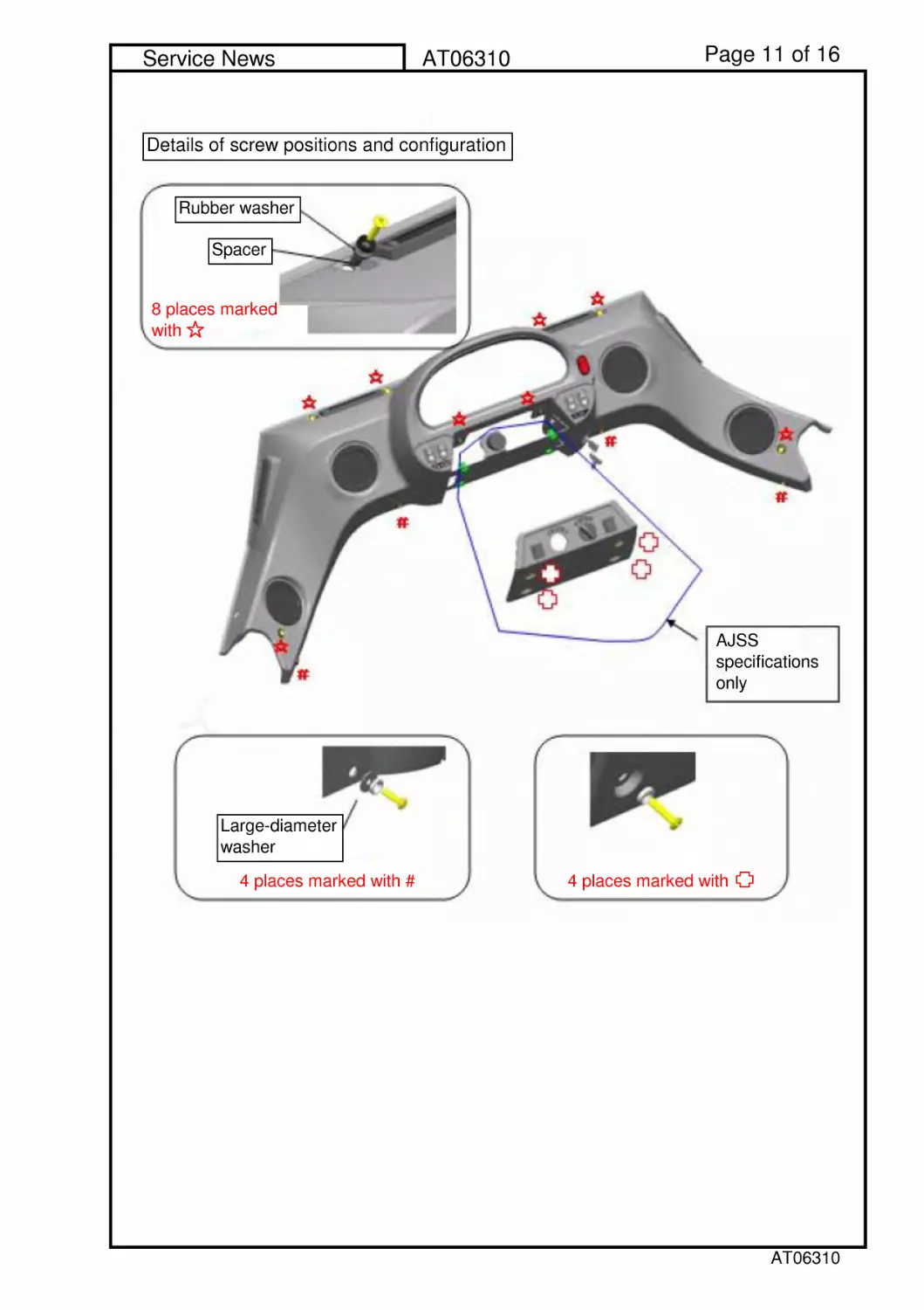
Details of screw positions and configuration
Rubber washer
Spacer
8 places marked
with
AJSS
specifications
only
Large-diameter
washer
4placesmarkedwith#
4placesmarkedwith
AT06310
Page 12 of 16
Service News
AT06310
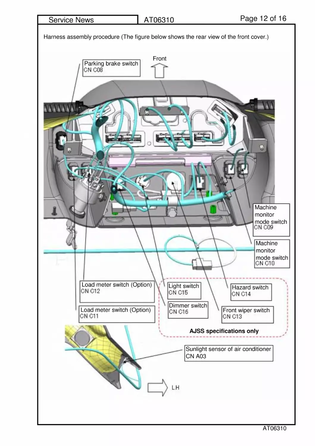
Harness assembly procedure (The figure below shows the rear view of the front cover.)
Front
Parking brake switch
AJSS specifications only
Machine
monitor
mode switch
Machine
monitor
mode switch
Load meter switch (Option)
Load meter switch (Option)
Light switch
Dimmer switch
Hazard switch
Front wiper switch
Sunlight sensor of air conditioner
CN A03
AT06310
Page 13 of 16
Service News
AT06310
3.3
3.4 Setting "Service Meter" and "Travel Distance Integrated Value."
1)
2)
3) Make sure that "Service Meter" is displayed on the character display of the machine
monitor.
Execute the setting items at replacement of the machine monitor in accordance with the
Shop Manual.
Insert the T-adaptor for Connector 070 into the connector (CN C04) of the machine
monitor, ground the 6 pins of the Connector C04 to the body and tack them temporarily.
Set the starting switch to the ON position.
When any trouble occurred, refer to Part: Troubleshooting in the Shop Manual to
correct the trouble.
Character display
AT06310
Page 14 of 16
Service News
AT06310
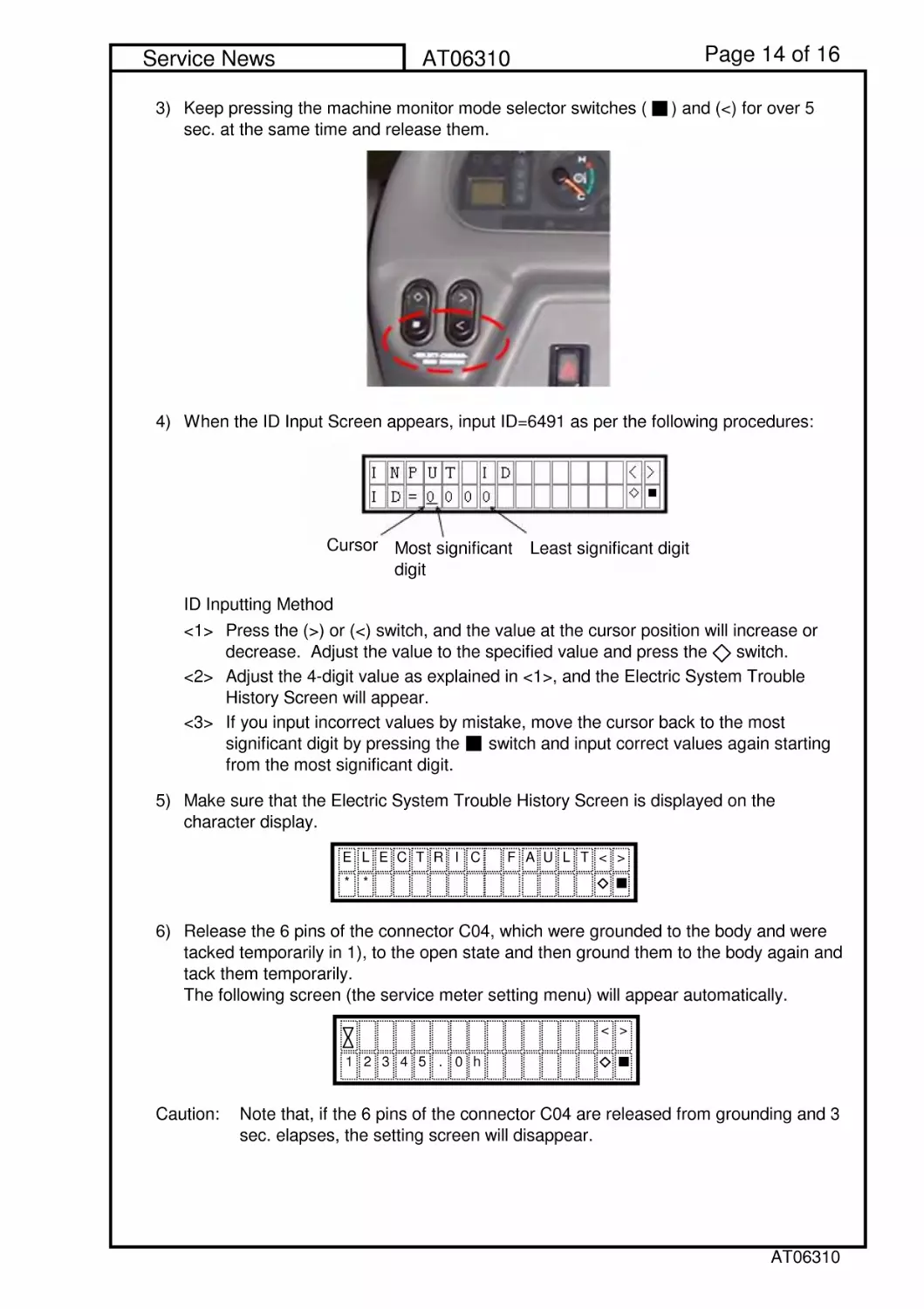
3)
4) When the ID Input Screen appears, input ID=6491 as per the following procedures:
ID Inputting Method
<1>
<2>
<3>
5)
6)
Caution: Note that, if the 6 pins of the connector C04 are released from grounding and 3
sec. elapses, the setting screen will disappear.
Make sure that the Electric System Trouble History Screen is displayed on the
character display.
Release the 6 pins of the connector C04, which were grounded to the body and were
tacked temporarily in 1), to the open state and then ground them to the body again and
tack them temporarily.
The following screen (the service meter setting menu) will appear automatically.
Keep pressing the machine monitor mode selector switches ( ) and (<) for over 5
sec. at the same time and release them.
Press the (>) or (<) switch, and the value at the cursor position will increase or
decrease. Adjust the value to the specified value and press the switch.
Adjust the 4-digit value as explained in <1>, and the Electric System Trouble
History Screen will appear.
If you input incorrect values by mistake, move the cursor back to the most
significant digit by pressing the switch and input correct values again starting
from the most significant digit.
ELECTRIC FAULT<>
**
<>
12345.0h
Cursor
Most significant
digit
Least significant digit
AT06310
Page 15 of 16
Service News
AT06310
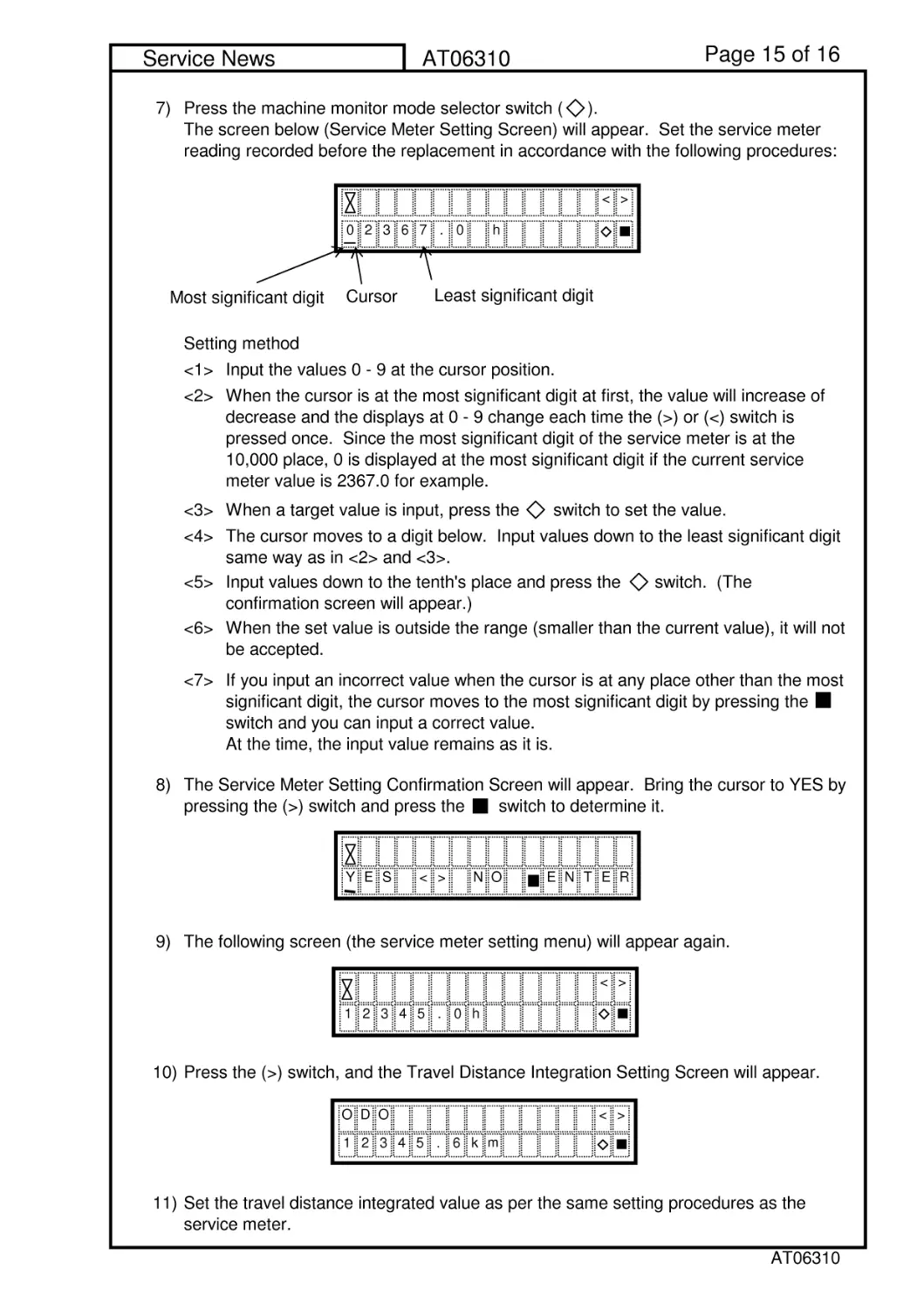
7)
Setting method
<1> Input the values 0 - 9 at the cursor position.
<2>
<3> When a target value is input, press the switch to set the value.
<4>
<5>
<6>
<7>
8)
9) The following screen (the service meter setting menu) will appear again.
10) Press the (>) switch, and the Travel Distance Integration Setting Screen will appear.
11) Set the travel distance integrated value as per the same setting procedures as the
service meter.
Input values down to the tenth's place and press the switch. (The
confirmation screen will appear.)
When the set value is outside the range (smaller than the current value), it will not
be accepted.
If you input an incorrect value when the cursor is at any place other than the most
significant digit, the cursor moves to the most significant digit by pressing the
switch and you can input a correct value.
At the time, the input value remains as it is.
Press the machine monitor mode selector switch ( ).
The screen below (Service Meter Setting Screen) will appear. Set the service meter
reading recorded before the replacement in accordance with the following procedures:
When the cursor is at the most significant digit at first, the value will increase of
decrease and the displays at 0 - 9 change each time the (>) or (<) switch is
pressed once. Since the most significant digit of the service meter is at the
10,000 place, 0 is displayed at the most significant digit if the current service
meter value is 2367.0 for example.
The cursor moves to a digit below. Input values down to the least significant digit
same way as in <2> and <3>.
The Service Meter Setting Confirmation Screen will appear. Bring the cursor to YES by
pressing the (>) switch and press the switch to determine it.
YES<>NO
ENTER
<>
12345.0h
DO
<>
12345.6k
m
O
<>
0236
h
Cursor
Most significant digit
7.0
Least significant digit
AT06310
Page 16 of 16
Service News
AT06310
12)
13)
14)
3.5
When the travel distance integrated value is determined, the following screen will
appear again.
After having set the travel distance integrated value, set the starting switch to the OFF
position.
Disconnect the T-adaptor for the connector 070 inserted in the machine monitor
connector (CN C04) and return the machine monitor connector to where it was.
Carry out the Reinstallation Procedures <1> - <6> in Paragraph 3.2 in the order of <6>
to <1> to finish the setting of "Service Meter" and "Travel Distance Integrated Value."
DO
<>
12345.6k
m
O
AT06310