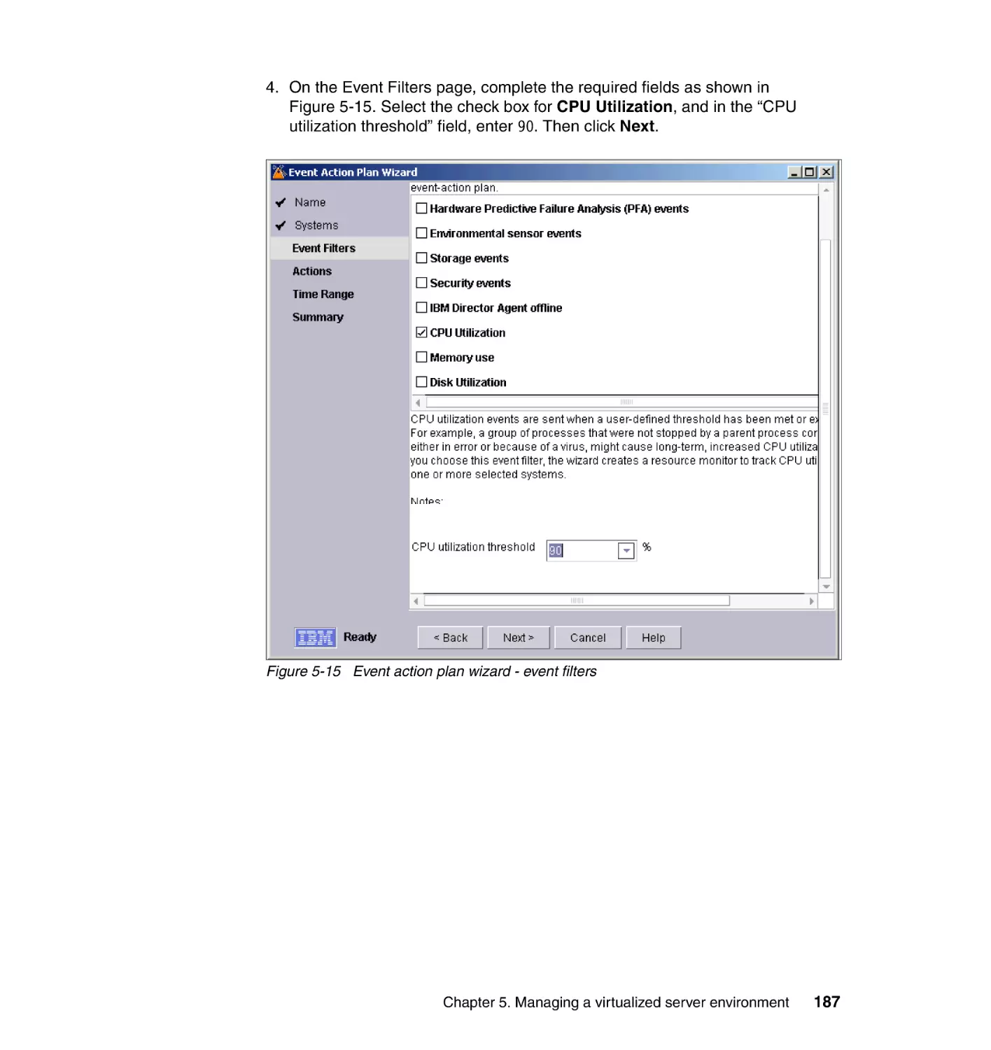
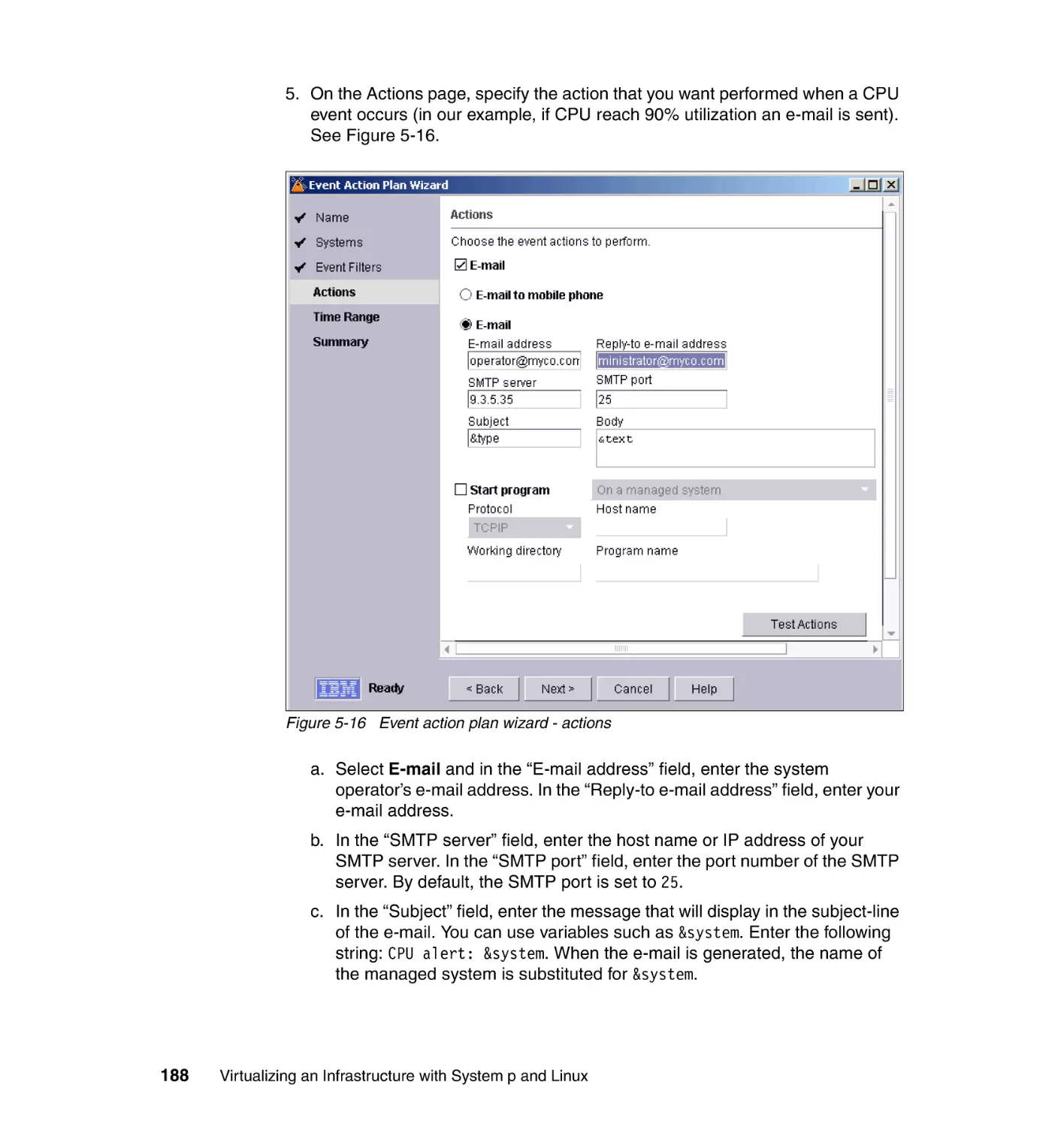
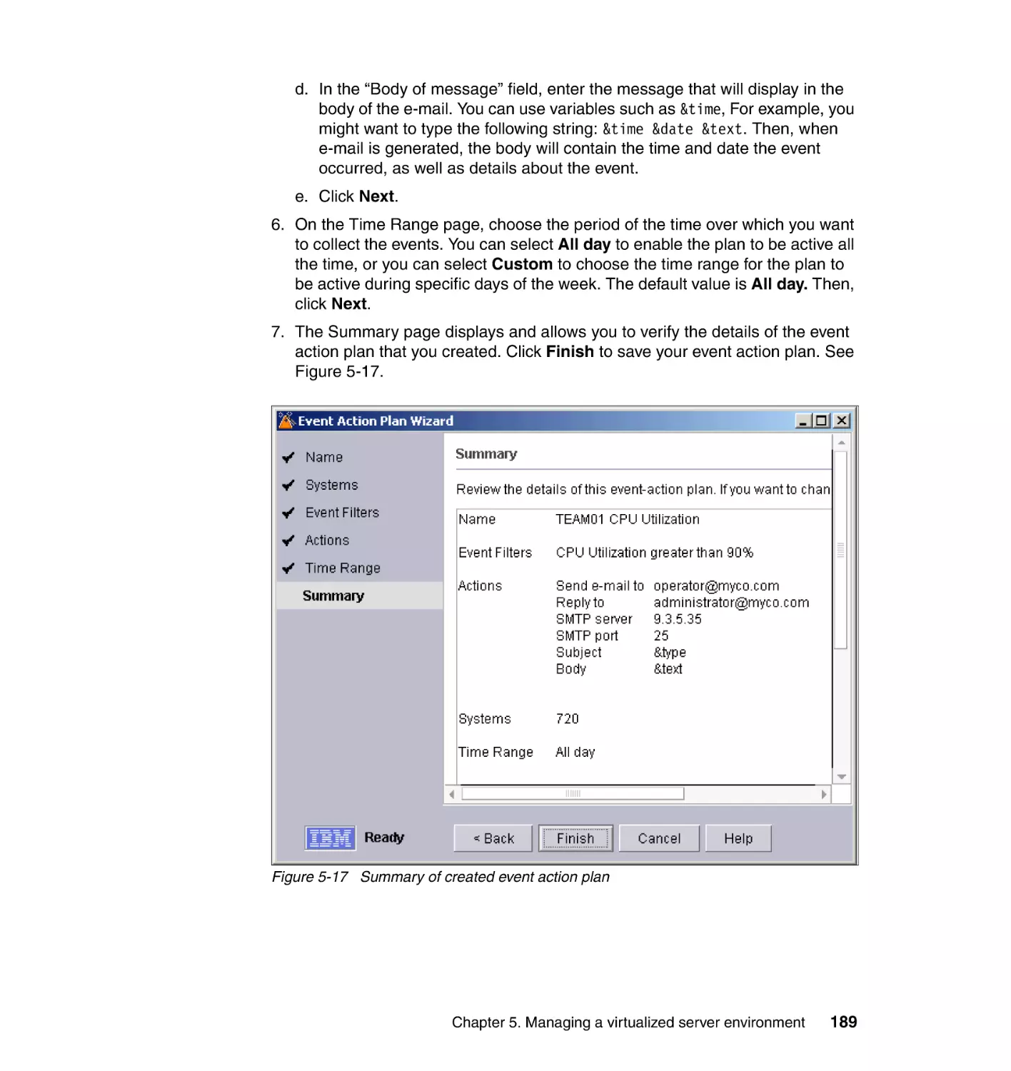
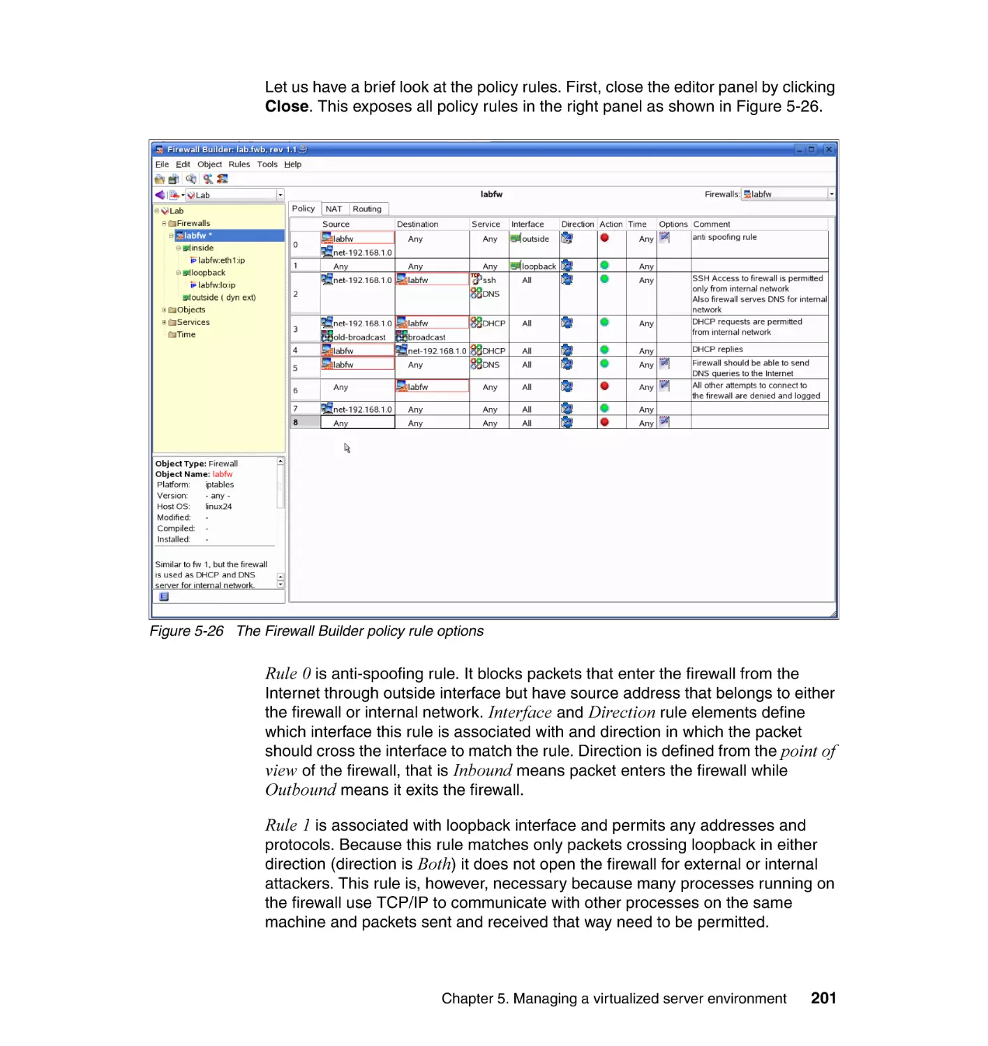
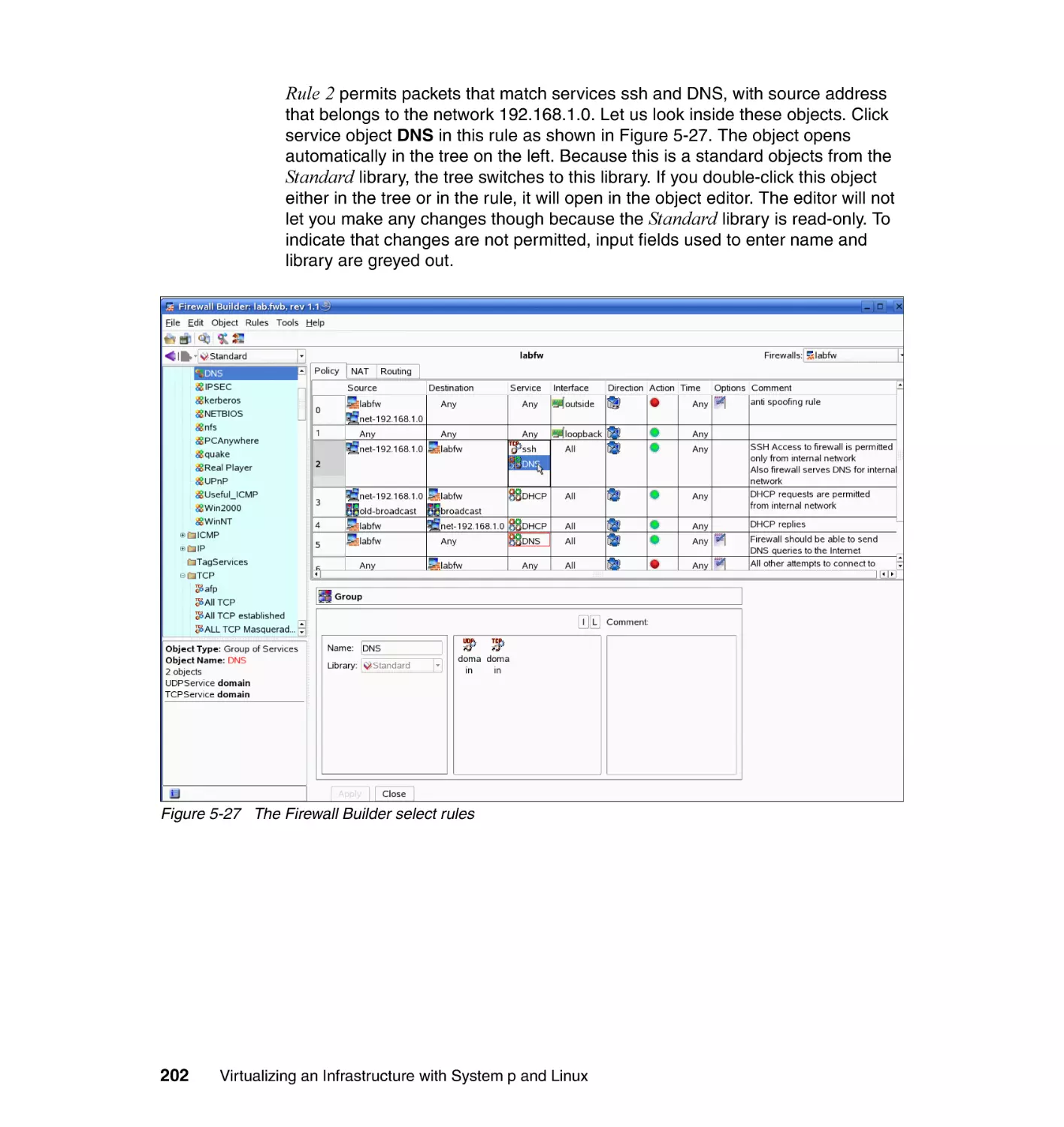
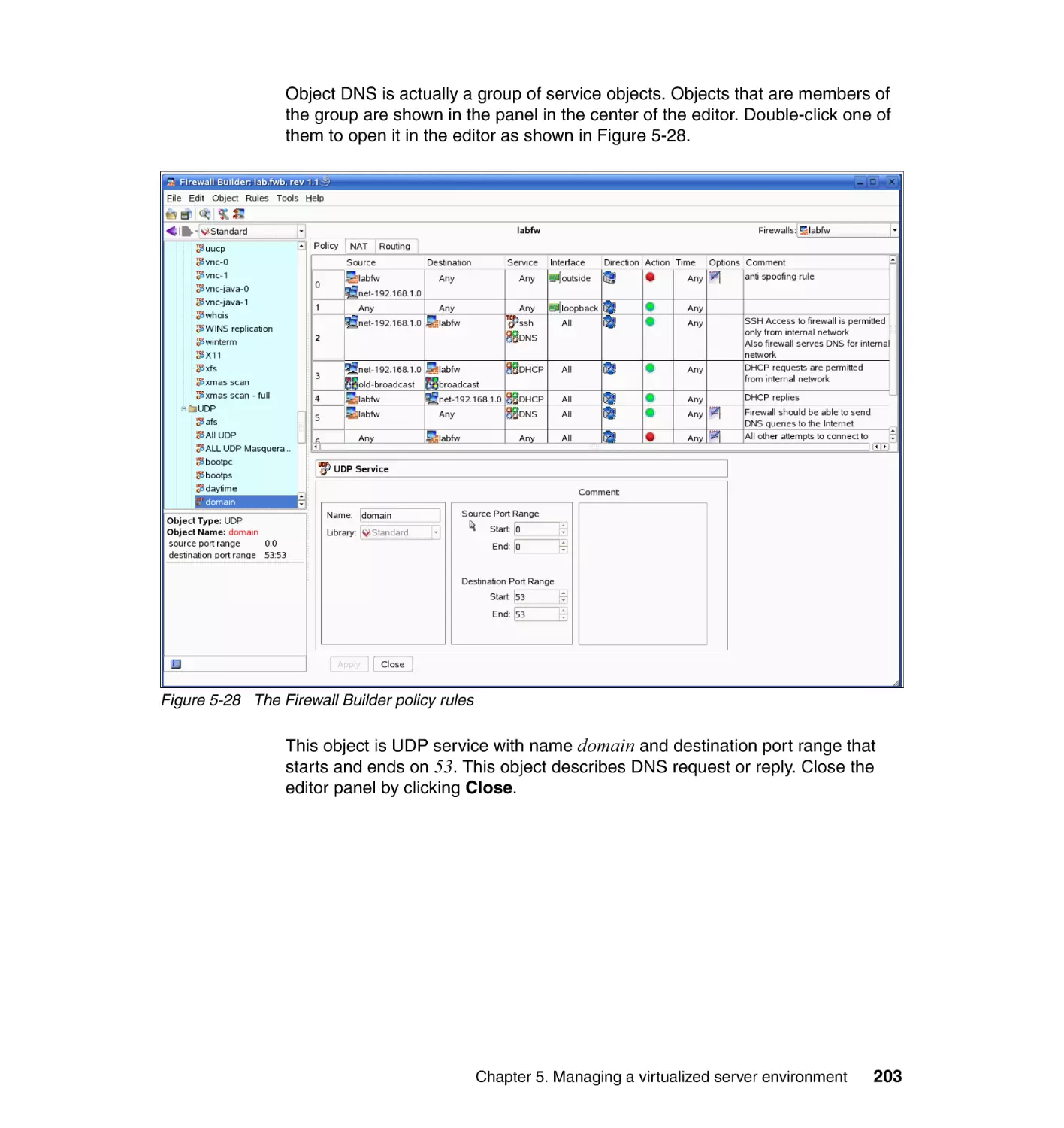
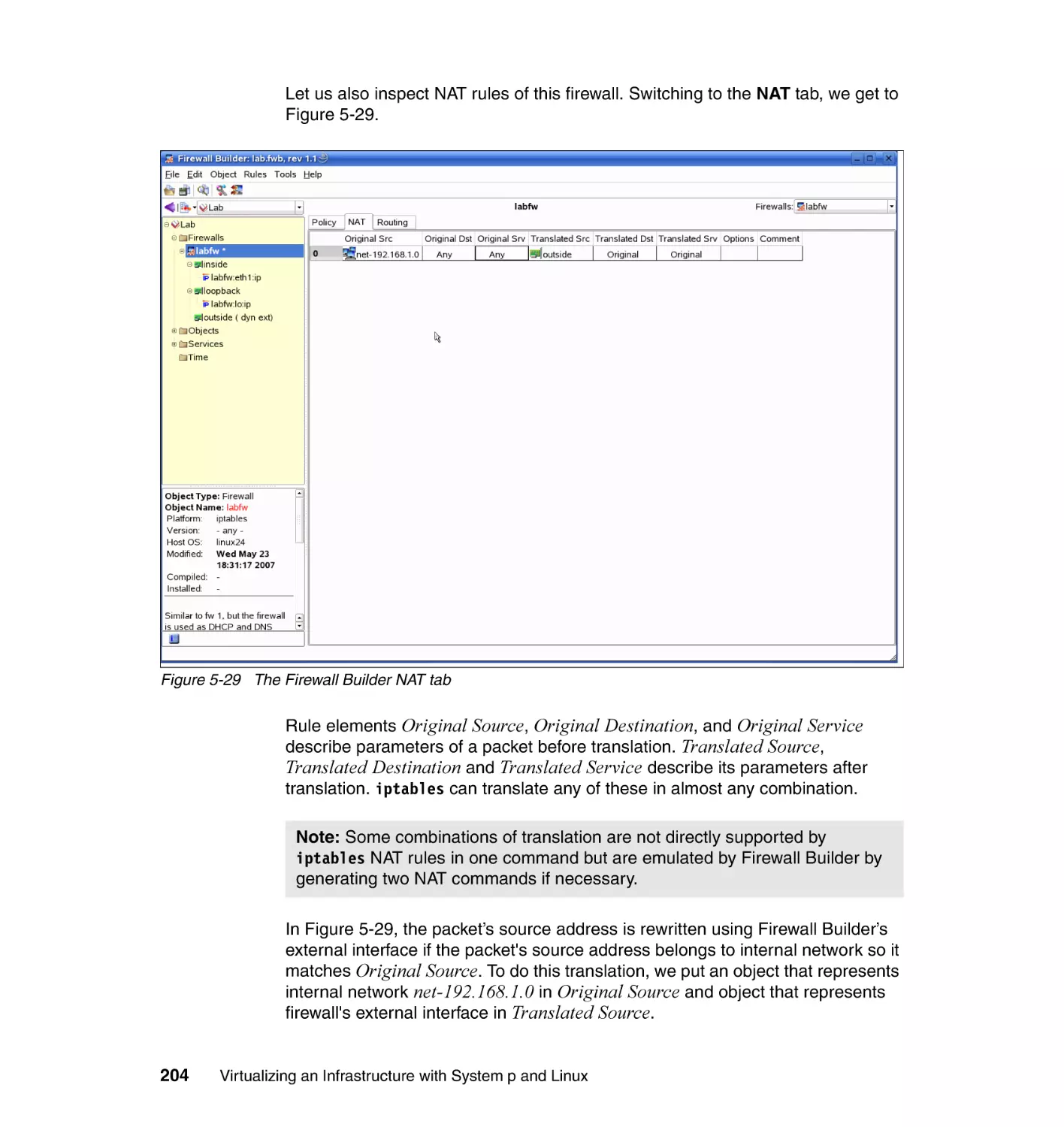
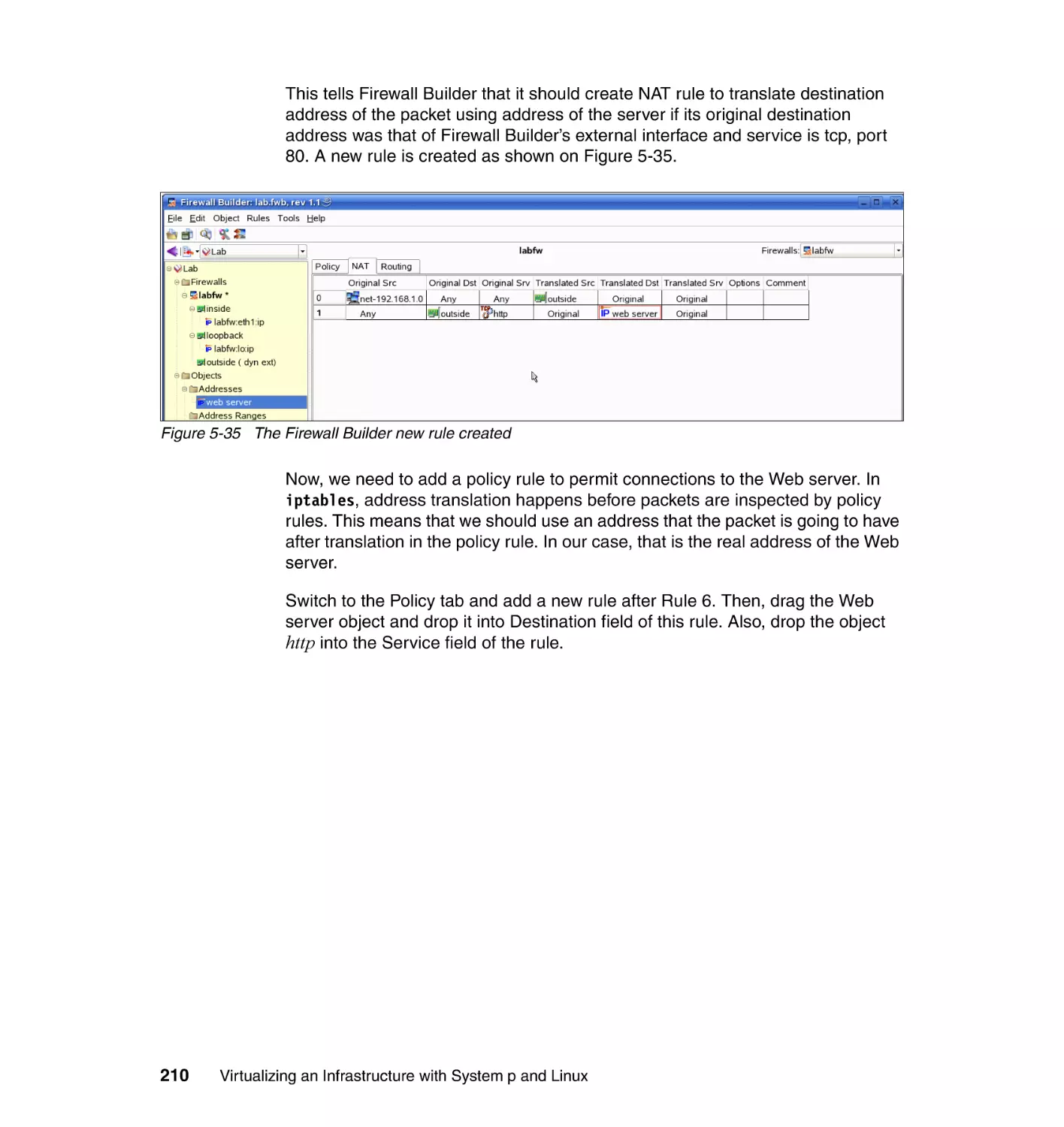
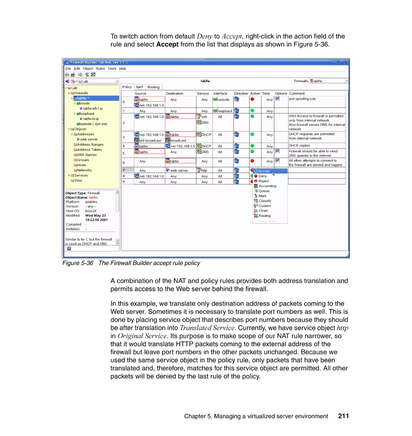
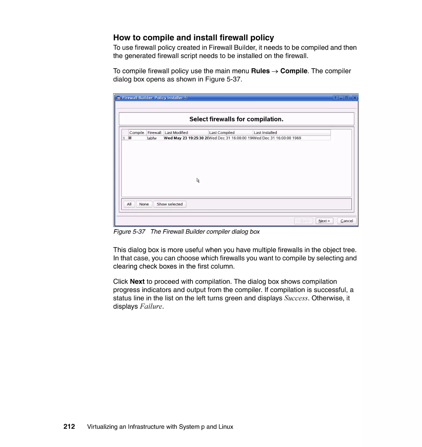
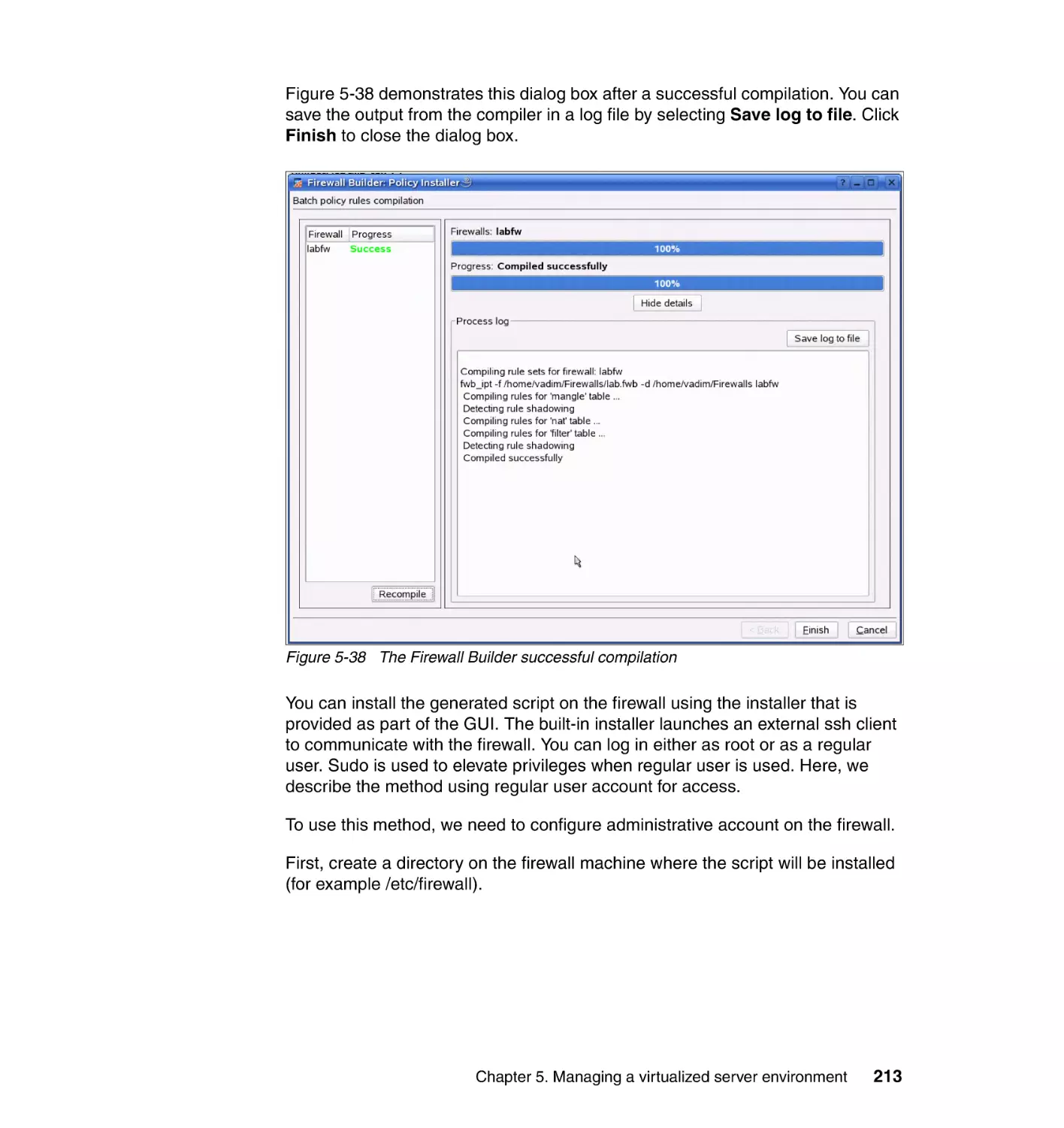
/


Author: Castillo L. Montes W. Hochstetler S.
Tags: operating system linux
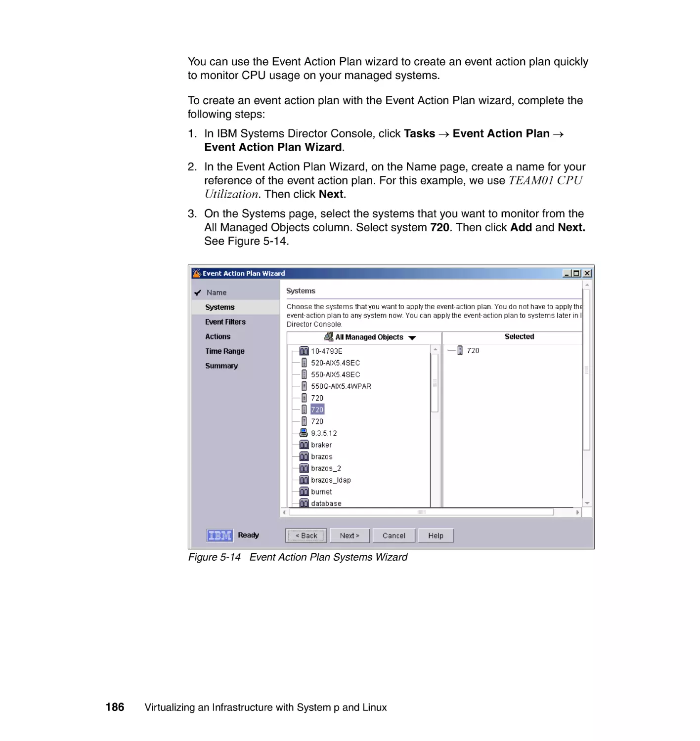
ISBN: 0738486752
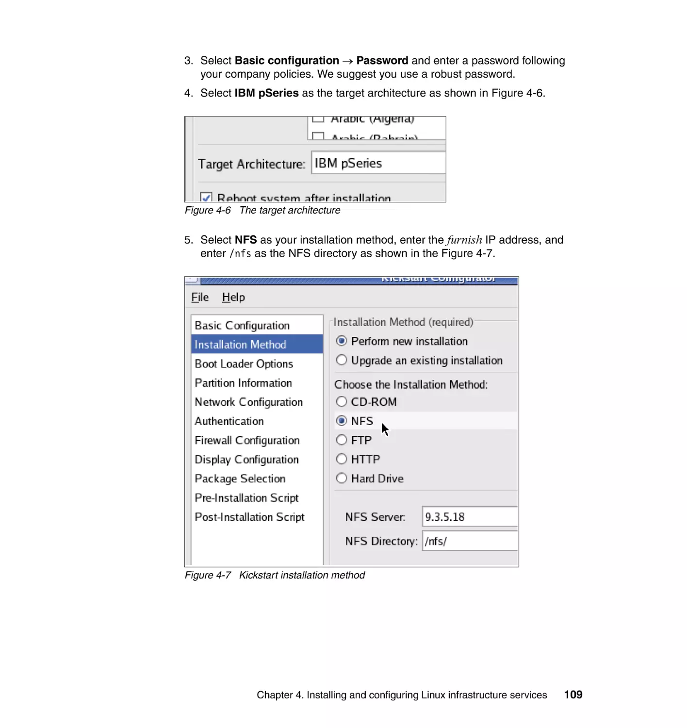
Year: 2008

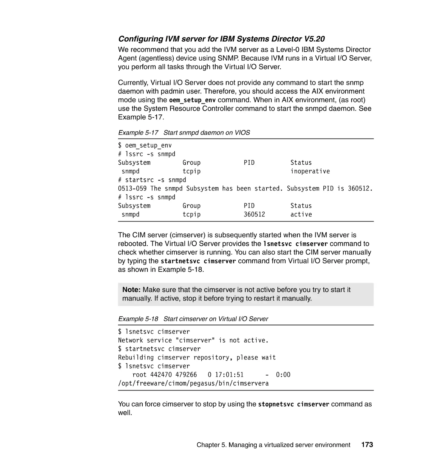
Text
Front cover
Virtualizing an Infrastructure
with System p and Linux
Use System p virtualization
capabilities with Linux
Plan, configure, and install Linux
infrastructure services
Create and manage a Linux operating
system-based server environment
Lancelot Castillo
Walter Montes
Stephen Hochstetler
ibm.com/redbooks
International Technical Support Organization
Virtualizing an Infrastructure with System p and
Linux
January 2008
SG24-7499-00
Note: Before using this information and the product it supports, read the information in
“Notices” on page vii.
First Edition (January 2008)
This edition applies to Version 1.4 of the Virtual I/O Server, a feature of IBM System p servers.
© Copyright International Business Machines Corporation 2008. All rights reserved.
Note to U.S. Government Users Restricted Rights -- Use, duplication or disclosure restricted by GSA ADP
Schedule Contract with IBM Corp.
Contents
Notices . . . . . . . . . . . . . . . . . . . . . . . . . . . . . . . . . . . . . . . . . . . . . . . . . . . . . . vii
Trademarks . . . . . . . . . . . . . . . . . . . . . . . . . . . . . . . . . . . . . . . . . . . . . . . . . . . viii
Preface . . . . . . . . . . . . . . . . . . . . . . . . . . . . . . . . . . . . . . . . . . . . . . . . . . . . . . . ix
The team that wrote this book . . . . . . . . . . . . . . . . . . . . . . . . . . . . . . . . . . . . . . ix
Become a published author . . . . . . . . . . . . . . . . . . . . . . . . . . . . . . . . . . . . . . . . x
Comments welcome. . . . . . . . . . . . . . . . . . . . . . . . . . . . . . . . . . . . . . . . . . . . . . xi
Chapter 1. Introduction . . . . . . . . . . . . . . . . . . . . . . . . . . . . . . . . . . . . . . . . . . 1
1.1 Overview . . . . . . . . . . . . . . . . . . . . . . . . . . . . . . . . . . . . . . . . . . . . . . . . . . . 2
1.2 Virtualization overview. . . . . . . . . . . . . . . . . . . . . . . . . . . . . . . . . . . . . . . . . 2
1.2.1 Business drivers . . . . . . . . . . . . . . . . . . . . . . . . . . . . . . . . . . . . . . . . . 3
1.2.2 Why IT optimization and virtualization. . . . . . . . . . . . . . . . . . . . . . . . . 4
1.3 Linux as the operating system. . . . . . . . . . . . . . . . . . . . . . . . . . . . . . . . . . 11
1.3.1 Overview of the Linux operating system . . . . . . . . . . . . . . . . . . . . . . 11
1.3.2 Linux infrastructure services . . . . . . . . . . . . . . . . . . . . . . . . . . . . . . . 13
1.3.3 The role of IBM in the Linux community . . . . . . . . . . . . . . . . . . . . . . 13
1.3.4 Linux on POWER Distributions . . . . . . . . . . . . . . . . . . . . . . . . . . . . . 14
1.4 Linux on System p. . . . . . . . . . . . . . . . . . . . . . . . . . . . . . . . . . . . . . . . . . . 16
1.4.1 Virtualization on IBM System p . . . . . . . . . . . . . . . . . . . . . . . . . . . . . 17
1.4.2 Linux for System p hardware enablement. . . . . . . . . . . . . . . . . . . . . 19
1.4.3 Virtualization capabilities of System p running Linux . . . . . . . . . . . . 20
1.4.4 Logical Partitioning of Linux on Power Architecture . . . . . . . . . . . . . 21
1.4.5 Supported servers and blades . . . . . . . . . . . . . . . . . . . . . . . . . . . . . 22
1.4.6 Scalability . . . . . . . . . . . . . . . . . . . . . . . . . . . . . . . . . . . . . . . . . . . . . 22
1.4.7 Linux on System p RAS features . . . . . . . . . . . . . . . . . . . . . . . . . . . 23
1.4.8 Considerations at the operating system and application level . . . . . 24
1.5 Benefits of deploying IBM Advanced POWER Virtualization on Linux
environment . . . . . . . . . . . . . . . . . . . . . . . . . . . . . . . . . . . . . . . . . . . . . . . 25
Chapter 2. Configuration planning . . . . . . . . . . . . . . . . . . . . . . . . . . . . . . . 27
2.1 Planning for virtual environment . . . . . . . . . . . . . . . . . . . . . . . . . . . . . . . . 28
2.2 Understanding infrastructure services workload . . . . . . . . . . . . . . . . . . . . 28
2.2.1 Domain Name System . . . . . . . . . . . . . . . . . . . . . . . . . . . . . . . . . . . 29
2.2.2 Dynamic Host Configuration Protocol . . . . . . . . . . . . . . . . . . . . . . . . 29
2.2.3 Web server . . . . . . . . . . . . . . . . . . . . . . . . . . . . . . . . . . . . . . . . . . . . 30
2.2.4 Database server . . . . . . . . . . . . . . . . . . . . . . . . . . . . . . . . . . . . . . . . 31
2.2.5 File server . . . . . . . . . . . . . . . . . . . . . . . . . . . . . . . . . . . . . . . . . . . . . 32
2.2.6 Print server . . . . . . . . . . . . . . . . . . . . . . . . . . . . . . . . . . . . . . . . . . . . 32
© Copyright IBM Corp. 2008. All rights reserved.
iii
2.2.7 The e-mail server . . . . . . . . . . . . . . . . . . . . . . . . . . . . . . . . . . . . . . . 33
2.3 Understanding Virtual I/O Server workload . . . . . . . . . . . . . . . . . . . . . . . . 34
2.3.1 Further reference . . . . . . . . . . . . . . . . . . . . . . . . . . . . . . . . . . . . . . . 35
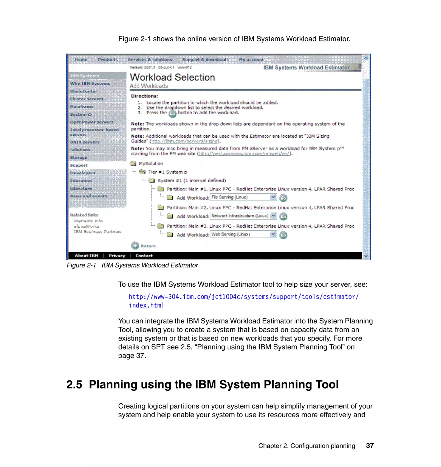
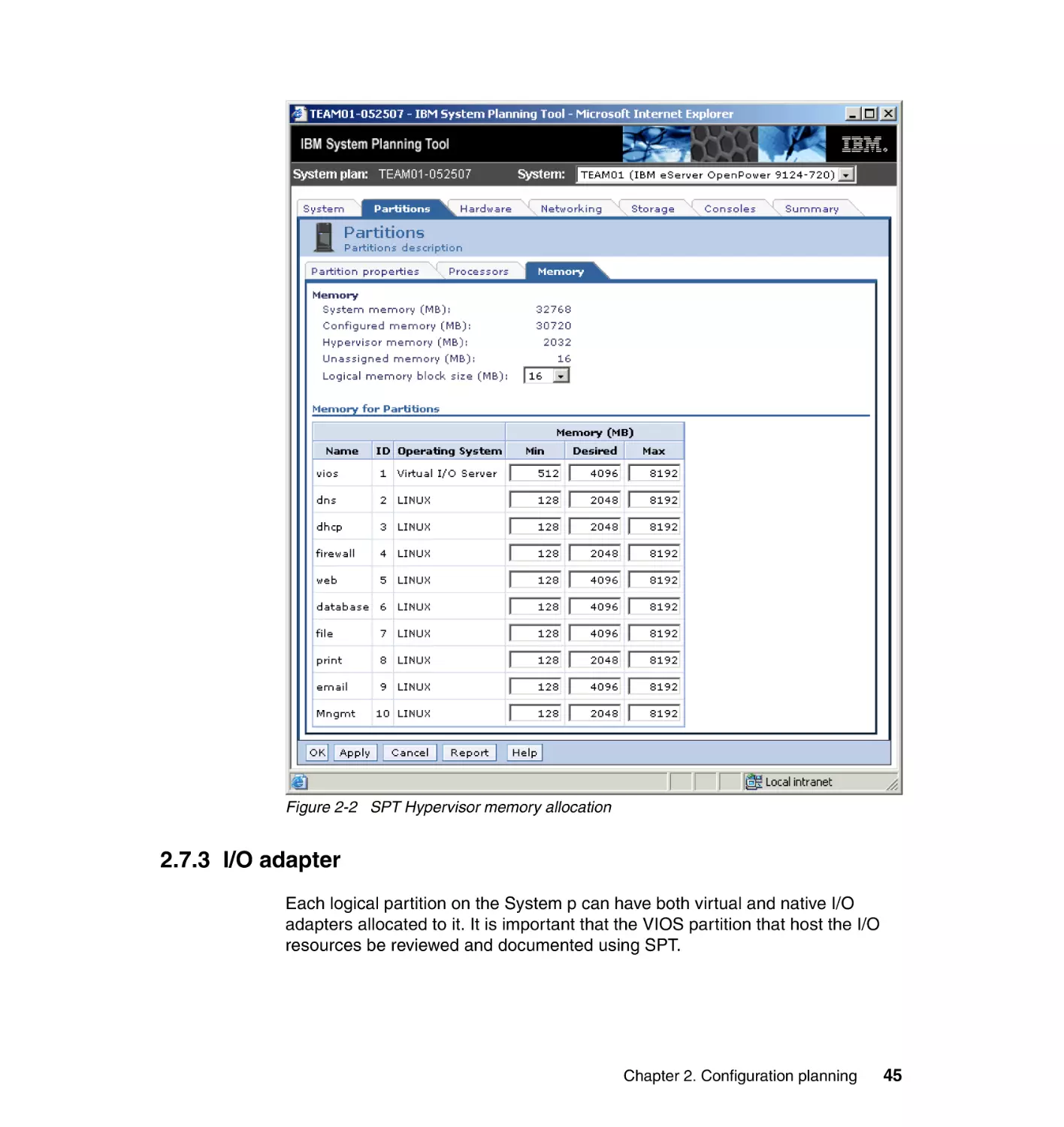
2.4 IBM Systems Workload Estimator . . . . . . . . . . . . . . . . . . . . . . . . . . . . . . . 36
2.5 Planning using the IBM System Planning Tool . . . . . . . . . . . . . . . . . . . . . 37
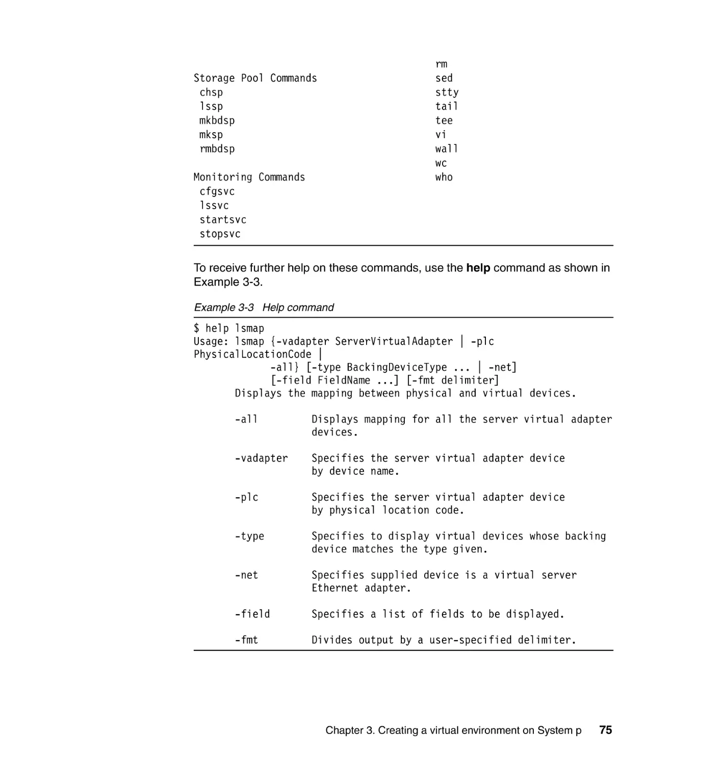
2.6 Planning your setup. . . . . . . . . . . . . . . . . . . . . . . . . . . . . . . . . . . . . . . . . . 40
2.7 Planning for resource allocation . . . . . . . . . . . . . . . . . . . . . . . . . . . . . . . . 40
2.7.1 Processor . . . . . . . . . . . . . . . . . . . . . . . . . . . . . . . . . . . . . . . . . . . . . 41
2.7.2 Memory . . . . . . . . . . . . . . . . . . . . . . . . . . . . . . . . . . . . . . . . . . . . . . . 44
2.7.3 I/O adapter . . . . . . . . . . . . . . . . . . . . . . . . . . . . . . . . . . . . . . . . . . . . 45
2.7.4 Network . . . . . . . . . . . . . . . . . . . . . . . . . . . . . . . . . . . . . . . . . . . . . . . 46
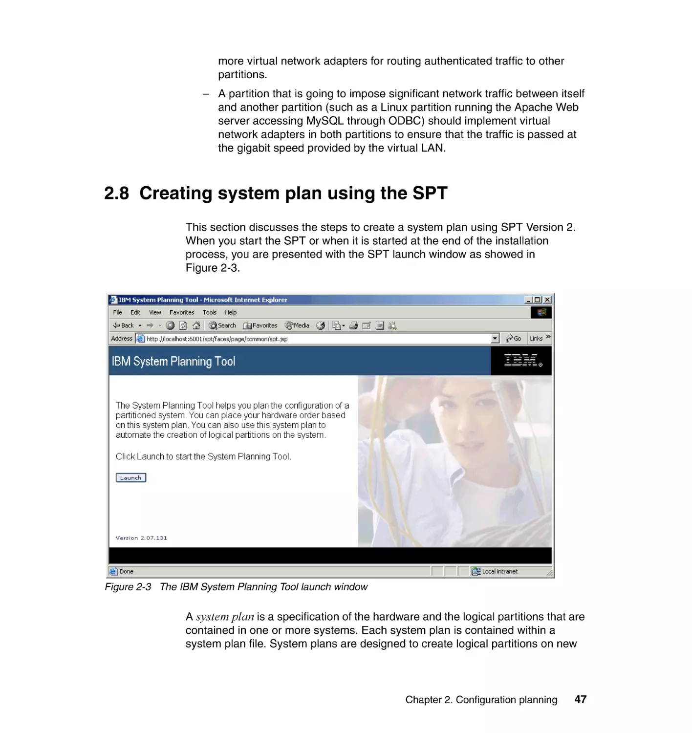
2.8 Creating system plan using the SPT . . . . . . . . . . . . . . . . . . . . . . . . . . . . . 47
2.9 Preparing to deploy the system plan . . . . . . . . . . . . . . . . . . . . . . . . . . . . . 49
Chapter 3. Creating a virtual environment on System p . . . . . . . . . . . . . . 51
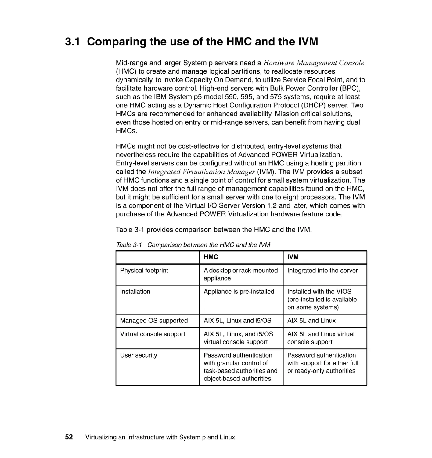
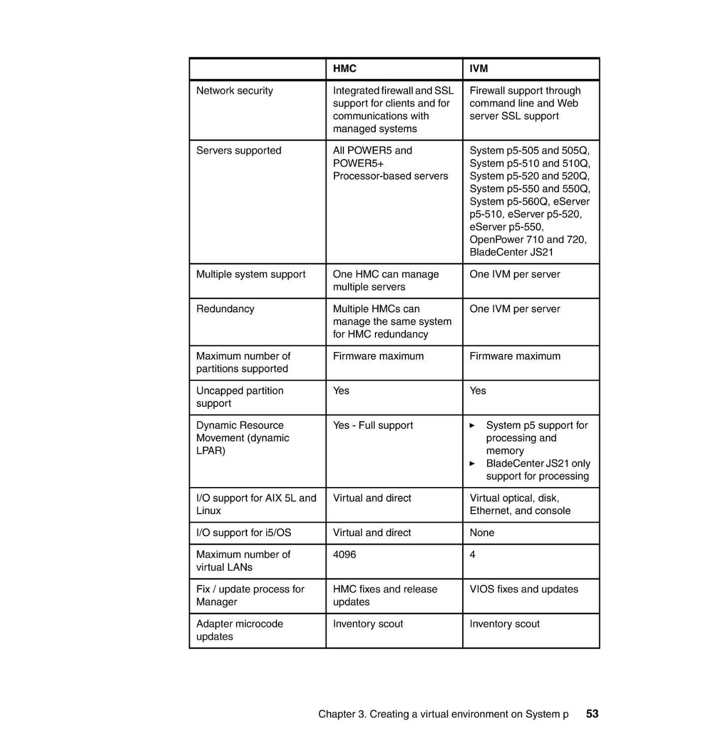
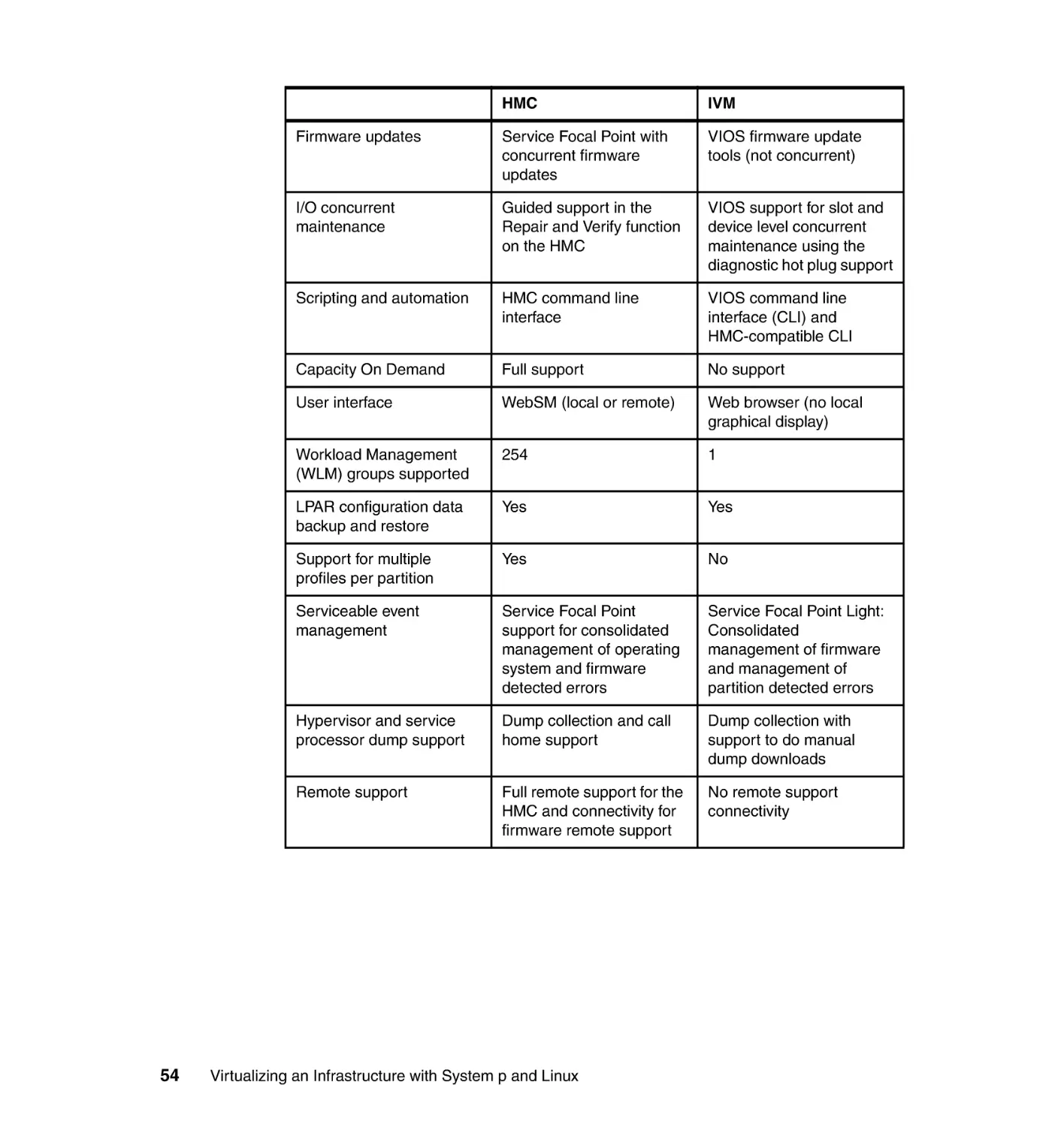
3.1 Comparing the use of the HMC and the IVM . . . . . . . . . . . . . . . . . . . . . . 52
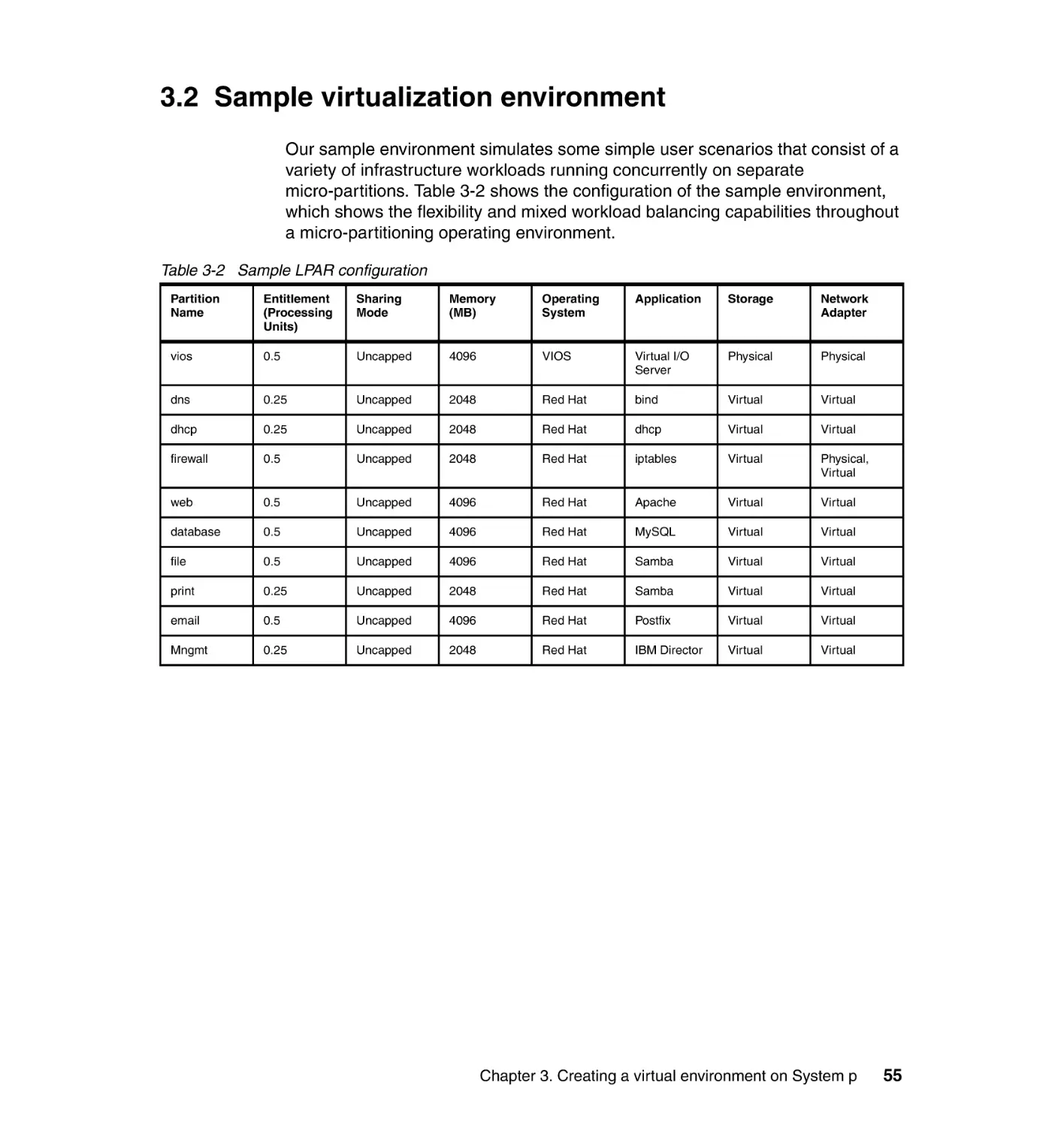
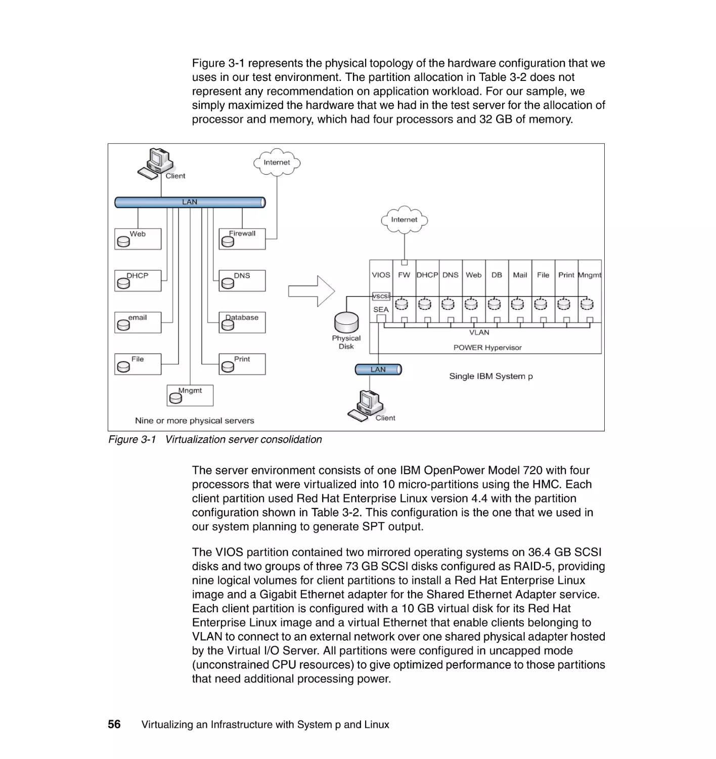
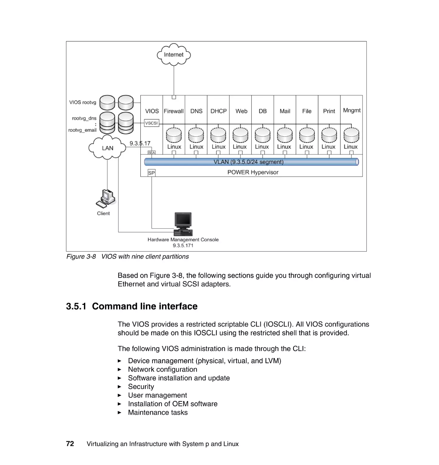
3.2 Sample virtualization environment . . . . . . . . . . . . . . . . . . . . . . . . . . . . . . 55
3.2.1 Using the HMC for System p virtualization . . . . . . . . . . . . . . . . . . . . 57
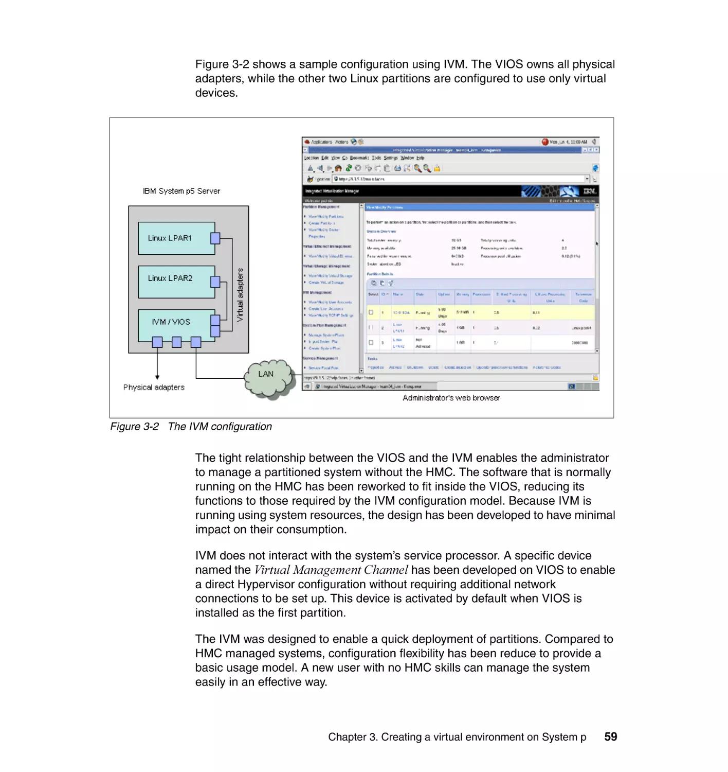
3.2.2 Using the IVM for System p virtualization . . . . . . . . . . . . . . . . . . . . . 58
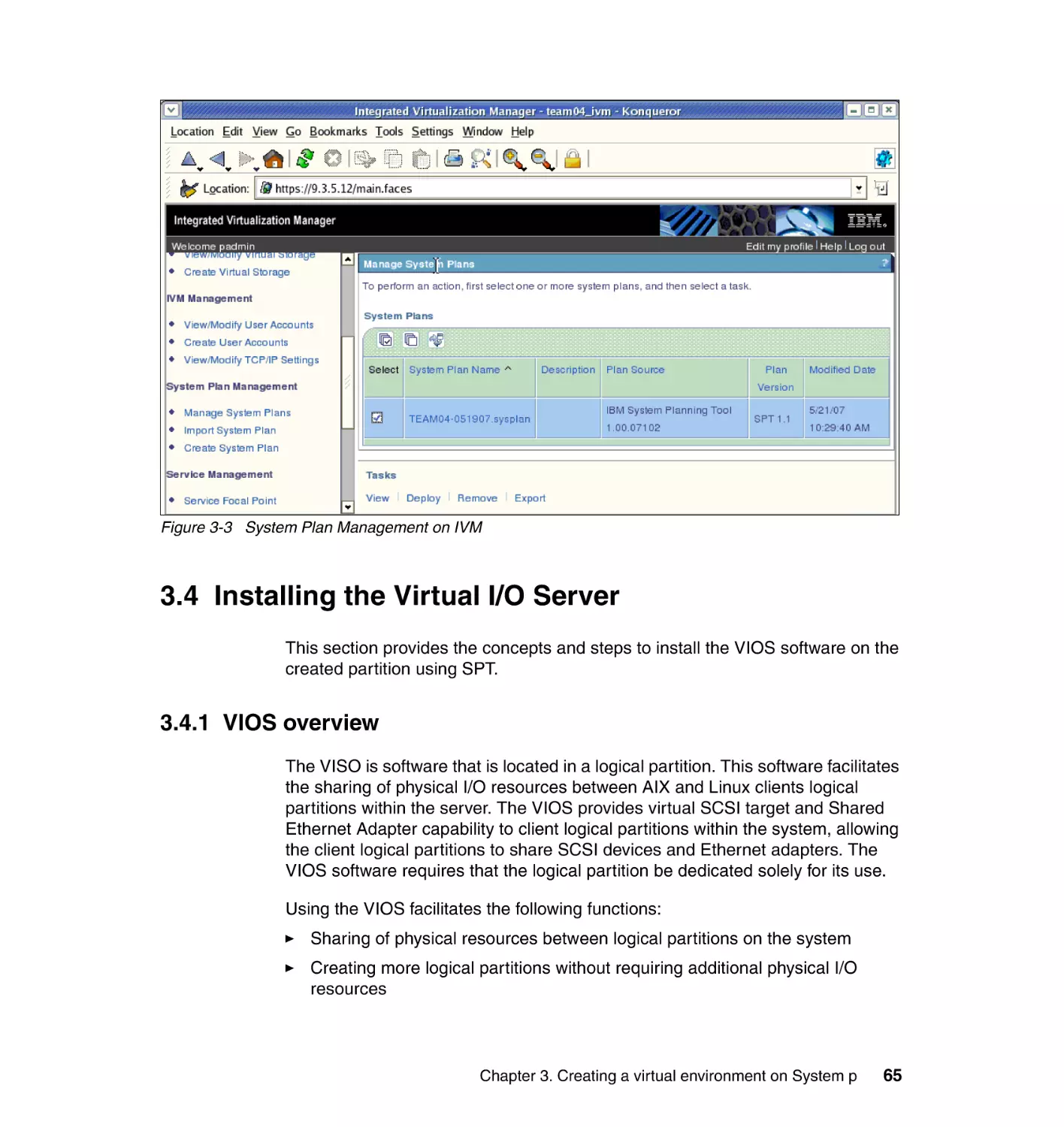
3.3 Working with a system plan. . . . . . . . . . . . . . . . . . . . . . . . . . . . . . . . . . . . 60
3.3.1 Validating the system plan . . . . . . . . . . . . . . . . . . . . . . . . . . . . . . . . 60
3.3.2 Importing a system plan . . . . . . . . . . . . . . . . . . . . . . . . . . . . . . . . . . 61
3.3.3 Deploying a system plan . . . . . . . . . . . . . . . . . . . . . . . . . . . . . . . . . . 63
3.4 Installing the Virtual I/O Server . . . . . . . . . . . . . . . . . . . . . . . . . . . . . . . . . 65
3.4.1 VIOS overview . . . . . . . . . . . . . . . . . . . . . . . . . . . . . . . . . . . . . . . . . 65
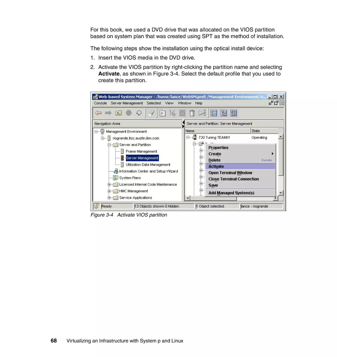
3.4.2 Installing VIOS software . . . . . . . . . . . . . . . . . . . . . . . . . . . . . . . . . . 67
3.5 Configuring the Virtual I/O Server . . . . . . . . . . . . . . . . . . . . . . . . . . . . . . . 71
3.5.1 Command line interface . . . . . . . . . . . . . . . . . . . . . . . . . . . . . . . . . . 72
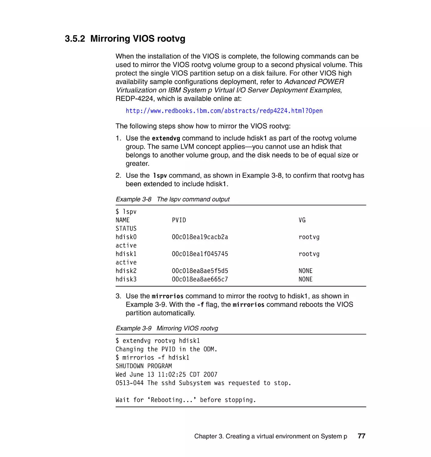
3.5.2 Mirroring VIOS rootvg . . . . . . . . . . . . . . . . . . . . . . . . . . . . . . . . . . . . 77
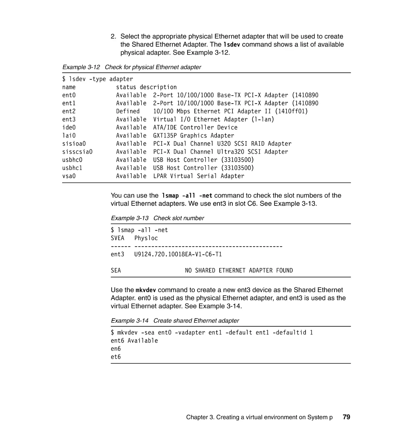
3.5.3 Creating a Shared Ethernet Adapter . . . . . . . . . . . . . . . . . . . . . . . . . 78
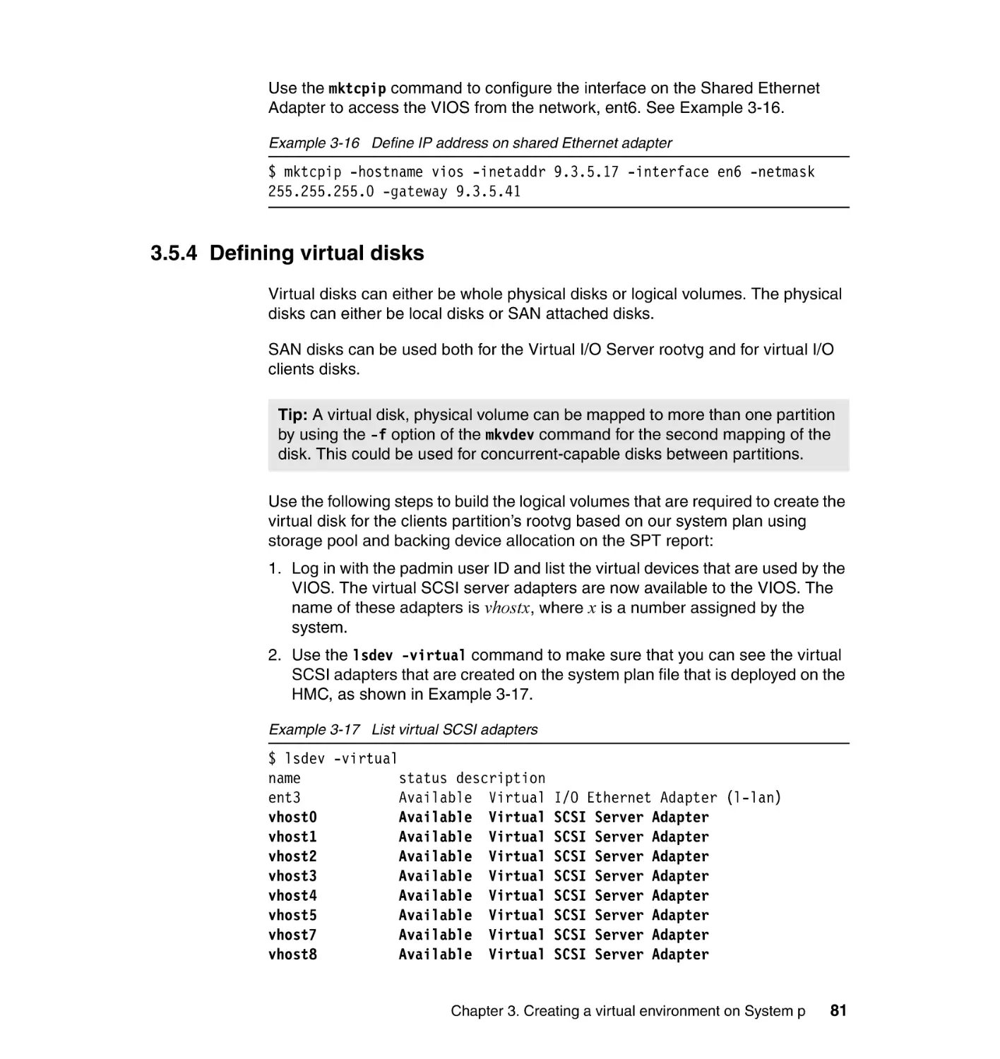
3.5.4 Defining virtual disks . . . . . . . . . . . . . . . . . . . . . . . . . . . . . . . . . . . . . 81
3.6 Installing the client Linux partition . . . . . . . . . . . . . . . . . . . . . . . . . . . . . . . 87
3.6.1 Installation tools for Linux on POWER . . . . . . . . . . . . . . . . . . . . . . . 87
3.7 Installing service and productivity tools for Linux on POWER. . . . . . . . . . 88
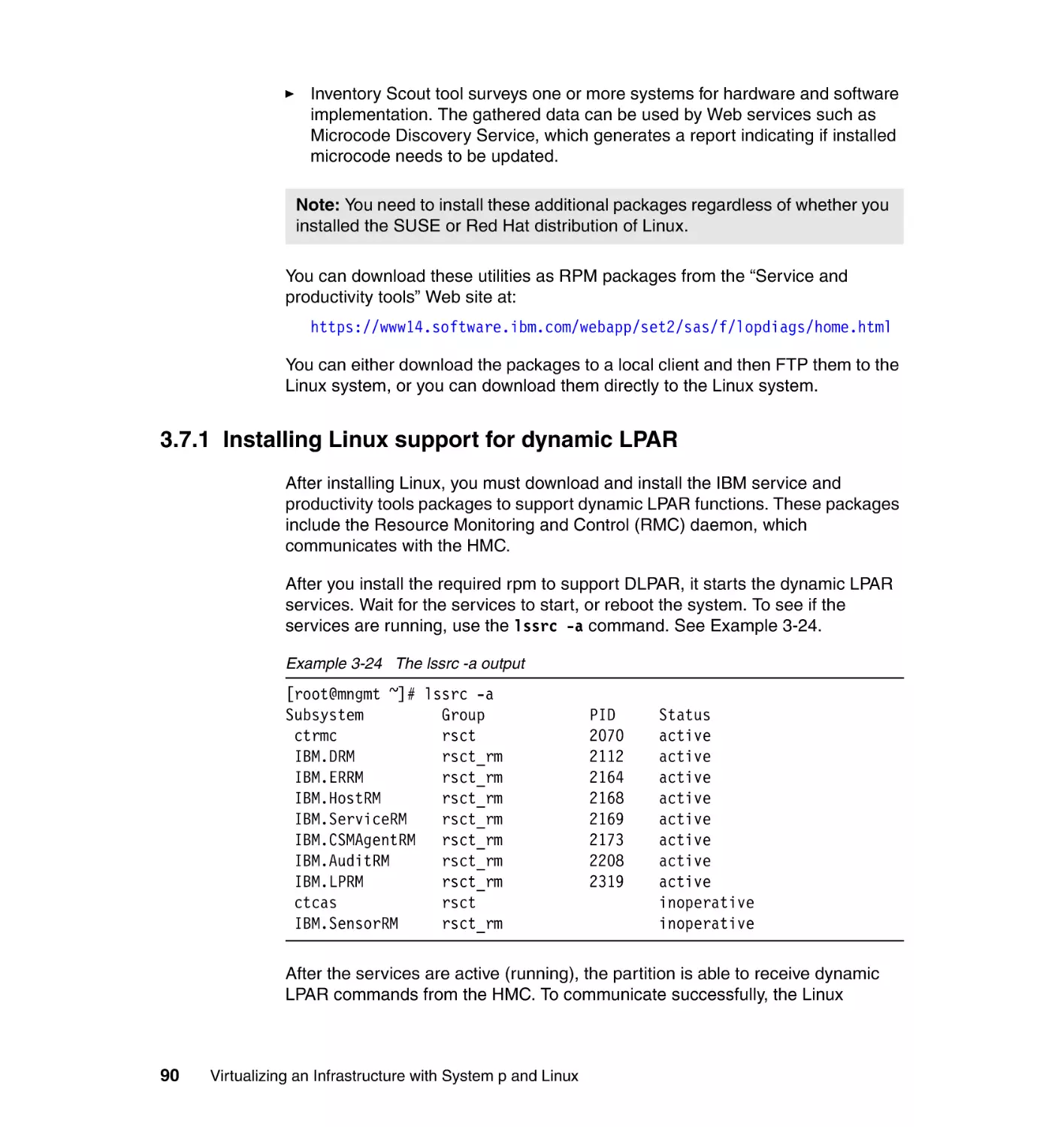
3.7.1 Installing Linux support for dynamic LPAR . . . . . . . . . . . . . . . . . . . . 90
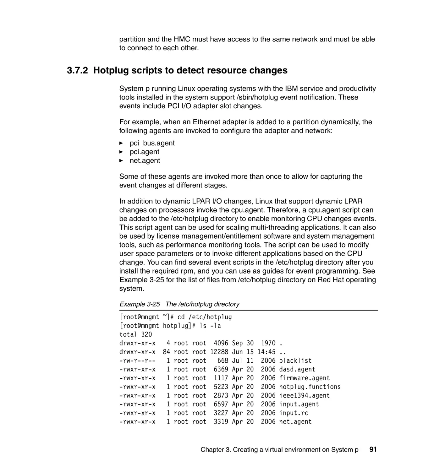
3.7.2 Hotplug scripts to detect resource changes . . . . . . . . . . . . . . . . . . . 91
Chapter 4. Installing and configuring Linux infrastructure services . . . . 93
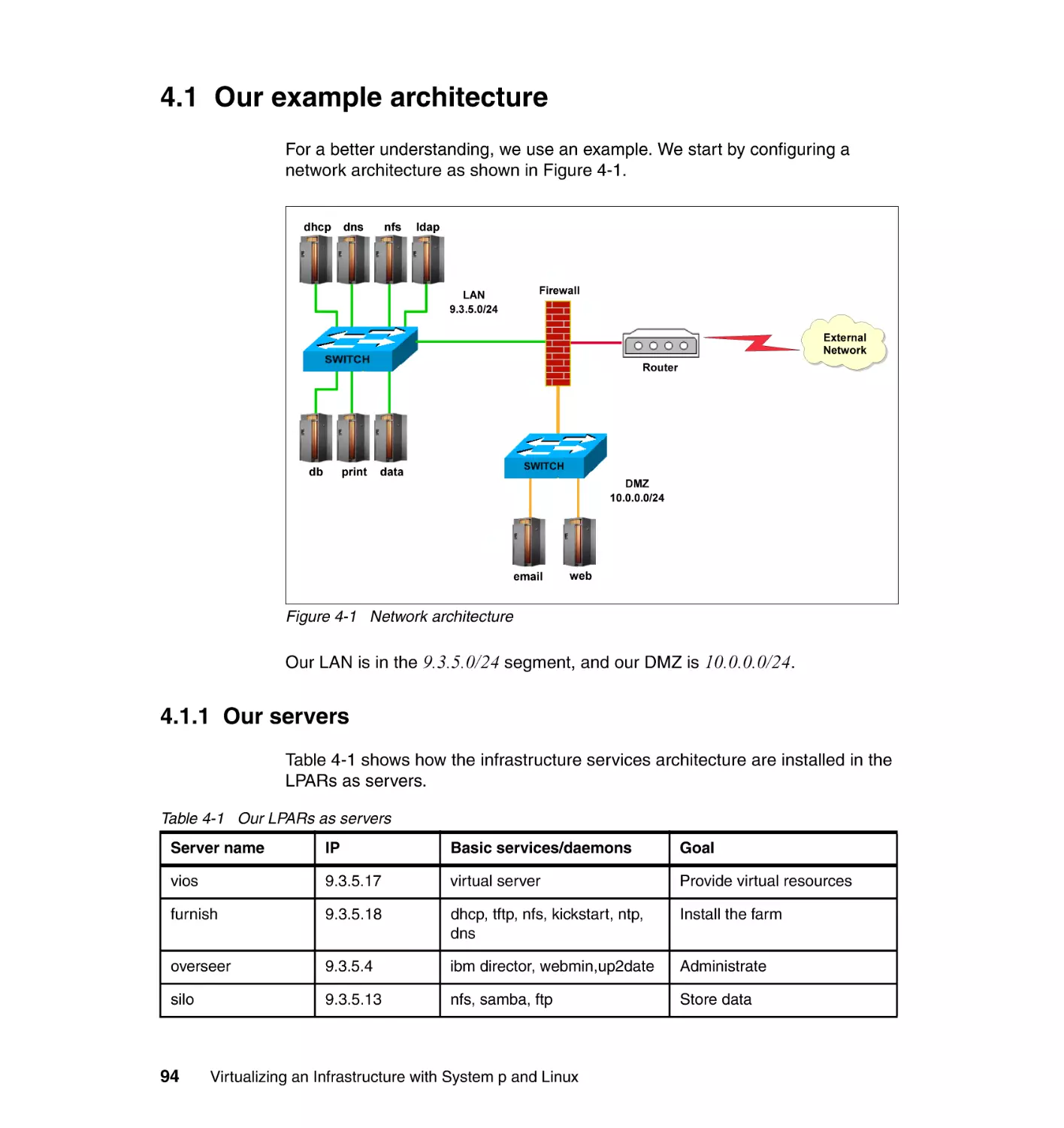
4.1 Our example architecture . . . . . . . . . . . . . . . . . . . . . . . . . . . . . . . . . . . . . 94
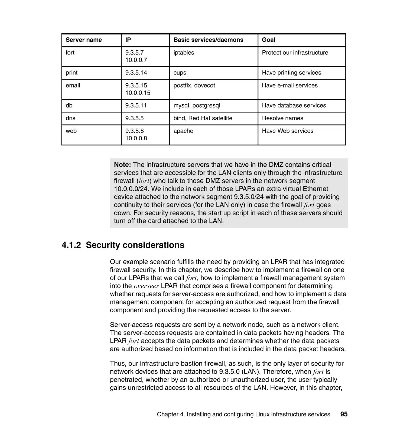
4.1.1 Our servers . . . . . . . . . . . . . . . . . . . . . . . . . . . . . . . . . . . . . . . . . . . . 94
4.1.2 Security considerations . . . . . . . . . . . . . . . . . . . . . . . . . . . . . . . . . . . 95
iv
Virtualizing an Infrastructure with System p and Linux
4.2 Installation prerequisites . . . . . . . . . . . . . . . . . . . . . . . . . . . . . . . . . . . . . . 96
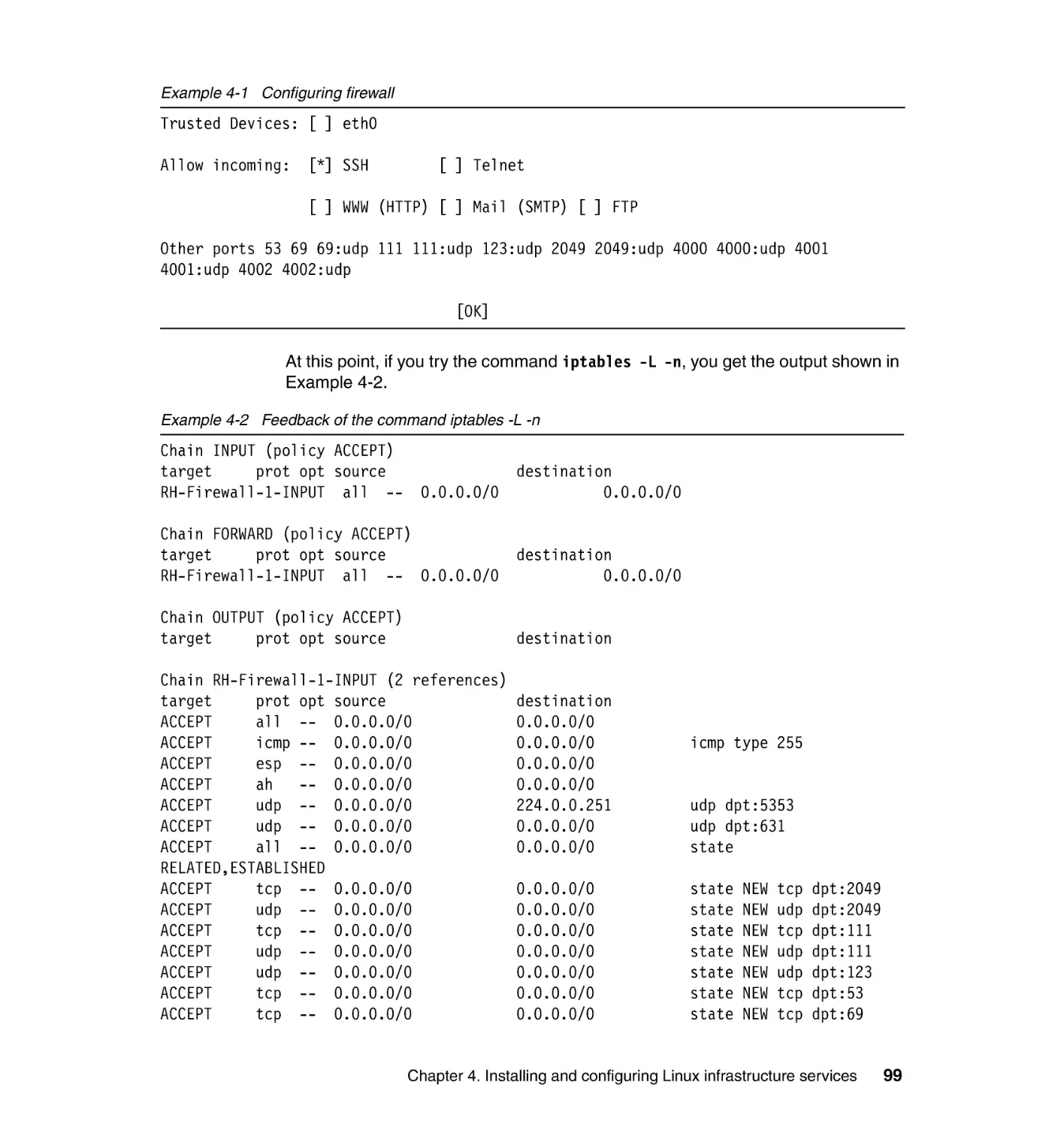
4.3 Installing and configuring Linux infrastructure services . . . . . . . . . . . . . . . 96
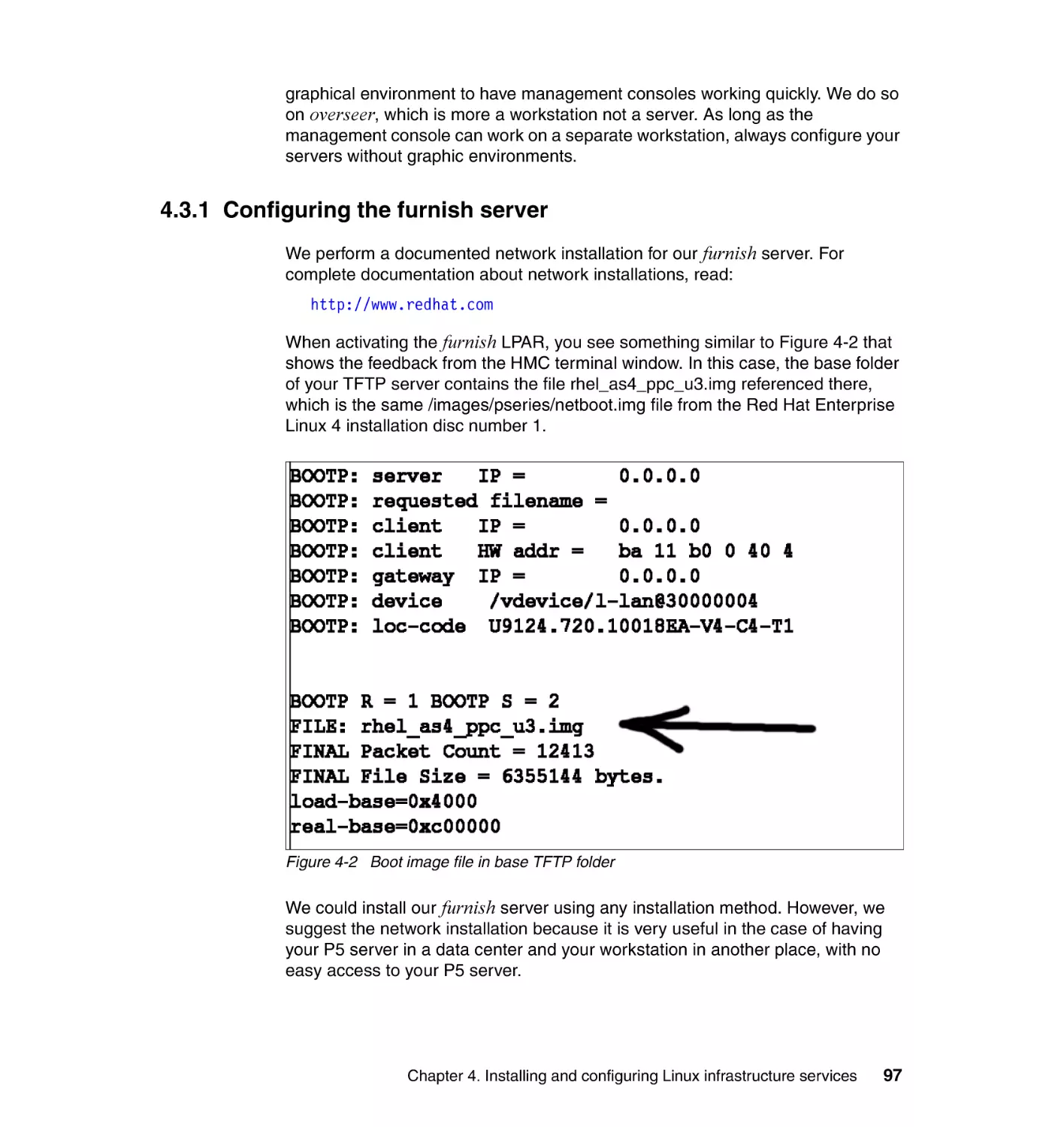
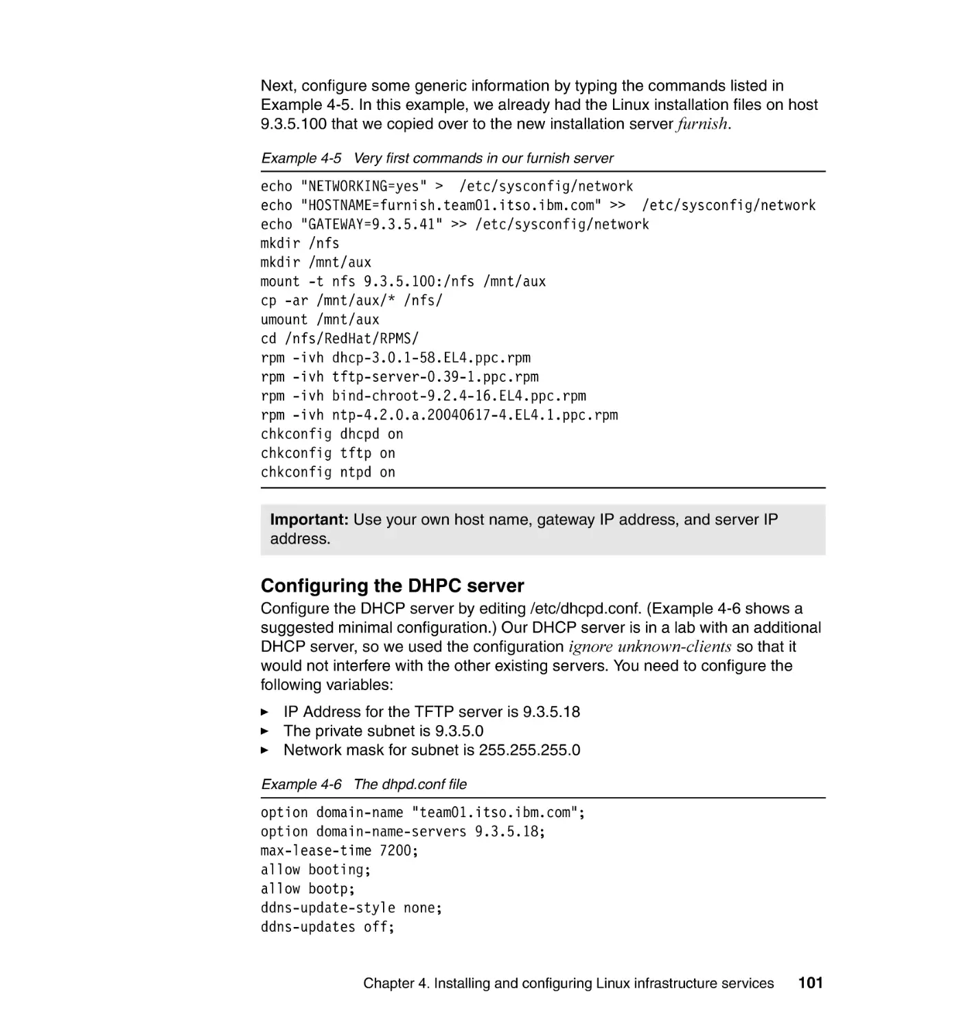
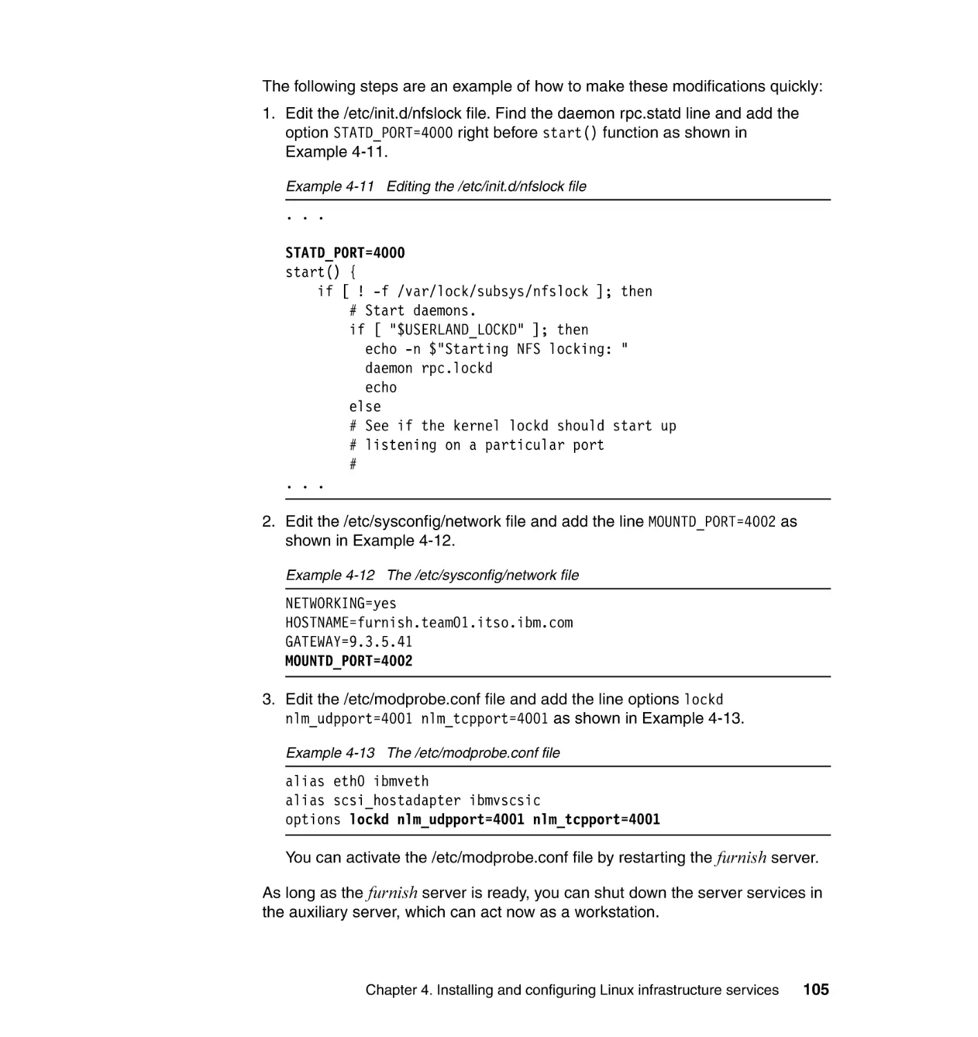
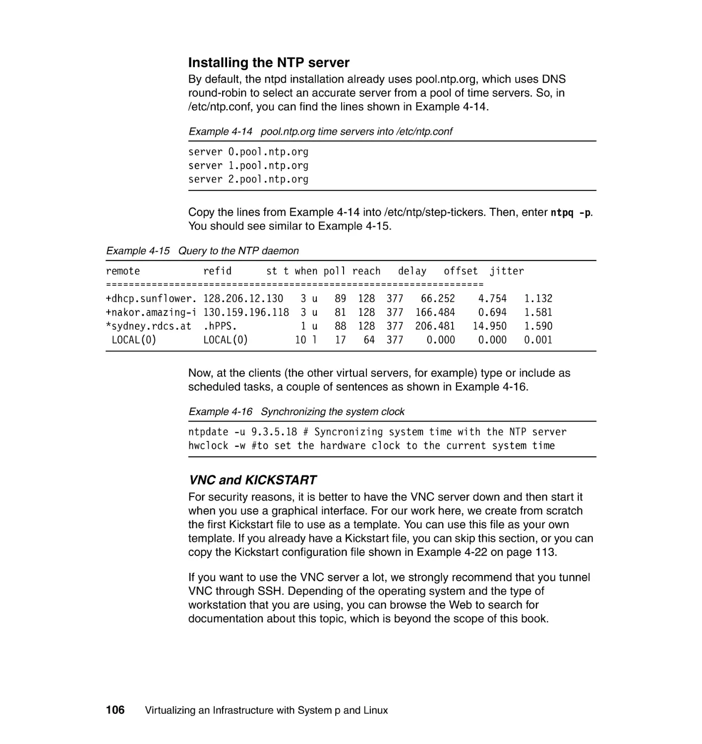
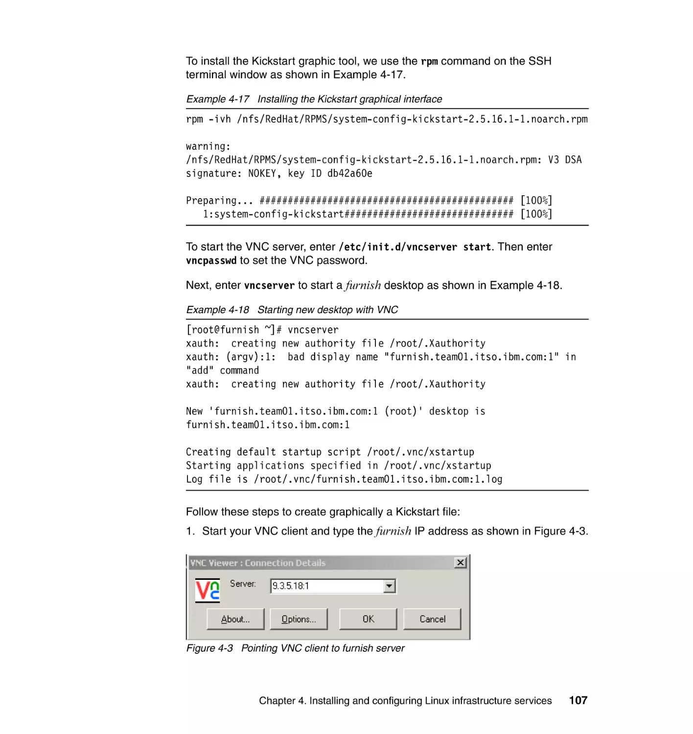
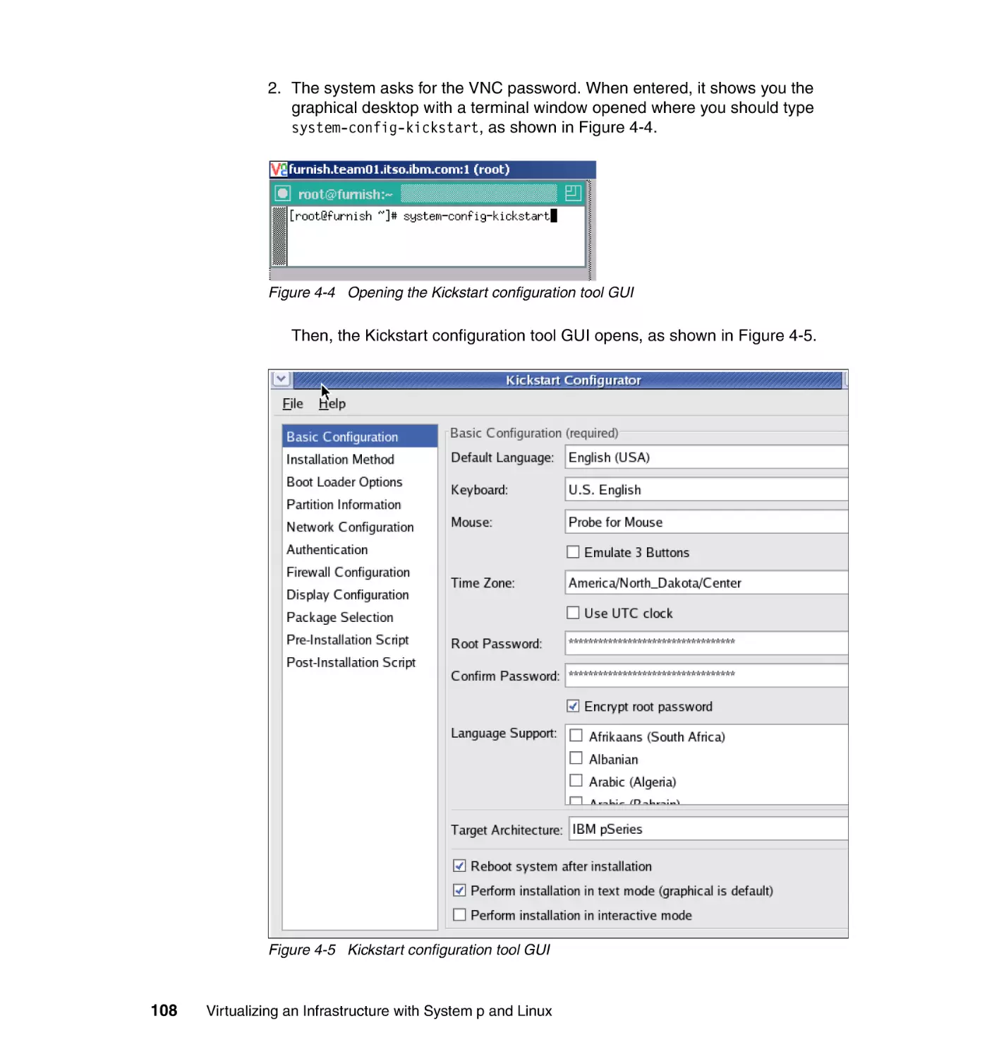
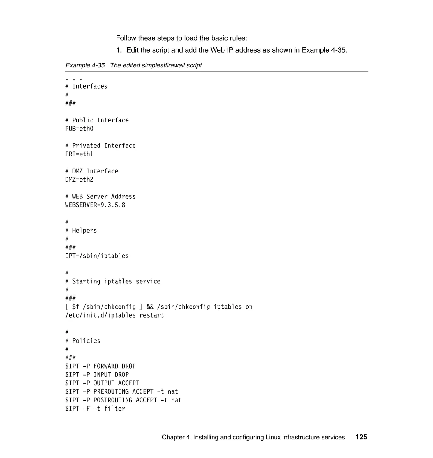
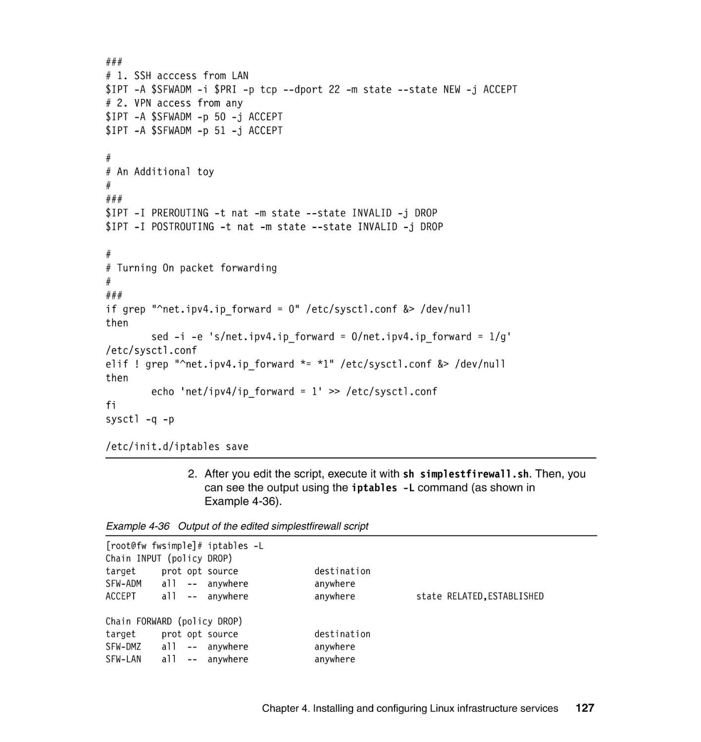
4.3.1 Configuring the furnish server . . . . . . . . . . . . . . . . . . . . . . . . . . . . . . 97
4.3.2 Installing the remaining servers . . . . . . . . . . . . . . . . . . . . . . . . . . . 114
4.4 Migrating current Red Hat Enterprise Linux servers . . . . . . . . . . . . . . . . 130
4.4.1 Planning for the migration . . . . . . . . . . . . . . . . . . . . . . . . . . . . . . . . 130
4.4.2 Completing the pre-installation tasks . . . . . . . . . . . . . . . . . . . . . . . 130
4.4.3 Migrating . . . . . . . . . . . . . . . . . . . . . . . . . . . . . . . . . . . . . . . . . . . . . 131
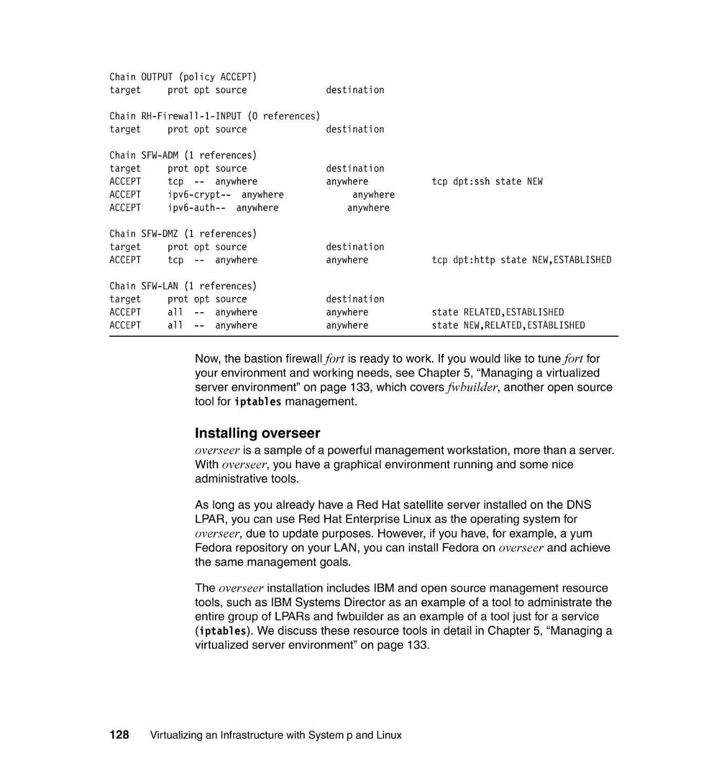
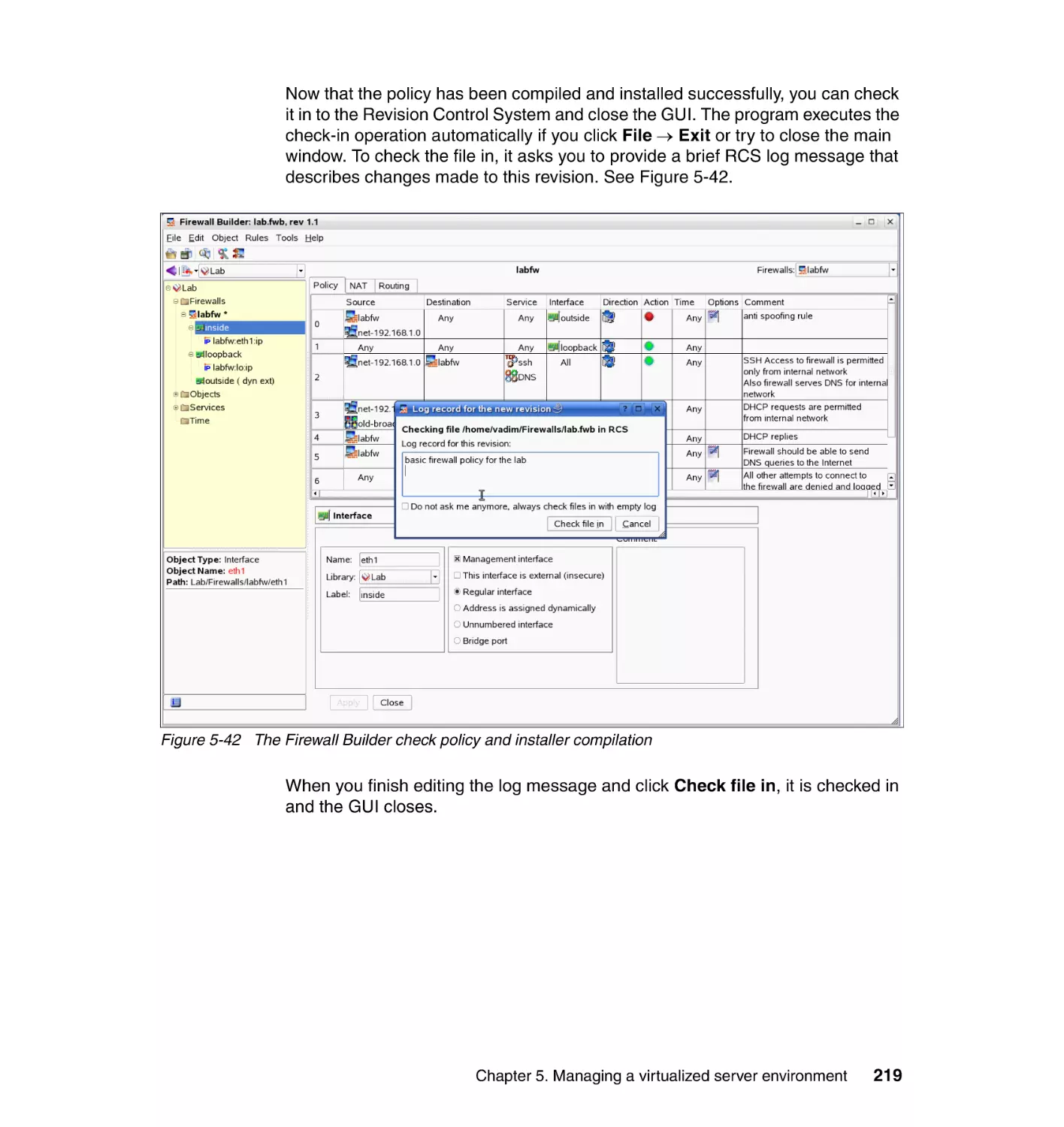
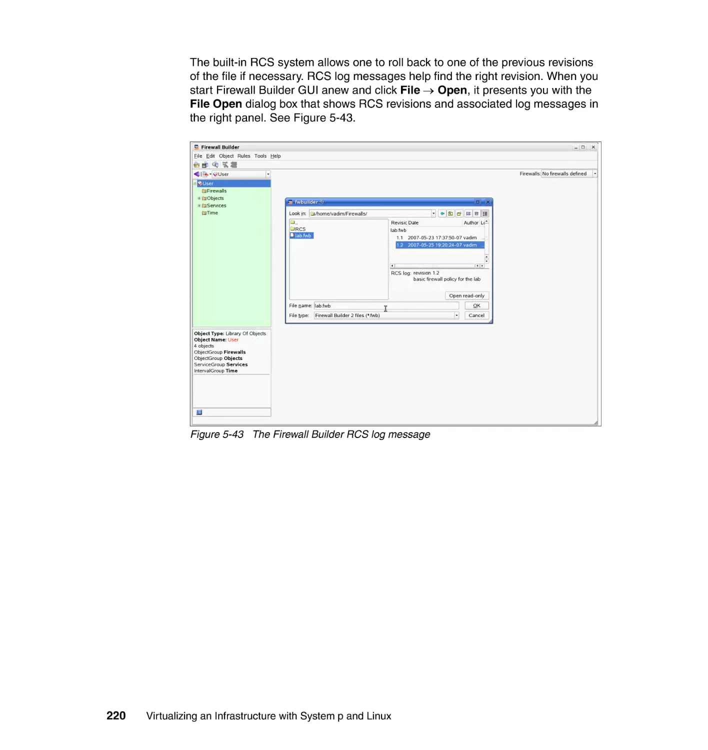
Chapter 5. Managing a virtualized server environment . . . . . . . . . . . . . . 133
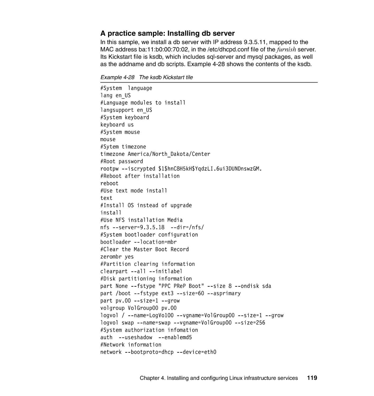
5.1 Hardware Management Console. . . . . . . . . . . . . . . . . . . . . . . . . . . . . . . 134
5.2 Integrated Virtualization Manager . . . . . . . . . . . . . . . . . . . . . . . . . . . . . . 134
5.3 Virtual I/O Server. . . . . . . . . . . . . . . . . . . . . . . . . . . . . . . . . . . . . . . . . . . 135
5.4 IBM Systems Director . . . . . . . . . . . . . . . . . . . . . . . . . . . . . . . . . . . . . . . 136
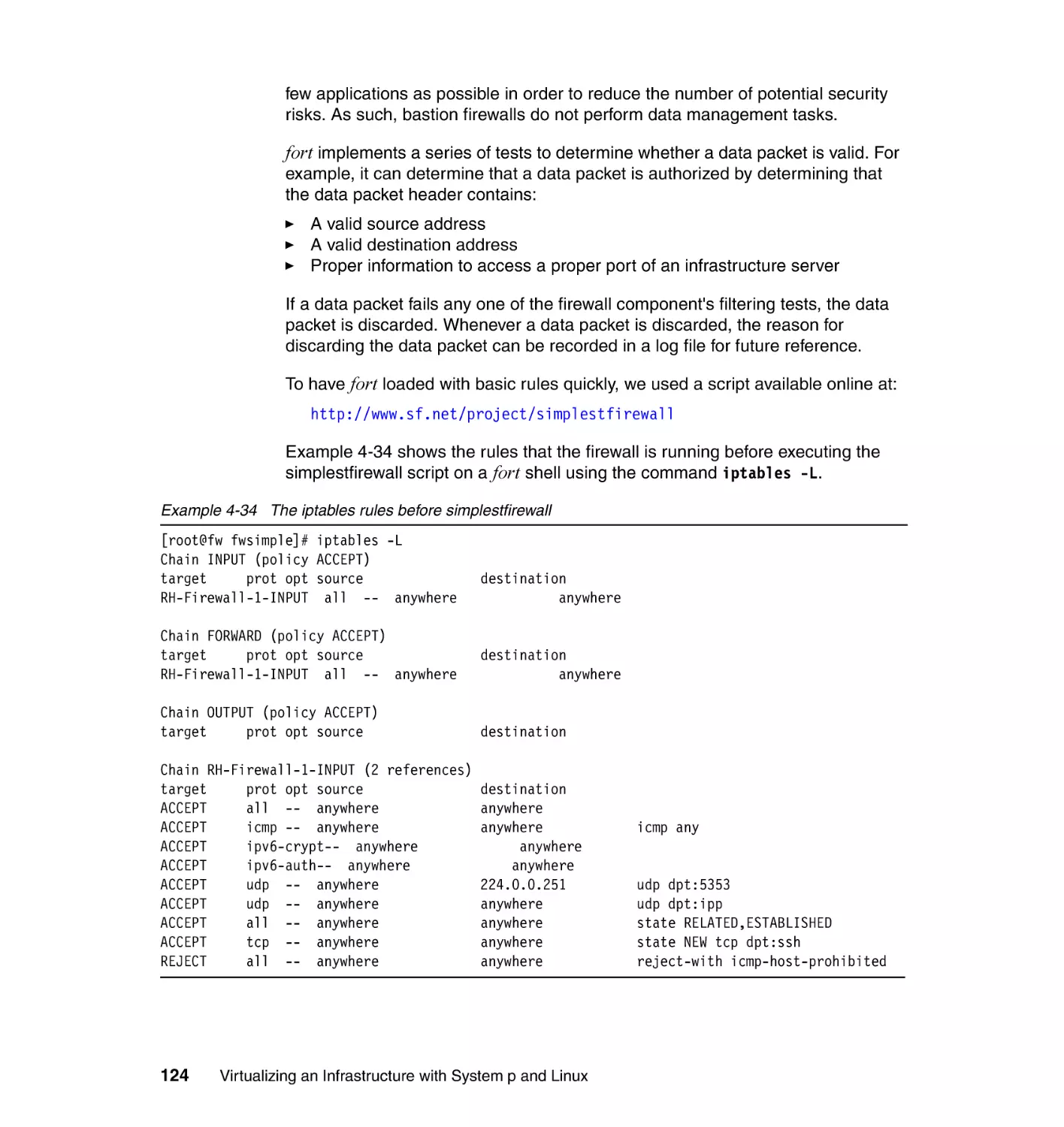
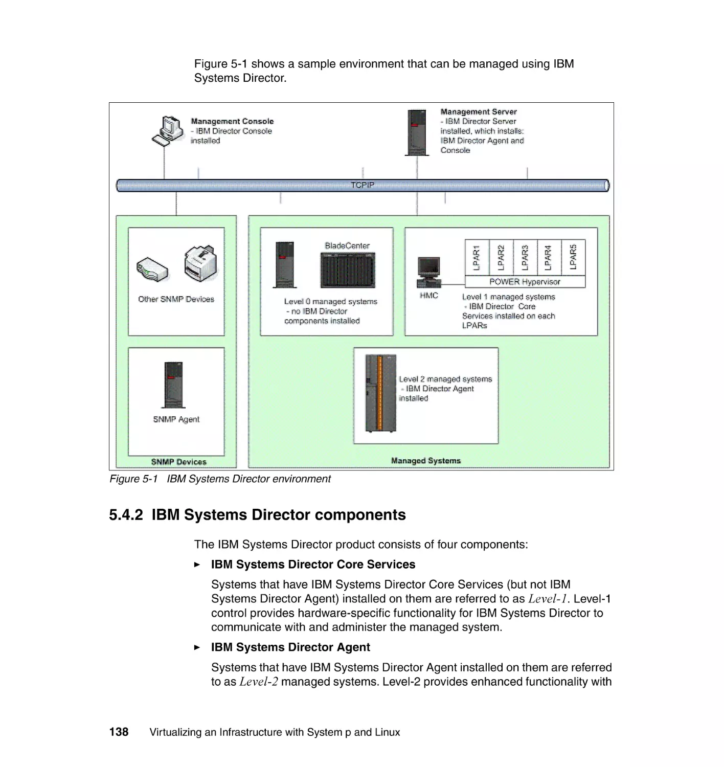
5.4.1 IBM Systems Director environment. . . . . . . . . . . . . . . . . . . . . . . . . 137
5.4.2 IBM Systems Director components . . . . . . . . . . . . . . . . . . . . . . . . . 138
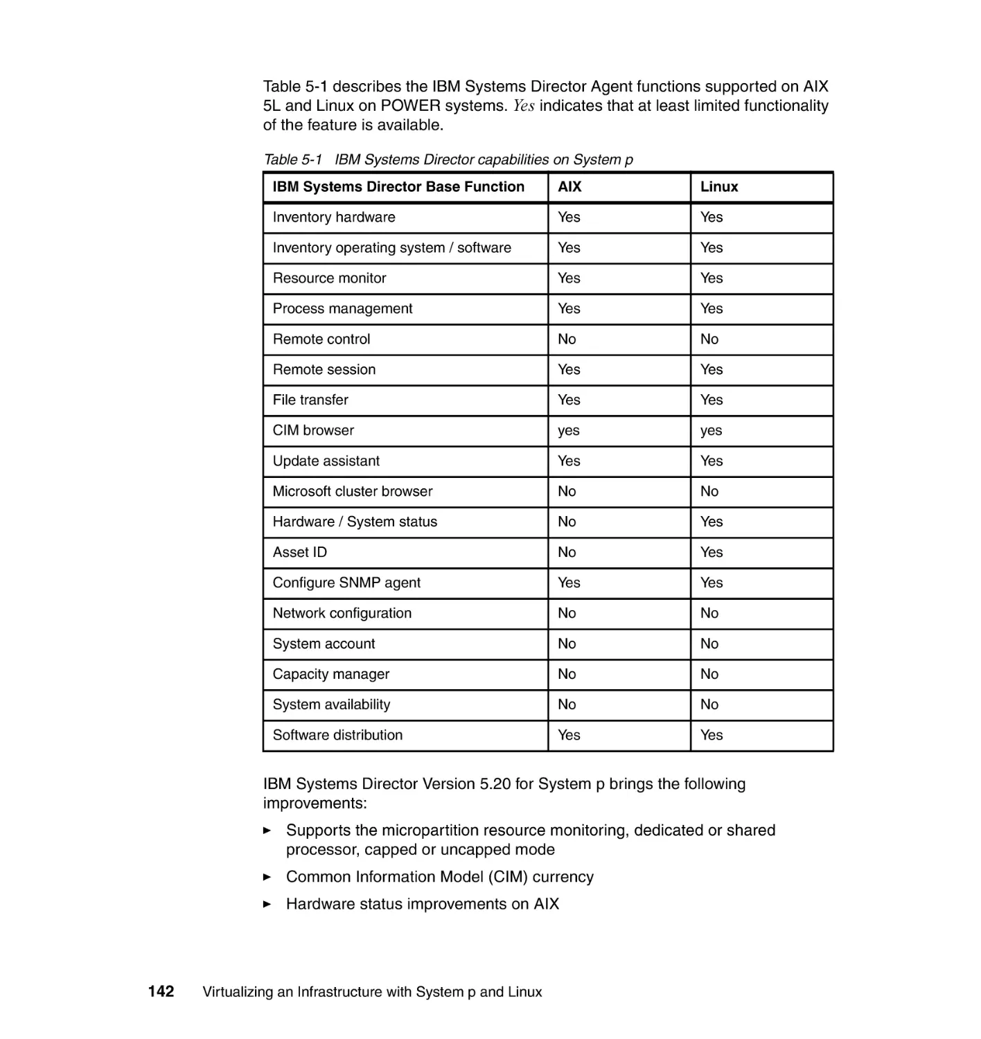
5.4.3 IBM Systems Director capabilities on System p . . . . . . . . . . . . . . . 139
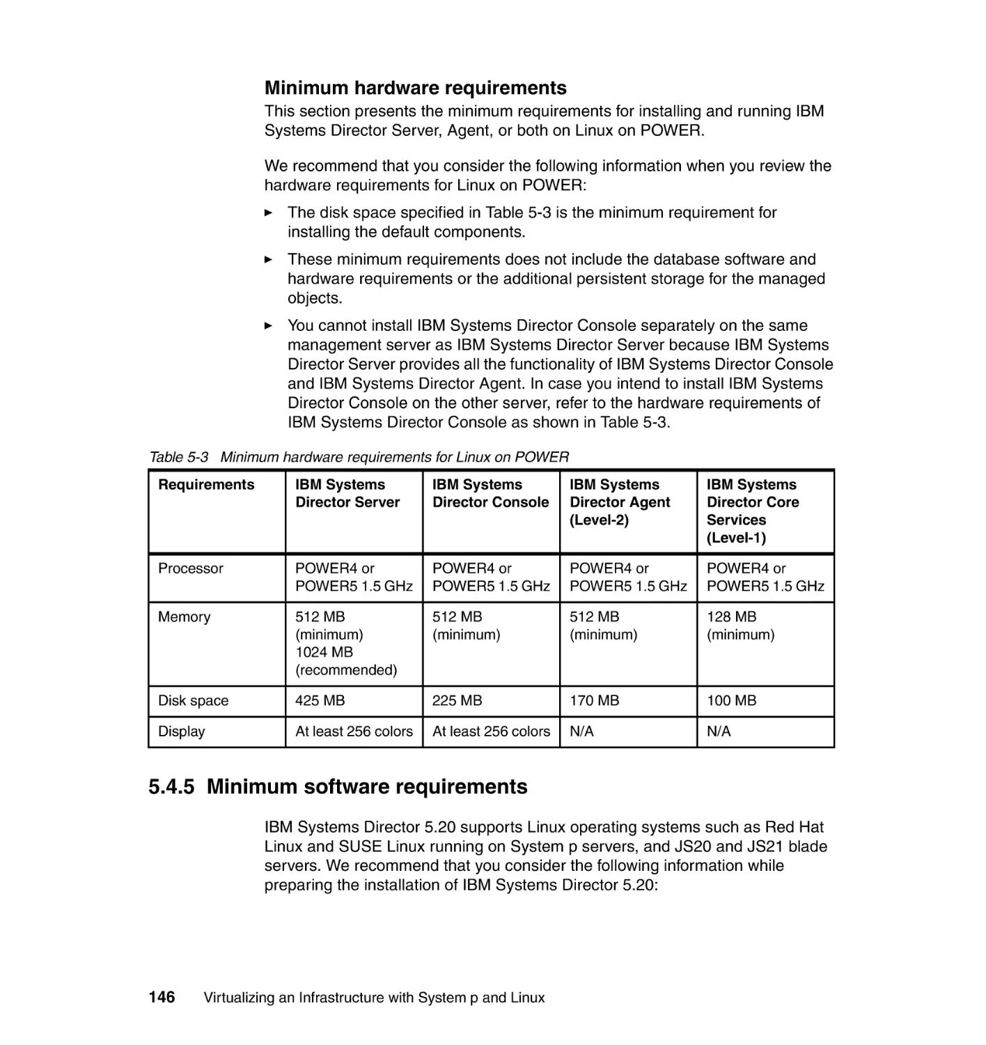
5.4.4 Installation on Linux on POWER . . . . . . . . . . . . . . . . . . . . . . . . . . . 145
5.4.5 Minimum software requirements . . . . . . . . . . . . . . . . . . . . . . . . . . . 146
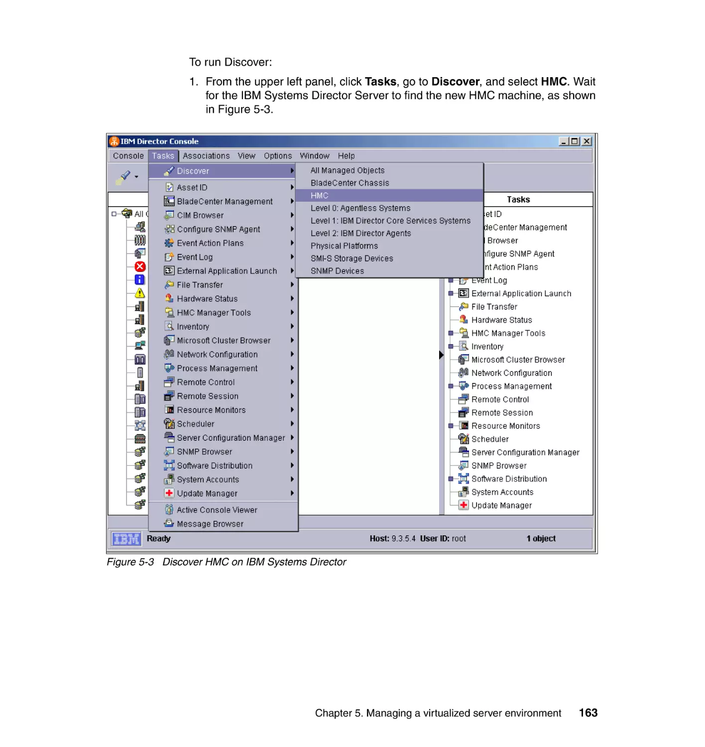
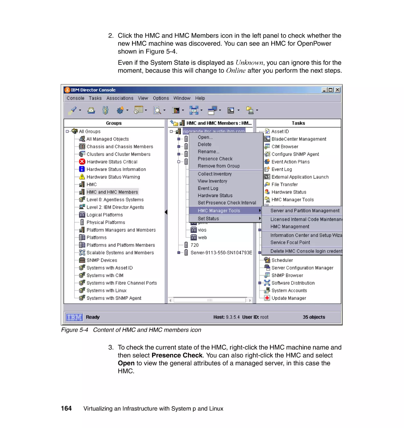
5.4.6 HMC managed environment . . . . . . . . . . . . . . . . . . . . . . . . . . . . . . 161
5.4.7 IVM managed environment . . . . . . . . . . . . . . . . . . . . . . . . . . . . . . . 171
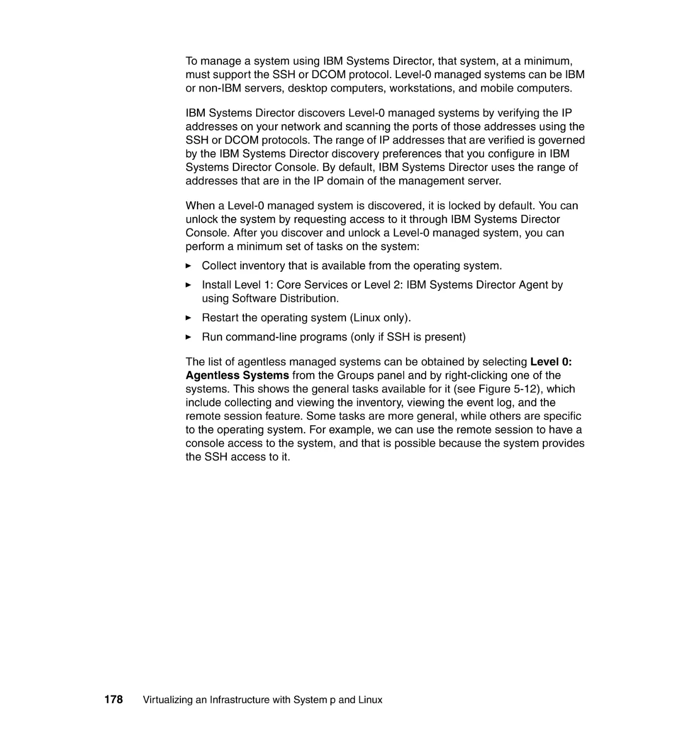
5.4.8 Managing agentless environment . . . . . . . . . . . . . . . . . . . . . . . . . . 177
5.4.9 Monitoring system resources . . . . . . . . . . . . . . . . . . . . . . . . . . . . . 181
5.4.10 Event management using IBM Systems Director . . . . . . . . . . . . . 182
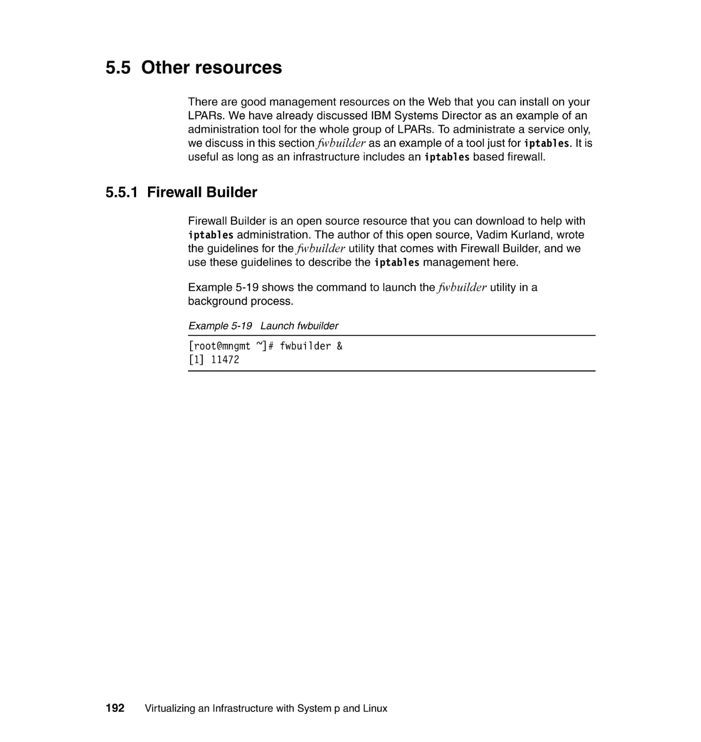
5.5 Other resources. . . . . . . . . . . . . . . . . . . . . . . . . . . . . . . . . . . . . . . . . . . . 192
5.5.1 Firewall Builder . . . . . . . . . . . . . . . . . . . . . . . . . . . . . . . . . . . . . . . . 192
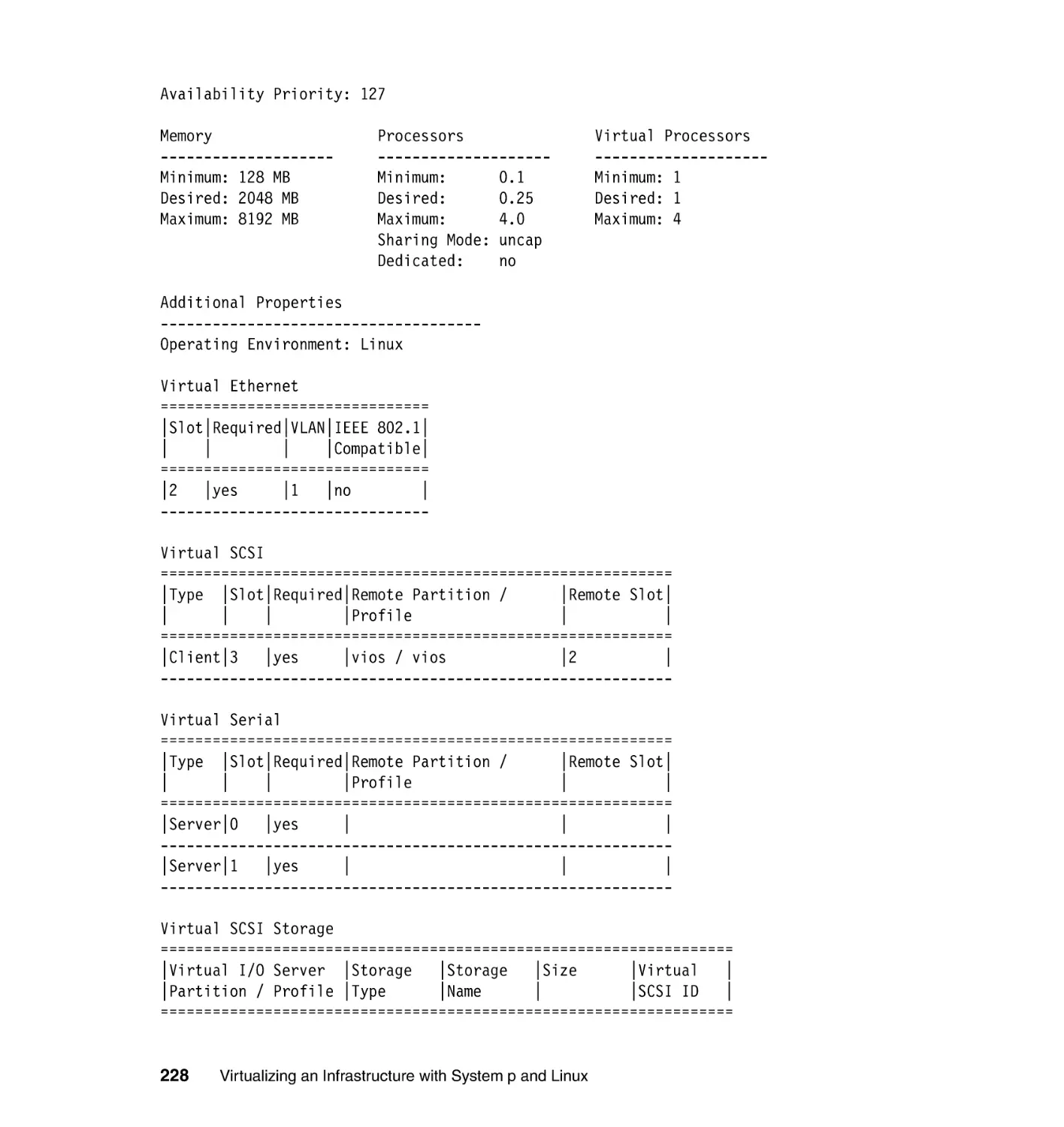
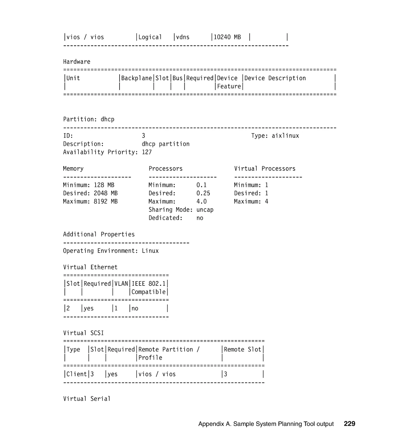
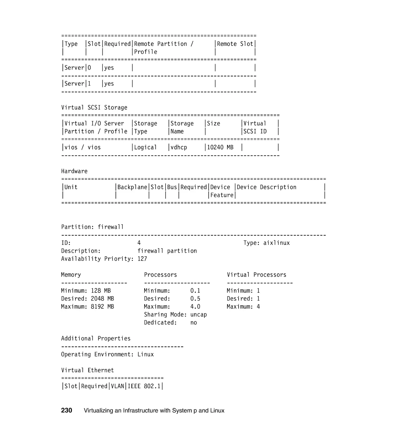
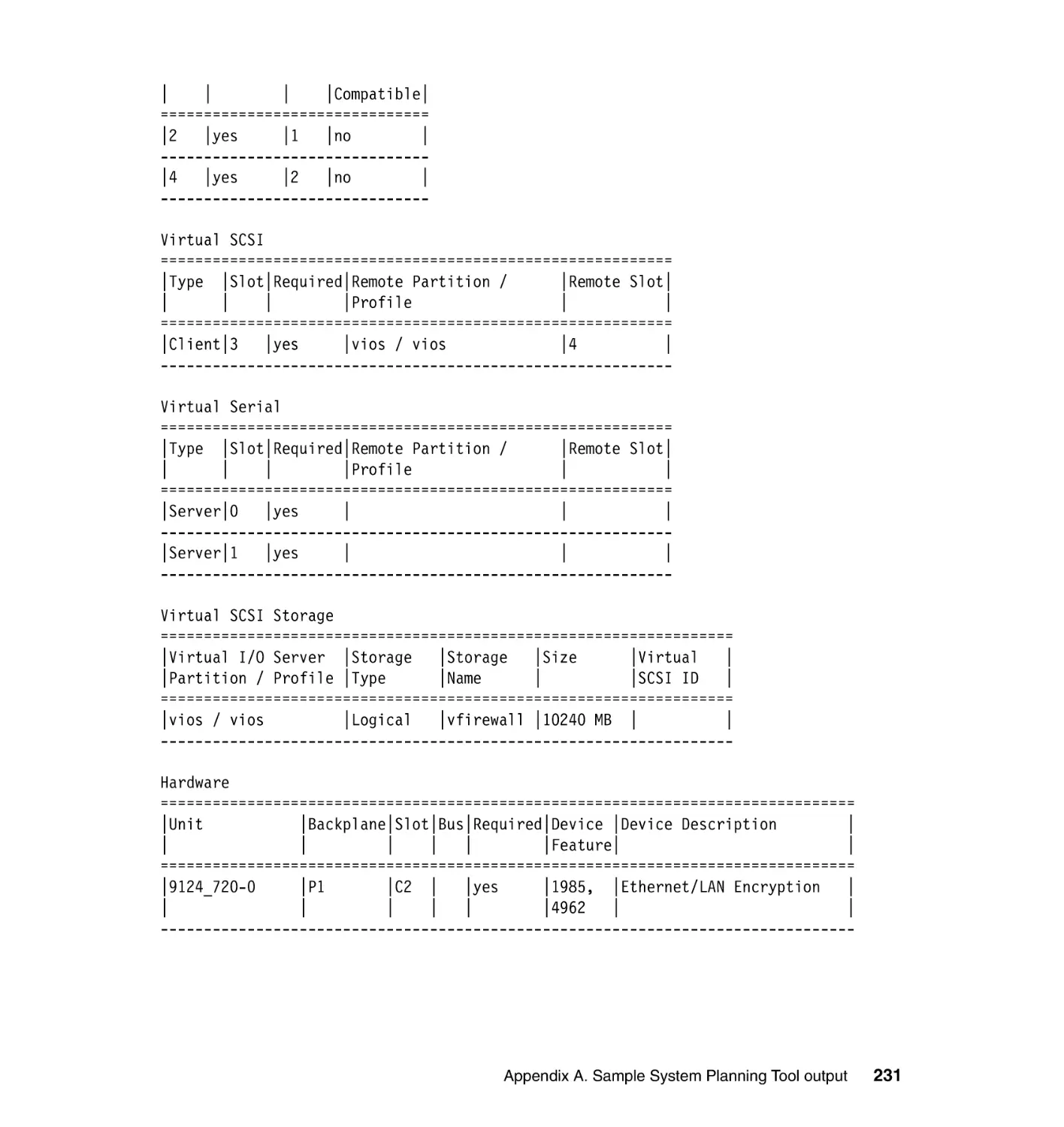
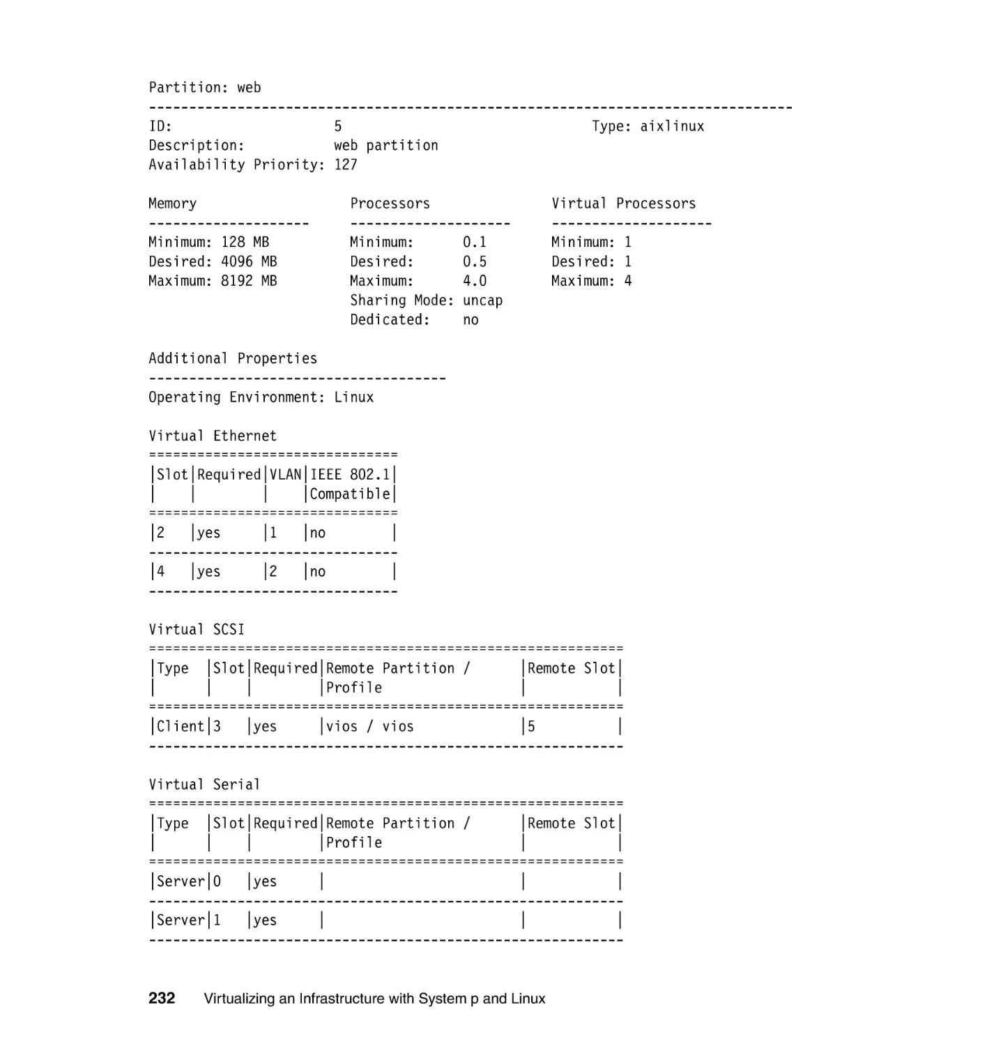
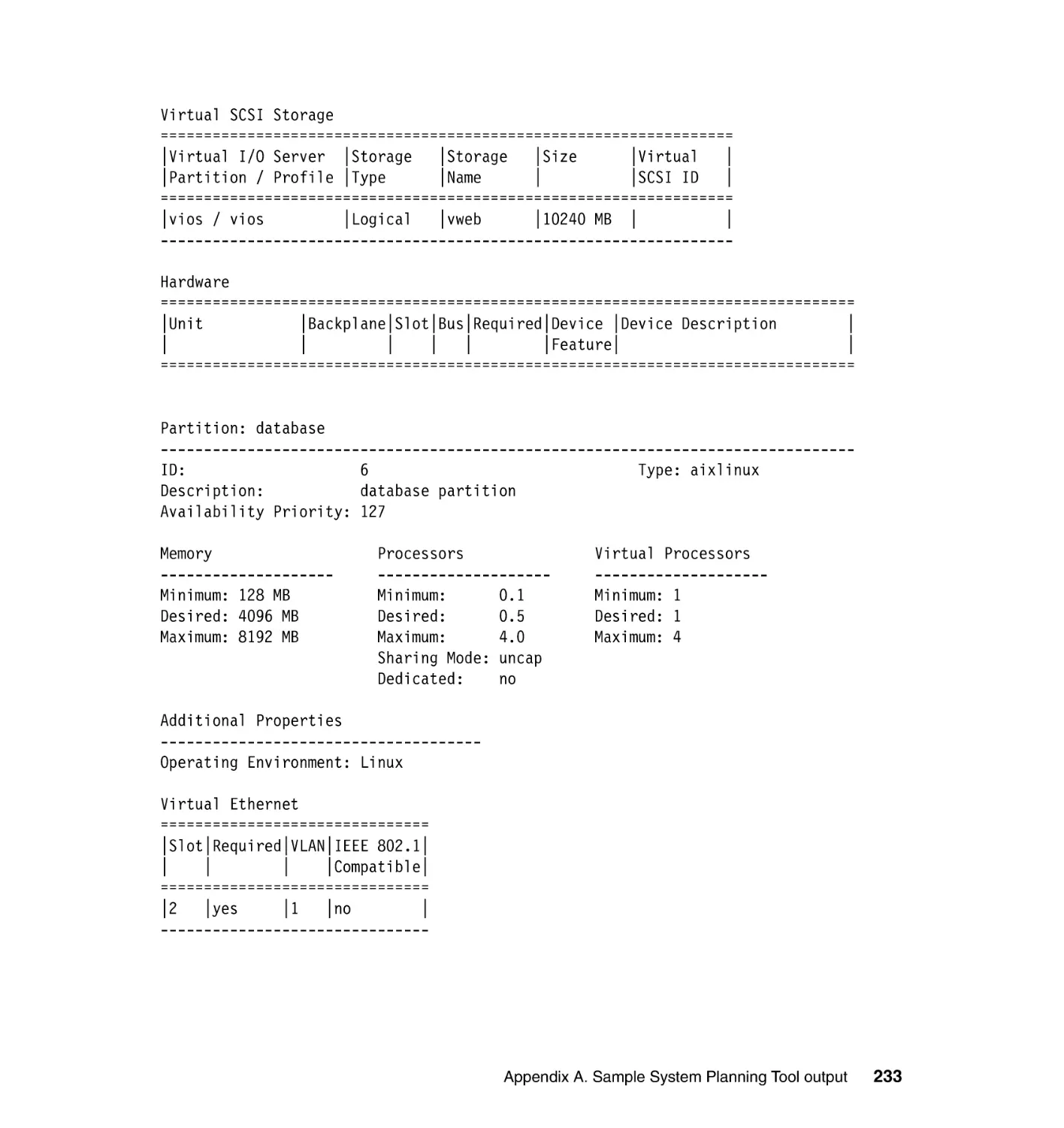
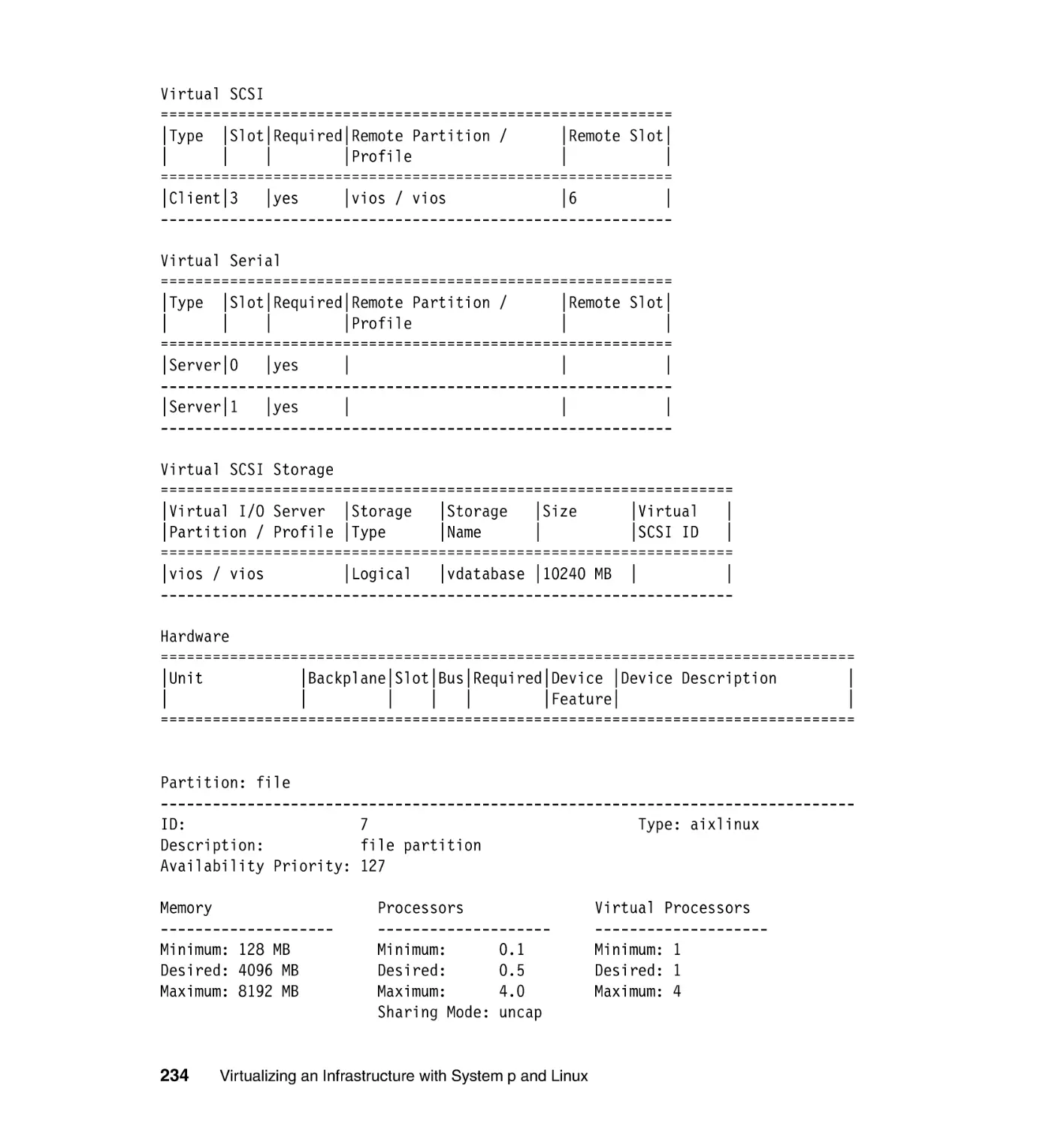
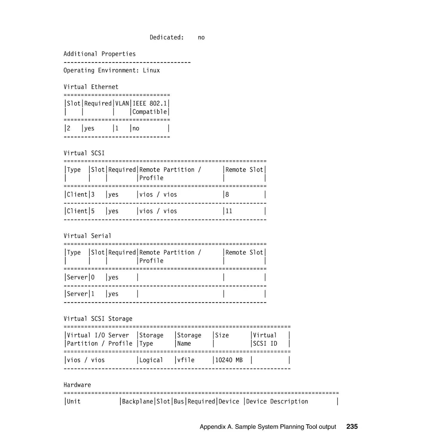
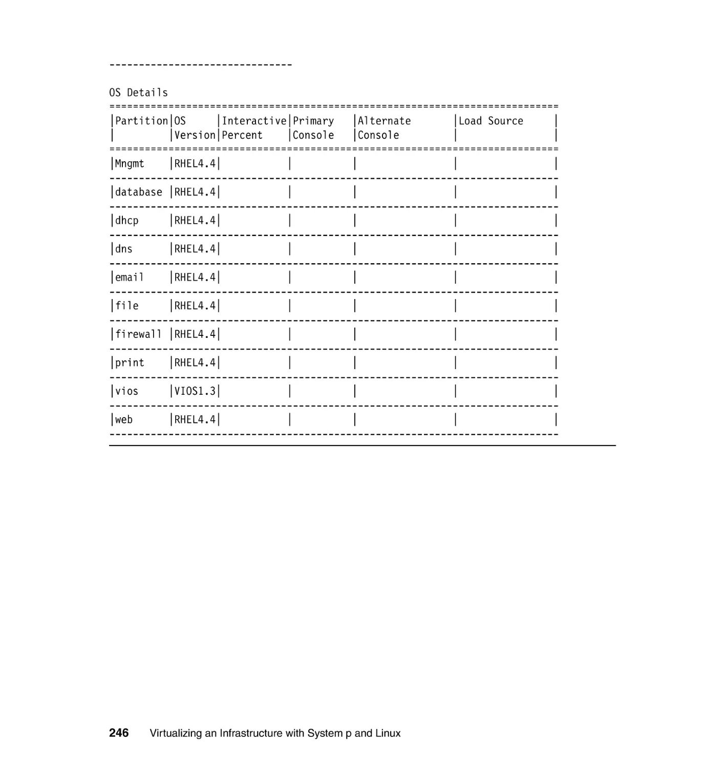
Appendix A. Sample System Planning Tool output . . . . . . . . . . . . . . . . . 221
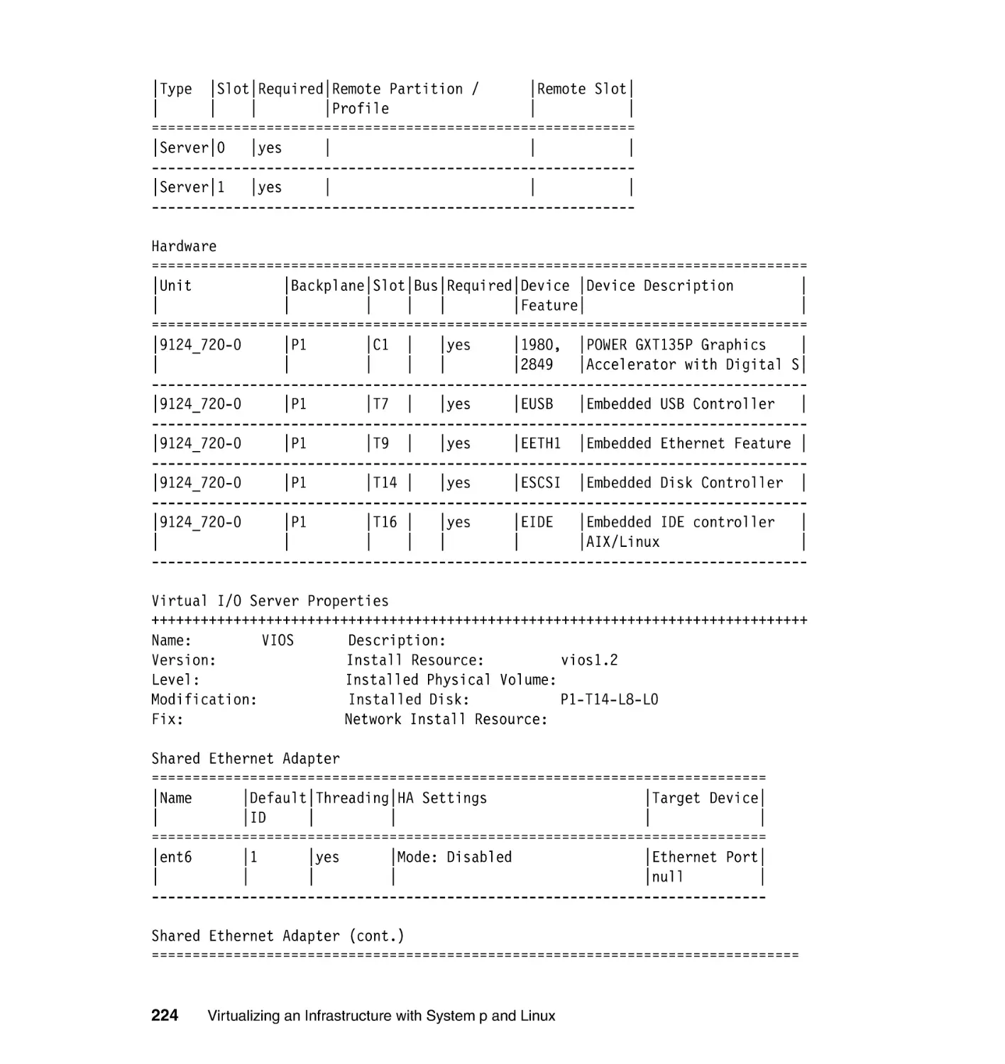
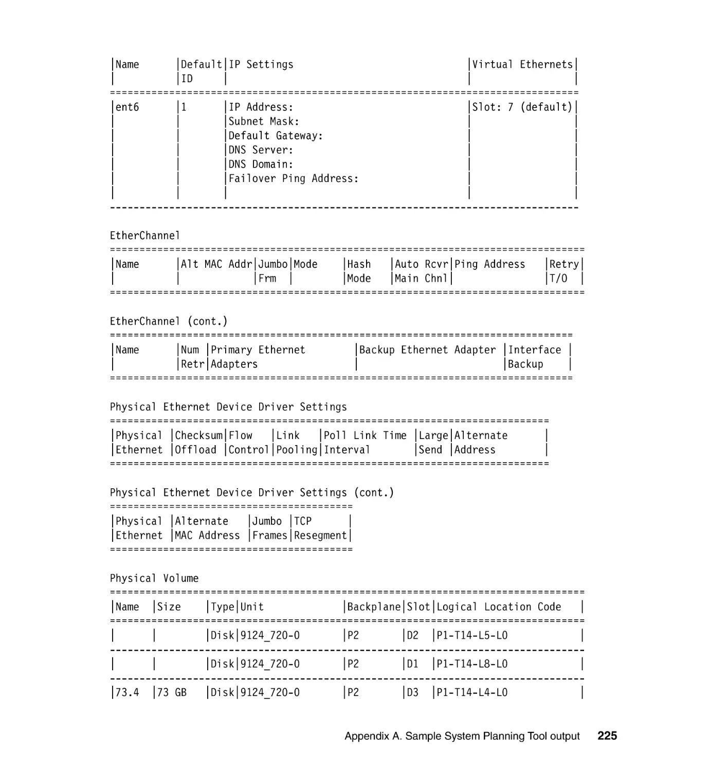
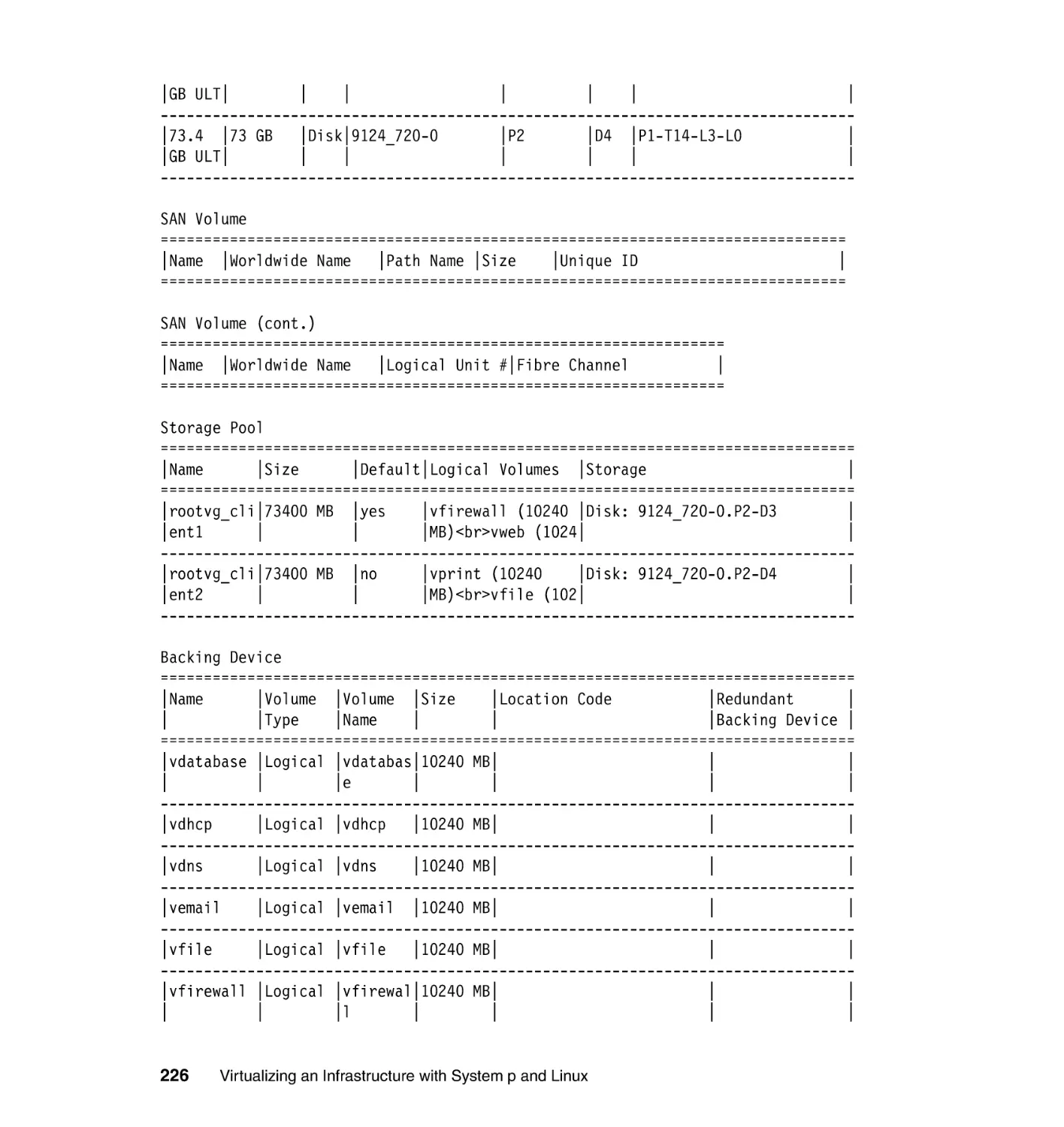
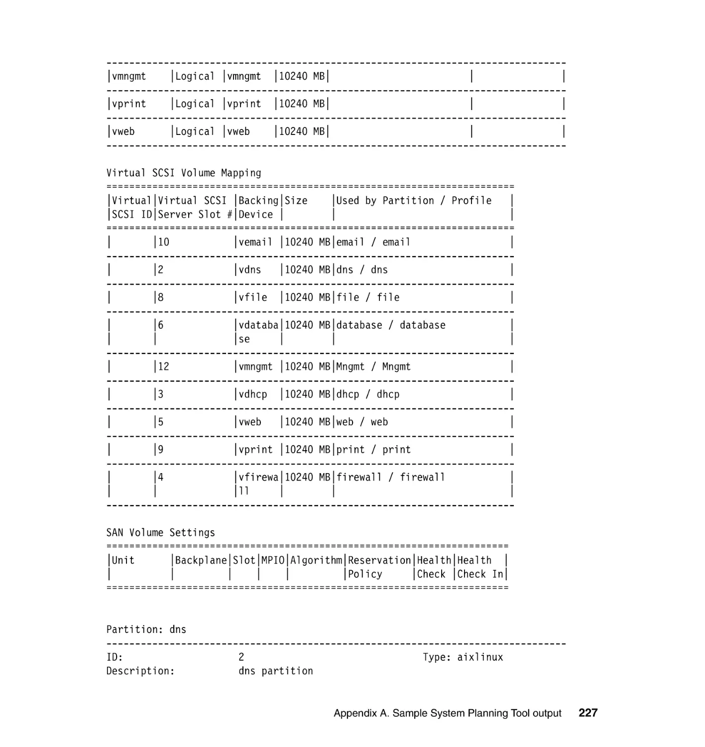
Sample SPT report. . . . . . . . . . . . . . . . . . . . . . . . . . . . . . . . . . . . . . . . . . . . . 222
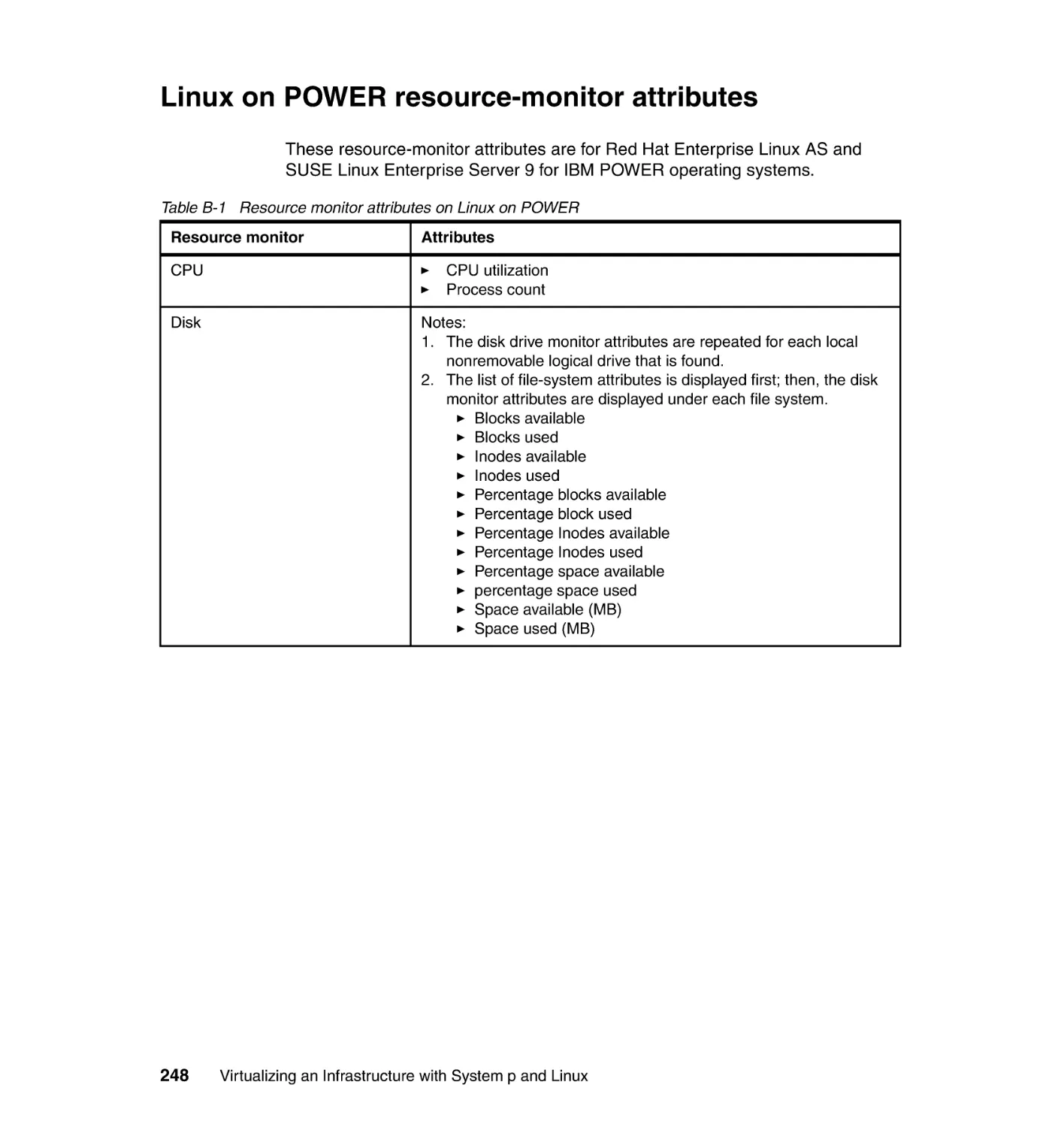
Appendix B. Resource monitor attributes on Linux on POWER. . . . . . . 247
Linux on POWER resource-monitor attributes . . . . . . . . . . . . . . . . . . . . . . . . 248
Related publications . . . . . . . . . . . . . . . . . . . . . . . . . . . . . . . . . . . . . . . . . . 251
IBM Redbooks . . . . . . . . . . . . . . . . . . . . . . . . . . . . . . . . . . . . . . . . . . . . . . . . 251
Online resources . . . . . . . . . . . . . . . . . . . . . . . . . . . . . . . . . . . . . . . . . . . . . . 251
How to get IBM Redbooks publications . . . . . . . . . . . . . . . . . . . . . . . . . . . . . 255
Help from IBM . . . . . . . . . . . . . . . . . . . . . . . . . . . . . . . . . . . . . . . . . . . . . . . . 255
Index . . . . . . . . . . . . . . . . . . . . . . . . . . . . . . . . . . . . . . . . . . . . . . . . . . . . . . . 257
Contents
v
vi
Virtualizing an Infrastructure with System p and Linux
Notices
This information was developed for products and services offered in the U.S.A.
IBM may not offer the products, services, or features discussed in this document in other countries. Consult
your local IBM representative for information on the products and services currently available in your area.
Any reference to an IBM product, program, or service is not intended to state or imply that only that IBM
product, program, or service may be used. Any functionally equivalent product, program, or service that
does not infringe any IBM intellectual property right may be used instead. However, it is the user's
responsibility to evaluate and verify the operation of any non-IBM product, program, or service.
IBM may have patents or pending patent applications covering subject matter described in this document.
The furnishing of this document does not give you any license to these patents. You can send license
inquiries, in writing, to:
IBM Director of Licensing, IBM Corporation, North Castle Drive, Armonk, NY 10504-1785 U.S.A.
The following paragraph does not apply to the United Kingdom or any other country where such
provisions are inconsistent with local law: INTERNATIONAL BUSINESS MACHINES CORPORATION
PROVIDES THIS PUBLICATION "AS IS" WITHOUT WARRANTY OF ANY KIND, EITHER EXPRESS OR
IMPLIED, INCLUDING, BUT NOT LIMITED TO, THE IMPLIED WARRANTIES OF NON-INFRINGEMENT,
MERCHANTABILITY OR FITNESS FOR A PARTICULAR PURPOSE. Some states do not allow disclaimer
of express or implied warranties in certain transactions, therefore, this statement may not apply to you.
This information could include technical inaccuracies or typographical errors. Changes are periodically made
to the information herein; these changes will be incorporated in new editions of the publication. IBM may
make improvements and/or changes in the product(s) and/or the program(s) described in this publication at
any time without notice.
Any references in this information to non-IBM Web sites are provided for convenience only and do not in any
manner serve as an endorsement of those Web sites. The materials at those Web sites are not part of the
materials for this IBM product and use of those Web sites is at your own risk.
IBM may use or distribute any of the information you supply in any way it believes appropriate without
incurring any obligation to you.
Information concerning non-IBM products was obtained from the suppliers of those products, their published
announcements or other publicly available sources. IBM has not tested those products and cannot confirm
the accuracy of performance, compatibility or any other claims related to non-IBM products. Questions on
the capabilities of non-IBM products should be addressed to the suppliers of those products.
This information contains examples of data and reports used in daily business operations. To illustrate them
as completely as possible, the examples include the names of individuals, companies, brands, and products.
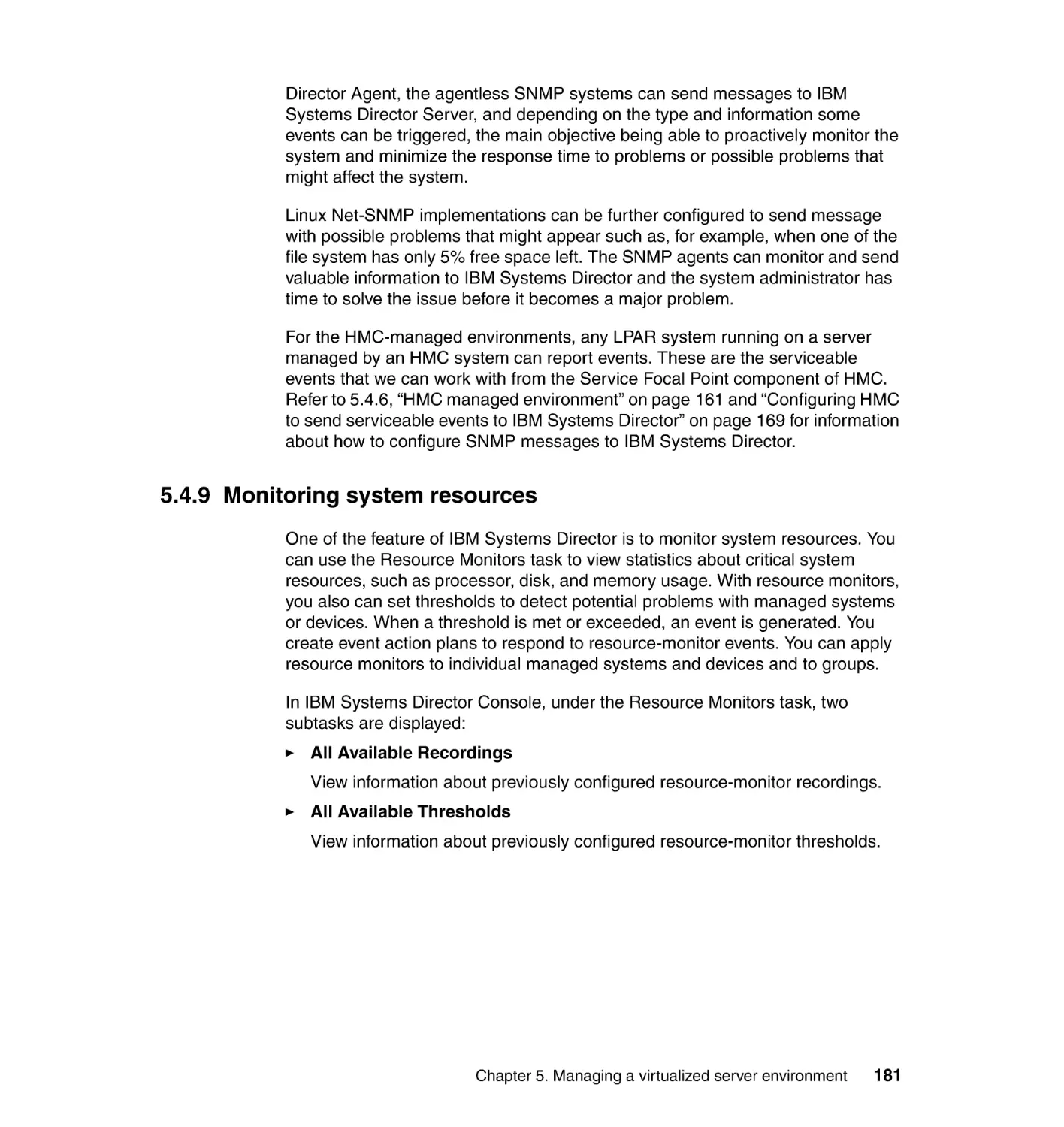
All of these names are fictitious and any similarity to the names and addresses used by an actual business
enterprise is entirely coincidental.
COPYRIGHT LICENSE:
This information contains sample application programs in source language, which illustrate programming
techniques on various operating platforms. You may copy, modify, and distribute these sample programs in
any form without payment to IBM, for the purposes of developing, using, marketing or distributing application
programs conforming to the application programming interface for the operating platform for which the
sample programs are written. These examples have not been thoroughly tested under all conditions. IBM,
therefore, cannot guarantee or imply reliability, serviceability, or function of these programs.
© Copyright IBM Corp. 2008. All rights reserved.
vii
Trademarks
The following terms are trademarks of the International Business Machines Corporation in the United States,
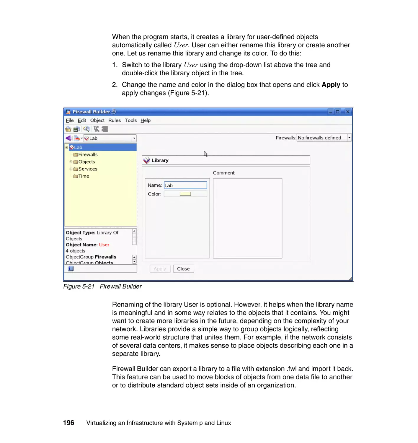
other countries, or both:
Redbooks (logo)
alphaWorks®
developerWorks®
eServer™
i5/OS®
pSeries®
z/VM®
Asset ID™
AIX 5L™
AIX®
BladeCenter®
Chipkill™
®
Domino®
Electronic Service Agent™
IBM®
Lotus®
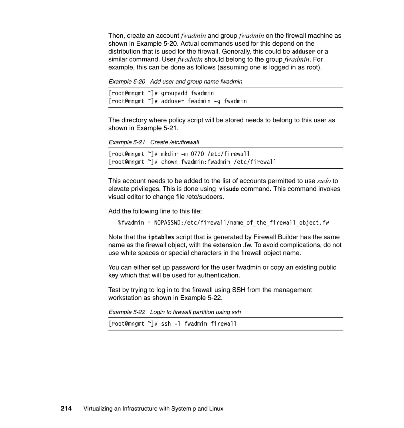
Micro-Partitioning™
OpenPower™
Power Architecture™
PowerPC Architecture™
PowerPC®
POWER™
POWER Hypervisor™
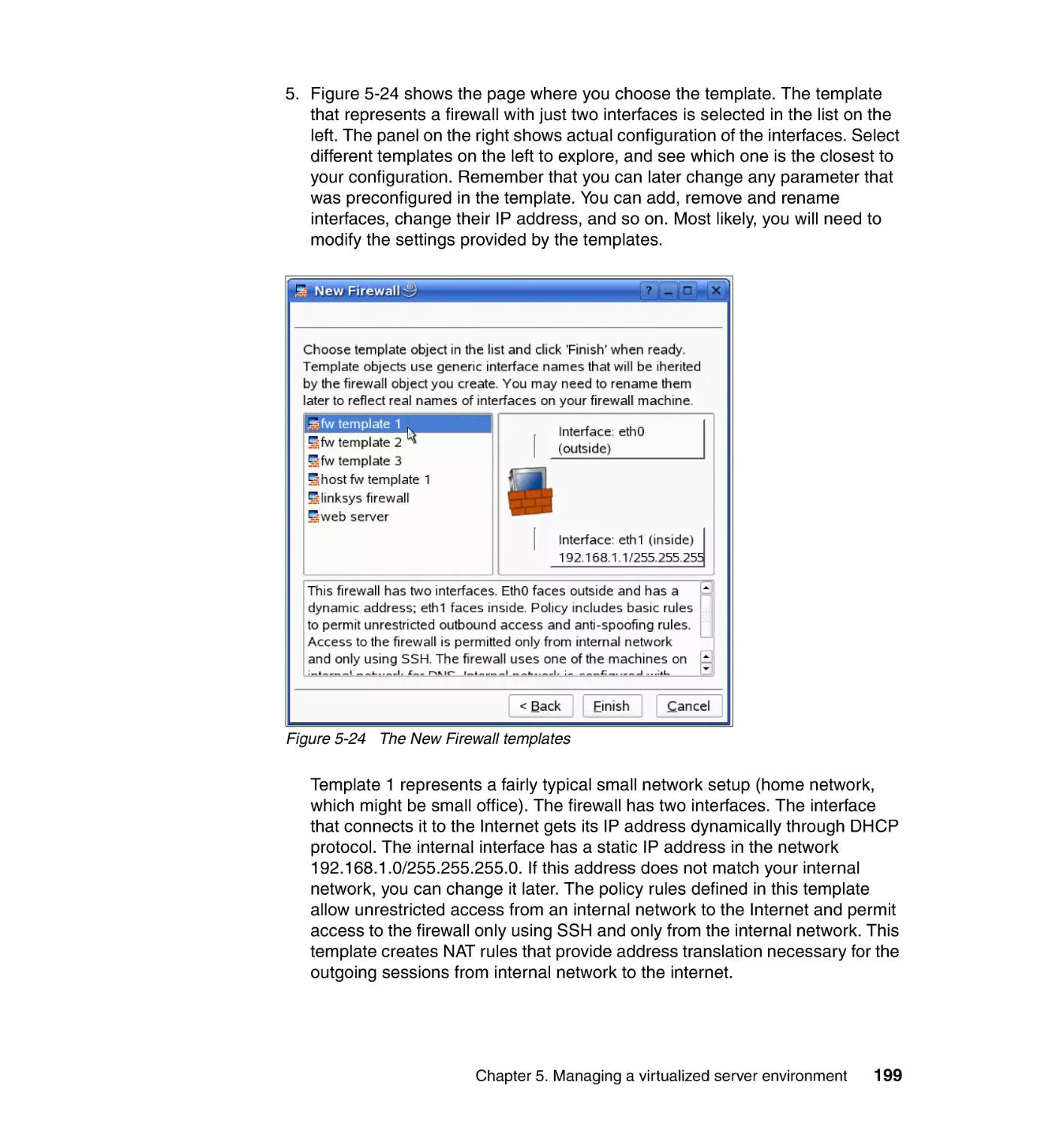
POWER4™
POWER5™
POWER5+™
Redbooks®
RS/6000®
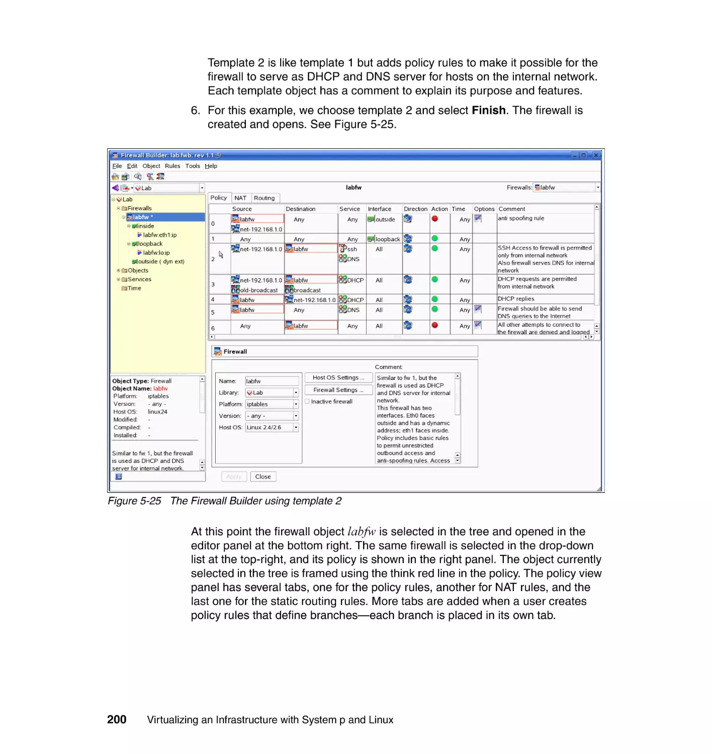
ServeRAID™
System i™
System p™
System p5™
System x™
Virtualization Engine™
WebSphere®
The following terms are trademarks of other companies:
mySAP, and SAP logos are trademarks or registered trademarks of SAP AG in Germany and in several other
countries.
JVM, Power Management, and all Java-based trademarks are trademarks of Sun Microsystems, Inc. in the
United States, other countries, or both.
Microsoft, Windows, and the Windows logo are trademarks of Microsoft Corporation in the United States,
other countries, or both.
UNIX is a registered trademark of The Open Group in the United States and other countries.
Linux is a trademark of Linus Torvalds in the United States, other countries, or both.
Other company, product, or service names may be trademarks or service marks of others.
viii
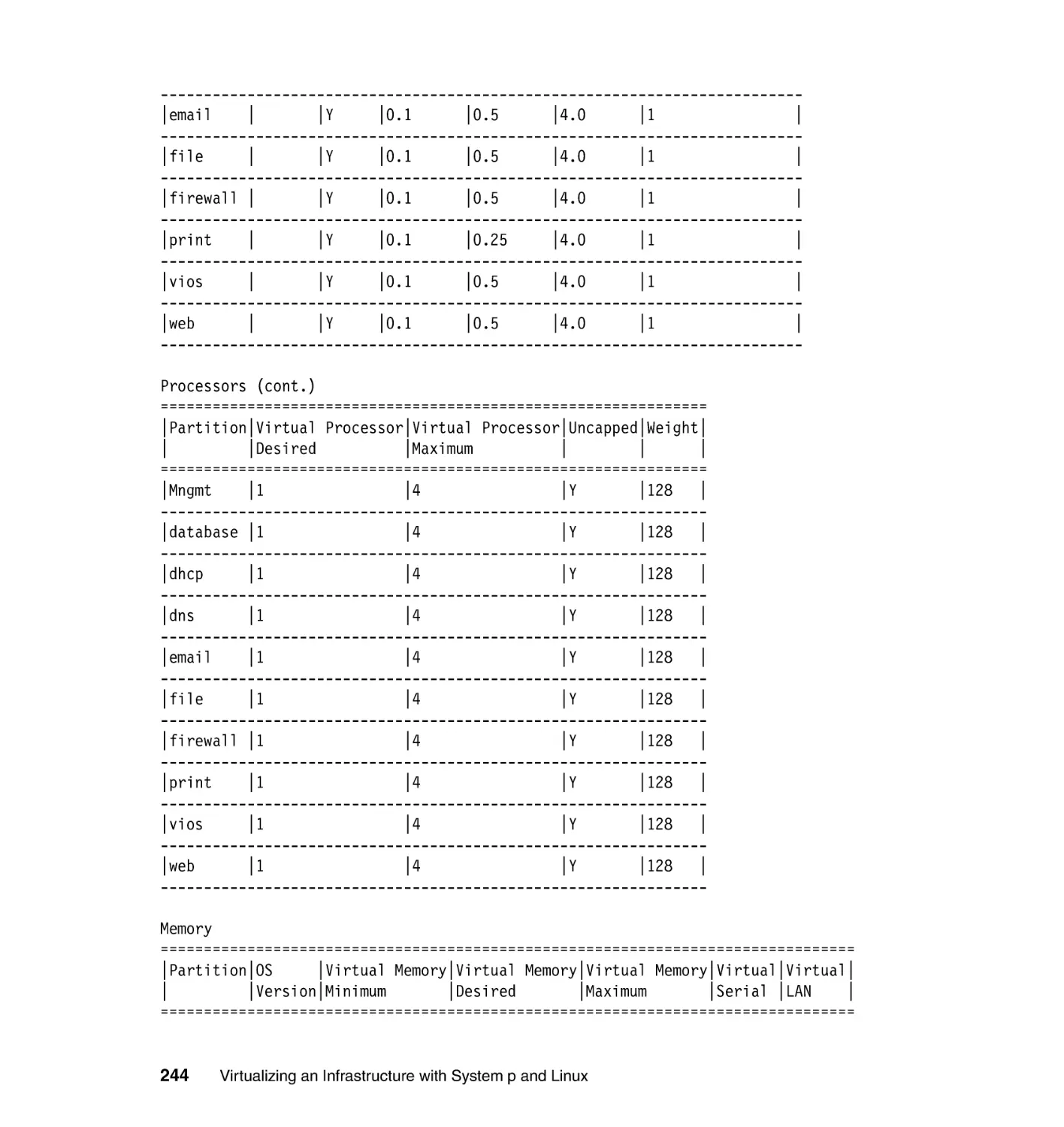
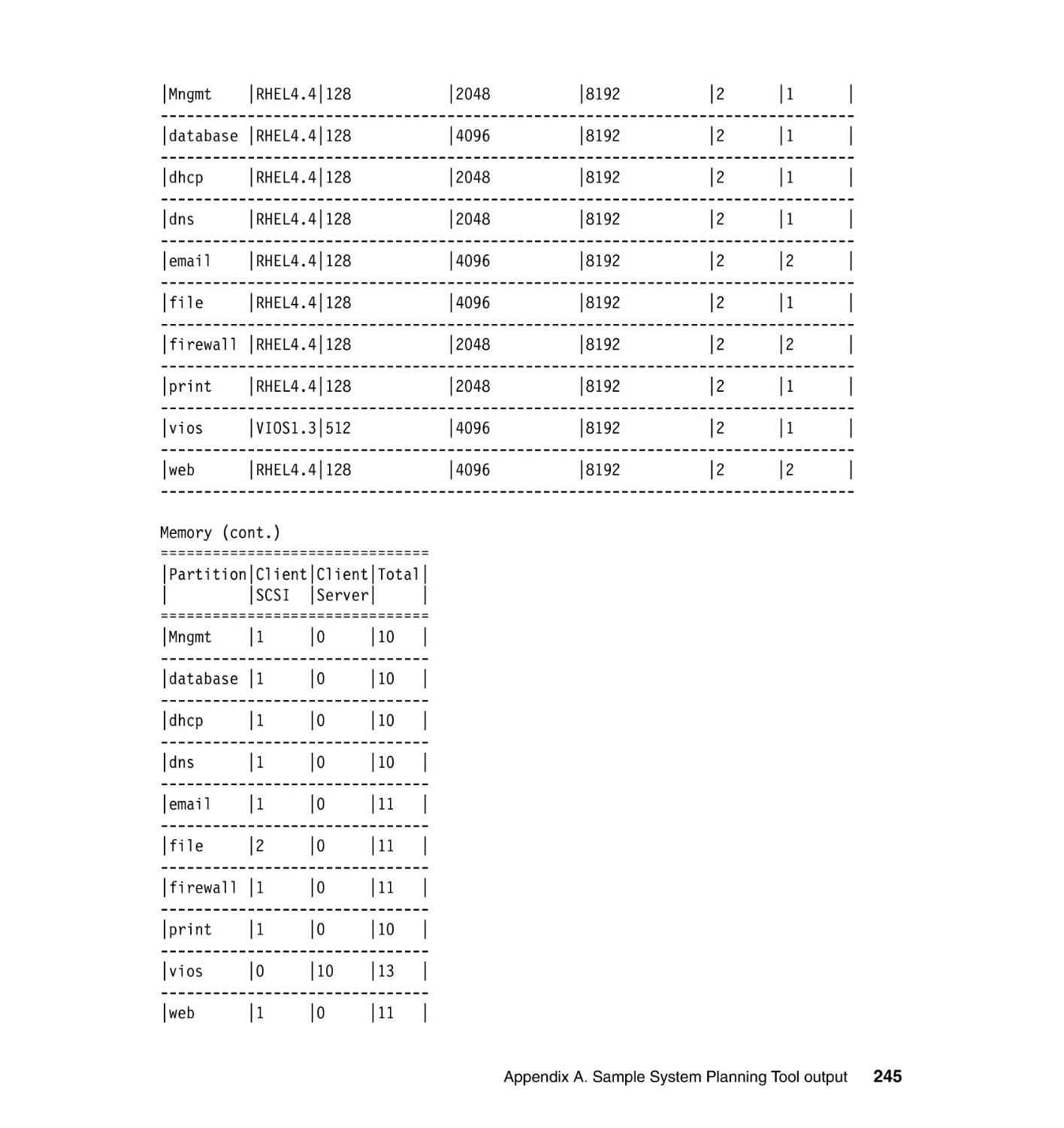
Virtualizing an Infrastructure with System p and Linux
Preface
This book positions the capabilities of IBM® System p™ to virtualize Linux®
infrastructure services for server consolidation using Advanced POWER™
Virtualization features. It discusses the benefits of virtualization, the Linux
infrastructure services workload, planning, and configuration of a virtualized
server environment, and the various tools that are available.
This book can help you plan, configure, and install Linux infrastructure services
on System p platform and use System p virtualization capabilities with Advanced
POWER virtualization features. It also covers various topics on how to configure
Linux built-in infrastructure services, such as DNS, DHCP, firewall, and so forth,
and the different virtualization management techniques that are available on
System p.
This book is intended as an additional source of information that, together with
existing sources referenced throughout the book, can enhance your knowledge
of IBM virtualization technology. While the discussion focuses on the Linux
operating system, you can extend the basic concepts to other operating systems
running on System p. The information in this book is not intended to replace the
latest marketing materials and tools.
The team that wrote this book
This book was produced by a team of specialists from around the world working
at the International Technical Support Organization (ITSO), Austin Center.
Lancelot Castillo is an IBM Certified Infrastructure Systems Architect and is
TOGAF Certified. He works as a Systems Architect at Questronix Corporation,
an IBM Premier Business Partner in the Philippines, and has more than nine
years of experience in IBM System p and Storage solutions. Castillo holds a
Bachelor’s degree in Electronic and Communications Engineering from Mapua
Institute of Technology. He is also an IBM CATE in AIX® and has several IBM
Certifications on System p, System x™, and Storage. His areas of expertise
include infrastructure design and sizing, solution assurance review, virtualization
implementation, performance management, and high availability solutions. This
is his second IBM Redbooks® residency.
Walter Montes is Mathematician graduate and Computer Engineer autodidact.
He brings 18 years of experience in Computer Science and network solutions. At
© Copyright IBM Corp. 2008. All rights reserved.
ix
Tomas Moreno Cruz y Cia, an IBM Business Partner based in Colombia, Walter
directs a team that focus on Networked Services Management practice areas
that span performance availability and service management across enterprise
and telecommunication markets. Recently, Walter has focused largely on
virtualized environments and the convergence of integrated security and
applications functionality. Prior to joining TMC, Walter worked to develop Web
applications strategies and new business models and spent 12 years with
industry sectors.
Thanks also to the following people for their contributions to this project:
Kenneth Rozendal
IBM Austin
Mark VanderWiele
IBM Austin
Tomas Moreno Anjel
TMC Bogota
Henry Molina
MZN Bogota
Vadim Kurland
NetCitadel LLC
Paul Michael Macaranas
Questronix Corporation
Become a published author
Join us for a two- to six-week residency program! Help write a book dealing with
specific products or solutions, while getting hands-on experience with
leading-edge technologies. You will have the opportunity to team with IBM
technical professionals, Business Partners, and Clients.
Your efforts will help increase product acceptance and customer satisfaction. As
a bonus, you will develop a network of contacts in IBM development labs, and
increase your productivity and marketability.
Find out more about the residency program, browse the residency index, and
apply online at:
ibm.com/redbooks/residencies.html
x
Virtualizing an Infrastructure with System p and Linux
Comments welcome
Your comments are important to us!
We want our books to be as helpful as possible. Send us your comments about
this book or other IBM Redbooks publications in one of the following ways:
Use the online Contact us review Redbooks form found at:
ibm.com/redbooks
Send your comments in an e-mail to:
redbooks@us.ibm.com
Mail your comments to:
IBM Corporation, International Technical Support Organization
Dept. HYTD Mail Station P099
2455 South Road
Poughkeepsie, NY 12601-5400
Preface
xi
xii
Virtualizing an Infrastructure with System p and Linux
1
Chapter 1.
Introduction
This chapter provides an overview of the Linux operating system that is available
on the IBM System p platform. It includes information about the following topics:
Virtualization overview
Linux as the operating system
Linux on System p
Benefits of deploying IBM Advanced POWER Virtualization on Linux
environment
© Copyright IBM Corp. 2008. All rights reserved.
1
1.1 Overview
This book looks at the question of running your infrastructure in a totally
virtualized environment. There are many reasons for a business to perform an
architectural review of their existing infrastructure to determine the value of
migrating to a virtualized environment. A few include:
Business challenges to reduce costs of existing infrastructure
Consolidation of IT resources during a business merger
Containing costs of growth
Capturing opportunities by provisioning new resources quickly
Business desire to utilize Capacity On Demand
Physical consolidation to reduce space, power and cooling requirements
Moving from a just-on-time purchase model to an architected high availability
business model with flexibility and scalability
The IBM System p hardware with the enterprise ready Linux OS provides a solid
foundation on which to build your business. Advanced POWER virtualization
provides flexibility and proven IBM System p systems provide scalability. The
infrastructure can be ready to handle your business opportunities without the
burdening costs that growth can otherwise bring to your IT environment.
Consolidating existing infrastructure server farms into a IBM System p virtualized
environment can help you address business challenges of space, power, and
total cost of ownership.
1.2 Virtualization overview
Virtualization is the creation of substitutes for real resources, that is substitutes
that have the same functions and external interfaces as their counterparts but
that differ in attributes such as size, performance, and cost. These substitutes
are called virtual resources, and their users are typically unaware of the
substitution. Virtualization is commonly applied to physical hardware resources
by combining multiple physical resources into shared pools from which users
receive virtual resources. With virtualization, you can make one physical
resource look like multiple virtual resources. Virtual resources can have functions
or features that are not available in their underlying physical resources.
2
Virtualizing an Infrastructure with System p and Linux
Virtualization can provide the following benefits:
Consolidation to reduce hardware cost:
– Virtualization enables you to access and manage resources efficiently to
reduce operations and systems management costs while maintaining
needed capacity.
– Virtualization enables you to have a single server function as multiple
virtual servers.
Optimization of workloads:
– Virtualization enables you to respond dynamically to the application needs
of its users.
– Virtualization can increase the use of existing resources by enabling
dynamic sharing of resource pools.
IT flexibility and responsiveness:
– Virtualization enables you to have a single, consolidated view of, and easy
access to, all available resources in the network, regardless of location.
– Virtualization enables you to reduce the management of your environment
by providing emulation for compatibility, improved interoperability, and
transparent change windows.
1.2.1 Business drivers
Increasing emphasis on the cost of delivering IT services has caused an
unprecedented interest in server consolidation. Server consolidation is the
simplification and optimization of IT environments by a reduction of the number of
discrete components of infrastructure. Consolidation can be done on application
environments, such as application servers and databases, and on physical
hardware, such as servers, routers, and storage. While numerous benefits can
be cited for server consolidation, this book focuses on the practical management
aspects of consolidating mixed workload types onto asymmetrically configured
fractional CPU server partitions.
Server consolidation has become especially attractive as the current generation
hardware and logical partitioning allow a number of systems to be hosted within
a single frame. With the announcement of the POWER5™ processor-based
family of systems, optional mainframe-inspired IBM Virtualization Engine™
systems technologies have arrived for the Linux environment. The term
virtualization has achieved near universal recognition. It refers to the ability to
abstract the physical properties of hardware in a way that allows a more flexible
usage model. Virtualization can apply to microprocessors, memory, I/O devices,
or storage. Fine grain virtualization permits near instantaneous matching of
Chapter 1. Introduction
3
workload to resources allocated, eschewing the wasted resources common to
the one-server/one-application model of computing.
This ability to balance CPU resources quickly and dynamically between different
workload priorities on multiple partitions in a single server fulfills an important
requirement for an on demand operating environment.
1.2.2 Why IT optimization and virtualization
The primary purpose of IT optimization and virtualization is to simplify the IT
infrastructure. It simplifies access to resources and the management of those
resources.
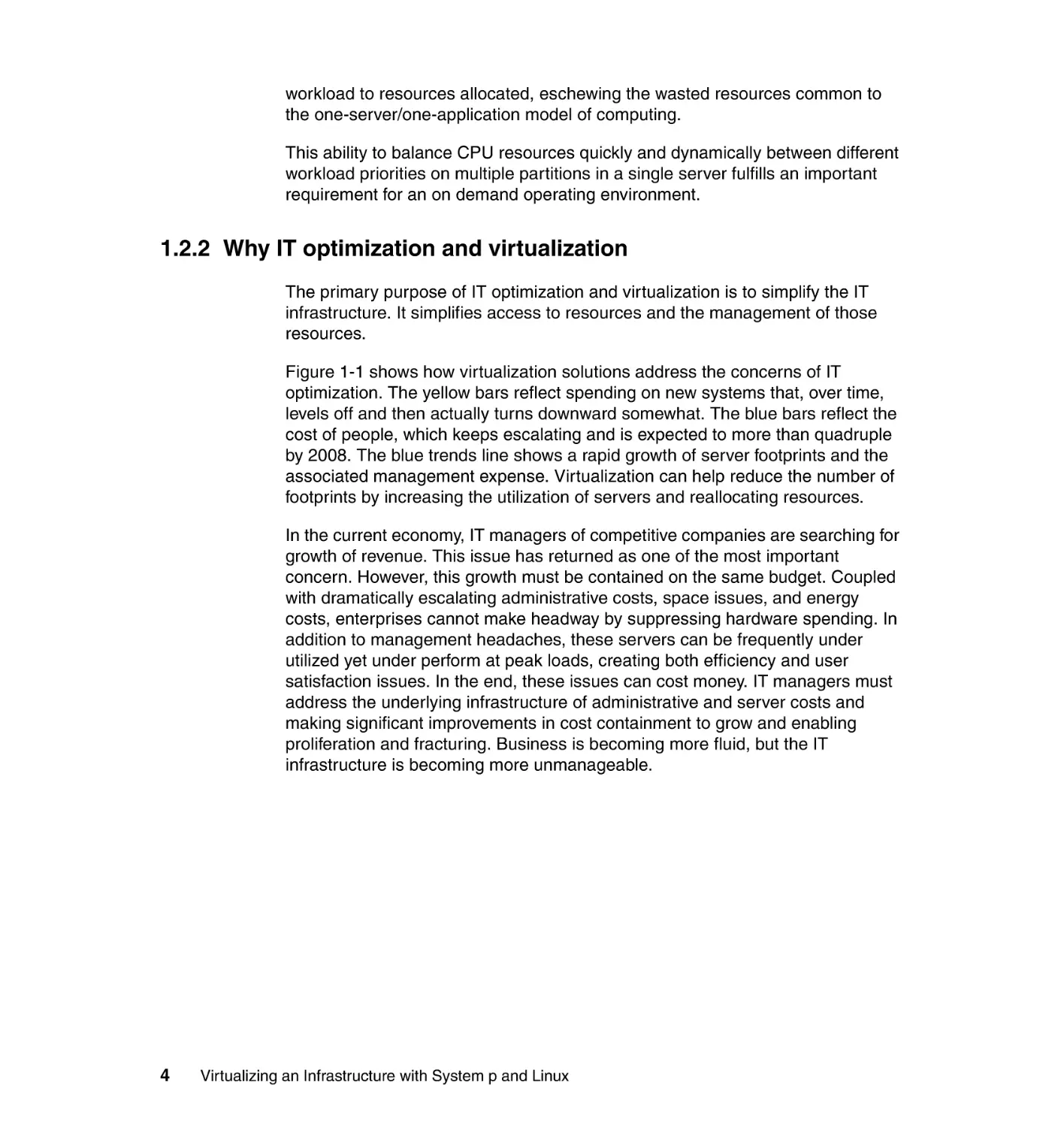
Figure 1-1 shows how virtualization solutions address the concerns of IT
optimization. The yellow bars reflect spending on new systems that, over time,
levels off and then actually turns downward somewhat. The blue bars reflect the
cost of people, which keeps escalating and is expected to more than quadruple
by 2008. The blue trends line shows a rapid growth of server footprints and the
associated management expense. Virtualization can help reduce the number of
footprints by increasing the utilization of servers and reallocating resources.
In the current economy, IT managers of competitive companies are searching for
growth of revenue. This issue has returned as one of the most important
concern. However, this growth must be contained on the same budget. Coupled
with dramatically escalating administrative costs, space issues, and energy
costs, enterprises cannot make headway by suppressing hardware spending. In
addition to management headaches, these servers can be frequently under
utilized yet under perform at peak loads, creating both efficiency and user
satisfaction issues. In the end, these issues can cost money. IT managers must
address the underlying infrastructure of administrative and server costs and
making significant improvements in cost containment to grow and enabling
proliferation and fracturing. Business is becoming more fluid, but the IT
infrastructure is becoming more unmanageable.
4
Virtualizing an Infrastructure with System p and Linux
Worldwide IT Spending on Servers, Power and
Cooling, and Management/Administration
Spending
(US$B)
Installed Base
(M Units)
50
$300
$250
$200
45
Power and Cooling Costs x8
Server Mgt and Admin Costs x4
New Server Spending
40
35
30
$150
25
20
$100
15
10
$50
5
$0
19
96
19
97
19
98
19
99
20
00
20
01
20
02
20
03
20
04
20
05
20
06
20
07
20
08
20
09
20
10
0
Many Servers, Much Capacity, Low Utilization = $140B unutilized server assets
© 2007 IDC
Figure 1-1 Cost of management versus spending on new systems1
IBM virtualization solutions address the need to increase utilization of information
assets, simplify the IT infrastructure, and reduce operating costs across servers,
storage, networking, and grid computing. By extracting some administrative costs
out of the infrastructure (through increased and resource utilization and improved
productivity and flexibility), these virtualized IT assets can help fuel business
growth, control the cost, and in doing so, increase staff productivity.
As clients seek to improve the effectiveness of the IT infrastructure, consolidating
workloads onto a single larger system becomes an attractive proposition. IBM
Virtualization Engine system technologies are designed to enable the reduction
in overall total cost of ownership (TCO) and increase in business flexibility to
meet anticipated and unanticipated processing capacity demands with a more
streamlined system infrastructure.
This book discusses the most basic virtualization capability, logical partitioning,
that is available on System p servers and JS21 blades running Linux on POWER.
Linux can run in one or more logical partitions (LPARs) on the system. The AIX
1
Source: IDC, Virtualization and Multicore Innovations Disrupt the Worldwide Server Market, Doc
#206035, Mar 2007.
Chapter 1. Introduction
5
5L™ operating system, IBM’s industrial strength UNIX®, and Linux operating
system can run concurrently in separate partitions on an LPAR-enabled system
in any combination (that is, zero or more Linux partitions along with zero or more
AIX 5L partitions). The System p Enterprise servers such as p5-590 and p5-595
or even p5-570 can also run i5/OS® operating system as part of the supported
operating system. This capability enables the consolidation of workloads from
several separate servers onto a single system, potentially increasing system
utilization.
Advanced POWER Virtualization option
IBM has long been a leader in virtualization. With the arrival of POWER5
processor-based systems, new virtualization capabilities extend IBM’s leadership
in this field. IBM offers a set of advanced features in the Advanced POWER
Virtualization (APV) option available for System p and BladeCenter® JS20 and
JS21 platforms. APV was named Best Virtualization Solution at Linux World
2006. For more information, see Web site:
http://www.ibm.com/press/us/en/pressrelease/20138.wss
With these additional features from APV such as Micro-Partitioning™ and virtual
I/O (disk and communication adapter), users can now further virtualize system
resources within a single server.
Micro-Partitioning is the ability to run more partitions on a server than there are
physical microprocessors. The concept is not novel. IBM Mainframe systems
have supported it for years. What is unique is that IBM has implemented
Micro-Partitioning as an option in the POWER5 processor-based servers
(standard on System p5™ 590 and 595), bringing this function to a broader class
of Linux environment clients and applications. The Linux operating system has
been adapted and optimized for virtualization.
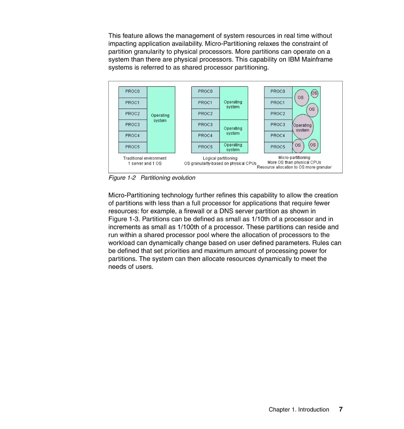
Micro-Partitioning is the latest in a set of evolutionary steps in server
virtualization for POWER5 processor-based servers. Figure 1-2 shows the steps
of partitioning evolution, beginning with the historical view of a server with one
operating system managing the resources of the system.
The next step was logical partitioning (LPAR), which was first offered on the
POWER4™-based servers in 2001. With logical partitioning, it is possible to run
more than one partition on a server, with each partition hosting a unique
operating system. The CPU granularity of logical partitions was done at the
physical processor level. Thus, there could not be more partitions than physical
processors. Logical partitioning was extended with Linux in 2004 to permit
resources to be moved between partitions dynamically, though the granularity of
the partitions was still by physical processor.
6
Virtualizing an Infrastructure with System p and Linux
This feature allows the management of system resources in real time without
impacting application availability. Micro-Partitioning relaxes the constraint of
partition granularity to physical processors. More partitions can operate on a
system than there are physical processors. This capability on IBM Mainframe
systems is referred to as shared processor partitioning.
Figure 1-2 Partitioning evolution
Micro-Partitioning technology further refines this capability to allow the creation
of partitions with less than a full processor for applications that require fewer
resources: for example, a firewall or a DNS server partition as shown in
Figure 1-3. Partitions can be defined as small as 1/10th of a processor and in
increments as small as 1/100th of a processor. These partitions can reside and
run within a shared processor pool where the allocation of processors to the
workload can dynamically change based on user defined parameters. Rules can
be defined that set priorities and maximum amount of processing power for
partitions. The system can then allocate resources dynamically to meet the
needs of users.
Chapter 1. Introduction
7
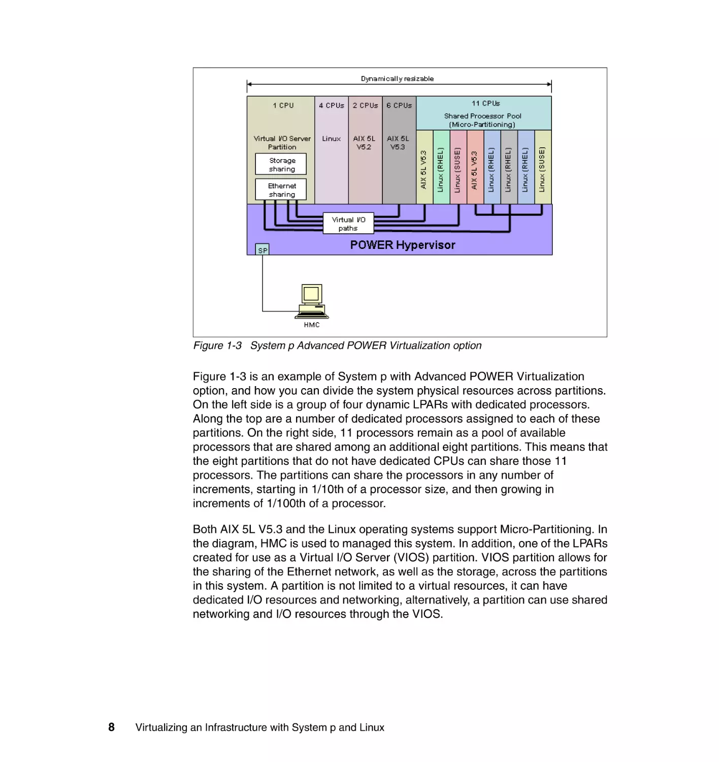
Figure 1-3 System p Advanced POWER Virtualization option
Figure 1-3 is an example of System p with Advanced POWER Virtualization
option, and how you can divide the system physical resources across partitions.
On the left side is a group of four dynamic LPARs with dedicated processors.
Along the top are a number of dedicated processors assigned to each of these
partitions. On the right side, 11 processors remain as a pool of available
processors that are shared among an additional eight partitions. This means that
the eight partitions that do not have dedicated CPUs can share those 11
processors. The partitions can share the processors in any number of
increments, starting in 1/10th of a processor size, and then growing in
increments of 1/100th of a processor.
Both AIX 5L V5.3 and the Linux operating systems support Micro-Partitioning. In
the diagram, HMC is used to managed this system. In addition, one of the LPARs
created for use as a Virtual I/O Server (VIOS) partition. VIOS partition allows for
the sharing of the Ethernet network, as well as the storage, across the partitions
in this system. A partition is not limited to a virtual resources, it can have
dedicated I/O resources and networking, alternatively, a partition can use shared
networking and I/O resources through the VIOS.
8
Virtualizing an Infrastructure with System p and Linux
Other IBM Redbooks publications discuss Advanced POWER Virtualization
technology. Refer to the following Web sites:
Advanced POWER Virtualization on IBM System p5: Introduction and
Configuration, SG24-7940
http://www.redbooks.ibm.com/Redbooks.nsf/RedbookAbstracts/sg247940.h
tml?Open
Advanced POWER Virtualization on IBM System p Virtual I/O Server
Deployment Examples, REDP-4224
http://www.redbooks.ibm.com/Redbooks.nsf/RedbookAbstracts/redp4224.h
tml?Open
IBM System p Advanced POWER Virtualization Best Practices, REDP-4194
http://www.redbooks.ibm.com/Redbooks.nsf/RedbookAbstracts/redp4194.h
tml/Open
Virtualization and Clustering Best Practices Using IBM System p Servers,
SG24-7349
http://www.redbooks.ibm.com/Redbooks.nsf/RedbookAbstracts/sg247349.h
tml?Open
With APV, it enables customers to build their own flexible and reliable
infrastructure. It allows for the rapid deployment of new systems without the
normally lengthy and time-consuming process of validation, acquisition, and
installation of new physical systems. It is also designed to simplify the movement
of operating system instances from one physical system to another given that the
infrastructure is carefully planned and certain requirements are met. It allows for
fast setup of test and development machines in the same physical environment
and even on the same machine as production machines, taking away the bias if
different types of physical machines were used. In addition, it adds trust and
confidence in systems operations because the sheer computing power and the
stability of POWER5 processor based systems are proven and recorded by many
installations. Overall, this leads to a substantial improvement in TCO and
simplified IT operations.
Why APV is the choice for Linux virtualization solutions
As more and more companies today use Linux operating systems on their
infrastructure services environment to reduce costs and increase flexibility, the
challenge becomes how to gain these advantages and continue the same quality
of service if we consolidate into one physical server. Linux on POWER servers
provide the solution to this challenge by enabling the virtualization using APV
and RAS features capabilities of the IBM POWER5 architecture in Linux.
Chapter 1. Introduction
9
Some reasons why Advanced POWER Virtualization is the leader in Linux
virtualization solutions include:
1. Provides low cost application security and isolation with confidence and
EAL4+ certification - Supports partition stability, security, and fault isolation
due to POWER Hypervisor™ implementation.
2. Provides for consolidation, migrations, and multi-use systems without concern
for OS constraints. Runs multiple operating systems, versions, and releases
levels without dynamic OS patches.
3. Provides flexible management of I/O requirements based on system needs,
unlike other implementations. Implements I/O utilization with automatic
failover or dedicated support for partitions.
4. Provides consolidation and scaling support based on application need without
artificial limitations. Scales to System p capabilities up to 64-cores and 2 TB
of real memory with 64-bit support.
5. Provides maximum system utilization for applications by minimized
processing in virtualization layer. Increases overall system performance due
to low overhead of Hypervisor hardware implementation.
6. Provides for low TCO through robust functions and high cost effectiveness,
offered at no-charge on selected System p models and is lower priced than
alternative commercial virtualization solutions with comparable features.
7. Provides investment protection in virtualization capabilities and future
capabilities, developed within System p hardware and software community.
8. Provides proven technology by supporting over 440,000 cores today. Lowers
risk by large user base within the POWER community, blogs, and Wikis.
9. Provides complete virtualization solution from planning to tracking to support
to service. Extends basic virtualization code with sizing and planning tools,
usage and accounting tools, and dependable support and service from IBM
and IBM Business Partners.
10.Provide ease-of-use management interfaces based on system and economic
needs. Includes hardware console support for multiple servers or a no-charge
Web interface.
Virtual x86 Linux environment on System p
IBM intends to expand the capabilities of IBM POWER5 processor-based
System p servers and POWER processor-based blade servers to install and run
most x86 Linux applications. This new platform feature enhances System p
capabilities to consolidate other workloads into a single server.
This feature will create a virtual x86 Linux environment, which executes x86
Linux instructions dynamically by mapping system calls on a POWER system
10
Virtualizing an Infrastructure with System p and Linux
and caching them to optimize performance. IBM clients should be able to easily
install and run a wide range of x86 Linux applications on System p and
BladeCenter JS20 and JS21 servers that are using a Linux operating system.
Additionally, this feature can help ISVs expand their addressable market to Linux
on POWER servers at minimal to no cost by allowing them to run their existing
x86 Linux applications in a POWER environment.
You can access the IBM System p Application Virtual Environment for x86 Linux
Beta program at:
http://www-03.ibm.com/systems/p/linux/systempave.html
1.3 Linux as the operating system
This section provides a brief description of the Linux operating system and
explains why other companies adopted Linux as their operating system. It also
demonstrate the advantages of choosing System p as the platform for Linux
deployment in a virtualized environment.
1.3.1 Overview of the Linux operating system
Linux is an operating system (OS) that is based on a development approach that
delivers innovation and portability, sometimes referred to as open source. It is an
open, reliable, and efficient operating system that runs on virtually any platform
from embedded systems to mainframes.
The Linux OS is the creation of Linus Torvalds, a Finnish computer science
student, who developed it while a student at the University of Helsinki in 1991.
The architecture is similar to the UNIX OS. Linux provides a cost-effective,
UNIX-like implementation for many computer architectures. After doing the initial
development work, Torvalds made the source code available on the Internet for
use, feedback, and further development by others who were interested in helping
to evolve Linux.
As an open source technology, Linux is not owned or controlled by any individual
(although Linus Torvalds does own the copyright) or company, but rather it is
maintained by the open source community—a dedicated group of independent
developers collaborating to make it the most open operating system. Being open
source, the Linux kernel, like other open source technologies, can be acquired at
no cost.
The GNU Project was launched in 1984 to develop a complete clone of the UNIX
operating system which is free software: the GNU system. (GNU is a recursive
Chapter 1. Introduction
11
acronym for “GNU’s not UNIX.”) Variants of the GNU operating environment
which use the Linux kernel are now widely used. Though these systems are often
referred to as Linux, they are perhaps more accurately called GNU/Linux
systems. You can find the GNU Project Web site at:
http://www.gnu.org/gnu/the-gnu-project.html
Clients benefit from the rapid innovation and enhancements made to Linux,
enabled by the open source development approach. Linux is licensed under the
terms of the GNU General Public License or GPL:
http://www.fsf.org/copyleft/gpl.html
The GPL requires, among other things, that the source code be made freely
available to all who receive the program and that all modifications to the code are
licensed using the GPL as well. This requirement ensures that all changes and
even derivative works remain open source. As a result, innovations are rapidly
fed back into Linux for the benefit of all users.
At the time of writing, the current version of the Linux kernel is 2.6 and is
available for download at:
http://www.kernel.org
The commercially available distributions of the 2.6 kernel that are certified to
support the IBM Power Architecture™ technology include: Red Hat, Inc., Red
Hat Enterprise Linux AS 4 for POWER, Novell SUSE Linux: SUSE Linux
Enterprise Server 10 for POWER, and SUSE Linux Enterprise Server 9. While
Linux is a UNIX-like, it is not the same as UNIX. The similarity begins and ends
with the fact that Linux is based on the same design principles and standards as
UNIX, and it is derived from that heritage. The Linux source code is distinct from
that of UNIX and Linux offers compatibility, portability, and horizontal scalability
for many architected platforms.
Today, UNIX has split into a series of competing operating systems derived from
the original code. Standards such as POSIX and UNIX 98 have been
promulgated to specify many of the APIs and features of the various UNIX
offerings. Linux is a single source operating system available to all, and as such
has common APIs and capabilities regardless of the system it executes on.
Through the GPL, developers must contribute their modifications back to the
community, which also continues the system singularity as Linux progresses in
capabilities.
12
Virtualizing an Infrastructure with System p and Linux
1.3.2 Linux infrastructure services
Linux enters the mainstream markets by providing critical infrastructure services,
which we describe in this section.
Web serving
The combination of Linux and the Apache Web server, or other Linux supported
Web servers such as Zeus, offers an attractive package for customers. It
provides a low-cost, flexible solution originally for static Web sites, with over 30%
of the world’s Web sites running this combination. The demand is now moving
toward a more dynamic approach with Web sites that users can interact with and
that support high transaction rates.
Domain name server (DNS) and DHCP
As a UNIX-like operating system, Linux is well proven at hosting Berkeley
Internet Name Daemon (BIND) name servers and Dynamic Host Configuration
Protocol (DHCP) services.
File and print serving
One of the basics for Linux implementation is the provision of inexpensive
facilities such as file and print services. Linux offers a rapid return on investment
(ROI) in this part of the infrastructure space. The management capabilities and
low cost make this an easy solution to justify. Also, this is an important
environment, but it does not typically have the operational importance of
line-of-business applications. It is a relatively safe place for businesses to test
this new technology.
Router
Linux is capable of advanced routing using inexpensive commodity hardware.
Also, some router vendors have chosen Linux to be their embedded operating
system.
Firewall and Intrusion Detection Services (IDS)
Linux has been a popular provider of firewall and IDS services. Because of the
advanced configuration and customization options, along with a small memory
footprint, Linux has been an ideal solution for many organizations who want to
avoid proprietary solutions.
1.3.3 The role of IBM in the Linux community
IBM has made an extensive commitment to support Linux as an open computing
environment. Contributions based on IBM developed technology, the “opening” of
Chapter 1. Introduction
13
IBM patents and developed subsystems, and being committee members and
leaders are just some of the ways IBM is contributing to the advancement of
Linux. IBM understands that the open computing business model supports client
flexibility and choice. Linux is the epitome of flexibility and choice, at least in the
terms of an operating system. Linux continues to scale and address larger
computing tasks, and IBM is doing its part to speed this process along by
optimizing IBM System p platforms to work synergistically with Linux for clients
who need to support evolving mission-critical workloads on Linux.
IBM is working with the open source community on a variety of committees and
projects to enhance the value of Linux for clients. You can learn more about this
support and IBM commitment to Linux at the following Web sites:
The IBM Linux portal for a general point of entry into IBM and Linux
http://www-03.ibm.com/linux
IBM Linux Technology Center (LTC)
http://www-03.ibm.com/linux/ltc/mission.shtml
IBM Support for IBM System p AIX 5L and Linux servers
http://www-304.ibm.com/jct01004c/systems/support/supportsite.wss/bra
ndmain?brandind=5000025
The Open Source Development Lab
http://www.linux-foundation.org/en/Accessibility
IBM developerWorks® Linux
http://www.ibm.com/developworks/
IBM alphaWorks®
http://www.alphaworks.ibm.com
1.3.4 Linux on POWER Distributions
A Linux port for the PowerPC® Architecture™ technology has been available for
several years. As with the ports to other architectures, it was started by members
of the open source community. You can find more background on this effort at the
Linux PowerPC community Web site at:
http://penguinppc.org/
IBM became involved in Linux on PowerPC initially by contributing IBM
RS/6000® equipment and some technical expertise to the effort. The initial port
supported only the PowerPC chips, not the current POWER4, POWER5 and
POWER5+™ processors. Many of the PowerPC distributions such as Novell
SUSE Linux and Yellow Dog work on Apple Power Macs as well as PowerPC
14
Virtualizing an Infrastructure with System p and Linux
systems from IBM. There has also been a large effort around Linux on
embedded PowerPC processors such as found in game boxes.
To implement Linux as the operating environment on System p, and JS20/JS21
blades, a client would need to have the server and a copy of Linux. For all
System p5 servers and JS20/JS21 blades and their Express offerings, clients
can order Linux distributions developed by Novell SUSE Linux or Red Hat, Inc.
with their initial system order. You can find more details on this ordering process
in the “Red Hat Enterprise Linux” on page 15 and “Novell SUSE Linux Enterprise
Server” on page 16.
For the convenience of clients, IBM offers the ability to accept orders and
payment for the Novell SUSE Linux and Red Hat, Inc. Linux distributions. This
includes shipping program media with initial System p5 and processor upgrade
orders. Clients or authorized IBM Business Partners are responsible for the
installation of the Linux operating system, with orders handled pursuant to
license agreements between the client and the Linux distributor.
This section describes the Linux distributors who are working with IBM to provide
and support Linux for POWER servers. Each distributor is wholly responsible for
the contents, availability, and pricing of their offering. Regardless of how a Linux
distribution is ordered, the distributors offer maintenance and support. IBM also
has support offerings from IBM Global Services for these distributions as
described in a later section.
Red Hat Enterprise Linux
Founded in 1994, Red Hat is a well known Linux provider and is the market
leader as a Linux distributor. For more information about Red Hat, see:
http://www.redhat.com
Red Hat Enterprise Linux AS 3 for POWER became generally available for
eServer™ pSeries® in November 2003 and was updated to support eServer p5
and OpenPower™ servers and JS20 blades in August 2004 with Red Hat
Enterprise Linux AS 3 Update 3. This is a full 64-bit kernel (based on the 2.4.21
kernel with selective code backported from the 2.6 kernel, such as the NTPL and
simultaneous multithreading support) with 32- and 64-bit application support. On
February 2005, Red Hat Enterprise Linux AS 4 is available from Red Hat, Inc.
This release is based on the 2.6 kernel, which includes Large Page support and
the Preemptive kernel. This version supports POWER4, POWER5 and
POWER5+ processor-based servers and JS20/JS21 blades. The current release
of Red Hat Enterprise Linux for POWER is version 5, which is also based on 2.6
kernel.
For the convenience of clients, IBM provides the ability to order a full distribution
of Red Hat Enterprise Linux AS 4 in conjunction with new System p5 servers and
Chapter 1. Introduction
15
BladeCenter JS21 purchases, with any new processor upgrade or, as
appropriate, with any activation of a Capacity on Demand (CoD) processor. IBM
will accept the client’s order and will have the Linux distribution arrive with the
server shipment at the client location. Clients always have the option of ordering
directly from Red Hat, Inc. at any time from the Red Hat Web site or a Red Hat
business partner. Red Hat Enterprise Linux is also available in an evaluation
version from Red Hat.
You can find full information about this product, including pricing and support
options, at:
http://www.ibm.com/systems/linux/power
Novell SUSE Linux Enterprise Server
SUSE Linux was the first of the IBM Linux Distribution Companies to release
Linux for the System p. Since then, SUSE Linux was acquired by Novell and is
now called Novell SUSE Linux. For more information about Novell SUSE Linux,
see:
http://www.novell.com/linux
The latest version of Novell SUSE Linux for enterprise clients, SUSE Linux
Enterprise Server 10 for POWER became available in July 2006 and contains the
64-bit Linux operating system based on the 2.6.15 kernel and supports both 32and 64-bit applications.
Full details on SUSE Linux Enterprise Server 10 for System p servers and
BladeCenter JS21 blades are available directly from Novell at:
http://www.novell.com/products/server/
For the convenience of clients, IBM will provide the ability to order a full retail
distribution of SUSE Linux Enterprise Server 10 in conjunction with new System
p5 server and JS21 blade purchases, processor upgrades or, as appropriate,
CoD activation. IBM will accept client orders and payment for Novell SUSE Linux
and deliver the code with the respective systems. Maintenance and support can
also be provided for an additional charge. Clients always have the option of
ordering directly from Novell SUSE Linux at any time per the information above,
either via their Web site or from Novell SUSE Linux business partners.
1.4 Linux on System p
The System p servers offer industry-proven performance, scalability and
reliability. Linux on System p leverages the enterprise-level advantages of
System p hardware while allowing customers to utilize Linux applications such as
16
Virtualizing an Infrastructure with System p and Linux
Web servers and infrastructure services available on Linux operating system.
Linux for System p is design for solutions requiring a 64-bit architecture or the
high-performance floating-point capabilities of the POWER processor. IBM
System servers utilize POWER processors to provide excellent 64-bit
performance and industrial strength reliability, as well as 32-bit applications on
Linux for System p for added choice.
In addition, the virtualization capability of System p servers makes it possible to
run one or more instances of Linux along with AIX 5L operating systems. In
addition, the System p enterprise servers provide more flexibility by supporting
i5/OS to run concurrently in different partition along with Linux and AIX 5L
operating systems. This capability enables the consolidation of workloads from
several separate servers onto a single system, potentially increasing system
utilization.
1.4.1 Virtualization on IBM System p
In this section, we describe the IBM System p virtualization system technologies
that are available on the POWER5 processor-based servers.
POWER Hypervisor
The POWER Hypervisor is the foundation for virtualization on a System p server.
It enables the hardware to be divided into multiple partitions and ensures strong
isolation between them. Always active on POWER5-based servers, the POWER
Hypervisor is responsible for dispatching the logical partition workload across the
physical processors. The POWER Hypervisor also enforces partition security
and can provide inter-partition communication that enables the Virtual I/O
Server’s virtual SCSI and virtual Ethernet function.
Simultaneous multithreading
Enhancements in POWER5 processor design allow for improved overall
hardware resource utilization. Simultaneous multithreading (SMT) technology
allows two separate instruction streams (threads) to run concurrently on the
same physical processor, improving overall throughput.
The System p platform servers fully automate SMT without requiring any
application modifications or tuning. Depending on the workload, SMT can make
the system more efficient. Using the SMT function, some performance increases
have been realized.
Due to SMT, Linux thinks it has double the number of processors than it is
configured for. For example, if the Linux partition is assigned two processors, four
processors show in the /proc/cpuinfo.
Chapter 1. Introduction
17
LPAR and shared-processor partitions
A logical partition (LPAR) is not constrained to physical processor boundaries
and can be allocated processor resources from a shared processor pool. An
LPAR that uses processor resources from the shared processor pool is known as
a Micro-Partition LPAR.
The percentage of a physical processor that is allocated is known as processor
entitlement. Processor entitlement can range from 10% of a physical processor
up to the maximum installed processor capacity of the IBM System p. You can
allocate additional processor entitlement in increments of 1% of a physical
processor.
Dynamic reconfiguration
It is possible to move system resources, physical processors, virtual processors,
memory, and I/O slots dynamically between partitions without rebooting. This
process is known as dynamic reconfiguration or dynamic LPAR.
Virtual LAN
A function of the POWER Hypervisor, Virtual LAN allows secure communication
between logical partitions without the need for a physical I/O adapter. The ability
to share Ethernet bandwidth securely across multiple partitions increases
hardware utilization.
Virtual I/O
Virtual I/O provides the capability for a single physical I/O adapter and disk to be
used by multiple logical partitions of the same server, which allows consolidation
of I/O resources and minimizes the number of I/O adapters required.
Capacity on Demand
There are multiple Capacity on Demand (CoD) possibilities offered, including:
Permanent Capacity Upgrade on Demand, which enables permanent system
upgrades by activating processors or memory.
Trial Capacity Upgrade on Demand, which includes partial or total activation
of installed processors or memory for a fixed period of time.
On/Off Capacity Upgrade on Demand, which includes usage based billing
that allows for activation and deactivation of both processors and memory as
required.
Reserve Capacity Upgrade on Demand, which includes a prepaid agreement
that adds reserve processor capacity to the shared processor pool that is
used if the base shared pool capacity is exceeded.
18
Virtualizing an Infrastructure with System p and Linux
Capacity Backup, which provides an off-site disaster recovery server using
On/Off CoD capabilities. This offering has a minimum set of processors that
can be activated using On/Off CoD in the event of a disaster and is available
only on p5-590 and p5-595.
For more information regarding CoD, refer to the following Web sites:
IBM Capacity on Demand Web site
http://www-03.ibm.com/systems/p/cod
System i™ and System p Capacity on Demand
http://publib.boulder.ibm.com/infocenter/eserver/v1r3s/topic/ipha2/
ipha2book.pdf
Multiple operating system support
The POWER5 processor based System p5 products support IBM AIX 5L Version
5.2 ML2, IBM AIX 5L Version 5.3, i5/OS, and Linux distributions from SUSE and
Red Hat.
Hardware Management Console
The Hardware Management Console (HMC) is a separate machine that provides
hardware control of managed systems. It provides logical partition management,
dynamic resource allocation, monitoring, power control, and call home features
to initialize hardware calls to IBM service automatically in the event of a detected
problem. The HMC maintains a unified event log for all its managed systems that
can be used for diagnostic and alerting purposes. For more information about
HMC managed System p virtualization, refer to 3.2.1, “Using the HMC for
System p virtualization” on page 57.
Integrated Virtualization Manager
The Integrated Virtualization Manager (IVM) is a hardware management solution
that inherits the most basic features of the HMC and removes the requirement of
an external HMC. The IVM is limited to managing a single System p server. For
more information about IVM managed System p virtualization, refer to 3.2.2,
“Using the IVM for System p virtualization” on page 58.
1.4.2 Linux for System p hardware enablement
Both 32-bit and 64-bit versions of Linux for System p are provided to optimize
choices and to exploit System p hardware capabilities. The 64-bit POWER5
systems provide a 32-bit and 64-bit kernel and support a 32-bit and 64-bit
application environment, depending on the model and Linux distribution. Current
Linux development efforts are focused on the 64-bit products.
Chapter 1. Introduction
19
1.4.3 Virtualization capabilities of System p running Linux
With the introduction of the Power Architecture in the System p servers and JS20
and JS21 blades, there has been advancement in the ability to virtualize server
resources and selective I/O devices within a single server. Linux supports this
function. First, the LPAR capability of POWER4 processor-based systems is
extended with dynamic LPAR capabilities (the ability to change processor
allocation to partitions without having to reboot the partition) in Power
Architecture technology-based systems and is currently supported by SUSE
Linux Enterprise Server 9, SUSE Linux Enterprise Server 10, and Red Hat
Enterprise Linux AS 4. In addition to dynamic LPAR, you can run partitions with
processor allocations in fractional amounts. This capability is called
Micro-Partitioning. Micro-Partitioning can be used to provide a partition with
less than a full processor (for example, a firewall or a DNS server partition).
Partitions as small as 1/10th of a processor and in increments as small as
1/100th of a processor can be defined. These partitions can reside and run within
a pool of processors (shared processor pool) where the allocation of processors
to the workload can change dynamically based on user-defined parameters and
rules. The rules can indicate that a partition can only have a maximum amount of
processing power or can be unlimited in its ability to absorb all the unused
processor capabilities.
Another feature in System p and BladeCenter virtualization is Virtual I/O Server
(VIOS) where several partitions can share a single physical adapter, thus saving
the cost of multiple adapters when workloads allow the sharing. Today Power
Architecture technology-based systems with Linux can share SCSI, Fibre
Channel, DVD, and Ethernet adapters. Virtual LAN capabilities (AIX 5L V5.3 and
Linux) allow inter-partition communications on a virtual LAN without the need for
LAN adapters or cabling.
The virtualization capabilities in System p5 servers and BladeCenter JS21 are
partially included in the base system as a no charge feature code (providing
LPAR, dynamic LPAR, and VLAN) and an optionally charged for feature,
Advanced POWER Virtualization (Virtual I/O Server and Micro-Partitioning),
which is standard on the p5-590 and p5-595. Both capabilities require partition
management support either through IVM or an HMC. This support is required to
initialize and manage the virtualized environment. A single HMC can manage up
to 48 different physical servers. The IVM feature is enabled through a Web
browser and can only manage the system to which the Web browser is
connected. The JS21 blade is supported by these same virtualization capabilities
but only through the IVM interface because the JS21 has no HMC connectivity
support.
20
Virtualizing an Infrastructure with System p and Linux
1.4.4 Logical Partitioning of Linux on Power Architecture
Linux is supported running in one or more logical partitions (LPARs) on all
System p servers and BladeCenter blades that support logical partitioning. The
AIX 5L and Linux operating systems can run concurrently in separate partitions
on an LPAR-enabled system in any combination. This capability enables a client
to consolidate workloads from several separate physical servers on to a single
system, increasing the system utilization. Because the partitioning is controlled
by the POWER Hypervisor firmware and the HMC or the IVM, the AIX 5L
operating system is never required to run Linux.
Dynamic LPAR is not supported by Linux 2.4 kernel-based distributions or on
POWER4 processor-based systems. However, you can create Linux partitions
on systems that are enabled for dynamic LPAR. The Linux partition is disabled on
the HMC and cannot be changed dynamically on POWER4 systems. On
POWER4 systems, to reconfigure Linux in an LPAR environment, you must first
stop it, then reconfigure the partition, and then restart Linux.
To see how virtualization can benefit IT solutions, consider a typical service
provider or Web hosting environment. It is designed typically as a two- or
three-tier model. In most installations, there are front-end systems (typically edge
of network and appliance servers) to handle caching, proxy, DNS, and so forth.
There can then be a second tier of mid-range servers (or larger or smaller
servers, based on workload) to do Web application serving using WebSphere®
in conjunction with an ERP or CRM product. The third tier of servers run a UNIX
or Linux operating system on a large symmetric multiprocessor (SMP) that
provides the back-office and database management (DBMS) functions that
require high performance and scalability. In many cases, the first and, possibly,
second tiers are running Linux or Microsoft® Windows® operating systems. This
setup results in a proliferation of servers and the need for more staff and
expensive software to manage multiple platforms.
Installing the IBM productivity tool packages for Linux on POWER is required for
dynamic LPAR support. (See 3.7, “Installing service and productivity tools for
Linux on POWER” on page 88 for more detailed information regarding this tool.)
After you install these packages, you can now add or remove processors or I/O
dynamically from the supported Linux operating system running on a partition
using an attached HMC.
Chapter 1. Introduction
21
1.4.5 Supported servers and blades
The IBM System p and BladeCenter facts and features give a side-by-side
comparison of the various systems that are available with many of their key
specifications and information about supported AIX 5L and Linux versions.
These documents are available at:
http://www-03.ibm.com/system/p/hardware/factsfeatures.html
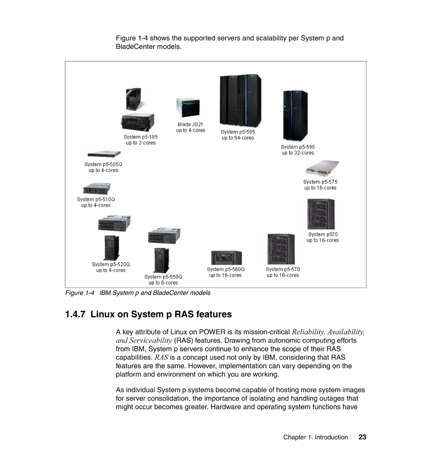
1.4.6 Scalability
The Linux 2.6 kernel has been found to scale well up to 32 cores and in selected
workloads to 64-core processors in an SMP system, depending on the workload.
This scaling makes it a good match for systems with 4-cores and up capabilities,
such as:
22
p5-505Q
p5-510Q
p5-520Q
p5-550
p5-550Q
p5-560Q
p5-570
p5-575
p5-590
p5-595
Virtualizing an Infrastructure with System p and Linux
Figure 1-4 shows the supported servers and scalability per System p and
BladeCenter models.
Figure 1-4 IBM System p and BladeCenter models
1.4.7 Linux on System p RAS features
A key attribute of Linux on POWER is its mission-critical Reliability, Availability,
and Serviceability (RAS) features. Drawing from autonomic computing efforts
from IBM, System p servers continue to enhance the scope of their RAS
capabilities. RAS is a concept used not only by IBM, considering that RAS
features are the same. However, implementation can vary depending on the
platform and environment on which you are working.
As individual System p systems become capable of hosting more system images
for server consolidation, the importance of isolating and handling outages that
might occur becomes greater. Hardware and operating system functions have
Chapter 1. Introduction
23
been integrated into the system design to monitor system operation, predict
where outages can occur, isolate outage conditions that do occur, handle the
outage condition, and when possible, continue operation. IBM RAS engineers
are constantly improving server design to help ensure that System p servers
support high levels of concurrent error detection, fault isolation, recovery, and
availability.
Ultimately AIX and IBM System p provide the most robust system; however,
many of the AIX industrial duty features have been included in Linux by IBM and
the open source community for Linux on POWER. Here are some RAS features
that are available on System p when running Linux operating system:
Chipkill™ and ECC memory
Disk mirroring (software level)
Journaled file system (several available under Linux)
PCI extended error detection
Redundant, hot-plug power and cooling (where available)
Error reporting to Service Focal Point
Error log analysis
Boot-time processor and memory deallocation
First Failure Data Capture
Service Processor
Some of the RAS features that are currently supported only with the Linux 2.6
kernel on POWER-based systems include:
Hot-swapping of disk drives
Dynamic Processor Deallocation
Hot-plug PCI disk
PCI extended error recovery (device driver dependent)
Dynamic Memory Add (SUSE Linux Enterprise Server 10 only)
To support some of these features, you need to install the service and
productivity tools for Linux on POWER systems. For detailed information, refer to
3.7, “Installing service and productivity tools for Linux on POWER” on page 88.
1.4.8 Considerations at the operating system and application level
Due to the characteristics of the virtualization features in the System p POWER5
servers, the operating system and the application do not realize that they are
running in either a micro-partitioned or a virtualized I/O environment. This
capability allows all applications to run unmodified in a partition that takes
advantage of both features.
Additionally, because the VIOS partition handles the translation of the virtual
adapters I/O operation to the physical adapter, you must ensure that this partition
24
Virtualizing an Infrastructure with System p and Linux
is sized properly to handle the I/O requirements in all partitions based on I/O
requirements. For information about how to size the partition properly, see:
http://www14.software.ibm.com/webapp/set2/sas/f/vios/documentation/
perf.html
Other virtualization implementation is based on a host operating system running
a virtualization software. However, System p can implement a redundant virtual
I/O environment where a partition is able to access a physical adapter in two
different VIOS partitions, through the definition of multiples virtual adapters.
When this is done, the operating system can take advantage of high availability
features, such as multi-path I/O software, or link aggregation technologies, such
as Etherchannel. Then, the entire partition can continue to operate properly even
in the case of a fault at the VIOS level or even in the external network or storage
devices that are connected to the server.
1.5 Benefits of deploying IBM Advanced POWER
Virtualization on Linux environment
IBM Advanced POWER Virtualization (APV) is a comprehensive virtualization
product that can help simplify and optimize IT infrastructures. This set of
comprehensive systems technologies and services are designed to increase
individual system utilization and enable clients to aggregate and manage
resources via a consolidated, logical view. Some key benefits of deploying APV
on your Linux environment include:
Help in lowering the cost of existing system infrastructure by up to 62%2.
Increasing business flexibility that allows you to meet anticipated and
unanticipated capacity needs.
Reducing the complexity of managing and growing your system infrastructure.
Taking advantage of 39 years of proven leadership in virtualization from IBM.
Linux on POWER solutions combine outstanding technology and IBM expertise
to help simplify and optimize IT infrastructure, reduce cost and complexity
through optimized resource utilization, and increase the business value of IT
investments.
2
Business Case for IBM System p5 Virtualization, “Economic Benefits of IT Simplification.
International Technology Group, 10 Feb 2006
Chapter 1. Introduction
25
26
Virtualizing an Infrastructure with System p and Linux
2
Chapter 2.
Configuration planning
This chapter provides information to help you in planning for Linux partitions
using the System Planning Tool. It also includes information to help you to
understand the different infrastructure services workload that can be deployed
with Linux on the System p servers.
© Copyright IBM Corp. 2008. All rights reserved.
27
2.1 Planning for virtual environment
This chapter describes the different aspects of planning that you must consider
before you deploy a virtual environment. Planning your virtual environment is the
first step to take when creating a virtual environment. Sufficient planning helps
ensure that the virtual environment is configured in a way that meets your
computing needs and that you are using your hardware resources effectively.
Various tools exist to help you when planning your virtual environment:
The IBM Systems Workload Estimator estimates the computing resources
that are required to support various workloads.
The IBM System Planning Tool (SPT) assists in designing LPAR systems.
You can use output from the SPT to deploy your LPAR configuration on the
Hardware Management Console (HMC) or Integrated Virtualization Manager
(IVM).
2.2 Understanding infrastructure services workload
There are various server workloads in the client IT environment that place
different requirements on the underlying IT infrastructure. To satisfy these
workloads, some infrastructures might require high network bandwidth, a high
degree of backup, or have large disk I/O rates. Most workloads have a
combination of these various characteristics.
Planning for your workload helps set the hardware and software resources that
you will need when you create and use a virtual environment. Workload planning
includes considering the capacity, performance, and availability requirements for
your server and its logical partitions. For example, the workload requirements for
your server or logical partitions can vary based on the type or importance of the
work that it is performing. Several workload planning tools are available to assist
you in planning for workloads.
To optimize system performance in a virtualized environment, it is important first
to understand the intended use of the system and the performance constraints
that might be encountered. When you have identified the critical subsystems, you
can then focus your attention on these components when resolving performance
issues, such as whether to use virtual or native I/O in a partition.
This section describes the common infrastructure services workload that are
most likely deployed in your environment using open source tools that are
28
Virtualizing an Infrastructure with System p and Linux
available on Linux OS. When defining the subsystem workload for server types,
we list them in order of impact.
2.2.1 Domain Name System
Domain Name System (DNS) is a protocol for naming computers and network
services. It is used to locate computers and services through user-friendly
names. When a client uses a DNS name, DNS services can resolve the name to
other information that is associated with that name, such as an IP address. The
number of requests that the DNS server is required to respond to is determined
by the size of the environment that it is supporting and the number of DNS
servers that are located within that environment. You should consider these
factors when sizing the server type.
Important subsystems include:
Network
Memory
Overall, the network subsystem, particularly the network interface card or the
bandwidth of the LAN itself, can create a bottleneck due to heavy workload or
latency. Performance measurements of the virtual Ethernet between LPARs
within a System p system has greater throughput than the physical interfaces to
the outside network. If a latency problem exists when accessing a DNS, it is
recommended that you check the network route between the client and DNS
server and that you start your investigations with any firewalls through which the
DNS traffic is passing.
Insufficient memory might limit the ability to cache files and thus cause more disk
and CPU activity, which results in performance degradation. For a system that is
running a large or very large DNS system, insufficient system resources would
be the primary item to monitor.
Due to the nature of DNS serving, the processor subsystem is the least utilized in
the system and has the least need for monitoring.
2.2.2 Dynamic Host Configuration Protocol
Dynamic Host Configuration Protocol (DHCP) is a protocol for using a server to
manage and administer IP addresses and other related configuration items in the
network. When a device starts, it can issue a request to obtain an IP address.
The DHCP server responds and provides that device with a valid IP address that
is valid for a predefined period of time. This protocol removes the requirement to
assign individual IP addresses for each device.
Chapter 2. Configuration planning
29
The number of requests that the DHCP server is required to respond to and the
size of IP address scope is critical in determining the server size. Having multiple
DHCP and splitting the scope might reduce overheads on individual servers.
Important subsystems include:
Network
Disk
Memory
The network subsystem, particularly the network interface card or the bandwidth
of the LAN itself, can create a bottleneck due to heavy workload or latency. High
disk I/O requests require an appropriately designed disk subsystem. Insufficient
memory might limit the ability to cache files and thus cause more disk and CPU
activity, which results in performance degradation.
Due to the nature of DHCP serving, the processor subsystem is the least utilized
in the system.
2.2.3 Web server
Web server is responsible for hosting Web pages and running server-intensive
Web applications. If Web site content is static, the subsystems that might be
sources of bottlenecks are:
Network
Memory
CPU
If the Web server is computation-intensive (such as with dynamically created
pages), the subsystems that might be sources of bottlenecks are:
Memory
Network
CPU
Disk
The performance of Web servers depends on the site content. There are sites
that use dynamic content that connects to databases for transactions and
queries and this requires additional CPU cycles. It is important that in this type of
server that there is adequate RAM for caching and to manage the processing of
dynamic pages for a Web server. Also, additional RAM is required for the Web
server service. The operating system adjusts the size of cache automatically,
depending on requirements.
Because of high hit ratio and transferring large dynamic data, the network
subsystem can be a source of high subsystem utilization.
30
Virtualizing an Infrastructure with System p and Linux
2.2.4 Database server
The database server's primary function is to store, search, retrieve, and update
data from disk. Examples of open source database engines include MySQL and
PostGresql. Due to the high number of random I/O requests that database
servers are required to do and the computation intensive activities that occur, the
potential areas that have the most impact on performance are:
Memory
Buffer caches are one of the most important components in the server and
both memory quantity and memory configuration is a critical factor. If the
server does not have sufficient memory, paging occurs, which results in
excessive disk I/O, which in turn generates latencies. Memory is required for
both the operating system and the database engine.
Disk
Even with sufficient memory, most database servers will perform large
amounts of disk I/O to bring data records into memory and flush modified data
to disk. The disk substorage system needs to be well designed to ensure that
it is not a potential bottleneck.
Therefore, it is important to configure a sufficient number of disk drives and
keep the data files on different disks to other VIO SCSI clients. If the database
requires high IO and throughput, it is recommended to put the data files in the
direct IO (not virtualize). This can be done by installing additional physical
adapters that can access the IO device directly and assigning it to the LPAR
that is running the database.
Processor
Processing power is another important factor for database servers because
database queries and update operations require intensive CPU time. The
database replication process also requires considerable amounts of CPU
cycles.
Database servers are multi-threaded applications. So, SMP-capable systems
provide improved performance scaling to 16-way and beyond. L2 cache size
is also important due to the high hit ratio-the proportion of memory requests
that fill from the much faster cache instead of from memory.
Network
The networking subsystem tends to be the least important component on an
application or database server, because the amount of data returned to the
client is a small subset of the total database. The network can be important,
however, if the application and the database are on separate servers.
Chapter 2. Configuration planning
31
2.2.5 File server
The role of the file server is to store, retrieve, and update data that is dependent
on client requests. Therefore, the critical areas that impact performance are the
speed of the data transfer and the networking subsystems. The amount of
memory that is available to resources such as network buffers and disk I/O
caching also influence performance greatly. Processor speed or quantity typically
has little impact on file server performance.
In larger environments, you should also consider where the file servers are
located within the networking environment. It is advisable to locate them on a
high-speed backbone as close to the core switches as possible.
The subsystems that have the most impact on file server performance are:
Network
Memory
Disk
The network subsystem, particularly the network interface card or the bandwidth
of the LAN itself, might create a bottleneck due to heavy workload or latency.
Network capacity can be extended using Ethernet adapter bonding.
Insufficient memory can limit the ability to cache files and thus cause more disk
activity, which results in performance degradation.
When a client requests a file, the server must initially locate, then read and
forward the requested data back to the client. The reverse of this applies when
the client is updating a file. Therefore, the disk subsystem is potentially a
bottleneck on systems where you have a large number of clients accessing the
file server.
2.2.6 Print server
Print servers remove the requirement to install printers on individual clients and
are capable of supporting a large number of printer types and print queues. They
manage client print requests by spooling the print job to disk.
The printer device itself can influence performance, because having to support
slower printers with limited memory capacity takes longer to produce output
while using resources on the Print Server. Therefore, the critical areas that
impact performance are the speed of the data transfer and memory
configuration.
By default, the spool directory is located on the same disk as the operating
system files, but it is better to redirect the directory to another physical drive than
32
Virtualizing an Infrastructure with System p and Linux
the operating system disk to improve printing performance. Implementing printer
pools and virtual printer configurations might help to reduce printing workload.
The subsystems that have the most impact on print server performance are:
Memory
Disk
Processor
2.2.7 The e-mail server
An e-mail server acts as a repository and router of electronic mail, and it handles
the transfer of e-mail to its destination. Because e-mail servers need to
communicate regularly to do directory replication, mail synchronization, and
interface to third-party servers, they do generate network traffic. Because they
also have to store and manage mail, the disk subsystem is becoming
increasingly more important.
The important subsystems for e-mail servers are:
Memory
CPU
Disk
Network
An e-mail server uses memory to support database buffers and e-mail server
services. Ensuring that memory is sized appropriately and that the disk
subsystems are effective is very important because these impact server
performance. For example, if memory size is sufficient, the server is capable of
caching more data, which results in improved performance.
An e-mail server uses log files to transfer modified data to an information store.
These log files are written sequentially, which means that new transactions are
appended to the end of the transaction files. Log files and database files have
different usage patterns, with log files performing better with separate physical
disks and database files performing better with striped disk arrays due to the
random workload. Using several drives instead of a single drive can significantly
increase e-mail throughput. Read-ahead disk-caching disk subsystems can also
offer performance benefits.
Users' mailboxes can be stored on the server, on each user's local hard drive, or
on both. In each case, you need high network performance because clients still
retrieve their mail over the network. The larger the size of the e-mails, the more
bandwidth that is required. Also, server-to-server replication traffic can be a
significant load in the network and using multiple LAN adapters can help to
improve its network performance.
Chapter 2. Configuration planning
33
When an e-mail server receives a message, it determines the appropriate server
to handle the e-mail. If the address is local, it is stored in the database of the
e-mail server. If the address is not local, the e-mail is forwarded to the most
appropriate server for processing. If the address is a distribution list, the server
checks the addresses in the list and routes the message accordingly. These
processes require CPU cycles, and sufficient memory must be allocated to
ensure that these processes occur efficiently.
If your server supports directory replication and connectors between sites, your
server will experience high distribution list usage, and the CPU will be a more
important factor in e-mail server performance.
Adequate network bandwidth between e-mail servers and their clients is
essential. However, contrary to popular belief, this is not the most impacted
subsystem. If IPsec is to be used to encrypt network traffic, using a specialized
network card to off load the encryption process will reduce CPU utilization.
2.3 Understanding Virtual I/O Server workload
To activate the Virtual I/O Server (VIOS), the Advanced POWER Virtualization
feature, and a logical partition with enough resources to share with other
partitions is required on your System p.
Due to the characteristics of the virtualization features of System p servers, the
operating system and application does not realize that they are running in either
a micro-partition or a virtualized I/O environment. This allows applications to run
unmodified in partitions that take advantage of both features. Additionally,
because VIOS partitions handle the translation of the virtual adapters I/O
operation to the physical adapter, you need to make sure that this partition is
sized properly to handle I/O requirements in all partitions.
The IBM Systems Hardware Information Center provides a starting point for
detailed planning calculations to help with CPU and memory planning:
http://publib.boulder.ibm.com/infocenter/eserver/v1r3s/topic/iphb1/
iphb1_vios_planning.htm
System workload such as network and disk usage has sporadic activity because
there are bursts of network traffic and disk activity when actions are performed.
For example, when a client accesses a Web site and submits changes, some
network use is generated with a burst of disk activity to update a backend
database. For this reason, making full use of the micro-partitioning and
uncapped CPU features within the VIOS makes the most sense. A guideline is to
use 1 GB of memory as a starting point for the VIOS, and scale down or up from
34
Virtualizing an Infrastructure with System p and Linux
there. The CPU can take a bit more thought, but the only way to guarantee
accuracy is to run the system under real workloads and then monitor
performance for tuning.
If you plan dual VIOS, a bit of planning can make sure that you can size two
smaller Virtual I/O Servers that support half of the virtual I/O clients each.
Additional capacity to allow for virtual I/O resilience can be provided through the
uncapping facility of the servers. With redundant VIOS environment, client
partitions can access a physical adapter in two different VIOS partitions, through
the definition of multiples virtual adapters. This environment for client partitions
can take advantage of high availability features such as multi-path I/O software or
link aggregation technologies such as Etherchannel, and the whole partition can
continue to operate properly even in the case of a fault of the VIOS level or even
in the external network or storage devices connected to the server.
The strategic planning of using dual Virtual I/O Servers also allows you to do
maintenance on one Virtual I/O Server while the other one continues to provide
production services.
2.3.1 Further reference
For more detailed information about VIOS, refer to:
IBM Support for System p and AIX Web site:
http://techsupport.services.ibm.com/server/vios/documentation/
perf.html
Advanced POWER Virtualization on IBM System p Virtual I/O Server
Deployment Examples, REDP-4224
http://www.redbooks.ibm.com/Redbooks.nsf/RedbookAbstracts/redp4224.h
tml?Open
Advanced POWER Virtualization on IBM System p5: Introduction and
Configuration, SG24-7940
http://www.redbooks.ibm.com/Redbooks.nsf/RedbookAbstracts/sg247940.h
tml?OpenDocument
IBM System p Advanced POWER Virtualization Best Practices, REDP-4194
http://www.redbooks.ibm.com/Redbooks.nsf/RedbookAbstracts/redp4194.h
tml?OpenDocument
Chapter 2. Configuration planning
35
2.4 IBM Systems Workload Estimator
You can use the IBM Systems Workload Estimator when planning for capacity
and workloads. Using the IBM Systems Workload Estimator, you can model your
logical partition environment, specify operating systems and applications that run
in those logical partitions, and specify what types of jobs they will handle. The
IBM Systems Workload Estimator then assists you in making sure that your
configuration is sufficient to meet the computing requirements. This tool is a
Web-based sizing tool for System i, System p, and System x. You can use the
tool to size a new system, to size an upgrade to an existing system, or to size a
consolidation of several systems.
The Workload Estimator also allows measurement input to best reflect your
current workload and provides a variety of built-in workloads to reflect your
emerging application requirements. Virtualization can be used to yield a more
robust solution. The Workload Estimator provides current and growth
recommendations for processor, memory, and disk that satisfy the overall client
performance requirements. Some available sizing guides on System p include:
36
Apache Web serving, generic p5/System p workload
Existing p5/System p workload
Network File System
Samba File Serving
Message Processing Platform
mySAP™ interactive quicksizer
WebSphere Portal Server
Lotus® Domino®
Virtualizing an Infrastructure with System p and Linux
Figure 2-1 shows the online version of IBM Systems Workload Estimator.
Figure 2-1 IBM Systems Workload Estimator
To use the IBM Systems Workload Estimator tool to help size your server, see:
http://www-304.ibm.com/jct1004c/systems/support/tools/estimator/
index.html
You can integrate the IBM Systems Workload Estimator into the System Planning
Tool, allowing you to create a system that is based on capacity data from an
existing system or that is based on new workloads that you specify. For more
details on SPT see 2.5, “Planning using the IBM System Planning Tool” on
page 37.
2.5 Planning using the IBM System Planning Tool
Creating logical partitions on your system can help simplify management of your
system and help enable your system to use its resources more effectively and
Chapter 2. Configuration planning
37
efficiently. Using logical partitions, you can consolidate the workloads of multiple
servers onto a single server. To use a logical partition effectively, you must plan
your logical partition environment, such as how many partitions that you need
and what types of work those partitions will perform.
In this book, we use the IBM System Planning Tool (SPT) to simplify the process
of planning and configuring LPAR profile on the HMC and IVM. This tool saves
time in the implementation of multiple LPAR environments and reduces the
possibility of error. This tool assists you in the partition planning process. The
SPT can provide a report that reflects your system requirements, while not
exceeding LPAR recommendations.
The SPT is the next generation of the IBM LPAR Validation Tool (LVT). It contains
all of the function from the LVT and is integrated with the IBM Systems Workload
Estimator (WLE). System plans generated by the SPT can be deployed on the
system by the HMC or IVM. The SPT is available to assist the user in system
planning, design, and validation and to provide a system validation report that
reflects the user’s system requirements, while not exceeding system
recommendations. The SPT is a PC-based browser application that is designed
to be run in a stand-alone environment.
The resulting design, represented by a System Plan, can then be imported onto
HMC V5.2, or later, and the IVM, where through the new System Plan feature,
clients can automate configuration of the partitions designed using the SPT. The
System Plan feature of the HMC and IVM also allows generation of System Plan
using the mksysplan command.
Highlights of SPT V2 includes:
Export system configuration to IBM for order processing through the IBM
Sales eConfigutator
Export system configuration to HMC or IVM for support of POWER-based
systems configuration
Performance Monitor and WLE integration to aid in sizing workloads
Interactive report
Help system
Support for System p
– VIOS Resource Planning based on Performance Analysis and Workload
Sizing Tool
– SPT integration with Performance Analysis and Sizing (PTX/WLE) allows
Virtual I/O simulation and adds validation of resulting configuration
– VIOS LPAR Deployment automates deployment in a seamless manner
using a predefined, validated plan (SPT)
38
Virtualizing an Infrastructure with System p and Linux
– Complex configurations can be planned and deployed, including
redundancy, Shared Ethernet, SAN connections and internal storage, and
MPIO attachments
– Make system plan can capture VIO configuration, enabling configuration
recovery
– Deployment Planning and Configuration of IVM-managed partitions
– Automated configuration of partitions from SPT system plan through
deployment wizard on the IVM partition
System Plan Viewer
– Allows viewing and printing of the system plan that contains the hardware
inventory and partition profile attributes for the system
– Allows viewing of system plan report generated by mksysplan on HMC or
IVM
– Provides reporting enhancements and the report shows both HTML and
text view, system diagram
SPT is available as a no-charge download from the following Web site:
http://www-304.ibm.com/jct01004c/systems/support/tools/systemplannin
gtool/
You can subscribe to SPT distribution list to receive notification of the latest
release of the SPT that is available on the Web site. The first time you download
the SPT, you must use the full version, which includes the required JVM™ Code
and other support files. For downloading subsequent versions of the SPT, you
can download just the updated version of the SPT. In either case, when you run
the .exe file, an installation wizard initiates to guide you through the installation.
An icon for the SPT is placed on your desktop when the installation is complete.
You can find the following detailed installation information about SPT:
Getting started with the IBM System Planning Tool (SPT)
http://www-304.ibm.com/jct01004c/systems/support/tools/systemplannin
gtool/
LPAR Simplification Tools Handbook, SG24-7231
http://redbooks.ibm.com/abstracts/sg247231.html?Open
Chapter 2. Configuration planning
39
2.6 Planning your setup
First, do some planning of the VIOS and client logical partitions using SPT.
Experience has shown that just creating LPARs without some planning will not
give you the desired results and will use valuable time. Appendix A, “Sample
System Planning Tool output” on page 221 shows the planning we used on this
book, which is with an IBM OpenPower 720 server. Except for the references to
PCI slots such as C3, T14, and T16, which are machine dependent, the
reference could be for any System p machine with four cores. In our sample
configuration, all Virtual I/O client logical partitions are running Linux, and we
install Linux open source software for the infrastructure services.
To implement virtualization on System p, the Advanced POWER Virtualization
hardware feature is required. A logical partition running VIOS with enough
resources to share with other partitions is required. Table 2-1 lists the minimum
hardware requirements that must be available to create the VIOS.
Table 2-1 Resources that are required to create the VIOS
Resource
Requirement
HMC or IVM
Required to create the partition and assign resources
Storage adapter
The server partition needs at least one storage adapter
Physical disk
Must be at least 16 GB; can be shared
Ethernet adapter
If you want to route network traffic from virtual Ethernet
adapters to a Shared Ethernet Adapter, you need an
Ethernet Adapter
Memory
At least 512 MB required
Processor
At least 0.1 shared pool virtual processor capacity
2.7 Planning for resource allocation
Planning for the virtualization implementation on the System p platform consists
of determining resource allocation in the following areas:
40
Processor
Memory
I/O Adapter
Network
Virtualizing an Infrastructure with System p and Linux
This section discusses each of these items, presents steps for determining
current resource allocation on your System p platform, and discusses
considerations for allocating resources for the Logical Partition that will contain
the resources for the Linux instances.
2.7.1 Processor
This section discusses the requirements when allocating processor resources to
the logical partition for Linux.
Whole or partial processor allocation
The System p platform supports the allocation of processor resources to a logical
partition as either whole or dedicated processors or as partial or shared
processor units. A dedicated processor is a processor that is allocated in totality
to a single logical partition and used exclusively by that partition. A partial
processor allows for the sharing of a processor across a number of logical
partitions (up to 10 partitions on a single processor). Additionally, the use of
shared processor units allows for the automatic movement of processor units
between partitions as determined by the POWER Hypervisor.
The allocation of dedicated processors is the most efficient use of a processor on
the System p platform because there is no processor migration or task switching
events that need to be managed by the POWER Hypervisor. Alternatively, the
use of shared processors allows for a full exploitation of the overall resources of
the system because many workloads that can be implemented on the System p
platform require less then a full processor allocation.
In a shared processor logical partition, there is no fixed relationship between
virtual processors and physical processors. The POWER Hypervisor can use
any physical processor in the shared processor pool when it schedules the virtual
processor. By default, it attempts to use the same physical processor, but this
cannot always be guaranteed. The POWER Hypervisor uses the concept of a
home node for virtual processors, enabling it to select the best available physical
processor from a memory affinity perspective for the virtual processor that is to
be scheduled.
Affinity scheduling is designed to preserve the content of memory caches so that
the working data set of a job can be read or written in the shortest time period
possible. Affinity is actively managed by the POWER Hypervisor because each
partition has a completely different context. Currently, there is one shared
processor pool, so all virtual processors are implicitly associated with the same
pool.
Chapter 2. Configuration planning
41
It is recommended that infrastructure servers be installed into LPARs that are
configured with shared processors instead of dedicated processors. The reason
is simple—you want to lower the total cost of the solution by increasing the
utilization of the server. Shared processors will move from one server to another
automatically as the workload moves from one server to another. Running this
configuration on multiple servers causes idle CPU resources to be wasted
because they are unable to transfer idle resources to another server that could
use the resources. If you run the same workload in multiple LPARs that are
configured with shared processors, then the idle CPU resources of one LPAR are
moved automatically to handle the increased workload of another LPAR. This
results in higher overall server utilization and can also result in higher throughput
by the infrastructure.
Number of virtual processors
After you have determined the amount of processor resource, you need to
determine the number of virtual processors across which to spread the workload.
A virtual processor can be thought of as a manifestation of a processor and is
represented to the operating system as a processor thread. The number of
virtual processors to allocate to a logical partition can be affected by a number of
factors, including:
Type of workload
Amount of processor allocation
Number of physical processors in the system
There are certain workloads, such as database, that can benefit from a large
number of processor threads; however, most workloads that are implemented on
the System p platform do not require a large number of processor threads. Each
processor thread that is allocated to a logical partition requires at least 0.1 of a
processor unit allocated to the partition. Additionally, no more than a full
processor (that is, 1.00 processor units) can be allocated to a single processor
thread. Put another way, if 4.20 processor units are allocated to a partition, then
the minimum number of virtual processors that can be allocated is 5, while the
maximum number of virtual processors that can be allocated is 42.
As a general rule for Linux partitions, the number of virtual processors allocated
will be the least amount required by the allocation of processor units to the
platform.
On the System p platform, for each virtual processor allocated to the logical
partition, the Linux operating system will actually see two processors. This is due
to the SMT support on the System p platform and ensures that the Linux
operating system will benefit from multi-threading even across a single virtual
processor.
42
Virtualizing an Infrastructure with System p and Linux
It is recommended that for every LPAR that is using resources from the shared
processor pool that you configure the virtual processor count to be equal to the
number of physical processors in the shared processor pool. This is a good place
to start because it allows all partitions to be able to utilize the CPUs in the shared
processor pool. Configuring the virtual processor count to be the entire shared
processor pool reduces the risk of an LPAR using these resources and being
unable to use idle resources.
Later, if you find an LPAR that should not have access to the shared processor
pool, you can change the LPAR profile to have a smaller number of virtual
processors. The other reason for choosing a smaller number of virtual
processors is for software that is licensed by processor (core).
Capped and uncapped setting
The System p platform micro-partitions provide specific processing modes that
determine the maximum processing capacity given from the shared processor
pool. The processing modes are:
Capped mode
In capped mode, the processing units given to the partition at a time never
exceed the guaranteed processing capacity (the entitlement capacity is
guaranteed by the system and it is not exceeded when resources are
available in the shared processing pool).
Uncapped mode
Uncapped partitions provide the ability for the system to balance the
allocation of processor resources across the system based upon the active
workloads. In uncapped mode, the processing capacity given to the partition
at a time can exceed the guaranteed processing capacity when resources are
available in the shared processing pool. You must specify the uncapped
weight of that partition.
If multiple uncapped logical partitions require idle processing units, the managed
system distributes idle processing units to the logical partitions in proportion to
each logical partition's uncapped weight. The higher the uncapped weight of a
logical partition, the more processing units the logical partition gets.
The uncapped weight must be a whole number from 0 to 255. The default
uncapped weight for uncapped logical partitions is 128. A partition's share is
computed by dividing its variable capacity weight by the sum of the variable
capacity weights for all uncapped partitions. If you set the uncapped weight at 0,
the managed system treats the logical partition as a capped logical partition. A
logical partition with an uncapped weight of 0 cannot use more processing units
than those that are committed to the logical partition.
Chapter 2. Configuration planning
43
From a software licensing perspective, different vendors have different pricing
structures on which they license their applications running in an uncapped
partition. Because an application has the potential of using more processor
resource than the partition’s entitled capacity, many software vendors that charge
on a processor basis require additional processor licenses to be purchased
simply based on the possibility that the application might consume more
processor resource than it is entitled. When deciding to implement an uncapped
partition, verify with your software vendor regarding their licensing terms.
It is recommended that you start with your LPARs in uncapped mode to allow the
System p server to distribute its resources to every LPAR that is executing a
workload. As you monitor the LPARs and feel like one is not receiving enough
CPU resources compared to others, you can go back and increase the weight of
the uncapped resources. Alternatively, if you want to lower the priority for a
particular LPAR, you can lower the weight. This allows it to get all of the CPU
resources that it desires but only if other LPARs are not using them. If other
LPARs are running with few idle resources, then this lower weighted LPAR runs
with less CPU resources until the other LPARs CPUs become idle.
2.7.2 Memory
Memory is allocated to the logical partitions on the System p platform from the
overall memory that is installed in the system. The amount of memory to allocate
to a Linux partition is directly dependent on the workload that will be
implemented in the Linux partition as well as the type of I/O (virtual or direct) that
will be allocated to the Linux partition.
For each partition on the managed system, the Hypervisor sets aside memory
resources to manage the memory addressing for the partition. This memory is
referred to as the Hardware Paging Table (HPT). The size of the HPT is based
on the maximum memory definition for the partition and provides a set of offsets
from the partitions memory address to the physical memory of the system. So,
when selecting maximum memory value for the LPAR, such as 128 GB, you pin a
lot of memory. The Hypervisor firmware reserves 1/64th of the value entered as
the maximum value in the Hypervisor firmware memory. For example, if you
select 128 GB, you reserve 2 GB memory in the Hypervisor memory for a value
that you might never need.
You can obtain the estimate size of Hypervisor memory in the SPT as shown in
Figure 2-2. The estimate is calculated based on system configuration and
assumes that all I/O connections in the system are to be used.
44
Virtualizing an Infrastructure with System p and Linux
Figure 2-2 SPT Hypervisor memory allocation
2.7.3 I/O adapter
Each logical partition on the System p can have both virtual and native I/O
adapters allocated to it. It is important that the VIOS partition that host the I/O
resources be reviewed and documented using SPT.
Chapter 2. Configuration planning
45
Virtual I/O adapter
Virtual I/O is storage devices (disk drives, CD/DVD, tape, and so on) that are
physically owned by one partition and accessed by the operating system running
in another partition. Virtual I/O is the predominate method of storage allocation
for a Linux partition on the System p. For planning purposes, access to Virtual
I/O resources requires that a virtual Small Computer System Interface (SCSI)
pairing be established between the Linux partition and the VIOS partition that will
host the I/O resources.
Direct I/O adapter
Native I/O is storage devices (disk drives, CD/DVD, tape and so on) that are
physically owned by the logical partition in which Linux will be running. In this
case, a physical storage adapter is allocated to the logical partition in which Linux
is running.
2.7.4 Network
The System p platform supports the allocation of both virtual and native network
adapters to a logical partition (in fact both types of adapters can be allocated to
the same logical partition). With virtual network adapters, network packets are
“copied” between the memory allocations of the partitions by the Hypervisor and
provides for very fast, reliable, and secure communications between logical
partitions.
In addition to virtual network adapters, physical network adapters can also be
allocated to a logical partition. For Linux partitions, physical network adapters are
typically used when Linux is being implemented as a firewall or when there is a
heavy network bandwidth requirement on the workload being supported on
Linux.
There are a number of considerations for determining the allocation of network
adapters to a Linux partition. These considerations include:
Requirements for fast intra-partition access
Requirement for external network using Shared Ethernet Adapter to access to
the Linux operating system partitions
Requirement for direct access (that is, firewall implementation) by the Linux
partition to network traffic
While the assignment of virtual and physical network adapters are very
dependent on the environment as well as the availability of system resources,
some general recommendations can be made:
– Linux partitions that are going to perform firewall functions should have a
physical network adapter allocated to it for the external traffic, and one or
46
Virtualizing an Infrastructure with System p and Linux
more virtual network adapters for routing authenticated traffic to other
partitions.
– A partition that is going to impose significant network traffic between itself
and another partition (such as a Linux partition running the Apache Web
server accessing MySQL through ODBC) should implement virtual
network adapters in both partitions to ensure that the traffic is passed at
the gigabit speed provided by the virtual LAN.
2.8 Creating system plan using the SPT
This section discusses the steps to create a system plan using SPT Version 2.
When you start the SPT or when it is started at the end of the installation
process, you are presented with the SPT launch window as showed in
Figure 2-3.
Figure 2-3 The IBM System Planning Tool launch window
A system plan is a specification of the hardware and the logical partitions that are
contained in one or more systems. Each system plan is contained within a
system plan file. System plans are designed to create logical partitions on new
Chapter 2. Configuration planning
47
managed systems that do not have logical partitions created on them. To create
logical partitions from a system plan, you need to complete the following tasks:
1. Create the system plan.
2. Import the system plan (if necessary).
3. Deploy the system plan.
To create a system plan using SPT Version 2, follow these steps:
1. Create a new system plan:
a. Select the system platform, machine type and model.
b. Select how you will manage the system (HMC or IVM).
c. Work with system attributes such as number of processors and memory.
d. Define system partitions, such as number of partitions and operating
system.
e. Define processing units, number of virtual processors and sharing mode
(capped/uncapped).
f. Define memory size.
g. Complete the system summary.
2. Work with the planned system:
a. Place hardware with the SPT.
b. Add an expansion unit to the configuration.
c. Define virtual LAN for each partitions.
d. Define virtual SCSI connections for each partitions.
e. Define storage pool for client partitions.
f. Select a console for partitions.
After all the components of the system plan are showing a valid status on the
Work with Planned Systems display, the system plan is deemed complete. You
can save your work with the following options:
Save for sales configuration. You can send this to IBM, and when the system
plan is validated by IBM eConfig, a priced proposal can be produced to the
customer.
Save as .sysplan file. This system plan file can be deploy on the HMC or IVM
during the system setup. You should ensure that the HMC or IVM being used
to manage the system is at the supported or latest version. Visit IBM Fix
Central to check for the latest information.
Save as report as documentation of your system plan.
48
Virtualizing an Infrastructure with System p and Linux
You can find the detailed configuration information about SPT in LPAR
Simplification Tools Handbook, SG24-7231, which is available online at:
http://redbooks.ibm.com/abstracts/sg247231.html?Open
2.9 Preparing to deploy the system plan
You can save the system plan displayed on the Work with Planned Systems page
to a system-plan file, import the system-plan file into a Hardware Management
Console or Integrated Virtualization Manager, and deploy the system plan to one
or more systems.
System plan deployment provides the following benefits:
You can use a system plan to partition a system without re-entering the
partitioning information that you have already entered into the SPT, which
saves time and reduces the possibility of error.
You can easily review, change, and re-validate the systems within the system
plan as necessary.
You can deploy multiple, identical systems almost as easily as a single
system.
You can archive the system plan as a permanent electronic record of the
systems that you create.
Before you deploy the system plan, ensure that the systems within the system
plan are valid. If warnings or informational messages display for a system, you
must verify that the warnings or informational messages do not apply to that
specific system. You can deploy a system within the system plan only if the
system passes validation.
Depending on the system model and feature numbers ordered, the system might
or might not come with all I/O in the correct positions. You should run the
mksysplan command on the HMC before deployment to produce a view of the
shipped hardware placement and configuration. The physical placement should
also be checked, especially the disk locations. Devices such as the disk do not
show in the system plan produced by the mksysplan command.
Chapter 2. Configuration planning
49
50
Virtualizing an Infrastructure with System p and Linux
3
Chapter 3.
Creating a virtual
environment on System p
This chapter describes how to create virtual environment on a System p platform
using the Hardware Management Console (HMC) and Integrated Virtualization
Manager (IVM). We discuss the following basic topics:
Comparing the use of the HMC and the IVM
Sample virtualization environment
Working with a system plan
Installing the Virtual I/O Server
Configuring the Virtual I/O Server
Installing the client Linux partition
Installing service and productivity tools for Linux on POWER
© Copyright IBM Corp. 2008. All rights reserved.
51
3.1 Comparing the use of the HMC and the IVM
Mid-range and larger System p servers need a Hardware Management Console
(HMC) to create and manage logical partitions, to reallocate resources
dynamically, to invoke Capacity On Demand, to utilize Service Focal Point, and to
facilitate hardware control. High-end servers with Bulk Power Controller (BPC),
such as the IBM System p5 model 590, 595, and 575 systems, require at least
one HMC acting as a Dynamic Host Configuration Protocol (DHCP) server. Two
HMCs are recommended for enhanced availability. Mission critical solutions,
even those hosted on entry or mid-range servers, can benefit from having dual
HMCs.
HMCs might not be cost-effective for distributed, entry-level systems that
nevertheless require the capabilities of Advanced POWER Virtualization.
Entry-level servers can be configured without an HMC using a hosting partition
called the Integrated Virtualization Manager (IVM). The IVM provides a subset
of HMC functions and a single point of control for small system virtualization. The
IVM does not offer the full range of management capabilities found on the HMC,
but it might be sufficient for a small server with one to eight processors. The IVM
is a component of the Virtual I/O Server Version 1.2 and later, which comes with
purchase of the Advanced POWER Virtualization hardware feature code.
Table 3-1 provides comparison between the HMC and the IVM.
Table 3-1 Comparison between the HMC and the IVM
52
HMC
IVM
Physical footprint
A desktop or rack-mounted
appliance
Integrated into the server
Installation
Appliance is pre-installed
Installed with the VIOS
(pre-installed is available
on some systems)
Managed OS supported
AIX 5L, Linux and i5/OS
AIX 5L and Linux
Virtual console support
AIX 5L, Linux, and i5/OS
virtual console support
AIX 5L and Linux virtual
console support
User security
Password authentication
with granular control of
task-based authorities and
object-based authorities
Password authentication
with support for either full
or ready-only authorities
Virtualizing an Infrastructure with System p and Linux
HMC
IVM
Network security
Integrated firewall and SSL
support for clients and for
communications with
managed systems
Firewall support through
command line and Web
server SSL support
Servers supported
All POWER5 and
POWER5+
Processor-based servers
System p5-505 and 505Q,
System p5-510 and 510Q,
System p5-520 and 520Q,
System p5-550 and 550Q,
System p5-560Q, eServer
p5-510, eServer p5-520,
eServer p5-550,
OpenPower 710 and 720,
BladeCenter JS21
Multiple system support
One HMC can manage
multiple servers
One IVM per server
Redundancy
Multiple HMCs can
manage the same system
for HMC redundancy
One IVM per server
Maximum number of
partitions supported
Firmware maximum
Firmware maximum
Uncapped partition
support
Yes
Yes
Dynamic Resource
Movement (dynamic
LPAR)
Yes - Full support
System p5 support for
processing and
memory
BladeCenter JS21 only
support for processing
I/O support for AIX 5L and
Linux
Virtual and direct
Virtual optical, disk,
Ethernet, and console
I/O support for i5/OS
Virtual and direct
None
Maximum number of
virtual LANs
4096
4
Fix / update process for
Manager
HMC fixes and release
updates
VIOS fixes and updates
Adapter microcode
updates
Inventory scout
Inventory scout
Chapter 3. Creating a virtual environment on System p
53
54
HMC
IVM
Firmware updates
Service Focal Point with
concurrent firmware
updates
VIOS firmware update
tools (not concurrent)
I/O concurrent
maintenance
Guided support in the
Repair and Verify function
on the HMC
VIOS support for slot and
device level concurrent
maintenance using the
diagnostic hot plug support
Scripting and automation
HMC command line
interface
VIOS command line
interface (CLI) and
HMC-compatible CLI
Capacity On Demand
Full support
No support
User interface
WebSM (local or remote)
Web browser (no local
graphical display)
Workload Management
(WLM) groups supported
254
1
LPAR configuration data
backup and restore
Yes
Yes
Support for multiple
profiles per partition
Yes
No
Serviceable event
management
Service Focal Point
support for consolidated
management of operating
system and firmware
detected errors
Service Focal Point Light:
Consolidated
management of firmware
and management of
partition detected errors
Hypervisor and service
processor dump support
Dump collection and call
home support
Dump collection with
support to do manual
dump downloads
Remote support
Full remote support for the
HMC and connectivity for
firmware remote support
No remote support
connectivity
Virtualizing an Infrastructure with System p and Linux
3.2 Sample virtualization environment
Our sample environment simulates some simple user scenarios that consist of a
variety of infrastructure workloads running concurrently on separate
micro-partitions. Table 3-2 shows the configuration of the sample environment,
which shows the flexibility and mixed workload balancing capabilities throughout
a micro-partitioning operating environment.
Table 3-2 Sample LPAR configuration
Partition
Name
Entitlement
(Processing
Units)
Sharing
Mode
Memory
(MB)
Operating
System
Application
Storage
Network
Adapter
vios
0.5
Uncapped
4096
VIOS
Virtual I/O
Server
Physical
Physical
dns
0.25
Uncapped
2048
Red Hat
bind
Virtual
Virtual
dhcp
0.25
Uncapped
2048
Red Hat
dhcp
Virtual
Virtual
firewall
0.5
Uncapped
2048
Red Hat
iptables
Virtual
Physical,
Virtual
web
0.5
Uncapped
4096
Red Hat
Apache
Virtual
Virtual
database
0.5
Uncapped
4096
Red Hat
MySQL
Virtual
Virtual
file
0.5
Uncapped
4096
Red Hat
Samba
Virtual
Virtual
print
0.25
Uncapped
2048
Red Hat
Samba
Virtual
Virtual
email
0.5
Uncapped
4096
Red Hat
Postfix
Virtual
Virtual
Mngmt
0.25
Uncapped
2048
Red Hat
IBM Director
Virtual
Virtual
Chapter 3. Creating a virtual environment on System p
55
Figure 3-1 represents the physical topology of the hardware configuration that we
uses in our test environment. The partition allocation in Table 3-2 does not
represent any recommendation on application workload. For our sample, we
simply maximized the hardware that we had in the test server for the allocation of
processor and memory, which had four processors and 32 GB of memory.
Figure 3-1 Virtualization server consolidation
The server environment consists of one IBM OpenPower Model 720 with four
processors that were virtualized into 10 micro-partitions using the HMC. Each
client partition used Red Hat Enterprise Linux version 4.4 with the partition
configuration shown in Table 3-2. This configuration is the one that we used in
our system planning to generate SPT output.
The VIOS partition contained two mirrored operating systems on 36.4 GB SCSI
disks and two groups of three 73 GB SCSI disks configured as RAID-5, providing
nine logical volumes for client partitions to install a Red Hat Enterprise Linux
image and a Gigabit Ethernet adapter for the Shared Ethernet Adapter service.
Each client partition is configured with a 10 GB virtual disk for its Red Hat
Enterprise Linux image and a virtual Ethernet that enable clients belonging to
VLAN to connect to an external network over one shared physical adapter hosted
by the Virtual I/O Server. All partitions were configured in uncapped mode
(unconstrained CPU resources) to give optimized performance to those partitions
that need additional processing power.
56
Virtualizing an Infrastructure with System p and Linux
Note: This test environment used a single VIOS. For a higher degree of data
access or resilience, consider a scenario that uses multipath I/O or include a
second Virtual I/O Server.
We use Table 3-2 on page 55 as an example in creating virtualization
environment for Linux infrastructure services in Chapter 4, “Installing and
configuring Linux infrastructure services” on page 93. There are two ways you
can implement virtualization on System p, using the HMC or the IVM. We explain
how to use both in the following sections.
3.2.1 Using the HMC for System p virtualization
The HMC provides a centralized point of hardware control in an System p
environment. A single HMC can manage multiple POWER5 processor-based
systems, and two HMCs can manage the same set of servers in a dual-active
configuration that is designed for high availability.
Hardware management is performed by an HMC using a standard Ethernet
connection to the service processor of each system. Interacting with the service
processor, the HMC is capable of modifying the hardware configuration of the
managed system, querying for changes, and managing service calls.
An administrator can either log in to the physical HMC and use the native GUI or
download a client application from the HMC. This application can be used to
manage the HMC from a remote desktop with the same look and feel of the
native GUI.
Because it is a stand-alone personal computer, the HMC does not use any
managed system resources and can be maintained without affecting system
activity. Reboots and software maintenance on the HMC do not have any impact
on the managed systems.
In the unlikely case that the HMC requires manual intervention, the systems
continue to be operational and a new HMC can be plugged into the network and
configured to download from the managed systems the current configuration,
thus becoming operationally identical to the replaced HMC.
The major HMC functions include:
Monitoring of system status
Management of IBM Capacity on Demand
Creation of logical partitioning with dedicated processors
Management of LPARs including power on, power off, and console
Dynamic reconfiguration of partitions
Chapter 3. Creating a virtual environment on System p
57
Support for deploying plans created by the SPT
Management of virtual Ethernet among partitions
Clustering
Concurrent firmware updates
Hot add or remove of I/O drawers
One HMC supports up to 48 POWER5 processor-based systems and up to 254
LPARs using the HMC Machine Code Version 6.1. For updates of the Machine
Code and HMC functions and hardware pre-requisites, refer to the following Web
site:
http://www14.software.ibm.com/webapp/set2/sas/f/hmc/home.html
3.2.2 Using the IVM for System p virtualization
When using the IVM to manage System p virtualization, consider the following
following guidelines:
Not all System p model are supported by IVM. It is limited to managing a
single server. See Table 3-1 on page 52 for the supported servers.
The first operating system to be installed must be the VIOS. Virtual I/O Server
Version 1.2 or higher has to be installed on the predefined partition.
The VIOS is configured automatically to own all of the I/O resources. It can be
configured to provide service to other LPARs through its virtualization
capabilities. With this, you cannot allocate dedicated physical Ethernet
adapter on the Firewall partition as shown in Table 3-2 on page 55.
The IVM does not provide a Web-based terminal session to partitions. To
connect to an LPAR console, the administrator has to log in to the VIOS and
use the command line interface.
It is important to note that moving between an HMC and an IVM environment
requires a certain amount of reconfiguration that is dependent on the
configuration of the server at the time of the migration.
58
Virtualizing an Infrastructure with System p and Linux
Figure 3-2 shows a sample configuration using IVM. The VIOS owns all physical
adapters, while the other two Linux partitions are configured to use only virtual
devices.
Figure 3-2 The IVM configuration
The tight relationship between the VIOS and the IVM enables the administrator
to manage a partitioned system without the HMC. The software that is normally
running on the HMC has been reworked to fit inside the VIOS, reducing its
functions to those required by the IVM configuration model. Because IVM is
running using system resources, the design has been developed to have minimal
impact on their consumption.
IVM does not interact with the system’s service processor. A specific device
named the Virtual Management Channel has been developed on VIOS to enable
a direct Hypervisor configuration without requiring additional network
connections to be set up. This device is activated by default when VIOS is
installed as the first partition.
The IVM was designed to enable a quick deployment of partitions. Compared to
HMC managed systems, configuration flexibility has been reduce to provide a
basic usage model. A new user with no HMC skills can manage the system
easily in an effective way.
Chapter 3. Creating a virtual environment on System p
59
3.3 Working with a system plan
A system plan is a specification of the hardware and the logical partitions that are
contained in one or more systems. Each system plan is contained within a
system plan file. This section explains how to validate the system plan, how to
import the system plan (using both the HMC and the IVM), and how to deploy a
system plan (using both the HMC and the IVM).
3.3.1 Validating the system plan
When validating the hardware on the managed system, the HMC compares the
following information from the system plan with the hardware that is available on
the managed system:
Amount of processor and memory
Physical I/O adapter placement
The hardware that is described in the system plan passes validation if it matches
the hardware that is specified by the managed system. The hardware on the
managed system can contain resources in addition to those specified in the
system plan and still pass validation. However, the hardware on the managed
system must at least match the hardware that is specified in the system plan.
For example, a system plan specifies a server with two processors, 8 GB of
memory, and a specific placement of physical I/O adapters within the system
unit. A server that contains two processors, 16 GB of memory, a matching
placement of physical I/O adapters within the system unit, and an expansion unit
with additional physical I/O adapters allows the system to pass validation. A
server that contains 4 GB of memory causes the system to fail validation. A
system plan also fails validation if the system plan specifies one type of physical
I/O adapter in a slot, but the actual system unit has a different type of physical I/O
adapter in that slot. (However, if the system plan specifies an empty slot,
validation allows any type of physical I/O adapter to be in that slot on the actual
system.)
The HMC does not validate the disk drives that are attached to physical I/O
adapters against the disk drives that are specified in the system plan. You must
ensure that the disk drives that are installed in the managed system support the
desired logical partition configuration. Embedded devices pass hardware
validation automatically because they are embedded into the system and cannot
be removed.
When validating an existing logical partition, the HMC validates the following for
that logical partition. Validation fails for the existing logical partition if any step
fails. Any existing partition found on the managed system must appear in the
60
Virtualizing an Infrastructure with System p and Linux
system plan and must match the system plan as it appears in the managed
system.
Is there a logical partition in the system plan that has the same partition ID as
the existing logical partition specified in the machine default configuration?
Does the existing logical partition have partition profiles that match each
partition profile specified for the logical partition in the system plan?
Do the partition profiles for the existing logical partitions contain the resources
specified in the corresponding partition profiles in the system plan?
For example, if the server has an existing logical partition with a partition ID of 1,
the HMC looks for the logical partition in the system plan that has a partition ID of
1. If this logical partition exists and has a partition profile that is named
PROFILE01, the HMC looks at the existing logical partition to see if it also has a
partition profile that is named PROFILE01. If so, the HMC verifies that the
resources specified in the PROFILE01 partition profile in the system plan are
contained in the PROFILE01 partition profile in the existing logical partition.
When the HMC validates partition profiles, it compares the following resources in
the partition profiles:
Amount of processor and memory
Physical I/O slot assignments
For example, if the PROFILE01 partition profile in the system plan specifies 2 GB
of memory and the PROFILE01 partition profile for the existing logical partition
specifies 3 GB of memory, the amount of memory is valid. If the PROFILE01
partition profile in the system plan specifies 4 GB of memory and the
PROFILE01 partition profile for the existing logical partition specifies 3 GB of
memory, the amount of memory is invalid. If physical I/O slot P1 is assigned to
the PROFILE01 partition profile in the system plan but not to the PROFILE01
partition profile for the existing logical partition, the physical slot assignment is
invalid. If physical I/O slot P2 is not assigned to the PROFILE01 partition profile
in the system plan, it does not matter whether slot P2 is assigned to the
PROFILE01 partition profile for the existing logical partition.
The HMC does not install the operating systems on the logical partitions. Thus,
the HMC is also unable to configure virtual I/O adapters within the operating
systems so that logical partitions can provide virtual storage resources to other
logical partitions.
3.3.2 Importing a system plan
This section describes how to import a system plan file into an HMC and an IVM
managed system.
Chapter 3. Creating a virtual environment on System p
61
Using HMC
You can import a system plan file in to an HMC using a media that is mounted on
the system or using FTP from a remote site.
To import a system-plan file into a HMC, complete the following steps:
1. In the navigation area of your HMC, select System Plans.
2. In the content area, select Import System Plan.
3. Enter the name of the system plan file into the System plan file name field.
The name of the system plan file must end with the .sysplan file name suffix.
4. Specify whether you are importing the system-plan file from locally mounted
media or from a remote FTP site.
5. Click Import. If the HMC returns an error, return to step 2 and verify that the
information that you entered on this window is correct.
When you are done, you can deploy the system plan to a managed system that is
managed by the HMC.
Using IVM
You need first to install the VIOS operating system V1.4 on your system to enable
the IVM to support system plan management. When the VIOS is installed in an
environment where no HMC is present, the IVM is also installed and enabled.
You can find detailed information about IVM installation on:
IBM Systems Hardware Information Web site:
http://publib.boulder.ibm.com/infocenter/eserver/v1r3s/index.jsp?top
ic=/iphat/iphc6deploysysplan.htm
Integrated Virtualization Manager on IBM System p5, REDP-4061:
http://www.redbooks.ibm.com/abstract/redp4061.html?Open
IBM Support for System p and AIX Web site:
http://www14.software.ibm.com/webapp/set2/sas/f/vios/documentation/
home.html
You can import a system plan file into an IVM using a media that is mounted on
the system or using FTP from a remote site.
To import a system plan file into an IVM, complete the following steps:
1. In the content area of System Plan Management of your IVM, select Import
System Plan.
2. Enter the name of the system-plan file into the System plan file name field.
The name of the system plan file must end with the .sysplan file name suffix.
62
Virtualizing an Infrastructure with System p and Linux
3. Specify whether you are importing the system plan file from locally mounted
media or from a remote FTP site.
4. Click Import. If the IVM returns an error, return to step 2 and verify that the
information that you entered on this window is correct.
When you are done, you can deploy the system plan to a managed system that is
managed by the IVM.
3.3.3 Deploying a system plan
This section describes how you can deploy a system plan file to a managed
system using an HMC and the IVM.
Using HMC
You can deploy all or part of a system plan to a managed system using the HMC.
When you deploy a system plan, the HMC creates logical partitions on the
managed system according to the specifications in the system plan.
To deploy a system plan on a managed system using the HMC, complete the
following steps:
1. In the navigation area of your HMC, select System Plans.
2. In the contents area, select Managed System Plans.
3. Select the system plan file that contains the system plan that you want to
deploy and click Deploy. If you are not certain which system plan file to
choose, you can select a system plan file and click View to list the contents of
a system plan file in a browser window.
4. Verify that the system plan file that you want to deploy is displayed and click
Next.
5. Select the system plan that you want to deploy in the System plan to deploy
field and click Next.
6. Choose the managed system to which you want to deploy the system plan in
Managed system and click Next. If the system plan does not match the
managed system to which you want to deploy the plan, the wizard displays a
dialog box that informs you of this. Click OK to continue or Cancel to select a
different system plan.
7. Wait for the wizard to validate the managed system and its hardware against
the system plan. The validation process can take several minutes.
8. If the validation process completes successfully, click Next. If the validation
process does not complete successfully, correct the issues indicated by the
dialog. Cancel to exit the wizard, and restart this procedure from the
Chapter 3. Creating a virtual environment on System p
63
beginning. When you correct validation issues, you might want to create a
system plan that is based on the current configuration of the managed
system. Such a system plan would allow you to compare the system plan that
you want to deploy with the current configuration of the managed system. For
more information about creating a system plan, see Web site:
http://publib.boulder.ibm.com/infocenter/eserver/v1r3s/index.jsp?top
ic=/iphat/iphc6deploysysplan.htm
9. Click Next to continue. If you do not want to create all the logical partitions,
partition profiles, virtual adapter types, or virtual adapters in the system plan,
you can clear the boxes in the Deploy column beside the items that you do not
want to create. Virtual serial adapters are required in virtual slot 0 and 1 for
each logical partition. You cannot create the logical partition unless you create
these virtual serial adapters.
10.Review the system deployment step order and click Finish. The HMC creates
the specified logical partitions. This process can take several minutes.
After you have deployed the system plan, complete the following tasks:
Locate the physical disk I/O adapters that belong to each logical partition and
verify that the disk drives that are attached to these physical I/O adapters will
support your desired configuration for each logical partition.
For the HMC, install the VIOS operating system on the VIOS partition.
Configure the virtual I/O adapters that are assigned to each logical partition
within the operating systems so that virtual storage resources can be shared
among client logical partitions.
Using IVM
The Integrated Virtualization Manager V1.4.1.1 or Fix Pack 9.1 supports System
Plan Management. This allow for System Plan generation by the SPT and
deployment by Web user interface deployment wizard or command line. See
Figure 3-3 for the new SPT menu on the IVM interface. Deploying a system plan
on an IVM environment is similar to deploying a system plan on the HMC (see
“Using HMC” on page 63 for reference).
For information about how to set up and use IVM and how to create and work
with Linux partitions, refer to the following IBM developerWorks article:
http://www.ibm.com/developerwoks/systems/library/es-ivm/index.html
64
Virtualizing an Infrastructure with System p and Linux
Figure 3-3 System Plan Management on IVM
3.4 Installing the Virtual I/O Server
This section provides the concepts and steps to install the VIOS software on the
created partition using SPT.
3.4.1 VIOS overview
The VISO is software that is located in a logical partition. This software facilitates
the sharing of physical I/O resources between AIX and Linux clients logical
partitions within the server. The VIOS provides virtual SCSI target and Shared
Ethernet Adapter capability to client logical partitions within the system, allowing
the client logical partitions to share SCSI devices and Ethernet adapters. The
VIOS software requires that the logical partition be dedicated solely for its use.
Using the VIOS facilitates the following functions:
Sharing of physical resources between logical partitions on the system
Creating more logical partitions without requiring additional physical I/O
resources
Chapter 3. Creating a virtual environment on System p
65
Creating more logical partitions than there are I/O slots or physical devices
available with the ability for partitions to have dedicated I/O, virtual I/O, or both
Maximizing use of physical resources on the system
Helping to reduce the Storage Area Network (SAN) infrastructure
The VIOS comprises the following primary components:
Virtual SCSI
Physical adapters with attached disks or optical devices on the VIOS logical
partition can be shared by one or more client logical partitions. The VIOS
offers a local storage subsystem that provides standard SCSI-compliant
logical unit numbers (LUNs). The VIOS can export a pool of heterogeneous
physical storage as an homogeneous pool of block storage in the form of
SCSI disks.
Unlike typical storage subsystem that are physically located in the SAN, the
SCSI devices exported by the VIOS are limited to the domain within the
server. Although the SCSI LUNs are SCSI compliant, they might not meet the
needs of all applications, particularly those that exists in a distributed
environment.
The following SCSI peripheral-device types are supported:
– Disks backed by a logical volume
– Disks backed by a physical volume
– Optical devices (DVD-RAM and DVD-ROM)
Virtual networking
Shared Ethernet Adapter allows logical partitions on the virtual local area
network (VLAN) to share access to a physical Ethernet adapter and to
communicate with systems and partitions outside the server. This function
enables logical partitions on the internal VLAN to share the VLAN with
stand-alone servers.
IVM
The IVM provides a browser-based interface and a command-line interface
that you can use to manage IBM System p5 servers that use the VIOS. On
the managed system, you can create logical partitions, managed the virtual
storage and virtual Ethernet, and view service information related to the
server. The IVM is packaged with the VIOS, but it is activated and usable only
on certain platforms and where no HMC is present. See 3.2.2, “Using the IVM
for System p virtualization” on page 58 for more information regarding IVM.
66
Virtualizing an Infrastructure with System p and Linux
3.4.2 Installing VIOS software
There are three supported methods of installing the VIOS software after you
deploy the Virtual I/O partition named VIOS on the HMC using the SPT:
Use the optical drive (CD or DVD) allocated to the VIOS partition and boot
from it.
Instal the VIOS software from the HMC using the installios command,
which uses NIM for a network installation. If you just enter installios without
any flags, a wizard starts and you are prompted to enter the information
contained in the flags. The default is to use the optical drive on the HMC for
the VIOS installation media. However, you can also specify a remote file
system. See the HMC Information Center for details on how to use the
installios command from the HMC:
http://publib.boulder.ibm.com/infocenter/eserver/v1r3s/index.jsp?top
ic=/iphaz/iphazinstalllinux.htm
When installing the media using NIM, the installios command is also
available in AIX 5L both for the NIM server and any NIM client. If you run the
installios command on a NIM client, you are prompted for the location of
the bos.sysmgt.nim.master fileset. The NIM client is then configured as a NIM
master. See the AIX documentation Web site on how to install VIOS using
NIM:
http://publib.boulder.ibm.com/infocenter/pseries/v5r3/index.jsp?topic
=/com.ibm.aix.install/doc/insgdrf/InstallVirtualIOServerLPManNIM.htm
Note: A network adapter with connection to the HMC network is required for
the VIOS installation when using NIM installation.
Chapter 3. Creating a virtual environment on System p
67
For this book, we used a DVD drive that was allocated on the VIOS partition
based on system plan that was created using SPT as the method of installation.
The following steps show the installation using the optical install device:
1. Insert the VIOS media in the DVD drive.
2. Activate the VIOS partition by right-clicking the partition name and selecting
Activate, as shown in Figure 3-4. Select the default profile that you used to
create this partition.
Figure 3-4 Activate VIOS partition
68
Virtualizing an Infrastructure with System p and Linux
3. Select the VIOS profile and select Open a terminal window or console
session, as shown in Figure 3-5. Then click Advanced.
Figure 3-5 Select a profile
4. Under the Boot Mode drop-down list, choose SMS, as shown in Figure 3-6,
and then click OK.
Figure 3-6 SMS boot mode
Chapter 3. Creating a virtual environment on System p
69
Figure 3-7 shows the SMS menu after booting the partition on SMS mode.
Figure 3-7 SMS menu
5. Next, you need to boot the VIOS partition. Follow these steps:
a. Choose 5. Select Boot Options and press Enter.
b. Choose 1. Select Install/Boot Device and press Enter.
c. Choose 3. CD/DVD and press Enter.
d. Choose 4. IDE and press Enter.
e. Choose 1. IDE CD-ROM and press Enter.
f. Choose 2. Normal Mode Boot and press Enter.
g. Confirm your choice with 1 for Yes and press Enter to exit System
Management Services.
h. The system begins to boot the VIOS image. After several minutes, the
“Welcome to the Virtual I/O Server” boot image information displays.
When asked to define the system console, enter the number that is
displayed as directed, and enter 1 to choose English during the
installation.
70
Virtualizing an Infrastructure with System p and Linux
i. When asked to choose the installation preferences, enter 1. Start Install
Now with Default Settings. On the system installation summary, make
sure hdisk0 is the only disk selected and enter 1 to continue with
installation. The installation progress displays.
j. When the installation procedure has finished and rebooted, use the
padmin user name to login. You are prompted to supply a new password.
After logging in successfully, you are placed under the VIOS command line
interface (CLI). Enter the command shown in Example 3-1 to accept the license.
Example 3-1 Accept VIOS license
$ license -accept
You are now ready to use the newly created VIOS software to create virtual
resources on the client partitions.
3.5 Configuring the Virtual I/O Server
In this section, we use Table 3-2 on page 55, which consists of a single VIOS
partition servicing virtual SCSI devices to nine Linux logical partitions, for our
sample configuration. Refer to Figure 3-8 for the basic configuration scenario.
Chapter 3. Creating a virtual environment on System p
71
Figure 3-8 VIOS with nine client partitions
Based on Figure 3-8, the following sections guide you through configuring virtual
Ethernet and virtual SCSI adapters.
3.5.1 Command line interface
The VIOS provides a restricted scriptable CLI (IOSCLI). All VIOS configurations
should be made on this IOSCLI using the restricted shell that is provided.
The following VIOS administration is made through the CLI:
72
Device management (physical, virtual, and LVM)
Network configuration
Software installation and update
Security
User management
Installation of OEM software
Maintenance tasks
Virtualizing an Infrastructure with System p and Linux
Upon logging in to the VIOS, you are placed into a restricted Korn shell. The
restricted Korn shell works the same way as a regular Korn shell with the
following restrictions:
Cannot change the current working directory.
Cannot set the value of the SHELL, ENV, or PATH variable.
Cannot specify the path name of the command that contains a redirect output
of a command with a >, >|, <>, or >.
As a result of these restrictions, you are not able to run commands that are not
accessible to your PATH variable. These restrictions prevent you from sending
output of the command directly to a file, requiring that you to pipe the output to
the tee command instead.
After you are logged on, you can enter the help command to get an overview of
the supported commands, as shown in Example 3-2.
Example 3-2 Supported commands on VIOS
$ help
Install Commands
ioslevel
license
lssw
oem_platform_level
oem_setup_env
remote_management
updateios
LAN Commands
cfglnagg
cfgnamesrv
entstat
hostmap
hostname
lsnetsvc
lstcpip
mktcpip
chtcpip
netstat
optimizenet
ping
rmtcpip
startnetsvc
stopnetsvc
traceroute
Security Commands
lsfailedlogin
lsgcl
viosecure
mkldap
ldapadd
ldapsearch
UserID Commands
chuser
lsuser
mkuser
passwd
rmuser
Maintenance Commands
alt_root_vg
backupios
bootlist
cattracerpt
chdate
chlang
cfgassist
cl_snmp
diagmenu
errlog
Chapter 3. Creating a virtual environment on System p
73
vasistat
Device Commands
chdev
chpath
cfgdev
lsdev
lsmap
lspath
mkpath
mkvdev
mkvt
rmdev
rmpath
rmvdev
rmvt
Physical Volume Commands
lspv
migratepv
Logical Volume Commands
chlv
cplv
extendlv
lslv
mklv
mklvcopy
rmlv
rmlvcopy
Volume Group Commands
activatevg
chvg
deactivatevg
exportvg
extendvg
importvg
lsvg
mirrorios
mkvg
redefvg
reducevg
syncvg
unmirrorios
74
Virtualizing an Infrastructure with System p and Linux
fsck
invscout
ldfware
loginmsg
lsfware
lslparinfo
motd
mount
pdump
replphyvol
restorevgstruct
save_base
savevgstruct
showmount
shutdown
snap
snmp_info
snmp_trap
startsysdump
starttrace
stoptrace
sysstat
topas
unmount
viostat
wkldmgr
wkldagent
wkldout
Shell Commands
awk
cat
chmod
clear
cp
crontab
date
ftp
grep
head
ls
man
mkdir
more
mv
rm
sed
stty
tail
tee
vi
wall
wc
who
Storage Pool Commands
chsp
lssp
mkbdsp
mksp
rmbdsp
Monitoring Commands
cfgsvc
lssvc
startsvc
stopsvc
To receive further help on these commands, use the help command as shown in
Example 3-3.
Example 3-3 Help command
$ help lsmap
Usage: lsmap {-vadapter ServerVirtualAdapter | -plc
PhysicalLocationCode |
-all} [-type BackingDeviceType ... | -net]
[-field FieldName ...] [-fmt delimiter]
Displays the mapping between physical and virtual devices.
-all
Displays mapping for all the server virtual adapter
devices.
-vadapter
Specifies the server virtual adapter device
by device name.
-plc
Specifies the server virtual adapter device
by physical location code.
-type
Specifies to display virtual devices whose backing
device matches the type given.
-net
Specifies supplied device is a virtual server
Ethernet adapter.
-field
Specifies a list of fields to be displayed.
-fmt
Divides output by a user-specified delimiter.
Chapter 3. Creating a virtual environment on System p
75
The VIOS CLI supports two execution modes:
Traditional mode
Interactive mode
The traditional mode is for single command execution. In this mode, you run one
command at a time from the shell prompt. For example, to display the mapping
between physical, logical and virtual devices, enter the command shown in
Example 3-4.
Example 3-4 The lsmap command in traditional mode
$ ioscli lsmap -all
To reduce the amount of typing required in traditional shell level mode, there is an
alias for each subcommand. With the aliases set, you are not required to type the
ioscli command as shown in Example 3-5.
Example 3-5 The lsmap command with an alias set
$ lsmap -all
In interactive mode, the user is presented with the ioscli command prompt by
executing the ioscli command without any subcommands or arguments. From
this point forward, ioscli commands are run one after the other without having
to re-enter the ioscli command. For example, to enter interactive mode, enter
the command shown in Example 3-6.
Example 3-6 Interactive mode
$ ioscli
When in interactive mode, to list all virtual devices, enter the lsmap command as
shown in Example 3-7.
Example 3-7 Command in interactive mode
$ lsmap -all
External commands, such as grep or sed, cannot be run from the interactive
mode command prompt. You must first exit interactive mode by entering quit or
exit.
76
Virtualizing an Infrastructure with System p and Linux
3.5.2 Mirroring VIOS rootvg
When the installation of the VIOS is complete, the following commands can be
used to mirror the VIOS rootvg volume group to a second physical volume. This
protect the single VIOS partition setup on a disk failure. For other VIOS high
availability sample configurations deployment, refer to Advanced POWER
Virtualization on IBM System p Virtual I/O Server Deployment Examples,
REDP-4224, which is available online at:
http://www.redbooks.ibm.com/abstracts/redp4224.html?Open
The following steps show how to mirror the VIOS rootvg:
1. Use the extendvg command to include hdisk1 as part of the rootvg volume
group. The same LVM concept applies—you cannot use an hdisk that
belongs to another volume group, and the disk needs to be of equal size or
greater.
2. Use the lspv command, as shown in Example 3-8, to confirm that rootvg has
been extended to include hdisk1.
Example 3-8 The lspv command output
$ lspv
NAME
STATUS
hdisk0
active
hdisk1
active
hdisk2
hdisk3
PVID
VG
00c018ea19cacb2a
rootvg
00c018ea1f045745
rootvg
00c018ea8ae5f5d5
00c018ea8ae665c7
NONE
NONE
3. Use the mirrorios command to mirror the rootvg to hdisk1, as shown in
Example 3-9. With the -f flag, the mirrorios command reboots the VIOS
partition automatically.
Example 3-9 Mirroring VIOS rootvg
$ extendvg rootvg hdisk1
Changing the PVID in the ODM.
$ mirrorios -f hdisk1
SHUTDOWN PROGRAM
Wed June 13 11:02:25 CDT 2007
0513-044 The sshd Subsystem was requested to stop.
Wait for ‘Rebooting...’ before stopping.
Chapter 3. Creating a virtual environment on System p
77
4. Check whether logical volumes are mirrored and if the normal boot sequence
has been updated, as shown in Example 3-10.
Example 3-10 The lsvg and bootlist command output
$ lsvg -lv rootvg
rootvg:
LV NAME
TYPE
POINT
hd5
boot
hd6
paging
paging00
paging
hd8
jfs2log
hd4
jfs2
hd2
jfs2
hd9var
jfs2
hd3
jfs2
hd1
jfs2
hd10opt
jfs2
lg_dumplv
sysdump
$ bootlist -mode normal -ls
hdisk0 blv=hd5
hdisk1 blv=hd5
LPs
PPs
PVs
LV STATE
MOUNT
1
16
16
1
3
19
9
17
160
1
16
2
32
32
2
6
38
18
34
320
2
16
2
2
2
2
2
2
2
2
2
2
1
closed/syncd
open/syncd
open/syncd
open/syncd
open/syncd
open/syncd
open/syncd
open/syncd
open/syncd
open/syncd
open/syncd
N/A
N/A
N/A
N/A
/
/usr
/var
/tmp
/home
/opt
N/A
3.5.3 Creating a Shared Ethernet Adapter
To create a Shared Ethernet adapter, perform the following steps:
1. Use the lsdev command on the VIOS to verify that the Ethernet trunk adapter
is available. See Example 3-11.
Example 3-11 Check for shared Ethernet adapter
$ lsdev -virtual
name
status description
ent3
Available Virtual I/O Ethernet Adapter (l-lan)
vhost0
Available Virtual SCSI Server Adapter
vhost1
Available Virtual SCSI Server Adapter
vhost2
Available Virtual SCSI Server Adapter
vhost3
Available Virtual SCSI Server Adapter
vhost4
Available Virtual SCSI Server Adapter
vhost5
Available Virtual SCSI Server Adapter
vhost7
Available Virtual SCSI Server Adapter
vhost8
Available Virtual SCSI Server Adapter
vhost9
Available Virtual SCSI Server Adapter
vhost10
Available Virtual SCSI Server Adapter
vsa0
Available LPAR Virtual Serial Adapter
78
Virtualizing an Infrastructure with System p and Linux
2. Select the appropriate physical Ethernet adapter that will be used to create
the Shared Ethernet Adapter. The lsdev command shows a list of available
physical adapter. See Example 3-12.
Example 3-12 Check for physical Ethernet adapter
$ lsdev -type adapter
name
status description
ent0
Available 2-Port 10/100/1000 Base-TX PCI-X Adapter (1410890
ent1
Available 2-Port 10/100/1000 Base-TX PCI-X Adapter (1410890
ent2
Defined
10/100 Mbps Ethernet PCI Adapter II (1410ff01)
ent3
Available Virtual I/O Ethernet Adapter (l-lan)
ide0
Available ATA/IDE Controller Device
lai0
Available GXT135P Graphics Adapter
sisioa0
Available PCI-X Dual Channel U320 SCSI RAID Adapter
sisscsia0
Available PCI-X Dual Channel Ultra320 SCSI Adapter
usbhc0
Available USB Host Controller (33103500)
usbhc1
Available USB Host Controller (33103500)
vsa0
Available LPAR Virtual Serial Adapter
You can use the lsmap -all -net command to check the slot numbers of the
virtual Ethernet adapters. We use ent3 in slot C6. See Example 3-13.
Example 3-13 Check slot number
$ lsmap -all -net
SVEA
Physloc
------ -------------------------------------------ent3
U9124.720.10018EA-V1-C6-T1
SEA
NO SHARED ETHERNET ADAPTER FOUND
Use the mkvdev command to create a new ent3 device as the Shared Ethernet
Adapter. ent0 is used as the physical Ethernet adapter, and ent3 is used as the
virtual Ethernet adapter. See Example 3-14.
Example 3-14 Create shared Ethernet adapter
$ mkvdev -sea ent0 -vadapter ent1 -default ent1 -defaultid 1
ent6 Available
en6
et6
Chapter 3. Creating a virtual environment on System p
79
3. Confirm that the newly created Shared Ethernet Adapter is available using the
lsdev -virtual command. See Example 3-15.
Example 3-15 Confirm shared Ethernet device
$ lsdev -virtual
name
status
description
ent3
Available
vhost0
Available
vhost1
Available
vhost2
Available
vhost3
Available
vhost4
Available
vhost5
Available
vhost7
Available
vhost8
Available
vhost9
Available
vhost10
Available
vsa0
Available
ent6
Available
Virtual I/O Ethernet Adapter (l-lan)
Virtual SCSI Server Adapter
Virtual SCSI Server Adapter
Virtual SCSI Server Adapter
Virtual SCSI Server Adapter
Virtual SCSI Server Adapter
Virtual SCSI Server Adapter
Virtual SCSI Server Adapter
Virtual SCSI Server Adapter
Virtual SCSI Server Adapter
Virtual SCSI Server Adapter
LPAR Virtual Serial Adapter
Shared Ethernet Adapter
The Shared Ethernet Adapter form s a bridge, allowing communication between
the inter-partition VLAN and the external network.
Based on our sample configuration, we only have one physical network
connection to the public network that is through the physical Ethernet. So, we
configure the Shared Ethernet Adapter to act as a bridge between the public
network and the inter-partition VLAN.
We use the values listed in Table 3-3 for our scenario.
Table 3-3 Network settings
80
Settings
Value
Host Name
VIOS
IP Address
9.3.5.17
Netmask
255.255.255.0
Gateway
9.3.5.41
Virtualizing an Infrastructure with System p and Linux
Use the mktcpip command to configure the interface on the Shared Ethernet
Adapter to access the VIOS from the network, ent6. See Example 3-16.
Example 3-16 Define IP address on shared Ethernet adapter
$ mktcpip -hostname vios -inetaddr 9.3.5.17 -interface en6 -netmask
255.255.255.0 -gateway 9.3.5.41
3.5.4 Defining virtual disks
Virtual disks can either be whole physical disks or logical volumes. The physical
disks can either be local disks or SAN attached disks.
SAN disks can be used both for the Virtual I/O Server rootvg and for virtual I/O
clients disks.
Tip: A virtual disk, physical volume can be mapped to more than one partition
by using the -f option of the mkvdev command for the second mapping of the
disk. This could be used for concurrent-capable disks between partitions.
Use the following steps to build the logical volumes that are required to create the
virtual disk for the clients partition’s rootvg based on our system plan using
storage pool and backing device allocation on the SPT report:
1. Log in with the padmin user ID and list the virtual devices that are used by the
VIOS. The virtual SCSI server adapters are now available to the VIOS. The
name of these adapters is vhostx, where x is a number assigned by the
system.
2. Use the lsdev -virtual command to make sure that you can see the virtual
SCSI adapters that are created on the system plan file that is deployed on the
HMC, as shown in Example 3-17.
Example 3-17 List virtual SCSI adapters
$ lsdev -virtual
name
status description
ent3
Available Virtual
vhost0
Available Virtual
vhost1
Available Virtual
vhost2
Available Virtual
vhost3
Available Virtual
vhost4
Available Virtual
vhost5
Available Virtual
vhost7
Available Virtual
vhost8
Available Virtual
I/O Ethernet Adapter (l-lan)
SCSI Server Adapter
SCSI Server Adapter
SCSI Server Adapter
SCSI Server Adapter
SCSI Server Adapter
SCSI Server Adapter
SCSI Server Adapter
SCSI Server Adapter
Chapter 3. Creating a virtual environment on System p
81
vhost9
vhost10
vsa0
Available
Available
Available
Virtual SCSI Server Adapter
Virtual SCSI Server Adapter
LPAR Virtual Serial Adapter
3. Use the lsmap -all command to check the slot number of each virtual SCSI
adapters as shown in Example 3-18. If the devices are not available, then
there was an issue defining them. You can use the rmdev -dev vhostx
-recursive command for each device and then reboot the VIOS if needed.
Upon reboot, the configuration manager detects the hardware and re-create
the vhost devices.
Example 3-18 Virtual SCSI slot number
$ lsmap -all | grep vhost
vhost0
U9124.720.10018EA-V1-C13
vhost1
U9124.720.10018EA-V1-C14
vhost2
U9124.720.10018EA-V1-C15
vhost3
U9124.720.10018EA-V1-C16
vhost4
U9124.720.10018EA-V1-C17
vhost5
U9124.720.10018EA-V1-C18
vhost7
U9124.720.10018EA-V1-C20
vhost8
U9124.720.10018EA-V1-C21
vhost9
U9124.720.10018EA-V1-C22
vhost10
U9124.720.10018EA-V1-C23
0x00000002
0x00000003
0x00000004
0x00000005
0x00000006
0x00000007
0x00000009
0x0000000a
0x0000000b
0x00000009
In our sample configuration, we created the volume group named rootvg_clients1
on hdisk2 and rootvg_clients2 on hdisk3, and partitioned it to serve as boot disks
to our nine Linux client partitions. Note that the size of hdisk2 and hdisk3 is
73 GB each, with RAID-5 protected, and we allocated 10 GB on each Linux boot
devices on the SPT system plan.
Important: We do not recommend using the VIOS rootvg disk for virtual client
disks (logical volumes).
4. Create a volume group and assign hdisk2 to rootvg_clients using the mkvg
command, as shown in Example 3-19.
Example 3-19 Create rootvg_clients for client partitions
$ mkvg -f -vg rootvg_clients1 hdisk2
rootvg-clients1
$ mkvg -f -vg rootvg_clients2 hdisk3
rootvg-clients2
82
Virtualizing an Infrastructure with System p and Linux
5. Define all the logical volumes that are going to be presented to the client
partitions as hdisks. In our case, these logical volumes will be our rootvg for
the client partitions, as shown in Example 3-20.
Example 3-20 Create logical volumes
$ mklv -lv rootvg_mngmt rootvg_clients1 10G
rootvg_mngmt
$ mklv -lv rootvg_dns rootvg_clients1 10G
rootvg_dns
$ mklv -lv rootvg_dhcp rootvg_clients1 10G
rootvg_dhcp
$ mklv -lv rootvg_firewall rootvg_clients1 10G
rootvg_firewall
$ mklv -lv rootvg_web rootvg_clients1 10G
rootvg_web
$ mklv -lv rootvg_database rootvg_clients1 10G
rootvg_database
$ mklv -lv rootvg_file rootvg_clients2 10G
rootvg_file
$ mklv -lv rootvg_print rootvg_clients2 10G
rootvg_print
$ mklv -lv rootvg_email rootvg_clients2 10G
rootvg_email
$ mklv -lv datavg_file rootvg_clients2 10GB
6. Define the SCSI mappings to create the virtual target device that associates
to the logical volume you have defined in the previous step. Based on
Example 3-18, we have 10 virtual host devices on the VIOS. These vhost
devices are the ones that we are going to map to our logical volumes.
Example 3-21 Create virtual device mappings
$ mkvdev -vdev rootvg_mngmt -vadapter vhost0 -dev vmngmt
vmngmt Available
$ mkvdev -vdev rootvg_dns -vadapter vhost1 -dev vdns
vdns Available
$ mkvdev -vdev rootvg_dhcp -vadapter vhost2 -dev vdhcp
vdhcp Available
$ mkvdev -vdev rootvg_firewall -vadapter vhost3 -dev vfirewall
vfirewall Available
$ mkvdev -vdev rootvg_web -vadapter vhost4 -dev vweb
vweb Available
$ mkvdev -vdev rootvg_database -vadapter vhost5 -dev vdatabase
vdatabase Available
$ mkvdev -vdev rootvg_file -vadapter vhost7 -dev vfile
Chapter 3. Creating a virtual environment on System p
83
vfile Available
$ mkvdev -vdev rootvg_print -vadapter vhost8 -dev vprint
vprint Available
$ mkvdev -vdev rootvg_email -vadapter vhost9 -dev vemail
vemail Available
$ mkvdev -vdev datavg_file -vadapter vhost10 -dev vdata_file
vdata_file Available
7. Confirm that the created virtual devices are available using the lsdev
-virtual command. Example 3-22 shows the list of created virtual devices.
Example 3-22 List created virtual devices
$ lsdev -virtual
name
status
description
ent3
Available
vhost0
Available
vhost1
Available
vhost2
Available
vhost3
Available
vhost4
Available
vhost5
Available
vhost7
Available
vhost8
Available
vhost9
Available
vhost10
Available
vsa0
Available
vdata_file
Available
vdatabase
Available
vdhcp
Available
vdns
Available
vemail
Available
vfile
Available
vfirewall
Available
vmngmt
Available
vprint
Available
vweb
Available
ent6
Available
84
Virtual I/O Ethernet Adapter (l-lan)
Virtual SCSI Server Adapter
Virtual SCSI Server Adapter
Virtual SCSI Server Adapter
Virtual SCSI Server Adapter
Virtual SCSI Server Adapter
Virtual SCSI Server Adapter
Virtual SCSI Server Adapter
Virtual SCSI Server Adapter
Virtual SCSI Server Adapter
Virtual SCSI Server Adapter
LPAR Virtual Serial Adapter
Virtual Target Device - Logical Volume
Virtual Target Device - Logical Volume
Virtual Target Device - Logical Volume
Virtual Target Device - Logical Volume
Virtual Target Device - Logical Volume
Virtual Target Device - Logical Volume
Virtual Target Device - Logical Volume
Virtual Target Device - Logical Volume
Virtual Target Device - Logical Volume
Virtual Target Device - Logical Volume
Shared Ethernet Adapter
Virtualizing an Infrastructure with System p and Linux
8. Use the lsmap command to ensure that all logical connections between newly
created devices are correct, as shown in Example 3-23.
Example 3-23 Check virtual mappings
$ lsmap -all
SVSA
Physloc
Client Partition ID
--------------- -------------------------------------------- -----------------vhost0
U9124.720.10018EA-V1-C13
0x00000002
VTD
LUN
Backing device
Physloc
vmngmt
0x8100000000000000
rootvg_mngmt
SVSA
Physloc
Client Partition ID
--------------- -------------------------------------------- -----------------vhost1
U9124.720.10018EA-V1-C14
0x00000003
VTD
LUN
Backing device
Physloc
vdns
0x8100000000000000
rootvg_dns
SVSA
Physloc
Client Partition ID
--------------- -------------------------------------------- -----------------vhost2
U9124.720.10018EA-V1-C15
0x00000004
VTD
LUN
Backing device
Physloc
vdhcp
0x8100000000000000
rootvg_dhcp
SVSA
Physloc
Client Partition ID
--------------- -------------------------------------------- -----------------vhost3
U9124.720.10018EA-V1-C16
0x00000005
VTD
LUN
Backing device
Physloc
vfirewall
0x8100000000000000
rootvg_firewall
SVSA
Physloc
Client Partition ID
--------------- -------------------------------------------- -----------------vhost4
U9124.720.10018EA-V1-C17
0x00000006
Chapter 3. Creating a virtual environment on System p
85
VTD
LUN
Backing device
Physloc
vweb
0x8100000000000000
rootvg_web
SVSA
Physloc
Client Partition ID
--------------- -------------------------------------------- -----------------vhost5
U9124.720.10018EA-V1-C18
0x00000007
VTD
LUN
Backing device
Physloc
vdatabase
0x8100000000000000
rootvg_database
SVSA
Physloc
Client Partition ID
--------------- -------------------------------------------- -----------------vhost7
U9124.720.10018EA-V1-C20
0x00000009
VTD
LUN
Backing device
Physloc
vfile
0x8100000000000000
rootvg_file
SVSA
Physloc
Client Partition ID
--------------- -------------------------------------------- -----------------vhost8
U9124.720.10018EA-V1-C21
0x0000000a
VTD
LUN
Backing device
Physloc
vprint
0x8100000000000000
rootvg_print
SVSA
Physloc
Client Partition ID
--------------- -------------------------------------------- -----------------vhost9
U9124.720.10018EA-V1-C22
0x0000000b
VTD
LUN
Backing device
Physloc
vemail
0x8100000000000000
rootvg_email
SVSA
Physloc
Client Partition ID
--------------- -------------------------------------------- -----------------vhost10
U9124.720.10018EA-V1-C23
0x00000009
86
Virtualizing an Infrastructure with System p and Linux
VTD
LUN
Backing device
Physloc
vdata_file
0x8100000000000000
datavg_file
The same concept applies when creating virtual disks that are going to be used
as data volume groups as shown in our previous steps.
3.6 Installing the client Linux partition
This section describes the method to install Linux onto a previously defined client
partition. You can choose from different Linux installation methods:
Install from Linux ISO image and boot the system from the DVD/CD-ROM
drive. This method is applicable if you only have few Linux to install in your
environment.
Linux network installation (installing using NFS, FTP, or HTTP). This method
requires that your client partition can access network where the ISO image is
located. This method is useful if you will deploy more Linux operating systems
in your environment.
For our test environment, we created a furnish partition to handle the Linux ISO
image and configured this partition as an TFTP/NFS/DHCP/DNS partition. We
use the virtual Ethernet adapters for network booting and the virtual SCSI disks
that were previously allocated to client partitions for operating system image. For
more information regarding Linux installation, refer to Chapter 4, “Installing and
configuring Linux infrastructure services” on page 93.
Tip: A virtual optical device in a System p virtualization environment can be
used for a CD or DVD installation, as long as it is not already assigned to a
client partition.
3.6.1 Installation tools for Linux on POWER
The IBM Installation Toolkit for Linux on POWER provides a set of tools and
utilities that can help you install the Linux operating system on IBM servers with
Power Architecture. The toolkit is available for download as an ISO image, which
you can use to burn your own CD for the Toolkit at:
https://www14.software.ibm.com/webapp/set2/sas/f/lopdiags/
installtools/home.html
Chapter 3. Creating a virtual environment on System p
87
An IBM Installation Toolkit is available to ease a Linux system installation on your
System p server. It can also be used as a general use rescue CD or rescue live
CD. For more information, refer to IBM Installation Toolkit Users Guide which is
also available at the Web site where you can download the ISO image.
The supported Linux distributions for installation using the ISO image include:
SUSE Linux Enterprise Server 9, SUSE Linux Enterprise Server 9 SP1,
SUSE Linux Enterprise Server 9 SP2, SUSE Linux Enterprise Server 9 SP3,
SUSE Linux Enterprise Server 10
Red Hat Enterprise Linux 4, Red Hat Enterprise Linux 4 U1, Red Hat
Enterprise Linux 4 U2, Red Hat Enterprise Linux 4 U3, Red Hat Enterprise
Linux 4 U4
Note: The minimum memory size supported to run IBM Installation Toolkit,
should be 512 MB.
3.7 Installing service and productivity tools for Linux on
POWER
There are a number of additional Linux on POWER utilities that you need to
install to support specific functions of a running Linux operating system on a
POWER based system, including hardware service diagnostic aids and
productivity tools, as well as installation aids. Some tools that are available for
Linux on POWER include:
The librtas package contains a library that allows applications to access
certain functionality provided by platform firmware. This functionality is
required by many of the other higher-level service and productivity tools
System Resource Controller (SRC) is a facility for managing daemons on a
system. It provides a standard command interface for defining, undefining,
starting, stopping, querying status, and controlling trace for daemons.
The Reliable, Scalable, Cluster Technology (RSCT) packages provide the
Resource Monitoring Control (RMC) functions and infrastructure needed to
monitor and manage one or more Linux systems. RMC provides a flexible and
extensible system for monitoring numerous aspects of the system. It also
allows customized responses to detected events.
Cluster Systems Management (CSM) packages provide for the exchange of
host-based authentication security keys. These tools also set up distributed
RMC features on the HMC.
88
Virtualizing an Infrastructure with System p and Linux
Service Resource Manager is a RSCT resource manager that creates the
Serviceable Events from the output of the Error Log Analysis Tool (diagela).
Service Resource Manager sends these events to the Service Focal Point on
the HMC.
Service aids tool such as the update_flash command for installing system
firmware updates, the serv_config command for modifying various
serviceability policies, the usysident and usysattn utilities for manipulating
system LEDs, the bootlist command for updating the list of devices from
which the system will boot, and the snap command for capturing extended
error data to aid analysis of intermittent errors.
The lsvpd package contains the lsvpd, lscfg, and lsmcode commands.
These commands, along with a boot-time scanning script called
update-lsvpd-db, constitute a hardware inventory system. The lsvpd
command provides Vital Product Data (VPD) about hardware components to
higher-level serviceability tools. The lscfg command provides a more
human-readable format of the VPD, as well as some system-specific
information.
Service Log package creates a database to store system-generated events
that might require service. The package includes tools for querying the
database.
– servicelog used to query the database
– servicelog_notify used to configure tools to be notified when serviceable
events occur on the system
– log_repair_action used to indicate when a repair action has taken place
on the system
Error Log Analysis tool provides automatic analysis and notification of errors
reported by the platform firmware on IBM System p servers. This RPM
analyzes error written to /var/log/platform. If a corrective action is required,
notification is sent to the Service Focal Point on the HMC, if so equipped, or to
users subscribed for notification via the file /etc/diagela/mail_list. The
Serviceable Event sent to the Service Focal Point and listed in the e-mail
notification can contain a Service Request Number. This number is listed in
the “Diagnostics Information for Multiple Bus Systems” manual.
Support PCI hotplug tools that allow PCI devices to be added, removed, or
replaced while the system is in operation: the lsslot command which lists the
current status of the system’s PCI slots and the drslot_chrp_pci command,
which is an interactive tool for performing hotplug operations.
Dynamic Reconfiguration Tools which contains a collection of tools allowing
the addition and removal of processors and I/O slots from a running partition.
These tools are invoked automatically when a dynamically reconfiguration
operation is initiated from the attached HMC.
Chapter 3. Creating a virtual environment on System p
89
Inventory Scout tool surveys one or more systems for hardware and software
implementation. The gathered data can be used by Web services such as
Microcode Discovery Service, which generates a report indicating if installed
microcode needs to be updated.
Note: You need to install these additional packages regardless of whether you
installed the SUSE or Red Hat distribution of Linux.
You can download these utilities as RPM packages from the “Service and
productivity tools” Web site at:
https://www14.software.ibm.com/webapp/set2/sas/f/lopdiags/home.html
You can either download the packages to a local client and then FTP them to the
Linux system, or you can download them directly to the Linux system.
3.7.1 Installing Linux support for dynamic LPAR
After installing Linux, you must download and install the IBM service and
productivity tools packages to support dynamic LPAR functions. These packages
include the Resource Monitoring and Control (RMC) daemon, which
communicates with the HMC.
After you install the required rpm to support DLPAR, it starts the dynamic LPAR
services. Wait for the services to start, or reboot the system. To see if the
services are running, use the lssrc -a command. See Example 3-24.
Example 3-24 The lssrc -a output
[root@mngmt ~]# lssrc -a
Subsystem
Group
ctrmc
rsct
IBM.DRM
rsct_rm
IBM.ERRM
rsct_rm
IBM.HostRM
rsct_rm
IBM.ServiceRM
rsct_rm
IBM.CSMAgentRM
rsct_rm
IBM.AuditRM
rsct_rm
IBM.LPRM
rsct_rm
ctcas
rsct
IBM.SensorRM
rsct_rm
PID
2070
2112
2164
2168
2169
2173
2208
2319
Status
active
active
active
active
active
active
active
active
inoperative
inoperative
After the services are active (running), the partition is able to receive dynamic
LPAR commands from the HMC. To communicate successfully, the Linux
90
Virtualizing an Infrastructure with System p and Linux
partition and the HMC must have access to the same network and must be able
to connect to each other.
3.7.2 Hotplug scripts to detect resource changes
System p running Linux operating systems with the IBM service and productivity
tools installed in the system support /sbin/hotplug event notification. These
events include PCI I/O adapter slot changes.
For example, when an Ethernet adapter is added to a partition dynamically, the
following agents are invoked to configure the adapter and network:
pci_bus.agent
pci.agent
net.agent
Some of these agents are invoked more than once to allow for capturing the
event changes at different stages.
In addition to dynamic LPAR I/O changes, Linux that support dynamic LPAR
changes on processors invoke the cpu.agent. Therefore, a cpu.agent script can
be added to the /etc/hotplug directory to enable monitoring CPU changes events.
This script agent can be used for scaling multi-threading applications. It can also
be used by license management/entitlement software and system management
tools, such as performance monitoring tools. The script can be used to modify
user space parameters or to invoke different applications based on the CPU
change. You can find several event scripts in the /etc/hotplug directory after you
install the required rpm, and you can use as guides for event programming. See
Example 3-25 for the list of files from /etc/hotplug directory on Red Hat operating
system.
Example 3-25 The /etc/hotplug directory
[root@mngmt ~]# cd /etc/hotplug
[root@mngmt hotplug]# ls -la
total 320
drwxr-xr-x
4 root root 4096 Sep
drwxr-xr-x 84 root root 12288 Jun
-rw-r--r-1 root root
668 Jul
-rwxr-xr-x
1 root root 6369 Apr
-rwxr-xr-x
1 root root 1117 Apr
-rwxr-xr-x
1 root root 5223 Apr
-rwxr-xr-x
1 root root 2873 Apr
-rwxr-xr-x
1 root root 6597 Apr
-rwxr-xr-x
1 root root 3227 Apr
-rwxr-xr-x
1 root root 3319 Apr
30 1970 .
15 14:45 ..
11 2006 blacklist
20 2006 dasd.agent
20 2006 firmware.agent
20 2006 hotplug.functions
20 2006 ieee1394.agent
20 2006 input.agent
20 2006 input.rc
20 2006 net.agent
Chapter 3. Creating a virtual environment on System p
91
drwxr-xr-x
-rwxr-xr-x
-rwxr-xr-x
-rwxr-xr-x
-rwxr-xr-x
drwxr-xr-x
-rwxr-xr-x
-rw-r--r--rw-r--r--rwxr-xr-x
-rw-r--r--
2
1
1
1
1
2
1
1
1
1
1
root
root
root
root
root
root
root
root
root
root
root
root
root
root
root
root
root
root
root
root
root
root
4096
3746
2256
1527
6967
4096
13464
39306
4364
12963
63479
Apr
Apr
Apr
Apr
Apr
Sep
Apr
Apr
Apr
Apr
Sep
20
20
20
20
20
30
20
20
20
20
30
2006
2006
2006
2006
2006
1970
2006
2006
2006
2006
1970
pci
pci.agent
pci.rc
scsi.agent
tape.agent
usb
usb.agent
usb.distmap
usb.handmap
usb.rc
usb.usermap
Processing units (entitlement capacity) changes are not reported as Linux
hotplug events because these events are transparent to the operating system.
92
Virtualizing an Infrastructure with System p and Linux
4
Chapter 4.
Installing and configuring
Linux infrastructure services
This chapter describes how to install and configure some useful Linux
infrastructure servers and services on our LPARs with examples of ready-to-use
servers, including:
DHCP
DNS
NFS
TFTP
NTP
IPTABLES
UP2DATE
SAMBA
We also include an example of an unattended migration of Red Hat Enterprise
Linux servers fashion, to have a mirror of the current server into the virtual
environment quickly.
Note: In this chapter we use the term server or virtual server when we refer to
an logical partition (LPAR) with an operation system.
© Copyright IBM Corp. 2008. All rights reserved.
93
4.1 Our example architecture
For a better understanding, we use an example. We start by configuring a
network architecture as shown in Figure 4-1.
dhcp
dns
nfs
ldap
LAN
9.3.5.0/24
Firewall
External
Network
Router
db
print
data
DMZ
10.0.0.0/24
email
web
Figure 4-1 Network architecture
Our LAN is in the 9.3.5.0/24 segment, and our DMZ is 10.0.0.0/24.
4.1.1 Our servers
Table 4-1 shows how the infrastructure services architecture are installed in the
LPARs as servers.
Table 4-1 Our LPARs as servers
Server name
IP
Basic services/daemons
Goal
vios
9.3.5.17
virtual server
Provide virtual resources
furnish
9.3.5.18
dhcp, tftp, nfs, kickstart, ntp,
dns
Install the farm
overseer
9.3.5.4
ibm director, webmin,up2date
Administrate
silo
9.3.5.13
nfs, samba, ftp
Store data
94
Virtualizing an Infrastructure with System p and Linux
Server name
IP
Basic services/daemons
Goal
fort
9.3.5.7
10.0.0.7
iptables
Protect our infrastructure
print
9.3.5.14
cups
Have printing services
email
9.3.5.15
10.0.0.15
postfix, dovecot
Have e-mail services
db
9.3.5.11
mysql, postgresql
Have database services
dns
9.3.5.5
bind, Red Hat satellite
Resolve names
web
9.3.5.8
10.0.0.8
apache
Have Web services
Note: The infrastructure servers that we have in the DMZ contains critical
services that are accessible for the LAN clients only through the infrastructure
firewall (fort) who talk to those DMZ servers in the network segment
10.0.0.0/24. We include in each of those LPARs an extra virtual Ethernet
device attached to the network segment 9.3.5.0/24 with the goal of providing
continuity to their services (for the LAN only) in case the firewall fort goes
down. For security reasons, the start up script in each of these servers should
turn off the card attached to the LAN.
4.1.2 Security considerations
Our example scenario fulfills the need by providing an LPAR that has integrated
firewall security. In this chapter, we describe how to implement a firewall on one
of our LPARs that we call fort, how to implement a firewall management system
into the overseer LPAR that comprises a firewall component for determining
whether requests for server-access are authorized, and how to implement a data
management component for accepting an authorized request from the firewall
component and providing the requested access to the server.
Server-access requests are sent by a network node, such as a network client.
The server-access requests are contained in data packets having headers. The
LPAR fort accepts the data packets and determines whether the data packets
are authorized based on information that is included in the data packet headers.
Thus, our infrastructure bastion firewall, as such, is the only layer of security for
network devices that are attached to 9.3.5.0 (LAN). Therefore, when fort is
penetrated, whether by an authorized or unauthorized user, the user typically
gains unrestricted access to all resources of the LAN. However, in this chapter,
Chapter 4. Installing and configuring Linux infrastructure services
95
we discuss an easy way to have local or integrated firewalls in each of our LPARs
using the setup → firewall option. An integrated firewall into each server
provides an additional layer of security beyond that provided by fort.
Depending of your organization security rules, the level of security that is
provided by a bastion firewall such as fort might not always supply adequate
protection for the infrastructure. For example, you might want to establish varying
levels of security clearance, such that only certain authorized users of the LAN
are permitted to access a particular server. Also, if a server provides access to
valuable or sensitive data, you might want to implement extra security measures
to prevent unauthorized use of the LAN. You can find additional information about
firewall rules, including the use of fort, in 5.5.1, “Firewall Builder” on page 192.
4.2 Installation prerequisites
You must have an auxiliary server or workstation to use initially for the installation
of the furnish server as described at 4.3.1, “Configuring the furnish server” on
page 97 and later for support purposes. The auxiliary server needs to be ready
with network read access to the following services:
Functional TFTP service.
NFS with the Red Hat Enterprise Linux RPMs shared in a directory /nfs.
The IP address of our furnish server has read access to that directory.
From RHEL4-U4-ppc-AS-disc1.iso or from the Red Hat Enterprise Linux 4
installation disc number 1 copy the file /images/pseries/netboot.img to the
/tftpboot/ directory of that auxiliary server.
4.3 Installing and configuring Linux infrastructure
services
This section provides a step-by-step guide to your servers working quickly.
Initially, we configure the furnish server. Then, we use the furnish server to install
the remainder servers. We perform here a Kickstart network installation. A
detailed tutorial about this topic is beyond the scope of this book. For more
information, consult:
http://www.redhat.com
Servers need to run stripped down Linux distribution without X11 or any graphic
environment. However, in this chapter and in Chapter 5, “Managing a virtualized
server environment” on page 133, we cover the installation of tools that need a
96
Virtualizing an Infrastructure with System p and Linux
graphical environment to have management consoles working quickly. We do so
on overseer, which is more a workstation not a server. As long as the
management console can work on a separate workstation, always configure your
servers without graphic environments.
4.3.1 Configuring the furnish server
We perform a documented network installation for our furnish server. For
complete documentation about network installations, read:
http://www.redhat.com
When activating the furnish LPAR, you see something similar to Figure 4-2 that
shows the feedback from the HMC terminal window. In this case, the base folder
of your TFTP server contains the file rhel_as4_ppc_u3.img referenced there,
which is the same /images/pseries/netboot.img file from the Red Hat Enterprise
Linux 4 installation disc number 1.
Figure 4-2 Boot image file in base TFTP folder
We could install our furnish server using any installation method. However, we
suggest the network installation because it is very useful in the case of having
your P5 server in a data center and your workstation in another place, with no
easy access to your P5 server.
Chapter 4. Installing and configuring Linux infrastructure services
97
We configure the furnish server with the following packages:
DHCP server
TFTP server
NFS server
SSH server
BIND (DNS server)
VNC server1
NTP server
Make a Red Hat Enterprise Linux installation choosing Auto partition, DHCP
network configuration, firewall, not SELinux and the following list of packages:
X Windows (see Note 1 on page 98)
GNOME (see Note 1 on page 98)
Server configuration tools
DNS name server
Network servers
Administration tools
System tools
Compatibility Arch support
When you have completed the Linux installation, reboot the machine and
double-check that the system boots correctly from the hard disk.
When the system starts the very first time, it shows the setup configuration menu
in the HMC terminal window. If not, when logged as root, type setup and choose
Firewall Configuration → Customize → Allow Incoming.
As shown in the Example 4-1, select SSH protocol only and, at Other ports, add
the following ports:
123 (udp)
53
69 (tcp and udp)
111 (tcp and udp)
2049 (tcp and udp)
4000 (tcp and udp)
4001 (tcp and udp)
4002 (tcp and udp)
5801 and 5901 whether you want VNC server (see Note 1 on page 98)
Then choose OK twice and you should see the setup main menu again.
1
98
This package is optional. We used this package to have the Kickstart configuration tool available.
We recommend that you edit configuration files (such as the Kickstart files) instead of having
graphical environments in the servers.
Virtualizing an Infrastructure with System p and Linux
Example 4-1 Configuring firewall
Trusted Devices: [ ] eth0
Allow incoming:
[*] SSH
[ ] Telnet
[ ] WWW (HTTP) [ ] Mail (SMTP) [ ] FTP
Other ports 53 69 69:udp 111 111:udp 123:udp 2049 2049:udp 4000 4000:udp 4001
4001:udp 4002 4002:udp
[OK]
At this point, if you try the command iptables -L -n, you get the output shown in
Example 4-2.
Example 4-2 Feedback of the command iptables -L -n
Chain INPUT (policy ACCEPT)
target
prot opt source
RH-Firewall-1-INPUT all --
0.0.0.0/0
destination
0.0.0.0/0
Chain FORWARD (policy ACCEPT)
target
prot opt source
RH-Firewall-1-INPUT all -- 0.0.0.0/0
destination
0.0.0.0/0
Chain OUTPUT (policy ACCEPT)
target
prot opt source
destination
Chain RH-Firewall-1-INPUT (2 references)
target
prot opt source
ACCEPT
all -- 0.0.0.0/0
ACCEPT
icmp -- 0.0.0.0/0
ACCEPT
esp -- 0.0.0.0/0
ACCEPT
ah
-- 0.0.0.0/0
ACCEPT
udp -- 0.0.0.0/0
ACCEPT
udp -- 0.0.0.0/0
ACCEPT
all -- 0.0.0.0/0
RELATED,ESTABLISHED
ACCEPT
tcp -- 0.0.0.0/0
ACCEPT
udp -- 0.0.0.0/0
ACCEPT
tcp -- 0.0.0.0/0
ACCEPT
udp -- 0.0.0.0/0
ACCEPT
udp -- 0.0.0.0/0
ACCEPT
tcp -- 0.0.0.0/0
ACCEPT
tcp -- 0.0.0.0/0
destination
0.0.0.0/0
0.0.0.0/0
0.0.0.0/0
0.0.0.0/0
224.0.0.251
0.0.0.0/0
0.0.0.0/0
0.0.0.0/0
0.0.0.0/0
0.0.0.0/0
0.0.0.0/0
0.0.0.0/0
0.0.0.0/0
0.0.0.0/0
icmp type 255
udp dpt:5353
udp dpt:631
state
state
state
state
state
state
state
state
NEW
NEW
NEW
NEW
NEW
NEW
NEW
tcp
udp
tcp
udp
udp
tcp
tcp
dpt:2049
dpt:2049
dpt:111
dpt:111
dpt:123
dpt:53
dpt:69
Chapter 4. Installing and configuring Linux infrastructure services
99
ACCEPT
udp -- 0.0.0.0/0
ACCEPT
tcp -- 0.0.0.0/0
ACCEPT
udp -- 0.0.0.0/0
ACCEPT
tcp -- 0.0.0.0/0
ACCEPT
udp -- 0.0.0.0/0
ACCEPT
tcp -- 0.0.0.0/0
ACCEPT
udp -- 0.0.0.0/0
ACCEPT
tcp -- 0.0.0.0/0
REJECT
all -- 0.0.0.0/0
icmp-host-prohibited
0.0.0.0/0
0.0.0.0/0
0.0.0.0/0
0.0.0.0/0
0.0.0.0/0
0.0.0.0/0
0.0.0.0/0
0.0.0.0/0
0.0.0.0/0
state NEW udp
state NEW tcp
state NEW udp
state NEW tcp
state NEW udp
state NEW tcp
state NEW udp
state NEW tcp
reject-with
dpt:69
dpt:4000
dpt:4000
dpt:4001
dpt:4001
dpt:4002
dpt:4002
dpt:22
Now, on the same setup tool, choose System services and deselect cups,
cups-config-daemon, isdn, kudzu, pcmcia, rpcgssd, rpcidmapd, and
sendmail. Then, select packages that you want to start at booting time, in
addition to the ones already selected by default:
named
nfs
nfslock
ntpd
vncserver (see Note 1 on page 98).
Then choose OK and quit.
Next, you fix the machine’s IP address, because it will be your main DHCP
server. On the shell line of your HMC terminal window, enter netconfig and write
down values similar to the ones shown in Example 4-3.
Example 4-3 Output of netconfig
[ ] Use dynamic IP configuration (BOOTP/DHCP)
IP address:
Netmask:
Default gateway (IP):
Primary nameserver:
9.3.5.18________
255.255.254.0___
9.3.4.1_________
9.3.4.2_________
Use the command shown in the Example 4-4 to restart the network.
Example 4-4 Restarting network
[root@furnish ~]# /etc/init.d/network restart
Now that the network and firewall are configured, you can choose to stay using
your HMC terminal window or to connect to this server with the SSH client of your
choice.
100
Virtualizing an Infrastructure with System p and Linux
Next, configure some generic information by typing the commands listed in
Example 4-5. In this example, we already had the Linux installation files on host
9.3.5.100 that we copied over to the new installation server furnish.
Example 4-5 Very first commands in our furnish server
echo "NETWORKING=yes" > /etc/sysconfig/network
echo "HOSTNAME=furnish.team01.itso.ibm.com" >> /etc/sysconfig/network
echo "GATEWAY=9.3.5.41" >> /etc/sysconfig/network
mkdir /nfs
mkdir /mnt/aux
mount -t nfs 9.3.5.100:/nfs /mnt/aux
cp -ar /mnt/aux/* /nfs/
umount /mnt/aux
cd /nfs/RedHat/RPMS/
rpm -ivh dhcp-3.0.1-58.EL4.ppc.rpm
rpm -ivh tftp-server-0.39-1.ppc.rpm
rpm -ivh bind-chroot-9.2.4-16.EL4.ppc.rpm
rpm -ivh ntp-4.2.0.a.20040617-4.EL4.1.ppc.rpm
chkconfig dhcpd on
chkconfig tftp on
chkconfig ntpd on
Important: Use your own host name, gateway IP address, and server IP
address.
Configuring the DHPC server
Configure the DHCP server by editing /etc/dhcpd.conf. (Example 4-6 shows a
suggested minimal configuration.) Our DHCP server is in a lab with an additional
DHCP server, so we used the configuration ignore unknown-clients so that it
would not interfere with the other existing servers. You need to configure the
following variables:
IP Address for the TFTP server is 9.3.5.18
The private subnet is 9.3.5.0
Network mask for subnet is 255.255.255.0
Example 4-6 The dhpd.conf file
option domain-name "team01.itso.ibm.com";
option domain-name-servers 9.3.5.18;
max-lease-time 7200;
allow booting;
allow bootp;
ddns-update-style none;
ddns-updates off;
Chapter 4. Installing and configuring Linux infrastructure services
101
ignore unknown-clients;
log-facility local7;
default-lease-time 600;
subnet 9.3.4.0 netmask 255.255.254.0 {
option routers 9.3.4.1;
range dynamic-bootp 9.3.5.23 9.3.5.25;
host overseer {
fixed-address 9.3.5.4;
hardware ethernet ba:11:b0:00:20:02;
filename "netboot.img";
}
host furnish {
fixed-address 9.3.5.18;
hardware ethernet ba:11:b0:00:40:02;
filename "netboot.img";
}
host fort {
fixed-address 9.3.5.7;
hardware ethernet ba:11:b0:00:50:02;
filename "netboot.img";
}
host db {
fixed-address 9.3.5.11;
hardware ethernet ba:11:b0:00:70:02;
filename "netboot.img";
}
host silo {
fixed-address 9.3.5.13;
hardware ethernet ba:11:b0:00:90:02;
filename "netboot.img";
}
host email {
fixed-address 9.3.5.15;
hardware ethernet ba:11:b0:00:b0:02;
filename "netboot.img";
}
host dns {
fixed-address 9.3.5.5;
hardware ethernet ba:11:b0:00:30:02;
filename "netboot.img";
}
host web {
fixed-address 9.3.5.8;
hardware ethernet ba:11:b0:00:60:02;
filename "netboot.img";
102
Virtualizing an Infrastructure with System p and Linux
}
host print {
fixed-address 9.3.5.14;
hardware ethernet ba:11:b0:00:a0:02;
filename "netboot.img";
}
}
Start your dhcp server with the command shown in Example 4-7.
Example 4-7 Starting dhcp daemon
[root@furnish ~]# /etc/init.d/dhcpd start
Configuring the TFTP server
Because TFTP is underneath xinetd, you need to configure TFTP server by
editing the TFTP configuration /etc/xinetd.d/tftp. Make the following two changes:
Enable tftp by typing chkconfig tftp on
Change the base directory
Example 4-8 shows the TFTP xinetd configuration file.
Example 4-8 The /etc/xinetd.d/tftp file
service tftp
{
disable = no
socket_type
protocol
wait
user
server
server_args
per_source
cps
flags
}
=
=
=
=
=
=
=
=
=
dgram
udp
yes
root
/usr/sbin/in.tftpd
-s /tftpboot
11
100 2
IPv4
Chapter 4. Installing and configuring Linux infrastructure services
103
Verify that xinetd is set to run on boot, and restart it, as shown in Example 4-9.
Example 4-9 Enabling autostart of xinet and restarting i
[root@furnish ~]# chkconfig xinetd on
[root@furnish ~]# /etc/init.d/xinetd restart
Leave the netboot.img file from the installation CD in the /tftpboot/netboot.img.
Creating an NFS server
Now, create an NFS export to the directory for the share folders by editing
/etc/exports and adding a line similar to that shown in Example 4-10.
Example 4-10 Sharing /nfs
/nfs
9.3.5.0/255.255.255.0(ro,no_root_squash,sync)
Then, restart your NFS server with the command /etc/init.d/nfs start.
NFS and iptables
NFS server has a lot of ports to open, and because we have iptables running,
NFS client might not be able to access it. So, you need to configure the NFS
ports as shown in Table 4-2. Table 4-2 summarizes the relevant information for
the ports required and the iptables.
Table 4-2 Information for configuring NFS ports to access iptables
Service
Default port
Used port
Tasks to do
portmap
111
111
Nothing
rpc.nfsd
2049
2049
Nothing
rpc.statd
Random
4000
Add STATD_PORT=4000 to /etc/init.d/nfslock
rpc.lockd
Random
4001
Add options lockd nlm_udpport=4001 nlm_tcpport=4001
to /etc/modprobe.conf
rpc.mountd
Random
4002
Add MOUNTD_PORT=4002 to /etc/sysconfig/network
104
Virtualizing an Infrastructure with System p and Linux
The following steps are an example of how to make these modifications quickly:
1. Edit the /etc/init.d/nfslock file. Find the daemon rpc.statd line and add the
option STATD_PORT=4000 right before start() function as shown in
Example 4-11.
Example 4-11 Editing the /etc/init.d/nfslock file
. . .
STATD_PORT=4000
start() {
if [ ! -f /var/lock/subsys/nfslock ]; then
# Start daemons.
if [ "$USERLAND_LOCKD" ]; then
echo -n $"Starting NFS locking: "
daemon rpc.lockd
echo
else
# See if the kernel lockd should start up
# listening on a particular port
#
. . .
2. Edit the /etc/sysconfig/network file and add the line MOUNTD_PORT=4002 as
shown in Example 4-12.
Example 4-12 The /etc/sysconfig/network file
NETWORKING=yes
HOSTNAME=furnish.team01.itso.ibm.com
GATEWAY=9.3.5.41
MOUNTD_PORT=4002
3. Edit the /etc/modprobe.conf file and add the line options lockd
nlm_udpport=4001 nlm_tcpport=4001 as shown in Example 4-13.
Example 4-13 The /etc/modprobe.conf file
alias eth0 ibmveth
alias scsi_hostadapter ibmvscsic
options lockd nlm_udpport=4001 nlm_tcpport=4001
You can activate the /etc/modprobe.conf file by restarting the furnish server.
As long as the furnish server is ready, you can shut down the server services in
the auxiliary server, which can act now as a workstation.
Chapter 4. Installing and configuring Linux infrastructure services
105
Installing the NTP server
By default, the ntpd installation already uses pool.ntp.org, which uses DNS
round-robin to select an accurate server from a pool of time servers. So, in
/etc/ntp.conf, you can find the lines shown in Example 4-14.
Example 4-14 pool.ntp.org time servers into /etc/ntp.conf
server 0.pool.ntp.org
server 1.pool.ntp.org
server 2.pool.ntp.org
Copy the lines from Example 4-14 into /etc/ntp/step-tickers. Then, enter ntpq -p.
You should see similar to Example 4-15.
Example 4-15 Query to the NTP daemon
remote
refid
st t when poll reach
delay
offset jitter
==================================================================
+dhcp.sunflower. 128.206.12.130
3 u
89 128 377
66.252
4.754
1.132
+nakor.amazing-i 130.159.196.118 3 u
81 128 377 166.484
0.694
1.581
*sydney.rdcs.at .hPPS.
1 u
88 128 377 206.481
14.950
1.590
LOCAL(0)
LOCAL(0)
10 l
17
64 377
0.000
0.000
0.001
Now, at the clients (the other virtual servers, for example) type or include as
scheduled tasks, a couple of sentences as shown in Example 4-16.
Example 4-16 Synchronizing the system clock
ntpdate -u 9.3.5.18 # Syncronizing system time with the NTP server
hwclock -w #to set the hardware clock to the current system time
VNC and KICKSTART
For security reasons, it is better to have the VNC server down and then start it
when you use a graphical interface. For our work here, we create from scratch
the first Kickstart file to use as a template. You can use this file as your own
template. If you already have a Kickstart file, you can skip this section, or you can
copy the Kickstart configuration file shown in Example 4-22 on page 113.
If you want to use the VNC server a lot, we strongly recommend that you tunnel
VNC through SSH. Depending of the operating system and the type of
workstation that you are using, you can browse the Web to search for
documentation about this topic, which is beyond the scope of this book.
106
Virtualizing an Infrastructure with System p and Linux
To install the Kickstart graphic tool, we use the rpm command on the SSH
terminal window as shown in Example 4-17.
Example 4-17 Installing the Kickstart graphical interface
rpm -ivh /nfs/RedHat/RPMS/system-config-kickstart-2.5.16.1-1.noarch.rpm
warning:
/nfs/RedHat/RPMS/system-config-kickstart-2.5.16.1-1.noarch.rpm: V3 DSA
signature: NOKEY, key ID db42a60e
Preparing... ############################################# [100%]
1:system-config-kickstart############################## [100%]
To start the VNC server, enter /etc/init.d/vncserver start. Then enter
vncpasswd to set the VNC password.
Next, enter vncserver to start a furnish desktop as shown in Example 4-18.
Example 4-18 Starting new desktop with VNC
[root@furnish ~]# vncserver
xauth: creating new authority file /root/.Xauthority
xauth: (argv):1: bad display name "furnish.team01.itso.ibm.com:1" in
"add" command
xauth: creating new authority file /root/.Xauthority
New 'furnish.team01.itso.ibm.com:1 (root)' desktop is
furnish.team01.itso.ibm.com:1
Creating default startup script /root/.vnc/xstartup
Starting applications specified in /root/.vnc/xstartup
Log file is /root/.vnc/furnish.team01.itso.ibm.com:1.log
Follow these steps to create graphically a Kickstart file:
1. Start your VNC client and type the furnish IP address as shown in Figure 4-3.
Figure 4-3 Pointing VNC client to furnish server
Chapter 4. Installing and configuring Linux infrastructure services
107
2. The system asks for the VNC password. When entered, it shows you the
graphical desktop with a terminal window opened where you should type
system-config-kickstart, as shown in Figure 4-4.
Figure 4-4 Opening the Kickstart configuration tool GUI
Then, the Kickstart configuration tool GUI opens, as shown in Figure 4-5.
Figure 4-5 Kickstart configuration tool GUI
108
Virtualizing an Infrastructure with System p and Linux
3. Select Basic configuration → Password and enter a password following
your company policies. We suggest you use a robust password.
4. Select IBM pSeries as the target architecture as shown in Figure 4-6.
Figure 4-6 The target architecture
5. Select NFS as your installation method, enter the furnish IP address, and
enter /nfs as the NFS directory as shown in the Figure 4-7.
Figure 4-7 Kickstart installation method
Chapter 4. Installing and configuring Linux infrastructure services
109
6. Select Firewall configuration → Enable firewall → SSH (Figure 4-8).
Figure 4-8 Kickstart Firewall Configuration
110
Virtualizing an Infrastructure with System p and Linux
7. Select Network Configuration, add the device eth0 and DHCP as its
network type (Figure 4-9).
Figure 4-9 Kickstart Network Configuration
8. Save the file into /nfs as ks. You can see the contents of the file by entering
the command cat /nfs/ks on the SSH terminal window. Example 4-19 shows
the output of the command.
Example 4-19 First ks draft
#Generated by Kickstart Configurator
#platform=IBM pSeries
#System language
lang en_SG
#Language modules to install
langsupport en_SG
#System keyboard
keyboard us
#System mouse
mouse
#Sytem timezone
timezone America/New_York
#Root password
Chapter 4. Installing and configuring Linux infrastructure services
111
rootpw --iscrypted $1$M7pjM/jH$zT/Hr9K7f415PsSWfIUSg0
#Reboot after installation
reboot
#Install OS instead of upgrade
install
#Use NFS installation Media
nfs --server=9.3.5.18 --dir=/nfs
#System bootloader configuration
bootloader --location=mbr
#Clear the Master Boot Record
zerombr yes
#Partition clearing information
clearpart --all --initlabel
#System authorization infomation
auth --useshadow --enablemd5
#Network information
network --bootproto=dhcp --device=eth0
#Firewall configuration
firewall --enabled --ssh
#Do not configure XWindows
skipx
#Package install information
%packages --resolvedeps
9. You now have a basic ks template. To add information about disks to this
template, edit the file and add it. Add the disks information shown in
Example 4-20. This information should work with any disk size.
Example 4-20 Kickstart disk information
#Disk partitioning information
part None --fstype "PPC PReP Boot" --size 8 --ondisk sda
part /boot --fstype ext3 --size=60 --asprimary
part pv.00 --size=1 --grow
volgroup VolGroup00 pv.00
logvol / --name=LogVo100 --vgname=VolGroup00 --size=1 --grow
logvol swap --name=swap --vgname=VolGroup00 --size=256
112
Virtualizing an Infrastructure with System p and Linux
10.Set the root password using the command passwd. After you answer the new
password twice, use awk -F":" '/^root/ {print $2}' /etc/shadow to ask
for that encrypted password and copy the feedback that you get to the line
that starts with rootpw --iscrypted of the Kickstart file as shown in the
Example 4-21 and Example 4-22.
Example 4-21 Setting up the root password
[root@furnish nfs]# passwd
Changing password for user root.
New UNIX password:
Retype new UNIX password:
passwd: all authentication tokens updated successfully.
[root@furnish nfs]# awk -F":" '/^root/ {print $2}' /etc/shadow
$1$SISa7VIg$XTGwAd9IfHGv3M2hYRNqZ0
With the right disk information and a little tuning, the ks template looks like
that shown in Example 4-22.
Example 4-22 The ks template
#Generated by Kickstart Configurator
#platform=IBM pSeries
#System language
lang en_US
#Language modules to install
langsupport en_US
#System keyboard
keyboard us
#System mouse
mouse
#Sytem timezone
timezone America/North_Dakota/Center
#Root password
rootpw --iscrypted $1$SISa7VIg$XTGwAd9IfHGv3M2hYRNqZ0
#Reboot after installation
reboot
#Use text mode install
text
#Install OS instead of upgrade
install
#Use NFS installation Media
nfs --server=9.3.5.18 --dir=/nfs/
#System bootloader configuration
bootloader --location=mbr
Chapter 4. Installing and configuring Linux infrastructure services
113
#Clear the Master Boot Record
zerombr yes
#Partition clearing information
clearpart --all --initlabel
#Disk partitioning information
part None --fstype "PPC PReP Boot" --size 8 --ondisk sda
part /boot --fstype ext3 --size=60 --asprimary
part pv.00 --size=1 --grow
volgroup VolGroup00 pv.00
logvol / --name=LogVo100 --vgname=VolGroup00 --size=1 --grow
logvol swap --name=swap --vgname=VolGroup00 --size=256
#System authorization infomation
auth --useshadow --enablemd5
#Network information
network --bootproto=dhcp --device=eth0
#Firewall configuration
firewall --enabled --ssh
#Run the Setup Agent on first boot
firstboot --enable
#Do not configure XWindows
skipx
#Package install information
%packages --resolvedeps
4.3.2 Installing the remaining servers
We discuss here two different installation methods:
A network installation from scratch in which we answer the Red Hat
Enterprise Linux installation interview
An unattended Kickstart network installation, using the Kickstart files, that
might be useful for the installation of many servers quickly or that might help
to re-install or configure servers continuously
In any case, when the installation is finished, you use script files for an express
configuration. We include samples of such scripts in Table 4-3 on page 117.
After the general considerations for each installation method, we talk about
specific considerations for some of the remaining servers under the perspective
of this book and the specific infrastructure example that we develop here.
114
Virtualizing an Infrastructure with System p and Linux
Network installation from scratch
To perform this kind of installation, we already have in our furnish server:
An active TFTP service including the netboot.img file in its base directory
/tftpboot/
The /nfs directory is shared to our private subnet through NFS service and
the RPM files for Red Hat Enterprise Linux installation are in the directory
/nfs/RedHat/RPMS/ of our furnish server
The DHCP service running and the servers IP addresses mapped to their
MAC addresses stored in /etc/dhcpd.conf file
When you activate your LPAR, at the HMC terminal window you should see
something similar to that shown in Example 4-23. You can review that feedback
by scrolling your window. Example 4-23 shows a snippet of the actual feedback
log. The information that you might be interested in include the NIC MAC address
or hardware address.
Example 4-23 HMC terminal window feedback
BOOTP:
BOOTP:
BOOTP:
BOOTP:
BOOTP:
BOOTP:
BOOTP:
BOOTP:
BOOTP
FILE:
FINAL
FINAL
chosen-network-type = ethernet,auto,none,auto
server IP =
0.0.0.0
requested filename =
client IP =
0.0.0.0
client HW addr =
ba 11 b0 0 70 2
gateway IP =
0.0.0.0
device
/vdevice/l-lan@30000002
loc-code U9124.720.10018EA-V11-C2-T1
R = 1 BOOTP S = 2
netboot.img
Packet Count = 12413
File Size = 6355144 bytes.
Then you should answer the Red Hat Enterprise Linux installation interview to
finish your server installation. Follow the information shown in Table 4-3 on
page 117 to install the correct packages for each server. Because all the RPM
files are available in the /nfs/RedHat/RPMS/, after the installation starts to format
patitions, it should continue until it completes the installation. Then, the system
reboots, and the Red Hat Enterprise Linux prompt displays.
Chapter 4. Installing and configuring Linux infrastructure services
115
Installing the Kickstart network
With an unattended installation, at this point we already have in our furnish
server:
An active TFTP service including the netboot.img file in its base directory
/tftpboot/
The /nfs directory is shared to our private subnet through NFS service and
the RPM files for Red Hat Enterprise Linux installation are in the directory
/nfs/RedHat/RPMS/ of our furnish server
The DHCP service running and the servers IP addresses mapped to their
MAC addresses stored in /etc/dhcpd.conf file
A basic Kickstart file to be used as a template
To perform an unattended installation of the remaining servers and the servers
that we want to install later, we need a Kickstart file that includes the necessary
data about the particularities for each case, such as basic configuration,
installation method, boot loader options, partition information, network
configuration, authentication, firewall configuration, display configuration,
packages selection, as well as pre- and post-installation scripts. For more
information about Kickstart installations, including commands that we do not
discuss here, see the Kickstart installation guide, which is available online at:
http://www.redhat.com
ks template files
We created the Kickstart file, named ks, using the Kickstart configuration tool. We
modify this template file following the next ks templates table. The final files are
ks templates that you can use each time you need to install a new server. You
can modify these files according to your requirements, or you can create your
own files using the Kickstart installation guide.
Each ks template includes the minimal configuration stored in the ks file plus
some additional services or packages that we specify in the Additional Packages
column of the Table 4-3 on page 117 as well as the particular post-installation
script for each server.
116
Virtualizing an Infrastructure with System p and Linux
The Additional Packages column includes what you enter in the Kickstart file to
get the required functionality for a server. For example, if you need a database
server including Mysql and postgresql, the Kickstart file needs the lines shown in
Example 4-24. However, if the required server is a print server, the Kickstart file
needs the lines shown in the Example 4-25.
Example 4-24 Kickstart, database server
#Package install information
%packages --resolvedeps
@ sql-server
@ mysql
Example 4-25 Kickstart, print server
#Package install information
%packages --resolvedeps
@ printing
Table 4-3 Kickstart templates
ks File
Server
Network
Additional
Packages
Post-installation
script
ks
N/A
eth0 DHCP
none
none
ksdb
db
eth0 DHCP
@ sql-server
@ mysql
addname
db
ksovr
overseer
eth0 DHCP
@ server-cfg
@ admin-tools
@ system-tools
addname
overseer
ksilo
silo
eth0 DHCP
@ dns-server
@ smb-server
@ ftp-server
@ network-server
@ system-tools
addname
silo
ksfw
fort
eth0 DHCP
eth1 static
eth2 static
none
addname
fort
kspr
print
eth0 DHCP
@ printing
addname
print
ksdns
dns
eth0 DHCP
@ dns-server
addname
dns
Chapter 4. Installing and configuring Linux infrastructure services
117
ks File
Server
Network
Additional
Packages
Post-installation
script
ksweb
web
eth0 DHCP
eth1 static
@ web-server
addname
web
ksmail
email
eth0 DHCP
eth1 static
@ mail-server
addname
mail
The ks template files include some useful lines for server configuration, stored in
scripting files, that you can see in the Post-installation script column of Table 4-3.
Example 4-26 and Example 4-27 show some sample scripts.
Example 4-26 The addname script
# Use this scipt to fix the server name
echo "NETWORKING=yes" > /etc/sysconfig/network
echo "HOSTNAME=email.team01.itso.ibm.com" >> /etc/sysconfig/network
echo "GATEWAY=9.3.5.41" >> /etc/sysconfig/network
Example 4-27 Setting up services at booting time
# Use this script to start and stop the right services at boot ing time
# services to stop
chkconfig isdn off
chkconfig pcmcia off
chkconfig kudzu off
chkconfig cups off
chkconfig sendmail off
chkconfig nfslock off
chkconfig rpcgssd off
chkconfig rpcidmapd off
chkconfig portmap off
# services to start
chkconfig auditd on
chkconfig saslauthd on
chkconfig ipmi on
chkconfig psacct on
chkconfig ipmi on
118
Virtualizing an Infrastructure with System p and Linux
A practice sample: Installing db server
In this sample, we install a db server with IP address 9.3.5.11, mapped to the
MAC address ba:11:b0:00:70:02, in the /etc/dhcpd.conf file of the furnish server.
Its Kickstart file is ksdb, which includes sql-server and mysql packages, as well
as the addname and db scripts. Example 4-28 shows the contents of the ksdb.
Example 4-28 The ksdb Kickstart tile
#System language
lang en_US
#Language modules to install
langsupport en_US
#System keyboard
keyboard us
#System mouse
mouse
#Sytem timezone
timezone America/North_Dakota/Center
#Root password
rootpw --iscrypted $1$hnC8H5kH$YqdzLI.6ui3DUNDnswzGM.
#Reboot after installation
reboot
#Use text mode install
text
#Install OS instead of upgrade
install
#Use NFS installation Media
nfs --server=9.3.5.18 --dir=/nfs/
#System bootloader configuration
bootloader --location=mbr
#Clear the Master Boot Record
zerombr yes
#Partition clearing information
clearpart --all --initlabel
#Disk partitioning information
part None --fstype "PPC PReP Boot" --size 8 --ondisk sda
part /boot --fstype ext3 --size=60 --asprimary
part pv.00 --size=1 --grow
volgroup VolGroup00 pv.00
logvol / --name=LogVo100 --vgname=VolGroup00 --size=1 --grow
logvol swap --name=swap --vgname=VolGroup00 --size=256
#System authorization infomation
auth --useshadow --enablemd5
#Network information
network --bootproto=dhcp --device=eth0
Chapter 4. Installing and configuring Linux infrastructure services
119
#Firewall configuration
firewall --disabled --ssh
#Run the Setup Agent on first boot
firstboot --enable
#Do not configure XWindows
skipx
#Package install information
%packages --resolvedeps
@ sql-server
@ mysql
%post
# Use this file to fix the server name
echo "NETWORKING=yes" > /etc/sysconfig/network
echo "HOSTNAME=db.team01.itso.ibm.com" >> /etc/sysconfig/network
echo "GATEWAY=9.3.5.41" >> /etc/sysconfig/network
# services to stop
chkconfig isdn off
chkconfig pcmcia off
chkconfig kudzu off
chkconfig cups off
chkconfig sendmail off
chkconfig nfslock off
chkconfig rpcgssd off
chkconfig rpcidmapd off
chkconfig portmap off
# services to start
chkconfig auditd on
chkconfig saslauthd on
chkconfig ipmi on
chkconfig psacct on
chkconfig ipmi on
While the Kickstart process is running, it is possible to monitor what the client is
asking to the different services during the process by running the tail -f
/var/log/messages command on furnish. If you do so, you should get something
similar to Example 4-29.
Example 4-29 Log messages on furnish server
Jun 13 09:15:16 furnish dhcpd: BOOTREQUEST from ba:11:b0:00:50:02 via eth0
Jun 13 09:15:16 furnish dhcpd: BOOTREPLY for 9.3.5.7 to db (ba:11:b0:00:70:02) via
eth0
. . .
Jun 13 09:15:16 furnish dhcpd: BOOTREQUEST from ba:11:b0:00:50:02 via eth0
120
Virtualizing an Infrastructure with System p and Linux
Jun 13 09:15:16 furnish dhcpd: BOOTREPLY for 9.3.5.7 to db (ba:11:b0:00:70:02) via
eth0
Jun 13 09:15:16 furnish mountd[2178]: authenticated mount request from
linuxinstall2.itsc.austin.ibm.com:610 for /nfs (/nfs)
Jun 13 09:27:46 furnish mountd[2178]: authenticated unmount request from
linuxinstall2.itsc.austin.ibm.com:898 for /nfs (/nfs)
To have the db server working quickly, follow these steps:
1. Activate the partition db in the HMC with a terminal window open.
2. On the terminal window type 8 to activate the Open Firmware prompt. You
see something similar to Figure 4-10.
Figure 4-10 Open Firmware prompt
Tip: When you enter these commands on the HMC terminal, do not
change the HMC terminal size. If you do, the system could misunderstand
the command.
3. To list the virtual devices in the Open Firmware prompt, enter the command
shown in Example 4-30.
Example 4-30 Open firmware - listing vdevices
0> show-devs /vdevice
Chapter 4. Installing and configuring Linux infrastructure services
121
The system answers with something similar to that shown in Figure 4-11.
Note the device starting with l-lan@.
Figure 4-11 Open Firmware - lan vdevice
4. To boot the virtual machine through the network using the furnish server, it is
necessary to map the system variable net to the virtual device
l-lan@30000002 and then booting with the corresponding parameters for db,
as shown in Example 4-31.
Example 4-31 Open Firmware - Booting from Kickstart file
0> devalias net /vdevice/l-lan@30000002
0> boot net:9.3.5.18,,9.3.5.11,9.3.5.18 ks=nfs:9.3.5.18:/nfs/ksdb ksdevice=eth0
You then see something similar to Example 4-32.
Example 4-32 Open Firmware - booting from Kickstart file feedback l
BOOTP:
BOOTP:
BOOTP:
BOOTP:
BOOTP:
BOOTP:
BOOTP:
BOOTP:
. . .
(. . .
chosen-network-type = ethernet,auto,none,auto
server IP =
9.3.5.18
requested filename =
client IP =
9.3.5.11
client HW addr =
ba 11 b0 0 70 2
gateway IP =
9.3.5.18
device
/vdevice/l-lan@30000002
loc-code U9124.720.10018EA-V11-C2-T1
the usual Kickstart network installation feedback)
Then the system reboots, and you get the Linux system prompt. Try the user
root with the password that you entered for the Kickstart configuration tool.
DNS
Our particular goal for this server is not just having a DNS server—it is also
consolidating patches and Red Hat Enterprise Linux RPM updates that are
available locally for our infrastructure in a fashion similar to yum, yast or apt
122
Virtualizing an Infrastructure with System p and Linux
repository.2 In this way, all package management tasks, are performed through
the LAN using system profiles that are stored in the satellite server without
having to provide public Internet access to their servers or other client systems
with security, control, bandwidth management, and scalability advantages.
The full process is explained in detail at the following Web site:
https://rhn.redhat.com/rhn/help/satellite/rhn420/en/index.jsp
It includes NTP configuration already explained at “Installing the NTP server” on
page 106.
To use the DNS server as a Red Hat satellite server, you must have an active
Enterprise Linux FTP account with manager approved access to Red Hat
Enterprise Linux content.
Client set up
After you have configured your DNS server, you can then configure the Red Hat
Enterprise Linux up2date client to pull updates from the internal satellite server.
Follow these steps:
1. Update the system date with the correct date and time. Better if the NTP
server is functional on the DNS server, and you run on the client the
commands as shown in Example 4-16 on page 106.
2. Register your Red Hat Enterprise Linux system by running as root the
command shown at the Example 4-33 and using your Enterprise Linux FTP
user ID and password.
Example 4-33 Registering a Red Hat satellite server
rhnreg_ks --force --username=user@company --password=my_password
3. On your client, run rpm --import /usr/share/rhn/RPM-GPG-KEY.
4. Explore the use of time saving tools such as up2date. For example, try
up2date -l.
The fort firewall
fort will be our bastion firewall that restricts access between the internal network
9.3.5.0 and the external network, such as the Internet. The main fort behavior is
uni-directional, that is protecting 9.3.5.0 from unauthorized traffic that is incoming
from the external network. A bastion firewall such as fort is designed to run as
2
For more information see:
– http://www.fedoraproject.org
– http://www.suse.com
– http://www.redhat.com
Chapter 4. Installing and configuring Linux infrastructure services
123
few applications as possible in order to reduce the number of potential security
risks. As such, bastion firewalls do not perform data management tasks.
fort implements a series of tests to determine whether a data packet is valid. For
example, it can determine that a data packet is authorized by determining that
the data packet header contains:
A valid source address
A valid destination address
Proper information to access a proper port of an infrastructure server
If a data packet fails any one of the firewall component's filtering tests, the data
packet is discarded. Whenever a data packet is discarded, the reason for
discarding the data packet can be recorded in a log file for future reference.
To have fort loaded with basic rules quickly, we used a script available online at:
http://www.sf.net/project/simplestfirewall
Example 4-34 shows the rules that the firewall is running before executing the
simplestfirewall script on a fort shell using the command iptables -L.
Example 4-34 The iptables rules before simplestfirewall
[root@fw fwsimple]# iptables -L
Chain INPUT (policy ACCEPT)
target
prot opt source
RH-Firewall-1-INPUT all -- anywhere
destination
anywhere
Chain FORWARD (policy ACCEPT)
target
prot opt source
RH-Firewall-1-INPUT all -- anywhere
destination
anywhere
Chain OUTPUT (policy ACCEPT)
target
prot opt source
destination
Chain RH-Firewall-1-INPUT (2 references)
target
prot opt source
ACCEPT
all -- anywhere
ACCEPT
icmp -- anywhere
ACCEPT
ipv6-crypt-- anywhere
ACCEPT
ipv6-auth-- anywhere
ACCEPT
udp -- anywhere
ACCEPT
udp -- anywhere
ACCEPT
all -- anywhere
ACCEPT
tcp -- anywhere
REJECT
all -- anywhere
destination
anywhere
anywhere
anywhere
anywhere
224.0.0.251
anywhere
anywhere
anywhere
anywhere
124
Virtualizing an Infrastructure with System p and Linux
icmp any
udp dpt:5353
udp dpt:ipp
state RELATED,ESTABLISHED
state NEW tcp dpt:ssh
reject-with icmp-host-prohibited
Follow these steps to load the basic rules:
1. Edit the script and add the Web IP address as shown in Example 4-35.
Example 4-35 The edited simplestfirewall script
. . .
# Interfaces
#
###
# Public Interface
PUB=eth0
# Privated Interface
PRI=eth1
# DMZ Interface
DMZ=eth2
# WEB Server Address
WEBSERVER=9.3.5.8
#
# Helpers
#
###
IPT=/sbin/iptables
#
# Starting iptables service
#
###
[ $f /sbin/chkconfig ] && /sbin/chkconfig iptables on
/etc/init.d/iptables restart
#
# Policies
#
###
$IPT -P FORWARD DROP
$IPT -P INPUT DROP
$IPT -P OUTPUT ACCEPT
$IPT -P PREROUTING ACCEPT -t nat
$IPT -P POSTROUTING ACCEPT -t nat
$IPT -F -t filter
Chapter 4. Installing and configuring Linux infrastructure services
125
$IPT -F -t nat
#
# This machine
#
###
$IPT -A INPUT -m state --state ESTABLISHED,RELATED -j ACCEPT
#
# Our chains
#
###
SFWLAN=SFW-LAN
SFWDMZ=SFW-DMZ
SFWADM=SFW-ADM
$IPT -N $SFWLAN
$IPT -N $SFWDMZ
$IPT -N $SFWADM
$IPT -I FORWARD -j $SFWLAN
$IPT -I FORWARD -j $SFWDMZ
$IPT -I INPUT -j $SFWADM
#
# LAN to Internet
#
###
$IPT -A $SFWLAN -i $PUB -o $PRI -m state --state ESTABLISHED,RELATED -j ACCEPT
$IPT -A $SFWLAN -i $PRI -o $PUB -m state --state NEW,ESTABLISHED,RELATED -j ACCEPT
$IPT -A POSTROUTING -t nat -o $PUB -j MASQUERADE
#
# Internet to DMZ
#
###
$IPT -A $SFWDMZ -i ! $DMZ -o $DMZ -p tcp --dport 80 -m state --state NEW,ESTABLISHED
-j ACCEPT
$IPT -A PREROUTING -i ! $DMZ -p tcp --dport 80 -m state --state NEW,ESTABLISHED -j
DNAT \ --to-destination $WEBSERVER
# If you have a fix public IP
#$IPT -A PREROUTING -i $PUB -d $YOUR_PUB_ADDR -p tcp --dport 80 -m state --state
NEW,ESTABLISHED -j DNAT --to-destination $WEBSERVER
#
# You need access to firewall
#
126
Virtualizing an Infrastructure with System p and Linux
###
# 1.
$IPT
# 2.
$IPT
$IPT
SSH acccess from LAN
-A $SFWADM -i $PRI -p tcp --dport 22 -m state --state NEW -j ACCEPT
VPN access from any
-A $SFWADM -p 50 -j ACCEPT
-A $SFWADM -p 51 -j ACCEPT
#
# An Additional toy
#
###
$IPT -I PREROUTING -t nat -m state --state INVALID -j DROP
$IPT -I POSTROUTING -t nat -m state --state INVALID -j DROP
#
# Turning On packet forwarding
#
###
if grep "^net.ipv4.ip_forward = 0" /etc/sysctl.conf &> /dev/null
then
sed -i -e 's/net.ipv4.ip_forward = 0/net.ipv4.ip_forward = 1/g'
/etc/sysctl.conf
elif ! grep "^net.ipv4.ip_forward *= *1" /etc/sysctl.conf &> /dev/null
then
echo 'net/ipv4/ip_forward = 1' >> /etc/sysctl.conf
fi
sysctl -q -p
/etc/init.d/iptables save
2. After you edit the script, execute it with sh simplestfirewall.sh. Then, you
can see the output using the iptables -L command (as shown in
Example 4-36).
Example 4-36 Output of the edited simplestfirewall script
[root@fw fwsimple]#
Chain INPUT (policy
target
prot opt
SFW-ADM
all -ACCEPT
all --
iptables -L
DROP)
source
anywhere
anywhere
Chain FORWARD (policy DROP)
target
prot opt source
SFW-DMZ
all -- anywhere
SFW-LAN
all -- anywhere
destination
anywhere
anywhere
state RELATED,ESTABLISHED
destination
anywhere
anywhere
Chapter 4. Installing and configuring Linux infrastructure services
127
Chain OUTPUT (policy ACCEPT)
target
prot opt source
destination
Chain RH-Firewall-1-INPUT (0 references)
target
prot opt source
destination
Chain SFW-ADM (1 references)
target
prot opt source
ACCEPT
tcp -- anywhere
ACCEPT
ipv6-crypt-- anywhere
ACCEPT
ipv6-auth-- anywhere
destination
anywhere
anywhere
anywhere
Chain SFW-DMZ (1 references)
target
prot opt source
ACCEPT
tcp -- anywhere
destination
anywhere
tcp dpt:http state NEW,ESTABLISHED
Chain SFW-LAN (1 references)
target
prot opt source
ACCEPT
all -- anywhere
ACCEPT
all -- anywhere
destination
anywhere
anywhere
state RELATED,ESTABLISHED
state NEW,RELATED,ESTABLISHED
tcp dpt:ssh state NEW
Now, the bastion firewall fort is ready to work. If you would like to tune fort for
your environment and working needs, see Chapter 5, “Managing a virtualized
server environment” on page 133, which covers fwbuilder, another open source
tool for iptables management.
Installing overseer
overseer is a sample of a powerful management workstation, more than a server.
With overseer, you have a graphical environment running and some nice
administrative tools.
As long as you already have a Red Hat satellite server installed on the DNS
LPAR, you can use Red Hat Enterprise Linux as the operating system for
overseer, due to update purposes. However, if you have, for example, a yum
Fedora repository on your LAN, you can install Fedora on overseer and achieve
the same management goals.
The overseer installation includes IBM and open source management resource
tools, such as IBM Systems Director as an example of a tool to administrate the
entire group of LPARs and fwbuilder as an example of a tool just for a service
(iptables). We discuss these resource tools in detail in Chapter 5, “Managing a
virtualized server environment” on page 133.
128
Virtualizing an Infrastructure with System p and Linux
To install fwbuilder on overseer, use the Kickstart file as shown in Example 4-37
and the process described online at:
http://www.fwbuilder.org/archives/cat_installation.html
Example 4-37 Kickstart example
#Generated by Kickstart Configurator
#platform=IBM pSeries
#System language
lang en_US
#Language modules to install
langsupport en_US
#System keyboard
keyboard us
#System mouse
mouse
#Sytem timezone
timezone America/North_Dakota/Center
#Root password
rootpw --iscrypted $1$hnC8H5kH$YqdzLI.6ui3DUNDnswzGM.
#Reboot after installation
reboot
#Use text mode install
text
#Install OS instead of upgrade
install
#Use NFS installation Media
nfs --server=9.3.5.18 --dir=/nfs/
#System bootloader configuration
bootloader --location=mbr
#Clear the Master Boot Record
zerombr yes
#Partition clearing information
clearpart --all --initlabel
#Disk partitioning information
part None --fstype "PPC PReP Boot" --size 8 --ondisk sda
part /boot --fstype ext3 --size=60 --asprimary
part pv.00 --size=1 --grow
volgroup VolGroup00 pv.00
logvol / --name=LogVo100 --vgname=VolGroup00 --size=1 --grow
logvol swap --name=swap --vgname=VolGroup00 --size=256
#System authorization infomation
auth --useshadow --enablemd5
#Network information
Chapter 4. Installing and configuring Linux infrastructure services
129
network --bootproto=dhcp --device=eth0
#Firewall configuration
firewall --enabled --ssh
#Run the Setup Agent on first boot
firstboot --enable
#Do not configure XWindows
skipx
#Package install information
%packages --resolvedeps
@ base-x
@ kde-desktop
@ server-cfg
@ web-server
@ dns-server
@ development-tools
@ kde-software-development
@ compat-arch-development
@ legacy-software-development
@ admin-tools
@ system-tools
@ compat-arch-support
%post
# Use this file to fix the server name
echo "NETWORKING=yes" > /etc/sysconfig/network
echo "HOSTNAME=overseer.team01.itso.ibm.com" >> /etc/sysconfig/network
echo "GATEWAY=9.3.5.41" >> /etc/sysconfig/network
4.4 Migrating current Red Hat Enterprise Linux servers
This section describes how to make a mirror of a Red Hat Enterprise Linux
server to a new virtual server in the new infrastructure.
4.4.1 Planning for the migration
On your current server, make an inventory of your current memory, CPUs, and
partitions.
4.4.2 Completing the pre-installation tasks
Create an LPAR that maps the information collected in 4.3.1, “Configuring the
furnish server” on page 97, such as the amount of memory, CPUs, and disk
130
Virtualizing an Infrastructure with System p and Linux
capacity. The virtual server that you create needs to have equal or more disk
capacity than the current server.
Add the corresponding IP address and MAC address to the /etc/dhcpd.conf file of
your furnish server.
4.4.3 Migrating
To migrate your server:
1. Review the Kickstart template file.
If your server will work with the disk partitioning that the Kickstart template
provides, use it following the Kickstart network installation process already
described in “Installing the Kickstart network” on page 116.
If your server will not work with the disk partitioning that the Kickstart template
provides, make a Network installation from scratch, partitioning your virtual
disk or disks with the same disk partitions structure that your current server
has.
2. Open an HMC terminal window and ask for its IP address using the ifconfig
command. For this example, assume that the new server answers that its IP
address is 9.3.5.2.
3. Open a terminal window in your current server. Then, use the IP of your new
sever (9.3.5.2) to synchronize with your current server as shown in
Example 4-38.
Example 4-38 Synchronizing your current Red Hat Enterprise Linux server with a new virtual one
rsync -v -a -e ssh --stats --exclude='/proc/*' --exclude='/sys/*' /* 9.3.5.2:/
Important: Be sure that you use this command exactly as it is written here to
copy from the current server to the new one and not from the new one to your
current server. Note the colon (:) and the last slash (/) after the target IP
address. Remember, run this command from your current server.
Chapter 4. Installing and configuring Linux infrastructure services
131
132
Virtualizing an Infrastructure with System p and Linux
5
Chapter 5.
Managing a virtualized
server environment
This chapter contains information about managing System p virtualization using
the following components:
Hardware Management Console
Integrated Virtualization Manager
Virtual I/O Server
IBM Systems Director
Other resources
© Copyright IBM Corp. 2008. All rights reserved.
133
5.1 Hardware Management Console
This section provides an overview of the Hardware Management Console (HMC)
and the role that it plays in configuring, managing, and troubleshooting virtual
resources.
An HMC is a hardware appliance that allows you to create and manage logical
partitions on a managed system. You use the HMC to specify how you want
resources to be allocated among the logical partitions on the managed system.
You also use the HMC to start and stop the logical partitions, update the server
firmware code, and transmit service information to service and support if there
are any hardware problems with your managed system. For more information
about the HMC, refer to the following Web sites:
IBM Support for System p and AIX for HMC:
http://www14.software.ibm.com/webapp/set2/sas/f/hmc/home.html
System i and System p Managing the Hardware Management Console
http://publib.boulder.ibm.com/infocenter/eserver/v1r3s/topic/iphai/i
phaibook.pdf
IBM Systems Hardware Information
http://publib.boulder.ibm.com/infocenter/eserver/v1r3s/index.jsp?top
ic=/iphai/hmc.htm
Hardware Management Console Service Strategy and Best Practices
http://www14.software.ibm.com/webapp/set2/sas/f/best/hmc_best_practi
ces.html
HMC can be integrated to IBM Systems Director to have a centralize system
management console to support customers variety of hardware infrastructure
environment. See 5.4.6, “HMC managed environment” on page 161 for
information about how to integrate HMC to IBM Systems Director.
5.2 Integrated Virtualization Manager
This section provides an overview of Integrated Virtualization Manager (IVM) and
describes how you can use it to manage virtual resources.
The IVM is a browser-based system-management interface that you can use to
manage a single managed system that uses the Virtual I/O Server on a
management partition. You can use the IVM to create and manage AIX and Linux
client logical partitions on a single managed system, manage the virtual storage
134
Virtualizing an Infrastructure with System p and Linux
and virtual Ethernet on the managed system, and view service information
related to the managed system. See Table 3-1 on page 52 for the supported
servers on IVM.
If you install the Virtual I/O Server on a supported server, and if there is no HMC
attached to the server when you install the Virtual I/O Server, then the IVM is
enabled on that server. You can then use the IVM to configure the managed
system.
For more information about the IVM, refer to the following Web sites:
System i and System p Managing the Integrated Virtualization Manager
http://publib.boulder.ibm.com/infocenter/eserver/v1r3s/topic/iphcn/i
phcnpdf.pdf
IBM Systems Hardware Information
http://publib.boulder.ibm.com/infocenter/eserver/v1r3s/index.jsp?top
ic=/iphai/hmc.htm
IBM Integrated Virtualization Manager whitepaper
http://www-03.ibm.com/systems/p/hardware/whitepapers/ivm.pdf
Integrated Virtualization Manager on IBM System p5, REDP-4061
http://www.redbooks.ibm.com/redpieces/abstracts/redp4061.html
IVM can be managed by IBM Systems Director to have a centralize system
management console, with this you can launch IVM from IBM Systems Director
Console. See 5.4.7, “IVM managed environment” on page 171 for information
about how to manage IVM as an agentless client of IBM Systems Director.
5.3 Virtual I/O Server
This section provides an overview of the Virtual I/O Server in the context of
managing virtual resources.
The Virtual I/O Server provides virtual storage and shared Ethernet capability to
client logical partitions. It allows physical adapters with attached disks or optical
devices on the Virtual I/O Server logical partition to be shared by one or more
client partitions. Virtual I/O Server partitions are not intended to run applications
or for general user login sessions. The Virtual I/O Server is installed in its own
logical partition.
Chapter 5. Managing a virtualized server environment
135
Using the Virtual I/O Server facilitates the following functions:
Sharing of physical resources between partitions on the system
Creating partitions without requiring additional physical I/O resources
Creating more partitions than there are I/O slots or physical devices available
with the ability for partitions to have dedicated I/O, virtual I/O, or both
Maximizing physical resource use on the system
For more information about the managing Virtual I/O Server, refer to the following
Web sites:
System i and System p Using the Virtual I/O Server
http://publib.boulder.ibm.com/infocenter/eserver/v1r3s/topic/iphb1/i
phb1pdf.pdf
IBM Support for System p and AIX
http://www14.software.ibm.com/webapp/set2/sas/f/vios/home.html
Advanced POWER Virtualization on IBM System p Virtual I/O Server
Deployment Examples, REDP-4224
http://www.redbooks.ibm.com/Redbooks.nsf/RedbookAbstracts/redp4224.h
tml?Open
Advanced POWER Virtualization on IBM System p Introduction and
Configuration, SG24-7940
http://www.redbooks.ibm.com/Redbooks.nsf/RedbookAbstracts/sg247940.h
tml?OpenDocument
Virtual I/O Server can be managed by IBM Systems Director to have a centralize
system management console. See “Virtual I/O Server as managed objects” on
page 177 on how to manage using IVM as a Level-0 Agent client by IBM
Systems Director.
5.4 IBM Systems Director
IBM Systems Director is an integrated suite of tools that provides you with
comprehensive system management solution for heterogeneous environments,
including IBM System p5 environment. IBM Systems Director automates
numerous processes that are required to manage your infrastructure proactively,
including software distribution, system inventory, monitoring, remote hardware
control, task execution, and more.
136
Virtualizing an Infrastructure with System p and Linux
The IBM Systems Director core infrastructure is designed to provide a single
point of control for managing up to 5000 agents. It has a graphical user interface
that provides easy access to both local and remote systems.
For more information about IBM Systems Director, details on managing other
platforms, and for licensing information, visit the following Web pages:
IBM Systems Director home page
http://www-03.ibm.com/systems/management/director/index.html
IBM Systems Software Information Center home page
http://publib.boulder.ibm.com/infocenter/eserver/v1r2/index.jsp?topi
c=/diricinfo_5.20/fqm0_main.html
This section focuses on System p5 management on Linux environment using
IBM Systems Director Version 5.20.
5.4.1 IBM Systems Director environment
IBM Systems Director is designed to manage complex environments that contain
a large number of servers. Focusing on System p5 management, an IBM
Systems Director environment contains the following groups of hardware:
Management servers
One or more servers on which IBM Systems Director is installed.
Managed systems
Logical partitions (LPARs) and servers that are managed by IBM Systems
Director. It includes System p and System p5 servers and IBM BladeCenter
JS20 and JS21.
SNMP devices
Devices that have Simple Network Management Protocol (SNMP) installed.
Managed objects
Any additional managed object, such as platforms, chassis, and HMC.
Chapter 5. Managing a virtualized server environment
137
Figure 5-1 shows a sample environment that can be managed using IBM
Systems Director.
Figure 5-1 IBM Systems Director environment
5.4.2 IBM Systems Director components
The IBM Systems Director product consists of four components:
IBM Systems Director Core Services
Systems that have IBM Systems Director Core Services (but not IBM
Systems Director Agent) installed on them are referred to as Level-1. Level-1
control provides hardware-specific functionality for IBM Systems Director to
communicate with and administer the managed system.
IBM Systems Director Agent
Systems that have IBM Systems Director Agent installed on them are referred
to as Level-2 managed systems. Level-2 provides enhanced functionality with
138
Virtualizing an Infrastructure with System p and Linux
which IBM Systems Director can communicate with and administer the
managed system.
IBM Systems Director Console
This is the graphical user interface (GUI) for IBM Systems Director Server
from which the system administrator can perform tasks in IBM Systems
Director. This is installed automatically with the Director Server on System p,
running AIX or Linux. The IBM Systems Director console provides the same
GUI, independently of the machine type and operating system.
IBM Systems Director Server
This is the main component of IBM Systems Director. It contains the
management repository and data, the server engine and the application logic.
It provides all the management functions of IBM Systems Director.
IBM Systems Director can also manage systems on which no component of IBM
Systems Director is installed. Such managed systems are referred to as Level-0
managed systems. These systems must at a minimum support either the Secure
Shell (SSH) or Distributed Component Object Model (DCOM) protocol.
IBM Systems Director capabilities relative to the different levels are detailed in
the next section, IBM Systems Director capabilities on System p. The
management features vary according to the operating system on which the agent
is installed.
5.4.3 IBM Systems Director capabilities on System p
IBM Systems Director provides a comprehensive suite of system management
capabilities. Management capabilities can vary depending on the operating
system that is hosting the management server, the operating system of the
managed system, and the agent level that is installed on it.
This section provides a list of the tasks that are available for a System p
management server and the features available from a managed System p server.
IBM Systems Director Server tasks
When running in a System p server, almost all of the IBM Systems Director
Server tasks are available. The following list includes both core features and
extensions:
Base Director tasks
Available on System p5 server: Discovery, Associations, Group Management,
System Status, Inventory, Event Log Viewer, Event Action Plan, Resource
Monitor, Process Management, Remote Control, Remote Session, File
Transfer, CIM Browser, SNMP Browser, Scheduler, Update Assistant,
Chapter 5. Managing a virtualized server environment
139
Microsoft Cluster Browser, Discovery preferences, Console preferences,
Server preferences, User administration, Encryption administration, Message
Browser, Command Line Interface
Platform tasks
Available on System p5 server: Hardware/System status, Hardware Control,
Asset ID™, Configure SNMP Agent, Network Configuration, System
Accounts
BladeCenter tasks
Available on System p5 server: BladeCenter Configuration Wizard,
BladeCenter Management Module Launch, Switch Management Launch
IBM System x specific functions
– Available on System p platform: Management Processor Assistant
Launch, Configure Alert Standard Format
– Not Available on System p platform: ServeRAID™ Manager
Other platform-specific tasks
Available on System p platform: HMC Support, z/VM® Center Management
Advanced Server tasks
– Available on System p platform: Rack Manager, Software Distribution
– Not available on System p platform: Capacity Manager, System
Availability, Remote Deployment Manager, Virtual Machine Manager
Attention: Some tasks are available on a Windows management server used
as System p5 management but are not available in a System p5 management
server, regardless of the managed operating system.
IBM Systems Director Agent features
Depending on the agent level, a System p managed system provides different
features for management.
Agentless managed systems
A managed System p5 server on which no IBM Systems Director component is
installed is named as an agentless system, or Level-0.
An agentless managed system provides the following basic features:
140
Discovery
Remote session (requires ssh)
Power control
Promotion to Level-1 or Level-2 through Update Assistant
Virtualizing an Infrastructure with System p and Linux
Important: These systems must, at a minimum, support either the SSH or
DCOM protocol.
For more details about enhancing Level-0 features with SNMP, see 5.4.8,
“Managing agentless environment” on page 177.
Agent Level-1 managed system
Managed systems that have IBM Systems Director Core Services (but not IBM
Systems Director Agent) installed on them are referred to as Level-1. It provides
hardware-specific functionality for IBM Systems Director to communicate with
and administer the managed system.
The IBM Systems Director Core Services package installs on Linux:
A Service Location Protocol (SLP) service agent
An Secure Sockets Layer (SSL) enabled CIMOM
An optional ssh server
Platform-specific instrumentation
IBM Systems Director Core Services provide a subset of IBM Systems Director
Agent functionality. Level-1 Agent provides management entirely through
standard protocols. You can perform the following tasks on a Level-1 managed
system:
All Level-0 functions
Collecting inventory
Promotion to Level-2 management by distributing the IBM Systems Director
Agent package
Managing events using event action plans, event subscription, and the event
log
Monitoring hardware status
Running command-line programs
Distributing system update packages through Software Distribution
Agent Level-2 managed system
A managed system on which the IBM Systems Director Agent is installed is
referred to as Agent Level-2 managed system. It provides enhanced
management functionality, which vary depending on the operating system on
which it is installed.
Chapter 5. Managing a virtualized server environment
141
Table 5-1 describes the IBM Systems Director Agent functions supported on AIX
5L and Linux on POWER systems. Yes indicates that at least limited functionality
of the feature is available.
Table 5-1 IBM Systems Director capabilities on System p
IBM Systems Director Base Function
AIX
Linux
Inventory hardware
Yes
Yes
Inventory operating system / software
Yes
Yes
Resource monitor
Yes
Yes
Process management
Yes
Yes
Remote control
No
No
Remote session
Yes
Yes
File transfer
Yes
Yes
CIM browser
yes
yes
Update assistant
Yes
Yes
Microsoft cluster browser
No
No
Hardware / System status
No
Yes
Asset ID
No
Yes
Configure SNMP agent
Yes
Yes
Network configuration
No
No
System account
No
No
Capacity manager
No
No
System availability
No
No
Software distribution
Yes
Yes
IBM Systems Director Version 5.20 for System p brings the following
improvements:
Supports the micropartition resource monitoring, dedicated or shared
processor, capped or uncapped mode
Common Information Model (CIM) currency
Hardware status improvements on AIX
142
Virtualizing an Infrastructure with System p and Linux
Figure 5-2 shows the proposed actions when you right-click a System p5
managed system running the IBM Systems Director Agent.
Figure 5-2 Right-clicking a Linux client partition on IBM Systems Director
IBM Systems Director extensions for System p
In this section, we present the IBM Systems Director extensions, free or
fee-based, and for each of them, we focus on the System p5 management.
IBM Systems Director extensions are plug-in modules, which extend the
capabilities of IBM Systems Director:
Install-time extensions: Provided on the base IBM Systems Director CD,
installed along with IBM Systems Director Server
Free extensions: Available for download at no charge
Fee-based extensions: Products that require a license
Chapter 5. Managing a virtualized server environment
143
Install-time extensions
Depending on the platform on which you install IBM Systems Director Server, the
installation package comes with different install-time extensions, which are
installed automatically with the server software.
When installing IBM Systems Director Server on System p (AIX 5L or Linux), the
installation package contains:
Cluster Systems Management (CSM) hardware control utilities
Flexible Service Provider
Collection Services extensions
IBM Systems Director Agent
ASMLIB
System x extension
BladeCenter extension
IBM Systems Director HMC common code extension
IBM Systems Director HMC console extension
See 5.4.6, “HMC managed environment” on page 161 for details about how to
work with HMC managed systems.
Additional extensions
In addition to the basic IBM Systems Director server installation, some
extensions can extend its capabilities.
For more information about IBM Systems Director extensions, refer to the
following Web sites:
IBM Systems Director extensions
http://www-03.ibm.com/systems/management/director/extensions/
IBM Systems Software Information Center
http://publib.boulder.ibm.com/infocenter/eserver/v1r2/index.jsp?topi
c=/diricinfo_5.20/fqm0_main.html
This section lists the extensions that are available on a System p management
server. See Table 5-2 for the complete list.
Table 5-2 IBM Systems Director extensions on System p
144
IBM Systems Director Extension
Functions
Extension Type
System p
Hardware Management Console
Install-time
Yes
BladeCenter
Install-time
Yes
System x
Install-time
Yes
Virtualizing an Infrastructure with System p and Linux
IBM Systems Director Extension
Functions
Extension Type
System p
ServeRAID
Free
No
System Availability
Free
No
Virtual Machine Manager
Free
No
Electronic Service Agent™
Free
Yes
Capacity Manager
Fee-based
No
Software Distribution Premium Edition
Fee-based
Yes
Remote Deployment Manager
Fee-based
No
Virtual Machine Manager Extension cannot be installed along with IBM Systems
Director management server on System p. However, when this feature is
installed on another platform, this extension provides useful features for LPARs
running on System p. Install-time extensions are free, because they come with
the IBM Systems Director code.
Note: Certain IBM Systems Director extensions are not supported on a
System p management server. However, they can be installed on a Windows
management server that is used to manage a System p5 server.
5.4.4 Installation on Linux on POWER
This section contains information that helps you with the planning and installing
of your management environment using the IBM Systems Director on Linux on
POWER (Server, Agents, and Console).
Planning
Before installing IBM Systems Director 5.20, we recommend that you review the
installation requirements and plan your installation. See the IBM Systems
Software Information Center Web site for a downloadable PDF on IBM Systems
Director Planning, Installation, and Configuration Guide at:
http://publib.boulder.ibm.com/infocenter/eserver/v1r2/topic/diricinf
o_5.20/fqp0_bk_install_gde.pdf
Chapter 5. Managing a virtualized server environment
145
Minimum hardware requirements
This section presents the minimum requirements for installing and running IBM
Systems Director Server, Agent, or both on Linux on POWER.
We recommend that you consider the following information when you review the
hardware requirements for Linux on POWER:
The disk space specified in Table 5-3 is the minimum requirement for
installing the default components.
These minimum requirements does not include the database software and
hardware requirements or the additional persistent storage for the managed
objects.
You cannot install IBM Systems Director Console separately on the same
management server as IBM Systems Director Server because IBM Systems
Director Server provides all the functionality of IBM Systems Director Console
and IBM Systems Director Agent. In case you intend to install IBM Systems
Director Console on the other server, refer to the hardware requirements of
IBM Systems Director Console as shown in Table 5-3.
Table 5-3 Minimum hardware requirements for Linux on POWER
Requirements
IBM Systems
Director Server
IBM Systems
Director Console
IBM Systems
Director Agent
(Level-2)
IBM Systems
Director Core
Services
(Level-1)
Processor
POWER4 or
POWER5 1.5 GHz
POWER4 or
POWER5 1.5 GHz
POWER4 or
POWER5 1.5 GHz
POWER4 or
POWER5 1.5 GHz
Memory
512 MB
(minimum)
1024 MB
(recommended)
512 MB
(minimum)
512 MB
(minimum)
128 MB
(minimum)
Disk space
425 MB
225 MB
170 MB
100 MB
Display
At least 256 colors
At least 256 colors
N/A
N/A
5.4.5 Minimum software requirements
IBM Systems Director 5.20 supports Linux operating systems such as Red Hat
Linux and SUSE Linux running on System p servers, and JS20 and JS21 blade
servers. We recommend that you consider the following information while
preparing the installation of IBM Systems Director 5.20:
146
Virtualizing an Infrastructure with System p and Linux
IBM Systems Director provides Level-0 (agentless) support for all operating
systems, which provides Discovery, Remote Session, and a limited subset of
the Software Distribution task.
IBM Systems Director Server and IBM Systems Director Console cannot be
installed on the same system as IBM Systems Director Server on System p
servers, and JS20 and JS21 blade servers running Linux on POWER.
Table 5-4 Linux operating systems supported by IBM Systems Director on System p
Operating System
IBM Systems
Director
Server
IBM Systems
Director
Console
IBM Systems
Director
Agent
(Level-2)
IBM Systems
Director Core
Services
(Level-1)
Red Hat Enterprise Linux 4.3 for
IBM POWER
Yes
Yes
Yes
Yes
Red Hat Enterprise Linux 4.4 for
IBM POWER
Yes
Yes
Yes
Yes
SUSE Linux Enterprise Server 9
for IBM POWER (SP3 required)
Yes
Yes
Yes
Yes
SUSE Linux Enterprise Server
10 for IBM POWER5
Yes
Yes
Yes
Yes
In addition to the operating system requirements, you need to verify that the
prerequisite RPM for Linux on POWER are installed. Some components of IBM
Systems Director 5.20 might not be installed if the prerequisites are missing. See
the prerequisites for IBM Systems Director 5.20 for Linux on POWER in
“Installation on Linux environment” on page 150.
Implementation of IBM Systems Director on Linux on POWER
This section covers the steps that you need to follow to implement a
management solution infrastructure based on IBM Systems Director running on
Linux on POWER systems. (Before you start the actual installation process, you
have to collect and install, if necessary, the prerequisite software components.)
We also present a high-level overview of the installation process and how to start
and stop the product.
Before you install the IBM Systems Director Server or Agent components, the
Linux system needs to meet the applicable requirements for a System p platform,
meaning that the operating system needs to be aware of features such as
dynamic LPAR (DLPAR) or serviceable and informational hardware events that
the POWER platform can provide.
Chapter 5. Managing a virtualized server environment
147
For Linux on POWER, you need to install a set of packages first. For more
information regarding these packages, refer to 3.7, “Installing service and
productivity tools for Linux on POWER” on page 88.
The POWER-based platforms covered by the packages on Red Hat and SUSE
Linux include the HMC-managed or IVM-managed servers, BladeCenter servers,
and other (non-blade, non-HMC-managed) systems.
The minimum set of packages that must be installed on Red Hat Enterprise Linux
4, SUSE Linux Enterprise Server 9, and SUSE Linux Enterprise Server 10
systems before any IBM Systems Director 5.20 Server or Agent installation on a
POWER platform include:
librtas-1.2-1.ppc64.rpm
lsvpd-0.12.7-1.ppc.rpm
diagela-2.1.5-0.ppc64.rpm
servicelog-0.2.1-2.ppc64.rpm
powerpc-utils-1.0.3-1.ppc64.rpm
powerpc-utils-papr-1.0.3-1.ppc64.rpm
After you install the prerequisite packages, you can begin the installation process
by running the utility that corresponds to the product component image:
To install the IBM Systems Director Server, run the command shown in
Example 5-1.
Example 5-1 Install IBM Systems Director Server
[root@mngmt ppc]# ./dirinstall
To install the IBM Systems Director Agent Level-2, run the command shown in
Example 5-2.
Example 5-2 Install IBM Systems Director Agent Level-2
[root@mngmt FILES]# ./dir5.20_agent_linppc.sh
To install the IBM Systems Director Agent Level 1, run the command shown in
Example 5-3.
Example 5-3 Install IBM Systems Director Agent Level-1
[root@mngmt FILES]# ./dir5.20_agent_linppc.sh
148
Virtualizing an Infrastructure with System p and Linux
To install the IBM Systems Director Console, run the command shown in
Example 5-4.
Example 5-4 Install IBM Systems Director Console
[root@mngmt ppc]# ./dirinstall
The installer performs the basic verifications and deploys the RPM packages on
the system. When the installation has finished, for both server and agent you can
use the following commands:
To start IBM Systems Director services, run the command shown in
Example 5-5.
Example 5-5 Start IBM Systems Director services
[root@mngmt FILES]# /opt/ibm/director/bin/twgstart
Service started.
You can use the same command for the server and the agent, because the
server installation comes by default with the agent (and the console).
Therefore, at the server side, running the /opt/ibm/director/bin/twgstart
command starts the server components processes, which also include the
agent functionality. The IBM Systems Director Server system can also be
discovered and managed as a Level-2 Agent system.
To stop IBM Systems Director services, run the command shown in
Example 5-6.
Example 5-6 Stop IBM Systems Director services
[root@mngmt FILES]# /opt/ibm/director/bin/twgstop
Requesting service to end.
Waiting for service to end.
Service ended.
To view status of IBM Systems Director services, run the command shown in
Example 5-7.
Example 5-7 To check status of IBM Systems Director services
[root@mngmt snmp]# /opt/ibm/director/bin/twgstat
Inactive
Chapter 5. Managing a virtualized server environment
149
To start the IBM Systems Director Console, run the command shown in
Example 5-8.
Example 5-8 Start IBM Systems Director Console services
[root@mngmt FILES]# /opt/ibm/director/bin/twgcon
27474
Console started.
Because the console is a GUI-based application, it requires a DISPLAY, which
can be provided by a local X Server, or by an external (remote) X Server. You can
also use the VNC server on your system, which is seen as a local X Server, and
you connect to it remotely using a VNC console session.
Installation on Linux environment
This section covers the installation of IBM Systems Director Server and Level-1
and Level-2 Agents on IBM System p running Linux on POWER.
Obtaining the installation files
To prepare the system before installing the IBM Systems Director Server or
Agent components, you should first install the prerequisites packages listed in
“Implementation of IBM Systems Director on Linux on POWER” on page 147.
You can download IBM Systems Director for Linux on POWER from the IBM
Systems Director Web site:
http://www.ibm.com/systems/management/director
In case you have the IBM Systems Director for Linux on POWER V5.20 CD,
mount it and start the installation process for the IBM Systems Director Server
component. The same installation sources are available for IBM Systems
Director Agent, IBM Systems Director Core Services (formerly known as Level-1
Agent), and IBM Systems Director Console images for the POWER platforms.
The following sections cover the installation of the server and Level-2 Agent
components. The information presented applies also for the Level-1 Agent
because the installation process does not differ from the Level-2 Agent
installation process.
150
Virtualizing an Infrastructure with System p and Linux
Installing the prerequisites
After you download the prerequisite files to a local directory, you can install them
one by one in the order shown in the following list. You can also install them all
together. To install a package, use the following command:
rpm -ivh <package>.rpm
In this command, <package>.rpm is the name of the package.
Starting with the requirements that are specified in the IBM Systems Director
Planning, Installation, and Configuration Guide for installing the IBM Systems
Director Server or Agent components, and the files that are available online at
the time of writing this paper, the following minimum set of packages are
required:
librtas-1.3.0-0.ppc64.rpm
lsvpd-0.15.1-1.ppc.rpm
servicelog-0.2.2-0.ppc64.rpm
diagela-2.1.5-0.ppc64.rpm
powerpc-utils-1.0.3-1.ppc64.rpm
powerpc-utils-papr-1.0.3-1.ppc64.rpm
You need to install the RPM files (or later versions) for Red Hat Enterprise Linux
4, SUSE Linux Enterprise Server 9, and SUSE Linux Enterprise Server 10
systems. For Red Hat Enterprise Linux 4 systems, before installing IBM Systems
Director, ensure that the compat-libstdc++-33-3.2.3-47.3.ppc.rpm file (or later
version) is installed.
Depending on the POWER platform (System p or BladeCenter), there might be
cases when one or more of the new packages that you have to install are in
conflict with an existing vendor-provided package that is installed by default with
the Linux operating system. In Example 5-9 and Example 5-10, we present the
installation options for Red Hat Enterprise Linux 4 that we used in our testing
environment.
Tip: In case of a file conflict reported when installing an RPM package, use
the --Uvh --force option to install the package. This might apply to the
librtas-1.3.0-0.ppc64.rpm, powerpc-utils-1.0.0-1.ppc64.rpm, and
powerpc-utils-papr-1.0.3-1.ppc64.rpm files on Red Hat Enterprise Linux 4 and
SUSE Linux Enterprise Server 10.
Chapter 5. Managing a virtualized server environment
151
In the outputs in Example 5-9 and Example 5-10, we include the installation
output of the minimum set of packages required.
Example 5-9 Installing prerequisites for IBM Systems Director
[root@mngmt power5]# rpm -ivh compat-libstdc++-33-3.2.3-47.3.ppc.rpm
Preparing...
#################################### [100%]
1:compat-libstdc++-33
#################################### [100%]
[root@mngmt power5]# rpm -ivh librtas-1.3.0-0.ppc64.rpm
Preparing...
#################################### [100%]
1:librtas
#################################### [100%]
[root@mngmt power5]# rpm -ivh lsvpd-0.15.1-1.ppc.rpm
Preparing...
#################################### [100%]
1:lsvpd
#################################### [100%]
[root@mngmt power5]# rpm -ivh servicelog-0.2.4-0.ppc64.rpm
Preparing...
#################################### [100%]
1:servicelog
#################################### [100%]
[root@mngmt power5]# rpm -ivh diagela-2.1.5-0.ppc64.rpm
Preparing...
#################################### [100%]
1:diagela
#################################### [100%]
Starting rtas_errd (platform error handling) daemon: [ OK ]
The servicelog, diagela, and powerpc-utils packages are required by IBM
Systems Director Core Services (formerly known as Level-1 Agent) and IBM
Systems Director Level-2 Agent too, because the Level-1 Agent is also a base for
Level-2 Agent.
The Red Hat Enterprise Linux 4 installation comes with the ppc64-utils package
and SUSE Linux Enterprise Server 10 supplies the powerpc-utils package
(installed by default). These packages conflict with the powerpc-utils packages
provided by IBM. To install the powerpc-utils RPMs, you must use the rpm --Uvh
--force installer flags as shown in Example 5-10.
Example 5-10 Installing prerequisites with force option for IBM Systems Director
[root@mngmt power5]# rpm -Uvh --force powerpc-utils-1.0.3-1.ppc64.rpm
Preparing...
#################################### [100%]
1:powerpc-utils
#################################### [100%]
[root@mngmt power5]# rpm -Uvh --force \
powerpc-utils-papr-1.0.3-1.ppc64.rpm
Preparing...
#################################### [100%]
1:powerpc-utils-papr
#################################### [100%]
After these steps, the system is ready for the IBM Systems Director Server and
agents installation.
152
Virtualizing an Infrastructure with System p and Linux
Installing IBM Systems Director Server on Linux on POWER
You can perform the installation of IBM Systems Director components in an
interactive (standard) way, or you can use a response file to customize the
features to be installed.
The standard installation is a straightforward process. You have to run the
dirinstall utility from the directory where the installation image files have been
extracted (or from the CD mount point), and the file sets are installed on the
system. In case the system has the IBM Systems Director Console or IBM
Systems Director Agent components already installed, you must first uninstall
these components, because the IBM Systems Director Server includes the
functionality for both the agent and the console.
You can download the IBM Systems Director for Linux on POWER, Version 5.20
image (Dir5.20_LinuxonPower.tar.gz) from the IBM Systems Director Web site at:
http://www.ibm.com/systems/management/director
Then extract the archive using:
gzip -cd Dir5.20_LinuxonPower.tar.gz | tar -xvf Start the installation from the same directory by running dirinstall.
Example 5-11 shows the dirinstall installation output.
Example 5-11 Start IBM Systems Director installation
[root@mngmt ppc]# ./dirinstall
In case you have the IBM Systems Director for Linux on POWER, V5.20 CD,
mount it and run the installer from the correct location, using the commands as
shown in Example 5-12.
Example 5-12 Installation from CD media
[root@mngmt power5]# mount /dev/cdrom /mnt/cdrom
[root@mngmt power5]# cd /mnt/cdrom/director/server/linux/ppc
[root@mngmt power5]# ./dirinstall
In Example 5-12, cdrom is the CD drive device, and /mnt/cdrom is the mount
point for the ISO file system. Example 5-13 shows the output from the previous
command.
Example 5-13 Output of IBM Systems Director Server installation
[root@mngmt ppc]# ./dirinstall
***********************************************************************
Chapter 5. Managing a virtualized server environment
153
This Program is licensed under the terms of the agreement located in
the license file in the Program's installation license folder or in the
license folder on the source media.
By installing, copying, accessing, or using the Program, you agree to
the terms of this agreement. If you do not agree to the terms, do not
install, copy, access, or use the Program.
***********************************************************************
Attempting to install ITDServer-5.20-1.ppc.rpm
Preparing...
##################################################
ITDServer
##################################################
Generating Level 1 agent certificates
Interprocess communications data are encrypted with Advanced Encryption
Standard
(AES) by default. Run /opt/ibm/director/bin/cfgsecurity to remove
this setting.
Attempting to install DirSeriesServerLib-5.20-1.noarch.rpm
error: failed to stat /mnt/sdb3: Stale NFS file handle
Preparing...
##################################################
DirSeriesServerLib
##################################################
Attempting to install IBMCimCore-5.20-1_RHEL4.ppc.rpm
error: failed to stat /mnt/sdb3: Stale NFS file handle
Preparing...
##################################################
IBMCimCore
##################################################
Creating SSL certificate and private key
Compiling MOF files...
Finished compiling MOF files.
Starting SLP ....
Starting IBM SLP SA:
please wait ......
[ OK ]
Starting Pegasus CIM Listener [ OK ]
Starting Pegasus CIM Object Manager [ OK ]
Attempting to install IBMCimExt-5.20-1_RHEL4.ppc.rpm
error: failed to stat /mnt/sdb3: Stale NFS file handle
154
Virtualizing an Infrastructure with System p and Linux
Preparing...
##################################################
IBMCimExt
##################################################
Starting ICC Extension SNMP SubAgent [ OK ]
Compiling MOF files...
Subscribing default handlers ...
Finished subscribing default handlers.
Attempting to install DirectorCimCore-5.20-1_RHEL4.ppc.rpm
error: failed to stat /mnt/sdb3: Stale NFS file handle
Preparing...
##################################################
DirectorCimCore
##################################################
Compiling MOF files...
Shutting down Pegasus CIM Object Manager [ OK ]
Starting Pegasus CIM Object Manager [ OK ]
Starting SLP Attributes
Attempting to install pSeriesCoreServices-level1-5.20-1_RHEL4.ppc.rpm
error: failed to stat /mnt/sdb3: Stale NFS file handle
Preparing...
##################################################
pSeriesCoreServices-level1
##################################################
Configuring registration MOF files...
Finished configuring registration MOF files.
Compiling mof files ...
compiling AssetIDProviderSchema.mof
compiling CimomSchema.mof
compiling PFAProviderSchema.mof
compiling SensorProviderSchema.mof
compiling SystemProviderSchema.mof
compiling SmartProviderSchema.mof
compiling AssetIDProviderRegistration.mof
Chapter 5. Managing a virtualized server environment
155
compiling PFAProviderRegistration.mof
compiling SensorProviderRegistration.mof
compiling SystemProviderRegistration.mof
compiling SmartProviderRegistration.mof
compiling IndicationSchema.mof
Setup filters using batch file ->
/opt/ibm/director/cimom/bin/pSeriesLinuxIndicationSettingsFilters.dat
Number of filters now active ===>
21
Setup subscriptions using batch file ->
/opt/ibm/director/cimom/bin/pSeriesLinuxIndicationSettingsSubscriptions
.dat
Number of subscriptions now active ===>
42
Attempting to install src-1.3.0.2-06249.ppc.rpm
error: failed to stat /mnt/sdb3: Stale NFS file handle
Preparing...
##################################################
src
##################################################
Adding srcmstr to inittab...
Attempting to install csm.hc_utils-1.6.0.0-29.ppc.rpm
error: failed to stat /mnt/sdb3: Stale NFS file handle
Preparing...
##################################################
csm.hc_utils
##################################################
Checking for hdwr_svr subsystem
Attempting to install FSPProxyServerExt-5.20-1_RHEL4.ppc.rpm
error: failed to stat /mnt/sdb3: Stale NFS file handle
Preparing...
##################################################
FSPProxyServerExt
##################################################
stopping cimlistener...
stopping cimserver...
creating namespace root/ibmsd_remote...
starting cimserver...
stopping cimserver...
loading /opt/ibm/director/cimom/mof/FSP.mof
156
Virtualizing an Infrastructure with System p and Linux
loading /opt/ibm/director/cimom/mof/FSPRegistration.mof
attempting to start cimserver...
cimserver started...
attempting to start cimlistener...
cimlistener started...
Attempting to install ColSrvDirExt-5.20-1_RHEL4.ppc.rpm
error: failed to stat /mnt/sdb3: Stale NFS file handle
Preparing...
##################################################
ColSrvDirExt
##################################################
If the IBM Director agent is running, restart the agent to activate the
extension.
Attempting to install xSeriesCmnServerExt-5.20-1.noarch.rpm
error: failed to stat /mnt/sdb3: Stale NFS file handle
Preparing...
##################################################
xSeriesCmnServerExt
##################################################
Attempting to install BladeCenterServerExt-5.20-1.noarch.rpm
error: failed to stat /mnt/sdb3: Stale NFS file handle
Preparing...
##################################################
BladeCenterServerExt
##################################################
Attempting to install HMCCommonExt-5.20-1.noarch.rpm
error: failed to stat /mnt/sdb3: Stale NFS file handle
Preparing...
##################################################
HMCCommonExt
##################################################
Attempting to install HMCServerExt-5.20-1.noarch.rpm
error: failed to stat /mnt/sdb3: Stale NFS file handle
Preparing...
##################################################
HMCServerExt
##################################################
No repository backup has been created during this script run.
(C)
IBM
IBM
The
Copyright IBM Corp. 1999, 2005. All Rights Reserved.
Director Server - Database Configuration - Command Line Utility
Director Server - Version 5.20.0
database was configured successfully.
Chapter 5. Managing a virtualized server environment
157
The file /proc/net/dev exist.
Installation of selected components is successful.
To start IBM Director Server manually, run
/opt/ibm/director/bin/twgstart
This concludes the installation of IBM Systems Director Server and the basic
checks that are performed.
Installing IBM Systems Director Agent on Linux on POWER
The installation of the Level-2 Agent component is slightly different from the
installation process of the Server component. To make sure that the system is
ready for the installation, you should follow the instructions in “Installing the
prerequisites” on page 151.
When you have installed all the prerequisites, you can begin installing the Level-1
Agent: IBM Systems Director Agent for Linux on POWER or Level-2 Agent: IBM
Systems Director Agent for Linux on POWER.
There are two methods to install IBM Systems Director agent on Linux operating
system:
Downloading the installation image from IBM Web site:
http://www.ibm.com/systems/management/director
From IBM Systems Director for Linux on POWER, V5.20 CD. Mount the CD
and go to /mnt/cdrom/director/agent/linux/ppc directory.
Example 5-14 presents the installation of Level-2 Agent on Linux on System p.
Example 5-14 Installation of IBM Systems Director Agent on Linux on POWER
[root@web FILES]# ./dir5.20_agent_linppc.sh
./dir5.20_agent_linppc.sh self-extracting installation program...
Please wait...
***********************************************************************
This Program is licensed under the terms of the agreement located in
the license file in the Program's installation license folder or in the
license folder on the source media.
By installing, copying, accessing, or using the Program, you agree to
the terms of this agreement. If you do not agree to the terms, do not
install, copy, access, or use the Program.
***********************************************************************
Attempting to install ITDAgent-5.20-1.ppc.rpm
158
Virtualizing an Infrastructure with System p and Linux
Preparing...
##################################################
ITDAgent
##################################################
Interprocess communications data are encrypted by default. Run
/opt/ibm/director/bin/cfgsecurity to remove this setting.
To start the IBM Director Agent manually, run
/opt/ibm/director/bin/twgstart
Attempting to install IBMCimCore-5.20-1_RHEL4.ppc.rpm
error: failed to stat /mnt/sdb3: Stale NFS file handle
Preparing...
##################################################
IBMCimCore
##################################################
Creating SSL certificate and private key
Compiling MOF files...
Finished compiling MOF files.
Starting SLP ....
Starting IBM SLP SA:
please wait ......
[ OK ]
Starting Pegasus CIM Listener [ OK ]
Starting Pegasus CIM Object Manager [ OK ]
Attempting to install IBMCimExt-5.20-1_RHEL4.ppc.rpm
error: failed to stat /mnt/sdb3: Stale NFS file handle
Preparing...
##################################################
IBMCimExt
##################################################
Starting ICC Extension SNMP SubAgent [ OK ]
Compiling MOF files...
Subscribing default handlers ...
Finished subscribing default handlers.
Attempting to install DirectorCimCore-5.20-1_RHEL4.ppc.rpm
error: failed to stat /mnt/sdb3: Stale NFS file handle
Preparing...
##################################################
DirectorCimCore
##################################################
Chapter 5. Managing a virtualized server environment
159
Compiling MOF files...
Shutting down Pegasus CIM Object Manager [ OK ]
Starting Pegasus CIM Object Manager [ OK ]
Starting SLP Attributes
Attempting to install pSeriesCoreServices-level1-5.20-1_RHEL4.ppc.rpm
error: failed to stat /mnt/sdb3: Stale NFS file handle
Preparing...
##################################################
pSeriesCoreServices-level1
##################################################
Configuring registration MOF files...
Finished configuring registration MOF files.
Compiling mof files ...
compiling AssetIDProviderSchema.mof
compiling CimomSchema.mof
compiling PFAProviderSchema.mof
compiling SensorProviderSchema.mof
compiling SystemProviderSchema.mof
compiling SmartProviderSchema.mof
compiling AssetIDProviderRegistration.mof
compiling PFAProviderRegistration.mof
compiling SensorProviderRegistration.mof
compiling SystemProviderRegistration.mof
compiling SmartProviderRegistration.mof
compiling IndicationSchema.mof
Setup filters using batch file ->
/opt/ibm/director/cimom/bin/pSeriesLinuxIndicationSettingsFilters.dat
Number of filters now active ===>
21
160
Virtualizing an Infrastructure with System p and Linux
Setup subscriptions using batch file ->
/opt/ibm/director/cimom/bin/pSeriesLinuxIndicationSettingsSubscriptions
.dat
Number of subscriptions now active ===>
42
Attempting to install ColSrvDirExt-5.20-1_RHEL4.ppc.rpm
error: failed to stat /mnt/sdb3: Stale NFS file handle
Preparing...
##################################################
ColSrvDirExt
##################################################
If the IBM Director agent is running, restart the agent to activate the
extension.
No repository backup has been created during this script run.
Installation of selected components is successful.
To start IBM Director Agent manually, run
/opt/ibm/director/bin/twgstart
5.4.6 HMC managed environment
This section discusses the integration of IBM Systems Director with an HMC
system that is used for managing one or more IBM System p servers. As a
hardware control point, HMC provides access to features such as logical partition
management, micropartitioning, and dynamic LPAR operations.
The HMC extension is installed automatically with IBM Systems Director Server
and IBM Systems Director Console on management servers and management
consoles running Linux on POWER. You can check the installed HMC extension
of IBM Systems Director Server on Linux on POWER by enter the rpm -qa |
grep HMC command, as shown in Example 5-15.
Example 5-15 Verifying HMC extensions installed on Linux
[root@mngmt bin]# rpm -qa | grep HMC
HMCCommonExt-5.20-1
HMCServerExt-5.20-1
HMCConsoleExt-5.20-1
Chapter 5. Managing a virtualized server environment
161
HMC support from IBM Systems Director Server is provided by an extension
installed automatically with the IBM Systems Director. Therefore, you do not have
to install additional extensions.
Discovering the HMC
To manage and monitor HMC through IBM Systems Director Server, you have to
add the HMC definition to the IBM Systems Director Server database. We
recommend that you use the automatic discovery process for the HMC, rather
than adding it to the system manually. Before running automatic discovery, you
can change certain HMC discovery options in Discovery Preferences under the
Options menu.
162
Virtualizing an Infrastructure with System p and Linux
To run Discover:
1. From the upper left panel, click Tasks, go to Discover, and select HMC. Wait
for the IBM Systems Director Server to find the new HMC machine, as shown
in Figure 5-3.
Figure 5-3 Discover HMC on IBM Systems Director
Chapter 5. Managing a virtualized server environment
163
2. Click the HMC and HMC Members icon in the left panel to check whether the
new HMC machine was discovered. You can see an HMC for OpenPower
shown in Figure 5-4.
Even if the System State is displayed as Unknown, you can ignore this for the
moment, because this will change to Online after you perform the next steps.
Figure 5-4 Content of HMC and HMC members icon
3. To check the current state of the HMC, right-click the HMC machine name and
then select Presence Check. You can also right-click the HMC and select
Open to view the general attributes of a managed server, in this case the
HMC.
164
Virtualizing an Infrastructure with System p and Linux
4. To activate the integrated HMC support menu on IBM Systems Director
Console, you have to grant access to the HMC. Right-click the HMC and then
select Request Access. In the dialog box, enter the HMC user ID (usually
hscroot), and the password for this ID.
5. Next, list the newly integrated HMC-related menus on the IBM Systems
Director Console, see Figure 5-4. The HMC Manager Tools that are
integrated with IBM Systems Director Consoles are:
– Server and Partition Management
•
•
Frame Management
Server Management
– Licensed Internal Code Maintenance
•
•
HMC Code Update
Licensed Internal Code Updates
– HMC Management
•
•
HMC Users
HMC Configuration
– Information Center and Setup Wizard
– Service Focal Point
– Delete HMC Console login credential
When you run one of these tools, an HMC Web-based System Manager
window is launched, and you can go to the selected tool panel. You can also
manage Central Electronics Complex (CEC) and HMC-managed LPARs. We
discuss the detailed CEC support functionality in “Managing CECs and
LPARs” on page 168.
6. You can see all the HMC-managed LPARs that are discovered by IBM
Systems Director Server regardless of the IBM Systems Director Agent level.
Click the HMC and HMC Members icon in the left panel, and observe the
HMC and HMC-managed LPARs, as shown in Figure 5-4.
When IBM Systems Director Server fails to discover the HMC managed objects,
the following message displays:
Error occured while attempting to add the HMC
Usable to establish a connection with the system.
Chapter 5. Managing a virtualized server environment
165
This failure can happen after an upgrade installation of the HMC, when the
firewall ports for Open Pegasus and SLP are disabled and no longer have firewall
access. To correct this problem, complete the following steps, as shown in
Figure 5-5 on page 167:
1. In the HMC Navigation Area pane, expand the affected and expand HMC
Management. Click HMC Configuration.
2. In the HMC Configuration pane, click Customize Network Settings.
3. Select the LAN Adapter that is connected to your LAN and click Details.
4. In the LAN Adapter Details window, go to the Firewall page.
5. The top pane displays the firewall ports that you can enable. Select Open
Pegasus and SLP from the list and click Allow Incoming. Open Pegasus
and SLP is added to the bottom pane of enabled ports. Click OK.
6. If a message window about restarting the HMC displayed, click OK. After the
HMC is restarted, the ports are enabled and IBM Systems Director Server
can discover the HMC.
166
Virtualizing an Infrastructure with System p and Linux
Figure 5-5 HMC and HMC-managed LPARs
Chapter 5. Managing a virtualized server environment
167
Working with HMC Manager Tools
When you select HMC functions provided by IBM Systems Director Console, an
HMC WebSM window is started. Follow these steps:
1. Click the HMC and HMC Members icon in the left panel. Go to the central
panel of IBM Systems Director Console and right-click the managed object
that represents the HMC. Go to HMC Manager Tools. Select the task that you
want to run.
2. Provide HMC credentials (user ID and password) to launch the HMC WebSM
console. Usually, this is the hscroot user.
Managing CECs and LPARs
In addition to the HMC Manager Tools, IBM Systems Director Server provides
support for managing CECs. For example, you can turn off and turn on the IBM
System p server hardware that is managed by HMC through IBM Systems
Director Console. Follow these steps:
1. Start by clicking the HMC and HMC Members icon in the Groups panel on the
left. Go to the central panel and right-click the physical platform that
represents the System p server hardware. Select Power Management™
from the menu to turn ON or OFF, or restart the System p server. See
Figure 5-6.
2. You can schedule another time to turn System p server on or off by selecting
the Schedule button. To turn it on or off immediately, click the Execute Now
button.
168
Virtualizing an Infrastructure with System p and Linux
Figure 5-6 Managing CEC and LPAR using IBM Systems Director
Configuring HMC to send serviceable events to IBM Systems
Director
One HMC can manage several IBM System p5 servers. Each server can send
informational or warning messages to the HMC and these messages are
collected by the HMC as serviceable events.
The serviceable events collected by the HMC can also be forwarded as SNMP
traps to the IBM Systems Director Server. HMC software has the capability to
notify an SNMP manager about any new SNMP event. This is the Customer
Notification feature of the Service Agent component.
Chapter 5. Managing a virtualized server environment
169
To configure the HMC to send events to an IBM Systems Director server, we
have to connect to HMC using the WebSM client or from the IBM Systems
Director Console (the HMC Extension must be installed). Follow these steps:
1. From the IBM Systems Director Console, you have to right-click the HMC
system and select HMC Manager Tools then select Service Focal Point.
2. Provide the credentials and you will log in to the WebSM.
3. Select the Service Agent icon from the Service Applications Navigation
Area pane and click the Customer Notification in the Service Agent
Configuration pane.
4. Customer Notification feature can send messages to the IBM Systems
Director when a service events occurs on the HMC or on the connected
systems. From the Customer Notification dialog box, select the SNMP Trap
Configuration tab and add the IP address of the IBM Systems Director Server
system and the public community name, as shown in Figure 5-7.
Figure 5-7 Customer notification feature of HMC
Generating serviceable events
To test that the HMC can send serviceable events (as SNMP messages) to the
IBM Systems Director Server, you have to generate a serviceable event. For this
example, we choose the Virtual I/O Server partition from our OpenPower test
server that is managed by the HMC that we configured previously.
170
Virtualizing an Infrastructure with System p and Linux
To generate a serviceable event from in VIOS partition, use the diag utility:
1. To execute diag command from Virtual I/O Server, we run oem_setup_env
command to access AIX shell prompt.
2. To generate such an event, run diag in a shell prompt.
3. In the FUNCTION SELECTION menu, go to Advanced Diagnostics
Routines and select Problem Determination.
4. From the list of the resources, select the Operator panel (oppanel) resource
by moving the cursor to it and pressing Enter.
5. Press F7 to continue, and finish by selecting Yes to create a test Serviceable
Event.
Later you can observe the event in the HMC Service Focal Point using the HMC
Manager Tools that are provided in the IBM Systems Director Console or by
running the command shown in Example 5-16 from an SSH session on the HMC
console.
Example 5-16 Serviceable event generated by Virtual I/O Server partition
hscroot@riogrande:~> lssvcevents -t hardware
problem_num=33,pmh_num=,refcode=B3030001,status=Open,first_time=08/31/2
006 14:53 :50,last_time=08/31/2006
14:53:50,sys_name=riogrande,sys_mtms=9124-720/10018DA,e
nclosure_mtms=9124-720/10018DA,firmware_fix=,text=Other subsystem
(0x7C): Predictive Error (0x20),created_time=08/31/2006
14:53:50,reporting_name=riogrande,repo
rting_mtms=9124-720/10018DA,failing_mtms=9124-720/10018DA,analyzing_hmc
=riogrande,event_time=01/09/1970 21:00:59
We can see the serviceable event generated from the Virtual I/O Server partition
in the list of the events, as shown in Example 5-16. After you configure HMC to
send serviceable events to IBM Systems Director, the same event can be seen in
the IBM Systems Director Console as a warning message associated with the
HMC system.
5.4.7 IVM managed environment
IVM support has been introduced in IBM Systems Director version 5.20. This
section discusses how IBM Systems Director 5.20 works with an IVM managed
IBM System p5 server. Throughout this section, we present this new functionality
and how we applied it in our test environment. This scenario presents how to
manage an IVM server managed using SNMP in IBM Systems Director 5.20 and
Chapter 5. Managing a virtualized server environment
171
the tasks for making an IVM server a managed device in IBM Systems Director
5.20.
IBM Systems Director 5.20 support for IVM functionality also works with a
Level-0 IBM Systems Director Agent (known as an agentless system). Thus, this
section covers a Level-0 Agent environment using an IVM server. The chart
shown in Figure 5-8 illustrates the infrastructure that we have used for this
scenario.
Our test environment consists of:
Management Server
– Red Hat Enterprise Linux 4.4
– IBM Systems Director Server 5.20 (including all the install-time
extensions)
– VNC Server 4.0-8.1 to enable GUI-based Director Console
IVM Server (managed server)
– Virtual I/O Server v1.4
– OpenSSH_4.3p2
Figure 5-8 Access IBM Systems Director Console using vnc-server
172
Virtualizing an Infrastructure with System p and Linux
Configuring IVM server for IBM Systems Director V5.20
We recommend that you add the IVM server as a Level-0 IBM Systems Director
Agent (agentless) device using SNMP. Because IVM runs in a Virtual I/O Server,
you perform all tasks through the Virtual I/O Server.
Currently, Virtual I/O Server does not provide any command to start the snmp
daemon with padmin user. Therefore, you should access the AIX environment
mode using the oem_setup_env command. When in AIX environment, (as root)
use the System Resource Controller command to start the snmpd daemon. See
Example 5-17.
Example 5-17 Start snmpd daemon on VIOS
$ oem_setup_env
# lssrc -s snmpd
Subsystem
Group
PID
Status
snmpd
tcpip
inoperative
# startsrc -s snmpd
0513-059 The snmpd Subsystem has been started. Subsystem PID is 360512.
# lssrc -s snmpd
Subsystem
Group
PID
Status
snmpd
tcpip
360512
active
The CIM server (cimserver) is subsequently started when the IVM server is
rebooted. The Virtual I/O Server provides the lsnetsvc cimserver command to
check whether cimserver is running. You can also start the CIM server manually
by typing the startnetsvc cimserver command from Virtual I/O Server prompt,
as shown in Example 5-18.
Note: Make sure that the cimserver is not active before you try to start it
manually. If active, stop it before trying to restart it manually.
Example 5-18 Start cimserver on Virtual I/O Server
$ lsnetsvc cimserver
Network service "cimserver" is not active.
$ startnetsvc cimserver
Rebuilding cimserver repository, please wait
$ lsnetsvc cimserver
root 442470 479266
0 17:01:51
- 0:00
/opt/freeware/cimom/pegasus/bin/cimservera
You can force cimserver to stop by using the stopnetsvc cimserver command as
well.
Chapter 5. Managing a virtualized server environment
173
Note: The CIM server is integrated with one of the IVM components
(ios.lparmgr.cim.rte). Therefore, you should be careful if you re-install or
uninstall the CIM server.
Discovering IVM server as a managed object
To establish the communication between IVM server and IBM Systems Director
Server, you should register IVM server into the managed objects group in IBM
Systems Director Server. There are two ways to add a managed object:
Automatic discovery of IVM server
Manually adding the IVM server
When the IVM server is discovered as a managed object, its IP address is stored
into the IBM Systems Director database. We recommend that you add the IVM
server to the IBM Systems Director’s managed objects repository manually.
Before the manual procedure, you should start IBM Systems Director Console
using the /opt/ibm/director/bin/twgcon command and log in to the IBM Systems
Director Server.
If you have more than one IBM Systems Director Server in your network
environment, you can access another management server by typing the IP
address (or host name) in the IBM Systems Director Server login window. See
Figure 5-9.
Figure 5-9 IBM Systems Director login panel
174
Virtualizing an Infrastructure with System p and Linux
The steps to add the IVM server to managed objects in IBM Systems Director
are:
1. In the IBM Systems Director Console menu, click Console → New →
Managed Objects → Systems. See Figure 5-10.
Figure 5-10 Add IVM on IBM Systems Director
2. In the Add Systems window, specify values for the System Name, Network
Protocol, and Network Address fields, and click OK.
3. To verify the IVM server information, click Level 0: Agentless Systems in the
Groups panel of IBM Systems Director Console. If you cannot see it in central
panel, click All Managed Objects in the Groups panel on the left.
Chapter 5. Managing a virtualized server environment
175
4. Right-click the IVM server and click Request Access. When you provide the
correct credentials for the SSH daemon in the IVM server, the managed
object is unlocked, as shown in Figure 5-11.
Figure 5-11 Request access on IVM
Note: If you upgrade to Virtual I/O Server 1.3 or later from a previous Virtual
I/O Server version using a fix pack, and you have already installed OpenSSH
manually, then the /etc/ssh/sshd_config file will not be updated. If the file is not
updated, the non-interactive SSH sessions will not be allowed. To force the
update, run the startnetsvc ssh command from the Virtual I/O Server
prompt. If the OpenSSH was not installed previously, everything should work
without any manual intervention.
176
Virtualizing an Infrastructure with System p and Linux
Adding an IVM-managed LPAR manually
There is no difference between the IVM server itself and the IVM-managed
LPARs for the steps to add managed objects to IBM Systems Director Server.
You can refer to “Discovering IVM server as a managed object” on page 174, for
the steps to add a LPAR that is managed by IVM.
Launching IBM Integrated Virtualization Manager
One of the new features of IBM Systems Director 5.20 is to launch the IBM
Integrated Virtualization Manager through IBM Systems Director Console. Follow
these steps:
1. Click Platform Managers and Members in the left panel of IBM Systems
Director Console to go to the managed object on which IVM is installed. Then,
you can see that object on the central panel.
2. Right-click the IVM installed object and click Web Browser to launch the IVM
Web-based GUI.
Virtual I/O Server as managed objects
Virtual I/O Server is managed as a Level-0 Agent (agentless) object by IBM
Systems Director Server. The steps for discovery and configuration of the Virtual
I/O Server are similar to IVM. Therefore, you can apply this scenario to a Virtual
I/O Server as well.
If you want to manage a Virtual I/O Server and IVM with SNMP, see the next
section, “Managing agentless environment”, for information about how to add the
SNMP device and to configure SNMP features of IBM Systems Director Server.
5.4.8 Managing agentless environment
This section covers the management features that are provided by IBM Systems
Director for systems where no IBM Systems Director software is installed.
Because most of the operating systems installations come with the SNMP
software installed (because the book is related to systems on POWER platforms,
we refer here to Linux), this section also covers the SNMP installation,
configuration, and features provided, and how IBM Systems Director can interact
with these systems.
The agentless systems are managed through the network services that are
native to the operating system. These services can be SSH or Windows
Management Instrumentation (WMI). They are called agentless or Level-0
managed systems because no IBM Systems Director Agent is installed.
Chapter 5. Managing a virtualized server environment
177
To manage a system using IBM Systems Director, that system, at a minimum,
must support the SSH or DCOM protocol. Level-0 managed systems can be IBM
or non-IBM servers, desktop computers, workstations, and mobile computers.
IBM Systems Director discovers Level-0 managed systems by verifying the IP
addresses on your network and scanning the ports of those addresses using the
SSH or DCOM protocols. The range of IP addresses that are verified is governed
by the IBM Systems Director discovery preferences that you configure in IBM
Systems Director Console. By default, IBM Systems Director uses the range of
addresses that are in the IP domain of the management server.
When a Level-0 managed system is discovered, it is locked by default. You can
unlock the system by requesting access to it through IBM Systems Director
Console. After you discover and unlock a Level-0 managed system, you can
perform a minimum set of tasks on the system:
Collect inventory that is available from the operating system.
Install Level 1: Core Services or Level 2: IBM Systems Director Agent by
using Software Distribution.
Restart the operating system (Linux only).
Run command-line programs (only if SSH is present)
The list of agentless managed systems can be obtained by selecting Level 0:
Agentless Systems from the Groups panel and by right-clicking one of the
systems. This shows the general tasks available for it (see Figure 5-12), which
include collecting and viewing the inventory, viewing the event log, and the
remote session feature. Some tasks are more general, while others are specific
to the operating system. For example, we can use the remote session to have a
console access to the system, and that is possible because the system provides
the SSH access to it.
178
Virtualizing an Infrastructure with System p and Linux
Figure 5-12 General tasks for agentless systems
In addition to the regular tasks that are available for the agentless systems, we
are interested in complementary ways to extend the management features for
such systems. One solution is to use SNMP features by installing and configuring
the SNMP daemon on the agentless managed system. For more information
regarding managing agentless including SNMP systems, refer to IBM Systems
Software Information Center:
http://publib.boulder.ibm.com/infocenter/eserver/v1r2/index.jsp?topi
c=/diricinfo_5.20/fqm0_main.html
SNMP devices
IBM Systems Director discovers SNMP devices in your network according to
discovery parameters that you can specify. The process that is used to discover
SNMP devices in your network uses lists of initial IP addresses, SNMPv1 and
SNMPv2c community names, subnet masks, and SNMPv3 profiles.
IBM Systems Director works with SNMPv1, SNMPv2c, and SNMPv3 for all
communications and recognizes Management Information Bases (MIBs) in
System Management Information (SMI) version 1 and version 2 formats.
SNMPv1 and SNMPv2c devices and agents use community names to control
their access. A community name can be any case-sensitive text string. By
default, the community name of an SNMP device is set to public. If specific
SNMP devices in your network have unique community names to restrict access,
Chapter 5. Managing a virtualized server environment
179
you can specify the correct name to gain access to a device. SNMPv3 devices
and agents use profiles to control their access.
The subnet mask enables you to further refine the scope of the discovery
process, limiting the search to certain subnets in the network. The default subnet
mask is set to the subnet of each corresponding IP address.
Using your lists of IP addresses, community names, and subnet masks, a series
of SNMP GET statements are performed against port 161 of the IP address to
determine whether the address is associated with a valid SNMP device. A valid
SNMP device for IBM Systems Director has the following accessible values:
sysName
sysObjectID
sysLocation
sysContact
sysDescr
sysUpTime
If the object is determined to be a valid SNMP device, another series of SNMP
GET statements are sent to obtain information in the ipNetToMediaNetAddress
table, where additional IP addresses can be used to discover even more SNMP
devices. The search continues until no new addresses are located. Newly
discovered or created SNMP-device managed-object names default to the value
of sysName. If sysName has no value, the host name of the device is used. If no
host name is assigned, the IP address is used.
All SNMP traps that are configured with IBM Systems Director Server as the
destination are forwarded as events to the event log. Therefore, you can view an
SNMP trap using the event log on the SNMP managed device that originated the
trap. If a trap is received that corresponds to an SNMP device that has not been
discovered, IBM Systems Director creates the device automatically, if you
selected the Auto-add unknown agents which contact server check box on the
SNMP Discovery page in the Discovery Preferences window.
The MIB file is used to translate raw SNMP dotted decimal notation into
human-readable text. This is especially useful for SNMP devices for Level-0
managed devices, which do not have IBM Systems Director Core Services or
IBM Systems Director Agent installed (such as network hubs, switches, printers,
and USPs). MIBs that are placed in the data\snmp directory on the management
server are compiled automatically. You can also compile MIBs manually from the
SNMP Browser window.
SNMP messages to IBM Systems Director
The SNMP agents can send informational or alert messages in the form of traps
to IBM Systems Director. Like the managed systems running an IBM Systems
180
Virtualizing an Infrastructure with System p and Linux
Director Agent, the agentless SNMP systems can send messages to IBM
Systems Director Server, and depending on the type and information some
events can be triggered, the main objective being able to proactively monitor the
system and minimize the response time to problems or possible problems that
might affect the system.
Linux Net-SNMP implementations can be further configured to send message
with possible problems that might appear such as, for example, when one of the
file system has only 5% free space left. The SNMP agents can monitor and send
valuable information to IBM Systems Director and the system administrator has
time to solve the issue before it becomes a major problem.
For the HMC-managed environments, any LPAR system running on a server
managed by an HMC system can report events. These are the serviceable
events that we can work with from the Service Focal Point component of HMC.
Refer to 5.4.6, “HMC managed environment” on page 161 and “Configuring HMC
to send serviceable events to IBM Systems Director” on page 169 for information
about how to configure SNMP messages to IBM Systems Director.
5.4.9 Monitoring system resources
One of the feature of IBM Systems Director is to monitor system resources. You
can use the Resource Monitors task to view statistics about critical system
resources, such as processor, disk, and memory usage. With resource monitors,
you also can set thresholds to detect potential problems with managed systems
or devices. When a threshold is met or exceeded, an event is generated. You
create event action plans to respond to resource-monitor events. You can apply
resource monitors to individual managed systems and devices and to groups.
In IBM Systems Director Console, under the Resource Monitors task, two
subtasks are displayed:
All Available Recordings
View information about previously configured resource-monitor recordings.
All Available Thresholds
View information about previously configured resource-monitor thresholds.
Chapter 5. Managing a virtualized server environment
181
See Appendix B, “Resource monitor attributes on Linux on POWER” on
page 247 for the list of resource monitor attributes supported on Linux on
POWER. On how to monitor, change or remove threshold, record statistics,
import or export data to a file, and saving a resource monitor, refer to the
following Web sites:
IBM Systems Software Information Center
http://publib.boulder.ibm.com/infocenter/eserver/v1r2/index.jsp?topi
c=/diricinfo_5.20/fqm0_main.html
IBM Systems Director Systems Management Guide Version 5.20
http://publib.boulder.ibm.com/infocenter/eserver/v1r2/topic/diricinf
o_5.20/fqr0_bk_systm_mgmt.pdf
5.4.10 Event management using IBM Systems Director
Effective systems management requires more than just monitoring capabilities.
You need to have some form of action take place when a monitored event occurs.
The most powerful feature of IBM Systems Director is probably its extensive
ability to respond to events, and this makes another differentiating element of
IBM Systems Director. This section discuss the steps on how to create, build and
maintain Event Action Plans (EAPs). There are 23 customizable actions, ranging
from e-mail, paging, starting applications, to even posting to a newsgroup. See
Figure 5-13 for EAP menu on the IBM Systems Director Console.
182
Virtualizing an Infrastructure with System p and Linux
Figure 5-13 Event action plan builder
All event management is done through EAPs, which associate the actions that
occur as a result of a specified event. EAPs can be applied to individual objects
or groups, easing administration in large environments.
EAPs are comprised of two components:
Event filters, which specify explicit criteria that the plan react on
Actions, the tasks that are executed as a result of the event
Chapter 5. Managing a virtualized server environment
183
To create, build, and maintain EAPs:
1. Plan for EAP implementation. Consider what event you want to monitor for,
and what action should occur as a result of that alert.
2. Create any trigger points if necessary, such as resource monitors, process
monitors, and so forth. This step is only required if you want to trigger your
EAP on an event that does not normally occur. For example, a CPU utilization
threshold or process termination.
3. Create any actions if necessary, such as process tasks, batch files, and so
forth. This step is only required if you want to take an action that does not
exist in the standard installation (for example, a Process Task that terminates
a process or a batch file that executes a series of commands).
4. Create and name an empty EAP to contain the desired event filters and
actions. The purpose of an EAP is to bind an event generated by one or more
managed systems to one or more desired actions.
5. Create an event filter. Event filters can be configured to use an approach
where the criteria is very broad (for example, any IBM Systems Director Agent
event), or a very specific approach (for example, an IBM Systems Director
Console login failure due to a bad password). An EAP can have one or more
event filters associated with it.
6. Select and customize the actions. Most actions require some configuration in
order to be used. For example, you must provide several pieces of information
about the recipient and e-mail server to use the Send an Internet (SMTP)
e-mail action. An event filter can have one or more actions associated with it.
7. Apply (associate) the completed EAP to a group or managed system.
It is important to understand how the typical event message flows through IBM
Systems Director. A basic understanding of the process can help you build and
troubleshoot an action plan efficiently.
When IBM Systems Director receives an event message from a system, it
performs the following steps to determine which actions must be taken:
1. The system generates an event and forwards the event to all IBM Systems
Director Servers that have discovered the system (except for some events,
such as Resource Monitor thresholds, which are sent only to the
management server where they were configured).
2. IBM Systems Director Server examines the event and determines which
system generated the event and to which groups the system belongs.
3. IBM Systems Director Server checks to see if EAPs are associated with the
system or its groups.
184
Virtualizing an Infrastructure with System p and Linux
4. The associated EAPs are checked to determine whether any event filters
match the event that was received.
5. The server carries out each associated action for each matching filter.
Definitions of terms:
Event
A flag that identifies a change in a process or device, such that notification of
that change can be generated and tracked. Examples include a server going
offline, or CPU utilization exceeding a predefined percentage.
Event filter
A set of characteristics or criteria that determine whether an incoming event
should be acted upon.
Action
A step that is taken in response to an event.
Event action plan
An association of one or more event filters with one or more actions. EAPs
become active when you apply them to a system or a group of systems.
In addition, if you have an HMC managed system, the serviceable events such
as informational or warning messages on the HMC can also be forwarded as
SNMP traps to the IBM Systems Director Server. For more information, refer to
“Configuring HMC to send serviceable events to IBM Systems Director” on
page 169.
For more detailed information about Event Management on IBM Systems
Director, refer to:
IBM Systems Software Information Center
http://publib.boulder.ibm.com/infocenter/eserver/v1r2/index.jsp?topi
c=/diricinfo_5.20/fqm0_main.html
IBM Systems Director Systems Management Guide Version 5.20
http://publib.boulder.ibm.com/infocenter/eserver/v1r2/topic/diricinf
o_5.20/fqr0_bk_systm_mgmt.pdf
Implementing IBM Director 5.20, SG24-6188
http://www.redbooks.ibm.com/abstracts/sg246188.html?Open
Sample event action plan notification
This section illustrates how to monitor CPU usage on a managed system using
an IBM Systems Director event action plan. The objective is to notify the operator
immediately by e-mail if the CPU utilization exceeds 90% on a managed system.
Chapter 5. Managing a virtualized server environment
185
You can use the Event Action Plan wizard to create an event action plan quickly
to monitor CPU usage on your managed systems.
To create an event action plan with the Event Action Plan wizard, complete the
following steps:
1. In IBM Systems Director Console, click Tasks → Event Action Plan →
Event Action Plan Wizard.
2. In the Event Action Plan Wizard, on the Name page, create a name for your
reference of the event action plan. For this example, we use TEAM01 CPU
Utilization. Then click Next.
3. On the Systems page, select the systems that you want to monitor from the
All Managed Objects column. Select system 720. Then click Add and Next.
See Figure 5-14.
Figure 5-14 Event Action Plan Systems Wizard
186
Virtualizing an Infrastructure with System p and Linux
4. On the Event Filters page, complete the required fields as shown in
Figure 5-15. Select the check box for CPU Utilization, and in the “CPU
utilization threshold” field, enter 90. Then click Next.
Figure 5-15 Event action plan wizard - event filters
Chapter 5. Managing a virtualized server environment
187
5. On the Actions page, specify the action that you want performed when a CPU
event occurs (in our example, if CPU reach 90% utilization an e-mail is sent).
See Figure 5-16.
Figure 5-16 Event action plan wizard - actions
a. Select E-mail and in the “E-mail address” field, enter the system
operator’s e-mail address. In the “Reply-to e-mail address” field, enter your
e-mail address.
b. In the “SMTP server” field, enter the host name or IP address of your
SMTP server. In the “SMTP port” field, enter the port number of the SMTP
server. By default, the SMTP port is set to 25.
c. In the “Subject” field, enter the message that will display in the subject-line
of the e-mail. You can use variables such as &system. Enter the following
string: CPU alert: &system. When the e-mail is generated, the name of
the managed system is substituted for &system.
188
Virtualizing an Infrastructure with System p and Linux
d. In the “Body of message” field, enter the message that will display in the
body of the e-mail. You can use variables such as &time, For example, you
might want to type the following string: &time &date &text. Then, when
e-mail is generated, the body will contain the time and date the event
occurred, as well as details about the event.
e. Click Next.
6. On the Time Range page, choose the period of the time over which you want
to collect the events. You can select All day to enable the plan to be active all
the time, or you can select Custom to choose the time range for the plan to
be active during specific days of the week. The default value is All day. Then,
click Next.
7. The Summary page displays and allows you to verify the details of the event
action plan that you created. Click Finish to save your event action plan. See
Figure 5-17.
Figure 5-17 Summary of created event action plan
Chapter 5. Managing a virtualized server environment
189
Applying the event action plan
To apply the TEAM01 CPU Utilization event action plan, complete the following
steps:
1. In the Group Contents pane of IBM Systems Director Console, select the
managed system, 720.
2. Click Tasks → Event Action Plans → “TEAM01 CPU Utilization” →
“TEAM01 CPU Utilization: file.
3. You receive a message that says “Event action plan has been added to
selected group/system(s).” Click OK.
Now that the event action plan is applied, whenever the CPU exceed 90%
utilization, your operator will receive an e-mail so that you can monitor the
performance of your system and do the necessary adjusted to improve your
system performance.
See Figure 5-18 to activate the created event action plan.
190
Virtualizing an Infrastructure with System p and Linux
Figure 5-18 Activate event action plan
Chapter 5. Managing a virtualized server environment
191
5.5 Other resources
There are good management resources on the Web that you can install on your
LPARs. We have already discussed IBM Systems Director as an example of an
administration tool for the whole group of LPARs. To administrate a service only,
we discuss in this section fwbuilder as an example of a tool just for iptables. It is
useful as long as an infrastructure includes an iptables based firewall.
5.5.1 Firewall Builder
Firewall Builder is an open source resource that you can download to help with
iptables administration. The author of this open source, Vadim Kurland, wrote
the guidelines for the fwbuilder utility that comes with Firewall Builder, and we
use these guidelines to describe the iptables management here.
Example 5-19 shows the command to launch the fwbuilder utility in a
background process.
Example 5-19 Launch fwbuilder
[root@mngmt ~]# fwbuilder &
[1] 11472
192
Virtualizing an Infrastructure with System p and Linux
The Firewall Builder program starts and loads the default network object set
automatically as shown in Figure 5-19.
Figure 5-19 The Firewall Builder main menu
The Firewall Builder utility main window is divided onto three panels:
The top left panel shows objects tree.
The bottom left panel shows brief information about the object chosen in the
tree.
The right panel shows the policy of the firewall selected in the drop-down box
Firewalls.
Chapter 5. Managing a virtualized server environment
193
When you first start the program, you have only standard default objects and no
firewalls. Therefore, No firewalls defined is shown in the drop-down box, and the
policy panel is empty.
Objects in Firewall Builder are organized in libraries and inside each library they
are organized in trees. Standard objects that ship with the program come in the
library Standard. This library provides objects that represent many often used
networks, protocols, and services. Figure 5-20 demonstrates some of these
objects, note that the bottom left panel shows properties of the TCP service
object bgp which is selected in the tree.
194
Virtualizing an Infrastructure with System p and Linux
Figure 5-20 The Firewall Builder objects tree
All objects in the default standard are read-only. Objects created by the user in
the process of working on the firewall policy, including the firewall object itself, are
added in the user-defined libraries.
Chapter 5. Managing a virtualized server environment
195
When the program starts, it creates a library for user-defined objects
automatically called User. User can either rename this library or create another
one. Let us rename this library and change its color. To do this:
1. Switch to the library User using the drop-down list above the tree and
double-click the library object in the tree.
2. Change the name and color in the dialog box that opens and click Apply to
apply changes (Figure 5-21).
Figure 5-21 Firewall Builder
Renaming of the library User is optional. However, it helps when the library name
is meaningful and in some way relates to the objects that it contains. You might
want to create more libraries in the future, depending on the complexity of your
network. Libraries provide a simple way to group objects logically, reflecting
some real-world structure that unites them. For example, if the network consists
of several data centers, it makes sense to place objects describing each one in a
separate library.
Firewall Builder can export a library to a file with extension .fwl and import it back.
This feature can be used to move blocks of objects from one data file to another
or to distribute standard object sets inside of an organization.
196
Virtualizing an Infrastructure with System p and Linux
At this point, it would probably be a good idea to pick a place to store Firewall
Builder configuration files and save the data file with one empty library. Create a
directory somewhere in your home, for example ~/Firewalls, and then use the
main menu File → Save As to save data file there.
Firewall Builder has built-in revision control system that uses standard system
RCS tools. You might want to start tracking revisions of the data file. Use the
main menu File → Add file to RCS. After you add the file to RCS, the program
reloads it, but this time it tracks its revision and shows it in the title bar of the main
window (Figure 5-22).
Figure 5-22 The Firewall Builder title bar
Note: RCS needs to be installed on the system for this feature to work. RCS
usually comes in a package called rcs and needs to be installed separately.
Chapter 5. Managing a virtualized server environment
197
Creating a new firewall
To create a new firewall:
1. Select library Lab (the name is Lab because we renamed it).
2. Right-click the Firewalls folder in the tree and select New Firewall.
Figure 5-23 shows the New Firewall dialog box.
Figure 5-23 New firewall dialog box
3. Assign a name for the new firewall object and choose firewall platform
iptables and OS Linux 2.4/2.6 in the drop-down boxes, because you are
going to create firewall object describing the iptables firewall on Linux.
If this is your first firewall and your firewall setup is rather simple, it is probably
easier to set it up using one of the preconfigured templates. A firewall object
created from a template will be completely configured, including typical set of
interfaces with IP addresses and basic set of policy and NAT rules. You can
then edit the object and change anything in it to match your actual
configuration. the program comes with several templates to choose from.
4. To use the template, select Use preconfigured template firewall objects.
However, if none of the templates are close to your setup, you have an option
of building a firewall manually. Do not check this option and click Next. You
are then taken to the panel where you add interfaces manually. In this book,
we use one of the templates.
198
Virtualizing an Infrastructure with System p and Linux
5. Figure 5-24 shows the page where you choose the template. The template
that represents a firewall with just two interfaces is selected in the list on the
left. The panel on the right shows actual configuration of the interfaces. Select
different templates on the left to explore, and see which one is the closest to
your configuration. Remember that you can later change any parameter that
was preconfigured in the template. You can add, remove and rename
interfaces, change their IP address, and so on. Most likely, you will need to
modify the settings provided by the templates.
Figure 5-24 The New Firewall templates
Template 1 represents a fairly typical small network setup (home network,
which might be small office). The firewall has two interfaces. The interface
that connects it to the Internet gets its IP address dynamically through DHCP
protocol. The internal interface has a static IP address in the network
192.168.1.0/255.255.255.0. If this address does not match your internal
network, you can change it later. The policy rules defined in this template
allow unrestricted access from an internal network to the Internet and permit
access to the firewall only using SSH and only from the internal network. This
template creates NAT rules that provide address translation necessary for the
outgoing sessions from internal network to the internet.
Chapter 5. Managing a virtualized server environment
199
Template 2 is like template 1 but adds policy rules to make it possible for the
firewall to serve as DHCP and DNS server for hosts on the internal network.
Each template object has a comment to explain its purpose and features.
6. For this example, we choose template 2 and select Finish. The firewall is
created and opens. See Figure 5-25.
Figure 5-25 The Firewall Builder using template 2
At this point the firewall object labfw is selected in the tree and opened in the
editor panel at the bottom right. The same firewall is selected in the drop-down
list at the top-right, and its policy is shown in the right panel. The object currently
selected in the tree is framed using the think red line in the policy. The policy view
panel has several tabs, one for the policy rules, another for NAT rules, and the
last one for the static routing rules. More tabs are added when a user creates
policy rules that define branches—each branch is placed in its own tab.
200
Virtualizing an Infrastructure with System p and Linux
Let us have a brief look at the policy rules. First, close the editor panel by clicking
Close. This exposes all policy rules in the right panel as shown in Figure 5-26.
Figure 5-26 The Firewall Builder policy rule options
Rule 0 is anti-spoofing rule. It blocks packets that enter the firewall from the
Internet through outside interface but have source address that belongs to either
the firewall or internal network. Interface and Direction rule elements define
which interface this rule is associated with and direction in which the packet
should cross the interface to match the rule. Direction is defined from the point of
view of the firewall, that is Inbound means packet enters the firewall while
Outbound means it exits the firewall.
Rule 1 is associated with loopback interface and permits any addresses and
protocols. Because this rule matches only packets crossing loopback in either
direction (direction is Both) it does not open the firewall for external or internal
attackers. This rule is, however, necessary because many processes running on
the firewall use TCP/IP to communicate with other processes on the same
machine and packets sent and received that way need to be permitted.
Chapter 5. Managing a virtualized server environment
201
Rule 2 permits packets that match services ssh and DNS, with source address
that belongs to the network 192.168.1.0. Let us look inside these objects. Click
service object DNS in this rule as shown in Figure 5-27. The object opens
automatically in the tree on the left. Because this is a standard objects from the
Standard library, the tree switches to this library. If you double-click this object
either in the tree or in the rule, it will open in the object editor. The editor will not
let you make any changes though because the Standard library is read-only. To
indicate that changes are not permitted, input fields used to enter name and
library are greyed out.
Figure 5-27 The Firewall Builder select rules
202
Virtualizing an Infrastructure with System p and Linux
Object DNS is actually a group of service objects. Objects that are members of
the group are shown in the panel in the center of the editor. Double-click one of
them to open it in the editor as shown in Figure 5-28.
Figure 5-28 The Firewall Builder policy rules
This object is UDP service with name domain and destination port range that
starts and ends on 53. This object describes DNS request or reply. Close the
editor panel by clicking Close.
Chapter 5. Managing a virtualized server environment
203
Let us also inspect NAT rules of this firewall. Switching to the NAT tab, we get to
Figure 5-29.
Figure 5-29 The Firewall Builder NAT tab
Rule elements Original Source, Original Destination, and Original Service
describe parameters of a packet before translation. Translated Source,
Translated Destination and Translated Service describe its parameters after
translation. iptables can translate any of these in almost any combination.
Note: Some combinations of translation are not directly supported by
iptables NAT rules in one command but are emulated by Firewall Builder by
generating two NAT commands if necessary.
In Figure 5-29, the packet’s source address is rewritten using Firewall Builder’s
external interface if the packet's source address belongs to internal network so it
matches Original Source. To do this translation, we put an object that represents
internal network net-192.168.1.0 in Original Source and object that represents
firewall's external interface in Translated Source.
204
Virtualizing an Infrastructure with System p and Linux
Now that we are done with rules, let us look at Firewall Builder’s interfaces.
Double-click the interface outside in the tree to open it in the editor as shown in
Figure 5-30.
Figure 5-30 The Firewall Builder interface
Here, the actual interface name is eth0. We also assigned a label outside to it.
Firewall Builder shows the interface label in the tree if the label has been set.
Otherwise, the interface name is shown. Options in the interface dialog box tell
us that interface eth0 gets its IP address dynamically and is external (insecure).
Chapter 5. Managing a virtualized server environment
205
Let us look at the internal interface inside. Double-click it to open it in the editor
(Figure 5-31).
Figure 5-31 The Firewall Builder interface inside
This interface is regular, that it is supposed to have a static IP address. Also, the
“Management interface” option is checked, which tells Firewall Builder that it will
communicate with the firewall through this interface while installing policy. We do
not need to change anything in this interface.
Extending the firewall policy
Suppose address 192.168.1.0/24 matches your internal network. So, there is no
need to change it, but you need to add support for the Web server inside. For
that, we need to add rules to permit clients on the Internet to connect to it on TCP
port 80. Let the server's address be 192.168.1.10.
There is an available Firewall Builder Cookbook on the Web site at:
http://www.fwbuilder.org/archives/cat_cookb.html
206
Virtualizing an Infrastructure with System p and Linux
This cookbook provides many examples of typical NAT and policy rules for
various situations. Because we use private addresses for the internal network
(192.168.1.0/24, as per RFC-1918), we are going to need to add NAT and a
policy rule to support our Web server. Cookbook also explains how to do Server
behind the firewall using NAT Rules.
In this example, we assume that we only have one external IP address, which will
be used for both outgoing translation and for access to the Web server (inbound
translation). Note that we do not know the actual IP address that our external
interface will have because it is obtained dynamically. However, the iptables
script that Firewall Builder generates works around this problem. If at all possible,
Firewall Builder uses iptables commands format that allows it to avoid using
actual interface address. Using iptables chain INPUT makes this possible in
many cases. For other cases, Firewall Builder adds shell script code at the
beginning of the generated script to determine actual address of the dynamic
interface and then uses this address in rules where necessary. This makes it
possible to use interface with dynamic address for the inbound translation,
among other things.
Let us start with the server object. Choose library Lab in the tree, open tree
branch Objects, and right-click Addresses. Then, use menu item New Address.
New address object is created and opened in the editor as shown in Figure 5-32.
Chapter 5. Managing a virtualized server environment
207
Figure 5-32 The Firewall Builder library Lab
Give new object a name and set its address in the editor. Then, click Apply and
close the editor panel.
208
Virtualizing an Infrastructure with System p and Linux
Now, let us add NAT rule. Switch to the NAT tab, right mouse click in the rule
number element of existing rule #0 and choose Add Rule Below as shown in
Figure 5-33.
Figure 5-33 The Firewall Builder add rule
A new rule that is created this way is empty (Figure 5-34).
Figure 5-34 The Firewall Builder policy rule menu
Find the interface outside of the firewall in the tree and drag and drop it into the
element Original Destination of the new NAT rule.
Find a new Web server object in the library Lab in the tree and drag it into the
Translated Destination element of the new NAT rule. Then, switch to the library
Standard, open tree branch Services/TCP, find object http, and drag and drop it
into Original Service of the new rule.
Chapter 5. Managing a virtualized server environment
209
This tells Firewall Builder that it should create NAT rule to translate destination
address of the packet using address of the server if its original destination
address was that of Firewall Builder’s external interface and service is tcp, port
80. A new rule is created as shown on Figure 5-35.
Figure 5-35 The Firewall Builder new rule created
Now, we need to add a policy rule to permit connections to the Web server. In
iptables, address translation happens before packets are inspected by policy
rules. This means that we should use an address that the packet is going to have
after translation in the policy rule. In our case, that is the real address of the Web
server.
Switch to the Policy tab and add a new rule after Rule 6. Then, drag the Web
server object and drop it into Destination field of this rule. Also, drop the object
http into the Service field of the rule.
210
Virtualizing an Infrastructure with System p and Linux
To switch action from default Deny to Accept, right-click in the action field of the
rule and select Accept from the list that displays as shown in Figure 5-36.
Figure 5-36 The Firewall Builder accept rule policy
A combination of the NAT and policy rules provides both address translation and
permits access to the Web server behind the firewall.
In this example, we translate only destination address of packets coming to the
Web server. Sometimes it is necessary to translate port numbers as well. This is
done by placing service object that describes port numbers because they should
be after translation into Translated Service. Currently, we have service object http
in Original Service. Its purpose is to make scope of our NAT rule narrower, so
that it would translate HTTP packets coming to the external address of the
firewall but leave port numbers in the other packets unchanged. Because we
used the same service object in the policy rule, only packets that have been
translated and, therefore, matches for this service object are permitted. All other
packets will be denied by the last rule of the policy.
Chapter 5. Managing a virtualized server environment
211
How to compile and install firewall policy
To use firewall policy created in Firewall Builder, it needs to be compiled and then
the generated firewall script needs to be installed on the firewall.
To compile firewall policy use the main menu Rules → Compile. The compiler
dialog box opens as shown in Figure 5-37.
Figure 5-37 The Firewall Builder compiler dialog box
This dialog box is more useful when you have multiple firewalls in the object tree.
In that case, you can choose which firewalls you want to compile by selecting and
clearing check boxes in the first column.
Click Next to proceed with compilation. The dialog box shows compilation
progress indicators and output from the compiler. If compilation is successful, a
status line in the list on the left turns green and displays Success. Otherwise, it
displays Failure.
212
Virtualizing an Infrastructure with System p and Linux
Figure 5-38 demonstrates this dialog box after a successful compilation. You can
save the output from the compiler in a log file by selecting Save log to file. Click
Finish to close the dialog box.
Figure 5-38 The Firewall Builder successful compilation
You can install the generated script on the firewall using the installer that is
provided as part of the GUI. The built-in installer launches an external ssh client
to communicate with the firewall. You can log in either as root or as a regular
user. Sudo is used to elevate privileges when regular user is used. Here, we
describe the method using regular user account for access.
To use this method, we need to configure administrative account on the firewall.
First, create a directory on the firewall machine where the script will be installed
(for example /etc/firewall).
Chapter 5. Managing a virtualized server environment
213
Then, create an account fwadmin and group fwadmin on the firewall machine as
shown in Example 5-20. Actual commands used for this depend on the
distribution that is used for the firewall. Generally, this could be adduser or a
similar command. User fwadmin should belong to the group fwadmin. For
example, this can be done as follows (assuming one is logged in as root).
Example 5-20 Add user and group name fwadmin
[root@mngmt ~]# groupadd fwadmin
[root@mngmt ~]# adduser fwadmin -g fwadmin
The directory where policy script will be stored needs to belong to this user as
shown in Example 5-21.
Example 5-21 Create /etc/firewall
[root@mngmt ~]# mkdir -m 0770 /etc/firewall
[root@mngmt ~]# chown fwadmin:fwadmin /etc/firewall
This account needs to be added to the list of accounts permitted to use sudo to
elevate privileges. This is done using visudo command. This command invokes
visual editor to change file /etc/sudoers.
Add the following line to this file:
%fwadmin = NOPASSWD:/etc/firewall/name_of_the_firewall_object.fw
Note that the iptables script that is generated by Firewall Builder has the same
name as the firewall object, with the extension .fw. To avoid complications, do not
use white spaces or special characters in the firewall object name.
You can either set up password for the user fwadmin or copy an existing public
key which that will be used for authentication.
Test by trying to log in to the firewall using SSH from the management
workstation as shown in Example 5-22.
Example 5-22 Login to firewall partition using ssh
[root@mngmt ~]# ssh -l fwadmin firewall
214
Virtualizing an Infrastructure with System p and Linux
Make sure you can authenticate and get to the shell prompt on the firewall
partition. Then, follow these steps:
1. Double-click the firewall object in Firewall Builder object tree to open it in the
editor, and click Firewall Settings. In the dialog box that opens, switch to the
Installer tab (Figure 5-39).
Figure 5-39 The Firewall Builder advanced settings menu
2. This tab controls the installer. Put /etc/firewall in the first entry field and
user name fwadmin in the second. Then, click OK to close and save the
changes.
Chapter 5. Managing a virtualized server environment
215
3. Use main menu item Rules → Install to activate the installer, see
Figure 5-40.
Figure 5-40 The Firewall Builder compile and install menu
The installer compares the time when objects were modified last with the time
when they were compiled. If objects have changed since the last compile, the
check box in the first column is activated suggesting that objects need to be
recompiled. Because we modified the firewall by adding things to the Install
tab, the installer suggests a recompile. Strictly speaking changes that we
made do not affect the resultant iptables script. However, the installer cannot
determine this because it simply uses time stamps.
216
Virtualizing an Infrastructure with System p and Linux
4. Click Next to go through the compile phase. Then, click Next again to activate
installer (Figure 5-41).
Figure 5-41 The Firewall Builder install options menu
Here the user name used to log in to the firewall is prepopulated using
information taken from the Install tab of the firewall object dialog box. If you used
password authentication, enter the password in the “Password or passphrase”
entry field. If you use passphrase protected private key, enter the passphrase in
the same field.
Here is the description of the options available in the installer:
Quiet install
Suppresses most of the output during install.
Verbose
The opposite of a quiet install. Installer runs an external ssh client with -v
option and prints lines of iptables script as they are executed on the firewall.
Use this for debugging because it can produce a lot of output.
Chapter 5. Managing a virtualized server environment
217
Store copy of fwb file on the firewall
Makes the installer copy the data file (.fwb) to the firewall along with
generated firewall script. Some users use this as a simple form of backup.
The installer can install the policy in a test mode if the “Test run” option is on. In
this case, the policy script does not overwrite the old copy is in /etc/firewall but is
saved in a temporary place and executed from there. This is intended for testing
changes in the policy or for temporary changes. After reboot, the firewall comes
up with last known good policy.
Use the “Schedule reboot in” option to schedule a reboot in a few minutes if you
want to. This, in combination with test mode installation, helps avoid issues when
an error in the policy blocks communication between management station and
the firewall. If this happens, a scheduled reboot will reboot the firewall in a few
minutes. The installer comes up with the policy as it was before the change, so
that you can recover from the error.
If installation was successful, you can cancel scheduled reboot either by logging
in to the firewall and executing the shutdown -c command or by installing a policy
again with test mode turned off. Click OK in this dialog box to start the installer.
218
Virtualizing an Infrastructure with System p and Linux
Now that the policy has been compiled and installed successfully, you can check
it in to the Revision Control System and close the GUI. The program executes the
check-in operation automatically if you click File → Exit or try to close the main
window. To check the file in, it asks you to provide a brief RCS log message that
describes changes made to this revision. See Figure 5-42.
Figure 5-42 The Firewall Builder check policy and installer compilation
When you finish editing the log message and click Check file in, it is checked in
and the GUI closes.
Chapter 5. Managing a virtualized server environment
219
The built-in RCS system allows one to roll back to one of the previous revisions
of the file if necessary. RCS log messages help find the right revision. When you
start Firewall Builder GUI anew and click File → Open, it presents you with the
File Open dialog box that shows RCS revisions and associated log messages in
the right panel. See Figure 5-43.
Figure 5-43 The Firewall Builder RCS log message
220
Virtualizing an Infrastructure with System p and Linux
A
Appendix A.
Sample System Planning
Tool output
This appendix includes a system plan that is generated with the System Planning
Tool (SPT) that we used in our sample configuration for a virtualized environment
on the System p platform.
© Copyright IBM Corp. 2008. All rights reserved.
221
Sample SPT report
Example A-1 shows a sample text report that we generated from the SPT for our
sample configuration in creating a virtualized environment for an infrastructure
services workload.
Table A-1 Sample SPT report
TEAM01
################################################################################
Description:
History
++++++++++++++++++++++++++++++++++++++++++++++++++++++++++++++++++++++++++++++++
==========================================================================
|Application
|Version
|Date
|
==========================================================================
|IBM System Planning Tool |2.07.131
|
|
--------------------------------------------------------------------------
Systems
++++++++++++++++++++++++++++++++++++++++++++++++++++++++++++++++++++++++++++++++
System: TEAM01
################################################################################
Description:
Quantity:
1
Memory:
32768 MB
Memory Region Size: 16
Active Processors: 4.0
Total Processors:
4
Processor Feature: 1961
Auto Start:
no
Partitions
++++++++++++++++++++++++++++++++++++++++++++++++++++++++++++++++++++++++++++++++
Partition: vios
-------------------------------------------------------------------------------ID:
1
Type: vioserver
Description:
vios partition
Availability Priority: 127
Memory
-------------------Minimum: 512 MB
Desired: 4096 MB
222
Processors
-------------------Minimum:
0.1
Desired:
0.5
Virtualizing an Infrastructure with System p and Linux
Virtual Processors
-------------------Minimum: 1
Desired: 1
Maximum: 8192 MB
Maximum:
4.0
Sharing Mode: uncap
Dedicated:
no
Maximum: 4
Additional Properties
------------------------------------Operating Environment: Virtual I/O
Server
Virtual Ethernet
===============================
|Slot|Required|VLAN|IEEE 802.1|
|
|
|
|Compatible|
===============================
|7
|yes
|1
|no
|
------------------------------Virtual SCSI
===========================================================
|Type |Slot|Required|Remote Partition /
|Remote Slot|
|
|
|
|Profile
|
|
===========================================================
|Server|2
|yes
|dns / dns
|3
|
----------------------------------------------------------|Server|3
|yes
|dhcp / dhcp
|3
|
----------------------------------------------------------|Server|4
|yes
|firewall / firewall
|3
|
----------------------------------------------------------|Server|5
|yes
|web / web
|3
|
----------------------------------------------------------|Server|6
|yes
|database / database
|3
|
----------------------------------------------------------|Server|8
|yes
|file / file
|3
|
----------------------------------------------------------|Server|9
|yes
|print / print
|3
|
----------------------------------------------------------|Server|10 |yes
|email / email
|3
|
----------------------------------------------------------|Server|11 |yes
|file / file
|5
|
----------------------------------------------------------|Server|12 |yes
|Mngmt / Mngmt
|3
|
----------------------------------------------------------Virtual Serial
===========================================================
Appendix A. Sample System Planning Tool output
223
|Type |Slot|Required|Remote Partition /
|Remote Slot|
|
|
|
|Profile
|
|
===========================================================
|Server|0
|yes
|
|
|
----------------------------------------------------------|Server|1
|yes
|
|
|
----------------------------------------------------------Hardware
================================================================================
|Unit
|Backplane|Slot|Bus|Required|Device |Device Description
|
|
|
|
|
|
|Feature|
|
================================================================================
|9124_720-0
|P1
|C1 |
|yes
|1980, |POWER GXT135P Graphics
|
|
|
|
|
|
|2849
|Accelerator with Digital S|
-------------------------------------------------------------------------------|9124_720-0
|P1
|T7 |
|yes
|EUSB
|Embedded USB Controller
|
-------------------------------------------------------------------------------|9124_720-0
|P1
|T9 |
|yes
|EETH1 |Embedded Ethernet Feature |
-------------------------------------------------------------------------------|9124_720-0
|P1
|T14 |
|yes
|ESCSI |Embedded Disk Controller |
-------------------------------------------------------------------------------|9124_720-0
|P1
|T16 |
|yes
|EIDE
|Embedded IDE controller
|
|
|
|
|
|
|
|AIX/Linux
|
-------------------------------------------------------------------------------Virtual I/O Server Properties
++++++++++++++++++++++++++++++++++++++++++++++++++++++++++++++++++++++++++++++++
Name:
VIOS
Description:
Version:
Install Resource:
vios1.2
Level:
Installed Physical Volume:
Modification:
Installed Disk:
P1-T14-L8-L0
Fix:
Network Install Resource:
Shared Ethernet Adapter
===========================================================================
|Name
|Default|Threading|HA Settings
|Target Device|
|
|ID
|
|
|
|
===========================================================================
|ent6
|1
|yes
|Mode: Disabled
|Ethernet Port|
|
|
|
|
|null
|
--------------------------------------------------------------------------Shared Ethernet Adapter (cont.)
===============================================================================
224
Virtualizing an Infrastructure with System p and Linux
|Name
|Default|IP Settings
|Virtual Ethernets|
|
|ID
|
|
|
===============================================================================
|ent6
|1
|IP Address:
|Slot: 7 (default)|
|
|
|Subnet Mask:
|
|
|
|
|Default Gateway:
|
|
|
|
|DNS Server:
|
|
|
|
|DNS Domain:
|
|
|
|
|Failover Ping Address:
|
|
|
|
|
|
|
------------------------------------------------------------------------------EtherChannel
================================================================================
|Name
|Alt MAC Addr|Jumbo|Mode
|Hash
|Auto Rcvr|Ping Address
|Retry|
|
|
|Frm |
|Mode
|Main Chnl|
|T/O |
================================================================================
EtherChannel (cont.)
==============================================================================
|Name
|Num |Primary Ethernet
|Backup Ethernet Adapter |Interface |
|
|Retr|Adapters
|
|Backup
|
==============================================================================
Physical Ethernet Device Driver Settings
==========================================================================
|Physical |Checksum|Flow
|Link
|Poll Link Time |Large|Alternate
|
|Ethernet |Offload |Control|Pooling|Interval
|Send |Address
|
==========================================================================
Physical Ethernet Device Driver Settings (cont.)
=========================================
|Physical |Alternate
|Jumbo |TCP
|
|Ethernet |MAC Address |Frames|Resegment|
=========================================
Physical Volume
================================================================================
|Name |Size
|Type|Unit
|Backplane|Slot|Logical Location Code
|
================================================================================
|
|
|Disk|9124_720-0
|P2
|D2 |P1-T14-L5-L0
|
-------------------------------------------------------------------------------|
|
|Disk|9124_720-0
|P2
|D1 |P1-T14-L8-L0
|
-------------------------------------------------------------------------------|73.4 |73 GB
|Disk|9124_720-0
|P2
|D3 |P1-T14-L4-L0
|
Appendix A. Sample System Planning Tool output
225
|GB ULT|
|
|
|
|
|
|
-------------------------------------------------------------------------------|73.4 |73 GB
|Disk|9124_720-0
|P2
|D4 |P1-T14-L3-L0
|
|GB ULT|
|
|
|
|
|
|
-------------------------------------------------------------------------------SAN Volume
===============================================================================
|Name |Worldwide Name
|Path Name |Size
|Unique ID
|
===============================================================================
SAN Volume (cont.)
=================================================================
|Name |Worldwide Name
|Logical Unit #|Fibre Channel
|
=================================================================
Storage Pool
================================================================================
|Name
|Size
|Default|Logical Volumes |Storage
|
================================================================================
|rootvg_cli|73400 MB |yes
|vfirewall (10240 |Disk: 9124_720-0.P2-D3
|
|ent1
|
|
|MB)<br>vweb (1024|
|
-------------------------------------------------------------------------------|rootvg_cli|73400 MB |no
|vprint (10240
|Disk: 9124_720-0.P2-D4
|
|ent2
|
|
|MB)<br>vfile (102|
|
-------------------------------------------------------------------------------Backing Device
================================================================================
|Name
|Volume |Volume |Size
|Location Code
|Redundant
|
|
|Type
|Name
|
|
|Backing Device |
================================================================================
|vdatabase |Logical |vdatabas|10240 MB|
|
|
|
|
|e
|
|
|
|
-------------------------------------------------------------------------------|vdhcp
|Logical |vdhcp
|10240 MB|
|
|
-------------------------------------------------------------------------------|vdns
|Logical |vdns
|10240 MB|
|
|
-------------------------------------------------------------------------------|vemail
|Logical |vemail |10240 MB|
|
|
-------------------------------------------------------------------------------|vfile
|Logical |vfile
|10240 MB|
|
|
-------------------------------------------------------------------------------|vfirewall |Logical |vfirewal|10240 MB|
|
|
|
|
|l
|
|
|
|
226
Virtualizing an Infrastructure with System p and Linux
-------------------------------------------------------------------------------|vmngmt
|Logical |vmngmt |10240 MB|
|
|
-------------------------------------------------------------------------------|vprint
|Logical |vprint |10240 MB|
|
|
-------------------------------------------------------------------------------|vweb
|Logical |vweb
|10240 MB|
|
|
-------------------------------------------------------------------------------Virtual SCSI Volume Mapping
=======================================================================
|Virtual|Virtual SCSI |Backing|Size
|Used by Partition / Profile
|
|SCSI ID|Server Slot #|Device |
|
|
=======================================================================
|
|10
|vemail |10240 MB|email / email
|
----------------------------------------------------------------------|
|2
|vdns
|10240 MB|dns / dns
|
----------------------------------------------------------------------|
|8
|vfile |10240 MB|file / file
|
----------------------------------------------------------------------|
|6
|vdataba|10240 MB|database / database
|
|
|
|se
|
|
|
----------------------------------------------------------------------|
|12
|vmngmt |10240 MB|Mngmt / Mngmt
|
----------------------------------------------------------------------|
|3
|vdhcp |10240 MB|dhcp / dhcp
|
----------------------------------------------------------------------|
|5
|vweb
|10240 MB|web / web
|
----------------------------------------------------------------------|
|9
|vprint |10240 MB|print / print
|
----------------------------------------------------------------------|
|4
|vfirewa|10240 MB|firewall / firewall
|
|
|
|ll
|
|
|
----------------------------------------------------------------------SAN Volume Settings
======================================================================
|Unit
|Backplane|Slot|MPIO|Algorithm|Reservation|Health|Health |
|
|
|
|
|
|Policy
|Check |Check In|
======================================================================
Partition: dns
-------------------------------------------------------------------------------ID:
2
Type: aixlinux
Description:
dns partition
Appendix A. Sample System Planning Tool output
227
Availability Priority: 127
Memory
-------------------Minimum: 128 MB
Desired: 2048 MB
Maximum: 8192 MB
Processors
-------------------Minimum:
0.1
Desired:
0.25
Maximum:
4.0
Sharing Mode: uncap
Dedicated:
no
Virtual Processors
-------------------Minimum: 1
Desired: 1
Maximum: 4
Additional Properties
------------------------------------Operating Environment: Linux
Virtual Ethernet
===============================
|Slot|Required|VLAN|IEEE 802.1|
|
|
|
|Compatible|
===============================
|2
|yes
|1
|no
|
------------------------------Virtual SCSI
===========================================================
|Type |Slot|Required|Remote Partition /
|Remote Slot|
|
|
|
|Profile
|
|
===========================================================
|Client|3
|yes
|vios / vios
|2
|
----------------------------------------------------------Virtual Serial
===========================================================
|Type |Slot|Required|Remote Partition /
|Remote Slot|
|
|
|
|Profile
|
|
===========================================================
|Server|0
|yes
|
|
|
----------------------------------------------------------|Server|1
|yes
|
|
|
----------------------------------------------------------Virtual SCSI Storage
==================================================================
|Virtual I/O Server |Storage
|Storage
|Size
|Virtual
|
|Partition / Profile |Type
|Name
|
|SCSI ID
|
==================================================================
228
Virtualizing an Infrastructure with System p and Linux
|vios / vios
|Logical
|vdns
|10240 MB |
|
-----------------------------------------------------------------Hardware
================================================================================
|Unit
|Backplane|Slot|Bus|Required|Device |Device Description
|
|
|
|
|
|
|Feature|
|
================================================================================
Partition: dhcp
-------------------------------------------------------------------------------ID:
3
Type: aixlinux
Description:
dhcp partition
Availability Priority: 127
Memory
-------------------Minimum: 128 MB
Desired: 2048 MB
Maximum: 8192 MB
Processors
-------------------Minimum:
0.1
Desired:
0.25
Maximum:
4.0
Sharing Mode: uncap
Dedicated:
no
Virtual Processors
-------------------Minimum: 1
Desired: 1
Maximum: 4
Additional Properties
------------------------------------Operating Environment: Linux
Virtual Ethernet
===============================
|Slot|Required|VLAN|IEEE 802.1|
|
|
|
|Compatible|
===============================
|2
|yes
|1
|no
|
------------------------------Virtual SCSI
===========================================================
|Type |Slot|Required|Remote Partition /
|Remote Slot|
|
|
|
|Profile
|
|
===========================================================
|Client|3
|yes
|vios / vios
|3
|
----------------------------------------------------------Virtual Serial
Appendix A. Sample System Planning Tool output
229
===========================================================
|Type |Slot|Required|Remote Partition /
|Remote Slot|
|
|
|
|Profile
|
|
===========================================================
|Server|0
|yes
|
|
|
----------------------------------------------------------|Server|1
|yes
|
|
|
----------------------------------------------------------Virtual SCSI Storage
==================================================================
|Virtual I/O Server |Storage
|Storage
|Size
|Virtual
|
|Partition / Profile |Type
|Name
|
|SCSI ID
|
==================================================================
|vios / vios
|Logical
|vdhcp
|10240 MB |
|
-----------------------------------------------------------------Hardware
================================================================================
|Unit
|Backplane|Slot|Bus|Required|Device |Device Description
|
|
|
|
|
|
|Feature|
|
================================================================================
Partition: firewall
-------------------------------------------------------------------------------ID:
4
Type: aixlinux
Description:
firewall partition
Availability Priority: 127
Memory
-------------------Minimum: 128 MB
Desired: 2048 MB
Maximum: 8192 MB
Processors
-------------------Minimum:
0.1
Desired:
0.5
Maximum:
4.0
Sharing Mode: uncap
Dedicated:
no
Additional Properties
------------------------------------Operating Environment: Linux
Virtual Ethernet
===============================
|Slot|Required|VLAN|IEEE 802.1|
230
Virtualizing an Infrastructure with System p and Linux
Virtual Processors
-------------------Minimum: 1
Desired: 1
Maximum: 4
|
|
|
|Compatible|
===============================
|2
|yes
|1
|no
|
------------------------------|4
|yes
|2
|no
|
------------------------------Virtual SCSI
===========================================================
|Type |Slot|Required|Remote Partition /
|Remote Slot|
|
|
|
|Profile
|
|
===========================================================
|Client|3
|yes
|vios / vios
|4
|
----------------------------------------------------------Virtual Serial
===========================================================
|Type |Slot|Required|Remote Partition /
|Remote Slot|
|
|
|
|Profile
|
|
===========================================================
|Server|0
|yes
|
|
|
----------------------------------------------------------|Server|1
|yes
|
|
|
----------------------------------------------------------Virtual SCSI Storage
==================================================================
|Virtual I/O Server |Storage
|Storage
|Size
|Virtual
|
|Partition / Profile |Type
|Name
|
|SCSI ID
|
==================================================================
|vios / vios
|Logical
|vfirewall |10240 MB |
|
-----------------------------------------------------------------Hardware
================================================================================
|Unit
|Backplane|Slot|Bus|Required|Device |Device Description
|
|
|
|
|
|
|Feature|
|
================================================================================
|9124_720-0
|P1
|C2 |
|yes
|1985, |Ethernet/LAN Encryption
|
|
|
|
|
|
|4962
|
|
--------------------------------------------------------------------------------
Appendix A. Sample System Planning Tool output
231
Partition: web
-------------------------------------------------------------------------------ID:
5
Type: aixlinux
Description:
web partition
Availability Priority: 127
Memory
-------------------Minimum: 128 MB
Desired: 4096 MB
Maximum: 8192 MB
Processors
-------------------Minimum:
0.1
Desired:
0.5
Maximum:
4.0
Sharing Mode: uncap
Dedicated:
no
Virtual Processors
-------------------Minimum: 1
Desired: 1
Maximum: 4
Additional Properties
------------------------------------Operating Environment: Linux
Virtual Ethernet
===============================
|Slot|Required|VLAN|IEEE 802.1|
|
|
|
|Compatible|
===============================
|2
|yes
|1
|no
|
------------------------------|4
|yes
|2
|no
|
------------------------------Virtual SCSI
===========================================================
|Type |Slot|Required|Remote Partition /
|Remote Slot|
|
|
|
|Profile
|
|
===========================================================
|Client|3
|yes
|vios / vios
|5
|
----------------------------------------------------------Virtual Serial
===========================================================
|Type |Slot|Required|Remote Partition /
|Remote Slot|
|
|
|
|Profile
|
|
===========================================================
|Server|0
|yes
|
|
|
----------------------------------------------------------|Server|1
|yes
|
|
|
-----------------------------------------------------------
232
Virtualizing an Infrastructure with System p and Linux
Virtual SCSI Storage
==================================================================
|Virtual I/O Server |Storage
|Storage
|Size
|Virtual
|
|Partition / Profile |Type
|Name
|
|SCSI ID
|
==================================================================
|vios / vios
|Logical
|vweb
|10240 MB |
|
-----------------------------------------------------------------Hardware
================================================================================
|Unit
|Backplane|Slot|Bus|Required|Device |Device Description
|
|
|
|
|
|
|Feature|
|
================================================================================
Partition: database
-------------------------------------------------------------------------------ID:
6
Type: aixlinux
Description:
database partition
Availability Priority: 127
Memory
-------------------Minimum: 128 MB
Desired: 4096 MB
Maximum: 8192 MB
Processors
-------------------Minimum:
0.1
Desired:
0.5
Maximum:
4.0
Sharing Mode: uncap
Dedicated:
no
Virtual Processors
-------------------Minimum: 1
Desired: 1
Maximum: 4
Additional Properties
------------------------------------Operating Environment: Linux
Virtual Ethernet
===============================
|Slot|Required|VLAN|IEEE 802.1|
|
|
|
|Compatible|
===============================
|2
|yes
|1
|no
|
-------------------------------
Appendix A. Sample System Planning Tool output
233
Virtual SCSI
===========================================================
|Type |Slot|Required|Remote Partition /
|Remote Slot|
|
|
|
|Profile
|
|
===========================================================
|Client|3
|yes
|vios / vios
|6
|
----------------------------------------------------------Virtual Serial
===========================================================
|Type |Slot|Required|Remote Partition /
|Remote Slot|
|
|
|
|Profile
|
|
===========================================================
|Server|0
|yes
|
|
|
----------------------------------------------------------|Server|1
|yes
|
|
|
----------------------------------------------------------Virtual SCSI Storage
==================================================================
|Virtual I/O Server |Storage
|Storage
|Size
|Virtual
|
|Partition / Profile |Type
|Name
|
|SCSI ID
|
==================================================================
|vios / vios
|Logical
|vdatabase |10240 MB |
|
-----------------------------------------------------------------Hardware
================================================================================
|Unit
|Backplane|Slot|Bus|Required|Device |Device Description
|
|
|
|
|
|
|Feature|
|
================================================================================
Partition: file
-------------------------------------------------------------------------------ID:
7
Type: aixlinux
Description:
file partition
Availability Priority: 127
Memory
-------------------Minimum: 128 MB
Desired: 4096 MB
Maximum: 8192 MB
234
Processors
-------------------Minimum:
0.1
Desired:
0.5
Maximum:
4.0
Sharing Mode: uncap
Virtualizing an Infrastructure with System p and Linux
Virtual Processors
-------------------Minimum: 1
Desired: 1
Maximum: 4
Dedicated:
no
Additional Properties
------------------------------------Operating Environment: Linux
Virtual Ethernet
===============================
|Slot|Required|VLAN|IEEE 802.1|
|
|
|
|Compatible|
===============================
|2
|yes
|1
|no
|
------------------------------Virtual SCSI
===========================================================
|Type |Slot|Required|Remote Partition /
|Remote Slot|
|
|
|
|Profile
|
|
===========================================================
|Client|3
|yes
|vios / vios
|8
|
----------------------------------------------------------|Client|5
|yes
|vios / vios
|11
|
----------------------------------------------------------Virtual Serial
===========================================================
|Type |Slot|Required|Remote Partition /
|Remote Slot|
|
|
|
|Profile
|
|
===========================================================
|Server|0
|yes
|
|
|
----------------------------------------------------------|Server|1
|yes
|
|
|
----------------------------------------------------------Virtual SCSI Storage
==================================================================
|Virtual I/O Server |Storage
|Storage
|Size
|Virtual
|
|Partition / Profile |Type
|Name
|
|SCSI ID
|
==================================================================
|vios / vios
|Logical
|vfile
|10240 MB |
|
-----------------------------------------------------------------Hardware
================================================================================
|Unit
|Backplane|Slot|Bus|Required|Device |Device Description
|
Appendix A. Sample System Planning Tool output
235
|
|
|
|
|
|Feature|
|
================================================================================
Partition: print
-------------------------------------------------------------------------------ID:
8
Type: aixlinux
Description:
print partition
Availability Priority: 127
Memory
-------------------Minimum: 128 MB
Desired: 2048 MB
Maximum: 8192 MB
Processors
-------------------Minimum:
0.1
Desired:
0.25
Maximum:
4.0
Sharing Mode: uncap
Dedicated:
no
Virtual Processors
-------------------Minimum: 1
Desired: 1
Maximum: 4
Additional Properties
------------------------------------Operating Environment: Linux
Virtual Ethernet
===============================
|Slot|Required|VLAN|IEEE 802.1|
|
|
|
|Compatible|
===============================
|2
|yes
|1
|no
|
------------------------------Virtual SCSI
===========================================================
|Type |Slot|Required|Remote Partition /
|Remote Slot|
|
|
|
|Profile
|
|
===========================================================
|Client|3
|yes
|vios / vios
|9
|
----------------------------------------------------------Virtual Serial
===========================================================
|Type |Slot|Required|Remote Partition /
|Remote Slot|
|
|
|
|Profile
|
|
===========================================================
|Server|0
|yes
|
|
|
-----------------------------------------------------------
236
Virtualizing an Infrastructure with System p and Linux
|Server|1
|yes
|
|
|
----------------------------------------------------------Virtual SCSI Storage
==================================================================
|Virtual I/O Server |Storage
|Storage
|Size
|Virtual
|
|Partition / Profile |Type
|Name
|
|SCSI ID
|
==================================================================
|vios / vios
|Logical
|vprint
|10240 MB |
|
-----------------------------------------------------------------Hardware
================================================================================
|Unit
|Backplane|Slot|Bus|Required|Device |Device Description
|
|
|
|
|
|
|Feature|
|
================================================================================
Partition: email
-------------------------------------------------------------------------------ID:
9
Type: aixlinux
Description:
email partition
Availability Priority: 127
Memory
-------------------Minimum: 128 MB
Desired: 4096 MB
Maximum: 8192 MB
Processors
-------------------Minimum:
0.1
Desired:
0.5
Maximum:
4.0
Sharing Mode: uncap
Dedicated:
no
Virtual Processors
-------------------Minimum: 1
Desired: 1
Maximum: 4
Additional Properties
------------------------------------Operating Environment: Linux
Virtual Ethernet
===============================
|Slot|Required|VLAN|IEEE 802.1|
|
|
|
|Compatible|
===============================
|2
|yes
|1
|no
|
------------------------------|4
|yes
|2
|no
|
-------------------------------
Appendix A. Sample System Planning Tool output
237
Virtual SCSI
===========================================================
|Type |Slot|Required|Remote Partition /
|Remote Slot|
|
|
|
|Profile
|
|
===========================================================
|Client|3
|yes
|vios / vios
|10
|
----------------------------------------------------------Virtual Serial
===========================================================
|Type |Slot|Required|Remote Partition /
|Remote Slot|
|
|
|
|Profile
|
|
===========================================================
|Server|0
|yes
|
|
|
----------------------------------------------------------|Server|1
|yes
|
|
|
----------------------------------------------------------Virtual SCSI Storage
==================================================================
|Virtual I/O Server |Storage
|Storage
|Size
|Virtual
|
|Partition / Profile |Type
|Name
|
|SCSI ID
|
==================================================================
|vios / vios
|Logical
|vemail
|10240 MB |
|
-----------------------------------------------------------------Hardware
================================================================================
|Unit
|Backplane|Slot|Bus|Required|Device |Device Description
|
|
|
|
|
|
|Feature|
|
================================================================================
Partition: Mngmt
-------------------------------------------------------------------------------ID:
10
Type: aixlinux
Description:
Mngmt partition
Availability Priority: 127
Memory
-------------------Minimum: 128 MB
Desired: 2048 MB
Maximum: 8192 MB
238
Processors
-------------------Minimum:
0.1
Desired:
0.25
Maximum:
4.0
Virtualizing an Infrastructure with System p and Linux
Virtual Processors
-------------------Minimum: 1
Desired: 1
Maximum: 4
Sharing Mode: uncap
Dedicated:
no
Additional Properties
------------------------------------Operating Environment: Linux
Virtual Ethernet
===============================
|Slot|Required|VLAN|IEEE 802.1|
|
|
|
|Compatible|
===============================
|2
|yes
|1
|no
|
------------------------------Virtual SCSI
===========================================================
|Type |Slot|Required|Remote Partition /
|Remote Slot|
|
|
|
|Profile
|
|
===========================================================
|Client|3
|yes
|vios / vios
|12
|
----------------------------------------------------------Virtual Serial
===========================================================
|Type |Slot|Required|Remote Partition /
|Remote Slot|
|
|
|
|Profile
|
|
===========================================================
|Server|0
|yes
|
|
|
----------------------------------------------------------|Server|1
|yes
|
|
|
----------------------------------------------------------Virtual SCSI Storage
==================================================================
|Virtual I/O Server |Storage
|Storage
|Size
|Virtual
|
|Partition / Profile |Type
|Name
|
|SCSI ID
|
==================================================================
|vios / vios
|Logical
|vmngmt
|10240 MB |
|
-----------------------------------------------------------------Hardware
================================================================================
|Unit
|Backplane|Slot|Bus|Required|Device |Device Description
|
|
|
|
|
|
|Feature|
|
Appendix A. Sample System Planning Tool output
239
================================================================================
Hardware
++++++++++++++++++++++++++++++++++++++++++++++++++++++++++++++++++++++++++++++++
System Unit: 9124_720-0
-------------------------------------------------------------------------------Cards
================================================================================
|Backplane|Slot|Bus|Device |Device
|Device |Order |Used by Partition |
|
|
|
|Feature|Description
|Serial |Status|/ Profile
|
================================================================================
|P1
|C1 |
|1980, |POWER GXT135P
|
|IBM
|vios / vios
|
|
|
|
|2849
|Graphics Accelera|
|
|
|
-------------------------------------------------------------------------------|P1
|T9 |
|EETH1 |Embedded Ethernet|
|IBM
|vios / vios
|
|
|
|
|
|Feature
|
|
|
|
-------------------------------------------------------------------------------|P1
|C7 |
|
|
|
|
|
|
-------------------------------------------------------------------------------|P1
|T14 |
|ESCSI |Embedded Disk
|
|IBM
|vios / vios
|
|
|
|
|
|Controller
|
|
|
|
-------------------------------------------------------------------------------|P1
|C2 |
|1985, |Ethernet/LAN
|
|IBM
|firewall /
|
|
|
|
|4962
|Encryption
|
|
|firewall
|
-------------------------------------------------------------------------------|P1
|C3 |
|
|
|
|
|
|
-------------------------------------------------------------------------------|P1
|T7 |
|EUSB
|Embedded USB
|
|IBM
|vios / vios
|
|
|
|
|
|Controller
|
|
|
|
-------------------------------------------------------------------------------|P1
|T16 |
|EIDE
|Embedded IDE
|
|IBM
|vios / vios
|
|
|
|
|
|controller AIX/Li|
|
|
|
-------------------------------------------------------------------------------|P1
|C4 |
|
|
|
|
|
|
-------------------------------------------------------------------------------|P1
|C5 |
|
|
|
|
|
|
-------------------------------------------------------------------------------Drives
================================================================================
|Backplane|Slot|Bus|Device |Device
|Device |Disk |Order |Used by Partition|
|
|
|
|Feature|Description|Serial |Contro|Status|/ Profile
|
240
Virtualizing an Infrastructure with System p and Linux
================================================================================
|P2
|D1 |
|1970, |36.4 GB
|
|P1/T14|IBM
|vios / vios
|
|
|
|
|3277
|ULTRA320 15|
|
|
|
|
-------------------------------------------------------------------------------|P2
|D2 |
|1970, |36.4 GB
|
|P1/T14|IBM
|vios / vios
|
|
|
|
|3277
|ULTRA320 15|
|
|
|
|
-------------------------------------------------------------------------------|P2
|D3 |
|1971, |73.4 GB
|
|P1/T14|IBM
|vios / vios
|
|
|
|
|3278
|ULTRA320 15|
|
|
|
|
-------------------------------------------------------------------------------|P2
|D4 |
|1971, |73.4 GB
|
|P1/T14|IBM
|vios / vios
|
|
|
|
|3278
|ULTRA320 15|
|
|
|
|
-------------------------------------------------------------------------------|P3
|D1 |
|
|
|
|
|
|
|
-------------------------------------------------------------------------------|P3
|D2 |
|
|
|
|
|
|
|
-------------------------------------------------------------------------------|P3
|D3 |
|
|
|
|
|
|
|
-------------------------------------------------------------------------------|P3
|D4 |
|
|
|
|
|
|
|
-------------------------------------------------------------------------------|P4
|D1 |
|
|
|
|
|
|
|
-------------------------------------------------------------------------------|P4
|D2 |
|1993, |IDE
|
|P1/T16|IBM
|vios / vios
|
|
|
|
|5751
|DVDRAMBO
|
|
|
|
|
-------------------------------------------------------------------------------|P4
|D3 |
|1993, |IDE
|
|P1/T16|IBM
|vios / vios
|
|
|
|
|5751
|DVDRAMBO
|
|
|
|
|
-------------------------------------------------------------------------------Ethernet Port
===============================================================================
|Backplane|Slot|Port|Logical
|MAC Address |Connection|Duplex|Max Rcv|Flow|
|
|
|#
|Location Code|
|Speed
|
|Pkt Sz |Ctrl|
===============================================================================
|P1
|T9 |T10 |P1-T10
|
|
|
|
|no |
------------------------------------------------------------------------------|P1
|T9 |T9 |P1-T9
|
|
|
|
|no |
------------------------------------------------------------------------------Ethernet Port (cont.)
===============================================================
|Backplane|Slot|HEA
|HEA Physical|Used by Partition /
|
|
|
|Enabled|Port
|Profile
|
===============================================================
Appendix A. Sample System Planning Tool output
241
|P1
|T9 |no
|
|vios / vios
|
--------------------------------------------------------------|P1
|T9 |no
|
|vios / vios
|
---------------------------------------------------------------
Summary
################################################################################
TEAM01
++++++++++++++++++++++++++++++++++++++++++++++++++++++++++++++++++++++++++++++++
Product: 9124-720
-------------------------------------------------------------------------------Partitions / Feature Code
================================================================================
|Feature |Mngmt
|database
|dhcp
|dns
|email
|
|Code
|
|
|
|
|
|
================================================================================
|0265
|0
|0
|0
|0
|0
|
-------------------------------------------------------------------------------|0266
|1
|1
|1
|1
|1
|
-------------------------------------------------------------------------------|1970
|0
|0
|0
|0
|0
|
-------------------------------------------------------------------------------|1971
|0
|0
|0
|0
|0
|
-------------------------------------------------------------------------------|1980
|0
|0
|0
|0
|0
|
-------------------------------------------------------------------------------|1985
|0
|0
|0
|0
|0
|
-------------------------------------------------------------------------------|1993
|0
|0
|0
|0
|0
|
-------------------------------------------------------------------------------================================================================================
|Feature |file
|firewall
|print
|vios
|web
|
|Code
|
|
|
|
|
|
================================================================================
|0265
|0
|0
|0
|1
|0
|
-------------------------------------------------------------------------------|0266
|1
|1
|1
|0
|1
|
-------------------------------------------------------------------------------|1970
|0
|0
|0
|2
|0
|
-------------------------------------------------------------------------------|1971
|0
|0
|0
|2
|0
|
--------------------------------------------------------------------------------
242
Virtualizing an Infrastructure with System p and Linux
|1980
|0
|0
|0
|1
|0
|
-------------------------------------------------------------------------------|1985
|0
|1
|0
|0
|0
|
-------------------------------------------------------------------------------|1993
|0
|0
|0
|2
|0
|
-------------------------------------------------------------------------------Part
================================================================================
|Feature|Description
|Orderable|Exists|Switchable|
|Code
|
|Count
|Count |Count
|
================================================================================
|0265
|Partition Specify
|1
|0
|0
|
-------------------------------------------------------------------------------|0266
|Partition Specify
|9
|0
|0
|
-------------------------------------------------------------------------------|1961
|Processor feature code
|3
|0
|0
|
-------------------------------------------------------------------------------|1970
|36.4 GB ULTRA320 15K RPM
|2
|0
|0
|
-------------------------------------------------------------------------------|1971
|73.4 GB ULTRA320 15K RPM
|2
|0
|0
|
-------------------------------------------------------------------------------|1980
|POWER GXT135P Graphics Accelerator with
|1
|0
|0
|
|
|Digital Support
|
|
|
|
-------------------------------------------------------------------------------|1985
|Ethernet/LAN Encryption
|1
|0
|0
|
-------------------------------------------------------------------------------|1993
|IDE DVDRAMBO
|2
|0
|0
|
--------------------------------------------------------------------------------
Partitions Summary
++++++++++++++++++++++++++++++++++++++++++++++++++++++++++++++++++++++++++++++++
Processors
==========================================================================
|Partition|OS
|Shared|Processor|Processor|Processor|Virtual Processor|
|
|Version|
|Minimum |Desired |Maximum |Minimum
|
==========================================================================
|Mngmt
|
|Y
|0.1
|0.25
|4.0
|1
|
-------------------------------------------------------------------------|database |
|Y
|0.1
|0.5
|4.0
|1
|
-------------------------------------------------------------------------|dhcp
|
|Y
|0.1
|0.25
|4.0
|1
|
-------------------------------------------------------------------------|dns
|
|Y
|0.1
|0.25
|4.0
|1
|
Appendix A. Sample System Planning Tool output
243
-------------------------------------------------------------------------|email
|
|Y
|0.1
|0.5
|4.0
|1
|
-------------------------------------------------------------------------|file
|
|Y
|0.1
|0.5
|4.0
|1
|
-------------------------------------------------------------------------|firewall |
|Y
|0.1
|0.5
|4.0
|1
|
-------------------------------------------------------------------------|print
|
|Y
|0.1
|0.25
|4.0
|1
|
-------------------------------------------------------------------------|vios
|
|Y
|0.1
|0.5
|4.0
|1
|
-------------------------------------------------------------------------|web
|
|Y
|0.1
|0.5
|4.0
|1
|
-------------------------------------------------------------------------Processors (cont.)
===============================================================
|Partition|Virtual Processor|Virtual Processor|Uncapped|Weight|
|
|Desired
|Maximum
|
|
|
===============================================================
|Mngmt
|1
|4
|Y
|128
|
--------------------------------------------------------------|database |1
|4
|Y
|128
|
--------------------------------------------------------------|dhcp
|1
|4
|Y
|128
|
--------------------------------------------------------------|dns
|1
|4
|Y
|128
|
--------------------------------------------------------------|email
|1
|4
|Y
|128
|
--------------------------------------------------------------|file
|1
|4
|Y
|128
|
--------------------------------------------------------------|firewall |1
|4
|Y
|128
|
--------------------------------------------------------------|print
|1
|4
|Y
|128
|
--------------------------------------------------------------|vios
|1
|4
|Y
|128
|
--------------------------------------------------------------|web
|1
|4
|Y
|128
|
--------------------------------------------------------------Memory
================================================================================
|Partition|OS
|Virtual Memory|Virtual Memory|Virtual Memory|Virtual|Virtual|
|
|Version|Minimum
|Desired
|Maximum
|Serial |LAN
|
================================================================================
244
Virtualizing an Infrastructure with System p and Linux
|Mngmt
|RHEL4.4|128
|2048
|8192
|2
|1
|
-------------------------------------------------------------------------------|database |RHEL4.4|128
|4096
|8192
|2
|1
|
-------------------------------------------------------------------------------|dhcp
|RHEL4.4|128
|2048
|8192
|2
|1
|
-------------------------------------------------------------------------------|dns
|RHEL4.4|128
|2048
|8192
|2
|1
|
-------------------------------------------------------------------------------|email
|RHEL4.4|128
|4096
|8192
|2
|2
|
-------------------------------------------------------------------------------|file
|RHEL4.4|128
|4096
|8192
|2
|1
|
-------------------------------------------------------------------------------|firewall |RHEL4.4|128
|2048
|8192
|2
|2
|
-------------------------------------------------------------------------------|print
|RHEL4.4|128
|2048
|8192
|2
|1
|
-------------------------------------------------------------------------------|vios
|VIOS1.3|512
|4096
|8192
|2
|1
|
-------------------------------------------------------------------------------|web
|RHEL4.4|128
|4096
|8192
|2
|2
|
-------------------------------------------------------------------------------Memory (cont.)
===============================
|Partition|Client|Client|Total|
|
|SCSI |Server|
|
===============================
|Mngmt
|1
|0
|10
|
------------------------------|database |1
|0
|10
|
------------------------------|dhcp
|1
|0
|10
|
------------------------------|dns
|1
|0
|10
|
------------------------------|email
|1
|0
|11
|
------------------------------|file
|2
|0
|11
|
------------------------------|firewall |1
|0
|11
|
------------------------------|print
|1
|0
|10
|
------------------------------|vios
|0
|10
|13
|
------------------------------|web
|1
|0
|11
|
Appendix A. Sample System Planning Tool output
245
------------------------------OS Details
============================================================================
|Partition|OS
|Interactive|Primary
|Alternate
|Load Source
|
|
|Version|Percent
|Console
|Console
|
|
============================================================================
|Mngmt
|RHEL4.4|
|
|
|
|
---------------------------------------------------------------------------|database |RHEL4.4|
|
|
|
|
---------------------------------------------------------------------------|dhcp
|RHEL4.4|
|
|
|
|
---------------------------------------------------------------------------|dns
|RHEL4.4|
|
|
|
|
---------------------------------------------------------------------------|email
|RHEL4.4|
|
|
|
|
---------------------------------------------------------------------------|file
|RHEL4.4|
|
|
|
|
---------------------------------------------------------------------------|firewall |RHEL4.4|
|
|
|
|
---------------------------------------------------------------------------|print
|RHEL4.4|
|
|
|
|
---------------------------------------------------------------------------|vios
|VIOS1.3|
|
|
|
|
---------------------------------------------------------------------------|web
|RHEL4.4|
|
|
|
|
----------------------------------------------------------------------------
246
Virtualizing an Infrastructure with System p and Linux
B
Appendix B.
Resource monitor attributes
on Linux on POWER
This appendix provides a list of resource monitor attributes that are supported by
Linux on POWER. You can use Table B-1 to identify the resource monitor
attributes that you want to monitor on your Linux environment.
© Copyright IBM Corp. 2008. All rights reserved.
247
Linux on POWER resource-monitor attributes
These resource-monitor attributes are for Red Hat Enterprise Linux AS and
SUSE Linux Enterprise Server 9 for IBM POWER operating systems.
Table B-1 Resource monitor attributes on Linux on POWER
Resource monitor
Attributes
CPU
Disk
Notes:
1. The disk drive monitor attributes are repeated for each local
nonremovable logical drive that is found.
2. The list of file-system attributes is displayed first; then, the disk
monitor attributes are displayed under each file system.
Blocks available
Blocks used
Inodes available
Inodes used
Percentage blocks available
Percentage block used
Percentage Inodes available
Percentage Inodes used
Percentage space available
percentage space used
Space available (MB)
Space used (MB)
248
CPU utilization
Process count
Virtualizing an Infrastructure with System p and Linux
Resource monitor
Attributes
File
Notes:
1. File-monitor attributes can be files or directories.
2. For compatible file-system types, the “Directory exists” or “File
exists” attribute (depending on which is applicable) is always
valid data.
3. If there are additional directories, additional subelements are
displayed.
4. A directory can contain hundreds of subelements. If it does, a
directory might take 5 seconds or longer to open.
Directory
– Directory exists
– Last modified
– Directory attributes
– Directory owner
– Directory size (bytes)
– Object type
File
– Checksum
– File exists
– Last modified
– File attributes
– File owner
– File size (bytes)
– Object type
List of directory contents
Directory attributes
Directory exists
Directory owner
Directory size (bytes)
Last modified
Object type
Memory
Available (bytes)
Used (bytes)
Total memory
Unused non-cached (MB)
Appendix B. Resource monitor attributes on Linux on POWER
249
Resource monitor
Attributes
Process
Note: The number of applications or executable files that a process
monitor checks can vary. The IBM Systems Director user configures
the processes that are monitored using the Process Monitor task in
IBM Systems Director Console. Each of the process-monitor
attributes is displayed for each executable file that is monitored.
Current active processes
Maximum running at once
Maximum running yesterday
New executions counted
Times failed to start
Time started
Time stopped
Total execution time
Yesterday’s execution time
Yesterday’s new executions
CIM
Note: The attributes for CIM monitors can vary depending on the
features and functions that you have configured on the managed
system.
CIMV2
ibmsd
ibmsd_remote
pg_internal
pg_interop
250
Virtualizing an Infrastructure with System p and Linux
Related publications
We consider the publications that we list in this section particularly suitable for a
more detailed discussion of the topics that we cover in this book.
IBM Redbooks
For information about ordering these publications, see “How to get IBM
Redbooks publications” on page 255. Note that some of the documents
referenced here might be available in softcopy only.
Advanced POWER Virtualization on IBM System p5: Introduction and
Configuration, SG24-7940
Virtualization and Clustering Best Practices Using IBM System p Servers,
SG24-7349
LPAR Simplification Tools Handbook, SG24-7231
Implementing IBM Director 5.20, SG24-6188
Advanced POWER Virtualization on IBM System p Virtual I/O Server
Deployment Examples, REDP-4224
IBM System p Advanced POWER Virtualization Best Practices, REDP-4194
Online resources
These Web sites are also relevant as further information sources:
Advanced POWER Virtualization (APV) Press release
http://www.ibm.com/press/us/en/pressrelease/20138.wss
IBM System p Application Virtual Environment for x86 Linux Beta program
http://www-03.ibm.com/systems/p/linux/systempave.html
GNU Project Web site
http://www.gnu.org/gnu/the-gnu-project.html
Linux kernel
http://www.kernel.org
© Copyright IBM Corp. 2008. All rights reserved.
251
IBM Linux portal
http://www-03.ibm.com/linux
IBM Linux Technology Center (LTC)
http://www-03.ibm.com/linux/ltc/mission.shtml
IBM Support for IBM System p AIX 5L and Linux servers
http://www-304.ibm.com/jct01004c/systems/support/supportsite.wss/bra
ndmain?brandind=5000025
The Open Source Development Lab
http://www.linux-foundation.org/en/Accessibility
IBM developerWorks Linux
http://www.ibm.com/developworks/
IBM alphaWorks
http://www.alphaworks.ibm.com
Linux PowerPC community
http://penguinppc.org/
Red Hat
http://www.redhat.com
IBM Linux on POWER
http://www.ibm.com/systems/linux/powe
Novell SUSE Linux
(http://www.novell.com/linux
SUSE Linux Enterprise Server
http://www.novell.com/products/server/
IBM Capacity on Demand Web site
http://www-03.ibm.com/systems/p/co
System i and System p Capacity on Demand
http://publib.boulder.ibm.com/infocenter/eserver/v1r3s/topic/ipha2/i
pha2book.pdf
IBM System p Facts and Features
http://www-03.ibm.com/system/p/hardware/factsfeatures.html
Virtual I/O Performance and Sizing Considerations
http://www14.software.ibm.com/webapp/set2/sas/f/vios/documentation/p
erf.html
252
Virtualizing an Infrastructure with System p and Linux
IBM Systems Hardware Information Center VIOS Planning
http://publib.boulder.ibm.com/infocenter/eserver/v1r3s/topic/iphb1/i
phb1_vios_planning.htm
IBM Support for System p and AIX Web site VIOS Performance
http://techsupport.services.ibm.com/server/vios/documentation/perf.h
tml
IBM Systems Workload Estimator tool
http://www-304.ibm.com/jct1004c/systems/support/tools/estimator/inde
x.html
System Planning Tool download site
http://www-304.ibm.com/jct01004c/systems/support/tools/systemplannin
gtool/
Hardware Management Console
http://www14.software.ibm.com/webapp/set2/sas/f/hmc/home.html
IBM Systems Hardware Information
http://publib.boulder.ibm.com/infocenter/eserver/v1r3s/index.jsp?top
ic=/iphat/iphc6deploysysplan.htm
Creating a system plan
http://publib.boulder.ibm.com/infocenter/eserver/v1r3s/index.jsp?top
ic=/iphat/iphc6deploysysplan.htm
Integrated Virtualization Manager
http://www.ibm.com/developerwoks/systems/library/es-ivm/index.html
Installing VIOS from HMC
http://publib.boulder.ibm.com/infocenter/eserver/v1r3s/index.jsp?top
ic=/iphaz/iphazinstalllinux.htm
Installing VIOS from NIM
http://publib.boulder.ibm.com/infocenter/pseries/v5r3/index.jsp?topic
=/com.ibm.aix.install/doc/insgdrf/InstallVirtualIOServerLPManNIM.htm
IBM Installation Toolkit for Linux on POWER
https://www14.software.ibm.com/webapp/set2/sas/f/lopdiags/home.html
Red Hat Satellite Network
https://rhn.redhat.com/rhn/help/satellite/rhn420/en/index.jsp
Simplest Firewall
http://www.sf.net/project/simplestfirewall
Related publications
253
Firewall Builder
http://www.fwbuilder.org/archives/cat_installation.html
System i and System p Managing the Hardware Management Console
http://publib.boulder.ibm.com/infocenter/eserver/v1r3s/topic/iphai/i
phaibook.pdf
IBM Systems Hardware Information Web site
http://publib.boulder.ibm.com/infocenter/eserver/v1r3s/index.jsp?top
ic=/iphai/hmc.htm
Hardware Management Console Service Strategy and Best Practices
http://www14.software.ibm.com/webapp/set2/sas/f/best/hmc_best_practi
ces.html
System i and System p Using the Virtual I/O Server
http://publib.boulder.ibm.com/infocenter/eserver/v1r3s/topic/iphb1/i
phb1pdf.pdf
IBM Systems Director home page
http://www-03.ibm.com/systems/management/director/index.html
IBM Systems Software Information Center home page
http://publib.boulder.ibm.com/infocenter/eserver/v1r2/index.jsp?topi
c=/diricinfo_5.20/fqm0_main.html
IBM Systems Director extensions
http://www-03.ibm.com/systems/management/director/extensions/
IBM Systems Director Planning, Installation and Configuration Guide
http://publib.boulder.ibm.com/infocenter/eserver/v1r2/topic/diricinf
o_5.20/fqp0_bk_install_gde.pdf
IBM Systems Director for Linux on POWER
http://www.ibm.com/systems/management/director
IBM Systems Director Systems Management Guide Version 5.20
http://publib.boulder.ibm.com/infocenter/eserver/v1r2/topic/diricinf
o_5.20/fqr0_bk_systm_mgmt.pdf
Firewall Builder Cookbook
http://www.fwbuilder.org/archives/cat_cookb.html
254
Virtualizing an Infrastructure with System p and Linux
How to get IBM Redbooks publications
You can search for, view, or download Redbooks, Redpapers, Technotes, draft
publications and Additional materials, as well as order hardcopy Redbooks, at
this Web site:
ibm.com/redbooks
Help from IBM
IBM Support and downloads
ibm.com/support
IBM Global Services
ibm.com/services
Related publications
255
256
Virtualizing an Infrastructure with System p and Linux
Index
Symbols
/etc/hotplug 91
/etc/init.d/network restart 100
/etc/init.d/nfslock 105
/etc/modprobe.conf 105
/etc/ntp.conf 106
/etc/sysconfig/network 105
/images/pseries/netboot.img 97
/tftpboot 96
Numerics
32-bit 19
64-bit 19
A
activate VIOS partition 68
Advanced POWER Virtualization 9
diagram 8
Advanced POWER Virtualization (APV) 6
Affinity 41
alphaWorks 14
anti-spoofing 201
Apache Web server 13
Application Virtual Environment for x86 Linux 11
command
chkconfig 104
extendvg 77
hwclock 106
ifconfig 131
installios 67
iptables 99
lsdev 78–81, 84
lsmap 79, 82, 85
lspv 77
lssrc 90
mklv 83
mktcpip 81
mkvdev 79, 81, 83
mkvg 82
netconfig 100
ntpdate 106
rmdev 82
rsync 131
up2date 123
consolidating 2
CRM 21
cups 100
cups-config-daemon 100
D
B
back-office 21
BIND 13, 98
BladeCenter 6
Boot Mode 69
booting with Kickstart file 122
bootlist 89
boot-time processor and memory deallocation 24
business drivers 3
C
Capacity Backup 19
Capacity on Demand (CoD) 18
capped mode 43
Chipkill 24
cimserver 173
© Copyright IBM Corp. 2008. All rights reserved.
database server
kickstart installation 119
performance consideration 31
dedicated processor 41
developerWorks 14
DHCP 13, 93, 98
dhcp daemon
starting 103
DHCP server
performance considerations 30
DHCP service
configuration 101
Direct I/O adapter 46
disk mirroring 24
DMZ 94–95
DNS 13, 21, 93, 122
performance considerations 29
257
drslot_chrp_pci 89
dual Virtual I/O Servers 35
dynamic LPAR 20, 90
dynamic LPAR support 21
Dynamic Memory Add 24
Dynamic Processor Deallocation 24
Dynamic reconfiguration 18
Dynamic Reconfiguration Tools 89
E
EAL4+ certification 10
EAP
creating, maintaining 184
ECC memory 24
E-mail server
performance consideration 33
entitlement capacity 92
ERP 21
Error Log Analysis tool 89
event action plan 182
applying 190
notification 185
F
file and print services 13
file server
performance consideration 32
firewall 13, 198
Firewall Builder Cookbook 206
firewall configuration
ports for installation server 98
firewall policy 206, 212
firewall security 95
firewall server 123
fwbuilder 128
create new firewall 198
G
general tasks for agentless systems 179
GNU General Public License 12
H
Hardware Management Console. See HMC.
Hardware Paging Table (HPT) 44
HMC 19, 57
comparison with IVM 52
functions 57
258
sending serviceable events to IBM Systems Director 169
hot-plug PCI disk 24
hot-swapping of disk drives 24
Hypervisor 17
I
i5/OS 19
IBM Advanced POWER Virtualization (APV) 25
IBM AIX 5L 19
IBM installation toolkit for Linux on POWER 87
IBM Linux portal 14
IBM Linux Technology Center 14
IBM LPAR Validation Tool (LVT) 38
IBM OpenPower Model 720 56
IBM productivity tool packages 21
IBM System p Application Virtual Environment for
x86 Linux 11
IBM System p Facts and Features 22
IBM System Planning Tool (SPT) 28
IBM Systems Director 128, 136
Agent Level-1 managed system 141
Agent Level-2 managed system 141
Agentless managed systems 140
capabilities on System p 139
component installation commands 148
components 138
discovering HMC 162
event management 182
event message 184
extensions for System p 143
extensions Web sites 144
failed HMC discovery 165
hardware requirements 146
HMC common code extension 144
HMC console extension 144
HMC integration 134
implementing on Linux on POWER 147
installation 150
installing Agent 158
installing Server 153
Linux on POWER 145
Linux prerequisites 148
managing IVM based LPAR 177
managing IVM environment 171
managing LPARs 168
notification 185
overview 136
Virtualizing an Infrastructure with System p and Linux
receiving servable events from HMC 169
Resource Monitors 181
SNMP devices 179
SNMP traps 180
software requirements 146
starting services 149
starting the Console 150
stopping services 149
IBM Systems Director Agent 138
features 140
functions 142
IBM Systems Director Console 139
installation considerations 146
IBM Systems Director Core Services 138
Agent Level-1 managed system 141
IBM Systems Director Server 139
tasks 139
IBM Systems Hardware Information Center 34
IBM Systems Worklaod Estimator 37
IBM Systems Workload Estimator 28, 36
infrastructure servers 95
processor recommendations 42
infrastructure services workload 28
Integrated Virtualization Manager. See IVM.
Intrusion Detection Services 13
Inventory Scout tool 90
iptables 93, 104, 198
isdn 100
IT optimization 4
IVM 19, 21
configuring for IBM Systems Director 173
deploying system plan
deployment 28
overview 134
Web sites 135
IVM and HMC
comparison 52
template 131
template files 116
kudzu 100
L
librtas 88
Linux
history 11
installation methods 87
Linux on POWER 25
capabilities 9
service and productivity tools 88
Linux PowerPC community Web site 14
log_repair_action 89
logical partition. See LPAR.
logical volumes 81, 83
loopback interface 201
LPAR 18
configuration
deployment tools 28
HMC validation
install Linux 87
uncapped recommendation 44
uncapped versus capped 43
lscfg 89
lsmcode 89
lsslot 89
lsvpd 89
M
managing agentless environment 177
managing CECs and LPARs 168
memory 44
Micro-Partitioning 6–8
mksysplan 49
MySQL 31
J
N
JS20 6, 15, 20
JS21 6, 15–16, 20
named 100
NAT rule 210
native I/O adapter 45
Network installation 115
network installation 97
NFS 93, 96, 98, 100, 104
firewall considerations 104
nfslock 100
NIM 67
K
Kickstart 96, 106
configuration tool 108
disk information 112
root password 113
target architecture 109
Index
259
Red Hat
Enterprise Linux 15
Enterprise Linux mirroring a server 130
install packages 98
satellite server 123, 128
Redbooks Web site 255
Contact us xi
Reliability, Availability, and Serviceability (RAS) features 23
Reliable, Scalable, Cluster Technology (RSCT) 88
reply-to e-mail address 188
Reserve Capacity Upgrade on Demand 18
resource allocation
planning 40
resource monitor attributes 247
Resource Monitoring Control (RMC) 88
rpcgssd 100
rpcidmapd 100
RSCT 88
Sample LPAR config 55
Sample SPT report 222
Scalability 22
second tier 21
SELinux 98
sendmail 100
serv_config 89
server consolidation 3
servers
example configuration 94
service aids 89
Service Log package 89
Service Resource Manager 89
serviceable events
generating 170
servicelog 89
servicelog_notify 89
Shared Ethernet Adapter 56, 80
creation 78
shared processor pool 43
shared processor units 41
simplestfirewall 124–125
Simultaneous Multithreading (SMT) 17
slot number
checking 82
SMS menu 70
SMT
Linux consideration 42
SMTP server 188
snap 89
SRC 88
SSH 98
SUSE Linux 16
system clock
syncronizing 106
system performance
optimization 28
system plan
deployment 38, 49
importing 61
validation 60
System Planning Tool 27, 37
creating system plan 47
sample output 221
usage 37
S
T
Novell 16
NTP 93, 98, 123
ntpd 100, 106
O
On/Off Capacity Upgrade 18
Open Firmware 121
P
Partial processor 41
partition profile 61
PCI extended error recovery 24
Permanent Capacity Upgrade 18
physical network adapter 46
physical processor 18
POWER Hypervisor 10, 17, 21, 41
POWER5 6
print server
performance consideration 32
processor allocation
planning 41
processor entitlement 18
proxy, 21
R
SAMBA 93
260
TFTP 93, 96, 98, 103
Virtualizing an Infrastructure with System p and Linux
three tier model 21
total cost of ownership
TCO 9–10
Trial Capacity Upgrade 18
U
uncapped mode 43
recommendation 44
uncapped partition
software considerations 44
uncapped weight 43
UP2DATE 93
update_flash 89
update-lsvpd-db 89
usysattn 89
usysident 89
V
VIOS
command line interface 72
configuraiton 71
high availability 77
installation 67
Interactive mode 76
IVM 134
mirroring rootvg 77
overview 135
performance considerations 34
references 35
sizing 24
Traditional mode 76
Web sites 136
workload 34
virtual and native network adapters 46
virtual device mappings 83
virtual disks 81
virtual environment
planning 28
Virtual I/O 18, 46
Virtual I/O adapter 45
Virtual I/O Server. See VIOS.
Virtual LAN 18
Virtual Machine Manager Extension 145
virtual networking 66
virtual processor 42
Linux consideration 42
relation with physical processors 41
shared processsor pool consideration 43
software consideration 43
Virtual SCSI 66
Virtual SCSI adapters 82
virtualization
capabilities 20
overview 2
purpose 4
VNC 98
VNC server 106
starting 107
VNC through SSH 106
vncserver 100
W
Web hosting environment 21
Web server
performance considerations 30
workload
optimization 3
planning 28
X
x86 Linux 11
xinetd 103
Z
Zeus 13
Index
261
262
Virtualizing an Infrastructure with System p and Linux
Virtualizing an Infrastructure with System p and Linux
(0.5” spine)
0.475”<->0.875”
250 <-> 459 pages
Back cover
®
Virtualizing an Infrastructure
with System p and Linux
Use System p
virtualization
capabilities with
Linux
Plan, configure, and
install Linux
infrastructure
services
Create and manage a
Linux operating
system-based server
environment
®
This book positions the capabilities of IBM System p to
virtualize Linux infrastructure services for server
consolidation using Advanced POWER Virtualization features.
It discusses the benefits of virtualization, the Linux
infrastructure services workload, planning, and configuration
of a virtualized server environment, and the various tools that
are available.
INTERNATIONAL
TECHNICAL
SUPPORT
ORGANIZATION
This book can help you plan, configure, and install Linux
infrastructure services on System p platform and use
virtualization capabilities of System p with Advanced POWER
Virtualization features. It also covers various topics on how to
configure Linux built-in infrastructure services, such as DNS,
DHCP, firewall, and so forth, and the different virtualization
management tools that are available on System p.
BUILDING TECHNICAL
INFORMATION BASED ON
PRACTICAL EXPERIENCE
This book is intended as an additional source of information
that, together with existing sources referenced throughout
the book, can enhance your knowledge of IBM®
virtualization technology. While the discussion focuses on the
Linux operating system, you can extend the basic concepts
to other operating systems running on System p. The
information in this book is not intended to replace the latest
marketing materials and tools.
IBM Redbooks are developed by
the IBM International Technical
Support Organization. Experts
from IBM, Customers and
Partners from around the world
create timely technical
information based on realistic
scenarios. Specific
recommendations are provided
to help you implement IT
solutions more effectively in
your environment.
For more information:
ibm.com/redbooks
SG24-7499-00
ISBN 0738486752