/


Author: Danielson M. Läppinen A.
Tags: software information technology databases computer equipment
ISBN: 978-91-527-6233-2
Year: 2023


Text
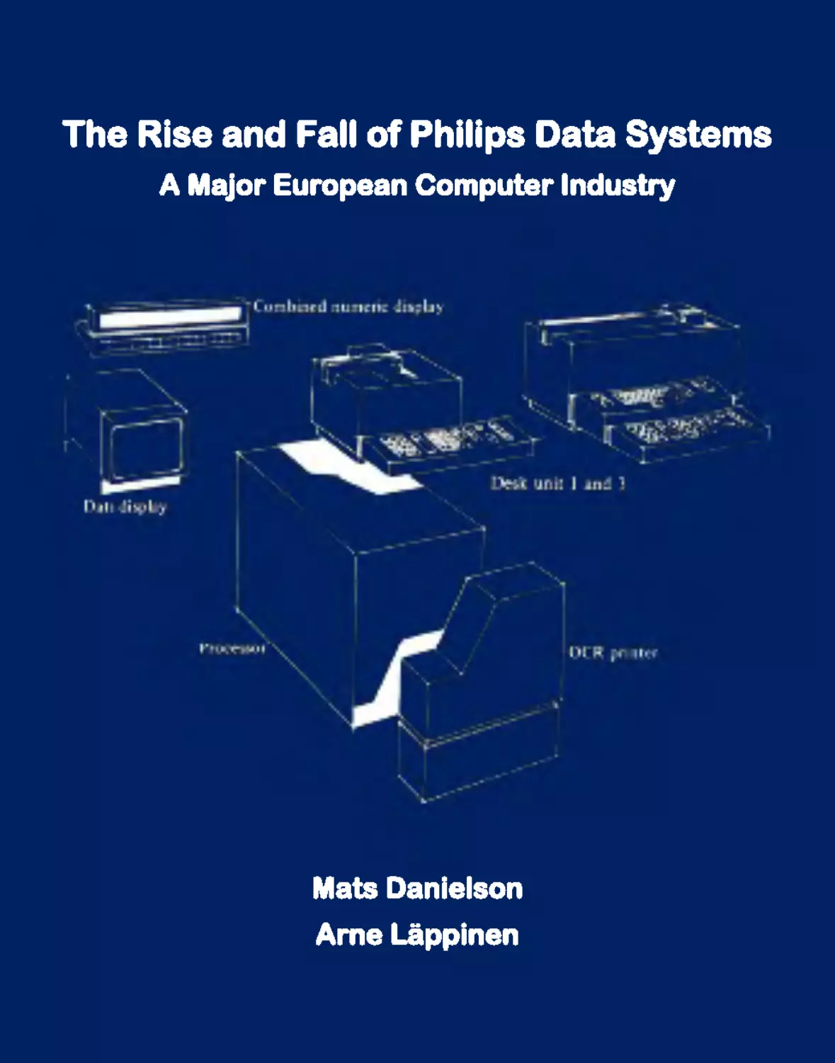
The Rise and Fall of Philips Data Systems
A Major European Computer Industry
Mats Danielson
Arne Läppinen
A MAJOR EUROPEAN COMPUTER INDUSTRY
III
The Rise and Fall of Philips Data Systems
A Major European Computer Industry
Mats Danielson Arne Läppinen
Sine Metu
IV
THE RISE AND FALL OF PHILIPS DATA SYSTEMS
Published by Sine Metu Productions, Stockholm, Sweden
Website: www.sinemetu.se
Licence details: https://creativecommons.org/licenses/by-nc -nd/4.0/
Front cover image: Arenco Electronics 6110 bank terminal prototype from 1969
Front inner cover: All four generations of PTS computers counterclockwise
Back cover image: Philips PTS 6811/UK01/6863 bank computer from 1976
ISBN 978-91-527-6233 -2
Fifth revised printing, December 2024
A MAJOR EUROPEAN COMPUTER INDUSTRY
V
Ticking away the moments that make up a dull day
You fritter and waste the hours in an offhand way
Kicking around on a piece of ground in your hometown
Waiting for someone or something to show you the way
Tired of lying in the sunshine, staying home to watch the rain
You are young and life is long and there is time to kill today
And then one day you find ten years have got behind you
No one told you when to run, you missed the starting gun
So you run and you run to catch up with the sun but it’s sinking
Racing around to come up behind you again
The sun is the same in a relative way but you’re older
Shorter of breath and one day closer to death
–
Time, Roger Waters, 1973
VI
THE RISE AND FALL OF PHILIPS DATA SYSTEMS
Printing History
First printing, May 2023
Second printing, December 2023: Chapter 5 split into two chapters for readability reasons
and Saab Tower footnote on page 347 amended due to new information on its destiny.
Third printing, February 2024: Model number on page 104 and table on page 131 corrected.
Fourth printing, May 2024: Sections 2.8 and A.4 added, Section 9.6 split into two sections,
remainder sign on page 301 corrected, and pages 324 and 325 in Appendix E exchanged.
Fifth printing, December 2024: Sections 4.6 and 5.8 updated, P876 corrected on page 136,
Maestro corrected to PET on page 151, TFM corrected to Task Flow Management on
page 282, and image quality improved through a new printing process.
Table of Contents
Preface .................................................................................................................... 5
1. Early Swedish Computers .............................................................................. 7
1.1 BARK ....................................................................................................................9
1.2 BESK ...................................................................................................................10
1.3 Facit EDB.............................................................................................................16
1.4 TRASK ................................................................................................................22
1.5 Alwac ...................................................................................................................24
1.6 Saab......................................................................................................................27
1.7 Technology Comparison ......................................................................................34
1.8 Nordic Countries ..................................................................................................37
2. Arenco ............................................................................................................ 39
2.1 Arehns Mekaniska Verkstad ................................................................................39
2.2 Siefvert & Fornander ...........................................................................................43
2.3 Merger of Arenco and Sivco ................................................................................45
2.4 Arenco Electronics ...............................................................................................46
2.5 Reunification........................................................................................................48
2.6 Scienta Scandia ....................................................................................................51
2.7 Swedish Computer ...............................................................................................55
2.8 Acquisitions .........................................................................................................59
3. Swedish Banking Automation ..................................................................... 61
3.1 Handelsbanken System 70 ...................................................................................62
3.2 Handelsbanken System 71 ...................................................................................63
3.3 Philips Terminal Systems.....................................................................................68
3.4 Market Competition .............................................................................................71
4. Early Philips Computers .............................................................................. 75
4.1 First Dutch Computers .........................................................................................75
4.2 Electrologica ........................................................................................................76
4.3 Philips Computer Industry ...................................................................................79
2
THE RISE AND FALL OF PHILIPS DATA SYSTEMS
4.4 Philips-Electrologica............................................................................................81
4.5 European Computer Markets ...............................................................................85
4.6 Unidata.................................................................................................................89
5. Philips Minicomputers ............................................................................... 101
5.1 Honeywell ..........................................................................................................101
5.2 Philips Sciences et Industrie ..............................................................................109
5.3 Philips Centre Technique et Industriel ...............................................................112
5.4 Sagittaire ............................................................................................................115
5.5 First Generation P800 Processors ......................................................................117
5.6 Radiotechnique ..................................................................................................121
5.7 First Generation Minicomputers ........................................................................126
5.8 P800 Processor Generations...............................................................................131
6. Product Lines .............................................................................................. 141
6.1 Philips Parts Bin.................................................................................................141
6.2 12NC Part Numbers ...........................................................................................147
6.3 P4000 Office Computers....................................................................................148
6.4 P7000 Data Entry Systems.................................................................................150
6.5 Summary of Product Lines ................................................................................153
7. Philips Sweden ............................................................................................ 157
7.1 First Head Office................................................................................................158
7.2 Philips Teleindustri ............................................................................................163
7.3 Second Head Office ...........................................................................................165
7.4 Philips Electronics Centre..................................................................................168
7.5 Philips Elektronikindustrier ...............................................................................176
7.6 PEAB-D Defence Systems.................................................................................180
8. Philips Terminal Systems ........................................................................... 187
8.1 PTS Division......................................................................................................187
8.2 First PTS Generation..........................................................................................190
8.3 Second PTS Generation .....................................................................................198
A MAJOR EUROPEAN COMPUTER INDUSTRY
3
8.4 Philips Data Systems Service.............................................................................206
8.5 The Development Environment .........................................................................208
8.6 Third PTS Generation ........................................................................................210
8.7 Workstation Controller ......................................................................................218
8.8 Model Numbers .................................................................................................219
8.9 Turf Wars ...........................................................................................................223
8.10 Market Shares ..................................................................................................224
9. Data Systems Decline.................................................................................. 227
9.1 Software Packages .............................................................................................228
9.2 Cool Advertisements..........................................................................................231
9.3 Reorganisation ...................................................................................................235
9.4 32-bit Processors ................................................................................................236
9.5 Octopus ..............................................................................................................241
9.6 Defence Market Withdrawal..............................................................................248
9.7 Divorce and Downsizing....................................................................................249
9.8 Digital Equipment Corp. ....................................................................................250
References............................................................................................................ 259
A. Non-Bank-Office Projects .......................................................................... 267
B. Fil m Star ...................................................................................................... 287
C. Hardware Bugs ........................................................................................... 297
D. Microcode Disassembly .............................................................................. 315
E. CLODO.. .... .... .... .... .... .... .... .... .... .... .... .... .... .... .... .... .... .... .... .... .... .... .... ... .... ... 323
F. Former Premises ......................................................................................... 329
About the Authors .............................................................................................. 353
4
THE RISE AND FALL OF PHILIPS DATA SYSTEMS
“There is no reason for any individual to have a computer in their home.”
–
Ken Olsen, founder, CEO and chairman of Digital Equipment Corp. , 1977
A MAJOR EUROPEAN COMPUTER INDUSTRY
5
Preface
This book is about Philips Data Systems (PDS) in general and Philips Terminal Systems
(PTS) in particular. PTS, a division of PDS, was one of the very few European computer
system manufacturers, perhaps the only one, that managed to occupy the top position world-
wide, by a margin, in a major computer systems market segment over a considerable amount
of time. In this case, it was the segment of front-office banking systems from circa 1975 to
1985. Or probably over a longer period; we are trying to be a bit conservative here. The
book commemorates the great efforts of the many people involved, not only at PTS but also
at the rest of PDS, the great pleasure of working with these colleagues, products, systems,
and projects, and the fantastic results that came out of the endeavour as a whole.
This book can be read in two ways. Either you read it from the first page to the last. That
will give you the complete story. However, readers primarily interested in general Philips
Data Systems history rather than domestic Swedish matters can skip ahead to Chapter 4 on
early Philips computers without much loss of continuity. But as authors, we of course rec-
ommend reading the entire book to get the full picture.
After a long development period together with the pilot customer Svenska Handelsbanken,
regular production shipments of its front-office banking computer systems commenced in
early 1973 – more on this foundational project in the book itself. At the same time, requests
for similar equipment were made to Philips from many other banks, nationally as well as
internationally. Based on the project’s success and the market reactions, Philips Sweden
decided in May 1973 to make PTS banking equipment a large-scale international business
with its focal point in Stockholm. Also in May 1973, it was decided to expand the Philips
Järfälla Electronics Centre premises (in Veddesta, 15 kilometres northwest of Stockholm
City) to house the PTS banking development and manufacturing division as well, thereby
doubling its office and factory space (which had until then only contained Philips Teleindu-
stri, a defence equipment manufacturer). To commemorate these two 50-year anniversaries
during the same month, which in reality was the month when the worldwide PTS industry
was born, this book is finally completed and sent to the publisher in May 2023.
The objectives of this book belong to the categories of general knowledge and education
and preserving industrial heritage rather than trying to be overly analytical. It is not a re-
search book in an academic sense, even though thousands of hours have been spent re-
searching facts included (or not included) in the book. While factual truth is of course par-
amount, an ambition to be fully comprehensive would have been time-wise overwhelming
6
THE RISE AND FALL OF PHILIPS DATA SYSTEMS
and probably killed the project.1 However, if the book can bring back some good memories
combined with some new insights and realisations for those working with Philips computer
equipment in one capacity or another during the 1960s to 1990s, its goals have been met,
perhaps even surpassed. And for those readers, probably the majority, who did not work
with Philips equipment, we hope that the book can serve as a historical account of European
computer technology endeavours – how a European computer industry successfully posi-
tioned itself against tough, sometimes almost overwhelming, American competition in a
significantly large computer world market segment.
The book was written over a rather long period of time, with frequent intermissions. From
the outset, it was conceived as a textbook but it was subsequently decided that it would also
become a picture book. Images are quite often very enjoyable and effective in bringing back
old memories for us that were a part of the endeavours at that time. And for the rest of the
readers, we hope that the images can convey some of the spirit of that time period.
And if the book was written over quite some period of time, it was conceived over a much
longer period. The authors gathered stories as long ago as back in the 1980s when we started
working with Philips equipment and collected images from the early 2000s and on – just for
fun. After a while, the idea of compiling the material into a more coherent form emerged,
but the end result has certainly been a long time in the making. Now we are finally here.
Happy reading!
The authors, Stockholm, May 2023
1 This book is a compilation of information gathered and stories told to us over decades. It has been fact-
checked as far as possible. However, since it is self-funded work, it would have been impracticable for
resource reasons to maintain an academic reference note system.
A MAJOR EUROPEAN COMPUTER INDUSTRY
7
1. Early Swedish Computers
Like many countries at the beginning of the post-war period, Sweden felt the need to secure
its own supply of computing power in order to use it for everything from weapon ballistics
to meteorology, plus (much more unusual) for its in 1945 secretly launched nuclear weapons
programme. For these purposes, Matematikmaskinnämnden (MMN, the Mathematical Ma-
chinery Board) was established in 1948 as a government institution intended to research and
develop computer technology in Sweden. The Swedish government had secretly, immedi-
ately after the end of the Second World War in 1945, decided on the development of a
nuclear weapons programme while keeping the nation and its people in the dark. The pro-
gramme had three cornerstone guises: i) nuclear bomb research at FOA (The Swedish Na-
tional Defence Research Institute), officially aimed only at defending the country from nu-
clear attacks; ii) civilian nuclear power research, officially aimed only at producing cheap
electric power from controlled nuclear reactions; and iii) an ambition to be computationally
self-sufficient in times of crisis. To begin meeting the third requirement, in mid-1948 MMN
scanned the market (which was essentially a US-only market) which contained both differ-
ential analysers and real computers with stored programs in primary memory. After a survey
of user needs and machine availability, MMN placed an order for a REAC differential ana-
lyser from Reeves Instrument Corporation in the US. In those days, no public procurement
process was required in Sweden and it consequently placed the order directly with Reeves.
In 1946, shortly after the war ended, Reeves Instrument Corporation began developing plans
for a digital calculation machine. It hired a mathematician from the original team who had
designed the ENIAC computer to lead the project. His first proposal was to build a machine
called REEVAC based on von Neumann’s EDVAC design descriptions. For reasons un-
known, Reeves decided to scrap his proposal and go ahead with building an analogue com-
puter instead, the REAC. It did with electric circuits what a mechanical differential analyser
did with gears, shafts, and discs, and operated at roughly ten times the speed but with one-
tenth the accuracy. Not very impressive – neither to the MMN scientists, nor to the military.
But why did the MMN board settle for this rather outdated calculation device? The main
reason was that MMN thought it would be easier to obtain an export licence for it, and the
second reason was that the Swedish Navy was one of the more prominent promoters of the
project, and it preferred to have an almost immediate solution. Besides, the REAC differen-
tial analyser suited its needs reasonably well. When the MMN board convened in December
1948, the news had just arrived. Sweden was denied an export licence for the REAC differ-
ential analyser, and now the only option left was for MMN to build a computer on its own.
8
THE RISE AND FALL OF PHILIPS DATA SYSTEMS
The REAC differential analyser
A MAJOR EUROPEAN COMPUTER INDUSTRY
9
1.1 BARK
When the US, which likely knew about the nuclear weapons programme and doubted Swe-
den’s ability to defend itself against the Eastern Bloc, in 1948 denied Sweden an export
licence for a REAC, Swedish researchers did not understand the reasons why. REAC was
an analogue computer with relatively low capacity. It would only have been a stopgap ma-
chine until Sweden either acquired or designed and built its own fully digital general-pur-
pose computer. Now, however, Sweden had to find another intermediate solution. MMN
quickly chose a practical solution to meet the urgent needs of the military. More specifically,
the Navy needed to calculate firing tables for its missiles. In the background was the FRA
(Försvarets radioanstalt, Sweden’s NSA), which needed a computing machine to decrypt
and interpret intercepted radio communication.
The solution came in the form of a relay computer design without stored program memory
called BARK (Binary Arithmetic Relay Calculator). BARK was inspired by the American
ENIAC computer and it was also a way for Swedish scientists to learn about computers
hands-on. Through invisible channels, the nuclear weapons programme was also pushing
for an expedited completion of BARK, which was being built partly from off-the-shelf tel-
ephone switch relays. MMN decided that BARK should be designed and built at the old
premises of KTH Royal Institute of Technology at Drottninggatan 95 in central Stockholm.
The former Drottninggatan premises of KTH Royal Institute of Technology
10
THE RISE AND FALL OF PHILIPS DATA SYSTEMS
The project, which was started in 1948 and ended in 1950, after which BARK was in service
until 1955, was a high-pressure mission for the participants. The KTH associate professor
(Swedish: docent) Conrad Palm was responsible for BARK’s design and construction. The
pressure from the military (primarily the Navy and the FRA, the intelligence agency) pre-
sumably took a significant toll on the promising scientist Palm’s health, and he died within
a year of the project’s completion at the remarkably young age of 44.
Conrad Palm in front of the completed and installed BARK computer
1.2 BESK
Although BARK was better than nothing, it was both slow and unreliable compared to “real”
computers, which at that time were built with vacuum tubes instead of relays. For example,
BARK turned out to have a capacity that was too low for the calculations for the nuclear
weapons programme. BARK’s limited success rushed the plans for an electronic, vacuum
tube-based computer, and the same MMN project group was tasked with building the suc-
cessor to BARK which it called BESK (Binary Electronic Sequence Calculator).
A MAJOR EUROPEAN COMPUTER INDUSTRY
11
BESK’s design was based on vacuum tubes rather than relays and, as a consequence, was
much more powerful. It was so advanced at the time that it, at its debut, was one of the
fastest computers in the world. Depending on which program was being executed, it was
rivalled by the Standards Western Automatic Computer (SWAC) at the US National Bureau
of Standards (NBS) in Los Angeles or the IAS machine at the Institute for Advanced Study
in Princeton, New Jersey. Folklore in Sweden had it that the BESK computer at some point
in time (“for several weeks”) held the overall world record for computing capacity.
2
The
primary point of observation was not the world record as such but that Sweden managed to
build a world-leading computer despite being denied a contract for a simple differential
analyser only five years prior. BESK was completed in late 1953 but not inaugurated until
April 1, 1954, by H.M . King Gustaf VI Adolf of Sweden. At BESK’s inauguration cere-
mony, the King asked, “How can you know its results are correct”? The host briefly lost his
composure and mumbled, “That’s an interesting question”, to which the King replied, “And
what is the answer? I would like to know.” The King was promised an answer at a later date,
and the host was let off the hook. Whether the King ever received an answer is not known.
Upon completion, the machine was recommended to be installed at the site of the under-
ground reactor hall under construction in the middle of Stockholm (on Drottning Kristinas
väg) near KTH, where Sweden’s first experimental nuclear reactor R1 was being built.3
Much to the chagrin of the military, who could not disclose the primary reason for the pro-
posed location, BESK was instead kept in the former KTH premises on Drottninggatan, also
in Stockholm City but two kilometres away, where the machine had been built. One of the
world’s fastest computers and an experimental nuclear reactor in the same building would
have been a formidable facility. Instead, the military personnel and researchers had to carry
their programs (on punched paper tape) those two kilometres back and forth to run their
calculations. Apart from losing time, it also gave them much less control over security and
much of what surrounded the R1 project was top secret. Even today, some software pro-
grams and calculations from the nuclear project are still classified information.
2 Regardless, BESK and the other contenders were surpassed by quite a margin by the IBM NORC (Naval
Ordinance Research Computer) built at Columbia University in New York and completed in late 1954. It
held the world record as the fastest number cruncher for many years. Already at its inauguration, NORC
broke the world record for most decimals of π, delivering a result of 3,089 digits. BESK countered with
the largest known prime number by Hans Riesel, KTH, having 969 digits, a world record held until 1961.
3 The risk-taking by placing an experimental nuclear reactor, intended both for weapons and power-generat-
ing research, in the middle of the city was, by today’s standards, totally incomprehensible. The risk of it
running rampant could in no way be ruled out or even quantified since too little was known in Sweden
about the implementation of control mechanisms of critical nuclear processes at that time.
12
THE RISE AND FALL OF PHILIPS DATA SYSTEMS
BESK installed and running at Drottninggatan 95
Outline of BESK’s main peripheral units and secondary memory
A MAJOR EUROPEAN COMPUTER INDUSTRY
13
BESK calculated highly advanced (at the time) numerical problems, including telephone
traffic statistics for Televerket (the Swedish phone operator monopoly), weather forecasts
for SMHI, wing profiles for Saab’s military aircraft and road profiles for the Swedish Road
Administration. At night, the FRA decrypted intercepted radio traffic but it was secret, so
secret that some of the logbooks are still classified. Equally secret were the calculations for
the Swedish nuclear bomb programme that were run on BESK. For some such processing,
the smaller BESK-replica SMIL in Lund was preferred because it was more of a low-profile
installation and secrecy and security were vital. However, SMIL was far away and not in
service until June 1956, which meant that all calculations prior to that date had to be made
using BESK during the night shift. The suggested placement of MMN’s BESK cousin, the
Facit EDB 3 (see Section 1.3), in the R1 reactor hall that was argued for in 1959 also had to
do with the nuclear weapons programme. But it was instead installed in the same building
as BESK, just one floor down (on the ground floor). The two computers served in parallel
until January 1966. When the weapons part of the national nuclear programme was revealed
to the public in March 1966, requests for computing capacity at the R1 site ceased immedi-
ately. Four years later, in 1970, the R1 reactor was closed. The weapons programme did,
however, secretly continue until 1972 when it was finally terminated.
The R1 nuclear reactor at Drottning Kristinas väg 51 in central Stockholm
14
THE RISE AND FALL OF PHILIPS DATA SYSTEMS
The IBM NORC took over as the world’s fastest computer in late 1954
In 1960, a 49-second vector graphics animation of a car travelling along the planned motor-
way from Stockholm City to Nacka (Värmdöleden, Road 222) was created using the BESK
computer. Programmers at Kungliga väg- och vattenbyggnadsstyrelsen (The Swedish Royal
Board for Public Road and Water Structures; later Vägverket, presently Trafikverket) real-
ised that they had all the information available to be able to visualise the planned road from
a driver’s perspective. In front of an adapted oscilloscope-type screen connected to BESK,
with a resolution of about one megapixel, a 35 mm camera with an extended film magazine
was mounted on a custom-made stand. The camera was automatically controlled by the
computer, which sent a signal to the camera to advance the film when a new image was fed
into the oscilloscope. It took a picture every twenty metres of the virtual road. Not much
post-processing was possible, so the film was quickly completed once the equipment had
been built and tested. It resulted in a fictitious journey on the virtual motorway at a speed
of 110 km/h (70 mph). The animation was broadcast in November 1961 during primetime
on the Swedish national TV news programme Aktuellt. This was the world’s first computer
animation and the general public was duly amazed.4
4 The animation can still be found on YouTube in 2023; search for “rendering of a planned highway”.
A MAJOR EUROPEAN COMPUTER INDUSTRY
15
The filming device attached to BESK
The Road 222 animation on the BESK computer
16
THE RISE AND FALL OF PHILIPS DATA SYSTEMS
The image above shows one frame of the animation. It is clearly visible how the road
stretches out in front of the viewer. Some claims were made that the animation showed a
road in another country. For example, West Germany was suggested but it is obvious from
the footage that it shows left-hand traffic which was quite unusual among non-British/Com-
monwealth countries but was observed until September 1967 in Sweden.
When BESK was completed in late 1953, plans were already made for its successor. Super-
BESK was the MMN employees’ project name for the larger and faster machine they
wanted to build as BESK’s successor. The MMN board formally belonged to the Ministry
of Education but it also had to belong to some management structure and reside in an or-
ganisational chart to fit the Swedish state’s bureaucratic system. It had been decided that
MMN should be placed under SCB (Statistiska centralbyrån, The Swedish Central Statisti-
cal Agency, now Statistics Sweden), whose director general Karin Kock, as a consequence
of MMN’s placement under her control, almost single-handedly killed off the Swedish gov-
ernment’s computing initiative. Surprisingly, although BESK was fully booked day and
night except for maintenance, she turned out to be of the opinion that the computational
capacity of the BESK machine would be sufficient for the coming 20 years and conse-
quently did not want to support a new design, not even a feasibility study. BESK was never
a financial burden to SCB – its hourly rate easily covered the running costs. Although Kock
was a former member of the Swedish government, she was probably unaware of the fact
that she simultaneously killed a cornerstone of the Swedish nuclear weapons programme.
There was another development option proposed by the MMN team as well – to build a
transistorised version of BESK that would use the same but somewhat extended architec-
ture. It would be software compatible and would run much faster and be considerably more
reliable thanks to the use of newer technologies. That option was also rejected.
MMN sold the BESK blueprints to other organisations that wanted to build a BESK replica.
They were acquired by Lund University (1954), Saab (1954), Regnecentralen in Denmark
(1955) and Facit (1956). The former three only built one copy each while Facit built nine,
making a total of 14 BESK-based machines built including TRASK in Section 1.4. MMN
was moved in 1961 to the Ministry of Finance and in 1963 it was disbanded and its future
responsibilities transferred to Statskontoret (the Swedish Agency for Public Management).
1.3 Facit EDB
Disgruntled, the key employees at MMN (18 out of 40 in total) collectively looked for new
job positions and opportunities in another organisation where they could continue to develop
A MAJOR EUROPEAN COMPUTER INDUSTRY
17
and build new computers. The Swedish company Facit, one of the world’s largest manufac-
turers of typewriters and mechanical calculators, wanted a piece of the emerging computer
industry business. As noted above, in 1956 it acquired the blueprints and rights to produce
BESK machines and employed the 18 former MMN group members to make its version of
BESK. The group was internally at Facit referred to as the “BESK boys”. The computer
was named Facit EDB (Elektronisk DataBehandling, Electronic Data Processing), and was
manufactured in a total of nine copies, four of which became the basis of their own compu-
ting service business. All except the first copy were partly transistorised and called model
EDB 3. The first was delivered in 1957 and the last in 1962.
The new Facit division’s offices were initially housed in the predominantly residential dis-
trict Östermalm in Stockholm at Karlavägen 62, a classic address in Swedish computing
history. Facit soon outgrew the premises, and additional offices were rented in neighbouring
buildings. When this was not enough either, other solutions had to be found. A building lot
was acquired in Vreten industrial park in Solna, just north of Stockholm, and a five-storey
“computer centre” was established there (instead of at Facit’s primary location in Åtvida-
berg, 220 kilometres south of Stockholm) to produce the EDB computers. The centre was
inaugurated in 1960. This was a significant undertaking by Facit and around 300 people
were employed in its heyday, but only a few years later the entire computer division was
closed. The last (and most spectacular) computer was delivered in November 1962 to the
insurance company Framtiden (The Future). It displayed the computer with ten spinning
magnetic tape carousel memories in its corporate storefront windows located at Birger Jarls-
gatan 50 in the middle of Stockholm City (see page 22). The installation was a popular sight
among Stockholmers. Those were the days when a major company could keep its infor-
mation processing behind ground-floor ordinary glass windows and display it to the public
in the capital’s city centre without risking interruption, sabotage or data theft.
And speaking of storefront windows, the Facit computing service centre at Karlavägen 62
remained in operation until November 1966, displaying a large model replica of the EDB
computer in its storefront that attracted the neighbourhood kids (see page 20). Computers
were known as “electronic brains” by the public at that time, spurring all kinds of fantasies
in the kids around. One of the authors started school just a block away a few years later, and
the stories still lingered. The world’s once fastest electronic brain only a block away was
something out of the ordinary for elementary school children, especially at that time when
both information and, in particular, sensations were scarce. What could it do? Could it think?
Could it do our homework? Could it read our thoughts? Was it dangerous? The storefront
model at least seemed friendly.
18
THE RISE AND FALL OF PHILIPS DATA SYSTEMS
An electronic brain was both scary and exciting for us young school kids. And although we
never got to see it in real life, its impression stayed with us for many years afterwards.
Karlavägen 62, containing Facit Electronics head office and computing service centre
A MAJOR EUROPEAN COMPUTER INDUSTRY
19
In fact, some stories of the Facit EDB electronic brain, albeit quite a bit more real, were one
of the reasons that led one of the authors to study computer science more than a decade later.
Karlavägen 64, containing Facit Electronics offices, demolished in 1964
20
THE RISE AND FALL OF PHILIPS DATA SYSTEMS
EDB 3 display model in Facit Electronics’ head office storefront at Karlavägen 62
The surprising actual size of an EDB 3 display model (at another location)
A MAJOR EUROPEAN COMPUTER INDUSTRY
21
Advertisement for Facit EDB computers
The nine Facit EDB deliveries (buyer, location and inauguration date; in Swedish)
22
THE RISE AND FALL OF PHILIPS DATA SYSTEMS
Since Facit quite soon realised that there was no money to be made from hand-built, over-
engineered vacuum-tube mainframes, it tried to halt the business but nine systems had al-
ready been sold and therefore had to be manufactured. When Facit’s top management un-
derstood that the Facit EDB computer had become obsolete, they decided to move on to
transistorised military computers and peripherals. The transistorised military DS 9000 com-
puter, manufactured in ten copies, became Facit’s last self-built computer; see also page 30.
The insurance company Framtiden’s storefront windows facing Birger Jarlsgatan
1.4 TRASK
Those who remained at the Mathematical Machinery Board after the BESK boys left were
mainly kept busy running BESK and planning for and receiving a Facit EDB 3 which would
more than double MMN’s total computing capacity, despite the reluctance shown by SCB.
It was installed on the ground floor in October 1959 (BESK was one floor up), and after
that installation, MMN could start planning for the next step – the continuation of BESK in
the form of upgrades that made it faster and more reliable and also enabled it to be gradually
A MAJOR EUROPEAN COMPUTER INDUSTRY
23
expanded with new capabilities. Any new designs were ruled out, even if the next machine
would have been software compatible with BESK and thus all programs could continue to
run even after BESK was shut down (which occurred in 1966). However, the latter idea was
revised by MMN to become a maintenance plan to improve reliability. Part of the plan was
to replace the vacuum tubes in BESK with transistors. While the transistors were being
procured and installed, MMN was, under a maintenance and upgrade guise, secretly devel-
oping the new TRASK (Transistorised Sequence Calculator) computer, which was a fully
transistorised and improved successor to BESK. But too much time had been lost, and the
next disaster soon struck. MMN was disbanded in 1963 (see page 16) and the responsibility
for and ownership of the half-finished TRASK was transferred to the Nobel Institute for
Physics in Frescati (from 1964, the Atomic Research Institute, AFI). It had no space for the
development work, and hence TRASK was built mainly elsewhere, in a former dairy shop
at the corner of Dalagatan and Vanadisvägen in north central Stockholm. With no interest
shown by SCB, the only copy of TRASK ever built was completed in 1965 and handed over
to AFI at Stockholm University where it remained in service until 1980.
The TRASK computer at the Atomic Research Institute
24
THE RISE AND FALL OF PHILIPS DATA SYSTEMS
1.5 Alwac
In 1952, the Electrolux (Swedish whiteware giant) owner and billionaire Axel Wenner-Gren
acquired Logistics Research in Los Angeles (later renamed Alwac Corporation) and began
manufacturing Alwac – Axel Leonard Wenner-Gren’s Automatic Computer. It was initially
intended for control purposes for a Wenner-Gren invention, the Alweg monorail 5 (an acro-
nym also created directly from his name) but it was soon realised that the computers could
also be marketed and sold more widely. In 1956, Wenner-Gren decided to start manufactur-
ing in Sweden in the newly-built Wegetronic Center in Bollmora, 19 kilometres southeast
of Stockholm City. The Bollmora computer was a version of the Alwac III called Wege-
matic 1000. Sales were slow on both sides of the Atlantic but Wenner-Gren was in the habit
of donating equipment to educational institutions. Uppsala University and CTH received
Alwac III computers and in 1960, Åbo Akademi received Finland’s first computer, a We-
gematic 1000. The obligatory oscilloscope on every operator console desk added a scientific
touch to all Alwac and Wegematic installations. Seven Wegematic computers were deliv-
ered in 1960−1961 through an agreement with the office equipment manufacturer Addo in
Malmö (see page 86) until production ceased following Wenner-Gren’s death in November
1961. The Wegetronic Center became an LM Ericsson telecom factory from 1963 to 1993.
The 18-kilometre Tokyo Alweg Monorail from 1964, still in operation today
5 When Wenner-Gren’s health declined in 1960, Alweg’s technology was licensed to Hitachi which to this day
continues to build monorail systems worldwide based on that technology. For example, the world’s busiest
monorail line, the Tokyo Monorail, was supplied by Hitachi and completed in time for the Olympics in 1964.
A MAJOR EUROPEAN COMPUTER INDUSTRY
25
Alwac III computer in 1959, complete with an oscilloscope
Wegematic 1000 computer in 1960, also with an oscilloscope
26
THE RISE AND FALL OF PHILIPS DATA SYSTEMS
Wenner-Gren was good at finding publicity about his projects
A MAJOR EUROPEAN COMPUTER INDUSTRY
27
1.6 Saab
Facit realised already in the early 1960s that hand-built low-volume computers would not
be profitable and ceased production in 1962. Saab, on the other hand, stuck to the idea and
developed a series of computers that over time accrued substantial losses (see also page 33).
Datasaab was a division within Saab that in the mid-1950s began working with computers
as a by-product of its aircraft manufacturing needs. The first step in this direction was to
sign an agreement in December 1954 with Matematikmaskinnämnden for the permission to
build its own copy of BESK in Linköping, which when completed in late 1957 was called
SARA (Saabs RäkneAutomat, Saab’s Calculator Automaton). The vacuum tube-equipped
digital computer performed strength calculations (especially for the wings) for the already
almost fully developed Saab 35 Draken fighter aircraft and later for its successor, the Saab
37 Viggen. But for some reason, compatibility was not high on the priority list of SARA’s
project manager although he was expected to build a BESK replica. SARA’s instruction set
deliberately differed from BESK’s (“enhanced”). Although they were the same machine in
principle, this difference prohibited software compatibility and reuse. Instead, in 1958 Saab
had to develop an inefficient emulator for BESK to run SARA’s programs. This is a lesson
that has been learned many times since, almost every time a “superior” instruction set was
implemented instead of the prevailing standard. One of Saab’s first computer-based field
experiments was carried out in the late 1950s aboard the Robot 330, a two-stage missile
capable of striking Baltic cities and ports in the Soviet Union carrying a nuclear bomb.
Datasaab’s fully transistorised military computer SANK (Saabs Automatiska Navigerings -
Kalkylator, Saab’s Automatic Navigation Calculator, later called D2 in its civilian version),
completed in 1960, was the prototype for Datasaab’s computer development. SANK was
specified to be able to be so small that a version (CK37/NSK) could fit aboard the Saab 37
but also in missiles. Thus, SANK was a cornerstone of the Swedish nuclear weapons pro-
gramme, but the development of missile computers was dealt a financial blow in 1966 when
the programme was revealed to the public. Saab’s computer efforts, based on SANK, fol-
lowed two branches: on one hand control computers mounted in Saab’s military aircraft and
missiles, see above; on the other hand non-military computers for the commercial market.
The civilian mainframe computers were called the “heavy” product line (D21, D22, D23
and derivatives), based on the SANK architecture, and the minicomputers were called the
“light” product line (D5, D15, D16), with both the latter products based on computers from
Computer Automation in Los Angeles rather than from Saab itself. Similarly, the successor
to the CK37 aircraft computer was the CD107 from Singer Kearfott in New Jersey.
28
THE RISE AND FALL OF PHILIPS DATA SYSTEMS
Development of the Saab-built computers
The first D21 installation, at Skandinaviska Elverk in Stockholm
A MAJOR EUROPEAN COMPUTER INDUSTRY
29
The order value of military procurements decreased sharply in Sweden during the second
half of the 1960s, and the company SRT then wanted to abolish its thereby unprofitable
military-oriented computer business. The company’s computer division was spun off and
established as the new company Stansaab, initially owned in equal parts by the government,
Saab and ITT. After about two years, ITT left its co-ownership. Forming Stansaab was one
of the events in the 1970s structural changes of the unprofitable Swedish computer industry.
The global development of the computer industry was in the 1970s dominated by several
American companies led by IBM. The European computer industry had a tough time with
the competition from these companies, which inspired many European governments to in-
vest considerable tax funds to keep their domestic computer industries afloat under their
wings. In 1978, it was decided to merge the computer businesses of Saab and Stansaab; see
the flowchart on the next page. The new company called Datasaab, a merger of the Stansaab
company and Saab’s Datasaab division, received substantial government grants and subsi-
dies. Despite this, it was very far from profitable (the loss in 1978 was 40% of the turnover,
the worst of all large companies in Sweden; in 1979 30%) and new ownership was sought.
Datasaab as a company lasted only for three years. In 1981, the telecommunications com-
pany LM Ericsson took over Datasaab, and Ericsson Information Systems AB (EIS) was
born; see page 33. Not being much more successful than Saab, Ericsson sold its EIS business
to Nokia already in 1988 and only two years later, in 1990, Nokia sold it on to the British
company ICL. The specialised financial/banking knowledge and organisational culture ac-
cumulated within the Datasaab/EIS organisation was carried over to ICL at the acquisition.
It was subsequently put to use by ICL in, for example, the Horizon UK Post Office system.
The system was developed by ICL in the mid-1990s and piloted from 1996 onwards. ICL,
in turn, was acquired by Fujitsu in 1998 (the name was not changed until 2002).
Since acquiring ICL, Fujitsu has been involved in a surprising number of software scandals,
particularly in the UK, ranging from the Libra (legal management system) and NHS (the
National Health Service’s digitalisation of medical records) cases in the early 2000s to the
Horizon reconciliation scandal in the 2010s and counting. The latter is certainly the largest
public computer scandal in the world by far. 236 UK Post Office subpostmasters were im-
prisoned and over 500 more falsely convicted of fraud due to ICL/Fujitsu software bugs. A
lot of trust is placed in those who develop banking and retail systems that handle large sums
of money. The sense of responsibility to keep such systems error-free should be very strong.
Many users of these systems handle much larger amounts daily than they have in total sav-
ings. It must not be the systems that fail them by malfunctioning. This is an ethical and
moral responsibility that every such software organisation should respect and embrace.
30
THE RISE AND FALL OF PHILIPS DATA SYSTEMS
Flowchart of Saab’s computer businesses6
But could anyone in Sweden build office computer systems? Let us go back in time to the
mid-1960s. The two mechanical office equipment manufacturers Addo and Facit were fierce
competitors. Addo developed calculators based on so-called ledger cards, and the machines
were eventually transistorised. However, the competition between the two companies ended
when Facit acquired the entire Addo company in 1966 (see also page 62), and in 1973, the
merged company began using an imported American minicomputer. In 1974, Saab bought
the office machinery business from Facit consisting of a product line using that minicom-
puter (Computer Automation Alpha LSI, which Facit called 6501 and Saab subsequently
called D15, later D16; see pages 3536) and a series of desk calculators. Thus, Datasaab’s
product line D15/D16 was not included in the minicomputer business by Saab itself but via
the acquisition of Facit/Addo’s office division.
6 The authors would like to mention that we are not experts on the Datasaab products/lineage since we come
from the other camp in Sweden – Philips. There exist detailed sources on Datasaab’s activities, which are
much more documented than those of Philips Sweden. For the sake of completeness, we still include some
facts about Datasaab’s endeavours since they became competitors in the front-office banking systems mar-
ket segment which this book is largely about. This section is based on documents from the Saab veteran so-
ciety Datasaabs vänner (Friends of Datasaab) and on the PhD thesis recommended in the References.
A MAJOR EUROPEAN COMPUTER INDUSTRY
31
However, there was also the earlier D5.
Inspired by the development of the
“heavy” product line and of the flight
computer, Datasaab developed the D5
minicomputer in 1969 in close collab-
oration with Facit. It was quite a small
computer which had a 16-bit instruc-
tion length and was made of TTL logic
mounted on printed circuit boards. It
had only 28 different instructions and
16 kwords of memory (32 kB). An ad-
dition of two 16-bit numbers took 9.4
μs on a D5/20 from 1972. This can be
compared to Philips P855 from 1971,
which we will discuss in the coming
chapters. The P855 had 97 instructions
and took less than 4 μs for a double ad-
dition, i.e. a 32-bit addition on a 16-bit
machine, which is a fairly much more complicated operation. Even the Saab history docu-
ment Tema Bank 7 admits that Swedish Computer (SC) was ahead of Saab regarding front-
office banking computers. This was despite SC’s CPU being considered by Philips to be
severely behind its own P855. For mechanical, compatibility and time constraint reasons,
Philips still decided to use SC’s CPU in its first-generation online banking computers .
But despite its weaknesses, the D5 formed the core of one of the world’s first online front-
office banking systems. In the late 1960s, Sparbankerna (the Nordic Savings Banks) wanted
to build a network of bank terminal systems. It became the world’s second distributed com-
puting contract for online banking, signed in September 1969, only preceded by Svenska
Handelsbanken’s agreement with Arenco Electronics in April 1968. Datasaab had the D5
minicomputer under development, but no suitable workstation modules or other peripherals.
The solution for Datasaab was to join forces with Facit. Together, they won the savings
banks contract and the first pilot installations in a real banking environment took place in
April 1972. During 1973, many of the banking terminals were connected to the savings
7 Datasaabs historia Tema Bank by Datasaabs vänner. The specific text quoted was written by Tord Jöran
Hallberg whose book on Sweden’s IT history is recommended in the References. He was deeply involved in
Saab’s computer activities at the time and acknowledged that Arenco/Swedish Computer was ahead of Saab.
32
THE RISE AND FALL OF PHILIPS DATA SYSTEMS
banks’ central mainframe computers. More than 6,000 terminals were installed in the four
Nordic countries in total. Ultimately, around 1,000 savings bank offices participated in this
project. The project was the first of several bank terminal system projects sold by Datasaab,
and the company rose to number five in the world market for banking front-office comput-
ers, albeit without making much profit since the systems had to be heavily customised for
each customer. Much more on the bank front-office system market in Chapter 3.
Datasaab D16 with peripherals; CAI Alpha LSI-4 (see pages 3536) on top in the cabinet
The “heavy” product line was in 1975 handed over to a jointly formed company, Saab Uni-
vac, with American Sperry Univac as the majority owner. Saab had major problems with
the quality of its D23 computers, which after repeated delays were finally sold in four cop-
ies, and then Univac 1100 computers were sold to the customers instead. The joint company
lasted only for five years, until Univac had captured Saab’s customer base. From records, it
seems that only 32 D21, 42 D22, 18 D220, 12 D223 and 4 D23 computers were ever sold.
This sums up to 108 units, fewer than the Philips P1000/P2000 series discussed in Section
A MAJOR EUROPEAN COMPUTER INDUSTRY
33
4.4. Even if the numbers are not exactly accurate, they were at least an order of magnitude
less than many American manufacturers. See also Section 4.5 for a “heavy” world market
overview and Section 8.10 for a “light” one. Similar to Philips’ mainframes, Saab’s “heavy”
computers were much less of a market success than the “light” ones. It was simply not
sustainable for European actors during that time to compete in the civilian mainframe mar-
ket sector. Of course, the financial situation was very different for projects involved in and
financed by the military, such as the Swedish nuclear weapons programme. The offspring
CK37 from 1964 was the first navigation computer for the Viggen military aircraft (see page
27), and a version was intended to become the on-board navigation computer for future
nuclear missiles. However, since everything is not yet known about the Swedish nuclear
bomb programme, it is not fruitful to discuss the actual profitability of Saab’s “heavy” com-
puters. It might be that the “heavy” product line ultimately managed to break even due to
indirect financing from the nuclear weapons programme; we cannot know. But it is defi-
nitely a possibility because otherwise, if it was unprofitable for so long, why was it contin-
ued? The weapons programme might also have been a reason for the subsidies and prefer-
ential treatment the civilian “heavy” Saab computers received in Sweden at the time; again,
we cannot know and will therefore refrain from speculating. The fact that the Swedish gov-
ernment had a secret nuclear weapons programme running for 27 years until 1972 makes it
difficult to exclude such external factors when trying to understand the domestic computer
market in Sweden at that time. Due to confidentiality reasons, we may never know the truth.
In 1981, LM Ericsson took over Datasaab, which by then only sold the “light” product line,
with Televerket (the Swedish telecom monopoly agency) as a minority shareholder, and
called it Ericsson Information Systems (EIS). It was forecasted that in 1990, EIS’ sales vol-
ume would constitute as large a part of LM Ericsson as the telecommunications systems
division. It was perceived within EIS as a realistic objective to become as large as telecom.
This would be realised by selling existing products, supplemented by the acquisition of ad-
ditional companies. When EIS was formed in 1981, the question of the future of the bank
terminal systems was a stumbling block. They posed a large problem and lost much money
every year. The first plan was to hold discussions with Philips about a joint venture or other
alternative solutions. However, Philips showed no interest, itself having a more modern and
profitable business in the exact same sector. Furthermore, Philips believed it could win over
Datasaab’s customers through open tender processes. Thus, EIS was forced to keep the bank
terminal business. It formed the Business Systems division together with the minicomputer
systems business. The strategy was to try to reduce costs by collaborating with the mini-
computers in the new division. That plan ultimately failed, and the banking business would
34
THE RISE AND FALL OF PHILIPS DATA SYSTEMS
never be turned around. See the PhD thesis recommended in the References for a much
more detailed account of the events that unfolded before and after the takeover and merger.
1.7 Technology Comparison
Although this chapter precedes the description of the Philips minicomputers in Chapter 5,
we will briefly compare the two manufacturers’ CPUs before leaving Datasaab. Both man-
ufacturers’ systems in the early 1970s were built around homemade minicomputers with
self-designed processors. In the Saab case, at least ten different architectures were suggested
and tried during 1969 in a design process that seemed rather academic and non-industrial.
At least three professors from KTH were deeply involved in the designs (Dahlquist, Lange-
fors and Thorelli), which might partly explain the working methods in the project. Although
all three were highly competent professors , their industrial experience was limited. This is
similar to the professors Dijkstra and Parnas, who worked on Philips-Electrologica comput-
ers; see Section 4.4 . They did not contribute much to industrial or market success either.
Of the ten or more Datasaab design proposals, some were 16-bit solutions while others were
8 or 24. Ultimately, four proposals were selected to become a family of minicomputers
called D5/10, D5/20, D5/30 and D5/40 (the latter one never realised). There was some com-
patibility between the four members of the family, but not completely. The family members
all had limited instruction sets, ranging from 25 to 35 instructions. This can be compared
with the Philips minicomputer CPU P855 discussed in Chapter 5. It was created in the same
time period as the D5 family, but the architecture was inspired by studies of i.a. the then-
leading processor PDP-8 from Digital Equipment and several field trips were made to the
US to meet leading manufacturers. The P855 had 97 instructions in its instruction set; see
pages 117120. The exact number depends on what counts as an instruction, but it was
evident that the P855 had a full and rich instruction set while the D5 did not. Furthermore,
only one Philips architecture was ever proposed and once approved, it was realised as only
one processor model. That laid the foundation for greater sales volumes and profitability.
Another difference was that the Philips CPU was from the outset designed for real-time
applications. It had a complete interrupt-handling system with 63 interrupt levels, including
software interrupts. This enabled the construction of a real-time operating system with very
short response times, and the CPU was easy to use in everything from banking systems and
office computers to process control systems. The D5 family, on the other hand, lacked in-
terrupt handling, and thus it was difficult to implement a real operating system. Instead, the
language interpreter had to check the hardware status of the peripherals through a busy loop
A MAJOR EUROPEAN COMPUTER INDUSTRY
35
to see if data should be transferred. An architecture requiring a program like the following
would never have been accepted at Philips. It contains an instruction that jumps to itself
(L1: JUMP L1), seemingly creating an eternal loop, i.e. a lock-up. However, in the absence
of an operating system, the interpreter in the background had to do a lot of manipulation
and somehow released the code once the keyboard was activated. Such behind-the-scene
semantics were rarely advisable, especially when done in lieu of a real operating system.
Program for reading a digit key press in the interpreted D5 DIL language (in Swedish)
While the Philips P855 was further developed for two more generations and also cast onto
chipsets (a five-chip set in 1976 and a single chip in 1979), the D5 series does not appear to
have been further developed. Instead, in 1973 Facit imported an Alpha LSI-2 computer from
Computer Automation Inc. (CAI) and renamed it the Facit 6501.8 It was then taken over by
Saab and re-renamed the Datasaab D15. Saab now had a small, inexpensive computer with
a fairly modern processor. Philips was no stranger to rebranding either. Before building its
own P855 processor, it imported Honeywell minicomputers and gave them Philips names.
The difference was that Philips did so before it had designed its first minicomputer CPU,
not after. The subsequent Datasaab D16/10 and D16/30 were CAI LSI-4/10 and LSI-4 /30
8 Computer Automation Inc. in Los Angeles developed the Alpha LSI computer series, which contained an LSI
technology processor (standard at the time), and sold it either as a circuit board or as a complete computer in
a rack-mountable unit. It can be seen as a part of the D16 computer on page 32 (the top half of the cabinet).
The Alpha LSI computers were actually imported to Sweden by the electronics instrument maker and trading
house Scandia Metric in Solna, which then resold them to Swedish customers including Facit and (later) Data -
saab. However, the largest customer group in Sweden was upper secondary schools (high schools) that bought
Alpha LSI computers for educational purposes. More than one thousand machines were imported in total.
36
THE RISE AND FALL OF PHILIPS DATA SYSTEMS
Alpha computers from 1977 with chipsets consisting of four ALU and three control logic
chips (less powerful than the 1976 Philips P851 with four ALU chips and one control logic
chip; see page 133). Surprisingly, the follow-up Datasaab D16/20 from 1979 was not a CAI
computer but rather a homebrew machine that existed in parallel. When Datasaab became
EIS in 1981, the D16 was rebranded as EIS E2100 (banking) and E2500 (office computers).
The US Computer Automation Alpha LSI-4 computer; compare with the image on page 32
A MAJOR EUROPEAN COMPUTER INDUSTRY
37
1.8 Nordic Countries
In all Nordic countries, as in most of the rest of Europe, domestic computer manufacturers
were subsidised and given preferential treatment. Whether it was Saab in Sweden, Norsk
Data in Norway, Regnecentralen in Denmark or Nokia in Finland, it was rarely a good idea
in the long run compared to participating in open procurements. We end this chapter with a
story from Norway. Norsk Data was a minicomputer manufacturer located in Oslo, Norway.
It existed from 1967 to 1998 and had its most prolific period from the mid-1970s to the late
1980s. When the company peaked in 1987, it was the 30th largest in Norway by turnover
but hyped to be the second largest on the stock exchange. According to Norsk Data, the next
page recounts how it conquered the university college market in its home country.
A Norsk Data ND-560 computer system
38
THE RISE AND FALL OF PHILIPS DATA SYSTEMS
Part of a paper from the conference History of Nordic Computing, IFIP WG 9.7, June 16-
18, 2003, in Trondheim, Norway. Proceeding editors Bubenko, Impagliazzo and Sølvberg.
This way of winning tenders in domestic markets was not uncommon, and the text tells that
Norsk Data considered this a viable and appropriate method to defeat competitors. Further-
more, the company boasted of using this method repeatedly. Such a strategy of avoiding
competition and gaining artificial market shares by preferential treatment was common not
only in the Nordic countries but also in most of the rest of Europe and is discussed further
in Chapter 4 in conjunction with European markets and the Unidata debacle.
A MAJOR EUROPEAN COMPUTER INDUSTRY
39
2. Arenco
2.1 Arehns Mekaniska Verkstad
The predecessors of Arehns Mekaniska Verkstad, some smaller match manufacturing com-
panies, were established in the mid-1800s in the western part of Kungsholmen island, then
a remote industrial area in Stockholm, now a part of the inner city. Some were located close
to Igeldammarna, the pharmacies’ leech farms.9 During the 1880s, more efficient machines
were developed to manufacture both matches and matchboxes and the operations became
more industrialised. Oscar Arehn and his son Gerhard were active in the industry and ac-
quired patents for several inventions. Gerhard Arehns Mekaniska Verkstad was founded in
1885 and became a subsidiary of Förenade Tändsticksfabriker in 1915. Its business was to
develop automatic machines for, e.g ., the match manufacturing and packaging industries.
Interior at the Arehns Mekaniska Verkstad factory in 1908
9 Leeches were considered an essential and effective medical treatment at that time.
40
THE RISE AND FALL OF PHILIPS DATA SYSTEMS
In 1927, it was renamed Arenco AB. The company’s factory was located at Alströmergatan
on Kungsholmen island in central Stockholm. Arenco manufactured mechanical parts with
high precision that were resistant to harsh environments. New customers were sought where
these advanced properties were required, with defence equipment customers becoming an
important prospective group to target.
Arenco’s premises consisted of a four-storey factory and a single-storey foundry for casting
the larger machine parts. The foundry can be seen as a gap in the front of the building to the
right in the picture. The gap was filled much later when three more floors were built on top
of the foundry. That became profitable when property prices rose steeply on Kungsholmen
as an effect of the former industrial district being gentrified and transformed into a fashion-
able inner-city residential district.
Arenco’s Kungsholmen factory building; the one-storey foundry to the right
A MAJOR EUROPEAN COMPUTER INDUSTRY
41
On the same island where Arehns was located, the company Formator AB was formed in
September 1907 to explore advances in die casting in nearby Hornsberg on Kungsholmen.
When the casting business did not go well, the company switched to manufacturing military
weapons instead, with greater success. After a while, it supplemented its product portfolio
with machine parts for the match and tobacco industries. During the autumn of 1923, Forma-
tor was sold to the German company Brunsviga, a manufacturer of, among other things,
mechanical calculators. As a consequence, Formator began developing more modern calcu-
lators with ten separate keys for the ten digits instead of traditional levers. When Arehns
acquired Formator some years later, however, the calculator division was disbanded and the
patents of Karl Rudin from Formator were sold to Åtvidabergs Industrier in 1929. They
became the foundation for the Facit calculators from 1932 onwards and thus for the entire
Facit office machine business discussed in Chapter 1, which initially used these patents.
Thereby, through its own actions, Arenco missed out on a very large world-class business.
An early Facit Standard calculator
From the beginning, Facit was a calculator business with a factory on Alströmergatan in
Stockholm, i.e . on the same street as Arenco. When the company went bankrupt in 1922,
Åtvidabergs Industrier was given the opportunity to take over the business of manufacturing
42
THE RISE AND FALL OF PHILIPS DATA SYSTEMS
the Facit Standard calculating machine. The Standard had been developed by Karl Rudin,
who laid the foundation for Åtvidabergs Industrier’s later successes through his inventions.
The machine was initially not a financial success for the company. Facit made substantial
cost savings by moving the production to Åtvidaberg and thus the company did better fi-
nancially, but Åtvidabergs Industrier was sceptical of Facit for a long time, and it was close
to being sold to Brunsviga. However, Facit would later become a key pillar.
Arenco and Formator shared offices and production facilities but had separate product lines.
Most parts were handmade at this time, and thus there were fewer synergies found in pro-
duction than what became possible some years later. However, they shared a construction
office so that the mechanical engineers could work on products from both companies.
Arenco and Formator shared offices and production facilities on Kungsholmen island
A MAJOR EUROPEAN COMPUTER INDUSTRY
43
2.2 Siefvert & Fornander
Siefvert & Fornander (commonly called Sivco) was founded in 1877 by mechanical engi-
neers Sten Siefvert and Daniel Fornander. It was a mechanical workshop with a foundry
located in Kalmar in southern Sweden. The castings were used as components for machines,
not least for the match factories Jönköping Tändsticksfabrik and Kalmar Tändsticksfabrik
within the Kreuger Group. In 1914, the company was transformed into a limited company
and acquired by the businessman Torsten Kreuger’s Förenade Tändsticksfabriker, known
as Svenska Tändsticks AB from 1917. Until the 1970s, it had a very diversified product
range which, in addition to match manufacturing machinery, also included packing and tube
filling machines, fish cleaning and processing machines, cigar rolling machines, and many
other products.
10
Being under the wings of Svenska Tändsticks AB (Swedish Match) meant
a fair level of protection against unruly market forces but, on the other hand, also having to
confine the business to the sectors assigned to them by the parent company. In Sivco’s case,
that meant being able to design and manufacture special machines for printing, corrugating
and rolling wallpaper, as well as wrapping razor blades. It was a much diversified mechan-
ical business whose product range made more sense when seen from the viewpoint of the
Svenska Tändsticksaktiebolaget parent company.
Siefvert & Fornander’s premises around 1930 in Kalmar
10 The merged company’s Kalmar division went through a number of strategy cycles. Initially, it was focused
only on match manufacturing, then it diversified during the 1900s into a broad product range. In 1979, it
again focused solely on match manufacturing, while from 1996 the product range was once more expanded
to include other machines, more similar to Arenco’s offerings in 1962; see page 50.
44
THE RISE AND FALL OF PHILIPS DATA SYSTEMS
Sivco in 1940 and Arenco in 1970 in Kalmar (same premises, different viewpoints)
A MAJOR EUROPEAN COMPUTER INDUSTRY
45
2.3 Merger of Arenco and Sivco
Since Arenco and Sivco both had the same parent company (Svenska Tändsticksaktiebo-
laget, later Swedish Match) and were active in the same broad business areas, the parent
wanted to merge the two companies. In 1955, a new company was formed through a merger
under the name Arenco. The former companies’ activities remained in Stockholm and Kal-
mar, respectively, with synergies mostly found in trimming and streamlining the product
lines and in marketing. Since it was a merger facilitated by the parent company rather than
a takeover, neither Arenco nor Sivco gained control of product line planning. On the con-
trary, the parent assured both parties it was a merger of two equals. While good for work
climate and morale, it prohibited some pruning of product line overlaps. It would take until
1970 before the merged company’s divisions were physically colocated in Kalmar when
Arenco completely left Stockholm and further product line rationalisations could take place.
Arenco and Sivco formally merged in 1955 but were physically separated until 1970
46
THE RISE AND FALL OF PHILIPS DATA SYSTEMS
2.4 Arenco Electronics
Arehns’ military engineering business began as early as the 1930s with licensed manufac-
turing of electromechanical anti-aircraft instruments, developed in Hungary for its national
army. Arenco’s own design team further developed this product line during the 1950s and
1960s and it became successful in a broader export market.
After the Second World War broke out in September 1939, most mechanical industries in
Sweden were subsequently converted (at least partially) into military equipment suppliers
as a consequence. This also applied to the merged Arehns Mekaniska Verkstad / Formator.
Partly to reflect its new direction, the merged company decided in 1943 to use the former
machine brand Arenco as the name of the new company. After the peace in May 1945,
Arenco wanted to explore its newfound competence in the manufacture of military equip-
ment and continued to be a significant supplier to the Swedish military also in peacetime.
This success caused Arenco to outgrow its premises, and it began looking for a new location.
This was accelerated by the Swedish government which, having witnessed increased preci-
sion bombing of cities during the war, did not want military suppliers to have their manu-
facturing facilities in what had then become the city centre.
In 1952, Arenco was convinced by Stockholm’s urban planners that the new ABC suburb
Vällingby was the ideal place to move to.11 Vällingby was created mostly from agricultural
land in the early 1950s and its J ohannelund part was designated as an industrial area (the A
in ABC). After the war, all advanced military equipment began to include more and more
electronics to improve its functionality. Consequently, Arenco built up considerable com-
petence in electronics development, and it decided to create a subsidiary called Arenco Elec-
tronics to specialise in electronics and move that subsidiary to Siktgatan in Johannelund
ahead of the parent company. In 1954, it moved to its new, functional premises, although
quite far from the city centre, and in 1955 the subsidiary was formed. Already in 1956, the
new Johannelund metro station opened within a two-minute walking distance from Arenco.
From Johannelund station, it was a 22-minute metro journey to Fridhemsplan station, near
its old premises on Alströmergatan. For employees living in the city or to the south, it meant
an extension of their daily commute by 45 minutes. Despite that, most employees decided
to remain with Arenco due to it being a fair and stable employer offering job security.
11 An ABC suburb was designed by urban planners to contain A (arbete = workplaces), B (bostad = residential
areas) and C (centrum = shopping mall) within a small geographic area. This was an attractive idea in urban
planning research and practice in the 1950s when jobs were simpler and much less diversified.
A MAJOR EUROPEAN COMPUTER INDUSTRY
47
Typical Arenco Electronics advertisements for defence equipment (in Swedish)
Vällingby, while being an ABC suburb, had very few workplaces to offer when it was es-
tablished, despite its efforts to focus on all of A, B and C. Arenco’s only neighbour in Jo-
hannelund in the late 1950s was IBM, which can be seen in the aerial photo on the next
page. In line with its high-profile image, IBM had its logo painted on the roof. Since no
satellite photos or drones were available at that time, why did it do that? Because Johanne-
lund was located in the approach zone to Bromma Airport, which was Stockholm’s only
international airport at that time. In that unconventional way, IBM customers and employees
could be greeted when they landed at the airport. Initially mainly a factory, the IBM building
would also partially house the newly founded IBM Nordic Laboratories from 1960 to 1965
(it was split between Siktgatan in Johannelund and Ankdammsgatan in Solna, “Duck Pond
Street”) before the lab moved to brand-new offices on Karins Allé in Näset, Lidingö, on the
opposite side of Stockholm City.
48
THE RISE AND FALL OF PHILIPS DATA SYSTEMS
Aerial photo of Johannelund from 1958 – Arenco Electronics at the bottom
2.5 Reunification
In 1960, the mechanical industry Arenco followed Arenco Electronics out to Johannelund
in Vällingby. Its office and factory were built adjacent to the Electronics building, on the
south side toward the metro station. The authors have no picture of the exterior of the com-
bined buildings from that time, but the buildings look almost the same today and now house
a discount department store. From the height of the brick-covered staircase between the two
buildings, it can be seen that the second building (mechanics) was being planned at the same
time as the first one (electronics). Both also had similarly designed factories in the rear.
A MAJOR EUROPEAN COMPUTER INDUSTRY
49
Former Arenco Electronics building to the left (brick building), mechanics to the right (2018)
An Arenco manager’s office in the mechanics building at Siktgatan 11 (1962)
50
THE RISE AND FALL OF PHILIPS DATA SYSTEMS
The offices, especially in the newer mechanics building, were much more modern and spa-
cious than the old ones on Kungsholmen, which were more than 60 years old. A manager
had a four-window room, while engineers and other office workers had two- or three-win-
dow rooms. Nevertheless, it was a considerable upgrade from Alströmergatan. The products
designed and manufactured at the Johannelund location of the merged Arenco continued to
be similar throughout the 1960s, with increasing quality due to the much more modern
newly-built premises that also allowed for more extensive quality control measures . But it
came at the expense of much higher costs for the business compared to Sivco in Kalmar.
Advertisement from 1962 showcasing the range of Arenco’s offerings (in Swedish) 12
12 See also footnote 10 on page 43 which discusses the cyclical strategic planning of Sivco. Later, after the
merger, this also included Arenco’s mechanical industry in Stockholm.
A MAJOR EUROPEAN COMPUTER INDUSTRY
51
2.6 Scienta Scandia
In 1951, a couple of newly graduated electrical engineers from Chalmers University of
Technology (CTH) in Gothenburg started a business called Scienta (formally Scienta Scan-
dia AB) which imported industrial electronic instruments and equipment to resell to manu-
facturing companies of different kinds, intended for their internal production needs.
Typical Scienta advertisement from the mid-1950s (in Swedish)
52
THE RISE AND FALL OF PHILIPS DATA SYSTEMS
During the 1950s, electric device manufacturers and many other businesses began incorpo-
rating electronics into their products to improve functionality as well as quality. Scienta also
sold electronic instruments to the Swedish Army and the Swedish Air Force.
Another advertisement, this time with its Grimsta (Vällingby) address as well (in Swedish)
A MAJOR EUROPEAN COMPUTER INDUSTRY
53
In 1958, Scienta set up a subsidiary in Grimsta in the northwest of Stockholm, less than a
kilometre away from Arenco Electronics (which had moved to nearby Johannelund in 1954)
–
a very short distance that will play a key role later in the book. Scienta began to get to
know Arenco Electronics by selling instruments and other equipment.
During the late 1950s and early 1960s, Scienta started to build its own electronics instru-
ments and systems rather than only being a reseller. One of the markets that Scienta suc-
cessfully entered was NC machines (numerically controlled tooling machines).
Article in a Swedish trade magazine describing Scienta’s NC solutions (in Swedish)
54
THE RISE AND FALL OF PHILIPS DATA SYSTEMS
In 1962, Gothenburg-based Turitz & Co, owners of the nationwide department store chain
EPA (EnhetsPrisAktiebolaget, the Unit Price Company), asked Scienta to carry out a feasi-
bility study of a system for department store automation, including electronic cash registers,
barcode readers, etc. This was a co-creation project, which in reality was primarily a design
study for a new product line at Scienta. At the same time, it constituted administrative de-
velopment and rationalisation for Turitz. The study led to a fully functional demonstrator
with an electromechanical cash register connected to the racecourse odds computer dis-
cussed in the next section.
EPA department store in Uppsala, north of Stockholm
Due to fairly mature plans to sell the EPA chain, which grew stronger in 1964–1965, Turitz
turned out to be somewhat reluctant to invest heavily in an automation project that would
A MAJOR EUROPEAN COMPUTER INDUSTRY
55
almost certainly be incompatible with the acquirer’s computer systems and not represent
that much of an added value for a new owner . Therefore, the study was not taken beyond
the demonstration stage. Nevertheless, this feasibility study would later become very im-
portant for Scienta’s new owner.
EPA department store in Handen, south of Stockholm
In 1969, the EPA chain was sold to Nordiska Kompaniet (NK), another Swedish department
store chain, thereby finally sealing the fate of the Turitz store automation project.
2.7 Swedish Computer
In 1959, Scienta received an order from the Åby horse racecourse outside Gothenburg for
an automated totalisator (odds calculator) and betting system. This system was designed and
constructed by a project team at Scienta, consisting partly of newly graduated engineers
from CTH, and was successfully installed at the track in 1961. This was the world’s first
electronic totalisator (albeit not computerised), and the installation caught the eye of many
other racecourses as well as competing totalisator manufacturers.
In 1962, when several requests for installations of totalisators began to arrive, Scienta
started a subsidiary, which it futuristically named Swedish Computer, for the development
56
THE RISE AND FALL OF PHILIPS DATA SYSTEMS
and sales of totalisators. A pre-computerised system was installed in 1964 at the Vincennes
racecourse in Paris, home of the world’s most prestigious horserace, Prix d’Amérique. The
racecourse’s turnover increased almost immediately by around 30% due to more efficient
handling of betting odds. It was followed by a fully computerised solution a few years later.
Åby horse racecourse outside Gothenburg
Swedish Computer was soon contacted by AmTote, the American Totalisator Company, the
world’s largest manufacturer of totalisator equipment at the time, who wanted to co-develop
a computerised totalisator based on Swedish know-how. A collaboration began, where a
highly adaptable computer was acquired (Monrobot IX from Monroe Calculating Machines
Co. in San Francisco), and work on its integration with the electronics from Swedish Com-
puter began. After a year, engineers and equipment were transferred to AmTote in Mary-
land, US, and in 1965, the world’s first computerised totalisator was completed and installed
at Roosevelt Raceway in New York. Later the same year, the American subsidiary of the
Australian company Automatic Totalisators also installed computerised totalisators at three
other racecourses in New York State.
A MAJOR EUROPEAN COMPUTER INDUSTRY
57
The high-profile installation at Vincennes in Paris was news all over the world
In 1967, the French Vincennes system was upgraded to full computerisation, the news of
which was spread worldwide. Many more installations followed at prestigious racecourses,
such as Täby Galopp outside Stockholm in Sweden and Gelsenkirchen in West Germany.
Totalisator installations were rather complicated, with (in the beginning) a lot of mechanics
and electromechanics, later supplemented by a computer which increased the level of com-
plication even more. Handling this type of project prepared Swedish Computer for future
projects where computers would be integrated with both electronics and mechanics in time-
critical installations where the downtime was measured in minutes, preferably in single dig-
its. In the events that followed, the focus of Swedish Computer would shift from horseracing
to other sectors of societal automation and computerisation, which constitutes the subject of
most of the rest of this book.
58
THE RISE AND FALL OF PHILIPS DATA SYSTEMS
Field service of a totalisator from Swedish Computer
Swedish Computer formally described its totalisator design and applied for a patent already
in 1962. The patent was subsequently granted in 1967 when Arenco had already acquired
the company. Since the company remained in Gothenburg, there was not much interference
from the new owner, neither regarding product lines nor design and production methods, as
long as the company continued to show profit. This allowed Swedish Computer to develop
its 4-bit processor to suit the needs of the totalisator industry (and later banking). This was
a large and complicated undertaking for such a small company, but its competence was
considerable – to the extent that Saab later admitted that Swedish Computer’s horseracing
computer was clearly ahead of Datasaab’s own D5 series of processors; see page 31.
A MAJOR EUROPEAN COMPUTER INDUSTRY
59
The first page of Swedish Computer’s totalisator patent application, granted in June 1967
2.8 Acquisitions
Arenco got to know Scienta through its sales office in Grimsta, which as we have noted (see
page 54) was less than one kilometre away from Johannelund where Arenco was located.
Scienta sold electronic instruments to Arenco and also tried to sell the electronic design
competence of Scienta and its subsidiary Swedish Computer, both located in Gothenburg.
After some successful projects together, Arenco decided to acquire its project partner. In
60
THE RISE AND FALL OF PHILIPS DATA SYSTEMS
1964, Swedish Computer was sold to Arenco and the Turitz project was sidelined (and fi-
nally closed five years later; see page 55). The following year, in 1965, the parent company
Scienta met a similar fate, being sold to Arenco, but in Scienta’s case, it was also partially
moved to Stockholm and integrated into Arenco Electronics. This was made possible by the
oversized buildings in which Arenco resided, a consequence of planning for an expansion
but also a result of a sharp reduction in military defence orders in the mid-1960s.
After the acquisitions, Arenco possessed two international businesses but it was difficult to
find any synergies between them. Swedish Computer sold totalisators all over Europe and
also in the Americas. But its sales network was firmly rooted in the horseracing sector and
of little use to Arenco Electronics’ sales force which was active in the defence industry. The
projects were different, as were the sales methods, cycles and channels. In addition, defence
sales had much longer sales cycles and involved lengthy negotiations with governments.
Typical international systems sales advertisement
A MAJOR EUROPEAN COMPUTER INDUSTRY
61
3. Swedish Banking Automation
Swedish banks were at the forefront globally regarding automation and other optimisation
efforts – with a long history of banking dating back to the world’s first central bank (Riks-
banken), founded in 1668. When data processing was developed in the banking and insur-
ance sectors in Sweden in the early 1960s, data capture was a major problem. One way to
find cost efficiency in electronic data processing was to centralise it. The transactions had
to be captured and transferred to the central data facility in an efficient manner. Collecting
and recording bank transactions was often time-consuming and fraught with inaccuracies.
It could take days for a transaction at a bank branch to be registered in the central computer
system. Methods and techniques were developed to deal with these issues. Equipment for
recording transactions on punch cards or punched paper tape was developed. Simple check
digits constituted the error checking. The main objective was to reduce transaction pro-
cessing time and meet the banks’ and customers’ demands for fast and reliable account
information. In addition to purely financial gains, the banks saw competitive advantages in
such developments.
As the technology matured, the banks began considering the possibility of transferring trans-
actions via a telecommunications network. Some banks had slowly begun to realise how an
online bank front-office terminal should be specified and constructed to be viable and suit-
able. Apart from the obvious demand for cost efficiency, there were a number of things to
consider at the time. Since data communication was not very reliable, a backup solution
must be reasonably efficient and secure. The backup solution also had to fit in with the
manual procedures prevailing at the time. In other words, as few new procedures as possible
should be invented for offline cases, both for reasons of efficiency and familiarity. It could
reasonably be assumed that all bank tellers and other front-office staff were familiar with
the existing manual procedures. Piggybacking on them for a backup solution was necessary.
The first two banks in Sweden (and among the very first in the world, possibly the first two)
to consider implementing such online ideas were Svenska Handelsbanken (SHB) and the
regional (non-commercial) Sparbankerna (the Savings Banks); see also pages 3132 . In the
mid-1960s, they started separate feasibility studies. Their only point of contact was making
sure the studies were carried out with separate automation partners. There were two very
large manufacturers of office machines in Sweden at the time: Facit and Addo. So it was no
surprise that since SHB’s study was conducted in collaboration with Addo, the savings
banks’ was conducted in collaboration with Facit in order to prevent information leakage
between the two projects.
62
THE RISE AND FALL OF PHILIPS DATA SYSTEMS
3.1 Handelsbanken System 70
In 1966, before Facit’s takeover, SHB selected
Addo to specify and demonstrate a solution for
a new generation of front-office banking ma-
chines. Addo came up with an electromechani-
cal solution that was about to be accepted by
SHB’s board. The proposed solution was called
System 70 since it would lead the bank into the
next decade. It was based on Addo’s mechani-
cal cash register and was demonstrated to SHB
in a set of relatively successful events.
Later in 1966, Facit acquired all of Addo, its
fiercest competitor in Sweden as well as one of
the leaders in the mechanical calculator world
market, where Facit was number one in the
world. This coincided with the beginning of the
decline of both Facit and Addo since electronics
was taking over the market, a fact that was not
understood by those companies’ boards at the
time. Nor, obviously, by the banks that selected
them for demonstration studies and proofs of
concept regarding future automation projects .
Advertisement for Addo calculators
Recreated logo for the System 70 project
13
13 All images in the book are authentic except this one. The authors have reconstructed it from hearsay. It
should contain the Addo logo with “Made in Sweden” either replaced or supplemented by “System 70”,
plus the SHB logo to the right.
A MAJOR EUROPEAN COMPUTER INDUSTRY
63
3.2 Handelsbanken System 71
However, not all Addo demonstration viewers at SHB’s management level were overly im-
pressed. Therefore, the project team needed a second opinion and SHB was recommended
to contact Swedish Match’s subsidiary Arenco since it (as Scienta) had been working with
Turitz on cash register automation a few years earlier. Arenco, together with its subsidiary
Swedish Computer, quickly put together a specification and a mock-up demonstration of a
teller workplace consisting of a modified Turitz cash register connected to the horserace
totalisator computer developed by Swedish Computer. This impressed SHB to the extent
that it very soon abandoned the Addo proposal to begin working with Arenco to specify an
Demo of an Arenco cashier-made-teller terminal and digital display in an SHB branch office
64
THE RISE AND FALL OF PHILIPS DATA SYSTEMS
all-electronic front-office teller workstation instead. More demonstrations and trials fol-
lowed, resulting in a draft contract that was subsequently signed in April 1968, making it
the world’s first contract for online front-office banking equipment. SHB ordered bank ter-
minals for 50 MSEK, plus an additional 10 MSEK order to IBM for data communication
devices. The project was called System 71, reflecting both the year when the first pilot in-
stallation was planned and also signalling a clear step up from the Addo proposal.
Arenco envisioned a design with one processor controlling each teller unit. This was due to
the limited capacity of Swedish Computer’s 4-bit processor. The idea was later abandoned
when the project changed hands, and the new solution became to redesign the processor,
which was originally intended for odds calculations, to better suit banking transactions.
A MAJOR EUROPEAN COMPUTER INDUSTRY
65
The local area communication solution within a group of branch offices was developed in-
ternally at SHB (which incidentally had its national data processing centre across the street
from Philips Sweden’s head office on Tegeluddsvägen) by a former Philips employee. It
66
THE RISE AND FALL OF PHILIPS DATA SYSTEMS
was based on the idea of a kind of token being passed around between computers, with
several offices connected via a telephone network in a ring. The current holder of the token
was allowed to transmit data over the network, the others just to listen. The inventor refined
the idea and filed a patent application in 1974, granted in 1981. The patent was licensed to
IBM and others and became known as Token Ring, a protocol for extensive data networks,
and as a direct consequence the inventor nowadays travels around the world in a private jet.
Immediately after the contract was signed, Arenco began developing keyboards and printers
for front-office use. There were plans for three different teller desk unit configurations.
A MAJOR EUROPEAN COMPUTER INDUSTRY
67
The designs were prototyped, built in small pre-series, and tested in live settings with role
plays involving real bank tellers and customers. In this way, the project was able to develop
well-functioning equipment in a market segment that barely existed. A strong and continu-
ous commitment from the bank was necessary for the project to achieve its goals regarding
efficient and ergonomic workplaces as well as bank customer satisfaction.
An early prototype of the desk unit type 1 being demonstrated to SHB
The numerical Nixie display and the connection to the office computer were developed and
tested separately by one project team (codenamed Karin; see page 63) while the keyboards
and printers were developed and tested by another team (codenamed Lisa; see this page).
68
THE RISE AND FALL OF PHILIPS DATA SYSTEMS
Numerical display using Nixie tubes
Further observation studies of tellers and more tests led to a redesign of the keyboard layout.
3.3 Philips Terminal Systems
As we saw in Chapter 2, Arenco Electronics had initially focused mainly on products for
military use. But eventually, it also began to develop products for civilian electronics mar-
kets, which, for example, resulted in advanced systems for collecting and transmitting data.
Due to drastically reduced incoming military orders – from 60 MSEK in 1966 to 20 MSEK
in 1968 – Arenco was destined to reduce the military-oriented business within Arenco Elec-
tronics which was still the main pillar. At the same time, Arenco realised that even if it tried
to complete the contract with SHB, it did not have the resources to further develop and sell
the system as a general banking system to other customers. In addition, the temporary in-
crease in personnel due to the SHB order was worrying, given the poor market outlook for
military equipment and the strict Swedish labour market laws regarding layoffs.
A MAJOR EUROPEAN COMPUTER INDUSTRY
69
An important observation here is that SHB, Sweden’s largest bank at the time, would not
have accepted placing its order in the hands of a small company. In its first attempt, it se-
lected Addo, a company large enough to match SHB’s requirements. In its second attempt,
it selected Arenco, whose owner was Swedish Match, one of Sweden’s largest companies
at the time. Again, it ticked all the boxes. The situation was not as simple as selling the SHB
contract. SHB had to accept the new entrant into the agreement, and it required the new one
to be a substantial electronics industry or it would withdraw. Therefore, there were not many
potential buyers of Arenco Electronics that SHB would have accepted. This naturally put a
cap on the valuation of Arenco Electronics during the negotiations. There were also the
usual concerns in such negotiations. Who puts trust in whom? Whose backs are covered,
should the project backfire? However, it was clear almost from the outset that the world’s
largest electronics company, Philips, would be accepted as the successor in the project.
On April 14, 1969, Swedish Match sold Arenco Electronics to Philips Sweden. The agree-
ment was approved by SHB. The contract stated that Philips would take over Arenco Elec-
tronics in Johannelund (Vällingby) and its subsidiary Swedish Computer in Gothenburg. In
Philips’ view, these were fairly small companies. Arenco Electronics had about 400 em-
ployees and Swedish Computer 115, while Philips had over 370,000 employees in total.
Through the agreement with Philips, the reduction in the workforce became considerably
less than previously estimated. Arenco Electronics’ personnel could be integrated into three
Philips companies. Arenco Electronics had only owned Scienta and Swedish Computer for
four to five years and they were not fully integrated into the daily operations. This was true
not least for Swedish Computer which had remained in Gothenburg while Arenco Electron-
ics was located in Johannelunds industriområde (industrial park) in Vällingby, Stockholm.
The former Scienta was transferred to Philips Industrial Electronics (PIE), Swedish Com-
puter to the newly formed Philips Terminal Systems under Philips Sweden, and the rest,
Arenco Electronics’ military products, to Philips Teleindustri (PTAB); see also page 176.
The parent company, Arenco AB, a tooling and machinery company fairly separate from
Arenco Electronics, see Chapter 2, was only affected by the takeover in the sense that it
more quickly completed its previously planned relocation of its mechanics business to Kal-
mar. The costs for a continued establishment in Stockholm had risen above the profit mar-
gins. Arenco’s management compared the costs in Stockholm and Kalmar, regarding prem-
ises as well as personnel – and Johannelund came out poorly in both categories. The sales
organisation was the same and the competence needed for mechanics development was eas-
ily found in Kalmar, while electronics knowledge and skills were scarcer there.
70
THE RISE AND FALL OF PHILIPS DATA SYSTEMS
Engineers developing a bank teller printer at Philips Terminal Systems in late 1969
After the takeover, Philips discontinued the other Swedish Computer (SC) product lines.
The most prominent one was the betting totalisators (see Section 2.7). SC had a good and
growing market share in Europe, including a high-profile installation at Vincennes in Paris,
home to the world’s most prestigious horserace, Prix d’Amérique. The official reason for
discontinuing was that the SC system could not meet future real-time operational and relia-
bility requirements without major investments. The real reason, however, was that it did not
resonate well with the ethical and moral standards of the Dutch parent company.
14
When Philips acquired Arenco Electronics, the hardware development was not finished and
the necessary software needed to be developed. Following both a change of CEOs at SHB
and a change of owners of Arenco Electronics (and thus a new supplier contract), the project
was halted for a year. SHB wanted to conduct a full internal review of the potential benefits
in relation to the costs and risks of this proposed computerisation of its front offices. After
14 But how was it possible to manufacture and sell military equipment while complying with the same standards?
Philips explained this by claiming that it only sold defensive weapon systems, not offensive ones. Where and
how the moral boundary was drawn was hard to tell. Philips’ goalposts would indeed be moved considerably,
in a more ethical and moral direction, a couple of decades later. More on that in Section 9.6.
A MAJOR EUROPEAN COMPUTER INDUSTRY
71
a year, the project received its go-ahead from SHB’s CEO. After delays and a year of pilot
testing, the system was in full operation in early 1973 under the internal name HTS (Han-
delsbanken’s Terminal System). It remained in full service until 1988 when a Nixdorf solu-
tion replaced it (the last office disconnected was in Sveg in April 1989). The Philips solution
was designed to be continuously online, but in the event of a data communication failure
the transactions were saved on cassettes to be transmitted later or, in the worst case, mailed.
SHB HTS front panel with the “transmit cassette” switch to the lower left in the picture
3.4 Market Competiti on
We have already seen SHB’s feasibility/tender/order process, which began in 1966. In 1968,
the Nordic savings banks sent a request for tender to several computer companies (albeit
not Arenco) for a system with the project name Nordisk Spardata (later also NTP). It aimed
to connect all the savings banks’ front offices in a data communication network similar to
72
THE RISE AND FALL OF PHILIPS DATA SYSTEMS
SHB’s. The idea was to provide all offices with a minicomputer to communicate in real time
with the central computer system. Several terminals in an office would be connected to the
same minicomputer so that all teller registers could communicate with the central system.
After a review, Saab and Facit won the contract together in September 1969. The computer
in this system was the Datasaab D5 being developed in parallel. Pilot systems were installed
in 1972, with regular installations in 1973. Because of the delay caused by SHB’s CEO
postponing its System 71 automation project for more than a year, the Saab-Facit project,
in parallel with Philips, became one of the first two in the world to deliver a fully operational
online front-office banking system, although Arenco/Philips’ contract had been signed al-
most a year and a half earlier than Saab-Facit’s .
However, that delay had no impact on the com-
panies’ respective world market shares in the
years to come, with Philips as number one and
Datasaab as number five; see pages 224225 .
Philips and SHB were roughly on par with Facit
and the savings banks regarding mechanics, but
as we saw in Chapter 1, Philips /SC was clearly
ahead of Saab in computer electronics. The ar-
chitecture of the Saab solution was somewhat
similar to Arenco/SC’s but with lower capacity.
The future vision of Saab’s (Datasaab’s) bank-
ing division was a society where cash was with-
drawn at drive-in/through machines being more
advanced than ATMs. Every citizen had to
have a digital ID card to be allowed to make
withdrawals from these machines (see next
page). In a sense, this prediction was not too far
from where we are today. The age of the ATM
might be waning, but there was a period when
the automatic teller was in its prime – even
though it never took the form of drive-through
banks. What Datasaab completely missed was
the electronic transactions such as point-of-sale
Datasaab’s front-office system architecture
A MAJOR EUROPEAN COMPUTER INDUSTRY
73
purchases, made with payment/credit cards, which have almost completely taken over most
Swedish (and European) citizens’ day-to-day purchases. Datasaab’s idea that every citizen
must have a digital bank ID to do daily personal businesses is not quite here yet, although
most banking and other financial services in Sweden today require some form of digital ID,
primarily in the form of the Mobile Bank-ID smartphone app supported by all major actors .
Nevertheless, anyone who does not want to be subject to these Big Brother tendencies or
carry a modern smartphone can still withdraw cash from an ATM without a digital ID – the
payment/credit card suffices. Thus, today we are not yet at Datasaab’s vision from 1975.
Datasaab’s vision from 1975 of a future banking system (in Swedish)
74
THE RISE AND FALL OF PHILIPS DATA SYSTEMS
The initial order from Sparbankerna was worth 50 MSEK and consisted of bank terminals
and IBM 3967 data communication concentrators. This was comparable to Philips’ order
from SHB, which was worth 50 MSEK for bank terminals plus 10 MSEK for IBM concen-
trators. Saab subsequently received additional orders from Sparbankerna, but that was the
only bank from which it received any order in Sweden. In the years that followed, Philips
received orders from all commercial banks in Sweden except Skandinaviska Enskilda Ban-
ken (SEB, which went to Nixdorf), plus also a large order from the Swedish Post to Philips.
Thus, Philips had a much broader national customer base on which to build its internation-
alisation. In the coming chapters, we will see how Philips explored these possibilities.
One of Philips’ advantages over Datasaab was that Arenco Electronics had already devel-
oped teller equipment, i.e. displays, keyboards and printers. As we will see in Chapter 8,
Philips found the quality of these devices to be a little too low but starting from Arenco’s
devices as prototypes rather than from scratch, rapid progress was soon made. Not least
because human-centred design principles were used, involving real front-office personnel.
The first Arenco desk unit type 1 prototype from late 1968 – compare with pages 6667
A MAJOR EUROPEAN COMPUTER INDUSTRY
75
4. Early Philips Computers
Philips was founded in May 1891 by Frederik Philips and his son Gerard in Eindhoven in
the Netherlands. Its first products were light bulbs. In 1895, the brother Anton joined the
business. Philips advanced to be Europe’s third-largest light bulb manufacturer as early as
1901. The business grew and in 1912, Philips became a limited company named Philips
Gloeilampenfabriken. In 1914, Philips’ research unit, Philips Natuurkundig Laboratorium
(NatLab), was started. In 1916, the first factory, a glass factory for lamp manufacturing, was
built. The NatLab building was built on the factory site in 1923. Keeping up with the social
ambitions at the time, the Philipsdorp community was built from 1910 onwards for Philips
workers living adjacent to the factory. As Philips grew, new workers came from all over the
Netherlands. Amenities such as public schools, a bathhouse and a bakery were established
in Philipsdorp. This was not unique, competitors such as Siemens in Germany also built
similar facilities (Siemensstadt). PSV (Philips Sport Vereniging) Eindhoven was created as
a company-sponsored sports and football club for the workers at Philips. It would later be-
come one of the leading professional football clubs in Europe, based on Philips’ funding.
An important step for the company was when it began manufacturing radio tubes in 1918
and began to expand worldwide. Shortwave radio was a major area of development in the
1920s. During the 1920s, more and more products began to be manufactured. In 1927,
Philips began producing radios and in 1928, the first television sets were shown around
Europe. Philips developed the first TV sets in the Netherlands, with a first broadcast in 1930.
Philips also expanded outside Europe and its business grew during the interwar period. After
the war, Philips grew during the 1950s into one of the major European electronics manu-
facturers. In 1953, a semiconductor business was started. In the beginning, diodes and tran-
sistors were manufactured. At the same time, record players, speakers and similar consumer
products were manufactured as well as compact cassette players from 1963. Philips was
much into both consumer and industrial electronics but did not build computers on its own.
4.1 First Dutch Computers
Most Western European governments, with the notable exception of France, were after the
Second World War interested in domestically developing computing technology. The first
computer in the Netherlands was ARRA (Automatic Relay Calculator Amsterdam). It was
built by the Mathematics Centre, part of the University of Amsterdam, in a set-up similar to
Matematikmaskinnämnden (MMN) in Sweden. ARRA was equipped with relays , as was
the Swedish BARK. At the inauguration in June 1952, the device was demonstrated, by
76
THE RISE AND FALL OF PHILIPS DATA SYSTEMS
generating a table of random numbers. In a project parallel to MMN’s BESK, the ARRA II
was built in 1954. It contained vacuum tubes instead of relays. This computer successfully
carried out calculations for the Fokker aircraft manufacturer, although it was significantly
slower than BESK. 1954 also marked the start of a second-generation computer, ARMAC,
at the Mathematics Centre and in 1956 the computer was ready. New to this machine was
the software perspective taken by the developers. As with the Swedish BESK, this computer
made use of transistors, a drum memory, and a ferrite core memory. ARMAC was used for
societal planning including the Delta Works, a series of construction projects to protect the
Netherlands from the North Sea. But there was no nuclear weapons programme to cater to.
After a while, two commercial research centres got involved in building computers: TNO
and Philips Research Laboratory (NatLab). In 1955, TNO, a scientific and technical consul-
tancy for government and industry, built a computer, the VTH, a technically advanced ana-
logue computer. Fokker used this computer to calculate aircraft movements and airflow and
performed simulations.
In the 1950s, Philips could not engage in the construction of commercial computers. This
was due to an agreement with IBM in which Philips was a major supplier of components
for IBM’s computers. In return, Philips agreed not to build any computers or otherwise use
the knowledge gained from being a component supplier. NatLab built the non-commercial
computer PETER, which entered into service in 1958. It was followed by PASCAL, which
entered into service in 1960 and proved to be much faster and more reliable. However, a
commercial version of either computer was never built due to the IBM agreement.
4.2 Electrologica
By the late 1950s, Dutch universities, notably the University of Amsterdam and Delft Uni-
versity of Technology, were done with building computers. After completing the ARMAC
in 1956, the Mathematical Centre decided to cease all computer-building activities. Similar
to Facit EDB in Sweden, the team involved drew up plans, based on the ARMAC, to start a
commercial company focusing on the manufacture of computers. But those plans needed
funding. A venture partner was found in Nillmij, the Netherlands Indië Life Insurance and
Annuity Company, which was prepared to provide venture capital. The CEO of the insur-
ance company had already taken steps to automate processes within the organisation and
was convinced of a potential market for computer manufacturing in the Netherlands. Col-
laboration between the group of researchers from the Mathematical Centre and the insurance
company led in 1956 to the creation of NV Electrologica, the first Dutch commercial man-
ufacturer of computers.
A MAJOR EUROPEAN COMPUTER INDUSTRY
77
The Electrologica building in Rijswijk
The first computer, X1, was introduced in 1958. Only 33 machines were ever sold in total,
most of them on its domestic market in the Netherlands.
X1 sales figures up to 1968 from R.H . Williams’ book (see page 85)
The research and development continued and five years later, the X8 was announced, which
was also sold only in a few copies, less than 30. The company then began to produce variants
of the X8 by making smaller versions of the machine, but they were even less successful.
The Electrologica X series was totally unrelated to the Unidata X models on pages 9196.
The later X2X8 models’ sales figures from the same source
78
THE RISE AND FALL OF PHILIPS DATA SYSTEMS
Eventually, the development costs became too high and there was a lot of competition in
the mainframe market, mainly from American manufacturers such as IBM. Consequently,
Electrologica sought collaboration with Philips as early as 1965, and the latter subsequently
took over the company and integrated it into Philips -Electrologica. That meant the end of
Electrologica and its X series and also an end to the endeavour that had been started by the
Mathematics Centre and continued for 20 years. Although the X product line was the result
of good engineering efforts, losses accumulated over the years due to continuously low sales
volumes. The new owners, Philips, decided already in 1968 to close down Electrologica and
write off the investment. Most personnel were transferred to the P1000 project (see the next
page) but some of them were assigned the task of maintaining the X series customer base
and meeting its service needs. Being a service-oriented company, Philips knew that high-
quality after-sales activities were essential to retain customers for future P1000 sales.
The operator console of the X1
A MAJOR EUROPEAN COMPUTER INDUSTRY
79
4.3 Philips Computer Industry
When the IBM component agreement expired, Philips decided to start manufacturing com-
puters on its own and in July 1963, Philips Computer Industry (PCI) was formally founded
in Apeldoorn with about 30 researchers initially transferred from NatLab. They started in
an old renovated 1,200 m2 factory building on Molenstraat in the centre of Apeldoorn.
The first Philips Computer Industry building on Molenstraat being renovated
PCI began the development of an IBM 360-like (but incompatible) family of mainframes
called P1000, ultimately consisting of five models: the P1100, P1200 and P1400 in 1969,
followed by the P1075 (a downscaled P1100) in 1970 and the P1175 (a downscaled P1200)
in 1972. These computers were designed with a lot of instructions to satisfy the requirements
of compilers for a large range of programming languages – what today would be called a
complex instruction set (CISC) machine. This was at the suggestion of several theoretical
computer scientists who worked for or were advisors to PCI. For example, the architecture
had 49 stack instructions only for ALGOL implementations. Since IBM made no such con-
cessions, this was already a major departure from industry standards. Like the IBM ma-
chines, the P1000 family had byte addressing and 16 4-byte registers. The software for the
P1000 series was developed in collaboration with Computer Sciences Corporation in the
US until 1975, the same year the series was discontinued (production stopped in 1976) along
with its continuation, the P2000 (sold only as the Unidata 7∙720; see pages 9196).
80
THE RISE AND FALL OF PHILIPS DATA SYSTEMS
PCI quickly outgrew its small, centrally located factory and began looking for a real estate
lot to build a much larger office and factory complex. It found a mud-covered farmland
about six kilometres south of central Apeldoorn, in what was then “in the middle of no-
where” (and still is on the outskirts of Apeldoorn almost 60 years later). The new factories
were to be located on Oude Apeldoornseweg, where “oude” means old and “weg” means
road, close to the border between the Apeldoorn district and Beekbergen village.
The farmland acquired already in late 1963 for the future Philips Apeldoorn facilities
Many Philips PCI employees did not appreciate the move from central Apeldoorn to the
countryside, but since Philips was the only employer working with computers (or electron-
ics of any sizeable scale) in the vicinity, there was not much to choose from. From a five-
minute walk to the city centre to reach restaurants, shopping, etc. during the lunch break, it
was now more than an hour’s walk each way, and thus infeasible unless driving by car.
A MAJOR EUROPEAN COMPUTER INDUSTRY
81
Locations of the old (Molenstraat) and new (Oude Apeldoornseweg) premises
4.4 Philips-Electrologica
In 1965, the first office building and some adjacent factories were completed, and in 1968,
the building complex was shown to the public for the first time. PCI was renamed Philips-
Electrologica to signify the earlier merger (which was in reality a takeover). Since Electro-
logica NV had a long history in the computer industry, it was considered to strengthen the
brand to include its name even after its computers were discontinued. What began in 1965
would later become many more offices and factories. In its heyday, Philips Apeldoorn’s
facilities consisted of over 40 buildings in total, all built on the former farmland lot. There
were over 2,000 people employed. The building complex was claimed by some employees
to look like a circuit board with chips from above. Although quite large, it was still smaller
than Philips Elektronikindustrier in Sweden, which will be discussed in Chapters 7 and 8.
82
THE RISE AND FALL OF PHILIPS DATA SYSTEMS
The Philips-Electrologica building complex on Oude Apeldoornseweg
When the production of Electrologica computers was discontinued in 1968, Philips instead
brought its P1000 computer series to market a year later. The first machines were sold to
the Dutch PTT (The National Post, Telegraph and Telephone Administration) to automate
its banking and finance systems. The sale of many of the machines was mainly achieved
through existing connections and networks rather than by open procurement. The Dutch
government continually supported Philips by ordering P1000 series computers. Already in
1967, for example, the Minister of Transport signed a contract between a Dutch PTT-owned
company and Philips for a P1100 machine, two years before the product was available. In
this and other cases, government agencies felt compelled to acquire Philips machines.
Famous computer scientists such as Edsger Dijkstra and David Parnas worked for Philips-
Electrologica. Dijkstra was also Electrologica’s representative in the ECMA TC2 language
standardisation group, where ECMA was the European Computer Manufacturers’ Associa-
tion and TC2 meant a technical committee. He later became a well-known professor of
A MAJOR EUROPEAN COMPUTER INDUSTRY
83
computer science at the University of Texas at Austin. Parnas, best known for his opposition
to America’s “Star Wars” computerised nuclear missile shield in the mid-1980s, was a con-
sultant to Philips in 19691970. He later became a professor at several well-known US and
Canadian universities.
Brilliant scientists as they were, they did not help Philips-Electrologica or the P1000 series
in any industrial or market sense. Only 149 or 150 P1000 computers were ever shipped
worldwide (statistics differ),15 making the series unsuccessful globally. In 1975, the entire
series was discontinued and in 1976, production was stopped after all pending orders (in-
cluding the P2000/Unidata 7∙720) had been fulfilled (see also page 79).
Philips P1100 demo installation
Relying on protectionist ideas, i.e. to have a “protected” domestic market, was not uncom-
mon among European computer manufacturers. The larger the country, the more powerful
the mechanism was. But smaller countries like Sweden and the Netherlands also used this
15 Plus 116 P2000 computers, the continuation of the P1000, sold only as the Unidata 7∙720. In the Unidata con-
sortium, Philips had to agree not to sell the P2000 under its Philips brand. Philips was the latest party to join
and was assigned the task to build the low-end computer codenamed X0. The original Unidata plan before
Philips joined was for CII and Siemens to build only the larger models codenamed X1X5. As it turned out,
the X0/Philips P2000 was the only Unidata computer to sell in any substantial quantities; see pages 9196 .
84
THE RISE AND FALL OF PHILIPS DATA SYSTEMS
method to support their domestic computer manufacturers; see e.g. pages 2933 and 3738.
However, this did not often turn out well, and the P1000 series was a case in point. If too
large a proportion of incoming orders were won without full competition in open procure-
ment processes, the sales departments were not learning the market forces and dynamics
correctly. The subsidies always ended at some point, and then the sales forces had to under-
stand the actual market conditions under which they were operating.
When it came to marketing, the following advertisement was surprisingly honest. It frankly
declared that Philips was its own guinea pig when it came to developing and selling the
P1000 series, suggesting that many systems delivered were in-house, governmental, or the
results of other preferential treatments in the tender processes. This was definitely true, but
few computer companies would have admitted it. However, honesty did not bolster sales.
“The guinea pigs of our own computer experiences were – ourselves”
A MAJOR EUROPEAN COMPUTER INDUSTRY
85
In the Scandinavian countries, the P1000 series was sold through a rather strange mecha-
nism known as the “Philips Computer Idea”. This meant that Philips first acted as an inde-
pendent consultant and gathered the customer’s needs in a feasibility study. Based on the
study, in a second phase, Philips would make an unbiased recommendation to the customer
on which computer system to acquire. A new sales unit, DMS (Datamaskinsystem, Com-
puter Machinery Systems),16 was created in 1970 in Stockholm for these new sales, consist-
ing of around 40 recruited employees and more than 50 consultants. The unit grew fast and
became far too large for its modest office space in the Philipshuset head office in Stockholm
and had to move 15 kilometres north of Stockholm City to Näsbypark in Täby municipal-
ity.17 During the years the “Idea” lasted, it did not recommend the Philips P1000 series in
any of its studies. Most of the recommendations went to IBM equipment. The only P1000
computer that ever ran in Sweden was the one that PDS Apeldoorn forced Philips Sweden
to use at its internal data processing centre. In cumbersome and expensive conversions, tak-
ing more than a year in each direction, all IBM programs were converted to P1000 in 1970–
1971 and then back to IBM in 1977–1978 after the P1000 was finally discontinued. Since
no P1000 sales were ever made in Sweden, these conversions were to no avail.
4.5 European Computer Markets
To understand what the European computer manufacturers were up against, we show some
market sales figures from a book by R. H . Williams
which claims to have recorded all computer system installations worldwide up to and in-
cluding the year 1968. The important observation is not precisely which year was considered
or whether the numbers are exactly accurate or not – the point is the order of magnitude that
separates the American and European computer industries. Only a select few manufacturers
that are interesting to us, from the many tables in that book, are included in our excerpts.
Those are, in table order, Addo, Alwac, Digital Equipment, Facit, Honeywell, IBM, Philips -
Electrologica, Philips Sciences et Industrie, RCA, Siemens, Siemag (acquired by Philips)
and Saab respectively. All those companies figure in this book in one way or another.
16 DMS was an offshoot of the regular sales unit DSY (Datorsystem, Computer Systems) at the Philips head
office in Stockholm, the latter unit created in 1968. However, the DMS personnel were employed as a task
force directly by PDS in Apeldoorn instead of Philips Sweden. Confusing? For us too...
17 Incidentally, this location was less than one kilometre away from the Täby Galopp horse racecourse where
Swedish Computer (see Section 2.7) had one of its larger totalisator installations.
86
THE RISE AND FALL OF PHILIPS DATA SYSTEMS
A MAJOR EUROPEAN COMPUTER INDUSTRY
87
This should have constituted enough evidence to make European manufacturers think twice
about being active in the mainframe (large computer) market segment. But at the time, it
was the most prestigious one – and old dreams die slowly (if at all). Through many mergers
and acquisitions, the Europeans tried to reach critical mass by taking over each other ’s mar-
kets in the first place and products second. The following excerpt (on the next page) is
around one-third of a mapping of European computer manufacturers’ mergers and acquisi-
tions in the early 1970s. Apparently, many of them had little understanding of the interna-
tional computer markets and were driven, at least in part, by nationalistic arguments and
reasoning. Philips was no exception – it had high hopes for and put much faith in the P1000
mainframe series to succeed in the European mainframe market. But when the series showed
no signs of taking off, Philips also went down the mergers and acquisitions route with, as it
would turn out, questionable results.
88
THE RISE AND FALL OF PHILIPS DATA SYSTEMS
Excerpt from a chart of European computer manufacturer mergers in the early 1970s
As an example, ICL (International Computer Limited; see also page 29) was created in
Great Britain in 1968 through a government initiative that forced the mergers of several
computer manufacturing companies. From that time, significant government support was
given to the company. For example, in 1972, a decision was made to disburse £40 million
of government funding during the period 1972–1976 as a contribution to R&D costs in con-
nection with the development and introduction of a new generation of British computers.
A MAJOR EUROPEAN COMPUTER INDUSTRY
89
A similar development took place in France in 1966. France left NATO that year, citing a
need to be more independent and in better control of its military defence strategies. Part of
the strategy was to be self-sufficient regarding computers. This was implemented as the
governmental Plan Calcul. In doing so, CII (Compagnie Internationale pour l’Informatique)
was formed through forced mergers of several companies. Since its inception, CII received
significant government support. During the period 1972–1975, the support had a value of
approximately 550 million francs. CII was also gifted the former European NATO head-
quarters as premises for developing a national computer industry (see Section F.7).
4.6 Unidata
In the early 1970s, in what seemed to some to be the only possibility at the time, many of
the largest European manufacturers were prepared to give up their independent companies
and form Europe-wide organisations. The Unidata consortium was formed and subsequently
signed by French CII, Dutch Philips and West German Siemens in July 1973. It essentially
merged the three manufacturers’ large computer divisions into one joint sales organisation
where each manufacturer agreed to supply computers and peripherals. Their minicomputer
operations were, as a side effect, also drawn into the agreement (see image on the next page).
Signing of the Unidata consortium agreement in The Hague in July 1973
90
THE RISE AND FALL OF PHILIPS DATA SYSTEMS
Unidata’s joint resources represented a total of more than 35,000 employees, of which 8,500
were in research and development, and had production facilities in several European coun-
tries. The marketing was intended to be Europe-wide, possibly global. The product focus
included general-purpose computer systems and data entry systems. The requirement for
software compatibility (see the next page) prevented immediate product coordination.
Unidata announced that it was open to an expansion of the consortium and welcomed other
European initiatives wherever they originated from. The most obvious candidate was ICL
from Great Britain. From the British side, however, there was no sign of approaching Uni-
data. Rather, ICL oriented itself towards possible collaborations with West German Nixdorf
and AEG/ Telefunken instead. Due to the very limited British interest in a collaboration,
Unidata’s offerings were not made available in the British market.
It was realised rather quickly, and even more so in hindsight, that this was an overcompli-
cated construction that was essentially three parallel organisations kept under one umbrella.
Employees from the three companies should suddenly work together without any attempt
to build a new corporate culture or even a “we feeling”. It was more or less doomed to fail.
The “Three Kings” Unidata organisation for small, medium and large computers
A MAJOR EUROPEAN COMPUTER INDUSTRY
91
The intention was for each party to develop new, world-leading mainframe-sized computers
in a well-defined product range that could also be easily compared to IBM’s offerings. The
plan was for Philips to produce the low-end volume model codenamed X0, which would be
followed in increasing order of power by the X1 (Siemens), X2 (CII), X3 (Siemens) and
X4/X5 (CII). But all three parties were in reality primarily interested in each other’s mar-
kets, so they all decided to reuse their existing designs rather than develop new ones. The
Philips P2000 (which had not yet been introduced to the market) with a P400 series console
became the Unidata 7∙720 (X0). It was manufactured by Philips MBLE (Manufacture Belge
de Lampes Électriques) and was available in mid-1974 running the Siemens BS 1000 oper-
ating system. Next to follow were the Unidata 7∙730 (X1), an RCA (Radio Corporation of
America) Spectra 70/46 renamed Siemens 4004/46, and the Unidata 7∙740 (X2), a redressed
Xerox Sigma 7 / CII IRIS 50. No X2, X3/7∙750 (RCA Spectra 70/61 or Siemens 4004/151),
X4 or X5 (Xerox Sigma 9 / CII IRIS 80 with 1 or 2 CPUs) were ever built, other than pro-
totypes, except for a few X3 machines sold as X2/7∙740 when CII failed to deliver.
A Unidata consortium requirement was that all computers should be compatible with each
other despite coming from different manufacturers and design teams. Much of the consor-
tium’s development work therefore consisted of modifying operating systems and creating
microcode sets for each machine so that they could run the P object code (Philips), the R
code (RCA/Siemens) and the X code (Xerox /CII), none of which were IBM compatible (to
run IBM code was planned but never materialised). See the news clippings below for details.
The Unidata organisation was governed from Paris, Apeldoorn and Munich. The Unidata
top management consisted of the managers of the three partners’ computer operations. The
managers reported to a shareholder council, where the owners’ boards were represented (see
page 90). The joint management governed the commercial resources in a Europe-wide sales
organisation. The intention was to initially establish local Unidata sales companies in all
important European markets except Great Britain. Such organisations were soon established
in Austria, Belgium, France, Italy, the Netherlands, Scandinavia, Spain and West Germany.
These organisations took over sales responsibilities for the partners’ current product lines
as well as future systems developed within Unidata. As a consequence, Philips was forced
to sell its P300 and P400 series of smaller office computers under the Unidata brand.
In the Nordic countries, Philips was active in Denmark, Finland, Norway and Sweden, Sie-
mens Data Scandinavia in Denmark and Sweden, while CII had no representation. The Uni-
data sales organisation became a Scandinavian organisation under joint management. Uni-
data established sales organisations in Denmark and Sweden to serve the Nordic countries .
In Sweden, the organisation consisted of approximately 200 employees.
92
THE RISE AND FALL OF PHILIPS DATA SYSTEMS
Unidata as an agreement and a consortium lasted for less than two years. In May 1975,
following domestic political turmoil in France, CII withdrew from the consortium to merge
with Honeywell Bull instead. This meant that the consortium collapsed and after the summer
Philips withdrew as well (see the timeline on page 95). Much has been written about Uni-
data’s history and we have no Philips-specific angle to contribute since almost none of the
former Philips employees or consultants the authors have spoken to wanted to tell us any-
thing about the Unidata years. Therefore, we rely on some news sources (Datamation and
New Scientist) to report on the development of Unidata and its product lines.
Colourful Unidata sales material tried to cover up for a lack of products
A MAJOR EUROPEAN COMPUTER INDUSTRY
93
The Unidata 7∙720 (Philips P2000 with a modified P400 console)
94
THE RISE AND FALL OF PHILIPS DATA SYSTEMS
The first (and, as it turned out, only real) Unidata offering (in Dutch)
A MAJOR EUROPEAN COMPUTER INDUSTRY
95
96
THE RISE AND FALL OF PHILIPS DATA SYSTEMS
Trying to create a portfolio of Unidata offerings; Datamation October 1974
Business continued, but not as planned. Only one product was ready and nothing else could
be offered to prospective customers. There was a clear advantage in designing your own
architecture compared to having licensed one. The X0 (7∙720, a.k.a. Philips P2000) was the
only computer in the range that had a proprietary, non-US architecture. It was available for
delivery in 1974 while the X1X3, which were around 1.5, 1.8 and 3.4 times faster than the
P2000, were only available on paper. This was not the best of times for European computer
manufacturers, but for historical reasons we still give it some space in the book.
A MAJOR EUROPEAN COMPUTER INDUSTRY
97
See also the Unidata alliance timeline on page 95 for a reference to when various milestones
occurred. Unidata’s active period was in reality only between July 1973 (when the agree-
ment was signed) and May 1975 (when CII left the consortium, leading to its collapse).
98
THE RISE AND FALL OF PHILIPS DATA SYSTEMS
After the dissolution, one of the founding partners, Siemens, was keen to continue selling
the Unidata computers under its own brand. It was made possible by a feature of the Unidata
processor designs; see page 91. All Unidata computers could become “Siemens machines”
by running microcode for the R object code which contained a superset of the original RCA
Spectra instruction set. This was clever from a market perspective but not computationally
efficient since the RCA/Siemens R instruction set contained 169 instructions.
From Datamation one year later, in October 1975, after the collapse
A MAJOR EUROPEAN COMPUTER INDUSTRY
99
The collapse of the Unidata consortium was so severe that several sources speculated that
Philips would stop making and selling computers altogether. Although it was indeed true
for mainframes, it was not an accurate speculation about other computer segments such as
minicomputers for various markets, see the following chapters. The Unidata debacle did
cast some doubt on Philips’ immediate future plans regarding computers. That was swiftly
resolved, but what was both true and sad was that more than 1,400 Philips employees lost
their jobs during 19761978 in the aftermath of the Unidata failure and dissolution.
A misleading news story in the New Scientist, December 1975
100
THE RISE AND FALL OF PHILIPS DATA SYSTEMS
But why are we bringing this up? For two reasons. First, it marks the end of the European
mainframe era, by which we mean the fixation of every reasonably large European computer
manufacturer to take on IBM and its American cousins in the mainframe (large computer)
segment. Second, minicomputers were, as a side effect, neglected during the Unidata period.
Sound industrial efforts, such as Philips’ banking minicomputers (PTS) which we will dis-
cuss in Chapter 8, were stifled in some countries, both when Unidata was in operation (all
the focus was on large, general-purpose computer sales) and afterwards (homeless product
lines without much support). In Sweden, the PTS systems were never included and the Uni-
data office, located in Hallonbergen (“The Raspberry Mountains”) in Sundbyberg munici-
pality outside Stockholm, was only in operation from August 1974 until the collapse in
September 1975 and no mainframes were sold. After the Unidata demise, it became a Philips
customer project office. It remained in Hallonbergen until 1978 when, after three years in
exile, it was finally reunited with the rest of the organisation at the Philipshuset head office.
To conclude the chapter, and in an attempt to link back to the earlier parts of it, we will try
to summarise Philips’ computer manufacturing divisions before and after the Unidata pe-
riod. Before Unidata, Philips’ computer operations were organised in Industrial Groups
(IGs). There were four or five IGs, depending on what counted as an industry: IG Computer
Systems based in Apeldoorn (primarily the P1000, P2000 and P880 systems, essentially the
original PCI from 1963); IG Peripheral Equipment based in Rijswijk (mainly the “parts bin”
introduced in Chapter 6; informally started in 1965, formally in 1967); IG Office Machines
based in Eiserfeld, Siegen, West Germany (the Siemag P300 systems, partly (40%) acquired
by Philips in 1965 and entirely in 1969); IG Small Computers based in Fontenay-aux-Roses ,
France (the CTI P880 and P800 systems, started in 1968; a misnomer since these computers
were actually more powerful than the P300 systems); and finally IG Data Information Ser-
vices, a data centre based in Eindhoven, hardly an industrial group in a manufacturing sense
and of little interest to this book. These divisions lasted until the Unidata agreement was
made in mid-1973, which essentially merged the three participating companies’ computer
divisions based on product line similarities and perceived synergies. However, as discussed
in this section, Unidata was never successful in any of the European computer markets.
After the Unidata period ended, that organisation was dissolved and the surviving Philips
product lines were reorganised into two independent divisions: Data Systems (the P800,
PTS 6000 and X1100 /P7000 systems; with P880 discontinued) and Information Systems
(the P300 and P400 systems, the latter based on a resurrected and downsized P880 architec-
ture, see Section 5.3, which could handle several terminals and disk drive peripherals while
the former only used magnetic tape; with P1000 and P2000/Unidata 7∙720 discontinued).
A MAJOR EUROPEAN COMPUTER INDUSTRY
101
5. Philips Minicomputers
5.1 Honeywell
At first, Philips had no eyes for anything in computing other than IBM-sized mainframes.
However, in the mid-1960s it began to receive customer requests for smaller computers
called minicomputers. Philips soon began importing and marketing Honeywell minicom-
puters under its Philips brand. Honeywell had in 1966 acquired CCC, the Computer Control
Company, which had two product lines at the time of acquisition. DDP-x24 was a 24-bit
series intended primarily for flight simulators. The other, newer and more commercially
attractive, was the world’s first 16-bit minicomputer, DDP-116, built from discrete compo-
nents. Next, two models with a similar architecture, DDP-416 and DDP-516, were devel-
oped in 1965 using integrated circuits which increased both capacity and reliability.
A Honeywell DDP-516 computer
102
THE RISE AND FALL OF PHILIPS DATA SYSTEMS
Those models were imported to and sold in Europe by Philips. Upon arrival, a Philips ser-
vice technician ran test programs to see that the machines had survived the Atlantic voyage
and then simply glued Philips stickers over the Honeywell logos, thus “producing” Philips
computers P9201 (416) and P9202 (516).18 This was sometimes called badge engineering.
Testing and converting a DDP-516 to a P9202 (?)
The most significant difference between the 416 and 516 was that the latter could do multi-
plication and division in hardware, making these instructions 30–55 times faster than soft-
ware emulation. This made it much more popular with customers, and that observation
would play an important role later when Philips designed and built its own minicomputers.
The machines were also sold as a bundle with one 516 for computations and one 416 for
terminal handling. That combination was called the P9200 and was that generation’s flag-
ship offering. Note that while the Philips logos on the computer cabinets are correct (the
18 A P9201 powered the world’s first computer-controlled art piece, called the Senster, a four metre tall sensing
robot displayed at the Philips Evoluon exhibition centre in Eindhoven, the Netherlands, from 1970 to 1974.
A MAJOR EUROPEAN COMPUTER INDUSTRY
103
ones glued on), the plaintext capital letter logo on the control panel (whose front was made
separately by an independent contractor) is incorrect (see page 104). Philips finally solved
the issue with a badge-on -a -rebadge sticker that corrected the logo. This was not the only
time the logo was incorrect; see page 173 for another example with larger implications.
An architectural comparison in 1968 (from R.H . Williams’ book; see page 85)
The table shows that, more precisely, multiplication was 55 times faster and division 32
times faster in hardware (microcode) than in software. This, of course, came with a cost.
The extra circuitry, on a separate circuit board, made the DDP-516 more expensive than the
DDP-416. And if a customer did not need fast arithmetic, there was no reason to pay for it.
However, the DDP-516 was the more popular of the two models because the price differ-
ence was not very large and many customers wanted to be future-proof in their acquisitions.
The customer observations, made by some Philips engineers, will play a role in Section 5.5.
104
THE RISE AND FALL OF PHILIPS DATA SYSTEMS
A DDP-516 with Philips badges attached by glue
Close-up of a P9202 control panel with the incorrect Philips logo
A MAJOR EUROPEAN COMPUTER INDUSTRY
105
In 1968, the DDP-416 and 516 were soon to be superseded by the newly announced H316,
and Philips was once again offered to import and rebadge the new machine. The H316 was
more modern and looked more like an office machine. Therefore, this was an attractive
proposition, but at the same time Philips began to consider producing minicomputers on its
own, not only focusing on mainframes and IBM. Regardless, Philips was interested in Hon-
eywell’s proposal as a stopgap product. Building a minicomputer on its own would require
considerable time and effort. Honeywell offered Philips three versions of the H316: the rack
version (left), the desktop version (middle), and the kitchen version (right). Wait...the what?
The kitchen version? Yes, the console was offered as a kitchen computer. Although origi-
nally made for promotional commercial activities, it was also available for consumer pur-
chase. Whether anyone actually bought the kitchen version is not known to the authors.
The three H316 models (rack, desktop, console)
106
THE RISE AND FALL OF PHILIPS DATA SYSTEMS
The H316 in red was the first computer ever offered for home use. It was marketed as a
kitchen computer and could be purchased together with two recipe collections (digitised
cookbooks) and a matching apron. A two-week programming course was also included. The
front of the console provided a convenient cutting board for cooking. The advertisements
for the kitchen model were a bit remarkable, though. The terminology “menu selection”
suddenly took on an additional meaning (to the right in the image below).19
An H316 offered in a package with two digitised cookbooks and a red apron (left)
Philips saw Honeywell minicomputers being used in serious applications. The US military’s
Advanced Research Projects Agency (ARPA) used these minicomputers to build Interface
Message Processors (IMPs) for the ARPA Computer Network. The older DDP -516R was
chosen in 1968 to build the first-generation IMP machines to connect host computers to the
ARPANET. The IMP was used to store and forward messages, the precursor to modern
internet routers. This was impressive to Philips. If minicomputers were trusted with such
tasks they were definitely, according to Philips, a serious market segment to consider.
19 The tagline “If she can only cook as well as Honeywell can compute” raised some eyebrows. Nevertheless,
she seems prepared to cut the vegetables on the console’s cutting board. There were two aprons, a red and a
multi-coloured, and the woman is wearing the multi-pastel one. Any apron would at USD 28 have been the
authors’ favourite purchase since the kitchen computer at USD 10,600 was quite a bit over our budgets.
A MAJOR EUROPEAN COMPUTER INDUSTRY
107
Advertisement for the kitchen version of the Honeywell H316
108
THE RISE AND FALL OF PHILIPS DATA SYSTEMS
The H316 was called P9205 when it had a Philips sticker attached
A MAJOR EUROPEAN COMPUTER INDUSTRY
109
5.2 Philips Sciences et Industrie
In 1968, the Dutch Philips head office finally realised it wanted to become a real player in
the minicomputer market. Importing Honeywell computers was no longer enough, although
that would continue for a few more years. Philips was looking for architectural ideas as well
as design skills within its conglomerate. Scanning its many subsidiaries across Europe, it
found Philips Industrielle et Commerciale SA in France. It had a division called Sciences et
Industrie (S&I), located on Rue de Paris in Bobigny eight kilometres northeast of the centre
of Paris, which primarily built electronic instruments for Philips and Fluke. But it had also
developed a minicomputer called the PR 8000, which was of interest to Philips since the
company had not been very active as a minicomputer designer/manufacturer in the 1960s.
Philips Sciences et Industrie, Rue de Paris, Bobigny
110
THE RISE AND FALL OF PHILIPS DATA SYSTEMS
The Philips division was housed in a locally quite famous former high-quality chocolate
and candy factory, Chocolaterie Klaus SA, which had moved to a less expensive location.
Therefore, the offices and factory were known by the locals as Philips Chocolate.
A delicious assortment of chocolate offered by Klaus
A delegation from Dutch Philips’ top management visited Chocolate to learn more about
the development of the minicomputer. It was of an older, discrete design that had premiered
as early as the fall of 1965. Furthermore, it was intended for industrial control applications
rather than office administration. Technologically, much had happened since 1965 and sales
of the outdated PR 8000 had been minimal. No successor was ever built or even considered.
However, the visitors learned that there was a lot of computer design competence at Choc-
olate, so they decided to transfer the engineers to a different project – that of the first really
powerful Philips minicomputer. Philips’ head office commissioned French Philips Indus-
trielle et Commerciale to create a new industrial division intended primarily for developing
and manufacturing a new minicomputer product line for the European market. Industrielle
et Commerciale were given three years to develop and establish a commercially successful
minicomputer in the major European markets, to reinforce Philips’ computer market pres-
ence and partly to compensate for the lack of success that the P1000 mainframe had.
A MAJOR EUROPEAN COMPUTER INDUSTRY
111
The PR 8000 minicomputer from Philips S&I in Bobigny
112
THE RISE AND FALL OF PHILIPS DATA SYSTEMS
5.3 Philips Centre Technique et Industriel
To get started quickly, Industrielle et Commerciale recruited massively and moved the re-
cruits, along with the computer designers from Chocolate, to form CTI (Centre Technique
et Industriel) in a building in Fontenay-aux-Roses about eight kilometres southwest of Paris
city centre. That was a clever move for several reasons. First, moving the PR 8000 designers
into a new environment meant that they brought their skills with them but not their old
designs. Second, although not all new employees were familiar with computers, they had
been doing digital designs and were malleable to new ideas. Third, CTI’s location was only
a few hundred metres up the road from CEA TFR, the French government’s experimental
nuclear fusion tokamak reactor, where many skilled but underpaid electrical engineers
worked who might be tempted with higher salaries and more intellectual freedom.
Philips CTI on Avenue du Général Leclerc in Fontenay-aux-Roses
A MAJOR EUROPEAN COMPUTER INDUSTRY
113
The location of Philips CTI in the proximity of the CEA TFR tokamak nuclear reactor
Five divisions were established within CTI: computer hardware, computer software, general
electronics, general logic including simulations, and CAD (computer-aided design). Four of
the five heads of those divisions came from Chocolate in Bobigny, reflecting their computer
design seniority but also the influence Philips wanted to have on the newly created CTI.
Furthermore, the new CTI CEO came directly from Dutch Philips-Electrologica, reinforcing
the power and control structure that was put in place with almost immediate effect.
While this leadership structure was neither good nor bad in itself, what was this new organ-
isation supposed to produce? The notion in France of a minicomputer at that time was a bit
vague. There was no strong home market as in the US, where computer manufacturers could
constantly test their ideas in a strong and demanding market. In that way, and by observing
whose machines were in demand, US companies could learn about technology and the mar-
ket in parallel. This interplay was a massive advantage for the US manufacturers since the
European players at the same time did not even resonate very well with their own smaller
home markets.
114
THE RISE AND FALL OF PHILIPS DATA SYSTEMS
Philips P880 “minicomputer” demo installation
Philips CTI became operational in late 1968. As noted, most managers came from the S&I
Bobigny organisation and were therefore loyal to Philips. But to the big disappointment of
most employees, including the former Chocolate managers, control of the entire operation
was immediately handed over to Philips-Electrologica in Apeldoorn, which commissioned
CTI to build a smaller version of the P1000 mainframe and call it a “minicomputer”. There
was a certain amount of numerology in Apeldoorn, so the new computer must have a num-
ber lower than 1000. But the team from Bobigny brought a former project with an out-of-
kilter number: 8000. This was, of course, because Chocolate from Bobigny belonged to
another Philips industrial division that was not mainly dealing with computers. So even if
Apeldoorn had no prior influence over the number series, that numbering could still not be
tolerated. Since S&I came with an 8-first-digit numbered computer, Apeldoorn gave the
new project the product number 880. The P880 project was carried out by CTI according to
the assignment, using the same old DTL technology as the P1000 at Apeldoorn’s request.
But it was clear to CTI that a downsized P1000 called P880 would be no more attractive
than the P1000 itself. The low market demand would rather soon prove the engineers right.
A MAJOR EUROPEAN COMPUTER INDUSTRY
115
P880 circuit board with old DTL technology chips and an old-style board layout
5.4 Sagittaire
The CPU designers now had two options. Either change jobs, but there were not many com-
puter design jobs out there at that time – especially not with the critical mass that CTI had
accumulated. Or, the other option was to start a secret clandestine feasibility study on how
to produce something along the lines of Digital Equipment’s (DEC) PDP-8, which was the
most admired and popular minicomputer at the time. The project started in December 1969
and was named after that month’s zodiac sign, Sagittarius (French: Sagittaire), the archer.
The Sagittarius zodiac sign, aiming up, which became the symbol of the underground project
116
THE RISE AND FALL OF PHILIPS DATA SYSTEMS
In less than a year, the team succeeded – under the radar – in building a functional proof of
concept of a 16-bit minicomputer CPU using the latest TTL circuits (such as the 74181 4-
bit slice ALU and the 74182 carry lookahead generator) and printed circuit boards, similar
to what one could imagine that a first proof of concept at DEC would look like. It was
nowhere near a complete CPU. For example, it was only an 8-bit processor (two 4-bit ALUs
in parallel instead of four) to save board space and development time. Only the bus was 16
bits, so it had to “cheat” by fetching the 16-bit words in one cycle but then processing them
in two parts of 8 bits each. Furthermore, it had no microcontroller and thus no micropro-
gram. Therefore, there were a lot of instructions it could not execute since it could not loop
internally. But that did not matter since Sagittaire demonstrated two things. First, the team
was capable of producing a modern minicomputer CPU design, but they had also arrived at
a proposed 16-bit architectural design that could be developed into a real one. After a while,
the low interest in and sales figures for the P880 convinced Apeldoorn to give CTI the go-
ahead to produce a real minicomputer based on its proof-of-concept design.
One of Sagittaire’s four proof-of-concept processor circuit boards
A MAJOR EUROPEAN COMPUTER INDUSTRY
117
With Sagittaire as a starting point, the real design was completed in record time. Already in
the spring of 1971, the first prototype could be demonstrated to management. At this point,
it became a “real” project in the eyes of the Apeldoorn marketing department and had to be
given a product name. Still confined to the 8-series and with the requirement to be placed
well below the P880 (which was not yet discontinued), it was christened P850.
5.5 First Generation P800 Processors
Getting closer to the product launch, Dutch Apeldoorn’s marketing department suddenly
one day knocked on the door of CTI in Fontenay-aux-Roses. It wanted the new processor
to become a series of minicomputers, not merely a single one, to show Philips’ commitment
to this new market segment. Since there was only one version in reality, what could be done?
Marketing requested that the proof-of-concept design was dressed up to become a product
on its own. With its very modest and underwhelming specifications, the engineers argued
that it would be an almost useless product and only give a bad reputation to the real CPU in
the series. Marketing won, of course, and the Sagittaire prototype took over the P850 name.
Furthermore, according to the marketing department, the “other two” should be named P855
and P860 to have a nice gap between them. Sagittaire’s 8-bit internals and no microprogram
meant that the “new” P850 would have a rather different instruction set from the real CPU
(P855/860). And some instructions that the CPUs shared would behave differently. For ex-
ample, in the microprogrammed P855/860 some instructions set the condition register (CR)
while others did not since it was determined by how the microprogram ended each instruc-
tion. In the P850 (former Sagittaire), this was not possible. Without a microprogram, each
instruction had to terminate in the same way, i .e. by setting the CR. This and other similar
issues rendered the assembly code of the P850 and the P855/860 remarkably different as if
they did not belong to the same processor family (which, in actual fact, they did not).
Part of an instruction and opcode list for P850 and P855/P860
118
THE RISE AND FALL OF PHILIPS DATA SYSTEMS
The complete instruction set of the early P800 series (P855 and P860)
A MAJOR EUROPEAN COMPUTER INDUSTRY
119
But what about a “third” model? How could it be pulled out of the magician’s hat? Some of
the engineers had previously worked with the P9201 and P9202 (Honeywell DDP-416 and
516). The major difference between the two Honeywell models was having multiplication
and division in hardware (516), which was faster than in software (416) by a factor of around
30–50 . Since the new CTI processor had its multiplication and division hardware on a sep-
arate board, this was an easy distinction to make that had also worked in the market before.
Thus, Philips prepared to go to market with this set of three CPUs: Sagittaire as P850, the
real CPU stripped of multiplication and division hardware as P855 and the full version of
the real CPU as P860.
However, after the initial marketing materials had been printed and distributed, the Apel-
doorn marketing department realised it did not like the distinction between P855 and P860.
In its view, fast multiplication and division were not “cool” enough. But being able to boast
of a memory cycle time below the magic one-microsecond level was, in its opinion, much
“cooler”. Since marketing almost always won such disputes, the meaning of P855 and P860
was changed sometime after the introduction so that the differentiator was memory speed
instead of arithmetic functionality.
The initial meaning of P855 and P860, refer to the previous page
The subsequent meaning of P855 and P860, refer to the previous page
Was this confusing? Sorry about that, and unfortunately it would soon get worse. But before
that, let us make a small table to clarify what engineering and marketing wanted for the first
generation of “real” P850-series processors, i.e. the P855 and P860. In the table, ‘***’ means
mandatory, blank means unavailable, ‘std’ means standard and ‘opt’ means optional.
The columns contain what the engineering department at CTI and the marketing department
at PDS Apeldoorn, respectively, considered the most appropriate differentiators between
the two “different” CPU models. The rows contain the actual processor properties.
120
THE RISE AND FALL OF PHILIPS DATA SYSTEMS
Engineering
Marketing
P855 P860 P855 P860
Mult./div.
instructions
SW ***
std
std
HW
***
opt
opt
Memory
speed
1.2 μs std
std
***
0.7 μs opt
opt
***
After about a year and a half on the market, primary memory chips became less expensive
and all real processors sold (not the P850) were, from late 1973, equipped with the faster
memories rendering the P855 meaningless. The engineers were not surprised, but marketing
was. However, pressure from above dictated that the P860 name was too daringly close to
P880 and had to be dropped. The P860 with its faster memory took over and became the
new P855. It soon became the only remaining CPU being sold from the first generation of
processors since the P850 was not a meaningful processor for real applications.
The difference in execution time for the two types of memory
A MAJOR EUROPEAN COMPUTER INDUSTRY
121
5.6 Radiotechnique
When Philips rented the premises in Fontenay-aux-Roses to house CTI, the plan was to
build the P880 there, which was essentially a scaled-down P1000 mainframe. All large com-
puters were at that time built one by one in a craftsmanship style, think aeroplane assembly.
Fontenay only had the capacity to slowly build a few copies of any computer. However, one
of the main ideas for the new P800 product line was low cost due to modern components
and fast and simple manufacturing in an assembly line, think car manufacturing. CTI had
no space or knowledge to set up and operate such an assembly line. CTI turned to Dutch
Philips for advice, and the parent company evaluated its options. Philips had several elec-
tronics factories in the vicinity of Paris, but most were low-level component factories rather
than product assembly lines. The chain of factories that Philips operated was called Radio-
technique and had been acquired by Philips shortly after the war. Wikipedia knows more
than the authors about the details of these factories, so let us ask it instead.
122
THE RISE AND FALL OF PHILIPS DATA SYSTEMS
Looking at the table, the obvious choice became Rambouillet since it was the only factory
with a classic assembly line for slightly more complex products. There was a concern, how-
ever, both at CTI in Fontenay-aux-Roses and at Philips in the Netherlands, that Rambouillet
was situated quite far away, around 40 kilometres southwest of Fontenay, which, in an era
before the internet and video conferences, could be a stumbling block to achieve cost effi-
ciency and high quality at the same time. After all, manufacturing computers was not the
same thing as manufacturing radios and TV sets, so close communication was important.
Distances between Rambouillet (left), Fontenay-aux-Roses (middle) and Bobigny (right)
Rambouillet was (and still is) a small municipality with only a few tens of thousands of
inhabitants. When Radiotechnique established its factory there in 1954, it quickly became
the main employer. And although it was located only a few kilometres from the centre of
the town, on Rue de Clairefontaine, it was built on farmland since it was on the very out-
skirts of the town. A P800 CPU production line was set up in this radio and TV set factory,
including repairs. After a calibration period, the assembly and repair line was operating
A MAJOR EUROPEAN COMPUTER INDUSTRY
123
efficiently. It was in full operation until the end of 1986 when production was decreased
due to falling order volumes caused by a ban on new 16-bit sales (see Section 9.4). From
1987, repairs were made at PDS in Apeldoorn instead while production was kept at Ram-
bouillet, albeit in less frequent batches and more aimed at manufacturing replacements when
old processor boards were beyond repair. After 1989, Apeldoorn took over completely.
Rambouillet’s assembly line changed a lot over the years as did the P800 CPUs. The first
generation (P855/P860) had a more complex and fragile design. Thus, the assembly pace
was lower. In the beginning, this was interpreted by CTI as the assembly line not being
efficient. After a while, CTI realised that its CPU design was very good from an architec-
tural perspective but needed improvements on the industrial production side. These insights
were incorporated into the second-generation CPUs, which became much more durable.
Even today, Radiotechnique’s building is almost on the outskirts of the town
124
THE RISE AND FALL OF PHILIPS DATA SYSTEMS
It was organisationally quite far from Philips Sweden to Radiotechnique in Rambouillet.
The Swedish PTS product line (see Chapter 8) used P800 processors which were controlled
by PDS in Apeldoorn. It, in turn, used CTI in Fontenay-aux-Roses for the design and devel-
opment of the CPUs, while all other electronics were either manufactured in Apeldoorn (for
the P800 series) or in Sweden (for the PTS series).20 From CTI as a design centre, it was
one more step further to the Radiotechnique factory in Rambouillet. Thus, none of the au-
thors have ever been to Rambouillet so we turn to Wikipedia for some facts about the town.
20 Philips used the P800 CPUs in other products as well, such as the telephone switch DSX 60 and the com-
pact computer series PM4400 (such as the MDS microcomputer development system PM4421). The inter-
face electronics was in each case developed by the division owning the product (see also pages 138139).
A MAJOR EUROPEAN COMPUTER INDUSTRY
125
The Radiotechnique factory was built on farmland in 1954
126
THE RISE AND FALL OF PHILIPS DATA SYSTEMS
5.7 First Generation Minicomputers
The next confusing distinction was between, say, a P855 and a P855. What? So far, we have
discussed the P855 CPU, i.e. the processor at the core of a minicomputer. But in all its
wisdom, the marketing department also named the complete minicomputer containing the
CPU the P855 computer. The accompanying computer cabinet sometimes had an M (as in
minicomputer) after its name, and we use that convention if the distinction is unclear from
the context. We will also sometimes collectively call all P8xx models the P800 series, which
was what it became known as after a while. So, what about the minicomputers P850, P855
and P860? They were available in both rack versions and desktop/floor versions.
P8xxM series chassis, desktop/floor version (left) and rack version (right)
To get a feeling for their sizes, consider that configurations vary in height, from a washing
machine to a full-size refrigerator. The marketing division, however, wanted the computers
to appear as small as possible in the marketing material. Minimum configuration sizes were
A MAJOR EUROPEAN COMPUTER INDUSTRY
127
specified as follows. The heights j, k, l are for the standalone version and g, h, i are for the
rack version. These are the most interesting measurements when compared with the mar-
keting photos.
Minimum sizes (especially heights) for P8xxM chassis
The P855M, for example, has a minimum height of 425 mm in the desktop version. How-
ever, in the marketing images it is no more than 300 mm, probably less. This was said to be
because of trying to reinforce the “mini” message, but since very few knew the distinction
between a large computer (mainframe) and a minicomputer, nobody really got the message.
Photo of a mock-up P855M from a sales brochure
128
THE RISE AND FALL OF PHILIPS DATA SYSTEMS
A larger P855M or P860M system could easily reach from floor almost to ceiling
A MAJOR EUROPEAN COMPUTER INDUSTRY
129
A lot of press material was distributed before the launch in late 1971, resulting in many
newspaper articles being written this one is from Computerworld in November 1971
130
THE RISE AND FALL OF PHILIPS DATA SYSTEMS
Philips had a rather peculiar communication style when trying to impress OEM customers
A MAJOR EUROPEAN COMPUTER INDUSTRY
131
5.8 P800 Processor Generations
From its first launch in late 1971, the P800 processor series was continuously developed
until 1982, sold until 1989 (actively until the end of 1986) and supported (repaired) until
1998. Here, we try first to describe the evolution using some capacity measures and then
tell the story behind each of the processors. We start with a table of all 13 CPUs in the series.
CPU
Internal P800 PTS
Years Memory Board Bus
MMU FPU
P850
Sagittaire P850
1971-73 8 kB Belier Sagittaire
P855
P850
P855
1971-76 64 kB Belier Sagittaire
P860
P850
P860
1971-73 64 kB Belier Sagittaire
P852
CPA
P852 6810-12 1974-79 64 kB Belier
GP
P856
CPB*
P856
1975-83 64 kB Belier
GP
P857
CPB*
P857 6813 1975-83 256 kB Belier
GP
18-bit FPU
P851
SBC
P851 6805 1976-85 64 kB DE GBUS
SPC16/10 SBCA
P870 6910 1979-86 64+64 kB DE
UPL FW/SW
SPC16/20 CP1A
P853 6911 1981-89 64+64 kB DE
UPL FW/SW*
P857R CP7R
P858 6814 1980-83 1 MB Belier
GP
20-bit FPU
P857RA CP7RA** P859 6824 1981-86 16 MB Belier
GP
24-bit FPU
P857E CP7E**** P854 6925 1980-89 16 MB DE
UPL
24-bit FPU*
P857EB CP7EB*** P854 6927 1982-89 16 MB DE
UPL
24-bit FPU*
The columns in the table contain the following information (see also table on page 136):
CPU
The product name of the processor
Internal The internal name of the CPU board (later also *CP7B **CP1BF ****CP2A ***CP2B)
P800
The product name of the P800 computer system containing the processor
PTS
The product name of the PTS computer(s) that used the processor (see Chapter 8)
Years The years the processor was actively sold (support continued much longer)
Memory Maximum size of the physical primary memory (in bytes)
Board Circuit board format: Belier: 48 x 48 cm (19 x 19 in.); Double Eurocard: 23 x 16 cm (9 x 6 in.)
Bus
Bus generation: Sagittaire = Gen. 1; GP (General Purpose) = Gen. 2; GBUS = Gen. 2 .5,
partly compatible with UPL; UPL (Universal Product Line) = Gen. 3
MMU If MMU supported: number of bits in the full address range (* MMU not used, see page 140);
FW /SW = non -compatible 16+16-bit memory management (see also page 286)
FPU
Whether or not floating-point number instructions were supported (* military trigonometry)
132
THE RISE AND FALL OF PHILIPS DATA SYSTEMS
The instruction set of the original CPU (P855/P860) was extended as new models came out.
In the first generation, the 8-bit Sagittaire (renamed P850) had a rather limited set with no
multiplication or division, no character handling, and no multiple load/store. Furthermore,
there were only a few shift operations and they could only shift one position. We also know
the reason for this – it was only a proof of concept and had no microcontroller and thus no
microcode that could do loops. It should never have left the factory, and it was never meant
to. As we saw earlier, after the intervention of the marketing department the P855 and P860
were the same machine, only with differing memory cycle times. They had instruction sets
much more like the coming generations and even had some I/O instructions that were later
removed. They also had the system/user mode distinction (unprotected/protected program
execution) to prevent inadvertent access to operating system memory.
In the second generation, the P857 was the flagship processor, incorporating as standard
everything optional in the first generation; see the table on page 131. In addition, it contained
an MMU (memory management unit for extending the address range beyond 64 kB, up to
256 kB) and an FPU (floating point number unit) with corresponding extensions to the in-
struction set. The P856 was almost the same CPU as the P857 but without MMU or FPU
options and with a slightly different microcode. The P852 was the budget option, lacking
multiplication and division, double-sized operations and multiple load/store. It had no sys-
tem/user mode distinction and could be seen as a properly implemented P850 in terms of
the instruction set. The P856 was almost meaningless as a product from a market perspective
since the same functionality could be obtained by omitting the optional MMU and FPU
boards of the P857. But the marketing department requested and got its three models again.
The P857 processor was the core of the P857 process control computer
A MAJOR EUROPEAN COMPUTER INDUSTRY
133
As a later addition to the second generation, almost a generation 2.5, the P800 architecture
was reimplemented in 1976 as a set of five LSI chips called P851. The instruction set was a
superset of its predecessor P852 since it had the system/user mode distinction of P856/P857.
Due to the much smaller chipset size, the P851 was delivered on a Double Eurocard board
instead of the 19-inch Belier board format previously used. It was internally called the SBC
(Single-Board Computer) but sold as an OEM product, it was called the Euro MicroMini.
A P851 chipset consisted of a microcontroller (PLANET, marked OQ6683, to the left)
and four 4-bit ALU slices in parallel (SPALU, marked OQ6682, the four to the right) 21
The third and final generation contained two lines of development, both resting on the idea
of reimplementing the P800 architecture using more modern (LSI) hardware of a generation
later than the previously used TTL chips. The industry-standard AM2901 was selected for
the ALU functionality (except for the low-end P853). This was the same choice as almost
every leading manufacturer, such as Digital Equipment and Data General, made at the time.
2 1 First row marking: O = component not sold outside Philips, Q = integrated circuit, and 668x = internal number.
Second row marking: Process + manufacturing date YYWW, where YY = year and WW = week number.
134
THE RISE AND FALL OF PHILIPS DATA SYSTEMS
The first major line of development was the continuation from the P851 of the LSI reimple-
mentations on the Double Eurocard format. This time, P852 and P857 were Eurocard-im-
plemented since no 19-inch versions were planned. For the P853, replacing the P852, all
new instructions (except string instructions) were implemented in the SPC16/20 chipset;
see page 140. Thus, the P853 instruction set was a superset of P857’s. The larger P854 (the
CPU was the P857E/CP7E with the ‘E’ as in extended) had a proper superset of the earlier
architecture. In addition to all instructions found in the architecture, secret unpublished trig-
onometric functions were implemented for military use only (ballistic calculations). These
instructions were, however, not difficult to discover and map up because a simple program
looping through the entire instruction set could easily capture those unpublished instructions
since they did not generate illegal instruction traps when they were supposed to. This was
the largest the P800 instruction set ever became since the follow-up CPU CP7EB (P857EB)
was the same as CP7E but with a cache memory added to speed it up. However, by deciding
to keep the Eurocard format, the EB version had to be split into two boards (CP7E1B/E2B).
The P857E processor was the core of the P854 process control computer
A MAJOR EUROPEAN COMPUTER INDUSTRY
135
The second line of development was a direct continuation of the P857 on 19-inch (48 cm)
boards . The two new CPUs were named P857R and P857RA while the computer models
were called P858 and P859 respectively. Contrary to popular belief, there were never any
processors called P858 or P859 (the external CPU names were P857R and P857RA). The
new instructions in the third-generation P800 architecture, compared to the P857, dealt with
bit testing, string handling, and explicit address loading. From the beginning, Apeldoorn did
not want to develop the 19-inch Belier/GP bus CPUs further. But that would jeopardise the
only really successful product line based on these processors, the PTS banking systems; see
Chapter 8. In response, the CP7R (P857R, with the ‘R’ as in redesign) was quickly con-
ceived and developed. But it was of rather poor quality, with a large amount of patch wires
to fix hardware bugs. In a CPU circuit board layout, a few patch wires can be used to sim-
plify the design and bridge signals over long distances, but not that many. The risk of failure
at customer sites when handling fragile boards was a magnitude higher. This was not taken
lightly by Swedish PEAB-T (see Chapter 8) which had uptime, reliability and serviceability
as strong selling points. Thus, it was of major concern to PEAB-T and its PTS product line.
Close-up of a part of a CP7R circuit board – all the orange wires are signal patches
136
THE RISE AND FALL OF PHILIPS DATA SYSTEMS
As a forced response, the subsequent redesign of the redesign was called CP7RA (P857RA,
with the ‘A’ as in advanced), and it was a better designed and much less fragile processor.
Redesigned CP7RA circuit board – significantly fewer patch wires
In 1983, Apeldoorn discontinued some P800
computers in a PDS product line pruning and
changed the system and CPU board names
of the rest while retaining the old names in
some places. In order to make our text more
readable, we will only use the original names
of the computer systems and processors.
A MAJOR EUROPEAN COMPUTER INDUSTRY
137
Already in 1979, Philips implemented the P857 instruction set on a single chip called the
FAST chip after the three Philips production facilities involved: Fontenay-aux-Roses , Apel-
doorn and Sunnyvale, ending with a ‘T’ as in technology. Fontenay designed the architec-
ture, Apeldoorn funded the project and Sunnyvale manufactured the chip. Marketing, how-
ever, dubbed it both the Philips and Signetics SPC16 /10, meaning 16-bit Single Processor
Chip and with the ‘1’ in ‘10’ meaning the first SPC chipset. Because it had only 40 pins and
a limited silicon area, it was accompanied by two support chips – the 22-pin SPC16 /11
interrupt controller and the 28-pin SPC16 /12 bus manager. The SPC16/10 chip had only
five pins for interrupts, with cascaded interrupt controller chips handling the rest. Philips
wanted to keep the P800 (P851) architecture intact even in a microprocessor design; thus it
had to support 16 interrupts out of 63 levels using three SPC16/11 chips; see also page 286.
SPC16/10 chip (40-pin DIP marked 1I40 A, later version 2N40 B)
The above chip is the Signetics version, not the Philips one (although identical in reality),
as can be seen by the first character on the first row being a stylised S. Compare it with the
S in the Signetics logo below. The number after the S, 8316, indicates that this particular
sample was produced during week 16 of 1983, i.e. from Monday 18 to Friday 22 of April,
in Philips-Signetics Research Laboratories in Sunnyvale, California.
The Signetics logotype (older S to the left)
The SPC16/10 chipset was so miniaturised that a circuit board containing the chips looked
incomplete when tested in a P851M computer. The older P851 chipset plus support chips
took up a full Double Eurocard board, and consequently the P851M chassis was built around
that board size. When an experimental FAST (SPC16/10) Double Eurocard circuit board
with the same functionality as the P851 (SBC) board was inserted into a P851M chassis, the
FAST board appeared to be almost empty. See the image on the next page where the arrow
points at the SPC16/10 processor and behind the arrow is the SPC16 /12 bus manager. Most
138
THE RISE AND FALL OF PHILIPS DATA SYSTEMS
of the rest of the board was not used because the space was not needed. Such was the pace
of chip technologies evolving at that time, enabling a large step in miniaturisation between
1976 (LSI SPALU/PLANET) and 1979 (CMOS FAST).
Two-thirds of the FAST chipset (SPC16 /10 and 12) inserted in a P851M chassis
Philips was proud of its achievements, being able to keep pace with US minicomputer giants
such as Digital Equipment and Data General, who during the same years also introduced
multi-chip and single-chip microprocessor implementations of their main minicomputer
CPU architectures. In profile advertisements, it told the world of its accomplishments. On
the next page, in an advertisement from 1979, not only does the right part deal directly with
the FAST chipset but the middle case contains the PM4000 data logger in tandem with a
PM4400 compact computer with a P851 LSI chipset and an IEC bus. Philips was definitely
at the top of its game and on par with the world-leading 16-bit competitors of that day.
A MAJOR EUROPEAN COMPUTER INDUSTRY
139
140
THE RISE AND FALL OF PHILIPS DATA SYSTEMS
The SPC16 /10 chipset was followed in 1981 by the SPC16 /20 chipset. It consisted of the
SPC16/2022 CPU, interrupt controller and bus manager, which were pin-compatible faster
versions of the SPC16/1012 (slightly extended instruction set), plus the SPC16 /23 MMU
with a 24-bit physical and 32-bit virtual address space. With a processor speed twice that of
the P851, this new chipset (internally called XSC 2752/2550/2549/2569, meaning extended
SPC) except the MMU was used in the new low-end computer P853; see pages 134 and
222. It became the last 16-bit CPU chipset designed by Philips/Signetics before moving on
to 32-bit CPUs (such as the MC68070). The SPC16/24 FPU chip was never produced (there
were also plans for an SPC16/25 decimal arithmetic chip, similar to DEC PDP-11 CIS).
A surprising result of the particular CMOS process used by Signetics was its radiation hard-
ness. Signetics’ CPU chips could be exposed to much higher amounts of radiation than any
other ones on the market. As a consequence, they were used in satellite missions and some
chips still orbit planet Earth to this day.
From a research paper measuring and analysing radiation hardness for space use:
“One of the MOS microprocessors” is the Philips FAST (SPC16 /10) processor chip
A MAJOR EUROPEAN COMPUTER INDUSTRY
141
6. Product Lines
6.1 Philips Parts Bin
A computer is not only a central processor and its primary memory, memory management,
input/output control and similar functions. To do any useful work, peripherals are also re-
quired. Those were not conceived of or manufactured in Fontenay-aux-Roses, Rambouillet
or even France. Philips had a very efficient system for sharing peripherals between several
of its product lines, sometimes internally nicknamed the “parts bin”. Some peripherals in
the “bin” were of Philips origin, but most were purchased in large quantities from other
OEM manufacturers and then adapted to each product line as required. For the P800 series,
the following manufacturers produced the devices listed on the next page.
The lists come from a manual in the P800 series, primarily intended for process control and
similar applications. It is evident that only a few of the devices are Philips-made. The rest
come from large, well-known worldwide suppliers of peripheral equipment. These were
purchased centrally by Philips in large quantities and then made available internally to dif-
ferent divisions at a fraction of the time and cost it would have been for the divisions to
acquire the peripherals themselves. For each product series, each peripheral unit received a
unique name. Thus, the same hardware was known under many different names in the
Philips product range. Furthermore, the interface between the general peripheral and each
product line had to be specifically developed and manufactured, usually by the receiving
product organisation. The coordinating division, but not with exclusive rights to be the parts
bin supplier, was the Industrial Group Peripheral Equipment in Rijswijk just outside The
Hague. See page 100 for an overview of the various Data Systems Industrial Groups.
142
THE RISE AND FALL OF PHILIPS DATA SYSTEMS
List of peripheral devices available for the P855/P860 minicomputers
A MAJOR EUROPEAN COMPUTER INDUSTRY
143
The Industrial Group Peripheral Equipment building in Rijswijk outside The Hague
144
THE RISE AND FALL OF PHILIPS DATA SYSTEMS
An example of a successful parts bin product was the Xerox Diablo 44 /44B disk drives
(named after the IBM 5444/5440 cartridge disk packs it used), but with Philips electronics,
included in most product lines during the mid-1970s to early 1980s. The front was custom-
made for Philips and thereafter adapted to each product line’s visual identity. Some Philips
names for these disk drives were X1215/X1216, P824, P3433/P3434 and PTS 6875/6876.
Philips front (left) and original Diablo front (right)
The classic left-mounted Philips lamps (Diablo had them on the right)
A MAJOR EUROPEAN COMPUTER INDUSTRY
145
Examples from a product line (P400) that uses generic (parts bin) peripherals:
P3433/P3434 from Xerox Diablo Systems and P3320 from Dataproducts
146
THE RISE AND FALL OF PHILIPS DATA SYSTEMS
Another example of a product line that uses many parts bin components
A MAJOR EUROPEAN COMPUTER INDUSTRY
147
6.2 12NC Part Numbers
Anyone who has ever worked for a substantial period within Philips, be it with Data Systems
or any other division or company, has probably been confused by the universally applied
part numbers known as 12NC that were assigned to every item, be it a complete computer
or a nut, bolt or resistor. Everything had its own 12NC number (4+3+5 = 12-digit Numerical
Code). However, it did not stop there. Some items had 5–10 numbers depending on use, and
many had one number as a part and another when used to service equipment. One of the
authors worked quite a lot with maintaining the order, inventory and parts computer system
for the Philips Data Systems Service Centre in Sweden and had an almost daily headache
when the 12NC mappings turned out to be wrong. What today might be nostalgic memories
were something completely different back in the day. Even with the rather limited compu-
ting power of that era, why did Philips not provide a universal translation service for those
pesky 12NC numbers? That would have saved a lot of time and reduced the pain. For ex-
ample, even simple parts like single resistors and capacitors had at least two 12NC numbers.
Example of 12NC numbers for small components
As another example, the P857R (CP7R, sometimes also called CPU 7 R) circuit board had
four 12NC numbers, plus the last digit would vary by version, so anyone dealing with that
board had to keep track of at least ten 12NC numbers in total. If an 11-digit 12NC number
was ever seen, it was because the 12th digit, the version number, should be read elsewhere.
Such is the case in our example with the CPU board, where two of its four 12NC numbers
only had 11 pre-printed digits and the final digit was manually circled (see next page).
148
THE RISE AND FALL OF PHILIPS DATA SYSTEMS
Four different 12NC numbers on a CP7R circuit board
6.3 P4000 Office Computers
This book is not about every Philips computer product line per se, P4000 does not even
belong to PDS, but mentioning some of them here has to do with the clever and efficient
handling of equipment reuse (the parts bin). We will highlight some apparent similarities
with PDS product lines. P4000 was a series of PTI office computers built in West Germany
for small and medium-sized enterprises where a minicomputer solution was sufficient to
handle the company’s administrative tasks, and it was also used in the Megadoc optical disk
systems. The series was created around the smaller PDS P800 processors embedded in sep-
arately designed cabinets, giving the product line its particular look and feel. Moreover,
although the P4000 series ran on familiar PDS hardware, it had its own PTI operating system
(DINOS) specially designed for the office needs of small and medium-sized enterprises ra-
ther than real-time and interrupt-driven systems of process control or banking applications.
A MAJOR EUROPEAN COMPUTER INDUSTRY
149
The DINOS 4000 operating system for the P4000 computers
P4000 office terminals that are in actual fact PTS 6000 equipment from the parts bin
150
THE RISE AND FALL OF PHILIPS DATA SYSTEMS
The parts bin did flow both ways, as we will see in the coming chapters. The P4200 was a
relatively early product in the P4000 series and consisted of – as can be seen in the image –
many components sourced from the parts bin. When PDS in Apeldoorn discontinued the
CTI P852 budget CPU, Philips banking/retail systems business (PTS in Chapter 8) was left
without a cheaper option for smaller branch offices of banks and retailers. Then, as we will
see in that chapter, the P4200 cabinet containing a P851 computer was sourced via the parts
bin and decorated with an orange stripe to become the PTS 6805 banking/retail computer.
A P4200 computer with an extension unit and peripherals from the parts bin
6.4 P7000 Data Entry Systems
One component of the P1000 series of mainframes that Philips offered among its first prod-
ucts from the Philips-Electrologica computer division was the X1100 data entry console. It
allowed data entry operators to enter data onto paper tape for later processing by a computer
system, be it a Philips P1000 or another one. To Philips’ big surprise, the X1100 was more
popular than the P1000 computers. Apparently, there was a market for data entry products.
Soon, Philips made this a separate market niche by developing a new product line. In 1974,
A MAJOR EUROPEAN COMPUTER INDUSTRY
151
the decision was made to use the Four-Phase Systems IV/70 24-bit computer, due to its
ability to handle a large set of computer terminals performing low-intensity work, and re-
brand it the Philips X1150.22 It was followed by the X1140/X1160 and in 1978 by the Four-
Phase IV/90 renamed Philips P7000. All other devices in the product line, such as Philips
keyboards and screens, Control Data (CDC) hard disks and Pertec magnetic tape stations ,
were sourced from the parts bin, resulting in minimal investment and development costs.
To begin with, the standard Philips X11 Data Entry Software consisted of a rather simple
key-to-disk application, but storing the data on disk was in itself a vast improvement over
punched tape. In parallel, Softlab GmbH in Munich developed the software PET (Pro-
gramm-Entwicklungs-Terminal, later renamed Maestro) for the X1150. PET was initially
an add-on package to the X11 software for program editing and version control but evolved
over time to become a stand-alone software development environment. The X11 product
line was used for many other multi-terminal purposes as well, but the PET application be-
came so popular that it was sold as a bundled hardware/software product called PET X1150.
The X1100 data entry console from 1970
22 Four-Phase Systems is nowadays best known for producing the world’s first 8-bit microprocessor AL1 in 1969.
152
THE RISE AND FALL OF PHILIPS DATA SYSTEMS
P7000 system (model P7030) with all its peripherals sourced from the parts bin
Four-Phase Systems IV/70 24-bit computer
A MAJOR EUROPEAN COMPUTER INDUSTRY
153
6.5 Summary of Product Lines
Little has been written academically about Philips’ computer endeavours, and it is often
neither complete nor accurate. In the 2004 book Information Technology Policy: An Inter-
national History, edited by R. Coopey, there is a chapter by van den Ende et al. on Philips’
IT product strategy which examines Philips’ various computer product lines and their im-
pacts from 1967 to 1990, both in terms of markets and profitability. In their Table 8.6 (see
below) they specify “all” product lines together with the extent of the Dutch government
interventions and estimates of their degrees of success. Besides some incorrect product year
ranges and surprising product line mergers and confusions, they fail to include the most
successful product line, PTS 6000, which we will discuss in detail in Chapter 8. For some
reason, these authors seem to have considered only Dutch and West German product lines.
Table 8.6 in Coopey’s book
This is despite the fact that those authors seem to know about Philips Sweden’s acquisition
of Arenco Electronics (they got the year wrong – it was 1969, not 1970). They mention the
formation of CTI but seem to believe that CTI processors were only utilised in the P800
process control product line, missing not only the PTS 6000 banking systems but also the
P4000 office computers. In addition, almost all the dates are inaccurate. For example, the
global computer business was not renamed Philips Data Systems until after the Unidata
154
THE RISE AND FALL OF PHILIPS DATA SYSTEMS
debacle in 1975–1976. Before that, Philips Data Systems was the name of the product lines
but not of the global computer industry. The Swedish sales office had already in 1970
adopted that name when it moved from the Philips head office to a separate facility north of
Stockholm. It was the first to use that name, which was subsequently adopted worldwide.
Furthermore, to claim that the P9000 initiative was a success, as these authors do, when it
ruined three product lines (see Chapter 9) is somewhat surprising and clearly misleading.
From pages 198 and 199 of the aforementioned book
A MAJOR EUROPEAN COMPUTER INDUSTRY
155
However, at the same time, from the two excerpts from the book on the previous page, they
seem to know that the P800 processors equip the PTS 6000 computers (their footnote 35).
Still, they included the P4000 but not the PTS 6000 in their Table 8.6. This is both confusing
and misleading. We hope that our book can rectify some of these misunderstandings.
Philips sales offices in Europe in 1971, only Sweden used “Data Systems”; see also page 143
We conclude this chapter with a comment on Philips’ computer product lines in general.
Some readers might be missing one or more product lines in the book. This is probably
because the book covers Philips Data Systems (PDS), but Philips had another computer
division as well, Philips Telecommunications and Information Systems (PTI, earlier Philips
Telecommunicatie Industrie). PTI, in turn, consisted of two main units: telecommunication
systems and information systems. The latter originated from the small office computer man-
ufacturer Siemag in Siegen, West Germany, which Philips had acquired in 1969 (number 3
in the acquisition list on the previous page). Since this book is about PDS, not PTI, we do
not discuss PTI computer systems in detail. We only mention them in passing in a few
places: the P400 console which, together with the P2000 mainframe, was the only Unidata
computer ever sold in significant quantities; the parts bin examples on pages 145–146; and
the P330, P430 and P5002 which were funny props in the James Bond film in Appendix B.
To a customer, however, there was not much to tell whether a computer came from PDS or
156
THE RISE AND FALL OF PHILIPS DATA SYSTEMS
PTI; they all had very similar Philips logos. For completeness, we include a list of the PTI
computers as well. Each product line (number series) consisted of several models.
Number series Product line contents
P250
Desk calculators
P300, P170
Small accounting computers (P350 was the oldest, P170 the smallest)
P400, P4000 23 Small business systems (P4000 contained PDS P800 processors)
P2000
Portable and home computers (PDS mainframe name reused)
P3000, :YES 24 Personal computers (P3x00 contained Intel 80x86 processors)
P3500, P3800 Personal computer servers/systems (Intel 8088/Zilog Z80 processors)
P5000
Word processors (Micom 2000 /3000 in N orth America, Z80-based)
The PDS and PTI product divisions existed in parallel until Philips embraced the then much-
touted idea of a convergence between computers and telecom devices; see Section 9.3 for a
discussion and an organisational chart of the new TDS division which in 1985 became the
result of a merger between PTI and PDS. Plans had been in the making since 1983 and did
have a very unlucky influence on the PDS product lines. PTI strongly influenced the future
planning of computer products, and it was only interested in general-purpose computers.
The joint 32-bit Octopus project that started in 1983 was intended to be the successor to the
16-bit PTI systems as well as the
PDS systems. They never under-
stood the additional requirements
for either real-time process control
systems (P800) or real-time front-
office banking/retail systems (PTS
6000), regretfully leading to such
properties being deprioritised in
the joint project. Thus, the TDS re-
organisation was seen as one of
the factors that led to the demise of
the PTS product line, which is why
it has its own section in Chapter 9.
P252 desk calculator
23 But why is the P4000 series mentioned in the book if it was a PTI product line? We regard it as a joint
PTI/PDS effort for two reasons: it used PDS P800 processors and the P4200 was also sold as PTS 6805.
24 The ‘:’ as the prefix in the product line name “:YES” is not a typo, it indeed had that peculiar name.
A MAJOR EUROPEAN COMPUTER INDUSTRY
157
7. Philips Sweden
In the late 19th century, Stockholm City grew rapidly. The urban planners wanted all blocks
to be rectangular and all streets to cross perpendicularly in a grid pattern. The plan for the
northwest of the city district Norrmalm, an undeveloped area at that time, was to build such
rectangular city blocks. Those can be seen in lighter grey on the map below. Not even Sankt
Eriksgatan, a street that crossed the planning area in a Broadway-like style and started far
away on the Kungsholmen island (where Arenco, Formator and Facit resided), would be
spared. The old urban planners had a New York-influenced city view but wanted to go fur-
ther by not allowing even one single non-perpendicular street. But by the early 20th century,
nothing had yet been built in the district, and European cities like Paris influenced the newly
appointed younger urban planners more. They proposed a pattern of streets that more closely
followed the landscape and its undulations. In addition, cars and electric trams were being
introduced and thus sloping streets were not nearly as large a problem as before.
The old city plan (in light grey/brown) with the new plan superimposed (in orange)
158
THE RISE AND FALL OF PHILIPS DATA SYSTEMS
This meant that height differences did not have to be reduced as much as before. The new
city plan kept Sankt Eriksgatan, and the new blocks to the northwest had several non-rec-
tangular shapes. One particular block, marked in red on the map, became triangular-shaped.
7.1 First Head Office
In 1919, Philips established its business in Sweden with an import agency for light bulbs.
In 1923, Svenska Philips (Philips Sweden) was formed with 40 employees. Philips Neon
was founded in 1925 as a subsidiary of Svenska Philips. It soon became a major supplier in
the booming neon sign market. Philips planned to build an office building and a warehouse
within the red triangle on page 157 in 1929–1931, with the offices facing Gävlegatan.
The original plan for the Philips office (right) and warehouse (left) buildings
A MAJOR EUROPEAN COMPUTER INDUSTRY
159
Due to an economic downturn and the uncertain interwar political situation in Europe, only
half of the office building was built (only the basement was built for the other half). The
original plan was to connect the offices with the warehouse with a bridge structure so that
all employees could easily reach the entire building complex by walking indoors. For some
unknown reason, the office half facing away from the warehouse was built instead of the
other way around. Thus, they became two standalone buildings instead of two connected
ones. The image above shows where the missing building block should have been built
along with the connecting bridge. Stairs and future door openings can be seen as slightly
darker spots on the right building. It was not until 1950 that the gaping hole was filled with
the other half of the planned office building. For almost 20 years, the employees who went
between the office and the warehouse had to cross outdoors on top of the basement between
the two separate buildings. In addition, the 1950 part of the building complex was designed
in a slightly different style by another architect, not using the original drawings .
The Philips office (left) and warehouse (right) buildings in 1931; unfinished until 1950
160
THE RISE AND FALL OF PHILIPS DATA SYSTEMS
Philips Gävlegatan building entrance – street view
The triangular block (later named Blästern) continued to prosper. In 1932, Philips together
with Osram started the lightbulb factory Ophinab on Gävlegatan. During the Second World
War, Philips received orders for military equipment and rented more office and factory
space in the same block, in the corner of Gävlegatan and Norra Stationsgatan (marked PTAB
on the map below), to fulfil these orders. In 1953, IBM moved to the closest nearby office
building and kept an IBM 650 computer on the top floor under a tiny tin roof (which made
summer use unstable due to a lack of cooling). Also in 1953, Siemens acquired a lot directly
adjacent to the block for its new office and warehouse. It did not immediately build its
premises, but this district in the city was for a while an electronics hotspot in Stockholm.
When the war ended, Philips, like many others, wanted to put to good use what it had learned
during the war period. In addition, the Swedish government signalled that it would continue
to spend a great deal of money on defence equipment. The Philips Telelab division was
started in rented offices on Ynglingagatan, less than a kilometre from the Gävlegatan head
office. The business grew rapidly and Philips subsequently rented more office and factory
spaces around Gävlegatan, the largest one being, apart from the earlier Gävlegatan–Norra
A MAJOR EUROPEAN COMPUTER INDUSTRY
161
Stationsgatan building, Norrtullspalatset on Norra Stationsgatan, close to the first Telelab
premises. After a few years, the Telelab business was organisationally transferred from
Philips Sweden to independent companies, Jakobsbergs Elektrotekniska Fabriker (JEFA) in
1951 for the manufacture of i.a. proximity fuses 25 (in collaboration with Bofors) and Philips
Teleindustri (PTAB) in 1953 for the manufacture of communications radio, radar and artil-
lery observation equipment. PTAB was formally founded in preparation for its 1954 move
from Gävlegatan to the Stora Essingen island in Stockholm, where it resided until 1968.
Location of Philips (including PTAB), IBM and Siemens
25 A proximity fuse was a trigger that detonated an explosive device automatically when it reached within a
certain distance from its target. It was primarily intended for, at the time, elusive military targets such as
aeroplanes and missiles.
162
THE RISE AND FALL OF PHILIPS DATA SYSTEMS
PTAB’s corner building (Siemens in the background, upper left in the distance)
A MAJOR EUROPEAN COMPUTER INDUSTRY
163
7.2 Philips Teleindustri
From having the Swedish Army and Navy as its primary customers, PTAB exports soon
became more significant than domestic orders. The Swedish military was willing to provide
references when bids for international orders were made. This was the wish of the Swedish
government, which realised that a small country like Sweden could only develop and man-
ufacture world-class defence equipment if the sales volumes were substantially higher than
the domestic military needs. The greatest “problem” for PTAB was its rapid expansion. The
neighbouring building on Stora Essingen was acquired and connected to the main building
via indoor bridges . The next acquisition became the Esso building behind PTAB, and a
pavilion was also built to house design engineers. After that, there was no more expansion
space to acquire and no other buildings to rent in the vicinity. Only ten years after its move
to Stora Essingen, PTAB had once more outgrown its premises – the only solution available
was to move again. See Section 7.4 for the next PTAB premises.
Profiling advertisements for Philips Teleindustri (see also next page; in Swedish)
164
THE RISE AND FALL OF PHILIPS DATA SYSTEMS
PTAB’s office and factory on the Stora Essingen island in the middle of Stockholm
A MAJOR EUROPEAN COMPUTER INDUSTRY
165
7.3 Second Head Office
Philips Sweden grew rapidly in many market segments, consumer and non-consumer re-
lated. Even after the completion of the Gävlegatan office building in 1950 and the relocation
of PTAB in 1954, it was still starting to become overcrowded. Philips did not want to make
the same mistakes as with Gävlegatan. This time, the building must not have to fit into a
predetermined urban plan with a limited number of floors. Philips instead aimed at a taller,
more space-efficient office building. However, not all was bad at Gävlegatan. Having the
warehouse interconnected with the offices had been a good idea, and it should be repeated.
Furthermore, product repair centres should be located near the offices to gain a better un-
derstanding of the faults and weaknesses of the products manufactured and sold. Plans for
a new building were made and a vacant lot was acquired close to Värtahamnen, which was
at that time considered to be on the outskirts of the city centre. Construction of the new
building known as Philipshuset 26 (The Philips Building) commenced in 1962, and it was
ready for occupation in mid-1964. It consisted of a 16-storey office section (including a
space-saving and time-efficient paternoster lift) and a five-storey warehouse section.
Construction of the Philipshuset building in 1963
26 Cf. Svenska Philips-huset (“Swedish Philips Building”) which confusingly was the old building on Gävlegatan.
166
THE RISE AND FALL OF PHILIPS DATA SYSTEMS
Philipshuset close to completion in 1964
The office building received several awards for design, fast time to completion and modern
and efficient use of resources. It had a modular design that allowed for rooms to be resized
according to needs. From an onlooker’s point of view, there was one peculiarity. The build-
ing’s name was misspelled. In Swedish, there is no space between a company name and the
thing named. Philipshuset is therefore one word. Despite this, the sign over the entrance to
Philipshuset said “PHILIPS HUSET”. Many people, including one of the authors, pointed
out the misspelling but Philips never bothered to move the “HUSET” part closer to the be-
ginning. Philips itself spelled its building “Philipshuset” in text material like everyone else
but saw nothing illogical in keeping the giant space when displayed in all caps over the
building’s main entrance.
A MAJOR EUROPEAN COMPUTER INDUSTRY
167
The completed and occupied Philipshuset in 1965
168
THE RISE AND FALL OF PHILIPS DATA SYSTEMS
The “mis spelling” of the building
7.4 Philips Electronics Centre
When Philips Teleindustri (PTAB) moved to Stora Essingen in 1954, there was hope of
acquiring nearby buildings or vacant lots to build on in order to concentrate all non-con-
sumer electronics in one place, but that never came true to any large extent. The office space
that could be acquired was not enough for the rapid expansion of PTAB. Philips Industriel-
ektronik (PIE, Industrial Electronics), which worked with power supplies, measuring equip-
ment and similar, had already 1962 moved from Gävlegatan out from Stockholm to Svet-
sarvägen in nearby Solna municipality. There was no hope of them joining PTAB on Stora
Essingen either. When Philips Sweden’s new CEO took office in 1961, plans were already
being made for a “Philips Electronics Centre” containing all professional and industrial
electronics. This time, a large piece of land should be acquired so as not to hit expansion
limits again in the form of other buildings, roads, etc. Another requirement was cost-effec-
tiveness; a third was that the land had to be bought, not leased. The latter was a policy
requirement from Dutch Philips and could not be negotiated or even discussed.
These three requirements led to a search quite far from Stockholm City. Four sites made it
to the final round: Njursta (Upplands Väsby), Veddesta (Järfälla), Lunda (Spånga), all three
north of Stockholm, and Kungens kurva 27 in the south. The problem with the Kungens kurva
alternative was that Huddinge municipality was busy establishing the first IKEA store in
Stockholm and surprisingly did not show any interest in another large establishment. Lunda
was excluded when Stockholm was only open to a lease contract. When it was time to make
a decision, the worldwide CEO of Philips inspected only two alternative sites during his
27 Kungens kurva means the King’s Bend, named after H.M . King Gustaf V’s car accident there in 1946.
A MAJOR EUROPEAN COMPUTER INDUSTRY
169
visit. The Swedish favourite site was Veddesta, so it was visited first. Later the same after-
noon, near sunset, Njursta was visited. “Unfortunately”, heavy rain began to fall and the
primitive roads in the future industrial park soon became muddy. The CEO quickly decided
that Upplands Väsby was not a future location for Philips and, according to the Swedish
plan, it became J ärfälla. Philips Sweden acquired the site to build on in mid-1965.
Map of the four scouted locations (green dots) and the old PTAB location (yellow dot)
170
THE RISE AND FALL OF PHILIPS DATA SYSTEMS
Veddesta seen from Järfällavägen in 1965 facing south; Philips’ acquired farmland to the left
The architectural drawings for the Electronics Centre were completed in early 1966 and the
contractor, SIAB, began construction in the fall of 1966. The image below shows the two
cranes that were used on-site until the completion of the office buildings. It had been decided
that the facilities would consist of a taller office building directly connected to a lower fac-
tory building. The lower two-storey building did not need cranes for its construction.
The Veddesta buildings were designed at the same time as PCI’s move from Molenstraat.
PCI in Apeldoorn followed the progress of the Veddesta design and construction project
with considerable interest. Once the architect’s design was completed, PCI wanted to know
the reasons for many decisions. The functional requirements came mainly from PTAB’s
experiences at Stora Essingen – what worked well and what did not. The Veddesta design
was created based on purely practical considerations and hence cost-effective. For example,
the two-storey factory was seamlessly integrated with the seven-storey office building, the
lower two floors of which as a consequence were given higher ceilings (see page 172 for an
image). In this way, Veddesta’s design influenced the later Philips-Electrologica facilities
in Apeldoorn, which in turn became a model for other Philips factories worldwide.
A MAJOR EUROPEAN COMPUTER INDUSTRY
171
Beginning of the construction of the new buildings during the winter of 1966–1967
172
THE RISE AND FALL OF PHILIPS DATA SYSTEMS
In the autumn of 1967, the office building was about to have its roof constructed
The topping-out ceremony (taklagsfest, roofing party) was held a week before Christmas
1967. It is not unusual for a building to be ready to occupy about one year from that point.
But the contractor had promised and was sure that only half a year remained. That prediction
turned out to be correct, but with a small caveat that later turned out to become a big one.
The keys were handed over from the contractor to Philips on July 1, 1968, and PTAB moved
from its former premises on Stora Essingen to the new ones during the summer holiday
month of July, experiencing minimal interruption in its product design and manufacturing.
The official inauguration featuring H.M . King Gustaf VI Adolf and the CEO of Philips
worldwide was scheduled to take place in September. However, shortly after the move to
Veddesta, a hawk-eyed employee looked up at the top of the building from a distance. To
his surprise, it was not the Philips logo that was mounted on the short ends of the office
building. This can easily be seen by comparing the Philips logo on the image above with
the PHILIPS text on the building. The P and S are especially telling. For example, the P in
A MAJOR EUROPEAN COMPUTER INDUSTRY
173
the logo has a much larger closed part than the P on the build-
ing. Panic! Philips’ worldwide CEO could not inaugurate a
flagship facility with inaccurate logos as its neon signs. Unfor-
tunately, the inauguration thus had to be postponed. A discus-
sion began with the contractor about what the contract said:
each short end should have a “Philips neon sign” of this-and-
that size near the top of the building. For Philips, this obviously
referred to the Philips logo, but the contractor had interpreted it
as any neon sign that contained the capital letters P H I L I P S.
Not having time on its side, Philips ordered new neon signs and
replaced them. Months delayed, the inauguration was held on
December 1, 1968, with the King and CEO present. So, after all,
the ceremony was held almost a year later than the topping-out.
The Veddesta facilities on Nettovägen before the neon signs were replaced
One deciding factor in selecting the Electronics Centre site, which has yet to be mentioned,
was access to public transport. With several thousand employees planned to work at the
facilities, not all could arrive by their own transportation. Good public transport connections
were paramount, not least from Stockholm City. Philips had been informed that a commuter
train line would be established in 1968 and would stop at the Jakobsberg and Barkarby train
174
THE RISE AND FALL OF PHILIPS DATA SYSTEMS
stations, both of which were nearby. In addition, a new bus line would connect not only the
Jakobsberg and Barkarby stations with Veddesta. The line would also pass through several
residential districts in western Stockholm, making it very easy for many employees living
there, either in apartments or detached houses, to commute to work by public transport.
The 541 bus at a bus stop on Nettovägen in Veddesta (Philips in the background)
In May 1968, two months before the move, a suburban train line (förortståg 28) was opened
between Kungsängen (30 kilometres northwest of Stockholm City) and Södertälje (35 kilo-
metres southwest of Stockholm City). Already on the same day, bus line 541 started its
service, enabling convenient public transport from almost anywhere in the Greater Stock-
holm area all the way to the doorstep of the new Philips premises. The politicians and the
transport authority (SL, Storstockholms lokaltrafik) had kept their promises. The commuter
trains and bus line 541 continue to run to this day, albeit with some destination changes.
28 It was initially called förortståg (suburban trains) by the SL transport authority, and later lokaltåg (local
trains), but from the beginning pendeltåg (commuter trains) by the general public. It was not until the
1980s that the authority finally succumbed and changed the official name to pendeltåg.
A MAJOR EUROPEAN COMPUTER INDUSTRY
175
The farmland of a few years earlier had been transformed into an electronics centre, one of
the largest R&D and manufacturing sites of non-consumer electronics in Sweden. Philips
had finally found a place where it would not outgrow its future expansion needs. The orig-
inal buildings from 1968 were supplemented with additional buildings in 1976 and 1980.
Satellite images from 1963 and 2023. The railway in the upper right corner is the point
of reference since it runs on the same embankment as before but has more tracks today.
176
THE RISE AND FALL OF PHILIPS DATA SYSTEMS
7.5 Philips Elektronikindustrier
Philips’ industrial activities in the field of non-consumer electronics were concentrated to
the Greater Stockholm area and included four units at the time: PTAB (Philips Teleindustri
AB) in Veddesta (Järfälla), PIE (Philips Industrielektronik AB) in Vireberg (Solna), SLAB
(Sivers Lab AB) in Västberga (Hägersten, southern Stockholm), and PTS (Philips Terminal-
system) in Johannelund (Vällingby, western Stockholm).
PTAB has been covered above and PTS will be the subject of the next chapter. PIE was the
international Philips group’s development and manufacturing centre for electronic equip-
ment in rapid pulse measurement technology. Typical users of these instruments were com-
panies that developed equipment for telecommunications and computer industries, not un-
like the segment Scienta was active in previously. PIE was also the development and man-
ufacturing centre for power supply equipment, which for example included stabilised mains
voltage devices for computers. In the field of medical equipment, computer systems were
used for dose planning in high-voltage therapy and processing of information from scintil-
lation scanners and gamma cameras.
To conclude the discussion of the Electronics Centre idea, it was fully materialised in the
mid-1970s. According to plan, Philips now had plenty of space to build new premises and
it was in 1973 decided to gather all non-consumer electronics in one physical location. New
buildings were planned and constructed, and in February 1976 PTS moved from Johan-
nelund to Veddesta. PTS was about the same size as PTAB, and thus their building com-
plexes were of comparable size. The much smaller PIE was housed a little here and there,
where there was room. At the same time, all three companies merged into one. It was named
Philips Elektronikindustrier (PEAB) and the three former organisations became divisions:
PTAB became PEAB-D, PIE became PEAB-I and PTS became PEAB-T. Sivers Lab was a
radar component manufacturer that would not have profited much from a PEAB integration.
Philips worldwide had a highly decentralised way of organising its over 300,000 employees.
The management in each country essentially made the decisions for all companies, divisions
and units in its own country. However, if a unit was not a local one but a unit with substantial
export and global responsibilities within Philips, that unit also belonged to a global division,
usually in the Netherlands. Therefore, PEAB-T, while being a division of PEAB was also a
unit under the global Philips Data Systems with head office in Apeldoorn, the Netherlands.
This was essentially a matrix organisation, albeit with a first (local) and second line of com-
mand – except for very important decisions, such as an investment in a brand new office
and factory complex. The global head office in the Netherlands always decided these.
A MAJOR EUROPEAN COMPUTER INDUSTRY
177
Organisational environment of PEAB-T
While the PEAB-T division had three subdivisions, as seen in the image, PTS was an order
of magnitude larger than the others. Telecom produced modems and other general telecom-
munication devices. The Telex subdivision produced different telex and teletex machines,
which were quite popular ways of business communication at the time. A particularly suc-
cessful product was the PACT telex machine (Programmed All-purpose Communications
Terminal), sold in large quantities to many telecom operators throughout Europe.
The telex machine Philips PACT 200
178
THE RISE AND FALL OF PHILIPS DATA SYSTEMS
A word or two about all these acronyms. When Philips acquired Arenco Electronics, a di-
vision under Philips Sweden was formed called Philips Terminal Systems, PTS. At the same
time, the product line was also called PTS, as in, for example, the first computer PTS 6110
or the keyboard PTS 6234. When PEAB was founded as a company in 1975, Philips Sweden
transferred its PTS department to the new electronics centre, where it made up one of three
divisions, PEAB-T . But the product line kept its name, so from 1975 PTS only referred to
computer products and systems, not an organisation.
All PEAB divisions expanded during the latter half of the 1970s. As the expansion contin-
ued, the office bulidings became crowded and it was decided that the administration should
be moved to separate new buildings ready for use in 1980. In a recent satellite photo of the
site, the three large building complexes PEAB-T , PEAB-D and ADM are highlighted. The
latter contained the administration (sometimes called PEAB-A), a canteen and conference
rooms. At the top left in the image is an E-shaped building that did not exist when Philips
owned the premises. It has a very peculiar shape with an extremely narrow part (only a few
metres wide but taller than the rest) and will make a surprise return in Appendix F.
Recent satellite image of the former PEAB site
A MAJOR EUROPEAN COMPUTER INDUSTRY
179
Some things can be noted if we compare the recent satellite image with the 1984 aerial photo
below. First, pavilion P03, located to the left of PEAB-D’s main building in the image, is
now gone. It contained factory premises for PEAB-D but also for the, in 1973, merged Ja-
kobsbergs elektrotekniska fabriker (JEFA). The new owners obviously did not like that pa-
vilion. Next, there is a large tent instead of a car park in front of the T-shaped pavilion P04,29
closest to the camera in the aerial photo. It was just a car park when PEAB owned the site.
And finally, the E-shaped building mentioned above did not exist before. The architect of
that building might have misunderstood a key function of the entire PEAB building com-
plex. On cold, windy or snowy days (of which there are many in Sweden), you could put on
your cardigan and slippers when you arrived in the morning and then by walking indoors
reach every part of every building. However, the new non-PEAB E-building was discon-
nected from all other buildings since it emanated from another era, mindset and ownership.
Aerial photo of PEAB from 1984 (PEAB-T is the closest half, darker)
29 The pavilion was colloquially called the T pavilion because of its shape, although its official name was P04.
It mainly contained consultants for various banking front-office and retail customer projects.
180
THE RISE AND FALL OF PHILIPS DATA SYSTEMS
7.6 PEAB -D Defence Systems
All three divisions of PEAB expanded rapidly during the late 1970s and early 1980s. Since
PEAB-D was considered the “coolest” division, most of PEAB’s branding and positioning
advertisements were based on defence products. Employment advertisements also usually
had defence content. When prospective employees contacted PEAB’s HR department, they
were directed to the division with jobs of interest to them, which could as well have been
PEAB-T or PEAB-I . Needless to say, neither defence systems nor bank terminal systems
were sold through advertising. These were large sales projects and required the effort of
many salespeople and sales support staff over long periods of time. So the positional brand-
ing through advertisements directed to the general public was implemented primarily to
promote the perception of an exciting employer. Compared to chasing submarines or track-
ing fighter jets, how exciting was a teller job behind a bank branch office desk after all?
The organisational chart on page 177 shows that PEAB-D (and for that matter also PEAB-
I) was not entangled in any dual-matrix organisation with two separate lines of control.
Instead, PEAB-D could make its own decisions rather independently of the Dutch parent
company. Although the dual command matrix was not a problem for PEAB-T either in the
1970s, it would become a major problem in the 1980s – much more on that in Chapter 9.
Intriguing and action-packed advertisements for PEAB-D products and employment
A MAJOR EUROPEAN COMPUTER INDUSTRY
181
Within the global Philips matrix organisation, PEAB-T and PEAB-D belonged to the same
local Swedish company (PEAB) but were organised differently in international Philips since
PEAB-T was formally also part of Dutch Philips Data Systems. Nevertheless, PEAB-T and
PEAB-D had much in common: similar management structures and shared technology.
An example of an excellent PEAB-D product, and of technology sharing, from the era we
are focusing on is the well-known and highly successful STINA system. STINA was an
acronym for Sjö- och Tullinformationsanläggning (Sea and Customs Information System).
One of the tasks of military bases and naval commands has always been to monitor the
situation at sea as a basis for making decisions and managing operations. Well into the
1970s, monitoring was done only through manual plots. The information came from radar
stations along the coast and from ships, lookouts and other reporting sources. But in the
early 1970s, the Swedish Navy began to realise the need for and the importance of contin-
uous follow-up of traffic and operations at sea in order to obtain a movement baseline. This
baseline would then form the background for detecting deviations that could indicate a
threat of some kind. The concept of a maritime surveillance centre was therefore established.
In 1974–1975, the Navy headquarters decided to produce initial specifications and guide-
lines for such a surveillance centre. To make use of the available radar information from
radar tower stations, which were constantly in operation, a proof-of-concept project was
initiated to see if it was possible to utilise narrowband radar plots from tower radars for
surveillance. The radar stations were not originally built to provide complete surface cover-
age, but it turned out that they still provided valuable and consistent information. This proof
of concept led to the specification of a complete control system for a maritime monitoring
centre, and PEAB-D won the subsequent tender process. The first order for a STINA system
came to Philips from FMV, Försvarets Materielverk (The Swedish Defence Materiel Ad-
ministration), in 1977. It was for one system, and the order value was 1.7 MSEK.
This project very well illustrates the parts bin system discussed in Chapter 6. Since the order
value was low, the only way to achieve profitability was to reuse parts bin components. The
architecture of the STINA system is shown in the image below. Its major parts were a central
computer (huvuddator) and a communications computer (kommunikationsdator). Together,
they processed incoming information on the movements of various vessels in the Swedish
territorial waters. The processed information was displayed on custom-made workstations
where various functions enabled tracking. In this way, the Navy and the Coast Guard could
track the movements of all kinds of vessels and were immediately notified when any kind
of divergent or otherwise suspect behaviour was detected.
182
THE RISE AND FALL OF PHILIPS DATA SYSTEMS
STINA’s main architecture (not showing the operator workstations; in Swedish)
The central computer was a Philips P857 (128 kB memory with an MMU) mounted in a
large (1.8 metres /6 in. tall) P800 rack. The rack had the unmistakable light-blue ribbon of the
P800 series at the top stating “P800 minicomputer system” . Below the ribbon, the P857’s
extended SOP (system operator’s panel) can be seen with switches for manual address input
on top of switches for manual data input, both in 16-bit format. Beneath the CPU, there were
two X1215/P824/P3433/PTS 6875 disk drives with 2.7 + 2.7 MB disks each, one fixed and
one removable. At the bottom of the rack a “semigraph” was installed, which was what
A MAJOR EUROPEAN COMPUTER INDUSTRY
183
would today be called a graphics computer, displaying data on colour TV screens connected
directly to the device. The semigraph was designed by SRA, a competitor to PEAB-D from
the Saab/Ericsson camp but which, in this particular case, wanted a share of the STINA
order. The communications computer was likewise a P857 (64 kB memory, no MMU),
which acted as an interface between the main computer, the incoming radar, radio and te-
lephony information, and the operator stations; see the overview of the main architecture.
STINA’s main computer (left) and communications computer (right)
184
THE RISE AND FALL OF PHILIPS DATA SYSTEMS
In fact, the communications computer to the right in the image above is of a more modern
STINA generation (Malmö, one of the later deliveries) since a P854 computer with the
FRCP front panel (and the secret military-only trigonometry CPU instructions) can be seen
installed at the top instead of a P857. After the first delivery of a STINA system to the
maritime surveillance centre in Visby (on Gotland island), further orders came for a total of
four more systems to be placed at the Muskö naval base in the southern Stockholm archi-
pelago, then Karlskrona, Malmö and last (in 1983) Gothenburg. These new orders included
some additional functionality, bringing the order value up to, for the final unit, 3.2 MSEK.
Five systems were still not much of a total sales volume, according to global Philips, so the
parts bin approach clearly helped the financial situation a lot. In the main architecture draw-
ing on page 182, many PEAB-T PTS front-office banking devices can be seen, ranging from
the PTS 6346 VDU (computer screen) and the PTS 6272 keyboard to the PTS 6321 / PER
3100 printer. Since the development and know-how of these peripherals were in-house, in
the same PEAB building complex where STINA was built, integrations into the STINA
system were quite seamless. In larger projects, the parts bin devices were usually relabelled
to match the project profile and image, but here in the STINA case, due to the much lower
sales volume, we can see that the P800 light-blue ribbon and PTS 6000 orange stripe both
remained untouched, acknowledging their origins within Philips. This was obviously a de-
cision both supplier and customer were happy with since it was kept the way it was .
PTS 6346 monitor used in STINA, inserted into the operator console
A MAJOR EUROPEAN COMPUTER INDUSTRY
185
However, it was not only hardware that was shared. The operating system in many of the
PEAB-D’s P800-equipped systems was TOSS (Terminal Operating System Software), de-
veloped by PEAB-T for banking and retail terminal use. The Philips P800 series from Apel-
doorn had five operating systems to choose from – BOM and BRTM for tape-based opera-
tion and DOM, DRTM and MAS for disk-based. However, none of them had the real-time
performance or data communications capabilities (such as HDLC) of TOSS, properties that
were crucial in PEAB-D’s applications. It was a rule within Philips worldwide to never deny
sharing any resource in a division with all other Philips divisions and companies – again, an
aspect of the parts bin approach. Thus, PEAB-T was not asked but rather told to share its
operating system TOSS with its sister division PEAB-D . In the end, that was a time- and
cost-saving approach that contributed to the profitability of many projects. By comparison,
a typical PTS project contained hundreds of computers and many more terminals. At the
same time, STINA, albeit with a
much more advanced input /out-
put subsystem handling radar sig-
nals and similar, was still only a
five-unit project.
STINA was launched in 1979 and
remained in operation until 1999,
making it one of the longest-run-
ning and surviving P800 CPU-
equipped systems. PEAB-T/PTS
banking/retail systems, which we
will come back to in the next
chapter, were also P800-powered
but in comparison rarely lasted
beyond 1997 due to mismanage-
ment by Digital Equipment Corp.
which acquired the PTS business
in 1991, first under the name of
Philips BCFI but changed after a
few years to DEC BCFI. More on
the takeover and its very dire con-
sequences in Chapter 9.
Part of a STINA console (radar screen to the left not seen)
186
THE RISE AND FALL OF PHILIPS DATA SYSTEMS
STINA was for a long time an important cornerstone in the Swedish coastal defence system.
A case in point is the Hårsfjärden incident, in which an alien submarine was discovered in
the Stockholm archipelago in the fall of 1982 and trapped, surrounded by naval vessels and
stations, sonar tracking systems and activated underwater minefields. The newly installed
STINA system at the adjacent Muskö naval base went into full alert. The submarine was
discovered on September 30, 1982, by maritime detection devices and then verified by two
conscripts on board a ship from the Berga naval base who the next day sighted a submarine
periscope in the Hårsfjärden bay. A naval helicopter almost immediately tracked the sub-
marine down by detecting its radar echoes. In the coming days, intensive reconnaissance
work was carried out in the Hårsfjärden bay and several contacts with the submarine were
made which also led to repeated weapon deployments, not least at the Mällsten mine station
further south (around 10 kilometres away) in the later phase of the operation. Among other
actions, mines from the coastal artillery’s fixed submerged mine defence lines were blown
numerous times, and traces were repeatedly observed on the water surface afterwards.
One of the authors started his military service as a conscript at the Berga naval base during
the latter part of the incident before moving on to a position as a computer programmer at
the Swedish Armed Forces Headquarters (Högkvarteret) on Lidingövägen in central Stock-
holm. He can attest to the Navy’s confusion and panic, at least at Berga, during the incident.
For example, he had to spend the nights on the lookout for submarine periscopes or other
movements, using amplified binoculars and other special devices, instead of sleeping. Need-
less to say, the quality of the conscripts’ observations quickly deteriorated. However,
throughout the entire incident, STINA ensured through intensive tracking that no surface
support vessels of any kind could approach the trapped submarine. After the military oper-
ations ceased, on October 30, the Swedish government concluded that the submarine had
made a successful escape from Hårsfjärden into international waters already on October
14.
30
This was by no means due to STINA, which made a very important and successful
surface-tracking contribution during the more than four weeks long incident. On the con-
trary, this was one of STINA’s moments of fame, a brief period in the limelight, a pressure
test it passed with flying colours.
30 It was immediately speculated that the submarine had been let out by a four-hour ceasefire command issued
to the mine operators at Mällsten on the evening of October 14. This was allegedly to avoid a complicated
diplomatic crisis, which a bombed and sunken submarine would have caused, whether from the Eastern
Bloc or NATO – both origins were mentioned in the speculations. To this day, speculations continue and
nothing is still known for certain about the submarine’s origin or mission.
A MAJOR EUROPEAN COMPUTER INDUSTRY
187
8. Philips Terminal Systems
8.1 PTS Division
As we saw in Section 3.3, Philips acquired Arenco Electronics in April 1969. The primary
reason was its contract to supply bank terminals to Svenska Handelsbanken’s (SHB) branch
offices. Under the new Philips PTS (Terminal Systems) banner, Arenco’s former banking
unit remained at its location in Johannelund until February 1976 when it moved to Veddesta
and merged into the newly formed Philips Elektronikindustrier (PEAB). However, Philips’
takeover began immediately in mid-1969. Philips engineers joined the various Arenco teams
to learn and to ensure that the project met Philips’ standards and design goals.
Arenco Electronics’ original workstation architecture (repeated from page 64)
188
THE RISE AND FALL OF PHILIPS DATA SYSTEMS
It turned out rather quickly that the project did not. The Philips engineers found the design
too expensive and over-engineered, with one processor per teller terminal (see the image on
the previous page). A study was immediately initiated to reduce the number of processors
to one per bank branch office or, in the case of a large branch, one per four teller terminals.
Example of an Arenco Electronics program flowchart
A MAJOR EUROPEAN COMPUTER INDUSTRY
189
In addition, the software was behind schedule to the extent that it consisted only of flow-
charts rather than computer code. This fact, plus the aim to concentrate the processing power
within each bank branch, made redesigning the system architecture a high priority.
The fact that the new SHB CEO halted the project for almost a year was a blessing in dis-
guise. Although Philips was officially disappointed, this became an opportunity to deliver
the project on time and, most importantly, with high quality. SHB’s reason for stopping the
project was completely different. The CEO wanted to find out if such an “advanced hi-tech
project” was in the best interest of the bank’s development in general – which he a year later
found that it was. Consequently, the CEO gave a second go-ahead signal (see pages 7071).
A Swedish Computer circuit board being installed in a PTS 6110 computer cabinet
190
THE RISE AND FALL OF PHILIPS DATA SYSTEMS
8.2 First PTS Generation
At the time of the takeover, Philips did not have a CPU in its own product range that suited
the project. Thus, the incumbent CPU was retained for the continuation of the project. Swe-
dish Computer had developed the Arenco Electronics CPU for use in its horseracing totali-
sator equipment (see Section 2.7). It was a 4-bit CPU that had 4 kB of memory – enough
for horseracing but not for an online transaction system. The program soon became too big
and heavy for the CPU, and it had to be redesigned to make better use of the instructions.
Since it was an in-house CPU (Swedish Computer, as a former subsidiary of Arenco, see
Section 2.7, was now also Philips-owned although still located in Gothenburg), the engi-
neers developed a new instruction set and demanded a number of modifications to the pro-
cessor before the bulk of the programming could commence. Programmers were both hired
and transferred from other parts of Philips. The programs were stored on punch cards in
boxes that, after a while, became well over a metre wide. They were transported by the
Stockholm metro system to a computing centre across the city (the QZ university computer
service centre) for compilation. Each box was taken daily to the data centre and compiled.
The roundtrip from Johannelund to Gärdet and back took a couple of hours each day. The
compiler was homebrewed; it was a program written in IBM assembly language and ran
only on IBM computers, which the project team did not have access to internally at the time.
A computer is only one part of a bank terminal system. Everything from monitors to key-
boards and printers, not to mention storage media, had to either be found in the Philips parts
bin and adapted, or developed by PTS themselves. A first look in the parts bin revealed
several Honeywell keyboards that could be adapted. It was therefore no need to develop the
Arenco keyboards further. A couple of numeric and alphanumeric keyboards were chosen
that became the PTS 6231, 6233 and 6234 respectively. Philips was early into ergonomics ,
and found the keyboards a bit too thick for comfort. Consequently, all PTS customers (SHB,
the Swedish Post, and those that subsequently followed during the first PTS generation)
were required to recess their keyboards into the desks.
However, with thickness came reliability and ease of repair. Keyboard technology was not
very advanced at the time, and keyboards had not yet become a consumer product. The
development was consistent with the market size, which was small compared to a few dec-
ades later. However, one advantage of the Honeywell keyboards was that they were easy to
repair, which most often meant changing individual keys that had stopped working. Back
in the 1970s, the ratio between product value and repairman salary was such that it was well
worth the cost to repair old PTS (Honeywell) keyboards.
A MAJOR EUROPEAN COMPUTER INDUSTRY
191
Available Philips-adapted Honeywell keyboards in the first PTS generation
192
THE RISE AND FALL OF PHILIPS DATA SYSTEMS
Recessed PTS 6233 keyboard in a Swedish Post installation
There was also the eternal question of naming. At Philips-Electrologica, all product lines
had their own number series, i.e. their starting digit, controlled by Apeldoorn. Since the
P1000 mainframe was not the success it was intended to be, by this time it had become
conceivable to use four-digit product numbers for other product lines. Besides, PTS in Swe-
den was so far away from the Netherlands that it almost went under the radar. The five
original Arenco Electronics teller workstation offerings had the numbers 6010 and 6020 for
the offline versions and 6110, 6120 and 6130 for the online ones, with differences due to
the keyboards and printers attached. Thus, the ‘6’ number series, which happened to be free,
was assigned to PTS products by Apeldoorn. The PTS solutions were online designs, and
consequently, following Arenco’s numbering scheme, 6110 was selected as the number for
the terminal computer and, in addition, 62xx for peripherals such as keyboards, printers, etc.
There were two displays on offer in the product line – a simple signal display and a more
advanced numeric display combined with a signal display. The signal display part was the
same in both displays and the additional numeric one in the advanced display was a further
development of the numeric display using Nixie tubes which Arenco Electronics showcased
in the Karin demo project; see pages 63 and 68. Both had readability and reliability as their
main advantages. There were some VDU screens (monitors) on the market, but they were
mainly TV sets or similar converted to computer screens. From an ergonomics standpoint,
they were often terrible, much worse than the PTS 6241 plasma display. There was a trade-
off between screen size and readability and Philips’ position, which it thoroughly verified,
was to minimise the strain the screen put on employees assigned to sit in front of such a
device for most of their working day. When the Swedish white-collar union TCO started
ranking computer monitors in the early 1980s, Philips always came out very well.
A MAJOR EUROPEAN COMPUTER INDUSTRY
193
Simple signal display and advanced combined display
194
THE RISE AND FALL OF PHILIPS DATA SYSTEMS
A significant component of front-office banking systems was a printer that could print eve-
rything from receipts and local paper logs to rows in thick bankbooks (passbooks). The PTS
printers were initially designed and developed by Arenco Electronics but were further de-
veloped and refined by Philips after the takeover (see also page 70).
Design drawings of the first two printers offered by PTS
A MAJOR EUROPEAN COMPUTER INDUSTRY
195
A PTS 6222 printer in real life
Since the PTS 6110, unlike the Arenco 6110, was an architectural design with each proces-
sor serving several teller workstations instead of one, the CPU requirements shifted consid-
erably upwards. The Swedish Computer 4-bit device had a hard time coping. Time-wise in
parallel, the minicomputer processors of the Philips parts bin were developed at CTI in
Fontenay-aux-Roses, France. As the CPU load became more and more extensive, PTS had
a project group visit CTI to be informed about its new 16-bit CPUs. They were yet to be
released to the market but were available for internal demos and assessment. However, when
the PTS team was shown a P855 demo CPU they did not like what they saw. The overall
processor design was too cluttered, with the backplane full of wires. That would not work
in a product that was to be mass-produced to serve every single SHB branch office and
possibly additional PTS customers. Too much risk for mistakes and failures, too difficult to
service. Therefore, it was decided to continue using a (heavily modified) Swedish Computer
CPU for the time being.31 However, it soon turned out that the factory in Gothenburg was
too small and did not meet Philips’ quality standards, which is why it was decided to move
the Swedish Computer operations to PTS in Johannelund and close its Gothenburg facilities.
31 PEAB-D was supposed to have considered the P855 CPU for some projects. But its projects had a different
characteristic: larger projects with far fewer instances – so no mass production concerns. To the authors’
knowledge, neither PEAB-D used CTI P800 CPUs until the second generation became available (P852, P856
and P857). See, for example, the STINA project in Section 7.6 which was an early P857 user at PEAB-D .
196
THE RISE AND FALL OF PHILIPS DATA SYSTEMS
Backplane of an early P855M minicomputer
Work on the 6110 processor slowly converged as the Philips engineers in Johannelund re-
defined its instruction set based on the progress they could see with the software. It was an
unusual project, in which the hardware and software were truly co-developed. This was
necessary to make the most of the limited processing power and memory available to the
designers, engineers and programmers. They were convinced no one else could have done
it better at that capacity and price point. The constraint in all such large system projects is
that the hardware will be multiplied by many hundreds of copies while the software exists
in one or, at most, a few versions. The Philips engineers skilfully navigated this imbalance.
The only known preserved samples of the PTS 6110 computer and some of its peripherals
are located at Tekniska museet (The Swedish National Museum of Science and Technology)
and Postmuseum (The Swedish Postal Museum) in Stockholm. The items are kept in their
collections but stored in remote warehouses and therefore not shown to the public.
A MAJOR EUROPEAN COMPUTER INDUSTRY
197
PTS 6110 front-office computer (from an SHB branch office)
198
THE RISE AND FALL OF PHILIPS DATA SYSTEMS
PTS 6231 keyboard, PTS 6221 teller printer and PTS 6241 advanced display unit
8.3 Second PTS Generation
After the initial SHB order started shipping regularly, a management decision was made by
Philips Sweden in May 1973 to make the PTS products a much broader offering, nationally
as well as internationally. The many inquiries that were made were clear indications of a
large market segment in the future. In Sweden alone, inquiries and orders piled up from at
least five more banks (Götabanken, Skaraborgsbanken, Uplandsbanken, Wermlandsbanken
and Stockholms Sparbank) for over 5,000 bank teller terminals, plus the Swedish Post which
wanted 2,600 teller workstations for its 750 largest post offices.32 Philips therefore imme-
diately directed its attention to the next generation of equipment. As a bridge to that gener-
ation, the PTS 6164 magnetic tape unit was developed for more extensive data storage, and
it had interfaces both to the PTS 6110 computer and subsequently to the later PTS 6810
series. Although cassettes were practical for smaller amounts of data, such as a day’s trans-
actions at a branch office, a different technology was required for larger datasets. A suitable
Pertec unit was sourced via the parts bin and adapted to the product line. At the same time,
the new industrial design look of the second generation equipment was premiered with this
generation 1.5 magnetic tape station.
32 After a while, it turned out that all major commercial banks in Sweden except SE-banken became customers
of Philips PTS equipment. SE-banken used Nixdorf and the non-commercial Sparbanken used Datasaab.
A MAJOR EUROPEAN COMPUTER INDUSTRY
199
PTS 6164 magnetic tape unit of a generation between first and second (worked with both)
PTS realised that the second generation would require a more powerful processor. As early
as the autumn of 1972, PTS was shown a prototype of the next-generation processors by
CTI. In addition to better performance, the neater design with a better bus and much cleaner
backplane convinced PTS to make this CTI processor generation the workhorse of the next
generation banking equipment. The first processor to become available was the P852. It was
available internally within Philips in the spring of 1974 (officially released in November).
The PTS cabinet for that CPU was a new design that could contain up to ten Belier format
(19 inches = 48 cm) square-shaped circuit boards on which the P800 CPU was built. To
signify the change of processors, the new computer was called PTS 6810 with the ‘8’ in the
hundreds position, as in the P85x processor names, replacing the ‘1’. There was soon a
follow-up model PTS 6811, the most significant difference being that it was possible to
connect an extension unit PTS 6863 with ten extra Belier slots for larger systems that re-
quired more than ten board slots (see page 201 and the back cover of the book).
200
THE RISE AND FALL OF PHILIPS DATA SYSTEMS
PTS 6811 fitted with an SOP (system operator’s panel)
A MAJOR EUROPEAN COMPUTER INDUSTRY
201
PTS 6863 extension unit with its front cover removed
The backplane of this new generation of processors was much cleaner, which meant fewer
things could go wrong during cabinet assembly as well as during field service.
The peripherals also underwent a generational change. Technology progressed at a fast pace
and soon alphanumeric displays were available, obliterating the old displays in an instant.
Most devices in this second generation were assigned product numbers in the 63xx series.
202
THE RISE AND FALL OF PHILIPS DATA SYSTEMS
The first alphanumeric displays were plasma devices with eight rows of a maximum of 36
characters each. Although a considerable improvement, a much more significant step would
soon be taken when high-quality video display units (VDUs or monitors) were introduced.
A MAJOR EUROPEAN COMPUTER INDUSTRY
203
The PTS 6346 VDU had 24 rows on its screen with up to 80 characters per row, which was
a big improvement. It was also a very ergonomic display for its time since the unit had an
optional stand that could both swivel and tilt, allowing each workplace to be adjusted ac-
cording to individual needs.
PTS 6346 VDU with the optional ergonomic stand
The PTS 6346 VDU, and matching keyboard and printer, were connected to the computer
via a special adapter unit called SUM (selector unit modular), which came in several ver-
sions and constituted an exception to the second-generation 63xx numbering scheme.
204
THE RISE AND FALL OF PHILIPS DATA SYSTEMS
PTS 6314 SUM-L workstation connection unit
PEAB-T produced not only bank teller/passbook printers but also general printers that could
be used as smaller line printers or as ticket printers due to their robust print heads. It quickly
became popular, not only for banking purposes and not only in PTS systems. Due to the
parts bin system, it found its use in many different application areas, of course under many
names. Its most common name was PER 3100, and sometimes that name could even be seen
on printers sold as PTS 6321. The printer was also sold to other manufacturers as OEM
equipment. Thereby, its production volume was kept high and the cost per unit became
reasonably low. Its robust and durable print head made it popular for many printing tasks.
A MAJOR EUROPEAN COMPUTER INDUSTRY
205
PTS 6321 printer with a PER 3100 label
206
THE RISE AND FALL OF PHILIPS DATA SYSTEMS
Almost worn-out equipment: PTS 6321 printer, PTS 6346 VDU and PTS 6234 keyboard
As we saw in a previous chapter, the French CTI family of second-generation processors
soon grew to three. Of the three processors available in 1975, P852, P856 and P857, PEAB-
T selected the least powerful (P852) for smaller applications and the most powerful (P857)
for larger applications. The P856 CPU made no sense at all in PEAB-T’s product line (or
anywhere else, for that matter) since it was basically just a P857 stripped of its ability to use
the MMU and FPU expansion boards. The processor in the PTS 6810 and 6811 computers
was the P852. When the P857 became available, PEAB-T designed a conversion kit to uti-
lise the more powerful processor for heavier applications while letting the customers keep
the rest of their hardware, including cabinets. The kit was named UK01 (Upgrade Kit 01).
8.4 Philips Data Systems Service
As the number of PTS customers increased rapidly from 1974 onwards, with a dip only due
to the Unidata debacle, Philips built a service organisation with branches in all countries
with PTS installations. All PTS hardware was designed and constructed with serviceability
in mind. The aim was that customers should have as little downtime as possible since most
A MAJOR EUROPEAN COMPUTER INDUSTRY
207
customers had time-critical online applications. Good designs and high-quality assemblies
primarily achieved this, but prompt service was also an important cornerstone when parts
inevitably failed. Through a modular design, entire modules were usually replaced at the
customers’ sites and the faulty modules were returned to service centres for repair.
208
THE RISE AND FALL OF PHILIPS DATA SYSTEMS
It is a bit unclear to the authors why the repairman on the previous page had a red nose and
sweat oozing out from his forehead, with puddles of sweat on the floor in front of him. Was
it really that difficult to repair PTS equipment back in the day?
It was necessary to remind the repairmen to be careful
8.5 The Development Environment
Programs for the PTS systems were developed on special stand-alone development ma-
chines. The hardware was the same PTS 681x computers sold to customers but with fewer
peripherals connected. A PTS 6875 or 6876 disk drive was connected to the central unit,
together with either a PTS 6346 VDU monitor and a PTS 6272 keyboard or a console con-
sisting of a PER 3100 printer and an older PTS 6234 Honeywell keyboard. Furthermore,
there was also a PTS 6882 line printer connected, but nothing else. This was because the
development systems used a different operating system than the one shipped with customer
software. The development systems used the DOS operating system from Apeldoorn (mod-
ified P800 DOM). PDS Apeldoorn did not supply a multi-user development system. PEAB-
T prided itself on having a very efficient multitasking operating system (TOSS) for cus-
tomer solutions that could handle a large number of workstations simultaneously. But DOS
was a single-user system, so a complete development computer could only serve one pro-
grammer at a time. As a consequence, there could be quite long waiting lists for access to
these DOS computers to edit programs. Then, after editing, compiling/assembling and link-
ing, the programmer carried the binary file on a cassette or floppy disk to a test system
configured precisely as a target computer system at the project’s specific customer site.
Some development teams were split into more than one location. If a programmer wanted
to change locations for a day or be at a customer’s site with the source code, it was necessary
to carry around a 40 cm wide hard disk (or a magnetic tape if there was a PTS 6872 tape
unit on the site). Since each PTS 6875/6876 disk drive contained two disks, one fixed and
one removable, all files had to be copied to the removable one in order to change locations.
The cartridges for the PTS 6875/6876 disk drives were “portable” but somewhat fragile, so
A MAJOR EUROPEAN COMPUTER INDUSTRY
209
PTS 6876 cartridge disk pack with carrying case
they had to be carried in special carrying cases with foam cut out to keep them steady. The
disk capacity was 2.7 MB for 6875 and 5 MB for 6876, which resulted in a relatively small
MB per kilogram ratio. But the programmers’ arms became stronger.
PTS customers used other means for regular offline data communication. Various magnetic
solutions were used. Magnetic tapes were often the preferred solution if there were more
intermittent data exchanges. Some early data capture solutions used magnetic tape cassettes,
a spinoff of the music cassette invented by Philips in 1963. But when programmers needed
to transfer source code between sites, they were quite often confined to carrying hard disks
since there were not always magnetic tape stations at customer sites. The somewhat odd,
square-shaped carrying case sometimes drew attention when travelling by public transport.
210
THE RISE AND FALL OF PHILIPS DATA SYSTEMS
8.6 Third PTS Generation
Design study for the third generation of PTS computers
A MAJOR EUROPEAN COMPUTER INDUSTRY
211
A new design style was sought for the third generation of PTS computers. The first genera-
tion (PTS 6110) did not have much intentional design – it became what it became, with a
control panel at the top. The most important factors were being functional and durable.
The second generation (PTS 6810 and PTS 6811) had a more industrial design that signalled
great durability, reliability and professionalism. That was the message that Philips wanted
to convey at that time (mid-1970s). But it was increasingly criticised for not being very
office-like or elegant, perhaps a bit too much on the industrial side.
When the third generation was planned (late 1970s), minicomputers were much more ac-
cepted in office environments and should therefore blend in with other office equipment. A
design study was launched with designers both from PEAB-T in Järfälla and PDS in Apel-
doorn. The result of the study was a greyish, slightly brown-tinted cabinet with a black top
and an orange stripe. Beneath the orange stripe to the right was an orange on/off switch that
lit up when the computer’s power was on. The upper part of the front door was transparent
and the front behind the door was black (see the image on the previous page).
Design of an actual third-generation PTS 6813 computer
212
THE RISE AND FALL OF PHILIPS DATA SYSTEMS
PEAB-T in Järfälla was satisfied with the new design study, while PDS in Apeldoorn was
slightly less so. PDS did not like the orange on/off switch that the engineers at PEAB-T in
particular adored. It was a tribute to the first PTS computer, PTS 6110, which had such an
on/off switch. Since marketing departments and /or Dutch Philips almost always won dis-
putes, the orange switch was removed and replaced by a black switch labelled ON and OFF;
see the image above of a PTS 6813. As a token of consolation, the orange switch was kept
on the SUM adapters since they were tucked away, out of sight under or behind desks. The
overall colour scheme was changed from light grey-and-black to light-and-dark brown.
Two SUM-L adapter units with orange on/off switches
A MAJOR EUROPEAN COMPUTER INDUSTRY
213
The design pattern established for PTS equipment was also used for other Philips products
in various product lines, also in TDS after the internal merger; see Section 9.3 . An example
is the SOPHO-TEXT unit in the image below. The authors have no idea what such a device
did; the image only serves as an illustration of how widespread the design pattern became.
SOPHO-TEXT unit displaying the established design pattern
The third generation PTS computers, PTS 6812 (P852) and 6813 (P857), used the second -
generation CTI P800 processors. When CTI introduced its third processor generation, PTS
stayed with its already established third-generation cabinet design but released new models.
The first new model was the PTS 6814 (P857R), but as already discussed the CP7R CPU
was a flaky underperformer and risky to use as the workhorse of a worldwide customer sales
and maintenance operation (see page 135). After many lengthy and convoluted discussions
with CTI, the P857RA replaced the P857R and the RA was a much better product. But why
was the new PTS computer, based on the P857RA, called PTS 6824 and not PTS 6815 when
214
THE RISE AND FALL OF PHILIPS DATA SYSTEMS
the others were called 6810, 6811, 6812, 6813 and 6814 in succession? The official reason
was that the PTS 6824 used CMOS memories instead of ferrite core, which justified a step
up in the ‘10’ position. But in reality, it was to point out in an indirect way that it was the
second attempt to build the 6814 using P800 processors from CTI and that the first one
barely counted. Since the P857R was an inferior product, no significant volumes of either
the PTS 6814 or P858 (the P800 version) were ever sold. The number series 682x was orig-
inally reserved for memory modules (all circuit boards were 68xx), so the 6824 memory
board had to be relabelled 6825 when suddenly 6824 became a computer name instead.
PTS 6000 and P800 memory module descriptions
Many new peripherals were developed for the third PTS generation. Philips in general, and
PEAB-T in particular, were very much into ergonomics. They had long observed that their
keyboard offerings (Honeywell OEM from the parts bin) were much too thick, but the
technology of that day required a certain thickness. However, as the 1970s progressed, much
slimmer parts and solutions became available and PEAB-T designed the world’s thinnest
keyboard at the time, which it was rightly very proud of. It first came in an alphanumeric
version, the 99-key PTS 6272, and was later followed by a numeric version PTS 6271 (40
keys, essentially the right half of a 6272) which later became the basis for the PTS 6280
retail cash register. These keyboards were produced both at PEAB in Järfälla and in Siegen,
West Germany. The PTS 6271 keyboard will make a surprise appearance in Appendix B.
A MAJOR EUROPEAN COMPUTER INDUSTRY
215
PTS 6272 alphanumeric keyboard
As seen in Chapter 5, PDS decided in 1976 to follow the global trend of taking existing
architectures , until then built with TTL technology, and putting them on a few, much denser
LSI chips. For example, this was what Digital Equipment did when it took its immensely
popular PDP-11 architecture and shrunk it down to an LSI chipset, aptly named LSI-11.
Philips PDS did not want to be left behind in this race and commenced on a similar project,
to be carried out by Signetics, a silicon chip foundry in Silicon Valley that Philips had ac-
quired. Said and done. As discussed in the previous chapters, Signetics together with CTI
produced the SPALU /PLANET chipset containing a complete P800-architecture processor.
Surprisingly, PDS Apeldoorn immediately decided to use this chipset to design a successor
to the least powerful processor of the second generation, P852, and call it the P851 since it
was slightly less powerful than the P852.
The problem for PEAB-T was that the new CPU board and the computer designed around
it, P851, was of another board size. Instead of the standard Belier boards, a P851/SBC was
built on a smaller Double Eurocard (6U) board and also utilised a different bus, so it could
not fit into the PTS product line. And since P852 was going to be discontinued, there was
no longer any low-end product to offer PTS customers. How could PEAB-T solve this di-
lemma? The customer base could not reasonably be served with only one single computer
model offering for all different sizes of installations, local (small and large branch offices)
as well as central (head offices). Once again, the parts bin concept came to the rescue. The
P4000 series was a PTI product line consisting of office computers for smaller enterprises;
see Section 6.3. In that series, the P4200 model was equipped with the P851 chipset and
therefore architecturally compatible with all other P800-based machines regardless of label.
216
THE RISE AND FALL OF PHILIPS DATA SYSTEMS
This model was “borrowed” from the P4000 series via the parts bin and given the name PTS
6805 since it was around half as powerful as the old PTS 6810. Its design was not exactly
like the larger PTS 6800 computer models, but with the addition of an orange PTS stripe it
was close enough to be acceptable as a substitute to projects, developers and customers.
PTS 6805 (middle), PTS 6876 disk drive (left) and part of an “alien” PTI P4700 (right)
A MAJOR EUROPEAN COMPUTER INDUSTRY
217
It can easily be seen in the images above and below that the P4200 and PTS 6805 were
indeed the same PTI machine. In the same manner, the keyboards, VDUs and printers of the
P4200 were PTS equipment that “went the opposite way” in the parts bin exchange system.
A P4200 office system (repeated from page 150)
PTS 6805 computer shown from the front (left, cover removed) and back (right)
218
THE RISE AND FALL OF PHILIPS DATA SYSTEMS
8.7 Workstation Controller
As a general technological trend miniaturisation continued. After a few years of sales, a
leading minicomputer manufacturer such as Digital Equipment was no longer satisfied with
its five-chip LSI solution (LSI-11) but wanted a single-chip version of its PDP-11 architec-
ture. The chip was called J-11 but needed two more chips in reality to be fully functional
due to the limited chip area and the number of pins available on a single chip package.
Philips did the exact same thing and implemented its P800 architecture in a single chip, the
SPC16 /10 (later also the SPC16/20). It also needed more chips to function as a complete
and compatible computer: two or three SPC16 /11 interrupt controllers and one SPC16 /12
bus manager. PEAB-T decided to design an entirely new small computer (workstation con-
troller) based on this chipset and discontinue the PTS 6805 (P4200) which, as we saw in
Section 6.3 , was not a PEAB-T computer in the first place.
The new computer was of an entirely new design and thus of a new generation. For that
reason, it was named PTS 6910 after the SPC16/10 chip, with the ‘9’ indicating a breakaway
from the older Belier-based designs. Internally called WS10/WS11 (WorkStation control-
ler) during development, the main differences between the versions were the CPU and
memory options, optional hard drives and data communication capabilities. Both contained
floppy drives as standard, either two 51⁄4-inch or one 8-inch, and could handle up to four
terminals. In the design drawings, the engineers placed a classic orange on/off switch on
the right side of the chassis front. Unsurprisingly, the switch did not make it into serial
production.
PTS 6910 /6911 design drawing (left) and the final control panel layout (right)
A MAJOR EUROPEAN COMPUTER INDUSTRY
219
8.8 Model Numbers
Model numbers were always an issue for the P800 series due to the Apeldoorn numerology.
From the original designation of the first CPU as the P850, we saw that marketing immedi-
ately invalidated the numbering scheme because it wanted three different computers in a
“series”. The 8-bit Sagittaire proof-of-concept prototype, never intended for serial produc-
tion, became the “new” P850. The real first-generation CPU became both the P855 and the
P860 when marketing forced the engineers to “conceive” two more versions. As we recall,
the engineers decided that the extended arithmetic capabilities of multiplication, division,
double shifts, etc., should be the difference. Marketing scrapped that idea and made memory
cycle time the differentiator instead. The first generation of the P800 product line went to
market with a model series consisting of the P850, P855 and P860 computers.
Central product planning in Apeldoorn was not happy about the P860 name since it was
“too close” to the much larger and very different P880 which was still on sale. When the
further development of integrated circuits advanced at an increasing pace, only the faster
memory made sense and all computers sold were the faster P860. However, Apeldoorn saw
its chance to increase the model number gap to the P880 and mandated that the only remain-
ing computer in the series (the P860) should be called P855, and no future products should
go above P85x. Instead of the PTS numbering scheme where the central processor was PTS
6110 and the peripherals 62xx and 63xx, the peripherals of the P85x process control com-
puter product line were relegated to the number series 801–849; see the list on page 142.
We will now discuss the P800 series from another perspective, that of the buses (data and
address buses). This was an important factor since a product line, consisting of a number of
CPUs and memory boards, also contained a vast number of communication adapter boards
for peripherals as well as data communication. A product line such as PTS was very sus-
ceptible to changes to the buses. Such changes could trigger many redesigns and even force
the closure (i.e. cancellation) of a product line due to the high redesign costs.
The first generation of P800 computers was equipped with the Sagittaire bus, carried over
from the Sagittaire prototype. Given the time-to-market plans that Philips PDS in Apeldoorn
made for CTI, there was not enough time to redesign the bus. The result was mediocre bus
transfer capacity and cluttered backplanes due to an inefficient bus design, a major reason
why PTS decided not to adopt that processor generation.
A new bus, the Belier GP bus (where GP stood for general purpose), was developed for the
second generation. This time, there were plans for two different CPUs already at the outset.
PTS was immediately much more interested. Key processor differences would be advanced
220
THE RISE AND FALL OF PHILIPS DATA SYSTEMS
integer arithmetic (again – a second attempt by the engineers), a separate floating point
processor (FPU) for non-integer arithmetic, and an MMU (memory management unit) that
provided the ability to address more memory than the 16-bit addresses allowed (64 kB). To
signify that these were substantial upgrades to the first generation, while still staying within
the designated P85x range, the product numbers were increased by two. The low-end P850
successor was named P852 and the P855 successor became the P857, so it was two steps up
for both. The simpler P852 was ready to be shipped already in November 1974 while the
P857 was shipped almost a year later. Again, marketing got the idea that it needed a third
model in the new second-generation series, and thus the P856 was born. It was simply a
crippled P857 in that it lacked the MMU capability and the floating point processor but
retained the advanced integer arithmetic, the multiple load/store instructions, and all other
features of the real P857 CPU board, internally called CPB (CPU model B, later also CP7B).
Essentially, the P856 was a P857/CPB circuit board but without the optional MMU and FPU
boards being made available. This was, again, a meaningless product distinction since it was
just as easy to buy a P857 and not use the MMU and FPU options. Internally, the P856 was
also called CPB since it was the same as P857; see the table on page 131. PEAB-T only
used the two real models in its computers: P852 in PTS 6810, PTS 6811 and later PTS 6812;
P857 in PTS 6813 and UK01, the latter being a kit that upgraded a PTS 6810 or PTS 6811
with a P857 processor, making it equal to the PTS 6813 in performance while allowing the
PTS customers to retain the rest of their hardware in the earlier generation’s cabinet.
It was getting more densely populated in the P850 number series. Numbers were not allowed
to be reused since many older machines were still in use by customers. With ever-shrinking
chip dimensions during the 1970s, Philips decided (along with many other leading computer
manufacturers such as DEC) to make its own LSI version of its P850 architecture. The 5-
chip CPU was based on the P85x architecture with some improvements versus the P852.
With no MMU or FPU to save silicon real estate, the chipset consisted of four 4-bit ALU
chips called SPALU and one controller chip called PLANET (see page 133). When imple-
mented in the P800 computer series, since it was smaller and had a lower processing capac-
ity than the P852, it was named P851. Due to the size reduction, the P851/SBC was built on
Double Eurocard circuit boards, which were substantially smaller than the previously used
Belier boards (about 1/6 of Belier’s size which were 19-inch / 48-cm square-shaped boards).
The bus was no longer the Belier GP bus but rather a more universal bus (GBUS). For both
reasons, the P851 boards did not fit into the PEAB-T product line. The bus war was about
to break out as Apeldoorn signalled that the Belier GP bus was on its way out. To underline
that fact, PEAB-T was no longer allowed to design its new peripheral or communication
A MAJOR EUROPEAN COMPUTER INDUSTRY
221
boards in the Belier format – they had to adhere to Apeldoorn’s preferred Double Eurocard
format. As a case in point, the Datex X.21 circuit-switched data communication board PTS
6891 was not allowed to be constructed in the Belier format, although its use was limited to
PTS systems in Northern Europe. No other P800-based systems anywhere used X.21. It
simply had to be produced as a Double Eurocard board (called PTS 6858 without an adapter
and 6891 with it). It then had to be supplemented with an adapter from Double Eurocard to
Belier. In addition to higher costs, reliability was negatively affected by the more compli-
cated and delicate design. Needless to say, it was assigned a lot of 12NC numbers...
As chip speeds increased and miniaturisation continued during the latter part of the 1970s,
CTI decided to update its main CPU series by changing the older 74181 ALU chips for
either AM2901s or custom chipsets, a trend that almost all minicomputer manufacturers
such as DEC and Data General also followed. Philips Apeldoorn decided that the new com-
puters would only be built in the much smaller Double Eurocard format and were assigned
the numbers P853 (replacing P852) and P858 (replacing P857). The new CPU boards would
feature the new, enterprise-wide UPL bus (UPL stood for Universal Product Line). PEAB-
222
THE RISE AND FALL OF PHILIPS DATA SYSTEMS
T expressed strong concerns about this plan since it would be left without any CPUs because
both P852 and P857 were being discontinued. In a late move, it was decided to indeed build
a new CPU using the new AM2901 ALUs on a Belier board with the familiar GP bus to fit
the PTS computers; see pages 135136. This bought PEAB-T some time, but it was warned
that this would be the last time the Belier format and the GP bus were going to be supported.
This change in product planning messed up the P850 number series a bit. It was decided to
move the most powerful Double Eurocard computer down to a P854 label from P858 (just
above the weaker P853) and place the new Belier computer at P858 (the new de facto suc-
cessor to P857, not least in terms of board size but also bus). To get the message across, the
name of the P854’s CPU was P857E/CP7E (where the ‘E’ stood for extended), signifying
that this was the “real” successor to the ageing P857 according to PDS Apeldoorn.
The P853 was the first of the third-generation computers to debut, followed by the P858
whose unplanned design was rushed. The P858’s CPU name was P857R/CP7R (where the
‘R’ stood for redesigned), underlining that it was considered a stopgap solution until the
Belier format could be discontinued for good. However, the rushed design yielded an infe-
rior product that was slower than anticipated and contained a lot of bugs and patch wires to
work around design errors, also being more fragile and less reliable in field use at customer
sites. The P857R was reluctantly adopted by PEAB-T – what else could it do? The original
P857 was said to soon become unavailable, so the PTS 6813 (P857) computer was replaced
by the P857R CPU in a computer called PTS 6814 (see pages 135 and 213). Since the P857R
did not have any of the newest features of the P857E, such as larger virtual addressing or
the ability to handle CMOS primary memory, this only added to the dissatisfaction. After a
final plea to save the Belier format for the time being, Apeldoorn agreed to have CTI re-
redesign the P857R, not only because of design errors but also to handle CMOS memories,
24-bit virtual addressing, etc. The new board, which had a much better design, was called
P857RA and used in the computers PTS 6824 and P859. Being a much better CPU, it was
put in a slightly modified PTS computer cabinet with a battery backup catering to the CMOS
memories (see page 214). Other Belier processor boards, such as the IOP (input-output pro-
cessor) or FPU, did not need to be redesigned from the original second-generation (P857)
era. The P857R/CP7R processor and the PTS 6814/P858 computers were quickly forgotten.
By that point in time all numbers in the 850 series had been used, although that was defi-
nitely not what ultimately sealed the fate of either the P800 or PTS 6000 product lines.33
33 Near the end of the 16-bit era, with no Belier-sized P800 processors available anymore, PEAB-T was
forced to use the P857E and P857EB processors in its last stopgap computers PTS 6925 and 6927.
A MAJOR EUROPEAN COMPUTER INDUSTRY
223
8.9 Turf Wars
As the reader might have guessed, many turf wars were going on. PEAB-T in Järfälla and
PDS in Apeldoorn had, on several occasions, different views on this or that matter. The
orange on/off switch was just one case in point. Some turf wars were amusing, others were
plainly silly. The control panel that was introduced with the third generation processors was
a silly one. The first two generations had lamp-and-switch-based control panels (SOP pan-
els) which made it possible to read from and write to the memory, single-step the processor,
etc. The third generation instead had control panels with buttons and numerical displays.
The Apeldoorn P800 series offered a handheld control panel (HHCP) with limited function-
ality and a chassis -mounted one with full functionality (FRCP).
Handheld Control Panel (HHCP)
The chassis-mounted version was offered in, for example, the P854 computer; see page 134.
However, it did not fit into the PTS computer cabinets. PDS Apeldoorn then decided that
only the HHCP should be available in the PTS product line. PEAB-T refused to accept this
224
THE RISE AND FALL OF PHILIPS DATA SYSTEMS
due to its limited functionality and designed a box by which the FRCP became handheld
and fitted a five-metre cable, much longer than the HHCP’s, to allow the technicians to
move around more freely. For those reasons, PTS did not include the HHCP in its product
line at all. That did not sit well with Apeldoorn, so it invented its own made-up PTS product
number for a product that PEAB-T never sold. Since PEAB-T owned the 6-series numbers,
Apeldoorn assigned the part number PTS 8890 (from the planned but never-launched PTS-
based P8000 series; see page 273) to the HHCP, although it was in reality never on offer.
Front Rack Control Panel (FRCP)
8.10 Market Shares
As we have seen, both Datasaab and Philips took their front-office banking solutions to the
world market. While Datasaab was definitely viable, becoming the world’s fifth-largest
manufacturer, it never made much profit from its efforts. The reasons were many. It did not
have access to a parts bin like Philips had (see Section 6.1). That made the cost for the
peripherals included in a customer contract considerably higher. In addition, it was not able
to reuse the software in the way Philips did, which led to higher software costs in its projects.
Furthermore, Philips stayed out of the US market and tried to conquer all other world mar-
kets instead, while Datasaab lost a substantial amount of time and money trying to establish
themselves in the one market where by far the most computer competence resided and the
A MAJOR EUROPEAN COMPUTER INDUSTRY
225
banking system was also immature. Datasaab also had problems with software quality, un-
able to replicate the quality of the mostly error-free software that came out of Philips pro-
jects. This led to costly software revisions and long test periods. To quote a computer sci-
ence professor in the US who was involved with PTS software in the early-to-mid 1980s.34
In summary, the world market for front-office banking equipment during 1975–1985 con-
sisted of the following top five companies in order of market share:
1. Philips
2. NCR
3. Nixdorf
--------------
4. IBM
5. Datasaab
Of these, the three first had around 50% of the world market, with Philips having more than
20% on its own. The other suppliers, and there were many of them, shared the other half of
the market. The reason IBM was not higher on the list had nothing to do with resources but
was simply due to the fact that in its home market, the US, the banking system was scattered
and somewhat antiquated (or at least immature) with different state-by-state rules and reg-
ulations. It was thus not the large home market it enjoyed with general computers.
PEAB-T and its distributed sales organisations maintained close contact with its front-office
banking customer base, both with current and prospective customers. Soon after the intro-
duction and proliferation of the IBM PC and clones, it was understood that this was the new
industry-wide basic “all-in-one-terminal”. However, PEAB-T’s problems were twofold.
The Philips PCs were neither very good nor (in the beginning) IBM-compatible and fairly
late to the market. They were also rather expensive as they were being built in Austria, while
many competitors built theirs in newly industrialised countries with much lower labour
34 From Design of Multithreaded Software by Bo Sandén, one of the three PhDs in computer science working
in the DIDAS project discussed in Section 9.1 and the one creating and deploying the Banpais solution.
226
THE RISE AND FALL OF PHILIPS DATA SYSTEMS
costs. In addition, there was an implicit ban on developing 16-bit systems, see Section 9.4,
so that interface electronics for PCs as terminals could not be developed, not even for inter-
nal testing. PEAB-T, being less clandestine than CTI whom we met earlier, unfortunately
obeyed the policy. Although it was recognised that some applications, such as the SMART
travel reservations project in Appendix A, needed much more advanced screens than a mid-
1980s PC, many banking applications were satisfied with displays having 24 rows of 80
characters each. The ergonomics of Philips’ early PCs were class-leading, so it could have
charged extra for those screens in PC-based front-office systems sales. And although the
“coolness” of the banking advertisements in Section 9.2 was criticised (two out of three
showing PC terminals), the approach of using PCs as terminals was the right one and never
doubted internally or externally. But the actual product strategies and the tone of the sales
pitches were very different and separate aspects of keeping a product line alive.
The sales value in large computer systems contracts such as front-office banking was mostly
in the complete solutions sold, where customers did not have to worry about or concern
themselves with the technology or its advancement at all for the scope of the contract. In-
stead, they put their trust in the supplier’s competence. In other words, there was a consid-
erable premium paid for receiving a turnkey solution complete with lifetime development,
updates, service and repairs. Replacing custom-made VDU screens with in-house PC clones
in customer projects was a perfectly viable option at the time (1984–1985) when PEAB-T’s
decline began. The most viable option for PEAB-T would have been to obtain IBM-
compatible OEM PCs via the parts bin and use Philips display screens together with them.
However, as we saw above, that would have meant designing new 16-bit interface electron-
ics. This should have been the overall strategy – modernise the 16-bit product line as far as
possible while planning for a gradual transition to 32-bit products. In the same way that the
Intel 8088 harboured a 16-bit CPU in an 8-bit environment, PTS could have introduced 32-
bit hardware into its product line in an evolutionary process if given permission.
Even if the IBM PC appearing on the world stage was being claimed as a major nail in the
PTS coffin, it actually was not. Of course, the Philips PCs (or some other, cheaper OEM
PCs) would have had to be modified and developed into special versions for PTS use, pos-
sibly including full IBM compatibility as per customer requirements, but that was mostly
BIOS and software development and could easily have been carried out by a standard parts
bin exchange within Philips. PEAB-T was used to modify incoming parts bin equipment for
front-office banking use in large sales projects. It was a PTS specialitiy and a prerequisite
for survival. For some real explanations of the ensuing decline, we now turn instead to
Chapter 9 for the next (and final) chapter describing the PDS endeavour.
A MAJOR EUROPEAN COMPUTER INDUSTRY
227
9. Data Systems Decline
At the beginning of the 1980s, some worrying signs began to emerge. PEAB-T no longer
seemed to be in complete charge of its decisions. The decision-making power drifted slowly
and gradually away from Järfälla to Apeldoorn. This was related both to decisions on the
content of the product line and to the development of software packages.
The original organisation (above) and the new one, gradually imposed (below)
228
THE RISE AND FALL OF PHILIPS DATA SYSTEMS
The original matrix organisation with different roles, in which Philips Sweden hosted the
industry through PEAB-T and Dutch Philips Data Systems in Apeldoorn was the market
coordinator, was being replaced step-by-step with a command structure where Dutch Philips
Data Systems in Apeldoorn was more and more in command, and PEAB-T became a factory
that mainly obeyed orders. It took a couple of years before the shift was complete and pos-
sibly more before it was fully realised in the PEAB-T organisation, but it was troublesome
already when it started. From an organisation with full control over its products, PEAB-T
slowly transformed into a remote-controlled factory. That change would later prove to be
disastrous. Compare the two organisational charts above – the original one from Chapter 7
(repeated here) and the new, gradually imposed and enforced one.
9.1 Software Packages
An immediate result of the power shift was that major new software packages should be
developed in Apeldoorn, or at least controlled from there, not as before at PEAB-T in
Järfälla which knew all its own products and market needs inside and out. Two of the largest
packages affected were EDM, an advanced file management system, and DIDAS, a distri-
buted database.
PDS Apeldoorn led the EDM development with some assistance from PEAB-T in Järfälla.
The two existing PTS file management packages, SDM and ADM, developed in Järfälla,
were deemed unsatisfactory by Apeldoorn. SDM was Standard Data Management which
efficiently implemented normal file handling functions. It was the choice for most applica-
tions that needed to manage files, i.e. most customer projects. ADM was Abridged Data
Management, implementing a subset of SDM’s file management functions for applications
that were short of memory (recall that these were 16-bit systems, some without MMU, thus
having a limited 64 kB address space). However, it was decided that a new package, EDM
(Extended Data Management), was necessary for the largest and most complex applications.
Its main (and possibly only real) advantage was the ROLLBCK command (yes, no ‘A’)
which could roll back the content of the file system to its latest commit point if something
had gone wrong. It sounded good in theory, but such functionality was not that difficult to
implement in the application itself if SDM was being used instead. EDM was mainly devel-
oped over 1300 kilometres away from PEAB-T in another country by people who did not
know the PTS software architecture or development culture very well. This arrangement
resulted in a product that was unstable and felt very alien. The manual for EDM made for
some strange reading. For example, the EDM package could intentionally signal “All ok”
(condition register 0) while in reality a fatal error had occurred. Its error signalling was
A MAJOR EUROPEAN COMPUTER INDUSTRY
229
different from and counter to every other PTS software package – all of which were cast in
the same uniform API format. Two excerpts from the EDM manual serve as examples:
Intermittently, EDM would signal that the entire file system was corrupt. Nobody under-
stood where that came from, and no information was available other than the dreaded first
byte of the index file containing 1 instead of 0. The only thing to do was then to restore the
file system from a backup. Quite a few of the projects that adopted EDM later reverted back
230
THE RISE AND FALL OF PHILIPS DATA SYSTEMS
to the much more stable and lightweight SDM and handled rollback when needed in the
application instead by using checkpoints and transaction logging.
Software developers and engineers were also perplexed when they encountered the follow-
ing error code during runtime, either during system testing or at customer sites, in EDM-
based systems that were in no way deliberately generated to contain internal errors.
DIDAS (Distributed Database System) was another software package developed primarily
in Apeldoorn. It was intended to be even more advanced than EDM, implementing a dis-
tributed file system that could completely recover if one node went down or became corrupt.
It seemed to be an excellent idea that the PDS sales forces worldwide immediately sold to
a lot of customers. Three of the relatively few computer science PhDs in Sweden at the time
were hired to design and implement DIDAS in Järfälla. But as the development initiative
drifted away from PEAB-T to PDS in Apeldoorn, there was not much PEAB-T could do
and the PhDs were assigned other tasks. Unsurprisingly, DIDAS was never completed. In-
stead, it unfortunately imploded during construction. The sales forces worldwide had to re-
negotiate all contracts promising DIDAS. Most customers accepted a modification to their
order in exchange for a substantial price reduction. DIDAS was therefore expensive, not
only from a development point of view but even much more so from a sales perspective.
However, two customers were unwilling to renegotiate their contracts: The National Bank
of Greece (which was, despite its name, a commercial bank and not a governmental central
bank) and Banpais in Mexico – for these two, special solutions had to be created. The Na-
tional Bank of Greece had less competence in its project team, so it (unknowingly) accepted
a special version of EDM as “DIDAS” and consequently had its fair share of EDM problems
to deal with. For Banpais, an application layer solution needed to be developed to act as
“DIDAS”. Two of the three PhDs hired in Järfälla for the DIDAS development had by then
left PEAB-T because the project they were hired to work on had been “kidnapped” by PDS
in Apeldoorn. The third PhD was asked to develop an application layer solution for Banpais,
which, in essence, was a way of storing each message locally before sending it, combined
with clever ways of recombining messages if any were lost either in transmission or because
of a hard disk failure. The Banpais solution went live in 1985, effectively marking the end
of any substantial collaboration between PEAB-T and PDS Apeldoorn regarding software
packages. From a PTS point of view, it had been a tortuous and expensive adventure. The
A MAJOR EUROPEAN COMPUTER INDUSTRY
231
Banpais solution was used for almost ten years until the bank failed due to mismanagement
and all the bank’s assets were seized. The Mexican government took over and when Banpais
was sold at an auction two years later, the buyer’s IT systems were to be used instead. Nev-
ertheless, in 1997 Banpais had the last PTS front-office banking system operating in the
Americas. However, some PTS systems and other P800-based systems in other places, e.g .
in medicine and air traffic control, survived into the next millennium.
The fate of Banpais, Mexico; in New York Times, August 1997
9.2 Cool Advertisements
Many oddities emerged as PDS (and later TDS) took over more and more of the PTS sys-
tems’ marketing decisions. The advertisements went from few and factual to many more
and “cool”. However, neither PEAB-T nor the customers recognised this new style. This
was not how systems sales were conducted; these were rather multi-year efforts building
mutual trust and understanding. The cool profiling only confused customers who wanted to
know if any substantial changes were occurring within the PTS product family and offerings
and if so, which? Below are three examples of such alienating advertisements.
232
THE RISE AND FALL OF PHILIPS DATA SYSTEMS
The first shows an angry-looking bank customer facing a teller who inconsiderately looks
away from the customer. Her keyboard is not in front of the teller position or the screen, so
the ergonomics are terrible. What a way to (not) show PTS’ strong ergonomics engagement.
Cool advertisement number 1
A MAJOR EUROPEAN COMPUTER INDUSTRY
233
The second advertisement shows a bank clerk looking away from his Philips PC while typ-
ing on a keyboard not in front of the computer. The screen is facing away from the teller,
who could not have seen much had he wanted to. For the ergonomically conscious PEAB-
T, this was adding insult to injury. This style was a remarkable shift away from the highly
successful marketing activities of earlier PTS front-office banking and retail sales teams.
Despite that, since the picture shows a Philips PC, not a PTS terminal, the message to large
bank customers was clear. The idea for the next generation front-office systems was to use
PCs instead of tailor-made terminals, for reasons of cost efficiency but also for versatility.
Cool advertisement number 2
234
THE RISE AND FALL OF PHILIPS DATA SYSTEMS
The third advertisement shows two bank clerks in a marble bank palace without customers
or other employees. Up front, there is a P9100 computer (we will get to those shortly) but
none of the clerks engage with any computer screen.
Cool advertisement number 3
A MAJOR EUROPEAN COMPUTER INDUSTRY
235
9.3 Reorganisation
In the computer industry, and as observed by market watchers, there was a lot of talk at the
beginning of the 1980s about “convergence”, which meant that telecommunication switches
and gear were, to an increasing extent, containing computers. The functions of specialised
relays and switches were increasingly being taken over by computers that could perform the
same functions in software which previously required a lot of electromechanics in older-
generation telecom switches. The underlying technology of telecom switches and computers
was increasingly becoming the same, i.e. converging. Philips erroneously interpreted this as
the markets converging. That was not true – telecom and computers had their different mar-
ket logics and sales procedures, but Philips decided to merge the Data Systems (PDS) divi-
sion with the Telecommunications and Information Systems (PTI) company, creating an
unhappily merged TDS (Telecommunications and Data Systems) division. Conceived in
1983–1984, the reorganisation was fully implemented in 1985 and was almost a PTI takeo-
ver. The further away from the centre of the new organisation, the less attention and re-
sources. As a consequence, PEAB-T and the PTS 6000 product line were even more out in
the cold. Still partly operating as two separate organisations but with unified management,
TDS was an unhappy marriage lasting for four years until it was dissolved in 1989. What
the newly-divorced Data Systems might have achieved never became known since DEC
took over all of Philips’ computer businesses only two years later, in 1991; see Section 9.8 .
The TDS reorganisation was likewise implemented
in the Nordic countries, but there it went further. All
the Nordic national organisations were merged into
Philips Nordic, although there were four separate
markets that worked in similar but not identical
ways. As a consequence, all telecom and computer
activities were merged into one sales unit with the
Swedish head of PDS computer systems sales as the
new Nordic head of TDS. He stayed for four years and later described those years as taking
more than five years out of his lifespan. That is remarkable considering his further appoint-
ments, which included being the worldwide CEO of NCR (National Cash Register), one of
PTS’ fiercest competitors in the world market for front-office banking systems, and later
CEO of Telia, the privatised former Swedish government monopoly telecom operator.
There must have been something clearly wrong with the TDS organisation and how it was
controlled from the Netherlands, combined with the implicit sales ban on new 16-bit PTS
systems and disastrous 32-bit local pilot projects (the Swedish Post and later PK-banken;
236
THE RISE AND FALL OF PHILIPS DATA SYSTEMS
see Section 9.5). The TDS organisation was dissolved both globally and nationally in 1989,
by which time there was unfortunately not much left of the PTS business. Old customers
were still served, but very few new ones were acquired.
A convoluted TDS organisation that was never fully understood
9.4 32 -bit Processors
PEAB-T, like all major computer manufacturers, could observe some new trends in the early
1980s. After the “LSI implementation” and “computer-on-a-chip” trends, it was clear that
the world was moving on from 16-bit to 32-bit processor solutions. PEAB made a study trip
to the US in 1982 and visited the leading processor chip manufacturers of that time, Intel,
Motorola and Digital Equipment (DEC), to see what they had to offer. With a narrower
customer base than the computer giants, it did not seem likely to Philips that it would be
A MAJOR EUROPEAN COMPUTER INDUSTRY
237
able to repeat its 16-bit success at the 32-bit level by designing and developing its own
processors. It was better to seek cooperation. The project team went on the trip with only
one instruction: “Make any inquiries you want and make any suggestions you like in your
travel report as long as it recommends Motorola.” The background was that in 1981, Philips
had globally signed a five-year agreement with Motorola to produce its MC68000 micro-
processor series as a second source through Signetics, and the deal included the co-devel-
opment of various computer chips. Signetics even designed and built its own MC68070.
Motorola MC68000 P10 chip (10 MHz clock frequency, originally 8 MHz)
The study trip went well in the sense that the team met with senior management, chief design
engineers and global marketing managers of all three companies. Philips was the world’s
largest electronics manufacturer and was well-received everywhere. At Intel, they saw the
iAPX 432, a 32-bit microprocessor that had been in the making for quite some time. It was
two to three years delayed and showed signs of being overcomplicated and slow. Visiting
Motorola, they saw the MC68020, the first full 32-bit version in the 68000 series. Finally,
they met with DEC, who showed them the MicroVAX (Seahorse), but it was only in the
design stage and at risk of becoming too expensive and/or delayed. So it was not difficult
for the team to recommend Motorola for the next generation of processors. However, shortly
after their arrival back in Järfälla, due to the power slipping away from PEAB-T, PDS Apel-
doorn announced that PEAB-T would no longer make its own computer systems. The next
generation should come directly from Apeldoorn. That basically put a cap on all develop-
ment efforts at PEAB-T. In the years that followed, it waited, and waited, and waited...
But the market did not wait. The demand for PTS front-office banking solutions remained
very robust, and many systems were still sold each year – the world’s number one spot in
front-office banking systems was being held on to, although the lack of 32-bit computing
power began to have an impact. For example, in Sweden the new Svenska Handelsbanken
(SHB) front-office order was lost to Nixdorf in 1985 when no 32-bit solution could be of-
fered. This was particularly sad for some older Philips personnel for nostalgic reasons since
SHB had been the very first PTS customer, and the success of the SHB System 71 project
(see Sections 3.2 3.3) was the basis on which the entire PTS worldwide business was built.
238
THE RISE AND FALL OF PHILIPS DATA SYSTEMS
An example from September 1986 shows incoming orders for around 50–60 MEUR in to-
day’s exchange rates (in Dutch, but system names and order amounts are easy to read). And
most orders still came from Europe, not from other parts of the world where automation had
not progressed as far. The PTS product line was still attractive to fastidious European banks,
not least because of its very extensive, durable and easily serviceable peripheral offerings,
mostly exclusively made for or adapted to the requirements of online front-office banking
systems. Not bad for a series of computer systems that started well over a decade earlier.
Incoming order s in September 1986 (in Dutch; “belangrijke” means important)
A MAJOR EUROPEAN COMPUTER INDUSTRY
239
In October 1986, Philips still showcased all of its 16-bit systems at an exhibition fair in
Amsterdam. But only a couple of months later, a message came from the Netherlands that
after the end of 1986, new 16-bit systems sales were no longer viewed favourably. The
future consisted only of 32-bit systems. While that was certainly true in the longer run, an
immediate ban on new 16-bit sales would mean that the sales forces had nothing to sell since
the 32-bit Octopus, see the next section, was years behind schedule. This sudden ban was a
hard blow to the PTS 6000 product line as well as other Philips TDS computer product lines.
Report from a computer fair in Amsterdam in October 1986 (in Dutch)
240
THE RISE AND FALL OF PHILIPS DATA SYSTEMS
The last large order for new PTS 16-bit equipment came from the bank Första Sparbanken
in Sweden, wanting to replace its dysfunctional Datasaab/ EIS systems. It was signed on
December 17, 1986, only a few weeks before the sales ban. It was perhaps an act of fate that
the first and last orders for PTS 6000 equipment both came from Sweden where it all began.
The last large contract ever for new PTS 16-bit equipment being signed (in Dutch)
A MAJOR EUROPEAN COMPUTER INDUSTRY
241
The 16-bit PTI P4000 system had its implicit ban on new sales lifted for most of the rest of
the decade since those systems were much smaller and had much shorter sales cycles. No
such luck for either the Swedish PTS 6000 front-office banking product line or the Dutch
P800 process control product line. The latter two were essentially suffocated to death by the
end of 1986 since no suitable 32-bit systems were available, although aftermarket sales and
repair services for the 16-bit systems would continue for more than a decade afterwards.
Artificial respiration for P4000 as P9000 systems were poised to take over
9.5 Octopus
PTI and PDS decided to put all their eggs in one basket, in the form of the P9000 computer
series codenamed Octopus, and with PTI the more influential of the two. The 9000 number-
ing was the highest so far (except the Honeywell-rebadged P920x) and the sky was the limit.
PTI and PDS decided back in early 1983 to co-develop a new family of computers using the
MC680x0 series of microprocessors. It was not a bad choice at all since Motorola was the
leader in microprocessor technology at the time. But there were some major problems. First,
many other manufacturers also built very similar machines using the same MC680x0 pro-
cessors. How could Philips stand out? Nobody knew. Second, compared to many of its com-
petitors, Philips had previously been notoriously bad at selling general-purpose computers.
The PDS successes were found in niche markets where it could flourish because of special-
isation – PTS banking being one example. But now, Philips would once again build general
computers (old dreams die slowly, if at all). Third, neither front-office banking systems nor
process control systems could do with general-purpose computers. They needed computer
hardware and operating systems with specific real-time properties that general computers
did not have. Neglecting these facts led PDS (and later TDS) down a rabbit hole.
242
THE RISE AND FALL OF PHILIPS DATA SYSTEMS
To add insult to injury, the P9000 project was delayed from the outset and became more
delayed over time. It was originally supposed to be ready in early 1985, then in late 1985.
But in August 1985, it was announced that it would not be available until late 1986 and then
only for internal use. With release 1.1 in April 1986, 1.2 in July and 1.3 in December, it
finally became available (1.3 was the first release outside of the project team) although only
to other Philips divisions. Based on the internal 1.3 release, almost all 16-bit sales were
immediately banned, even though there were still no 32-bit systems to sell. It was said that
the filled order books would keep the business afloat during the generational change.
PEAB-T had been given special permission
to sample the earliest release (1.1) because
TDS needed some demo projects to show
prospective customers. The two banking
showcases that were decided upon were the
Swedish Post and the Hong Kong Shanghai
Bank. Both projects quickly ran into major
problems since the P9000 series was neither
ready nor suitable for front-office banking
applications. The Unix-derivative proprie-
tary operating system MPX had to be heav-
ily modified along with the hardware.
TDS Apeldoorn’s Octopus project symbol
Since the original P9000 computers were late, overcomplicated and expensive, TDS began
looking for another solution for the mass market. The solution became to buy off-the-shelf
computers from its chip partner Motorola and rebadge them, just as it had done with the
Honeywell minicomputers DDP-416/516 and H316 some 15 years earlier. Thus, the P9000
series was split into two halves. P9x00 were the original Octopus computers in three ver-
sions, while P90x0 were rebadged Motorola 8000 computers (initially the 8620/8640 mod-
els). The first Motorola computers were rebadged as the P9070, followed by the P9050 and
P9090. Not much later, this became even more confusing when TDS launched the P9000i
computer series equipped with Intel x86 processors instead. Now, there were three com-
pletely different product lines within the P9000 label. This did not make sense, neither to
developers nor to customers. However, it did not end there. In an attempt to gain market
shares, TDS also launched the P9070r equipped with the Motorola MC88000 RISC proces-
sor, i .e. introducing a third incompatible instruction set within the P9070 label. As confusing
as this was for TDS insiders, imagine how utterly confusing it must have been for customers.
A MAJOR EUROPEAN COMPUTER INDUSTRY
243
Motorola 8000 (model 8620) rebadged as Philips P9000 (model P9070)
The few incoming 32-bit PTS 9000 orders in Sweden, the Swedish Post (a worldwide demo
showcase) and PK-banken, were severely delayed (multiple years!) and ultimately failed
from a business perspective after requiring an eightfold increase in the primary memory
(from 2 MB to 16 MB) without being able to confine the projects’ runaway software. Long
in the making, the Swedish Post system finally shipped in 1988 but made almost no profit.
244
THE RISE AND FALL OF PHILIPS DATA SYSTEMS
Philips TDS was not at all shy about admitting their rebadging. Turning the front page of a
P9070 manual, all other pages immediately showed that it was a 100% Motorola manual
and thus computer. They were good, but why buy them via a Philips procurement detour?
A MAJOR EUROPEAN COMPUTER INDUSTRY
245
The P9100, P9200 and P9300 computers were primarily aimed at smaller offices and were
never suitable as workhorses in either banking or process control. The authors have had
problems finding people to talk to about Octopus. Some did not want to talk about it; most
had already left or were in the process of leaving by that time. We will instead try to follow
the process through a set of Computer Business Review news clippings from 1987 onwards.
February 18, 1987
BETTER LATE THAN NEVER – PHILIPS ENTERS THE UNIX MARKET
Philips UK yesterday launched its first Unix-based machines in the UK – and although it
claims them to be new, Unit-C (now out of business) claimed to have a remarkably similar
product from Philips late last year. The P9000 comes in two versions, the P9070 and P9X00.
The P9070 is a 68020-based VME bus product from Motorola running the V/68 implemen-
tation of Unix. The P9X00 uses a proprietary Philips bus, PGP-Bus, and is based on the
Motorola 68000 series. For the P9300 and P9200 the Motorola 68010 and 68020 are
available but the P9100 can only use the 68010. The P9300 has either one 8 or two 5.25
hard disks; up to two 5.25 floppy drives; one 45 Mb streamer tape; and a PGP-bus with 20
slots. The P9200 has up to two 5.25 hard disks; 45 Mb tape streamer; and a PGP-Bus with
10 slots. The P9100 is supplied as a diskless or disk-based unit and has four PGP-Bus slots.
The P9X00 uses Philips’ own MPX implementation of Unix (Multi-Processor UNIX),
claimed to be superior to System V although conformant to the SVID and X/Open
portability guide. It has proprietary tools and transaction processing enhancements for
service industries. The P9070 is aimed at P7000 users and the P9X00 at PTS 6000 users.
Very few orders came in during 1987. They were so rare that they made headline news. The
first order in the UK was for a general information system, not a front-office system.
August 24, 1987
BANK OF SCOTLAND GIVES PHILIPS ITS FIRST UK UNIX ORDER
The Bank of Scotland will be taking UK£11m worth of Philips Business Machines Unix -
based systems for use in its CABINET project. It was Philips’ reputation for banking
systems that won it this first UK order, and amongst the first worldwide, for the P9000.
CABINET, Customer And Branch Information NETwork, will provide general information
services to the bank’s branches for customers and accounts and ultimately will include
balance sheet analysis functions for loan activities with companies. The P9000 Financial
Business Systems will be connected to the bank’s IBM mainframes using SNA. The Bank
246
THE RISE AND FALL OF PHILIPS DATA SYSTEMS
of Scotland decision to take Philips’ Unix-based machines was based not only on its
reputation but also because it could offer Unix and a system that could mesh with its existing
computer systems. The P9000 Unix implementation has been specifically developed for
banks, and includes security and data integrity features. Seven pilot branches are currently
operational and from September 20 branches a month will have their systems installed. The
software for the IBM mainframe side of the project was developed using the Maestro
Integrated Project Support Environment. The Bank of Scotland is planning to use Maestro
to develop C code for the P9000, which will be the first time C code has been developed
using Maestro in the UK although it has been done a couple of times before on the continent.
In addition to its two Octopus product lines, the homebrew P9x00 and the Motorola-re-
badged P90x0, both based on Motorola MC68000 processors, TDS explored another prod-
uct line using the Motorola MC88000 RISC architecture chip. That made the customer of-
ferings even more confusing and the potential volumes lower for each product line.
March 28, 1988
PHILIPS EYES 88000 CHIP, MAESTRO UNDER UNIX
Philips Business Systems was showing off its first 68030-based P9050 Unix supermicro at
the Hannover Fair last week, but the Dutch company is looking towards RISC
microprocessors to provide a performance step-up in its next generation systems. Software
Productivity Systems marketing manager John Williams said that the evaluation process
was still continuing, but that he would be very surprised if the company did not choose
Motorola’s forthcoming 88000 RISC processor – Philips’ Signetics chip shop is an official
second source for lower-level members of the Motorola 68000 family. Williams said that
higher performance systems would be necessary to allow Unix to compete in installations
involving computer aided software engineering tools such as its Maestro Integrated Project
Support Environment. Philips recently signed a deal to supply five Maestro systems to the
UK’s Automobile Association, linked to a central IBM mainframe and supporting 212
proprietary Philips workstations and micros. Unix systems will eventually be integrated into
this and similar projects by a communications sub-system. The intention, says Williams, is
to gradually put more and more functionality into the Unix box, with Maestro under Unix
being the ultimate aim.
After a year of offering Octopus to the market, the first sale in Australia made headline
news. Again, it was just a general-purpose computer sale based on Philips’ earlier credibility
from selling PTS 6000 systems, which Philips incidentally also points out. However, the
A MAJOR EUROPEAN COMPUTER INDUSTRY
247
problem was that very many competitors also offered general-purpose computers. Margins
were much smaller and the profitability was very low.
August 29, 1988
PHILIPS WINS $3m UNIX SYSTEM CONTRACT FROM AUSTRALIAN BANK
While it is not widely seen as a general-purpose Unix systems supplier, Philips Telecommu-
nications and Data Systems is gradually placing more and more emphasis on selling its Unix
based P9000 series systems into its traditionally strong market areas. The banking world is
one such niche, and now Philips has gained its first major success in Australia. The recently
established Tasmania Bank has ordered some 50 P9200 systems, with 300 workstations for
its 45 branches throughout the island state. The installation is due for completion by October
of this year, using software developed with Philips’ Text Form (TFP) and Workstation
Management (WSM) development tools. The P9000 series was launched in Australia at the
end of last year, but Philips says that it has PTS 6000 automatic teller machines and front
and back office terminals installed with 39 Australian financial institutions.
To further add to the confusion, the different Octopus product lines used different versions
of Unix. The P9x00 line used the homebrew Philips MPX operating system while the P90x0
line used Unix System V.3 .
October 4, 1988
PHILIPS READY WITH 68030 MODELS FOR ITS P9000 UNIX FAMI LY
Philips Business Systems first previewed its Motorola 68030-based P9050 systems at the
Hannover Fair back in March, but has only just got round to announcing the full range of
its next generation P9000 Unix departmental computers in Paris: the first UK airing will be
at London’s Government Computing Exhibition on November 16. The new processor gives
a boost to the price performance of the current P9050 and P9070 boxes, which are supple-
mented with a new high-end model, the P9090. The low-end model uses a highly integrated
single board VME-compatible computer which includes a 20 MHz processor, floating point
processor, and 4Mb on board memory. The top-end models use a more conventional board
with just processor and memory, but with faster clock speeds and high speed off-processor
memory. The Unix System V.3 compatible systems range from the four-terminal P9050 to
the 100+ terminal P9090, with 390 Mb disk and up to 40 Mb memory. Low-end system
shipments have already begun around Europe, and the P9090 will be available in quantities
by January 1989.
248
THE RISE AND FALL OF PHILIPS DATA SYSTEMS
We are slightly ahead chronologically here but would like to point out that in 1990, the
newly divorced PDS introduced yet another Octopus product line, this time based on Intel
80386 and 80486 processors instead of Motorola. The particular contract in the box below
had a high order value but sent the money down a fourth product line. And profitability in
the Intel-based server segment was low to none while production costs were higher for
Philips than for many of its competitors. Furthermore, since this was again a general-pur-
pose computer order, there was no need for the capabilities of PEAB-turned-PFBS equip-
ment that distinguished PDS offerings in the front-office market segment.
June 12, 1990
PHILIPS LANDS $100m IN BANK CONTRACTS
Philips NV announced a major Unix sales in Belgium yesterday with Banque Bruxelles
Lambert, the country’s second largest bank, and Aslk-Cger-Bank, the largest building
society. The Banque Bruxelles Lambert order is for 5,800 80386- and 80486-based models
in Philips’ P9000 Unix line; the Cger order is for 1,200 P9000s. The combined business is
worth $100m over five years. Banque Bruxelles wants the machines as branch controllers
and controllers for its Self-Bank system. Three of Belgium’s five biggest financial institu-
tions have now nailed their colours to the Unix mast.
9.6 Defence Market Withdrawal
The next knife stab in the back of PEAB-T and its PTS product line came when the board
of directors of Philips worldwide in late 1987 secretly decided to sell or close down all its
military defence divisions and operations for ethical and moral reasons. The largest one
worldwide was PEAB-D, located in Järfälla, Sweden, in the same building complex and
belonging to the same company as PEAB-T . To facilitate the sale of PEAB-D – by offering
its premises together with the company – the two other divisions (PEAB-T and PEAB-I)
had to move out without understanding why. For that purpose, PEAB-T was made into a
separate company, Philips Financial Business Systems (PFBS), and PEAB-I later became
Philips Kistaindustrier for the same reason. The latter continued to build measuring instru-
ments, mainly for Fluke, but was downsized to only 50 employees and sold to GE Capital
in 2005. In 1988, PEAB-D was put up for sale and was in 1989 acquired by the military
equipment company Bofors to become Bofors Electronics, which then became NobelTech
Systems in 1991 and NobelTech Electronics in 1992 before being acquired by Celsius In-
dustries in 1993 to become CelsiusTech Systems. It does not end there, however, since in
2000, Saab (see Section 1.6) acquired Celsius and the old PEAB-D and its premises became
A MAJOR EUROPEAN COMPUTER INDUSTRY
249
SaabTech Systems, which it (almost) remains to this day in the sense that it is still Saab-
owned even if the company name has changed a few more times. Confusing? For us too...
So PFBS (old PEAB-T) was forced out of its home and returned to Johannelund (Vällingby)
where it originated from some 15 years prior. With not much to sell, it was constantly down-
sizing and mainly serving old customers. Many employees who had an opportunity left the
company. From more than 1,400 employees in its heyday, only 460 remained at the move.
9.7 Divorce and Downsizing
The unhappy marriage between the Telecommunications (PTI) and Data Systems (PDS)
divisions in 1985 was dissolved by divorce only four years later. The fatal misunderstanding
of what the much-talked-about convergence of computers and telecom equipment was all
about led to an organisation where neither side understood the other or even cared to do so.
Another important reason for the split was to dress the brides to sell either or both more
easily, should that become a reality. Which it did.
December 17, 1989
PHILIPS FIRMS PLANS TO SPLIT TELECOM, DATA SYSTEMS
Philips Gloeilampenfabrieken NV has firmed up its plans to split asunder its Telecommu-
nications & Data Systems unit, which was formed only four years ago to pursue the chimera
of convergence of computers and telecommunications. The plan, foreshadowed here last
month, is intended to improve operating efficiency, sharpen management effectiveness and
enhance profitability in fiercely competitive markets, the company says – the computer side
of its business is currently unprofitable. The combination of the businesses failed because
it burdened top divisional management with the task of balancing diverse demands for
resources and attention from line managers dealing with differently behaving markets and
profit potential, slowing decision-making at the divisional level and preventing middle
managers from reacting fast to shifting industry trends. Philips Data Systems has been an
indifferent performer for so many years now that this could well be the last chance it gets
to come good before Philips decides to give it best and seek a buyer for the unit.
If anyone at Philips PFBS in Johannelund had not seen the disaster coming, it was now
painted large on the walls. PDS wanted to stop building the homebrew P9x00 computers,
the only ones with a shadow of the real-time properties and capabilities required for front-
office banking. The P800 process control systems had similar requirements, but that product
line already seemed to be dead and buried.
250
THE RISE AND FALL OF PHILIPS DATA SYSTEMS
June 20, 1990
PHILIPS ANNOUNCES 210 JOB CUTS: MOST HARDWARE CUT OUT
Philips NV yesterday committed to bringing its information systems division back into
profit by 1992, but the moves will require drastic surgery and the company is going to phase
out most hardware manufacturing and development. As a first step, 210 of the 700 people
at its Dutch computer division in Apeldoorn are to go, but in the longer term it will buy in
much of what it now makes which suggests that personal computer manufacturing will be
the first to go. The company says that it has not yet decided on the future of the P9000 Unix
family. Currently, it consists of Intel iAPX-86 family-based models at the bottom, 68030
models – with 68040 ones planned – in the middle, and Edgecore-based 68020-compatible
models at the top. It has also been planning for the introduction of the Motorola 88000
RISC. Now any such move is likely to be via bought-in products as it switches its research
and development efforts over to systems integration and vertical market applications
development. The proprietary P4000 office computers, which compete in the IBM System
36 market, are also likely to go.
9.8 Digital Equipment Corp.
The third knife stab came in 1990 when the newly appointed CEO of Philips decided to
divest the company of everything that had to do with computers globally. That, of course,
included PFBS (Philips Financial Business Systems), the former PEAB-T which had been
renamed Business Centre Financial Industries (BCFI) in an attempt to dress the bride.
Philips BCFI was included in the sale of all computer-related businesses to Digital Equip-
ment (DEC) in July 1991.
The PTS business would never recover from this third stab wound– it only went downhill
after that. A redundancy programme was immediately launched at BCFI by DEC, with the
sole purpose of reducing the number of employees by at least 100 regardless of strategic
competence. After that, the number continued to decrease through further downsizing pro-
grammes and employees were encouraged to look for jobs elsewhere. It is difficult to find
any traces from that time because the company was still legally named Philips BCFI until
April 1993 when DEC BCFI was formally established. The company formation coincided
with a move back to Veddesta, only 1.5 kilometres south of Nettovägen where PEAB-T (a
division of Philips Elektronikindustrier and thus Philips Sweden) had previously been lo-
cated for many years. But now we are getting a bit ahead in time. Let us first have a look at
how Philips put PEAB-T/PFBS/BCFI and all other of its computer businesses worldwide
on the market and what the result became.
A MAJOR EUROPEAN COMPUTER INDUSTRY
251
By leaking stories like this, Philips was effectively putting its computer bus inesses up for
sale. A too direct approach, using a mergers and acquisitions firm, could have put pressure
on the market value since it would have (correctly) signalled some degree of desperation.
May 16, 1990
THE ASSETS – AND LIABILITIES
– PHILIPS
OFFERS WOULD-BE PARTNERS
FOR ITS COMPUTER ARM
Philips NV’s problematic information systems business account for some $1,100m of the
company’s $30,000m turnover for 1989. The computer side of the business is split into five
product areas – personal computers, optical storage systems, minicomputer systems, Unix
systems and the strongest area of the computer side globally, systems and terminals for
banks and building societies. Sales to the financial sector account for 38% of all information
system sales, the bulk of this is taken up by sales of financial terminals – so that that will
clearly be a key inducement for any eventual partner, and would offer ICL an very attractive
extra string to its bow. Sales to small businesses account for 34% of all information system
sales. In product terms, of the information system sales in Europe personal computers
represent 23%; minicomputer systems 38% (many of these are used as financial terminal
controllers and network nodes); and Megadoc, the optical filing system, accounts for 6%.
No figures are available for Unix systems or products for the financial sector. But in the
UK, sales of Unix systems account for almost 100% of all information system sales.
Manufacturing is split between West Germany, the Netherlands, and Canada. Minicom-
puters and Unix systems are made in hideously expensive West Germany, in Holland there
is a systems software development centre, and personal computers are made in Canada –
Philips entered the dedicated word processor market with the acquisition of Montreal -based
Micom Ltd back in 1982. Dedicated word processors gave way to personal computers and
Philips had to follow, by which it has had an unhappy time in personal computers, typically
coming out with attractive-looking, well-engineered machines, originally made in high-cost
Austria, that were simply too expensive. Despite the pain in its computer business, Philips
was still expanding that side of its business as recently as last year, acquiring Headstart
Technologies in an effort to become a major player in the US market. There would be clear
benefits to ICL in taking control of the Philips business, with little overlap after manu -
facturing is rationalised, and the UK company must be interested – it looked closely at
Nixdorf Computer AG before Siemens AG exercised force majeure with a German solution,
but it is not certain that the elder statesman in Eindhoven would stomach a sufficiently
radical restructuring.
252
THE RISE AND FALL OF PHILIPS DATA SYSTEMS
Philips rejected ICL’s approach as being too unserious. The ethical and moral compass that
governed the sale did not point to ICL. See page 29 for reasons why Philips rejected the ICL
offer due to its business methods. A year later, DEC had made the acquisition instead.
July 23, 1991
DEC ADDS PHILIPS INFORMATION SYSTEMS TO ITS TROPHIES
Digital Equipment Corp. has duly come out on top in the bidding for Philips Electronics
NV’s Philips Information Systems, and will add the company to its other big European
acquisition, Mannesmann-Kienzle GmbH, which it bought late last year. DEC is paying an
undisclosed sum for everything except Philips’ personal computer business, Smart Card
operations and dictation systems, but needless to say will leave Philips to sort out the
Eiserfeld factory in Germany. The German plant was in large part responsible for the
downfall of Philips, because the cost of manufacturing there made its products uncompe-
titive. The two most interesting elements DEC gets are the banking terminals and the
Megadoc document image processing system, which is claimed to be the European market
leader. It will take on the 7,000 non-manufacturing employees – 620 in the UK – and gets
a business said to be doing annual sales of almost $1,000m. In addition to the transfer of the
information systems activities, Philips said that it will explore further possibilities for co -
operation with DEC in the areas of personal computers, components, and compact disk
interactive. At present, DEC buys its personal computers sold in Europe OEM from Olivetti.
No doubt Philips would like to take on that business. There is little product logic in the
acquisition. Philips these days buys most of its computers OEM from Motorola Inc. and Sun
Microsystems Inc. – and the fact that Motorola failed to buy the company raises a question
mark over how serious the chipmaker really is about making it in computers.
The banking terminal business was hailed to be one of the two jewels acquired, but DEC
had no idea what to do with BCFI and mostly let it decay. BCFI diligently served its old
PTS customers, but all of them realised from DEC’s behaviour that they unfortunately
needed to phase out their PTS systems as soon as possible. There were some market activi-
ties, but DEC’s more aggressive marketing and sales activities tended to turn happy PTS
customers into unhappy DEC BCFI customers, many of whom chose to switch suppliers
sooner than initially planned. There was also uncertainty as to whether and for how long
spare parts and repair services for PTS equipment would be available. This fear abruptly
came true when Compaq acquired DEC in 1998. Compaq was only interested in sales of
general-purpose computers and showed no interest in BCFI. Compaq’s complete lack of
interest in PTS equipment very soon turned it into expensive electronics junk; see page 256.
A MAJOR EUROPEAN COMPUTER INDUSTRY
253
The DEC headquarters in Maynard, MA, US
DEC-rented office space for BCFI on Veddestavägen in Järfälla
254
THE RISE AND FALL OF PHILIPS DATA SYSTEMS
The net movement of PFBS/BCFI was rather small, only 1.5 kilometres
The new DEC banking market organisation was complicated and very few understood it.
Previously, PEAB-T had been Philips’ worldwide banking competence centre. DEC instead
had an organisation where, apart from the main headquarters in Maynard which governed
the overall systems sales operations, Retail Banking Worldwide was located in Boston, the
Financial Industry Expertise Center Europe in London, and Retail Banking Europe in
Järfälla. As an example, the press release below was intended to clarify PFBS/BCFI’s role
within DEC but had the opposite effect, at least in Sweden. The downsizing continued, as
did the rebadging. The Philips-rebadged Motorola 8000 computers were now re-rebadged
with the Digital Equipment logo. However, they did not sell more because of that.
Excerpt from one in a series of confusing press releases from DEC in 1992
A MAJOR EUROPEAN COMPUTER INDUSTRY
255
Re-rebadged Motorola 8000 computer; compare with page 243
BCFI was perceived as a rather peculiar organisation, even within DEC, sometimes being
on its own odd missions. As one example, it applied for trademarks that did not include the
DEC logo. BCFI’s antics were not popular with DEC in the US. Old PEAB-T staff mostly
did not feel at home in the new DEC organisation, they even felt alienated. There was not
any corporate culture in place or efforts made to counteract such sentiments. The confidence
shown in DEC BCFI, from customers as well as employees and head office, was very low.
256
THE RISE AND FALL OF PHILIPS DATA SYSTEMS
Trademarks applied for as late as 1997, the year before DEC folded
It was not only the acquired Philips banking division, or for that matter the entire Philips
computer operations, that was unsuccessful for DEC which had long been the world’s sec-
ond-largest computer manufacturer. Its entire business almost completely failed within a
few years, and in 1998, it was taken over by upstart PC manufacturer Compaq. Compaq had
almost double the turnover of DEC but with half the number of employees. However, turn-
over is not the only important business indicator – there is also something called profitabil-
ity. Especially large system sales, such as those of PTS equipment, while taking a lot of
initial effort, once signed had a good profit margin if the generic/reuse aspects of both hard-
ware and software were kept in mind (which Philips but not Datasaab managed to do).
However, Compaq had even fewer ideas about what to do with a banking division and the
front-office market, so it almost immediately put BCFI up for sale. A well-known Swedish
innovator, who once designed the banknote dispensers for the PTS ATM machines (see
Appendix A), acquired BCFI in 1999 and renamed it BanqIT. With only 160 employees
remaining (the downsizing had been brutal), the idea was to build a new generation of ATMs
where it was also possible to deposit cash, not just withdraw it. In a 2001 interview, BanqIT
saw no risk of debit/credit cards taking over from cash as the primary payment method
within the next 20 years. In fact, it did not foresee any reduction at all in the world market
demand for cash, not even the slightest. Unsurprisingly, BanqIT failed and it was acquired
by the Norwegian consulting firm EDB in 2005. By then, almost all traces of PTS’ original
knowledge and skills had been lost and PEAB-T had already been largely forgotten.
A MAJOR EUROPEAN COMPUTER INDUSTRY
257
“No decrease within 20 years”, from the newspaper Ny Teknik in April 2001 (in Swedish)
This was a rather sad ending to a formidable endeavour spanning decades, one that actually
reached the undisputable top spot in the world in its large primary market. Not many Euro-
pean computer industries have done that, perhaps only Philips PTS. At the same time, and
at the other end of the story, Compaq was acquired by Hewlett-Packard (HP) in 2002 and
that, in some sense, brings this whole story back full circle since HP started as an electronic
instrument company much like Scienta Scandia did (see Section 2.6), also a long time ago.
258
THE RISE AND FALL OF PHILIPS DATA SYSTEMS
The first Hewlett-Packard advertisement – compare with Scienta
By this, we have reached the end of the story and thus the actual book. We hope you have
enjoyed it. But while the main text ends here, there are several appendices with lots of in-
teresting information and quite a few images worth having a look at.
Thank you for reading this far!
The authors, Stockholm, May 2023
A MAJOR EUROPEAN COMPUTER INDUSTRY
259
References
While all images in the book are subject to non-profit fair use for educational and industrial
heritage documentation purposes, attributions to originators are of course given whenever
they are known and are not since long defunct companies. The images have been corrected
for printability when necessary due to the printing process, such as contrast and colour,
sharpening, levelling, and scratch and scanning artefact removal. However, some artefacts
and other defects still remain. Furthermore, some news clippings are in the form of pixel
images (screenshots). All image and news clipping attributions are listed in Section R.2 .
Two recommended books (one in Swedish)
Since this is mainly a narrative book focused on business storytelling, we do not provide an
extensive reading list. We also do not have any formal references since the text is primarily
based on notes from many years of PTS experience and conversations with older and wiser
colleagues. But we do recommend two books for further reading, plus one PhD thesis.
260
THE RISE AND FALL OF PHILIPS DATA SYSTEMS
1. Much has been written, especially in Sweden, about Facit, Saab/Datasaab, and the other
companies in that family tree. We recommend a comprehensive historical book – IT-gryning
by Tord Jöran Hallberg – although it is in Swedish. It covers the years up to 1969. As far as
the authors know, it is the most extensive account of early Swedish computer history, and
Hallberg was also deeply involved in the development of the Saab /Datasaab computers.
Since our focus in this book is from 1969 onwards, his book is an excellent complement
time-wise for events in Sweden. But there is also plenty of free material covering the Data-
saab time period in both Swedish and English, for example series of papers from different
organisations and Saab veteran groups, which can be found by searching the internet.
2. The second recommended book is, in the opinion of the authors, the best novel ever writ-
ten about computer development. Tracy Kidder describes the birth of the Data General 32-
bit computer Eclipse MV/8000 in The Soul of a New Machine. This is one author’s most
borrowed book by a wide margin, and it is a mystery how the glue on the back still holds
the pages together reasonably well. We turn to Wikipedia for a summary of the plot of the
book. It bears quite some resemblance to the CTI Sagittaire project, even though that one
was more of an underground clandestine project than a skunkworks one. Both were carried
out by creative and heroic teams, not given compasses from above to navigate.
A MAJOR EUROPEAN COMPUTER INDUSTRY
261
3. The PhD thesis Ledning av Fusionsförlopp (Managing Fusion Processes), in Swedish, by
Göran Dahlgren and Per Witt from Handelshögskolan (Stockholm School of Economics).
In 439 pages, they describe Datasaab before and after merging with parts of LM Ericsson
into Ericsson Information Systems (EIS). Their thesis was completed in 1988, the same year
Nokia acquired EIS. It gives thorough and initiated insights into both Datasaab and EIS, and
how much of a burden Datasaab considered the front-office banking business to be (the D2x
mainframes were since long gone). See, e.g., thesis pages 138142, 241244, 252254 and
292293 for further information on the actual state of affairs and accrued financial losses.
R.1 Museums
One reason for researching and writing this book is the lack of balance in available docu-
mentation regarding the family trees of the two major Swedish computer manufacturers; on
one hand Saab/Stansaab /Datasaab/Facit/Addo/EIS/etc. and on the other Philips/PEAB. In
addition, the same imbalance unfortunately also holds for museums. Tekniska museet (The
Swedish National Museum of Science and Technology) is responsible for collecting all
kinds of technical and engineering devices, including computers. But in the early 2000s, a
new museum called IT-ceum was announced with the explicitly stated purpose of collecting
and preserving computers and everything around them nationwide in Sweden. It opened in
2004 and gathered a significant collection of computers and items over the years, but when
it came to non-consumer devices mostly from the Saab family tree. Tekniska museet possi-
bly cut back on collecting computers at the same time.
35
The result was that IT-ceum col-
lected large amounts of equipment from Saab and its descendants but nothing at all from
the at least equally strong market competitor PEAB (Philips Sweden). The only PEAB de-
vice known to the authors in the IT-ceum collection is a PTS 6321 (PER 3100) printer, but
it was collected as part of a decommissioned SJ (Swedish railways) SNAP 2 railway ticket
reservation system, not for being a Philips PTS device as such.36 The only known Philips
minicomputer collected by any Swedish museum, other than the PTS 6110 computers and
peripherals at Tekniska museet (see pages 197198) and Postmuseum, is a PEAB-D STINA
maritime surveillance system, based on Philips P800 control computers, which can be found
in the Marinmuseum (the Swedish Naval Museum) collection in Karlskrona (see pages 183–
185). However, like the PTS 6110s, it is kept in remote storage and not shown to the public.
35 This might be a misunderstanding, but the authors have no other explanation for the lack of Philips
minicomputers in Tekniska museet’s collection as well since they were presumably not biased.
36 IT-ceum has been closed for renovation for a couple of years but is scheduled to reopen in late 2023.
Since the museum is currently closed, the authors have not been able to obtain any comments from it.
262
THE RISE AND FALL OF PHILIPS DATA SYSTEMS
[...]
Example of IT-ceum explicitly claiming the national computer museum role (in Swedish)
A MAJOR EUROPEAN COMPUTER INDUSTRY
263
The end result is that almost no PTS equipment seems to have been collected by Swedish
museums despite its Swedish origin and significant impact on and success in the banking
front-office computer world market, where PTS, as we have seen, was number one in the
world for many consecutive years. The only PTS items at Tekniska museet known to the
authors appear in this book: items 39273 (PTS 6110 and peripherals; pages 197198), col-
lected in 1984 (incorrectly listed as 1978 on its website), and 42074 (PTS ATM machine;
page 268), collected in the early 1990s. Of the museum’s 517 items marked Philips, these
are the only ones from PTS that the authors have found. Almost all the others are consumer
products except for a few that constitute Philips military equipment from PEAB-D. This is
a very sad fact considering the industrial importance of the PTS product line in Sweden as
well as worldwide.
Surprisingly, there are some more extensive collections of PTS equipment outside of Swe-
den. Probably the most complete in the world is at the Dansk Datahistorisk Forening’s
(DDF, The Danish Computer History Society) museum, located between Copenhagen and
Roskilde in Denmark, which has a large collection of equipment from all PTS generations.
A number of images in this book are from its collection. DDF has published a list of the
contents of its collection which, in our opinion, beats all other collections; see the next page
for a listing. Naturally, there are also some collections in the Netherlands, but they are dis-
appointingly few and small. Not even the official Philips museum in Eindhoven seems to
have much, if anything at all. The authors have contacted the museum but have not visited
since it replied that it does not have anything in terms of PTS equipment. Unfortunately, the
same applies to the Philips Historische Producten Museum, also in Eindhoven, where a sin-
gle P330 accounting computer represents the entire era covered by this book. A few private
collectors in the Netherlands have some items but they are more focused on the P800 pro-
cess control systems. A surprising find is the PTS 6805 computer and the PTS 6876 disk
drive on display at Nationaal Brandweermuseum (The National Fire Brigade Museum) in
Hellevoetsluis, around 30 kilometres from both Rotterdam and The Hague, of which we
have an image in this book (page 216). Finally, some vintage computer museums around
the world have images of PTS equipment, but sadly nothing in terms of physical hardware.
On the other hand, scanned and uploaded manuals of both PTS 6000 and P800 equipment,
hardware and software, can be found relatively easily in various archives around the inter-
net. Since they might move around occasionally, it is easiest to locate them through general
internet searches using an established search engine. For a PTS enthusiast, they are fun reads
and bring back memories. Around 60–80 different scanned files should not be too difficult
for enthusiasts to collect with a little effort.
264
THE RISE AND FALL OF PHILIPS DATA SYSTEMS
A MAJOR EUROPEAN COMPUTER INDUSTRY
265
R.2 Image and News Clipping Attributions
Originators
Pages
Arenco
45, 340
Asheville Citizen Times, US (news clipping)
26
Brenac & Gonzalez et Associés, FR
354–355
Centre for Computing History, UK
146
Computer Business Review, UK (news clippings)
245–252
Computer History Museum, US
36
Computerworld, US (news clipping)
129
Dansk Datahistorisk Forening, DK
(some images stored at Vaxbarn)
135–136, 148, 195, 199–201, 206, 211 –
212, 264
Datamation, US (news clippings)
95–98
Département de la Seine, FR
109
Eniro kartor
161, 169, 175, 178, 254
Google Maps, US
81, 113 , 122 –123, 346, 355
Google Street View, US
49, 253, 343 , 347–350, 358, 360
Jornal do Brasil, BR (news clipping)
57
Järfälla kommun
356
Järfälla kommuns bildarkiv, Lars Gustafsson
170–174
Kalmar läns museum
43–44
Marinmuseum
183–185
Moatti et Rivière, FR
352–353
Museum of Information Technology, US
152
Mölndals stadsmuseum
56
Nationaal Brandweermuseum, NL
209, 216
New Scientist, UK (news clipping)
99
New York Times, US (news clipping)
231
Norges Postmuseum, NO
192
Ny teknik (news clipping)
257
Saab
28, 357–359
266
THE RISE AND FALL OF PHILIPS DATA SYSTEMS
Stichting Electrologica, NL
78
Stockholms stad
341, 362
Stockholms stadsmuseum
270
Stockholmskällan, Margareta Cramér
18–19
Sveriges Television / Gobiten
273
Tekniska museet
13, 32, 41 , 177, 197–198 , 268
The CPU Shack Museum, US
133, 137
Upplandsmuseet
54
United Pictures, Eon Productions, UK
287–296
VGP Apeldoorn, NL
82–83
Yvelines County, FR
125
Östergötlands museum
20
List of image and news clipping attributions, with country if not Sweden
R.3 Appendices
This reference chapter concludes the main body of the book. However, there was a lot of
material of considerable interest that did not fit easily into the main story. We have chosen
to make some of it available as appendices instead. All appendices are self-contained, except
for Appendix D which follows up and provides details of the contents of Appendix C. Thus,
with that exception the appendices can be read in any order or skipped according to interest
without loss of continuity. But as authors, we of course recommend reading them all – they
are all relevant to the story we are telling in the book as a whole.
Appendix Table of Contents
A. Non-Bank-Office Projects .........................................................................................267
B. Film Star.....................................................................................................................287
C. Hardware Bugs ..........................................................................................................297
D. Microcode Disassembly .............................................................................................315
E. CLODO ......................................................................................................................323
F. Former Premises ........................................................................................................329
A MAJOR EUROPEAN COMPUTER INDUSTRY
267
A. Non-Bank-Office Projects
The PTS product line was mainly sold to banks for use as front-office banking equipment.
However, a fair share was made up of other projects such as ATMs and various retail appli-
cations. To demonstrate the breadth of PTS installations, a few examples of the latter cate-
gories will be discussed in this appendix. It was no coincidence that the PTS customers
came, apart from banks, from the wider health care, insurance, energy, and travel segments
since those were among the first sectors to invest in large central mainframes that could
automatically process the information captured in the various branch offices and establish-
ments, be it travel agents or petrol stations.
There was an ongoing debate within PEAB-T/PTS and its worldwide network of sales
forces and engineers. Should PTS focus solely on its mainstay – bank front-office terminal
systems? Or should PTS make more attempts and forays into other markets? It was evident
to most that the market success and dominance of the banking segment would not be possi-
ble to repeat or attain in the same way in any other market. But were only number-one-spot
markets worth pursuing? In some markets, such as West Germany (but not the Nordic coun-
tries), attempts were made to sell the PTS 6000 product line for general office use under the
name P8000. This was before the P4000 office systems existed, but those attempts were
never very successful. The diversification was an internal debate among salespeople and
engineers alike. Although no conclusion was ever reached, it kept the thought processes
going. The projects in this appendix represent one vote for the diversification side. But what
finally ended the discussion was the void created by the generational gap between 16-bit
and 32-bit solutions (see Section 9.4). That was where the momentum was ultimately lost.
A.1 ATM Machines
Sweden, like many other Western countries, had in the 1970s experienced waves of urban
bomb explosions when ATMs were blown up by criminals hunting for cash. To counter this
trend, PEAB-T decided to design a new ATM machine around a bomb-proof safe from the
British safe manufacturer Chubb. In addition, problems arose when some bank customers
claimed that they received too little or no money from an ATM withdrawal, and the actual
circumstances were often difficult to prove or disprove. However, a Swedish inventor had
come up with a much more reliable solution, relying on the friction between banknotes to
count them. Therefore, the note dispenser from Inter Innovation was used in the much-im-
proved new ATM design. Since this was not a regular PTS bank office design, it was built
around the smaller P851 LSI chipset computer and its Double Eurocard circuit board. The
268
THE RISE AND FALL OF PHILIPS DATA SYSTEMS
computer was situated in the back for easy access. An armoured lid rolled down from the
top/back of the ATM to prevent sabotage and theft when no customer was using it. Known
as the “Upper Lip ATM”, it became very successful in Sweden as well as abroad.
Swedish version (called Bankomat) of the “Upper Lip” PTS ATM machine
It was always delicate to test these ATM machines because they involved banknotes. Of
course, PEAB-T had its own homebrew notes, but at some point in time the ATM had to be
tested with real money. With four cassettes, a total of 800,000 SEK could be loaded into a
single ATM and a full load was sometimes required for testing. The testing procedure was
both complicated and intricate since it had to be supervised by bank managers as well as
security guards. During testing, a few abnormalities or opportunities for software improve-
ment sometimes appeared and dedicated developers liked to stay until the problems were
either resolved or at least understood if at all possible before ending the test session. Testing
days often ran the risk of being extended beyond office hours, but bank managers wanted
A MAJOR EUROPEAN COMPUTER INDUSTRY
269
to leave by three o’clock at the latest and security guards were contracted and paid by the
hour. Counting all the money at the end of each test session was also cumbersome since
every note had to be fully accounted for and kept in a secure vault between tests.
Suffice it to conclude that the dynamics of software development, the inflexibility of bank
managers and the bureaucracy of security firms did not go hand in hand. Testing in other
countries meant even more logistical troubles, but none of the authors were ever involved
in that. Stories circulated of PTS personnel caught at customs with briefcases loaded with
cash meant for ATM testing. A day or two in jail on suspicions of money laundering was
not uncommon for those developers or test engineers before the situation could be resolved.
One of Philips’ homemade banknotes, cut to each country’s required size
A.2 Retail
Shellhuset (the Shell building) is a building at Birger Jarlsgatan 64 in central Stockholm.
The building was erected as the head office of Svensk-Engelska Mineralolje AB (which in
1939 changed its name to AB Svenska Shell). The company had already been established
in 1912 as a subsidiary within the Shell group with premises on Skeppsbron in central Stock-
holm. In 1927, construction began on the modern office building at the corner of Birger
Jarlsgatan and Rådmansgatan. The building, with its characteristic rounded shape, was an
adaptation to the built-in petrol pumping station on the ground floor and a canopy erected
in front of the building. The classicist facade was decorated with bronze lamp holders and
a decorative wrought iron railing that ran along the entire facade on the second floor. The
Shell logo is still present in the upper parts of the windows on the same floor. At that time,
only two-storey buildings were allowed on top of petrol stations for safety reasons, based
on earlier disasters involving fires at petrol pumps. However, the Shell building was granted
an exemption, allowing it to be seamlessly integrated with the surrounding buildings.
270
THE RISE AND FALL OF PHILIPS DATA SYSTEMS
The early Shell head office building at Birger Jarlsgatan 64 in Stockholm
Shell Sweden’s head office quickly became famous for its architecture. One of the authors
remembers roaming the corridors as a young kid in the 1960s since his father worked there.
The author was most impressed by two things: the bent corridors and the intercom system
that made meetings and discussions possible, even between floors, without leaving the re-
spective attendants’ rooms. Shell’s expanding operations in Sweden soon required addi-
tional office space, and several more offices were rented in various locations in northern
Stockholm and surrounding municipalities. In 1970, this was deemed unsustainable and a
decision was made to move all Swedish Shell’s Stockholm offices to a single new location.
According to the 1965 Stockholm subway/metro plan, a new metro line was planned to pass
through Solna municipality where Shell had already rented offices (Svetsarvägen, Industri-
vägen, and others). The decision was made to build a new head office on Armégatan in
Västra skogen in Solna. Construction started in 1972 and was completed in 1974. The build-
ing was, however, a shock to many employees. From the classic and beautiful Stockholm
premises to a neo-brutal ultra-modern building where steel, glass and unpolished concrete
were the design elements. In addition, the new building had almost no windows.
A MAJOR EUROPEAN COMPUTER INDUSTRY
271
The neo-brutal Shell head office at Armégatan 38 in Solna
272
THE RISE AND FALL OF PHILIPS DATA SYSTEMS
The new premises were criticised not only by a lot of employees but also by the union which
claimed that the concrete-and-steel design combined with an almost total absence of win-
dows led to an unhealthy work environment. The Shell building was one of the first open
floor plan experiments in Sweden, i.e. nobody had a room to sit in. Since the building had
almost no windows, it also had no rooms.37 Desks were placed all over the four floors above
ground, each a couple of thousand square metres in size. The desks were separated only by
screens designed to be no taller than an average person. Anyone could look over them and
stare at a colleague’s desk at any time – the opposite of privacy. The noise and echoes in
the staircases could also be heard in the office
areas. There were only steel, glass and clinker
tiles to bounce the sound around, plus noisy
door locks and handles. There was nothing at
all in place to muffle the noise.
Exterior and staircase of the new Shell building
37 Except top management, of course. And the computer centre, which for obvious reasons was behind locked
doors in an air-conditioned and dust-filtered environment.
A MAJOR EUROPEAN COMPUTER INDUSTRY
273
One of Shell’s more than 850 petrol stations in Sweden, connected to the station network
The PTS cash terminal/register FT80/6280 was developed in collaboration with the Shell
retail automation project but also with other projects in parallel such as SLL (the regional
health care system) and Systembolaget (the state liquor store monopoly).38 This was typical
of PEAB-T’s approach to human-centred design – not only having customer projects as
pilots but also developing key functionality and ergonomics in collaboration with end users .
Shell’s online petrol station system was one of the first in the world, probably the very first,
to be completely online. A few other systems, including Esso in Sweden, had previously
done authorisation and/or transaction logging online but only for its own loyalty cards. To
the authors’ knowledge, the Shell system was the first major, nationwide online real-time
retail network system in the world that also accepted all debit/credit/payment cards on the
market (Mastercard, Visa, American Express, etc.), with PIN verification of all cards, and
also carried out the daily local reconciliation process completely online. Furthermore, there
was a “velocity check”, meaning functionality to track cards that changed buying patterns
–
indicating that they were probably stolen along with their PIN codes or otherwise used
illicitly. It was not uncommon in those days for groups of younger motorists to approach a
38 Regretfully, the authors do not have access to an image of an FT80 despite having worked with it for several
years. It was built around a 6271 keyboard and a 6223 printer mechanism with a display and a cash drawer.
274
THE RISE AND FALL OF PHILIPS DATA SYSTEMS
remote petrol station at night, cut its telecommunication wires, and then start filling every-
one’s cars, even selling slots in the queue to bypassers for a “discount”. But the Shell system
had a reasonably clever solution for that as well, saving remarkable amounts of money.
The system had a function that evaluated blacklisted cards regarding their seriousness. If it
was a general payment card (debit or credit), the purchase was simply denied and the attempt
was recorded. This applied both to outdoor purchases at a petrol pump and indoors in a
store. But if it was a Shell loyalty card, the agreement between Shell and the customers
stated that the loyalty cards were Shell’s property. If a loyalty card was found on the online
blacklist with a high enough severity, the prompter on the indoor cash terminal should dis -
play “SEIZE CARD”. That message appeared already within 20 minutes of the first live test
run at the first pilot installation (Kanalvägen, Sollentuna – 15 km north of Stockholm). The
Philips and Shell test crews that were present on the occasion looked at each other in sur-
prise. Could that really be correct, or was it some kind of bug? But the cashier promptly told
the customer that his card was confiscated and would be kept. A few silent moments fol-
lowed as everyone held their breath. But then suddenly, the customer rushed out of the store,
thus confirming with a high probability that it was not a software bug – which it also later
turned out not to be. Lucky for one of the authors who was the main architect of that system.
Shell’s station network consisted of over 850 petrol stations connected to a cluster of central
PTS 6813 and 6824 computers located at Armégatan, Solna, via the newly launched Datex
X.21 circuit-switched data network running at 2400 bps. The system had fault tolerance and
load balancing built in and experienced a total of two hours of downtime during its 12 years
of operation.39 Those two hours occurred when the telecom operator Televerket had a total
power blackout at its main operations centre in Stockholm and no transactions could reach
the central cluster even though it was itself fully operational. The response time at a petrol
pump from the moment the customer had keyed in his or her PIN code and pressed OK until
the pump was released for filling was 0.8–1.1 seconds. This included the pump talking to
the pump controller which in turn talked to the station computer (PTS 6805 or 6911). The
station computer called the central computer cluster using X.21, and when the call came
through a blacklist check was requested. After a central PTS 6824 consulted the blacklist,
which due to memory limitations resided on disk,40 a go/no-go message was sent back to
the station computer which immediately, in parallel with disconnecting the communication
line, messaged the pump computer to release the pump if the response was positive.
39 During which time the station network operated as normal from the customers’ point of view.
40 A cleverly designed blacklist hash table in memory made it rare to actually need to access the disk anyway.
A MAJOR EUROPEAN COMPUTER INDUSTRY
275
The system remained operational until January 1997.41 Shell had decided in 1995 that the
maintenance situation since DEC took over PTS (see Section 9.8) was too unpredictable
and thus it was untenable to continue operating its PTS network of petrol station systems.
National (left) and international (right) Shell loyalty cards for petrol station purchases
A.3 Travel Reservations
Travel reservation and ticketing agencies were also early adopters of fully computerised
front-office and retailer solutions. The national infrastructure was there in the form of large
central mainframe computers that kept track of the reservations in real time.
At the same time, in the early 1980s, two travel reservation systems involving the Swedish
state railways SJ (Statens järnvägar) were under development in Sweden. Why two? The
SNAP 2 system was intended to be used only by SJ’s own agencies, while SMART was a
multivendor system initiated by, among others, SJ and the airline SAS for use by third-party
travel agencies and ticket bureaus, i.e . for agencies and retailers outside of SJ itself.
SNAP 2 was named after the original SNAP system from 1970, Sveriges och Norges auto-
matiska platsbokningssystem (Sweden’s and Norway’s automatic ticket reservation sys-
tem). The catchy acronym was retained even though Norway soon withdrew from the first
SNAP consortium to join the Danish counterpart instead. The name was also kept for the
second generation, SNAP 2, which was going to be fully computerised with modern termi-
nal equipment from Philips PTS.
41 Just for fun, one of the authors measured the same response time when recently filling up a car at one of the
major Swedish petrol station chains in 2023. Despite access to almost infinitely much more processing power
and faster data communication, that system took 10.5 seconds from pressing OK to releasing the pump.
276
THE RISE AND FALL OF PHILIPS DATA SYSTEMS
The first electromechanical SNAP system from 1970 (in Swedish)
The SNAP 2 project was actually comprised of two systems. The first was the ticket reser-
vation system, where travel agents could book and print railway tickets. Up to four ticket-
handling stations, consisting of a PTS 6346 VDU, a PTS 6271 numeric keyboard and a PTS
6376 IATA-compliant ticket printer (as in the image on the next page), could be handled by
a PTS 6911 workstation controller. All workstation controllers were connected to PTS 6824
communications computers that communicated with a central IBM mainframe placed in
Stockholm. The IBM SNA/SDLC protocol handled the data communication. It used SJ’s
internal communications network, carried by cables that ran parallel to the train tracks and
covered the whole of Sweden. This system consisted of more than 400 ticket terminals.
A MAJOR EUROPEAN COMPUTER INDUSTRY
277
SNAP 2 ticket reservation and sales system
The other SNAP 2 system was the reporting system, where all financial activities at the
points of sale were recorded and reported. Up to four workstations, consisting of a PTS 6346
VDU, a PTS 6272 alphanumeric keyboard and a PTS 6376 printer (as in the image), could
be handled by a PTS 6911 workstation controller. Again, all workstation controllers were
connected to PTS 6824 communications computers that communicated with the central
IBM mainframe using the same communications method as above. This system consisted
of a total of approximately 600 reporting terminals.
While the reporting system basically looked similar to the ticket reservation system, there
were differences in the configurations due to much higher real-time demands on the reser-
vation computers where there could be competition time-wise for seat reservations.
278
THE RISE AND FALL OF PHILIPS DATA SYSTEMS
SNAP 2 reporting system
In early 1981, the SNAP 2 system was piloted in Stockholm. When serial installations later
began after a successful pilot, 400 terminals were initially ordered, but the completion of
the entire deal depended on a successful pilot installation and subsequent evaluation.
The PTS SNAP 2 solution was put into regular use in July 1981 and remained in operation
until October 1994. But SJ had already in early 1990 realised that the future maintenance
situation for PTS equipment was too unpredictable since PEAB-T had been thrown out of
its PEAB premises and the risk of Philips closing its PTS product line could not be disre-
garded (see Chapter 9). It was too risky to continue operations, and SNAP 2 was already in
1992 replaced by a system called Petra, based on standard IBM-compatible PCs. In a much-
modernised form, the Petra system is still in operation today and receives its fair share of
A MAJOR EUROPEAN COMPUTER INDUSTRY
279
bashing when it breaks down, such as during the release of train tickets for the latest (2022)
Christmas holiday. In Sweden, a large country in terms of distance, it is popular to travel
home by train to family and friends during Christmas, not least considering the potentially
difficult winter/snow weather/road conditions. But with more than 30 years of Petra expe-
rience notwithstanding, it still crashed severely and ticket reservations became a total mess.
PTS SNAP 2 reservation equipment in the foreground, old SNAP 1 in the back
280
THE RISE AND FALL OF PHILIPS DATA SYSTEMS
PEAB-T showcasing ergonomic PTS equipment (from the SNAP 2 project; in Swedish)
A MAJOR EUROPEAN COMPUTER INDUSTRY
281
The SNAP 2 system was not the only ticket reservation system developed in Sweden by
PEAB-T at that time. SNAP 2 was intended for internal use at the SJ-owned travel agents
and train stations. But for general travel agencies, another system, also by Philips, was being
designed and built in parallel but by completely separated project groups. It was called
SMART, and we borrow an overview of the system from Wikipedia. The text is well-
written, obviously by someone with extensive knowledge from within the project group.
282
THE RISE AND FALL OF PHILIPS DATA SYSTEMS
The SMART project was one of
the projects where PTS equip-
ment was developed in collabo-
ration with a pilot customer. Of
course, every manufacturer of
computer equipment had pilot
customers who were the first to
try new equipment, but PEAB-
T had a more involving way of
working, not least in relation to
ergonomics and HCD (human-
centred development). One of
SMART’s requests was to have
a much smaller computer than
the, at the time, current PTS
6805 branch office computers.
The new workstation controller
WS10/WS11 (PTS 6910 /6911)
was developed in collaboration
with the SMART consortium. Another co-development between PEAB-T and SMART was
software to allow customers to easily design their own workflow, menus and screen layouts.
PEAB-T developed two packages called WSM (Workstation Management) and TFP (Text
Form Package). WSM allowed customers to design the workflow between different parts
(screens) of an application, defining conditions for the flow paths. TFP was software for
creating the various forms (screens) that WSM stipulated
the work processes would flow through. Both these ideas
were relatively new and advanced at the time, and a few
years later they were combined into the TFM (Task Flow
Management) software design and development product
and integrated into a 4GL (fourth generation language)
tool based on an expert system (AR/XPS) which was at
the frontier back then. It received considerable attention
as well as generated a lot of sales during the 16-bit PTS
era. Since WSM and TFP were initially developed as
parts of a Swedish customer project, there was minimal
interference from PDS in Apeldoorn. The combined
A MAJOR EUROPEAN COMPUTER INDUSTRY
283
Philips TFM and AR/XPS software tool was subsequently taken over by DEC (see Section
9.8 about the acquisition) but unfortunately got lost in its product maze.
The main architecture of SMART, except for the SCC control centre
As can be seen from Wikipedia, the Host Interface Processors (HIP) and SMART Terminal
Equipment (STE) were the two main components seen in daily work. But there was also a
third system component: SCC – the SMART Control Centre. This operations centre could
monitor the HIP concentrators as well as remotely control, configure and restart the SMART
STE travel agency computers. Software distribution, automatic or manual restart (IPL or
boot) of the STEs, reconfiguration when devices were added or removed, diagnostic tests
for malfunctioning equipment, and datacom, hardware and usage statistics collection were
functions of SCC. Already in 1981, more than a year before the official start of the national
Datex X.21 data communication network in Sweden, one of the authors remotely distributed
software online and restarted the PTS 6911 workstation controllers (STEs) situated at pilot
284
THE RISE AND FALL OF PHILIPS DATA SYSTEMS
travel agencies. To the authors’ knowledge, this was the first time in Europe that a complete
file transfer, software configuration, update and restart sequence was performed on an in-
dustrial scale, remotely and fully online without any manual intervention.
The three first HIP nodes, online already at the time of SMART’s launch, were the Scandi-
navian SAS airline, the Swedish SJ railways and the Norwegian Braathens SAFE (South
American and Far East) airline.42 Shortly after that, some of the larger leisure travel organ-
isers in Sweden followed, such as Vingresor and Fritidsresor, and from there the SMART
network grew very fast. The first three HIP interface processors were developed separately
for SAS, SJ and Braathens, but shortly thereafter, a general HIP was defined and developed
to keep new customers’ implementation costs down. Modifications still needed to be made,
but they were comparatively minor. General interfaces to the major mainframe manufactur-
ers and communication protocols were implemented in the standard HIP for travel supplier
organisations to choose from when joining the SMART network.
While the STE computers were the new PTS 6911 workstation controllers (see Section 8.7),
to which newly-designed VDU screens with a white background and 75 Hz refresh rate to
eliminate flicker were connected, the HIP computers were the workhorses PTS 6813 and
PTS 6824. The latter ones were placed in clusters at the respective customer sites, whether
it was SAS, SJ or Braathens. The Datex X.21 network itself load-balanced the clusters, a
service offered to large customers by the network operator (Televerket). These were the
same computers and network solution that Shell used in its petrol station network.
42 The authors do not know if any pun was intended with the SAFE acronym.
A MAJOR EUROPEAN COMPUTER INDUSTRY
285
SNAP (previous page) and SMART SJ train tickets – same printer model, different layouts
There was some terminology confusion since SJ’s reservation system had one name as seen
from the operators, SNAP (without numbering them 1 or 2), and then from 1994 it was
called Plats 94 (plats means seat). But the underlying computer system was first SNAP
(which we call SNAP 1) and then SNAP 2 (Philips PTS equipment) followed by the PC-
based Petra which used SNAP 2 as its booking core for a while, by which time the authors
had definitely lost track of all systems and versions. Even this may not be fully accurate. It
was claimed that the PC-based solution was called SNAP 3 for a while. But was it a nick-
name or an official name? And then there was the SMART SJ system, which sales personnel
at non-SJ travel agents connected to by using a SMOD number (SMART Origin/Destina-
tion) as the host identifier. SJ’s SMOD number was 01 as can be seen in the upper left corner
of the ticket (not assigned in alphabetical provider order). Confused? We were too...
A.4 Non-Banking Project Work
We conclude this appendix by providing a few snapshots from working with non-banking
PTS projects. PTS 6910 /6911 were the workstation controllers introduced in the SMART,
SJ /SNAP and Shell projects. The computers were built around the FAST (SPC16 /10 and
16 /20) chipsets, which were application software compatible with all other P800 family
processors and had almost all the instructions in the P800 instruction set. So one might have
thought that the transition from PTS 6805 to 6910/6911 as the low-end machine would have
been as smooth as earlier from PTS 6812 to 6805. But it was not, for two reasons. First,
SMART required that the computer could be placed on the desktop, much like the first PCs,
but additionally without a fan – a requirement not even the first PCs could fulfil although
286
THE RISE AND FALL OF PHILIPS DATA SYSTEMS
they were much less powerful and energy-consuming. The compromise became a stand-up
version (“tower-style”) with a very quiet but much more expensive fan. Confusing small
size with low processing power, the SMART consortium initially believed that each work-
place had to have its own PTS 6911, while it could in reality handle up to four workstations.
Second, the FAST’s architects had meticulously adhered to the P800 instruction set but not
its memory handling. All other P800 processors with extended memory, before and after
FAST, had a traditional MMU where 64 kB of non-consecutive memory could be addressed
at any given moment, selectable from a larger total memory space in 4 kB blocks called
pages. FAST instead had the processor running in two different modes, firmware and soft-
ware (FW/SW), each with 64 kB of directly addressable non-overlapping memory space.
So while the total addressable memory was 128 kB, it could not be used as a continuous
memory. Besides limiting the total memory size available to user processes, those could not
tell the difference between FAST and other CPUs and were not harmed by the chip design.
For the operating system, however, things were completely different. Some privileged in-
structions could only be executed in firmware mode and some interrupts arrived in firmware
mode which became a kind of second system/user mode while keeping the original sys-
tem/user distinction. As a consequence, the TOSS operating system, which was the same
for all PTS computers except FAST, had to be split down the middle into a special FAST
version. The code became much less readable when some parts resided in firmware memory,
separately assembled and linked, and others in the traditional software memory. Debugging
the operating system also became much more complicated and convoluted since the assem-
bler debugger only worked in (and had knowledge of) the software memory. It was almost
as if a magician suddenly and invisibly had performed certain tasks that should belong to
TOSS but the code was not there – still, the tasks had been performed. Definitely a strange
experience for developers, such as one of the authors, who occasionally had to debug the
operating system’s inner workings. Easy to do on all machines except FAST-based ones
where it was almost impossible. This was the only disadvantage of the FAST processor,
which was brilliantly conceived and designed – except for its incompatible interrupt and
memory management solutions. It was argued that the problems were related to the 40 pins
on the SPC16/10 (20) chip which necessitated separate interrupt and bus handling chips.
And while not completely untrue, the problems could have been solved in a much less in-
compatible way, even if not fully compatible. Evidently, the chip designers had limited ex-
perience in operating system design, otherwise they would not have selected the solutions
they did. Ignorance per se was not to blame, however, but not consulting the most significant
user of the P800 CPU family, PEAB-T, and its operating system team was inexcusable.
A MAJOR EUROPEAN COMPUTER INDUSTRY
287
B. Film Star
It was in late 1981, and one of the authors had been working with Philips PTS computers
for less than a year. The sales department suddenly reached out and offered tickets to the
recently released James Bond 007 film For Your Eyes Only, starring Roger Moore. This
offer was apparently due to product placements that Philips had made in the film. It was
quite common already in the early 1980s to use that form of advertising, and filmmakers
were happy to partially finance their films in that way. Philips had paid a handsome sum to
showcase a range of consumer electronics products in the Bond film. Every TV set, radio,
loudspeaker, dictation device, etc. in the film was manufactured and sold by Philips.
Those of us who got tickets were told to look out for Philips products. Little did we know
that not only would lots of consumer products appear but also Philips PDS and PTI com-
puter equipment! It turned out much later that the film’s producers had reached out to Philips
and asked to borrow some “hi-tech-looking” computer stuff for certain scenes. These were
not paid product placements, but rather it was natural to ask Philips for these devices as well
because of its large product placement contract for consumer goods.
The film opens with a scene where a fishing trawler turns out to be a spy (command) ship
in disguise. On board this ship is a secret command centre operated by MI6, seemingly
containing around ten operators. One of them is using a Philips P330, which in real life was
an accounting computer for small and medium-sized enterprises.
288
THE RISE AND FALL OF PHILIPS DATA SYSTEMS
The P330 can be recognised by its typical form factor. To the left in the same image above,
a Philips P5002 word processor can be seen (called Micom 2002 in North America). Or
rather, its screen part since the bulkier processor part had been removed. In the image below,
the P330 can be seen from a different angle with its characteristic shape and positioning of
its screen and its large, flat, slightly sloping keyboard area.
To the left of the P330 operator in the first image, another operator (behind the man in the
white shirt, quite hard to see) sits in front of a backlit wall-mounted map on one wall and a
set of 16 white tiles on another. The map itself is easy to spot, as are the tiles. Below the
map is a vertically mounted keyboard, but it is rather difficult to see in detail. The same
goes for the keyboard below the tiles. This is especially true during a quick sweep by a
motion-picture camera. Why the keyboards are wall-mounted is a bit hard to understand.
The ergonomics-conscious Philips would not have done that at a customer installation, and
why would something as mission-critical as a command centre have hard-to-use keyboards?
A MAJOR EUROPEAN COMPUTER INDUSTRY
289
A few moments later, however, the film shows a close-up of the man with the map. Now, it
is quite a bit easier to see that it indeed is a Philips PTS 6272 keyboard. Well, at least if you
were given the opportunity to rewind and freeze the frame using a VHS videocassette copy
of the film a couple of years later. VHS might have been a fairly low-resolution medium,
but it was a much clearer sight compared to a brief, non-rewindable glimpse in a cinema.
The keyboard seems to be missing some keys or to be without some keytops. The 6272 keys
are black underneath if the tops are removed (which is very easy to do).
A few seconds later, there is a close-up of an emergency alarm button. Now, the unmistak-
able characteristic look of a Philips PTS 6272 keyboard can be spotted, even from a distance
in a cinema. The design, key layout and position of the physical lock keys are giveaways,
even at motion-picture speed. The spy ship is thus equipped with at least three vertically
mounted PTS 6272 keyboards.
290
THE RISE AND FALL OF PHILIPS DATA SYSTEMS
The sight of this 6272 keyboard was an instant wake-up mo-
ment for anyone watching the movie who was working with
Philips computer equipment in general and PTS computers
in particular. Apparently, the spy ship was partly PTS-
equipped. But there was more to come, much more.
It was not until the film became available on VHS tape that
it was possible to identify additional spy-ship PTS equip-
ment that was shown too quickly to be possible to identify
in a cinema setting. For example, when an MI6 operator en-
ters the command area from an airlock, he walks by a rack
of removable cartridge hard disks (for PTS 6876/P3434 hard
disk drives). A PTS 6346 VDU screen is visible behind the
rack (lower left corner). Since it is lit up and displaying some
text (it has 24 rows with 80 characters each), it is obviously
connected to something. This ‘something’ cannot have been
a regular P330 computer since they were incompatible.
A MAJOR EUROPEAN COMPUTER INDUSTRY
291
Next, the ATAC console is shown in the film. ATAC is short for Automatic Targeting At-
tack Communicator (sic!) and is a device for coordinating all British Polaris submarines
worldwide. It exists in only one copy and turns out to be a very attractive device for many
countries to possess, especially some in the Eastern Bloc. In its normal (rest) state, the cen-
tral ATAC controller is recessed into the console. The vertical part of the ATAC consists of
two mirrored halves and a centre part that reads A.T .A .C .
When there is a need for submarine coordination, the central control unit is activated by the
operator and automatically deployed once the cover has been retracted. The central control
unit is situated in a red docking station with a large red-and-white button to the right. The
control unit itself turns out to contain – lo and behold – a Philips PTS 6271 numeric key-
board with 40 keys in an unmistakable configuration. At this point in the film, the eyes of
everyone working with PTS equipment popped out.
292
THE RISE AND FALL OF PHILIPS DATA SYSTEMS
The 6271 keyboard was a fairly new product in the autumn of 1980 when the film was shot.
The keyboard was designed and manufactured by PEAB-T in Järfälla. Although it would,
as usual, become available to all of Philips through the parts bin system, it was still a bit
rare in 1980. As Appendix A shows, Philips Sweden (rightly) boasted of the keyboard in its
1981 advertising campaign featuring the Swedish Railways (SJ). On top of the non-PTS
part of the ATAC is a metal plate with “ATAC” embossed to identify it when disconnected
from its docking station. A fun fact is that the prop makers apparently felt the 6271 was too
thin (which was one of its major ergonomic strongholds) and added some extra height that
perhaps was supposed to contain the ATAC computing device – who knows?
In any case, the operator (who has to be chained to the console to avoid falling off it in case
of bad weather or an emergency) enters new commands and coordinates using the keyboard
after activating it by turning one of the physical keys. In the film, of course disaster strikes.
The ship runs into a giant sea mine that explodes and it begins to sink. Some other operator
presses the large alarm button next to one of the vertical 6272 keyboards, and all hell breaks
loose. At this moment, another cover retracts and a handle protrudes upwards to the right of
the ATAC console. The handle is marked with various warning texts and lined with polka-
striped red-and-white tape. When pulled, the handle activates a mechanism that eradicates
the ATAC in order to prevent it from falling into enemy hands. Of course, the operator fails
to do so before seawater floods the operating room. During a rather terrifying catastrophic
scene, the ship sinks with the ATAC on board so it is still up for grabs if unharmed after
being submerged in saltwater for an extended period of time.
A MAJOR EUROPEAN COMPUTER INDUSTRY
293
After this opening scene, the story of the rest of the film revolves around recovering the
ATAC. In classic Bond style, this is both complicated and violent.
To identify one of the villains, Bond a bit later in the film requests the help of Q (the head
of MI6’s R&D department) on a visit to the MI6 headquarters. Q has an “Identigraph”,
which is a computer that can generate sharp and accurate composite facial images (“police
sketches”) from text input data alone. The computer turns out to be a Philips P430 office
computer equipped with a microphone, a P3434/P824/PTS 6876 hard disk drive (in front of
Bond) and a P3320/P809/PTS 6882 line printer (to the right of Q); see also page 145.
294
THE RISE AND FALL OF PHILIPS DATA SYSTEMS
Midway through the film, Bond finds out the location of the sunken spy ship. He and an
assistant use a mini-submarine to recover the ATAC from the bottom of the sea. Of course,
some enemies appear looking for the very same device, but after a hard struggle the ATAC
is in Bond’s possession. The recovered ATAC appears relatively undamaged by the long
exposure to saltwater and marine life. One can even clearly see the Philips brand name and
logo on the 6271. The quality of PTS products must indeed have been truly amazing.
The ATAC keytops are a mix of conventional keys and made-up ones. The right numeric
keypad consists mainly of the traditional numeric keys in the original PTS font. The left
keypad, however, contains very imaginative arrows, numbers and symbols.
A MAJOR EUROPEAN COMPUTER INDUSTRY
295
Close to the end of the film, the ATAC is captured by some villains who are about to sell it
to the Soviet Union’s secret service, the KGB. It is kept in a monastery on top of a mountain.
Bond and compatriots climb the mountain to reclaim the ATAC, but the KGB is already
there. The film ends with Bond throwing the ATAC off the mountain, destroying it so that
neither party can make use of it anymore, thus resolving the stand-off situation.
In summary, the centrepiece and real star of the film is not Bond (sorry, Roger) but instead
the Philips PTS 6271 keyboard.
296
THE RISE AND FALL OF PHILIPS DATA SYSTEMS
The advertisement that tempted one of the authors to see the film
A MAJOR EUROPEAN COMPUTER INDUSTRY
297
C. Hardware Bugs
The class-leading Digital Equipment PDP-11 computer had eight general-purpose 16-bit
registers named R0 to R7. R6 was also the stack pointer (SP) and R7 was the program
counter (PC). It featured register-oriented little-endian, byte-addressable addressing modes.
The PC was a general-purpose register, and constants were loaded using an indirect mode
which loaded the 16-bit word following the current instruction and then incremented the PC
to the next instruction before fetching. The SP could be accessed in the same way, and any
register could be used for a user stack. A program status word (PSW) register held the results
from the instructions that had been executed. Adjacent registers could be grouped into a 32-
bit register for multiply and divide instructions. PDP-11 addresses were 16 bits, limiting the
program space to 64 kB. However, an MMU could be used to expand the total address space
(18 to 22 bits in different PDP-11 versions).
The PDP-11 was heavily inspired by its predecessor the PDP-8, and so was the P800 archi-
tecture as well. The P800 family of processors (the 8-bit Sagittaire-renamed-P850 does not
count) had a similar RISC-like microcoded instruction set with 16 general purpose registers,
where A0 was the program counter (PC) and A15 was the stack pointer (SP). All instructions
used the same 5-bit opcode field and were partitioned into two types: single-operand or
dual-operand instructions. In the former case, the operand was constrained to A0–A7. In the
latter case, the first operand was a register but the second operand could be either a register
or memory, and the results could be stored in a register or in memory. Immediate or direct
addressing was done as in the PDP-11 by specifying the PC as the second operand, but in
the P800 family the PC was auto-incremented. The stack supported subroutine linkage and
48 priority hardware interrupts (levels 0–47) plus 15 software interrupts (levels 48–62). A
16-bit program status word provided status and control information such as current interrupt
level, interrupt control and condition register. The P800 CPUs could directly address 32 k
16-bit words of primary memory (64 kB, up to 1 MB with an MMU; later 16 MB and 32-
bit virtual addresses), 256 external registers and 64 I/O devices. The instruction set had eight
addressing modes and operated on byte, word or double-word data types. The instruction
set of the higher models (all except P850 and P852) included hardware multiply and divide,
multiple shifts and rotate, and load and store of multiple registers. An extended instruction
set (third-generation processors) also contained test and set/reset operations on bit strings.
Despite their similarities, the PDP-11 and P800 architectures took different paths in proces -
sor miniaturisation when the LSI technology arrived in the mid-1970s. The 1976 LSI-11
from DEC was a microprocessor implementation of the PDP-11 using the Western Digital
298
THE RISE AND FALL OF PHILIPS DATA SYSTEMS
MCP1600 microprogrammable CPU, i .e. DEC used another company’s existing CPU and
added its microprogram. Philips (CTI and Signetics) chose another route for the P851 and
designed a separate 4-bit ALU (SPALU) and a microcontroller (PLANET), where the latter
–
as its name hints at – was implemented as a network of PLAs (programmable logic arrays,
sometimes called PALs). In any case, the Philips/CTI/Signetics solution was much more of
a custom solution than the LSI-11 and, by staying closer to its origin, was able to avoid
introducing new hardware bugs.
Block logic diagram of the P857 processor
C.1 Division Instructions
Of the 97 instructions in the P800 instruction set, the only instructions suspected to contain
bugs were the three DV (divide) instructions. One known bug was already documented in
the assembler manual for Generation 2 as follows: If the most significant half of the divi-
dend (residing in register A1) is equal to the two-complement of the divisor (residing in a
register selected by the user), the result returned is erroneous. As we will see later, this is a
complicated way of saying something rather simple; see the discussion on T3 and INT_MIN
below. We will also find out that there were more bugs hidden inside the DV instructions.
A MAJOR EUROPEAN COMPUTER INDUSTRY
299
A page from the P800 assembler manual describing one of the DV instructions
300
THE RISE AND FALL OF PHILIPS DATA SYSTEMS
In earlier days, in the 1970s and 1980s, the divide operation used to be performed in hard-
ware by a so-called restoring algorithm. It is actually a clever extension of the manual dec-
imal division we all learned in school. Decimal division by hand works by considering num-
ber positions one by one, starting with the most significant. From Wikipedia, we fetch the
examples of decimally dividing 500 with 4, resulting in 125 with no remainder, and binary
dividing 26 (11010) with 5 (101), resulting in 5 (101) with 1 as the remainder. It is the same
principle regardless of the number system base.
Decimal (base 10, left) and binary (base 2, right) division examples
The basic idea in binary division is the same, albeit with a few observations and caveats.
Instead of dividing in each step, it is sufficient to perform a right shift since that is equal to
dividing by two which is the base of the binary number system. For a more thorough expla-
nation, refer to any textbook on binary arithmetic such as books on computer hardware or
other digital systems. Additionally, with clever use of internal CPU registers, only three
registers plus a counter are necessary for dividing a double-precision integer by a single-
precision one and being able to obtain both the quotient and the remainder.
Back in 1970, when the first P800 processor was designed (not counting the Sagittaire proof -
of-concept that had no microcode and therefore could never have had a division operation),
every manufacturer had to discover its division operator by itself. No textbooks were avail-
able on computer architecture in general or hardware arithmetic in particular, even if there
were research papers written and conferences to attend. What the manufacturers discovered
was the restoring algorithm, which comes in two variants depending on where in the inevi-
table loop the algorithm begins. The microcode loop shifts one step per cycle, dividing the
dividend (numerator) by two each time. Nowadays, there are of course textbooks available
and two of the most popular elementary ones are Ghoshal: Computer Architecture and Or-
ganization and Stallings: Computer Organization and Architecture. Both books present the
A MAJOR EUROPEAN COMPUTER INDUSTRY
301
same algorithm. We borrow two examples of a restoring division algorithm from the former
book. The first example shows how to divide 5 by 2, resulting in a quotient of 2 and a
remainderof1since2∙2+1=5.
Process showing 5
2⁄ = 2 with remainder 1
Such division algorithms were initially conceived to handle only positive integers but turned
out also to function relatively well for negative integers. Albeit not perfectly. They act as if
negative integers are very large positive ones, larger than the highest possible one. This
computation most often turns out to be correct, but not always. We will study the cases that
turn out bad, but first another correct computation. The next example shows how to divide
5
by2,resultinginaquotient of2 andaremainder of 1since2∙(2)+(1)= 5.
302
THE RISE AND FALL OF PHILIPS DATA SYSTEMS
Process showing 5
2
⁄ = 2 with remainder 1
The examples are a bit deceptive, however, since the algorithm described works only if the
numerator and the denominator have the same sign. If they have different signs, the resulting
quotient must have its sign changed (the absolute value is correct). This is known as the
quotient sign flip rule and is unfortunately not mentioned in the textbooks. The remainder
has the correct sign in all cases. If this was the only correction needed, it would be a simple
algorithm. But more complicated corrections are needed as a consequence of feeding nega-
tive numbers into an algorithm that was intended only for positive numbers. As an illustra-
tion, let us introduce a more compact form for studying algorithms. We trace the contents
of the registers after each loop. R1 and R2 form a 7-bit R register with the most significant
(sign) bit in R2 being 0 (P850-style double integers). Then 5/2 would look like this:
A MAJOR EUROPEAN COMPUTER INDUSTRY
303
R1Q
VALUR2C
0000 1010 0010 0000 0101 4
0001 0100 0010 1111 0101 3
0000 1001 0010 0000 0101 2
0001 0010 0010 1111 0101 1
Without getting into details, the result is Q = 0010 = decimal 2 and R1 = 0001 = decimal 1
which is correct. Next, 5 / 2 would look like this.
R1Q
VALUR2C
1111 0110 1110 0000 0011 4
1110 1100 1110 0000 0011 3
1111 1001 1110 1111 0011 2
1111 0010 1110 0001 0011 1
The result is now Q = 0010 = decimal 2 and R1 = 1111 = decimal 1 which is again correct.
If we as a third example try 5/2, it would look like this:
R1Q
VALUR2C
0000 1010 1110 0000 0101 4
0001 0100 1110 1111 0101 3
0000 1001 1110 0000 0101 2
0001 0010 1110 1111 0101 1
This time, we get Q = 0010 = decimal 2 and R1 = 0001 = decimal 1 which is not correct.
We need to do the Q flip as a post-processing step to obtain Q = 2 and R1 = 1. This is a
well-known algorithm property and can easily be compensated for by a simple sign test.
However, it gets worse. Next, we try 5/ 8 which does not involve the Q flip.
R1Q
VALUR2C
1111 0110 1000 0000 0011 4
0110 1101 1000 0110 0011 3
0101 1011 1000 0101 0011 2
0011 0111 1000 0011 0011 1
Now, we get Q = 0111 = decimal 7 and R1 = 0011 = decimal 3 which is far from correct.
We expected Q = 0000 = decimal 0 and R1 = 1011 = decimal 5 . Something has clearly
gone wrong. What happened?
304
THE RISE AND FALL OF PHILIPS DATA SYSTEMS
This is where the two variants of the algorithm mentioned above come into play. Let us call
the Ghoshal/Stallings version above D1, and it works as in the examples. The other one, we
call it D2, of course contains the same operations but has different entry and exit points and
conditions for the microcode loop.
For positive integers, D1 and D2 yield the same results for all input because that was the
data they were originally conceived to work with. Ideally, the division algorithm should be
a partitioning algorithm with the property that for a dividend T, a divisor N, a quotient Q
and a remainder R, the following always holds: T = Q ∙ N + R.
The documented P800 division microcode is shown in Appendix D. It is from the hardware
service manual but is unfortunately problematic. First, the flowchart contains some errors,
such as the flow from instruction /049 should end before the Q0 test and that the /15B mi-
croinstruction jumps to the end when detecting a zero as the denominator (divisor). Those
flows are not depicted in the flowchart. The latter is recognised in the assembly manual:
[When] overflow occurs, [...] the contents of [the registers] A1 and A2 are destroyed except
when the division is equal to zero. By “division” is most certainly meant divisor, and this is
discovered by the microcode test GCRDSR in microinstruction /15B. From /15B, there
should be a path to the end of the instruction which is not shown in the flowchart.
However, these are minor documentation problems and were easily discovered. The red flag
is that the rest of the documentation is not up-to-date either. The authors hypothesise that
the division algorithm ran into some correction problems during its development and that
the main approach was subsequently changed from D1 to D2. This hypothesis is supported
by some traces in the hardware design, such as which conditions trigger which hardware
signals used in the microcode. Since the hardware was finished before the microcode, cor-
rections in the microcode algorithms sometimes cannot be mirrored by hardware changes.
The four correction problems not disclosed by textbooks are as follows. Let us label them
T0–T3 to give them some names to refer to.
T0 is the quotient sign flip that we have already discussed. Any algorithm must do this, and
indeed, the P800 DV instruction flowchart has a part called quotient correction with a test
named Q0. However, the paths from the test do not contain code for flipping quotient signs,
so these are wrong operations shown in both paths. We can safely assume that this is a
documentation error and not in microcode, since otherwise all computations with opposite
signs for dividend and divisor would be wrong, and that could not have passed any tests.
Sadly, the DV documentation shows quite a few signs of sloppiness due to being rushed.
A MAJOR EUROPEAN COMPUTER INDUSTRY
305
Flowchart of the DV instruction in microcode (two path errors marked in red)
306
THE RISE AND FALL OF PHILIPS DATA SYSTEMS
T1 is the observation that, although the invariance T = Q ∙ N + R holds, sometimes upon
exit from the microcode loop the remainder R is too large, or rather its absolute value | R|
which should be less than the denominator N in a correct result. Think of division as re-
peated subtraction (much like multiplication can be viewed as repeated addition). Keep re-
moving (subtracting) chunks of N from T until it is no longer possible. Depending on the
signofT,theloopshouldhaltat–N<R0or0R<N.Butsometimes,thealgorithm
stops one step too early. This has to do with the asymmetric representation of integers but
we will not go into details here. Suffice it to note that it occurs when | N| is a factor in | T|
for T < 0. Thus, a prime number factorisation quickly enumerates all the cases. We denote
thecasesN>0asT1AandN<0asT1B,buttheyfailinthesameway.ForaD2algorithm,
the detection is always when the equality | R| = N holds, but for D1 it can be | R| N. Since
the P800 hardware checks for | R| N instead of | R| = N, this clearly indicates that the
developers were on the D1 route to begin with.43 For T1 cases, the algorithm sometimes
must do an extra loop operation in addition to the number determined by the word size. It is
easiest to do this separately and the step can be found it in the middle of the P800 DV
flowchart marked remainder correction. The conditions for the correction are incomplete in
the flowchart and also wrong, indicating that this was changed late in the development pro-
cess when the focus was changed from algorithm D1 to D2.
Let INT_MIN be the most negative integer that can be represented in a word. For a 16-bit
architecture such as the P800, this is the number –32768. For reasons that can be found in
any textbook on computer architecture, the largest positive number is one numeral less, so
INT_MAX is +32767. This asymmetry and its overflow behaviour, i.e. the fact that
INT_MAX+1 suddenly becomes INT_MIN rather than a larger positive integer, lies behind
some of the division algorithm correction issues.
T2 is the next observation: When the denominator is INT_MIN, if the numerator is negative
and the remainder is non-zero, a correction similar to T1 must be made. However, the CTI
developers did not discover this, and missing T2 conditions are an undocumented bug in the
P800 processor family.
Finally, T3 is the observation that if the resulting quotient is INT_MIN , then the Q flip rule
T0 is ineffectual when dividend and divisor signs are opposite. The Q flip is a two-comple-
ment operation in hardware and the two-complement of INT_MIN (= –32768 in our case)
43 The hardware manual even says “greater than” for the detection of the condition, which is obviously wrong,
but the kinder interpretation “greater than or equal to” is only consistent with the development of a D1 algo-
rithm. D2 only needs “equal to”. See Appendix D for a more elaborate discussion.
A MAJOR EUROPEAN COMPUTER INDUSTRY
307
is, by definition, the same number since +32768 cannot be represented with 16 bits. This is
all fine, and the division algorithm works the same way. T3 should not be a real problem at
all. However, according to the P800 assembler manual, an “erroneous result is given when
[...]” (a complicated expression that is simply the same as the quotient being INT_MIN).
In this case, all should be fine but the condition register should not test for overflow . The
hardware signals CR=3 (overflow) when the C2R (two-complement) instruction operates
on INT_MIN. The mistake was to reuse the same microcode operation CRADD as in the
C2R instruction when it should have been CRLOG. The flowchart hints at this mistake,
even though it is completely wrong when it later comes to the quotient correction and mixes
this up with remainder correction. The authors conclude that the numbers out of DV are
correct but that the wrong condition register value is set. But it might be even worse.
If the DV microcode algorithm is closer to Ghoshal/Stallings D1, however, then the results
are, for some pairs of numerator and denominator, much worse in the sense that the output
result does not fulfil the invariance condition T = Q ∙ N + R and is not reasonably possible
to compensate for (much too complicated). In such a case, the only feasible solution would
be to detect the two-complement condition and then abort the algorithm.
A problem with a D1 algorithm approach is that in some cases, it needs to do more than one
remainder correction. Introducing a repeat here instead of a simple sequence carries an un-
necessary performance penalty. The penalties incurred for the corrections are already over
13% for the selected P800 solution (which went from D1 to D2) and it does not even ac-
complish all of what it set out to do.
The authors do not have access to any P800 CPU hardware, nor to an assembler and linker.
But if we ever will, or if any reader has access and is prepared to run a small test program
(on as many CPUs in the P800 family as possible), there will almost certainly be a second
edition of this book with the results obtained for each of the processors. The program
DIVTST exploits bugs known from the assembler manual (one) and from a thorough study
of the P857 hardware documentation (two more). But are there more, and were any of them
kept in the latest, completely redesigned AM2901-based CPU generation? Or have they all
been eradicated? Or were new ones introduced? We do not know...
While this is of course only of historical interest, the efforts put forth by CPU designers and
engineers back then were as creative and required as much talent and engineering skills as
today’s hardware design and development tasks, even if there now exist an immensely much
larger knowledge base and more sophisticated design tools to increase productivity. Good
engineering efforts from older times are definitely just as admirable.
308
THE RISE AND FALL OF PHILIPS DATA SYSTEMS
Test program DIVTST to exploit P800 CPU hardware bugs
A MAJOR EUROPEAN COMPUTER INDUSTRY
309
While the division calculations in DIVTST look complicated in decimal form, their binary
(hex) representations are very simple. In fact, they are among the simplest for exploiting the
bugs. The correct results and the bugs intended to be exploited can be found in the following
table. T1–T3 are the correction problems as discussed above, while OVF is an overflow
condition (CR = 3) and those latter calculations are expected to be correct.
Table of exploited bug conditions and the correct results
Finally, there is a better way to record the program status word (PSW) including the condi-
tion register if it would be of interest to see its full content. However, it is not expected to
find any bugs there, so it was deemed sufficient to record the OVF condition.
Recording of the complete condition register
310
THE RISE AND FALL OF PHILIPS DATA SYSTEMS
There is another way out of this algorithm dilemma, and that was the path Intel took when
designing the first of its x86 microprocessors, the 8086. Intel had observed the various di-
vision microcode problems that minicomputer manufacturers experienced through the first
half of the 1970s. So in 1977, when it was about to design its division instruction on the
rather small chip area it had available, it went for the simplest solution. It implemented
division only for positive numerators and denominators by negating numbers that were neg-
ative before the microcode loop and keeping track of the signs in order to be able to restore
them at the end. The same signs on the numerator and denominator yield a positive quotient,
otherwise negative. The sign of the remainder follows the numerator (dividend). Therefore,
in total 0–3 sign flips were needed using the standard two-complement operation already on
board. With no flips for the predominant case of a positive numerator and likewise denom-
inator. The only extra check was to keep track of the most negative integer since it has no
two-complement. And by avoiding that special case, all the troubles above were circum-
vented. But why did not more minicomputer CPU designers choose this simple yet elegant
solution back in the day? Probably because of a misguided ambition to handle all integers,
even the single most negative one. But the price paid for such an ambition was indeed high,
both in terms of processing and bugs introduced.44
C.2 DEC PDP -11
Philips CTI insisted on keeping these microcode bugs for almost three CPU generations.
Why? The reason was that you know what you have but not what you might get. At least
one of these bugs was known to many users, and their software code therefore circumvented
it if necessary. In order to keep compatibility and, foremost, not introduce any new bugs,
the microcode bugs (known and unknown) were kept for the first two and a half generations
(until AM2901). A company that took a different approach was Digital Equipment (DEC).
44 As a side note, although we are discussing integer division, similar problems arise in floating-point (non-
integer) division since, while the exponent part of a floating-point algorithm is only subtraction, the
mantissa part performs a division very similar to integer division. Intel decided in 1992 to abandon its tra-
ditional floating-point division algorithm in favour of the so-called SRT algorithm for speed reasons, and
fully integrate it into the main microprocessor chip. Until then, the traditional restoring algorithm had been
used for all x86 coprocessors (8087 to 80487) for the 8086 to 80486 microprocessors. The algorithm switch
ended in the first full recall ever of a computer chip: the Pentium processor and its infamous FDIV bug.
The SRT algorithm was partly based on lookup tables and was clever in that it could handle (guess) more
than one bit at a time, but required correct lookup tables for its guesses. Intel accidently omitted a five-entry
table section when manufacturing the chip, which instead was filled with zeroes leading to miscalculations.
So Intel bit the dust and it ended up costing them around 500 MUSD. Quite an expensive aftermath for
simply forgetting to enter five ‘+2’ into table entries that remained at ‘0’ since they were untouched.
A MAJOR EUROPEAN COMPUTER INDUSTRY
311
In almost parallel development paths, it converted its PDP-11 architecture to a set of LSI
chips in 1975 called LSI-11 (Philips P851 was the parallel in 1976) and then to one single
chip called J-11 in 1979 (Philips SPC16 /10 was the parallel from the same year). Having a
bug-correction strategy opposite to Philips’, DEC tried to fix all known bugs before the
processors were etched onto LSI silicon, but that resulted in a number of new bugs being
introduced instead. As an illustration, this is an excerpt from the bug chart of the PDP-11
family that shows different behaviours depending on the model number, some even marked
“unpredictable”. The full chart has 56 entries; the snapshots illustrate the scattering of the
‘X’ markings indicating different behaviours among the various processor versions.
Differences in PDP-11 processor versions, i .e . part of the hardware bug list
For the DEC J-11 single chip (it was in reality a 2–3 chip set, the same as for the Philips
SPC16 /10–12), bugs were even discovered so late that DEC had to override and reuse two
bug table positions (53, 54) in the bug list and replace them with the newly discovered worse
bugs 55 and 56 documented by a typewriter and the ‘X’s entered using a pen. Recall that
typesetting in these times was made by publishers, not on personal computers, so these were
late calls, long after the manual was sent to the publisher. Philips’ (CTI and Signetics) more
312
THE RISE AND FALL OF PHILIPS DATA SYSTEMS
conservative approach paid off comparatively well in this case, with much better hardware
compatibility and no new bugs introduced.
45
Some more differences between PDP-11 processor versions, especially the J-11 bugs
C.3 Set System Mode
The following architectural bug was a convenient way to bypass the operating system’s
protection of the CPUs in the P800 series (the budget model P852 had no such protection).
Many instructions reserved for the operating system – everything from I/O and interrupt
handling to manipulating the memory map – were protected by the system mode/user mode
distinction. The core parts of the operating system would run in system mode, having access
to all instructions, while both user processes and some aspects of device drivers, although
the latter was a part of the operating system, had to use a restricted set of instructions that
were harmless in the sense that they could not compromise the integrity of the operating
45 There was, however, a bug introduced in the later P857E/R’s microcode PROM. The new CA (compare all)
D-format string instruction used the wrong register (A4) as the address pointer and did not set the condition
register correctly. A new set of PROMs had to be manufactured to rectify the bug, see Appendix D.
A MAJOR EUROPEAN COMPUTER INDUSTRY
313
system or its resources. Whether the CPU was in system or user mode was indicated by a
bit (flag) in the PSW (program status word) which also contained information on the pro-
cessor priority level the program was running at, the condition register and some other hard-
ware-related information.
Since various functions and subroutines were executed under different hardware conditions,
the PSW was pushed onto the stack at each function call (CF instruction) and at each hard-
ware interrupt, and consequently restored on return from the function or interrupt (RTN
instruction). Since the stack was just a part of memory, it could be manipulated by program
code and the stored PSW copy (on the stack) could be edited by software if so desired. The
designers of the P800 architecture naturally realised this and made sure that a process run-
ning in user mode could not modify almost anything of the PSW when an RTN instruction
was executed. From the hardware description, we can see this as case A15 where only the
two bits in the condition register (CR) are restored from the stack and the rest are ignored.
314
THE RISE AND FALL OF PHILIPS DATA SYSTEMS
Thus, running in user mode and executing an RTN instruction would not change the FU bit
that determined whether the processor was in system or user mode. Loophole plugged. Well,
not entirely. One of the authors discovered and exploited (only for benign purposes, of
course) a loophole within the plugged potential loophole. And this loophole-within-a-loop-
hole was the real deal. It was never disclosed and, to the authors’ knowledge, never used
except in systems designed by us.
The trick was to find a way to temporarily be in system mode. This way, the processor
would actually honour a return using a modified FU bit on the stack. The trick consisted of
creating a new, non-existing instruction. The authors chose the illegal instruction /4001
(hex) and named it SSM (= set system mode), a mnemonic that would have sent a shiver
down every hardware architect’s spine. When the processor encountered this instruction, an
illegal instruction trap interrupt occurred. Since all interrupts were serviced in system mode,
the code that received this illegal instruction needed only to modify the FU bit on the stack
and immediately return in order for a user process to have switched to system mode and
gained access to all instructions in the processor, including the protected ones. This was
done for reasons of convenience, efficiency and budget since finding a solution to a cus-
tomer project issue without having to modify the operating system was a substantial time
and money saver. The code that did this was surprisingly simple. All instructions in this
routine were allowed since the trap itself operated in system mode due to the processor’s
architectural design. There was no mechanism to stop it, and it was only four lines of code
(plus a test that the /4001 instruction caused the trap).
The code could easily be patched into the illegal instruction trap handler. The only caveat
was that this “instruction” changed the A1 register, a small side effect that the programmers
could easily live with, given the power of the trick. It was of course used with great care
and only in well-justified and well-documented situations since it essentially affected the
integrity of the operating system. It was never disclosed to customers and was only used
internally by Philips PTS project groups. The trick does not work on the earliest P800 CPUs
(P855/P860) because they had no illegal instruction trap, instead treating an illegal instruc-
tion as an LKM (link-to-monitor) operating system call, but those processors were never
utilised by PEAB-T/PTS anyway (and the trick would still have worked, but differently).
A MAJOR EUROPEAN COMPUTER INDUSTRY
315
D. Microcode Disassembly
To create an emulator for the P800 processor family, the authors had to dissect and interpret
the microcode. The code is published on the internet, so nowadays it is mostly a matter of
time spent – the information is available. The authors have no special access to Philips in-
ternal hardware documentation, so this can be done by anyone interested. The format for
the microcode is a 48-bit word (of which 46 bits are used) with the following subfields. We
refer to the P800 hardware service manual, which can be found by searching the internet,
for details on the microinstruction subfield syntax and semantics.
P800 microcode fields
There are 384 48-bit words in the microcode ROM, of which 28 are for test and diagnostic
programs and the rest are for the instruction set. No word is unoccupied. To emulate the
processor, it is necessary to begin by looking at the microcode flowcharts of each instruc-
tion. We have previously shown the DV instruction flowchart, refer to page 305.
316
THE RISE AND FALL OF PHILIPS DATA SYSTEMS
The next step is to locate the microinstruction addresses that each box in the flowchart is
tagged with. They are in hexadecimal form and some of them in the DV instruction are /099,
/15A, /049 and /0BE. For each of these addresses, decode the 48-bit microword subfields to
arrive at the totality of what that particular microinstruction does in parallel. This disassem-
bly of the DV instruction is what follows next. The page numbers refer to the P856 /P857
hardware service manual, revision October 1978.
2. /0A5: next address in 1-comp (p.62): /15A
3. ARA2: read A2 (p.62)
4.TWOA:A+A
5. CALU: Selector for C register: ALU (p.84)
7. QYC:
Effect:A+AQ
2. /0A4: next address in 1-comp (p.62): /15B
3. AWA1: write A1 (p.62)
4. ALUA: A
14.GCRVZO: reset OVF + store dividend sign
Effect: A1 A1
2. /0A3: next address in 1-comp (p.62): /15C
3. AWA1: write A1 (p.62)
4. DIVSH: 2(A B) + Q0 (p.82, but says SHR, should be SHL)
7. SLQ: Shift left Q (p.84)
10.CTP1: 5-bit CT++
14.GCRDSR: set CR if divide error [or D00D (D00 double right shift)]
(p.61,83)
Effect:2(A1M)+Q0A1
2. /0A2: next address in 1-comp (p.62): /15D
3. AWA1: write A1 (p.62)
4. DIVSH: 2(A B) + Q0 (p.82)
A MAJOR EUROPEAN COMPUTER INDUSTRY
317
7. SLQ: shift left Q (p.84)
10.CTP1: 5-bit CT++
12.REPEAT:
Effect:2(A1M)+Q0A1
1. FLAG: selection next address (p.62) Addr. /1B6 = flag 110 DIV
(p.55+56)
2. /1B6: next address in 1-comp (p.62): /048 (DIVA=0) or /049 (DIVA=1)
3. AWA1: write A1 (p.62)
4.DIVALU:AB
7. SLQ: here sets μQ1=1 (p.63), μQ1=1 DIVA (p.56) [& shift left
Q (p.84)]
14.GCRFNU: store OALU in FNU (p.61)
Effect:A1MA1
Path DIVA = 1
1. FLAG: selection next address (p.62). Addr. /140 = flag 000 Q00N
(p.55, but Q00 p.107)
2. /140: next address in 1-comp (p.62): /0BE (Q00N=0) or /0BF
(Q00N=1)
3. ARA1: read A1 (p.62)
4. AXB: A XOR B (p.81)
5. CALU: Selector for C register: ALU (p.84)
6.MYQ:QM(p.83)
7. QYC: Parallel load Q from C (p.84)
Effect:A1XORMQ;QM
Jump to /0BE or /0BF
Path DIVA = 0
1. FLAG: selection next address (p.62). Addr. /1A6 = Flag 110 DIV
(p.55+56)
2. /1A6: next address in 1-comp (p.62): /058 (DIVB=0) or /059 (DIVB=1)
3. ARA1: read A1 (p.62)
318
THE RISE AND FALL OF PHILIPS DATA SYSTEMS
4. DIVALU: A B (p.82)
7. 0 resets μQ0 and μQ1. μQ1=0 DIVB (p.56)
14.GCRFNU: store 0ALU in FNU (p.61)
Effect:A1MALU
Path DIVB = 0
2. /1A6: next address in 1-comp (p.62): /059
3. AWA1: write A1 (p.62)
4. DIVALU: A B (p.82)
Effect:A1MA1
Path DIVB = 0 (cont’d) or 1
1. FLAG: selection next address (p.62). Addr. /140 = Flag 000 Q00N
(p.55)
2. /140: next address in 1-comp (p.62): /0BE (Q00N=0) or /0BF (Q00N=1)
3. ARA1: read A1 (p.62)
4. AXB: A XOR B (p.81)
5. CALU: Selector for C register: ALU (p.84)
6.MYQ:QM(p.83)
7. QYC: Parallel load Q from C (p.84)
Effect:A1XORMQ;QM
PathQ0=1
2. /09E: next address in 1-comp (p.62): /161
3.AZ:zeroA
4. APLB1: A + B + 1, with carry (p.81)
5. CALU: Selector for C register: ALU (p.84)
6.MYC:CM(p.83)
13.BUSR:
14.GCRVML: set CR=3 if OFL (p.61)
15.CRADD: set CR=0. .3 (p.90)
Effect:M+1M
A MAJOR EUROPEAN COMPUTER INDUSTRY
319
2. FTA /1FF: next address in 1-comp (p.62): /000
3. AWA2: write A2 (p.62)
4. ALUB: B
Effect: M A2
PathQ0=0
1. FTA /1FF: next address in 1-comp (p.62): /1E9 /016 = Fetch
2. AWA2: write A2 (p.62)
3. ALUB: B (p.81)
13.BUSR:
14.GCRVML: set CR=3 if OFL (p.61)
15.CRLOG: set CR=0. .2 (p.90)
Effect: M A2
Finally, to understand how the path selections in the flowchart occur (if-then-else), we con-
sider the DIV flag which can operate in two modes (DIVA and DIVB).
The DIV flag with its two modes (the last row should say μQ1N, not μQ1)
In the description of the DIV flag, there are a few things to notice. Recall that of the three
remainder situations to correct, T1–T3, the processor only attempts to correct T1. The DIVA
test opens the remainder correction path, but the conditions are more suitable for a D1 al-
gorithm. This suggests that CTI switched algorithm families midway through the develop-
ment. A correctly implemented D2 algorithm only needs to check the FSIG signal (the sign
320
THE RISE AND FALL OF PHILIPS DATA SYSTEMS
of the dividend) since T1 and T2 corrections are only necessary for negative dividends. 46
T3 needs no correction at all for D2 if the condition register is handled correctly for the two-
complement instruction. Next, DIVB checks | remainder | > | divisor |. This is obviously a
misprint; it has to be | remainder | | divisor | for the algorithm to function. But the ‘’
condition is only necessary if the microcode runs a D1 algorithm since it can overshoot/un-
dershoot by more than the amount | remainder |. A D2 algorithm, which behaves more
properly, will only overshoot with exactly | remainder | and thus a ‘=’ test would have been
the choice. That is another clue that the hardware was initially designed for a D1 algorithm,
and when its not-so -good properties were discovered during microcoding and testing, it was
probably too late to change the hardware circuit board. However, the documentation is a bit
sloppy, so the authors are not aware of, in any detail, what the DV instruction does when it
encounters boundary conditions. The test program in Section C.1, if ever run, will be the
ultimate decider for all processors in the P800 family that have DV instructions.
The two disappointing weaknesses of the P800 architecture implementation were the divi-
sion bugs discussed above and the multiplication instruction not using Booth’s algorithm
known since 1950. The non-Sagittaire arithmetics (multiplication and division instructions)
were probably developed late and in a hurry. In such rather complex functions, hardware
and microcode should preferably be developed at least somewhat in parallel. The division
bugs were kept for two and a half generations in order not to introduce new bugs, a strategy
that compares favourably to, for example, DEC’s; see Section C.2. However, the microcode
had to be thoroughly revised for the third generation due to the complete redesign using
AM2901 ALU chips. For the Generation 2.5 FAST chip, the microcode was etched onto
silicon, making microcode corrections nearly impossible. For the board-sized CPUs, both
Generation 2 CPA/CPB and Generation 3 CP7E/EB/R/RA, the microcode resided in PROM
(read-only) memory outside the CPU chips and could be updated by changing PROM chips
on the boards. For the third generation P800 processors, the division microcode bugs were
fixed but other bugs appeared instead in one of the new D-format string-handling instruc-
tions that did not exist in earlier processor generations.
All the instructions that were carried over from the second generation were comparatively
easy to test. First, the assembler already contained those instructions and it was known to
be error-free. Thus, the object code generated could be assumed to be correct. Second, there
were second-generation CPUs (CPA/CPB) that could be used to compare the results with,
since they were known to be error-free (except for the CPB division bugs). A large set of
46 See Appendix C for a discussion of the D1 and D2 families of restoring microcode division algorithms.
A MAJOR EUROPEAN COMPUTER INDUSTRY
321
test programs existed already for the second-generation instruction set, intended both for
hardware development and for field diagnostics and repair. But for the new instructions ,
among them string-handling, the tests had to be carried out based only to the hardware ar-
chitecture specifications. When the development team, originally supposed only to develop
the Double Eurocard CP7E processor board, suddenly had to also develop the Belier-sized
CP7R board in parallel, the time pressure was increased considerably. As a result, the string
instructions were not tested thoroughly enough and two bugs slipped through the system
tests and out into the world. When discovered by customers, a new set of microcode PROMs
(V2) had to be manufactured. Some V1-equipped boards were recalled, others were not. To
find out which version a particular CPU board had, a short detection program was run.
322
THE RISE AND FALL OF PHILIPS DATA SYSTEMS
We conclude this appendix with a computer folklore adage: “Those who once deeply knew
a specific computer architecture will remember its instruction code for the HALT instruction
to their dying day.” HALT symbolises the definite end of any program and in the P800
assembler, which mainly used three-letter mnemonics for instructions, the HLT instruction
was /207F (hex). Referring to the microcode flowchart below, it can be seen that the HLT
instruction shared flow with the INH (inhibit interrupt) and RIT (reset interrupt) instruc-
tions. That was reasonable since they were similar. But to the left in the flowchart is the
ANK instruction, which was a logical AND between a register (only A1–A7 allowed) and
a short positive constant in the range [0, 255]. At first glance, that might not seem reasona-
ble. However, in the P800 architecture, special instructions were piggybacked on unoccu-
pied parts of other instructions to keep the instruction space as compact as possible, allowing
for future extensions to the instruction set. The instruction code for ANK was /2rkk, where
r was a register in the range [1, 7] and kk was a short positive constant [/00, /FF]. For ANK,
it did not make sense to allow r = 0 since A0 was the program counter and a bitmask opera-
tion on it would be nonsensical (and besides, it could still be done with the longer ANKL
instruction). In this way, the instructions /20xx became available for other functions.
Microcode flowchart for the HLT instruction (among others)
A MAJOR EUROPEAN COMPUTER INDUSTRY
323
E. CLODO
Unlike the book’s other chapters, which only contain facts, this text contains a speculation
at the end. Therefore, it has been moved to a separate appendix. In the early 1980s, there
was a terrorist group in the south of France that called itself CLODO (Committee for Liq-
uidation or Subversion of Computers) which only attacked computer companies. Some peo-
ple admired it and claimed it was nicer than other terrorists. Indeed, it did not kidnap and
kill leading politicians and CEOs, like some of its counterparts such as Rote Armee Fraktion
in West Germany, Brigate Rosse in Italy and Action Directe in France did. But it started
large arsons through firebombings and was completely indifferent to any innocent victims
killed or maimed in these attacks, so it was a terrorist group and should be regarded as such.
CLODO claimed to consist of computer programmers and other computer staff tired of the
Big Brother tendencies they had observed in society. Being white-collar criminals, they
needed terrorism training and “luckily” they resided in the same city (Toulouse) as the well-
known Action Directe terrorist group. With no internet or similar knowledge resources
available at that time, information on terrorist matters and procedures was mainly accessible
either through military training or from other terrorist groups through apprenticeships.
CLODO’s first target was Philips Data Systems in Toulouse in April 1980, followed by CII
Honeywell Bull a few days later. Extensive material damages resulted from these attacks.
Unlike other terrorist groups, it did not send out communiqués after each attack. Instead, it
let the results speak for themselves, unless someone else claimed to be the perpetrator in
which case it felt compelled to “rectify” matters. Because it was mostly publicly silent, no
members were ever brought to justice or even identified. With at least seven attacks con-
firmed in 1980 and three more in 1983 after a two-year hiatus, it has been speculated that
these two sets of attacks were carried out by (at least partly) different groups of people. The
group’s preferred means of communication was graffiti sprayed on walls at its targets, but
since it is very difficult to control the spread of arsons, CLODO might have been responsible
for more firebomb attacks where the graffiti went up in smoke.
In the 1983 attacks, the graffiti messages became more generally political, not specifically
directed against Big Brother’s computerisation. How many attacks CLODO was responsible
for in total is largely unknown, with guesstimates ranging between 10 and 20. Its low-key
profile makes the estimation harder to make and unfortunately allowed the members to es-
cape justice despite the large amount of damage they did. Nothing is known about these
terrorists’ identities more than 40 years later. Assuming they were in their mid-to-late twen-
ties back then, they would be around seventy by now and most certainly retired if still alive.
324
THE RISE AND FALL OF PHILIPS DATA SYSTEMS
The authors do not know much about CLODO other than what can be read from commonly
available sources. Therefore, we turn to Wikipedia for a characterisation of the terrorists.
A MAJOR EUROPEAN COMPUTER INDUSTRY
325
The generally accepted (by researchers) minimum list of CLODO’s realised targets
326
THE RISE AND FALL OF PHILIPS DATA SYSTEMS
CLODO’s message “Reagan attacks Grenada – Sperry accomplice” at an arson site
It had long been speculated that CLODO would have liked to end where it began, with an
attack on Philips Data Systems. Philips was the world’s leading electronics manufacturer at
that time and stood for much of what CLODO deeply despised. It was further assumed that
the attack would take place in France, and extensive security measures were continuously
taken at all Philips premises in the country. They were constantly on alert.
On the night between April 5 and 6, 1984, a large fire broke out in the F building at Philips
Data Systems in Apeldoorn. Almost half of the building was destroyed, and many projects
were affected. No person was injured, but the fire brigade had to work many hours to extin-
guish the fire. The subsequent investigation revealed no natural cause of the fire. It had
started in several locations in and near room B13 on the first floor. Usually, when there are
multiple starting points there is no natural explanation. No graffiti was found, but any such
messages would have been lost due to the extent of the damages. Rumours and speculations
immediately linked the incident to CLODO, even though the group had never before carried
out an attack outside of France. With the French border only a three-hour car drive away, it
was not impossible. As was neither the possibility that CLODO could have had some local
support, even accomplices. It took almost a year to repair and restore the F building.
A MAJOR EUROPEAN COMPUTER INDUSTRY
327
Exterior damages to the F building from the fire
No cause or perpetrator was ever found, so the fire remains a mystery to this day. That was ,
of course, a basis for rife rumours and speculations. It was also felt among some Philips
employees that the authorities were not overly interested in finding out more about possible
French terror group operations on Dutch home soil. Thus, the drama ends inconclusively.
Was CLODO the perpetrator or at least the instigator? The question remains unanswered.
Fortunately for PEAB-T, no PTS projects were damaged or delayed by the fire. As can be
read in Chapter 9, many other PDS/TDS Apeldoorn problems affected PTS’ production and
sales but not this one. In Sweden, there was never any fear of being attacked by these ter-
rorists so the indecent passed relatively unnoticed, even within Philips Sweden.
328
THE RISE AND FALL OF PHILIPS DATA SYSTEMS
Interior damages from the fire
A MAJOR EUROPEAN COMPUTER INDUSTRY
329
F. Former Premises
Companies and organisations come and go, but buildings and other concrete facilities tend
to be more permanent. Therefore, we will investigate what happened to the premises of the
organisations we have met in this book.
G.1 Arenco, Stockholm
What happened to Arenco after it sold its Electronics subsidiary to Philips? The rest of the
company in Stockholm moved to Kalmar to finally physically unite with the Siefvert &
Fornander (Sivco) half of the company. Having formally been the same company since
1955, it was only in the early 1970s that they were co-located and the full synergies of the
merger could be harvested. The mechanics part of Arenco completely left Johannelund and
another electronics company, SRT,47 moved to its Siktgatan premises. Arenco flourished
within its niches and is still today a viable business with around 250 employees and an
annual turnover of 200 MSEK (20 MEUR), with most of its equipment being manufactured
in its factory in Shanghai. The old Arenco building on Kungsholmen has been thoroughly
renovated and converted to offices, earlier occupied by Tullverket (Swedish Customs).
Old (1908) and current Arenco Kungsholmen building courtyard
47 The same SRT we met in Chapter 1 when it wanted to divest its military electronics business, which it
successfully did when that became a constituent part in the formation of Stansaab.
330
THE RISE AND FALL OF PHILIPS DATA SYSTEMS
A strange thing about the official timeline is that Arenco Electronics, Scienta and Swedish
Computer are not mentioned at all despite being a substantial and important part of Arenco’s
history. It is almost like trying to erase that part of the company’s past. This is difficult to
understand. Although the descendants of Arenco Electronics no longer exist, they formed
one of Europe’s most successful computer businesses. Hiding that fact makes no sense to
the authors. It should be something to be proud of. The timeline is continued from page 45.
Johannelund, where Arenco moved in 1954 and 1960, respectively, is undergoing a consid-
erable refurbishment – from an industrial park to a modern residential district. Today it is
still an industrial park, with the most prominent construction work being the Förbifarten
(The Bypass) tunnel motorway constructed under significant parts of the Greater Stockholm
area. An exit is built at Johannelund, and the entire area’s traffic planning is turned upside
down. But ten years into the future, Johannelund (by then renamed Vinsta) will be one of
the new residential districts in a fast-growing Stockholm. The building on the left in the
vision image is the old Arenco Electronics part of the Arenco building. According to Stock-
holm’s urban planners, that part will be kept but the mechanics building will be demolished.
A MAJOR EUROPEAN COMPUTER INDUSTRY
331
Johannelund today (above, ex -Arenco in the middle) and the vision ten years ahead (below)
332
THE RISE AND FALL OF PHILIPS DATA SYSTEMS
G.2 Scienta, Gothenburg
In August 1898, Göteborgs Porslinsfabrik (Gothenburg Porcelain Factory) was founded on
Kvillegatan on Hisingen island. Almost all the equipment for the factory was bought in the
UK. It produced classic porcelain items, some ornaments and, in addition, some utility prod-
ucts like potties, the latter after which the factory got its nickname Pötta (Gothenburg dia-
lect; the Potty). In 1914, the factory was acquired by Rörstrand in Stockholm and it contin-
ued to run as Göteborgs Porslinsfabrik until 1926. Then the production at Rörstrand was
stopped. All production was moved to Gothenburg and the factory was renamed Rörstrand
Göteborg. In the years 1926–1935, the Gothenburg factory was the only Rörstrand factory.
In 1929, the owners of Lidköpings Porslinsfabrik acquired Göteborgs Porslinsfabrik and
thus also Rörstrand. The factory in Gothenburg was closed, and in 1935, all production was
moved to the modern, newly-built factory in Lidköping. The factory building in Gothenburg
was sold in 1943, after which the relatively well-known Levin guitar factory moved there
along with a nickel plating factory, a mechanical workshop, a car workshop and a paint
shop, among others. They were located in the premises on the right in the image (Kvillega-
tan 9 B–F) where Scienta also established itself when it was founded in 1951.
In the 1980s, the buildings were deemed uninhabitable and the district was abandoned until
the buildings were demolished in 2003. In recent years, the area has undergone extensive
redevelopment work and is now a modern residential district in central Gothenburg.
Göteborgs Porslinsfabrik in 1901
A MAJOR EUROPEAN COMPUTER INDUSTRY
333
The residential district in 2023, with Kvillegatan 9 in the distance to the right
G.3 Philips Data Systems, Apeldoorn
Philips Data Systems in Apeldoorn was a flagship in the Dutch Philips organisation. How-
ever, due to mismanagement and poor decisions, it was already in decline when DEC ac-
quired PDS and other computer activities in 1991. Only a few years later, the Apeldoorn
site was essentially abandoned. Some efforts were made to turn it into a business park for
small and medium-sized companies under the name Vision Park, but it did not really take
off. In 2016, new plans were made for a hi-tech park named Fission Park (as in nuclear
fission, which forces particles together). The entire area should become a business park for
new, modern hi-tech enterprises. The first new buildings were intended to be four office
buildings located between the only two of over 40 buildings that had survived from the
Philips era (Oak and Sequoia); the rest were demolished.
After those initial buildings, there would be many more to cover the entire old Philips area,
which had essentially been turned into a wasteland after all the demolitions. Instead of a
traditional park environment, there should, according to the property developers, be ele-
phant paths and bush-like vegetation rather than lawns between the buildings.
334
THE RISE AND FALL OF PHILIPS DATA SYSTEMS
The first planned park buildings from 2016
A MAJOR EUROPEAN COMPUTER INDUSTRY
335
Elephant paths and bush-like vegetation between planned buildings
336
THE RISE AND FALL OF PHILIPS DATA SYSTEMS
However, a satellite image from 2023 reveals that almost nothing of the vision ever hap-
pened, at least not yet. The wasteland is as barren as ever, and only one very small new
building called Eminent can be spotted on the premises. Whether that building belongs to
the (almost non-existent) Fission Park is unclear. But the failure of the plans from 2016 is
apparent. The park’s location on the outskirts of Apeldoorn probably at least partly explains
the current lack of interest in flashy buildings in an expensive but rather remote location.
Recent satellite image of the former Philips PDS site in Apeldoorn
A MAJOR EUROPEAN COMPUTER INDUSTRY
337
The only new facility at the old Philips PDS Apeldoorn location is PostNL, i.e. the Dutch
postal services. One of its 20 mail sorting and distribution centres is located in Fission Park.
Hardly what can be called hi-tech, even if it is an essential societal function.
PostNL mail and parcel sorting terminal in Fission Park
G.4 Philips Sciences et Industrie, Bobigny
The Philips Chocolate (Sciences et Industrie) building on Rue de Paris in Bobigny has de-
cayed remarkably since Philips left in 1999 when its electronics instrument business was
reorganised.48 The paint is now peeling and graffiti is everywhere. That also seems to be the
case in the surrounding district; it looks relatively run-down and partly abandoned. This was
a bit surprising to the authors, given the location’s relative proximity to the Paris city centre
(less than 10 kilometres). The Chocolate building is currently used to lease office space to
small businesses sharing common office resources such as reception, telephone switch-
board, copiers/printers and meeting rooms. Municipal plans to renovate the area seem to
exist, but they are mostly vision plans without dates.
48 The computer designers left for Fontenay-aux-Roses in 19681969 but the main business, industrial
electronics instrument development and manufacture, stayed until 1995.
338
THE RISE AND FALL OF PHILIPS DATA SYSTEMS
Former Philips Chocolate buildings at 105109 Rue de Paris, Bobigny, in 2023
The closest neighbouring lot to the Chocolate building, also in 2023
A MAJOR EUROPEAN COMPUTER INDUSTRY
339
G.5 Philips Centre Technique et Industriel, Fontenay-aux -Roses
What happened to CTI, the division that designed and developed the P800 processor series?
When Apeldoorn decided that 16-bit processors were dead and no 32-bit processor devel-
opment should occur within Philips, CTI was in limbo. Apeldoorn wanted no collaboration
in designing the 32-bit Octopus from prefabricated microprocessors (see Section 9.5). CTI
was transferred to another company within the Philips corporate structure that worked on
telecom products and merged in 1992 with TRT SA, the French telecommunications divi-
sion of Philips Communication Systems. By then, it had left its old building on Avenue du
Général Leclerc in Fontenay-aux-Roses, France, and its CPU design skills had since long
been scattered. The building still stands today but seems to be for rent, at least partly. The
new urban plan for the municipality appears to include new, taller buildings instead at this
location, but there seem to be no dates given for the project or even a preliminary time plan.
Part of the former CTI buildings at 416 Avenue du Général Leclerc in 2023
340
THE RISE AND FALL OF PHILIPS DATA SYSTEMS
G.6 Radiotechnique, Rambouillet
The old Radiotechnique building in Rambouillet still stands. After the factory was trans-
formed into a car radio factory by Philips in 1997, it was taken over by Siemens in 2001
and again by Continental in 2007. The latter relocated the production, leaving only product
development and technical support in Rambouillet. A lot of the factory space became empty.
The building has since been painted green and the empty space has been turned into a busi-
ness hotel and incubator where smaller companies can rent a few rooms and use common
facilities like switchboard, meeting rooms, reception, printers, etc. It is the same idea as in
Bobigny, but the building is well-maintained and the district seems much less run-down.
The former Radiotechnique building at 1 Rue de Clairefontaine in Rambouillet in 2023 49
49 The strange gap in the pedestrian crossing in the image is a Google Street View artefact.
A MAJOR EUROPEAN COMPUTER INDUSTRY
341
G.7 Compagnie Internationale pour l’Informatique, Louveciennes
In 1950, it was decided that the NATO headquarters in Europe (Supreme Headquarters Al-
lied Powers Europe, SHAPE) should be located in Paris. After residing in a hotel for a year,
NATO was donated land in Louveciennes, about 20 kilometres west of Paris, close to Ver-
sailles, on which barracks were built. The streets in the headquarters were named after the
capitals of the 12 founding countries, such as Avenue de Washington and Rue de Reykjavík.
In 1966, France suddenly decided to withdraw from NATO’s military command structure,
citing greater military independence from the US as the primary reason.50 One cornerstone
for independence was the ability to build computers instead of importing them from the US.
The flash point was when the US refused to grant its ally General de Gaulle an export licence
for Control Data computers intended for its Nuclear Deterrence Force (compare with a sim-
ilar previous Swedish situation in Chapter 1). Thus was born Plan Calcul, where large sums
were invested in creating a national computer industry. As discussed in Section 4.5, Com-
pagnie Internationale pour l’Informatique (CII) was established, already in December 1966,
as a French nationwide computer manufacturer (albeit only building US-licensed Xerox
computers) and the SHAPE buildings were handed over to the new company. CII and its
successors would use SHAPE as offices for 35 years. Plan Calcul distributed large govern-
ment subsidies to CII until 1975, even during its Unidata phase, after which it merged with
Honeywell Bull. It was that merger that broke the Unidata consortium. The Unidata offices,
located in Le Chesney only 300 metres from CII in Louveciennes, were closed at the merger.
The company was nationalised in 1982 and continued to reside in Louveciennes until 2002.
The CII Honeywell Bull site has been subject to many plans after the computer business
moved out in 2002. First, it was to become the headquarters of TV giant Canal Plus which
acquired the land. When Canal Plus decided to establish itself elsewhere, it would instead
become the training centre for the PSG (Paris Saint-Germain) football club. When that plan
failed, it would instead become the next Roland-Garros tennis stadium. However, none of
these projects progressed very far. The next project idea was the Unibail shopping centre in
2015, planned by Unibail-Rodamco-Westfield, Europe’s largest commercial real estate de-
veloping company that, for example, owns and operates Mall of Scandinavia, Sweden’s
largest shopping centre. This was a very credible business developer with a well-thought-
out concept. Combined with its decades-long experience, this was surely bound to happen.
50 While France did not entirely leave NATO, SHAPE was forced out of France and relocated to Belgium
instead. In 2004, France took its first step to rejoin NATO’s integrated military command structure by
assigning personnel to SHAPE’s permanent staff, and in 2009 France officially rejoined NATO.
342
THE RISE AND FALL OF PHILIPS DATA SYSTEMS
Vision images of the Unibail shopping centre
A MAJOR EUROPEAN COMPUTER INDUSTRY
343
More vision images of the Japanese-inspired luxury shopping centre
344
THE RISE AND FALL OF PHILIPS DATA SYSTEMS
But it didn’t. When the Unibail shopping centre project also failed, the land changed hands
again. This time to a vast residential district project that started in 2021 when two develop-
ment groups bought the land, which is located attractively close to the Palace of Versailles.
Its attractive location is somewhat compromised by its proximity to a large motorway.
Vision images of the Villevert residential district
Whether this fifth attempt to use the land will lead to anything remains to be seen. At the
time of writing in 2023, the satellite images still reveal only a wasteland. Two years into the
project, nothing can yet be seen in terms of progress.
A MAJOR EUROPEAN COMPUTER INDUSTRY
345
The Villevert buildings will have an advanced architecture
Still only a wasteland in 2023; the old NATO streets seen on the map
346
THE RISE AND FALL OF PHILIPS DATA SYSTEMS
G.8 Philips Elektronikindustrier, Järfälla
Let us now turn to some more promising projects, the former Philips Sweden buildings. We
begin with the PEAB premises in Järfälla (Veddesta) which were sold in a package deal
together with the defence equipment division PEAB-D to Bofors in 1989. After a long chain
of changes of owners, PEAB-D landed in the hands of Saab (see Section 9.6). Saab has kept
the premises mostly as they were in 1989 but added an E-shaped building in the site’s north-
east corner. In 2018, Saab announced that it will by 2024 build a new 28-storey building
called Saab Tower on the current car park and move all operations there – thereby freeing
up the area currently occupied by offices and factories to build a new residential district,
Bällstadalen. The construction plans were approved by Järfälla municipality in April 2022
after a pandemic-induced delay of more than a year and a half. All detailed building permits
were approved in April 2023 and construction is now underway. The plan must necessarily
be divided into two phases. The Saab Tower and its surrounding buildings will be built at
the car park in the first phase. This phase, planned to be completed in 2024, is now delayed
until 2025. Only after that can Saab evacuate its present buildings and, in the second phase,
build over 2,000 apartments, a hotel, shops and schools. The overall layout of the new dis-
trict can be viewed in a 3D simulator on the municipality’s website.
A 3D model of Bällstadalen – the Saab Tower on Nettovägen to the right
A MAJOR EUROPEAN COMPUTER INDUSTRY
347
One thing that surprised the authors was the E-shaped building to the upper left (north) in
the 3D model. We took a screenshot of the model and did not look at the image in more
detail until it was mounted on its page in the book. This mysterious building is the only one
preserved in the new district, and at the same time, it is the only building that does not
originate from PEAB. Maybe it is as simple as it being the newest building and therefore
the only one worth keeping. Or is there something truly unique to this mysterious building?
Saab Tower as seen from the car-free plaza 51
51 Which for some reason still has a car in the image. And the car is strangely not a Saab but an Audi A5.
Note: Between the first and second printings of the book, word got out that perhaps Saab very surprisingly
will not build the Tower but instead move all its operations to Solna, closer to the Stockholm city centre.
348
THE RISE AND FALL OF PHILIPS DATA SYSTEMS
The mysterious E-shaped building (in grey) with an ultra-thin extra-tall annexe to the right
The Saab Tower will dominate the view, despite being located in a corner of the district. In
front of the Tower, two five-storey car parks are planned. These are unappealing and would
be better placed behind the Tower, but for logistical reasons the Tower must be built first.
View from the residential district towards the Tower
A MAJOR EUROPEAN COMPUTER INDUSTRY
349
Visions of summer and winter sunsets in Bällstadalen
350
THE RISE AND FALL OF PHILIPS DATA SYSTEMS
G.9 Philipshuset, Stockholm
The other large Philips building in Sweden was the Philipshuset office and warehouse, lo-
cated on Tegeluddsvägen near the Värtahamnen seaport in Gärdet. Built in 1962–1964, it is
still a landmark in that part of Stockholm. When Philips was short of money globally, Philips
Sweden was forced to sell the building, relinquish the funds and move away from the city.
In 1993, Philips Sweden therefore relocated to a rather battered area on the border between
Husby and Akalla, two suburbs perhaps best known for the civil unrest, widespread riots
and serial arsons that later took place there. There was no service in the vicinity, not even a
kiosk, and walking outside felt unsafe after office hours. Naturally, many employees started
looking for other jobs outside of Philips after a while.
The former head office of Philips Sweden in Husby/Akalla
After a subsequent move to Kista, and under constant downsizing, Philips decided in 2021
to move again, this time to a small leased office space, less than 1000 m2, on one floor of
A MAJOR EUROPEAN COMPUTER INDUSTRY
351
an office complex right next to one of the busiest motorways in Sweden. The entire leased
space is smaller than a single floor in the former Philipshuset. Thus, the downsizing of
Philips has continued to this day. In addition, it has some product storage in a small section
of the former Philips consumer electronics factory premises in Norrköping (today called
Strömbrytaren, the Electric Switch) around 150 kilometres south of Stockholm, adjacent to
the old E4 national motorway. But that is all that remains today of Philips Sweden.
The single floor rented by Philips in the K12 building in Frösunda (circled in red)
The Philips -built and formerly owned Bremen 3 property (Philipshuset) is currently valued
at around 2.5 billion SEK (250 MEUR). Moreover, the valuation is expected to rise sub-
stantially in the near future since the area surrounding the building will be subject to exten-
sive development over the next decade. The profit from having kept the building and renting
out unoccupied floors would have exceeded Philips Sweden’s total accumulated profits
since the sale in 1993. Such was the extent of the poor decisions made in the early 1990s.
The new development will densify the district with new offices and apartments. During a
ten-year period, the plan is to build around 90,000 m2 office and 16,000 m2 residential space.
352
THE RISE AND FALL OF PHILIPS DATA SYSTEMS
Bremen 3 is Philipshuset; light grey are existing and dark grey planned buildings
Philipshuset in the upper left corner marked ‘Ph’; yellow buildings are to be built
A MAJOR EUROPEAN COMPUTER INDUSTRY
353
About the Authors
Mats Danielson has worked in the computer industry as a software architect and developer
for over twenty years, with Philips PTS equipment as well as many other systems. Starting
in 1981, he worked a total of 16 years with PTS systems, of which more than four were full-
time assignments. He now spends the second half of his working life in academia as a Full
Professor of Computer Science at Stockholm University.
Arne Läppinen is a composite persona, gathered from discussions and interviews over the
years with many people involved in Philips PTS development in one way or another. It is
not a real person but a representative and an acknowledgement of the many people without
whom this book would not have been possible to write.
But there is a funny story behind the name Läppinen. Back in the late 1970s, in the PEAB-
T unit that developed the TOSS operating system for the PTS computers, not every room
had its own computer or terminal (see Section 8.5 on the development environment). Pro-
grammers would go to designated data entry rooms to type or edit their code. Once com-
piled, the source code was printed on striped continuous-feed paper, nicknamed pyjama
paper using high-speed dot-matrix line printers. These printers worked by hammering pins
through an ink ribbon, row by row, and were incredibly loud. At first, the printers were
placed in the corridors, but the noise soon became unbearable. Eventually, someone repur-
posed an unused office into a printer room, just so the door could be closed on the noise.
But no one thought of disconnecting the office phone.
After a few months, the phone in the printer room started ringing, over and over. At first,
no one answered. But eventually, someone in the TOSS unit got annoyed enough to call the
company switchboard and ask for the phone to be disconnected. The operator replied that it
could only be disconnected if the room’s occupant was formally deregistered. The caller
then asked if the phone number could simply be marked as “person being on holiday”. That
would be possible, the operator said, but only if such a person actually existed. Not wanting
to give up that easily, the programmer quickly made up a name: Läppinen. He claimed
Läppinen was the current occupant and that he was indeed on holiday. The operator accepted
this, and the phone stopped ringing for a month or so.
Word of the story quickly spread, and Läppinen became a running joke in the unit. If an
error report turned up with no clear origin, Läppinen was listed as the receiver. Läppinen
also became the unit’s participant in company meetings that no one wanted to attend. Even-
tually, Läppinen’s “holiday” ended in the switchboard system and the phone in the printer
354
THE RISE AND FALL OF PHILIPS DATA SYSTEMS
room started ringing again. But by then, the myth had taken on a life of its own. People
began contacting Läppinen, asking for help. The TOSS unit’s personnel took turns to be
Läppinen and fix his error reports, whether they were bugs or (most often) misunderstand-
ings. When the TOSS group was not able to respond to the error reports in time, they an-
nounced that Läppinen was ill. Some of the wittier programmers even answered Läppinen’s
phone, pretending to be Läppinen, if they were having a break or were waiting for a time
slot at a terminal to edit a program.
It all continued until PEAB-T’s management discovered the prank and Läppinen immedi-
ately had to vanish from all protocols and phone lists. Still, the phone kept ringing even
years later, and people on the other end kept asking for help from Läppinen, a man who had
never existed.
A MAJOR EUROPEAN COMPUTER INDUSTRY
355
Other books from Sine Metu in the same series
Transcending Business Intelligence
K. Borking, M. Danielson, G. Davies, L. Ekenberg, J. Idefeldt, A. Larsson
ISBN 978-91-978-4505-2
A Decision-Analytic Manifesto
L. Ekenberg, M. Danielson
ISBN 978-91-527-5306-4
A Little Book on Error-Free Software
M. Danielson
ISBN 978-91-531 -0456-8
Foundations of Computational Decision Analysis
M. Danielson
ISBN 978-91-531 -0457-5
Addendum to The Rise and Fall of Philips Data Systems
M. Danielson, A . Läppinen
ISBN 978-91-527-6234-9
Only a handful of European computer industries made it to the
world’s top position in their market segments – perhaps only one.
This is the story of Philips Data Systems in general and its division
Philips Terminal Systems in particular, the latter being the world’s
leading manufacturer of front-office banking systems for many
years. It reached the position in the first half of the 1970s, held that
for more than a decade until the mid-1980s, and then found itself
on a slippery slope downwards because of bad management de-
cisions until it was acquired by Digital Equipment Corporation in
1991, which itself was acquired by Compaq in 1998. By that time,
almost nothing remained of the pioneering efforts put into Philips
Data Systems by a large number of people over a 20-year period.
Sine Metu