/


Tags: weapons military affairs machine gun
Year: 1917


Text
MACHINE GUN
FIRE CONTROL
By Captain Glenn P. Wilhelm
Fourth U. S. Infantry
Price $250—includes Sliding Rule
Price $ 1.75—for either Book or Rule
Remit by Registered Letter. Money
Order or Bank Draft
Published and For S ale 6y EDWARD C.McKAY
409 SWETLAND BLDG. CLEVELAND. OHIO
COPYRIGHT. 1917
BY
EDWARD C. McKAY
CLEVELAND.
OHIO
Machine Gun Fire Control
ERRATA SHEET
Page Eleven, Figure One
Substitute the letter “T” for “H” in “GHH”,
making it “GTH”.
Page Fifteen
In the middle of the page following sentence
containing “beaten zone varies inversely as the
range” insert quotation “Small Arms Firing
MANUAL”.
Page Seventeen, Line Five
Change “It is always an angle of elevation” to
“It is usually an angle of elevation but may some-
times be an angle of depression.”
Page Twenty-three, Line Six
Change “17.7 mils” to “17.5 mils.”
Page Twenty-five, Middle of Page
Change “cross cuts on the pencil every twenty
inches” to “cross cuts on the pencil every inch.”
Page Thirty-two, Line Fourth from Bottom of
Page
Omit the word “and,” substituting therefore,
“as viewed from”.
Pages Thirty-three to Thirty-five
Under Parallax 1, 2, 3, 4 insert the word “to”
preceding the word “find” as follows: “At the
Gun ‘G’ to find the angle TGP”, etc.
Page Thirty-four
Omit the word “not” in the title beneath
Fig. 24, making it read: “Observer on flank on
line with gun.”
Page Thirty-five
Insert the word “not” in the title beneath
Fig. 25, making it read: “Observer not on flank
on line with gun.”
Page Thirty-eight, Line Twenty-one
Actual value of one mil equals 3.6 inches per
100 yards of range. Actual value of one point
windage equals 4.31 inches per 100 yards of range.
(See page 73 of Description and Rules for United
States Rifle Cal. .30, model of 1903, revised to
1917.) One point of windage therefore equals 1.2
mils approximately or 1-| mils. The value of 1|
mils for one point of windage was determined
experimentally. It is probable, however, that
machine gun sights may be graduated to read mils
instead of points and thus render any conversion
unnecessary.
Page Thirty-nine, Figure Twenty-six
Change horizontal dotted line “HOH” to
“AOA.”
Page Forty-four, Figure Twenty-eight
Change contour elevation of “890” and “891”
to “990” and “991.”
Page Fifty, Line Six
Change “17% mils” to “17% mils.”
Page Sixty-six, Eleventh Line from Bottom
Change “1000” yards to “100” yards, making
line read: “For each 100 yards of range beyond
2000 yards.”
Page Seventy
Insert lines 16-17 from top of page: “In the
effective zone or a total of 4. If three sight settings
are”.
Page Seventy-two, Second Line from Bottom
Change “index in.” to “index M”.
Page Seventy-five, Map Reading
Change “Map visivility” to “Map visibility.”
Table Nine
Correct initial velocities as follows:
Browning Heavy__________2680
Browning Light__________2682
Lewis Machine Gun_______2693
Marlin Aero_____________2706
Vickers Machine Gun_____2690
On the Milometer the 1° = 17.7 mils should be
17.5 mils. This figure 17.7 was given in text as approxi-
mate which is perfectly true. All calculations were
based on the exact value of mil however.
MACHINE GUN FIRE CONTROL
PREFACE
MACHINE gun firing is a science requiring considerable
mechanical ability and a thorough knowledge of ballistics.
It is not the province of this text to take up the mechanical
problems of the machine gunner, as that is a subject complete in
itself. The study of the ballistics of the machine gun with a working
knowledge of the control of machine gun fire are essential to success
on the battlefield.
In order that the machine gun commander may utilize his
machine guns to the best of advantage he should be capable of
scientifically directing their fire on any objective or sector within
the extreme limits of the trajectory.
This text was written and the fire control rule designed in order
to try and teach the difficult subject of the exterior ballistics of the
machine gun and to simplify to a minimum the mathematical
operations in the control of fire.
The rule is not a chance design, but is the final result of numerous
previous attempts to devise a rule that would render any reference
to tables or penciled notes unnecessary in the field for the computa-
tion of firing data.
There is nothing official in this text and it is hoped that the
methods as outlined will not be blindly followed as a drill regulation.
Machine gunners must be adaptable, as the conditions at the
front are continually changing and old methods are soon rendered
obsolete and scrapped.
However, a careful study of the text and a thorough knowledge
of the operation of the slide rule will enable one to meet all manner
of conditions and to understandingly control and direct machine
gun fire under circumstances and in conformity with whatever
technical methods are being used at that particular phase of the war
Knowledge and ability to make use of knowledge should be the
goal of the gunner. Then, whatever may happen he can confidently
follow the progress continually being made in the technique of
machine gun fire and if need be, can take the initiative and work
out practical methods of his own. Knowledge combined with
experience will make the master machine gunner and machine gun
commander.
GLENN P. WILHELM
Capt.’4th U. S. Inf.
MACHINE GUN SCHOOL
SPRINGFIELD ARMORY
SPRINGFIELD, MASS.
LIST OF FIGURES
DEFINITIONS
1. Trajectory............................................ 11
2. Angle of Departure and Angle of Fall................. 11
3. Quadrant Angle of Elevation Horizontal............... 11
4. Quadrant Angle of Elevation Above Gun................ 11
5. Quadrant Angle of Elevation Below Gun................ 13
6. Danger Spaces........................................ 14
7. Beaten Zones......................................... 14
8. Relation of Ground to Fire Effect.................... 14
8. Rising and Falling Ground............................ 14
9. Gentle Slope Down.................................... 16
10. Parallel to Line of Fire. -.......................... 16
11. Dead Spaces.......................................... 18
12. Short and Long Ranges................................ 18
13. Plunging Fire........................................ 19
14. Fixed Fire........................................... 19
15. Distributed Fire..................................... 19
16. Sweeping Fire........................................ 20
17. Searching Fire....................................... 20
18. Enfilade Fire........................................ 20
19. Overhead Fire........................................ 20
20. Mil System.......................................... 23
21. Parallax............................................ 32
22. Parallax—Observer in Rear of Gun.................... 33
23. Parallax—Observer in Front of Gun................... 34
24. Parallax—Observer on Flank on Line with Gun......... 34
25. Parallax—Observer on Flank not on Line with Gun..... 35
26. Quadrant Angle of Elevation, Observer in Front of Gun. . 39
27. Quadrant Angle of Elevation, Observer in Rear of Gun. .. 41
28. Indirect Fire from a Map............................ 44
A. Profile B. Contoured Sketch
29. Long Range Searching or Barrage Fire................ 52
Case 1. Case 2. Case 3.
GENERAL INDEX
DEFINITIONS
Machine Gun............................................. 10
Burst (of Fire)......................................... 10
Trajectory.............................................. 10
Drift................................................... 10
Ordinate................................................ 12
Abscissa................................................ 12
Maximum Ordinate........................................ 12
Windage................................................. 12
Indirect Fire........................................... 12
Parallax................................................ 12
Angle of Departure...................................... 12
Angle of Fall........................................... 12
Angle of Elevation and Depression....................... 12
Angle of Site........................................... 13
Quadrant Angle of Elevation............................. 13
Clinometer—Quadrant..................................... 13
Cone of Fire or Cone of Dispersion...................... 15
Beaten Zone or Machine Gun Sheaf........................ 15
50—75—100% Zone......................................... 15
Safety Zone—Angle of Safety............................. 15
Danger Space............................................ 17
Mask.................................................... 17
Mask Angle.............................................. 17
Troop Angle............................................. 17
Defilade................................................ 17
Dead Space.............................................. 17
Grazing Fire............................................ 17
Plunging Fire........................................... 17
Fixed Fire.............................................. 17
Distributed Fire........................................ 21
Sweeping Fire........................................... 21
Searching Fire.......................................... 21
Combined Sights......................................... 21
Enfilade Fire........................................... 22
Overhead Fire........................................... 22
Long Range Searching or Barrage Fire.................... 22
PART I
The Mil System of Angular Measurements.................
Discussion of Mil—Field Artillery Mil..............
Advantages of Mil System...........................
Mil Formulas—Range, Width, Mils....................
The Mil Rule...........................................
How to make a Mil Rule.............................
Practical uses of Mil Rule.........................
1. Determination of Height or Width...............
2. Determination of Range.........................
3. Determination of Range where Height or Width
is unknown.........................................
4. Determination of Angles in Mils................
5. Determination of Movements in Mils of Elevating and
Traversing Mechanism of Machine Gun Mounts....
PART II
Indirect Firing...........................................
Practicability of Indirect and Long Range Firing......
Advantages of Indirect Firing.........................
Disadvantages of Indirect Firing......................
Principles of Indirect Fire...........................
Indirect Fire from Map....................................
For Elevation.........................................
For Deflection........................................
Parallax
Methods of Computing Parallax.............................
1. When the Observer is in the Rear of the Gun.......
2. When the Observer is in the Front of the Gun......
3. When the Observer is on the Flank on a Line with the
WWW WWWWWWbOW W W W N3N>bON3N5N3N3N3N3
J£ww WWWW>-'>-'^D^D 00 00
Gun............................................... 34
4. When the Observer is on the Flank but not in Line with
the Gun........................................... 35
Table of Methods of Indirect Fire......................... 36
Indirect Fire............................................. 36
1. By Observation..................................... 36
2. Distant Point nearly Vertical above Target......... 37
3. Method by use of Pocket Level Bubble............... 38
4. Method by use of Quadrant Elevation when Gun and
Target are not on an approximate level................ 38
a. By determination of Vertical Angles when the
Observer is in Front of the Gun................ 37
b. By determination of Vertical Angles when the
Observer is in Rear of the Gun................. 37
5. Indirect Fire from a Map........................... 43
Indirect Firing Precaution................................ 46
Universal Rule for Determination of Sight Setting......... 46
Field Methods of reading Vertical Angles measured from
a Horizontal Plane................................ 47
Method 1.............................................. 47
Method 2.............................................. 47
Method 3.............................................. 47
Correction of Indirect Fire........................... 48
Night Firing.......................................... 49
Overhead Firing....................................... 49
Precaution for Overhead Fire.......................... 50
Long Range Searching or Barrage Fire...................... 51
General Rules......................................... 53
Case 1 53
Case II 53
Case III 53
Trajectory Tabulations.......?.................... 56-57
PART III
The Milometer or Ballistic Slide Rule and Mil Calculator. 57
Essential Parts........................................... 57
Design and General Description............................ 58
Explanation of Formulas on back of Milometer.............. 59
Range Rules........................................... 59
Windage............................................... 59
Telescopic Sight Windage.............................. 60
Enfield Rifle Windage................................ 60
Elevation............................................. 60
Explanation of Scales “Inches”—Millimeter................. 61
Use of Mil Slide Rule..................................... 61
Example 1. —Given range and angle in Mils, find width... 62
Example 2. —Given range and width, find angle in Mils... 62
Example 3. —Given width and mils, find range........ 63
Example 4. —Given base “D” and first and second mil
readings, find range.................................. 63
Example 5. —Use with Contoured Map
Given range and difference of elevation between gun,
target, troops, and mask, find angle of site, mask 63
angle and troop ahgle...............................
Precaution for using Mil Slide Rule..........................
The use of Scales F-G-H......................................
Example 6. —Given the range. What is the angle of
departure or of fall in mils.............................
Use of Angle of Site-Trajectory Slide D-E....................
Example 7. —Given range and angle of site. Find quadrant
angle of elevation. (Sight Setting)......................
Example 8. —Given range, angle of site, mask distance and
mask angle. Find whether trajectory will clear mask
when target is subjected to fire.........................
Example 9. —Given range, angle of site, troop distance and
troop angle. Find whether it will be safe to fire over
troops •
Example 10. —Given range. Find depth of 100% zone. . .
Uses of both Mil Slide Rule and Trajectory Slide.............
Example 11. —Given the range and distance to any ordi-
nate, find height of ordinate............................
Example 12. —Given range and difference in elevation in
yards between the guns and targets. Find quadrant
angle of elevation.......................................
о о о СП cn о cn <3> <3>
oo & Oo oo •<] сл
Other Uses of the Milometer................................
Example 13. —Given range. Find combined sight setting
and amount of searching fire........................... 68
Example 14. —Given range. Find sight setting for auxil-
iary aiming point...................................... 71
Example 15. —Given range and impact of burst of fire not
on target. How to adjust fire.......................... 71
Example 16. —From a contoured map given the horizontal
difference in yards and the difference in elevation in
feet between two points on a slope. What is the slope
angle in mils?......................................... 72
Example 17. —Given the slope angle in mils of a reverse
slope, what trajectory must be used to search the
reverse slope with long range searching fire?......... 72
Example 18. —Given data in meters, mils, centimeters, kilo-
grams and kilometers. To convert to yards, minutes,
inches, pounds and kilometers.......................... 72
Example 19. —Use of protractor on back of rule as a slope
board for determining vertical angles approximately.. 73
Table 1.
Indirect Fire Signals for Observation of Fire....... 73
Formulas for Angle of Site for Indirect Fire from a Map.. 73
Table 2. —Formulas Consolidated......................... 74
Mil Scale........................................... 74
Range Rules......................................... 74
Indirect Fire Formulas.............................. 75
Map Reading......................................... 75
Table 3. —Fire Table U. S. Rifle Cal. .30............... 76
Table 4. —Conversion Data for English and Metric Systems... 77
Slide Rule Proportion............................... 77
Table 5. —Mil Data for Machine Gunners.................. 77
Table 6. —Drift Table................................... 79
Table 7. —Fire Table.................................... 79
Table 8. —Gravitation and Law of Falling Bodies as applied to
Trajectory Curve.................................... 80
Table 9. —Miscellaneous Data of Interest to the Machine
Gunner.............................................. 82
Table 10. —Penetration of Rifle Bullet................. 83
DEFINITIONS
Machine Gun
An automatic weapon firing rifle ammunition, and capable of
prolonged and continuous firing. It is provided with a stable
mount having a mechanical control of the barrel for motion in
elevation and deflection.
Burst (of fire)
The automatic firing of a number of shots between successive
releases of the firing mechanism.
Trajectory G T Fig. 1
The path of the bullet through the air. It is a curve resembling
a modified parabola and is described by the moving bullet under
the combined influences of the propelling force, the force of gravity
and the air resistance.
The trajectory is assumed to be “rigid”. That is, for all small
angles, under about fifteen degrees, it is considered that regardless
of whether the gun is fired up hill or down, the path the bullet
describes through the air is not altered in shape by the change
in the application of the attraction of gravity.
Drift
The lateral deviation of the bullet caused by the resistance of
the air and the rotation of the bullet on its longer axis. With a
right twist in the gun barrel, drift is to the right. It is caused by
gyroscopic precession which is set up by the upward thrust of the
air on the nose of the bullet as the rapidly rotating bullet is in-
fluenced by the attraction of gravity. This upward thrust causes
the bullet (a miniature gyroscope) in resisting the thrust, to point
its nose at right angles to the line of thrust.
It is probable that the thrust is first set up under the bullet by the
air resistance under the nose due to the bullet keeping its long axis
or nose pointed in the original direction while its trajectory or line
of travel is constantly changing. At long ranges, the drift is very
great due to the constantly increasing effect of the falling bullet,
change of direction of its line of travel and the air resistance as it
plunges its-nose more and more to the side.
For.Ipfig tange firing with machine guns an allowance must be
made for drift when using indirect fire and barrage fire as the fire
control instruments, (clinometer or quadrant, etc.) give elevations
[10]
Fig. 1
TRAJECTORY
Fig. 2
ANGLE OF DEPARTURE AND FALL
Fig 3
Mwi fte farmer on a tjor/z onto/ flora
ffirougfi fljo gon
Fig. 4
h/t/e/7 Me forgot /s о boro a bonronfot
/о/аоо //тгоод/г //te gt/o
uncorrected for drift. Fire unit commanders must take this de-
flection into consideration when directing concentrated fire at narrow
fronted targets at all long ranges.
Ordinate—Abscissa—Maximum Ordinate
The vertical distance from the horizontal plane through the gun
to the trajectory curve is called the ordinate. The horizontal
distance from the gun to the ordinate is called the abscissa. The
greatest height of the trajectory curve is called the maximum
ordinate.
Windage
The deviation of the bullet from the normal point of strike
caused by the effect of the wind. It is also the amount of change
made on the wind gauge.
Indirect Fire
Fire directed at a target which is usually invisible without
directing the line of sight at the target.
Parallax
The apparent movement of the target or the change in the
angle between the target and an aiming point other than the target,
when viewed from two different positions as for instance from the
position of the gun and the observer’s position.
Angle of Departure DMT Fig, 2
The angle between the line of departure of the bullet and the
line of sight.
Angle of Fall D T M Fig, 2
The angle between the tangent to the trajectory at the point
of strike and the horizontal plane through the point of strike.
Angle of Elevation and Depression
All angles above a horizontal plane through the gun are always
considered as positive and called plus. Such angles are angles
of elevation.
All angles below the horizontal plane through the gun are always
considered as negative and called minus. Such angles are angles of
depression.
[12]
Angle of Site T G H Fig. 4 and 5
Angle of site is the angle between the target, gun and a horizon-
tal plane through the gun. It may be either an angle of elevation
or depression. For indirect fire it is necessary to calculate the
angle of site in order to add or subtract this angle from the original
angle of departure for the range from the gun to the target.
Quadrant Angle of Elevation D G H Fig. 3
D'G H Fig. 4 and 5
The quadrant elevation is the angle between the line of departure
of the bullet and horizontal plane through the gun. When the
target is on the horizontal plane the quadrant elevation is the same
as the angle of departure. The quadrant elevation is the sum of
the angle of site and the angle of departure when the target is
above the horizontal, and the difference between these angles when
the target is below the level of the gun.
Clinometer—Quadrant
An instrument for measuring vertical angles of elevation and
depression by means of a level bubble and an adjustable graduated
scale. A clinometer is called a Quadrant when graduated for
use as a sighting device on machine guns.
Fig. 5
[13]
Fig. 7
BEATEN ZONES
Fig. 6
DANGER ZONES
Fig. 8
RISING AND FALLING GROUND
RELATION OF GROUND TO FIRE EFFECT
Cone of Fire or Cone of Dispersion Fig. 6
The figure formed in space by the trajectories of a machine gun
burst directed at a single objective without altering the direction
of the bore.
Beaten Zone or Machine Gun Sheaf Fig. 7
The intersection of the cone of dispersion with the surface on
which the objective stands.
The nucleus of the shots are included in the center of the beaten
zone which contains about 50% of all the shots, although in length
it measures approximately of the total length.
The effective portion of the zone contains about 75% of all
the shots and equals in length approximately И the total beaten zone.
The 100% beaten zone contains approximately all the shots of
the cone of dispersion. If the cone of dispersion were cut by a plane
perpendicular to the trajectory at any range, the intersection of the
cone with this plane except at the longest ranges would measure less
than 8 mils from the highest bullets of the sheaf to the lowest.
On a horizontal surface the size of the beaten zone would depend
on the range, being great for short ranges and small for long ranges.
In other words the depth of the beaten zone varies inversely as the
range.
The average width of the beaten zone is about mils.
The 100% zone, due to the mechanical action of the gun, cannot
be greatly altered in size or shape. It can, however, be displaced.
It is similar to a stream of water from a hose in that the nozzle
once set, the size or shape of the stream cannot be altered by moving
the nozzle about, although it can be readily displaced in any direction.
For the relation between the ground and the effect of fire see
Figs. 8, 9, 10, 11, 12, and 13. In Fig. 8 it is seen that the beaten
zone is greatest on a slope whose surface falls away parallel to the
trajectory.
Safety Zones—Angle of Safety Fig. 6
The portion of the ground covered by the high part of the tra-
jectory curve is the safety zone.
The angle of safety is the angle between the line of sight to the
target and a line short of the target beyond which point the falling
branch of the trajectory curve renders the ground unsafe for friendly
troops.
[15]
[ 9Т ]
Fig. 9
Fig. 10
GRAZING FIRE
Danger Space Fig. 6
The portion of the terrain adjacent to the rising and falling
branches of the trajectory curve is called the danger space.
Mask, Mask Angle and Troop Angle
Mask angle is the angle between the mask (hill or object screening
target from gun), gun and a horizontal plane through the gun. It
is always an angle of elevation.
When firing from a contoured map the mask angle must be
known in order to calculate whether the mask will be cleared by
the trajectory when fire is opened on the target.
The troop angle is the angle between the advancing friendly
troops, the gun, and a horizontal plane through the gun.
The troop angle must be determined in order to find whether
the trajectory clears the friendly troops by a sufficient height to
render over-head fire safe.
Defilade Fig. 11
An obstacle either natural or artificial of sufficient thickness to
intercept projectiles and afford shelter from fire delivered from a
given point.
Dead Space Fig. 11
Portions of the terrain such as folds in the ground or the reverse
slope of a hill which cannot be covered with fire delivered from a
given point. It is also called defiladed space.
Grazing Fire Figs. 9 and 12
Fire delivered over the crest of a hill with an angle of fall con-
forming to the slope of the ground.
Plunging Fire Fig. 13
Fire delivered from a height at a target situated on a horizon-
tal plane beneath.
Fixed Fire Fig. 14
Fire delivered at a single point. The direction and elevation
of the gun is not intentionally altered.
[17]
(81]
RELATION OF GROUND TO FIRE EFFECT
Fig. 11
DEAD SPACES
GROUND DEFILADED BY SHORT RANGE FIRE IS EFFECTIVELY COVERED BY LONG RANGE FIRE
Fig. 13
PLUNGING FIRE
RELATION OF GROUND TO FIRE EFFECT
[19]
FIRE IS INEFFECTIVE UNLESS RANGE IS CORRECT AS THE BEATEN ZONE IS TOO SMALL
Fig. 14
FIXED FIRE
MG
I
Fig. 15
DISTRIBUTED FIRE
[20)
Fig. 16
SWEEPING FIRE
Fig. 17
SEARCHING FIRE
Fig. 18
ENFILADE FIRE
Enemy Trench
Fig. 19
OVERHEAD FIRE
Enemy Trench Our Firing Line
Distributed Fire Fig. 15
Fire whose direction only is altered continually by successively
taking aim at a series of lineal points.
The amount of distributed fire depends essentially on the width
of the target and of the effective beaten zone. The number of
aiming points used will depend upon two factors, the character
of the target and the width of the effective zone.
If the width of the effective beaten zone is considered to be
approximately 2 И mils, then the number of aiming points used will
be the width of the target in mils divided by the width of the beaten
zone in mils or:
W
2И
in which W is the width of the target in mils.
Each aiming point will then be 2 И mils apart. This is con-
sidering that the elements of the target have less than 2И mils
between them. If the lateral interval between the individual
elements of the target exceed 2 И mils then the fire must be directed
at each element in turn. The number of aiming points for each
element will depend upon the width of the element just as the
number of aiming points for any target depends upon its width.
Sweeping Fire Fig. 16
Fire whose direction is shifted rapidly without aim by swinging
the gun loosely on its traversing mechanism. Used in trench
warfare at close ranges for stopping assaults.
Searching Fire Fig. 17
Fire whose elevation, only, is altered continually by elevating
and depressing the bore of the gun by means of the elevating mechan-
ism. This is the most effective fire that can be delivered from a
machine gun, providing the target is suitable, i. e., column target
or enfiladed line target. See Example XIII, Part III.
Combined Sights
The device of using a series of sight settings on different guns in
order to include the target in the effective beaten zone when the
range is long or inaccurately determined. See Example XIII,
Part III.
[21]
Enfilade Fire Fig. 18
Fire delivered from a point in prolongation of the target itself.
For instance the flank of a line of trenches or in prolongation of
an advancing line.
Machine guns using searching fire while enfilading a charging
line is an example of the most effective manner of firing under the
most desirable conditions.
Overhead Fire Fig. 19
Also called covering fire and fire of position.
Fire delivered from a vantage point in the second line over the
heads of friendly troops or trenches at the enemy target.
Long Range Searching or Barrage Fire Fig. 29
Fire delivered at extremely long ranges over the front line
trenches to search enemy lines of communication or to form a curtain
of fire called a barrage.
The barrage may be laid down between the friendly trenches
and the hostile trenches or laid in the rear of the enemy trenches
in order to cut off the supports, etc.
A creeping barrage is one which moves forward by time table
or at a stated distance in advance of the leading elements of an
attack. A barrage is usually formed by the combined fire of many
guns and the firing data secured from accurately contoured maps
[22]
PART I
THE MIL SYSTEM OF ANGULAR MEASUREMENTS
The mil is an angle subtended by one unit at a distance of
one thousand such units. One inch, foot, yard or meter subtend
an angle of one mil when placed at a distance of one thousand
inches, feet, yards or meters.
The mil is an angle whose natural tangent is .001 and equals
in circular angular values 3'26.2" (3.437') or 17.7 mils approxi-
mately equals one degree. A minute therefore equals .291 mils
or approximately % of a mil. To convert mils to minutes multiply
the mils by 3.437 or for rough values multiply by 3.
To convert minutes to mils, multiply the minutes by .291 or
for rough values divide by 3.
Field Artillery MU
The exact number of mils in a complete circle would be 6283
(2 X 3.1416 X 1000). In order to facilitate measurements, the
field artillery has adopted 6400 mils as the standard number of mils
to the circle and have calibrated their instruments accordingly.
This gives a value to the mil of 3'22.4", which is correct for all
practical purposes.
[23]
The advantages of the mil system over circular measurements
for computations involving angles is that the mil system is very
much simpler and requires no knowledge or application of trig-
nometric values in order to obtain range, width or angular measure-
ments as the mil itself is the relation between the range and width.
For instance, if one is asked: How much does 2° 53.5' subtend
at 500 yards? It would be impossible to answer without consulting
a trignometric table. If, however, one is asked: How much does
50 mils subtend at 500 yards? it is a simple mental calculation to
answer 25 yards; as 1 mil at 1000 yards = 1 yard (from definition)
and 50 mils at 1000 yards equals 50 yards; therefore 50 mils at
500 yards must be % of the value at 1000 or 25 yards.
However calculations with the mil system are most easily
handled by familiarity with the following equations.
From the definition of a mil, the following formulas are
obtained:
Let R=Range in yards.
W = Width or height of target in yards.
M = Number of mils subtended by W.
RXM = 1000xW, or RM = 1000 W.
Transposing,
1000 W
R=----------
M
1000JW
M-----------
R
RM
W=----------
1000
Note that to get either range or mils the width is multiplied by
1000 which is divided by the other known quantity, while to get
width, it is the product of the two known quantities divided by 1000.
In case these three equations become confused, memorize the
single equation RM = 1000 W and then by transposition secure
the one you wish.
The Mil Rule
A mil rule is a scale, having graduations W, which subtend
angular values M, if the scale is held at a distance R from the eye.
To calculate the graduations of any rule select the values of R
in inches and M in mils, and solve the equation for W in inches.
[24].
Example, Select R as 20 inches and M as 50 mils as the gradua-
tion you wish on the rule. To find W substitute as follows:
RM = 1000 W.
Transposing,
RM
W=------
1000
Substituting,
20X50
W=---------= linch.
1000
Therefore every inch on the mil rule is equal to 50 mils. Each
tenth of an inch will therefore equal 5 mils. These are the most
convenient dimensions to use with inches as this rule will perform
a dual function, being both a mil rule and a scale of inches and
tenths inches.
For the metric system the most convenient rule is one graduated
in millimeters with a string Уъ meter long. Each millimeter will
then represent two mils and every 25 millimeters, 50 mils, etc.
The simpl&t form of mil rule that can be fashioned would be
one made up of a 20-inch string and a lead pencil with cross-cuts
on the pencil every 20 inches to represent units of 50 mils.
The practical uses of a mil rule are as follows:
I. Determination of Height or Width.
From a map or a range finder the distance to the tower of an
old ruin has been found, from an observation point in rear of
the firing line or fire trench to be 1500 yards.
How high is the tower?
Upon measuring the angle in mils, subtended by the tower, it
is found to be 10 mils high.
RM
By substitution in W (H) =----
1000
1500X10
W =----------= 15 yards or 45 feet high.
1000
Note. This same method can be applied to a length of trench
or a distance between any two objects which can later be used
to range upon.
II. Determination of Range.
Enemy machine guns are known to be adjacent to the tower
of an old ruin. What is the range to the hostile position, knowing
[25]
the height of the tower to be 45 feet (15 yards) as previously
determined from an observation point in the rear?
Upon measuring the angle in mils subtended by the tower it
is found to be 150 mils high.
Therefore,
1000 W
R =---------
M
Substituting,
1000 X45
R =---------=300 yards.
150
Note. The range can always be determined direct from a known
height or width. The dimensions of familiar objects such as distances
between trolley poles, etc., can always be utilized thus.
Estimation of the height or width of objects as a means to
determine a range is not advocated as it has been found by experience
to be inaccurate since it introduces two errors in the result, the
first error being the original estimation and the other the taking
of the mil reading. In $uch cases it is best to estimate the range
direct, thereby eliminating the error in the mil reading.
Where the initial range to an objective is known, a width or
height should be calculated for use further up as the range finder
may not then be available.
After the width of the target has been determined, as the firing
line advances it is necessary to make but one mil reading for each
halt and immediately secure that range by dividing 1000 times
the width by the mil reading, which is readily done.
Example. The flanks of an enemy position are seen to subtend
90 mils when the firing line begins to deploy at a known range of
1300 yards as determined by the B. and L. range finder.
Hence the width of the enemy position in yards is:
RM 1300X90
W =-----; W =----------= 117 yards.
1000 1000
As the line moves forward and the method of original determina-
tion of the range being unavailable, it is found at the first halt
that the hostile position now subtends 100 mils.
What is the new range?
1000 W 1000X117
R =---------=----------= 1170 yards.
M 100
[26]
At the next halt the reading is 120 mils. What is the range?
117000
R=--------=975 yards.
120
At the next halt a reading of 130 mils would be 900 yards and
likewise a reading of 200 mils would be 585 yards.
Regardless of the number of halts the range is always im-
mediately obtained by using 1000 X W as a constant as long as
the same width is used, and dividing by the mil reading.
III. Determination of Range where the height or width is
unknown.
It is not necessary to know either the height or width of a
target in order to calculate a range providing that a distance for-
ward or backward from the position of the observer can either be
paced or measured.
This range finding method is as follows:
1. Read the number of mils from the observer’s position that
the target subtends. Call this first reading Mx.
2. Go forward or backward a certain known distance. Call
this distance D.
3. Read the number of mils subtended by the target from
the observer’s new position. Call this second reading M2.
Substitute Mi; D and M, in the following formula which is
derived from the previous ones by factoring and eliminating W.
Range = Distance of advance or retirement times the second
mil reading; divided by the difference between the two mil readings,
or,
DM2
R=--------------------------
Diff. between Mx and M2
Example. From an observation point in the second line a hostile
trench is found to measure 150 mils.
On advancing 200 yards it is found to measure 200 mils. What
is the range?
DM, 200X150
R =-------------=---------=600 yards.
Diff. in mils 50
Note. Regardless of which way the base D is measured, whether
away from or towards the object, the numerator of the fraction
is always the product of the last two operations performed i. e.
measuring or pacing D and taking the second mil reading; while
[27]
the denominator is always the difference between the two mil
readings.
IV. Determination of angles in mils.
From a map, the distance occupied by the enemy trenches
on a reverse slope of a hill is scaled as 300 yards. The range scales
1800 yards. What is the angle in mils subtended by the enemy
trenches?
1000 W
M=-----------
R
Substituting,
1000 X300
M =----------= 166 mils.
1800
V. Determination of angular movements in mils of the elevating
and traversing mechanism of machine gun mounts.
While the graduations on any scale, upon which measurements
can be taken are easily calculated into mils, it will be found that
the easiest way to get at the amount in mils, made by the various
movements of the traversing and elevating mechanism on machine
gun mounts is as follows:
Set machine gun on mount with center of motion (axis about
which gun pivots) 1000 inches (27J yds.) from a wall.
Determine the number of inches on the wall that one turn of
the elevating wheel or traversing wheel will throw the line of sight
on the wall.
The angle in mils will then be equal to the number of inches
the line of sight has moved.
It is best to clamp a telescopic sight or a field glass to the gun
in order to get a finer sight to points on the wall.
In the same manner, tripods can be calibrated using the metric
system. A convenient measure will be 10 meters (1000 centimeters)
to the wall and the change in the line of sight measured in centi-
meters. Each centimeter will then be 1 mil.
The most accurate determination will be made if a number
of turns of the hand wheel is made and the total number of mils
the line of sight is shifted is divided by the number of turns of the
wheel in order to get at the value of one turn.
A good machine gunner should know the angle in mils that
the front sight of his gun subtends, both vertically and horizontally.
Any other measurements that are convenient, such as the width
of the sight cover, etc., should also be obtained.
[28]
The mil system is the most adaptable system of calculating
angular values. It is applicable to any unit of any system, whether
metric or English.
Mil calculations are readily calculated mentally, but the compu-
tations are more rapidly and accurately performed by employing
the Milometer—thus eliminating mental effort and errors.
PART II
INDIRECT FIRING
Indirect fire with machine guns is the practice of firing at a
target while using a different sight setting and a different aiming
point than is offered by the objective itself. The target may or
may not be visible to the gunner. Over-head fire (i. e. firing over
friendly troops), night firing and firing with the use of auxiliary
aiming points are various methods of employing indirect fire.
As to the practicability of indirect fire, a well-known British
authority* says in part as follows:
“Experience of machine gun work in the entrenchment battles
of the Western front shows that whatever may have been written
on the subject before the war, there are plenty of means of using
the guns at even the longest ranges in this new kind of fire.
The use of the guns at longer ranges is for covering fire over
the heads of the infantry they are supporting, or directed against
the enemy supports and the lines by which he is bringing up his
re-enforcements to the fighting line.
There certainly will be occasions when the long range fire of
the machine gun may be usefully employed. In discussing machine
gun tactics in the entrenchment battle, we have described methods
by which this kind of fire has been effectually used at ranges up
to 2800 yards.
The special conditions of the entrenchment battle, the thorough
mapping of the ground and the accumulated results of aerial
reconnaissance, make this kind of fire easier to employ than it
will be in battles in the open.
There are two kinds of machine gun tactics. The tactics of
long range, rendered possible by the conditions of the entrenchment
battle, and the tactics of medium and short ranges which have
their place in the manoeuvre battle in the open, and the assault
during the entrenchment battle.
* “Longstaff and Atteridge.”
[29]
The special conditions that render long range fire practicable
and effective are these. In the entrenchment battle prolonged
not only over days, but it may be over weeks, the enemy’s position
is fixed and easily defined. More than this, systematic aerial
reconnaissance day after day renders it possible not merely to fix
the general position and limits of the hostile position, but also to
map out most accurately the position of the advanced trenches
which form his firing line, the trenches farther back where he keeps
his supports and reserves, and the lines by which these supports
and all supplies of ammunition must be brought up to the advanced
trench. These lines being the communication trenches, not only
is the enemy’s firing line permanently fixed to a defined position,
but all movements immediately in rear of it must necessarily follow
clearly fixed lines.
During the long preparation for an attack upon the enemy,
all these positions and lines of communication can be accurately
laid down, if large scale maps of the ground he holds are available.
In the warfare on the Western front these maps, elaborately
contoured at short vertical intervals, are available, and this not
only facilitates the mapping of the enemy’s position, but also
makes it perfectly easy to work out rapidly accurate sections of
the ground on any line of fire to its front. It is, therefore, possible
to select a machine gun position in our own lines, or in rear of
them, from which, by indirect fire, selecting the appropriate range
and trajectory, the bullet sheaf from the guns will clear the inter-
vening obstacles and descend upon a given spot in the enemy’s
lines. That the bullets will strike the selected patch of ground
in the enemy’s position is not a matter of chance, but of absolute
certainty.
Reserve trenches will often be placed in rear of the crest of a
slope of ground. In such a case we will find the communication
trenches running back by the reverse slope of the rise in the ground
to support trenches in rear of and hidden by it. In such a case it
will often be possible to select a machine gun position that will
give a trajectory which will sweep the reverse slope. It is obvious
that the longer the range the more chance there is of selecting
lines of trench that are open to enfilade. In the entrenchment
battle the advanced trenches on both sides are fairly near each
other at the outset. By using the longer ranges of his weapon,
the machine gunner with his guns in position behind the advanced
lines can pick out lines of trench far away to right or left, on which
[30]
he can bring a diagonal indirect fire, sometimes enfilading a con-
siderable length of trench.”
The advantages of indirect fire over direct fife are:
1. Screened from direct hostile fire.
2. Produces feeling of security and confidence on crew.
3. Fire is mechanical as crew is calm.
4. Company may come into action unobserved and under
cover.
5. Simplifies supply of ammunition.
6. Position of guns may often be changed unknown to the
enemy.
7. Flash of guns at night concealed by mask from the enemy.
8. Good line of retirement in withdrawal actions.
Indirect fire has the following disadvantages:
1. Slowness.
2. Requires skill to be effective.
3. The ground in the immediate front of the mask is not covered
by the guns firing over the mask, thus creating a dead space that
must be covered by other guns.
4. Moving targets can not be covered readily by indirect fire.
Machine guns are being multiplied in numbers in all armies.
Now that there are many of them the rule is to divide the force,
put some machine guns into action at once and hold the others
in reserve for a while, to be sent up as the firing line is reinforced,
or to be pushed forward to bring a storm of concentrated fire to
bear as ordered.
Machine guns are not artillery, but are condensed infantry
fire. The reserve of machine guns do not represent fire power
left idle, but they should be classed with the infantry supports
and reserves kept in hand to be used to reinforce and carry forward
the firing line.”
The principles upon which indirect fire is based are that the
direction and elevation of the piece are absolutely independent of
the sighting. Thus there is only one position in which the bore
of a gun may be pointed in such a manner that upon the piece
being fired, the shots will strike the target.
However, there are an infinite number of positions in which the-
sight may be placed in order that the bore may be correctly pointed
and after the gun is properly laid the sights may be shifted up to
the limit of their capacity and thus utilize any convenient aiming
point within the radius of their action.
[31]
However, in order to lay the piece properly two things
must be determined.
1st. Deflection or direction.
2nd. Elevation.
The deflection or direction is usually determined by:
1. Eye.
2. Instruments (compass)
3. Parallax and mil scale.
The elevation is usually determined by the reading of the
necessary vertical angles and a table of elevations or their equivalent.
The elevation necessary to place on the gun is generally computed
from a level aiming point in the horizontal plane through the gun.
This point is located easily with a pocket level placed on the gun.
A horizontal plane is thus always determined and if a more con-
venient aiming point is desired, the necessary data for its use is
readily calculated from the horizontal plane.
Both the direction of the gun and its elevation for indirect
fire are determined more or less approximately and the fire corrected
by an observer who is stationed at any place within signaling distance
of the gun position. The observer is equipped with a range finder and
such equipment as may be best utilized for obtaining ranges and
angles.”
Fig. 21
PARALLAX
P=First position.
P' = Second position.
О=Object.
Parallax=POP'.
Parallax
Parallax is the apparent movement of an object when viewed
from two different positions. It is the angle subtended by the
distance between the two positions and the object.
For indirect fire with machine guns parallax is applied to the
apparent change in the position of the aiming point when viewed
from the gun and from the location of the observer. This apparent
[32]
change is the angle of parallax, and in order to give the proper
deflection to the gun for the aiming point, the angle of parallax
must be determined first, aft^r which the angle of deflection can
be calculated.
Parallax
Let О=Position of observer.
G=Position of gun.
T=Position of target.
P=Position of aiming point.
W=Width (yards) between P and line of fire.
I. When the observer is in the rear of the gun.
Fig. 22
PARALLAX
OBSERVER IN REAR OF GUN
Known values are:
Distance ОG and ОP and angle TOP.
At the gun G find the angle T G P between the target T and
aiming point P.
From the known distance OP and measured angle TOP
(mils) calculate the width W (yards).
For small angles such as at O, G P=0 P — О G (approximately).
Knowing G P and W, angle T G P in mils is computed.
Example,
О P = 1700 yards. О G =300 yards.
Angle T О P = 10 mils.
1700X10
Then W =-----------= 17 yards.
1000
And
17X1000
Angle T G P=-----:----= 12 mils.
1400
[33]
II. When the observer is in the front of the gun.
Fig. 23
PARALLAX
Known values are distance G О and ОP and angle TOP.
At the gun G, find the angle T G P between the target T and
the aiming point P.
Measure W in mils from O.
Knowing О P and W (mils) calculate W in yards.
Knowing W yards and GP yards (GO+OP) find W (angle
T G P) in mils from G.
Example
О P = 1400 yards. О G = 400 yards.
Angle TOP=20 mils.
1400X20
W=-----------= 28 yards.
1000
Therefore,
1000 X28
Angle T G P=----------= 16 mils.
1800
III. When the observer is on a flank on line with the gun.
OBSERVER ON FLANK NOT ON LINE WITH GUN
[34]
The known values are the distances OP; ОТ and OG and
the angle TOP.
At the gun position G, find the angle T G P.
Assuming that T G =T О and G P=G O; from P О and О G
calculate the angle G P О in mils.
Knowing T О and G О calculate angle G T О in mils.
The sum of the angles GTO and TGP=the sum of the
angles GPО and TOP.
(Vertical angles, etc.)
Hence angle TGP=angle GPО4-angle TОP—angle GTO.
Example. OP=3000 yards. ОТ = 2200 yards.
О G =80 yards. Angle T О P = 20 mils.
Then
1000 X80
Angle G P О=----------=27 mils.
3000
1000 X80
Angle GTO =-----------=37 mils.
2200
Hence Angle T G P=20 4-27—37 = 10 mils.
IV. When the observer is on a flank but not on line with the gun.
Fig. 25
OBSERVER ON FLANK ON LINE WITH GUN
The known values are the distances OP, ОТ, OG and the
angle TOP.
At the gun position G, find the angle T G P.
Let 1 ft. = 100 yards and lay off OP'=OP locating a point
P' in line with О and P.
Likewise locate G' and T' so that OG'=OG in prolongation
of G О and so that OT'=OT in prolongation of T O.
[35]
The observer at G' actually measures on the ground, angle
T'G'P' which equals angle T G P.
Angle T'G'P' may also be determined as follows:
The observer measures the angles О P'G' and О T'G'.
Angle TOP=T'OP'.
Then angle T G P = angle T О P4-angle О P'G'— angle О T'G'.
Note that this method of determining the horizontal angle
between the target and any aiming point may be determined with
the observer in any position he may assume.
Methods of indirect firing are enumerated in the following
table:
Methods of Indirect Fire
I. Observation.
A. Estimation.
B. Mil scale.
II. Distant points nearly vertically above the target.
A. Graticule or inverted sight.
B. Methods by use of mil system.
III. Level bubble.
IV. Method by use of quadrant elevation where gun and
target are not on the same approximate level.
A. By determination of vertical angles where the
observer is in front of gun.
B. By determination of vertical angles where the
observer is in rear of the gun.
V. Indirect fire from a map.
A. Quadrant elevation.
B. Natural aiming point.
Indirect Fire
I. Observation.
Under favorable circumstances where the target and strike
of the bullets are readily seen, indirect fire may be directed by the
same means as direct fire.
A. By estimation.
Find the range and lay the gun with the line of sight directed
as nearly as possible toward the target.
Fire a burst for observation and by estimating the shorts and
overs correct the sight setting accordingly. When on the target,
clamp the gun and run the sight up or down until a good natural
aiming mark is found or a suitable artificial one prepared.
[36]
В. Proceed as in A, except that instead of estimating the shorts
or overs, correct the sight setting by the use of the mil scale or
inverted sight leaf scale.
II. Distant points nearly vertically above target.
A. Method for graticule card (string and card graduated
similarly to rear sight leaf) type EE field glass fitted with graduations
similarly to rear sight leaf, or string with an inverted sight leaf
held at sight base (22 >g") from eye.
Procedure.
a. Determine range to target.
b. From position in rear of gun not over six feet above it
sight at the target with the scale aligning the graduation on the
scale corresponding to the true range, on the target.
Note. True range on target.
c. Choose any aiming mark vertically or nearly so above the
target and note what graduation of the scale cuts the aiming mark.
This graduation is the correct sight setting to use while firing
at the target and aiming at the mark.
Example. Range 800 yards. Set 800 yard line of scale on
target. Without moving scale note that spot caused by shell
crater on side of hill above target is cut by 300 yard line. A sight
setting of 300 yards with gun aimed at crater will hit the target
800 yards distant.
B. Methods by use of mil system.
Procedure.
a. Proceed as for graticules except that the vertical interval
between the target and aiming mark is measured on the mil rule.
b. Subtract this reading from the angle of departure in mils
(see table in back of book) for the correct range.
c. Set the sights at the range whose angle of departure in
mils is equal to this remainder.
Example.
a. Range 800 yards. Vertical interval between target and
aiming point 7 mils.
b. From the table the angle of departure for 800 yards is 9.3 mils.
9.3 mils less 7 mils=2.3 mils.
c. Range whose angle of departure equals 2.3 mils is seen
from the table to be 300 yards which is the correct sight setting
to use.
[37]
The following method can be used on all machine guns having
a rear sight with an elevating screw head one complete turn of
which equals 1 mil. (Benet Merde—Maxim—Vickers—Colt, etc.)
After obtaining the mil reading as above and having set the
sights at the correct range to the target, screw down the elevating
screw head as many complete turns as there are mils in the reading.
It is obvious that the sights are then set at the correct range.
Another method applicable to a tripod which has a slow vertical
motion that can be determined in mils follows:
Benet Merde. One turn of hand-wheel equals 16 mils,
turn=2 mils.
After having secured the mil reading set the sights to the true
range and aim at the aiming point. Lower line of sight as many
% turns as two is contained in the mil reading. Without disturbing
the laying of the gun run the sights down until the aiming point
can be seen again.
Note. In all the foregoing examples it is assumed that the
aiming point is practically above the target. If it is to one side,
measure the horizontal interval between the target and the aiming
point in mils and take windage in the opposite direction allowing
1| mils for every point of windage.
This deflection may be determined with the gun by first aiming
at a point above the target with zero windage and then taking
enough windage in the opposite direction until looking through
the sights the aiming point can be seen. The gun must not be moved,
however, while doing this.
IH. Method by use of pocket level bubble.
Gun and target must be approximately on the same level.
a. Determine range to the target
b. Level the gun and with zero sight setting or by looking
through the bore select or locate a level point 25 or more yards
in front.
c. Reset the sights to the range to the target, aim at the level
point and the gun is correctly set for the target.
Note. The aiming point can be aligned on the target by an officer
standing in rear of the gun or by any one of the methods of parallax.
IV. Method by use of quadrant elevations where gun and
target are not on the same approximate level.
The direction to the target when the target is marked can always
actually be determined on the ground by aiming in a row of stakes
[38]
from gun to target or the deflection to the aiming point can be
determined by the aid of an observer using the most suitable parallax
method.
The elevation to use on the gun for any aiming point is always
determined by subtracting the angle of site from the angle of
departure when the aiming point is above the target and adding
it when below it, because to hit the target which is not on the
same level with the gun it is first necessary to elevate the gun to
the correct angle to carry the bullets to the full range to the target
if it were on a horizontal plane. If it is above, an additional angle
must be added to the full range (angle of departure) and if it is
below this angle must be subtracted. This angle is the angle of
site previously mentioned.
In practice in the field where a map is not available the aiming
point selected is usually a level one but any aiming point may be
used that is suitable.
The angle of departure is obtained from the tables in the back
of the book but the angle of site must be obtained in the field by
actually measuring the vertical angles and calculating the resulting
angle from the following formula:
Fig. 26
QUADRANT ELEVATION
OBSERVER IN FRONT OF GUN
In the figure: G=position of the gun; T = target and O=the
position of the observer.
Then О T=distance from observer to target.
О G = distance from observer to gun.
GT=Range (i. e., distance from gun to target.)
Let A=angle of site. A OT=angle from observer, the target
and a horizontal plane through the observer. AOG=angle from
the observer, the gun and a horizontal plane through the observer.
(О ТхА О T)—(O GxA О G)
Then A=---------------------------in degrees, minutes or
GT .
or mils, depending upon which unit is chosen.
[39]
This formula is derived from the fact that the tangents of
small angles are directly proportional to their angles.
A. Procedure for indirect fire by this method. Observer
between gun and target.
a. Select location of gun.
b. Send observer forward to locate aiming point, read angles
plus or minus to gun (A О G) and to target (А О T) from his posi-
tion on the mask and to get distances to gun (O G) and to target О T.
Note angles A О G and А О T will be plus or minus, depending
upon whether they are above or below the observer’s position.
c. Multiply each angle by its corresponding distance and
divide the algebraic difference by the total range as illustrated
by formula. This will give the angle of site.
d. Add (or subtract) the angle of site to the angle of departure
for the range and look up the range whose angle of departure cor-
responds to the result.
e. Level the gun with the sights set at zero on a level aiming
point, and raise the sights to the range found above. Then relay
the gun on the level aiming point again with the elevation set
off on the sight. This will elevate the gun for the target.
Example. Range G T = 1300. О G=500. О T=800.
Observer’s angle to gun A О G =—1 °=—60' =—18 mils.
Observer angle to target AOT=—2°-—120'=—35.5 mils.
What is angle of site H G T in minutes? In mils?
Minutes: Substitute values in formula
(800 X—120)—(500 X—60) (—96,600)—(—30,000)
A =--------------------------=--------------------
1300 1300
Note. Minus a negative 30,000 changes the minus to plus.
-96,0004-30,000 —66,000
-----------------=---------=—51 minutes approx.
1300 1300
Mils: Substitute values in formula.
(800 X—35,5)—(500 X—18) (—28,400)—(—9,000)
A=-----------------------------------------------
1300 1300
-28,400.4-9,000 19,400
=-----------------------=—15. mils, approx.
::1300 1300
[40]
The correct sight setting for a level aiming point using either
minutes or mils will be:
Minutes Mils
Angle of departure for 1300 yards 80 23
Angle of site —51 —15
New range whose angle of departure is 29 min. or 8 mils is
approx. 750 yards.
Note that on any machine gun having a rear sight with an
elevating screw head one turn of which is equivalent to so many
mils, tables of elevation are unnecessary.
For instance, on the Vickers one turn of elevating screw head
is one mil. If then, in the foregoing problem the sight is set at
1300 yards (angle of departure) and the sight is screwed down
15 complete turns of the elevating screw head, it will automatically
subtract the angle of site and leave the sight set in readiness at
the correct range for opening fire. Of course, if the target is higher
than the gun, the sight would be screwed up instead of down.
B. By determination of the vertical angles where the observer
is in the rear of the gun.
Fig. 27
QUADRANT ELEVATION
OBSERVER IN REAR OF GUN
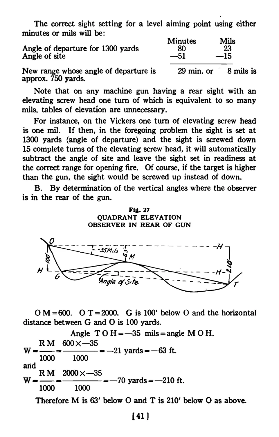
О M=600. О T = 2000. G is 100' below О and the horizontal
distance between G and О is 100 yards.
Angle T О H =—35 mils=angle M О H.
RM 600X—35
W =-----=--------------21 yards=—63 ft.
1000 1000
and
RM 2000X—35
W=------=----------=—70 yards =—210 ft.
1000 1000
Therefore M is 63' below О and T is 210' below О as above.
[41]
Thus M is 37' above G; since G is 100' below О while M is 63'
below O, and T is 110' below G; since G is 100' below О while T
is 210' below O.
Also the mask angle measured from the gun is:
1000 W 1000X12
M =-------— =----------= 24 mils.
R 500
And angle of site is:
1000 W 1000X—37
M =----------=---------=—19.5 mils.
R 1900
The angle corresponding to the range would be the angle of
departure for 1900 yards less the angle of site or:
50.5 mils—19.5 mils or 31 mils approximately.
The sight setting to correspond to an angle of departure of 31
mils is 1500 yards.
This is the correct sight setting to use with the aiming point
on a level with the gun or in other words the quadrant elevation.
If it is desired to use as an aiming point a convenient point on
the slope or crest of the hill forming the mask, proceed as follows:
Subtract from the quadrant elevation of 31 mils the
vertical angular difference between the horizontal plane and
the aiming point.
In this problem the vertical angular difference between the
horizontal plane and the aiming point, if taken as the crest of the
hill equals 24 mils.
31 mils minus 24 mils = 7 mils.
Therefore with the sights set at a range corresponding to 7 mils
or 650 yards, the crest of the mask or hill or a point on the crest,
can be taken as the aiming point and fire opened on the target.
If an aiming point higher than 31 mils were chosen it could not
be used as it would result in a negative setting of the rear sight leaf.
With a clinometer, this, of course could be done,
[42]
INDIRECT FIRE FROM A MAP
Gun is at Gi, Target at T.
Range scales 1000 yards. The line of fire passes over the crest
of the hill (mask) at 400 yards, contours show elevation of gun
as 1000', mask as 1012', and target as 991', therefore mask is 4
yards above Gi, the target is 3 yards below Gi and the:
1000 W 1000 X4
Mask angle=----------=---------= 4-10 mils.
R 400
1000 W 1000X3
Angle of site =------=---------=—3 mils.
R 1000
The sight setting necessary to hit the crest of the mask and
the sight setting to clear the mask are approximately identical.
Therefore the sight setting to clear the mask is the angle of
departure plus angle to mask or:
Angle of departure 400 yards = 3.4 mils.
Angle to mask =4-10 mils.
Then the range whose angle of departure = 13.4 mils is 975 yards.
Therefore the sight setting to clear the mask is 975 yards.
The sight setting necessary to hit the target is calculated in
a similar manner from the range and angle of site to be 880 yards.
Since it takes 975 yards elevation to clear the top of the hill
and only 880 yards to hit the target it is obvious that to fire on
the target over the hill from the present gun position is impossible.
Move the gun 300 yards to the rear to G2.
The gun is now 1300 yards from the target, 700 yards from the
hill and 900 yards from the friendly troops in the firing line at
F. L.
The contours show the gun to be 2 yards below the mask, 6 yards
above the troops and 5 yards above the target.
Therefore the:
Mask angle = 4-3 mils 1
Angle of site=—3 mils J aPProx-
Troop angle=—6И mils.
The mask trajectory is therefore 850 yards, the target trajectory
1180 yards while the trajectory^necessary to hit troops at F. L. is
500 yards.
The 1180 yard trajectory for the target will easily clear the hill
which has an 850 yard trajectory for its crest.
[43]
(44]
Fig. 28
♦Is it safe to fire over the troops at F. L. neglecting the defilade
of the mask?
Overhead fire is generally considered safe when the lowest
bullets of the machine gun sheaf clears the friendly troops by an
angle of 1 degree or 17% mils. The lower half of the 100% zone
(which contains all bullets of the machine gun sheaf below the
theoretical center of the sheaf or actual trajectory) rarely exceeds
3% mils.
Allowing 3% mils as the vertical angle between the lowest
bullets of the sheaf and the center of the sheaf or actual trajectory
and adding 17% mils as a factor of safety gives 21 mils as the
necessary safety angle between the friendly troops over which
the fire is being directed and the lowest flying bullets of that sheaf.
Following this system, fire can not be directed over the troops for:
Angle of departure of trajectory to troops = 5 mil approx.
Safety angle =21 mils approx.
Angle of departure for range to be considered safe =26 mils.
This is the angle of departure for a range of 1375 yards and is
a greater range than is being used i. e. 1180 yards.
Considering the mask which offers a defilade for the friendly
troops, it is safe for over head fire as:
The lowest bullets that can clear the hill, however, are repre-
sented by the 850 yard trajectory. Any low lying bullets including
the lower half of the 100% zone will strike the crest of the hill.
The difference in mils between the troop trajectory 500 yards
and the mask trajectory 850 yards is 6 mils. And 9 mils at 900
yards, the troop distance, is 5% yards.
Therefore it is seen that the lowest bullet that can clear the hill
will pass 17 feet over the heads of the friendly troops.
In order to get the direction for the gun, use a protractor on
the map at G2 and read the direction of T from G2 as S 30° E.
The firing data for the gun is then:
Elevation =1180 yards or 19 mils.
Deflection =S 30° E.
The elevation is for a quadrant, clinometer or rear sight leaf
on a level aiming point.
The direction is laid by compass bearing.
B.- A natural aiming point on the crest of the hill, such as an
angle in a stone wall may be utilized as follows:
[45]
For Elevation
The vertical angle from the gun to the aiming point is 10 mils.
As the aiming point is above, subtract this vertical angular dif-
ference from the elevation of 19 mils on the gun, giving as a result
9 mils.
9 mils = 790 yards elevation.
For Deflection
The aiming point is 5 yards to the right of the line of sight.
5 yards @ 400 yards = 12И mils.
12 mils = 10 points windage approx.
10 points left windage is the correct deflection.
Indirect Firing Precaution
The gunner can always determine whether the trajectory will
clear an intervening obstacle between his gun position and the
target by first laying his gun to hit the target and then without
disturbing his piece reset his sight to a range corresponding to the
distance the obstacle is from the gun. His sheaf will clear only if
his line of sight clears.
*See Overhead Fire. (Page No. 49).
UNIVERSAL RULE FOR DETERMINATION OF
SIGHT SETTING
1. Determine trajectory necessary to hit target on horizontal
plane.
2. Add algebraically the angle of site to the target, using
proper sign plus or minus.
3. Subtract algebraically the angle of site to the aiming point,
using proper sign plus or minus.
Summary
1. Includes all cases:
A. With direct fire on any target.
B. Indirect fire with level aiming point or a quadrant
on a target on a horizontal plane with gun.
1 and 2. Includes all cases:
Of indirect fire with a level aiming point or a quadrant
when the target is not on the horizontal plane of
the gun.
1, 2 and 3. Includes all cases:
Where indirect fire is used on a target, using an aiming
point not on the horizontal.
[46]
FIELD METHODS OF READING VERTICAL ANGLES
MEASURED FROM A HORIZONTAL PLANE
Method No. 1
1. Clinometer, quadrant and pocket transit.
2. Level and gun.
3. Level gun and mil scale.
4. Level and mil field glass.
5. Slope boards.
Methods 1 and 5 need no explanation as the use of a clinometer,
quadrant and slope board are more or less universal.
The other methods are improvised ones dependent upon the
use of a small pocket level. When a pocket level is not available,
make a^lumb line with a string and bullet and fasten to the gun
at some convenient place such as the handle on the Colt machine
gun, letting the string hang along the rear straight edge of the side
plates.
The line of the distant horizon can always be considered to
be on a level with an observer’s eyes and can be used as a level
point as a last resource.
Method No. 2
A. To measure depression angles (angles below horizontal
plane).
Level the gun with the pocket level and without moving the
gun, alter the sights until the line of sight is on the mark to be
measured. Note the reading of the sight and look up its value
in mils from the angle of departure table.
B. To measure elevation angles (angles above horizontal
plane).
Level the gun with the pocket level, set the sights at zero and
determine a level point by looking along the sights and locating
the point where they strike the ground. Then without moving
the sight elevate the gun until the zero line of sight is on the mark.
The sight is then raised and the procedure carried out as for a
depression angle considering the level point first located as the
lower line of the angle.
Method No. 3
This method is somewhat similar to No. 2, except that after
the level point has been located, the vertical angle between the
level point and the other point is read direct with the mil scale.
[47]
Method No. 4
Fasten a small level to the frame of a field glass fitted with a
mil scale. Determine which graduation of the mil scale corresponds
to the level point when the bubble is centered, by trials.
After this graduation has once been determined, fix it in mind.
Then in order to read a vertical angle, center the bubble of the
level and read the mils between the graduation corresponding to
the horizontal point and the point to be measured.
Correction of Indirect Fire
The observer is the eyes of the gunner during indirect firing.
A simple, efficient system of fire signals are necessary between the
observer and the gun commander in order to keep the guns on the
target. The gun is the only range finder after all. *
Indirect fire formulas and methods are only intended to place
the first burst of fire where it can be best observed. After the
burst is once picked up by the observer’s glasses, it must be directed
and held on the target.
In order that the correction of fire by observation is facilitated,
the aiming points used for indirect fire should be kept on or near
the level of the gun. Then the range to the target and the sight
setting on the rear sight leaf will correspond and a burst of fire
short or over will be corrected by this amount on the sight leaf.
In case the aiming point is not on the horizontal, corrections to
the range must be made for the true range and not for the range
as indicated on the sight leaf.
Example. Range 1500 yards. Sights set for aiming point
30 mils above the target or 125 yards elevation. Upon opening
fire the burst is 200 yards short. What is the correction?
In order to correct the fire 200 yards at 1500 yards or in other
words throw it to 1700 yards will require, according to the table
of elevations, over 9 mils increased elevation. Upon raising the
sight leaf 200 yards above the sight setting of 125 yards gives
325 yards, which the table shows to be an increase of about 1%
mils. And 1% mils at 1500 yards will throw the sheaf about 40
yards when it should throw it 200.
If, however, 9 mils were added to the 125 yard sight setting it
would bring the new sight setting to about 825 yards, which would
be the proper correction to make.
When the table of elevations is at hand or the Milometer,
corrections can be made as above.
[48]
For guns having a rear sight elevating screw head one turn of
which is one mil, corrections can be made by the following approxi-
mate rule.
Note in the table of elevations that the difference between ranges
for each hundred yards from beyond short range up to beyond
distant ranges, is about X as many mils as there are hundreds
of yards in the range.
Hence a “rule of thumb” for mils, which in turn can be applied
to turns of the rear sight elevating screw head is: To alter the
machine gun sheaf 100 yards at any range, change the elevation
on the rear sight И as many mils as there are hundreds of yards
in the range.
Note that this rule is applicable to any machine gun which has
a rear sight with an elevating screw head, one turn of which alters
the sight setting an amount which can be determined in mils.
Night Firing
Night firing can readily be done with machine guns by using
indirect firing methods and artificially illuminating the aiming
point used.
The illuminated aiming point usually consists of a box closed
towards the enemy and with the side toward the gun covered
with a semi-transparent cloth. Lines drawn on the cloth are made
to stand out in relief by a flash light placed in the box.
A convenient distance to place the box is 14 yards from the gun
and with the aiming lines on the cloth measured in even inches.
Each half-inch on the cloth is then a mil and accurate placing
of the fire is possible.
Much ingenuity must often be exercised in the placing of the
night firing points. Luminous paint or “radiolite” points may
often be utilized successfully. The night firing box can be placed
on the flank of the gun, in the trench and reflected to the sights
of the gun by a mirror placed on the parapet of a trench.
Overhead Fire
Overhead fire has already been discussed under the map indirect
firing problem. (See page 46)
An additional problem of overhead fire using the safety angle
of 1 degree from the lowest bullets of the sheaf to the. friendly
troops is given here.
Method. Troops may advance to a range where the angle of
elevation of the gun for that range plus the angle of safety, including
[49]
the lower half of the 100% zone, is equal to the angle of elevation
necessary to use on the gun to fire at the target. Or expressed in
known terms, troops may advance to q range determined by sub-
tracting the angle of safety plus % the 100% zone from the angle
of elevation used on the guns for firing on the target.
If the angle of safety is considered to be 1 degree or 17% mils
and % the 100% zone is considered to be 3% mils, the total angle
to subtract will be 21 mils approximately.
Example, Range 1800 yards. If the terrain is more or less
flat, how far may our troops advance before overhead fire would
be rendered unsafe?
Angle of elevation 1800 yards =45.3 mils.
Subtract 21.0 mils.
Range whose angle of elevation = 24.3 mils is 1325 yards.
The danger zone defined by the angle of safety should be
increased 2J^ mils for every 100 yards of additional range
beyond 2000 yards. That is if the range is 2200 yards use
26 mils, as the angle of safety and for 2400 yards use 31 mils,
etc. This is a necessary precaution because of the larger
errors in the determination of the range and the variation
in the 100% zone.
Note. Overhead fire must not be opened on level ground unless
the troops are 600 yards away and the target at least 1400 yards,
on account of the rising branch of the trajectory.
The angle of safety for the rising branch is considerably smaller
than for the falling branch as the variation for an error in range
would not be dangerous and at long ranges (2000 yards) troops 300
yards in front of the gun position may be safely fired over.
Precaution for Overhead Fire
The method above given is correct in principle for determining
the practicability of utilizing overhead fire because it is based
on an actual angle between the lowest bullets of the machine gun
sheaf and the advancing troops.
However, the factor of safety of one degree above cited, in all
cases may not be nearly great enough or may be too great, depending
upon a number of other conditions which may render overhead
fire so dangerous on level ground as to be prohibitive.
Such conditions are:
1. Accuracy of range.
2. Visibility of target.
♦See Overhead Fire. (See page 49.)
[50]
3. Conditions for observation.
4. Type of machine gun.
5. Condition of barrel.
6. Method of mounting gun.
7. Expertness of gunner.
8. Nature of soil upon which mount rests.
Therefore, because of these variable conditions the machine gun
officer, if required to fire over his own troops, must use that factor
of safety, which will assure his fire reaching the target and not his
own comrades.
After determining his factor of safety, the method outlined
will give him the remaining data as scientifically as it can be
computed.
Long Range Searching or Barrage Fire
The relation of ground to the effect of fire must be thoroughly
studied in order to achieve the most effective results with long
range firing from machine guns.
By selecting appropriate trajectories at long ranges, defiladed
space under short range fire becomes a suitable target at the longer
ranges. In this manner supply stations, lines of communication
and supports of the enemy on the reverse slope of hills from our
front line trenches, may be effectively brought under a curtain
of fire from our second line positions.
With an accurately contoured map this is accomplished by
first calculating the reverse slope angle in mils using the formula:
1000 W
M=----------
R
and substituting the values of W and R from the difference in
elevation in feet between a point on the crest of the slope and one
at the bottom and the horizontal distance between the two points.
Knowing the reverse slope angle we must select a trajectory
whose angle of fall will approximate the reverse slope angle. This
problem can be solved by making a profile of the map to the same
scale as a transparent drawing of all the trajectories.
By superimposing the trajectory drawing over the profile, by
inspection the trajectory whose angle of fall approximates the
reverse slope angle can be selected.
However, the problem can be solved just as quickly with a table
to a slide rule showing angles of fall, thus eliminating the bulky
trajectory drawing and the making of a profile.
[51]
[52]
Fig. 29
LONG RANGE SEARCHING OR BARRAGE FIRE
The general rule or formula by which the appropriate trajectory
is selected is as follows:
The trajectory at a range “R” Whose angle of fall equals
the reverse slope angle is the trajectory whose angle of fall
is the algebraic sum of the reverse slope angle and the angle
of site from “R” to the crest of the hill.
This rule may be understood more clearly by considering the
three following cases regarding the location of the target with respect
to the position of the gun:
GENERAL RULES
Case 1
When the gun and the crest of the slope are on the same
elevation the' angle of site becomes zero and range R will
be the trajectory whose angle of fall EQUALS the reverse
slope angle.
Case 2
When the crest of the slope is above the elevation of the
gun use the trajectory at range R whose angle of fall is the
SUM of the reverse slope angle and the angle of site to the
crest from range R.
Case 3
When the crest of the slope is below the elevation of
the gun use the trajectory at range R whose angle of fall
is the DIFFERENCE between the reverse slope angle and the
angle of site to the crest from range R.
In both Case 2 and 3 there is only one known quantity, the
reverse slope angle, and two unknowns, the angle of site and range
R. Consequently several trials will have to be made in order to
meet the conditions of the formula.
The method of procedure for both Case 2 and Case 3 will be
as follows:
Select the trajectory whose angle of fall equals the reverse
slope angle. At a range from the crest equal to this trajectory
locate R on the map and calculate the angle of site to the crest
of the reverse slope by the difference in elevation between the two
points and the horizontal distance between them, similarly to
the reverse slope calculation.
Add this angle of site to the angle of fall of the trajectory if the
crest is higher than the gun or subtract it if it is lower and look up
the new trajectory whose angle of fall equals the sum or difference
of the two.
[53]
For small angles of site and where the nature of the terrain in
the vicinity of the gun is level, this trajectory will be the correct
range and sight setting to use for the line of sight to be directed
at the crest.
If, however, the angle of site is large, over 10 mils, and the gun
position as just determined is on sloping ground a series of calcula-
tions must be made as follows:
Calculate the angle of site from the gun in its last de-
termined position: i. e., the range whose trajectory has
an angle of fall equal to the^algebraic sum of the reverse
slope angle and the angle of site for that range; and take
the algebraic sum of this angle of site and angle of fall for
that range and again look up a new range whose trajectory
has an angle of fall that corresponds to the algebraic sum.
This cycle of operations must be carried on until there is no
appreciable difference between the angles of site due to the change
in range.
After the first determination of the range, taking into considera-
tion the nature of the terrain, the fire control officer should be able
to select the proper trajectory by inspection and verify it in a moment
by calculating the angle of site and determining whether the algebraic
sum of the angle of site and the angle of fall will equal the reverse
slope angle.
The cycle of operations are best performed by tabulating the
data as shown in the examples for Case 2 and Case 3.
Example Case 1.
When the crest of the reverse slope is on the same approxi-
mate elevation as the gun.
From the contours the difference in elevation between points
C and D on the reverse slope is seen to be 20 yards (60 feet) in 300
yards horizontal distance.
Therefore the slope angle is:
1000 W 1000X 20
M=------------=---------=67 mils.
R 300
From a table or the Milometer giving angles of fall the trajectory
whose angle of fall corresponds to 67 mils is seen to be 1540 yards.
Hence the firing data for searching the reverse slope With fire is:
Range = 1540 yards from the crest.
Sight setting = 1540 yards.
Aiming point=the crest.
[54]
Example Case 2.
When the position of the reverse slope is at an elevation
above the position of the gun.
As in Case 1 the trajectory whose angle of fall equals the reverse
slope angle is 1540 yards. The crest of the hill is seen to be 40
yards above the elevation of the gun and the gun must be elevated
this angle in order to clear the crest. If, however, it is elevated
this much the angle of fall will also be changed a corresponding angle
and will no longer equal the slope angle but will be less. In order
to make the angle of fall parallel the slope again, the angle the gun
was elevated must be added to the angle of fall.
The angle the gun was elevated is the angle of site to the crest:
Or
1000 W 1000X40
M=-----------=---------= 26 mils.
R 1540
The slope angle=67 mils.
Angle of site =26 mils.
Total =93 mils.
The trajectory whose angle of fall equals 93 mils is found to be
1790 yards. However, upon moving back to 1790 yards on account
of the increased distance to the crest, the angle of site is changed.
The angle of site for 1790 yards is:
1000 X40
M =----------=22.4 mils.
1790
And the new trajectory would be:
Slope angle =67 mils.
Angle of site=22.4 mils.
Total =89.4 mils.
The trajectory whose angle of fall equals 89.4 mils is 1760
yards. The entire cycle of operations should be tabulated as follows:
[55]
TABULATION
Reverse Slope Angle Angle of Site Angle of Fall (Algebraic Sum of Col. 1 and 2) Trajectory
67 0 67 1540
67 26 93 1790
67 22.4 89.4 1760
67 22.7 89.7 1765
Note that column 1 is always known and never varies during
the cycle, column 2 is obtained from the preceding row in column 4,
column 3 is the algebraic sum of column 1 and column 2, and column 4
is always obtained from column 3.
With an ordinary slide rule and a table of angles of fall, or with
the Milometer alone, the entire cycle is calculated quite rapidly.
By inspection it should be solved in three operations at the most.
In this problem then, the last trajectory in column 4 or 1765
yards would be the sight setting for aim taken at the crest at a
range from the crest of 1765 yards.
This range is scaled on the map and the gun position located
accordingly.
Regardless of the nature of the terrain the appropriate trajectory
can always be selected as above.
Example Case 3.
When the crest of the reverse slope is at an elevation
lower than the position of the gun.
As before the trajectory whose angle of fall equals the slope angle
is 1540 yards.
The crest of the hill is seen to be 40 yards below the elevation
of the gun and the gun must be depressed this angle in order to
clear the crest. If, however, it is depressed this much the angle of
fall will also be changed a corresponding amount relative to the
slope and will no longer equal the slope angle but will be greater.
In order to make the angle of fall parallel the slope again the
angle the gun was depressed must be subtracted from the angle
of fall.
[56]
The angle the gun was depressed is the angle of site to the
crest or 26 mils.
Slope angle =67 mils.
Angle of site = 26 mils.
Total =41 mils.
The trajectory whose angle of fall equals 41 mils is found to
be 1225 yards.
Tabulating as in Case 2.
TABULATION
Reverse Slope Angle Angle of Site Angle of Fall (Algebraic Sum of Col. 1 and 2) Trajectory
67 O' 67 1540
67 . 26 41 1225
67 32.6 34.4 1130
67 35.4 31.6 1080
67 37 30 1055
67 37.9 29.1 1040
67 38.4 28.6 | 1035
Hence firing data for searching the reverse slope with fire is
Range = 1035 yards from the crest.
Sight setting = 1035 yards.
Aiming point is the crest.
PART III
THE MILOMETER OR BALLISTIC SLIDE RULE AND
MIL CALCULATOR
Five essential parts.
1. The inches scale.
2. The mil slide rule B-C.
3. The angle of site-trajectory slide D-E.
4. The mil angle of departure and of fall scales F-G-H.
5. The combination millimeter-protractor slope-board
scale with formulas, on back of rule.
[57]
General Description
A computing slide rule is always more or less mysterious to
those unfamiliar with its use and they are prone to think its operation
is far more difficult than it really is.
The Milometer is as simple and as easily operated as any arith-
metical calculation can possibly be. It requires but little more
mental effort than is necessary to measure off 1 foot and inches
using a yard stick.
If the instructions are carefully read and the examples studied,
the principles upon which all the scales operate will be understood
quickly. After that any number of problems can be solved without
reference to the instructions.
Scales В and C work by multiplication and division as they are
logarithmic numbers plotted to scale. They differ from scales C-D
on the manheim slide rule in that one scale is the reciprocal of the
other. Scales В and C of the Milometer also consist of one complete
logarithmic scale from 1 to 10 and portions of two other scales of
varying values.
Scales D-E operate by simple addition and subtraction, the
trajectory being plotted on scale E while scale D is so arranged
that angular values in mils, plotted to the same pioportion as the
trajectory on E, can be added or subtracted. Scale E is plotted
to the increasing angle of elevation or departure of the trajectory
for ranges from 0 to 3000 yards.
To use the Milometer, operate the slide C-D with the thumb
of the right hand by pressing on the lower end of the slide, being
careful to apply the pressure on the end of the slide only and not
on the bottom or on the ends of B-E.
The Milometer is held in the left hand, face (B-C-D-E) up.
The Milometer is operated and is read similar to any slide rule.
The value of the small divisions of the scales, until one is familiar
with the rule, can always be determined by referring to the figures
above and below and dividing the difference of any two figures
by the number of graduations between them.
For instance on scale B, there are ten graduations between
300 and 400. Each graduation is then equal to 10. However,
between 400 and 500 of the same scale there are only 5 graduations.
Therefore each one has a value of 20.
As on any slide rule the figures on scales B-C represent units
of 1, 10, 100, 1000 or whatever number is desired, it being merely
a question of moving the decimal point.
[58]
However, as the Milometer is primarily for the use of range
calculations it is most convenient to make the figures represent
the actual ranges and for all calculations of ranges from 50 yards
to 3000 and widths in yards or angles in mils from 5 to 300; it is
unnecessary to use decimals as the reading is direct.
When, however, scales B-C are used for calculations other than
yards and mils the decimal point must be kept in mind. And if
on scale В 400 is read as 4 and 500 read as 5 then each small division
between 400 and 500 will have a value of iV
A detailed discussion of each scale with minute instructions
regarding its use will be found on succeeding pages.
The formulas on the back of the rule are self-explanatory for
those familiar with windage and elevation rules, the mil system
and indirect firing. They do not, however, form a text book and
are merely for ready reference for one previously acquainted with
their use.
They are, in some cases, “rule of thumb” rules and are only
approximately true. The rear sight referred to is the one now in
common use on our machine guns, such as the Colt and Vickers,
and are equipped with an elevating screw head; one complete turn
of which is 1 mil.
The points of windage are the standard windage graduations for
U. S. rifles and U. S. ammunition.
EXPLANATION OF FORMULAS ON THE BACK OF THE
MILOMETER
Range Rules
Windage
Let P=Pts. windage. V=wind velocity in miles per hour
and R=range in hundreds of yards.
Rules
One point of windage moves the point of strike 4 inches for each
100 yards of range, or:
1 P=4 R inches; or at 1000 yards 1 P = 4X10=40 inches.
The points of windage necessary to take for all side winds is
equal to the range in hundreds of yards multiplied by the velocity
of the wind in miles per hour and divided by 40; or:
RV
P=—
40
For winds from 1-5-7 of 11 o’clock take И P.
[59]
Telescopic Sight Windage
One point of windage on the telescope sight moves the bullet
И as much as one point on the Springfield Rifle or one inch per
hundred yards of range.
Combat Rule for Approximate Windage
For all winds, except head and rear winds, take one-quarter
as many points of windage as there are hundreds of yards in the
range; or:
R
P=—
4
Note that the wind gauge is always moved into the wind. The
point of strike of the bullet is moved in the same lateral direction
as the base of the wind gauge is moved.
The deflection in mils, to counteract a wind is, from the windage
formula
RV
P=—, found to be
40
RV
M=—.
35
Example, Range 800 yards. Wind velocity estimated at 10
miles per hour. How many mils between the point of aim and
the target?
8X10
M=-------=2 mils.
35
Enfield Rifle Windage
On the Enfield Rifle which is without a wind gauge the deflection
must be figured in mils and the gun aimed off accordingly.
Elevation
E = 100 yards difference of elevation.
One hundred yards difference of elevation on the rear sight will
throw the point of strike of the bullet a distance in inches cor-
responding to the square of the Range in hundreds of yards; or:
E = R squared inches on rear sight.
Example. Range 900 yards. The sight is shifted from 900
to 1000 yards. How far has the point of strike of the bullet been
changed vertically?
Substitute E = 9 X 9=81 inches.
[60]
Conversely; from the discussion of sights and the mil system if
C = change on rear sight to shift sheaf of fire 100 yards.
T = complete turns of elevating screw head.
С = И as many complete turns of the rear sight elevating screw
head as there are hundreds of yards in the range (see page 48 on
“Correction of Indirect Fire”) or
С = J4 T Hds. yards in R.
Example. Range =900 yards. It is desired to increase the
range to 1000 yards.
Substitute
9
C =— = 2}< mils or turns.
4
The distance to the maximum ordinate i. e. the point where
the trajectory reaches the summit is .57 of the range or
Dm = .57 R.
The angle of fall is approximately twice the angle of departure, or
Af = 2 Ad.
The mil scale formulas are all discussed under Part I and the
Indirect Fire Formulas under Part II
Uses of Inches, Millimeter and Mil Scales
The scale on the upper edge of the under side of the slide is a
six inch scale graduated in inches and tenths inches. The scale
is conveniently used by drawing the slide to the left and using
the straight edge of the main body of the rule as a right angle or
T-square to measure from.
On the lower edge of the slide is a six inch scale so graduated
in inches and sixteenths inches that when the slide is drawn out
to the right until the index represented by the arrow is just visible,
the graduations on the slide then have the correct relation for a
12 inch scale as the main part of the rule and the slide are then
1 foot in length.
If a measure of less than six inches is desired, draw the slide to
the left, otherwise draw it to the right.
The millimeter scale on the protractor performs two roles.
It is both an angle measuring instrument and at the same time
it is so graduated as to be used for linear measure.
The millimeter scale is graduated in millimeters and centimeters.
Each millimeter subtends an angle of 2 mils as seen from a point
19Т7Л inches (И meter) distant.
[61]
To use the mil scale fasten a non-shrinking string to the rule
with a knot tied in the string at 19/^ inches,. Hold this knot
to the eye with the right hand, or hold it in the teeth, while at the
same time the scale is held with the left hand parallel to and nearly
coinciding with the line adjoining the two objects which define
the angle. By holding the zero of the scale under one object, the
reading of the scale at the other object will be the angle in mils.
The Use of the Mil Scale Rule Scales B-C
The mil slide rule consists of two scales В, С. В is called range
in yards, and C is called mils and width (yards) scale.
The range scale В is graduated in yards, and has an index
consisting of the letter W at the 1000 yard graduation. This W
signifies width which is read in yards opposite the index.
The mil and width scale C is graduated in mils, which in addi-
tion to always reading the width in mils opposite all range gradua-
tions, also indicates the width in yards opposite the 1000 yard index.
Width in yards is always opposite this index and never opposite
any other graduation.
The use of the mil slide rule is as follows:
R = Range in yards. W=Width in yards. M= angle, sub-
tended by W.
Example I. Given R and M. Find W.
Set the angle in mils on scale C opposite the range in yards on
scale B. Then on scale C read W in yards opposite the 1000 yard
index.
Let R = 1200. M = 10. W = ?
Set 10 on scale C opposite 1200 on scale В and read 12 yards
on scale C opposite 1000 on scale B.
Example IL Given R and W. Find M.
Set W (yards) on scale C opposite the index on scale В and
read the angle in mils on scale C opposite the range on scale B.
For instance: On a contoured map the elevation of the gun is
950' while the target is 800'. The range scales 1100 yards. What
is the angle of site (angle between target, gun and horizontal)?
R = 1100. W=H=950—800 = 150'= 50 yards. =M = ?
Set 50 on scale C opposite the index on scale B, while opposite
1100 on scale В is found 46 mils on scale C .’. angle of site is — 46
mils, as target is Ipwer than gun.
[62]
Example HI. Given M and W. Find R.
Set the width in yards on scale C opposite the index, and read
on scale В the range opposite the mil angles on scale C.
The distance between telephone poles on a road is known to
be 50 yards. The angle subtended by two of them, parallel to
the front, is 60 mils. Find range. M = 60. W=50. R = ?
Set 50, scale C, opposite the index, and read 833 yards on scale
В opposite 60 on scale C.
Example IV. Given D, Mi and M2. Find R where D= dis-
tance in yards toward or from a width, W; which subtends Mi
at initial point of D and M2 at the other end.
Set D on scale В opposite M2 on scale C, and read range R
on scale В opposite the difference between Mi and M2 on scale C.
Note that M2 is always the second reading, regardless of which
way D is measured. /
Points on the flank of enemy trench parallel to the front are
seen to subtend an angle of 200 mils. Upon pacing, measuring
or estimating a distance of 200 yards to the rear, the same points
are seen to subtend 150 mils.
What is the range?
D = 200. Mi =200. M2 = 150. R = ?
Set 200 on scale В opposite 150 on scale C, and read 600 on
scale В opposite 50 scale C.
Where D is measured toward the object using the above figures,
Mi would equal 150 and M2 200. Solve as before.
Example V. Use with a contoured map.
From a contoured map, the angle of site, mask angle and troop
angle are calculated on the mil slide rule as follows:
Range scales on map, 2000. Contours show target as 1000',
gun as 950'. Therefore target is 50' higher than the gun. Find
angle of site.
Use slide rule as in Example II, considering 50' (17 yards)
as W.
Opposite index on range scale Opp. 2000 on range scale
Set 17 yards on mil scale Read angle of site+8 >6 nails
Map gives mask distance as 1200 yards, and elevation above
gun as 75' (25 yards). Find mask angle. Solve as for angle of site.
W on scale В 1200 on scale В
25 on scale С M (4-21) scale C
[63]
Similarly troop dist. = 1000 yards at 40' above gun. Troop angle
is therefore
W on scale В 1100 on scale В
13 on scale С M (4-12 mils) scale C
Precaution for Using Mil Slide Rule
Whenever W or M is of less value than 5 mils (smallest reading
on scale C), assume M or W as multiplied by 10, and then take -/o'
of the result as the answer.
Example, R = 1200. W = 5. Find M.
If 5, scale C, is set opposite index on scale B, 12 on scale В is
above end of slide on scale C. Therefore set 50 (10X5) on scale
C opposite index on scale B, and read 42 on scale C opposite
1200 on scale B. Dividing 42 by 10 gives result of 4.2 mils
as M.
When the slide is below the index W use the 100 yard graduation
as the index and point off one place.
Example, Range=600.
M=8.
Find W.
If 8 on scale C is set opposite 600 on B, the end of the slide
fails to reach the index W. In this case read opposite the 100
mark on В or 48 and point off one place or 4.8 yards.
By setting 80 instead of 8 opposite 600, the upper index could
have been used and the result divided by 10.
THE USE OF THE SCALES F-G-H
Example VI. Given the range, what is the angle of departure
or of fall in mils for a horizontal plane.
Push sliding scale C-D up until scale F-G-H under the slider,
is sufficiently uncovered. Scale G gives the range in hundreds
of yards. Scales Eand H in units of ten mils, each small graduation
being 2 mils on F and 1 mil on H. Opposite the range in hundreds
of yards on scale G read the angle of departure on scale H. Opposite
the range in hundreds of yards on scale G read the angle of fall
on scale F.
Example. Range 1700 yards. What is angle of departure
and of fall?
The angle of departure on scale H opposite 17 on scale G is 40
mils (4X10). The angle of fall on scale F opposite 17 on scale G
is 82.5 mils (8Х10+2И)-
[64]
Note. The angle of fall for distances beyond 1000 yards and
up to 3000 is approximately twice the angle of departure.
The angle of departure may also be read on scales D-E by first
setting the zero of scale D opposite the zero of scale E.
The angle of site-trajectory slide consists of two scales, the
angle of site scale D and the sight leaf graduation (trajectory)
scale E. The angle of site scale is graduated in mils from a center
point marked zero. From zero up the angle is minus (negative),
and from zero down it is plus (positive). This must not be confused
with the fact that a minus angle of site is below the horizontal,
etc. See definition.
The lines above and below zero, marked 100% zone, defines
the limits of the 100% zone, that is the upper and lower edges of
the zone where the bullets are passing in the air and hitting on the
ground or theoretical horizontal surface through the gun.
The line marked “not safe” defines the danger zone of one degree,
which is considered to be the factor of safety necessary for firing
over troops. That is the lowest bullets of the machine gun sheaf
at any range are passing over the range indicated by this line,
at an angle of 1° between lowest bullets, gun and the indicated
range.
Example VII. Given the range and angle of site. To find the
quadrant angle of elevation (sight setting) when the gun is level.
Set the angle of site, plus or minus, depending upon whether the
target is above or below the level of the gun, on scale D opposite
the range on scale E, and read the quadrant elevation in yards on
scale E opposite the zero on scale D.
Let R=1200 yards. Angle of site 4-30 mils.
Quadrant elevation is found by setting 4- 30 of scale D opposite
1200 of scale E, and reading 1890 on scale E opposite the zero
on scale D.
Example VIII. Given the range, angle of site, mask distance
and mask angle. Find whether the mask will be cleared by the
trajectory when the gun.is firing on the target.
1. Find the sight setting necessary to hit the target from the
range and angle of site as in Example VII.
2. Determine the sight setting necessary to hit the crest of
the mask, knowing the distance to crest of mask, and the angle
to crest of mask. Solve as in 1.
3. Set the zero of scale D opposite the sight setting on E,
necessary to hit the target (determined in 1).
[65]
Then the relation of the graduation on scale E, showing the sight
setting necessary to hit the crest of the mask, to the lowest line
“100% zone” on scale D, indicates whether the mask will be cleared.
The sight setting on scale D necessary to hit the mask, shows
the position on the top of the mask in relation to the sheaf required
to hit the target, the lower limits of this sheaf being shown by the
100% zone line.
Thus, if the 100% zone line is above the sight setting necessary
to hit the mask, then the entire sheaf will clear the mask. If,
however, the same sight setting required to hit the target also hit
the crest of the mask, then it is evident that only the^upper half
of the 100% zone would clear the mask.
Given R = 2000 yards. Angle of site 4-20 mils; mask distance
1400 yards, mask angle 4-45 mils. Find the clearance.
1. Sight setting necessary to hit the target, following the
method of Example VII, is found to be 2300 yards.
2. The sight setting necessary to hit the mask is found in a
similar way to be 2240 yards.
3. Set the zero of scale D opposite 2300 (sight setting for
target) on scale E, and note that the 100% zone line is about 2250
on scale E, and is therefore just above 2240 the mask sight setting,
hence the mask will be cleared by the lowest shots of the 100%
zone by a narrow margin.
The value of the 75% zone and the 100% zone as shown on the
scale must be modified somewhat for short and long ranges.
For beaten zones under 1000 yards range decrease the
value of the 75% zone by one mil and the 100% zone by
two mils.
For beaten zones over 2000 yards range increase the value
of the 75% zone by one mil and the 100% zone by two mils
for each 1000 yards of range beyond 2000 yards.
In other words up to 1000 yards the 75% zone is about 3 mils
and the 100% zone about 5И mils. For 2200 yards the 75% zone
is 6 mils and the 100% zone 11И mils for 2400 yards they would
be 8 mils and 15 И mils respectively, etc.
Example IX. Given the range, angle of site, troop distance
and troop angle. Find whether it will be safe to fire over the troops.
Proceed as in VIII, substituting the “not safe” line for the
“100% zone” line.
Similarly, if the “not safe” line is above the sight setting neces-
sary to hit the troops, overhead fire is safe.
[66]
However, if the line on scale E indicating the sight setting
necessary to hit the troops, is between the “not safe” line and the
zero on scale D, then overhead fire is not safe, as the factor of
safety of one degree is not secured, and the troops are within the
danger zone.
R = 1500 yards. Angle of site 4-20 mils. Troop distance 1100
yards. Troop angle 4-10 mils. Is overhead fire safe?
1. Target sight setting is 1900 yards.
2. Troop sight setting is 1400 yards.
3 When the zero of scale D is opposite 1900 on scale E, the
“not safe” line is above 1400, hence overhead fire is safe, as the
heads of the troops are cleared by over one degree.
The safety zone defined by the 4 4not safe” line should
be increased 2 И mils for every 100 yards of additional range
beyond 2000 yards. That is if the range is 2200 yards use
26 mils as the “not safe” line and for 2400 yards use 31 mils,
etc. This is a necessary precaution because of the larger
errors in the determination of the range and the variation
in the 100% zone.
Example X, Given range. Find depth on the ground surface
of the 100% beaten zone (i. e. intersection of the ground with the
machine gun sheaf).
Set zero of scale D opposite the range on scale E. Then read
the ranges on scale E opposite the 100% zone lines on scale D.
Example. Range 1500 yards. Set zero D at 1500 В and read
lower limit of 100% zone as 1410 yards and upper limit as 1580
yards. Therefore the beaten zone extends from 1410 to 1580
yards for the 1500 yard trajectory.
The above discussion of the 100% zone is for a level gun on a
horizontal plane surface.
Where the ground is sloping, it will be necessary to use Von
Rohnes formula. (See S. A. F. M.)
a b
В =-------in which
a4-s
В = Depth of beaten zone on sloping ground.
a = Angle of fall in degrees.
b = Depth of beaten zone on level ground.
s=Slope of sloping surface in degrees.
s=Plus on rising slope.
s=Minus on falling slope.
[67]
The following examples require the use of both the mil slide
rule and the trajectory slide rule.
Example XL Given the range and abscissa (distance hori-
zontally in yards to ordinate). Find height of ordinate (vertical
distance from ground to trajectory at abscissa) in mils and in yards.
Set the zero of scale D opposite the range graduation on scale E,
which corresponds to the abscissa. Then read the height of the
ordinate in mils on scale D opposite the range graduation on scale E.
Knowing this angle in mils, convert to yards by using the
abscissa as range, the ordinate as M and finding W by use of the
mil slide rule scales В, C.
Range 1300 yards. What is ordinate at 800 yards?
Zero scale D 1300 scale E
800 scale E Read 14 mils scale D
To convert to yards:
14 scale C Index scale В
800 scale В Read 11 plus yards scale C
Note. The distance to the maximum ordinate is approximately
.57 times the range in yards.
Example XII. Given range and difference in elevation in yards
between the gun and target. Find^ proper setting of sight for
horizontal aiming point.
1. Convert yards to mils by mil slide rule. (Same as determining
angle of site.)
2. Add or subtract, depending whether target is above or
below gun, the angle of site in mils, using trajectory slide.
Range = 1200. Target 30' above gun. Find sight setting
1.
10 scale C Index scale В
1200 scale В Read 12 scale C
2.
4- 12 scale D Zero scale D
1200 scale E Read 1525 scale E
Other uses of the machine gun slide rule areas follows:
Example XIII. Given range. Find combined sight setting or
searching fire in mils. Determine mentally the probable error in
the range.
[68]
Range Errors.
Fixed base range finders............ 5%
Scaled from map.....................10%
Estimation..........................15%
The effective beaten zone or 75% zone must include the target
within its limits. The effective beaten zone can be considered
to extend two mils on each side of the zero mark which will give
the total depth of the zone of 4 mils. Four mils at 1200 yards
equals an effective beaten zone of about 120 yards. At 2000 yards
it would be about 70 yards.
Combined sights or the amount of searching fire depends upon
the depth of the beaten zone and the probable error in the determi-
nation of the range. These factors are somewhat variable.
However, if the probable error in the range does not exceed И
the effective zone then combined sights or searching fire is
unnecessary.
When the probable error exceeds one-half the effective zone
combined sights should be used. One sight should be set above
the range and the other below it, the difference between the two
sight settings equaling the depth of the zone for that range.
If the probable error is two or more times as large as the effective
zone, three settings of the sight would be necessary. One sight
would be set for the range, one above and one below, the difference
between the sight settings being equal to the depth of the zone.
With the Milometer the sight setting for combined sights and
the amount of searching is determined as follows:
Set the zero of scale D opposite the range on scale E. If the
2 mil graduation above and below the zero are above and below
the probable error in the range, combined sights or searching fire
are unnecessary.
If the 2 mil graduations are included between the limits of the
probable error in the range proceed as described above.
Example. Range determined by scaling from a map is found
to be 1200 yards. Probable error is 10%, so that range may be
120 yards less or greater or 1080 yards as the least range and 1320
as the longest range.
Should combined sights be used? If so, what are the sight
settings?
Set zero of scale D at 1200 on scale E and read on scale E the
ranges opposite the 2 mil graduation above and below the zero on
scale D which are 1260 and 1140 yards. As 1260 and 1140 yards
[69]
represents the respective upper and lower edge of the effective
zone and 1320 and 1080 yards as the possible ranges, it is evident
that the target may not be included in the beaten zone.
The reading of the mil graduations on scale D opposite the
1320 and 1080 yard graduations on scale E equals nearly eight
mils or twice the amount represented by the beaten zone. Two
sight settings will just include the target.
The upper sight setting will be the range on scale E opposite
the 2 mil graduation above the zero on scale D or 1260. The lower
sight setting will be the range on scale E opposite the 2 mil gradua-
tion below the zero on scale D or 1140.
Similarly the amount of searching fire would be 2 mils above
target and 2 mils below, as the amount of searching fire in mils
would be the number of mils in the beaten zone corresponding to
the number of sight settings used for combined sights. If two
sight settings are used searching fire would be the number of mils
necessary then the searching would be 8 mils, etc.
By utilizing searching fire with the amount of searching equal
to the total number of mils between the estimated range and the
lowest and highest ranges determined from the probable error, in
this case 8 mils, the target may be located momentarily in the exact
center of the beaten zone. This, however, is impractical as the
amount of searching is too great.
The actual amount of searching fire required to bring
the target within the outer limits of the 75% zone will
be the total number of mils between the highest and lowest
ranges determined from the probable error, less the depth
of the 75% zone in mils.
This is determined by setting the zero of scale D at the lowest
range on scale E and reading the number of mils on D opposite
the longest range on E. From this result subtract the 75% zone
of 4 mils.
In this problem the amount of searching is found to be:
No. of mils between shortest and longest range 8
Depth of 75% zone 4
Difference or amount of searching 4 mils.
This result happens to coincide with the result found by taking
the number of mils in the beaten zone corresponding to the com-
bined sight setting because two sight settings differing from each
other by the depth of the beaten zone exactly equaled the probable
errors in range.
[70]
If the probable error in range had been two mils less in depth
it would have still required two sight settings for combined sights
while requiring two mils less searching. It is evident then that as
a general rule when searching is used and the amount determined
by the above rule it is far more effective than combined sights as
it covers the exact amount of ground necessary and covers it more
evenly.
Example XIV. Given range. What is the sight setting for an
auxiliary aiming point?
Measure the angular distance in mils between the target and
the aiming point. When the target is above the aiming point, add
this angular distance to the sight setting for the range, and when
it is below, subtract it.
Range 1200. Aiming point 25 mils below the target.
Plus 25 scale D Zero scale D
1200 scale E Read 1800 scale E
Hence a sight setting of 1800 yards is required.
Example XV. Given range and impact of burst of fire not
on the target. Adjust the impact on target.
1. For elevation, measure the vertical angular distance between
the target and the center of impact (estimated) in mils. Estimate
the number of yards horizontally between the target and center
of impact. If the impact is below the target add the mil reading
to the range. If above, subtract. After adding the mil reading,
if the impact is short, add, if over, subtract the estimated shortage
or excess in yards to range found by the sum of angular mil distance
and original range.
2. For deflection.
Measure the horizontal angular distance between the target and
impact. Take as many points of windage in the opposite direction
as may be necessary, considering 1 point of windage as It mils.
Range 1000 yards. Impact 5 mils low, 100 yards short and
12 mils to the right of the target. What is the true elevation and
windage?
1.
Plus 5 scale D Zero scale D
1000 scale E Read 1175 scale E
11754-100 = 1275 yards correct elevation.
[71]
12
2. 12 mils right------= 10 mils windage left for correct windage.
Note. When using an auxiliary aiming point, make corrections
on the true range and not on the sight setting of the sight for the
auxiliary point.
Example XVI. From a contoured map the horizontal difference
in yards and the difference in elevation in feet between two points
on a slope is scaled. What is the slope angle in mils?
Change feet to yards and solve as in Example II, calling difference
of elevation W.
Note. This method of calculating slopes is also true of the
metric system.
Example XVII. Given the slope angle in mils (according to
preceding example) of a reverse slope, what trajectory must be
used to search the reverse slope with long range searching or
barrage fire?
Determine angle of fall from scale F that corresponds to slope
angle.
Note that range in yards opposite the angle of fall will be the
correct trajectory to use in order to have the angle of fall approxi-
mately parallel to the slope of the ground. This would be for the
crest of the slope as an aiming point on a horizontal plane with the
gun at the same range as the trajectory.
If the crest or aiming point is not on the horizontal plane of
the gun, proceed as indicated in Part II.
Example XVIII. Given data in meters, mils, centimeters,
kilograms and kilometers. To convert to yards, minutes, inches,
pounds and kilometers.
On scale C are the following indexes which are listed with their
names and their proportion in the table below.
у (yards) : m (meters) =82 : 75.
min. (minutes) : mils = 55 : 16.
in. (inches) : cm (centimeters) =26 : 66.
lb. (pounds) : kg (kilograms) =75 : 34.
mi. (miles) : km (kilometers) =87 : 140.
Therefore to convert yards to meters set index у of scale C on
yards of scale В and read meters on scale В opposite index in. on
scale C.
[72]
The other indexes are used similarly. In order to keep the
decimal point correct note that since meters are larger than yards
the reading will be slightly less.
Note that the mils will be about И of the minutes, centimeters
about 3 times the inches, kilograms about y2 the pounds and
kilometers about twice the mils.
The conversion on the slide rule is simple and direct and should
not be confused as the proportion is automatically carried out..
For instance to convert minutes to mils set index “min” opposite
the 1000 mark on scale B. Then the mil index reads 291 on scale
B. If 1 minute is converted to mils it will be 291 mils, remembering
that the mil reading will be about J4 of the minute. If 10 minutes
are converted it would be 2.91 mils, etc.
Example XIX. Use of protractor on back of rule as a slope
board for determining vertical angles approximately.
Tie a bullet or other weight to mil string to act as plumb-bob
and line. Let the plumb line extend over face of protractor, holding
rule vertical and use the upper edge of rule as a sighting line.
TABLE I
INDIRECT FIRE SIGNALS FOR OBSERVATION OF FIRE
P (Plus) = Fire observed 50 yards beyond target.
PP=Fire observed 100 yards beyond target.
M (Minus) =Fire observed 50 yards short of target.
MM = Fire observed 100 yards short of target.
R (Right) =Fire observed to right of target.
L (Left) =Fire observed to left of target.
D = Direction is correct.
RR (Right range) = Range is correct.
Q (Question) = Observed but uncertain.
U = Unobserved.
OA=Out of action.
FORMULAS FOR ANGLE OF SITE, USING INDIRECT FIRE
FROM MAP
Let A = (angle of site) angle between target, gun and horizontal
plane, which is necessary to add to the angle of departure.
D = Diff. in elevation between target and gun (taken from
contours).
R=Range in yards.
Example. D = 10 ft., ЗИ yds., 120 in. R = 1000 yds
[73]
(1) Angle of site in minutes (D = feet)
1146 D 1146X10
A «---------=---------= 11.5 min.
R 1000
When D=inches.
D 120
A =-------------------=— = 12 min.
Hds. yds. in range 10
(2) Angle of site in degrees (D = ft.).
20 D 20X10
A =-----=---------= .2 degrees.
R 1000
(3) Angle of site in mils (D = yds.).
1000 D 1000ХЗИ
A «-----=-------------=3 % mils.
R 1000
(4)
20 D (ft.)
A ----------in degrees.
1000 D
A =--------in mils.
R
TABLE II
FORMULAS CONSOLIDATED
Mil Scale
R=range (yds.) W= width (yds.) M = mils (subtended by W).
1000 W RM 1000 W
R =-------- W=----- M=-----------
M 1000 R
D «base. Mi = 1st mil read. M2 = 2nd mil read.
DM2
R=------------------------
Diff. between Mi and M2
RANGE RULES
P = Pts. windage. V=wind velocity mils per hr. R = range (Hds.
yds.).
RV R
1P=4R inches. P=— P=—
40 4
RV
M = mils deflection. M =—
35
E = 100 yds. diff. elevation. E = R squared inches.
[74]
INDIRECT FIRE FORMULAS.
A=angle of site. G = gun. T=target. О = observer. Aot «target
angle at O.
AoG=gun angle at O.
ОТ X Aot—OG X Aog
(1.) A =---------------------in degrees, minutes or mils.
GT
R=range in yards. D= difference in elevation between
target and gun in feet.
1146 D
(2.) A =---------in min. when D= inches.
R
Hds. yds. in R
(3.) A =--------------in minutes.
D
20 D (ft.)
(4.) A=-----------indegrees.
R
1000 D
(5.) A =---------in mils.
R
Distance to maximum ordinate = Dm.
Dm = .57R.
Ad=angle of departure. Af=angle of fall.
Af=2Ad.
C=change on rear sight to shift sheaf of fire 100 yards.
T=complete turns of rear sight elevating screw head.
C = X TxHds. yds. in R.
MAP READING
Map Visibility.
A and В = 2 points on contoured map. P=point between A and B.
Dx=difference of elevation of A and B. Dy=difference in elevation
of A and P.
M=distance AB. N = distance AP.
N equals M
----- or --------then В is visible from A.
Dy less Dx
Scale for 2000 Paces.
S=total length of scale desired in inches.
R.F = maps representative fraction expressed as a fraction.
Y = number of paces in 100 yards.
7,200,000
S=R.FX-----------
Y
[75]
TABLE III
FIRE TABLE U. S. RIFLE. Cal. 30
Range Yards Angle of Departure Angle of Fall
Minutes Mils Minutes Mils
100 2.424 .705 2.576 .750
200 5.152 1.499 5.827 1.68
300 8.275 2.4095 9.978 2.90
400 11.831 3.445 15.240 4.44
500 15.918 4.632 21.937 6.39—
600 20.650 6.009 30.435 8.85
700 26.104 7.598 41.137 11.97
800 32.441 9.443 54.543 15.88
900 39.785 11.581 70.814 20.61
1000 48.198 14.027 89.669 26.14
1100 57.728 16.802 110.917 3230
1200 68.379 19.90 134.310 39.10
1300 80.131 23.33 159.762 46.50
1400 92.987 27.07 187.418 54.56
—1500 —106.951^ 31.13 - 217.390 63.37
1600 122.038 35.53 249.745 72.72
1700 138.272 40.23 284.621 82.81
1800 155.674 45.32 322.245 93.85
1900 174.277 | 50.74 362.746 105.52
2000 194.111 I 56.48 406.364 118.30
2100 215.247 62.67 453.479 132.00
2200 237.744 69.196 504.208 146.66
2300 261.664 76.14 558.963 162.73
' 2400 287.091 83.55 618.230 179.86
2500 314.127— 91.44 681.568 198.36
2600 342350 99.85 750.050 218.31
2700 373.303 108.62 823.750 239.82
2800 405.854 1 118.15 902.970 ' 262.88
2900 , : . 440.404 128.17 989.021 287.86
3000 477.175 138.85 1079.20 314.26
1 ° = 17.7 mils. 1 mil =3.437 minutes. 1 minute = .291 mils.
[76)
TABLE IV
CONVERSION DATA FOR ENGLISH AND
METRIC SYSTEMS
Approximate Values
1 millimeter = j1- inch
1 centimeter = И inch
1 decimeter = 4 inches
1 meter = l/& yards=39.3685 inches (exact)
1 decameter=33 feet
1 Kilometer = % mile
Linear
Inches : C’timeters =26 : 66
Yards : meters =82 : 75
Miles : kilometers =87 : 140
Ounces : grammes = 6 : 170
U. S. gals. : litres = 14 : 53
Square Cubic
31 : 200 5’: 82
61 : 51 85 : 65
22 : 57
Cu. ft. : lbs. water =5 : 312
U.S.gals. : lbs. water=3 : 25
Pounds : Kilogrammes = 75 : 34
Cubic feet : litres = 6 : 170
TABLE V
MIL DATA FOR MACHINE GUNNERS
As most of the results in the following did not come out in
even mils, figures are given to the nearest even mil.
Vickers, Model 1917—Mark 4 Tripod
One tooth traversing arc................................ 12.5 mils
One turn tripod elevating handwheel... ................. 43 . 44
One turn sight elevating screw.......................... 1— mil
One division windage...................................... 1+ “
With chin against safety catch:
Width of front sight cover outside subtends......... 17— mils
Width of front sight cover inside subtends.......... 12 °
Height of front sight cover outside subtends........ 14 + 44
Height of front sight cover inside subtends......... 12— 44
[77]
Golt, 1917
One turn mount elevating handwheel.................... 63+ mils
One turn sight elevating screw........................ 1 mil
With chin against grip:
Width of front sight cover outside subtends............ 14 mils
Width of front sight cover inside subtends............. 11 +
Width of front sight base proper subtends.............. 5
Height of front sight proper subtends.................. 5
Benet-Mercie
One turn elevating mechanism handwheel................ 16 mils
One-eighth turn elevating mechanism handwheel......... 2
One turn sight elevating screw........................ 1 mil
In firing position:
Width front sight cover............................... 12 mils
Height front sight cover.............................. 5
Lewis, American Model, Cal. 30
One turn sight elevating screw........................ 7— mils
Three notches sight elevating screw................... 1— mil
In firing position:
Width of front sight proper subtends.................... 2+ mils
Height of front sight subtends......................... 4—
Width of front sight base subtends..................... 9+
Width between front sight guards inside subtends...... 17+
Peep hole in rear sight subtends...................... 30
Hotchkiss
One turn tripod elevating screw....................... 53 mils
One division traverse................................. 10
With chin against breech housing handle:
Width of front sight subtends.......................... 6+ mils
Height of front sight subtends.................... 7—
Width of rear sight head subtends..................... 43—
Width of rear sight notch subtends.................... 7+
Depth of rear sight notch subtends.................... 7—
[78]
TABLE VI
TABLE OF DRIFT
Cal. 30 U. S. Ammunition 1906
Range Uncorrected Drift
Yards (Right)
Feet
1000 1
1200 2
1400 4
1600 6
1800 9
Range Uncorrected Drift
Yards (Right)
Feet
2000 12
2200 17
2400 22
2600 28
2800 36
TABLE VII
FIRE TABLE
U. S. Rifle Cal. 30. Model 1903, Model 1905 Sight and 1906
Ammunition. Initial Velocity 2700 ft. per second
Range Time of Flight (Computed) Range Time of Flight (Computed)
(Yards) (Seconds) (Yards) (Seconds)
100 0.116 1700 4.189
200 0.243 1800 4.572
300 0.384 1900 4.977
400 0.693 2000 5.394
500 0.709 2100 5.827
600 0.899 2200 6.277
700 1.108 2300 6.744
800 1.340 2400 7.182
900 1.593 2500 7.734
1000 1.864 2600 8.258
1100 2.153 2700 8.803
1200 2.458 2800 9.370
1300 2.776 2900 9.962
1400 3.108 3000 10.577
1500 3.453 3100 11.219
1600 3.813
[79]
TABLE VIII
GRAVITATION AND THE LAW OF FALLING BODIES AS
APPLIED TO THE TRAJECTORY CURVE
The earth’s attraction is measured by the increase in the velocity
of a falling body which that attraction produces in a second of
time. This quantity is called “G” or 32 feet approximately.
This means that when a body starts to fall its velocity at the
beginning is zero, and at the end of the first second is "G” or 32
feet and for each second of fall the object gains velocity at the
rate of 32 feet per second.
The velocity of any falling body at any instant equals “G”
multiplied by the number of seconds the body has been falling.
From this fundamental law of motion of falling bodies we get
the following formulas:
V = Velocity at any point in feet per second.
H=The distance through which the body has fallen
from rest to the given instant.
T=The duration of the time of fall in seconds.
Then
V’=2GH
as
V=GT, H = HGT2
or
H = 16T3
From the above relations it is seen that the time of flight of a
bullet determines the amount it will drop before reaching the
target and therefore the amount which it is necessary to direct
the bullet above it to counter-act the drop.
The angle necessary to elevate the gun in order to counter-
act the drop in attaining a given range, is the angle of departure.
The graduations of the rear sight are therefore based upon
the angle of departure.
The highest point a bullet attains in its flight for a given range
or in other words, the maximum ordinate for any trajectory is
obtained by the following rule:
The maximum ordinate in feet equals the square of
double the time of flight.
Any ordinate in mils of any trajectory is equal to the
difference between the angle of departure of the trajectory
[80]
in mils, and the angle of departure (in mils) of a range
equal to the horizontal distance to the ordinate.
The height of the ordinate in yards is the height of the
ordinate in mils multiplied by the horizontal distance in
yards to the ordinate; divided by 1000.
Dividing by 1000 is the same as pointing off the last 3 figures
in the answer.
Note, The above discussion which may appear irrelevant and
useless, has been inserted in this text for the purpose of a better
understanding of machine gun ballistics and trajectory curves.
The same may also be said of the definition of drift in the fore part
of the book and the table of the time of flight of the bullet. While
of no practical use whatever, this information enables one to more
thoroughly grasp the principles upon which all sighting and firing
must be based. Such matter is usually omitted from hand-books
but its insertion here can do no harm and may do some good.
Therefore it has been presented here for those who wish it and all
others may leave it alone.
[81]
[82]
TABLE IX.
MISCELLANEOUS DATA OF INTEREST TO THE MACHINE GUNNER
Machine Guns and Automatic Rifles of the Various Belligerents Method of Operation Method of Cooling Weight Caliber Initial Velocity Rounds per Minute Weight of Tripod Rounds per Clip or Belt Model Nation by Whom Used
Name of Gun i Ft. per ! Second Pounds I
Browning—Heavy.... Recoil Water 28 .30 g 2641 600 37 250 1918 U. S.’
Browning—Light . .. Gas Air 18 .30 " 2640 600 20 1918 u. s:
Berthier M. R Gas Air 19.8 .30 w 2641 500 30 1918 u. s.
Benet-Mercie A. M. R. _ Gas Air 30 .30" 2650 550 1И_ 30 1909 u. s.
Chauchat M. R Recoil Air 19.5 .30 g 8mm 300 20 1915 U. S. & France
Colt A. M. G Gas Air 35 “.30^ 2663 430 56.5 250 1914 U. S.
Lewis Machine Gun. . Gas Air 25И 26И .303" .30" 2651 500 *6.0 47 1916 English & U. S.
Madsen Auto. Rifle... Recoil Air 18 7mm 2096 375 20 1903
Madsen—Aero Recoil Air 12 20 1914
Marlin—Aero Gas Air 25 .30* ! 500 250 1918 U.S.
Maxim A. M. G Recoil Water 64И .30" 7.9mm 440 80 250 1904 U. S. & Germany
Vickers Machine Gun. Recoil Water 29.7 .30* 2648 500 37 250 1915 u. s.
Vickers—Light Recoil Air 22 .30* 600 250 1918 u. s.
Hotchkiss M. R Gas Air 52.9 8mm .30* 2733 400 50.7 30 1914 French & U. S.
*Note. Lewis Bipod .303 Model 1916 = 6 lbs.; .30 Model 1917 = 1И lbs.
TABLE X
PENETRATION OF RIFLE BULLET
Engineer Field Manual
Inches
200 Yards 600 Yards
Commercial Steel 0.30 0.10
1-inch broken stone, gravel 4.80 4.30
Hard coal between 1-inch boards 9.00 7.00
Brick masonry, cement t 2.20 1.20
Brick masonry, limet 2.40 1.20
Sand, dry 9.00 12.00
Concrete, 1-3-5 ! 3.00 2.00
Oak 27.00 12.00
Sand, wet 15.00 13.00
Pine 2*00 • 13.00
Earth, loam 20.00 15.00
Grease clay 60.00 32.00
fFor single shot: 150 rounds concentrated at one spot will break
a 9-inch wall at 200 yards.
Armor*piercing Bullets versus First-class Special Steel
Armor Plates
Penetrations have been obtained at following ranges for following
thicknesses of armor plate (normal impact):
Thickness of
Plate in Inches
0.05
.10
.15
.20
.25
.30
.35
.45
Range in
Yards
2,000
1,500
1,000
500
400
320
200
About 25
[83)
The bullets were special armor piercing bullets such as are being
used by European belligerents for attacking trench shields, armored
automobiles and aircraft, etc. The armor plate was of the first
quality special high carbon steel. One-half inch special armor
plate is probably the minimum that will resist all bullets at short
range.
Ordinary Service Bullets (Springfield Caliber .30) versus
Special Steel Armor Plates
(Same plate as above.)
In connection with the above tests, it was found that the ordinary
service bullet will not penetrate a X-inch special armor plate at
10 yards range.
И84 1
MACHINE GUN FIRE CONTROL
By Capt. Glenn P. Wilhelm, 4th U. S. Infantry
A complete text book, fully illustrated, of the .use of the Mil
system in the control of Machine Gun Fire with particular reference
to modem trench warfare methods.
For beginners as well as experts. All terms are fully defined
and illustrated. Tells how to calculate ranges and elevations from
contoured maps for Indirect Fire. Valuable tables are in the book
to be found in no other publication.
Do you know how to elevate and direct your Machine Gun
in order to safely fire over your own troops at an invisible enemy
trench over a hill?
Do you know what elevation and direction to use on your
Machine Gun in order that you may fire over your own front line
trenches and search with long range fire enemy supply dumps and
communications on the reverse slope of a hill?
This book tells you how.
THE MILOMETER OR BALLISTIC COMPUTING
SLIDE RULE
Have you a natural dislike for mathematical data required
for indirect fire? If so, you need this book which is furnished with
a most ingenious fire control slide rule that will mechanically figure
ranges, measure angles, determine widths, calculate any sight
setting or elevation for direct fire, indirect fire, searching fire,
combined sights, overhead fire, barrage fire, night firing, etc., and
determine all manner of fire control and map problems.
Will do all any mil scale will do and more.
Will do all any fire control computing slide rule will do and more.
The Milometer is constructed on the usual rectangular slide
rule design and is simple in appearance and operation.
EXCLUSIVE FEATURES
Common or Mannheim style of slide rule similar to majority
of slide rules.
Mil and trajectory scales are on the same side of rule.
Direct reading scales for angles of departure and angles of fall.
Six-inch scale in inches and tenths of inches.
Twelve-inch scale in inches and sixteenths inches.
Fifteen-centimeter scale in millimeters.
Least reading on mil scale is two mils, by estimation one mil.
Rectangular protractor reading to one degree.
Fourteen formulas for range, mil scale and indirect fire.
Mechanically converts metric units to English and vice versa,
with the conversion indexes on the rule.
Made of heavy white celluloid. Graduations cannot be
obliterated by wear or soiling as the face of the rule is protected by
transparent celluloid.
Each rule is equipped with a catgut cord conveniently located
for use with either the mil scale, the protractor or as a slope board.
Price $2.50, includes Sliding Rule
Price $1.75 for Book or Rule separate
Remit by Registered Letter, Money Order or Bank Draft
OCT 7 1918
Published and For Sale by
EDWARD C. MCKAY
409 SWETLAND BUILDING - - - CLEVELAND, OHIO
MACHINE GUNS
BY
( Capt. J. S. Hatcher, Ordnance, Springfield Armory
Collaborators < Capt. Glenn P. Wilhelm, 4th U. S. Infantry
( Capt. H. J. Malony, U. S. A. E. F.
This book was written by above officers of the Regular Army,
who have been on Machine Gun work exclusively for the past
eighteen months.
It is the latest book on Machine Guns.
It is the most comprehensive work on this subject ever published.
Part I. MATERIAL
By Captain J. S. Hatcher, Ordnance Department, Senior
Instructor at the Machine Gun School at Springfield Armory,
treats of the mechanical operation of the principal guns, and includes
the care and preservation of the piece. The construction of the
guns and the detailed action of the mechanism is clearly shown
by photographs and sectional cuts, and is fully described.
Part II. “THE PRACTICAL HANDLING OF MACHINE
GUN FIRE"
By Captain Glenn P. Wilhelm, 4th U. S. Infantry, Instructor
at the Machine Gun School at Springfield Armory, and formerly
in command of the Machine Gun Company, 4th Infantry, treats
of Target Designation, Fire Orders, Training in Marksmanship,
the Mil System, Overhead Fire, Indirect Fire, Night Firing, etc.
Part III. “MACHINE GUN TACTICS"
By Captain H. J. Malony, U. S. A., now on machine gun duty
with the Army in Europe, and formerly in command of the Machine
Gun Company, 26th Infantry, covers the tactical principles govern-
ing the use of machine guns, including the lessons of the present war.
Cloth, 251 pages, profusely illustrated with photographs and
drawings.
Price $2.50, postpaid
Remit by Registered Letter, Money Order or Bank Draft
Publishers
GEO. BANTA PUBLISHING CO.
For Sale by
EDWARD C. McKAY
409 SWETLAND BUILDING - - - CLEVELAND, OHIO
THE NEW PLATOON
INSTRUCTOR
By Captain T. H. Gillman, С. E. F.
Up to the minute and full of information on training under the
new Platoon Formation. Includes special chapters on bombing,
rifle grenades, bayonet fighting, Lewis Machine Guns and other
automatic rifles, anti-gas measures, modem trench construction,
wire entanglements and range finding, etc., all of which informa-
tion must be mastered to insure the perfect Infantry Platoon.
Fifty-six sketches, colored plates and photographs.
MILITARY MAP READING AND
INTELLIGENCE TRAINING
By Captain C. D. A. Barber, C.E.F
Full of very complete and reliable information on the training
of Scouts, Snipers and Observers. Latest details given on French,
English and German military maps. Chapters on Aeroplane
photographs, compass, protractors, fixed rifles, gas masks, etc.,
also translation of German documents. Thirty-four new plates
and colored maps.
Both Captains Gillman and Barber are just back from France
after spending two years in active service. Military authorities
concede that both these books are of invaluable service at this
time as an aid to military training. A careful study of same rriay
hasten your promotion.
Price single volume $2.50. Both volumes $5.00
Full flexible leather cover
Remit by Registered Letter, Money Order or Bank Draft
Published and For Sale by
EDWARD C. MCKAY
409 SWETLAND BUILDING - - - CLEVELAND, OHIO
MAP READING AND MACHINE
GUNNER’S PROTRACTOR
Designed by Captains C. D. A. Barber and T, H. Gillman, C.E.F
NO INFANTRY OR MACHINE GUN OFFICER, N. С. O. OR
MAN CAN AFFORD TO BE WITHOUT IT
Protractor is made of circular, transparent celluloid, eight
inches in diameter and one thirty-second of an inch thick. Has
been cleverly designed to read, measure and solve every problem
in military map reading and machine gunnery by simply placing
it over your map and immediately before your eyes is the range,
the choice of proper trajectory to clear obstacles and compass
bearing.
On the face of the Protractor are tables and formulas for over-
coming the difficulties in indirect fire.
A novice can use it accurately in ten minutes. Made of one
piece of celluloid. No book to study. Calculations made almost
instantly.
Compass bearing transposed to and from maps at sight.
Scale to degrees and minutes or mils. Trajectory diagram. Angle
of wind and drift tables. Designed for use of United States
Ammunition.
Teaches how to transpose magnetic and true bearings.
Price, $2.50 each.
1st Design Yards 2nd Design Meters
Remit by Registered Letter, Money Order or Bank Draft
Manufacturer and Distributor
EDWARD C. MCKAY
409 SWETLAND BUILDING - - - CLEVELAND, OHIO