/


Tags: weapons military affairs patent
Year: 1936

Text
Jan. 7, 1936.
S. G. GREEN
2,026,528
PACKED JOINT FOR GUNS
Filed Nov. 23, 1931
Patented Jan. 7, 1936
2,026,528
UNITED STATES PATENT OFFICE
2,026,528
PACKED JOINT FOR GUNS
Samuel G. Green, Gray, Ga.
Application November 23, 1931, Serial No. 576,819
5 Claims. (Cl. 89—1)
(Granted under the act of March 3, 1883, as
amended April 30, 1928; 370 O. G. 757)
5
10
13
20
23
30
33
40
43
50
55
The invention described herein may be manu-
factured and used by or for the Government for
governmental purposes, without the payment to
me of any royalty thereon.
This invention relates to a packed joint and
is especially applicable to automatic guns.
In the water-cooled type of gun, the barrel
is surrounded by a water jacket and a fluid seal
is provided at the movable joint between these
members. According to present practice the seal-
ing material is in direct contact with the barrel
at some distance from the ends thereof with the
result that the heat transmitted by the barrel
injures the sealing material and the ends of the
barrel are denied access to the cooling medium.
The purpose of the present invention is to pro-
vide a mounting whereby a shaft, rod, or barrel
will be in direct contact with a cooling medium
over all or practically all of its entire length and
the packing material of the fluid seal will be
spaced from the barrel by a portion of the cooling
medium and by a metal sleeve.
With the foregoing and other objects in view,
the invention resides in the novel arrangement
and combination of parts and in the details of
construction hereinafter described and claimed,
it being understood that changes in the precise
embodiment of the invention herein disclosed
may be made within the scope of what is claimed
without departing from the spirit of the inven-
tion.
A practical embodiment of the invention is
illustrated in the accompanying drawing,
wherein:
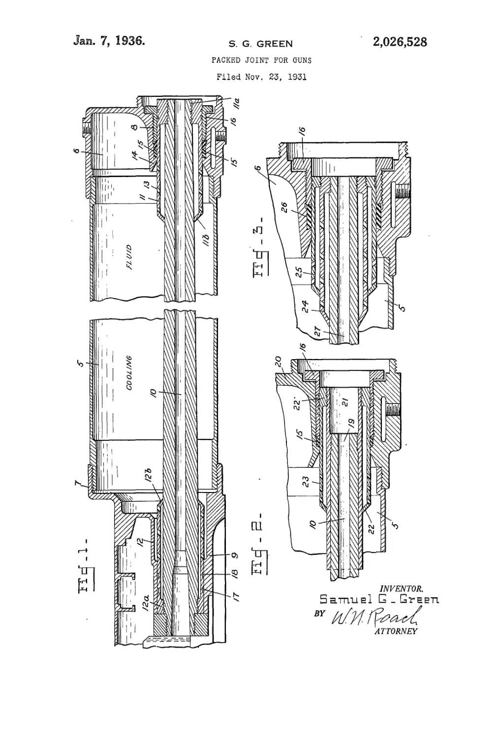
Fig. 1 is a longitudinal sectional view through
the cooling jacket of a machine gun and showing
the improved manner of mounting the front
and rear ends of the gun barrel.
Figs. 2 and 3 are longitudinal sectional views
showing modifications of the front mounting,
the barrel being in position of recoil.
Referring to Fig. 1, there is shown a jacket
5 adapted to contain a cooling medium. The
front plate 6 and the rear plate 1 are each pro-
vided with a bearing portion, respectively 8 and
9, for receiving a shaft, tube or gun barrel 10,
which may be movable relative to the jacket and
attains a high temperature in action. The barrel
is radially spaced from the bearings by means
of a front sleeve 11 and a rear sleeve 12, each of
which is of greater length than its bearings. The
sleeves are of equal external diameter to facili-
tate formation and alignment of the bearings 8
and 9, and reduce the vibration error of the
barrel.
The sleeves 11 and 12 are substantially identi-
cal, being formed with inturned ends engageable
with the barrel and serving to space the sleeves
from the barrel. The outer ends I la and 12a are
internally threaded for connection with the bar- 5
rel while the inner ends I lb and 12b are prefer-
ably inclined to facilitate insertion and removal
of the barrel. Apertures 13 in the sleeves enable
the cooling medium to come into direct contact
with the barrel. 10
.The front bearing 8 is formed with an internal
flange 14 against which a packing member 15 is
held by a gland 16 threaded into the bearing.
The packing embraces the sleeve and is spaced
from the barrel by the sleeve and the cooling 15
medium.
The rear sleeve 12 is formed externally with
one or more annular grooves 17 in which is placed
a packing material 18 that presses against the
wall of the bearing and prevents leakage of the 20
cooling medium.
In the modification shown in Fig. 2 the rifled
muzzle end 19 of the barrel is terminated con-
siderably short of the front plate 20 of the jacket,
and a tubular extension 21 on the barrel is 25
threadedly connected to the intumed end 22 of the
sleeve 23. By this arrangement the muzzle of
the barrel is always surrounded by the cooling
medium.
In the modification shown in Fig. 3 a pair of 30
spaced concentric sleeves 24 and 25 are provided
to separate the packing 26 from tile gun barrel
27. The outer sleeve 25 is preferably shorter
than the inner sleeve 24 to which it is attached
and the cooling medium may or may not be 35
admitted into the space between the sleeves.
While the invention is described with particu-
lar reference to a gun barrel it is to be under-
stood that it has application to any packed joint
for a stationary and rotatable as well as a re- 40
ciprocable member.
I claim:
1. In combination with a cooling jacket adapt-
ed to contain a fluid medium and having bear-
ings at its front and rear ends, a gun barrel 45
mounted for reciprocation within the jacket, a
sleeve on each end of the barrel fitting in the
bearings and extending into the fluid space of
the jacket, and inclined fluid passages in the
sleeves, all passages in a sleeve having the same 50
direction of inclination whereby fluid is circu-
lated through the sleeves in one direction on
recoil and in the opposite direction on counter-
recoil.
2. In combination with a cooling jacket adapt- 55
2
ed to contain a fluid medium and having bear-
ings at its front and rear ends, a gun barrel
mounted for reciprocation within the jacket, a
sleeve on each end of the barrel, each sleeve in
5 engagement with the barrel at the ends of the
sleeve but spaced from the barrel throughout
the greater portion of its length, said sleeves fit-
ting the bearings and extending into the fluid
space of the jacket, and means provided in said
10 sleeves whereby fluid is circulated through the
sleeves on recoil and counter-recoil of the barrel.
3. In combination with a cooling jacket adapt-
ed to contain a fluid medium, a bearing at the
front end of the jacket and surrounded by the
15 cooling medium, a gun barrel mounted for re-
ciprocation within the jacket, a sleeve on the
muzzle of the barrel having intumed ends
whereby the sleeve is spaced from the barrel.
2,026,628
and means formed in the sleeve which circulates
the fluid therethrough on recoil and counter-
recoil of the barrel.
4. A sleeve for fluid cooled reciprocating gun
barrels embodying a tubular member, inturhed (
ends on the tubular member adapted to engage
a gun barrel, and ports spaced about the sleeve
and inclined at an angle other than 90° to the
longitudinal axis of the gun barrel, the inclina-
tion of all ports being in the same direction. 10
5. A sleeve for fluid cooled reciprocating gun
barrels embodying a tubular member adapted
to fit on and be spaced from a gun barrel, and
means formed in the sleeve which circulates the
cooling fluid through the sleeve on recoil and 1*
counter-recoil of the gun barrel.
SAMUEL G. GREEN.