/

Tags: weapons military affairs patent
Year: 1934


Text
Nov. 9, 1937.
2,098,727
A. J. LAHTI
LOCK MECHANISM FQ? AUTOMATIC GUNS
Files July 6, 1936
Patented Nov. 9, 1937
2,098,727
UNITED STATES PATENT OFFICE
2,098,727
LOCK MECHANISM FOR AUTOMATIC GUNS
Aimo Johannes Lahti, Jyvaskyla, Finland
Application July 6, 1936, Serial No. 89,209
In Germany September 23, 1935
1 Claim. (Cl. 42—3)
5
10
15
20
25
30
35
40
45
50
55
60
The present invention relates to lock mecha-
nism of automatic guns the automatic function of
which depends on the pressure of the powder
gases as in the so-called gas guns, or on the short
recoil of the barrel as in the so-called recoil guns.
The invention is fundamentally characterized
by the fact that the connection between the lock
and the barrel is effected by means of a type of
one-armed locking lever, aided by the inclined
plane provided on the closing piece, and that the
connection is opened by a double armed lever
which receives its movement from the backwardly
sliding closing piece.
The above mentioned locking device, viz, the
'closing piece and the double armed lever, is ca-
pable of simple and mobile manufacture on ac-
count of its advantageous operation in the move-
ment of a one armed lever and a double armed
lever. These conditions are important factors in
the guns mentioned, and particularly in obtaining
a high rate of firing.
Reference will now be made to the accompany-
ing drawing which shows the lock mechanism ac-
cording to the invention adapted for use in a gas
gun and in which;—
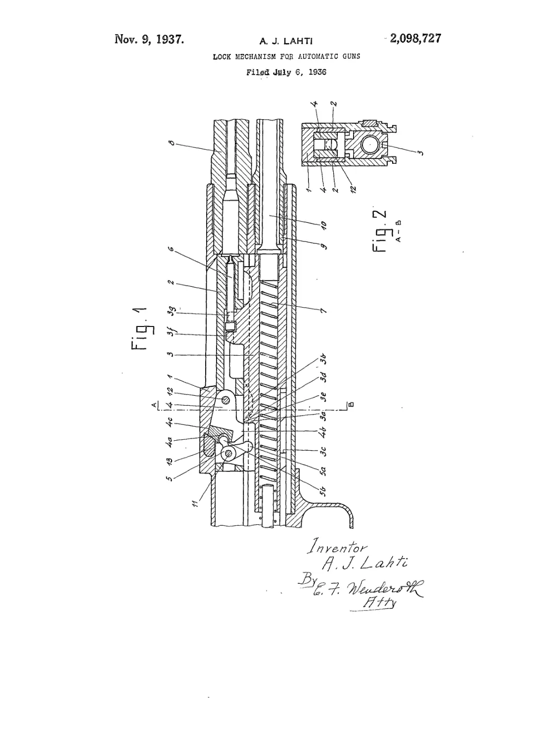
Figure 1 is a longitudinal section of the mid-
dle part of the gun and
Figure 2 is a cross section on the line A—В of
Fig. 1.
A lock mechanism is provided in the lock body
i on the butt end of the gun, the main parts of
which are a lock 2, a closing piece 3, a locking
lever <3, a double armed lever 5, a striking pin 6
and a recoil spring 7. The barrel 8 and the gas
cylinder 9 into which the powder gas is supplied
in the known manner from the front part of the
barrel, are screwed on to the front part of the
casing i. The piston rod i 8 which is constructed
in the known maimer and moves in the cylinder
9 is screwed on to the front part of the closing
piece 3.
The operation of the lock arrangement is as
follows;—
When the gas arising from the shot passes into
the cylinder 9 the piston with the piston rod 10
forces back the closing part 3, the striking sur-
face 3a hitting the lower part of the shaft 5a of
the double-armed lever 5. The double-armed
lever 5 rotates about the pin i 1 fixed in the lock
and forces downwards the rear part of the locking
lever <3 with its upper arm 5b in the cut out por-
tion 4a in the locking lever 4. The locking lever
4 rotates about a pin 12 supported on the lock
2 in such a way that the projection 4b therein is
pressed into the cut out portion 3b of the closing
part 3, the locking point 4,c of the locking lever 4
drops to the rear side of a counter-part 13 fixed
on the casing (, and connection between the lock
2 and the barrel 8 is opened.
The backward sliding movement of the clos-
ing part 3 continues on account of the pressure
of the explosion and the lock 2 slides back with it,
whilst the striking surface 3a moves by means of
the lever Sa until the empty case is ejected in the 5
known manner and lock 2 is in its rear position.
If firing is interrupted, the closing part 3 is
held ready cocked with the tooth 3c on the dis-
charge device, until loaded by hand, whereby the
closing part 3 is drawn from the forward into the 1°
rear position with the help of a cocking bar of the
known type, and the other parts of the locking
device follow and operate in the above described
manner.
If firing is maintained, and also if the cocking 16
position is no longer maintained the spring 7
moves the closing part 3 forward. The inclined
surfaces 3d of the closing part 3 are pressed
against the rear edges of the projections 4b and
the lock is moved forward and a new cartridge 2®
moves into the barrel 8 in the known manner
from the cartridge chamber. When the lock 2
stops, the closing part 3 continues its forward
movement and the inclined surface 3d moves the
rear end of the locking lever 4 upwards, so that 25
the locking point 4c is pressed against the coun-
ter-part 13 whilst it effects the connection be-
tween the lock 2 and the barrel 8. If the closing
part 3 moves further forward its upper surface
3c, whilst sliding against the projection 4b, car- 30
ries the locking parts 4 and prevents the same
moving.
At the end of the forward movement the clos-
ing part 3 between the projection 3/ and the fork
3ff hits the striking pin 6 against the detonating ss
cap and fires the cartridge, after which the recoil
movement of the closing part 3 starts anew and
the operation of the gun as described above con-
tinues.
40
With short recoil guns the operation is the same
with the difference that the closing part 3 re-
ceives its movement from the recoiling barrel in
the already known manner.
I claim:
In a recoil loading firearm the combination of
a reciprocating breech block, a pivoted locking
member on said block having an abutment seat-
ing in a recess of the breech to lock said breech
block thereto, a double armed lever pivoted to 59
said breech block having one arm cooperating
with said locking member to release said member
from said recess in said breech, an actuator co-
operating with the other arm of said lever to
actuate the same and said actuator having a cam 55
surface cooperating with said locking member to
replace said member in said recess after having
been removed therefrom by said lever.
AIMO JOHANNES LAHTI. eo