/


Tags: weapons military affairs patent
Year: 1929


Text
April 16, 1929.
W. I. WESTERVELT ET AL
1,709,162
AUTOMATIC GUN
Filed April 21, 1925 9 Sheets-Sheet 1
April 16, 1929.
W. 1. WESTERVELT ET AL
AUTOMATIC GUN
1,709,162
Filed April 21, 1925
9 Sheets-Sheet 2
April 16, 1929.
W. I. WESTERVELT ET AL
AUTOMATIC GUN
1,709,162
9 Sheets-Sheet 3
Filed April 21, 1925
April 16, 1929.
W. I. WESTERVELT ET AL
1,709,162
AUTOMATIC GUN
Filed April 21, 1925
9 Sheets-Sheet 4
April 16, 1929.
W. I. WESTERVELT ET AL
AUTOMATIC GUN
1,709,162
Filed April 21, 1925 9 Sheets-Sheet 5
INVENTORS
W. I -Westervelt
- >₽
' ATTORNEY
April 16, 1929.
W. I. WESTERVELT ET AL
AUTOMATIC GUN
1,709,162
Filed April 21, 1925 9 Sheets-Sheet 6
April 16, 1929.
W. I. WESTERVELT ET AL
AUTOMATIC GUN
1,709,162
Filed April 21, 1925
9 Sheets-Sheet 7
April 16, 1929.
W. I. WESTERVELT ET AL
AUTOMATIC GUN
1,709,162
Filed April 21, 1925
9 Sheets-Sheet 8
€Lttoi ne
April 16, 1929.
W. I. WESTERVELT ET AL
AUTOMATIC GUN
1,709,162
Filed April 21, 1925 9 Sheets-Sh6et 9
Patented Apr. 16, 1929.
1,709,162
UNITED STATES PATENT OFFICE.
WILLIAM I. WESTERVELT, OF THE UNITED STATES ARMY, SAN ANTONIO, TEXAS,
AND WILLIAM SUMMERBELL, OF WATERVLIET, NEW YORK.
AUTOMATIC GUN.
Application filed April 21, 1925. Serial No. 25,074.
(GRANTED UNDER THE ACT OF MARCH 3, 1883, AS AMENDED APRIL 30, 1928; 370 0. G. 757.)
The invention described herein may be
manufactured and used by or for the Gov-
ernment for governmental purposes without
the payment to us of any royalty thereon.
5 The subject of the present invention is an
automatic gun, especially adapted for projec-
tiles of 37 m/m caliber though not restricted
thereto.
In designing automatic guns for projec-
10 tiles of large calibers, it is essential by reason
of the explosive nature of this class of projec-
tiles to insure positive feeding of the round
into the barrel and it is desirable to accom-
plish the feeding and other operations with-
15 out unduly increasing the number and size of
the operative elements of the gun. The
weight and length of the projectile together
with the correspondingly longer stroke of re-
coil precludes the feasibility of overhead ex-
20 traction of a live round from the magazine
during recoil and subsequent lowering of the
round into position to enter the chamber on-
counterrecoil of the block or bolt which is the
method popularly adopted for light machine
25 guns. It is also desirable that the gun be
manually as well as automatically operable
to provide for initially loading the piece and
for correcting stoppages and misfires.
With these and other objects in view, we
30 have devised novel means for unlocking an
axially movable breech block which extracts
a live round from the magazine during re-
coil and which moves en masse with the bar-
rel until, in the initial stage of counterrecoil
35 it is arrested by the unlocking means, while
the barrel, continuing into battery to permit
ejection and feeding respectively of the
empty case and the live round, controls the
release of the block and the advancement of
40 the feed strip through the magazine. A
novel buffer mechanism, for decreasing the
velocity of the counterrecoiling barrel, serves
to energize the block for independent return
movement. The live round is fed trans-
45 versely across the face of the block as the
block after release, continues its return to
battery and the round is brought to rest by a
novel support immediately preceding its en-
try into the chamber, the support being sub-
50 sequently collapsed as the block approaches
the limit of its forward movement. An im-
portant innovation consists in the provision
for buffing the breech block, the mechanism
reacting to slide the block laterally in lock-
ing. A further departure in the manner of 55
grouping the firing pin, cocking lever, sear,
and firing post renders them more accessible
and enables the firing pin to be readily and
directly cocked while the gun is locked in
battery. 60
To these and other ends, our invention con-
sists in the construction, arrangement, and
combination of elements, described herein-
after and pointed out in the claims forming a
part of this specification. 65
A practical embodiment of our invention
is illustrated in the accompanying drawings,
wherein:
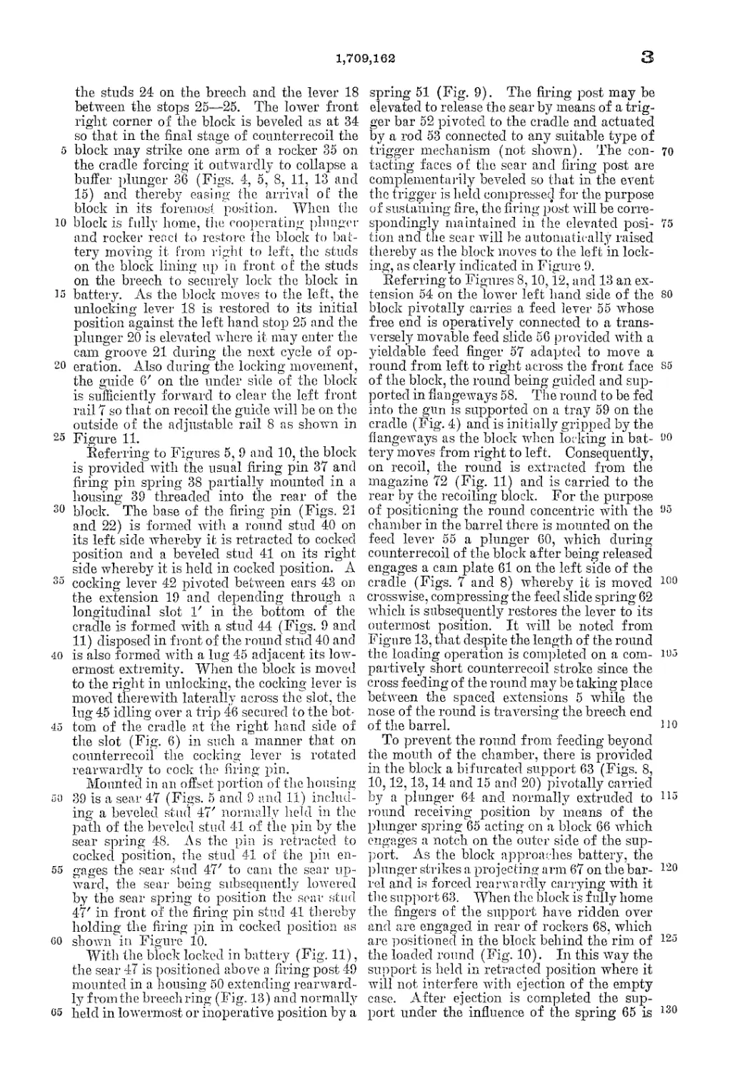
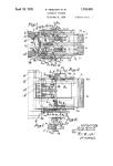
Fig. 1 is a plan view of a gun constructed
in accordance with the invention; 70
Fig. 2 is a view in side elevation partly
broken to show details of the combined coun-
terrecoil buffer and block return mechanism;
Fig. 3 is a plan view of the rear end of the
gun partly broken to show details of the 75
block release rod;
Fig. 4 is a plan view of a portion of the
gun in. extension of Fig. 3 with the block
locked in firing position, the cradle broken
away above the breech to reveal parts in plan 80
and section and the magazine removed from
the cradle;
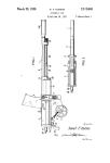
Fig. 5 is a fragmentary view in right side
elevation and partly in section, the firing pin
being released and about to prime the loaded 85
round;
Fig. 6 is a similar view of the end of the
gun in rear of Fig. 5;
Figs. 7 and 8 are horizontal sectional views
through the breech end of the gun with the 90
breech block partly in section and showing a
round entering the chamber;
Fig. 9 is a transverse sectional view through
the gun, the breech block unlocked in the for-
ward position, and shown in rear elevation 95
with parts in section;
Fig. 10 is a fragmentary plan view partly
in section of the breech block cocked and in
unlocked position, the barrel being sectioned
to show the loaded round; юо
Fig. 11 is a rear elevation with the end
plate removed of the gun locked in firing
position and parts being shown in section;
Fig. 12 is a partial horizontal sectional
view through the breech block showing the 105
feed slide, ejector., and cartridge support;
2
1,709,162
a
10
15
20
25
30
35
40
45
50
55
60
G5
Fig. 13 is a plan view of the separated block
and barrel, the upper part of the cradle and
magazine being removed;
Fig. 14 is a fragmentary view of the breech
block partly in plan and partly in section to
show details of the cartridge support;
Fig. 15 is a front view of the block shown
in Fig. 14;
Fig. 16 is an enlarged fragmentary view
partly in seclion of (he corresponding por-
tion of the gun shown in Fig. 2;
Fig. 17 is a sectional view on the line 7—7
of Fig. 2;
Fig. 18 is a detail view in side elevation and
partly in section of the trigger bar;
Fig. 19 is a view in rear elevation thereof;
Fig. 20 is a detail view in left side elevation
of the cartridge support;
Fig. 21 is a detail plan view of the firing
pi11;
Fig. 22 is a view in right side elevation
thereof;
Fig. 23 is a detail sectional view on the line
3—3 of Fig. 12;
Fig. 24 is a fragmentary view in left side
elevation of the gun with the magazine closed
and loaded;
Figs. 25 and 26 are detail views, respective-
ly, in plan and front elevation of a member
of the breech block.
Referring to the drawings by numerals of
reference:
In carrying out the invention, there is pro-
vided a frame or cradle 1, in which recipro-
cates a barrel 2 being guided in reciprocation
by rails 3 integral with the base of the cradle
(Figs. 9,11 and 13). Surrounding the barrel
1 and enclosed by the cradle is a spring 4
(Figs. 2 and 16) compressed during recoil
for returning the barrel to battery, the return
movement of the barrel being eased or re-
tarded by a buffer mechanism hereinafter to
be described.
Idle breech end of the barrel is squared
(Figs. 5, 9 and 11) and embodies horizontally
disposed spaced extensions 5 between which
is received an axially movable breech block 6
which is guided in reciprocation after being
separated from the barrel by stationary rails
7 on either side of the cradle, and also by an
adjustable rail 8 (Figs. 7, 8,11 and 13) which
interrupts the left hand rail 7. The adjust-
able rail 8 is lowered by the breech block
guide 6' as the block moves to the right in
unlocking and is restored to normal position
by plungers 8' when cleared by the block in
counterrecoil.
As the barrel moves in recoil, it retracts
a hollow piston 9 (Figs. 2 and 5) disposed
in a cylinder 10 and which is constrained to
be reciprocated with the barrel by reason of
its attachment to the bracket 11 on the breech.
Within the piston 9 is a rod 12 surrounded
by a spring 13 which is confined between an
internal annular shoulder 14 (Fig. 5) of the
piston and the collar 15 on the forward end
of the rod (Fig. 2). This rod passes under-
neath a bridge guide 16 on the breech and
terminates in an enlarged head 17 having a
depending lever 18 whose ball end is disposed 70
in a slot 19' formed in a rearward extension
19 of the breech block, (Figs. 8, 9, 11, 12 and
13). The head 17 is also provided with a
plunger 20 adapted during recoil to traverse
the cam groove 21 in a plate 22 secured to the 75
top left side of the cradle whereby to rotate
the head 17 and rod 12 in a counter-clockwise
direction to move the block to the right to the
position shown in Figure 9. When the block
is in this position the locking studs 23 on so
the block have moved clear of the studs 24 on
the breech ring and the lever 18 brought to
rest by the right hand element of a pair of
stops 25—25 on the barrel is now free to pass
between the stops at the proper moment of 85
separation of the block and barrel.
The cam groove 21 terminates in a bevel
portion 26 (Figs. 3 and 6) whereby the
plunger 20 after serving to unlock the block
is forced inwardly but on passing the plate 90
22 it is again extruded so that on counter-
recoil it may be brought up against the rear
shoulder 27 of the plate to restrain the block
while the barrel continues into battery.
During recoil and initial counterrecoil the 95
piston 9 and rod 12 participate in the move-
ment of the barrel and block, (he spring
13 remaining idle. However, when the
rod 12 is hung up by reason of the engage-
ment of the plunger 20 on the shoulder 27 of Ю0
the cam plate 22 the piston compresses the
spring for the purpose of decreasing the. veloc-
ity of the counterrecoiling barrel as it runs
into battery while also energizing the spring
to subsequently accomplish return movement K>5
of the block, the block advancing a round
into the chamber.
Referring to Figures 1, 3, 4, 9 and 11 there,
is mounted on the upper left side of the cradle
a block release rod 28, its forward extremity 1H>
having a finger 29 and its rear extremity re-
ceiving an arm of a bell crank lever 30 piv-
oted in the.cradle and normally moved to in-
operative position by a spring 31 which is
enclosed in a housing 32 formed integrally H5
with the cam plate 22. As the barrel arrives
in battery, a stud 33 (Fig. 13) on the barrel
strikes the finger 29 to impel the rod for-
wardly. this action causing the lever 30 to
be swung inwardly to strike the plunger 20 120
and release it from engagement with the
shoulder 27 whence the energized spring 13
returns the block independently to battery.
Separation of the block and barrel is essential
to effect ejection of the empty case and in- 125
section of a live round into the barrel cham-
ber as will appear in detail as the description
proceeds.
The block moves forward in the unlocked
position, the locking studs 23 passing between i30
1,709,162
3
5
10
15
20
25
30
За
40
45
а 0
55
GO
65
the studs 24 on the breech and the lever 18
between the stops 25—25. The lower front
right corner of the block is beveled as at 34
so that in the final stage of counterrecoil the
block may strike one arm of a rocker 35 on
the cradle forcing it outwardly to collapse a
buffer plunger 36 (Figs. 4, 5, 8, 11, 13 and
15) and thereby easing the arrival of the
block in its foremost position. When the
block is fully home, the cooperating plunger
and rocker read to restore the block to bat-
tery moving it from right to left, the studs
on the block lining up in front of the studs
on the breech to securely lock the block in
battery. As the block moves to the left, the
unlocking levei' 18 is restored to its initial
position against the left hand stop 25 and the
plunger 20 is elevated where it may enter the
cam groove 21 during the next cycle of op-
eration. Also during the locking movement,
the guide 6' on the under side of the block
is sufficiently forward to clear the left front
rail 7 so that on recoil the guide will be on the
outside of the adjustable rail 8 as shown in
Figure 11.
Referring to Figures 5, 9 and 10, the block
is provided with the usual firing pin 37 and
firing pin spring 38 partially mounted in a
housing 39 threaded into the rear of the
block. The base of the firing pin (Figs. 21
and 22) is formed with a round stud 40 on
its left side whereby it is retracted to cocked
position and a beveled stud 41 on its right
side whereby it is held in cocked position. A
cocking lever 42 pivoted between ears 43 on
the extension 19 and depending through a
longitudinal slot 1' in the bottom of the
cradle is formed with a stud 44 (Figs. 9 and
11) disposed in front of the round stud 40 and
is also formed with a lug 45 adjacent its low-
ermost extremity. When the block is moved
to the right in unlocking, the cocking lever is
moved therewith laterally across the slot, the
lug 45 idling over a trip 46 secured to the bot-
tom of the cradle at the right hand side of
the slot (Fig. 6) in such a manner that on
counterrecoil the cocking lever is rotated
rearwardly to cock the firing pin.
Mounted in an offset portion of the housing
39 is a sear 47 (Figs. 5 and 9 and 11) includ-
ing a beveled stud 47' normally held in the
path of the beveled stud 41 of the pin by the
sear spring 48. As the pin is retracted to
cocked position, the stud 41 of the pin en-
gages the sear stud 47' to cam the sear up-
ward, the sear being subsequently lowered
by the sear spring to position the sear stud
47' in front of the firing pin stud 41 thereby
holding the firing pin in cocked position as
shown in Figure 10.
With the block locked in battery (Fig. 11),
the sear 47 is positioned above a firing post 49
mounted in a housing 50 extending rearward-
ly from the breechring (Fig. 13) and normally
held in lowermost or inoperative position by a
spring 51 (Fig. 9). The firing post may be
elevated to release the sear by means of a trig-
ger bar 52 pivoted to the cradle and actuated
by a rod 53 connected to any suitable type of
trigger mechanism (not shown). The con- 70
tacting faces of the sear and firing post are
complementarity beveled so that in the event
the trigger is held compressed for the purpose
of sustaining fire, the firing post will be corre-
spondingly maintained in the elevated posi- 75
tion and the sear will be automatically raised
thereby as the block moves to the left in lock-
ing, as clearly indicated in Figure 9.
Referring to Figures 8,10,12, and 13 an ex-
tension 54 on the lower left hand side of the 80
block pivotally carries a feed lever 55 whose
free end is operatively connected to a trans-
versely movable feed slide 56 provided with a
yieldable feed finger 57 adapted to move a
round from left to right across the front face 85
of the block, the round being guided and sup-
ported in flangeways 58. The round to be fed
into the gun is supported on a tray 59 on the
cradle (Fig. 4) and is initially gripped by the
flangeways as the block when locking in bat- 8°
tery moves from right to left. Consequently,
on recoil, the round is extracted from the
magazine 72 (Fig. 11) and is carried to the
rear by the recoiling block. For the purpose
of positioning the round concentric with the 95
chamber in the barrel there is mounted on the
feed lever 55 a plunger 60, which during
counterrecoil of the block after being released
engages a cam plate 61 on the left side of the
cradle (Figs. 7 and 8) whereby it is moved 100
crosswise, compressing the feed slide spring 62
which is subsequently restores the lever to its
outermost position. It will be noted from
Figure 13, that despite the length of the round
the loading operation is completed on a com- 165
partively short counterrecoil stroke since the
cross feeding of the round may be taking place
between the spaced extensions 5 while the
nose of the round is traversing the breech end
of the barrel. no
To prevent the round from feeding beyond
the mouth of the chamber, there is provided
in the block a bifurcated support 63 (Figs. 8,
10,12,13,14 and 15 and 20) pivotally carried
by a plunger 64 and normally extruded to П5
round receiving position by means of the
plunger spring 65 acting on a block 66 which
engages a notch on the outer side of the sup-
port. As the block approaches battery, the
plunger strikes a projecting arm 67 on the bar- 120
rel and is forced rearwardly carrying with it
the support 63. When the block is fully home
the fingers of the support have ridden over
and are engaged in rear of rockers 68, which
are positioned in the block behind the rim of 125
the loaded round (Fig. 10). In this way the
support is held in retracted position where it
will not interfere with ejection of the empty
case. After ejection is completed the sup-
port under the influence of the spring 65 is 130
4
1,709,162
free to again lie moved to round receiving po-
sition, the rockers being rotated to release the
lingers of the support.
"When the block is full}7 home but unlocked
5 the feed linger 57 and a similarly constructed
ejector 69 are in the position shown in Figure
10 being collapsed by reason of contact respec-
tively with the base of the round in the tray
59 and the loaded round in the chamber. As
10 tbe block is moved to the left in lucking, the
feed finger and ejector move with it to engage
the rim of the respective rounds as shown in
Fig. 4. During the intermediate stage of re-
coil the block, as has been previously de-
15 scribed, is moved to the right in unlocking but
the ejector remains stationary by reason of its
contact with the rim of the empty case. This
action energizes the feed slide spring 62, the
inner end of which is confined in the ejector
20 casing 70 io subsequently expel the empty
case from the face of the block, when, during
independent return of the barrel to battery,
file mouth of the chamber clears the forward
end of the empty case.
35 To facilitate ejection of the empty case
and to prevent jamming, the flangeways 58
are of minimum length, retaining merely a
sufficient hold on the rounds to perforin its
dual extracting operation. It will be noted
30 from Figure 15 that when the block is moved
in locking to grip the round in the magazine,
the flangeways will be clear of the loaded
round but will again grip the empty case to
extract it as the block is unlocked during
35 recoil. The live round, however, is clear of
the magazine before unlocking takes place
and consequently it is still retained by the
block as the flangeways reengage the empty
ease.
io Referring to Figures 8. 11, 13 and 24, the
cradle is provided with ears 71 positioned on
its left side adjacent the breech end of the
barrel when in battery. Pivotally mounted
on the ears 71 and overlying the cradle is a
•15 curved magazine 72 which when closed is
supported by, and locked with a latch 73 to a
standard 74 formed integrally with the top
of the cradle. The magazine is suitably
grooved to receive a metallic strip 75 in which
50 a number of rounds are retained by resilient
split rings 76 riveted to the strip.
Mounted in the cradle is a shaft 77 formed
vvitli a cam groove 78 in which is disposed a
pin 79 on the breech ring (Figs. 9,11 and 24)
55 whereby during recoil and counterrecoil of
the hiu-rel the shaft is rotated. On the for-
ward end of the shaft is a lever 80 having
a scarfed plunger 81 which projects through
an arcuate slot 82 in the rear face of the
oo magazine to engage slots 83 in the strip,
During; recoil, the lever is raised so that on
counterrecoil the strip may be fed through
the magazine until the lowermost round is
brought to rest by the tray 59 in position to
65 be gripped by the flangeways of the block
as the block is moved from right to left in
locking. The feed finger 57 is adapted on
locking of the block to project through a
slot 84 in order to engage the rim of the
round on the tray. The magazine is also pro- 70
vicled with a scarfed plunger 85 engageable
in the slots 83 to hold the strip while the lever
is being raised during recoil. When the last
round from the strip has been gripped by the
block and extracted from the magazine, the 75
strip is free to pass through the magazine
and fall clear. To provide for uninterrupt-
edly feeding rounds through the magazine
the individual strips may be hooked together
in any well known manner. 80
For the purpose of initially loading the
piece and correcting stoppages, there is pro-
vided a handle 86 slidably mounted on a rod
87 secured on the upper right side of the
cradle (Figs. 1, 4, 9 and 11). The pivot encl 85
of the handle is formed with a slotted pro-
jection 88 (Figs. 9 and 11) which forwardly
engages a lug 89 on the head 17 of the rod
12. The handle is normally held in the
raised or inoperative position as shown in 90
Figures 9 and 11 by a plunger 90.
To open the block the handle is turned
downwardly in a clockwise direction (Figs.
9 and 11) and through the lug 89 rotates (lie
head 17, the lever 18 moving the block to the 95
right to disengage the locking studs 23 from
the studs 24 on the breech ring. The handle
is then drawn to the rear carrying with it
the block and may be latched in a recess 91
(Fig. 3) sufficiently far to the rear to allow 100
the lug 45 of the cocking lever to ride over
and get behind the trip 46 and also a suitable
distance from battery to clear stoppages or
manually insert a new round.
As a provision for remedying misfires the 105
extremity of the cocking lever 42 is formed
into a finger grip 42' protruding below the
cradle (Figs. 5, 9 and 11) so that with the
block locked in battery the gunner may reach
underneath the cradle and by directly press- 110
ing the cocking lever the firing pin will be
cocked. On pulling the trigger, the firing
pin may again be released and if the misfire
persists the round may be cleared and a new
round inserted. 115
It will be understood that any suitable
buffer mechanism for absorbing the surplus
energy of recoil may be provided on the end
plate of the cradle.
In operation, to load the piece, assuming 120
the gun to be locked in the firing position and
a loaded strip in the magazine, the handle 86
is turned down and operates through the
lever 18 to move the breech block from left
to right in unlocking, the block assuming the 125
position shown in Figure 9 so that it will not
extract a round from the magazine as it is
retracted. The block is then manually
drawn to the rear and latched in place where
the initial round may be inserted in the 130
i,700,163
5
flangeways 58 until the yieldable feed finger
57 grips the outer rim of the case. On the
release of the block for return to battery the
cocking lever 42 is actuated by the trip 46 to
5 cock the firing pin and the feed lever 54 is
moved crosswise by means of the cam plate
61 until the round is brought up against the
support 63 whence it is advanced into the
chamber by the counterrecoiling block, the
10 support being forced rearwardly into the
block when its plunger 64 strikes the arm 67
on the barrel (Fig. 10). The block is eased
on completion of its return movement by the
cooperating rocker 35 and buffer 36 which re-
15 act to automatically slide the block laterally
into the firing position, the lever 18 moving
therewith until brought up against the left
stop 25 on the barrel. The gun is then in the
position shown in Figure 4, the flange 57 of
20 the block picking up the lowermost round in
the magazine (Fig. 11) and the feed finger
56 and ejector 69 engaging respectively the
rim of the incoming and the loaded round.
When a round is discharged the block and
25 barrel move together in recoil, at first inter-
locked and later, after the incoming round
has been withdrawn clear of the magazine,
unlocked. The unlocking of the block is
automatically accomplished by the plunger
30 20 on the enlarged head 17 of the return rod
12 working in the cam groove 21 of the plate
22, the block moving from left to right while
the ejector is held stationary to energize the
spring 62 by reason of its engagement with
35 the rim of the empty case. Also during un-
locking, the flangeways 58 reengage the rim
of the empty case so that subsequently on
separation of the barrel and block the empty
case will be extracted from the chamber.
40 During the initial stage of counterrecoil,
the plunger 20 engages the rear shoulder 27
of the plate 22, (Fig. 3) to restrain the block
while the barrel continues uninterruptedly
and is eased into battery by compressing the
45 spring (Fig. 2) which is thus energized to
subsequently return the block independently
to battery. When the chambered end of the
barrel has cleared the forward end of the
empty case, the ejector expels the case from
50 the flangeways 58 freeing the rockers 68 for
rotation to allow the support 63 to be re-
leased to round engaging position.
As the barrel approaches battery (Figs. 3
and 4), a stud 33 thereon strikes the finger
55 29 of the release rod 28, this action causing
the bell crank lever 30 to be swung inwardly
to release the plunger 20 from the cam plate
22 whence the energized spring 13 effects the
independent return of the block.
60 On release of the block the pivoted feed
lever 55 engages the cam plate 61 to move the
feed slide 56 transversely of the block until
the incoming round is stopped concentric
with the chamber by the support 63 at which
65 time the block will have advanced to a point
where the round is about to enter the cham-
ber. After accomplishing its function the
feed lever is returned to its normal outward
position by the feed slide spring 62.
Also on initial release of the block, the 70
cocking lever 42 is rotated rearwardly by the
trip 46 to retract the firing pin 37 to cocked
position, the stud 41 of the pin displacing the
sear 47 which reacts to hold the pin in cocked
position. By reference to Figures 9 and 11, 75
it will be noted that the firing pin and primer
of the round and also the sear 47 and firing
post 49 are only aligned when the block is
locked in the firing position so that in the
event of accidental release of the pin while 80
the block is unlocked no damage will result.
During recoil and counterrecoil of the bar-
rel the lever 80 on the shaft 77 is rocked to
advance the strip 75 through the magazine
until the lowermost round rests on the tray 85
59 in position to be gripped by the flange-
ways 58 as the block is automatically locked
by the combined rocker buffer 35 and 36.
While in the foregoing there has been
illustrated and described such combination 90
and arrangement of elements, as constitute
the preferred embodiment of our invention,
it is nevertheless desired to emphasize the
fact that interpretation of the invention
should only be conclusive when made in the 95
light of the subjoined claims.
We claim:
1. The combination of a cradle, a barrel
mounted to reciprocate freely therein, an
axially movable breech block for the barrel, 100
cooperating means on the block and cradle for
sliding the block laterally in unlocking dur-
ing recoil, said means adapted during
counterrecoil to arrest the block while the
barrel continues into battery, a buffer mecha- 105
nism for the counterrecoiling barrel adapted
to react to return the block independently,
means mounted on the cradle and controlla-
ble by the barrel in counterrecoil for releas-
ing the block, an ejector mounted in the block no
and energized in unlocking of the block for
expelling the empty case when clear of the
chamber, feed mechanism mounted in the
block for moving a round transversely across
the face of the block, a support carried by the 115
block for stopping the incoming round in
line with the chamber, means on the barrel
for collapsing the support as the block arrives
in battery, means in the block for holding the
support inoperative until ejection of the 120
empty case, a buffer mechanism for easing
the return of the block, said mechanism re-
acting to lock the block, a transverse flange-
way formed on the face of the block, said
flangeway gripping a live round on locking 125
of the block and regripping the empty case
on unlocking, a firing pin and spring in the
block, a sear therefor, means for automati-
cally cocking the pin during counterrecoil of
the block, a firing post carried by the barrel, 130
6
1,709,162
means for actuating the post to displace the
sear, an arcuate magazine pivoted to the
cradle and overlying the same, means con-
trollable by the barrel in recoil and counterre-
5 coil for advancing a feed strip through the
magazine, means for manually unlocking and
retracting the block and means whereby the
firing pin may be cocked with the gun locked
in firing position.
10 2. The combination of a cradle, a barrel
mounted to reciprocate freely therein, an
axially movable breech block for the barrel,
cooperating means on the block and cradle
for sliding the block laterally in unlocking,
15 said means adapted during counterrecoil to
arrest the block while the barrel continues
into battery, a buffer mechanism for the
counterrecoiling barrel adapted to react to
return the block independently, means
20 mounted on the cradle and controllable by the
barrel in counterrecoil for releasing the block,
an ejector for expelling the empty case when
clear of the chamber, feed mechanism for
moving a round transversely across the face
25 of the block, a support for stopping the in-
coming round in line with the chamber, means
for collapsing the support as the block arrives
in battery, means for holding the support in-
operative until ejection of the empty case, a
30 buffer mechanism for easing the return of the
block, said mechanism reacting to lock the
block, a transverse flangeway formed on the
face of the block, said flangeway gripping a
live round on locking of the block and re-
35 gripping the empty case on unlocking, a fir-
ing pin and spring in the block, a sear there-
for, means for automatically cocking the pin,
a firing post carried by the barrel, means for
actuating the post to displace the sear, a
40 magazine pivoted to the cradle, means con-
trollable by the barrel in recoil and counter-
recoil for advancing a feed strip through the
magazine, means for manually unlocking and
retracting the block, and means whereby the
45 firing pin may be cocked with the gun locked
in firing position.
3. The combination of a cradle, a barrel
mounted to reciprocate freely therein, an
axially movable breech block for the barrel,
50 cooperating means on the block and cradle
tor sliding the block laterally in unlocking,
said means adapted during counterrecoil to
arrest the block while the barrel continues
into battery, a buffer mechanism for the
55 counterrecoiling barrel adapted to react to
return the block independently, means
mounted on the cradle and controllable by the
barrel in counterrecoil for releasing the block,
an ejector for expelling the empty case when
00 clear of the chamber, feed mechanism for
moving a round transversely across the face
of the block, a support for stopping the in-
coming round in line with the chamber, means
for collapsing the support as the block ar-
vives in battery, a buffer mechanism for eas-
ing the return of the block, said mechanism
reacting to lock the block, a transverse flange-
way formed on the face of the block, said
flangeway gripping a live round on locking
of the block and regripping the empty case 70
on unlocking, a firing pin and spring in the
block, a sear therefor, means for automati-
cally cocking the pin, a firing post carried by
the barrel, means for actuating the post to
displace the sear, a magazine pivoted to the 75
cradle, means controllable by the barrel in
recoil and counterrecoil for advancing a feed
strip through the magazine.
4. The combination of a cradle, a barrel
mounted to reciprocate freely therein, an so
axially movable breech block for the barrel,
cooperating means on the block and cradle for
sliding the block laterally in unlocking, said
means adapted during counterrecoil to arrest
the block while the barrel continues into bat- 85
tery, a buffer mechanism for counterrecoiling
barrel adapted to react to return the block
independently, means mounted on the cradle
and controllable by the barrel in counterre-
coil for releasing the block, an ejector for 90
expelling the empty case when clear of the
chamber, feed mechanism for moving a round
transversely across the face of the block, a
support for stopping the incoming round, a
buffer mechanism for easing the return of the 95
block, said mechanism reacting to lock the
block, a transverse flangeway formed on the
face of the block, said flangeway gripping a
live round on locking of the block and regrip-
ping the empty ease on unlocking, a firing 100
pin and spring in the block, a sear therefor,
means for automatically cocking the pin, a fir-
ing post carried by the barrel, and means for
actuating the post to displace the sear.
5. The combination of a cradle, a barrel 105
mounted to reciprocate freely therein, an
axially movable breech block for the barrel,
cooperating means on the block and cradle for
sliding the block laterally in unlocking, said
means adapted during counterrecoil ho ar- 110
rest the block while the barrel continues into
battery, a buffer mechanism for the counter-
recoiling barrel adapted to react to return the
block independently, means controllable by
the barrel in counterrecoil for releasing the 115
block, an ejector for expelling the empty case
when clear of the chamber, feed mechanism
for moving a round transversely across the
face of the block, a buffer mechanism for eas-
ing the return of the block, said mechanism 120
reacting to lock the block, a transverse flange-
way formed on the face of the block, said
flangeway gripping a live round on locking
of the block and regripping the empty case
on unlocking, and a firing mechanism mount- 125
ed in the block.
6. The combination of a cradle, a barrel
mounted to reciprocate freely therein, an
axially movable breech block for the barrel
adapted to be energized by the barrel, said 13°
1,709,162
5
10
15
20
25
30
35
40
45
50
55
60
G5
block formed with a flangeway for extracting
a live round from a magazine and an empty
case from the chamber, means for unlocking
and locking the block, means for arresting the
block in counterrecoil while the barrel con-
tinues into battery, means for ejecting the
empty case, means for releasing the block for
independent return movement, means for
feeding the live round across the face of the
block, and a firing mechanism in the block.
7. The combination of a cradle, a barrel
therein, formed with a divided breech having
internal spaced lugs, a separable axially mov-
able block having external spaced lugs, coop-
erating means on the block and cradle for slid-
ing the block laterally during recoil to unlock
the lugs, means whereby the block is separated
from the barrel for independent return move-
ment, a buffer mechanism on the cradle for
moving the block laterally on completion of
its return movement whereby to lock the lugs
of the block in front of the lugs on the barrel,
and a rail movable in unlocking of the block
for supporting the block on independent re-
turn movement.
8. The combination of a cradle, a barrel
therein formed with a divided breech having
internal spaced lugs, a separable axially mov-
able block having external spaced lugs, co-
operating means on the block and cradle for
sliding the block laterally during recoil to un-
lock the lugs, means whereby the block is
separated from the barrel for independent re-
turn movement, a buffer mechanism on the
cradle for moving the block laterally on com-
pletion of its return movement whereby to
lock the lugs of the block in front of the lugs
on the barrel.
9. The combination of a cradle, a barrel
therein formed with a divided breech having
internal spaced lugs, a separable axially mov-
able breech block having external spaced lugs,
cooperating means on the block and cradle
for sliding the block laterally during the re-
coil to unlock the lugs, means whereby the
block is separated from the barrel for inde-
pendent return movement, and means on the
cradle for moving the block laterally on com-
pletion of its return movement whereby to
lock the lugs.
10. The combination of a cradle, a barrel
therein formed with a divided breech, a sep-
arable axially movable breech block for clos-
ing the breech, said block adapted to be ener-
gized for independent return movement, and
cooperating means on the block and barrel
whereby the block in sliding laterally is
locked and unlocked.
. 11. The combination of a cradle, a barrel
therein formed with a divided breech, a sep-
arable axially movable breech block having
a laterally sliding movement in locking and
unlocking, and a collapsible rail for support-
ing the block in counterrecoil.
12. The combination of a cradle, a barrel
therein, a breech block for the barrel, said
block having a laterally sliding movement
in locking and unlocking, and collapsible
means for supporting the block when un-
locked. 7o
13. The combination of a cradle, a barrel
therein, a separable axially movable breech
block adapted to be energized for independent
return movement and having a laterally slid-
ing movement in locking and unlocking, and 75
a buffer mechanism for easing the return of
the block, said mechanism reacting to move
the block laterally in locking.
14. The combination of a cradle, a barrel
mounted to reciprocate freely therein, a 80
breech block for the barrel, a hollow piston
movable with the barrel, a rod within the pis-
ton and operatively connected to the block, a
spring surrounding the rod and confined by
the rod and piston, a cam plate on the cradle 85
for rotating the rod to unlock the block,
said rod and plate cooperating to arrest the
block during counterrecoil while the barrel
returns to battery to compress the spring,
and means for releasing the block. 90
15. The combination of a cradle, a barrel
mounted to reciprocate freely therein, a
breech block for the barrel, cooperating
means associated with the barrel and block
for buffing the barrel on counterrecoil and 95
for energizing the block for independent re-
turn movement, the means associated with
the block constituting part of a breech block
unlocking and restraining mechanism.
16. The combination of a cradle, a barrel Ю0
mounted to reciprocate freely therein, a
breech block for the barrel, cooperating
means associated with the barrel and block
for buffing the barrel on counterrecoil and
for energizing the block for independent re- 105
turn movement, the means associated with the
block constituting part of a breech block re-
straining mechanism.
17. The combination of a cradle, a barrel
mounted to reciprocate freely therein, a 110
breech block for the barrel, cooperating
means associated with the barrel and block
for buffing the barrel on counterrecoil and
for energizing the block for independent, re-
turn movement, the means associated with the 115
block constituting part of a breech block un-
locking mechanism.
18. In an automatic gun a cradle, a barrel
mounted to reciprocate freely therein, a
breech block for the barrel, cooperating 120
means associated with the barrel and block
for buffing the barrel on counterrecoil and for
energizing the block for independent return
movement.
19. The combination of a cradle, a barrel 125
mounted to reciprocate freely therein, an ax-
ially movable breech block for the barrel, a
rod operatively connected to the block, a
spring surrounding the rod and adapted to be
energized on counterrecoil of the barrel for 130
8
1,709,162
5
10
20
25
30
35
;о
50
55
60
65
returning the block independently, a plung-
in' on the rod, a cam plate on the cradle where-
by the plunger serves to rotate the rod dur-
ing recoil to unlock the block, said plung-
er adapted during counierrecoil to engage the
end of the cam plate whereby to arrest the
block, and means controllable by the barrel
on coimterrecoil for disengaging the plunger
from the cam plate to release the block.
20. The combination of a cradle, a barrel
mounted to reciprocate freely therein, an ax-
ially movable breech block for the barrel, a
real operatively connected to the block, a
spring surrounding the rod and adapted to
be energized on counterrecoil of the barrel
for returning the block independently, a
plunger on the rod, a cam plate on the cradle
whereby the plunger serves to rotate the rod
during recoil to unlock the block, said plung-
er adapted during counierrecoil to engage the
end of the cam plate whereby to arrest the
block, and means for releasing the block.
21. The combination of a cradle, a barrel
mounted to reciprocate freely therein, an ax-
ially movable breech block for the barrel,
means for either automatically or manually
sliding the block laterally in locking and un-
locking, means for manually retracting the
block, and means for holding the block in re-
tracted position.
22. The combination of a cradle, a barrel
mounted to reciprocate freely therein, an ax-
ially movable breech block for the barrel,
means for either automatically or manually
sliding the block laterally in locking and
unlocking, and means for manually retract-
ing the block.
23. The combination of a cradle, a barrel
mounted to reciprocate freely therein, an ax-
ially movable breech block for the barrel
adapted to slide laterally in locking and un-
locking and to return independently to bat-
tery, flangeways formed on the face of the
block for extracting a live round from a mag-
azine and an empty case from the barrel,
a feed slide in the block, a yieldable feed fin-
ger on the slide for gripping the live round,
a movable casing in the block, a yieldablo
ejector on the casing for gripping the empty
case, a spring confined between the slide and
casing, a feed lever pivoted to the block, said
lever "adapted during independent return of
the block to move the slide across the block
and to be returned by the spring to initial
position, and means for stopping and sup-
porting the live round concentric with the
chamber of the barrel.
2-1. The combination of a cradle, a barrel
mounted to reciprocate freely therein, an ax-
ially movable breech block for the barrel
adapted to slide laterally in locking and un-
locking and to return independently to bat-
tery, flangeways formed on the face of the
block for gripping a live round and an empty
case, means energized on unlocking of the
block for ejecting the case, cooperating
means on the block and cradle for feeding
the live round transversely across the flange-
ways during independent return of the block,
and means for stopping and supporting the 7d
incoming round.
25. The combination of a cradle, a bar-
rel mounted to reciprocate freely therein, an
axially movable breech block for the barrel
adapted to slide laterally in locking and im- 75
locking and to return independently to bat-
tery, flangeways formed on the face of the
block for gripping a live round and an empty
case, means carried by the block for ejecting
the empty case, cooperating means on the 80
block and cradle for feeding the live round
transversely across the flangeways, and means
for stopping and supporting the incoming
round.
2(i. The combination of a cradle, a barrel 85
mounted to reciprocate freely therein, an
axially movable breech block for the barrel
adapted to return independently to battery,
means for moving a live round horizontally
across the face of the block during incle- 90
pendent return movement of the block, said
block adapted to extract an empty case from
the barrel, and means for ejecting the empty
case from the block.
27. The combination of a cradle, a barrel 95
mounted to reciprocate freely therein, an ax-
ially movable breech block adapted to re-
turn independently to battery, means for au-
tomatically moving a live round horizontally
across lhe face of the block, and means asso- Ю0
ciated with said means for ejecting an empty
case.
28. The combination of a cradle, a barrel
mounted to reciprocate freely therein, an
axially movable breech block adapted to re- 105
turn independently to battery, means for
automatically moving a live round horizon-
tally across the face of the block, means on
the block for supporting the round during
such movement, and means for ejecting an no
empty case.
29. The combination of a cradle, a barrel
mounted to reciprocate freely therein, an
axially movable breech block adapted to re-
turn independently to battery, means for 115
automatically moving a live round horizon-
tally across the face of the block and means
on the block for supporting the round during
such movement.
30. The combination of a cradle, a barrel 120
mounted to reciprocate freely therein, an
axially movable breech block for the barrel
adapted to slide laterally in locking and un-
locking and to return independently to bat-
tery, a flange-way formed on the face of the 125
block and adapted to successively extract a
live round from a magazine on recoil and
the empty case from the chamber on coun-
terrecoil.
31. The combination of a cradle, a barrel 130
1,709,162
9
5
10
15
20
25
30
35
40
45
50
mounted to reciprocate freely therein, an
axially movable breech block adapted to slide
laterally in locking and unlocking, means
whereby the block is returned independently
to battery, and a flangeway formed on the
face of the block and adapted on locking of
the block to grip a live round from a maga-
zine, and on unlocking to grip the empty
case in the chamber.
32. The combination of a cradle, a barrel
mounted to reciprocate freely therein, an
axially movable breech block for the barrel
adapted to be separated from the barrel for
independent return to battery, feed mech-
anism for moving a round across the block,
a support for stopping the incoming round
in line with the chamber, a plunger in the
block to which the support is pivoted and by
which the support is normally held in round
receiving position, means on the barrel for
collapsing the plunger to withdraw the sup-
port, and means in the block controllable by
the empty case whereby the support is held
inoperative during separation of the barrel
and block.
33. The combination of a cradle, a barrel
mounted to reciprocate freely therein, an
axially movable breech block for the barrel
adapted to be separated from the barrel for
independent return to battery, feed mech-
anism for moving a round across the block,
and a bifurcated support carried by the
breech block and normally in round receiv-
ing position for stopping the incoming
round in line with the chamber.
34. The combination of a cradle, a barrel
mounted to reciprocate freely therein, an
axially movable breech block for the barrel
adapted to be moved laterally in locking and
unlocking, a firing pin in the block, a cocking
lever depending from the block, means for
tripping the lever on counterrecoil to retract
the pin, a sear mounted vertically at the rear
of the block for holding the pin in cocked
position, a rearward extension on the bar-
rel, a vertically mounted firing post in said
extension, said sear and post formed with
adjacent complementary beveled faces, and
means for elevating the firing post to release
the sear from firing pin engagement.
35. The combination of a cradle, a barrel
mounted to reciprocate freely therein, an
axially movable breech block for the barrel
adapted to be moved laterally in locking and
unlocking, a firing pin in the block, a cock- 55
ing lever depending from the block, means
for tripping the lever to retract the pin, a
sear mounted vertically at the rear end of
the block for holding the pin in cocked posi-
tion, a rearward extension on the barrel, a oo
vertically mounted firing post in said exten-
sion, and means for elevating the firing post
to release the sear from firing pin engage-
ment.
36. The combination of a cradle, a barrel 55
mounted to reciprocate freely therein, an
axially movable breech block for the barrel,
a firing pin in the block, a cocking lever de-
pending from the block and protruding
through the bottom of the cradle whereby it 70
may be manually actuated, means for auto-
matically actuating the cocking lever during
counterrecoil of the block, and a sear for
holding the pin in cocked position.
37. The combination of a cradle, a barrel 75
mounted to reciprocate freely therein, an
arcuate cartridge feed way pivoted to the
cradle, mechanism for successively feeding
a round to a position at one side of the bar-
rel, means for extracting the round from the so
cartridge feed way during recoil, and means
for moving the round transversely into posi-
tion to enter the barrel chamber.
38. The combination of a cradle, a barrel
mounted to reciprocate freely therein, an 85
arcuate cartridge feed way pivoted to the
cradle, and mechanism controllable by the
barrel for successively feeding a round to a
position at one side of the barrel.
39. The combination of a cradle, a barrel 90
mounted to reciprocate freely therein, an
arcuate cartridge feed way pivoted to the
cradle, and mechanism for successively feed-
ing a round to a position at one side of the
barrel. 95
40. In a gun, a barrel, an axially movable
breech block having a transverse movement
in locking and unlocking, and an ejector en-
ergized on unlocking of the block.
WILLIAM I. WESTERVELT.
WILLIAM SUMMERBELL.