/


Text
Service News AT20055 Page 1 of 11
Subject:
1. Introduction
If it occurs, modify it according to this Service News.
In addition, perform the modification in this Service News at overhauls, as well.
2. Target machines
WA100-6 # 80001 - # 84320
WA100-7 # 85001 - # 89715
WA100-8 # 90001 - # 92230
WA150-6 # 80001 - # 84320
WA150PZ-6 # 80001 - # 92240
WA150-8 # 90001 - # 84320
WR12-6 # 60001 - # 60189
WR12-8 # 65001 - # 65001
3. Disposal of removed parts
Discard the removed current parts.
The axle output shaft seal may crack, and as a result, oil may leak in WA100-6, WA100-7, WA100-8,
WA150-6, WA150PZ-6, WA150-8, WR12-6, or WR12-8.
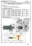
Modification procedure for axle output shaft seal for
WA100-6, WA100-7, WA100-8, WA150-6, WA150PZ-6,
WA150-8, WR12-6, WR12-8
Target machine models Target serial Nos.
AT20055
Service News AT20055 Page 2 of 11
4. Improvement details
1) The material of seal (1) is changed to prevent cracking. (Section 5, Table 1)
2)
3) The changed parts are common to the front and rear axles.
: New part
Current New
A103 A571
4 5 3 2 1
Axle
sectional
view
ID
stamp
ID
stamp
The changed parts are common to the standard differential specification and limited slip differential
specification.
Shape
Material
ID stamp
20 20
Z
BQ2679E
Z
BQ2679F
AT20055
Service News AT20055 Page 3 of 11
5. Modification parts
1)
2)
3)
Table 1: List of parts changed (Modification parts) : New part
6. Modification procedure
Perform the modification work on the rear axle assembly removed from the machine.
Thoroughly wash the parts reused.
For unstated sections, see Shop Manual.
6-1. Disassembly procedure
Disassemble according to Shop Manual.
The quantity of each part is number for 1 axle assembly. (When replacing only the right or left side,
prepare only half)
The parts changed and the replacement parts are common to the standard differential specification
and limited slip differential specification.
The parts changed and the parts to be replaced at disassembly are common to the front and rear
axles.
No. Part name Current New
Part No. Q'ty Part No. Q'ty
1 SEAL 417-22-12460 2 417-22-12461 2
Table 2: List of parts replaced at disassembly (consumable parts)
No. Part name Current
Part No. Q'ty
2 BEARING 417-22-12850 2
3 BEARING 417-22-12840 2
4 SHIM(t0.05) 417-22-12360 2
SHIM(t0.2) 417-22-12370 4
SHIM(t0.3) 417-22-12380 6
SHIM(t0.8) 417-22-12390 2
5 BOLT 01010-61685 2
AT20055
Service News AT20055 Page 4 of 11
6-2. Assembly procedure
1) Jig 2 2 6 3 Jig 1
· Reference part No. of jig 1: 793T-222-1310
2)
No gap
Fig. 1
· Reference part No. of jig 2: 793T-613-1310
3) Check that the stamp on seal (1) is correct.
4) Press fit seal (1) and bearing (2) inner race to axle shaft (7) by using jig 3. (Fig. 2)
Apply AXO80 to the seal press fitting face of axle shaft (7). (Fig. 2)
· Reference part Nos. of jig 3: 793T-222-1210, 793T-422-1440, 793T-623-1170 (Join when using)
5) Install jig 4 under seal (1). (Fig. 3)
Adjust jig 4 so that jig 4 top lightly touches seal (1) and the gap is even.
· Reference part No. of jig 4: 793-520-2600
Jig 3 1a Jig 4 1
Flush
2 Face A
1
7
Apply AXO80
Seal press fitting surface Fig. 2 Fig. 3
Press fit until bearing (2) inner race and seal sleeve (1a) are flush with face A of axle shaft (7). (Fig.
2)
Press fit bearing (3) outer race to axle housing (6) by
using jig 1. (Fig. 1)
After press fitting, check that there is no gap between the
large flange of bearing (3) outer race and axle housing
(6). (Fig. 1)
Press fit bearing (2) outer race to axle housing (6) by using
jig 1. (Fig. 1)
After press fitting, check that there is no gap between the
large flange of bearing (2) outer race and axle housing (6).
(Fig. 1)
P
P
AT20055
Page 5 of 11
Service News AT20055
6) Raise axle shaft (7) on the block and fix it securely. (Fig. 4)
Securely fix axle shaft (7) so that it does not fall down, then work on it. (Fig. 4)
7) Sling axle housing (6) vertically, then lower it slowly. (Fig. 4)
Apply at least 6 cc of AXO80 or KP-9 to bearing (2) inner race. (Fig. 4)
Apply AXO80 to the seal press fitting surface of axle housing (6). (Fig. 4)
8) Keep jig 4 installed until step 9 after installation of axle housing (6).
9) Press fit bearing (3) to axle shaft (7) by using jig 4. (Fig. 4)
Apply at least 6 cc of AXO80 or KP-9 to bearing (3) inner race. (Fig. 4)
Press fit while turning axle housing (6) with your hand.
· Reference part No. of jig 5: 792T-413-1120
Reference pressing force: 23.83 to 29.13 kN {2,430 to 2,970 kgf}
10) Horizontally remove jig 4.
Check that seal (1) is not leaning.
Clearance (b) between axle housing (6) end face and seal (1): 0.2 mm max. (Fig. 5)
Jig 5 6
6 1
3 b
7
Apply AXO80 or KP-9 Fig. 5
2
1 Apply AXO80
Block
Jig 4
Fig. 4
F
φ155
AT20055
Service News AT20055 Page 6 of 11
11)
(Common to front and rear, including seal resistance)
Measure before installing the planetary carrier.
When the starting torque is below the standard value, press fit bearing (3) according to steps 8 to 10.
If the starting torque exceeds the standard value, adjust it according to steps 12 to 14 below.
· Reference part No. of push-pull scale: 79A-264-0021
12) Sling axle housing assembly (8) at 2 points 20 to 30 mm. (Fig. 7)
13)
14) Measure the starting torque according to step 11. (Fig. 6)
Pitch circle diameter: φ296
8
6
7
Weight of axle housing assembly
Fig. 6 Front: 90 kg
Rear: 85 kg
Fig. 7
Turn axle housing (6) clockwise and counterclockwise at least 10 turns each to sufficiently fit the
bearing, then install the push-pull scale to the drill hole in axle housing (6), and measure the starting
torque of axle housing (6). (Fig. 6)
Starting torque at drill hole in axle housing (6) (φ296 of pitch circle diameter):
16.5 to 19.6 N {1.6 to 2.0 kgf}
Push out axle shaft (7) by hitting its flange with a copper hammer in the arrow direction several times,
while turning it. (Fig. 7)
AT20055
Service News AT20055 Page 7 of 11
15)
16) Measure distance "Yp" between carrier (9) end face and holder (10). (Fig. 9)
17)
Clearance Y = Yp - Yh
9 10
6 7 3
4
Fig. 8 Fig. 9 Fig. 10
18) Install shim (4) selected in step 17 to axle shaft (7) end face. (Fig. 11)
Carefully clean axle shaft (7) end face and splines.
When installing a thin shim, hold it between thicker shims.
19) Sling carrier assembly (11), and install it to axle housing assembly (8). (Fig. 12)
When installing carrier assembly (11), take care not to catch your fingers.
Apply LM-G or LM-P to the contact surfaces of carrier assembly (11) and bearing (3). (Fig. 12)
20) Tighten bolt (5). (Fig. 12)
Bolt tightening torque: 245 to 309 Nm {25 to 31.5 kgfm}
Remove old LT-2 remaining on axle shaft (7) threads. (Fig. 12)
Apply LT-2 to bolt (5). (Fig. 12)
8 11 5 4 3
7
Fig. 11 Apply LT-2
Carrier assembly: 15 kg
Fig. 12
Turn axle housing (6) clockwise and counterclockwise at least 10 turns each, then measure distance
"Yh" between axle shaft (7) end face and bearing (3) end face. (Fig. 8)
Calculate clearance "Y", and select shim (4) so that shim thickness "Tw" is as follows; Y - 0.05 < T2 <
Y. (Fig. 10)
Y = Yp - Yh
Yp
Yh
4
Apply LM-G or LM-P
AT20055
Service News AT20055 Page 8 of 11
21) Install the dial gauge to axle housing (6), and measure the end play at carrier (9) end face. (Fig. 13)
End play: 0 mm
22) If the end play is out of the standard value, reduce shim thickness "Tw" in step 17 and adjust again.
23)
If starting torque at drill hole in axle housing (6) (φ296 of pitch circle diameter) is Fw, and
starting torque in step 10 is Fwa,
then, Fwa < Fw ≦ 51.0 N {5.2 kg} (Common to front and rear)
· Reference part No. of push-pull scale: 79A-264-0021
Fig. 13 Fig. 14
24) If the starting torque exceeds the standard value, adjust it again according to step 11.
25) Assemble the remaining parts according to Shop Manual.
After installing the axle assembly to the machine, bleed air from the brake circuit.
7. Check work
Check that "BQ2679E" is stamped on the removed seal and confirm that the improved seal is installed.
Turn axle housing (6) clockwise and counterclockwise at least 10 turns each to sufficiently fit the
bearing, then install the push-pull scale to the drill hole in axle housing (6), and measure the starting
torque of axle housing (2). (Fig. 14)
Use the starting torque as a reference value, since it contains the seal resistance and carrier
assembly resistance.
9 Dial gauge
Push-pull scale
6
Z BQ2679E
Z
AT20055
Service News AT20055 Page 9 of 11
Reference drawings of jigs
Jig 1
Jig 2
Spacer
Spacer
AT20055
Service News AT20055 Page 10 of 11
Jig 3-A
Jig 3-B
Jig 3-C
H1-1 push tool Use by joining H1-1, 2, and 3.
H1-2 push tool Use by joining H1-1, 2, and 3.
H1-3 push tool Use by joining H1-1, 2, and 3.
AT20055
Service News AT20055 Page 11 of 11
Jig 4
793-520-2600
L 793-520-2730 (Support) x 2 pcs.
L 793-520-2740 (Bolt) x 4 pcs.
Jig 5
Part No. stamp location
Stamped letters: 03
Through drill hole
Part A
Push tool
AT20055