/


Text
ENGINE INTRODUCTION (J08E)
2—1
ENGINE INTRODUCTION (J08E)
2-001
ENGINE ASSEMBLY.....................2-2
DATA AND SPECIFICATIONS...........2-2
ENGINE TUNEUP.....................2-3
SPECIAL TOOL......................2-9
OVERHAUL CRITERIA................2-10
DISMOUNTING AND MOUNTING.........2-12
LIQUID GASKET AND APPLICATION POINTS... 2-16
2—2
ENGINE INTRODUCTION (J08E)
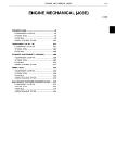
ENGINE ASSEMBLY
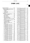
DATA AND SPECIFICATIONS
EN01F01103010102001001
ENGINE SERIES: J08E-WA, WB
Type Diesel, 4 cycle, vertical, 6 cylinder, in-line overhead camshaft, water-cooled, direct injection
Aspiration Turbocharged with intercooler
Bore and stroke 112x130 mm {4.41 x5.11 in.}
Piston displacement 7.684 L {468.9 cu.in.}
Compression ratio 18:1
Firing order 1-4-2-6-3-5 (The cylinder numbers are counted in order from the crankshaft pulley side)
Direction of rotation Counterclockwise viewed from flywheel
Compression pressure 3.4-3.6 MPa {35-36 kgf/cm2, 494-522 lbf/in.2} at 150 r/min.
Maximum revolution (at full load) 2,500 r/min.
Idling revolution 500 r/min.
Dry weight Approximately 600 kg {1,323 lb.}
Valve seat angle Intake 30°
Exhaust 45°
Valve face angle Intake 30°
Exhaust 45°
Valve timing (flywheel travel) Intake opens 14° before top dead center
Intake closes 30° after bottom dead center
Exhaust opens 54° before bottom dead center
Exhaust closes 13° after top dead center
Valve clearance (when cold) Intake 0.30 mm {0.0118 in.}
Exhaust 0.45 mm {0.0177 in.}
Engine oil pump Type Full forced pressure feed by gear pump
Drive By gear
Engine oil cooler Multi-plate type, water cooled
Injector Type Multi-hole nozzle type
Coolant pump Type Forced circulation by volute pump
Drive By V-belt
Thermostat type Wax.type, bottom bypass system
Injection timing (flywheel travel) 0° before top dead center for No.1 cylinder of the compres- sion stroke
ENGINE INTRODUCTION (J08E)
2—3
ENGINE TUNEUP
EN01F01103010H03001001
VALVE CLEARANCE CHECKING AND ADJUSTING
PROCEDURES
Д CAUTION
Valve clearance adjustment is performed only when the checking
result is not within the specified value.
SHTS011030100002
SHTS011030100003
1. PREPARATION OF CHECKING AND ADJUSTMENT
(1) Turn the crankshaft counterclockwise (viewed from the fly-
wheel side) to align mark "16" on the outer periphery of the
flywheel with the pointer of the flywheel housing.
NOTICE
• Always turn the crankshaft counterclockwise (viewed from the
flywheel side).
• In this position the No.1 or No.6 piston is at the Top Dead Center
of the compression stroke.
(2) Among three drill holes on the camshaft gear, when two drill
holes are on horizontal position, and the rest of the drill hole
is visible, the No.1 piston is at the Top Dead Center of the
compression stroke.
NOTICE
If the rest of drill hole is invisible by camshaft housing, the No.6
piston is at the Top Dead Center of the compression stroke.
(3) Make sure that the valve stem is correctly inserted in the
cross head.
NOTICE
Move the cross head with fingers right and left to confirm the
valve stem is correctly inserted in the cross head by listening to
the clicking sound.
(4) Confirm that there are no foreign particles or dust between
the cross head and the valve stem.
2—4
ENGINE INTRODUCTION (J08E)
2. VALVE CLEARANCE CHECKING
NOTICE
Before beginning the checking, you must perform "PREPARATION
OF CHECKING AND ADJUSTMENT" described on page 2-3.
(1) You can understand which valve to adjust when No.1 or No.6
piston is at the Top Dead Center of the compression stroke
by the following chart.
Cylinder 1 2 3 4 5 6
Valve IN EX IN EX IN EX IN EX IN EX IN EX
With No.1 piston at T.D.C. on compres- sion stroke Cam- shaft gear condi- tion wo Two drill holes and camshaft housing is hor- izontal. The rest of drill hole is visible. #1 О О О О О О
With No.6 piston at T.D.C. on compres- sion stroke Two drill holes and camshaft housing is hor- izontal. The rest of drill hole is invisi- ble. #1 О О О О О О
SHTS011030100007
• #1 = View from rear side of camshaft housing
• OMark: Possible to check valve clearance
• Firing order: 1-4-2-6-3-5
• T.D.C.: Top Dead Center
(2) Before checking the valve clearance, make sure that the
roller is on the base circle of the camshaft.
(3) Insert a feeler gauge of the specified thickness as below
between the rocker arm and the cross head to check the
valve clearance.
VALVE CLEARANCE (when cold)
Intake valve 0.30 mm {0.0118 in.}
Exhaust valve 0.45 mm {0.0177 in.}
Д CAUTION
Valve clearance adjustment is performed only when the checking
result is outside the specified value.
ENGINE INTRODUCTION (J08E)
2—5
SHTS011030100008
SHTS011030100009
SHTS011030100010
3. VALVE CLEARANCE ADJUSTMENT
Д CAUTION
Valve clearance adjustment is performed only when the checking
result is outside the specified value.
NOTICE
• Before beginning the adjustment you must perform "PREPARA-
TION OF CHECKING AND ADJUSTMENT" described on page 2-
3.
• As for the valve which can adjust the valve clearance refer to the
chart on page 2-4.
• Make sure that the cylinder head bolt, rocker arm support bolt,
nozzle clamp bolt, cam housing bolt and cam bearing cap bolt
are tightened to the specified torque.
(1) Loosen the adjusting screw lock nut A, D of the rocker arm
and cross head fully.
(2) The cross head adjusting screw must protrude 10 mm {0.394
in.} or more from the cross head upper face.
NOTICE
Unless the adjusting screw is completely loose to the valve stem
head, the following adjustments may be adversely affected.
(3) Insert a feeler gauge of the specified thickness shown below
between the rocker arm and the cross head, and adjust the
valve clearance with the adjust screw of the rocker arm.
VALVE CLEARANCE (when cold)
Intake valve 0.30 mm {0.0118 in.}
Exhaust valve 0.45 mm {0.0177 in.}
(4) After completion of the adjustment, tighten the lock nut A
securely with the specified tightening torque.
Tightening Torque:
25 N-m {250 kgf-cm, 18 Ibf-ft}
(5) The condition of inserted feeler gauge, loosen the adjusting
screw of the cross head, make sure that the feeler gauge
does not feel loose.
NOTICE
If the feeling of the feeler gauge becomes loose, repeat steps from
(1)-
2—6
ENGINE INTRODUCTION (J08E)
SHTS011030100011
SHTS011030100012
SHTS011030100013
(6) Tighten the adjusting screw C of the cross head until the
feeler gauge does not move.
NOTICE
In this situation, clearance between adjusting screw C and valve
stem head is zero.
(7) While loosening the adjusting screw C of the cross head
gradually, adjust the valve clearance. Tighten the lock nut D
of the cross head securely with the specified tightening
torque when the feeler gauge feels correct.
Tightening Torque:
25 N-m {250 kgf-cm, 18 Ibf-ft}
NOTICE
• Do not over loosen the adjusting screw.
• Over loosening of the adjusting screw C will cause the same
condition as in step (3) again. The feeler gauge may feel correct,
but there may be excessive clearance between the adjusting
screw C of the cross head and the valve stem head E. This does
not allow for correct adjustment.
(8) Position each piston at Top Dead Center of compression
stroke by turning the crankshaft counterclockwise viewed
from flywheel side. Then adjust the valve clearance for each
cylinder in the firing order.
ENGINE INTRODUCTION (J08E)
2—7
INJECTION TIMING INSPECTION PROCEDURES
SHTS011030100015
SHTS011030100016
1. INSPECT THE INJECTION TIMING.
(1) Turn the crankshaft counterclockwise (viewed from the fly-
wheel side) to align mark "16" on the outer periphery of the
flywheel with the pointer of the flywheel housing.
NOTICE
Always turn the crankshaft counterclockwise (viewed from the fly-
wheel side).
(2) Taking off the inspection hole plug, located at bearing holder
case of supply pump and tightening slightly the special tool
therein, check that the seat face of tool is seated with the
bearing holder.
SST: SZ105-08067
Guide bolt
NOTICE
When it is not seated, it means it is contacting with other parts
than the turning stopper hole of coupling flange. Therefore, do not
tighten in too much. In this case, the timing is not fit. So, perform
again the setting for Top Dead Center of No.1 cylinder compres-
sion stroke in above (1).
START THE ENGINE
A warning
Do not leave tools on or around the engine. Contact of tools with
moving parts may result in personal injury or damage to equip-
ment.
1. PREPARATION
(1) Supply engine oil.
(2) Supply cooling water and bleed air from it.
(3) Bleed air from the fuel system.
(4) Check connection to the alternator.
NOTICE
Starting the engine without wiring in place may burn out the alter-
nator.
(5) Check the engine stopping performance.
2—8
ENGINE INTRODUCTION (J08E)
LUBRICATION
1. CHECK THE ROCKER ARM.
(1) Remove the head cover.
(2) Set the engine revolution to the specified idling revolution.
(3) After the engine starts, check that oil is supplied to the follow-
ing locations of all rocker arms within approximately 10 sec-
onds.
a. Roller and cam face A
b. Cross head top C and spring upper seat top face D
through adjusting screw В
NOTICE
If the supply of oil is delayed or not happening, hydraulic pressure
may be low or the oil gallery may be clogged. Insufficient supply
of oil may lead to seizure, abnormal wear or abnormal noise.
Recheck the assembly.
CORRECT
VIEWE
INCORRECT
SHTS011030100017
ENGINE INTRODUCTION (J08E)
2—9
SPECIAL TOOL
EN01F01103010K01001001
Prior to starting an engine overhaul, it is necessary to have these special tools.
Illustration Part No. Name Remarks
]p SZ105-08067 GUIDE BOLT For "ENGINE TUNEUP"
0 |Г p
S0955-21110 COMPRESSION GAUGE ADAPTER (A) For "OVERHAUL CRITERIA"
S0955-21030 COMPRESSION GAUGE ADAPTER (B) For 3/4- 16UNF thread size Select according to the thread size of air gauge.
S0955-21060 COMPRESSION GAUGE ADAPTER (B) For W16 threads 18 threads size
2-10
ENGINE INTRODUCTION (J08E)
OVERHAUL CRITERIA
EN01F01103010H03001002
FACTORS TO DETERMINE THE ENGINE OVERHAUL
1. LOW COMPRESSION PRESSURE
(1) Before measurement
a. Charge the battery completely.
b. Set the valve clearance to the correct value.
c. Idle the engine (Coolant temperature at 80°C {176°F}).
d. Remove the air cleaner.
e. Remove all injectors.
(2) Measurement
a. Insert the gauge adaptor into the nozzles.
SST: S0955-21110
Compression gauge adaptor (A)
S0955-21030
Compression gauge adaptor (B)
S0955-21060
Compression gauge adaptor (B)
b. Run the engine with the starter and measure the compres-
sion pressure.
SHTS011030100021
Standard Limit Difference between each cylinder
2.9-3.1 MPa {30-31 kgf/cm2, 421-449 lbf/in.2} 2.3 MPa {24 kgf/cm2, 334 lbf/in.2} 0.3 MPa {3 kgf/cm2, 43 lbf/in.2}
Engine revolution 150 r/min.
NOTICE
Do not operate the starter for more than 15 seconds.
c. Measure the compression pressure of each cylinder.
NOTICE
Do not allow gas leakage from the seal face.
(3) Reassemble the removed parts.
ENGINE INTRODUCTION (J08E)
2-11
2. ENGINE OIL PRESSURE
(1) Check the oil pressure warning light when the oil and coolant
temperature is hot [about 80°C {176°F}].
a. If the warning light lightens, check the oil level.
b. Check oil deterioration.
If oil quality is poor, replace with a suitable grade oil.
c. Remove the oil pressure switch and install the oil pressure
gauge.
d. Measure the oil pressure at a coolant temperature of 80°C
{176°F} or more.
Oil pressure
VISCOSITY RECOMMENDATIONS (SAE)
Standard Limit
49-490 kPa {0.5-5.0 kgf/cm2, 7.11-71.10 lbf/in.2} Less than 49 kPa {0.5 kgf/cm2, 7.11 lbf/in.2}
SHTS011030100023
3. OTHER FACTORS
(1) Increase of blowby gas
(2) Defective engine start
(3) Decrease of engine output
(4) Increase of fuel consumption
(5) Increase of engine noise
(6) Increase of oil consumption
2-12
ENGINE INTRODUCTION (J08E)
DISMOUNTING AND MOUNTING
EN01F01103010H01001001
IMPORTANT POINT - DISMOUNTING
1. DISMOUNT THE ENGINE ASSEMBLY.
(1) Park the vehicle on level ground and then block the wheels.
(2) Over tilt work for cab.
HINT
Over tilt work is not required for a vehicle equipped with an elec-
tric tilt device.
a. Open the front panel.
Д CAUTION
If you do over tilt work without opening the front panel, the radia-
tor grille will hit and damage the bumper.
SHTS011030100024
b. Remove the R-pin, washer and pin from the cab stopper
stay.
SHTS011030100025
c. Using the 10 mm (0.394 in.} dia. bolt and nuts (2 pcs.),
reattach the cab stopper stay to the bracket upper hole.
NOTICE
Using the double nuts, prevent the bolt from coming off.
d. Tilt the cab in the usual manner.
NOTICE
Before tilting the cab, be sure that the over tilt bolt is correctly
inserted into the bracket and cab stopper stay.
(3) Drain coolant from the radiator and cylinder block, and
engine oil from the oil pan.
A WARNING
To avoid the danger of burns, do not drain the coolant and engine
oil while the engine and radiator are still hot.
(4) Disconnect the power steering piping and hose.
(5) Disconnect the electric lines, fuel lines and air lines.
NOTICE
• Disconnect the battery cable from the negative terminal (-) of
the battery and disconnect the electric lines.
• Cover open ends of the pipes, hoses and pumps to prevent
entry of dirt.
(6) Disconnect the hoses (coolant, heater and air intake) and
remove the radiator.
NOTICE
Do not damage the radiator.
ENGINE INTRODUCTION (J08E)
2-13
SHTS011030100026
(7) Disconnect the air intake and exhaust lines.
(8) Disconnect the propeller shaft.
(9) Disconnect the transmission control and transmission with
clutch housing from the flywheel housing.
(10) Remove the cab mounting member from the frame.
(11) Connect a cable from an engine hanger to the generator
brace (1 point) on the front of the engine, and to the hanger
bracket (1 point) on the flywheel housing at the rear of the
engine. Using a hoist, raise the hanger until there is a bit of
slack in the cables.
Engine weight: Refer to the section "DATA AND SPECIFI-
CATIONS".
(12) Remove the engine mounting fitting nuts (front and rear, both
sides).
(13) Lift the engine hanger so that the cables are fully tightened,
then, after checking that the cables are securely, lift gently
and remove the engine from the vehicle.
NOTICE
When the transmission is attached to the engine, attach the third
cable to the hanger bolt.
SHTS011030100027
(14) Remove the power steering oil reservoir.
Reference: CHASSIS, POWER STEERING
(15) Remove the 8 bolts. Using the hoist crane, remove the rear
cab mounting from the frame.
Д CAUTION
Handle it with care because it is a heavy load.
2-14
ENGINE INTRODUCTION (J08E)
IMPORTANT POINTS - MOUNTING
1. MOUNT THE ENGINE ASSEMBLY.
(1) Mount the engine assembly in the reverse order of dismount-
ing.
Tightening Torque:
A: 100 N-m {1,020 kgf-cm, 74 Ibf-ft}
B: 75 N-m {765 kgf-cm, 55 Ibf-ft}
NOTICE
Check to see that there are no oil leaks, fuel leaks, coolant leaks,
or air leaks.
(Front side) (Rear side)
A: Engine mounting fitting nut (Engine side)
B: Engine mounting fitting nut (Frame side)
SHTS011030100028
(2) Lift the rear cab mounting by using the hoist crane and mount
it to the frame with the 8 bolts.
Tightening Torque:
125-169 N-m {1,275-1,725 kgf-cm, 93-124 Ibf-ft}
NOTICE
Use the new bolts with reassembling.
Д CAUTION
Handle it with care because it is a heavy load.
(3) Over tilt work for cab.
HINT
Returning to the standard tilt is not required for a vehicle
equipped with an electric tilt device.
a. Lower the cab.
ENGINE INTRODUCTION (J08E)
2-15
SHTS011030100031
b. Remove the 10 mm {0.394 in.} dia. bolt and 2 nuts
attached to the cab stopper stay.
c. Using the standard pin, washer and R-pin, reattach the cab
stopper stay to the bracket lower hole.
NOTICE
• The 10 mm {0.394 in.} dia. bolt used for over tilt is not used for
normal tilt.
• Attach the washer and R-pin on the frame side.
2-16
ENGINE INTRODUCTION (J08E)
LIQUID GASKET AND APPLICATION POINTS
EN01F01103010H02001001
• Liquid gasket is used at the following positions for the J08E series
engine.
Liquid gasket specification
ThreeBond TB1207B or equivalent: Black
Liquid gasket specification
ThreeBond TB1207D or equivalent: Silver
Liquid gasket specification
ThreeBond TB1211 or equivalent: White
1.
SHTS011030100033
LIQUID GASKET APPLICATION AND PART ASSEMBLY PRO-
CEDURE
(1) Remove old liquid gasket from each part and matching parts
and wipe off oil, moisture or dirt with a rag.
(2) Overlap the liquid gasket at the start and end of application.
(3) Be careful of misalignment when assembling parts with liquid
gasket. If they are misaligned, reapply the liquid gasket.
(4) Assemble parts within 20 minutes of application.
If more than 20 minutes have passed, remove and reapply
the liquid gasket.
(5) Wait for at least 15 minutes or more after assembly of parts
before starting the engine.
REMOVE PARTS
(1) When removing parts, do not use a tool for removal at one
location only. Use the tool at various locations such as a
flange step or gap for removal. When removing the gasket,
be careful that gasket residue does not enter the engine.
OTHERS
(1) For tube-type liquid gasket, use the winding tool that comes
with the liquid gasket.
(2) For cartridge-type gasket, use an application gun.
ENGINE INTRODUCTION (J08E)
2-17
SHTS011030100034
(3) For tube-type liquid gasket, required width of application can
be obtained by cutting the nozzle to suit.
1: Approximately 2 mm {0.079 in.} wide when cut at the 1st step
2: Approximately 5 mm {0.197 in.} wide when cut at the 2nd step
4. PARTS AND POSITIONS FOR LIQUID GASKET
(1) Apply liquid gasket to positions and types of gasket accord-
ing to the table shown below.
Follow the application pattern at each position shown in the
figures.
Unit: mm {in.}
No. Part name Application position and pattern Application width Gasket to be used Remarks
1 Oil seal retainer Matching flange face with tt ie block /LIQUID GASKET 1.5-2.5 {0.0591- 0.0984} Black
2 Coolant pump Matching flange face with the block ri u LIQUID GASKET s' S' 1.5-2.5 {0.0591- 0.0984} Black
3 Oil cooler Matching flange face with the block LIQUID GASKET 1.5-2.5 {0.0591- 0.0984} Black
n T TV JT
4 Thermostat case Matching flange fac< э with tt 1£ J< J D. cylinder head DUID GASKET 1.5-2.5 {0.0591- 0.0984} Black
2-18
ENGINE INTRODUCTION (J08E)
No. Part name Application position and pattern Application width Gasket to be used Remarks
5 Flange Matching face with the rear edge HOLE AT ^-2\lIQUID GASKET HEAD SIDEsj^' \e>-— 1.5-2.5 {0.0591- 0.0984} Silver
6 Intake pipe Mate hing face with the О inta ke manifold LIQUID GASKET 1.5-2.5 {0.0591- 0.0984} Black
ENGINE INTRODUCTION (J08E)
2-19
No. Part name Application position and pattern Application width Gasket to be used Remarks
7 Front and rear ends of upper/ lower faces of block Matching parts of block upper face rear end, gasket, rear end plate, flywheel housing, cylin- der head gasket Matching parts of oil seal retainer and block lower face front end Matching parts of block lower front end, gasket, rear end plate and flywheel housing 1.5-2.5 {0.0591- 0.0984} 1.5-2.5 {0.0591- 0.0984} White Black Silver
LIQUID GASKET^
II II ° эоЖ (Я
oV ) —y LIQUID GASKET rCYLINDER HEAD ' GASKET
Г \
BLOCK OIL SEAL \ RFTAIMFR \ AX ^-LIQUID GASKET (2 LOCATION EACH) REAR END PLATE / .FLYWHEEL / /housing
\ T 'X //
[
CUTTER-^''^7 ^GASKET NOTICE Cut the rear end plate gasket with a craft knife flush with the block upper face.
8 Flywheel hous- ing Matching face of rear end plate / LIQUID GASKET foj J |Ю/ A LIQUID ML- 7 GASKET (of / 1.5-2.5 {0.0591- 0.0984} Silver
2-20
ENGINE INTRODUCTION (J08E)
No. Part name Application position and pattern Application width Gasket to be used Remarks
9 Cam housing 1. Matching faces with cam housing and plug 2. Matching parts of cam housing, plug, cylinder head cover and gasket (o \o/ LIQUID GASKET-x \ NOTICE • Application area of liquid gasket is half circle of cam housing. Never apply it to the upper half circle of the plug. • Remove the excessive gasket completely. y-CYLINDER HEAD COVER O-RING-^/^correct CORRECT EXCESSIVE GASKET • When the cylinder head cover is assembled, reapply the liquid gasket. (Assembly must be done within 20 minutes.) LIQU1D GASKET LIQU1D GASKET 1.5-2.5 {0.0591- 0.0984} Black 2 loca- tions at front and rear ends
NOTICE Figure on the right shows application "pattern" of the liquid gasket. x— Apply the liquid gasket to the center of seal flange inside whenever pos- sible.