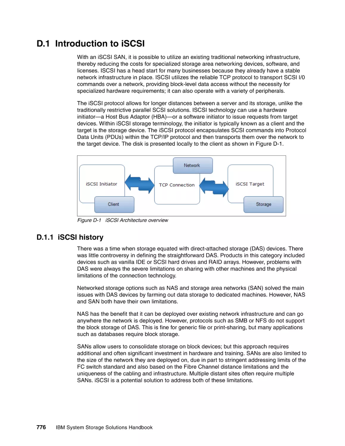
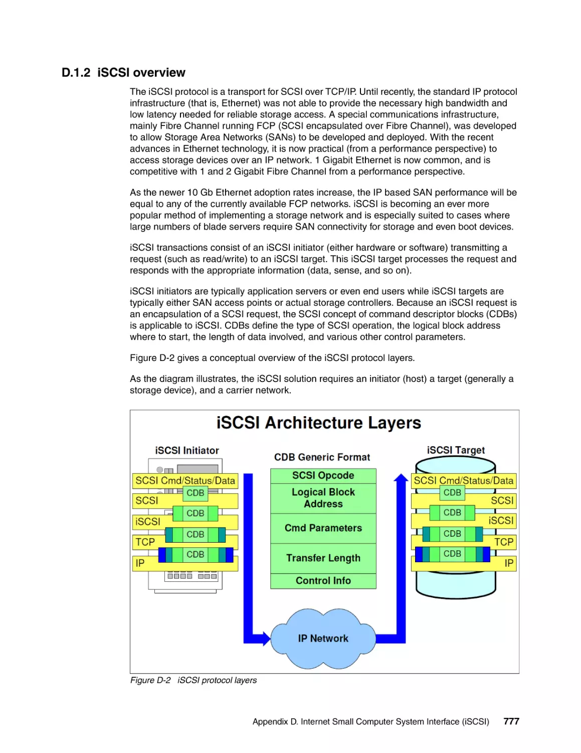
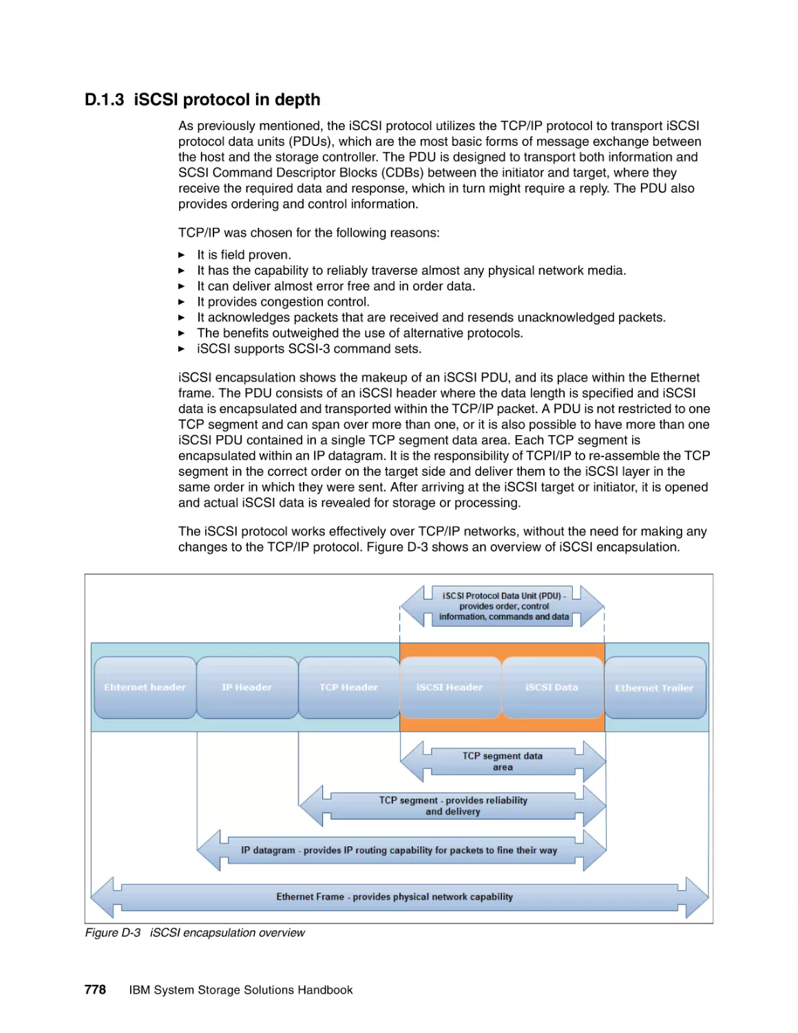
/


Author: Racherla S. Miklas L. Montenegro T. Mulholland J.M.
Tags: software computer science
ISBN: 0738435465
Year: 2011


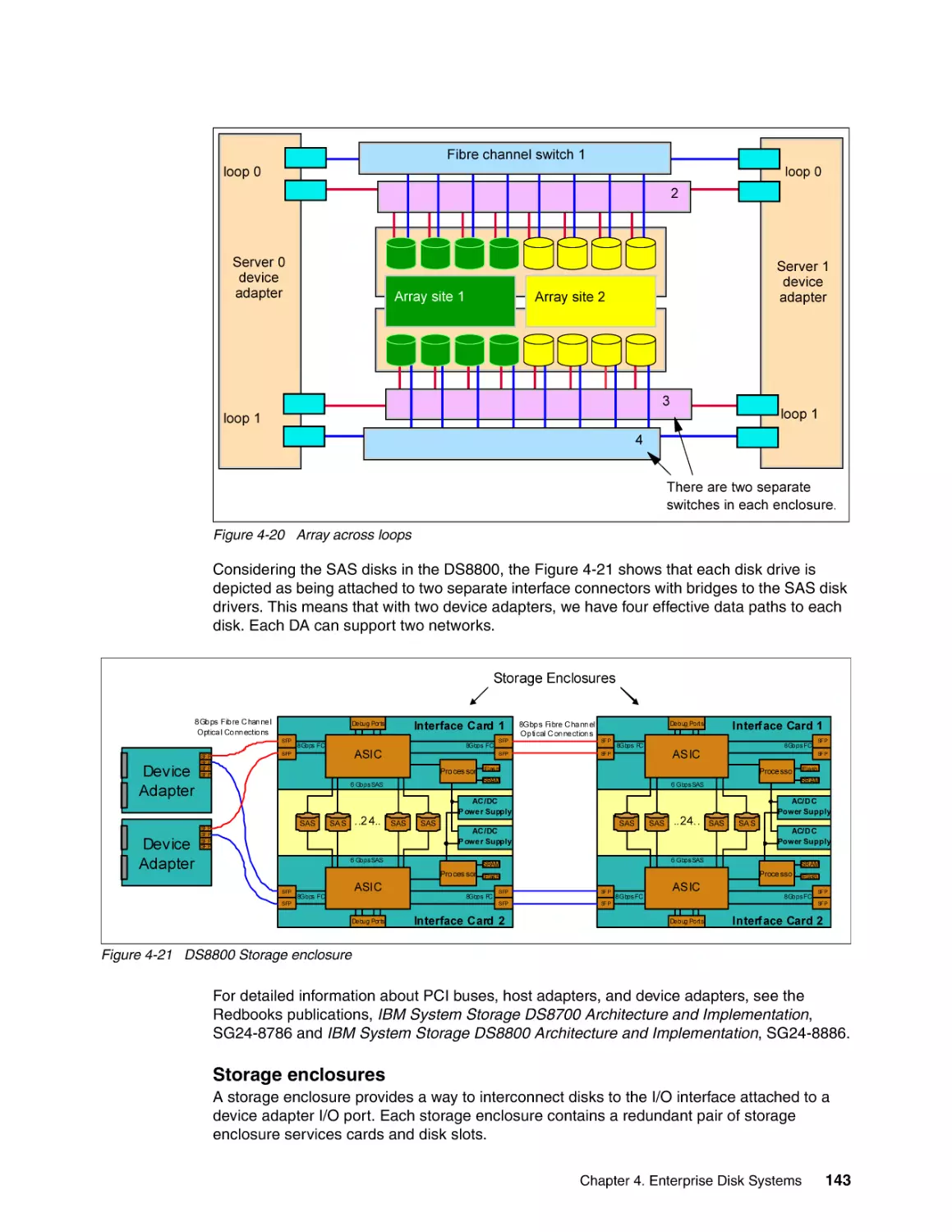
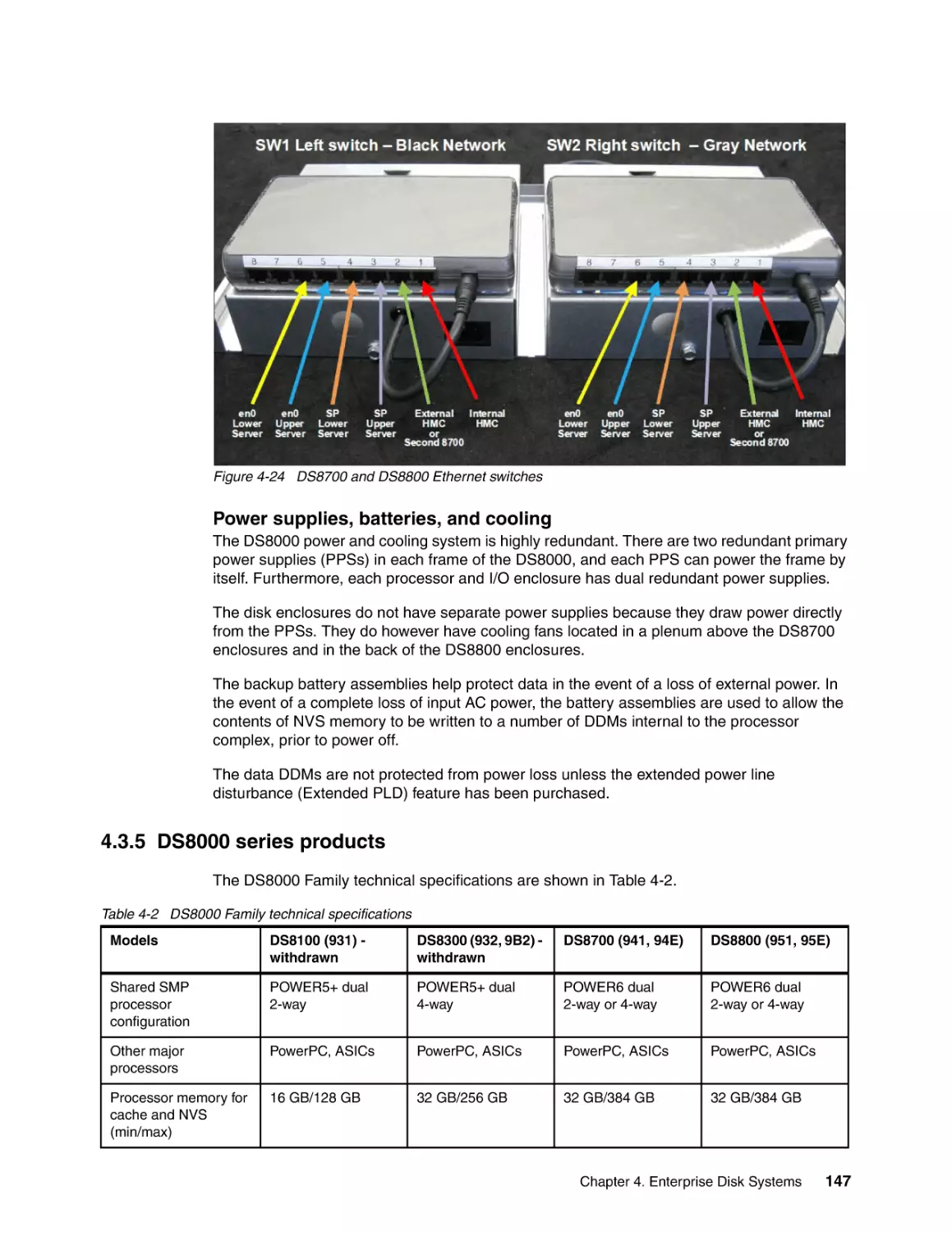
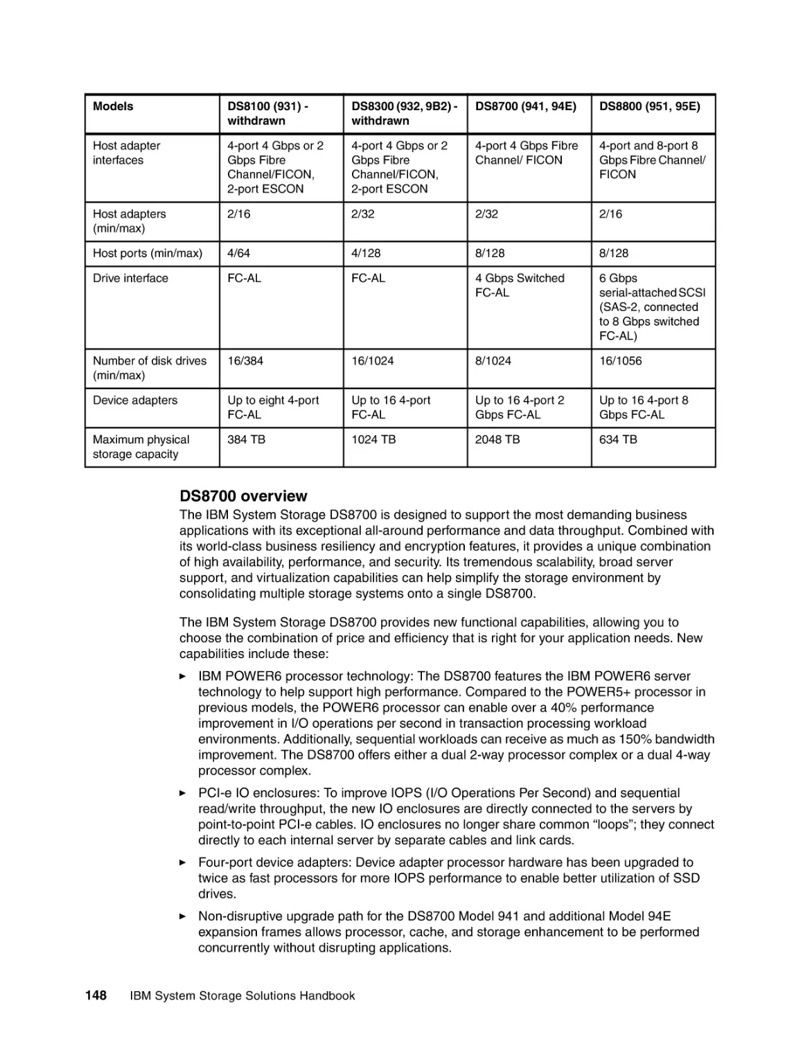
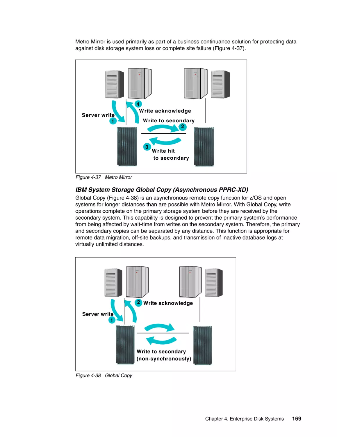
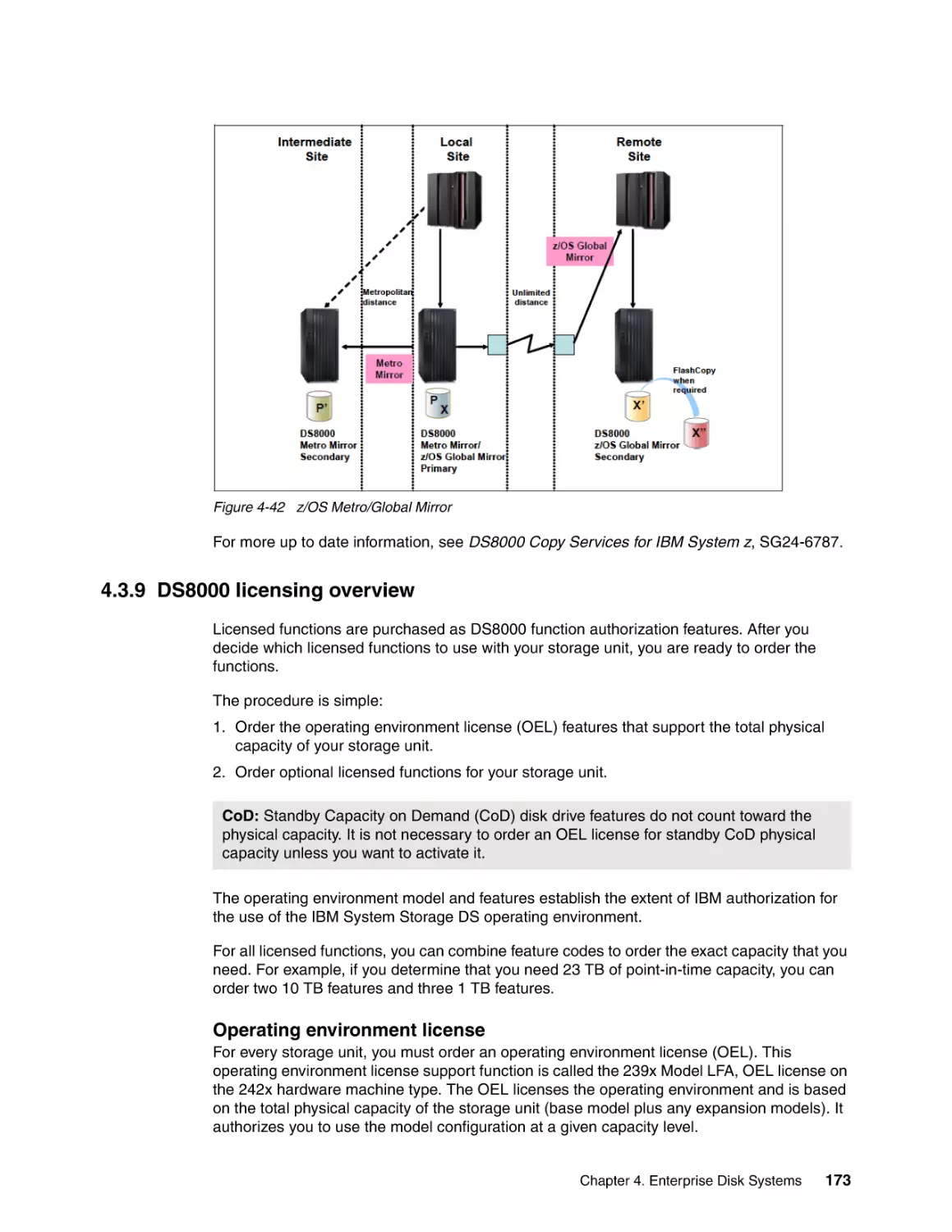
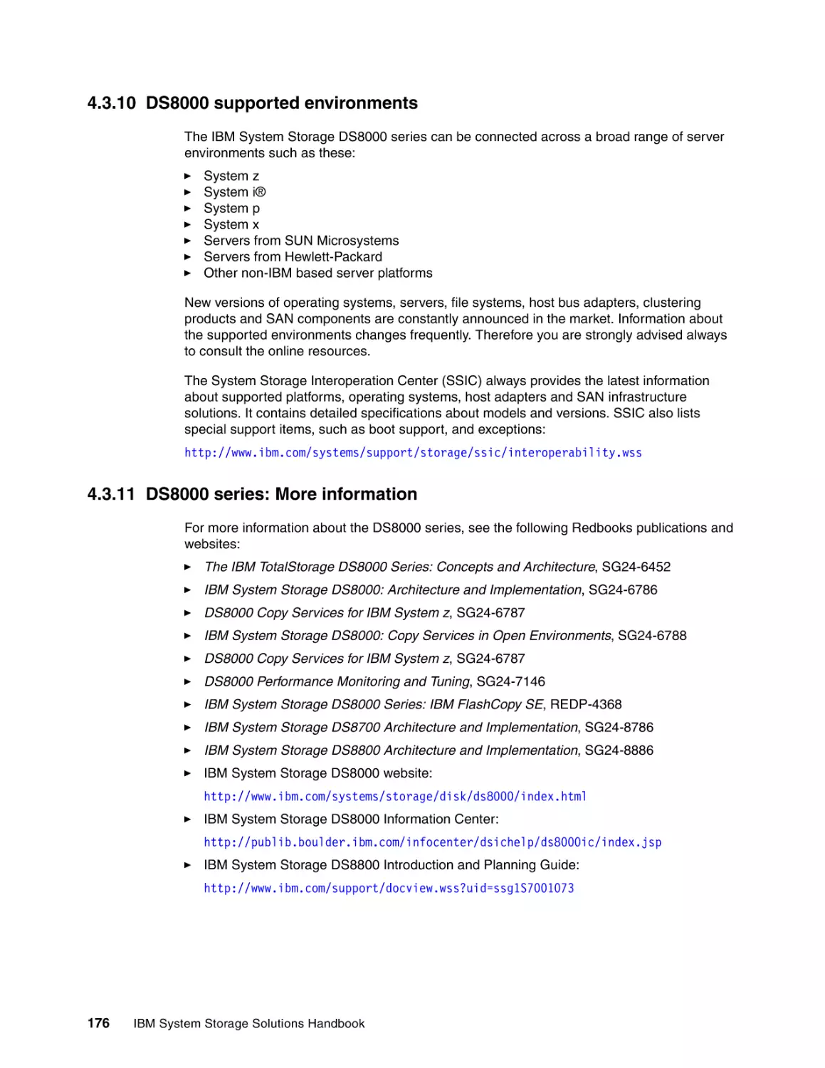
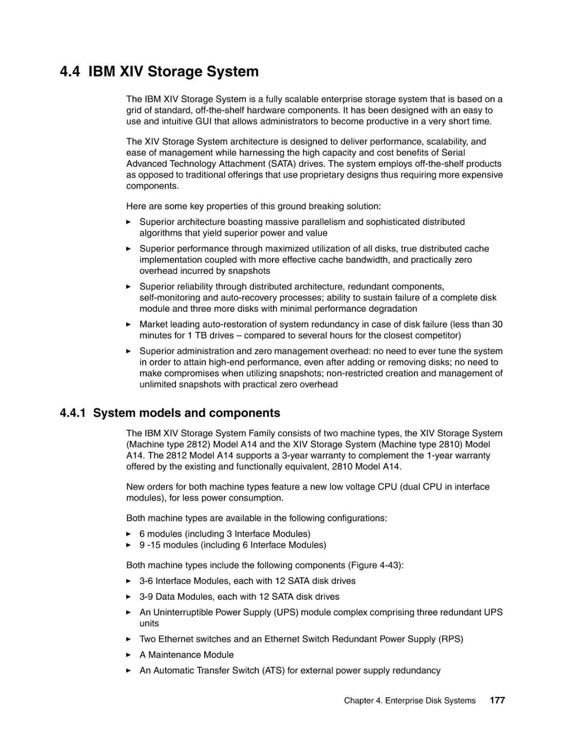
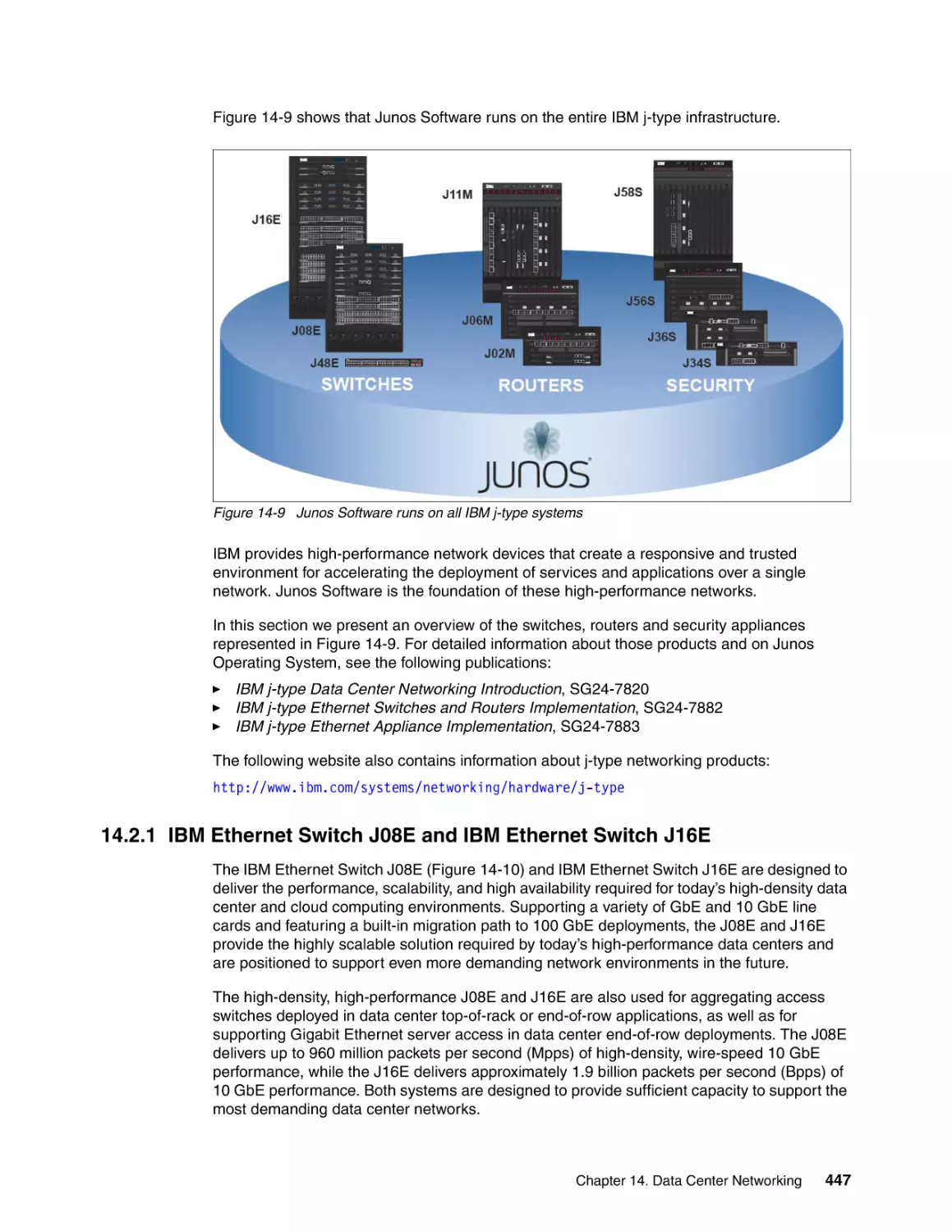
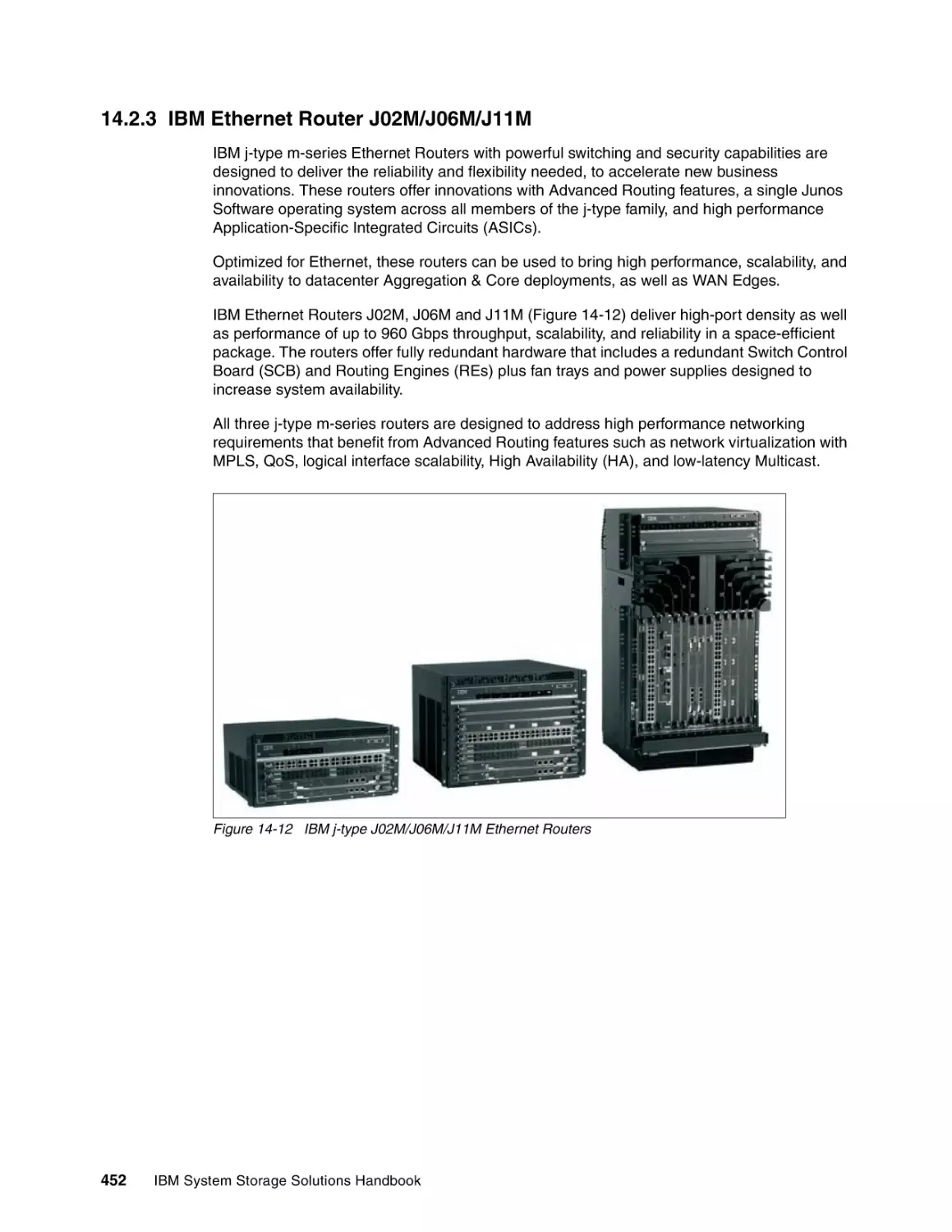
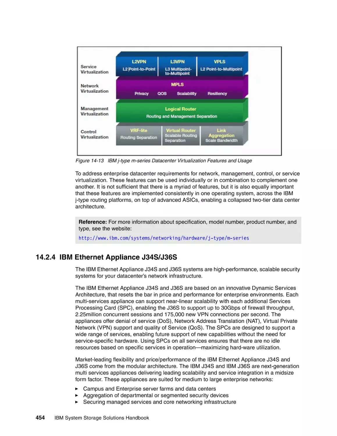
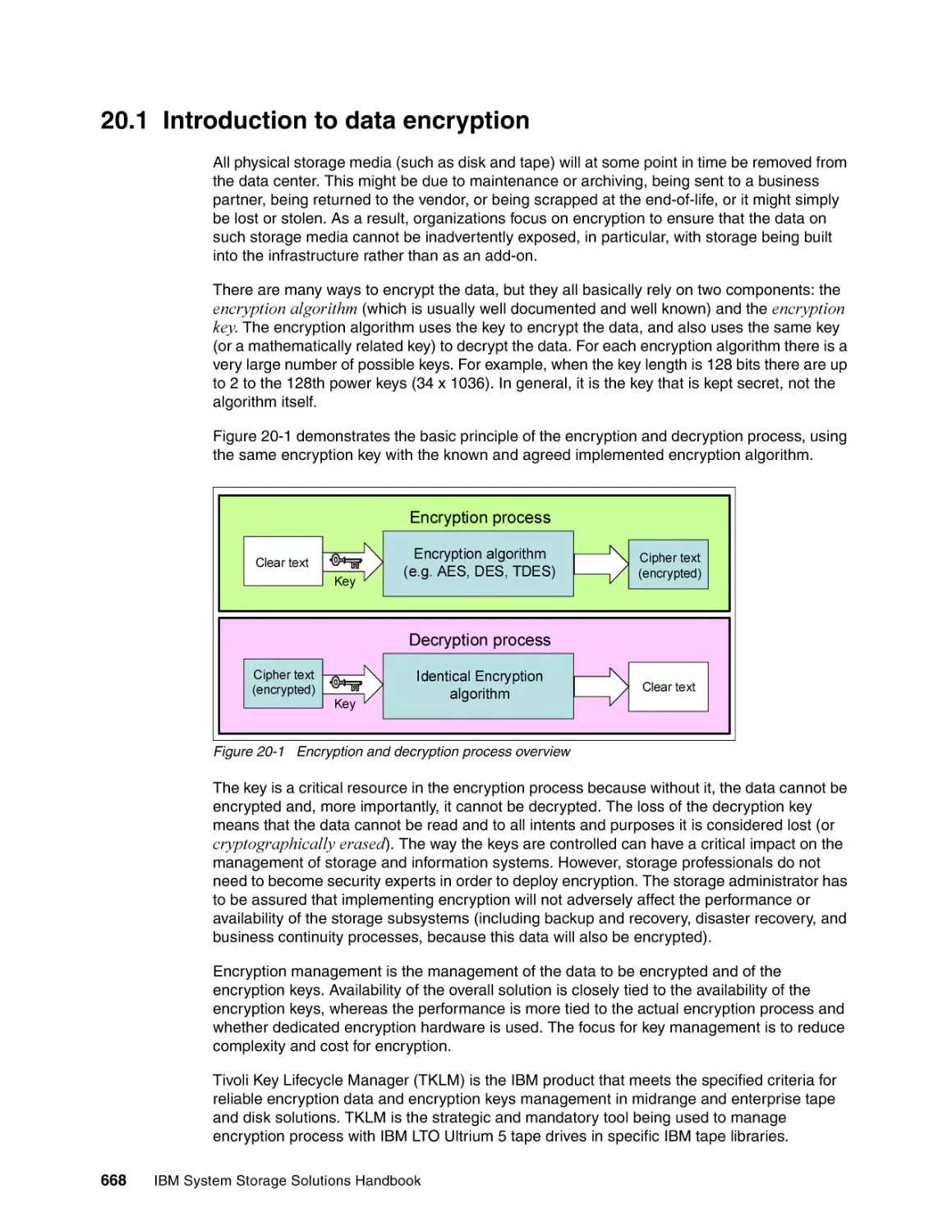
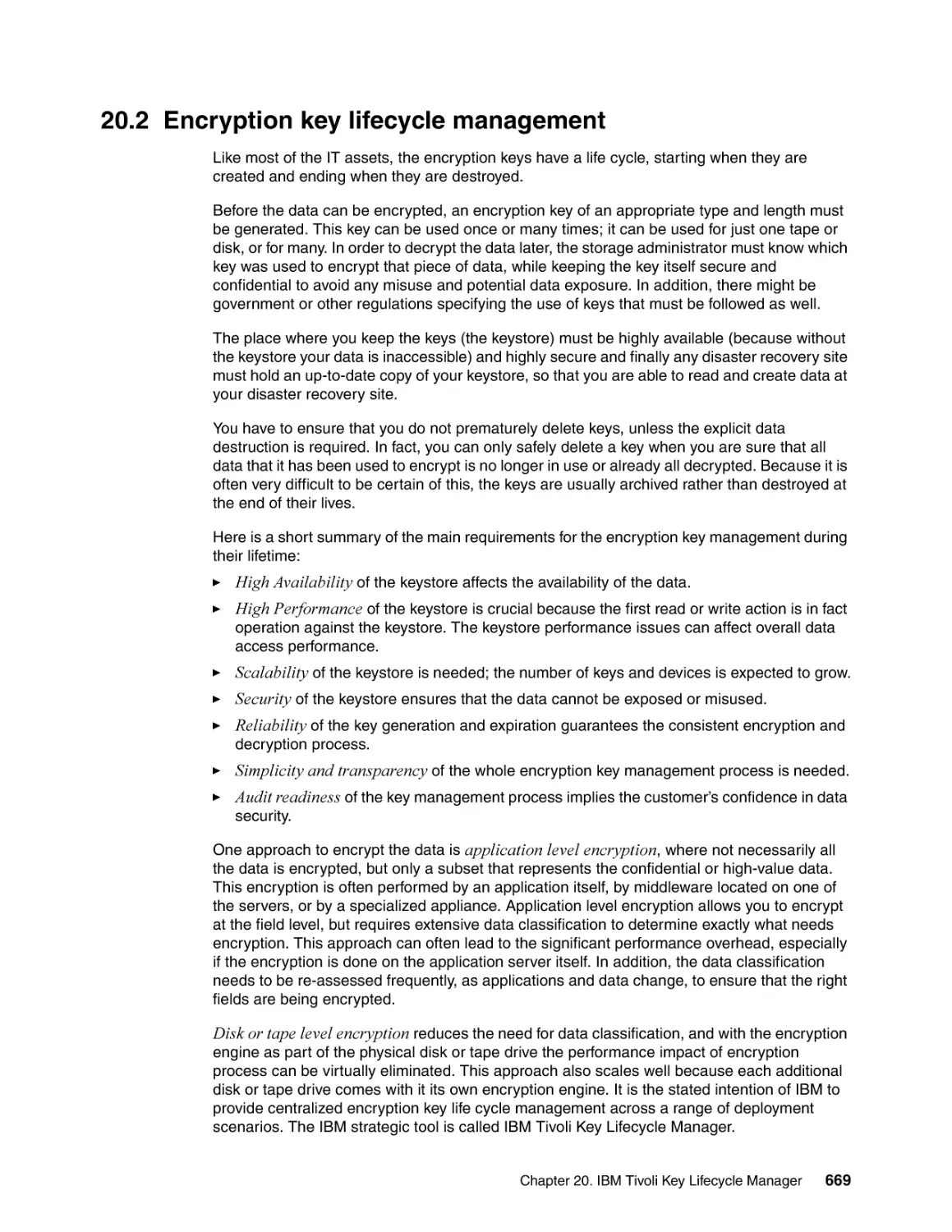
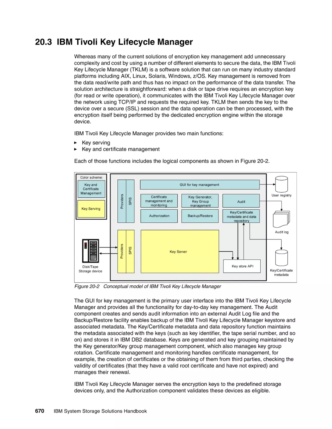
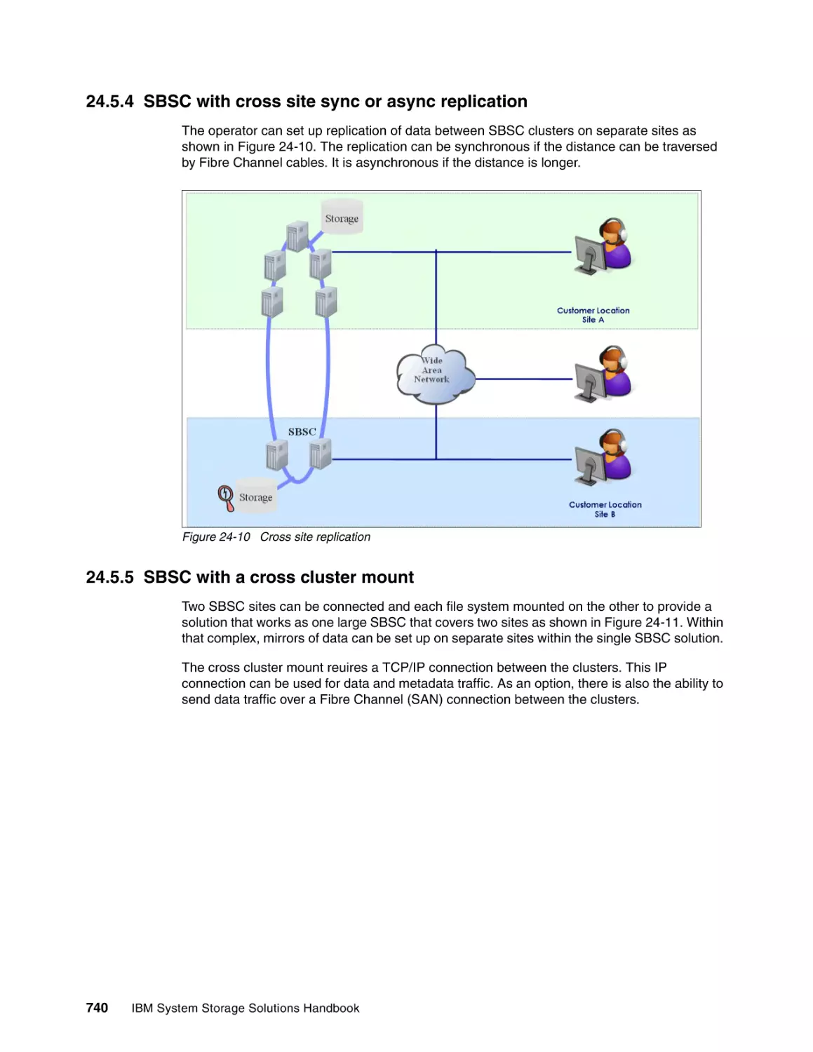
Text
Front cover
IBM System Storage
Solutions Handbook
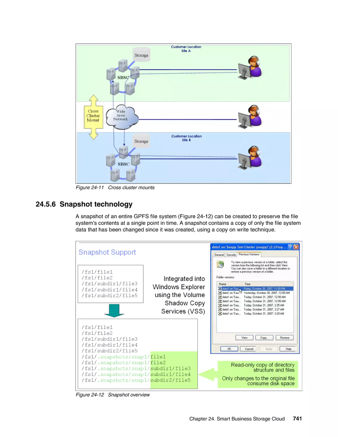
Learn about IBM storage products
and solutions
Get flexible, scalable storage
solutions for the on demand world
Find the products that
answer your business needs
Sangam Racherla
Libor Miklas
Thiago Montenegro
James M Mulholland
ibm.com/redbooks
International Technical Support Organization
IBM System Storage Solutions Handbook
May 2011
SG24-5250-08
Note: Before using this information and the product it supports, read the information in “Notices” on
page xix.
Ninth Edition (May 2011)
This edition applies to IBM System Storage products portfolio as of December 2010.
© Copyright International Business Machines Corporation 1999-2011. All rights reserved.
Note to U.S. Government Users Restricted Rights -- Use, duplication or disclosure restricted by GSA ADP Schedule
Contract with IBM Corp.
Contents
Notices . . . . . . . . . . . . . . . . . . . . . . . . . . . . . . . . . . . . . . . . . . . . . . . . . . . . . . . . . . . . . . . . xix
Trademarks . . . . . . . . . . . . . . . . . . . . . . . . . . . . . . . . . . . . . . . . . . . . . . . . . . . . . . . . . . . . . . xx
Preface . . . . . . . . . . . . . . . . . . . . . . . . . . . . . . . . . . . . . . . . . . . . . . . . . . . . . . . . . . . . . . . xxiii
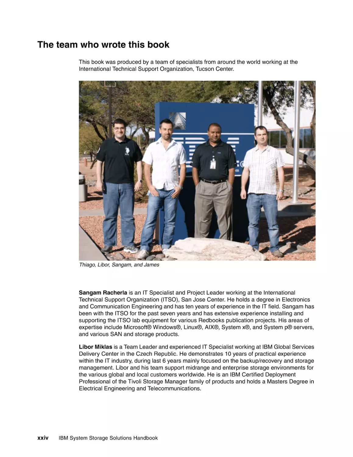
The team who wrote this book . . . . . . . . . . . . . . . . . . . . . . . . . . . . . . . . . . . . . . . . . . . . . . xxiv
Now you can become a published author, too! . . . . . . . . . . . . . . . . . . . . . . . . . . . . . . . . . . xxv
Comments welcome. . . . . . . . . . . . . . . . . . . . . . . . . . . . . . . . . . . . . . . . . . . . . . . . . . . . . . xxvi
Stay connected to IBM Redbooks . . . . . . . . . . . . . . . . . . . . . . . . . . . . . . . . . . . . . . . . . . . xxvi
Chapter 1. Introduction: Dynamic Infrastructure and IBM Smarter Planet Strategy . . 1
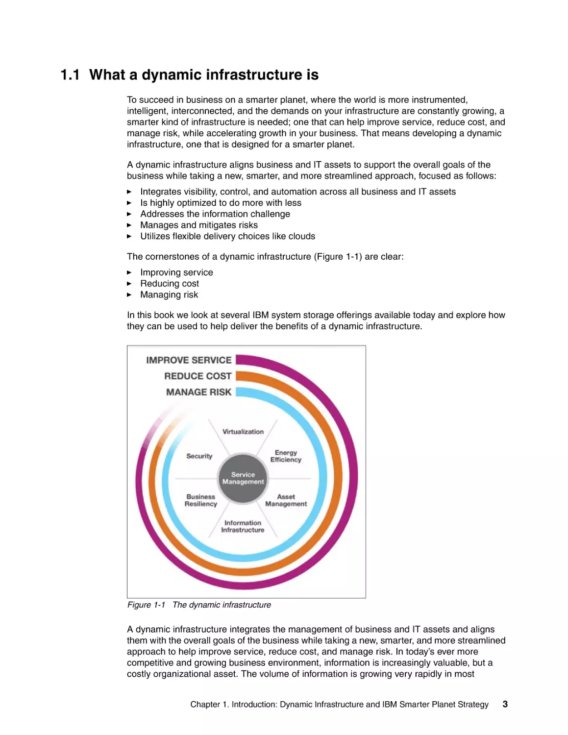
1.1 What a dynamic infrastructure is . . . . . . . . . . . . . . . . . . . . . . . . . . . . . . . . . . . . . . . . . . . 3
1.2 Delivering a dynamic infrastructure . . . . . . . . . . . . . . . . . . . . . . . . . . . . . . . . . . . . . . . . . 4
1.2.1 Information infrastructure . . . . . . . . . . . . . . . . . . . . . . . . . . . . . . . . . . . . . . . . . . . . 4
1.2.2 Smarter security and resiliency . . . . . . . . . . . . . . . . . . . . . . . . . . . . . . . . . . . . . . . . 6
1.2.3 Virtualization . . . . . . . . . . . . . . . . . . . . . . . . . . . . . . . . . . . . . . . . . . . . . . . . . . . . . . 6
1.2.4 Energy efficiency. . . . . . . . . . . . . . . . . . . . . . . . . . . . . . . . . . . . . . . . . . . . . . . . . . . 7
1.2.5 IBM data and information security. . . . . . . . . . . . . . . . . . . . . . . . . . . . . . . . . . . . . . 7
1.2.6 Service management . . . . . . . . . . . . . . . . . . . . . . . . . . . . . . . . . . . . . . . . . . . . . . . 9
1.2.7 Outsourcing. . . . . . . . . . . . . . . . . . . . . . . . . . . . . . . . . . . . . . . . . . . . . . . . . . . . . . . 9
1.3 IBM cloud computing and storage. . . . . . . . . . . . . . . . . . . . . . . . . . . . . . . . . . . . . . . . . 10
1.3.1 What a storage cloud is . . . . . . . . . . . . . . . . . . . . . . . . . . . . . . . . . . . . . . . . . . . . 10
1.3.2 Private storage cloud architecture: An overview . . . . . . . . . . . . . . . . . . . . . . . . . . 10
1.3.3 IBM and storage cloud technology . . . . . . . . . . . . . . . . . . . . . . . . . . . . . . . . . . . . 11
1.4 IBM System Storage Disk Systems . . . . . . . . . . . . . . . . . . . . . . . . . . . . . . . . . . . . . . . 11
1.4.1 High-end and enterprise disk systems . . . . . . . . . . . . . . . . . . . . . . . . . . . . . . . . . 12
1.4.2 Midrange disk storage. . . . . . . . . . . . . . . . . . . . . . . . . . . . . . . . . . . . . . . . . . . . . . 13
1.4.3 Entry-level disk . . . . . . . . . . . . . . . . . . . . . . . . . . . . . . . . . . . . . . . . . . . . . . . . . . . 14
1.5 IBM Tape systems . . . . . . . . . . . . . . . . . . . . . . . . . . . . . . . . . . . . . . . . . . . . . . . . . . . . 15
1.5.1 Enterprise class tape systems . . . . . . . . . . . . . . . . . . . . . . . . . . . . . . . . . . . . . . . 15
1.5.2 Midrange tape systems . . . . . . . . . . . . . . . . . . . . . . . . . . . . . . . . . . . . . . . . . . . . . 16
1.5.3 Entry tape systems . . . . . . . . . . . . . . . . . . . . . . . . . . . . . . . . . . . . . . . . . . . . . . . . 18
1.6 Storage Area Networks . . . . . . . . . . . . . . . . . . . . . . . . . . . . . . . . . . . . . . . . . . . . . . . . . 20
1.6.1 Enterprise SAN directors. . . . . . . . . . . . . . . . . . . . . . . . . . . . . . . . . . . . . . . . . . . . 20
1.6.2 Midrange SAN switches . . . . . . . . . . . . . . . . . . . . . . . . . . . . . . . . . . . . . . . . . . . . 22
1.6.3 Entry SAN switches . . . . . . . . . . . . . . . . . . . . . . . . . . . . . . . . . . . . . . . . . . . . . . . 23
1.6.4 Multiprotocol routers . . . . . . . . . . . . . . . . . . . . . . . . . . . . . . . . . . . . . . . . . . . . . . . 23
1.6.5 New Ethernet switches . . . . . . . . . . . . . . . . . . . . . . . . . . . . . . . . . . . . . . . . . . . . . 24
1.7 IBM NAS systems . . . . . . . . . . . . . . . . . . . . . . . . . . . . . . . . . . . . . . . . . . . . . . . . . . . . . 28
1.7.1 IBM N series hardware . . . . . . . . . . . . . . . . . . . . . . . . . . . . . . . . . . . . . . . . . . . . . 28
1.7.2 IBM N series software . . . . . . . . . . . . . . . . . . . . . . . . . . . . . . . . . . . . . . . . . . . . . . 29
1.7.3 Data management software . . . . . . . . . . . . . . . . . . . . . . . . . . . . . . . . . . . . . . . . . 32
1.7.4 Storage management and application integration software . . . . . . . . . . . . . . . . . 34
1.8 Storage software . . . . . . . . . . . . . . . . . . . . . . . . . . . . . . . . . . . . . . . . . . . . . . . . . . . . . . 34
1.8.1 IBM System Storage SAN Volume Controller (SVC) . . . . . . . . . . . . . . . . . . . . . . 34
1.8.2 IBM Information Archive . . . . . . . . . . . . . . . . . . . . . . . . . . . . . . . . . . . . . . . . . . . . 35
1.8.3 IBM Tivoli Storage Productivity Center . . . . . . . . . . . . . . . . . . . . . . . . . . . . . . . . . 35
1.8.4 IBM Tivoli Storage Manager . . . . . . . . . . . . . . . . . . . . . . . . . . . . . . . . . . . . . . . . . 35
1.8.5 IBM Tivoli Key Lifecycle Manager . . . . . . . . . . . . . . . . . . . . . . . . . . . . . . . . . . . . . 36
1.8.6 IBM General Parallel File System . . . . . . . . . . . . . . . . . . . . . . . . . . . . . . . . . . . . . 37
© Copyright IBM Corp. 1999-2011. All rights reserved.
iii
1.8.7 z/OS storage management tools . . . . . . . . . . . . . . . . . . . . . . . . . . . . . . . . . . . . . 37
1.8.8 IBM System Storage Productivity Center . . . . . . . . . . . . . . . . . . . . . . . . . . . . . . . 37
Part 1. Disk systems . . . . . . . . . . . . . . . . . . . . . . . . . . . . . . . . . . . . . . . . . . . . . . . . . . . . . . . . . . . . . . . . . .
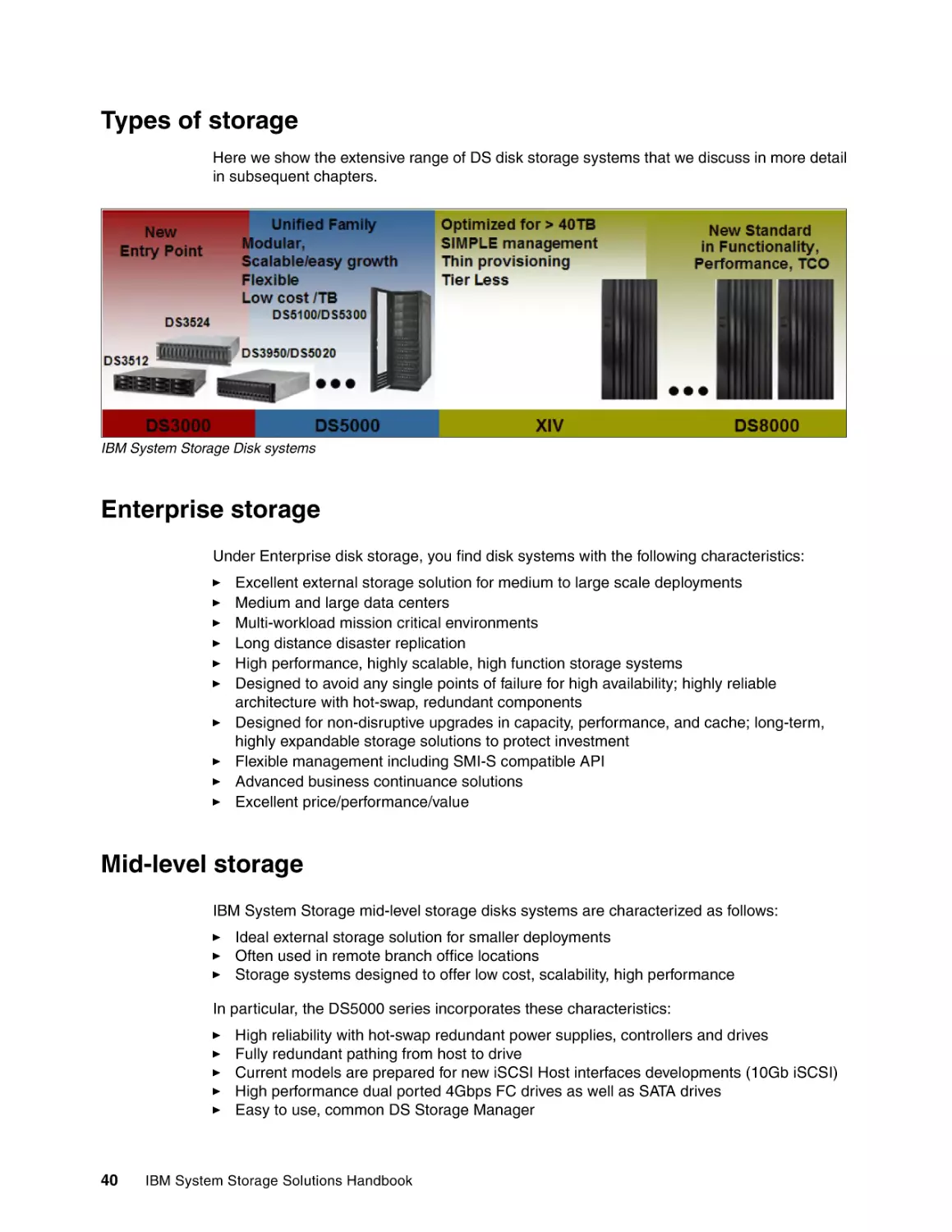
Types of storage . . . . . . . . . . . . . . . . . . . . . . . . . . . . . . . . . . . . . . . . . . . . . . . . . . . . . . . . .
Enterprise storage . . . . . . . . . . . . . . . . . . . . . . . . . . . . . . . . . . . . . . . . . . . . . . . . . . . . . . . .
Mid-level storage . . . . . . . . . . . . . . . . . . . . . . . . . . . . . . . . . . . . . . . . . . . . . . . . . . . . . . . . .
Near-line storage and reference data . . . . . . . . . . . . . . . . . . . . . . . . . . . . . . . . . . . . . . . . .
Entry-level storage . . . . . . . . . . . . . . . . . . . . . . . . . . . . . . . . . . . . . . . . . . . . . . . . . . . . . . . .
Network attached storage . . . . . . . . . . . . . . . . . . . . . . . . . . . . . . . . . . . . . . . . . . . . . . . . . .
39
40
40
40
41
41
41
Chapter 2. Entry-level disk storage . . . . . . . . . . . . . . . . . . . . . . . . . . . . . . . . . . . . . . . . .
2.1 Overview of new entry-level series models . . . . . . . . . . . . . . . . . . . . . . . . . . . . . . . . . .
2.1.1 IBM System Storage DS3500 . . . . . . . . . . . . . . . . . . . . . . . . . . . . . . . . . . . . . . . .
2.1.2 IBM System Storage EXP2500 . . . . . . . . . . . . . . . . . . . . . . . . . . . . . . . . . . . . . . .
2.2 IBM System Storage DS3500 . . . . . . . . . . . . . . . . . . . . . . . . . . . . . . . . . . . . . . . . . . . .
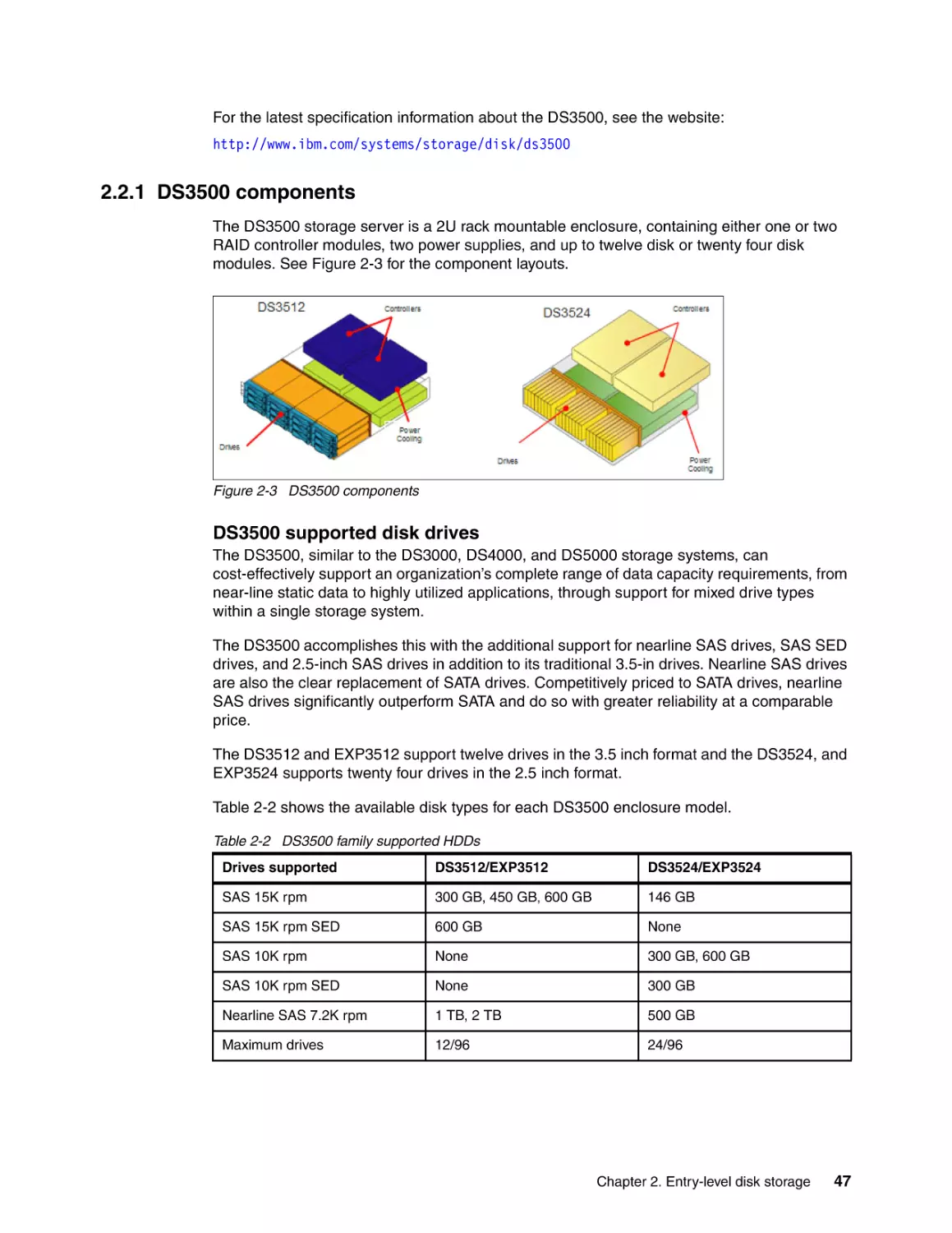
2.2.1 DS3500 components . . . . . . . . . . . . . . . . . . . . . . . . . . . . . . . . . . . . . . . . . . . . . .
2.2.2 Supported configurations . . . . . . . . . . . . . . . . . . . . . . . . . . . . . . . . . . . . . . . . . . .
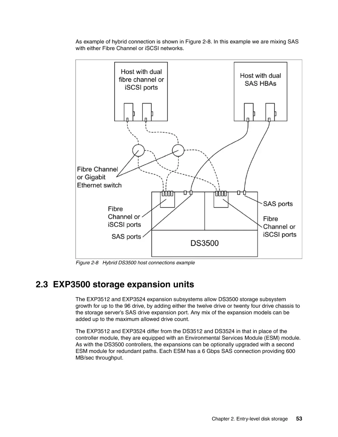
2.3 EXP3500 storage expansion units . . . . . . . . . . . . . . . . . . . . . . . . . . . . . . . . . . . . . . . .
2.4 IBM System Storage model DS3400 . . . . . . . . . . . . . . . . . . . . . . . . . . . . . . . . . . . . . .
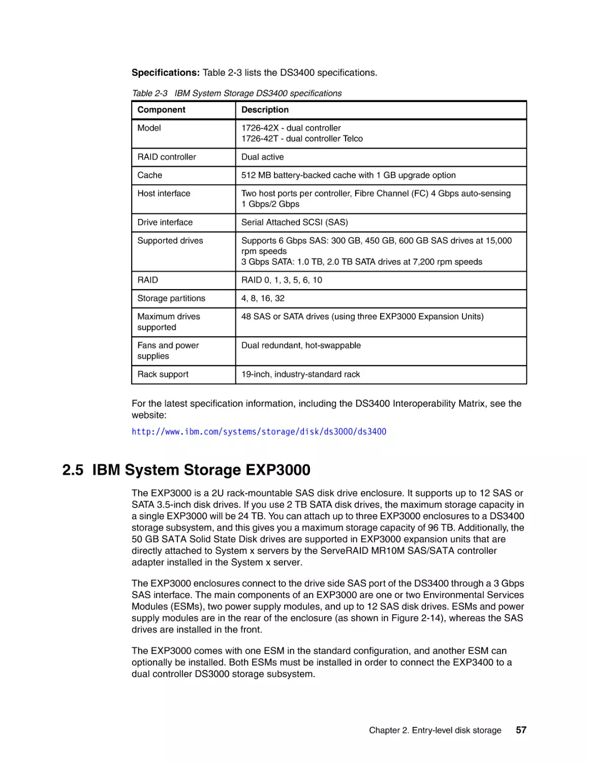
2.5 IBM System Storage EXP3000 . . . . . . . . . . . . . . . . . . . . . . . . . . . . . . . . . . . . . . . . . . .
2.6 IBM DS Storage Manager . . . . . . . . . . . . . . . . . . . . . . . . . . . . . . . . . . . . . . . . . . . . . . .
2.6.1 Host server and management station . . . . . . . . . . . . . . . . . . . . . . . . . . . . . . . . . .
2.6.2 Premium features . . . . . . . . . . . . . . . . . . . . . . . . . . . . . . . . . . . . . . . . . . . . . . . . .
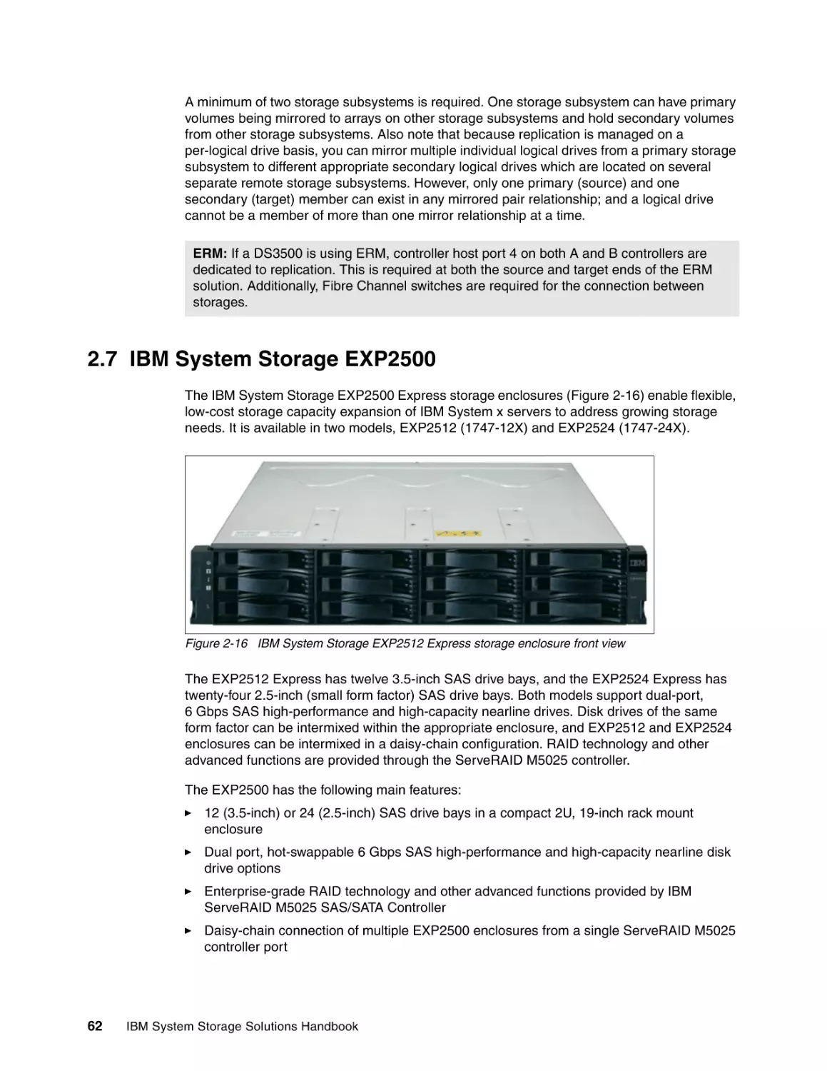
2.7 IBM System Storage EXP2500 . . . . . . . . . . . . . . . . . . . . . . . . . . . . . . . . . . . . . . . . . . .
2.8 More information . . . . . . . . . . . . . . . . . . . . . . . . . . . . . . . . . . . . . . . . . . . . . . . . . . . . . .
43
44
44
44
45
47
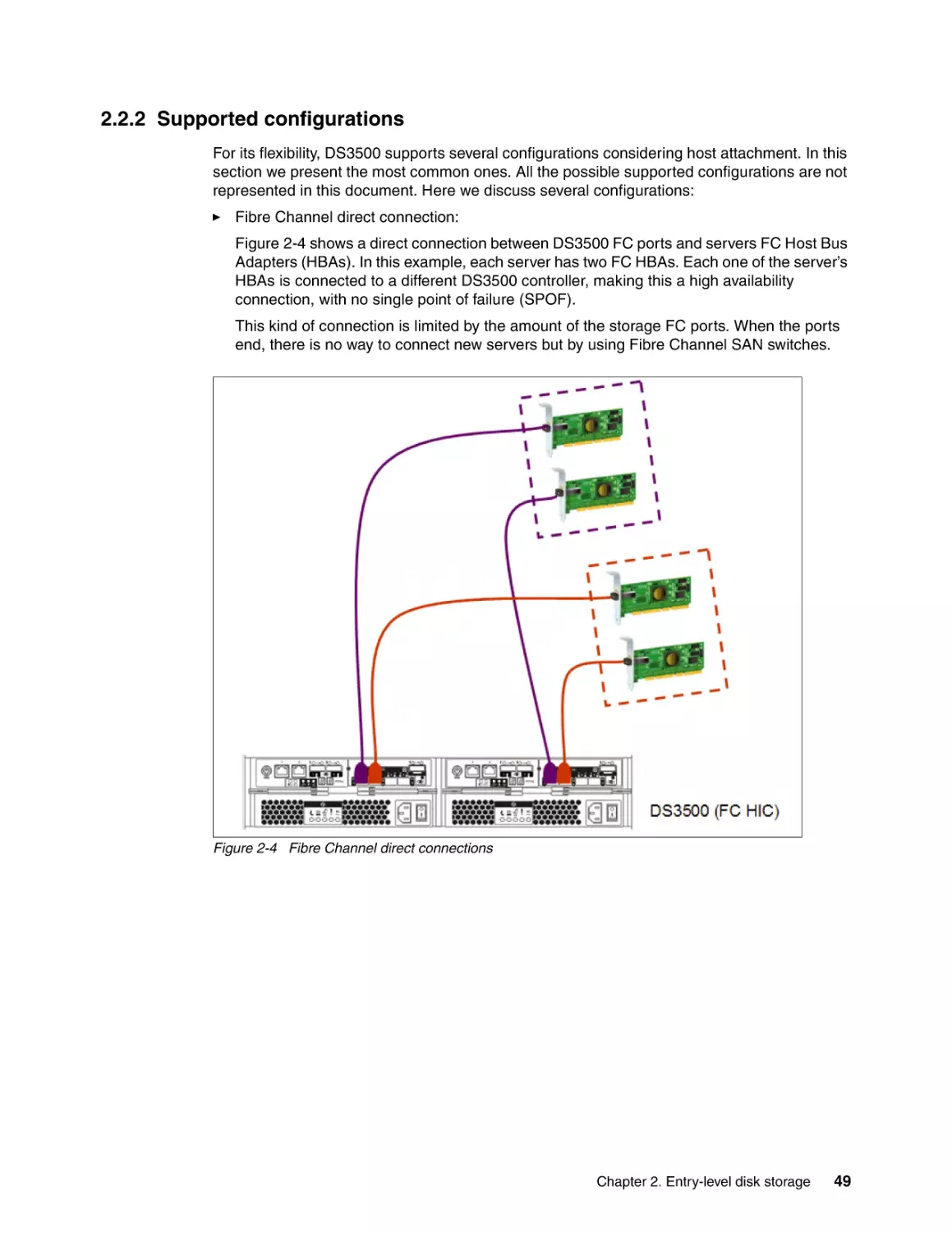
49
53
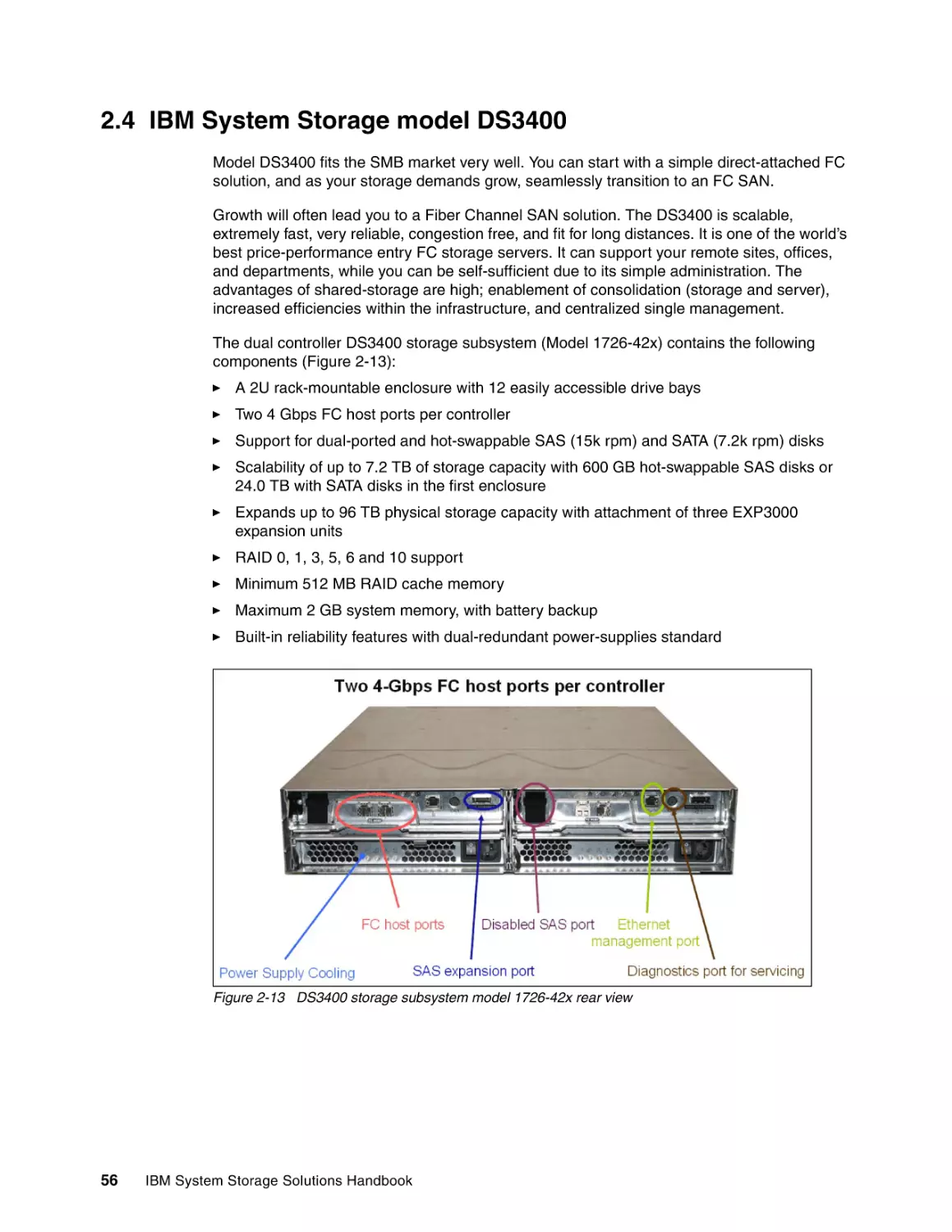
56
57
58
59
60
62
63
Chapter 3. Midrange disk systems . . . . . . . . . . . . . . . . . . . . . . . . . . . . . . . . . . . . . . . . .
3.1 Overview of IBM Storwize V7000 . . . . . . . . . . . . . . . . . . . . . . . . . . . . . . . . . . . . . . . . .
3.1.1 IBM Storwize V7000 highlights . . . . . . . . . . . . . . . . . . . . . . . . . . . . . . . . . . . . . . .
3.1.2 IBM Storwize V7000 product features. . . . . . . . . . . . . . . . . . . . . . . . . . . . . . . . . .
3.1.3 IBM Storwize V7000 hardware summary . . . . . . . . . . . . . . . . . . . . . . . . . . . . . . .
3.2 Overview of IBM System Storage DS Models. . . . . . . . . . . . . . . . . . . . . . . . . . . . . . . .
3.2.1 IBM System Storage DS3950 . . . . . . . . . . . . . . . . . . . . . . . . . . . . . . . . . . . . . . . .
3.2.2 IBM System Storage DS5000 . . . . . . . . . . . . . . . . . . . . . . . . . . . . . . . . . . . . . . . .
3.3 IBM System Storage DS3950 Express . . . . . . . . . . . . . . . . . . . . . . . . . . . . . . . . . . . . .
3.3.1 IBM System Storage DS3950 highlights . . . . . . . . . . . . . . . . . . . . . . . . . . . . . . . .
3.3.2 IBM System Storage DS Series common features . . . . . . . . . . . . . . . . . . . . . . . .
3.3.3 IBM System Storage DS3950 Express Hardware summary. . . . . . . . . . . . . . . . .
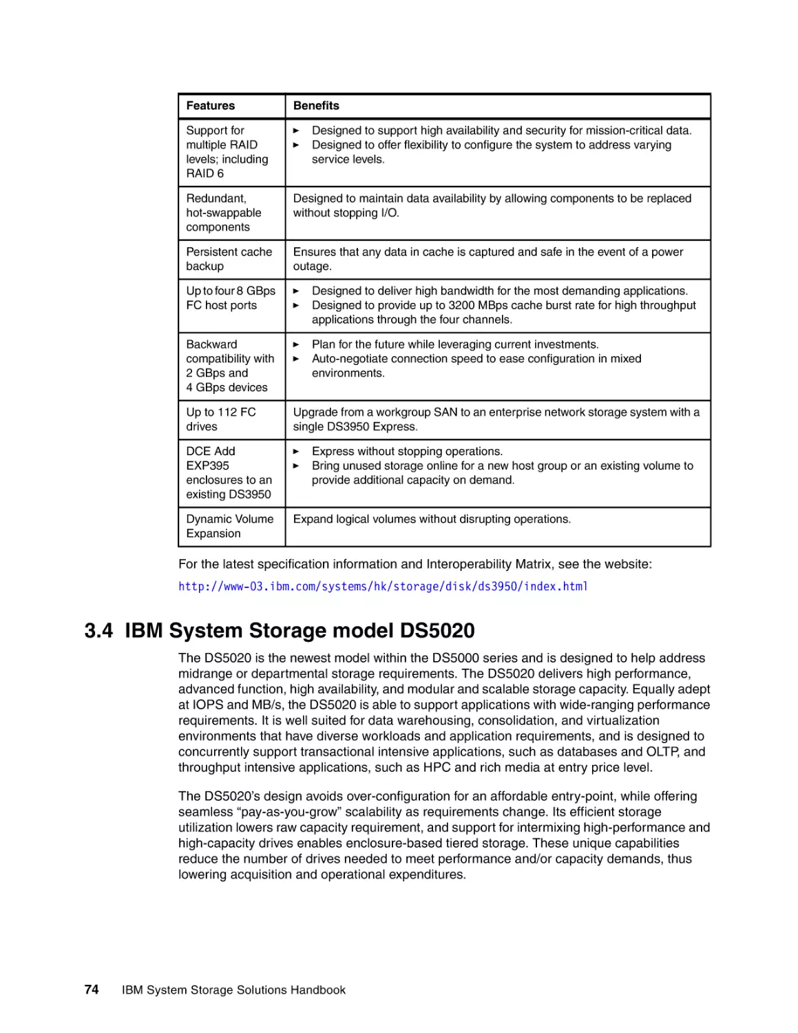
3.4 IBM System Storage model DS5020 . . . . . . . . . . . . . . . . . . . . . . . . . . . . . . . . . . . . . .
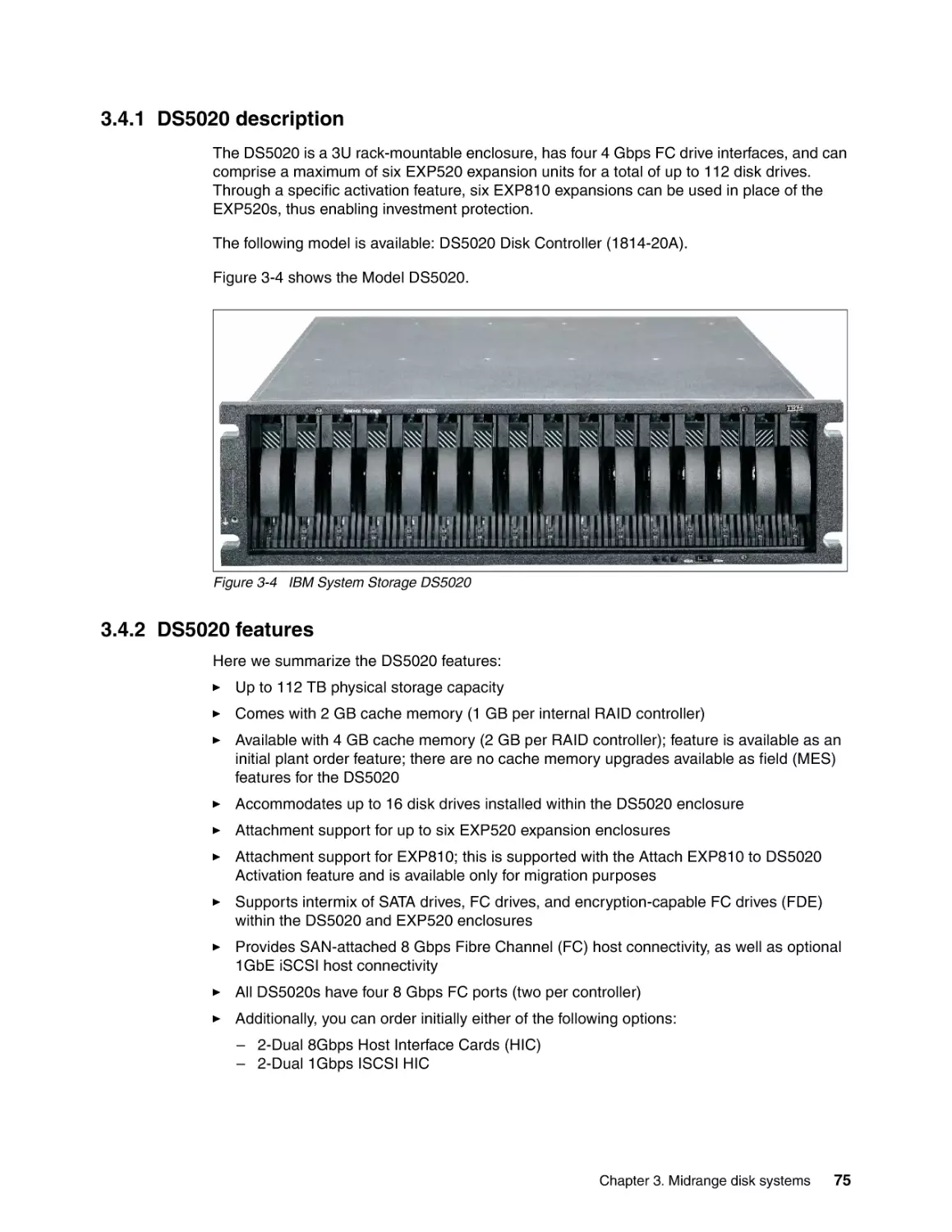
3.4.1 DS5020 description. . . . . . . . . . . . . . . . . . . . . . . . . . . . . . . . . . . . . . . . . . . . . . . .
3.4.2 DS5020 features . . . . . . . . . . . . . . . . . . . . . . . . . . . . . . . . . . . . . . . . . . . . . . . . . .
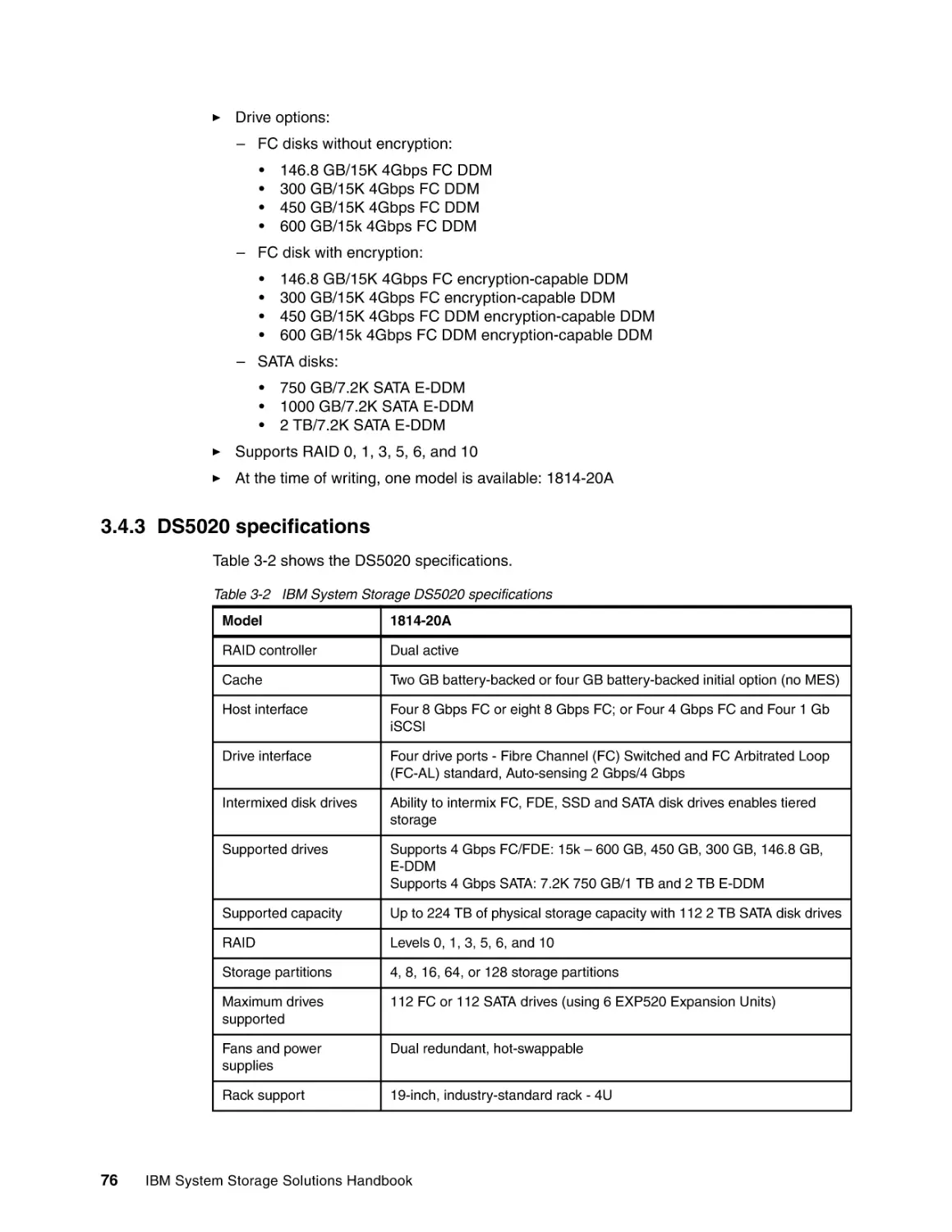
3.4.3 DS5020 specifications . . . . . . . . . . . . . . . . . . . . . . . . . . . . . . . . . . . . . . . . . . . . .
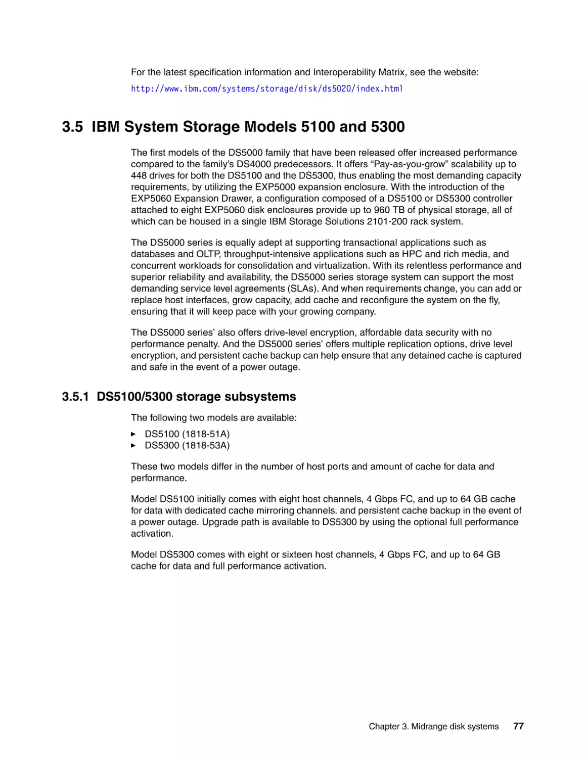
3.5 IBM System Storage Models 5100 and 5300 . . . . . . . . . . . . . . . . . . . . . . . . . . . . . . . .
3.5.1 DS5100/5300 storage subsystems . . . . . . . . . . . . . . . . . . . . . . . . . . . . . . . . . . . .
3.5.2 DS5100 and DS5300 features . . . . . . . . . . . . . . . . . . . . . . . . . . . . . . . . . . . . . . .
3.6 IBM System Storage Model DCS9900 . . . . . . . . . . . . . . . . . . . . . . . . . . . . . . . . . . . . .
3.6.1 New features . . . . . . . . . . . . . . . . . . . . . . . . . . . . . . . . . . . . . . . . . . . . . . . . . . . . .
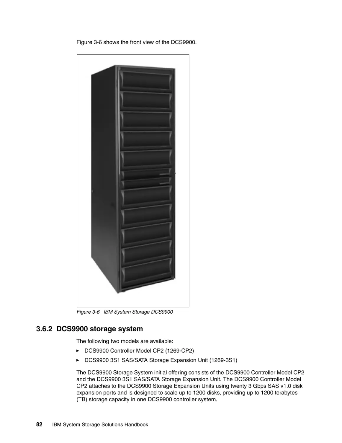
3.6.2 DCS9900 storage system . . . . . . . . . . . . . . . . . . . . . . . . . . . . . . . . . . . . . . . . . . .
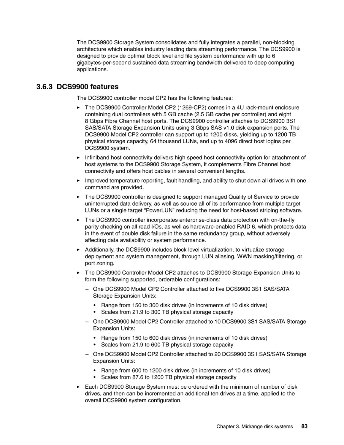
3.6.3 DCS9900 features . . . . . . . . . . . . . . . . . . . . . . . . . . . . . . . . . . . . . . . . . . . . . . . .
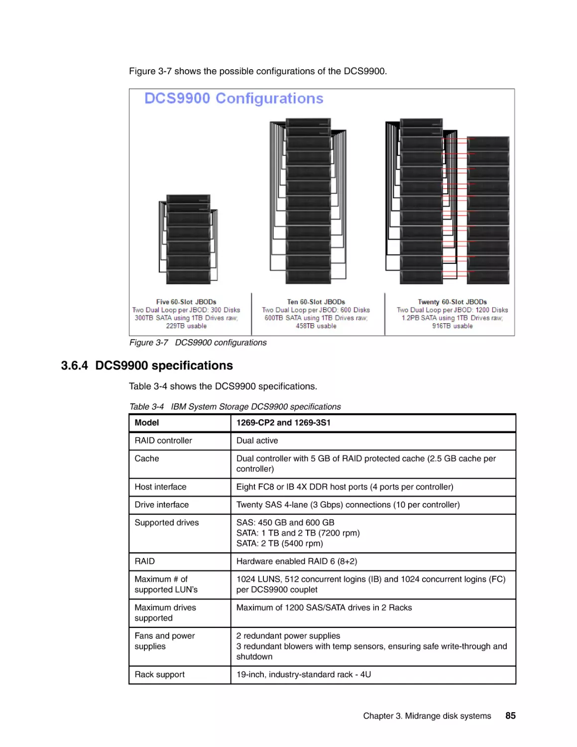
3.6.4 DCS9900 specifications . . . . . . . . . . . . . . . . . . . . . . . . . . . . . . . . . . . . . . . . . . . .
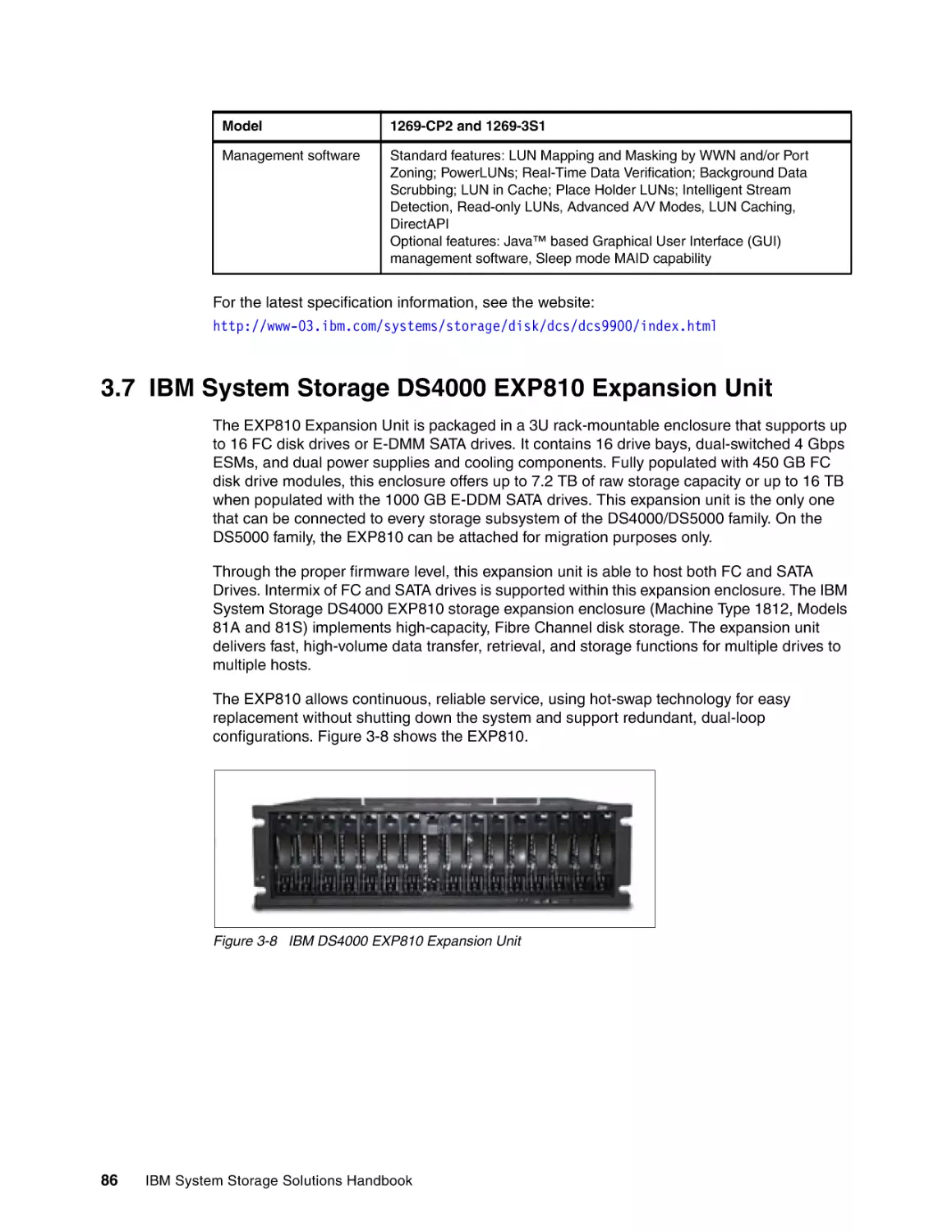
3.7 IBM System Storage DS4000 EXP810 Expansion Unit . . . . . . . . . . . . . . . . . . . . . . . .
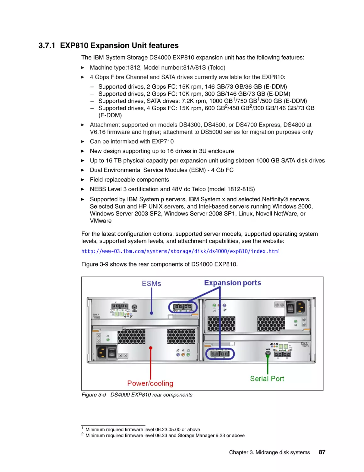
3.7.1 EXP810 Expansion Unit features . . . . . . . . . . . . . . . . . . . . . . . . . . . . . . . . . . . . .
3.7.2 EXP810 Expansion Unit specifications . . . . . . . . . . . . . . . . . . . . . . . . . . . . . . . . .
65
67
67
67
68
68
68
68
69
70
70
70
74
75
75
76
77
77
78
81
81
82
83
85
86
87
88
iv
IBM System Storage Solutions Handbook
3.8 IBM System Storage model EXP520 and EXP5000 . . . . . . . . . . . . . . . . . . . . . . . . . . . 88
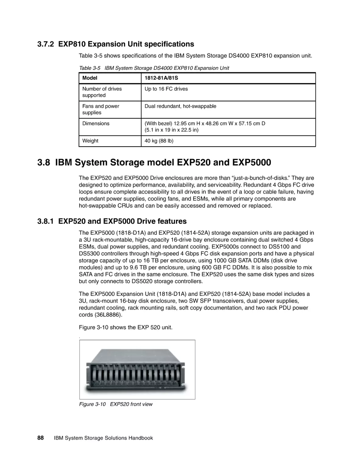
3.8.1 EXP520 and EXP5000 Drive features . . . . . . . . . . . . . . . . . . . . . . . . . . . . . . . . . 88
3.8.2 EXP520 and EXP5000 Drive support . . . . . . . . . . . . . . . . . . . . . . . . . . . . . . . . . . 89
3.9 IBM System Storage EXP5060 . . . . . . . . . . . . . . . . . . . . . . . . . . . . . . . . . . . . . . . . . . . 89
3.9.1 EXP5060 overview . . . . . . . . . . . . . . . . . . . . . . . . . . . . . . . . . . . . . . . . . . . . . . . . 89
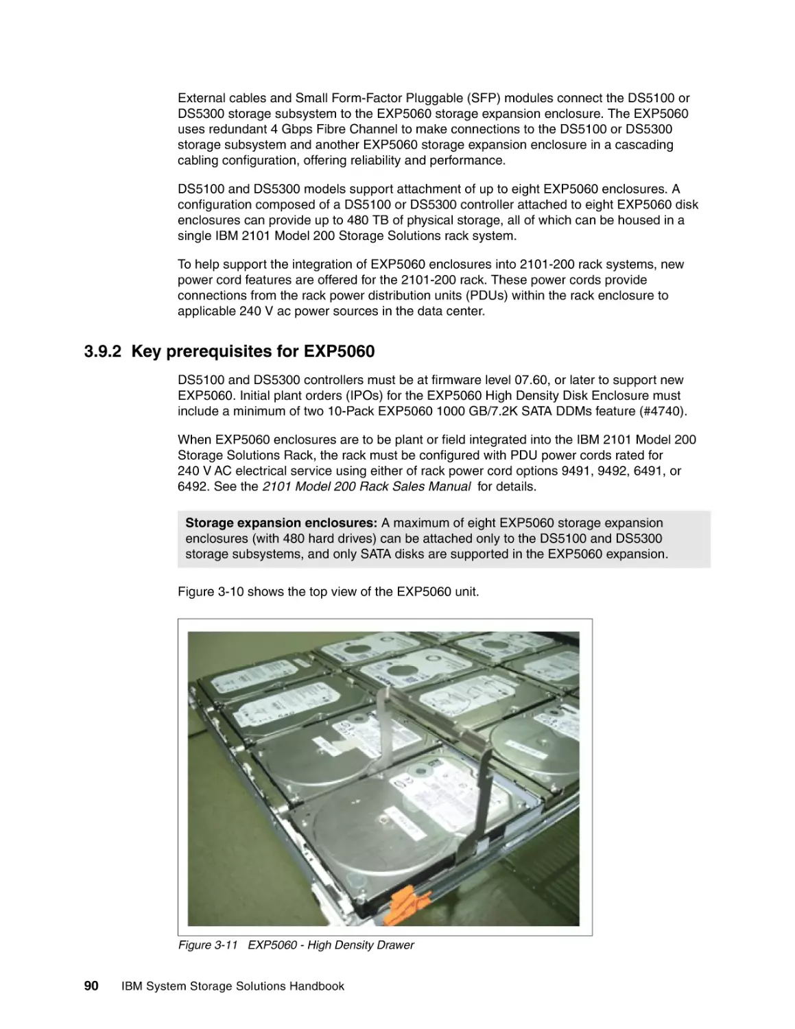
3.9.2 Key prerequisites for EXP5060 . . . . . . . . . . . . . . . . . . . . . . . . . . . . . . . . . . . . . . . 90
3.10 IBM TotalStorage EXP24 . . . . . . . . . . . . . . . . . . . . . . . . . . . . . . . . . . . . . . . . . . . . . . 91
3.11 Solid State Disk and Full Disk Encryption . . . . . . . . . . . . . . . . . . . . . . . . . . . . . . . . . . 91
3.11.1 Solid State Disk. . . . . . . . . . . . . . . . . . . . . . . . . . . . . . . . . . . . . . . . . . . . . . . . . . 91
3.11.2 Full Disk Encryption . . . . . . . . . . . . . . . . . . . . . . . . . . . . . . . . . . . . . . . . . . . . . . 94
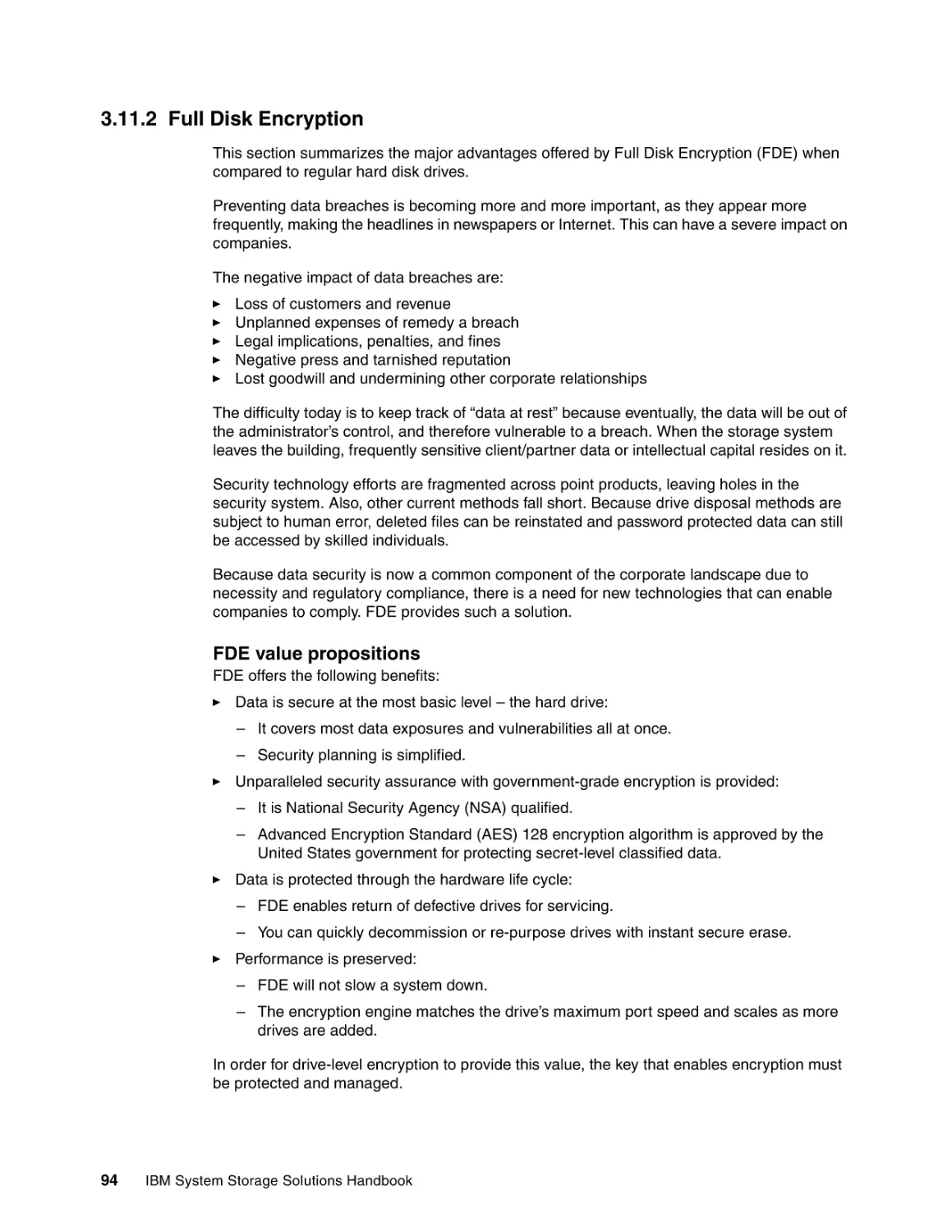
3.12 IBM System Storage DS Storage Manager . . . . . . . . . . . . . . . . . . . . . . . . . . . . . . . . 97
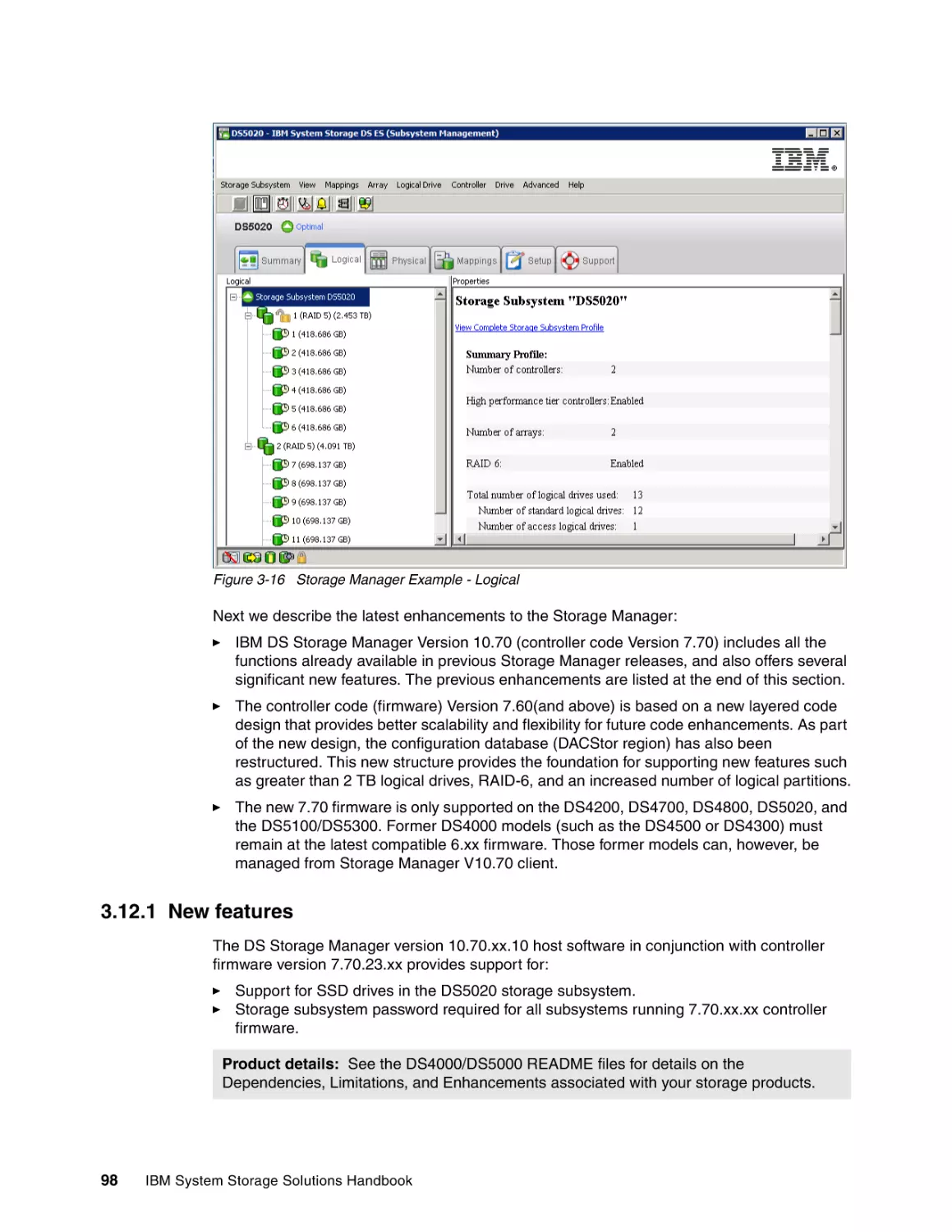
3.12.1 New features . . . . . . . . . . . . . . . . . . . . . . . . . . . . . . . . . . . . . . . . . . . . . . . . . . . . 98
3.12.2 Other features . . . . . . . . . . . . . . . . . . . . . . . . . . . . . . . . . . . . . . . . . . . . . . . . . . . 99
3.13 Introduction to IBM Midrange Storage Copy Services . . . . . . . . . . . . . . . . . . . . . . . . 99
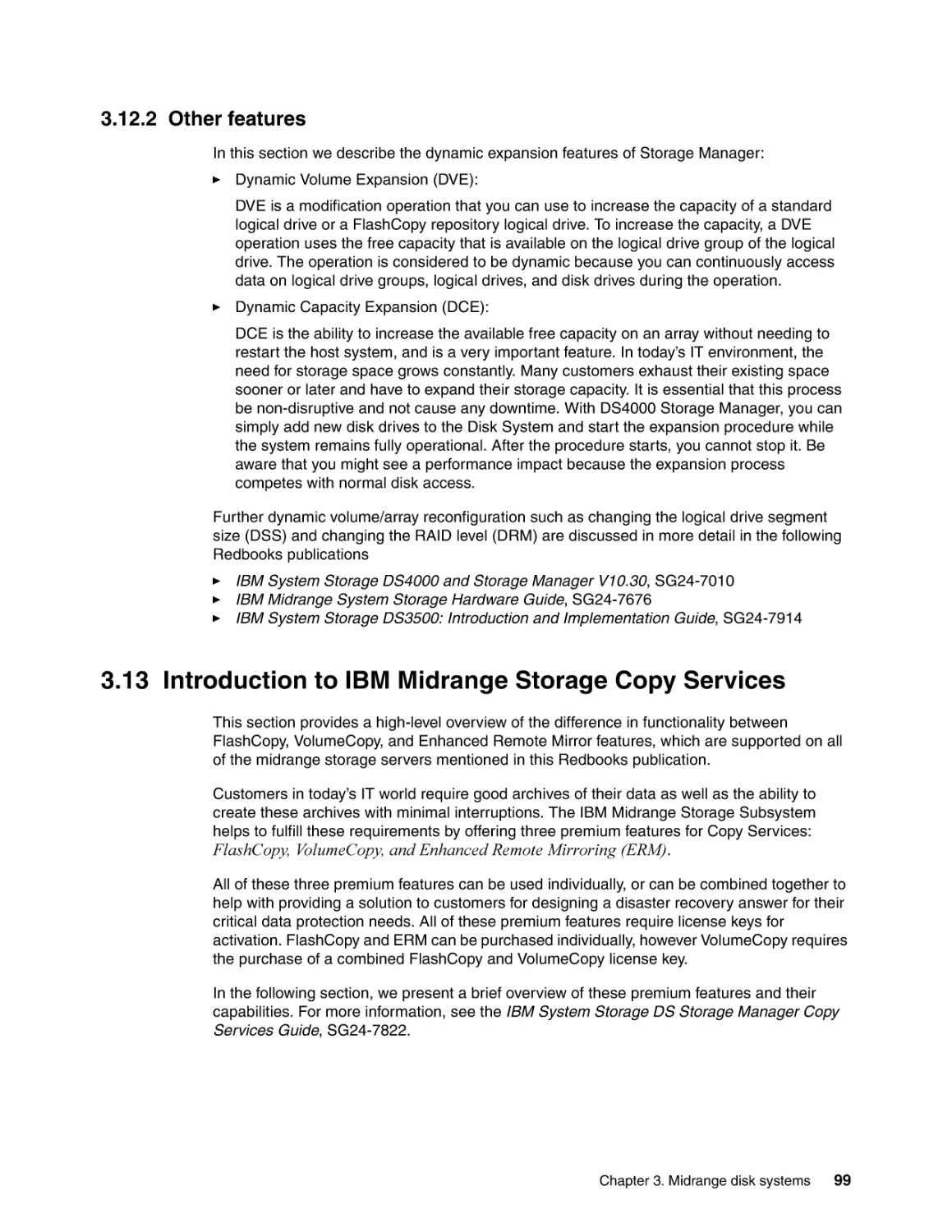
3.13.1 FlashCopy premium feature . . . . . . . . . . . . . . . . . . . . . . . . . . . . . . . . . . . . . . . 100
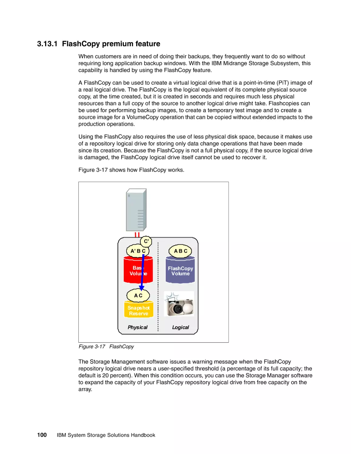
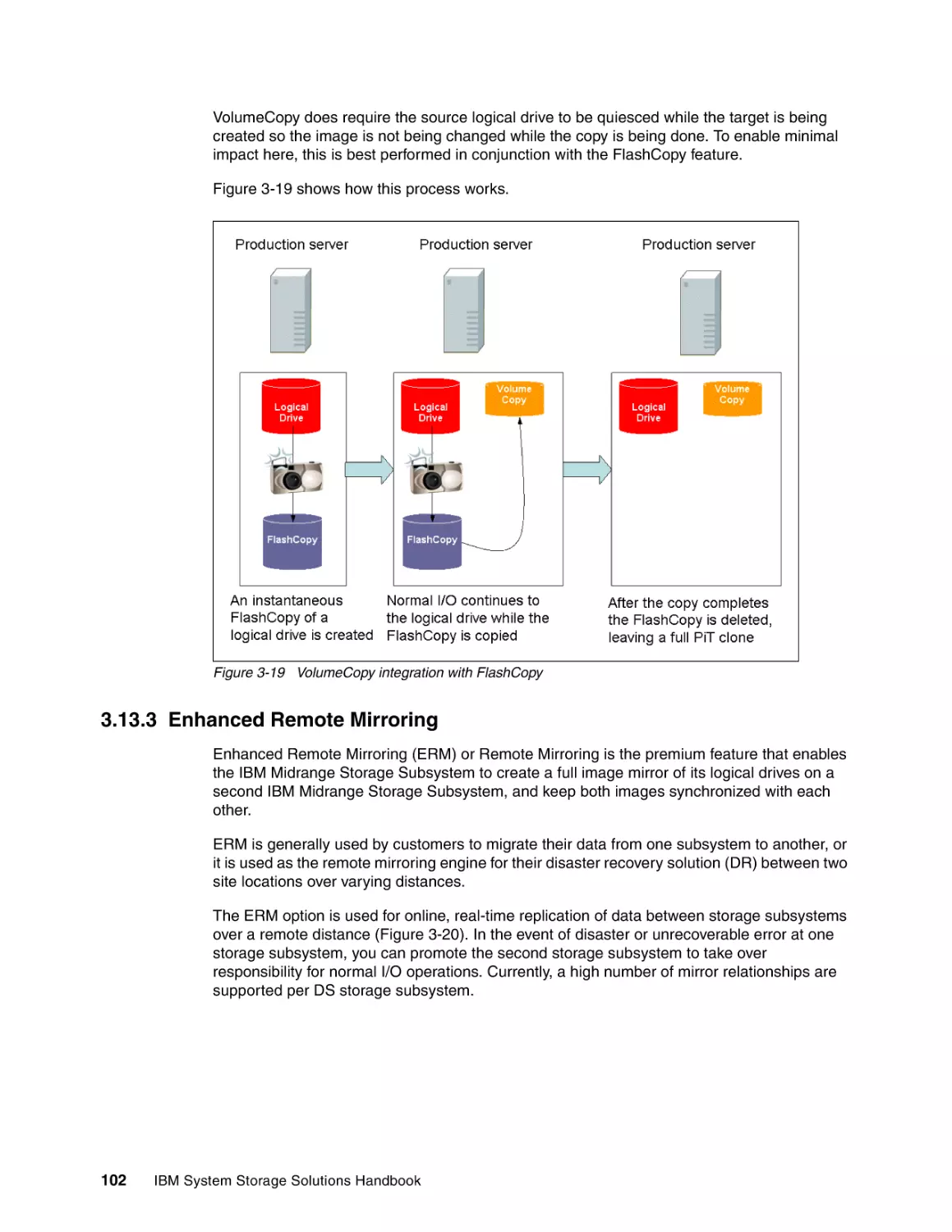
3.13.2 VolumeCopy . . . . . . . . . . . . . . . . . . . . . . . . . . . . . . . . . . . . . . . . . . . . . . . . . . . 101
3.13.3 Enhanced Remote Mirroring . . . . . . . . . . . . . . . . . . . . . . . . . . . . . . . . . . . . . . . 102
3.14 IBM Remote Support Manager for Storage. . . . . . . . . . . . . . . . . . . . . . . . . . . . . . . . 104
3.14.1 Overview . . . . . . . . . . . . . . . . . . . . . . . . . . . . . . . . . . . . . . . . . . . . . . . . . . . . . . 104
3.14.2 Hardware and software requirements . . . . . . . . . . . . . . . . . . . . . . . . . . . . . . . . 106
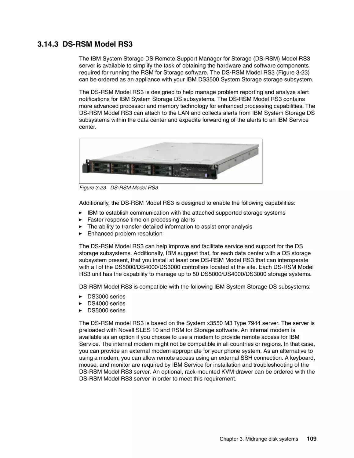
3.14.3 DS-RSM Model RS3 . . . . . . . . . . . . . . . . . . . . . . . . . . . . . . . . . . . . . . . . . . . . . 109
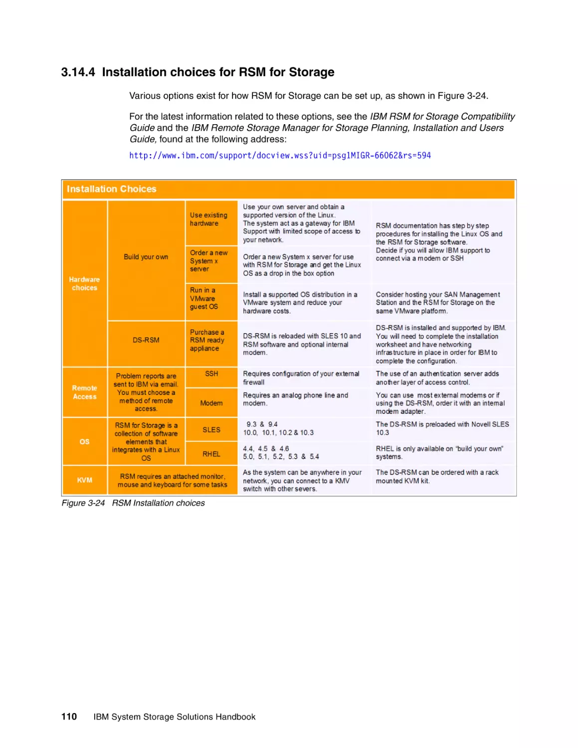
3.14.4 Installation choices for RSM for Storage. . . . . . . . . . . . . . . . . . . . . . . . . . . . . . 110
3.15 More information . . . . . . . . . . . . . . . . . . . . . . . . . . . . . . . . . . . . . . . . . . . . . . . . . . . . 111
Chapter 4. Enterprise Disk Systems . . . . . . . . . . . . . . . . . . . . . . . . . . . . . . . . . . . . . . .
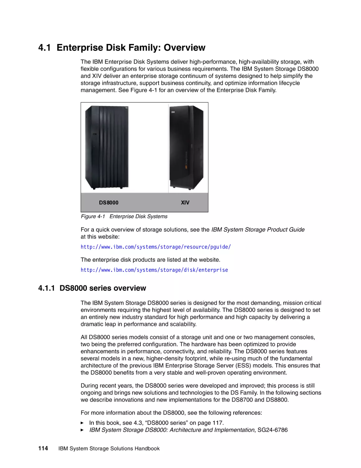
4.1 Enterprise Disk Family: Overview . . . . . . . . . . . . . . . . . . . . . . . . . . . . . . . . . . . . . . . .
4.1.1 DS8000 series overview . . . . . . . . . . . . . . . . . . . . . . . . . . . . . . . . . . . . . . . . . . .
4.1.2 XIV series overview . . . . . . . . . . . . . . . . . . . . . . . . . . . . . . . . . . . . . . . . . . . . . .
4.2 Enterprise Disk Solutions . . . . . . . . . . . . . . . . . . . . . . . . . . . . . . . . . . . . . . . . . . . . . .
4.2.1 Infrastructure simplification . . . . . . . . . . . . . . . . . . . . . . . . . . . . . . . . . . . . . . . . .
4.2.2 Business continuity . . . . . . . . . . . . . . . . . . . . . . . . . . . . . . . . . . . . . . . . . . . . . . .
4.2.3 Green Data Center . . . . . . . . . . . . . . . . . . . . . . . . . . . . . . . . . . . . . . . . . . . . . . .
4.3 DS8000 series. . . . . . . . . . . . . . . . . . . . . . . . . . . . . . . . . . . . . . . . . . . . . . . . . . . . . . .
4.3.1 DS8000 concepts . . . . . . . . . . . . . . . . . . . . . . . . . . . . . . . . . . . . . . . . . . . . . . . .
4.3.2 The DS8000 series design keys . . . . . . . . . . . . . . . . . . . . . . . . . . . . . . . . . . . . .
4.3.3 Overview of DS8000 recent features and technology. . . . . . . . . . . . . . . . . . . . .
4.3.4 DS8000 series architecture. . . . . . . . . . . . . . . . . . . . . . . . . . . . . . . . . . . . . . . . .
4.3.5 DS8000 series products . . . . . . . . . . . . . . . . . . . . . . . . . . . . . . . . . . . . . . . . . . .
4.3.6 DS8000 management . . . . . . . . . . . . . . . . . . . . . . . . . . . . . . . . . . . . . . . . . . . . .
4.3.7 IBM Standby Capacity on Demand offering for the DS8000. . . . . . . . . . . . . . . .
4.3.8 DS8000 Copy Services . . . . . . . . . . . . . . . . . . . . . . . . . . . . . . . . . . . . . . . . . . . .
4.3.9 DS8000 licensing overview . . . . . . . . . . . . . . . . . . . . . . . . . . . . . . . . . . . . . . . . .
4.3.10 DS8000 supported environments . . . . . . . . . . . . . . . . . . . . . . . . . . . . . . . . . . .
4.3.11 DS8000 series: More information . . . . . . . . . . . . . . . . . . . . . . . . . . . . . . . . . . .
4.4 IBM XIV Storage System . . . . . . . . . . . . . . . . . . . . . . . . . . . . . . . . . . . . . . . . . . . . . .
4.4.1 System models and components . . . . . . . . . . . . . . . . . . . . . . . . . . . . . . . . . . . .
4.4.2 Key design features . . . . . . . . . . . . . . . . . . . . . . . . . . . . . . . . . . . . . . . . . . . . . .
4.4.3 IBM XIV Storage System software . . . . . . . . . . . . . . . . . . . . . . . . . . . . . . . . . . .
4.4.4 Parallelism . . . . . . . . . . . . . . . . . . . . . . . . . . . . . . . . . . . . . . . . . . . . . . . . . . . . .
4.4.5 Full storage virtualization . . . . . . . . . . . . . . . . . . . . . . . . . . . . . . . . . . . . . . . . . .
4.4.6 Reliability, availability, and serviceability. . . . . . . . . . . . . . . . . . . . . . . . . . . . . . .
4.4.7 More information about the IBM XIV Storage System . . . . . . . . . . . . . . . . . . . .
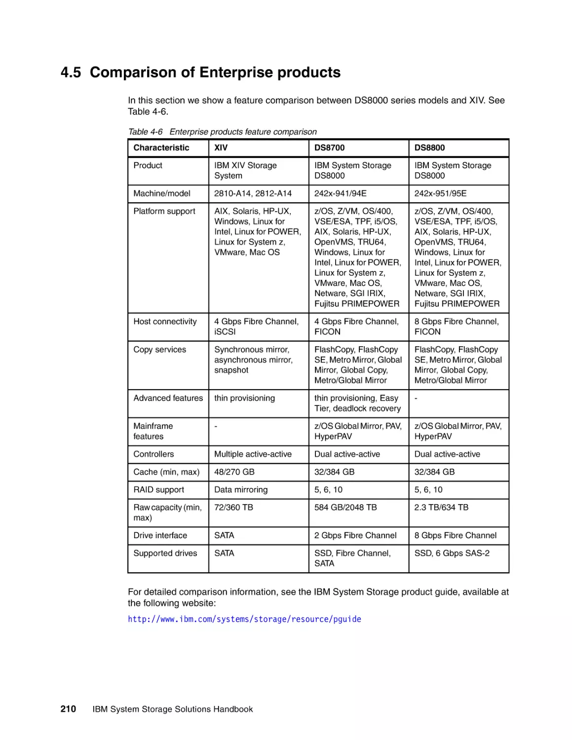
4.5 Comparison of Enterprise products. . . . . . . . . . . . . . . . . . . . . . . . . . . . . . . . . . . . . . .
113
114
114
115
115
115
116
117
117
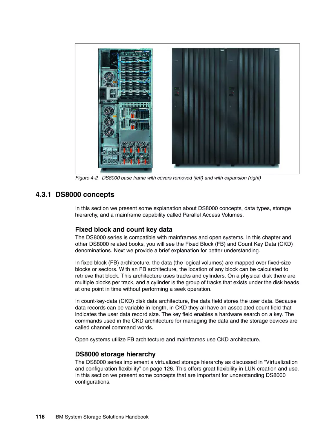
118
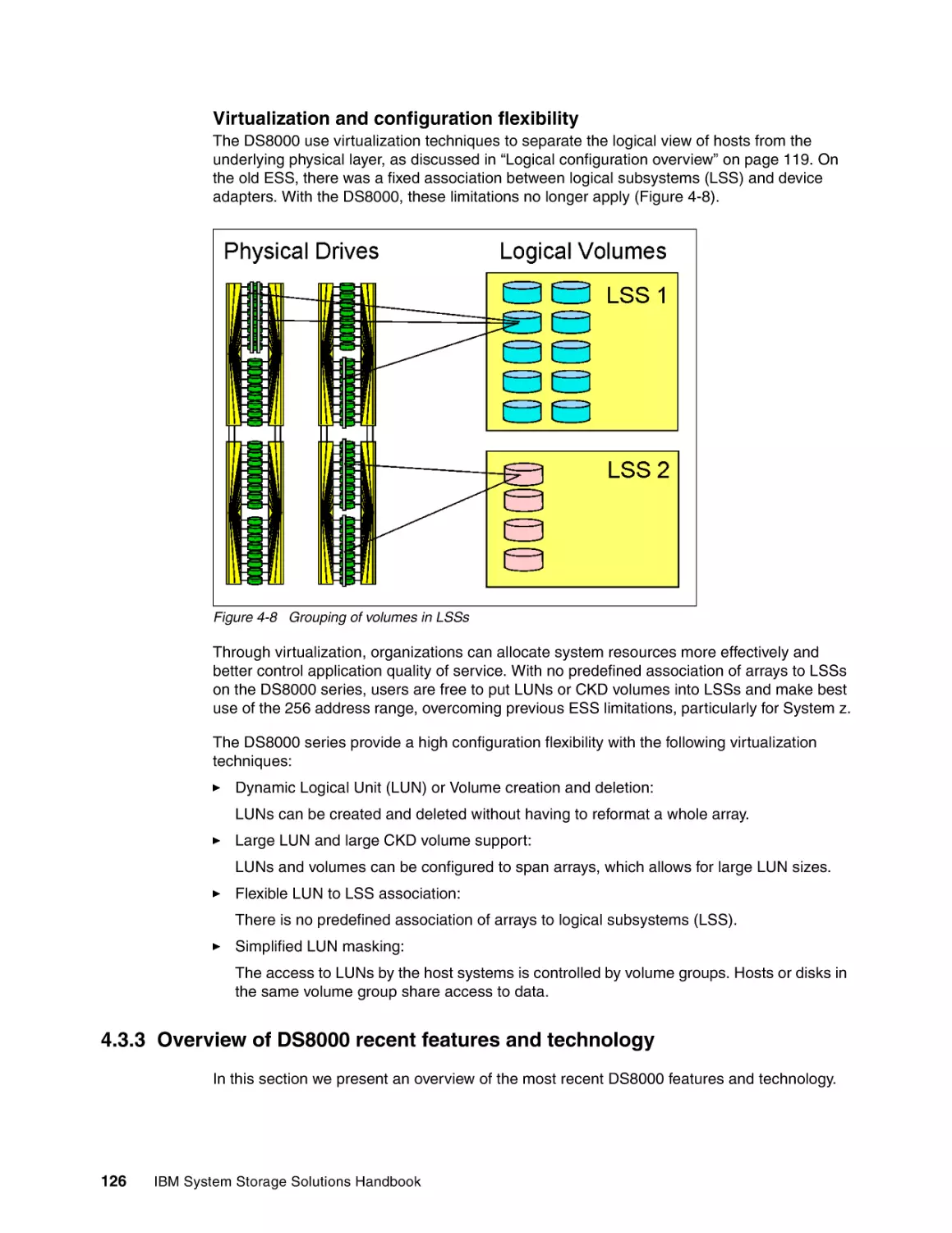
121
126
133
147
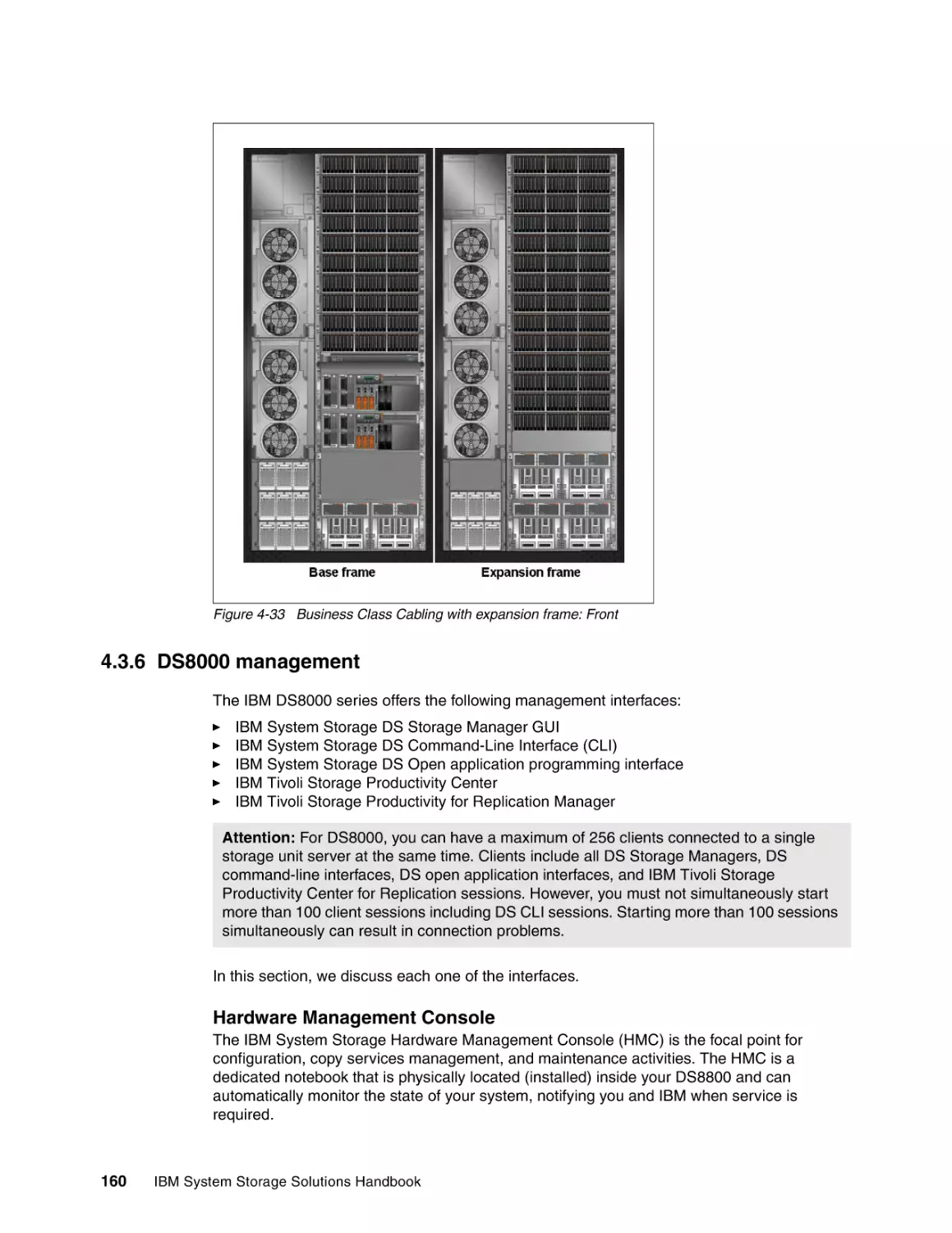
160
165
165
173
176
176
177
177
181
182
186
188
201
209
210
Contents
v
vi
Chapter 5. IBM System Storage N series . . . . . . . . . . . . . . . . . . . . . . . . . . . . . . . . . . .
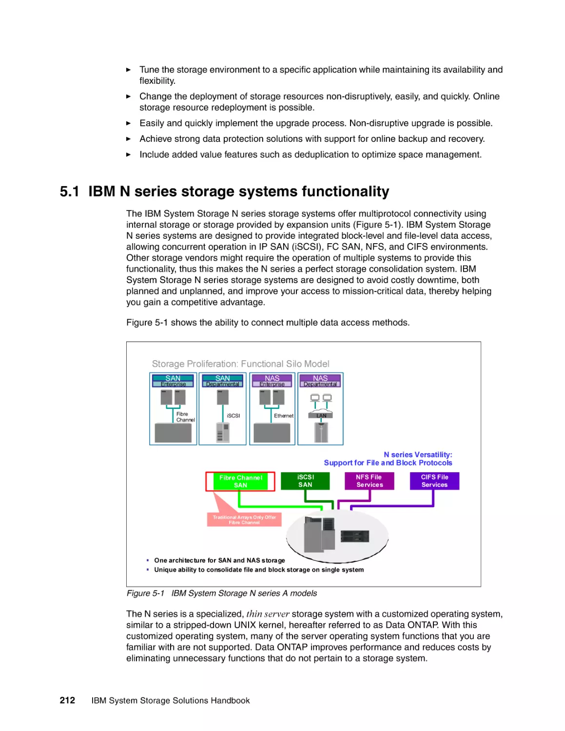
5.1 IBM N series storage systems functionality . . . . . . . . . . . . . . . . . . . . . . . . . . . . . . . .
5.1.1 Drive flexibility . . . . . . . . . . . . . . . . . . . . . . . . . . . . . . . . . . . . . . . . . . . . . . . . . . .
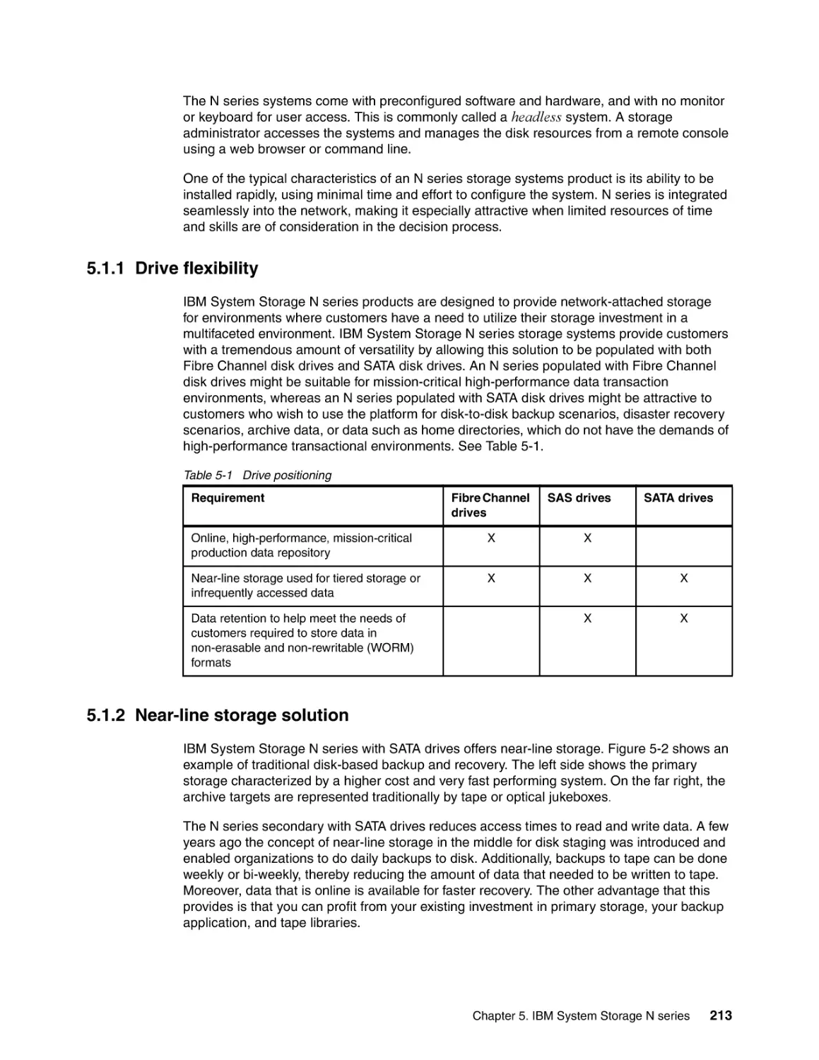
5.1.2 Near-line storage solution . . . . . . . . . . . . . . . . . . . . . . . . . . . . . . . . . . . . . . . . . .
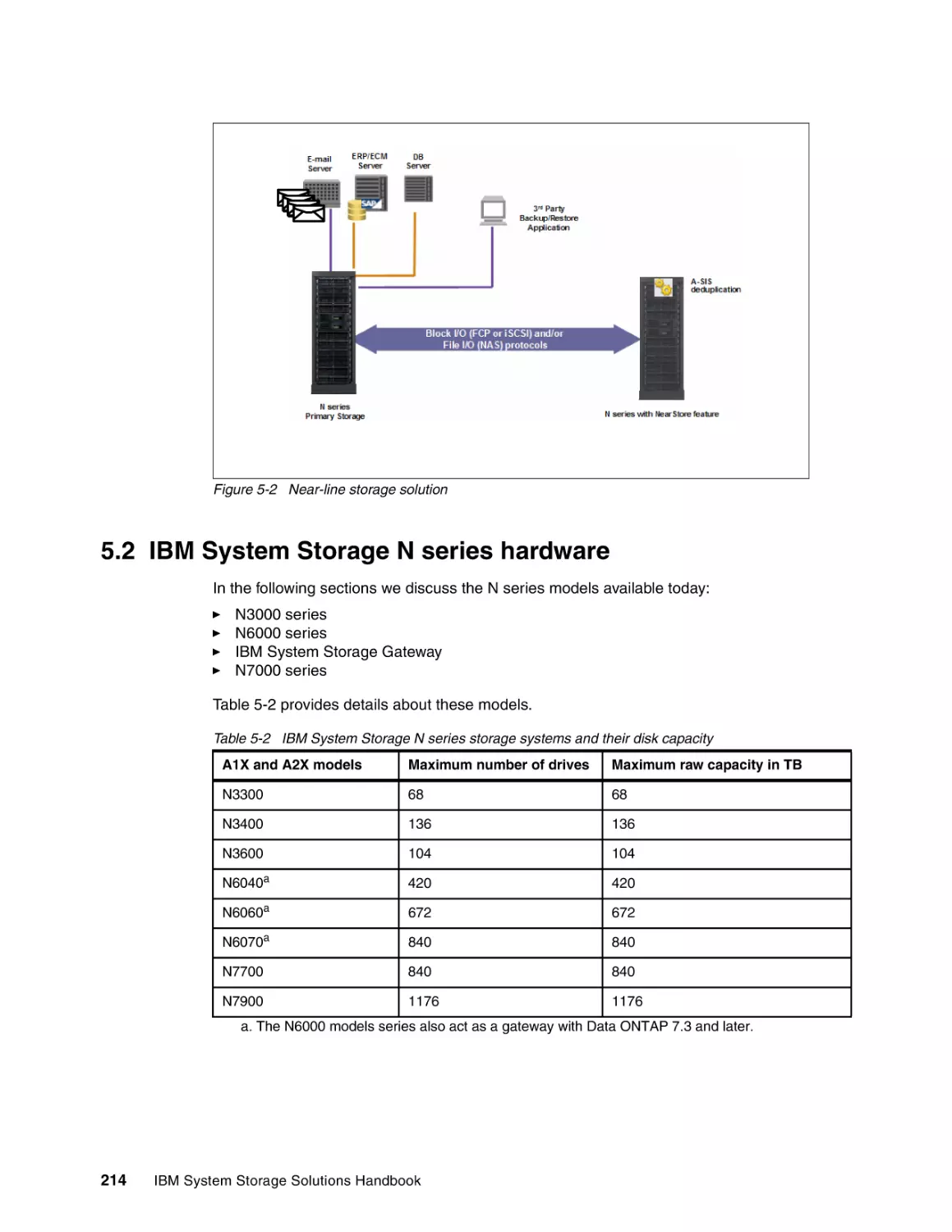
5.2 IBM System Storage N series hardware . . . . . . . . . . . . . . . . . . . . . . . . . . . . . . . . . . .
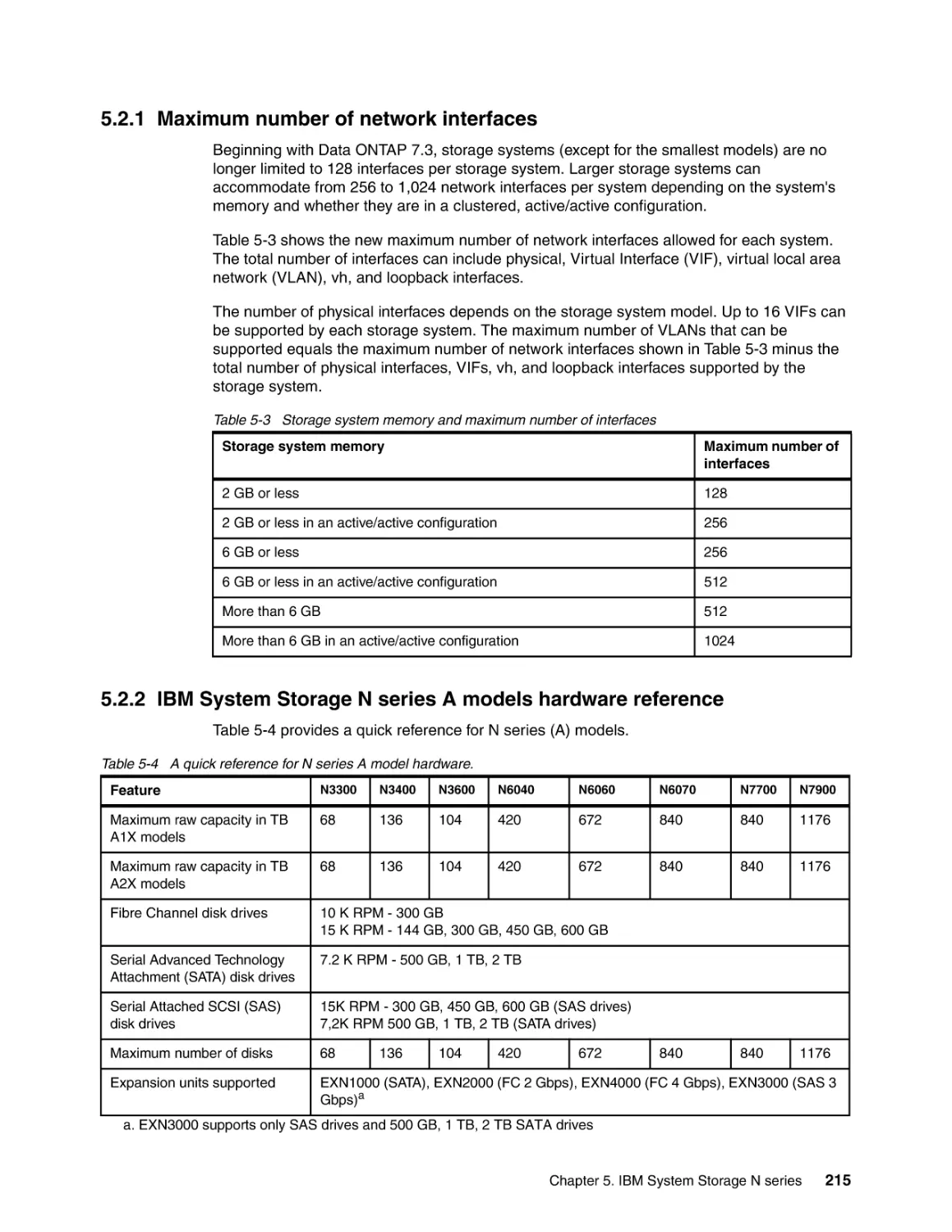
5.2.1 Maximum number of network interfaces . . . . . . . . . . . . . . . . . . . . . . . . . . . . . . .
5.2.2 IBM System Storage N series A models hardware reference. . . . . . . . . . . . . . .
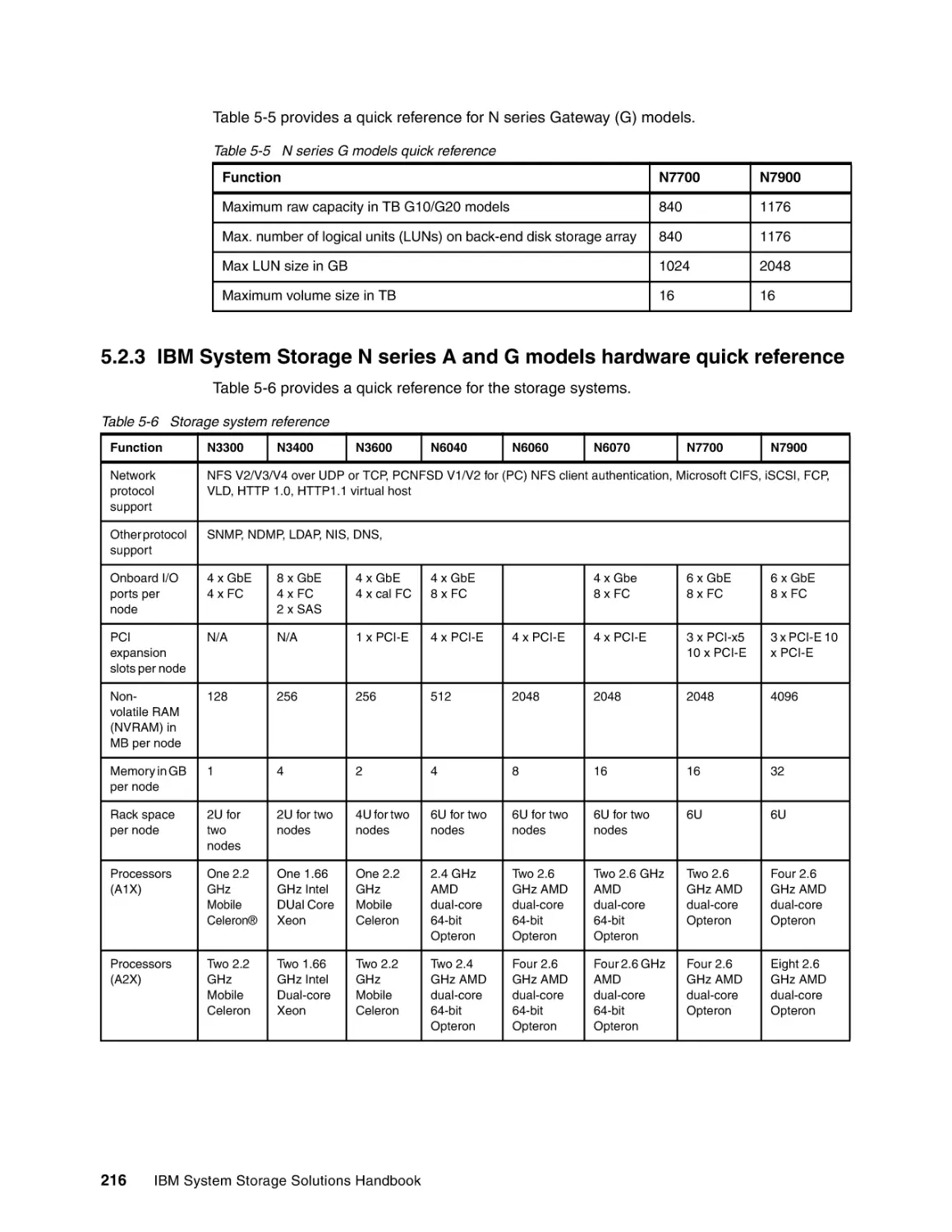
5.2.3 IBM System Storage N series A and G models hardware quick reference. . . . .
5.2.4 IBM System Storage N3000 introduction . . . . . . . . . . . . . . . . . . . . . . . . . . . . . .
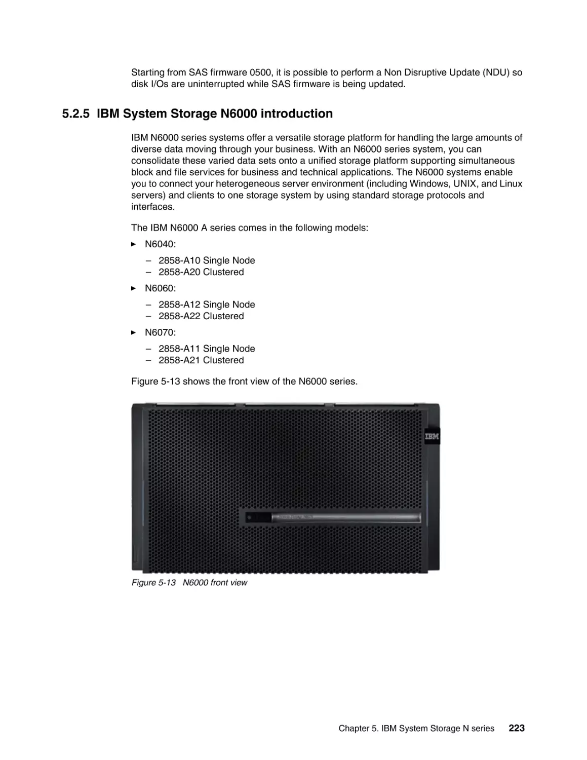
5.2.5 IBM System Storage N6000 introduction . . . . . . . . . . . . . . . . . . . . . . . . . . . . . .
5.2.6 IBM System Storage N7000 introduction . . . . . . . . . . . . . . . . . . . . . . . . . . . . . .
5.3 IBM System Storage N series Gateways . . . . . . . . . . . . . . . . . . . . . . . . . . . . . . . . . .
5.3.1 IBM System Storage N series Gateway highlights . . . . . . . . . . . . . . . . . . . . . . .
5.3.2 IBM System Storage N6040, N6060, and N6070 Gateway models . . . . . . . . . .
5.3.3 IBM System Storage N7700 and N7900 Gateway models . . . . . . . . . . . . . . . . .
5.4 N series expansion units . . . . . . . . . . . . . . . . . . . . . . . . . . . . . . . . . . . . . . . . . . . . . . .
5.4.1 Intermixing EXN units with N series A models . . . . . . . . . . . . . . . . . . . . . . . . . .
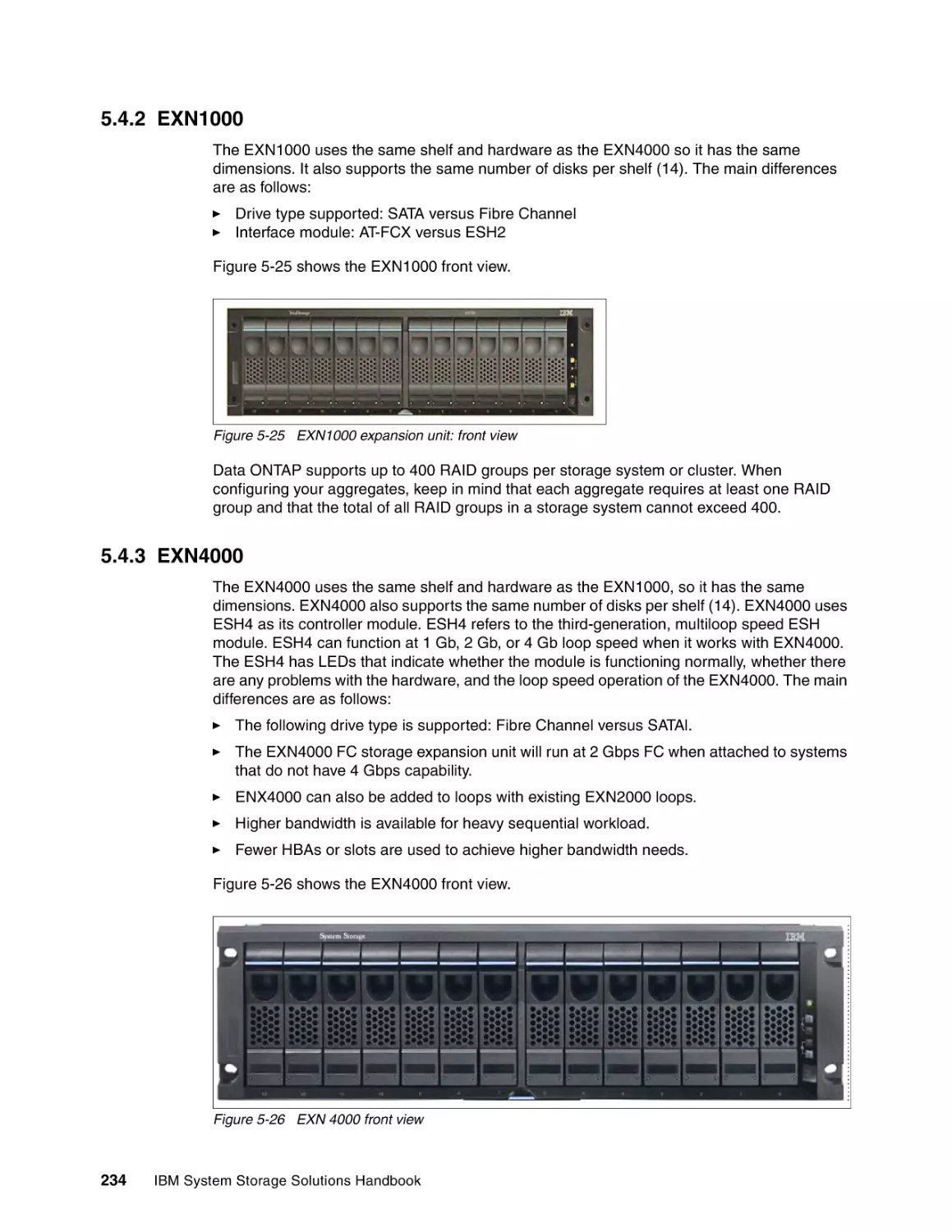
5.4.2 EXN1000. . . . . . . . . . . . . . . . . . . . . . . . . . . . . . . . . . . . . . . . . . . . . . . . . . . . . . .
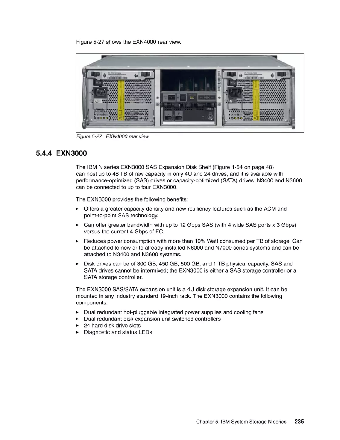
5.4.3 EXN4000. . . . . . . . . . . . . . . . . . . . . . . . . . . . . . . . . . . . . . . . . . . . . . . . . . . . . . .
5.4.4 EXN3000. . . . . . . . . . . . . . . . . . . . . . . . . . . . . . . . . . . . . . . . . . . . . . . . . . . . . . .
5.5 Overview of Data ONTAP for IBM System Storage N series . . . . . . . . . . . . . . . . . . .
5.5.1 Background . . . . . . . . . . . . . . . . . . . . . . . . . . . . . . . . . . . . . . . . . . . . . . . . . . . . .
5.5.2 Benefits . . . . . . . . . . . . . . . . . . . . . . . . . . . . . . . . . . . . . . . . . . . . . . . . . . . . . . . .
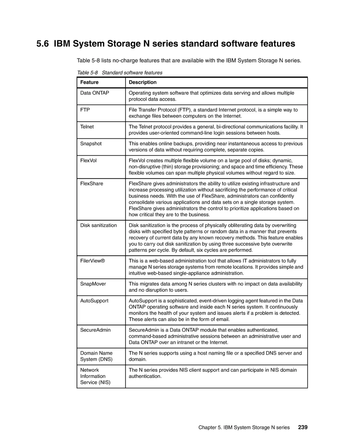
5.6 IBM System Storage N series standard software features . . . . . . . . . . . . . . . . . . . . .
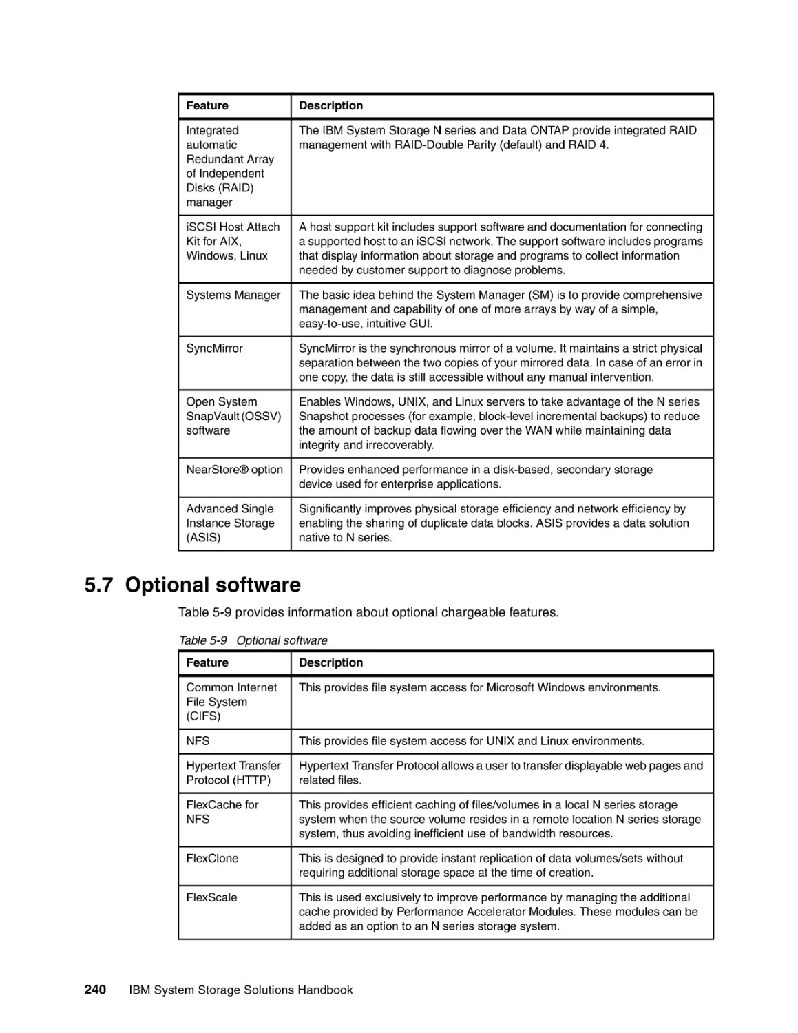
5.7 Optional software . . . . . . . . . . . . . . . . . . . . . . . . . . . . . . . . . . . . . . . . . . . . . . . . . . . .
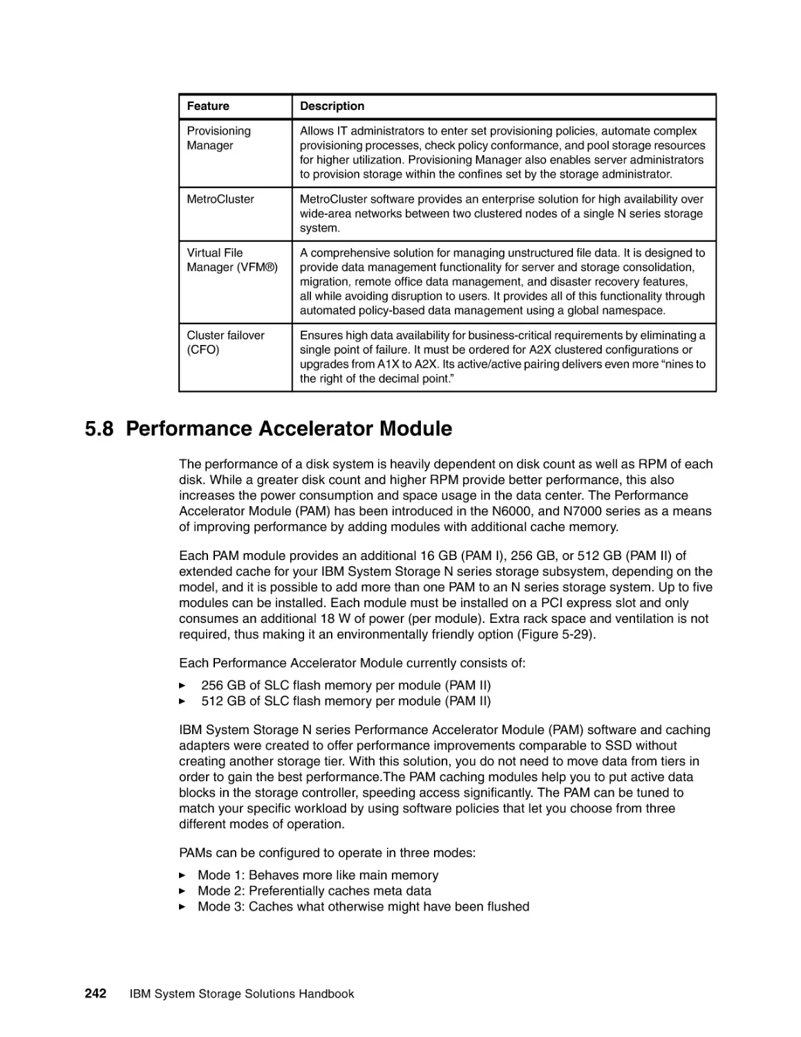
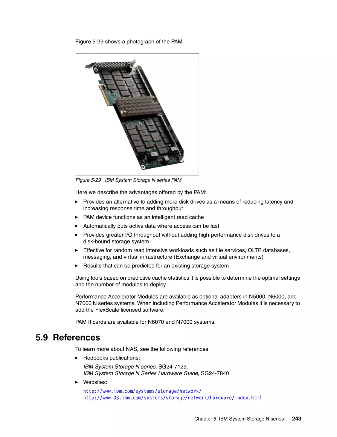
5.8 Performance Accelerator Module . . . . . . . . . . . . . . . . . . . . . . . . . . . . . . . . . . . . . . . .
5.9 References . . . . . . . . . . . . . . . . . . . . . . . . . . . . . . . . . . . . . . . . . . . . . . . . . . . . . . . . .
211
212
213
213
214
215
215
216
217
223
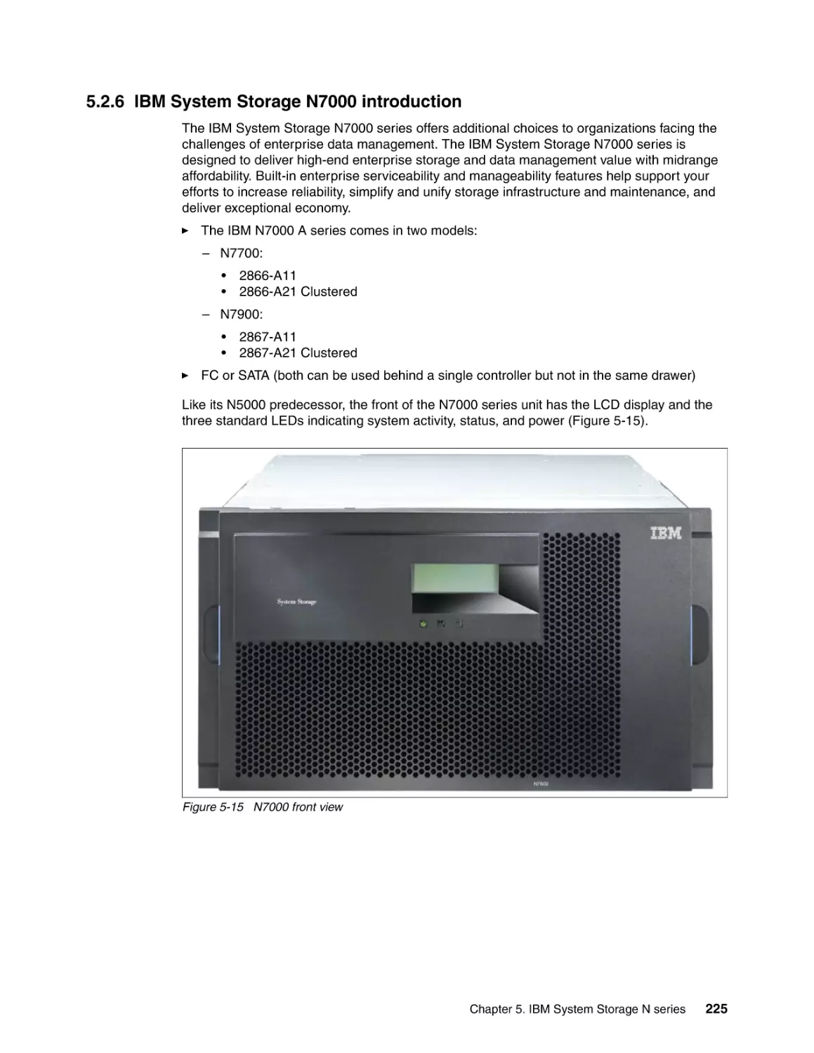
225
227
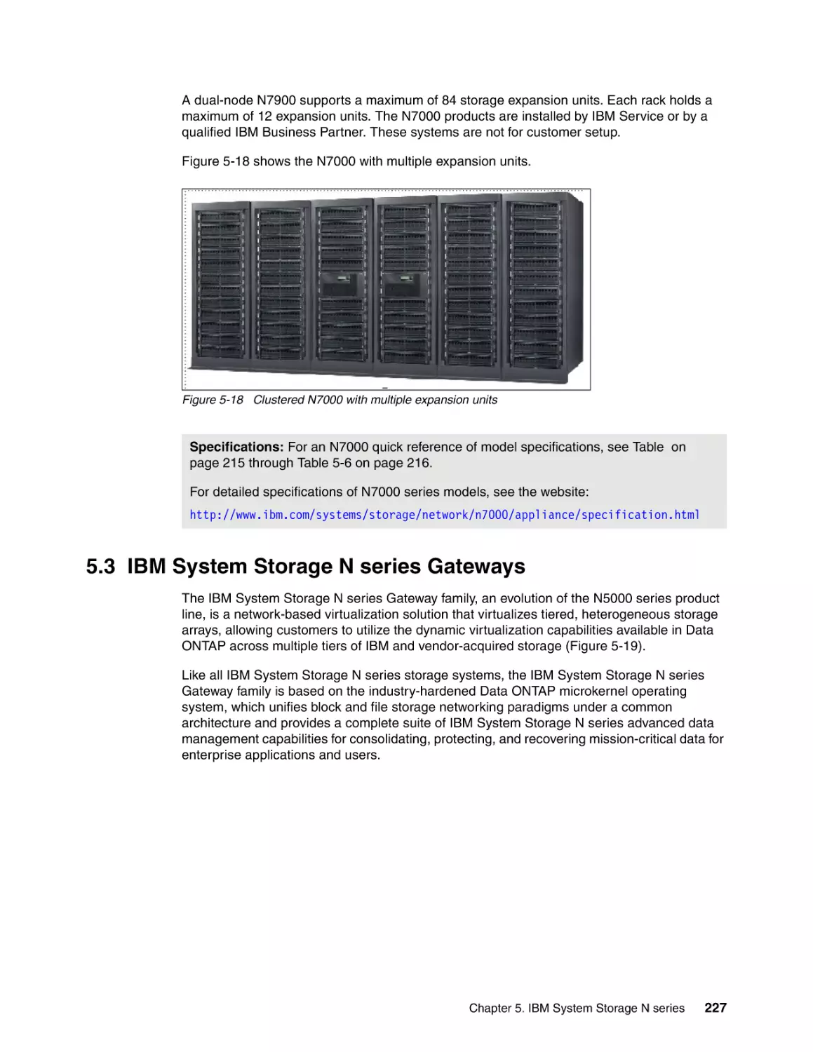
230
230
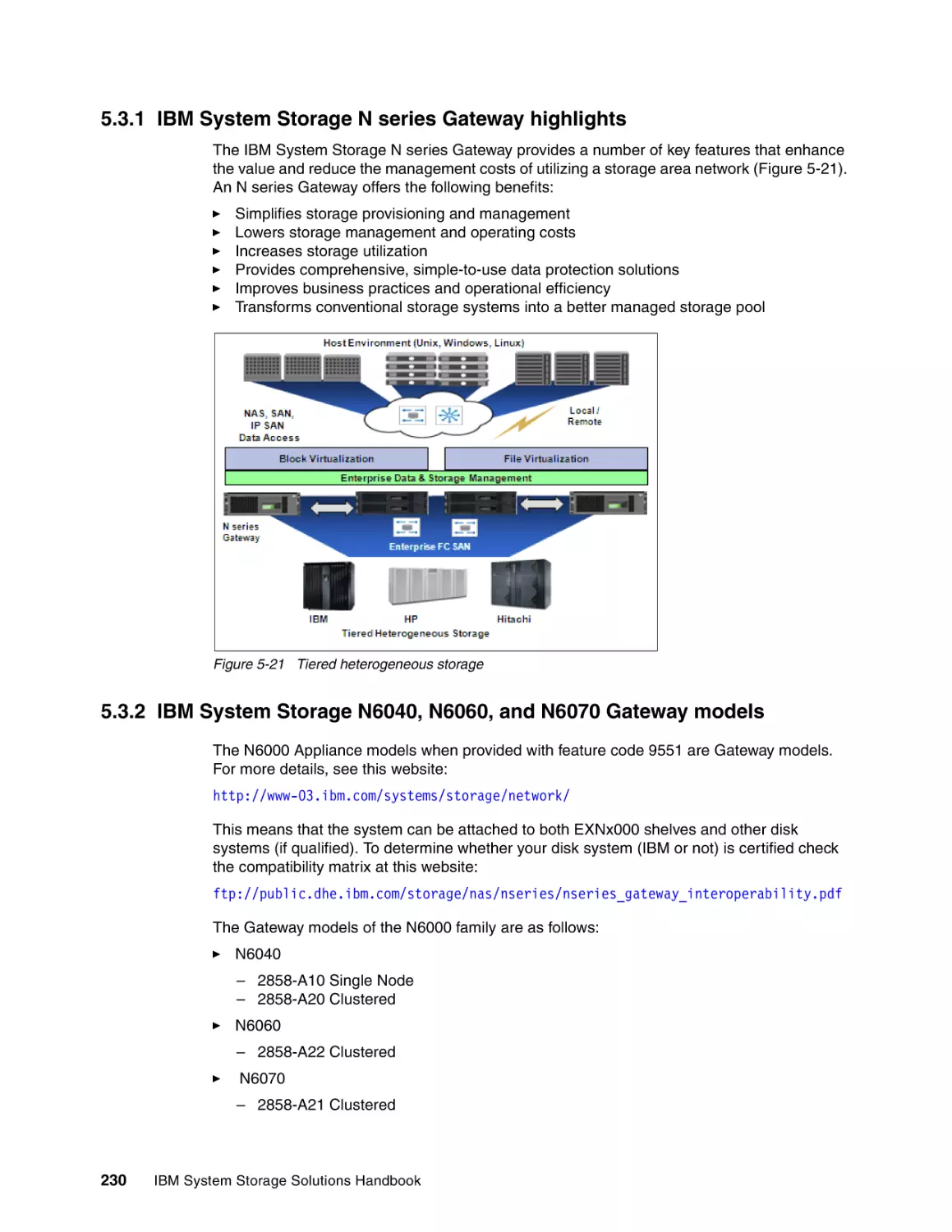
231
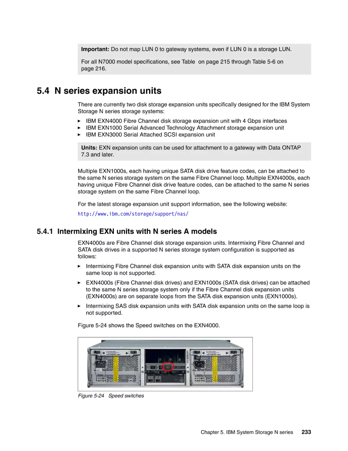
233
233
234
234
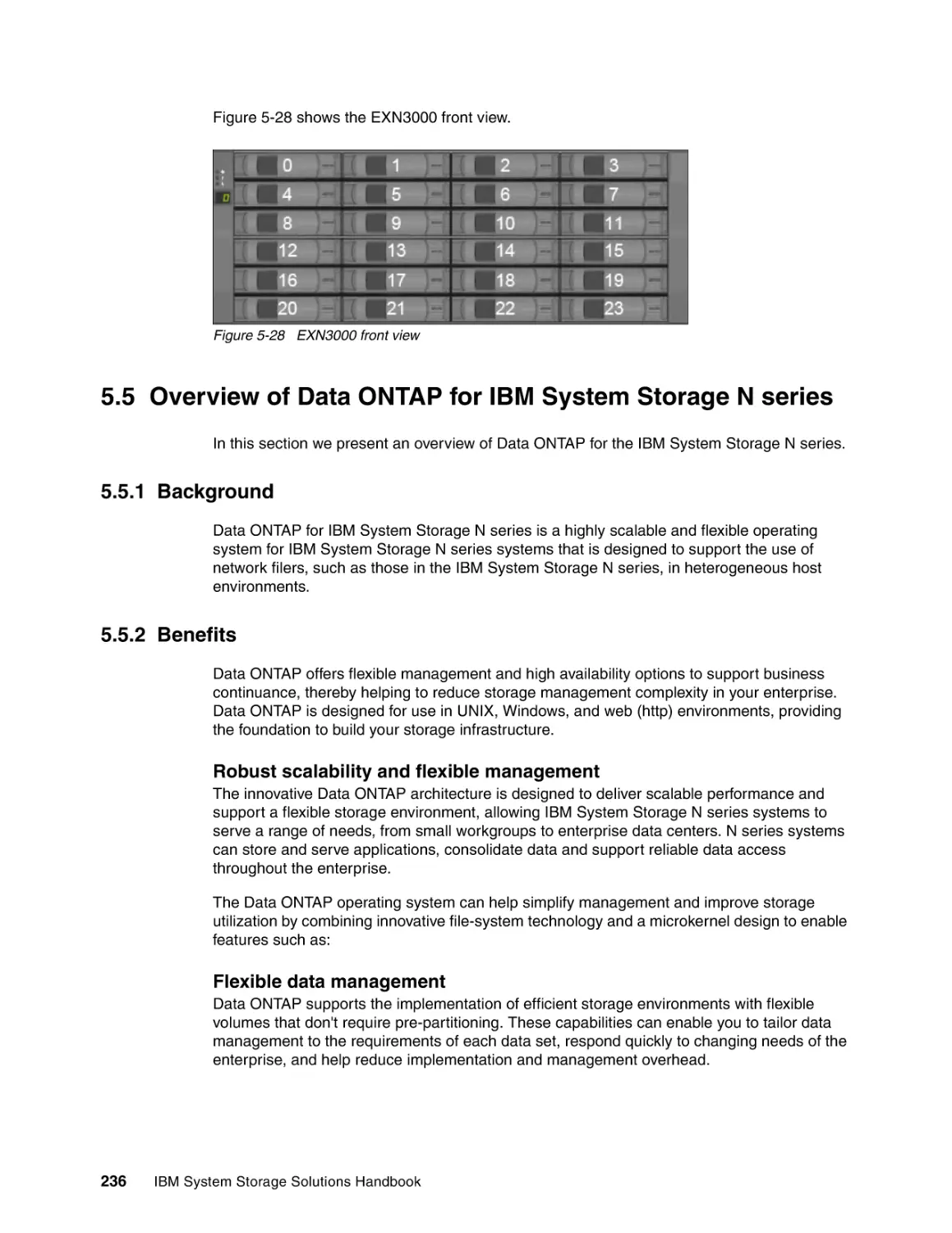
235
236
236
236
239
240
242
243
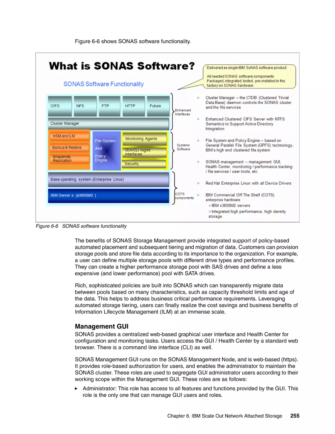
Chapter 6. IBM Scale Out Network Attached Storage . . . . . . . . . . . . . . . . . . . . . . . . .
6.1 Overview of SONAS . . . . . . . . . . . . . . . . . . . . . . . . . . . . . . . . . . . . . . . . . . . . . . . . . .
6.1.1 SONAS features . . . . . . . . . . . . . . . . . . . . . . . . . . . . . . . . . . . . . . . . . . . . . . . . .
6.1.2 SONAS highlights . . . . . . . . . . . . . . . . . . . . . . . . . . . . . . . . . . . . . . . . . . . . . . . .
6.2 How SONAS works . . . . . . . . . . . . . . . . . . . . . . . . . . . . . . . . . . . . . . . . . . . . . . . . . . .
6.3 SONAS features . . . . . . . . . . . . . . . . . . . . . . . . . . . . . . . . . . . . . . . . . . . . . . . . . . . . .
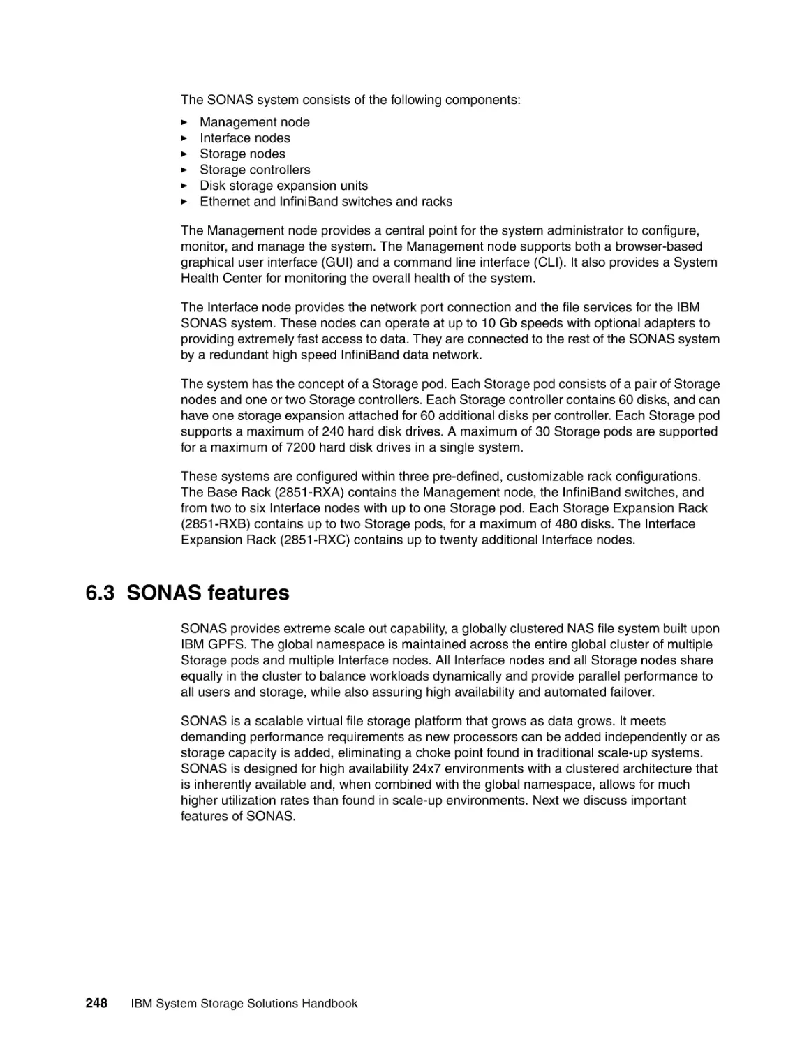
6.3.1 Centrally managed, centrally deployed storage . . . . . . . . . . . . . . . . . . . . . . . . .
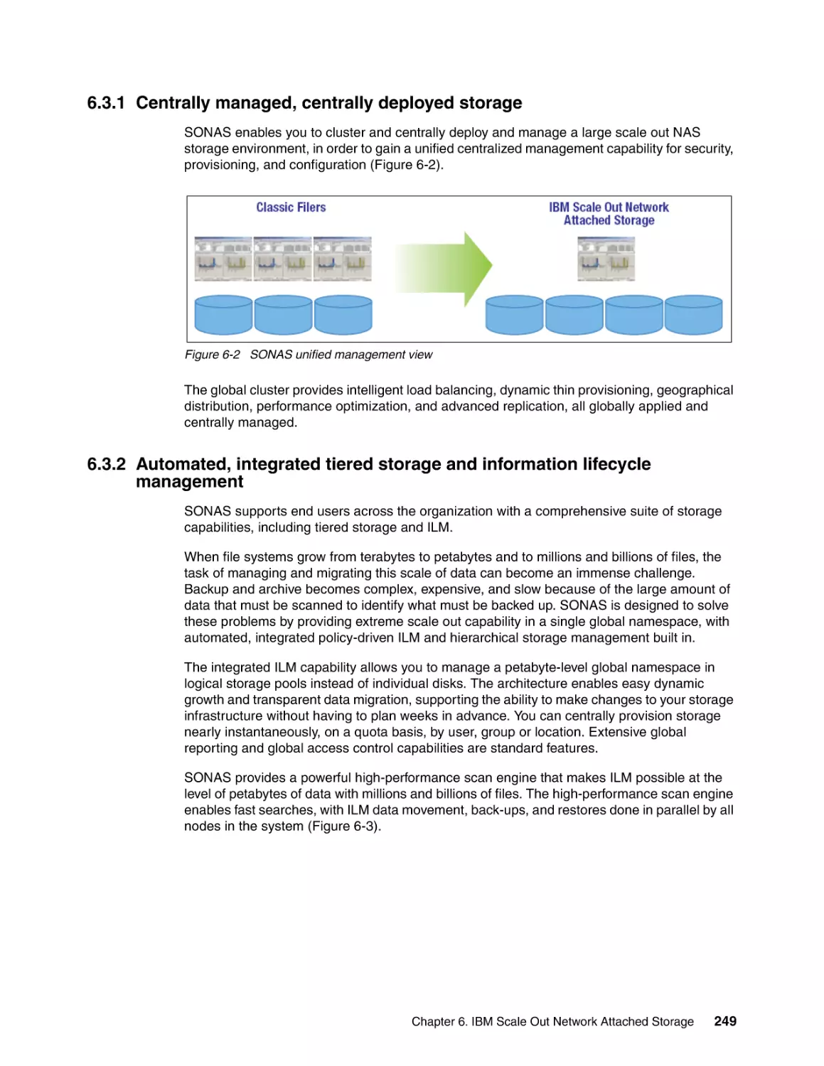
6.3.2 Automated, integrated tiered storage and information lifecycle management . .
6.3.3 Protecting data and replicating between sites. . . . . . . . . . . . . . . . . . . . . . . . . . .
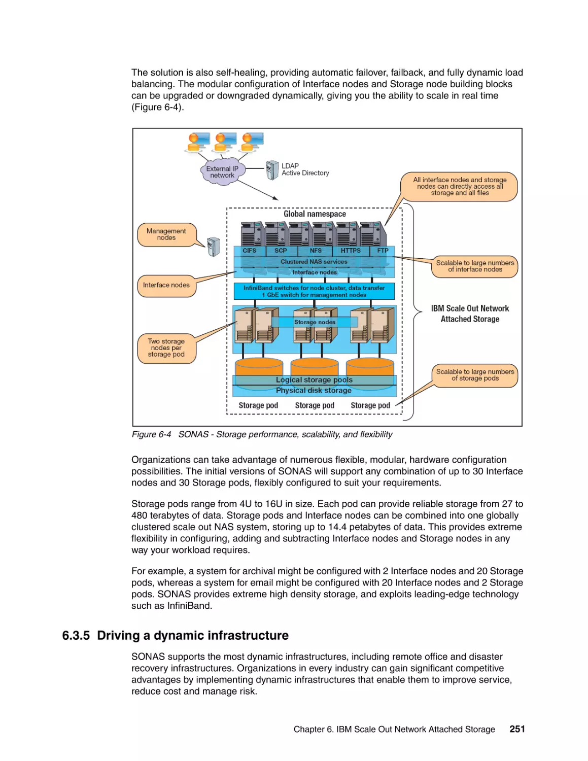
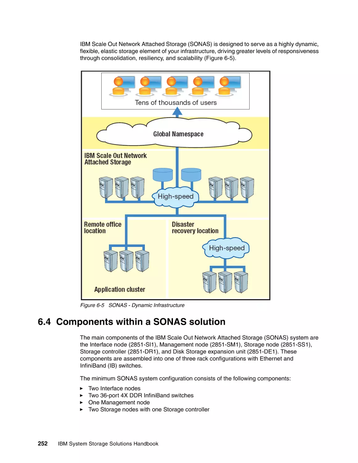
6.3.4 Utilizing unique capabilities and modular hardware . . . . . . . . . . . . . . . . . . . . . .
6.3.5 Driving a dynamic infrastructure . . . . . . . . . . . . . . . . . . . . . . . . . . . . . . . . . . . . .
6.4 Components within a SONAS solution . . . . . . . . . . . . . . . . . . . . . . . . . . . . . . . . . . . .
6.4.1 Interface node . . . . . . . . . . . . . . . . . . . . . . . . . . . . . . . . . . . . . . . . . . . . . . . . . . .
6.4.2 Management node . . . . . . . . . . . . . . . . . . . . . . . . . . . . . . . . . . . . . . . . . . . . . . .
6.4.3 Storage node . . . . . . . . . . . . . . . . . . . . . . . . . . . . . . . . . . . . . . . . . . . . . . . . . . .
6.4.4 InfiniBand switches . . . . . . . . . . . . . . . . . . . . . . . . . . . . . . . . . . . . . . . . . . . . . . .
6.5 Summary of features and benefits . . . . . . . . . . . . . . . . . . . . . . . . . . . . . . . . . . . . . . .
6.6 More information . . . . . . . . . . . . . . . . . . . . . . . . . . . . . . . . . . . . . . . . . . . . . . . . . . . . .
245
246
246
246
246
248
249
249
250
250
251
252
253
254
257
260
261
262
Chapter 7. IBM Information Archive . . . . . . . . . . . . . . . . . . . . . . . . . . . . . . . . . . . . . . .
7.1 IBM Smart Archive strategy . . . . . . . . . . . . . . . . . . . . . . . . . . . . . . . . . . . . . . . . . . . .
7.1.1 Utilizing IBM archiving offerings . . . . . . . . . . . . . . . . . . . . . . . . . . . . . . . . . . . . .
7.1.2 Solution elements . . . . . . . . . . . . . . . . . . . . . . . . . . . . . . . . . . . . . . . . . . . . . . . .
7.2 Data retention and compliance . . . . . . . . . . . . . . . . . . . . . . . . . . . . . . . . . . . . . . . . . .
7.2.1 Characteristics of retention managed data . . . . . . . . . . . . . . . . . . . . . . . . . . . . .
7.2.2 IBM strategy and positioning. . . . . . . . . . . . . . . . . . . . . . . . . . . . . . . . . . . . . . . .
263
264
264
265
265
265
266
IBM System Storage Solutions Handbook
7.3 IBM Information Archive . . . . . . . . . . . . . . . . . . . . . . . . . . . . . . . . . . . . . . . . . . . . . . .
7.3.1 IBM Information Archive appliance . . . . . . . . . . . . . . . . . . . . . . . . . . . . . . . . . . .
7.3.2 Enhanced Remote Mirroring . . . . . . . . . . . . . . . . . . . . . . . . . . . . . . . . . . . . . . . .
7.3.3 Migration from DR550 to Information Archive . . . . . . . . . . . . . . . . . . . . . . . . . . .
7.3.4 IBM Information Archive components . . . . . . . . . . . . . . . . . . . . . . . . . . . . . . . . .
7.3.5 Summary of features and benefits . . . . . . . . . . . . . . . . . . . . . . . . . . . . . . . . . . .
7.3.6 Additional information . . . . . . . . . . . . . . . . . . . . . . . . . . . . . . . . . . . . . . . . . . . . .
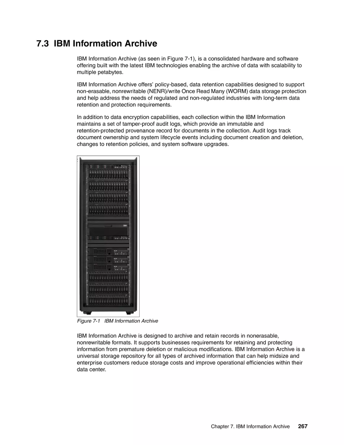
267
268
273
273
274
275
277
Part 2. Tape Systems . . . . . . . . . . . . . . . . . . . . . . . . . . . . . . . . . . . . . . . . . . . . . . . . . . . . . . . . . . . . . . . . 279
Chapter 8. IBM TotalStorage and System Storage Tape Drives . . . . . . . . . . . . . . . . .
8.1 LTO technology . . . . . . . . . . . . . . . . . . . . . . . . . . . . . . . . . . . . . . . . . . . . . . . . . . . . . .
8.1.1 Interleaved recording . . . . . . . . . . . . . . . . . . . . . . . . . . . . . . . . . . . . . . . . . . . . .
8.1.2 Servo tracks . . . . . . . . . . . . . . . . . . . . . . . . . . . . . . . . . . . . . . . . . . . . . . . . . . . .
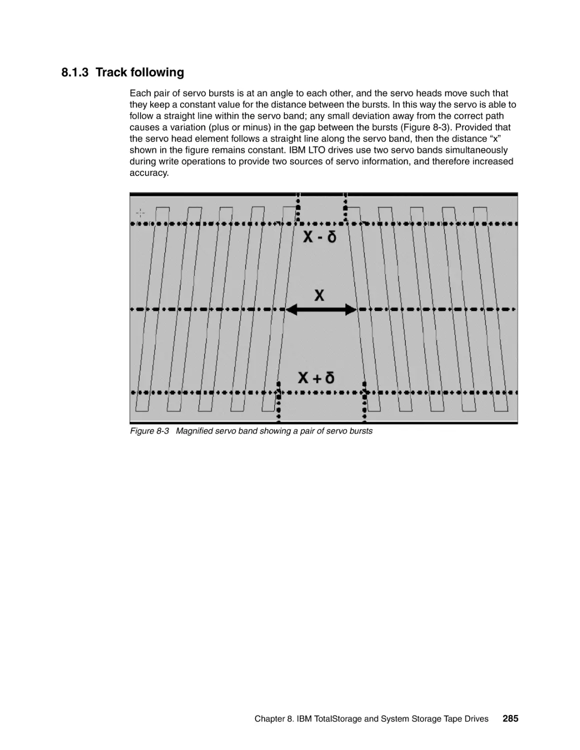
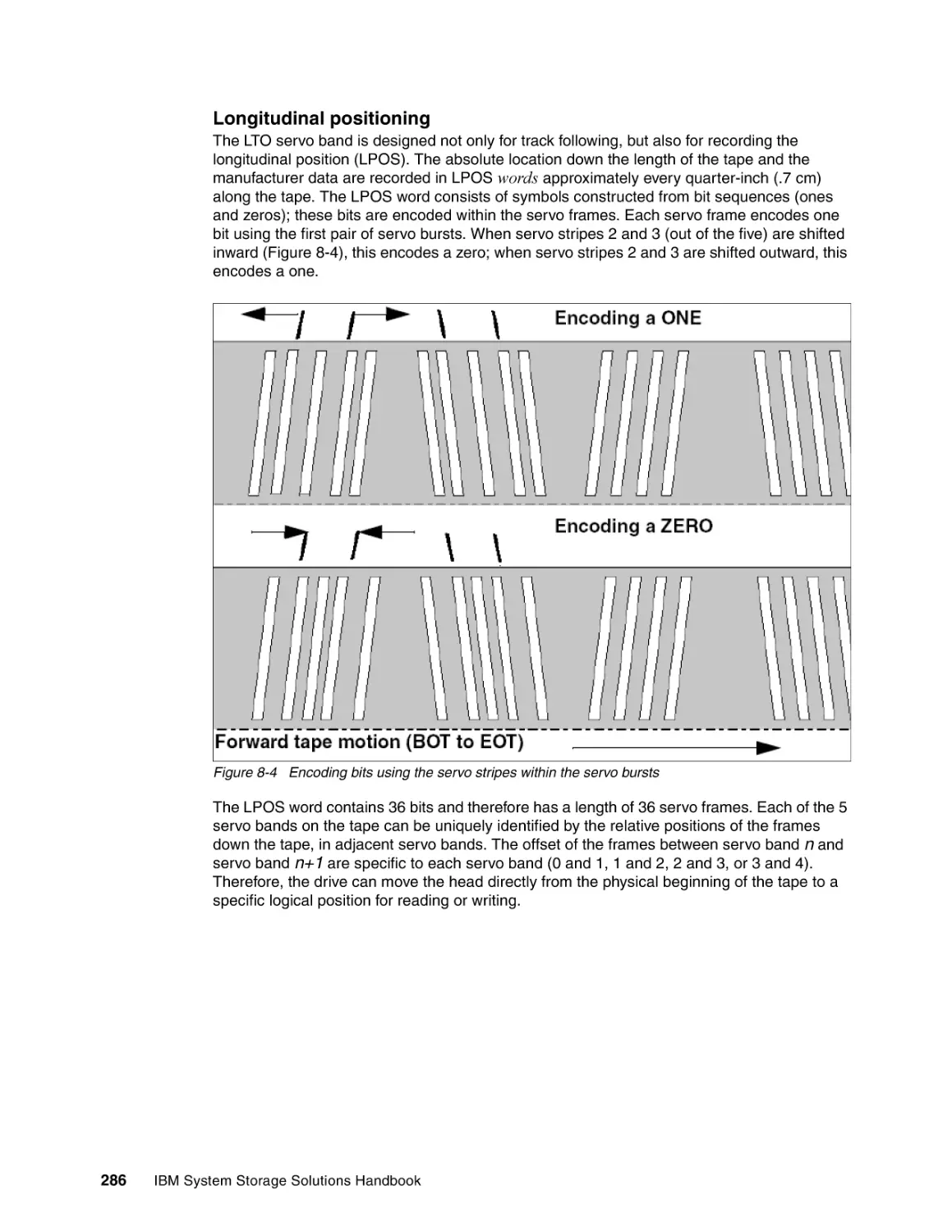
8.1.3 Track following . . . . . . . . . . . . . . . . . . . . . . . . . . . . . . . . . . . . . . . . . . . . . . . . . .
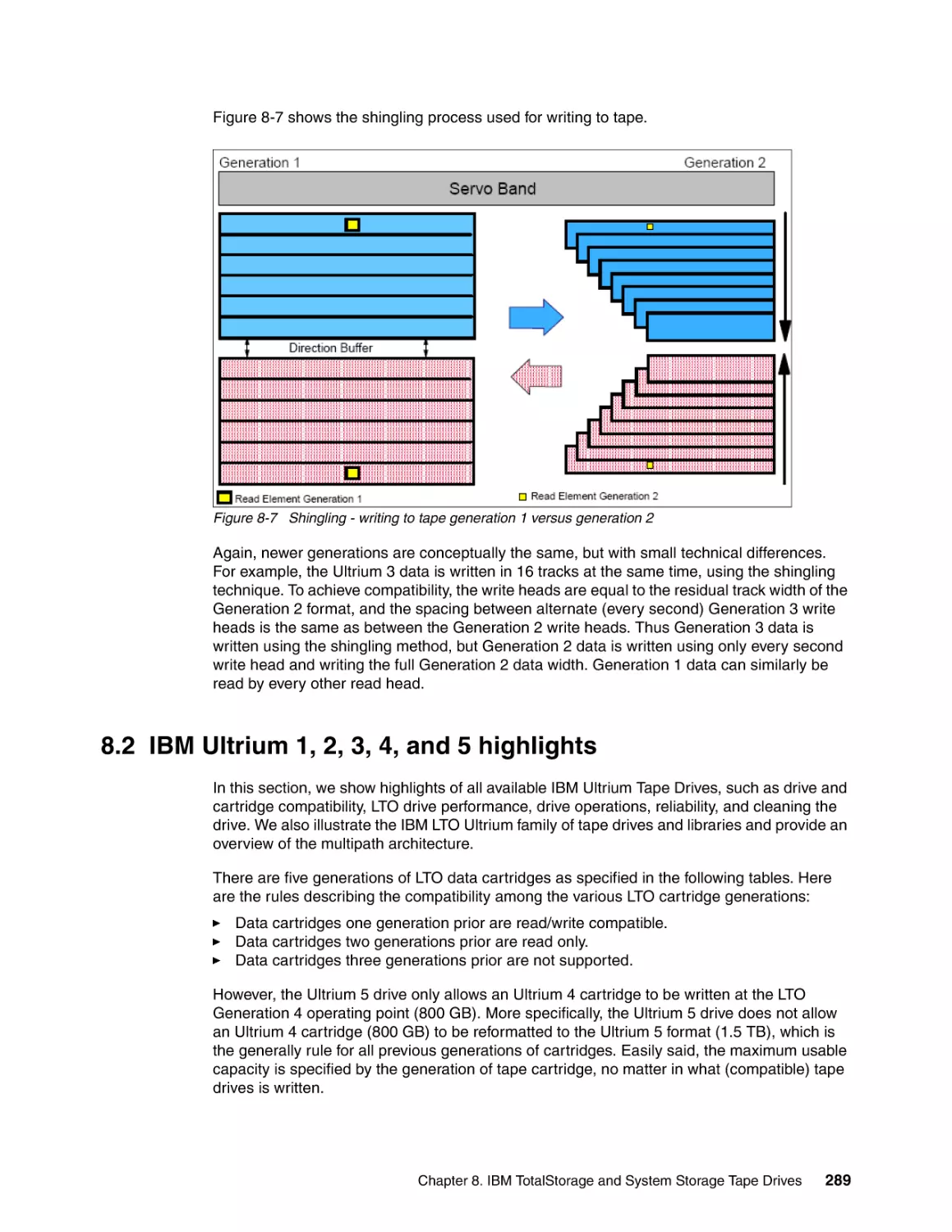
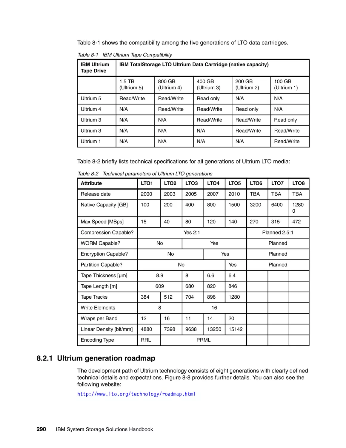
8.2 IBM Ultrium 1, 2, 3, 4, and 5 highlights . . . . . . . . . . . . . . . . . . . . . . . . . . . . . . . . . . . .
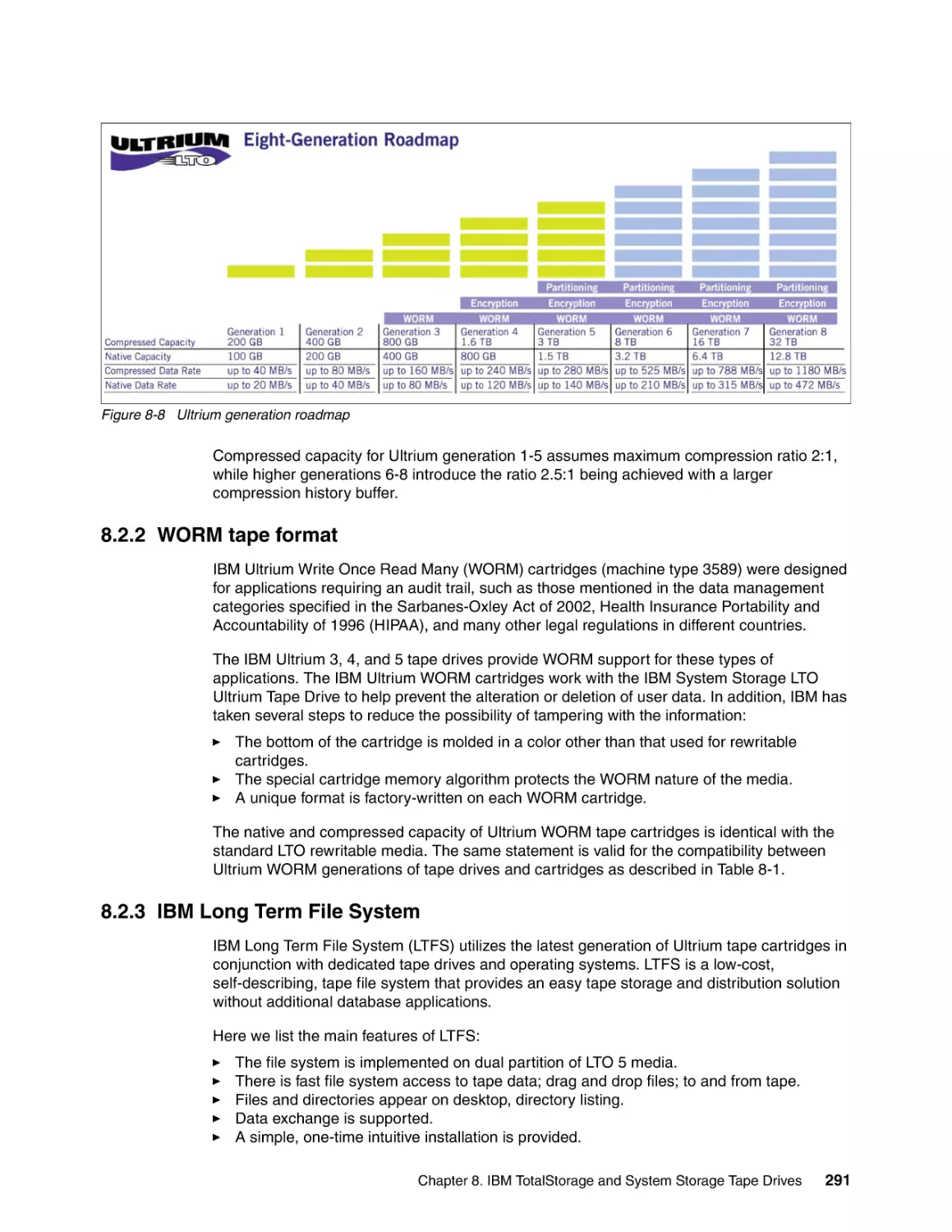
8.2.1 Ultrium generation roadmap . . . . . . . . . . . . . . . . . . . . . . . . . . . . . . . . . . . . . . . .
8.2.2 WORM tape format . . . . . . . . . . . . . . . . . . . . . . . . . . . . . . . . . . . . . . . . . . . . . . .
8.2.3 IBM Long Term File System . . . . . . . . . . . . . . . . . . . . . . . . . . . . . . . . . . . . . . . .
8.2.4 Reliability. . . . . . . . . . . . . . . . . . . . . . . . . . . . . . . . . . . . . . . . . . . . . . . . . . . . . . .
8.3 IBM LTO Tape Drives . . . . . . . . . . . . . . . . . . . . . . . . . . . . . . . . . . . . . . . . . . . . . . . . .
8.3.1 IBM System Storage TS2230 Tape Drive Express Model . . . . . . . . . . . . . . . . .
8.3.2 IBM System Storage TS2240 Tape Drive Express Model . . . . . . . . . . . . . . . . .
8.3.3 IBM System Storage TS2250 Tape Drive Express Model . . . . . . . . . . . . . . . . .
8.3.4 IBM System Storage TS2340 Tape Drive Express Model . . . . . . . . . . . . . . . . .
8.3.5 IBM System Storage TS2350 Tape Drive Express Model . . . . . . . . . . . . . . . . .
8.3.6 IBM TotalStorage 3580 Tape Drive. . . . . . . . . . . . . . . . . . . . . . . . . . . . . . . . . . .
8.4 IBM System Storage TS1100 Tape Drive Family . . . . . . . . . . . . . . . . . . . . . . . . . . . .
8.4.1 Milestone: 1 TB on tape . . . . . . . . . . . . . . . . . . . . . . . . . . . . . . . . . . . . . . . . . . .
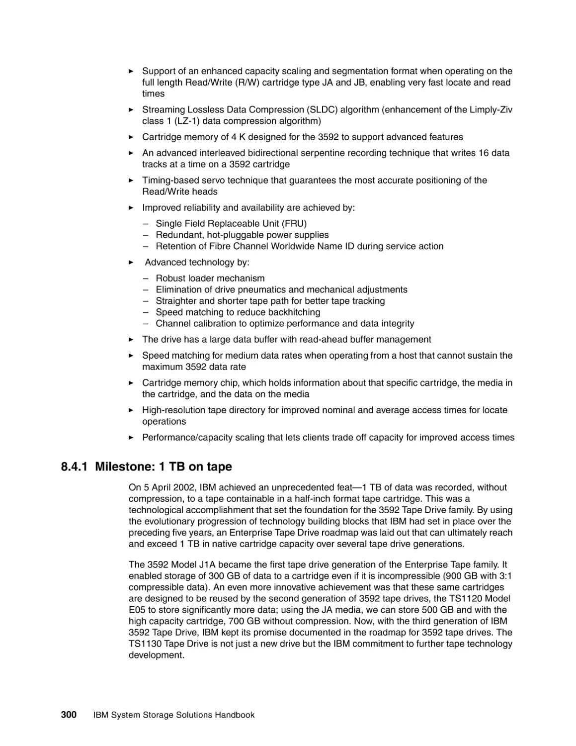
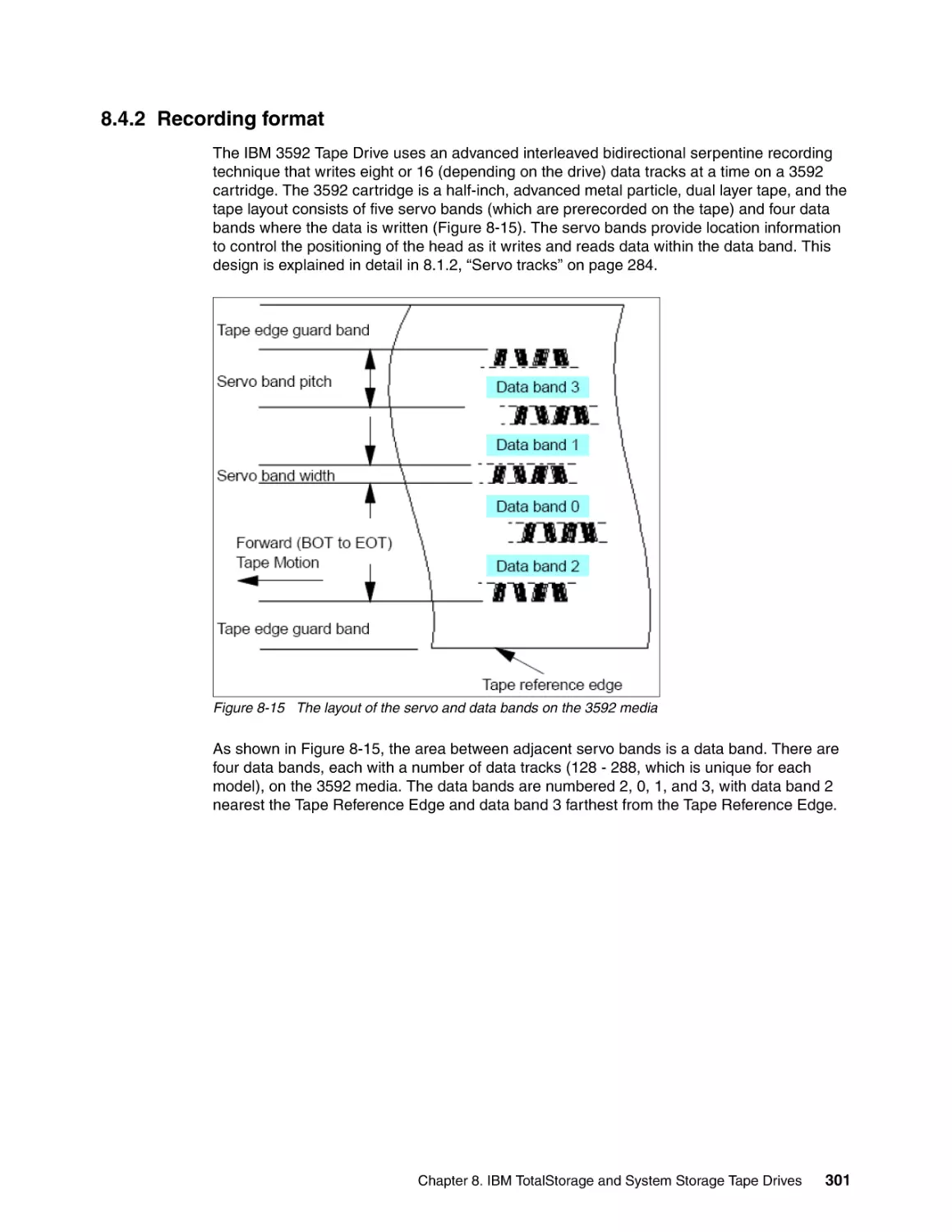
8.4.2 Recording format . . . . . . . . . . . . . . . . . . . . . . . . . . . . . . . . . . . . . . . . . . . . . . . .
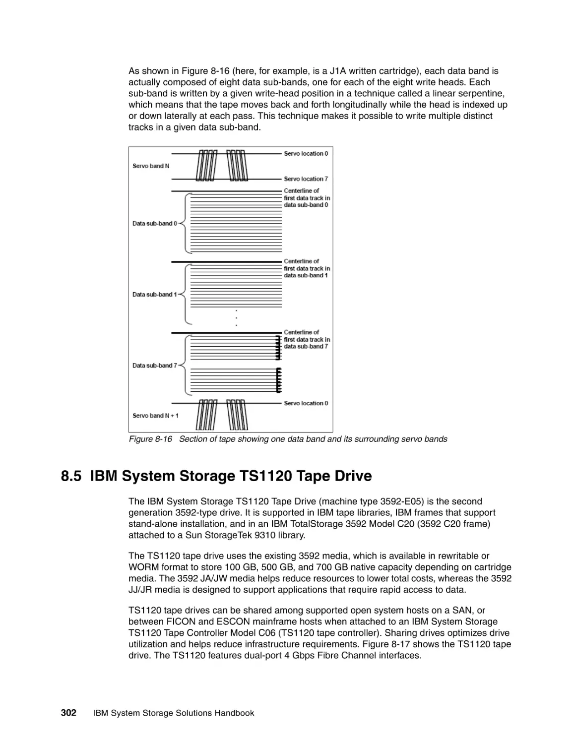
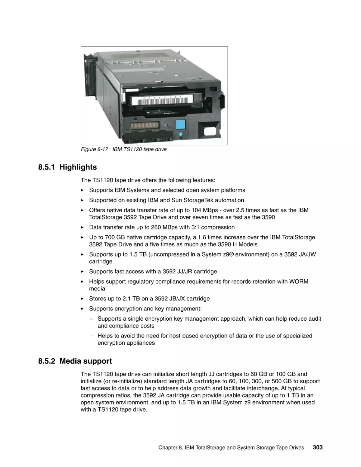
8.5 IBM System Storage TS1120 Tape Drive . . . . . . . . . . . . . . . . . . . . . . . . . . . . . . . . . .
8.5.1 Highlights . . . . . . . . . . . . . . . . . . . . . . . . . . . . . . . . . . . . . . . . . . . . . . . . . . . . . .
8.5.2 Media support . . . . . . . . . . . . . . . . . . . . . . . . . . . . . . . . . . . . . . . . . . . . . . . . . . .
8.5.3 More information . . . . . . . . . . . . . . . . . . . . . . . . . . . . . . . . . . . . . . . . . . . . . . . . .
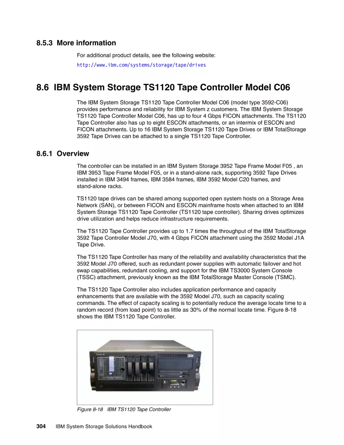
8.6 IBM System Storage TS1120 Tape Controller Model C06 . . . . . . . . . . . . . . . . . . . . .
8.6.1 Overview . . . . . . . . . . . . . . . . . . . . . . . . . . . . . . . . . . . . . . . . . . . . . . . . . . . . . .
8.6.2 Highlights . . . . . . . . . . . . . . . . . . . . . . . . . . . . . . . . . . . . . . . . . . . . . . . . . . . . .
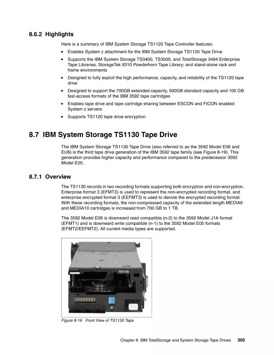
8.7 IBM System Storage TS1130 Tape Drive . . . . . . . . . . . . . . . . . . . . . . . . . . . . . . . . . .
8.7.1 Overview . . . . . . . . . . . . . . . . . . . . . . . . . . . . . . . . . . . . . . . . . . . . . . . . . . . . . .
8.7.2 Highlights . . . . . . . . . . . . . . . . . . . . . . . . . . . . . . . . . . . . . . . . . . . . . . . . . . . . .
8.8 IBM Midrange and Enterprise Storage Media . . . . . . . . . . . . . . . . . . . . . . . . . . . . . . .
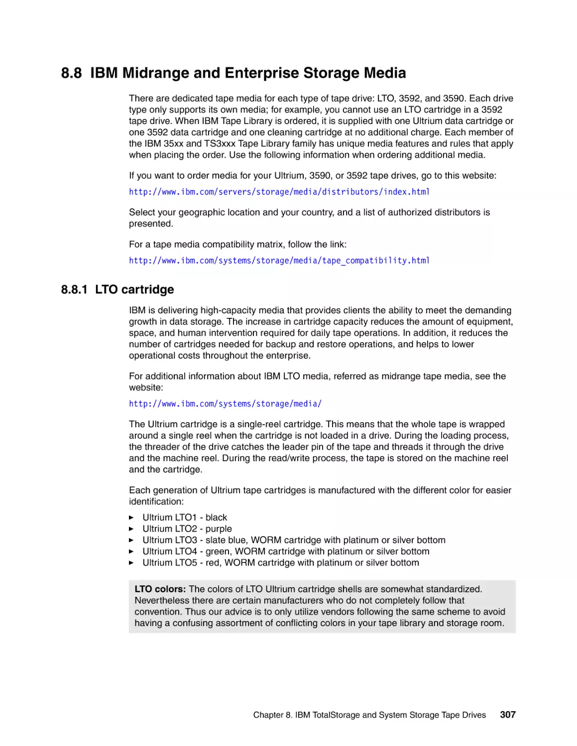
8.8.1 LTO cartridge . . . . . . . . . . . . . . . . . . . . . . . . . . . . . . . . . . . . . . . . . . . . . . . . . . .
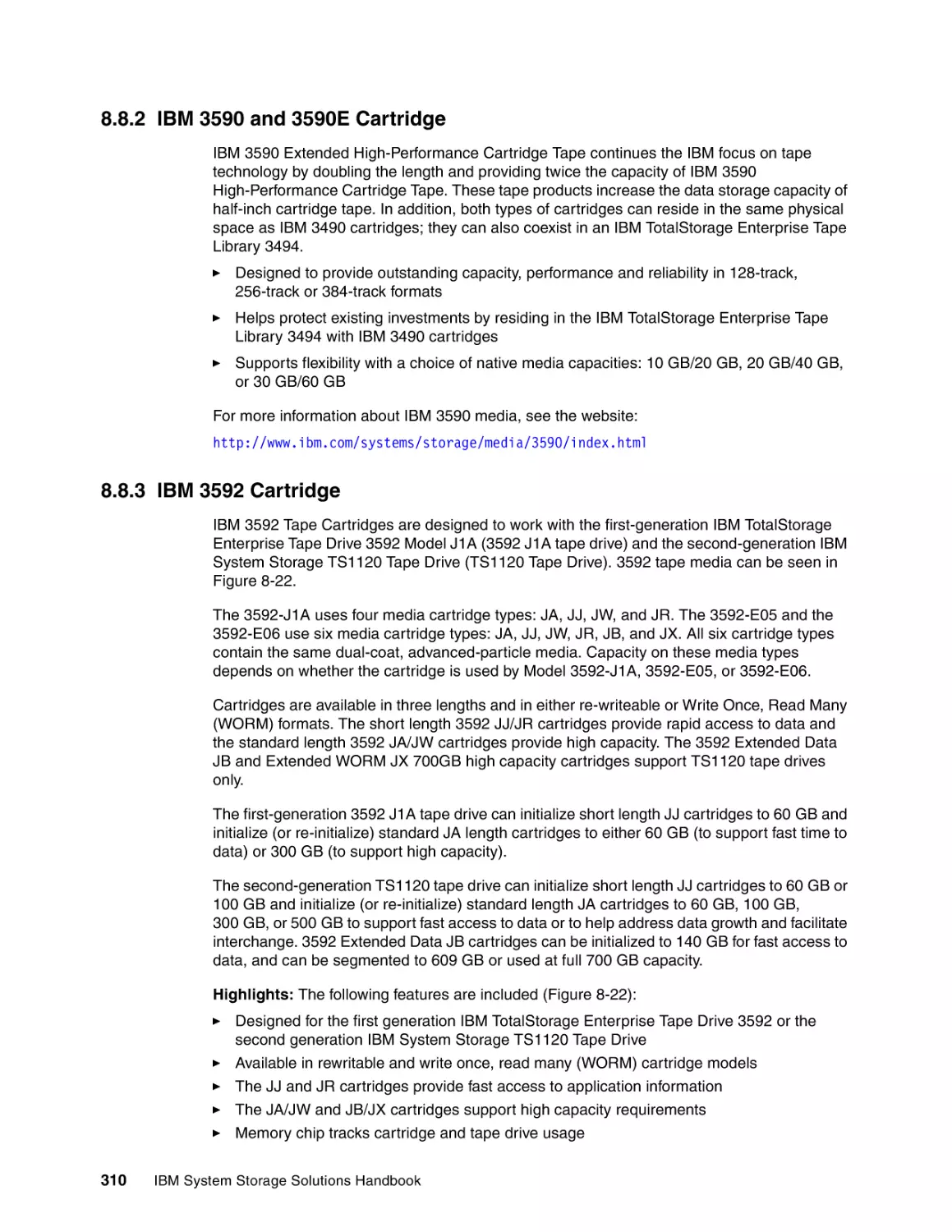
8.8.2 IBM 3590 and 3590E Cartridge . . . . . . . . . . . . . . . . . . . . . . . . . . . . . . . . . . . . .
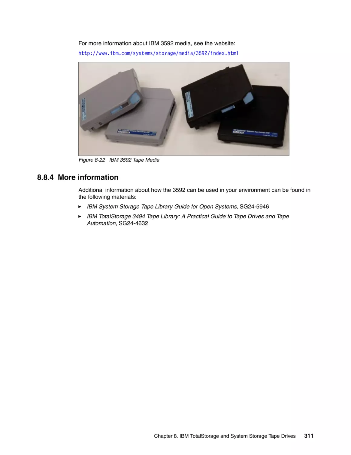
8.8.3 IBM 3592 Cartridge . . . . . . . . . . . . . . . . . . . . . . . . . . . . . . . . . . . . . . . . . . . . . . .
8.8.4 More information . . . . . . . . . . . . . . . . . . . . . . . . . . . . . . . . . . . . . . . . . . . . . . . . .
281
282
283
284
285
289
290
291
291
292
292
293
294
295
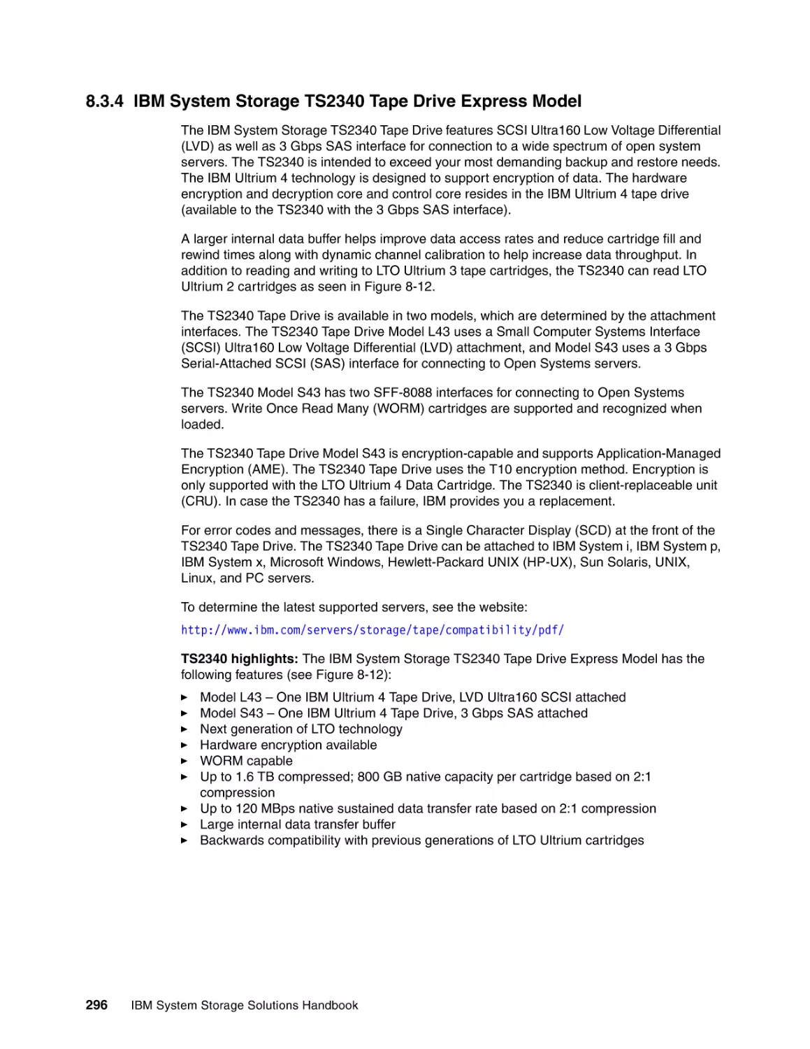
296
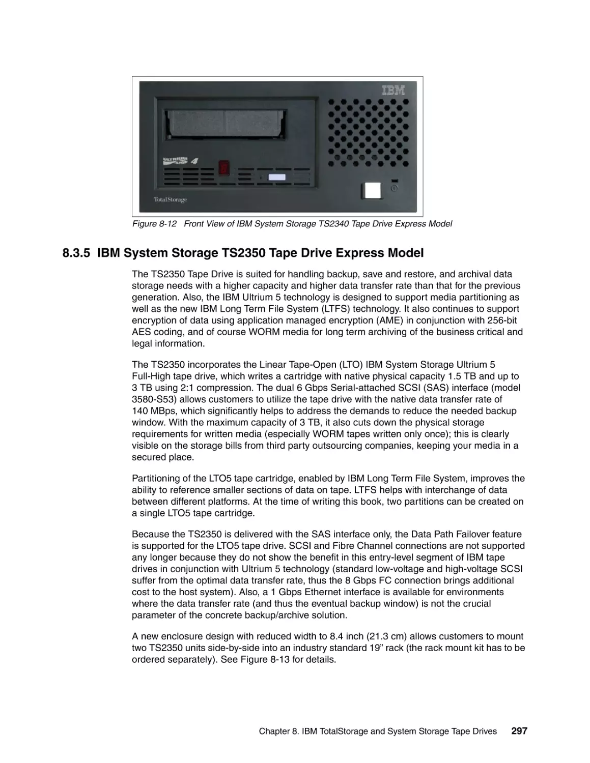
297
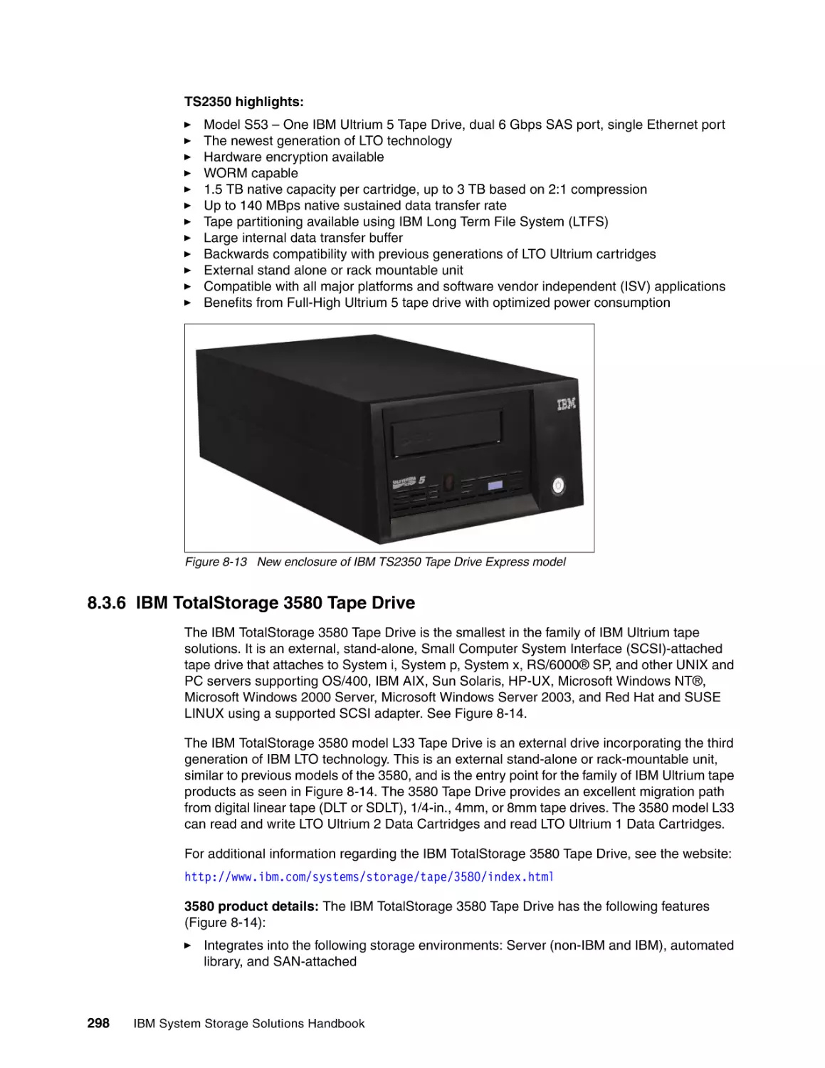
298
299
300
301
302
303
303
304
304
304
305
305
305
306
307
307
310
310
311
Chapter 9. IBM Tape Automation products. . . . . . . . . . . . . . . . . . . . . . . . . . . . . . . . . .
9.1 Valuable IBM tape library features . . . . . . . . . . . . . . . . . . . . . . . . . . . . . . . . . . . . . . .
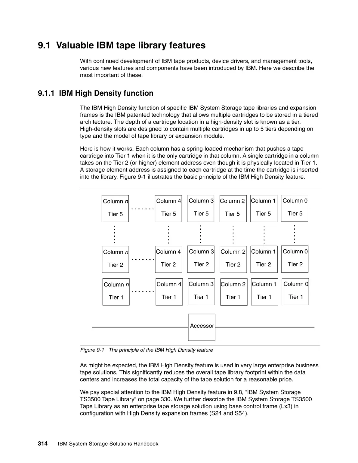
9.1.1 IBM High Density function. . . . . . . . . . . . . . . . . . . . . . . . . . . . . . . . . . . . . . . . . .
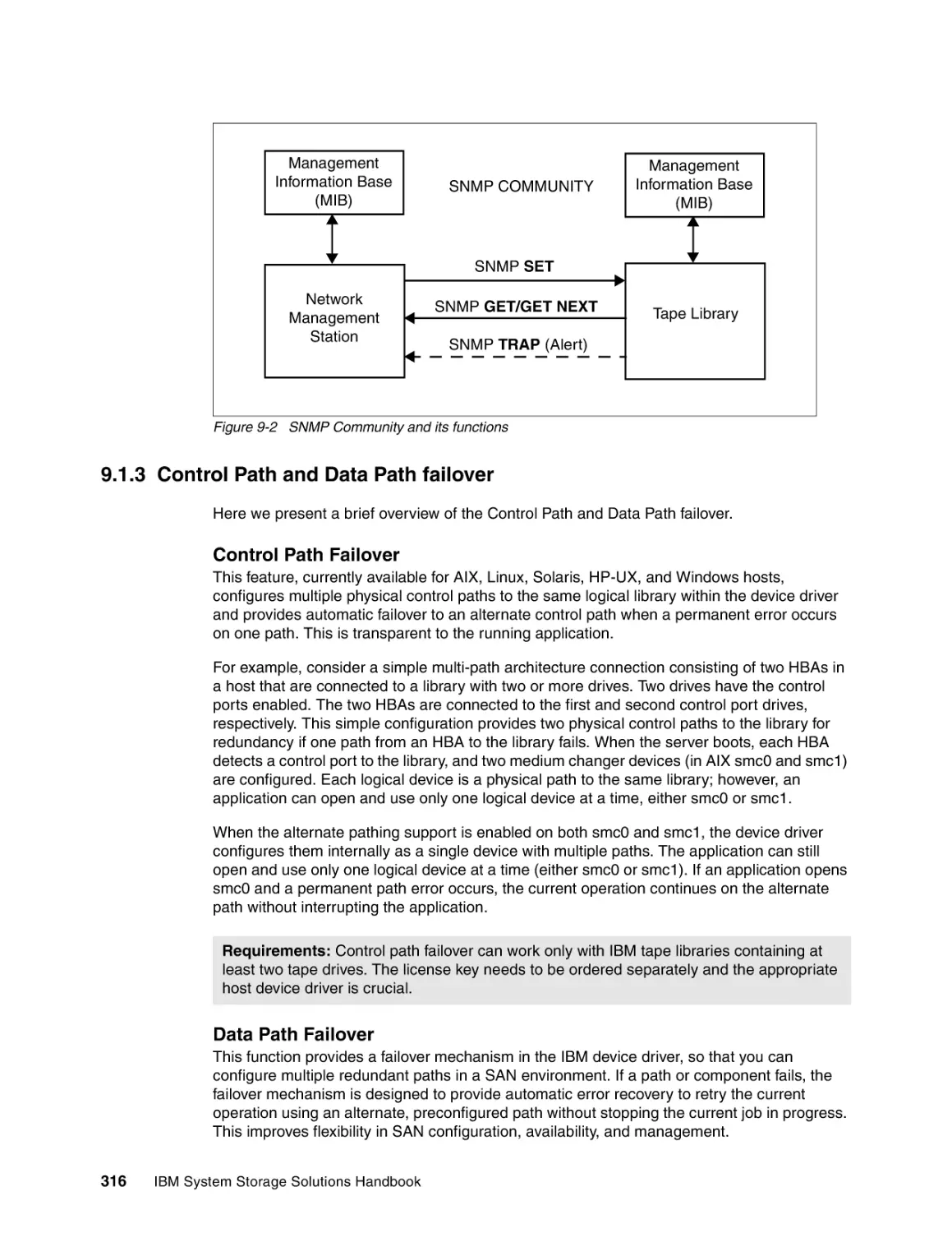
9.1.2 SNMP Messaging and SNMP traps . . . . . . . . . . . . . . . . . . . . . . . . . . . . . . . . . .
9.1.3 Control Path and Data Path failover . . . . . . . . . . . . . . . . . . . . . . . . . . . . . . . . . .
9.2 Overview of available tape libraries . . . . . . . . . . . . . . . . . . . . . . . . . . . . . . . . . . . . . .
9.2.1 IBM System Storage TS2900 Autoloader . . . . . . . . . . . . . . . . . . . . . . . . . . . . . .
9.2.2 IBM System Storage TS3100 Tape Library . . . . . . . . . . . . . . . . . . . . . . . . . . . .
313
314
314
315
316
317
317
317
Contents
vii
viii
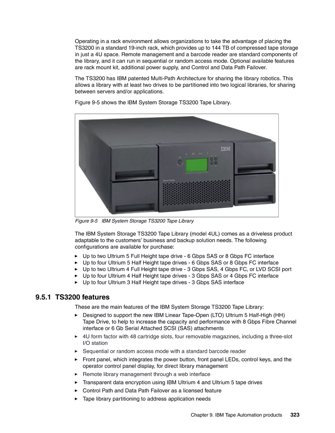
9.2.3 IBM System Storage TS3200 Tape Library . . . . . . . . . . . . . . . . . . . . . . . . . . . .
9.2.4 IBM System Storage TS3400 Tape Library . . . . . . . . . . . . . . . . . . . . . . . . . . . .
9.2.5 IBM System Storage TS3500 Tape Library . . . . . . . . . . . . . . . . . . . . . . . . . . . .
9.2.6 IBM System Storage TS3310 Tape Library . . . . . . . . . . . . . . . . . . . . . . . . . . . .
9.2.7 IBM TotalStorage 3494 Tape Library . . . . . . . . . . . . . . . . . . . . . . . . . . . . . . . . .
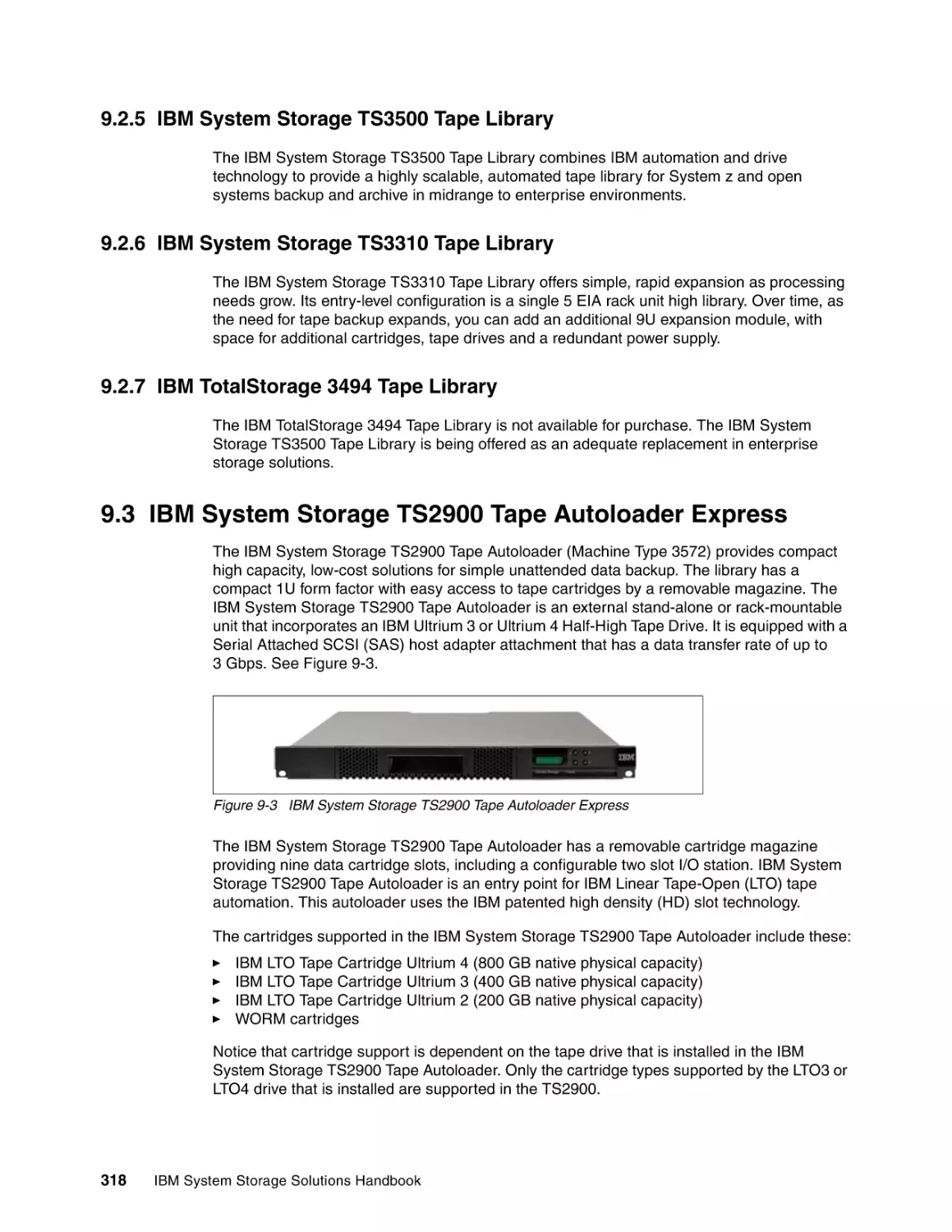
9.3 IBM System Storage TS2900 Tape Autoloader Express . . . . . . . . . . . . . . . . . . . . . .
9.3.1 TS2900 features . . . . . . . . . . . . . . . . . . . . . . . . . . . . . . . . . . . . . . . . . . . . . . . . .
9.3.2 TS2900 specifications . . . . . . . . . . . . . . . . . . . . . . . . . . . . . . . . . . . . . . . . . . . . .
9.4 IBM System Storage TS3100 Tape Library Express Model . . . . . . . . . . . . . . . . . . . .
9.4.1 TS3100 features . . . . . . . . . . . . . . . . . . . . . . . . . . . . . . . . . . . . . . . . . . . . . . . . .
9.4.2 TS3100 specifications . . . . . . . . . . . . . . . . . . . . . . . . . . . . . . . . . . . . . . . . . . . . .
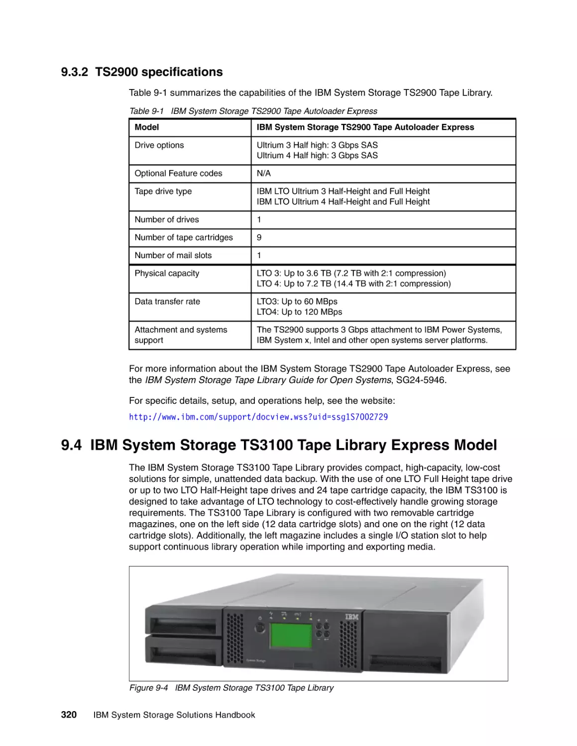
9.5 IBM System Storage TS3200 Tape Library . . . . . . . . . . . . . . . . . . . . . . . . . . . . . . . .
9.5.1 TS3200 features . . . . . . . . . . . . . . . . . . . . . . . . . . . . . . . . . . . . . . . . . . . . . . . . .
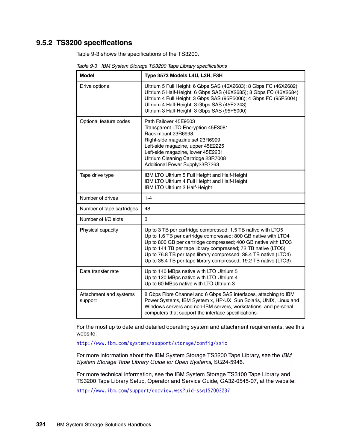
9.5.2 TS3200 specifications . . . . . . . . . . . . . . . . . . . . . . . . . . . . . . . . . . . . . . . . . . . . .
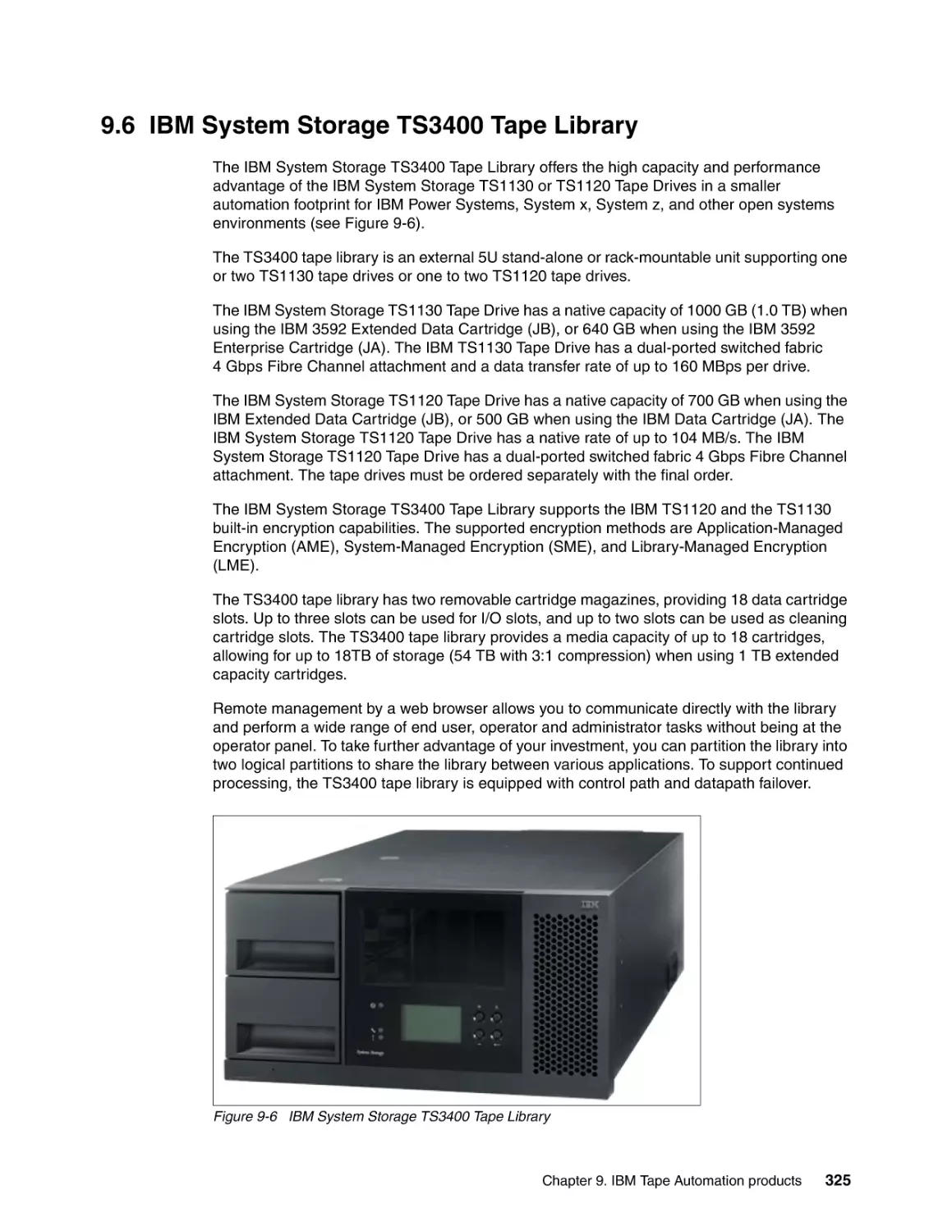
9.6 IBM System Storage TS3400 Tape Library . . . . . . . . . . . . . . . . . . . . . . . . . . . . . . . .
9.6.1 TS3400 features . . . . . . . . . . . . . . . . . . . . . . . . . . . . . . . . . . . . . . . . . . . . . . . . .
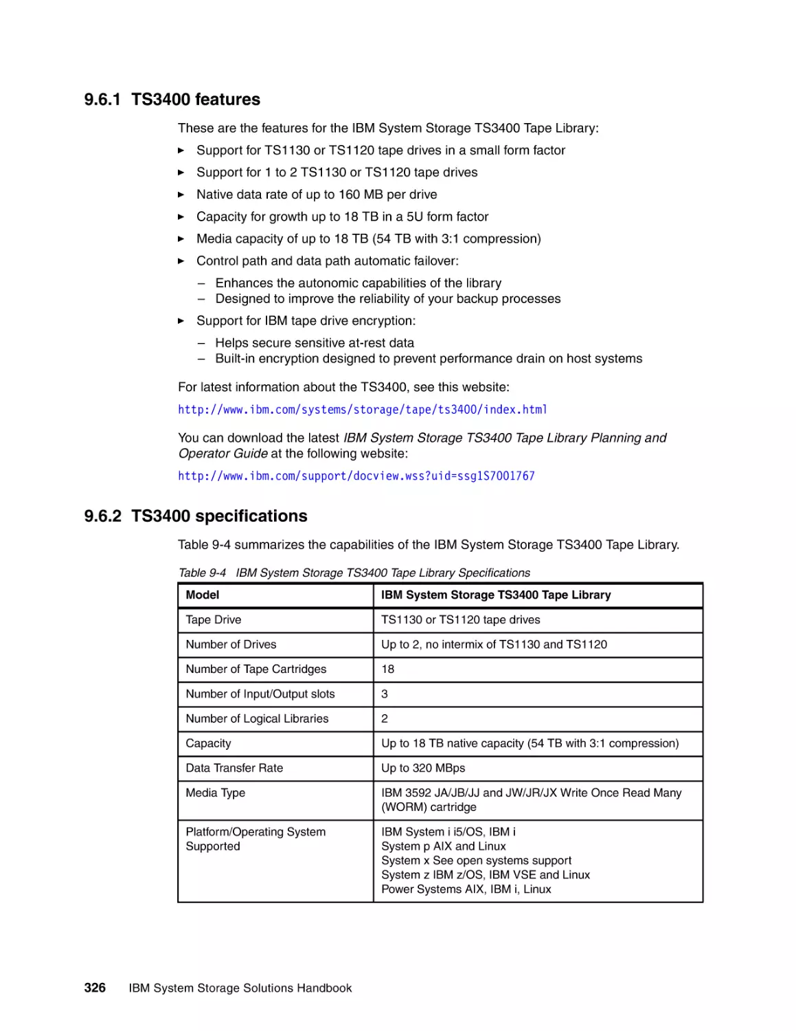
9.6.2 TS3400 specifications . . . . . . . . . . . . . . . . . . . . . . . . . . . . . . . . . . . . . . . . . . . . .
9.7 IBM System Storage TS3310 Tape Library . . . . . . . . . . . . . . . . . . . . . . . . . . . . . . . .
9.7.1 TS3310 features . . . . . . . . . . . . . . . . . . . . . . . . . . . . . . . . . . . . . . . . . . . . . . . . .
9.7.2 TS3310 specifications . . . . . . . . . . . . . . . . . . . . . . . . . . . . . . . . . . . . . . . . . . . . .
9.8 IBM System Storage TS3500 Tape Library . . . . . . . . . . . . . . . . . . . . . . . . . . . . . . . .
9.8.1 Advanced Library Management System . . . . . . . . . . . . . . . . . . . . . . . . . . . . . . .
9.8.2 IBM high density frames . . . . . . . . . . . . . . . . . . . . . . . . . . . . . . . . . . . . . . . . . . .
9.8.3 Virtual I/O slots . . . . . . . . . . . . . . . . . . . . . . . . . . . . . . . . . . . . . . . . . . . . . . . . . .
9.8.4 TS3500 features . . . . . . . . . . . . . . . . . . . . . . . . . . . . . . . . . . . . . . . . . . . . . . . . .
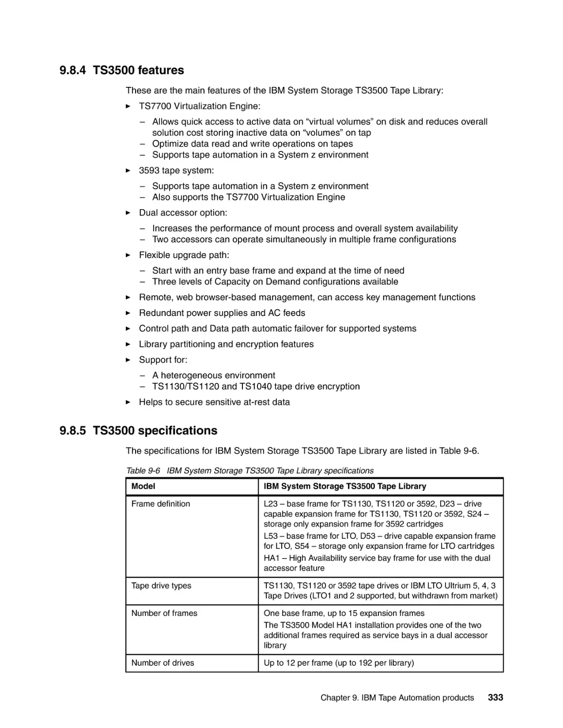
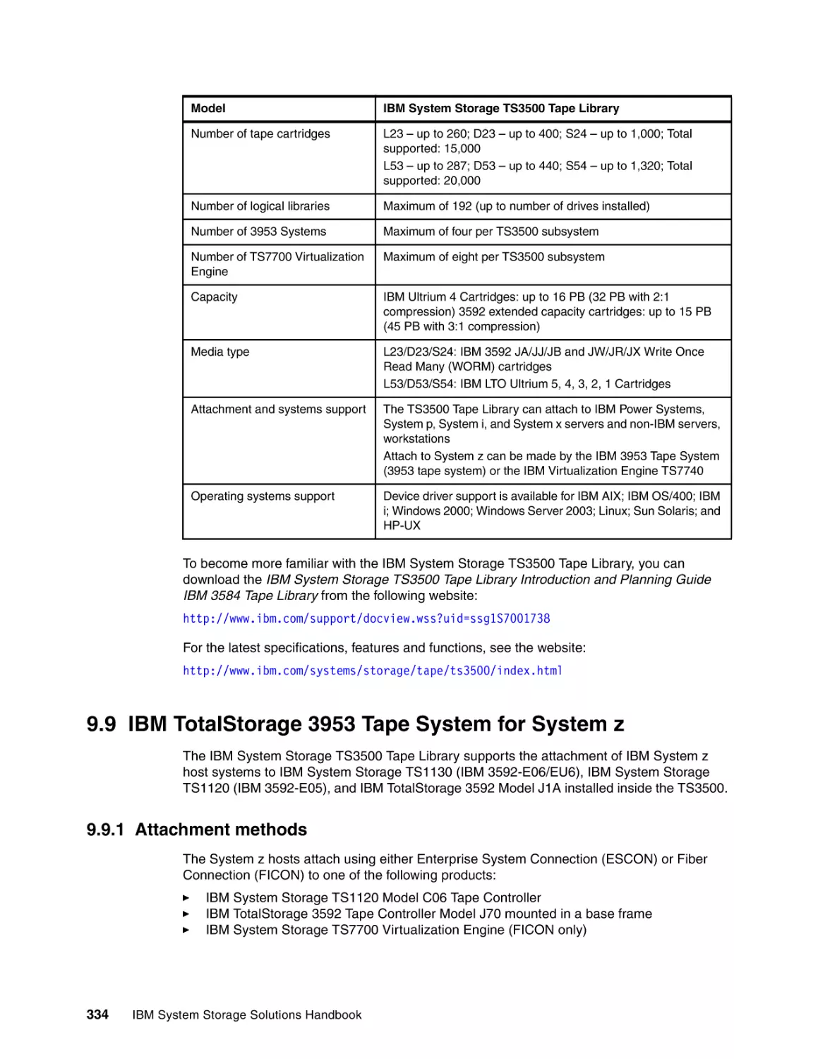
9.8.5 TS3500 specifications . . . . . . . . . . . . . . . . . . . . . . . . . . . . . . . . . . . . . . . . . . . . .
9.9 IBM TotalStorage 3953 Tape System for System z . . . . . . . . . . . . . . . . . . . . . . . . . .
9.9.1 Attachment methods . . . . . . . . . . . . . . . . . . . . . . . . . . . . . . . . . . . . . . . . . . . . . .
9.9.2 3953 Tape System features . . . . . . . . . . . . . . . . . . . . . . . . . . . . . . . . . . . . . . . .
317
317
318
318
318
318
319
320
320
321
321
322
323
324
325
326
326
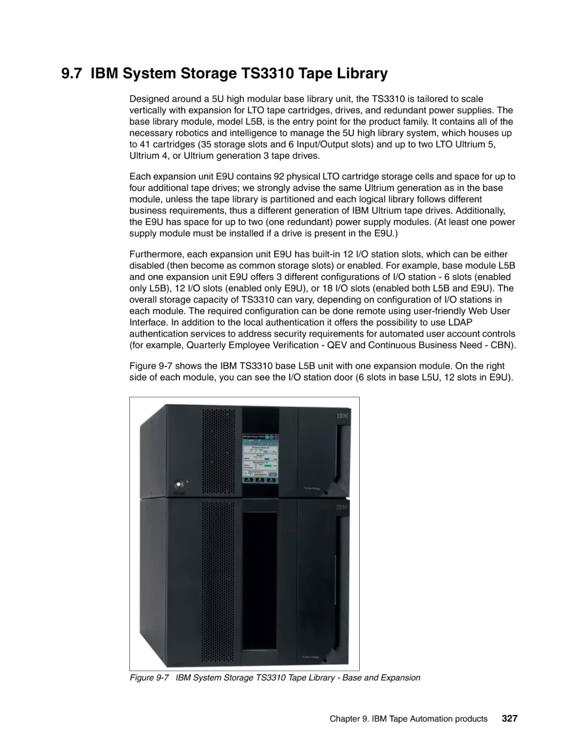
327
328
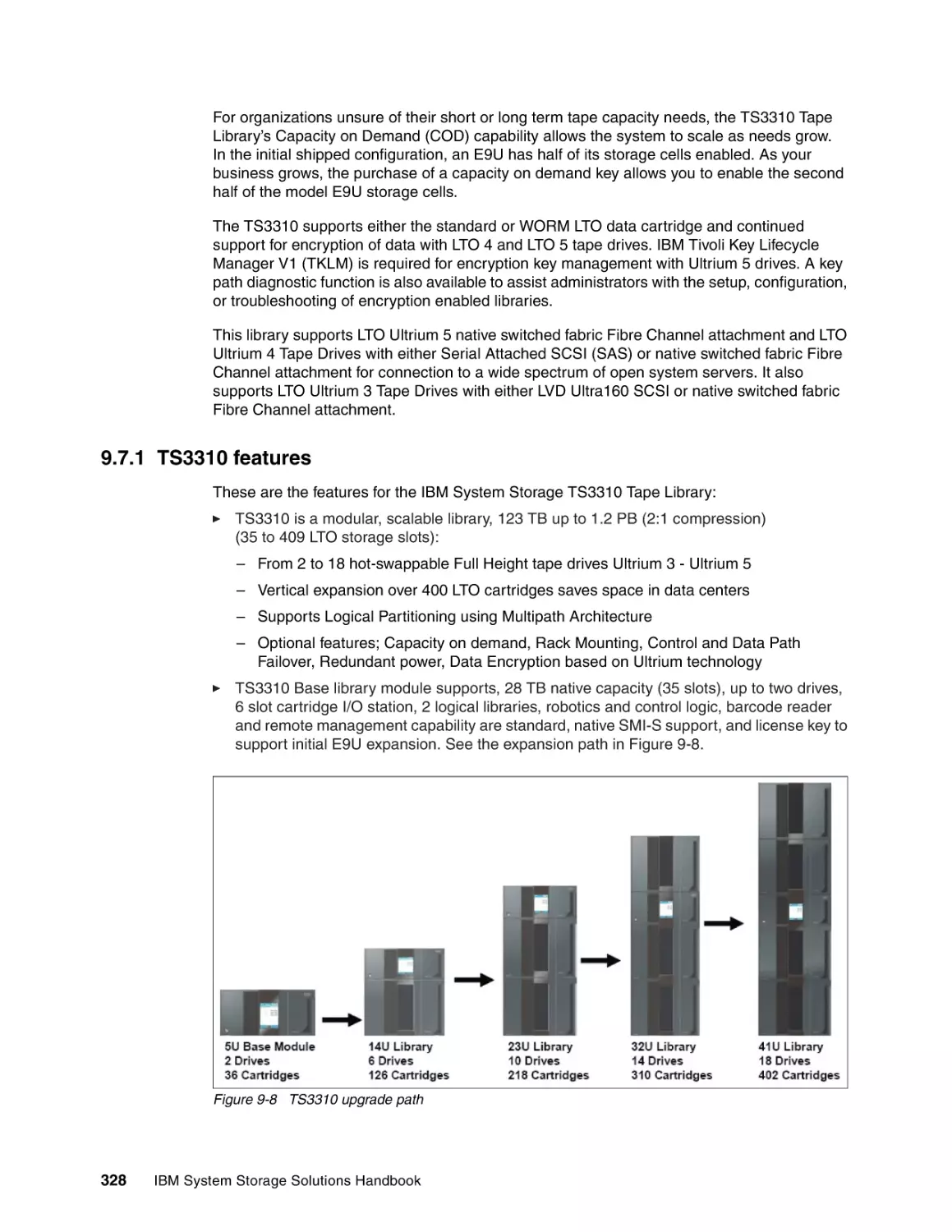
329
330
331
332
332
333
333
334
334
336
Chapter 10. IBM Tape Virtualization products . . . . . . . . . . . . . . . . . . . . . . . . . . . . . . .
10.1 Introduction to tape virtualization . . . . . . . . . . . . . . . . . . . . . . . . . . . . . . . . . . . . . . .
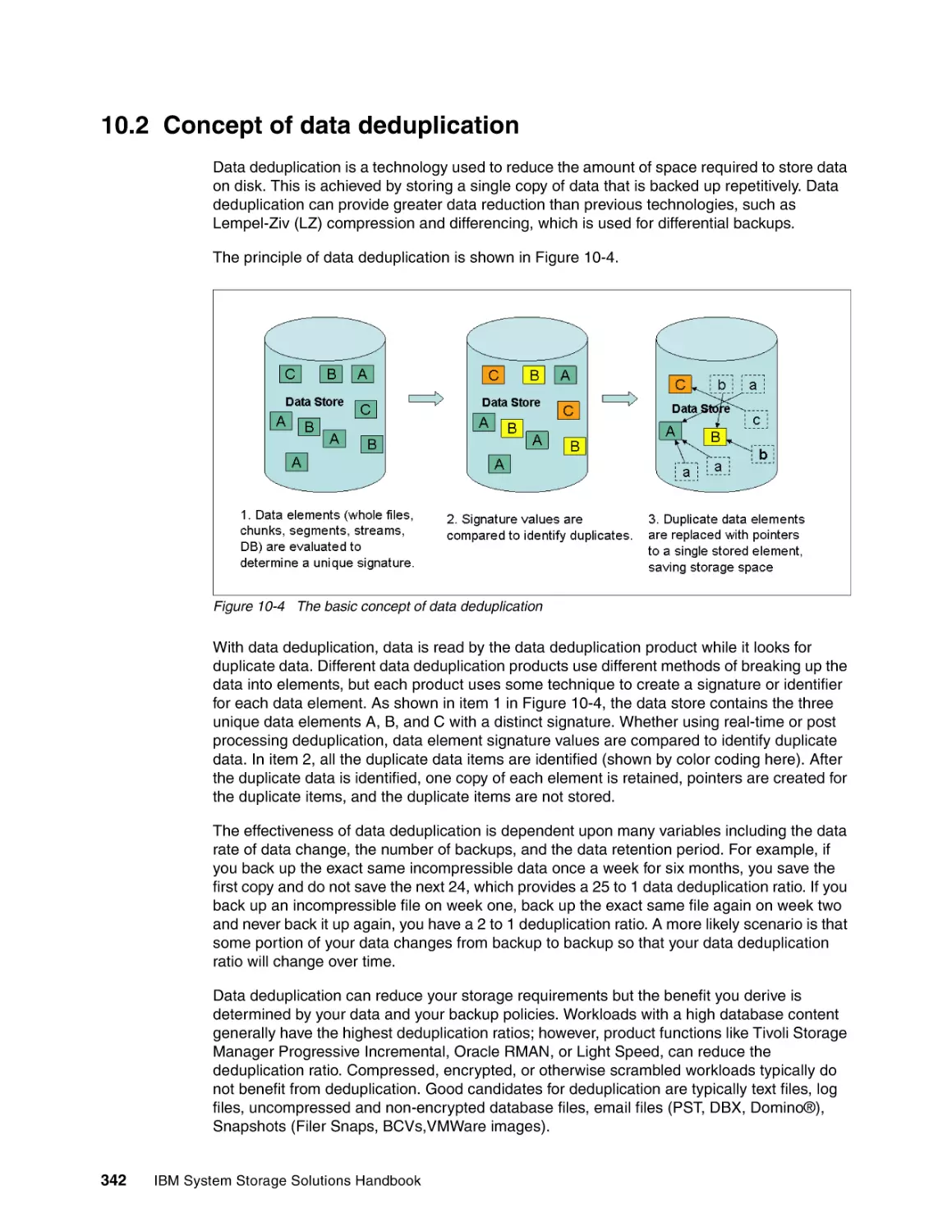
10.2 Concept of data deduplication. . . . . . . . . . . . . . . . . . . . . . . . . . . . . . . . . . . . . . . . . .
10.2.1 Types of data deduplication and HyperFactor . . . . . . . . . . . . . . . . . . . . . . . . .
10.2.2 ProtecTIER Native Replication . . . . . . . . . . . . . . . . . . . . . . . . . . . . . . . . . . . . .
10.3 TS7610 ProtecTIER Deduplication Appliance Express . . . . . . . . . . . . . . . . . . . . . .
10.3.1 TS7610 solution . . . . . . . . . . . . . . . . . . . . . . . . . . . . . . . . . . . . . . . . . . . . . . . .
10.3.2 TS7610 features . . . . . . . . . . . . . . . . . . . . . . . . . . . . . . . . . . . . . . . . . . . . . . . .
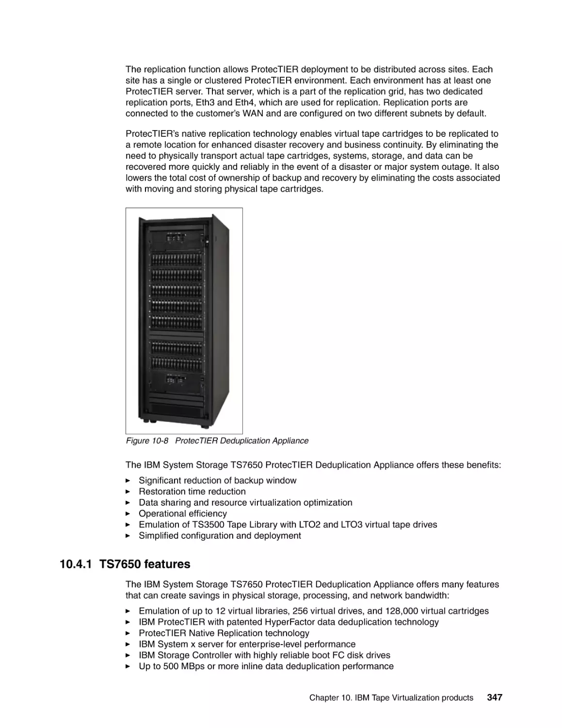
10.4 TS7650 ProtecTIER Deduplication Appliance . . . . . . . . . . . . . . . . . . . . . . . . . . . . .
10.4.1 TS7650 features . . . . . . . . . . . . . . . . . . . . . . . . . . . . . . . . . . . . . . . . . . . . . . . .
10.4.2 TS7650 configuration options . . . . . . . . . . . . . . . . . . . . . . . . . . . . . . . . . . . . . .
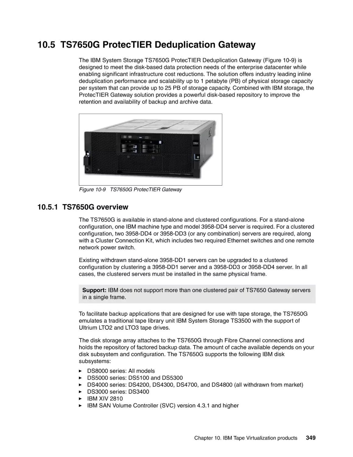
10.5 TS7650G ProtecTIER Deduplication Gateway . . . . . . . . . . . . . . . . . . . . . . . . . . . . .
10.5.1 TS7650G overview . . . . . . . . . . . . . . . . . . . . . . . . . . . . . . . . . . . . . . . . . . . . . .
10.5.2 TS7650G features. . . . . . . . . . . . . . . . . . . . . . . . . . . . . . . . . . . . . . . . . . . . . . .
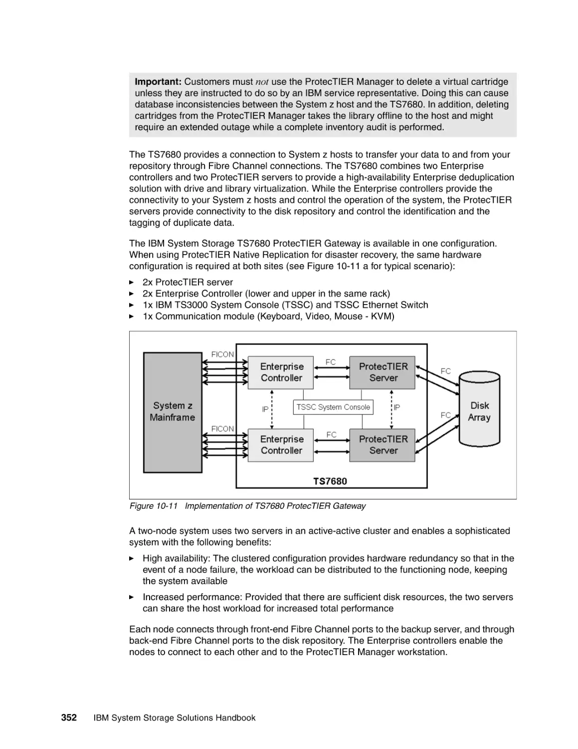
10.6 IBM TS7680 ProtecTIER Gateway for System z . . . . . . . . . . . . . . . . . . . . . . . . . . .
10.6.1 TS7680 overview . . . . . . . . . . . . . . . . . . . . . . . . . . . . . . . . . . . . . . . . . . . . . . .
10.6.2 TS7680 features . . . . . . . . . . . . . . . . . . . . . . . . . . . . . . . . . . . . . . . . . . . . . . . .
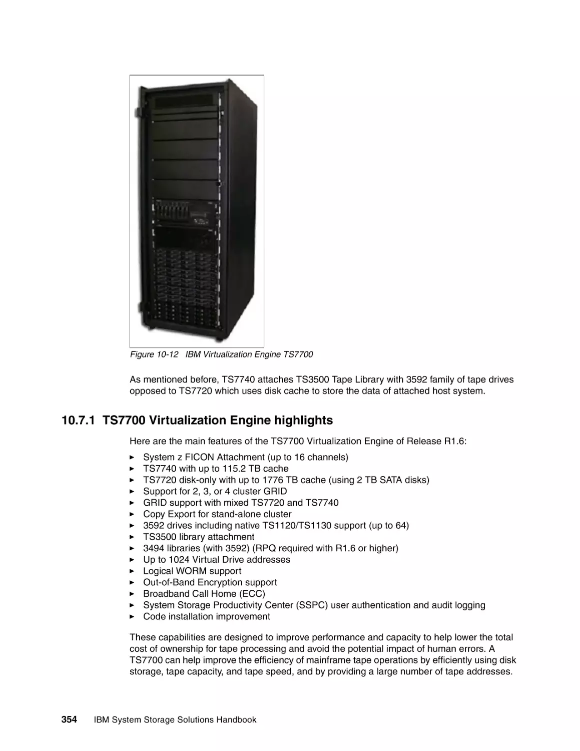
10.7 IBM Virtualization Engine TS7700 . . . . . . . . . . . . . . . . . . . . . . . . . . . . . . . . . . . . . .
10.7.1 TS7700 Virtualization Engine highlights . . . . . . . . . . . . . . . . . . . . . . . . . . . . . .
10.7.2 Characteristics of components comprising the TS7700 . . . . . . . . . . . . . . . . . .
10.7.3 IBM Virtualization Engine TS7740 . . . . . . . . . . . . . . . . . . . . . . . . . . . . . . . . . .
10.7.4 IBM Virtualization Engine TS7720 . . . . . . . . . . . . . . . . . . . . . . . . . . . . . . . . . .
10.8 IBM Data Facility Storage Management Subsystem. . . . . . . . . . . . . . . . . . . . . . . . .
337
338
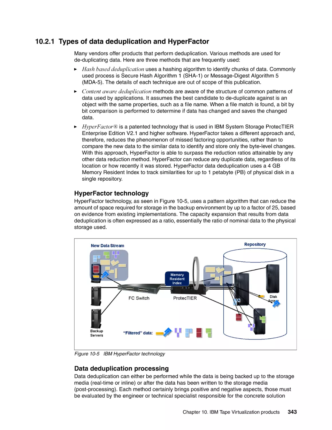
342
343
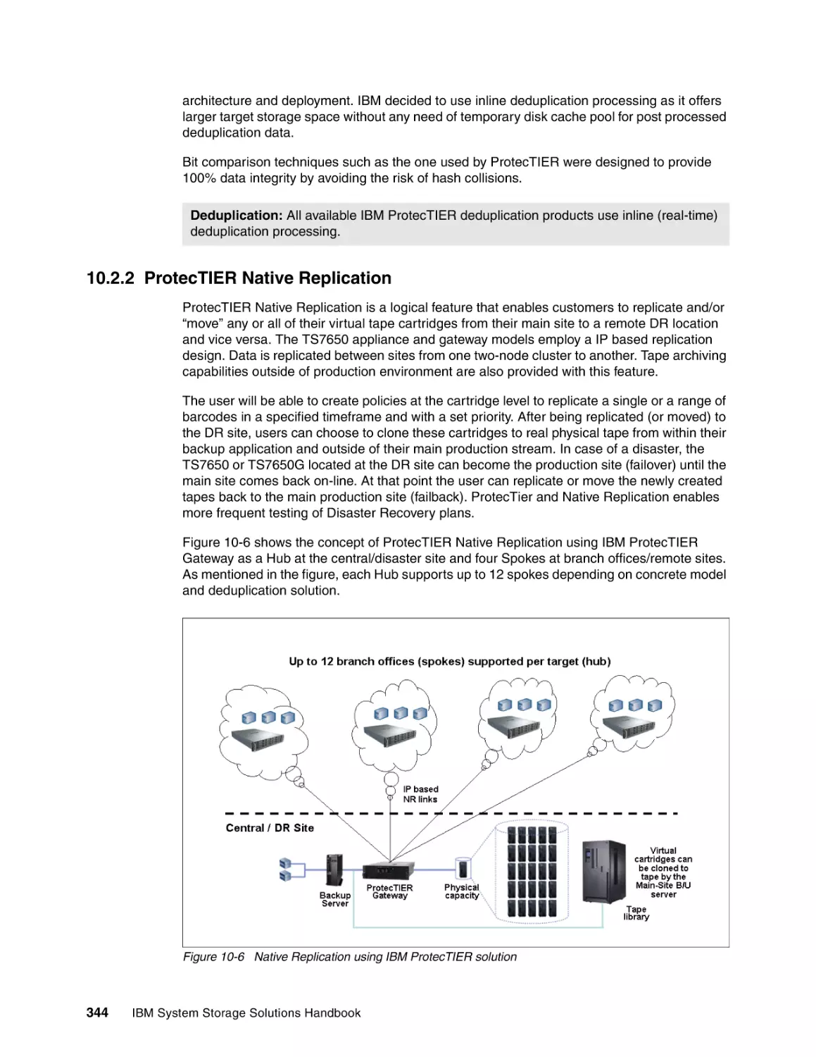
344
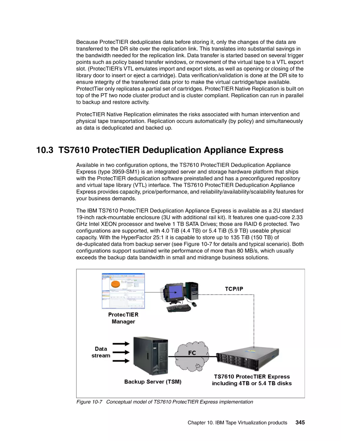
345
346
346
346
347
348
349
349
351
351
351
353
353
354
355
355
356
356
IBM System Storage Solutions Handbook
10.8.1 IBM Data Facility Storage Management Subsystem Removable Media Manager for
z/OS environments . . . . . . . . . . . . . . . . . . . . . . . . . . . . . . . . . . . . . . . . . . . . . . . 356
10.8.2 DFSMSrmm highlights . . . . . . . . . . . . . . . . . . . . . . . . . . . . . . . . . . . . . . . . . . . 357
10.9 More information . . . . . . . . . . . . . . . . . . . . . . . . . . . . . . . . . . . . . . . . . . . . . . . . . . . . 357
Chapter 11. Complementary storage products . . . . . . . . . . . . . . . . . . . . . . . . . . . . . .
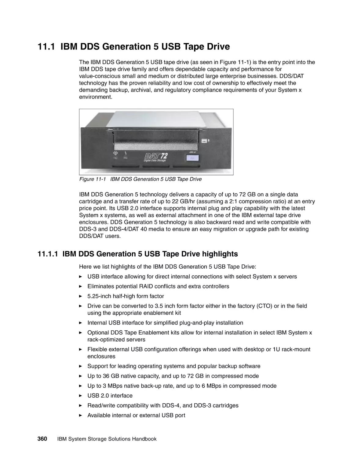
11.1 IBM DDS Generation 5 USB Tape Drive . . . . . . . . . . . . . . . . . . . . . . . . . . . . . . . . .
11.1.1 IBM DDS Generation 5 USB Tape Drive highlights . . . . . . . . . . . . . . . . . . . . .
11.1.2 Additional information . . . . . . . . . . . . . . . . . . . . . . . . . . . . . . . . . . . . . . . . . . . .
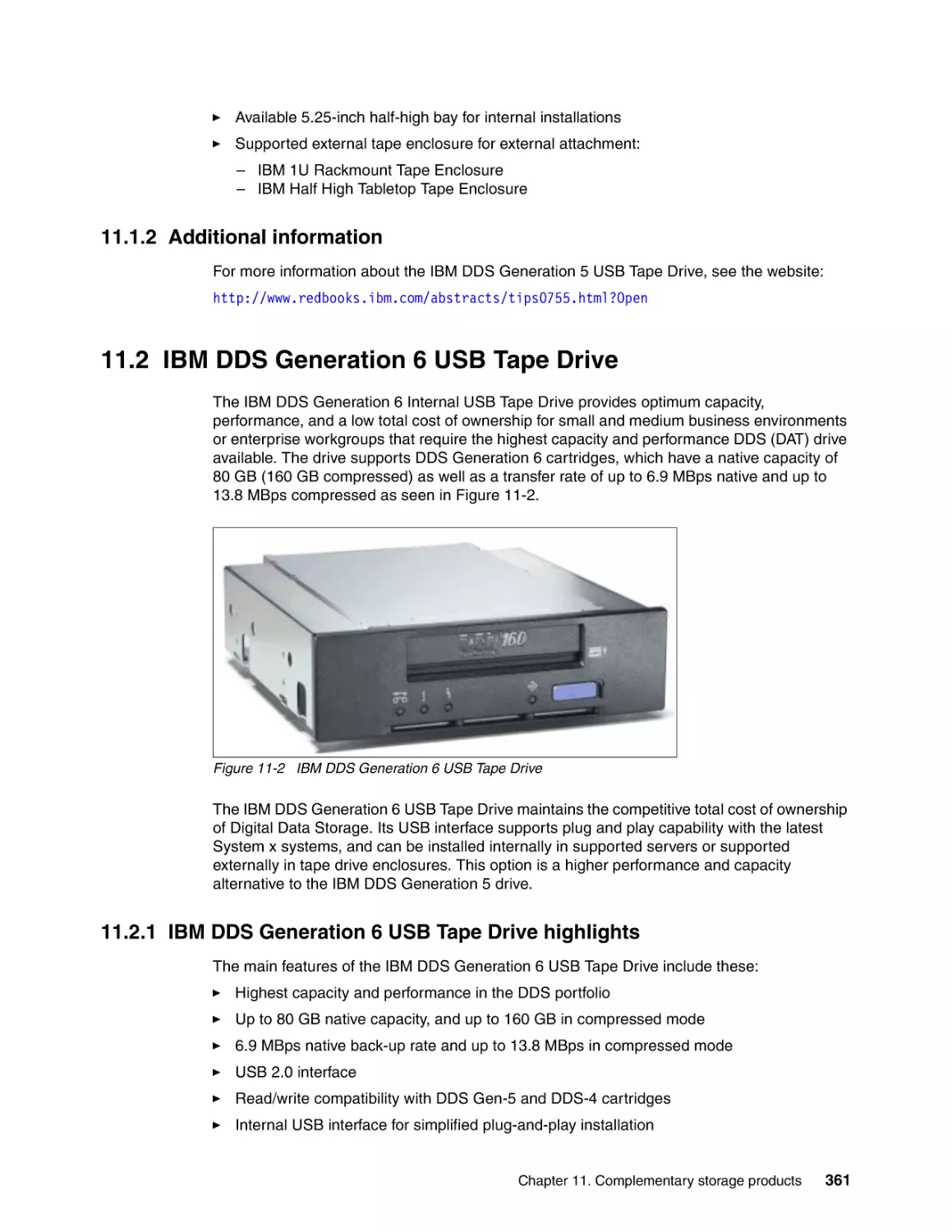
11.2 IBM DDS Generation 6 USB Tape Drive . . . . . . . . . . . . . . . . . . . . . . . . . . . . . . . . .
11.2.1 IBM DDS Generation 6 USB Tape Drive highlights . . . . . . . . . . . . . . . . . . . . .
11.2.2 Additional information . . . . . . . . . . . . . . . . . . . . . . . . . . . . . . . . . . . . . . . . . . . .
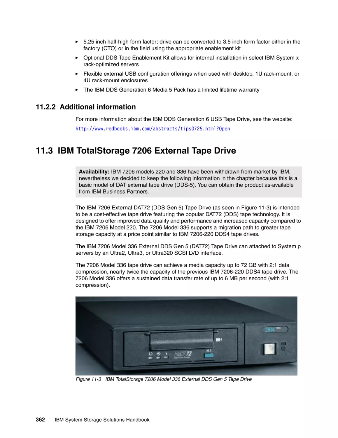
11.3 IBM TotalStorage 7206 External Tape Drive . . . . . . . . . . . . . . . . . . . . . . . . . . . . . .
11.3.1 IBM 7206 Model 336 highlights. . . . . . . . . . . . . . . . . . . . . . . . . . . . . . . . . . . . .
11.3.2 Additional information . . . . . . . . . . . . . . . . . . . . . . . . . . . . . . . . . . . . . . . . . . . .
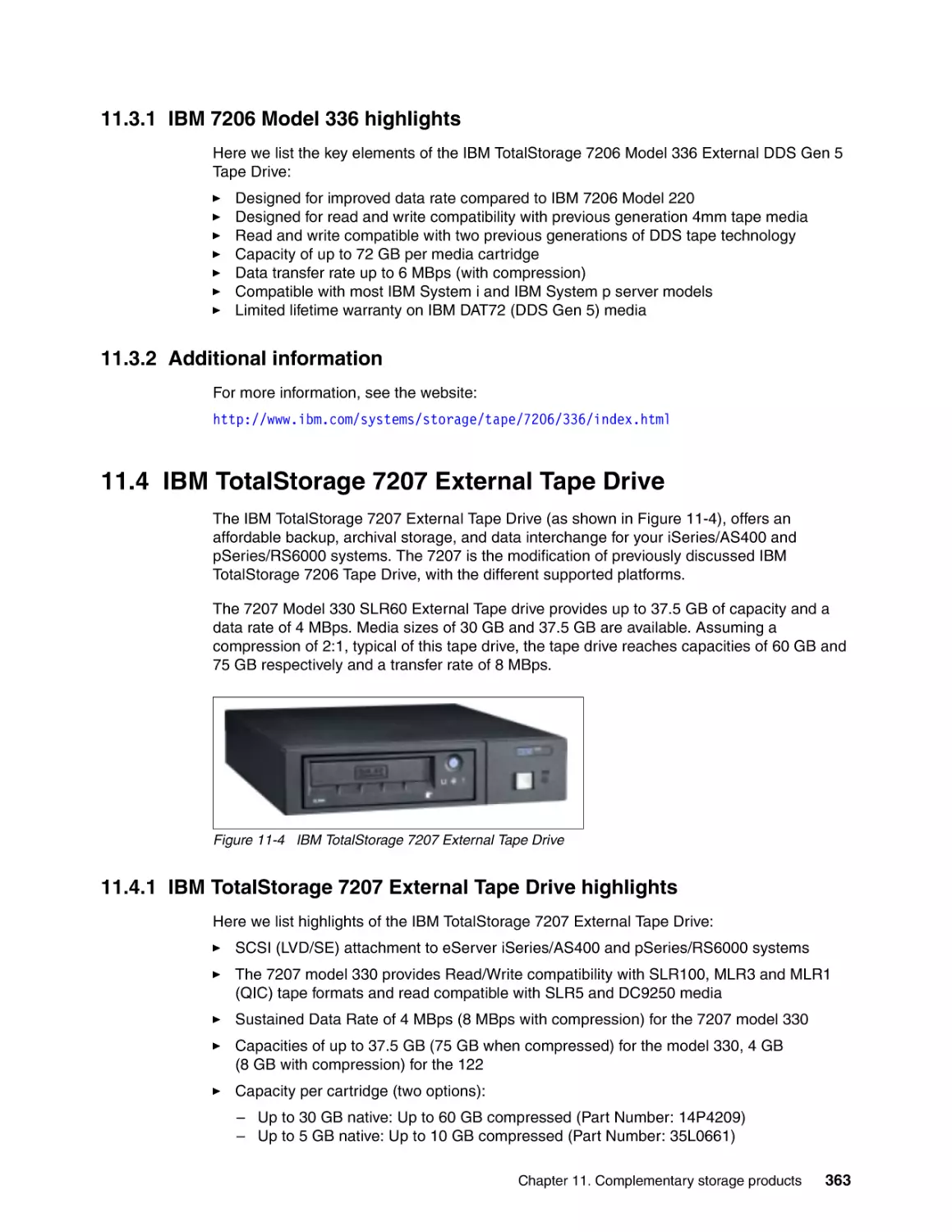
11.4 IBM TotalStorage 7207 External Tape Drive . . . . . . . . . . . . . . . . . . . . . . . . . . . . . .
11.4.1 IBM TotalStorage 7207 External Tape Drive highlights . . . . . . . . . . . . . . . . . .
11.4.2 Additional information . . . . . . . . . . . . . . . . . . . . . . . . . . . . . . . . . . . . . . . . . . . .
11.5 IBM External Tape Enclosures . . . . . . . . . . . . . . . . . . . . . . . . . . . . . . . . . . . . . . . . .
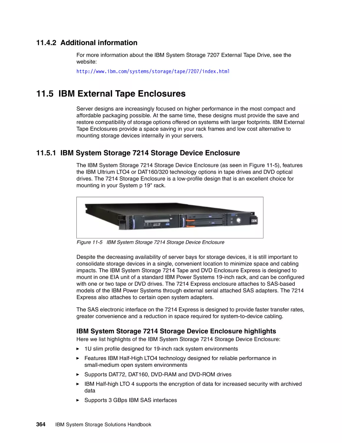
11.5.1 IBM System Storage 7214 Storage Device Enclosure . . . . . . . . . . . . . . . . . . .
11.5.2 IBM System Storage 7216 Multimedia Enclosure. . . . . . . . . . . . . . . . . . . . . . .
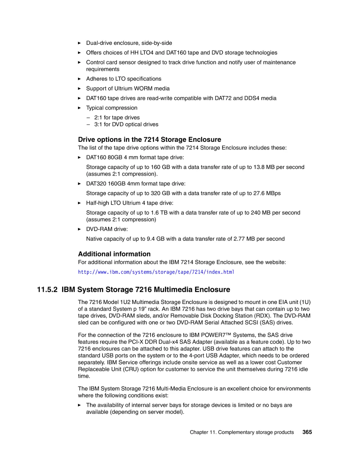
11.5.3 Half High Tape Drive External Enclosure . . . . . . . . . . . . . . . . . . . . . . . . . . . . .
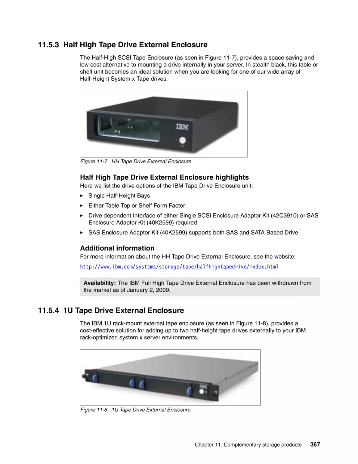
11.5.4 1U Tape Drive External Enclosure . . . . . . . . . . . . . . . . . . . . . . . . . . . . . . . . . .
359
360
360
361
361
361
362
362
363
363
363
363
364
364
364
365
367
367
Part 3. Storage Networking . . . . . . . . . . . . . . . . . . . . . . . . . . . . . . . . . . . . . . . . . . . . . . . . . . . . . . . . . . . 369
Chapter 12. Introduction to storage networking . . . . . . . . . . . . . . . . . . . . . . . . . . . . .
12.1 Overview . . . . . . . . . . . . . . . . . . . . . . . . . . . . . . . . . . . . . . . . . . . . . . . . . . . . . . . . . .
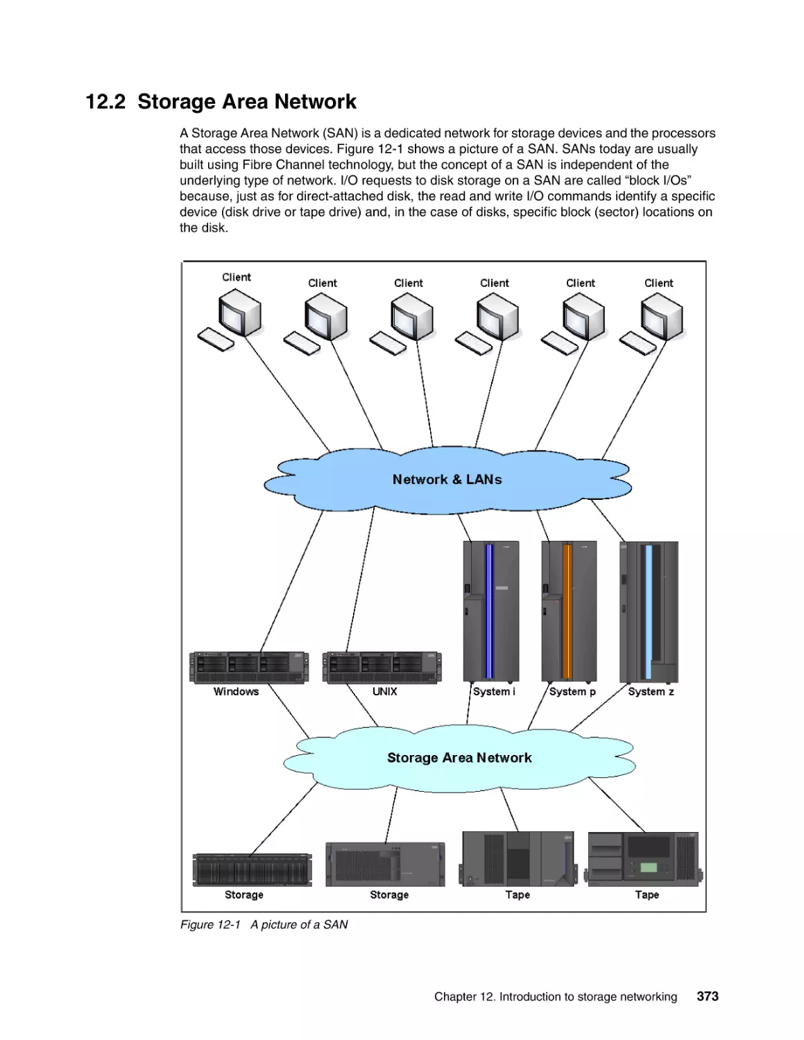
12.2 Storage Area Network . . . . . . . . . . . . . . . . . . . . . . . . . . . . . . . . . . . . . . . . . . . . . . . .
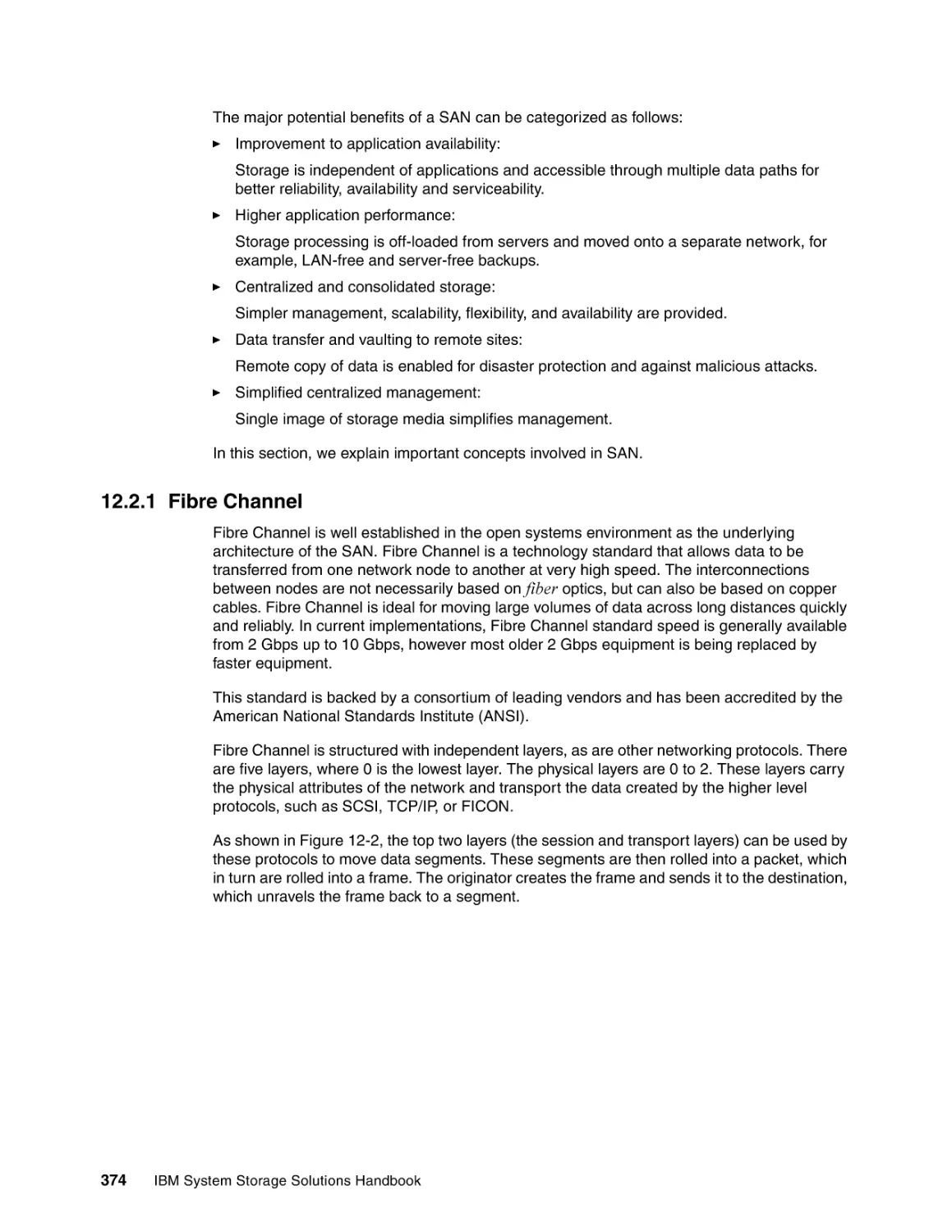
12.2.1 Fibre Channel . . . . . . . . . . . . . . . . . . . . . . . . . . . . . . . . . . . . . . . . . . . . . . . . . .
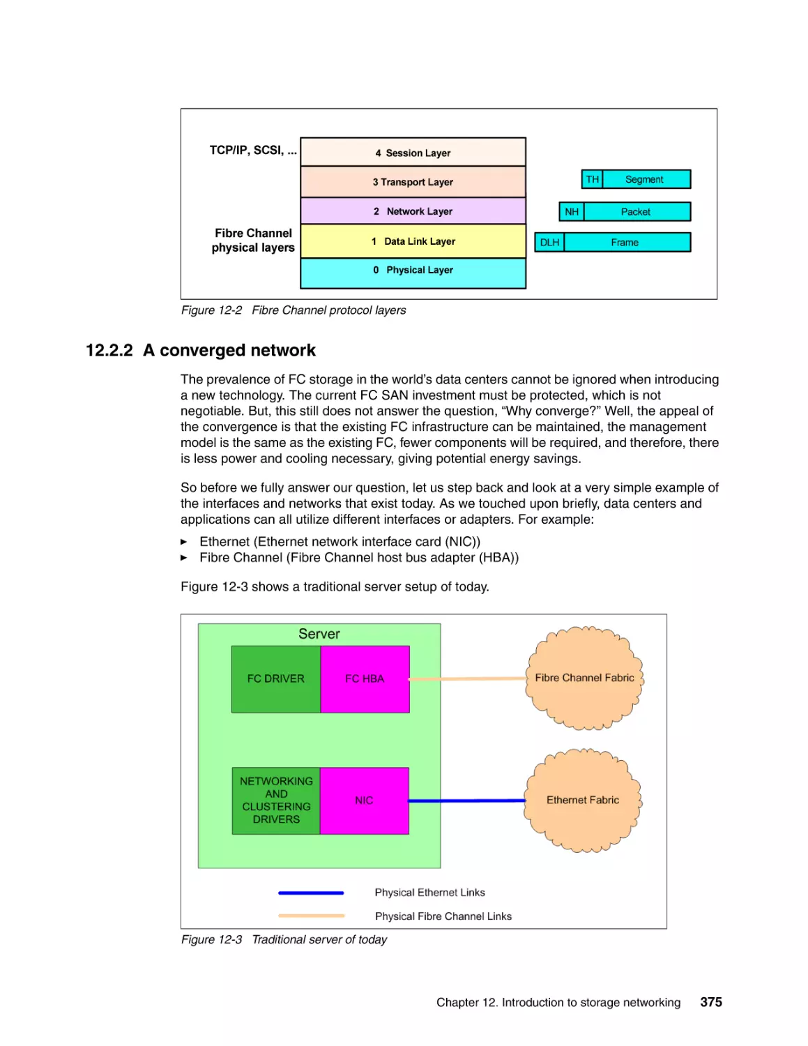
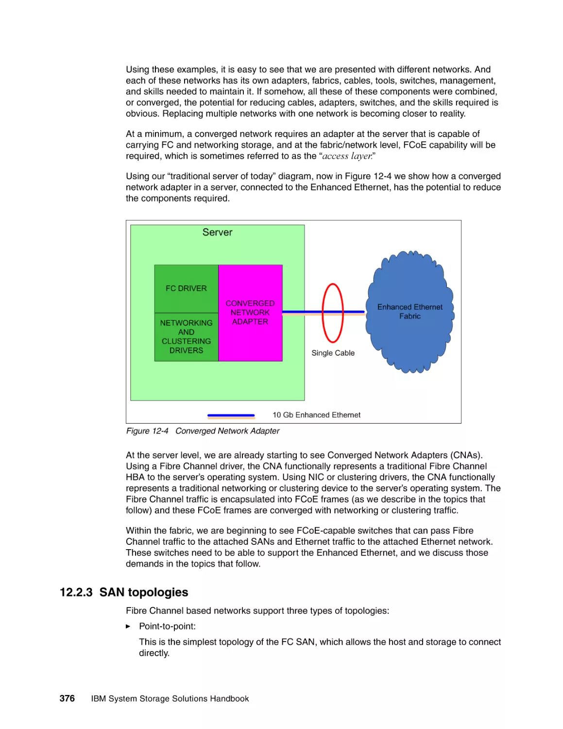
12.2.2 A converged network . . . . . . . . . . . . . . . . . . . . . . . . . . . . . . . . . . . . . . . . . . . .
12.2.3 SAN topologies . . . . . . . . . . . . . . . . . . . . . . . . . . . . . . . . . . . . . . . . . . . . . . . . .
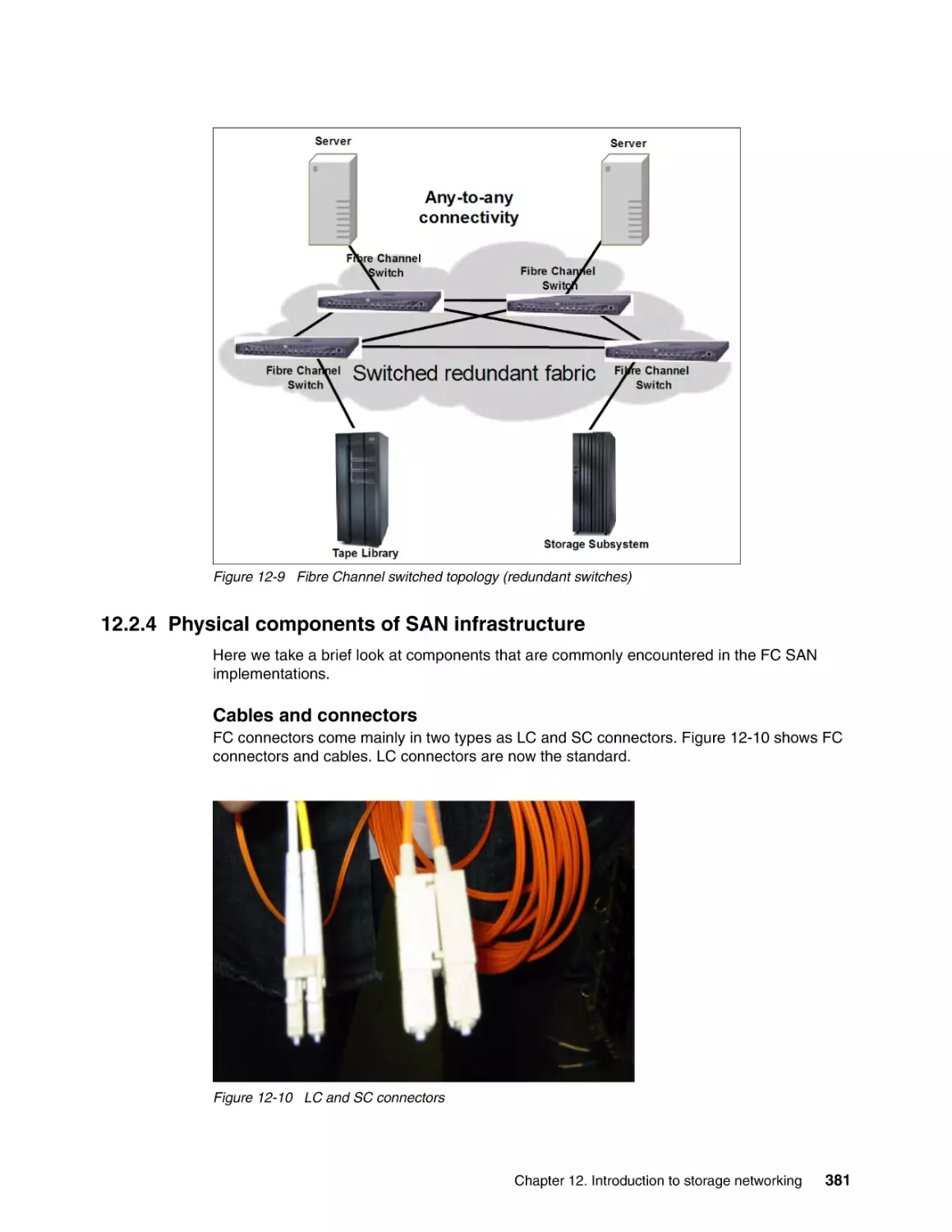
12.2.4 Physical components of SAN infrastructure . . . . . . . . . . . . . . . . . . . . . . . . . . .
12.2.5 Naming and addressing . . . . . . . . . . . . . . . . . . . . . . . . . . . . . . . . . . . . . . . . . .
12.2.6 Types of ports . . . . . . . . . . . . . . . . . . . . . . . . . . . . . . . . . . . . . . . . . . . . . . . . . .
12.2.7 FICON . . . . . . . . . . . . . . . . . . . . . . . . . . . . . . . . . . . . . . . . . . . . . . . . . . . . . . . .
12.3 IP storage networking technologies . . . . . . . . . . . . . . . . . . . . . . . . . . . . . . . . . . . . .
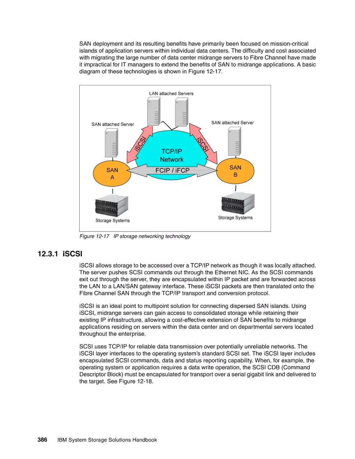
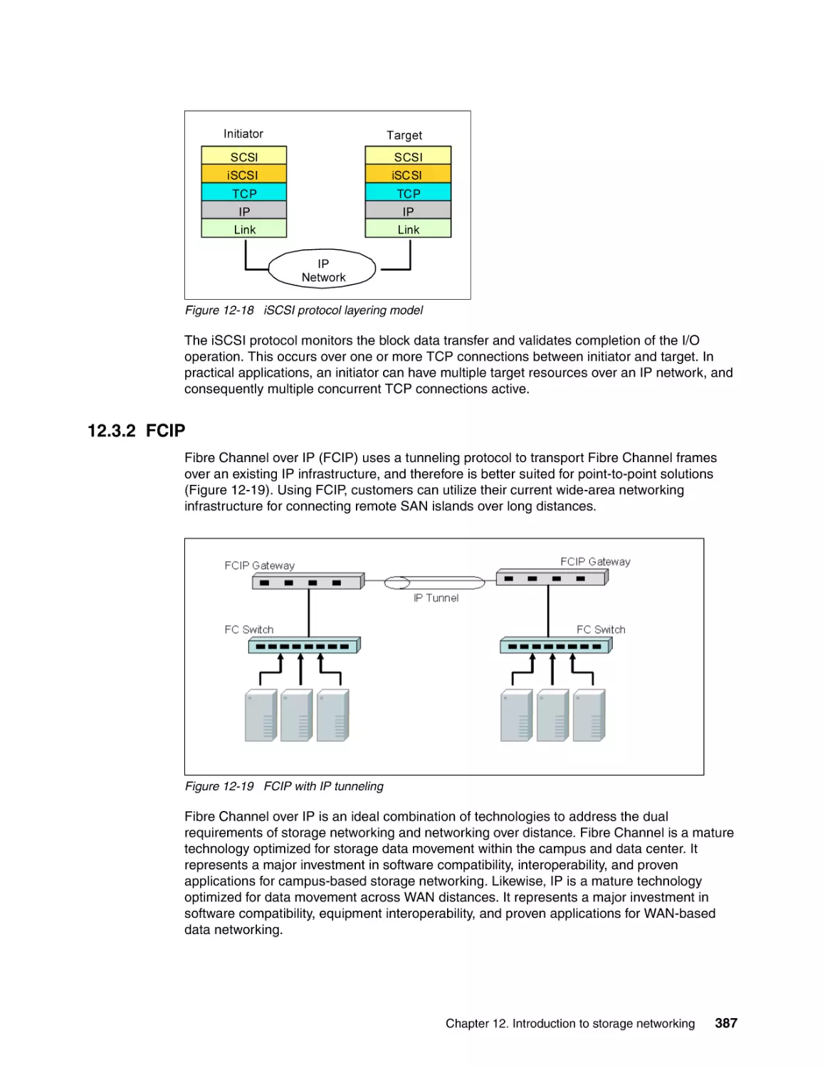
12.3.1 iSCSI . . . . . . . . . . . . . . . . . . . . . . . . . . . . . . . . . . . . . . . . . . . . . . . . . . . . . . . . .
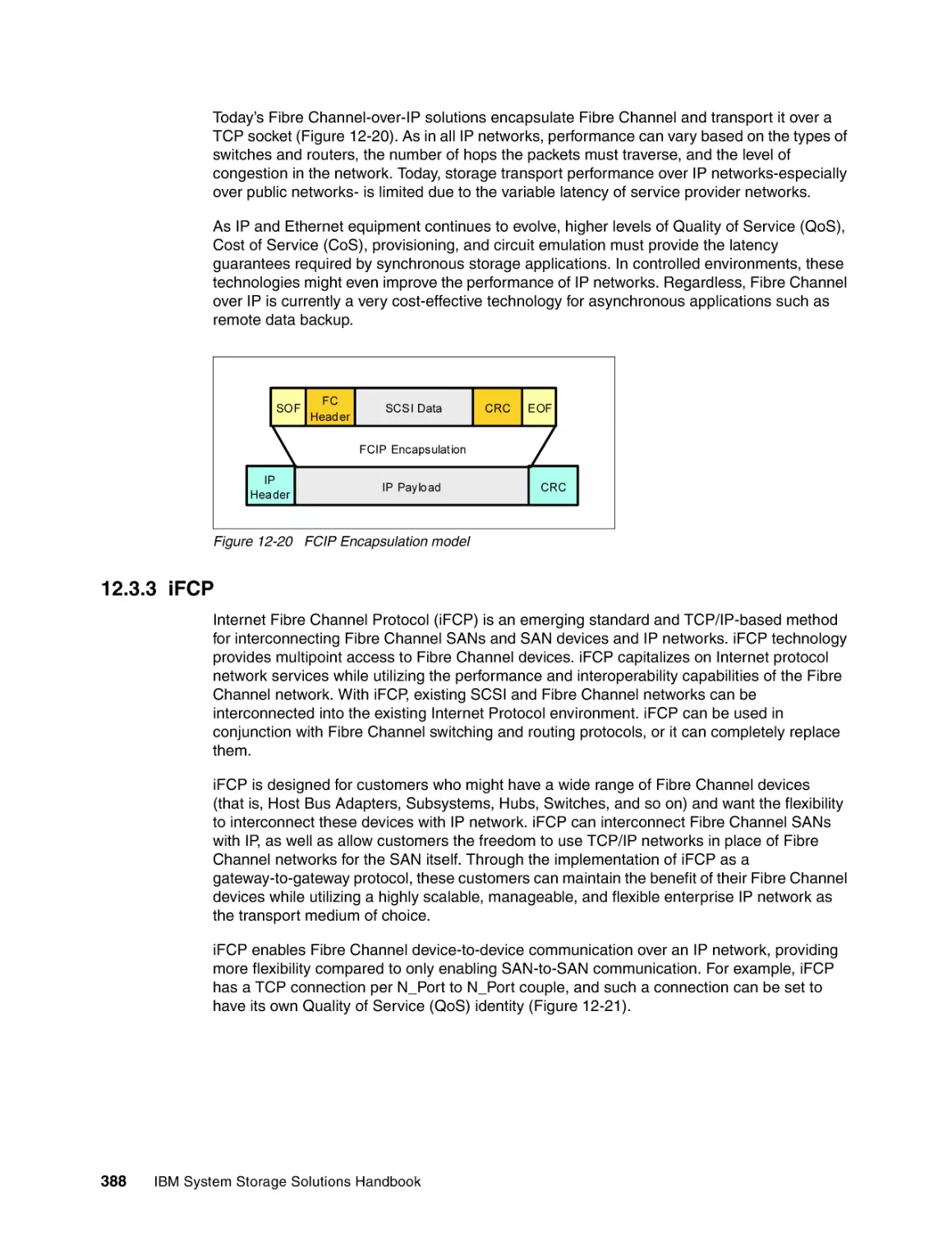
12.3.2 FCIP . . . . . . . . . . . . . . . . . . . . . . . . . . . . . . . . . . . . . . . . . . . . . . . . . . . . . . . . .
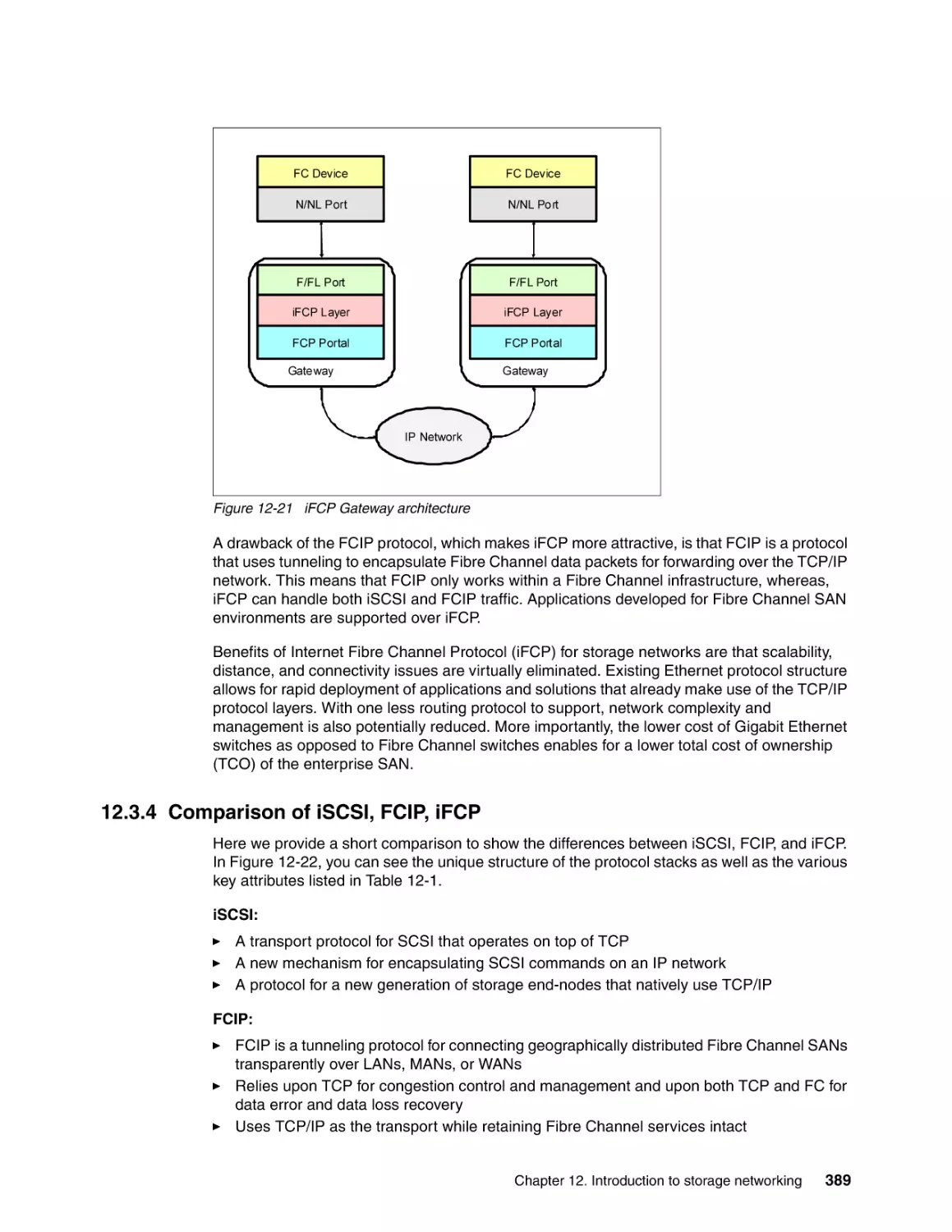
12.3.3 iFCP . . . . . . . . . . . . . . . . . . . . . . . . . . . . . . . . . . . . . . . . . . . . . . . . . . . . . . . . .
12.3.4 Comparison of iSCSI, FCIP, iFCP . . . . . . . . . . . . . . . . . . . . . . . . . . . . . . . . . .
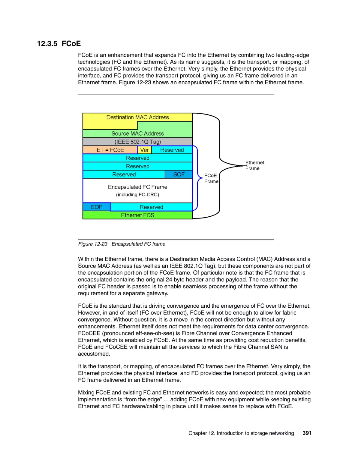
12.3.5 FCoE . . . . . . . . . . . . . . . . . . . . . . . . . . . . . . . . . . . . . . . . . . . . . . . . . . . . . . . . .
12.4 Network Attached Storage . . . . . . . . . . . . . . . . . . . . . . . . . . . . . . . . . . . . . . . . . . . .
12.4.1 NAS benefits . . . . . . . . . . . . . . . . . . . . . . . . . . . . . . . . . . . . . . . . . . . . . . . . . . .
12.4.2 NAS gateways . . . . . . . . . . . . . . . . . . . . . . . . . . . . . . . . . . . . . . . . . . . . . . . . .
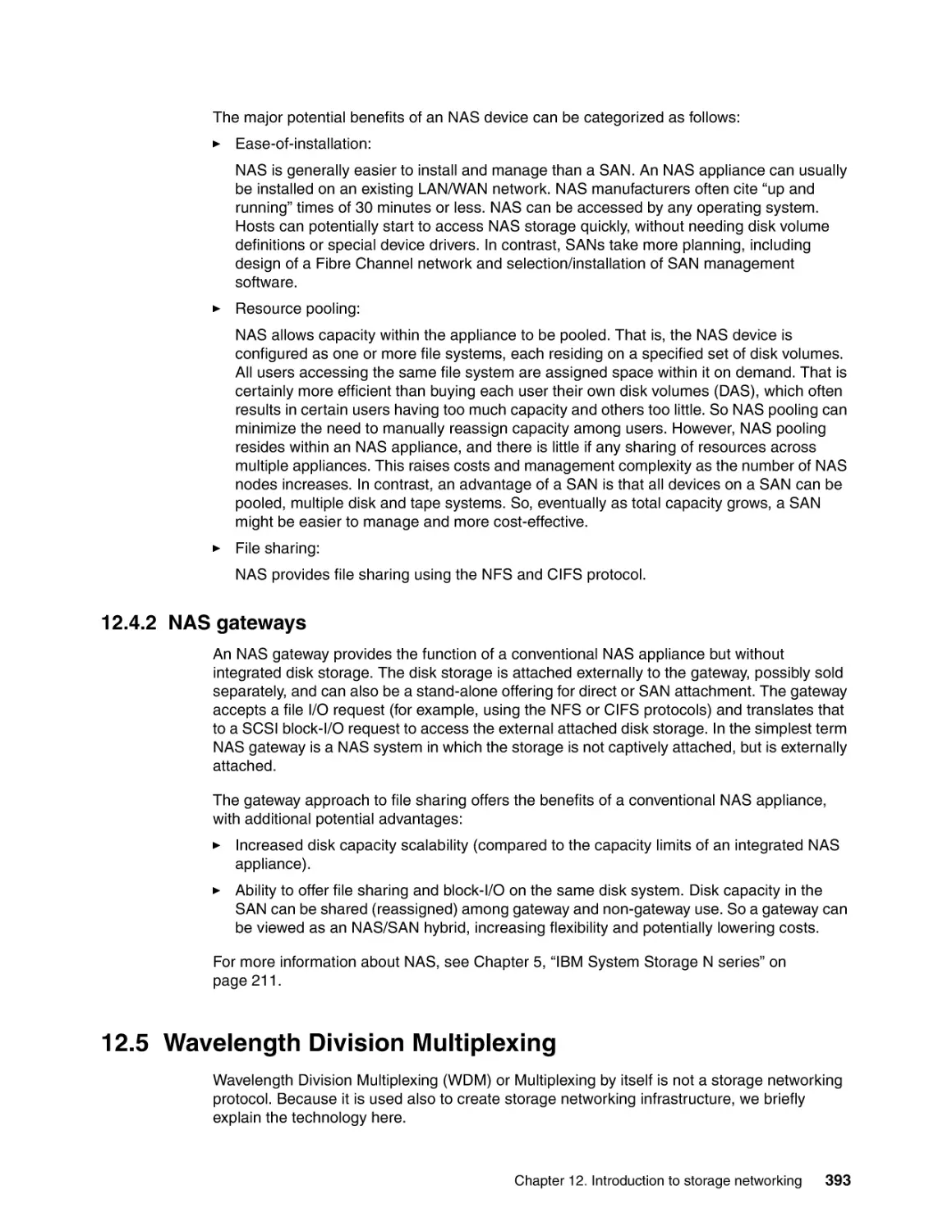
12.5 Wavelength Division Multiplexing . . . . . . . . . . . . . . . . . . . . . . . . . . . . . . . . . . . . . . .
12.6 Selecting the best alternative . . . . . . . . . . . . . . . . . . . . . . . . . . . . . . . . . . . . . . . . . .
12.7 More information . . . . . . . . . . . . . . . . . . . . . . . . . . . . . . . . . . . . . . . . . . . . . . . . . . . .
371
372
373
374
375
376
381
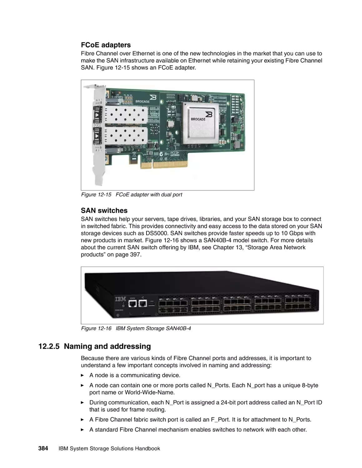
384
385
385
385
386
387
388
389
391
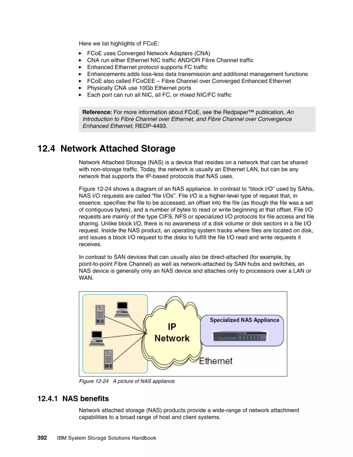
392
392
393
393
394
395
Chapter 13. Storage Area Network products . . . . . . . . . . . . . . . . . . . . . . . . . . . . . . . .
13.1 SAN switches and connectivity products . . . . . . . . . . . . . . . . . . . . . . . . . . . . . . . . .
13.1.1 Common characteristics . . . . . . . . . . . . . . . . . . . . . . . . . . . . . . . . . . . . . . . . . .
13.1.2 Other switch features . . . . . . . . . . . . . . . . . . . . . . . . . . . . . . . . . . . . . . . . . . . .
13.2 Entry SAN switches. . . . . . . . . . . . . . . . . . . . . . . . . . . . . . . . . . . . . . . . . . . . . . . . . .
397
398
398
398
400
Contents
ix
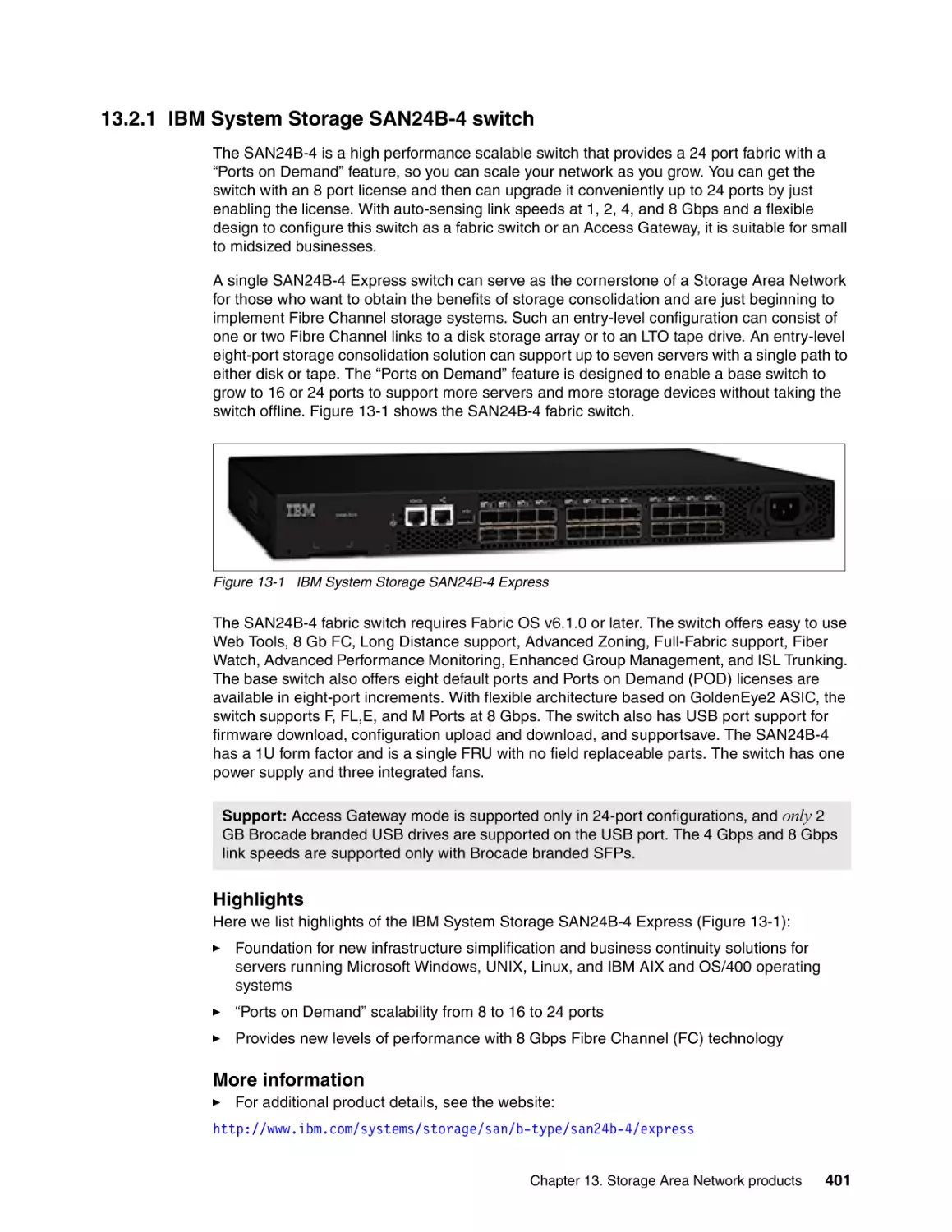
13.2.1 IBM System Storage SAN24B-4 switch . . . . . . . . . . . . . . . . . . . . . . . . . . . . . .
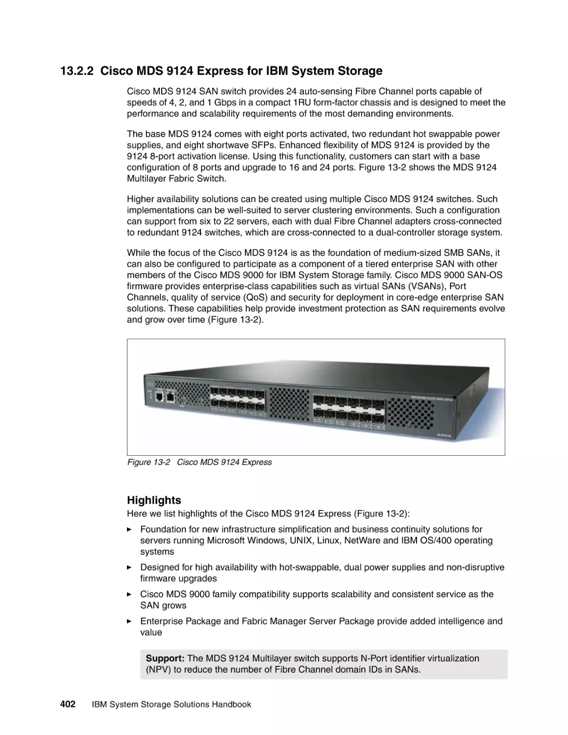
13.2.2 Cisco MDS 9124 Express for IBM System Storage . . . . . . . . . . . . . . . . . . . . .
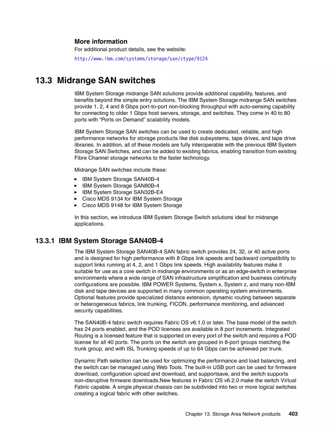
13.3 Midrange SAN switches . . . . . . . . . . . . . . . . . . . . . . . . . . . . . . . . . . . . . . . . . . . . . .
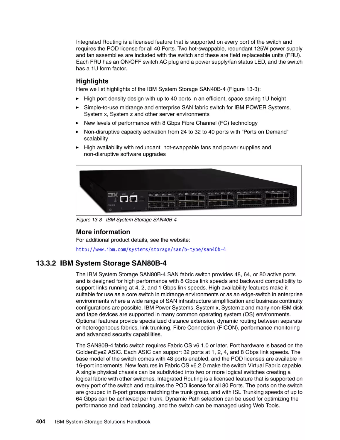
13.3.1 IBM System Storage SAN40B-4 . . . . . . . . . . . . . . . . . . . . . . . . . . . . . . . . . . . .
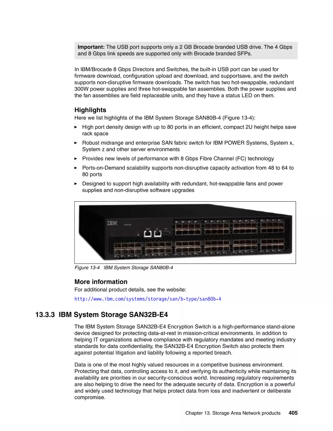
13.3.2 IBM System Storage SAN80B-4 . . . . . . . . . . . . . . . . . . . . . . . . . . . . . . . . . . . .
13.3.3 IBM System Storage SAN32B-E4. . . . . . . . . . . . . . . . . . . . . . . . . . . . . . . . . . .
13.3.4 Cisco MDS 9134 for IBM System Storage . . . . . . . . . . . . . . . . . . . . . . . . . . . .
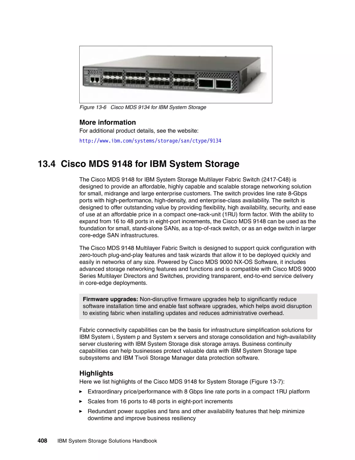
13.4 Cisco MDS 9148 for IBM System Storage . . . . . . . . . . . . . . . . . . . . . . . . . . . . . . . .
13.5 Enterprise SAN switches. . . . . . . . . . . . . . . . . . . . . . . . . . . . . . . . . . . . . . . . . . . . . .
13.5.1 IBM TotalStorage SAN256B . . . . . . . . . . . . . . . . . . . . . . . . . . . . . . . . . . . . . . .
13.5.2 IBM System Storage SAN384B . . . . . . . . . . . . . . . . . . . . . . . . . . . . . . . . . . . .
13.5.3 IBM System Storage SAN768B . . . . . . . . . . . . . . . . . . . . . . . . . . . . . . . . . . . .
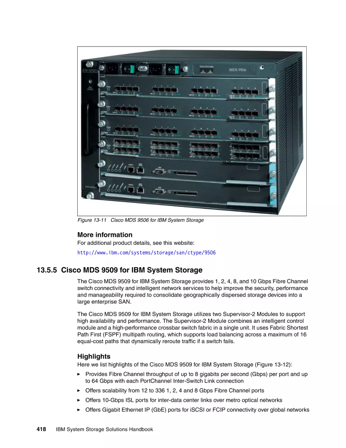
13.5.4 Cisco MDS 9506 for IBM System Storage . . . . . . . . . . . . . . . . . . . . . . . . . . . .
13.5.5 Cisco MDS 9509 for IBM System Storage . . . . . . . . . . . . . . . . . . . . . . . . . . . .
13.5.6 Cisco MDS 9513 for IBM System Storage . . . . . . . . . . . . . . . . . . . . . . . . . . . .
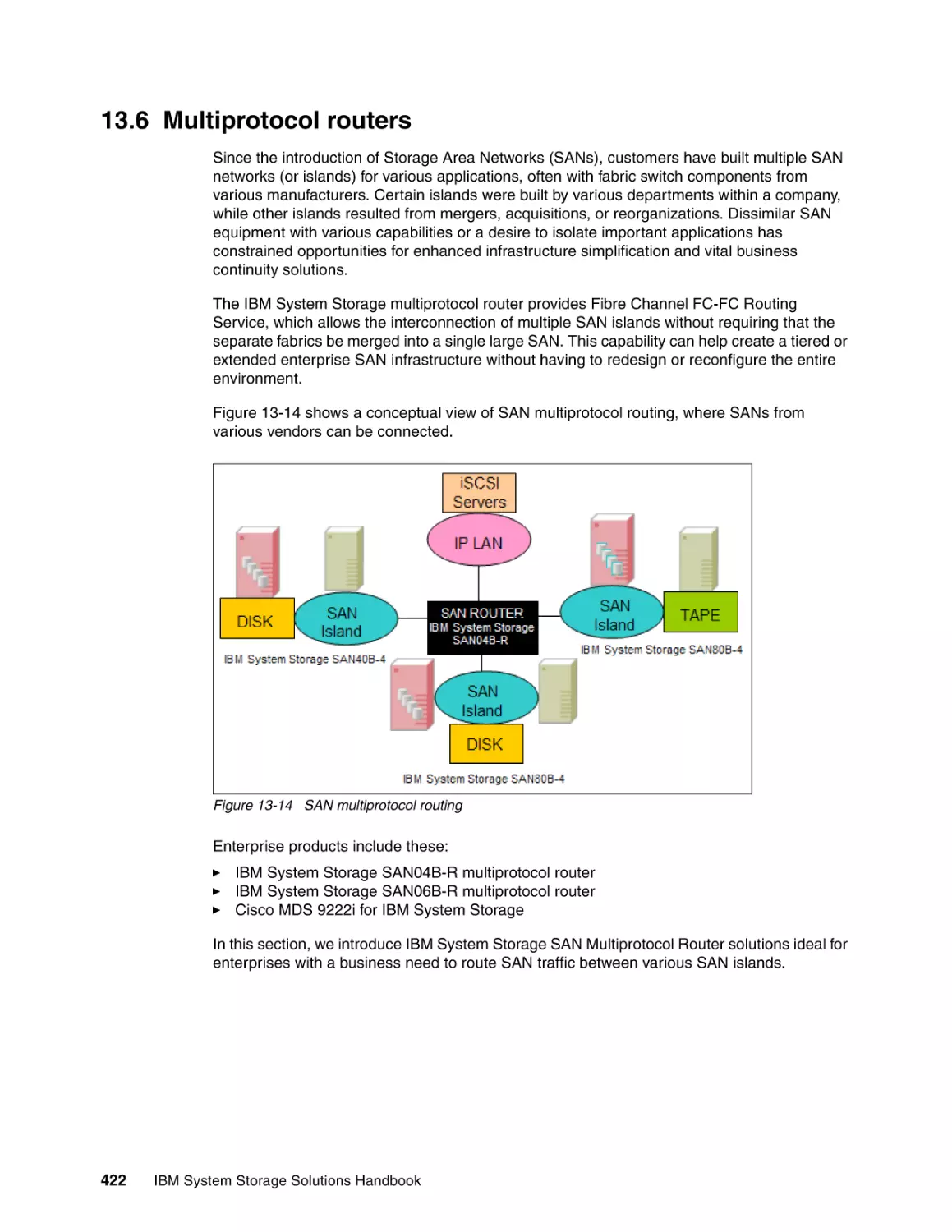
13.6 Multiprotocol routers . . . . . . . . . . . . . . . . . . . . . . . . . . . . . . . . . . . . . . . . . . . . . . . . .
13.6.1 IBM System Storage SAN04B-R multiprotocol router. . . . . . . . . . . . . . . . . . . .
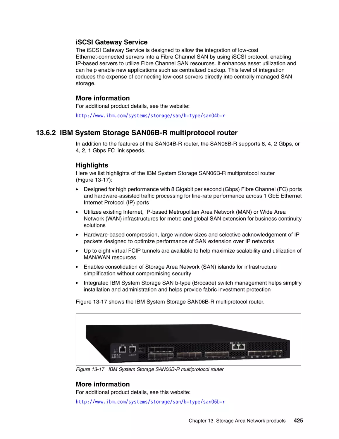
13.6.2 IBM System Storage SAN06B-R multiprotocol router. . . . . . . . . . . . . . . . . . . .
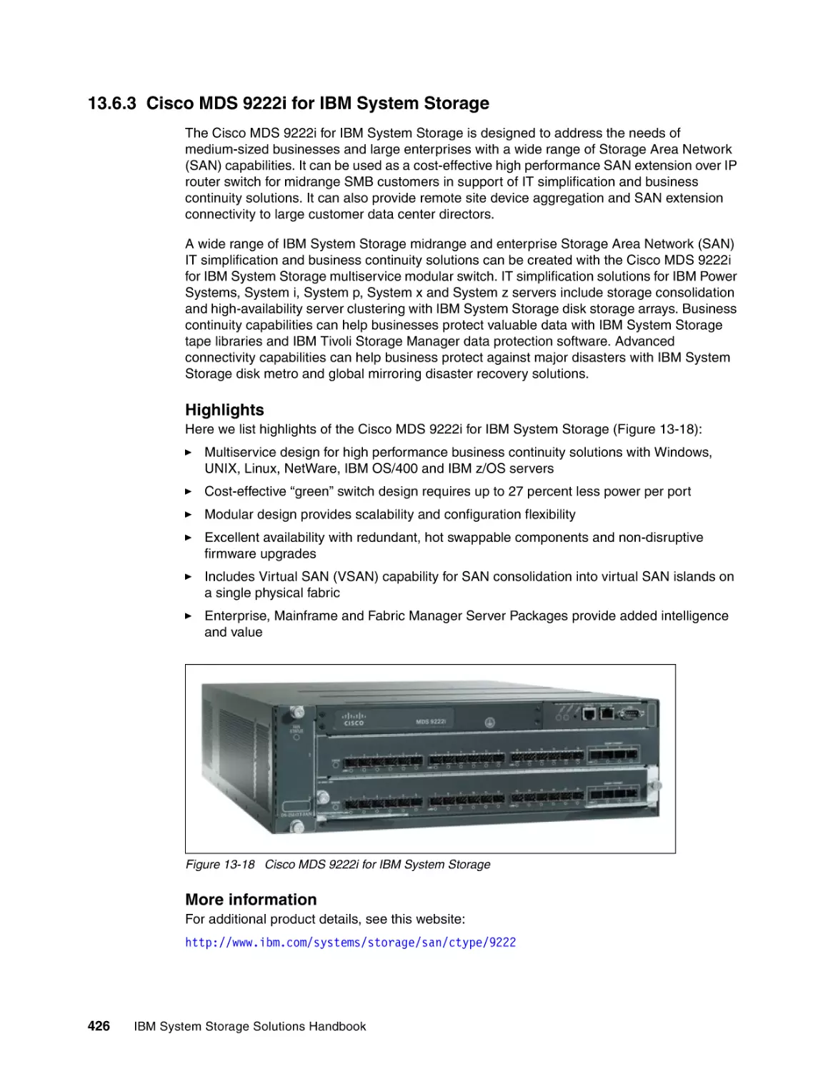
13.6.3 Cisco MDS 9222i for IBM System Storage . . . . . . . . . . . . . . . . . . . . . . . . . . . .
13.7 SAN management . . . . . . . . . . . . . . . . . . . . . . . . . . . . . . . . . . . . . . . . . . . . . . . . . . .
13.7.1 Features . . . . . . . . . . . . . . . . . . . . . . . . . . . . . . . . . . . . . . . . . . . . . . . . . . . . . .
13.7.2 Highlights . . . . . . . . . . . . . . . . . . . . . . . . . . . . . . . . . . . . . . . . . . . . . . . . . . . . .
13.8 SAN solutions . . . . . . . . . . . . . . . . . . . . . . . . . . . . . . . . . . . . . . . . . . . . . . . . . . . . . .
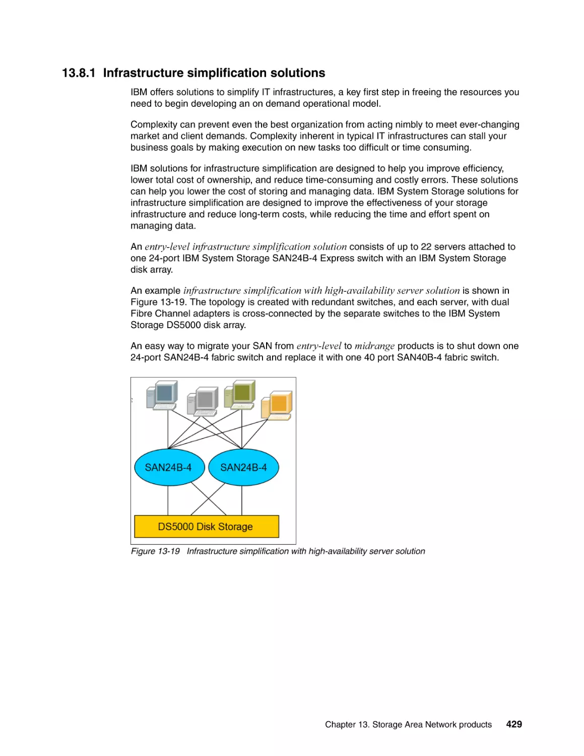
13.8.1 Infrastructure simplification solutions . . . . . . . . . . . . . . . . . . . . . . . . . . . . . . . .
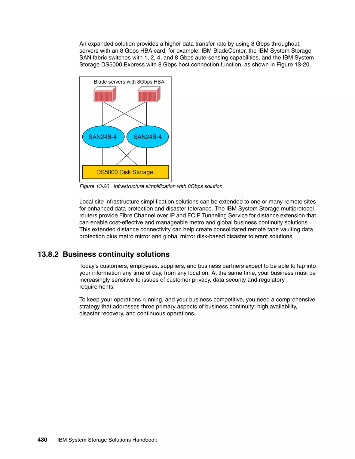
13.8.2 Business continuity solutions . . . . . . . . . . . . . . . . . . . . . . . . . . . . . . . . . . . . . .
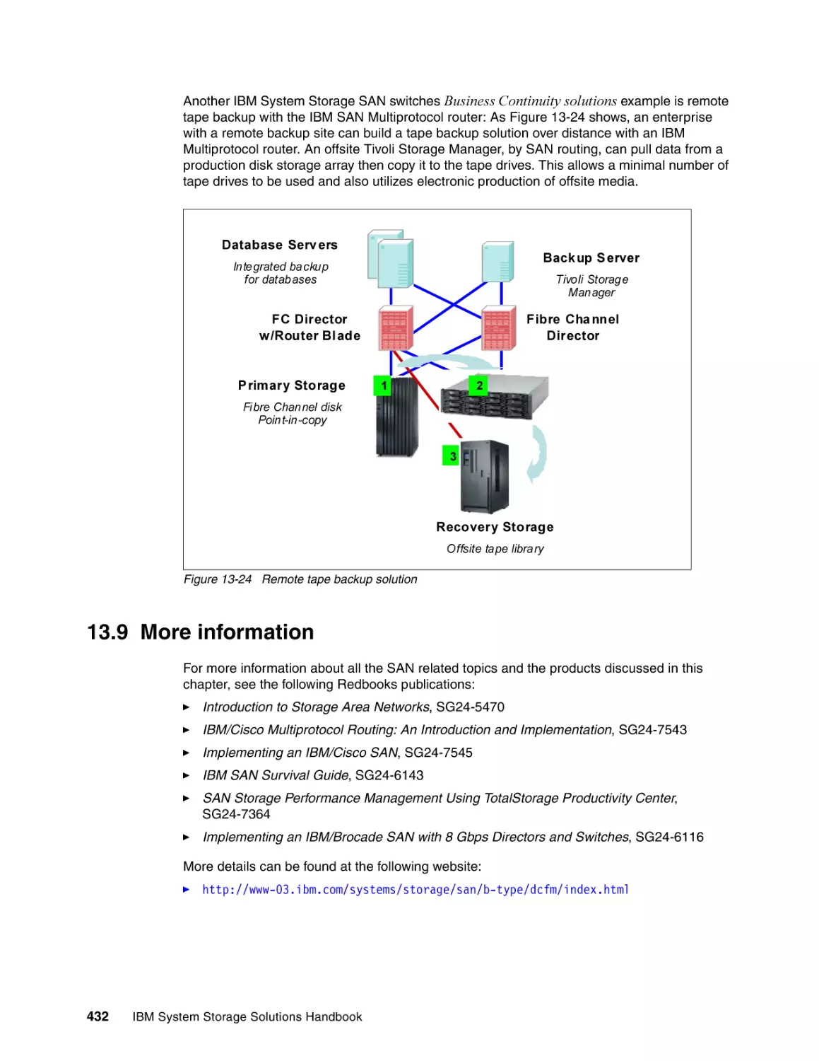
13.9 More information . . . . . . . . . . . . . . . . . . . . . . . . . . . . . . . . . . . . . . . . . . . . . . . . . . . .
401
402
403
403
404
405
407
408
409
409
412
413
417
418
420
422
423
425
426
427
427
427
428
429
430
432
Chapter 14. Data Center Networking . . . . . . . . . . . . . . . . . . . . . . . . . . . . . . . . . . . . . . .
14.1 IBM b-type Ethernet products . . . . . . . . . . . . . . . . . . . . . . . . . . . . . . . . . . . . . . . . . .
14.1.1 IBM y-series Ethernet switches. . . . . . . . . . . . . . . . . . . . . . . . . . . . . . . . . . . . .
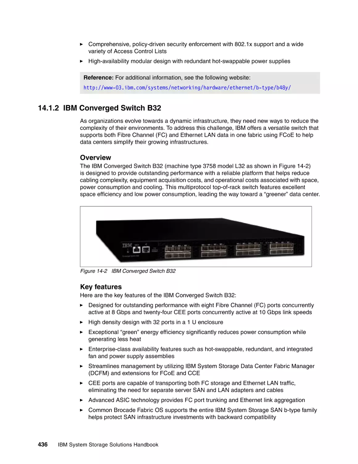
14.1.2 IBM Converged Switch B32 . . . . . . . . . . . . . . . . . . . . . . . . . . . . . . . . . . . . . . .
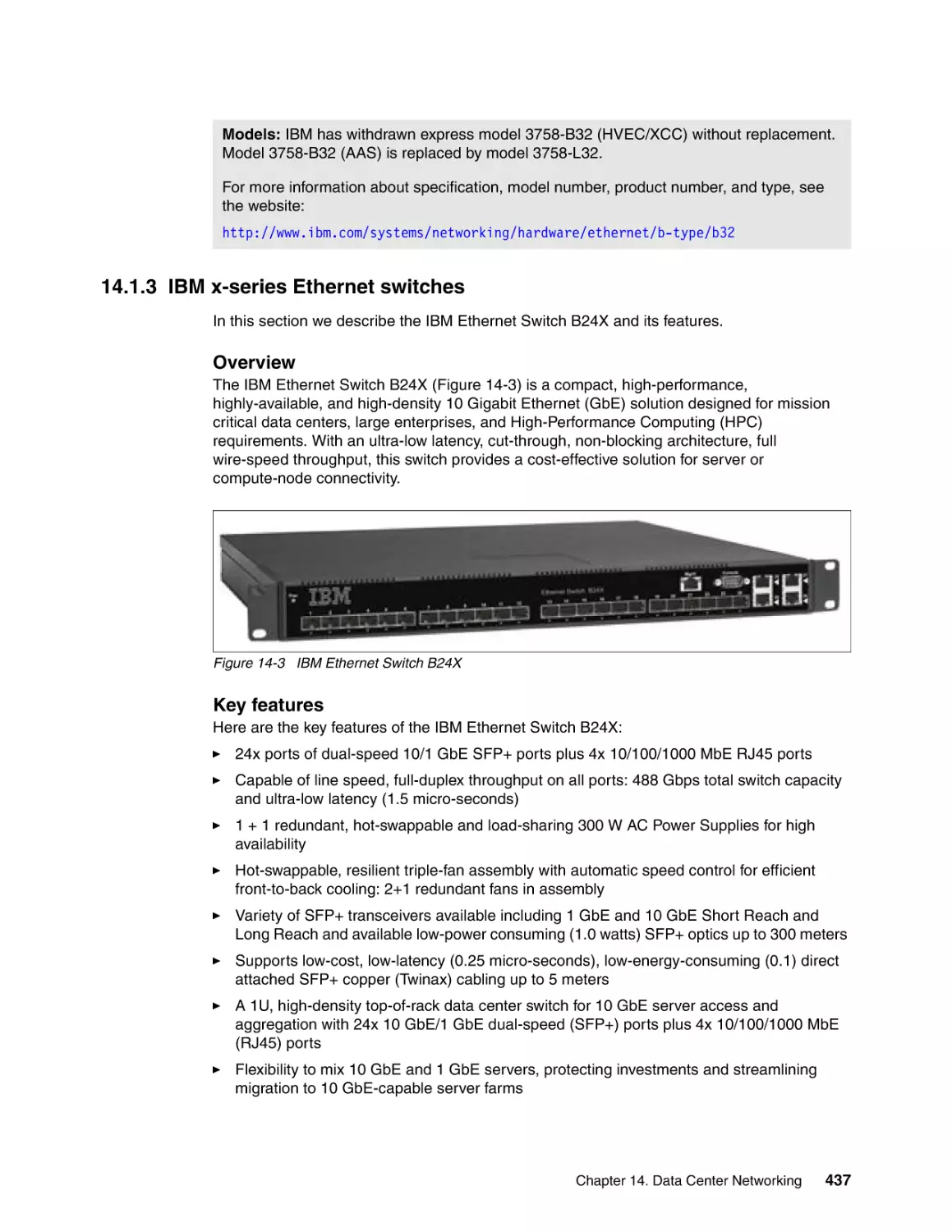
14.1.3 IBM x-series Ethernet switches. . . . . . . . . . . . . . . . . . . . . . . . . . . . . . . . . . . . .
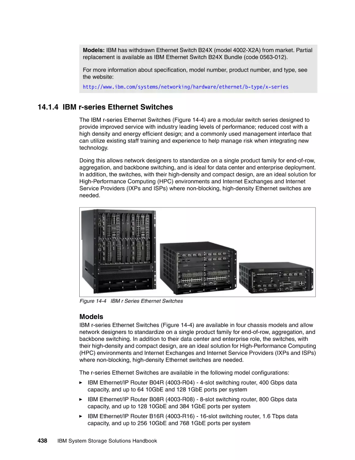
14.1.4 IBM r-series Ethernet Switches. . . . . . . . . . . . . . . . . . . . . . . . . . . . . . . . . . . . .
14.1.5 IBM c-series Ethernet Switches . . . . . . . . . . . . . . . . . . . . . . . . . . . . . . . . . . . .
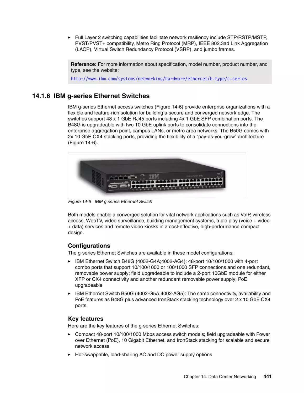
14.1.6 IBM g-series Ethernet Switches . . . . . . . . . . . . . . . . . . . . . . . . . . . . . . . . . . . .
14.1.7 IBM m-series Ethernet/IP Routers . . . . . . . . . . . . . . . . . . . . . . . . . . . . . . . . . .
14.1.8 IBM s-series Ethernet Switch . . . . . . . . . . . . . . . . . . . . . . . . . . . . . . . . . . . . . .
14.2 IBM j-type Ethernet products. . . . . . . . . . . . . . . . . . . . . . . . . . . . . . . . . . . . . . . . . . .
14.2.1 IBM Ethernet Switch J08E and IBM Ethernet Switch J16E. . . . . . . . . . . . . . . .
14.2.2 IBM Ethernet Switch J48E . . . . . . . . . . . . . . . . . . . . . . . . . . . . . . . . . . . . . . . .
14.2.3 IBM Ethernet Router J02M/J06M/J11M . . . . . . . . . . . . . . . . . . . . . . . . . . . . . .
14.2.4 IBM Ethernet Appliance J34S/J36S . . . . . . . . . . . . . . . . . . . . . . . . . . . . . . . . .
14.2.5 IBM Ethernet Appliance J56S/J58S . . . . . . . . . . . . . . . . . . . . . . . . . . . . . . . . .
14.3 IBM c-type Ethernet products . . . . . . . . . . . . . . . . . . . . . . . . . . . . . . . . . . . . . . . . . .
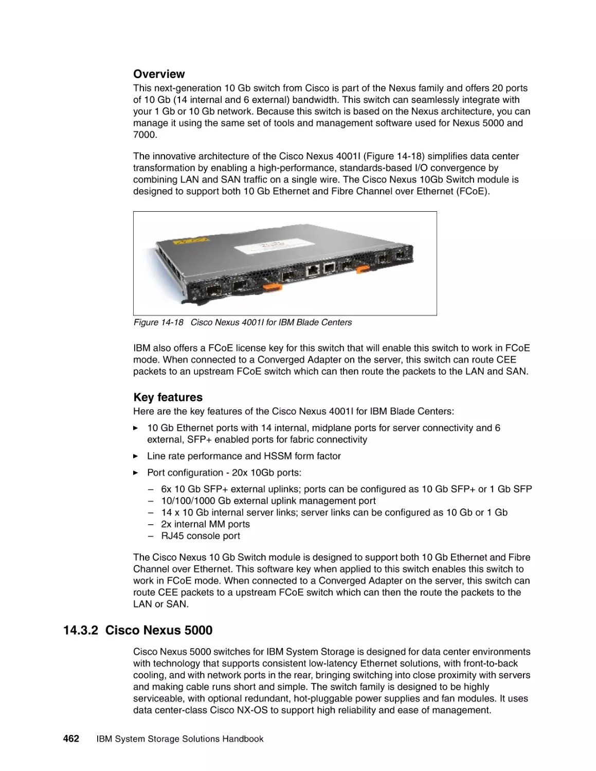
14.3.1 Cisco Nexus 4000 . . . . . . . . . . . . . . . . . . . . . . . . . . . . . . . . . . . . . . . . . . . . . . .
14.3.2 Cisco Nexus 5000 . . . . . . . . . . . . . . . . . . . . . . . . . . . . . . . . . . . . . . . . . . . . . . .
14.4 More information . . . . . . . . . . . . . . . . . . . . . . . . . . . . . . . . . . . . . . . . . . . . . . . . . . . .
433
434
434
436
437
438
439
441
442
444
446
447
450
452
454
458
461
461
462
464
Part 4. IBM System Storage software . . . . . . . . . . . . . . . . . . . . . . . . . . . . . . . . . . . . . . . . . . . . . . . . . . . 465
Chapter 15. IBM System Storage Virtualization . . . . . . . . . . . . . . . . . . . . . . . . . . . . . .
15.1 What is storage virtualization? . . . . . . . . . . . . . . . . . . . . . . . . . . . . . . . . . . . . . . . . .
15.1.1 Inefficiencies in sharing storage . . . . . . . . . . . . . . . . . . . . . . . . . . . . . . . . . . . .
15.1.2 Benefits of implementing storage virtualization in your SAN. . . . . . . . . . . . . . .
x
IBM System Storage Solutions Handbook
467
468
468
470
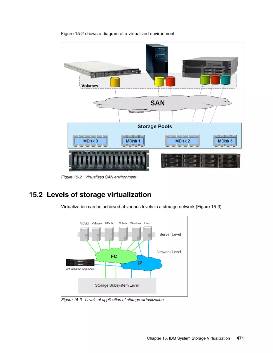
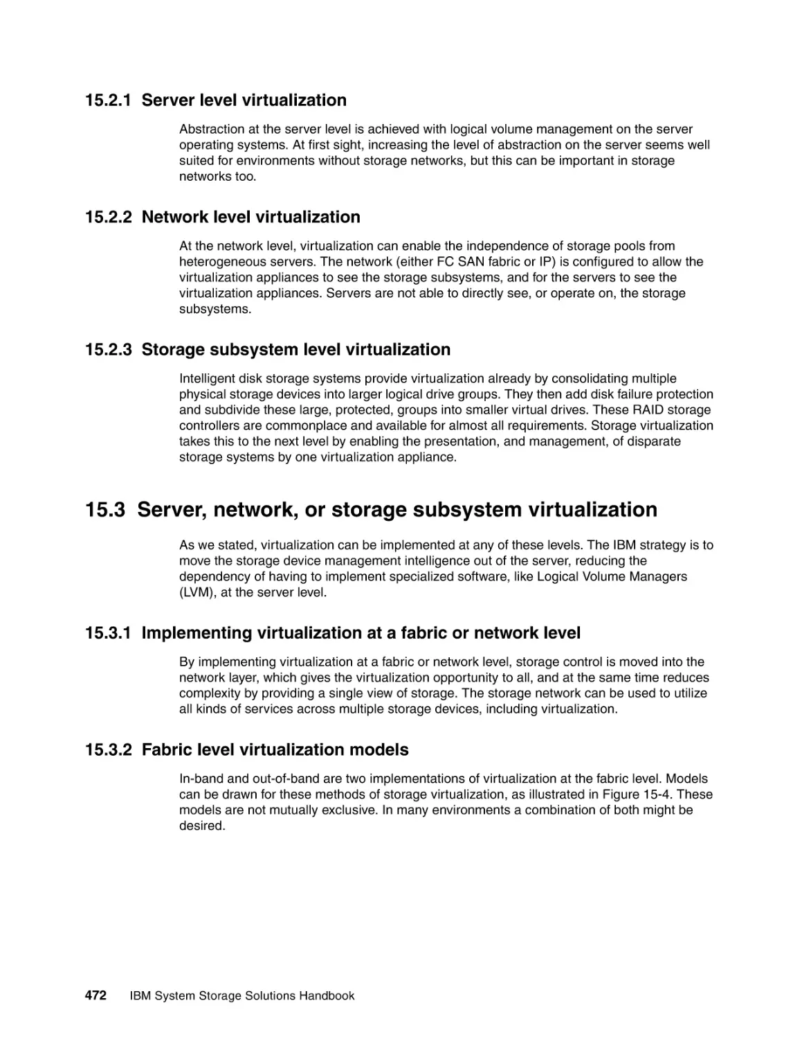
15.2 Levels of storage virtualization . . . . . . . . . . . . . . . . . . . . . . . . . . . . . . . . . . . . . . . . .
15.2.1 Server level virtualization . . . . . . . . . . . . . . . . . . . . . . . . . . . . . . . . . . . . . . . . .
15.2.2 Network level virtualization . . . . . . . . . . . . . . . . . . . . . . . . . . . . . . . . . . . . . . . .
15.2.3 Storage subsystem level virtualization . . . . . . . . . . . . . . . . . . . . . . . . . . . . . . .
15.3 Server, network, or storage subsystem virtualization . . . . . . . . . . . . . . . . . . . . . . . .
15.3.1 Implementing virtualization at a fabric or network level. . . . . . . . . . . . . . . . . . .
15.3.2 Fabric level virtualization models . . . . . . . . . . . . . . . . . . . . . . . . . . . . . . . . . . .
15.4 IBM System Storage approach to virtualization . . . . . . . . . . . . . . . . . . . . . . . . . . . .
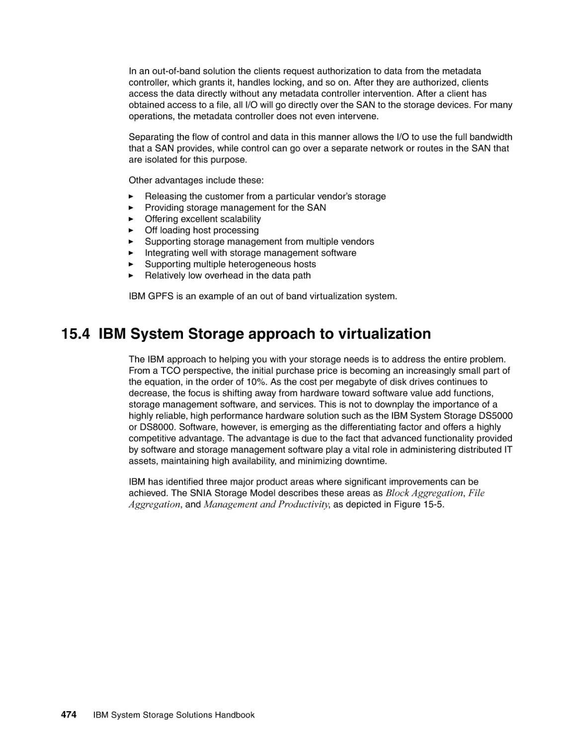
15.4.1 IBM block aggregation characteristics . . . . . . . . . . . . . . . . . . . . . . . . . . . . . . .
15.4.2 IBM file aggregation characteristics . . . . . . . . . . . . . . . . . . . . . . . . . . . . . . . . .
15.5 IBM System Storage Virtualization family . . . . . . . . . . . . . . . . . . . . . . . . . . . . . . . . .
15.5.1 IBM SAN Volume Controller . . . . . . . . . . . . . . . . . . . . . . . . . . . . . . . . . . . . . . .
15.5.2 IBM Storwize V7000 . . . . . . . . . . . . . . . . . . . . . . . . . . . . . . . . . . . . . . . . . . . . .
15.5.3 IBM XIV Storage System . . . . . . . . . . . . . . . . . . . . . . . . . . . . . . . . . . . . . . . . .
15.5.4 IBM System Storage DS8000 Series . . . . . . . . . . . . . . . . . . . . . . . . . . . . . . . .
15.5.5 IBM Scale Out Network Attached Storage (SONAS) . . . . . . . . . . . . . . . . . . . .
15.5.6 IBM Virtualization Engine . . . . . . . . . . . . . . . . . . . . . . . . . . . . . . . . . . . . . . . . .
15.5.7 IBM System Storage TS7680 ProtecTIER Deduplication Gateway: System z .
15.5.8 IBM System Storage TS7650 ProtecTIER Appliance . . . . . . . . . . . . . . . . . . . .
15.5.9 IBM System Storage TS7650G ProtecTIER Deduplication Gateway . . . . . . . .
15.5.10 IBM Tivoli Storage Productivity Center . . . . . . . . . . . . . . . . . . . . . . . . . . . . . .
15.5.11 IBM System Storage N series . . . . . . . . . . . . . . . . . . . . . . . . . . . . . . . . . . . . .
15.5.12 IBM General Parallel File System . . . . . . . . . . . . . . . . . . . . . . . . . . . . . . . . . .
15.6 IBM SAN Volume Controller and Storwize V7000 features. . . . . . . . . . . . . . . . . . . .
15.6.1 Storage virtualization . . . . . . . . . . . . . . . . . . . . . . . . . . . . . . . . . . . . . . . . . . . .
15.6.2 Thin provisioning . . . . . . . . . . . . . . . . . . . . . . . . . . . . . . . . . . . . . . . . . . . . . . . .
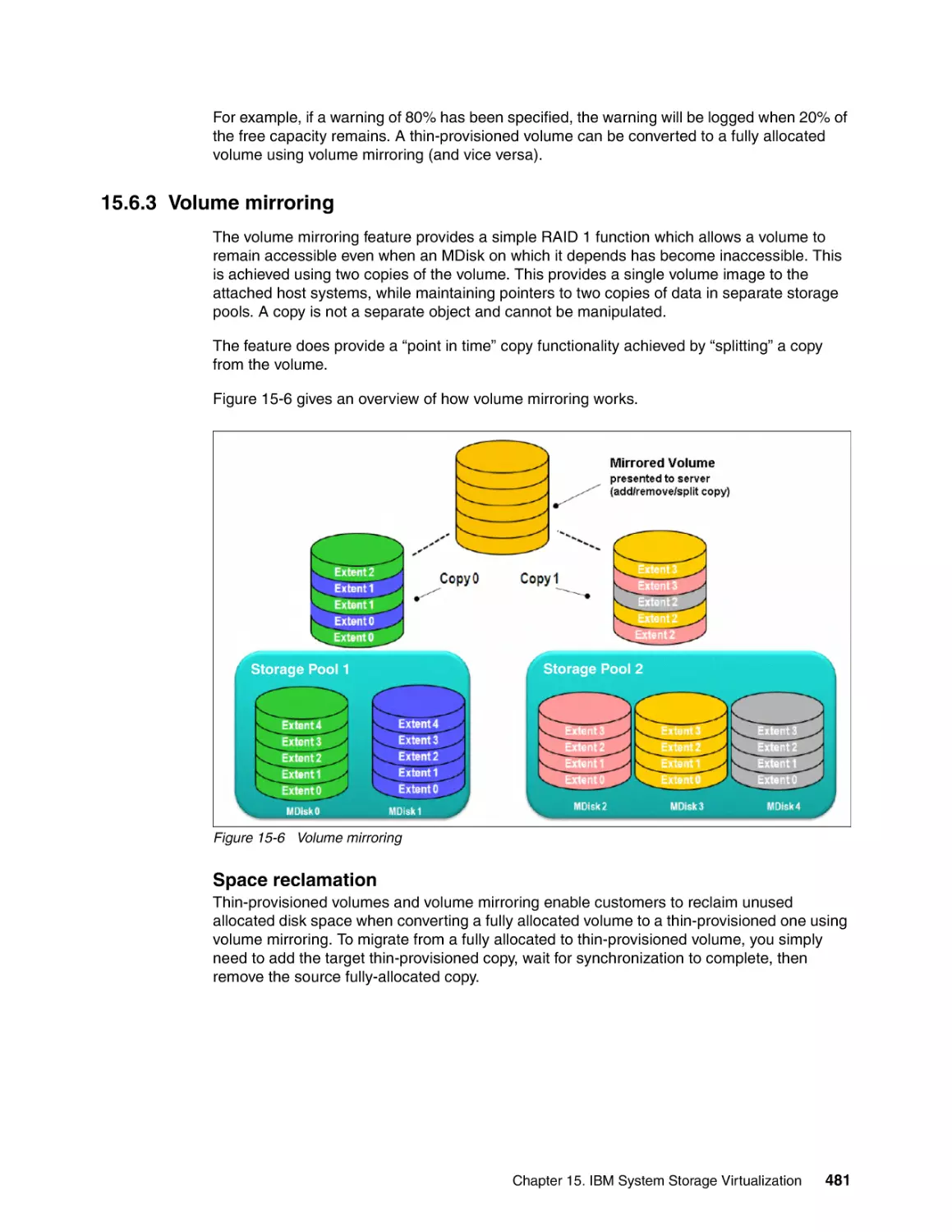
15.6.3 Volume mirroring. . . . . . . . . . . . . . . . . . . . . . . . . . . . . . . . . . . . . . . . . . . . . . . .
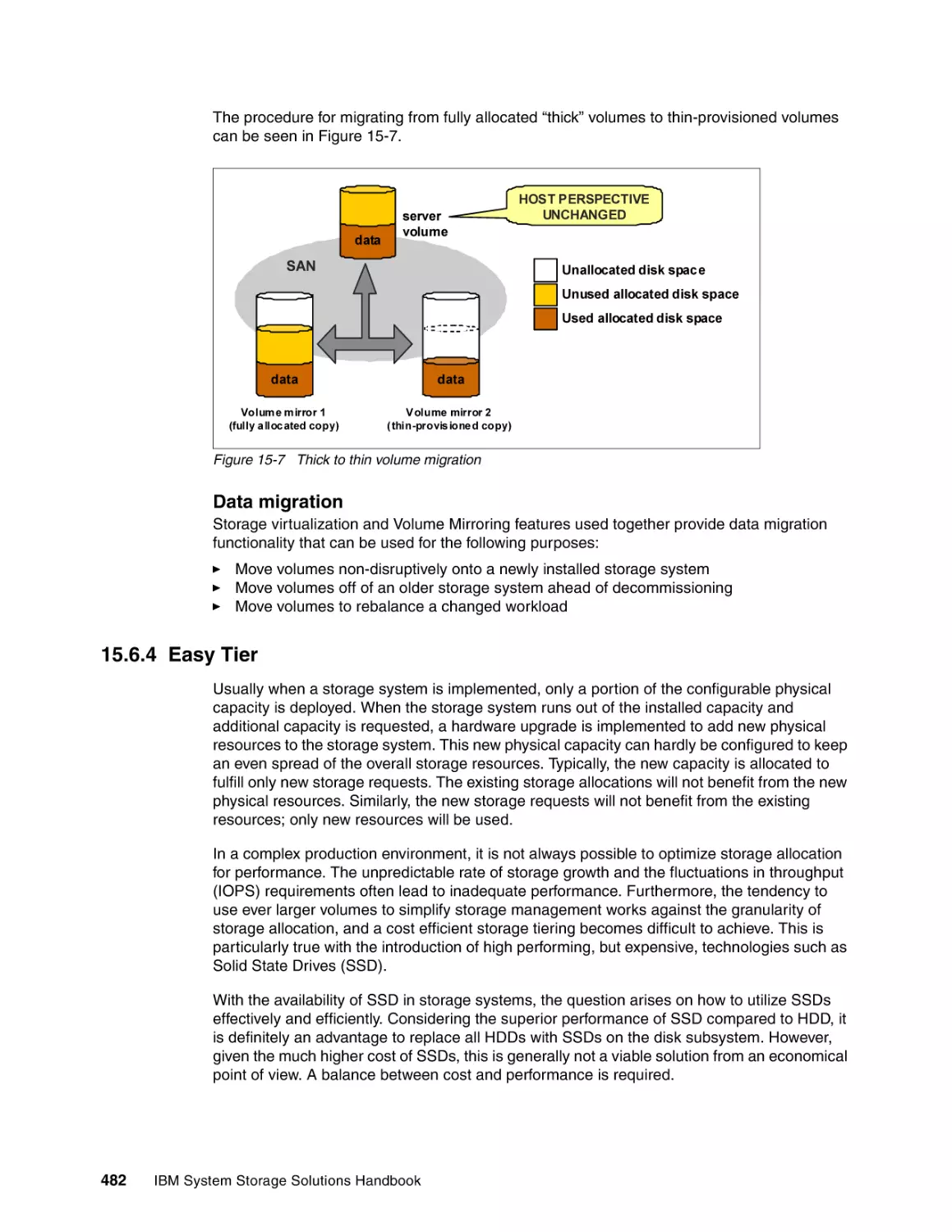
15.6.4 Easy Tier . . . . . . . . . . . . . . . . . . . . . . . . . . . . . . . . . . . . . . . . . . . . . . . . . . . . . .
15.6.5 FlashCopy . . . . . . . . . . . . . . . . . . . . . . . . . . . . . . . . . . . . . . . . . . . . . . . . . . . . .
15.6.6 Metro Mirror and Global Mirror Copy Services . . . . . . . . . . . . . . . . . . . . . . . . .
15.7 More information . . . . . . . . . . . . . . . . . . . . . . . . . . . . . . . . . . . . . . . . . . . . . . . . . . . .
471
472
472
472
472
472
472
474
475
475
475
476
476
476
476
477
477
477
477
478
478
478
479
479
479
480
481
482
485
489
494
Chapter 16. IBM System Storage SAN Volume Controller. . . . . . . . . . . . . . . . . . . . . .
16.1 IBM System Storage SAN Volume Controller: Overview . . . . . . . . . . . . . . . . . . . . .
16.1.1 Introduction . . . . . . . . . . . . . . . . . . . . . . . . . . . . . . . . . . . . . . . . . . . . . . . . . . . .
16.1.2 Design intent . . . . . . . . . . . . . . . . . . . . . . . . . . . . . . . . . . . . . . . . . . . . . . . . . . .
16.2 New features in SAN Volume Controller 6.1 . . . . . . . . . . . . . . . . . . . . . . . . . . . . . . .
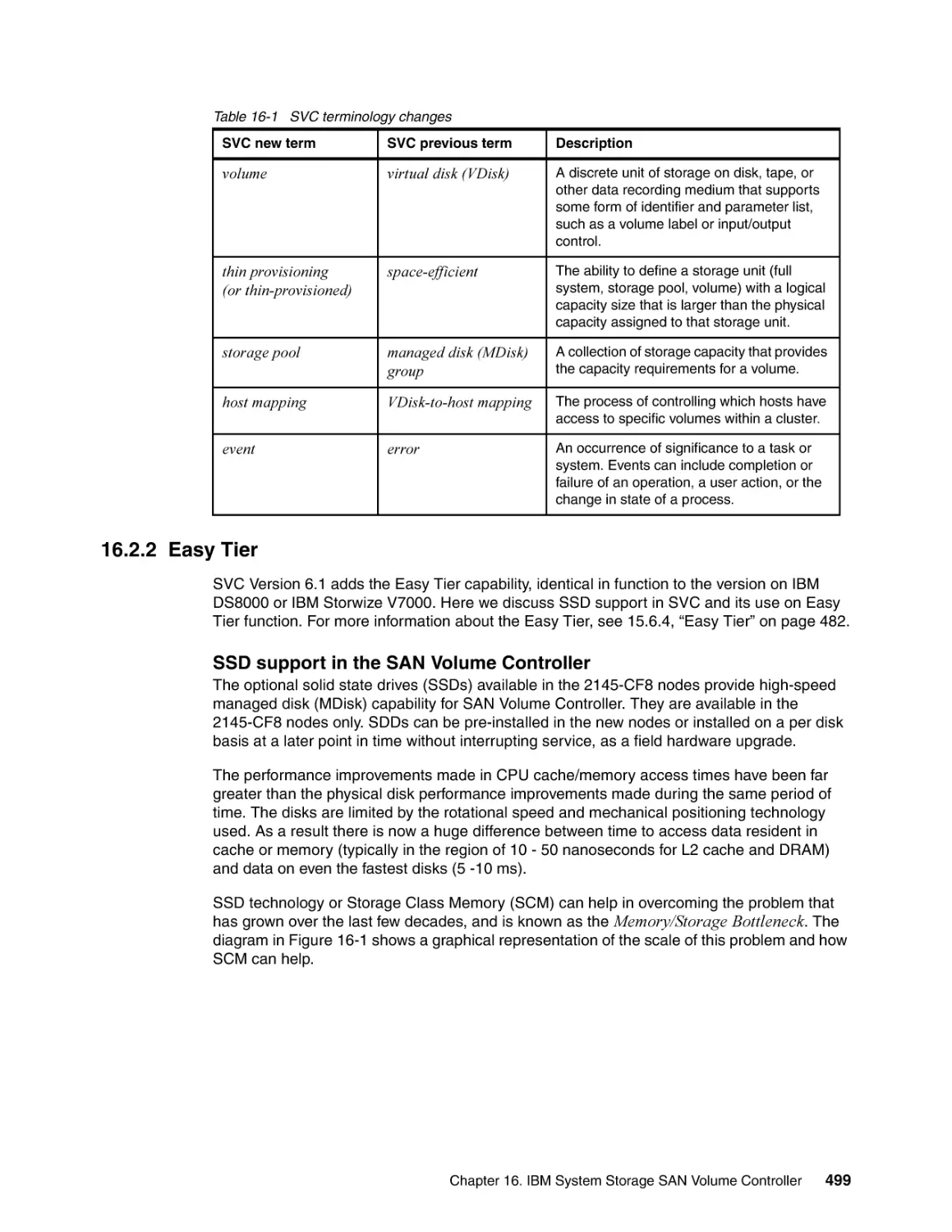
16.2.1 Terminology changes . . . . . . . . . . . . . . . . . . . . . . . . . . . . . . . . . . . . . . . . . . . .
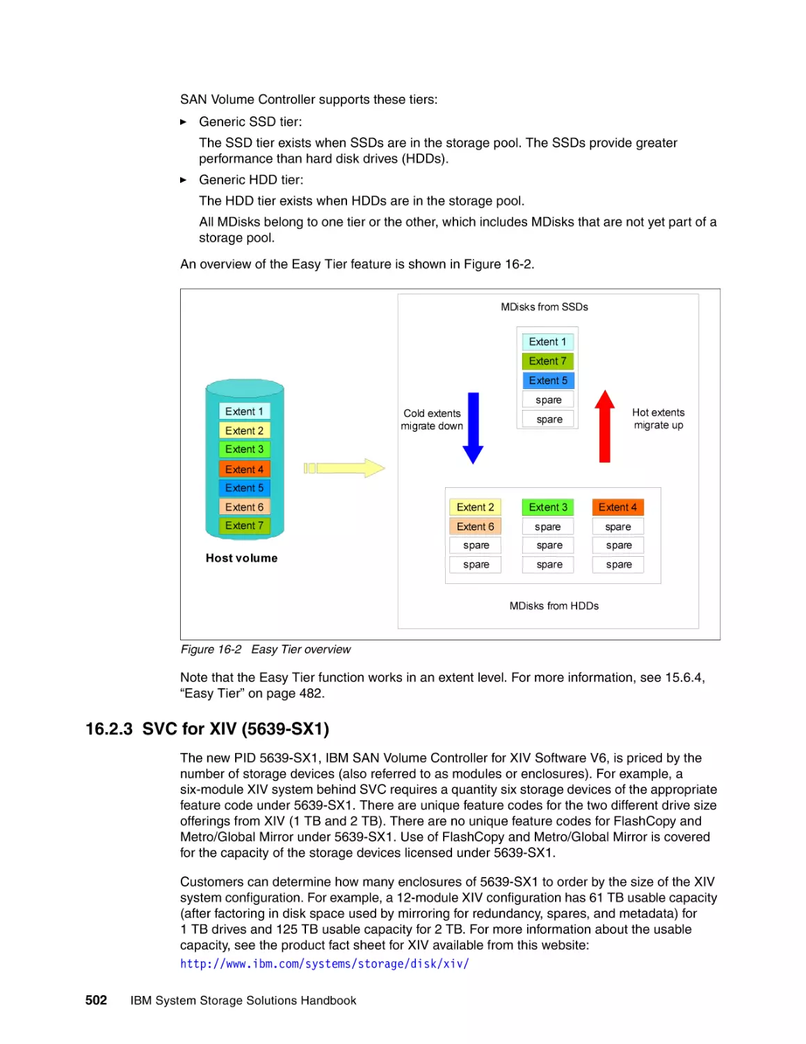
16.2.2 Easy Tier . . . . . . . . . . . . . . . . . . . . . . . . . . . . . . . . . . . . . . . . . . . . . . . . . . . . . .
16.2.3 SVC for XIV (5639-SX1) . . . . . . . . . . . . . . . . . . . . . . . . . . . . . . . . . . . . . . . . . .
16.3 SAN Volume Controller architecture . . . . . . . . . . . . . . . . . . . . . . . . . . . . . . . . . . . . .
16.3.1 SVC Hardware . . . . . . . . . . . . . . . . . . . . . . . . . . . . . . . . . . . . . . . . . . . . . . . . .
16.3.2 SVC features. . . . . . . . . . . . . . . . . . . . . . . . . . . . . . . . . . . . . . . . . . . . . . . . . . .
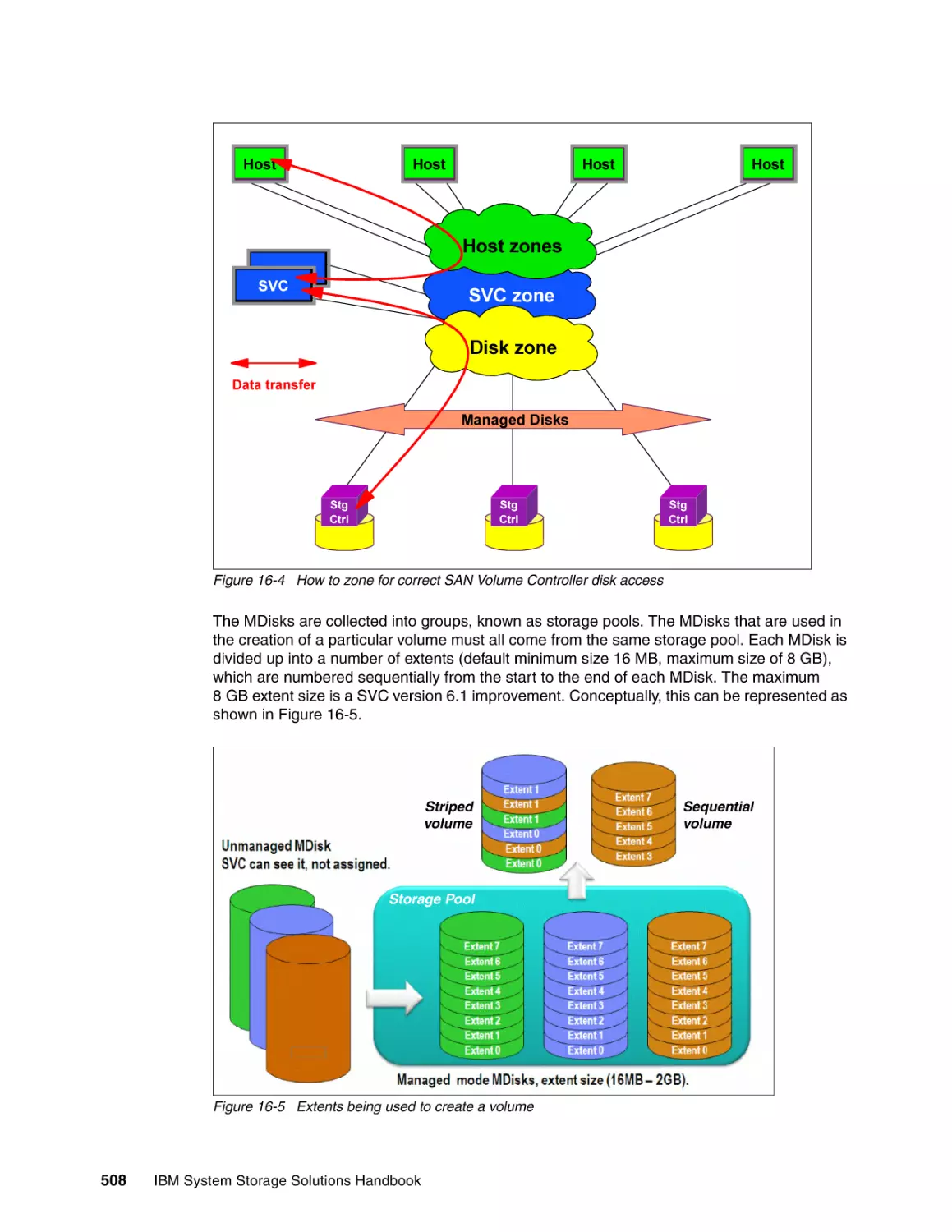
16.4 SAN Volume Controller virtualization . . . . . . . . . . . . . . . . . . . . . . . . . . . . . . . . . . . .
16.5 SAN Volume Controller iSCSI host attachment . . . . . . . . . . . . . . . . . . . . . . . . . . . .
16.5.1 Sample configurations . . . . . . . . . . . . . . . . . . . . . . . . . . . . . . . . . . . . . . . . . . .
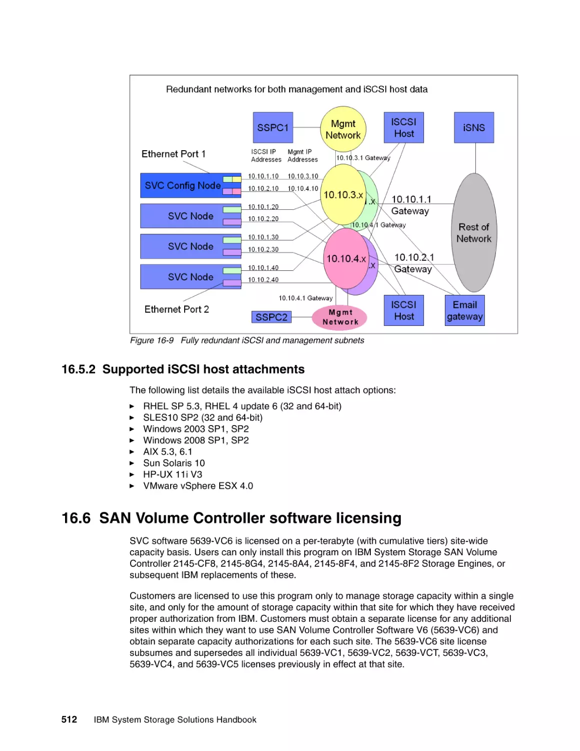
16.5.2 Supported iSCSI host attachments . . . . . . . . . . . . . . . . . . . . . . . . . . . . . . . . . .
16.6 SAN Volume Controller software licensing . . . . . . . . . . . . . . . . . . . . . . . . . . . . . . . .
16.7 SAN Volume Controller solutions . . . . . . . . . . . . . . . . . . . . . . . . . . . . . . . . . . . . . . .
16.7.1 Business continuity . . . . . . . . . . . . . . . . . . . . . . . . . . . . . . . . . . . . . . . . . . . . . .
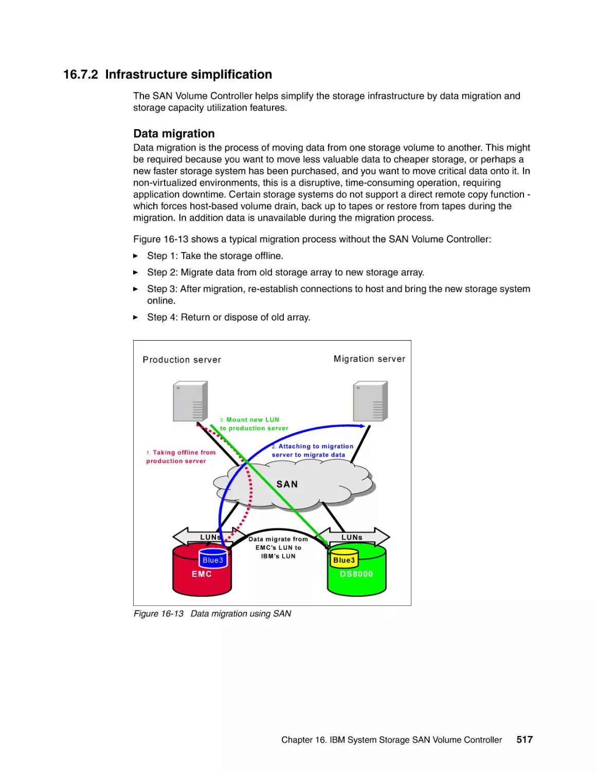
16.7.2 Infrastructure simplification . . . . . . . . . . . . . . . . . . . . . . . . . . . . . . . . . . . . . . . .
16.8 SAN Volume Controller compatibility . . . . . . . . . . . . . . . . . . . . . . . . . . . . . . . . . . . .
16.9 SAN Volume Controller commonly used terms . . . . . . . . . . . . . . . . . . . . . . . . . . . . .
495
496
496
496
498
498
499
502
503
505
505
507
510
510
512
512
516
516
517
519
519
Contents
xi
16.10 More information . . . . . . . . . . . . . . . . . . . . . . . . . . . . . . . . . . . . . . . . . . . . . . . . . . . 520
xii
Chapter 17. IBM Storwize V7000 . . . . . . . . . . . . . . . . . . . . . . . . . . . . . . . . . . . . . . . . . .
17.1 IBM Storwize V7000: Overview. . . . . . . . . . . . . . . . . . . . . . . . . . . . . . . . . . . . . . . . .
17.2 IBM Storwize V7000 components . . . . . . . . . . . . . . . . . . . . . . . . . . . . . . . . . . . . . . .
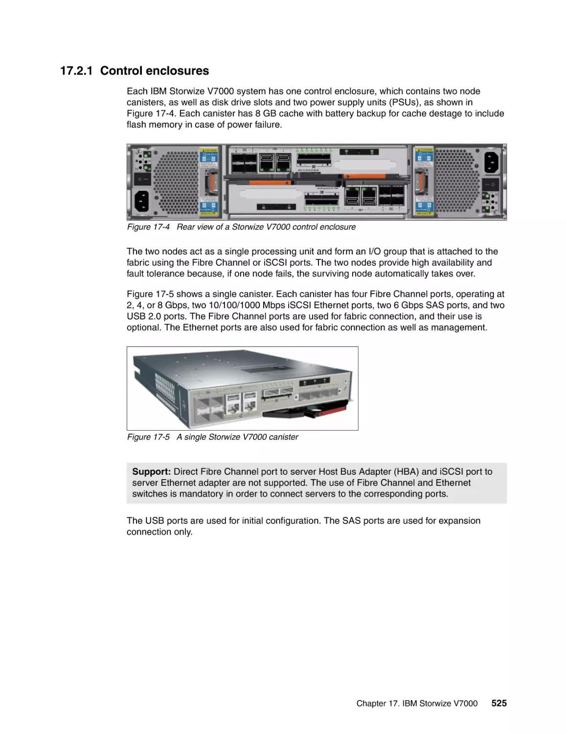
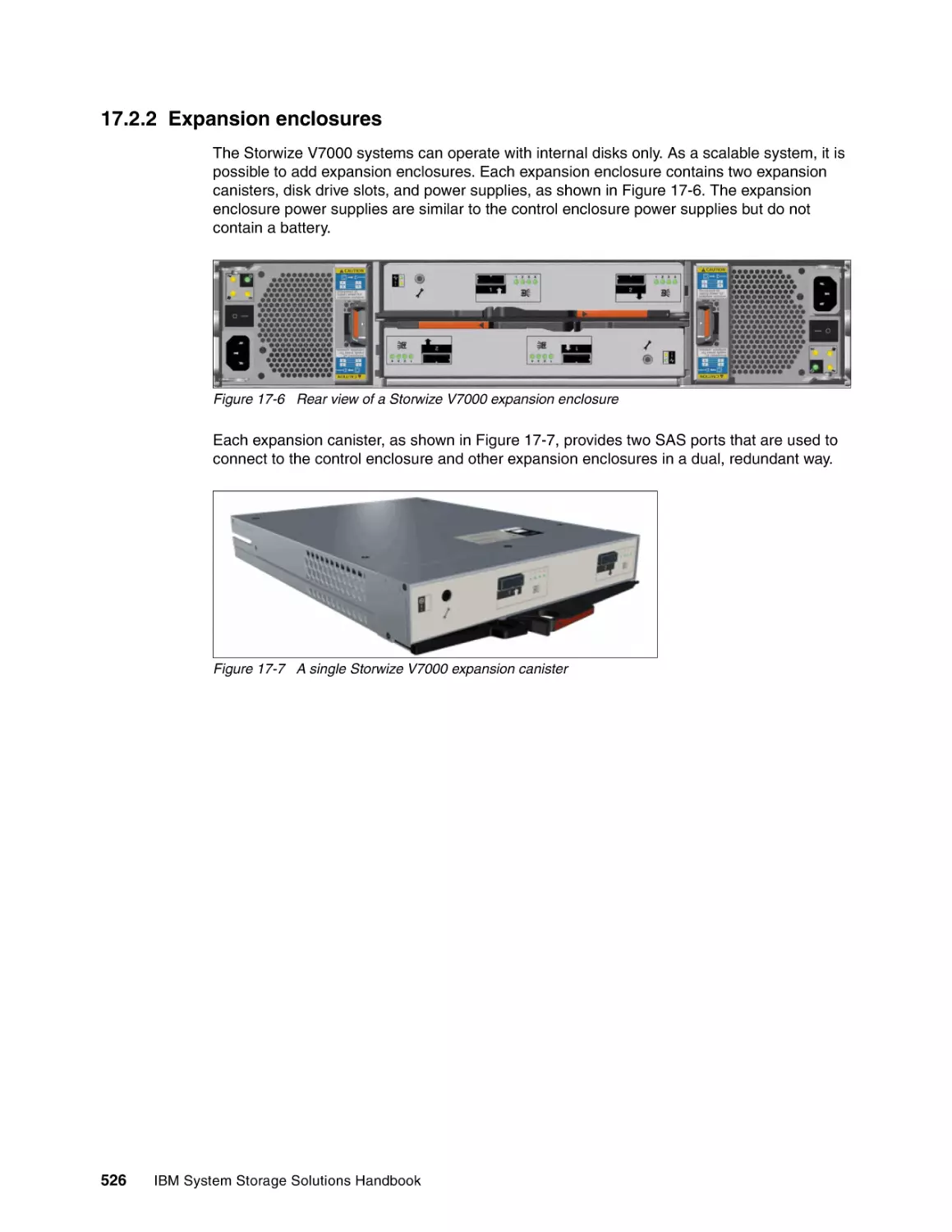
17.2.1 Control enclosures . . . . . . . . . . . . . . . . . . . . . . . . . . . . . . . . . . . . . . . . . . . . . .
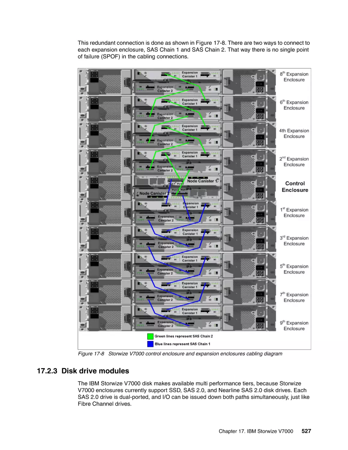
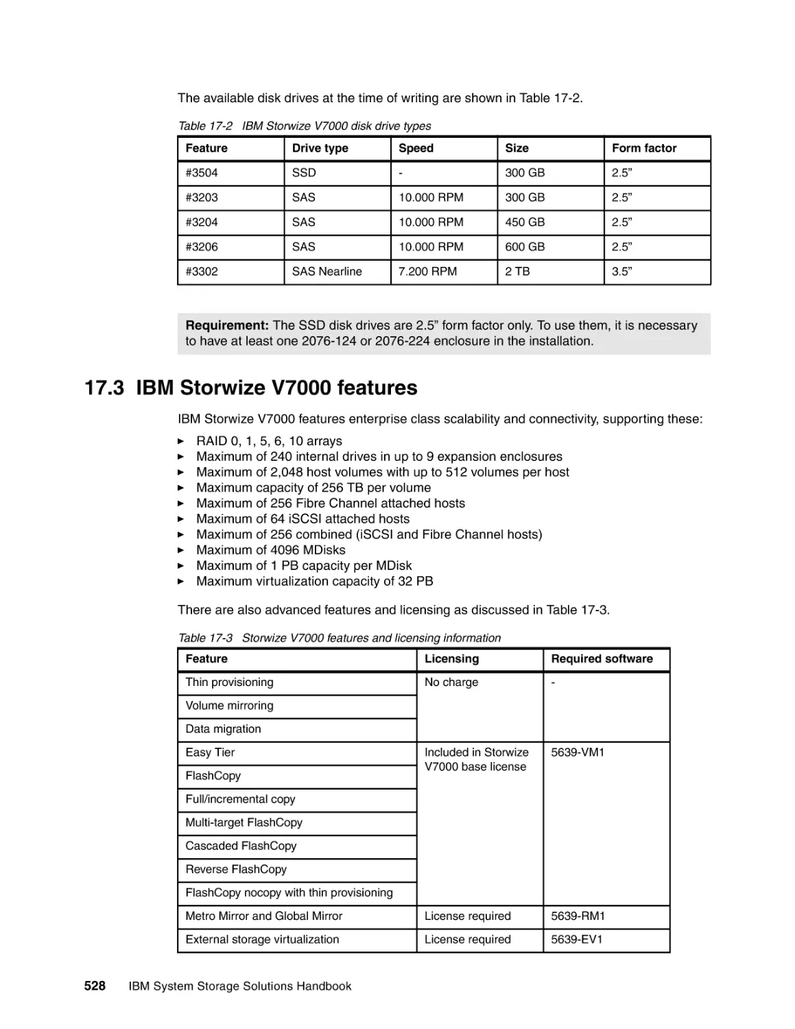
17.2.2 Expansion enclosures . . . . . . . . . . . . . . . . . . . . . . . . . . . . . . . . . . . . . . . . . . . .
17.2.3 Disk drive modules . . . . . . . . . . . . . . . . . . . . . . . . . . . . . . . . . . . . . . . . . . . . . .
17.3 IBM Storwize V7000 features . . . . . . . . . . . . . . . . . . . . . . . . . . . . . . . . . . . . . . . . . .
17.3.1 Thin provisioning . . . . . . . . . . . . . . . . . . . . . . . . . . . . . . . . . . . . . . . . . . . . . . . .
17.3.2 Volume mirroring. . . . . . . . . . . . . . . . . . . . . . . . . . . . . . . . . . . . . . . . . . . . . . . .
17.3.3 Data migration. . . . . . . . . . . . . . . . . . . . . . . . . . . . . . . . . . . . . . . . . . . . . . . . . .
17.3.4 Easy Tier . . . . . . . . . . . . . . . . . . . . . . . . . . . . . . . . . . . . . . . . . . . . . . . . . . . . . .
17.3.5 FlashCopy . . . . . . . . . . . . . . . . . . . . . . . . . . . . . . . . . . . . . . . . . . . . . . . . . . . . .
17.3.6 Metro Mirror and Global Mirror . . . . . . . . . . . . . . . . . . . . . . . . . . . . . . . . . . . . .
17.3.7 External storage virtualization . . . . . . . . . . . . . . . . . . . . . . . . . . . . . . . . . . . . . .
17.4 IBM Storwize V7000 topology . . . . . . . . . . . . . . . . . . . . . . . . . . . . . . . . . . . . . . . . . .
17.4.1 Logical topology and storage hierarchy . . . . . . . . . . . . . . . . . . . . . . . . . . . . . .
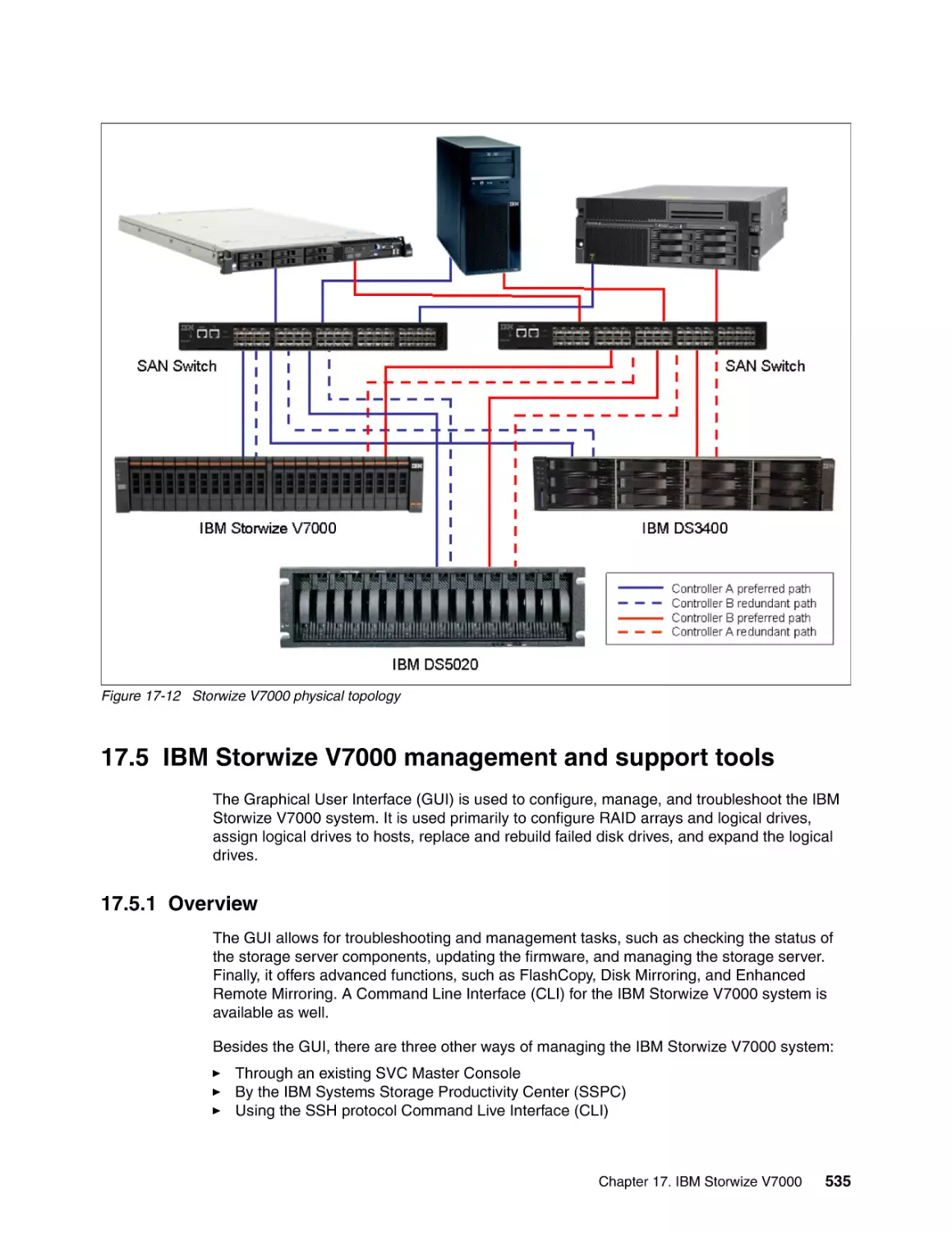
17.4.2 Physical topology . . . . . . . . . . . . . . . . . . . . . . . . . . . . . . . . . . . . . . . . . . . . . . .
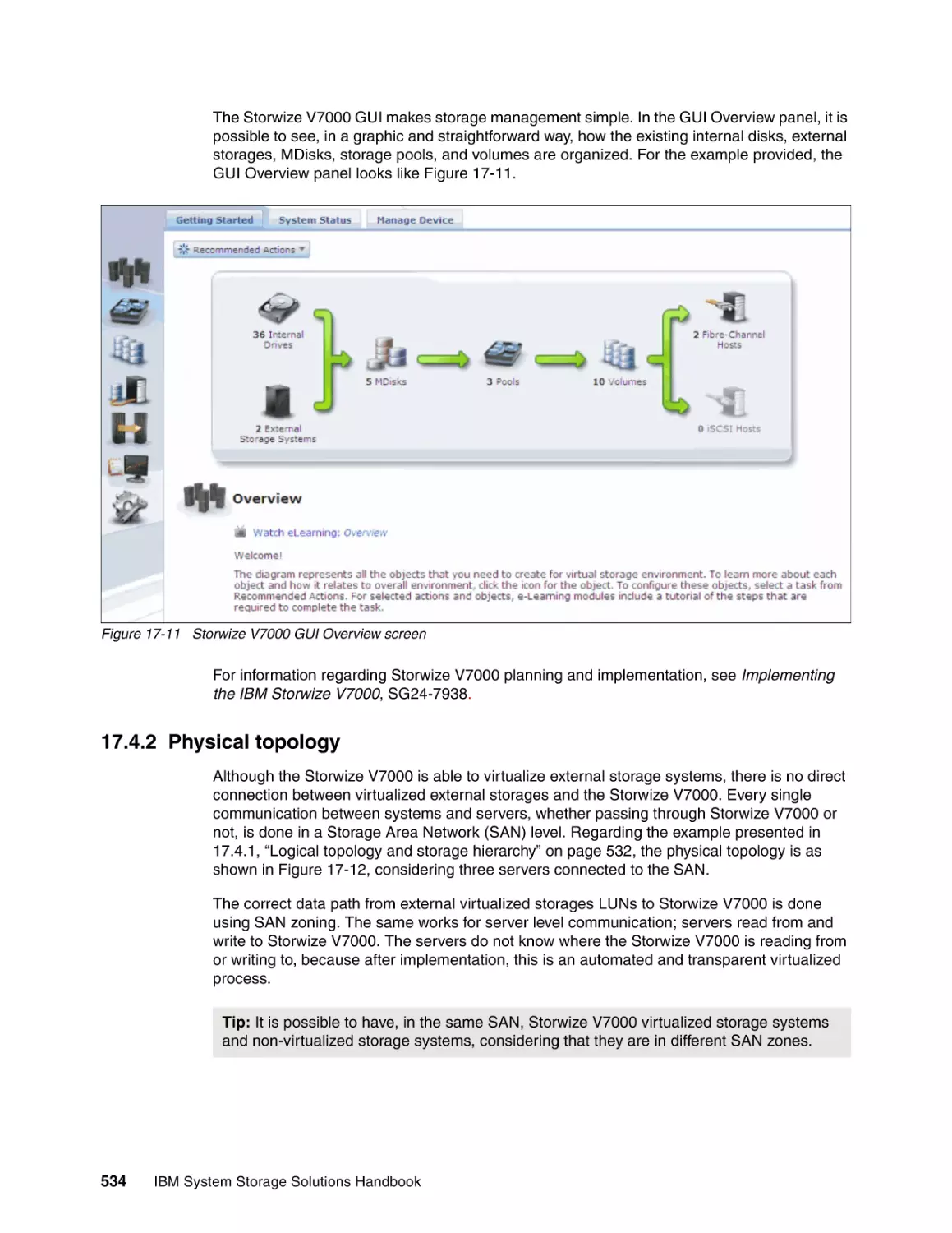
17.5 IBM Storwize V7000 management and support tools . . . . . . . . . . . . . . . . . . . . . . . .
17.5.1 Overview . . . . . . . . . . . . . . . . . . . . . . . . . . . . . . . . . . . . . . . . . . . . . . . . . . . . . .
17.5.2 Event notifications . . . . . . . . . . . . . . . . . . . . . . . . . . . . . . . . . . . . . . . . . . . . . . .
17.6 IBM Storwize V7000 supported environments . . . . . . . . . . . . . . . . . . . . . . . . . . . . .
17.7 More information . . . . . . . . . . . . . . . . . . . . . . . . . . . . . . . . . . . . . . . . . . . . . . . . . . . .
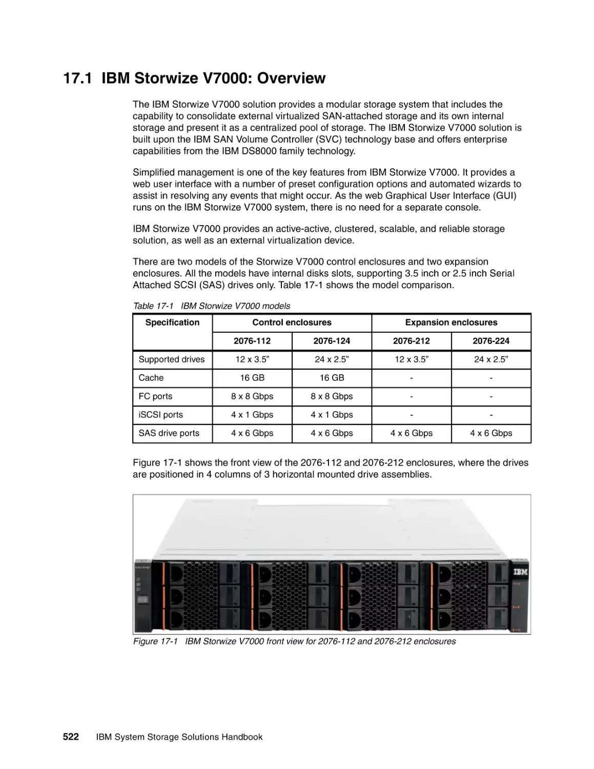
521
522
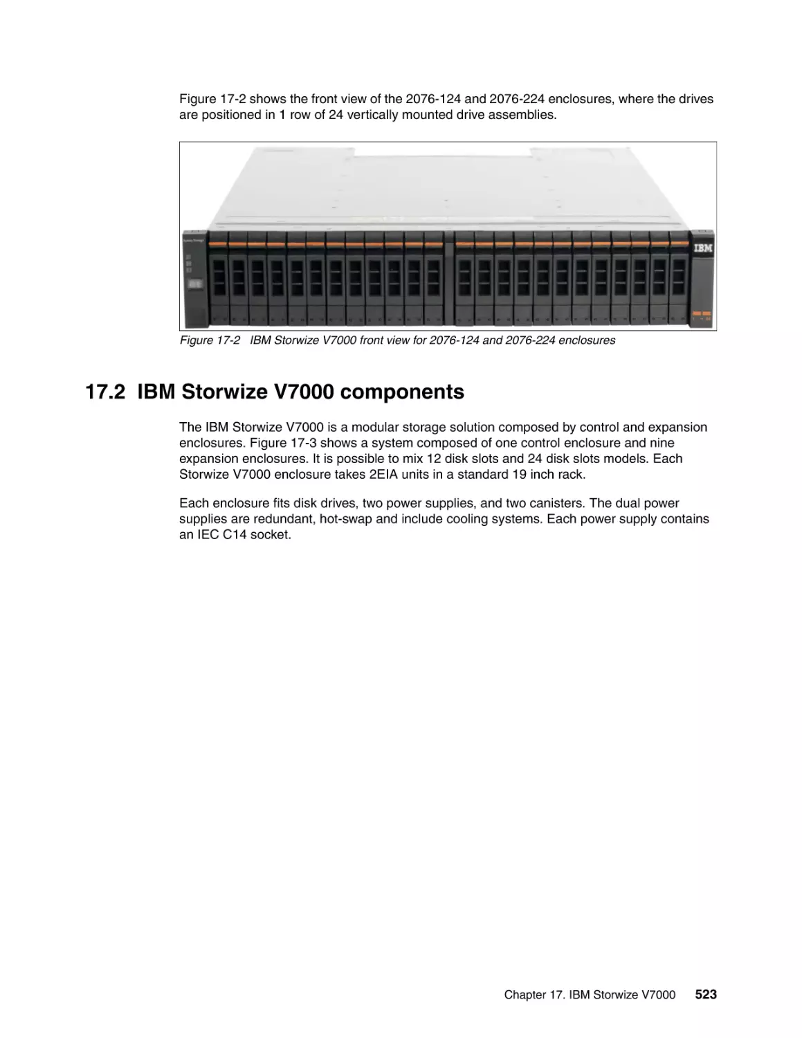
523
525
526
527
528
529
529
529
530
531
532
532
532
532
534
535
535
536
536
536
Chapter 18. IBM Tivoli Storage Manager. . . . . . . . . . . . . . . . . . . . . . . . . . . . . . . . . . . .
18.1 New in IBM Tivoli Storage Manager V6.2 . . . . . . . . . . . . . . . . . . . . . . . . . . . . . . . . .
18.1.1 Server updates . . . . . . . . . . . . . . . . . . . . . . . . . . . . . . . . . . . . . . . . . . . . . . . . .
18.1.2 Tivoli Storage Manager licensing . . . . . . . . . . . . . . . . . . . . . . . . . . . . . . . . . . .
18.1.3 Reporting and monitoring feature . . . . . . . . . . . . . . . . . . . . . . . . . . . . . . . . . . .
18.1.4 Backup-archive client updates . . . . . . . . . . . . . . . . . . . . . . . . . . . . . . . . . . . . .
18.1.5 Application program interface (API) updates . . . . . . . . . . . . . . . . . . . . . . . . . .
18.1.6 Space Management for UNIX and Linux client updates . . . . . . . . . . . . . . . . . .
18.1.7 HSM for Windows updates . . . . . . . . . . . . . . . . . . . . . . . . . . . . . . . . . . . . . . . .
18.1.8 IBM Tivoli Storage FlashCopy Manager V2.2 . . . . . . . . . . . . . . . . . . . . . . . . . .
18.1.9 Data Protection for Mail updates. . . . . . . . . . . . . . . . . . . . . . . . . . . . . . . . . . . .
18.1.10 Data Protection for SAP updates . . . . . . . . . . . . . . . . . . . . . . . . . . . . . . . . . .
18.1.11 Storage agent updates . . . . . . . . . . . . . . . . . . . . . . . . . . . . . . . . . . . . . . . . . .
18.1.12 Previous products and components prior to V6.2 . . . . . . . . . . . . . . . . . . . . . .
18.2 IBM Tivoli Storage Manager overview . . . . . . . . . . . . . . . . . . . . . . . . . . . . . . . . . . .
18.3 IBM Tivoli Storage Manager architecture . . . . . . . . . . . . . . . . . . . . . . . . . . . . . . . . .
18.3.1 IBM Tivoli Storage Manager architectural components . . . . . . . . . . . . . . . . . .
18.3.2 How client data is stored . . . . . . . . . . . . . . . . . . . . . . . . . . . . . . . . . . . . . . . . . .
18.3.3 How the server manages storage . . . . . . . . . . . . . . . . . . . . . . . . . . . . . . . . . . .
18.3.4 Tivoli Storage Manager backup and archive concepts . . . . . . . . . . . . . . . . . . .
18.3.5 Progressive incremental backups . . . . . . . . . . . . . . . . . . . . . . . . . . . . . . . . . . .
18.3.6 Tivoli Storage Manager reporting and monitoring . . . . . . . . . . . . . . . . . . . . . . .
18.3.7 Tivoli Storage Manager Administration Center . . . . . . . . . . . . . . . . . . . . . . . . .
18.3.8 Tivoli Storage Manager API . . . . . . . . . . . . . . . . . . . . . . . . . . . . . . . . . . . . . . .
18.3.9 Tivoli Storage Manager security . . . . . . . . . . . . . . . . . . . . . . . . . . . . . . . . . . . .
18.4 IBM Tivoli Storage Manager family of products . . . . . . . . . . . . . . . . . . . . . . . . . . . .
18.4.1 IBM Tivoli Storage Manager Basic or Standard Edition . . . . . . . . . . . . . . . . . .
18.4.2 IBM Tivoli Storage Manager Extended Edition . . . . . . . . . . . . . . . . . . . . . . . . .
537
538
538
543
545
545
546
547
548
548
549
549
550
550
550
551
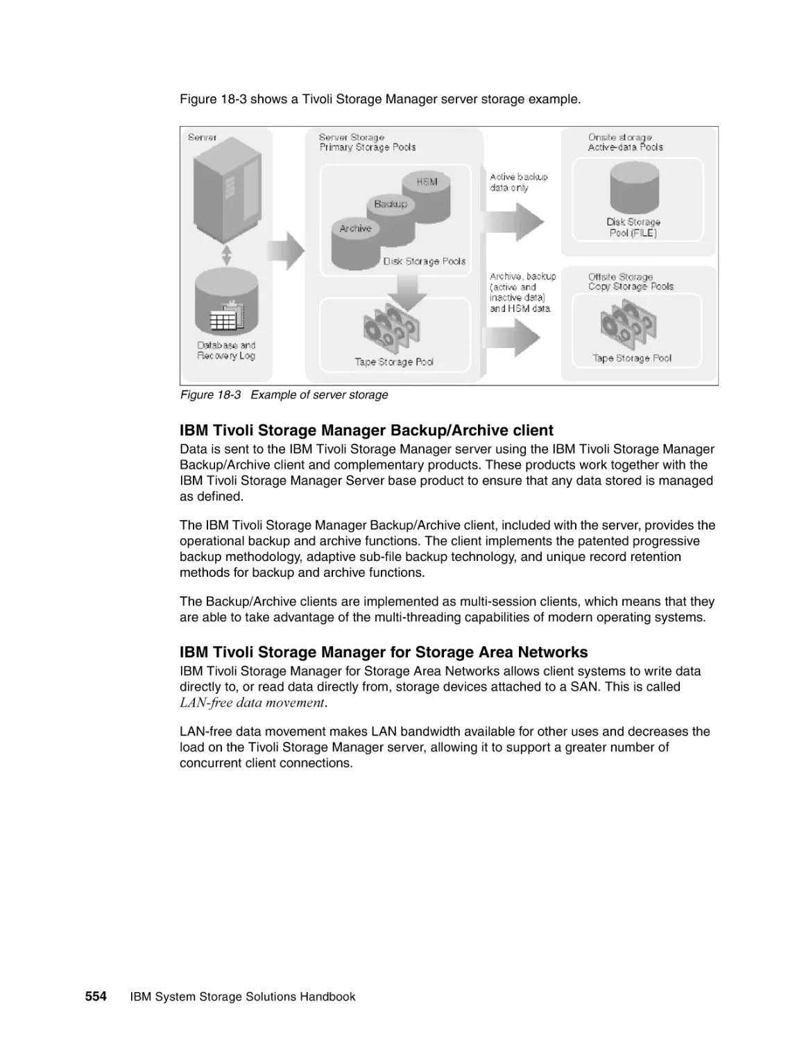
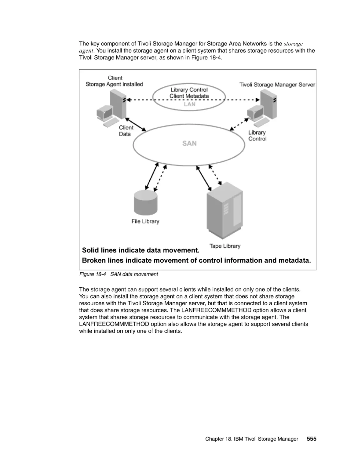
553
557
559
563
563
563
566
567
567
568
568
569
IBM System Storage Solutions Handbook
18.5 IBM Tivoli Storage Manager complementary products . . . . . . . . . . . . . . . . . . . . . . .
18.5.1 .IBM Tivoli Storage Manager for Mail . . . . . . . . . . . . . . . . . . . . . . . . . . . . . . . .
18.5.2 IBM Tivoli Storage Manager for Databases . . . . . . . . . . . . . . . . . . . . . . . . . . .
18.5.3 IBM Tivoli Storage Manager for Microsoft SharePoint . . . . . . . . . . . . . . . . . . .
18.5.4 IBM Tivoli Storage Manager HSM for Windows . . . . . . . . . . . . . . . . . . . . . . . .
18.5.5 IBM Tivoli Storage Manager for Advanced Copy Services . . . . . . . . . . . . . . . .
18.5.6 IBM Tivoli Storage Manager for Copy Services . . . . . . . . . . . . . . . . . . . . . . . .
18.5.7 IBM Tivoli Storage Manager for SAP Version 6 . . . . . . . . . . . . . . . . . . . . . . . .
18.5.8 IBM Tivoli Storage Manager for Space Management . . . . . . . . . . . . . . . . . . . .
18.5.9 IBM Tivoli Storage Manager for Storage Area Networks . . . . . . . . . . . . . . . . .
18.5.10 IBM Tivoli Storage Manager for System Backup and Recovery . . . . . . . . . . .
18.5.11 IBM Tivoli Storage Manager FastBack . . . . . . . . . . . . . . . . . . . . . . . . . . . . . .
18.5.12 IBM Tivoli Storage Manager FastBack for Microsoft Exchange . . . . . . . . . . .
18.5.13 IBM Tivoli Storage Manager FastBack for Bare Machine Recovery . . . . . . . .
18.5.14 IBM Tivoli Continuous Data Protection for Files . . . . . . . . . . . . . . . . . . . . . . .
18.6 Client backup and restore operations . . . . . . . . . . . . . . . . . . . . . . . . . . . . . . . . . . . .
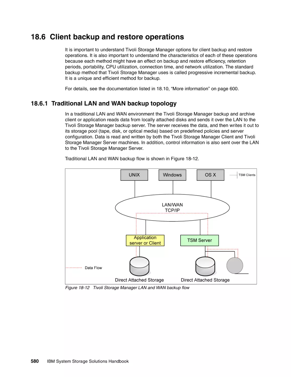
18.6.1 Traditional LAN and WAN backup topology . . . . . . . . . . . . . . . . . . . . . . . . . . .
18.6.2 SAN backup topology: LAN-free . . . . . . . . . . . . . . . . . . . . . . . . . . . . . . . . . . . .
18.6.3 Split-mirror/point-in-time copy backup using SAN. . . . . . . . . . . . . . . . . . . . . . .
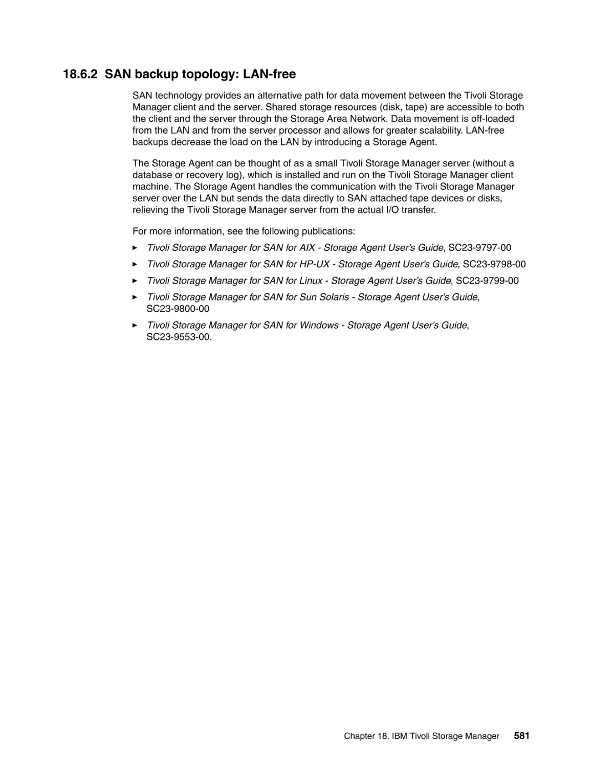
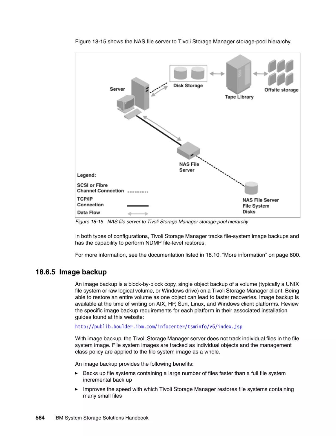
18.6.4 Network-attached storage backup and restore . . . . . . . . . . . . . . . . . . . . . . . . .
18.6.5 Image backup . . . . . . . . . . . . . . . . . . . . . . . . . . . . . . . . . . . . . . . . . . . . . . . . . .
18.6.6 VMware Consolidated Backup . . . . . . . . . . . . . . . . . . . . . . . . . . . . . . . . . . . . .
18.7 Tivoli Storage Manager server-to-server communications . . . . . . . . . . . . . . . . . . . .
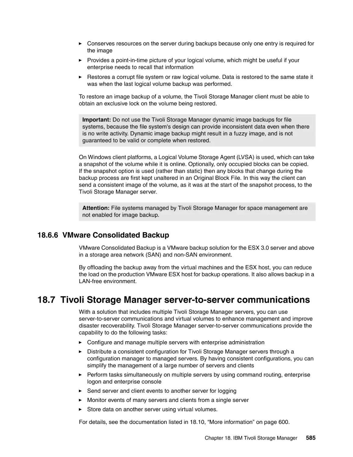
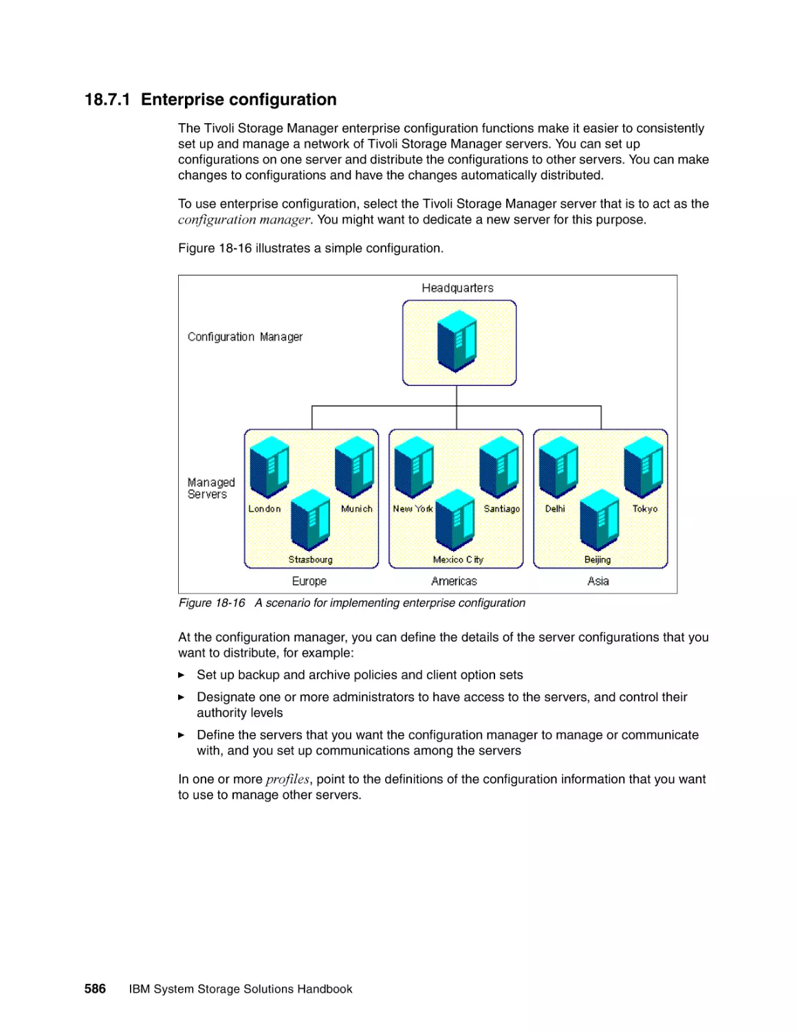
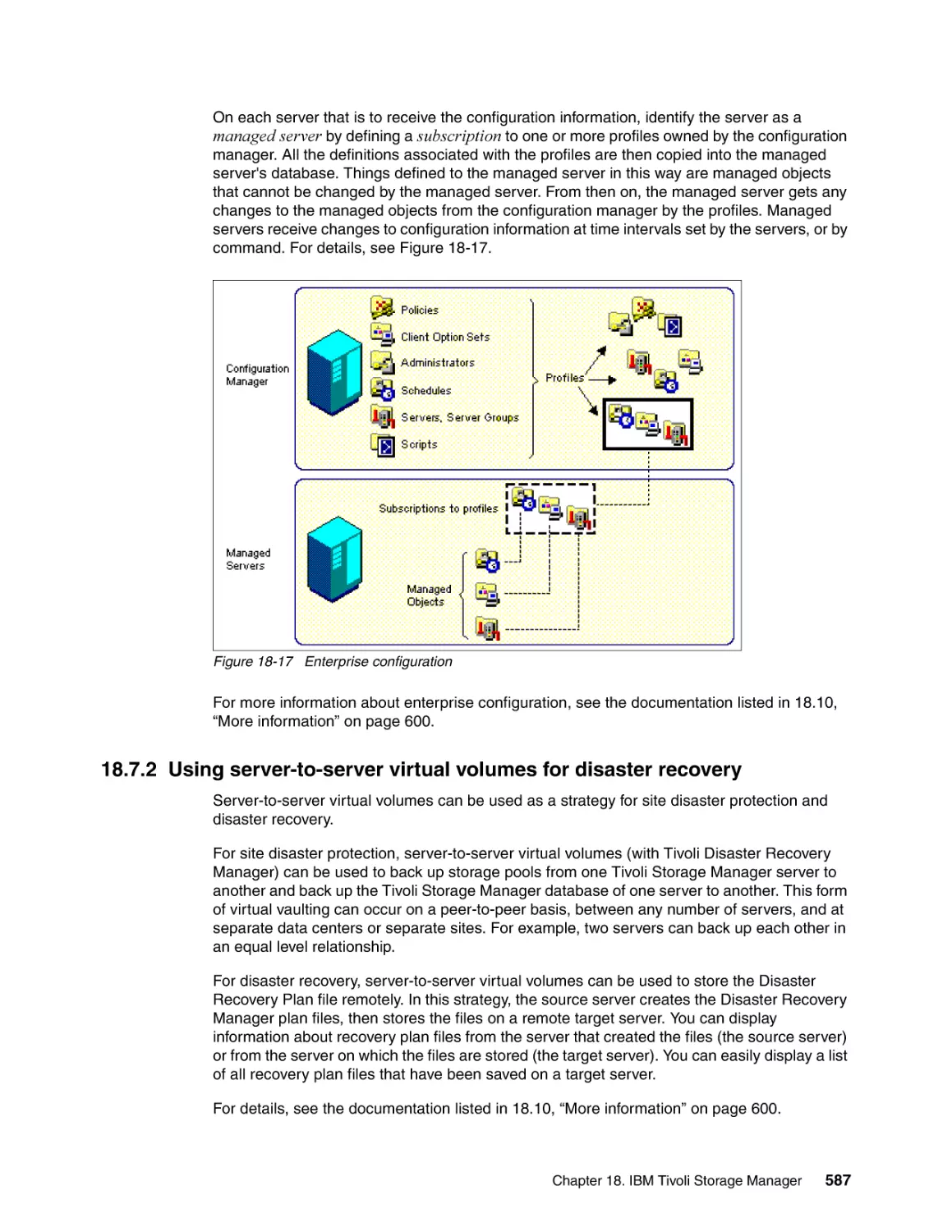
18.7.1 Enterprise configuration . . . . . . . . . . . . . . . . . . . . . . . . . . . . . . . . . . . . . . . . . .
18.7.2 Using server-to-server virtual volumes for disaster recovery . . . . . . . . . . . . . .
18.8 Tivoli Storage Manager and high availability clustering . . . . . . . . . . . . . . . . . . . . . .
18.8.1 IBM High Availability Cluster Multi-Processing . . . . . . . . . . . . . . . . . . . . . . . . .
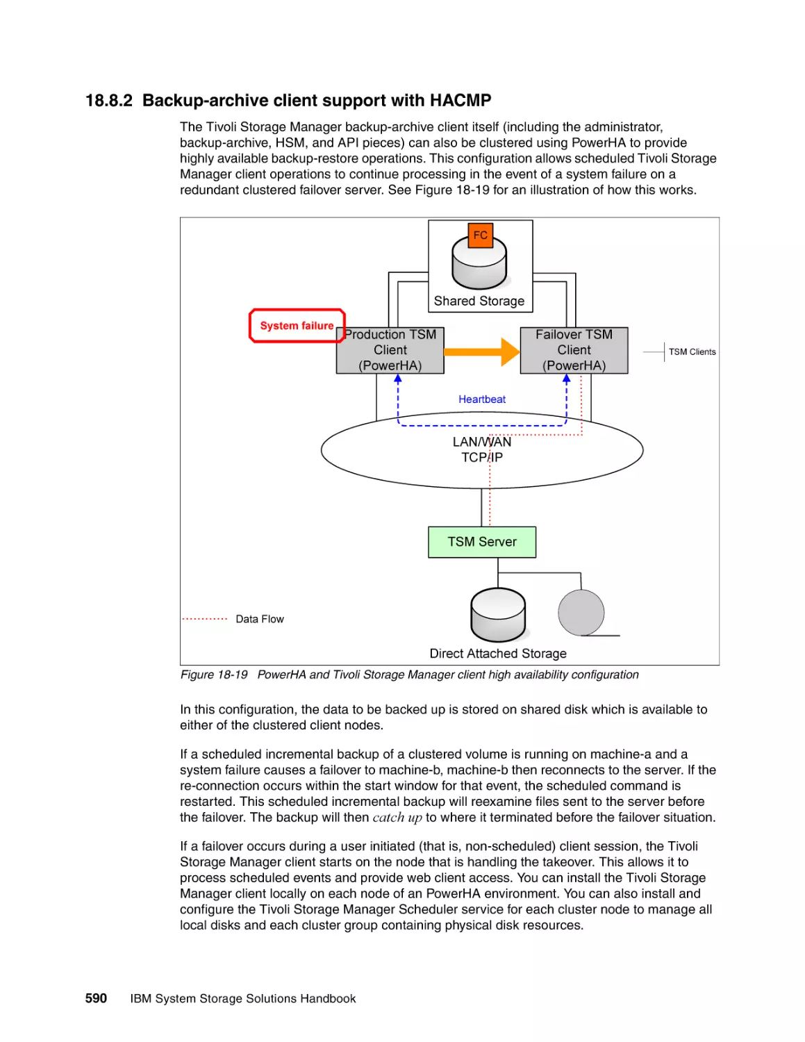
18.8.2 Backup-archive client support with HACMP . . . . . . . . . . . . . . . . . . . . . . . . . . .
18.8.3 Tivoli Storage Manager server and Microsoft Cluster Server (MSCS) . . . . . . .
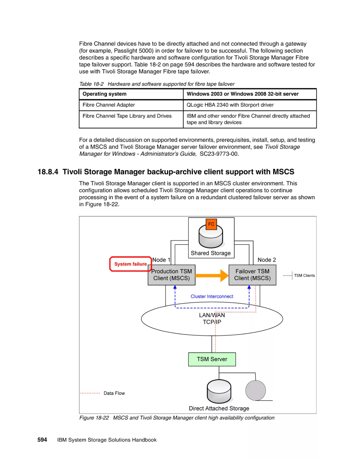
18.8.4 Tivoli Storage Manager backup-archive client support with MSCS . . . . . . . . .
18.9 Tivoli Storage Manager and tape vaulting. . . . . . . . . . . . . . . . . . . . . . . . . . . . . . . . .
18.9.1 Electronic tape vaulting . . . . . . . . . . . . . . . . . . . . . . . . . . . . . . . . . . . . . . . . . . .
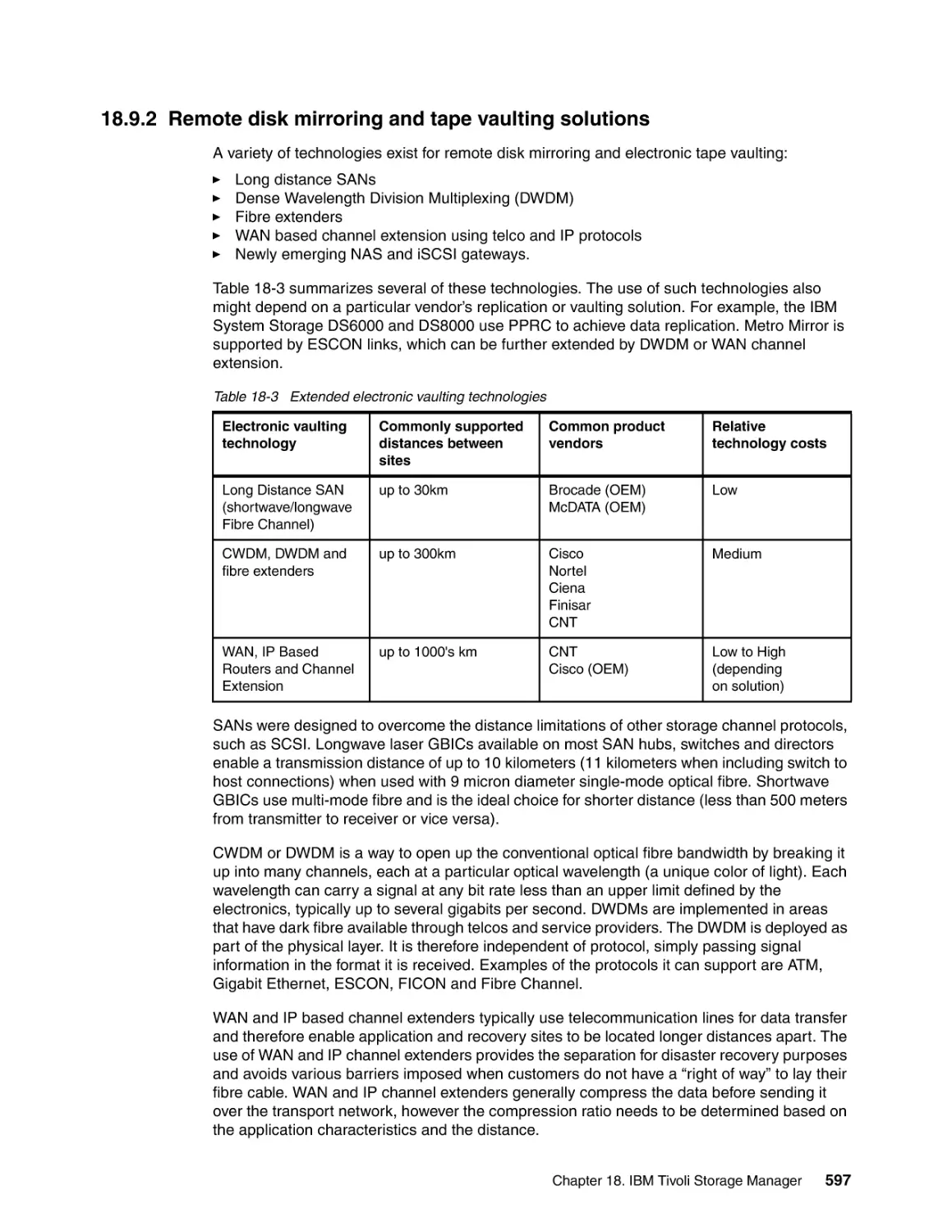
18.9.2 Remote disk mirroring and tape vaulting solutions . . . . . . . . . . . . . . . . . . . . . .
18.9.3 Collocation considerations for off-site vaulting . . . . . . . . . . . . . . . . . . . . . . . . .
18.9.4 Reclamation considerations for off-site vaulting . . . . . . . . . . . . . . . . . . . . . . . .
18.10 More information . . . . . . . . . . . . . . . . . . . . . . . . . . . . . . . . . . . . . . . . . . . . . . . . . . .
573
573
574
574
574
575
575
576
576
577
577
578
578
579
579
580
580
581
582
583
584
585
585
586
587
588
588
590
591
594
595
595
597
598
598
600
Chapter 19. IBM Tivoli Storage Productivity Center . . . . . . . . . . . . . . . . . . . . . . . . . .
19.1 New with IBM Tivoli Storage Productivity Center V4.2.1. . . . . . . . . . . . . . . . . . . . . .
19.1.1 Name and licensing changes . . . . . . . . . . . . . . . . . . . . . . . . . . . . . . . . . . . . . .
19.1.2 Integration features . . . . . . . . . . . . . . . . . . . . . . . . . . . . . . . . . . . . . . . . . . . . . .
19.1.3 Storage Resource agents . . . . . . . . . . . . . . . . . . . . . . . . . . . . . . . . . . . . . . . . .
19.1.4 SQL access to Tivoli Storage Productivity Center database. . . . . . . . . . . . . . .
19.1.5 Performance management improvements . . . . . . . . . . . . . . . . . . . . . . . . . . . .
19.1.6 Storage Optimizer . . . . . . . . . . . . . . . . . . . . . . . . . . . . . . . . . . . . . . . . . . . . . . .
19.1.7 Advanced Brocade Discovery . . . . . . . . . . . . . . . . . . . . . . . . . . . . . . . . . . . . . .
19.1.8 Discovery Library Adapter. . . . . . . . . . . . . . . . . . . . . . . . . . . . . . . . . . . . . . . . .
19.1.9 Storage resource groups . . . . . . . . . . . . . . . . . . . . . . . . . . . . . . . . . . . . . . . . .
19.1.10 IBM Support Assistant . . . . . . . . . . . . . . . . . . . . . . . . . . . . . . . . . . . . . . . . . .
19.1.11 IBM General Parallel File System . . . . . . . . . . . . . . . . . . . . . . . . . . . . . . . . . .
19.1.12 Installation changes . . . . . . . . . . . . . . . . . . . . . . . . . . . . . . . . . . . . . . . . . . . .
19.1.13 New device and application support . . . . . . . . . . . . . . . . . . . . . . . . . . . . . . . .
19.2 Tivoli Storage Productivity Center overview . . . . . . . . . . . . . . . . . . . . . . . . . . . . . . .
603
604
604
605
606
606
607
607
607
608
608
608
609
609
610
612
Contents
xiii
xiv
19.3 Tivoli Storage Productivity Center architecture . . . . . . . . . . . . . . . . . . . . . . . . . . . . .
19.3.1 Tivoli Storage Productivity Center components . . . . . . . . . . . . . . . . . . . . . . . .
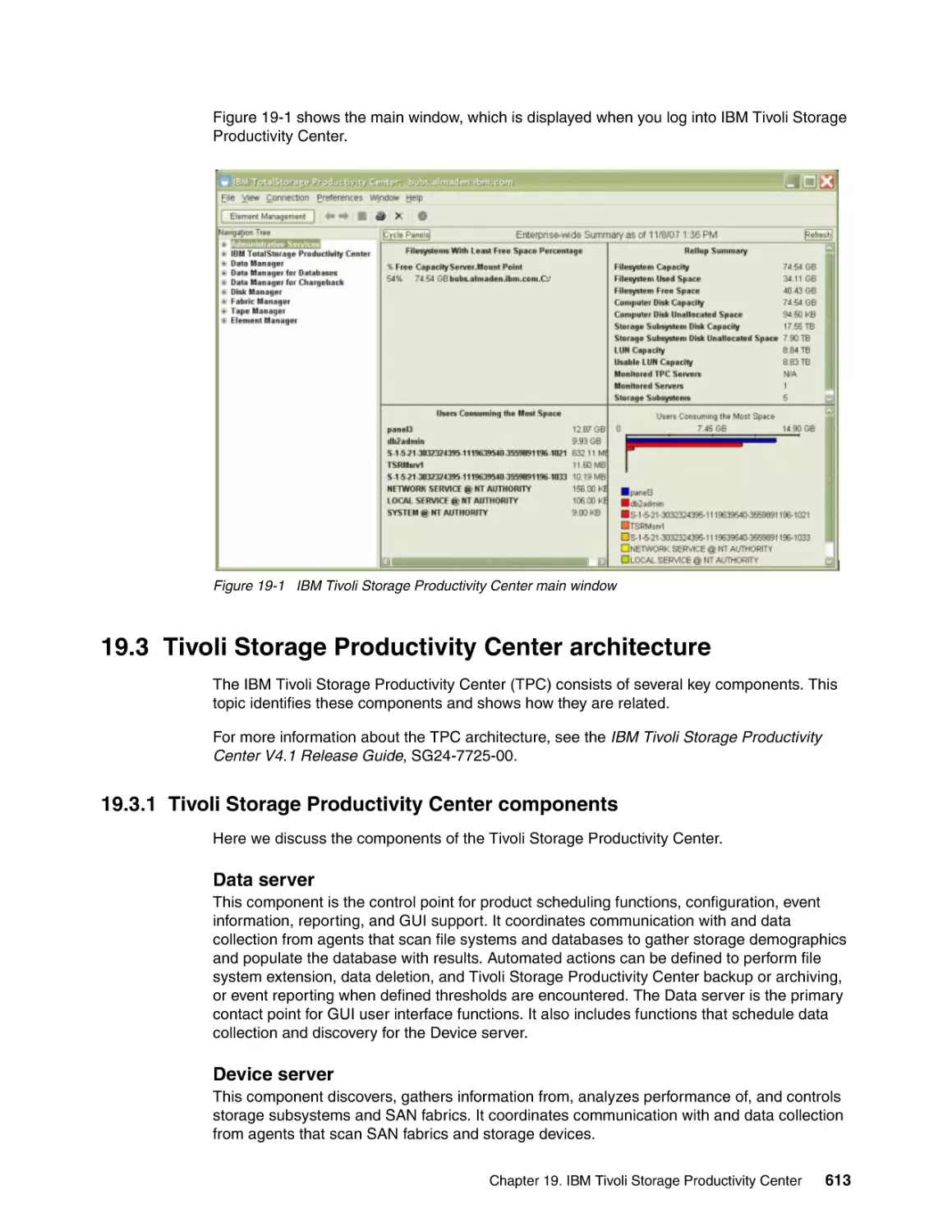
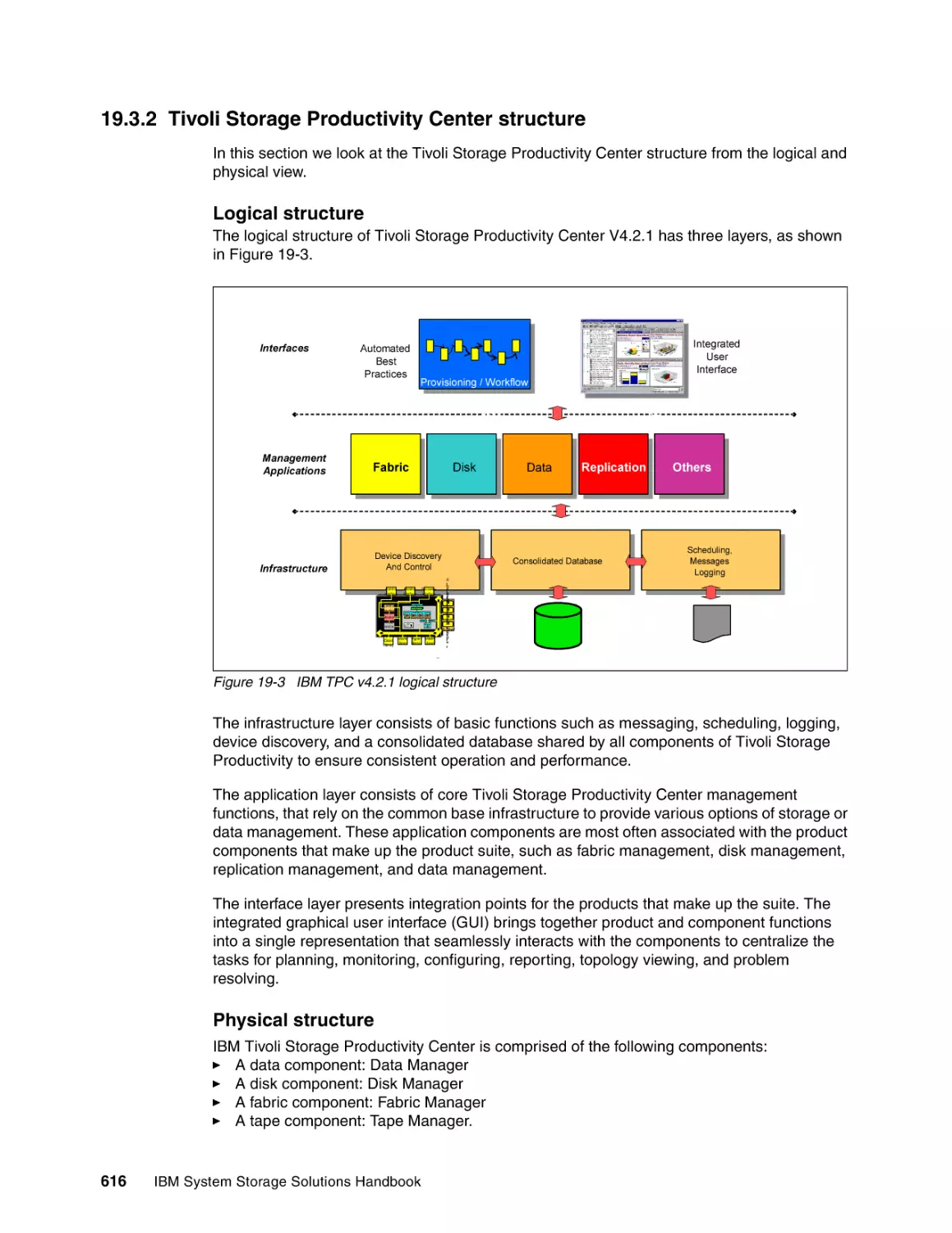
19.3.2 Tivoli Storage Productivity Center structure . . . . . . . . . . . . . . . . . . . . . . . . . . .
19.4 Standards and protocols used in IBM Tivoli Storage Productivity Center . . . . . . . . .
19.4.1 Common Information Model and Web-Based Enterprise Management . . . . . .
19.4.2 Storage Management Initiative - Specification . . . . . . . . . . . . . . . . . . . . . . . . .
19.4.3 Service Location Protocol . . . . . . . . . . . . . . . . . . . . . . . . . . . . . . . . . . . . . . . . .
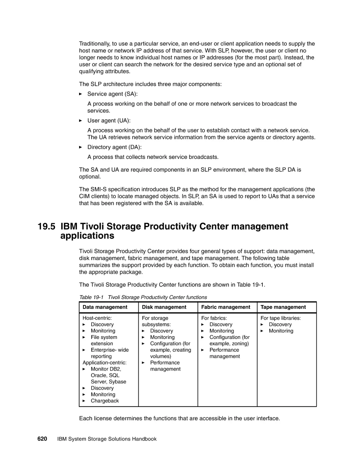
19.5 IBM Tivoli Storage Productivity Center management applications . . . . . . . . . . . . . .
19.5.1 Data Manager . . . . . . . . . . . . . . . . . . . . . . . . . . . . . . . . . . . . . . . . . . . . . . . . . .
19.5.2 Disk Manager . . . . . . . . . . . . . . . . . . . . . . . . . . . . . . . . . . . . . . . . . . . . . . . . . .
19.5.3 Disk Manager overview. . . . . . . . . . . . . . . . . . . . . . . . . . . . . . . . . . . . . . . . . . .
19.5.4 Fabric Manager . . . . . . . . . . . . . . . . . . . . . . . . . . . . . . . . . . . . . . . . . . . . . . . . .
19.5.5 Tape Manager. . . . . . . . . . . . . . . . . . . . . . . . . . . . . . . . . . . . . . . . . . . . . . . . . .
19.6 Performance analysis with Storage Optimizer . . . . . . . . . . . . . . . . . . . . . . . . . . . . .
19.6.1 Storage Optimizer overview . . . . . . . . . . . . . . . . . . . . . . . . . . . . . . . . . . . . . . .
19.6.2 How the Storage Optimizer works. . . . . . . . . . . . . . . . . . . . . . . . . . . . . . . . . . .
19.6.3 Important performance metrics . . . . . . . . . . . . . . . . . . . . . . . . . . . . . . . . . . . . .
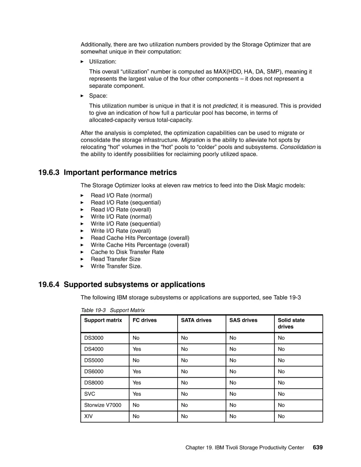
19.6.4 Supported subsystems or applications . . . . . . . . . . . . . . . . . . . . . . . . . . . . . . .
19.7 IBM Tivoli Provisioning Manager. . . . . . . . . . . . . . . . . . . . . . . . . . . . . . . . . . . . . . . .
19.7.1 Tivoli Provisioning Manager overview. . . . . . . . . . . . . . . . . . . . . . . . . . . . . . . .
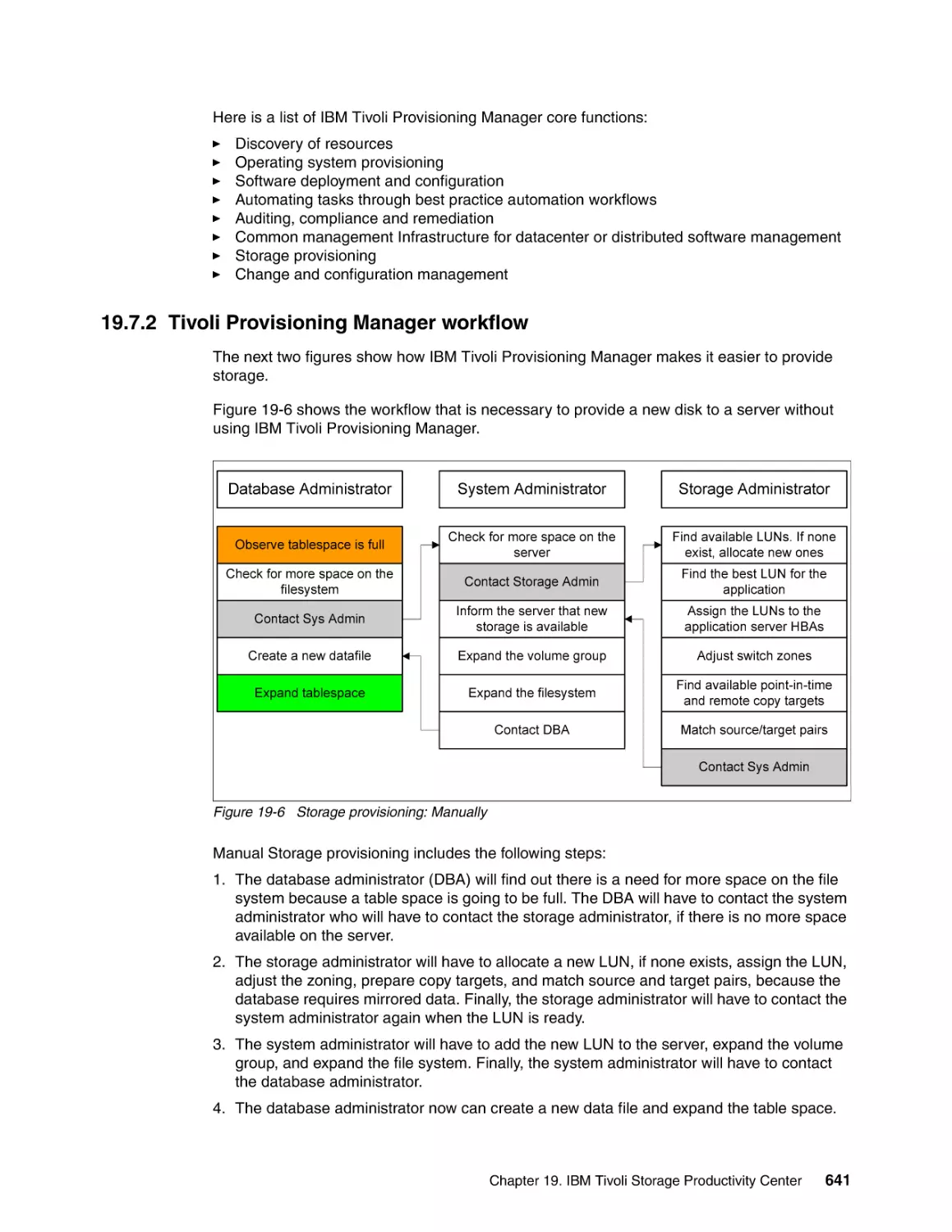
19.7.2 Tivoli Provisioning Manager workflow . . . . . . . . . . . . . . . . . . . . . . . . . . . . . . . .
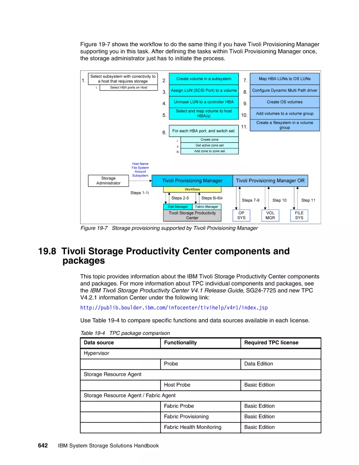
19.8 Tivoli Storage Productivity Center components and packages . . . . . . . . . . . . . . . . .
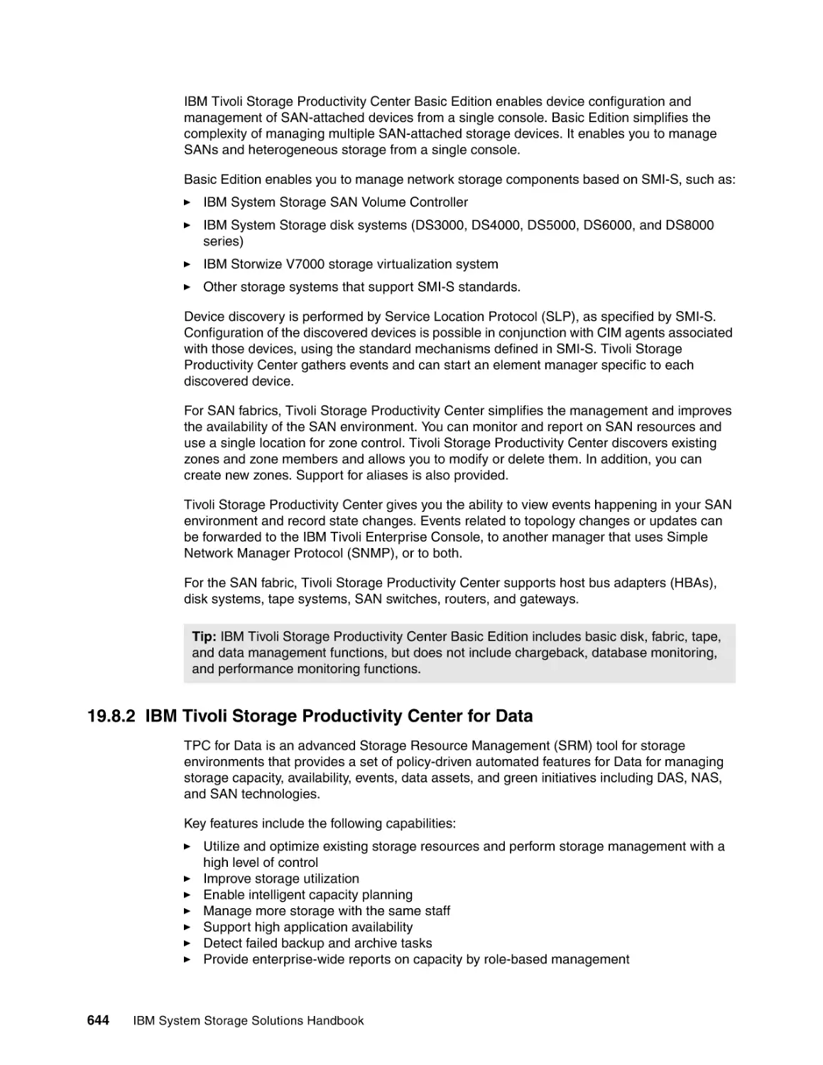
19.8.1 IBM Tivoli Storage Productivity Center Basic Edition . . . . . . . . . . . . . . . . . . . .
19.8.2 IBM Tivoli Storage Productivity Center for Data . . . . . . . . . . . . . . . . . . . . . . . .
19.8.3 IBM Tivoli Storage Productivity Center for Disk . . . . . . . . . . . . . . . . . . . . . . . .
19.8.4 IBM Tivoli Storage Productivity Center For Disk Midrange Edition . . . . . . . . . .
19.8.5 IBM Tivoli Storage Productivity Center for Replication . . . . . . . . . . . . . . . . . . .
19.8.6 IBM Tivoli Storage Productivity Center Standard Edition . . . . . . . . . . . . . . . . .
19.8.7 IBM Tivoli Storage Productivity Center with Advanced Provisioning . . . . . . . .
19.9 IBM Tivoli Storage Productivity Center licenses . . . . . . . . . . . . . . . . . . . . . . . . . . . .
19.10 IBM System Storage Productivity Center . . . . . . . . . . . . . . . . . . . . . . . . . . . . . . . .
19.10.1 New with IBM System Storage Productivity Center Version 1.5 . . . . . . . . . . .
19.10.2 System Storage Productivity Center overview . . . . . . . . . . . . . . . . . . . . . . . .
19.10.3 System Storage Productivity Center hardware components. . . . . . . . . . . . . .
19.10.4 System Storage Productivity Center licensing . . . . . . . . . . . . . . . . . . . . . . . .
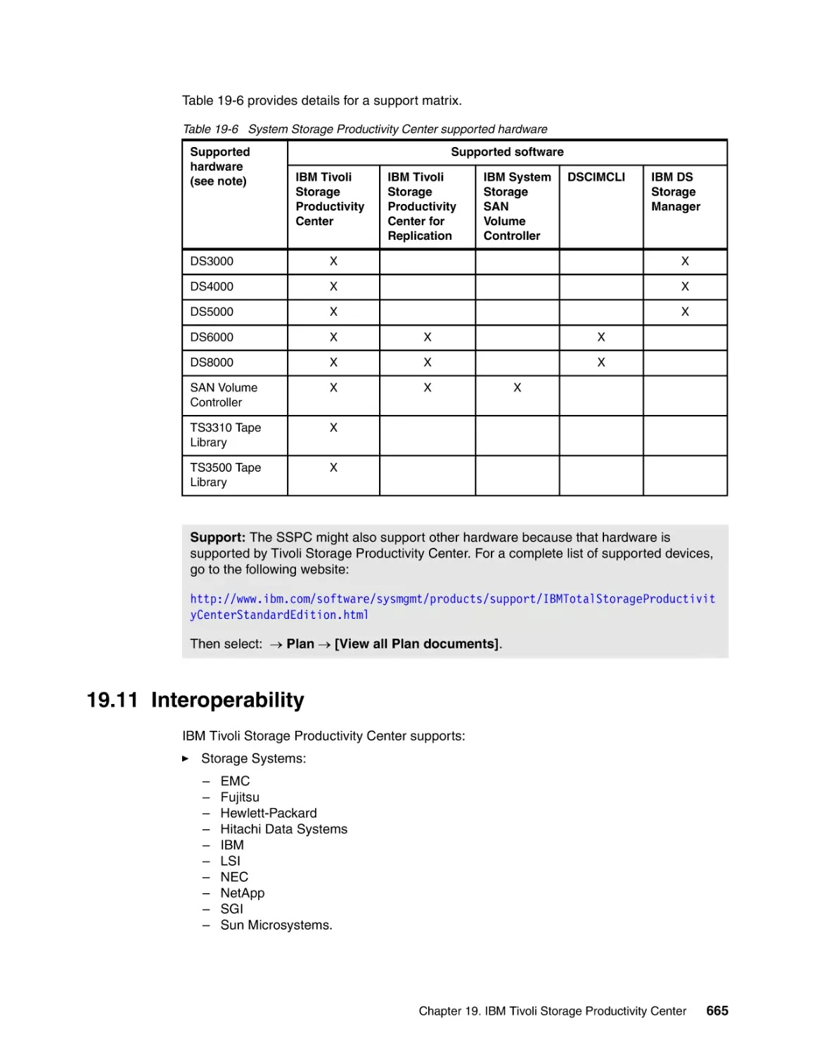
19.10.5 System Storage Productivity Center support matrix . . . . . . . . . . . . . . . . . . . .
19.11 Interoperability. . . . . . . . . . . . . . . . . . . . . . . . . . . . . . . . . . . . . . . . . . . . . . . . . . . . .
19.12 More information . . . . . . . . . . . . . . . . . . . . . . . . . . . . . . . . . . . . . . . . . . . . . . . . . . .
613
613
616
618
618
619
619
620
621
627
627
631
635
636
637
638
639
639
640
640
641
642
643
644
645
646
646
655
656
656
658
658
659
663
663
664
665
666
Chapter 20. IBM Tivoli Key Lifecycle Manager . . . . . . . . . . . . . . . . . . . . . . . . . . . . . . .
20.1 Introduction to data encryption . . . . . . . . . . . . . . . . . . . . . . . . . . . . . . . . . . . . . . . . .
20.2 Encryption key lifecycle management . . . . . . . . . . . . . . . . . . . . . . . . . . . . . . . . . . . .
20.3 IBM Tivoli Key Lifecycle Manager . . . . . . . . . . . . . . . . . . . . . . . . . . . . . . . . . . . . . . .
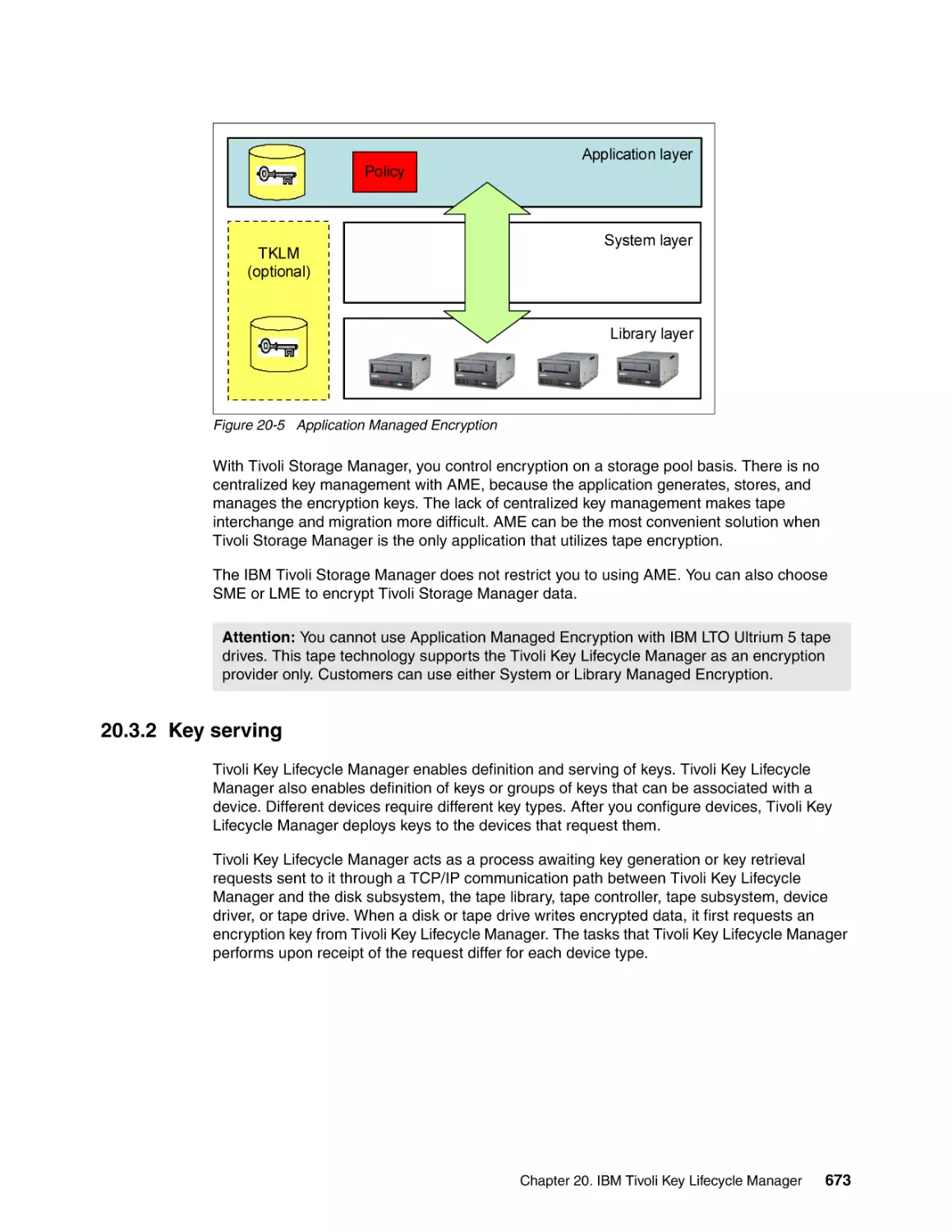
20.3.1 Tape encryption methods . . . . . . . . . . . . . . . . . . . . . . . . . . . . . . . . . . . . . . . . .
20.3.2 Key serving . . . . . . . . . . . . . . . . . . . . . . . . . . . . . . . . . . . . . . . . . . . . . . . . . . . .
20.4 Summary of key features and benefits . . . . . . . . . . . . . . . . . . . . . . . . . . . . . . . . . . .
20.4.1 Compliance with key lifecycle management process . . . . . . . . . . . . . . . . . . . .
20.4.2 More information . . . . . . . . . . . . . . . . . . . . . . . . . . . . . . . . . . . . . . . . . . . . . . . .
667
668
669
670
671
673
676
677
678
Chapter 21. IBM GPFS and SoFS. . . . . . . . . . . . . . . . . . . . . . . . . . . . . . . . . . . . . . . . . .
21.1 IBM General Parallel File System . . . . . . . . . . . . . . . . . . . . . . . . . . . . . . . . . . . . . . .
21.2 GPFS: Overview . . . . . . . . . . . . . . . . . . . . . . . . . . . . . . . . . . . . . . . . . . . . . . . . . . . .
21.3 Benefits and highlights of GPFS . . . . . . . . . . . . . . . . . . . . . . . . . . . . . . . . . . . . . . . .
679
680
681
682
IBM System Storage Solutions Handbook
21.3.1 Scalable high-performance shared disk file systems . . . . . . . . . . . . . . . . . . . .
21.3.2 Increased data availability. . . . . . . . . . . . . . . . . . . . . . . . . . . . . . . . . . . . . . . . .
21.3.3 Simplified storage management . . . . . . . . . . . . . . . . . . . . . . . . . . . . . . . . . . . .
21.3.4 Simplified administration: Features and benefits of GPFS . . . . . . . . . . . . . . . .
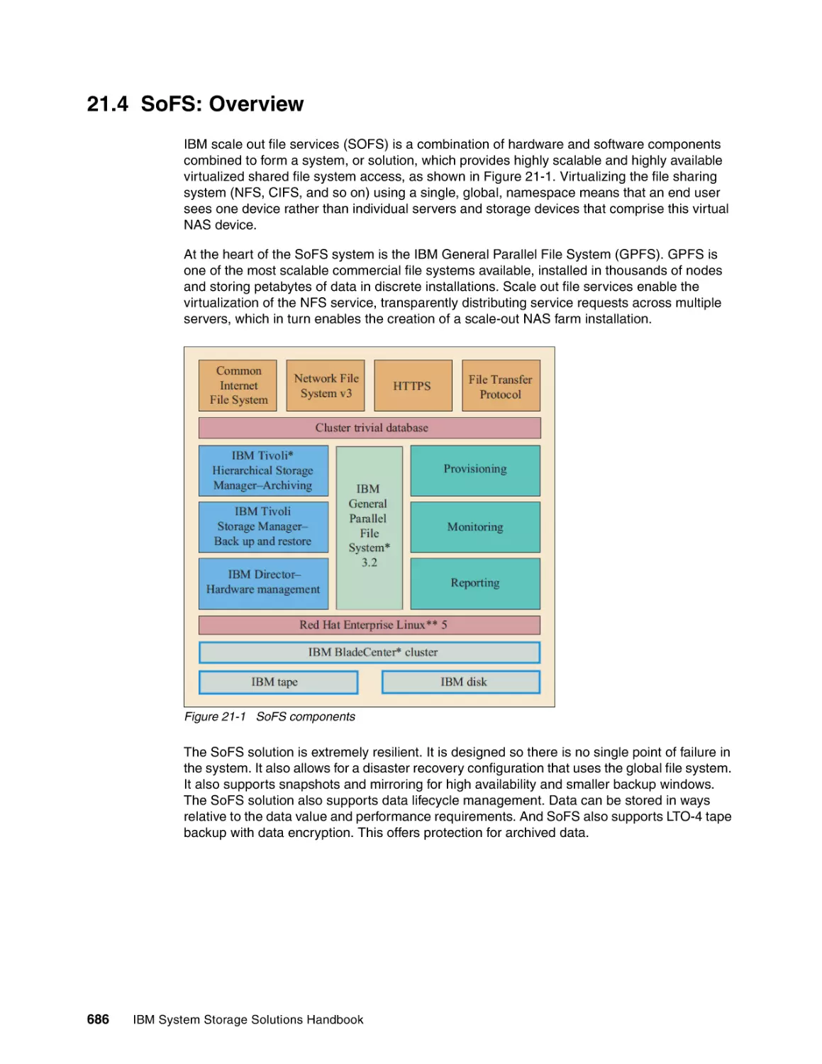
21.4 SoFS: Overview . . . . . . . . . . . . . . . . . . . . . . . . . . . . . . . . . . . . . . . . . . . . . . . . . . . .
21.5 How SoFS works. . . . . . . . . . . . . . . . . . . . . . . . . . . . . . . . . . . . . . . . . . . . . . . . . . . .
21.6 Why use SoFS . . . . . . . . . . . . . . . . . . . . . . . . . . . . . . . . . . . . . . . . . . . . . . . . . . . . .
21.6.1 Using the scale-up approach . . . . . . . . . . . . . . . . . . . . . . . . . . . . . . . . . . . . . .
21.6.2 Difference between SoFS and other clustered file systems . . . . . . . . . . . . . . .
21.7 Components within an SoFS solution . . . . . . . . . . . . . . . . . . . . . . . . . . . . . . . . . . . .
21.7.1 SoFS hardware components . . . . . . . . . . . . . . . . . . . . . . . . . . . . . . . . . . . . . .
21.7.2 SoFS software components . . . . . . . . . . . . . . . . . . . . . . . . . . . . . . . . . . . . . . .
21.8 Data protection and disaster recovery . . . . . . . . . . . . . . . . . . . . . . . . . . . . . . . . . . .
21.8.1 Data protection . . . . . . . . . . . . . . . . . . . . . . . . . . . . . . . . . . . . . . . . . . . . . . . . .
21.8.2 Simple SoFS single site solution: No disaster recovery . . . . . . . . . . . . . . . . . .
21.8.3 SoFS with synchronous replication on-site . . . . . . . . . . . . . . . . . . . . . . . . . . . .
21.8.4 SoFS with cross site replication . . . . . . . . . . . . . . . . . . . . . . . . . . . . . . . . . . . .
21.8.5 SoFS with a cross cluster mount. . . . . . . . . . . . . . . . . . . . . . . . . . . . . . . . . . . .
21.8.6 Snapshot technology . . . . . . . . . . . . . . . . . . . . . . . . . . . . . . . . . . . . . . . . . . . .
21.9 More information . . . . . . . . . . . . . . . . . . . . . . . . . . . . . . . . . . . . . . . . . . . . . . . . . . . .
682
683
684
684
686
687
687
687
688
688
688
690
690
690
690
691
692
693
693
694
Part 5. z/OS storage management. . . . . . . . . . . . . . . . . . . . . . . . . . . . . . . . . . . . . . . . . . . . . . . . . . . . . . 695
Chapter 22. Data management with DFSMS and data sorting with DFSORT . . . . . .
22.1 Data Facility Product (DFSMSdfp) . . . . . . . . . . . . . . . . . . . . . . . . . . . . . . . . . . . . . .
22.1.1 DFSMS SDM Copy Services . . . . . . . . . . . . . . . . . . . . . . . . . . . . . . . . . . . . . .
22.1.2 z/OS NFS . . . . . . . . . . . . . . . . . . . . . . . . . . . . . . . . . . . . . . . . . . . . . . . . . . . . .
22.1.3 XRC Performance Monitor . . . . . . . . . . . . . . . . . . . . . . . . . . . . . . . . . . . . . . . .
22.1.4 IBM TotalStorage Expert. . . . . . . . . . . . . . . . . . . . . . . . . . . . . . . . . . . . . . . . . .
22.2 Data Set Services (DFSMSdss) . . . . . . . . . . . . . . . . . . . . . . . . . . . . . . . . . . . . . . . .
22.2.1 Concurrent Copy . . . . . . . . . . . . . . . . . . . . . . . . . . . . . . . . . . . . . . . . . . . . . . . .
22.2.2 FlashCopy . . . . . . . . . . . . . . . . . . . . . . . . . . . . . . . . . . . . . . . . . . . . . . . . . . . . .
22.2.3 DFSMSdss Stand-Alone Services . . . . . . . . . . . . . . . . . . . . . . . . . . . . . . . . . .
22.3 Hierarchical Storage Manager (DFSMShsm) . . . . . . . . . . . . . . . . . . . . . . . . . . . . . .
22.3.1 Storage hierarchy . . . . . . . . . . . . . . . . . . . . . . . . . . . . . . . . . . . . . . . . . . . . . . .
22.3.2 Availability management . . . . . . . . . . . . . . . . . . . . . . . . . . . . . . . . . . . . . . . . . .
22.3.3 Space management . . . . . . . . . . . . . . . . . . . . . . . . . . . . . . . . . . . . . . . . . . . . .
22.3.4 Disaster recovery . . . . . . . . . . . . . . . . . . . . . . . . . . . . . . . . . . . . . . . . . . . . . . .
22.3.5 List, report, query, audit . . . . . . . . . . . . . . . . . . . . . . . . . . . . . . . . . . . . . . . . . .
22.4 Removable Media Manager (DFSMSrmm) . . . . . . . . . . . . . . . . . . . . . . . . . . . . . . . .
22.4.1 Management of the tape library . . . . . . . . . . . . . . . . . . . . . . . . . . . . . . . . . . . .
22.4.2 DFSMSrmm volume retention and movement policies . . . . . . . . . . . . . . . . . . .
22.4.3 Report generator . . . . . . . . . . . . . . . . . . . . . . . . . . . . . . . . . . . . . . . . . . . . . . . .
22.4.4 Full function removable media management system . . . . . . . . . . . . . . . . . . . .
22.4.5 Compatibility with existing tape management systems. . . . . . . . . . . . . . . . . . .
22.5 DFSMS Transactional VSAM Services (DFSMStvs). . . . . . . . . . . . . . . . . . . . . . . . .
22.6 More information . . . . . . . . . . . . . . . . . . . . . . . . . . . . . . . . . . . . . . . . . . . . . . . . . . . .
22.7 DFSORT . . . . . . . . . . . . . . . . . . . . . . . . . . . . . . . . . . . . . . . . . . . . . . . . . . . . . . . . . .
22.7.1 Product highlights . . . . . . . . . . . . . . . . . . . . . . . . . . . . . . . . . . . . . . . . . . . . . . .
22.7.2 Data sets, records, and fields . . . . . . . . . . . . . . . . . . . . . . . . . . . . . . . . . . . . . .
697
698
698
699
699
700
701
701
701
702
703
703
703
704
705
706
707
707
707
707
707
708
708
709
709
709
710
Chapter 23. z/OS Storage Management Tools . . . . . . . . . . . . . . . . . . . . . . . . . . . . . . . 713
23.1 IBM Tivoli Omegamon XE . . . . . . . . . . . . . . . . . . . . . . . . . . . . . . . . . . . . . . . . . . . . . 714
23.2 IBM DB2 Cloning Tool. . . . . . . . . . . . . . . . . . . . . . . . . . . . . . . . . . . . . . . . . . . . . . . . 715
Contents
xv
23.3 IBM Tivoli Advanced Catalog Management for z/OS . . . . . . . . . . . . . . . . . . . . . . . .
23.3.1 Infrastructure benefits . . . . . . . . . . . . . . . . . . . . . . . . . . . . . . . . . . . . . . . . . . . .
23.3.2 Application benefits . . . . . . . . . . . . . . . . . . . . . . . . . . . . . . . . . . . . . . . . . . . . . .
23.4 IBM Tivoli Advanced Backup and Recovery . . . . . . . . . . . . . . . . . . . . . . . . . . . . . . .
23.4.1 Infrastructure benefits . . . . . . . . . . . . . . . . . . . . . . . . . . . . . . . . . . . . . . . . . .
23.4.2 Application benefits . . . . . . . . . . . . . . . . . . . . . . . . . . . . . . . . . . . . . . . . . . . . . .
23.5 IBM Tivoli Advanced Audit for DFSMShsm. . . . . . . . . . . . . . . . . . . . . . . . . . . . . . . .
23.6 IBM Tivoli Automated Tape Allocation Manager . . . . . . . . . . . . . . . . . . . . . . . . . . . .
23.6.1 Product benefits . . . . . . . . . . . . . . . . . . . . . . . . . . . . . . . . . . . . . . . . . . . . . . . .
23.6.2 Product features . . . . . . . . . . . . . . . . . . . . . . . . . . . . . . . . . . . . . . . . . . . . . . . .
23.7 IBM Tivoli Advanced Allocation Manager for z/OS . . . . . . . . . . . . . . . . . . . . . . . . . .
23.8 IBM Tivoli Tape Optimizer for z/OS. . . . . . . . . . . . . . . . . . . . . . . . . . . . . . . . . . . . . .
23.9 IBM Tivoli Storage Optimizer for z/OS . . . . . . . . . . . . . . . . . . . . . . . . . . . . . . . . . . .
23.10 DFSMS Optimizer . . . . . . . . . . . . . . . . . . . . . . . . . . . . . . . . . . . . . . . . . . . . . . . . . .
716
717
717
717
718
718
719
720
720
720
721
722
724
725
Chapter 24. Smart Business Storage Cloud. . . . . . . . . . . . . . . . . . . . . . . . . . . . . . . . .
24.1 Overview . . . . . . . . . . . . . . . . . . . . . . . . . . . . . . . . . . . . . . . . . . . . . . . . . . . . . . . . . .
24.1.1 Public cloud scenarios versus private cloud scenarios . . . . . . . . . . . . . . . . . . .
24.1.2 Public cloud solutions . . . . . . . . . . . . . . . . . . . . . . . . . . . . . . . . . . . . . . . . . . . .
24.1.3 Private cloud solutions . . . . . . . . . . . . . . . . . . . . . . . . . . . . . . . . . . . . . . . . . . .
24.2 Smart Business Storage Cloud components . . . . . . . . . . . . . . . . . . . . . . . . . . . . . .
24.2.1 How SBSC system works . . . . . . . . . . . . . . . . . . . . . . . . . . . . . . . . . . . . . . . . .
24.2.2 Difference between SBSC and other clustered file systems. . . . . . . . . . . . . . .
24.3 Benefits of using SBSC . . . . . . . . . . . . . . . . . . . . . . . . . . . . . . . . . . . . . . . . . . . . . . .
24.3.1 Continuous availability . . . . . . . . . . . . . . . . . . . . . . . . . . . . . . . . . . . . . . . . . . .
24.3.2 Online transparent data migration. . . . . . . . . . . . . . . . . . . . . . . . . . . . . . . . . . .
24.3.3 What is new for IBM storage cloud solutions . . . . . . . . . . . . . . . . . . . . . . . . . .
24.3.4 Summary of benefits . . . . . . . . . . . . . . . . . . . . . . . . . . . . . . . . . . . . . . . . . . . . .
24.4 Components within an SBSC solution . . . . . . . . . . . . . . . . . . . . . . . . . . . . . . . . . . .
24.4.1 Host attachment . . . . . . . . . . . . . . . . . . . . . . . . . . . . . . . . . . . . . . . . . . . . . . . .
24.4.2 Hardware . . . . . . . . . . . . . . . . . . . . . . . . . . . . . . . . . . . . . . . . . . . . . . . . . . . . .
24.4.3 Software components . . . . . . . . . . . . . . . . . . . . . . . . . . . . . . . . . . . . . . . . . . . .
24.5 Data protection and disaster recovery . . . . . . . . . . . . . . . . . . . . . . . . . . . . . . . . . . .
24.5.1 Data protection . . . . . . . . . . . . . . . . . . . . . . . . . . . . . . . . . . . . . . . . . . . . . . . . .
24.5.2 Simple SBSC single site solution: No disaster recovery . . . . . . . . . . . . . . . . . .
24.5.3 SBSC with synchronous replication on-site . . . . . . . . . . . . . . . . . . . . . . . . . . .
24.5.4 SBSC with cross site sync or async replication . . . . . . . . . . . . . . . . . . . . . . . .
24.5.5 SBSC with a cross cluster mount . . . . . . . . . . . . . . . . . . . . . . . . . . . . . . . . . . .
24.5.6 Snapshot technology . . . . . . . . . . . . . . . . . . . . . . . . . . . . . . . . . . . . . . . . . . . .
24.6 IBM General Parallel File System (GPFS) . . . . . . . . . . . . . . . . . . . . . . . . . . . . . . . .
24.7 More information . . . . . . . . . . . . . . . . . . . . . . . . . . . . . . . . . . . . . . . . . . . . . . . . . . . .
727
728
728
728
729
729
731
731
732
732
733
734
734
735
735
736
738
739
739
739
739
740
740
741
742
742
Appendix A. Simplified Storage Management . . . . . . . . . . . . . . . . . . . . . . . . . . . . . . .
A.1 IBM Systems Director . . . . . . . . . . . . . . . . . . . . . . . . . . . . . . . . . . . . . . . . . . . . . . . . .
A.1.1 Overview. . . . . . . . . . . . . . . . . . . . . . . . . . . . . . . . . . . . . . . . . . . . . . . . . . . . . . .
A.1.2 IBM Systems Director Storage Control. . . . . . . . . . . . . . . . . . . . . . . . . . . . . . . .
A.1.3 IBM Systems Director key components . . . . . . . . . . . . . . . . . . . . . . . . . . . . . . .
A.2 IBM Tivoli Storage Productivity Center (TPC). . . . . . . . . . . . . . . . . . . . . . . . . . . . . . .
A.2.1 More information. . . . . . . . . . . . . . . . . . . . . . . . . . . . . . . . . . . . . . . . . . . . . . . . .
A.2.2 Additional material . . . . . . . . . . . . . . . . . . . . . . . . . . . . . . . . . . . . . . . . . . . . . . .
743
744
744
746
746
755
755
755
Appendix B. Introduction to SMI-S and CIM/WBEM. . . . . . . . . . . . . . . . . . . . . . . . . . . 757
B.1 Overview . . . . . . . . . . . . . . . . . . . . . . . . . . . . . . . . . . . . . . . . . . . . . . . . . . . . . . . . . . . 758
B.1.1 SMI-S . . . . . . . . . . . . . . . . . . . . . . . . . . . . . . . . . . . . . . . . . . . . . . . . . . . . . . . . . 758
xvi
IBM System Storage Solutions Handbook
B.1.2 CIM . . . . . . . . . . . . . . . . . . . . . . . . . . . . . . . . . . . . . . . . . . . . . . . . . . . . . . . . . . .
B.1.3 WBEM . . . . . . . . . . . . . . . . . . . . . . . . . . . . . . . . . . . . . . . . . . . . . . . . . . . . . . . .
B.1.4 SLP . . . . . . . . . . . . . . . . . . . . . . . . . . . . . . . . . . . . . . . . . . . . . . . . . . . . . . . . . . .
B.2 Typical component interaction . . . . . . . . . . . . . . . . . . . . . . . . . . . . . . . . . . . . . . . . . .
B.3 Where to find SMI-S providers for IBM Systems Director. . . . . . . . . . . . . . . . . . . . . .
B.4 Applicable standards . . . . . . . . . . . . . . . . . . . . . . . . . . . . . . . . . . . . . . . . . . . . . . . . .
B.4.1 IBM TotalStorage DS3000, DS4000, or DS5000 . . . . . . . . . . . . . . . . . . . . . . . .
B.4.2 IBM TotalStorage DS6000 . . . . . . . . . . . . . . . . . . . . . . . . . . . . . . . . . . . . . . . . .
B.4.3 IBM System Storage N series N3600 . . . . . . . . . . . . . . . . . . . . . . . . . . . . . . . . .
B.4.4 Brocade switches . . . . . . . . . . . . . . . . . . . . . . . . . . . . . . . . . . . . . . . . . . . . . . . .
B.4.5 Qlogic switches. . . . . . . . . . . . . . . . . . . . . . . . . . . . . . . . . . . . . . . . . . . . . . . . . .
B.5 More information . . . . . . . . . . . . . . . . . . . . . . . . . . . . . . . . . . . . . . . . . . . . . . . . . . . . .
758
758
760
760
761
762
762
763
763
763
763
763
Appendix C. High Performance Storage System (HPSS) . . . . . . . . . . . . . . . . . . . . . .
C.1 Introduction to HPSS . . . . . . . . . . . . . . . . . . . . . . . . . . . . . . . . . . . . . . . . . . . . . . . . .
C.2 HPSS technology . . . . . . . . . . . . . . . . . . . . . . . . . . . . . . . . . . . . . . . . . . . . . . . . . . . .
C.2.1 HPSS capabilities . . . . . . . . . . . . . . . . . . . . . . . . . . . . . . . . . . . . . . . . . . . . . . . .
C.2.2 HPSS interfaces . . . . . . . . . . . . . . . . . . . . . . . . . . . . . . . . . . . . . . . . . . . . . . . . .
C.3 HPSS supported environments . . . . . . . . . . . . . . . . . . . . . . . . . . . . . . . . . . . . . . . . .
C.4 More information. . . . . . . . . . . . . . . . . . . . . . . . . . . . . . . . . . . . . . . . . . . . . . . . . . . . .
765
766
766
768
772
772
773
Appendix D. Internet Small Computer System Interface (iSCSI) . . . . . . . . . . . . . . . .
D.1 Introduction to iSCSI. . . . . . . . . . . . . . . . . . . . . . . . . . . . . . . . . . . . . . . . . . . . . . . . . .
D.1.1 iSCSI history. . . . . . . . . . . . . . . . . . . . . . . . . . . . . . . . . . . . . . . . . . . . . . . . . . . .
D.1.2 iSCSI overview . . . . . . . . . . . . . . . . . . . . . . . . . . . . . . . . . . . . . . . . . . . . . . . . . .
D.1.3 iSCSI protocol in depth. . . . . . . . . . . . . . . . . . . . . . . . . . . . . . . . . . . . . . . . . . . .
D.2 Benefits of iSCSI . . . . . . . . . . . . . . . . . . . . . . . . . . . . . . . . . . . . . . . . . . . . . . . . . . . .
775
776
776
777
778
781
Appendix E. Redundant Arrays of Independent Disks (RAID) . . . . . . . . . . . . . . . . . .
E.1 Overview . . . . . . . . . . . . . . . . . . . . . . . . . . . . . . . . . . . . . . . . . . . . . . . . . . . . . . . . . . .
E.1.1 Data striping . . . . . . . . . . . . . . . . . . . . . . . . . . . . . . . . . . . . . . . . . . . . . . . . . . . .
E.1.2 RAID levels . . . . . . . . . . . . . . . . . . . . . . . . . . . . . . . . . . . . . . . . . . . . . . . . . . . . .
E.2 Summary . . . . . . . . . . . . . . . . . . . . . . . . . . . . . . . . . . . . . . . . . . . . . . . . . . . . . . . . . .
783
784
784
784
792
Appendix F. Withdrawn products . . . . . . . . . . . . . . . . . . . . . . . . . . . . . . . . . . . . . . . . . 793
F.1 List of withdrawn products . . . . . . . . . . . . . . . . . . . . . . . . . . . . . . . . . . . . . . . . . . . . . 794
Related publications . . . . . . . . . . . . . . . . . . . . . . . . . . . . . . . . . . . . . . . . . . . . . . . . . . . .
IBM Redbooks . . . . . . . . . . . . . . . . . . . . . . . . . . . . . . . . . . . . . . . . . . . . . . . . . . . . . . . . . .
Online resources . . . . . . . . . . . . . . . . . . . . . . . . . . . . . . . . . . . . . . . . . . . . . . . . . . . . . . . .
Help from IBM . . . . . . . . . . . . . . . . . . . . . . . . . . . . . . . . . . . . . . . . . . . . . . . . . . . . . . . . . .
797
797
799
799
Index . . . . . . . . . . . . . . . . . . . . . . . . . . . . . . . . . . . . . . . . . . . . . . . . . . . . . . . . . . . . . . . . . 801
Contents
xvii
xviii
IBM System Storage Solutions Handbook
Notices
This information was developed for products and services offered in the U.S.A.
IBM may not offer the products, services, or features discussed in this document in other countries. Consult
your local IBM representative for information on the products and services currently available in your area. Any
reference to an IBM product, program, or service is not intended to state or imply that only that IBM product,
program, or service may be used. Any functionally equivalent product, program, or service that does not
infringe any IBM intellectual property right may be used instead. However, it is the user's responsibility to
evaluate and verify the operation of any non-IBM product, program, or service.
IBM may have patents or pending patent applications covering subject matter described in this document. The
furnishing of this document does not give you any license to these patents. You can send license inquiries, in
writing, to:
IBM Director of Licensing, IBM Corporation, North Castle Drive, Armonk, NY 10504-1785 U.S.A.
The following paragraph does not apply to the United Kingdom or any other country where such
provisions are inconsistent with local law: INTERNATIONAL BUSINESS MACHINES CORPORATION
PROVIDES THIS PUBLICATION "AS IS" WITHOUT WARRANTY OF ANY KIND, EITHER EXPRESS OR
IMPLIED, INCLUDING, BUT NOT LIMITED TO, THE IMPLIED WARRANTIES OF NON-INFRINGEMENT,
MERCHANTABILITY OR FITNESS FOR A PARTICULAR PURPOSE. Some states do not allow disclaimer of
express or implied warranties in certain transactions, therefore, this statement may not apply to you.
This information could include technical inaccuracies or typographical errors. Changes are periodically made
to the information herein; these changes will be incorporated in new editions of the publication. IBM may make
improvements and/or changes in the product(s) and/or the program(s) described in this publication at any time
without notice.
Any references in this information to non-IBM websites are provided for convenience only and do not in any
manner serve as an endorsement of those websites. The materials at those websites are not part of the
materials for this IBM product and use of those websites is at your own risk.
IBM may use or distribute any of the information you supply in any way it believes appropriate without incurring
any obligation to you.
Information concerning non-IBM products was obtained from the suppliers of those products, their published
announcements or other publicly available sources. IBM has not tested those products and cannot confirm the
accuracy of performance, compatibility or any other claims related to non-IBM products. Questions on the
capabilities of non-IBM products should be addressed to the suppliers of those products.
This information contains examples of data and reports used in daily business operations. To illustrate them
as completely as possible, the examples include the names of individuals, companies, brands, and products.
All of these names are fictitious and any similarity to the names and addresses used by an actual business
enterprise is entirely coincidental.
COPYRIGHT LICENSE:
This information contains sample application programs in source language, which illustrate programming
techniques on various operating platforms. You may copy, modify, and distribute these sample programs in
any form without payment to IBM, for the purposes of developing, using, marketing or distributing application
programs conforming to the application programming interface for the operating platform for which the sample
programs are written. These examples have not been thoroughly tested under all conditions. IBM, therefore,
cannot guarantee or imply reliability, serviceability, or function of these programs.
© Copyright IBM Corp. 1999-2011. All rights reserved.
xix
Trademarks
IBM, the IBM logo, and ibm.com are trademarks or registered trademarks of International Business Machines
Corporation in the United States, other countries, or both. These and other IBM trademarked terms are
marked on their first occurrence in this information with the appropriate symbol (® or ™), indicating US
registered or common law trademarks owned by IBM at the time this information was published. Such
trademarks may also be registered or common law trademarks in other countries. A current list of IBM
trademarks is available on the web at http://www.ibm.com/legal/copytrade.shtml
The following terms are trademarks of the International Business Machines Corporation in the United States,
other countries, or both:
1350™
AIX 5L™
AIX®
AS/400®
BladeCenter®
CICS®
DB2 Universal Database™
DB2®
Domino®
DS4000®
DS6000™
DS8000®
Dynamic Infrastructure®
ECKD™
Enterprise Storage Server®
ESCON®
eServer™
Express Storage™
FICON®
FileNet®
FlashCopy®
GDPS®
Geographically Dispersed Parallel
Sysplex™
GPFS™
HACMP™
HyperFactor®
HyperSwap®
i5/OS®
IBM®
IMS™
IMS/ESA®
Informix®
Lotus®
MVS™
Netfinity®
NetView®
OMEGAMON®
OS/390®
OS/400®
Parallel Sysplex®
Passport Advantage®
Power Systems™
POWER5™
POWER5+™
POWER6+™
POWER6®
POWER7™
POWER7 Systems™
PowerHA™
PowerPC®
POWER®
ProtecTIER®
pSeries®
RACF®
Redbooks®
Redpaper™
Redbooks (logo)
®
RMF™
RS/6000®
S/390®
SANergy®
Smarter Planet™
SysBack®
System i®
System p5®
System p®
System Storage DS®
System Storage®
System x®
System z10®
System z9®
System z®
TDMF®
Tivoli Enterprise Console®
Tivoli®
TotalStorage®
Visibility. Control. Automation.™
Visibility.Control.Automation.™
WebSphere®
XIV®
z/OS®
z/VM®
z/VSE™
z10™
z9®
zSeries®
The following terms are trademarks of other companies:
ITIL is a registered trademark, and a registered community trademark of the Office of Government
Commerce, and is registered in the U.S. Patent and Trademark Office.
Snapshot, SecureAdmin, RAID-DP, Network Appliance, FlexShare, FlexCache, WAFL, VFM, SyncMirror,
SnapVault, SnapValidator, SnapRestore, SnapMover, SnapMirror, SnapManager, SnapLock, SnapDrive,
SecureShare, NearStore, MultiStore, FlexVol, FlexClone, FilerView, DataFabric, Data ONTAP, NetApp, and
the NetApp logo are trademarks or registered trademarks of NetApp, Inc. in the U.S. and other countries.
Java, and all Java-based trademarks are trademarks of Sun Microsystems, Inc. in the United States, other
countries, or both.
Microsoft, Windows NT, Windows, and the Windows logo are trademarks of Microsoft Corporation in the
United States, other countries, or both.
Celeron, Intel Xeon, Intel, Intel logo, Intel Inside logo, and Intel Centrino logo are trademarks or registered
trademarks of Intel Corporation or its subsidiaries in the United States and other countries.
UNIX is a registered trademark of The Open Group in the United States and other countries.
xx
IBM System Storage Solutions Handbook
Linux is a trademark of Linus Torvalds in the United States, other countries, or both.
Other company, product, or service names may be trademarks or service marks of others.
Notices
xxi
xxii
IBM System Storage Solutions Handbook
Preface
IBM® System Storage® solutions provide the capabilities needed to help organizations
reduce cost and mitigate risks while managing continued information growth and service level
demands. Dynamic environments, such as Cloud Computing and Service Oriented
Architecture, require scalable, always on information services delivered by a robust storage
infrastructure.
This IBM Redbooks® publication provides overviews and pointers for information about the
most current IBM System Storage products, showing how IBM delivers the right mix of
products for nearly every aspect of business continuance and business efficiency. IBM
System Storage products can help you store, safeguard, retrieve, and share your data.
We cover these topics:
First, we introduce the IBM Dynamic Infrastructure® and the Smarter Planet™ Strategy.
Part 1 describes disk products that include IBM System Storage DS® Series (entry-level,
midrange, and enterprise offerings), IBM XIV® Storage System, IBM System Storage N
Series, and the IBM Information Archive.
Part 2 presents an overview of the IBM TotalStorage® and System Storage Tape Drives,
IBM Tape Automation Products, and IBM Tape Virtualization solutions Products.
Part 3 describes storage networking infrastructure and presents the switches and
directors to form SAN solutions. Also provided is an overview of the recently introduced
IBM Ethernet switches and routers.
Part 4 discusses the IBM System Storage software portfolio, which includes IBM System
Storage Virtualization, IBM Tivoli® Storage Manager, IBM Tivoli Storage Productivity
Center (TPC) Suite, and IBM Tivoli Key Lifecycle Manager (TKLM). We also introduce the
IBM General Parallel File System (GPFS™) and the IBM scale out file services (SOFS).
Part 5 describes the z/OS® storage management software (DFSMS and DFSORT) and
z/OS storage management tools, including an overview of the IBM Smart Business
Storage Cloud solution.
Finally, in the Appendixes, we provide information about the Simplified Storage
Management, High Performance Storage System (HPSS), iSCSI, RAID, and standards
such as Storage Management Initiative Specification (SMI-S), Common Information Model
(CIM), and Web Based Enterprise Management (WBEM).
This book is intended as a reference for basic and comprehensive information about the IBM
System Storage products portfolio. This book provides a starting point when establishing your
own enterprise storage environment.
Attention: This book, previously published in 2010, has since been extensively updated
for the 2011 edition.
© Copyright IBM Corp. 1999-2011. All rights reserved.
xxiii
The team who wrote this book
This book was produced by a team of specialists from around the world working at the
International Technical Support Organization, Tucson Center.
Thiago, Libor, Sangam, and James
Sangam Racherla is an IT Specialist and Project Leader working at the International
Technical Support Organization (ITSO), San Jose Center. He holds a degree in Electronics
and Communication Engineering and has ten years of experience in the IT field. Sangam has
been with the ITSO for the past seven years and has extensive experience installing and
supporting the ITSO lab equipment for various Redbooks publication projects. His areas of
expertise include Microsoft® Windows®, Linux®, AIX®, System x®, and System p® servers,
and various SAN and storage products.
Libor Miklas is a Team Leader and experienced IT Specialist working at IBM Global Services
Delivery Center in the Czech Republic. He demonstrates 10 years of practical experience
within the IT industry, during last 6 years mainly focused on the backup/recovery and storage
management. Libor and his team support midrange and enterprise storage environments for
the various global and local customers worldwide. He is an IBM Certified Deployment
Professional of the Tivoli Storage Manager family of products and holds a Masters Degree in
Electrical Engineering and Telecommunications.
xxiv
IBM System Storage Solutions Handbook
Thiago Montenegro is an accredited IT professional and Technical Business Manager at
LanLink Informatica, a major IBM Business Partner in Brazil. He has six years of experience
in IBM Storage and POWER® products. Currently, he manages the Solution Engineering
Product Managers team. His department supports sales and pre-sales teams and defines the
company’s portfolio. His responsibilities include planning and design of new products, training
and supporting critical and complex projects on Business Continuity, Virtualization, Disaster
Recovery, Communications, High Availability, and Collaboration. He is certified on IBM
System Storage, System x, POWER Systems, and Tivoli Storage Manager solutions sales.
He is also a VMware® VSP and VTSP. He holds a degree in Electrical Engineering from the
Federal University of Ceara (UFC) and an Executive MBA from COPPEAD at Federal
University of Rio de Janeiro (UFRJ).
James M Mulholland is an experienced IT Specialist working with the IBM Global
Technology Services organization in Portugal and previously in Ireland. He has 14 years of
practical experience within the IT industry. During the last 8 years focusing mainly on SAN,
Storage implementation and management. James supports a wide variety of storage
technologies for various customers within Portugal. He has been responsible for various
implementation and support projects for customers across Portugal. He holds a Masters
Degree in IT (Information Security).
Thanks to the following people for their contributions to this project:
Bertrand Dufrasne
Mary Lovelace
Ann Lund
Alex Osuna
Jon Tate
David Watts
International Technical Support Organization, San Jose Center
Tom O'Brien
Jochen Erb
IBM
Thanks to the authors of the previous editions of this book.
Now you can become a published author, too!
Here's an opportunity to spotlight your skills, grow your career, and become a published
author—all at the same time! Join an ITSO residency project and help write a book in your
area of expertise, while honing your experience using leading-edge technologies. Your efforts
will help to increase product acceptance and customer satisfaction, as you expand your
network of technical contacts and relationships. Residencies run from two to six weeks in
length, and you can participate either in person or as a remote resident working from your
home base.
Find out more about the residency program, browse the residency index, and apply online at:
ibm.com/redbooks/residencies.html
Preface
xxv
Comments welcome
Your comments are important to us!
We want our books to be as helpful as possible. Send us your comments about this book or
other IBM Redbooks publications in one of the following ways:
Use the online Contact us review Redbooks form found at:
ibm.com/redbooks
Send your comments in an email to:
redbooks@us.ibm.com
Mail your comments to:
IBM Corporation, International Technical Support Organization
Dept. HYTD Mail Station P099
2455 South Road
Poughkeepsie, NY 12601-5400
Stay connected to IBM Redbooks
Find us on Facebook:
http://www.facebook.com/IBMRedbooks
Follow us on Twitter:
http://twitter.com/ibmredbooks
Look for us on LinkedIn:
http://www.linkedin.com/groups?home=&gid=2130806
Explore new Redbooks publications, residencies, and workshops with the IBM Redbooks
weekly newsletter:
https://www.redbooks.ibm.com/Redbooks.nsf/subscribe?OpenForm
Stay current on recent Redbooks publications with RSS Feeds:
http://www.redbooks.ibm.com/rss.html
xxvi
IBM System Storage Solutions Handbook
1
Chapter 1.
Introduction: Dynamic
Infrastructure and IBM Smarter
Planet Strategy
In this chapter, we present an introduction to the book as a whole. Subsequent chapters are
organized under parts according to specific topics.
The IBM vision is to bring a new level of intelligence to the way the world works, and how
every person, business, organization, government, natural system, and man-made system
interacts. Each interaction represents a chance to do something better, more efficiently, and
more productively. But, more than that, as the systems of the planet become smarter, we
have a chance to open up meaningful new possibilities for progress. By harnessing our
increasingly digitized world, we can help to solve intractable social problems, bring
organizations closer to our customers, and vastly shrink decision windows that help
executives drive better business outcomes. Success in achieving a smarter planet demands
smarter systems.
Yet, as the pace of business continues to accelerate and the planet becomes smarter, the
physical and digital foundations on which progress depends are straining to keep up. They
are too complex, too inefficient, and too inflexible, and the current explosion of network
connected devices and data will only intensify the demands that we continue to place on IT.
Within our own organizations, we face a growing realization that our physical and IT
infrastructure is not built for what is coming. Going forward, the most successful organizations
will be those with technology that enables informed, real-time decision making at the point of
greatest business impact without requiring analytical expertise.
Consider what might it mean to your organization if you were always able to access critical
business data at the exact moment you needed it. Likewise, imagine that you can improve
service and reduce costs by delivering IT services when the customer requests those
services, and automatically reclaim the services when they are no longer needed.
© Copyright IBM Corp. 1999-2011. All rights reserved.
1
Storage is as important to a dynamic infrastructure as servers and networks. Because of the
explosion of information in most data centers, storage can be more challenging to manage
than server resources, but the payoff is potentially more beneficial.
IBM is a market leader in the storage industry. IBM System Storage solutions offer excellent
performance, innovative technology, and open standards. IBM System Storage solutions can
help you manage information growth more effectively, dramatically improve service levels,
lower costs associated with energy consumption and footprint, mitigate risks, and extract new
intelligence for business insight.
For today’s information explosion, there is a necessity for smarter means to provision and
protect critical business data, IBM Storage solutions provide the capabilities needed to help
organizations reduce cost and mitigate risks while managing continued information growth
and service level demands. Dynamic environments, such as Cloud Computing and Service
Oriented Architecture, require scalable, always-on information services delivered by a robust
storage infrastructure.
IBM Smart Business Storage Cloud solutions facilitate the growth of data. As the ability to
handle various file formats becomes more complex, supporting efficient and cost-effective
access to data can be increasingly difficult, with users experiencing reduced performance and
outages. IBM Smart Business Storage Cloud can help you to successfully deploy
high-performance, scalable storage-virtualization solutions to facilitate growth and innovation
at lower operational costs.
Allocating the right amount of data storage to the right users at the right time is an ongoing
challenge for organizations of all sizes. The explosive growth of workgroup communities and
multiple data volumes demands efficient and cost-effective interdepartmental data sharing.
Although traditional solutions might offer simplicity, they can lack the crucial scalability to
expand the storage space to serve large end-user communities.
IBM Smart Business Storage Cloud offers a storage-virtualization solution designed to
support your storage optimization efforts. It can help alleviate your data storage challenges by
enabling rapid implementation of a scalable, global file storage system with flexibility in
deployment and management options. The solution provides virtualized storage to enable
storage and server consolidation, a unified management platform to help reduce outages and
storage management labor demands and costs, and advanced data replication for
cost-effective business continuity and disaster recovery.
One of the aims of the IBM Smarter Planet strategy is to enable the dynamic infrastructure in
order to deliver this improved service at a reduced cost and with better managed risk.
To learn more about the IBM Smarter Planet strategy, see the following link:
http://www.ibm.com/smarterplanet
2
IBM System Storage Solutions Handbook
1.1 What a dynamic infrastructure is
To succeed in business on a smarter planet, where the world is more instrumented,
intelligent, interconnected, and the demands on your infrastructure are constantly growing, a
smarter kind of infrastructure is needed; one that can help improve service, reduce cost, and
manage risk, while accelerating growth in your business. That means developing a dynamic
infrastructure, one that is designed for a smarter planet.
A dynamic infrastructure aligns business and IT assets to support the overall goals of the
business while taking a new, smarter, and more streamlined approach, focused as follows:
Integrates visibility, control, and automation across all business and IT assets
Is highly optimized to do more with less
Addresses the information challenge
Manages and mitigates risks
Utilizes flexible delivery choices like clouds
The cornerstones of a dynamic infrastructure (Figure 1-1) are clear:
Improving service
Reducing cost
Managing risk
In this book we look at several IBM system storage offerings available today and explore how
they can be used to help deliver the benefits of a dynamic infrastructure.
Figure 1-1 The dynamic infrastructure
A dynamic infrastructure integrates the management of business and IT assets and aligns
them with the overall goals of the business while taking a new, smarter, and more streamlined
approach to help improve service, reduce cost, and manage risk. In today’s ever more
competitive and growing business environment, information is increasingly valuable, but a
costly organizational asset. The volume of information is growing very rapidly in most
Chapter 1. Introduction: Dynamic Infrastructure and IBM Smarter Planet Strategy
3
organizations, and with this, the need to protect and manage information also continues to
increase. Organizations are seeking to minimize risk, reduce costs, and increase flexibility by
aligning IT investments according to information value and business needs.
1.2 Delivering a dynamic infrastructure
A dynamic infrastructure is designed for today's instrumented and interconnected world,
helping clients to integrate their growing intelligent business infrastructure with the necessary
underlying design of a flexible, secure, and seamlessly managed IT infrastructure.
IBM System Storage products can help deliver the solutions required to implement a dynamic
infrastructure. Such solutions include the following capabilities:
Information infrastructure
Smarter Security and resiliency
Virtualization
Energy efficiency
IBM data and information security
Service management
Outsourcing
1.2.1 Information infrastructure
IBM information infrastructure solutions are designed to help you manage the information
explosion and address challenges around information compliance, availability, retention, and
security.
The goal, the advantage, the benefits
IBM infrastructure solutions can lead your company toward improved productivity, service
delivery, and reduced risk while streamlining costs:
The goal: Continuous and reliable access to information
Your organization's success can hinge on information availability. Providing access to
critical information, when and where it is needed, has an immediate impact on employee
productivity, client satisfaction, and your bottom line. Even one hour of downtime can have
dramatic effects and cause significant expense. Organizations must take steps to ensure
information availability so users have reliable access to critical information in real time.
The advantage: Managing information availability for efficiency and cost effectiveness
IBM can help. IBM offers comprehensive services, hardware, and software to help you
build and implement an information availability strategy. The IBM information infrastructure
helps you to deliver quality information services, even as demand increases or if
components fail.
The benefits: Information and business resiliency
IBM information infrastructure solutions can help you establish a solid foundation for
keeping your information available. By optimizing the software, servers, storage, and
networks, we can help you create a secure, resilient information infrastructure that allows
you to exploit your data, maximize its value, and deliver the required information to the
right people at the right time.
4
IBM System Storage Solutions Handbook
What IBM has to offer
IBM offers innovative solutions that enable smart movement and management of information,
and capacity growth without complexity. IBM Information infrastructure solutions are designed
to help you manage the information explosion and address challenges around storage
efficiency, service delivery, or data protection.
Storage efficiency
Manage your information more intelligently with storage solutions from IBM. With data
growing at 40% or more per year, companies cannot address challenges in a traditional way;
and new technologies are required, such as virtualization, thin provisioning, deduplication,
compression, and automated tiering. Let IBM show you how our storage efficiency solutions
not only improve productivity, but at the same time, reduce costs.
Data protection and retention
Maintain access to information throughout its useful life. IBM can help you meet recovery
objectives reliably and efficiently with solutions that deliver continuous data availability, more
efficient backup and recovery systems, and optimized data archive processes to meet
retention and compliance requirements.
Service delivery
If you are having trouble maintaining service levels while information grows, IBM can help you
improve service delivery, beat expectations, and maximize the business value of your
information infrastructure. IBM solutions include flexible delivery options, such as cloud and
managed services, and products to help improve the visibility, control, and automation of the
infrastructure you own.
Here is how IBM system storage products can help you to develop your information
infrastructure:
Scale Out NAS: Managing vast repositories of information in enterprise environments
Storage virtualization: Reducing SAN disk cost by increasing utilization
Data deduplication: Lowering storage acquisition costs while reducing energy, cooling,
floor space, management requirements, and maintenance costs
Solid-state storage architectures: Improving drive response time up to 800% without
application tuning
Enterprise Storage: Choosing optimized enterprise storage solutions for Linux, UNIX®,
Windows, and z/OS environments
Information Archiving: Optimizing application performance and simplifying application
administration, while lowering total costs
Next Generation Storage Systems: Revolutionary disk systems that can help deliver Tier 1
functionality at Tier 2 costs
Encryption and Security Management: Encryption at the drive level that improves security
with little or no performance impact
Storage Management: Improving storage utilization and simplifying administration
Business Intelligence Platform Integration: Correlating disparate information across the
value chain up to 600% faster
Continuous Data Protection: Getting applications and users up and running within minutes
following a data loss
For more details about information infrastructure, see the website:
http://www.ibm.com/systems/information_infrastructure
Chapter 1. Introduction: Dynamic Infrastructure and IBM Smarter Planet Strategy
5
1.2.2 Smarter security and resiliency
Fundamentally, security is the posture taken to protect people, assets, data, and technology
across an entire enterprise. Resilience is the ability to rapidly adapt and respond to business
disruptions and to maintain continuous business operations.
Security and resiliency address the following topics:
Business continuity planning: Evaluating, planning, and mitigating the business impact of
various types of risks
Regulatory compliance: Responding to regulatory requirements associated with business
resiliency
High availability: Assessing, planning for, creating, and running an infrastructure that
supports the ongoing availability and performance objectives of the business
Information protection: Ensuring that data is available and accessible in the event of a
disruption
Disaster recovery: Ensuring that human capital, processes, and systems are able to
predictably recover and respond to catastrophic disruptive events that might require
recovery at a remote location
For more information about business continuity and resiliency, see the website:
http://www.ibm.com/systems/business_resiliency
1.2.3 Virtualization
Virtualization and consolidation can reduce IT complexity to help your data center become
more resilient and secure while reducing costs. The ability to deploy capacity and server
images virtually increases speed of deployment roughly by a factor of 30 times1.
Virtualization of physical storage resources is an essential part of a dynamic infrastructure
environment. Such resources are more flexible because the logical files and disks can be
manipulated more easily than numerous individual physical disk and tape devices.
Virtualization can further improve resource utilization, simplify storage management, and
accelerate application deployment with improved resource sharing. These capabilities can
help organizations enact a tiered storage environment, where information is stored at a cost
befitting its value at that point in time.
IBM storage virtualization unlocks “logical” volumes from physical locations, making
information more readily available to business applications across the infrastructure. With a
virtualized storage infrastructure, organizations can drive greater utilization of storage assets,
enable greater flexibility and responsiveness to rapidly changing business demands, and
significantly simplify storage infrastructure management.
IBM storage virtualization can help you:
1
6
Support business agility by making storage provisioning fast, easy, and flexible
Dramatically improve storage utilization rates
Extend the value of investments by transparently pooling diverse storage assets
Improve productivity with reliable data access across the organization
Optimize physical media access for energy efficiency
Enable easy scalability to keep pace with data demands
Simplify storage infrastructure management, even to a single point of control
Tom Bittman, Gartner 27th Annual Data Center Conference. December 2008
IBM System Storage Solutions Handbook
Ultimately, the business value of the IT infrastructure is defined by its ability to deliver the right
data to the right resources at the right time. IBM storage virtualization makes that process
faster, easier, and more efficient, helping you extract more value from your infrastructure
investments and from your available data.
For more information about virtualization, see the website:
http://www.ibm.com/itsolutions/virtualization
1.2.4 Energy efficiency
Energy efficiency solutions can help lower data center energy costs by up to 40% or more
through facilities design, power, and cooling infrastructure, active energy management,
efficient, scalable IBM systems and, most importantly, better utilization of existing resources.
The challenges have become clear: the need for clean water and air; affordable and reliable
delivery of energy; the dwindling supply of fossil fuels; the reality of climate change and its
implications for future generations.
At IBM, our approach is two-fold: we are working to make our existing products and
processes more efficient for both the environment and for business, while also developing
new innovations that can accelerate the adoption of products and services that have lesser
environmental impact.
Today's energy-related and climate-related issues are at the top of our strategic agenda.
We recognize that information technology plays an extremely important role in helping solve
the myriad of ecological challenges faced by the global society, such as conserving our
scarce resources even as global demand skyrockets, reducing pollution, minimizing the
environmental impact of our activities, and enabling safe and renewable alternative sources of
energy.
In the past year, IBM conducted more than 30 energy assessments around the world and
found the average data center infrastructure efficiency (DCiE) index was 43 percent. This
means that 43 cents of every energy dollar are spent to power IT, while 57 cents are spent on
the physical infrastructure for conditioned power and cooling.
Energy is used by the IT equipment (servers, storage and network equipment), as well as the
physical infrastructure equipment, like the computer room air conditioners, uninterruptible
power supplies and chillers. As a result 60 to 70 percent of the energy in a data center is used
on the physical infrastructure equipment, while only 30 to 40 percent is used on the IT
equipment.
For more information about energy efficiency, see the website:
http://www.ibm.com/itsolutions/energy-efficiency
1.2.5 IBM data and information security
Security is one critical component of a dynamic infrastructure. A flexible, dynamic
infrastructure can enable real business innovation by integrating security with other key IT
components so they function together to help you reduce cost, improve service, and manage
risk.
IT security used to rely on a perimeter-based approach. But in today’s environment, it is hard
to define the perimeter. Web-based applications improve the productivity of your employees,
partners, and customers, but they also expose you to risk. A service oriented infrastructure
offers extraordinary flexibility and efficiency, but it forces you to re-think data security.
Chapter 1. Introduction: Dynamic Infrastructure and IBM Smarter Planet Strategy
7
It used to be possible to protect your data with a perimeter, but now you have to secure that
data wherever it resides and while it is in motion.
Today, information is at the heart of businesses, and organizations face many challenges
trying to safeguard it. Data and information security is about enabling collaboration while
managing risk with an approach that balances availability versus the confidentiality of data.
IBM data and information security capabilities
IBM data and information security solutions deliver comprehensive capabilities for data
protection and access management that can be integrated to help address information
lifecycle security across the enterprise with:
Data discovery and classification to identity sensitive mission critical information
Data encryption and key management
Executable access protection policy management
Messaging security and data loss prevention
Secure storage and archiving for data retention
Services to assess, protect, monitor and manage information
IBM data and information security products and services
IBM offers the following security products and services to provide data and information
security:
IBM Tivoli Security Information and Event Manager centralizes security event and
compliance policy management providing visibility to the enterprise-wide security posture.
It includes centralized log management, event correlation, a policy compliance dashboard,
and comprehensive reporting capabilities.
IBM Tivoli Access Manager for e-business serves as a hub for authentication and
authorization for web and other applications, centralizes access management, and makes
it easy and cost effective to deploy secure applications.
IBM Tivoli Access Manager for Operating Systems protects individual application and
operating system resources by addressing system vulnerabilities surrounding UNIX/Linux
super user or root accounts.
IBM Tivoli Key Lifecycle Manager Helps IT organizations better manage the encryption
key lifecycle by allowing them to simplify, centralize, automate and strengthen key
management processes across the computing environment.
IBM Security zSecure suite (formerly known as IBM Tivoli zSecure suite) improves
organizations’ ability to facilitate security compliance, monitor and audit incidents, and
automate routine administrative tasks for the mainframe.
IBM FileNet® Records Manager streamlines records-based activities to help enforce
compliance without user participation. Enterprises can use it to classify, apply retention
policies and store electronic records according to fiscal, legal and regulatory
requirements.
IBM Data Security Services for activity compliance monitoring and reporting helps you
stay on top of your database security initiatives and improve visibility into activities of
administrators and others who support critical applications. Powered by IBM Tivoli
Compliance Insight Manager software and Application Security’s DbProtect AppDetective,
the solution utilizes the IBM security expertise and proven services methodology.
IBM Data Security Services for endpoint data protection is designed to help you improve
endpoint security. With rapid implementation, reliable managed security services and
industry-leading software, IBM can help you protect sensitive data that is accessed,
stored, and transmitted on your endpoint devices.
8
IBM System Storage Solutions Handbook
IBM Data Security Services for enterprise content protection provides a comprehensive
solution for your unique environment that uses market-leading data loss prevention
technology to drive consistent coverage from endpoint to network. From policy creation
and implementation to continued management and remediation, the solution utilizes the
IBM security expertise and proven services methodologies.
For more information about IBM data and information security solutions, see the website:
http://www.ibm.com/software/tivoli/governance/security/information.html
1.2.6 Service management
A smart planet is more instrumented, interconnected, and intelligent, creating new
opportunities for business to deliver innovative, differentiated services across a dynamic
infrastructure. IBM Service Management provides visibility, control, and automation across all
stages of the service life cycle. Organizations can build, run, and manage services across
both IT and business environments to support rapidly changing business requirements.
Only Integrated Service Management provides the software, systems, best practices, and
expertise needed to manage infrastructure, people and processes—across the entire service
chain—in the data center, across design and delivery, and tailored for specific industry
requirements. With Integrated Service Management, you gain the Visibility. Control.
Automation.™ needed to deliver quality services, manage risk and compliance, and
accelerate business growth.
We back this feature with years of industry expertise and worldwide experience.
For more information about Service Management, see the website:
http://www.ibm.com/ibm/servicemanagement/us/en/
1.2.7 Outsourcing
Outsourcing your IT needs to IBM helps enable you to focus on strategic direction while
trusting IBM to manage the day-to-day operations that monopolize your time. Consider the
breadth of IBM expertise and experience managing business processes, applications, and IT
infrastructure.
Industry-specific business processes are available 24/7. When your company is looking to
access new business services quickly and cost-effectively, IBM hosted business processes
can be the answer. IBM provides one of the most comprehensive application hosting
capabilities in the industry, from basic support to global deployments.
By outsourcing to IBM, you can utilize the leading business applications that can help reduce
your time-to-market or boost customer satisfaction without the usual upfront infrastructure
costs, or the ongoing implementation and management headaches.
IBM Managed Storage Services provides state of the art storage technologies and on
demand storage capacity, monitoring and management services for clients’ disk, backup and
restore, and archive infrastructures in a security-rich environment. Combining best-in-class
networking technologies with world-class service management helps enable highly available,
cost-effective storage management.
For more information about Service management, see the website:
http://www-935.ibm.com/services/us/index.wss/itservice/outscg/a1029376/?met=direll
inks
Chapter 1. Introduction: Dynamic Infrastructure and IBM Smarter Planet Strategy
9
1.3 IBM cloud computing and storage
Cloud computing has the potential to make an enormous impact to your business as follows:
Reducing IT labor cost by 50% in configuration, operations, management, and monitoring
Improving capital utilization by 75%, significantly reducing license costs
Reducing provisioning cycle times from weeks to minutes
Improving quality, eliminating 30% of software defects
Reducing end user IT support costs by up to 40%
Storage services are among the easiest to adapt to the cloud computing model. IT storage
teams commonly provide storage “as a service” to other departments, so best practices and
service level agreements have become standardized over the years.
IBM offers an expanding menu of cloud storage services, available on a pay-per-use basis,
delivered from state-of-the-art IBM data centers. IBM also helps clients implement public,
private, and hybrid cloud storage services, with expert consulting and workload optimized
systems.
1.3.1 What a storage cloud is
A storage cloud is an emerging technology and an integral part of the future of data storage.
Designed for affordability and efficiency, a flexible storage cloud solution can optimize your
available storage capacity, enabling fast, easy access to storage where and when you need it.
There are two types of scenarios available for a storage cloud: public or private. An example
of a public implementation of a storage cloud might be a service that allows you to back up
your video files to the Internet so that end users will be able to access them on demand. An
example of a private implementation of a storage cloud might be enabling hospitals and
facilities within a network to access stored images from a medical imaging provider.
While the public storage cloud provides for variable billing options and shared tenancy, the
private cloud offers fixed charges and dedicated tenancy for enterprises looking for flexibility
around ownership, management, and maintenance of the storage cloud.
The IBM Information Infrastructure includes next generation virtualized storage and storage
management products that can support the demands of cloud computing. Cloud computing
applications are typically deployed in a virtualized environment with a strong security model.
1.3.2 Private storage cloud architecture: An overview
Storage area network (SAN) technology introduced the ability to connect storage through a
network, which was a great improvement to disks attached using small computer system
interface (SCSI) or another type of direct connection. For the first time, the SAN allowed
storage administrators to more easily, and with far less wiring, attach multiple hosts to shared
storage or multiple storage servers. Although SAN was a great improvement over locally
attached devices within the SAN, there is still a direct relationship between a host and the
associated storage. For example, if you need more space, the administrator can add a logical
unit number (LUN), zone it to the host, and expand the file system. This works well in cases
where there is extra capacity on the SAN and the host operating system supports dynamically
growing a file system.
A private storage cloud architecture takes this idea further by decoupling the server and the
storage. When a host needs more space in a storage cloud infrastructure, the administrator
clicks to assign more space to that host from a pool of available storage, and the application
continues. The additional space is not simply whatever is available in the storage server
10
IBM System Storage Solutions Handbook
attached to the host. Instead, it is the proper storage type for the application based on
performance, availability, and quality of service levels. When more of a particular type of
storage is required, it is added to the cloud, assigned characteristics such as level of
performance and reliability, and made available for use.
Many organizations have not implemented tiered storage yet because they lack a tightly
integrated infrastructure between the tiers and high-performance tools to effectively manage
the data. It was not always practical to provide three different classes of storage to each host
or application due to SAN complexity and tool limitations. An effective private storage cloud
solution makes managing tiers of storage a practical reality. To the host, the private storage
cloud is accessed in a common manner through standard network file access protocols,
regardless of the use of the storage. The data is available concurrently through multiple
protocols. By providing access to pools of storage to a variety of applications, you can more
efficiently utilize the storage available instead of fragmenting across hosts.
1.3.3 IBM and storage cloud technology
Although many vendors offer storage cloud solutions in the market with promising levels of
scalability and performance, often these solutions can be built on relatively new software and
hardware combinations. In 2007, IBM introduced a second-generation storage cloud
technology called IBM Storage Optimization and Integration Services – scale out file services
(SOFS).
Like SOFS, IBM Smart Business Storage Cloud, the next generation of storage cloud
solutions from IBM are built on the proven reliability of IBM System x servers and IBM
TotalStorage disk technologies paired with industry-leading software, such as the IBM
General Parallel File System (GPFS) and IBM Tivoli Storage Manager. These technologies
have been integrated into a storage cloud solution based on years of internal use providing
file services to more than 300,000 employees of IBM. The result is a flexible, standards-based
and enterprise-ready storage cloud solution that can support advanced virtualization. Private
storage cloud solution technology and services from IBM address multiple areas of
functionality, including these:
Dynamic storage management
Scalable capacity and performance
Concurrent, multiprotocol data access
New levels of manageability
1.4 IBM System Storage Disk Systems
The IBM System Storage Disk Systems products and offerings provide storage solutions with
superior value for all levels of business from small and medium business (SMB) to high-end
and enterprise systems. IBM System Storage solutions are designed to reduce the cost and
complexity of managing vast amounts of data while improving the productivity of your storage
administration staff—and storage space—as the volumes of data grow.
IBM offers a range of disk storage systems to meet these demands:
IBM Storwize V7000, a midrange disk system that delivers storage efficiency
technologies, exceptional ease of use and performance—all integrated into a compact,
modular design that’s offered at a competitive, midrange price.
Enterprise storage systems such as the IBM System Storage DS8000® and the IBM XIV
Storage System with capacities up to thousands of terabytes and a range of reliability and
performance features to support the most demanding storage challenges.
Chapter 1. Introduction: Dynamic Infrastructure and IBM Smarter Planet Strategy
11
Multiterabyte mid-range storage systems for organizations with growing storage needs.
Multi gigabyte entry storage enclosures designed for small and medium businesses.
1.4.1 High-end and enterprise disk systems
IBM offers a range of disk storage systems to meet these demands, as discussed next.
IBM System Storage DS8000
The IBM System Storage DS8000 Turbo offers high-performance, high-capacity, secure
storage systems that are designed to deliver resiliency and total value for the most
demanding, heterogeneous storage environments.
IBM introduces the new IBM System Storage DS8800, the most advanced model in the
high-end disk portfolio, with new hardware that offers faster performance and a significant
reduction in floor space and energy requirements.
This fourth-generation DS8000 system includes high-density, 2.5-inch, 6 Gigabits per second
(Gbps) SAS drives that can enable clients to pack almost 90% more drives in the same frame
footprint. Fully configured with a base frame and two expansion frames, the new DS8800 can
reduce floor space requirements by 40% and energy requirements by over 35%, all while
supporting more drives than a five-frame DS8700 model.
See 4.3, “DS8000 series” for more information.
IBM XIV Storage System
The IBM XIV Storage System is a ground breaking, high-end, open disk system designed to
support business requirements for a highly available information infrastructure. The XIV
architecture is a grid of standard Intel/Linux components connected in any-to-any topology by
means of massively paralleled, non-blocking Gigabit Ethernet, providing outstanding
enterprise-class reliability, performance, and scalability.
See 4.4, “IBM XIV Storage System” for more information.
IBM Scale Out Network Attached Storage
IBM has designed IBM Scale Out Network Attached Storage (SONAS) to embrace cloud
storage and the petabyte age. It can meet today’s storage challenges with quick and
cost-effective IT-enabled business enhancements designed to grow with unprecedented
scale:
Manage multiple petabytes of storage and up to a billion files in a single file system
Achieve operational efficiency with automated, policy-driven tiered storage
Lower TCO with automated life cycle management and migration to tape
Scale-out performance to satisfy bandwidth hungry applications
Asynchronous replication for disaster recovery and business continuity
It can also deliver computing services that make the technology underlying user devices
almost invisible. It enables applications and services to be uncoupled from the underlying
infrastructure, enabling the business to adjust quickly to change. As a result, IBM SONAS can
easily integrate with your organization’s strategies to develop a more dynamic enterprise.
See Chapter 6, “IBM Scale Out Network Attached Storage” on page 245 for more information.
12
IBM System Storage Solutions Handbook
1.4.2 Midrange disk storage
Midrange disk storage products provide convenient solutions for an on demand world.
IBM Storwize V7000
IBM Storwize V7000 is a midrange disk system that delivers storage efficiency technologies,
exceptional ease of use and performance—all integrated into a compact, modular design that
is offered at a competitive, midrange price.
See Chapter 17, “IBM Storwize V7000” on page 521 for more information.
IBM System Storage DCS9900 Storage System
The IBM System Storage DCS9900 Storage System is designed for applications with
high-performance streaming data requirements served by Deep Computing systems, IBM
System p High Performance Computing (HPC) systems, and System x 1350™ Linux Cluster
systems.
Applications such as those in HPC, rich media, life sciences, and government research
require high-performance, reliable access to streaming data, and extreme capacity and
density to simplify management and reduce cost. Examples of such applications include
weather forecasting, seismic processing, reservoir modelling, high definition (HD) creation
and distribution, proteomics, structural analysis, fluid dynamics, and gene sequencing. With
its parallel storage solution architecture, the DCS9900 is specifically designed to address
those needs.
See 3.6, “IBM System Storage Model DCS9900” on page 81 for more information.
IBM System Storage DS5020 Express
In a continuing effort to provide storage solutions that are designed to provide low total cost of
ownership, high performance, robust functionality, and unparalleled ease of use, IBM offers
the IBM System Storage DS5020 Express. As part of the DS series, the DS5020 Express
offers high-performance 8 Gbps capable Fibre Channel connections, optional 1 Gbps iSCSI
interface for less demanding applications and lower cost implementation, up to 50.4 TB of
Fibre Channel physical storage capacity, up to 112 TB of SATA physical storage capacity.
See 3.4, “IBM System Storage model DS5020” for more information.
IBM System Storage DS5000 series
The IBM System Storage DS5000 series is designed to meet today's and tomorrow’s
demanding open-systems requirements while establishing a new standard for life cycle
longevity with field-replaceable host interface cards.
See 3.5, “IBM System Storage Models 5100 and 5300” for more information.
IBM System Storage DS3950 Express
IBM offers the IBM System Storage DS3950 Express. As part of the DS series, the DS3950
Express offers high-performance 8 GBps capable FC connections, optional 1 GBps iSCSI
interface for less demanding applications and lower cost implementation, up to 67.2 TB of FC
physical storage capacity, 224 TB of SATA physical storage capacity, and powerful system
management, data management, and data protection features. The DS3950 Express is
designed to expand from workgroup to enterprise-wide capability with up to six FC expansion
units with the EXP395 Expansion Unit.
See 3.3, “IBM System Storage DS3950 Express” for more information.
Chapter 1. Introduction: Dynamic Infrastructure and IBM Smarter Planet Strategy
13
1.4.3 Entry-level disk
Designed to deliver advanced functionality at a breakthrough price, these systems provide an
exceptional solution for workgroup storage applications such as email, file, print, and web
servers, as well as collaborative databases and remote boot for diskless servers.
IBM System Storage DS3400
The IBM System Storage DS3400 Express is a FC host-based external storage system
specifically designed for a wide range of organizations. With FC interface technology,
next-generation SAS back-end technology, SAS and SATA drive intermix support, and DS
Storage Manager software, the DS3400 storage system provides businesses with robust,
reliable, cost-effective FC networked storage.
DS3400: The DS3400 Single Controller model was withdrawn from marketing effective
January 15, 2011. At the time of writing, only the dual controller models are available.
See 2.4, “IBM System Storage model DS3400” on page 56 for more information.
IBM System Storage DS3500 Express
IBM has combined best-of-breed development with leading 6 Gbps host interface and drive
technology in the IBM System Storage DS3500 Express. With its simple, efficient and flexible
approach to storage, the DS3500 is a cost-effective, fully integrated complement to System x
servers, BladeCenter® and Power Systems™. Offering substantial improvements at a price
that will fit most budgets, the DS3500 delivers superior price to performance ratios,
functionality, scalability, and ease of use for the entry-level storage user. DS3500 Express is
designed to offer scalability to midrange performance and features, efficiency to help reduce
annual energy expenditures and environmental footprint, and simplicity that does not sacrifice
control with the perfect combination of robustness and ease of use.
See 2.2, “IBM System Storage DS3500” on page 45 for more information.
IBM System Storage EXP2500 Express
IBM has combined best-of-breed development with leading 6 Gbps host interface and drive
technology in the IBM System Storage EXP2500 Express, a cost-effective, fully integrated
complement to System x servers. The EXP2500 Express delivers superior
price-to-performance ratios, functionality, scalability and ease of use for the entry-level
storage user.
Easy to manage, flexible, and extendable, the EXP2500 Express is designed to work as a
direct-attach solution for IBM System x servers by ServeRAID host bus adapters. The
EXP2500 Express help organizations enhance capacity seamlessly to address their current
and future data needs.
The new EXP2500 Express is a performance-oriented SAS platform designed to help
increase both bandwidth and throughput with next-generation storage technology.
See 2.7, “IBM System Storage EXP2500” on page 62 for more information.
IBM System Storage EXP3000
The EXP3000 Express supports attachment to the DS3000 Express Series, providing a
highly available storage system scaling up to 48 SAS and/or SATA disk drives. Up to three
EXP3000s can be connected to expand capacity and IOPs performance of the solution to
help address your data needs today and tomorrow. The IBM System Storage EXP3000
provides support for a combination of 12 SAS up to 7.2 TB or 12 SATA up to 24.0 TB drives
14
IBM System Storage Solutions Handbook
per enclosure or for three EXP3000 enclosures on a DS3000 system up to 28.8 TB with SAS
or up to 96.0 TB SATA.
See 2.5, “IBM System Storage EXP3000” on page 57 for more information.
1.5 IBM Tape systems
IBM Tape storage, backup, and information management systems address a range of needs.
1.5.1 Enterprise class tape systems
IBM enterprise class tape products are designed to offer high performance, availability,
reliability, and capacity to help meet the needs of customers seeking enterprise class storage
solutions for mass storage, data archiving, enterprise backup, and disaster recovery. IBM
enterprise class storage products provide on demand solutions for business.
TS7700 Virtualization Engine
The IBM Virtualization Engine TS7700 (TS7700 Virtualization Engine) is a family of
mainframe virtual-tape solutions that are designed to optimize tape processing. With one
solution, the implementation of a fully integrated tiered storage hierarchy of disk and tape
utilizes the benefits of both technologies to help enhance performance and provide the
capacity needed for today’s tape processing requirements. Deploying this innovative
subsystem can help reduce batch processing time, total cost of ownership and management
overhead.
See 10.7, “IBM Virtualization Engine TS7700” on page 353 for more information.
TS7650G ProtecTIER Deduplication Gateway
The IBM System Storage TS7650G ProtecTIER® Deduplication Gateway offers industry
leading inline deduplication performance and scalability up to 1 petabyte (PB) of physical
storage capacity per system that can provide up to 25 PB of storage capacity. Combined with
IBM storage, the ProtecTIER Gateway solution provides a powerful disk-based repository to
improve the retention and availability of backup and archive data.
See 10.5, “TS7650G ProtecTIER Deduplication Gateway” on page 349 for more information.
TS7680 ProtecTIER Deduplication Gateway for System z
The IBM System Storage TS7680 ProtecTIER Deduplication Gateway for System z® helps
improve tape application performance in the System z environment while enabling significant
infrastructure cost reductions. The solution offers high-performance inline data deduplication,
highly available two-node clustering, and up to 1 petabyte (PB) of physical storage capacity
per system. Combined with IBM storage, the ProtecTIER Gateway solution provides an
optimal disk-based target for tape data.
See 10.6, “IBM TS7680 ProtecTIER Gateway for System z” on page 351 for more
information.
TS3500 Tape Library
The IBM TS3500 Tape Library supports System z through the IBM 3953 Tape System (3953
tape system) or the IBM Virtualization Engine TS7740, which enable System z hosts to
access the TS3500 Tape Library cartridge inventory and allow connection to TS1130,
TS1120, and IBM TotalStorage 3592 Model J1A tape drives.
Chapter 1. Introduction: Dynamic Infrastructure and IBM Smarter Planet Strategy
15
See 9.8, “IBM System Storage TS3500 Tape Library” on page 330 for more information.
TS1130 Tape Drive
The IBM TS1130 Tape Drive offers high-performance flexible data storage with support for
data encryption. The TS1130 Tape Drive supports IBM System Storage TS3400 and TS3500
Tape Libraries, IBM TotalStorage 3494 Tape Libraries, IBM Virtualization Engine TS7700,
IBM racks that enable stand-alone installation, and IBM 3952 Tape Frames Model C20
(3952C20 frame) attached to a Sun 9310 library.
See 8.7, “IBM System Storage TS1130 Tape Drive” on page 305 for more information.
IBM System Storage TS1120 Tape Drive
The IBM System Storage TS1120 Tape Drive offers a tape solution with high capacity, fast
access to data and long-term data retention. It is supported in IBM tape libraries, or frames
that support stand-alone installations.
See 8.5, “IBM System Storage TS1120 Tape Drive” on page 302 for more information.
1.5.2 Midrange tape systems
Whether a small or medium size business is expanding operations or experiencing rapid
growth, IBM midrange tape products are designed to help meet the customer needs of data
backup, archive, and management. Each tape product is designed to offer reliability,
performance, and flexibility for today and the future.
TS3200 Tape Library Express Model
The IBM TS3200 Tape Library Express Model is an entry-level tape library designed to
provide reliable, high capacity, high performance tape backup. It is designed to support up to
two IBM LTO Ultrium Full Height Tape Drives or up to four IBM LTO Ultrium Half Height Tape
Drives.
See 9.5, “IBM System Storage TS3200 Tape Library” on page 322 for more information.
TS7610 ProtecTIER Deduplication Appliance Express
The IBM System Storage TS7610 ProtecTIER Deduplication Appliance Express provides
fast, reliable, and easy-to-deploy backup and recovery for midsized IT environments.
Available in two configuration options (4 TB and 5.5 TB), the TS7610 ProtecTIER
Deduplication Appliance Express provides capacity, price/performance, and RAS features
required by midsized customers.
See 10.3, “TS7610 ProtecTIER Deduplication Appliance Express” on page 345 for more
information.
TS7650 ProtecTIER Deduplication Appliance
The IBM System Storage TS7650 ProtecTIER Deduplication Appliance is a preconfigured
solution of IBM storage, IBM server, and IBM revolutionary ProtecTIER data deduplication
software designed to improve backup and recovery operations, making it easy to deploy data
deduplication for your information infrastructure.
See 10.4, “TS7650 ProtecTIER Deduplication Appliance” on page 346 for more information.
IBM System Storage TS3310 Tape Library
The IBM System Storage TS3310 Tape Library is a modular, scalable tape library designed to
address the tape storage needs of rapidly growing companies who find themselves space
16
IBM System Storage Solutions Handbook
and resource constrained with tape backup and other tape applications. It is scalable from 2
to 18 drives and from 35 to 401 slots.
See 9.7, “IBM System Storage TS3310 Tape Library” on page 327 for more information.
IBM System Storage TS2340 Tape Drive Express Model
The IBM System Storage TS2340 Tape Drive Express Model is an external drive
incorporating the fourth generation of IBM LTO technology. This is an external stand-alone or
rack-mountable unit, similar to previous models of the IBM 3580 and is the entry point for the
family of IBM Ultrium tape products. The TS2340 supports encryption of data and offers a
3 Gbps SAS connection. In addition, the TS2340 can read and write LTO Ultrium 3 Data
Cartridges and read LTO Ultrium 2 Data Cartridges.
TS2340: Effective November 26, 2010, the IBM System Storage TS2340 Tape Drive has
been withdrawn from marketing. See the following link for more information.
http://www-01.ibm.com/common/ssi/ShowDoc.jsp?docURL=/common/ssi/rep_ca/9/897/EN
US910-229/index.html&breadCrum=DET001PT022&url=buttonpressed=DET002PT005&specif
ic_index=DET001PEF502&DET015PGL002=DET001PEF011&submit.x=7&submit.y=8&lang=en_U
S
See 8.3.4, “IBM System Storage TS2340 Tape Drive Express Model” on page 296 for more
information.
IBM System Storage TS2350 Tape Drive Express
The IBM System Storage TS2350 Tape Drive Express is an external drive, incorporating the
5th generation of IBM Linear Tape-Open (LTO) technology in a full height form factor. This
external stand-alone or rack-mountable unit is the entry point for the family of IBM Ultrium
tape products. It is designed to provide greater capacity and improved data transfer rate with
the capability of data encryption and media partitioning with a 6 Gbps SAS interface
connection. In addition, the TS2350 can read and write LTO Ultrium 4 data cartridges and
read LTO Ultrium 3 data cartridges.
See 8.3.5, “IBM System Storage TS2350 Tape Drive Express Model” on page 297 for more
information.
IBM System Storage TS3100 Tape Library Express Model
The IBM TS3100 Tape Library Express Model is well-suited for handling backup, save and
restore, and archival data storage needs for small to medium-size environments. With one full
height tape drive or up to 2 half-height tape drives and 24 tape cartridge capacity, the IBM
TS3100 model is designed to utilize Linear Tape-Open (LTO) technology to help cost
effectively handle growing storage requirements.
See 9.4, “IBM System Storage TS3100 Tape Library Express Model” on page 320 for more
information.
IBM System Storage TS3500 Tape Library
The IBM System Storage TS3500 Tape Library (TS3500 Tape Library) combines IBM
automation and drive technology to provide a highly scalable, automated tape library for IBM
System z and open systems backup and archive in midrange to enterprise environments.
See 9.8, “IBM System Storage TS3500 Tape Library” on page 330 for more information.
Chapter 1. Introduction: Dynamic Infrastructure and IBM Smarter Planet Strategy
17
IBM TotalStorage 3580 Tape Drive
The IBM System Storage 3580 model L33 Tape Drive is an external drive incorporating the
third generation of IBM LTO technology. This is an external stand-alone or rack-mountable
unit, similar to previous models of the 3580, and is the entry point for the family of IBM Ultrium
tape products. The 3580 Tape Drive provides an excellent migration path from digital linear
tape (DLT or SDLT), 1/4-in., 4mm, or 8mm tape drives. The 3580 model L33 can read and
write LTO Ultrium 2 Data Cartridges and read LTO Ultrium 1 Data Cartridges.
See 8.3.6, “IBM TotalStorage 3580 Tape Drive” on page 298 for more information.
IBM System Storage 7214 Storage Device Enclosure
The IBM System Storage 7214 Storage Device Enclosure features the latest technology
options in tape drives and DVD optical drives. The 7214 Storage Enclosure is a low-profile
design that is an excellent choice for mounting in your System p 19" rack.
1.5.3 Entry tape systems
IBM offers entry-level tape products that are designed to provide backup and protection of
client data at an appealing cost to a company's budget.
TS2900 Tape Autoloader
The IBM System Storage TS2900 Tape Autoloader Express Model offers low profile,
entry-level IBM LTO tape storage supported in open system platforms.
See 9.3, “IBM System Storage TS2900 Tape Autoloader Express” on page 318 for more
information.
TS2230 Tape Drive Express
The IBM System Storage TS2230 Tape Drive Express Model offers high capacity and
performance half-height Linear Tape-Open Tape Drive, with double the storage capacity of
existing HH LTO2 drives in the market.
See 8.3.1, “IBM System Storage TS2230 Tape Drive Express Model” on page 293 for more
information.
TS3100 Tape Library Express
The IBM TS3100 Tape Library Express Model offers large-capacity, high-performance tape
backup for critical data. Designed to support one IBM LTO Ultrium Full Height Tape Drive or
up to two IBM LTO Ultrium Half Height Tape Drives, to help increase capacity and
performance. It is designed to offer outstanding capacity, performance, and reliability for
midrange and network tape storage environments in a 2U form factor with 24 data cartridge
slots and a mail slot.
See 9.4, “IBM System Storage TS3100 Tape Library Express Model” on page 320 for more
information.
TS3200 Tape Library Express Model
The IBM TS3200 Tape Library Express Model is well-suited for handling backup, save and
restore, and archival data-storage needs for small to medium-size environments. With up to
two Ultrium full height tape drive(s) or up to four Ultrium Half-Height tape drive(s) and 48 tape
cartridge capacity, the IBM TS3200 is designed to utilize Linear Tape-Open (LTO) technology
to help cost effectively handle growing storage requirements.
18
IBM System Storage Solutions Handbook
See 9.5, “IBM System Storage TS3200 Tape Library” on page 322 for more information.
TS2240 Tape Drive Express
The IBM TS2240 Tape Drive Express Model offers a next generation, high capacity, half-high
Linear Tape-Open Tape Drive. The TS2240 has a physical storage capacity of up to 1.6 TB
(with 2:1 compression) in conjunction with the new IBM System Storage LTO Ultrium 800 GB
data cartridge, which provides up to double the capacity of Ultrium 3 cartridges.
See 8.3.2, “IBM System Storage TS2240 Tape Drive Express Model” on page 294 for more
information.
IBM System Storage TS2250 Tape Drive Express
The IBM System Storage TS2250 Tape Drive Express is an external drive, incorporating the
5th generation of IBM Linear Tape-Open (LTO) technology in a half height form factor. This
external stand-alone or rack-mountable unit, is the entry point for the family of IBM Ultrium
tape products. It is designed to provide greater capacity and improved data transfer rate with
the capability of data encryption and media partitioning with a 6 Gbps SAS interface
connection. In addition, the TS2250 can read and write LTO Ultrium 4 data cartridges and
read LTO Ultrium 3 data cartridges.
See 8.3.3, “IBM System Storage TS2250 Tape Drive Express Model” on page 295 for more
information.
IBM System Storage TS2340 Tape Drive Express Model
The IBM System Storage TS2340 Tape Drive Express Model is an external drive
incorporating the fourth generation of IBM LTO technology. This is an external stand-alone or
rack-mountable unit, similar to previous models of the IBM 3580 and is the entry point for the
family of IBM Ultrium tape products. The TS2340 supports encryption of data and offers a 3
Gbps SAS connection. In addition, the TS2340 can read and write LTO Ultrium 3 Data
Cartridges and read LTO Ultrium 2 Data Cartridges.
See 8.3.4, “IBM System Storage TS2340 Tape Drive Express Model” on page 296 for more
information.
IBM System Storage TS2350 Tape Drive Express
The IBM System Storage TS2350 Tape Drive Express is an external drive, incorporating the
5th generation of IBM Linear Tape-Open (LTO) technology in a full height form factor. This
external stand-alone or rack-mountable unit, is the entry point for the family of IBM Ultrium
tape products. It is designed to provide greater capacity and improved data transfer rate with
the capability of data encryption and media partitioning with a 6 Gbps SAS interface
connection. In addition, the TS2350 can read and write LTO Ultrium 4 data cartridges and
read LTO Ultrium 3 data cartridges.
See 8.3.5, “IBM System Storage TS2350 Tape Drive Express Model” on page 297 for more
information.
IBM System Storage TS2900 Tape Autoloader
The IBM System Storage TS2900 Tape Autoloader is a single-drive, low profile automated
tape solution and the first entry automation solution for small- to mid-market tape
environments. The TS2900 utilizes the technology of IBM half-high LTO tape drives to help
create a high-capacity tape storage solution suited for handling backup and archival data
storage for the Windows, Linux and other open system environments.
Chapter 1. Introduction: Dynamic Infrastructure and IBM Smarter Planet Strategy
19
IBM TotalStorage 3580 Tape Drive
The IBM System Storage 3580 model L33 Tape Drive is an external drive incorporating the
third generation of IBM LTO technology. This is an external stand-alone or rack-mountable
unit, similar to previous models of the 3580 and is the entry point for the family of IBM Ultrium
tape products. The 3580 Tape Drive provides an excellent migration path from digital linear
tape (DLT or SDLT), 1/4-in., 4 mm, or 8 mm tape drives. The 3580 model L33 can read and
write LTO Ultrium 2 Data Cartridges and read LTO Ultrium 1 Data Cartridges.
See 8.3.6, “IBM TotalStorage 3580 Tape Drive” on page 298 for more information.
IBM System Storage 7214 Storage Device Enclosure
The IBM System Storage 7214 Storage Device Enclosure features the latest technology
options in tape drives and DVD optical drives. The 7214 Storage Enclosure is a low-profile
design that is an excellent choice for mounting in your System p 19" rack.
See 11.5.1, “IBM System Storage 7214 Storage Device Enclosure” on page 364 for more
information.
IBM System Storage 7216 Multi-Media Storage Enclosure
The IBM System Storage 7216 Multi-Media Storage Device Enclosure features a low-profile
design that can be configured with up to four storage devices.
See 11.5.2, “IBM System Storage 7216 Multimedia Enclosure” on page 365 for more
information.
1.6 Storage Area Networks
IBM SAN products and solutions provide integrated SMB and enterprise SAN solutions with
multi-protocol local, campus, metropolitan, and global storage networking.
1.6.1 Enterprise SAN directors
The Enterprise SAN directors are designed for the highest availability and scalability
enterprise solutions.
IBM System Storage SAN768B
The IBM System Storage SAN768B fabric backbone is designed to be the premier platform
for consolidation of your data center connectivity, providing high-performance and
high-availability data networking. It provides new levels of performance with industry-leading
8 Gbps per second (Gbps) Fibre Channel (FC) and 10 Gbps Fibre Channel over Converged
Enhanced Ethernet (FCoCEE) technologies.
See 13.5.3, “IBM System Storage SAN768B” on page 413 for more information.
IBM System Storage SAN384B
The IBM System Storage SAN384B fabric backbone is designed to be the premier platform
for consolidation of your data center connectivity, providing high-performance and highly
available data networking. It provides new levels of performance with industry-leading 8 Gbps
Fibre Channel (FC) and 10 Gbps Fibre Channel over Converged Enhanced Ethernet
(FCoCEE) technologies.
20
IBM System Storage Solutions Handbook
Built for large enterprise networks, the SAN768B has eight vertical blade slots to provide up
to 512 8 Gbps Fibre Channel ports. The SAN384B is ideal for midsize core or edge
deployments, providing four horizontal blade slots and up to 256 8-Gbps Fibre Channel ports.
The flexible blade architecture also supports FCoE, fabric-based encryption for data-at-rest,
and SAN extension advanced functionality for high-performance server I/O consolidation,
data protection, and disaster recovery solutions.
See 13.5.2, “IBM System Storage SAN384B” on page 412 for more information.
IBM TotalStorage SAN256B
The IBM TotalStorage SAN256B is designed to provide outstanding performance, enhanced
scalability, and a design ready for high-performance 4 Gbps, 8 Gbps, and 10 Gbps capable
hardware and expanded capability features. The SAN256B is well suited to address
enterprise SAN customer requirements for infrastructure simplification and improved
business continuity.
SAN256B: Effective December 18, 2010, IBM TotalStorage SAN256B had been withdrawn
from marketing. See the following link for more details:
http://www-01.ibm.com/common/ssi/ShowDoc.jsp?docURL=/common/ssi/rep_ca/7/897/ENUS
910-187/index.html&breadCrum=DET001PT022&url=buttonpressed=DET002PT005&specific_i
ndex=DET001PEF502&DET015PGL002=DET001PEF011&submit.x=7&submit.y=8&lang=en_US
See 13.5.1, “IBM TotalStorage SAN256B” on page 409 for more information.
Cisco MDS 9513
The Cisco MDS 9513 for IBM System Storage provides 12 to 528 Fibre Channel ports, with
4 and 8 Gbps support and a high-availability design. It offers 4 to 44 10 Gbps ports for ISL
connectivity across metro optical networks. It includes Virtual SAN (VSAN) capability for SAN
consolidation into virtual SAN “islands” on a single physical fabric. The Cisco MDS 9513
provides network security features for large-enterprise SANs deployment. The director also
offers intelligent networking services to help simplify mainframe FICON® and Fibre Channel
SAN management and reduce total cost of ownership (TCO).
See 13.5.6, “Cisco MDS 9513 for IBM System Storage” on page 420 for more information.
Cisco MDS 9509
The Cisco MDS 9509 for IBM System Storage provides 1, 2, 4, 8, and 10 Gbps Fibre Channel
switch connectivity and intelligent network services to help improve the security, performance,
and manageability required to consolidate geographically dispersed storage devices into a
large enterprise SAN. The 9509 has from 12 to 336 Fibre Channel ports, which are 1, 2, 4,
and 8 Gbps autosensing ports.
See 13.5.5, “Cisco MDS 9509 for IBM System Storage” on page 418 for more information.
Cisco MDS 9506
The Cisco MDS 9506 for IBM System Storage supports 1, 2, 4, 8, and 10 Gbps Fibre Channel
switch connectivity and intelligent network services to help improve the security, performance,
and manageability required to consolidate geographically dispersed storage devices into a
large enterprise SAN. The 9506 has from 12 to 192 Fibre Channel ports, which are 1, 2, 4,
and 8 Gbps autosensing ports.
See 13.5.4, “Cisco MDS 9506 for IBM System Storage” on page 417 for more information.
Chapter 1. Introduction: Dynamic Infrastructure and IBM Smarter Planet Strategy
21
1.6.2 Midrange SAN switches
IBM midrange SAN switches are scalable and affordable solutions ranging from SMB to an
enterprise level.
IBM System Storage SAN32B-E4
The IBM System Storage SAN32B-E4 Encryption Switch is a high-performance stand-alone
device designed for protecting data-at-rest in mission-critical environments. In addition to
helping IT organizations achieve compliance with regulatory mandates and meeting industry
standards for data confidentiality, the SAN32B-E4 Encryption Switch also protects them
against potential litigation and liability following a reported breach.
See 13.3.3, “IBM System Storage SAN32B-E4” on page 405 for more information.
IBM System Storage SAN80B-4
The IBM System Storage SAN80B-4 SAN fabric switch provides 48, 64, or 80 active ports,
and is designed for high performance with 8 Gbps link speeds and backward compatibility to
support links running at 4, 2, and 1 Gbps link speeds. High availability features make it
suitable for use as a core switch in midrange environments or as an edge-switch in enterprise
environments.
See 13.3.2, “IBM System Storage SAN80B-4” on page 404 for more information.
IBM System Storage SAN40B-4
The IBM System Storage SAN40B-4 is a simple-to-use midrange and enterprise SAN fabric
switch for IBM POWER Systems, System x, System z, and other server environments. They
offer high port density design with up to 40 ports in an efficient, space saving 1U format, and
non-disruptive capacity activation from 24 to 32 to 40 ports with Ports on Demand scalability.
See 13.3.1, “IBM System Storage SAN40B-4” on page 403 for more information.
Cisco MDS 9134
The Cisco MDS 9134 for IBM System Storage is designed to address the needs of
medium-sized businesses and large enterprises with a wide range of Storage Area Network
(SAN) capabilities. It can be used as part of a high performance simple SAN with
single-switch or stacked switch configurations for business-class customers in support of IT
simplification and business continuity solutions. It can also be used as an edge switch for
device aggregation with 10 Gbps core director configurations for large enterprise customers.
See 13.3.4, “Cisco MDS 9134 for IBM System Storage” on page 407 for more information.
Cisco MDS 9148
The Cisco MDS 9148 for IBM System Storage Multilayer Fabric Switch (2417-C48) is
designed to provide an affordable, highly capable, and scalable storage networking solution
for small, midrange, and large enterprise customers. The switch provides line rate 8-Gbps
ports with high-performance, high-density, and enterprise-class availability. The switch is
designed to offer outstanding value by providing flexibility, high availability, security, and ease
of use at an affordable price in a compact one-rack-unit (1RU) form factor. With the ability to
expand from 16 to 48 ports in eight-port increments, the Cisco MDS 9148 can be used as the
foundation for small, stand-alone SANs, as a top-of-rack switch, or as an edge switch in larger
core-edge SAN infrastructures.
22
IBM System Storage Solutions Handbook
1.6.3 Entry SAN switches
Scalable, flexible storage infrastructure IBM SAN products and solutions provide integrated,
simple, affordable SMB solutions with multi-protocol local, campus, metropolitan, and global
storage networking.
IBM System Storage SAN24B-4 Express
The IBM System Storage SAN24B-4 Express fabric switch is designed specifically to address
the needs of small to medium-sized SAN environments. It can be used to create a wide range
of high-performance SAN solutions, from simple, single-switch configurations to larger,
multi-switch configurations that support fabric connectivity and advanced business continuity
capabilities.
See 13.2.1, “IBM System Storage SAN24B-4 switch” on page 401 for more information.
Cisco MDS 9124 Express
The Cisco MDS 9124 Express for IBM System Storage is designed to address the needs of
small and medium-sized businesses with a wide range of SAN capabilities. It can be used as
part of SAN solutions from simple single-switch configurations to larger multi-switch
configurations in support of fabric connectivity and advanced business continuity capabilities.
See 13.2.2, “Cisco MDS 9124 Express for IBM System Storage” on page 402 for more
information.
Cisco MDS 9148 for System Storage
The Cisco MDS 9148 for IBM System Storage Multilayer Fabric Switch (2417-C48) is
designed to provide an affordable, highly capable and scalable storage networking solution
for small, midrange and large enterprise customers. It can be used as part of SAN solutions
from simple single-switch configurations to larger multiswitch configurations in support of
fabric connectivity and advanced business continuity capabilities.
1.6.4 Multiprotocol routers
Multiprotocol routers are designed to connect two Storage Area Networks (SANs) over a wide
distance using the Internet as the interconnection fabric (upgrades to enterprise-level
functions are available). They are intended to support business continuity solutions between
supported servers at one site and support servers or IBM System Storage disk or tape
devices at a distant location.
IBM System Storage SAN04B-R
The IBM System Storage SAN04B-R is designed for high performance with 4 Gigabit per
second (Gbps) Fibre Channel (FC) ports and hardware-assisted traffic processing for
line-rate performance across Ethernet Internet Protocol (IP) ports. It utilizes existing Internet,
IP-based Metropolitan Area Network (MAN) or Wide Area Network (WAN) infrastructures for
metro and global SAN extension for business continuity solutions.
SAN04B-R: Effective November 27, 2010, IBM System Storage SAN04B-R has been
withdrawn from marketing. See the following link for more information:
http://www-01.ibm.com/common/ssi/ShowDoc.jsp?docURL=/common/ssi/rep_ca/7/897/ENUS
910-167/index.html&breadCrum=DET001PT022&url=buttonpressed=DET002PT005&specific_i
ndex=DET001PEF502&DET015PGL002=DET001PEF011&submit.x=7&submit.y=8&lang=en_US
Chapter 1. Introduction: Dynamic Infrastructure and IBM Smarter Planet Strategy
23
See 13.6.1, “IBM System Storage SAN04B-R multiprotocol router” on page 423 for more
information.
IBM System Storage SAN06B-R
The IBM System Storage SAN06B-R is designed for high performance with 8 Gigabit per
second (Gbps) Fibre Channel (FC) ports and hardware-assisted traffic processing for
line-rate performance across 1 GbE Ethernet Internet Protocol (IP) ports. It utilizes existing
Internet, IP-based Metropolitan Area Network (MAN) or Wide Area Network (WAN)
infrastructures for metro and global SAN extension for business continuity solutions.
See 13.6.2, “IBM System Storage SAN06B-R multiprotocol router” on page 425 for more
information.
Cisco MDS 9222i
The Cisco MDS 9222i for IBM System Storage is designed to address the needs of
medium-sized businesses and large enterprises with a wide range of Storage Area Network
(SAN) capabilities. It can be used as a cost-effective high performance SAN extension over
an IP router switch for midrange SMB customers in support of IT simplification and business
continuity solutions. It can also provide remote site device aggregation and SAN extension
connectivity to large customer data center directors.
See 13.6.3, “Cisco MDS 9222i for IBM System Storage” on page 426 for more information.
1.6.5 New Ethernet switches
Expanded network technology choices with the new IBM Ethernet switches and routers
provide an integrated end-to-end resiliency and security framework. The big product range
from IBM makes data center networking a cost efficient solution.
IBM b-type Ethernet switches and routers
IBM offers a versatile switch that supports both Fibre Channel (FC) and Ethernet LAN data in
one fabric using FCoE to help data centers simplify their growing infrastructures. IBM b-type
y-series Ethernet switches (4002BY2, 4002BY4, 4002CY2) are available in 24-port and
48-port models and designed for wire-speed, nonblocking performance in a compact 1U form
factor. Available with Power over Ethernet Plus (PoE+) capabilities, these switches are
designed to support next-generation campus convergence of video, voice, and data by
providing a single-cable solution for devices such as Voice over IP (VoIP) phones, video
surveillance cameras, and wireless access points. Additionally, multiple switches can be
stacked and managed into a single logical switch to enable pay-as-you-grow expansion. The
high-performance and reliability features also make the switch ideal for data center
top-of-rack server and iSCSI storage connectivity.
See 14.1, “IBM b-type Ethernet products” on page 434 for more information.
IBM Converged Switch B32
The IBM Ethernet Switch B24X is a compact, high-performance, highly-available, and
high-density 10 Gigabit Ethernet (GbE) solution designed for mission critical data centers,
large enterprises, and High-Performance Computer (HPC) requirements. With an ultra-low
latency, cut-through, non-blocking architecture, full wire-speed throughput, this switch
provides a cost-effective solution for server or compute-node connectivity.
See 14.1.2, “IBM Converged Switch B32” on page 436 for more information.
24
IBM System Storage Solutions Handbook
IBM y-series Ethernet switches
The IBM y-series Ethernet switches are a high-performance, feature-rich, and
easy-to-manage 1 GbE solution for network device access. Available in 24- and 48-port
models in a compact 1 RU form-factor, these switches are designed to provide all-purpose
network connectivity with Full Layer 2 and Enterprise Layer 3 features and the capability to
unify the access layer utilizing IronStack technology, simplifying management and device
deployment. These switches are available in two model families — purpose-built Data Center
models featuring rack-friendly airflow and double the uplink bandwidth (4x10 Gbps, optional
module) of standard 1 GbE switches, eliminating network bottlenecks in heavily virtualized
environments, and Power over Ethernet Plus (PoE+) models to support the next generation of
access devices such as 802.11n Access Points, tilt/pan surveillance cameras, and video
teleconferencing systems in Enterprise Campus environments.
See 14.1.1, “IBM y-series Ethernet switches” on page 434 for more information.
IBM r-series Ethernet switches
The IBM r-series Ethernet switches are available in four chassis models, and allow network
designers to standardize on a single product family for end-of-row, aggregation, and
backbone switching. In addition, the switches, with their high-density and compact design, are
an ideal solution for High-Performance Computing (HPC) environments and Internet
Exchanges and Internet Service Providers (IXPs and ISPs) where non-blocking, high-density
Ethernet switches are needed.
See 14.1.4, “IBM r-series Ethernet Switches” on page 438 for more information.
IBM c-series Ethernet switches
The IBM c-series Ethernet switches are powerful enablers of advanced converged enterprise
backbones. Featuring state-of-the-art Quality of Service and wire-speed unicast/multicast
routing, they enable the efficient rollout of converged backbones, providing reliable transport
of Voice over IP (VoIP), video services, and mission critical data. IBM c-series Ethernet
switches are compact 1 RU, multi-service edge/aggregation switches with a powerful set of
capabilities that combine performance with rich functionality at the network edge. These
switches offer network planners a broad set of high-performance IPv4 Full Layer 2 and Base
Layer 3 functionalities with flexible software upgrade options in the same device, and come in
four models.
See 14.1.5, “IBM c-series Ethernet Switches” on page 439 for more information.
IBM s-series Ethernet switches
The IBM s-series Ethernet switches meet today's demanding requirements to protect,
optimize, and grow the enterprise from basic connectivity to much higher levels of intelligent
service-based infrastructures, providing even greater value to organizations. A highly dense,
resilient and flexible architecture allows scaling up to 384 10/100/1000 Mbps Class 3 (15.4
watts) PoE capable ports or 36 ports of high-speed 10 GbE. IBM s-series Ethernet switches
have an extensive feature set, making them well suited for real-time collaborative
applications, IP telephony, IP video, e-learning and wireless LANs to raise an organization's
productivity. With wire-speed performance and ultra low latency, these systems are ideal for
converged network applications such as VoIP and video conferencing.
See 14.1.8, “IBM s-series Ethernet Switch” on page 444 for more information.
Chapter 1. Introduction: Dynamic Infrastructure and IBM Smarter Planet Strategy
25
IBM g-series Ethernet switches
The IBM g-series Ethernet access switches provide enterprise organizations with a flexible
and feature-rich solution for building a secure and converged network edge. Upgradeable with
10-Gigabit Ethernet, PoE, and IronStack stacking technology, the switches provide
enterprises with the cost and operational benefits of a “pay-as-you-grow” architecture.
See 14.1.6, “IBM g-series Ethernet Switches” on page 441 for more information.
IBM m-series Ethernet/IP routers
The IBM m-series Ethernet/IP routers are high performance multi-service IP/MPLS routers
that help virtualize data center core routing and are available in four high density chassis.
They feature state-of-the-art QoS and wire-speed unicast/multicast routing for IPv4, IPv6, and
MPLS services.
See 14.1.7, “IBM m-series Ethernet/IP Routers” on page 442 for more information.
IBM x-series Ethernet switches
The IBM Ethernet Switch is a compact, high-performance, high-availability, and high-density
1 RU switch specifically designed for mission-critical data centers and High-Performance
Computer (HPC) requirements. This switch provides twenty-four 10/1 GbE (SFP+) ports plus
four 10/100/1000 MbE (RJ45) ports of connectivity in an ultra-low-latency, cut-through,
non-blocking architecture.
See 14.1.3, “IBM x-series Ethernet switches” on page 437 for more information.
IBM j-type Ethernet routers and switches
The IBM j-type Ethernet switches and routers are designed to deliver the performance,
scalability, and high availability required for today’s high-density data center and cloud
computing environments. The IBM j-type family includes the following switches and router.
IBM Ethernet Switch J08E/J16E
The IBM Ethernet Switch J08E/J16E are high-performance 8-slot (J08E) and 16-slot (J16E)
switches that support data center as well as campus LAN core and aggregation layer
deployments.
See 14.2.1, “IBM Ethernet Switch J08E and IBM Ethernet Switch J16E” on page 447 for more
information.
IBM Ethernet Switch J48E
The IBM Ethernet Switch J48E was designed for high-performance server access
deployments, running Juniper Networks’ JUNOS Software operating system. A single switch
can be deployed initially; as requirements grow, Virtual Chassis technology allows up to nine
additional switches to be interconnected over a 128 gigabit-per-second (Gbps) backplane and
managed as a single device.
See 14.2.2, “IBM Ethernet Switch J48E” on page 450 for more information.
IBM Ethernet Router J02M/J06M/J011M
The IBM Ethernet Routers J02M, J06M, and J11M deliver high-port density as well as
performance of up to 960 Gbps throughput, scalability, and reliability in a space-efficient
package. The routers offer fully redundant hardware that includes a redundant Switch Control
Board (SCB) and Routing Engines (REs) plus fan trays and power supplies designed to
increase system availability.
See 14.2.3, “IBM Ethernet Router J02M/J06M/J11M” on page 452 for more information.
26
IBM System Storage Solutions Handbook
IBM Ethernet Appliance J34S/JS6S
The IBM Ethernet Appliance J34S and IBM Ethernet Appliance J36S are next-generation
security appliances that deliver market-leading scalability and service integration in a
midsized form factor. These devices are ideally suited for medium-to-large enterprise data
centers. The IBM J34S and J36S can be equipped with a flexible number of I/O cards (IOCs),
network processing cards (NPCs) and service processing cards (SPCs)—allowing the
system to be configured to support the ideal balance of performance and port density,
enabling each deployment to be tailored to specific network security requirements. The IBM
J3xS appliances can provide up to a 30 Gbps firewall, 2.25 million concurrent sessions and
175,000 new VPN connections per second, The IBM J3xS appliances are equipped with a
robust list of features including firewall, denial of service (DoS), Network Address Translation
(NAT), Virtual Private Network (VPN) support and quality of Service (QoS).
IBM Ethernet Appliance J56S/J58S
Based on the Dynamic Services Architecture, the J56S and J58S provide superior scalability.
Each services appliance can support almost linear scalability, with each additional services
processing card (SPC) enabling a fully equipped J58S to support up to120 Gbps firewall
throughput and up to 10 million concurrent sessions with 350,000 new VPN connections per
second. The SPCs are designed to support a wide range of services, enabling future support
of new capabilities without the need for service-specific hardware. The IBM J5xS appliances
are equipped with a robust list of features including firewall, denial of service (DoS), Network
Address Translation (NAT), Virtual Private Network (VPN) support and quality of Service
(QoS).
IBM c-type Ethernet switches
IBM c-series Ethernet switches are powerful enablers of advanced converged enterprise
backbones. Featuring state-of-the-art Quality of Service and wire-speed unicast/multicast
routing, they enable the efficient rollout of converged backbones, providing reliable transport
of Voice over IP (VoIP), video services, and mission critical data. The platform’s low latency,
high-touch processing and deep buffering makes it an ideal fit for Data Center top-of-the-rack
server access switch.
Cisco Nexus 4000
The Cisco Nexus 4001I Switch Module is a blade switch solution for the BladeCenter H and
HT chassis providing the server I/O solution required for high-performance, scale-out,
virtualized, and non-virtualized x86 computing architectures. It is a line rate, extremely
low-latency, non-blocking, Layer 2, 10 Gigabit Ethernet blade switch that is fully compliant
with Fibre Channel over Ethernet (FCoE) and IEEE Data Center Bridging standards.
Cisco Nexus 5000
The Cisco Nexus 5010 for IBM System Storage and Cisco Nexus 5020 for IBM System
Storage FCoE switches help reduce costs through data center infrastructure simplification.
A unified fabric over 10 Gigabit Ethernet (GbE) for server LAN and SAN traffic enables
consolidation of server adapters, cables, and top-of-rack (TOR) switches by up to 50 percent.
Cisco Nexus 5020 provides up to 56 ports: 40 fixed 10 GbE and FCoE ports and 16 optional
Fibre Channel, FC ports.
Cisco Nexus 5010 provides up to 28 ports: 20 fixed 10 GbE and FCoE ports and 8 optional
FC ports.
See 14.3.2, “Cisco Nexus 5000” on page 462 for more information.
Chapter 1. Introduction: Dynamic Infrastructure and IBM Smarter Planet Strategy
27
1.7 IBM NAS systems
IBM Network attached storage (NAS) products provide a wide range of network attachment
capabilities to a broad range of host and client systems.
1.7.1 IBM N series hardware
IBM N series unified system storage solutions can provide customers with the latest
technology to help them improve performance, virtualization manageability, and system
efficiency at a reduced total cost of ownership.
IBM System Storage N3000 Express
The IBM N3000 Express systems are designed to provide primary and secondary storage for
midsize enterprises. Consolidating all of their fragmented application-based storage and
unstructured data into one unified, easily managed, and expandable platform can help IT
generalists increase their effectiveness. N3000 Express systems offer integrated block-level
and file-level data access, intelligent management software and data protection
capabilities—such as higher-end N series systems—in a cost-effective package. IBM N3000
Express series innovations include internal controller support for Serial-Attached SCSI (SAS)
or SATA drives, expandable I/O connectivity and onboard remote management.
The N3300 series squeezes 12 TB of internal raw capacity into a 2U enclosure and optional
external expansion that can increase total system raw capacity to 68 TB. The new N3400
series can scale up to 12 TB of internal raw capacity and increase total raw capacity to 136
TB. The N3600 series scales up to 20 TB of internal raw capacity and can scale up to 104 TB
by supporting up to 104 disk drives.
See 5.2.4, “IBM System Storage N3000 introduction” on page 217 for more information.
IBM System Storage N series Gateway
The IBM System Storage N series Gateway product line is a network-based unified storage
solution designed to provide Internet Protocol (IP) and Fibre Channel (FC) protocol access to
SAN-attached heterogeneous storage arrays. The N6000 and N7000 series ordered with a
Gateway feature code can help you make the most of the dynamic provisioning capabilities of
Data ONTAP® software across your existing Fibre Channel SAN infrastructure to support an
expanded set of business applications.
This gateway is designed to enable organizations to consolidate UNIX, Linux, Windows, and
web workloads with existing SAN storage, thereby helping to increase storage utilization.
See 5.3, “IBM System Storage N series Gateways” on page 227 for more information.
IBM System Storage N6000
The IBM System Storage N6000 series offers excellent performance and impressive
scalability with a low total cost of ownership. The IBM N6000 systems support simultaneous
host attachment by CIFS, NFS, iSCSI and Fibre Channel protocols. The IBM N6040 system
supports up to 420 disk drives with a maximum raw capacity of 420 TB, and the IBM N6070
system supports up to 840 disk drives for a maximum raw capacity of 840 TB. The IBM
N6060 system supports up to 672 disk drives for a maximum raw capacity of 672 TB. The
IBM N6000 series supports attachment to a broad range of IBM, EMC, Hitachi, Fujitsu, 3PAR
and HP storage subsystems, including the IBM Enterprise Storage Server® (ESS) series,
IBM DS8000 and DS4000® series ordered through its Gateway feature.
See 5.2.5, “IBM System Storage N6000 introduction” on page 223 for more information.
28
IBM System Storage Solutions Handbook
IBM System Storage N7000
The IBM System Storage N7000 series systems are designed to help you tackle the
challenge of effective data management using virtualization technology and a unified storage
architecture. The N7000 series is designed to deliver high-end enterprise storage and data
management capabilities with midrange affordability. Built-in serviceability and manageability
features help support your efforts to increase reliability; simplify and unify storage
infrastructure and maintenance; and deliver exceptional economy.
The IBM N7000 series can unify FC SAN, iSCSI SAN, NAS, primary, nearline, and regulatory
compliance data retention and archival storage in an integrated architecture. The N7000 also
offers massive scalability to support growth and consolidation. The combination of versatility
and simplicity of N series systems is intended to help you respond quickly to changing
business needs. The IBM System Storage N7000 Modular Disk Storage System is designed
for non-disruptive expansion to more than 1.1 petabytes (1176 TB) storage capacity
In addition, the N7000 series ordered with a Gateway feature can help you get the most from
your existing storage equipment.
See 5.2.6, “IBM System Storage N7000 introduction” on page 225 for more information.
1.7.2 IBM N series software
The IBM System Storage N series also provides a selection of features and functions
designed to provide a comprehensive set of robust management and operational tools as well
as high availability features, disaster recovery, and data copy services that help the system
administration provide a high level of support for environments requiring IP attached storage
solutions.
See 5.7, “Optional software” on page 240 for more information.
IBM System Storage N series with Performance Accelerator Module
IBM System Storage N series Performance Accelerator Module (PAM) was created to provide
you with a new way to optimize storage performance. The N series PAM solution has been
designed to help you improve performance for workloads that are random read-intensive
without increasing drive counts.
IBM System Storage N series Provisioning Manager
IBM System Storage N series Provisioning Manager software provides operational efficiency
by streamlining the provisioning process across enterprise-wide data sets. IT administrators
can enter set provisioning policies, automate complex provisioning processes, check policy
conformance, and pool storage resources for higher utilization. Provisioning Manager also
allows server administrators the ability to provision storage within the confines set by the
storage administrator.
IBM System Storage N series Open System SnapVault software
IBM N series Open System SnapVault® Software enables Windows, UNIX and Linux servers
utilize N series Snapshot™ processes (block-level incremental backups) reduce the amount
of backup data flowing over the WAN while maintaining data integrity and recoverability.
IBM System Storage N series Protection Manager Software
Protection Manager is designed as an intuitive backup and replication management software
application for IBM N series unified storage disk-based data protection environments. The
application is intended to support data protection and help increase productivity with
automated setup and policy-based management.
Chapter 1. Introduction: Dynamic Infrastructure and IBM Smarter Planet Strategy
29
Protection Manager is intended to help equip data center professionals with an innovative
software solution to manage the enterprise’s disk-based data protection environment. The
application is designed to allow administrators to apply consistent data protection policies
across the enterprise, automate complex data protection processes, and pool backup and
replication resources to help improve utilization.
IBM System Storage N series with Operations Manager
(formerly DataFabric Manager)
IBM System Storage N series with Operations Manager offers comprehensive monitoring and
management for N series enterprise storage and content delivery environments. Operations
Manager is designed to provide centralized alerts, reports, and configuration tools to help
keep your storage and content delivery infrastructure in-line with your business requirements
for high availability and low total cost of ownership.
Data ONTAP
IBM System Storage N series systems employ Data ONTAP, a highly scalable and flexible
operating system for network storage appliances used in heterogeneous host environments.
Data ONTAP is designed to deliver flexible management and support high availability and
business continuance, thereby reducing storage management complexity in your enterprise.
FlexCache
IBM N series FlexCache™ software is designed to address some of the most difficult data
access and data management problems. If storage infrastructure suffers from frequent read
bottlenecks, if there is the need to efficiently support remote access, or if there is a need for
tiered storage that can automatically adjust to changing usage patterns, then FlexCache
software is an ideal solution.
IBM System Storage N series with SnapManager for Microsoft Exchange
IBM System Storage N series with SnapManager® for Microsoft Exchange is a
comprehensive data management solution designed to streamline storage management by
simplifying configuration, backup, and restore operations for Exchange databases.
IBM System Storage N series SnapManager For Hyper-V Software
SnapManager for Hyper-V provides an easy to use, quick and simple method to backup and
restore virtual machines. SnapManager for Microsoft Hyper-V can help you to maximize your
Microsoft virtual environment with elevated storage flexibility and innovative data protection
solutions at a very low storage cost. This revolutionary management tool offers a
comprehensive interface intended to provide an automated solution for managing backup,
recovery, and replication of virtual machines in a virtualized environment.
IBM System Storage N series with Single Mailbox Recovery with
SnapManager for Microsoft Exchange
The powerful combination of IBM System Storage N series, SnapManager for Microsoft
Exchange and Single Mailbox Recovery functionality supports the fast, accurate, and
cost-effective backup and recovery of Microsoft Exchange data. N series software is designed
to take near-instantaneous online backups of Exchange databases, verify that the backups
are consistent, and rapidly recover Exchange at almost any level of granularity-storage group,
database, folder, single mailbox, or single message.
30
IBM System Storage Solutions Handbook
IBM System Storage N series with SnapManager for Microsoft SQL
Server
IBM System Storage N series with SnapManager for Microsoft SQL Server is a
comprehensive data management solution designed to enable storage consolidation and
help simplify management across a SQL Server data farm. SnapManager features can help
you streamline database storage while simplifying configuration, backup, and restore
operations for SQL Server databases.
IBM System Storage N series SnapManager for Microsoft Office
SharePoint Server 2007 Software
IBM System Storage N series with SnapManager for Microsoft Office SharePoint Server is
designed to decrease the time spent on routine backup/recovery.
IBM System Storage N series with SnapManager for Oracle
IBM System Storage N series with SnapManager for Oracle is a comprehensive data
management solution designed to help you streamline storage management while simplifying
configuration, backup, and restore operations for Oracle databases.
IBM System Storage N series with SnapManager for SAP
IBM System Storage N series SnapManager for SAP software’s integration and certification
with SAP BRTools makes the full benefits of innovative N series technologies available for
SAP data management. SnapManager is designed to automate complex and time-consuming
tasks such as backup, recovery, and cloning—helping free IT personnel to focus more effort
on value-added tasks. Administrators no longer have to worry about the underlying SAP data
layout when performing routine data management tasks, because SnapManager for SAP is
designed to understand and address the underlying complexity
SnapManager for Virtual Infrastructure
IBM System Storage N series SnapManager for Virtual Infrastructure is a comprehensive
data management solution intended to streamline storage management in a VMware ESX
environment. It can also help simplify backup, restore, and disaster recovery operations for
virtual machines.
AutoSupport service for IBM System Storage N series
AutoSupport Service for IBM System Storage N series is designed to continuously monitor
the health of your storage system using a sophisticated, event-driven logging agent featured
in the Data ONTAP operating system inside each N series storage system.
IP SAN solution
The IBM System Storage N series IP SAN solution offers a comprehensive set of functions
designed to help organizations easily consolidate data storage from dispersed systems into a
single, high-performance storage pool. This consolidation can help improve data availability
and application uptime, enable comprehensive data protection, simplify storage infrastructure
and management, and utilize existing investments and resources.
Chapter 1. Introduction: Dynamic Infrastructure and IBM Smarter Planet Strategy
31
1.7.3 Data management software
The data management software for the IBM System Storage N series includes the following
features.
Clustered Failover
IBM System Storage N series with Clustered Failover is designed to deliver a robust and
highly available data service for business-critical environments. Installed on a pair of N series
filers, Clustered Failover can help improve data availability by transferring the data service of
an unavailable filer to the other filer in the cluster. Often, the transfer of data service occurs
without impacting end users and applications, and the data service can be quickly resumed
with no detectable interruption to business operation.
FlexShare
IBM System Storage N series with FlexShare™ is a control-of-service tool designed to help
reduce costs and simplify storage management. It allows storage administrators to host and
prioritize different applications on a single storage system while avoiding impact to critical
applications.
FlexVol and FlexClone
IBM System Storage N series systems with FlexClone® and FlexVol® technologies can help
deliver storage virtualization solutions—solutions that support the sharing and pooling of
enterprise data. Using FlexVol technology, system administrators can dynamically assign
storage space to a user from the available pool of storage resources based on that user's
space requirements. This flexibility can help your organization simplify operations, improve
utilization and efficiency, and make changes quickly and seamlessly. FlexClone technology
generates nearly instantaneous replicas of data sets and storage volumes that require no
additional storage space. Each cloned volume is a transparent virtual copy that can be used
for enterprise operations.
MetroCluster
IBM System Storage N series with MetroCluster is an integrated, high-availability and
business continuance solution that is designed to expand the capabilities of the
comprehensive IBM System Storage N series portfolio of high-availability and disaster
recovery solutions. A simple-to-administer solution, MetroCluster is designed to extend
failover capability from within a data center to a site located many miles away. It also helps
support replication of data from a primary to a remote site to maintain data currency.
MultiStore
IBM System Storage N series with MultiStore® software is designed to let you quickly and
easily create separate, private logical partitions in filer network and storage resources. Each
virtual storage partition is designed to maintain separation from every other storage partition
to prevent different enterprise departments that share the same storage resources from
accessing or finding other partitions. MultiStore helps prevent information located on any
virtual partition from being viewed, used or downloaded by unauthorized users.
NearStore
The IBM System Storage N series configured with SATA disk drives or an N series Gateway is
designed to provide terabytes of near-primary storage performance at near-tape storage
costs. Near-line storage can help organizations complement and improve existing tape
backup, archiving and data protection schemes by inserting economical and simple-to-use
disk-based storage or utilize SAN disk storage between application storage and tape libraries
in a three-tier storage architecture.
32
IBM System Storage Solutions Handbook
SnapLock
The SnapLock® function is designed to deliver high performance and high security data
function to disk-based nearline and primary IBM System Storage N series storage. An
integrated element of the Data ONTAP operating system, the SnapLock function can help
manage the permanence, accuracy, integrity, and security of data by storing business records
in an inalterable form and allowing for their rapid online accessibility for long periods of time
SnapMirror
IBM System Storage N series systems with SnapMirror® technology can help deliver the
disaster recovery and data distribution solutions that today's global enterprises need. By
replicating data at high speeds over a LAN or a WAN, SnapMirror technology can support
high data availability and quick recovery for mission-critical applications. SnapMirror
technology can mirror data to one or more network filers and constantly update the mirrored
data to keep it current and available.
SnapMover
SnapMover® technology is a fast and simple solution for migrating data among IBM System
Storage N series systems while avoiding impact on data availability and disruption to users.
Offering powerful and flexible data migration capabilities, SnapMover technology can help IT
departments efficiently address evolving storage and performance requirements while
maintaining user productivity.
SnapRestore
IBM System Storage N series systems with SnapRestore® capability is designed to help an
enterprise recover data quickly in the case of a disaster. SnapRestore software can help
recover data in amounts as small as an individual file up to a multiterabyte volume so that
operations can quickly resume.
Snapshot
IBM System Storage N series systems with point-in-time Snapshot capability can help deliver
data stability, scalability, recoverability and performance capabilities. IBM System Storage N
series systems can utilize the Snapshot technology as a foundation for developing a range of
data protection solutions to support advanced enterprise data protection
SnapDrive
IBM System Storage N series with SnapDrive® software can help reduce the cost and
complexity of managing storage for your company by supporting the flexible and efficient
utilization of storage resources. SnapDrive software offers a rich set of capabilities designed
to virtualize and enhance storage management for Microsoft Windows and UNIX
environments.
SnapVault
IBM System Storage N series with SnapVault capabilities can help you efficiently backup and
restore critical data by supporting the frequent backup of data stored on IBM System Storage
N series systems. SnapVault technology is designed to provide a centralized, disk-based
backup solution for IBM N series systems. Storing backup data in multiple Snapshot copies
on a SnapVault secondary storage system can let enterprises keep multiple backups online
over a period of time for faster restoration.
Chapter 1. Introduction: Dynamic Infrastructure and IBM Smarter Planet Strategy
33
SyncMirror
IBM System Storage N series systems with SyncMirror® is designed to keep data available
and up-to-date by maintaining two copies of data online. When used with a high-availability
solution, such as an IBM System Storage N series system with Clustered Failover, SyncMirror
can help you support even higher levels of data availability.
1.7.4 Storage management and application integration software
The IBM System Storage N series includes the following software for Storage management
and application integration
SecureAdmin
SecureAdmin™ is designed to enable authenticated, command-based administrative
sessions between an administrative user and Data ONTAP over an intranet or the Internet.
SecureAdmin supports authentication of both the administrative user and the filer, creating a
secured, direct communication link to the filer. It helps protect administrative logins,
passwords, and session commands from “cleartext” snooping by replacing rsh and telnet with
the strongly encrypted SSH 1.0 protocol.
SnapValidator
IBM System Storage N series with SnapValidator® software is designed to provide a high
level of protection for Oracle data, helping you to detect potential data corruption before it
occurs. By adding intelligence and database awareness to modular storage systems—across
iSCSI SAN, FC SAN, and NAS protocols—the software can help you extend the advantages
of checksum functionality beyond monolithic storage environments.
N series: For more comprehensive information about the full range of N series software
products, see the website:
http://www.ibm.com/systems/storage/network/software
1.8 Storage software
Here we describe IBM Storage software and Storage technologies for a Smarter Planet.
1.8.1 IBM System Storage SAN Volume Controller (SVC)
IBM System Storage SAN Volume Controller is designed to help increase the efficiency and
flexibility of your storage infrastructure by pooling storage, centralizing management, and
enabling changes to the physical storage while avoiding disruption to applications. SAN
Volume Controller combines the capacity from multiple disk storage systems into a single
storage pool, which can be managed from a central point in a consistent manner regardless
of storage vendor. Now with tightly integrated support for solid-state drives (SSDs), numerous
replication enhancements, dramatic performance improvements, and support for many
non-IBM storage systems including EMC, HP, and HDS, SAN Volume Controller can help
transform your storage environment into a tool to build a more dynamic infrastructure.
SAN Volume Controller software is delivered pre-installed on SVC Storage Engines so it is
quickly ready for implementation after the engines are attached to your storage area network
(SAN). SVC Storage Engines are based on proven IBM System x server technology and are
always deployed in redundant pairs, which are designed to deliver very high availability.
34
IBM System Storage Solutions Handbook
SVC is designed to take control of existing storage, retaining all your existing information. This
ability helps speed and simplify implementation while helping to minimize the need for
additional storage. After SVC is implemented, you can make changes to the configuration
quickly and easily as needed.
SAN Volume Controller Version 6.1 introduces a completely new graphic user interface
modeled on the IBM XIV Storage System, which has been very well received by customers.
The new user interface is designed to be much easier to use and includes many built-in IBM
guidelines to help simplify storage provisioning and enable new users to get started quickly
with a rapid learning curve.
See Chapter 16, “IBM System Storage SAN Volume Controller” on page 495 for more
information.
1.8.2 IBM Information Archive
IBM Information Archive is the next-generation information retention solution designed as a
universal archiving repository for all types of content to help midsize and enterprise clients
reduce cost, manage risk and address clients complete information retention needs business, legal, or regulatory.
With IBM Information Infrastructure solutions, you can utilize tiers of storage (disk and tape)
with policy-based management that automatically moves less active information to a more
cost-effective storage system, as well as deduplication and compression techniques to
achieve storage capacity optimization and improved productivity.
To learn more about the IBM Information Archive, see the following website:
http://www-03.ibm.com/systems/storage/disk/archive/
1.8.3 IBM Tivoli Storage Productivity Center
IBM Tivoli Storage Productivity Center (TPC) is an integrated suite that includes a single user
interface to manage capacity utilization of storage systems, file systems, and databases, and
to automate file system capacity provisioning in both physical and virtual environments. IBM
Tivoli Storage Productivity Center components can be ordered as a bundled suite or ordered
separately based on specific needs.
The individual components include these:
IBM Tivoli Storage Productivity Center Basic Edition
IBM Tivoli Storage Productivity Center Standard Edition
IBM Tivoli Storage Productivity Center for Data
IBM Tivoli Storage Productivity Center for Disk
IBM Tivoli Storage Productivity Center for Disk Midrange Edition
IBM Tivoli Storage Productivity Center for Replication for System z
See Chapter 19, “IBM Tivoli Storage Productivity Center” on page 603 for more information.
1.8.4 IBM Tivoli Storage Manager
IBM Tivoli Storage Manager is the number one product of choice for an efficient and effective
enterprise wide storage solution. It provides a data protection solution for backup, archiving,
disaster recovery planning, space management, database and application protection, bare
machine recovery, and record retention. More than 44 operating platforms are supported,
using a consistent graphical user interface.
Chapter 1. Introduction: Dynamic Infrastructure and IBM Smarter Planet Strategy
35
Tivoli Storage Manager provides the following capabilities:
Centralized administration for data and storage management
Fully automated data protection
Efficient management of information growth
High-speed automated server recovery
Full compatibility with hundreds of storage devices, and local area network (LAN), wide
area network (WAN), and storage area network (SAN) infrastructures
Optional specifically designed backup solutions for major groupware, enterprise resource
planning (ERP) applications, and database products.
Tivoli Storage Manager is the premier storage management solution for mixed platform
environments. Coming with the latest version V6.2 new features such as client-side
deduplication which reduces the network bandwidth impact during backup jobs and automatic
update of Windows Backup/Archive Clients which simplifies administration, reduces risks of
errors and more efficient backup of very large SAP databases (TSM for ERP v6.2).
See Chapter 18., “IBM Tivoli Storage Manager” for more information.
1.8.5 IBM Tivoli Key Lifecycle Manager
IBM Tivoli Key Lifecycle Manager helps IT organizations better manage the encryption key
lifecycle by enabling them to centralize and strengthen key management processes
throughout the enterprise.
Simplify, centralize, and strengthen encryption key management for the enterprise
Enhance data security while dramatically reducing the cost and complexity of managing
encryption keys
Simplify encryption key management with an easy to use and intuitive user interface for
configuration and management
Utilize the support for Key Management Interoperability Protocol (Released through
OASIS) and consolidate key management in a single enterprise key management system
hence reducing operational costs and enhancing data security
Help minimize the risk of loss or breach of sensitive information
Help facilitate compliance management of regulatory standards such as Health Insurance
Portability and Accountability Act (HIPAA), HiTECH, and so on
Enhance security of key management operations with support for role based access
control
Utilize open standards to help enable flexibility and facilitate vendor interoperability
See Chapter 20., “IBM Tivoli Key Lifecycle Manager” for more information.
36
IBM System Storage Solutions Handbook
1.8.6 IBM General Parallel File System
IBM General Parallel File System (GPFS) is a scalable, parallel cluster file system. In addition
to high-speed parallel file access, GPFS provides fault tolerance, including automatic
recovery from disk and node failures.
IBM General Parallel File System (GPFS) currently powers many of the world's largest
scientific supercomputers and commercial applications requiring high-speed access to large
volumes of data.
See Chapter 21, “IBM GPFS and SoFS” on page 679 for more information.
1.8.7 z/OS storage management tools
The z/OS storage management tools are a collection of products designed to provide a
comprehensive menu of solutions in order to meet the storage management requirements of
z/OS customers. The tools are positioned to complement and extend the storage
management capabilities of DFSMS.
These products allow IBM to provide a more complete suite of storage management
solutions:
IBM Tivoli OMEGAMON XE
IBM DB2® Cloning Tool
IBM Tivoli Advanced Catalog Management for z/OS
IBM Tivoli Advanced Backup and Recovery
IBM Tivoli Advanced Audit for DFSMShsm
IBM Tivoli Automated Tape Allocation Manager
IBM Tivoli Storage Optimizer for z/OS
IBM Tivoli Tape Optimizer for z/OS
DFSMS Optimizer
See Chapter 23., “z/OS Storage Management Tools” for more information.
1.8.8 IBM System Storage Productivity Center
The IBM System Storage Productivity Center (SSPC) is an integrated hardware and software
solution that can help you improve and centralize the management of your storage
environment through the integration of products. It provides a single point from which to
manage your storage systems.
See 19.10, “IBM System Storage Productivity Center” on page 658 for more information.
Strategies: Only IBM can provide a complete portfolio of solutions and services,
innovative servers, storage, and systems software that facilitate combined business and IT.
To learn more about the IBM Dynamic Infrastructure and Smarter Planet strategies, see
the following websites:
http://www-03.ibm.com/systems/dynamicinfrastructure
http://www-03.ibm.com/systems/dynamicinfrastructure/smarter_planet/index.html
Chapter 1. Introduction: Dynamic Infrastructure and IBM Smarter Planet Strategy
37
38
IBM System Storage Solutions Handbook
Part 1
Part
1
Disk systems
In Part 1 we describe disk products that either can be directly attached to a server by Direct
Attached Storage (DAS), used in a Storage Area Network (SAN) infrastructure, or used with
Network Attached Storage (NAS).
The IBM System Storage disk products portfolio covers the needs of a wide spectrum of
possible implementations, from entry-level to large enterprise.
The IBM System Storage DS family combines the high-performance of the IBM System
Storage DS8000 series and XIV enterprise servers with the IBM System Storage DS5000
series of midrange systems, and with DS3000 series low priced entry systems.
The family is further complemented by a range of expansion enclosures to expand the disk
storage capacities of individual systems into hundreds of terabytes (TB), or even to a
petabyte (PB).
Furthermore, a full range of IBM System Storage capabilities such as advanced copy
services, management tools, and virtualization services are available to help protect data.
© Copyright IBM Corp. 1999-2011. All rights reserved.
39
Types of storage
Here we show the extensive range of DS disk storage systems that we discuss in more detail
in subsequent chapters.
IBM System Storage Disk systems
Enterprise storage
Under Enterprise disk storage, you find disk systems with the following characteristics:
Excellent external storage solution for medium to large scale deployments
Medium and large data centers
Multi-workload mission critical environments
Long distance disaster replication
High performance, highly scalable, high function storage systems
Designed to avoid any single points of failure for high availability; highly reliable
architecture with hot-swap, redundant components
Designed for non-disruptive upgrades in capacity, performance, and cache; long-term,
highly expandable storage solutions to protect investment
Flexible management including SMI-S compatible API
Advanced business continuance solutions
Excellent price/performance/value
Mid-level storage
IBM System Storage mid-level storage disks systems are characterized as follows:
Ideal external storage solution for smaller deployments
Often used in remote branch office locations
Storage systems designed to offer low cost, scalability, high performance
In particular, the DS5000 series incorporates these characteristics:
40
High reliability with hot-swap redundant power supplies, controllers and drives
Fully redundant pathing from host to drive
Current models are prepared for new iSCSI Host interfaces developments (10Gb iSCSI)
High performance dual ported 4Gbps FC drives as well as SATA drives
Easy to use, common DS Storage Manager
IBM System Storage Solutions Handbook
Near-line storage and reference data
For near-line storage and reference data, the IBM System Storage disk products in that
category offer the following features:
Excellent external storage solution for small to large scale deployments
Data Protection with local snapshot and remote mirrors to help support rapid recovery and
zero-time backup windows
Fixed Content Support for those unchanging files and blocks that have light to moderate
access profiles
A design with no single point of failure for high availability, which offers high reliability with
hot-swappable redundant components
Designed to be non-disruptive for upgrades in capacity and performance, helping to
protect investment
Flexible management, including SMI-S compatible FSM API
Entry-level storage
IBM System Storage entry-level disk systems offer the following benefits:
Excellent external storage solution for smaller deployments:
– Smaller data center
– Remote branch office locations
Storage subsystems designed to provide low cost, scalability, high performance
A design that offers high reliability with hot-swap redundant power supplies, controllers,
and drives
Easy to use Storage Manager helps remove complexity from SAN deployment and
management
Network attached storage
IBM N series (NAS) products provide a wide-range of network attachment capabilities to a
broad range of host and client systems. The range includes NAS gateways, providing
heterogeneous access to Fibre Channel attached storage arrays, and NAS expandable
storage systems, which come with Fibre Channel disks.
41
42
IBM System Storage Solutions Handbook
2
Chapter 2.
Entry-level disk storage
In this chapter, we describe the IBM System Storage entry-level family of external storage
enclosures. The models are entry-level, cost-effective workgroup storage servers, and are
flexible for use with the IBM System x, IBM system p, and IBM BladeCenter servers, and also
for selected third party products.
There are new members to the entry-level disk storage family, the DS3500 and the EXP2500.
The DS3500 is able to perform in SAS, iSCSI, and Fibre Channel environments. The
EXP2500 provides storage expansion for selected System x servers. Both of them perform in
the next-generation 6 Gbps SAS.
With a wide range of Advanced functions such as Partitioning, FlashCopy®, VolumeCopy,
and Enhanced Remote Mirroring, the DS3500 disk solution is highly suitable for small to
midsize companies.
Furthermore, the DS3500 disk systems are easy to deploy and manage through the IBM
System Storage DS Storage Manager (also known as IBM DS Storage Manager).
DS3200, DS3300, DS3400: The DS3000 previous models (DS3200, DS3300, and
DS3400) have been withdrawn from marketing on January 15, 2011, according to the
withdrawal announcement letter number 910-217, available at the following URL. See the
IBM System Storage DS3000: Introduction and Implementation Guide, SG24-7065 for
information about those older models:
http://www.ibm.com/common/ssi/rep_ca/7/897/ENUS910-217/ENUS910-217.PDF
© Copyright IBM Corp. 1999-2011. All rights reserved.
43
2.1 Overview of new entry-level series models
Designed to deliver advanced functionality at a breakthrough price, these entry-level systems
provide an exceptional solution for workgroup storage applications such as email, file, print
and web servers, as well as collaborative databases and remote boot for diskless servers.
2.1.1 IBM System Storage DS3500
The IBM System Storage DS3500 series models are entry-level, low-cost workgroup storage
subsystems for IBM System x, IBM System p, IBM BladeCenter servers, and selected servers
from other parties. They come in either single-controller or dual-controller configuration
versions. The DS3500 series offer a solution for workgroup storage applications, such as file,
print, and web serving, as well as remote boot storage for diskless servers.
The DS3500 is flexible about host connection options. It supports SAS direct connection,
Fibre Channel direct connection, iSCSI connection through GbE switches, and Fibre Channel
through SAN switches. The DS3500 supports intermixing four 1 Gbps iSCSI or four 8 Gbps
FC host ports with its native 6 Gbps SAS interfaces. This flexible and multi-purpose dual
protocol approach allows organizations to implement a single storage system to support all of
their shared storage requirements, thereby maximizing productivity, reliability, and cost.
The modular and scalable design of the DS3500 Series can easily be upgraded to meet the
growing needs of storage. Disk enclosures will enable flexible growth up to higher disk space
requirement regions.
Availability of data is secured by common high availability features:
Dual active RAID controllers
Redundant hot-swappable components (controllers, drives, cables, and power/cooling)
Automated IO path failover
Online administration, expansion, configuration, and RAID level migration
Unlimited Global Hot-Spares
Battery backed cache with cache mirroring
Additional advanced (premium) software features are available on the DS3500 series:
Storage partitions
FlashCopy functionality
VolumeCopy
Enhanced Remote Mirroring (ERM)
Out of the box, the DS3500 series models include licenses for four partitions, two FlashCopy
images, and Windows and Linux on Intel® host-attach license. The DS3500 can be expanded
using EXP3500 expansion units.
2.1.2 IBM System Storage EXP2500
The EXP2500 is a cost-effective, fully integrated complement to System x servers. Offering
substantial improvements at a price that will fit most budgets, the EXP2500 Express delivers
superior price-to-performance ratios, functionality, scalability and ease of use for the
entry-level storage user. EXP2500 highlights are as follows:
Easy installation and management with storage expansion technology designed for IBM
System x direct attachment by ServeRAID M5025 adapter
Next-generation 6 Gbps Serial Attached SCSI (SAS) host and drive interfaces, which
enable infrastructure simplification
44
IBM System Storage Solutions Handbook
Support for flexible high-performance and nearline disk drive options
High capacity, with support for multiple enclosures per configuration
High-density 2U enclosure designed for supporting up to 12 3.5" disk drives on model
EXP2512 Express and 24 2.5" disk drives on model EXP2524 Express
High availability and reliability, with dual AC power supplies and fans
2.2 IBM System Storage DS3500
IBM has combined best-of-breed development with leading 6 Gbps host interface and drive
technology in the IBM System Storage DS3500 Express.
The new IBM System Storage DS3500 series storage subsystems support up to two
redundant RAID controllers in either a twelve or twenty four drive configuration. The models
for the storage servers are DS3512 and DS3524. There are also two models of drive
expansion chassis (a twelve drive and a twenty four drive) that can be attached to either of the
storage subsystems, the EXP3512 and EXP3524. The new DS3500 models provide the
following new capabilities from the previous generations:
This capability allows for one storage subsystem to be able to perform in the environments
of the three previous DS3000 family members, with support options for SAS, iSCSI, and
Fibre Channel host connections.
DS3500 shares the same management console, Storage Manager, and firmware releases
from the DS5000 midrange family.
This capability brings the Enhanced Remote Mirroring (ERM) premium feature to the
DS3000 line (which was not supported in previous DS3000 models).
New 6 Gbps SAS technology for host and drive attachments.
Support for greater capacity with new larger capacity SAS drive offerings.
Option to further enhance the performance of your dual controller DS3500 system with the
Turbo Performance option. You choose the configuration to match your current
performance requirements and budget, and IBM offers a way to protect your investment
with an upgrade path to later add the options you need.
Figure 2-1 shows the 12 slot model and Figure 2-2 shows the 24 slot model.
Figure 2-1 DS3512 or EXP3512 subsystem assembly from the front view
Chapter 2. Entry-level disk storage
45
Figure 2-2 DS3524 or EXP3524 servers assembly from the front view
Specifications: Table 2-1 lists the DS3500 specifications.
Table 2-1 IBM System Storage DS3500 specifications
Component
Description
Model
1746-A2S - DS3512 Express Single Controller Storage System
1746-A2D - DS3512 Express Dual Controller Storage System
1746-A4S - DS3524 Express Single Controller Storage System
1746-A4D - DS3524 Express Dual Controller Storage System
1746-A2E - EXP3512 Express Storage™ Expansion Unit
1746-A4E - EXP3524 Express Storage Expansion Unit
RAID controller
Dual active, hot-swappable controllers
Cache per controller
1 GB cache per controller with 2 GB upgrade (battery-backed)
Host interface
Three options:
-Four or eight 6 Gbps SAS ports
-Eight 8 Gbps FC ports and four 6 Gbps SAS ports
-Eight 1 Gbps iSCSI ports and four 6 Gbps SAS port
Drive interface
Two 6 Gbps Serial Attached SCSI (SAS) ports
Supported drives
6 Gbps SAS 3.5" drives:
-300 GB 15k rpm, 450 GB 15k rpm, 600 GB 15k rpm
-1 TB 7.2k rpm Nearline, 2 TB 7.2k rpm Nearline
-600 GB 15k rpm SED
6 Gbps SAS 2.5" drives:
-146 GB 15k rpm
-300 GB 10k rpm
-600 GB 10k rpm
-500 GB 7.2k rpm Nearline
-300 GB 10k rpm SED
46
RAID
RAID 0, 1, 3, 5, 6, 10
Storage partitions
4 standard with upgrades to 8, 16, 32, and 64
Maximum drives
supported
Up to 96 drives (high performance SAS drives, nearline SAS drives, and
SED SAS drives) using EXP3512 (2U, 12 x 3.5-in drives) and EXP3524
(2U, 24 x 2.5-in drive) enclosures, which can be intermixed
Fans and power
supplies
Dual redundant, hot-swappable
Rack support
19-inch, industry-standard rack
IBM System Storage Solutions Handbook
For the latest specification information about the DS3500, see the website:
http://www.ibm.com/systems/storage/disk/ds3500
2.2.1 DS3500 components
The DS3500 storage server is a 2U rack mountable enclosure, containing either one or two
RAID controller modules, two power supplies, and up to twelve disk or twenty four disk
modules. See Figure 2-3 for the component layouts.
Figure 2-3 DS3500 components
DS3500 supported disk drives
The DS3500, similar to the DS3000, DS4000, and DS5000 storage systems, can
cost-effectively support an organization’s complete range of data capacity requirements, from
near-line static data to highly utilized applications, through support for mixed drive types
within a single storage system.
The DS3500 accomplishes this with the additional support for nearline SAS drives, SAS SED
drives, and 2.5-inch SAS drives in addition to its traditional 3.5-in drives. Nearline SAS drives
are also the clear replacement of SATA drives. Competitively priced to SATA drives, nearline
SAS drives significantly outperform SATA and do so with greater reliability at a comparable
price.
The DS3512 and EXP3512 support twelve drives in the 3.5 inch format and the DS3524, and
EXP3524 supports twenty four drives in the 2.5 inch format.
Table 2-2 shows the available disk types for each DS3500 enclosure model.
Table 2-2 DS3500 family supported HDDs
Drives supported
DS3512/EXP3512
DS3524/EXP3524
SAS 15K rpm
300 GB, 450 GB, 600 GB
146 GB
SAS 15K rpm SED
600 GB
None
SAS 10K rpm
None
300 GB, 600 GB
SAS 10K rpm SED
None
300 GB
Nearline SAS 7.2K rpm
1 TB, 2 TB
500 GB
Maximum drives
12/96
24/96
Chapter 2. Entry-level disk storage
47
Full Disk Encryption
In the life cycle of a hard drive, it will at some point be out of the user’s control, either through
theft, off-site service, repair, or disposal. The DS3500 combines local key management and
drive-level encryption for comprehensive data security designed to protect data throughout
the life of the drive without sacrificing storage system performance or ease of use.
Full Disk Encryption (FDE) provides data security at the most basic level, the hard drive. FDE
protects against many exposures and vulnerabilities all at once. This drive-level encryption
ensures data security in the event of a drive loss, theft or retirement. The FDE engine
performs encryption without a performance penalty, which allows organizations to achieve the
highest levels of data security while retaining optimal performance.
Fully integrated into the DS Storage Manager as a premium feature upgrade, the DS3500’s
local key management provides the necessary management and protection of self-encrypting
disk (SED) drives by utilizing a single authorization scheme, or lock key, which can be set and
applied to all SED drives within a DS3500. The DS Storage Manager maintains and controls
the key linkage and communications with the SED drives, secures user-selected logical drive
groups, and initiates the instant secure erase feature for customers desiring even more peace
of mind when servicing, decommissioning, or repurposing drives. With local encryption
services, FDE key management is transparent today-to-day storage administration, making
SED drives as easy to manage as traditional drives.
48
IBM System Storage Solutions Handbook
2.2.2 Supported configurations
For its flexibility, DS3500 supports several configurations considering host attachment. In this
section we present the most common ones. All the possible supported configurations are not
represented in this document. Here we discuss several configurations:
Fibre Channel direct connection:
Figure 2-4 shows a direct connection between DS3500 FC ports and servers FC Host Bus
Adapters (HBAs). In this example, each server has two FC HBAs. Each one of the server’s
HBAs is connected to a different DS3500 controller, making this a high availability
connection, with no single point of failure (SPOF).
This kind of connection is limited by the amount of the storage FC ports. When the ports
end, there is no way to connect new servers but by using Fibre Channel SAN switches.
Figure 2-4 Fibre Channel direct connections
Chapter 2. Entry-level disk storage
49
Fibre Channel connection through SAN switches:
Using Fibre Channel SAN switches, the number of connected servers is not limited by the
number of storage ports anymore. Figure 2-5 shows a topology considering high
availability and no SPOFs, that is why it has two switches instead of one.
In this topology, each DS3500 controller (considering the dual controller models) is
connected to both SAN switches. Each server has two FC HBAs, each one of which is
connected to a different switch. That way, if something fails (FC HBA, switch, or storage
controller), the service is not interrupted. If only one SAN switch was available, we then
have an SPOF, the switch itself. If it fails, all the service is interrupted and all the
connections are dropped.
Figure 2-5 Fibre Channel connection through SAN switches
50
IBM System Storage Solutions Handbook
iSCSI connection:
With iSCSI, customers can use Ethernet switches, which are cheaper than Fibre Channel
ones. The same discussion about high availability and SPOFs, considering one or two
switches and HBAs from the previous topology, applies to this case.
Figure 2-6 shows connections using one GbE switch. Although the two storage controllers
are connected to the switch (and for that, if one of them fails, the service does not stop
working), there is one switch only, and this is an SPOF.
Support: Direct storage controller connection to an iSCSI HBA on a server is not
supported. One or more GbE switches are necessary.
Figure 2-6 iSCSI connection using a GbE switch
Chapter 2. Entry-level disk storage
51
SAS connection:
SAS is also supported by DS3500. It is possible to directly connect the storage SAS ports
to SAS HBAs on servers or connect the storage SAS ports to a BladeCenter SAS switch
connection, as shown in Figure 2-7.
Figure 2-7 SAS connections
The DS3500 can use a mix of technologies too. Regarding its ports, there are three possible
configurations:
Four / Eight 6 Gbps SAS; or
Eight 8 Gbps FC and four 6 Gbps SAS; or
Eight 1 Gbps iSCSI and four 6 Gbps SAS
52
IBM System Storage Solutions Handbook
As example of hybrid connection is shown in Figure 2-8. In this example we are mixing SAS
with either Fibre Channel or iSCSI networks.
Figure 2-8 Hybrid DS3500 host connections example
2.3 EXP3500 storage expansion units
The EXP3512 and EXP3524 expansion subsystems allow DS3500 storage subsystem
growth for up to the 96 drive, by adding either the twelve drive or twenty four drive chassis to
the storage server’s SAS drive expansion port. Any mix of the expansion models can be
added up to the maximum allowed drive count.
The EXP3512 and EXP3524 differ from the DS3512 and DS3524 in that in place of the
controller module, they are equipped with an Environmental Services Module (ESM) module.
As with the DS3500 controllers, the expansions can be optionally upgraded with a second
ESM module for redundant paths. Each ESM has a 6 Gbps SAS connection providing 600
MB/sec throughput.
Chapter 2. Entry-level disk storage
53
Figure 2-9 shows the back view of a EXP3500. Each ESM has two SAS IN ports (although
only one can be used) and a SAS OUT port.
Figure 2-9 EXP3512 and EXP3524 rear view
If you have a single controller DS3500 and three single ESM expansion units, your connection
looks as shown in Figure 2-10. There is an SAS cable going from the expansion port on
DS3500 to the SAS IN port on the EXP3500 ESM and then from each ESM SAS OUT port to
the next expansion unit in its SAS IN port.
Figure 2-10 Single controller DS3500 connected to three single ESM EXP3500
54
IBM System Storage Solutions Handbook
Regarding the dual controller DS3500 and dual ESM EXP3500, the expansion cabling follows
the top-down / bottom-up rule, making it redundant and without any SPOFs. That way, if an
ESM fails, there is an alternative path, as shown in Figure 2-11.
Figure 2-11 Dual controller DS3500 connected to three dual ESM EXP3500
It is not necessary to have more than one expansion unit to get a redundant and highly
available connection. With a dual controller DS3500 and just one dual ESM expansion unit,
the cabling is redundant too, as shown in Figure 2-12.
Figure 2-12 Dual controller DS3500 connected to one dual ESM EXP3500
Chapter 2. Entry-level disk storage
55
2.4 IBM System Storage model DS3400
Model DS3400 fits the SMB market very well. You can start with a simple direct-attached FC
solution, and as your storage demands grow, seamlessly transition to an FC SAN.
Growth will often lead you to a Fiber Channel SAN solution. The DS3400 is scalable,
extremely fast, very reliable, congestion free, and fit for long distances. It is one of the world’s
best price-performance entry FC storage servers. It can support your remote sites, offices,
and departments, while you can be self-sufficient due to its simple administration. The
advantages of shared-storage are high; enablement of consolidation (storage and server),
increased efficiencies within the infrastructure, and centralized single management.
The dual controller DS3400 storage subsystem (Model 1726-42x) contains the following
components (Figure 2-13):
A 2U rack-mountable enclosure with 12 easily accessible drive bays
Two 4 Gbps FC host ports per controller
Support for dual-ported and hot-swappable SAS (15k rpm) and SATA (7.2k rpm) disks
Scalability of up to 7.2 TB of storage capacity with 600 GB hot-swappable SAS disks or
24.0 TB with SATA disks in the first enclosure
Expands up to 96 TB physical storage capacity with attachment of three EXP3000
expansion units
RAID 0, 1, 3, 5, 6 and 10 support
Minimum 512 MB RAID cache memory
Maximum 2 GB system memory, with battery backup
Built-in reliability features with dual-redundant power-supplies standard
Figure 2-13 DS3400 storage subsystem model 1726-42x rear view
56
IBM System Storage Solutions Handbook
Specifications: Table 2-3 lists the DS3400 specifications.
Table 2-3 IBM System Storage DS3400 specifications
Component
Description
Model
1726-42X - dual controller
1726-42T - dual controller Telco
RAID controller
Dual active
Cache
512 MB battery-backed cache with 1 GB upgrade option
Host interface
Two host ports per controller, Fibre Channel (FC) 4 Gbps auto-sensing
1 Gbps/2 Gbps
Drive interface
Serial Attached SCSI (SAS)
Supported drives
Supports 6 Gbps SAS: 300 GB, 450 GB, 600 GB SAS drives at 15,000
rpm speeds
3 Gbps SATA: 1.0 TB, 2.0 TB SATA drives at 7,200 rpm speeds
RAID
RAID 0, 1, 3, 5, 6, 10
Storage partitions
4, 8, 16, 32
Maximum drives
supported
48 SAS or SATA drives (using three EXP3000 Expansion Units)
Fans and power
supplies
Dual redundant, hot-swappable
Rack support
19-inch, industry-standard rack
For the latest specification information, including the DS3400 Interoperability Matrix, see the
website:
http://www.ibm.com/systems/storage/disk/ds3000/ds3400
2.5 IBM System Storage EXP3000
The EXP3000 is a 2U rack-mountable SAS disk drive enclosure. It supports up to 12 SAS or
SATA 3.5-inch disk drives. If you use 2 TB SATA disk drives, the maximum storage capacity in
a single EXP3000 will be 24 TB. You can attach up to three EXP3000 enclosures to a DS3400
storage subsystem, and this gives you a maximum storage capacity of 96 TB. Additionally, the
50 GB SATA Solid State Disk drives are supported in EXP3000 expansion units that are
directly attached to System x servers by the ServeRAID MR10M SAS/SATA controller
adapter installed in the System x server.
The EXP3000 enclosures connect to the drive side SAS port of the DS3400 through a 3 Gbps
SAS interface. The main components of an EXP3000 are one or two Environmental Services
Modules (ESMs), two power supply modules, and up to 12 SAS disk drives. ESMs and power
supply modules are in the rear of the enclosure (as shown in Figure 2-14), whereas the SAS
drives are installed in the front.
The EXP3000 comes with one ESM in the standard configuration, and another ESM can
optionally be installed. Both ESMs must be installed in order to connect the EXP3400 to a
dual controller DS3000 storage subsystem.
Chapter 2. Entry-level disk storage
57
Each EXP3000 is also equipped with two hot-swappable and redundant power supply
modules. Each power supply module contains two fans for cooling redundancy. If a power
supply or a fan fails, you can replace it while the EXP3000 remains fully operational.
Figure 2-14 EXP3000 storage subsystem rear view
Specifications: Table 2-4 lists the EXP3000 specifications.
Table 2-4 IBM System Storage EXP3000 specifications
Component
Description
Model
1727-01X - IBM System Storage EXP3000
1727-02T - IBM System Storage EXP3000 with DC power supplies
Environmental Services
Module
Single ESM with dual ESM upgrade
SAS interface: Mini-SAS connectors
Drives supported
3 Gbps SAS: 146 GB, 300 GB, and 450 GB SAS drives at 15,000 rpm
speeds
6 Gbps SAS: 300 GB, 450 GB, 600 GB SAS drives at 15,000 rpm speeds
3 Gbps SATA: 500 GB, 750 GB, 1.0 TB, 2.0 TB SATA drives at 7,200 rpm
speeds
Solid State Disk: 50 GB SATA (System x direct attach only by the
ServeRAID MR10M SAS/SATA controller adapter)
Fans and power
supplies
Two hot-swappable 515 watt (115 – 230 V AC) power supplies
Rack support
19-inch, industry-standard rack
For the latest specification information, including the EXP3000 dimensions, see the website:
http://www-03.ibm.com/systems/storage/disk/exp3000/index.html
2.6 IBM DS Storage Manager
The IBM DS Storage Manager provides a powerful, yet easy-to-use and intuitive graphical
user interface (GUI) for DS3500 administrative activities, including configuration,
reconfiguration, expansion, and routine maintenance, as well as performance tuning and
management of advanced functions, such as data replication and Full Disk Encryption (FDE)
keys.
58
IBM System Storage Solutions Handbook
The DS Storage Manager extends the robustness and functionality of storage management
previously only available on the DS4000 and DS5000 products to the DS3500, while
maintaining the ease-of-use and intuitive nature of the DS3000 Storage Manager. It provides
a complete physical view of your DS3500, but with expertise built into the interface and
automated policy decisions, you no longer have to contend with low-level activities. With DS
Storage Manager, dynamic and other high functionality capabilities are now available for the
DS3500 through the GUI functions available only through the Command Line Interface (CLI).
Along with your storage subsystem, you might get DS Storage Manager Software and Host
Kit CDs; otherwise, you can download it from the IBM support website. Using DS Storage
Manager software, you can perform tasks such as creating arrays and logical drives,
assigning logical drives to the host servers, setting up premium features, capturing logs for
troubleshooting, and so on.
2.6.1 Host server and management station
When discussing the DS Storage Manager, it is important to differentiate between the two
terms, host server and management station.
Host server
The host server is a server attached to the DS3500 storage subsystem through the I/O path
(SAS, iSCSI, or Fibre Channel). The host server has access to certain logical drives defined
on the DS3500.
Management station
The management station is a system used for DS3500 management. The DS Storage
Manager GUI runs on the management station. This management station can be based on
Windows, Linux, AIX, or HP-UX operating systems. There might be slight screen shading
differences between the different operating system version of the displays, but the fit and
functions are the same for all. You need to establish a management connection between the
management station and the DS3500 storage subsystem, which can be done in two ways:
Out-of-band: With this method, also called direct-attached management, the management
station is connected to the Ethernet management port in each DS3500 RAID controller.
The management station in this case only requires an Ethernet connection to the DS3500.
In-band: This method, also called host-attached management, utilizes the I/O path
between a host server and the DS3500. In this case, the management station does not
have a direct TCP/IP connection to the DS3500, but rather communicates with the
DS3500 through an HBA, which acts as a gateway to the DS3500 storage subsystem.
Chapter 2. Entry-level disk storage
59
Figure 2-15 shows the “look and feel” of the Storage Manager.
Figure 2-15 Storage Manager GUI
2.6.2 Premium features
In this section we describe the supported DS3500 premium features. For detailed information
about Copy Services premium features, see IBM System Storage DS Storage Manager Copy
Services Guide, SG24-7822.
Partition Expansion Licenses
As part of the standard configuration, four storage partitions are enabled on the DS3500 with
Windows and Linux on Intel host attach license. The maximum number of storage partitions
on the DS3500 is 64. Use the Partition Expansion Licenses to enable more storage partitions
as needed.
FlashCopy Expansion Licenses
This feature enables FlashCopy, which is a point-in-time copy of a source logical drive. The
FlashCopy logical drive becomes available almost instantaneously. FlashCopy requires the
use of a defined FlashCopy repository, which contains the original content of the data that
has since been altered. FlashCopy logical drives are often used as a source for a backup
operation. They can also be used to simply and quickly roll back to an original data state, thus
providing a restore point. However, if the source logical drive is lost, point-in-time FlashCopy
will be lost as well. As part of the standard configuration, two FlashCopies are enabled on
every DS3500 storage subsystem and this premium feature enables up to 64 FlashCopies.
A maximum of eight FlashCopies can be created on a single logical drive.
60
IBM System Storage Solutions Handbook
VolumeCopy Licenses
VolumeCopy is a way to provide a complete point-in-time copy of a source logical drive.
As opposed to FlashCopy (where only the original values of changed data are copied to the
repository), the whole source logical drive is copied to target. You can use this functionality for
data replication, relocation, backup, or to restore snapshot data to the original logical drive.
The time required to establish a copy will depend on the size of the source data and the
operation priority settings. While establishing the copy, the source logical drive will be in
read-only state. After all the data is copied to the target, the target will remain available if the
source logical drive is lost. The VolumeCopy premium feature allows for up to 128
VolumeCopies. Be aware that FlashCopy is a prerequisite for VolumeCopy.
Enhanced Remote Mirroring
The Enhanced Remote Mirroring (ERM) option is used for online, real-time replication of data
between storage subsystems over a remote distance. ERM mirrors by creating a full logical
drive image on a secondary of the logical drive that is being mirrored from the primary. The
DS3500 can have up to eight mirrored pair relationships and works on Fibre Channel only.
The DS3500 can mirror to another DS3500 or another member of the IBM Midrange DS
Storage System family running 7.70.xx code or higher.
Support: Enhanced Remote Mirroring is not supported on previous DS3000 models.
Operating modes for ERM
Enhanced Remote Mirroring (formerly named “Remote Volume Mirroring”) offers three
operating modes:
Metro mirroring:
Metro mirroring is a synchronous mirroring mode. Any host write requests are written to
the primary (local) storage subsystem and then to the secondary (remote) storage
subsystem. The remote storage controller acknowledges the write request operation to the
local storage controller, which reports a write completion to the host. This mode is called
synchronous. The host application does not get the write request result until the write
request has been executed on both (local and remote) storage controllers.
Global copy:
This mode copies a non-synchronous, remote copy function designed to complete write
operations on the primary storage system before they are received by the secondary
storage system. This capability is designed to prevent primary performance from being
affected by wait time from writes on the secondary system. Therefore, the primary and
secondary copies can be separated by long distances. This function is appropriate for
remote data migration, offsite backups, and transmission of inactive database logs at
virtually unlimited distances.
Global mirroring:
This mode is a two-site remote data mirroring function designed to maintain a complete
and consistent remote mirror of data asynchronously at virtually unlimited distances with
virtually no degradation of application response time. Separating data centers by longer
distances helps provide protection from regional outages. This asynchronous technique
can help achieve better performance for unlimited distances by allowing the secondary
site to trail in data currency a few seconds behind the primary site. With Global Mirror,
currency can be configured to be as little as three to five seconds with respect to host I/O.
This two-site data mirroring function is designed to provide a high-performance,
cost-effective global distance data replication and disaster recovery solution.
Chapter 2. Entry-level disk storage
61
A minimum of two storage subsystems is required. One storage subsystem can have primary
volumes being mirrored to arrays on other storage subsystems and hold secondary volumes
from other storage subsystems. Also note that because replication is managed on a
per-logical drive basis, you can mirror multiple individual logical drives from a primary storage
subsystem to different appropriate secondary logical drives which are located on several
separate remote storage subsystems. However, only one primary (source) and one
secondary (target) member can exist in any mirrored pair relationship; and a logical drive
cannot be a member of more than one mirror relationship at a time.
ERM: If a DS3500 is using ERM, controller host port 4 on both A and B controllers are
dedicated to replication. This is required at both the source and target ends of the ERM
solution. Additionally, Fibre Channel switches are required for the connection between
storages.
2.7 IBM System Storage EXP2500
The IBM System Storage EXP2500 Express storage enclosures (Figure 2-16) enable flexible,
low-cost storage capacity expansion of IBM System x servers to address growing storage
needs. It is available in two models, EXP2512 (1747-12X) and EXP2524 (1747-24X).
Figure 2-16 IBM System Storage EXP2512 Express storage enclosure front view
The EXP2512 Express has twelve 3.5-inch SAS drive bays, and the EXP2524 Express has
twenty-four 2.5-inch (small form factor) SAS drive bays. Both models support dual-port,
6 Gbps SAS high-performance and high-capacity nearline drives. Disk drives of the same
form factor can be intermixed within the appropriate enclosure, and EXP2512 and EXP2524
enclosures can be intermixed in a daisy-chain configuration. RAID technology and other
advanced functions are provided through the ServeRAID M5025 controller.
The EXP2500 has the following main features:
12 (3.5-inch) or 24 (2.5-inch) SAS drive bays in a compact 2U, 19-inch rack mount
enclosure
Dual port, hot-swappable 6 Gbps SAS high-performance and high-capacity nearline disk
drive options
Enterprise-grade RAID technology and other advanced functions provided by IBM
ServeRAID M5025 SAS/SATA Controller
Daisy-chain connection of multiple EXP2500 enclosures from a single ServeRAID M5025
controller port
62
IBM System Storage Solutions Handbook
Specifications: Table 2-5 lists the EXP2500 specifications.
Table 2-5 IBM System Storage EXP2500 specifications
Component
Description
Model
1747-HC1 (PN 174712X) - EXP2512 Express Storage Enclosure
1747-HC2 (PN 174724X) - EXP2524 Express Storage Enclosure
RAID controller
This expansion unit connects directly to selected System x servers using
the IBM ServeRAID M5025 SAS/SATA Controller
Supported drives
EXP2512:
300 GB 15,000 rpm 6 Gb SAS 3.5" HDD
450 GB 15,000 rpm 6 Gb SAS 3.5" HDD
600 GB 15,000 rpm 6 Gb SAS 3.5" HDD
1 TB 7,200 rpm 6 Gb SAS NL 3.5" HDD
2 TB 7,200 rpm 6 Gb SAS NL 3.5" HDD
EXP2524:
146 GB 15,000 rpm 6 Gb SAS 2.5" HDD
300 GB 10,000 rpm 6 Gb SAS 2.5" HDD
600 GB 10,000 rpm 6 Gb SAS 2.5" HDD
500 GB 7,200 rpm 6 Gb SAS NL 2.5" HDD
Fans and power
supplies
Two hot-swappable 515 watt (115 - 230 V ac) power supplies
Rack support
19-inch, industry-standard rack, 2U
Each EXP3500 has two upstream and one downstream 6 Gbps SAS ports, as well as one
10/100 Mbps Ethernet enclosure management port.
Cables are required if the EXP2500 will be managed “out of band” using the 1 Gb Ethernet
management port.
EXP2500 and EXP3000:
EXP2500 and EXP3000 Expansion Unit enclosures cannot be intermixed in a
daisy-chain connection to a single RAID controller port.
EXP2500 is not supported for attachment to IBM System Storage DS3000 Storage
Controllers or IBM System Storage DS3500 Express Storage Systems.
For the latest specification information, including the EXP2500 dimensions, see the website:
http://www.ibm.com/systems/storage/disk/exp2500
2.8 More information
For more information about the IBM System Storage entry-level disk systems, see the
following Redbooks publications and websites:
IBM System Storage DS3000: Introduction and Implementation Guide, SG24-7065
IBM System Storage DS3500: Introduction and Implementation Guide, SG24-7914
Product information for entry-level disk systems:
http://www.ibm.com/systems/storage/disk/entry
IBM/LSI Internet site for IBM employees and Business Partners (after subscription):
http://www.ibmdsseries.com
Chapter 2. Entry-level disk storage
63
64
IBM System Storage Solutions Handbook
3
Chapter 3.
Midrange disk systems
The introduction of the IBM Model DS5000 series offers a replacement path for the very
successful range of DS4000 series systems. Whereas the midrange entry model DS5020 is
the natural replacement for the model DS4700, the midrange model DS5100 is the natural
replacement for the model DS4800.
In this chapter, we focus on the DS5000 models, also including the DS4000 series models for
comparison when choosing an appropriate upgrade path.
The previous-generation DS4000 series systems are RAID controller devices that contain
Fibre Channel (FC) interfaces to connect the host systems and the disk drive enclosures.
All DS4000 series systems have dual, hot swappable RAID controllers, thereby providing
excellent system availability even if one of the parts malfunctions. Furthermore, hot-swap and
redundant power supplies and fans can also help with the availability.
The DS5000 series are dual RAID controller devices that support intermixing Fibre Channel
and iSCSI interfaces to the host systems and FC interfaces to the disk drive enclosures. They
deliver a tremendous balanced performance for IOPS and MB/s application behavior, while
having all the availability features to keep your data safe and reachable.
The IBM System Storage model DCS9900 is designed for applications with high-performance
streaming data requirements served by deep computing servers, high performing computers,
and clustered systems. With its parallel storage solution architecture, the DCS9900 is
especially designed to address such needs.
The IBM Storwize V7000 is a powerful midrange disk system that has been designed to be
easy to use and enable rapid deployment without additional resources. Storwize V7000 offers
IBM storage virtualization, SSD optimization and “thin provisioning” technologies built in to
improve storage utilization and to enable the system to be reconfigured to meet changing
needs quickly and easily. Storwize V7000 advanced functions also enable non-disruptive
migration of data from existing storage, simplifying implementation and minimizing disruption
to users. IBM Storwize V7000 also allows you to virtualize and reuse existing disk systems.
© Copyright IBM Corp. 1999-2011. All rights reserved.
65
IBM offers the IBM System Storage DS3950 Express. As part of the DS series, the DS3950
Express offers high-performance 8 GBps capable FC connections, optional 1 GBps iSCSI
interface for less demanding applications and lower cost implementation, up to 67.2 TB of FC
physical storage capacity, 224 TB of SATA physical storage capacity, and powerful system
management, data management, and data protection features. The DS3950 Express is
designed to expand from workgroup to enterprise-wide capability with up to six FC expansion
units with the EXP395 Expansion Unit.
In this chapter, we present the features and major characteristics of the various models that
make up the current IBM Storwize V7000 and DS Midrange disk systems family, as known at
the time of writing:
IBM Storwize V7000
IBM System Storage DS3950 Express
IBM System Storage model DS5020 Express
IBM System Storage model DS5100
IBM System Storage model DS5300
IBM System Storage model DCS9900
IBM System Storage DS4000 EXP810 Expansion Unit
IBM System Storage DS5020 EXP520 Expansion Unit
IBM System Storage DS5100 and DS5300 EXP5000 Expansion Unit
IBM System Storage EXP5060 High Density Drawer
IBM TotalStorage EXP24
Technical descriptions and specifications are given for each model in the corresponding
sections.
We also briefly discuss the IBM System Storage DS Storage Manager software that is used to
manage the DS family series systems, and we give highlights of Full Disk Encryption and
Solid State Disk. Then we close this chapter with a description of the Remote Support
Manager product.
66
IBM System Storage Solutions Handbook
3.1 Overview of IBM Storwize V7000
IBM Storwize V7000 incorporates some of the IBM top technologies typically found only in
enterprise-class storage systems, raising the standard for storage efficiency in midrange disk
systems. This cutting-edge storage system extends the comprehensive storage portfolio from
IBM and can help change the way organizations address the ongoing information explosion.
3.1.1 IBM Storwize V7000 highlights
Here we list highlights of the IBM Storwize V7000:
Sophisticated enterprise-class storage function that is easy to use for midsized
businesses
Integrated IBM System Storage Easy Tier function provides up to 300 percent
performance improvement with automatic migration to high-performing solid state drives
(SSD)
Thin provisioning allows you to purchase only the disk capacity you need
Dynamic migration provides continuous availability of applications while migrating critical
data
Faster and more efficient data copies for online backup, testing or data mining with IBM
FlashCopy
IBM Systems Director provides flexible server and storage management capabilities
Easy-to-use data management designed with a graphical user interface and
point-and-click system management capabilities Metro Mirror and Global Mirror for
replicating data synchronously or asynchronously between systems for backup efficiency
Solid state drive (SSD) for applications that demand high speed and quick access to data
RAID 0, 1, 5, 6 and 10
IBM Storwize V7000 provides unmatched performance, availability, advanced functions, and
highly scalable capacity never seen before in midrange disk systems. IBM Storwize V7000 is
a powerful midrange disk system that has been designed to be easy to use and enable rapid
deployment without additional resources. Storwize V7000 offers IBM storage Virtualization,
SSD optimization and “thin provisioning” technologies built in to improve storage utilization
and to enable the system to be reconfigured to meet changing needs quickly and easily.
Storwize V7000 advanced functions also enable non-disruptive migration of data from
existing storage, simplifying implementation and minimizing disruption to users.
3.1.2 IBM Storwize V7000 product features
The IBM Storwize V7000 offers the following features:
Automatic migration of frequently accessed data to high performing solid state disks
(SSD)
Provisioning support for business applications that need to grow dynamically but consume
only the storage space they are actually using
Migration capabilities that provide efficiency and business value in a non-disruptive
migration
Support for near instant data copies for backup or application testing
Integrated instant copy capabilities for critical business needs
Integrated tools and capabilities for server and storage management
Chapter 3. Midrange disk systems
67
3.1.3 IBM Storwize V7000 hardware summary
The IBM Storwize V7000 consists of the following hardware:
2U rack-mountable chassis
Twenty four 2.5" drive bays (Model 124) or twelve 3.5" drive bays (Model 112)
Up to 24 TB of physical storage using 2 TB near-line SAS disk drive modules on the
2076-112 model, or up to 14 TB physical storage using 600 GB SAS disk drive modules
SAS disk drives, near-line SAS disk drives and SSDs
Redundant dual-active intelligent RAID controllers
16 GB cache memory (8 GB per internal RAID controller) as a base feature
Eight 8 Gbps FC host ports (four 8 Gbps Fibre Channel ports per RAID controller) and four
1 Gbps iSCSI host ports (two 1 Gbps iSCSI host ports per RAID controller), with an RJ-45
connector for each port
RAID controller supports attachment of up to nine storage expansion units with
configurations up to 240 TB physical storage capacities
Dual power supplies and cooling components
See Chapter 17, “IBM Storwize V7000” on page 521 for detailed information about the IBM
Storwize V7000.
3.2 Overview of IBM System Storage DS Models
In this section we present an overview of the current IBM System Storage DS Models.
3.2.1 IBM System Storage DS3950
Optimized data management requires storage solutions with high data availability, strong
storage management capabilities, and powerful performance features. IBM offers the IBM
System Storage DS3950 Express, designed to provide lower total cost of ownership, high
performance, robust functionality, and unparalleled ease of use. As part of the IBM DS series,
the DS3950 Express offers the following capabilities:
High-performance 8 Gbps capable Fibre Channel connections.
Model 98H offers 1 Gbps iSCSI interface.
Up to 224 TB of physical storage capacity with 112 2 TB SATA disk drives.
Powerful system management, data management, and data protection features.
3.2.2 IBM System Storage DS5000
IBM System Storage and System Storage DS5000 series are disk storage products using
redundant array of independent disks (RAID) that contain 4 or 8Gbps Fibre Channel (FC) and
1 Gbps Internet SCSI (iSCSI) interface to connect to the host systems, thus enabling host
tiering, and 4 Gbps FC to the disk drive enclosures. The DS5000 series of disk storage
systems are an IBM solution for low to high-range departmental (and even low Enterprise)
storage requirements.
68
IBM System Storage Solutions Handbook
The DS5000 series is equally adept at supporting transactional applications such as
databases and OLTP, throughput-intensive applications such as HPC and rich media, and
concurrent workloads for consolidation and virtualization. With its relentless performance and
superior reliability and availability, the DS5000 series storage system can support the most
demanding service level agreements (SLAs) for the most common operating systems,
including Microsoft Windows, UNIX, and Linux. And when requirements change, you can add
or replace host interfaces, grow capacity, add cache, and reconfigure the system on the fly,
thus ensuring that it will keep pace with your growing company.
The IBM System Storage DS5000 series family consists of the following products:
IBM System Storage DS5020 Express:
The DS5020 Express offers high-performance 8 Gbps capable Fibre Channel
connections, optional 1 Gbps iSCSI interface for less demanding applications and lower
cost implementation, up to 67.2 TB of Fibre Channel physical storage capacity, 224 TB of
SATA physical storage capacity, and powerful system management, data management
and data protection features. The DS5020 Express is designed to expand from workgroup
to enterprise-wide capability with up to six Fibre Channel expansion units with the EXP520
Expansion Unit.
IBM System Storage DS5100 and DS5300:
The IBM System Storage model DS5100 and DS5300 offer high performance 4 Gbps and
8 Gbps Fibre Channel and 1Gbps iSCSI connections to the Host and 4 Gbps FC drive
interfaces to the EXP5000 and EXP810 (for migration purposes only) expansion units.
Both can support up to 448 disk drives by 6 EXP5000 Expansion Drawers offering 268 TB
FC or 448 TB SATA of physical storage capacity. Furthermore, they can support up to 8
EXP5060 High Density Drawers, which offers 480 TB of physical storage.
The DS5000 series is equally adept at supporting transactional applications such as
databases and OLTP, throughput-intensive applications such as HPC and rich media, and
concurrent workloads for consolidation and virtualization. With its relentless performance and
superior reliability and availability, the DS5000 series storage system can support the most
demanding service level agreements (SLAs) for the most common operating systems,
including Microsoft Windows, UNIX, and Linux. And when requirements change, you can add
or replace host interfaces, grow capacity, add cache, and reconfigure the system on the fly,
thus ensuring that it will keep pace with your growing company.
The DS5100 can have the same performance as the DS5300 using the option of an
enhanced performance key, so technically there is no difference. The difference is within the
price setting. The DS5100 starts at a much lower price than the DS5300, but after full
transition to a DS5300, it results in just a slightly higher price than an original DS5300. For the
purposes of this chapter, we regard the DS5100 and the DS5300 as one.
3.3 IBM System Storage DS3950 Express
The new DS3950 storage subsystem is a version of the DS5020 storage subsystem, which is
offered in the European and some Asian Pacific geographies. This subsystem has most of the
same capabilities as the DS5020 with the major difference being the number of available host
Fiber Channel attachments it can have. IBM offers the IBM System Storage DS3950 Express.
As part of the DS series, the DS3950 Express offers high-performance 8 GBps capable FC
connections, optional 1 GBps iSCSI interface for less demanding applications and lower cost
implementation, up to 67.2TB of FC physical storage capacity, 224 TB of SATA physical
storage capacity and powerful system management, data management, and data protection
features. The DS3950 Express is designed to expand from workgroup to enterprise-wide
capability with up to six FC expansion units with the EXP395 Expansion Unit.
Chapter 3. Midrange disk systems
69
3.3.1 IBM System Storage DS3950 highlights
Next-generation 8 GBps FC interfaces that enable infrastructure simplification
Mixed host interfaces support (FC/iSCSI), enabling Storage Area Network (SAN) tiering
Balanced performance, well-suited for virtualization/consolidation
Reduced cost of consolidation
Support for intermixing FC/SATA drives, enabling cost effective tiered storage
Trusted storage that protects and delivers your data when needed
Flexibility to address wide range of storage needs
Feature-rich management software that maximizes utilization and minimizes storage TCO
Key application certifications to ensure confidence
Central management of the DS series with the IBM System Storage DS Storage Manager
Support of up to 112 disk drive modules with attachment of six EXP395 expansion units
3.3.2 IBM System Storage DS Series common features
Dynamic Capacity Expansion (DCE)
System Storage DS Storage Manager Software
IBM FlashCopy to take point-in-time copies of logical volumes
Dynamic Volume Expansion
VolumeCopy feature designed to provide full replication of one logical volume to another
Enhanced Remote Mirror to multi-Logical Unit Number (LUN) applications
Hot-spare disk drives
3.3.3 IBM System Storage DS3950 Express Hardware summary
The IBM System Storage DS3950 Express consists of the following hardware components.
Up to 4 GB cache battery-backed
Up to eight host ports, four drive ports FC Switched and FC Arbitrated Loop (FC-AL)
standard, Auto-sensing 2 GBps / 4 GBps, optional 1 GBps iSCSI interface
Support for 4 GBps FC: 15k – 600 GB, 450 GB, 300 GB, E-DDM
Support for 3 GBps SATA: 7.2K, 1 TB and 2 TB GB E-DDM
Redundant Array of Independent Disk (RAID) level 0, 1, 3, 5, 6 and 10 support
Up to 128 storage partitions
112 FC drives (using 6 EXP395 Expansion Units)
Dual redundant, hot-swappable cooling fans
19-inch, industry-standard rack
The hot-swap features of the DS3950 enable you to remove and replace the hard disk drives
without turning off the storage expansion enclosure. You can maintain the availability of your
system while a hot-swap device is removed, installed, or replaced.
The DS3950 Express supports up to 16 disk drive modules (DDMs). Each drive bay also
provides dual paths to each drive for path redundancy. The drives are customer replacement
units (CRUs).
Several LED indicators and the FC Link speed selector are also visible from the front of the
storage unit. For detailed description of all the LEDs and their usage, see the DS5020 section
of the IBM Midrange System Storage Hardware Guide, SG24-7676.
70
IBM System Storage Solutions Handbook
Figure 3-1 shows a front view of the IBM System Storage DS3950 Express.
Figure 3-1 IBM System Storage DS3950 front view
Attention: Never hot-swap an E-DDM CRU when its associated green activity LED is
flashing. Hot-swap a drive CRU only when its associated amber fault LED light is not
flashing or when the drive is inactive and its associated green activity LED light is not
flashing. Wait 70 seconds before inserting the drive back into the bay.
The rear of the DS3950 can be ordered in two different versions, depending on what host port
configuration is needed for the solution (see Figure 3-2 and Figure 3-3).
Figure 3-2 shows a rear view of the IBM System Storage DS3950.
Figure 3-2 IBM System Storage DS950 rear view of base model
The base model does not have the optional Host Interface Cards (HICs). It comes with four
8 Gbps Fibre Channel host ports.
Chapter 3. Midrange disk systems
71
The optional configuration of the DS3950 has an additional four 1 Gbps iSCSI host ports
added to the controllers with the optional FC HIC installed (Figure 3-3).
Figure 3-3 shows a rear view of the IBM System Storage DS3950 with the optional FC HIC
installed.
Figure 3-3 IBM System Storage DS950 with optional FC HIC installed
The DS3950 rear view shows four hot swappable parts:
The two controllers with the Backup Battery Unit (BBU)
The two Power Supply and Fan Units
The two controllers hold host and drive interfaces as well as the batteries. The left controller is
controller A and the right controller is controller B. Note that controller A is upside-down
relative to controller B. The same configuration applies to the power supply and fan unit. It is
important to keep this information in mind when connecting the back-end ports to hosts and
drive-side expansion enclosures.
The IBM System Storage DS3950 Express manages data more effectively with IBM System
Storage DS3950 Express. Optimized data management requires storage solutions with high
data availability, strong storage management capabilities and powerful performance features.
IBM offers the IBM System Storage DS3950 Express, designed to provide lower TCO, high
performance, robust functionality, and extreme ease of use. As part of the IBM DS series, the
DS3950 Express offers the following capabilities:
72
High-performance 8 GBps capable FC connections
Model 98H offers 1 GBps iSCSI interface
Up to 224 TB of physical storage capacity with 112 2 TB SATA disk drives
Powerful system management, data management, and data protection features
IBM System Storage Solutions Handbook
Table 3-1 shows the IBM System Storage DS3950 features and benefits.
Table 3-1 DS3950 features and benefits
Features
Benefits
Host interface
intermix
Support for intermixing FC and iSCSI interfaces allows for cost-effective SAN
tiering.
Balanced
performance
Balanced performance. Equally adept at input/output operations per second
(IOPS) and MegaBytes per second MBps, the DS3950 is able to support
applications with wide-ranging performance requirements.
Well suited for data warehousing, consolidation, and virtualization
environments that have diverse workloads and application requirements.
Designed to concurrently support transactional-applications, such as
databases and OnLine Transaction Processing (OLTP) and
throughput-intensive applications, such as high performance computing
(HPC) and rich media.
Up to 112
intermixed drives
Ability to intermix FC and SATA disk drives enables tiered storage. FC disk is
allocated to applications that demand high performance and have high I/O rates
and less-expensive SATA disks are allocated to applications that require less
performance. Enclosure-based intermixing maximizes efficiency.
Built-in
efficiencies
DS Storage
Manager
software
Modular design avoids over-configuration for an affordable entry-point while
offering seamless “pay-as-you-grow” scalability as requirements change.
Efficient utilization lowers raw capacity requirement, and support for
intermixing high performance and high capacity drives enables tiered
storage
Exceptional per drive performance creates performance value by getting the
most performance out of the fewest drives.
Feature-rich storage management software enables maximum utilization
and uninterrupted data availability.
Configuration flexibility supports custom LUN tuning to ensure maximum
performance or utilization.
Centralized management of all local and networked based systems.
Quickly configure and monitor storage from a centralized interface.
Configure volumes, perform routine maintenance, and add new enclosures
and capacity without interrupting access to data.
Dynamic
Expansion
capabilities
Up to 128
partitions
Enough partitions to effectively support medium scale consolidation or
virtualization environments; thus helping to reduce hardware and storage
management costs
Fully-integrated
replication
features
Support for
heterogeneous,
open operating
systems
Supports Microsoft Windows, UNIX, and Linux systems. Designed to enable the
storage system to operate in any and all open system environments.
Custom XOR
engine for RAID
parity
calculations
Efficiently handles compute-intensive parity calculations enabling exceptional
disk-based performance that is ideally-suited for RAID 5 and RAID 6
configurations.
Designed to offer ability to bring unused storage online for a new host group
or an existing volume to provide additional capacity on demand (CoD).
Designed to eliminate application interruptions due to growth,
reconfigurations, or tuning.
Multiple options allows administrators to best fit their replication needs
Local or remote copies can be used for file restoration, backups, application
testing, data mining or disaster recovery (DR)
Chapter 3. Midrange disk systems
73
Features
Benefits
Support for
multiple RAID
levels; including
RAID 6
Redundant,
hot-swappable
components
Designed to maintain data availability by allowing components to be replaced
without stopping I/O.
Persistent cache
backup
Ensures that any data in cache is captured and safe in the event of a power
outage.
Up to four 8 GBps
FC host ports
Designed to deliver high bandwidth for the most demanding applications.
Designed to provide up to 3200 MBps cache burst rate for high throughput
applications through the four channels.
Backward
compatibility with
2 GBps and
4 GBps devices
Plan for the future while leveraging current investments.
Auto-negotiate connection speed to ease configuration in mixed
environments.
Up to 112 FC
drives
Upgrade from a workgroup SAN to an enterprise network storage system with a
single DS3950 Express.
DCE Add
EXP395
enclosures to an
existing DS3950
Dynamic Volume
Expansion
Expand logical volumes without disrupting operations.
Designed to support high availability and security for mission-critical data.
Designed to offer flexibility to configure the system to address varying
service levels.
Express without stopping operations.
Bring unused storage online for a new host group or an existing volume to
provide additional capacity on demand.
For the latest specification information and Interoperability Matrix, see the website:
http://www-03.ibm.com/systems/hk/storage/disk/ds3950/index.html
3.4 IBM System Storage model DS5020
The DS5020 is the newest model within the DS5000 series and is designed to help address
midrange or departmental storage requirements. The DS5020 delivers high performance,
advanced function, high availability, and modular and scalable storage capacity. Equally adept
at IOPS and MB/s, the DS5020 is able to support applications with wide-ranging performance
requirements. It is well suited for data warehousing, consolidation, and virtualization
environments that have diverse workloads and application requirements, and is designed to
concurrently support transactional intensive applications, such as databases and OLTP, and
throughput intensive applications, such as HPC and rich media at entry price level.
The DS5020’s design avoids over-configuration for an affordable entry-point, while offering
seamless “pay-as-you-grow” scalability as requirements change. Its efficient storage
utilization lowers raw capacity requirement, and support for intermixing high-performance and
high-capacity drives enables enclosure-based tiered storage. These unique capabilities
reduce the number of drives needed to meet performance and/or capacity demands, thus
lowering acquisition and operational expenditures.
74
IBM System Storage Solutions Handbook
3.4.1 DS5020 description
The DS5020 is a 3U rack-mountable enclosure, has four 4 Gbps FC drive interfaces, and can
comprise a maximum of six EXP520 expansion units for a total of up to 112 disk drives.
Through a specific activation feature, six EXP810 expansions can be used in place of the
EXP520s, thus enabling investment protection.
The following model is available: DS5020 Disk Controller (1814-20A).
Figure 3-4 shows the Model DS5020.
Figure 3-4 IBM System Storage DS5020
3.4.2 DS5020 features
Here we summarize the DS5020 features:
Up to 112 TB physical storage capacity
Comes with 2 GB cache memory (1 GB per internal RAID controller)
Available with 4 GB cache memory (2 GB per RAID controller); feature is available as an
initial plant order feature; there are no cache memory upgrades available as field (MES)
features for the DS5020
Accommodates up to 16 disk drives installed within the DS5020 enclosure
Attachment support for up to six EXP520 expansion enclosures
Attachment support for EXP810; this is supported with the Attach EXP810 to DS5020
Activation feature and is available only for migration purposes
Supports intermix of SATA drives, FC drives, and encryption-capable FC drives (FDE)
within the DS5020 and EXP520 enclosures
Provides SAN-attached 8 Gbps Fibre Channel (FC) host connectivity, as well as optional
1GbE iSCSI host connectivity
All DS5020s have four 8 Gbps FC ports (two per controller)
Additionally, you can order initially either of the following options:
– 2-Dual 8Gbps Host Interface Cards (HIC)
– 2-Dual 1Gbps ISCSI HIC
Chapter 3. Midrange disk systems
75
Drive options:
– FC disks without encryption:
•
•
•
•
146.8 GB/15K 4Gbps FC DDM
300 GB/15K 4Gbps FC DDM
450 GB/15K 4Gbps FC DDM
600 GB/15k 4Gbps FC DDM
– FC disk with encryption:
•
•
•
•
146.8 GB/15K 4Gbps FC encryption-capable DDM
300 GB/15K 4Gbps FC encryption-capable DDM
450 GB/15K 4Gbps FC DDM encryption-capable DDM
600 GB/15k 4Gbps FC DDM encryption-capable DDM
– SATA disks:
•
•
•
750 GB/7.2K SATA E-DDM
1000 GB/7.2K SATA E-DDM
2 TB/7.2K SATA E-DDM
Supports RAID 0, 1, 3, 5, 6, and 10
At the time of writing, one model is available: 1814-20A
3.4.3 DS5020 specifications
Table 3-2 shows the DS5020 specifications.
Table 3-2 IBM System Storage DS5020 specifications
76
Model
1814-20A
RAID controller
Dual active
Cache
Two GB battery-backed or four GB battery-backed initial option (no MES)
Host interface
Four 8 Gbps FC or eight 8 Gbps FC; or Four 4 Gbps FC and Four 1 Gb
iSCSI
Drive interface
Four drive ports - Fibre Channel (FC) Switched and FC Arbitrated Loop
(FC-AL) standard, Auto-sensing 2 Gbps/4 Gbps
Intermixed disk drives
Ability to intermix FC, FDE, SSD and SATA disk drives enables tiered
storage
Supported drives
Supports 4 Gbps FC/FDE: 15k – 600 GB, 450 GB, 300 GB, 146.8 GB,
E-DDM
Supports 4 Gbps SATA: 7.2K 750 GB/1 TB and 2 TB E-DDM
Supported capacity
Up to 224 TB of physical storage capacity with 112 2 TB SATA disk drives
RAID
Levels 0, 1, 3, 5, 6, and 10
Storage partitions
4, 8, 16, 64, or 128 storage partitions
Maximum drives
supported
112 FC or 112 SATA drives (using 6 EXP520 Expansion Units)
Fans and power
supplies
Dual redundant, hot-swappable
Rack support
19-inch, industry-standard rack - 4U
IBM System Storage Solutions Handbook
For the latest specification information and Interoperability Matrix, see the website:
http://www.ibm.com/systems/storage/disk/ds5020/index.html
3.5 IBM System Storage Models 5100 and 5300
The first models of the DS5000 family that have been released offer increased performance
compared to the family’s DS4000 predecessors. It offers “Pay-as-you-grow” scalability up to
448 drives for both the DS5100 and the DS5300, thus enabling the most demanding capacity
requirements, by utilizing the EXP5000 expansion enclosure. With the introduction of the
EXP5060 Expansion Drawer, a configuration composed of a DS5100 or DS5300 controller
attached to eight EXP5060 disk enclosures provide up to 960 TB of physical storage, all of
which can be housed in a single IBM Storage Solutions 2101-200 rack system.
The DS5000 series is equally adept at supporting transactional applications such as
databases and OLTP, throughput-intensive applications such as HPC and rich media, and
concurrent workloads for consolidation and virtualization. With its relentless performance and
superior reliability and availability, the DS5000 series storage system can support the most
demanding service level agreements (SLAs). And when requirements change, you can add or
replace host interfaces, grow capacity, add cache and reconfigure the system on the fly,
ensuring that it will keep pace with your growing company.
The DS5000 series’ also offers drive-level encryption, affordable data security with no
performance penalty. And the DS5000 series’ offers multiple replication options, drive level
encryption, and persistent cache backup can help ensure that any detained cache is captured
and safe in the event of a power outage.
3.5.1 DS5100/5300 storage subsystems
The following two models are available:
DS5100 (1818-51A)
DS5300 (1818-53A)
These two models differ in the number of host ports and amount of cache for data and
performance.
Model DS5100 initially comes with eight host channels, 4 Gbps FC, and up to 64 GB cache
for data with dedicated cache mirroring channels. and persistent cache backup in the event of
a power outage. Upgrade path is available to DS5300 by using the optional full performance
activation.
Model DS5300 comes with eight or sixteen host channels, 4 Gbps FC, and up to 64 GB
cache for data and full performance activation.
Chapter 3. Midrange disk systems
77
Figure 3-5 shows the front view of the DS5000.
.
Figure 3-5 IBM System Storage DS5000
3.5.2 DS5100 and DS5300 features
Models DS5100 (1818-51A) and DS5300 (1818-53A) have the following features:
Compact 4U rack-mountable enclosure
Utilize new 7th generation dedicated ZIP ASIC engines on RAID controllers
Intel Xeon® 2.8 GHz processor
Dual, redundant controllers
PCI Express x8 bus technology
Ability to attach up to Eight EXP5060 Enclosures feature
New DS5000 IBM i Host Kit feature: The DS5000 IBM i Host Kit feature (#7735) is
supported with DS5300 and DS5100 controllers at firmware level 07.60, or later operating
with IBM Power Systems (rack/tower systems only, no Power Blade support) while hosting
IBM iOS 6.1 with 6.1.1 machine code
Dedicated cache for data (base model has 8 GB cache) with enhanced diagnostics; the
architecture is designed to support a 64 GB cache
Dedicated processor memory of 2 GB per controller
Hot-swappable lithium-ion battery for backup and de-staging data from cache
New flash memory to store data from cache during power outage
Two dedicated PCI Express buses for cache mirroring
Redundant, hot-swappable power supplies and fans
Hot-swappable interconnect module acts as midplane
Support for RAID 6, 5, 3, 10, 1, 0
Support RAID 1 and 10 dedicated mirrored drive pair configurations
Ability to create a RAID 10 or 0 group on all available drives to maximize performance for
a LUN
Flexible host interface modules that can be added, changed, or mixed as the infrastructure
changes; quad-4 Gbps Fibre Channel (FC) Host Interface Cards (HIC) that can now be
replaced with quad-8 Gbps FC HIC or a dual-1 Gbps iSCSI Host Interface Card; field
replacements (MES) available
78
IBM System Storage Solutions Handbook
Support an unlimited number of Global Hot Spare drives with the ability to enable/disable
the copy back function (important for SATA drives)
Host-side connections support:
– Fibre Channel Switched Fabric
– Arbitrated Loop and Fibre Channel Direct Connections
– Ethernet Direct Connection and Ethernet Switched Network (with iSCSI HIC)
Support sixteen 4 Gbps drive-side connections for both controllers, allowing a total of eight
dual-redundant drive channel pairs to be implemented to support expansion enclosure
additions
Redundant drive-side connections designed to avoid any single-point of failure and
maintain high availability
Support up to 28 EXP5000 (or a mix of EXP5000 and EXP810 for migration purposes) for
a total of 448 disks, thus allowing you to install up to 448 TB of raw capacity with 1 TB
SATA disks or 268 TB of raw capacity with FC drives
Migration: DS4800 running firmware version 6.60 or earlier can migrate its EXP810s
into a DS5000 with at least one EXP5000.
Up to 448 FC or SATA drives with EXP5000 and up to 480 drives when attaching 8 x
EXP5060s.
Support a maximum of 20 solid state drives (SSDs) within EXP5000:
Fully support Fibre Channel/SATA/SSD intermix (premium feature) by allowing the
simultaneous usage of SATA, Fibre Channel, and SSD behind one DS5000 controller,
allowing user flexibility and increased storage capacity utilization; also possible to mix
disks of various size and technology inside one enclosure
Support up to 512 host storage partitions that isolate LUNs for various servers or groups
of servers
Support up to 2048 logical volumes
Support up to 2048 host logins
Support 4096 command queue depth (maximum drive queue depth is 16)
Support logical volumes greater than 2 TB (when required and supported by the operating
system)
Support shortwave Fibre Channel 4 and 8 Gbps host attachment
Support 1 Gbps copper iSCSI host attachment
Multiple heterogeneous server and operating system support (host kits required)
Powerful On Demand functions: Dynamic Volume Expansion, Dynamic Capacity
Expansion, and Dynamic RAID Level Migration. Dynamic Segment Size allows users to
modify storage configurations on-the-fly without incurring any downtime.
Remote Support Manager notifies IBM if there is an issue; see 3.14, “IBM Remote
Support Manager for Storage” on page 104.
New dual 10/100/1000 Ethernet for out-of-band management to separate out-of-band
management from service diagnostics for each controller
FlashCopy (premium feature) for up to 16 copies per base volume. Two FlashCopies per
default (without premium feature)
VolumeCopy (premium feature)
Chapter 3. Midrange disk systems
79
Remote Volume Mirroring: Metro Mirror, Global Mirror, and Global Copy (premium
features) for up to 128 pairs
Standard DB-9 serial connection for service purposes
The DS5000 series also helps to protect stored data as follows:
DACstore technology stores configuration metadata on each drive.
Proactive Drive Health Monitoring (PDHM) technology identifies faulty drives before they
create problems.
RAID 6 technology guards against concurrent drive failures and errors.
Persistent cache backup ensures that data in the cache is captured and safe in the event
of a power outage.
Additionally, the DS5100 offers further value in flexibility, scalability, and investment protection
by providing the ability to upgrade to a DS5300. The DS5100 provides excellent performance
for dynamic storage consolidation solutions in the deployment stage, with the full assurance
that this model can be upgraded to a DS5300 performance level if required.
Table 3-3 shows the DS5000 specifications.
Table 3-3 IBM System Storage DS5000 specifications
Model
DS5100 (1818-51A) and DS5300 (1818-53A)
RAID controller
Dual active
Cache
Starts with 8 GB battery-backed
Maximum 64 GB battery-backed
Host interface
4, 8 Gbps FC HICs or 1 Gbps iSCSI (sixteen total host ports)
Drive interface
16x 4Gbps drive ports - Fibre Channel (FC) Switched and FC Arbitrated
Loop (FC-AL) standard
Supported drives
146 GB, 300 GB, 450 GB, 600 GB 15,000 rpm (Fibre Channel)
146 GB, 300 GB, 450 GB, 600 GB 15,000 rpm (Fibre Channel) FDE
Also full 16 Encryption capable Disk packs and FC Disk packs available
750 GB, 1 TB SATAII 7,200 rpm, 2 TB SATAII 7,200 rpm
73 GB Solid State Disk (SSD)
RAID
Support for RAID 6, 5, 3, 10, 1, 0
Storage partitions
8, 16, 32, 64, 128, 256, 512 storage partitions - choice required
Upgrades in steps available: 8–16, 16–64, and so on
Maximum drives
supported
All models: 448 FC/FDE/SATA drives (using 28 EXP5000 Expansion
Units)
Maximum of 480 SATA drives (using 8 EXP5060 High Density Drawers
Maximum of 20 Solid State Disks per Model
Fans and power
supplies
Dual redundant, hot-swappable
Rack support
19-inch, industry-standard rack - 4U
For the latest specification information, including Interoperability Matrix, see the website:
http://www.ibm.com/systems/storage/disk/ds5000
For further details about the DS5000 storage subsystem and advice about how to configure it,
see the IBM Midrange System Storage Hardware Guide, SG24-7676.
80
IBM System Storage Solutions Handbook
3.6 IBM System Storage Model DCS9900
The IBM System Storage DCS9900 Storage System is designed for applications with
high-performance streaming data requirements served by Deep Computing systems, IBM
System p High Performance Computing (HPC) systems, System x 1350 Linux Cluster
systems, and Broadcast Video applications.
Applications such as those in HPC, rich media, life sciences, and government research
require high-performance, reliable access to streaming data and extreme capacity and
density to simplify management and reduce cost. Examples of such applications include
weather forecasting, seismic processing, reservoir modeling, high definition (HD) creation
and distribution, proteomics, structural analysis, fluid dynamics, and gene sequencing. With
its parallel storage solution architecture, the DCS9900 is specifically designed to address
those needs.
The DCS9900 brings many advantages:
Performance: Industry leading streaming I/O performance (up to 5.7 Gbps)
Dense packaging and capacity: Up to 1.2 PetaByte (PB) in a single rack and 2.4 PB in just
two floor tiles
Energy efficiency: Fewer Controller/Powersupplies/Fans and Sleep mode enabled
Availability and Reliability: Hardware based RAID 6…8+2…with no performance penalty,
Parity computed on every read – no SATA silent corruption errors, and all data remaining
visible to all clients even in the case of a disk, enclosure or controller failure; parallel
architecture at every level
3.6.1 New features
The DCS9900 provides the following new features.
New – 2 TeraByte (TB) Serial Advanced Technology Attachment (SATA) disk drive —
7200 revolutions per minute (rpm)
New 600 GB Serial Attached SCSI (SAS) disk drive (15000rpm)
Support for SAS/SATA intermix in the same enclosure
Support for 3-enclosure configuration
High-performance sequential I/O: Reads and writes at up to 5.9 GigaBytes per second
(GBps) with no Redundant Array of Independent Disk (RAID) 6 write penalty
Dense packaging and capacity: Up to 1.2 PetaByte (PB) in a single rack and 2.4 PB in just
two floor tiles
High availability: Data access assured independent of disk, enclosure or controller failures
Extreme reliability: Data transfer rates sustained independent of disk or enclosure failures,
simultaneous detection and correction of SATA silent data-corruption errors and RAID 6
reliability
Orders: All orders for the DCS9900 Storage System, which includes the DCS9900
Controller Model CP2, DCS9900 Storage Expansion Units, and features, must first be
approved by the mandatory I-listed RPQ 8S0870. Ask your IBM representative how to
order the I-listed RPQ.
Chapter 3. Midrange disk systems
81
Figure 3-6 shows the front view of the DCS9900.
.
Figure 3-6 IBM System Storage DCS9900
3.6.2 DCS9900 storage system
The following two models are available:
DCS9900 Controller Model CP2 (1269-CP2)
DCS9900 3S1 SAS/SATA Storage Expansion Unit (1269-3S1)
The DCS9900 Storage System initial offering consists of the DCS9900 Controller Model CP2
and the DCS9900 3S1 SAS/SATA Storage Expansion Unit. The DCS9900 Controller Model
CP2 attaches to the DCS9900 Storage Expansion Units using twenty 3 Gbps SAS v1.0 disk
expansion ports and is designed to scale up to 1200 disks, providing up to 1200 terabytes
(TB) storage capacity in one DCS9900 controller system.
82
IBM System Storage Solutions Handbook
The DCS9900 Storage System consolidates and fully integrates a parallel, non-blocking
architecture which enables industry leading data streaming performance. The DCS9900 is
designed to provide optimal block level and file system performance with up to 6
gigabytes-per-second sustained data streaming bandwidth delivered to deep computing
applications.
3.6.3 DCS9900 features
The DCS9900 controller model CP2 has the following features:
The DCS9900 Controller Model CP2 (1269-CP2) comes in a 4U rack-mount enclosure
containing dual controllers with 5 GB cache (2.5 GB cache per controller) and eight
8 Gbps Fibre Channel host ports. The DCS9900 controller attaches to DCS9900 3S1
SAS/SATA Storage Expansion Units using 3 Gbps SAS v1.0 disk expansion ports. The
DCS9900 Model CP2 controller can support up to 1200 disks, yielding up to 1200 TB
physical storage capacity, 64 thousand LUNs, and up to 4096 direct host logins per
DCS9900 system.
Infiniband host connectivity delivers high speed host connectivity option for attachment of
host systems to the DCS9900 Storage System, it complements Fibre Channel host
connectivity and offers host cables in several convenient lengths.
Improved temperature reporting, fault handling, and ability to shut down all drives with one
command are provided.
The DCS9900 controller is designed to support managed Quality of Service to provide
uninterrupted data delivery, as well as source all of its performance from multiple target
LUNs or a single target “PowerLUN” reducing the need for host-based striping software.
The DCS9900 controller incorporates enterprise-class data protection with on-the-fly
parity checking on all read I/Os, as well as hardware-enabled RAID 6, which protects data
in the event of double disk failure in the same redundancy group, without adversely
affecting data availability or system performance.
Additionally, the DCS9900 includes block level virtualization, to virtualize storage
deployment and system management, through LUN aliasing, WWN masking/filtering, or
port zoning.
The DCS9900 Controller Model CP2 attaches to DCS9900 Storage Expansion Units to
form the following supported, orderable configurations:
– One DCS9900 Model CP2 Controller attached to five DCS9900 3S1 SAS/SATA
Storage Expansion Units:
•
•
Range from 150 to 300 disk drives (in increments of 10 disk drives)
Scales from 21.9 to 300 TB physical storage capacity
– One DCS9900 Model CP2 Controller attached to 10 DCS9900 3S1 SAS/SATA Storage
Expansion Units:
•
•
Range from 150 to 600 disk drives (in increments of 10 disk drives)
Scales from 21.9 to 600 TB physical storage capacity
– One DCS9900 Model CP2 Controller attached to 20 DCS9900 3S1 SAS/SATA Storage
Expansion Units:
•
•
Range from 600 to 1200 disk drives (in increments of 10 disk drives)
Scales from 87.6 to 1200 TB physical storage capacity
Each DCS9900 Storage System must be ordered with the minimum of number of disk
drives, and then can be incremented an additional ten drives at a time, applied to the
overall DCS9900 system configuration.
Chapter 3. Midrange disk systems
83
The DCS9900 3S1 SAS/SATA Storage Expansion Unit (1269-3S1) has the following features:
The DCS9900 will support Intermix of SAS and SATA in the same enclosures.
The DCS9900 will also support three disk enclosure configurations.
The DCS9900 3S1 SAS/SATA Storage Expansion Unit comes in a 4U, rack-mounted, 60
SAS or 60 SATA disk enclosure. The Model 3S1 internally accommodates up to 60 SAS or
60 SATA disk drives logically configured as a 1x60 or 2x30 connection to the DCS9900
Model CP2 controller, dependent upon whether the configuration will contain five 3S1
expansion units or ten/twenty 3S1 expansion units. The Model 3S1 includes
hot-swappable power supplies and hot-swappable cooling fans.
The Model 3S1 disk expansion unit integrates into a 45U 1050mm deep rack, rack feature
(#2003). A single DCS9900 system can consist of a configuration made up of either one or
two racks. The first rack can contain either five 3S1 expansion units or ten 3S1 expansion
units. The second rack must contain ten 3S1 expansion units for a maximum configuration
of up to twenty 3S1 expansion units and up to 1200 disk drives.
An order for a configuration made up of five 3S1 disk expansion units must be ordered
with a minimum of 150 disk drives (30 drives per 3S1 expansion unit), and scales in
increments of ten up to a maximum of 300 disk drives (60 drives per 3S1 expansion unit).
Each group of five 3S1 disk expansion units ordered must contain the same number and
same type of disk drives and ordered in increments of ten drives applied across the entire
configuration. For example, each of the five 3S1 expansion units in the rack can contain
either 30-, 32-, 34-, 36-,.......54-, 56-, 58-, up to 60-disk drives. But all 3S1 expansion units
must contain the same number and type of drives.
Additionally, when field upgrading from five 3S1 expansion units to ten 3S1 expansion
units, specify feature 9231, the resulting rack of ten 3S1 expansion units must contain the
same number and type of disk drives in each expansion unit.
An order for a configuration made up of ten 3S1 disk expansion units must be ordered with
a minimum of 150 disk drives (15 drives per 3S1 expansion unit), and scales in increments
of ten drives up to a maximum of 600 drives (60 disk drives per 3S1 enclosure).
Each group of ten 3S1 disk expansion units ordered must contain the same number and
type of disk drives and ordered in increments of ten drives applied across the entire
configuration. For example, each of the ten 3S1 expansion units in the rack can contain
either 15-, 16-, 17-, 18-,.......57-, 58-, 59-, up to 60-disk drives. But all expansion units
must contain the same number and type of drives.
A configuration made up of two racks of ten 3S1 expansion units attached to a DCS9900
controller can have a unique disk drive feature in each rack. Therefore, disk drive features
must not be intermixed within each rack of five 3S1s or each rack of ten 3S1s, however,
configurations made up of two rack of ten 3S1 expansion units can have a unique SAS or
SATA disk drive feature in each rack.
–
–
–
–
–
–
500 GB SATA disk drive (#3201)
750 GB SATA disk drive (#3202)
1000 GB SATA disk drive (#3203)
146 GB/15K SAS disk drive (#3231)
300 GB/15K SAS disk drive (#3232)
450 GB/15K SAS disk drive (#3233)
Every DCS9900 system location which has a DCS9900 system configuration that uses
the 45U 1050mm deep Rack Unit (#2003), must have access to one Service Ladder
(#2011). The Service Ladder is mandatory for installation, service, and maintenance of
components within the upper drawers of the 45U 1050mm deep Rack Unit. Failure to have
at least one Service Ladder available in a required location can result in delayed or
prolonged maintenance times.
84
IBM System Storage Solutions Handbook
Figure 3-7 shows the possible configurations of the DCS9900.
Figure 3-7 DCS9900 configurations
3.6.4 DCS9900 specifications
Table 3-4 shows the DCS9900 specifications.
Table 3-4 IBM System Storage DCS9900 specifications
Model
1269-CP2 and 1269-3S1
RAID controller
Dual active
Cache
Dual controller with 5 GB of RAID protected cache (2.5 GB cache per
controller)
Host interface
Eight FC8 or IB 4X DDR host ports (4 ports per controller)
Drive interface
Twenty SAS 4-lane (3 Gbps) connections (10 per controller)
Supported drives
SAS: 450 GB and 600 GB
SATA: 1 TB and 2 TB (7200 rpm)
SATA: 2 TB (5400 rpm)
RAID
Hardware enabled RAID 6 (8+2)
Maximum # of
supported LUN’s
1024 LUNS, 512 concurrent logins (IB) and 1024 concurrent logins (FC)
per DCS9900 couplet
Maximum drives
supported
Maximum of 1200 SAS/SATA drives in 2 Racks
Fans and power
supplies
2 redundant power supplies
3 redundant blowers with temp sensors, ensuring safe write-through and
shutdown
Rack support
19-inch, industry-standard rack - 4U
Chapter 3. Midrange disk systems
85
Model
1269-CP2 and 1269-3S1
Management software
Standard features: LUN Mapping and Masking by WWN and/or Port
Zoning; PowerLUNs; Real-Time Data Verification; Background Data
Scrubbing; LUN in Cache; Place Holder LUNs; Intelligent Stream
Detection, Read-only LUNs, Advanced A/V Modes, LUN Caching,
DirectAPI
Optional features: Java™ based Graphical User Interface (GUI)
management software, Sleep mode MAID capability
For the latest specification information, see the website:
http://www-03.ibm.com/systems/storage/disk/dcs/dcs9900/index.html
3.7 IBM System Storage DS4000 EXP810 Expansion Unit
The EXP810 Expansion Unit is packaged in a 3U rack-mountable enclosure that supports up
to 16 FC disk drives or E-DMM SATA drives. It contains 16 drive bays, dual-switched 4 Gbps
ESMs, and dual power supplies and cooling components. Fully populated with 450 GB FC
disk drive modules, this enclosure offers up to 7.2 TB of raw storage capacity or up to 16 TB
when populated with the 1000 GB E-DDM SATA drives. This expansion unit is the only one
that can be connected to every storage subsystem of the DS4000/DS5000 family. On the
DS5000 family, the EXP810 can be attached for migration purposes only.
Through the proper firmware level, this expansion unit is able to host both FC and SATA
Drives. Intermix of FC and SATA drives is supported within this expansion enclosure. The IBM
System Storage DS4000 EXP810 storage expansion enclosure (Machine Type 1812, Models
81A and 81S) implements high-capacity, Fibre Channel disk storage. The expansion unit
delivers fast, high-volume data transfer, retrieval, and storage functions for multiple drives to
multiple hosts.
The EXP810 allows continuous, reliable service, using hot-swap technology for easy
replacement without shutting down the system and support redundant, dual-loop
configurations. Figure 3-8 shows the EXP810.
Figure 3-8 IBM DS4000 EXP810 Expansion Unit
86
IBM System Storage Solutions Handbook
3.7.1 EXP810 Expansion Unit features
The IBM System Storage DS4000 EXP810 expansion unit has the following features:
Machine type:1812, Model number:81A/81S (Telco)
4 Gbps Fibre Channel and SATA drives currently available for the EXP810:
–
–
–
–
Supported drives, 2 Gbps FC: 15K rpm, 146 GB/73 GB/36 GB (E-DDM)
Supported drives, 2 Gbps FC: 10K rpm, 300 GB/146 GB/73 GB (E-DDM)
Supported drives, SATA drives: 7.2K rpm, 1000 GB1/750 GB1 /500 GB (E-DDM)
Supported drives, 4 Gbps FC: 15K rpm, 600 GB2/450 GB2 /300 GB/146 GB/73 GB
(E-DDM)
Attachment supported on models DS4300, DS4500, or DS4700 Express, DS4800 at
V6.16 firmware and higher; attachment to DS5000 series for migration purposes only
Can be intermixed with EXP710
New design supporting up to 16 drives in 3U enclosure
Up to 16 TB physical capacity per expansion unit using sixteen 1000 GB SATA disk drives
Dual Environmental Service Modules (ESM) - 4 Gb FC
Field replaceable components
NEBS Level 3 certification and 48V dc Telco (model 1812-81S)
Supported by IBM System p servers, IBM System x and selected Netfinity® servers,
Selected Sun and HP UNIX servers, and Intel-based servers running Windows 2000,
Windows Server 2003 SP2, Windows Server 2008 SP1, Linux, Novell NetWare, or
VMware
For the latest configuration options, supported server models, supported operating system
levels, supported system levels, and attachment capabilities, see the website:
http://www-03.ibm.com/systems/storage/disk/ds4000/exp810/index.html
Figure 3-9 shows the rear components of DS4000 EXP810.
Figure 3-9 DS4000 EXP810 rear components
1
2
Minimum required firmware level 06.23.05.00 or above
Minimum required firmware level 06.23 and Storage Manager 9.23 or above
Chapter 3. Midrange disk systems
87
3.7.2 EXP810 Expansion Unit specifications
Table 3-5 shows specifications of the IBM System Storage DS4000 EXP810 expansion unit.
Table 3-5 IBM System Storage DS4000 EXP810 Expansion Unit
Model
1812-81A/81S
Number of drives
supported
Up to 16 FC drives
Fans and power
supplies
Dual redundant, hot-swappable
Dimensions
(With bezel) 12.95 cm H x 48.26 cm W x 57.15 cm D
(5.1 in x 19 in x 22.5 in)
Weight
40 kg (88 lb)
3.8 IBM System Storage model EXP520 and EXP5000
The EXP520 and EXP5000 Drive enclosures are more than “just-a-bunch-of-disks.” They are
designed to optimize performance, availability, and serviceability. Redundant 4 Gbps FC drive
loops ensure complete accessibility to all drives in the event of a loop or cable failure, having
redundant power supplies, cooling fans, and ESMs, while all primary components are
hot-swappable CRUs and can be easily accessed and removed or replaced.
3.8.1 EXP520 and EXP5000 Drive features
The EXP5000 (1818-D1A) and EXP520 (1814-52A) storage expansion units are packaged in
a 3U rack-mountable, high-capacity 16-drive bay enclosure containing dual switched 4 Gbps
ESMs, dual power supplies, and redundant cooling. EXP5000s connect to DS5100 and
DS5300 controllers through high-speed 4 Gbps FC disk expansion ports and have a physical
storage capacity of up to 16 TB per enclosure, using 1000 GB SATA DDMs (disk drive
modules) and up to 9.6 TB per enclosure, using 600 GB FC DDMs. It is also possible to mix
SATA and FC drives in the same enclosure. The EXP520 uses the same disk types and sizes
but only connects to DS5020 storage controllers.
The EXP5000 Expansion Unit (1818-D1A) and EXP520 (1814-52A) base model includes a
3U, rack-mount 16-bay disk enclosure, two SW SFP transceivers, dual power supplies,
redundant cooling, rack mounting rails, soft copy documentation, and two rack PDU power
cords (36L8886).
Figure 3-10 shows the EXP 520 unit.
.
Figure 3-10 EXP520 front view
88
IBM System Storage Solutions Handbook
3.8.2 EXP520 and EXP5000 Drive support
Both expansion units support the following drives:
600 GB, 450 GB, 300 GB, 146 GB FC 4 Gbps, 15000 rpm (FDE and non-FDE)
2 TB SATAII, 1000 GB SATAII and 750 GB SATAII 4 Gbps 7,200 rpm
76 GB, FC, solid state drive (only in EXP5000)
For the latest specification information about the expansion units, see the website:
http://www.ibm.com/systems/storage/disk/
For the latest specification information for the DS5000, see the website:
http://www.ibm.com/systems/storage/disk/ds5000/specifications.html
3.9 IBM System Storage EXP5060
The IBM System Storage DS5000 series now offers an EXP5060 High Density Disk
Enclosure. The EXP5060 can support up to 60 disk drives in a 4U unit, allowing a great
reduction of footprint. Next to its lower infrastructure costs, with its high density format and
amount of disks, it will deliver beneficial performance for HPC capacity intensive application
environments, and with its efficient power supplies and variable speed cooling fans, it is a real
energy saver.
Customers who will benefit most are the ones who have the following requirements:
Have traditional HPC or GPC environments
Have growing capacity needs
Want to reduce power consumption
Want to maximize density to reduce footprint in the data center
The EXP5060 comes in a 4U rack-mount enclosure and accommodates up to sixty
1000 GB 7.2K SATA DDMs. Up to eight EXP5060 Disk Enclosures are attachable to a
DS5100 or DS5300 controller, providing up to 480 TB of physical storage.
3.9.1 EXP5060 overview
The EXP5060 is a 4U rack-mountable enclosure that supports up to 60 SATA Disk Drive
Modules (DDMs), offering up to 60 TB of SATA disk space per enclosure using 1 TB SATA
DDMs. The IBM System Storage EXP5060 storage expansion enclosure provides
high-capacity SATA disk storage for the DS5100 and DS5300 storage subsystems. The
storage expansion enclosure provides continuous and reliable service by using hot-swap
technology for easy replacement, without shutting down the system, and supports redundant,
dual-loop configurations. The expansion enclosure contains 60 drive bays (arranged on five
stacked drawers with twelve drives for each drawer), dual-switched 4 Gbps ESMs, and dual
power supplies and cooling components.
Coupled with a storage subsystem (DS5100 or DS5300), you can configure RAID-protected
storage solutions of up to 480 TB when using 1 TB SATA DDMs and eight EXP5060 storage
expansion enclosures, providing economical and scalable storage for your rapidly growing
application needs. The “Attach up to 8 EXP5060s” feature pack must be purchased for the
DS5100/DS5300 storage subsystem to enable it to be connected to up to eight EXP5060
storage expansion enclosures.
Chapter 3. Midrange disk systems
89
External cables and Small Form-Factor Pluggable (SFP) modules connect the DS5100 or
DS5300 storage subsystem to the EXP5060 storage expansion enclosure. The EXP5060
uses redundant 4 Gbps Fibre Channel to make connections to the DS5100 or DS5300
storage subsystem and another EXP5060 storage expansion enclosure in a cascading
cabling configuration, offering reliability and performance.
DS5100 and DS5300 models support attachment of up to eight EXP5060 enclosures. A
configuration composed of a DS5100 or DS5300 controller attached to eight EXP5060 disk
enclosures can provide up to 480 TB of physical storage, all of which can be housed in a
single IBM 2101 Model 200 Storage Solutions rack system.
To help support the integration of EXP5060 enclosures into 2101-200 rack systems, new
power cord features are offered for the 2101-200 rack. These power cords provide
connections from the rack power distribution units (PDUs) within the rack enclosure to
applicable 240 V ac power sources in the data center.
3.9.2 Key prerequisites for EXP5060
DS5100 and DS5300 controllers must be at firmware level 07.60, or later to support new
EXP5060. Initial plant orders (IPOs) for the EXP5060 High Density Disk Enclosure must
include a minimum of two 10-Pack EXP5060 1000 GB/7.2K SATA DDMs feature (#4740).
When EXP5060 enclosures are to be plant or field integrated into the IBM 2101 Model 200
Storage Solutions Rack, the rack must be configured with PDU power cords rated for
240 V AC electrical service using either of rack power cord options 9491, 9492, 6491, or
6492. See the 2101 Model 200 Rack Sales Manual for details.
Storage expansion enclosures: A maximum of eight EXP5060 storage expansion
enclosures (with 480 hard drives) can be attached only to the DS5100 and DS5300
storage subsystems, and only SATA disks are supported in the EXP5060 expansion.
Figure 3-10 shows the top view of the EXP5060 unit.
Figure 3-11 EXP5060 - High Density Drawer
90
IBM System Storage Solutions Handbook
For the latest specification information for the EXP5060, see the website:
http://www.ibm.com/systems/storage/disk/
3.10 IBM TotalStorage EXP24
The EXP24 is designed to interoperate with IBM eServer™ pSeries® servers. The EXP24
also includes management tools designed to help lower administration costs. And the cost
benefits that come with the EXP24 are not at the expense of reliability—the Ultra 320 SCSI
based EXP24 helps support increased reliability and performance compared to many older,
non-redundant designed products.
The IBM TotalStorage EXP24 is designed to give cost-conscious businesses an entry-level
server that can help meet storage and near-line application storage needs without undue
expense, while leaving them room to grow. The EXP24 is scalable up to 7.2 TB of Ultra 320
SCSI physical disk storage with 24 internal 300 GB disks. The EXP24 is designed to provide
ample yet scalable storage without the cost of extra expansion units. This storage server also
is designed to help consolidate storage into a centrally managed environment.
Here we list highlights of the IBM TotalStorage EXP24:
Well-suited for small to medium-sized enterprises that need affordable, entry-level storage
Supports storage expansion of up to 24 Ultra 320 SCSI disk drives
Expandable to over 7 Terabytes of storage capacity
Offers high-availability features, including redundant power supplies, cooling, and hot
swap DASD
Provides up to four SCSI initiator host ports designed for economical attachment of up to 8
servers to a single EXP24 or for failover capabilities
Configurable as either 4 groups of 6 drives or 2 groups of 12 drives with either single or
dual connection any group of drives
For the latest specification information for the EXP24, see the website:
http://www.ibm.com/systems/storage/disk/
3.11 Solid State Disk and Full Disk Encryption
In this section we explain the high-level concepts and advantages of the relatively new
products, Solid State Disk and Full Disk Encryption.
3.11.1 Solid State Disk
This section summarizes the major advantages offered by Solid State Disk (SSD) when
compared to spinning, magnetic hard disk drives.
Chapter 3. Midrange disk systems
91
Figure 3-12 shows an SSD and its dimensions.
Figure 3-12 SSD
The simple fact that there are no moving parts (disk platters, magnetic heads, motor) in an
SDD results in the following benefits:
Faster data access and throughput:
The access to the data with an SSD is faster because again, there is no read/write head to
move and no magnetic platters need to spin up (no latency). On an SSD, the data can be
read almost immediately. The SSD has up to 100x more throughput and 10x better
response time than 15K RPM spinning disks. High transactional environments benefit
most from SSD technology.
Better reliability:
Again, the lack of moving and rotating parts almost eliminates the risk of mechanical
failure. SSDs have the ability to tolerate extreme shocks, higher altitude, vibration, and
extremes of temperature. However, they can still fail and must be RAID protected like
traditional drives.
Less power consumption:
Because there is no power for the motor required to spin up the magnetic platters and to
move the heads, the drive uses less energy than a traditional hard disk drive. Each SSD
uses about half of the power of a 15K RPM HDD. The savings can be substantial if a few
SSDs can replace many HDDs to deliver the same performance. This is particularly true
for applications that were forced, for performance reasons, to use large quantities of HDDs
to get as many spindles as they can, while only using a small portion of the disk capacity.
Besides power consumption savings, the overall system weighs much less because SSDs
are already much lighter than HDDs.
Considerations for using SSDs
In this section we review special considerations and general usage guidelines to follow when
SSDs are used:
Copy Services:
Copy Services operations are not specifically affected by SSD. However, it is best (as is
the case with HDDs as well) not to use a slower device as the target of a copy services
function.
Sparing and rebuild time:
The sparing algorithm is unchanged for storage systems equipped with SSDs. The rebuild
time for an SSD is, however, much faster than with regular HDDs of the same capacity. For
an idle 6+P SSD array, we have measured a rebuild time that is around 10-15% faster than
a 6+P array with 15K RPM HDDs.
92
IBM System Storage Solutions Handbook
SSD usage
SSDs cost more per unit of storage than HDDs but the gap in price is expected to narrow over
time. Also SDDs offer only relatively small capacity per drive in comparison to HDDs. You thus
want to make sure that they are used (reserved) for the most business critical applications
and that they are used under conditions that can guarantee optimum performance. Note that
any update of the SSD firmware must be done in non-concurrent mode. This means that any
application IO to the drives must be stopped prior to the upgrade.
Use the following guidelines when deciding:
SSDs currently remain targeted at applications with high access workloads (IOPS).
Applications with high IO rates and poor cache hit ratios are ideal candidates for SSDs
while applications with a good cache hit ratios or low IO rates just remain on spinning
drives.
Also, sequential workloads (as opposed to random) stay on spinning disks.
Given the current high cost per GB for SSDs, use a mix of SSDs and HDDs (not on the
same DA), such that data from less critical applications can be stored on HDDs (you can
use FC and SATA drives).
Do not use SSDs as a source of a Remote Mirror or FlashCopy where the target is a
regular HDD.
If you run an I/O driver to a single SSD that is set up for direct attach, it can do up to 30k
IOPS. The DS8000 for example can do about high IOPS across seven or eight disks on
one device adapter. This is close to double on a device adapter pair. The throughput can
scale up as more device adapter pairs are used for SSDs. Even the most active production
data cannot exploit the range of 30k IOPS making use of 73 GB or 146 GB disk.
In other words, the SSDs are so fast that the Device Adapter becomes the performance
bottleneck on random workloads. For sequential workloads the DA was already the
bottleneck with traditional HDDs (hence using SSDs for sequential IO is not a good
investment).
Use optimum host attachment options. The functionality provided by a storage server such
as virtualization layers that make the particularities of disk hardware transparent to
applications is critical for the usability of the system. However, this functionality adds to the
response time that you normally get from an SSD. It is important not to further impact the
response time that you use the host attachment options that guarantee the best
performance.
Attention: You need sufficient amount of SSD to gain the best performance benefit.
Indeed, applications such as databases can have high access rates, which makes them
good candidates for deployment on SSD. However, the same database might require a
large storage capacity. In this case you thus need a sufficient amount of SSD capacity to
get the best performance improvement. To help customers get insight of their current
Storage Data behavior and clarifying which data is expected to benefit from SSD, IBM has
developed “Smart Data Placement Tools.”
For specific information about SSD usage with DB2, see Ready to Access DB2 for z/OS Data
on Solid-State Drives, REDP-4537.
For more SSD performance related information, see the website:
http://www.ibm.com/systems/storage/solutions/ssd/
Chapter 3. Midrange disk systems
93
3.11.2 Full Disk Encryption
This section summarizes the major advantages offered by Full Disk Encryption (FDE) when
compared to regular hard disk drives.
Preventing data breaches is becoming more and more important, as they appear more
frequently, making the headlines in newspapers or Internet. This can have a severe impact on
companies.
The negative impact of data breaches are:
Loss of customers and revenue
Unplanned expenses of remedy a breach
Legal implications, penalties, and fines
Negative press and tarnished reputation
Lost goodwill and undermining other corporate relationships
The difficulty today is to keep track of “data at rest” because eventually, the data will be out of
the administrator’s control, and therefore vulnerable to a breach. When the storage system
leaves the building, frequently sensitive client/partner data or intellectual capital resides on it.
Security technology efforts are fragmented across point products, leaving holes in the
security system. Also, other current methods fall short. Because drive disposal methods are
subject to human error, deleted files can be reinstated and password protected data can still
be accessed by skilled individuals.
Because data security is now a common component of the corporate landscape due to
necessity and regulatory compliance, there is a need for new technologies that can enable
companies to comply. FDE provides such a solution.
FDE value propositions
FDE offers the following benefits:
Data is secure at the most basic level – the hard drive:
– It covers most data exposures and vulnerabilities all at once.
– Security planning is simplified.
Unparalleled security assurance with government-grade encryption is provided:
– It is National Security Agency (NSA) qualified.
– Advanced Encryption Standard (AES) 128 encryption algorithm is approved by the
United States government for protecting secret-level classified data.
Data is protected through the hardware life cycle:
– FDE enables return of defective drives for servicing.
– You can quickly decommission or re-purpose drives with instant secure erase.
Performance is preserved:
– FDE will not slow a system down.
– The encryption engine matches the drive’s maximum port speed and scales as more
drives are added.
In order for drive-level encryption to provide this value, the key that enables encryption must
be protected and managed.
94
IBM System Storage Solutions Handbook
Figure 3-13 shows an FDE setup.
Figure 3-13 Locked, secured data with self encrypting drives
Components of FDE solution
The IBM Full Disk Encryption (FDE) solution has two components:
FDE Hard Disk Drives (HW):
– Encryption is performed at HDD level.
Tivoli Key Lifecycle Manager (TKLM SW):
– With the FDE drive, it generates and encrypts a security key.
– It creates a unique security key ID that is paired with the security key.
– It adds its WW identifier and a randomly generated number.
– The security key ID is saved – this folder location will be needed whenever a security
operation requires (such as when a drive powers up).
– It creates a backup of the security key and the security key identifier.
– A secure backup is provided in which the security key and the security key identifier are
encrypted utilizing a user-selected pass phrase.
Chapter 3. Midrange disk systems
95
Figure 3-14 shows the classification of data levels.
Figure 3-14 Levels of Data to protect
Reasons to classify data for encryption
Here are some reasons to classify data for encryption:
Encryption of the entire data center requires a large investment:
– Utilization of earlier investments of non-FDEs
– Utilization of SATA drives
Instead, utilize available FDEs for the most sensitive high-security data:
– Determine the associated risk with the potential breach of that data.
– Determine what data is regulated and must be encrypted.
– Prioritize data accordingly.
– Cut in FDE drives as storage is routinely replaced.
– Enterprise businesses can choose to encrypt only their regulated data, because
managing the keys and the overall encryption process remains complex.
– Small and medium-size companies can consider encrypting just about everything to
ease the management challenge of determining what to encrypt.
96
IBM System Storage Solutions Handbook
3.12 IBM System Storage DS Storage Manager
The IBM System Storage DS Storage Manager software is used to configure, manage, and
troubleshoot the Disk System. Its front-end component, the Storage Manager client, is a Java
based management tool that is available for various operating systems.
This tool is used primarily to configure RAID arrays and logical drives, assign logical drives
into storage partitions, replace and rebuild failed disk drives, expand the size of the arrays
and logical drives, and convert from one RAID level to another. It allows troubleshooting and
management tasks, such as checking the status of the Disk System components, updating
the firmware of the RAID controllers, and managing the Disk System. Finally, it offers
advanced functions such as FlashCopy, Enhanced Remote Mirroring and VolumeCopy
(these are premium features that need to be purchased).
IBM DS Storage Manager(SM)10.70 is the most recent version available at the time of writing
this book. This version of the DS Storage Manager host software is required for managing the
DS5300-all models, the DS5100-all models, the DS5020-all models, and the DS3950-all
models with controller firmware version 07.70.xx.xx. In addition, it is also preferable for
managing DS4000 storage subsystems with controller firmware version 05.40.xx.xx or higher
installed.
Figure 3-15 and Figure 3-16 show the Summary tab and the Logical tab of the Storage
Manager with a DS5000 storage subsystem.
Figure 3-15 Storage Manager Example - Summary
Chapter 3. Midrange disk systems
97
Figure 3-16 Storage Manager Example - Logical
Next we describe the latest enhancements to the Storage Manager:
IBM DS Storage Manager Version 10.70 (controller code Version 7.70) includes all the
functions already available in previous Storage Manager releases, and also offers several
significant new features. The previous enhancements are listed at the end of this section.
The controller code (firmware) Version 7.60(and above) is based on a new layered code
design that provides better scalability and flexibility for future code enhancements. As part
of the new design, the configuration database (DACStor region) has also been
restructured. This new structure provides the foundation for supporting new features such
as greater than 2 TB logical drives, RAID-6, and an increased number of logical partitions.
The new 7.70 firmware is only supported on the DS4200, DS4700, DS4800, DS5020, and
the DS5100/DS5300. Former DS4000 models (such as the DS4500 or DS4300) must
remain at the latest compatible 6.xx firmware. Those former models can, however, be
managed from Storage Manager V10.70 client.
3.12.1 New features
The DS Storage Manager version 10.70.xx.10 host software in conjunction with controller
firmware version 7.70.23.xx provides support for:
Support for SSD drives in the DS5020 storage subsystem.
Storage subsystem password required for all subsystems running 7.70.xx.xx controller
firmware.
Product details: See the DS4000/DS5000 README files for details on the
Dependencies, Limitations, and Enhancements associated with your storage products.
98
IBM System Storage Solutions Handbook
3.12.2 Other features
In this section we describe the dynamic expansion features of Storage Manager:
Dynamic Volume Expansion (DVE):
DVE is a modification operation that you can use to increase the capacity of a standard
logical drive or a FlashCopy repository logical drive. To increase the capacity, a DVE
operation uses the free capacity that is available on the logical drive group of the logical
drive. The operation is considered to be dynamic because you can continuously access
data on logical drive groups, logical drives, and disk drives during the operation.
Dynamic Capacity Expansion (DCE):
DCE is the ability to increase the available free capacity on an array without needing to
restart the host system, and is a very important feature. In today’s IT environment, the
need for storage space grows constantly. Many customers exhaust their existing space
sooner or later and have to expand their storage capacity. It is essential that this process
be non-disruptive and not cause any downtime. With DS4000 Storage Manager, you can
simply add new disk drives to the Disk System and start the expansion procedure while
the system remains fully operational. After the procedure starts, you cannot stop it. Be
aware that you might see a performance impact because the expansion process
competes with normal disk access.
Further dynamic volume/array reconfiguration such as changing the logical drive segment
size (DSS) and changing the RAID level (DRM) are discussed in more detail in the following
Redbooks publications
IBM System Storage DS4000 and Storage Manager V10.30, SG24-7010
IBM Midrange System Storage Hardware Guide, SG24-7676
IBM System Storage DS3500: Introduction and Implementation Guide, SG24-7914
3.13 Introduction to IBM Midrange Storage Copy Services
This section provides a high-level overview of the difference in functionality between
FlashCopy, VolumeCopy, and Enhanced Remote Mirror features, which are supported on all
of the midrange storage servers mentioned in this Redbooks publication.
Customers in today’s IT world require good archives of their data as well as the ability to
create these archives with minimal interruptions. The IBM Midrange Storage Subsystem
helps to fulfill these requirements by offering three premium features for Copy Services:
FlashCopy, VolumeCopy, and Enhanced Remote Mirroring (ERM).
All of these three premium features can be used individually, or can be combined together to
help with providing a solution to customers for designing a disaster recovery answer for their
critical data protection needs. All of these premium features require license keys for
activation. FlashCopy and ERM can be purchased individually, however VolumeCopy requires
the purchase of a combined FlashCopy and VolumeCopy license key.
In the following section, we present a brief overview of these premium features and their
capabilities. For more information, see the IBM System Storage DS Storage Manager Copy
Services Guide, SG24-7822.
Chapter 3. Midrange disk systems
99
3.13.1 FlashCopy premium feature
When customers are in need of doing their backups, they frequently want to do so without
requiring long application backup windows. With the IBM Midrange Storage Subsystem, this
capability is handled by using the FlashCopy feature.
A FlashCopy can be used to create a virtual logical drive that is a point-in-time (PiT) image of
a real logical drive. The FlashCopy is the logical equivalent of its complete physical source
copy, at the time created, but it is created in seconds and requires much less physical
resources than a full copy of the source to another logical drive might take. Flashcopies can
be used for performing backup images, to create a temporary test image and to create a
source image for a VolumeCopy operation that can be copied without extended impacts to the
production operations.
Using the FlashCopy also requires the use of less physical disk space, because it makes use
of a repository logical drive for storing only data change operations that have been made
since its creation. Because the FlashCopy is not a full physical copy, if the source logical drive
is damaged, the FlashCopy logical drive itself cannot be used to recover it.
Figure 3-17 shows how FlashCopy works.
C’
A’ B C
AB C
Base
Volume
FlashCopy
Volume
AC
Snapshot
Reserve
Physical
Logical
Figure 3-17 FlashCopy
The Storage Management software issues a warning message when the FlashCopy
repository logical drive nears a user-specified threshold (a percentage of its full capacity; the
default is 20 percent). When this condition occurs, you can use the Storage Manager software
to expand the capacity of your FlashCopy repository logical drive from free capacity on the
array.
100
IBM System Storage Solutions Handbook
3.13.2 VolumeCopy
The VolumeCopy premium feature is used to copy data from one logical drive (source) to
another logical drive (target) to create a complete PiT image copy to a target logical drive
within a single IBM Midrange Storage Subsystem. The target logical drive is an exact copy or
clone of the source logical drive. This feature can be used to migrate data from one array to
another. There is no requirement that the arrays be of a common RAID type, physical drive
type or size, only that the target logical drive be of at least the same size in capacity as the
source.
VolumeCopy is a full PiT replication of the source; which enables its use for the creation of a
logical drive image to be used in analysis, data mining, and testing without placing additional
overhead on the source production logical drives.
Figure 3-18 shows how VolumeCopy works.
Figure 3-18 VolumeCopy
Chapter 3. Midrange disk systems
101
VolumeCopy does require the source logical drive to be quiesced while the target is being
created so the image is not being changed while the copy is being done. To enable minimal
impact here, this is best performed in conjunction with the FlashCopy feature.
Figure 3-19 shows how this process works.
Figure 3-19 VolumeCopy integration with FlashCopy
3.13.3 Enhanced Remote Mirroring
Enhanced Remote Mirroring (ERM) or Remote Mirroring is the premium feature that enables
the IBM Midrange Storage Subsystem to create a full image mirror of its logical drives on a
second IBM Midrange Storage Subsystem, and keep both images synchronized with each
other.
ERM is generally used by customers to migrate their data from one subsystem to another, or
it is used as the remote mirroring engine for their disaster recovery solution (DR) between two
site locations over varying distances.
The ERM option is used for online, real-time replication of data between storage subsystems
over a remote distance (Figure 3-20). In the event of disaster or unrecoverable error at one
storage subsystem, you can promote the second storage subsystem to take over
responsibility for normal I/O operations. Currently, a high number of mirror relationships are
supported per DS storage subsystem.
102
IBM System Storage Solutions Handbook
Figure 3-20 shows how ERM works.
Figure 3-20 ERM
ERM supports three methods of creating the target images over various distances and
networks. In the following topics, we describe the mirroring methods that are supported.
Metro Mirror method
Metro mirroring is a synchronous mirroring method, generally used for campus or local (up to
10 mile) distances. Any host write request is written to the primary (local) storage subsystem
and then transferred to the secondary (remote) storage subsystem. The host application must
wait until receiving acknowledgement that the write request has been executed on both (local
and remote) storage controllers.
Global mirror method
Global mirroring is an asynchronous method of mirroring that also uses write order
consistency (WOC) to ensure that the IO changes are sent to the secondary in the same
sequence as they were processed on the primary. This method must be used when the host
application has critical data to be mirrored, spread across several logical drives. This method
writes all requests from a host to the primary (local) storage subsystem and immediately
reports them as completed to the host. Doing this ensures that the inter-dependent write
requests are carried out in the same order at the remote site as they were performed at
primary (local) site so that it performs the mirroring writes in the same order that they were
received. This is accomplished through the use of a consistency group that tracks the order in
which the member logical drives’ IOs were received and processed.
Chapter 3. Midrange disk systems
103
Global copy method
Global copy is a second asynchronous ERM write method. With this method, all write
requests from a host are written to its primary (local) storage subsystem and immediately
reported as completed back to the host system as is done with global mirroring as just
described. The secondary (target) is also written to at a later time however, there is no
inter-dependency check done to any of the other logical drives to determine if there are any
relationships there. This method of mirroring can be used to copy static logical drives that
have no IO being performed to them; or to mirror LUNs which are totally independent from all
other logical drives that are being mirrored.
For information about the Copy Services, see the following Redbooks publications:
IBM System Storage DS4000 and Storage Manager V10.30, SG24-7010
IBM System Storage DS Storage Manager Copy Services Guide, SG24-7822
IBM System Storage DS3500: Introduction and Implementation Guide, SG24-7914
IBM Midrange System Storage Hardware Guide, SG24-7676
IBM Midrange System Storage Implementation and Best Practices Guide, SG24-6363
IBM System Storage DS3000: Introduction and Implementation Guide, SG24-7065
3.14 IBM Remote Support Manager for Storage
The storage challenges facing businesses are very demanding. Faster response times are
needed for alerts, more detailed information is needed from these alerts in order to resolve
the potential issue, and they need to be resolved in a timely manner. DS Remote Support
Manager (DS-RSM) Model RS3 is an integrated solution designed to help address these
challenges.
3.14.1 Overview
DS-RSM is designed to manage problem reporting and resolution for the IBM entry and
midrange disk systems by providing the following capabilities:
Fast response time to alerts
Detailed information about each alert for analysis and accuracy
Management for up to 50 storage systems per implementation and with no annual fees for
lower IT costs
Security designed to give control of remote access and notifications when remote users
connect
Compatibility with your existing IBM Storage Manager client application to help detect
events
Fast problem resolution by sending log and status with the initial alert to IBM
Ability for IBM service to remotely connect and obtain additional information and logs to
aid problem determination and speed problem resolution
What Remote Support Manager for Storage does
The IBM Remote Support Manager for Storage (RSM for Storage) software installs on an IBM
System x server running Novell SUSE Linux Enterprise Server 9, SUSE Linux Enterprise
Server 10, Red Hat Enterprise Linux 4 Advanced Server, or Red Hat Enterprise Linux 5 and
provides problem reporting and remote access for IBM Service for the DS3000, DS4000, and
DS5000 families of IBM storage subsystems.
104
IBM System Storage Solutions Handbook
The problem reporting provided by RSM for Storage automatically creates an entry in the IBM
call management system for each subsystem that reports a problem. This is the equivalent of
placing a voice call to IBM Service for a problem. After being entered into the IBM call
management system, problems are responded to with the same priority as specified by the
maintenance agreement in place for the product.
RSM for Storage controls security for remote access by managing hardware and software
components of the server it is installed on. After being installed, the server has to be
considered a single purpose appliance for problem reporting and remote access support for
your storage subsystems. Only applications approved by IBM and specified in this document
are to be installed. (Management of the internal firewall and other configuration changes
made by the software might prevent other applications from working.) There is no guarantee
that applications that work with the current version of RSM for Storage will continue to work
with future releases.
Remote access to the RSM for Storage system by IBM Support is provided by either an
external modem attached to the server or by an external SSH connection. This connection
provides IBM Service with a command-line interface to the server. All bulk data transfers for
logs and other problem determination files are sent to IBM by email using the server's
Ethernet interface. Isolation of remote and local users of the system from other devices on
your intranet is performed by an internal firewall that is managed by the RSM for Storage
software. Local and remote IBM users of the system do not have the ability to change any
security features of the software.
Figure 3-21 shows the RSM for Storage layout.
Figure 3-21 RSM for Storage layout
Monitoring of storage subsystems is performed by your existing IBM DS Storage Manager
software, which is configured to send SNMP traps to the Remote Support Manager when
critical events are detected. Configuration of the management application is addressed later
in this document.
The RSM for Storage user interface allows you to control and view status of four management
areas:
System configuration
Reporting
Remote access
Internal firewall
Your configured contact person for RSM for Storage will also receive emails of status changes
in these areas.
Chapter 3. Midrange disk systems
105
Supported products
The RSM for Storage software supports the subsystems, management applications, and
other SAN devices outlined in the following sections.
Storage subsystems
The RSM for Storage software supports the DS3000, DS4000, and DS5000 families of
mid-range storage subsystems. The storage subsystems must be covered under warranty or
a current IBM maintenance agreement to be eligible to use the RSM for Storage software.
Storage management applications
The RSM for Storage software works with the Event Monitor of IBM DS Storage Manager.
While you can use other applications for routine management of your storage subsystems,
DS Storage Manager's Event Monitor must be running.
Other SAN devices
While RSM for Storage does not support problem reporting for other SAN devices (such as
switches), you can specify other devices in the RSM for Storage configuration in order to
permit IBM Service to access the management ports of these devices for problem
determination. Remote access to these devices must be enabled by the administrator of RSM
for Storage when access is required.
3.14.2 Hardware and software requirements
RSM for Storage has the following hardware and software requirements.
Hardware requirements
IBM internal databases that support RSM for Storage use the IBM Machine Type and Serial
Numbers of the servers, and therefore an IBM System x server must be used. This is required
in order to properly register heartbeat records from the RSM for Storage system in IBM
tracking databases. RSM for Storage can be run on a dedicated System x server or in a
VMware client running on a System x server.
For the minimum server requirements and a list of the specific servers that have been tested
with the RSM software, see the IBM RSM for Storage Compatibility Guide, available at:
http://www.ibm.com/support/docview.wss?uid=psg1MIGR-66062&rs=594
Suggested servers
The following servers have been tested with the RSM for Storage software, and installation
instructions are available for configuring and using them with RSM for Storage software:
IBM System x3250 4364
IBM System x306m 8849
IBM System x3550 7978
IBM System x3550m2 7946
IBM System x3550m3 7944
IBM DS-RSM Model RS3 (1818-RS3)
The DS-RSM Model RS3 solution includes the following components:
IBM System x3550 M3 (Type 7944) server configured with 2.13GHz IntelXeon processor,
4 GB system memory, two 146 GB 10,000 rpm SAS disk drives (configured as RAID 1)
and dual power supplies
Novell SUSE Linux Enterprise Server (SLES) 10 SP3 operating system (preinstalled)
IBM Remote Support Manager software (preinstalled)
106
IBM System Storage Solutions Handbook
The following optional features are available with the DS-RSM solution:
Keyboard/Video/Mouse (KVM) assembly (feature number 2510)
Internal Modem (feature number 2512)
For specific information about the BIOS configuration and device drivers that might be
required to install the Linux OS on the foregoing servers, see the document IBM Remote
Support Manager for Storage: Installation Hints and Tips , available at this website
http://www.ibm.com/support/docview.wss?uid=psg1MIGR-66062&rs=594
DS-RSM Model RS3 (1818-RS3) replaces the DS-RSM Model RS2 (1818-RS2), and
provides the same functional capabilities with comparable performance. DS-RSM Model RS3
includes IBM Remote Support Manager Software preinstalled on an IBMSystem x3550 M3
server.
Additionally, the DS-RSM Model RS3 is designed to enable the following capabilities:
IBM to establish communication with the attached supported storage systems
Faster response time on processing alerts
The ability to transfer detailed information to assist error analysis
Enhanced problem resolution
The DS RSM can help improve and facilitate service and support for DS series disk storage
systems. Additionally, for each data center with a DS employed, it is desirable to install at
least one DS RSM that will be operational with all of the DS5000/DS4000/DS3000 controllers
located at the site. Each DS RSM unit has the capability to manage up to 50
DS5000/DS4000/DS3000 storage systems.
Figure 3-22 shows the DS RSM Model RS3.
Figure 3-22 DS RSM Model RS3
RSM requires a service contract. You can contact your IBM representative for further
information regarding the service offering.
Installing on other IBM servers
You can use other System x servers that meet the following requirements:
Memory: 512 MB memory is required.
Disk space: 20 GB disk space is required.
Serial port: The serial port must be on the server system board. Some servers have a
build-in Remote Supervisor Adapter (RSA) that also includes a serial port. The serial port
on the RSA cannot be accessed by the RSM for Storage software.
Ethernet port: Note that if your SAN devices are on a private management LAN, a second
Ethernet port for accessing your company's SMTP server and the Internet will be required
if your selected server has only a single Ethernet port.
Chapter 3. Midrange disk systems
107
Other servers: To use servers other than those specifically tested with RSM for Storage,
you will need to see the System x server support website for technical information about
BIOS configuration and device drivers that might be required to install the Linux OS or
configure the server’s internal RAID capability.
The IBM RSM for Storage Compatibility Guide also contains the setup required for a VMware
client that will host the Linux operating system running RSM for Storage.
RSM for Storage in a VMware virtual client
RSM for Storage has been tested for operation in a VMware virtual client. For specific
configurations, see the IBM RSM for Storage Compatibility Guide.
In setting up the virtual client, allocate the following resources:
Storage: 20 GB HDD.
Memory: 512 MB.
Assign exclusive physical ownership of the host system’s first serial port to the virtual
client as /dev/ttyS0.
The client must be configured to automatically start when the host reboots.
RSM for Storage has been tested on both SLES 10 and RHEL 5 running on an System x
server with the following servers:
VMware Server 1.05, 2.0
VMware ESX Server 3
Software requirements
The RSM for Storage software requires the following prerequisite software to monitor an IBM
System Storage DS subsystem:
IBM System Storage DS Storage Manager V10.70 or later (the latest version is
suggested) with Event Monitor installed on a management station in a different server.
Storage subsystems with controller firmware supported by Storage Manager V10.70 or
later. The latest supported firmware version is suggested.
One of the following operating systems to install the RSM for Storage software:
–
–
–
–
Novell SUSE Linux Enterprise Server 9 (SP3 or SP4)
Novell SUSE Linux Enterprise Server 10 (Base, SP1, SP2, SP3)
Red Hat Enterprise Linux 4 AS (Update 4, 5, or 5)
Red Hat Enterprise Linux 5 (Base, Update 1, 2, 3, 4)
RSM for Storage software receives SNMP traps from the Event Monitor included with the
Storage Manager. RSM for Storage software cannot be installed on the same system used to
manage your storage network.
Support: See the IBM RSM for Storage Compatibility Guide for the latest update of
supported servers, modem, and operating systems. The document can be downloaded
from the following web page:
http://www.ibm.com/support/docview.wss?uid=psg1MIGR-66062&rs=594
108
IBM System Storage Solutions Handbook
3.14.3 DS-RSM Model RS3
The IBM System Storage DS Remote Support Manager for Storage (DS-RSM) Model RS3
server is available to simplify the task of obtaining the hardware and software components
required for running the RSM for Storage software. The DS-RSM Model RS3 (Figure 3-23)
can be ordered as an appliance with your IBM DS3500 System Storage storage subsystem.
The DS-RSM Model RS3 is designed to help manage problem reporting and analyze alert
notifications for IBM System Storage DS subsystems. The DS-RSM Model RS3 contains
more advanced processor and memory technology for enhanced processing capabilities. The
DS-RSM Model RS3 can attach to the LAN and collects alerts from IBM System Storage DS
subsystems within the data center and expedite forwarding of the alerts to an IBM Service
center.
Figure 3-23 DS-RSM Model RS3
Additionally, the DS-RSM Model RS3 is designed to enable the following capabilities:
IBM to establish communication with the attached supported storage systems
Faster response time on processing alerts
The ability to transfer detailed information to assist error analysis
Enhanced problem resolution
The DS-RSM Model RS3 can help improve and facilitate service and support for the DS
storage subsystems. Additionally, IBM suggest that, for each data center with a DS storage
subsystem present, that you install at least one DS-RSM Model RS3 that can interoperate
with all of the DS5000/DS4000/DS3000 controllers located at the site. Each DS-RSM Model
RS3 unit has the capability to manage up to 50 DS5000/DS4000/DS3000 storage systems.
DS-RSM Model RS3 is compatible with the following IBM System Storage DS subsystems:
DS3000 series
DS4000 series
DS5000 series
The DS-RSM model RS3 is based on the System x3550 M3 Type 7944 server. The server is
preloaded with Novell SLES 10 and RSM for Storage software. An internal modem is
available as an option if you choose to use a modem to provide remote access for IBM
Service. The internal modem might not be compatible in all countries or regions. In that case,
you can provide an external modem appropriate for your phone system. As an alternative to
using a modem, you can allow remote access using an external SSH connection. A keyboard,
mouse, and monitor are required by IBM Service for installation and troubleshooting of the
DS-RSM Model RS3 server. An optional, rack-mounted KVM drawer can be ordered with the
DS-RSM Model RS3 server in order to meet this requirement.
Chapter 3. Midrange disk systems
109
3.14.4 Installation choices for RSM for Storage
Various options exist for how RSM for Storage can be set up, as shown in Figure 3-24.
For the latest information related to these options, see the IBM RSM for Storage Compatibility
Guide and the IBM Remote Storage Manager for Storage Planning, Installation and Users
Guide, found at the following address:
http://www.ibm.com/support/docview.wss?uid=psg1MIGR-66062&rs=594
Figure 3-24 RSM Installation choices
110
IBM System Storage Solutions Handbook
3.15 More information
More detailed information about the DS4000 and DS5000 families can be found in the
following publications and websites:
Deployment Guide Series: IBM TotalStorage Productivity Center for Data, SG24-7140
IBM i and Midrange External Storage, SG24-7668
IBM Midrange System Storage Hardware Guide, SG24-7676
IBM Midrange System Storage Implementation and Best Practices Guide, SG24-6363
IBM System Storage DS Storage Manager Copy Services Guide, SG24-7822
IBM System Storage DS3000: Introduction and Implementation Guide, SG24-7065
IBM System Storage DS3500: Introduction and Implementation Guide, SG24-7914
IBM System Storage DS4000 and Storage Manager V10.30, SG24-7010
IBM System Storage FlashCopy Manager and PPRC Manager Overview, REDP-4065
Interoperability matrix:
http://www.ibm.com/servers/storage/disk/ds4000/interop-matrix.html
http://www-03.ibm.com/systems/storage/disk/ds5000/interop-matrix.html
Servers and storage:
http://www.ibm.com/servers/storage/disk/index.html
Chapter 3. Midrange disk systems
111
112
IBM System Storage Solutions Handbook
4
Chapter 4.
Enterprise Disk Systems
The family of IBM Enterprise Disk Systems offers a broad range of scalable solutions to
address various enterprise storage needs. By making use of IBM leading technology, the
Enterprise Disk Systems provide a significant choice in functionality, performance, and
resiliency.
In this chapter, we discuss the features and major characteristics of the following enterprise
disk storage products:
IBM System Storage DS8000 Series:
– IBM System Storage DS8700 (type 242x model 941 and 94E)
– IBM System Storage DS8800 (type 242x model 951 and 95E)
IBM System Storage XIV (type 281x model A14)
The previous DS8000 series models, DS8100 and DS8300 (types 2107 and 242x, models
931, 932, and 9B2), have been withdrawn from marketing and are not covered in this chapter.
© Copyright IBM Corp. 1999-2011. All rights reserved.
113
4.1 Enterprise Disk Family: Overview
The IBM Enterprise Disk Systems deliver high-performance, high-availability storage, with
flexible configurations for various business requirements. The IBM System Storage DS8000
and XIV deliver an enterprise storage continuum of systems designed to help simplify the
storage infrastructure, support business continuity, and optimize information lifecycle
management. See Figure 4-1 for an overview of the Enterprise Disk Family.
DS8000
XIV
Figure 4-1 Enterprise Disk Systems
For a quick overview of storage solutions, see the IBM System Storage Product Guide
at this website:
http://www.ibm.com/systems/storage/resource/pguide/
The enterprise disk products are listed at the website.
http://www.ibm.com/systems/storage/disk/enterprise
4.1.1 DS8000 series overview
The IBM System Storage DS8000 series is designed for the most demanding, mission critical
environments requiring the highest level of availability. The DS8000 series is designed to set
an entirely new industry standard for high performance and high capacity by delivering a
dramatic leap in performance and scalability.
All DS8000 series models consist of a storage unit and one or two management consoles,
two being the preferred configuration. The hardware has been optimized to provide
enhancements in performance, connectivity, and reliability. The DS8000 series features
several models in a new, higher-density footprint, while re-using much of the fundamental
architecture of the previous IBM Enterprise Storage Server (ESS) models. This ensures that
the DS8000 benefits from a very stable and well-proven operating environment.
During recent years, the DS8000 series were developed and improved; this process is still
ongoing and brings new solutions and technologies to the DS Family. In the following sections
we describe innovations and new implementations for the DS8700 and DS8800.
For more information about the DS8000, see the following references:
In this book, see 4.3, “DS8000 series” on page 117.
IBM System Storage DS8000: Architecture and Implementation, SG24-6786
114
IBM System Storage Solutions Handbook
IBM System Storage DS8700 Architecture and Implementation, SG24-8786
IBM System Storage DS8800 Architecture and Implementation, SG24-8886
4.1.2 XIV series overview
The XIV Storage System architecture is designed to deliver performance, scalability, and
ease of management while harnessing the high capacity and cost benefits of Serial
Advanced Technology Attachment (SATA) drives. The system employs off-the-shelf products
as opposed to traditional offerings that use proprietary designs and therefore require more
expensive components. The main idea of this machine is the Modules architecture based on
the massive parallelism: The system architecture ensures full exploitation of all system
components.
The IBM XIV Storage System is a next-generation high-end open disk storage system. An
integral part of the IBM broad spectrum of system storage and SAN offerings, the XIV system
is based on a grid of standard, off-the-shelf hardware components connected in any-to-any
topology by means of massively paralleled, non-blocking Gigabit Ethernet. Its innovative
architecture is designed to deliver the highest levels of reliability, performance, scalability, and
functionality at low overall cost, while providing unprecedented ease of management.
For more information about the XIV, see 4.4, “IBM XIV Storage System” on page 177, and the
book, IBM XIV Storage System: Architecture, Implementation, and Usage, SG24-7659.
4.2 Enterprise Disk Solutions
IBM Enterprise Disk Systems are designed for high performance that takes advantage of IBM
leading technologies. In today’s world, enterprises need business solutions that can deliver
high levels of performance continuously every day, day after day. They also need a solution
that can handle various workloads simultaneously, so they can run business intelligence
models, large databases for enterprise resource planning (ERP), and online and Internet
transactions alongside each other. In this section we present some of the business solutions
addressed by IBM Enterprise Disk systems.
4.2.1 Infrastructure simplification
The IBM System Storage DS Family and XIV offers the opportunity to simplify your IT
infrastructure through consolidation and streamlined storage management.
Consolidating storage assets
Consolidation begins with interoperability. The IBM System Storage DS Family and XIV can
be connected across a broad range of server environment, including AIX, i5/OS®, Linux,
HP-UX, Sun SOLARIS, Novell NetWare, UNIX, and Microsoft Windows. IBM DS8000 series
also support IBM z/OS, z/VM®, and OS/400®. You can easily split storage capacity among
the attached servers, reducing the total number of storage systems required.
Streamlining storage management
The IBM System Storage DS Family and XIV incorporates streamlined management tools
with an easy-to-use and straightforward GUI based on open Storage Management Initiative
Specification (SMI-S) interfaces. The GUI allows users to manage multiple subsystems and
controllers, perform logical configurations, and administer copy service management
functions, all by a web browser.
Chapter 4. Enterprise Disk Systems
115
There is a set of common functions for storage management, including the IBM System
Storage DS Command-Line Interface (DS CLI) and the IBM System Storage DS open
application programming interface (API). The XIV Storage System offers a comprehensive set
of Extended Command Line Interface (XCLI) commands to configure and monitor the system.
All the functions available in the GUI are also available in the XCLI.
Advanced copy functions and storage management tools are described later in this chapter.
4.2.2 Business continuity
The IBM Enterprise Family offers the capability to increase your IT continual operation
tolerance by data protection and compatible copying service.
Data protection
Many design characteristics and advanced functions of the IBM Enterprise Disk Systems
contribute to protect data effectively:
Fault-tolerant:
The IBM System Storage DS8000 and XIV series are designed with no single point of
failure. They are fault-tolerant storage subsystems that can be maintained and upgraded
concurrently with user operations.
RAID and mirroring protected storage:
The IBM DS Family Systems support RAID 5, RAID 6, and RAID 10 configurations, or a
combination of them. This gives more flexibility when selecting the redundancy technique
for data protection. RAID 6 protection provides more fault tolerance than RAID 5 in the
case of disk failures and uses less raw disk capacity than RAID 10.
The XIV systems use no regular RAID. XIV mirrors every 1 MB data chunk in two different
modules. That way there are always two copies of data in two different and redundant
parts of the system.
Copy Services
IBM FlashCopy point-in-time copy functions support higher application availability and
continuity of operations because they are designed to shrink backup window time. Metro and
Global Mirror functions allow for creation of duplicate copies of application data at remote
sites for rapid recovery purposes.
The IBM System Storage DS Family also supports open standards. As a result, you can
mirror a DS8000 series system with an existing DS6000™ series system to help lower the
total cost of the disaster recovery solution.
XIV supports business continuity through synchronous and asynchronous differential
mirroring that offers flexible backup and restore options between remote sites for rapid
recovery.
Copy Services can be managed and automated with Tivoli Storage Productivity Center for
Replication. For information regarding supported systems and functions, see Chapter 19,
“IBM Tivoli Storage Productivity Center” on page 603 and IBM Tivoli Storage Productivity
Center V4.1 Release Guide, SG24-7725.
116
IBM System Storage Solutions Handbook
4.2.3 Green Data Center
Faced with increasingly urgent warnings about the consequences of the projected rise in both
energy demands and greenhouse gas emissions, governments and businesses alike are now
focusing more attention than ever on the need to improve energy efficiency. Corporate data
centers are well known as significant power users.
IBM launched the Green Data Center environment in a very responsible green way, which is
catching the attention of many companies. IBM Enterprise products can provide huge
increases in processing, with dramatically less power consumption and lower carbon output.
For more information about creating a Green Data Center, call your IBM representative or visit
following web page:
http://www.ibm.com/cio
4.3 DS8000 series
Organizations in nearly every industry are facing the challenge of exponential data growth.
Storage systems are being stretched and multiple system architectures combined to meet
these demands. The IBM System Storage DS8000 series offers high-performance, high
capacity, secure storage systems that are designed to deliver the highest levels of
performance, flexibility, scalability, resiliency and total overall value for the most demanding,
heterogeneous storage environments.
The DS8000 series offers a unique combination of flexibility, resiliency, performance, and
scalability, which can help address the many challenges stemming from the exponential
growth of data across the enterprise. As organizations evolve their data centers to become
smarter, they are looking for innovative ways to manage and adapt in today’s increasingly
competitive, global business environment, and the DS8000 series is designed to meet this
challenge.
The physical storage capacity of the DS8000 series systems can range from 2.3 TB to
2048 TB. The system can start small and easily scale to large levels of storage by adding
DS8000 expansion enclosures to your environment. A DS8000 system is shown in
Figure 4-2.
The DS8000 delivers robust, flexible, and cost-effective disk storage for mission-critical
workloads and helps to ensure exceptionally high system availability for continuous
operations in 24x7 environments.
Chapter 4. Enterprise Disk Systems
117
Figure 4-2 DS8000 base frame with covers removed (left) and with expansion (right)
4.3.1 DS8000 concepts
In this section we present some explanation about DS8000 concepts, data types, storage
hierarchy, and a mainframe capability called Parallel Access Volumes.
Fixed block and count key data
The DS8000 series is compatible with mainframes and open systems. In this chapter and
other DS8000 related books, you will see the Fixed Block (FB) and Count Key Data (CKD)
denominations. Next we provide a brief explanation for better understanding.
In fixed block (FB) architecture, the data (the logical volumes) are mapped over fixed-size
blocks or sectors. With an FB architecture, the location of any block can be calculated to
retrieve that block. This architecture uses tracks and cylinders. On a physical disk there are
multiple blocks per track, and a cylinder is the group of tracks that exists under the disk heads
at one point in time without performing a seek operation.
In count-key-data (CKD) disk data architecture, the data field stores the user data. Because
data records can be variable in length, in CKD they all have an associated count field that
indicates the user data record size. The key field enables a hardware search on a key. The
commands used in the CKD architecture for managing the data and the storage devices are
called channel command words.
Open systems utilize FB architecture and mainframes use CKD architecture.
DS8000 storage hierarchy
The DS8000 series implement a virtualized storage hierarchy as discussed in “Virtualization
and configuration flexibility” on page 126. This offers great flexibility in LUN creation and use.
In this section we present some concepts that are important for understanding DS8000
configurations.
118
IBM System Storage Solutions Handbook
Extent pools
An extent pool is a logical construct that is used to manage a set of extents of the same type
that are associated with a given rank group.
When an extent pool is defined, it must be assigned a rank group and an extent type. One or
more ranks with the same extent type can be assigned to an extent pool, but a rank can be
assigned to only one extent pool. There can be as many extent pools as there are ranks.
There are no constraints on the number or size of ranks assigned to the extent pool. All
extents of the ranks assigned to an extent pool are independently available for allocation to
logical volumes that are associated with the extent pool.
Typically, all the ranks within an extent pool have the same characteristics relative to RAID
type, disk-drive module (DDM) RPM, and DDM interface rate. This allows for a differentiation
of logical volumes by assigning them to the appropriate extent pool for the desired
characteristics. Different extent sizes for the same device type (for example, count-key-data or
fixed block) can be supported on the same storage image, but these different extent types
must be in different extent pools.
Logical control unit
A logical control unit (LCU) represents a logical subsystem for System z hosts.
For System z hosts, a logical subsystem represents an LCU. Each LCU is associated with
only one logical subsystem and groups logical volumes in groups of up to 256 logical
volumes.
Logical volumes
A logical volume is the storage medium that is associated with a logical disk. It typically
resides on one or more hard disk drives.
For the storage unit, the logical volumes are defined at logical configuration time. For
count-key-data (CKD) servers, the logical volume size is defined by the device emulation
mode and model. For fixed block (FB) hosts, you can define each FB volume (LUN) with a
minimum size of a single block (512 bytes) to a maximum size of 232 blocks or 2 TB.
A logical device that has nonremovable media has one and only one associated logical
volume. A logical volume is composed of one or more extents. Each extent is associated with
a contiguous range of addressable data units on the logical volume.
Logical configuration overview
In the storage hierarchy, you begin with a physical disk. Logical groupings of eight disks form
an array site. Logical groupings of one array site form an array. After you define your array
storage type as CKD or FB, you can create a rank. A rank is divided into a number of
fixed-size extents. If you work with an open-systems host, an extent is 1 GB. If you work in an
IBM System z environment, an extent is the size of an IBM 3390 Mod 1 disk drive.
After you create ranks, your physical storage can be considered virtualized. Virtualization
dissociates your physical storage configuration from your logical configuration, so that volume
sizes are no longer constrained by the physical size of your arrays.
The available space on each rank is divided into extents. The extents are the building blocks
of the logical volumes. An extent is striped across all disks of an array.
Extents of the same storage type are grouped together to form an extent pool. Multiple extent
pools can create storage classes that provide greater flexibility in storage allocation through a
combination of RAID types, DDM size, DDM speed, and DDM technology. This allows a
differentiation of logical volumes by assigning them to the appropriate extent pool for the
Chapter 4. Enterprise Disk Systems
119
desired characteristics. Different extent sizes for the same device type (for example, CKD or
FB) can be supported on the same storage unit, but these different extent types must be in
different extent pools.
A logical volume is composed of one or more extents. A volume group specifies a set of
logical volumes. By identifying different volume groups for different uses or functions (for
example, SCSI target, FICON/ESCON® control unit, remote mirror and copy secondary
volumes, FlashCopy targets, and Copy Services), access to the set of logical volumes that
are identified by the volume group can be controlled. Volume groups map hosts to volumes.
Figure 4-3 shows a graphic representation of the logical configuration sequence.
Figure 4-3 DS8000 storage hierarchy
Parallel access volumes
Parallel access volumes (PAVs) provide your system with access to volumes in parallel when
you use a System z or S/390® host.
120
IBM System Storage Solutions Handbook
A PAV capability represents a significant performance improvement by the storage unit over
traditional I/O processing. With PAVs, your system can access a single volume from a single
host with multiple concurrent requests.
You must configure both your storage unit and operating system to use PAVs. You can use the
logical configuration definition to define PAV-bases, PAV-aliases, and their relationship in the
storage unit hardware. This unit address relationship creates a single logical volume,
providing concurrent I/O operations.
Static PAV associates the PAV-base address and its PAV aliases in a predefined and fixed
method. That is, the PAV-aliases of a PAV-base address remain unchanged. Dynamic PAV,
however, dynamically associates the PAV-base address and its PAV aliases. The device
number types (PAV-alias or PAV-base) must match the unit address types as defined in the
storage unit hardware.
You can further enhance PAV by adding the IBM HyperPAV feature. IBM HyperPAV
associates the volumes with either an alias address or a specified base logical volume
number. When a host system requests IBM HyperPAV processing and the processing is
enabled, aliases on the logical subsystem are placed in an IBM HyperPAV alias access state
on all logical paths with a given path group ID.
Support: The IBM HyperPAV feature is only supported on FICON channel paths.
PAVs can improve the performance of large volumes. You get better performance with one
base and two aliases on a 3390 Model 9 than from three 3390 Model 3 volumes with no PAV
support. With one base, it also reduces storage management costs that are associated with
maintaining large numbers of volumes. The alias provides an alternate path to the base
device. For example, a 3380 or a 3390 with one alias has only one device to write to, but can
use two paths.
The storage unit supports concurrent or parallel data transfer operations to or from the same
volume from the same system or system image for System z or S/390 hosts. PAV software
support enables multiple users and jobs to simultaneously access a logical volume. Read and
write operations can be accessed simultaneously to different domains. (The domain of an I/O
operation is the specified extents to which the I/O operation applies.)
4.3.2 The DS8000 series design keys
The DS8000 series incorporates performance, resiliency, and scalability features. In this
section we discuss key architectural basics of DS8000 and improvements of DS8700 and
DS8800. From an architectural point of view, the DS8700 and DS8800 have not changed
much with respect to the fundamental architecture of the predecessor DS8100 and DS8300
models. This ensures that the new models can benefit from a very stable and well-proven
operating environment, offering the optimum in availability. Their hardware have been
optimized to provide higher performance, connectivity, and reliability.
Server-based design
The design decision to use processor memory as I/O cache is a key element of the IBM
Enterprise storage architecture. Performance improvements can be traced to the capabilities
of the processor speeds, the L1/L2 cache sizes and speeds, the memory bandwidth and
response time, and the PCI bus performance. This architecture is used since the first ESS E
models, using PowerPC® based RS6000 H50 servers, to the actual POWER6+™ based
servers on the DS8800 model.
Chapter 4. Enterprise Disk Systems
121
With the DS8000 series, the cache access has been accelerated further by making the
non-volatile storage (NVS) a part of the main memory. Part of the memory is used for the
operating system and another part in each controller card acts as non-volatile storage (NVS),
but most of the memory is used as cache. This design to use processor memory makes
cache accesses very fast.
IBM POWER processor technology
The DS8100 and the DS8300 used the IBM POWER5™ server technology. They used 64-bit
POWER5 microprocessors in dual 2-way or dual 4-way processor complexes, with up to 256
GB of cache.
The DS8700 uses the IBM POWER6®, and the DS8800 uses the IBM POWER6+ processor.
They both run symmetric multiprocessor (SMP) system featuring 2-way or 4-way processor
configuration.
Compared to the POWER5+™ processor in previous models, the POWER6 processor can
enable over a 50% performance improvement in I/O operations per second in transaction
processing workload environments. Additionally, sequential workloads can receive as much
as 150% bandwidth improvement. Compared to the POWER6 processor in DS8700 models,
the DS8800 POWER6+ processor offers up to over a 40 percent performance improvement.
Multipathing software
IBM Multipath Subsystem Device Driver (SDD) provides load balancing and enhanced data
availability in configurations with more than one I/O path between the host server and the
storage server. Most vendors’ priced multipathing software selects the preferred path at the
time of initial request. IBM free of charge preferred path multipathing software dynamically
selects the most efficient and optimum path to use at each data interchange during read and
write operations.
Multi-tiered storage environments
The DS8000 series is ideally suited to a multi-tiered storage environment. This helps
minimize storage costs by retaining frequently accessed or high-value data on higher
performance disk and archiving less frequently accessed or less valuable information about
less-costly and high-capacity disk.
Switched Fibre Channel Arbitrated Loop (Switched FC-AL)
There is a switched FC-AL implementation in the DS Family (Figure 4-4). This switching
technology uses a point-to-point connection to each disk drive and adapter, which allows
maximum bandwidth for data movement, eliminates the bottlenecks of loop designs, and
allows for specific disk drive fault indication and isolation in the same time. Each disk is
attached to both switches. Whenever the device adapter connects to a disk, it uses a switched
connection to transfer data. This means that all data travels by the shortest possible path.
Figure 4-4 Disk enclosure switched connections (considering DS8700 Fibre Channel connections)
122
IBM System Storage Solutions Handbook
Features of FC-AL technology
Key features of switched FC-AL technology are as follows:
Standard FC-AL communication protocol from DA to DDMs
Direct point-to-point links are established between DA and DDM
Isolation capabilities in case of DDM failures, providing easy problem determination
Predictive failure statistics
Simplified expansion: No cable rerouting is required when adding another disk enclosure
The DS8000 architecture employs dual redundant switched FC-AL access to each of the disk
enclosures. The key benefits of doing this are as follows:
Two independent networks to access the disk enclosures
Four access paths to each DDM
Each device adapter port operating independently
Double the bandwidth over traditional FC-AL loop implementations
Figure 4-5 shows the connections in a DS8700.
Figure 4-5 DS8700 switched disk expansion
Chapter 4. Enterprise Disk Systems
123
Figure 4-6 shows how each DS8800 DA connects to the two disk networks (loops).
Figure 4-6 DS8800 switched disk expansion
Expansion is achieved by adding enclosures to the expansion ports of each switch. Each loop
can potentially have up to six enclosures.
Arrays across loops
Each array site consists of eight DDMs. Four DDMs are taken from the upper enclosure in an
enclosure pair, and four are taken from the lower enclosure in the pair. This means that when
a RAID array is created on the array site, half of the array is on each enclosure. Because the
front enclosures are on one switched loop, and the rear enclosures are on a second switched
loop, this splits the array across two loops. This is called array across loops (AAL).
Four path switched drive subsystem
There are four paths from the device adapters to each disk drive to provide greater data
availability in the event of multiple failures along the data path (Figure 4-7). The four paths
provide two FC-AL device interfaces, each with two paths such that either path can be used to
communicate with any disk drive on that device interface (in other words, the paths are
redundant). One device interface from each device adapter connects to a set of FC-AL
devices such that either device adapter has access to any disk drive through two independent
switched fabrics (in other words, the device adapters and switches are redundant).
In normal operation, however, disk drives are typically accessed by one device adapter and
one server. Each path on each device adapter can be active concurrently, but the set of eight
paths on the two device adapters can all be concurrently accessing independent disk drives.
This avoids any contention between the two device adapters for access to the same disk, and
means that all eight ports on the two device adapters can be concurrently communicating
with independent disk drives.
124
IBM System Storage Solutions Handbook
Figure 4-7 Four paths to each disk drive
Self-learning cache algorithms: SARC
The DS8000 use the Sequential Prefetching in Adaptive Replacement Cache (SARC)
algorithm, developed by IBM Storage Development in partnership with IBM Research. It is a
self-tuning, self-optimizing solution for a wide range of workloads with a varying mix of
sequential and random I/O streams. SARC is inspired by the Adaptive Replacement Cache
(ARC) algorithm and inherits many features from it.
When a host performs a read I/O, the DS8000 fetch the data from the disk arrays through the
high performance switched disk architecture. The data is then cached in volatile memory in
case it is required again. The DS8000 attempt to anticipate future reads by the SARC
algorithm. Data is held in cache as long as possible using this smart algorithm. If a cache hit
occurs where requested data is already in cache, then the host does not have to wait for it to
be read from the disks.
SARC provides the following benefits:
Sophisticated algorithms to determine what data is to be stored in cache based upon the
recent access and frequency needs of the hosts.
Pre-fetching, which anticipates data prior to a host request and loads it into cache.
Predictive Failure Analysis
The DS Enterprise Family uses Predictive Failure Analysis (PFA) to monitor disk drive
operations. PFA takes preemptive and automatic actions before critical drive failures occur.
The disk drives can anticipate certain forms of failures by keeping internal statistics of read
and write errors. If the error rates exceed predetermined threshold values, the drive will be
nominated for replacement. Because the drive has not yet failed, data can be copied directly
to a spare drive. This avoids using RAID recovery to reconstruct all of the data onto the spare
drive.
Chapter 4. Enterprise Disk Systems
125
Virtualization and configuration flexibility
The DS8000 use virtualization techniques to separate the logical view of hosts from the
underlying physical layer, as discussed in “Logical configuration overview” on page 119. On
the old ESS, there was a fixed association between logical subsystems (LSS) and device
adapters. With the DS8000, these limitations no longer apply (Figure 4-8).
Figure 4-8 Grouping of volumes in LSSs
Through virtualization, organizations can allocate system resources more effectively and
better control application quality of service. With no predefined association of arrays to LSSs
on the DS8000 series, users are free to put LUNs or CKD volumes into LSSs and make best
use of the 256 address range, overcoming previous ESS limitations, particularly for System z.
The DS8000 series provide a high configuration flexibility with the following virtualization
techniques:
Dynamic Logical Unit (LUN) or Volume creation and deletion:
LUNs can be created and deleted without having to reformat a whole array.
Large LUN and large CKD volume support:
LUNs and volumes can be configured to span arrays, which allows for large LUN sizes.
Flexible LUN to LSS association:
There is no predefined association of arrays to logical subsystems (LSS).
Simplified LUN masking:
The access to LUNs by the host systems is controlled by volume groups. Hosts or disks in
the same volume group share access to data.
4.3.3 Overview of DS8000 recent features and technology
In this section we present an overview of the most recent DS8000 features and technology.
126
IBM System Storage Solutions Handbook
Thin provisioning or space efficient volumes
The Thin Provisioning feature provides over-provisioning capability for more efficient usage of
the storage capacity and reduced storage management requirements, hence improving cost
efficiency and reducing the Total Cost of Ownership (TCO).
The DS8700 provides two different types of Space Efficient volumes: Track Space Efficient
volumes and Extent Space Efficient volumes. Both of these features enable over-provisioning
capabilities that provide the customers with benefits in terms of more efficient usage of the
storage capacity and reduced storage management requirements.
Support: At the time of writing, thin provisioning is not yet supported on DS8800.
A Space Efficient (or thin-provisioned) volume does not occupy physical capacity when it is
created. Space gets allocated when data is actually written to the volume. The amount of
space that gets physically allocated is a function of the amount of data written to or changes
performed on the volume. The sum of capacities of all defined Space Efficient volumes can
be larger than the physical capacity available.
For more information, see DS8000 Thin Provisioning, REDP-4554 or the announcement
letter, available at:
http://www.ibm.com/common/ssi/rep_ca/1/897/ENUS109-431/ENUS109-431.PDF
Space Efficient FlashCopy
The FlashCopy SE capability enables more Space Efficient utilization of capacity for
FlashCopy operations, improving cost effectiveness.
How it works
FlashCopy Space Efficient (SE) uses Space Efficient volumes as FlashCopy target volumes.
A Space Efficient target volume has a virtual size that is equal to or greater than the source
volume size. However, space is not allocated for this volume when the volume is created and
the FlashCopy initiated. Only when updates are made to the source volume will any original
tracks of the source volume (that will be modified) are copied to the Space Efficient target
volume. Space in the repository is allocated for just these tracks or for any write to the target
itself.
For more information, see IBM System Storage DS8000 Series: IBM FlashCopy SE,
REDP-4368.
Limitations
Most options available for standard FlashCopy (as discussed in “IBM System Storage
FlashCopy: Point-in-Time Copy feature” on page 166) are also available for FlashCopy SE.
Only the options that differ are discussed in this section.
Incremental FlashCopy:
Because Incremental FlashCopy implies an initial full volume copy, and a full volume copy
is not possible in an IBM FlashCopy SE relationship, Incremental FlashCopy is not
possible with IBM FlashCopy SE.
Data Set FlashCopy:
FlashCopy SE relationships are limited to full volume relationships. As a result, data set
level FlashCopy is not supported within FlashCopy SE.
Chapter 4. Enterprise Disk Systems
127
Multiple Relationship FlashCopy SE:
Standard FlashCopy supports up to 12 relationships and one of these relationships can be
incremental. There is always some impact when doing a FlashCopy or any kind of copy
within a storage subsystem. A FlashCopy onto a Space Efficient volume has more impact
because additional tables have to be maintained. All IBM FlashCopy SE relations are
nocopy relations; incremental FlashCopy is not possible. Therefore, the practical number
of IBM FlashCopy SE relationships from one source volume will be lower than 12. You
need to test in your own environment how many concurrent IBM FlashCopy SE
relationships are acceptable from a performance standpoint.
Consistency Group FlashCopy:
With IBM FlashCopy SE, consistency groups can be formed in the same way as with
standard FlashCopy, as discussed in “IBM System Storage FlashCopy: Point-in-Time
Copy feature” on page 166. Within a consistency group, there can be a mix of standard
FlashCopy and IBM FlashCopy SE relationships.
Quick Initialization
IBM now supports Quick Initialization for open (FB) volumes as an enhancement to device
provisioning technology on DS8700 platforms. Quick initialization improves initialization
speeds up to 2.6 times over previous versions of the DS8700 and allows a copy services
relationship to be established after a device is created, while the provisioning of storage is in
progress. These improvements can help allow users to create an enterprise storage
environment, quickly provision new logical devices, and move the devices into production
while utilizing the new thin provisioning technology in less time than ever before on DS8700
systems.
Support: At the time of writing, the Quick Initialization feature is not supported on DS8800.
Remote Pair FlashCopy
The Remote Pair FlashCopy feature (not in Licensed Machine Code 5.4.3x.xx) enables more
effective two-site business continuity with FlashCopy and Metro Mirror. It allows you to
establish a FlashCopy relationship where the target is a remote mirror Metro Mirror primary
volume keeping the pair in the full duplex state. This significantly reduces the recoverability
time that exists when a FlashCopy background copy and Metro Mirror Resync are in
progress. The Remote Pair FlashCopy provides a solution for data replication, data migration,
remote copy, and disaster recovery tasks.
For business continuity, the Remote Pair FlashCopy operations are non-disruptive, allowing
the primary device of each FlashCopy pair to remain available to all hosts for both read and
write I/O operations. After being established, Remote Pair FlashCopy operations continue
unattended to support continuous data backup to the secondary device. z/OS support of
Remote Pair FlashCopy is available on z/OS V1.9, or later, using the name FlashCopy
Preserve Mirror.
Support: At the time of writing, Remote Pair FlashCopy is not yet supported on DS8800.
See IBM System Storage DS8000: Remote Pair FlashCopy (Preserve Mirror), REDP-4504
for more information.
Multiple Global Mirror sessions
This allows creation of separate global mirror sessions so that separate applications can fail
over to remote sites at different times. The support for this feature is available by RPQ only.
128
IBM System Storage Solutions Handbook
Support: At the time of writing, the Multiple Global Mirror sessions feature is not yet
supported on DS8800.
LDAP authentication support
The DS8000 provides support for both unified sign-on functions (available through the DS
Storage Manager), and the ability to specify an existing Lightweight Directory Access Protocol
(LDAP) server.
The LDAP server can have existing users and user groups that can be used for authentication
on the DS8000. Setting up unified sign-on support for the DS8000 is achieved using the Tivoli
Storage Productivity Center. The LDAP authentication support allows single sign-on
functionality. This can simplify user management by allowing the DS8000 to rely on a
centralized LDAP directory rather than a local user repository.
For more information, see IBM System Storage DS8000: LDAP Authentication, REDP-4505.
Data encryption
The DS8700 and DS8800 support data encryption with the use of Tivoli Key Lifecycle
Manager (TKLM) and the IBM Full Disk Encryption feature. The IBM Tivoli Key Lifecycle
Manager implements a key server application and integrates with certain IBM storage
products. The Tivoli Key Lifecycle Manager can be installed on a set of servers to implement
a set of redundant key servers.
Encryption capable storage devices that require key services from the key server are
configured to communicate with one or more key servers and the key servers are configured
to define the devices to which they are allowed to communicate. The storage device does not
maintain a persistent copy of the data key. Therefore, the storage device must access the
Tivoli Key Lifecycle Manager to encrypt or decrypt data. To enable encryption, the DS8000
must be configured to communicate with two or more Tivoli Key Lifecycle Manager key
servers. The physical connection between the DS8000 HMC and the key server is through a
TCP/IP network.
Encryption: To use data encryption, a DS8000 must be ordered from the factory with all
IBM Full Disk Encryption drives. At this time, DS8000 does not support intermix of FDE
and non-FDE drives so additional drives added to a DS8000 must be consistent with the
drives that are already installed.
Enhancements to disk encryption key management that can help address PCI-DSS (Payment
Card Industry Data Security Standard) requirements:
Encryption deadlock recovery key: Supports the ability for IBM to restore access to a
DS8700 when the encryption key for the storage is unavailable due to an encryption
deadlock scenario.
Dual platform key server support: DS8000 requires an isolated key server in encryption
configurations. The isolated key server currently defined is an IBM System x server. Dual
platform key server support allows two different server platforms to host the key manager
with either platform operating in either “clear key” or “secure key” mode.
Deadlock recovery
The DS8000 family of storage servers with Full Disk Encryption drives can utilize a System z
key server running the Tivoli Key Lifecycle Manager (TKLM) solution. A TKLM server provides
a robust platform for managing the multiple levels of encryption keys needed for a secure
storage operation. System z mainframes do not have local storage; their operating system,
Chapter 4. Enterprise Disk Systems
129
applications, and application data are often stored on an enterprise-class storage server,
such as a DS8000 storage subsystem. So it becomes possible, due to a planning error or
even the use of automatically-managed storage provisioning, for the System z TKLM server
storage to end up residing on the DS8000 that is a client for encryption keys. After a power
interruption event, the DS8000 becomes inoperable because it must retrieve the Data Key
(DK) from the TKLM database on the System z server. The TKLM database becomes
inoperable because the System z server has its OS or application data on the DS8000. This
represents a deadlock situation.
Recovery key
The DS8700 mitigates this problem by implementing a recovery key (RK). The recovery key
allows the DS8700 to decrypt the Group Key (GK) that it needs to come up to full operation.
A new customer role is defined in this process: the Security Administrator. This must be a
different person from the Storage Administrator so that no single user can perform recovery
key actions. Setting up the recovery key and use of the recovery key to boot a DS8700
requires both people to take action. Usage of a recovery key is entirely within the customer’s
control; no IBM service representative needs to be involved. The DS8700 never stores a copy
of the recovery key on the encrypted disks and it is never included in any service data.
Support: At the time of writing, encryption deadlock recovery disable key is not supported
on DS8800.
For more information about encryption, see the following references:
Chapter 20, “IBM Tivoli Key Lifecycle Manager” on page 667
IBM System Storage DS8700 Disk Encryption Implementation and Usage Guidelines,
REDP-4500
IBM System Storage DS8800 Architecture and Implementation, SG24-8886
IBM Encrypted Storage Overview and Customer Requirements website:
http://www.ibm.com/support/techdocs/atsmastr.nsf/WebIndex/WP101479
Solid state drives
To improve data transfer rate (IOPS) and response time, IBM DS8000 series provides support
for solid state drives (SSDs), which have improved I/O transaction-based performance over
traditional platter-based drives. SSDs are a high-IOPS class enterprise storage device
targeted at Tier 0 applications that can use a high level of fast-access storage. SSDs offer a
number of potential benefits over hard disk drives, including up to 100 times the throughput
and 10 times lower response time than 15K rpm spinning disks, lower power consumption,
less heat generation, and lower acoustical noise.
Support: SSDs are limited to 256 drives per the DS8700 system and 384 drives per
DS8800 system. RAID 6 and RAID 10 are not supported for SSD arrays.
For more information about SSDs, see DS8000: Introducing Solid State Drives, REDP-4522.
Easy Tier
The IBM System Storage Easy Tier is a DS8000 built-in dynamic data relocation feature that
allows a host transparent movement of data among the storage subsystem resources. This
improves significantly the configuration flexibility and the performance tuning and planning.
130
IBM System Storage Solutions Handbook
Easy Tier feature helps enable more effective storage consolidation by taking the guesswork
out of deploying solid-state drives. Easy Tier can automatically and dynamically move the
appropriate data to the appropriate drive tier in the system, based on ongoing performance
monitoring. The performance attributes of solid state drives are attractive but they remain
considerably more expensive than traditional spinning disks. Without the tools to manage the
effective placement of data across the various drive tiers in the system, you might have been
unwilling to pay high premiums for SSDs without knowing exactly which data to place on
them. For some organizations this is acceptable; for many others, the inefficient use of these
expensive drives limits their appeal.
Automatic mode or manual mode
Easy Tier can operate in two modes:
Easy Tier Automatic Mode:
Easy Tier automatic mode is a facility that autonomically manages the capacity allocated
in a DS8000 Extent Pool containing mixed disk technology (HDD + SSD) in order to place
the most demanding pieces of data (hot data) on the appropriate storage media. The data
relocation is at the extent level. This significantly improves the overall storage
cost-performance ratio and simplifies the performance tuning and management. This is
shown in Figure 4-9.
Easy Tier Manual Mode:
HDD arrays
Easy Tier manual mode allows a set of manual initiated actions to relocate data among
the storage subsystem resources in dynamic fashion, that is, without any disruption of the
host operations. The Easy Tier Manual Mode capabilities are Dynamic Volume Relocation
and Dynamic Extent Pool Merge. Dynamic Volume Relocation allows a DS8700 volume to
be migrated to the same or different Extent Pool. Dynamic Extent Pool Merge allows an
Extent Pool to be merged to another Extent Pool. By combining these two capabilities, we
can significantly improve the configuration flexibility of the DS8000.
Cold Extents
migrate down
SSD arrays
Hot Extents
migrate up
Figure 4-9 DS8000 Easy Tier
Chapter 4. Enterprise Disk Systems
131
Today, you have “extent pools” that can be either SSD-only or HDD-only. With Easy Tier
announcement, IBM introduced “mixed” SSD+HDD extent pools. The hottest extents are
moved to SSD, and cooler extents are moved down to HDD. The support applies to both
Fixed block architecture (FBA) LUNs as well as Count-Key-Data (CKD) volumes. In other
words, an individual LUN or CKD volume can have some of its 1 GB extents on SSD and
other extents on HDD.
Easy Tier feature:
Easy Tier is a DS8000 firmware function available with LMC level 6.5.1.xx or later.
An additional no-cost LIC feature must be ordered and installed.
At the time of writing, Easy Tier is not supported on DS8800.
Easy Tier provides a performance monitoring capability whether or not the licensed feature is
activated. This monitoring capability enables workload data collection that can be off loaded
and further processed with the Storage Tiering Advisor Tool. Providing a graphical
representation of hot data distribution at the volume level, this powerful tool allows you to
analyze the workload characteristics and evaluate the benefits of the higher performance
possible with the solid state drive technology.
See IBM System Storage DS8700 Easy Tier, REDP-4667 for more information.
High Performance FICON for System z
High Performance FICON for System z (zHPF) is a new FICON protocol and system I/O
architecture that results in improvements for small block transfers (a track or less) to disk
using the device independent random access method. Instead of Channel Command Word
(CCWs), Transport Control Words (TCWs) can be used. I/O that is using the Media Manager,
like DB2, PDSE, VSAM, zFS, VTOC Index (CVAF), Catalog BCS/VVDS, or Extended Format
SAM, will benefit from zHPF.
zHPF reduces the impact associated with supported commands on current adapter
hardware, thereby improving FICON throughput on the DS8000 I/O ports. The DS8700 also
supports the new zHPF I/O commands for multi-track I/O operations. With LMC level
6.5.1.xx.xx, the zHPF feature has been further enhanced by the implementation of the zHPF
Disable Transfer Ready protocol. This introduces the High Performance FICON Multi-track
Extended Distance capability, which provides higher throughput for longer distances.
Optional licensed feature
High Performance FICON for z (zHPF) is an optional licensed feature. In situations where this
is the exclusive access in use, it can improve FICON I/O throughput on a single DS8000 port
by 100%. Realistic workloads with a mix of data set transfer sizes can see 30 - 70% of FICON
IOs utilizing zHPF, resulting in up to a 10-30% channel utilization savings.
Although customers can expect to see I/Os complete faster as the result of implementing
zHPF, the real benefit is expected to be obtained by using fewer channels to support existing
disk volumes, or increasing the number of disk volumes supported by existing channels.
Additionally, the changes in architecture offer end-to-end system enhancements to improve
reliability, availability, and serviceability (RAS).
Support: Only the System z10® processors support zHPF, and only on the FICON
Express8, FICON Express 4, or FICON Express2 adapters. The FICON Express adapters
are not supported. The required software is z/OS V1.7 with IBM Lifecycle Extension for
zOS V1.7 (5637-A01), z/OS V1.8, z/OS V1.9, or z/OS V1.10 with PTFs.
132
IBM System Storage Solutions Handbook
IBM Laboratory testing and measurements are available at the following website:
http://www.ibm.com/systems/z/hardware/connectivity/ficon_performance.html
zHPF is transparent to applications. However, z/OS configuration changes are required.
High Performance FICON for System z (zHPF) Extended Distance
This new feature enhances zHPF write performance by supporting the zHPF “Disable
Transfer Ready” protocol.
zHPF Extended Distance allows clients to achieve equivalent FICON write performance at a
distance, because some existing customers running multiple sites at long distances (10-100
km) cannot exploit zHPF due to the large impact to the write I/O service time.
Support: At the time of writing, zHPF Extended Distance is not yet supported on DS8800.
4.3.4 DS8000 series architecture
This section describes the architecture of the DS8000 systems and provides information
about the following components:
Processor complexes
Disk subsystems (switched FC-AL loops)
I/O enclosures (device and host adapters)
Power and cooling
Battery backup units
Hardware Management Console (HMC)
Network switches
Frames and expansion frames
The DS8700 storage facility consists of two POWER6 servers and the DS8800 uses two
POWER6+ servers. The servers form a processor complex that utilizes a RIO-G loop for
processor communication and an PCIe infrastructure to communicate to the I/O subsystem,
as seen in Figure 4-15 on page 139.
When a host performs a read operation, the servers (also called CECs) fetch the data from
the disk arrays using the high performance switched disk architecture. The data is then
cached in volatile memory in case it is required again. The servers attempt to anticipate future
reads by an algorithm known as Sequential prefetching in Adaptive Replacement Cache
(SARC). Data is held in cache as long as possible using this smart algorithm. If a cache hit
occurs where requested data is already in cache, then the host does not have to wait for it to
be fetched from the disks. The cache management has been enhanced by breakthrough
caching technologies from IBM Research, such as the Adaptive Multistream Prefetching
(AMP) and Intelligent Write Caching (IWC).
On a DS8700 and DS8800, the data traffic is isolated from the processor complex
communication that utilizes the RIO-G loop.
DS8000 physical view
A DS8000 base frame provides the rack and packaging that contain a dual processor
complex, I/O enclosures, host adapters, device adapters, power supplies, batteries, and
cooling, as well as space for disk drive sets in storage enclosures. It has also the capability to
attach expansion units. Figure 4-10 shows the components used to create the DS8000
primary frame.
Chapter 4. Enterprise Disk Systems
133
Figure 4-10 DS8000 base frame
The DS8700 base frame can contain up to eight disk enclosures, each can contain up to 16
disk drives. They are described as 16-packs because each enclosure can hold 16 disks. In a
maximum configuration, the base frame can hold 128 disk drives. Each expansion frame can
hold up to 16 disk enclosures which contain the disk drives. In a maximum configuration, an
expansion frame can hold 256 disk drives.
The DS8800 base frame can contain up to ten disk enclosures, each can contain up to 24
disk drives. Each HD Disk enclosure pair can hold 48 disks (or three 16-disk drive sets). In a
maximum configuration, the base frame can hold 240 disk drives. The DS8800 expansion
frame 95E provides the rack and packaging for an additional 21 drive sets of 16 drives (in the
second position) or 30 drive sets (in the third position).
The left side of the base frame (viewed from the front of the machine) is the frame power
area. Only the base frame contains rack power control cards (RPC) to control power
sequencing for the storage unit. It also contains a fan sense card to monitor the fans in that
frame. The base frame contains two primary power supplies (PPSs) to convert input AC into
DC power. The power area also contains two or three battery backup units (BBUs),
depending on the model and configuration. Expansion frames also contain their own set of
power supplies, batteries, and cooling.
Between the disk enclosures and the processor complexes are two Ethernet switches and a
Storage Hardware Management Console (HMC).
The base frame contains two processor complexes. These POWER6/6+ servers contain the
processor and memory that drive all functions within the DS8000.
Finally, the base frame contains two or four I/O enclosures. These I/O enclosures provide
connectivity between the adapters and the processors. The adapters contained in the I/O
enclosures can be either device adapters (DAs) or host adapters (HAs), or both.
The inter processor complex communication still utilizes the RIO-G loop as in previous
models of the DS8000 Family. However, this RIO-G loop no longer has to handle data traffic,
which improves reliability to a great extent.
134
IBM System Storage Solutions Handbook
DS8000 expansion units provide the rack and packaging for an additional disk drive sets.
They also contain their own set of power supplies, batteries, and cooling. Expansion frames in
the second position can also contain additional host adapters, device adapters, and I/O
enclosures. A DS8700 base frame and two expansion frames are shown in Figure 4-11.
Rack
power
control
Cooling plenum
Fan
sense
card
disk enclosure pair
disk enclosure pair
disk enclosure pair
disk enclosure pair
Fan
sense
card
Primary
power
supply
disk enclosure pair
disk enclosure pair
Primary
power
supply
eServer p5 570
eServer p5 570
disk enclosure pair
disk enclosure pair
Battery
Backup unit
Battery
Backup unit
Battery
Backup unit
I/O
I/O
Enclosure 1 enclosure 0
I/O
I/O
Enclosure 3 enclosure 2
Battery
Backup unit
Battery
backup unit
Battery
Backup unit
disk enclosure pair
disk enclosure pair
disk enclosure pair
disk enclosure pair
Primary
power
supply
disk enclosure pair
disk enclosure pair
disk enclosure pair
Primary
power
supply
Cooling plenum
disk enclosure pair
disk enclosure pair
disk enclosure pair
Primary
power
supply
Cooling plenum
Primary
power
supply
disk enclosure pair
disk enclosure pair
I/O
I/O
Enclosure 5 enclosure 4
I/O
I/O
Enclosure 7 enclosure 6
Figure 4-11 DS8700 frame types
A DS8800 scenario with two expansion frames is shown in Figure 4-12.
Figure 4-12 DS8800 frame types
Chapter 4. Enterprise Disk Systems
135
Processor complex
The DS8000 base frame contains two symmetric multiprocessor IBM POWER Systems
processor complexes, which contain the processor and memory that drive all functions in the
DS8000.
The DS8700 base frame contains two processor complexes, based on POWER6
microprocessors running at 4.7 GHz. The 941 model can have the 2-way processors feature
or the 4-way processors feature. There can be two or four I/O enclosures. In this case, at least
four I/O enclosures are required. More might be necessary depending on the number of disk
drives.
The DS8800 high-performance flagship model features two processor complexes as well,
using the IBM POWER6+ server technology running at 5.0 GHz to help support high
performance. Compared to the performance of the previous DS8000 system, DS8700, the
new processor aids the DS8800 in achieving sequential read throughput performance
improvement of up to 20% and sequential write throughput performance improvement of up to
40%. The DS8800 offers either a dual 2-way processor complex or a dual 4-way processor
complex and has been built on a proven and reliable code base, as seen in Figure 4-13.
Figure 4-13 DS8000 and POWER processors
Using SMPs as the primary processing engine sets the DS8000 apart from other disk storage
systems on the market. Additionally, the POWER Systems POWER6/6+ processors used in
the DS8700 series and DS8800 series support the execution of two independent threads
concurrently. This capability is referred to as simultaneous multi-threading (SMT). The two
threads running on the single processor share a common L1 cache. The SMP/SMT design
minimizes the likelihood of idle or overworked processors, while a distributed processor
design is more susceptible to an unbalanced relationship of tasks to processors.
The design decision to use SMP memory as I/O cache is a key element of IBM storage
architecture. Although a separate I/O cache can provide fast access, it cannot match the
access speed of the SMP main memory.
The inter processor complex communication still utilizes the RIO-G loop as in previous
models of the DS8000 family. However, this RIO-G loop no longer has to handle data traffic,
which greatly improves reliability.
136
IBM System Storage Solutions Handbook
All memory installed on any processor complex is accessible to all processors in that
complex. The addresses assigned to the memory are common across all processors in the
same complex. Alternatively, using the main memory of the SMP as the cache leads to a
partitioned cache. Each processor has access to the processor complex’s main memory but
not to that of the other complex. Keep this in mind with respect to load balancing between
processor complexes.
Processor memory
The DS8700 and DS8800 offer up to 384 GB of processor memory. Half of this will be located
in each processor complex. In addition, the Non-Volatile Storage (NVS) scales to the
processor memory size selected, which can also help optimize performance.
Service processor and SPCN
The service processor (SP) performs predictive failure analysis based on any recoverable
processor errors. The SP can monitor the operation of the firmware during the boot process,
and it can monitor the operating system for loss of control. This enables the service processor
to take appropriate action. The system power control network (SPCN) is used to control the
power of the attached I/O subsystem.
A redundant pair of rack power control (RPC) cards coordinate the power management within
the storage unit. The RPC cards are attached to the service processors in each processor
complex, the primary power supplies in each rack, and indirectly to the fan/sense cards and
storage enclosures in each rack.
I/O enclosures
An I/O enclosure provides a way to interconnect one or more external I/O adapters to the
processor complex I/O interface. The DS8000 base frame contains I/O enclosures and
adapters. There can be two or four I/O enclosures in a DS8700 or DS8800 base frame. The
I/O enclosures hold the adapters and provide connectivity between the adapters and the
processors. Device adapters and host adapters are installed in the I/O enclosure.
The I/O enclosure supports the following types of external I/O adapters:
Host adapters:
A host adapter supports the attachment of host systems to the storage facility device
adapters.
Device adapters:
A device adapter supports the attachment of storage devices to the storage facility through
one or more I/O ports. The attachment is a PCIe point to point connection in a DS8700 or
a DS8800 system. Each DS8700 Model 941 (2-way) or DS8800 Model 951 (2-way)
system can have up to four device adapter pairs and each DS8700 Model 941 (4-way) or
DS8800 Model 951 (4-way) system can have up to eight device adapter pairs.
An I/O enclosure pair supports up to two device adapter pairs and up to eight host adapters in
a DS8700 or four host adapters in a DS8800.
Chapter 4. Enterprise Disk Systems
137
In previous generations of the DS8000, the I/O enclosures were on the RIO-G loops between
the two CECs. The RIO-G interconnect is a high speed loop between the two CECs. Each
RIO-G port can operate at 1 GHz in bidirectional mode and is capable of passing data in each
direction on each cycle of the port. The RIO-G bus carried the CEC-to-DDM data (host I/O)
and all CEC-to-CEC communications. This is shown in Figure 4-14.
The attached hosts interact with software running on the complexes to access data on logical
volumes. Each complex hosts at least one instance of this software (which is called a server),
running in an LPAR. The servers manage all read and write requests to the logical volumes
on the disk arrays. During write requests, the servers use fast-write where the data is written
to volatile memory on one complex and persistent memory on the other complex. The server
then reports the write as complete before it has been written to disk. This provides much
faster write performance.
SAN fabric
Processor
Complex 0
Processor
Complex 1
Host ports
Volatile
memory
Host adapter
Host adapter
in I/O enclosure
in I/O enclosure
Persistent memory
First RIO-G loop
Figure 4-14 The DS8000 previous architecture
IBM System Storage Solutions Handbook
N-way
SMP
Fibre channel switch
Fibre channel switch
Device adapter in
I/O enclosure B
Fibre channel switch
Front storage
enclosure with
16 DDMs
Fibre channel switch
Device adapter in
I/O enclosure A
138
RIO-G
Persistent memory
RIO-G
N-way
SMP
Volatile
memory
Rear storage
enclosure with
16 DDMs
On a DS8700 or DS8800, the RIO-G ports are used for inter processor communication only,
and the I/O enclosures are wired point-to-point with each CEC using a PCI Express
architecture. This means that only the CEC-to-CEC communications are now carried on the
RIO-G, and the RIO loop configuration is greatly simplified. This is shown in Figure 4-15.
S A N fa b ric
H ost p o rts
H ost ad apter
H ost a d apter
in I/O e nc lo su re
in I/O e n clo su re
I/O e n c lo s u re
P rocessor
C om plex 1
P ro ce ss o r
C om plex 0
P6
P e rsiste nt
m e m o ry
R IO -G loop
for cluster com m unication
P6
G X + a da p te r
P6
P e rs iste n t
m e m ory
G X + ada pte r
x4 G e n 2 P C Ie
x4 G e n2 P C Ie
Fibre channel switch
Fibre channel switch
D evice adapter in
I/O e n closu re B
Fibre channel switch
Fibre channel switch
D evic e adapte r in
I/O enc los ure A
F ro nt sto ra g e
e n clo su re w ith
16 DDM s
V o la tile
m e m ory
RIO-G
P6
RIO-G
V o la tile
m e m o ry
R e a r s to ra g e
e n clo su re w ith
16 DDM s
Figure 4-15 DS8000 series new architecture
Figure 4-16 shows this new fabric design. The DS8700 and DS8800 processor complex uses
a PCIe infrastructure to access I/O enclosures. PCIe is a standard-based replacement to the
general-purpose PCI expansion bus. PCIe is a full duplex serial I/O interconnect. Transfers
are bi-directional, which means data can flow to and from a device simultaneously. The PCIe
infrastructure uses a non-blocking switch so that more than one device can transfer data. The
communication path used for adapter-to-processor complex communication consists of four,
8 lane (x8) PCI-e Generation 2 connections.
Chapter 4. Enterprise Disk Systems
139
Figure 4-16 DS8700 and DS8800 new design of RIO-G loop and I/O enclosures
The communication path used for adapter to processor complex communication in DS8700 or
DS8800 are now four lane (x4) PCIe Generation 2 connections providing a bandwidth of
2 Gbps for each connection. To translate the x8 Gen 1 lanes from the processor to the x4 Gen
2 lanes used by its I/O enclosures, a bridge is used, as shown in Figure 4-17.
Gen1 to Gen2
translation
GX+
Four 4x PCIe Gen2
cable connectors
P5IOC2
Four 4x Gen2
PCIe buses
Four 8x Gen1
PCIe buses
Figure 4-17 GX+ to PCI Express adapter
140
IBM System Storage Solutions Handbook
Host adapters
The DS8000 series offers host connectivity with Fibre Channel/FICON Host Adapters. Fibre
Channel is a technology standard that allows data to be transferred from one node to another
at high speeds and great distances (up to 10 km and beyond). The DS8000 uses Fibre
Channel protocol to transmit SCSI traffic inside Fibre Channel frames. It also uses Fibre
Channel to transmit FICON traffic, which uses Fibre Channel frames to carry System z I/O.
The DS8700 supports 4-port 4 Gbps, and the DS8800 supports 4-port and 8-port 8 Gbps
Fibre Channel/FICON host adapters.
The Fibre Channel/FICON Host Adapters are offered in longwave and shortwave. The 4 Gbps
DS8700 Host Adapters auto-negotiate to either 4 Gbps, 2 Gbps, or 1 Gbps link speeds. The 8
Gbps DS8800 Host Adapters auto-negotiate to either 8 Gbps, 4 Gbps, or 2 Gbps link speeds.
Each port on the adapter can be individually configured to operate with Fibre Channel
Protocol (FCP) (also used for mirroring) or FICON. The DS8800 8 Gbps Fibre
Channel/FICON host adapter supports FICON attachment to FICON Express8 on
zEnterprise 196 (z196) and System z10 (z10 EC, z10 BC).
The DS8700 model with 2-way configuration offers up to 16 host adapters and the DS8700
model with 4-way configuration offers up to 32 host adapters, which provide up to 128 Fibre
Channel/FICON ports.
Up to 8 Fibre Channel (SCSI-FCP and FICON host adapters) can be installed in any
combination in a DS8800 Model 951 (2-way). Up to 16 Fibre Channel (SCSI-FCP and
FICON) host adapters can be installed in a DS8800 Model 951 (4-way) system in any
combination (8 in DS8800 base unit and another 8 in the first DS8800 expansion unit), which
provide up to 128 Fibre Channel/FICON ports as well.
Support: Only Fibre Channel/FICON adapters are supported for both DS8700 and
DS8800. ESCON adapters are no longer supported.
The card itself is a PCI-X 64 Bit 133 MHz for DS8700 configuration. The card is driven by a
new high function, high performance ASIC. To ensure maximum data integrity, it supports
meta data creation and checking. Each Fibre Channel port supports a maximum of 509 host
login IDs and 1,280 paths. This allows for the creation of very large storage area networks
(SANs). The design of the card is depicted in Figure 4-18.
QDR
Fibre Channel
Protocol
Engine
Fibre Channel
Protocol
Engine
Protocol
Chipset
PPC
750GX
Processor
1 GHz
Buffer
Data Protection
Data Mover
ASIC
Flash
QDR
Data Mover
Figure 4-18 DS8700 Fibre Channel/FICON host adapter
Chapter 4. Enterprise Disk Systems
141
The DS8800 features new host cards as well. It is a PCIe Gen 2 card. The card is driven by a
new high function, that is, high performance ASIC. To ensure maximum data integrity, it
supports metadata creation and checking. Each Fibre Channel port supports a maximum of
509 host login IDs and 1,280 paths. This allows for the creation of very large storage area
networks (SANs). For more information about the design of the card, see IBM System
Storage DS8800 Architecture and Implementation, SG24-8886.
Device adapters
Device adapters provide the connection between storage devices and the storage facility
images through I/O ports.
Device adapters are ordered and installed in pairs. A device adapter pair supports two
independent paths to all of the disk drives served by the pair. The two paths connect to two
different network fabrics to provide fault tolerance and to help ensure availability. The physical
links allow two read operations and two write operations to be performed simultaneously
around the fabric.
Each DS8000 device adapter (DA) card offers four FC-AL ports, 2 Gbps for DS8700 and 8
Gbps for DS8800. These ports are used to connect the processor complexes to the disk
enclosures. The adapter is responsible for managing, monitoring, and rebuilding the RAID
arrays. The adapter provides remarkable performance thanks to a high function/high
performance ASIC. To ensure maximum data integrity, it supports meta data creation and
checking.
The DS8700 device adapter design is shown in Figure 4-19.
PPC
750GX
Fibre Channel
Protocol
Engine
Fibre Channel
Protocol
Engine
NVRAM
1Ghz
processor
Bridge
RAID –
Data Protection
Data Mover
ASIC
SDRAM
Buffer
Data Mover
Protocol Chipset
Figure 4-19 New DS8700 device adapter with 1 Ghz processor
In the DS8800, a faster application-specific integrated circuit (ASIC) and a faster processor is
used on the device adapter cards compared to adapters of other members of the DS8000
family, which leads to higher throughput rates. The DS8800 replaces the PCI-X device and
host adapters with native PCIe 8 Gbps FC adapters. This is an improvement from all previous
DS8000 models. For more information about the new DS8800 device adapter design, see
IBM System Storage DS8800 Architecture and Implementation, SG24-8886.
The DAs are installed in pairs because each storage partition requires its own adapter to
connect to each disk enclosure for redundancy. This is why we call them pairs.
The DS8000 implements the concept of Array Across Loops (AAL) which splits each array
site into two halves. Half of the site is located on the first disk loop of a device adapter (DA)
pair and the other half is located on the second disk loop of that DA pair. It is implemented
primarily to maximize performance; however it also provides higher level of redundancy with
RAID-10 configurations, as shown in Figure 4-20.
142
IBM System Storage Solutions Handbook
Fibre channel switch 1
loop 0
loop 0
2
Server 0
device
adapter
Array site 1
Server 1
device
adapter
Array site 2
3
loop 1
loop 1
4
There are two separate
switches in each enclosure.
Figure 4-20 Array across loops
Considering the SAS disks in the DS8800, the Figure 4-21 shows that each disk drive is
depicted as being attached to two separate interface connectors with bridges to the SAS disk
drivers. This means that with two device adapters, we have four effective data paths to each
disk. Each DA can support two networks.
Storage Enclosures
8 Gb ps Fib re C han ne l
Optica l Co nn ectio ns
Device
Adapter
Device
Adapter
SF P
SF P
SF P
SF P
Interface Card 1
Debug Ports
SFP
8Gbps FC
8Gbps FC
ASIC
SFP
Interf ace Card 1
Debug Port s
8Gbp s Fi bre C ha nn el
Op ti cal C on ne ction s
SFP
SF P
SFP
SF P
8Gbps FC
8Gbps FC
AS IC
SF P
Pro ces sor Flas h
SAS
SF P
SF P
SF P
SF P
..2 4..
SA S
6 GbpsSAS
SFP
8Gbps FC
ASIC
SFP
Debug Ports
Proce sso r Flash
SRAM
6 GbpsSAS
SAS
SAS
AC /DC
P owe r Supply
SFP
SF P
SFP
SF P
Interface Card 2
SAS
..24..
6 Gbps SAS
SRAM
Pro ces sor Flas h
8Gbps FC
SRAM
6 Gbps SAS
AC /DC
P owe r Supply
SAS
SF P
8Gbps FC
AS IC
AC/D C
Power Supply
SAS
SA S
AC/D C
Power Supply
SRAM
Proce sso r Flash
8Gbps FC
SF P
SF P
Debug Port s
Interf ace Card 2
Figure 4-21 DS8800 Storage enclosure
For detailed information about PCI buses, host adapters, and device adapters, see the
Redbooks publications, IBM System Storage DS8700 Architecture and Implementation,
SG24-8786 and IBM System Storage DS8800 Architecture and Implementation, SG24-8886.
Storage enclosures
A storage enclosure provides a way to interconnect disks to the I/O interface attached to a
device adapter I/O port. Each storage enclosure contains a redundant pair of storage
enclosure services cards and disk slots.
Chapter 4. Enterprise Disk Systems
143
Table 4-1 provides a comparison between DS8700 and DS8800 storage enclosures.
Table 4-1 DS8700 and DS8800 storage enclosures comparison
Characteristic
DS8700 megapack
DS8800 gigapack
Disk technology
3.5’ LFF Fibre Channel
2.5’ SFF SAS
Throughput
2 Gbps FC interconnect backbone
and 2 Gbps FC to disks
8 Gbps FC interconnect backbone
and 6 Gbps SAS-2 to disks
Density
16 disks per enclosure
24 disks per enclosure
Rack vertical space
3.5U
2U
Cabling
passive copper interconnect
optical short wave multimode
interconnect
Modularity
rack level power and cooling
integrated power and cooling
In the following sections we present an overview of each storage enclosure.
DS8700 storage enclosures
A storage enclosure interconnects the DDMs to the Fibre Channel switch cards that connect
to the device adapters. Each storage enclosure contains a redundant pair of Fibre Channel
switch cards. Figure 4-22 shows a sketch of a Storage Enclosure.
Figure 4-22 DS8700 storage enclosure
The storage enclosures are always installed in pairs, one enclosure in the front of the unit and
one enclosure in the rear. A storage enclosure pair can be populated with one or two disk
drive sets (16 or 32 DDMs), or in the case of SSDs, a half disk drive set (eight DDMs). All
DDMs in a disk enclosure pair must be of the same type (capacity and speed). Most
commonly, each storage enclosure is shipped full with 16 DDMs, meaning that each pair has
32 DDMs. If a disk enclosure pair is populated with only eight or 16 DDMs, disk drive filler
modules called baffles are installed in the vacant DDM slots. This is to maintain the correct
cooling airflow throughout the enclosure.
Each storage enclosure attaches to two device adapters (DAs). The DAs are the RAID
adapter cards that connect the CECs to the DDMs. The DS8700 DA cards are always
installed as a redundant pair, so they are referred to as DA pairs.
144
IBM System Storage Solutions Handbook
For example, if a DS8700 has six disk enclosures total, it has three at the front and three at
the rear. If all the enclosures are fully populated with disks, and an additional order of 16
DDMs are purchased, then two new disk enclosures are added, one at the front and one at
the rear. The switched networks do not need to be broken to add these enclosures. They are
simply added to the end of the loop; eight DDMs go in the front enclosure and the remaining
eight DDMs go in the rear enclosure. If an additional 16 DDMs get ordered later, they will be
used to fill up that pair of disk enclosures. These additional DDMs added have to be of the
same type as the eight DDMs residing in the two enclosures already.
To access the disk subsystem, each complex (CEC) uses several four-port Fibre Channel
arbitrated loop (FC-AL) device adapters. A DS8700 can have up to sixteen of these adapters
arranged into eight pairs. Each adapter connects the complex to two separate switched Fibre
Channel networks. Each switched network attaches disk enclosures that each contain up to
16 disks. Each enclosure contains two 20-port Fibre Channel switches. Of these 20 ports, 16
are used to attach to the 16 disks in the enclosure and the remaining four are used to either
interconnect with other enclosures or to the device adapters. Each disk is attached to both
switches. Whenever the device adapter connects to a disk, it uses a switched connection to
transfer data. This means that all data travels through the shortest possible path.
Mixing: SSDs and other disks cannot be intermixed within the same enclosure. SSDs can
be intermixed with HDDs within the same DA pair, but not on the same disk enclosure pair.
FDE drives cannot be intermixed with other drive types in the same storage facility image.
DS8800 storage enclosures
The DS8800 includes the new high-density storage enclosure, a small form factor (SFF) drive
enclosure which retains Fibre Channel (FC) cable connection. A high performance 8 Gbps
optical FC-AL fabric attachment is provided from the device adapter to the storage expansion
enclosure. The enclosure control card provides the FC to SAS bridge, matching industry
standards. Device adapter (DA) attachment supports dual-trunked Fibre Channel, which
allows for higher bandwidth and an extra layer of redundancy.
Figure 4-23 shows front and back views of the storage enclosure. This supports 24 SFF, 2.5”
SAS drives. The storage enclosure is 2U (EIA units) or 3.5” in height.
Figure 4-23 Front and back view of DS8800 storage enclosure
Chapter 4. Enterprise Disk Systems
145
The front of the enclosure contains slots for 24 drives, and also contains enclosure-level
status indicators. The back of the enclosure contains the following components:
Two power supplies, N+1 for redundancy, each with four cooling elements at the
drawer-level.
Two interface controller (IC) cards, N+1 for redundancy.
All power and signal cables exit from the back of the enclosure.
The following features are included in the expansion storage enclosure:
Support for up to four enclosures per loop
Redundant, integrated power and cooling
6 Gbps SAS data transfer rate to the disk drives
The power and cooling systems are composed of two redundant power supply units. Each
power supply contains fans to supply cooling for the entire enclosure.
There are two types of frame configurations supported, which are commonly designated as A
and B frames. An A frame is the base configuration (Mode 951) and contains not just power
and storage but also the CECs, Ethernet switch, HMC, and I/O Bays. If more storage is
needed than the A frame (base Model 951) can provide, the next step is to add a B frame, or
expansion (Model 95E). The 95E contains more storage and more I/O Bays, increasing the
number of DA cards you can select.
Each disk plugs into the disk enclosure backplane. The backplane is the electronic and
physical backbone of the disk enclosure.
The enclosure has a redundant pair of interface control cards (IC) that provides the
interconnect logic for the disk access and a SES processor for enclosure services. The ASIC
is an 8 Gbps FC-al switch with a Fibre Channel (FC) to SAS conversion logic on each disk
port. The FC and SAS conversion function provides speed aggregation on the FC
interconnection ports. The FC trunking connection provides full 8 Gbps transfer rates from a
group of drives with lower interface speeds.
Intermixing: The design of this enclosure assumes that all drives used are homogeneous,
possessing the same interface speed, type (all native SAS or all SSD) and capacity.
However, drives with differing speeds can be combined if the capacity is the same. An
exception to this is that intermixing encrypting and non-encrypting drives is not supported.
Hardware Management Console (HMC)
The Hardware Management Console (HMC) is the focal point for maintenance activities. This
dedicated laptop is physically located (installed) inside your DS8700 or DS8800 and can
proactively monitor the state of your system, notifying you and IBM when service is required.
It can also be connected to your network to enable centralized management of your system
using the IBM System Storage DS Command Line Interface or storage management software
utilizing the IBM System Storage DS Open API. For more information regarding the HMC and
other management features, see 4.3.6, “DS8000 management” on page 160.
Ethernet switches
The DS8000 base frame contains two 8-port Ethernet switches. Two switches are supplied to
allow the creation of a fully redundant management network. Each processor complex has
multiple connections to each switch to allow each server to access each switch. This switch
cannot be used for any equipment not associated with the DS8700. The switches get power
from the internal power bus and thus do not require separate power outlets. The switches are
shown in Figure 4-24.
146
IBM System Storage Solutions Handbook
Figure 4-24 DS8700 and DS8800 Ethernet switches
Power supplies, batteries, and cooling
The DS8000 power and cooling system is highly redundant. There are two redundant primary
power supplies (PPSs) in each frame of the DS8000, and each PPS can power the frame by
itself. Furthermore, each processor and I/O enclosure has dual redundant power supplies.
The disk enclosures do not have separate power supplies because they draw power directly
from the PPSs. They do however have cooling fans located in a plenum above the DS8700
enclosures and in the back of the DS8800 enclosures.
The backup battery assemblies help protect data in the event of a loss of external power. In
the event of a complete loss of input AC power, the battery assemblies are used to allow the
contents of NVS memory to be written to a number of DDMs internal to the processor
complex, prior to power off.
The data DDMs are not protected from power loss unless the extended power line
disturbance (Extended PLD) feature has been purchased.
4.3.5 DS8000 series products
The DS8000 Family technical specifications are shown in Table 4-2.
Table 4-2 DS8000 Family technical specifications
Models
DS8100 (931) withdrawn
DS8300 (932, 9B2) withdrawn
DS8700 (941, 94E)
DS8800 (951, 95E)
Shared SMP
processor
configuration
POWER5+ dual
2-way
POWER5+ dual
4-way
POWER6 dual
2-way or 4-way
POWER6 dual
2-way or 4-way
Other major
processors
PowerPC, ASICs
PowerPC, ASICs
PowerPC, ASICs
PowerPC, ASICs
Processor memory for
cache and NVS
(min/max)
16 GB/128 GB
32 GB/256 GB
32 GB/384 GB
32 GB/384 GB
Chapter 4. Enterprise Disk Systems
147
Models
DS8100 (931) withdrawn
DS8300 (932, 9B2) withdrawn
DS8700 (941, 94E)
DS8800 (951, 95E)
Host adapter
interfaces
4-port 4 Gbps or 2
Gbps Fibre
Channel/FICON,
2-port ESCON
4-port 4 Gbps or 2
Gbps Fibre
Channel/FICON,
2-port ESCON
4-port 4 Gbps Fibre
Channel/ FICON
4-port and 8-port 8
Gbps Fibre Channel/
FICON
Host adapters
(min/max)
2/16
2/32
2/32
2/16
Host ports (min/max)
4/64
4/128
8/128
8/128
Drive interface
FC-AL
FC-AL
4 Gbps Switched
FC-AL
6 Gbps
serial-attached SCSI
(SAS-2, connected
to 8 Gbps switched
FC-AL)
Number of disk drives
(min/max)
16/384
16/1024
8/1024
16/1056
Device adapters
Up to eight 4-port
FC-AL
Up to 16 4-port
FC-AL
Up to 16 4-port 2
Gbps FC-AL
Up to 16 4-port 8
Gbps FC-AL
Maximum physical
storage capacity
384 TB
1024 TB
2048 TB
634 TB
DS8700 overview
The IBM System Storage DS8700 is designed to support the most demanding business
applications with its exceptional all-around performance and data throughput. Combined with
its world-class business resiliency and encryption features, it provides a unique combination
of high availability, performance, and security. Its tremendous scalability, broad server
support, and virtualization capabilities can help simplify the storage environment by
consolidating multiple storage systems onto a single DS8700.
The IBM System Storage DS8700 provides new functional capabilities, allowing you to
choose the combination of price and efficiency that is right for your application needs. New
capabilities include these:
IBM POWER6 processor technology: The DS8700 features the IBM POWER6 server
technology to help support high performance. Compared to the POWER5+ processor in
previous models, the POWER6 processor can enable over a 40% performance
improvement in I/O operations per second in transaction processing workload
environments. Additionally, sequential workloads can receive as much as 150% bandwidth
improvement. The DS8700 offers either a dual 2-way processor complex or a dual 4-way
processor complex.
PCI-e IO enclosures: To improve IOPS (I/O Operations Per Second) and sequential
read/write throughput, the new IO enclosures are directly connected to the servers by
point-to-point PCI-e cables. IO enclosures no longer share common “loops”; they connect
directly to each internal server by separate cables and link cards.
Four-port device adapters: Device adapter processor hardware has been upgraded to
twice as fast processors for more IOPS performance to enable better utilization of SSD
drives.
Non-disruptive upgrade path for the DS8700 Model 941 and additional Model 94E
expansion frames allows processor, cache, and storage enhancement to be performed
concurrently without disrupting applications.
148
IBM System Storage Solutions Handbook
Enhancements to disk encryption key management that can help address PCI-DSS
(Payment Card Industry Data Security Standard) requirements:
– Encryption deadlock recovery key: This feature supports the ability for IBM to restore
access to a DS8700 when the encryption key for the storage is unavailable due to an
encryption deadlock scenario.
– Dual platform key server support: DS8000 requires an isolated key server in encryption
configurations. The isolated key server currently defined is an IBM System x server.
Dual platform key server support allows two separate server platforms to host the key
manager with either platform operating in either clear key or secure key mode.
Value based pricing/licensing: Operating Environment License is now priced based on the
performance, capacity, speed, and other characteristics that provide value in customer
environments.
Besides these new functions, the DS8700 inherits most of the features of its predecessors.
DS8700 Models 941 and 94E
The DS8700 series currently has one model available: the DS8700 model 941. You can also
order Expansion Frames with the base frame: 94E.
In the following sections, we describe these models further:
DS8700 Model 941:
This model features a dual two-way processor complex with only 64 DDMs and 8 FC
Adapter cards, a dual two-way processor complex with 128 DDMs and 16 FC Adapter
cards and a dual four-way processor complex with 128 DDMs and 16 FC Adapter cards.
DS8700 Model 94E:
This model represents the Expansion Frame for the 941 model and includes additional FC
Adapter cards to allow a maximum configuration of 32 FC Adapter cards.
Frames: The 3th, 4th, and 5th frame from a DS8300 (92E) can be reused in the DS8700.
The DS8700 Model 941 has the following features:
Two processor complexes, each with a System p6 POWER6 4.7GHz two-way or four-way
Central Electronics Complex (CEC).
A two-way configuration requires two battery packs; a four-way configuration requires
three battery packs.
Base frame with up to 128 DDMs for a maximum base frame disk storage capacity of
128 TB with SATA DDMs.
Up to 128 GB (two way) or 384 GB (four way) of processor memory, also referred to as the
cache. Note that the DS8700 supports concurrent cache upgrades.
Up to 16 four-port Fibre Channel/FICON host adapters (HAs) of 4 Gbps. Each port can be
independently configured as either:
– FCP port to open systems hosts attachment.
– FCP port for Metro Mirror, Global Copy, Global Mirror, and Metro/Global Mirror
connectivity.
– FICON port to connect to System z hosts.
– FICON port for z/OS Global Mirror connectivity.
– This totals up to 64 ports with any mix of FCP and FICON ports.
Chapter 4. Enterprise Disk Systems
149
The DS8700 Model 941 can connect up to four Expansion Frame Model 94E/92E.
Figure 4-2 on page 118 depicts a front view of a DS8700 Model 941 and 94E with the
covers off. The base and Expansion Frame together allow for a maximum capacity of 384
DDMs: 64 DDMs minimum or 128 DDMs maximum in the base frame and 256 DDMs in
the Expansion Frame. With all of these being 1 TB enterprise DDMs, this results in a
maximum disk storage subsystem capacity of 384 TB.
Figure 4-25 shows the maximum configuration of a DS8700 with the 941 base frame plus a
94E Expansion Frame and provides the front view of the basic structure and placement of the
hardware components within both frames.
Upgrades: A model 941 supports non-disruptive upgrades from a 64 DDM install to a full
four expansion rack unit.
Figure 4-25 Maximum DS8700 configuration: 941 base unit and 94E expansion
150
IBM System Storage Solutions Handbook
DS8700 models vary in processor type, maximum disk storage capacity, processor memory,
and maximum host adapters. Table 4-3 provides a comparison of the DS8700 model 941 and
its available combination of resources.
Table 4-3 DS8700 series model comparison 941 and additional resources
Base models
Expansion
models
Processor
types
DDMs
Processor
memory
Max. host
adapters
941
None
2-way
4.7 GHz
<= 64
<= 128 GB
<= 8
941
None
2-way
4.7 GHz
<= 128
<= 128 GB
<= 16
941
None
4-way
4.7 GHz
<= 64
<= 384 GB
<= 16
1 x 94E
<= 384
2 x 94E
<= 640
3 x 94E
<= 896
4 x 94E
<= 1024
<= 32
Depending on the DDM sizes, which can vary within a 941 or 94E and the number of DDMs,
the total capacity is calculated accordingly.
DS8700 disk drives
The DS8700 offers a selection of Fibre Channel and SATA disk drives as well as SSD. This
way it is possible to consolidate multiple workloads in a single storage system, with different
tiers of performance and cost. The DS8700 uses 3.5 inch form factor disks only.
Fibre Channel disk drives:
The DS8700 offers a selection of industry standard Fibre Channel disk drives, including
300 GB (15K rpm), 450 GB (15K rpm), and 600 GB (15K rpm). The 600 GB 15K rpm Fibre
Channel Disk Drive provides capacity, allowing a single system to scale up to 614 TB of
Fibre Channel capacity. The DS8700 also allow customers to install 300 GB 15K rpm and
450 GB 15K rpm Full Disk Encryption drive sets.
Serial ATA drives:
With the 2 TB (7,200) Serial ATA (SATA) drives, the DS8700 capacity scales up to 2 PB
(2048 TB = 2 petabytes = 2 PB). These SATA drives offer a cost-effective option for lower
priority data.
Solid state drives:
With solid state drives (SSDs), which are available in 73 GB, 146 GB, and 600 GB, the
DS8700 offers new opportunities for ultra high performance applications.
DS8800 overview
The IBM System Storage DS8000 series encompasses the flagship disk enterprise storage
products in the IBM System Storage portfolio. The DS8800 represents the latest in this series
designed for high-performance, high-capacity, and resilient series of disk storage systems.
The DS8800 family includes the DS8800 Model 951 base frame and the associated DS8800
Expansion Unit Model 95E.
Chapter 4. Enterprise Disk Systems
151
The DS8800 is available in either of the following configurations:
DS8800 Model 951 Standard Cabling:
This model is available as either a dual 2-way processor complex with installation
enclosures for up to 144 DDMs and 4 FC adapter cards or a dual 4-way processor
complex with enclosures for up to 240 DDMs and 8 FC adapter cards. Standard cabling is
optimized for performance and highly scalable configurations, allowing large long-term
growth
DS8800 Model 951 Business Class Cabling:
This configuration of the Model 951 is available as a dual 2-way processor complex with
installation enclosures for up to 240 DDMs and 4 FC adapter cards. The business class
option allows a system to be configured with more drives per device adapter, reducing
configuration cost and increasing adapter utilization. Scalability is limited with this option.
Upgrades: Model 951 supports non-disruptive upgrades from dual 2-way to dual 4-way.
For more details on Business Class Cabling, see “DS8800 Business Class cabling
feature” on page 157.
DS8800 Model 95E:
This expansion frame for the 951 model includes enclosures for additional DDMs and
additional FC adapter cards to allow a maximum configuration of 16 FC adapter cards.
The Expansion Unit 95E can only be attached to the 951 4-way processor complex. Up to
two expansion frames can be attached to a Model 951. FC adapter cards can only be
installed in the first expansion frame.
Requirements:
Former 92E and 94E expansion frames cannot be reused in the DS8800
A model 951 supports non-disruptive upgrades from a 48 DDM install to a full two
expansion rack unit.
Only one expansion frame can be added concurrently to the business class
configuration.
Addition of a second expansion frame to a business class configuration requires
recabling as standard class, is disruptive, and is available by RPQ only.
Table 4-4 provides a comparison of the DS8800 model 951 and its available combinations of
resources.
Table 4-4 DS8800 series model comparison 951 and additional resources
152
Base
model
Cabling
Expansion
model
Processor
type
Max DDMs
Max
processor
memory
Max
host
adapters
951
Standard
None
2-way
5.0 GHz
<==144
<==128 GB
<==4
951
Business
None
2-way
5.0 GHz
<==240
<==128 GB
<==4
951
Standard
None
4-way
5.0 GHz
<==240
<==384 GB
<==8
IBM System Storage Solutions Handbook
Base
model
Cabling
Expansion
model
Processor
type
Max DDMs
Max
processor
memory
Max
host
adapters
951
Standard
1 x 95E
4-way
5.0 GHz
<==576
<==384 GB
<==16
951
Standard
2 x 95E
4-way
5.0 GHz
<==1056
<==384 GB
<==16
951
Business
1 x 95E
4-way
5.0 GHz
<==576
<==384 GB
<==12
Depending on the DDM sizes, which can be different within a 951or 95E, and the number of
DDMs, the total capacity is calculated accordingly.
Each Fibre Channel/FICON host adapter has four or eight Fibre Channel ports, providing up
to 128 Fibre Channel ports for a maximum configuration. Machine type 242x
DS8800 models are associated to machine type 242x, exclusively. This machine type
corresponds to the “Enterprise Choice” length of warranty offer that allows a 1 year, 2 year, 3
year, or 4 year warranty period (x=1, 2, 3, or 4, respectively). The 95E expansion frame has
the same 242x machine type as the base unit.
The DS8800 features up to 90% more drives in a single frame. Compared to the DS8700, the
DS8800 offers more drives in 60% the floor space when fully-configured, as seen in
Figure 4-26.
Figure 4-26 Fully configured DS8800 and DS8700 floor space comparison
Chapter 4. Enterprise Disk Systems
153
Energy efficiency
The previous models of DS8000 series were designed to take in cold air from both front and
back, and route the hot air out the top, known as chimney design. However, many companies
are re-arranging their data centers into separate cold aisles and hot aisles to optimize energy
efficiency. The new DS8800 has front-to-back cooling to help accommodate this design with a
complete front-to-back airflow, as shown in Figure 4-27.
Figure 4-27 DS8800 front-to-back cooling design
DS8800 Models 951 and 95E
The DS8800 Model 951, shown in Figure 4-28, has the following features:
A base frame with up to 240 DDMs for a maximum base frame disk storage capacity of
140 TB in high density storage enclosures. 1
Two processor complexes, each with a IBM System p POWER6+ 5.0 GHz 2-way or 4-way
Central Electronic Complex (CEC). 2
Up to 128 GB (2-way) or 384 GB (4-way) of processor memory, also referred to as the
cache. Note that the DS8800 supports concurrent cache upgrades.
Up to 8 four-port or eight-port Fibre Channel/FICON host adapters (HAs) of 8 Gbps. 3
Each port can be independently configured as either:
– FCP port to open systems hosts attachment
– FCP port for Metro Mirror, Global Copy, Global Mirror, and Metro/Global Mirror
connectivity
– FICON port to connect to System z hosts
– FICON port for z/OS Global Mirror connectivity
– This totals up to 64 ports with any mix of FCP and FICON ports
A 2-way configuration requires two battery packs. A 4-way configuration requires three
battery packs. 4
The DS8800 has redundant Primary power supplies (PPS) 5 are on the side of the frame.
They provide a redundant 208 VDC power distribution to the rack. The processor nodes,
I/0 drawers, and storage enclosures have dual power supplies that are connected to the
rack power distribution units (PDU) 6
The DS8800 Model 951 can connect up to two expansion frames (Model 95E).
Figure 4-28 depicts a front and rear view of a DS8800 Model 951 with the covers off,
displaying the components as shown.
154
IBM System Storage Solutions Handbook
Figure 4-28 DS8800 base frame with covers removed: Front and rear
Example 4-29 shows the maximum configuration for a DS8800 Model 951 base frame with
one 95E expansion frame.
Figure 4-29 DS8800 configuration: 951 base unit with one 95E expansion frame: Front
Chapter 4. Enterprise Disk Systems
155
There are no additional I/O enclosures installed for the second expansion frame. The result of
installing all possible 1056 DDMs is that they will be distributed nearly evenly over all the
device adapter (DA) pairs. The second 95E expansion frame is depicted in Figure 4-30.
Figure 4-30 DS8800 models 951/95E maximum configuration with 1056 disk drives: Front
Here we list considerations for scalability of the DS8800 disk drive modules (DDMs):
The DS8800 model 951 can have up to 144 DDMs and 4 FC adapter cards in the 2-way
standard configuration.
The DS8800 model 951 can have up to 240 DDMs and 4 FC adapter cards in the 2-way
business class configuration.
The DS8800 model 951 can have up to 240 DDMs and 8 FC adapter cards in the 4-way
configuration in the base frame. The DS8800 model 951 4-way configuration supports up
to 1056 DDMs and 16 FC adapter cards with two expansion frames.
A summary of the capacity characteristics is given in Table 4-5.
Table 4-5 Capacity comparison of device adapters, DDMs, and storage capacity
Component
2-way base
frame with one
I/O enclosure
pair
2-way base
frame, business
class cabling
4-way base with
two I/O
enclosure pairs
4-way (one
expansion
frame)
4-way (two
expansion
frames)
DA pairs
1 or 2
1 or 2
1 to 4
1 to 8
1 to 8
HDDs
Up to 144
increments of 16
Up to 240
increments of 16
Up to 240
increments of 16
Up to 576
increments of 16
Up to 1056
increments of 16
156
IBM System Storage Solutions Handbook
Component
2-way base
frame with one
I/O enclosure
pair
2-way base
frame, business
class cabling
4-way base with
two I/O
enclosure pairs
4-way (one
expansion
frame)
4-way (two
expansion
frames)
SSDs
Up to 96
increments of 16
Up to 96
increments of 16
Up to 192
increments of 16
Up to 384
increments of 16
Up to 384
increments of 16
Maximum
physical capacity
86 TB
144 TB
144 TB
346 TB
633 TB
DS8800 disk drives
The DS8800 provides storage enclosure support for 24 small form factor (SFF, 2.5") SAS
drives in 2U of rack space. This option helps improve the storage density for disk drive
modules (DDMs) as compared to previous enclosures, which only supported 16 DDMs in
3.5U of rack space.
Serial Attached SCSI (SAS) disk drives:
The DS8800 offers a selection of industry standard SAS-2 disk drives, including 146 GB
(15K rpm), 450 GB (10K rpm), and 600 GB (10K rpm). The DS8800 also allow customers
to install 450 GB 10K rpm and 600 GB 10K rpm with Full Disk Encryption.
Solid state drives:
The DS8800 offers 300 GB SSD SAS attached disk drives. SSDs are a high-IOPS class
enterprise storage device targeted at Tier 0 applications that can use a high level of
fast-access storage. SSDs offer a number of potential benefits over hard disk drives,
including better IOPS performance, lower power consumption, less heat generation, and
lower acoustical noise.
Device adapters and performance
By default, the DS8800 comes with an additional pair of device adapters per 48 DDMs. If you
order a system with, for example, 96 drives, you will get two Device Adapter (DA) pairs.
When ordering 432 disk drives, you get eight DA pairs, which is the maximum number of DA
pairs. Adding more drives will not add DA pairs. Having many DA pairs is important to
achieving a higher throughput level required by some sequential workloads, such as data
warehouse installations requiring a throughput of 1 GBps or more.
DS8800 Business Class cabling feature
The IBM System Storage DS8800 business class cabling feature offers a streamlined, lower
cost configuration than the standard configuration. The DS8800 business class cabling
feature reconfigures the Model 951, reducing the number of installed device adapters and I/O
enclosures while increasing the number of storage enclosures attached to the remaining
device adapters. The business class option allows a system to be configured with more drives
per device adapter, thereby reducing configuration cost and increasing adapter usage.
The DS8800 Model 951 with business class cabling has the following features:
Cost-optimized cabling
Dual two-way processor complex
Up to 128 GB of processor memory on a two-way processor and up to 384 GB on a
four-way.
Up to 4 host adapters or up to 32 host ports, FCP (Fibre Channel protocol) or FICON, and
up to 12 host adapters on a four-way configuration.
Chapter 4. Enterprise Disk Systems
157
With one Model 95E expansion unit, the DS8800 Model 951 business class supports up to
576 disk drives, for a maximum capacity of up to 346 TB, and up to 12 host adapters. An
expansion model 95E is added after reaching 240 drives, and as with a standard Model 951
with expansion frame, provides 576 drives. The cabling of the expansion frame remains the
same for both the standard and business class.
Cable: The DS8800 high-density business class disk drive cable option is an optional
feature (feature code 1250).
Figure 4-31 shows the business class cabling configuration for a Model 951 used with an
expansion model (95E).
Figure 4-31 Cabling configuration for Model 951 (business class) with expansion Model 95E
158
IBM System Storage Solutions Handbook
As explained before, the DS8800 business cabling class option of the Model 951 is available
as a dual 2-way processor complex with installation enclosures for up to 240 DDMs and 4 FC
adapter cards. Figure 4-32 shows the maximum configuration of 2-way standard versus
2-way business class cabling.
Figure 4-32 DS8800 2-way Processor standard cabling versus business cabling: Front
In order to connect an expansion frame to the business cabling configuration, an upgrade
from a 2-way to 4-way processor complex is a pre-requisite. The upgrade of the processor
complex and the addition of the expansion frame are both concurrent operations. Figure 4-33
shows the maximum configuration of business class cabling.
Chapter 4. Enterprise Disk Systems
159
Figure 4-33 Business Class Cabling with expansion frame: Front
4.3.6 DS8000 management
The IBM DS8000 series offers the following management interfaces:
IBM System Storage DS Storage Manager GUI
IBM System Storage DS Command-Line Interface (CLI)
IBM System Storage DS Open application programming interface
IBM Tivoli Storage Productivity Center
IBM Tivoli Storage Productivity for Replication Manager
Attention: For DS8000, you can have a maximum of 256 clients connected to a single
storage unit server at the same time. Clients include all DS Storage Managers, DS
command-line interfaces, DS open application interfaces, and IBM Tivoli Storage
Productivity Center for Replication sessions. However, you must not simultaneously start
more than 100 client sessions including DS CLI sessions. Starting more than 100 sessions
simultaneously can result in connection problems.
In this section, we discuss each one of the interfaces.
Hardware Management Console
The IBM System Storage Hardware Management Console (HMC) is the focal point for
configuration, copy services management, and maintenance activities. The HMC is a
dedicated notebook that is physically located (installed) inside your DS8800 and can
automatically monitor the state of your system, notifying you and IBM when service is
required.
160
IBM System Storage Solutions Handbook
The HMC management features include these:
DS8000 power control
Storage provisioning
Advanced Copy Services management
Interface for on-site service personnel
Call Home and problem management
Remote support
TKLM encryption functions
The HMC is the point where the DS8000 is connected to the customer network. It provides
the services that the customer needs to configure and manage the storage, and it also
provides the interface where service personnel will perform diagnostics and repair actions.
The HMC is the contact point for remote support, both modem and VPN.
Access to the IBM DS8000 Storage Manager interface is embedded in the management
console. All base model ships with one internal Management Console. An external
Management Console is available as a optional feature and can be used as a redundant
management console for environments with high-availability requirements.
Internet Protocol: The DS8000 HMC supports IPv6, the next generation of the Internet
Protocol. The Hardware Management Console (HMC) continues to support the IPv4
standard as well as mixed IPV4 and IPv6 environments.
The graphical user interface (GUI) of the IBM System Storage DS8000 Storage Manager is
accessible from IBM System Storage Productivity Center (SSPC) through the IBM Tivoli
Storage Productivity Center GUI.
IBM System Storage DS Storage Manager GUI
The DS Storage Manager is a web based GUI that is used to perform logical configurations
and Copy Services management functions. It is accessed by a web browser invoked from the
SSPC, as shown in Figure 4-34.
Chapter 4. Enterprise Disk Systems
161
Figure 4-34 IBM DS Storage Manager GUI invoked from SSPC
You have the following options to use the DS Storage Manager:
Simulated (Offline) Configuration:
With this option, you can create or modify logical configurations when disconnected from
the network. After creating the configuration, you can save it and then apply it to the
storage system later when connected to the network.
Real-time (Online) Configuration:
This option provides real-time management support for logical configuration and Copy
Services features for a network attached storage system.
The DS Storage Manager provides a graphical user interface (GUI) to configure the IBM
System Storage DS8000 series and manage Copy Services. The DS Storage Manager GUI
(DS GUI) is invoked from SSPC.
The Tivoli Storage Productivity Center is required to remotely access the DS Storage
Manager GUI. The DS Storage Manager can be accessed through the Tivoli Storage
Productivity Center Element Manager from any network-connected workstation with a
supported browser. It can also be accessed directly from the management console by using
the browser on the hardware management console.
For DS GUI changes related to disk encryption, see IBM System Storage DS8700 Disk
Encryption Implementation and Usage Guidelines, REDP-4500.
162
IBM System Storage Solutions Handbook
IBM System Storage Productivity Center management console
The DS8000 series utilizes the IBM System Storage Productivity Center (SSPC), an
advanced management console that can provide a view of both IBM and non-IBM storage
environments. SSPC can enable a greater degree of simplification for organizations grappling
with the growing number of element managers in their environment. The SSPC provides
preloaded software including IBM Tivoli Storage Productivity Center (previously known as
TotalStorage Productivity Center) Basic Edition and the enhanced DS Storage Manager.
The enterprise edition of the SSPC also supports the option to install the IBM Tivoli Storage
Productivity Center for Replication, designed to support hundreds of replication sessions
across thousands of volumes, supporting both open and z/OS attached volumes.
Important: The SSPC is a separately purchased product (using Machine type 2805) for
the DS8000. Any new DS8000 shipped requires a minimum of one SSPC per data center
to enable the launch of the DS8000 Storage Manager other than from the HMC. Clients
with currently installed DS8000 machines are not required to purchase the SSPC.
Utilizing IBM Tivoli Storage Productivity Center Basic Edition software, SSPC extends the
capabilities available through the IBM DS Storage Manager. SSPC offers the unique
capability to manage a variety of storage devices connected across the storage area network
(SAN). The rich, user-friendly graphical user interface provides a comprehensive view of the
storage topology, from which the administrator can explore the health of the environment at
an aggregate or in-depth view.
Moreover, the pre-installed Tivoli Storage Productivity Center Basic Edition can be optionally
licensed and used to enable more in-depth performance reporting, asset and capacity
reporting, and automation for the DS8000, as well as being able to manage other resources,
such as server file systems, tape drives, and libraries, with the full licensed Tivoli Storage
Productivity Center modules:
IBM Tivoli Storage Productivity Center for Disk
IBM Tivoli Storage Productivity Center for Data
IBM Tivoli Storage Productivity Center for Fabric
IBM Tivoli Storage Productivity Center for Replication
This can provide an integration point for storage and fabric management and replication. For
more information about the IBM Tivoli Storage Productivity Center, see Chapter 19, “IBM
Tivoli Storage Productivity Center” on page 603.
IBM System Storage DS Open Application Programming Interface (API)
The DS Open API supports routine LUN management activities, such as LUN creation,
mapping, and masking, and the management of point-in-time copy and remote mirroring. It
supports these activities through the use of a standard interface as defined by the Storage
Networking Industry Association (SNIA) Storage Management Initiative Specification
(SMI-S). It is implemented through the IBM System Storage Common Information Model
Agent (CIM Agent) for the DS series, a middleware application that provides a CIM-compliant
interface.
You can implement the DS Open API without using a separate middleware application, like
the IBM System Storage Common Information Model (CIM) agent, which provides a
CIM-compliant interface. The DS Open API uses the CIM technology to manage proprietary
devices as open system devices through storage management applications. The DS Open
API is used by storage management applications to communicate with a storage unit.
The DS Open API and CIM Agent are provided with the DS8000.
Chapter 4. Enterprise Disk Systems
163
For additional information, see the IBM System Storage DS Open Application Programming
Interface Reference at the following website:
http://www.ibm.com/support/docview.wss?uid=ssg1S7001160
IBM System Storage DS Command-Line Interface
The IBM System Storage DS Command-Line Interface (DS CLI) is a single CLI that can
perform a full set of commands for logical configuration and/or Copy Services activities.
These tasks can be performed either interactively, in batch processes (operating system shell
scripts), or in DS CLI script files. A DS CLI script file is a text file that contains one or more DS
CLI commands and can be issued as a single command. Scripts can enhance productivity
because it eliminates the previous requirement (on ESS) to create and save a task using the
GUI (Example 4-1).
The following list highlights a few of the functions that you can perform with the DS CLI:
Create user IDs that can be used with the GUI and the DS CLI.
Manage user ID passwords.
Install activation keys for licensed features.
Manage storage complexes and units.
Configure and manage storage facility images.
Create and delete RAID arrays, ranks, and extent pools.
Create and delete logical volumes.
Manage host access to volumes.
Check the current Copy Services configuration that is used by the storage unit.
Create, modify, or delete Copy Services configuration settings.
Integration of LDAP policy usage and configuration.
Implement encryption functionality.
Internet Protocol: For DS8000 with Licensed Machine Code (LMC) level 5.40xx.xx or
later, you have the possibility to access the HMC over the newest Internet Protocol IPv6,
IPv4, or both. Remember to have the DSCLI version corresponding to the LMC level
installed on your system.
Example 4-1 DS CLI
dscli> lssi
Date/Time: 27 June, 2005 9:47:23 IBM DSCLI Version: 5.1.0.276
Name ID
Storage Unit
Model WWNN
State ESSNet
============================================================================
IBM.2107-75ABTV1 IBM.2107-75ABTV0 9A2
5005076303FFC663 Online Enabled
IBM.2107-75ABTV2 IBM.2107-75ABTV0 9A2
5005076303FFCE63 Online Enabled
dscli> lsarray
Date/Time: 27 June 2006 9:48:27 IBM DSCLI Version: 5.1.0.276 DS: IBM.2107-7ABTV1
Array State Data RAIDtype
arsite Rank DA Pair DDMcap (10^9B)
=====================================================================
A0 Assigned Normal 5 (6+P+S) S1
R0
0
146.0
A1 Assigned Normal 5 (6+P+S) S2
R1
0
146.0
dscli>
The DS CLI provides a full-function set of commands to manage logical configurations and
Copy Services configurations. The DS CLI can be installed on and is supported in many
different environments (for example, IBM AIX, IBM i operating system, HP-UX, Linux,
NetWare, OpenVMS, Solaris, and Microsoft Windows). Batch processes and task schedulers
164
IBM System Storage Solutions Handbook
(for example, cron), can be used to automate many DS CLI common tasks (such as data
replication).
For more information, see the IBM System Storage DS8000: Command-Line Interface User´s
Guide, SC26-7916.
For DS CLI commands related to disk encryption, see the IBM System Storage DS8700 Disk
Encryption Implementation and Usage Guidelines, REDP-4500.
4.3.7 IBM Standby Capacity on Demand offering for the DS8000
IBM Standby Capacity on Demand (Standby CoD) solutions are designed to meet the
changing storage needs of rapidly growing e-businesses. IBM Standby CoD for the DS8000
offering allows inactive disk drives to be installed and easily activated as business needs
require.
The Standby CoD provides the ability to tap into additional storage and is particularly
attractive for rapid or unpredictable growth, or just for the knowledge that extra storage will be
there when needed.
With this offering, up to for Standby CoD disk drive sets (64 disks drives) for DS8700 or up to
six Standby CoD disk drive sets (96 disk drives) in DS8800 can be factory or field installed
into the system. For activation, the disk drives have to be logically configured. This is a
non-disruptive activity that does not require intervention from IBM.
Upon activation of any portion of a Standby CoD disk drive set, an order must be placed with
IBM to initiate billing for the activated set. At that time, replacement Standby CoD disk drive
sets can also be ordered.
This offering allows licensed functions to be purchased based upon the machine's physical
capacity, excluding unconfigured Standby CoD capacity.
This offering does not have an offering fee premium. A Standby CoD disk drive set must be
activated within a 12-month period from the date of installation and all activation is
permanent. For more information about the CoD offering, see IBM System Storage DS8700
Architecture and Implementation, SG24-8786 and IBM System Storage DS8800 Architecture
and Implementation, SG24-8886.
4.3.8 DS8000 Copy Services
Advanced Copy Services are enterprise-level, leading-edge functions that address an
organization’s needs for disaster recovery, data migration, and data duplication.
Copy Services in the DS Family includes the following optional licensed functions:
IBM System Storage FlashCopy and IBM FlashCopy SE, which are point-in-time copy
functions
Remote mirror and copy functions, which include these:
–
–
–
–
IBM System Storage Metro Mirror, previously known as synchronous PPRC
IBM System Storage Global Copy, previously known as PPRC Extended Distance
IBM System Storage Global Mirror, previously known as asynchronous PPRC
IBM System Storage Metro/Global Mirror, a 3-site solution to meet the most rigorous
business resiliency needs
Chapter 4. Enterprise Disk Systems
165
Additionally for the System z users, the following options are available:
– z/OS Global Mirror, previously known as Extended Remote Copy (XRC)
– z/OS Metro/Global Mirror, a 3-site solution that combines z/OS Global Mirror and Metro
Mirror
Many design characteristics of the DS systems and its data copy and mirror capabilities and
features contribute to the protection of your data, 24 hours a day and seven days a week.
In this section we present an overview on DS8000 Copy Services. For more detailed
information, see IBM System Storage DS8000: Copy Services in Open Environments,
SG24-6788 and DS8000 Copy Services for IBM System z, SG24-6787.
IBM System Storage FlashCopy: Point-in-Time Copy feature
IBM System Storage FlashCopy (Figure 4-35) helps reduce or eliminate planned outages for
critical applications. FlashCopy enables data to be copied in the background while making
both source and copied data available to users almost immediately. The point-in-time copy
created by FlashCopy is typically used when a copy of production data must be produced with
minimal application downtime. It can be used for online backup, testing of new applications, or
for copying a database for data mining purposes.
F la s h C o p y p ro v id e s a p o in t-in -tim e c o p y
S o u rc e
T a rg e t
F la s h C o p y c o m m a n d is s u e d
C o p y im m e d ia te ly a v a ila b le
Read
Read
W rite
Time
W rite
R e a d a n d w rite to b o th s o u rc e
a n d c o p y p o s s ib le
T0
W h e n c o p y is c o m p le te ,
re la tio n s h ip b e tw e e n
s o u rc e a n d ta rg e t e n d s
Figure 4-35 FlashCopy
FlashCopy is an additional charged feature. You must order the Point-in-Time Copy feature,
which includes FlashCopy.
FlashCopy supports many advanced capabilities, including these:
Data Set FlashCopy:
This feature allows a FlashCopy of a data set in a System z environment.
Multiple Relationship FlashCopy:
This feature allows a source volume to have multiple targets simultaneously. A source
volume or extent can be FlashCopied to up to 12 target volumes or target extents.
166
IBM System Storage Solutions Handbook
Incremental FlashCopy:
This feature allows update of a FlashCopy target without having to recopy the entire
volume. When a subsequent FlashCopy is initiated, only the data required to make the
target current with the source's newly established point-in-time is copied.
In many cases, at most 10 to 20 percent of the entire data is changed in a day. In this
situation, if you use this function for daily backup, you can save the time for the physical
copy of FlashCopy.
Consistency group function:
This feature is used to help create a consistent point-in-time copy across multiple LUNs or
volumes, and even across multiple DS8000, DS6000, ESS800, and ESS750 systems.
If a consistent point-in-time copy across many logical volumes is required, and you do not
want to quiesce host I/O or database operations, then you can use consistency group
FlashCopy to create a consistent copy across multiple logical volumes in multiple storage
units.
In order to create this consistent copy, issue a set of establish FlashCopy commands with
the freeze option, which will freeze host I/O to the source volumes. In other words,
Consistency Group FlashCopy provides the capability to temporarily queue at the host I/O
level, not at the application level, subsequent write operations to the source volumes that
are part of the consistency group. During the temporary queuing, Establish FlashCopy is
completed. The temporary queuing continues until this condition is reset by the
Consistency Group Created command or the timeout value expires.
After all of the Establish FlashCopy requests have completed, a set of Consistency Group
Created commands must be issued using the same set of DS network interface servers.
The Consistency Group Created commands are directed to each logical subsystem (LSS)
involved in the consistency group. The Consistency Group Created command allows the
write operations to resume to the source volumes.
Important: Consistency Group FlashCopy can create host-based consistent copies;
they are not application-based consistent copies. The copies have power-fail or crash
level consistency. This means that if you suddenly power off your server without
stopping your applications and without destaging the data in the file cache, the data in
the file cache can be lost and you might need recovery procedures to restart your
applications. To start your system with Consistency Group FlashCopy target volumes,
you might need the same operations as the crash recovery.
In-band commands over remote mirror link:
In a remote mirror environment, commands to manage FlashCopy at the remote site can
be issued from the local or intermediate site and transmitted over the remote mirror Fibre
Channel links. This eliminates the need for a network connection to the remote site solely
for the management of FlashCopy.
Persistent FlashCopy:
Persistent FlashCopy allows the FlashCopy relationship to remain even after the copy
operation completes. You must explicitly delete the relationship.
Chapter 4. Enterprise Disk Systems
167
FlashCopy to a Remote Mirror Primary:
This feature allows a FlashCopy target volume to be used also as a remote mirror primary
volume. This process allows you to create a point-in-time copy and then make a copy of
that data at a remote site with Metro Mirror or Global Copy (Figure 4-36).
FlashCopy
Source Volume
FlashCopy
Target Volume
Remote Mirror
Primary Volume
FlashCopy to
Remote Mirror Primary
Volume
Remote Mirror
relation
Remote Mirror
Secondary Volume
Figure 4-36 Establish FlashCopy on existing Remote Mirror and Copy Primary
This process keeps the local and remote site consistent which facilitates recovery, supports
HyperSwap®, and reduces link bandwidth utilization. See IBM System Storage DS8000:
Remote Pair FlashCopy (Preserve Mirror), REDP-4504 for more information.
Remote Mirror and Copy feature
Remote Mirror and Copy is another separately orderable priced feature, which includes Metro
Mirror, Global Copy, and Global Mirror. The local and remote storage systems must have a
Fibre Channel connection between them. The Fibre Channel ports used for Remote Mirror
and Copy can be configured either as a dedicated remote mirror link or as a shared port
between remote mirroring and Fibre Channel Protocol (FCP) data traffic.
The DS6000 and DS8000 series systems can participate in remote mirror and copy solutions
with each other as well with other systems which support this service.
IBM supports the following remote mirror and copy solutions.
IBM System Storage Metro Mirror (Synchronous PPRC)
Metro Mirror is a remote-mirroring technique for all supported servers, including z/OS and
open systems, providing mirroring of logical volumes between two DS8000s or any other
combination of DS8000, DS6000, and ESS800. It is designed to constantly maintain an up to
date copy of the local application data at a remote site which is within the metropolitan area
(typically up to 300 Km away using DWDM). With synchronous mirroring techniques, data
currency is maintained between sites, though the distance can have an impact on
performance.
168
IBM System Storage Solutions Handbook
Metro Mirror is used primarily as part of a business continuance solution for protecting data
against disk storage system loss or complete site failure (Figure 4-37).
Server w rite
1
4
W rite acknow ledge
W rite to secondary
2
3
W rite hit
to secondary
Figure 4-37 Metro Mirror
IBM System Storage Global Copy (Asynchronous PPRC-XD)
Global Copy (Figure 4-38) is an asynchronous remote copy function for z/OS and open
systems for longer distances than are possible with Metro Mirror. With Global Copy, write
operations complete on the primary storage system before they are received by the
secondary system. This capability is designed to prevent the primary system’s performance
from being affected by wait-time from writes on the secondary system. Therefore, the primary
and secondary copies can be separated by any distance. This function is appropriate for
remote data migration, off-site backups, and transmission of inactive database logs at
virtually unlimited distances.
2 Write acknowledge
Server write
1
Write to secondary
(non-synchronously)
Figure 4-38 Global Copy
Chapter 4. Enterprise Disk Systems
169
Global Copy does not keep the sequence of write operations. Therefore, the copy is a fuzzy
copy, but you can make a consistent copy through synchronization called a go-to-sync
operation. After the synchronization, you can issue FlashCopy at the secondary site to make
the backup copy with data consistency. After the establishment of the FlashCopy, you can
change the mode back to the non-synchronous mode.
IBM System Storage Global Mirror (Asynchronous PPRC)
Global Mirror (Figure 4-39) copying provides a two-site extended distance remote mirroring
function for z/OS and open systems servers. With Global Mirror, the data that the host writes
to the storage unit at the local site is asynchronously shadowed to the storage unit at the
remote site. A consistent copy of the data is then automatically maintained on the storage unit
at the remote site. This two site data mirroring function is designed to provide a
high-performance, cost-effective global distance data replication and disaster recovery
solution.
Global Mirror provide the following benefits:
Support for virtually unlimited distances between the local and remote sites. The distances
are typically limited only by the capabilities of the network and channel extension products.
A consistent and restartable copy of the data at the remote site, created with minimal
impact to applications at the local site.
Dynamic selection of the desired recovery point objectives.
Efficient synchronization of the local and remote sites with support for failover and failback
modes.
2 Write acknowledge
Server write
1
B
A
FlashCopy
(automatically)
Write to secondary
(non-synchronously)
C
Automatic cycle in active session
Figure 4-39 Global Mirror
170
IBM System Storage Solutions Handbook
IBM System Storage Metro/Global Mirror
Metro/Global Mirror is a three-site, multi-purpose, replication solution for both System z and
Open Systems data. Local site (site A) to intermediate site (site B) provides high availability
replication using Metro Mirror, and intermediate site (site B) to remote site (site C) supports
long distance disaster recovery replication with Global Mirror. Figure 4-40 illustrates this
feature.
Figure 4-40 Metro/Global Mirror elements
The Metro Mirror provides the opportunity to locate the intermediate site disk subsystems
close to the local site allows use of intermediate site disk subsystems in a high availability
configuration. Then the Global Mirror provides a recoverable, restartable, and consistent
image at the remote site with an RPO typically in the 3 to 5 second range.
Chapter 4. Enterprise Disk Systems
171
IBM System Storage z/OS Global Mirror (Extended Remote Copy XRC)
z/OS Global Mirror (Figure 4-41) is a remote data mirroring function available for the z/OS
and OS/390® operating systems. It maintains a copy of the data asynchronously at a remote
location over unlimited distances. z/OS Global Mirror is well suited for large System z server
workloads and can be used for business continuance solutions, workload movement, and
data migration.
Attention: DS6000 series systems can only be used as a target system in z/OS Global
Mirror operations.
Secondary server
Primary server
2 Write acknowledge
System
Data
Mover
Write
asynchronously
Server write
1
System Data Mover is
managing data consistency
Figure 4-41 z/OS Global Mirror
IBM System Storage z/OS Metro/Global Mirror
This mirroring capability utilizes z/OS Global Mirror to mirror primary site data to a location
that is a long distance away and also uses Metro Mirror to mirror primary site data to a
location within the metropolitan area. This enables a 3-site high availability and disaster
recovery z/OS solution for even greater protection from unplanned outages (Figure 4-42).
Support: z/OS Metro/Global Mirror is not supported on DS6000 series.
172
IBM System Storage Solutions Handbook
Figure 4-42 z/OS Metro/Global Mirror
For more up to date information, see DS8000 Copy Services for IBM System z, SG24-6787.
4.3.9 DS8000 licensing overview
Licensed functions are purchased as DS8000 function authorization features. After you
decide which licensed functions to use with your storage unit, you are ready to order the
functions.
The procedure is simple:
1. Order the operating environment license (OEL) features that support the total physical
capacity of your storage unit.
2. Order optional licensed functions for your storage unit.
CoD: Standby Capacity on Demand (CoD) disk drive features do not count toward the
physical capacity. It is not necessary to order an OEL license for standby CoD physical
capacity unless you want to activate it.
The operating environment model and features establish the extent of IBM authorization for
the use of the IBM System Storage DS operating environment.
For all licensed functions, you can combine feature codes to order the exact capacity that you
need. For example, if you determine that you need 23 TB of point-in-time capacity, you can
order two 10 TB features and three 1 TB features.
Operating environment license
For every storage unit, you must order an operating environment license (OEL). This
operating environment license support function is called the 239x Model LFA, OEL license on
the 242x hardware machine type. The OEL licenses the operating environment and is based
on the total physical capacity of the storage unit (base model plus any expansion models). It
authorizes you to use the model configuration at a given capacity level.
Chapter 4. Enterprise Disk Systems
173
After the OEL has been activated for the storage unit, you can configure the storage unit.
Activating the OEL means that you have obtained the feature activation key from the DSFA
website and entered it into the DS Storage Manager.
The operating environment license (OEL) must cover the full physical capacity of your storage
unit, which includes the physical capacity of any expansion models within the storage unit.
The license must cover both open systems data (fixed block data) and System z data (count
key data). Standby CoD drives are not included in this calculation.
As you add additional disk drives to your storage unit, you must increase the OEL
authorization level for the storage unit by purchasing additional license features (otherwise,
you cannot logically configure the additional disk drives for use).
Optional licensed functions
The following ordering rules apply when you order point-in-time licenses for FlashCopy or
Remote Mirror and Copy licenses:
If the function is used with only open systems data, a license is required for only the total
physical capacity that is logically configured as fixed block (FB).
If the function is used with only System z data, a license is required for only the total
physical capacity that is logically configured as count key data (CKD).
If the function is used for both open systems and System z data, a license is required for
the total configured capacity.
For better understanding, we provide an example: suppose you have a 120 TB physical
capacity DS8000 and you want 20 TB for the Mainframe, 100 TB for Open Systems (30 TB for
AIX servers, 50 TB for Linux servers and 20 TB for Windows servers). Suppose you need
FlashCopy for the Windows servers only and you are doing Metro Mirror for all the Linux and
Mainframe servers. Your licensing needs will be as follows:
120 TB of OEL license, to activate ALL the physical capacity
100 TB of PTC license for FlashCopy (considering all the FB data)
120 TB of MM license for Metro Mirror (considering ALL data, that is, FB + CKD)
Note that you cannot license only the Windows part or Linux part. The licensing is divided into
Open Systems data (FB), Mainframe data (CKD), or both (ALL).
Point-in-time copy functions: PTC and SE
The PTC features (239x Model LFA, PTC) license FlashCopy function. The SE features
(239x Model LFA, SE) license FlashCopy SE function.
The point-in-time copy licensed function model and features establish the extent of IBM
authorization for the use of the point-in-time copy licensed function on your storage unit. The
IBM System Storage FlashCopy function is a point-in-time licensed function.
Remote copy functions: MM, GM, MGM
The remote mirror and copy (242x Model RMC and 239x Model LFA) licensed function model
and features establish the extent of IBM authorization for the use of the remote mirror and
copy licensed functions on your storage unit.
The following functions are remote mirror and copy licensed functions:
174
Metro Mirror (formerly Synchronous PPRC)
Global Mirror (formerly Asynchronous PPRC)
Global Copy (formerly PPRC Extended Distance)
Metro/Global Mirror
IBM System Storage Solutions Handbook
You must purchase features for both the source (primary) and target (secondary) DS8000
storage units.
If you use the Metro/Global Mirror solution in your environment, the following rules apply:
Site A: You must have a Metro/Global Mirror license, and a remote mirror and copy
license.
Site B: You must have a Metro/Global Mirror license, and a remote mirror and copy
license.
Site C: You must have a Metro/Global Mirror license, a remote mirror and copy license,
and a point-in-time copy license.
If you use Global Mirror, you must follow these additional rules:
A point-in-time copy function authorization (239x Model LFA, PTC license, 242x machine
type) must be purchased for the secondary storage unit.
If Global Mirror is to be used during failback on the secondary storage unit, a point-in-time
copy function authorization must also be purchased on the primary system.
Remote mirror for z/OS: RMZ
The remote mirror for z/OS (242x Model RMZ and 239x Model LFA) licensed function model
and features establish the extent of IBM authorization for the use of the z/OS remote mirroring
licensed function on your storage unit. It is licensed for CKD capacity only.
Parallel access volumes: PAV
The parallel access volumes (239x Model LFA, PAV license) features establish the extent of
IBM authorization for the use of the parallel access volumes licensed function. It is licensed
for CKD capacity only.
IBM HyperPAV: HyperPAV license
You can add the optional IBM HyperPAV feature (242x Model PAV and 239x Model LFA) to
any licensed parallel access volume (PAV) feature.
IBM HyperPAV can be enabled only if PAV is enabled on the storage image. The IBM
HyperPAV feature is available for a single charge (flat fee) regardless of the extent of IBM
authorization that you have for the corresponding PAV feature.
License activation
All licenses are activated through the IBM website. Activation refers to the retrieval and
installation of the feature activation code into the DS8000 system. The feature activation code
is obtained using the DSFA website and is based on the license scope and license value.
You perform these activities at the following times:
After the IBM service representative has installed your storage unit and before you
configure it
When you increase the extent of the function authorization for a licensed function (that is,
you add additional capacity to your license)
When you reallocate function authorizations between images on Model
To perform these activities, you must access the DSFA website:
http://www.ibm.com/storage/dsfa
Chapter 4. Enterprise Disk Systems
175
4.3.10 DS8000 supported environments
The IBM System Storage DS8000 series can be connected across a broad range of server
environments such as these:
System z
System i®
System p
System x
Servers from SUN Microsystems
Servers from Hewlett-Packard
Other non-IBM based server platforms
New versions of operating systems, servers, file systems, host bus adapters, clustering
products and SAN components are constantly announced in the market. Information about
the supported environments changes frequently. Therefore you are strongly advised always
to consult the online resources.
The System Storage Interoperation Center (SSIC) always provides the latest information
about supported platforms, operating systems, host adapters and SAN infrastructure
solutions. It contains detailed specifications about models and versions. SSIC also lists
special support items, such as boot support, and exceptions:
http://www.ibm.com/systems/support/storage/ssic/interoperability.wss
4.3.11 DS8000 series: More information
For more information about the DS8000 series, see the following Redbooks publications and
websites:
The IBM TotalStorage DS8000 Series: Concepts and Architecture, SG24-6452
IBM System Storage DS8000: Architecture and Implementation, SG24-6786
DS8000 Copy Services for IBM System z, SG24-6787
IBM System Storage DS8000: Copy Services in Open Environments, SG24-6788
DS8000 Copy Services for IBM System z, SG24-6787
DS8000 Performance Monitoring and Tuning, SG24-7146
IBM System Storage DS8000 Series: IBM FlashCopy SE, REDP-4368
IBM System Storage DS8700 Architecture and Implementation, SG24-8786
IBM System Storage DS8800 Architecture and Implementation, SG24-8886
IBM System Storage DS8000 website:
http://www.ibm.com/systems/storage/disk/ds8000/index.html
IBM System Storage DS8000 Information Center:
http://publib.boulder.ibm.com/infocenter/dsichelp/ds8000ic/index.jsp
IBM System Storage DS8800 Introduction and Planning Guide:
http://www.ibm.com/support/docview.wss?uid=ssg1S7001073
176
IBM System Storage Solutions Handbook
4.4 IBM XIV Storage System
The IBM XIV Storage System is a fully scalable enterprise storage system that is based on a
grid of standard, off-the-shelf hardware components. It has been designed with an easy to
use and intuitive GUI that allows administrators to become productive in a very short time.
The XIV Storage System architecture is designed to deliver performance, scalability, and
ease of management while harnessing the high capacity and cost benefits of Serial
Advanced Technology Attachment (SATA) drives. The system employs off-the-shelf products
as opposed to traditional offerings that use proprietary designs thus requiring more expensive
components.
Here are some key properties of this ground breaking solution:
Superior architecture boasting massive parallelism and sophisticated distributed
algorithms that yield superior power and value
Superior performance through maximized utilization of all disks, true distributed cache
implementation coupled with more effective cache bandwidth, and practically zero
overhead incurred by snapshots
Superior reliability through distributed architecture, redundant components,
self-monitoring and auto-recovery processes; ability to sustain failure of a complete disk
module and three more disks with minimal performance degradation
Market leading auto-restoration of system redundancy in case of disk failure (less than 30
minutes for 1 TB drives – compared to several hours for the closest competitor)
Superior administration and zero management overhead: no need to ever tune the system
in order to attain high-end performance, even after adding or removing disks; no need to
make compromises when utilizing snapshots; non-restricted creation and management of
unlimited snapshots with practical zero overhead
4.4.1 System models and components
The IBM XIV Storage System Family consists of two machine types, the XIV Storage System
(Machine type 2812) Model A14 and the XIV Storage System (Machine type 2810) Model
A14. The 2812 Model A14 supports a 3-year warranty to complement the 1-year warranty
offered by the existing and functionally equivalent, 2810 Model A14.
New orders for both machine types feature a new low voltage CPU (dual CPU in interface
modules), for less power consumption.
Both machine types are available in the following configurations:
6 modules (including 3 Interface Modules)
9 -15 modules (including 6 Interface Modules)
Both machine types include the following components (Figure 4-43):
3-6 Interface Modules, each with 12 SATA disk drives
3-9 Data Modules, each with 12 SATA disk drives
An Uninterruptible Power Supply (UPS) module complex comprising three redundant UPS
units
Two Ethernet switches and an Ethernet Switch Redundant Power Supply (RPS)
A Maintenance Module
An Automatic Transfer Switch (ATS) for external power supply redundancy
Chapter 4. Enterprise Disk Systems
177
A modem, connected to the Maintenance Module for externally servicing the system
(note that the modem, feature number 910, is not available in all countries).
All of the modules in the system are linked through an internal redundant Gigabit Ethernet
network, which enables maximum bandwidth utilization and is resilient to at least any single
component failure.
The system and all of its components come pre-assembled and wired in a lockable rack.
Figure 4-43 Components of XIV system
The XIV Storage System architecture incorporates a variety of features designed to uniformly
distribute data across internal resources. This unique data distribution method fundamentally
differentiates the XIV Storage System from conventional storage subsystems, thereby
offering numerous availability, performance, and management benefits across both physical
and logical elements of the system.
Hardware elements
In order to convey the conceptual principles that comprise the XIV Storage System
architecture, it is useful to first provide a glimpse of the physical infrastructure.
The primary components of the XIV Storage System are known as modules. Modules provide
processing, cache, and host interfaces and are based on “off the shelf” Intel based systems.
They are redundantly connected to one another through an internal switched Ethernet
network, as shown in Figure 4-44. All of the modules work together concurrently as elements
of a grid architecture, and therefore, the system harnesses the powerful parallelism inherent
in such a distributed computing environment.
178
IBM System Storage Solutions Handbook
Ethernet Switches
Interface/Data
Modules
Data Modules
UPS units
Although externally similar in appearance, Data and Interface/Data Modules differ in
functions, interfaces, and in how they are interconnected.
Figure 4-44 IBM XIV Storage System major hardware elements
Figure 4-44 summarizes the main hardware characteristics of the IBM XIV Storage System
2810-A14 and 2812-A14.
All XIV hardware components come pre-installed in a standard 19” data center class rack.
At the bottom of the rack, an Uninterruptible Power Supply (UPS) module complex, which is
made up of three redundant UPS units, is installed and provides power to the various system
components.
Fully populated configurations
A fully populated rack contains 9 Data Modules and 6 Interface Modules for a total of 15
modules. Each module is equipped with the following connectivity adapters:
USB ports
Serial ports
Ethernet adapters
Fibre Channel adapters (Interface Modules only)
Each module also contains twelve 1 TB or 2 TB Serial Advanced Technology Attachment
(SATA) disk drives. This design translates into a total usable capacity of 79 TB (180 TB raw)
using 1 TB drives, or 161 TB (360 TB raw) using 2 TB drives for the complete system.
Chapter 4. Enterprise Disk Systems
179
Data Modules
At a conceptual level, the Data Modules function as the elementary “building blocks” of the
system, providing storage capacity, processing power, and caching, in addition to advanced
system-managed services. The Data Module’s ability to share and manage system software
and services are key elements of the physical architecture, as depicted in Figure 4-45.
Interface Modules
Interface Modules are equivalent to Data Modules in all aspects, with the following
exceptions:
In addition to disk, cache, and processing resources, Interface Modules are designed to
include both Fibre Channel and iSCSI interfaces for host system connectivity, Remote
Mirroring, and Data Migration activities. Figure 4-45 conceptually illustrates the placement
of Interface Modules within the topology of the XIV IBM Storage System architecture.
The system services and software functionality associated with managing external I/O
reside exclusively on the Interface Modules.
Ethernet switches
The XIV Storage System contains a redundant switched Ethernet network that transmits both
data and metadata traffic between the modules. Traffic can flow in any of the following ways:
Between two Interface Modules
Between two Data Modules
Between an Interface Module and a Data Module
Interface and Data Modules are connected to each other through an internal IP switched network.
Figure 4-45 Architectural overview
Architecture: Figure 4-45 depicts the conceptual architecture only. Do not misinterpret the
number of connections and such as a precise hardware layout.
180
IBM System Storage Solutions Handbook
4.4.2 Key design features
This section describe the key design features of the XIV Storage System architecture.
Massive parallelism
The system architecture ensures full exploitation of all system components. Any I/O activity
involving a specific logical volume in the system is always inherently handled by all spindles.
The system harnesses all storage capacity and all internal bandwidth, and it takes advantage
of all available processing power, which is as true for host-initiated I/O activity as it is for
system-initiated activity, such as rebuild processes and snapshot generation. All disks, CPUs,
switches, and other components of the system contribute to the performance of the system at
all times.
Workload balancing
The workload is evenly distributed over all hardware components at all times. All disks and
modules are utilized equally, regardless of access patterns. Despite the fact that applications
might access certain volumes more frequently than other volumes, or access certain parts of
a volume more frequently than other parts, the load on the disks and modules will be
balanced perfectly.
Pseudo-random distribution ensures consistent load-balancing even after adding, deleting, or
resizing volumes as well as adding or removing hardware. This balancing of all data on all
system components eliminates the possibility of a hot-spot being created.
Self-healing
Protection against double disk failure is provided by an efficient rebuild process that brings
the system back to full redundancy in minutes. In addition, the XIV Storage System extends
the self-healing concept, resuming redundancy even after failures in components other than
disks.
True virtualization
Unlike other system architectures, storage virtualization is inherent to the basic principles of
the XIV Storage System design. Physical drives and their locations are completely hidden
from the user, which dramatically simplifies storage configuration, letting the system lay out
the user’s volume in the optimal way. The automatic layout maximizes the system’s
performance by utilizing system resources for each volume, regardless of the user’s access
patterns.
Thin provisioning
The system supports thin provisioning, which is the capability to allocate actual storage to
applications on a just-in-time and as needed basis, allowing the most efficient use of available
space and as a result, significant cost savings compared to traditional provisioning
techniques. This is achieved by defining a logical capacity that is larger than the physical
capacity and utilizing space based on what is consumed rather than what is allocated.
Processing power
The IBM XIV Storage System open architecture benefits from the latest processor
technologies and is more scalable than solutions that are based on a closed architecture. The
IBM XIV Storage System avoids sacrificing the performance of one volume over another, and
therefore requires little to no tuning.
Chapter 4. Enterprise Disk Systems
181
4.4.3 IBM XIV Storage System software
The IBM XIV system software 10.2 (or later) provides the functions of the system, which
include these:
Bundled advanced features:
All the features of the XIV including advanced features such as migration and mirroring are
included free of charge and apply to the entire storage capacity.
Non-Disruptive Code Load (NDCL):
System software code can be upgraded without requiring downtime. This enables
‘non-stop’ production environments to remain running while new code is upgraded.
The code upgrade is run on all modules in parallel and the process is fast enough to
minimize impact on hosts applications.
No data migration or rebuild process is allowed during the upgrade. Mirroring, if any, will
be suspended during the upgrade and automatically reactivated upon completion.
Storage management operations are also not allowed during the upgrade, although the
status of the system and upgrade progress can be queried. It is also possible to cancel the
upgrade process up to a point of no return.
Note that the NDCL does not apply to specific components firmware upgrades (for
instance, module BIOS and HBA firmware). Those require a phase in / phase out process
of the impacted modules.
Support for 16000 snapshots:
The snapshot capabilities within the XIV Storage System Software utilize a metadata,
redirect-on-write design that allows snapshots to occur in a sub-second time frame with
little performance overhead. Up to 16000 full or differential copies can be taken. Any of the
snapshots can be made writable, and then snapshots can be taken of the newly writable
snapshots. Volumes can even be restored from these writable snapshots.
Remote Mirroring:
The IBM XIV Storage System enables mirroring for business continuity, as well as to
distribute workloads across the organization’s various data centers, improving efficiency
by utilizing existing assets for more diverse uses, such as backup, decision support,
testing, and application development.
The system offers mirroring with broad support:
– Replication on volume-based granularity, with up to 16 target XIV systems supported
– All mirroring based on differential snapshot technology; allows moving of minimal
amounts of data, avoiding the high cost of communications
– Synchronous and asynchronous mirroring
– Mirroring of volumes and/or consistency groups
– Ability to specify Recovery Point Objectives (RPOs) per mirror
– Flexible replication schedules
– Concurrent and bidirectional mirroring
– FC and iSCSI-based mirroring, with the mirroring protocol agnostic to the host protocol
(mirroring by iSCSI volumes served by FC and vice versa)
– Flexible RPO per volume from 30 seconds to 24 hours, enabling flexible planning and
priority setting based on business needs
182
IBM System Storage Solutions Handbook
The XIV asynchronous mirroring function enables data replication over extended
distances between two sites. Asynchronous mirroring complements the XIV synchronous
mirroring function which was already available. Both provide solutions for business
continuity and disaster recovery.
The XIV system's remote mirroring capability provides a flexible, cost effective, simple to
implement, and simple to test solution for a disaster recovery site.
Support for thin provisioning:
Thin provisioning allows administrators to over-provision storage within storage pools; this
is done by defining logical volume sizes that are larger than the physical capacity of the
pool. Unlike other approaches, the physical capacity only needs to be larger than the
actual written data, not larger than the logical volumes. Physical capacity of the pool
needs to be increased only when actual written data increases.
Instant space reclamation:
A new instant space capability enhances the existing XIV Thin Provisioning space
reclamation capability. The new capability is designed to enable XIV users to optimize
capacity utilization, thus saving costs, by allowing supporting applications, such as
Symantec's Veritas Storage Foundation product, to instantly regain unused file system
space in thin-provisioned XIV volumes.
Support for in-band data migration of heterogeneous storage:
The XIV Storage System is also capable of acting as a host, gaining access to volumes on
an existing legacy storage system. The XIV is then configured as a proxy to respond to
requests between the current hosts and the legacy storage while migrating all existing
data in the background. In addition, XIV supports thick-to-thin data migration, which allows
the XIV Storage System to reclaim any allocated space that is not occupied by actual data.
Authentication using Lightweight Directory Access Protocol (LDAP):
LDAP can be used to provide user logon authentication allowing the XIV Storage System
to integrate with Microsoft Active Directory (AD) or Sun Java Systems Directory Server
(formerly Sun ONE Directory). Multiple directory servers can be configured to provide
redundancy if one becomes unavailable.
Robust user auditing with access control lists:
The XIV Storage System Software offers the capability for robust user auditing with
Access Control Lists (ACLs) in order to provide more control and historical information.
Support for Tivoli Storage Productivity Center:
Tivoli Storage Productivity Center (TPC) can now discover XIV Storage Systems and all
internal components, manage capacity for storage pools including allocated, unallocated,
and available capacity with historical trending on utilization. It can also receive events and
define policy-based alerts based on user-defined triggers and thresholds.
IBM XIV Storage Manager GUI
The XIV Storage Manager GUI acts as the management console for the XIV Storage System.
A simple and intuitive GUI enables storage administrators to manage and monitor all system
aspects easily, with almost no learning curve. Figure 4-46 shows one of the top level
configuration panels.
Chapter 4. Enterprise Disk Systems
183
Figure 4-46 The IBM XIV Storage Manager GUI
The GUI is also supported on the following platforms:
Microsoft Windows 2000, Windows ME, Windows XP, Windows Server 2003, and
Windows Vista
Linux (Red Hat 5.x or equivalent)
AIX 5.3, AIX 6.1
Solaris v9, Solaris v10
HPUX 11i v2, HPUX 11i v3
The GUI can be downloaded at the following site:
ftp://ftp.software.ibm.com/storage/XIV/GUI/
The XIV system’s virtualization and simplicity, together with its powerful GUI management,
significantly reduce the time and effort required for managing storage resources. Note that
GUI and XCLI (command line interface) are packaged together.
Here we list the GUI enhancements:
You can use the organization’s LDAP (Lightweight Directory Access Protocol) server to
manage users, passwords and access lists.
Cluster private mapping: You can define private LUNs for hosts even if they are members
of a cluster.
Additional statistics filters:
– System statistics per host ports
– System capacity usage over time
Up to 15 systems can be managed with a single GUI (up from 9 systems).
184
IBM System Storage Solutions Handbook
Demo mode provides the ability to run the GUI without connecting to any live system,
using predefined sample data and configuration. To access Demo mode, login with the
user name “P10DemoMode”.
Snapshots Tree and Snapshot Groups Tree views can now be used to actively manage
snapshots (for example, create, delete, map, and so on.)
You can execute tasks for multiple objects at once, for example, delete volumes, activate
mirroring, and so on.
Capacity usage thresholds: You can adjust the thresholds that determine the alert level for
capacity usage by pool volumes and snapshots.
Gradual events retrieval: Events are retrieved from the system gradually, to allow better
performance as well as the ability to retrieve any number of events that match the used
filter (up to a maximum of 10,000).
These are the advanced support features:
Support logs: You can automatically collect all the system logs required by IBM-XIV
support for timely analysis of the system status and health.
Customer contact information forms: Use these forms to facilitate communication.
VPN setup: VPN allows secure connectivity to IBM-XIV Remote Support Center.
IBM XIV Storage System XCLI
The XIV Storage System offers a comprehensive set of Extended Command Line Interface
(XCLI) commands to configure and monitor the system. All the functions available in the GUI
are also available in the XCLI. The XCLI can be used in a shell environment to interactively
configure the system or as part of a script to perform lengthy and/or complex tasks.
Example 4-2 shows a command being run in the XCLI interactive mode (XCLI session).
Example 4-2 The XCLI interactive mode
>> config_get
Name
dns_primary
dns_secondary
email_reply_to_address
email_sender_address
email_subject_format
iscsi_name
machine_model
machine_serial_number
machine_type
ntp_server
snmp_community
snmp_contact
snmp_location
snmp_trap_community
support_center_port_type
system_id
system_name
Value
{severity}: {description}
iqn.2005-10.com.xivstorage:000019
A14
MN00019
2810
XIV
Unknown
Unknown
XIV
Management
19
XIV MN00019
The XCLI is supported on the following platforms:
Microsoft Windows 2000, Windows ME, Windows XP, Windows Server 2003, and
Windows Vista
Linux (Red Hat 5.x or equivalent)
Chapter 4. Enterprise Disk Systems
185
AIX 5.3, AIX 6.1
Solaris v9, Solaris v10
HPUX 11i v2, HPUX 11i v3
The XCLI can be downloaded at the following site:
ftp://ftp.software.ibm.com/storage/XIV/GUI/
4.4.4 Parallelism
Here we provide an overview of the concept of parallelism. Complete information about the
XIV System can be found in the IBM Redbooks publication, IBM XIV Storage System:
Architecture, Implementation, and Usage, SG24-7659.
The concept of parallelism pervades all aspects of the XIV Storage System architecture by
means of a balanced, redundant data distribution scheme in conjunction with a pool of
distributed (or grid) computing resources. In order to explain the principle of parallelism
further, it is helpful to consider the ramifications of both the hardware and software
implementations independently. We subsequently examine virtualization principles in 4.4.5,
“Full storage virtualization” on page 188.
Important: The XIV Storage System exploits parallelism at both the hardware and
software levels.
Hardware parallelism and grid architecture
The XIV grid design in Figure 4-47 involves the following characteristics:
Both Interface Modules and Data Modules work together in a distributed computing sense.
However, the Interface Modules also have additional functions and features associated
with host system connectivity.
The modules communicate with each other through the internal, redundant Ethernet
network.
The software services and distributed computing algorithms running within the modules
collectively manage all aspects of the operating environment.
Design principles
The XIV Storage System grid architecture, by virtue of its distributed topology and “off the
shelf” Intel components, ensures that the following design principles are possible:
Performance:
– The relative effect of the loss of a module is minimized.
– All modules are able to participate equally in handling the total workload.
Compatibility:
– Modules consist of standard “off the shelf” components.
– Because components are not specifically engineered for the system, the resources
and time required for the development of newer hardware technologies are minimized.
Scalability:
– Computing resources can be dynamically changed.
– “Scaled out” by adding new modules to accommodate both new capacity and new
performance demands.
– “Scaled up” by upgrading modules.
186
IBM System Storage Solutions Handbook
Interface
Interface
Interface
Interface
Interface
Switching
Data Module
Data Module
Data Module
Data Module
Data Module
Data Module
Data Module
Figure 4-47 IBM XIV Storage System scalable conceptual grid architecture
Proportional scalability
Within the XIV Storage System, each module contains all of the pertinent hardware elements
that are necessary for a grid topology (processing, caching, and storage). All modules are
connected through a scalable network. This aspect of the grid infrastructure enables the
relative proportions of cache, processor, disk, and interconnect bandwidth to remain optimal
even in the event that modules are added or removed:
Linear cache growth: The total system cache size and cache bandwidth increase linearly
with disk capacity, because every module is a self-contained computing resource that
houses its own cache (in terms of both host-to-cache and cache-to-disk).
Proportional interface growth: Interface Modules house Ethernet and Fibre Channel host
interfaces and are able to access not only the local resources within the module, but the
entire system. With every Interface Module added, the system proportionally scales both
the number of host interfaces and the bandwidth to the internal resources.
Constant switching capacity: The internal switching capacity is designed to scale
proportionally as the system grows, preventing bottlenecks regardless of the number of
modules.
Embedded processing power: Because each module incorporates its own processing
power in conjunction with cache and disk components, the ability of the system to perform
processor-intensive tasks, such as aggressive prefetch caching, sophisticated cache
updates, snapshot management, and data distribution, is always maintained regardless of
of the system capacity.
Software parallelism
In addition to the hardware parallelism, the XIV Storage System also employs sophisticated
algorithms to achieve optimal parallelism.
Modular software design
The XIV Storage System internal operating environment consists of a set of software
functions that are loosely coupled with the hardware modules. These software functions
reside on one or more modules and can be redistributed among modules as required, thus
ensuring resiliency under changing hardware conditions.
An example of this modular design resides specifically in the interface modules. All six
interface modules actively manage system services and software functionality associated
with managing external I/O. Also, three of the interface modules deliver the system’s
management interface service for use with the XIV Storage System.
Chapter 4. Enterprise Disk Systems
187
Data distribution algorithms
Data is distributed across all drives in a pseudo-random fashion. The patented algorithms
provide a uniform yet random spreading of data across all available disks to maintain data
resilience and redundancy. Figure 4-48 on page 190 provides a conceptual representation of
the pseudo-random data distribution within the XIV Storage System.
4.4.5 Full storage virtualization
In this part we give the overview for concept of virtualization. See IBM XIV Storage System:
Architecture, Implementation, and Usage, SG24-7659 for complete information about the XIV
System.
The data distribution algorithms employed by the XIV Storage System are innovative in that
they are deeply integrated into the system architecture itself, instead of at the host or storage
area network level. The XIV Storage System is unique in that it is based on an innovative
implementation of full storage virtualization within the system itself.
IBM XIV Storage System virtualization design
The implementation of full storage virtualization employed by the XIV Storage System
eliminates many of the potential operational drawbacks that can be present with conventional
storage subsystems, while maximizing the overall usefulness of the subsystem.
The XIV Storage System virtualization offers the following benefits:
Easier volume management:
– Logical volume placement is driven by the distribution algorithms, which manage all of
the data in the system collectively without deference to specific logical volume
definitions.
– Any interaction, whether host or system driven, with a specific logical volume in the
system is inherently handled by all resources; it harnesses all storage capacity, all
internal bandwidth, and all processing power currently available in the system.
– Logical volumes are not exclusively associated with a subset of physical resources
(can be dynamically resized and thinly provisioned).
Consistent performance and scalability:
– Hardware resources are always utilized equally, because all logical volumes always
span all physical resources and are therefore able to reap the performance potential of
the full system and maintain data integrity.
– There are no “pockets” of capacity, “orphaned” disk space, or resources that are
inaccessible due to array mapping constraints or data placement.
Flexible snapshots:
– Full storage virtualization incorporates snapshots that are differential in nature; only
updated data consumes physical capacity:
•
Many concurrent snapshots are used (up to 16000 volumes and snapshots can be
defined).
•
Multiple concurrent snapshots are possible because a snapshot uses physical
space only after a change has occurred on the source.
•
Multiple snapshots of a single master volume can exist independently of each other.
•
Snapshots can be cascaded, in effect, creating snapshots of snapshots.
– Creation and deletion of snapshots do not require data to be copied and hence occur
immediately.
188
IBM System Storage Solutions Handbook
– When updates occur to master volumes, the system’s virtualized logical structure
enables it to preserve the original point-in-time data associated with any and all
dependent snapshots by redirecting the update to a new physical location on disk. This
process, which is referred to as redirect on write, occurs transparently from the host
perspective and uses the virtualized remapping of the updated data to minimize any
performance impact associated with preserving snapshots, regardless of the number
of snapshots defined for a given master volume.
Snapshot: The XIV snapshot process uses “redirect on write,” which is more
efficient than the “copy on write” that is used by many other storage subsystems.
Data migration efficiency:
– XIV supports thin provisioning. When migrating from a system that only supports
regular (or thick) provisioning, XIV allows thick-to-thin provisioning of capacity.
– Due to the XIV pseudo-random distribution of data, the performance impact of data
migration on production activity is minimized, because the load is spread evenly over
all resources.
Logical system concepts
In this section, we elaborate on the logical system concepts, which form the basis for the
system full storage virtualization.
Logical constructs
The XIV Storage System logical architecture incorporates constructs that underlie the storage
virtualization and distribution of data, which are integral to its design. The logical structure of
the system ensures that there is optimum granularity in the mapping of logical elements to
both modules and individual physical disks, thereby guaranteeing an equal distribution of data
across all physical resources.
Partitions
The fundamental building block of logical volumes is known as a partition. Partitions have the
following characteristics on the XIV Storage System:
All partitions are 1 MB (1024 KB) in size.
A partition contains either a primary copy or secondary copy of data:
– Each partition is mapped to a single physical disk:
•
This mapping is dynamically managed by the system through innovative data
distribution algorithms in order to preserve data redundancy and equilibrium.
•
The storage administrator has no control or knowledge of the specific mapping of
partitions to drives.
– Secondary copy partitions are always placed in another Module than the one
containing the primary copy partition.
Important: In the context of the XIV Storage System logical architecture, a partition
consists of 1 MB (1024 KB) of data. Do not confuse this definition with other definitions of
the term “partition.”
The diagram in Figure 4-48 illustrates that data is uniformly, yet randomly distributed over all
disks. Each 1 MB of data is duplicated in a primary and secondary partition. For the same
data, the system ensures that the primary partition and its corresponding secondary are not
located within the same module.
Chapter 4. Enterprise Disk Systems
189
Figure 4-48 Pseudo-random data distribution1
Logical volumes
The XIV Storage System presents logical volumes to hosts in the same manner as
conventional subsystems; however, both the granularity of logical volumes and the mapping
of logical volumes to physical disks differ:
As discussed previously, every logical volume is comprised of 1 MB (1024 KB) constructs
of data known as partitions.
The physical capacity associated with a logical volume is always a multiple of 17 GB
(decimal).
Therefore, while it is possible to present a block-designated logical volume to a host that is
not a multiple of 17 GB, the actual physical space that is allocated for the volume will
always be the sum of the minimum number of 17 GB increments needed to meet the
block-designated capacity.
1
190
Copyright 2005-2008 Mozilla. All Rights Reserved. All rights in the names, trademarks, and logos of the Mozilla
Foundation, including without limitation, Mozilla, Firefox, as well as the Firefox logo, are owned exclusively by the
Mozilla Foundation.
IBM System Storage Solutions Handbook
Physical capacity: The initial physical capacity actually allocated by the system upon
volume creation can be less than this amount.
The maximum number of volumes that can be concurrently defined on the system is
limited by the following constraints:
– The logical address space limit:
•
The logical address range of the system permits up to 16 377 volumes, although
this constraint is purely logical, and therefore, is not normally a practical
consideration.
•
Note that the same address space is used for both volumes and snapshots.
– The limit imposed by the logical and physical topology of the system for the minimum
volume size.
The physical capacity of the system, based on 180 drives with 1 TB of capacity per
drive (considering the 1 TB drives) and assuming the minimum volume size of 17 GB,
limits the maximum volume count to 4 605 volumes. Again, a system with active
snapshots can have more than 4 605 addresses assigned collectively to both volumes
and snapshots, because volumes and snapshots share the same address space.
Important: The logical address limit is ordinarily not a practical consideration during
planning, because under most conditions, this limit will not be reached; it is intended to
exceed the adequate number of volumes for all conceivable circumstances.
Storage Pools
Storage Pools are administrative boundaries that enable storage administrators to manage
relationships between volumes and snapshots and to define separate capacity provisioning
and snapshot requirements for such uses as separate applications or departments. Storage
Pools are not tied in any way to physical resources, nor are they part of the data distribution
scheme.
Snapshots
A snapshot represents a point-in-time copy of a volume. Snapshots are like volumes except
snapshots incorporate dependent relationships with their source volumes, which can be
either logical volumes or other snapshots. Because they are not independent entities, a given
snapshot does not necessarily wholly consist of partitions that are unique to that snapshot.
Conversely, a snapshot image will not share all of its partitions with its source volume if
updates to the source occur after the snapshot was created.
Logical volume layout on physical disks
The XIV Storage System manages the distribution of logical volumes over physical disks and
modules by means of a dynamic relationship between primary data partitions, secondary
data partitions, and physical disks. This virtualization of resources in the XIV Storage System
is governed by the data distribution algorithms.
Distribution table
The Distribution table is created at system startup, and contains a mapping of every primary
and secondary partition, as well as the Module and physical disk they reside on. When
hardware changes occur, a new Distribution table is created and delivered to every module.
Each module retains redundant copies of the Distribution table.
Chapter 4. Enterprise Disk Systems
191
Volume layout
At a conceptual level, the data distribution scheme can be thought of as an mixture of
mirroring and striping. While it is tempting to think of this scheme in the context of RAID 1+0
(10) or 0+1, the low-level virtualization implementation precludes the usage of traditional
RAID algorithms in the architecture.
As discussed previously, the XIV Storage System architecture divides logical volumes into
1 MB partitions. This granularity and the mapping strategy are integral elements of the logical
design that enable the system to realize the following features and benefits:
Partitions that make up a volume are distributed on all disks using what is defined as a
pseudo-random distribution function, as introduced in “Software parallelism” on page 187:
– The distribution algorithms seek to preserve the equality of access among all physical
disks under all conceivable conditions and volume access patterns. Essentially, while
not truly random in nature, the distribution algorithms in combination with the system
architecture preclude the occurrence of “hot-spots”:
•
A fully configured XIV Storage System contains 180 disks, and each volume is
allocated across at least 17 GB (decimal) of capacity that is distributed evenly
across all disks.
•
Each logically adjacent partition on a volume is distributed across another disk;
partitions are not combined into groups before they are spread across the disks.
•
The pseudo-random distribution ensures that logically adjacent partitions are never
striped sequentially across physically adjacent disks. See “Software parallelism” on
page 187 for a further overview of the partition mapping topology.
– Each disk has its data mirrored across all other disks, excluding the disks in the same
module.
– Each disk holds approximately one percent of any other disk in other modules.
– Disks have an equal probability of being accessed regardless of aggregate workload
access patterns.
Goal distribution: When the number of disks or modules changes, the system defines
a new data layout that preserves redundancy and equilibrium. This target data
distribution is called the goal distribution.
As discussed previously in “IBM XIV Storage System virtualization design” on page 188:
– The storage system administrator does not plan the layout of volumes on the modules.
– Provided that there is space available, volumes can always be added or resized
instantly with negligible impact on performance.
– There are no unusable pockets of capacity known as “orphaned spaces.”
When the system is scaled out through the addition of modules, a new goal distribution is
created whereby just a minimum number of partitions are moved to the newly allocated
capacity to arrive at the new distribution table.
The new capacity is fully utilized within several hours and with no need for any
administrative intervention. Thus, the system automatically returns to a state of equilibrium
among all resources.
Upon the failure or phase-out of a drive or a module, a new goal distribution is created
whereby data in non-redundant partitions is copied and redistributed across the remaining
modules and drives.
192
IBM System Storage Solutions Handbook
The system rapidly returns to a state in which all partitions are again redundant, because
all disks and modules participate in achieving the new goal distribution.
System usable capacity
The XIV Storage System reserves physical disk capacity for the following purposes:
Global spare capacity
Metadata, including statistics and traces
Mirrored copies of data
Global spare capacity
The dynamically balanced distribution of data across all physical resources by definition
obviates the inclusion of dedicated spare drives that are necessary with conventional RAID
technologies. Instead, the XIV Storage System reserves capacity on each disk in order to
provide adequate space for the redistribution or rebuilding of redundant data in the event of a
hardware failure.
This global spare capacity approach offers advantages over dedicated hot spare drives,
which are used only upon failure and are not used otherwise, therefore reducing the number
of spindles that the system can utilize for better performance. Also, those non-operating disks
are typically not subject to background scrubbing processes, whereas in XIV, all disks are
operating and subject to examination, which helps detect potential reliability issues with
drives.
The global reserved space includes sufficient capacity to withstand the failure of a full module
and a further three disks, and will still allow the system to execute a new goal distribution,
and to return to full redundancy.
Failures: The system will tolerate multiple hardware failures, including up to an entire
module in addition to three subsequent drive failures outside of the failed module, provided
that a new goal distribution is fully executed before a subsequent failure occurs. If the
system is less than 100% full, it can sustain more subsequent failures based on amount of
unused disk space that will be allocated at the event of failure as a spare capacity.
Snapshots: The XIV Storage System does not manage a global reserved space for
snapshots. We explore this topic in the next section.
Metadata and system reserve
The system reserves roughly 4% of the physical capacity for statistics and traces, as well as
the distribution table.
Net usable capacity
The calculation of the net usable capacity of the system consists of the total disk count, less
disk space reserved for sparing (which is the equivalent of one module plus three more
disks), multiplied by the amount of capacity on each disk that is dedicated to data (that is 96%
because of metadata and system reserve), and finally reduced by a factor of 50% to account
for data mirroring achieved by the secondary copy of data.
Storage Pool concepts
While the hardware resources within the XIV Storage System are virtualized in a global
sense, the available capacity in the system can be administratively portioned into separate
and independent Storage Pools. The concept of Storage Pools is purely administrative.
Essentially, Storage Pools function as a means to effectively manage a related group of
similarly provisioned logical volumes and their snapshots.
Chapter 4. Enterprise Disk Systems
193
Improved management of storage space
Storage Pools form the basis for controlling the usage of storage space by imposing a
capacity quota on specific applications, a group of applications, or departments, enabling
isolated management of relationships within the associated group of logical volumes and
snapshots.
A logical volume is defined within the context of one and only one Storage Pool. As Storage
Pools are logical constructs, a volume and any snapshots associated with it can be moved to
any other Storage Pool, as long as there is sufficient space.
As a benefit of the system virtualization, there are no limitations on the size of Storage Pools
or on the associations between logical volumes and Storage Pools. In fact, manipulation of
Storage Pools consists exclusively of metadata transactions and does not trigger any copying
of data. Therefore, changes are completed instantly and without any system overhead or
performance degradation.
Consistency groups
A consistency group is a group of volumes of which a snapshot can be made at the same
point in time, thus ensuring a consistent image of all volumes within the group at that time.
The concept of a consistency group is common among storage subsystems in which it is
necessary to perform concurrent operations collectively across a set of volumes, so that the
result of the operation preserves the consistency among volumes. For example, effective
storage management activities for applications that span multiple volumes, or for creating
point-in-time backups, is not possible without first employing consistency groups.
This consistency between the volumes in the group is paramount to maintaining data integrity
from the application perspective. By first grouping the application volumes into a consistency
group, it is possible to later capture a consistent state of all volumes within that group at a
given point-in-time using a special snapshot command for consistency groups.
Issuing this type of a command results in the following process:
1. Complete and destage writes across the constituent volumes.
2. Instantaneously suspend I/O activity simultaneously across all volumes in the consistency
group.
3. Create the snapshots.
4. Finally, resume normal I/O activity across all volumes.
The XIV Storage System manages these suspend and resume activities for all volumes within
the consistency group.
Consistency: Additional mechanisms or techniques, such as those provided by the
Microsoft Volume Shadow copy Services (VSS) framework, might still be required to
maintain full application consistency.
Storage Pool relationships
Storage Pools facilitate the administration of relationships among logical volumes, snapshots,
and consistency groups.
The following principles govern the relationships between logical entities within the Storage
Pool:
A logical volume can have multiple independent snapshots. This logical volume is also
known as a master volume.
194
IBM System Storage Solutions Handbook
A master volume and all of its associated snapshots are always a part of only one Storage
Pool.
A volume can only be part of a single consistency group.
All volumes of a consistency group must belong to the same Storage Pool.
Storage Pools have the following characteristics:
The size of a Storage Pool can range from 17 GB (the minimum size that can be assigned
to a logical volume) to the capacity of the entire system.
Snapshot reserve capacity is defined within each Storage Pool and is effectively
maintained separately from logical, or master, volume capacity. The same principles apply
for thinly provisioned Storage Pools, with the exception that space is not guaranteed to be
available for snapshots due to the potential for hard space depletion, which is discussed in
IBM XIV Storage System: Architecture, Implementation, and Usage, SG24-7659:
– Snapshots are structured in the same manner as logical, or master, volumes.
Attention: The snapshot reserve needs to be a minimum of 34 GB. The system
preemptively deletes snapshots if the snapshots fully consume the allocated
available space.
– As mentioned before, snapshots will only be automatically deleted when there is
inadequate physical capacity available within the context of each Storage Pool. This
process is managed by a snapshot deletion priority scheme. Therefore, when the
capacity of a Storage Pool is exhausted, only the snapshots that reside in the affected
Storage Pool are deleted in order of the deletion priority.
The space allocated for a Storage Pool can be dynamically changed by the storage
administrator:
– The Storage Pool can be increased in size. It is limited only by the unallocated space
on the system.
– The Storage Pool can be decreased in size. It is limited only by the space that is
consumed by the volumes and snapshots that are defined within that Storage Pool.
The designation of a Storage Pool as a regular pool or a thinly provisioned pool can be
dynamically changed even for existing Storage Pools. Thin provisioning is discussed
in-depth in “Capacity allocation and thin provisioning” on page 196.
The storage administrator can relocate logical volumes between Storage Pools without
any limitations, provided there is sufficient free space in the target Storage Pool:
– If necessary, the target Storage Pool capacity can be dynamically increased prior to
volume relocation, assuming there is sufficient unallocated capacity available in the
system.
– When a logical volume is relocated to a target Storage Pool, sufficient space must be
available for all of its snapshots to reside in the target Storage Pool as well.
Notes:
When moving a volume into a Storage Pool, the size of the Storage Pool is not
automatically increased by the size of the volume. Likewise, when removing a volume
from a Storage Pool, the size of the Storage Pool does not decrease by the size of the
volume.
The system defines capacity using decimal metrics. Using decimal metrics, 1 GB is
1 000 000 000 bytes. Using binary metrics, 1 GB is 1 073 741 824 bytes.
Chapter 4. Enterprise Disk Systems
195
Capacity allocation and thin provisioning
Thin provisioning is a central theme of the virtualized design of the XIV system, because it
uncouples the virtual, or apparent, allocation of a resource from the underlying hardware
allocation.
Capacity allocation
The following benefits emerge from the XIV Storage System’s implementation of thin
provisioning:
Capacity associated with specific applications or departments can be dynamically
increased or decreased per the demand imposed at a given point in time, without
necessitating an accurate prediction of future needs. Physical capacity is only committed
to the logical volume when the associated applications execute writes, as opposed to
when the logical volume is initially allocated.
Because the total system capacity is architected as a globally available pool, thinly
provisioned resources share the same “buffer” of free space, which results in highly
efficient aggregate capacity utilization without pockets of inaccessible unused space.
With the static, inflexible relationship between logical and physical resources commonly
imposed by traditional storage subsystems, each application’s capacity must be managed
and allocated independently. This situation often results in a large percentage of the total
system capacity remaining unused, because the capacity is confined within each volume
at a highly granular level.
Capacity acquisition and deployment can be more effectively deferred until actual
application and business needs demand additional space, in effect facilitating an on
demand infrastructure.
Thin provisioning
The idea behind thin provisioning is simple. Users define volumes with any logical size, and
acquire and install only the physical capacity needed for data that is actually written.
This simple idea is similar to others used widely in other IT areas, for example:
Virtual memory in a computer gives each process the perception of a huge memory
space, while physical memory is much smaller.
File systems allocate user quotas that can total more than the available space.
Communication infrastructure paradigms have switched from dedicating capacity per user
or application to statistical multiplexing of multiple users or applications.
With the XIV system, thin provisioning functions similarly to the aforementioned concepts.
Thin provisioning principles are as follows:
For a system, two types of capacities are defined:
– Hard capacity. The physical disk capacity available to applications (net capacity, after
taking into account redundancy and spares)
– Soft capacity. The logical capacity of the entire system. Volumes are defined out of this
capacity.
When defining a volume, its size is only limited by the remaining soft capacity of the
system.
At the time of provisioning, the new volume is defined as formatted, meaning all zeros, and
does not consume any hard capacity. As applications start to write data, the written areas
consume hard capacity.
196
IBM System Storage Solutions Handbook
Soft capacity: Any system must potentially be expanded to its soft capacity. When
defining the soft capacity, the customer must pre-plan how storage capacity will be added,
reserve the required floor space, and ensure that the future power and cooling
requirements can be met.
Thin provisioning conceptual examples
It is helpful to examine the following basic examples, because they incorporate all of the
concepts inherent to the XIV Storage System’s implementation of thin provisioning.
System-level thin provisioning conceptual example
Figure 4-49 depicts the incremental allocation of capacity to both a regular Storage Pool and
a thinly provisioned Storage Pool within the context of the global system soft and hard sizes.
This example assumes that the soft system size has been defined to exceed its hard size.
The unallocated capacity shown within the system’s soft and hard space is represented by a
discontinuity in order to convey the full scope of both the logical and physical view of the
system’s capacity. Each increment in the diagram represents 17 GB of soft or hard capacity.
When a regular Storage Pool is defined, only one capacity is specified, and this amount is
allocated to the Storage Pool from both the hard and soft global capacity within the system.
When a thinly provisioned Storage Pool is defined, both the soft and hard capacity limits for
the Storage Pool must be specified, and these amounts are deducted from the system’s
global available soft and hard capacity, respectively.
In the next example we focus on the regular Storage Pool introduced in Figure 4-49.
Figure 4-49 Thin provisioning at the system level
Chapter 4. Enterprise Disk Systems
197
Regular Storage Pool conceptual example
Figure 4-50 represents a focused view of the regular Storage Pool that is shown here in
Figure 4-49 and depicts the division of both soft and hard capacity among volumes within the
pool. Note that the regular pool is the same size (102 GB) in both diagrams.
First, consider Volume 1. Although Volume 1 is defined as 19,737,900 blocks (10 GB), the
soft capacity allocated will nevertheless be comprised of the minimum number of 17 GB
increments needed to meet or exceed the requested size in blocks, which is in this case only
a single 17 GB increment of capacity. The host will, however, see exactly 19,737,900 blocks.
When Volume 1 is created, the system does not initially allocate any hard capacity. At the
moment that a host writes to Volume 1, even if it is just to initialize the volume, the system will
allocate 17 GB of hard capacity. The hard capacity allocation of 17 GB for Volume 1 is
illustrated in Figure 4-50 on page 199, although clearly this allocation will never be fully
utilized as long as the host-defined capacity remains only 10 GB.
Unlike Volume 1, Volume 2 has been defined in terms of gigabytes and has a soft capacity
allocation of 34 GB, which is the amount that is reported to any hosts that are mapped to the
volume. In addition, the hard capacity consumed by host writes has not yet exceeded the
17 GB threshold, and hence, the system has thus far only allocated one increment of 17 GB
hard capacity. However, because the hard capacity and the soft capacity allocated to a
regular Storage Pool are equal by definition, the remaining 17 GB of soft capacity assigned to
Volume 2 is effectively preserved and will remain available within the pool’s hard space until it
is needed by Volume 2. In other words, because the pool’s soft capacity does not exceed its
hard capacity, there is no way to allocate soft capacity to effectively “overcommit” the available
hard capacity.
The final reserved space within the regular Storage Pool shown in Figure 4-50 is dedicated
for the snapshot usage. The diagram illustrates that the specified snapshot reserve capacity
of 34 GB is effectively deducted from both the hard and soft space defined for the regular
Storage Pool, thus guaranteeing that this space will be available for consumption collectively
by the snapshots associated with the pool. Although snapshots consume space granularly at
the partition level, as discussed in “Storage Pool relationships” on page 194, the snapshot
reserve capacity is still defined in increments of 17 GB.
The remaining 17 GB within the regular Storage Pool have not been allocated to either
volumes or snapshots. Note that all soft capacity remaining in the pool is “backed” by hard
capacity; the remaining unused soft capacity will always be less than or equal to the
remaining unused hard capacity.
198
IBM System Storage Solutions Handbook
Figure 4-50 Volumes and snapshot reserve space within a regular Storage Pool
Thinly provisioned Storage Pool conceptual example
The thinly provisioned Storage Pool that was introduced in Figure 4-49 on page 197 is
explored in detail in Figure 4-51. Note that the hard capacity and the soft capacity allocated to
this pool are the same in both diagrams: 136 GB of soft capacity and 85 GB of hard capacity
are allocated. Because the available soft capacity exceeds the available hard capacity by 51
GB, it is possible to thinly provision the volumes collectively by up to 66.7%, assuming that the
snapshots are preserved and the remaining capacity within the pool is allocated to volumes.
Consider Volume 3 in Example 4-51. The size of the volume is defined as 34 GB; however,
less than 17 GB has been consumed by host writes, so only 17 GB of hard capacity have
been allocated by the system. In comparison, Volume 4 is defined as 51 GB, but Volume 4
has consumed between 17 GB and 34 GB of hard capacity and therefore has been allocated
34 GB of hard space by the system. It is possible for either of these two volumes to require up
to an additional 17 GB of hard capacity to become fully provisioned, and therefore, at least
34 GB of additional hard capacity must be allocated to this pool in anticipation of this
requirement.
Finally, consider the 34 GB of snapshot reserve space depicted in Figure 4-51. If a new
volume is defined in the unused 17 GB of soft space in the pool, or if either Volume 3 or
Volume 4 requires additional capacity, the system will sacrifice the snapshot reserve space in
order to give priority to the volume requirements. Normally, this scenario does not occur,
because additional hard space must be allocated to the Storage Pool as the hard capacity
utilization crosses certain thresholds.
Chapter 4. Enterprise Disk Systems
199
Figure 4-51 Volumes and snapshot reserve space within a thinly provisioned Storage Pool
Depletion of hard capacity
Using thin provisioning creates the inherent danger of exhausting the available physical
capacity. If the soft system size exceeds the hard system size, the potential exists for
applications to fully deplete the available physical capacity.
Important: Upgrading the system beyond the full 15 modules in a single frame is currently
not supported.
Snapshot deletion:
As mentioned previously, snapshots in regular Storage Pools can be automatically deleted
by the system in order to provide space for newer snapshots, or in the case of thinly
provisioned pools, to permit more physical space for volumes.
Volume locking:
If more hard capacity is still required after all the snapshots in a thinly provisioned Storage
Pool have been deleted, all the volumes in the Storage Pool are locked, thereby preventing
any additional consumption of hard capacity. There are two possible behaviors for a
locked volume: read only (the default behavior) or no I/O at all.
Important: Volume locking prevents writes to all volumes in the Storage Pool.
200
IBM System Storage Solutions Handbook
It is very important to note that thin provisioning implementation in the XIV Storage System
manages space allocation within each Storage Pool, so that hard capacity depletion in one
Storage Pool will never affect the hard capacity available to another Storage Pool. There are
both advantages and disadvantages:
Because Storage Pools are independent, thin provisioning volume locking on one Storage
Pool never cascades into another Storage Pool.
Hard capacity cannot be reused across Storage Pools, even if a certain Storage Pool has
free hard capacity available, which can lead to a situation where volumes are locked due
to the depletion of hard capacity in one Storage Pool, while there is available capacity in
another Storage Pool. Of course, it is still possible for the storage administrator to
intervene in order to redistribute hard capacity.
4.4.6 Reliability, availability, and serviceability
The XIV Storage System’s unique modular design and logical topology fundamentally
differentiate it from traditional monolithic systems, and this architectural divergence extends to
the exceptional reliability, availability, and serviceability aspects of the system. In addition, the
XIV Storage System incorporates autonomic, proactive monitoring and self-healing features
that are capable of not only transparently and automatically restoring the system to full
redundancy within minutes of a hardware failure, but also taking preventive measures to
preserve data redundancy even before a component malfunction actually occurs.
For further reading about the XIV Storage System’s parallel modular architecture, see 4.4.4,
“Parallelism” on page 186.
Resilient architecture
As with any enterprise class system, redundancy pervades every aspect of the XIV Storage
System, including the hardware, internal operating environment, and the data itself. However,
the design elements, including the distribution of volumes across the whole of the system, in
combination with the loosely coupled relationship between the underlying hardware and
software elements, empower the XIV Storage System to realize unprecedented resiliency.
The resiliency of the architecture encompasses not only high availability, but also excellent
maintainability, serviceability, and performance under non-ideal conditions resulting from
planned or unplanned changes to the internal hardware infrastructure, such as the loss of a
module.
Availability
The XIV Storage System maximizes operational availability and minimizes the degradation of
performance associated with non-disruptive planned and unplanned events, while providing
for the capability to preserve the data to the fullest extent possible in the event of a disaster.
Write path redundancy
Data arriving from the hosts is temporarily placed in two separate caches before it is
permanently written to disk drives located in separate modules. This design guarantees that
the data is always protected against possible failure of individual modules, even before the
data has been written to the disk drives.
Chapter 4. Enterprise Disk Systems
201
Figure 4-52 illustrates the path taken by a write request as it travels through the system. The
diagram is intended to be viewed as a conceptual topology, so do not interpret the specific
numbers of connections and so forth as literal depictions. Also, for purposes of this
discussion, the Interface Modules are depicted on a separate level from the Data Modules.
However, in reality the Interface Modules also function as Data Modules. The following
numbered steps correspond to the numbers in Figure 4-52:
1. A host sends a write request to the system. Any of the Interface Modules that are
connected to the host can service the request, because the modules work in an
active-active capacity. Note that the XIV Storage System does not load balance the
requests itself. Load balancing must be implemented by storage administrators to equally
distribute the host requests among all Interface Modules.
2. The Interface Module uses the system configuration information to determine the location
of the primary module that houses the referenced data, which can be either an Interface
Module, including the Interface Module that received the write request, or a Data Module.
The data is written only to the local cache of the primary module.
3. The primary module uses the system configuration information to determine the location
of the secondary module that houses the copy of the referenced data. Again, this module
can be either an Interface Module or a Data Module, but it will not be the same as the
primary module. The data is redundantly written to the local cache of the secondary
module.
After the data is written to cache in both the primary and secondary modules, the host
receives an acknowledgement that the I/O is complete, which occurs independently of copies
of either cached, or dirty, data being destaged to physical disk.
Figure 4-52 Write path
202
IBM System Storage Solutions Handbook
System quiesce and graceful shutdown
When an event occurs that compromises both sources of power to the XIV Storage System’s
redundant uninterruptible power supplies, the system executes the graceful shutdown
sequence. Full battery power is guaranteed during this event, because the system monitors
available battery charge at all times and takes proactive measures to prevent the possibility of
conducting write operations when battery conditions are non-optimal.
Due to the XIV Storage System’s grid topology, a system quiesce event essentially entails the
graceful shutdown of all modules within the system. Each module can be thought of as an
independent entity that is responsible for managing the destaging of “dirty” data, that is,
written data that has not yet been destaged to physical disk. The dirty data within each
module consists of equal parts primary and secondary copies of data, but will never contain
both primary and secondary copies of the same data.
Write cache protection:
Each module in the XIV Storage System contains a local, independent space reserved for
caching operations within its system memory.
Each module contains 8 GB of high speed volatile memory (a total of 120 GB), from which
5.5 GB (and 82.5 GB overall) is dedicated for caching data.
Destage: The system does not contain non-volatile memory space reserved for write
operations. However, the close proximity of the cache and the drives, in conjunction
with the enforcement of an upper limit for dirty, or non-destaged, data on a per-drive
basis, ensures that the full destage will occur while operating under battery power.
Graceful shutdown sequence:
The system executes the graceful shutdown sequence under either of these conditions:
– The battery charge remaining in two or more universal power supplies is below a
certain threshold, which is conservatively predetermined in order to provide adequate
time for the system to fully destage all dirty data from cache.
– The system detects the loss of external power for more than 30 seconds.
Power on sequence:
Upon startup, the system will verify that the battery charge levels in all uninterruptible
power supplies exceed the threshold necessary to guarantee that a graceful shutdown can
occur. If the charge level is inadequate, the system will halt the startup process until the
charge level has exceeded the minimum required threshold.
I/O activity: If the battery charge is inadequate, the system will remain fully locked until
the battery charge has exceeded the necessary threshold to safely resume I/O activity.
Rebuild and redistribution
As discussed in “Data distribution algorithms” on page 188, the XIV Storage System
dynamically maintains the pseudo-random distribution of data across all modules and disks
while ensuring that two copies of data exist at all times when the system reports Full
Redundancy. Obviously, when there is a change to the hardware infrastructure as a result of a
failed component, data must be restored to redundancy and distributed, or when a
component is added, or phased-in, a new data distribution must accommodate the change.
Chapter 4. Enterprise Disk Systems
203
Goal distribution
The process of achieving a new goal distribution while simultaneously restoring data
redundancy due to the loss of a disk or module is known as a rebuild. Because a rebuild
occurs as a result of a component failure that compromises full data redundancy, there is a
period during which the non-redundant data is both restored to full redundancy and
homogeneously redistributed over the remaining disks.
The process of achieving a new goal distribution (only occurring when redundancy exists) is
known as a redistribution, during which all data in the system (including both primary and
secondary copies) is redistributed, when it is a result of the following events:
The replacement of a failed disk or module following a rebuild, also known as a “phase-in”
When one or more modules are added to the system, known as a “scale out” upgrade
Following the completion of goal distribution resulting from a rebuild or phase-out, a
subsequent redistribution must occur when the system hardware is fully restored through a
phase-in.
Goal distribution: The goal distribution is transparent to storage administrators and
cannot be changed. In addition, the goal distribution has many determinants depending on
the precise state of the system.
Important: Never perform a phase-in to replace a failed disk or module until after the
rebuild process has completed. These operations must be performed by the IBM XIV
technician anyway.
Preserving data redundancy
Whereas conventional storage systems maintain a static relationship between RAID arrays
and logical volumes by preserving data redundancy only across a subset of disks that are
defined in the context of a particular RAID array, the XIV Storage System dynamically and
fluidly restores redundancy and equilibrium across all disks and modules in the system during
the rebuild and phase-out operations.
See “Logical volume layout on physical disks” on page 191 for a detailed discussion of the
low-level virtualization of logical volumes within the XIV Storage System. The proactive
phase-out of non-optimal hardware through autonomic monitoring and the modules’
cognizance of the virtualization between the logical volumes and physical disks yield
unprecedented efficiency, transparency, and reliability of data preservation actions,
encompassing both rebuilds and phase-outs.
204
IBM System Storage Solutions Handbook
Rebuild examples
When the full redundancy of data is compromised due to a module failure, as depicted in
Figure 4-53, the system immediately identifies the non-redundant partitions and begins the
rebuild process. Because none of the disks within a given module contain the secondary
copies of data residing on any of the disks in the module, the secondary copies are read from
the remaining modules in the system. Therefore, during a rebuild resulting from a module
failure, there will be concurrently 168 disks (180 disks in the system minus 12 disks in a
module) reading, and 168 disks writing, as is conceptually illustrated in Figure 4-53.
Figure 4-53 Non-redundant group of partitions following module failure
Figure 4-54 depicts a denser population of redundant partitions for both volumes A and B,
thus representing the completion of a new goal distribution, as compared to Figure 4-53,
which contains the same number of redundant partitions for both volumes distributed less
densely over the original number of modules and drives.
Finally, consider the case of a single disk failure occurring in an otherwise healthy system (no
existing phased-out or failed hardware). During the subsequent rebuild, there will be only 168
disks reading, because there is no non-redundant data residing on the other disks within the
same module as the failed disk. Concurrently, there will be 179 disks writing in order to
preserve full data distribution.
Attention: Figure 4-53 and Figure 4-54 conceptually illustrate the rebuild process resulting
from a failed module. The diagrams are not intended to depict in any way the specific
placement of partitions within a real system, nor do they literally depict the number of
modules in a real system.
Chapter 4. Enterprise Disk Systems
205
Figure 4-54 Performing a new goal distribution following module failure
Transient soft and hard system size
The capacity allocation that is consumed for purposes of either restoring non-redundant data
during a rebuild, or creating a tertiary copy during a phase-out, will be sourced based on
availability.
In the event that sufficient unallocated hard capacity is available, the system will withhold
allocating reserve spare space to complete the rebuild or phase-out process in order to
provide additional protection. As a result, it is possible for the system to report a maximum
soft size that is temporarily less than the allocated soft capacity. The soft and hard system
sizes will not revert to the original values until a replacement disk or module is phased-in, and
the resultant redistribution completes.
Important: While it is possible to resize or create volumes, snapshots, or Storage Pools
while a rebuild is underway, we strongly discourage these activities until the system has
completed the rebuild process and restored full data redundancy.
Redistribution
The XIV Storage System homogeneously redistributes all data across all disks whenever new
disks or modules are introduced or phased in to the system. This redistribution process is not
equivalent to the “striping volumes on all disks” employed in traditional systems. when new
capacity is added and new volumes are allocated, ordinary RAID striping algorithms do not
intelligently redistribute data to preserve equilibrium for all volumes through the
pseudo-random distribution of data. Thus, the XIV Storage System employs dynamic
volume-level virtualization, obviating the need for ongoing manual volume layout planning.
206
IBM System Storage Solutions Handbook
The redistribution process is triggered by the “phase-in” of a new drive or module and differs
from a rebuild or phase-out in the following respects:
The system does not need to create secondary copies of data to reinstate or preserve full
data redundancy.
The distribution density, or the concentration of data on each physical disk, decreases
instead of increasing.
The redistribution of data performs differently, because the concentration of write activity
on the new hardware resource is the bottleneck.
Minimized exposure
In this section we describe other features that contribute to the XIV Storage System reliability
and availability.
Disaster recovery
All high availability SAN implementations must account for the contingency of data recovery
and business continuance following a disaster, as defined by the organization’s recovery point
and recovery time objectives. The provision within the XIV Storage System to efficiently and
flexibly create nearly unlimited snapshots, coupled with the ability to define consistency
groups of logical volumes, constitutes integral elements of the data preservation strategy. In
addition, the XIV Storage System’s synchronous data mirroring functionality facilitates
excellent potential recovery point and recovery time objectives as a central element of the full
disaster recovery plan.
Proactive phase-out and self-healing mechanisms
The XIV Storage System can seamlessly restore data redundancy with minimal data
migration and overhead. A further enhancement to the level of reliability standards attained by
the XIV Storage System entails self-diagnosis and early detection mechanisms that
autonomically phase out components before the probability of a failure increases beyond a
certain point. In real systems, the failure rate is not constant with time, but rather increases
with service life and duty cycle. By actively gathering component statistics to monitor this
trend, the system ensures that components will not operate under conditions beyond an
acceptable threshold of reliability and performance. Thus, the XIV Storage System’s
self-healing mechanisms dramatically increase the already exceptional level of availability of
the system, because they virtually preclude the possibility of data redundancy from ever
being compromised along with the associated danger, however unlikely, of subsequent
failures during the rebuild process.
The autonomic attributes of the XIV Storage System cumulatively impart an enormous benefit
to not only the reliability of the system, but also the overall availability, by augmenting the
maintainability and serviceability aspects of the system. Both the monetary and time
demands associated with maintenance activities, or in other words, the total cost of
ownership (TCO), are effectively minimized by reducing reactive service actions and
enhancing the potential scope of proactive maintenance policies:
Disk scrubbing:
The XIV Storage System maintains a series of scrubbing algorithms that run as
background processes concurrently and independently scanning multiple media locations
within the system in order to maintain the integrity of the redundantly stored data. This
continuous checking enables the early detection of possible data corruption, alerting the
system to take corrective action to restore the data integrity before errors can manifest
themselves from the host perspective. Thus, redundancy is not only implemented as part
of the basic architecture of the system, but it is also continually monitored and restored as
required.
Chapter 4. Enterprise Disk Systems
207
In summary, the data scrubbing process has the following attributes:
– Verifies the integrity and redundancy of stored data
– Enables early detection of errors and early recovery of redundancy
– Runs as a set of background processes on all disks in parallel
– Checks whether data can be read from partitions and verifies data integrity by
employing checksums
– Examines a partition approximately every two seconds
Enhanced monitoring and disk diagnostics:
The XIV Storage System continuously monitors the performance level and reliability
standards of each disk drive within the system, using an enhanced implementation of
Self-Monitoring, Analysis and Reporting Technology (SMART) tools. As typically
implemented in the storage industry, SMART tools simply indicate whether certain
thresholds have been exceeded, thereby alerting that a disk is at risk for failure and thus
needs to be replaced.
However, as implemented in XIV Storage System, the SMART diagnostic tools, coupled
with intelligent analysis and low tolerance thresholds, provide an even greater level of
refinement of the disk behavior diagnostics and the performance and reliability driven
reaction. For instance, the XIV Storage System measures the specific values of
parameters including, but not limited to:
– Reallocated sector count: If the disk encounters a read or write verification error, it
designates the affected sector as “reallocated” and relocates the data to a reserved
area of spare space on the disk. Note that this spare space is a parameter of the drive
itself and is not related in any way to the system reserve spare capacity that is
described in “Global spare capacity” on page 193. The XIV Storage System initiates
phase-out at a much lower count than the manufacturer says.
– Disk temperature: The disk temperature is a critical factor that contributes to premature
drive failure and is constantly monitored by the system.
– Raw read error: The raw read error count provides an indication of the condition of the
magnetic surface of the disk platters and is carefully monitored by the system to ensure
the integrity of the magnetic media itself.
– Spin-up time: The spin-up time is a measure of the average time that is required for a
spindle to accelerate from zero to 7,200. The XIV Storage System recognizes
abnormal spin-up time as a potential indicator of an impending mechanical failure.
Likewise, for additional early warning signs, the XIV Storage System continually monitors
other aspects of disk-initiated behavior, such as spontaneous reset or unusually long
latencies. The system intelligently analyzes this information in order to reach crucial
decisions concerning disk deactivation and phase-out. The parameters involved in these
decisions allow for a very sensitive analysis of the disk health and performance.
Redundancy-supported reaction:
The XIV Storage System incorporates redundancy-supported reaction, which is the
provision to exploit the distributed redundant data scheme by intelligently redirecting reads
to the secondary copies of data, thereby extending the system’s tolerance of above
average disk service time when accessing primary data locations. The system will
reinstate reads from the primary data copy when the transient degradation of the disk
service time has subsided. Of course, a redundancy-supported reaction itself might be
triggered by an underlying potential disk error that will ultimately be managed
autonomically by the system according to the severity of the exposure, as determined by
ongoing disk monitoring.
208
IBM System Storage Solutions Handbook
Flexible handling of dirty data:
In a similar manner to the redundancy-supported reaction for read activity, the XIV Storage
System can also make convenient use of its redundant architecture in order to consistently
maintain write performance. Because intensive write activity directed to any given volume
is distributed across all modules and drives in the system, and the cache is independently
managed within each module, the system is able to tolerate sustained write activity to an
under-performing drive by effectively maintaining a considerable amount of “dirty,” or
unwritten, data in cache, thus potentially circumventing any performance degradation
resulting from the transient, anomalous service time of a given disk drive.
Non-disruptive code load
Non-disruptive code load (NDCL) enables upgrades to the IBM XIV Storage System software
from a current version (starting with Version 10.1) to a later version without disrupting the
application service.
The code upgrade is run on all modules in parallel and the process is fast enough to minimize
impact on the host applications.
No data migration or rebuild process is allowed during the upgrade. Mirroring, if any, will be
suspended during the upgrade and automatically reactivated upon completion.
Storage management operations are also not allowed during the upgrade, although the status
of the system and upgrade progress can be queried. It is also possible to cancel the upgrade
process up to a point of no return.
Note that the NDCL does not apply to specific components firmware upgrades (for instance,
module BIOS, HBA firmware). Those require a phase in / phase out process of the impacted
modules.
4.4.7 More information about the IBM XIV Storage System
For more information about the DS8000 series, see the following Redbooks publications and
websites:
IBM XIV Storage System: Architecture, Implementation, and Usage, SG24-7659
IBM XIV Storage System: Copy Services and Migration, SG24-7759
IBM XIV Storage System with the Virtual I/O Server and IBM i, REDP-4598
IBM XIV Storage System website:
http://www.ibm.com/systems/storage/disk/xiv/index.html
IBM XIV Storage System Information Center:
http://publib.boulder.ibm.com/infocenter/ibmxiv/r2/index.jsp
White Paper IBM XIV Storage System: Thin Provisioning Reinvented:
ftp://service.boulder.ibm.com/storage/disk/xiv/ibm_xiv_thin_provisioning_paper.pdf
Chapter 4. Enterprise Disk Systems
209
4.5 Comparison of Enterprise products
In this section we show a feature comparison between DS8000 series models and XIV. See
Table 4-6.
Table 4-6 Enterprise products feature comparison
Characteristic
XIV
DS8700
DS8800
Product
IBM XIV Storage
System
IBM System Storage
DS8000
IBM System Storage
DS8000
Machine/model
2810-A14, 2812-A14
242x-941/94E
242x-951/95E
Platform support
AIX, Solaris, HP-UX,
Windows, Linux for
Intel, Linux for POWER,
Linux for System z,
VMware, Mac OS
z/OS, Z/VM, OS/400,
VSE/ESA, TPF, i5/OS,
AIX, Solaris, HP-UX,
OpenVMS, TRU64,
Windows, Linux for
Intel, Linux for POWER,
Linux for System z,
VMware, Mac OS,
Netware, SGI IRIX,
Fujitsu PRIMEPOWER
z/OS, Z/VM, OS/400,
VSE/ESA, TPF, i5/OS,
AIX, Solaris, HP-UX,
OpenVMS, TRU64,
Windows, Linux for
Intel, Linux for POWER,
Linux for System z,
VMware, Mac OS,
Netware, SGI IRIX,
Fujitsu PRIMEPOWER
Host connectivity
4 Gbps Fibre Channel,
iSCSI
4 Gbps Fibre Channel,
FICON
8 Gbps Fibre Channel,
FICON
Copy services
Synchronous mirror,
asynchronous mirror,
snapshot
FlashCopy, FlashCopy
SE, Metro Mirror, Global
Mirror, Global Copy,
Metro/Global Mirror
FlashCopy, FlashCopy
SE, Metro Mirror, Global
Mirror, Global Copy,
Metro/Global Mirror
Advanced features
thin provisioning
thin provisioning, Easy
Tier, deadlock recovery
-
Mainframe
features
-
z/OS Global Mirror, PAV,
HyperPAV
z/OS Global Mirror, PAV,
HyperPAV
Controllers
Multiple active-active
Dual active-active
Dual active-active
Cache (min, max)
48/270 GB
32/384 GB
32/384 GB
RAID support
Data mirroring
5, 6, 10
5, 6, 10
Raw capacity (min,
max)
72/360 TB
584 GB/2048 TB
2.3 TB/634 TB
Drive interface
SATA
2 Gbps Fibre Channel
8 Gbps Fibre Channel
Supported drives
SATA
SSD, Fibre Channel,
SATA
SSD, 6 Gbps SAS-2
For detailed comparison information, see the IBM System Storage product guide, available at
the following website:
http://www.ibm.com/systems/storage/resource/pguide
210
IBM System Storage Solutions Handbook
5
Chapter 5.
IBM System Storage N series
In this chapter, we introduce the IBM System Storage N series and describe its hardware and
software. The IBM System Storage N series provides a range of reliable, scalable storage
solutions for a variety of storage requirements.
All IBM N series systems utilize a single operating system across the entire portfolio to help
minimize the IT storage skills required. A combination of multiple advanced function software
features provide one of the industry's most versatile storage platform solutions ranging from
comprehensive system management, storage management, onboard and outboard copy
services, virtualization technologies and disaster recovery and backup solutions. The
N series products provide a wide range of network attachment capabilities to a broad range of
host and client systems using a multitude of network access protocols including file system
protocols (CIFS, NFS, HTTP, FTP); and block I/O protocols including iSCSI and FCP, utilizing
built-in Redundant Array of Inexpensive Disks (RAID) technologies.
All data is well protected with options to enhance protection through mirroring, replication,
Snapshots, virtualization technologies, and disaster recovery and backup solutions. The
N series systems are also characterized by simple management interfaces that make
installation, administration, and troubleshooting straightforward. The IBM System Storage
N series is designed from the ground up as a stand-alone storage system.
Advantages of using this type of flexible storage solution include the following capabilities:
Tune the storage environment to a specific application while maintaining flexibility to
increase, decrease, or change access methods with minimal disruption.
React easily and quickly to changing storage requirements. If additional storage is
required you can expand it quickly and non-disruptively. If existing storage is deployed
incorrectly you have the capability to reallocate available storage from one application to
another quickly and simply.
Maintain availability and productivity during upgrades. If outages are necessary, they can
be kept to the shortest time possible.
Create effortless backup and recovery solutions that operate in a common manner across
all data access methods.
Simplify your infrastructure with file- and block-level services in a single system.
© Copyright IBM Corp. 1999-2011. All rights reserved.
211
Tune the storage environment to a specific application while maintaining its availability and
flexibility.
Change the deployment of storage resources non-disruptively, easily, and quickly. Online
storage resource redeployment is possible.
Easily and quickly implement the upgrade process. Non-disruptive upgrade is possible.
Achieve strong data protection solutions with support for online backup and recovery.
Include added value features such as deduplication to optimize space management.
5.1 IBM N series storage systems functionality
The IBM System Storage N series storage systems offer multiprotocol connectivity using
internal storage or storage provided by expansion units (Figure 5-1). IBM System Storage
N series systems are designed to provide integrated block-level and file-level data access,
allowing concurrent operation in IP SAN (iSCSI), FC SAN, NFS, and CIFS environments.
Other storage vendors might require the operation of multiple systems to provide this
functionality, thus this makes the N series a perfect storage consolidation system. IBM
System Storage N series storage systems are designed to avoid costly downtime, both
planned and unplanned, and improve your access to mission-critical data, thereby helping
you gain a competitive advantage.
Figure 5-1 shows the ability to connect multiple data access methods.
Storage Proliferation: Functional Silo Model
SAN
Enterprise
Fibre
Channel
SAN
Departmental
NAS
Enterprise
iSCSI
NAS
Departmental
Ethernet
LAN
N series Versatility:
Support for File and Block Protocols
Fibre Channel
SAN
iSCSI
SAN
NFS File
Services
CIFS File
Services
Tr aditional Arrays O nly Offer
Fibre Channel
One architecture for SAN and NAS storage
Unique ability to consolidate file and block storage on single system
1
IB M Syste m Stor ag e N s eri es Qu ick R efe ren ce Gu id e
Figure 5-1 IBM System Storage N series A models
The N series is a specialized, thin server storage system with a customized operating system,
similar to a stripped-down UNIX kernel, hereafter referred to as Data ONTAP. With this
customized operating system, many of the server operating system functions that you are
familiar with are not supported. Data ONTAP improves performance and reduces costs by
eliminating unnecessary functions that do not pertain to a storage system.
212
IBM System Storage Solutions Handbook
The N series systems come with preconfigured software and hardware, and with no monitor
or keyboard for user access. This is commonly called a headless system. A storage
administrator accesses the systems and manages the disk resources from a remote console
using a web browser or command line.
One of the typical characteristics of an N series storage systems product is its ability to be
installed rapidly, using minimal time and effort to configure the system. N series is integrated
seamlessly into the network, making it especially attractive when limited resources of time
and skills are of consideration in the decision process.
5.1.1 Drive flexibility
IBM System Storage N series products are designed to provide network-attached storage
for environments where customers have a need to utilize their storage investment in a
multifaceted environment. IBM System Storage N series storage systems provide customers
with a tremendous amount of versatility by allowing this solution to be populated with both
Fibre Channel disk drives and SATA disk drives. An N series populated with Fibre Channel
disk drives might be suitable for mission-critical high-performance data transaction
environments, whereas an N series populated with SATA disk drives might be attractive to
customers who wish to use the platform for disk-to-disk backup scenarios, disaster recovery
scenarios, archive data, or data such as home directories, which do not have the demands of
high-performance transactional environments. See Table 5-1.
Table 5-1 Drive positioning
Requirement
Fibre Channel
drives
SAS drives
SATA drives
Online, high-performance, mission-critical
production data repository
X
X
Near-line storage used for tiered storage or
infrequently accessed data
X
X
X
X
X
Data retention to help meet the needs of
customers required to store data in
non-erasable and non-rewritable (WORM)
formats
5.1.2 Near-line storage solution
IBM System Storage N series with SATA drives offers near-line storage. Figure 5-2 shows an
example of traditional disk-based backup and recovery. The left side shows the primary
storage characterized by a higher cost and very fast performing system. On the far right, the
archive targets are represented traditionally by tape or optical jukeboxes.
The N series secondary with SATA drives reduces access times to read and write data. A few
years ago the concept of near-line storage in the middle for disk staging was introduced and
enabled organizations to do daily backups to disk. Additionally, backups to tape can be done
weekly or bi-weekly, thereby reducing the amount of data that needed to be written to tape.
Moreover, data that is online is available for faster recovery. The other advantage that this
provides is that you can profit from your existing investment in primary storage, your backup
application, and tape libraries.
Chapter 5. IBM System Storage N series
213
Figure 5-2 Near-line storage solution
5.2 IBM System Storage N series hardware
In the following sections we discuss the N series models available today:
N3000 series
N6000 series
IBM System Storage Gateway
N7000 series
Table 5-2 provides details about these models.
Table 5-2 IBM System Storage N series storage systems and their disk capacity
A1X and A2X models
Maximum number of drives
Maximum raw capacity in TB
N3300
68
68
N3400
136
136
N3600
104
104
N6040a
420
420
N6060a
672
672
N6070a
840
840
N7700
840
840
N7900
1176
1176
a. The N6000 models series also act as a gateway with Data ONTAP 7.3 and later.
214
IBM System Storage Solutions Handbook
5.2.1 Maximum number of network interfaces
Beginning with Data ONTAP 7.3, storage systems (except for the smallest models) are no
longer limited to 128 interfaces per storage system. Larger storage systems can
accommodate from 256 to 1,024 network interfaces per system depending on the system's
memory and whether they are in a clustered, active/active configuration.
Table 5-3 shows the new maximum number of network interfaces allowed for each system.
The total number of interfaces can include physical, Virtual Interface (VIF), virtual local area
network (VLAN), vh, and loopback interfaces.
The number of physical interfaces depends on the storage system model. Up to 16 VIFs can
be supported by each storage system. The maximum number of VLANs that can be
supported equals the maximum number of network interfaces shown in Table 5-3 minus the
total number of physical interfaces, VIFs, vh, and loopback interfaces supported by the
storage system.
Table 5-3 Storage system memory and maximum number of interfaces
Storage system memory
Maximum number of
interfaces
2 GB or less
128
2 GB or less in an active/active configuration
256
6 GB or less
256
6 GB or less in an active/active configuration
512
More than 6 GB
512
More than 6 GB in an active/active configuration
1024
5.2.2 IBM System Storage N series A models hardware reference
Table 5-4 provides a quick reference for N series (A) models.
Table 5-4 A quick reference for N series A model hardware.
Feature
N3300
N3400
N3600
N6040
N6060
N6070
N7700
N7900
Maximum raw capacity in TB
A1X models
68
136
104
420
672
840
840
1176
Maximum raw capacity in TB
A2X models
68
136
104
420
672
840
840
1176
Fibre Channel disk drives
10 K RPM - 300 GB
15 K RPM - 144 GB, 300 GB, 450 GB, 600 GB
Serial Advanced Technology
Attachment (SATA) disk drives
7.2 K RPM - 500 GB, 1 TB, 2 TB
Serial Attached SCSI (SAS)
disk drives
15K RPM - 300 GB, 450 GB, 600 GB (SAS drives)
7,2K RPM 500 GB, 1 TB, 2 TB (SATA drives)
Maximum number of disks
68
840
840
1176
Expansion units supported
EXN1000 (SATA), EXN2000 (FC 2 Gbps), EXN4000 (FC 4 Gbps), EXN3000 (SAS 3
Gbps)a
136
104
420
672
a. EXN3000 supports only SAS drives and 500 GB, 1 TB, 2 TB SATA drives
Chapter 5. IBM System Storage N series
215
Table 5-5 provides a quick reference for N series Gateway (G) models.
Table 5-5 N series G models quick reference
Function
N7700
N7900
Maximum raw capacity in TB G10/G20 models
840
1176
Max. number of logical units (LUNs) on back-end disk storage array
840
1176
Max LUN size in GB
1024
2048
Maximum volume size in TB
16
16
5.2.3 IBM System Storage N series A and G models hardware quick reference
Table 5-6 provides a quick reference for the storage systems.
Table 5-6 Storage system reference
Function
N3300
Network
protocol
support
NFS V2/V3/V4 over UDP or TCP, PCNFSD V1/V2 for (PC) NFS client authentication, Microsoft CIFS, iSCSI, FCP,
VLD, HTTP 1.0, HTTP1.1 virtual host
Other protocol
support
SNMP, NDMP, LDAP, NIS, DNS,
Onboard I/O
ports per
node
4 x GbE
4 x FC
8 x GbE
4 x FC
2 x SAS
4 x GbE
4 x cal FC
4 x GbE
8 x FC
PCI
expansion
slots per node
N/A
N/A
1 x PCI-E
4 x PCI-E
Nonvolatile RAM
(NVRAM) in
MB per node
128
256
256
Memory in GB
per node
1
4
Rack space
per node
2U for
two
nodes
Processors
(A1X)
Processors
(A2X)
216
N3400
N3600
N6040
N6060
N6070
N7700
N7900
4 x Gbe
8 x FC
6 x GbE
8 x FC
6 x GbE
8 x FC
4 x PCI-E
4 x PCI-E
3 x PCI-x5
10 x PCI-E
3 x PCI-E 10
x PCI-E
512
2048
2048
2048
4096
2
4
8
16
16
32
2U for two
nodes
4U for two
nodes
6U for two
nodes
6U for two
nodes
6U for two
nodes
6U
6U
One 2.2
GHz
Mobile
Celeron®
One 1.66
GHz Intel
DUal Core
Xeon
One 2.2
GHz
Mobile
Celeron
2.4 GHz
AMD
dual-core
64-bit
Opteron
Two 2.6
GHz AMD
dual-core
64-bit
Opteron
Two 2.6 GHz
AMD
dual-core
64-bit
Opteron
Two 2.6
GHz AMD
dual-core
Opteron
Four 2.6
GHz AMD
dual-core
Opteron
Two 2.2
GHz
Mobile
Celeron
Two 1.66
GHz Intel
Dual-core
Xeon
Two 2.2
GHz
Mobile
Celeron
Two 2.4
GHz AMD
dual-core
64-bit
Opteron
Four 2.6
GHz AMD
dual-core
64-bit
Opteron
Four 2.6 GHz
AMD
dual-core
64-bit
Opteron
Four 2.6
GHz AMD
dual-core
Opteron
Eight 2.6
GHz AMD
dual-core
Opteron
IBM System Storage Solutions Handbook
5.2.4 IBM System Storage N3000 introduction
The N3000 systems are designed to provide primary and secondary storage for midsize
enterprises. IT administrators can consolidate fragmented application-based storage and
unstructured data into one unified, easily managed, expandable platform. N3000 systems
offer integrated block-level and file-level data access, intelligent management software, and
data protection capabilities (similar to those offered in higher-end N series systems) in a
cost-effective package. N series innovations include Serial-Attached SCSI (SAS) disk drive
support, expandable I/O connectivity, and onboard remote management.
N3000 systems
The N3000 systems are designed as the entry point to the entire N series family. These
systems can provide the following key advantages:
High availability: Utilizes proven features including a high-performing and scalable
operating system, data management software, and redundancy features
Backup and recovery features: Designed to support disk-based backup, with file or
application-level recovery with Snapshot and SnapRestore software features
Simple replication and disaster recovery: Designed to provide an easy-to-deploy mirroring
solution that is highly tolerant of wide area network (WAN) interruptions
Management simplicity: Self-diagnosing systems designed to enable on-the-fly
provisioning
Versatile, single, integrated architecture: Designed to support concurrent block I/O and file
serving over Ethernet and Fibre Channel SAN infrastructures
The N3000 series is compatible with the entire family of N series unified storage systems,
which feature a comprehensive line-up from top-to-bottom of hardware and software
designed to address a variety of possible deployment environments:
N3300:
– 2859-A10 Single Node
– 2859-A20 Clustered
N3400
– 2859-A11 Single Node
– 2859-A21 Clustered
N3600:
– 2862-A20 Clustered
The N3000 series supports Ethernet and Fibre Channel environments, enabling economical
NAS, FC, and iSCSI deployments. The N3000 system functions as a unification engine,
which is designed to allow you to simultaneously serve both file-level and block-level data
across a single or multiple networks demanding procedures that, for certain solutions, require
multiple separately managed systems.
N3000 storage systems can offer significant advantages for distributed enterprises with
remote and branch office sites. These organizations and others can utilize the SnapVault and
SnapMirror software functions to implement a cost-effective data protection strategy by
mirroring data to a central corporate data center.
There are no additional PCI adapter slots in the N3300 storage system. On the other hand,
the N3600 storage system has one available PCIe adapter slot per node. For an A20 model,
identical adapters must be added in pairs, one to each node, so that both nodes are
populated with identical types of PCIe adapters.
Chapter 5. IBM System Storage N series
217
N3300 and N3600
The N3300 and 3600 systems (Figure 5-3 and Figure 5-4) provide multiple I/O connectivity
options, a small footprint to hold high-density Serial-Attached SCSI (SAS) drives, and
external expansion using either low-cost SATA drives or Fibre Channel disks for production
applications while using Data ONTAP’s Snapshot technology. SAS is the next generation of
SCSI that combines the advantages of parallel SCSI and serial FC.
For further systems administration time and cost advantages, the systems come standard
with Remote Onboard Management capabilities to simplify remote system monitoring, cycle
power, execute firmware upgrades, enter console commands, and run diagnostics to maintain
the reliability of the system as well as business-critical data.
Figure 5-3 N3300
Figure 5-4 N3600
Figure 5-5 and Figure 5-6 show the rear views of N3300 and N3600, respectively. The single
node models (A10) use a single control unit, while the dual-node clustered models (A20) use
two control units.
Figure 5-5 N3300 rear view
218
IBM System Storage Solutions Handbook
Figure 5-6 N3600 rear view
N3300 is a 2U-high device with capacity for 12 internal SAS drive bays and supports up to
two external disk expansion units. Each controller has dual gigabit Ethernet ports, dual 4
Gbps Fibre Channel ports (Figure 5-7), one console port, and one remote management port.
Figure 5-7 External ports on N3300
Tips: The N3300 series supports SAS, FC, and SATA disk technologies. The N3300
controller chassis supports from 6 to12 SAS or SATA disk drives. All disks must be of the
same type. The N3300 controller can be configured with 0 disk drives and storage in disk
expansion units such as EXN1000/SATA or EXN4000/FC.
Chapter 5. IBM System Storage N series
219
The N3600 has redundant power supplies (Figure 5-8).
Figure 5-8 N3600 power supplies and expansion slot
The N3600 is a 4U-high device with capacity for 20 internal SAS drive Bays. N3600 can
support up to six external disk expansion units. Each controller has dual gigabit Ethernet
ports and dual 4 Gbps Fibre Channel ports (Figure 5-9). It also has one console port and one
remote management port, as well as one PCIe slot on each controller for an expansion card.
Figure 5-9 External ports on N3600
Tips: The N3600 series supports SAS, FC, and SATA disk technologies. The controller
chassis supports either 20 SAS or 20 SATA disk drives. The N3600 requires a minimum of
six SAS drives in the controller chassis.
The N3000 series is a small form-factor appliance that conserves scarce and valuable space
in data centers or remote office locations and it is engineered for small to medium-sized
enterprises.
220
IBM System Storage Solutions Handbook
Specifications: For an N3000 quick reference of model specifications, see Table on
page 215 through Table 5-6 on page 216.
For detailed specifications of N3000 series models, see the website:
http://www-03.ibm.com/systems/storage/network/n3000/appliance/specification.html
N3400
The IBM System Storage N3400 is the newcomer of the N3000 family and can provide
primary and secondary storage for the midsize enterprise. It enables the IT department of
such an organization to consolidate all of their distributed application-based storage and
unstructured data into one unified, easily managed and expandable platform, thereby
increasing their effectiveness. N3400 offers integrated block-level and file-level data access,
intelligent management software, and data protection capabilities in a cost-effective package.
The IBM System Storage N3400 and the other N3000 models provide innovation with internal
controller support for Serial-Attached SCSI (SAS) or SATA drives, expandable I/O
connectivity, and onboard remote management.
The new N3400 series can scale up to 24 TB of internal raw capacity and increase total raw
capacity to 104 TB. Using 2 TB SATA drives will the lower maximum spindle count in the
system.
Figure 5-10 and Figure 5-11 show front and back views of the N3400 controller module. In the
rear panel both clustered controllers and stand-alone controller options are available.
Power
Fault
Controller A
Controller B
Figure 5-10 Front views of 3400 controller modules
N3400 is a 2U box with the capability to host up to 12 drives in the controller enclosure. If
more capacity is needed the N3400 can be attached to external EXN1000 and EXN4000
units with SATA and FC drives. It is also possible to connect the controllers to the new
EXN3000 shelf.
Chapter 5. IBM System Storage N series
221
N3400
(Active –Active)
N3400
(Standard)
Figure 5-11 Comparison of N3400 configurations
The N3400 has one SAS expansion port per controller with one Alternate Control Path (ACP).
If you need to attach the EXN3000 shelf to the controller you can configure the shelf Alternate
Control Path during the setup process. This will enable Data ONTAP to manage the EXN3000
on a separate network in order to increase availability and stability. The ACP is shown in
Figure 5-12.
Controller Module I/O
–
–
–
–
–
–
FC (SFP)*
SAS (QSFP)
Console
ACP
Remote Management
GbE
FC (SFP) FRU*
(2x)
SAS (QSFP)
SAS WWN
on handle
FC WWN
SSN
Console
Port
ACP
MAC ID
Gb Ethernet (4x)
Remote
Management
*SFPs will not be shipped with systems
Figure 5-12 N 3400 communication ports
The N3400 has the following key specifications:
222
2U high
Up to eight external EXN1000, EXN4000 expansion units (up to 6 in stack)
High-performance SAS infrastructure
Single controller or dual controller (for HA)
Unified storage: iSCSI, NAS, Fibre Channel
Each controller: Up to 8 gigabit Ethernet ports and two dual 4 Gbps Fibre Channel ports
Onboard remote platform management
Internal SAS drive bays
IBM System Storage Solutions Handbook
Starting from SAS firmware 0500, it is possible to perform a Non Disruptive Update (NDU) so
disk I/Os are uninterrupted while SAS firmware is being updated.
5.2.5 IBM System Storage N6000 introduction
IBM N6000 series systems offer a versatile storage platform for handling the large amounts of
diverse data moving through your business. With an N6000 series system, you can
consolidate these varied data sets onto a unified storage platform supporting simultaneous
block and file services for business and technical applications. The N6000 systems enable
you to connect your heterogeneous server environment (including Windows, UNIX, and Linux
servers) and clients to one storage system by using standard storage protocols and
interfaces.
The IBM N6000 A series comes in the following models:
N6040:
– 2858-A10 Single Node
– 2858-A20 Clustered
N6060:
– 2858-A12 Single Node
– 2858-A22 Clustered
N6070:
– 2858-A11 Single Node
– 2858-A21 Clustered
Figure 5-13 shows the front view of the N6000 series.
Figure 5-13 N6000 front view
Chapter 5. IBM System Storage N series
223
Figure 5-14 shows the rear view of the N6000 series.
Figure 5-14 N6000 rear view
Specifications: For an N6000 quick reference of model specifications, see Table on
page 215 through Table 5-6 on page 216.
For detailed specifications of N6000 series models, see the website:
http://www.ibm.com/systems/storage/network/n6000/appliance/specifications.html
224
IBM System Storage Solutions Handbook
5.2.6 IBM System Storage N7000 introduction
The IBM System Storage N7000 series offers additional choices to organizations facing the
challenges of enterprise data management. The IBM System Storage N7000 series is
designed to deliver high-end enterprise storage and data management value with midrange
affordability. Built-in enterprise serviceability and manageability features help support your
efforts to increase reliability, simplify and unify storage infrastructure and maintenance, and
deliver exceptional economy.
The IBM N7000 A series comes in two models:
– N7700:
•
•
2866-A11
2866-A21 Clustered
– N7900:
•
•
2867-A11
2867-A21 Clustered
FC or SATA (both can be used behind a single controller but not in the same drawer)
Like its N5000 predecessor, the front of the N7000 series unit has the LCD display and the
three standard LEDs indicating system activity, status, and power (Figure 5-15).
Figure 5-15 N7000 front view
Chapter 5. IBM System Storage N series
225
From the rear of the N7000, you can see the redundant power supplies marked, the NVRAM
card, the gigabit Ethernet interfaces, and the Fibre Channel interfaces. The console port and
RLM port are also located on the rear (Figure 5-16).
Figure 5-16 N7000 rear view
Each N7000 node requires 6U of rack space. Each expansion unit requires 3U of rack space.
Each N7000 node requires at least one expansion unit (Figure 5-17).
Figure 5-17 N7000 racked
226
IBM System Storage Solutions Handbook
A dual-node N7900 supports a maximum of 84 storage expansion units. Each rack holds a
maximum of 12 expansion units. The N7000 products are installed by IBM Service or by a
qualified IBM Business Partner. These systems are not for customer setup.
Figure 5-18 shows the N7000 with multiple expansion units.
Figure 5-18 Clustered N7000 with multiple expansion units
Specifications: For an N7000 quick reference of model specifications, see Table on
page 215 through Table 5-6 on page 216.
For detailed specifications of N7000 series models, see the website:
http://www.ibm.com/systems/storage/network/n7000/appliance/specification.html
5.3 IBM System Storage N series Gateways
The IBM System Storage N series Gateway family, an evolution of the N5000 series product
line, is a network-based virtualization solution that virtualizes tiered, heterogeneous storage
arrays, allowing customers to utilize the dynamic virtualization capabilities available in Data
ONTAP across multiple tiers of IBM and vendor-acquired storage (Figure 5-19).
Like all IBM System Storage N series storage systems, the IBM System Storage N series
Gateway family is based on the industry-hardened Data ONTAP microkernel operating
system, which unifies block and file storage networking paradigms under a common
architecture and provides a complete suite of IBM System Storage N series advanced data
management capabilities for consolidating, protecting, and recovering mission-critical data for
enterprise applications and users.
Chapter 5. IBM System Storage N series
227
Figure 5-19 shows the N series gateway in a heterogeneous SAN environment.
Figure 5-19 Heterogeneous storage
The industry's most comprehensive virtualization solution, the N series Gateway provides
proven and innovative data management capabilities for sharing, consolidating, protecting,
and recovering mission-critical data for enterprise applications and users and seamlessly
integrates into mission-critical enterprise-class SAN infrastructures. These innovative data
management capabilities, when deployed with disparate storage systems, simplify
heterogeneous storage management (Figure 5-19).
The IBM System Storage N series Gateway presents shares, exports, or LUNs that are built
on flexible volumes that reside on aggregates. The N series Gateway is also a host on the
storage array SAN. N series Gateways can take storage array LUNs (which are treated as
disks) and virtualize them through Data ONTAP, presenting a unified management interface.
The IBM System Storage N series Gateway offers customers new levels of performance and
scalability and a robust portfolio of proven data management software for sharing,
consolidating, protecting, and recovering mission-critical data.
IBM System Storage N series storage systems seamlessly integrate into mission-critical SAN
environments and provide a simple, elegant data management solution by decreasing
management complexity, improving asset utilization, and streamlining operations to increase
business agility and reduce total cost of ownership for organizations that are looking for ways
to utilize SAN-attached storage to create a consolidated storage environment for the various
classes of applications and storage needs throughout their enterprise. These customers are
looking for ways to increase utilization, simplify management, improve consolidation, enhance
data protection, enable rapid recovery, increase business agility, deploy heterogeneous
storage services, and broaden centralized storage usage by provisioning SAN capacity for
business solutions requiring NAS, SAN, or IP SAN data access.
228
IBM System Storage Solutions Handbook
Figure 5-20 shows the Gateway topology for N series gateways.
Figure 5-20 Gateway topology
These customers have the following requirements:
Significant investments or a desire to invest in a SAN architecture
Excess capacity or an attractive storage cost for SAN capacity expansion
Increasing requirements for both block access (FCP, iSCSI) and file access
(NFS, CIFS, and so on)
Increasing local or remote shared file services and file access workloads
They are seeking solutions for the following purposes:
Cost-effectively increase utilization
Consolidate distributed storage, Direct Access Storage, and file services to SAN storage
Simplify storage management
Improve storage management business practices
With Data ONTAP, the N series Gateway now supports attachment of heterogeneous storage
systems as well as IBM expansion units of the type used with N series storage systems.
When implementing an N series Gateway, there are two halves to set up.
An N series Gateway implementation can be thought of as a front-end implementation and a
back-end implementation:
The front-end setup includes configuring the N series Gateway for all protocols (NAS or
FCP), implementing any snap features (Snapshot, SnapMirror, SnapVault, and so on), and
setting up backup including NDMP dumps to tapes.
The back-end implementation includes all tasks required to set up the N series Gateway
system up to the point where it is ready for Data ONTAP installation. These include array
LUN formatting, port assignment, cabling, switch zoning, assigning LUNs to the N series
Gateway system, creating aggregates, and loading Data ONTAP.
Chapter 5. IBM System Storage N series
229
5.3.1 IBM System Storage N series Gateway highlights
The IBM System Storage N series Gateway provides a number of key features that enhance
the value and reduce the management costs of utilizing a storage area network (Figure 5-21).
An N series Gateway offers the following benefits:
Simplifies storage provisioning and management
Lowers storage management and operating costs
Increases storage utilization
Provides comprehensive, simple-to-use data protection solutions
Improves business practices and operational efficiency
Transforms conventional storage systems into a better managed storage pool
Figure 5-21 Tiered heterogeneous storage
5.3.2 IBM System Storage N6040, N6060, and N6070 Gateway models
The N6000 Appliance models when provided with feature code 9551 are Gateway models.
For more details, see this website:
http://www-03.ibm.com/systems/storage/network/
This means that the system can be attached to both EXNx000 shelves and other disk
systems (if qualified). To determine whether your disk system (IBM or not) is certified check
the compatibility matrix at this website:
ftp://public.dhe.ibm.com/storage/nas/nseries/nseries_gateway_interoperability.pdf
The Gateway models of the N6000 family are as follows:
N6040
– 2858-A10 Single Node
– 2858-A20 Clustered
N6060
– 2858-A22 Clustered
N6070
– 2858-A21 Clustered
230
IBM System Storage Solutions Handbook
5.3.3 IBM System Storage N7700 and N7900 Gateway models
The IBM System Storage N7000 series Gateway models offer additional choices to
organizations facing the challenges of enterprise data management. The IBM System
Storage N7000 series is designed to deliver high-end enterprise storage and data
management value with midrange affordability. Built-in enterprise serviceability and
manageability features help support your efforts to increase reliability, simplify and unify
storage infrastructure and maintenance, and deliver exceptional economy.
The IBM System Storage N series Gateway models N7700 and N7900 deliver all the feature
function that the N5000 series did, but with increased processing, memory, NVRAM, and total
storage capacity. The N7700 and N7900 are designed with the high-end of the enterprise
environments. The N7000 series Gateway hardware is identical to the A10 and A20 models,
the difference being in the enabled features and disk attachment by Data ONTAP.
The IBM System Storage N7000 G series comes in two models:
N7700:
– 2866-G11
– 2866-G21 Clustered
N7900:
– 2867-G11
– 2867-G21 Clustered
LUN sizing
Gateway support for LUN sizes is as follows:
Maximum LUN size: 1024 GB
Minimum LUN size: 100 MB
Data ONTAP definition: One GB is equal to 1000 x 1024 x 1024 bytes.
Therefore, the maximum LUN size that Data ONTAP supports means
1024* 1000 * 1024 * 1024 = 1,048,576,000,000 bytes.
LUN mapping
Storage subsystem LUNs are converted to disks for the IBM System Storage N series
Gateway (Figure 5-22). When external storage is used, the logical disk count equals the
physical LUN count associated with the N series. The diagram shows an example of an array
LUN mapped to a gateway disk.
Chapter 5. IBM System Storage N series
231
2865-A10
RAID4, RAID-DP™
2865-G10
RAID0
ESH
ESS
RAID5
LUN 1
LUN 2
LUN 3
ESH
d1
d1
d7
d7
d8
d14
d14
d2
d2
d6
d9
d13
d3
d5
d5
d10
d10
d4
LUN 10
LUN 12
LUN 13
LUN 14
d12
d12
d11
d11
To Next Shelf
LUN 1 = Disk 1
LUN 2 = Disk 2
LUN 3 = Disk 3
LUN 4 = Disk 4
***
LUN 12 = Disk 12
LUN 13 = Disk 13
LUN 14 = Disk 14
***
LUN 336 = Disk 336
Figure 5-22 LUN to N series Gateway disk relationship
LUNs are added to the Gateway through the same volume wizard that we use on the N series
A models (Figure 5-23).
Figure 5-23 Volume wizard
232
IBM System Storage Solutions Handbook
Important: Do not map LUN 0 to gateway systems, even if LUN 0 is a storage LUN.
For all N7000 model specifications, see Table on page 215 through Table 5-6 on
page 216.
5.4 N series expansion units
There are currently two disk storage expansion units specifically designed for the IBM System
Storage N series storage systems:
IBM EXN4000 Fibre Channel disk storage expansion unit with 4 Gbps interfaces
IBM EXN1000 Serial Advanced Technology Attachment storage expansion unit
IBM EXN3000 Serial Attached SCSI expansion unit
Units: EXN expansion units can be used for attachment to a gateway with Data ONTAP
7.3 and later.
Multiple EXN1000s, each having unique SATA disk drive feature codes, can be attached to
the same N series storage system on the same Fibre Channel loop. Multiple EXN4000s, each
having unique Fibre Channel disk drive feature codes, can be attached to the same N series
storage system on the same Fibre Channel loop.
For the latest storage expansion unit support information, see the following website:
http://www.ibm.com/storage/support/nas/
5.4.1 Intermixing EXN units with N series A models
EXN4000s are Fibre Channel disk storage expansion units. Intermixing Fibre Channel and
SATA disk drives in a supported N series storage system configuration is supported as
follows:
Intermixing Fibre Channel disk expansion units with SATA disk expansion units on the
same loop is not supported.
EXN4000s (Fibre Channel disk drives) and EXN1000s (SATA disk drives) can be attached
to the same N series storage system only if the Fibre Channel disk expansion units
(EXN4000s) are on separate loops from the SATA disk expansion units (EXN1000s).
Intermixing SAS disk expansion units with SATA disk expansion units on the same loop is
not supported.
Figure 5-24 shows the Speed switches on the EXN4000.
Figure 5-24 Speed switches
Chapter 5. IBM System Storage N series
233
5.4.2 EXN1000
The EXN1000 uses the same shelf and hardware as the EXN4000 so it has the same
dimensions. It also supports the same number of disks per shelf (14). The main differences
are as follows:
Drive type supported: SATA versus Fibre Channel
Interface module: AT-FCX versus ESH2
Figure 5-25 shows the EXN1000 front view.
Figure 5-25 EXN1000 expansion unit: front view
Data ONTAP supports up to 400 RAID groups per storage system or cluster. When
configuring your aggregates, keep in mind that each aggregate requires at least one RAID
group and that the total of all RAID groups in a storage system cannot exceed 400.
5.4.3 EXN4000
The EXN4000 uses the same shelf and hardware as the EXN1000, so it has the same
dimensions. EXN4000 also supports the same number of disks per shelf (14). EXN4000 uses
ESH4 as its controller module. ESH4 refers to the third-generation, multiloop speed ESH
module. ESH4 can function at 1 Gb, 2 Gb, or 4 Gb loop speed when it works with EXN4000.
The ESH4 has LEDs that indicate whether the module is functioning normally, whether there
are any problems with the hardware, and the loop speed operation of the EXN4000. The main
differences are as follows:
The following drive type is supported: Fibre Channel versus SATAl.
The EXN4000 FC storage expansion unit will run at 2 Gbps FC when attached to systems
that do not have 4 Gbps capability.
ENX4000 can also be added to loops with existing EXN2000 loops.
Higher bandwidth is available for heavy sequential workload.
Fewer HBAs or slots are used to achieve higher bandwidth needs.
Figure 5-26 shows the EXN4000 front view.
Figure 5-26 EXN 4000 front view
234
IBM System Storage Solutions Handbook
Figure 5-27 shows the EXN4000 rear view.
Figure 5-27 EXN4000 rear view
5.4.4 EXN3000
The IBM N series EXN3000 SAS Expansion Disk Shelf (Figure 1-54 on page 48)
can host up to 48 TB of raw capacity in only 4U and 24 drives, and it is available with
performance-optimized (SAS) drives or capacity-optimized (SATA) drives. N3400 and N3600
can be connected to up to four EXN3000.
The EXN3000 provides the following benefits:
Offers a greater capacity density and new resiliency features such as the ACM and
point-to-point SAS technology.
Can offer greater bandwidth with up to 12 Gbps SAS (with 4 wide SAS ports x 3 Gbps)
versus the current 4 Gbps of FC.
Reduces power consumption with more than 10% Watt consumed per TB of storage. Can
be attached to new or to already installed N6000 and N7000 series systems and can be
attached to N3400 and N3600 systems.
Disk drives can be of 300 GB, 450 GB, 500 GB, and 1 TB physical capacity. SAS and
SATA drives cannot be intermixed; the EXN3000 is either a SAS storage controller or a
SATA storage controller.
The EXN3000 SAS/SATA expansion unit is a 4U disk storage expansion unit. It can be
mounted in any industry standard 19-inch rack. The EXN3000 contains the following
components:
Dual redundant hot-pluggable integrated power supplies and cooling fans
Dual redundant disk expansion unit switched controllers
24 hard disk drive slots
Diagnostic and status LEDs
Chapter 5. IBM System Storage N series
235
Figure 5-28 shows the EXN3000 front view.
Figure 5-28 EXN3000 front view
5.5 Overview of Data ONTAP for IBM System Storage N series
In this section we present an overview of Data ONTAP for the IBM System Storage N series.
5.5.1 Background
Data ONTAP for IBM System Storage N series is a highly scalable and flexible operating
system for IBM System Storage N series systems that is designed to support the use of
network filers, such as those in the IBM System Storage N series, in heterogeneous host
environments.
5.5.2 Benefits
Data ONTAP offers flexible management and high availability options to support business
continuance, thereby helping to reduce storage management complexity in your enterprise.
Data ONTAP is designed for use in UNIX, Windows, and web (http) environments, providing
the foundation to build your storage infrastructure.
Robust scalability and flexible management
The innovative Data ONTAP architecture is designed to deliver scalable performance and
support a flexible storage environment, allowing IBM System Storage N series systems to
serve a range of needs, from small workgroups to enterprise data centers. N series systems
can store and serve applications, consolidate data and support reliable data access
throughout the enterprise.
The Data ONTAP operating system can help simplify management and improve storage
utilization by combining innovative file-system technology and a microkernel design to enable
features such as:
Flexible data management
Data ONTAP supports the implementation of efficient storage environments with flexible
volumes that don't require pre-partitioning. These capabilities can enable you to tailor data
management to the requirements of each data set, respond quickly to changing needs of the
enterprise, and help reduce implementation and management overhead.
236
IBM System Storage Solutions Handbook
Impressive scalability
Data ONTAP takes advantage of multiple processors to help deliver attractive performance.
You can consolidate multiple terabytes of data onto a single appliance, making IBM System
Storage N series systems a good fit for a variety of database, messaging, web and other
applications.
Heterogeneous access
Data ONTAP provides data access using block- and file-level protocols from the same
hardware platform. IBM System Storage N series systems provide block-level data access
over a Fibre Channel SAN fabric using FCP and over an IP-based Ethernet network using
iSCSI. File access protocols such as NFS, CIFS, HTTP or FTP provide file-level access over
an IP-based Ethernet network. Additionally, SecureShare® cross-protocol locking provides
heterogeneous data sharing while supporting security, compatibility and performance.
Flexibility, availability, and reliability
IBM System Storage N series systems can help reduce costly downtime and improve access
to mission-critical data. A combination of standard features and optional software capabilities
allows Data ONTAP to support high availability for mission-critical applications.
Write Anywhere File Layout file system
The Write Anywhere File Layout (WAFL) file system supports a high-level of data availability
while providing dynamic and flexible data storage volumes using FlexVol technology, as well
as data protection using integrated, nonvolatile RAM and block-level checksum capability.
Support for business continuance and data retention
In today's business environment, lengthy disruptions to information access, as well as
noncompliance with records retention regulations, are of increasing concern. Data ONTAP
incorporates several innovative features to support disaster-tolerant data protection and
recovery to help improve business continuance. It also provides disk-based, non-erasable,
non-rewritable (WORM) data for the retention of reference data.
Integrated RAID
Data ONTAP is designed to provide cost-effective protection against disk failures and errors
using double-parity RAID to help reduce disruption of service to users.
Lowered total cost of ownership
Data ONTAP can help reduce the complexity of deploying, administering and managing the
storage infrastructure in your enterprise, enabling greater efficiency and productivity within
your organization.
Ease of deployment
Data ONTAP can integrate into existing UNIX and Windows environments by utilizing
standard naming and authentication services. Additionally, Data ONTAP incorporates a setup
wizard to quickly complete basic configuration and installation.
Ease of management
Wizard-based tools guide you through common management operations. DataFabric®
Manager supports centralized, multi-appliance management throughout your network.
Chapter 5. IBM System Storage N series
237
Table 5-7 lists the benefits and features for Data ONTAP.
Table 5-7 Benefits and features for Data ONTAP
Features
Benefits
Integrates into UNIX, Windows,
and web environments
Flexible volumes, no
pre-partitioning
Takes advantage of multiple
processors
Transport-independent, data
access
WAFL® (Write Anywhere File
Layout) file system
Integrated RAID
Wizard-based tools
238
IBM System Storage Solutions Handbook
Provides the foundation to build a storage infrastructure
across your enterprise
Provides a platform that has been optimized for storing and
serving files, supports consolidation of data and data access
throughout the enterprise
Tailors data management to the requirements of each data
set
Can help respond quickly to changing needs of the
enterprise
Reduce implementation and management overhead
Consolidates multiple terabytes of data onto a single
appliance
Improves performance for a variety of database, messaging,
web and other data intensive applications
Provides file-level access over an IP-based, Ethernet
network using standard protocols
Provides block-level data access over a Fibre Channel SAN
fabric using FCP and over an IP-based Ethernet network
using iSCSI
Contributes to a high level of data availability
Provides dynamic and flexible data storage containers using
FlexVol technology
Offers data protection using integrated, nonvolatile RAM and
a patent-pending, block-level checksum capability
Helps provide cost-effective protection against disk failures
and errors
Can help reduce disruption of service to users
Guides administrators through common management
operations
Eases management of your storage infrastructure
5.6 IBM System Storage N series standard software features
Table 5-8 lists no-charge features that are available with the IBM System Storage N series.
Table 5-8 Standard software features
Feature
Description
Data ONTAP
Operating system software that optimizes data serving and allows multiple
protocol data access.
FTP
File Transfer Protocol (FTP), a standard Internet protocol, is a simple way to
exchange files between computers on the Internet.
Telnet
The Telnet protocol provides a general, bi-directional communications facility. It
provides user-oriented command-line login sessions between hosts.
Snapshot
This enables online backups, providing near instantaneous access to previous
versions of data without requiring complete, separate copies.
FlexVol
FlexVol creates multiple flexible volume on a large pool of disks; dynamic,
non-disruptive (thin) storage provisioning; and space and time efficiency. These
flexible volumes can span multiple physical volumes without regard to size.
FlexShare
FlexShare gives administrators the ability to utilize existing infrastructure and
increase processing utilization without sacrificing the performance of critical
business needs. With the use of FlexShare, administrators can confidently
consolidate various applications and data sets on a single storage system.
FlexShare gives administrators the control to prioritize applications based on
how critical they are to the business.
Disk sanitization
Disk sanitization is the process of physically obliterating data by overwriting
disks with specified byte patterns or random data in a manner that prevents
recovery of current data by any known recovery methods. This feature enables
you to carry out disk sanitization by using three successive byte overwrite
patterns per cycle. By default, six cycles are performed.
FilerView®
This is a web-based administration tool that allows IT administrators to fully
manage N series storage systems from remote locations. It provides simple and
intuitive web-based single-appliance administration.
SnapMover
This migrates data among N series clusters with no impact on data availability
and no disruption to users.
AutoSupport
AutoSupport is a sophisticated, event-driven logging agent featured in the Data
ONTAP operating software and inside each N series system. It continuously
monitors the health of your system and issues alerts if a problem is detected.
These alerts can also be in the form of email.
SecureAdmin
SecureAdmin is a Data ONTAP module that enables authenticated,
command-based administrative sessions between an administrative user and
Data ONTAP over an intranet or the Internet.
Domain Name
System (DNS)
The N series supports using a host naming file or a specified DNS server and
domain.
Network
Information
Service (NIS)
The N series provides NIS client support and can participate in NIS domain
authentication.
Chapter 5. IBM System Storage N series
239
Feature
Description
Integrated
automatic
Redundant Array
of Independent
Disks (RAID)
manager
The IBM System Storage N series and Data ONTAP provide integrated RAID
management with RAID-Double Parity (default) and RAID 4.
iSCSI Host Attach
Kit for AIX,
Windows, Linux
A host support kit includes support software and documentation for connecting
a supported host to an iSCSI network. The support software includes programs
that display information about storage and programs to collect information
needed by customer support to diagnose problems.
Systems Manager
The basic idea behind the System Manager (SM) is to provide comprehensive
management and capability of one of more arrays by way of a simple,
easy-to-use, intuitive GUI.
SyncMirror
SyncMirror is the synchronous mirror of a volume. It maintains a strict physical
separation between the two copies of your mirrored data. In case of an error in
one copy, the data is still accessible without any manual intervention.
Open System
SnapVault (OSSV)
software
Enables Windows, UNIX, and Linux servers to take advantage of the N series
Snapshot processes (for example, block-level incremental backups) to reduce
the amount of backup data flowing over the WAN while maintaining data
integrity and irrecoverably.
NearStore® option
Provides enhanced performance in a disk-based, secondary storage
device used for enterprise applications.
Advanced Single
Instance Storage
(ASIS)
Significantly improves physical storage efficiency and network efficiency by
enabling the sharing of duplicate data blocks. ASIS provides a data solution
native to N series.
5.7 Optional software
Table 5-9 provides information about optional chargeable features.
Table 5-9 Optional software
240
Feature
Description
Common Internet
File System
(CIFS)
This provides file system access for Microsoft Windows environments.
NFS
This provides file system access for UNIX and Linux environments.
Hypertext Transfer
Protocol (HTTP)
Hypertext Transfer Protocol allows a user to transfer displayable web pages and
related files.
FlexCache for
NFS
This provides efficient caching of files/volumes in a local N series storage
system when the source volume resides in a remote location N series storage
system, thus avoiding inefficient use of bandwidth resources.
FlexClone
This is designed to provide instant replication of data volumes/sets without
requiring additional storage space at the time of creation.
FlexScale
This is used exclusively to improve performance by managing the additional
cache provided by Performance Accelerator Modules. These modules can be
added as an option to an N series storage system.
IBM System Storage Solutions Handbook
Feature
Description
Multistore
This permits an enterprise to consolidate a large number of Windows, Linux, or
UNIX file servers onto a single storage system.
Many virtual N series storage systems on one physical appliance ease
migration and multi-domain failover scenarios.
SnapLock
This provides non-erasable and non-rewritable data protection that helps enable
compliance with government and industry records retention regulations.
Snaplock is not available starting in DATA ONTAP 7.3.0. It is available in Data
ONTAP 7.3.1.
SnapMirror
This is remote mirroring software that provides automatic block-level
incremental file system replication between sites. It is available in synchronous,
asynchronous, and semi-synchronous modes of operation.
SnapRestore
This allows rapid restoration of the file system to an earlier point in time, typically
within a few seconds.
SnapVault
This provides disk-based backup for N series systems by periodically backing
up a Snapshot copy to another system
SnapDrive
SnapDrive enables Windows and UNIX applications to access storage
resources on N series storage systems, which are presented to the Windows
2000 or later operation system as locally attached disks. For UNIX it allows you
to create storage on N series storage systems in the form of logical unit numbers
(LUNs), file systems, logical volumes, or disk groups.
SnapManager
Host software for managing Snapshots for backup and restore operations.
There are various versions of SnapManager that integrate easily with critical
applications, in particular:
SnapManager for MS Exchange
SnapManager for SQLServer
SnapManager for MS SharePoint
SnapManager for Oracle
SnapManager for SAP
SnapManager for Virtual Infrastructures, which automates and simplifies
backup and recovery of primary storage used by VMWare Virtual
Infrastructure
SnapManager for Hyper-V
SnapValidator
For Oracle deployments, SnapValidator can be used to provide an additional
layer of integrity checking between the application and N series storage.
SnapValidator allows Oracle to create checksums on data transmitted to N
series storage for writes to disk and include the checksum as part of the
transmission.
Single Mailbox
Recovery for
Exchange (SMBR)
SMBR is a software option from SnapManager that is designed to take
near-instantaneous online backups of Exchange databases, verify that the
backups are consistent, and rapidly recover Exchange within levels (storage
group, database, folder, single mailbox, or single message). The potential
results are improved service to internal clients, reduced infrastructure
expenses, and significant time savings for Exchange administrators.
Operations
Manager FSRM
The File Storage Resource Manager (FSRM) feature of Operations Manager
provides monitoring and management of storage resources, including
applications, files, file systems, and networks.
Operations
Manager Core
Operations Manager provides remote, centralized management of IBM System
Storage N series data storage infrastructure, including global enterprise,
storage network, and so on.
Chapter 5. IBM System Storage N series
241
Feature
Description
Provisioning
Manager
Allows IT administrators to enter set provisioning policies, automate complex
provisioning processes, check policy conformance, and pool storage resources
for higher utilization. Provisioning Manager also enables server administrators
to provision storage within the confines set by the storage administrator.
MetroCluster
MetroCluster software provides an enterprise solution for high availability over
wide-area networks between two clustered nodes of a single N series storage
system.
Virtual File
Manager (VFM®)
A comprehensive solution for managing unstructured file data. It is designed to
provide data management functionality for server and storage consolidation,
migration, remote office data management, and disaster recovery features,
all while avoiding disruption to users. It provides all of this functionality through
automated policy-based data management using a global namespace.
Cluster failover
(CFO)
Ensures high data availability for business-critical requirements by eliminating a
single point of failure. It must be ordered for A2X clustered configurations or
upgrades from A1X to A2X. Its active/active pairing delivers even more “nines to
the right of the decimal point.”
5.8 Performance Accelerator Module
The performance of a disk system is heavily dependent on disk count as well as RPM of each
disk. While a greater disk count and higher RPM provide better performance, this also
increases the power consumption and space usage in the data center. The Performance
Accelerator Module (PAM) has been introduced in the N6000, and N7000 series as a means
of improving performance by adding modules with additional cache memory.
Each PAM module provides an additional 16 GB (PAM I), 256 GB, or 512 GB (PAM II) of
extended cache for your IBM System Storage N series storage subsystem, depending on the
model, and it is possible to add more than one PAM to an N series storage system. Up to five
modules can be installed. Each module must be installed on a PCI express slot and only
consumes an additional 18 W of power (per module). Extra rack space and ventilation is not
required, thus making it an environmentally friendly option (Figure 5-29).
Each Performance Accelerator Module currently consists of:
256 GB of SLC flash memory per module (PAM II)
512 GB of SLC flash memory per module (PAM II)
IBM System Storage N series Performance Accelerator Module (PAM) software and caching
adapters were created to offer performance improvements comparable to SSD without
creating another storage tier. With this solution, you do not need to move data from tiers in
order to gain the best performance.The PAM caching modules help you to put active data
blocks in the storage controller, speeding access significantly. The PAM can be tuned to
match your specific workload by using software policies that let you choose from three
different modes of operation.
PAMs can be configured to operate in three modes:
Mode 1: Behaves more like main memory
Mode 2: Preferentially caches meta data
Mode 3: Caches what otherwise might have been flushed
242
IBM System Storage Solutions Handbook
Figure 5-29 shows a photograph of the PAM.
Figure 5-29 IBM System Storage N series PAM
Here we describe the advantages offered by the PAM:
Provides an alternative to adding more disk drives as a means of reducing latency and
increasing response time and throughput
PAM device functions as an intelligent read cache
Automatically puts active data where access can be fast
Provides greater I/O throughput without adding high-performance disk drives to a
disk-bound storage system
Effective for random read intensive workloads such as file services, OLTP databases,
messaging, and virtual infrastructure (Exchange and virtual environments)
Results that can be predicted for an existing storage system
Using tools based on predictive cache statistics it is possible to determine the optimal settings
and the number of modules to deploy.
Performance Accelerator Modules are available as optional adapters in N5000, N6000, and
N7000 N series systems. When including Performance Accelerator Modules it is necessary to
add the FlexScale licensed software.
PAM II cards are available for N6070 and N7000 systems.
5.9 References
To learn more about NAS, see the following references:
Redbooks publications:
IBM System Storage N series, SG24-7129.
IBM System Storage N Series Hardware Guide, SG24-7840
Websites:
http://www.ibm.com/systems/storage/network/
http://www-03.ibm.com/systems/storage/network/hardware/index.html
Chapter 5. IBM System Storage N series
243
244
IBM System Storage Solutions Handbook
6
Chapter 6.
IBM Scale Out Network Attached
Storage
IBM Scale Out Network Attached Storage (SONAS) is a highly scalable system designed to
provide a clustered NAS system with a single name space for CIFS, NFS, FTP, and HTTP
services. In this chapter, we describe SONAS and its use.
The system consists of two to thirty Interface nodes (2851-SI1), one to thirty Storage pods
consisting of the Storage node (2851-SS1), Storage controller (2851-DR1) and attached
disks, and one to two Management nodes (2851-SM1). The maximum configuration provides
up to 14.4 PB of storage capacity in a single clustered, highly-redundant system, and it
supports up to 256 file systems.
The storage used in the SONAS system can be high performance 15K RPM SAS hard disk
drives or high capacity 7.2K RPM SATA hard disk drives, allowing users to tune the
configuration to suit their needs.
There are three rack configurations (2851-RXA, -RXB, and -RXC) that can be populated with
the systems and switches needed to configure according to the needs of the environment.
© Copyright IBM Corp. 1999-2011. All rights reserved.
245
6.1 Overview of SONAS
SONAS is designed to address the new storage challenges posed by the continuing
explosion of data. Utilizing mature technology from the IBM High Performance Computing
experience, and based upon the IBM General Parallel File System (GPFS), SONAS is an
easy-to-install, turnkey, modular, scale out NAS solution that provides the performance,
clustered scalability, high availability, and functionality that are essential to meeting strategic
Petabyte Age and cloud storage requirements.
The high-density, high-performance SONAS system can help organizations consolidate and
manage data affordably, reduce crowded floor space, and reduce management expense
associated with administering an excessive number of disparate storage systems. With its
advanced architecture, SONAS virtualizes and consolidates multiple filers into a single,
enterprise-wide file system, which can translate into reduced total cost of ownership, reduced
capital expenditure, and enhanced operational efficiency.
6.1.1 SONAS features
SONAS provides a global namespace that enables your storage infrastructure to scale to
extreme amounts of data, from terabytes to petabytes. Within the solution, centralized
management, provisioning, control, and automated Information Lifecycle Management (ILM)
are integrated as standard features to provide the foundation for a truly cloud storage-enabled
solution.
SONAS provides extreme scale out capability, a globally clustered NAS file system built upon
IBM GPFS. The global namespace is maintained across the entire global cluster of multiple
Storage pods and multiple Interface nodes. All Interface nodes and all Storage nodes share
equally in the cluster to balance workloads dynamically and provide parallel performance to
all users and storage, while also assuring high availability and automated failover.
SONAS supports a full complement of standards-based network protocols, including
Common Internet File System (CIFS), Network File System (NFS), Hypertext Transfer
Protocol (HTTP) and File Transfer Protocol (FTP).
6.1.2 SONAS highlights
Here is a summary of the highlights from SONAS:
Multiple petabytes of storage and up to a billion files managed in a single file system
Operational efficiency achieved with automated, policy-driven tiered storage
Lower TCO with automated life cycle management and migration to tape
Scale-out performance to satisfy bandwidth hungry applications
Asynchronous replication for disaster recovery and business continuity
6.2 How SONAS works
SONAS is a scale out NAS offering designed to manage vast repositories of information in
enterprise environments requiring very large capacities, high levels of performance, and high
availability. The system supports multiple petabytes of storage and up to a billion files in a
single file system and supports up to 256 file systems per system. Data access to the system
from client computers is provided using industry standard network file protocols NFS v2/v3,
CIFS, and FTP (including z/OS NFS client support).
246
IBM System Storage Solutions Handbook
In addition, the system supports traditional NAS features and functions, including these:
Snapshots
Quotas (user, group, and fileset level)
Integration with user directory servers such as Microsoft Active Directory (AD) and
Lightweight Directory Access Protocol (LDAP)
Command line interface (CLI) and browser-based graphical user interface (GUI)
Call home and remote support capabilities
In addition to these traditional features, the system supports advanced features, including
integrated Tivoli Storage Manager backup client.
The advanced architecture of SONAS virtualizes and consolidates the file space into a single,
enterprise-wide file system as shown in Figure 6-1.
Figure 6-1 SONAS architecture
Chapter 6. IBM Scale Out Network Attached Storage
247
The SONAS system consists of the following components:
Management node
Interface nodes
Storage nodes
Storage controllers
Disk storage expansion units
Ethernet and InfiniBand switches and racks
The Management node provides a central point for the system administrator to configure,
monitor, and manage the system. The Management node supports both a browser-based
graphical user interface (GUI) and a command line interface (CLI). It also provides a System
Health Center for monitoring the overall health of the system.
The Interface node provides the network port connection and the file services for the IBM
SONAS system. These nodes can operate at up to 10 Gb speeds with optional adapters to
providing extremely fast access to data. They are connected to the rest of the SONAS system
by a redundant high speed InfiniBand data network.
The system has the concept of a Storage pod. Each Storage pod consists of a pair of Storage
nodes and one or two Storage controllers. Each Storage controller contains 60 disks, and can
have one storage expansion attached for 60 additional disks per controller. Each Storage pod
supports a maximum of 240 hard disk drives. A maximum of 30 Storage pods are supported
for a maximum of 7200 hard disk drives in a single system.
These systems are configured within three pre-defined, customizable rack configurations.
The Base Rack (2851-RXA) contains the Management node, the InfiniBand switches, and
from two to six Interface nodes with up to one Storage pod. Each Storage Expansion Rack
(2851-RXB) contains up to two Storage pods, for a maximum of 480 disks. The Interface
Expansion Rack (2851-RXC) contains up to twenty additional Interface nodes.
6.3 SONAS features
SONAS provides extreme scale out capability, a globally clustered NAS file system built upon
IBM GPFS. The global namespace is maintained across the entire global cluster of multiple
Storage pods and multiple Interface nodes. All Interface nodes and all Storage nodes share
equally in the cluster to balance workloads dynamically and provide parallel performance to
all users and storage, while also assuring high availability and automated failover.
SONAS is a scalable virtual file storage platform that grows as data grows. It meets
demanding performance requirements as new processors can be added independently or as
storage capacity is added, eliminating a choke point found in traditional scale-up systems.
SONAS is designed for high availability 24x7 environments with a clustered architecture that
is inherently available and, when combined with the global namespace, allows for much
higher utilization rates than found in scale-up environments. Next we discuss important
features of SONAS.
248
IBM System Storage Solutions Handbook
6.3.1 Centrally managed, centrally deployed storage
SONAS enables you to cluster and centrally deploy and manage a large scale out NAS
storage environment, in order to gain a unified centralized management capability for security,
provisioning, and configuration (Figure 6-2).
Figure 6-2 SONAS unified management view
The global cluster provides intelligent load balancing, dynamic thin provisioning, geographical
distribution, performance optimization, and advanced replication, all globally applied and
centrally managed.
6.3.2 Automated, integrated tiered storage and information lifecycle
management
SONAS supports end users across the organization with a comprehensive suite of storage
capabilities, including tiered storage and ILM.
When file systems grow from terabytes to petabytes and to millions and billions of files, the
task of managing and migrating this scale of data can become an immense challenge.
Backup and archive becomes complex, expensive, and slow because of the large amount of
data that must be scanned to identify what must be backed up. SONAS is designed to solve
these problems by providing extreme scale out capability in a single global namespace, with
automated, integrated policy-driven ILM and hierarchical storage management built in.
The integrated ILM capability allows you to manage a petabyte-level global namespace in
logical storage pools instead of individual disks. The architecture enables easy dynamic
growth and transparent data migration, supporting the ability to make changes to your storage
infrastructure without having to plan weeks in advance. You can centrally provision storage
nearly instantaneously, on a quota basis, by user, group or location. Extensive global
reporting and global access control capabilities are standard features.
SONAS provides a powerful high-performance scan engine that makes ILM possible at the
level of petabytes of data with millions and billions of files. The high-performance scan engine
enables fast searches, with ILM data movement, back-ups, and restores done in parallel by all
nodes in the system (Figure 6-3).
Chapter 6. IBM Scale Out Network Attached Storage
249
Databases
Tiered
Storage
Protocols
CIFS
NFS
HTTP
FTP
SCP
High-end Workstations
Management
Central
Administration
Monitoring
File management
End Users
Availability
Automated ILM
between pools
Data migration
Replication
Backup
Application Servers
Virtualization and
consolidation technology
Figure 6-3 SONAS Tiered storage and ILM
The clustered architecture means all nodes share in performing the high-performance scan,
and all nodes can participate in the transparent movement of ILM data or backup data to
other storage pools or external removable media. ILM is performed at the individual file level,
thus greatly optimizing storage usage while enabling maximum business flexibility. Physical
data movement between pools, or migration and recall to and from tape, is transparent to the
global namespace and to the logical user paths, directory locations, and applications.
6.3.3 Protecting data and replicating between sites
SONAS offers data protection through space-efficient snapshots that protect against
accidental deletion or modification of files and that enable you to restore at the file level. The
solution also provides for synchronous replication as well as bandwidth-optimized
asynchronous replication to multiple sites.
6.3.4 Utilizing unique capabilities and modular hardware
In addition to extreme scale out capability and integrated ILM, SONAS enables your
organization to utilize an array of uniquely scalable, globally clustered hardware capabilities.
For instance, it has wide area network (WAN) capabilities that enable local caching of remote
files for fast service.
The solution is self-tuning, with all data automatically striped across all disks in a logical
storage pool for high performance. All nodes share equally in the reading and writing of files
in parallel from all disks, thus providing intelligent load balancing, eliminating of hot spots, and
ensuring very high performance. Storage capacity is only allocated when written, providing
dynamic thin provisioning.
250
IBM System Storage Solutions Handbook
The solution is also self-healing, providing automatic failover, failback, and fully dynamic load
balancing. The modular configuration of Interface nodes and Storage node building blocks
can be upgraded or downgraded dynamically, giving you the ability to scale in real time
(Figure 6-4).
Figure 6-4 SONAS - Storage performance, scalability, and flexibility
Organizations can take advantage of numerous flexible, modular, hardware configuration
possibilities. The initial versions of SONAS will support any combination of up to 30 Interface
nodes and 30 Storage pods, flexibly configured to suit your requirements.
Storage pods range from 4U to 16U in size. Each pod can provide reliable storage from 27 to
480 terabytes of data. Storage pods and Interface nodes can be combined into one globally
clustered scale out NAS system, storing up to 14.4 petabytes of data. This provides extreme
flexibility in configuring, adding and subtracting Interface nodes and Storage nodes in any
way your workload requires.
For example, a system for archival might be configured with 2 Interface nodes and 20 Storage
pods, whereas a system for email might be configured with 20 Interface nodes and 2 Storage
pods. SONAS provides extreme high density storage, and exploits leading-edge technology
such as InfiniBand.
6.3.5 Driving a dynamic infrastructure
SONAS supports the most dynamic infrastructures, including remote office and disaster
recovery infrastructures. Organizations in every industry can gain significant competitive
advantages by implementing dynamic infrastructures that enable them to improve service,
reduce cost and manage risk.
Chapter 6. IBM Scale Out Network Attached Storage
251
IBM Scale Out Network Attached Storage (SONAS) is designed to serve as a highly dynamic,
flexible, elastic storage element of your infrastructure, driving greater levels of responsiveness
through consolidation, resiliency, and scalability (Figure 6-5).
Figure 6-5 SONAS - Dynamic Infrastructure
6.4 Components within a SONAS solution
The main components of the IBM Scale Out Network Attached Storage (SONAS) system are
the Interface node (2851-SI1), Management node (2851-SM1), Storage node (2851-SS1),
Storage controller (2851-DR1), and Disk Storage expansion unit (2851-DE1). These
components are assembled into one of three rack configurations with Ethernet and
InfiniBand (IB) switches.
The minimum SONAS system configuration consists of the following components:
252
Two Interface nodes
Two 36-port 4X DDR InfiniBand switches
One Management node
Two Storage nodes with one Storage controller
IBM System Storage Solutions Handbook
The maximum size of a SONAS system, in terms of Interface nodes and Storage pods,
depends on whether the 36-port or 96-port InfiniBand switch is selected. Each of the following
major components requires one IB port on each IB switch:
Management node
Interface node
Storage node
Three InfiniBand ports of each IB switch are reserved for the following components:
Two ports are reserved for future use.
One port is for the required Management node.
The remaining IB ports are available for Interface nodes and Storage nodes.
6.4.1 Interface node
The Interface node provides the connections to the customer's IP network for attaching to the
SONAS system for network file serving capabilities (CIFS, NFS, FTP). A SONAS system
contains a minimum of two Interface nodes and a maximum of 30.
The Interface node (2851-SI1) is a 2U server containing the following components:
Two Intel Xeon E5530 (Nehalem EP) quad-core processors
32 GB of DDR3 memory standard, with feature to add an additional 32 GB of memory
Four onboard 10/100/1000 Ethernet ports (two available for customer use)
Two 300 GB 2.5-inch SFF 10K RPM SAS Slim-HS hard disk drives with mirroring between
the two HDDs
Four PCIe Gen 2.0 x8 adapter slots (two available for customer use)
Integrated Baseboard Management controller (IBMC)
Two redundant hot-swappable power supplies
Six redundant hot-swappable cooling fans
The Interface node contains two redundant hot-swappable 300 GB 2.5-inch 10K RPM SAS
HDDs with mirroring between them for high-availability. The HDDs contain the SONAS
System Software product which hosts the operating system and all other software needed for
an operational SONAS system.
Two of the PCIe adapter slots are already populated with two single-port 4X Double Data
Rate (DDR) InfiniBand Host Channel Adapters (HCA). The two HCAs attach to two
independent InfiniBand switches in the SONAS system and interconnect the Interface nodes
to the Management node(s) and the Storage nodes.
Two of the PCIe adapter slots are available for customer use to add more adapters for host IP
interface connectivity.
Each Interface node comes standard with two 10/100/1000 Ethernet ports available to
connect to the customer's IP network. Additional Ethernet connectivity can be achieved by
adding one of the following features:
1100 (Quad-port 1GbE NIC)
1101 (Dual-port 10 Gb Converged Network Adapter)
Each Interface node is connected to the two InfiniBand switches by one InfiniBand cable to
each switch, a total of two cables. The InfiniBand Host Channel Adapters (HCA) in the
Interface nodes have an X4 port. The 36-port InfiniBand switches have QSFP connectors and
the 96-port IB switches have X4 connects.
Chapter 6. IBM Scale Out Network Attached Storage
253
For an Interface node (2851-SI1) in the base rack (2851-RXA), no InfiniBand cables need to
be ordered. Copper InfiniBand cables are automatically provided for all Interface nodes in the
base rack. The length of the copper InfiniBand cables provided is based on the position of the
Interface node in the rack.
6.4.2 Management node
The Management node provides the user interface for configuring, administering, and
monitoring the SONAS system. A single Management node is required. The Management
node contains two redundant hot-swappable 300 GB 2.5-inch 10K RPM SAS HDDs with
mirroring between them for high-availability. The hard disk drives contain the SONAS System
Software product which hosts the operating system and all other software needed for an
operational SONAS system.
The Management node (2851-SM1) is a 2U server containing the following components:
Two Intel Xeon E5530 (Nehalem EP) quad-core processors
32 GB of DDR3 memory
Four onboard 10/100/1000 Ethernet ports (two for connecting to customer network for
management access)
Two 300 GB 2.5-inch SFF 10K RPM SAS Slim-HS hard disk drives with mirroring between
the two HDDs
One non-mirrored 300 GB 2.5-inch SFF 10K RPM SAS Slim-HS hard disk drive for
centralized log/trace file collection
Four PCIe Gen 2.0 x8 adapter slots
Integrated Baseboard Management Controller (IBMC)
Two redundant hot-swappable power supplies
Six redundant hot-swappable cooling fans
Two of the PCIe x8 adapter slots are already populated with two single-port 4X Double Data
Rate (DDR) InfiniBand Host Channel Adapters (HCA). The two HCAs attach to two
independent InfiniBand switches in the SONAS system and interconnect the Management
node to the other components of the SONAS system.
The Management node comes with two InfiniBand copper cables to connect it to the two
InfiniBand switches in the base rack. Both the primary Management node and the optional
redundant Management node are assumed to be in the SONAS base rack with the two
InfiniBand switches.
SONAS Management node software
SONAS software utilizes a powerful cross-platform access to the same files with locking for
data integrity. In addition, SONAS provides high availability Linux, UNIX, CIFS (Windows)
sessions with no client side changes (see Figure 6-6 on page 255). Deploying SONAS allows
users to reduce the overall number of disk drives and file storage systems that need to be
housed, powered, cooled, and managed relative to scale-up systems.
254
IBM System Storage Solutions Handbook
Figure 6-6 shows SONAS software functionality.
Figure 6-6 SONAS software functionality
The benefits of SONAS Storage Management provide integrated support of policy-based
automated placement and subsequent tiering and migration of data. Customers can provision
storage pools and store file data according to its importance to the organization. For example,
a user can define multiple storage pools with different drive types and performance profiles.
They can create a higher performance storage pool with SAS drives and define a less
expensive (and lower performance) pool with SATA drives.
Rich, sophisticated policies are built into SONAS which can transparently migrate data
between pools based on many characteristics, such as capacity threshold limits and age of
the data. This helps to address business critical performance requirements. Leveraging
automated storage tiering, users can finally realize the cost savings and business benefits of
Information Lifecycle Management (ILM) at an immense scale.
Management GUI
SONAS provides a centralized web-based graphical user interface and Health Center for
configuration and monitoring tasks. Users access the GUI / Health Center by a standard web
browser. There is a command line interface (CLI) as well.
SONAS Management GUI runs on the SONAS Management Node, and is web-based (https).
It provides role-based authorization for users, and enables the administrator to maintain the
SONAS cluster. These roles are used to segregate GUI administrator users according to their
working scope within the Management GUI. These roles are as follows:
Administrator: This role has access to all features and functions provided by the GUI. This
role is the only one that can manage GUI users and roles.
Chapter 6. IBM Scale Out Network Attached Storage
255
Operator: The operator can do the following tasks:
–
–
–
–
Check the health of the cluster.
View the cluster configuration.
Verify the system and file system utilization.
Manage to set thresholds and notifications settings.
Export administrator: The export administrator is allowed to create and manage shares, as
well as performing the tasks that the operator can execute.
Storage administrator: The storage administrator is allowed to manage disks and storage
pools, as well as performing the tasks that the operator can execute.
System administrator: The system administrator is allowed to manage nodes and tasks,
as well as performing the tasks that the operator can execute.
SONAS has a central database that stores configuration information and events. This
information is partly pulled by the Management node and partly pushed to the Management
node by the other nodes in the cluster.
The SONAS Management GUI and Health Center provides panels for most major functions:
Storage management
File system management
Pool management
Fileset management
Policy management
Access control list (ACL) management
Synchronous replication management
Hierarchical Storage management
Tivoli Storage Manager backup management
Asynchronous replication management
Snapshot management
Quota management
Cluster management
Protocol management (CIFS, NFS, HTTPS, FTP)
Export management
Event log
Node availability
Node utilization (CPU, memory, I/O)
Performance management (CPU, memory, I/O)
File system utilization (capacity)
Pool / disk utilization (capacity)
Notifications / call-home
Hardware monitoring
File access services such as NFS, HTTPS, FTP, and CIFS
File system services
Nodes including CPU’s, memory DIMM’s, VRM, disk drives, power supplies, fans and
onboard network interface ports
I/O adapters including storage and network access
Storage utilization
Command Line Interface
The SONAS Command Line Interface (CLI) runs on the SONAS Management Node. The CLI
provides the ability to perform SONAS administrative tasks, and implements about 110 CLI
commands. The focus is on enabling scripting of administrative tasks. The CLI is used
primarily for installation and setup commands, with additional configuration functionality.
256
IBM System Storage Solutions Handbook
The CLI includes commands for the following capabilities:
Cluster configuration
Authentication
Network
Files
File Systems
Exports
File Sets
Quotas
Snapshots
Replication
ILM automatic tiered storage
Hierarchical storage management
Physical management of disk storage
Performance and Reports
System Utilization
SONAS Console Settings
Scheduled Tasks
The SONAS CLI is designed to be familiar to the standard UNIX, Windows, and NAS
administrator.
6.4.3 Storage node
The Storage node provides the InfiniBand connection to the InfiniBand cluster interconnect
and direct Fibre Channel attachment to the SONAS Storage controller. Storage nodes must
be configured in high-availability (HA) pairs. The two Storage nodes in the HA pair are
connected to one or two SONAS Storage controllers. Four PCIe adapters are attached to the
internal network and the Scale Out NAS Storage controller.
The Storage node (2851-SS1) is a 2U server containing the following components:
Two Intel Xeon E5530 (Nehalem EP) quad-core processors
2.26 Ghz, 8 MB L2 cache, 80 W
8 GB of DDR3 memory
Four onboard 10/100/1000 Ethernet ports
Two 300 GB 2.5-inch SFF 10K RPM SAS Slim-HS hard disk drives with mirroring between
the two HDDs
Four PCIe Gen 2.0 x8 adapter slots
Integrated Baseboard Management Controller (IBMC)
Two redundant hot-swappable power supplies
Six redundant hot-swappable cooling fans
Two of the onboard Ethernet ports connect the Storage node to the internal private
management network, and two for a NULL Ethernet connection to the SONAS Disk Storage
controllers.
The Storage node contains two redundant hot-swappable 300 GB 2.5-inch 10K RPM SAS
HDDs with mirroring between them for high-availability. The hard disk drives contain the
SONAS System Software product which hosts the operating system and all other software
needed for an operational SONAS system.
Chapter 6. IBM Scale Out Network Attached Storage
257
All of the PCIe x8 adapter slots in the Storage node are already populated with adapters.
Two of the PCIe adapter slots are populated with two single-port 4X DDR InfiniBand HCAs for
attaching to the two InfiniBand switches in the SONAS system. The other two PCIe x8
adapter slots are populated with two dual-port 8 Gbps Fibre Channel Host Bus Adapters
(HBAs) for attaching to the SONAS Storage controller.
The SONAS Storage controller (2851-DR1) is a high-performance 4U Storage controller with
the following components:
Dual redundant hot-swappable RAID controllers
Dual redundant hot-swappable power supply and cooling modules
Support for 60 3.5-inch SAS/SATA HDDs
Each RAID controller contains the following components:
Cache of 4 GB
Two 8 Gbps FC host ports
One drive-side SAS expansion port
The Storage controller supports RAID 1, 5 and 6. One high-density disk Storage expansion
unit can be attached to the Storage controller. The Storage controller comes with four FC
optical cables for attaching the Storage controller to the two Storage nodes.
All sixty hard disk drives in the Storage controller must be the same, therefore a quantity of six
of feature #1300, #1301, or #1310 must be ordered.
Table 6-1 shows the total raw storage capacity of the Storage controller when populated with
the various hard disk drive features.
Table 6-1 Raw storage capacity of the Storage controller
Quantity
Feature
Description
Total raw storage
capacity
6
1300
10-pack of 7.2K RPM 1 TB SATA
60 TB
6
1301
10-pack of 7.2K RPM 2 TB SATA
120 TB
6
1310
10-pack of 15K RPM 450 GB SAS
27 TB
Features #9011, #9012, #9013, and #9014 are plant-only feature and are used to indicate
into which Storage controller location (1-4) this particular Storage controller is to be placed
during manufacturing. The rack must be populated from the bottom of the rack (EIA position
1) to the top of the rack (EIA position 42) for stability reasons. Therefore, the following rules
apply to the placement of Storage controllers within the rack:
You cannot have a Storage controller in location #4 (EIA positions 29-32) unless you have
a Storage controller in location #3 (EIA positions 21-24).
You cannot have a Storage controller in location #3 (EIA positions 21-24) unless you have
a Storage controller in location #2 (EIA positions 9-12).
You cannot have a Storage controller in location #2 (EIA positions 9-12) unless you have a
Storage controller in location #1 (EIA positions 1-4).
Also, features #9013 and #9014 are not valid when plant-merging the Storage controller into
the Base Rack (2851-RXA), because the Base Rack only holds two Storage controllers.
258
IBM System Storage Solutions Handbook
The SONAS disk Storage expansion unit (2851-DE1) is a 4U high-density disk enclosure
supporting 60 3.5 inch SATA or SAS hard disk drives. One disk Storage expansion unit might
be attached to a single SONAS Storage controller. Each disk Storage expansion unit contains
the following features:
Two SAS switch modules that provide SAS connections to the Storage controller
Two redundant hot-swappable power supply and cooling units
Support for 60 3.5-inch SAS or SATA HDDs
The Disk Storage expansion unit must be physically located in the same rack and in adjacent
EIA positions as the SONAS Storage controller to which it is attaching. All sixty hard disk
drives in the disk Storage expansion unit must be the same, therefore a quantity of six of
feature #1300, #1301, or #1310 must be ordered.
Table 6-2 shows the total raw storage capacity of the disk Storage expansion unit when
populated with the various types of hard disk drive features.
Table 6-2 Raw storage capacity of the disk Storage expansion unit
Quantity
Feature
Description
Total raw storage capacity
6
1300
10-pack of 7.2K RPM 1 TB SATA
60 TB
6
1301
10-pack of 7.2K RPM 2 TB SATA
120 TB
6
1310
10-pack of 15K RPM 450 GB SAS
27 TB
Features #9021, #9022, #9023, and #9024 are plant-only features and are used to indicate
into which disk Storage expansion unit location (1-4) this particular disk Storage expansion
unit is to be placed during manufacturing. A disk Storage expansion unit must be attached to
a Storage controller. The Storage controller attached to a disk Storage expansion unit must
be in the EIA position immediately adjacent and below the disk Storage expansion unit.
Therefore, the following rules apply to the placement of Storage controllers within the rack:
You cannot have a disk Storage expansion unit in disk Storage expansion unit location #1
(EIA positions 5-8) unless you have a Storage controller in Storage controller location #1
(EIA positions 1-4).
You cannot have a disk Storage expansion unit in disk Storage expansion unit location #2
(EIA positions 13-16) unless you have a Storage controller in Storage controller location
#2 (EIA positions 9-12)
You cannot have a disk Storage expansion unit in disk Storage expansion unit location #3
(EIA positions 25-28) unless you have a Storage controller in Storage controller location
#3 (EIA positions 21-24)
You cannot have a disk Storage expansion unit in disk Storage expansion unit location #4
(EIA positions 33-36) unless you have a Storage controller in Storage controller location
#4 (EIA positions 29-32)
Additionally, features #9023 and #9024 are not valid when plant-merging the Storage
controller into the Base Rack (2851-RXA), because the Base Rack only holds two disk
Storage expansion units.
Chapter 6. IBM Scale Out Network Attached Storage
259
6.4.4 InfiniBand switches
The major components of a SONAS system (Interface node, Storage node, and Management
node) are interconnected by a high-performance low-latency InfiniBand 4X Double Data Rate
(DDR) fabric. Two redundant InfiniBand switches are incorporated inside each SONAS
system.
For small and medium configurations, a 1U 36-port 4X DDR InfiniBand switch is available. For
larger configurations, a 7U 96-port 4X DDR InfiniBand switch is available. Two identical IB
switches must be ordered for a SONAS system, either two 36-port IB switches or two 96-port
IB switches. These IB switches are described in the following sections.
36-port IB switch
The SONAS 36-port IB switch (2851-I36) is a 4X DDR InfiniBand switch providing 36 QSFP
ports, with each port operating at 20 Gbps. This IB switch provides a maximum backplane
bandwidth of 1.44 Tbps and contains an embedded IB fabric manager. The switch provides
two redundant hot-swap power supplies.
96-port IB switch
The 96-port IB switch (2851-I96) provides a 96-port 4X DDR InfiniBand switch providing up to
96 4X DDR X4 switch ports. The 96-port IB switch is intended for large SONAS system
configurations. The IB switch provides a maximum backplane bandwidth of 3.84 Tbps.
The 96-port IB switch comes standard with the following features:
Two 96-port InfiniBand Switch Fabric boards
One 24-port 4X DDR Line Board
One Hi-Memory Management board containing an embedded IB fabric manager
Two Power Supply Units (PSU)
All fan assembles
The 96-port switch comes standard with one 24-port 4X DDR line board providing 24 4X DDR
(20 Gbps) IB ports. Up to three additional SLB-2024 24-port 4X DDR line boards can be
added for a total of 96 ports.
The 96-port IB switch comes standard with two SLB-2004 Switch Fabric boards. Up to two
additional SLB-2004 Switch Fabric boards can be added to provide additional backplane
bandwidth.
The 96-port IB switch comes standard with two power supplies. Up to two additional PSUs
can be added for redundancy. The two standard power supplies are capable of powering a
fully configured 96-port IB switch with the following boards:
Four SFV-2004 Switch Fabric boards
Four SLB-2024 24-port 4X DDR line boards
Two SMB-HM Hi-Memory Management boards
The following options can be added to the 96-port InfiniBand switch:
260
FC 1500 96-port InfiniBand Switch Fabric board
FC 1501 24-port 4X DDR InfiniBand Line Board
FC 1502 Hi-Memory Management Board
FC 1503 Power Supply
IBM System Storage Solutions Handbook
6.5 Summary of features and benefits
Here we provide a summary of the features and benefits of SONAS.
Massive scalability:
Supports multiple petabytes of storage for organizations that need billions of files in a
single file system.
Supports the ability to rapidly add massive amounts of storage capacity. Supports up to
256 file systems per system.
Flexibility:
Access your data in a single global namespace allowing all users a single, logical view of
files through a single drive letter such as a Z drive.
Offers internal (SAS, SATA) and external (Tape) storage pools. Automated file placement
and file migration are based on policies. It can store and retrieve any file data in/out of any
pool transparently and quickly without any administrator involvement.
Tiered storage for highly available primary data and secondary storage for less accessed
data.
Industry standard protocols: CIFS, NFS, FTP, HTTP.
High-performance metadata: IBM SONAS stores metadata in a very efficient format which
allows scanning of metadata for millions of files, very fast searches, and custom queries.
Consolidation:
Your organization can consolidate and manage data to avoid problems associated with
administering an array of disparate storage systems.
It is highly scalable, helps conserve floor space, and can help to reduce your capital
expenditure and enhance your operational efficiency.
Its advanced architecture virtualizes and consolidates your file space into a single,
enterprise-wide file system, which can translate into reduced total cost of ownership.
GPFS:
GPFS integrates into organizational environments by bringing together mixed server and
storage components to provide a common view to enterprise file data.
It also provides online storage management, scalable access and information lifecycle
tools to manage large volumes of data.
Data protection:
Snapshots, up to 256 per file system
Supports RAID 5, 6
Cloud storage:
In a cloud environment, applications and services are not tethered to specific hardware
components. Instead, processing is handled across a distributed, globally accessible
network of resources, which are dispensed on demand.
Self-managing, autonomic system that enables capacity, provisioning and other IT service
management decisions to be made dynamically, without human intervention or increased
administrative costs.
Seamless elasticity to scale computing resources up or down, as required, to fulfil
changing organizational needs without service interruption.
Chapter 6. IBM Scale Out Network Attached Storage
261
Highly resilient and secure applications, and an underlying infrastructure capable of
meeting expected levels of availability, reliability and integrity.
A highly standardized environment that facilitates simultaneous service deployment and
upgrades for all users, no matter where they reside.
Lowers the cost of service access by economies of scale.
Preserves capital.
Clouds can provide rapid access to computing capacity at a lower cost of ownership
enabling companies to perform operations that might have previously been unaffordable or
impractical.
Management software:
SONOS Software
Interface:
Supports both Command line interface (CLI) and browser-based graphical user interface
(GUI).
Advanced features:
Integrated Tivoli Storage Manager backup/archive client.
Drive drive support:
Supports both SAS and SATA drives (15K RPM 450 GB or 600 GB SAS drives and 7.2K
RPM 1 TB or 2 TB SATA drives.)
Maximum drives supported:
7,200
6.6 More information
For further information about SONAS, see the following references:
Websites:
http://www-03.ibm.com/systems/storage/network/sonas/index.html
http://publib.boulder.ibm.com/infocenter/sonasic/sonas1ic/index.jsp
http://publib.boulder.ibm.com/infocenter/sonasic/sonas1ic/index.jsp?topic=/com.ib
m.sonas.doc/pln_f2c_featurecode_storage_dr1.html
Redbooks publications:
IBM Scale Out Network Attached Storage Concepts, SG24-7874
IBM Scale Out Network Attached Storage Architecture and Implementation, SG24-7875
262
IBM System Storage Solutions Handbook
7
Chapter 7.
IBM Information Archive
In this chapter, we discuss the IBM Information Archive, which represents the next generation
information and data retention solution. It is designed as an archiving repository for all types
of content (structured or unstructured) to help organizations of any size address complete
information retention needs - business, legal, or regulatory.
IBM Information Archive is the unique part of the complete solution of IBM Smart Archive Information Archive for Email, Files and eDiscovery. This solution contains three components:
Content Collector Discovery Analytics
Information Archive
Content Manager Enterprise Edition
To help you meet the growing challenge of efficiently managing and protecting business
information, IBM offers IBM Information Archive, an integrated storage repository solution for
archiving multiple types of data from multiple sources. Designed to help you store, retrieve,
manage, share, and secure regulated and non-regulated data, the Information Archive is
designed to be highly secured and offers extraordinary cost efficiency.
As you address your information retention needs: whether keeping valuable content for long
periods of time, meeting industry retention regulations or addressing corporate governance,
you need an archiving solution that is secure, scalable, but also cost-effective.
For complete information about the IBM Information Archive, see the product page at the
following website:
http://www.ibm.com/systems/storage/disk/archive/
Product name: Although IBM Information Archive is sometimes shortened to “IA”, in this
chapter we are using the full name to avoid confusion with other possible products thusly
abbreviated.
© Copyright IBM Corp. 1999-2011. All rights reserved.
263
7.1 IBM Smart Archive strategy
The IBM Smart Archive strategy, a broad strategy unifying the power and value of IBM
software, systems and services offers specific solutions in a unified, integrated, and coherent
information aware strategy that maximizes customer value.
As part of the IBM Smart Archive strategy, Information Archive for Email, Files and
eDiscovery is a specific solution that helps to simplify and accelerate the implementation of
an end-to-end archiving and eDiscovery solution from weeks to days. With this solution, IBM
is delivering a specific Smart Archive strategy solution that will ensure the success of
information archiving projects.
This solution consists of pre-configured software, hardware, and implementation services
from a single vendor. The total solution configuration utilizes IBM experience in customer
archiving deployments, simplifying implementation and providing quick time to value.
Additionally, proven service packages are available to manage ongoing administration and
maintenance.
This solution is ideal for organizations that have the following requirements:
Capture and retain email and file system content
Demonstrate compliance with retention mandates
Bring soaring storage costs under control
Quickly and efficiently respond to eDiscovery requests
The new solution utilizes IBM experience and best practices in customer archiving
deployments, simplifying implementation and providing quick time to value. It is built on a
highly scalable, secure, high performance infrastructure with the flexibility to meet multiple
requirements in a single solution. As a result, customers can improve their ability to locate,
collect, organize, analyze, trust, and utilize information across the organization.
7.1.1 Utilizing IBM archiving offerings
Three main components of the IBM Smart Archive strategy help to utilize archiving offerings:
Optimized and unified ingest capabilities enable a deeper understanding of what
information to archive through discovery and analytics based assessment technologies.
They reduce solution complexity and costs by unifying data and content archiving through
common collection and classification technologies. This phase is also known as Content
Collection and Archiving
Flexible and secure infrastructure allows you to easily implement and enforce policies,
and protect the integrity of your business records throughout its lifecycle. Speed time to
value through multiple modular, yet integrated solutions, including choice of management
and delivery models such as traditional on-premise software, preconfigured appliance,
cloud-based and hybrid options. The component includes:
– Content repositories
– Storage repositories
– Archive services
Integrated software, supporting compliance, analytics, and eDiscovery reduces the risk,
responds more quickly to legal inquiries, establishes trust, and utilizes information using
integrated software to support your information lifecycle governance, analytics, and
eDiscovery requirements. The main feature of the component is called Compliance
Management.
264
IBM System Storage Solutions Handbook
7.1.2 Solution elements
As already mentioned, the IBM Smart Archive strategy and its Information Archive for Email,
Files and eDiscovery solutions consists of three crucial elements:
Content Collector Discovery Analytics Starter pack, which includes Content Collector for
Email, Content Collector for File Systems, eDiscovery Manager, eDiscovery Analyzer
IBM Information Archive
Content Manager Enterprise Edition
In the following text we mainly focus on IBM Information Archive as a key storage repository
for archived data identified and collected by Content Collectors and managed by Content
Manager.
For detailed information about IBM Smart Archive, visit the site:
http://www.ibm.com/software/data/smart-archive/
7.2 Data retention and compliance
There is a rapidly growing class of data that is best described by the way in which it is
managed rather than the arrangement of its bits. The most important attribute of this kind of
data is its retention period, hence it is called retention managed data, and it is typically kept in
an archive or a repository. In the past it has been variously known as archive data, fixed
content data, reference data, unstructured data, or other terms implying its read-only nature.
It is often measured in terabytes and is kept for long periods of time, sometimes forever.
Not only are there numerous state and governmental regulations that must be met for data
storage, but there are also industry-specific and company-specific ones as well. And of
course these regulations are constantly being updated and amended. Organizations need to
develop a strategy that must ensure that the correct records are kept for the correct period of
time. Needless to say these records must be readily accessible when they need to be
retrieved at the request of regulators or auditors. It is easy to envisage the exponential growth
in data storage that will result from these regulations and the concomitant requirement for a
means of managing this data. Overall, the management and control of retention managed
data is a significant challenge for the IT industry when taking into account factors such as
cost, latency, bandwidth, integration, security, and privacy.
7.2.1 Characteristics of retention managed data
When considering the safekeeping of retention managed data, companies also need to
consider storage and data characteristics that differentiate it from transactional data.
Storage characteristics of retention managed data include these:
Variable data retention period: This is usually a minimum of a few months, up to forever.
Variable data volume: Many customers start with 5 TB to 10 TB of storage in an
enterprise. It also usually consists of a large number of small files.
Data access frequency: Write Once Read Rarely or even Write Once Read Never.
Data read/write performance: Write handles volume; Read varies by industry and
application.
Data protection: Requirement for non-erasability, non-rewritability, and deletion when the
retention policy expires
Chapter 7. IBM Information Archive
265
Data characteristics of retention managed data include these:
Data lifecycle: Typically, the data is frequently accessed near its creation, then the access
frequency diminishes exponentially, near zero. Certain industries have peaks that require
access, such as check images in tax season.
Data rendering: Ability to view or use data in a very old data store. There is a risk that the
data format used to store the data might no longer be supported in 25 years.
Data mining: With all this data being saved, there is intrinsic value in the content of the
archive that can be exploited using data mining. But this implies indexing and
categorization of the data when it is initially written.
For additional information about managing data, see the following Redbooks publications:
ILM Library: Information Lifecycle Management Best Practices Guide, SG24-7251
ILM Library: Techniques with Tivoli Storage and IBM TotalStorage Products, SG24-7030
IBM Enterprise Content Management and DR550 for E-mail Archiving and Records
Management Overview, REDP-4284
7.2.2 IBM strategy and positioning
Regulations and other business imperatives, as briefly outlined before, stress the need for an
Information Lifecycle Management process and tools to be in place. The unique experiences
that IBM has had with the broad range of ILM technologies, and its broad portfolio of offerings
and solutions, can help businesses address this particular need and provide them with the
best solutions to manage their information throughout its lifecycle.
IBM provides a comprehensive, open, set of solutions to help. IBM has products that provide
content management, data retention management, and sophisticated storage management,
along with the storage systems to house the data. To specifically help companies with their
risk and compliance efforts, the IBM Risk and Compliance framework is another tool
designed to illustrate the infrastructure capabilities needed to help address the myriad of
compliance requirements. Using the framework, organizations can standardize on the use of
common technologies to design and deploy a compliance architecture that can help them
deal more effectively with compliance initiatives.
IBM has identified six key industry sectors with specific set of retention and data management
requirements:
Financial Services
Health Care/Life Sciences
Insurance
Manufacturing
Transportation
Government
Based on the analysis of each of those industry sectors, IBM has been able to develop and
prepare concrete industry-adapted archiving solution with specific sets of data management
policies, which are part of strategic IBM Information Archive and which significantly help
customers to identify their archiving requirements as they are part of pre-configured solution.
266
IBM System Storage Solutions Handbook
7.3 IBM Information Archive
IBM Information Archive (as seen in Figure 7-1), is a consolidated hardware and software
offering built with the latest IBM technologies enabling the archive of data with scalability to
multiple petabytes.
IBM Information Archive offers’ policy-based, data retention capabilities designed to support
non-erasable, nonrewritable (NENR)/write Once Read Many (WORM) data storage protection
and help address the needs of regulated and non-regulated industries with long-term data
retention and protection requirements.
In addition to data encryption capabilities, each collection within the IBM Information
maintains a set of tamper-proof audit logs, which provide an immutable and
retention-protected provenance record for documents in the collection. Audit logs track
document ownership and system lifecycle events including document creation and deletion,
changes to retention policies, and system software upgrades.
Figure 7-1 IBM Information Archive
IBM Information Archive is designed to archive and retain records in nonerasable,
nonrewritable formats. It supports businesses requirements for retaining and protecting
information from premature deletion or malicious modifications. IBM Information Archive is a
universal storage repository for all types of archived information that can help midsize and
enterprise customers reduce storage costs and improve operational efficiencies within their
data center.
Chapter 7. IBM Information Archive
267
IBM Information Archive can help reduce the need for primary storage by enabling archiving
applications to move inactive or unnecessary information off the primary storage tier to
lower-cost storage tiers. When your primary storage tier has less information, applications
can run faster and backup and recovery operations can be completed more quickly. In
addition, IBM Information Archive can help reduce your business risk by providing a storage
repository in which stored information cannot be altered or deleted until the compliance
retention period has elapsed. Information Archive features the option to use the retention
policies from archiving applications or to assign your own retention policies.
There are three retention policy enforcement options:
Basic enables applications and users to delete documents before the retention period or
retention hold expires. Users can also increase or decrease a retention policy and modify
the collection’s protection level if warranted. This option can be used when information is
archived for general business reference purposes or to meet broad corporate governance
requirements.
Intermediate allows users to increase or decrease retention periods, but prevents deletion
before the expiration of the retention period or the retention hold requirements. Users can
increase the protection level to Maximum, but cannot decrease it to Basic. Customers
looking to save important project information or enforce strict corporate governance
requirements are likely to use this protection level.
Maximum only allows users to increase retention periods and prevents information from
being deleted until the retention period or retention hold has expired. This protection level
cannot be altered and is ideal for companies that have to archive data to meet strict
regulatory compliance requirements. This protection level can be compared to storage
systems configured in WORM format.
IBM Information Archive is the next generation information retention solution that brings
together off-the-shelf IBM hardware and software products along with customized
applications for ease of management and use. It is a universal, scalable, and secure storage
repository for structured and unstructured information as a compliant or non-compliant
integrated archive appliance.
IBM Information Archive is an integrated IBM software and hardware solution that retains and
protects data by enforcing the industry's most stringent data retention laws and addresses the
complete information retention needs of midsize and enterprise clients.
7.3.1 IBM Information Archive appliance
The IBM Information Archive appliance is an integrated information-retention solution. The
appliance includes preinstalled servers, disk storage, and the Information Archive software.
The appliance can be used to store and manage multiple billions of documents over its
deployment lifetime.
The Information Archive appliance provides policy-managed storage for compliance,
archiving, and content management applications. Both time-based and event-based retention
options are available. Stored data can be compressed and deduplicated. Optional features
include Enhanced Remote Mirroring for disaster recovery, high-availability server
configurations, and migration from disk to tape storage.
Depending on the configuration you choose, files can be archived using the Network File
System (NFS) protocol, and retrieved using either NFS or HTTP. Another option is to use the
IBM Tivoli Storage Manager archive client or application programming interface (API) to
archive and retrieve files.
268
IBM System Storage Solutions Handbook
Data: If you use the Tivoli Storage Manager archive client or API client, a different process
is used for storing data in the appliance.
The base appliance frame (2231-IA3) has a drawer with a 16-drive capacity, and comes with
one disk controller. For more storage, the controller can be attached to a maximum of six
expansion drawers; each with the capacity for another 16 disk drives. You can configure each
drawer in half-drawer increments (eight hard disk drives at a time). A fully populated base
frame of one controller and six expansion drawers yields a capacity of 112, 2 terabyte (TB)
Serial Advanced Technology Attachment (SATA) disks.
The 2231-IA3 base rack can be supplemented with a 2231-IS3 expansion rack that has the
capacity for two additional disk controllers plus a maximum of 10 expansion drawers. Each
document collection requires another disk controller, so two additional controllers represents
two additional document collections. Each expansion drawer is configured in half-drawer
increments (eight hard disk drives at a time). A fully populated expansion rack has a capacity
of 192 disks (two controllers with 192 TB of total physical storage each), and provides 254.6
TB of total usable storage space. This space is divided up into 127.3 TB each for the two
collections. A primary rack, combined with an expansion rack, provides the total physical
storage capacity of 304 2 TB hard disks.
The hard disk drives operate in a Redundant Array of Independent Disks (RAID) 6
configuration to maintain data integrity. Because of the RAID 6 configuration, two of every
eight drives are reserved for parity. A spare drive is set aside in the disk controller drawer the
third expansion drawer in each controller string. An additional drive is allocated in the first rack
for a special all-appliance utility file system. This drive configuration yields a maximum of 81
usable 2 TB drives in the primary rack, and 70 usable 2 TB drives for each of the two possible
collections in the expansion rack.
Archiving processing and data management
The data information lifecycle within IBM information Archive consists of three phases as
shown in Figure 7-2.
1 – Storing data in appliance
Archiving
application
1
2 – Managing data
Cluster
node
2
3 – Migrating to tape
Disk
storage
3
Tape
storage
(optional)
Collection
Information Archive (2231-IA3)
Figure 7-2 Data processing within IBM Information Archive
Chapter 7. IBM Information Archive
269
Those three steps can be described the following way:
Storing Data in the Appliance: Information Archive uses a logical object called a collection
to manage archived data. Each collection is represented by a file system. To begin the
process of storing data, an archiving application (for example, IBM Content Manager)
writes a new file to the collection file system. The file is then committed to the archive by
one of several available methods. Committing a file starts the process of ingestion. During
ingestion, the file is added to the collection, along with a set of descriptive metadata. This
metadata includes information about when the file was created, who owns the file, and
other identifying information. You can extend the metadata by adding custom fields to the
metafile schema. Files and their accompanying metadata are referred to as documents.
Managing Archived Data: The Information Archive appliance includes up to three servers
for ingesting and managing documents. These servers are called cluster nodes because
they use a clustered file system to provide workload balancing and high-availability
through failover. Each collection is associated with a dedicated pool of disk-based storage.
Each collection has its own policy domain, which includes rules for managing security, for
setting document retention periods, and for managing storage resources. During the
ingestion process, the retention policies that are defined for the collection are applied to
the newly ingested document. These policies determine how long the document is
retained in the archive, and whether the document can be deleted before its retention
period expires. After a document has been ingested, it is migrated to the next level in the
disk storage hierarchy. During the migration process, documents can be compressed and
deduplicated to make the most efficient use of the available storage capacity.
Migration to tape storage (optional): By default, all documents that are stored in the
appliance are protected by a RAID6 storage configuration. A remote replication option is
also available. To provide an additional level of disaster recovery protection, archived data
can be automatically copied to tape storage and transferred to an off-site location. The
Information Archive solution includes an integrated storage management application that
provides policy-based management of this migrated data. Attaching a tape library to the
appliance can significantly increase its overall storage capacity, while still providing the
ability to access the documents through the Information Archive interface.
Conceptual model
The IBM Information Archive can be described conceptually as follows:
The next generation information retention solution
A universal storage repository for all types of content of structured (database) and
unstructured (files, email, images, and docs)
A robust, scalable, secure information retention, fully integrated hardware, software, and
services solution
A solution that addresses the complete business, legal, or regulatory information retention
needs of midsize and enterprise clients
IBM Information Archive is easy to implement, configure, and manage, allowing you to start
archiving the next day. It looks like a file server; just simply drag and drop files to IBM
Information Archive. Built to industry standards, IBM Information Archive works with any
archiving application that supports standard NAS interface. There is no additional integration
work required.
IBM Information Archive allows you to optimize your storage infrastructure immediately. You
can do this by offloading your production files to IBM Information Archive right away and gain
storage efficiencies, utilizing tape, and automatically migrating to tape for cost and energy
savings, and storing a single instance of the same files creating storage space savings.
270
IBM System Storage Solutions Handbook
IBM Information Archive allows you to quickly archive, locate, and retrieve information and
offers index / search on data and metadata. IBM Information Archive automates “file” lifecycle
(from ingestion to deletion) by policy driven administration and enforces retention policies set
forth by the application, or allows administrators set retention policies (time or event based).
Retain your data with confidence and protect, secure, and tamper-proof your information with
customizable retention policies to meet your organization's needs.
IBM Information Archive scales up to 604 TB (raw) with disk only repository and petabytes
with attached external tape library allowing you to consolidate your data and be ready for
growth.
Because the IBM Information Archive solution allows the usage of multiple collections per
IBM Information Archive, you can handle multiple archive applications at once under one
management point and with it, being a cloud ready smart business system, you have a unified
and simplified smart business system infrastructure which will adapt as business needs
evolve.
As you can see in Figure 7-3, IBM Information Archive allows input by NFS and supported
applications that can write to the Tivoli Storage Manager API client. After the data is stored in
the appropriate secured collection on internal disk, you have the capability to migrate them to
the external tape or other supported device, bringing further options of overall scalability.
Figure 7-3 Information Archive High Level Architecture
Chapter 7. IBM Information Archive
271
Partitioning by collections
A single Information Archive can be partitioned into three archive collections, and each
collection is assigned to a storage node. The IBM Information Archive can have up to three
storage nodes thus, up to three archive collections and each collection can be customized to
support various protection levels. Each collection is accessible by Network for File System
(NFS) or System Storage Archive Manager (SSAM) protocols. IBM Information Archive
supports multiple ingest and input models including custom applications, as shown in
Figure 7-4.
Figure 7-4 IBM Information Archive Advanced 3x3 Collection Architecture
Appliance administration
Information Archive includes a web-based user interface called the administrative interface.
Customers can use this interface to configure and manage the appliance. The administrative
interface provides wizards to guide you through common tasks. Properties notebooks allow
you to modify settings and perform advanced management tasks. The administrative
interface is only used to configure and manage the appliance, and to download audit logs.
This interface is not used to archive or retrieve documents.
Interface: The Information Archive administrative interface is installed as a component of
the IBM Integrated Solutions Console (ISC).
The IBM Information Archive administrative interface can be used to control the following
features:
Archive Management:
– Document collection configuration (creation, modification, deletion)
– Reporting (documents and capacity)
System Management:
– System configuration
– System monitoring and alerting (SNMP and email)
Services:
– Retrieve logs from all servers and SW components
– Launch Director and RSM GUIs
272
IBM System Storage Solutions Handbook
Auditing:
– Download audit logs per document collection
– Configure access to audit logs for feeding into TCIM, and so on
In addition to the web-based administrative interface, Information Archive provides a
command-line interface. This interface runs on the management console server in the
appliance and can be accessed locally from the keyboard video mouse (KVM) console or
from a remote computer using an SSH client. The command-line interface is keyboard
accessible and supports command automation through scripting. System administrators can
use the command-line interface to perform most of the same tasks that can be done using the
administrative interface.
7.3.2 Enhanced Remote Mirroring
IBM Information Archive (Information Archive) exploits the Enhanced Remote Mirroring
feature available with the DS family of storage controllers. This feature provides the
technology that enables business continuity in the event of a disaster or unrecoverable error
at one appliance, accomplished by maintaining copies of the data at two locations, enabling a
second appliance to take over responsibility.
The optional Enhanced Remote Mirroring feature allows data synchronization between two
Information Archive appliances installed at a primary and a secondary site. The secondary
Information Archive appliance can take over I/O responsibility when the primary appliance
becomes unavailable. Enabling the feature reduces the chances of data loss and system
down time.
The remote replication is enabled by manufacturing, when you order two Information Archive
appliances, one being specified as primary and the other one as secondary appliance. The
Enhanced Remote Mirroring feature must be installed on each of the 2231-D1A storage
controllers installed in the appliance. Therefore, if one storage controller is mirrored, all of the
other storage controllers potentially installed in the same IBM Information Archive appliance
must be mirrored too.
When you order two Information Archive systems with the Enhanced Remote Mirroring
option, several additional components are installed in both the primary and secondary
appliances. These components include shortwave or longwave SFP transceivers in the SAN
switches and additional Fibre Channel cables. Enabling Enhanced Remote Mirroring for the
storage controllers and the Ports on Demand feature to enable eight additional ports in the
Fibre Channel (FC) switches is already taken care of by manufacturing.
The detail description and step-by-step procedure how to configure and enable Enhanced
Remote Mirroring between two sites with IBM Information Archives, see IBM Information
Archive Architecture and Deployment, SG24-7843.
7.3.3 Migration from DR550 to Information Archive
Customers can migrate the archived data from an IBM System Storage DR550 into a System
Storage Archive Manager collection on an IBM Information Archive. Use the information in
this section to understand the process and requirements for System Storage DR550
migration.
Chapter 7. IBM Information Archive
273
A System Storage DR550 migration is a one-time service action that moves archived data
and compliance settings from an existing System Storage DR550 over a local area network to
the newly created System Storage Archive Manager collection. The management classes
and copy groups are moved to Information Archive to ensure that the expiration date of each
document is preserved after the migration.
Data is migrated from System Storage DR550 to Information Archive at approximately 10 - 20
Terabytes (TB) per day. The System Storage DR550 appliance can receive and respond to
archive requests while the data is being migrated. You can stop the migration at any point and
resume it later.
Migration: The migration is performed by an IBM service representative. A log tracks the
migration status so that customers can audit the process and ensure that all the data and
policies from the System Storage DR550 were successfully received by the Information
Archive appliance.
The System Storage DR550 migration has the following restrictions:
The migrated documents must be stored in a System Storage Archive Manager collection
on Information Archive.
The documents must be exported to a System Storage Archive Manager collection that
was created as part of the migration procedure. You cannot use a collection that was
created before this procedure, even if the collection is empty.
You cannot migrate the contents of two System Storage DR550s into a single System
Storage Archive Manager collection.
You must migrate all the data on a System Storage DR550 to a System Storage Archive
Manager collection. Migrating a portion of the archive can impact the compliance of the
archive.
The System Storage DR550 archive must be smaller than the maximum capacity of a
System Storage Archive Manager collection. The first collection has a capacity of 148 TB
and two additional collections can be added with a capacity of 127 TB each.
A System Storage DR550 containing File System Gateway data cannot be migrated to
Information Archive.
To migrate the data from an IBM System Storage DR450, you must upgrade it to a System
Storage DR550 before this procedure.
7.3.4 IBM Information Archive components
There are various configurations of IBM Information Archive available. The standard 2231-IA3
base frame includes the following hardware and software components.
Hardware
The frame integrates the following IBM hardware components:
274
At least one cluster node 2231-S2M (IBM System x 3560 M2 server)
One Management Console server - IBM System x 3550 M2
One Remote Support Manager (RSM) server - IBM System x 3550 M2
One console kit (Keyboard, Video, Mouse) and KVM switch
Two 1 Gbps Ethernet switches
Two 4 Gbps IBM SAN switches (2498-B24, optional)
One Storage Controller 2231-D1A (IBM System Storage DS4200)
Up to six Expansion Drawers 2231-D1B (IBM System Storage EXP420)
IBM System Storage Solutions Handbook
The base frame can be extended by one expansion frame 2231-IS3 to provide storage for up
to two additional collections.The optional expansion unit consists of the following hardware
components:
Up to two Storage Controllers 2231-D1A (DS4200)
Up to ten Expansion Drawers 2231-D1B (EXP420)
Both frames of IBM Information Archive can be equipped by either 1 TB or 2 TB Serial
Advanced Technology Attachment (SATA) disk. There are limitations and restrictions when
one needs to use a combination of 1 TB and 2 TB disks, thus we do not advise such
installations.
Software
The frame integrates the following IBM software components:
IBM System Storage Archive Manager
IBM Tivoli Storage Manager for Hierarchical Storage Management (HSM)
Scale Out File System - General Parallel File System (GPFS)
IBM Systems Director
RSM for Information Archive
DS Storage client for Information Archive
Content Manager
DB2 and Net Search Extender
CommonStore
eDiscovery Manager
7.3.5 Summary of features and benefits
In order to meet the widest range of retention demands, the IBM Information Archive allows
the IT Administrator to customize retention policies based on unique and dynamically
changing business requirements.
It provides three information protection levels with up to three archive collections within a
single system. This 3x3 combination provides you the greatest flexibility of protection levels to
help your organization meet unique data retention requirements. With various collections, you
have the flexibility to assign customized levels of protection, and retention policies for various
kinds of data based on business rules.
These customizable retention policies include time-based and event-based information
retention policies to protect information from intentional or accidental deletions or
modifications. They also include a retention hold and deletion hold feature to set indefinite
period of retention on a file during circumstances such as legal discovery.
Backward compatibility with IBM System Storage DR550 allows the data migration to the
newly deployed IBM Information Archive without risk of data loss and according to the
compliance requirements.
Enhanced Remote Mirroring allows customers to build highly available, disaster resistant
solution across primary and secondary (disaster) sites for reasonable time and material
investment.
Chapter 7. IBM Information Archive
275
There are many additional features and benefits of the IBM Information Archive. Here we list
and summarize the majority of them and the most important features:
Designed to offer quick time-to-value; can be installed and configured quickly and easily
Ease of use:
– Ability to manage the archive from a single point
– Ability to manage data with fewer resources
– Designed to help reduce cost
Information Protection Levels and Retention policies that address unique data retention
needs with flexible information protection levels:
– Ability to store data in up to three collections per system and assign various levels of
protection, and retention policies for various kinds of data
– Allows compliant and non-compliant storage within the same appliance footprint
– Offers Enhanced Tamper protection
– Accepts retention policies from applications or creates them
– Accepts time-based and event-based information retention policies to protect
information from intentional or accidental deletions or modifications
– Accepts retention hold and deletion hold policies to set an indefinite period of retention
for a file, such as during legal discovery
Grows with your needs; can add storage to increase capacity and nodes for performance
Industry standard interfaces:
– Eliminates the need for customized application programming interface (API) or add on
feature requirements
– Helps to manage the operational costs
Data deduplication and compression:
– Helps lower total cost of ownership (TCO) by providing embedded deduplication and
compression capabilities
– Designed to optimize storage capacity and to improve productivity
Tiered storage management:
– Designed to allow a cost-effective mix on nearline and offline storage (disk and/or tape)
– Contains costs while utilizing storage technology for optimum usage
Universal storage repository for all types of content; structured and unstructured;
compliant and non-compliant
Numerous other capabilities:
–
–
–
–
–
–
–
–
276
Provides up to three information protection levels offering maximum flexibility
Stores information by multiple access methods
Scales up to 608 TB (raw capacity)
Maintains data integrity until deletion is permitted by retention policy
Enhanced security and protection with data encryption option
Helps optimize storage consumption with data deduplication and compression features
Lowers Total Cost of Ownership (TCO) by allowing use of mixed media (disk and tape)
Increases data security through Enhanced Tamper Protection feature
IBM System Storage Solutions Handbook
7.3.6 Additional information
For additional information about the IBM Information Archive topics, see these websites:
IBM Information Archive:
http://www.ibm.com/systems/storage/disk/archive
IBM Information Archive V1.2 Information Center:
http://publib.boulder.ibm.com/infocenter/tivihelp/v37r1/index.jsp
IBM Information Archive Architecture and Deployment, SG24-7843:
http://www.redbooks.ibm.com/abstracts/sg247843.html
IBM Information Archive V1.2 - Introduction and Planning Guide, SC27-2324-02:
http://www.ibm.com/support/docview.wss?rs=1328&uid=ssg1S7003200
IBM Information Archive, V1.2 - Installing and Configuring IBM Information Archive,
GC27-2326-02:
http://www.ibm.com/support/docview.wss?rs=1328&uid=ssg1S7003240
IBM Information Archive V1.2 - User's Guide, SC27-2325-02:
http://www.ibm.com/support/docview.wss?rs=1328&uid=ssg1S7003239
IBM Information Archive V1.2 - Service Guide, SC27-2327-02:
http://www.ibm.com/support/docview.wss?rs=1328&uid=ssg1S7003241
Chapter 7. IBM Information Archive
277
278
IBM System Storage Solutions Handbook
Part 2
Part
2
Tape Systems
In Part 2 we review IBM TotalStorage and System Storage Tape Drives, IBM Tape Automation
products, and IBM Tape Virtualization products.
© Copyright IBM Corp. 1999-2011. All rights reserved.
279
280
IBM System Storage Solutions Handbook
8
Chapter 8.
IBM TotalStorage and System
Storage Tape Drives
In this chapter, we provide information about IBM tape drives starting from the entry-level
TS2230 Tape Drive Express model all the way to the enterprise capable IBM System Storage
TS1130 Tape Drive.
We briefly discuss Linear Tape-Open (LTO) technology and related Ultrium specifications, as
well as TS1100 (formerly 3592) tape technology.
We also briefly consider the IBM midrange and enterprise storage media used in LTO and
TS1130 tape drives.
Finally, we supply comprehensive information about the strategic IBM tape systems and
briefly summarize the next steps in the development of tape technology.
© Copyright IBM Corp. 1999-2011. All rights reserved.
281
8.1 LTO technology
Linear Tape-Open (LTO) is an open format technology. This means that users can have
multiple sources of products and media. The LTO technology establishes a new open format
specification for high-capacity, high-performance storage products and addresses a growing
customer need for improved data interchange across platforms.
LTO technology was developed jointly by IBM, Hewlett Packard (HP), and Seagate in 1997 to
provide a clear and viable choice in an increasing complex array of tape storage options. The
consortium created two specifications, Accelis and Ultrium.
The current technology provider companies are IBM, HP, and Certance LLC (owned by
Quantum). The Accelis technology has not been pursued by manufacturers because it is
apparent that Ultrium meets the market needs.
Here we describe technical standards defined for LTO technology:
The cartridge dimensions (approximate) are 4.1 x 4.0 x 0.8 inches (105 x 102 x 21 mm).
The single-hub design allows for the cartridge to be optimally packed with media. High
capacity is further enhanced by the use of an LTO technology data compression algorithm
with two control modes to maximize compression efficiency.
Dedicated Dual Servo means that the servo bands are pre-written on the tape during the
tape cartridge manufacture process. If one servo element becomes defective, the head
will continue to track as a result of the second “redundant” servo system.
There are currently five available Ultrium formats:
– Ultrium format generation 1: This has 100 GB native capacity (up to 200 GB using 2:1
compression) per cartridge. Ultrium 1 drives are no longer being actively sold, although
the media can still be purchased; those are fully compatible with Ultrium 2 tape drives
and readable by Ultrium 3 drives. Only SCSI interface available for direct attachment to
the systems.
– Ultrium format generation 2: This has 200 GB native capacity (up to 400 GB using 2:1
compression) per cartridge. The product is withdrawn from the market, nevertheless
LTO2 media are still available for purchase as fully compatible with Ultrium 3 tape
drives. SCSI and 2 Gbps FC connection usable.
– Ultrium format generation 3: This has 400 GB native capacity (up to 800 GB using 2:1
compression) per cartridge. SCSI, SAS and 4 Gbps FC interface feasible.
– Ultrium format generation 4: This has 800 GB native capacity (up to 1.6 TB with 2:1
compression) per cartridge (3 Gbps SAS and 4 Gbps FC interface). Additional features
include 256-bit AES encryption and Write Once, Read-Many (WORM) technology
– Ultrium format generation 5: This has 1.5 TB native capacity (up to 3 TB using 2:1
compression) per cartridge (6 Gbps SAS and 8 Gbps FC interfaces). Ultrium 5
technology offers 256-bit AES application manageable encryption, WORM, and tape
partitioning.
LTO technology delivers the following benefits:
High capacity for improved Total Cost of Ownership (TCO) is provided.
LTO easily integrates into current operating environments.
The roadmap protects investment today and in the future as each new generation reads
the previous two generations format and offers full compatibility with previous generation
(read/write).
282
IBM System Storage Solutions Handbook
Migration paths are focused on increasing maximum transfer rates to reduce the backup
window. In addition, native capacity will double in each successive generation.
Simplified product planning means faster cycle time for new features.
Compliance testing ensures that LTO Ultrium drives and media cartridges conform to the
specification to deliver data interchange among multiple vendors' products.
Instant access to data; this is made possible by LTO Cartridge Memory (CM), which is a
passive, contactless silicon storage device that is physically a part of the cartridge. Strong
algorithm using CM and low level encoding prevent data tampering in case the WORM
feature is enabled.
Figure 8-1 shows technical details of Ultrium LTO2 tape cartridge. The other generations
have the same structure and disposition of all components, only their functional parameters
are slightly different.
leader pin
tape band
write-protection switch
cartridge memory (CM)
Figure 8-1 Technical details of Ultrium LTO2 tape cartridge
For details about the LTO or Ultrium, see the following websites:
http://www.lto-technology.com
http://www.ultrium.com
8.1.1 Interleaved recording
The LTO drive uses an interleaved, serpentine, longitudinal recording format. The first set of 8
or 16 data tracks is written from near the physical beginning of the tape to near the physical
end of the tape. The head then repositions to the next set of tracks for the return. This process
continues until all tracks are written and the tape is full.
The format of the recording of the data and servo tracks is defined as part of the LTO
specification in order to meet the requirement for interchange between various
manufacturers’ implementations.
Chapter 8. IBM TotalStorage and System Storage Tape Drives
283
8.1.2 Servo tracks
Servo tracks (also called servo bands) enable accurate positioning of the tape drive head
over the data track, ensuring that the head does not stray onto an adjacent track. They are
necessary to support high-data densities on the tape where the tracks are very close
together. The servo bands are written at time of cartridge manufacture, before the cartridge is
usable for data storage and retrieval. If the servo bands are erased, the tape becomes
unusable.
Servo tracks are like lane markings on a multi-lane highway. Imagine the difficulty of driving
on the highway without any lane markings. Lane markings help by positioning you on the
lane, just as servo tracks support the drive recording head to position on the data tracks
(Figure 8-2).
Figure 8-2 Servo band position and nomenclature
284
IBM System Storage Solutions Handbook
8.1.3 Track following
Each pair of servo bursts is at an angle to each other, and the servo heads move such that
they keep a constant value for the distance between the bursts. In this way the servo is able to
follow a straight line within the servo band; any small deviation away from the correct path
causes a variation (plus or minus) in the gap between the bursts (Figure 8-3). Provided that
the servo head element follows a straight line along the servo band, then the distance “x”
shown in the figure remains constant. IBM LTO drives use two servo bands simultaneously
during write operations to provide two sources of servo information, and therefore increased
accuracy.
Figure 8-3 Magnified servo band showing a pair of servo bursts
Chapter 8. IBM TotalStorage and System Storage Tape Drives
285
Longitudinal positioning
The LTO servo band is designed not only for track following, but also for recording the
longitudinal position (LPOS). The absolute location down the length of the tape and the
manufacturer data are recorded in LPOS words approximately every quarter-inch (.7 cm)
along the tape. The LPOS word consists of symbols constructed from bit sequences (ones
and zeros); these bits are encoded within the servo frames. Each servo frame encodes one
bit using the first pair of servo bursts. When servo stripes 2 and 3 (out of the five) are shifted
inward (Figure 8-4), this encodes a zero; when servo stripes 2 and 3 are shifted outward, this
encodes a one.
Figure 8-4 Encoding bits using the servo stripes within the servo bursts
The LPOS word contains 36 bits and therefore has a length of 36 servo frames. Each of the 5
servo bands on the tape can be uniquely identified by the relative positions of the frames
down the tape, in adjacent servo bands. The offset of the frames between servo band n and
servo band n+1 are specific to each servo band (0 and 1, 1 and 2, 2 and 3, or 3 and 4).
Therefore, the drive can move the head directly from the physical beginning of the tape to a
specific logical position for reading or writing.
286
IBM System Storage Solutions Handbook
Data tracks
The area between adjacent servo bands is a data band. There are four data bands numbered
2, 0, 1, and 3, where data band number 2 is nearest the reference edge of the tape and data
band 3 is farthest away, as in Figure 8-5. The data bands are written in sequence beginning
with 0 (in the center of the tape) and ending with 3.
Figure 8-5 Four data bands written between the servo tracks
Each data band consists of numbers of tracks that are recorded eight tracks at a time (for
Ultrium 1 and Ultrium 2) from one end of the tape to the other end. For Ultrium 3 and Ultrium
4, the tracks are recorded 16 tracks at a time. The process is as follows:
1. The head is positioned over data band 0, and the first set of eight (16) tracks is written
from the physical beginning of the tape (BOT) to the physical end of the tape (EOT).
2. The head physically repositions (using a separate servo position within the same servo
bands) and switches electronically3 to a second set of eight (16) write elements in order to
write eight (16) tracks in the reverse direction back to the physical beginning of the tape.
3. The head physically repositions again, and, switching back to the first set of write
elements, writes another set of tracks to the physical end of the tape.
4. The head continues to switch and index in this manner until all the tracks are written, and
the head is back at the physical beginning of the tape (Ultrium 1 and 2) or at the end of the
tape for Ultrium 3.
5. The head moves to data band 1 to continue writing the data.
For Ultrium 1, 96 data tracks (8 tracks times 6 forward and backward writes) coexist in one
data band. For Ultrium 2, there are 128 data tracks in one data band (8 tracks times 8 forward
and backward writes), and for Ultrium 3 there are 176 tracks in one data band (16 tracks times
6+5 forward or backward writes). For Ultrium 4, 224 data tracks (16 tracks times 14 forward
and backward writes) are in one data band.
Chapter 8. IBM TotalStorage and System Storage Tape Drives
287
A group of tracks recorded concurrently in the physical forward or the physical backward
direction is called a wrap. Wraps recorded while the tape is moving from BOT to EOT are
forward wraps; wraps recorded while the tape is moving from EOT to BOT are reverse wraps.
The wraps are recorded in a serpentine fashion, as described: a forward wrap, then a reverse
wrap. They are numbered sequentially in the order that they are processed, starting with
wrap 0. Therefore, for Ultrium 1 six forward wraps and six reverse wraps make up a data
band. For Ultrium 2, eight forward and eight reverse wraps make up a data band. The
individual tracks within a wrap are interleaved with tracks from other wraps; in other words,
adjacent tracks are not part of the same wrap (Figure 8-6).
Figure 8-6 Portion of data band showing Ultrium 1 track-writing sequence
Backwards compatibility
The LTO standard specifies a backwards compatibility of writing one generation backwards
and reading two generations backwards. To make this possible, LTO uses a technique called
shingling. When using shingling, a write track can overlap the bottom of a previously written
track. LTO Generation 2 uses shingling when writing data to an LTO Generation 2 Cartridge.
The very first two passes write to the tape in the normal way. The following passes can
partially overwrite previously written data tracks. The IBM LTO Generation 2 write head width
is that of the LTO Generation 1. Therefore the LTO Generation 2 drives can write an LTO 1
cartridge in full track width, and when writing to an LTO 2 cartridge it uses the shingling write
function. To read the residual LTO generation 2 data tracks, the read head must of course be
narrower than the LTO generation 1 read head.
288
IBM System Storage Solutions Handbook
Figure 8-7 shows the shingling process used for writing to tape.
Figure 8-7 Shingling - writing to tape generation 1 versus generation 2
Again, newer generations are conceptually the same, but with small technical differences.
For example, the Ultrium 3 data is written in 16 tracks at the same time, using the shingling
technique. To achieve compatibility, the write heads are equal to the residual track width of the
Generation 2 format, and the spacing between alternate (every second) Generation 3 write
heads is the same as between the Generation 2 write heads. Thus Generation 3 data is
written using the shingling method, but Generation 2 data is written using only every second
write head and writing the full Generation 2 data width. Generation 1 data can similarly be
read by every other read head.
8.2 IBM Ultrium 1, 2, 3, 4, and 5 highlights
In this section, we show highlights of all available IBM Ultrium Tape Drives, such as drive and
cartridge compatibility, LTO drive performance, drive operations, reliability, and cleaning the
drive. We also illustrate the IBM LTO Ultrium family of tape drives and libraries and provide an
overview of the multipath architecture.
There are five generations of LTO data cartridges as specified in the following tables. Here
are the rules describing the compatibility among the various LTO cartridge generations:
Data cartridges one generation prior are read/write compatible.
Data cartridges two generations prior are read only.
Data cartridges three generations prior are not supported.
However, the Ultrium 5 drive only allows an Ultrium 4 cartridge to be written at the LTO
Generation 4 operating point (800 GB). More specifically, the Ultrium 5 drive does not allow
an Ultrium 4 cartridge (800 GB) to be reformatted to the Ultrium 5 format (1.5 TB), which is
the generally rule for all previous generations of cartridges. Easily said, the maximum usable
capacity is specified by the generation of tape cartridge, no matter in what (compatible) tape
drives is written.
Chapter 8. IBM TotalStorage and System Storage Tape Drives
289
Table 8-1 shows the compatibility among the five generations of LTO data cartridges.
Table 8-1 IBM Ultrium Tape Compatibility
IBM Ultrium
Tape Drive
IBM TotalStorage LTO Ultrium Data Cartridge (native capacity)
1.5 TB
(Ultrium 5)
800 GB
(Ultrium 4)
400 GB
(Ultrium 3)
200 GB
(Ultrium 2)
100 GB
(Ultrium 1)
Ultrium 5
Read/Write
Read/Write
Read only
N/A
N/A
Ultrium 4
N/A
Read/Write
Read/Write
Read only
N/A
Ultrium 3
N/A
N/A
Read/Write
Read/Write
Read only
Ultrium 3
N/A
N/A
N/A
Read/Write
Read/Write
Ultrium 1
N/A
N/A
N/A
N/A
Read/Write
Table 8-2 briefly lists technical specifications for all generations of Ultrium LTO media:
Table 8-2 Technical parameters of Ultrium LTO generations
Attribute
LTO1
LTO2
LTO3
LTO4
LTO5
LTO6
LTO7
LTO8
Release date
2000
2003
2005
2007
2010
TBA
TBA
TBA
Native Capacity [GB]
100
200
400
800
1500
3200
6400
1280
0
Max Speed [MBps]
15
40
80
120
140
270
315
472
Compression Capable?
Yes 2:1
WORM Capable?
No
Encryption Capable?
Planned 2.5:1
Yes
No
Partition Capable?
Planned
Yes
No
Yes
Tape Thickness [μm]
8.9
8
6.6
6.4
Tape Length [m]
609
680
820
846
704
896
1280
Tape Tracks
384
Write Elements
512
8
Planned
Planned
16
Wraps per Band
12
16
11
14
20
Linear Density [bit/mm]
4880
7398
9638
13250
15142
Encoding Type
RRL
PRML
8.2.1 Ultrium generation roadmap
The development path of Ultrium technology consists of eight generations with clearly defined
technical details and expectations. Figure 8-8 provides further details. You can also see the
following website:
http://www.lto.org/technology/roadmap.html
290
IBM System Storage Solutions Handbook
Figure 8-8 Ultrium generation roadmap
Compressed capacity for Ultrium generation 1-5 assumes maximum compression ratio 2:1,
while higher generations 6-8 introduce the ratio 2.5:1 being achieved with a larger
compression history buffer.
8.2.2 WORM tape format
IBM Ultrium Write Once Read Many (WORM) cartridges (machine type 3589) were designed
for applications requiring an audit trail, such as those mentioned in the data management
categories specified in the Sarbanes-Oxley Act of 2002, Health Insurance Portability and
Accountability of 1996 (HIPAA), and many other legal regulations in different countries.
The IBM Ultrium 3, 4, and 5 tape drives provide WORM support for these types of
applications. The IBM Ultrium WORM cartridges work with the IBM System Storage LTO
Ultrium Tape Drive to help prevent the alteration or deletion of user data. In addition, IBM has
taken several steps to reduce the possibility of tampering with the information:
The bottom of the cartridge is molded in a color other than that used for rewritable
cartridges.
The special cartridge memory algorithm protects the WORM nature of the media.
A unique format is factory-written on each WORM cartridge.
The native and compressed capacity of Ultrium WORM tape cartridges is identical with the
standard LTO rewritable media. The same statement is valid for the compatibility between
Ultrium WORM generations of tape drives and cartridges as described in Table 8-1.
8.2.3 IBM Long Term File System
IBM Long Term File System (LTFS) utilizes the latest generation of Ultrium tape cartridges in
conjunction with dedicated tape drives and operating systems. LTFS is a low-cost,
self-describing, tape file system that provides an easy tape storage and distribution solution
without additional database applications.
Here we list the main features of LTFS:
The file system is implemented on dual partition of LTO 5 media.
There is fast file system access to tape data; drag and drop files; to and from tape.
Files and directories appear on desktop, directory listing.
Data exchange is supported.
A simple, one-time intuitive installation is provided.
Chapter 8. IBM TotalStorage and System Storage Tape Drives
291
The following hardware and software are supported:
IBM System Storage TS2250 or TS2350 tape drive with LTO 5 media
x86 or x86_64bit platforms
SAS interface supported by IBM Ultrium 5 tape drives
1 GB of available RAM for each 1 million files stored on tape
Red Hat Enterprise Linux Server version 5.4 and higher
When using LTFS, the raw capacity of LTO 5 tape media is 1325.25 GiB (1 GiB = 0.93 GB) or
1425 GB (1 GB = 1 × 10^9 bytes). However, the actual usable capacity is greater because
LTO drives compress data while writing. For example, when the LTO compression ratio is 2:1,
the capacity of LTO 5 tape media with LTFS is 2650.5 GiB (2850 GB).
8.2.4 Reliability
The IBM LTO Ultrium tape format differs from earlier IBM products, and the following reliability
and availability features are included:
Data integrity: The drive performs a read after write, for verification.
Power loss: No recorded data is lost as a result of normal or abnormal power loss while
the drive is reading or writing data.
Error correction: Two levels of error correction can provide recovery from longitudinal
media scratches.
Integrated head cleaner: During the load process, a brush integrated into the drive
mechanism cleans the head before it is used with the tape. Additionally, IBM tape libraries
introduce the dedicated slots for special LTO cleaning cartridges, increasing the data
lifecycle together with the automatic cleaning functions of tape drives and libraries.
Surface control guiding: This feature guides the tape along the tape path using the surface
of the tape rather than the edges to control tape motion.
Flat lap head: This feature improves contact between the read and write recording
elements and the tape, giving higher quality recording and readback of data.
Statistical Analysis and Reporting System (SARS): Only IBM LTO drives provide this level
of preventive diagnostic reporting to assist in isolating failures between media and
hardware.
For more information, see the website:
http://www.ibm.com/servers/storage/tape/lto/
8.3 IBM LTO Tape Drives
The IBM LTO Ultrium family of tape drives is comprised of the following products:
292
IBM System Storage TS2230 Tape Drive Express Model
IBM System Storage TS2240 Tape Drive Express Model
IBM System Storage TS2250 Tape Drive Express Model
IBM System Storage TS2340 Tape Drive Express Model
IBM System Storage TS2350 Tape Drive Express Model
IBM TotalStorage 3580 Tape Drive
IBM System Storage Solutions Handbook
8.3.1 IBM System Storage TS2230 Tape Drive Express Model
The IBM System Storage TS2230 Tape Drive Express LTO3 HH Mode is the entry-level IBM
System Storage tape product family offering. By utilizing advanced Linear Tape-Open
technology and the half-high format, the TS2230 Tape Drive is suited for handling the backup,
save and restore, and archival data storage needs of a wide range of small systems. See
Figure 8-9.
The TS2230 has a storage capacity of up to 800 GB (with 2:1 compression) in conjunction
with the IBM TotalStorage LTO Ultrium 400 GB data cartridge, which is double the capacity of
the Ultrium 2 technology. Along with its higher capacity, the performance of the TS2230 Tape
Drive has more than doubled over the previous generation of half-high LTO drives in the
market for a native data transfer rate of up to 60 MBps. The TS2230 Tape Drive provides an
excellent alternative to slower and smaller capacity 1/4-inch, 4 mm and 8 mm DLT/SDLT tape
drives.
The TS2230 Tape Drive houses the Half-High Ultrium 3 Tape Drive. The TS2230 came
available at the end of 2006 and might be an ideal tape drive for small clients who want a
reliable tape drive with LTO technology. The TS2230 Tape Drive provides an excellent
migration path from digital linear tape (DLT or SDLT), 1/4-inch, 4mm, or 8mm tape drives.
The TS2230 Tape Drive Express Model incorporates third-generation IBM LTO Ultrium
technology. The maximum tape drive throughput data rate performance is up to 60 MB/s
native data transfer rate. IBM Ultrium 3 Tape Drives can read and write LTO Ultrium 2 Data
Cartridges and can read LTO Ultrium 1 Data Cartridges.
The TS2230 can be attached to IBM System i, IBM System p, IBM System x, Microsoft
Windows, Hewlett-Packard UNIX (HP-UX), Sun Solaris, UNIX, Linux, and PC servers. To
determine the latest update of the supported servers, see the website:
http://www-03.ibm.com/systems/storage/tape/library.html
TS2230 highlights: The IBM System Storage TS2230 Tape Drive Express Model has the
following features (Figure 8-9):
Half-high LTO 3
Lower list price than full-high LTO 3 tape drives
LVD Ultra160 SCSI attach
3 Gbps SAS attach
WORM capable
Up to 800 GB compressed; 400 GB native capacity per cartridge based on 2:1
compression
Up to 60 MBps native sustained data transfer rate based on 2:1 compression
Figure 8-9 Front view of IBM System Storage TS2230 Tape Drive Express Model
Chapter 8. IBM TotalStorage and System Storage Tape Drives
293
8.3.2 IBM System Storage TS2240 Tape Drive Express Model
The System Storage TS2240 Tape Drive, as seen in Figure 8-10, is an excellent tape storage
solution for businesses requiring backup or low-cost, real-time archival storage of their data.
The TS2240, with a half-high form factor, offers the same high capacity of full-high LTO 4 tape
drives. The TS2240 has a physical storage capacity of up to 1.6 TB (with 2:1 compression) in
conjunction with the new IBM System Storage LTO Ultrium 800 GB data cartridge, which
provides up to double the capacity of Ultrium 3 cartridges.
The native data transfer performance of the TS2240 Tape Drive has increased over the
previous LTO half-high generation to up to 120 MBps. The TS2240 Tape Drive continues to
provide an excellent alternative to slower and smaller capacity 1/4-inch, 4 mm, and 8 mm
DLT/SDLT tape drives.
The IBM System Storage TS2240 Tape Drive (3580 Model H4S) is an external stand-alone or
rack-mountable shelf unit, designed for the family of IBM Ultrium Tape products. The TS2240
Tape Drive is a high-capacity data storage device that offers high performance and is
designed for backup and restore by midrange Open Systems applications. The TS2240 Tape
Drive incorporates the Linear Tape-Open (LTO) IBM System Storage Ultrium 4 Half-High
Tape Drive.
The TS2240 Tape Drive Model H4S is encryption-capable and supports Application-Managed
Encryption (AME). The TS2240 Tape Drive can use the T10 encryption method. Encryption is
only supported with the LTO Ultrium 4 Data Cartridge. The TS2240 is a Customer
Replaceable Unit (CRU). In case the TS2240 has a failure, IBM provides you a replacement
rather than repairing the tape drive.
TS2240 highlights: The IBM System Storage TS2240 Tape Drive Express Model has the
following features (Figure 8-10):
New IBM Ultrium 4 Tape Drive in a half-high form factor
IBM Ultrium 4 technology that is designed to support encryption of data and continues to
support write once, read many (WORM) operation
Hardware encryption available
3 Gbps SAS attach
Up to 1.6 TB compressed; 800 GB native capacity per cartridge based on 2:1
compression
Up to 120 MBps native sustained data transfer rate based on 2:1 compression
Large internal data transfer buffer
Backwards compatibility with previous generations of LTO Ultrium cartridges
Figure 8-10 Front View of IBM System Storage TS2240 Tape Drive Express Model
294
IBM System Storage Solutions Handbook
8.3.3 IBM System Storage TS2250 Tape Drive Express Model
TS2250, incorporating the latest available generation of industry leading LTO technology Ultrium 5 tape drive, is the logical step in offerings of IBM entry-level tape drive systems. Tape
Drive is suited for handling backup, save and restore, and archival data storage needs with
higher capacity and higher data transfer rate than previous generation. In addition, the IBM
Ultrium 5 technology is designed to support media partitioning, and the new IBM Long Term
File System technology. It also continues to support encryption of data and WORM media.
The TS2250 provides a physical storage capacity of up to 3.0TB (with 2:1 compression) in
conjunction with the new IBM Ultrium 5 (1.5TB) data cartridge, nearly double of the capacity
of previous Ultrium 4 cartridges. The data transfer performance of the TS2250 Tape Drive has
increased over the previous LTO half-height generation with a transfer rate of up to 140MBps
with 6 Gbps SAS interface connectivity. It also now offers two SAS and one Ethernet port per
drive to improve availability. SCSI and FC interface is no longer supported as SCSI
connection does not offer
TS2250 is delivered with an extended 3 year warranty as a Customer Replaceable Unit.
TS2250 highlights: The tape drive features include these:
IBM Ultrium 5 Tape Drive in a half-high form factor with reduced power consumption and
smart stand-by mode
IBM Ultrium 5 technology that supports application managed data encryption and WORM
cartridges
Maximum storage capacity up to 3 TB with 2:1 compression rate, 1.5 TB native capacity
Dual 6 Gbps SAS interface and 1 Gbps Ethernet port available
Native data transfer rate up to 140 MBps
Introduces partitioning on LTO 5 tape media and new IBM Long Term File System (LTFS)
Compatible with major operating systems and software vendor independent (ISV)
applications
New design (see Figure 8-11) allowing two units to be mounted side-by-side in 19” rack
Figure 8-11 IBM System Storage TS2250 Tape Drive Express Model
Chapter 8. IBM TotalStorage and System Storage Tape Drives
295
8.3.4 IBM System Storage TS2340 Tape Drive Express Model
The IBM System Storage TS2340 Tape Drive features SCSI Ultra160 Low Voltage Differential
(LVD) as well as 3 Gbps SAS interface for connection to a wide spectrum of open system
servers. The TS2340 is intended to exceed your most demanding backup and restore needs.
The IBM Ultrium 4 technology is designed to support encryption of data. The hardware
encryption and decryption core and control core resides in the IBM Ultrium 4 tape drive
(available to the TS2340 with the 3 Gbps SAS interface).
A larger internal data buffer helps improve data access rates and reduce cartridge fill and
rewind times along with dynamic channel calibration to help increase data throughput. In
addition to reading and writing to LTO Ultrium 3 tape cartridges, the TS2340 can read LTO
Ultrium 2 cartridges as seen in Figure 8-12.
The TS2340 Tape Drive is available in two models, which are determined by the attachment
interfaces. The TS2340 Tape Drive Model L43 uses a Small Computer Systems Interface
(SCSI) Ultra160 Low Voltage Differential (LVD) attachment, and Model S43 uses a 3 Gbps
Serial-Attached SCSI (SAS) interface for connecting to Open Systems servers.
The TS2340 Model S43 has two SFF-8088 interfaces for connecting to Open Systems
servers. Write Once Read Many (WORM) cartridges are supported and recognized when
loaded.
The TS2340 Tape Drive Model S43 is encryption-capable and supports Application-Managed
Encryption (AME). The TS2340 Tape Drive uses the T10 encryption method. Encryption is
only supported with the LTO Ultrium 4 Data Cartridge. The TS2340 is client-replaceable unit
(CRU). In case the TS2340 has a failure, IBM provides you a replacement.
For error codes and messages, there is a Single Character Display (SCD) at the front of the
TS2340 Tape Drive. The TS2340 Tape Drive can be attached to IBM System i, IBM System p,
IBM System x, Microsoft Windows, Hewlett-Packard UNIX (HP-UX), Sun Solaris, UNIX,
Linux, and PC servers.
To determine the latest supported servers, see the website:
http://www.ibm.com/servers/storage/tape/compatibility/pdf/
TS2340 highlights: The IBM System Storage TS2340 Tape Drive Express Model has the
following features (see Figure 8-12):
Model L43 – One IBM Ultrium 4 Tape Drive, LVD Ultra160 SCSI attached
Model S43 – One IBM Ultrium 4 Tape Drive, 3 Gbps SAS attached
Next generation of LTO technology
Hardware encryption available
WORM capable
Up to 1.6 TB compressed; 800 GB native capacity per cartridge based on 2:1
compression
Up to 120 MBps native sustained data transfer rate based on 2:1 compression
Large internal data transfer buffer
Backwards compatibility with previous generations of LTO Ultrium cartridges
296
IBM System Storage Solutions Handbook
Figure 8-12 Front View of IBM System Storage TS2340 Tape Drive Express Model
8.3.5 IBM System Storage TS2350 Tape Drive Express Model
The TS2350 Tape Drive is suited for handling backup, save and restore, and archival data
storage needs with a higher capacity and higher data transfer rate than that for the previous
generation. Also, the IBM Ultrium 5 technology is designed to support media partitioning as
well as the new IBM Long Term File System (LTFS) technology. It also continues to support
encryption of data using application managed encryption (AME) in conjunction with 256-bit
AES coding, and of course WORM media for long term archiving of the business critical and
legal information.
The TS2350 incorporates the Linear Tape-Open (LTO) IBM System Storage Ultrium 5
Full-High tape drive, which writes a cartridge with native physical capacity 1.5 TB and up to
3 TB using 2:1 compression. The dual 6 Gbps Serial-attached SCSI (SAS) interface (model
3580-S53) allows customers to utilize the tape drive with the native data transfer rate of
140 MBps, which significantly helps to address the demands to reduce the needed backup
window. With the maximum capacity of 3 TB, it also cuts down the physical storage
requirements for written media (especially WORM tapes written only once); this is clearly
visible on the storage bills from third party outsourcing companies, keeping your media in a
secured place.
Partitioning of the LTO5 tape cartridge, enabled by IBM Long Term File System, improves the
ability to reference smaller sections of data on tape. LTFS helps with interchange of data
between different platforms. At the time of writing this book, two partitions can be created on
a single LTO5 tape cartridge.
Because the TS2350 is delivered with the SAS interface only, the Data Path Failover feature
is supported for the LTO5 tape drive. SCSI and Fibre Channel connections are not supported
any longer because they do not show the benefit in this entry-level segment of IBM tape
drives in conjunction with Ultrium 5 technology (standard low-voltage and high-voltage SCSI
suffer from the optimal data transfer rate, thus the 8 Gbps FC connection brings additional
cost to the host system). Also, a 1 Gbps Ethernet interface is available for environments
where the data transfer rate (and thus the eventual backup window) is not the crucial
parameter of the concrete backup/archive solution.
A new enclosure design with reduced width to 8.4 inch (21.3 cm) allows customers to mount
two TS2350 units side-by-side into an industry standard 19” rack (the rack mount kit has to be
ordered separately). See Figure 8-13 for details.
Chapter 8. IBM TotalStorage and System Storage Tape Drives
297
TS2350 highlights:
Model S53 – One IBM Ultrium 5 Tape Drive, dual 6 Gbps SAS port, single Ethernet port
The newest generation of LTO technology
Hardware encryption available
WORM capable
1.5 TB native capacity per cartridge, up to 3 TB based on 2:1 compression
Up to 140 MBps native sustained data transfer rate
Tape partitioning available using IBM Long Term File System (LTFS)
Large internal data transfer buffer
Backwards compatibility with previous generations of LTO Ultrium cartridges
External stand alone or rack mountable unit
Compatible with all major platforms and software vendor independent (ISV) applications
Benefits from Full-High Ultrium 5 tape drive with optimized power consumption
Figure 8-13 New enclosure of IBM TS2350 Tape Drive Express model
8.3.6 IBM TotalStorage 3580 Tape Drive
The IBM TotalStorage 3580 Tape Drive is the smallest in the family of IBM Ultrium tape
solutions. It is an external, stand-alone, Small Computer System Interface (SCSI)-attached
tape drive that attaches to System i, System p, System x, RS/6000® SP, and other UNIX and
PC servers supporting OS/400, IBM AIX, Sun Solaris, HP-UX, Microsoft Windows NT®,
Microsoft Windows 2000 Server, Microsoft Windows Server 2003, and Red Hat and SUSE
LINUX using a supported SCSI adapter. See Figure 8-14.
The IBM TotalStorage 3580 model L33 Tape Drive is an external drive incorporating the third
generation of IBM LTO technology. This is an external stand-alone or rack-mountable unit,
similar to previous models of the 3580, and is the entry point for the family of IBM Ultrium tape
products as seen in Figure 8-14. The 3580 Tape Drive provides an excellent migration path
from digital linear tape (DLT or SDLT), 1/4-in., 4mm, or 8mm tape drives. The 3580 model L33
can read and write LTO Ultrium 2 Data Cartridges and read LTO Ultrium 1 Data Cartridges.
For additional information regarding the IBM TotalStorage 3580 Tape Drive, see the website:
http://www.ibm.com/systems/storage/tape/3580/index.html
3580 product details: The IBM TotalStorage 3580 Tape Drive has the following features
(Figure 8-14):
Integrates into the following storage environments: Server (non-IBM and IBM), automated
library, and SAN-attached
298
IBM System Storage Solutions Handbook
Adheres to the widely supported LTO specification that promotes standardization and
allows for multiple media and drive providers
Provides superior performance and capacity attributes for unattended backup within
midrange and enterprise server environments
Is compatible with major operating systems and ISV applications
Uses advanced technologies that optimize throughput, increase cartridge capacity, and
provide superior data protection
Figure 8-14 3580 Model L33/L3H
8.4 IBM System Storage TS1100 Tape Drive Family
The IBM System Storage TS1120 and TS1130 tape drives (machine types 3592-E05 and
3592-E06/EU6) offer a design focused on high capacity, performance, and high reliability for
storing mission critical data. With the September 2003 introduction of the first generation of
the new family of tape drives, IBM advanced its high-end half-inch cartridge tape technology
to a new level. The second generation of the 3592 family enhanced the capacity and
performance characteristics, which have now become increased by the IBM System Storage
TS1130 Model E06/EU6 Tape Drive, the third generation of the 3592 family, which provides
the unprecedented capacity of 1 TB of uncompressed data.
The following key features are included:
Virtual backhitch, which is the optimum adaptive format and algorithm designed for
improved start/stop write synchronize performance
High performance and robust dual microprocessor architecture; one microprocessor
operates the host attachment interface (running what is essentially proven 3590 host
attach microcode), while the other microprocessor is allowed to focus strictly on writing
data and reading data from tape; each microprocessor is designed to reset the other
microprocessor to act as a fail-safe
S/390 and System z attachment through ESCON and FICON by means of the existing J70
controller, as well as the TS1120 Tape Controller
Statistical Analysis Recording System (SARS) algorithm with extended mount count
Fast random access performance when operating on any of the Short Length Cartridge
(SLC) types
Chapter 8. IBM TotalStorage and System Storage Tape Drives
299
Support of an enhanced capacity scaling and segmentation format when operating on the
full length Read/Write (R/W) cartridge type JA and JB, enabling very fast locate and read
times
Streaming Lossless Data Compression (SLDC) algorithm (enhancement of the Limply-Ziv
class 1 (LZ-1) data compression algorithm)
Cartridge memory of 4 K designed for the 3592 to support advanced features
An advanced interleaved bidirectional serpentine recording technique that writes 16 data
tracks at a time on a 3592 cartridge
Timing-based servo technique that guarantees the most accurate positioning of the
Read/Write heads
Improved reliability and availability are achieved by:
– Single Field Replaceable Unit (FRU)
– Redundant, hot-pluggable power supplies
– Retention of Fibre Channel Worldwide Name ID during service action
Advanced technology by:
–
–
–
–
–
Robust loader mechanism
Elimination of drive pneumatics and mechanical adjustments
Straighter and shorter tape path for better tape tracking
Speed matching to reduce backhitching
Channel calibration to optimize performance and data integrity
The drive has a large data buffer with read-ahead buffer management
Speed matching for medium data rates when operating from a host that cannot sustain the
maximum 3592 data rate
Cartridge memory chip, which holds information about that specific cartridge, the media in
the cartridge, and the data on the media
High-resolution tape directory for improved nominal and average access times for locate
operations
Performance/capacity scaling that lets clients trade off capacity for improved access times
8.4.1 Milestone: 1 TB on tape
On 5 April 2002, IBM achieved an unprecedented feat—1 TB of data was recorded, without
compression, to a tape containable in a half-inch format tape cartridge. This was a
technological accomplishment that set the foundation for the 3592 Tape Drive family. By using
the evolutionary progression of technology building blocks that IBM had set in place over the
preceding five years, an Enterprise Tape Drive roadmap was laid out that can ultimately reach
and exceed 1 TB in native cartridge capacity over several tape drive generations.
The 3592 Model J1A became the first tape drive generation of the Enterprise Tape family. It
enabled storage of 300 GB of data to a cartridge even if it is incompressible (900 GB with 3:1
compressible data). An even more innovative achievement was that these same cartridges
are designed to be reused by the second generation of 3592 tape drives, the TS1120 Model
E05 to store significantly more data; using the JA media, we can store 500 GB and with the
high capacity cartridge, 700 GB without compression. Now, with the third generation of IBM
3592 Tape Drive, IBM kept its promise documented in the roadmap for 3592 tape drives. The
TS1130 Tape Drive is not just a new drive but the IBM commitment to further tape technology
development.
300
IBM System Storage Solutions Handbook
8.4.2 Recording format
The IBM 3592 Tape Drive uses an advanced interleaved bidirectional serpentine recording
technique that writes eight or 16 (depending on the drive) data tracks at a time on a 3592
cartridge. The 3592 cartridge is a half-inch, advanced metal particle, dual layer tape, and the
tape layout consists of five servo bands (which are prerecorded on the tape) and four data
bands where the data is written (Figure 8-15). The servo bands provide location information
to control the positioning of the head as it writes and reads data within the data band. This
design is explained in detail in 8.1.2, “Servo tracks” on page 284.
Figure 8-15 The layout of the servo and data bands on the 3592 media
As shown in Figure 8-15, the area between adjacent servo bands is a data band. There are
four data bands, each with a number of data tracks (128 - 288, which is unique for each
model), on the 3592 media. The data bands are numbered 2, 0, 1, and 3, with data band 2
nearest the Tape Reference Edge and data band 3 farthest from the Tape Reference Edge.
Chapter 8. IBM TotalStorage and System Storage Tape Drives
301
As shown in Figure 8-16 (here, for example, is a J1A written cartridge), each data band is
actually composed of eight data sub-bands, one for each of the eight write heads. Each
sub-band is written by a given write-head position in a technique called a linear serpentine,
which means that the tape moves back and forth longitudinally while the head is indexed up
or down laterally at each pass. This technique makes it possible to write multiple distinct
tracks in a given data sub-band.
Figure 8-16 Section of tape showing one data band and its surrounding servo bands
8.5 IBM System Storage TS1120 Tape Drive
The IBM System Storage TS1120 Tape Drive (machine type 3592-E05) is the second
generation 3592-type drive. It is supported in IBM tape libraries, IBM frames that support
stand-alone installation, and in an IBM TotalStorage 3592 Model C20 (3592 C20 frame)
attached to a Sun StorageTek 9310 library.
The TS1120 tape drive uses the existing 3592 media, which is available in rewritable or
WORM format to store 100 GB, 500 GB, and 700 GB native capacity depending on cartridge
media. The 3592 JA/JW media helps reduce resources to lower total costs, whereas the 3592
JJ/JR media is designed to support applications that require rapid access to data.
TS1120 tape drives can be shared among supported open system hosts on a SAN, or
between FICON and ESCON mainframe hosts when attached to an IBM System Storage
TS1120 Tape Controller Model C06 (TS1120 tape controller). Sharing drives optimizes drive
utilization and helps reduce infrastructure requirements. Figure 8-17 shows the TS1120 tape
drive. The TS1120 features dual-port 4 Gbps Fibre Channel interfaces.
302
IBM System Storage Solutions Handbook
Figure 8-17 IBM TS1120 tape drive
8.5.1 Highlights
The TS1120 tape drive offers the following features:
Supports IBM Systems and selected open system platforms
Supported on existing IBM and Sun StorageTek automation
Offers native data transfer rate of up to 104 MBps - over 2.5 times as fast as the IBM
TotalStorage 3592 Tape Drive and over seven times as fast as the 3590
Data transfer rate up to 260 MBps with 3:1 compression
Up to 700 GB native cartridge capacity, a 1.6 times increase over the IBM TotalStorage
3592 Tape Drive and a five times as much as the 3590 H Models
Supports up to 1.5 TB (uncompressed in a System z9® environment) on a 3592 JA/JW
cartridge
Supports fast access with a 3592 JJ/JR cartridge
Helps support regulatory compliance requirements for records retention with WORM
media
Stores up to 2.1 TB on a 3592 JB/JX cartridge
Supports encryption and key management:
– Supports a single encryption key management approach, which can help reduce audit
and compliance costs
– Helps to avoid the need for host-based encryption of data or the use of specialized
encryption appliances
8.5.2 Media support
The TS1120 tape drive can initialize short length JJ cartridges to 60 GB or 100 GB and
initialize (or re-initialize) standard length JA cartridges to 60, 100, 300, or 500 GB to support
fast access to data or to help address data growth and facilitate interchange. At typical
compression ratios, the 3592 JA cartridge can provide usable capacity of up to 1 TB in an
open system environment, and up to 1.5 TB in an IBM System z9 environment when used
with a TS1120 tape drive.
Chapter 8. IBM TotalStorage and System Storage Tape Drives
303
8.5.3 More information
For additional product details, see the following website:
http://www.ibm.com/systems/storage/tape/drives
8.6 IBM System Storage TS1120 Tape Controller Model C06
The IBM System Storage TS1120 Tape Controller Model C06 (model type 3592-C06)
provides performance and reliability for IBM System z customers. The IBM System Storage
TS1120 Tape Controller Model C06, has up to four 4 Gbps FICON attachments. The TS1120
Tape Controller also has up to eight ESCON attachments, or an intermix of ESCON and
FICON attachments. Up to 16 IBM System Storage TS1120 Tape Drives or IBM TotalStorage
3592 Tape Drives can be attached to a single TS1120 Tape Controller.
8.6.1 Overview
The controller can be installed in an IBM System Storage 3952 Tape Frame Model F05 , an
IBM 3953 Tape Frame Model F05, or in a stand-alone rack, supporting 3592 Tape Drives
installed in IBM 3494 frames, IBM 3584 frames, IBM 3592 Model C20 frames, and
stand-alone racks.
TS1120 tape drives can be shared among supported open system hosts on a Storage Area
Network (SAN), or between FICON and ESCON mainframe hosts when attached to an IBM
System Storage TS1120 Tape Controller (TS1120 tape controller). Sharing drives optimizes
drive utilization and helps reduce infrastructure requirements.
The TS1120 Tape Controller provides up to 1.7 times the throughput of the IBM TotalStorage
3592 Tape Controller Model J70, with 4 Gbps FICON attachment using the 3592 Model J1A
Tape Drive.
The TS1120 Tape Controller has many of the reliability and availability characteristics that the
3592 Model J70 offered, such as redundant power supplies with automatic failover and hot
swap capabilities, redundant cooling, and support for the IBM TS3000 System Console
(TSSC) attachment, previously known as the IBM TotalStorage Master Console (TSMC).
The TS1120 Tape Controller also includes application performance and capacity
enhancements that are available with the 3592 Model J70, such as capacity scaling
commands. The effect of capacity scaling is to potentially reduce the average locate time to a
random record (from load point) to as little as 30% of the normal locate time. Figure 8-18
shows the IBM TS1120 Tape Controller.
Figure 8-18 IBM TS1120 Tape Controller
304
IBM System Storage Solutions Handbook
8.6.2 Highlights
Here is a summary of IBM System Storage TS1120 Tape Controller features:
Enables System z attachment for the IBM System Storage TS1120 Tape Drive
Supports the IBM System Storage TS3400, TS3500, and TotalStorage 3494 Enterprise
Tape Libraries, StorageTek 9310 Powderhorn Tape Library; and stand-alone rack and
frame environments
Designed to fully exploit the high performance, capacity, and reliability of the TS1120 tape
drive
Designed to support the 700GB extended capacity, 500GB standard capacity and 100 GB
fast-access formats of the IBM 3592 tape cartridges
Enables tape drive and tape cartridge sharing between ESCON and FICON enabled
System z servers
Supports TS1120 tape drive encryption
8.7 IBM System Storage TS1130 Tape Drive
The IBM System Storage TS1130 Tape Drive (also referred to as the 3592 Model E06 and
EU6) is the third tape drive generation of the IBM 3592 tape family (see Figure 8-19). This
generation provides higher capacity and performance compared to the predecessor 3592
Model E05.
8.7.1 Overview
The TS1130 records in two recording formats supporting both encryption and non-encryption.
Enterprise format 3 (EFMT3) is used to represent the non-encrypted recording format, and
enterprise encrypted format 3 (EEFMT3) is used to denote the encrypted recording format.
With these recording formats, the non-compressed capacity of the extended length MEDIA9
and MEDIA10 cartridges is increased from 700 GB to 1 TB.
The 3592 Model E06 is downward read compatible (n-2) to the 3592 Model J1A format
(EFMT1) and is downward write compatible (n-1) to the 3592 Model E05 formats
(EFMT2/EEFMT2). All current media types are supported.
Figure 8-19 Front View of TS1130 Tape
Chapter 8. IBM TotalStorage and System Storage Tape Drives
305
The 3592-E06 supports all of the same subsystems and automation environments as the
previous models. The 3592-E06 and 3592 cartridges support multiple automation libraries
and can be easily transported between environments (consider the compatibility
requirements for silo-attached 3592 tape drives).
The TS1120 tape controller offers ESCON and FICON attachment of TS1130 tape drives in a
TS3400, TS3500 or 3494 tape library, 3952 C20 frame or rack to support drives in a 3494
tape library the tape controller must reside in an IBM 3952 Tape Frame Model F05.
To help optimize drive utilization and reduce infrastructure requirements, the TS1130 tape
drives can be shared among supported open system hosts on a Storage Area Network (SAN)
or between IBM FICON and ESCON mainframe hosts when attached to an IBM System
Storage TS1120 Tape Controller.
To further protect mission-critical data, the TS1130 tape drive provides advanced technology,
such as error correction code and factory-written servo tracks on the tape cartridge, to
provide precise head positioning. In addition, unique functions such as virtual backhitch and a
high-resolution directory help improve small file write performance and improve recall access
to data, respectively.
The IBM 3592 cartridges used in the TS1130 tape drive are available in short, standard, and
extended lengths and in rewritable and WORM formats. Cartridges can be ordered in packs
of 20 and can be labeled and initialized, initialized only, or unlabeled and uninitialized. An
RFID label option is also available.
8.7.2 Highlights
The following features are included:
Provides information security with support for encryption and key management
– Supports a single encryption key management approach, which can help reduce audit
and compliance costs
– Helps to avoid the need for host-based encryption of data or the use of specialized
encryption appliances
Optimizes information retention with support for existing IBM tape automation
Supports Write Once Read Many (WORM) cartridges to help satisfy compliance
requirements
Offers high performance and high capacity for storage consolidation
Up to 3 TB on a 3592 JB/JX cartridge:
– High capacity helps reduce the need for additional tape drives and cartridges
– Use fewer drives to reduce complexity of your tape infrastructure
320 MBps in open system environments where data typically compresses at 2:1
350 MBps in a mainframe environment where data typically compresses at 3:1
Virtual backhitch and high resolution directory which will improve access to data and
reduce wear and tear on media
IBM Power Systems, System i, System p, System z, and System x support
306
IBM System Storage Solutions Handbook
8.8 IBM Midrange and Enterprise Storage Media
There are dedicated tape media for each type of tape drive: LTO, 3592, and 3590. Each drive
type only supports its own media; for example, you cannot use an LTO cartridge in a 3592
tape drive. When IBM Tape Library is ordered, it is supplied with one Ultrium data cartridge or
one 3592 data cartridge and one cleaning cartridge at no additional charge. Each member of
the IBM 35xx and TS3xxx Tape Library family has unique media features and rules that apply
when placing the order. Use the following information when ordering additional media.
If you want to order media for your Ultrium, 3590, or 3592 tape drives, go to this website:
http://www.ibm.com/servers/storage/media/distributors/index.html
Select your geographic location and your country, and a list of authorized distributors is
presented.
For a tape media compatibility matrix, follow the link:
http://www.ibm.com/systems/storage/media/tape_compatibility.html
8.8.1 LTO cartridge
IBM is delivering high-capacity media that provides clients the ability to meet the demanding
growth in data storage. The increase in cartridge capacity reduces the amount of equipment,
space, and human intervention required for daily tape operations. In addition, it reduces the
number of cartridges needed for backup and restore operations, and helps to lower
operational costs throughout the enterprise.
For additional information about IBM LTO media, referred as midrange tape media, see the
website:
http://www.ibm.com/systems/storage/media/
The Ultrium cartridge is a single-reel cartridge. This means that the whole tape is wrapped
around a single reel when the cartridge is not loaded in a drive. During the loading process,
the threader of the drive catches the leader pin of the tape and threads it through the drive
and the machine reel. During the read/write process, the tape is stored on the machine reel
and the cartridge.
Each generation of Ultrium tape cartridges is manufactured with the different color for easier
identification:
Ultrium LTO1 - black
Ultrium LTO2 - purple
Ultrium LTO3 - slate blue, WORM cartridge with platinum or silver bottom
Ultrium LTO4 - green, WORM cartridge with platinum or silver bottom
Ultrium LTO5 - red, WORM cartridge with platinum or silver bottom
LTO colors: The colors of LTO Ultrium cartridge shells are somewhat standardized.
Nevertheless there are certain manufacturers who do not completely follow that
convention. Thus our advice is to only utilize vendors following the same scheme to avoid
having a confusing assortment of conflicting colors in your tape library and storage room.
Chapter 8. IBM TotalStorage and System Storage Tape Drives
307
A top and rear view of the tape cartridge is shown in Figure 8-20.
Figure 8-20 Ultrium cartridge view from top and rear
A top and front view of the tape cartridge is shown in Figure 8-21.
Figure 8-21 Ultrium cartridge view from top and front
IBM TotalStorage LTO Ultrium 100 GB Data Cartridge
This data cartridge offers the following features:
Provides the capacity, performance, and reliability for midrange and network tape storage
environments
Contains half-inch metal particle tape that features a native data capacity of 100 GB and a
compressed data capacity of 200 GB
Includes a Linear Tape-Open Cartridge Memory (LTO - CM) chip that contains cartridge
specific information to communicate with Ultrium tape drives during loading/unloading by a
radio frequency component
Adheres to widely supported Linear Tape-Open (LTO) design specifications
308
IBM System Storage Solutions Handbook
IBM TotalStorage LTO Ultrium 200 GB Data Cartridge
This data cartridge offers the following features:
Provides capacity, performance and reliability for midrange and network tape automated
storage environments
Contains half-inch metal particle tape; cartridges feature a native data capacity of 200GB
and a compressed data capacity of 400GB (2:1 compression)
Includes a Linear Tape-Open Cartridge Memory (LTO - CM) chip that contains cartridge
specific information to communicate with Ultrium tape drives during loading/unloading by a
radio frequency component
Adheres to widely supported Linear Tape-Open (LTO) Ultrium 2 design specifications
IBM TotalStorage LTO Ultrium 400 GB Data Cartridge
This data cartridge offers the following features:
High-capacity, high-reliability tape cartridge for LTO Generation 3 storage environments
Provides 400 GB storage physical capacity (800 GB with 2:1 compression)
Available in rewritable and Write Once Read Many (WORM) cartridge models
Designed to help improve read/write reliability by storing the IBM statistical media
read/write analysis on every use of the cartridge
Designed to adhere to widely supported Linear Tape-Open (LTO) Ultrium 3 design
specifications
IBM TotalStorage LTO Ultrium 800 GB Data Cartridge
This data cartridge offers the following features:
High-capacity, high-reliability tape cartridge for LTO Ultrium Generation 4 storage
environments
Provides 800 GB storage physical capacity (1.6 TB with 2:1 compression)
Available in rewritable and write once, read many cartridge (WORM) models
Data that is encrypted by LTO Ultrium 4 drives can be stored on both rewritable and
WORM media to securely maintain data integrity
Designed to help improve read/write reliability by storing the IBM statistical media
read/write analysis on every use of the cartridge when using IBM LTO tape drives
IBM TotalStorage LTO Ultrium 1.5 TB Data Cartridge
This data cartridge offers the following features:
High-capacity, high-reliability tape cartridge for LTO Ultrium Generation 5 storage
environments
Provides 1.5 TB storage physical capacity (3 TB with 2:1 compression)
Available in rewritable and write once, read many cartridge (WORM) models
Data that is encrypted by LTO Ultrium 5 drives can be stored on both rewritable and
WORM media to securely maintain data integrity
Designed to help improve read/write reliability by storing the IBM statistical media
read/write analysis on every use of the cartridge when using IBM LTO tape drives
Chapter 8. IBM TotalStorage and System Storage Tape Drives
309
8.8.2 IBM 3590 and 3590E Cartridge
IBM 3590 Extended High-Performance Cartridge Tape continues the IBM focus on tape
technology by doubling the length and providing twice the capacity of IBM 3590
High-Performance Cartridge Tape. These tape products increase the data storage capacity of
half-inch cartridge tape. In addition, both types of cartridges can reside in the same physical
space as IBM 3490 cartridges; they can also coexist in an IBM TotalStorage Enterprise Tape
Library 3494.
Designed to provide outstanding capacity, performance and reliability in 128-track,
256-track or 384-track formats
Helps protect existing investments by residing in the IBM TotalStorage Enterprise Tape
Library 3494 with IBM 3490 cartridges
Supports flexibility with a choice of native media capacities: 10 GB/20 GB, 20 GB/40 GB,
or 30 GB/60 GB
For more information about IBM 3590 media, see the website:
http://www.ibm.com/systems/storage/media/3590/index.html
8.8.3 IBM 3592 Cartridge
IBM 3592 Tape Cartridges are designed to work with the first-generation IBM TotalStorage
Enterprise Tape Drive 3592 Model J1A (3592 J1A tape drive) and the second-generation IBM
System Storage TS1120 Tape Drive (TS1120 Tape Drive). 3592 tape media can be seen in
Figure 8-22.
The 3592-J1A uses four media cartridge types: JA, JJ, JW, and JR. The 3592-E05 and the
3592-E06 use six media cartridge types: JA, JJ, JW, JR, JB, and JX. All six cartridge types
contain the same dual-coat, advanced-particle media. Capacity on these media types
depends on whether the cartridge is used by Model 3592-J1A, 3592-E05, or 3592-E06.
Cartridges are available in three lengths and in either re-writeable or Write Once, Read Many
(WORM) formats. The short length 3592 JJ/JR cartridges provide rapid access to data and
the standard length 3592 JA/JW cartridges provide high capacity. The 3592 Extended Data
JB and Extended WORM JX 700GB high capacity cartridges support TS1120 tape drives
only.
The first-generation 3592 J1A tape drive can initialize short length JJ cartridges to 60 GB and
initialize (or re-initialize) standard JA length cartridges to either 60 GB (to support fast time to
data) or 300 GB (to support high capacity).
The second-generation TS1120 tape drive can initialize short length JJ cartridges to 60 GB or
100 GB and initialize (or re-initialize) standard length JA cartridges to 60 GB, 100 GB,
300 GB, or 500 GB to support fast access to data or to help address data growth and facilitate
interchange. 3592 Extended Data JB cartridges can be initialized to 140 GB for fast access to
data, and can be segmented to 609 GB or used at full 700 GB capacity.
Highlights: The following features are included (Figure 8-22):
Designed for the first generation IBM TotalStorage Enterprise Tape Drive 3592 or the
second generation IBM System Storage TS1120 Tape Drive
Available in rewritable and write once, read many (WORM) cartridge models
The JJ and JR cartridges provide fast access to application information
The JA/JW and JB/JX cartridges support high capacity requirements
Memory chip tracks cartridge and tape drive usage
310
IBM System Storage Solutions Handbook
For more information about IBM 3592 media, see the website:
http://www.ibm.com/systems/storage/media/3592/index.html
Figure 8-22 IBM 3592 Tape Media
8.8.4 More information
Additional information about how the 3592 can be used in your environment can be found in
the following materials:
IBM System Storage Tape Library Guide for Open Systems, SG24-5946
IBM TotalStorage 3494 Tape Library: A Practical Guide to Tape Drives and Tape
Automation, SG24-4632
Chapter 8. IBM TotalStorage and System Storage Tape Drives
311
312
IBM System Storage Solutions Handbook
9
Chapter 9.
IBM Tape Automation products
In this chapter, we describe the IBM Midrange and Enterprise Tape Automation products,
which provide the highest levels of performance and reliability of any IBM tape subsystem.
The chapter covers the following products:
IBM System Storage:
–
–
–
–
–
–
IBM System Storage TS2900 Tape Autoloader Express
IBM System Storage TS3100 Tape Library
IBM System Storage TS3200 Tape Library
IBM System Storage TS3400 Tape Library
IBM System Storage TS3310 Tape Library
IBM System Storage TS3500 Tape Library
IBM TotalStorage 3593 Tape System:
– The TS7740 includes the functionality of the previously required IBM 3593 Tape
System consisting of one or more frames and the Library Manager.
– The 3953 Tape System is still required for attachment of TS1100 tape drives installed
in the TS3500 Tape Library and connected to a System z host through tape controllers.
Other models:
– IBM TotalStorage 3581 Tape Autoloader: The IBM TotalStorage 3581 Tape Autoloader
has been replaced by the IBM System Storage TS3100 Tape Library Express Model.
– IBM TotalStorage 3582 Tape Library: The IBM TotalStorage 3582 Tape Library has
been replaced by the IBM System Storage TS3200 Tape Library Express Model.
– IBM TotalStorage 3583 Tape Library: The IBM TotalStorage 3583 Tape Library has
been replaced by the IBM System Storage TS3310 Tape Library.
– IBM TotalStorage 3584 Tape Library: The IBM TotalStorage 3584 Tape Library is
known as IBM System Storage TS3500 Tape Library. The TS3500 is offered as an
alternative to the IBM TotalStorage 3494 Tape Library.
© Copyright IBM Corp. 1999-2011. All rights reserved.
313
9.1 Valuable IBM tape library features
With continued development of IBM tape products, device drivers, and management tools,
various new features and components have been introduced by IBM. Here we describe the
most important of these.
9.1.1 IBM High Density function
The IBM High Density function of specific IBM System Storage tape libraries and expansion
frames is the IBM patented technology that allows multiple cartridges to be stored in a tiered
architecture. The depth of a cartridge location in a high-density slot is known as a tier.
High-density slots are designed to contain multiple cartridges in up to 5 tiers depending on
type and the model of tape library or expansion module.
Here is how it works. Each column has a spring-loaded mechanism that pushes a tape
cartridge into Tier 1 when it is the only cartridge in that column. A single cartridge in a column
takes on the Tier 2 (or higher) element address even though it is physically located in Tier 1.
A storage element address is assigned to each cartridge at the time the cartridge is inserted
into the library. Figure 9-1 illustrates the basic principle of the IBM High Density feature.
Column n
Column 4
Column 3
Column 2
Column 1
Column 0
Tier 5
Tier 5
Tier 5
Tier 5
Tier 5
Tier 5
Column n
Column 4
Column 3
Tier 2
Tier 2
Tier 2
Tier 2
Tier 2
Tier 2
Column n
Column 4
Column 3
Column 2
Column 1
Column 0
Tier 1
Tier 1
Tier 1
Tier 1
Tier 1
Tier 1
Column 2 Column 1
Column 0
Accessor
Figure 9-1 The principle of the IBM High Density feature
As might be expected, the IBM High Density feature is used in very large enterprise business
tape solutions. This significantly reduces the overall tape library footprint within the data
centers and increases the total capacity of the tape solution for a reasonable price.
We pay special attention to the IBM High Density feature in 9.8, “IBM System Storage
TS3500 Tape Library” on page 330. We further describe the IBM System Storage TS3500
Tape Library as an enterprise tape storage solution using base control frame (Lx3) in
configuration with High Density expansion frames (S24 and S54).
314
IBM System Storage Solutions Handbook
Caution: The HD slots have a constant force spring for maintaining forward pressure on
the tape cartridges. Therefore, use caution when inserting or removing cartridges into or
from the HD slots.
9.1.2 SNMP Messaging and SNMP traps
Occasionally, the tape library might encounter a situation that you want to know about, such
as an open magazine or library door or a fault that causes the library to stop. IBM tape
libraries provide a standard TCP/IP protocol called Simple Network Management Protocol
(SNMP) to send alerts about conditions (such as a need for operator intervention) over a
TCP/IP LAN network to an SNMP monitoring station. These alerts are called SNMP traps.
Using the information supplied in each SNMP trap, the monitoring station (together with
customer-supplied software) can alert operations personnel of possible problems or operator
interventions that occur.
SNMP traps are alerts or status messages that can be collected, monitored and used to
proactively manage attached libraries using SNMP protocol with the SNMP monitoring
station(s). In summary, each trap provides the following information:
Product Identification such as product name, description, manufacturer, model number,
firmware level, and the URL that the trap is designated for.
Product Status such as the severity of the trap, status (current and previous) and the time
the trap occurred.
Library State (physical device status) such as identification and status of devices that are
monitored. In the case of the library, it includes enclosure, power supply, controller,
magazine status, drive count, cartridge slot count, and I/O station count. Also included are
certain library statistics, and where appropriate, the fault symptom code (FSC) including
the severity and description of that fault.
Drive Status such as the identification of each drive in the library, firmware level, serial
number and other address and status information.
Trap Definitions such as library status change, open magazine, I/O accessed, hard fault
information, drive cleaning requests, excessive retries and library returning to normal
operations.
The library’s Management Information Base (MIB) contains units of information that
specifically describe an aspect of the system, such as the system name, hardware
number or communications configuration
See the principal diagram of the SNMP configuration in Figure 9-2.
Chapter 9. IBM Tape Automation products
315
Management
Information Base
(MIB)
SNMP COMMUNITY
Management
Information Base
(MIB)
SNMP SET
Network
Management
Station
SNMP GET/GET NEXT
Tape Library
SNMP TRAP (Alert)
Figure 9-2 SNMP Community and its functions
9.1.3 Control Path and Data Path failover
Here we present a brief overview of the Control Path and Data Path failover.
Control Path Failover
This feature, currently available for AIX, Linux, Solaris, HP-UX, and Windows hosts,
configures multiple physical control paths to the same logical library within the device driver
and provides automatic failover to an alternate control path when a permanent error occurs
on one path. This is transparent to the running application.
For example, consider a simple multi-path architecture connection consisting of two HBAs in
a host that are connected to a library with two or more drives. Two drives have the control
ports enabled. The two HBAs are connected to the first and second control port drives,
respectively. This simple configuration provides two physical control paths to the library for
redundancy if one path from an HBA to the library fails. When the server boots, each HBA
detects a control port to the library, and two medium changer devices (in AIX smc0 and smc1)
are configured. Each logical device is a physical path to the same library; however, an
application can open and use only one logical device at a time, either smc0 or smc1.
When the alternate pathing support is enabled on both smc0 and smc1, the device driver
configures them internally as a single device with multiple paths. The application can still
open and use only one logical device at a time (either smc0 or smc1). If an application opens
smc0 and a permanent path error occurs, the current operation continues on the alternate
path without interrupting the application.
Requirements: Control path failover can work only with IBM tape libraries containing at
least two tape drives. The license key needs to be ordered separately and the appropriate
host device driver is crucial.
Data Path Failover
This function provides a failover mechanism in the IBM device driver, so that you can
configure multiple redundant paths in a SAN environment. If a path or component fails, the
failover mechanism is designed to provide automatic error recovery to retry the current
operation using an alternate, preconfigured path without stopping the current job in progress.
This improves flexibility in SAN configuration, availability, and management.
316
IBM System Storage Solutions Handbook
When accessing a tape drive device that has been configured with alternate pathing across
multiple host ports, the IBM device driver automatically selects a path through the HBA that
has the fewest open tape devices and assigns that path to the application. This autonomic,
self-optimizing capability is called load balancing.
The dynamic load balancing support is designed to optimize resources for devices that have
physical connections to multiple HBAs in the same machine. The device driver is designed to
dynamically track the usage on each HBA as applications open and close devices, and
balance the number of applications using each HBA in the machine. This can help optimize
HBA resources and improve overall performance. Further, the data path failover provides
autonomic self-healing capabilities similar to control path failover, with transparent failover to
an alternate data path in the event of a failure in the primary host-side path.
Data Path Failover is enabled automatically when Control Path Failover license keys are
installed within the supported IBM tape libraries and the appropriate device drivers are
correctly configured on the host machine.
9.2 Overview of available tape libraries
IBM System Storage provides a complete spectrum of tape libraries highlighting high
performance and capacity for entry, midrange and enterprise systems. The IBM libraries
handle backups, save and restore, and archival data storage needs with minimal or even
none manual intervention of on-site personnel.
9.2.1 IBM System Storage TS2900 Autoloader
The IBM System Storage TS2900 Tape Autoloader is a single-drive, low profile automated
tape solution and the first entry automation solution for small- to mid-market tape
environments. The TS2900 utilizes the technology of IBM half-high LTO tape drives to help
create a high-capacity tape storage solution suited for handling backup and archival data
storage for the Windows, Linux and other open system environments. The TS2900 is
available with IBM HH LTO 3 or HH LTO 4 tape technology for a reliable, low entry-priced
solution.
9.2.2 IBM System Storage TS3100 Tape Library
The IBM System Storage TS3100 Tape Library is well-suited for handling backup, save and
restore, and archival data-storage needs for small to medium-size environments. It has a
single Ultrium 3 tape drive and 22 tape-cartridge capacity.
9.2.3 IBM System Storage TS3200 Tape Library
The IBM System Storage TS3200 Tape Library is designed for backup, save and restore, and
archival data-storage needs for small to medium-size environments. The TS3200 is an
external 4U stand-alone or rack-mountable unit that incorporates up to two Ultrium 3 tape
drives and 44 tape cartridges, as well as 3 media mail slots and 1 dedicated cleaning
cartridge slot.
9.2.4 IBM System Storage TS3400 Tape Library
The IBM System Storage TS3400 Tape Library offers the high capacity and performance
advantage of the IBM System Storage TS1130 or TS1120 Tape Drives in a smaller
automation footprint for IBM Power Systems, System x, System z and other open systems
environments.
Chapter 9. IBM Tape Automation products
317
9.2.5 IBM System Storage TS3500 Tape Library
The IBM System Storage TS3500 Tape Library combines IBM automation and drive
technology to provide a highly scalable, automated tape library for System z and open
systems backup and archive in midrange to enterprise environments.
9.2.6 IBM System Storage TS3310 Tape Library
The IBM System Storage TS3310 Tape Library offers simple, rapid expansion as processing
needs grow. Its entry-level configuration is a single 5 EIA rack unit high library. Over time, as
the need for tape backup expands, you can add an additional 9U expansion module, with
space for additional cartridges, tape drives and a redundant power supply.
9.2.7 IBM TotalStorage 3494 Tape Library
The IBM TotalStorage 3494 Tape Library is not available for purchase. The IBM System
Storage TS3500 Tape Library is being offered as an adequate replacement in enterprise
storage solutions.
9.3 IBM System Storage TS2900 Tape Autoloader Express
The IBM System Storage TS2900 Tape Autoloader (Machine Type 3572) provides compact
high capacity, low-cost solutions for simple unattended data backup. The library has a
compact 1U form factor with easy access to tape cartridges by a removable magazine. The
IBM System Storage TS2900 Tape Autoloader is an external stand-alone or rack-mountable
unit that incorporates an IBM Ultrium 3 or Ultrium 4 Half-High Tape Drive. It is equipped with a
Serial Attached SCSI (SAS) host adapter attachment that has a data transfer rate of up to
3 Gbps. See Figure 9-3.
Figure 9-3 IBM System Storage TS2900 Tape Autoloader Express
The IBM System Storage TS2900 Tape Autoloader has a removable cartridge magazine
providing nine data cartridge slots, including a configurable two slot I/O station. IBM System
Storage TS2900 Tape Autoloader is an entry point for IBM Linear Tape-Open (LTO) tape
automation. This autoloader uses the IBM patented high density (HD) slot technology.
The cartridges supported in the IBM System Storage TS2900 Tape Autoloader include these:
IBM LTO Tape Cartridge Ultrium 4 (800 GB native physical capacity)
IBM LTO Tape Cartridge Ultrium 3 (400 GB native physical capacity)
IBM LTO Tape Cartridge Ultrium 2 (200 GB native physical capacity)
WORM cartridges
Notice that cartridge support is dependent on the tape drive that is installed in the IBM
System Storage TS2900 Tape Autoloader. Only the cartridge types supported by the LTO3 or
LTO4 drive that is installed are supported in the TS2900.
318
IBM System Storage Solutions Handbook
The library media capacity can be further increased by using hardware compression (2:1
compression factor). The library supports the movement of any media generation in any slot
or drive. It is set in the host application to limit any operations that might result in unsupported
media issues.
The TS2900 has a 3 Gbps single-port SFF-8088 SAS connector. This is the same connector
for all of the other IBM tape products that support the SAS interface. The drive is integrated
into the library. There is no drive field-replaceable unit (FRU) or client-replaceable unit (CRU),
because the entire library is a CRU.
Designed for tape automation, The TS2900 supports 3 Gbps attachment to IBM Power
Systems, IBM System x, Intel and other open systems server platforms. To determine the
latest supported servers, see the website:
http://www.ibm.com/systems/storage/tape/
Requirements: The TS2900 Tape Autoloader uses a single SCSI ID and dual LUNs to
control the tape drive (LUN 0) and library accessor (LUN 1). The library requires a Host
Bus Adapter (HBA) that supports LUN scanning. If it is not enabled, your host system will
not scan beyond LUN 0 and will fail to detect the library. It will only see the tape drive.
See the IBM System Storage Interoperation Center (SSIC) to determine the supported
adapters:
http://www.ibm.com/systems/support/storage/config/ssic
The IBM Ultrium 4 LTO Tape Drive with a Fibre Channel or a SAS interface is
encryption-capable. The IBM LTO4 Tape Drive supports Application-Managed Encryption
(AME), System-Managed Encryption (SME), and Library-Managed Encryption (LME).
However, SME and LME require an additional license key that can be purchased using
Feature Code 5901. Remember that the IBM Ultrium 3 LTO Tape drive does not support
encryption at all.
9.3.1 TS2900 features
These are the features of the IBM System Storage TS2900 Tape Autoloader Express Model:
IBM Half-high LTO 4 supports the encryption of data for increased security with archived
data
Supports HH LTO 3 or HH LTO4 tape technology from IBM with 3 Gbps SAS interface
A single I/O station to help support continuous library operation
Removable magazine to facilitate the offsite relocation of media and archival data
Features IBM half-high LTO technology designed for reliable performance and low power
consumption
HH LTO 3 tape drives can read and write to LTO 2 Media and read LTO 1 media; HH LTO
4 tape drives can read and write to LTO 3 media and read LTO 2 media
Supports LTO3 and LTO4 WORM media
Bar code reader allows the synchronous or random access to the media cartridges
Adheres to LTO specifications
User-friendly Web User Interface helps to manage TS2900 remotely
Chapter 9. IBM Tape Automation products
319
9.3.2 TS2900 specifications
Table 9-1 summarizes the capabilities of the IBM System Storage TS2900 Tape Library.
Table 9-1 IBM System Storage TS2900 Tape Autoloader Express
Model
IBM System Storage TS2900 Tape Autoloader Express
Drive options
Ultrium 3 Half high: 3 Gbps SAS
Ultrium 4 Half high: 3 Gbps SAS
Optional Feature codes
N/A
Tape drive type
IBM LTO Ultrium 3 Half-Height and Full Height
IBM LTO Ultrium 4 Half-Height and Full Height
Number of drives
1
Number of tape cartridges
9
Number of mail slots
1
Physical capacity
LTO 3: Up to 3.6 TB (7.2 TB with 2:1 compression)
LTO 4: Up to 7.2 TB (14.4 TB with 2:1 compression)
Data transfer rate
LTO3: Up to 60 MBps
LTO4: Up to 120 MBps
Attachment and systems
support
The TS2900 supports 3 Gbps attachment to IBM Power Systems,
IBM System x, Intel and other open systems server platforms.
For more information about the IBM System Storage TS2900 Tape Autoloader Express, see
the IBM System Storage Tape Library Guide for Open Systems, SG24-5946.
For specific details, setup, and operations help, see the website:
http://www.ibm.com/support/docview.wss?uid=ssg1S7002729
9.4 IBM System Storage TS3100 Tape Library Express Model
The IBM System Storage TS3100 Tape Library provides compact, high-capacity, low-cost
solutions for simple, unattended data backup. With the use of one LTO Full Height tape drive
or up to two LTO Half-Height tape drives and 24 tape cartridge capacity, the IBM TS3100 is
designed to take advantage of LTO technology to cost-effectively handle growing storage
requirements. The TS3100 Tape Library is configured with two removable cartridge
magazines, one on the left side (12 data cartridge slots) and one on the right (12 data
cartridge slots). Additionally, the left magazine includes a single I/O station slot to help
support continuous library operation while importing and exporting media.
Figure 9-4 IBM System Storage TS3100 Tape Library
320
IBM System Storage Solutions Handbook
The IBM System Storage TS3100 Tape Library Express Model comes as driveless product
adaptable to the customers’ business and backup solution needs. Customers have an option
to purchase one of the following configurations:
Single Ultrium 5 Full Height tape drive - 6 Gbps SAS or 8 Gbps FC interface
Up to two Ultrium 5 Half Height tape drives - 6 Gbps SAS or 8 Gbps FC interface
Single Ultrium 4 Full Height tape drive - 3 Gbps SAS, 4 Gbps FC, or LVD SCSI port
Up to two Ultrium 4 Half Height tape drives - 3 Gbps SAS or 4 Gbps FC interface
Up to two Ultrium 3 Half Height tape drives - 3 Gbps SAS interface
Although the IBM Ultrium 4 tape drives are still available for purchase with the Ultra160 SCSI
interface, we do not advise using them, because the technology benefits of IBM Ultrium 4
performance parameters are not optimally utilized. IBM Ultrium 3 tape drives are available
only in the Half-Height model.
We also strongly suggest to avoid a combination of two Ultrium Half Height tapes drives of
different generation because this might cause unlikely complications during their
configuration on host machines and in the backup applications. Definitely, refrain from mixing
the Ultrium media generations within the same IBM TS3100 Tape Library.
9.4.1 TS3100 features
These are the features for the IBM System Storage TS3100 Tape Library Express Model:
IBM LTO Ultrium 5, Ultrium 4, or Ultrium 3 in either full or half height dispositions
Support for 8 Gbps Fibre Channel, 6 Gbps LVD Serial SCSI (SAS) attachment
Ultrium data rates and capacities:
–
–
–
–
–
–
Ultrium 5 native data rate of up to 140 MBps
Ultrium 4 native data rate of up to 120 MBps
Ultrium 3 native data rate of up to 60 MBps
Ultrium 5 native data capacity up to 36 TB (72 TB with 2:1 compression)
Ultrium 4 native data capacity up to 19.2 TB (38.4 TB with 2:1 compression)
Ultrium 3 native data capacity up to 9.6 TB (19.2 TB with 2:1 compression)
2U form factor with 24 data-cartridge slots split by 12 into left and right magazines
A single input/output station (I/O) slot on the left cartridge magazine providing
import/export facilities for cartridges, without interrupting library operation
Sequential or random access mode with a standard bar-code reader
Operator front control panel contains power button, front panel LEDs, control keys, and the
operator control panel display
Remote library management through a user-friendly web interface
9.4.2 TS3100 specifications
Table 9-2 summarizes the capabilities of the IBM System Storage TS3100 Tape Library.
Table 9-2 IBM System Storage TS3100 Tape Library Express specifications
Model
TS3100 Tape Library Express
Drive options
Ultrium 5 Full Height: 6 Gbps SAS (46X2683); 8 Gbps FC (46X2682)
Ultrium 5 Half-Height: 6 Gbps SAS (46X2685); 8 Gbps FC (46X2684)
Ultrium 4 Full Height: 3 Gbps SAS (95P5006); 4 Gbps FC (95P5004)
Ultrium 4 Half-Height: 3 Gbps SAS (45E2243)
Ultrium 3 Half-Height: 3 Gbps SAS (95P5000)
Chapter 9. IBM Tape Automation products
321
Optional feature codes
Transparent LTO Encryption 45E3081
Rack mount 23R6998
Right-side magazine set 23R6999
Left-side magazine 45E2237
Ultrium Tape Cartridges Ultrium 4 media: 95P4278
Ultrium Cleaning Cartridge 23R7008
Tape drive type
IBM LTO Ultrium 5 Half-Height and Full Height
IBM LTO Ultrium 4 Half-Height and Full Height
IBM LTO Ultrium 3 Half-Height
Number of drives
1 Full Height or 2 Half-Height
Number of tape cartridges
24
Number of I/O slots
1
Physical capacity
Up to 3 TB per cartridge compressed; 1.5 TB native with LTO5
Up to 1.6 TB per cartridge compressed; 800 GB native with LTO4
Up to 800 GB per cartridge compressed; 400 GB native with LTO3
Up to 72 TB per tape library compressed; 36 TB native (LTO5)
Up to 38.4 TB per tape library compressed; 19.6 TB native (LTO4)
Up to 19.2 TB per tape library compressed; 9.6 TB native (LTO3)
Data transfer rate
Up to 140 MBps native with LTO Ultrium 5
Up to 120 MBps native with LTO Ultrium 4
Up to 60 MBps native with LTO Ultrium 3
Attachment and systems
support
8 Gbps Fibre Channel and 6 Gbps SAS interfaces, attaching to IBM
Power Systems, IBM System x, HP-UX, Sun Solaris, UNIX, Linux and
Windows servers and non-IBM servers, workstations and personal
computers that support the interface specifications.
For the most up to date and detailed operating system and attachment requirements, see:
http://www.ibm.com/systems/support/storage/config/ssic
For more information about the IBM System Storage TS3100 Tape Library, see the IBM
System Storage Tape Library Guide for Open Systems, SG24-5946, at the website:
For more technical information, see the IBM System Storage TS3100 Tape Library and
TS3200 Tape Library Setup, Operator and Service Guide, GA32-0545-07, at the website:
http://www.ibm.com/support/docview.wss?uid=ssg1S7003237
9.5 IBM System Storage TS3200 Tape Library
Just like the IBM System Storage TS3100 Tape Library, the IBM System Storage TS3200
Tape Library is a dual or single drive tape library, offering high capacity and performance
technology for the midrange environments. The TS3200 Tape Library is an external 4U
stand-alone or rack-mountable unit that incorporates up to two Full Height Linear Tape-Open
(LTO) IBM TotalStorage Ultrium 5, Ultrium 4, or tape drives or up to four Half-Height tape
drives of the Ultrium 5, Ultrium 4, and Ultrium 3 generation.
The IBM System Storage TS3200 Tape Library Express Model is an excellent tape storage
solution for organizations with existing digital linear tape or requiring high-performance
automated tape backup. The TS3200 is also designed for organizations that have limited
physical space in their IT environments.
322
IBM System Storage Solutions Handbook
Operating in a rack environment allows organizations to take the advantage of placing the
TS3200 in a standard 19-inch rack, which provides up to 144 TB of compressed tape storage
in just a 4U space. Remote management and a barcode reader are standard components of
the library, and it can run in sequential or random access mode. Optional available features
are rack mount kit, additional power supply, and Control and Data Path Failover.
The TS3200 has IBM patented Multi-Path Architecture for sharing the library robotics. This
allows a library with at least two drives to be partitioned into two logical libraries, for sharing
between servers and/or applications.
Figure 9-5 shows the IBM System Storage TS3200 Tape Library.
Figure 9-5 IBM System Storage TS3200 Tape Library
The IBM System Storage TS3200 Tape Library (model 4UL) comes as a driveless product
adaptable to the customers’ business and backup solution needs. The following
configurations are available for purchase:
Up to two Ultrium 5 Full Height tape drive - 6 Gbps SAS or 8 Gbps FC interface
Up to four Ultrium 5 Half Height tape drives - 6 Gbps SAS or 8 Gbps FC interface
Up to two Ultrium 4 Full Height tape drive - 3 Gbps SAS, 4 Gbps FC, or LVD SCSI port
Up to four Ultrium 4 Half Height tape drives - 3 Gbps SAS or 4 Gbps FC interface
Up to four Ultrium 3 Half Height tape drives - 3 Gbps SAS interface
9.5.1 TS3200 features
These are the main features of the IBM System Storage TS3200 Tape Library:
Designed to support the new IBM Linear Tape-Open (LTO) Ultrium 5 Half-High (HH)
Tape Drive, to help to increase the capacity and performance with 8 Gbps Fibre Channel
interface or 6 Gb Serial Attached SCSI (SAS) attachments
4U form factor with 48 cartridge slots, four removable magazines, including a three-slot
I/O station
Sequential or random access mode with a standard barcode reader
Front panel, which integrates the power button, front panel LEDs, control keys, and the
operator control panel display, for direct library management
Remote library management through a web interface
Transparent data encryption using IBM Ultrium 4 and Ultrium 5 tape drives
Control Path and Data Path Failover as a licensed feature
Tape library partitioning to address application needs
Chapter 9. IBM Tape Automation products
323
9.5.2 TS3200 specifications
Table 9-3 shows the specifications of the TS3200.
Table 9-3 IBM System Storage TS3200 Tape Library specifications
Model
Type 3573 Models L4U, L3H, F3H
Drive options
Ultrium 5 Full Height: 6 Gbps SAS (46X2683); 8 Gbps FC (46X2682)
Ultrium 5 Half-Height: 6 Gbps SAS (46X2685); 8 Gbps FC (46X2684)
Ultrium 4 Full Height: 3 Gbps SAS (95P5006); 4 Gbps FC (95P5004)
Ultrium 4 Half-Height: 3 Gbps SAS (45E2243)
Ultrium 3 Half-Height: 3 Gbps SAS (95P5000)
Optional feature codes
Path Failover 45E9503
Transparent LTO Encryption 45E3081
Rack mount 23R6998
Right-side magazine set 23R6999
Left-side magazine, upper 45E2225
Left-side magazine, lower 45E2231
Ultrium Cleaning Cartridge 23R7008
Additional Power Supply23R7263
Tape drive type
IBM LTO Ultrium 5 Full Height and Half-Height
IBM LTO Ultrium 4 Full Height and Half-Height
IBM LTO Ultrium 3 Half-Height
Number of drives
1-4
Number of tape cartridges
48
Number of I/O slots
3
Physical capacity
Up to 3 TB per cartridge compressed; 1.5 TB native with LTO5
Up to 1.6 TB per cartridge compressed; 800 GB native with LTO4
Up to 800 GB per cartridge compressed; 400 GB native with LTO3
Up to 144 TB per tape library compressed; 72 TB native (LTO5)
Up to 76.8 TB per tape library compressed; 38.4 TB native (LTO4)
Up to 38.4 TB per tape library compressed; 19.2 TB native (LTO3)
Data transfer rate
Up to 140 MBps native with LTO Ultrium 5
Up to 120 MBps native with LTO Ultrium 4
Up to 60 MBps native with LTO Ultrium 3
Attachment and systems
support
8 Gbps Fibre Channel and 6 Gbps SAS interfaces, attaching to IBM
Power Systems, IBM System x, HP-UX, Sun Solaris, UNIX, Linux and
Windows servers and non-IBM servers, workstations, and personal
computers that support the interface specifications.
For the most up to date and detailed operating system and attachment requirements, see this
website:
http://www.ibm.com/systems/support/storage/config/ssic
For more information about the IBM System Storage TS3200 Tape Library, see the IBM
System Storage Tape Library Guide for Open Systems, SG24-5946.
For more technical information, see the IBM System Storage TS3100 Tape Library and
TS3200 Tape Library Setup, Operator and Service Guide, GA32-0545-07, at the website:
http://www.ibm.com/support/docview.wss?uid=ssg1S7003237
324
IBM System Storage Solutions Handbook
9.6 IBM System Storage TS3400 Tape Library
The IBM System Storage TS3400 Tape Library offers the high capacity and performance
advantage of the IBM System Storage TS1130 or TS1120 Tape Drives in a smaller
automation footprint for IBM Power Systems, System x, System z, and other open systems
environments (see Figure 9-6).
The TS3400 tape library is an external 5U stand-alone or rack-mountable unit supporting one
or two TS1130 tape drives or one to two TS1120 tape drives.
The IBM System Storage TS1130 Tape Drive has a native capacity of 1000 GB (1.0 TB) when
using the IBM 3592 Extended Data Cartridge (JB), or 640 GB when using the IBM 3592
Enterprise Cartridge (JA). The IBM TS1130 Tape Drive has a dual-ported switched fabric
4 Gbps Fibre Channel attachment and a data transfer rate of up to 160 MBps per drive.
The IBM System Storage TS1120 Tape Drive has a native capacity of 700 GB when using the
IBM Extended Data Cartridge (JB), or 500 GB when using the IBM Data Cartridge (JA). The
IBM System Storage TS1120 Tape Drive has a native rate of up to 104 MB/s. The IBM
System Storage TS1120 Tape Drive has a dual-ported switched fabric 4 Gbps Fibre Channel
attachment. The tape drives must be ordered separately with the final order.
The IBM System Storage TS3400 Tape Library supports the IBM TS1120 and the TS1130
built-in encryption capabilities. The supported encryption methods are Application-Managed
Encryption (AME), System-Managed Encryption (SME), and Library-Managed Encryption
(LME).
The TS3400 tape library has two removable cartridge magazines, providing 18 data cartridge
slots. Up to three slots can be used for I/O slots, and up to two slots can be used as cleaning
cartridge slots. The TS3400 tape library provides a media capacity of up to 18 cartridges,
allowing for up to 18TB of storage (54 TB with 3:1 compression) when using 1 TB extended
capacity cartridges.
Remote management by a web browser allows you to communicate directly with the library
and perform a wide range of end user, operator and administrator tasks without being at the
operator panel. To take further advantage of your investment, you can partition the library into
two logical partitions to share the library between various applications. To support continued
processing, the TS3400 tape library is equipped with control path and datapath failover.
Figure 9-6 IBM System Storage TS3400 Tape Library
Chapter 9. IBM Tape Automation products
325
9.6.1 TS3400 features
These are the features for the IBM System Storage TS3400 Tape Library:
Support for TS1130 or TS1120 tape drives in a small form factor
Support for 1 to 2 TS1130 or TS1120 tape drives
Native data rate of up to 160 MB per drive
Capacity for growth up to 18 TB in a 5U form factor
Media capacity of up to 18 TB (54 TB with 3:1 compression)
Control path and data path automatic failover:
– Enhances the autonomic capabilities of the library
– Designed to improve the reliability of your backup processes
Support for IBM tape drive encryption:
– Helps secure sensitive at-rest data
– Built-in encryption designed to prevent performance drain on host systems
For latest information about the TS3400, see this website:
http://www.ibm.com/systems/storage/tape/ts3400/index.html
You can download the latest IBM System Storage TS3400 Tape Library Planning and
Operator Guide at the following website:
http://www.ibm.com/support/docview.wss?uid=ssg1S7001767
9.6.2 TS3400 specifications
Table 9-4 summarizes the capabilities of the IBM System Storage TS3400 Tape Library.
Table 9-4 IBM System Storage TS3400 Tape Library Specifications
326
Model
IBM System Storage TS3400 Tape Library
Tape Drive
TS1130 or TS1120 tape drives
Number of Drives
Up to 2, no intermix of TS1130 and TS1120
Number of Tape Cartridges
18
Number of Input/Output slots
3
Number of Logical Libraries
2
Capacity
Up to 18 TB native capacity (54 TB with 3:1 compression)
Data Transfer Rate
Up to 320 MBps
Media Type
IBM 3592 JA/JB/JJ and JW/JR/JX Write Once Read Many
(WORM) cartridge
Platform/Operating System
Supported
IBM System i i5/OS, IBM i
System p AIX and Linux
System x See open systems support
System z IBM z/OS, IBM VSE and Linux
Power Systems AIX, IBM i, Linux
IBM System Storage Solutions Handbook
9.7 IBM System Storage TS3310 Tape Library
Designed around a 5U high modular base library unit, the TS3310 is tailored to scale
vertically with expansion for LTO tape cartridges, drives, and redundant power supplies. The
base library module, model L5B, is the entry point for the product family. It contains all of the
necessary robotics and intelligence to manage the 5U high library system, which houses up
to 41 cartridges (35 storage slots and 6 Input/Output slots) and up to two LTO Ultrium 5,
Ultrium 4, or Ultrium generation 3 tape drives.
Each expansion unit E9U contains 92 physical LTO cartridge storage cells and space for up to
four additional tape drives; we strongly advise the same Ultrium generation as in the base
module, unless the tape library is partitioned and each logical library follows different
business requirements, thus a different generation of IBM Ultrium tape drives. Additionally,
the E9U has space for up to two (one redundant) power supply modules. (At least one power
supply module must be installed if a drive is present in the E9U.)
Furthermore, each expansion unit E9U has built-in 12 I/O station slots, which can be either
disabled (then become as common storage slots) or enabled. For example, base module L5B
and one expansion unit E9U offers 3 different configurations of I/O station - 6 slots (enabled
only L5B), 12 I/O slots (enabled only E9U), or 18 I/O slots (enabled both L5B and E9U). The
overall storage capacity of TS3310 can vary, depending on configuration of I/O stations in
each module. The required configuration can be done remote using user-friendly Web User
Interface. In addition to the local authentication it offers the possibility to use LDAP
authentication services to address security requirements for automated user account controls
(for example, Quarterly Employee Verification - QEV and Continuous Business Need - CBN).
Figure 9-7 shows the IBM TS3310 base L5B unit with one expansion module. On the right
side of each module, you can see the I/O station door (6 slots in base L5U, 12 slots in E9U).
Figure 9-7 IBM System Storage TS3310 Tape Library - Base and Expansion
Chapter 9. IBM Tape Automation products
327
For organizations unsure of their short or long term tape capacity needs, the TS3310 Tape
Library’s Capacity on Demand (COD) capability allows the system to scale as needs grow.
In the initial shipped configuration, an E9U has half of its storage cells enabled. As your
business grows, the purchase of a capacity on demand key allows you to enable the second
half of the model E9U storage cells.
The TS3310 supports either the standard or WORM LTO data cartridge and continued
support for encryption of data with LTO 4 and LTO 5 tape drives. IBM Tivoli Key Lifecycle
Manager V1 (TKLM) is required for encryption key management with Ultrium 5 drives. A key
path diagnostic function is also available to assist administrators with the setup, configuration,
or troubleshooting of encryption enabled libraries.
This library supports LTO Ultrium 5 native switched fabric Fibre Channel attachment and LTO
Ultrium 4 Tape Drives with either Serial Attached SCSI (SAS) or native switched fabric Fibre
Channel attachment for connection to a wide spectrum of open system servers. It also
supports LTO Ultrium 3 Tape Drives with either LVD Ultra160 SCSI or native switched fabric
Fibre Channel attachment.
9.7.1 TS3310 features
These are the features for the IBM System Storage TS3310 Tape Library:
TS3310 is a modular, scalable library, 123 TB up to 1.2 PB (2:1 compression)
(35 to 409 LTO storage slots):
– From 2 to 18 hot-swappable Full Height tape drives Ultrium 3 - Ultrium 5
– Vertical expansion over 400 LTO cartridges saves space in data centers
– Supports Logical Partitioning using Multipath Architecture
– Optional features; Capacity on demand, Rack Mounting, Control and Data Path
Failover, Redundant power, Data Encryption based on Ultrium technology
TS3310 Base library module supports, 28 TB native capacity (35 slots), up to two drives,
6 slot cartridge I/O station, 2 logical libraries, robotics and control logic, barcode reader
and remote management capability are standard, native SMI-S support, and license key to
support initial E9U expansion. See the expansion path in Figure 9-8.
Figure 9-8 TS3310 upgrade path
328
IBM System Storage Solutions Handbook
Host machines can be attached using the following supported interfaced:
– Ultrium 5 tape drives - 8 Gbps FC dual port
– Ultrium 4 tape drives - 4 Gbps FC port, 3 Gbps SAS port
– Ultrium 3 tape drives - 4 Gbps FC port, Ultra160 LVD SCSI port
For the latest features, functions, and specifications regarding the TS3310, see the website:
http://www.ibm.com/systems/storage/tape/ts3310/index.html
For more technical information, library setup, and configuration guidance, see the website:
http://www.ibm.com/support/docview.wss?uid=ssg1S7003238
See the following online application for supported systems and platforms:
http://www.ibm.com/systems/support/storage/config/ssic
Additional details can be found in the IBM System Storage Tape Library Guide for Open
Systems, SG24-5946.
9.7.2 TS3310 specifications
The specifications for the IBM System Storage TS3310 Tape Library are listed in Table 9-5.
Table 9-5 IBM System Storage TS3310 Tape Library Specifications
Type and Model
3576 Model L5B
3576 Model L5B and 4 E9U Models
Configuration
Base library
Base library and 4 expansion units
LTO storage slots (max)
35
401
LTO Input/Output slots
(min/max)
6
54
Maximum tape drives
2
18
Total Physical Capacity
2:1 compression
123 TB
1.2 PB
Capacity on Demand
increments
n/a
46 cartridges per license key
Maximum logical libraries
2
18
Hot-swap components
Power supplies, tape drives
Systems management
Data Encryption, SMI-S enabled
Operating systems/servers
supported
OS/400, V5R2, V5R3, or later
AIX 5L™ V5.1, V5.2, V5.3, V6.1 or later
Sun Solaris 8 and 9
Microsoft Windows 2003 all editions
Microsoft Windows 2008 all editions
HP-UX 11.0, HP-UX 11.11 and HP-UX 11.231
Linux distributions: Red Hat Enterprise Linux Version 4
SUSE Linux Enterprise Server 9
Chapter 9. IBM Tape Automation products
329
9.8 IBM System Storage TS3500 Tape Library
The IBM System Storage TS3500 Tape Library is a highly scalable, automated tape library for
mainframe and open systems backup and archive from midrange to enterprise environments.
It was formerly known as the IBM TotalStorage Tape Library 3584.
The TS3500 Tape Library supports System z using the IBM 3953 Tape System (3953 tape
system) or the IBM Virtualization Engine TS7740,which enable System z hosts to access the
TS3500 Tape Library cartridge inventory and allow connection to TS1130, TS1120 and IBM
TotalStorage 3592 Model J1A tape drives.
The TS3500 Tape Library can support up to four 3953 tape systems, and up to eight IBM
Virtualization Engine TS7740 subsystems per physical library.
The TS3500 Tape Library’s entry base frame provides a more flexible upgrade path for users
who want to expand their tape storage at any time of need. Capacity on Demand (CoD)
configurations for TS3500 Tape Library L-frame models include the “entry-level” configuration,
an “intermediate” configuration, and a “full capacity” configuration. IBM High Density S-frame
models also allow two CoD expansions.
The TS3500 Model HA1 allows two robotic accessories to operate simultaneously in two to
16 frame configurations. Figure 9-9 shows the minimum and maximum 16 frame TS3500
configuration.
Figure 9-9 IBM System Storage TS3500 Tape Library Minimum and Maximum Configuration
Seven different frames are currently available to build a TS3500 Tape Library. Each frame is
identified by a three character model number (L23, L53, D23, D53, S24, S54, or HA1), which
describes the nature of the frame.
330
IBM System Storage Solutions Handbook
Libraries are built of modules as follows:
Every library requires a base frame (model Lxx) to which optional expansion frames
(model Dxx or model Sxx) can be added. Only one base frame is permitted in each library
configuration.
Base and Expansion frames support either of the following possibilities:
– LTO1, 2, 3, and 4 Tape Drives (model x53 frames)
– IBM System Storage 3592 Models E Tape Drives and 3592 Tape Drive Model J1A
(model x23 frames)
An optional second accessor is made available through the addition of the model HA1
frames in conjunction with Service Bay frame.
Model Lxx and Dxx frames can be intermixed with each other and installed frames with the
provision that there is only one base frame Lxx in each tape library. S24 can be attached to
the tape library that has 3592 drives installed and S54 can extend tape library with LTO tape
drives only. The withdrawn frames L22 and D22 (referring to the former IBM TotalStorage
3584 Tape library) can be upgraded to the respective x23 frames and L52 and L53 frames
can be upgraded to the respective x53 frames of TS3500.
The IBM System Storage TS3500 Tape Library offers a wide scale of capacities and storage
solutions based on the concrete frame configuration. Here are the highlights:
Number of tape cartridges:
– 3592: L23 - up to 260; D23 - up to 400; S24 - up to 1000; (total > 15000)
– LTOx: L53 - up to 287; D53 - up to 440; S54 - up to 1320; (total > 20000)
Storage capacity:
– 3592: up to 15 PB native data (45 PB using 3:1 compression)
– LTO5: up to 30 PB native data (60 PB using 2:1 compression)
Functional parameters:
– Maximum 16 library frames including one base frame Lx3
– Maximum 192 in the library (12 per Lx3 or Dx3 frame)
– Maximum 224 I/O slots in maximally 4 I/O station doors (minimum 16 I/O slots)
9.8.1 Advanced Library Management System
The Advanced Library Management System (ALMS) is an available feature that supports
dynamic storage management, allowing the user to dynamically create and change logical
libraries and configure any drive into any logical library. ALMS is required when attaching to
mainframe environments and also when integrating high-density frames into a library
configuration. Based on capacity requirements, ALMS can be implemented as an “entry,”
“intermediate” or “full” Capacity on Demand level in the TS3500 Tape Library.
ALMS virtualizes the locations of cartridges in the TS3500. Logical libraries can then consist
of unique drives and ranges of volume serial numbers instead of fixed locations.
ALMS is an extension of IBM patented Multi-Path Architecture. With ALMS, the TS3500 is the
industry’s first standards-based tape library to virtualize the locations of cartridges (called
SCSI element addresses) while maintaining native SAN attachment for the tape drives. ALMS
enables logical libraries to consist of unique drives and ranges of volume serial (VOLSER)
numbers, instead of fixed locations.
Chapter 9. IBM Tape Automation products
331
When you enable ALMS with its license key, you can assign tape drives to any logical library
by using the Tape Library Specialist web interface. Logical libraries can also be added,
deleted, or easily changed without disruption. Storage capacity can be changed without
impact to host applications.
ALMS offers dynamic management of cartridges, cartridge storage slots, tape drives, and
logical libraries. It enables the TS3500 to achieve unprecedented levels of integration for
functionality through dynamic partitioning, storage slot pooling, and flexible drive assignment.
ALMS eliminates downtime when you add Capacity on Demand (CoD) storage, add or
remove logical libraries, or change logical library storage allocation. ALMS also reduces
downtime when you add expansion frames, add or remove tape drives, or change logical
drive allocation.
9.8.2 IBM high density frames
The IBM System Storage TS3500 storage only frame includes the Model S24 Frame and the
Model S54 Frame. The TS3500 Tape Library Model S24 and S54 frames are high density
storage only expansion frames compatible with existing TS3500 Tape Libraries and frames.
For details about the Advanced Library Management System (ALMS), see 9.8.1, “Advanced
Library Management System”).
The TS3500 Tape Library Model S24 expansion frame is designed for 3592 data cartridges.
You can add up to 15 Model S24 expansion frames to the TS3500 Model L22 or L23 base
frame to increase 3592 cartridge storage. Each Model S24 frame supports up to 1000 IBM
3592 cartridge slots.
The TS3500 Tape Library Model S54 expansion frame is designed for LTO data cartridges.
You can add up to 15 Model S54 expansion frames to the TS3500 Tape Library Model L32,
L52, or L53 base frame to increase LTO cartridge storage. Each Model S54 frame supports
up to 1320 LTO cartridge slots.
To understand the IBM patented technology behind the high density frames, study this
concept in 9.1.1, “IBM High Density function” on page 314.
9.8.3 Virtual I/O slots
The IBM TS3500 Tape Library has I/O stations and I/O slots that enable you to import and
export up to 32 cartridges at any given time. The I/O slots are also known as import/export
elements (IEEs). Virtual I/O (VIO) slots increase the quantity of available I/O slots by allowing
storage slots to appear to the host as I/O slots. Storage slots that appear to the host as I/O
slots are called virtual import/export elements (VIEEs). The goal of virtual I/O slots is to
reduce the dependencies between the system administrator and library operator so that each
person performs their import and export tasks without needing the other person to perform
any actions. With virtual I/O slots, the library automatically moves cartridges from the I/O
stations to physical storage slots and from physical storage slots to the I/O stations.
With virtual I/O slots, you can configure up to 255 VIEEs per logical library. Each logical
library will have a unique VIEE address space that is not accessible by other logical libraries.
New logical libraries will, by default, be assigned the maximum number of virtual I/O slots,
while logical libraries that were defined (before ALMS is enabled) initially have the number of
physical I/O slots in the library.
For more information covering ALMS and Virtual I/O slots, see IBM System Storage TS3500
Tape Library Introduction and Planning Guide IBM 3584 Tape Library at:
http://www.ibm.com/support/docview.wss?uid=ssg1S7001738
332
IBM System Storage Solutions Handbook
9.8.4 TS3500 features
These are the main features of the IBM System Storage TS3500 Tape Library:
TS7700 Virtualization Engine:
– Allows quick access to active data on “virtual volumes” on disk and reduces overall
solution cost storing inactive data on “volumes” on tap
– Optimize data read and write operations on tapes
– Supports tape automation in a System z environment
3593 tape system:
– Supports tape automation in a System z environment
– Also supports the TS7700 Virtualization Engine
Dual accessor option:
– Increases the performance of mount process and overall system availability
– Two accessors can operate simultaneously in multiple frame configurations
Flexible upgrade path:
– Start with an entry base frame and expand at the time of need
– Three levels of Capacity on Demand configurations available
Remote, web browser-based management, can access key management functions
Redundant power supplies and AC feeds
Control path and Data path automatic failover for supported systems
Library partitioning and encryption features
Support for:
– A heterogeneous environment
– TS1130/TS1120 and TS1040 tape drive encryption
Helps to secure sensitive at-rest data
9.8.5 TS3500 specifications
The specifications for IBM System Storage TS3500 Tape Library are listed in Table 9-6.
Table 9-6 IBM System Storage TS3500 Tape Library specifications
Model
IBM System Storage TS3500 Tape Library
Frame definition
L23 – base frame for TS1130, TS1120 or 3592, D23 – drive
capable expansion frame for TS1130, TS1120 or 3592, S24 –
storage only expansion frame for 3592 cartridges
L53 – base frame for LTO, D53 – drive capable expansion frame
for LTO, S54 – storage only expansion frame for LTO cartridges
HA1 – High Availability service bay frame for use with the dual
accessor feature
Tape drive types
TS1130, TS1120 or 3592 tape drives or IBM LTO Ultrium 5, 4, 3
Tape Drives (LTO1 and 2 supported, but withdrawn from market)
Number of frames
One base frame, up to 15 expansion frames
The TS3500 Model HA1 installation provides one of the two
additional frames required as service bays in a dual accessor
library
Number of drives
Up to 12 per frame (up to 192 per library)
Chapter 9. IBM Tape Automation products
333
Model
IBM System Storage TS3500 Tape Library
Number of tape cartridges
L23 – up to 260; D23 – up to 400; S24 – up to 1,000; Total
supported: 15,000
L53 – up to 287; D53 – up to 440; S54 – up to 1,320; Total
supported: 20,000
Number of logical libraries
Maximum of 192 (up to number of drives installed)
Number of 3953 Systems
Maximum of four per TS3500 subsystem
Number of TS7700 Virtualization
Engine
Maximum of eight per TS3500 subsystem
Capacity
IBM Ultrium 4 Cartridges: up to 16 PB (32 PB with 2:1
compression) 3592 extended capacity cartridges: up to 15 PB
(45 PB with 3:1 compression)
Media type
L23/D23/S24: IBM 3592 JA/JJ/JB and JW/JR/JX Write Once
Read Many (WORM) cartridges
L53/D53/S54: IBM LTO Ultrium 5, 4, 3, 2, 1 Cartridges
Attachment and systems support
The TS3500 Tape Library can attach to IBM Power Systems,
System p, System i, and System x servers and non-IBM servers,
workstations
Attach to System z can be made by the IBM 3953 Tape System
(3953 tape system) or the IBM Virtualization Engine TS7740
Operating systems support
Device driver support is available for IBM AIX; IBM OS/400; IBM
i; Windows 2000; Windows Server 2003; Linux; Sun Solaris; and
HP-UX
To become more familiar with the IBM System Storage TS3500 Tape Library, you can
download the IBM System Storage TS3500 Tape Library Introduction and Planning Guide
IBM 3584 Tape Library from the following website:
http://www.ibm.com/support/docview.wss?uid=ssg1S7001738
For the latest specifications, features and functions, see the website:
http://www.ibm.com/systems/storage/tape/ts3500/index.html
9.9 IBM TotalStorage 3953 Tape System for System z
The IBM System Storage TS3500 Tape Library supports the attachment of IBM System z
host systems to IBM System Storage TS1130 (IBM 3592-E06/EU6), IBM System Storage
TS1120 (IBM 3592-E05), and IBM TotalStorage 3592 Model J1A installed inside the TS3500.
9.9.1 Attachment methods
The System z hosts attach using either Enterprise System Connection (ESCON) or Fiber
Connection (FICON) to one of the following products:
334
IBM System Storage TS1120 Model C06 Tape Controller
IBM TotalStorage 3592 Tape Controller Model J70 mounted in a base frame
IBM System Storage TS7700 Virtualization Engine (FICON only)
IBM System Storage Solutions Handbook
The IBM TS3500 Tape Library is managed on behalf of the System z hosts by an external
Library Manager, the IBM 3953 Model L05. This Library Manager, the System z control units,
and various switches are housed in a special frame type, the IBM 3953 Model F05 Frame,
which is located physically outside the library enclosure. These two components, the Library
Manager Model L05 and the 3953-F05 Frame in which it resides, make up the IBM 3953 Tape
System.
Beside the existing TS3500 attachment support for the Open Systems Fibre Channel
environments for Linear Tape-Open (LTO) and 3592 drives, the TS3500 together with the IBM
3953 Tape System provides the additional attachment functionality for System z ESCON and
FICON environments. Both platforms can be used in an isolated manner, or they can be
consolidated into one shared library (Figure 9-10).
Figure 9-10 TS3500 and 3953 Library Manager Basic Diagram
As shown in Figure 9-10, the System z components are accommodated in their own logical
library within the TS3500, using the multi-path capability of the library. The hosts connect to
the TS3500 Tape Library only through the TS1120 Model C06 Controller, the TS7700
Virtualization Engine, or through the IBM VTS Model B10 or B20. The supported connection
types are ESCON or FICON except for the TS7700 Virtualization Engine, which supports only
FICON connections.
Chapter 9. IBM Tape Automation products
335
One IBM 3953 Model L05 Library Manager (or a pair of separate Library Managers), which
manages the TS3500 logical library on behalf of the System z host, is provided. The IBM
3953-L05 is similar in function to the Library Manager in the IBM 3494 Tape Library.
The controllers, TS7700 Virtualization Engines, and VTSs in the subsystem communicate
with the IBM 3953 Model L05 Library Manager or the pair of Library Managers, which control
the library on behalf of the System z hosts. The Library Managers send simple SCSI
commands to the TS3500 library robotics using the controller, TS7700 Virtualization Engine,
or VTS path to the logical unit number 1 (LUN 1) address of the drives.
The communication between the IBM 3953 Library Manager and the tape controllers is
established over an internal LAN.
For additional information, see the IBM 3953 Tape System Introduction and Planning Guide at
the website:
http://www.ibm.com/support/docview.wss?uid=ssg1S7001862
9.9.2 3953 Tape System features
These are the features for the IBM TotalStorage 3953 Tape System for System z:
Builds on recent tape library enhancements:
– Dual robotics and non-disruptive frame addition
– Advanced Library Managements System
– TS1120 and 3592 J1A tape drive support
Supports VTS B10 / B20 and TS1120 controller; attached to TS1120 and 3592 J1A
tape drives
Supports System z operating systems; Linux is supported natively
Supports open systems:
– Coexists with open systems in their own logical library
– Securely isolated from System z environment
3953 L05 Library Manager:
– Functionally equivalent to 3494 Library Manager
– Employs identical microcode and server
The 3953 L05 is mounted in the first 3953 F05 frame:
– Requires dual internal LAN features
– Requires TotalStorage Master Console (TSMC)
Optional 3953 L05 provides redundancy:
– Mounted in first 3953 F05 frame
– Facilitates microcode updates
Issues TS3500 mount requests:
– Accepts PLF commands from VTS or TS1120 controller
– Issues SCSI media manager mount request
336
IBM System Storage Solutions Handbook
10
Chapter 10.
IBM Tape Virtualization products
In this chapter, we discuss tape virtualization, data deduplication, and associated IBM Tape
Virtualization products and solutions:
IBM System Storage ProtecTIER products:
–
–
–
–
IBM System Storage TS7610 ProtecTIER Deduplication Appliance Express
IBM System Storage TS7650 ProtecTIER Deduplication Appliance
IBM System Storage TS7650G ProtectTIER Deduplication Gateway
IBM System Storage TS7680 ProtectTIER Deduplication Gateway for System z
IBM Virtualization Engine TS7700:
– IBM Virtualization Engine Model TS7740
– IBM Virtualization Engine Model TS7720
DFSMSrmm, formerly known as Enterprise Removable Media Manager (eRMM)
New product: The IBM TotalStorage 3494 Virtual Tape Server has been replaced by the
IBM System Storage TS7700 Virtualization product.
© Copyright IBM Corp. 1999-2011. All rights reserved.
337
10.1 Introduction to tape virtualization
In order to maintain continuous business operations, address regulatory requirements, and
archive business records, you need an infrastructure that enables you to manage your data
from online application storage to offline, permanent archive media. Tape is a key part of both
the backup and archive life cycle. Tape provides the lowest total cost of ownership alternative
for securely storing long-term archives for record keeping and disaster recovery. As data
centers and data stores grow, manual tape operations can become more complex. This
growth can lead to increased backup and restore times and higher management overhead
and costs. A solution to this is virtual tape.
A virtual tape library provides high performance backup and restore by using disk arrays and
virtualization software. A virtual tape library is a unique blend of several storage tiers. The life
cycle of data from its creation at the server level migrates by backup software to a virtual tape
library. There is no better place for the data to be, because the virtual tape library is a
combination of high performance SAN-attached disk and high performance servers emulating
a tape storage device. At this level, you have many options for the data. For example, the data
can remain on the virtual tape library indefinitely, as long as there is enough space, or it can
be migrated to tape for off-site storage, archive, or both.
Any business with a need for high performance backup and restore might need virtualization
solutions. Instant access backups and restores are capabilities that only the disk storage tier
can provide. All backup software products were designed to back data up to tape drives and
libraries, and virtual tape library emulates tape. You can go directly to a virtual tape library
and have your backups completed quickly. The great benefit you get from tape virtualization is
the large number of virtual tape drives available to backup applications with minimal cost
compared to the same number of physical tape drives installed in the tape library.
Virtual tape libraries fill a void in the backup infrastructure for data that needs to be restored at
a certain moment. Many restore requests often happen within six weeks of the data being
backed up. Backup software can be configured to back up data to a virtual tape library and
then create a virtual tape-to-tape copy for off-site deployment. It is no longer necessary to call
the tapes back from an off-site location, unless data is required from years past.
One of the biggest challenges with backup planning today is that the amount of data being
backed up is growing, but the time allotted for a backup (the backup window) is shrinking or
remaining static. Applications need to be up and operational nearly 24 hours a day. To
manage the need for increased data capacity and data protection, customers must find ways
to shrink their backup windows and recover as quickly as possible.
Each IBM tape virtualization product is the combination of IBM hardware and software
designed to provide backup/recovery operations with the performance benefits of Fibre
Channel, iSCSI, or Serial Attached SCSI (SAS). IBM tape virtualization products are able to
emulate all currently known tape libraries and tape drives including IBM System Storage
TS3100, TS3200, TS3400, TS3310, TS3500, and tape drives either Ultrium LTO or 3592
models. The latest model TS7700 and its software release R1.6 introduce the support for
Logical WORM cartridges (LWORM).
Because many applications are not able to fill the high capacity media of today’s tape
technology, you can end up with a large number of underutilized cartridges, wasting a lot of
space on your physical media and requiring an excessive number of cartridge slots in your
tape automation system. Tape virtualization reduces the space required by volumes and fully
utilizes the capacity of current tape technology. Tape virtualization enables you to exploit the
full potential of modern tape drive and tape media technology without making any changes to
your applications.
338
IBM System Storage Solutions Handbook
Here is a short summary of the main benefits that you can expect from tape virtualization:
Brings efficiency to the tape operation environment.
Reduces batch window.
Provides high availability and disaster recovery configurations
Provides fast access to data through caching on disk.
Provides utilization of current tape drive, tape media, and tape automation technology.
Provides the capability of filling high capacity media to 100%.
Provides a large number of tape drives or concurrent use.
Provides data consolidation, protection, and sharing.
Requires no additional software.
Reduces total cost of ownership (TCO)
In traditional backup environments, as shown in Figure 10-1, the client data is backed up in
two ways:
LAN clients write their backup data by the backup server to tape.
LAN-free clients utilize the SAN for direct backup to the tape devices.
Figure 10-1 Traditional backup
The following problems are encountered with these traditional backups:
LAN backups cannot benefit from fast tape drives, because the network transfer rate is the
limiting factor; data cannot be delivered fast enough to keep the tape drives streaming.
LAN-free clients require dedicated tape drives for every backup session. So, many tape
drives are needed during the backup window.
A solution for these problems is to use disk to disk (D2D) or disk to disk to tape (D2D2T)
backups.
Chapter 10. IBM Tape Virtualization products
339
LAN backups can be done by using a disk buffer, as shown in Figure 10-2. The client writes
the backup data by LAN first to a disk buffer on the backup server. From there it can be
recalled quite rapidly if needed. After the backup on disk is completed, the backup server can
migrate the data from the disk buffer to a physical tape with no impact on the client.
Furthermore, the disk buffer works as a cache. The most recently backed up data resides in
the fast disk buffer until its overwritten by newer data.
Figure 10-2 Backup to disk buffer
This is a good solution if the backup software supports it. IBM Tivoli Storage Manager
supports a hierarchy of storage pools, and can automatically migrate from disk to tape, but
other backup applications might not have this capability.
An alternative solution to optimizing backup is to introduce a virtualization and emulation
layer. This layer appears to both the backup server and the LAN-free clients as a tape drive;
however internally, the backup data is stored as logical volumes on disk space.
340
IBM System Storage Solutions Handbook
The combination of hardware (servers, cache controllers, and cache modules), and software
(tape drive and robotic emulation) is called a Virtual Tape Library (VTL) as seen in
Figure 10-3.
Figure 10-3 Tape virtualization diagram
Chapter 10. IBM Tape Virtualization products
341
10.2 Concept of data deduplication
Data deduplication is a technology used to reduce the amount of space required to store data
on disk. This is achieved by storing a single copy of data that is backed up repetitively. Data
deduplication can provide greater data reduction than previous technologies, such as
Lempel-Ziv (LZ) compression and differencing, which is used for differential backups.
The principle of data deduplication is shown in Figure 10-4.
Figure 10-4 The basic concept of data deduplication
With data deduplication, data is read by the data deduplication product while it looks for
duplicate data. Different data deduplication products use different methods of breaking up the
data into elements, but each product uses some technique to create a signature or identifier
for each data element. As shown in item 1 in Figure 10-4, the data store contains the three
unique data elements A, B, and C with a distinct signature. Whether using real-time or post
processing deduplication, data element signature values are compared to identify duplicate
data. In item 2, all the duplicate data items are identified (shown by color coding here). After
the duplicate data is identified, one copy of each element is retained, pointers are created for
the duplicate items, and the duplicate items are not stored.
The effectiveness of data deduplication is dependent upon many variables including the data
rate of data change, the number of backups, and the data retention period. For example, if
you back up the exact same incompressible data once a week for six months, you save the
first copy and do not save the next 24, which provides a 25 to 1 data deduplication ratio. If you
back up an incompressible file on week one, back up the exact same file again on week two
and never back it up again, you have a 2 to 1 deduplication ratio. A more likely scenario is that
some portion of your data changes from backup to backup so that your data deduplication
ratio will change over time.
Data deduplication can reduce your storage requirements but the benefit you derive is
determined by your data and your backup policies. Workloads with a high database content
generally have the highest deduplication ratios; however, product functions like Tivoli Storage
Manager Progressive Incremental, Oracle RMAN, or Light Speed, can reduce the
deduplication ratio. Compressed, encrypted, or otherwise scrambled workloads typically do
not benefit from deduplication. Good candidates for deduplication are typically text files, log
files, uncompressed and non-encrypted database files, email files (PST, DBX, Domino®),
Snapshots (Filer Snaps, BCVs,VMWare images).
342
IBM System Storage Solutions Handbook
10.2.1 Types of data deduplication and HyperFactor
Many vendors offer products that perform deduplication. Various methods are used for
de-duplicating data. Here are three methods that are frequently used:
Hash based deduplication uses a hashing algorithm to identify chunks of data. Commonly
used process is Secure Hash Algorithm 1 (SHA-1) or Message-Digest Algorithm 5
(MDA-5). The details of each technique are out of scope of this publication.
Content aware deduplication methods are aware of the structure of common patterns of
data used by applications. It assumes the best candidate to de-duplicate against is an
object with the same properties, such as a file name. When a file match is found, a bit by
bit comparison is performed to determine if data has changed and saves the changed
data.
HyperFactor® is a patented technology that is used in IBM System Storage ProtecTIER
Enterprise Edition V2.1 and higher software. HyperFactor takes a different approach and,
therefore, reduces the phenomenon of missed factoring opportunities, rather than to
compare the new data to the similar data to identify and store only the byte-level changes.
With this approach, HyperFactor is able to surpass the reduction ratios attainable by any
other data reduction method. HyperFactor can reduce any duplicate data, regardless of its
location or how recently it was stored. HyperFactor data deduplication uses a 4 GB
Memory Resident Index to track similarities for up to 1 petabyte (PB) of physical disk in a
single repository.
HyperFactor technology
HyperFactor technology, as seen in Figure 10-5, uses a pattern algorithm that can reduce the
amount of space required for storage in the backup environment by up to a factor of 25, based
on evidence from existing implementations. The capacity expansion that results from data
deduplication is often expressed as a ratio, essentially the ratio of nominal data to the physical
storage used.
Figure 10-5 IBM HyperFactor technology
Data deduplication processing
Data deduplication can either be performed while the data is being backed up to the storage
media (real-time or inline) or after the data has been written to the storage media
(post-processing). Each method certainly brings positive and negative aspects, those must
be evaluated by the engineer or technical specialist responsible for the concrete solution
Chapter 10. IBM Tape Virtualization products
343
architecture and deployment. IBM decided to use inline deduplication processing as it offers
larger target storage space without any need of temporary disk cache pool for post processed
deduplication data.
Bit comparison techniques such as the one used by ProtecTIER were designed to provide
100% data integrity by avoiding the risk of hash collisions.
Deduplication: All available IBM ProtecTIER deduplication products use inline (real-time)
deduplication processing.
10.2.2 ProtecTIER Native Replication
ProtecTIER Native Replication is a logical feature that enables customers to replicate and/or
“move” any or all of their virtual tape cartridges from their main site to a remote DR location
and vice versa. The TS7650 appliance and gateway models employ a IP based replication
design. Data is replicated between sites from one two-node cluster to another. Tape archiving
capabilities outside of production environment are also provided with this feature.
The user will be able to create policies at the cartridge level to replicate a single or a range of
barcodes in a specified timeframe and with a set priority. After being replicated (or moved) to
the DR site, users can choose to clone these cartridges to real physical tape from within their
backup application and outside of their main production stream. In case of a disaster, the
TS7650 or TS7650G located at the DR site can become the production site (failover) until the
main site comes back on-line. At that point the user can replicate or move the newly created
tapes back to the main production site (failback). ProtecTier and Native Replication enables
more frequent testing of Disaster Recovery plans.
Figure 10-6 shows the concept of ProtecTIER Native Replication using IBM ProtecTIER
Gateway as a Hub at the central/disaster site and four Spokes at branch offices/remote sites.
As mentioned in the figure, each Hub supports up to 12 spokes depending on concrete model
and deduplication solution.
Figure 10-6 Native Replication using IBM ProtecTIER solution
344
IBM System Storage Solutions Handbook
Because ProtecTIER deduplicates data before storing it, only the changes of the data are
transferred to the DR site over the replication link. This translates into substantial savings in
the bandwidth needed for the replication link. Data transfer is started based on several trigger
points such as policy based transfer windows, or movement of the virtual tape to a VTL export
slot. (ProtecTIER’s VTL emulates import and export slots, as well as opening or closing of the
library door to insert or eject a cartridge). Data verification/validation is done at the DR site to
ensure integrity of the transferred data prior to make the virtual cartridge/tape available.
ProtectTier only replicates a partial set of cartridges. ProtecTIER Native Replication is built on
top of the PT two node cluster product and is cluster compliant. Replication can run in parallel
to backup and restore activity.
ProtecTIER Native Replication eliminates the risks associated with human intervention and
physical tape transportation. Replication occurs automatically (by policy) and simultaneously
as data is deduplicated and backed up.
10.3 TS7610 ProtecTIER Deduplication Appliance Express
Available in two configuration options, the TS7610 ProtecTIER Deduplication Appliance
Express (type 3959-SM1) is an integrated server and storage hardware platform that ships
with the ProtecTIER deduplication software preinstalled and has a preconfigured repository
and virtual tape library (VTL) interface. The TS7610 ProtecTIER Deduplication Appliance
Express provides capacity, price/performance, and reliability/availability/scalability features for
your business demands.
The IBM TS7610 ProtecTIER Deduplication Appliance Express is available as a 2U standard
19-inch rack-mountable enclosure (3U with additional rail kit). It features one quad-core 2.33
GHz Intel XEON processor and twelve 1 TB SATA Drives; those are RAID 6 protected. Two
configurations are supported, with 4.0 TiB (4.4 TB) or 5.4 TiB (5.9 TB) useable physical
capacity. With the HyperFactor 25:1 it is capable to store up to 135 TiB (150 TB) of
de-duplicated data from backup server (see Figure 10-7 for details and typical scenario). Both
configurations support sustained write performance of more than 80 MB/s, which usually
exceeds the backup data bandwidth in small and midrange business solutions.
Figure 10-7 Conceptual model of TS7610 ProtecTIER Express implementation
Chapter 10. IBM Tape Virtualization products
345
10.3.1 TS7610 solution
IBM System Storage TS7610 ProtecTIER Express is an ideal solution for these customers:
Those experiencing significant data-growth in small and midrange storage solutions
Those wanting to make backup/recovery improvements without making radical changes
Those with weekly full backups 3 TB or less
Those with daily incremental backups 1 TB or less
10.3.2 TS7610 features
IBM TS7610 ProtecTIER Appliance Express provides the following features:
Capacity to store up to 150 TB (135 TiB) or more backup data on single 5.4 TiB appliance
Up to 80 MB/s or more inline deduplication performance
Emulation of up to four virtual libraries, 64 drives, 8,000 cartridges, and 1022 I/O slots
Emulation of TS3500 Tape Library and Ultrium LTO3 tape cartridges only
Functions of IBM System Storage ProtecTIER Entry Edition V2.1 software
Replication capabilities across the sites with all IBM ProtecTIER devices
Backup or recovery of 1 TB of data in less than four hour
Support of SNMP traps and email messaging
Factory pre-configured with 1 virtual TS3500, 16 LTO3 drives balanced across both FC
ports, 400 (4 TiB model) or 540 (5.4 TiB model) cartridges of 200GB, 16 virtual I/O slots
Easy deployment and manageability
Field upgradeable from 4.0 to 5.4 TiB configuration
User-friendly graphical user interface; easy to use
Plug-and-play solution easy to install
Stand-alone configuration only
For additional information, see the IBM System Storage TS7610 ProtecTIER Deduplication
Appliance Express User’s and Maintenance Guide at the following website:
http://www.ibm.com/support/docview.wss?uid=ssg1S7003273
Interactive documentation is available online for service and support personnel at this site:
http://publib.boulder.ibm.com/infocenter/ts7610/serv/index.jsp
Comprehensive information for customers and end users can be found at this website:
http://publib.boulder.ibm.com/infocenter/ts7610/cust/index.jsp
10.4 TS7650 ProtecTIER Deduplication Appliance
The IBM System Storage TS7650 ProtecTIER Deduplication Appliance (machine type
3958-AP1 in Figure 10-8) is a preconfigured solution of IBM storage, IBM server, and the IBM
revolutionary ProtecTIER data deduplication software designed to improve backup and
recovery operations. This is not just a bundle of components, but a truly integrated solution
that makes it easy to harness the power of deduplication without making radical changes to
the existing environment. The solution is available in four configurations designed to meet the
disk-based data protection needs of a wide variety of organizations, from midsized IT
environments to enterprise data centers.
The TS7650 Appliance compresses and stores backup data on the attached IBM System
Storage DS4700 disk storage unit. To facilitate backup applications that are designed for use
with tape storage, the TS7650 Appliance emulates a traditional tape library unit. The TS7650
Appliance is available in a stand-alone configuration, or in a clustered configuration which
facilitates increased throughput and higher availability.
346
IBM System Storage Solutions Handbook
The replication function allows ProtecTIER deployment to be distributed across sites. Each
site has a single or clustered ProtecTIER environment. Each environment has at least one
ProtecTIER server. That server, which is a part of the replication grid, has two dedicated
replication ports, Eth3 and Eth4, which are used for replication. Replication ports are
connected to the customer’s WAN and are configured on two different subnets by default.
ProtecTIER’s native replication technology enables virtual tape cartridges to be replicated to
a remote location for enhanced disaster recovery and business continuity. By eliminating the
need to physically transport actual tape cartridges, systems, storage, and data can be
recovered more quickly and reliably in the event of a disaster or major system outage. It also
lowers the total cost of ownership of backup and recovery by eliminating the costs associated
with moving and storing physical tape cartridges.
Figure 10-8 ProtecTIER Deduplication Appliance
The IBM System Storage TS7650 ProtecTIER Deduplication Appliance offers these benefits:
Significant reduction of backup window
Restoration time reduction
Data sharing and resource virtualization optimization
Operational efficiency
Emulation of TS3500 Tape Library with LTO2 and LTO3 virtual tape drives
Simplified configuration and deployment
10.4.1 TS7650 features
The IBM System Storage TS7650 ProtecTIER Deduplication Appliance offers many features
that can create savings in physical storage, processing, and network bandwidth:
Emulation of up to 12 virtual libraries, 256 virtual drives, and 128,000 virtual cartridges
IBM ProtecTIER with patented HyperFactor data deduplication technology
ProtecTIER Native Replication technology
IBM System x server for enterprise-level performance
IBM Storage Controller with highly reliable boot FC disk drives
Up to 500 MBps or more inline data deduplication performance
Chapter 10. IBM Tape Virtualization products
347
10.4.2 TS7650 configuration options
The IBM System Storage TS7650 ProtecTIER Deduplication Appliance is available in the
following four configurations:
TS7650 ProtecTIER Deduplication Appliance:
– 7 TB configuration with performance up to 100 MBps or more inline:
•
Value based configuration that delivers inline data deduplication and scalability that
is ideal for medium sized businesses or regional data centers
•
Inline data deduplication with a physical capacity of 7 TB and usable capacity of
175 TB (based on deduplication ratio of 25:1)
– 18 TB configuration with performance up to 250 MBps or more inline:
•
A flexible solution that delivers inline deduplication and scalability that is ideal for IT
organizations that are experiencing rapid data growth and struggling to meet a
shrinking backup window
•
Inline data deduplication with a physical capacity of 18 TB and usable capacity of
450 TB (based on deduplication ratio of 25:1)
•
Flexible and scalable growth to 36 TB
– 36 TB Configuration with performance up to 500 MBps or more inline:
•
A single-node configuration that delivers inline data deduplication and large
capacity for enterprise-class IT organization that needs high performance to meet
significant backup and recovery workloads
•
Inline data deduplication with a physical capacity of 36 TB and usable capacity of
900 TB
•
Up to nine times faster than the competition delivers
– 36 TB Dual-node Cluster Configuration with performance up to 500 MBps or more:
•
A dual-node high-availability cluster configuration that delivers inline data
deduplication performance and large usable capacity for the most demanding
high-volume backup and recovery environments
•
Inline data deduplication with a physical capacity of 36 TB and usable capacity of
900 TB
For additional information about IBM System Storage ProtecTIER products, see IBM System
Storage TS7650 and TS7650G with ProtecTIER, SG24-7652.
For the latest features and support, see the website:
http://www-03.ibm.com/systems/storage/tape/index.html
Online documentation including web-based training sessions is available at this website:
http://publib.boulder.ibm.com/infocenter/ts7650/serv/index.jsp
The IBM Customer Information Center provides complete and comprehensive information
about the IBM System Storage TS7650 Deduplication Appliance to the customers and IT
managers under the following link:
http://publib.boulder.ibm.com/infocenter/ts7650/cust/index.jsp
348
IBM System Storage Solutions Handbook
10.5 TS7650G ProtecTIER Deduplication Gateway
The IBM System Storage TS7650G ProtecTIER Deduplication Gateway (Figure 10-9) is
designed to meet the disk-based data protection needs of the enterprise datacenter while
enabling significant infrastructure cost reductions. The solution offers industry leading inline
deduplication performance and scalability up to 1 petabyte (PB) of physical storage capacity
per system that can provide up to 25 PB of storage capacity. Combined with IBM storage, the
ProtecTIER Gateway solution provides a powerful disk-based repository to improve the
retention and availability of backup and archive data.
Figure 10-9 TS7650G ProtecTIER Gateway
10.5.1 TS7650G overview
The TS7650G is available in stand-alone and clustered configurations. For a stand-alone
configuration, one IBM machine type and model 3958-DD4 server is required. For a clustered
configuration, two 3958-DD4 or 3958-DD3 (or any combination) servers are required, along
with a Cluster Connection Kit, which includes two required Ethernet switches and one remote
network power switch.
Existing withdrawn stand-alone 3958-DD1 servers can be upgraded to a clustered
configuration by clustering a 3958-DD1 server and a 3958-DD3 or 3958-DD4 server. In all
cases, the clustered servers must be installed in the same physical frame.
Support: IBM does not support more than one clustered pair of TS7650 Gateway servers
in a single frame.
To facilitate backup applications that are designed for use with tape storage, the TS7650G
emulates a traditional tape library unit IBM System Storage TS3500 with the support of
Ultrium LTO2 and LTO3 tape drives.
The disk storage array attaches to the TS7650G through Fibre Channel connections and
holds the repository of factored backup data. The amount of cache available depends on your
disk subsystem and configuration. The TS7650G supports the following IBM disk
subsystems:
DS8000 series: All models
DS5000 series: DS5100 and DS5300
DS4000 series: DS4200, DS4300, DS4700, and DS4800 (all withdrawn from market)
DS3000 series: DS3400
IBM XIV 2810
IBM SAN Volume Controller (SVC) version 4.3.1 and higher
Chapter 10. IBM Tape Virtualization products
349
The replication function allows IBM ProtecTIER deployment to be distributed across sites.
Network bandwidth remains the most expensive component in most distributed IT
environments. IBM ProtecTIER’s patented deduplication technology dramatically reduces the
amount of bandwidth required by only transmitting new, unique data to the remote location.
This feature radically reduces the costs associated with the electronically transmitting data
and extends the benefits of replication to a larger portion of applications and data. See
Figure 10-10 for a typical IBM TS7650G ProtecTIER native replication scenario.
Figure 10-10 ProtecTIER Native Replication using TS7650G Gateways
ProtecTIER Native Replication enables customers to improve their Disaster Recovery
capabilities in the following ways:
Accelerated recovery time: With ProtecTIER, all data is stored on high speed disk, making
recovery fast and efficient, enabling systems to be brought online at a fraction of the time
of a tape-based recovery environment.
Expanded DR coverage: IBM ProtecTIER enables more production applications and
associated data to be protected with replication, something previously only reserved for
Tier 1 applications and mission critical data.
Automated Operations: Native Replication is a tightly integrated feature of ProtecTIER that
enables IT organizations to automate the process of getting backup data to an offsite
location quickly and reliably, avoiding the hassles and security risks associated with the
transport of physical tapes.
The IBM TS7650G delivers a unique data protection solution that provides these benefits:
350
Accelerates backups to meet ever-shrinking backup windows
Enhances ability to rapidly restore mission-critical data
Increases reliability of backup operations
Enables proactive verification of backup data integrity
Increases onsite recovery capacity to retain using smaller amount of storage
Does not require changes in existing backup processes, procedures and policies
Extends disaster recovery capabilities
Significantly lowers Total Cost of Ownership (TCO)
IBM System Storage Solutions Handbook
10.5.2 TS7650G features
The IBM TS7650G ProtecTIER Deduplication Gateway offers the following benefits:
Virtual tape emulation of up to 16 virtual tape libraries per single node or two node cluster
configuration and up to 512 per two node cluster or 256 virtual tape drives per TS7650G
Inline data deduplication powered by HyperFactor technology
Multicore virtualization and deduplication engine
Clustering support for higher performance
Fibre Channel ports for host and server connectivity
Performance: up to 1000 MB/s or more sustained inline deduplication (clustered nodes)
Emulation of the IBM TS3500 Tape Library with IBM Ultrium 2 or Ultrium 3 tape drives
Scales to 1 PB of physical storage and over 25 PB of user data
Data integrity non-hashed-based verification avoids any data loss due to hash collision
Cloning of virtual cartridges to physical tapes at remote sites
Easy to use GUI management web-based console
Support of SNMP traps and email messaging
Online documentation including web-based training sessions is available at:
http://publib.boulder.ibm.com/infocenter/ts7650/serv/index.jsp
The IBM Customer Information Center makes accessible the comprehensive information
about the IBM System Storage TS7650G Deduplication Gateway to customers and end users
at the following website:
http://publib.boulder.ibm.com/infocenter/ts7650/cust/index.jsp
10.6 IBM TS7680 ProtecTIER Gateway for System z
The IBM System Storage TS7680 ProtecTIER Deduplication Gateway for System z (machine
type and model 3958-DE2) combines a virtual tape library solution, with the IBM unique and
patented HyperFactor deduplication technology and integrated native replication technology
to provide users an optimal disk-based target for Systems z applications that traditionally use
tape.
10.6.1 TS7680 overview
As the previous models TS7650 and TS7650G, the IBM System Storage TS7680 ProtecTIER
is designed to simplify and improve the performance and reliability of tape processing
operations while reducing infrastructure costs, the TS7680 offers high-performance inline
deduplication, highly available two node clustering and scalability to store up to 25 petabytes
(PB) of tape data on high-speed disk capacity per system.
The 3958-DE2 (TS7680) uses the ProtecTIER Virtual Tape, or VT, service to emulate a
standard tape library. In this way, the host perceives that the data is being stored on tape
cartridges while the data is actually stored as virtual volumes in the disk repository. The disk
repository uses disk drive modules (DDMs) as storage media and the ProtecTIER server
simulates the function and operation of IBM 3592 J1A tape drives. These simulated tape
drives are called virtual tape drives, and to an attached host they appear identical to physical
tape drives.
Data written or read through a virtual tape drive resides in a virtual volume on the DDMs in
the repository. To a host application, a virtual volume shows the same characteristics as a
physical tape volume. The size of virtual volumes is dependent upon the size of data received
from the host. Virtual volumes are only as large as necessary to hold the host data.
Chapter 10. IBM Tape Virtualization products
351
Important: Customers must not use the ProtecTIER Manager to delete a virtual cartridge
unless they are instructed to do so by an IBM service representative. Doing this can cause
database inconsistencies between the System z host and the TS7680. In addition, deleting
cartridges from the ProtecTIER Manager takes the library offline to the host and might
require an extended outage while a complete inventory audit is performed.
The TS7680 provides a connection to System z hosts to transfer your data to and from your
repository through Fibre Channel connections. The TS7680 combines two Enterprise
controllers and two ProtecTIER servers to provide a high-availability Enterprise deduplication
solution with drive and library virtualization. While the Enterprise controllers provide the
connectivity to your System z hosts and control the operation of the system, the ProtecTIER
servers provide connectivity to the disk repository and control the identification and the
tagging of duplicate data.
The IBM System Storage TS7680 ProtecTIER Gateway is available in one configuration.
When using ProtecTIER Native Replication for disaster recovery, the same hardware
configuration is required at both sites (see Figure 10-11 a for typical scenario):
2x ProtecTIER server
2x Enterprise Controller (lower and upper in the same rack)
1x IBM TS3000 System Console (TSSC) and TSSC Ethernet Switch
1x Communication module (Keyboard, Video, Mouse - KVM)
Figure 10-11 Implementation of TS7680 ProtecTIER Gateway
A two-node system uses two servers in an active-active cluster and enables a sophisticated
system with the following benefits:
High availability: The clustered configuration provides hardware redundancy so that in the
event of a node failure, the workload can be distributed to the functioning node, keeping
the system available
Increased performance: Provided that there are sufficient disk resources, the two servers
can share the host workload for increased total performance
Each node connects through front-end Fibre Channel ports to the backup server, and through
back-end Fibre Channel ports to the disk repository. The Enterprise controllers enable the
nodes to connect to each other and to the ProtecTIER Manager workstation.
352
IBM System Storage Solutions Handbook
10.6.2 TS7680 features
The 3958-DE2 (TS7680) provides the following capabilities:
Compatible with wide area of IBM disk subsystems (DS4000, DS5000, DS8000, XIV)
Up to one million virtual tape volumes
128 virtual drive images per Enterprise controller
Up to 1 PB of raw storage scalability per ProtecTIER server
Integrated library manager functionality
Clustering for higher performance and availability
DFSMS (SMSTAPE) functionality
Support for z/OS V1R10 and later with program temporary fixes (PTFs)
Support for z/VM 5.4 and later with PTFs
Support for replication functions and disaster recovery (DR) management
FICON attachment (up to 4 ports per Enterprise controller)
Scratch processing delete function
Inline data deduplication performance
Extended information for service support and IT personnel can be found at this website:
http://publib.boulder.ibm.com/infocenter/ts7680/serv/index.jsp
For customer related and general information, including all technical details, see this website:
http://publib.boulder.ibm.com/infocenter/ts7680/cust/index.jsp
10.7 IBM Virtualization Engine TS7700
The IBM Virtualization Engine TS7700, a member of the IBM TS7000 virtualization family,
provides tape virtualization for the System z environment. As the follow-on product to the
highly successful IBM TotalStorage Virtual Tape Server, the TS7700 Virtualization Engine is
designed to provide improved performance and capacity to help lower the total cost of
ownership for tape processing. It introduces a new modular, scalable, high-performing
architecture for mainframe tape virtualization.
The TS7700 Virtualization Engine integrates the advanced performance, capacity, and data
integrity design of the 3592 Tape Drives, the IBM industry-leading tape technology, with
high-performance disk and a new advanced System p server to form a storage hierarchy
managed by robust storage management firmware with extensive self-management
capability. It includes functions such as advanced policy management to control physical
volume pooling, cache management, dual copy, dual copy across a grid network, and copy
mode control. The TS7700 offers a new standards-based management interface and
enhanced statistical reporting, compared to the VTS.
IBM offers two models of the TS7700 (Figure 10-12) Virtualization Engine:
The TS7740 Virtualization Engine supports attachment to and exploits the performance
and capacity of the IBM System Storage TS1130 and TS1120 Tape Drives or the IBM
TotalStorage 3592 Model J1A Tape Drive installed in an IBM System Storage TS3500
Tape Library or IBM TotalStorage 3494 Tape Library. Support for these tape drives can
help to reduce the number of cartridges and the size of the library by allowing the storage
of up to 3 TB on a single 3592 JB cartridge, assuming 3:1 compression.
The TS7720 Virtualization Engine provides high capacity for workloads that are cache
friendly due to their rapid recall requirements. The TS7720 Virtualization Engine features
2 TB SATA disk drives with RAID 6 to allow customers to scale their solution to meet the
needs of growing workloads without affecting application availability.
Chapter 10. IBM Tape Virtualization products
353
Figure 10-12 IBM Virtualization Engine TS7700
As mentioned before, TS7740 attaches TS3500 Tape Library with 3592 family of tape drives
opposed to TS7720 which uses disk cache to store the data of attached host system.
10.7.1 TS7700 Virtualization Engine highlights
Here are the main features of the TS7700 Virtualization Engine of Release R1.6:
System z FICON Attachment (up to 16 channels)
TS7740 with up to 115.2 TB cache
TS7720 disk-only with up to 1776 TB cache (using 2 TB SATA disks)
Support for 2, 3, or 4 cluster GRID
GRID support with mixed TS7720 and TS7740
Copy Export for stand-alone cluster
3592 drives including native TS1120/TS1130 support (up to 64)
TS3500 library attachment
3494 libraries (with 3592) (RPQ required with R1.6 or higher)
Up to 1024 Virtual Drive addresses
Logical WORM support
Out-of-Band Encryption support
Broadband Call Home (ECC)
System Storage Productivity Center (SSPC) user authentication and audit logging
Code installation improvement
These capabilities are designed to improve performance and capacity to help lower the total
cost of ownership for tape processing and avoid the potential impact of human errors. A
TS7700 can help improve the efficiency of mainframe tape operations by efficiently using disk
storage, tape capacity, and tape speed, and by providing a large number of tape addresses.
354
IBM System Storage Solutions Handbook
The Virtualization Engine TS7700 utilizes outboard policy management functions to manage
cache and volume pools, to control selective dual copy, dual copy across a grid network, copy
mode control, encryption, and Copy Export. It also includes a new standards-based
management interface and enhanced statistical reporting.
The IBM Virtualization Engine TS7700 is designed to provide tape virtualization for IBM
System z servers, and can help you meet the major needs in your environment, such as
reliability and window reduction of the backup/restore process, services downtime caused for
physical tape drives and library outages, impacts to the operational staff that manage daily
backup/restore processing, and infrastructure simplification through reduction of the number
of physical tape libraries, drives, and media.
10.7.2 Characteristics of components comprising the TS7700
Here we summarize the characteristics of these virtualization engines:
The Virtualization Engine TS7700 Server provides host connections for up to four FICON
channels for attachment to IBM System z servers with the appropriate levels of System z
software.
In a TS3500 Tape Library, the TS7740 supports from four to 64 IBM 3592 tape drives.
In a 3494 Tape Library, the TS7740 supports from four to 16 IBM 3592 tape drives.
The TS7720 does not attach to any tape library or drives A TS7700 with Grid Enablement
features can be interconnected with one or two other TS7700s (the same model of
TS7700) to provide peer-to-peer copy capability between Virtualization Engines for tape
using IP network connections.
Each TS7700 supports up to a maximum of 1024 3490E virtual tape drives.
A TS7700 Single or Multi Cluster Grid supports up to 1,000,000 logical volumes, each
logical volume having a maximum capacity of 1.2 GB to 12 GB (assuming 3:1
compression and using the 400 MB to 4000 MB volume sizes).
Supported systems include IBM z/OS v1.9, z/VM v5.3, z/VSE™ V4.1, and z/TPF 4.1
For additional information about IBM System Storage TS7700 models, see IBM Virtualization
Engine TS7700 with R1.6, SG24-7712.
10.7.3 IBM Virtualization Engine TS7740
The IBM TS7740 is designed to help customers reduce costs by potentially using fewer tape
drives and therefore reducing tape cartridge handling, reducing floor space requirements, and
improving tape library slot utilization, by using disk storage and the performance and capacity
of TS1130 tape drives.
Highlights of the TS7740 virtualization Engine are as follows:
Can be attached to supported IBM System z servers
Maximum of 1024 virtual drives and 1,000,000 virtual volumes
Web-based management tools
Advanced policy management
IBM TS3000 System Console
Up to 115.2 TB native tape volume cache (4 Cluster GRID)
Can attach up to 64 TS1100 or 3592 tape drives
Up to 16 4 Gbps FICON channel
Chapter 10. IBM Tape Virtualization products
355
10.7.4 IBM Virtualization Engine TS7720
IBM TS7720, which addresses the need for a very high volume tape cache capacity for
applications that can benefit from having all their data cache resident, uses 2 TB SATA disk
drives to provide high capacity cache with rapid recall of data.
Highlights of the TS7720 Virtualization Engine are as follows:
Can be attached to supported IBM System z servers
Maximum of 1024 virtual drives and 1,000,000 virtual volumes
Web-based management tools
Advanced policy management
IBM TS3000 System Console
Up to 1776 TB native tape volume cache using 2TB SATA drives
Up to 16 4 Gbps FICON channels
10.8 IBM Data Facility Storage Management Subsystem
IBM Data Facility Storage Management Subsystem (DFSMS) is a software suite that
automatically manages data from creation to expiration. DFSMS provides allocation control
for availability and performance, backup/recovery and disaster recovery services, space
management, tape management, and reporting and simulation for performance and
configuration tuning. It offers the following benefits:
Integrated, comprehensive data management solution
Delivers managed, predictable service to meet Service Level Agreements for Storage
Up to 50% increased effective storage capacity with reduced overall storage cost
10.8.1 IBM Data Facility Storage Management Subsystem Removable Media
Manager for z/OS environments
The IBM Data Facility Storage Management Subsystem Removable Media Manager
(DFSMSrmm) is the functional component of DFSMS for managing all removable media
resources, including automatic, manual, and virtual tape libraries (such as the IBM TS7700
series), for the z/OS environment.
The following key functions are provided by DFSMSrmm:
Tape Data Set Recording: DFSMSrmm automatically tracks and records metadata for data
written to all types of tape volumes.
Inventory Management: DFSMSrmm automatically records metadata for tape volumes
used on the system, and allows you to define any tape volume, enabling your complete
tape inventory be monitored and managed. DFSMSrmm supports tape volumes which are
used anywhere in your enterprise, including z/VM, and those managed by the IBM
Integrated Removable Media Manager for the enterprise on System z. You can easily
partition your tape inventory and tape libraries and use DFSMSrmm to control which
system can use the volumes.
Life Cycle Management: DFSMSrmm provides policies to enable tape data sets and tape
volumes to be managed throughout their life. You define your tape data service levels,
tape technology retention criteria and DFSMSrmm automatically manages the life cycle.
Scratch Pool Management: DFSMSrmm supports either a global scratch pool or you can
define one or more specific scratch pools for non-system managed tape volumes.
DFSMSrmm manages the selection of the pool, and the return of volumes back to the
scratch pool after the tape data expires.
356
IBM System Storage Solutions Handbook
10.8.2 DFSMSrmm highlights
Here we list highlights for DFSMSrmm:
DFSMSrmm is an integral part of DFSMS and is shipped as part of DFSMS with the z/OS
operating system. DFSMSrmm cooperates with and exploits many various system
components that are required for the complete security, management, and well being of
your tape library.
DFSMSrmm volume retention and movement policies, can optionally be specified
interactively with ISPF panels. This allows authorized application owners to alter existing
values without contacting the tape librarian.
DFSMSrmm includes the report generator which is an ISPF based tool for easily building
and customizing many various storage management reports. Sample report types and
reports enable reporting based on DCOLLECT data, DFSMShsm functional statistics, and
DFSMSrmm created data.
In addition to the regular release updates, the DFSMSrmm enhancements provide many
improvements; which recently include support for IBM's Integrated Removable Media
Manager for the Enterprise (IRMM) on System z, support for D/T3592 Model E06 and
larger tape volumes, support for TS7700 Release 1.6 and copy export, and migration
health checks for V1R10 and V1R11.
DFSMSrmm is a full function removable media management system for your enterprise.
DFSMSrmm supports tape volumes which are used anywhere in your enterprise,
including z/VM, and those managed by the IBM Integrated Removable Media Manager for
the enterprise on System z.
DFSMSrmm is functionally compatible with existing tape management systems and runs
in parallel during conversion. The easy to use conversion tools and related documentation
and Redbooks publications enable the easy migration of your existing tape environment to
management by DFSMSrmm. The special expiration date formats of 99nnn and 98nnn are
supported by DFSMSrmm.
For DFSMSrmm enhancements, past and present, see the website:
http://www-01.ibm.com/support/docview.wss?rs=0&q1=T1010391&uid=isg3T1010391&loc=en
_US&cs=utf-8&cc=us&lang=en
To learn more about DFSMS, see the DFSMS V1.10 and EAV Technical Guide, SG24-7617.
10.9 More information
For more information about the IBM tape virtualization products and service offerings, see
this website:
http://www-03.ibm.com/systems/storage/tape/index.html
Also see the following publications:
IBM Virtualization Engine TS7700 Release 1.4a: Tape Virtualization for System z Servers,
SG24-7312
IBM Virtualization Engine TS7700 with R1.6, SG24-7712
The IBM Virtualization Engine TS7510: Getting Started with i5/OS and Backup Recovery
and Media Services, SG24-7510
IBM System Storage TS7650 and TS7650G with ProtecTIER, SG24-7652
TS7680 Deduplication ProtecTIER Gateway for System z, SG24-7796
Chapter 10. IBM Tape Virtualization products
357
358
IBM System Storage Solutions Handbook
11
Chapter 11.
Complementary storage
products
In this chapter, we discuss entry-level tape products that are complementary to the LTO
series of drives and libraries discussed earlier. The entry-level tape products cover a wide
range of formats to suit varied business needs. We also consider drive enclosures for
table/shelf and rack mounting.
Low cost and high reliability are key in making the right decision to purchase products listed in
this chapter. These devices usually do not replace typical central backup solutions such as
Tivoli Storage Manager (TSM). Their intention is to offer cost-effective tools for fast recovery
of basic operating systems and business critical data without any need to have available a
complete backup/recovery environment. Thus these products are very suitable for operating
system image backups, application configuration backups, data migration to different
environments, and so on.
IBM offers a wide range of external tape drives and external enclosure technology to help
support business continuance in the workplace, such as the following models:
IBM DDS Generation 5 USB Tape Drive
IBM DDS Generation 6 USB Tape Drive
IBM TotalStorage 7206 Model 336 External DAT72 (DDS Gen 5) Tape Drive
IBM TotalStorage 7207 External Tape Drive for AS/400® and System p
IBM System Storage 7214 Storage Device Enclosure
IBM System Storage 7216 Storage Device Enclosure
Half High Tape Drive External Enclosure
1U Tape Drive External Enclosure
Availability: The IBM System Storage 7212 Storage Device Enclosure Express model has
been withdrawn from market. The IBM System Storage 7216 Storage Device Enclosure is
being offered instead.
© Copyright IBM Corp. 1999-2011. All rights reserved.
359
11.1 IBM DDS Generation 5 USB Tape Drive
The IBM DDS Generation 5 USB tape drive (as seen in Figure 11-1) is the entry point into the
IBM DDS tape drive family and offers dependable capacity and performance for
value-conscious small and medium or distributed large enterprise businesses. DDS/DAT
technology has the proven reliability and low cost of ownership to effectively meet the
demanding backup, archival, and regulatory compliance requirements of your System x
environment.
Figure 11-1 IBM DDS Generation 5 USB Tape Drive
IBM DDS Generation 5 technology delivers a capacity of up to 72 GB on a single data
cartridge and a transfer rate of up to 22 GB/hr (assuming a 2:1 compression ratio) at an entry
price point. Its USB 2.0 interface supports internal plug and play capability with the latest
System x systems, as well as external attachment in one of the IBM external tape drive
enclosures. DDS Generation 5 technology is also backward read and write compatible with
DDS-3 and DDS-4/DAT 40 media to ensure an easy migration or upgrade path for existing
DDS/DAT users.
11.1.1 IBM DDS Generation 5 USB Tape Drive highlights
Here we list highlights of the IBM DDS Generation 5 USB Tape Drive:
USB interface allowing for direct internal connections with select System x servers
Eliminates potential RAID conflicts and extra controllers
5.25-inch half-high form factor
Drive can be converted to 3.5 inch form factor either in the factory (CTO) or in the field
using the appropriate enablement kit
Internal USB interface for simplified plug-and-play installation
Optional DDS Tape Enablement kits allow for internal installation in select IBM System x
rack-optimized servers
Flexible external USB configuration offerings when used with desktop or 1U rack-mount
enclosures
Support for leading operating systems and popular backup software
Up to 36 GB native capacity, and up to 72 GB in compressed mode
Up to 3 MBps native back-up rate, and up to 6 MBps in compressed mode
USB 2.0 interface
Read/write compatibility with DDS-4, and DDS-3 cartridges
Available internal or external USB port
360
IBM System Storage Solutions Handbook
Available 5.25-inch half-high bay for internal installations
Supported external tape enclosure for external attachment:
– IBM 1U Rackmount Tape Enclosure
– IBM Half High Tabletop Tape Enclosure
11.1.2 Additional information
For more information about the IBM DDS Generation 5 USB Tape Drive, see the website:
http://www.redbooks.ibm.com/abstracts/tips0755.html?Open
11.2 IBM DDS Generation 6 USB Tape Drive
The IBM DDS Generation 6 Internal USB Tape Drive provides optimum capacity,
performance, and a low total cost of ownership for small and medium business environments
or enterprise workgroups that require the highest capacity and performance DDS (DAT) drive
available. The drive supports DDS Generation 6 cartridges, which have a native capacity of
80 GB (160 GB compressed) as well as a transfer rate of up to 6.9 MBps native and up to
13.8 MBps compressed as seen in Figure 11-2.
Figure 11-2 IBM DDS Generation 6 USB Tape Drive
The IBM DDS Generation 6 USB Tape Drive maintains the competitive total cost of ownership
of Digital Data Storage. Its USB interface supports plug and play capability with the latest
System x systems, and can be installed internally in supported servers or supported
externally in tape drive enclosures. This option is a higher performance and capacity
alternative to the IBM DDS Generation 5 drive.
11.2.1 IBM DDS Generation 6 USB Tape Drive highlights
The main features of the IBM DDS Generation 6 USB Tape Drive include these:
Highest capacity and performance in the DDS portfolio
Up to 80 GB native capacity, and up to 160 GB in compressed mode
6.9 MBps native back-up rate and up to 13.8 MBps in compressed mode
USB 2.0 interface
Read/write compatibility with DDS Gen-5 and DDS-4 cartridges
Internal USB interface for simplified plug-and-play installation
Chapter 11. Complementary storage products
361
5.25 inch half-high form factor; drive can be converted to 3.5 inch form factor either in the
factory (CTO) or in the field using the appropriate enablement kit
Optional DDS Tape Enablement Kit allows for internal installation in select IBM System x
rack-optimized servers
Flexible external USB configuration offerings when used with desktop, 1U rack-mount, or
4U rack-mount enclosures
The IBM DDS Generation 6 Media 5 Pack has a limited lifetime warranty
11.2.2 Additional information
For more information about the IBM DDS Generation 6 USB Tape Drive, see the website:
http://www.redbooks.ibm.com/abstracts/tips0725.html?Open
11.3 IBM TotalStorage 7206 External Tape Drive
Availability: IBM 7206 models 220 and 336 have been withdrawn from market by IBM,
nevertheless we decided to keep the following information in the chapter because this is a
basic model of DAT external tape drive (DDS-5). You can obtain the product as-available
from IBM Business Partners.
The IBM 7206 External DAT72 (DDS Gen 5) Tape Drive (as seen in Figure 11-3) is intended
to be a cost-effective tape drive featuring the popular DAT72 (DDS) tape technology. It is
designed to offer improved data quality and performance and increased capacity compared to
the IBM 7206 Model 220. The 7206 Model 336 supports a migration path to greater tape
storage capacity at a price point similar to IBM 7206-220 DDS4 tape drives.
The IBM 7206 Model 336 External DDS Gen 5 (DAT72) Tape Drive can attached to System p
servers by an Ultra2, Ultra3, or Ultra320 SCSI LVD interface.
The 7206 Model 336 tape drive can achieve a media capacity up to 72 GB with 2:1 data
compression, nearly twice the capacity of the previous IBM 7206-220 DDS4 tape drive. The
7206 Model 336 offers a sustained data transfer rate of up to 6 MB per second (with 2:1
compression).
Figure 11-3 IBM TotalStorage 7206 Model 336 External DDS Gen 5 Tape Drive
362
IBM System Storage Solutions Handbook
11.3.1 IBM 7206 Model 336 highlights
Here we list the key elements of the IBM TotalStorage 7206 Model 336 External DDS Gen 5
Tape Drive:
Designed for improved data rate compared to IBM 7206 Model 220
Designed for read and write compatibility with previous generation 4mm tape media
Read and write compatible with two previous generations of DDS tape technology
Capacity of up to 72 GB per media cartridge
Data transfer rate up to 6 MBps (with compression)
Compatible with most IBM System i and IBM System p server models
Limited lifetime warranty on IBM DAT72 (DDS Gen 5) media
11.3.2 Additional information
For more information, see the website:
http://www.ibm.com/systems/storage/tape/7206/336/index.html
11.4 IBM TotalStorage 7207 External Tape Drive
The IBM TotalStorage 7207 External Tape Drive (as shown in Figure 11-4), offers an
affordable backup, archival storage, and data interchange for your iSeries/AS400 and
pSeries/RS6000 systems. The 7207 is the modification of previously discussed IBM
TotalStorage 7206 Tape Drive, with the different supported platforms.
The 7207 Model 330 SLR60 External Tape drive provides up to 37.5 GB of capacity and a
data rate of 4 MBps. Media sizes of 30 GB and 37.5 GB are available. Assuming a
compression of 2:1, typical of this tape drive, the tape drive reaches capacities of 60 GB and
75 GB respectively and a transfer rate of 8 MBps.
Figure 11-4 IBM TotalStorage 7207 External Tape Drive
11.4.1 IBM TotalStorage 7207 External Tape Drive highlights
Here we list highlights of the IBM TotalStorage 7207 External Tape Drive:
SCSI (LVD/SE) attachment to eServer iSeries/AS400 and pSeries/RS6000 systems
The 7207 model 330 provides Read/Write compatibility with SLR100, MLR3 and MLR1
(QIC) tape formats and read compatible with SLR5 and DC9250 media
Sustained Data Rate of 4 MBps (8 MBps with compression) for the 7207 model 330
Capacities of up to 37.5 GB (75 GB when compressed) for the model 330, 4 GB
(8 GB with compression) for the 122
Capacity per cartridge (two options):
– Up to 30 GB native: Up to 60 GB compressed (Part Number: 14P4209)
– Up to 5 GB native: Up to 10 GB compressed (Part Number: 35L0661)
Chapter 11. Complementary storage products
363
11.4.2 Additional information
For more information about the IBM System Storage 7207 External Tape Drive, see the
website:
http://www.ibm.com/systems/storage/tape/7207/index.html
11.5 IBM External Tape Enclosures
Server designs are increasingly focused on higher performance in the most compact and
affordable packaging possible. At the same time, these designs must provide the save and
restore compatibility of storage options offered on systems with larger footprints. IBM External
Tape Enclosures provide a space saving in your rack frames and low cost alternative to
mounting storage devices internally in your servers.
11.5.1 IBM System Storage 7214 Storage Device Enclosure
The IBM System Storage 7214 Storage Device Enclosure (as seen in Figure 11-5), features
the IBM Ultrium LTO4 or DAT160/320 technology options in tape drives and DVD optical
drives. The 7214 Storage Enclosure is a low-profile design that is an excellent choice for
mounting in your System p 19" rack.
Figure 11-5 IBM System Storage 7214 Storage Device Enclosure
Despite the decreasing availability of server bays for storage devices, it is still important to
consolidate storage devices in a single, convenient location to minimize space and cabling
impacts. The IBM System Storage 7214 Tape and DVD Enclosure Express is designed to
mount in one EIA unit of a standard IBM Power Systems 19-inch rack, and can be configured
with one or two tape or DVD drives. The 7214 Express enclosure attaches to SAS-based
models of the IBM Power Systems through external serial attached SAS adapters. The 7214
Express also attaches to certain open system adapters.
The SAS electronic interface on the 7214 Express is designed to provide faster transfer rates,
greater convenience and a reduction in space required for system-to-device cabling.
IBM System Storage 7214 Storage Device Enclosure highlights
Here we list highlights of the IBM System Storage 7214 Storage Device Enclosure:
1U slim profile designed for 19-inch rack system environments
Features IBM Half-High LTO4 technology designed for reliable performance in
small-medium open system environments
Supports DAT72, DAT160, DVD-RAM and DVD-ROM drives
IBM Half-high LTO 4 supports the encryption of data for increased security with archived
data
Supports 3 GBps IBM SAS interfaces
364
IBM System Storage Solutions Handbook
Dual-drive enclosure, side-by-side
Offers choices of HH LTO4 and DAT160 tape and DVD storage technologies
Control card sensor designed to track drive function and notify user of maintenance
requirements
Adheres to LTO specifications
Support of Ultrium WORM media
DAT160 tape drives are read-write compatible with DAT72 and DDS4 media
Typical compression
– 2:1 for tape drives
– 3:1 for DVD optical drives
Drive options in the 7214 Storage Enclosure
The list of the tape drive options within the 7214 Storage Enclosure includes these:
DAT160 80GB 4 mm format tape drive:
Storage capacity of up to 160 GB with a data transfer rate of up to 13.8 MB per second
(assumes 2:1 compression).
DAT320 160GB 4mm format tape drive:
Storage capacity of up to 320 GB with a data transfer rate of up to 27.6 MBps
Half-high LTO Ultrium 4 tape drive:
Storage capacity of up to 1.6 TB with a data transfer rate of up to 240 MB per second
(assumes 2:1 compression)
DVD-RAM drive:
Native capacity of up to 9.4 GB with a data transfer rate of 2.77 MB per second
Additional information
For additional information about the IBM 7214 Storage Enclosure, see the website:
http://www.ibm.com/systems/storage/tape/7214/index.html
11.5.2 IBM System Storage 7216 Multimedia Enclosure
The 7216 Model 1U2 Multimedia Storage Enclosure is designed to mount in one EIA unit (1U)
of a standard System p 19” rack. An IBM 7216 has two drive bays that can contain up to two
tape drives, DVD-RAM sleds, and/or Removable Disk Docking Station (RDX). The DVD-RAM
sled can be configured with one or two DVD-RAM Serial Attached SCSI (SAS) drives.
For the connection of the 7216 enclosure to IBM POWER7™ Systems, the SAS drive
features require the PCI-X DDR Dual-x4 SAS Adapter (available as a feature code). Up to two
7216 enclosures can be attached to this adapter. USB drive features can attach to the
standard USB ports on the system or to the 4-port USB Adapter, which needs to be ordered
separately. IBM Service offerings include onsite service as well as a lower cost Customer
Replaceable Unit (CRU) option for customer to service the unit themselves during 7216 idle
time.
The IBM System Storage 7216 Multi-Media Enclosure is an excellent choice for environments
where the following conditions exist:
The availability of internal server bays for storage devices is limited or no bays are
available (depending on server model).
Chapter 11. Complementary storage products
365
It is important to consolidate storage devices in a single, convenient location to minimize
space and cabling impacts.
There is a need for the versatility of tape, DVD-RAM, and removable disk drives with either
SAS and USB interface electronics.
19-inch rack space is limited.
Figure 11-6 Two bays of IBM System Storage 7216 Multimedia Enclosure
The two bays (left and right) of the 7216 shown in the Figure 11-6 can accommodate the
following concrete tape or DVD drives for IBM POWER7 server models:
DAT320 160 GB SAS Tape Drive - up to two drives
DAT320 160 GB USB Tape Drive - up to two drives
Half-high Ultrium LTO5 1.5 TB SAS Tape Drive - up to two drives
DVD-RAM SAS Optical Drive - up to four drives
RDX Removable USB Disk Drives - up to two drives
The IBM System Storage 7216 Multimedia Enclosure is designated as customer setup. The
specific 7216 configuration ordered will arrive fully assembled, with drive firmware installed.
IBM System Storage 7216 Multimedia Enclosure highlights
The product just described provides customers with the following features:
A low-profile design that can be configured with up to four storage devices and mounted in
1U space in a19-inch rack
Offers the DAT320 4 mm format and Half-height Ultrium 5 tape drives, DVD-RAM or RDX
Removable disk drives. DAT320 available with either SAS or USB electronic bus
Connects to high performance IBM POWER7 System
Provides performance and capacity enhancements of DAT320 and LTO5 tape drives, and
additional versatility of RDX removable disk drives
Data encryption available on tape drives
Onsite IBM support or Customer Replaceable Unit (CRU)
Additional information
For more details and additional information about IBM System Storage 7216 Multimedia
Enclosure, visit the online repository under the following link:
http://www.ibm.com/systems/storage/tape/7216/index.html
366
IBM System Storage Solutions Handbook
11.5.3 Half High Tape Drive External Enclosure
The Half-High SCSI Tape Enclosure (as seen in Figure 11-7), provides a space saving and
low cost alternative to mounting a drive internally in your server. In stealth black, this table or
shelf unit becomes an ideal solution when you are looking for one of our wide array of
Half-Height System x Tape drives.
Figure 11-7 HH Tape Drive External Enclosure
Half High Tape Drive External Enclosure highlights
Here we list the drive options of the IBM Tape Drive Enclosure unit:
Single Half-Height Bays
Either Table Top or Shelf Form Factor
Drive dependent Interface of either Single SCSI Enclosure Adaptor Kit (42C3910) or SAS
Enclosure Adaptor Kit (40K2599) required
SAS Enclosure Adaptor Kit (40K2599) supports both SAS and SATA Based Drive
Additional information
For more information about the HH Tape Drive External Enclosure, see the website:
http://www.ibm.com/systems/storage/tape/halfhightapedrive/index.html
Availability: The IBM Full High Tape Drive External Enclosure has been withdrawn from
the market as of January 2, 2009.
11.5.4 1U Tape Drive External Enclosure
The IBM 1U rack-mount external tape enclosure (as seen in Figure 11-8), provides a
cost-effective solution for adding up to two half-height tape drives externally to your IBM
rack-optimized system x server environments.
Figure 11-8 1U Tape Drive External Enclosure
Chapter 11. Complementary storage products
367
1U Tape Drive External Enclosure highlights
The main features of the IBM 1U Tape Drive External Enclosure include these:
Two Half-Height Bays
1U Rack-Mount Form Factor
Interface of either Single SCSI Enclosure Adaptor Kit (42C3910) or SAS Enclosure
Adaptor Kit (40K2599) required (up to 2 maximum)
SAS Enclosure Adaptor Kit (40K2599) supports both SAS and SATA Based Drives
Additional information
For additional information about the 1U Tape Drive External Enclosure, see the website:
http://www.ibm.com/systems/storage/tape/1utapedrive/index.html
Availability: The IBM 4U Tape Drive External Enclosure has been withdrawn from the
market as of July 3, 2008.
368
IBM System Storage Solutions Handbook
Part 3
Part
3
Storage Networking
In Part 3 we introduce important technologies and protocols that can be used to interconnect
storage devices. These include SAN, NAS, and iSCSI. Then we provide information about the
recently introduced IBM Ethernet switches and routers.
© Copyright IBM Corp. 1999-2011. All rights reserved.
369
370
IBM System Storage Solutions Handbook
12
Chapter 12.
Introduction to storage
networking
Variations for storage networking seem to be materializing faster than they can be
implemented. Storage networking offers significant capabilities and flexibility for accessing
stored data that was not previously available.
Storage area networks (SANs) have become extremely important for today’s data storage
technologies. Previously, for client server systems, data was stored directly on internal
devices or directly attached to the server. Eventually Network Attached Storage (NAS) took
the storage devices away from the server and connected them directly to the network.
However, SANs have taken the principle one step further by allowing storage devices to exist
on their own separate network and communicate directly with each other over very fast
media. Today, storage networking allows users to gain access to their storage devices
through server systems that are connected to both the LAN and the SAN. Understanding the
technology basics is essential to making the best choices.
In this chapter, we introduce various storage networking options that you can choose to build
the infrastructure for accessing your stored data. We mainly cover the fundamentals of SAN
and various SAN expansion technologies.
© Copyright IBM Corp. 1999-2011. All rights reserved.
371
12.1 Overview
Why are there so many forms of storage networking? One reason is that new technologies
emerge and evolve but do not replace the investment in previous technologies overnight. And
no single storage networking approach solves all problems, or optimizes all variables. There
are trade-offs in cost, ease-of-management, performance, distance, and maturity, to name
but a few. For the foreseeable future, multiple storage networking alternatives will coexist,
often within the same organization.
The three popular models for attaching storage for the network are Storage Area Network
(SAN), Network Attached Storage (NAS), and iSCSI. These methods help to remove direct
attachments between storage and server, giving more flexibility in storage access.
The SAN can be viewed as an extension to the storage bus concept that enables storage
devices and servers to be interconnected using similar elements as in LAN: routers, hubs,
switches, directors and gateways. Storage resides on this dedicated network, providing an
any-to-any connection for processors and storage on that network. The data traffic is based
on a block level I/O (requests access devices directly). The most common media is Fibre
Channel. Fibre Channel Protocol (FCP) is the I/O protocol for open systems, and Fibre
Connectivity (FICON) replaces it for mainframe environments. Ethernet-based SANs have a
new protocols emerging. Today, there are several popular protocols used to build or extend a
SAN besides FCP like Internet SCSI (iSCSI), Fibre Channel over IP (FCIP), Internet Fibre
Channel Protocol (iFCP), and now there are new emerging protocols, Fibre Channel over
Ethernet (FCoE), and Fibre Channel over Convergence Enhanced Ethernet (FCoCEE).
The NAS device is attached to a TCP/IP-based network (LAN or WAN), and accessed using
CIFS, NFS or specialized I/O protocols for file access and file sharing. The data traffic is
based on a file level I/O. It receives an NFS or CIFS request over a network and has an
internal processor which translates that request to the block-I/O commands to access the
appropriate device only visible to the NAS product itself.
372
IBM System Storage Solutions Handbook
12.2 Storage Area Network
A Storage Area Network (SAN) is a dedicated network for storage devices and the processors
that access those devices. Figure 12-1 shows a picture of a SAN. SANs today are usually
built using Fibre Channel technology, but the concept of a SAN is independent of the
underlying type of network. I/O requests to disk storage on a SAN are called “block I/Os”
because, just as for direct-attached disk, the read and write I/O commands identify a specific
device (disk drive or tape drive) and, in the case of disks, specific block (sector) locations on
the disk.
Figure 12-1 A picture of a SAN
Chapter 12. Introduction to storage networking
373
The major potential benefits of a SAN can be categorized as follows:
Improvement to application availability:
Storage is independent of applications and accessible through multiple data paths for
better reliability, availability and serviceability.
Higher application performance:
Storage processing is off-loaded from servers and moved onto a separate network, for
example, LAN-free and server-free backups.
Centralized and consolidated storage:
Simpler management, scalability, flexibility, and availability are provided.
Data transfer and vaulting to remote sites:
Remote copy of data is enabled for disaster protection and against malicious attacks.
Simplified centralized management:
Single image of storage media simplifies management.
In this section, we explain important concepts involved in SAN.
12.2.1 Fibre Channel
Fibre Channel is well established in the open systems environment as the underlying
architecture of the SAN. Fibre Channel is a technology standard that allows data to be
transferred from one network node to another at very high speed. The interconnections
between nodes are not necessarily based on fiber optics, but can also be based on copper
cables. Fibre Channel is ideal for moving large volumes of data across long distances quickly
and reliably. In current implementations, Fibre Channel standard speed is generally available
from 2 Gbps up to 10 Gbps, however most older 2 Gbps equipment is being replaced by
faster equipment.
This standard is backed by a consortium of leading vendors and has been accredited by the
American National Standards Institute (ANSI).
Fibre Channel is structured with independent layers, as are other networking protocols. There
are five layers, where 0 is the lowest layer. The physical layers are 0 to 2. These layers carry
the physical attributes of the network and transport the data created by the higher level
protocols, such as SCSI, TCP/IP, or FICON.
As shown in Figure 12-2, the top two layers (the session and transport layers) can be used by
these protocols to move data segments. These segments are then rolled into a packet, which
in turn are rolled into a frame. The originator creates the frame and sends it to the destination,
which unravels the frame back to a segment.
374
IBM System Storage Solutions Handbook
TCP/IP, SCSI, ...
4 Session Layer
TH
3 Transport Layer
2 Network Layer
Fibre Channel
physical layers
1 Data Link Layer
NH
DLH
Segment
Packet
Frame
0 Physical Layer
Figure 12-2 Fibre Channel protocol layers
12.2.2 A converged network
The prevalence of FC storage in the world’s data centers cannot be ignored when introducing
a new technology. The current FC SAN investment must be protected, which is not
negotiable. But, this still does not answer the question, “Why converge?” Well, the appeal of
the convergence is that the existing FC infrastructure can be maintained, the management
model is the same as the existing FC, fewer components will be required, and therefore, there
is less power and cooling necessary, giving potential energy savings.
So before we fully answer our question, let us step back and look at a very simple example of
the interfaces and networks that exist today. As we touched upon briefly, data centers and
applications can all utilize different interfaces or adapters. For example:
Ethernet (Ethernet network interface card (NIC))
Fibre Channel (Fibre Channel host bus adapter (HBA))
Figure 12-3 shows a traditional server setup of today.
Figure 12-3 Traditional server of today
Chapter 12. Introduction to storage networking
375
Using these examples, it is easy to see that we are presented with different networks. And
each of these networks has its own adapters, fabrics, cables, tools, switches, management,
and skills needed to maintain it. If somehow, all these of these components were combined,
or converged, the potential for reducing cables, adapters, switches, and the skills required is
obvious. Replacing multiple networks with one network is becoming closer to reality.
At a minimum, a converged network requires an adapter at the server that is capable of
carrying FC and networking storage, and at the fabric/network level, FCoE capability will be
required, which is sometimes referred to as the “access layer.”
Using our “traditional server of today” diagram, now in Figure 12-4 we show how a converged
network adapter in a server, connected to the Enhanced Ethernet, has the potential to reduce
the components required.
Figure 12-4 Converged Network Adapter
At the server level, we are already starting to see Converged Network Adapters (CNAs).
Using a Fibre Channel driver, the CNA functionally represents a traditional Fibre Channel
HBA to the server’s operating system. Using NIC or clustering drivers, the CNA functionally
represents a traditional networking or clustering device to the server’s operating system. The
Fibre Channel traffic is encapsulated into FCoE frames (as we describe in the topics that
follow) and these FCoE frames are converged with networking or clustering traffic.
Within the fabric, we are beginning to see FCoE-capable switches that can pass Fibre
Channel traffic to the attached SANs and Ethernet traffic to the attached Ethernet network.
These switches need to be able to support the Enhanced Ethernet, and we discuss those
demands in the topics that follow.
12.2.3 SAN topologies
Fibre Channel based networks support three types of topologies:
Point-to-point:
This is the simplest topology of the FC SAN, which allows the host and storage to connect
directly.
376
IBM System Storage Solutions Handbook
Loop (arbitrated):
Arbitrated loop, also known as FC-AL, is a Fibre Channel topology in which devices are
connected in a one-way loop fashion in a ring topology.
Switched:
Switched fabric is a computer network topology where many storage devices connect with
each other by switches.
These can be implemented separately or interconnected to form a fabric. The fabric can also
be extended to cover even greater distances. Currently, the distance limitation for
synchronous data transfers is about 100 km and virtually unlimited for asynchronous data
transfers (see 12.3, “IP storage networking technologies” on page 385).
Synchronous data transfers require an acknowledgement that the data arrived at the
receiving end before the data is discarded at the transmitting end, whereas asynchronous
data transfers do not require acknowledgement before the data is discarded.
Point-to-point topology
The point-to-point topology is the easiest Fibre Channel configuration to implement, and it is
also the easiest to administer. This simple link can be used to provide a high-speed
interconnection between two nodes as shown in Figure 12-5. A node is any device with one
or more Fibre Channel ports.
Figure 12-5 Fibre Channel point-to-point topology
Because connectivity is limited to two nodes, the exploitation of point-to-point in tape
environments is limited; however the distance between nodes can be up to 10 km, which
enables a tape library to be located at another site.
When greater connectivity and performance are required, each device can be connected to a
fabric without incurring any additional expense beyond the cost of the fabric itself.
Loop (arbitrated) topology
The Fibre Channel arbitrated loop offers relatively high bandwidth and connectivity at a low
cost. For a node to transfer data, it must first arbitrate to win control of the loop. When the
node has control, it is now free to establish a virtual point-to-point connection with another
node on the loop. After this point-to-point (virtual) connection is established, the two nodes
consume all of the loop’s bandwidth until the data transfer operation is complete. After the
transfer is complete, any node on the loop can now arbitrate to win control of the loop.
Chapter 12. Introduction to storage networking
377
A Fibre Channel arbitrated loop includes the following characteristics:
Support of up to 126 devices is possible on a single loop.
Devices can be hot-swapped with the implementation of hubs and bypass ports.
A loop is self-discovering; it finds out who is on the loop and tells everyone else.
Logic in the port allows a failed node to be isolated from the loop without interfering with
other data transfers.
Virtual point-to-point communications are possible.
A loop can be interconnected to other loops, essentially forming its own fabric.
A loop can be connected to a suitable Fibre Channel switch to create fan-out, or the ability
to increase the size of the fabric even more. Note that not all switches support direct
attachment of loops.
FC hub devices support FC loop connections while offering several of the benefits of
switches. Figure 12-6 shows an FC loop using a hub. Be aware that FC hub technology is no
longer marketed and is now rare in production environments.
Figure 12-6 Fibre Channel loop topology
Switched topology
Fibre Channel switches function in a manner similar to traditional network switches to provide
increased bandwidth, scalable performance, an increased number of devices, and, in certain
cases, increased redundancy. Fibre Channel switches vary in the number of ports and media
types they support.
Topology: This topology is the most widely used in current SAN implementations.
378
IBM System Storage Solutions Handbook
Multiple switches can be connected to form a switch fabric capable of supporting a large
number of host servers and storage subsystems, as shown in Figure 12-7. When switches
are connected, each switch’s configuration information has to be copied (cascaded) into all
the other participating switches.
Figure 12-7 Fibre Channel switched topology
Switched fabrics provide the richest function for the tape environment, providing distance for
remote tape vaulting and disaster tolerance, multi-server connectivity for tape library sharing,
and multiple paths for redundancy. Switches can be connected together (Figure 12-7) to
provide extra paths and larger networks.
Single switched fabric
A switched point-to-point fabric without redundancy can support a large number of servers.
A configuration can be set up to allow every server to have access to every switch, and every
controller to be connected to at least two switches. This allows any server to get to any
controller or device, and it allows for continuous operation (although with degraded
performance) in the event that a switch fails.
Chapter 12. Introduction to storage networking
379
An example of a non-redundant fabric is shown in Example 12-8.
Figure 12-8 Fibre Channel single switched topology
Switched fabric with redundancy
A switched fabric with redundancy provides interconnections between switches, so that the
collection of switches looks like one large, any-to-any switch. Fabric management becomes
more complex than with basic switched point-to-point configurations and there are often limits
imposed by product vendors on the number of switch-to-switch hops permitted when
negotiating the fabric. Inter-switch links can fail and must be identified (many switch vendors
do not yet support any reporting on inter-switch links).
Traffic can be routed in many ways. For technical, security, or other reasons, various levels of
zoning or other mechanisms can be used to restrict the any-to-any access. Performance
monitoring and configuration changes or upgrades needed to keep the network performing
adequately are more complex.
Tip: Zoning splits the SAN into subnetworks. The servers within a zone have any-to-any
connectivity, but anything outside the zone is not visible to them. Virtual SANs (VSANs) are
used by Cisco, where the SAN is partitioned at the hardware level, into logical sections, for
the purpose of isolating traffic, security, and error containment.
The primary advantage of a switched redundant fabric is that it looks like a very large logical
switch, where a single connection provides access to any other port on the total set of
switches, as shown in Figure 12-9.
380
IBM System Storage Solutions Handbook
Figure 12-9 Fibre Channel switched topology (redundant switches)
12.2.4 Physical components of SAN infrastructure
Here we take a brief look at components that are commonly encountered in the FC SAN
implementations.
Cables and connectors
FC connectors come mainly in two types as LC and SC connectors. Figure 12-10 shows FC
connectors and cables. LC connectors are now the standard.
Figure 12-10 LC and SC connectors
Chapter 12. Introduction to storage networking
381
Transceivers
Transceivers are plugged on switches or directors on each port and used to convert the
internal communication transport to gigabit transport. For 1 Gbps, the transceivers are called
Gigabit Interface Converters (GBICs) and for 2 Gbps, 4 Gbps, 8 Gbps and 10 Gbps, the
transceivers are called SFPs (Small Form Factor Pluggable Media (SFPs). Figure 12-11
shows SFPs and a GBIC.
Figure 12-11 SFP (Small Form Factor Pluggable Media) and GBIC (Gigabit Interface Converter)
Fibre Channel Host Bus Adapters
The Host Bus Adapter (HBA) connects to the bus of the host or storage system. It can
connect to the cable leading to the SAN. The function of the HBA is to convert the parallel
electrical signals from the bus into a serial signal to pass to the SAN. Figure 12-12 shows an
HBA.
Figure 12-12 Host Bus Adapter with single Fibre Channel port
382
IBM System Storage Solutions Handbook
HBAs with dual Fibre Channel ports are also available. Figure 12-13 shows a dual port HBA.
Figure 12-13 Dual port HBA
iSCSI HBAs
For iSCSI based SAN solutions, iSCSI HBAs are available. iSCSI uses TCP/IP and allows
two hosts to exchange iSCSI commands using an IP network. Single and dual port iSCSI
HBAs are available in the market. Figure 12-14 shows an iSCSI adapter with dual ports.
Figure 12-14 Dual port iSCSI HBA
Chapter 12. Introduction to storage networking
383
FCoE adapters
Fibre Channel over Ethernet is one of the new technologies in the market that you can use to
make the SAN infrastructure available on Ethernet while retaining your existing Fibre Channel
SAN. Figure 12-15 shows an FCoE adapter.
Figure 12-15 FCoE adapter with dual port
SAN switches
SAN switches help your servers, tape drives, libraries, and your SAN storage box to connect
in switched fabric. This provides connectivity and easy access to the data stored on your SAN
storage devices such as DS5000. SAN switches provide faster speeds up to 10 Gbps with
new products in market. Figure 12-16 shows a SAN40B-4 model switch. For more details
about the current SAN switch offering by IBM, see Chapter 13, “Storage Area Network
products” on page 397.
Figure 12-16 IBM System Storage SAN40B-4
12.2.5 Naming and addressing
Because there are various kinds of Fibre Channel ports and addresses, it is important to
understand a few important concepts involved in naming and addressing:
A node is a communicating device.
A node can contain one or more ports called N_Ports. Each N_port has a unique 8-byte
port name or World-Wide-Name.
During communication, each N_Port is assigned a 24-bit port address called an N_Port ID
that is used for frame routing.
A Fibre Channel fabric switch port is called an F_Port. It is for attachment to N_Ports.
A standard Fibre Channel mechanism enables switches to network with each other.
384
IBM System Storage Solutions Handbook
12.2.6 Types of ports
Here we describe various types of ports:
E_Port: A port used to connect a Multiprotocol Router to an edge fabric. An EX_Port
follows standard E_Port protocols and supports FC-NAT but does not allow fabric merging
across EX_Ports.
FL_Port: A fabric loop port to which a loop attaches; it is the access to the fabric for
NL_Ports on a loop.
FX_Port: A fabric port that can operate as either an F_Port or an FL_Port.
G_Port: A generic port that supports either E_Port or F_Port functionality.
L_Ports: A node port (NL_Port) or fabric port (FL_Port) that has arbitrated loop capabilities
L_Port: A loop port supporting the Arbitrated Loop protocol. It appears as the part of the
output of a switchShow command.
NL_Port: A node loop port, supporting the Arbitrated Loop protocol.
NPIV: Refers to N_Port ID Virtualization. It allows a single FC_Port to appear as multiple,
distinct ports providing separate port identification and security zoning with the fabric for
each operating system image as if each one had its own physical port.
Nx_Port: A node port that can operate as either an N_Port or NL_Port.
Reference: For more information about naming and addressing, see the Redbooks
publication, Introduction to Storage Area Networks, SG24-5470.
12.2.7 FICON
FICON (Fibre Connectivity) is a high speed input/output interface for mainframe computer
connections to storage devices. A FICON channel is a high bandwidth connection between
processor and storage device within a relatively close proximity.
FICON channels increase I/O capacity through the combination of a new architecture and
faster physical link rates to make them more efficient than ESCON (Enterprise System
Connection), IBM previous fiber optic channel standard.
FICON is based on FCP, and runs on an FCP infrastructure - including all the cabling,
switched, and directors.
Reference: For more information about FICON, see the Redbooks publication, FICON
Native Implementation and Reference Guide, SG24-6266.
12.3 IP storage networking technologies
iSCSI, FCIP, and iFCP are SAN extension technologies ideal for connecting smaller
departmental and less I/O intensive servers into a SAN.
Chapter 12. Introduction to storage networking
385
SAN deployment and its resulting benefits have primarily been focused on mission-critical
islands of application servers within individual data centers. The difficulty and cost associated
with migrating the large number of data center midrange servers to Fibre Channel have made
it impractical for IT managers to extend the benefits of SAN to midrange applications. A basic
diagram of these technologies is shown in Figure 12-17.
LAN attached Servers
SAN attached Server
iSC
SAN
A
TCP/IP
Network
FCIP / iFCP
Storage Systems
SI
iS C
SI
SAN attached Server
SAN
B
Storage Systems
Figure 12-17 IP storage networking technology
12.3.1 iSCSI
iSCSI allows storage to be accessed over a TCP/IP network as though it was locally attached.
The server pushes SCSI commands out through the Ethernet NIC. As the SCSI commands
exit out through the server, they are encapsulated within IP packet and are forwarded across
the LAN to a LAN/SAN gateway interface. These iSCSI packets are then translated onto the
Fibre Channel SAN through the TCP/IP transport and conversion protocol.
iSCSI is an ideal point to multipoint solution for connecting dispersed SAN islands. Using
iSCSI, midrange servers can gain access to consolidated storage while retaining their
existing IP infrastructure, allowing a cost-effective extension of SAN benefits to midrange
applications residing on servers within the data center and on departmental servers located
throughout the enterprise.
SCSI uses TCP/IP for reliable data transmission over potentially unreliable networks. The
iSCSI layer interfaces to the operating system’s standard SCSI set. The iSCSI layer includes
encapsulated SCSI commands, data and status reporting capability. When, for example, the
operating system or application requires a data write operation, the SCSI CDB (Command
Descriptor Block) must be encapsulated for transport over a serial gigabit link and delivered to
the target. See Figure 12-18.
386
IBM System Storage Solutions Handbook
Initiator
Target
SCSI
SCSI
iSCSI
iSCSI
TCP
TCP
IP
IP
Link
Link
IP
Network
Figure 12-18 iSCSI protocol layering model
The iSCSI protocol monitors the block data transfer and validates completion of the I/O
operation. This occurs over one or more TCP connections between initiator and target. In
practical applications, an initiator can have multiple target resources over an IP network, and
consequently multiple concurrent TCP connections active.
12.3.2 FCIP
Fibre Channel over IP (FCIP) uses a tunneling protocol to transport Fibre Channel frames
over an existing IP infrastructure, and therefore is better suited for point-to-point solutions
(Figure 12-19). Using FCIP, customers can utilize their current wide-area networking
infrastructure for connecting remote SAN islands over long distances.
Figure 12-19 FCIP with IP tunneling
Fibre Channel over IP is an ideal combination of technologies to address the dual
requirements of storage networking and networking over distance. Fibre Channel is a mature
technology optimized for storage data movement within the campus and data center. It
represents a major investment in software compatibility, interoperability, and proven
applications for campus-based storage networking. Likewise, IP is a mature technology
optimized for data movement across WAN distances. It represents a major investment in
software compatibility, equipment interoperability, and proven applications for WAN-based
data networking.
Chapter 12. Introduction to storage networking
387
Today’s Fibre Channel-over-IP solutions encapsulate Fibre Channel and transport it over a
TCP socket (Figure 12-20). As in all IP networks, performance can vary based on the types of
switches and routers, the number of hops the packets must traverse, and the level of
congestion in the network. Today, storage transport performance over IP networks-especially
over public networks- is limited due to the variable latency of service provider networks.
As IP and Ethernet equipment continues to evolve, higher levels of Quality of Service (QoS),
Cost of Service (CoS), provisioning, and circuit emulation must provide the latency
guarantees required by synchronous storage applications. In controlled environments, these
technologies might even improve the performance of IP networks. Regardless, Fibre Channel
over IP is currently a very cost-effective technology for asynchronous applications such as
remote data backup.
SOF
FC
Head er
SCSI Data
CRC
EOF
FCIP Encapsulat ion
IP
Header
IP Paylo ad
CRC
Figure 12-20 FCIP Encapsulation model
12.3.3 iFCP
Internet Fibre Channel Protocol (iFCP) is an emerging standard and TCP/IP-based method
for interconnecting Fibre Channel SANs and SAN devices and IP networks. iFCP technology
provides multipoint access to Fibre Channel devices. iFCP capitalizes on Internet protocol
network services while utilizing the performance and interoperability capabilities of the Fibre
Channel network. With iFCP, existing SCSI and Fibre Channel networks can be
interconnected into the existing Internet Protocol environment. iFCP can be used in
conjunction with Fibre Channel switching and routing protocols, or it can completely replace
them.
iFCP is designed for customers who might have a wide range of Fibre Channel devices
(that is, Host Bus Adapters, Subsystems, Hubs, Switches, and so on) and want the flexibility
to interconnect these devices with IP network. iFCP can interconnect Fibre Channel SANs
with IP, as well as allow customers the freedom to use TCP/IP networks in place of Fibre
Channel networks for the SAN itself. Through the implementation of iFCP as a
gateway-to-gateway protocol, these customers can maintain the benefit of their Fibre Channel
devices while utilizing a highly scalable, manageable, and flexible enterprise IP network as
the transport medium of choice.
iFCP enables Fibre Channel device-to-device communication over an IP network, providing
more flexibility compared to only enabling SAN-to-SAN communication. For example, iFCP
has a TCP connection per N_Port to N_Port couple, and such a connection can be set to
have its own Quality of Service (QoS) identity (Figure 12-21).
388
IBM System Storage Solutions Handbook
FC Device
FC Device
N/NL Port
N/NL Port
F/FL Port
F/FL Port
iFCP Layer
iFCP Layer
FCP Portal
FCP Portal
Gateway
Gateway
IP Network
Figure 12-21 iFCP Gateway architecture
A drawback of the FCIP protocol, which makes iFCP more attractive, is that FCIP is a protocol
that uses tunneling to encapsulate Fibre Channel data packets for forwarding over the TCP/IP
network. This means that FCIP only works within a Fibre Channel infrastructure, whereas,
iFCP can handle both iSCSI and FCIP traffic. Applications developed for Fibre Channel SAN
environments are supported over iFCP.
Benefits of Internet Fibre Channel Protocol (iFCP) for storage networks are that scalability,
distance, and connectivity issues are virtually eliminated. Existing Ethernet protocol structure
allows for rapid deployment of applications and solutions that already make use of the TCP/IP
protocol layers. With one less routing protocol to support, network complexity and
management is also potentially reduced. More importantly, the lower cost of Gigabit Ethernet
switches as opposed to Fibre Channel switches enables for a lower total cost of ownership
(TCO) of the enterprise SAN.
12.3.4 Comparison of iSCSI, FCIP, iFCP
Here we provide a short comparison to show the differences between iSCSI, FCIP, and iFCP.
In Figure 12-22, you can see the unique structure of the protocol stacks as well as the various
key attributes listed in Table 12-1.
iSCSI:
A transport protocol for SCSI that operates on top of TCP
A new mechanism for encapsulating SCSI commands on an IP network
A protocol for a new generation of storage end-nodes that natively use TCP/IP
FCIP:
FCIP is a tunneling protocol for connecting geographically distributed Fibre Channel SANs
transparently over LANs, MANs, or WANs
Relies upon TCP for congestion control and management and upon both TCP and FC for
data error and data loss recovery
Uses TCP/IP as the transport while retaining Fibre Channel services intact
Chapter 12. Introduction to storage networking
389
iFCP:
A gateway-to-gateway protocol for the implementation of a Fibre Channel fabric in which
TCP/IP switching and routing elements supplement or replace Fibre Channel fabric
components
The protocol enables the attachment of existing Fibre Channel storage devices or Fibre
Channel SANs to an IP network
The following benefits are common to all IP storage protocols:
Built on SCSI and Ethernet technologies
Provides more affordable SAN infrastructure
Increases operating distance
Improves availability of storage systems
App lications
O perating S ystem
Stan dard SCS I Comma nd Se t
FCP FC-4
New Se rial SCS I
FCP FC-4
TCP
TCP
TCP
IP
IP
IP
iSCS I
iFCP
FCIP
FC Lowe r La yers
Figure 12-22 iSCSI, FCIP, and iFCP protocol stacks
Table 12-1 summarizes the key attributes of iSCSI, FCIP, and iFCP protocols.
Table 12-1 Key attributes iSCSI, FCIP, iFCP
390
Protocol Attributes
iFCP
iSCSI
FCIP
Implementation
native IP transport
native IP transport
encapsulation,
tunneling
SCSI encapsulation
FCP
new iSCSI layer
FCP
Prioritization based on port
identification
yes
yes
no
End device interface
FC/FCP
IP/iSCSI
FC/FCP
End device routing
RIP, OSPF, BGP
RIP, OSPF, BGP
FSPF
Fibre Channel device support
yes
no
yes
IBM System Storage Solutions Handbook
12.3.5 FCoE
FCoE is an enhancement that expands FC into the Ethernet by combining two leading-edge
technologies (FC and the Ethernet). As its name suggests, it is the transport, or mapping, of
encapsulated FC frames over the Ethernet. Very simply, the Ethernet provides the physical
interface, and FC provides the transport protocol, giving us an FC frame delivered in an
Ethernet frame. Figure 12-23 shows an encapsulated FC frame within the Ethernet frame.
Figure 12-23 Encapsulated FC frame
Within the Ethernet frame, there is a Destination Media Access Control (MAC) Address and a
Source MAC Address (as well as an IEEE 802.1Q Tag), but these components are not part of
the encapsulation portion of the FCoE frame. Of particular note is that the FC frame that is
encapsulated contains the original 24 byte header and the payload. The reason that the
original FC header is passed is to enable seamless processing of the frame without the
requirement for a separate gateway.
FCoE is the standard that is driving convergence and the emergence of FC over the Ethernet.
However, in and of itself (FC over Ethernet), FCoE will not be enough to allow for fabric
convergence. Without question, it is a move in the correct direction but without any
enhancements. Ethernet itself does not meet the requirements for data center convergence.
FCoCEE (pronounced eff-see-oh-see) is Fibre Channel over Convergence Enhanced
Ethernet, which is enabled by FCoE. At the same time as providing cost reduction benefits,
FCoE and FCoCEE will maintain all the services to which the Fibre Channel SAN is
accustomed.
It is the transport, or mapping, of encapsulated FC frames over the Ethernet. Very simply, the
Ethernet provides the physical interface, and FC provides the transport protocol, giving us an
FC frame delivered in an Ethernet frame.
Mixing FCoE and existing FC and Ethernet networks is easy and expected; the most probable
implementation is “from the edge” … adding FCoE with new equipment while keeping existing
Ethernet and FC hardware/cabling in place until it makes sense to replace with FCoE.
Chapter 12. Introduction to storage networking
391
Here we list highlights of FCoE:
FCoE uses Converged Network Adapters (CNA)
CNA run either Ethernet NIC traffic AND/OR Fibre Channel traffic
Enhanced Ethernet protocol supports FC traffic
Enhancements adds loss-less data transmission and additional management functions
FCoE also called FCoCEE – Fibre Channel over Converged Enhanced Ethernet
Physically CNA use 10Gb Ethernet ports
Each port can run all NIC, all FC, or mixed NIC/FC traffic
Reference: For more information about FCoE, see the Redpaper™ publication, An
Introduction to Fibre Channel over Ethernet, and Fibre Channel over Convergence
Enhanced Ethernet, REDP-4493.
12.4 Network Attached Storage
Network Attached Storage (NAS) is a device that resides on a network that can be shared
with non-storage traffic. Today, the network is usually an Ethernet LAN, but can be any
network that supports the IP-based protocols that NAS uses.
Figure 12-24 shows a diagram of an NAS appliance. In contrast to “block I/O” used by SANs,
NAS I/O requests are called “file I/Os”. File I/O is a higher-level type of request that, in
essence, specifies the file to be accessed, an offset into the file (as though the file was a set
of contiguous bytes), and a number of bytes to read or write beginning at that offset. File I/O
requests are mainly of the type CIFS, NFS or specialized I/O protocols for file access and file
sharing. Unlike block I/O, there is no awareness of a disk volume or disk sectors in a file I/O
request. Inside the NAS product, an operating system tracks where files are located on disk,
and issues a block I/O request to the disks to fulfill the file I/O read and write requests it
receives.
In contrast to SAN devices that can usually also be direct-attached (for example, by
point-to-point Fibre Channel) as well as network-attached by SAN hubs and switches, an
NAS device is generally only an NAS device and attaches only to processors over a LAN or
WAN.
Figure 12-24 A picture of NAS appliance
12.4.1 NAS benefits
Network attached storage (NAS) products provide a wide-range of network attachment
capabilities to a broad range of host and client systems.
392
IBM System Storage Solutions Handbook
The major potential benefits of an NAS device can be categorized as follows:
Ease-of-installation:
NAS is generally easier to install and manage than a SAN. An NAS appliance can usually
be installed on an existing LAN/WAN network. NAS manufacturers often cite “up and
running” times of 30 minutes or less. NAS can be accessed by any operating system.
Hosts can potentially start to access NAS storage quickly, without needing disk volume
definitions or special device drivers. In contrast, SANs take more planning, including
design of a Fibre Channel network and selection/installation of SAN management
software.
Resource pooling:
NAS allows capacity within the appliance to be pooled. That is, the NAS device is
configured as one or more file systems, each residing on a specified set of disk volumes.
All users accessing the same file system are assigned space within it on demand. That is
certainly more efficient than buying each user their own disk volumes (DAS), which often
results in certain users having too much capacity and others too little. So NAS pooling can
minimize the need to manually reassign capacity among users. However, NAS pooling
resides within an NAS appliance, and there is little if any sharing of resources across
multiple appliances. This raises costs and management complexity as the number of NAS
nodes increases. In contrast, an advantage of a SAN is that all devices on a SAN can be
pooled, multiple disk and tape systems. So, eventually as total capacity grows, a SAN
might be easier to manage and more cost-effective.
File sharing:
NAS provides file sharing using the NFS and CIFS protocol.
12.4.2 NAS gateways
An NAS gateway provides the function of a conventional NAS appliance but without
integrated disk storage. The disk storage is attached externally to the gateway, possibly sold
separately, and can also be a stand-alone offering for direct or SAN attachment. The gateway
accepts a file I/O request (for example, using the NFS or CIFS protocols) and translates that
to a SCSI block-I/O request to access the external attached disk storage. In the simplest term
NAS gateway is a NAS system in which the storage is not captively attached, but is externally
attached.
The gateway approach to file sharing offers the benefits of a conventional NAS appliance,
with additional potential advantages:
Increased disk capacity scalability (compared to the capacity limits of an integrated NAS
appliance).
Ability to offer file sharing and block-I/O on the same disk system. Disk capacity in the
SAN can be shared (reassigned) among gateway and non-gateway use. So a gateway can
be viewed as an NAS/SAN hybrid, increasing flexibility and potentially lowering costs.
For more information about NAS, see Chapter 5, “IBM System Storage N series” on
page 211.
12.5 Wavelength Division Multiplexing
Wavelength Division Multiplexing (WDM) or Multiplexing by itself is not a storage networking
protocol. Because it is used also to create storage networking infrastructure, we briefly
explain the technology here.
Chapter 12. Introduction to storage networking
393
Wavelength Division Multiplexing is deployed as part of the physical layer. It is therefore
independent of protocol, simply passing signal information in the format it is received. WDM
allows the simultaneous transmission of a number of data streams over the same physical
fiber, each using a unique optical wavelength.
F ICON
GbE
Multiplexer
FC
Sin gle fibre
ESCON
Demultiplexer
WDM receives incoming optical signals from many sources (Fibre Channel, IP, ESCON,
FICON) which it converts to electrical signals, it then assigns them a specific wavelength (or
lambdas) of light and retransmits them on that wavelength. This method relies on the large
number of wavelengths available within the light spectrum. You can think about WDM as
though each channel is a particular color of light; several channels then make up a rainbow
(Figure 12-25). In summary, WDM enables many signals to be concentrated into a single
fibre, all being sent at various wavelengths.
FC
FICON
GbE
ESC ON
Figure 12-25 Wave Division Multiplexer concept
Each wavelength can carry a signal at any bit rate less than an upper limit defined by the
electronics, typically up to several gigabits per second. Due to the nature of these boxes, they
are often considered transparent to protocol and bit rate.
Today, WDM of itself, is rarely seen. Coarse Wave Division Multiplexing (CWDM), which
combines up to 16 wavelengths onto a single fiber, and Dense Wave Division Multiplexing
(DWDM) which combines up to 64 wavelengths onto a single fiber are the standard.
12.6 Selecting the best alternative
Which storage networking alternative is best for a given organization might be obvious based
on organizational objectives, current storage infrastructure, and what the alternatives provide.
Or, it might be a totally open question. Storage technology has clearly become more varied
and sophisticated, and accordingly decisions have become more complex than ever. Choice
means flexibility, and that is good, but which choice to make is not always clear.
If a group of individual users with PCs needs to share disk storage capacity and perhaps
also share files in that storage, then a NAS might be easiest to install and manage.
If application servers need to share disk storage, and are each accessing independent
(block I/O) databases, an FC based SAN might be appropriate.
For a small number of servers where no SAN exists, iSCSI might be less expensive and
less complex.
For a larger number of servers and greater distances, FCOE can be used over existing
Ethernet infrastructures. However, this can add increased complexity.
If required, FCIP or iFCP provide a cost-effective way to achieve business protection,
enabling such solutions as remote tape archiving.
394
IBM System Storage Solutions Handbook
12.7 More information
For a better understanding of Fibre Channel, SAN technology, FICON, and NAS technology,
see these Redbooks publications:
Introduction to Storage Area Networks, SG24-5470
Designing an IBM Storage Area Network, SG24-5758
IBM SAN Survival Guide, SG24-6143
FICON Implementation Guide, SG24-6497
FICON (FCV Mode) Planning Guide, SG24-5445
Introduction to IBM S/390 FICON, SG24-5176
IBM S/390 FICON Implementation Guide, SG24-5169
The IBM TotalStorage NAS Integration Guide, SG24-6505
An Introduction to Fibre Channel over Ethernet, and Fibre Channel over Convergence
Enhanced Ethernet, REDP-4493
Chapter 12. Introduction to storage networking
395
396
IBM System Storage Solutions Handbook
13
Chapter 13.
Storage Area Network products
Companies are searching for more efficient ways to manage ever-expanding volumes of data
and to make that data accessible throughout the enterprise, which is propelling the move of
storage into the network. The Storage Area Network (SAN) infrastructure offers simplified
storage management, scalability, flexibility, availability, and improved data access, movement,
and backup.
SAN switches interconnect multiple host servers with storage servers and devices to create a
SAN. The SAN switches can be used either as stand-alone devices to build a simple SAN
fabric, or they can be interconnected with other switches to build a larger SAN fabric.
In this chapter, we present the IBM System Storage SAN product portfolio, which includes
Fibre Channel switches and directors with Fibre Channel and FICON ports.
We describe the following entry, midrange, and enterprise level switch products:
IBM System Storage SAN b-type switches and director
Cisco switches and directors
Usage: These products can be used with disk storage systems, which are explained in
the chapters for Disk Systems. Additionally, these products can be used with tape drives
and libraries, as discussed in Part 2, “Tape Systems” on page 279.
For the latest SAN products and information, see the website:
http://www.ibm.com/servers/storage/san/
© Copyright IBM Corp. 1999-2011. All rights reserved.
397
13.1 SAN switches and connectivity products
IBM System Storage SAN switch offerings provide integrated small and medium business
(SMB) and enterprise solutions with multiprotocol local, campus, metropolitan, and global
storage networking. IBM provides the choice of Brocade (b-type), and Cisco switches and
directors.
IBM System Storage SAN switch products provide a broad range of storage networking
options designed with a common architecture and integrated enterprise SAN management
capabilities, and supported by the broadest range of IBM open server and storage devices.
The interconnection of IBM and compatible switches can support the creation of scalable,
dual redundant core-to-edge SAN fabrics that can support high performance, scalability, and
fault tolerance required by e-business applications and enterprise storage management
applications.
IBM System Storage SAN switch offerings can be positioned into four broad product groups:
entry, midrange, enterprise, and multiprotocol routers. Suitable products for every SAN
project can be found among these.
13.1.1 Common characteristics
With all IBM System Storage SAN products, you get the following capabilities:
Industry standard performance with 1, 2, 4, 8, 10 Gigabit per second (Gbps) throughput
Broadest range of IBM open server and storage support including fabric, loop, and private
loop attachments
Intelligent Fabric Services Architecture providing switch interoperability
Enterprise-level scalability with fault-tolerant core-to-edge SAN fabrics containing
thousands of devices
Open fabric management allowing support for the widest range of solutions, from very
small workgroup SANs up to very large enterprise SAN fabrics with thousands of devices
Flexible management options including Tivoli Ready certification for centralized
management of very large enterprise SAN fabrics
Manageable by IBM Tivoli Productivity Center for Fabric
Common enterprise SAN fabric which simplifies deployment, management and network
growth
Common firmware which enables introduction of new switch technologies while protecting
prior switch investments
Flexible Fibre Channel connectivity provides connectivity to a host of IBM and non-IBM
servers and storage products
Pay-as-you-grow scalability provides scalable network growth in a modular, cost-effective,
and non-disruptive manner
13.1.2 Other switch features
Here we cover other features available in selected IBM System Storage SAN switch products.
Advanced Web Tools
Advanced Web Tools is an intuitive graphical user interface (GUI) that allows network
managers to monitor and manage SAN fabrics consisting of switches using a Java-capable
web browser from standard desktop workstations.
398
IBM System Storage Solutions Handbook
Advanced Performance Monitoring
Advanced Performance Monitoring enables SAN administrators to monitor transmit and
receive traffic from the source device all the way to the destination device. This end-to-end
visibility into the fabric enables SAN administrators to identify bottlenecks and optimize fabric
configuration resources.
Advanced Security
Advanced Security (AS) significantly reduces the security holes left by traditional SAN
implementations and greatly improves the ability to minimize SAN-specific vulnerabilities by
providing a comprehensive, policy based security system for IBM SAN Switch fabrics.
Advanced Zoning
Advanced Zoning segments a fabric into virtual private SANs. It provides data exchange
between devices in the same zone and prohibits exchange to any device not in the same
zone. Advanced zoning of 1, 2, and 4 Gbps switches separately enlarges the range of
hardware enforcement and so provides the switch with more security access control functions
as before, preventing an unauthorized devices from accessing the fabric.
Common IBM SAN Switch capabilities
IBM System Storage SAN Switches include universal ports that can determine the port type
when connected to a fabric port (F_port), fabric loop port (FL_port) or expansion port
(E_port).
Enterprise Fabric Connectivity Manager
Enterprise Fabric Connectivity Manager (EFCM) software is designed to support
interconnection of multiple IBM System Storage SAN m-type switches and directors for the
creation of enterprise-to-edge SANs.
Extended Fabric
The Extended Fabric feature provides extensions within the internal switch buffers. This
maintains performance with distances greater than 10 km, and up to 120 km, by maximizing
buffering between the selected switch interconnect links. With the Extended Fabric feature,
the ISLs are configured with up to 60 buffer credits and optimize buffers for up to 120 km on 1
Gbps fiber optic link, and up to 60 km on 2 Gbps fiber optic link.
Fabric Manager
Fabric Manager provides a Java-based application that can simplify management of a
multiple switch fabric. It administers, configures, and maintains fabric switches and SANs with
host-based software.
Fabric Watch
Fabric Watch enables switches to continuously monitor the health of the fabrics, watching for
potential faults based on defined thresholds for fabric elements and events, so making it easy
to quickly identify and escalate potential problems.
FlexPort scalability
FlexPort technology is designed to support scalable switch upgrades in four-port increments
without fabric disruption.
Chapter 13. Storage Area Network products
399
ISL Trunking
The ISL Trunking feature allows up to four ISLs between the same pair of switches to be
grouped and to act as a single, high speed “pipe” or trunk with a capacity of up to 8 Gbps. It is
possible to have up to eight ISLs can be combined into a single logical ISL with a total
bandwidth of 68 Gbps that can support any number of devices. ISL Trunking is designed to
significantly reduce traffic congestion in storage networks.
Remote Switch
The Remote Switch feature enables two fabric switches to be connected over an
asynchronous transfer mode (ATM) connection. This requires a compatible Fibre Channel to
ATM gateway, and can have a distance of up to 10 km between each switch and the
respective ATM gateway.
More information
For the interoperability matrix, see the website:
http://www.ibm.com/servers/storage/support/san/index.html
Select the product from list, then click Plan and Upgrade under the desired switch product.
For technical support information, see the website:
http://www.ibm.com/servers/storage/support/san/index.html
SAN-related Redbooks publications include these:
– Introduction to Storage Area Networks, SG24-5470
– IBM/Cisco Multiprotocol Routing: An Introduction and Implementation, SG24-7543
– Implementing an IBM/Cisco SAN, SG24-7545
– IBM SAN Survival Guide, SG24-6143
– SAN Storage Performance Management Using TotalStorage Productivity Center,
SG24-7364
– Implementing an IBM/Brocade SAN with 8 Gbps Directors and Switches, SG24-6116
13.2 Entry SAN switches
The IBM System Storage SAN switch entry-level products are designed specifically to
address the needs of small to medium-size SAN environments. They can be used to create a
wide range of high-performance SAN solutions, from simple single-switch configurations to
larger multi-switch configurations that support fabric connectivity and advanced business
continuity capabilities.
Infrastructure simplification solutions for IBM System x, IBM System i, and IBM System p
include storage consolidation and high-availability server clustering with IBM System Storage
disk storage arrays. Business continuity solutions include data protection with IBM System
Storage tape libraries and devices and IBM Tivoli Storage Manager data protection software.
IBM entry fabric switches provide up to 8 Gbps, 24 ports for fully non-blocking performance,
and advanced intelligence features.
Entry-level products include these:
IBM System Storage SAN24B-4 Express
Cisco MDS 9124 Express for System Storage
In this section, we introduce IBM System Storage Switch solutions ideal for entry-level
applications.
400
IBM System Storage Solutions Handbook
13.2.1 IBM System Storage SAN24B-4 switch
The SAN24B-4 is a high performance scalable switch that provides a 24 port fabric with a
“Ports on Demand” feature, so you can scale your network as you grow. You can get the
switch with an 8 port license and then can upgrade it conveniently up to 24 ports by just
enabling the license. With auto-sensing link speeds at 1, 2, 4, and 8 Gbps and a flexible
design to configure this switch as a fabric switch or an Access Gateway, it is suitable for small
to midsized businesses.
A single SAN24B-4 Express switch can serve as the cornerstone of a Storage Area Network
for those who want to obtain the benefits of storage consolidation and are just beginning to
implement Fibre Channel storage systems. Such an entry-level configuration can consist of
one or two Fibre Channel links to a disk storage array or to an LTO tape drive. An entry-level
eight-port storage consolidation solution can support up to seven servers with a single path to
either disk or tape. The “Ports on Demand” feature is designed to enable a base switch to
grow to 16 or 24 ports to support more servers and more storage devices without taking the
switch offline. Figure 13-1 shows the SAN24B-4 fabric switch.
Figure 13-1 IBM System Storage SAN24B-4 Express
The SAN24B-4 fabric switch requires Fabric OS v6.1.0 or later. The switch offers easy to use
Web Tools, 8 Gb FC, Long Distance support, Advanced Zoning, Full-Fabric support, Fiber
Watch, Advanced Performance Monitoring, Enhanced Group Management, and ISL Trunking.
The base switch also offers eight default ports and Ports on Demand (POD) licenses are
available in eight-port increments. With flexible architecture based on GoldenEye2 ASIC, the
switch supports F, FL,E, and M Ports at 8 Gbps. The switch also has USB port support for
firmware download, configuration upload and download, and supportsave. The SAN24B-4
has a 1U form factor and is a single FRU with no field replaceable parts. The switch has one
power supply and three integrated fans.
Support: Access Gateway mode is supported only in 24-port configurations, and only 2
GB Brocade branded USB drives are supported on the USB port. The 4 Gbps and 8 Gbps
link speeds are supported only with Brocade branded SFPs.
Highlights
Here we list highlights of the IBM System Storage SAN24B-4 Express (Figure 13-1):
Foundation for new infrastructure simplification and business continuity solutions for
servers running Microsoft Windows, UNIX, Linux, and IBM AIX and OS/400 operating
systems
“Ports on Demand” scalability from 8 to 16 to 24 ports
Provides new levels of performance with 8 Gbps Fibre Channel (FC) technology
More information
For additional product details, see the website:
http://www.ibm.com/systems/storage/san/b-type/san24b-4/express
Chapter 13. Storage Area Network products
401
13.2.2 Cisco MDS 9124 Express for IBM System Storage
Cisco MDS 9124 SAN switch provides 24 auto-sensing Fibre Channel ports capable of
speeds of 4, 2, and 1 Gbps in a compact 1RU form-factor chassis and is designed to meet the
performance and scalability requirements of the most demanding environments.
The base MDS 9124 comes with eight ports activated, two redundant hot swappable power
supplies, and eight shortwave SFPs. Enhanced flexibility of MDS 9124 is provided by the
9124 8-port activation license. Using this functionality, customers can start with a base
configuration of 8 ports and upgrade to 16 and 24 ports. Figure 13-2 shows the MDS 9124
Multilayer Fabric Switch.
Higher availability solutions can be created using multiple Cisco MDS 9124 switches. Such
implementations can be well-suited to server clustering environments. Such a configuration
can support from six to 22 servers, each with dual Fibre Channel adapters cross-connected
to redundant 9124 switches, which are cross-connected to a dual-controller storage system.
While the focus of the Cisco MDS 9124 is as the foundation of medium-sized SMB SANs, it
can also be configured to participate as a component of a tiered enterprise SAN with other
members of the Cisco MDS 9000 for IBM System Storage family. Cisco MDS 9000 SAN-OS
firmware provides enterprise-class capabilities such as virtual SANs (VSANs), Port
Channels, quality of service (QoS) and security for deployment in core-edge enterprise SAN
solutions. These capabilities help provide investment protection as SAN requirements evolve
and grow over time (Figure 13-2).
Figure 13-2 Cisco MDS 9124 Express
Highlights
Here we list highlights of the Cisco MDS 9124 Express (Figure 13-2):
Foundation for new infrastructure simplification and business continuity solutions for
servers running Microsoft Windows, UNIX, Linux, NetWare and IBM OS/400 operating
systems
Designed for high availability with hot-swappable, dual power supplies and non-disruptive
firmware upgrades
Cisco MDS 9000 family compatibility supports scalability and consistent service as the
SAN grows
Enterprise Package and Fabric Manager Server Package provide added intelligence and
value
Support: The MDS 9124 Multilayer switch supports N-Port identifier virtualization
(NPV) to reduce the number of Fibre Channel domain IDs in SANs.
402
IBM System Storage Solutions Handbook
More information
For additional product details, see the website:
http://www.ibm.com/systems/storage/san/ctype/9124
13.3 Midrange SAN switches
IBM System Storage midrange SAN solutions provide additional capability, features, and
benefits beyond the simple entry solutions. The IBM System Storage midrange SAN switches
provide 1, 2, 4 and 8 Gbps port-to-port non-blocking throughput with auto-sensing capability
for connecting to older 1 Gbps host servers, storage, and switches. They come in 40 to 80
ports with “Ports on Demand” scalability models.
IBM System Storage SAN switches can be used to create dedicated, reliable, and high
performance networks for storage products like disk subsystems, tape drives, and tape drive
libraries. In addition, all of these models are fully interoperable with the previous IBM System
Storage SAN Switches, and can be added to existing fabrics, enabling transition from existing
Fibre Channel storage networks to the faster technology.
Midrange SAN switches include these:
IBM System Storage SAN40B-4
IBM System Storage SAN80B-4
IBM System Storage SAN32B-E4
Cisco MDS 9134 for IBM System Storage
Cisco MDS 9148 for IBM System Storage
In this section, we introduce IBM System Storage Switch solutions ideal for midrange
applications.
13.3.1 IBM System Storage SAN40B-4
The IBM System Storage SAN40B-4 SAN fabric switch provides 24, 32, or 40 active ports
and is designed for high performance with 8 Gbps link speeds and backward compatibility to
support links running at 4, 2, and 1 Gbps link speeds. High availability features make it
suitable for use as a core switch in midrange environments or as an edge-switch in enterprise
environments where a wide range of SAN infrastructure simplification and business continuity
configurations are possible. IBM POWER Systems, System x, System z, and many non-IBM
disk and tape devices are supported in many common operating system environments.
Optional features provide specialized distance extension, dynamic routing between separate
or heterogeneous fabrics, link trunking, FICON, performance monitoring, and advanced
security capabilities.
The SAN40B-4 fabric switch requires Fabric OS v6.1.0 or later. The base model of the switch
has 24 ports enabled, and the POD licenses are available in 8 port increments. Integrated
Routing is a licensed feature that is supported on every port of the switch and requires a POD
license for all 40 ports. The ports on the switch are grouped in 8-port groups matching the
trunk group, and with ISL Trunking speeds of up to 64 Gbps can be achieved per trunk.
Dynamic Path selection can be used for optimizing the performance and load balancing, and
the switch can be managed using Web Tools. The built-in USB port can be used for firmware
download, configuration upload and download, and supportsave, and the switch supports
non-disruptive firmware downloads.New features in Fabric OS v6.2.0 make the switch Virtual
Fabric capable. A single physical chassis can be subdivided into two or more logical switches
creating a logical fabric with other switches.
Chapter 13. Storage Area Network products
403
Integrated Routing is a licensed feature that is supported on every port of the switch and
requires the POD license for all 40 Ports. Two hot-swappable, redundant 125W power supply
and fan assemblies are included with the switch and these are field replaceable units (FRU).
Each FRU has an ON/OFF switch AC plug and a power supply/fan status LED, and the switch
has a 1U form factor.
Highlights
Here we list highlights of the IBM System Storage SAN40B-4 (Figure 13-3):
High port density design with up to 40 ports in an efficient, space saving 1U height
Simple-to-use midrange and enterprise SAN fabric switch for IBM POWER Systems,
System x, System z and other server environments
New levels of performance with 8 Gbps Fibre Channel (FC) technology
Non-disruptive capacity activation from 24 to 32 to 40 ports with “Ports on Demand”
scalability
High availability with redundant, hot-swappable fans and power supplies and
non-disruptive software upgrades
Figure 13-3 IBM System Storage SAN40B-4
More information
For additional product details, see the website:
http://www.ibm.com/systems/storage/san/b-type/san40b-4
13.3.2 IBM System Storage SAN80B-4
The IBM System Storage SAN80B-4 SAN fabric switch provides 48, 64, or 80 active ports
and is designed for high performance with 8 Gbps link speeds and backward compatibility to
support links running at 4, 2, and 1 Gbps link speeds. High availability features make it
suitable for use as a core switch in midrange environments or as an edge-switch in enterprise
environments where a wide range of SAN infrastructure simplification and business continuity
configurations are possible. IBM Power Systems, System x, System z and many non-IBM disk
and tape devices are supported in many common operating system (OS) environments.
Optional features provide specialized distance extension, dynamic routing between separate
or heterogeneous fabrics, link trunking, Fibre Connection (FICON), performance monitoring
and advanced security capabilities.
The SAN80B-4 fabric switch requires Fabric OS v6.1.0 or later. Port hardware is based on the
GoldenEye2 ASIC. Each ASIC can support 32 ports at 1, 2, 4, and 8 Gbps link speeds. The
base model of the switch comes with 48 ports enabled, and the POD licenses are available in
16-port increments. New features in Fabric OS v6.2.0 make the switch Virtual Fabric capable.
A single physical chassis can be subdivided into two or more logical switches creating a
logical fabric with other switches. Integrated Routing is a licensed feature that is supported on
every port of the switch and requires the POD license for all 80 Ports. The ports on the switch
are grouped in 8-port groups matching the trunk group, and with ISL Trunking speeds of up to
64 Gbps can be achieved per trunk. Dynamic Path selection can be used for optimizing the
performance and load balancing, and the switch can be managed using Web Tools.
404
IBM System Storage Solutions Handbook
Important: The USB port supports only a 2 GB Brocade branded USB drive. The 4 Gbps
and 8 Gbps link speeds are supported only with Brocade branded SFPs.
In IBM/Brocade 8 Gbps Directors and Switches, the built-in USB port can be used for
firmware download, configuration upload and download, and supportsave, and the switch
supports non-disruptive firmware downloads. The switch has two hot-swappable, redundant
300W power supplies and three hot-swappable fan assemblies. Both the power supplies and
the fan assemblies are field replaceable units, and they have a status LED on them.
Highlights
Here we list highlights of the IBM System Storage SAN80B-4 (Figure 13-4):
High port density design with up to 80 ports in an efficient, compact 2U height helps save
rack space
Robust midrange and enterprise SAN fabric switch for IBM POWER Systems, System x,
System z and other server environments
Provides new levels of performance with 8 Gbps Fibre Channel (FC) technology
Ports-on-Demand scalability supports non-disruptive capacity activation from 48 to 64 to
80 ports
Designed to support high availability with redundant, hot-swappable fans and power
supplies and non-disruptive software upgrades
Figure 13-4 IBM System Storage SAN80B-4
More information
For additional product details, see the website:
http://www.ibm.com/systems/storage/san/b-type/san80b-4
13.3.3 IBM System Storage SAN32B-E4
The IBM System Storage SAN32B-E4 Encryption Switch is a high-performance stand-alone
device designed for protecting data-at-rest in mission-critical environments. In addition to
helping IT organizations achieve compliance with regulatory mandates and meeting industry
standards for data confidentiality, the SAN32B-E4 Encryption Switch also protects them
against potential litigation and liability following a reported breach.
Data is one of the most highly valued resources in a competitive business environment.
Protecting that data, controlling access to it, and verifying its authenticity while maintaining its
availability are priorities in our security-conscious world. Increasing regulatory requirements
are also helping to drive the need for the adequate security of data. Encryption is a powerful
and widely used technology that helps protect data from loss and inadvertent or deliberate
compromise.
Chapter 13. Storage Area Network products
405
Security: Frame Redirection technology enables easy, non-intrusive deployment of
fabric-based security services. Industry-standard AES-256 encryption algorithms are used
for both disk and tape in a centralized security platform for SAN environments.
In the context of data center fabric security, IBM provides advanced encryption services for
Storage Area Networks (SANs) with the IBM System Storage SAN32B-E4 Encryption Switch.
The switch is a high-speed, highly reliable hardware device that delivers fabric-based
encryption services to protect data assets either selectively or on a comprehensive basis. The
8 Gbps SAN32B-E4 Fibre Channel Encryption Switch scales non-disruptively, providing from
48 up to 96 Gbps of encryption processing power to meet the needs of the most demanding
environments with flexible, on-demand performance. It also provides compression services at
speeds up to 48 Gbps for tape storage systems. Moreover, it is tightly integrated with one of
the industry-leading, enterprise-class key management systems, the IBM Tivoli Key Lifecycle
Manager (TKLM), which can scale to support key lifecycle services across distributed
environments.
Highlights
Here we list highlights of the IBM System Storage SAN32B-E4 Encryption Switch
(Figure 13-5):
Enforce data confidentiality and privacy requirements using high-performance, scalable
fabric-based encryption
Centralize administration of data-at-rest encryption services to ensure data protection on
both disk and tape
Reduce operational costs and simplify management through the IBM Tivoli Key Lifecycle
Manager solution
Meet regulatory mandates for securing data while maintaining application performance
with on-demand encryption and compression processing power
Industry-standard AES-256 encryption algorithms for both disk and tape in a centralized
security platform for SAN environments
High-performance encryption processing at up to 96 Gbps to support heterogeneous
enterprise data centers
Plug-in encryption services available to all host servers, including virtual machines,
attached to data center fabrics
Frame Redirection technology to enable easy, non-intrusive deployment of fabric-based
security services
Figure 13-5 IBM System Storage SAN32B-E4
406
IBM System Storage Solutions Handbook
More information
For additional product details, see the website:
http://www-03.ibm.com/systems/storage/san/b-type/san32b-e4/index.html
13.3.4 Cisco MDS 9134 for IBM System Storage
A wide range of IBM System Storage medium-size and enterprise storage area network
(SAN) IT simplification and business continuity solutions can be created with the Cisco MDS
9134 for IBM System Storage stackable fabric switch. Infrastructure simplification solutions for
the IBM System i, System p, System x and System z families of servers include storage
consolidation and high-availability server clustering with IBM System Storage disk storage
arrays. Business continuity solutions include data protection with IBM System Storage tape
libraries and devices and IBM Tivoli Storage Manager data protection software; and disaster
protection with IBM System Storage disk metro and global mirroring disaster recovery
solutions.
The Cisco MDS 9134 for IBM System Storage is designed to address the needs of
medium-sized businesses and large enterprises with a wide range of Storage Area Network
(SAN) capabilities. It can be used as part of a high performance simple SAN with
single-switch or stacked switch configurations for business-class customers in support of IT
simplification and business continuity solutions. It can also be used as an edge switch for
device aggregation with 10 Gbps core director configurations for large enterprise customers.
Fabric connectivity capabilities can be the basis for IT simplification solutions for IBM
System i, System p, System x and System z servers and storage consolidation and
high-availability server clustering with IBM System Storage disk storage arrays. Business
continuity capabilities can help businesses protect valuable data with IBM System Storage
tape libraries and IBM Tivoli Storage Manager data protection software. Advanced
connectivity capabilities can help businesses protect against major disasters with IBM
System Storage disk metro and global mirroring disaster recovery solutions.
Highlights
Here we list highlights of the Cisco MDS 9134 for IBM System Storage (Figure 13-6):
Simple-to-use 4 and 10 Gigabit per second performance for simplification and business
continuity solutions with Windows, UNIX, Linux, NetWare, IBM OS/400 and IBM z/OS
servers
Cost-effective “green” switch requires up to 50 percent less power per port
Stackable design provides pay-as-you-grow scalability and flexibility with On-Demand port
activation features
Designed to support high availability with redundant, hot swappable power supplies and
fans and non-disruptive firmware upgrades
Includes Virtual SAN (VSAN) capability for SAN consolidation into virtual SAN islands on
a single physical fabric
Enterprise, Mainframe, and Fabric Manager Server Packages provide added intelligence
and value
Support: The MDS 9134 Multilayer Switch supports N-Port identifier virtualization (NPV)
to reduce the number of Fibre Channel domain IDs in SANs.
Chapter 13. Storage Area Network products
407
Figure 13-6 Cisco MDS 9134 for IBM System Storage
More information
For additional product details, see the website:
http://www.ibm.com/systems/storage/san/ctype/9134
13.4 Cisco MDS 9148 for IBM System Storage
The Cisco MDS 9148 for IBM System Storage Multilayer Fabric Switch (2417-C48) is
designed to provide an affordable, highly capable and scalable storage networking solution
for small, midrange and large enterprise customers. The switch provides line rate 8-Gbps
ports with high-performance, high-density, and enterprise-class availability. The switch is
designed to offer outstanding value by providing flexibility, high availability, security, and ease
of use at an affordable price in a compact one-rack-unit (1RU) form factor. With the ability to
expand from 16 to 48 ports in eight-port increments, the Cisco MDS 9148 can be used as the
foundation for small, stand-alone SANs, as a top-of-rack switch, or as an edge switch in larger
core-edge SAN infrastructures.
The Cisco MDS 9148 Multilayer Fabric Switch is designed to support quick configuration with
zero-touch plug-and-play features and task wizards that allow it to be deployed quickly and
easily in networks of any size. Powered by Cisco MDS 9000 NX-OS Software, it includes
advanced storage networking features and functions and is compatible with Cisco MDS 9000
Series Multilayer Directors and Switches, providing transparent, end-to-end service delivery
in core-edge deployments.
Firmware upgrades: Non-disruptive firmware upgrades help to significantly reduce
software installation time and enable fast software upgrades, which helps avoid disruption
to existing fabric when installing updates and reduces administrative overhead.
Fabric connectivity capabilities can be the basis for infrastructure simplification solutions for
IBM System i, System p and System x servers and storage consolidation and high-availability
server clustering with IBM System Storage disk storage arrays. Business continuity
capabilities can help businesses protect valuable data with IBM System Storage tape
subsystems and IBM Tivoli Storage Manager data protection software.
Highlights
Here we list highlights of the Cisco MDS 9148 for System Storage (Figure 13-7):
Extraordinary price/performance with 8 Gbps line rate ports in a compact 1RU platform
Scales from 16 ports to 48 ports in eight-port increments
Redundant power supplies and fans and other availability features that help minimize
downtime and improve business resiliency
408
IBM System Storage Solutions Handbook
Built-in management, operational and configuration tools, and plug-and-play features that
support quick deployment and easy end-to-end SAN management
All-in-one licensing with no hidden charges
Figure 13-7 Cisco MDS 9148 for IBM System Storage
Rack space: High-density design that scales from 16 to 48 ports in a 1RU height can help
save rack space.
More information
For additional product details, see the website:
http://www-03.ibm.com/systems/storage/san/ctype/9148/index.html
13.5 Enterprise SAN switches
The IBM System Storage SAN switches and directors are well suited to address enterprise
SAN customer requirements for infrastructure simplification and improved Business
Continuity.
The SAN Director is designed to be interoperable with other members of the IBM System
Storage switch family. You can configure a wide range of highly scalable solutions that
address demands for integrated, heterogeneous mainframe and open server enterprise
SANs.
Enterprise products include these:
IBM System Storage SAN768B
SAN 768B and SAN 384B plug-in Encryption Blade
IBM TotalStorage SAN384B
IBM TotalStorage SAN256B
Cisco MDS 9513 for IBM System Storage
Cisco MDS 9506 for IBM System Storage
Cisco MDS 9509 for IBM System Storage
In this section, we introduce IBM System Storage Switch solutions ideal for enterprise
applications. Advanced security with comprehensive, policy-based security capabilities can
improve availability and simplify operation.
13.5.1 IBM TotalStorage SAN256B
The IBM TotalStorage SAN256B is designed to provide outstanding performance, enhanced
scalability and a design ready for high-performance 4 Gbps, 8 Gbps, and 10 Gbps capable
hardware and expanded capability features. The SAN256B is well suited to address
enterprise SAN customer requirements for infrastructure simplification and improved
business continuity.
Chapter 13. Storage Area Network products
409
SAN256B: Effective December 18, 2010, IBM TotalStorage SAN256B had been withdrawn
from marketing. See the following link for more details:
http://www-01.ibm.com/common/ssi/ShowDoc.jsp?docURL=/common/ssi/rep_ca/7/897/ENUS
910-187/index.html&breadCrum=DET001PT022&url=buttonpressed=DET002PT005&specific_i
ndex=DET001PEF502&DET015PGL002=DET001PEF011&submit.x=7&submit.y=8&lang=en_US
The SAN256B director interoperates with other members of the IBM TotalStorage SAN b-type
and m-type families. It can be configured with a wide range of highly scalable solutions that
address demands for integrated IBM System z and open system server enterprise SANs.
Here is a summary of the hardware features of the IBM TotalStorage SAN256B:
8, 4, 2, and 1 Gbps server and device interfaces with auto-sensing capability
Brocade Fabric OS is common across all members of the IBM TotalStorage SAN b-type
family
Supports advanced Inter-Switch Link (ISL) Trunking, Load Balancing and Advanced
Zoning
Web Tools, Fabric Watch, Hot Code Activation and Performance Monitor
Optional Adaptive Networking Services, Extended Fabric Activation, Remote Switch
Activation, FICON Accelerator, FICON with CUP Activation, Advanced Security Activation,
FCIP Activation
Available blades include these:
–
–
–
–
8 or 4 Gbps 16-port, 32-port and 48-port switch blades
16-port FC/2-port IP routing blades
8-port FC plus 8-port iSCSI blade
6-port 10 Gbps FC ISL blade
8 Gbps and 4 Gbps shortwave and longwave Small Form-factor Pluggable (SFP) optical
transceivers
Available 10 Gbps XFPs support high-performance ISLs and distance extension
requirements
Copper GbE SFPs are available for connection to Ethernet fabrics
Full Fabric Operation and Universal Port (E, F and FL port) operation
Many non-disruptive software upgrades and hot-swappable switch blades, power supplies
and fans
Fabric Shortest Path First (FSPF) designed to reroute around failed links
Chassis includes two control processor blades plus space for one to eight port blades,
dual power supplies and fans in a 14U rack height and can be installed in IBM
TotalStorage SAN Cabinet C36.
Highlights
Here we list highlights of the IBM TotalStorage SAN256B (Figure 13-8):
High availability with built-in redundancy designed to avoid single points of failure
Highly scalable director with 16, 32 or 48 Fibre Channel (FC) ports per port switch blade
and from 16 to 384 ports in a single domain
Multiprotocol router blade with sixteen FC ports and two Internet Protocol (IP) ports for
SAN routing and distance extension over IP
410
IBM System Storage Solutions Handbook
iSCSI blade enables servers to access storage over IP (Ethernet)
10 Gbps Fibre Channel blade provides extended distance ISL connectivity between
directors over dark fibre or DWDM
Fibre Channel switch blades support either 4, 2, and 1 Gbps link speeds or 8, 4 and 2
Gbps link speeds
Sixteen and thirty-two port switch blades support IBM FICON
Interoperable with other IBM TotalStorage SAN b-type and m-type switches and directors
Offers advanced security with comprehensive policy-based security capabilities
Offers advanced fabric services such as end-to-end performance monitoring and
fabric-wide health monitoring
Figure 13-8 IBM TotalStorage SAN256B
More information
For additional product details, see the website:
http://www.ibm.com/systems/storage/san/b-type/san256b
Chapter 13. Storage Area Network products
411
13.5.2 IBM System Storage SAN384B
The IBM System Storage SAN384B fabric backbone is designed to be the premier platform
for consolidation of your data center connectivity, providing high-performance and highly
available data networking. Providing new levels of performance with industry-leading 8 Gbps
Fibre Channel (FC) technology, it is also one of the first members of the IBM System Storage
b-type SAN family designed to exploit Brocade’s new Data Center Fabric architecture.
The SAN384B interoperates with other members of the IBM System Storage b-type SAN
family as well as other fabrics:
It can be configured with a wide range of connectivity options, including 10, 8, 4, 2, and
1 gigabit per second (Gbps) Fibre Channel, up to 4 Gbps Fibre Connectivity (FICON), and
Fibre Channel over Internet Protocol (FCIP) over 1 gigabit per second Ethernet (GbE).
It is also designed to enable support for emerging high-performance and high-function
network protocols, including Fibre Channel over Converged Enhanced Ethernet
(FCoCEE).
The SAN384B is designed to serve as the basis for transforming existing networks into a
unified, high-performance data center fabric, connecting applications with their data and
virtual servers with virtual storage.
As a member of the IBM System Storage family of b-type SAN products, the SAN384B is
designed to participate in fabrics containing other b-type SAN devices manufactured by
Brocade. This versatile hardware can serve as a new top tier (or backbone) in a complex
fabric and provide connections to other b-type SAN directors, switches, and routers.
Here is a summary of the hardware features of the IBM System Storage SAN384B:
Chassis includes two control processor blades and two core module blades plus space for
up to four port blades, dual power supplies, and two fan modules in an 8U rack height
(plus 1U exhaust shelf).
Available blades include these:
–
–
–
–
–
8 Gbps 16-port, 32-port and 48-port switch blades
24-port FCoCEE blade
6-port 10 Gbps Inter Switch Link (ISL) blades
FC routing blade with sixteen 4 Gbps FC ports and two Gigabit Ethernet (GbE) ports
8 Gbps Extension blade containing twelve 8, 4, 2, and 1 Gbps FC ports, ten Ethernet
ports supporting 1 GbE and up to two optional 10 GbE ports
Available optical transceivers include these:
– 10 Gbps, 8 Gbps and 4 Gbps shortwave small-form-factor pluggable (SFPs)
– 10 Gbps and 8 Gbps 10 km and 4 Gbps 4 km and 10 km longwave SFPs
– 8 Gbps 25 km and 4 Gbps 30 km extended distance longwave SFPs
Full Fabric and Universal Port operation (E_Port, F_Port and FL_Port)
Can be installed in IBM TotalStorage SAN Cabinet (2109-C36)
Highlights
Here we list highlights of the IBM System Storage SAN384B (Figure 13-9):
Drive new levels of performance with 8 Gbps Fibre Channel (FC) technology in a compact
design
Reduce total cost of ownership (TCO) through consolidation of network resources
Protect existing infrastructure investment while positioning for future technologies Manage
your infrastructure with greater flexibility and scalability
412
IBM System Storage Solutions Handbook
Unify management framework for consolidated and virtualized resources
Improve energy efficiency by combining higher band-width with reduced power
consumption
Figure 13-9 IBM System Storage SAN384B
More information
For additional product details, see this website:
http://www.ibm.com/systems/storage/san/b-type/san384b
13.5.3 IBM System Storage SAN768B
The IBM System Storage SAN768B fabric backbone is designed to be the premier platform
for consolidation of your data center connectivity, providing high-performance and highly
available data networking. Providing new levels of performance with industry-leading 8 Gbps
Fibre Channel (FC) technology, it is also the first member of the IBM System Storage b-type
family designed to exploit Brocade's new Data Center Fabric architecture.
The SAN768B interoperates with other members of the IBM System Storage b-type and
m-type families as well as other fabrics.
It can be configured with a wide range of connectivity options, including 10, 8, 4, 2, and 1
gigabits per second (Gbps) Fibre Channel, up to 4 Gbps Fibre Connections (FICON), and
Fibre Channel over Internet Protocol (FCIP) over 1 gigabit per second Ethernet (GbE).
It is also designed to enable support for emerging high-performance and high-function
network protocols, including Fibre Channel over Converged Enhanced Ethernet
(FCoCEE).
The SAN768B is designed to serve as the basis for transforming existing networks into a
unified, high-performance data center fabric, connecting applications with their data and
virtual servers with virtual storage.
As a member of the IBM System Storage family of b-type products, the SAN768B is designed
to participate in fabrics containing other b-type and m-type devices manufactured by Brocade.
This versatile hardware can serve as a new top tier (or backbone) in a complex fabric and
provide connections to other b-type and m-type directors, switches and routers
Chapter 13. Storage Area Network products
413
Here is a summary of the hardware features of the IBM System Storage SAN768B:
Chassis includes two control processor blades and two core module blades plus space for
up to eight port blades, dual power supplies with an option for two additional power
supplies, and three fan modules in a 14U rack height
Available Blades include these:
–
–
–
–
–
8 Gbps 16-port, 32-port, and 48-port switch blades
24-port FCoCEE blade
10 Gbps Inter Switch Link (ISL) blades
FC routing blade with sixteen 4 Gbps FC ports and two Gigabit Ethernet (GbE) IP ports
8 Gbps Extension blade containing twelve 8, 4, 2, and 1 Gbps FC ports, ten Ethernet
ports supporting 1 GbE and up to two optional 10 GbE ports
Available optical transceivers include these:
– 10 Gbps, 8 Gbps, and 4 Gbps shortwave small-form-factor pluggable (SFPs)
– 10 Gbps and 8 Gbps 10 Km and 4 Gbps 4 Km and 10 Km longwave SFPs
– 10 Gbps XFPs, and GbE optical SFPs for IP connectivity
Full Fabric and Universal Port operation (E_Port, F_Port and FL_Port)
Can be installed in IBM TotalStorage SAN Cabinet (2109-C36)
Highlights
Here we list highlights of the IBM System Storage SAN768B (Figure 13-10):
Drive new levels of performance with 8 Gbps Fibre Channel (FC) technology
Reduce total cost of ownership (TCO) through consolidation of network resources
Protect existing infrastructure investment while positioning for future technologies
Manage your infrastructure with greater flexibility and scalability
Unify management framework for consolidated and virtualized resources
Improve energy efficiency by combining higher band-width with reduced power
consumption
414
IBM System Storage Solutions Handbook
Figure 13-10 IBM System Storage SAN768B
SAN 768B and SAN 384B plug-in Encryption Blade
The IBM System Storage SAN768B and IBM System Storage SAN384B fabric backbones
are highly robust network switching platforms designed for evolving enterprise data centers.
Each machine combines breakthrough performance, scalability and energy efficiency with
long-term investment protection. Supporting open systems and System z environments, they
address data growth and server virtualization challenges; enable server, SAN and data center
consolidation; minimize disruption and risk; and reduce infrastructure and administrative
costs.
Built for large enterprise networks, the SAN768B has eight vertical blade slots to provide up
to 512 8-Gbps Fibre Channel ports. The SAN384B is ideal for midsize core or edge
deployments, providing four horizontal blade slots and up to 256 8-Gbps Fibre Channel ports.
The flexible blade architecture also supports FCoE, fabric-based encryption for data-at-rest
and SAN extension advanced functionality for high-performance server I/O consolidation,
data protection and disaster recovery solutions.
Encryption: SAN 768B and SAN 384B plug-in Encryption Blade provides an 8 Gbps
16-port Encryption Blade that supports up to 96 Gbps of disk encryption and 48 Gbps of
tape encryption with compression.
The SAN768B and SAN384B are extremely efficient at reducing power consumption, cooling
and the carbon footprint in data centers. While providing exceptional performance and scale,
these networking backbones use less than one watt per Gbps—significantly more efficient
than alternate offerings.
Chapter 13. Storage Area Network products
415
The SAN768B and SAN384B build on years of innovation, using the core technology of
systems designed to perform at greater than 99.999 percent uptime in the world’s most
demanding data centers. With its intelligent sixth-generation application-specific integrated
circuits (ASICs) and advanced hardware and software capabilities, the SAN768B and
SAN384B provide a reliable foundation for fully connected multiprotocol SAN fabrics capable
of supporting thousands of servers, storage and networking devices.
As members of the IBM System Storage family of b-type SAN products, the SAN768B and
the SAN384B are designed to participate in fabrics containing other b-type and m-type
devices manufactured by Brocade. This versatile hardware can serve as the backbone in a
complex fabric and provide connections to other b-type and m-type directors, switches and
routers.
Fabric optimization services
The IBM System Storage SAN768B and IBM System Storage SAN384B can be expandable
platforms for intelligent, policy-driven services that can help manage and protect your
enterprise data in virtualized environments. The SAN768B and SAN384B backbones utilize
Brocade Fabric OS (FOS), which provides several characteristic features, including
Bottleneck Detection, Top Talkers (part of Advanced Performance Monitoring), and Adaptive
Networking, a suite of tools that includes Ingress Rate Limiting, Traffic Isolation and quality of
service (QoS). Managed through IBM System Storage Data Center Fabric Manager (DCFM)
or the command line interface (CLI), these advanced capabilities help optimize fabric
behavior and application performance.
QoS and traffic management applications help ensure that application workloads meet
service levels if congestion occurs anywhere in the data path. Resource recovery applications
can detect stranded resources or inefficiently used resources, and reclaim or reallocate them
to optimize data flow according to these rules:
Bottleneck Detection identifies and alerts administrators to ISL or device congestion and
device latency conditions in the fabric, conditions that can cause latency and I/O time outs
if left undetected and unresolved, particularly in highly virtualized server environments.
Top Talkers measures the top bandwidth-consuming traffic (including by individual virtual
machine) in real time over a physical device connection or throughout a network switch.
Ingress Rate Limiting restricts data flow from less-critical hosts at preset bandwidths.
Traffic Isolation dedicates paths in the fabric to specific data flows, enabling predictability
and avoiding network congestion.
QoS expedites critical traffic in the event of congestion while keeping all traffic flowing.
Virtual Fabrics
The IBM System Storage SAN768B and the IBM System Storage SAN384B support the
ANSI standard-based implementation of Virtual Fabrics (VF). Virtual Fabrics adds the
capability for physical switches to be partitioned into independently managed logical switches,
each with its own data, control, and management paths. Logical switches can be used to
allocate fabric resources on a per-port basis rather than on a per-switch basis. Additionally,
logical switches can simplify resource allocation by customer, department, application or
storage tier, and consolidate resources across multiple fabrics.
Each logical switch belongs to one logical fabric. A logical fabric can include both logical and
physical switches. Physical switches joining a logical fabric are not required to support the
Virtual Fabric feature, making it compatible with existing fabrics. All fabric services, such as
Zoning, QoS and Access Control List (ACL) policies are managed separately in each logical
fabric. Virtual Fabrics enable improved ISL bandwidth utilization, per-port resource allocation
and flexible management partitioning, which can result in reduced power and cooling costs,
more ports for connectivity to end devices, and a simplified management scheme.
416
IBM System Storage Solutions Handbook
Highlights
Here we list highlights of Virtual Fabrics:
Drive new levels of performance with 8 Gbps and 10 Gbps Fibre Channel (FC) supporting
a range of protocol and encryption options
Secure and protect data against threats and disasters with plug-in blades for data
encryption and SAN extension
Manage your infrastructure with greater flexibility and scalability
Unify management framework for consolidated and virtualized resources
Reduce total cost of ownership (TCO) through consolidation of network resources
Protect existing infrastructure investment while positioning for future technologies
Improve energy efficiency by combining higher bandwidth with reduced power
consumption
More information
For additional product details, see the following website:
http://www.ibm.com/systems/storage/san/b-type/san768b
13.5.4 Cisco MDS 9506 for IBM System Storage
The Cisco MDS 9506 for IBM System Storage supports 1, 2, 4, 8, and 10 Gbps Fibre Channel
switch connectivity and intelligent network services to help improve the security, performance,
and manageability required to consolidate geographically dispersed storage devices into a
large enterprise SAN.
The Cisco MDS 9506 for IBM System Storage utilizes two Supervisor-2 Modules designed for
high availability and performance. The Supervisor-2 Module combines an intelligent control
module and a high-performance crossbar switch fabric in a single unit. It uses Fabric Shortest
Path First (FSPF) multipath routing, which provides intelligence to load balance across a
maximum of 16 equal-cost paths and to dynamically reroute traffic if a switch fails.
Each Supervisor-2 Module provides the necessary crossbar bandwidth to deliver full system
performance in the Cisco MDS 9506 director with up to four Fibre Channel switching
modules. It is designed to eliminate the impact on system performance of the loss or removal
of a single crossbar module.
Highlights
Here we list highlights of the Cisco MDS 9506 for IBM System Storage (Figure 13-11):
Provides Fibre Channel throughput of up to 4 Gbps per port and up to 64 Gbps with each
PortChannel Inter-Switch Link connection
Offers scalability from 12 to 192 Fibre Channel ports
Offers 10 Gbps ISL ports for inter-Data Center links over metro optical networks
Offers Gigabit Ethernet IP, GbE ports for iSCSI or FCIP connectivity over global networks
High-availability design with support for non-disruptive firmware upgrades
Includes Virtual SAN (VSAN) capability for SAN consolidation into virtual SAN islands on
a single physical fabric
Enterprise, SAN Extension over IP, Mainframe and Storage Services Enabler and Fabric
Manager Server Packages provide added intelligence and value
Chapter 13. Storage Area Network products
417
Figure 13-11 Cisco MDS 9506 for IBM System Storage
More information
For additional product details, see this website:
http://www.ibm.com/systems/storage/san/ctype/9506
13.5.5 Cisco MDS 9509 for IBM System Storage
The Cisco MDS 9509 for IBM System Storage provides 1, 2, 4, 8, and 10 Gbps Fibre Channel
switch connectivity and intelligent network services to help improve the security, performance
and manageability required to consolidate geographically dispersed storage devices into a
large enterprise SAN.
The Cisco MDS 9509 for IBM System Storage utilizes two Supervisor-2 Modules to support
high availability and performance. The Supervisor-2 Module combines an intelligent control
module and a high-performance crossbar switch fabric in a single unit. It uses Fabric Shortest
Path First (FSPF) multipath routing, which supports load balancing across a maximum of 16
equal-cost paths that dynamically reroute traffic if a switch fails.
Highlights
Here we list highlights of the Cisco MDS 9509 for IBM System Storage (Figure 13-12):
Provides Fibre Channel throughput of up to 8 gigabits per second (Gbps) per port and up
to 64 Gbps with each PortChannel Inter-Switch Link connection
Offers scalability from 12 to 336 1, 2, 4 and 8 Gbps Fibre Channel ports
Offers 10-Gbps ISL ports for inter-data center links over metro optical networks
Offers Gigabit Ethernet IP (GbE) ports for iSCSI or FCIP connectivity over global networks
418
IBM System Storage Solutions Handbook
High-availability design with support for non-disruptive firmware upgrades
Includes Virtual SAN (VSAN) capability for SAN consolidation into virtual SAN islands on
a single physical fabric
Enterprise, SAN Extension over IP, Mainframe and Storage Services Enabler and Fabric
Manager Server packages provide added function and value
Figure 13-12 Cisco MDS 9509 for IBM System Storage
Chapter 13. Storage Area Network products
419
More information
For additional product details, see this website:
http://www.ibm.com/servers/storage/san/ctype/9509
13.5.6 Cisco MDS 9513 for IBM System Storage
The Cisco MDS 9513 for IBM System Storage supports 1, 2, 4, 8, and 10 Gbps Fibre Channel
switch connectivity and intelligent network services to help improve the security, performance,
and manageability required to consolidate dispersed SAN islands into a large-enterprise
SAN.
The Cisco MDS 9513 for IBM System Storage utilizes two Supervisor-2 modules to support
high availability. The Supervisor-2 Module provides industry-leading scalability, intelligent
SAN services, non-disruptive software upgrades, stateful process restart, and failover and
redundant operation. Dual crossbar switching fabric modules provide a total internal switching
bandwidth of 2.4 terabytes per second (Tbps) for interconnection of up to 11 Fibre Channel
switching modules.
Fibre Channel switching modules improve performance, flexibility and density. The Cisco
MDS 9513 for IBM System Storage requires a minimum of one Fibre Channel switching
module and allows a maximum of 11. These modules are available in 12-, 24- or 48-port 4
and 8 Gbps configurations, enabling the Cisco MDS 9513 to support 12 to 528 Fibre Channel
ports per chassis. Optionally, a 4-port 10-Gbps Fibre Channel module is available for
high-performance Inter-Switch Link (ISL) connections over metro optical networks.
Highlights
Here we list highlights of the Cisco MDS 9513 for IBM System Storage (Figure 13-13):
Provides Fibre Channel throughput of up to 8 gigabits per second (Gbps) per port and up
to 64 Gbps with each PortChannel Inter-Switch Link connection
Offers scalability from 12 to 528 1, 2, 4 and 8 Gbps Fibre Channel ports
Offers 10-Gbps ISL ports for inter-data center links over metro optical networks
Offers Gigabit Ethernet (GbE) IP ports for iSCSI or FCIP connectivity over global networks
Features high-availability design with support for non-disruptive firmware upgrades
Includes Virtual SAN (VSAN) capability for SAN consolidation into virtual SAN “islands” on
a single physical fabric
Provides added function and value through Enterprise, SAN Extension over IP, Mainframe,
Storage Services Enabler and Fabric Manager Server packages
420
IBM System Storage Solutions Handbook
Figure 13-13 Cisco MDS 9513 for IBM System Storage
More information
For additional product details, see this website:
http://www.ibm.com/systems/storage/san/ctype/9513
Chapter 13. Storage Area Network products
421
13.6 Multiprotocol routers
Since the introduction of Storage Area Networks (SANs), customers have built multiple SAN
networks (or islands) for various applications, often with fabric switch components from
various manufacturers. Certain islands were built by various departments within a company,
while other islands resulted from mergers, acquisitions, or reorganizations. Dissimilar SAN
equipment with various capabilities or a desire to isolate important applications has
constrained opportunities for enhanced infrastructure simplification and vital business
continuity solutions.
The IBM System Storage multiprotocol router provides Fibre Channel FC-FC Routing
Service, which allows the interconnection of multiple SAN islands without requiring that the
separate fabrics be merged into a single large SAN. This capability can help create a tiered or
extended enterprise SAN infrastructure without having to redesign or reconfigure the entire
environment.
Figure 13-14 shows a conceptual view of SAN multiprotocol routing, where SANs from
various vendors can be connected.
Figure 13-14 SAN multiprotocol routing
Enterprise products include these:
IBM System Storage SAN04B-R multiprotocol router
IBM System Storage SAN06B-R multiprotocol router
Cisco MDS 9222i for IBM System Storage
In this section, we introduce IBM System Storage SAN Multiprotocol Router solutions ideal for
enterprises with a business need to route SAN traffic between various SAN islands.
422
IBM System Storage Solutions Handbook
13.6.1 IBM System Storage SAN04B-R multiprotocol router
SAN04B-R: Effective November 27, 2010, IBM System Storage SAN04B-R has been
withdrawn from marketing. See the following link for more information:
http://www-01.ibm.com/common/ssi/ShowDoc.jsp?docURL=/common/ssi/rep_ca/7/897/ENUS
910-167/index.html&breadCrum=DET001PT022&url=buttonpressed=DET002PT005&specific_i
ndex=DET001PEF502&DET015PGL002=DET001PEF011&submit.x=7&submit.y=8&lang=en_US
A wide range of IBM System Storage midrange and enterprise Storage Area Network (SAN)
infrastructure simplification and business continuity solutions can be created with the IBM
System Storage SAN04B-R multiprotocol router. Infrastructure simplification solutions for the
IBM Power Systems and System x families include disaster tolerance over metropolitan and
global IP networks with IBM System Storage disk arrays, tape libraries, and IBM Tivoli
Storage Manager data protection software. Separate SAN islands can also be consolidated
using Fibre Channel routing. Support for System z servers is provided by the optional
High-Performance Extension and FICON CUP Activation features.
Local site infrastructure simplification solutions can be extended to one or more remote sites
for enhanced data protection and disaster tolerance. The IBM System Storage SAN04B-R
multiprotocol router provides Fibre Channel over IP and FCIP Tunneling Service for distance
extension, which can enable cost-effective and manageable metro and global business
continuity solutions. This extended distance connectivity can help create consolidated remote
tape vaulting data protection plus metro mirror and global mirror disk-based, disaster-tolerant
solutions.
Since the introduction of Storage Area Networks, customers have built multiple SAN networks
(or islands) for various applications, often with fabric switch components from various
manufacturers. Certain islands were built by various departments within a company, while
other islands resulted from mergers, acquisitions or reorganizations. Dissimilar SAN
equipment with various capabilities or a desire to isolate important applications has
constrained opportunities for enhanced infrastructure simplification and vital business
continuity solutions.
The IBM System Storage SAN04B-R multiprotocol router can provide Fibre Channel FC-FC
Routing Service, which allows the interconnection of multiple SAN islands without requiring
that the separate fabrics be merged into a single large SAN. This capability can help create a
tiered or extended enterprise SAN infrastructure without having to redesign or reconfigure the
entire environment.
Highlights
Here we list highlights of the IBM System Storage SAN04B-R multiprotocol router
(Figure 13-15):
Designed for high performance with 4 Gigabit per second (Gbps) Fibre Channel (FC) ports
and hardware-assisted traffic processing for line-rate performance across Ethernet
Internet Protocol (IP) ports
Utilizes existing Internet, IP-based Metropolitan Area Network (MAN) or Wide Area
Network (WAN) infrastructures for metro and global SAN extension for business continuity
solutions
Enables consolidation of Storage Area Network (SAN) islands for infrastructure
simplification without compromising security
Hardware-based compression, large window sizes, and selective acknowledgement of IP
packets designed to optimize performance of SAN extension over IP networks
Chapter 13. Storage Area Network products
423
Eight virtual FCIP tunnels per IP port are enabled by the High-Performance Extension
feature to help maximize scalability and utilization of MAN/WAN resources
Integrated IBM System Storage SAN b-type (Brocade) switch management helps simplify
installation and administration and helps provide fabric investment protection
FICON Accelerator uses special emulation techniques to reduce or eliminate degradation
for selected applications such as IBM z/OS Global Mirror (XRC) and tape pipelining
Figure 13-15 shows the IBM System Storage SAN04B-R multiprotocol router.
Figure 13-15 IBM System Storage SAN04B-R multiprotocol router
IBM System Storage SAN04B-R provides Fibre Channel FC-FC Routing Service, which
allows the interconnection of multiple SAN islands without requiring that the separate fabrics
be merged into a single large SAN. As shown in Figure 13-16, this capability can help create
a tiered or extended enterprise SAN infrastructure without having to redesign or reconfigure
the entire environment.
Figure 13-16 Inter-SAN routing
FC-FC Routing Service
The FC-FC Routing Service feature is designed to allow devices located on separate SAN
fabrics to communicate without merging the fabrics into a single large SAN environment. This
routed network consists of multiple individual SAN fabrics that form one storage network
connectivity model, known as a MetaSAN.
FCIP Tunneling Service
The FCIP Tunneling Service feature is designed to allow organizations to extend Fibre
Channel SANs over longer distances, using IP-based MAN/WAN infrastructure. This service
can be integrated with the FC-FC Routing Service.
424
IBM System Storage Solutions Handbook
iSCSI Gateway Service
The iSCSI Gateway Service is designed to allow the integration of low-cost
Ethernet-connected servers into a Fibre Channel SAN by using iSCSI protocol, enabling
IP-based servers to utilize Fibre Channel SAN resources. It enhances asset utilization and
can help enable new applications such as centralized backup. This level of integration
reduces the expense of connecting low-cost servers directly into centrally managed SAN
storage.
More information
For additional product details, see the website:
http://www.ibm.com/systems/storage/san/b-type/san04b-r
13.6.2 IBM System Storage SAN06B-R multiprotocol router
In addition to the features of the SAN04B-R router, the SAN06B-R supports 8, 4, 2 Gbps, or
4, 2, 1 Gbps FC link speeds.
Highlights
Here we list highlights of the IBM System Storage SAN06B-R multiprotocol router
(Figure 13-17):
Designed for high performance with 8 Gigabit per second (Gbps) Fibre Channel (FC) ports
and hardware-assisted traffic processing for line-rate performance across 1 GbE Ethernet
Internet Protocol (IP) ports
Utilizes existing Internet, IP-based Metropolitan Area Network (MAN) or Wide Area
Network (WAN) infrastructures for metro and global SAN extension for business continuity
solutions
Hardware-based compression, large window sizes and selective acknowledgement of IP
packets designed to optimize performance of SAN extension over IP networks
Up to eight virtual FCIP tunnels are available to help maximize scalability and utilization of
MAN/WAN resources
Enables consolidation of Storage Area Network (SAN) islands for infrastructure
simplification without compromising security
Integrated IBM System Storage SAN b-type (Brocade) switch management helps simplify
installation and administration and helps provide fabric investment protection
Figure 13-17 shows the IBM System Storage SAN06B-R multiprotocol router.
Figure 13-17 IBM System Storage SAN06B-R multiprotocol router
More information
For additional product details, see this website:
http://www.ibm.com/systems/storage/san/b-type/san06b-r
Chapter 13. Storage Area Network products
425
13.6.3 Cisco MDS 9222i for IBM System Storage
The Cisco MDS 9222i for IBM System Storage is designed to address the needs of
medium-sized businesses and large enterprises with a wide range of Storage Area Network
(SAN) capabilities. It can be used as a cost-effective high performance SAN extension over IP
router switch for midrange SMB customers in support of IT simplification and business
continuity solutions. It can also provide remote site device aggregation and SAN extension
connectivity to large customer data center directors.
A wide range of IBM System Storage midrange and enterprise Storage Area Network (SAN)
IT simplification and business continuity solutions can be created with the Cisco MDS 9222i
for IBM System Storage multiservice modular switch. IT simplification solutions for IBM Power
Systems, System i, System p, System x and System z servers include storage consolidation
and high-availability server clustering with IBM System Storage disk storage arrays. Business
continuity capabilities can help businesses protect valuable data with IBM System Storage
tape libraries and IBM Tivoli Storage Manager data protection software. Advanced
connectivity capabilities can help business protect against major disasters with IBM System
Storage disk metro and global mirroring disaster recovery solutions.
Highlights
Here we list highlights of the Cisco MDS 9222i for IBM System Storage (Figure 13-18):
Multiservice design for high performance business continuity solutions with Windows,
UNIX, Linux, NetWare, IBM OS/400 and IBM z/OS servers
Cost-effective “green” switch design requires up to 27 percent less power per port
Modular design provides scalability and configuration flexibility
Excellent availability with redundant, hot swappable components and non-disruptive
firmware upgrades
Includes Virtual SAN (VSAN) capability for SAN consolidation into virtual SAN islands on
a single physical fabric
Enterprise, Mainframe and Fabric Manager Server Packages provide added intelligence
and value
Figure 13-18 Cisco MDS 9222i for IBM System Storage
More information
For additional product details, see this website:
http://www.ibm.com/systems/storage/san/ctype/9222
426
IBM System Storage Solutions Handbook
13.7 SAN management
The IBM System Storage Data Center Fabric Manager allows you to configure and manage
multiple IBM System Storage b-type and mixed b-type and m-type network fabrics from a
single interface.
13.7.1 Features
IBM System Storage Data Center Fabric Manager (DCFM) is a comprehensive network
management application that enables end-to-end management of data center fabrics. DCFM
manages and secures the flow of data across multiple fabrics—empowering IT organizations
to achieve their SLA, security and compliance goals while containing operational expenses.
It provides exceptional scalability and performance that helps maximize data availability.
In addition, DCFM features easy-to-use administrative tools that streamline and automate
repetitive tasks so organizations can achieve new levels of productivity and efficiency.
The Data Center Fabric Manager is a key component of the IBM New Enterprise Data Center
architecture and supports and complements Brocade’s Data Center Fabric architecture.
DCFM is designed for unified management of data center fabrics—from ports on storage
devices all the way to the Host Bus Adapters in physical or virtualized servers. It can be used
to configure IBM System Storage SAN768B and Brocade DCX backbone directors along with
other SAN products manufactured by Brocade.
13.7.2 Highlights
Here we list highlights of the IBM System Storage Data Center Fabric Manager:
Centralizes management of IBM System Storage SAN b-type (Brocade) and mixed b-type
and m-type (McDATA) network fabrics within and across datacenters
Maximizes productivity and reduces expenses by automating tasks and providing
easy-to-use wizard-driven operations
Delivers real-time and historical performance monitoring to enable proactive problem
diagnosis, maximize resource utilization and facilitate capacity planning
Supports server virtualization, including setting Quality of Service (QoS) levels for
applications running on virtual machines
Helps administrators meet Service Level Agreements (SLAs) by innovative event
notification, monitoring, troubleshooting and diagnosis capabilities.
The IBM System Storage Data Center Fabric Manager also performs these tasks:
Proactively monitors critical fabric health information (at various levels of detail)
Configures QoS priorities for applications running on both physical and virtual servers to
optimize performance for high-priority applications
Collects and displays performance statistics in both real-time and historical views for
proactive problem determination
Enables organizations to capture, back up, and compare switch configuration profiles
through advanced cloning
Performs automatic data collection and triggers Call Home notification for easier fault
isolation, diagnostics and remote service
Provides proactive alerts with real-time logging, diagnostic and fault isolation capabilities
to resolve issues before they impact SLAs
Chapter 13. Storage Area Network products
427
Streamlines firmware download, switch configuration, backup and restore, and the
collection of diagnostic data across groups of switches
Enables organization to edit zone information and preview the impact of proposed
changes without affecting the production fabric
Provides a configurable fabric snapshot/compare capability to track changes to fabric
objects and membership
Generates reports for status changes, port usage, zoning activation, and more—either
on-demand, automatically on a scheduled basis, or in response to a fabric event
Configures and manages FICON and cascading FICON environments while providing
powerful analysis and diagnostic features
Configures, monitors and optimizes Fibre Channel over IP (FCIP) tunnels across WAN
links
Provides comprehensive support for Fibre Channel Routing, including configuration,
zoning, virtualization, analysis and trouble shooting tools
13.8 SAN solutions
IBM System Storage SAN solutions integrate IBM and other vendor server, storage, SAN
switches and software components into solution templates which have been extensively
tested to provide high availability, scalability, security, and simplicity of management. IBM
SAN solutions are offered with worldwide IBM service and end-to-end solution support.
These solutions templates might be customized by IBM Business Partners or IBM Global
Services to address individual customer requirements.
IBM System Storage Infrastructure Simplification solutions and Business Continuity solutions
are offered for Small and Medium Business (SMB) customers who require simplicity and
affordability and for large enterprise customers who demand highest availability, scalability,
security and management intelligence.
Infrastructure simplification solutions consist of storage consolidation with shared disk
storage and storage pooling with IBM SAN Volume Controller software.
Business Continuity solutions consist of data protection with shared local or remote tape
library technology and disk storage with point-in-time copy technology and automated
backup and recovery software; and disaster tolerance with disk storage mirroring
technologies and SAN fabric extension technologies which can provide metro and global
distance solutions.
The following examples show solution possibilities using IBM System Storage SAN switches.
For additional IBM SAN solution information, see this website:
http://www.ibm.com/servers/storage/solutions/san/
428
IBM System Storage Solutions Handbook
13.8.1 Infrastructure simplification solutions
IBM offers solutions to simplify IT infrastructures, a key first step in freeing the resources you
need to begin developing an on demand operational model.
Complexity can prevent even the best organization from acting nimbly to meet ever-changing
market and client demands. Complexity inherent in typical IT infrastructures can stall your
business goals by making execution on new tasks too difficult or time consuming.
IBM solutions for infrastructure simplification are designed to help you improve efficiency,
lower total cost of ownership, and reduce time-consuming and costly errors. These solutions
can help you lower the cost of storing and managing data. IBM System Storage solutions for
infrastructure simplification are designed to improve the effectiveness of your storage
infrastructure and reduce long-term costs, while reducing the time and effort spent on
managing data.
An entry-level infrastructure simplification solution consists of up to 22 servers attached to
one 24-port IBM System Storage SAN24B-4 Express switch with an IBM System Storage
disk array.
An example infrastructure simplification with high-availability server solution is shown in
Figure 13-19. The topology is created with redundant switches, and each server, with dual
Fibre Channel adapters is cross-connected by the separate switches to the IBM System
Storage DS5000 disk array.
An easy way to migrate your SAN from entry-level to midrange products is to shut down one
24-port SAN24B-4 fabric switch and replace it with one 40 port SAN40B-4 fabric switch.
Figure 13-19 Infrastructure simplification with high-availability server solution
Chapter 13. Storage Area Network products
429
An expanded solution provides a higher data transfer rate by using 8 Gbps throughout;
servers with an 8 Gbps HBA card, for example: IBM BladeCenter, the IBM System Storage
SAN fabric switches with 1, 2, 4, and 8 Gbps auto-sensing capabilities, and the IBM System
Storage DS5000 Express with 8 Gbps host connection function, as shown in Figure 13-20.
Figure 13-20 Infrastructure simplification with 8Gbps solution
Local site infrastructure simplification solutions can be extended to one or many remote sites
for enhanced data protection and disaster tolerance. The IBM System Storage multiprotocol
routers provide Fibre Channel over IP and FCIP Tunneling Service for distance extension that
can enable cost-effective and manageable metro and global business continuity solutions.
This extended distance connectivity can help create consolidated remote tape vaulting data
protection plus metro mirror and global mirror disk-based disaster tolerant solutions.
13.8.2 Business continuity solutions
Today's customers, employees, suppliers, and business partners expect to be able to tap into
your information any time of day, from any location. At the same time, your business must be
increasingly sensitive to issues of customer privacy, data security and regulatory
requirements.
To keep your operations running, and your business competitive, you need a comprehensive
strategy that addresses three primary aspects of business continuity: high availability,
disaster recovery, and continuous operations.
430
IBM System Storage Solutions Handbook
The IBM System Storage SAN Family solutions can help you protect critical business assets,
and align recovery costs based on patented business impact and information value. A typical
IBM System Storage SAN switch Business Continuity solutions example of a backup site
solution is shown in Figure 13-21.
Database
Servers
Backup
Server
FC Director
w/Router
Fibre Director
Primary
Storage
Backup Storage
FC disk
Figure 13-21 Typical backup site solution
When considering total cost of ownership, there are two choices: FCIP or FC direct route by
DWDM or CWDM. See Figure 13-22 for FC over IP and Figure 13-23 for FC route through
DWDM or CWDM.
Private C ontinuity N etw ork Solution
R outer
R outer
IP
D isk
D isk
Figure 13-22 FC over IP
Consolidated Continuity Network Solution
Router
Switch
Switch
Router
FC
Metro
DWDM
Switch
Switch
or
CWDM
Trunks
Figure 13-23 FC over DWDM or CWDM
Chapter 13. Storage Area Network products
431
Another IBM System Storage SAN switches Business Continuity solutions example is remote
tape backup with the IBM SAN Multiprotocol router: As Figure 13-24 shows, an enterprise
with a remote backup site can build a tape backup solution over distance with an IBM
Multiprotocol router. An offsite Tivoli Storage Manager, by SAN routing, can pull data from a
production disk storage array then copy it to the tape drives. This allows a minimal number of
tape drives to be used and also utilizes electronic production of offsite media.
Database Serv ers
Back up S erver
Integrated backup
for databases
Tivoli Storage
Manager
FC Director
w/Router Bl ade
P rimary Storage
Fibre Cha nnel
Director
1
2
Fibre Channel disk
Point-in-copy
3
Recovery Storage
Offsite tape library
Figure 13-24 Remote tape backup solution
13.9 More information
For more information about all the SAN related topics and the products discussed in this
chapter, see the following Redbooks publications:
Introduction to Storage Area Networks, SG24-5470
IBM/Cisco Multiprotocol Routing: An Introduction and Implementation, SG24-7543
Implementing an IBM/Cisco SAN, SG24-7545
IBM SAN Survival Guide, SG24-6143
SAN Storage Performance Management Using TotalStorage Productivity Center,
SG24-7364
Implementing an IBM/Brocade SAN with 8 Gbps Directors and Switches, SG24-6116
More details can be found at the following website:
http://www-03.ibm.com/systems/storage/san/b-type/dcfm/index.html
432
IBM System Storage Solutions Handbook
14
Chapter 14.
Data Center Networking
As you consolidate and virtualize your IT environment, capitalizing on the latest networking
technologies and approaches can help you save money, improve service, and reduce the risk
of security breaches. IBM Networking Strategy and Optimization Services, a network
infrastructure optimization for consolidation and virtualization, provides services to plan and
justify a networking infrastructure that supports and fully contributes to a dynamic, flexible IT
environment.
Expanded network technology choices with the new IBM Ethernet switches and routers
provide an integrated end-to-end resiliency and security framework. The big product range
from IBM makes data center networking a cost efficient solution. The product range includes:
IBM b-type Ethernet switches and routers
IBM j-type Ethernet switches, routers, and appliances
IBM c-type Ethernet switches and routers
In this chapter, we discuss data center networking products and features.
For more information about network technologies, network management, and networking
services, see the website:
http://www.ibm.com/systems/networking
© Copyright IBM Corp. 1999-2011. All rights reserved.
433
14.1 IBM b-type Ethernet products
IBM Networking b-type Ethernet routers and switches provide all the functionality required to
build an efficient dynamic infrastructure and transform physical and digital assets into more
relevant services. The b-type family was engineered to provide performance, better manage
risk, improve service, and reduce cost from the end user to the server connectivity:
IBM y-series Ethernet Switches are designed to support next-generation campus
convergence of video, voice, and data by providing a single-cable solution for devices such
as Voice over IP (VoIP) phones, video surveillance cameras, and wireless access points.
IBM x-series Ethernet Switches are designed to meet the most demanding requirements
of the data center Top-of-Rack (TOR) server access, cost-efficient aggregation, and high
performance computing solutions.
IBM r-series Ethernet Switches are designed to meet the most demanding requirements
of the data center aggregation and distribution, as well as campus backbone and border
layer solutions.
IBM c-series Ethernet Switches are designed to meet the most demanding requirements
of data center TOR server access, metro, and border edge layer solutions.
IBM g-series Ethernet Switches are designed to meet critical cost requirements of
enterprise campus stackable and PoE converged access layer solutions
IBM m-series Ethernet/IP Routers are designed to meet the most demanding
requirements of data center core and border, as well as enterprise campus backbone and
border layer solutions.
IBM s-series Ethernet Switches are designed to meet critical cost requirements of data
center aggregation and enterprise campus Power over Ethernet (PoE) access and
distribution layer solutions.
14.1.1 IBM y-series Ethernet switches
IBM Ethernet Switch y-series (B24Y and B48Y) are designed to provide the performance,
scalability, and flexibility required for today's enterprise data center and campus networks.
With advanced capabilities, these switches deliver performance and intelligence to the
network edge in a flexible 1U form factor that can help to reduce infrastructure and
administrative costs. IBM Ethernet Switch y-series switches are designed for wire-speed and
non-blocking performance, and can be deployed in stacks of up to eight switches with up to
384 1 GbE ports using IronStack technology.
Overview
IBM b-type y-series Ethernet switches (4002BY2, 4002BY4, 4002CY2) are available in
24-port and 48-port models and designed for wire-speed, nonblocking performance in a
compact 1U form factor. Available with Power over Ethernet Plus (PoE+) capabilities, these
switches are designed to support next-generation campus convergence of video, voice, and
data by providing a single-cable solution for devices such as Voice over IP (VoIP) phones,
video surveillance cameras, and wireless access points. Additionally, multiple switches can
be stacked and managed into a single logical switch to enable pay-as-you-grow expansion.
The high-performance and reliability features also make the switch ideal for data center
top-of-rack server and iSCSI storage connectivity.
434
IBM System Storage Solutions Handbook
The 24-port and 48-port models of y-series Ethernet switches are shown in Figure 14-1.
Figure 14-1 IBM y-series Ethernet switches
The y-series Ethernet Switches are available in these model configurations:
IBM Ethernet Switch B24Y (4002BY2) - 24x 10/100/1000 MbE ports, including 4x
100/1000 MbE combination ports (SFP), 2x 10 GbE module (XFP), 2x 16 Gbps dedicated
stacking ports
IBM Ethernet Switch B48Y (4002BY4) - 48x 10/100/1000 MbE ports, including 4x
100/1000 MbE combination ports (SFP), 2x 10 GbE module (XFP), 2x 16 Gbps dedicated
stacking ports
IBM Ethernet Switch B24Y (4002CY2) - 24x 10/100/1000 MbE ports, 4x 10 GbE module
(SFP+).
Key features
Here are the key features of the IBM y-series Ethernet Switches:
A 1U, high-performance and flexible access switch with 24-port and 48-port models
available
Support next-generation 802.1n access points and pan/tilt video surveillance cameras by
providing up to 30 watts of power to end devices through a single cable
Enable pay-as-you-grow expansion with IronStack technology, allowing up to 8 switches
(384 ports) to interoperate as a single logical switch
Build resilient and loop-free networks with Full Layer 2 Ethernet switching with advanced
protocols including Virtual Switch Redundancy Protocol (VSRP) and Metro Ring Protocol
(MRP)
Rich base feature set includes Full Layer 3 IP unicast and multicast routing including
support for RIP, OSPF, VRRP-E, IGMP, and PIM
Support rich media delivery with efficient use of bandwidth using multicast routing,
allowing a single stream of video to be delivered to multiple desktops
Hardware-based sFlow traffic monitoring capabilities, with comprehensive monitoring and
security features provide real-time protection from network-based and host-based attacks
Highly scalable to support large virtualized environments - up to 32k MAC addresses, 64k
ARP entries, 16k IP routes
Open standards management including an industry-standard CLI reduces training costs
and increases operational efficiency
Secure device access using SSHv2, SCP, SNMPv3, TACACS+, and RADIUS
Automate configuration of end devices such as VoIP phones utilizing LLDP and
LLDP-MED
Chapter 14. Data Center Networking
435
Comprehensive, policy-driven security enforcement with 802.1x support and a wide
variety of Access Control Lists
High-availability modular design with redundant hot-swappable power supplies
Reference: For additional information, see the following website:
http://www-03.ibm.com/systems/networking/hardware/ethernet/b-type/b48y/
14.1.2 IBM Converged Switch B32
As organizations evolve towards a dynamic infrastructure, they need new ways to reduce the
complexity of their environments. To address this challenge, IBM offers a versatile switch that
supports both Fibre Channel (FC) and Ethernet LAN data in one fabric using FCoE to help
data centers simplify their growing infrastructures.
Overview
The IBM Converged Switch B32 (machine type 3758 model L32 as shown in Figure 14-2)
is designed to provide outstanding performance with a reliable platform that helps reduce
cabling complexity, equipment acquisition costs, and operational costs associated with space,
power consumption and cooling. This multiprotocol top-of-rack switch features excellent
space efficiency and low power consumption, leading the way toward a “greener” data center.
Figure 14-2 IBM Converged Switch B32
Key features
Here are the key features of the IBM Converged Switch B32:
Designed for outstanding performance with eight Fibre Channel (FC) ports concurrently
active at 8 Gbps and twenty-four CEE ports concurrently active at 10 Gbps link speeds
High density design with 32 ports in a 1 U enclosure
Exceptional “green” energy efficiency significantly reduces power consumption while
generating less heat
Enterprise-class availability features such as hot-swappable, redundant, and integrated
fan and power supply assemblies
Streamlines management by utilizing IBM System Storage Data Center Fabric Manager
(DCFM) and extensions for FCoE and CCE
CEE ports are capable of transporting both FC storage and Ethernet LAN traffic,
eliminating the need for separate server SAN and LAN adapters and cables
Advanced ASIC technology provides FC port trunking and Ethernet link aggregation
Common Brocade Fabric OS supports the entire IBM System Storage SAN b-type family
helps protect SAN infrastructure investments with backward compatibility
436
IBM System Storage Solutions Handbook
Models: IBM has withdrawn express model 3758-B32 (HVEC/XCC) without replacement.
Model 3758-B32 (AAS) is replaced by model 3758-L32.
For more information about specification, model number, product number, and type, see
the website:
http://www.ibm.com/systems/networking/hardware/ethernet/b-type/b32
14.1.3 IBM x-series Ethernet switches
In this section we describe the IBM Ethernet Switch B24X and its features.
Overview
The IBM Ethernet Switch B24X (Figure 14-3) is a compact, high-performance,
highly-available, and high-density 10 Gigabit Ethernet (GbE) solution designed for mission
critical data centers, large enterprises, and High-Performance Computing (HPC)
requirements. With an ultra-low latency, cut-through, non-blocking architecture, full
wire-speed throughput, this switch provides a cost-effective solution for server or
compute-node connectivity.
Figure 14-3 IBM Ethernet Switch B24X
Key features
Here are the key features of the IBM Ethernet Switch B24X:
24x ports of dual-speed 10/1 GbE SFP+ ports plus 4x 10/100/1000 MbE RJ45 ports
Capable of line speed, full-duplex throughput on all ports: 488 Gbps total switch capacity
and ultra-low latency (1.5 micro-seconds)
1 + 1 redundant, hot-swappable and load-sharing 300 W AC Power Supplies for high
availability
Hot-swappable, resilient triple-fan assembly with automatic speed control for efficient
front-to-back cooling: 2+1 redundant fans in assembly
Variety of SFP+ transceivers available including 1 GbE and 10 GbE Short Reach and
Long Reach and available low-power consuming (1.0 watts) SFP+ optics up to 300 meters
Supports low-cost, low-latency (0.25 micro-seconds), low-energy-consuming (0.1) direct
attached SFP+ copper (Twinax) cabling up to 5 meters
A 1U, high-density top-of-rack data center switch for 10 GbE server access and
aggregation with 24x 10 GbE/1 GbE dual-speed (SFP+) ports plus 4x 10/100/1000 MbE
(RJ45) ports
Flexibility to mix 10 GbE and 1 GbE servers, protecting investments and streamlining
migration to 10 GbE-capable server farms
Chapter 14. Data Center Networking
437
Models: IBM has withdrawn Ethernet Switch B24X (model 4002-X2A) from market. Partial
replacement is available as IBM Ethernet Switch B24X Bundle (code 0563-012).
For more information about specification, model number, product number, and type, see
the website:
http://www.ibm.com/systems/networking/hardware/ethernet/b-type/x-series
14.1.4 IBM r-series Ethernet Switches
The IBM r-series Ethernet Switches (Figure 14-4) are a modular switch series designed to
provide improved service with industry leading levels of performance; reduced cost with a
high density and energy efficient design; and a commonly used management interface that
can utilize existing staff training and experience to help manage risk when integrating new
technology.
Doing this allows network designers to standardize on a single product family for end-of-row,
aggregation, and backbone switching, and is ideal for data center and enterprise deployment.
In addition, the switches, with their high-density and compact design, are an ideal solution for
High-Performance Computing (HPC) environments and Internet Exchanges and Internet
Service Providers (IXPs and ISPs) where non-blocking, high-density Ethernet switches are
needed.
Figure 14-4 IBM r Series Ethernet Switches
Models
IBM r-series Ethernet Switches (Figure 14-4) are available in four chassis models and allow
network designers to standardize on a single product family for end-of-row, aggregation, and
backbone switching. In addition to their data center and enterprise role, the switches, with
their high-density and compact design, are an ideal solution for High-Performance Computing
(HPC) environments and Internet Exchanges and Internet Service Providers (IXPs and ISPs)
where non-blocking, high-density Ethernet switches are needed.
The r-series Ethernet Switches are available in the following model configurations:
IBM Ethernet/IP Router B04R (4003-R04) - 4-slot switching router, 400 Gbps data
capacity, and up to 64 10GbE and 128 1GbE ports per system
IBM Ethernet/IP Router B08R (4003-R08) - 8-slot switching router, 800 Gbps data
capacity, and up to 128 10GbE and 384 1GbE ports per system
IBM Ethernet/IP Router B16R (4003-R16) - 16-slot switching router, 1.6 Tbps data
capacity, and up to 256 10GbE and 768 1GbE ports per system
438
IBM System Storage Solutions Handbook
Key features
Here are the key features of the IBM r-series Ethernet Switches:
4, 8, and 16-slot high-capacity modular switches for end-of-row, aggregation, and core
switching in data centers, large enterprises, HPC, IXP, and ISP networks
Powerful suite of unicast and multicast IPv4 and IPv6 protocol support
Interchangeable half-height line modules reduce sparing costs, TCO, and provide
cost-effective modular growth
Highly-dense chassis design supports up to 256 10 GbE or 768 wire-speed 1 GbE ports in
a single 16-slot chassis
Highly-available design features redundant and hot-pluggable hardware, hitless Layer 2
software upgrades, and graceful BGP and OSPF restart
Advanced non-blocking Close fabric features adaptive self-routing with graceful system
degradation in the event of two or more module failures
End to End QoS supported with hardware based honoring and marking and congestion
management
Scalable hardware-based IP routing to 512,000 IPv4 routes per line module.
Highly available chassis design supports hot-swappable 1:1 management module
redundancy, N+1 switch fabric module redundancy, M+N power module redundancy, and
N+1 fan redundancy
Interface modules include 16-port 10 GbE (SFP+), 2-port and 4-port 10 GbE (XFP),
24-port 1 GbE (RJ45 and SFP), and 48-port 1 GbE (MRJ21) modules
Reference: For more information about specification, model number, product number, and
type, see the website:
http://www.ibm.com/systems/networking/hardware/ethernet/b-type/r-series
14.1.5 IBM c-series Ethernet Switches
IBM c-series Ethernet Switches (Figure 14-5) are powerful enablers of advanced converged
enterprise backbones. Featuring state-of-the-art Quality of Service and wire-speed
unicast/multicast routing, they enable the efficient rollout of converged backbones, providing
reliable transport of Voice over IP (VoIP), video services, and mission critical data. The
platform’s low latency, high-touch processing and deep buffering makes it an ideal fit for Data
Center top-of-the-rack server access switch.
Overview
Whether deployed from a central or remote location, availability of space often determines the
feasibility of deploying new equipment and services within any environment. To meet these
challenges, IBM c-series Ethernet Switches are purpose-built to offer flexible, resilient, secure
and advanced services in a compact form factor.
IBM c-series Ethernet Switches are compact 1 RU, multi-service edge/aggregation switches
with a powerful set of capabilities that combine performance with rich functionality at the
network edge. These switches offer network planners a broad set of high-performance IPv4
Full Layer 2 and Base Layer 3 functionality with flexible software upgrade options in the same
device.
Chapter 14. Data Center Networking
439
Figure 14-5 IBM C Series Ethernet Switches
The c-series Ethernet Switches are available in these model configurations:
IBM Ethernet Switch B24C (4002AC2) - 24 x 10/100/1000 MbE RJ-45 ports including 4 x
100/1000 MbE SFP combination ports with optional 2-port 10 GbE XFP upgrade slot
IBM Ethernet Switch B24C (4002BC2) - 24x 100/1000 MbE SFP ports including 4 x
10/100/1000 MbE RJ-45 combination ports with optional 2-port 10 GbE XFP upgrade slot
IBM Ethernet Switch B48C (4002-C4A; 4002AC4) - 48 x 10/100/1000 Mbps Ethernet
RJ45 ports including 4 x 100/1000 MbE combination SFP ports
IBM Ethernet Switch B48C (4002-C4B;4002BC4) - 48 x 100/1000 Mbps Ethernet hybrid
fiber SFP ports
IBM Ethernet Switch B50C (4002-C5A;4002AC5) - 48 x 10/100/1000 Mbps Ethernet RJ45
ports and 2 x 10 Gbps Ethernet XFP uplink ports
IBM Ethernet Switch B50C (4002-C5B; 4002BC5) - 48 x 100/1000 Mbps Ethernet hybrid
fiber SFP ports and 2 x 10 Gbps Ethernet XFP uplink ports
Key features
Here are the key features of the IBM c-series Ethernet Switches:
Flexible model configurations include 24x ports of 1 GbE or 48x ports of 1 GbE with SFP
and RJ-45 options and 2x 10 GbE XFP uplinks available
The systems offers wire-speed, non-blocking performance in all configurations
Hot-swappable, resilient, six-fan, fan tray with sensors to automatically regulate speed
Comprehensive hardware-based security and policies including hardware-based Layer 3
and Layer 2 ACLs (both inbound and outbound) with logging
64 MB of deep buffering for each 24-port 1 GbE group or 2-port 10 GbE group (64 MB to
192 MB total) excels at handling transient bursts in traffic.
Advanced Carrier-Grade Ethernet services include platform capable of MPLS (VPLS,
VLL), Multi-VRF, MPLS VPNs, along with Provider Bridges, Provider Backbone Bridges
Comprehensive IPv4 unicast and multicast routing support based on the rich feature set of
Brocade Multi-Service IronWare
440
IBM System Storage Solutions Handbook
Full Layer 2 switching capabilities facilitate network resiliency include STP/RSTP/MSTP,
PVST/PVST+ compatibility, Metro Ring Protocol (MRP), IEEE 802.3ad Link Aggregation
(LACP), Virtual Switch Redundancy Protocol (VSRP), and jumbo frames.
Reference: For more information about specification, model number, product number, and
type, see the website:
http://www.ibm.com/systems/networking/hardware/ethernet/b-type/c-series
14.1.6 IBM g-series Ethernet Switches
IBM g-series Ethernet access switches (Figure 14-6) provide enterprise organizations with a
flexible and feature-rich solution for building a secure and converged network edge. The
switches support 48 x 1 GbE RJ45 ports including 4x 1 GbE SFP combination ports. The
B48G is upgradeable with two 10 GbE uplink ports to consolidate connections into the
enterprise aggregation point, campus LANs, or metro area networks. The B50G comes with
2x 10 GbE CX4 stacking ports, providing the flexibility of a “pay-as-you-grow” architecture
(Figure 14-6).
Figure 14-6 IBM g series Ethernet Switch
Both models enable a converged solution for vital network applications such as VoIP, wireless
access, WebTV, video surveillance, building management systems, triple play (voice + video
+ data) services and remote video kiosks in a cost-effective, high-performance compact
design.
Configurations
The g-series Ethernet Switches are available in these model configurations:
IBM Ethernet Switch B48G (4002-G4A;4002-AG4): 48-port 10/100/1000 with 4-port
combo ports that support 10/100/1000 or 100/1000 SFP connections and one redundant,
removable power supply; field upgradeable to include a 2-port 10GbE module for either
XFP or CX4 connectivity and another redundant removable power supply; PoE
upgradeable
IBM Ethernet Switch B50G (4002-G5A;4002-AG5): The same connectivity, availability and
PoE features as B48G plus advanced IronStack stacking technology over 2 x 10 GbE CX4
ports.
Key features
Here are the key features of the g-series Ethernet Switches:
Compact 48-port 10/100/1000 Mbps access switch models; field upgradeable with Power
over Ethernet (PoE), 10 Gigabit Ethernet, and IronStack stacking for scalable and secure
network access
Hot-swappable, load-sharing AC and DC power supply options
Chapter 14. Data Center Networking
441
Industry leading IEEE 802.3af PoE Class 3 port capacity in a compact form factor delivers
a scalable and cost-effective solution for unified communications at the network edge
Advanced IronWare Layer 2 Ethernet switching with robust suite of security capabilities
including ACLs, MAC filters, TCP SYN and ICMP denial of service (DoS) protection,
Spanning Tree BPDU Guard, Root Guard, unicast, broadcast and multicast rate limiting,
802.1X authentication, and enhanced lawful intercept features
Base Layer 3 capabilities enable routed topologies to the network edge; supported
features include: RIP v1/v2 route announcement, static routes, virtual and routed
interfaces, DHCP relay, and VRRP (Virtual Router Redundancy Protocol)
Open and standards-based network access control features multi-host 802.1x access
control, multi-device MAC authentication, and policy controlled MAC-based VLANs
Low packet latency and advanced Quality of Service (QoS) with eight hardware-based
priority queues and combined strict priority and weighted round robin scheduling ensure
dependable and high-quality network convergence
Embedded hardware-based sFlow packet sampling enables network wide traffic
monitoring for traffic accounting, intrusion detection, 802.1x identity monitoring, link
utilization, and fault isolation
IronShield 360 intrusion protection delivers dynamic, real-time protection from network
and host-based attacks
Brocade’s IronStack stacking technology provides cost-effective expansion at network
edge with operational simplicity of a single switch
IronStack supports up to eight B50G units in a logical chassis scaling to 384 PoE ports,
and it features automatic failover in event of link fault or active controller failure and hot
insertion and cross-unit trunking for increased resilience
Reference: For more information about specification, model number, product number, and
type, see the website:
http://www.ibm.com/systems/networking/hardware/ethernet/b-type/g-series
14.1.7 IBM m-series Ethernet/IP Routers
High performance multi-service IP/MPLS routers (Figure 14-7) help virtualize data center
core routing and are available in four high density chassis. Featuring state-of-the-art QoS and
wire-speed unicast/multicast routing for IPv4, IPv6, and MPLS services, they enable the
efficient rollout of converged backbones, providing reliable transport of Voice over IP (VoIP),
video services, and mission-critical data.
442
IBM System Storage Solutions Handbook
Figure 14-7 IBM m Series Ethernet/IP Routers
Overview
IBM m-series Ethernet/IP Routers are designed to enable reliable converged infrastructures
and support mission-critical applications. The m-series features an advanced N+1 redundant
switch fabric architecture designed for very high availability, even in the case of a switch fabric
card failure. The redundant fabric architecture is complemented by comprehensive hardware
redundancy for the management modules, power supplies, and cooling system.
With their superior 1 GbE and 10 GbE port densities, m-series switching routers are well
suited for large-scale high performance cluster computing. By combining superior data
capacity with ultra-low latency, m-series switching routers can accelerate application
performance in high performance computing clusters, thereby increasing processing power
and productivity.
The m-series Ethernet routers are available in the following model configurations:
IBM Ethernet/IP Router B04M (4003-M04) - 4-slot switching router, 400 Gbps data
capacity, and up to 16 10GbE and 128 1GbE ports per system
IBM Ethernet/IP Router B08M (4003-M08) - 8-slot switching router, 800 Gbps data
capacity, and up to 32 10GbE and 384 1GbE ports per system
IBM Ethernet/IP Router B16M (4003-M16) - 16-slot switching router, 1.6 Tbps data
capacity, and up to 64 10GbE and 768 1GbE ports per system
IBM Ethernet/IP Router B32M (4003-M32) - 32-slot switching router, 3.2 Tbps data
capacity, and up to 128 10GbE and 1,536 1GbE ports per system.
Chapter 14. Data Center Networking
443
Key features
Here are the key features of the IBM m-series Ethernet/IP Routers:
4, 8, 16, and 32-slot high-capacity modular routers ideal for a wide range of advanced
applications in the high-security data center core, Internet edge/aggregation routing,
large-enterprise backbone, high-performance computing (HPC), and Metropolitan Area
Networks (MAN)
Wire-speed IPv4, IPv6, and MPLS routing featuring full Forwarding Information Base (FIB)
programming in hardware
High-performance, wire-speed, non-oversubscribed port density featuring up to 128 10
GbE, 1,536 1 GbE, 256 OC-12/48, or 64 OC-192 ports in a single 32-slot chassis
Fully distributed, non-blocking architecture with up to 3.2 Tbps data capacity (~2 billion
pps) per system
Exceptional 320 Gbps cross-module link aggregation supports up to 32 10 GbE or
OC-192 links enabling high-bandwidth inter-switch trunking in the backbone.
Scalable hardware-based IP routing to 512,000 IPv4 and 112,000 IPv6 routes in
hardware, 2 million IPv4 BGP routes and up to 256 BGP peers H
Highly available chassis design supports hot-swappable 1:1 management module
redundancy, N+1 switch fabric module redundancy, M+N power module redundancy, and
N+1 fan redundancy.
Interface modules include 4-, 2-port 10 GbE (XFP), 48-port 1 GbE (MRJ21), 20-port 1
GbE (RJ-45 and SFP), 2-port OC-192 PoS/SDH (XFP), and 8-, 4-, 2-port OC-12/48
PoS/SDH (SFP) modules.
Reference: For more information about specification, model number, product number, and
type, see the website:
http://www.ibm.com/systems/networking/hardware/ethernet/b-type/m-series
14.1.8 IBM s-series Ethernet Switch
IBM s-series Ethernet Switches are designed to extend control from the network edge to the
backbone. The switches provide intelligent network services, including superior Quality of
Service (QoS), predictable performance, advanced security, comprehensive management
and integrated resiliency.
Overview
A common operating system and shared interface and power supply modules between the
Ethernet Switch B08S and B16S help reduce the cost of ownership by minimizing operational
expenses and improving return on investment (ROI). A highly dense, resilient, and flexible
architecture allows scaling up to 384 10/100/1000 Mbps Class 3 (15.4 watts) PoE capable
ports or 36 ports of high-speed 10 GbE.
IBM s-series Ethernet Switches (Figure 14-8) have an extensive feature set, making them
well suited for real-time collaborative applications, IP telephony, IP video, e-learning and
wireless LANs to raise an organization’s productivity. With wire-speed performance and ultra
low latency, these systems are ideal for converged network applications such as VoIP and
video conferencing. Providing one of the industry’s most scalable and resilient PoE designs,
the 1 GbE PoE capable ports support the IEEE 802.1AB LLDP and ANSI TIA1057
LLDP-MED standards, enabling organizations to build advanced multi-vendor networks.
444
IBM System Storage Solutions Handbook
LLDP enables discovery of accurate physical network topologies, including those that have
multiple VLANs where all subnets might not be known. LLDP-MED advertises media and IP
telephony specific messages, providing exceptional interoperability, IP telephony
troubleshooting, and automatic deployment of policies, advanced PoE power negotiation, and
location/emergency call service. These features make converged network services easier to
install, manage, and upgrade, significantly reducing operational costs.
Figure 14-8 IBM s Series Ethernet Switches
The s-series Ethernet Switches are available in the following model configurations:
IBM Ethernet Switch B08S (4003-S08): Switch with redundant management and switch
fabric modules for enhanced system resilience; 464 Gbps data switching capacity, PoE
over tri-speed 10/100/1000 Mbps interfaces
IBM Ethernet Switch B16S (4003-S16): Switch with redundant management and switch
fabric modules for enlaced system resilience; 848 Gbps data switching capacity, up to 384
Class 3 PoE ports with N+1 power redundancy making it the most powerful PoE solution in
the industry, PoE over tri-speed 10/100/1000 Mbps interfaces
Key features
Here are the key features of the IBM s Series Ethernet Switch:
Advanced chassis-based convergence solution provides a scalable, secure, low-latency
and fault-tolerant infrastructure for cost-effective deployment of Voice over IP (VoIP),
wireless, and high-capacity data services throughout the enterprise
8- and 16-slot systems for maximum deployment versatility. Highly available 1+1
management, fabric, and N+1 power redundant architecture enables resilient and
fault-tolerant network infrastructures
The B16S can scale to 384 IEEE 802.3af Class 3 PoE 10/100/1000 Mbps ports, each
capable of delivering 15.4 watts to provide customers with a convergence-ready
infrastructure that will scale to support future growth
Robust PoE auto-detection with IEEE 802.1AB LLDP and LLDP-MED enables support for
PoE and non-PoE devices along with auto-configuration of VoIP endpoints, simplifying
device deployment
Resilient Advanced Layer 2 protocol support including Protected Link Groups, IEEE
802.3ad Link Aggregation (LACP), UDLD, Virtual Switch Redundancy Protocol (VSRP),
Metro Ring Protocol (MRP), and STP/RSTP/MSTP to build a highly tolerant network
infrastructure
Chapter 14. Data Center Networking
445
Advanced Layer 2 unicast and multicast support including IGMP and PIM snooping to
improve bandwidth utilization, with flexibility to upgrade to Full Layer 3 and IGMPv1/v2/v3,
IGMP Proxy, and PIM-SM/-SSM/-DM multicast routing optimizes network traffic
Flexible options to upgrade the software to Full IPv4 Layer 3, including support for IP
routing protocols such as RIPv1/v2, OSPFv2, BGP-4, and support for multicast routing,
and Full IPv4+IPv6 Layer 3, adding support for RIPng, OSPFv3, 6-to-4 static tunnels, and
IPv6 ACLs
Future-proof with available IPv6 management and interface modules that can integrate
today with existing IPv4 switches within and across the network.
Reference: For more information about specification, model number, product number, and
type, see the website:
http://www.ibm.com/systems/networking/hardware/ethernet/b-type/s-series
14.2 IBM j-type Ethernet products
IBM j-type Ethernet switches, routers, and appliances are designed to deliver the
performance, scalability and high availability required for today’s high-density data center and
cloud computing environments.
The IBM j-type family includes following products:
IBM Ethernet Switch J08E/J16E
IBM Ethernet Switch J48E
IBM Ethernet Router J02M/J06M/J011M
IBM Ethernet Appliance J34S/J36S
IBM Ethernet Appliance J56S/J58S
All IBM j-type Ethernet products use Junos Software, an advanced network operating system
that powers some of the world’s largest and most complex networks.
Junos Software is the field-proven operating system powering IBM j-type products within the
data center. It enables the consolidation of switching and routing onto a common operating
system, with feature consistency and interoperability across the entire data center network.
Manageability and flexibility of the data center are enhanced to address business needs as
they arise and improve data center operations. A common set of tools allows administrators to
monitor, administer, and troubleshoot the network, allowing data center operations teams to
function more efficiently with less training while providing higher availability for users. Unlike
any other networking infrastructure OS on the market, Junos provides one operating system,
enhanced through a single release train, and developed upon a common modular
architecture, thus giving enterprises a “1-1-1” advantage:
One Operating System
One Software Release
One Modular Software Architecture
446
IBM System Storage Solutions Handbook
Figure 14-9 shows that Junos Software runs on the entire IBM j-type infrastructure.
Figure 14-9 Junos Software runs on all IBM j-type systems
IBM provides high-performance network devices that create a responsive and trusted
environment for accelerating the deployment of services and applications over a single
network. Junos Software is the foundation of these high-performance networks.
In this section we present an overview of the switches, routers and security appliances
represented in Figure 14-9. For detailed information about those products and on Junos
Operating System, see the following publications:
IBM j-type Data Center Networking Introduction, SG24-7820
IBM j-type Ethernet Switches and Routers Implementation, SG24-7882
IBM j-type Ethernet Appliance Implementation, SG24-7883
The following website also contains information about j-type networking products:
http://www.ibm.com/systems/networking/hardware/j-type
14.2.1 IBM Ethernet Switch J08E and IBM Ethernet Switch J16E
The IBM Ethernet Switch J08E (Figure 14-10) and IBM Ethernet Switch J16E are designed to
deliver the performance, scalability, and high availability required for today’s high-density data
center and cloud computing environments. Supporting a variety of GbE and 10 GbE line
cards and featuring a built-in migration path to 100 GbE deployments, the J08E and J16E
provide the highly scalable solution required by today’s high-performance data centers and
are positioned to support even more demanding network environments in the future.
The high-density, high-performance J08E and J16E are also used for aggregating access
switches deployed in data center top-of-rack or end-of-row applications, as well as for
supporting Gigabit Ethernet server access in data center end-of-row deployments. The J08E
delivers up to 960 million packets per second (Mpps) of high-density, wire-speed 10 GbE
performance, while the J16E delivers approximately 1.9 billion packets per second (Bpps) of
10 GbE performance. Both systems are designed to provide sufficient capacity to support the
most demanding data center networks.
Chapter 14. Data Center Networking
447
Figure 14-10 IBM j-type J08E and J16E Ethernet Switches
The IBM Ethernet Switch J08E and the IBM Ethernet Switch J16E are high-density,
high-performance, and highly available modular switches intended for the most demanding
datacenter core environments.
The IBM Ethernet Switch J08E and IBM Ethernet Switch J16E are designed to deliver the
performance, scalability and high availability required to support high-density datacenter,
cloud computing and enterprise campus environments. The high-density, high-performance
J08E and J16E are also used for aggregating access switches deployed in a datacenter
top-of-rack or end-of-row applications, as well as for supporting Gigabit Ethernet server
access in datacenter end-of-row deployments. The J08E delivers up to 960 million packets
per second (Mpps) of high-density, wire-speed 10GbE performance, while the J16E delivers
approximately 1.9 billion packets per second (Bpps) of 10GbE performance. Both systems
are designed to provide sufficient capacity to support the most demanding datacenter
networks.
To maximize investments, the J08E and J16E utilize common wire-speed line cards and
power supplies, ensuring consistent performance across the entire product family. Both
switches also run the same Juniper Networks Junos Software operating system, which helps
to reduce capital and operational expenses across the datacenter infrastructure.
Key features
Here are the key features of the IBM Ethernet Switch J08E and IBM Ethernet Switch J16E:
High-performance 8-slot (J08E) and 16-slot (J16E) switches support data center as well
as campus LAN core and aggregation layer deployments
Scalable switch fabric delivers up to 320 Gbps per slot
48-port 10/100/1000BASE-T and 100BASE-FX/1000BASE-X line cards support up to 384
(J08E) or 768 (J16E) GbE ports per chassis
Eight-port 10GBASE-X line cards with SFP+ interfaces deliver up to 64 (J08E) or 128
(J16E) 10 GbE ports per chassis
Carrier-class architecture includes redundant internal Routing Engines, switch fabrics,
power and cooling, ensuring uninterrupted forwarding and maximum availability
448
IBM System Storage Solutions Handbook
All IBM j-type switches and routers run the modular, fault-tolerant Juniper Networks
JUNOS Software operating system.
Fourteen (J08E) rack-unit (RU) and 21 (J16E) RU chassis Eight (J08E) and sixteen (J16E)
dedicated I/O slots
6.2 (J08E) and 12.4 (J16E) Tbps backplane capacity
320 Gbps (full duplex) per slot fabric capacity
Full 10 GbE line-rate forwarding (even under failure conditions)
Dedicated data, control and management planes
LCD panel for system monitoring Energy efficient: 200,000 packets per second per watt
Fully configured, a single J08E can support up to 384 GbE or 64 10 GbE ports at wire speed
for all packet sizes. The J16E can support twice that number: 768 GbE or 128 10 GbE
wire-speed ports for all packet sizes. Up to three 14 rack-unit (RU) J08Es or two 21 RU J16Es
can fit in a standard 42RU wiring rack, enabling up to 1,536 line-rate GbE or 256 line-rate 10
GbE ports in a single rack, delivering one of the highest port densities in the industry.
J08E description
The IBM Ethernet Switch J08E, which features a passive backplane design that supports a
capacity of up to 6.2 terabits per second (Tbps), is a high-performance, high-density platform
that reduces cost and complexity while improving overall scalability and providing
carrier-class reliability in the datacenter.
The J08E base configuration includes a side-mounted hot-swappable fan tray with
variable-speed fans, one Switch Fabric and Routing Engine (SRE) module, one dedicated
Switch Fabric module, and two 2000 watt internal power supplies. An optional second SRE
module for hot-standby resiliency and up to six power supplies can provide component
redundancy.
The J08E SRE module performs two functions: It incorporates switch fabric, control plane and
management plane functionality on a single module, and it includes an integrated Routing
Engine featuring a 1.2GHz processor with 2 gigabytes of DRAM and 2 gigabytes of Flash
storage. The Routing Engine on the SRE module includes a central CPU that performs all
system control functions and maintains the hardware forwarding table and routing protocol
states for the switch.
J16E description
The IBM Ethernet Switch J16E, which delivers a backplane capacity of up to 12.4 Tbps, is
designed for core datacenter deployments as well as demanding cloud computing and
Internet exchange environments.
The base J16E configuration includes two side-mounted hot-swappable fan trays with
variable-speed fans, one Routing Engine module, eight dedicated Switch Fabric modules,
and two 3,000 watt power supplies. Redundant configurations include an optional second
Routing Engine module to provide hot-standby resiliency and up to six power supplies.
The J16E Routing Engine module supports control and management plane functionality with
an integrated routing engine featuring a 1.2GHz processor with 2 gigabytes of DRAM and 2
gigabytes-bytes of Flash storage. As on the J08E,the J16E’s routing engine includes a CPU
that performs all system control functions and maintains the hardware forwarding table and
routing protocol states for the switch.
Chapter 14. Data Center Networking
449
The switch fabric for the J16E is spread across eight rear-accessible Switch Fabric modules.
All eight Switch Fabric modules are always active, enabling the switch to support line-rate
Layer 2 and Layer 3 switching on all ports for packets of any size.
Line cards
The J08E and J16E can accommodate various combinations of the following Ethernet line
card options:
Exx 48 Port 1GbE RJ-45 Line Card, that offers the following features:
–
–
–
–
–
48 RJ-45 10/100/1000BASE-T interfaces
Line-rate for any packet size or type (64-9216 bytes)
48 Gbps, 71 million packets per second
10 to 25 µs port-to-port latency depending on packet size
Eight queues, 42MB buffer per port
Exx 48 Port 100FX/1000B-X Line Card, that offers the following features:
–
–
–
–
–
48 SFP 100/1000BASE-X interfaces
Line-rate for any packet size or type (64-9216 bytes)
48 Gbps, 71 million packets per second
10 to 25 µs port-to-port latency depending on packet size
Eight queues, 42MB buffer per port
Exx 8 Port 10GbE Line Card, that offers the following features:
–
–
–
–
–
Eight SFP+ 10GbE interfaces
Line-rate for any packet size or type (64-9216 bytes)
80 Gbps, 119 million packets per second
8 to 15 µs port-to-port latency depending on packet size
Eight queues, 512MB buffer per port
Reference: For more information about specification, model number, product number, and
type, see the website:
http://www.ibm.com/systems/networking/hardware/j-type/j08e
14.2.2 IBM Ethernet Switch J48E
The IBM Ethernet Switch J48E (Figure 14-11) is a high-performance, scalable Ethernet
switch for datacenter top-of-rack and end-of-row deployments. It delivers high availability, high
performance, and a single point of management in a compact, power-efficient one rack-unit
(1RU) form factor system.
Overview
The IBM Ethernet Switch J48E is designed to combine the high availability and carrier-class
reliability of modular systems with the economics and flexibility of stackable platforms,
thereby providing a high-performance, scalable solution for datacenter top-of-rack and
end-of-row applications.Offering a full suite of Layer 2 and Layer 3 switching capabilities as
part of the base software, the IBM Ethernet Switch J48E can also satisfy a variety of
high-performance branch and campus deployments.
A single 48-port switch can be deployed initially; then as requirements grow, integrated
“Virtual Chassis” technology allows up to 10 switches to be interconnected over a 128
gigabit-per-second (Gbps) back-plane and be managed as a single device. This capability
delivers a scalable, pay-as-you-grow solution for supporting escalating customer
requirements. Optional Gigabit Ethernet (GbE) and 10-Gigabit Ethernet (10 GbE) uplink
modules enable high-speed connectivity to aggregation or core-layer switches.
450
IBM System Storage Solutions Handbook
The IBM Ethernet Switch J48E includes features designed for high availability, such as
redundant, hot-swappable internal power supplies and field-replaceable, multi-blower fan
trays to maximize uptime. In addition, the switch offers Class 3 Power over Ethernet (PoE),
delivering 15.4 watts on the first eight ports to support net-worked devices such as top-of-rack
security cameras and wireless LAN (WLAN) access points for low-density converged
networks.
Figure 14-11 IBM j-type J48E Ethernet Switch
Key features
Here are the key features of the IBM Ethernet Switch J48E:
Full Layer 2 and Layer 3 Ethernet switching Virtual Chassis technology enables up to 10
switches to be interconnected as a single logical device supporting up to 480 ports in data
center top-of-rack or end-of-row applications
Interconnected switches in a Virtual Chassis configuration share a single control plane
and operating system, and automatically assign master (active) and backup (hot-standby)
Routing Engines
Integrated application-specific integrated circuit (ASIC)-based Packet Forwarding Engine
and integrated Routing Engine (RE) deliver switching and routing functionality at wire rates
Front-panel LCD display offers flexible interface for performing device bring-up and
configuration rollbacks, reporting switch alarm and LED status, or restoring the switch to
its default settings
Eight ports of IEEE 802.3af-compatible Class 3 Power over Ethernet (PoE)
Single rack unit-height device (1RU) 48 10/100/1000BASE-T front-panel ports
Optional GbE or 10 GbE front-panel uplink modules for connecting to other switches or
upstream devices
Scalable to 480 server access ports with up to 20 10 GbE uplinks to the core
Back-panel Virtual Chassis ports interconnect up to 10 switches over 128 Gbps backplane
Redundant, internal hot-swappable power supplies
Hot-swappable fan tray with redundant blowers
Dual Routing Engines with graceful Routing Engine switchover (GRES)
Single management interface.
Reference: For more information about specification, model number, product number, and
type, see: http://www.ibm.com/systems/networking/hardware/j-type/j48e
Chapter 14. Data Center Networking
451
14.2.3 IBM Ethernet Router J02M/J06M/J11M
IBM j-type m-series Ethernet Routers with powerful switching and security capabilities are
designed to deliver the reliability and flexibility needed, to accelerate new business
innovations. These routers offer innovations with Advanced Routing features, a single Junos
Software operating system across all members of the j-type family, and high performance
Application-Specific Integrated Circuits (ASICs).
Optimized for Ethernet, these routers can be used to bring high performance, scalability, and
availability to datacenter Aggregation & Core deployments, as well as WAN Edges.
IBM Ethernet Routers J02M, J06M and J11M (Figure 14-12) deliver high-port density as well
as performance of up to 960 Gbps throughput, scalability, and reliability in a space-efficient
package. The routers offer fully redundant hardware that includes a redundant Switch Control
Board (SCB) and Routing Engines (REs) plus fan trays and power supplies designed to
increase system availability.
All three j-type m-series routers are designed to address high performance networking
requirements that benefit from Advanced Routing features such as network virtualization with
MPLS, QoS, logical interface scalability, High Availability (HA), and low-latency Multicast.
Figure 14-12 IBM j-type J02M/J06M/J11M Ethernet Routers
452
IBM System Storage Solutions Handbook
Key features
Here are the key features of the IBM Ethernet Router J02M/J06M/J11M:
High performance Ethernet L2/L2VPN/L3/L3VPN router, designed to deliver advanced
routing features, including network virtualization with MPLS, low-latency Multicast, and
Quality of Service, without compromising performance
Redundant hardware and high availability features designed to ensure that the network is
always up and running, with the following components:
– Redundant hardware: cooling, power supplies, Routing Engines, and Switch Control
Boards
– Modular operating system
– Separate data and control planes
– Graceful restart
– Non-stop routing
– MPLS FRR
– VPLS multi-homing
Excellent performance to ensure that services and customers stay connected:
–
–
–
–
Powered by custom-designed application-specific integrated circuits (ASICs)
Enhanced QoS capabilities
Additional packet processing flexibility
Scaling enhancements including route lookup, next hop, IFL scaling, and interface
accounting
– Additional control storage capacity to provide headroom for future JUNOS Software
operating system features
– Enhanced multicast
Operational efficiencies and simplicity delivered through JUNOS Software operating
system
Each chassis scales in size with choices of 2, 6 or 11 slots that can be populated with line
cards for access or network interfaces
Flexible port densities and WAN interfaces (Dense Port-Count Line Cards)
Simultaneous support for Layer 2 and Layer 3 Ethernet services
Can be deployed in two-tier collapsed architectures, which can yield operational savings
through reduced power, cooling and space requirements.
2, 6 and 11-slot systems with full duplex throughput per slot provide versatile port
densities and WAN interfaces
Each chassis scales in size and can be populated with line cards for access or network
interfaces
Ideal fit for high-density deployments including the data center, campus and WAN
gateways
Flexible Architecture with IPv6,I PV4,industry leading IP/MPLS and VPLS
Powered by the I-chip ASIC, the Ethernet Router family includes features such as
enhanced QoS capabilities and scaling enhancements and advanced packet processing
performance. Each slot provides line-rate 40 1-Gbps packet forwarding.
Virtualization in IBM j-type m-series Ethernet routers
There are numerous benefits for implementing virtualization in the data center. Virtualization
is used to improve asset utilization, scalability, privacy, resiliency, and more. IBM j-type
m-series Ethernet routers provide a myriad of virtualization features and technologies, as
shown in Figure 14-13.
Chapter 14. Data Center Networking
453
Figure 14-13 IBM j-type m-series Datacenter Virtualization Features and Usage
To address enterprise datacenter requirements for network, management, control, or service
virtualization. These features can be used individually or in combination to complement one
another. It is not sufficient that there is a myriad of features, but it is also equally important
that these features are implemented consistently in one operating system, across the IBM
j-type routing platforms, on top of advanced ASICs, enabling a collapsed two-tier data center
architecture.
Reference: For more information about specification, model number, product number, and
type, see the website:
http://www.ibm.com/systems/networking/hardware/j-type/m-series
14.2.4 IBM Ethernet Appliance J34S/J36S
The IBM Ethernet Appliance J34S and J36S systems are high-performance, scalable security
systems for your datacenter’s network infrastructure.
The IBM Ethernet Appliance J34S and J36S are based on an innovative Dynamic Services
Architecture, that resets the bar in price and performance for enterprise environments. Each
multi-services appliance can support near-linear scalability with each additional Services
Processing Card (SPC), enabling the J36S to support up to 30Gbps of firewall throughput,
2.25million concurrent sessions and 175,000 new VPN connections per second. The
appliances offer denial of service (DoS), Network Address Translation (NAT), Virtual Private
Network (VPN) support and quality of Service (QoS). The SPCs are designed to support a
wide range of services, enabling future support of new capabilities without the need for
service-specific hardware. Using SPCs on all services ensures that there are no idle
resources based on specific services in operation—maximizing hard-ware utilization.
Market-leading flexibility and price/performance of the IBM Ethernet Appliance J34S and
J36S come from the modular architecture. The IBM J34S and IBM J36S are next-generation
multi services appliances delivering leading scalability and service integration in a midsize
form factor. These appliances are suited for medium to large enterprise networks:
Campus and Enterprise server farms and data centers
Aggregation of departmental or segmented security devices
Securing managed services and core networking infrastructure
454
IBM System Storage Solutions Handbook
The IBM J34S and IBM J36S appliances can be equipped with a flexible number of I/O cards
(IOCs), network processing cards (NPCs) and service processing cards (SPCs). This allows
the system to be configured to support the ideal balance of performance and port density so
you can tailor each deployment of the IBM Ethernet Appliance J34S and the IBM Ethernet
Appliance J36S to specific network requirements. With this flexibility, the J36S can be
configured to support more than 100 Gbps interfaces with choices of Gigabit Ethernet or
10-Gigabit Ethernet ports; firewall performance from 10 to 30 Gbps; and services processing
to match specific business needs.
The switch fabric employed in the IBM J34S and the IBM J36S Ethernet Appliances enables
the scalability of SPCs, NPCs and IOCs. Supporting up to 320 Gbps of data transfer, the
fabric enables maximum processing and I/O capability available in any particular
configuration. This level of scalability and flexibility enables uninterrupted expansion and
growth of the network infrastructure, without the security solution being a barrier. The
flexibility of the IBM Ethernet Appliance J34S and IBM Ethernet Appliance J36S extends
beyond the innovation and proven benefit of the dynamic services architecture. Enabling the
installation of SPCs on both the front and the back of the J34S and J36S, the mid-plane
design enables market leading flexibility and scalability. By doubling the number of SPCs
supported in half the rack space needed, the J34S and J36S offer not only the underlying
architectural innovation but also innovative physical design.
The feature integration on the IBM Ethernet Appliance J34S and IBM Ethernet Appliance
J36S is enabled by the Junos operating system. The J34S and J36S are equipped with a
robust list of features that include firewall, Internet Protocol Security (IPsec) VPN, Denial of
Service (DoS), Network Address Translation (NAT), and quality of service (QoS). In addition,
incorporating the various features under a single OS greatly optimizes the flow of traffic
through the multi services appliance. With Junos OS, the IBM Ethernet Appliance J34S and
IBM Ethernet Appliance J36S enjoy the benefit of a single source OS, single release train,
and one architecture that is also available across IBM j-type e-series switches and IBM j-type
m-series routers.
J34S overview
The IBM Ethernet Appliance J34S can support up to 2.25 million concurrent sessions, 20
Gbps firewall or 6 Gbps of IPsec VPN, along with up to 175,000 new connections per second.
The J34S is ideally suited for securing and segmenting enterprise data center network
infrastructures as well as aggregation of various security solutions. The capability to support
unique security policies per zones and its ability to scale with the growth of the network make
the J34S an ideal deployment for small-to-midsized server farms or hosting sites.
Figure 14-14 shows the IBM Ethernet Appliance J34S.
Figure 14-14 IBM j-type J34S Ethernet Appliance
Chapter 14. Data Center Networking
455
J36S overview
The IBM Ethernet Appliance J36S is a market leading security solution supporting up to 2.25
million concurrent sessions, a 30 Gbps firewall and a 10 Gbps of IPsec VPN along with up to
175,000 new connections per second. Equipped with the full range of security features, the
J36S is ideally suited for securing medium-to-large enterprise datacenters, hosted or
co-located data centers, or securing next-generation enterprise services/applications. It can
also be deployed to secure cloud provider infrastructures where multi-tenancy is required.
Scalability and flexibility of the J36S multi services appliance make it ideal for consolidating
legacy security appliances in densely populated data centers, growing data centers, and
cloud computing environments. Figure 14-15 shows the IBM Ethernet Appliance J36S.
Figure 14-15 IBM j-type J36S Ethernet Appliance
Line cards
IBM Ethernet Appliance J34S and IBM Ethernet Appliance J36S support a variety of line
cards.
Service Processing Cards (SPCs)
IBM Ethernet Appliance J34S and IBM Ethernet Appliance J36S Service Processing Cards
(SPCs) act as the “brains” of the systems and are designed to process all available services
on the appliance. By eliminating the need for dedicated hardware for specific services or
capabilities, there are no instances in which any piece of hardware is taxed to the limit while
other hardware sits idle. All of the processing capabilities of the SPCs are used to support
any and all services and capabilities of the appliance. The same SPCs are supported on both
the IBM Ethernet J34S and IBM Ethernet Appliance J36S.
Requirements: A minimum of one NPC and one SPC is required for proper system
functionality.
I/O Cards (IOCs)
In addition to supporting an ideal mix of built-in copper, small form-factor pluggable
transceiver (SFP), and high availability (HA) ports, the IBM Ethernet Appliance J34S and IBM
Ethernet Appliance J36S allows the greatest I/O port density of any comparable offering in
the same class. The J34S and J36S can be equipped with one or several IOCs, each
supporting either 16 x 1 copper, or fiber, Gigabit Ethernet, or 2 x 10 Gigabit XFP Ethernet.
456
IBM System Storage Solutions Handbook
With the flexibility to provide multiple IOCs, the J34S and J36S can be equipped to support an
ideal balance between interfaces and processing capabilities.
Network Processing Cards (NPCs)
To ensure maximum processing performance and flexibility, the IBM Ethernet Appliance J34S
and IBM Ethernet Appliance J36S utilize NPCs to distribute in bound and out bound traffic to
the appropriate SPCs and IOCs, apply QoS, and enforce DoS or Distributed Denial of Service
(DDoS) protections. The J36S can be configured to support one to three NPCs, while the
J34S can be configured to support one or two NPCs. Providing additional NPCs to the
appliance allows organizations to tailor the solution to fit their specific performance
requirements.
Common architectural components
The IBM Ethernet Appliance J34S and IBM Ethernet Appliance J36S share many
architectural elements and characteristics with the IBM J5xS series security offerings. The
J34S and J36S can accommodate 2.25 million concurrent sessions and 175,000 new session
connections per second with a maximum of 40,000 security policies and no restriction of
users supported. Both the IBM Ethernet Appliance J34S and IBM Ethernet Appliance J36S
run the Junos Software operating system, enabling customers to quickly and cost effectively
“turn on” new capabilities as dedicated or multiple services tightly integrated into the
operating system. The J34S and J36S also position customers for long-term growth through
the Junos Software’s capacity to easily accommodate new capabilities. In addition, the same
Service Processing Cards, I/O Cards, and Network Processing Cards can be used for the
IBM Ethernet Appliance J34S and IBM Ethernet Appliance J36S. The J34S and J36S also
come with fixed I/O ports (8 10/100/1000 + 4 SFPs).
Common features
Here we list the common features of the products just described:
Multi services security platform delivers the performance and flexibility to protect
high-speed network environments.
Scalable performance provides a simple and cost-effective solution to utilize new services
with appropriate processing.
System and network resiliency provides data center-class hardware design and proven
OS for reliable network deployments.
High availability interfaces to help achieve resiliency necessary to meet the critical
demands of enterprise data centers.
Interface flexibility offers variable I/O configuration and independent I/O scalability to meet
the needs of any particular network requirements.
Network segmentation features provide security zones, VLANs, and virtual routers to tailor
unique security policies to isolate guests and regional servers or databases.
Runs on the modular, fault-tolerant Junos Software operating system.
Robust routing engine provides physical and logical separation to data and control planes,
enabling the consolidation of routing and security devices.
Comprehensive threat management features on Junos software, including multi-gigabit
firewall, IPsec VPN, DoS, and other services offers integration to protect enterprise
networks.
For detailed information about IBM Ethernet appliances, such as firewall performance and
capabilities, network connectivity, processing scalability, IPsec VPN, NAT, traffic
management, and user authentication information, see IBM j-type Ethernet Appliance
Implementation, SG24-7883, and the following website:
http://www.ibm.com/systems/networking/hardware/j-type/j3xs
Chapter 14. Data Center Networking
457
14.2.5 IBM Ethernet Appliance J56S/J58S
The IBM Ethernet Appliance J56S and J58S systems offer high-performance and scalability,
ensuring uninterrupted expansion and growth of the network infrastructure while satisfying
data center security requirements.
Based on the Dynamic Services Architecture, the IBM Ethernet Appliance J56S and J58S
provide market leading scalability. Each multi services appliance can support almost linear
scalability, with each additional services processing card (SPC) enabling a fully equipped
J58S to support:
Up to 120 Gbps firewall throughput
Up to 10 million concurrent sessions
350,000 new VPN connections per second
A range of features including denial of service (DoS) protection, Network Address
Translation (NAT), Virtual Private Network (VPN) support and quality of Service (QoS) The
SPCs are designed to support a wide range of services enabling future support of new
capabilities without the need for service specific hardware. Using SPCs on all services
ensures that there are no idle resources based on specific services being used — maximizing
the utilization of equipped hardware. The IBM J56S and IBM J58S are next generation multi
services appliances delivering leading scalability and service integration in a midsized form
factor. These appliances are suited for medium-to-large enterprise networks including:
Cloud and hosting provider data centers
Managed service providers
Secure core data center infrastructure
Large enterprise data centers
Aggregate of departmental or segmented security infrastructure
The scalability and flexibility of the IBM Ethernet Appliance J56S and IBM Ethernet Appliance
J58S are supported by equally robust interfaces. The J56S and J58S employ a modular
approach to interfaces where the appliance can be equipped with a flexible number of I/O
cards (IOCs). With the IOCs sharing the same interface slot as the SPCs, the appliance can
be configured to support the ideal balance of processing and I/O. Hence, each deployment of
the J56S and J58S can be tailored to specific network requirements. With this flexibility, the
J58S can be configured to support more than 400 gigabit ports, with choices of Gigabit
Ethernet or 10-Gigabit Ethernet.
The switch fabric employed in the IBM J56S and IBM J58S Ethernet Appliances enables the
scalability of SPCs and IOCs. Supporting up to 960 Gbps of data transfer, the fabric enables
maximum processing and I/O capability available in any particular configuration. This level of
scalability and flexibility enables uninterrupted expansion and growth of the network
infrastructure, without the security solution being a barrier.
The feature integration on the IBM Ethernet Appliance J56S and IBM Ethernet Appliance
J58S is enabled by Junos software. By combining the routing heritage of Junos and the
security heritage of Screen OS, the J56S and J58S is equipped with a robust list of features
that include firewall, denial of service (DoS), Network Address Translation (NAT), and quality
of service (QoS). In addition to the benefit of individual features, incorporating the various
features under one OS greatly optimizes the flow of traffic through the services appliance.
Network traffic will no longer need to be routed across multiple paths, cards or even disparate
operating systems within a single appliance.
The IBM Ethernet Appliance J56S and IBM Ethernet Appliance J58S running Junos also offer
data center reliability and resiliency. The J56S and J58S enjoy the benefit of a single source
OS, single release train, and one architecture that is also available across IBM j -type e-series
switches and IBM j-type m-series routers.
458
IBM System Storage Solutions Handbook
J58S overview
The IBM Ethernet Appliance J58S is the market leading security solution, supporting up to
120 Gbps firewall, 30Gbps IPsec VPN, 10 million concurrent sessions and 350,000 new VPN
connections per second. Equipped with the full range of security features, the J58S is ideally
suited for securing large enterprise data centers and hosted or co-located data center, as well
as cloud provider infrastructures. The massive scalability and flexibility of the services
appliance make it ideal for densely consolidated data centers. The service density makes it
ideal for cloud computing environments. Figure 14-16 shows the IBM Ethernet Appliance
J58S.
Figure 14-16 IBM j-type J58S Ethernet Appliance
J56S overview
The IBM Ethernet Appliance J56S uses the same SPCs and IOCs as the J58S and can
support up to 60 Gbps firewall or a 15 Gbps IPsec VPN, offering up to 9 million concurrent
sessions with 350,000 new sessions per second. The J56S is ideally suited for securing
enterprise data centers as well as aggregation of various security solutions. The capability to
support unique security policies per zones and scale with the growth of the network
infrastructure makes the IBM Ethernet Appliance J56S an ideal deployment. Figure 14-17
shows the IBM Ethernet Appliance J56S.
Chapter 14. Data Center Networking
459
Figure 14-17 IBM j-type J56S Ethernet Appliance
Line cards
IBM Ethernet Appliance J56S and IBM Ethernet Appliance J58S support a variety of line
cards.
Service Processing Cards (SPCs)
As the “brain” behind the IBM J5xS security series, the SPCs are designed to process all
available services on the appliance. Without the need for dedicated hardware for specific
services or capabilities, there are no instances in which a piece of hardware is taxed to the
limit while other hardware is sitting idle. All of the processing capabilities of the SPCs are
designed to process all configured services on the appliance. The same SPCs are supported
on both IBM Ethernet Appliance J56S and IBM Ethernet Appliance J58S.
I/O Cards (IOCs)
To provide the most flexible solution, IBM Ethernet Appliance J56S and IBM Ethernet
Appliance J58S employ the same modular architecture for SPCs and IOCs. The J56S and
J58S can be equipped with one or several IOCs, with each IOC supporting 40 gigabit
interfaces (4 x 10-Gigabit Ethernet or 40 x 1Gigabit Ethernet). With the flexibility to install an
IOC or an SPC on a given slot, the J56S and J58S can be equipped to support an ideal
balance between interfaces and processing capabilities.
Common architectural components
The IBM Ethernet Appliance J56S and IBM Ethernet Appliance J58S share many
architectural elements and characteristics of the IBM J3xS series. Based on the Dynamic
Services Architecture, the J56S and J58S provide unrivaled scalability. Each appliance can
support almost linear scalability, with each additional services processing card (SPC)
enabling a fully equipped J58S to support up to120 Gbps firewall throughput. The SPCs are
designed to support a wide range of services enabling future support of new capabilities
without the need for service specific hardware. Using SPCs on all services ensures that there
are no idle resources based on specific services being used — maximizing the utilization of
equipped hardware.
460
IBM System Storage Solutions Handbook
Both the IBM Ethernet Appliance J56S and IBM Ethernet Appliance J58S run the Junos
software operating system, enabling customers to quickly and cost effectively “turn on” new
capabilities as dedicated or multiple services tightly integrated into the operating system. The
J56S and J58S also position customers for long-term growth through the Junos software’s
capacity to easily accommodate new capabilities. All major IBM Ethernet Appliance J56S and
IBM Ethernet Appliance J58S components are hot-swappable and all central functions are
available in redundant configurations designed to provide high operational availability by
allowing continuous system operation during maintenance or repairs.
Key features
Here are the key features of the IBM Ethernet Appliance J56S and J58S:
Multi services security platform delivers the performance and flexibility to protect
high-speed network environments
Scalable performance provides a simple and cost-effective solution to utilize new services
with appropriate processing
System and network resiliency provides data center-class hardware design and proven
OS for reliable network deployments
High availability interfaces to help achieve resiliency necessary to meet the critical
demands of enterprise data centers
Interface flexibility offers variable I/O configuration and independent I/O scalability to meet
the needs of any particular network requirements
Network segmentation features provide security zones, VLANs, and virtual routers to tailor
unique security policies to isolate guests and regional servers or databases
Runs on the modular, fault-tolerant Junos software operating system
Robust routing engine provides physical and logical separation to data and control planes,
enabling the consolidation of routing and security devices
Comprehensive threat management features on Junos software—including multi-gigabit
firewall, IPsec VPN, DoS, and other services—offer integration to protect enterprise
networks
For detailed information about IBM Ethernet appliances, such as firewall performance and
capabilities, network connectivity, processing scalability, IPsec VPN, NAT, traffic
management, and user authentication information, see IBM j-type Ethernet Appliance
Implementation, SG24-7883. Also check the following website:
http://www.ibm.com/systems/networking/hardware/j-type/j5xs
14.3 IBM c-type Ethernet products
In this section we discuss the IBM c-type networking systems, represented by the Cisco
Nexus products family, in regard to reducing the complexity of an organization’s environment.
14.3.1 Cisco Nexus 4000
The Cisco Nexus 4001I Switch Module is the latest Ethernet switching option for the IBM
BladeCenter. This offering allows BladeCenter integration with virtually any open standards
based local area network (LAN).
Chapter 14. Data Center Networking
461
Overview
This next-generation 10 Gb switch from Cisco is part of the Nexus family and offers 20 ports
of 10 Gb (14 internal and 6 external) bandwidth. This switch can seamlessly integrate with
your 1 Gb or 10 Gb network. Because this switch is based on the Nexus architecture, you can
manage it using the same set of tools and management software used for Nexus 5000 and
7000.
The innovative architecture of the Cisco Nexus 4001I (Figure 14-18) simplifies data center
transformation by enabling a high-performance, standards-based I/O convergence by
combining LAN and SAN traffic on a single wire. The Cisco Nexus 10Gb Switch module is
designed to support both 10 Gb Ethernet and Fibre Channel over Ethernet (FCoE).
Figure 14-18 Cisco Nexus 4001I for IBM Blade Centers
IBM also offers a FCoE license key for this switch that will enable this switch to work in FCoE
mode. When connected to a Converged Adapter on the server, this switch can route CEE
packets to an upstream FCoE switch which can then route the packets to the LAN and SAN.
Key features
Here are the key features of the Cisco Nexus 4001I for IBM Blade Centers:
10 Gb Ethernet ports with 14 internal, midplane ports for server connectivity and 6
external, SFP+ enabled ports for fabric connectivity
Line rate performance and HSSM form factor
Port configuration - 20x 10Gb ports:
–
–
–
–
–
6x 10 Gb SFP+ external uplinks; ports can be configured as 10 Gb SFP+ or 1 Gb SFP
10/100/1000 Gb external uplink management port
14 x 10 Gb internal server links; server links can be configured as 10 Gb or 1 Gb
2x internal MM ports
RJ45 console port
The Cisco Nexus 10 Gb Switch module is designed to support both 10 Gb Ethernet and Fibre
Channel over Ethernet. This software key when applied to this switch enables this switch to
work in FCoE mode. When connected to a Converged Adapter on the server, this switch can
route CEE packets to a upstream FCoE switch which can then the route the packets to the
LAN or SAN.
14.3.2 Cisco Nexus 5000
Cisco Nexus 5000 switches for IBM System Storage is designed for data center environments
with technology that supports consistent low-latency Ethernet solutions, with front-to-back
cooling, and with network ports in the rear, bringing switching into close proximity with servers
and making cable runs short and simple. The switch family is designed to be highly
serviceable, with optional redundant, hot-pluggable power supplies and fan modules. It uses
data center-class Cisco NX-OS to support high reliability and ease of management.
462
IBM System Storage Solutions Handbook
The switch family, using cut-through architecture, supports line-rate 10 Gigabit Ethernet on all
ports while maintaining consistent low latency independent of packet size and services
enabled. The product family supports IEEE Data Center Bridging and Converged Enhanced
Ethernet (CEE) capabilities that can help increase the reliability, efficiency, and scalability of
Ethernet networks. These features allow the switch to support multiple traffic classes over a
Ethernet fabric, thus enabling consolidation of LAN, SAN, and cluster environments. Its ability
to connect Fibre Channel over Ethernet (FCoE) to native Fibre Channel protects existing
storage system investments while dramatically simplifying in-rack cabling.
In addition to supporting standard 10 Gigabit Ethernet network interface cards (NICs) on
servers, the Cisco Nexus 5000 switches integrate with multifunction adapters called
converged network adapters (CNAs) that combine the functions of Ethernet NICs and Fibre
Channel host bus adapters (HBAs), making the transition to a single, unified network fabric
consistent with existing practices, management software, and operating system drivers. The
switch family is compatible with integrated transceivers and Twinax cabling solutions to help
deliver cost-effective connectivity for 10 Gigabit Ethernet to the servers at the rack level,
reducing or eliminating the need for expensive optical transceivers.
Figure 14-19 Cisco Nexus 5000 product family
The Cisco Nexus 5000 (Figure 14-19) for IBM System Storage switches are a family of
line-rate, low-latency, lossless 10 Gigabit Ethernet, Converged Enhanced Ethernet (CEE),
and Fibre Channel over Ethernet (FCoE) switches for data center applications.
Cisco Nexus 5010/5020
The Cisco Nexus 5010 28-port switch (3722-S51) for IBM System Storage and Cisco Nexus
5020 56-port switch (3722-S52) for IBM System Storage FCoE switches help reduce costs
through data center infrastructure simplification. The unified fabric over 10 Gigabit Ethernet
(GbE) for server LAN and SAN traffic enables consolidation of server adapters, cables and
top-of-rack (TOR) switches by up to 50 percent.
Both models support 8 Gbps Fibre Channel expansion modules with short wave and long
wave transceivers.
Chapter 14. Data Center Networking
463
Key features
Here are the key features of the Cisco Nexus 5010/5020:
Ports and power connections are at the rear, closer to server ports, helping keep cable
lengths as short and efficient as possible
IEEE Data Center Bridging features for lossless transmission, priority flow control and
enhanced transmission selection
Standards-based FCoE protocol preserves existing Fibre Channel network management
models and tools, helping protect investments in software and staff training
Unified Fabric designed to consolidate all data center I/O onto Layer 2 Ethernet and
reduce capital and operating costs by reducing the number of server adapters, cables, and
upstream switches needed
Server I/O consolidation reduces energy consumption by eliminating the need for separate
Fibre Channel adapters, cables, and switches
Consistent management is provided through consistency of both Cisco NX-OS Software
and Cisco MDS 9000 SAN-OS Software management models and tools
Multiprotocol switches with 10 Gbps Fibre Channel over Ethernet (FCoE), 10 Gbps
Converged Enhanced Ethernet, traditional 1, 10 Gbps Ethernet ports and optional 1, 2
and 4 Gbps Fibre Channel (FC) ports
Cisco Nexus 5010 for IBM System Storage provides eight 1, 10 GbE and twelve 10 GbE
fixed ports with one expansion module slot
Cisco Nexus 5020 for IBM System Storage provides sixteen 1, 10 GbE and twenty-four 10
GbE fixed ports with two expansion module slots
Expansion modules include eight 1, 2, 4, 8 Gbps FC ports; four 10 GbE and four 1, 2, 4, 8
Gbps FC ports; six 10 GbE ports
10 GbE ports are capable of transporting both storage and LAN traffic, eliminating the
need for separate server SAN and LAN adapters and cables
Dual speed 1, 10 GbE ports help provide a smooth transition to 10 Gigabit Ethernet
Reference: For more information about specification, model number, product number, and
type, see the website:
http://www.ibm.com/systems/networking/hardware/ethernet/c-type/nexus
14.4 More information
For more information about all the products discussed in this chapter, see the following
documentation.
IBM j-type Data Center Networking Introduction, SG24-7820
IBM j-type Ethernet Switches and Routers Implementation, SG24-7882
IBM j-type Ethernet Appliance Implementation, SG24-7883
IBM b-type Data Center Networking: Product Introduction and Initial Setup, SG24-7785
IBM b-type Data Center Networking: Design and Best Practices Introduction, SG24-7786
464
IBM System Storage Solutions Handbook
Part 4
Part
4
IBM System Storage
software
In Part 4, we discuss the IBM System Storage software products, which are designed with the
goal of helping customers drive down the cost and complexity of storage management while
providing greater flexibility to address rapidly changing storage needs.
© Copyright IBM Corp. 1999-2011. All rights reserved.
465
466
IBM System Storage Solutions Handbook
15
Chapter 15.
IBM System Storage
Virtualization
Storage virtualization reduces the complexity and costs of managing storage networks.
In this chapter, we describe what storage virtualization is, and the need for it in today’s
environment. We look at the IBM approach to both in-band and out-of-band storage
virtualization. The fundamental differences between the two architectures are described and
examples are given of IBM products in these categories. We then explain virtualization in
relation to storage networking and discuss benefits of implementing an IBM System Storage
virtualization solution.
© Copyright IBM Corp. 1999-2011. All rights reserved.
467
15.1 What is storage virtualization?
Storage virtualization products have become widespread in the IT industry today. They can
exist in one or more layers in a storage network and can be described as the abstraction of
the physical location of the data from the logical representation of it.
Storage virtualization is a general approach to decoupling logical resources from their
physical elements, so that those resources can be allocated faster, more cost-effectively, and
more dynamically. It is also the pooling of physical storage resources, from one or more
storage devices, which are then presented and managed through an abstraction layer in order
to present a unified view of a “virtual” storage resource or pool on what appears to be a single
device to users and attached hosts.
The abstraction can be made on several levels of the components of storage networks and is
not limited to the disk subsystem. The virtualization layer provides the same kind of services
to the layer above (as the hidden layer below it provides). Storage virtualization software
separates the representation of storage to the operating system (and its users) from the
actual physical components.
History: Storage virtualization existed, and was taken for granted in the mainframe
computing environment, for many years.
Today, information has become the lifeline for business sustainability and competitive
advantage. It shapes every idea and every decision. But as the world becomes more
instrumented, interconnected, and intelligent, the ability to manage and deliver trusted
information as a strategic asset becomes a critical enabler to making organizations smarter
and increasingly more competitive.
15.1.1 Inefficiencies in sharing storage
SAN is making it easier for customers to spread their IT systems out geographically, but even
in networks, various types of servers that use various operating systems do not automatically
get the full benefit of sharing storage. Instead, the storage is partitioned to each particular
type of server, this creates complex management and inefficient use of storage. When
storage is added, upgraded, moved or, removed applications can often be disrupted. At the
same time, the reduced cost of storage and the technology of storage networks, with ever
faster data transfer rates, have enabled customers to use increasingly sophisticated
applications. This has caused even greater complexity and difficulty of management as the
amount of storage required grows at unprecedented rates.
The following problems arise with the increasing complexity of storage environments:
1
468
Too many storage platforms and server operating systems.
Multiple management consoles
IT staff skill levels
Availability requirements
Poor utilization levels in traditional environments
– Typically 30%-50% for disk in a non-virtualized environment1
– Typically 20%-40% for tape in a non-virtualized environment1
taken from an SNIA virtualization education document written in 2008.
IBM System Storage Solutions Handbook
At the business level, clients are faced with three major storage challenges:
Managing storage growth: Storage needs continue to grow at a rate that is normally higher
than what had been planned for each year. As an example, storage subsystems might be
purchased to last for 3 to 5 years; however, organizations are finding that they are filling to
capacity much earlier than that.
In order to accommodate this growth, administrators are either extending their current
storage subsystems in chunks, or buying various types of storage subsystems to match
their storage needs and budget.
Increasing complexity: As storage needs grow, this need might be filled by multiple disk
subsystems, which might not even be from the same vendor.
Together with the variety of server platforms and operating systems in a customer’s
environment, customers might have SANs with multiple and diverse storage subsystems
and host platforms, as shown in Figure 15-1.
Combining this situation with the shortage of skilled storage administrators, the cost and
risk of storage increases as the environment becomes more complex.
Maintaining availability: With the increased range of storage options available, the storage
growth rate, and no similar increase in storage budget, businesses have to manage more
storage with no staff or minimal additional staff.
Figure 15-1 Traditional SAN environment
Chapter 15. IBM System Storage Virtualization
469
With the complexity highlighted before, and with requirements for higher business system
availability, the potential for errors increases as each new storage subsystem is added to the
infrastructure. Making changes to the storage infrastructure to accommodate storage growth
runs the risk of outages that might not be acceptable to the enterprise.
15.1.2 Benefits of implementing storage virtualization in your SAN
Storage needs are increasing at an ever faster rate, and the challenge of managing disparate
storage systems is growing. The case for using storage virtualization to reduce or even
eliminate the problems listed becomes stronger as the problems themselves increase:
Reduced storage management complexity
Significantly reduced downtime, both planned and unplanned.
Enhanced productivity through improved data availability
Consolidation to a single pool of storage
Heterogeneous storage is presented as homogenous storage
Better choice of storage, switch, and SAN technologies
Removal of “Tie-in” to a specific vendor or platform
Improved storage resource utilization
A single, cost-effective set of advanced copy services
Simplification and standardization of the IT infrastructure
Ease transition to an on demand IT infrastructure
These benefits lead to lower TCO and better flexibility to react to business changes.
The IBM storage virtualization brings storage devices together in a virtual pool to make all
storage appear as follows:
One “logical” device to centrally manage and to allocate capacity as needed
One solution to help achieve the most effective use of key storage resources on demand
Virtualization solutions can be implemented in the storage network, in the server, or in the
storage device itself. The IBM storage virtualization solutions are in-band SAN-based, which
helps allow for a more open virtualization implementation. Locating virtualization in the SAN,
and therefore in the path of input/output (I/O) activity, helps to provide a solid basis for
policy-based management. The focus of IBM on open standards means that its virtualization
solution supports freedom of choice in storage-device vendor selection.
470
IBM System Storage Solutions Handbook
Figure 15-2 shows a diagram of a virtualized environment.
Figure 15-2 Virtualized SAN environment
15.2 Levels of storage virtualization
Virtualization can be achieved at various levels in a storage network (Figure 15-3).
Figure 15-3 Levels of application of storage virtualization
Chapter 15. IBM System Storage Virtualization
471
15.2.1 Server level virtualization
Abstraction at the server level is achieved with logical volume management on the server
operating systems. At first sight, increasing the level of abstraction on the server seems well
suited for environments without storage networks, but this can be important in storage
networks too.
15.2.2 Network level virtualization
At the network level, virtualization can enable the independence of storage pools from
heterogeneous servers. The network (either FC SAN fabric or IP) is configured to allow the
virtualization appliances to see the storage subsystems, and for the servers to see the
virtualization appliances. Servers are not able to directly see, or operate on, the storage
subsystems.
15.2.3 Storage subsystem level virtualization
Intelligent disk storage systems provide virtualization already by consolidating multiple
physical storage devices into larger logical drive groups. They then add disk failure protection
and subdivide these large, protected, groups into smaller virtual drives. These RAID storage
controllers are commonplace and available for almost all requirements. Storage virtualization
takes this to the next level by enabling the presentation, and management, of disparate
storage systems by one virtualization appliance.
15.3 Server, network, or storage subsystem virtualization
As we stated, virtualization can be implemented at any of these levels. The IBM strategy is to
move the storage device management intelligence out of the server, reducing the
dependency of having to implement specialized software, like Logical Volume Managers
(LVM), at the server level.
15.3.1 Implementing virtualization at a fabric or network level
By implementing virtualization at a fabric or network level, storage control is moved into the
network layer, which gives the virtualization opportunity to all, and at the same time reduces
complexity by providing a single view of storage. The storage network can be used to utilize
all kinds of services across multiple storage devices, including virtualization.
15.3.2 Fabric level virtualization models
In-band and out-of-band are two implementations of virtualization at the fabric level. Models
can be drawn for these methods of storage virtualization, as illustrated in Figure 15-4. These
models are not mutually exclusive. In many environments a combination of both might be
desired.
472
IBM System Storage Solutions Handbook
Servers
Data + Control
Servers
DataData
+ Control
Storage
Storage
In-band
Out-of-band
Control
Figure 15-4 In-band and out-of-band virtualization models
In-band or block aggregation
When we implement an in-band virtual storage network, both data and control flow over the
same path. Levels of abstraction exist in the data path, and storage can be pooled under the
control of a domain manager. In general, in-band solutions are perceived to be simpler to
implement, especially because they do not require special software to be installed in servers
(other than conventional multipathing software). In-band solutions can also provide caching
and advanced functions within the storage network. This can help to improve the performance
of existing disk systems and can extend their useful life, and reduce the cost of new storage
capacity by enabling the use of lower function, lower cost disk systems, without the loss of
performance.
Other advantages include these:
Ability to off load function from the host
Providing storage management for the SAN
Performing performance optimizations in the data path
Supporting host systems not in a cluster
Supporting multiple heterogeneous hosts
Releasing the customer from a particular vendor’s storage
Integrating with storage to create a better management picture
Offering excellent scalability
The IBM System Storage SAN Volume Controller and the IBM Storwize V7000 are in-band
virtualization appliance solutions that maps virtualized volumes visible to hosts and
applications to physical volumes on storage devices.
Out-of-band or file aggregation
In an out-of-band implementation, the data flow is separated from the control flow. This is
achieved by separating the data and metadata (data about the data) into separate places.
Out-of-band virtualization involves moving all mapping and locking tables to a separate server
(the metadata controller) that contains the metadata of the files.
Chapter 15. IBM System Storage Virtualization
473
In an out-of-band solution the clients request authorization to data from the metadata
controller, which grants it, handles locking, and so on. After they are authorized, clients
access the data directly without any metadata controller intervention. After a client has
obtained access to a file, all I/O will go directly over the SAN to the storage devices. For many
operations, the metadata controller does not even intervene.
Separating the flow of control and data in this manner allows the I/O to use the full bandwidth
that a SAN provides, while control can go over a separate network or routes in the SAN that
are isolated for this purpose.
Other advantages include these:
Releasing the customer from a particular vendor’s storage
Providing storage management for the SAN
Offering excellent scalability
Off loading host processing
Supporting storage management from multiple vendors
Integrating well with storage management software
Supporting multiple heterogeneous hosts
Relatively low overhead in the data path
IBM GPFS is an example of an out of band virtualization system.
15.4 IBM System Storage approach to virtualization
The IBM approach to helping you with your storage needs is to address the entire problem.
From a TCO perspective, the initial purchase price is becoming an increasingly small part of
the equation, in the order of 10%. As the cost per megabyte of disk drives continues to
decrease, the focus is shifting away from hardware toward software value add functions,
storage management software, and services. This is not to downplay the importance of a
highly reliable, high performance hardware solution such as the IBM System Storage DS5000
or DS8000. Software, however, is emerging as the differentiating factor and offers a highly
competitive advantage. The advantage is due to the fact that advanced functionality provided
by software and storage management software play a vital role in administering distributed IT
assets, maintaining high availability, and minimizing downtime.
IBM has identified three major product areas where significant improvements can be
achieved. The SNIA Storage Model describes these areas as Block Aggregation, File
Aggregation, and Management and Productivity, as depicted in Figure 15-5.
474
IBM System Storage Solutions Handbook
Figure 15-5 SNIA storage model v2
For more information about the SNIA Shared Storage Model, see the website:
http://www.snia.org/education/storage_networking_primer/shared_storage_model/
15.4.1 IBM block aggregation characteristics
Block aggregation in the SNIA model provides what is also referred to in the industry as block
virtualization. Block level virtualization provides servers with a logical view of physical
storage. The SNIA Block Aggregation Model, as seen in Figure 15-5, specifies that block
aggregation can be performed within hosts (servers), in the storage network (storage routers,
storage controllers) or in storage devices (intelligent disk arrays). The IBM System Storage
SAN Volume Controller and the IBM Storwize V7000 are block aggregation solutions within
the storage network.
15.4.2 IBM file aggregation characteristics
For file/record aggregation in the SNIA model, hosts get file metadata from file system or
Network Attached Storage (NAS) controllers, then access the data directly. File aggregation
can be used in conjunction with or independent from block aggregation.
15.5 IBM System Storage Virtualization family
IBM Storage virtualization products exist in all areas of the storage product portfolio. They are
designed to help simplify storage infrastructure, optimize storage utilization, and enable
business to adapt quickly and dynamically to variable environments.
Chapter 15. IBM System Storage Virtualization
475
IBM System Storage Virtualization family of products can help you with the following tasks:
Simplify deployment and administration while increasing utilization of physical storage
assets.
Improve business application availability.
Manage all of your storage assets with a single, comprehensive, management tool set.
15.5.1 IBM SAN Volume Controller
The IBM SAN Volume Controller (SVC) is the world’s leading storage virtualization system,
which is designed to combine storage capacity from multiple disk systems into a reservoir of
capacity that can be better managed as a business resource and not as separate storage
islands. The abstraction of the physical location of the data from the logical representation of
it, which the application on a server sees, allows better utilization, flexibility, efficiency, and
performance.
For more information, see Chapter 16, “IBM System Storage SAN Volume Controller” on
page 495 for a brief overview of what SVC is and what business benefits it can deliver.
15.5.2 IBM Storwize V7000
The IBM Storwize V7000 is the new powerful and easy-to-use innovative midrange disk
system from IBM. It brings sophisticated enterprise-class storage function in a easy-to-use
way for midsized businesses. The system features internal disks itself and is able to virtualize
external attached multi-vendor storage systems, just like the IBM SVC does.
IBM Storwize V7000 provides unmatched performance, availability, advanced functions, and
highly scalable capacity never seen before in midrange disk systems. Storwize V7000 is a
powerful midrange disk system that has been designed to be easy to use and enable rapid
deployment without additional resources. Storwize V7000 offers IBM storage virtualization,
SSD optimization and thin provisioning technologies built in to improve storage utilization and
to enable the system to be reconfigured to meet changing needs quickly and easily.
For more information about the IBM Storwize V7000, see Chapter 17, “IBM Storwize V7000”
on page 521.
15.5.3 IBM XIV Storage System
The IBM XIV Storage System is a high-end open disk storage system. An integral part of the
IBM broad spectrum of system storage and SAN offerings, the XIV system is based on a grid
of standard, off-the-shelf hardware components connected in any-to-any topology by means
of massively paralleled, non-blocking Gigabit Ethernet. Its innovative architecture is designed
to deliver the highest levels of reliability, performance, scalability and functionality at low
overall cost, while providing unprecedented ease of management. Software virtualization
features of the XIV system include snapshotting, thin provisioning, space reclamation, and
remote mirroring.
For more information about the XIV, see 4.4, “IBM XIV Storage System” on page 177.
15.5.4 IBM System Storage DS8000 Series
The IBM System Storage DS8000 is a high-performance disk storage subsystem for
business-critical enterprise workloads. Virtualization features includes thin provisioning, Easy
Tier, flexible system logical partitions (LPARs) and Metro/Global Mirror Incremental Resync.
For more information about the DS8000, see 4.3, “DS8000 series” on page 117.
476
IBM System Storage Solutions Handbook
15.5.5 IBM Scale Out Network Attached Storage (SONAS)
IBM SONAS is a highly desired choice for large organizations seeking to better manage their
growing demand for file-based storage. IBM SONAS is designed to consolidate files that is
scattered in multiple storage locations and allows them to be efficiently shared and managed.
IBM SONAS is highly scalable, helps conserve floor space, and can help to reduce your
capital expenditure and enhance your operational efficiency. Its advanced architecture
virtualizes and consolidates your file space into a single, enterprise-wide file system, which
can translate into reduced total cost of ownership.
For more information about the IBM SONAS, see Chapter 6, “IBM Scale Out Network
Attached Storage” on page 245.
15.5.6 IBM Virtualization Engine
The IBM Virtualization Engine (TS7500 and TS7700 Virtualization Engines) are a family of
mainframe virtual-tape solutions that are designed to optimize tape processing. With one
solution, the implementation of a fully integrated tiered storage hierarchy of disk and tape
utilizes the benefits of both technologies to help enhance performance and provide the
capacity needed for today’s tape processing requirements. Deploying this innovative
subsystem can help reduce batch processing time, total cost of ownership and management
overhead.
For more information about the IBM Virtualization Engine, see 10.7, “IBM Virtualization
Engine TS7700” on page 353.
15.5.7 IBM System Storage TS7680 ProtecTIER Deduplication Gateway:
System z
The IBM System Storage TS7680 ProtecTIER Deduplication Gateway for System z combines
a virtual tape library solution, with the IBM unique and patented HyperFactor deduplication
technology and integrated native replication technology to provide users an optimal
disk-based target for Systems z applications that traditionally use tape.
Designed to simplify and improve the performance and reliability of tape processing
operations while reducing infrastructure costs, the TS7680 offers high-performance inline
deduplication, highly available two node clustering and scalability to store up to 25 petabytes
(PB) of tape data on high-speed disk capacity per system.
For more information about the IBM System Storage 10.6, “IBM TS7680 ProtecTIER
Gateway for System z” on page 351.
15.5.8 IBM System Storage TS7650 ProtecTIER Appliance
The IBM System Storage TS7650 ProtecTIER Deduplication Appliance is a preconfigured
solution of IBM storage, IBM server, and the IBM revolutionary ProtecTIER data deduplication
software designed to improve backup and recovery operations. This is not just a bundle of
components, but a truly integrated solution that makes it easy to harness the power of
deduplication without making radical changes to the existing environment.
For more information about the TS7650, see 10.4, “TS7650 ProtecTIER Deduplication
Appliance” on page 346.
Chapter 15. IBM System Storage Virtualization
477
15.5.9 IBM System Storage TS7650G ProtecTIER Deduplication Gateway
The IBM System Storage TS7650G ProtecTIER Deduplication Gateway is designed to meet
the disk-based data protection needs of the enterprise data center while enabling significant
infrastructure cost reductions. The solution offers industry leading inline deduplication
performance and scalability up to 1 petabyte (PB) of physical storage capacity per system
that can provide up to 25 PB of storage capacity*. Combined with IBM storage, the
ProtecTIER Gateway solution provides a powerful disk-based repository to improve the
retention and availability of backup and archive data.
For more information about the TS7650, see 10.5, “TS7650G ProtecTIER Deduplication
Gateway” on page 349.
15.5.10 IBM Tivoli Storage Productivity Center
The IBM Tivoli Storage Productivity Center suite of storage infrastructure management tools
can help customers reduce the complexity of managing their storage environments by
centralizing, simplifying and automating storage tasks associated with storage systems,
storage networks, replication services and capacity management. A brief summary of these
products is in Table 15-1.
Table 15-1 Tivoli Storage Productivity Center product features
Component
Use
IBM Tivoli Storage Productivity
Center for Data
Manage the capacity utilization of storage systems, file systems
and databases and to automate file-system capacity provisioning
IBM Tivoli Storage Productivity
Center for Disk
Perform device configuration and management of multiple devices
from a single user interface, tune and proactively manage the
performance of storage devices on the Storage Area Network
(SAN)
IBM Tivoli Storage Productivity
Center for Replication
Control and monitor copy services operations (like FlashCopy,
Metro Mirror and Global Mirror capabilities) and use data
replication for data protection and disaster recovery
For more information about the IBM Tivoli Storage Productivity Center products, see
Chapter 19, “IBM Tivoli Storage Productivity Center” on page 603.
15.5.11 IBM System Storage N series
Wide ranging suites of virtualization functions and options are available within the N series
product line. For more information, see Chapter 5, “IBM System Storage N series” on
page 211.
Virtualization features and functions in the N series product line are listed in Table 15-2.
Table 15-2 N series virtualization features
478
Feature
Use
Snapshot
Almost instantaneous point in time, read only copies of data.
Almost zero overhead during creation and space efficient copy
using little extra space in most cases.
IBM System Storage Solutions Handbook
Feature
Use
Virtual File Manager (VFM)
Provide out of band data management functionality for server
and storage consolidation, migration, remote office data
management and disaster recovery features; functionality
accomplished through automated policy-based data
management utilizing a global namespace
MultiStore
Quickly and easily create separate, private logical partitions in
filer network and storage resources.
SnapMirror
Mirror data to one or more network filers. Constant updates to the
mirrored data keep it current and available for disaster recovery
SnapMover
A fast and simple solution for migrating data among IBM System
Storage N series systems while avoiding impact on data
availability and disruption to users.
FlexClone
Ability to generate nearly instantaneous real time replicas of data
sets and storage volumes.
15.5.12 IBM General Parallel File System
The IBM General Parallel File System (GPFS) is more than just a file system; it is a file
management infrastructure. It provides unmatched performance and reliability with scalable
access to critical file data. GPFS distinguishes itself from other cluster file systems by
providing concurrent high-speed file access to applications executing on multiple nodes of an
AIX cluster, a Linux cluster, or a heterogeneous cluster of AIX and Linux nodes.
These virtualization products are part of an IBM commitment to the open standards adopted
by the Storage Networking Industry Association (SNIA). They implement standard Common
Information Model (CIM) based APIs to allow management applications from IBM, and other
vendors to administer and monitor their activities.
For more information about IBM GPFS, see Chapter 21, “IBM GPFS and SoFS” on page 679.
15.6 IBM SAN Volume Controller and Storwize V7000 features
IBM SAN Volume Controller and Storwize V7000 share most of their code and, therefore,
their features. In this session we explain IBM SAN Volume Controller and Storwize V7000
common features.
15.6.1 Storage virtualization
As discussed in 15.1, “What is storage virtualization?” on page 468, storage virtualization has
a lot of benefits. Both IBM SAN Volume Controller and Storwize V7000 are capable of
virtualizing external multi-vendor storage systems.
The virtualization layers and its hierarchy have their own nomenclature. The external
virtualized storage systems have their own Logical Units (LUNs). These LUNs are seen as
Managed Disks (MDisks). An MDisk refers to the unit of storage that IBM SVC or Storwize
V7000 virtualizes. It can be an external virtualized LUN or, regarding Storwize V7000, the
internal SAS and SSD drives.
Chapter 15. IBM System Storage Virtualization
479
The MDisks are then allocated into one or more storage pools. A storage pool is a collection
of MDisks that are grouped together in order to provide capacity for volumes. All MDisks in
the pool are split into extents with the same size. When a volume is created from a storage
pool the volume is allocated based on the number of extents required to satisfy the capacity
requirements for the volume. After volumes are allocated out of a storage pool, they are
mapped to a host system.
For more information about specific characteristics, see Chapter 16, “IBM System Storage
SAN Volume Controller” on page 495 and Chapter 17, “IBM Storwize V7000” on page 521.
15.6.2 Thin provisioning
Volumes can be configured to be either fully allocated or thin-provisioned. Thin-provisioned
volumes will behave as fully allocated ones to application reads and writes. When a
thin-provisioned volume is created, the user specifies two capacities, the real allocated
capacity of the volume and its virtual capacity.
The real capacity determines the quantity of MDisk extents that will be allocated for the
volume. The virtual capacity is the capacity of the volume reported to the storage system
(SAN Volume Controller or Storwize V7000) components, such as FlashCopy and Remote
Copy as well as to the host servers. The real capacity is used to store both the user data and
the metadata for the thin-provisioned volume. The real capacity can be specified as an
absolute value or a percentage of the virtual capacity.
The thin provisioning feature can be used on its own to create over-allocated volumes, or it
can be used in conjunction with FlashCopy. thin-provisioned volumes can also be used in
conjunction with the mirrored volume feature.
Thin-provisioned volumes can also help simplify server administration. Instead of assigning a
volume with some capacity to an application and increasing that capacity as the needs of the
application change, you can configure a volume with a large virtual capacity for the
application, and then increase or shrink the real capacity as the application needs change,
without disrupting the application or server.
A thin-provisioned volume can be configured to autoexpand. The autoexpand feature
prevents a thin-provisioned volume from using up its capacity and going offline. As a
thin-provisioned volume uses capacity, the autoexpand feature maintains a fixed amount of
unused real capacity, called the contingency capacity. For thin-provisioned volumes that are
not configured with the autoexpand feature, the contingency capacity can get used up,
causing the volume to go offline.
The contingency capacity is initially set to the real capacity that is assigned when the volume
is created. If the user modifies the real capacity, the contingency capacity is reset to be the
difference between the used capacity and real capacity.
Autoexpand will not cause the real capacity to grow much beyond the virtual capacity. The
real capacity can be manually expanded to more than the maximum that is required by the
current virtual capacity, and the contingency capacity will be recalculated.
When you configure a thin-provisioned volume, you can use the warning level attribute to
generate a warning event when the used real capacity exceeds a specified amount or
percentage of the total real capacity. You can also use the warning event to trigger other
actions, such as taking low-priority applications offline or migrating data into other storage
pools.
480
IBM System Storage Solutions Handbook
For example, if a warning of 80% has been specified, the warning will be logged when 20% of
the free capacity remains. A thin-provisioned volume can be converted to a fully allocated
volume using volume mirroring (and vice versa).
15.6.3 Volume mirroring
The volume mirroring feature provides a simple RAID 1 function which allows a volume to
remain accessible even when an MDisk on which it depends has become inaccessible. This
is achieved using two copies of the volume. This provides a single volume image to the
attached host systems, while maintaining pointers to two copies of data in separate storage
pools. A copy is not a separate object and cannot be manipulated.
The feature does provide a “point in time” copy functionality achieved by “splitting” a copy
from the volume.
Figure 15-6 gives an overview of how volume mirroring works.
Storage Pool 1
Storage Pool 2
Figure 15-6 Volume mirroring
Space reclamation
Thin-provisioned volumes and volume mirroring enable customers to reclaim unused
allocated disk space when converting a fully allocated volume to a thin-provisioned one using
volume mirroring. To migrate from a fully allocated to thin-provisioned volume, you simply
need to add the target thin-provisioned copy, wait for synchronization to complete, then
remove the source fully-allocated copy.
Chapter 15. IBM System Storage Virtualization
481
The procedure for migrating from fully allocated “thick” volumes to thin-provisioned volumes
can be seen in Figure 15-7.
data
server
volume
SAN
HOST PERSPECTIVE
UNCHANGED
Unallocated disk space
Unused allocated disk space
Used allocated disk space
data
data
Volum e m irror 1
(fully a lloc ated copy)
V olume mirror 2
( thin-provis ione d copy)
Figure 15-7 Thick to thin volume migration
Data migration
Storage virtualization and Volume Mirroring features used together provide data migration
functionality that can be used for the following purposes:
Move volumes non-disruptively onto a newly installed storage system
Move volumes off of an older storage system ahead of decommissioning
Move volumes to rebalance a changed workload
15.6.4 Easy Tier
Usually when a storage system is implemented, only a portion of the configurable physical
capacity is deployed. When the storage system runs out of the installed capacity and
additional capacity is requested, a hardware upgrade is implemented to add new physical
resources to the storage system. This new physical capacity can hardly be configured to keep
an even spread of the overall storage resources. Typically, the new capacity is allocated to
fulfill only new storage requests. The existing storage allocations will not benefit from the new
physical resources. Similarly, the new storage requests will not benefit from the existing
resources; only new resources will be used.
In a complex production environment, it is not always possible to optimize storage allocation
for performance. The unpredictable rate of storage growth and the fluctuations in throughput
(IOPS) requirements often lead to inadequate performance. Furthermore, the tendency to
use ever larger volumes to simplify storage management works against the granularity of
storage allocation, and a cost efficient storage tiering becomes difficult to achieve. This is
particularly true with the introduction of high performing, but expensive, technologies such as
Solid State Drives (SSD).
With the availability of SSD in storage systems, the question arises on how to utilize SSDs
effectively and efficiently. Considering the superior performance of SSD compared to HDD, it
is definitely an advantage to replace all HDDs with SSDs on the disk subsystem. However,
given the much higher cost of SSDs, this is generally not a viable solution from an economical
point of view. A balance between cost and performance is required.
482
IBM System Storage Solutions Handbook
Easy Tier overview
The workload or I/O characteristics of any installation is unique, even though there are
general or similar patterns. Many installations generally do more random I/Os during the day
when online transactions are the main activity. After the main online period finishes, the batch
period starts, during which time the I/Os become more sequential in nature. For example, with
typical financial institutions, the Market Open period is a critical time because of the flood of
transactions that come in during a relatively short period of time. Month-end, quarter-end and
year-end periods are generally times when I/O transactions might double or even more,
compared to normal days.
A very active volume (LUN) during the online period might become a close to idle volume
during the batch period. A very busy volume during the online period on one day might not
have much activity on the following day.
These variabilities make it next to impossible to manually track the changes in the I/O
characteristics of each and every volume, let alone to manage the location or placement of
those volumes based on their level of activity. Even within a volume there are hot spots,
meaning that the I/Os are not evenly distributed across all extents within the volume. In other
words, certain extents are hotter (more active) compared to other extents within the same
volume.
As you can infer from the foregoing facts, manually micro managing placement of data at the
extent level is definitely an impossible task. Even if that was possible to manage, there is no
function available to allow manual placement of data by extent. This apparently impossible
micro management is exactly what Easy Tier does.
Hot data and cold data
Note that there are two types of data regarding the use of SSD disks:
Hot data refers to data that can have a significant performance improvement if it were
migrated from HDD to SSD.
Cold data refers to data that might have very little or no benefit if it were migrated to SSD
(and this can include data that is not accessed at all).
Considering storage hierarchy in a virtualized environment, when we refer to data here, we
actually mean extent as Easy Tier performs its operations at the extent level.
Moving the data across the storage system resources (that is, physical disks) is always an
expensive task in terms of labor and service availability. Nonetheless, data relocation is often
required to adapt to physical configuration changes and new performance requirements. This
is particularly true when various disk technologies are implemented on the same hardware.
Business users know which applications are their important, business critical applications,
and based on that indication, the storage administrator can determine which are the relevant
volumes used by those applications. After the volumes have been identified and their sizes
are known, the storage administrator can determine how many SSD ranks will be needed to
accommodate all those volumes. Placing all those volumes on SSD can definitely provide a
significant performance improvement to the application.
The drawback here is that probably a significant number of SSD ranks might be required,
which makes the cost prohibitive, as discussed before. In addition, not all volumes are hot,
which means that we might be, inefficiently, placing cold volumes on SSD. Furthermore, even
on a volume that is considered hot, most probably not all extents on that volume are hot. This
can mean that we are not using the available storage on SSD as effectively as we might have
preferred.
Chapter 15. IBM System Storage Virtualization
483
Easy Tier concept
A performance monitoring embedded function collects performance metrics, at the extent
level, for every extent in every volumes. The Easy Tier function can analyze the data collected
by the monitor and produce a “heat map”. The heat map reflects the degree of hotness or
temperature of each extent.
Easy Tier then makes data relocation within SSD+HDD storage pools to achieve the optimum
performance, by moving hottest extents to SSD, and cooler extents to HDD. This is done
automatically, dynamically and transparently to hosts, that is, without disruption to
applications.
This significantly improves the overall storage cost performance and simplifies the
performance tuning and management.
Firmware feature: Easy Tier is an embedded firmware feature. No additional software or
servers are necessary to implement it and benefit from its features.
Consider the example depicted in Figure 15-8; cooler extents are migrated to standard HDD
MDisks and hotter extents are migrated to SDD MDisks. The MDisks have their own RAID
level and type of disk. In this example we considered RAID 1 for the SDD MDisk and RAID 5
for the HDD MDisk. Note that both SDD MDisk and HDD MDisk are in the same storage pool,
that is, a hybrid storage pool. This condition is necessary to make the Easy Tier feature work.
Extent 8
Extent 7
Extent 8
Extent 8
Extent 2
Extent 2
Extent 5
Extent 5
Extent 7
Extent 7
SSD RAID 1 MDisk
Extent 6
Hot extents
migrate up
Cold extents
migrate down
Extent 5
Extent 4
Extent 3
Extent 2
Colde r
Hotter
Extent 1
Extent 4
Parity 4-6
Extent 6
Extent 1
Extent 3
Parity 1-3
HDD RAID 5 MDisk
Hybrid Storage
Stora ge Pool
P ool
Figure 15-8 The Easy Tier concept
484
IBM System Storage Solutions Handbook
15.6.5 FlashCopy
The FlashCopy function provides the capability to perform a point-in-time (PiT) copy of one or
more volumes or groups of volumes (consistency groups). This technique is used to make a
consistent copy of a data set that is being constantly updated. The FlashCopy source is
frozen for the necessary time to make the PiT copy (typically some seconds). It will be able to
accept I/O when the PiT copy bitmap is set up and the FlashCopy function is ready to
intercept read/write requests in the IO path. If new data is written to the source or target
volume, the existing data on the source is copied to the target volume before the new data is
written to the source or target volume. The bitmap is updated to mark that the grain of the
source volume has been copied so that later write operations to the same grain do not recopy
the data.
To create an instant copy of a volume, you must first create a mapping between the source
volume (the disk that is copied) and the target volume (the disk that receives the copy). The
source and target volumes must be of equal size.
Although the “real” background copy operation takes time, the resulting data at the target
appears as though the copy were made instantaneously. These FlashCopy targets can be
used for application data backup, thus reducing backup windows to near zero time from an
application perspective. The FlashCopy service also provides the facility to make multiple
copies of the same source volume or make copies at various times while preserving the
earlier copies (restore points). This is called Multi-target FlashCopy.
With the thin provisioning and volume mirroring functions, it becomes possible to use
FlashCopy and thin-provisioned volumes to perform space reclamation within the managed
disk space.
FlashCopy can be used to help recover from situations where data has been lost because of
application or user error. Here is an example. You are performing routine maintenance and a
critical database is accidentally deleted. Typically, after the data is deleted, it is gone
permanently. To avoid this problem, you can use FlashCopy to take a snapshot of your data at
regular intervals and then use that copy to recover it. Before you begin any maintenance,
ensure that your latest backup FlashCopy is complete. Then, after a data loss is discovered,
create a new mapping from the FlashCopy target volume to the damaged source volume and
start that mapping. Your application will be able to use the recovered source volume while its
data is being copied in the background, without any need for you to reconfigure the hosts.
After the copy is complete, your data will be recovered to what it was when the most recent
backup FlashCopy was started.
Here is another example of how FlashCopy can provide business benefits. FlashCopy can be
ideal when you want to create a nightly backup of an application database. Without
FlashCopy, the data might have been copied directly to tape, which can take up to 8 hours.
During that time, you cannot change data without corrupting the backup tape. And if your
company data must be available 24 hours a day, having 8 hours of downtime is unacceptable.
Using FlashCopy as part of the backup process can help reduce the time needed for the
backup. When FlashCopy is started, your application stops for just a moment, and then
immediately resumes. At your leisure you can run the tape backup, using the FlashCopy
target volume as the source for the backup. Having minimal downtime while using FlashCopy
helps ensure the high availability of your application. While this backup is occurring you can
change your data on the source volume without compromising the consistency of the data
being copied to tape.
Using FlashCopy for backup can also help you optimize your use of thin provisioning, which
occurs when the virtual storage of a volume exceeds its real storage. For example, you can
use FlashCopy to map a fully allocated source volume to a thin-provisioned target volume.
Chapter 15. IBM System Storage Virtualization
485
The thin-provisioned target volume serves as a consistent snapshot copy that you can use to
back up your data to tape. And because this type of target volume uses less real storage than
the source volume, it can help you reduce costs in power, cooling, and space.
Full/Incremental FlashCopy
A mapping created with the “incremental” flag copies only the data that has been changed on
the source or the target since the previous copy completed. This incremental FlashCopy can
substantially reduce the time that is required to recreate an independent image.
The intention of the incremental FlashCopy function is to re-flash an existing FlashCopy
relation at a later point in time. In addition, only changes since the last flash must be copied to
the target volumes, but not the whole data (Figure 15-9).
source
target
Figure 15-9 Incremental FlashCopy tracks changes in a differences map
For the incremental copy operations, FlashCopy must be capable to identify the differences
since last flash operation. For this purpose, two additional bitmaps are introduced, one for the
source volume and one for the target volume, as shown in Figure 15-9 on page 486. These
bitmaps are referenced as the Change Recording bitmaps. While the out-of-sync bitmap is
responsible for the copy process, including blocks which has been copied due to a host
change while the copy process has not finished, the change recording bitmaps is journalizing
the changes of the relation from the last flash from both volumes independently.
An incremental FlashCopy can also be established as a no-copy relation. In this case just new
bitmaps are created, but no copy process will be started. The differences since the last flash
recorded in the change recording bitmaps will never be used, because a copy process will not
take place. The incremental FlashCopy as a no-copy has in fact the same effect as another
no-copy FlashCopy. The advantage of using it is that the relation must not be removed in
order to create a new FlashCopy.
If a full copy FlashCopy relation with change recording has to be reversed (see “Reverse
FlashCopy”, next), in order to restore data to the FlashCopy source volumes, the data which
has to be copied in this case, can also be copied incrementally from the target to the source
volume. The pair relation has now been turned around, where the source volume has become
the target volume and the target volume has become the source volume. When the
background copy has been finished, the relation can be used for subsequent incremental
FlashCopy operations in this direction, if required.
Multi-target FlashCopy
Multi target volumes are supported from a single source volume to create mappings for
different points in time from the source volume. Each copy is managed by a unique mapping
and in general, each mapping acts independently and is not affected by other mappings
486
IBM System Storage Solutions Handbook
sharing the same source volume. This allows simultaneous multiple actions against the same
dataset (using different copies) and facilitates maintenance of multiple versions of the same
dataset. This capability can help enhance business continuity solutions implementing the
FlashCopy function.
Mappings: Each of the mappings from a single source can be started and stopped
independently. If multiple mappings from the same source are active (in the copying or
stopping states), a dependency exists between these mappings.
Example 1
Mapping A depends on mapping B if the following statements are true:
Mapping A and mapping B both have the same source volume.
Mapping A and mapping B are both in the copying or stopping state.
Mapping B was started more recently than mapping A.
If both mappings were in the same consistency group and therefore started at the same
time, the order of dependency is decided internally when the consistency group is started.
Mapping A does not have a complete copy of the source because the copying progress for
the mapping is less than 100%.
A mapping does not exist from the same source started more recently than A and later
than B which has a complete copy of the source because the copying progress of the
mapping is less than 100%.
Example 2
Target volume A depends on target volume B if the mapping that volume A belongs to
depends on the mapping that target volume B belongs to. The target volume of the most
recently started mapping from the source volume depends on the source volume until there is
a complete copy of the source (progress is 100%).
Cascaded FlashCopy
An extension of FlashCopy technology is cascaded FlashCopy, which allows a target volume
in one mapping to be the source volume in another mapping, as shown in Figure 15-10. The
linking of mappings in this way is known as a cascade, and there is a limit on the number of
mappings allowed in one cascade. This function is used to create copies of copies and
supports full, incremental or nocopy operations.
0
1
2
source
FlashCopy
of Volume 0
Fla shCopy
of Volume 1
3
4
Flas hCopy
of Volume 1
FlashCopy
of Volume 3
Figure 15-10 Cascading FlashCopy volumes
Chapter 15. IBM System Storage Virtualization
487
Reverse FlashCopy
The direction of a FlashCopy relationship can be reversed, where the volume that was
previously defined as the target becomes the source for the volume that was previously
defined as the source (and is now the target). The data that has changed is copied to the
volume previously defined as the source.
You can reverse a FlashCopy relationship if you want to restore a source volume (Volume A)
to a point in time before you performed the FlashCopy operation. In effect, you are reversing
the FlashCopy operation so that it appears as though no FlashCopy operation ever
happened. Keep in mind that the background copy process of a FlashCopy operation must
complete before you can reverse volume A as the source and volume B as the target.
There might be certain circumstances when you might want to reverse an original FlashCopy
relationship. For example, suppose you create a FlashCopy relationship between source
volume A and target volume B. Data loss occurs on source volume A. To keep applications
running, you can reverse the FlashCopy relationship so that volume B is copied to volume A.
Reverse FlashCopy enables FlashCopy targets to become restore points for the source
without breaking the FlashCopy relationship and without having to wait for the original copy
operation to complete.
Mappings: Up to 256 mappings (thus multiple rollback points) can exist in a cascade for
both SAN Volume Controller and Storwize V7000. The same limit applies to multi-target
FlashCopy: it is possible to copy up to 256 target volumes from a single source volume.
Each relationship between a source and target volume is managed by a unique mapping
such that a single volume can be the source volume in up to 256 mappings.
A key advantage of Multi-target FlashCopy and Reverse FlashCopy functions is that the
reverse does not destroy the original target; thus anything using the target, such as a tape
backup process, will not be disrupted; multiple separate recovery points can be tested.
An optional copy of the source volume can be made before starting the reverse copy
operation in order to diagnose problems.
Figure 15-11 provides an example of Reverse FlashCopy.
source
volume
X
Y
target
volume
source
volume
X
Y
target
volume
or
SAN
W
SAN
target
volume
ORIGINAL RELATIONSHIPS
Multi-target FlashCopy operation
target
volume
Z
W
target
volume
LATER POINT IN TIME RECOVERY
Reverse FlashCopy operation
Figure 15-11 Reverse FlashCopy example
The disaster recovery procedure considering a restore from a disk in the provided example
can be described as follows:
1. (Optionally) Create a new target volume (Volume Z) and FlashCopy the production volume
(Volume X) onto the new target for later problem analysis.
2. Create a new FlashCopy map with the backup to be restored (Volume Y) or (Volume W)
as the source volume and Volume X as the target volume if this does not already exist.
488
IBM System Storage Solutions Handbook
3. Start the FlashCopy map (Volume Y Volume X) with the “-restore” option to copy the
backup data onto the production disk.
The production disk will be instantly available with the backup data.
FlashCopy nocopy with thin provisioning
This provides a combination of using thin-provisioned volumes and FlashCopy together to
help reduce disk space requirements when making copies. There are two variations of this
option:
Thin-provisioned source and target with background copy
This copies only the allocated space
Thin-provisioned target with no background copy
This copies only the space used for changes between the source and target and is
generally referred to as “snapshots”.
It can be used with multi-target, cascaded and incremental FlashCopy.
FlashCopy consistency groups
Consistency groups address the problem when applications have related data that spans
multiple volumes. In this situation, FlashCopy operations must be performed in a way that
preserves data integrity across the multiple volumes. One requirement for preserving the
integrity of data being written is to ensure that dependent writes are run in the intended
sequence of the application.
When you copy data from one volume to another, the data might not include all that you need
to enable you to use the copy. Many applications have data that spans multiple volumes and
requires that data integrity is preserved across them. For example, the logs for a particular
database usually reside on a different volume than the one that contains the data.
The consistency group is specified when the mapping is created. A consistency group is a
container for mappings. You can add many mappings to a consistency group. You can also
change the consistency group later. When you use a consistency group, you prepare and
start that group instead of the individual mappings. This ensures that a consistent copy is
made of all the source volumes. Mappings to control at an individual level are known as
stand-alone mappings.
Consistency groups aggregate FlashCopy mappings, not the volumes themselves. Therefore,
a source volume with multiple FlashCopy mappings can be in different consistency groups. If
a volume is the source volume for several FlashCopy mappings that are in the same
consistency group, multiple identical copies of the source volume are created when the
consistency group is started.
15.6.6 Metro Mirror and Global Mirror Copy Services
The Metro Mirror and Global Mirror copy services features enable you to set up a relationship
between two volumes, so that updates that are made by an application to one volume are
mirrored on the other volume.
Although the application only writes to a single volume, the system maintains two copies of
the data. If the copies are separated by a significant distance, the Metro Mirror and Global
Mirror copies can be used as a backup for disaster recovery. A prerequisite for Metro Mirror
and Global Mirror operations is that the SAN fabric to which they are attached provides
adequate bandwidth.
Chapter 15. IBM System Storage Virtualization
489
For both Metro Mirror and Global Mirror copy types, one volume is designated as the primary
and the other volume is designated as the secondary. Host applications write data to the
primary volume, and updates to the primary volume are copied to the secondary volume.
Normally, host applications do not perform I/O operations to the secondary volume.
Metro Mirror
The Metro Mirror (MM) feature provides a synchronous-copy process. When a host writes to
the primary volume, it does not receive confirmation of I/O completion until the write operation
has completed for the copy on both the primary volume and the secondary volume, usually in
cache, as seen in Figure 15-12. This ensures that the secondary volume is always up-to-date
with the primary volume in the event that a failover operation must be performed. However,
the host is limited to the latency and bandwidth limitations of the communication link to the
secondary volume. Metro Mirror operates over “metropolitan” distances, supporting
replication at distances up to 300 Km. As with any synchronous remote replication function,
the performance impact on host applications is related to the distance between source and
target. Accordingly, application performance requirements might limit the usable distance
between sites.
Figure 15-12 Metro Mirror operation
After the initial copy operation from the source location to the target location is complete, the
Metro Mirror function is designed to maintain a fully synchronized copy of the source data at
the target site at all times. Therefore, Disaster Recovery is the primary application for Metro
Mirror. Because an exact copy of your business data can be maintained at a remote location,
you can use your remote location as a recovery site in the event of a local disaster.
Global Mirror
The Global Mirror (GM) feature provides an asynchronous-copy process. When a host writes
to the primary volume, confirmation of I/O completion is received before the write operation
has completed for the copy on the secondary volume, as shown in Figure 15-13 on page 491.
That means that the secondary volume is not an exact match of the primary volume at every
point in time.
490
IBM System Storage Solutions Handbook
Figure 15-13 Global Mirror operation
This feature is comparable to a continuous backup process in which the last few updates are
always missing. When you use Global Mirror for disaster recovery, you must consider how
you want to handle these missing updates. If a failover operation is performed, the application
must recover and apply any updates that were not committed to the secondary volume. If I/O
operations on the primary volume are paused for a small length of time, the secondary
volume can become an exact match of the primary volume.
Global Mirror supports much longer distances than those supported by Metro Mirror.
Usage
Metro Mirror and Global Mirror are delivered as a single feature, which gives great flexibility to
customers to use one or both functions as necessary. The Storwize V7000 MM and GM
functions operate between Storwize V7000 systems at each site. The SVC MM and GM
functions operate between SVC clusters at each site.
Unlike conventional Metro Mirror and Global Mirror functions, with virtualized storage, the
source and target volumes can be in the same or separate disk systems, which can come
from any supported storage, from any supported vendor.
Restrictions: Usage of Remote Mirror target volumes as Remote Mirror source volumes
(cascaded remote mirroring) is not allowed. A FlashCopy target volume cannot be used as
Remote Mirror source volume as well.
Building up a partnership between up to four IBM Storwize V7000 systems is allowed.
Regarding SVC, multiple cluster mirroring enables Metro Mirror and Global Mirror
relationships to exist between a maximum of four SVC clusters. Each cluster can maintain up
to three partnerships, and each partnership can be with a single remote cluster. The following
examples show possible partnerships that can be established among up to four Storwize
V7000 or among up to four SAN Volume Controller clusters. Intermixing Storwize V7000
systems and SVC clusters is not supported.
Chapter 15. IBM System Storage Virtualization
491
Figure 15-14 shows two Storwize V7000 systems or SVC clusters with no partnerships.
Figure 15-14 Two Storwize V7000 systems or SVC clusters with no partnerships
Figure 15-15 shows two Storwize V7000 systems or SVC clusters with one partnership.
Figure 15-15 Two Storwize V7000 systems or SVC clusters with one partnership
Figure 15-16 shows four Storwize V7000 systems or SVC clusters in a partnership. The one
in the center might be a disaster recovery site.
Figure 15-16 Four Storwize V7000 systems or SVC clusters in a partnership
Figure 15-17 shows three Storwize V7000 systems or SVC clusters in a migration situation.
The Data Center on the right is migrating to the one down. The DataCenter on the left is host
production, and the other ones are disaster recovery.
Figure 15-17 Three Storwize V7000 systems or SVC clusters in a migration situation
492
IBM System Storage Solutions Handbook
Figure 15-18 shows a fully connected mesh configuration. Every Storwize V7000 system or
SVC cluster has a partnership to each of the three other Storwize V7000 systems or SVC
clusters.
Figure 15-18 Fully connected mesh configuration
Figure 15-19 shows four Storwize V7000 systems or SVC clusters in three partnerships
Figure 15-19 Four Storwize V7000 systems or SVC clusters in three partnerships
Interoperation: At the time of writing, it is not possible to interoperate MM and GM
between SVC clusters and Storwize V7000 systems.
For the provided examples, both Metro Mirror and Global Mirror are supported within the
same overall configuration (for example, site #1 to site #2 as Metro Mirror, and site #3 to site
#1 as Global Mirror).
Remote Mirror link requirements
The link requirements are valid for Metro Mirror and Global mirror. Basically, there are two link
requirements:
Round trip latency:
Total round trip latency must be <80ms, and in each direction <40ms
Bandwidth:
The required bandwidth is based on the following considerations:
– Peak write load for all mirrored volumes
– Additional background copy rate (best practice is 10% to 20% of maximum peak load)
for initial synchronization and re synchronization
– Remote Mirror internal communication with approximately 2.6 Mbps
For more information about Remote Mirroring, see Implementing the IBM System Storage
SAN Volume Controller V5.1, SG24-6423 and SAN Volume Controller V4.3.0 Advanced Copy
Services, SG24-7574.
Chapter 15. IBM System Storage Virtualization
493
Metro Mirror and Global Mirror consistency groups
You can group Metro Mirror or Global Mirror relationships into a consistency group so that
they can be updated at the same time. A command that is issued to the consistency group is
simultaneously applied to all of the relationships in the group.
Metro Mirror or Global Mirror relationships can be based on “loose” or “tight” associations.
A more significant use arises when the relationships contain volumes with a tight association.
A simple example of a tight association is the spread of data for an application across more
than one volume. A more complex example is when multiple applications run on different host
systems. Each application has data on different volumes, and these applications exchange
data with each other. In both examples, specific rules exist as to how the relationships can be
updated. This ensures that the set of secondary volumes contain usable data. The key
property is that these relationships are consistent.
Metro Mirror or Global Mirror relationships can only belong to one consistency group;
however, they do not have to belong to a consistency group. Relationships that are not part of
a consistency group are called stand-alone relationships. A consistency group can contain
zero or more relationships. All relationships in a consistency group must have matching
primary and secondary clusters, which are sometimes referred to as master and auxiliary
clusters. All relationships in a consistency group must also have the same copy direction and
state.
Metro Mirror and Global Mirror relationships cannot belong to the same consistency group. A
copy type is automatically assigned to a consistency group when the first relationship is
added to the consistency group. After the consistency group is assigned a copy type, only
relationships of that copy type can be added to the consistency group. Each cluster can have
a maximum of six different types of consistency groups.
15.7 More information
For more information about the IBM System Storage Virtualization family, see this website:
http://www.ibm.com/systems/storage/virtualization
For more information about SAN virtualization, see Virtualization in a SAN, REDP-3633,
For more information about the SNIA Shared Storage Model, see this website:
http://www.snia.org/education/storage_networking_primer/shared_storage_model/
For an Introduction to Virtualization tutorial from SNIA, see this website:
http://www.snia.org/images/tutorial_docs/VirtualStnds/Peglar_Virtualization_I.pdf
494
IBM System Storage Solutions Handbook
16
Chapter 16.
IBM System Storage SAN Volume
Controller
The IBM System Storage SAN Volume Controller (SAN Volume Controller) is an IBM storage
virtualization solution that helps increase the utilization of existing capacity and centralize the
management of multiple controllers in an open-system SAN environment.
The SAN Volume Controller supports attachment to IBM and non-IBM storage systems. It
enables storage administrators to reallocate and scale storage capacity and make changes to
underlying storage systems without disrupting applications.
In this chapter, we provide an overview of the SAN Volume Controller (SVC) and discuss
some of its features and capabilities.
© Copyright IBM Corp. 1999-2011. All rights reserved.
495
16.1 IBM System Storage SAN Volume Controller: Overview
The IBM System Storage SAN Volume Controller (SVC), machine type 2145, provides the
ability to simplify the storage infrastructure, utilize storage resources more efficiently, improve
personnel productivity and increase application availability. The SAN Volume Controller pools
storage volumes from IBM and non-IBM disk arrays into a single reservoir of capacity which
can be managed from a central point. The SAN Volume Controller allows data to be migrated
between disk arrays without disrupting the applications and moves copy services into the
network where the same suite of copy services tools can be applied across the entire storage
configuration irrespective of storage vendor restrictions that normally apply for the individual
disk controllers in use.
16.1.1 Introduction
Storage area networks (SAN) enable companies to share homogeneous storage resources
across the enterprise. But for many companies, information resources are spread over a
variety of locations and storage environments, often with products from various vendors. To
achieve higher utilization of resources, companies need to be able to share their storage
resources from all of their environments, regardless of vendor. While storage needs rise
rapidly, and companies operate on lean budgets and staffing, the best solution is one that
utilizes the investments already made and that provides growth when needed. The IBM
System Storage SAN Volume Controller offers a solution that can help strengthen existing
SANs by increasing storage capacity, efficiency, uptime, administrator productivity and
functionality.
16.1.2 Design intent
The IBM System Storage SAN Volume Controller is designed to handle the following tasks:
Combine storage capacity from multiple vendors into a single repository of capacity with a
central management point
Help increase storage utilization by providing host applications with more flexible access
to capacity
Help improve productivity of storage administrators by enabling management of combined
storage volumes from a single interface
Support improved application availability by insulating host applications from changes to
the physical storage infrastructure
Enable a tiered storage environment, in which the cost of storage can be better matched
to the value of data
Support advanced copy services, from higher-cost to lower-cost devices and across
subsystems from multiple vendors
The SAN Volume Controller combines hardware and software into a comprehensive, modular
appliance. Using IBM System x server technology in highly reliable clustered pairs, the SAN
Volume Controller has no single points of failure. SAN Volume Controller software is a highly
available cluster optimized for performance and ease of use.
Storage utilization
The SAN Volume Controller is designed to help increase the amount of storage capacity that
is available to host applications. By pooling the capacity from multiple disk arrays within the
SAN, it helps enable host applications to access capacity beyond their island of SAN storage.
SNIA estimates are that open systems disk utilization in a non-virtualized environment is only
between 30%-50% currently.
496
IBM System Storage Solutions Handbook
Scalability
A base configuration SAN Volume Controller consists of a single I/O group. An I/O group is a
pair of high performance, redundant Intel processor-based servers (referred to as nodes or
storage engines). Highly available I/O groups are the basic configuration of a cluster. Adding
another I/O group can help increase cluster performance and bandwidth.
The SAN Volume Controller can scale out to support up to four I/O groups, and it can scale up
to support 1024 host servers. For every cluster, the SVC supports up to 8192 volumes. SAN
Volume Controller Version 6.1 supports up to 256 virtualized disk systems, and supports
volumes up to 256 TB in size. This configuration flexibility means that SAN Volume Controller
configurations can start small with an attractive price to suit smaller environments or pilot
projects and then can grow with your business to manage very large storage environments.
Management
The SAN Volume Controller is managed at the cluster level, providing a single point of control
over all the managed storage. The SAN Volume Controller provides a comprehensive,
easy-to-use graphical interface for central management. This simple interface incorporates
the Storage Management Initiative Specification (SMI-S) API, and further demonstrates the
IBM commitment to open standards. With this single interface, administrators can perform
configuration, management and service tasks over storage volumes from all the attached
storage controllers. The GUI allows administrators to map disk storage volumes to virtual
pooled volumes to help better use existing storage. The GUI offers a single point access,
available anywhere on the network, with a web browser.
SAN Volume Controller Version 6.1 introduces a completely new graphic user interface
modeled on the IBM XIV Storage System, which has been very well received by customers.
The new user interface is designed to be much easier to use and includes many built-in IBM
guidelines to help simplify storage provisioning and enable new users to get started quickly
with a rapid learning curve. At the same, the new interface preserves access to all the
functional richness that experienced users have come to expect from SVC.
SAN Volume Controller uses the IBM System Storage Productivity Center (SSPC), an
advanced management console that can provide a view of both IBM and non-IBM storage
environments. While the new design provides many advantages over the former SVC
Console, enhancements include greater flexibility of views, increased number of characters
allowed for naming objects, display of the command lines being executed, and improved user
customization within the GUI.
Customers using Tivoli Storage Productivity Center and IBM Systems Director can take
advantage of integration points with the new SVC Console. As with managing the SVC under
Tivoli Storage Productivity Center, IBM Systems Director will be enabled to perform most
common day to day activities for SVC without ever needing to leave the IBM Systems Director
user interface. SVC Console users on SVC V5.1 and prior releases will need to migrate from
their present user interface to the new user interface when upgrading to SVC V6.1. See the
Implementing the IBM System Storage SAN Volume Controller V6.1, SG24-7933 further
instructions.
Linking infrastructure performance to business goals
By pooling storage into a single reservoir, the SAN Volume Controller helps insulate host
applications from physical changes to the storage pool, in order to minimize disruption. The
SVC simplifies the storage infrastructure by including a dynamic data-migration function,
which migrates storage from one device to another, without taking it offline. Using this
function, administrators can reallocate and scale storage capacity without disrupting
applications, increasing application availability.
Chapter 16. IBM System Storage SAN Volume Controller
497
With the SVC, your business can build an infrastructure from existing assets that is simpler to
manage, easier to provision, and can be changed without impacting application availability.
Businesses can use their assets more efficiently and actually measure the improvements.
They can allocate and provision storage to applications from a single view and know the effect
on their overall capacity situation instantaneously. They can also quantify improvements in
their application availability to enable better quality of service goals. These benefits help
businesses manage their costs and capabilities more closely, linking the performance of their
infrastructure to their individual business goals.
Tiered storage
In most IT environments, inactive data makes up the bulk of stored data. The SAN Volume
Controller helps administrators control storage growth more effectively by moving low-activity
or inactive data into a hierarchy of lower-cost storage. Administrators can free disk space on
higher-value storage for more-important, active data. This is achieved by creating various
groups of storage, corresponding to underlying storage with various characteristics, for
example, speed and reliability. With the SAN Volume Controller, you can better match the cost
of the storage used to the value of data placed on it.
Copy services
With many conventional SAN disk arrays, copy services can be performed within the array, or
between identical arrays. The SAN Volume Controller enables administrators to apply a single
set of advanced copy services, such as the IBM FlashCopy and, Metro Mirror, and Global
Mirror service across multiple storage subsystems from various vendors.
Technology for an on demand environment
Businesses are facing growing, critical application data supported by complex heterogeneous
storage environments, while their staffs are overburdened. The SAN Volume Controller is one
of many offerings in our System Storage portfolio that are essential for an on demand storage
environment. These offerings can help you simplify your IT infrastructure, manage information
throughout its lifecycle and maintain business continuity.
16.2 New features in SAN Volume Controller 6.1
SVC 6.1 features new functional enhancements, with functionality improvements and
increased maximum configuration limits. These are the most recent technical changes:
Easy Tier function
Updated license settings
Enhanced automatic upgrade functions
New external storage systems supported
Enhanced iSCSI host attachment support
New command-line interface commands
SVC for XIV
For detailed information about the new enhancements, see the “What’s New session in SVC”
Information Center:
http://publib.boulder.ibm.com/infocenter/svc/ic/index.jsp
16.2.1 Terminology changes
To coincide with new and existing IBM products and functions, several common terms have
changed and are incorporated in the SAN Volume Controller. Table 16-1 shows the current
and previous usage of the changed common terms.
498
IBM System Storage Solutions Handbook
Table 16-1 SVC terminology changes
SVC new term
SVC previous term
Description
volume
virtual disk (VDisk)
A discrete unit of storage on disk, tape, or
other data recording medium that supports
some form of identifier and parameter list,
such as a volume label or input/output
control.
thin provisioning
(or thin-provisioned)
space-efficient
The ability to define a storage unit (full
system, storage pool, volume) with a logical
capacity size that is larger than the physical
capacity assigned to that storage unit.
storage pool
managed disk (MDisk)
group
A collection of storage capacity that provides
the capacity requirements for a volume.
host mapping
VDisk-to-host mapping
The process of controlling which hosts have
access to specific volumes within a cluster.
event
error
An occurrence of significance to a task or
system. Events can include completion or
failure of an operation, a user action, or the
change in state of a process.
16.2.2 Easy Tier
SVC Version 6.1 adds the Easy Tier capability, identical in function to the version on IBM
DS8000 or IBM Storwize V7000. Here we discuss SSD support in SVC and its use on Easy
Tier function. For more information about the Easy Tier, see 15.6.4, “Easy Tier” on page 482.
SSD support in the SAN Volume Controller
The optional solid state drives (SSDs) available in the 2145-CF8 nodes provide high-speed
managed disk (MDisk) capability for SAN Volume Controller. They are available in the
2145-CF8 nodes only. SDDs can be pre-installed in the new nodes or installed on a per disk
basis at a later point in time without interrupting service, as a field hardware upgrade.
The performance improvements made in CPU cache/memory access times have been far
greater than the physical disk performance improvements made during the same period of
time. The disks are limited by the rotational speed and mechanical positioning technology
used. As a result there is now a huge difference between time to access data resident in
cache or memory (typically in the region of 10 - 50 nanoseconds for L2 cache and DRAM)
and data on even the fastest disks (5 -10 ms).
SSD technology or Storage Class Memory (SCM) can help in overcoming the problem that
has grown over the last few decades, and is known as the Memory/Storage Bottleneck. The
diagram in Figure 16-1 shows a graphical representation of the scale of this problem and how
SCM can help.
Chapter 16. IBM System Storage SAN Volume Controller
499
Figure 16-1 The Memory/Storage bottleneck
SVC SSD configuration rules
There are some rules that must be followed to use SSD disks.
SSD configuration rules for nodes, I/O groups, and clusters
You must follow the SAN Volume Controller SSD configuration rules for nodes, I/O groups,
and clusters:
Nodes that contain SSDs can coexist in a single SAN Volume Controller cluster with any
other supported nodes.
Do not combine nodes that contain SSDs and nodes that do not contain SSDs in a single
I/O group. However, while upgrading an earlier SAN Volume Controller node to a SAN
Volume Controller 2145-CF8 node, you can temporarily combine the two node types in a
single I/O group.
Nodes in the same I/O group must share the same number of SSDs.
Quorum functionality is not supported on SSDs within SAN Volume Controller nodes.
SSD configuration rules for MDisks and storage pools
You must follow the SAN Volume Controller SSD configuration rules for MDisks and MDisk
groups:
Each SSD is recognized by the cluster as a single MDisk.
For each node that contains SSDs, create a single MDisk group that includes only the
SSDs that are installed in that node.
SSD configuration rules for volumes
You must follow the SAN Volume Controller SSD configuration rules for volumes that use
storage from SSDs within SAN Volume Controller nodes. In the following rules, SAN Volume
Controller SSD storage is a storage pool that uses SSDs within a SAN Volume Controller
node.
Rules: SSD storages within SAN-attached storage systems, such as the IBM DS8000, are
not subject to these configuration rules.
500
IBM System Storage Solutions Handbook
These are the configuration rules for volumes:
Volumes that use SAN Volume Controller SSD storage must be created in the I/O group
that the SSDs physically reside in.
Volumes that use SAN Volume Controller SSD storage must be mirrored to another
managed disk group to provide fault tolerance. The following mirroring configurations are
supported:
– To maximize performance, create the two volume copies in the two storage pools that
correspond to the SAN Volume Controller SSD storage in two nodes in the same I/O
group.
– To maximize utilization of SSD capacity, place the primary volume copy on SAN
Volume Controller SSD storage, and the secondary copy on Tier 1 storage such as an
IBM DS8000.
To balance the read workload, evenly split the primary and secondary volume copies on
each node that contains SSDs.
The preferred node for the volume must be the node that contains the SSDs that are used
by the primary volume copy.
If you shut down a node that contains unmirrored volume that use SAN Volume Controller
SSD storage, you will lose access to any volume that are associated with SSD storage in
that node.
I/O requests to SSDs in other nodes are automatically forwarded, but this produces
additional delays. The SSD configuration rules are designed to direct all host I/O
operations to the node that contains the relevant SSDs.
SVC SSD performance
The scale out performance provided by the unique SVC SSD implementation will deliver
ultra-high throughput and fast response time for hard-to-tune workloads, up to 800,000 read
IOPS. Also, SSD is fully integrated within the SAN Volume Controller architecture.
Replication, data movement, and management are the same for the SSD backed MDisk or
volume storage as for any other managed storage in the SAN Volume Controller.
SVC SSD features
Here we highlight a few of the SSD features available:
Up to four SSDs can be installed on each SAN Volume Controller 2145-CF8 node.
Each SSD provides up to 140 GB of capacity.
SSDs are hot-pluggable and hot-swappable.
There can be up to 560 GB usable SSD capacity per node, 2.4 TB (mirrored) per cluster.
SVC Version 6.1 further improves efficiency when using SSDs by supporting RAID
protection for internal solid-state drives in addition to mirroring.
Easy Tier feature
Easy Tier is a function that responds to the presence of solid-state drives (SSDs) in a storage
pool that also contains hard disk drives (HDDs). The system automatically and non
disruptively moves frequently accessed data from HDD MDisks to SSD MDisks, thus placing
such data in a faster tier of storage.
Easy Tier eliminates manual intervention when assigning highly active data on volumes to
faster responding storage. In this dynamically tiered environment, data movement is
seamless to the host application regardless of the storage tier in which the data resides.
Manual controls exist so that you can change the default behavior, for example, such as
turning off Easy Tier on storage pools that have both types of MDisks.
Chapter 16. IBM System Storage SAN Volume Controller
501
SAN Volume Controller supports these tiers:
Generic SSD tier:
The SSD tier exists when SSDs are in the storage pool. The SSDs provide greater
performance than hard disk drives (HDDs).
Generic HDD tier:
The HDD tier exists when HDDs are in the storage pool.
All MDisks belong to one tier or the other, which includes MDisks that are not yet part of a
storage pool.
An overview of the Easy Tier feature is shown in Figure 16-2.
MDisks from SSDs
Extent 1
Extent 7
Extent 5
Extent 1
Extent 2
spare
Cold extents
migrate down
Hot extents
migrate up
spare
Extent 3
Extent 4
Extent 5
Extent 6
Extent 2
Extent 3
Extent 4
Extent 7
Extent 6
spare
spare
spare
spare
spare
spare
spare
spare
Host volume
MDisks from HDDs
Figure 16-2 Easy Tier overview
Note that the Easy Tier function works in an extent level. For more information, see 15.6.4,
“Easy Tier” on page 482.
16.2.3 SVC for XIV (5639-SX1)
The new PID 5639-SX1, IBM SAN Volume Controller for XIV Software V6, is priced by the
number of storage devices (also referred to as modules or enclosures). For example, a
six-module XIV system behind SVC requires a quantity six storage devices of the appropriate
feature code under 5639-SX1. There are unique feature codes for the two different drive size
offerings from XIV (1 TB and 2 TB). There are no unique feature codes for FlashCopy and
Metro/Global Mirror under 5639-SX1. Use of FlashCopy and Metro/Global Mirror is covered
for the capacity of the storage devices licensed under 5639-SX1.
Customers can determine how many enclosures of 5639-SX1 to order by the size of the XIV
system configuration. For example, a 12-module XIV configuration has 61 TB usable capacity
(after factoring in disk space used by mirroring for redundancy, spares, and metadata) for
1 TB drives and 125 TB usable capacity for 2 TB. For more information about the usable
capacity, see the product fact sheet for XIV available from this website:
http://www.ibm.com/systems/storage/disk/xiv/
502
IBM System Storage Solutions Handbook
A customer managing heterogeneous storage with XIV systems can calculate the remaining
storage to virtualize under a 5639-VC6 license, by subtracting the usable capacity of the XIV
configuration. Customers will use a similar methodology to enter what capacity they are
entitled to by adding up the usable capacity of the XIV systems managed under the 5639-SX1
license with the remaining capacity under the 5639-VC6 license. In every other way, other
than those points described herein, the 5639-SX1 license is like the 5639-VC6 license (same
code prerequisites, same hardware limitations, and so on) which is described in the license
information. There is no conversion of 5639-VC6 licenses to 5639-SX1. For existing SAN
Volume Controller customers, changes to licensing must be addressed with an IBM sales
representative.
16.3 SAN Volume Controller architecture
The IBM System Storage SAN Volume Controller is based on the COMmodity PArts Storage
System (Compass) architecture developed at the IBM Almaden Research Center. The overall
goal of the Compass architecture is to create storage subsystem software applications which
minimize the changes required when new storage hardware is deployed. The approach is to
minimize the dependency on unique hardware, and to allow exploitation of, or migration to,
new SAN interfaces simply by plugging in new commodity adapters. Compass solutions can
scale and expand over time, because they can be ported to just about any platform and
remain current with the latest processor and chipset technologies on each. The SAN Volume
Controller compass architecture implementation uses Linux as a convenient development
platform to deploy this function. This has, and will continue to, enhance the ability of IBM to
deploy robust function in a timely way.
The SAN Volume Controller is a modular solution that consists of a management console
(SSPC) for management, up to eight cluster nodes, and external UPS, one for each node, for
write cache data protection.
A SAN Volume Controller node is a single processing unit within a SAN Volume Controller
cluster. For redundancy, nodes are deployed in pairs to make up a cluster. A cluster can have
one to four pairs of nodes. Each pair of nodes is known as an I/O group. Each node can be in
only one I/O group. A maximum of four I/O groups each containing two nodes is supported. At
any one time, a single node in the cluster manages configuration activity. This configuration
node manages a cache of the configuration information that describes the cluster
configuration and provides a focal point for configuration commands. If the configuration node
fails, another node in the cluster takes over its responsibilities. Each of the engines in the
cluster is populated with up to 24GB of high-speed memory, which serves as the cluster
cache. A management card installed in each server monitors various parameters used by the
cluster to determine the optimum and continuous data path.
In simple terms, a cluster is a collection of servers that, together, provide a set of resources to
a client. The key point is that the attached hosts (clients) using the SAN Volume Controller to
access storage have no knowledge of the underlying physical hardware of the cluster. This
means that the host client is isolated and thus protected from changes to the physical storage
hardware. This brings a number of benefits. Perhaps the most important of these benefits is
high availability. Resources on clustered servers act as highly available versions of
unclustered resources. If a node (an individual computer) in the cluster is unavailable, or too
busy to respond to a request for a resource, the request is transparently passed to another
node capable of processing it. Clients are, therefore, unaware of the exact locations of the
resources they are using, as can be seen in the diagram in Figure 16-3.
Chapter 16. IBM System Storage SAN Volume Controller
503
Figure 16-3 SAN Volume Controller Architecture overview
During normal cluster operation, the nodes keep in touch with each other. If a node is idle for
a while (a few seconds) then a heartbeat signal is sent to assure connectivity with the cluster.
If a node fails for any reason, the workload intended for it will be taken over by another node
until the failed node has been restarted and re-admitted to the cluster (which happens
automatically). If the microcode on a node becomes corrupted, resulting in a failure, the
workload is transferred to another node. The code on the failed node is repaired, and the
node is re-admitted to the cluster (again, all automatically).
Clustering: Although the SAN Volume Controller code is based on a Linux kernel, the
clustering feature is not based on Linux clustering code. The clustering failover and failback
feature is part of the SAN Volume Controller application software itself.
SAN Volume Controller nodes within the cluster are grouped into pairs (called I/O groups),
with a single pair being responsible for serving I/O on a given volume (a volume is the SAN
Volume Controller device that appears to a host system as a SAN attached disk). One node
within the I/O Group represents the preferred path for I/O to a given volume; the other node
represents the non-preferred path. This preference will alternate between nodes as each
volume is created within an I/O Group to balance the workload evenly between the two nodes.
Each I/O group contains up to 4 of mirrored cache (on SAN Volume Controller model CF8
nodes). Each node also includes a Host Bus Adapter (HBA) providing four 8 Gbps FC SAN
connections, and two 1 Gbps Ethernet connections for iSCSI and management interface
connectivity.
The HBA allows the SAN Volume Controller to connect and operate at up to 8 Gbps SAN
speed.
8Gbps for CF8 and 8A4 nodes.
4 Gbps (Standard for 8G4 and 8F4 and option for 8F2)
2 Gbps (standard for model 4F2 and 8F2)
504
IBM System Storage Solutions Handbook
Beyond automatic configuration and cluster administration, data from attached storage clients
is also transmitted reliably. When data is written by the host, the preferred node within the I/O
Group stores a write in both its own write cache and the write cache of its partner
(non-preferred) node before sending an “I/O complete” status back to the host application. To
ensure that data is written if a node fails, the surviving node empties its write cache and
proceeds in write-through mode until the cluster is returned to a fully operational state.
As yet another data protection feature, the SAN Volume Controller is supplied with UPS. In
addition to voltage regulation to protect valuable electronic components within the SAN
Volume Controller configuration, in the event of a main power outage, the UPS provides
enough power to destage data to the SAN Volume Controller internal disk and shut down the
nodes within the SAN Volume Controller cluster gracefully. This is a feature found in most
high-end disk subsystems.
Important: The SAN Volume Controller UPS is essentially an NVram destage backup
battery. This UPS does not provide “normal” UPS facilities to allow the SAN Volume
Controller to continue operation in the event of external power failure. Ensure that an
external UPS is provided if this functionality is required.
16.3.1 SVC Hardware
The IBM 2145 System Storage SAN Volume Controller Storage Engine Model CF8, based on
the IBM System x3550 M2, has an Intel Core Xeon 5500 Series quad-core processor, two
power supply units (PSUs), 24 GB of cache, and four 8 Gbps Fibre Channel host bus adapter
(HBA) ports for attachment to the SAN, two 1 Gbps Ethernet ports, plus support to SSD
drives. This model auto-negotiates the fabric speed on a per-port basis and is not restricted to
run at the same speed as other node pairs in the cluster.
Availability: The SVC model 8A4 has been withdrawn on November 2010.
16.3.2 SVC features
The IBM SAN Volume Controller makes possible several enhancements in business
solutions, as discussed in 16.7, “SAN Volume Controller solutions” on page 516. To achieve
that, SVC offers the features discussed next.
Thin provisioning
Traditional fully allocated volumes allocate real physical disk capacity for an entire volume
even if never used. Thin provisioning provides the ability to allocate real physical disk capacity
only when data is actually written to the logical volume. A thin-provisioned volume can have a
logical capacity size that is larger than the physical capacity assigned to it.
A thin-provisioned volume can be configured to autoexpand, which causes SVC to
automatically expand the real capacity of a thin-provisioned volume as its real capacity is
used.
A thin-provisioned volume can be converted to a fully allocated volume using volume
mirroring (and vice versa).
For more information, see 15.6.2, “Thin provisioning” on page 480.
Chapter 16. IBM System Storage SAN Volume Controller
505
Volume mirroring
Volume mirroring enables a volume to have two physical copies, each one of them in separate
storage pool. Depending on how the storage pools are allocated, copies can be on
completely separate disk storage systems that are being virtualized. If one copy fails, SVC will
provide continuous data access by redirecting I/O to the remaining copy. When the failed copy
becomes available automatic resynchronization occurs.
For more information, see 15.6.3, “Volume mirroring” on page 481.
FlashCopy
This function provides volume level point-in-time copy function for any storage being
virtualized by SVC. This is designed to create copies for backup, parallel processing, test and
development and have the copies available almost immediately.
IBM SVC offers the following FlashCopy functions:
Full/Incremental Copy
This function copies only the changes from either the source or target data since the last
FlashCopy operation and is designed to enable completion of point-in-time online backups
much more quickly than using traditional FlashCopy.
Multi-target FlashCopy
IBM SVC supports copying up to 256 target volumes from a single source volume. Each copy
is managed by a unique mapping and in general, each mapping acts independently and is not
affected by other mappings sharing the same source volume.
Cascaded FlashCopy
This function is used to create copies of copies and supports full, incremental or nocopy
operations.
Reverse FlashCopy
This function allows for data from an earlier point-in-time copy to be restored with minimal
disruption to the host.
FlashCopy Nocopy with Thin Provisioning
This function provides a combination of using thin-provisioned volumes and FlashCopy
together to help reduce disk space requirements when making copies. There are two
variations of this option:
Thin-provisioned source and target with background copy:
This copies only the allocated space.
Thin-provisioned target with no background copy:
This copies only the space used for changes between the source and target and is
generally referred to as “snapshots”.
It can be used with multi-target, cascaded and incremental FlashCopy.
For more information about FlashCopy, see 15.6.5, “FlashCopy” on page 485.
FlashCopy consistency groups
Consistency groups address the issue where application data resides across multiple
volumes. By placing the FlashCopy relationships into a consistency group, commands can be
issued against all of the volumes residing in the group. This enables a consistent point-in-time
copy of all of the data even though it might reside on a separate physical volume.
506
IBM System Storage Solutions Handbook
FlashCopy mappings can be members of a consistency group, or they can be operated in a
stand-alone manner, not as part of a consistency group. FlashCopy commands can be issued
to a FlashCopy consistency group, which affects all FlashCopy mappings in the consistency
group, or to a single FlashCopy mapping if it is not part of a defined FlashCopy consistency
group.
For more information, see “FlashCopy consistency groups” on page 489.
Metro Mirror and Global Mirror
Metro Mirror provides synchronous remote mirroring function up to approximately 300 Km
between sites. As the host write operation only completes after the data is cached at both
locations, performance requirements can limit the practical distance. Metro Mirror provides
fully synchronized copies at both sites with zero data loss after the initial copy is completed.
Global Mirror provides long distance asynchronous remote mirroring function for up to
approximately 8,000 Km between sites. With Global Mirror the host write operation is
completed with a local write and the changed data is sent to the remote site later. This is
designed to maintain a consistent recoverable copy of data at the remote site which lags
behind the local site.
Metro Mirror and Global Mirror can operate between multiple SVC clusters. For more
information, see 15.6.6, “Metro Mirror and Global Mirror Copy Services” on page 489.
Remote Mirror consistency groups
A consistency group is a logical entity that groups copy relationships. By grouping the
relationships, you can ensure that these relationships are managed in unison and the data
within the group is in a Consistent state. consistency groups have the same limitations as
standard volumes.
For more information, see 15.6.6, “Metro Mirror and Global Mirror Copy Services” on
page 489.
16.4 SAN Volume Controller virtualization
The SAN Volume Controller provides block aggregation and volume management for disk
storage within the SAN. Essentially this means that the SVC manages a number of back-end
storage controllers and maps the physical storage within those controllers to logical disk
images that can be seen by application servers and workstations in the SAN. The SAN is
zoned in such a way that the application servers cannot see the back-end storage, preventing
any possible conflicts caused by the SVC and the application servers both trying to manage
the same back-end storage devices or LUNs.
The SVC I/O Groups are connected to the SAN so that all back-end storage and all
application servers are visible to all of the I/O Groups. The SVC I/O Groups see the storage
presented to the SAN by the back-end controllers as a number of disks, known as Managed
Disks or MDisks. Because the SVC does not attempt to provide recovery from physical disk
failures within the back-end controllers MDisks are usually, but not necessarily, part of a RAID
array. The application servers, on the other hand, do not see the MDisks at all.
The zoning layout is shown in Figure 16-4. Host zones connect the hosts to the I/O Groups,
and the disk zone connects the I/O Groups to the storage controllers. Typically there are
several host zones, because hosts can be grouped together in “host groups” to better
manage access.
Chapter 16. IBM System Storage SAN Volume Controller
507
Host
Host
Host
Host
Host
Hostzones
zone
SVC
SVC zone
Disk zone
Data transfer
Managed Disks
Stg
Ctrl
Stg
Ctrl
Stg
Ctrl
Figure 16-4 How to zone for correct SAN Volume Controller disk access
The MDisks are collected into groups, known as storage pools. The MDisks that are used in
the creation of a particular volume must all come from the same storage pool. Each MDisk is
divided up into a number of extents (default minimum size 16 MB, maximum size of 8 GB),
which are numbered sequentially from the start to the end of each MDisk. The maximum
8 GB extent size is a SVC version 6.1 improvement. Conceptually, this can be represented as
shown in Figure 16-5.
Striped
volume
Storage Pool
Figure 16-5 Extents being used to create a volume
508
IBM System Storage Solutions Handbook
Sequential
volume
The virtualization function in the SAN Volume Controller maps the volumes seen by the
application servers on to the MDisks provided by the back-end controllers. I/O traffic for a
particular volume is, at any one time, handled exclusively by the nodes in a single I/O Group.
Therefore, although a cluster can have many nodes within it, the nodes handle I/O in
independent pairs. This means that the I/O capability of the SVC scales well (almost linearly),
because additional throughput can be obtained by simply adding additional I/O Groups.
Each SVC node presents a volume to the SAN through multiple paths, usually four. In normal
operation, two nodes are used to provide redundant paths to the same storage, meaning that
depending on zoning, a single host HBA will see up to eight paths to each LUN presented by
the SVC. See Figure 16-6. Because most operating systems are not able to resolve multiple
paths back to a single physical device, IBM provides a multipathing device driver at no
additional cost.
The multipathing driver provided by IBM is the IBM Subsystem Device Driver (SDD). Note
that the SDD code supports both the SVC and the disk systems such as the ESS, DS6000,
and DS8000. Provided the latest version is used, a host can connect concurrently to both an
SVC and a “native” DS6000 or Ds8000 environment. Other multipath softwares are also
supported, like MPIO for Windows and AIX, MPxIO for Solaris, native NetWare, VMware,
OpenVMS, Tru64, and SGI Irix. For more information about the supported multipath software,
see the IBM SVC Datasheet, available at the following website
http://www.ibm.com/systems/storage/software/virtualization/svc/index.html
Figure 16-6 SAN Volume Controller logical view
Chapter 16. IBM System Storage SAN Volume Controller
509
Considerations:
Nodes auto-negotiate the fabric speed on a per-port basis and are not restricted to run
at the same speed as other node pairs in the cluster.
To provide high availability, the SAN Volume Controller nodes must be configured in
redundant SAN fabrics.
The Fibre Channel switches need to be zoned to permit the hosts to see the SVC
nodes and the SVC nodes to see the storage Controllers. The SVC nodes within a
cluster must be able to see each other and the master console. In addition, if there are
two SVC clusters with Metro Mirror (formerly referred to as PPRC) services between
them, zoning must be set so that all the nodes in both clusters see all the other nodes in
both clusters.
As well as a Fibre Channel connection or connections, each device has an Ethernet
connection for configuration and error reporting, though only one of the nodes, the
configuration node, binds an IP address to its Ethernet connection.
16.5 SAN Volume Controller iSCSI host attachment
SVC supports attachment to servers using iSCSI protocols over IP networks, which can help
reduce costs and simplify server configuration. iSCSI attachment avoids the cost of Fibre
Channel host bus adapters (HBAs) in servers and reduces the need for Fibre Channel switch
ports. This capability can be particularly attractive for IBM BladeCenter server configurations.
All SVC functionality available to FC attached hosts is also available to any iSCSI attached
hosts with the exception of host boot support. This new functionality is available at no extra
cost to all SVC customers, the iSCSI attachment feature is part of the SVC base software
since version 5.1.
SVC uses the node built-in Ethernet ports for iSCSI traffic. All node types which can run SVC
v5.1.0 or later can use the iSCSI feature (that is all nodes apart from model 4F2).
SVC supports the CHAP authentication methods for iSCSI, IP addresses can fail over to the
partner node in the IO group if a node fails. This reduces the need for multipathing support in
the iSCSI host.
Support for iSCSI features one additional ipv4 and one additional ipv6 address for each
Ethernet port on every node. These IP addresses are independent of the cluster configuration
IP addresses.
16.5.1 Sample configurations
The following diagrams indicate a sample of the available configurations for iSCSI and
management interface connections. We only show ipV4 addresses for clarity, but ipV6
addresses can also be assigned in addition to, or instead of, ipV4 addresses:
Figure 16-7 indicates the simplest configuration with all interfaces on the same subnet.
Figure 16-8 shows a three subnet configuration with redundant iSCSI connections and a
single management subnet.
Figure 16-9 shows a fully redundant configuration.
510
IBM System Storage Solutions Handbook
Figure 16-7 Simple single subnet config
Figure 16-8 Redundant iSCSI subnets
Chapter 16. IBM System Storage SAN Volume Controller
511
Figure 16-9 Fully redundant iSCSI and management subnets
16.5.2 Supported iSCSI host attachments
The following list details the available iSCSI host attach options:
RHEL SP 5.3, RHEL 4 update 6 (32 and 64-bit)
SLES10 SP2 (32 and 64-bit)
Windows 2003 SP1, SP2
Windows 2008 SP1, SP2
AIX 5.3, 6.1
Sun Solaris 10
HP-UX 11i V3
VMware vSphere ESX 4.0
16.6 SAN Volume Controller software licensing
SVC software 5639-VC6 is licensed on a per-terabyte (with cumulative tiers) site-wide
capacity basis. Users can only install this program on IBM System Storage SAN Volume
Controller 2145-CF8, 2145-8G4, 2145-8A4, 2145-8F4, and 2145-8F2 Storage Engines, or
subsequent IBM replacements of these.
Customers are licensed to use this program only to manage storage capacity within a single
site, and only for the amount of storage capacity within that site for which they have received
proper authorization from IBM. Customers must obtain a separate license for any additional
sites within which they want to use SAN Volume Controller Software V6 (5639-VC6) and
obtain separate capacity authorizations for each such site. The 5639-VC6 site license
subsumes and supersedes all individual 5639-VC1, 5639-VC2, 5639-VCT, 5639-VC3,
5639-VC4, and 5639-VC5 licenses previously in effect at that site.
512
IBM System Storage Solutions Handbook
A customer's right to use the IBM FlashCopy for SAN Volume Controller and Metro/Global
Mirror for SAN Volume Controller features of this program is also limited to the amount of
authorizations obtained from IBM. The authorizations for FlashCopy and for Metro/Global
Mirror cannot exceed the total capacity authorization for the amount of managed storage on
all clusters within the site.
Use of FlashCopy features requires license authorizations for only the FlashCopy sources,
not the targets. Use of Metro/Global Mirror features requires license authorizations for both
the Metro/Global Mirror source and target capacities in use. Use of the Metro/Global Mirror
feature between clusters located in different sites requires separate authorization for each
site.
In the following topics, we show a detailed version of software licensing, with examples.
There are three parameters to consider when licensing the SAN Volume Controller software:
The amount of storage managed by the SAN Volume Controller cluster:
The total amount of storage that is managed by the SAN Volume Controller cluster might
be greater than the amount of storage that is virtualized by the cluster. Usage is charged
based on the amount of managed disk and not the amount of storage virtualized by a
cluster, as shown in Figure 16-10.
Figure 16-10 SAN Volume Controller managed storage-based licensing
Chapter 16. IBM System Storage SAN Volume Controller
513
The amount of storage participating in FlashCopy:
The amount of virtualized storage that you want to participate in simultaneous active
FlashCopy relationships is priced based on the amount of source storage using
FlashCopy in a cluster. You might want to manage 8 TB of storage, but FlashCopy only
1 TB of storage. In this case, you need a 1 TB FlashCopy license even though there is
1 TB of source and 1 TB of target FlashCopy volumes. See Figure 16-11.
A single mapping from a source volume of 1 TB to a target of 1 TB consumes 1 TB of
license quota, further multiple target mappings from the same source consume no extra
license quota. A mapping from a 1 TB target of an existing mapping to another 1 TB target
(a cascaded mapping) consumes a further 1 TB of license quota because the target data
from the first mapping becomes source data for the cascaded mapping.
Figure 16-11 FlashCopy license illustration
514
IBM System Storage Solutions Handbook
The amount of virtualized storage in Metro or Global Mirror relationships:
You might be managing 8 TB of storage and cascading FlashCopies of 1 TB of data
(2 TB FlashCopy license required) and Metro Mirror copying 1 TB. In this case, both
clusters that are taking part in the Metro Mirror relationship require a 1 TB Metro Mirror
license. Both primary and secondary volume sizes must be licensed even if it is an
intracluster Metro Mirror, where both volumes are in the same cluster. See Figure 16-12.
Figure 16-12 Metro Mirror and Global Mirror license illustration
As another example including Global Mirror, consider at site A: 10 TB of virtualization, 2 TB
source for Metro Mirror, 2 TB target for Metro Mirror, and 2 TB source for Global Mirror; at Site
B: Base virtualization of 4 TB, and 2 TB of target for Global Mirror (source is at Site A). This
requires a Site A order for 10 TB base virtualization with 6 TB Metro/Global Mirror and a Site
B order for 4 TB base virtualization and 2 TB of Metro/Global Mirror.
It is possible to increase any one of these three licenses independently of the other. That is,
you can increase the total amount of managed storage without increasing the other licenses if
the amounts of storage being copied remains unchanged. Similarly it is possible to change
the copy licenses independently of each other.
Chapter 16. IBM System Storage SAN Volume Controller
515
16.7 SAN Volume Controller solutions
The SAN Volume Controller’s unique features give it real advantages when used for storage
tasks such as replication, data migration and storage capacity allocation.
16.7.1 Business continuity
Replicating data in a heterogeneous SAN environment from a high performance storage type
at a central site to a lower cost set of storage at a remote site is always a performance
concern. There are limits to the array based replication ability to have consistency groups
across unlike devices. Also host level replication consumes precious server resources. SAN
Volume Controller with its Metro Mirror and Global Mirror functions eliminates this problem
making it significantly simpler to deploy for disaster recovery.
The Metro Mirror and Global Mirror functions operate between SVC systems at different
locations to help create copies of data for use in the event of a catastrophic event at a data
center. Metro Mirror is designed to maintain a fully synchronized copy at “metropolitan”
distances (up to 300 Km) whereas Global Mirror is designed to operate asynchronously and
so helps maintain a copy at much greater distances (up to 8,000 Km).
Both functions are designed to support VMware vCenter Site Recovery Manager to help
speed disaster recovery. The SVC Multiple Cluster Mirror function is designed to enable an
SVC cluster to have remote copy relationships with more than one other cluster. For example,
this function helps support a single consolidated disaster recovery location supporting up to
three production locations, which can help reduce overall costs for implementing a business
continuance strategy.
Both Metro Mirror and Global Mirror on SVC are supported by IBM TotalStorage Productivity
Center for Replication.
516
IBM System Storage Solutions Handbook
16.7.2 Infrastructure simplification
The SAN Volume Controller helps simplify the storage infrastructure by data migration and
storage capacity utilization features.
Data migration
Data migration is the process of moving data from one storage volume to another. This might
be required because you want to move less valuable data to cheaper storage, or perhaps a
new faster storage system has been purchased, and you want to move critical data onto it. In
non-virtualized environments, this is a disruptive, time-consuming operation, requiring
application downtime. Certain storage systems do not support a direct remote copy function which forces host-based volume drain, back up to tapes or restore from tapes during the
migration. In addition data is unavailable during the migration process.
Figure 16-13 shows a typical migration process without the SAN Volume Controller:
Step 1: Take the storage offline.
Step 2: Migrate data from old storage array to new storage array.
Step 3: After migration, re-establish connections to host and bring the new storage system
online.
Step 4: Return or dispose of old array.
M igration server
Production server
3. M ount new LUN
to production server
1. Taking offline from
production server
2. Attaching to m igration
server to m igrate data
SAN
SAN
LU N s
Blue3
Data m igrate from
EM C's LUN to
IBM 's LUN
LU Ns
B lue3
DS8000
EM C
Figure 16-13 Data migration using SAN
Chapter 16. IBM System Storage SAN Volume Controller
517
Figure 16-14 shows how you can migrate from a non-virtualized environment, to a SAN
Volume Controller virtual environment:
1. The existing storage, applications and hosts are identified.
2. Next the SVC is installed, and the original volume to be migrated is mapped as a
“hypothetical” or unmanaged SAN volume on the SVC. The application server now sees
the virtual volume with all the existing data mapped to it. Operations can proceed as
before.
3. Finally, if for example, more space is required for that data, you can non-disruptively
move the data from the original volume to a new virtual volume. This will allow dynamic
expansion of the volume and frees up the space used by the original application disk.
Figure 16-14 Data migration using SAN Volume Controller
To migrate existing SAN Volume Controller data to other storage, you simply tell SVC to
remap the data on the virtual disk from one MDisk (managed disk) to another, online, without
disrupting the application. The SVC manages all the physical infrastructure, and the attached
hosts have no awareness of this, because the volume mapping and structure remains
unchanged.
Storage capacity utilization
Although traditional SAN heterogeneous environments share the physical network, but it
offers very limited sharing capacity resulting in poor utilization of storage assets. It has
procurement limitations due to the various purchasing requirements for each storage array
island. Configuration changes are very complex as well as consolidating storage across data
centers. It is hard to identify where storage pools capacity imbalances to move blocks around
to improve and balance utilization.
The SAN Volume Controller enables hosts to use volumes which consist of managed disks
from any device within the storage pools. Unused storage capacity can be easily reallocated
to help improve capacity utilization. The procurement of extra storage (in an environment
using the SAN Volume Controller) can be deferred until the total SAN capacity approaches
utilization trigger points. Storage capacity balancing done at the virtualization layer
transparently to servers and applications.
518
IBM System Storage Solutions Handbook
16.8 SAN Volume Controller compatibility
The SAN Volume Controller supports a wide range of host operating systems, server
platforms, FC SAN switches, and storage controllers. An Interoperability Matrix for each SVC
version is available at the following website:
http://www.ibm.com/systems/storage/software/virtualization/svc/interop.html
16.9 SAN Volume Controller commonly used terms
Here is a short glossary of the most commonly used SAN Volume Controller terms
(in alphabetic order).
Boss node
A single node acts as the boss node for overall management of the
cluster. If the boss node fails, another node in the cluster will take over
the responsibilities.
Configuration node At any one time, a single node in the cluster is used to manage
configuration activity. This configuration node manages a cache of the
configuration information that describes the cluster configuration and
provides a focal point for configuration commands. Similarly, at any
one time, a single node acts as the boss node for overall management
of the cluster.
Extent
An extent is a fixed size unit of data that is used to manage the
mapping of data between MDisks and volumes.
Front-end and
back-end
SVC takes managed disks and represents these to application
servers (hosts). The managed disks are looked after by the “back-end”
application of the SAN Volume Controller. The virtual disks presented
to hosts are looked after by the “front-end” application in the SVC.
Grain
A grain is the unit of data represented by a single bit in a FlashCopy
bitmap, 256 K in SVC.
I/O group
An input/output (I/O) group contains two SVC nodes defined by the
configuration process. Each SVC node is associated with exactly one
I/O group. The nodes in the I/O group provide access to the volumes in
the I/O group.
LU and LUN
Strictly speaking, there is a difference between a logical unit (LU) and
a logical unit number (LUN). A LUN is a unique identifier used on a
SCSI bus that enables it to differentiate between up to eight separate
devices (each of which is a logical unit). In practice, the two terms are
used interchangeably. In this book, when we talk about a LUN, we
mean the unit of storage that is defined in a storage subsystem such
as an IBM System Storage DS5000, DS6000 and DS8000 Storage
Server or storage servers from other vendors.
Managed disk
Managed disk (MDisk) is a SCSI disk presented by a RAID controller
and managed by the SAN Volume Controller. The MDisk must not be
configured to be visible to host systems on the SAN.
Managed disk group The storage pool is a collection of MDisks that jointly contain all the
data for a specified set of volumes.
Master console
The master console is the platform which runs the software used to
manage the SVC.
Chapter 16. IBM System Storage SAN Volume Controller
519
Node
Node is the name given to the individual servers in an SVC cluster that
run the SVC software.
SAN Volume
Controller
The SAN Volume Controller (SVC) is a SAN appliance designed for
attachment to a variety of host computer systems, which carries out
block level virtualization of disk storage.
Volumes
Volumes (previously referred as Virtual Disks or VDisks) are SVC
devices that appears to host systems attached to the SAN as a SCSI
disk. Each volume is associated with exactly one I/O group.
16.10 More information
For more information, see the following Redbooks publications:
Implementing the IBM System Storage SAN Volume Controller V5.1, SG24-6423
Implementing the IBM System Storage SAN Volume Controller V6.1, SG24-7933
Also see the following websites:
For the latest SAN Volume Controller product information:
http://www.ibm.com/servers/storage/software/virtualization/svc/
SAN Volume Controller 6.1 Recommended Software Levels:
http://www.ibm.com/support/docview.wss?rs=591&uid=ssg1S1003698
SAN Volume Controller Information Center
http://publib.boulder.ibm.com/infocenter/svc/ic/index.jsp
SAN Volume Controller Support
http://www.ibm.com/servers/storage/support/software/sanvc/
SAN Volume Controller 6.1.0 Configuration Limits and Restrictions
http://www.ibm.com/support/docview.wss?rs=591&uid=ssg1S1003704
SAN Volume Controller Interoperability and Restrictions Information
http://www.ibm.com/systems/storage/software/virtualization/svc/interop.html
520
IBM System Storage Solutions Handbook
17
Chapter 17.
IBM Storwize V7000
IBM has more than thirty years experience in virtualization technologies, with thousands of
virtualization systems installed worldwide. Server virtualization started in enterprise systems,
and in the past few years it became part of the small and medium businesses (SMB). Now is
the time for Storage Virtualization to reach SMB customers as well.
In this chapter, we describe how the new IBM Storwize V7000 uses virtualization to reduce
complexity and provide unmatched performance, availability, advanced functions, and highly
scalable capacity never seen before in midrange disk systems. We explain hardware
architecture, topology, and its features, and then explore the benefits of the Storwize V7000
solution.
© Copyright IBM Corp. 1999-2011. All rights reserved.
521
17.1 IBM Storwize V7000: Overview
The IBM Storwize V7000 solution provides a modular storage system that includes the
capability to consolidate external virtualized SAN-attached storage and its own internal
storage and present it as a centralized pool of storage. The IBM Storwize V7000 solution is
built upon the IBM SAN Volume Controller (SVC) technology base and offers enterprise
capabilities from the IBM DS8000 family technology.
Simplified management is one of the key features from IBM Storwize V7000. It provides a
web user interface with a number of preset configuration options and automated wizards to
assist in resolving any events that might occur. As the web Graphical User Interface (GUI)
runs on the IBM Storwize V7000 system, there is no need for a separate console.
IBM Storwize V7000 provides an active-active, clustered, scalable, and reliable storage
solution, as well as an external virtualization device.
There are two models of the Storwize V7000 control enclosures and two expansion
enclosures. All the models have internal disks slots, supporting 3.5 inch or 2.5 inch Serial
Attached SCSI (SAS) drives only. Table 17-1 shows the model comparison.
Table 17-1 IBM Storwize V7000 models
Specification
Control enclosures
Expansion enclosures
2076-112
2076-124
2076-212
2076-224
12 x 3.5”
24 x 2.5”
12 x 3.5”
24 x 2.5”
16 GB
16 GB
-
-
FC ports
8 x 8 Gbps
8 x 8 Gbps
-
-
iSCSI ports
4 x 1 Gbps
4 x 1 Gbps
-
-
SAS drive ports
4 x 6 Gbps
4 x 6 Gbps
4 x 6 Gbps
4 x 6 Gbps
Supported drives
Cache
Figure 17-1 shows the front view of the 2076-112 and 2076-212 enclosures, where the drives
are positioned in 4 columns of 3 horizontal mounted drive assemblies.
Figure 17-1 IBM Storwize V7000 front view for 2076-112 and 2076-212 enclosures
522
IBM System Storage Solutions Handbook
Figure 17-2 shows the front view of the 2076-124 and 2076-224 enclosures, where the drives
are positioned in 1 row of 24 vertically mounted drive assemblies.
Figure 17-2 IBM Storwize V7000 front view for 2076-124 and 2076-224 enclosures
17.2 IBM Storwize V7000 components
The IBM Storwize V7000 is a modular storage solution composed by control and expansion
enclosures. Figure 17-3 shows a system composed of one control enclosure and nine
expansion enclosures. It is possible to mix 12 disk slots and 24 disk slots models. Each
Storwize V7000 enclosure takes 2EIA units in a standard 19 inch rack.
Each enclosure fits disk drives, two power supplies, and two canisters. The dual power
supplies are redundant, hot-swap and include cooling systems. Each power supply contains
an IEC C14 socket.
Chapter 17. IBM Storwize V7000
523
Figure 17-3 Example of a rack mounted Storwize V7000 solution
524
IBM System Storage Solutions Handbook
17.2.1 Control enclosures
Each IBM Storwize V7000 system has one control enclosure, which contains two node
canisters, as well as disk drive slots and two power supply units (PSUs), as shown in
Figure 17-4. Each canister has 8 GB cache with battery backup for cache destage to include
flash memory in case of power failure.
Figure 17-4 Rear view of a Storwize V7000 control enclosure
The two nodes act as a single processing unit and form an I/O group that is attached to the
fabric using the Fibre Channel or iSCSI ports. The two nodes provide high availability and
fault tolerance because, if one node fails, the surviving node automatically takes over.
Figure 17-5 shows a single canister. Each canister has four Fibre Channel ports, operating at
2, 4, or 8 Gbps, two 10/100/1000 Mbps iSCSI Ethernet ports, two 6 Gbps SAS ports, and two
USB 2.0 ports. The Fibre Channel ports are used for fabric connection, and their use is
optional. The Ethernet ports are also used for fabric connection as well as management.
Figure 17-5 A single Storwize V7000 canister
Support: Direct Fibre Channel port to server Host Bus Adapter (HBA) and iSCSI port to
server Ethernet adapter are not supported. The use of Fibre Channel and Ethernet
switches is mandatory in order to connect servers to the corresponding ports.
The USB ports are used for initial configuration. The SAS ports are used for expansion
connection only.
Chapter 17. IBM Storwize V7000
525
17.2.2 Expansion enclosures
The Storwize V7000 systems can operate with internal disks only. As a scalable system, it is
possible to add expansion enclosures. Each expansion enclosure contains two expansion
canisters, disk drive slots, and power supplies, as shown in Figure 17-6. The expansion
enclosure power supplies are similar to the control enclosure power supplies but do not
contain a battery.
Figure 17-6 Rear view of a Storwize V7000 expansion enclosure
Each expansion canister, as shown in Figure 17-7, provides two SAS ports that are used to
connect to the control enclosure and other expansion enclosures in a dual, redundant way.
Figure 17-7 A single Storwize V7000 expansion canister
526
IBM System Storage Solutions Handbook
This redundant connection is done as shown in Figure 17-8. There are two ways to connect to
each expansion enclosure, SAS Chain 1 and SAS Chain 2. That way there is no single point
of failure (SPOF) in the cabling connections.
Figure 17-8 Storwize V7000 control enclosure and expansion enclosures cabling diagram
17.2.3 Disk drive modules
The IBM Storwize V7000 disk makes available multi performance tiers, because Storwize
V7000 enclosures currently support SSD, SAS 2.0, and Nearline SAS 2.0 disk drives. Each
SAS 2.0 drive is dual-ported, and I/O can be issued down both paths simultaneously, just like
Fibre Channel drives.
Chapter 17. IBM Storwize V7000
527
The available disk drives at the time of writing are shown in Table 17-2.
Table 17-2 IBM Storwize V7000 disk drive types
Feature
Drive type
Speed
Size
Form factor
#3504
SSD
-
300 GB
2.5”
#3203
SAS
10.000 RPM
300 GB
2.5”
#3204
SAS
10.000 RPM
450 GB
2.5”
#3206
SAS
10.000 RPM
600 GB
2.5”
#3302
SAS Nearline
7.200 RPM
2 TB
3.5”
Requirement: The SSD disk drives are 2.5” form factor only. To use them, it is necessary
to have at least one 2076-124 or 2076-224 enclosure in the installation.
17.3 IBM Storwize V7000 features
IBM Storwize V7000 features enterprise class scalability and connectivity, supporting these:
RAID 0, 1, 5, 6, 10 arrays
Maximum of 240 internal drives in up to 9 expansion enclosures
Maximum of 2,048 host volumes with up to 512 volumes per host
Maximum capacity of 256 TB per volume
Maximum of 256 Fibre Channel attached hosts
Maximum of 64 iSCSI attached hosts
Maximum of 256 combined (iSCSI and Fibre Channel hosts)
Maximum of 4096 MDisks
Maximum of 1 PB capacity per MDisk
Maximum virtualization capacity of 32 PB
There are also advanced features and licensing as discussed in Table 17-3.
Table 17-3 Storwize V7000 features and licensing information
Feature
Licensing
Required software
Thin provisioning
No charge
-
Included in Storwize
V7000 base license
5639-VM1
Metro Mirror and Global Mirror
License required
5639-RM1
External storage virtualization
License required
5639-EV1
Volume mirroring
Data migration
Easy Tier
FlashCopy
Full/incremental copy
Multi-target FlashCopy
Cascaded FlashCopy
Reverse FlashCopy
FlashCopy nocopy with thin provisioning
528
IBM System Storage Solutions Handbook
License: All the Storwize V7000 software is licensed based on the number of enclosures.
Each IBM Storwize V7000 Disk Control Enclosure and each IBM Storwize V7000 Disk
Expansion Enclosure uses the IBM Storwize Base Software, 5639-VM1. A quantity of one
5639-VM1 IBM Storwize V7000 Base Software license is required for each enclosure,
whether control or expansion enclosure.
Each IBM Storwize V7000 Disk Control Enclosure has the ability to attach and manage
external storage devices on the SAN in the same way as the SAN Volume Controller.
To authorize use of this function, the user licenses the IBM Storwize V7000 External
Virtualization Software, 5639-EV1. You will need to license the number of storage
enclosures attached externally to the IBM Storwize V7000.
The Storwize V7000 advanced features are highlighted next. For more information about any
of those features, see Chapter 15, “IBM System Storage Virtualization” on page 467.
17.3.1 Thin provisioning
Traditional fully allocated volumes allocate real physical disk capacity for an entire volume
even if never used. Thin provisioning provides the ability to allocate real physical disk capacity
only when data is actually written to the logical volume. A thin-provisioned volume can have a
logical capacity size that is larger than the physical capacity assigned to it.
A thin-provisioned volume can be configured to autoexpand, which causes IBM Storwize
V7000 to automatically expand the real capacity of a thin-provisioned volume as its real
capacity is used.
A thin-provisioned volume can be converted to a fully allocated volume using volume
mirroring (and vice versa).
For more information, see 15.6.2, “Thin provisioning” on page 480.
17.3.2 Volume mirroring
Volume mirroring enables a volume to have two physical copies, each one of them in a
separate storage pool. Depending on how the storage pools are allocated, copies can be on
completely separate disk storage systems that are being virtualized. If one copy fails, the IBM
Storwize V7000 will provide continuous data access by redirecting I/O to the remaining copy.
When the failed copy becomes available, automatic resynchronization occurs.
For more information, see 15.6.3, “Volume mirroring” on page 481.
17.3.3 Data migration
IBM Storwize V7000 provides a data migration wizard that can be used to import external
storage systems into the IBM Storwize V7000 system, to any of its MDisks, internal or
virtualized external ones.
Chapter 17. IBM Storwize V7000
529
It also has the same capability as the SVC, which allows it to perform these functions:
Move volumes non-disruptively onto a newly installed storage system
Move volumes off of an older storage system ahead of decommissioning
Move volumes to rebalance a changed workload
Migrate data from older back-end storage to Storwize V7000 managed storage
The connection to old storage systems to Storwize V7000 is a disruptive operation. However,
after this operation is done the migration is a online and transparent process to the servers.
Attention: Migrating from an existing disk controller to IBM Storwize V7000 considers that
the original disk controller will be removed from IBM Storwize V7000 control when
complete.
17.3.4 Easy Tier
Easy Tier provides a mechanism to seamlessly migrate hot spots to a higher performing
storage pool within the IBM Storwize V7000 solution. This can be to internal drives within IBM
Storwize V7000 or to external storage systems that are virtualized by IBM Storwize V7000.
This process is shown in Figure 17-9.
Figure 17-9 Easy Tier overview
Notice that the Easy Tier function works in an extent level.
The best way to benefit from Easy Tier is by using SSD disks, as shown in Figure 17-9.
This can be done with as little as two SSD disks.
For more information, see 15.6.4, “Easy Tier” on page 482.
530
IBM System Storage Solutions Handbook
17.3.5 FlashCopy
This function provides volume level point-in-time copy function for any storage being
virtualized by IBM Storwize V7000. It is designed to create copies for backup, parallel
processing, test. and development. and have the copies available almost immediately.
IBM Storwize V7000 includes the following FlashCopy functions.
Full/Incremental Copy
This function copies only the changes from either the source or target data since the last
FlashCopy operation and is designed to enable completion of point-in-time online backups
much more quickly than by using traditional FlashCopy.
Multi-Target FlashCopy
IBM Storwize V7000 supports copying up to 256 target volumes from a single source volume.
Each copy is managed by a unique mapping and in general, each mapping acts
independently and is not affected by other mappings sharing the same source volume.
Cascaded FlashCopy
This function is used to create copies of copies and supports full, incremental, or nocopy
operations.
Reverse FlashCopy
This function allows for data from an earlier point-in-time copy to be restored with minimal
disruption to the host.
FlashCopy Nocopy with Thin Provisioning
This function provides a combination of using thin-provisioned volumes and FlashCopy
together to help reduce disk space requirements when making copies. There are two
variations of this option:
Thin-provisioned source and target with background copy:
This copies only the allocated space.
Thin-provisioned target with no background copy:
This copies only the space used for changes between the source and target and is
generally referred to as “snapshots.”
It can be used with multi-target, cascaded, and incremental FlashCopy.
For more information about FlashCopy, see 15.6.5, “FlashCopy” on page 485.
FlashCopy consistency groups
Consistency groups address the issue where application data resides across multiple
volumes. By placing the FlashCopy relationships into a consistency group, commands can be
issued against all of the volumes residing in the group. Doing this enables a consistent
point-in-time copy of all of the data even though it might reside on a separate physical volume.
FlashCopy mappings can be members of a consistency group, or they can be operated in a
stand-alone manner, not as part of a consistency group. FlashCopy commands can be issued
to a FlashCopy consistency group, which affects all FlashCopy mappings in the consistency
group, or to a single FlashCopy mapping if it is not part of a defined FlashCopy consistency
group.
For more information, see “FlashCopy consistency groups” on page 489.
Chapter 17. IBM Storwize V7000
531
17.3.6 Metro Mirror and Global Mirror
Metro Mirror provides synchronous remote mirroring function up to approximately 300 Km
between sites. As the host write operation only completes after the data is cached at both
locations, performance requirements can limit the practical distance. Metro Mirror provides
fully synchronized copies at both sites with zero data loss after the initial copy is completed.
Overview
Global Mirror provides long distance asynchronous remote mirroring function for up to
approximately 8,000 Km between sites. With Global Mirror the host write operation is
completed with a local write and the changed data is sent to the remote site later. This is
designed to maintain a consistent recoverable copy of data at the remote site which lags
behind the local site.
Metro Mirror and Global Mirror can operate between multiple IBM Storwize V7000 systems.
For details, see 15.6.6, “Metro Mirror and Global Mirror Copy Services” on page 489.
Remote Mirror consistency groups
A consistency group is a logical entity that groups copy relationships. By grouping the
relationships, you can ensure that these relationships are managed in unison and the data
within the group is in a Consistent state. Consistency groups have the same limitations as
standard volumes.
For more information, see “Metro Mirror and Global Mirror consistency groups” on page 494.
17.3.7 External storage virtualization
The IBM Storwize V7000 solution has the ability to virtualize and manage external storage
devices on the SAN the same way the SAN Volume Controller does. Storwize V7000 can
consolidate multi vendor disk controllers into one or more common pools of storage. This way
it is possible, from a single user interface, to provision volumes to hosts and utilize a common
set of advanced functions across all the disk under Storwize V7000’s control.
For more information, see 15.6.1, “Storage virtualization” on page 479.
17.4 IBM Storwize V7000 topology
Host access to storage is independent of the physical storage layer because Storwize V7000
virtualizes the external disk systems, as well as its own internal storage, into consolidated
storage pools. Therefore there are two ways of seeing the Storwize V7000 topology: a logical
one and a physical one.
17.4.1 Logical topology and storage hierarchy
Figure 17-10 shows a logical topology of an example scenario. In this example, a Storwize
V7000 has disk drives itself and it is virtualizing two external disk storages, a IBM DS5020
and a IBM DS3400.
Each external virtualized disk storage has its own disks, organized in arrays with a RAID level
and then split into logical units (LUNs). They have their own hot spare drives, which are
transparent to the Storwize V7000.
532
IBM System Storage Solutions Handbook
The Storwize V7000 receives LUNs from external virtualized disk storages and treats them as
Managed Disks (MDisks). A managed disk refers to the unit of storage that IBM Storwize
V7000 virtualizes. This can be a logical volume on an external storage array or the internal
SAS and SSD drives that are presented to the IBM Storwize V7000.
The MDisks are then allocated into one or more storage pools. A storage pool is a collection
of MDisks that are grouped together in order to provide capacity for volumes. All MDisks in
the pool are split into extents with the same size. When a volume is created from a storage
pool, the volume is allocated based on the number of extents required to satisfy the capacity
requirements for the volume. After volumes are allocated out of a storage pool, they are
mapped to a host system.
In the example presented here, all the LUNs provided by external virtualized storage systems
are organized as MDisks the same way that the Storwize V7000’s internal disks are. The
MDisks are then organized into storage pools, split into volumes, and mapped to hosts.
Figure 17-10 Storwize V7000 logical topology
Chapter 17. IBM Storwize V7000
533
The Storwize V7000 GUI makes storage management simple. In the GUI Overview panel, it is
possible to see, in a graphic and straightforward way, how the existing internal disks, external
storages, MDisks, storage pools, and volumes are organized. For the example provided, the
GUI Overview panel looks like Figure 17-11.
Figure 17-11 Storwize V7000 GUI Overview screen
For information regarding Storwize V7000 planning and implementation, see Implementing
the IBM Storwize V7000, SG24-7938.
17.4.2 Physical topology
Although the Storwize V7000 is able to virtualize external storage systems, there is no direct
connection between virtualized external storages and the Storwize V7000. Every single
communication between systems and servers, whether passing through Storwize V7000 or
not, is done in a Storage Area Network (SAN) level. Regarding the example presented in
17.4.1, “Logical topology and storage hierarchy” on page 532, the physical topology is as
shown in Figure 17-12, considering three servers connected to the SAN.
The correct data path from external virtualized storages LUNs to Storwize V7000 is done
using SAN zoning. The same works for server level communication; servers read from and
write to Storwize V7000. The servers do not know where the Storwize V7000 is reading from
or writing to, because after implementation, this is an automated and transparent virtualized
process.
Tip: It is possible to have, in the same SAN, Storwize V7000 virtualized storage systems
and non-virtualized storage systems, considering that they are in different SAN zones.
534
IBM System Storage Solutions Handbook
Figure 17-12 Storwize V7000 physical topology
17.5 IBM Storwize V7000 management and support tools
The Graphical User Interface (GUI) is used to configure, manage, and troubleshoot the IBM
Storwize V7000 system. It is used primarily to configure RAID arrays and logical drives,
assign logical drives to hosts, replace and rebuild failed disk drives, and expand the logical
drives.
17.5.1 Overview
The GUI allows for troubleshooting and management tasks, such as checking the status of
the storage server components, updating the firmware, and managing the storage server.
Finally, it offers advanced functions, such as FlashCopy, Disk Mirroring, and Enhanced
Remote Mirroring. A Command Line Interface (CLI) for the IBM Storwize V7000 system is
available as well.
Besides the GUI, there are three other ways of managing the IBM Storwize V7000 system:
Through an existing SVC Master Console
By the IBM Systems Storage Productivity Center (SSPC)
Using the SSH protocol Command Live Interface (CLI)
Chapter 17. IBM Storwize V7000
535
17.5.2 Event notifications
IBM Storwize V7000 can use Simple Network Management Protocol (SNMP) traps, syslog
messages, and Call Home email to notify you and the IBM Support Center when significant
events are detected. Any combination of these notification methods can be used
simultaneously.
Each event that IBM Storwize V7000 detects is assigned a notification type of Error, Warning,
or Information. You can configure IBM Storwize V7000 to send each type of notification to
specific recipients.
17.6 IBM Storwize V7000 supported environments
The IBM Storwize V7000 supports a comprehensive list of host operating systems and
multi-vendor disk storage compatibility. The complete list is available at the following website:
http://www.ibm.com/support/docview.wss?uid=ssg1S1003703
17.7 More information
For more information about the Storwize V7000, see Implementing the IBM Storwize V7000,
SG24-7938 and the URLs listed here:
Product site
http://www.ibm.com/systems/storage/disk/storwize_v7000/index.html
Information Center
http://publib.boulder.ibm.com/infocenter/storwize/ic/index.jsp
Configuration Limits and Restrictions
http://www.ibm.com/support/docview.wss?uid=ssg1S1003702
Techdocs Library
http://www.ibm.com/support/techdocs/atsmastr.nsf/Web/Search
Product Manuals
http://www.ibm.com/support/docview.wss?uid=ssg1S7003318
536
IBM System Storage Solutions Handbook
18
Chapter 18.
IBM Tivoli Storage Manager
IBM Tivoli Storage Manager is the number one product of choice for an efficient and effective
enterprise-wide backup/recovery solution. It provides a data protection solution for backup,
archiving, disaster recovery planning, space management, database and application
protection, bare machine recovery, and record retention. More than 45 operating platforms
are supported, using a consistent graphical user interface, and a simple command line
interface.
In this chapter, we describe the capabilities that Tivoli Storage Manager provides:
Centralized administration for data and storage management
Fully automated data protection
Efficient management of information growth
Enhanced data security with innovative access and encryption features
High-speed automated server recovery
Data deduplication and a hierarchy of storage to help increase efficiencies and conserve
resources
Full compatibility with hundreds of storage devices, and local area network (LAN), wide
area network (WAN), and storage area network (SAN) infrastructures
Optional specifically designed backup solutions for major groupware, enterprise resource
planning (ERP) applications, and database products.
Transparent licensing reflecting the business needs
Tivoli Storage Manager is the premier storage management solution for mixed platform
environments.
© Copyright IBM Corp. 1999-2011. All rights reserved.
537
18.1 New in IBM Tivoli Storage Manager V6.2
New features and enhancements are available in Tivoli Storage Manager Version 6.2 and
subsequent fix packs, for the server, backup-archive clients, and related products. For
information about how to use the features, see the documentation listed in 18.10, “More
information” on page 600.
These features and enhancements are summarized in short descriptions, so that you can
start thinking about the potential benefits to your storage management operations.
18.1.1 Server updates
Many features in the Tivoli Storage Manager Version 6.2 server are new for previous Tivoli
Storage Manager users. The most significant change is the new database for the server.
Here we describe the most important of them in relation to the previous Version 5.4 and 5.5.
Changes in Version 6.2 against Version 6.1 are specifically highlighted.
Tivoli Storage Manager server database server database
Tivoli Storage Manager Version 6.2 provides a new DB2-based server database engine
(currently at level DB2 V9.7). Advantages include automatic statistics collection and database
reorganization, full-function SQL queries, and elimination of the need for offline audits of the
database.
Upgrading either to V6.1 or directly to V6.2 from Version 5.5 requires that data in a current
Tivoli Storage Manager server database to be extracted and then inserted into the new
database structure. Tivoli Storage Manager provides utilities to perform the process.
Upgrades: Tivoli Storage Manager server database servers running Version 5.4 must be
first upgraded to TSM V5.5 prior to the migration to the new, DB2-based TSM servers
V6.1. or V6.2.
Tivoli Integrated Portal GUI
The IBM Tivoli Integrated Portal is a graphical user interface (GUI) that is included with Tivoli
Storage Manager V6.2. The Tivoli Integrated Portal provides all the functions that were
available in the Integrated Solutions Console.
The Administration Center, Tivoli Storage Manager reporting and monitoring feature, and
other applications are integrated into this new graphical user interface. The Administration
Center can be moved to the Tivoli Integrated Portal if the servers being managed are at
Version 5.5 or later. By deploying the Tivoli Integrated Portal early, you can prepare your
system for an upgrade to Tivoli Storage Manager V6.2. Servers at versions earlier than 6.2
that are managed using the V6.2 Administration Center cannot use the version V6.2 features.
Administration Center in V6.2
Many features in the Tivoli Storage Manager Administration Center Version 6.2 are new for
previous users:
Updated Integrated Solutions Console:
Since V6.1, the Administration Center is hosted by the IBM Integrated Solutions Console
(ISC) Advanced Edition Version 7.1. After installation of the ISC installation completes,
open a web browser and enter the following URL, which will display the logon screen for
the Integrated Solutions Console: https://local_host:9043/ibm/console. The status screen
indicates a successful installation of the Integrated Solutions Console.
538
IBM System Storage Solutions Handbook
WebSphere® Windows service:
Since V6.1, the WebSphere Windows service is named TSM Administration Center TsmAC.
Identify managing servers:
The table of servers that is the hub of the enterprise-management work page has a
column identifying the managing server, if one exists, for each listed server. By sorting or
filtering on the column, you can display the set of servers managed by a given server.
Hover help for table links:
The Administration Center typically displays Tivoli Storage Manager objects in a table.
In V6.1 and higher, when the cursor hovers over an object image, hover-help text is
displayed. The hover help identifies the default action that results when you click the link
that is associated with the object.
Links to information about server messages and Administration Center messages:
When a problem or issue occurs with the server or Administration Center, you are
immediately notified and provided with a brief message about the problem or issue. The
message number is also provided. In V6.1, you can obtain detailed information about a
message by clicking the link that is associated with the message number. The information
is displayed in a new browser window.
Maintenance script enhancements:
Tivoli Storage Manager utilizes a maintenance script to perform scheduled maintenance
tasks. In V6.2, you can generate a maintenance script in one of two styles: predefined and
custom:
– A predefined maintenance script is one that is generated through a wizard. This script
contains standard commands that cannot be altered. A predefined script can only be
modified in the wizard.
– A custom maintenance script is created using the Administration Center maintenance
script editor. To have more control of your maintenance tasks, you can modify the
commands that you specify. You can also use the editor to update your custom
maintenance script.
Client nodes and backup sets enhancements:
The redesigned Administration Center displays information about backup sets, client
nodes, and client-node groups in one portlet. The design includes search functions that
you can use to find and display information more quickly. When you select a client node, a
summary panel is displayed with the current operation status, server actions, and
client-node actions.
Session and process information available in the health monitor:
The Administration Center health monitor now includes information about server
processes and sessions. The information is also available in the properties notebooks for
servers.
Centralized server-connection management:
In V6.2, server-connection tasks, such as adding a server connection, changing a
password, and creating a server instance, are consolidated in a single location, the
Manage Servers work item, located in the ISC navigation tree.
Changes to management-class activation:
In V6.2, Tivoli Storage Manager no longer activates changes to the existing management
classes automatically. You must activate the changes manually. Before the changes take
effect, they are validated. Results of the validation are displayed. You or another
administrator can review them, and then either confirm or cancel the activation.
Chapter 18. IBM Tivoli Storage Manager
539
Automatic backup-archive client deployment
IBM Tivoli Storage Manager V6.2 can deploy backup-archive client code to workstations that
already have the backup-archive client installed.
You can now deploy backup-archive client code to candidate client workstations from the
Tivoli Storage Manager V6.2 Administration Center. From the Administration Center, you can
coordinate the client updates to each workstation that is at release 5.4 and later to V6.2. You
are helped through the process by wizards that configure your workstation and schedule the
deployments. The backup-archive client deployment feature is available for supported
Windows backup-archive clients only.
Upgrades: We do not advise to push the automatic upgrades of Windows TSM clients on
servers where an additional Tivoli Data Protection tool is running to support TSM backups
of database systems (DB2, Oracle, SAP, SQL, ERP, Domino, and so on). Those client
upgrades must be considered manually because Tivoli Data Protection utilities share the
API of backup-archive TSM clients.
Server-side and client-side data deduplication
Data deduplication is a method of eliminating redundant data in sequential-access disk (FILE)
primary, copy, and active-data storage pools. One unique instance of the data is retained on
storage media, and redundant data is replaced with a pointer to the unique data copy. The
goal of deduplication is to reduce the overall amount of time that is required to retrieve data by
letting you store more data on disk, rather than on tape.
Data deduplication in Tivoli Storage Manager is a two-phase process. In the first phase,
duplicate data is identified. During the second phase, duplicate data is removed by certain
server processes, such as reclamation processing of storage-pool volumes. By default, a
duplicate-identification process begins automatically after you define a storage pool for
deduplication. (If you specify a duplicate-identification process when you update a storage
pool, it also starts automatically.) Because duplication identification requires extra disk I/O
and CPU resources, Tivoli Storage Manager lets you control when identification begins as
well as the number and duration of processes.
You can deduplicate any type of data except encrypted data. You can deduplicate client
backup and archive data, Tivoli Data Protection data, and so on. Tivoli Storage Manager can
deduplicate whole files as well as files that are members of an aggregate. You can
deduplicate data that has already been stored. No additional backup, archive, or migration is
required.
In V6.2, you have the option of identifying and removing redundant data during backup and
archive processing before data is sent to the server. This method of data deduplication is
called client-side data deduplication. It is available with V6.2 backup-archive clients and the
V6.2 Tivoli Storage Manager application programming interface (API).
Client-side data deduplication provides several advantages to server-side data deduplication.
Client-side data deduplication reduces the amount of data sent over the local area network
(LAN). In addition, the processing power that is required to identify duplicate data is offloaded
from the server to client nodes. The processing that is required to remove duplicate data on
the server is eliminated. Space savings occur immediately.
If you used server-side data deduplication, V6.2 client nodes can access existing
deduplicated data and storage pools that are already set up for data deduplication. When
restoring or retrieving files, the client node queries for and displays files as it normally does. If
a user selects a file that exists in a deduplicated storage pool, the server manages the work of
reconstructing the file.
540
IBM System Storage Solutions Handbook
You enable client-side data deduplication using a combination of settings on the client node
and the server. The primary storage pool that is specified by the copy group of the
management class associated with the client data must be a sequential-access disk (FILE)
storage pool that is enabled for data deduplication.
Important: You can use the data deduplication feature with Tivoli Storage Manager
Extended Edition V6.1. Starting with version TSM 6.2, data deduplication is available also
in Basic Edition.
Figure 18-1 shows an overview of the deduplication process.
Client 1
Deduplicated disk
storage pool, stores
unique chunks to
reduce disk
utilization.
A
A
Deduplication
B
Client 2
B
Server
Node
Client 1
Client 2
Client 3
File
A
B
C
A
TSM Database
B
C
Client 3
C
Tape copy pool
stores A, B, and C
individually to avoid
performance
degradation during
restore.
C
Figure 18-1 Deduplication overview
Parallel write operation during migration
With Tivoli Storage Manager, you can now write data simultaneously to copy storage pools
and active-data pools during server data-migration processes.
The simultaneous-write function during migration can reduce the amount of time required to
back up storage pools or copy active data. Data that is simultaneously written to copy storage
pools or active-data pools during migration is not copied again to the copy storage pools or
active-data pools. For example, suppose that you migrate all the data in your primary
random-access disk storage pool nightly and then back up your primary storage pools. By
using the simultaneous-write function during migration, you can significantly reduce the
amount of time required for backup operations.
You can also use the simultaneous-write function during migration if you have many client
nodes and the number of mount points that are required to perform the simultaneous-write
function during client store operations is unacceptable. If mounting and demounting tapes
when writing data simultaneously during client store operations is taking too much time,
consider writing data simultaneously during migration.
With Tivoli Storage Manager V6.2, you can specify the simultaneous-write function for a
primary storage pool if it is the target for any of the eligible operations (client store sessions,
server import processes, and server data-migration processes).
Concurrent read-and-write access to Centera volumes
In previous versions of Tivoli Storage Manager, a client session or server process had to wait
for a Centera volume if the volume was in use by another session or process. In V6.2, server
read-access and write-access to a Centera volume are available concurrently.
Chapter 18. IBM Tivoli Storage Manager
541
Concurrent access improves restore performance. Two or more clients can read the same
volume at the same time. One client can also write to the volume while it is being read. In
addition, multiple client sessions and server processes (for example, a client restore
operation and an export node operation) can read the same volume concurrently.
The following server processes can share read access to Centera volumes:
Exporting client node definitions or file data to sequential media or directly to another
server for immediate import
Exporting all or part of server control information and client file data (if specified) from the
server to sequential media
Generating a backup set for a backup-archive client node
The following server processes cannot share read access to Centera volumes:
Checking for inconsistencies between a storage pool volume and database information
Deleting a storage pool volume and, optionally, the files stored in the volume
A Centera volume can appear as the current volume for more than one session and as the
target of concurrent read and write operations. There are no command changes associated
with this feature.
Storage devices
New device support and other changes to storage devices are available in Tivoli Storage
Manager Version 6.2:
ACSLS functionality for Windows systems
Passthru device driver for HP-UX 11i v2 and v3 on the IA64 architecture
Support for HP and Quantum DAT160 drives and media
Support for Sun StorageTek T10000 drives, T10000B drives, and T10000 media including
application managed encryption (AME).
In-flight data encryption using SSL
Support for Secure Sockets Layer (SSL) is available on HP-UX, Linux, Solaris, AIX, and
Windows platforms.
With SSL industry-standard communications, you can encrypt all traffic between the
backup-archive client, the administrative command-line clients, and the IBM Tivoli Storage
Manager server. You can use either self-signed or vendor-acquired SSL certificates.
Inventory expiration enhancements
The EXPIRE INVENTORY command is now enhanced with new functionality.
The additional parameters that you can now use are NODE, DOMAIN, TYPE, DURATION,
AND RESOURCE. You can use these parameters to target specific client nodes and
domains, and also to determine the type of data to be processed. You can use the
RESOURCE parameter to specify the number of parallel processes that you want to run
within the single EXPIRE INVENTORY process. You can run up to ten threads at one time,
but if you are processing one node, only one thread is utilized.
Enabled functions
Functions that were disabled in Tivoli Storage Manager V6.1.0 and V6.1.1 are now enabled
since Version 6.1.2
Until Tivoli Storage Manager V6.1.2, a database that contained backup sets or tables of
contents (TOCs) cannot be upgraded to V6. These restrictions no longer exist. There is only a
warning message issued during the upgrade process, that the TSM server includes
TOC-based backups (backupsets, NAS backups).
542
IBM System Storage Solutions Handbook
In addition, the following commands have been enabled since Version 6.1.2:
BACKUP NAS client command if the TOC parameter specifies PREFERRED or YES
BACKUP NODE if the TOC parameter specifies PREFERRED or YES
DEFINE BACKUPSET
GENERATE BACKUPSET
GENERATE BACKUPSETTOC.
Tivoli Storage Manager server options
The following options are available:
Support for SAN discovery functions is now available for the Linux on zSeries® operating
system beginning in Tivoli Storage Manager fix pack level 6.1.2.
A new server option SANDISCOVERYTIMEOUTis available for SAN discovery functions
beginning in Tivoli Storage Manager fix pack level 6.1.2.
With the new CHECKTAPEPOS server option since V6.2.1.0, you can determine the
validity and consistency of the position of data blocks on tape.
The MOVESIZETHRESH server option default value has been increased from 2048 to
4096 and the maximum value from 2048 to 32768.
18.1.2 Tivoli Storage Manager licensing
Tivoli software products are priced using Tivoli Enhanced Value-Based Pricing. This licensing
and pricing system is based upon the Tivoli Environment-Managed Licensing Model, which
uses a managed-environment approach; whereby price is determined by what is managed
rather than the number and type of product components installed.
Unlike typical systems management licensing models that require entitlements of specific
software components to specific systems, the IBM Tivoli Environment-Managed Licensing
Model provides the customer flexibility to deploy its Tivoli software products within its
environment in a manner that can address and respond to the customer’s evolving
architecture. That is, as the architecture of a customer’s environment changes, the customer’s
implementation of Tivoli software can be altered, as needed, without affecting the customer’s
license requirements (as long as the customer does not exceed its entitlements to the
software).
Tivoli products priced by processor value units (PVU) participate in the Passport Advantage®
sub-capacity license terms. PVU Sub-capacity licensing lets the customer license an eligible
software product for less than the full processor core capacity of a server or group of servers.
It provides the licensing granularity needed to utilize various multicore chip and virtualization
technologies. Further information about PVU Sub-capacity licensing can be found on the
Passport Advantage licensing website:
http://www-01.ibm.com/software/lotus/passportadvantage/licensing.html
The Processor Value Unit (PVU) is a unit of measure by which the Program can be licensed.
Proofs of Entitlement for PVUs are based on processor technology (defined within the PVU
Table by Processor Vendor, Brand, Type and Model Number at:
http://www.ibm.com/software/lotus/passportadvantage/pvu_licensing_for_customers.ht
ml
IBM continues to define a processor, for the purpose of PVU-based licensing, to be each
processor core on a chip. Licensee must obtain entitlements sufficient to cover every
activated processor core in the environment that is made available to the Program.
Chapter 18. IBM Tivoli Storage Manager
543
The IBM Tivoli Storage Manager product family is Processor Value Units (PVU) based priced
(licensed) software, except the following two products that are licensed per terabyte of
managed Capacity:
IBM Tivoli Storage Hierarchical Storage Manager (HSM) for Windows:
IBM Tivoli Storage HSM for Windows TB Capacity includes primary HSM disk storage
pool size combined with the amount of utilized HSM removable media storage pool.
Storage pools are configured on the IBM Tivoli Storage Manager server.
IBM System Storage Archive Manager:
IBM System Storage Archive Manager Terabyte (TB) Capacity includes primary disk
storage pool size combined with the amount of utilized primary removable media storage
used by the IBM System Storage Archive Manager server.
Consider the following notes regarding the capacity measurement:
Capacity does not include these items:
– Copy storage pools for the space-managed data that reside on any media
– Disk on the host being space managed
– Space used on the TSM server for any purpose other than the primary storage of
space-managed data
A virtual tape library (VTL) is considered a removable media device.
The minimum amount of capacity that can be purchased is 1 TB.
Partial capacity will be rounded up to the next whole number of TB.
Additional capacity must be added in increments of 1 TB
Capacity: In terms of capacity licensing, 1 terabyte (TB) of managed storage is equal to
2 to the 40th power bytes = 1,099,511,627,776 bytes.
Additionally, IBM Tivoli Storage Manager includes components that have program-specific
license terms. The following components have specific entitlements:
Tivoli Storage Manager server (known also as TSM Basic Edition)
Tivoli Storage Manager Extended Edition server
Tivoli Storage Manager for SAN (storage agent)
Each NAS device being backed up requires license
Read the following notes carefully to properly determine what type of license entitlement is
necessary for your environment:
IBM Tivoli Storage Manager supports tape libraries (including virtual tape libraries) up to 4
tape drives or 48 slots. A PoE for IBM Tivoli Storage Manager Extended Edition is required
to use any of the following support: disaster recovery manager, Network Data
Management Protocol (NDMP), support of tape libraries (including virtual tape libraries)
with more than four drives or more than 48 slots.
TSM server V6.2 includes data deduplication feature, while V6.1 requires license
entitlement for TSM Extended Edition.
If the NAS device is backed up using NDMP, entitlement for TSM Extended Edition is
required.
License entitlements for IBM Tivoli Storage Manager and TSM Extended Edition are
required for all managed servers including the managing server (library manager server).
For a Manager server that is sharing a library where an IBM Tivoli Storage Manager acts
as the library manager, a license is required for each library client and library manager.
An IBM Tivoli Storage Manager for Storage Area Networks license is required for each
system that performs LAN-free operations.
544
IBM System Storage Solutions Handbook
License entitlements for client devices (laptops, desktops, technical workstations) are
required for all client devices being managed. Licensing is per client device.
Tip: License upgrade from the IBM Tivoli Storage Manager server (Basic Edition) to Tivoli
Storage Manager Extended Edition server is a simple, online process that does not require
application downtime.
18.1.3 Reporting and monitoring feature
The Tivoli Storage Manager reporting and monitoring feature, Version 6.2, has a few new
changes:
The Tivoli Storage Manager reporting and monitoring feature, Version 6.2, has been
integrated into a new user interface called the Tivoli Integrated Portal. This move affects
the reporting and monitoring reports that are run from the Administration Center. The
Administration Center moved from the Integrated Solutions Console to the Tivoli
Integrated Portal. The Tivoli Integrated Portal provides all the functions that were available
in the Integrated Solutions Console, but with a new look-and-feel.
The Administration Center is installed separately and is not included in the reporting and
monitoring installation.
There is a new information roadmap for the Tivoli Storage Manager reporting and monitoring
feature on the Tivoli Storage Manager Wiki. This roadmap has detailed information about
planning, installing, configuring, customizing, and troubleshooting for either Version 6.1 or
Version 6.2 of the Tivoli Storage Manager server. See the following website:
https://www.ibm.com/developerworks/wikis/display/tivolistoragemanager/Reporting+an
d+monitoring+feature+information+roadmap
18.1.4 Backup-archive client updates
The following features are new for IBM Tivoli Storage Manager in Version 6.2 and 6.1:
Backup of Windows System State:
TSM V6.2 introduces the progressive incremental backup of Windows System State to
address the explosive growth of System State data, especially in large organizations. This
feature enables significant performance improvement for Windows 2008 customers and
reduces the amount of objects in TSM server database.
MacOS X API support:
The Tivoli Storage Manager API is now supported on MacOS X platforms.
Improved memory usage for backup of Hierarchical Storage Management (HSM)
managed file systems:
The Tivoli Storage Manager Backup-Archive client can do a full incremental backup of
very large HSM managed file systems containing 100,000,000 files or more.
Space Management for UNIX and Linux system enhancements in V6.2:
GPFS policy-based file list reconciliation is being added to Tivoli Storage Manager for
Space Management. The reconciliation synchronizes the content on the local file system
and on the server. The GPFS policy engine generates a file list of all the premigrated and
migrated files. The HSM reconcile command processes the file list and updates the
content on the server.
Chapter 18. IBM Tivoli Storage Manager
545
UTF-8 encoding support is added for Tivoli Storage Manager UNIX and Linux clients:
UTF-8 is added for the language locales that are already supported by the Tivoli Storage
Manager Backup-Archive Client.
The Tivoli Storage Manager Version 6.1 and higher client message catalogs and help files
are encoded in UTF-8. If you are installing Tivoli Storage Manager client message
catalogs for languages other than English, you must also have the appropriate iconv
UTF-8 converters installed on your system. If the appropriate iconv UTF-8 converters are
not installed, all Tivoli Storage Manager client messages will be displayed in English.
Snapdiff option for CIFS and NFS data stored on NetApp® filers:
When used with the incremental command, the snapdiff option streamlines the
incremental process by performing an incremental backup of the files reported as
changed by NetApp, instead of scanning the volume looking for files that have changed.
Full VM backup and restore support:
The Tivoli Storage Manager backup vm command has been enhanced to provide full VM
backup capabilities in addition to the file-level backup capabilities previously provided. You
can copy full VM virtual disk exports to the backup proxy from snapshots. The entire virtual
machine is backed up as a single item, similar to a Tivoli Storage Manager image backup.
The exports are broken into 2 GB file chunks that the Tivoli Storage Manager
backup-archive client backs up at a file level.
Support for restoring Active Directory individual objects:
You can use Active Directory individual object recovery and item-level restore during
normal day-to-day operations to recover from accidental corruption or deletion of Active
Directory objects by restoring one or more individual Active Directory objects. This feature
does not require you to shut down or restart the Active Directory server.
The Windows Native GUI has been replaced with the Java GUI:
The Windows GUI is a Java application. The non-Java Windows Native GUI is installed as
dsmmfc.exe in the installation directory. However, it has not been updated with the new
Tivoli Storage Manager Version 6.1 features.
Support for querysummary option:
You can use the querysummary processing option to extend the query archive and
query backup commands. This support provides a restore preview so that you can
determine whether to use the classic or no-query restore method.
Enhanced help facilities:
The command-line client help command is enhanced so that you can specify the
command, option, or message on which you want help information.
18.1.5 Application program interface (API) updates
Several features in IBM Tivoli Storage Manager Version 6.2 are new for previous Tivoli
Storage Manager users.
The following features are new in API for Tivoli Storage Manager in Version 6.2:
Deduplication:
Client-side data deduplication is available through the API. Data deduplication reduces
storage needs by eliminating redundant data. Client-side data deduplication reduces the
amount of data sent over the LAN. The processing required to remove duplicate data on
the server is eliminated. Space savings occur immediately. Client-side data deduplication
requires a Tivoli Storage Manager Version 6.2 or later server.
546
IBM System Storage Solutions Handbook
Structure changes:
– The objAttr structure has been enhanced to include a new field that lets the
application force no data deduplication on that specific object.
– The archDetailCG structure has been enhanced to include a new field that indicates
whether the archive copy group has a deduplication-enabled storage pool destination.
– The backupDetailCG structure has been enhanced to include a new field that indicates
whether the backup copy group has a deduplication-enabled storage pool destination.
– The qryRespArchiveData structure has been enhanced to include a new field that
indicates whether this object has been deduplicated during archive.
– The qryRespBackupData structure has been enhanced to include a new field that
indicates whether this object has been deduplicated during backup.
– The ApiSessInfo structure has been enhanced to include a new field that indicates
whether this node is enabled for client-side data deduplication. The possible values are
dedupServerOnly or dedupClientorServer.
– The dsmEndSendObjExOut_t structure has been enhanced to include two new fields.
Objdeduplicated indicates whether the object was deduplicated by the client during a
send operation. TotalDedupSize indicates the number of bytes sent to the server after
data deduplication.
18.1.6 Space Management for UNIX and Linux client updates
The following features are new for IBM Tivoli Storage Manager since Version 6.1 and
enhanced in Version 6.2:
GPFS 3.2 storage pool support:
– Tivoli Storage Manager 6.1 or higher allows multiple General Parallel File System
(GPFS) storage pools in one file system. Monitoring a file system includes monitoring
each storage pool in the file system.
– The automigration command, dmsautomig, permits automatic migration of storage
pools and file systems.
Hierarchical Storage Management (HSM) for AIX and Linux for GPFS does not require
RSCT fileset for cluster support:
A new responsiveness service function is being added that provides:
– Node response monitoring
– Node failure detection and initiate failover actions
– Event notification processing
This function replaces the requirement of installing the RSCT Group Services. Do not use
RSCT fileset for cluster support.
Partial file recall enhancements for optimal tape access:
The dsmrecall command will recall partial files with the -OFFset and -SIZE options. With
this command, you can specify the portion of a file that is to be recalled.
GPFS policy-based file list reconciliation is being added to Tivoli Storage Manager for
Space Management.
Chapter 18. IBM Tivoli Storage Manager
547
18.1.7 HSM for Windows updates
Several features in the Hierarchical Storage Management (HSM) for Windows client Version
6.1 are new for previous HSM for Windows client users.
The following features are new for the IBM Tivoli Storage Manager HSM for Windows client in
Version 6.1:
Threshold migration:
Threshold migration provides the capability to automatically maintain a certain amount of
free space on protected file systems. No further interaction and manual inspection or
monitoring is needed to prevent out-of-space conditions.
Support for IPv6:
You can configure a connection with the Tivoli Storage Manager server that uses only
IPv4, or a connection that uses either IPv4 or IPv6. In the latter case, the version depends
on the network configuration of the file server where HSM for Windows client is installed,
and the capabilities of the Tivoli Storage Manager server. The default setting is
commmethod v6tcpip.
Support for Microsoft Windows Server 2008:
With the HSM for Windows client, you can use 64-bit versions of Microsoft Windows
Server 2008, Standard Edition, and Enterprise Edition.
18.1.8 IBM Tivoli Storage FlashCopy Manager V2.2
IBM Tivoli Storage FlashCopy Manager V2.2 is designed to deliver high levels of data
protection for business-critical databases through snapshot backup and restore capabilities
that are integrated with the databases.
Tivoli Storage FlashCopy Manager can back up IBM DB2, SAP, Oracle, Microsoft Exchange,
and Microsoft SQL databases. IBM DB2 and Oracle databases can be used either with or
without SAP environments.
Tivoli Storage FlashCopy Manager uses advanced IBM storage hardware snapshot
technology to help create a high performance, low impact application data protection solution.
It integrates with IBM System Storage DS8000, IBM SAN Volume Controller, and IBM XIV
Storage System products. For Microsoft Windows environments, Tivoli Storage FlashCopy
Manager also supports other hardware that is capable of Microsoft Volume Shadow Copy
Services (VSS) functions, such as IBM System Storage DS3000, DS4000, and DS5000.
Tivoli Storage FlashCopy Manager can replace the following products:
IBM Tivoli Storage Manager for Copy Services
IBM Tivoli Storage Manager for Advanced Copy Services.
These are the new features for Tivoli Storage FlashCopy Manager V2.2:
Microsoft Exchange Server 2010 is supported.
Improved Microsoft Exchange Server mailbox history and mailbox restore performance
Complete implementation of instant restore from space-efficient target volumes for SAN
Volume Controller (SVC) 5.1
Support for IBM DB2 and Oracle databases, with or without SAP environments, is
extended to Solaris SPARC and Linux x64 operating system platforms
548
IBM System Storage Solutions Handbook
Database cloning of IBM DB2, Oracle, and the IBM DB2 or Oracle databases of SAP
applications is available to help you perform tasks that are not directly related to backup
and recovery procedures such as quality assurance, education, and data mining.
18.1.9 Data Protection for Mail updates
Data Protection for Exchange 6.1 provides the new mailbox restore feature. Data Protection
for Exchange provides a single, easy to use, and well-integrated interface to perform the back
up and restore of mailbox databases, individual mailbox-level recovery, and item-level
recovery for Microsoft Exchange Server 2010.
With the Data Protection for Exchange 6.1 mailbox restore feature, you can also perform
individual mailbox recovery and item-level recovery operations in Microsoft Exchange Server
2003 or Microsoft Exchange Server 2007 environments using Data Protection for Exchange
backups.
Tip: Mailbox restore tracks and stores mailbox location history, which is used to automate
mailbox restore operations. This causes a slight delay before each backup.
Mailbox restore applies to backups that are taken with Data Protection for Exchange:
For Exchange Server 2003 environments, mailbox restore applies to Data Protection for
Exchange Legacy backups only. For Exchange Server 2003, mailbox restore operations
cannot be performed using VSS Backups.
For Exchange Server 2007 environments, mailbox restore applies to any Data Protection
for Exchange Legacy backups or VSS Backups.
Data Protection for Exchange 6.1 (and later) maintains mailbox location history. No
mailbox location history is available for backups taken with prior versions. When restoring
from these prior version backups, if the mailbox to be restored from has been moved or
deleted since the time of the backup, the /mailboxoriglocation parameter is necessary.
18.1.10 Data Protection for SAP updates
The following new functionality has been added to Version 6.1 of Data Protection for SAP
Oracle or DB2 and enhanced in Version 6.2:
Executable files on Windows platforms (except Java applets) now bear a digital signature.
Install Anywhere has replaced Install Shield as the installation vehicle.
As of version 7.1, the SAP BR*Tools components have a facility for invoking snapshot (in
SAP terminology, volume) backups and restores. Such requests received by TSM for ERP
are redirected to the Tivoli Storage Manager for Advanced Copy Services (TSM for ACS)
product (if it is installed). To facilitate the interaction of TSM for ACS with TSM for ERP
when the user wants to perform a Tivoli Storage Manager backup of the snapshots
produced, certain parameters have been added to the TSM for ERP profile for use by TSM
for ACS. For more information, see the TSM for ACS documentation.
AIX 6.1 is now supported.
In Data Protection for SAP Oracle or DB2 Version 6.2, backup objects are partitioned into
smaller segments to improve the handling of very large objects.
Support for 32–bit platforms has been discontinued.
Chapter 18. IBM Tivoli Storage Manager
549
18.1.11 Storage agent updates
With Tivoli Storage Manager for Storage Area Networks Version 6.1, you can use the
file-device-sharing software IBM General Parallel File System. You can also continue to use
either Tivoli SANergy® or IBM TotalStorage SAN File System. IBM General Parallel File
System is the preferred option for the operating systems on which it is supported.
With Tivoli Storage Manager for Storage Area Networks Version 6.2, the CHECKTAPEPOS
option applies only to operations using tape drives. It does not apply to non-tape,
sequential-access device classes such as FILE or OPTICAL. If the server information about
position does not match the position detected by the drive, an error message is displayed, the
transaction is rolled back, and the data is not committed to the database.
18.1.12 Previous products and components prior to V6.2
Here is a summary of products and components that are not available in V6.2 and might be
available in earlier versions.
The following products and components were last updated in V6.1:
IBM Tivoli Storage Manager for Advanced Copy Services
IBM Tivoli Storage Manager HSM for Windows
IBM Tivoli Storage Manager for Mail: Data Protection for Microsoft Exchange
IBM Tivoli Storage Manager for Microsoft SharePoint
The following products and components were last updated in V5.5:
IBM Tivoli Storage Manager server for z/OS operating systems
IBM Tivoli Storage Manager for Data Retention for z/OS
IBM Tivoli Storage Manager backup-archive client for Novell NetWare
IBM Tivoli Storage Manager for Copy Services
IBM Tivoli Storage Manager for Mail: Data Protection for Lotus® Domino for UNIX, Linux,
and i5/OS
IBM Tivoli Storage Manager for Databases: Data Protection for Oracle
IBM Tivoli Storage Manager for Databases: Data Protection for Microsoft SQL Server
IBM Tivoli Storage Manager for System Backup and Recovery
For information about these products, see the website:
http://publib.boulder.ibm.com/infocenter/tivihelp/v1r1
18.2 IBM Tivoli Storage Manager overview
Businesses face a tidal wave of information and data that seems to increase daily. The ability
to successfully manage information and data has become imperative. The IBM Tivoli Storage
Manager 6.x family of products help businesses successfully gain better control and
efficiently manage the information tidal wave with significant enhancements in multiple facets
of data protection.
From its inception, Tivoli Storage Manager has been a highly scalable and available data
protection solution. Tivoli Storage Manager 6.2 takes data protection scalability to the next
level with a new relational database, based on IBM DB2 technology, designed to store many
more objects and manage more data. Greater availability is delivered through enhancements
such as online, automated database reorganization. In addition, the increased scalability and
the ability to utilize the latest in server technology helps deliver increased performance of
backup and recovery processes.
550
IBM System Storage Solutions Handbook
Tivoli Storage Manager 6.2 delivers new near real-time monitoring and operational reporting
capabilities.
Tivoli Storage Manager 6.2 helps decrease the rate of storage capacity required to contain
data growth with a new built-in data deduplication feature that helps eliminate redundant data.
This can enable significantly more backup data to be stored on disk.
For enterprise IT departments, the ability to work around the clock anywhere in the world, can
translate to increasingly stringent recovery point objectives and recovery time objectives, and
drives the need for more effective business continuity, planning, and execution. Tivoli Storage
Manager 6.2 helps address these challenges with several new features and enhancements,
including:
Individual mailbox and item level recovery for Microsoft Exchange users
Up to two times throughput improvement for a single Tivoli Storage Manager server for
operations, such as backing up small files from multiple clients
Enhancements designed to improve performance for IBM System Storage N series and
NetApp Network Attached Storage (NAS)
Disaster recovery preparedness enhanced for VMware, IBM System Storage N series,
NetApp NAS environments, and Microsoft Windows Active Directory environments.
18.3 IBM Tivoli Storage Manager architecture
This topic provides general information about IBM Tivoli Storage Manager architecture. For
more details, see the Tivoli Storage Manager - Administrator’s Guide.
IBM Tivoli Storage Manager clients are the workstations, file servers, mobile computers, and
other machines that must have their data protected. IBM Tivoli Storage Manager client
software is installed on these systems.
Chapter 18. IBM Tivoli Storage Manager
551
The IBM Tivoli Storage Manager architecture is shown in Figure 18-2.
Figure 18-2 IBM Tivoli Storage Manager architecture
Tivoli Storage Manager is based on a DB2 database that tracks what is backed up, where it is
stored, how long it will be stored, how many versions of the data are kept, and the number
and length of time a copy of the file is kept after it is deleted from the original file system.
The relational database allows Tivoli Storage Manager to perform tasks that are not possible
when you use a flat file master catalog to track metadata and enables a two-phase commit,
which protects the integrity of the database and allows interrupted backups and restores to be
restarted. For example, the relational database can:
Move data from one type of storage pool to another
Retroactively update backed-up data when a policy changes
Track individual files
Schedule any type of client or administrative process
Reclaim expired dead space on tapes.
The Tivoli Storage Manager client sends its data to the Tivoli Storage Manager server either
by the LAN or by the SAN. Most backups occur through schedules, but clients can perform on
demand backups whenever they want. Clients can also perform their own restores. Tivoli
Storage Manager has an improved Administration Center that was introduced in Version 5.3
and can now be installed either on the same machine as the Tivoli Storage Manager Server
or on a separate machine.
The actual data that the client sends is stored in storage pools. Tivoli Storage Manager is
unique in the fact that the storage pools can form a storage hierarchy made up of more than
500 supported devices. This allows for flexibility, longevity, and, most important, fast backups
and fast restores.
552
IBM System Storage Solutions Handbook
Most businesses back up their data initially to disk storage. This allows for hundreds of clients
to back up at the same time. Then, based on policies, the data migrates in a fashion that
expedites restores to tape or optical disk. When the data migrates, all data belonging to one
client is moved together to the next pool. By keeping all of that data together, restores are
faster because not as much tape positioning is required. This migration process can also
accommodate data movement to collocated tapes, which further expedites restores by having
data for just one user on them. Collocation can be used to group important functions of your
business to ensure rapid recovery in the event of disaster.
The environment can be firewall protected, and Tivoli Storage Manager allows individual
configuration of nearly every TCP port that it uses for communication:
TCP/IP port:
To enable the Backup/Archive client, command-line Administrative Client, and the
scheduler to run outside a firewall, the port specified by the tcpport server option must be
opened by the firewall administrator. This port is set on the client and the server using the
tcpport option. The setting must be the same on the client and server. The default TCP/IP
port is 1500.
TCP/IP ports for the remote workstation:
The two TCP/IP ports for the remote workstation client must be opened. Use the
WEBPORTS option in the remote workstations option file to specify these ports. If you do
not specify the values for the WEBPORTS option, the default zero (0) causes TCP/IP to
randomly assign two free port numbers.
18.3.1 IBM Tivoli Storage Manager architectural components
The IBM Tivoli Storage Manager consists of several key components. This topic identifies
these components and shows how they are related.
For more information, see the documentation listed in 18.10, “More information” on page 600.
IBM Tivoli Storage Manager Server
The principal architectural component of the IBM Tivoli Storage Manager server is its DB2
database. The IBM Tivoli Storage Manager database was especially designed for the task of
managing data and implements zero-touch administration.
All policy information, logging, authentication and security, media management, and object
inventory are managed through this database.
Most of the fields are externalized through IBM Tivoli Storage Manager high-level
administration commands, SQL SELECT statements, or, for reporting purposes, by using an
ODBC driver. Obviously, this database is fully protected with software mirroring, roll-forward
capability, and its own management, online backup and restore functions.
For storing the managed data, the IBM Tivoli Storage Manager server manages a storage
repository. The storage repository can be implemented in a hierarchy using any combination
of supported media or magnetic or optical disk, tape, and robotic storage devices, which are
locally connected to the server system or are accessible through a SAN. To take advantage of
SAN technology, the IBM Tivoli Storage Manager server has features implemented that
dynamically share SAN-connected, automated tape library systems among multiple IBM
Tivoli Storage Manager servers, as well as provide (as an option) local area network, or
LAN-free and server-free backup.
Chapter 18. IBM Tivoli Storage Manager
553
Figure 18-3 shows a Tivoli Storage Manager server storage example.
Figure 18-3 Example of server storage
IBM Tivoli Storage Manager Backup/Archive client
Data is sent to the IBM Tivoli Storage Manager server using the IBM Tivoli Storage Manager
Backup/Archive client and complementary products. These products work together with the
IBM Tivoli Storage Manager Server base product to ensure that any data stored is managed
as defined.
The IBM Tivoli Storage Manager Backup/Archive client, included with the server, provides the
operational backup and archive functions. The client implements the patented progressive
backup methodology, adaptive sub-file backup technology, and unique record retention
methods for backup and archive functions.
The Backup/Archive clients are implemented as multi-session clients, which means that they
are able to take advantage of the multi-threading capabilities of modern operating systems.
IBM Tivoli Storage Manager for Storage Area Networks
IBM Tivoli Storage Manager for Storage Area Networks allows client systems to write data
directly to, or read data directly from, storage devices attached to a SAN. This is called
LAN-free data movement.
LAN-free data movement makes LAN bandwidth available for other uses and decreases the
load on the Tivoli Storage Manager server, allowing it to support a greater number of
concurrent client connections.
554
IBM System Storage Solutions Handbook
The key component of Tivoli Storage Manager for Storage Area Networks is the storage
agent. You install the storage agent on a client system that shares storage resources with the
Tivoli Storage Manager server, as shown in Figure 18-4.
Solid lines indicate data movement.
Broken lines indicate movement of control information and metadata.
Figure 18-4 SAN data movement
The storage agent can support several clients while installed on only one of the clients.
You can also install the storage agent on a client system that does not share storage
resources with the Tivoli Storage Manager server, but that is connected to a client system
that does share storage resources. The LANFREECOMMMETHOD option allows a client
system that shares storage resources to communicate with the storage agent. The
LANFREECOMMMETHOD option also allows the storage agent to support several clients
while installed on only one of the clients.
Chapter 18. IBM Tivoli Storage Manager
555
Figure 18-5 shows SAN data movement with the LANFREECOMMMETHOD option.
Solid lines indicate data movement.
Broken lines indicate movement of control information and metadata.
Figure 18-5 SAN data movement with the LANFREECOMMMETHOD option
A Tivoli Storage Manager server, acting as a library manager, controls the storage devices.
This server can be the server working in conjunction with the storage agent or another Tivoli
Storage Manager server in the enterprise. The Tivoli Storage Manager server keeps track of
the metadata that the client has stored. The metadata, such as policy information and file
name and size, is passed over the LAN connection between the storage agent and server.
The storage agent communicates with the server to obtain and store database information
and to coordinate device and volume access. The server and client coordinate and transfer
data access through the SAN. The client uses the storage agent for operations where
appropriate. For example, if a SAN path is defined, the client (by means of the storage agent)
transfers data on that path. If a failure occurs on the SAN path, failover occurs and the client
uses its LAN connection to the Tivoli Storage Manager server and moves the client data over
the LAN.
The storage agent can send the data directly to the server using the LAN control paths
between the storage agent and the server. An example is a LAN-free storage pool that is
updated to read-only after the client connects to the server and obtains its initial policy
information. The storage agent, instead of failing the operation, sends the data to the server. If
the storage hierarchy is configured so that the Next storage pool destination is available, the
server performs the operation.
Tivoli Storage Manager supports SAN-attached device sharing in the following environments:
Tivoli Storage Manager native library management support consists of an ACSLS, SCSI,
or 349X library manager and library clients or just a library manager.
Shared disk storage using a FILE library and the integration of IBM General Parallel File
System, Tivoli SANergy, or IBM TotalStorage SAN File System. IBM General Parallel File
System is the preferred option for operating systems on which it is supported.
External libraries are used.
556
IBM System Storage Solutions Handbook
18.3.2 How client data is stored
Tivoli Storage Manager policies are rules that determine how the client data is stored and
managed. The rules include where the data is initially stored, how many backup versions are
kept, how long archive copies are kept, and so on.
You can have multiple policies and assign the various policies as needed to specific clients, or
even to specific files. Policy assigns a location in server storage where data is initially stored.
Server storage is divided into storage pools that are groups of storage volumes.
Server storage can include hard disk, optical, and tape volumes.
Clients use Tivoli Storage Manager to store data for any of the following purposes:
Backup and restore:
The backup process copies data from client workstations to server storage to ensure
against loss of data that is regularly changed. The server retains versions of a file
according to policy, and replaces older versions of the file with newer versions. Policy
includes the number of versions and the retention time for versions.
A client can restore the most recent version of a file, or can restore earlier versions.
Archive and retrieve:
The archive process copies data from client workstations to server storage for long-term
storage. The process can optionally delete the archived files from the client workstations.
The server retains archive copies according to the policy for archive retention time. A client
can retrieve an archived copy of a file.
Instant archive and rapid recovery:
Instant archive is the creation of a complete set of backed-up files for a client. The set of
files is called a backupset. A backupset is created on the server from the most recently
backed-up files that are already stored in server storage for the client. Policy for the
backupset consists of the retention time that you choose when you create the backupset.
You can copy a backupset onto compatible portable media, which can then be taken
directly to the client for rapid recovery without the use of a network and without having to
communicate with the Tivoli Storage Manager server.
Migration and recall:
Migration, a function of the Tivoli Storage Manager for Space Management program,
frees up client storage space by copying files from workstations to server storage. On the
client, the Tivoli Storage Manager for Space Management program replaces the original
file with a stub file that points to the original in server storage. Files are recalled to the
workstations when needed.
For Windows, this process is also called Hierarchical Storage Management (HSM). After
being configured, the process is transparent to the users. Files are migrated and recalled
automatically.
Policy determines when files are considered for automatic migration. On the UNIX or Linux
systems that support the Tivoli Storage Manager for Space Management program,
policies determine whether files must be backed up to the server before being migrated.
Space management is also integrated with backup. If the file to be backed up is already
migrated to server storage, the file is backed up from there.
Chapter 18. IBM Tivoli Storage Manager
557
Figure 18-6 shows policy as part of the Tivoli Storage Manager process for storing client data.
Figure 18-6 How IBM Tivoli Storage Manager Controls Backup, Archive, and Migration Processes
The steps in the process are as follows:
1. A client initiates a backup, archive, or migration operation. The file involved in the
operation is bound to a management class. The management class is either the default or
one specified for the file in client options (the client's include-exclude list).
2. If the file is a candidate for backup, archive, or migration based on information in the
management class, the client sends the file and file information to the server.
3. The server checks the management class that is bound to the file to determine the
destination, the name of the Tivoli Storage Manager storage pool where the server initially
stores the file. For backed-up and archived files, destinations are assigned in the backup
and archive copy groups, which are within management classes. For space-managed
files, destinations are assigned in the management class itself.
4. The server stores the file in the storage pool that is identified as the storage destination.
The Tivoli Storage Manager server saves information in its database about each file that it
backs up, archives, or migrates. If you set up server storage in a hierarchy, Tivoli Storage
Manager can later migrate the file to a storage pool other than from the one where the file
was initially stored. For example, you might set up server storage so that Tivoli Storage
Manager migrates files from a disk storage pool to tape volumes in a tape storage pool.
558
IBM System Storage Solutions Handbook
Files remain in server storage until they expire (retention policies are met) and expiration
processing occurs, or until they are deleted from server storage. A file expires because of
criteria that are set in policy. For example, the criteria include the number of versions allowed
for a file and the number of days that have elapsed since a file was deleted from the client's
file system. If data retention protection is activated, an archive object cannot be inadvertently
deleted.
18.3.3 How the server manages storage
Through the server, you manage the devices and media used to store client data. The server
integrates the management of storage with the policies that you define for managing client
data. For more information, see the documentation listed in 18.10, “More information” on
page 600.
Device support
With Tivoli Storage Manager, you can use of a variety of devices for server storage. Tivoli
Storage Manager can use direct-attached storage devices as well as network-attached
storage devices.
See the current list on the IBM Tivoli Storage Manager website:
http://www.ibm.com/support/entry/portal/Overview/Software/Tivoli/Tivoli_Storage_Ma
nager
Tivoli Storage Manager represents physical storage devices and media with the following
administrator-defined objects:
Library:
A library is one or more drives (and possibly robotic devices) with similar media mounting
requirements.
Drive:
Each drive represents a drive mechanism in a tape or optical device.
Data mover:
A data mover represents a device that accepts requests from Tivoli Storage Manager to
transfer data on behalf of the server. Data movers transfer data between storage devices.
Path:
A path represents how a source accesses a destination. For example, the source can be a
server, and the destination can be a tape drive. A path defines the one-to-one relationship
between a source and a destination. Data might flow from the source to the destination,
and back.
Device class:
Each device is associated with a device class that specifies the device type and how the
device manages its media.
Storage pools and volumes:
A storage pool is a named collection of volumes that have the same media type. A storage
pool is associated with a device class. A storage pool volume is associated with a specific
storage pool.
Chapter 18. IBM Tivoli Storage Manager
559
Data migration through the storage hierarchy
You can organize the server's storage pools into one or more hierarchical structures. This
storage hierarchy allows flexibility in a number of ways. For example, you can set policy to
have clients send their backup data to disks for faster backup operations, then later have the
server automatically migrate the data to tape.
Storage pool hierarchies
You can arrange storage pools in a storage hierarchies, which consist of at least one primary
storage pool to which a client node backs up, archives, or migrates data. Typically, data is
stored initially in a disk storage pool for fast client restores, and then moved to a tape-based
storage pool, which is slower to access but which has greater capacity. The location of all
data objects is automatically tracked within the server database.
You can set up your devices so that the server automatically moves data from one device to
another, or one media type to another. The selection can be based on characteristics such as
file size or storage capacity. A typical implementation might have a disk storage pool with a
subordinate tape storage pool. When a client backs up a file, the server might initially store
the file on disk according to the policy for that file. Later, the server might move the file to tape
when the disk becomes full. This action by the server is called migration. You can also place
a size limit on files that are stored on disk, so that large files are stored initially on tape instead
of on disk.
For example, your fastest devices are disks, but you do not have enough space on these
devices to store all data that needs to be backed up over the long term. You have tape drives,
which are slower to access, but have much greater capacity. You define a hierarchy so that
files are initially stored on the fast disk volumes in one storage pool. This provides clients with
quick response to backup requests and certain recall requests. As the disk storage pool
becomes full, the server migrates, or moves, data to volumes in the tape storage pool.
Another option to consider for your storage pool hierarchy is IBM 3592 tape cartridges and
drives, which can be configured for an optimal combination of access time and storage
capacity.
Migration of files from disk to sequential storage pool volumes is particularly useful because
the server migrates all the files for a group of nodes or a single node together. This gives you
partial collocation for clients. Migration of files is especially helpful if you decide not to enable
collocation for sequential storage pools.
Keeping client files together using collocation
With collocation enabled, the server attempts to keep files belonging to a group of client
nodes, a single client node, or client file space on a minimal number of sequential-access
storage volumes. Collocation reduces the number of volume mounts required when users
restore, retrieve, or recall a large number of files from the storage pool. Collocation thus
reduces the amount of time required for these operations.
You can set collocation for each sequential-access storage pool when you define or update
the pool.
560
IBM System Storage Solutions Handbook
Figure 18-7 shows an example of collocation by client node with three clients, each having a
separate volume containing that client’s data.
Figure 18-7 Example of collocation enabled (by node)
Figure 18-8 shows an example of collocation by group of client nodes. Three groups have
been defined, and the data for each group is stored on separate volumes.
Figure 18-8 Example of collocation enabled (by group)
When collocation is disabled, the server attempts to use all available space on each volume
before selecting a new volume. While this process provides better utilization of individual
volumes, user files can become scattered across many volumes. Figure 18-9 shows an
example of collocation disabled, with three clients sharing space on single volume.
Chapter 18. IBM Tivoli Storage Manager
561
Figure 18-9 Example of collocation disabled
With collocation disabled, more media mount operations might be required to mount volumes
when users restore, retrieve, or recall a large number of files.
Collocation by group is the Tivoli Storage Manager system default for primary
sequential-access storage pools. The default for copy storage pools and active-data pools is
no collocation.
Removal of expired data
A policy that you define controls when client data automatically expires from the Tivoli
Storage Manager server. The expiration process is how the server implements the policy.
For example, you have a backup policy that specifies that three versions of a file be kept. File
A is created on the client, and backed up. Over time, the user changes file A, and three
versions of the file are backed up to the server. Then the user changes file A again. When the
next incremental backup occurs, a fourth version of file A is stored, and the oldest of the four
versions is eligible for expiration.
To remove data that is eligible for expiration, a server expiration process marks data as
expired and deletes metadata for the expired data from the database. The space occupied by
the expired data is then available for new data.
You control the frequency of the expiration process by using a server option, or you can start
the expiration processing by command or scheduled command.
Media reuse by reclamation
As server policies automatically expire data, the media where the data is stored accumulates
unused space. The Tivoli Storage Manager server implements a process, called reclamation,
which allows you to reuse media without traditional tape rotation.
Reclamation is a server process that automatically defragments media by consolidating
unexpired data onto other media when the free space on media reaches a defined level. The
reclaimed media can then be used again by the server. Reclaiming media allows the
automated circulation of media through the storage management process. Use of reclamation
can help minimize the number of media that you need to have available.
562
IBM System Storage Solutions Handbook
18.3.4 Tivoli Storage Manager backup and archive concepts
Backup, in Tivoli Storage Manager terms, means creating a copy of a data object to be used
for recovery. A Tivoli Storage Manager data object can be a file, a part of a file, a volume
image, a directory or a user-defined data object like a database table. The backup version of
this data object is stored separately in the Tivoli Storage Manager server storage hierarchy.
Tivoli Storage Manager policy tools allow great flexibility for the way data is managed for each
client. Backup frequency, retention, and copy policies are easily implemented on the Tivoli
Storage Manager client.
In addition to data backup, archive copies of data can also be created using Tivoli Storage
Manager. Archive creates an additional copy of data and stores it for a specific amount of
time, known as the retention period. Tivoli Storage Manager archives are not expired until the
retention period is past, even if the original files are deleted from the client system.
Therefore, the difference between backup and archive is that backup creates and controls
multiple backup versions, whereas archive creates an additional file that is retained for a
specific period of time.
For details, see the documentation listed in 18.10, “More information” on page 600.
18.3.5 Progressive incremental backups
One of the key differentiators between Tivoli Storage Manager and other data protection
products is the progressive incremental backup methodology. Tivoli Storage manager only
backs up new or changed files. It tracks all of the backups at a file level. It has no concept of a
full backup with dependent incrementals or differentials. Because of Tivoli Storage Manager’s
powerful relational database, it does not require periodic full backups. Incremental backup by
date is also available. This methodology reduces network and storage resource consumption
and lowers the overall cost of storage management. Tivoli Storage Manager’s file level
progressive backup methodology is far superior to other traditional backup methods such as
Full+Incremental or Full+Differential, because progressive incremental backups are never
redundant.
For more information, see the documentation listed in 18.10, “More information” on page 600.
18.3.6 Tivoli Storage Manager reporting and monitoring
The IBM Tivoli Storage Manager reporting and monitoring feature uses a combination of
reporting and monitoring components to offer you historical reports and real-time monitoring
information for the IBM Tivoli Storage Manager servers and clients.
You can view the historical reports to see if there are any issues that need attention, such as
uncontrolled growth over time. You can also view workspaces that are being monitored to see
the Tivoli Storage Manager server IDs, database size, agent status, client node status,
scheduled events, and so on.
The reporting component, sometimes referred to as Tivoli Common Reporting, reports on the
retrieved historical data. IBM Tivoli Monitoring acts as a monitoring application that provides
workspaces for you to monitor real-time information.
The Tivoli Storage Manager monitoring agent communicates with the Tivoli Storage Manager
reporting and monitoring server to retrieve data from its database and return this data to the
Tivoli Monitoring server. The Tivoli Storage Manager monitoring agent communicates with the
Tivoli Storage Manager reporting and monitoring server to retrieve data from its database and
return this data to the Tivoli Monitoring server.
Chapter 18. IBM Tivoli Storage Manager
563
Important: You can view reporting and monitoring information for Solaris and HP-UX
systems, but only on a Windows, AIX, or Linux IBM Tivoli Monitoring server.
The monitoring server stores this data in the Tivoli Data Warehouse.
The Tivoli Storage Manager reporting and monitoring feature uses the following components:
Tivoli Monitoring:
Consists of a number of components that accumulate and monitor historical data for
reporting:
– IBM Tivoli Enterprise Portal
– IBM Tivoli Enterprise Management Server
– Tivoli Data Warehouse.
IBM DB2:
Stores historical data that is obtained from Tivoli Storage Manager servers that are
monitored using IBM Tivoli Monitoring.
Tivoli Storage Manager monitoring agent:
Queries and formats data to be presented to you in the following ways:
– As workspaces using the Tivoli Enterprise Portal
– As reports using the Tivoli Data Warehouse and the reporting portion of the Tivoli
Storage Manager reporting and monitoring feature
The agent is installed on the Tivoli Storage Manager server or the Tivoli Monitoring server,
and is a multi-instance data collection agent.
Tivoli Storage Manager reporting and monitoring reporting infrastructure:
Reports on the Tivoli Storage Manager server activities from data that is collected using
the Tivoli Storage Manager monitoring agent. The monitoring feature uses the Tivoli
Enterprise Portal to view the current status of the Tivoli Storage Manager server.
Figure 18-10 shows how the data flows between the various components.
564
IBM System Storage Solutions Handbook
Figure 18-10 Tivoli Storage Manager reporting and monitoring feature infrastructure and data flow
Chapter 18. IBM Tivoli Storage Manager
565
If you are interested in creating your own custom reports, you are required to install the
Business Intelligence and Reporting Tools (BIRT) software. The Tivoli Storage Manager
reporting and monitoring feature does not have an option to create custom reports using
Tivoli Storage Manager.
For more information, see the documentation listed in 18.10, “More information” on page 600.
18.3.7 Tivoli Storage Manager Administration Center
The Tivoli Storage Manager Administration Center is a web-based interface for centrally
configuring and managing IBM Tivoli Storage Manager Version server V5.3 and later,
including V6.1 and V6.2. This topic provides general information about Tivoli Storage
Manager Administration Center.
For details, see the documentation listed in 18.10, “More information” on page 600.
The Administration Center is a task-oriented interface that replaces the previous
administrative web interface. The Administration Center provides wizards to help guide you
through common configuration tasks. Properties notebooks allow you to modify settings and
perform advanced management tasks.
Important: The Tivoli Storage Manager V5.3 server and Administration Center (AC) are
out of regular service. To obtain technical support for the V5.3 server and Administration
Center, you need an extended-support contract.
To administer a V6.1 and higher server using the Administration Center, the Administration
Center must be at least V6.1. It is highly desirable to upgrade AC together with a new
release of the Tivoli Storage Manager server and its upgrade.
Key features of the Administration Center
Here we list the key features of the Administration Center:
You only need to log in once to access multiple Tivoli Storage Manager servers from a
single interface.
You can easily monitor the health of your storage environment. Regular status updates are
provided for items such as these:
– Scheduled events
– The server database and recovery log in server Versions 5.3, 5.4, and 5.5
(using rules based on best practices)
– The database manager in server Version 6.1 and Version 6.2
– Storage devices, including information about off-line drives and paths, and mounted
volumes
You can filter and sort storage objects, such as client nodes and library volumes.
You can use wizards to more easily perform complex tasks such as these:
– Creating schedules to perform client node and administrative operations
– Creating a server maintenance script to perform database and storage pool backup,
migration, expiration, and reclamation
– Configuring storage devices; a comprehensive wizard helps you create a library, add
drives, check in media volumes, and create storage pools
– Configuring a Version 6.1 server on the local or a remote UNIX system
566
IBM System Storage Solutions Handbook
IBM Integrated Solutions Console infrastructure
The Integrated Solutions Console (ISC), is a component framework that allows you to install
components provided by multiple IBM applications, and access them from a single web
interface. The Administration Center is installed as an Integrated Solutions Console
component.
The Administration Center provides several other features that can help you monitor and
manage your storage management environment:
To centrally manage multiple Tivoli Storage Manager servers from a single server
To monitor Tivoli Storage Manager server status
To generate usage and security reports for your Tivoli Storage Manager servers.
Attention: The V6.2 Administration Center can only be used with V5.5, V6.1, and V6.2
servers. The Tivoli Storage Manager Version 5.3 server is out of regular service. To obtain
technical support for the V5.3 server, you need an extended-support contract.
18.3.8 Tivoli Storage Manager API
The Tivoli Storage Manager application program interface (API) enables an application client
to use storage management functions.
The API includes function calls you can use in an application to perform these operations:
Start or end a session
Assign management classes to objects before they are stored on a server
Back up or archive objects to a server
Restore or retrieve objects from a server
Query the server for information about stored objects
Manage file spaces
Send retention events.
For information about installing the API, see the documentation listed in 18.10, “More
information” on page 600.
18.3.9 Tivoli Storage Manager security
Security is a vital aspect for enterprise storage management. Data must be protected,
available, and secure. From the moment data is backed up from the client, IBM Tivoli Storage
Manager provides a secure storage management environment. Tivoli Storage Manager is the
only interface to your backup and archive data.
Before a communication session between the Tivoli Storage Manager client and the Tivoli
Storage Manager server begins, an authentication handshaking process occurs with
authentication tickets and a mutual suspicion algorithm. The Tivoli Storage Manager security
protocol is modeled after the Kerberos network authentication protocol, which is a highly
respected method for secure sign-on cryptography. The client uses its password as part of an
encryption key, and does not send the password over the network. Each session key is
unique, so replaying a session stream will not result in a sign-on to the Tivoli Storage
Manager server. This significantly lowers the chance of a Tivoli Storage Manager session
being hijacked by an outside user.
To heighten security for Tivoli Storage Manager sessions, data sent to the Tivoli Storage
Manager server during backup and archive operations can be encrypted with standard DES
56-bit encryption. For WAN implementations of Tivoli Storage Manager across public
networks, data encryption compliments and completes data security for Tivoli Storage
Manager.
Chapter 18. IBM Tivoli Storage Manager
567
IBM Tivoli Storage Manager has enhanced support for environments with firewalls in which
communication originating from outside the firewall is to be restricted. Clients normally
contact the server but with the new firewall support, you can choose to restrict session
initiation to the server (sessioninitiation=serveronly). Scheduled backup-archive client
operations can be restricted to server-initiated sessions.
For details, see the documentation listed in 18.10, “More information” on page 600.
18.4 IBM Tivoli Storage Manager family of products
This topic provides information about Tivoli Storage Manager family of products. For more
information about Tivoli Storage Manager family of products, see the documentation listed in
18.10, “More information” on page 600.
18.4.1 IBM Tivoli Storage Manager Basic or Standard Edition
With the advent of Version 6.2, there is no longer an Express Edition, so there is no longer a
Standard Edition. The standard version of IBM Tivoli Storage Manager (Basic Edition)
contains a rich set of features and provides the core functions of backup, recovery, and
archive management:
Progressive backup methodology:
Saves time and storage space by backing up only new files and modified files. The
progressive backup feature uses Tivoli Storage Manager’s own relational database to
track data wherever it is stored, delivering a direct one-step file restore. Progressive
backup eliminates the requirement for traditional full-plus-incremental or
full-plus-differential backup and restore procedures, commonly used by other storage
management products.
Tape resource sharing:
Enables multiple Tivoli Storage Manager servers to use the same tape library and drives,
optimizing tape hardware asset utilization.
Network-free rapid recovery:
Supports high-speed client data recovery directly from tape or optical devices. Recovery
time is minimized by eliminating the use of network and central server resources.
Dynamic multithreaded transfer:
Permits multiple clients to simultaneously transfer data to and from the same Tivoli
Storage Manager server. Performance is boosted to more than three times the rate of a
single-threaded session. The higher speed is achieved by transparently optimizing the
number of data transfer sessions, based on available system resources.
Adaptive differencing technology:
Changes the way data is backed up from the client. Using adaptive differencing, data is
transferred to the server either by byte, block, or file level, based on the size of the file
being backed up, and the portion of the file that has changed since the last backup.
Adaptive differencing technology supports all connectivity strategies, including LANs,
WANs, SANs, internet, and dial-up connections. Adaptive differencing was initially
designed with mobile computer users in mind. However, other users with a requirement to
minimize data transmitted over the network can also benefit from the technology.
568
IBM System Storage Solutions Handbook
Enterprise administration:
Simplifies centralized control across multiple Tivoli Storage Manager implementations
without sacrificing network performance. Tivoli Storage Manager 6.1 employs the
Integrated Solutions Console (ISC), which provides a task-based GUI interface to Tivoli
Storage Manager administrative tasks.
Clustering:
Tivoli Storage Manager includes enhanced support for IBM High Availability Cluster
Multi-Processing (HACMP™), Microsoft Cluster Server (MSCS), Novell Cluster Services
(NCS), and VERITAS Cluster Services (VCS) on Windows.
Tivoli Storage Manager 6.1 has improved the support for Small Computer System
Interface (SCSI) and fibre-attached tape device failover on Windows and UNIX, and
support for Storage Agents, Library Managers, and Library Clients as cluster members.
LAN-free data transfer:
An optional module for Tivoli Storage Manager effectively exploits SAN environments by
moving data transfers from the communication network to a SAN. Communication
bandwidth availability is therefore improved, increasing service levels for users and
customers.
Hierarchical Storage Management:
An optional module for Tivoli Storage Manager automatically and transparently moves
unused data files from online disk storage to offline tape storage. In the event that a file is
accessed after it has been moved to offline storage, Tivoli Storage Manager transparently
recalls the file.
Data deduplication:
Data deduplication is a method of eliminating redundant data in sequential-access disk
(FILE) primary, copy, and active-data storage pools. One unique instance of the data is
retained on storage media, and redundant data is replaced with a pointer to the unique
data copy. The goal of deduplication is to reduce the overall amount of time that is required
to retrieve data by letting you store more data on disk, rather than on tape. TSM V6.2.
offers server-side or client-side data deduplication.
Library and device support:
Tivoli Storage Manager supports libraries with up to three tape drives and up to 40
cartridge capacity. Larger libraries can be accommodated, but with only three devices and
40 slots enabled.
You can find more information about IBM Tivoli Storage Manager at this website:
http://www.ibm.com/software/tivoli/products/storage-mgr/
18.4.2 IBM Tivoli Storage Manager Extended Edition
The IBM Tivoli Storage Manager Extended Edition expands on the features and possibilities
of the standard version described in the previous section.
Tivoli Storage Manager Extended Edition adds disaster recovery planning capability for the
server, Network Data Management Protocol (NDMP) control for network-attached storage
(NAS) filers, and support for larger capacity tape libraries and more tape drives.
You can find more information at this website:
http://www.ibm.com/software/tivoli/products/storage-mgr-extended/
Chapter 18. IBM Tivoli Storage Manager
569
Disaster Recovery Manager
The Disaster Recovery Manager (DRM) component of Tivoli Storage Manager Extended
Edition provides disaster recovery for the Tivoli Storage Manager server and assists with
disaster recovery for clients.
DRM offers various options to configure, control, and automatically generate a disaster
recovery plan (DRP) file. The plan contains the information, scripts, and procedures required
to automate restoration and help ensure quick recovery of data after a disaster. The scripts
contain the commands necessary to rebuild the Tivoli Storage Manager server.
One of the key features of Tivoli Storage Manager and DRM is the ability to track media in all
possible states, such as on-site, in transit, or in a vault. The media movement features of
DRM assist greatly with the daily tasks of sending disaster recovery media off-site, and
receiving expired media on-site for reuse. With these features, the system administrator can
quickly locate all available copies of data.
DRM functions help maintain business continuity by taking care of these functions:
Establishing and helping to automate a thorough server DRP; clients can then
subsequently restore their data from the server if required, and can continue their daily
backup procedures.
Ensuring that vital site-specific information is available in the same plan.
Automating vital recovery steps to return the Tivoli Storage Manager server and backup
environment to normal operation.
Managing and identifying off-site media required for recovery.
Tracking and reporting destroyed systems in the event of a disaster.
Storing client configuration information and assigning client recovery priorities
With DRM, you can recover at an alternate site, on a replacement system with another
hardware configuration, and with people who are not familiar with the applications. The DRP
can be periodically tested to certify the recoverability of the server. The DRP can, and must,
be recreated easily every day so that it stays up to date.
During a disaster, these are commonly encountered errors:
A DRP does not exist
The DRP was not tested, or if it was, it is now out of date
The testing team’s skills were not sufficient to perform and evaluate testing
The disk volume definitions for the recovery site are not known
The location of recovery tapes is not known
It is not known which tapes are to be applied first
DRM keeps track of all the vital information required to rebuild the Tivoli Storage Manager
environment, such as these:
570
The current server configuration information and its location
The current Tivoli Storage Manager server database volumes (size, location, and number)
The recovery sequence
The currency of the DRP
The server and client machines configurations
The people to be contacted in the event of a disaster
The location of the recovery media and the organization or persons responsible
The point in time (PIT) to which the environment can be restored
IBM System Storage Solutions Handbook
During recovery from a disaster, DRM automates the following procedures to restore the
Tivoli Storage Manager servers:
Restore Tivoli Storage Manager server’s key option files
Copy files from alternate locations to production locations
Initialize the Tivoli Storage Manager database and log volumes
Match sizes and locations of the Tivoli Storage Manager database and log volumes
Automatically launch restoration of the Tivoli Storage Manager database
Track media required and availability
Register installed Tivoli Storage Manager server features and return the server state to a
valid license configuration
Update Tivoli Storage Manager volume catalog information, including whether volumes
have been destroyed during the disaster
Rebuild Tivoli Storage Manager hierarchical storage configuration
Restore destroyed volumes from those available where possible
Recreate customer backup environment
A detailed description, recovery scenario, and recovery plan built with DRM can be found in
Disaster Recovery Strategies with Tivoli Storage Management, SG24-6844. Also, guidelines
and examples of using DRM to store client machine information in the DRM plan file for use
during a client disaster recovery are given in the same book.
In summary, DRM will systematically rebuild the Tivoli Storage Manager server environment
and ensure that current application data for the entire enterprise is available for recovery. This
can all be done automatically from a single scripted command.
NDMP support for Network Attached Storage
For NAS devices, Tivoli Storage Manager Extended Edition uses NDMP to perform
high-performance, scalable backups and restores. NDMP-based backups and restores
minimize network traffic and transfer data outboard of the Tivoli Storage Manager client and
server. NDMP enables a full and differential file system image backup and restore of Network
Appliance™ file servers with OS Data ONTAP V7.1 or higher, and EMC Celerra systems.
Multiple backup and restore operations can be performed simultaneously. General NDMP
support also allows other NAS vendors to certify integration with Tivoli Storage Manager.
The NDMP backup and restore features are fully integrated with Tivoli Storage Manager
Extended Edition server and client. No extra software is required on the server, client, or NAS
appliance. When doing backups and restores, the NAS device and the Tivoli Storage
Manager server and client all have specific roles, as shown in Figure 18-11.
Chapter 18. IBM Tivoli Storage Manager
571
Figure 18-11 Topology for NDMP using IBM Tivoli Storage Manager
Tivoli Storage Manager Extended Edition offers the ability to do file-level and full/differential
file system image backups and restore of servers that support the NDMP protocol. You can
back up directly to the Tivoli Storage Manager hierarchy and also implement DRM, as it now
supports NAS storage. Multiple backup and restore operations can be performed in parallel.
During backup and restore operations, data flows directly between the tape drive and the
NAS appliance. NDMP for NAS backup uses either an SCSI-attached tape device local to the
NAS appliance, or a SAN-attached SCSI or Automated Cartridge System Library Software
(ACSLS) device that can be shared with the Tivoli Storage Manager server. Library robotics
can be controlled directly by the Tivoli Storage Manager server or by passing SCSI
commands through an NAS file server.
Drives must be supported by both the NAS appliance and the NAS OS. Drives can be
dedicated to NDMP operations from a single NAS file server or can be shared. Multiple NAS
appliances can share SAN-attached shared tape resources if backups are performed through
the same Tivoli Storage Manager server. Drives can be also shared with LAN-free
backup/restore operations, provided that the library is controlled directly by the Tivoli Storage
Manager server.
Extended library and drive support
Tivoli Storage Manager Extended Edition supports larger tape libraries, thus removing the
48-cartridge limit for library capacity, and allowing more than four tape drives within a single
library.
Database and application online protection
This feature protects a wide range of application data through the protection of the underlying
databases and application management systems holding that data. This module automates
data protection tasks and allows database and application servers to continue running their
primary applications while they back up and restore data to and from offline storage.
572
IBM System Storage Solutions Handbook
Data retention
IBM System Storage Archive Manager, previously known as Tivoli Storage Manager for Data
Retention, helps manage and simplify the retrieval of the ever-increasing amount of data that
organizations must retain for strict records retention regulations. Many regulations demand
archiving of records, emails, design documents, and other data for many years, in addition to
requiring that the data is not changed or deleted.
Bare Machine Recovery
This feature backs up and automatically restores the operating system structures required to
rebuild the operating system, as well as data files. It schedules regular operating system
backups so that a recovery brings back the latest information.
18.5 IBM Tivoli Storage Manager complementary products
IBM Tivoli Storage Manager can be integrated with several optional applications that together
form a powerful integrated storage management solution:
IBM Tivoli Storage Manager for Mail
IBM Tivoli Storage Manager for Databases
IBM Tivoli Storage Manager for Microsoft SharePoint
IBM Tivoli Storage Manager for Advanced Copy Services
IBM Tivoli Storage Manager for Copy Services
IBM Tivoli Storage Manager for Enterprise Resource Planning
IBM Tivoli Storage Manager for Space Management
IBM Tivoli Storage Manager HSM for Windows
IBM Tivoli Storage Manager for Storage Area Networks
IBM Tivoli Storage Manager for System Backup and Recovery
IBM Tivoli Storage Manager FastBack
IBM Tivoli Storage Manager FastBack for Microsoft Exchange
IBM Tivoli Storage Manager FastBack for Bare Machine Recovery
IBM Tivoli Storage Manager FastBack for Workstations
IBM Tivoli Storage Manager FastBack Center
IBM Tivoli Continuous Data Protection for Files
Updates: Not all of the products mentioned before have been updated with Tivoli Storage
Manager Version 6.1 or Version 6.2. The backward compatibility is guaranteed with the
previous Version 5.5.
18.5.1 .IBM Tivoli Storage Manager for Mail
IBM Tivoli Storage Manager for Mail is a software module for IBM Tivoli Storage Manager that
automates the data protection of email servers running either Lotus Domino or Microsoft
Exchange. This module utilizes the application programming interfaces (APIs) provided by
email application vendors to perform online backups without shutting down the email server
and improve data-restore performance. As a result, it can help protect the growing amount of
new and changing data that must be securely backed up to help maintain mail server
application availability 24x7, 365 days a year. The two products available are:
IBM Tivoli Storage Manager for Mail: Data Protection for Microsoft Exchange Server 6.2
IBM Tivoli Storage Manager for Mail: Data Protection for Lotus Domino 5.5.
For more information, see Tivoli Storage Manager for Mail - Data Protection for Microsoft
Exchange Server, Installation and User’s Guide, SC23-9796-00.
Chapter 18. IBM Tivoli Storage Manager
573
18.5.2 IBM Tivoli Storage Manager for Databases
IBM Tivoli Storage Manager for Databases is a software module designed to work with IBM
Tivoli Storage Manager to protect a wide range of application data through the protection of
the underlying database management systems holding that data. IBM Tivoli Storage Manager
for Databases exploits the various backup-certified utilities and interfaces provided for Oracle
using RMAN functionality and Microsoft SQL Server (with or without VSS.)
This same functionality is included in the IBM DB2 Universal Database™ package and
Informix® Dynamic Server, using ONBAR enabling them to work directly with IBM Tivoli
Storage Manager without the need to buy any additional modules.
For more information, see the website:
http://www.ibm.com/software/tivoli/products/storage-mgr-db/
18.5.3 IBM Tivoli Storage Manager for Microsoft SharePoint
IBM Tivoli Storage Manager 6 for Microsoft SharePoint is a policy-based backup and recovery
solution. It allows you to restore of your Microsoft SharePoint business data and content after
almost any kind of business interruption.
It provides the following functionality:
Performs backup and recovery of Microsoft SharePoint Portal 2003 and Microsoft Office
SharePoint Server 2007 environments
Restores portals, top level sites, subsites and individual document libraries, attachments,
lists, folders, areas, and sub areas
Schedules full, incremental, or differential backup at the site-level, subsite-level and
item-level
Preserves all meta-data versions
Integrates with the Tivoli Storage Manager server so that you can create synchronous or
asynchronous copies of SharePoint data for off-site protection
Includes an easy-to-use browser-based graphical user interface (GUI).
For more information, see the website:
http://www.ibm.com/software/tivoli/products/storage-mgr-sharepoint/
18.5.4 IBM Tivoli Storage Manager HSM for Windows
IBM Tivoli Storage Manager for HSM for Windows V6 provides Hierarchical Storage
Management functionality to the Windows platform. As with IBM Tivoli Storage Manager for
Space Management, HSM for Windows automatically migrates rarely-accessed files to
alternative storage, without disrupting the most frequently used files in local Windows file
systems. Similarly, migrated files are automatically and transparently recalled to their original
location when required by applications or users.
HSM for Windows allows various levels of granularity for migration of files. Files can be
migrated individually, and file systems can be partially or fully migrated, based on a
comprehensive set of policy options.
IBM Tivoli Storage Manager for Space Management complements both IBM Tivoli Storage
Manager and IBM Tivoli Storage Manager Extended Edition.
574
IBM System Storage Solutions Handbook
The following new support is provided in Version 6:
Support for Microsoft Windows Server 2008 (64 bit)
Support for Internet Protocol V6 (IPv6)
Automatic threshold migration that automatically helps maintain a certain amount of free
space on protected file systems
For more information, see the website:
http://www.ibm.com/software/tivoli/products/storage-mgr-hsm/
18.5.5 IBM Tivoli Storage Manager for Advanced Copy Services
IBM Tivoli Storage Manager for Advanced Copy Services (formerly known as IBM Tivoli
Storage Manager for Hardware) is an optional software module for AIX that integrates with
Tivoli Storage Manager Extended Edition. Tivoli Storage Manager for Advanced Copy
Services protects mission-critical data that must be available 24x7, and integrates hardwareand software-based snapshot capabilities with Tivoli Storage Manager and its Data Protection
components for DB2 UDB, Oracle, and mySAP.
Tivoli Storage Manager for Advanced Copy Services supports a wide range of hardware:
IBM Enterprise Storage Server (ESS)
IBM DS6000
IBM DS8000
SAN Volume Controller (SVC) and all IBM and non-IBM devices supported by the SVC.
For a complete list, see the website:
http://www.ibm.com/systems/storage/software/virtualization/svc/interop.html
Tivoli Storage Manager for Advanced Copy Services also provides the following functionality:
IBM FlashCopy support for ESS for Oracle
FlashCopy support for ESS for DB2
FlashCopy support for ESS for mySAP on DB2 UDB
FlashCopy support for ESS for mySAP on Oracle
Snapshot support for DS8000, DS6000, and SVC for DB2 UDB
Snapshot support for DS8000, DS6000, and SVC for Oracle
Snapshot support for DS8000, DS6000, and SVC for mySAP on DB2 UDB
Snapshot support for DS8000, DS6000, and SVC for mySAP on Oracle
Multiple snapshot versions managed by Tivoli Storage Manager policy
Coordinated FlashCopy backup of multi-partition DB2 UDB databases distributed across
multiple host systems.
Support of FlashCopy and snapshot functionality allows for “Zero Impact” backups and
instant recovery. Data transfer to the Tivoli Storage Manager server is handled from a
separate storage server, allowing the primary production data to remain online and
undisturbed.
For more information, see Tivoli Storage Manager for Advanced Copy Services - Data
Protection for Snapshot Devices Installation and User’s Guide, SC33-8331-00.
18.5.6 IBM Tivoli Storage Manager for Copy Services
IBM Tivoli Storage Manager for Copy Services is a new optional module for Windows that
integrates with Tivoli Storage Manager or Tivoli Storage Manager Extended Edition. It is
designed to utilize Microsoft’s Volume Snapshot Services (VSS) on Windows 2003. Tivoli
Storage Manager for Copy Services provides similar functionality to Tivoli Storage Manager
for Advanced Copy Services, but supports Windows VSS and Microsoft Exchange Server
2003 only.
Chapter 18. IBM Tivoli Storage Manager
575
Tivoli Storage Manager for Copy Services includes the following features:
Single command-line interface (CLI) for performing earlier and VSS snapshot backup,
restore, and query operations
Single GUI for performing earlier and VSS snapshot backup, restore, and query
operations
Support for both hardware and software VSS providers that strictly adhere to Microsoft
VSS provider requirements
Support for a clustered Exchange environment.
Full and Copy backup types are supported, with granularity at the Exchange Storage Group
level. Backups are managed by Tivoli Storage Manager policies and can be stored on the
Tivoli Storage Manager server, local disks or both. Different policies can be assigned for the
various storage locations and backup types (Full or Copy). As with Tivoli Storage Manager for
Advanced Copy Services, zero impact backups and instant recovery allow the primary
production data to remain online and undisturbed. Data movement to Tivoli Storage Manager
storage can be off-loaded to a secondary machine through a VSS hardware provider that
supports transportable shadow copy volumes.
For more information, see the website:
http://www-01.ibm.com/software/tivoli/products/storage-mgr-copy-services/
18.5.7 IBM Tivoli Storage Manager for SAP Version 6
Previously known as IBM Tivoli Storage Manager for Enterprise Resource Planning, Data
Protection for SAP for V6 is a software module that works with IBM Tivoli Storage Manager to
better protect infrastructure and application data and improve the availability of SAP R/3
servers.
For more details, see the following publications:
Tivoli Storage Manager for Enterprise Resource Planning - Data Protection for SAP,
Installation and User’s Guide for DB2, SC33-6341-10
Tivoli Storage Manager for Enterprise Resource Planning - Data Protection for SAP,
Installation and User’s Guide for Oracle, SC33-6340-10.
18.5.8 IBM Tivoli Storage Manager for Space Management
IBM Tivoli Storage Manager for Space Management provides Hierarchical Storage
Management (HSM) to automatically migrate rarely-accessed files to alternative storage,
without disrupting the most frequently used files in local storage. Migrated files are
automatically and transparently recalled to primary storage when required by applications or
users. Administrators and users are freed from manual file system maintenance tasks, and
more online disk space is available for more important active data. Tivoli Storage Manager for
Space Management can also help defer the requirement to purchase additional disk storage
for clients, by making optimal use of available client storage.
Tivoli Storage Manager for Space Management offers increased scalability and performance
through parallel migrations, improved candidate search, and optimized synchronization
between the IBM Tivoli Storage Manager server and the HSM client.
IBM Tivoli Storage Manager for Space Management complements both IBM Tivoli Storage
Manager and IBM Tivoli Storage Manager Extended Edition, and is supported on AIX,
HP/UX, Solaris, and Linux.
576
IBM System Storage Solutions Handbook
For more information, see Tivoli Storage Manager for Space Management for UNIX and Linux
- User’s Guide, SC23-9794-00.
18.5.9 IBM Tivoli Storage Manager for Storage Area Networks
IBM Tivoli Storage Manager for Storage Area Networks enables your SAN-connected Tivoli
Storage Manager servers and client computers to make maximum use of their direct network
connection to storage. This software extension enables both servers and client computers to
make the bulk of their backup/restore and archive/retrieve data transfers over the SAN
instead of the LAN, either directly to tape or to the Tivoli Storage Manager disk storage pool.
This ability greatly reduces the impact of data protection on the LAN while also reducing CPU
utilization on both client and server.
Certain SAN configurations allow specific SAN devices to perform data movements directly to
and from certain tape devices, further reducing client and server CPU utilization.
Tivoli Storage Manager for Storage Area Networks complements and coexists with the
standard library-sharing functionality of both standard version and Extended editions of the
Tivoli Storage Manager server.
The core functions of IBM Tivoli Storage Manager for Storage Area Network are:
LAN-free backup/restore
SAN-connected tape library.
This Tivoli Storage Manager component is also commonly referred to as a Storage Agent.
For more information, see the following publications:
Tivoli Storage Manager for SAN for AIX - Storage Agent User’s Guide, SC23-9797-00
Tivoli Storage Manager for SAN for HP-UX - Storage Agent User’s Guide, SC23-9798-00
Tivoli Storage Manager for SAN for Linux - Storage Agent User’s Guide, SC23-9799-00
Tivoli Storage Manager for SAN for Sun Solaris - Storage Agent User’s Guide,
SC23-9800-00
Tivoli Storage Manager for SAN for Windows - Storage Agent User’s Guide,
SC23-9553-00.
18.5.10 IBM Tivoli Storage Manager for System Backup and Recovery
IBM Tivoli Storage Manager for System Backup and Recovery (SysBack®) provides a flexible
backup method for AIX systems to help protect data and provide bare machine recovery
capabilities. It offers a comprehensive system backup, restore, and reinstallation tool.
SysBack is a simple-to-use and highly effective tool. Any feature might be executed from
either the AIX command line or by using the SMIT menu interface.
For Windows platforms, bare machine recovery can be achieved with the Tivoli Storage
Manager Backup/Archive client’s Automated System Recovery capability.
In addition, Windows, Sun, and Linux bare machine recovery can be done with Cristie Bare
Machine Recovery. This integrates directly with Tivoli Storage Manager to provide operating
system recovery for these platforms.
Tivoli Storage Manager for FastBack products also provide similar recovery capabilities for
the Windows environment only.
For more information, see Tivoli Storage Manager Backup-Archive Clients - Installation and
User’s Guide.
Chapter 18. IBM Tivoli Storage Manager
577
18.5.11 IBM Tivoli Storage Manager FastBack
IBM Tivoli Storage Manager FastBack is recovery software, a specific kind of storage
management that ensures that applications and users are back up and running within
minutes following any data loss while performing full data recovery in the background:
Protect and recover data for critical Windows applications
Reduce the need for traditional backup windows with storage management software that
captures data changes at the block level while providing extremely low systems overhead
Schedule automated data transfers based on flexible, policy-based settings, helping
administrators meet data protection and retention requirements on a per-application basis
Enable data asset recovery from any Windows application, including Microsoft Exchange,
Microsoft SQL Server, Oracle, IBM DB2 and SAP
Make the most effective use of available bandwidth with strategies such as
multi-threading, bundling of small files and industry-standard compression
Operating systems supported: Windows.
For more information about Tivoli Storage Manager FastBack, see the website:
http://www.ibm.com/software/tivoli/products/storage-mgr-fastback/
18.5.12 IBM Tivoli Storage Manager FastBack for Microsoft Exchange
IBM Tivoli Storage Manager FastBack for Microsoft Exchange provides the ability to recover
Microsoft Exchange data such as email, attachments, calendar entries, contacts and tasks.
It helps you to accomplish the following tasks:
Minimize business risk with the ability to recover Microsoft Exchange data objects from
virtually any Microsoft Exchange database, even corrupt databases
Optimize Microsoft Exchange recovery by applying it at a granular level to any individual
data object or group of objects, such as individual email messages, contact lists, tasks, or
calendar entries
Increase operational efficiency and user productivity by helping reduce recovery time from
hours or days to minutes
Improve service levels by helping to minimize the downtime associated with data recovery
Enable recovery of objects that were previously considered unrecoverable, such as
deleted email messages, or address books lost due to synchronization errors
Restore objects directly to an Exchange Server or to send objects to a user-defined
destination by SMTP
Integrate with Active Directory and Exchange Server security to help limit unauthorized
access to backup and restore systems.
For more information, see the website:
http://www.ibm.com/software/tivoli/products/storage-mgr-fastback-exchange/
578
IBM System Storage Solutions Handbook
18.5.13 IBM Tivoli Storage Manager FastBack for Bare Machine Recovery
IBM Tivoli Storage Manager FastBack for Bare Machine Recovery provides recovery following
a disaster or catastrophic server failure, restoring systems within an hour:
Enables systems recovery following a disaster or catastrophic server failure
Provides the flexibility of recovering to comparable hardware, to dissimilar hardware or to a
virtual machine using VMware or Microsoft Virtual Server
Helps protect remote or branch offices with a cost-effective disaster recovery and
business resiliency strategy that requires a minimum of standby hardware
Utilizes IBM Tivoli Storage Manager FastBack to provide near-instant access to
applications and data while full recovery takes place in the background
Facilitates the migration of workloads to new hardware platforms, making it fast and easy
to move workloads from old hardware or stand-alone servers to new hardware or blade
servers
Enables organizations to perform bare machine recovery in a local office, in a data center
or in a central recovery site
Operating systems supported: Windows.
For more information, see the website:
http://www.ibm.com/software/tivoli/products/storage-mgr-fastback-bmr/
18.5.14 IBM Tivoli Continuous Data Protection for Files
According to industry surveys, almost 70% of corporate data exists on notebooks (mobile
computers) or desktop machines, and less than 8% of it is backed up regularly. For notebook,
desktop, and file server machines that contain important, critical, or sensitive data that is
constantly being updated, a typical 24-hour backup cycle might not be sufficient to provide
adequate data protection. The addition of IBM Tivoli Continuous Data Protection for Files
provides a client machine with the capability of being able, transparently in real time, to back
up a file to a Tivoli Storage Manager server as soon as the file is saved. Files that are backed
up by this method are managed in the same way as other corporate data by the Tivoli Storage
Manager server.
Tivoli Continuous Data Protection for Files was developed with notebook (mobile computer)
and desktop users in mind, but can be applied to any client with a high rate of change of data
on its file systems.
Tivoli Continuous Data Protection for Files provides clients with true point-in-time
recoverability. It is supported on AIX, Solaris, Linux, and Windows platforms.
For more information, see the website:
http://www.ibm.com/software/tivoli/products/continuous-data-protection/
Chapter 18. IBM Tivoli Storage Manager
579
18.6 Client backup and restore operations
It is important to understand Tivoli Storage Manager options for client backup and restore
operations. It is also important to understand the characteristics of each of these operations
because each method might have an effect on backup and restore efficiency, retention
periods, portability, CPU utilization, connection time, and network utilization. The standard
backup method that Tivoli Storage Manager uses is called progressive incremental backup.
It is a unique and efficient method for backup.
For details, see the documentation listed in 18.10, “More information” on page 600.
18.6.1 Traditional LAN and WAN backup topology
In a traditional LAN and WAN environment the Tivoli Storage Manager backup and archive
client or application reads data from locally attached disks and sends it over the LAN to the
Tivoli Storage Manager backup server. The server receives the data, and then writes it out to
its storage pool (tape, disk, or optical media) based on predefined policies and server
configuration. Data is read and written by both the Tivoli Storage Manager Client and Tivoli
Storage Manager Server machines. In addition, control information is also sent over the LAN
to the Tivoli Storage Manager Server.
Traditional LAN and WAN backup flow is shown in Figure 18-12.
UNIX
Windows
OS X
LAN/WAN
TCP/IP
Application
server or Client
TSM Server
Data Flow
Direct Attached Storage
Direct Attached Storage
Figure 18-12 Tivoli Storage Manager LAN and WAN backup flow
580
IBM System Storage Solutions Handbook
TSM Clients
18.6.2 SAN backup topology: LAN-free
SAN technology provides an alternative path for data movement between the Tivoli Storage
Manager client and the server. Shared storage resources (disk, tape) are accessible to both
the client and the server through the Storage Area Network. Data movement is off-loaded
from the LAN and from the server processor and allows for greater scalability. LAN-free
backups decrease the load on the LAN by introducing a Storage Agent.
The Storage Agent can be thought of as a small Tivoli Storage Manager server (without a
database or recovery log), which is installed and run on the Tivoli Storage Manager client
machine. The Storage Agent handles the communication with the Tivoli Storage Manager
server over the LAN but sends the data directly to SAN attached tape devices or disks,
relieving the Tivoli Storage Manager server from the actual I/O transfer.
For more information, see the following publications:
Tivoli Storage Manager for SAN for AIX - Storage Agent User’s Guide, SC23-9797-00
Tivoli Storage Manager for SAN for HP-UX - Storage Agent User’s Guide, SC23-9798-00
Tivoli Storage Manager for SAN for Linux - Storage Agent User’s Guide, SC23-9799-00
Tivoli Storage Manager for SAN for Sun Solaris - Storage Agent User’s Guide,
SC23-9800-00
Tivoli Storage Manager for SAN for Windows - Storage Agent User’s Guide,
SC23-9553-00.
Chapter 18. IBM Tivoli Storage Manager
581
18.6.3 Split-mirror/point-in-time copy backup using SAN
A split-mirror/point-in-time backup occurs when a copy volume generated by Operating
System mirroring or a hardware assisted instant copy function (as found on many of today’s
high-end storage systems) is backed up to a Tivoli Storage Manager server. Such a backup
method virtually eliminates the backup-related performance impact on the production host.
This approach is facilitated and automated with the Tivoli Storage Manager for Advanced
Copy Services product, which integrates IBM FlashCopy on disk systems with Tivoli Storage
Manager and its database protection capabilities for Oracle, SAP, and DB2. This
Copy-Backup procedure adds value to storage and backup procedures, because it helps
ensure that essential applications can continue to run 24x7 with minimal backup-related
impact.
Figure 18-13 shown split-mirror/point-in-time backup flow.
UNIX
Windows
TSM Clients
LAN/WAN
TCP/IP
Database Server
TSM Server
FC
FC
SAN
FC
FC
Data Flow
Split Mirror/Point-in-time copy
Figure 18-13 Tivoli Storage Manager split-mirror/point-in-time copy backup flow
582
IBM System Storage Solutions Handbook
FC
18.6.4 Network-attached storage backup and restore
Network-attached storage (NAS) file servers are dedicated storage machines whose
operating systems are optimized for file-serving functions. NAS file servers typically do not
run third-party software. Instead, they interact with programs like Tivoli Storage Manager
through industry-standard network protocols, such as network data management protocol
(NDMP).
Tivoli Storage Manager provides two basic types of configurations that use NDMP for backing
up and managing NAS file servers. In one type of configuration, Tivoli Storage Manager uses
NDMP to back up a NAS file server to a library device directly attached to the NAS file server.
The NAS file server, which can be distant from the Tivoli Storage Manager server, transfers
backup data directly to a drive in a SCSI-attached tape library. Data is stored in special,
NDMP-formatted storage pools, which can be backed up to storage media that can be moved
offsite for protection in case of an on-site disaster.
See Figure 18-14 for details.
Figure 18-14 Library device directly attached to a NAS file server
In the other type of NDMP-based configuration, Tivoli Storage Manager uses NDMP to back
up a NAS file server to a Tivoli Storage Manager storage-pool hierarchy. With this type of
configuration, you can store NAS data directly to disk (either random access or sequential
access) and then migrate the data to tape. Data can also be backed up to storage media that
can then be moved offsite. The advantage of this type of configuration is that it gives you all
the back-end data management features associated with a conventional Tivoli Storage
Manager storage pool hierarchy, including migration and reclamation.
Chapter 18. IBM Tivoli Storage Manager
583
Figure 18-15 shows the NAS file server to Tivoli Storage Manager storage-pool hierarchy.
Figure 18-15 NAS file server to Tivoli Storage Manager storage-pool hierarchy
In both types of configurations, Tivoli Storage Manager tracks file-system image backups and
has the capability to perform NDMP file-level restores.
For more information, see the documentation listed in 18.10, “More information” on page 600.
18.6.5 Image backup
An image backup is a block-by-block copy, single object backup of a volume (typically a UNIX
file system or raw logical volume, or Windows drive) on a Tivoli Storage Manager client. Being
able to restore an entire volume as one object can lead to faster recoveries. Image backup is
available at the time of writing on AIX, HP, Sun, Linux, and Windows client platforms. Review
the specific image backup requirements for each platform in their associated installation
guides found at this website:
http://publib.boulder.ibm.com/infocenter/tsminfo/v6/index.jsp
With image backup, the Tivoli Storage Manager server does not track individual files in the file
system image. File system images are tracked as individual objects and the management
class policy are applied to the file system image as a whole.
An image backup provides the following benefits:
Backs up file systems containing a large number of files faster than a full file system
incremental back up
Improves the speed with which Tivoli Storage Manager restores file systems containing
many small files
584
IBM System Storage Solutions Handbook
Conserves resources on the server during backups because only one entry is required for
the image
Provides a point-in-time picture of your logical volume, which might be useful if your
enterprise needs to recall that information
Restores a corrupt file system or raw logical volume. Data is restored to the same state it
was when the last logical volume backup was performed.
To restore an image backup of a volume, the Tivoli Storage Manager client must be able to
obtain an exclusive lock on the volume being restored.
Important: Do not use the Tivoli Storage Manager dynamic image backups for file
systems, because the file system's design can provide inconsistent data even when there
is no write activity. Dynamic image backup might result in a fuzzy image, and is not
guaranteed to be valid or complete when restored.
On Windows client platforms, a Logical Volume Storage Agent (LVSA) is used, which can take
a snapshot of the volume while it is online. Optionally, only occupied blocks can be copied.
If the snapshot option is used (rather than static) then any blocks that change during the
backup process are first kept unaltered in an Original Block File. In this way the client can
send a consistent image of the volume, as it was at the start of the snapshot process, to the
Tivoli Storage Manager server.
Attention: File systems managed by Tivoli Storage Manager for space management are
not enabled for image backup.
18.6.6 VMware Consolidated Backup
VMware Consolidated Backup is a VMware backup solution for the ESX 3.0 server and above
in a storage area network (SAN) and non-SAN environment.
By offloading the backup away from the virtual machines and the ESX host, you can reduce
the load on the production VMware ESX host for backup operations. It also allows backup in a
LAN-free environment.
18.7 Tivoli Storage Manager server-to-server communications
With a solution that includes multiple Tivoli Storage Manager servers, you can use
server-to-server communications and virtual volumes to enhance management and improve
disaster recoverability. Tivoli Storage Manager server-to-server communications provide the
capability to do the following tasks:
Configure and manage multiple servers with enterprise administration
Distribute a consistent configuration for Tivoli Storage Manager servers through a
configuration manager to managed servers. By having consistent configurations, you can
simplify the management of a large number of servers and clients
Perform tasks simultaneously on multiple servers by using command routing, enterprise
logon and enterprise console
Send server and client events to another server for logging
Monitor events of many servers and clients from a single server
Store data on another server using virtual volumes.
For details, see the documentation listed in 18.10, “More information” on page 600.
Chapter 18. IBM Tivoli Storage Manager
585
18.7.1 Enterprise configuration
The Tivoli Storage Manager enterprise configuration functions make it easier to consistently
set up and manage a network of Tivoli Storage Manager servers. You can set up
configurations on one server and distribute the configurations to other servers. You can make
changes to configurations and have the changes automatically distributed.
To use enterprise configuration, select the Tivoli Storage Manager server that is to act as the
configuration manager. You might want to dedicate a new server for this purpose.
Figure 18-16 illustrates a simple configuration.
Figure 18-16 A scenario for implementing enterprise configuration
At the configuration manager, you can define the details of the server configurations that you
want to distribute, for example:
Set up backup and archive policies and client option sets
Designate one or more administrators to have access to the servers, and control their
authority levels
Define the servers that you want the configuration manager to manage or communicate
with, and you set up communications among the servers
In one or more profiles, point to the definitions of the configuration information that you want
to use to manage other servers.
586
IBM System Storage Solutions Handbook
On each server that is to receive the configuration information, identify the server as a
managed server by defining a subscription to one or more profiles owned by the configuration
manager. All the definitions associated with the profiles are then copied into the managed
server's database. Things defined to the managed server in this way are managed objects
that cannot be changed by the managed server. From then on, the managed server gets any
changes to the managed objects from the configuration manager by the profiles. Managed
servers receive changes to configuration information at time intervals set by the servers, or by
command. For details, see Figure 18-17.
Figure 18-17 Enterprise configuration
For more information about enterprise configuration, see the documentation listed in 18.10,
“More information” on page 600.
18.7.2 Using server-to-server virtual volumes for disaster recovery
Server-to-server virtual volumes can be used as a strategy for site disaster protection and
disaster recovery.
For site disaster protection, server-to-server virtual volumes (with Tivoli Disaster Recovery
Manager) can be used to back up storage pools from one Tivoli Storage Manager server to
another and back up the Tivoli Storage Manager database of one server to another. This form
of virtual vaulting can occur on a peer-to-peer basis, between any number of servers, and at
separate data centers or separate sites. For example, two servers can back up each other in
an equal level relationship.
For disaster recovery, server-to-server virtual volumes can be used to store the Disaster
Recovery Plan file remotely. In this strategy, the source server creates the Disaster Recovery
Manager plan files, then stores the files on a remote target server. You can display
information about recovery plan files from the server that created the files (the source server)
or from the server on which the files are stored (the target server). You can easily display a list
of all recovery plan files that have been saved on a target server.
For details, see the documentation listed in 18.10, “More information” on page 600.
Chapter 18. IBM Tivoli Storage Manager
587
18.8 Tivoli Storage Manager and high availability clustering
High availability clustering can be used to configure either or both a highly available Tivoli
Storage Manager server and/or clients. A highly available Tivoli Storage Manager server
provides highly available services to its clients without significant disruptions; and a highly
available Tivoli Storage Manager client provides highly available backup or restore services to
an application and data.
For a highly available Tivoli Storage Manager server, critical resources such as the database
and storage pools must be shared between the clustered nodes. A highly available Tivoli
Storage Manager client will be able to back up file systems that are commonly available to all
nodes in the cluster.
Tivoli Storage Manager supports clustering using supporting software such as IBM
PowerHA™, IBM HACMP, Microsoft Cluster Server (MSCS), VERITAS Storage Foundation,
and Tivoli System Automation.
This section provides overview information about a few of these environments. For more
information, see the documentation listed in 18.10, “More information” on page 600.
18.8.1 IBM High Availability Cluster Multi-Processing
A Tivoli Storage Manager server can use IBM High Availability Cluster Multi-Processing
(HACMP) software for high availability. HACMP is an AIX-based clustering solution, which
allows automatic system recovery on system failure detection. Using HACMP together with
Tivoli Storage Manager ensures server availability. HACMP offers local or campus disaster
survivability with real-time automated failover and reintegration within distance limitations. In
an HACMP environment, TCP/IP is the communications method used to support the checking
of status and availability of the production and failover server, also commonly referred to as
the heartbeat connection.
PowerHA: The new version of IBM HACMP for AIX Version 6.1 and Version 7.1 with
significant processing enhancements is called PowerHA. Tivoli Storage Manager with
embedded DB2 database engine behind can benefit from the new PowerHA.
588
IBM System Storage Solutions Handbook
HACMP detects system failures and manages failover to a recovery processor with a minimal
end-user downtime. You can set up a 2-way active-passive HACMP clustered configuration so
that, if the production Tivoli Storage Manager server fails, the server will be brought up on the
standby system in the cluster, as shown in Figure 18-18. Scripts are provided with Tivoli
Storage Manager to automate the failover and failback operations. The Tivoli Storage
Manager database, recovery log, and storage pools are stored on shared storage, available
to both servers in the cluster.
UNIX
Windows
OS X
TSM Clients
LAN/WAN
TCP/IP
Heartbeat
System failure
Production TSM
Server
(PowerHA)
Failover TSM
Server
(PowerHA)
FC
FC
Data Flow
Shared Storage
Figure 18-18 PowerHA and Tivoli Storage Manager server high availability configuration
Both failover and fallback act as though a Tivoli Storage Manager server has crashed or
halted and was then restarted - the fact that the server is running on other hardware is
transparent to the clients. Any transactions that were in-flight at the time are rolled back, and
all completed committed transactions are still complete. Tivoli Storage Manager clients see
this as a communications failure and try to re-establish the connection. The backup-archive
clients can usually restart from the last committed transaction.
Reference: For a detailed discussion of supported environments, prerequisites, install,
setup, and testing of a PowerHA and Tivoli Storage Manager server failover environment,
see Tivoli Storage Manager for AIX - Administrator’s Guide, SC23-9769-00, and PowerHA
for AIX Cookbook, SG24-7739-00.
Chapter 18. IBM Tivoli Storage Manager
589
18.8.2 Backup-archive client support with HACMP
The Tivoli Storage Manager backup-archive client itself (including the administrator,
backup-archive, HSM, and API pieces) can also be clustered using PowerHA to provide
highly available backup-restore operations. This configuration allows scheduled Tivoli Storage
Manager client operations to continue processing in the event of a system failure on a
redundant clustered failover server. See Figure 18-19 for an illustration of how this works.
FC
Shared Storage
System failure
Production TSM
Client
(PowerHA)
Failover TSM
Client
(PowerHA)
TSM Clients
Heartbeat
LAN/WAN
TCP/IP
TSM Server
Data Flow
Direct Attached Storage
Figure 18-19 PowerHA and Tivoli Storage Manager client high availability configuration
In this configuration, the data to be backed up is stored on shared disk which is available to
either of the clustered client nodes.
If a scheduled incremental backup of a clustered volume is running on machine-a and a
system failure causes a failover to machine-b, machine-b then reconnects to the server. If the
re-connection occurs within the start window for that event, the scheduled command is
restarted. This scheduled incremental backup will reexamine files sent to the server before
the failover. The backup will then catch up to where it terminated before the failover situation.
If a failover occurs during a user initiated (that is, non-scheduled) client session, the Tivoli
Storage Manager client starts on the node that is handling the takeover. This allows it to
process scheduled events and provide web client access. You can install the Tivoli Storage
Manager client locally on each node of an PowerHA environment. You can also install and
configure the Tivoli Storage Manager Scheduler service for each cluster node to manage all
local disks and each cluster group containing physical disk resources.
590
IBM System Storage Solutions Handbook
PowerHA supports for Hierarchical Storage Management (HSM) clients on AIX provides
support for PowerHA failover on AIX so that HSM managed file systems can continue to
operate in the case of an PowerHA node failover and fallback.
18.8.3 Tivoli Storage Manager server and Microsoft Cluster Server (MSCS)
Tivoli Storage Manager is a cluster-aware application and can be configured in a MSCS high
availability environment. Clustered systems are connected to the same disk subsystem and
provide a high-availability solution that minimizes or eliminates many potential sources of
downtime. Microsoft Cluster Server (MSCS) is software that helps configure, monitor, and
control applications and hardware components that are deployed on a Windows cluster.
When you use cluster configurations, you enhance the availability of your servers.
With a Microsoft Cluster Server, you can place Tivoli Storage Manager server cluster
resources into a virtual server. A virtual server is an MSCS cluster group that looks like a
Windows server. The virtual server has a network name, an IP address, one or more physical
disks, and a service. A Tivoli Storage Manager server can be one of the virtual services
provided by an MSCS virtual server.
The virtual server name is independent of the name of the physical node on which the virtual
server runs. The virtual server name and address migrate from node to node with the virtual
server. Clients connect to a Tivoli Storage Manager server using the virtual server name,
rather than the Windows server name. The virtual server name is implemented as a cluster
network name resource and maps to a primary or backup node. The mapping is dependent
on where the virtual server currently resides. Any client that uses WINS or directory services
to locate servers can automatically track the virtual server as it moves between nodes.
Automatically tracking the virtual server does not require client modification or
reconfiguration.
As mentioned earlier, each virtual server has its own disk as part of a cluster resource group.
Therefore, they cannot share data. Each Tivoli Storage Manager server that has been
implemented as a virtual server has its database, recovery log, and set of storage pool
volumes on a separate disk owned by that virtual server.
Because the server's location is transparent to client applications, this affords Tivoli Storage
Manager the maximum ease of failover and failback, while minimizing the impact on the Tivoli
Storage Manager clients.
TCP/IP: MSCS only supports an IP Address as a resource. This means that any Tivoli
Storage Manager server running on a cluster must limit its supported communication
method to just TCP/IP. Any client not using TCP/IP as a communication method will not be
able to reach the virtual server if it fails over to the other cluster node.
The following example demonstrates the way the MSCS virtual server concept works.
Assume that a clustered Tivoli Storage Manager server called TSMSERVER1 is running on
node A and a clustered Tivoli Storage Manager server called TSMSERVER2 is running on
node B. Clients connect to the Tivoli Storage Manager server TSMSERVER1 and the Tivoli
Storage Manager server TSMSERVER2 without knowing which node currently hosts their
server. The MSCS concept of a virtual server ensures that the server's location is transparent
to client applications. To the client, it appears that the Tivoli Storage Manager server is
running on a virtual server called TSMSERVER1.
Chapter 18. IBM Tivoli Storage Manager
591
Figure 18-20 illustrates the MSCS virtual server concept.
Figure 18-20 Clustering with TSMSERVER1 as node a and TSMSERVER2 as node b
When one of the software or hardware resources fails, failover occurs. Resources (for
example, applications, disks, or an IP address) migrate from the failed node to the remaining
node. The remaining node takes over the Tivoli Storage Manager server resource group,
restarts the Tivoli Storage Manager service, and provides access to administrators and
clients.
If node A fails, node B assumes the role of running TSMSERVER1. To a client, it is exactly as
if node A were turned off and immediately turned back on again. Clients experience the loss
of all connections to TSMSERVER1 and all active transactions are rolled back to the client.
Clients must reconnect to TSMSERVER1 after this occurs. The location of TSMSERVER1 is
transparent to the client.
592
IBM System Storage Solutions Handbook
Figure 18-21 demonstrates clustering with TSMSERVER2 as node b and assuming the role
of TSMSERVER1 as node a.
Figure 18-21 Clustering with TSMSERVER2 as node b and assuming the role of TSMSERVER1 as
node a
SCSI tape failover
With MSCS and VCS, you cannot use failover for tape devices. However, Tivoli Storage
Manager can handle this type of a failover pattern.
Tivoli Storage Manager uses a shared SCSI bus for the tape devices. Each node (two only)
involved in the tape failover must contain an additional SCSI adapter card. The tape devices
(library and drives) are connected to the shared bus. When failover occurs, the Tivoli Storage
Manager server issues a SCSI bus reset during initialization. In a failover situation, the bus
reset is expected to clear any SCSI bus reserves held on the tape devices. This allows the
Tivoli Storage Manager server to acquire the devices after the failover.
Table 18-1 describes the hardware and software tested for use with Tivoli Storage Manager
SCSI tape failover.
Table 18-1 Hardware and software supported for SCSI tape failover
Operating System
Windows Advanced Server or Datacenter Server
SCSI Adapter
Adaptec AHA-2944UW PCI SCSI Controller
SCSI Tape Library
IBM 3590-B11 or IBM 3570-C12
Fibre tape failover
With MSCS and VCS, you cannot use failover for tape and library devices. However, Tivoli
Storage Manager can handle the failover of Fibre Channel direct attached tape and library
devices on the Windows 2003 or Windows 2008 server without any additional hardware.
Chapter 18. IBM Tivoli Storage Manager
593
Fibre Channel devices have to be directly attached and not connected through a gateway
(for example, Passlight 5000) in order for failover to be successful. The following section
describes a specific hardware and software configuration for Tivoli Storage Manager Fibre
tape failover support. Table 18-2 on page 594 describes the hardware and software tested for
use with Tivoli Storage Manager Fibre tape failover.
Table 18-2 Hardware and software supported for fibre tape failover
Operating system
Windows 2003 or Windows 2008 32-bit server
Fibre Channel Adapter
QLogic HBA 2340 with Storport driver
Fibre Channel Tape Library and Drives
IBM and other vendor Fibre Channel directly attached
tape and library devices
For a detailed discussion on supported environments, prerequisites, install, setup, and testing
of a MSCS and Tivoli Storage Manager server failover environment, see Tivoli Storage
Manager for Windows - Administrator’s Guide, SC23-9773-00.
18.8.4 Tivoli Storage Manager backup-archive client support with MSCS
The Tivoli Storage Manager client is supported in an MSCS cluster environment. This
configuration allows scheduled Tivoli Storage Manager client operations to continue
processing in the event of a system failure on a redundant clustered failover server as shown
in Figure 18-22.
FC
Shared Storage
System failure
Node 1
Node 2
Production TSM
Client (MSCS)
Failover TSM
Client (MSCS)
Cluster Interconnect
LAN/WAN
TCP/IP
TSM Server
Data Flow
Direct Attached Storage
Figure 18-22 MSCS and Tivoli Storage Manager client high availability configuration
594
IBM System Storage Solutions Handbook
TSM Clients
In this example, the cluster contains two nodes: Node 1 and Node 2, and two cluster groups
containing physical disk resources. In this case, an instance of the Tivoli Storage Manager
Backup-Archive Scheduler Service is installed for each node: Node 1 and Node 2. This
ensures that proper resources are available to the Backup-Archive client when disks move (or
fail) between cluster nodes. The CLUSTERNODE option in the client option file ensures that
Tivoli Storage Manager manages backup data logically, regardless of which cluster node
backs up a cluster disk resource.
18.9 Tivoli Storage Manager and tape vaulting
Traditionally, disaster recovery plans include daily off-site tape backups that are picked up
from the local site and transported by a courier to a secure facility, which is often a tape
vaulting service provider. Vaulting of tapes at off-site locations can provide a secure means to
protect data in the event of a disaster at the primary site. To recover from a disaster, you must
know the location of off-site recovery media. Tivoli Storage Manager DRM helps determine
which volumes to move off-site and back on-site and tracks the location of the volumes.
With tape vaulting, you can back up primary storage pools to a copy storage pool and then
send the copy storage pool volumes off-site. You can track these copy storage pool volumes
by changing their access mode to off-site, and updating the volume history to identify their
location. If an off-site volume becomes expired, the server does not immediately return the
volume to the scratch pool. The delay prevents the empty volumes from being deleted from
the database, making it easier to determine which volumes must be returned to the on-site
location. DRM handles all of this automatically.
18.9.1 Electronic tape vaulting
Using Tivoli Storage Manager with electronic tape vaulting provides additional data protection
capabilities, with backups made to remote tape drives over communication links. Electronic
tape vaulting can enable shorter recovery times and reduced data loss if the server is
damaged. An electronic tape vaulting solution combined with Tivoli Storage Manager is
fundamental to achieving Tier 3 and above RPO and RTOs, that is, less than 24 hours.
With electronic tape vaulting, the Tivoli Storage Manager server will have an alternate
location to store primary and copy storage pools as though they are directly attached. The
Tivoli Storage Manager server can first write a copy of disk storage pool data to tape pools at
the remote site (Datacenter #2), then the data can be migrated to the tape storage pools at
the primary site (Datacenter #1). See Figure 18-23.
Chapter 18. IBM Tivoli Storage Manager
595
UNIX
Windows
OS X
TSM Clients
LAN/WAN
TCP/IP
TSM Server-A
TSM Server-B
FC
2# Migration to
Tape Storage Pool
FC
1# Remote Copy of
Primary Storage Pool
SAN
SAN
·
·
FC
Long distance SAN
WAN
FC
Datacenter #1
FC
FC
Datacenter #2
Data Flow
Figure 18-23 Tivoli Storage Manager and electronic tape vaulting
Depending on your configuration (and whether or not remote disk replication is being used in
conjunction with electronic tape vaulting) you might choose to backup the Tivoli Storage
Manager database and configuration files by this method. This ensures a copy of the data is
stored at both sites and that the Tivoli Storage Manager server can rapidly recover at the
remote site. If remote disk replication is used for mirroring of the Tivoli Storage Manager
database and storage pools, the Tivoli Storage Manager server can be recovered very quickly
without any loss of client data. A peer-to-peer configuration can be used to balance the load
of Tivoli Storage Manager services in the enterprise and provide data protection and rapid
recovery for a failure at either site.
Using electronic tape vaulting with Tivoli Storage Manager offers these advantages:
Critical data can be frequently and rapidly vaulted to remote off-site locations.
In the event of a disaster, up-to-date data can be restored at a hotsite, therefore improving
recovery time and recovery point objectives.
It eliminates physical tape handling that can result in damaged tapes, lost tapes, tapes
delayed in transit, or data that is sabotaged. Increased reliability.
It eliminates costs associated with couriers and off-site vaulting vendors.
Government off-site vaulting regulations are satisfied.
It lowers the cost of downtime and storage management.
It increases company control and data security.
Peer solutions eliminate or reduce costs associated with hot-site service providers.
596
IBM System Storage Solutions Handbook
18.9.2 Remote disk mirroring and tape vaulting solutions
A variety of technologies exist for remote disk mirroring and electronic tape vaulting:
Long distance SANs
Dense Wavelength Division Multiplexing (DWDM)
Fibre extenders
WAN based channel extension using telco and IP protocols
Newly emerging NAS and iSCSI gateways.
Table 18-3 summarizes several of these technologies. The use of such technologies also
might depend on a particular vendor’s replication or vaulting solution. For example, the IBM
System Storage DS6000 and DS8000 use PPRC to achieve data replication. Metro Mirror is
supported by ESCON links, which can be further extended by DWDM or WAN channel
extension.
Table 18-3 Extended electronic vaulting technologies
Electronic vaulting
technology
Commonly supported
distances between
sites
Common product
vendors
Relative
technology costs
Long Distance SAN
(shortwave/longwave
Fibre Channel)
up to 30km
Brocade (OEM)
McDATA (OEM)
Low
CWDM, DWDM and
fibre extenders
up to 300km
Cisco
Nortel
Ciena
Finisar
CNT
Medium
WAN, IP Based
Routers and Channel
Extension
up to 1000's km
CNT
Cisco (OEM)
Low to High
(depending
on solution)
SANs were designed to overcome the distance limitations of other storage channel protocols,
such as SCSI. Longwave laser GBICs available on most SAN hubs, switches and directors
enable a transmission distance of up to 10 kilometers (11 kilometers when including switch to
host connections) when used with 9 micron diameter single-mode optical fibre. Shortwave
GBICs use multi-mode fibre and is the ideal choice for shorter distance (less than 500 meters
from transmitter to receiver or vice versa).
CWDM or DWDM is a way to open up the conventional optical fibre bandwidth by breaking it
up into many channels, each at a particular optical wavelength (a unique color of light). Each
wavelength can carry a signal at any bit rate less than an upper limit defined by the
electronics, typically up to several gigabits per second. DWDMs are implemented in areas
that have dark fibre available through telcos and service providers. The DWDM is deployed as
part of the physical layer. It is therefore independent of protocol, simply passing signal
information in the format it is received. Examples of the protocols it can support are ATM,
Gigabit Ethernet, ESCON, FICON and Fibre Channel.
WAN and IP based channel extenders typically use telecommunication lines for data transfer
and therefore enable application and recovery sites to be located longer distances apart. The
use of WAN and IP channel extenders provides the separation for disaster recovery purposes
and avoids various barriers imposed when customers do not have a “right of way” to lay their
fibre cable. WAN and IP channel extenders generally compress the data before sending it
over the transport network, however the compression ratio needs to be determined based on
the application characteristics and the distance.
Chapter 18. IBM Tivoli Storage Manager
597
Network attached storage (NAS) and iSCSI solutions are beginning to offer low cost IP based
storage. Copies of Tivoli Storage Manager storage pools and the Tivoli Storage Manager
database can be storage at a remote site using IP based storage to offer a low cost
implementation while utilizing existing infrastructure. Configurations can include Tivoli
Storage Manager clients attached to iSCSI based data backing up to a Tivoli Storage
Manager server or Tivoli Storage Manager servers using iSCSI based storage as storage
pools.
For a detailed overview of technologies, products, costs, and best practices with distance
solutions, review Introduction to Storage Area Networks, SG24-5470-03.
18.9.3 Collocation considerations for off-site vaulting
With collocation, large numbers of files belonging to a client node can be restored, retrieved
and recalled more quickly. However, using collocation on copy storage pools requires special
consideration. Primary and copy storage pools perform various recovery roles. Normally you
use primary storage pools to recover data to clients directly. You use copy storage pools to
recover data to the primary storage pools. In a disaster where both clients and the server are
lost, the copy storage pool volumes will probably be used directly to recover clients. The types
of recovery scenarios that concern you the most will help you to determine whether to use
collocation on your copy storage pools.
You might also want to consider that collocation on copy storage pools will result in more
partially filled volumes and probably increased off-site reclamation activity. Collocation
typically results in a partially filled sequential volume for each client or client file space. This
might be acceptable for primary storage pools because these partially filled volumes remain
available and can be filled during the next migration process. However, for copy storage pools
this might be unacceptable because the storage pool backups are usually made to be taken
off-site immediately. If you use collocation for copy storage pools, you will have to decide
between these courses of action:
Taking more partially filled volumes off-site, thereby increasing the reclamation activity
when the reclamation threshold is lowered or reached
Leaving these partially filled volumes on-site until they fill and risk not having an off-site
copy of the data on these volumes.
With collocation disabled for a copy storage pool, typically there will be only a few partially
filled volumes after storage pool backups to the copy storage pool are complete. Consider
carefully before using collocation for copy storage pools. Even if you use collocation for your
primary storage pools, you might want to disable collocation for copy storage pools. Or, you
might want to restrict collocation on copy storage pools to certain critical clients, as identified
by the Business Impact Analysis.
18.9.4 Reclamation considerations for off-site vaulting
Space on a sequential volume becomes reclaimable as files expire or are deleted from the
volume. For example, files become obsolete because of aging or limits on the number of
versions of a file. In reclamation processing, the Tivoli Storage Manager server rewrites files
on the volume being reclaimed to other volumes in the storage pool, making the reclaimed
volume available for reuse.
598
IBM System Storage Solutions Handbook
When an off-site volume is reclaimed, the files on the volume are rewritten to another copy
storage pool volume that is on-site. The Tivoli Storage Manager server copies valid files
contained on the off-site volumes being reclaimed, from the original files in the primary
storage pools. In this way, the server can reclaim off-site copy storage pool volumes without
having to recall and mount these volumes. Logically, these files are moved back to the on-site
location. The new volume must be moved off-site as soon as possible. However, the files have
not been physically deleted from the original off-site volume. In the event of a disaster
occurring before the newly written copy storage pool volume has been taken off-site, these
files can still be recovered from the off-site volume, provided that it has not already been
reused and the database backup that you use for recovery references the files on the off-site
volume.
The server reclaims an off-site volume which has reached the reclamation threshold as
follows:
1. The server determines which files on the volume are still valid.
2. The server obtains these valid files from a primary storage pool, or if necessary, from an
on-site volume of a copy storage pool.
3. The server writes the files to one or more volumes in the copy storage pool and updates
the database. If a file is an aggregate file with unused space, the unused space is
removed during this process.
4. A message is issued indicating that the off-site volume was reclaimed.
5. The newly written volumes are then marked to be sent off-site, and after this has occurred,
the reclaimed volume can be returned to an on-site scratch pool.
Volumes with the access value of off-site are eligible for reclamation if the amount of empty
space on a volume exceeds the reclamation threshold for the copy storage pool. The default
reclamation threshold for copy storage pools is 100%, which means that reclamation is not
performed.
If you plan to make daily storage pool backups to a copy storage pool, then mark all new
volumes in the copy storage pool as off-site and send them to the off-site storage location.
This strategy works well with one consideration; if you are using automatic reclamation (the
reclamation threshold is less than 100%). Each day’s storage pool backups will create a
number of new copy storage pool volumes, the last one being only partially filled. If the
percentage of empty space on this partially filled volume is higher than the reclaim
percentage, this volume becomes eligible for reclamation as soon as you mark it off-site. The
reclamation process causes a new volume to be created with the same files on it. The volume
you take off-site is then empty according to the Tivoli Storage Manager database. If you do
not recognize what is happening, you can perpetuate this process by marking the new
partially filled volume off-site.
If you send copy storage pool volumes off-site, it is best that you control copy storage pool
reclamation by using the default value of 100. This turns reclamation off for the copy storage
pool. You can start reclamation processing at desired times by changing the reclamation
threshold for the storage pool.
Depending on your data expiration patterns, you might not need to do reclamation of off-site
volumes each day. You might choose to perform off-site reclamation on a less frequent basis.
For example, suppose you send copy storage pool volumes to and from your off-site storage
location once a week. You can run reclamation for the copy storage pool weekly, so that as
off-site volumes become empty they are sent back for reuse.
Chapter 18. IBM Tivoli Storage Manager
599
When you perform reclamation for off-site volumes, use the following sequence:
1. Back up your primary storage pools to copy storage pools.
2. Turn on reclamation for copy storage pools by lowering the reclamation threshold below
100%.
3. When reclamation processing completes, turn off reclamation for copy storage pools by
raising the reclamation threshold to 100%.
4. Mark any newly created copy storage pool volumes as off-site and then move them to the
off-site location.
This sequence ensures that the files on the new copy storage pool volumes are sent off-site,
and are not inadvertently kept on-site because of reclamation.
Attention: If collocation is enabled and reclamation occurs, the server tries to reclaim the
files for each client node or client file space onto a minimal number of volumes.
18.10 More information
More information about Tivoli Storage Manager can be found on the following website:
http://www.ibm.com/software/tivoli/products/storage-mgr/
Product manuals for API and Backup-Archive Clients:
– Using the Application Programming Interface, SC23-9793-00
– Tivoli Storage Manager for UNIX and Linux Backup-Archive Clients Version 6.1 Installation and User’s Guide, SC23-9791-00
– Tivoli Storage Manager for Windows Backup-Archive Clients, SC23-9792-00
Product manuals for Storage Manager for AIX:
–
–
–
–
Tivoli Storage Manager for AIX - Administrator’s Guide, SC23-9769-00
Tivoli Storage Manager for AIX - Administrator’s Reference, SC23-9775-00
Tivoli Storage Manager for AIX - Installation Guide, GC23-9781-00
Tivoli Storage Manager for SAN for AIX - Storage Agent User’s Guide, SC23-9797-00
Product manuals for Storage Manager for HP-UX:
–
–
–
–
Tivoli Storage Manager for HP-UX - Administrator’s Guide, SC23-9770-00
Tivoli Storage Manager for HP-UX - Administrator’s Reference, SC23-9776-00
Tivoli Storage Manager for HP-UX - Installation Guide, GC23-9782-00
Tivoli Storage Manager for SAN for HP-UX - Storage Agent User’s Guide,
SC23-9798-00
Product manuals for Storage Manager for Linux:
–
–
–
–
Tivoli Storage Manager for Linux - Administrator’s Guide, SC23-9771-00
Tivoli Storage Manager for Linux - Administrator’s Reference, SC23-9777-00
Tivoli Storage Manager for Linux - Installation Guide, GC23-9783-00
Tivoli Storage Manager for SAN for Linux - Storage Agent User’s Guide,
SC23-9799-00
Product manuals for Storage Manager for Sun Solaris:
–
–
–
–
600
Tivoli Storage Manager for Sun Solaris - Administrator’s Guide, SC23-9772-00
Tivoli Storage Manager for Sun Solaris - Administrator’s Reference, SC23-9778-00
Tivoli Storage Manager for Sun Solaris - Installation Guide, GC23-9784-00
Tivoli Storage Manager for SAN for Sun Solaris - Storage Agent User’s Guide,
SC23-9800-00
IBM System Storage Solutions Handbook
Product manuals for Storage Manager for Windows:
–
–
–
–
Tivoli Storage Manager for Windows - Administrator’s Guide, SC23-9773-00
Tivoli Storage Manager for Windows - Administrator’s Reference, SC23-9779-00
Tivoli Storage Manager for Windows - Installation Guide, GC23-9785-00
Tivoli Storage Manager for SAN for Windows - Storage Agent User’s Guide,
SC23-9553-00
Product manual for Space Management:
Tivoli Storage Manager for Space Management for UNIX and Linux - User’s Guide,
SC23-9794-00
Product manual for ACS:
Tivoli Storage Manager for Advanced Copy Services - Data Protection for Snapshot
Devices Installation and User’s Guide, SC33-8331-00
Product manuals for SAP:
– Tivoli Storage Manager for Enterprise Resource Planning - Data Protection for SAP,
Installation and User’s Guide for DB2, SC33-6341-10
– Tivoli Storage Manager for Enterprise Resource Planning - Data Protection for SAP,
Installation and User’s Guide for Oracle, SC33-6340-10
Product manual for Mail:
Tivoli Storage Manager for Mail - Data Protection for Microsoft Exchange Server,
Installation and User’s Guide, SC23-9796-00
Chapter 18. IBM Tivoli Storage Manager
601
602
IBM System Storage Solutions Handbook
19
Chapter 19.
IBM Tivoli Storage Productivity
Center
IBM Tivoli Storage Productivity Center (TPC) is an integrated suite that includes a single user
interface to manage capacity utilization of storage systems, file systems, and databases, and
to automate file system capacity provisioning in both physical and virtual environments.
In this chapter, we discuss the IBM Tivoli Storage Productivity Center components that can be
ordered as a bundled suite or ordered separately based on specific needs.
These individual components are included:
IBM Tivoli Storage Productivity Center for Data
IBM Tivoli Storage Productivity Center for Disk
IBM Tivoli Storage Productivity Center for Disk Midrange Edition
IBM Tivoli Storage Productivity Center for Replication for System z
These integrated packages are included:
IBM Tivoli Storage Productivity Center Basic Edition
IBM Tivoli Storage Productivity Center Standard Edition
IBM Tivoli Storage Productivity Center with Advanced Provisioning
IBM System Storage Productivity Center.
© Copyright IBM Corp. 1999-2011. All rights reserved.
603
19.1 New with IBM Tivoli Storage Productivity Center V4.2.1
You can use this information to learn about new features and enhancements in IBM Tivoli
Storage Productivity Center version 4.2.1. This section highlights the changes since IBM
Tivoli Storage Productivity Center 4.1 and IBM TotalStorage Productivity Center 3.3.2.
For more information about each of the features, go to the Tivoli Storage Productivity Center
Information Center and search for Planning for the IBM Tivoli Storage Productivity Center
family. For information about how to use the features, see the IBM Tivoli Storage Productivity
Center User’s Guide, SC27-2338-01.
Tivoli Storage Productivity Center 4.2.1 adds the following new features, functions, and
enhancements.
19.1.1 Name and licensing changes
This section notifies about the changes in naming convention and licensing.
Name change
IBM Tivoli Storage Productivity Center V4.2.1 has been renamed from IBM TotalStorage
Productivity Center. All user interfaces, documentation, online help, and messages have also
been changed to reflect the name change.
Licensing changes
These are the licensed software packages available for IBM Tivoli Storage Productivity
Center:
IBM Tivoli Storage Productivity Center Basic Edition
IBM Tivoli Storage Productivity Center for Data
IBM Tivoli Storage Productivity Center for Disk
IBM Tivoli Storage Productivity Center for Disk Midrange Edition
IBM Tivoli Storage Productivity Center Standard Edition.
If you have an IBM TotalStorage Productivity Center for Fabric license only, you can upgrade
to IBM Tivoli Storage Productivity Center Standard Edition.
If you have an IBM TotalStorage Productivity Center for Basic Edition license only, you can
upgrade to IBM Tivoli Storage Productivity Center Basic Edition, IBM Tivoli Storage
Productivity Center for Disk, IBM Tivoli Storage Productivity Center for Disk Midrange Edition,
IBM Tivoli Storage Productivity Center for Data, or IBM Tivoli Storage Productivity Center
Standard Edition.
If you have an IBM TotalStorage Productivity Center for Data license only, you can upgrade to
IBM Tivoli Storage Productivity Center for Data or IBM Tivoli Storage Productivity Center
Standard Edition.
If you have an IBM TotalStorage Productivity Center for Disk license only, you can upgrade to
IBM Tivoli Storage Productivity Center for Disk, IBM Tivoli Storage Productivity Center for
Disk Midrange Edition, IBM Tivoli Storage Productivity Center for Data (Disk plus Data), or
IBM Tivoli Storage Productivity Center Standard Edition.
If you have an IBM TotalStorage Productivity Center Standard Edition license, you can
upgrade to IBM Tivoli Storage Productivity Center Standard Edition.
IBM Tivoli Storage Productivity Center for Replication integrates with these products.
604
IBM System Storage Solutions Handbook
19.1.2 Integration features
Tivoli Storage Productivity Center (TPC) provides the following integration features.
Integration of TPC and TPC for Replication
Tivoli Storage Productivity Center and IBM Tivoli Storage Productivity Center for Replication,
previously separate products, are now integrated. You can start the IBM Tivoli Storage
Productivity Center for Replication user interface from within the Tivoli Storage Productivity
Center user interface.
The IBM Tivoli Storage Productivity Center and IBM Tivoli Storage Productivity Center for
Replication Installation and Configuration Guide, SC27-2337-01 also includes the installation,
upgrade, and uninstallation information for IBM Tivoli Storage Productivity Center for
Replication.
This integration enables you to perform the following tasks:
Start the IBM Tivoli Storage Productivity Center for Replication user interface from within
the Tivoli Storage Productivity Center user interface
Use the Tivoli Storage Productivity Center GUI to set up IBM Tivoli Storage Productivity
Center for Replication SNMP alerts and IBM Tivoli Enterprise Console® (TEC) events.
Provide a Tivoli Storage Productivity Center superuser role that has authority over all
Tivoli Storage Productivity Center commands. IBM Tivoli Storage Productivity Center for
Replication includes a replication administrator role that has authority to all IBM Tivoli
Storage Productivity Center for Replication commands. IBM Tivoli Storage Productivity
Center for Replication will honor the Tivoli Storage Productivity Center superuser role
giving the superuser role authority over all Tivoli Storage Productivity Center and IBM
Tivoli Storage Productivity Center for Replication commands.
Integration of TPC and IBM Tivoli Integrated Portal
Tivoli Integrated Portal is a standards-based architecture for web administration. Tivoli
Integrated Portal enables developers to build administrative interfaces for IBM and
independent software products as individual plug-ins to a common console network. The
installation of Tivoli Integrated Portal is required to enable single sign-on for Tivoli Storage
Productivity Center.
Single sign-on is an authentication process that enables you to enter one user ID and
password to access multiple applications. Single sign-on integrates with the launch in context
feature to enable you to move smoothly from one application to a specific location in a second
application.
Launch in context feature
The launch in context feature enables you to access external applications from the Tivoli
Storage Productivity Center GUI. Element managers are the most prevalent external
applications that use the launch in context feature. An element manager is usually the
vendor-specific software that is used to administer a particular storage device. The launch in
context feature provides starting points in the Tivoli Storage Productivity Center GUI so you
can click a button or select a menu item to start an element manager.
When you install TPC, Tivoli Integrated Portal, and Tivoli Storage Productivity Center for
Replication, the components are automatically configured to use launch in context. You can
access Tivoli Storage Productivity Center and Tivoli Storage Productivity Center for
Replication from the Tivoli Integrated Portal GUI and you can access Tivoli Storage
Productivity Center for Replication from the Tivoli Storage Productivity Center GUI.
Chapter 19. IBM Tivoli Storage Productivity Center
605
Single sign-on
Single sign-on is an authentication process that enables you to enter one user ID and
password to access multiple applications. It enables you to access these features:
Tivoli Storage Productivity Center and Tivoli Storage Productivity Center for Replication
from the Tivoli Integrated Portal GUI
Tivoli Storage Productivity Center for Replication from the Tivoli Storage Productivity
Center GUI
External applications such as element managers from the Tivoli Storage Productivity
Center GUI
The single sign-on feature requires a centralized user and group repository, such as an
LDAP-compliant directory, that all participating applications can access.
Tivoli Storage Productivity Center uses Lightweight Third Party Authentication (LTPA) tokens
to pass the user information between applications. To use LTPA tokens for single sign-on,
each participating application must possess the same set of keys to encode and decode the
user information contained in the token. As an additional security feature, the LTPA tokens
expire after a determined amount of time. When the tokens expire, you must re-enter your
user ID and password information.
If you select operating system authentication, then the use of the single sign-on feature is
limited. Operating system authentication does not support single sign-on for element
managers, even when the element manager is installed on the same machine as Tivoli
Storage Productivity Center.
19.1.3 Storage Resource agents
Tivoli Storage Productivity Center now supports Storage Resource agents on Microsoft
Windows, AIX, and Linux. The Storage Resource agent probe is equivalent to the information
that is collected by probes using the Data agent.
The Storage Resource agents do not require the Agent Manager and can be deployed to
other systems using the Tivoli Storage Productivity Center GUI on the server system.
You can use the following functions:
Asset reports (including HBA)
Capacity reports
Subsystem to host storage correlation including multipathing information
Topology and Data Path explorer functions.
This support does not include file system scans, NAS discovery or topology, zoning and zone
control functions or subsystem device driver configuration. You can still use the Data agent
and Fabric agent for this information.
19.1.4 SQL access to Tivoli Storage Productivity Center database
Tivoli Storage Productivity Center will provide a set of DB2 views that represent key
information that has been collected by monitoring jobs and stored in the database repository.
A view is a way of describing data that exists in one or more tables within the database
repository. It does not contain data but, instead, is a stored set of SQL commands that define
a subset of rows and columns in the base tables.
You can use the Structured Query Language (SQL) to retrieve the information from the views
and create reports using your own tools, such as Business Intelligence and Reporting Tools
(BIRT) or Microsoft Excel. Other applications can also use these views to gather and import
information that is collected by Tivoli Storage Productivity Center.
606
IBM System Storage Solutions Handbook
These categories of views contain information collected by Tivoli Storage Productivity Center.
Storage entity views
These views include information about the properties of the entity. For example, the name,
capacity, freespace, and so forth for a storage subsystem.
Entities defined by Tivoli Storage Productivity Center
These entities include Data agents, Fabric agents, alert log, Tivoli Storage Productivity
Center server, computer groups, storage subsystem groups, file system groups, storage
resource groups, and so forth.
Aggregated views
These views provide summary information for the database history, data in a database
instance, and the Data agent file system.
Reporting views
These views combine several various entities in one view for a report.
Rollup views
These views include rollup report information from the master and subordinate Tivoli Storage
Productivity Center servers, Data agents and Fabric agents, host cluster data, computer
group, host, database computer groups, fabric SAN assets, switch assets, storage subsystem
group, storage subsystems, and Tivoli Storage Productivity Center for Databases.
19.1.5 Performance management improvements
Tivoli Storage Productivity Center release 4.2.1 provides performance management
improvements for metrics, thresholds, and alert definitions. For more information, search for
improvements to performance metrics in following Information Center:
http://www.ibm.com/systems/storage/software/center/index.html
19.1.6 Storage Optimizer
The Storage Optimizer is a tool to help you analyze your storage networks to identify hot
spots or bottlenecks, plan for storage growth, improve performance, and help develop storage
migration or storage consolidation plans. Using the data in the Tivoli Storage Productivity
Center database, the Storage Optimizer enables you to create an analysis report and an
optimization report. The analysis report analyzes your data storage environment and
proposes changes to improve your environment. Based on the analysis report, the
optimization report includes storage migration or storage consolidation guidelines.
This feature requires an IBM Tivoli Storage Productivity Center Standard Edition license.
19.1.7 Advanced Brocade Discovery
The Advanced Brocade Discovery function has been removed from Tivoli Storage
Productivity Center. This function uses the Brocade API. If you have a fabric that is managed
by the Brocade API and do not have a Brocade SMI-S agent, install and configure the
Brocade SMI-S agent to manage the fabric before or after you upgrade Tivoli Storage
Productivity Center. You must install and configure the Brocade SMI-S agent to view zoning
data or perform zone control through Tivoli Storage Productivity Center. When you upgrade
Tivoli Storage Productivity Center, you receive a warning message if you are using the
Advanced Brocade API but no Brocade SMI-S agent is configured to manage the fabric.
Chapter 19. IBM Tivoli Storage Productivity Center
607
19.1.8 Discovery Library Adapter
Tivoli Storage Productivity Center provides a Discovery Library Adapter that can be used in a
multiple IBM Tivoli product environments to exchange data with other Tivoli products. The
data gathered by Tivoli Storage Productivity Center is put in a common data model format
and written to a file using the Identification Markup Language. This file can be loaded into IBM
Tivoli Change and Configuration Management database (CCMDB) so that other Tivoli
products such as IBM Tivoli Application Dependency Discovery Manager or IBM Tivoli
Business Service Manager can use that data.
19.1.9 Storage resource groups
Storage resource groups are new objects provided to help storage administrators plan,
monitor, and report on the managed environment.
A storage resource group is a set of entities managed by Tivoli Storage Productivity Center.
These entities can be servers, switches, storage subsystems, fabrics, storage pools, and
storage volumes. Storage resource groups can be a group of heterogeneous objects and can
also contain other storage resource groups without any connectivity.
Policies for provisioning (volume creation and selection, workload profiles, zoning and
multipathing configuration) can be specified and associated with storage resource groups.
These policies are used by the SAN Planner to populate default settings.
Storage resource groups are used primarily for planning functions but is also available with
the Tivoli Storage Productivity Center Basic Edition license. With the basic license, you can
create and view storage resource groups in the topology. With the Standard Edition license,
the planner function is enabled and you can use storage resource groups as input.
Storage resource groups also work with the following profiles.
Workload profiles
Describes the requirements that define the performance characteristics of newly provisioned
capacity.
Provisioning profiles
Describes the requirements such as total capacity, number of volumes, Redundant Array of
Independent Disks (RAID) level, volume name prefix, multipathing options, zoning options,
and so forth.
19.1.10 IBM Support Assistant
Tivoli Storage Productivity Center Standard Edition contains a plug-in for IBM Support
Assistant (ISA, version 4.1.1 includes all features of TPC). IBM Support Assistant is an
application provided at no charge to help discover solutions, and fix issues with IBM software.
For more information about ISA, see the website:
http://www.ibm.com/software/support/isa/
608
IBM System Storage Solutions Handbook
19.1.11 IBM General Parallel File System
Tivoli Storage Productivity Center supports the monitoring of the IBM General Parallel File
System (GPFS) 3.2 on AIX. GPFS provides access to critical file data. GPFS also provides
concurrent high-speed file access to applications that are running on multiple nodes of an AIX
cluster, a Linux cluster, or a heterogeneous cluster of AIX and Linux nodes. In addition to
providing file storage capabilities, GPFS provides storage management, information lifecycle
tools, centralized administration and allows for shared access to file systems from remote
GPFS clusters.
For more information about GPFS, see the General Parallel File System - Concepts,
Planning, and Installation Guide, GA76-0413-02.
19.1.12 Installation changes
This section highlights the installation changes since IBM TotalStorage Productivity Center
3.3.2.
IBM Tivoli Storage Productivity Center for Replication
IBM Tivoli Storage Productivity Center for Replication is now installed with IBM Tivoli Storage
Productivity Center. The IBM Tivoli Storage Productivity Center and IBM Tivoli Storage
Productivity Center for Replication Installation and Configuration Guide SC27-2337-01 also
includes the installation, upgrade, and uninstallation information for IBM Tivoli Storage
Productivity Center for Replication.
The specific installation procedure is required when deploying IBM TPC for Replication for
System z. The documentation just mentioned covers that topic as well.
IBM DB2 Database for Linux, UNIX, and Windows
Tivoli Storage Productivity Center now supports DB2 9.7. You will be able to migrate your
Tivoli Storage Productivity Center databases from DB2 9.1 or DB2 8.2 to DB2 9.5. DB2 9.7 is
optional. Tivoli Storage Productivity Center still supports DB2 9.1.
Attention: DB2 installation is an embedded part of the installation process of TPC. Thus,
TPC cannot be installed on the system where any independent DB2 application is already
running.
Installation of IBM Tivoli Integrated Portal
Tivoli Storage Productivity Center now installs IBM Tivoli Integrated Portal along with Tivoli
Storage Productivity Center.
Embedded WebSphere 6.1 and JRE version 6
The Device server is upgraded to run under Embedded WebSphere 6.1 (from Embedded
WebSphere 6.0.2). The Data server, GUI, and CLI is upgraded to use JRE version 6.
InstallShield uses JRE 1.5 during the installation and uninstallation process when Tivoli
Storage Productivity Center is installed using the disk1 image. The image to perform local
agent installations uses JRE version 1.4.2.
Silent installation
Tivoli Storage Productivity Center and IBM Tivoli Storage Productivity Center for Replication
do not support silent installation except for the Data agents and Fabric agents.
Chapter 19. IBM Tivoli Storage Productivity Center
609
19.1.13 New device and application support
You can use this information to learn about new device and application support in IBM Tivoli
Storage Productivity Center version 4.2.1.
IBM System Storage DS8800 R6
This release supports DS8800 R6 with these additional items:
Storage pool striping
Dynamic volume expansion
Internet Protocol Version 6 (IPv6)
Redundant Array of Independent Disks (RAID 6)
Variable logically partitioned mode (LPARs)
Space-efficient FlashCopy
Data encryption
Solid-state drives
2 TB SATA drives.
IBM Storwize V7000
Productivity Center’s (TPC) latest update, v4.2.1 delivers complete support for the new IBM
Storwize V7000.
DS5000 series
Support for the following DS5000 features is targeted for a future release of Tivoli Storage
Productivity Center. These features are included in the following DS5000 series systems:
DS5100 and DS5300: Full Disk Encryption, solid-state drives, 2 TB SATA drives
DS5020: Full Disk Encryption
IBM System Storage SAN Volume Controller 6.1.0
This release supports SAN Volume Controller 6.1.0 (SVC) and higher, with these additional
items:
Embedded CIM agent
64-bit logical block address (LBA) for the back end array
2 TB virtual disks (VDisks) and managed disks (MDisks).
SVC with Solid-State Disk (SSD) drives
Microsoft SQL Server 2005 and Microsoft SQL Server 2008 databases
Tivoli Storage Productivity Center can now monitor the Microsoft SQL Server 2005 and
Microsoft SQL Server 2008 databases. You must configure Microsoft SQL Server before you
can monitor the database. For information about configuration, see the Information Center.
Search for Configuring Microsoft SQL Server 2005 or 2008.
EMC PowerPath
With Tivoli Storage Productivity Center, you can now use EMC PowerPath storage systems
like CLARiiON and Symmetrix. Using these storage systems, you can discover host volume
information and display detailed information for the volume for capacity planning purposes.
Connection reports can show the connectivity from the host to the storage subsystems. EMC
PowerPath version 4.0 or later is supported.
610
IBM System Storage Solutions Handbook
LSI SMI-S Provider
Support for the LSI SMI-S Provider for IBM System Storage DS4000 and IBM System
Storage DS5000 storage systems is targeted for a future release of Tivoli Storage
Productivity Center. The LSI SMI-S Provider supports the Storage Management Initiative
Specification (SMI-S) 1.3 specifications. The LSI SMI-S Provider also provides performance
metrics.
Network Appliance (NetApp)
With Tivoli Storage Productivity Center, you can use the Network Appliance SMI-S agent to
support block storage devices. The SMI-S agent supports the SMI-S 1.2 array profile.
IBM XIV Storage System
XIV Storage System will have an embedded CIM agent that Tivoli Storage Productivity Center
will use to run discovery and probe jobs.
You will be able to start the XIV Storage System GUI from within Tivoli Storage Productivity
Center if the GUI is installed on the same system as the Tivoli Storage Productivity Center
GUI. The XIV Storage System GUI will be supported on Windows and Linux.
Both the Data agent and Storage Resource agent will support XIV Storage System.
For the IBM XIV Storage System software release 10.2 and later, the XIV Storage System
CIM agent must use user authentication credentials that are defined for the XIV Storage
System system. XIV Storage System offers the option of using a Lightweight Directory
Access Protocol (LDAP) repository for user authentication and authorization. For information
about user authentication for XIV Storage System, see the IBM XIV Storage System User
Manual.
Important: The XIV Storage System information provided in the Tivoli Storage Productivity
Center 4.2.1 documentation is only for planning purposes until the supported XIV Storage
System software is available. Tivoli Storage Productivity Center support is targeted for a
future XIV Storage System software release. A flash will be issued when Tivoli Storage
Productivity Center support for XIV Storage System is available.
Multipath subsystem device drivers
Tivoli Storage Productivity Center supports these subsystem device drivers (SDD):
AIX SDD
Windows SDD
Windows SDD DSM
Linux SDD
HP SDD
Solaris SDD
Novell SDD (reporting only)
AIX SDD PCM
Linux DM_Multipath.
IBM System Storage N Series Gateway servers
IBM Tivoli Storage Productivity Center supports IBM System Storage N Series Gateway
servers as Other NAS. This support allows you to monitor and report on file systems through
the Windows CIFS or UNIX NFS shares that are accessible to the scan or probe jobs for the
Data agent. No back-end storage information such as controllers, disks, and logical volumes
is collected or reported.
Chapter 19. IBM Tivoli Storage Productivity Center
611
High-Availability Cluster Multi-Processing
This release provides additional support for High-Availability Cluster Multi-Processing
(HACMP) version 5.5.
Tivoli Enterprise Portal
A Universal Agent for Tivoli Storage Productivity Center that utilizes a set of Tivoli Storage
Productivity Center web services calls to gather information and provide results files that will
display enhanced information such as job status and Tivoli Storage Productivity Center status
in the IBM Tivoli Integrated Portal.
Terminology
The Tivoli Storage Productivity Center documentation uses the term storage subsystem and
the Tivoli Storage Productivity Center for Replication documentation uses the term storage
system. Both terms mean the devices used for storage management.
19.2 Tivoli Storage Productivity Center overview
IBM Tivoli Storage Productivity Center provides a set of policy-driven automated tools for
managing storage capacity, availability, events, performance and assets in your enterprise
environment, including NetWare, NAS, Tivoli Storage Enterprise Storage Server, and
Microsoft Cluster Server technologies, as well as RDBMSs such as Oracle, Sybase SQL
Server, Microsoft SQL Server, and DB2 UDB. Tivoli Storage Productivity Center provides
storage management from the host and application to the target storage device. It provides
disk and tape subsystem configuration and management, performance management, SAN
fabric management and configuration, and usage reporting and monitoring.
Tivoli Storage Productivity Center can help you identify, evaluate, control and predict your
enterprise storage management assets. Because it is policy-based, it can detect potential
problems and automatically make adjustments based on the policies and actions that you
define. For example, it can notify you when your system is running out of disk space or warn
you of impending storage hardware failure. By alerting you to these and other issues related
to your stored data, it enables you to prevent unnecessary system and application downtime.
Tivoli Storage Productivity Center is designed to offer these benefits:
612
Simplifies the management of storage infrastructures
Manages, configures, and provisions SAN-attached storage
Monitors and tracks performance of SAN-attached devices
Monitors, manages, and controls (through zones) SAN fabric components
Manages the capacity utilization and availability of file systems and databases.
IBM System Storage Solutions Handbook
Figure 19-1 shows the main window, which is displayed when you log into IBM Tivoli Storage
Productivity Center.
Figure 19-1 IBM Tivoli Storage Productivity Center main window
19.3 Tivoli Storage Productivity Center architecture
The IBM Tivoli Storage Productivity Center (TPC) consists of several key components. This
topic identifies these components and shows how they are related.
For more information about the TPC architecture, see the IBM Tivoli Storage Productivity
Center V4.1 Release Guide, SG24-7725-00.
19.3.1 Tivoli Storage Productivity Center components
Here we discuss the components of the Tivoli Storage Productivity Center.
Data server
This component is the control point for product scheduling functions, configuration, event
information, reporting, and GUI support. It coordinates communication with and data
collection from agents that scan file systems and databases to gather storage demographics
and populate the database with results. Automated actions can be defined to perform file
system extension, data deletion, and Tivoli Storage Productivity Center backup or archiving,
or event reporting when defined thresholds are encountered. The Data server is the primary
contact point for GUI user interface functions. It also includes functions that schedule data
collection and discovery for the Device server.
Device server
This component discovers, gathers information from, analyzes performance of, and controls
storage subsystems and SAN fabrics. It coordinates communication with and data collection
from agents that scan SAN fabrics and storage devices.
Chapter 19. IBM Tivoli Storage Productivity Center
613
Database
A single database instance serves as the repository for all Tivoli Storage Productivity Center
components.
Agents
Data agents, Storage Resource agents, and fabric agents gather host, application, and SAN
fabric information and send this information to the Data Server or Device server.
GUI
The graphical user interface (GUI) lets you enter or receive information for all Tivoli Storage
Productivity Center components.
CLI
The command-line interface (CLI) lets you issue commands for major Tivoli Storage
Productivity Center functions.
Tivoli Integrated Portal
The IBM Tivoli Storage Productivity Center installation program includes IBM Tivoli Integrated
Portal. Tivoli Integrated Portal is a standards-based architecture for web administration.
Tivoli Integrated Portal enables developers to build administrative interfaces for IBM and
independent software products as individual plug-ins to a common console network.
The installation of Tivoli Integrated Portal is required to enable single sign-on for Tivoli
Storage Productivity Center. Single sign-on is an authentication process that enables you to
enter one user ID and password to access multiple applications. Single sign-on integrates
with the launch in context feature to enable you to move smoothly from one application to a
functionally-related location in a second application.
Availability: The single sign-on feature is not available for the following programs:
IBM XIV Storage System element manager
IBM System Storage SAN Volume Controller
IBM System Storage DS4000 (withdrawn from marketing).
614
IBM System Storage Solutions Handbook
Figure 19-2 shows a diagram of the Tivoli Storage Productivity Center components.
Figure 19-2 Tivoli Storage Productivity Center components
Chapter 19. IBM Tivoli Storage Productivity Center
615
19.3.2 Tivoli Storage Productivity Center structure
In this section we look at the Tivoli Storage Productivity Center structure from the logical and
physical view.
Logical structure
The logical structure of Tivoli Storage Productivity Center V4.2.1 has three layers, as shown
in Figure 19-3.
Interfaces
Integrated
User
Interface
Automated
Best
Practices
Provisioning / Workflow
CL
WSDL
Management
Applications
Fabric
Fabric
Infrastructure
Device Discovery
Device Discovery
And Control
And Control
Control
Interface
Disk
Disk
Monitor
Interface
Control
Translator
C
l
C
a
l
s
C
a
ls
s
C
M
a
ls
a
s
M
a
p
s
a
s
p
M
p
s
e
a
p
M
r
p
e
a
DB Driver
p
r
p
e
p
r
e
r
Discovery
Interface
Discover A P I
rocess
PProcess
P rocess
Job Engine
Queue
Queue
Queue
Queue
Monitor
Copy
Services
(eCS )
CIM
ESSNI Agent SNMP
Client
Library Library Library
Library
CIMS canner
SLPS canner
S LPP arser
CIMP arse r
CIMObject
P arser
Lege n d
Infrast ructure
Domain speci fic
P lug - ins
CIMX MLP ars er
CIMProcesso r
Profil e
Data
Replication
Replication
Performance
Consolidated Database
Consolidated Datab ase
Others
Data
…
Scheduling,
Scheduling,
Messages
Messages
Logging
Logging
…
Figure 19-3 IBM TPC v4.2.1 logical structure
The infrastructure layer consists of basic functions such as messaging, scheduling, logging,
device discovery, and a consolidated database shared by all components of Tivoli Storage
Productivity to ensure consistent operation and performance.
The application layer consists of core Tivoli Storage Productivity Center management
functions, that rely on the common base infrastructure to provide various options of storage or
data management. These application components are most often associated with the product
components that make up the product suite, such as fabric management, disk management,
replication management, and data management.
The interface layer presents integration points for the products that make up the suite. The
integrated graphical user interface (GUI) brings together product and component functions
into a single representation that seamlessly interacts with the components to centralize the
tasks for planning, monitoring, configuring, reporting, topology viewing, and problem
resolving.
Physical structure
IBM Tivoli Storage Productivity Center is comprised of the following components:
A data component: Data Manager
A disk component: Disk Manager
A fabric component: Fabric Manager
A tape component: Tape Manager.
616
IBM System Storage Solutions Handbook
Figure 19-4 shows the Tivoli Storage Productivity Center V4.2.1 physical structure.
Figure 19-4 TPC V4.2.1 physical structure
The Data server is the control point for product scheduling functions, configuration, event
information, reporting, and GUI support. It coordinates communication with agents and data
collection from agents that scan file systems and databases to gather storage demographics
and populate the database with results. Automated actions can be defined to perform file
system extension, data deletion, and backup or archiving or event reporting when defined
thresholds are encountered. The data server is the primary contact point for GUI user
interface functions. It also includes functions that schedule data collection and discovery for
the device server.
The device server component discovers, gathers information from, analyzes performance of,
and controls storage subsystems and SAN fabrics. It coordinates communication with agents
and data collection from agents that scan SAN fabrics.
The single database instance serves as the repository for all Tivoli Storage Productivity
Center components.
The Data agents and Fabric agents gather host, application, and SAN fabric information and
send this information to the data server or device server.
The GUI allows you to enter information or receive information for all Tivoli Storage
Productivity Center components.
The command-line interface (CLI) allows you to issue commands for major Tivoli Storage
Productivity Center functions.
For more details, see 19.5, “IBM Tivoli Storage Productivity Center management applications”
on page 620.
Chapter 19. IBM Tivoli Storage Productivity Center
617
19.4 Standards and protocols used in IBM Tivoli Storage
Productivity Center
Tivoli Storage Productivity Center was built upon storage industry standards. This section
presents an overview the standards used within the various TPC components.
For more information about standards and protocols used in the IBM Tivoli Storage
Productivity Center architecture, see the IBM Tivoli Storage Productivity Center V4.1 Release
Guide, SG24-7725-00.
19.4.1 Common Information Model and Web-Based Enterprise Management
Web-Based Enterprise Management (WBEM) is an initiative of the Distributed Management
Task Force (DMTF) with the objective to enable the management of complex IT environments.
It defines a set of management and Internet standard technologies to unify the management
of complex IT environments.
The three main conceptual elements of the WBEM initiative are as follows:
Common Information Model (CIM): A formal object-oriented modeling language that is
used to describe the management aspects of systems.
xmlCIM: The syntax used to describe CIM declarations and messages used by the CIM
protocol.
Hypertext Transfer Protocol (HTTP)
Hypertext Transfer Protocol over Secure Socket Layer (HTTPS)
HTTP and HTTPS are used as a way to enable communication between a management
application and a device that both use CIM.
The CIM Agent provides a means by which a device can be managed by common building
blocks rather than proprietary software. If a device is CIM-compliant, software that is also
CIM-compliant can manage the device. Using CIM, you can perform tasks in a consistent
manner across devices and vendors.
The CIM/WBEM architecture defines the following elements:
Agent code or CIM Agent:
An open-systems standard that interprets CIM requests and responses as they transfer
between the client application and the device. The Agent is normally embedded into a
device, which can be hardware or software. When not embedded (which is the case for
devices that are not CIM-ready such as the DS4000/DS5000), a device provider (usually
provided by the device manufacturer) is required.
CIM Object Manager (CIMOM):
The common conceptual framework for data management that receives, validates, and
authenticates the CIM requests from the client application (such as TPC for disk). It then
directs the requests to the appropriate component or a device provider.
Client application or CIM Client:
A storage management program, such as Tivoli Storage Productivity Center, that initiates
CIM requests to the CIM Agent for the device. A CIM Client can reside anywhere in the
network, because it uses HTTP to talk to CIM Object Managers and Agents.
618
IBM System Storage Solutions Handbook
Device or CIM Managed Object:
A Managed Object is a hardware or software component that can be managed by a
management application by using CIM.
Device provider:
A device-specific handler that serves as a plug-in for the CIMOM. That is, the CIMOM
uses the handler to interface with the device.
Terms: The terms CIM Agent and CIMOM are often used interchangeably. At this time,
few devices come with an integrated CIM Agent. Most devices need an external CIMOM for
CIM to enable management applications (CIM Clients) to talk to the device.
For more information, see the website:
http://www.dmtf.org/standards/wbem/
19.4.2 Storage Management Initiative - Specification
The Storage Networking Industry Association (SNIA) has fully adopted and enhanced the
CIM for Storage Management in its Storage Management Initiative - Specification (SMI-S).
SMI-S was launched in mid-2002 to create and develop a universal open interface for
managing storage devices, including storage networks.
The idea behind SMI-S is to standardize the management interfaces so that management
applications can use these and provide cross-device management. This means that a newly
introduced device can be immediately managed as it conforms to the standards. TPC for disk
uses that standard.
The API provided by SMI-S makes it easier for management applications to collect data from
devices. The specification also provides consistent definitions of the data fields in the API,
which in theory will give consistent views and comparisons between devices (vendors are
free to interpret the fields as they see fit.) So, it is important to know your devices and
understand just what is meant by the performance metrics returned by the device.
TPC uses SMI-S for the following tasks:
Storage Array discovery and reporting
Storage Array provisioning
Storage Array performance monitoring and reporting
Fabric (switch port) performance monitoring and reporting
Tape discovery and reporting
SVC discovery and reporting (IBM only).
Reference: For a list of IBM and non-IBM SMI-S Compliant devices that TPC supports,
see the website:
http://www.snia.org/ctp/conformingproviders/
19.4.3 Service Location Protocol
The Service Location Protocol (SLP) is an IETF standard that SLP provides as a scalable
framework for the discovery and selection of network services.
SLP enables the discovery and selection of generic services, which can range in function
from hardware services such as those for printers or fax machines, to software services such
as those for file servers, email servers, web servers, databases, or any other possible
services that are accessible through an IP network.
Chapter 19. IBM Tivoli Storage Productivity Center
619
Traditionally, to use a particular service, an end-user or client application needs to supply the
host name or network IP address of that service. With SLP, however, the user or client no
longer needs to know individual host names or IP addresses (for the most part). Instead, the
user or client can search the network for the desired service type and an optional set of
qualifying attributes.
The SLP architecture includes three major components:
Service agent (SA):
A process working on the behalf of one or more network services to broadcast the
services.
User agent (UA):
A process working on the behalf of the user to establish contact with a network service.
The UA retrieves network service information from the service agents or directory agents.
Directory agent (DA):
A process that collects network service broadcasts.
The SA and UA are required components in an SLP environment, where the SLP DA is
optional.
The SMI-S specification introduces SLP as the method for the management applications (the
CIM clients) to locate managed objects. In SLP, an SA is used to report to UAs that a service
that has been registered with the SA is available.
19.5 IBM Tivoli Storage Productivity Center management
applications
Tivoli Storage Productivity Center provides four general types of support: data management,
disk management, fabric management, and tape management. The following table
summarizes the support provided by each function. To obtain each function, you must install
the appropriate package.
The Tivoli Storage Productivity Center functions are shown in Table 19-1.
Table 19-1 Tivoli Storage Productivity Center functions
Data management
Disk management
Fabric management
Tape management
Host-centric:
Discovery
Monitoring
File system
extension
Enterprise- wide
reporting
Application-centric:
Monitor DB2,
Oracle, SQL
Server, Sybase
Discovery
Monitoring
Chargeback
For storage
subsystems:
Discovery
Monitoring
Configuration (for
example, creating
volumes)
Performance
management
For fabrics:
Discovery
Monitoring
Configuration (for
example, zoning)
Performance
management
For tape libraries:
Discovery
Monitoring
Each license determines the functions that are accessible in the user interface.
620
IBM System Storage Solutions Handbook
For more information about IBM Tivoli Storage Productivity Center management applications,
see these publications:
IBM Tivoli Storage Productivity Center Workflow User’s Guide, SC27-2341-01
IBM Tivoli Storage Productivity Center V4.1 Release Guide, SG24-7725-00.
19.5.1 Data Manager
This topic introduces the Data Manager application and discusses its architecture and key
features.
For details, see IBM Tivoli Storage Productivity Center V4.1 Release Guide, SG24-7725-00.
Data Manager overview
Data Manager is a comprehensive file and capacity management solution for heterogeneous
storage environments. Data Manager includes enterprise-wide reporting and monitoring,
policy-based management and automated capacity provisioning for Direct Attached Storage
(DAS), network attached storage (NAS), and SAN environments.
Data Manager helps you improve storage utilization, plan for future capacity, and ensure
availability by providing storage on demand for file systems. Use Data Manager to perform the
following functions:
Discover and monitor disks, partitions, shared directories, and servers
Monitor and report on capacity and utilization across platforms to help you to identify
trends and prevent problems
Provides a wide variety of standardized reports about file systems and storage
infrastructure to track usage and availability
Provide file analysis across platforms to help you to identify and reclaim space used by
non-essential files
Provide policy-based management and automated capacity provisioning for file systems
when user-defined thresholds are reached.
Using these functions, Data Manager helps you lower storage costs in these ways:
Improving storage utilization
Enabling intelligent capacity planning
Helping you manage more storage with the same staff
Supporting application availability through computer uptime reporting and application
database monitoring.
Information collected by Data Manager helps you understand what is really going on with data
on your servers and in your storage environment. View when files are created, accessed, and
modified, and by what group or user. This type of information helps system administrators
map storage resources to the consumers of the resource. The ability to map storage
consumption to storage hardware has become increasingly important as the size of open
systems environments has increased.
In addition to understanding the current consumption and usage of data within the enterprise,
Data Manager tracks the information over time. Not only does this historical view of storage
consumption and utilization show usage trends over time, the system administrator can also
see a projected use of storage in the future. System administrators can prepare for the need
to purchase additional capacity in a planned proactive manner rather than reacting to
out-of-space emergencies.
Chapter 19. IBM Tivoli Storage Productivity Center
621
Use Data Manager policy functions to help you evaluate and control the usage and status of
your enterprise storage management assets. Because Data Manager is policy-based, it has
autonomic self-healing capabilities that can detect potential problems and automatically make
adjustments based on the policies and actions you have established. Use the capability to
provision storage based upon storage policies to expand a file system, and to allocate storage
to a volume.
For example, Data Manager can notify you when your system is running out of disk space or
warn you of impending storage hardware failure. By alerting you to these and other issues
related to your stored data, Data Manager enables you to prevent unnecessary system and
application downtime.
Data management
Every storage administrator likes to have an unlimited amount of storage. Unfortunately in the
real world, this is not possible. The best you can hope for is to manage effectively the storage
which is available, and accurately predict what is needed for the future. An important tool to
assist this is knowing how much storage is actually needed, and to do that, you need to know
what you actually need to store. Data stored electronically essentially can be divided into the
categories shown in Figure 19-5.
Remaining Storage Capacity
Reclaim more of this
System Files
Leave this alone
Non Business Files
Delete this
Duplicate data
Delete / Share this
Redundant application data,
log files, dump files, temporary files
Clean this - often
Stale / Orphan Data
Delete / Archive this
Valid Data
Invest in storing, accessing,
managing and protecting this
Figure 19-5 Types of data typically found in an enterprise and what do with them
Data Manager helps you identify how much of each type of data that you have, and automate
actions to deal with each type.
Data Manager functions
Data Manager provides you with a number of functions that enable you to collect information
about and perform tasks against the storage resources within your enterprise. This section
provides a brief overview of the main functions that can help you manage and automate
capacity utilization of your file systems and databases.
622
IBM System Storage Solutions Handbook
Monitoring
Data Manager uses three methods to discover information about the assets in the storage
environment:
Pings:
A ping is a standard ICMP (Internet Control Message Protocol) ping which collects
information about the availability of the storage assets in your storage environment. By
running pings and viewing the results of those pings in Availability and System reports,
you can monitor and report on the availability of your storage, both from a network point of
view and from a computer uptime perspective. This allows you to see what percentage of
the time the storage in your enterprise (or on particular server or group of servers), is
off-network due to network problems or perhaps is unavailable due to system downtime.
You can define any number of pings to check the availability of various storage resources
at various times. If an agent does not respond to a ping (or a predefined number of pings),
you can set up an alert to take action. The actions can be one, any or all of SNMP Trap,
TEC Event, Login Notification, Windows Event Log, UNIX Syslog, running a script, and
email.
Scans:
Use scans to collect statistics about the usage and trending of storage consumption within
your environment. You can view the information collected by scans in Capacity, Usage,
Usage Violations, Backup, and System reports, as well as use that information as part of
quota analysis.
Scans are always directed against a Data agent and deliver very detailed information
about the file systems, files, and RDBMS objects (instances, databases, devices, table
spaces, tables, indexes, data files, containers) of computers. Use the statistics gathered
by scans as follows:
– View information about when storage resources are created, accessed, and modified
and by what group or user
– Map the actual storage resource to the consumers of that resource
– Generate a historical view of storage consumption to help determine usage trends over
time.
You can define any number of scans to gather information about various storage
resources at various times.
Probes:
Probes are used to gather information about the assets and system resources of
monitored servers, such as processor count and speed, memory size, disk count and size,
file systems, and so on. Probes also gather information about the files, instances, logs and
objects that makeup the monitored databases. Data collected by probes is used in Asset,
Capacity, Storage Subsystems, and System reports.
Alerting
An alert defines an action to be performed if a particular event occurs or condition is found.
Alerts in Data Manager can be set on computers, file systems, and directories. Alerts in Data
Manager for Databases can be set on instances, database-table spaces, and tables. Alerts
can tell you, for instance, if a file system or database is approaching capacity.
An Alert will register in the Alert log, plus you can also define one, any or all of the following
actions to be performed in addition:
Send an SNMP trap
Send an alert to the Tivoli Enterprise Console (TEC)
Generate a login notification next time a specified user logs in to TPC for Data
Chapter 19. IBM Tivoli Storage Productivity Center
623
Write out alert messages to the OS log (Windows Event Log or UNIX Syslog)
Run a script in response to an alert (you can execute any third-party tools for actions, such
as archiving, backup and recovery, or provisioning)
Send an email or a page indicating the nature of the alert.
Reporting
Reporting in Data Manager is very rich, with over 300 predefined views, and the capability to
customize those standard views, save the custom report, and add it to your menu for
scheduled or ad hoc reports. You can also create your own individual reports according to
particular needs and set them to run as needed, or in batch (regularly). Reports can be
produced in table format or a variety of charting (graph) views. You can export reports to a
PDF file, an HTML file, a CSV file or a formatted text file for external usage.
Reports are generated against data already in the repository. A common practice is to
schedule scans and probes just before running reports.
Reporting can be done at almost any level in the system, from the enterprise down to a
specific entity and any level in between.
Data Manager allows you to group information about similar entities (disk, file systems, and
so on) from various servers or business units into a Summary Report so that business and
technology administrators can manage an enterprise infrastructure. Or, you can summarize
information from a specific server. The flexibility and choice of configuration is entirely up to
the administrator.
These are major reporting categories for file systems and databases:
Assets Reporting uses the data collected by probes to build a hardware inventory of the
storage assets. You can then navigate through a hierarchical view of the assets by drilling
down through computers, controllers, disks, file systems, directories, and exports. For
databases, information about instances, databases, tables, and data files is presented for
reporting.
Availability Reporting shows responses to ping jobs, as well as computer uptime.
Capacity Reporting shows how much storage capacity is installed, how much of the
installed capacity is being used and how much is available for future growth. Reporting is
done by disk and file system, and for databases, by database.
Usage Reporting shows the usage and growth of storage consumption, grouped by file
system, and computers, individual users, or enterprise-wide.
Usage Violation Reporting shows violations to the corporate storage usage policies, as
defined through Data Manager. Violations are either of Quota (defining how much storage
a user or group of users is allowed) or Constraint (defining which file types, owners and file
sizes are allowed on a computer or storage entity). You can define what action is to be
taken when a violation is detected; for example, SNMPT trap, email, or running a
user-written script.
Backup Reporting identifies the most at risk files in your enterprise that are not backed up
properly.
Policy Management
Data Manager can enable you to define and enforce storage policies through user-defined
alerts, quotas, and constraints, notifying the user by email, pager, or the event log, or a
systems management console for events such as when a quota has been exceeded or a
constraint violated.
624
IBM System Storage Solutions Handbook
However, finding a problem is not enough. You need a way to fix problems, or potential
problems as they are discovered. Data Manager can provide automated solutions through
event management.
Policy Management function provides the following features:
Setting storage usage quotas:
Use quotas to set limits on the amount of storage space that a user or group of users can
consume. You can use Data Manager and Data Manager for Databases to set quotas at
the file system, computer, network, database, table space, and instance levels.
Storage usage for Network Appliance quotas:
Use Network Appliance quotas to import quotas from Network Appliance file servers and
determine how and when you will be alerted to the hard limits defined in those quotas.
Setting file constraints:
Use constraints to define the acceptable and unacceptable file types, file sizes, and file
owners for a NAS filer or a set of NAS filers in your environment. You can also use
constraints to request an IBM Tivoli Storage Manager archive and backup of the largest
violating files identified by a constraint.
Using file system extensions:
Use file system extensions to create additional space in the local file systems of managed
hosts. You can extend file systems manually, or set up policies to do it automatically.
File system extension is supported for JFS file systems running on AIX 5.1 and VxFS file
systems running on Sun Solaris 2.8. The AIX JFS2 file system is not supported.
File system extension/LUN provisioning jobs are not supported under Solaris 9.
LUN provisioning:
By default, IBM Tivoli Storage Productivity Center will attempt to extend a file system in its
local volume group. If there is not enough space in the local volume group and an
TotalStorage Enterprise Storage Server subsystem is available, additional LUNs can be
provisioned for file system extension. Provisioning consists of creating and formatting a
new LUN according to the parameters specified in the file system extension policy, and
assigning the new LUN to the managed host. You can enable and configure LUN
provisioning using the Provisioning tab in the File System Extension window.
Scheduling script-based actions:
Use scheduled actions to run user-defined scripts against selected computers and
computer groups.
You can access the scheduled actions facility using either Data Manager or Data Manager
for Chargeback. The actions that you schedule to run are based on user-defined scripts,
allowing you to use any third-party tools for actions, such as recovery or provisioning. You
can schedule scripts to run:
– Immediately
– Once at a specified time and date
– Repeatedly according to a schedule you specify.
Archive and backup functions:
Data Manager provides a method within the alerting function of a constraint by which you
can automatically invoke a IBM Tivoli Storage Manager archive or backup to run against
the files that violate that constraint.
Let us say that, as a result of running a report, you find a large number of files that have
not been accessed in over two years. Looking at the cumulative sizes of these files, you
Chapter 19. IBM Tivoli Storage Productivity Center
625
determine that they are taking up space that is better utilized elsewhere. You can archive
and delete these files to reclaim that space. If, at a time in the future, those files are
needed, they can be retrieved from the archive. The result of the archive job is more free
space without data loss.
Data Manager for Databases
Data Manager for Databases provides a set of policy-driven automated tools for managing
storage capacity, availability, events, performance and assets in your relational databases. It
can help you identify, evaluate, control and predict the storage needs of Relational Database
Management Systems (RDBMSs), which include Oracle, Sybase SQL Server, Microsoft SQL
Server, and DB2.
Data Manager for Databases is policy-based and through its autonomic self-healing
capabilities it can detect potential problems and automatically make adjustments based on
the policies and actions you have established. For example, it can notify you when your
database tables are running out of storage space or warn you of a dropped table space. By
alerting you to these and other issues related to your stored data, it enables you to prevent
unnecessary system and application downtime.
Table 19-2 lists the RDBMS objects whose storage usage is monitored by Data Manager for
Databases.
Table 19-2 RDBMS objects
Oracle
SQL Server
Sybase
DB2
Instances
Instances
Instances
Instances
Databases
Databases
Devices
Databases
Table spaces
Data files
Databases
Table spaces
Data files
Tables
Fragments
Containers
Tables
Indexes
Tables
Tables
Indexes
Log Files
Indexes
Indexes
Extents
Segments
Redo Log files
Control Files
Archive Log
Directories
Data Manager for Databases collects information about RDBMS storage assets and performs
tasks against the RDBMS storage assets. Methods for managing and automating capacity
utilization of your databases can help you perform these tasks:
Monitor storage assets associated with enterprise-wide databases and notification of
potential problems before they occur
Make intelligent capacity management decisions based on current and trended historical
data
See how much storage is being consumed by users, groups of users and OS's within the
database
Create policy-based management for databases when user-defined threshold is reached
View storage utilization management from a database and application perspective.
626
IBM System Storage Solutions Handbook
Data Manager for Chargeback
Data Manager for Chargeback uses the storage usage information gathered by Data
Manager and Data Manager for Databases to generate invoices that chargeback for storage
usage.
With Data Manager for Chargeback, you can collect usage information about a departmental,
group, or user level. You can allocate costs by storage usage by user, disk capacity by
computer, table space, or file system/physical device. You can create cost centers by creating
user, computer, or table space groups, allowing organization to chargeback individuals or
business units for their storage usage. By understanding the costs associated with existing
and future storage usage, you can improve the use of that storage and reduce the costs
associated with its maintenances and upgrades.
Using Data Manager, you can run monitoring jobs that gather detailed statistics about the
usage and trending of the storage consumed by the users and user groups within your
organization. Using Data Manager for Databases, you can run monitoring jobs that gather
detailed statistics about the usage and trending of the storage consumed within RDBMS
Instances by the users and user groups within your organization.
In addition to providing invoicing for storage usage, Data Manager for Chargeback also
integrates with the chargeback systems already implemented in your environment. It provides
you with a higher level, application-specific CIMS output format which can be imported into
CIMS applications. With Data Manager for Chargeback, you can export chargeback data for
direct import into CIMS, giving you the ability to integrate your storage usage data with other
enterprise chargeback information and processes.
19.5.2 Disk Manager
This topic introduces the Disk Manager application and discusses its architecture and key
features.
For details, see IBM Tivoli Storage Productivity Center V4.1 Release Guide, SG24-7725-00.
19.5.3 Disk Manager overview
As a component of the IBM Tivoli Storage Productivity Center, Disk Manager helps you
manage SANs and heterogeneous storage from a single console.
With Disk Manager, you can manage network storage components based on SMI-S:
IBM System Storage SAN Volume Controller
IBM Storwize V7000
IBM TotalStorage Enterprise Storage Server (TotalStorage Enterprise Storage Server)
Tivoli Storage Productivity Center disk systems (DS4000, DS5000, DS6000, and DS8000
series)
IBM XIV Storage System
Other storage subsystems that support the SMI-S standards.
Support: Certain disk management features are not supported for XIV Storage System.
See “Planning for XIV Storage System” in the IBM Tivoli Storage Productivity Center and
IBM Tivoli Storage Productivity Center for Replication Installation and Configuration Guide.
Chapter 19. IBM Tivoli Storage Productivity Center
627
Disk Manager can provide these capabilities:
Collect and store performance data and provides alerts
Provide graphical performance reports
Help optimize storage allocation
Provide volume contention analysis.
Through the use of data collection, setting of thresholds and use of performance reports,
performance can be monitored for the TotalStorage Enterprise Storage Server, DS4000,
DS5000, DS6000, DS8000, SAN Volume Controller, IBM Storwize V7000 and any other
storage subsystem that supports the SMI-S block server performance subprofile. The
performance function starts with the data collection task, which captures performance
statistics for the devices and stores the data in the database.
After data collection is done, you can set thresholds to identify exceptions for certain
performance metrics, depending on the type of device. Threshold checking is performed
during data collection, and when performance is outside the specified bounds, alerts can be
generated.
After performance data has been collected, you can configure Disk Manager to present
graphical or text reports on the historical performance behavior of specified devices, or of
specific internal components of those devices. The performance reports provide information
about past period performance metrics or current performance in graphical form.
Device discovery is done using the Service Location Protocol (SLP), as specified by SMI-S.
Configuration of the discovered devices is possible in conjunction with CIM agents associated
with those devices, using the standard mechanisms defined in SMI-S. Disk Manager also
gathers events, and can launch an element manager specific to each device.
Support: Tivoli Storage Productivity Center supports discovery of and reporting on both
FB and CKD volumes (and pools and arrays), but can create only FB volumes. Tivoli
Storage Productivity Center does not support the creation of CKD volumes.
Disk Manager functions
Disk Manager provides you with a number of functions that enable you to manage SANs and
heterogeneous storage from a single console. This section provides a brief overview of the
main functions that management application provides.
Monitoring:
Monitoring functions run regularly scheduled or as one-time data collection jobs. These
jobs gather detailed statistics about the storage subsystem performance. This data is later
used in reports, probes, and so forth.
The rules of monitoring are as follows:
– Threshold violations (exceptions) are always logged and saved in the TPC database.
– The user can view the exceptions that were detected in the TPC alert log, or can
generate an exception report. The exception report allows the user to drill-down into
the details of individual exceptions.
Alerting:
TPC for Disk allows configured alerts such as email, SNMP trap, SMTP, windows Event
Log, run a script for all devices managed from TPC. Use the Alerting feature of Disk
Manager to set alerts that notify you of storage-related events that occur within your
environment. After you have defined the events or conditions for which you want to be
alerted, you can let Disk Manager monitor your storage so that you do not have to.
628
IBM System Storage Solutions Handbook
Reporting:
Disk Manager can provide performance monitoring, customization of thresholds based on
your storage environment, and generation of events if thresholds are exceeded. In
addition, Disk Manager can help the IT administrators select LUNs for better performance.
The reporting data can be displayed in table format, giving the actual values of the various
collected metrics, or can be displayed in a graphical format, primarily as line-graphs.
Reports can be displayed on recent data, historical data, or on exception conditions.
Exception reports allow the user to view a list of any threshold violations in a given time
range. They are usually displayed as bar graphs, showing the total number of threshold
violations.
Disk Manager has defined the following performance reports:
–
–
–
–
–
–
–
–
–
–
–
–
–
–
–
–
Storage Subsystem Performance
Storage Subsystem Controller Performance
Storage Subsystem Controller Cache Performance
I/O Group Performance
Array Performance
Managed Disk Group Performance
Port Performance
Top 25 Volumes I/O Rate
Top 25 Volumes Data Rate
Top 25 Volumes Cache Hit
Top 25 Volumes Response Time
Top 25 Volumes Disk
SAN Switch Report
Switch Port Error Report
Top 25 Switch Ports Ops Rate Report
Top 25 Switch Ports Data Rate Report
However, the user can define their owner reports:
– The By Controller report (user-defined) has all possible metrics available, and the user
can select whatever they want. And they can save their customizations.
– They can make it act like a system-defined report (it's a “My Report”) if they want.
– “Customizing” here means: selecting which components are in the report, which
columns/metrics to include, what order to show them in. Reports can also be
scheduled to run in a “batch” on a schedule and generate, say, HTML files that can be
viewed later.
Performance management capabilities
Disk Manager has the following performance management capabilities:
“By Volume”, “By Array”, “By Port”, “By Subsystem” Reports can be produced.
By Volume, they are viewing a (textual) report of volume-level performance statistics
across multiple volumes.
A set of default thresholds are in effect for all devices of a particular device type. In
addition, thresholds can be user-defined for individual devices, overriding the default
thresholds for those individual devices.
Thresholds can be enabled or disabled, and the upper (stress) and lower (idle) boundaries
of the threshold can be set.
Performance data collection must be active for thresholds to be monitored.
Chapter 19. IBM Tivoli Storage Productivity Center
629
All thresholds defined by PM are bi-level thresholds, meaning that two unique boundary
conditions can be defined, one to indicate a warning condition, and another to indicate a
critical condition.
Each threshold can allow a total of 4 boundary values to be defined, the critical stress,
warning stress, warning idle, and critical idle boundaries, if so desired.
Configuring performance thresholds
You can use the Disk Manager to set performance thresholds for each device type. Setting
thresholds for certain criteria enables Disk Manager to notify you when a certain threshold
has been exceeded, so that you to take action before a critical event occurs.
You can specify what action must be taken when a threshold-exceeded condition occurs. The
action might be to log the occurrence or to trigger an event. The threshold settings can vary
by individual device.
Managing TagmaStore CIM agents with TPC for Disk
The TagmaStore CIM agents are provided by Hitachi Data Systems for the TagmaStore
storage subsystem. The TagmaStore CIM agent collects information from the TagmaStore
storage subsystem.
IBM Tivoli Storage Productivity Center now supports the Hitachi Data Systems TagmaStore
CIM Agent 5.8. This version of the CIM Agent supports only the Array Profile and not the
Storage Virtualizer Profile. However, Tivoli Storage Productivity Center will support the
TagmaStore as a Storage Virtualizer. Tivoli Storage Productivity Center will be able to display
information for virtual disks and local disks.
Tivoli Storage Productivity Center cannot provide correlation information between the virtual
storage used by TagmaStore and the volumes created on the storage due to an existing
limitation of the CIM agent 5.8 from Hitachi Data Systems. However, Tivoli Storage
Productivity Center reports correctly display the correlation between volumes created on the
local storage and the local disks. This limitation has no impact on the topology but it does
affect several reports that show the correlation:
Data Manager Reporting Asset By Storage Subsystem HDS_device
Disks Volumes (will not show the relation between the disk and Volume or volume in
the tree)
Disk Manager Reporting Storage Subsystem Volume to Back-end Volume
Assignment
Disk Manager Reporting Storage Subsystem Computer Views (because
Tivoli Storage Productivity Center cannot populate the information for volumes created on
the virtual disks)
All volumes are created from a storage pool that is allocated from a primordial storage pool
and an imported primordial pool. A volume cannot be created over both local and virtual
extents.
For volume correlation, the host machine must have the Data agent installed and the
TagmaStore device must be in the same SAN fabric. There must also be a zone configured in
the active zoneset between the ports of the host machine and the ports of the TagmaStore
device. The Fabric agent needs to be configured for the fabric to which the host is connected.
For back-end correlation, the TagmaStore device ports and back-end subsystem ports must
be in the same zone and the back-end subsystem has assigned storage volumes to all ports
of the TagmaStore device.
630
IBM System Storage Solutions Handbook
19.5.4 Fabric Manager
This topic introduces the Fabric Manager application and discusses its architecture and key
features.
For details, see IBM Tivoli Storage Productivity Center V4.1 Release Guide, SG24-7725-00.
Fabric Manager overview
Fabric Manager helps you manage the SAN fabric that connects the host systems and
applications to the storage devices. It is a comprehensive management solution for
multi-vendor SANs and includes automatic resource and topology discovery, monitoring and
alerts, and zone control.
Fabric Manager is an enterprise scalable solution architected to ANSI SAN standards,
allowing you to choose the products right for your environment. It helps you:
Simplify the task of SAN management and configuration
Ensure SAN availability
Improve SAN return on investment.
Fabric Manager is able to do SAN fabric performance and capacity management reporting
and monitoring. Zoning is one of many SAN security options. Zoning is the only configuration
supported for this release. Along with subsystem based volume masking, it is almost
universally employed to ensure that only systems that are authorized can access selected
data. Zoning is provided by the switch at the port level, so that, for example, a host on port X
can access the subsystem connected by port Y. When business needs change, often zones
must change also.
Zone control is enabled from a centralized location. Existing zones can be discovered and the
members that make up the zone can be viewed and modified by adding or deleting them.
New zones can be created and existing zones can be deleted. Fabric Manager makes
working with zones easy by providing a GUI that discovers SAN devices and makes them
available to add or remove from zones as individual devices.
The ability to do switch performance and capacity management reporting and monitoring can
help you to determine if more bandwidth is needed. Wide-area and local-area IP networks,
and storage area networks (SANs) move data from one place to another. The management of
the bandwidth is needed to continually monitor for link utilization and errors. Data needs to be
gathered to tune resources, balance workloads, and do capacity planning.
With Fabric Manager, the comprehensive management of multi-vendor SANs can help
simplify the IT infrastructure by providing automatic resource and topology discovery,
monitoring, and alerts, and zone control. It brings all the sources of information about SAN
topology and configuration into a single place, and creates topology mapping of the SANs.
This topology offers both host-centric and device-centric views that can be displayed
graphically. The SAN topology display tracks all topology and configuration changes through
in-band, out-of-band, and SMI-S monitoring. Without this type of centralized topology,
information from a number of sources, such as Element Management tools, device logs, and
SNMP traps, have to be continually monitored and manually correlated to determine the
current SAN configuration and topology.
Fabric Manager provides you with the ability to view events happening in your SAN
environment and records state changes. The events are displayed in a color-coded fashion
and can be further customized to reflect organizational priorities. It will forward events
signaling topology changes or updates to the IBM Tivoli Enterprise Console, another SNMP
manager, or both. Source side filtering by the Fabric Manager enables you to control what
events get sent to your centralized console. Filtering helps ensure that the administrators get
the information they need and are not overwhelmed by extraneous information.
Chapter 19. IBM Tivoli Storage Productivity Center
631
Fabric Manager functions
Fabric Manager provides you with a number of functions that enable you to discover and
manage SAN components and devices, and the topology of the storage area network
environment. You can monitor storage utilization on the SAN and determine the availability of
SAN components.
This section provides a brief overview of the main functions that Fabric Manager provides.
Discovery
The process of finding resources within an enterprise, including detection of network
topology, is called discovery. Fabric Manager uses the following two methods to discover the
network:
In-band:
Fabrics are automatically discovered and the Fabric agents can provide information about
the fabrics or switches to which the computers are attached. When Fabric agents (in-band
agents) are installed on the computers attached to the fabric and these agents are
registered with IBM Tivoli Storage Productivity Center, you do not have to perform a
specific discovery step for these agents.
For example, if you have McDATA and QLogic switches and have Fabric agents installed
on the computers that are attached to these switches, the switches are automatically
discovered when you install the Fabric agents.
If you have a McDATA switch, ensure that the switch has the Open Systems Management
Server (OSMS) feature enabled. OSMS is required for in-band discovery. The host control
option needs to be enabled if you want to do zone control and if no CIM Agent for the
fabric is present. See your McDATA documentation for information about these features
and how to enable them.
In-band discovery provides this following information:
– Topology information for switches, connections, nodes, and ports of the devices
connected to the fabric, zones, zone sets
– Host and device information (collected from in-band agents only)
– Basic information to identify the host and devices in the fabric.
Out-of-band:
Monitors the switches, managed hosts, and storage over an IP network by standardized
Management Information Base (MIB) files, which typically are loaded only onto the
managed switches. Fabric Manager gathers SNMP-collected information from out-of-band
agents.
Managing fabrics
A Storage Area Network zone is a grouping of multiple ports to form a virtual private storage
network. A zone set is a collection of zones that belong to a single SAN and can be activated
or deactivated as a single entity across all switches in the fabric. A zone set can contain one
or more zones, and a zone might be a member of more than one zone set. A zone might
contain one or more zone members (aliases), and an alias might belong to more than one
zone. Ports that are members of a group or zone can communicate with each other, but are
isolated from ports in other zones. Devices, however, can belong to more than one zone.
Using zoning, you can automatically or dynamically arrange fabric-connected devices into
logical groups, or zones, across the physical fabric. Support for aliases is also provided. An
alias is a name assigned to a device so that the name can be meaningful and familiar. Also,
an alias can be a group of devices that can be managed together to make the zoning process
easier.
632
IBM System Storage Solutions Handbook
To configure zones, you can use Fabric Manager, or the management application for the
devices. Advantages to zoning through Fabric Manager are that with Fabric Manager you can
perform zoning tasks from a single interface. Fabric Manager supports industry zone
management standards, which means that you can work with devices from multiple vendors
using consistent, familiar methods.
Topology viewer console lets you view zones in SANs. Fabric Manager lets you create,
update, and delete zones and zone sets within a SAN. In addition, you can:
Assign zones to zone sets
Activate and deactivate zone sets
View zone membership
Add and remove zone members.
Topology views
The Topology Viewer provides an extended graphical topology view; a graphical
representation of the physical and logical resources (for example, computers, fabrics, and
storage subsystems) that have been discovered in the storage environment. In addition, the
Topology Viewer depicts the relationships among resources (for example, the disks
comprising a particular storage subsystem). Detailed, tabular information (for example,
attributes of a disk) is also provided. With all the information that topology viewer provides,
you can easily and more quickly monitor and troubleshoot your storage environment.
The Topology Viewer provides a central location to view a storage environment, quickly
monitor and troubleshoot problems, and gain access to additional tasks and function within
the TPC user interface without users losing their orientation to the environment.
Monitoring fabrics
With monitoring feature, you can monitor fabrics by following divisions:
Groups:
A group represents a user-defined set of related objects against which you want to run
monitoring jobs. An object represents a storage resource, such as a computer, fabric,
storage subsystem, table space, and so on. For example, if you want to scan all of the
SAN switches in your Payroll department, create a Fabric Group named Payroll and
populate that group with the individual SAN switch from the Payroll department. Then,
whenever you want to collect information about those switches, you can simply select the
Fabric Group named Payroll when defining a monitoring job. As switches are added or
removed from the Payroll department, you can simply update the Payroll Fabric Group to
reflect those changes.
Switch Performance Monitors:
You can monitor the performance of selected fabric switches. Fabric Manager can collect
performance data for the switches and generate reports from the results of those monitors.
Report data is collected on data rates, operations rates, switch port errors, and other
performance statistics.
Alerting
The alerting feature lets you define alerts for events that occur in your environment. You can
define alerts as part of monitoring jobs, or use the alerting nodes under the Fabric Manager
component. For example, you can define an alert that will send you an email when a switch
goes offline or comes online. You can also define an alert to be triggered if one of your
monitoring jobs fails.
Chapter 19. IBM Tivoli Storage Productivity Center
633
There are three type of Fabric Manager alerts:
Fabric alerts:
You can use these alerts to monitor fabrics for changes such as these:
– Fabric Discovered: A fabric is discovered
– Fabric State Change: A fabric is missing or is rediscovered
– Fabric Status Change: Offline A fabric goes offline
– Fabric Status Change: Online A fabric comes online
– Fabric to Switch Change: A switch to fabric association is discovered, rediscovered, or
missing
– Zone State Change: A zone is missing or is rediscovered
– Zone Discovered: A zone is discovered
– Zone Set State Change: A zone set in a fabric was activated, deactivated, or has gone
missing
– Zone Set Discovered: A zone set is discovered
– Zone to Zone Alias Change: A zone to zone alias association is discovered, missing, or
rediscovered
– Zone to Zone Member Change: A zone to zone member association is discovered, is
missing, or is rediscovered
– Zone Set to Zone Change: A zone set to zone association is discovered, is missing, or
is rediscovered
– New Connection: A new connection is detected
– Connection State Change: A connection is missing or rediscovered
– Zone Alias to Member Change: A zone alias to member association is discovered,
rediscovered, or is missing
Switch alerts:
You can use these alerts to monitor switches for changes in configuration or status such
as these:
– Switch Discovered: A switch is discovered
– Switch State Change: A switch is missing or is rediscovered
– Switch Property Changes: A switch port is discovered, is missing, or is rediscovered
– Switch Status Change Offline: The status of the switch has changed from OK to a
lower status. This does not necessarily mean that the switch has gone missing
– Switch Status Change Online: The status of the switch status of the switch has been
upgraded to OK
– Switch Version Change: The version of a switch changes
– Switch to Port Change: A switch to switch port association is discovered, is missing, or
is rediscovered
– Switch Blade Change: A switch module is discovered, is missing, or is rediscovered
– Switch Blade Change Offline: A switch module goes offline
– Switch Blade Change Online: A switch module comes online
– Total Port Data Rate Threshold: A total port data rate threshold is reached
634
IBM System Storage Solutions Handbook
– Port Receive Bandwidth Percentage Threshold: The threshold on the average port
bandwidth utilization percentage for receive operations. The Port Send Utilization
Percentage metric is checked against the threshold boundaries for each collection
interval. This threshold uses the following default values: 85,75,-1,-1
– Port Send Bandwidth Percentage Threshold: The threshold on the average port
bandwidth utilization percentage for send operations. The Port Send Utilization
Percentage metric is checked against the threshold boundaries for each collection
interval. This threshold uses the following default values: 85,75,-1,-1
– Link Failure Rate Threshold: A link failure rate threshold is reached
– Error Frame Rate Threshold: An error frame rate threshold is reached
– Total Port Packet Rate Threshold: A total port packet rate threshold is reached.
Endpoint device alerts:
You can use these alerts to monitor endpoint devices for following conditions:
– Endpoint Discovered: An endpoint device is discovered
– Endpoint State Change: An endpoint device is missing or is rediscovered
– Endpoint to Node Change: A peripheral entity to node association is missing, newly
discovered, or rediscovered
– Endpoint Version Change: The version for an endpoint device changes.
Reporting
In addition to performance data collection and performance thresholds, TPC allows the user
to display the collected data and the recognized threshold exceptions in a user-friendly
format. Data can be displayed in table format, giving the actual values of the various collected
metrics, or can be displayed in a graphical format, primarily as line-graphs. Reports can be
displayed on recent data, historical data, or on exception conditions. They allow the user to
pick a device, a device component, to pick a particular metric, and to specify a time range,
and the performance data for the given device component and the given metrics will be
plotted over the given time range. Exception reports allow the user to view a list of any
threshold violations in a given time range. They are usually displayed as bar graphs, showing
the total number of threshold violations.
There are predefined reports of Fabric Manager:
SAN Switch Report
Switch Port Error Report
Top 25 Switch Ports Ops Rate Report
Top 25 Switch Data Rate Report.
19.5.5 Tape Manager
This topic introduces the Tape Manager application and discusses its key features.
For details, see IBM Tivoli Storage Productivity Center V4.1 Release Guide, SG24-7725-00.
Tape Manager overview
IBM Tivoli Storage Productivity Center Tape Manager helps you manage your SMI-S
compliant tape libraries which are based on SMI-S 1.1 profile for tape libraries.
You must have at least Tape Operator authority to access the functions in the Tape Manager
node. To view your authority level, open the Role to Group Mappings window in the
Administrative Services Configuration node in the navigation tree.
Chapter 19. IBM Tivoli Storage Productivity Center
635
With Tape Manager you can perform these tasks:
Discover SMI-S compliant tape libraries attached to your SAN fabrics
View tape library information
Monitor tape libraries by probing for data and viewing alerts
Create and view asset and capacity reports using data collected from your tape libraries.
Use the topology viewer to view information about tape libraries.
Tape library support
IBM Tivoli Storage Productivity Center Tape Manager provides support for tape library
management. Tape Manager is present and available in the GUI whenever the Device Server
is installed. No separate license is required. Using Tape Manager, you can discover tape
libraries, group libraries to monitor multiple libraries, view alerts generated by tape libraries,
and launch tape library element managers.
Tape Manager supports the following tape libraries:
TS3500 (formerly IBM 3584)
TS3310 (model 3576).
Managing tape libraries
Tape Manager provides the capability to manage your tape libraries. For this release, tape
library management capabilities are limited to support for the TS3500 Tape Library (full
support) and the TS3310 tape library.
The tape library management functions allow you to:
Discover TS3500 and TS3310 tape libraries attached to your SAN fabrics
Create groups of tape libraries with similar attributes, making it easier to perform
management tasks on multiple tape libraries at one time
Create and view asset reports using data collected from your tape libraries; these reports
can include such information as the library identifier and the status of the library
Create and view capacity reports using data collected from your tape libraries; these
reports can include such information as the number of drives in a library, the number of
tape slots, the number of occupied tape slots
View alerts generated by tape libraries; these alerts include read or write errors, media
changer errors, and maintenance requests
Launch the element manager from several places in the product user interface.
19.6 Performance analysis with Storage Optimizer
This section provides brief description of the Storage Optimizer and how to use it through
Tivoli Storage Productivity Center to analyze storage subsystems to identify performance
bottlenecks.
For more information about performance analysis with Storage Optimizer, see the IBM Tivoli
Storage Productivity Center V4.1 Release Guide, SG24-7725-00.
636
IBM System Storage Solutions Handbook
19.6.1 Storage Optimizer overview
Analyzing large amounts of performance data and interpreting the results is a time
consuming exercise and requires a certain set of skills. The Storage Optimizer changes all
this by automating the task of interpreting the vast amounts of configuration and performance
data, which allows even the most junior storage administrator the ability to identify areas for
improvement within their storage networks.
The Storage Optimizer uses data in the IBM Tivoli Storage Productivity Center database to
analyze your storage subsystems to identify performance bottlenecks, and propose changes
to improve performance. This topic lists the supported subsystems and describes the general
steps for using Storage Optimizer, as well as a look into how the Storage Optimizer functions.
The Storage Optimizer also helps you develop storage migration or storage consolidation
plans, and helps you plan for the growth of your storage infrastructure, based on the various
performance behaviors.
Two main aspects to the Storage Optimizer
There are two main aspects to the Storage Optimizer that we discuss in more detail later on in
this topic. The first portion of work is called the Analysis, and the second portion is the actual
Optimization itself. At a high level, the Analysis is responsible for collecting, aggregating and
predicting the utilizations of the storage subsystem infrastructure. The Optimization is
responsible for utilizing the results of the Analysis to help put together a plan for potential
migrations and consolidations, to improve overall utilization of the infrastructure.
Analysis: The Storage Optimizer does not actually perform any migrations or make any
modifications to subsystem configurations. It is the Storage Optimizer’s primary purpose to
provide you with a performance analysis and optimization report that you can choose to
implement at your own discretion.
Who ultimately uses the Storage Optimizer
The Storage Optimizer is used by the following staff members:
Junior storage who that do not have much experience with interpreting existing
performance reports
Senior storage administrators looking to validate a hunch or what other reports indicate to
be the case
All storage administrators looking for a plan to consolidate/retire storage hardware
This is useful when looking at retiring obsolete subsystems, or alternatively, when looking
at consolidating onto a subset of subsystems to improve their density, thus leaving various
subsystems shut down (saving money on maintenance, depreciation, and energy costs)
until such a time that their data growth actually catches up to their hardware capacities.
Anyone with a Standard Edition license.
The Storage Optimizer uses a unique “Heat Map” style of display that makes narrowing in
on “Hot Spots” (bottlenecks) much easier than having to analyze huge amounts of raw
performance data to identify problem areas.
The two primary use-cases are as follows:
Migration Scenario: Provides guidelines to neutralize the “hot spots”
Retirement Scenario: Provides guidelines to retire selected pools (move all volumes away
from the selected pools)
Chapter 19. IBM Tivoli Storage Productivity Center
637
Important: To use the Storage Optimizer, you must have an IBM Tivoli Storage
Productivity Center Standard Edition license.
19.6.2 How the Storage Optimizer works
The first process of the Storage Optimizer is the analysis. The analysis process uses the Disk
Magic1 tool to produce predicted utilizations based on actual, measured performance metrics
that are collected for that device by Tivoli Storage Productivity Center. These predicted
utilizations are provided on a per storage pool basis.
What do we mean by “utilizations”? The analysis reports on four unique aspects of the
internals of a storage subsystem and how these are specific to a particular pool, and
produces a percentage that represents how much of the total capacity of that component is
being used by the measured workload and configuration.
The analysis predicts these utilizations:
HDD (hard disk drive):
This is the estimated overall “saturation” of the physical disks in a given subsystem. This
number is impacted by the RPM speed, capacity and workload being measured. This
does not apply to situations where the subsystem is a virtualizer with no internal disk
(such as the SAN Volume Controller). This utilization is closely related to the “Disk
Utilization” metric in the By Array performance reports, but not exactly the same, because
this number comes from Disk Magic.
HA (host adapter):
Sometimes known as a fibre adapter or fibre card, this is the estimated “saturation” of the
ports on the subsystem. This number is impacted by the number of total ports, maximum
hardware bandwidth, and workload being measured. You can see raw performance
metrics related to this utilization in the By Port performance reports.
DA (device adapter):
Sometimes known as a Redundant Array of Independent Disks (RAID) controller, this is
the estimated “saturation” of the RAID controllers of the subsystem. This number is
impacted by the workload being measured and logical configuration of disks to pools.
SMP (controller):
This is the estimated “saturation” of the processor complex of the subsystem. This number
is impacted by the model of subsystem and the workload being measured.
Tip: If you are analyzing large numbers of subsystems, it is best to schedule a time to run
the Storage Optimizer when processor demand is at a minimum.
1
638
Disk Magic is an IBM licensed component from a company called IntelliMagic.
IBM System Storage Solutions Handbook
Additionally, there are two utilization numbers provided by the Storage Optimizer that are
somewhat unique in their computation:
Utilization:
This overall “utilization” number is computed as MAX(HDD, HA, DA, SMP), meaning it
represents the largest value of the four other components – it does not represent a
separate component.
Space:
This utilization number is unique in that it is not predicted, it is measured. This is provided
to give an indication of how full a particular pool has become, in terms of
allocated-capacity versus total-capacity.
After the analysis is completed, the optimization capabilities can be used to migrate or
consolidate the storage infrastructure. Migration is the ability to alleviate hot spots by
relocating “hot” volumes in the “hot” pools to “colder” pools and subsystems. Consolidation is
the ability to identify possibilities for reclaiming poorly utilized space.
19.6.3 Important performance metrics
The Storage Optimizer looks at eleven raw metrics to feed into the Disk Magic models:
Read I/O Rate (normal)
Read I/O Rate (sequential)
Read I/O Rate (overall)
Write I/O Rate (normal)
Write I/O Rate (sequential)
Write I/O Rate (overall)
Read Cache Hits Percentage (overall)
Write Cache Hits Percentage (overall)
Cache to Disk Transfer Rate
Read Transfer Size
Write Transfer Size.
19.6.4 Supported subsystems or applications
The following IBM storage subsystems or applications are supported, see Table 19-3
Table 19-3 Support Matrix
Support matrix
FC drives
SATA drives
SAS drives
Solid state
drives
DS3000
No
No
No
No
DS4000
Yes
No
No
No
DS5000
No
No
No
No
DS6000
Yes
No
No
No
DS8000
Yes
No
No
No
SVC
Yes
No
No
No
Storwize V7000
No
No
No
No
XIV
No
No
No
No
Chapter 19. IBM Tivoli Storage Productivity Center
639
No special firmware or CIMOM level requirements are introduced by this feature and the
supported TPC levels will be sufficient.
Support: Non-IBM subsystems are not supported by the Storage Optimizer.
You can analyze the front-end of an SVC that has non-IBM back-end storage, however no
guidelines will be offered for these non-IBM back-end subsystems because there are no
Disk Magic models for those devices. The analysis will be useful when looking at the “Hot
Spots” and determining where the bottlenecks lie on the SVC.
19.7 IBM Tivoli Provisioning Manager
This section provides a brief description of IBM Tivoli Provisioning Manager.
For more information about performance analysis with Storage Optimizer, see the IBM Tivoli
Storage Productivity Center User’s Guide, SC27-2338-01.
19.7.1 Tivoli Provisioning Manager overview
IBM Tivoli Provisioning Manager, built on a Service Oriented Architecture (SOA)2, enhances
usability for executing changes while keeping server and desktop software compliant. Tivoli
Provisioning Manager helps organizations with provisioning, configuration and maintenance
of servers and virtual servers, operating systems, middleware, applications, storage and
network devices acting as routers, switches, firewalls, and load balancers. With this release of
the Tivoli Provisioning Manager, users can benefit from significant ease of use enhancements
including a new graphical user interface, better reporting and streamlined use scenarios that
provide more out of the box value.
Key functional areas of enhancement include these:
Improved discovery and reporting of datacenter resources
Operating system imaging and bare metal provisioning
Software distribution and patch management over a scalable secure infrastructure
Automated deployment of servers through software templates
Simplification and automation of datacenter tasks
Compliance reporting and remediation.
These capabilities allow companies to manage the complete lifecycle of datacenter and
distributed resources from initial provisioning to patching and configuration maintenance to
resource repurposing or end of life. Through the automation of tasks, IT administrators can
manage more resources with fewer people, allowing key skilled people to focus on activities
that grow the business rather than serve to maintain it.
IBM Tivoli Provisioning Manager also contains a number of other new features designed to
simplify use and improve time-to-value. These features include a graphical user interface with
role based views designed to simplify change execution tasks and pre-canned reports that
can be easily modified to fit user needs.
2
640
SOA is an architectural approach to building applications and enables rapid development and deployment of new
services to meet business needs.
IBM System Storage Solutions Handbook
Here is a list of IBM Tivoli Provisioning Manager core functions:
Discovery of resources
Operating system provisioning
Software deployment and configuration
Automating tasks through best practice automation workflows
Auditing, compliance and remediation
Common management Infrastructure for datacenter or distributed software management
Storage provisioning
Change and configuration management
19.7.2 Tivoli Provisioning Manager workflow
The next two figures show how IBM Tivoli Provisioning Manager makes it easier to provide
storage.
Figure 19-6 shows the workflow that is necessary to provide a new disk to a server without
using IBM Tivoli Provisioning Manager.
Database Administrator
System Administrator
Storage Administrator
Observe tablespace is full
Check for more space on the
server
Find available LUNs. If none
exist, allocate new ones
Check for more space on the
filesystem
Contact Storage Admin
Find the best LUN for the
application
Contact Sys Admin
Inform the server that new
storage is available
Assign the LUNs to the
application server HBAs
Create a new datafile
Expand the volume group
Adjust switch zones
Expand tablespace
Expand the filesystem
Find available point-in-time
and remote copy targets
Contact DBA
Match source/target pairs
Contact Sys Admin
Figure 19-6 Storage provisioning: Manually
Manual Storage provisioning includes the following steps:
1. The database administrator (DBA) will find out there is a need for more space on the file
system because a table space is going to be full. The DBA will have to contact the system
administrator who will have to contact the storage administrator, if there is no more space
available on the server.
2. The storage administrator will have to allocate a new LUN, if none exists, assign the LUN,
adjust the zoning, prepare copy targets, and match source and target pairs, because the
database requires mirrored data. Finally, the storage administrator will have to contact the
system administrator again when the LUN is ready.
3. The system administrator will have to add the new LUN to the server, expand the volume
group, and expand the file system. Finally, the system administrator will have to contact
the database administrator.
4. The database administrator now can create a new data file and expand the table space.
Chapter 19. IBM Tivoli Storage Productivity Center
641
Figure 19-7 shows the workflow to do the same thing if you have Tivoli Provisioning Manager
supporting you in this task. After defining the tasks within Tivoli Provisioning Manager once,
the storage administrator just has to initiate the process.
1.
Select subsystem with conectivity to
a host that requires storage
i.
Select HBA ports on Host
Create volume in a subsystem
2.
3. Assign LUN (SCSI Port) to a volume
8. Configure Dynamic Multi Path driver
4.
Unmask LUN to a controller HBA
9.
Create OS volumes
5.
Select and map volume to host
HBA(s)
10.
Add volumes to a volume group
11.
Create a filesystem in a volume
group
For each HBA port, and switch set:
6.
Storage
Administrator
Map HBA LUNs to OS LUNs
7.
i.
Create zone
ii.
Get active zone set
iii.
Add zone to zone set
Host Name
File System
Amount
Subsystem
Tivoli Provisioning Manager
Tivoli Provisioning Manager OR
Workflows
Steps 1-1i
Steps 2-5
Disk Manager
Steps 6i-6iii
Steps 7-9
Step 10
Step 11
Fabric Manager
Tivoli Storage Productivity
Center
OP
SYS
VOL
MGR
FILE
SYS
Figure 19-7 Storage provisioning supported by Tivoli Provisioning Manager
19.8 Tivoli Storage Productivity Center components and
packages
This topic provides information about the IBM Tivoli Storage Productivity Center components
and packages. For more information about TPC individual components and packages, see
the IBM Tivoli Storage Productivity Center V4.1 Release Guide, SG24-7725 and new TPC
V4.2.1 information Center under the following link:
http://publib.boulder.ibm.com/infocenter/tivihelp/v4r1/index.jsp
Use Table 19-4 to compare specific functions and data sources available in each license.
Table 19-4 TPC package comparison
Data source
Functionality
Required TPC license
Probe
Data Edition
Host Probe
Basic Edition
Hypervisor
Storage Resource Agent
Storage Resource Agent / Fabric Agent
642
IBM System Storage Solutions Handbook
Fabric Probe
Basic Edition
Fabric Provisioning
Basic Edition
Fabric Health Monitoring
Basic Edition
Data source
Functionality
Required TPC license
NetApp/NAS Probe
Data Edition
Database Probe
Data Edition
Deep Filesystem Scans
Data Edition
Batch Reporting
Data Edition
Data Agent
Storage Resource Agent / Data Agent
Planning
Standard Edition
Analytics
Standard Edition
Probe
Basic Edition
Provisioning
Basic Edition
Health Monitoring
Basic Edition
Performance Monitoring
Standard Edition
Planning
Standard Edition
Analytics
Standard Edition
Probe
Basic Edition
Provisioning
Basic Edition
Health Monitoring
Basic Edition
Performance Monitoring
Disk Edition
Planning
Standard Edition
Analytics
Standard Edition
Fibre Channel Switch
Storage Subsystem
19.8.1 IBM Tivoli Storage Productivity Center Basic Edition
IBM Tivoli Storage Productivity Center Basic Edition is focused on providing basic device
management services for IBM System Storage DS3000, DS4000, DS5000, DS6000, DS8000
products, Storwize V7000, IBM SAN Volume Controller and heterogeneous storage
environments. This is a management option available with IBM Tivoli Storage hardware
acquisitions. This tool provides storage administrators a simple way to conduct device
management for multiple storage arrays and SAN fabric components from a single integrated
console that also is the base of operations for the IBM Tivoli Storage Productivity Center
suite. Productivity Center Basic Edition also does discovery and asset management of tape
libraries, specificallyTS3310 and TS3500 Tape Libraries.
Key features include these:
Discovery and configuration of supported devices
Event gathering, error logging, and launch of device element managers
Provisioning support, including LUN allocation and assignment
Basic Asset and Capacity Reporting
Topology viewer: End to End Storage Topology View and Health Console
Simple upgrade path to IBM Tivoli Storage Productivity Center for Disk, Data or Fabric
Chapter 19. IBM Tivoli Storage Productivity Center
643
IBM Tivoli Storage Productivity Center Basic Edition enables device configuration and
management of SAN-attached devices from a single console. Basic Edition simplifies the
complexity of managing multiple SAN-attached storage devices. It enables you to manage
SANs and heterogeneous storage from a single console.
Basic Edition enables you to manage network storage components based on SMI-S, such as:
IBM System Storage SAN Volume Controller
IBM System Storage disk systems (DS3000, DS4000, DS5000, DS6000, and DS8000
series)
IBM Storwize V7000 storage virtualization system
Other storage systems that support SMI-S standards.
Device discovery is performed by Service Location Protocol (SLP), as specified by SMI-S.
Configuration of the discovered devices is possible in conjunction with CIM agents associated
with those devices, using the standard mechanisms defined in SMI-S. Tivoli Storage
Productivity Center gathers events and can start an element manager specific to each
discovered device.
For SAN fabrics, Tivoli Storage Productivity Center simplifies the management and improves
the availability of the SAN environment. You can monitor and report on SAN resources and
use a single location for zone control. Tivoli Storage Productivity Center discovers existing
zones and zone members and allows you to modify or delete them. In addition, you can
create new zones. Support for aliases is also provided.
Tivoli Storage Productivity Center gives you the ability to view events happening in your SAN
environment and record state changes. Events related to topology changes or updates can
be forwarded to the IBM Tivoli Enterprise Console, to another manager that uses Simple
Network Manager Protocol (SNMP), or to both.
For the SAN fabric, Tivoli Storage Productivity Center supports host bus adapters (HBAs),
disk systems, tape systems, SAN switches, routers, and gateways.
Tip: IBM Tivoli Storage Productivity Center Basic Edition includes basic disk, fabric, tape,
and data management functions, but does not include chargeback, database monitoring,
and performance monitoring functions.
19.8.2 IBM Tivoli Storage Productivity Center for Data
TPC for Data is an advanced Storage Resource Management (SRM) tool for storage
environments that provides a set of policy-driven automated features for Data for managing
storage capacity, availability, events, data assets, and green initiatives including DAS, NAS,
and SAN technologies.
Key features include the following capabilities:
Utilize and optimize existing storage resources and perform storage management with a
high level of control
Improve storage utilization
Enable intelligent capacity planning
Manage more storage with the same staff
Support high application availability
Detect failed backup and archive tasks
Provide enterprise-wide reports on capacity by role-based management
644
IBM System Storage Solutions Handbook
Assist customers in support of data classification, ILM assessments, and ITIL® storage
practices.
Tip: IBM Tivoli Storage Productivity Center for Data includes data management, basic
tape, disk, and fabric management, database monitoring, and chargeback functions, but
does not include performance monitoring functions.
19.8.3 IBM Tivoli Storage Productivity Center for Disk
IBM Tivoli Storage Productivity Center for Disk is designed to enable device configuration and
management of SAN-attached devices from a single console. In addition, it also includes
performance capabilities to help monitor and manage the performance of the devices’ disks.
IBM Tivoli Storage Productivity Center for Disk is designed to help simplify the complexity of
managing multiple SAN-attached storage devices.
Productivity Manager for Disk is designed to enable the IT administrator to do these tasks:
Enable proactive performance management by provide an IT administrator with a single,
integrated console for the performance management of IBM System Storage devices.
Monitor performance metrics across multiple storage subsystems from a single console.
Designed to allow administrators to monitor metrics, such as I/O rates and cache
utilization, and support optimization of storage through the identification of the best LUNs
across multiple storage subsystems.
Monitor and analyze performance statistics for storage systems to measure services
levels by storing received performance statistics into database tables for later use, and
analyze and generate reports on monitored devices for display in central administrative
console.
Receive timely alerts to enable event action based on customer policies by setting
performance thresholds for the devices based on performance metrics and the generation
of alerts when those thresholds are exceeded.
Provides a Performance Optimization Engine that can help reduce service times of
resource-constrained application by an average of 48% and up to a maximum of 90%
using a heat map that provides storage IO utilization reports that can be used to determine
hotspots in the environment and generate plans for migration to distribute workload.
Key benefits include these:
Designed to help you potentially improve storage return on investment by keeping SANs
operational reliably and dependably
Designed to help reduce storage administration costs by simplifying the management of
complex SANs
Designed to offer continuous real-time monitoring and fault identification to improve SAN
availability.
Tip: IBM Tivoli Storage Productivity Center for Disk includes basic disk, fabric, tape, and
data management functions and storage system performance monitoring, but does not
include fabric performance monitoring, chargeback, and database monitoring functions.
Chapter 19. IBM Tivoli Storage Productivity Center
645
19.8.4 IBM Tivoli Storage Productivity Center For Disk Midrange Edition
IBM Tivoli Storage Productivity Center for Disk Midrange Edition offers equivalent
functionality to IBM Tivoli Storage Productivity Center for Disk. It is designed to provide
storage device configuration, performance monitoring, and management of IBM System
Storage DS3000 and DS5000 systems from a single console.
Administrators can monitor and analyze performance statistics for these storage systems
down to five minute intervals.The performance data can be viewed in real time in the topology
viewer, stored for historical reporting, or used to generate timely alerts by monitoring
performance thresholds for various device parameters.
Utilizing a new Storage Management Initiative—Specification (SMI-S) Common Information
Model (CIM) agent, Tivoli Storage Productivity Center for Disk Midrange Edition helps gather
performance data such as:
Controller input and output rate (read/write/total)
Controller data rate (read/write/total)
Controller cache hits percentage (read/write/overall)
Port I/O rate (read/write/total)
Port data rate (read/write/total)
TPC for Disk Midrange Edition is designed to enable the IT administrator to:
Provide reporting across multiple disk arrays from a single console
Receive timely alerts that can enable event action based on business policies by
monitoring performance thresholds for the devices based on performance metrics and the
generation of alerts when those thresholds are exceeded
Monitor performance metrics such as input and output(I/O) and data rates, and cache
utilization across multiple storage subsystems from a single console
Help administrators measure service level agreements (SLA) by storing received
performance statistics into database tables for later use, and helps analyze and generate
reports on monitored devices for display in the central administrative console
Key benefits include these:
Designed to offer proactive performance analysis with comprehensive monitoring and fault
identification to help improve SAN availability
Designed to help customers improve storage return on investment (ROI) by keeping SAN
operational reliably and dependably
Designed to help reduce storage administration costs by simplifying the management of
complex SAN infrastructures
19.8.5 IBM Tivoli Storage Productivity Center for Replication
This section provides an overview of the IBM Tivoli Storage Productivity Center (TPC) for
Replication, describes the key concepts necessary to use the product and its components,
and contains several scenarios that illustrate how to perform specific types of replication.
For more information about the TPC for Replication, see IBM Tivoli Storage Productivity
Center and IBM Tivoli Storage Productivity Center for Replication Installation and
Configuration Guide, SC27-2337-01.
646
IBM System Storage Solutions Handbook
Tivoli Storage Productivity Center TPC for Replication overview
IBM Tivoli Storage Productivity Center For Replication can help simplify and automate the
configuration of your replication environment. The basic functions of Tivoli Storage
Productivity Center (TPC) for Replication are designed to provide management of the
advanced copy services: IBM FlashCopy, Metro Mirror and Global Mirror capabilities for the
IBM System Storage DS8000, IBM System Storage DS6000 and the IBM System Storage
SAN Volume Controller (SVC).
It is designed to do the following processing:
Automate the configuration of IBM DS8000, DS6000, and the IBM SAN Volume Controller
advanced copy services features
Monitor the progress of the copy services so you can verify the amount of replication that
has been done as well as the amount of time needed to complete the replication
Manage and coordinate the copy operations to ensure successful completion from your
source volumes to your disaster recovery volumes:
–
–
–
–
Flash Copy
Metro Mirror
Global Mirror
Metro Global Mirror.
Execute automated failover to keep your critical data online and available to your users
even if your primary site fails. When the primary site comes back on, the software
manages failback to the default configuration as well.
Products: With Tivoli Storage Productivity Center V4.2.1, Tivoli Storage Productivity
Center and Tivoli Storage Productivity Center for Replication, previously separate
products, are now integrated. You can start the IBM Tivoli Storage Productivity Center for
Replication user interface from within the Tivoli Storage Productivity Center user interface.
IBM Tivoli Storage Productivity Center for Replication for System z is still a separate,
stand-alone product on z/OS.
The IBM Tivoli Storage Productivity Center (TPC) for Replication V4 includes new capabilities
and enhancements:
Metro Global Mirror with Practice Volumes
Metro Global Mirror with HyperSwap
Global Mirror with Practice Volume (Both Directions)
Global Copy, to minimize application impact when initializing Metro Mirror sessions
Replicating session progress indicators.
Chapter 19. IBM Tivoli Storage Productivity Center
647
TPC for Replication architecture
The architecture of TPC for Replication is shown in Figure 19-8.
Enable the configuration of complex replication
environments
GUI / CLI / API
·
Advanced
·
Basic function plus
High Availability
DR Management
3rd Party Storage
Provide Common Interface
·
·
Basic
Flash Copy
Metro Mirror, Global Mirror
Session Management
Consistency Groups
Replication Monitor
DS8000
Single point of control
Single set of commands & session states
Build on existing copy service functions
·
·
to provide our Customers a DR solution
to simplify implementation into existing environment
Hide differing hardware technologies and
unique Copy Service function implementations
Copy Device Interface
DS6000
provide quick and continuous feedback on the state of
their operation
make changes easy to accomplish
·
Built in best practices for complex Copy Service
management
SVC
Figure 19-8 TPC for Replication architecture
Consistency management
To maintain integrity of data in any operating system, the sequence in which updates are
being written is crucial. If that sequence is changed, data corruption will occur. The correct
sequence must be maintained within a volume, across volumes, and across multiple storage
systems.
In remote disk mirroring environments, the order of dependant writes across volumes and
across multiple storage systems must be maintained at the remote location. During a real
disaster (fire, flooding, earthquake), all the components in your environment will almost
certainly not fail simultaneously. Failures will more likely be intermittent and gradual, and the
disaster time frame will take many seconds or even minutes. This is known as a rolling
disaster.
Advanced Copy Services integrated with automation software such as TPC for Replication
can protect data from being a mirror of a “dying scenario” - that is, where multiple failures are
occurring during a rolling disaster.
648
IBM System Storage Solutions Handbook
TPC for Replication freezes affected sessions at a known point instead of mirroring literally
hundreds of time-offset failures in a short amount of time, as shown in Figure 19-9.
1.
2.
Notification of mirroring error
(SNMP alert or received
suspend event thru
subsystem interface)
Subsystem holds write I/Os to
suspended volumes until TPC
for Replication can handle
condition
Host
Host
Unit
Host
Unit
Unit
Host
3.
TPC-R issues freeze
command to all LSS pairs in
affected sessions, which will:
Remove path between
frozen LSS pairs
Suspend primary PPRC
pairs in affected
sessions
Cause subsystem to
hold write I/O
TPC-R will then, depending
on I/O policy, allow write I/O to
resume once Freeze is
completed (Unfreeze)
TPC for
Replication
LSS
LSS
Unit
Unit
LSS
LSS
Unit
LSS
LSS
Unit
Unit
LSS
LSS
Unit
4.
Session A
During disaster
Note: Session Freeze granularity depends on session layout across LSS pairs.
Session C is only affected because it shares sam e LSS pair with affected Session B
Host
Host
Unit
Host
Unit
Host
Unit
LSS
LSS
Unit
LSS
Unit
LSS
Unit
LSS
LSS
Unit
LSS
Unit
LSS
Unit
Session B
Session C
After disaster
Hold I/O policy (Freeze&Stop):
Sites are insync as updates on
primary are held until Release
I/O command issued or CG
timeout is over
Release I/O policy (Freeze&Go):
Sites are not insync as updates
on primary can continue,
however data to a site is
consistent (power drop
consistent)
Data at remote site is at a “Known State” and applications are restartable.
Figure 19-9 TPC for Replication monitoring and freeze capability
Chapter 19. IBM Tivoli Storage Productivity Center
649
The heartbeat functionality on managed LSSes (logical subsystems) is used to avoid losing
the alerting and freeze functionality of isolated subsystems (when the TCP/IP connection is
broken). See Figure 19-10.
TPC-R enables heartbeats to
primary LSSes of Metro Mirror
relations (MM, MGM)
Heartbeat interval is subset of
lowest LSS CG timeout value
in session
1.
TPC for
Replication
LSS
Unit
LSS
Unit
LSS
Unit
LSS
Host
Unit
Host
Unit
Host
Unit
Host
No TCP/IP connection to subsystem
when link breaks => subsystem cannot
trigger TPC for Replication
TPC-R issues freeze command to all
LSS pairs in affected TPC-R session
once HB interval is over
The connected LSSes will be
frozen
The disconnected LSSes will
freeze itself after their heartbeat
interval is over
To ensure consistency, TPC for
replication cannot Unfreeze LSS pairs if a
Freeze to any LSS pair failed
The LSSes will release write I/O
once CG timeout is over (default is
2 minutes!)
2.
LSS
Unit
LSS
Unit
LSS
Unit
LSS
3.
During disaster
Host
Host
Unit
Unit
Host
Host
Unit
LSS
Unit
LSS
LSS
Unit
Unit
LSS
LSS
LSS
Unit
Unit
LSS
LSS
Unit
After disaster
•
•
•
Data on both sites is consistent even
if TCP/IP connection problems
affected the Freeze automation of
TPC for Replication during a rolling
disaster
Data Consistency at remote site can
be guaranteed
But: TCP/IP or Active TPC for
Replication Server component failure
can cause lost HB and production
write I/O impact for defined CG
timeout!
The Heartbeat function is enabled by default, but can be disabled in TPC for Replication
Figure 19-10 TPC for Replication Heartbeat on DS6000/DS8000
Replication management
TPC for Replication uses a simple graphical user interface (GUI) as well as a command line
interface (CLI) to configure automation, manage ongoing activities and monitor progress of all
key tasks. Different types of storage systems can be managed by a single integrated tool.
The functions are:
Manage the entire Copy Services environment:
–
–
–
–
–
Add, modify and remove subsystems
Add and remove Paths
Add, modify and remove Sessions
Add and remove Copy Sets in Sessions
Manage Sessions with simple commands depending on Session type and state.
Monitor the entire Copy Services environment:
–
–
–
–
Health Check screen
All sessions overview screen
Individual session views with Copy sets overview and details
Progress Bars.
Diagnostics:
– Error overview
– Detail view of each error
– Error messaging and history console.
650
IBM System Storage Solutions Handbook
Session and copy sets
A copy set is a set of volumes that contain copies of the same data, shown in Figure 19-11.
All the volumes in a copy set are the same format (count key data (CKD) or fixed block) and
size. In a replication session, the number of volumes in a copy set and the role that each
volume in the copy set plays are determined by the copy type.
Data A
Data A
Data A
Data N
Data A
Data A
Data A
Data N
Site A
Site B
Data A
Data A
Data A
Data N
Note: Application data may be spread
across several Copy Sets
Site C
Figure 19-11 TPC for Replication copy set
A session is a container of multiple copy sets making up a consistency group, shown in
Figure 19-12.
Data A
Data N
Data A
Data A
Data Y
Site A
Data A
Data N
Data A
Data N
Data A
Data A
Data Y
Site B
Data A
Data A
Data Y
Note: All application dependend Copy
Sets must be put into same session
to guarantee consistent copy
management
Site C
Figure 19-12 TPC for Replication sessions
Three types of sessions can be created, corresponding to the type of the copy service
required:
FlashCopy:
A FlashCopy is a point-in-time local copy. FlashCopy replication creates the target volume
with a copy of the data that represents the data at the time the relationship was
established. Both source and target can be referenced and updated independently.
Metro Mirror:
A Metro Mirror session is synchronous remote replication. In this context, remote means
the source is in one physical subsystem and the target is in a separate physical
subsystem. Synchronous means that when a write is issued to change the source, the
change is propagated to the target before the write is completely posted. This method of
replication maintains identical data in both the source and target (unlike FlashCopy where
the copy is static). The advantage of Metro Mirror is that when a disaster occurs, there is
no data loss at the recovery site because both writes must complete before signaling
completion of a write to the source application.
Chapter 19. IBM Tivoli Storage Productivity Center
651
Global Mirror:
A Global Mirror session is continuous asynchronous remote replication. As with Metro
Mirror, remote means the source is in one physical subsystem and the target is in a
separate subsystem. Asynchronous means that when a write is issued to the source copy,
the change is not synchronously propagated and applied to the target. The updates to the
target occur after control is given back to the application. Asynchronous replication greatly
reduced (and might eliminate) performance impact of the copy on the application and is
preferred for copying data at distances of greater that 300 km. However, because the write
is not applied synchronously, there is a chance for data loss in the case of a disaster.
After you have decided which method of replication you want to use (copy type), you set up
the copy sets. In a replication session, the number of volumes in a copy set and the role that
each volume in the copy set plays is determined by the copy type.
The following terms are used in describing sessions:
Host volume:
A host volume is a volume that an application, such as a database, reads data from and
writes data to. A host volume can be the source for a copy function. A host volume can
also be the target of the copy function, in which case you cannot write to the volume
directly - it is only written by the copy service.
Journal volume:
A journal volume holds a consistent copy of the data until a new consistent copy is formed.
The journal volume restores the last consistent point during a recovery.
Role:
A volume’s role is the function it assumes in the copy set, and is composed of the intended
use and, for Global Mirror and Metro Mirror, the volume’s site location. Every volume in a
copy set is assigned a role. A role can assume the functions of a host volume, journal
volume, or target volume.
Role pair:
A role pair is the association of two roles in a session. For example, in a Metro Mirror
session, the role pair can be the association between volume roles Host 1 and Host 2.
Target volume:
A target volume is an intermediate volume that receives data from a source. Depending on
the session type, that data might or might not be consistent.
Copy sets as well as sessions can be created by using TPC for Replication wizards.
IBM Tivoli Storage Productivity Center for Replication Two Site Business
Continuity (AIX, Linux, Windows, z/OS)
IBM TPC for Replication Two Site Business Continuity helps to obtain continuous availability
and disaster recovery solutions by using point-in-time replication, which includes FlashCopy;
and continuous replication, which includes Metro Mirror and Global Mirror.
652
IBM System Storage Solutions Handbook
Use IBM Tivoli Storage Productivity Center for Replication Two Site Business Continuity for
the following tasks:
Perform a FlashCopy for DS6000, and DS8000
Perform a FlashCopy for SAN Volume Controller
Perform a Global Mirror Single Direction for DS6000, and DS8000
Perform a Global Mirror Either Direction with Two-Site Practice for DS6000, and DS8000
Perform a Global Mirror Single Direction for SAN Volume Controller
Perform a Global Mirror Failover/Failback for DS6000, and DS8000
Perform a Global Mirror Failover/Failback for SAN Volume Controller
Perform a Global Mirror Failover/Failback with Practice for DS6000, and DS8000
Perform a Global Mirror Failover/Failback with Practice for SAN Volume Controller
Perform a Metro Mirror Single Direction for SAN Volume Controller
Perform a Metro Mirror Failover/Failback for SAN Volume Controller
Perform a Metro Mirror Failover/Failback with Practice for SAN Volume Controller
Perform a Metro Mirror or Global Copy for DS6000, and DS8000
Perform a Metro Mirror Failover/Failback or Global Copy for DS6000, and DS8000
Perform a Metro Mirror Failover/Failback with HyperSwap for DS6000, and DS8000
Practice recovery procedures while maintaining disaster recover capability.
IBM Tivoli Storage Productivity Center for Replication Three Site
Business Continuity (AIX, Linux, Windows, z/OS)
IBM TPC for Replication Three Site Business Continuity helps to obtain continuous availability
and disaster recovery solutions by using point-in-time replication, which includes FlashCopy,
and continuous replication, which includes Metro Mirror, Global Mirror, and Metro Global
Mirror to secondary and tertiary sites.
Use IBM Tivoli Storage Productivity Center for Replication Three Site Business Continuity for
the following tasks:
Perform a FlashCopy for DS6000, and DS8000
Perform a FlashCopy for SAN Volume Controller
Perform a Global Mirror Single Direction for DS6000, and DS8000
Perform a Global Mirror Either Direction with Two-Site Practice for DS6000, and DS8000
Perform a Global Mirror Single Direction for SAN Volume Controller
Perform a Global Mirror Failover/Failback for DS6000, and DS8000
Perform a Global Mirror Failover/Failback for SAN Volume Controller
Perform a Global Mirror Failover/Failback with Practice for DS6000, and DS8000
Perform a Global Mirror Failover/Failback with Practice for SAN Volume Controller
Perform a Metro Mirror Single Direction for SAN Volume Controller
Perform a Metro Mirror Failover/Failback for SAN Volume Controller
Perform a Metro Mirror Failover/Failback with Practice for SAN Volume Controller
Perform a Metro Mirror or Global Copy for DS6000, and DS8000
Perform a Metro Mirror Failover/Failback or Global Copy for DS6000, and DS8000
Perform a Metro Mirror Failover/Failback with HyperSwap for DS6000, and DS8000
Perform a Metro Global Mirror for DS8000 (with failover and failback)
Perform a Metro Global Mirror for DS8000 (with failover and failback)
Perform a Metro Global Mirror with Practice for DS8000 (with failover and failback)
Perform a Global Metro Mirror with HyperSwap for DS8000
Practice recovery procedures while maintaining disaster recover capability.
Important: IBM Tivoli Storage Productivity Center for Replication Three Site Business
Continuity requires a BC license key.
Chapter 19. IBM Tivoli Storage Productivity Center
653
IBM Tivoli Storage Productivity Center for Replication for System z
IBM TPC for Replication Basic Edition for System z provides a disaster-recovery capable
solution, and helps protect from storage system failures.
Use IBM Tivoli Storage Productivity Center for Replication Basic Edition for System z with
Basic HyperSwap for the following tasks:
Monitoring for events that indicate a storage device has failed
Determining if the failing storage device is part of a peer-to-peer remote copy (PPRC) pair
Determining from policy, the action to be taken
Ensuring that data consistency is not violated
Swapping the I/O between the primary logical devices in the consistency group with the
secondary logical devices in the consistency group (performing a HyperSwap for DS6000,
and DS8000)
Allowing only z/OS attached count key data (CKD) volumes to be added to the HyperSwap
session.
IBM Tivoli Storage Productivity Center for Replication Basic Edition for System z provides
only the HyperSwap session and not the functionality of the other IBM Tivoli Storage
Productivity Center for Replication products.
License: No license is required for IBM Tivoli Storage Productivity Center for Replication
Basic Edition for System z. If you want to use IBM Tivoli Storage Productivity Center for
Replication or IBM Tivoli Storage Productivity Center for Replication Three Site Business
Continuity, a separate license for each of these products is required.
The z/OS HyperSwap license is required for running Basic HyperSwap.
IBM TPC for Replication for System z overview
IBM Tivoli Storage Productivity Center for Replication for System z provides the functions as
the IBM Tivoli Storage Productivity Center for Replication open systems products. It runs on
System z servers, using a mixture of FICON and TCP/IP communications, to provide
replication management of DS8000, and DS6000, regardless of type of data on them
(ECKD™ or FBA).
IBM Tivoli Storage Productivity Center for Replication for System z provides:
Volume protection to exclude any volumes from being used for disaster-protection copy
operations
Command prompting to confirm storage administrator actions before running the copy
services commands
User roles for administrative levels of access
Site awareness to indicate site locations of the storage volumes and help assure copies
are done correctly
Metro Global Mirror support for the DS8000, providing failover and failback support, fast
reestablishment of three-site mirroring, quick resynchronization of mirrored sites using
incremental changes only, and data currency at the remote site.
654
IBM System Storage Solutions Handbook
License: If you want to use IBM Tivoli Storage Productivity Center for Replication or IBM
Tivoli Storage Productivity Center for Replication Three Site Business Continuity, a
separate license for each of these features is required.
19.8.6 IBM Tivoli Storage Productivity Center Standard Edition
IBM Tivoli Storage Productivity Center Standard Edition is one of the industry’s most
comprehensive storage resource management solutions by combining the consolidated
benefits of the following three components as one bundle:
Tivoli Storage Productivity Center for Data
Tivoli Storage Productivity Center for Disk
Tivoli Storage Productivity Center Basic Edition.
In addition to the benefits and features of Data, Disk and Basic Edition, Productivity Center
Standard Edition offers additional management, control and performance reporting for the
Fibre Channel SAN infrastructure. These features include the following benefits:
Provide automated device discovery, topology rendering, error detection and fault
isolation, SAN error predictor, zone control, real-time monitoring and alerts, and event
management for heterogeneous enterprise SAN environments.
Help simplify the management and improve the availability of the SAN environment
Provide automatic device discovery and allow multiple SAN views, including physical,
logical and zone views.
View and analyze multiple aspects of the storage environment, including capacity,
utilization, assets and availability.
Detect storage events and generate the appropriate alerts to the administrator.
Provide a number of SAN availability features, including SAN error protector. An
autonomic computing capability, SAN error predictor is designed to help predict SAN
network problems before they become severe and impact data and application availability.
This functionality incorporates predictive failure analysis into the storage network
environment, designed to allow administrators to be proactive in managing SAN
availability.
Provide basic diagnostic capabilities to show which resources are impacted by an
availability or performance issue in the SAN. Today, it can monitor performance at the port
and switch level, and display this information in the common topology viewer for IBM Tivoli
Storage Productivity Center.
Tip: IBM Tivoli Storage Productivity Center Standard Edition contains all the functions for
data management, disk management, fabric management, and tape management, plus:
Analytical functions
Configuration Analysis
Configuration History
SAN Planner
Chapter 19. IBM Tivoli Storage Productivity Center
655
19.8.7 IBM Tivoli Storage Productivity Center with Advanced Provisioning
IBM Tivoli Storage Productivity Center with Advanced Provisioning is an integrated storage
capacity provisioning solution designed to simplify and automate complex cross-discipline
tasks for provisioning storage capacity in the enterprise environment and is designed to move
you from just-in-case provisioning to intelligent, automated on demand provisioning.
The IBM Tivoli Storage Productivity Center with Advanced Provisioning is comprised of:
IBM Tivoli Provisioning Manager
IBM Tivoli Storage Productivity Center:
– IBM Tivoli Storage Productivity Center for Data
– IBM Tivoli Storage Productivity Center for Disk
– IBM Tivoli Storage Productivity Center for Replication
Tivoli Storage Productivity Center with Advanced Provisioning is designed to allow you to
automate and execute the numerous steps necessary to provision storage in a consistent
manner, helping reduce or eliminate human error. Provisioning capabilities are provided by
the Tivoli Storage Productivity Center, while Tivoli Provisioning Manager facilitates the
automation of the provisioning tasks through the use of storage workflows.
Tivoli Storage Productivity Center with Advanced Provisioning includes workflow building
blocks designed to help you easily build and customize your own solution workflows with
minimal effort. The simplicity and flexibility of workflows helps enable you to automate at your
own pace. Through the use of automated storage capacity provisioning workflows, helps
allow you to:
Provision storage capacity with consistency in a repeatable and auditable manner
Automate storage capacity provisioning at your own pace with minimal effort
Enable staff to manage cross discipline IT projects more effectively and efficiently
Improve responsiveness to the storage needs of applications
19.9 IBM Tivoli Storage Productivity Center licenses
The following product licenses are available for IBM Tivoli Storage Productivity Center: Basic,
Data, Disk, Disk Midrange, and Standard. Each license determines the functions that are
accessible in the user interface.
For more information about licensing in the TPC, see the IBM Tivoli Storage Productivity
Center V4.1 Release Guide, SG24-7725-00.
656
IBM System Storage Solutions Handbook
Table 19-5 provides the list of functions that are included with each license to help you
determine which one best meets your storage management needs.
Table 19-5 Tivoli Storage Productivity Center packages
Package/License
Function
IBM Tivoli Storage
Productivity Center
for Data
Includes data management, basic tape, disk, and fabric management,
database monitoring, and chargeback functions, but does not include
performance monitoring functions.
IBM Tivoli Storage
Productivity Center
for Disk
Includes basic disk, fabric, tape, and data management functions and storage
system performance monitoring, but does not include fabric performance
monitoring, chargeback, and database monitoring functions.
IBM Tivoli Storage
Productivity Center
for Replication
(Two Site Business
Continuity license
and Three Site
Business
Continuity license)
IBM Tivoli Storage Productivity Center for Replication functions. When you
install IBM Tivoli Storage Productivity Center for Replication, no licenses will
be installed. You must install the Two Site or Three Site Business Continuity
license after you install IBM Tivoli Storage Productivity Center for Replication.
IBM Tivoli Storage
Productivity Center
Basic Edition
Includes basic disk, fabric, tape, and data management functions, but does
not include chargeback, database monitoring, and performance monitoring
functions.
IBM Tivoli Storage
Productivity Center
Standard Edition
Contains all the functions for data management, disk management, fabric
management, and tape management, plus:
Analytical functions
Data path explorer view (or context-sensitive performance analysis)
Configuration Analysis
Configuration History
SAN Planner
Important: Each marketing package contains the complete Tivoli Storage Productivity
Center product, and all functions are installed. However the various licenses that are
shipped with each marketing package will limit the functionality available at the graphical
user interface level.
Attention: IBM Tivoli Storage Productivity Center for Replication for System z is still a
separate, stand-alone product on z/OS.
Chapter 19. IBM Tivoli Storage Productivity Center
657
19.10 IBM System Storage Productivity Center
This topic describes the features and functionalities of IBM System Storage Productivity
Center (SSPC).
For more information about SSPC, see IBM System Storage Productivity Center V1.4:
Introduction and Planning Guide, SC23-8824-06.
19.10.1 New with IBM System Storage Productivity Center Version 1.5
You can use this information to learn about the new features and enhancements that are
included in IBM System Storage Productivity Center Version 1.5. SSPC 1.5 adds the following
new features, functions, and enhancements.
Name change
IBM TotalStorage Productivity Center has been renamed to Tivoli Storage Productivity Center
V4.2.1. All user interfaces, documentation, online help, and messages reflect the new name.
IBM Tivoli Storage Productivity Center
IBM Tivoli Storage Productivity Center Basic Edition 4.2.1 is preinstalled on the IBM System
Storage Productivity Center server, with the option to have HBA card pre-installed.
New Model 2805-MC4
System Storage Productivity Center Model 2805-MC4 includes a hard drive that is 10 GB
larger than the previous model. System Storage Productivity Center Models 2805-MC2 and
2805-MC3 are no longer available for purchase.
IBM System Storage DS8800 R6 is supported
You can monitor System Storage DS8800 R6 with System Storage Productivity Center.
(You can also monitor previous releases.)
IBM Storwize V7000
Customers can manage their Storwize V7000 virtualization product from SSPC V1.5.
IBM System Storage SAN Volume Controller
IBM SAN Volume Controller Console 6.1.0 is preinstalled on the System Storage Productivity
Center server. Because this level of the console no longer requires a CIM agent to
communicate with the SAN Volume Controller, a CIM agent is not installed with the console.
Instead, you can use the CIM agent that is embedded in the SAN Volume Controller
hardware. To manage older levels of the SAN Volume Controller, install the corresponding
CIM agent on the SSPC server. PuTTY remains installed on the System Storage Productivity
Center and available for key generation.
IBM System Storage DS Storage Manager
A new version of the System Storage DS Storage Manager user interface is available for you
to optionally install on the System Storage Productivity Center server or on a remote server.
The DS Storage Manager 10.60 can manage the IBM DS3000, IBM DS4000, and IBM
DS5000. With DS Storage Manager 10.60, when you use Tivoli Storage Productivity Center
to add and discover a DS CIM agent you can launch the DS Storage Manager from the
topology viewer, the Configuration Utility, or the Disk Manager of the Tivoli Storage
Productivity Center.
658
IBM System Storage Solutions Handbook
IBM Java Version 6 is preinstalled
IBM Java is preinstalled and supports DS Storage Manager 10.60. You do not need to
download Java from Sun Microsystems.
DS CIM agent management commands
The DS CIM agent management commands (DSCIMCLI) for 5.4.3 are preinstalled on the
System Storage Productivity Center system.
Enhancements to Password Tool
The Password Tool that you use to change the DB2 user, WebSphere user, and DB2 service
passwords now generates fewer messages and command windows.
19.10.2 System Storage Productivity Center overview
The IBM System Storage Productivity Center (SSPC) is an integrated hardware and software
solution that will help you improve and centralize the management of your storage
environment through the integration of products. It provides a single point from which to
manage your storage systems.
The SSPC combines the power of a customized IBM System x server with preinstalled
storage software that represents a significant point of centralized management. SSPC
enhances several rudimentary device utilities for easier, more intuitive, context based
administration and on the whole lowers resource overhead.
System Storage Productivity Center simplifies storage management in these ways:
Centralizing the management of storage network resources with IBM storage
management software
Providing greater synergy between storage management software and IBM storage
devices
Reducing the number of servers that are required to manage your software infrastructure
Providing a simple migration path from basic device management to using storage
management applications that provide higher-level functions.
Chapter 19. IBM Tivoli Storage Productivity Center
659
The System Storage Productivity Center is a 1U, rack-mounted hardware appliance that has
IBM Tivoli Storage Productivity Center Basic Edition and IBM Tivoli Storage Productivity
Center for Replication installed on it.
Figure 19-13 shows an overview of how the SSPC, TPC, TPC for Replication, and the
hardware and software for IBM System Storage DS8000, IBM System Storage SAN Volume
Controller, IBM System Storage DS3000, IBM System Storage DS4000, and IBM System
Storage D5000 all relate with each other.
Product name: The IBM Tivoli Storage Productivity Center was formerly known as the
IBM TotalStorage Productivity Center.
Figure 19-13 Overview of System Storage Productivity Center
660
IBM System Storage Solutions Handbook
The System Storage Productivity Center provides integration of storage management
applications by providing support for the following products:
IBM Tivoli Storage Productivity Center Basic Edition: IBM Tivoli Storage Productivity
Center Basic Edition enables device configuration and management of SAN-attached
devices from a single console. Basic Edition simplifies the complexity of managing multiple
SAN-attached storage devices. It enables you to manage SANs and heterogeneous
storage from a single console.
IBM System Storage DS8000 Storage Manager: The IBM System Storage DS8000
Storage Manager user interface is accessible from the Tivoli Storage Productivity Center
user interface. Tivoli Storage Productivity Center provides a DS8000 element manager
page, which allows you to add and manage multiple DS8000 element managers from one
console. You can use the DS8000 element manager page to:
– Access the IBM DS8000 Storage Manager interface that is embedded in the DS8000
Hardware Management Console (HMC)
– Use the DS8000 Storage Manager interface to configure and administer its associated
IBM DS8000 storage arrays.
IBM System Storage SAN Volume Controller: The IBM System Storage SAN Volume
Controller Console is installed with System Storage Productivity Center. The SAN Volume
Controller Console is a separate icon from the Tivoli Storage Productivity Center user
interface icon on your desktop.
IBM Tivoli Storage Productivity Center for Replication: Beginning with Release 4.1, IBM
Tivoli Storage Productivity Center for Replication and Tivoli Storage Productivity Center,
previously separate products, are integrated. This means that you can start the IBM Tivoli
Storage Productivity Center for Replication user interface from within the Tivoli Storage
Productivity Center user interface.
IBM System Storage DS3000, DS4000, and DS5000 Storage Manager: You can
optionally install the DS3000, DS4000, and DS5000 Storage Manager user interface on
the System Storage Productivity Center server, or a remote server so that you can
manage the storage systems from a single console.
To use Tivoli Storage Productivity Center to view reports and topology from the DS3000,
DS4000, or DS5000, you must first install the Engenio provider (CIM agent) for the storage
system (on a separate server; not the System Storage Productivity Center server). For
information about the Engenio provider, contact LSI at the website:
http://www.lsi.com/storage_home/products_home/external_raid/management_software
/smis_provider/index.html
DS CIM agent management commands: The DS CIM agent management commands
(DSCIMCLI) are installed on the System Storage Productivity Center system. The
DSCIMCLI can manage the CIM agents for DS8000, and DS6000.
For information about the CIM agent management commands, see DS Open Application
Programming Interface Reference at the website:
http://www.ibm.com/servers/storage/support/software/cimdsoapi/
Chapter 19. IBM Tivoli Storage Productivity Center
661
Figure 19-14 illustrates the steps that the IBM service representative and you must perform to
install and configure the IBM System Storage Productivity Center.
Figure 19-14 Overview of installing and configuring the System Storage Productivity Center
662
IBM System Storage Solutions Handbook
19.10.3 System Storage Productivity Center hardware components
The SSPC consists of an IBM System x server running the Microsoft Windows Server 2008
Enterprise Edition operating system. This topic describes the standard SSPC server
configuration.
The SSPC Model 2805-MC4 server is based on the IBM System x3550 M2 Type 7946 server,
with IBM Tivoli Storage Productivity Center, DS CIM agent management commands
(DSCIMCLI), the SAN Volume Controller Console, and IBM Tivoli Storage Productivity Center
for Replication all preinstalled. The System x3550 server is a rack-model server for
high-volume network-transaction processing. This quad-core server is suited for networking
environments that require microprocessor performance, input/output (I/O) flexibility, and
manageability. For detailed information, see the IBM System x3550 M2 Type 7946 Installation
and User’s Guide. This publication is available on the IBM System Storage Productivity
Center Documentation CD, which comes with the server.
The System Storage Productivity Center Model 2805-MC4 server includes the following
characteristics:
One Intel Xeon quad-core central processing unit, with speed of 2.4 GHz, cache of 8 MB,
and power consumption of 80 W
8 GB of RAM (eight 1-inch dual inline memory modules of double-data-rate three memory,
with a data rate of 1333 MHz)
Two 146-GB hard disk drives, each with a speed of 15 K
One Broadcom 6708 Ethernet card
One CD/DVD bay with read and write-read capability
Optionally, you can add a keyboard, video, and mouse (KVM) unit, or a redundant power
supply. The SSPC Model 2805-MC4 server supports six 2.5-inch hot-swap Serial Attached
SCSI (SAS) hard disk drives.
SSPC: You can create a server that is equivalent to the SSPC by installing the SSPC
software on any supported server. However, the hardware support included with the SSPC
is available only if the software is installed on a Model 2805-MC4 server. For more
information, see the section about installing SSPC components in the IBM System Storage
Productivity Center User’s Guide.
See this publication for more information about IBM System Storage Productivity Center: IBM
System Storage Productivity Center V1.4: Introduction and Planning Guide, SC23-8824-06.
19.10.4 System Storage Productivity Center licensing
License entitlement for preinstalled and optional software must be purchased separately from
the IBM System Storage Productivity Center server. Ensure that the necessary licenses have
been purchased before the IBM service representative arrives to install the System Storage
Productivity Center server.
Chapter 19. IBM Tivoli Storage Productivity Center
663
Preinstalled software
The following software is preinstalled on the System Storage Productivity Center server:
Microsoft Windows Server 2008 Enterprise Edition
IBM Tivoli Storage Productivity Center 4.2.1 Basic Edition
IBM Tivoli Storage Productivity Center for Replication 4.2.1
IBM DB2 Enterprise Server Edition 9.7
IBM System Storage SAN Volume Controller Console version 6.1.0
PuTTY
The Basic Edition of Tivoli Storage Productivity Center can be upgraded to the Standard
Edition, which includes additional data analysis and performance reporting features. For
information about upgrading to these packages, see the topic about upgrading in the IBM
System Storage Productivity Center Information Center at:
http://publib.boulder.ibm.com/infocenter/tivihelp/v4r1/index.jsp
Also see the IBM System Storage Productivity Center User’s Guide.
Licensing details
The IBM Tivoli Storage Productivity Center Basic Edition software is licensed per System
Storage Productivity Center server, regardless of the number of processors or amount of data
managed. Licensing includes the first year of software support. After the first year, support is
provided on a subscription basis.
Tivoli Storage Productivity Center for Replication is installed with local OS authentication.
This program is non-licensed. You are required to purchase and install the 2-site or 3-site
license to use the functions of Tivoli Storage Productivity Center for Replication.
Licensing for the IBM DB2 Enterprise Server is included in the Tivoli Storage Productivity
Center Basic Edition license agreement.
Attention: As a best practice, install antivirus software on the SSPC server but not other
software (except for the upgrades to the software listed in this topic). While antivirus
applications can offer protection to servers that might be in an unprotected environment,
installing other software can cause port conflicts or performance issues. Other precautions
that you can take to protect the SSPC server include enabling security updates to the
operating system and establishing a backup procedure for the SSPC.
19.10.5 System Storage Productivity Center support matrix
This topic describes IBM System Storage Productivity Center software support for each
supported hardware system.
664
IBM System Storage Solutions Handbook
Table 19-6 provides details for a support matrix.
Table 19-6 System Storage Productivity Center supported hardware
Supported
hardware
(see note)
Supported software
IBM Tivoli
Storage
Productivity
Center
IBM Tivoli
Storage
Productivity
Center for
Replication
IBM System
Storage
SAN
Volume
Controller
DSCIMCLI
IBM DS
Storage
Manager
DS3000
X
X
DS4000
X
X
DS5000
X
X
DS6000
X
X
X
DS8000
X
X
X
SAN Volume
Controller
X
X
TS3310 Tape
Library
X
TS3500 Tape
Library
X
X
Support: The SSPC might also support other hardware because that hardware is
supported by Tivoli Storage Productivity Center. For a complete list of supported devices,
go to the following website:
http://www.ibm.com/software/sysmgmt/products/support/IBMTotalStorageProductivit
yCenterStandardEdition.html
Then select: Plan [View all Plan documents].
19.11 Interoperability
IBM Tivoli Storage Productivity Center supports:
Storage Systems:
–
–
–
–
–
–
–
–
–
–
EMC
Fujitsu
Hewlett-Packard
Hitachi Data Systems
IBM
LSI
NEC
NetApp
SGI
Sun Microsystems.
Chapter 19. IBM Tivoli Storage Productivity Center
665
Operating Systems:
–
–
–
–
–
–
AIX
HP-UX
Solaris
Red Hat Linux
SUSE Linux
Microsoft Windows.
Host Business Adapters:
–
–
–
–
–
–
IBM
Brocade
QLogic
Emulex
LSI
Hewlett-Packard.
Switches and Directors:
–
–
–
–
Brocade
Cisco
QLogic
McData.
19.12 More information
See these publications for more information about IBM Tivoli Storage Productivity Center:
IBM Tivoli Storage Productivity Center V4.1 Release Guide, SG24-7725
IBM Tivoli Storage Productivity Center User’s Guide, SC27-2338-01
IBM Tivoli Storage Productivity Center Workflow User’s Guide, SC27-2341-01
IBM System Storage Productivity Center V1.4: Introduction and Planning Guide,
SC23-8824-06.
For the latest information about IBM Tivoli Storage Productivity Center, see following link:
http://www.ibm.com/systems/storage/software/center/index.html
The atest documentation is available from the TPC Infocenter at:
http://publib.boulder.ibm.com/infocenter/tivihelp/v4r1/index.jsp
666
IBM System Storage Solutions Handbook
20
Chapter 20.
IBM Tivoli Key Lifecycle Manager
Organizations have to manage their data effectively to ensure its availability, security,
resiliency, and compliance. At the same time, the volume of the data continuously grows
year-by-year, often at double-digit rates, which leads to increased threats to the data from
within or outside the organization, increasing regulatory requirements from the government or
industry sector, as well as more stringent contractual requirements from business partners.
Data is a crucial resource of any organization, and if it is lost, compromised, or stolen, the
negative effects on the business continuity can be truly devastating. One of the ways that
organizations can resist to the threats to their data, is by using the encryption tools to protect
the data against exposure and misuse.
In this chapter, we provide basic information about the IBM Tivoli Key Lifecycle Manager,
which is the IBM strategic tool for the encryption key lifecycle management process for disk
and tape systems.
© Copyright IBM Corp. 1999-2011. All rights reserved.
667
20.1 Introduction to data encryption
All physical storage media (such as disk and tape) will at some point in time be removed from
the data center. This might be due to maintenance or archiving, being sent to a business
partner, being returned to the vendor, or being scrapped at the end-of-life, or it might simply
be lost or stolen. As a result, organizations focus on encryption to ensure that the data on
such storage media cannot be inadvertently exposed, in particular, with storage being built
into the infrastructure rather than as an add-on.
There are many ways to encrypt the data, but they all basically rely on two components: the
encryption algorithm (which is usually well documented and well known) and the encryption
key. The encryption algorithm uses the key to encrypt the data, and also uses the same key
(or a mathematically related key) to decrypt the data. For each encryption algorithm there is a
very large number of possible keys. For example, when the key length is 128 bits there are up
to 2 to the 128th power keys (34 x 1036). In general, it is the key that is kept secret, not the
algorithm itself.
Figure 20-1 demonstrates the basic principle of the encryption and decryption process, using
the same encryption key with the known and agreed implemented encryption algorithm.
Encryption process
Clear text
Key
Encryption algorithm
(e.g. AES, DES, TDES)
Cipher text
(encrypted)
Decryption process
Cipher text
(encrypted)
Key
Identical Encryption
algorithm
Clear text
Figure 20-1 Encryption and decryption process overview
The key is a critical resource in the encryption process because without it, the data cannot be
encrypted and, more importantly, it cannot be decrypted. The loss of the decryption key
means that the data cannot be read and to all intents and purposes it is considered lost (or
cryptographically erased). The way the keys are controlled can have a critical impact on the
management of storage and information systems. However, storage professionals do not
need to become security experts in order to deploy encryption. The storage administrator has
to be assured that implementing encryption will not adversely affect the performance or
availability of the storage subsystems (including backup and recovery, disaster recovery, and
business continuity processes, because this data will also be encrypted).
Encryption management is the management of the data to be encrypted and of the
encryption keys. Availability of the overall solution is closely tied to the availability of the
encryption keys, whereas the performance is more tied to the actual encryption process and
whether dedicated encryption hardware is used. The focus for key management is to reduce
complexity and cost for encryption.
Tivoli Key Lifecycle Manager (TKLM) is the IBM product that meets the specified criteria for
reliable encryption data and encryption keys management in midrange and enterprise tape
and disk solutions. TKLM is the strategic and mandatory tool being used to manage
encryption process with IBM LTO Ultrium 5 tape drives in specific IBM tape libraries.
668
IBM System Storage Solutions Handbook
20.2 Encryption key lifecycle management
Like most of the IT assets, the encryption keys have a life cycle, starting when they are
created and ending when they are destroyed.
Before the data can be encrypted, an encryption key of an appropriate type and length must
be generated. This key can be used once or many times; it can be used for just one tape or
disk, or for many. In order to decrypt the data later, the storage administrator must know which
key was used to encrypt that piece of data, while keeping the key itself secure and
confidential to avoid any misuse and potential data exposure. In addition, there might be
government or other regulations specifying the use of keys that must be followed as well.
The place where you keep the keys (the keystore) must be highly available (because without
the keystore your data is inaccessible) and highly secure and finally any disaster recovery site
must hold an up-to-date copy of your keystore, so that you are able to read and create data at
your disaster recovery site.
You have to ensure that you do not prematurely delete keys, unless the explicit data
destruction is required. In fact, you can only safely delete a key when you are sure that all
data that it has been used to encrypt is no longer in use or already all decrypted. Because it is
often very difficult to be certain of this, the keys are usually archived rather than destroyed at
the end of their lives.
Here is a short summary of the main requirements for the encryption key management during
their lifetime:
High Availability of the keystore affects the availability of the data.
High Performance of the keystore is crucial because the first read or write action is in fact
operation against the keystore. The keystore performance issues can affect overall data
access performance.
Scalability of the keystore is needed; the number of keys and devices is expected to grow.
Security of the keystore ensures that the data cannot be exposed or misused.
Reliability of the key generation and expiration guarantees the consistent encryption and
decryption process.
Simplicity and transparency of the whole encryption key management process is needed.
Audit readiness of the key management process implies the customer’s confidence in data
security.
One approach to encrypt the data is application level encryption, where not necessarily all
the data is encrypted, but only a subset that represents the confidential or high-value data.
This encryption is often performed by an application itself, by middleware located on one of
the servers, or by a specialized appliance. Application level encryption allows you to encrypt
at the field level, but requires extensive data classification to determine exactly what needs
encryption. This approach can often lead to the significant performance overhead, especially
if the encryption is done on the application server itself. In addition, the data classification
needs to be re-assessed frequently, as applications and data change, to ensure that the right
fields are being encrypted.
Disk or tape level encryption reduces the need for data classification, and with the encryption
engine as part of the physical disk or tape drive the performance impact of encryption
process can be virtually eliminated. This approach also scales well because each additional
disk or tape drive comes with it its own encryption engine. It is the stated intention of IBM to
provide centralized encryption key life cycle management across a range of deployment
scenarios. The IBM strategic tool is called IBM Tivoli Key Lifecycle Manager.
Chapter 20. IBM Tivoli Key Lifecycle Manager
669
20.3 IBM Tivoli Key Lifecycle Manager
Whereas many of the current solutions of encryption key management add unnecessary
complexity and cost by using a number of different elements to secure the data, the IBM Tivoli
Key Lifecycle Manager (TKLM) is a software solution that can run on many industry standard
platforms including AIX, Linux, Solaris, Windows, z/OS. Key management is removed from
the data read/write path and thus has no impact on the performance of the data transfer. The
solution architecture is straightforward: when a disk or tape drive requires an encryption key
(for read or write operation), it communicates with the IBM Tivoli Key Lifecycle Manager over
the network using TCP/IP and requests the required key. TKLM then sends the key to the
device over a secure (SSL) session and the data operation can be then processed, with the
encryption itself being performed by the dedicated encryption engine within the storage
device.
IBM Tivoli Key Lifecycle Manager provides two main functions:
Key serving
Key and certificate management
Each of those functions includes the logical components as shown in Figure 20-2.
Color scheme:
Key Serving
SPIS
GUI for key management
Providers
Key and
Certificate
Management
User registry
Certificate
management and
monitoring
Key Generator,
Key Group
management
Audit
Authorization
Backup/Restore
Key/Certificate
metadata and data
repository
SPIS
Providers
Audit log
Key Server
Disk/Tape
Storage device
Key store API
Key/Certificate
metadata
Figure 20-2 Conceptual model of IBM Tivoli Key Lifecycle Manager
The GUI for key management is the primary user interface into the IBM Tivoli Key Lifecycle
Manager and provides all the functionality for day-to-day key management. The Audit
component creates and sends audit information into an external Audit Log file and the
Backup/Restore facility enables backup of the IBM Tivoli Key Lifecycle Manager keystore and
associated metadata. The Key/Certificate metadata and data repository function maintains
the metadata associated with the keys (such as key identifier, the tape serial number, and so
on) and stores it in IBM DB2 database. Keys are generated and key grouping maintained by
the Key generator/Key group management component, which also manages key group
rotation. Certificate management and monitoring handles certificate management, for
example, the creation of certificates or the obtaining of them from third parties, checking the
validity of certificates (that they have a valid root certificate and have not expired) and
manages their renewal.
IBM Tivoli Key Lifecycle Manager serves the encryption keys to the predefined storage
devices only, and the Authorization component validates these devices as eligible.
670
IBM System Storage Solutions Handbook
Tivoli Key Lifecycle Manager is designed to be a shared resource deployed in several
locations within an enterprise solution, and it is capable of serving many IBM encrypting
devices regardless of where those drives reside. Tivoli Key Lifecycle Manager communicates
with the managed storage devices over TCP/IP.
20.3.1 Tape encryption methods
There are three methods of tape encryption management that are supported by the IBM tape
data encryption solution. These methods differ in where the encryption policy engine resides,
where key management is performed, and how Tivoli Key Lifecycle Manager (TKLM) is
connected to the drive. Encryption policies control which volumes need to be encrypted.
Encryption: In case of Virtual Tape Libraries (VTL), the tape encryption methods do not
apply. There is always disk storage system behind the tape virtualization solution, even if
the application manages those virtual cartridges as standard physical tape. Disk
encryption is used instead, if there is such requirement.
System managed encryption
In a System Managed Encryption (SME) implementation, encryption policies reside within the
system layer. This method of tape encryption requires an TKLM for key management. SME is
fully transparent to the application and library layers. Figure 20-3 shows the principle of the
System Managed Encryption.
Application layer
System layer
Policy
Library layer
TKLM
Figure 20-3 System Managed Encryption overview
SME offers the centralized enterprise class key management, which facilitates tape
interchange and migration. Another advantage is its support for stand-alone tape drives.
Disadvantages are seen in its policy granularity for open systems, the additional
responsibilities for the storage administrator, and the dependency of data access on the
availability of TKLM and the key path.
Library managed encryption
In a Library Managed Encryption (LME) implementation, encryption policies reside within the
tape library. This method of tape encryption requires a TKLM for key management. LME is
fully transparent to the application and system layers. Figure 20-4 shows the conceptual
model of Library Managed Encryption.
Chapter 20. IBM Tivoli Key Lifecycle Manager
671
LME offers the broadest range of application and operating system support. Centralized
enterprise class key management facilitates tape interchange and migration. If you implement
LME on a TS3500 or 3494 tape library, you get policy granularity on a per-volume basis. LME
requires an additional responsibilities for the storage administrator as compared to AME.
Data access depends on the availability of TKLM and the key path.
Application layer
System layer
TKLM
Library layer
Policy
Figure 20-4 The concept of Library Managed Encryption
Key generation and management is handled by TKLM, running on a host with a TCP/IP
connection to the library. Policy control and keys pass through the library-to-drive interface,
therefore, encryption is transparent to the applications.
For TS3500 and IBM 3494 tape libraries, you can use barcode encryption policies to specify
when to use encryption. On an IBM TS3500 Tape Library, you set these policies through the
IBM System Storage Tape Library Specialist web interface. On a 3494 tape library, you can
use the Enterprise Automated Tape Library Specialist web interface or the Library Manager
Console. With barcode encryption policies, policies are based on cartridge volume serial
numbers. LME also allows for encryption of all volumes in a library, independent of barcodes.
Encryption: Throughout the variety of open system environments, Library Managed
Encryption is the most preferred method for tape encryption.
Application managed encryption
For Application Managed Encryption (AME), the application has to be capable of generating
and managing encryption keys and of managing encryption policies. The IBM Tivoli Storage
Manager contains these capabilities. Policies specifying when encryption is to be used are
defined through the application interface. The policies and keys pass through the data path
between the application layer and the encrypting tape drives. Encryption is the result of the
interaction between the application and the encryption-enabled tape drive and does not
require any changes to the system and library layers. See Figure 20-5 to understand the
concept of this type of encryption method.
AME is the easiest encryption method to implement and adds the fewest responsibilities for
the storage administrator. Because the data path and the key path are the same, there is no
additional risk to data and drive availability. Policy granularity depends on the application.
672
IBM System Storage Solutions Handbook
Policy
TKLM
(optional)
Application layer
System layer
Library layer
Figure 20-5 Application Managed Encryption
With Tivoli Storage Manager, you control encryption on a storage pool basis. There is no
centralized key management with AME, because the application generates, stores, and
manages the encryption keys. The lack of centralized key management makes tape
interchange and migration more difficult. AME can be the most convenient solution when
Tivoli Storage Manager is the only application that utilizes tape encryption.
The IBM Tivoli Storage Manager does not restrict you to using AME. You can also choose
SME or LME to encrypt Tivoli Storage Manager data.
Attention: You cannot use Application Managed Encryption with IBM LTO Ultrium 5 tape
drives. This tape technology supports the Tivoli Key Lifecycle Manager as an encryption
provider only. Customers can use either System or Library Managed Encryption.
20.3.2 Key serving
Tivoli Key Lifecycle Manager enables definition and serving of keys. Tivoli Key Lifecycle
Manager also enables definition of keys or groups of keys that can be associated with a
device. Different devices require different key types. After you configure devices, Tivoli Key
Lifecycle Manager deploys keys to the devices that request them.
Tivoli Key Lifecycle Manager acts as a process awaiting key generation or key retrieval
requests sent to it through a TCP/IP communication path between Tivoli Key Lifecycle
Manager and the disk subsystem, the tape library, tape controller, tape subsystem, device
driver, or tape drive. When a disk or tape drive writes encrypted data, it first requests an
encryption key from Tivoli Key Lifecycle Manager. The tasks that Tivoli Key Lifecycle Manager
performs upon receipt of the request differ for each device type.
Chapter 20. IBM Tivoli Key Lifecycle Manager
673
DS8000 family of disk subsystems
Tivoli Key Lifecycle Manager requests an asymmetric key from the cryptographic services that
is associated with the DS8000. When the DS8000 is enabled for encryption, Tivoli Key
Lifecycle Manager then generates a symmetric data key, which it wraps with the public key
(from the previously mentioned asymmetric key) and sends the wrapped data key to the
DS8000 in a structure known as the externally encrypted data key (EEDK). The EEDK is
stored on the system area of the disk. Only Tivoli Key Lifecycle Manager can extract the data
key from the EEDK, because only Tivoli Key Lifecycle Manager holds the private key. The
data key is also encrypted using the DS8000’s public key and sent to the DS8000 in a
structure known as the session encrypted data key (SEDK). Because the DS8000 holds the
corresponding private key, the DS8000 can retrieve the data key from the session encrypted
data key. This data key is then used to create an access credential for the disk, and the Tivoli
Key Lifecycle Manager server erases its copy o the data key.
The DS8000 Full Disk Encryption (FDE) encrypts all data on disks at all times, even when the
disks are set to be non-encrypting. Each disk holds its own symmetric key (not the data key
previously mentioned) that it uses to encrypt all data. The act of enabling encryption merely
requires that the controller presents access credentials to the disk before the disk will allow
access to the encrypted data. If encryption is not enabled, the disk does not require these
access credentials, and it will simply read the encrypted data, decrypt it using its own
symmetric key, and serve it to the host. In this way, the data key acts as an access credential,
not as the major encrypting key.
When the DS8000 is powered off, it erases the data key, so that the only way that it can
access the unlocking credentials and, hence, the data on the disk when it is powered up, is by
obtaining the data key. The DS8000 sends the externally encrypted data key to the Tivoli Key
Lifecycle Manager. Tivoli Key Lifecycle Manager is able to extract the data key, because it
holds the corresponding private key, and Tivoli Key Lifecycle Manager sends the data key to
the DS8000 in a session encrypted data key. Because the DS8000 holds the private key for
the session encrypted data key, it is able to extract the data key and unlock the drives.
TS1120 and TS1130 tape drives
Tivoli Key Lifecycle Manager requests an Advanced Encryption Standard (AES) key from the
cryptographic services and serves it to the tape drives in two protected forms:
The key can be encrypted or wrapped, using Rivest-Shamir-Adleman (RSA) key pairs.
TS1100 tape drives write this copy of the key to the cartridge memory and to three
additional places on the tape media in the cartridge for redundancy.
The key can be separately wrapped for secure transfer to the tape drive where it is
unwrapped upon arrival, and the key inside is used to encrypt the data being written to
tape.
Additionally, the libraries now support Secure Sockets Layer (SSL)-encrypted connections
between the Tivoli Key Lifecycle Manager and the library for all communication. However,
even when not using SSL for general communication, Tivoli Key Lifecycle Manager always
sends the keys to the library using a secured, encrypted session.
674
IBM System Storage Solutions Handbook
When an encrypted tape cartridge is read by a TS1100 Tape Drive, the protected AES key on
the tape is sent to Tivoli Key Lifecycle Manager where the wrapped AES key is unwrapped.
The AES key is then wrapped with a separate key for secure transfer back to the tape drive,
where it is unwrapped and used to decrypt the data that is stored on the tape. Tivoli Key
Lifecycle Manager also allows protected AES keys to be rewrapped, or rekeyed, using
separate RSA keys from the original keys that were used when the tape was written.
Rekeying is useful when an unexpected need arises to export volumes to business partners
whose public keys were not included; it eliminates having to rewrite the entire tape and
enables a tape cartridge’s data key to be re-encrypted with a business partner’s public key.
Figure 20-6 shows the whole process of write operation of the initial encrypted data to the
empty tape.
TKLM
Write request
IBM 3592
Tape drive
1. IBM 3592 (TS1120 or TS1130) receives
request to write from Beginning Of Tape (BOT)
with encryption
3. TKLM validates drive in drive table
2. 3592 initiates session with TKLM using
session key, then it requests data key
4. TKLM generates AES256 random Data Key
(DK). TKLM retrieves public key and certificate
from key store (KEK). TKLM wraps DK with
public key of KEK pair to create EEDK
5. TKLM encrypts DK and Key Identifier with
Drive Session Key to create Session Encrypted
Data Key (SEDK).
6. TKLM passes EEDK and SEDK to 3592 tape
drive.
7. 3592 decrypts SEDK to get Data Key
8. 3592 writes EEDK on tape header and 3592
encrypts and writes data to the cartridge using
Data Key
Figure 20-6 Initial write operation of encrypted data on IBM 3592 tape
A similar process between tape drive and Tivoli Key Lifecycle Manager applies when
application initiates write operation to the 3592 tape cartridge already occupied by some
initial data.
LTO Ultrium 4 and 5 tape drives
Tivoli Key Lifecycle Manager fetches an existing AES key from a keystore and wraps it for
secure transfer to the tape drive where it is unwrapped upon arrival and used to encrypt the
data being written to tape.
When an encrypted tape is read by an LTO Ultrium 4 Tape Drive, Tivoli Key Lifecycle Manager
fetches the required key from the keystore, based on the information in the Key ID on the
tape, and serves it, wrapped for secure transfer, to the tape drive.
Chapter 20. IBM Tivoli Key Lifecycle Manager
675
20.4 Summary of key features and benefits
IBM Tivoli Key Lifecycle Manager (TKLM) helps IT organizations better manage the
encryption key lifecycle by enabling them to centralize and strengthen key management
processes throughout the enterprise.
While the amount of data continues to grow, the same applies to the demand for data
encryption. The encryption keys are an integral and vital part of this strategy and need to be
carefully managed, otherwise data loss or data exposure can occur. A reliable key
management solution can provide the whole life cycle management in an effective,
centralized, and transparent way.
IBM Tivoli Key Lifecycle Manager is a full life cycle encryption key manager that addresses
many of the requirements and concerns of storage, security, and data governance teams:
It reduces encryption management costs related to setup, use, and expiration of keys.
It enables organizations to comply with data disclosure laws and regulations.
It helps prevent loss of information due to key manual mismanagement.
It transparently detects encryption-capable media to assign authorization keys.
It supports the majority of platforms to utilize the servers' existing access control/high
availability/disaster recovery configurations.
IBM Tivoli Key Lifecycle Manager simplifies, centralize, and strengthen encryption key
management of organizations in the enterprise disk and tape solutions by enabling the
following features:
Transparently simplifies, centralizes, and automates the encryption key management
process in an audit-ready way
Enhances the data security while dramatically reducing the cost and complexity of
managing encryption keys
Simplifies encryption key management with an easy to use and intuitive user interface for
configuration and management
Utilizes the support for Key Management Interoperability Protocol (released through
OASIS) and consolidate key management in a single enterprise key management system
hence reducing operational costs and enhancing data security
Helps minimize the risk of loss or breach of sensitive information
Helps facilitate compliance management of government or industry regulatory standards
Enhances security of key management operations with support for role based access
control
Utilizes open standards to help enable flexibility and facilitate vendor interoperability
676
IBM System Storage Solutions Handbook
20.4.1 Compliance with key lifecycle management process
Finally, we take a closer look at how Tivoli Key Lifecycle Manager (TKLM) meets some of the
requirements for a key management solution as identified in 20.2, “Encryption key lifecycle
management” on page 669.
High availability:
Disk drives and tape systems only need to communicate with TKLM once at power up
when they obtain the key. Most of the time these devices can operate independently from
TKLM. However, multiple TKLMs can be configured (primary and secondaries). If one of
these systems becomes unavailable, there are one or more secondary systems available
to take over the key serving task. In addition, because the TKLM is network attached to
the device, the secondary Tivoli Key Lifecycle Managers can reside in remote location if
needed. TKLM provides management tools to enable the primary and secondary systems
to be kept synchronized. TKLM offers management tools to allow full backup and restore
of all its critical data.
High performance:
TKLM is typically deployed on a dedicated server. The connectivity to the target device is
usually achieved by fast network, and the data volumes (used to deliver the keys to the
storage devices) are relatively small and independent of the amount of data being
encrypted, so network overhead is negligible.
Scalability:
By far the main potential overhead of any encrypting solution is the actual task of
encrypting the data, which is performed by dedicated encryption hardware in each storage
device (and not by Tivoli Key Lifecycle Manager). More supported storage devices can be
added to this solution in the future, and each one can bring its own encryption engine. This
implies scalable solution.
Security:
All versions of Tivoli Key Lifecycle Manager support the userid/password protected JCEKS
keystore in addition to any platform specific security. In the z/OS environment, three
additional keystore types are supported. Selecting the appropriate keystore for your
environment is driven by the regulations and requirements that your business must meet.
Reliability:
TKLM provides a web-based graphical user interface (GUI) for the creation and
management of keys. It provides sufficient level of monitoring when certificates are due for
expiration so they can be renewed or replaced in advance. TKLM also validates the
devices to which it must provision the keys, efficiently and reliable delivers those keys to
the authorized systems, while denying the key serving to all others.
Simplicity and transparency:
Tivoli Key Lifecycle Manager runs on a server that is effectively out-of-band to the data
path. The applications have no awareness of the data being encrypted. They send the
data to the disk, and the disk then handles the communication with Tivoli Key Lifecycle
Manager to encrypt the data. The whole encryption process is transparent to the
application.
In addition, the TKLM environment is easy to install and use, with an installation wizard
reducing the overall installation and configuration time to less than an hour for the
distributed versions of Tivoli Key Lifecycle Manager. TKLM is managed by user-friendly
web-based GUI as a part of Tivoli Integration Portal.
Chapter 20. IBM Tivoli Key Lifecycle Manager
677
Audit readiness:
In order to provide the proof of correct and mandated encryption, full audit log is available.
An audit record can be created for every type of encryption event and it is stored as a flat
file in the filesystem, independently on the running TKLM application.
20.4.2 More information
For more information about the IBM Tivoli Key Lifecycle Manager, and to study typical
scenarios of its implementation, see the following documentation:
IBM Tivoli Key Lifecycle Manager Information Center Version 2, including planning,
installation guide, and administration reference:
http://publib.boulder.ibm.com/infocenter/tivihelp/v2r1/topic/com.ibm.tklm.doc_2
.0/welcome.htm
IBM System Storage Data Encryption, SG24-7797
IBM System Storage Open Systems Tape Encryption Solutions, SG24-7907
IBM System Storage Tape Encryption Solutions, SG24-7320
IBM System Storage DS8700 Disk Encryption, REDP-4500
IBM Tivoli Key Lifecycle Manager for z/OS, REDP-4472
Tivoli Key Lifecycle Manager for z/OS: Migration Guide for the IBM Encryption Key
Manager, REDP-4646
Using IBM Tivoli Key Lifecycle Manager: Business Benefits and Architecture Overview,
REDP-4529
678
IBM System Storage Solutions Handbook
21
Chapter 21.
IBM GPFS and SoFS
IBM General Parallel File System (GPFS) is a scalable, parallel, clustered file system. In
addition to high-speed parallel file access, GPFS provides fault tolerance, including automatic
recovery from disk and node failures. IBM General Parallel File System (GPFS) currently
powers many of the world's largest scientific supercomputers and commercial applications
requiring high-speed access to large volumes of data.
IBM scale out file services (SOFS) is a flexible storage virtualization service that will help
alleviate data storage challenges by enabling quick implementation of highly scalable, global,
clustered network attached storage systems.
These virtualization products are part of an IBM commitment to the open standards adopted
by the Storage Networking Industry Association (SNIA). They implement standard common
information model (CIM) based APIs to allow management applications from IBM, and other
vendors to administer and monitor their activities.
Storage software solutions are a key element in the IBM overall storage strategy. This
strategy addresses several of the most pressing needs currently facing Chief Information
Officers (CIO) and IT managers. As part of its strategy, IBM intends to deliver industry-leading
technologies that will help dramatically reduce total cost of ownership (TCO) for storage.
In this chapter, we first discuss IBM GPFS and then give you an overview of IBM SoFS.
© Copyright IBM Corp. 1999-2011. All rights reserved.
679
21.1 IBM General Parallel File System
The IBM General Parallel File System (GPFS) is more than just a file system; it is a file
management infrastructure. It provides unmatched performance and reliability with scalable
access to critical file data. GPFS distinguishes itself from other cluster file systems by
providing concurrent high-speed file access to applications executing on multiple nodes of an
AIX cluster, a Linux cluster, or a heterogeneous cluster of AIX and Linux nodes. New with
GPFS 3.4, you can add windows client nodes to an AIX, Linux or mixed cluster. In addition to
providing file storage capabilities, GPFS provides storage management, information life cycle
management tools, centralized administration and allows for shared access to file systems
from remote GPFS clusters.
GPFS provides file system services to parallel and serial applications. GPFS allows parallel
applications simultaneous access to the same files, or other files, from any node which has
the GPFS file system mounted while managing a high level of control over all file system
operations.
GPFS is particularly appropriate in an environment where the aggregate peak need for data
bandwidth exceeds the capability of a distributed file system server. GPFS allows users
shared file access within a single GPFS cluster and across multiple GPFS clusters.
GPFS currently powers many of the world's largest scientific supercomputers and commercial
applications requiring high-speed access to large volumes of data such as these:
Engineering design
Digital Media
Business intelligence
Financial Analytics
Seismic data processing
Geographic information systems
Scalable file serving
GPFS provides online storage management, scalable access, and integrated information
lifecycle management tools capable of managing petabytes of data and billions of files.
Virtualizing your file storage space and allowing multiple systems and applications to share
common pools of storage provides you the flexibility to transparently administer the
infrastructure without disrupting applications, improving cost and energy efficiency, while
reducing management overhead.
Massive namespace support, seamless capacity and performance scaling, along with proven
reliability features and flexible architecture of GPFS helps your company foster innovation by
simplifying your environment and streamlining data workflows for increased efficiency.
Solutions that are powered by GPFS include these:
680
IBM Scale Out Network Attached Storage
IBM Smart Business Storage Cloud
IBM Information Archive
IBM Smart Analytics Optimizer
IBM Digital Media Center
Information Life cycle management
The IBM TotalStorage Virtual Tape
ServerSAP BI Accelerator
IBM System Storage Solutions Handbook
21.2 GPFS: Overview
A GPFS cluster consists of the following components:
AIX nodes, Linux nodes, Windows nodes, or a combination thereof
A node can be one of these possibilities:
– An individual operating system image on a single computer within a cluster.
– A system partition that contains an operating system. Certain IBM System p5® and
IBM System p machines allow multiple system partitions, each of which is considered
to be a node within a GPFS cluster.
Network shared disks (NSDs) created and maintained by the NSD component of GPFS
– All disks used by GPFS must first be given a globally-accessible NSD name.
– The GPFS NSD component provides a method for cluster-wide disk naming and
access.
– On Linux machines running GPFS, you can give an NSD name to these components:
•
•
•
Physical disks
Logical partitions of a disk
Representations of physical disks (such as LUNs)
– On AIX machines running GPFS, you can give an NSD name to these components:
•
•
Physical disks
Virtual shared disks
A shared network for GPFS communications allowing a single network view of the
configuration. A single network, a LAN or a switch, is used for GPFS communication,
including the NSD communication.
GPFS allows users shared access to files in either the cluster where the file system was
created or other GPFS clusters. Each site in the network is managed as a separate cluster,
while allowing shared file system access. When multiple clusters are configured to access the
same GPFS file system, Open Secure Sockets Layer (OpenSSL) is used to authenticate and
check authorization for all network connections.
GPFS V3.4 adds enhanced Windows cluster support:
Windows Server 2008 R2 x64.
Directly attached disks support higher bandwidth by local I/O: The use of fully
SAN-connected Windows clusters can enable much higher bandwidth to Windows
systems using GPFS, and SAN connectivity can provide greater flexibility in configuring
GPFS clusters.
Homogeneous Windows clusters: GPFS clusters can now be formed using only Windows
nodes; Linux or AIX are no longer required as NSD servers. The Windows nodes can
perform most of the required management and administrative operations. Exceptions
include these:
– Certain GPFS commands to apply policy, administer quotas and ACLs
– The ability to mount DMAPI-enabled file systems
– Support for Tivoli Storage Manager (TSM) Backup Archive client or the native Windows
Backup utility
See the GPFS Concepts, Planning and Installation Guide for a full list of limitations:
http://publibz.boulder.ibm.com/epubs/pdf/a7604134.pdf
Chapter 21. IBM GPFS and SoFS
681
There are further improvements for performance and scalability:
Extended attributes for a file can now be stored in the file's i-node:
This can improve the performance of applications that use extended attributes and reduce
the amount of disk space required to store them. This change enables the
high-performance GPFS policy engine to refer to extended attributes with the same
scale-out performance as the regular file attributes, providing richer semantics to content
managers and middleware.
Provides support for more than 2,147,483,648 files in a file system. For the current
maximum tested limit, see the GPFS FAQs at the following website:
http://publib.boulder.ibm.com/infocenter/clresctr/vxrx/topic/com.ibm.cluster.gpfs.doc/gpfs_
faqs/gpfs_faqs.html
A new diagnostic command: The new mmdiag command better enables IBM Service to
determine the state of your GPFS cluster.
Important: Nodes running GPFS 3.4 can coexist and interoperate with nodes running
GPFS 3.3. GPFS 3.4 is not compatible with GPFS 3.2 or earlier versions. After you install
GPFS 3.4 on some of the nodes in the cluster, nodes that are still running GPFS 3.2 or
earlier will not be able to join the cluster. Similarly, in a multicluster environment in which
clusters are remotely mounting file systems from other clusters, if one of the clusters is
migrated to GPFS 3.4, the remaining clusters are expected to be at GPFS 3.3 or later.
21.3 Benefits and highlights of GPFS
GPFS provides a wide range of beneficial features, among which are high levels of scalability
and performance, data availability, flexibility, and simplified storage management.
21.3.1 Scalable high-performance shared disk file systems
GPFS is not a network file system like NFS. There is no single-server bottleneck or protocol
overhead for data transfer. GPFS takes file management beyond a single system by providing
scalable access from multiple systems to a global namespace. This is done by:
Allowing multiple processes or applications on all nodes in the cluster simultaneous
access to the same file using standard file system calls.
Increasing aggregate bandwidth of your file system by spreading reads and writes across
multiple disks.
Balancing the load evenly across all disks to maximize their combined throughput. One
disk is no more active than another.
Supporting very large file and file system sizes.
Allowing concurrent reads and writes from multiple nodes.
Allowing for distributed token (lock) management.
Independent paths to the same file by the same name from anywhere in the cluster
Allowing for the specification of various networks for GPFS daemon communication and
for GPFS administration command usage within your cluster.
Achieving high throughput to a single, large file requires striping data across multiple disks
and multiple disk controllers. Rather than relying on striping in a separate volume manager
layer, GPFS implements striping in the file system. Managing its own striping affords GPFS
the control it needs to achieve fault tolerance and to balance load across adapters, storage
controllers, and disks. Large files in GPFS are divided into equal sized blocks, and
consecutive blocks are placed on separate disks in a round-robin fashion.
682
IBM System Storage Solutions Handbook
To exploit disk parallelism when reading a large file from a single-threaded application,
whenever it can recognize a pattern, GPFS prefetches data into its buffer pool, issuing I/O
requests in parallel to as many disks as necessary to achieve the bandwidth of which the
switching fabric is capable. GPFS recognizes sequential, reverse sequential, and various
forms of striped access patterns.
GPFS uses a sophisticated token management system to provide data consistency while
allowing multiple independent paths to the same file by the same name from anywhere in the
cluster
21.3.2 Increased data availability
GPFS provides multiple features that improve the reliability of your file system. This includes
automatic features like file system logging and configurable features like intelligently mounting
file systems on startup to providing tools for flexible synchronous replication.
GPFS allows you to organize your storage hardware into failure groups. A failure group is
defined as a set of disks that share a common point of failure that can cause them all to
become simultaneously unavailable. Failure groups are defined by the system administrator,
so care needs to be taken when defining disks to ensure proper failure group isolation. When
used in conjunction with the replication feature of GPFS, the creation of multiple failure
groups provides for increased file availability in case a group of disks fails. Replication in
GPFS ensures that there is a copy of each block of replicated data and metadata on disks in
different failure groups. In this case, if a set of disks becomes unavailable, GPFS fails over to
the replicated copies in another failure group.
During configuration, you assign a replication factor to indicate the total number of copies of
data and metadata you wish to store. Currently the maximum replication factor is 2, indicating
that two copies of data and metadata must be kept for replicated files. Replication allows you
to set different levels of protection for each file or one level for an entire file system. Because
replication uses additional disk space and requires extra write time, consider the impact of
replication on your application, especially if the replication is occurring over a WAN. To reduce
the overhead involved with the replication of data, you can also choose to replicate only
metadata as a means of providing additional file system protection.
GPFS is a logging file system and creates separate logs for each node. These logs record the
allocation and modification of metadata aiding in fast recovery and the restoration of data
consistency in the event of node failure. Even if you do not specify replication when creating a
file system, GPFS automatically replicates recovery logs in separate failure groups, if multiple
failure groups are available. This replication feature can be used in conjunction with other
GPFS capabilities to maintain one replica in a geographically separate location which
provides the capability to survive disasters at the other location.
Disks can be added or deleted while the file system is mounted. When the time is right and
system demand is low, you can then rebalance the file system across all currently configured
disks. In addition, you can also add or delete nodes without having to stop and restart the
GPFS daemon on all nodes.
In a SAN configuration where you have also defined NSD servers, if the physical connection
to the disk is broken, GPFS dynamically switches disk access to the servers nodes and
continues to provide data through NSD server nodes. GPFS falls back to local disk access
when it has discovered the path has been repaired.
Chapter 21. IBM GPFS and SoFS
683
21.3.3 Simplified storage management
GPFS provides storage management based on the definition and use of these elements:
Storage pools
Policies
Filesets
Storage pools
A storage pool is a collection of disks or RAIDs with similar properties that are managed
together as a group. Storage pools provide a method to partition storage on the file system,
which assists with improvements in these areas:
Price-performance, by matching the cost of storage to the value of the data
Performance, by reducing the contention for premium storage, and reducing the impact of
slower devices
Reliability, by providing for replication based on need and better failure containment
Policies
Files are assigned to a storage pool based on defined policies, providing these capabilities:
Placing files in a specific storage pool when the files are created
Migrating files from one storage pool to another
File deletion based on file characteristics
Snapshot metadata scans and file list creation
Filesets
Filesets provide a method for partitioning a file system and allow administrative operations at
a finer granularity than the entire file system. For example, filesets allow you to do these
tasks:
Define data block and inode quotas at the fileset level
Apply policy rules to specific filesets
Comprehensive features and benefits of the GPFS file system are highlighted in Table 21-1.
21.3.4 Simplified administration: Features and benefits of GPFS
GPFS offers many of the standard UNIX file system interfaces allowing most applications to
execute without modification or recompiling. UNIX file system utilities are also supported by
GPFS. That is, users can continue to use the UNIX commands they have always used for
ordinary file operations
The only unique commands are those for administering the GPFS file system. GPFS
administration commands are similar in name and function to UNIX file system commands,
with one important difference: the GPFS commands operate on multiple nodes. A single
GPFS command performs a file system function across the entire cluster.
GPFS commands save configuration and file system information in one or more files,
collectively known as GPFS cluster configuration data files. The GPFS administration
commands are designed to keep these files synchronized between each other and with the
GPFS system files on each node in the cluster, thereby providing for accurate configuration
data.
684
IBM System Storage Solutions Handbook
Table 21-1 summarizes the key features and benefits provided.
Table 21-1 GPFS features and benefits.
Feature
Benefit
Highly Scalable File System. Supports
thousands of nodes and thousands of disks.
GPFS enables the scale out expansion of the file
system using a building block approach with
commodity components as service demands and
data volumes increase.
Data Protection. Both user data and metadata
can be replicated (mirrored) in the GPFS
installation.
Improves availability by ensuring reliable access
to data and metadata.
Parallel File System. Divides individual files into
multiple blocks and stores these blocks across
multiple disks or disk arrays in parallel.
Higher performance and reliability by eliminating
the bottlenecks that typically arise when an entire
file resides on a single node.
Storage Pools. User-defined grouping of storage
resources.
Storage can be grouped or tiered based on
factors such as location, performance and
reliability.
External Storage Pools. Policy driven interactions
with external applications for near-line data
storage.
External pools utilize the high performance policy
engine to expand your data storage options. For
example, an external pool data can be stored on
a tape library.
Policy-Driven Automation
Simplifies data management and allows
matching the cost of storage to the
value/importance of the data. For example,
critical data can be stored on the fastest storage.
Concurrent File Access and Block-Level Locking
Enables multiple users, programs or nodes to
access a single file simultaneously – accelerates
processing for parallel applications that share
data and eliminates the need for multiple copies
of data, reducing data storage and management
costs.
High Availability
Automatically recovers from events that can
normally interrupt data availability. Applications
and users can continue without interruption in the
event of a node, path or storage system failure.
Clustered NFS. Tools to deploy and manage a
clustered NFS file serving solution.
Provides an integrated solution enabling scalable
NFS file serving from a cluster of Linux servers.
Large Blocksize Options
Data blocks of 16K, to 4MB can be used to
optimize throughput for various applications.
Large blocks allow more data to be written or
read in a single operation. The wide range of
block sizes enables more efficient use of disk
bandwidth and available storage space.
Chapter 21. IBM GPFS and SoFS
685
21.4 SoFS: Overview
IBM scale out file services (SOFS) is a combination of hardware and software components
combined to form a system, or solution, which provides highly scalable and highly available
virtualized shared file system access, as shown in Figure 21-1. Virtualizing the file sharing
system (NFS, CIFS, and so on) using a single, global, namespace means that an end user
sees one device rather than individual servers and storage devices that comprise this virtual
NAS device.
At the heart of the SoFS system is the IBM General Parallel File System (GPFS). GPFS is
one of the most scalable commercial file systems available, installed in thousands of nodes
and storing petabytes of data in discrete installations. Scale out file services enable the
virtualization of the NFS service, transparently distributing service requests across multiple
servers, which in turn enables the creation of a scale-out NAS farm installation.
Figure 21-1 SoFS components
The SoFS solution is extremely resilient. It is designed so there is no single point of failure in
the system. It also allows for a disaster recovery configuration that uses the global file system.
It also supports snapshots and mirroring for high availability and smaller backup windows.
The SoFS solution also supports data lifecycle management. Data can be stored in ways
relative to the data value and performance requirements. And SoFS also supports LTO-4 tape
backup with data encryption. This offers protection for archived data.
686
IBM System Storage Solutions Handbook
21.5 How SoFS works
The SoFS system provides file services by implementing a scale-out approach, hence the
product name, IBM Scale out File Services. SoFS uses the wide-striping capability of IBM
GPFS to spread the blocks of a single file across as many nodes as possible to combine the
streaming performance of many midrange back-end storage devices. By doing so, a
bandwidth of multiple gigabytes per second is possible because the I/O performance of many
disks can be combined instead of storing data only to a small RAID device as filers do today.
By fully exploiting the capabilities of GPFS, the integration of a policy-based lifecycle
management interface and the possibility to place files in a directory that spans multiple
independent storage classes creates a single file system with multiple storage classes. Each
has its own performance, availability, and cost criteria, on a file basis, not on a filer basis, as
has been done in the past.
SoFS utilizes and expands the IBM Tivoli Storage Manager and Tivoli Hierarchical Storage
Manager products to integrate tape as an additional storage class inside the scale-out NAS.
This allows transparent migration of data between disk and tape storage and provides
end-to-end lifecycle management of the data.
The physical implementation of SoFS utilizes the IBM Bladecenter for highly efficient and
scalable processing with various IBM storage devices. The Bladecenter provides a scalable
platform for adding storage controllers into the SoFS pool to achieve the right performance
balance. Processing blades share power, cooling, and I/O connectivity within the Bladecenter
chassis and achieve very efficient performance versus stand-alone servers.
To provide a single global namespace to the user, SoFS uses virtualization and redirection
technologies available within GPFS clusters. Each SoFS cluster node has internal access to
all data blocks simultaneously and is able to assume the responsibility for each of the other
nodes in a cluster. This provides the means for a transparent, non-disruptive protocol failover
for client applications. As none of the existing cluster technologies provides a transparent
failover of network-based file systems, SoFS introduces an extremely scalable cluster suite
dealing with the specifics of file systems to provide a high degree of semantic correctness
while being able to scale to very high bandwidths.
21.6 Why use SoFS
The efficient management of data is an ongoing struggle between access and scalability.
Providing access to file-level data (that is, those files associated with individual documents,
multimedia content, databases, and other applications) becomes more difficult as the number
of users with access, and the amount of data stored, both grow.
21.6.1 Using the scale-up approach
Achieving the scalability needed to respond to the growth of data volume typically results in
higher hardware and software costs and greater management challenges. Network-attached
storage (NAS) solutions provide simplicity, manageability, and access, but until now, they
lacked a single capability that has kept them from playing a role beyond the departmental
level: scalability.
If a traditional filer is reaching a scalability or capacity limit, users upgrade to the next higher
filer level until they reach the highest available system; this is the scale-up approach.
Chapter 21. IBM GPFS and SoFS
687
Instead of scaling up in a single high-end enterprise-class server node or building failover
clusters to provide high availability for the filers, the SoFS system utilizes software functions
to build a global namespace and exposes to the end user a single virtual cluster node with
very high scalability.
21.6.2 Difference between SoFS and other clustered file systems
Whereas other clustered File systems are just that, SoFS is more of a “storage controller in a
grid,” meaning that the ownership of data is handled dynamically. In many clustered file
system implementations, there is one node that is the default owner of a portion of the data.
To maintain this structure requires high volumes of internode communication and in case the
owning node goes down, the IP and data must be taken over by another node. While IP
takeover is not a big problem, the takeover of data often proves difficult. In SoFS, this problem
is completely non-existent, as any node can see any data at any time.
21.7 Components within an SoFS solution
In this section, we discuss the various hardware and software components of the SoFS
solution.
21.7.1 SoFS hardware components
The hardware side of a SoFS solution consists of servers, SAN switches, and disk storage.
Tape storage for archiving data is an optional part of any SoFS solution.
Storage server
The servers used in a SoFS solution are clusters of BladeCenter HS21 or HS21 XM blades or
rack mounted X3650M2 servers. Production servers might be connected by Gigabit or
10 Gigabit Ethernet. Connectivity to the switches and storage units is by Fibre Channel only
for the blades, and Fibre Channel or SAS attachment for the rack mounted servers.
As a minimum, three System x servers are required. All servers in a configuration will be the
same type. A separate management console can be added, or that function can be located in
one of the System x servers. The BladeCenter HS21 or HS21 XM blades can be housed in a
BladeCenter H with Gigabit Ethernet or a BladeCenter H with 10 Gigabit Ethernet.
SAN hardware
The SAN switch hardware currently used for SoFS systems can be seen in Table 21-2.
The base configuration of these switches activates less than the maximum number of Fibre
Channel ports on the switch, but for SoFS configurations, all ports will be activated.
Table 21-2 SoFS SAN switch hardware
688
Switch model
Description
2005-B16
SAN16B-2, 16-port 4Gbps Fibre Channel Switch
2498-24E
SAN24B-4, 24-port 8Gbps Fibre Channel Switch
2498-40E
SAN40B-4, 40-port 8Gbps Fibre Channel Switch
IBM System Storage Solutions Handbook
Storage units
Data is stored on one or more of the IBM storage system units described in Table 21-3.
Table 21-3 SoFS storage units
Storage unit
Description
XIV (2810-A14)
This large solution provides a capacity of 180 TB and uses only 1 TB or
2 TB SATA disk drives. The system has up to 240 GB cache and 24 FC
host ports and up to 6 iSCSI ports.
DS8000
SoFS will support the use of DS8100, DS8300, and DS8700 systems, but
a special request must be made. Configurations will be customized to the
particular solution. This large solution provides up to 512 TB using FATA
disks or 307.2 TB using FC disks, up to 32 GB cache, up to 128 FC host
ports
IBM SVC
SoFS will support attachment of IBM SVC managed devices, this means
any devices not on the supported hardware list can be used for SoFS
storage devices if they are supported by SVC.
DCS9900
SoFS will support the use of the DCS9900. This midsize solution provides
up to 1.2 PB per system (2.4 TB with 2 TB using SATA disks, SAS 450 GB
and 600 GB, RAID-6, 8 FC 8 GB host ports. Through its parallel,
non-blocking architecture, the DCS9900 delivers up to 5.9 GBps data
streaming bandwidth from/to disk media whether reading or writing data.
DS4800
This midsize solution provides up to 168 TB using SATA disks or 67.2 TB
using FC disks, up to 16 GB cache, 8 FC host ports
DS4200
This midsize solution provides up to 84 TB using SATA disks, 2 GB cache,
4 FC host ports.
DS3400
This dual controller model of the DS3400 is the only one supported in
SoFS configurations. Any number of DS3400 systems that can fit into the
SAN network are supported in SoFS configurations.
The preferred LUN configuration with 4 enclosures is RAID 5 in a 3+P
arrangement so that each drive is in a separate enclosure. As a result, the
system can survive the loss of a complete enclosure without losing a LUN.
DS3200
This entry-level solution provides up 14.4 TB using SAS disks, up to 1 GB
cache, and 6 SAS host ports.
Support: Supported hardware device information is supplied by Techline and current as of
1 October 2009. Consult your IBM or business partner sales team for updated information.
Chapter 21. IBM GPFS and SoFS
689
21.7.2 SoFS software components
IBM GPFS 3.2 product on servers running Red Hat Enterprise Linux 5 Is the heart of the
SoFS system; this provides the SoFS cluster nodes with a single-system view of the file
system. See Figure 21-1 on page 686 for an overview of the software components of SoFS
system.
Included within SoFS is a CIFS component that is based on the Samba open source project
and a newly developed, high speed, cluster-aware version of the TDB metadata store
database used by Samba. This Cluster Trivial Database (CTDB) allows Samba to scale well
across multiple cluster nodes. A more detailed explanation of this is available in the following
paper: IBM Scale out File Services: Reinventing network-attached storage, at this website:
http://www-935.ibm.com/services/us/its/pdf/sofs-am-journal-final-070108.pdf
Other software components included and their function are shown in Table 21-4.
Table 21-4 SoFS software components
Component
SoFS function
IBM Director
Hardware management
IBM Tivoli Storage Manager
Backup and restore
IBM Tivoli Hierarchical Storage manager
Archiving
DS Storage Manager SMclient
Storage device management
SoFS GUI
User interface
SoFS Toolset
Management of SoFS system
21.8 Data protection and disaster recovery
There are a number of choices the operator can make in the area of data protection and
disaster recovery. SoFS allows for appropriate choices for each type of data, giving maximum
flexibility to enable the right choice for each tier of data.
21.8.1 Data protection
The data protection choices match the choices available on the storage system used in the
SoFS solution. These typically include RAID 5, RAID 6, RAID 10, and the unique XIV data
protection algorithm.
21.8.2 Simple SoFS single site solution: No disaster recovery
A simple SoFS solution as shown in Figure 21-2 allows users to access data locally using a
LAN, and remotely using a WAN. Although the high availability is built into a single system,
there is no disaster recovery built into this solution.
690
IBM System Storage Solutions Handbook
Figure 21-2 Single-site setup
21.8.3 SoFS with synchronous replication on-site
The operator can set up synchronous replication of part or all of the data to other nodes within
the same SoFS site as shown in Figure 21-3.
Figure 21-3 Sync replication on a single site
Chapter 21. IBM GPFS and SoFS
691
21.8.4 SoFS with cross site replication
The operator can set up replication of data between SoFS clusters on various sites as shown
in Figure 21-4. The replication can be synchronous if the distance can be traversed by Fibre
Channel cables. It is asynchronous if the distance is longer.
Figure 21-4 Cross site replication
692
IBM System Storage Solutions Handbook
21.8.5 SoFS with a cross cluster mount
Two SoFS sites can be connected and each file system mounted on the other to provide a
solution that works as one large SoFS that covers two sites as shown in Figure 21-5. Within
that complex, mirrors of data can be set up on various sites within the single SoFS solution.
The cross cluster mount requires a TCP/IP connection between the clusters. This IP
connection can be used for data and metadata traffic. As an option, there is also the ability to
send data traffic over a Fibre Channel (SAN) connection between the clusters.
Figure 21-5 Cross cluster mounts
21.8.6 Snapshot technology
A snapshot of an entire GPFS file system might be created to preserve the file system's
contents at a single point in time. A snapshot contains a copy of only the file system data that
has been changed since it was created, using a copy on write technique. Snapshots of a file
system are read-only; changes might only be made to the active (that is, normal,
non-snapshot) files and directories.
The snapshot function allows a backup or mirror program to run concurrently with user
updates and still obtain a consistent copy of the file system as of the time that the snapshot
was created. Snapshots also provide an online backup capability that allows easy recovery
from common problems such as accidental deletion of a file, and comparison with older
versions of a file. Because snapshots are not copies of the entire file system, they must not be
used as protection against media failures.
Chapter 21. IBM GPFS and SoFS
693
21.9 More information
Further information about SoFS can be found here:
http://www-935.ibm.com/services/us/its/html/sofs-landing.html
A more detailed overview of SoFS is available in this white paper:
http://www-935.ibm.com/services/us/its/pdf/sofs-am-journal-final-070108.pdf
An ATS white paper provides an overview and sample configuration information:
http://www-03.ibm.com/support/techdocs/atsmastr.nsf/WebIndex/WP101565
Many thanks: Much of the information in this chapter was taken from the two documents
referenced previously and is reproduced with the kind permission of the original authors.
For more information about GPFS, see these links:
GPFS product home page:
http://www.ibm.com/systems/clusters/software/gpfs/index.html
GPFS 3.x information flyer:
ftp://ftp.software.ibm.com/common/ssi/pm/fy/n/clf03001usen/CLF03001USEN.PDF
Introduction to GPFS version 3.4 (current version at the time of writing):
http://publib.boulder.ibm.com/infocenter/clresctr/vxrx/index.jsp?topic=%2Fcom.i
bm.cluster.gpfs.doc%2Fgpfsbooks.html
694
IBM System Storage Solutions Handbook
Part 5
Part
5
z/OS storage
management
In Part 5 we describe the following products for z/OS storage management:
DFSMS
DFSORT
z/OS storage management tools
© Copyright IBM Corp. 1999-2011. All rights reserved.
695
696
IBM System Storage Solutions Handbook
22
Chapter 22.
Data management with DFSMS
and data sorting with DFSORT
The Data Facility Storage Management Subsystem (DFSMS) is a software suite that
automatically manages data from creation to expiration. DFSMS provides allocation control
for availability and performance, backup/recovery and disaster recovery services, space
management, tape management, and reporting and simulation for performance and
configuration tuning. It offers the following benefits:
Integrated, comprehensive data management solution
Delivers managed, predictable service to meet Service Level Agreements for Storage
Up to 50% increased effective storage capacity with reduced overall storage cost.
On the other hand Data Facility Sort (DFSORT) is the IBM high-performance sort, merge,
copy, analysis, and reporting product. DFSORT is an optional feature of z/OS.
DFSMS is made up of the following components:
Data Facility Product (DFSMSdfp): A base element of z/OS providing storage, data,
program, and device management functions and DFSMS Copy Services capabilities.
Data Set Services (DFSMSdss): An optional feature of z/OS providing data movement,
copy, backup, and space management functions.
Hierarchical Storage Manager (DFSMShsm): An optional feature of z/OS providing
backup, recovery, migration, and space management functions.
Removable Media Manager (DFSMSrmm): An optional feature of z/OS providing
management functions for removable media.
Transactional VSAM Services (DFSMStvs): An optional feature of z/OS that enables batch
jobs and CICS® online transactions to update shared VSAM data sets concurrently
In this chapter, we briefly discuss each of those components and especially Data Facility Sort.
© Copyright IBM Corp. 1999-2011. All rights reserved.
697
22.1 Data Facility Product (DFSMSdfp)
The Data Facility Product (DFSMSdfp) is the heart of the storage management subsystem; it
provides the logical and physical input and output for z/OS storage, it keeps track of all data
and programs managed within z/OS, and it provides data access both for native z/OS
applications and other platforms such as AIX/UNIX, the Windows family, AS/400, or OS/2.
DFSMSdfp helps you store and catalog information about DASD, optical, and tape resources
so that it can be quickly identified and retrieved from the system. You can use the Catalog
Search Interface, now part of DFSMSdfp, to access the catalog.
DFSMSdfp includes ISMF, an interactive facility that lets you define and maintain policies to
manage your storage resources on z/OS. Additionally it combines programs into executable
modules, prepares them to run on the operating system, stores them in libraries, and reads
them into storage for execution.
DFSMSdfp is involved in defining your input and output devices to the system and in
controlling the operation of those devices in the z/OS environment.
22.1.1 DFSMS SDM Copy Services
The IBM Data Facility Storage Management Subsystem (DFSMS) System Data Mover (SDM)
Copy Services are enterprise-level data duplication and disaster recovery capabilities.
Capabilities
The following capabilities are included:
z/OS Global Mirror, also known as Extended Remote Copy (XRC)
Peer-to-Peer Remote Copy (PPRC) including:
– Metro Mirror, also known as synchronous PPRC
– Global Copy, also known as PPRC-XD
– Global Mirror
3-site solutions:
– Metro/Global Copy
– Metro/Global Mirror (M/GM)
– Metro/zGlobal Mirror (M/zGM)
FlashCopy
Concurrent Copy
Virtual Concurrent Copy
SnapShot
Features and benefits
Here we list the main features and benefits provided:
The product provides a comprehensive disaster recovery solution for the z/OS
environment.
Included are a range of data duplication solutions that solve the customer requirement for
an immediate point-in-time copy of data.
SDM provides TSO commands and the ANTRQST API to enable disk hardware copy
services functions.
698
IBM System Storage Solutions Handbook
The DFSMSdfp NaviQuest component enables you to perform SMS migration functions
and many routine storage management tasks, including testing and reporting, in batch.
Reference: To understand more about FlashCopy, PPRC, and other features listed
previously, see the website:
http://www.ibm.com/systems/storage/software/sms/sdm/index.html
22.1.2 z/OS NFS
The z/OS Network File System (NFS) is a network file system product that brings IBM
leading-edge, system-managed storage to the network environment. It lets you optimize
efficiency in a distributed network while still capitalizing on the capacity, security, and integrity
of z/OS multiple virtual storage (MVS™).
One can use z/OS NFS for file serving (as a data repository) and file sharing between
platforms supported by z/OS.
You can also use NFS to remotely access both conventional MVS data sets and UNIX files.
These remote MVS data sets or z/OS UNIX files are mounted from the mainframe to appear
as local directories or files on the client system. As a result, you can bring the resources of an
MVS system (such as system-managed storage, high-performance storage access, file
access security, and centralized data access) to client platforms.
The data set organizations that z/OS NFS supports include physical sequential (PS), direct
access (DA), partitioned data sets (PDS), partitioned data sets extended (PDSE), VSAM
KSDS, VSAM ESDS, VSAM RRDS, SAM extended format data sets, and multivolume data
sets. Both SMS-managed and non-SMS-managed data sets are supported. z/OS NFS does
not support tape and optical drives, nor does it support generation data sets or multi-volume
striped data sets.
The z/OS NFS server is used with an NFS client which allows remote applications on other
servers to access z/OS data. Tested clients for the z/OS NFS server include these:
IBM RS/6000 AIX V5.3 and higher
Sun Solaris V10
Enterprise Linux 4
Platforms: Other client platforms ought to work as well, because NFS version 4 is an
industry standard protocol, but they have not been tested by IBM.
22.1.3 XRC Performance Monitor
Extended Remote Copy (XRC), also known as z/OS Global Mirror is the IBM premier disaster
recovery option for zSeries storage systems.
The XRC Performance Monitor provides additional information to better manage an XRC
environment and help XRC achieve the desired performance (typically measured as the
latency in updating the mirrored system) at a low cost. The monitor provides information in
realtime and also maintains historic records. From a very high level or from a detailed
perspective, administrators can view the parameters that contribute to system performance.
Chapter 22. Data management with DFSMS and data sorting with DFSORT
699
Several parts of an IBM zSeries environment affect the performance of XRC. The XRC
Performance Monitor gathers information from important sources. This functionality not only
helps determine the optimum XRC configuration,but also helps quickly identify performance
bottlenecks. The XRC Performance Monitor is also useful in spotting trends that might lead to
future performance problems;thus it can also assist with capacity planning
XRC Performance Monitor comprises three separate modules, which are integrated under
one user interface:
History monitor summarizes how the XRC system was running at a prior point in time.
Realtime monitor provides a summary of how system data movers are running.
Batch exception monitor checks the monitor information at user defined intervals for
predefined thresholds.
The bandwidth of the telecommunications link between the primary and secondary sites is
one of the key manageable resources in an XRC system. Because of the cost of high-speed
circuits, overbuying capacity can add expense without much benefit. Likewise, if the link is too
slow, unacceptably long delays might be introduced when updating the mirrored system.
One of the key applications of the XRC Performance Monitor is to make sure the link is sized
properly. Typically, traffic on the telecommunications link varies throughout the day. For
example, batch updates to an online system at night often produce much higher traffic on the
XRC link than daytime operations. Unattended charting enables administrators to see latency
as it varies throughout the day so that they can size resources accordingly. Historical charts
show trends, which can be useful for predicting future demands.
Reference: For more details about XRC, see the website:
http://www.ibm.com/systems/storage/software/xrc/index.html
22.1.4 IBM TotalStorage Expert
The IBM TotalStorage ETL Expert is a program whose purpose is to help administrators
manage Enterprise Tape Library (ETL) products using a web browser interface. TotalStorage
ETL Expert helps with the following tasks:
Performance management
Asset management
Capacity management
Performance management for ETL
System administrators might need to analyze performance information when an applications
performance had been degraded. The IBM TotalStorage ETL Expert can gather performance
information for the IBM TotalStorage 3494 Tape Library, IBM TotalStorage Virtual Tape
Servers (VTS) or peer-to-peer VTS or any combination of the three. TotalStorage ETL Expert
allows admininstrators to manage ETL's performance no matter what kind of host platform is
used.
Asset management for ETL
An IBM ETL can contain up to three libraries. From a host system's viewpoint, all of these can
be seen as a “tape library,” but the physical configuration varies extensively for each. For
example, a VTS is comprised of VTS controller, Tape Volume Cache (TVC) and its back end
native tape library. Adminstrators might want to review which VTS uses which native tape
library or might want to review how many physical tape drives in a native library are allocated
for a VTS's use. The TotalStorage ETL Expert shows the relationship between libraries and
the configuration is made plain and simple.
700
IBM System Storage Solutions Handbook
Capacity management for VTS/ETL
The TotalStorage Expert can show the capacity information for VTS, for example, how much
data is active in back-end tape cartridges, and how many empty tape cartridges are available
for stacked logical volumes. This information is important not only from a capacity planning
perspective, but also from the VTS's performance viewpoint, because the tape cartridge
utilization is tightly aligned with the VTS's back-end operation.
Reference: For more details on TotalStorage Expert, see the website:
http://www.ibm.com/systems/storage/software/expert/index.html
22.2 Data Set Services (DFSMSdss)
Data Set Services (DFSMSdss), a component of the Data Facility Storage Management
Subsystem (DFSMS), provides the following features:
DFSMSdss offers powerful, user-friendly functions that let you move or copy data between
volumes of like and unlike device types. It can also copy data that has been backed up.
DFSMSdss can increase performance by reducing or eliminating DASD free-space
fragmentation.
DFSMSdss provides you with host system backup and recovery functions at both the data
set and volume levels. It also includes an enhanced Stand-alone Restore Program that
lets you restore vital system packs during disaster recovery, without a host operating
system.
DFSMSdss can convert your data sets and volumes to system-managed storage, or
return your data to a non-system-managed state as part of a recovery procedure, all
without data movement.
22.2.1 Concurrent Copy
Concurrent Copy (CC) is both an extended function in cached IBM Storage Controls and a
component of DFSMSdss. CC enables you to copy or dump data while applications are
updating the data. Both IMS/ESA® and DB2 can use CC for their backups.
Concurrent copy can dramatically reduce the amount of time that is required to back up
application data, hence increasing the time available for online service. When you use
concurrent copy, application processing is interrupted for only a short period while the system
initializes the concurrent copy environment. After concurrent copy is active, your applications
can continue to process the data while it is being backed up using concurrent copy.
Of course, online applications might need to be interrupted while batch processing takes
place. Concurrent copy cannot reduce the requirement for batch processing, but it can reduce
the time required for processing by allowing batch processing and backup activities to take
place at the same time.
22.2.2 FlashCopy
FlashCopy provides a fast data duplication capability. This option helps eliminate the need to
stop applications for extended periods of time in order to perform backups and restores.
FlashCopy is automatically initiated by DFSMSdss on IBM System Storage DS8000 family
with the FlashCopy feature enabled.
Chapter 22. Data management with DFSMS and data sorting with DFSORT
701
Types of available FlashCopy functions in System z can be summarized as follows:
Full volume copy and nocopy
Data set FlashCopy
Background nocopy to copy
Persistent FlashCopy
Multiple relationships
Incremental FlashCopy
Inband FlashCopy
Fast Reverse Restore enabled FlashCopy
Fast Reverse Restore
consistency group FlashCopy
Table 22-1 shows which tools and interfaces can initiate each type of FlashCopy operation.
Table 22-1 FlashCopy for System z invocation matrix
DSS
TSO
API
DSF
DS CLI
Full volume
Yes
Yes
Yes
Yes
Yes
Nocopy - Copy
Yes
Yes
Yes
Yes
Yes
Incremental
Yes
Yes
Yes
Yes
Yes
Consistent Group
Yes
Yes
Yes
Yes
Yes
Persistent
No
No
No
No
Yes
Inband
Yes
Yes
Yes
Yes
Yes
FRR Enabled
No
Yes
Yes
Yes
Yes
FRR
No
Yes
Yes
Yes
Yes
Multiple relations
Yes
Yes
Yes
Yes
Yes
Data set
Yes
No
No
No
No
22.2.3 DFSMSdss Stand-Alone Services
DFSMSdss Stand-Alone Services was previously introduced as an APAR enhancement to all
releases of DFSMS. The stand-alone restore function is a single-purpose program designed
to allow the system programmer to restore vital system packs during disaster recovery
without needing to rely on an OS/390 or z/OS environment.
The Stand-Alone Services function is available to all supported releases of DFSMSdss. This
latest version of IBM's Stand-Alone restore function is a single-purpose program. It is
designed to allow the system programmer to restore vital system packs during disaster
recovery without needing to rely on a z/OS environment. Stand-Alone Services runs
independently of a system environment either as a true stand-alone system or under a VM
system.
Stand-Alone Services can perform either a full-volume or a tracks restore from dump tapes
that are produced by DFSMSdss or DFDSS. The Stand-Alone Services function offers the
following benefits:
Provides user-friendly commands to replace the previous control statements
Supports IBM 3494 and 3495 tape libraries and 3592 tape subsystems
Supports IPLing from a DASD volume, in addition to tape and card readers
702
IBM System Storage Solutions Handbook
Allows you to predefine the operator console to be used during Stand-Alone Services
processing
Reference: For more information of DFSMdss, see the website:
http://www.ibm.com/systems/storage/software/sms/dss/index.html
22.3 Hierarchical Storage Manager (DFSMShsm)
The Hierarchical Storage Manager (DFSMShsm) is an automated hierarchical storage
manager and productivity tool designed to support Availability Management, Space
Management, and Disaster Recovery.
DFSMShsm provides space, availability, and tape mount management functions in a storage
device hierarchy for both system-managed, and non-system-managed storage environments.
DFSMShsm allows you to automate your storage management tasks improving the
productivity by effectively managing the storage devices.
DFSMShsm ensures that space is available on your DASD volumes, so you can extend data
sets and allocate new ones. DFSMShsm makes sure that backup copies of your data sets are
always available in case your working copies are lost or corrupted. It relieves you from manual
storage management tasks and improves DASD use by automatically managing both space
and data availability in a storage hierarchy.
Eventually it is a policy-driven solution to storage management, removing the requirement for
batch jobs to perform backup, migration, or space retrieval functions. DFSMShsm works by
rules that you can apply and have set, but which are also dynamically adjustable to allow the
flexibility required in today's constantly changing environments.
22.3.1 Storage hierarchy
A storage device hierarchy consists of a set of storage devices that have differing costs for
storing data, differing amounts of data stored, and differing speeds for accessing the data.
Storage devices at the lower level typically provide lower cost per byte storage and might
have slower access time. These devices might be disk or tape.
22.3.2 Availability management
Availability management is the process that helps maintain a backup copy of data sets which
can be easily recovered if the original copy is damaged or accidentally deleted.
DFSMShsm can automatically make backup copies of changed data sets and copies
complete volumes (dumps) according to a definable schedule. DFSMShsm can also create a
point-in-time copy of a set of volumes using the FlashCopy process and automatically move
those copies to tape.
Availability management is the function of the DFSMShsm program that you use to ensure
that your customers can retrieve usable copies of their data sets in case their online copies
become lost or damaged. You can make the copies available as follows:
Make daily incremental backup copies of changed data sets.
Make periodic dump copies of the DFSMShsm-managed and ML1 volumes.
Make fast replication backup versions for sets of storage groups.
Make aggregate backup copies of data sets that your operation will need if your
installation is damaged.
Chapter 22. Data management with DFSMS and data sorting with DFSORT
703
Functions of DSDSMShsm Availability management offer the following capabilities:
Automatically make backup copies of individual changed data sets on
DFSMShsm-managed volumes. This is known as incremental backup. You can specify
how frequently to back up data sets on a data set basis for SMS-managed data sets and
on a system-wide basis for non-SMS-managed volumes. You can specify on a
system-wide basis how often backup runs.
Allow customers to issue commands to recover their own data sets.
Automatically make dump copies of DFSMShsm-managed level 0 volumes and ML1
volumes on a specified schedule for day and time. You can dump different groups of
volumes on different days with different periods for the number of days between dumps.
Allow your customer to issue the HBACKDS (inline backup) command from a batch
environment.
By command, back up data sets of an application to tape so they can be taken to another
computer site for recovery.
By command, recover user data sets or data sets of an application to their original system
environment at another computer site.
By command, restore a volume from a dump copy and update the restored volume from
later incremental backup versions.
By command, recover a specific data set from either a dump copy or an incremental
backup version.
By command, create a fast replication backup of a copy pool.
Automatically or by command, create a dump copy of a fast replication DASD backup
version.
By command, recover volumes that have a fast replication backup version.
By command, recover cataloged data sets from fast replication backup versions
22.3.3 Space management
Space management is a process that monitors usage to maintain enough space on user
volumes for new and active data. It ensures that only active data occupies the space on a
DASD. Space management allows you to keep DASD space available for users in order to
meet the service-level objectives for your system. The purpose of space management is to
manage your DASD storage efficiently, as follows:
DFSMShsm uses a three-level storage device hierarchy for space management:
– Level 0 contains data directly accessible to the end user or program.
– Level 1 is disk containing data sets that DFSMShsm has moved from level 0 volumes.
– Level 2 is tape containing data sets that DFSMShsm has moved from level 1 or level 0
volumes.
DFSMShsm can automatically move (migrate and recall) data sets, which have not been
referenced within a specified time, to lower cost devices. A migrated data set is one that
has been moved to a Level 1 or Level 2 volume, DASD or tape, in a special space saving
form on the volume.
DFSMShsm can automatically delete data sets that have passed their expiration dates.
704
IBM System Storage Solutions Handbook
The major activities of Space management include these:
Expiration
Extent reduction
Interval migration
Migration
Recall
Recycle
Primary space management
Secondary space management
Space management parameters control how DFSMShsm makes space available on level 0
volumes. Space management is specified as a combination of parameters in the
management classes and storage groups. In planning for space management, you want to
strike a balance between having enough DASD space available for new data set allocations
and having frequent recalls of migrated data sets. The management class attributes apply on
a data set basis so that different data sets on a volume can be migrated based on different
criteria.
22.3.4 Disaster recovery
The function is provided by Aggregate Backup And Recovery Support (ABARS). Disaster
recovery is a backup and recovery process used to protect against the loss of data in a
disaster. The premise is that copies of vital data sets are stored at a location separate from
your computer site and that a computer system of approximately the same capabilities is
available to resume operations. Because the data must be stored at another site, either it
must be on a portable media (tape) or you must automatically transmit it.
Disaster recovery data must include all data sets critical to your operation, such as critical
application data sets, RACF® inventory data sets, system data sets, and catalogs.
ABARS is the preferable method for disaster backup and recovery. To use ABARS, you must
decide which applications and data sets are critical to your business, and how to transport
backup information to the recovery site. After you have done so, ABARS can assist you in
producing a selection data set to be used as input to the ABARS backup function.
Both SMS and DFSMShsm must be active to perform ABARS backup. The data sets to be
backed up does not need to be SMS-managed, but they must be cataloged in an ICF catalog.
The ABARS output tapes can be sent to the recovery site by physically moving them, by
sending them by the NetView® file transfer program or an equivalent product, or by creating
tapes remotely in automated tape libraries.
Aggregate backup is a command-driven function that can back up a user-defined group
(called an aggregate group) of data sets for recovery at another computer site or at the same
site. Aggregate recovery is the command-driven function that recovers the data sets that were
previously backed up by aggregate backup. Aggregate groups simplify the control of backup
and recovery of critical data sets and applications.
Aggregate backup and recovery is a process to back up and recover user-defined groups of
data sets vital to your business. Aggregate backup can be done by TSO command or
in-stream application batch jobs. DFSMShsm uses aggregate groups and management
classes to manage the aggregate backup process. Data sets are identified in selection data
sets and can be copied, allocated empty, or accompanied on other tapes. ABARS tracks the
attributes of the aggregate group, and they can be used to create the proper environment at
the recovery site.
Chapter 22. Data management with DFSMS and data sorting with DFSORT
705
Three types of aggregate backup tape files are created: an aggregate control file, an
instruction data set, and aggregate data files. The control file contains information needed at
the remote site to recover the data sets. The instruction data set is free-form text that contains
information to assist in recovering and running the application. The data files contain the data
sets you want to recover.
During aggregate recovery, backed-up data sets are recreated at the recovery site. If data set
name conflicts arise, a large variety of resolution options are available. They include various
forms of rename, replacing the existing data set with the new data set, and bypassing the
recovery of certain data sets. There is also a conflict resolution data set that can be edited to
handle conflicts. It can be used by aggregate recover processing to resolve conflicts.
22.3.5 List, report, query, audit
DFSMShsm can manage backed up, dumped, and migrated volumes and data sets. It can
maintain an inventory and provides features so users might find information about their own
volumes and data sets through LIST, REPORT, QUERY, and AUDIT functions.
The LIST command lists selected data set, aggregate, user, DFSMShsm host serialization,
and volume information from the MCDS, BCDS, and OCDS. You can list the following
categories of information:
Aggregate backup and recovery activity information
Backup volume information
Copy pool information
Copy pool backup storage group information
Data set information
Dump class information
Dump volume information
Host information
Migration information
Primary volume information
Tape volume information
User authorization information
The REPORT command generates reports based on DFSMShsm statistics records in the
MCDS. You can get daily statistics reports and volume statistics reports for one function or for
all DFSMShsm functions, for one volume or for all volumes that have statistics records in the
MCDS, and for statistics that have been created on a specific date or between two specific
dates. Users can restrict the report to the functions DFSMShsm performs, such as migration
and backup, and you can restrict the report to specific dates. DFSMShsm allows only one
REPORT command to run at a time.
The QUERY command for DFSMShsm displays the status of various operational parameters
(control parameters, backup and recovery parameters, startup parameters, and so on),
statistics (volume space-use, list of all statistics, and so on), and requests (storage limits,
recall requests, and so on).
The AUDIT command operates differently depending on whether it is issued for a control data
set or for a common queue. In normal operation, these records stay in synchronization.
However, because of data errors, hardware failures, or human errors, it is possible for these
records to become unsynchronized. The Audit function allows the system to cross-check the
various records concerning data sets and DFSMShsm resources. Audit can list errors and
propose diagnostic actions or, at your option, complete most repairs itself. The command
operates differently depending on whether it is issued for a control data set or for a common
queue.
706
IBM System Storage Solutions Handbook
Reference: IBM recently announced new, higher capacity cartridges for the IBM System
Storage TS1120 tape subsystem. These new cartridges have a physical capacity of
around 700 GB and a logical capacity of around 2 terabytes when compressed at 3:1.
DFSMShsm can use these high capacity tapes for all tape related functions. For more
details about DFSMShsm, see the website:
http://www.ibm.com/systems/storage/software/sms/hsm/index.html
22.4 Removable Media Manager (DFSMSrmm)
The Data Facility System Managed Storage Removable Media Manager (DFSMSrmm) is a
full function tape management system that is available as a functional component of z/OS. It
enables you to manage your removable media as an enterprise library across systems that
can share disk.
DFSMSrmm can manage all of your tape volumes and the data sets on those volumes. It
protects tape data sets from being accidentally overwritten, manages the movement of tape
volumes between libraries and vaults over the life of the tape data sets, and handles expired
and scratch tapes, all according to policies that you define. Plus DFSMSrmm manages other
removable media that you define to it. For example, it can record the shelf location for optical
disks and track their vital record status. DFSMSrmm does not yet automatically record
information for optical volumes.
22.4.1 Management of the tape library
DFSMSrmm is an integral part of DFSMS and is shipped as part of DFSMS with the z/OS
operating system. DFSMSrmm cooperates with and exploits numerous system components
that are required for the complete security, management, and well being of your tape library.
22.4.2 DFSMSrmm volume retention and movement policies
DFSMSrmm volume retention and movement policies, can optionally be specified
interactively with ISPF panels. This allows authorized application owners to alter existing
values without contacting the tape librarian.
22.4.3 Report generator
DFSMSrmm includes the report generator which is an ISPF based tool for easily building and
customizing numerous storage management reports. Sample report types and reports enable
reporting based on DCOLLECT data, DFSMShsm functional statistics, and DFSMSrmm
created data.
22.4.4 Full function removable media management system
DFSMSrmm is a full function removable media management system for your enterprise.
DFSMSrmm supports tape volumes which are used anywhere in your enterprise, including
z/VM, and those managed by the IBM Integrated Removable Media Manager for the
enterprise on System z.
Chapter 22. Data management with DFSMS and data sorting with DFSORT
707
22.4.5 Compatibility with existing tape management systems
DFSMSrmm is functionally compatible with existing tape management systems and runs in
parallel during conversion. The easy to use conversion tools and related documentation and
Redbooks publications enable the easy migration of your existing tape environment to
management by DFSMSrmm. The special expiration date formats of 99nnn and 98nnn are
supported by DFSMSrmm.
22.5 DFSMS Transactional VSAM Services (DFSMStvs)
DFSMS Transactional VSAM Services (DFSMStvs) is an optional z/OS feature that enables
batch jobs and CICS online transactions to update shared VSAM data sets concurrently.
Multiple batch jobs and online transactions can be run against the same VSAM data sets.
DFSMStvs helps ensure data integrity for concurrent batch updates, while CICS ensures it for
online updates of these features:
Contributes to the reduction or elimination of the batch window for CICS applications and
other VSAM applications by allowing concurrent batch and online updating of VSAM
recoverable data sets.
Provides the ability to share VSAM data sets at record-level with integrity and commit and
rollback functions for non-CICS applications.
Offers Backup-while-open to be taken using DFSMSdss and DFSMShsm.
Enables batch applications to use the same forward recovery logs.
Delivers increased system availability with simpler, faster, and more reliable recovery
operations for VSAM storage structures.
Simplifies scheduling batch jobs because multiple batch jobs that access the same files
can be run concurrently on one or more z/OS images in a Geographically Dispersed
Parallel Sysplex™ (GDPS®) instead of serially on one image.
Since its introduction in the mid-1970s, VSAM has become a popular way of storing data. It
has offered a number of different ways of organizing data (for example, by key, by record
number, by relative byte address or in sequence) and has offered good performance and
device independence.
VSAM data sets are stored on direct access storage devices (DASD). VSAM divides its data
set storage into control areas (CAs), which are further divided into control intervals (CIs).
Control areas are the unit of allocation; a VSAM data set will contain an integral number of
control areas. Control intervals are the unit of data transmission between processor and disk
storage. Each control interval is of fixed size and, in general, contains a number of records.
There have been numerous improvements to VSAM throughout its life. DFSMStvs is the most
recent and builds upon VSAM Record Level Sharing (RLS).
VSAM data sets often have to be shared among several different applications in a z/OS
system image, or among applications on several different z/OS system images. For example,
transactions running in different CICS regions might have to access the same VSAM data set
at the same time. Likewise, a CICS transaction might have to access a VSAM data set at the
same time that a batch job is using the data set.
The requirements for sharing can vary. Sometimes applications only have to read the data
set. Sometimes an application has to update the data set while other applications are reading
it. The most complex case is when all applications have to update the data set, and all require
complete data integrity.
708
IBM System Storage Solutions Handbook
22.6 More information
For more information about DFSMS, see the website:
http://www.ibm.com/systems/storage/software/sms/index.html
Also see the following Redbooks publications:
DFSMShsm ABARS and Mainstar Solutions, SG24-5089
z/OS V1R3 DFSMS Technical Guide, SG24-6569
Z/OS V1R3 and V1R5 DFSMS Technical Guide, SG24-6979
DFSMStvs Overview and Planning Guide, SG24-6971
DFSMSrmm Primer, SG24-5983
DFSMS V1.10 and EAV Technical Guide, SG24-7617
22.7 DFSORT
Many organizations have a “batch window,” the time during which the overnight batch jobs
have to perform processing related to the previous day’s activity. As system capabilities and
usage have increased, so too, the number of reports required and the amount of data to be
processed by the batch jobs has increased. As the batch window cannot be extended, ways
have to be found to process the data as quickly and efficiently as possible. As many of the
batch jobs require data to be sorted, particularly those producing reports, improved sorting
can make a contribution to the goal of processing more data in the same period of time.
DFSORT is IBM's high-performance sort, merge, copy, analysis, and reporting product for
z/OS. With DFSORT, you can sort, merge, and copy data sets. You can use DFSORT to do
simple tasks such as alphabetizing a list of names, or you can use it to aid complex tasks
such as taking inventory or running a billing system. DFSORT gives you versatile data
handling capabilities at the record, field and bit level.
22.7.1 Product highlights
Here we list highlights for DFSORT:
DFSORT, together with DFSMS and RACF, form the strategic product base for the
evolving system-managed storage environment.
DFSORT adds the ability to do faster and easier sorting, merging, copying, reporting and
analysis of your business information, as well as versatile data handling at the record,
fixed position/length or variable position/length field, and bit level.
DFSORT is designed to optimize the efficiency and speed with which operations are
completed through synergy with processor, device, and system features (for example,
memory objects, Hyperspace, data space, striping, compression, extended addressing,
DASD and tape device architecture, processor memory, processor cache, and so on) and
other products (for example, The SAS System, COBOL, PL/I, IDCAMS BLDINDEX, and
so on).
DFSORT includes the high-performance ICEGENER facility, the versatile ICETOOL utility,
Symbols, and multiple output capability with the powerful OUTFIL feature.
Sort, merge or copy data sets while including, excluding or reformatting records.
Analyze data and produce detailed reports using the ICETOOL utility or the OUTFIL
function. In addition, OUTFIL allows you to create various views of the data and various
reports with a single pass over the data.
Chapter 22. Data management with DFSMS and data sorting with DFSORT
709
Use symbols for fields and constants in DFSORT and ICETOOL statements.
Join and match records from separate data sets in various ways.
Convert FB data sets to VB data sets, and VB data sets to FB data sets.
Add timestamps to records, include or omit records based on today's date, a past date or
a future date, and convert SMF, TOD and ETOD date and time values to readable form.
Collate and compare data according to your national and cultural needs using DFSORT's
National Language Support.
New ICETOOL capabilities greatly extend the variety of the batch processes where
DFSORT functions are being used. DFSORT function can be directly invoked from
respective ICETOOL operators
Attention: DFSORT cannot directly process database data, such as DB2 or IMS™. Such
data has to be extracted to flat files first or written from flat files afterwards.
22.7.2 Data sets, records, and fields
The information that you manipulate with DFSORT is contained in data sets. The term data
set refers to a file that contains one or more records. Any named group of records is called a
data set. The terms data set and file are synonymous, and are used interchangeably in this
document.
A data set contains the information that you want to sort, copy, or merge. For most of the
processing done by DFSORT, the whole data set is affected. However, some forms of
DFSORT processing involve only certain individual records in that data set.
Data sets can be cataloged, which permits the data set to be referred to by name without
specifying where the data set is stored. A cataloged data set must not be confused with a
cataloged procedure. A cataloged procedure is a named collection of JCL stored in a data
set, and a cataloged data set is a data set whose name is recorded by the system.
The term record refers to a collection of related information used as a unit, such as one item
in a data base or personnel data about one member of a department. The term field refers to
a specific portion of a record used for a particular category of data, such as an employee's
name or department.
DFSORT can sort, copy or merge fixed-length or variable-length records. The type and length
of a data set is defined by its record format (RECFM) and logical record length (LRECL).
Fixed-length data sets have a RECFM of F, FB, FBS, and so on. Variable-length data sets
have a RECFM of V, VB, VBS, and so on. For simplicity, the terms FB data set and FB
records are commonly referred as short-hand for fixed-length data sets and records,
respectively, and the terms VB data set and VB records are used as short-hand for
variable-length record data sets and variable-length records, respectively.
Sorting data sets
You can use DFSORT to rearrange the records in your data sets. Sorting is arranging records
in either ascending or descending order within a file. Data sets can be sorted in many
different formats. The most commonly used formats are:
710
EBCDIC (Character)
Binary (Unsigned Numeric)
Fixed-point (Signed Numeric)
Zoned Decimal (Signed Numeric)
Packed Decimal (Signed Numeric)
IBM System Storage Solutions Handbook
Floating Sign (Signed Numeric)
Free Form (Unsigned Numeric)
Free Form (Signed Numeric)
Merging data sets
Users can also use DFSORT to merge data sets. DFSORT merges data sets by combining
two or more files of sorted records to form a single data set of sorted records.The data sets
you merge must be previously sorted into the same order (ascending or descending).
Copying data sets
DFSORT can also copy data sets without any sorting or merging taking place. You copy data
sets in much the same way that you sort or merge them.
Other DFSORT functions
While sorting, merging, or copying data sets, you can also perform other tasks such as these:
Select a subset of records from an input data set. You can include or omit records that
meet specified criteria. For example, when sorting an input data set containing records of
course documents from many different school departments, you can sort the documents
for only one department.
Reformat records in a variety of ways. You can build your records one item at a time, only
overlay specific columns, or reformat different records in different ways. You can edit,
change, add or delete fields. |You can perform find and replace operations |on your
records. You can perform various operations on groups of records. You can work with fixed
position/length fields directly or convert variable position/length fields (such as comma
separated values) to fixed parsed fields for further processing. You can also insert blanks,
zeros, strings, current date, future date, past date, current time, sequence numbers,
decimal constants, and the results of arithmetic instructions before, between, and after
input fields. For example, you can create an output data set that contains character strings
and only certain edited fields from the input data set, arranged differently.
Sum the values in selected records while sorting or merging (but not while copying). In the
example of a data set containing records of course books, you can use DFSORT to add up
the dollar amounts of books for one school department.
Create multiple output data sets and simple or complex reports from a single pass over an
input data set. For example, you can create a different output data set for the records of
each department.
Convert VB data sets to FB data sets, or convert FB data sets to VB data sets.
Sample or repeat records.
Sort, merge, include or omit records according to the collating rules defined in a selected
locale.
Alter the collating sequence when sorting or merging records (but not while copying). For
example, you can have the lowercase letters collate after the uppercase letters.
Sort, merge, or copy Japanese data if the IBM Double Byte Character Set Ordering
Support (DBCS Ordering) is used with DFSORT to process the records.
Reference: For more details about DFSORT, see the following website:
http://www.ibm.com/support/docview.wss?rs=114&uid=isg3T7000077
Chapter 22. Data management with DFSMS and data sorting with DFSORT
711
712
IBM System Storage Solutions Handbook
23
Chapter 23.
z/OS Storage Management Tools
The z/OS storage management tools are a collection of products designed to provide a
comprehensive menu of solutions, in order to meet the storage management requirements of
z/OS customers. The tools are positioned to complement and extend the storage
management capabilities of DFSMS. In this chapter, we discuss these products.
The products allow IBM to provide a more complete suite of storage management solutions:
Ability to predict results of alternative actions with minimum risk
Overall ability to optimize the responsiveness of storage assets
Better response time and throughput by elimination of easily identified bottlenecks
A more simple, straightforward environment for storage administrators, increasing their
productivity while reducing mistakes as well as potential outages
An increased system availability from simpler, faster, and more reliable recovery
operations for storage structures
The following tools can be used to manage storage on z/OS:
IBM Tivoli Omegamon XE
IBM DB2 Cloning Tool
IBM Tivoli Advanced Catalog Management for z/OS
IBM Tivoli Advanced Backup and Recovery
IBM Tivoli Advanced Audit for DFSMShsm
IBM Tivoli Automated Tape Allocation Manager
IBM Tivoli Advanced Allocation Manager for z/OS
IBM Tivoli Tape Optimizer for z/OS
IBM Tivoli Storage Optimizer for z/OS
DFSMS Optimizer
© Copyright IBM Corp. 1999-2011. All rights reserved.
713
23.1 IBM Tivoli Omegamon XE
IBM Tivoli OMEGAMON® XE for Storage on z/OS enables you to manage elements of your
mainframe storage environment — including system-managed storage (SMS) and non-SMS
direct access storage device (DASD), and tape devices for optimal performance, disk use,
and related administration. From a single point of control, the product’s built-in tools give you
the power to manage disk use down to the individual data set level. Views and reporting
reveal a detailed picture of your storage environment.
The main features are as follows:
Enables you to monitor and manage storage (including DASD and tape devices), and the
analysis of two important IBM storage software components: Data Facility Systems
Managed Storage and Data Facility Hierarchical Storage Manager (DFHSM).
Provides the capability to quickly create commands or schedule actions that maintain and
administer DASD storage with a new storage toolkit for DFHSM and DFDSS functions.
Offers more versatile and granular reporting capabilities using the storage toolkit.
Improves problem resolution with Dynamic Workspace Linking (DWL) to OMEGAMON XE
on z/OS, which enables you to easily navigate between Tivoli Enterprise Portal
workspaces.
Adds enhanced problem determination capabilities with new problem-solving workspaces
in the Tivoli Enterprise Portal (TEP).
V4.1.0 is fully globalized and translated into group one languages.
In addition to using Tivoli OMEGAMON XE for Storage on z/OS to manage space, you can
rely on the included online toolkit to help resolve issues rapidly. The product provides a wealth
of real-time and long-term performance metrics that let you keep tabs on the overall health of
those systems. You can easily tailor product views to investigate storage issues within your
environment and quickly drill down to pinpoint bottlenecks and other contentions. Additionally,
you can use the software to automate daily storage tasks and respond to recurring problems and thereby help drive staff productivity.
To help you manage your most important workloads running on z/OS for maximum
performance and efficiency, Tivoli OMEGAMON XE for Storage on z/OS provides granular
control. Track details of all I/O to DASD used by an address space - in real time.
Other metrics provide granular performance and availability information on the volumes down
to the actual data sets used by an address space to help you tune performance.
When bottlenecks or other problems slow performance, Tivoli OMEGAMON XE for Storage
on z/OS pinpoints where contentions and resource locks occur. The source of those problems
can be identified by application name (address space). Easily customized workspaces let you
configure dynamic tables and charts to investigate related problems, then intuitively drill down
to the source of slow performance.
Tivoli OMEGAMON XE for Storage on z/OS also reveals when storage access hotspots are
potentially overburdened. You can see, for example, the time it takes to read or write to the
hard disk. Read-hit and write-hit percentages tell you when hard drives backing up the cache
are accessed too frequently - a common cause of slow performance.
714
IBM System Storage Solutions Handbook
Tivoli OMEGAMON XE for Storage on z/OS gives you the power to manage storage tasks
with great efficiency. With it, you closely monitor space use and administer it for maximum
efficiency. Detailed reports provide a thorough picture of your disk use. Included product
features then facilitate actions to move, migrate, reorganize and otherwise manage precious
disk space.
Additionally, the included online toolkit provides the ability to issue IBM Data Facility Storage
Management Subsystem Hierarchical Storage Manager (DFSMShsm), Data Set Services
(DFSMSdss), ICKDFS and IDCAMS commands. A new JCL generation capability is
provided, which greatly enhances the flexibility of the tools and functions you can use with this
product. Furthermore, the outcome of any toolkit-generated action is available directly from
the IBM Tivoli Enterprise Portal interface. The feature includes an intuitive graphical interface
to easily format related command options.
IBM Tivoli OMEGAMON products for System z include these:
Operating systems:
– IBM Tivoli OMEGAMON XE on z/OS
– IBM Tivoli OMEGAMON XE for Linux on System z
– IBM Tivoli OMEGAMON XE on z/VM and Linux
Data management:
– IBM Tivoli OMEGAMON XE for DB2 for Performance Expert on z/OS
– IBM Tivoli OMEGAMON XE for DB2 for Performance Monitor on z/OS
– IBM Tivoli OMEGAMON XE for IMS on z/OS
Host transaction processing:
IBM Tivoli OMEGAMON XE for CICS on z/OS
Networking:
IBM Tivoli OMEGAMON XE for Mainframe Networks
Storage management:
IBM Tivoli OMEGAMON XE for Storage on z/OS
Integration:
IBM Tivoli OMEGAMON DE on z/OS
Software requirements:
z/OS version 1.4 or higher
23.2 IBM DB2 Cloning Tool
IBM DB2 Cloning Tool for z/OS is a vendor-independent tool that provides access to data sets
on replicated volumes created with point-in-time copies of Fast Data Replication tools
(FlashCopy and SnapShot) or Splits of Continuous Mirrors tools (EMC TimeFinder, IBM
PPRC, HDS ShadowImage, Softek TDMF®, and Fujitsu Equivalent Copy).
The clones that these tools create are not accessible due to an inherent replication problem:
The target volume label, internal data, and data set names all reflect the source volume
name. DB2 Cloning Tool solves these issues so that the replicated data can be utilized quickly
and accessed on the same system.
Chapter 23. z/OS Storage Management Tools
715
DB2 Cloning Tool supports the replication of DB2 subsystems with intelligent features that
condition the target environment enabling the replicated data to be made available for use
within minutes.
DB2 Cloning Tool provides a way for customers to meet the demand for increased online
access to databases while continuing to meet business requirements for batch and backup
processing. Using the tool, customers can run processes in parallel. In addition, customers
can easily create test and QA environments and refresh the data on a regular basis.
IBM DB2 Cloning Tool provides the following benefits:
Solves the cloned data access dilemma, giving users access to datasets on target
volumes created with FlashCopy or Snapshot by renaming and cataloging them.
Resolves catalog conflicts of like-named datasets that are created by cloning a volume. It
also solves internal conflicts that are created when copying a volume to another VOLSER.
Fixes volume conflicts (VTOC, VTOCIX, and VVDS) and then renames and recatalogs the
datasets.
Has a rename capability that allows users to change any qualifier or add/delete qualifiers.
Tracks the behind-the-scenes FlashCopy, enabling a user to know when they can start
another cloning operation or withdraw from the current copy.
Provides automatic pairing of volume characteristics.
Provides the capability to FlashCopy or Snapshot by Storage Groups.
IBM DB2 Cloning Tool meets your requirements for a tool that quickly clones DB2 table and
index spaces, or an entire DB2 subsystem, creating the equivalent of a production
environment that you can use to test new features and functions.
Cloning facilitates upgrading to new versions of DB2 by allowing you to easily create a
complete subsystem environment (clone) for testing an upgrade and applications before
moving the production system to the new DB2 version. Users benefit from increased DB2
availability because they can query the database on the clone while the online system is
down.
DB2 Cloning Tool reduces the time required to copy table or index spaces or create an entire
subsystem clone from hours, even days, to minutes - and the tool does it while significantly
cutting the costs of traditional methods. Fast, efficient, and easy to use, DB2 Cloning Tool
gives you a cost-effective way to migrate with confidence and helps you create data
warehousing systems.
23.3 IBM Tivoli Advanced Catalog Management for z/OS
IBM Tivoli Advanced Catalog Management for z/OS offers vital data protection while helping
to increase data availability. With effective auditing tools, secure recovery, and improved
day-to-day management, you can access your data, even in the event of problems in the IT
environment ranging from simple human errors to natural disasters. Effective catalog
management requires the best tools available to ensure that key data assets are protected
and can be recovered in any event.
Advanced Catalog Management for z/OS is designed to provide backup and restore facilities
that provide high integrity and fast processing.
716
IBM System Storage Solutions Handbook
23.3.1 Infrastructure benefits
Infrastructure benefits for the product are as follows:
Backup and restore facilities that provide high integrity and fast processing.
A forward recovery facility for BCS and VVDS catalog structures that use SMF data,
merged with backup records, to update the BCS and VVDS from the time of the backup to
the current time.
A full-function backup and restore facility for VSAM files that allows attribute changes
during recovery and can back up damaged KSDS data sets.
An expanded diagnostic facility that enables frequent health checks of the BCS, VVDS,
VTOC, and tape management catalog structures. This facility contains an audit-check and
“fix” capability to re synchronize entries that are in error.
A fast and safe “MERGECAT” facility that enables moving or copying of individual BCS
entries, alias groups of BCS entries, or entire catalogs.
A fast and safe split/merge facility that enables moving or copying of individual BCS
entries, alias groups of BCS entries, or entire catalogs.
“Reorg While Open” and “Repair While Open” features that reorganize and repair ICF
catalogs while applications are still active. These high availability features can save hours
of application downtime over traditional tools.
23.3.2 Application benefits
Applications running on the z/OS platform can benefit from these capabilities:
A diagnostic set of commands that provides a safe and easy-to-use AMASPZAP-like
facility to delete, print, and update BCS, VVDS, VTOC and VSAM data set structures.
A powerful facility that allows users to change the VOLSER of online DASD volumes in a
single command, without requiring the user to unload and reload all data on the volume.
A set of commands that provide several BCS/VVDS facilities which include VOLSER
changes to BCS records and BCS back pointer correction in the VVDS.
Search and reporting functions that provide a powerful, high-performance search facility
with extensive dataset naming and file attribute filters to identify datasets of interest.
A simulation feature on most commands that enable users to check critical catalog
changes in advance in order to determine the effect of the command before it is run.
A journaling facility for certain critical commands which can enable a restart or backout
option in the event of a failure or interruption during the execution of the command.
23.4 IBM Tivoli Advanced Backup and Recovery
IBM Tivoli Advanced Backup and Recovery for z/OS, V2.2 helps maintain a resilient z/OS
environment in which complex z/OS applications can be restored quickly from either local
outages or disaster situations. It monitors applications automatically, determines the critical
datasets that applications use, and helps ensure the applications are backed up when and
where they have to be. Advanced Backup and Recovery for z/OS, V2.2 delivers the control
and visibility that might be needed to help manage critical z/OS backup and recovery activity:
Delivers powerful function for fast, reliable, and accurate backups
Helps identify data that is not backed up, whether by omission or due to system problems
Provides alerts so corrective action can be taken
Chapter 23. z/OS Storage Management Tools
717
In addition, Advanced Backup and Recovery for z/OS, V2.2 can help reduce costs associated
with remote Direct Access Storage Device (DASD) replication by helping to identify critical
data for replication, providing a localized backup for recovery, and helping to eliminate
duplicate backups. Automated, centralized tracking of z/OS backups, including DB2 image
copies, can enable quick recovery, ranging from local outages to recovering the z/OS
environment offsite. This can help to save crucial time and money and to eliminate
error-prone manual processes.
23.4.1 Infrastructure benefits
Infrastructure benefits for the product are as follows:
ABARS Manager enhances the value of DFSMShsm ABARS:
– All backup information and backup status are accessible through one central point.
– Backup status and details can be viewed online.
– Online access to the full activity log and all error messages, as well as condensed
status summary, makes ABARS management simple.
– Detailed dataset inventory provides recovery capacity requirements, recovery tape
VOLSER, and other key planning and operational details
Incremental ABARS allows users to combine their disaster recovery back up strategy with
an incremental backup capability. The benefits of this are a reduced backup size, improved
backup and recovery performance, and reduced resources to vault and maintain the
backup.
With ABARS Manager, the value of ABARS is expanded to provide a local recovery
solution that allows searching and recovering selected data sets from ABARS or
DFSMShsm backups.
Automated Critical Data Identification interfaces directly into ABARS Manager to ensure
all critical assets are included in the backup.
Critical Backup Tracking / Inventory ensures that all critical non-ABARS-managed assets
have a backup, tracks and inventories all other backups in the environment and identifies
duplicate backups.
23.4.2 Application benefits
Advanced Backup and Recovery can centralize and track all backups, including ICF catalogs.
This enables customer environments to bounce back quickly and fully from unplanned local
outages, saving crucial time and money.
Advanced Backup and Recovery for z/OS, V2.2 provides an easy-to-use GUI by TEP that can
provide backup status and audit readiness at a glance. Integration with other products
through the TEP helps make it easier to relate backup status to other aspects of managing
the System z storage environment. Common viewing and take-action capability make it easier
to transfer learning from one element of storage management to the next, which can help
improve time-to-value and reduce learning costs. The TEP interface provides an easy way to
capture expert knowledge directly into the product, to help reduce the constant reliance on
experienced subject matter experts, and add flexibility to the user workforce.
Advanced Backup and Recovery for z/OS, V2.2 integrates with the IBM Tivoli Monitoring V6.2
infrastructure components that enable it to supply TEP with key business performance
metrics for enhanced visualization and correlation within new workspaces, as well as with
other IBM Tivoli Monitoring V6.2 monitored systems. This integration delivers a single GUI
though TEP, which is used by many IBM Tivoli monitoring and management products,
718
IBM System Storage Solutions Handbook
including IBM Tivoli OMEGAMON XE for Storage, to help discover and investigate problems
and take immediate corrective actions. A dedicated TEP workspace for Advanced Backup
and Recovery for z/OS V2.2 shares key information with IBM Tivoli OMEGAMON XE for
Storage to help immediately discover and investigate problems and automatically take
corrective actions.
23.5 IBM Tivoli Advanced Audit for DFSMShsm
IBM Tivoli Advanced Audit for DFSMShsm offers comprehensive and extremely fast audit
support in the following areas: DFSMShsm Migration, Backup, Offline Control DataSets
(MCDS, BCDS, and OCDS), and DFSMShsm owned tape.
Advanced Audit for DFSMShsm evaluates the Migration, Backup, and Offline Control
DataSets (MCDS, BCDS, and OCDS) to resolve structural and logical discrepancies that
might have prevented migrated data from being recalled, or backup data from being restored.
Advanced Audit for DFSMShsm checks the ICF catalog relationships to assure that migrated
data is cataloged, and that data cataloged as “migrated” is actually migrated. This function
duplicates the DFSMShsm audit and enhanced audit commands with improved performance
and flexibility.
The IBM Data Facility System Managed Storage Hierarchical Storage Manager (DFSMShsm)
manages hundreds of thousands to millions of data assets, both critical and non-critical, in
licensed IT environments. As businesses grow the sheer quantity of data assets stored on
z/OS increases commensurately. This growth is mitigated using DFSMShsm to manage the
life cycle of data assets, from creation to expiration. DFSMShsm is a complex environment
requiring audit and reporting solutions that reduce resource consumption and help bridge the
learning curve for new or inexperienced DFSMShsm administrators.
Advanced Audit for DFSMShsm enables customers to manage DFSMShsm environments
using less time and fewer resources and provide powerful enhancements over the base
DFSMShsm offering. The solution provides proactive DFSMShsm management capabilities
that permit customers to produce a truly resilient DFSMShsm environment.
IBM Tivoli Advanced Audit for DFSMShsm V1.1 can help customers as follows:
Significantly reduce the time it takes to audit, diagnose, and correct DFSMShsm control
data set errors in data centers with a large number of records in the MCDS, BCDS, and
OCDS.
Proactively audit DFSMShsm control data sets and view the results in an ISPF interface.
Select just the right fix for your environment from a variety of provided fixes.
Automatically create FIXCDS and other fix commands directly from the panels.
Automatically execute the FIXCDS command during the audit to resolve errors.
Audit high-density tape media housing thousands to hundreds of thousands of individually
migrated or backup data sets in a fraction of the time required by the DFSMShsm
AUDITMEDIACONTROLS command.
Resolve failed create and failed recycle error conditions.
Rebuild broken migration and backup tapes, plus tapes that have been recycled but not
written over.
Specify corrective actions or diagnostic aids to build when errors are encountered.
Repair tapes quickly by executing corrective commands directly from an ISPF interface.
Chapter 23. z/OS Storage Management Tools
719
As mentioned before, IBM Tivoli Advanced Audit for DFSMShsm V1.1 helps you audit and
correct errors with your DFSMShsm migration and backup tapes. It works outside of the
DFSMShsm environment to correct errors that it finds, and has customer-documented
benchmark speeds of 5 to over 180 times faster than the traditional DFSMShsm
AUDITMEDIACONTROLS command.
23.6 IBM Tivoli Automated Tape Allocation Manager
IBM Tivoli Automated Tape Allocation Manager for z/OS addresses tape device availability,
providing automatic, unattended sharing of tape resources for across multiple images. Tivoli
Automated Tape Allocation Manager helps ensure that existing tape drives are available on
demand for requests from multiple images. Its tape sharing capabilities and commands can
help manage tape devices across your System z environment reducing tape-related
bottlenecks and job request backlogs.
23.6.1 Product benefits
By sharing the existing tape storage devices between multiple images, you can optimize the
return on tape hardware investments. Tivoli Automated Tape Allocation Manager for z/OS can
help you in these ways:
Reduce delays in batch processing
Improve use of existing devices
Reduce operational overhead
Enable administrators to spend less time managing tape storage needs and more time on
high-value business tasks
Tivoli Automated Tape Allocation Manager for z/OS operates at the hard-ware level to provide
dynamic sharing of assign-capable tape devices. Instead of relying on hooks to IBM z/OS
allocation and coordination of device sharing through a shared control file, Tivoli Automated
Tape Allocation Manager for z/OS exploits flags in the unit control block to determine whether
a device is available for use on a given system. As a result, you can use the tool to facilitate
sharing of tape resources between multiple systems without introducing a single point of
failure.
Tivoli Automated Tape Allocation Manager for z/OS uses global command support,
implemented through a TCP/IP-based communication infrastructure that provides users with
centralized query and control. Operators have the ability to issue commands to Tivoli
Automated Tape Allocation Manager for z/OS on one or all systems within the environment
from any z/OS console.
23.6.2 Product features
The features of this product can help you as follows:
Maximize use of existing tape resources before you invest in additional hardware.
Minimize batch processing delays and operational overhead by sharing tape storage
devices across a multi-system environment without the need for a shared control file.
Automate tape resource management and minimize the need for operator intervention.
Migrate from alternative vendor products to an IBM solution.
New in V3.1: Enables integration with Tivoli Enterprise Portal (TEP).
720
IBM System Storage Solutions Handbook
Configuration T1 parameter can be adjusted to specify particular timing intervals for
various device types.
A new “E” command shows a map of tape esoteric names and associated devices.
Option to use the SAF security interface to help control your ability to manage tape
availability by Automated Tape Allocation Manager for z/OS, V3.1.
Enhanced ability to employ preferential tape device assignment.
Tivoli Automated Tape Allocation Manager for z/OS provides integration with IBM Tivoli
Enterprise Portal (TEP), an easy-to-use, portal-based user interface that delivers real-time
and historical data in one customizable workspace. Tivoli Enterprise Portal enables
side-by-side data comparison for diagnostics, centralized reporting, and visibility into specific
areas for more effective monitoring and troubleshooting.
23.7 IBM Tivoli Advanced Allocation Manager for z/OS
IBM systems management software for z/OS is designed to help you get the most out of your
highly available z/OS environment. When you deploy IBM Tivoli Advanced Allocation
Management for z/OS to address X37 abends, you can help prevent outages of your
mission-critical z/OS applications. You can use Tivoli Advanced Allocation Management for
z/OS to detect problems before they happen - even before you are aware that something is a
miss - and correct the problems automatically, without your administrators’ beepers ever
going off.
Additionally, Tivoli Advanced Allocation Management for z/OS integrates with a broad range
of monitoring and management solutions through Tivoli Enterprise Portal. Bringing
information from Tivoli Advanced Allocation Management for z/OS together with information
from other IBM System z storage management solutions and IBM Tivoli Monitoring solutions,
you can discover, investigate and correct problems more efficiently.
In addition, Tivoli Advanced Allocation Management for z/OS helps you avoid JOB FAILED
Job Control Language (JCL) errors that occur due to insufficient disk space for the primary
allocation. When the software determines during allocation that a new data se twill cause a
JOB FAILED JCL error due to a storage issue, you can specify the amount by which Tivoli
Advanced Allocation Management for z/OS automatically reduces the original allocation (up
to a maximum value) until the allocation is successful. Tivoli Advanced Allocation
Management for z/OS allows you to include or exclude allocations based on JCL
specifications such as volume serial number (VOLSER), disposition, unit name, mount usage
type, and data set organization support (DSORG).
To manage your storage-related concerns more effectively, you can use Tivoli Advanced
Allocation Management for z/OS to help with the following tasks:
Control reduction of primary space to fit existing available space.
Automatically add a secondary allocation if one is not specified.
Reduce secondary allocation to the largest available free extent
Dynamically add volumes at end-of-volume (EOV) processing as needed.
Automatically release allocated, unused data set space at data set close.
Recover from secondary allocation space failures by reducing the allocation amount to a
value consistent with the current free space on the volume.
Increase the size of the secondary allocation as data set extends occur, both after a
particular extent and at a particular volume number.
Chapter 23. z/OS Storage Management Tools
721
Dynamically increase the directory space within a partitioned data set when a
DIRECTORY FULL condition occurs.
Advanced volume selection capabilities in Tivoli Advanced Allocation Management for z/OS
enable selection from a pool of volume groups to define volumes both at initial allocation and
at end-of-volume processing. In addition, allocation direction can be flexibly controlled based
on a number of variables (such as job name, data set name, program name, space and
dataset attributes), as well as on resource metrics such as best fit, performance, largest
single extent, and most freespace. Enhanced allocation management keywords make it
possible to set allocation attributes even if they are not specified, and to override specified
attributes that do not meet your installation standards. In cases where users are prohibited
from specifying certain allocation attributes, an allocation termination function is included to
automatically fail the allocation.
Regardless of the size of your organization and whether or not you have implemented
system-managed storage (SMS), you can realize immediate benefits from Tivoli Advanced
Allocation Management for z/OS. The software supports both SMS and non-SMS DASD data
sets. The flexible rule definitions of Tivoli Advanced Allocation Management for z/OS enable
you to specify SMS-related criteria to include or exclude SMS-managed data sets based on
storage class, storage group, data class, management class, and so on.
Tivoli Advanced Allocation Management for z/OS integrates with IBM Tivoli Enterprise Portal,
which offers a common user interface for managing information and tasks for a wide variety of
solutions. Other offerings that can be coordinated with Tivoli Advanced Allocation
Management for z/OS through Tivoli Enterprise Portal include System z storage management
solutions and Tivoli Monitoring solutions.
The only requirement to run the tool just described is z/OS operating system Version 1.8 or
higher.
23.8 IBM Tivoli Tape Optimizer for z/OS
IBM Tivoli Tape Optimizer on z/OS copies information from one or more tape volumes to other
tapes or tape-compatible media in a single batch job, called a copy request.
The product can work with any source or target media that is capable of storing physical or
logical tape volumes. It can copy most tape data sets; however, it cannot copy some data sets
that are in a proprietary format such as HSM and FDR.
Besides copying the tape data, Tape Optimizer automatically applies the Data Facility System
Managed Storage removable media manager (DFSMSrmm) tape library information to the
output tape definitions to preserve this information. Tape optimizer also updates the system
catalog to identify the new locations of the copied tape data sets.
Tape Optimizer is a robust tape-copy utility. It can efficiently copy a multitude of tape volumes
or data sets in a single copy request. Also, it provides many copy options for tailoring copy
requests and releasing copied tapes.
These are the key product features:
Copies data sets individually, or copies entire tape chains that include the tape volumes or
data sets that you specify
Works with all tape media and tape devices that are compatible with your IBM system,
including VTSs
722
IBM System Storage Solutions Handbook
Runs up to 10 copy tasks concurrently for a single copy job to help you copy tape volumes
or data sets much more quickly
Provides an ISPF interface with online Help for configuring and submitting copy requests
Enables you to define a variety of filters to specify precisely the input tapes or data sets to
copy
Optionally stacks tape volumes or data sets on output tapes to reduce the number of tapes
that need to be stored and maintained
Optionally renames tape data sets as they are copied based on the renaming criteria that
you specify
Generates a detailed copy log, online copy statistics by tape volume, and three summary
reports (the Tape Selection Summary report, Request Summary report, and Stacked Tape
Summary report) for each copy request
Applies the DFSMSrmm tape library information for the input tapes to the output tape
definitions to preserve this information
Updates the system catalog information for the copied tape data sets to reflect their new
tape locations
Enables you to perform a trial run of a copy job to ensure that the correct tape volumes or
data sets will be copied
Enables you to restart copy requests from the appropriate point
Tape Optimizer enables you to use any media that is capable of storing physical or logical
tape volumes and that is recognized as tape media by your IBM system as the input or output
tape media for copy jobs.
Supported media types include reel tapes (IBM 3420), cartridge tapes (IBM 3480,3490, 3492,
3590, or 3592), and logical tape volumes in a VTS. Tape Optimizer can copy single- or
multi-volume tapes, tapes with standard labels, unlabeled tapes, and tapes that contain either
cataloged or uncataloged data sets.
Restriction: IBM Tivoli Tape Optimizer does not support copying data from HSM-managed
tapes
A key feature of Tape Optimizer is its ability to copy numerous tapes in a single copy job. The
product imposes no limit on the number of tapes that can be copied per job. This feature can
provide the following benefits to your enterprise:
Reduce the impact of copy operations on system performance and availability. Only one
copy job is written to the JES queue, initiated, and scanned for completion status.
Reduce the workload for tape operators and the related personnel costs
Make recovery from a failed tape-copy operation easier. You restart just one copy job to
resume copy processing from the appropriate point
To successfully implement IBM Tivoli Tape Optimizer for z/OS you have to ensure that the
following software requirements are met:
z/OS version 1.7 or higher
Any version of TSO/E and ISPF that the operating system supports
Any version of DFSMSrmm that the operating system supports
JES2 or JES3
Chapter 23. z/OS Storage Management Tools
723
23.9 IBM Tivoli Storage Optimizer for z/OS
IBM Tivoli Storage Optimizer for z/OS automates the monitoring of storage resources across
the enterprise, which increases the efficiency of existing storage to yield a higher return on
your storage investment. Storage Optimizer automatically discovers your z/OS environment.
Storage administrators can then use the Java-based interface to set up rules, thresholds,
responses, and corrective actions to manage DASD resources proactively.
With extensive filtering capabilities, trend analysis, and root-cause analysis, administrators
and operators can proactively focus on storage issues before they become storage problems.
While Storage Optimizer manages resources automatically, based on site policies and best
practices established by the administrator, computer operators and administrators are free to
address other critical problems.
Through a Java-based graphical user interface, Storage Optimizer generates a true graphical
visualization of storage assets and current status. This includes extensive drill-down
capabilities to the actual metrics concerning the storage object in question, giving you
advanced support for storage management. In addition, Storage Optimizer provides an
optional ISPF-based interface to assist administrators in generating JCL for storage
management tasks.
Storage Optimizer operates 7x24x365. Based on site policies, Storage Optimizer regularly
collects measurements about your z/OS storage environment, then compares the results to
previous metrics and identifies exceptions. Whether you tell Storage Optimizer to simply
notify you when exceptions occur or have it automatically carry out corrective actions is your
call. Storage Optimizer can do as much or as little as you need.
Storage Optimizer follows the IBM blueprint for autonomic computing:
Collect data about the environment.
Decide if actions are necessary.
Control change in accordance with site policy.
Designed for storage administrators and computer operators of all skill levels, Storage
Optimizer enables you to do the following tasks:
Improve utilization, analysis, and planning for z/OS storage resources.
Manage multiple systems and locations from a single graphical interface with a
look-and-feel that is comfortable for operators, no matter what their level of mainframe
experience.
Define automatic responses with corrective actions triggered by both capacity and
trend-related issues.
Contact key personnel by email, pager, WTO, SNMP alerts, and other methods when an
immediate response is required.
View current status and historical trends that are based on usage and performance data.
Collect storage metrics automatically and receive actionable reports where a click of the
mouse displays a list of actions appropriate for that object.
724
IBM System Storage Solutions Handbook
Storage Optimizer uses a three-tier architecture. The product is written almost exclusively in
Java, with a few modules written in Assembler or C. There are several components to Storage
Optimizer:
A server process (running on Linux or Windows) is the core component to which all agents
and clients connect.
A storage monitoring agent runs as a process under USS (OMVS). Each agent can
monitor and manage all storage visible from the z/OS image that it is installed on. If you
have remote, additional images with their own set of DASD volumes, you will need to run a
separate agent on those images. Multiple agents can report to a single server.
A GUI client (running on Linux or Windows) provides the interface into all of the functions
provided by the server. The GUI client is where storage administrators and operators
monitor storage activities.
An optional MVS-only workbench with an ISPF interface is used to construct JCL for
storage management tasks.
TCP/IP is used to communicate requests and responses between the various
components. Event notification is based on the publish/subscribe methodology.
23.10 DFSMS Optimizer
The DFSMS Optimizer solution contains two features: The Performance Analyzer uses
historical and real time data to provide an overall data usage picture and the Management
Class Analyzer provides cost benefit analyzes and what-if simulations of DFSMS
Management Class policies. The Optimizer supports both System-Managed Storage (SMS)
and non-SMS environments. The Performance Analyzer uses historical and real time data to
provide an overall data usage picture and The Management Class Analyzer provides cost
benefit analyzes and what-if simulations of DFSMS Management Class policies. The
Optimizer supports both System-Managed Storage (SMS) and non-SMS environments.
Maximizing the use of your storage resources while helping minimize your overall storage
costs. DFSMS Optimizer includes a Management Class Analyzer that provides cost-benefit
analyses and what-if simulations of management class policies. DFSMS Optimizer helps you
make informed, timely data management decisions for your storage system environment.
DFSMS Optimizer provides the following features:
Graphical User Interface running on Windows or OS/2.
Includes a Performance Analyzer that uses historical and real-time data to provide an
overall data usage picture.
Powerful SMS filtering controls.
High compression (80-90%) of collected SMF, RMF™, CRR, and HSM data.
Reporting and analysis for both SMS and non-SMS data.
Reference: For more detailed information about all the z/OS storage management
features, see this website:
http://www.ibm.com/systems/storage/software/toolkit/
Chapter 23. z/OS Storage Management Tools
725
726
IBM System Storage Solutions Handbook
24
Chapter 24.
Smart Business Storage Cloud
The IBM Smart Business Storage Cloud (SBSC) is a range of flexible storage virtualization
solutions and appliances that can help alleviate data storage challenges by enabling quick
implementation of highly scalable, global, clustered network attached storage systems.
Additionally, IBM Smart Business Storage is a pre-packaged service that includes IBM
hardware, software, and service components, which can be deployed on a client's site or on
an IBM site. Using high speed links between the IBM data centers and the customer premise,
Smart Business Storage is a highly secure, scalable data storage solution that increases
instrumentation, control, and efficiencies.
Major benefits of the solution include configurations supporting multiple petabytes of capacity,
support for billions of files and scale-out performance previously limited to the largest “high
performance computing” systems. Also, the Storage Cloud replaces the need for large data
centers, thus allowing clients to reduce data center square footage and skilled IT resources.
In this chapter, we discuss these products and illustrate their use.
© Copyright IBM Corp. 1999-2011. All rights reserved.
727
24.1 Overview
IBM Smart Business Storage Cloud offers a storage virtualization solution designed to
support your storage optimization efforts. IBM Smart Business Storage Cloud (sometimes
referred to as storage cloud management, or cloud management) is a solution designed to
help reduce your total cost of ownership and improve your time to market by. It can help to
alleviate your data storage challenges by enabling quick implementation of a scalable, global
file storage system with flexibility in deployment and management options. The solution
provides virtualized storage to enable storage and server consolidation, a unified
management platform to help reduce outages and storage management labor demands and
costs, and advanced data replication for cost effective business continuity and disaster
recovery. The following capabilities are provided:
Virtualized storage that can provide for storage and server consolidation to help eliminate
fragmentation and improve utilization
A unified management platform designed to reduce storage management labor demands
and costs
Non-disruptive maintenance and dynamic node and storage capacity scaling that can help
reduce outages
Cost-effective disaster recovery and business continuity options through advanced data
replication
A full spectrum of cloud services, management, and hosting options
IBM offers several types of cloud solutions and appliances for storage and other services:
Smart Business on the IBM Cloud, Smart Business Cloud services, and Smart Business
Systems.
24.1.1 Public cloud scenarios versus private cloud scenarios
There are two main scenarios for storage clouds that IBM customers can choose to pursue
based on their business drivers and technical strategy.
The two scenarios are defined as pubic storage cloud and private storage cloud. The key
differentiators of these scenarios is that the public storage cloud is designed for customers
who do not want to own, manage, or maintain the storage environment, thus reducing their
capital and operational expenditures cost around storage. The public storage cloud provides
for variable billing options and shared tenancy of the storage cloud, giving customers the
flexibility to manage the usage and growth of their storage needs. This is the industry
standard view of a storage cloud offering and is comparable to storage cloud offerings by
other vendors.
The private storage cloud has fixed charges and dedicated tenancy, so it is designed for
enterprise customers who want flexibility around ownership, management, and maintenance
of the storage cloud.
24.1.2 Public cloud solutions
Similar to a rent model, IBM dictates the choice of technology and cloud location, shared
infrastructure with variable monthly charges, dynamic physical capacity at the customer level,
and security measures to isolate customer data. In a public cloud, IBM owns the physical
assets, facilities, and standard contracts with multiple service level agreements (SLAs) to
meet specific needs. Public cloud solutions work well for cross industry solutions that are
storing from tens of terabytes (TB) to multiple petabytes (PB) of data.
728
IBM System Storage Solutions Handbook
24.1.3 Private cloud solutions
Similar to a purchase or lease model, with a private cloud, customers have the choice of
technology and location on dedicated infrastructure with fixed monthly charges and physical
capacity at the customer level.
Each application can utilize dynamic capacity by sharing the cloud storage among multiple
applications. Furthermore, the private cloud provides built-in security through platform
dedication, choice of asset ownership, and custom service level agreements (SLAs) to meet
specific needs.
Private clouds also work well for cross industry solutions storing tens of terabytes (TB) to
multiple petabytes (PB) of data.
Private storage cloud solution technology and services from IBM address multiple areas of
functionality, including these:
Dynamic storage management
Scalable capacity and performance
Concurrent, multiprotocol data access
New levels of manageability
Figure 24-1 A summary of standard cloud computing deployment models
24.2 Smart Business Storage Cloud components
A Smart Business Storage Cloud is a combination of hardware and software components
combined to form a system or solution.
A Smart Business Storage Cloud solution provides three key features:
Global namespace
Clustered file system
Information Lifecycle Management (ILM)
Chapter 24. Smart Business Storage Cloud
729
As shown in Figure 24-2, virtualizing the file sharing system (NFS, CIFS, and so on) using a
single, global, namespace means that an end user sees one device rather than individual
servers and storage devices that comprise this virtual NAS device.
At the heart of the SBSC system is the IBM General Parallel File System (GPFS). GPFS is
one of the most scalable commercial file systems available, installed in thousands of nodes
and storing petabytes of data in discrete installations. SBSC enables the virtualization of the
NFS service, transparently distributing service requests across multiple servers, which in turn
enables the creation of a scale-out NAS farm installation.
Figure 24-2 SBSC components
The SBSC solution is extremely resilient. It is designed so that there is no single point of
failure in the system. It also allows for disaster recovery configurations that use the global file
system, these options include synchronous and asynchronous mirroring of data either on site
or between sites and cross cluster file system mounts.
SBSC supports snapshots integrated into Windows Explorer using Volume Shadow Copy
Services.
The SBSC solution also supports fully configurable data lifecycle management. Data can be
stored in ways relative to the data value and performance requirements. File placement can
be defined by flexible policies, data can be classified according to service level agreements
and placed on appropriate storage tiers automatically at creation time or moved automatically
using the integrated ILM functionality. SBSC also supports LTO-4 tape backup with data
encryption, this offers protection for archived data.
730
IBM System Storage Solutions Handbook
24.2.1 How SBSC system works
The SBSC system provides file services by implementing a scale-out approach. SBSC uses
the wide-striping capability of IBM GPFS to spread the blocks of a single file across as many
nodes as possible to combine the streaming performance of many midrange back-end
storage devices. All files are accessed by all nodes, this removes the traditional NAS and
earlier global namespace implementation limitations of specific files being ‘pinned’ to
individual filers. By doing so, a bandwidth of multiple gigabytes per second is possible
because the I/O performance of many disks can be combined instead of storing data only to a
small RAID device as filers do today.
By fully exploiting the capabilities of GPFS, the integration of a policy-based lifecycle
management interface and the possibility to place files in a directory that spans multiple
independent storage classes creates a single file system with multiple storage classes. Each
has its own performance, availability, and cost criteria, on a file basis, not on a filer basis, as
has been done in the past.
SBSC utilizes and expands the IBM Tivoli Storage Manager and Tivoli Hierarchical Storage
Manager products to integrate tape as an additional storage class inside the cloud. This
allows transparent migration of data between disk and tape storage and provides end-to-end
lifecycle management of the data.
The physical implementation of SBSC utilizes the IBM Bladecenter for highly efficient and
scalable processing with various IBM storage devices. The Bladecenter provides a scalable
platform for adding storage controllers into the SBSC pool to achieve the right performance
balance. Processing blades share power, cooling, and I/O connectivity within the Bladecenter
chassis and achieve very efficient performance versus stand-alone servers.
To provide a single global namespace to the user, SBSC uses virtualization and redirection
technologies available within GPFS clusters. Each SBSC cluster node has internal access to
all data blocks simultaneously and is able to assume the responsibility for each of the other
nodes in a cluster. This provides the means for a transparent, non-disruptive protocol failover
for client applications. Because none of the existing cluster technologies provides a
transparent failover of network-based file systems, SBSC introduces an extremely scalable
cluster suite dealing with the specifics of file systems to provide a high degree of semantic
correctness while being able to scale to very high bandwidths.
24.2.2 Difference between SBSC and other clustered file systems
While other clustered file systems are just that, SBSC is more of a “storage controller in a
grid,” meaning that the ownership of data is handled dynamically. In many clustered file
system implementations, there is one node that is the default owner of a portion of the data.
To maintain this structure requires high volumes of internode communication, and in case the
owning node goes down, the IP and data must be taken over by another node. Although IP
takeover is not a big problem, the takeover of data often proves difficult.
Chapter 24. Smart Business Storage Cloud
731
As can be seen in Figure 24-3, with SBSC, this problem is completely overcome, because
any node can see any data at any time.
Figure 24-3 The difference between SBSC and traditional approach
24.3 Benefits of using SBSC
The efficient management of data is an ongoing struggle between access and scalability.
Providing access to file-level data (that is, those files associated with individual documents,
multimedia content, databases, and other applications) becomes more difficult as the number
of users with access and the amount of data stored both grow.
Achieving the scalability needed to respond to the growth of data volume typically results in
higher hardware and software costs and greater management challenges.
Network-attached storage (NAS) solutions provide simplicity, manageability, and access, but
until now, they lacked a single capability that has kept them from playing a role beyond the
departmental level: scalability.
If a traditional filer is reaching a scalability or capacity limit, users upgrade to the next higher
filer level until they reach the highest available system; this is the scale-up approach.
Instead of scaling up in a single high-end enterprise-class server node or building failover
clusters to provide high availability for the filers, the SBSC system utilizes software functions
to build a global namespace and exposes to the end user a single virtual cluster node with
very high scalability.
24.3.1 Continuous availability
SBSC allows disk subsystems to be added, removed, and migrated non-disruptively, as can
be seen in Figure 24-4.
732
IBM System Storage Solutions Handbook
Figure 24-4 non disruptive upgrades
The numbers in this diagram indicate the following processes:
1. Add new disk subsystem.
2. Redistribute data excluding storage to be removed.
3. Remove old subsystem.
24.3.2 Online transparent data migration
Existing NAS storage can be easily integrated into a cloud by allowing existing devices to
become part of the global namespace. This enables migration from old storage to be
completed automatically and completely transparently as shown in Figure 24-5.
Figure 24-5 online data migration
Chapter 24. Smart Business Storage Cloud
733
24.3.3 What is new for IBM storage cloud solutions
IBM Scale Out Network Attached Storage offers extreme scale-out capability for very large
storage infrastructures requiring high availability—IBM Information Archive, an integrated IBM
Smart Business System for archive and retention management.
IBM Information Archive is a single integrated solution for both simple archive and
policy-based retention for compliance support. IBM Information Archive features rapid
installation, tiered storage management, built-in deduplication, and encryption—IBM Smart
Business Storage Cloud, a Capacity on Demand network file service that runs behind your
firewall.
IBM Smart Business Storage Cloud allows the enterprise customer to cost-effectively handle
the tidal wave of information—email and email attachments, images, video, web content,
presentations, CAD/CAM designs, source code, historical documents, contracts, and more.
24.3.4 Summary of benefits
Cloud computing has the potential to make an enormous impact to your business:
Reducing IT labor cost by 50% in configuration, operations, management, and monitoring
Improving capital utilization by 75%, significantly reducing license costs
Reducing provisioning cycle times from weeks to minutes
Improving quality, eliminating 30% of software defects
Reducing end user IT support costs by up to 40%
For more information, see this website:
http://www.ibm.com/systems/storage/solutions/cloud/index.html
Storage services are among the easiest to adapt to the cloud computing model. IT storage
teams commonly provide storage “as a service” to other departments, so Best Practices and
service level agreements have become standardized over the years.
IBM offers an expanding menu of cloud storage services, available on a pay-per-use basis,
delivered from state-of-the-art IBM data centers. IBM also helps clients implement public,
private, and hybrid cloud storage services, with expert consulting and workload optimized
systems.
The following summary lists business, operational, and technical benefits that can be
delivered by a Smart Business Storage Cloud.
Business benefits
Significant storage cost reduction
Faster access to data
Geographic access to data
Smart/Green adaptability
‘Bottomless’ cloud storage
Operational benefits
734
Simplified Infrastructure
Single point of management
High data availability
Seamless scalabilty
Better storage utilization
Improved performance
Greater application support
IBM System Storage Solutions Handbook
Technical benefits
Single global namespace
Multi-protocol data access
Simplified administration and back-up
Automated, policy based placement and migration of files
Scalable to billions of files
Faster provisioning
24.4 Components within an SBSC solution
The following sections provide a brief overview of the main components of an SBSC system.
24.4.1 Host attachment
The SBSC host attachments shown in Figure 24-6 are primarily provided through clustered
CIFS and NFS services. Using the new Cluster Trivial Database (CTDB), it is possible to
provide transparent, non-disruptive failover of CIFS and NFS between SBSC nodes. This also
provides unparalleled aggregate performance scaling, Intelligent load balancing, and
simultaneous access to a single file by heterogeneous clients.
Figure 24-6 Host connectivity
Chapter 24. Smart Business Storage Cloud
735
24.4.2 Hardware
The hardware components of a SBSC solution consist of servers, SAN switches, and disk
storage. Tape storage for archiving data is an optional part of any SBSC solution, as shown in
Figure 24-7.
Figure 24-7 SoFS Component View
Storage server
The servers used in a SBSC solution are clusters of BladeCenter HS21 or HS21 XM blades
or rack mounted X3650M2 servers. Production servers might be connected by Gigabit or 10
Gigabit Ethernet. Connectivity to the switches and storage units is by Fibre Channel only for
the blades, and Fibre Channel or SAS attachment for the rack mounted servers.
As a minimum three System x servers are required. All servers in a configuration will be the
same type. A separate management console might be added or that function many be
located in one of the System x servers. The BladeCenter HS21 or HS21 XM blades might be
housed in a BladeCenter H with Gigabit Ethernet or a BladeCenter H with 10 Gigabit
Ethernet.
SAN hardware
The SAN switch hardware currently used for SBSC systems can be seen in Table 24-1.
The base configuration of these switches activates less than the maximum number of Fibre
Channel ports on the switch but for SBSC configurations all ports will be activated.
736
IBM System Storage Solutions Handbook
Table 24-1 SBSC SAN switch hardware
Switch model
Description
2005-B16
SAN16B-2, 16-port 4Gbps Fibre Channel Switch
2498-24E
SAN24B-4, 24-port 8Gbps Fibre Channel Switch
2498-40E
SAN40B-4, 40-port 8Gbps Fibre Channel Switch
Storage units
Data is stored on one or more of the IBM storage system units described in Table 24-2.
Table 24-2 SBSC storage units
Storage unit
Description
XIV (2810-A14)
This large solution provides a capacity of 180 TB and uses only 1 TB or 2 TB
SATA disk drives. The system has up to 240 GB cache and 24 FC host ports
and up to 6 iSCSI ports.
DS8000
SoFS will support the use of DS8100, DS8300, and DS8700 systems, but a
special request must be made. Configurations will be customized to the
particular solution. This large solution provides up to 512 TB using FATA
disks or 307.2 TB using FC disks, up to 32 GB cache, up to 128 FC host ports
IBM SVC
SoFS will support attachment of IBM SVC managed devices, this means any
devices not on the supported hardware list can be used for SoFS storage
devices if they are supported by SVC.
DCS9000
SoFS will support the use of the DCS9900. This midsize solution provides up
to 1.2 PB per system (2.4 TB with 2 TB using SATA disks, SAS 450 GB and
600 GB, RAID-6, 8 FC 8 GB host ports. Through its parallel, non-blocking
architecture, the DCS9900 delivers up to 5.9 GBps data streaming
bandwidth from/to disk media whether reading or writing data.
DS4800
This midsize solution provides up to 168 TB using SATA disks or 67.2 TB
using FC disks, up to 16 GB cache, 8 FC host ports
DS4200
This midsize solution provides up to 84 TB using SATA disks, 2 GB cache,
4 FC host ports.
DS3400
This dual controller model of the DS3400 is the only one supported in SoFS
configurations. Any number of DS3400 systems that can fit into the SAN
network are supported in SoFS configurations.
The preferred LUN configuration with 4 enclosures is RAID 5 in a 3+P
arrangement so that each drive is in a separate enclosure. As a result, the
system can survive the loss of a complete enclosure without losing a LUN.
DS3200
This entry-level solution provides up 14.4 TB using SAS disks, up to 1 GB
cache, and 6 SAS host ports.
Support: Supported hardware device information is supplied by Techline and current at
1 October 2009. Consult your IBM or business partner sales team for updated information.
Chapter 24. Smart Business Storage Cloud
737
24.4.3 Software components
The IBM GPFS 3.2 product on servers running Red Hat Enterprise Linux 5 is the heart of the
SBSC system; this provides the SBSC cluster nodes with a single-system view of the file
system. See Figure 24-8 for an overview of the software components of the SBSC system.
Figure 24-8 software components
Other software components included and their function are shown in Table 24-3.
Table 24-3 SBSC software components
738
Component
SBSC function
IBM Director
Hardware management
IBM Tivoli Storage Manager
Backup and restore
IBM Tivoli Hierarchical Storage manager
Archiving
DS Storage Manager SMclient
Storage device management
SBSC GUI
User interface
SBSC Toolset
Management of SBSC system
IBM System Storage Solutions Handbook
24.5 Data protection and disaster recovery
There are a number of choices that the operator can make in the areas of data protection and
disaster recovery. SBSC allows for appropriate choices for each type of data, giving maximum
flexibility to enable the right choice for each tier of data.
24.5.1 Data protection
The data protection choices match the choices available on the storage system used in the
SBSC solution. These typically include RAID 5, RAID 6, RAID 10, and the unique XIV data
protection algorithm.
24.5.2 Simple SBSC single site solution: No disaster recovery
A simple SBSC solution allows users to access data locally using a LAN, and remotely using
a WAN. While the high availability is built into a single system, there is no disaster recovery
built into this solution.
24.5.3 SBSC with synchronous replication on-site
The operator can set up synchronous replication of part or all of the data to other nodes within
the same SBSC site as shown in Figure 24-9.
Figure 24-9 Sync replication on a single site
Chapter 24. Smart Business Storage Cloud
739
24.5.4 SBSC with cross site sync or async replication
The operator can set up replication of data between SBSC clusters on separate sites as
shown in Figure 24-10. The replication can be synchronous if the distance can be traversed
by Fibre Channel cables. It is asynchronous if the distance is longer.
Figure 24-10 Cross site replication
24.5.5 SBSC with a cross cluster mount
Two SBSC sites can be connected and each file system mounted on the other to provide a
solution that works as one large SBSC that covers two sites as shown in Figure 24-11. Within
that complex, mirrors of data can be set up on separate sites within the single SBSC solution.
The cross cluster mount reuires a TCP/IP connection between the clusters. This IP
connection can be used for data and metadata traffic. As an option, there is also the ability to
send data traffic over a Fibre Channel (SAN) connection between the clusters.
740
IBM System Storage Solutions Handbook
Figure 24-11 Cross cluster mounts
24.5.6 Snapshot technology
A snapshot of an entire GPFS file system (Figure 24-12) can be created to preserve the file
system's contents at a single point in time. A snapshot contains a copy of only the file system
data that has been changed since it was created, using a copy on write technique.
Figure 24-12 Snapshot overview
Chapter 24. Smart Business Storage Cloud
741
Snapshots of a file system are read-only; changes might only be made to the active (that is,
normal, non-snapshot) files and directories. The snapshot function allows a backup or mirror
program to run concurrently with user updates and still obtain a consistent copy of the file
system as of the time that the snapshot was created. Snapshots also provide an online
backup capability that allows easy recovery from common problems such as accidental
deletion of a file, and comparison with older versions of a file. Because snapshots are not
copies of the entire file system, they must not be used as protection against media failures.
24.6 IBM General Parallel File System (GPFS)
The IBM General Parallel File System (GPFS) is at the heart of the SBSC environment. See
Chapter 21, “IBM GPFS and SoFS” on page 679 in this book for a brief overview of GPFS
and its functionality.
24.7 More information
See the following websites for more information:
http://www.ibm.com/ibm/cloud/smart_business/
hhttp://www-935.ibm.com/services/us/index.wss/offering/its/a1031610
http://www-03.ibm.com/systems/storage/solutions/cloud/index.html
Included within SBSC is a CIFS component that is based on the Samba open source project
and a newly developed, high speed, cluster-aware version of the TDB metadata store
database used by Samba. This Cluster Trivial Database (CTDB) allows Samba to scale well
across multiple cluster nodes. A more detailed explanation is available in the paper,
IBM Scale out File Services: Reinventing network-attached storage; see the website:
http://www-935.ibm.com/services/us/its/pdf/sofs-am-journal-final-070108.pdf
http://www-05.ibm.com/il/news/events/di/downloads/track%202/2-Arie%20Blum%20IBM%20
SoFS%20and%20DCS9900%20-%20Seminar.pdf
742
IBM System Storage Solutions Handbook
A
Appendix A.
Simplified Storage Management
Data is recognized as one of the most important assets of businesses today. As the data
demand of e-commerce systems, mission-critical database applications, and multimedia
content continues to grow, there has been an exponential growth for storage required by
businesses. Unfortunately, this growth in storage requirements has led to increased
complexity in the management of storage resources. With this complexity, now more than
ever there is a requirement for greater simplified storage management tools to alleviate the
sophistication in storage resource provisioning, data disparity, and general overall storage
management.
The following tools are available to help centralize, simplify, and optimize the management of
your storage infrastructure:
IBM Systems Director
IBM Tivoli Storage Productivity Center
© Copyright IBM Corp. 1999-2011. All rights reserved.
743
A.1 IBM Systems Director
IBM Systems Director is a platform management foundation that streamlines the way that
physical and virtual systems are managed across a multi-system environment. Leveraging
industry standards, IBM Systems Director supports multiple operating systems and
virtualization technologies across IBM and non-IBM platforms.
IBM Systems Director provides multi-system support for IBM Power Systems, Systems x,
BladeCenter, System z, and Storage Systems, enabling integration of IBM systems with the
total infrastructure. IBM Systems Director also manages non-IBM x86-based systems through
a dedicated agent, and provides facilities to manage and configure storage devices, such as
disks, switches, internal RAID controllers, and RAID subsystems. This includes the use of
IBM Systems Director features, SMI-S providers, and external storage applications.
IBM Systems Director is a unified platform management solution to help control costs by
managing energy, virtualization and overall systems operations. This appendix describes key
storage management features within IBM Systems Director 6.2.
A.1.1 Overview
In this section we provide highlights, features, and benefits of IBM Systems Director.
IBM Systems Director highlights
Here are the highlights of the IBM Systems Director:
Unifies the essential management of IBM servers, storage, and network devices delivering
a consistent look and feel for common management tasks that reduces operational
complexity
Integrates the IBM best-of-breed virtualization capabilities to provide new ways to simplify
the management of physical and virtual platform resources
Reduces energy costs and usage by monitoring and managing the energy and cooling
needs of servers and storage
Easy integration with enterprise service management tools from Tivoli as well as other
third-party providers
IBM Systems Director Editions provide options to select the level of leading management
solutions based on your needs
Important: Be sure to choose the correct edition that suits your datacenter infrastructure.
744
IBM System Storage Solutions Handbook
Figure A-1 shows IBM Systems Director Edition features.
Figure A-1 IBM Systems Director Edition features
IBM Systems Director Storage features
This section describes the key features of the IBM Systems Director Storage component:
Extends storage management of IBM Systems Director and VMControl to cover most IBM
storage systems
Storage device discovery and coverage in integrated physical and logical topology views
Shows relationships between storage and server resources
Ability to configure logical and physical configuration
Ability to view controller and volume status and to set notification alerts
Single management server deployment
Integration with VMControl featuring the following additional functions:
– Storage provisioning for image creation, deployment, and cloning
– Ability to manage storage system pool lifecycle, take group actions across pool and
policy-based storage placement, provisioning, and cloning actions within the pool
IBM Systems Director Storage benefits
IBM Systems Director Storage component provides the following benefits for storage
environments:
Utilizes integrated server and storage management to improve service level agreements
and responsiveness to business needs
Significantly reduces storage management cost
Appendix A. Simplified Storage Management
745
A.1.2 IBM Systems Director Storage Control
IBM Systems Director Storage Control enables the management of systems and storage with
a single window. IBM Systems Director with Storage Control provides a single management
console and system for managing both server and storage systems. Storage Control is an
IBM systems Director plug-in based on IBM Tivoli Storage Productivity Center. It integrates
tightly with the IBM Systems Director and VMControl environment providing integrated
physical and virtual server and storage management through a single user interface.
Storage Control unifies the management of physical and virtual server and storage resources
for integrated end-to-end life cycle management, including: configuration, discovery, health,
capacity, inventory, provisioning, topology, updates, alerts and retirement. Storage Control is
especially important for IT administration groups that have responsibility across servers and
storage.
The ability to manage storage subsystems and devices is becoming an increasingly critical
function for most IT organizations. With the increased number of storage systems that have
adopted the Storage Management Initiative Specification (SMI-S), there exists an
industry-standard way to manage these systems. IBM Systems Director employs SMI-S to
manage a number of IBM storage devices from the same web console used to manage more
traditional systems.
Requirement: IBM Systems Director Storage Control requires IBM DB2 (restricted-use
license included at no additional cost) as the IBM Systems Director database.
A.1.3 IBM Systems Director key components
Here we can see the key areas concerning IBM Systems Director
Supported storage devices
SMI-S providers
Discovering storage devices
Viewing storage devices
Configuration templates
Managing storage in real-time
External storage applications
Supported storage devices
IBM Systems Director provides lifecycle management of your physical and virtual storage
systems, including discovery, health and status monitoring, configuration, updates, and
virtualization. IBM Systems Director provides facilities to manage and configure storage
devices such as disks, switches, internal RAID controllers, and RAID subsystems. This
includes the use of IBM Systems Director features, SMI-S providers, and external storage
applications. IBM Systems Director supports a wide variety of storage devices, including local
storage, BladeCenter integrated storage, network storage, and storage switches.
IBM Systems Director manages a wide variety of storage devices. Supported storage devices
are disks, switches, internal RAID controllers, and RAID subsystems.
Support: The degree of support that IBM Systems Director provides on these systems
and products might vary. For this information, see the IBM Systems Director Release
Notes.
746
IBM System Storage Solutions Handbook
.
Tip: A storage volume is similar to a logical volume.
Here we list supported storage devices, subsystems, storage modules, and their access
devices:
Controllers:
–
–
–
–
Dedicate Local Storage, access with Integrated RAID Controllers (IRC)
Legacy RAID Controller
Basic RAID Controller
Advanced RAID Controller
IBM BladeCenter integrated storage, accessed with IBM BladeCenter S SAS RAID
Controller Modules, supported only on Windows (2003 and 2008) and Linux on System x
systems.
Network Storage, which is an external SAN storage system. Network storage is accessed
with storage switches, adapters, and protocols such as Fibre Channel, SAS, or iSCSI:
–
–
–
–
–
IBM System Storage DS4100, DS4300, DS4700
IBM System Storage DS5020, DS5100, DS5300
IBM System Storage DS6000
IBM System Storage DS3200, DS3300, DS3400, DS3500
IBM System Storage N series 3600
Storage switches:
–
–
–
–
Brocade 2Gbit/sec and 4Gbit/sec Fibre Channel (chassis and external)
Qlogic 2Gbit/sec, 4Gbit/sec, and 8Gbit/sec Fibre Channel (chassis and external)
IBM BladeCenter SAS Connectivity Module
IBM BladeCenter S SAS RAID Controller Module
Figure A-2 shows storage management tasks and support devices.
Figure A-2 Shows storage management tasks and supported devices
Support: IBM Systems Director now provides IPv6 support for storage devices.
Appendix A. Simplified Storage Management
747
IBM Systems Director now provides support in an IPv6 environment. Figure A-3 shows which
storage devices have IPv6 support.
Figure A-3 Shows which storage devices have IPv6 support
SMI-S providers
The Storage Management Initiative Specification defines an interface for heterogeneous,
functionally rich, reliable, and secure monitoring and control of critical global resources in
complex and potentially broadly distributed, multivendor storage topologies. An SMI-S
provider is the vendor-specific module that must be installed and properly configured for IBM
Systems Director to manage certain storage devices. IBM Systems Director communicates
with a storage device through its respective SMI-S provider.
These storage devices require an SMI-S provider in order to work with IBM Systems Director:
IBM System Storage DS6000 devices
IBM System Storage N series N3600 devices
IBM TotalStorage DS4000 devices
IBM TotalStorage DS5000 devices
IBM TotalStorage DS3000 devices
Brocade 2G/4G Fibre Channel (IBM BladeCenter chassis and external)
For the Qlogic 4 Gbit/sec Fibre Channel (IBM BladeCenter chassis and external) switch, the
storage provider is embedded in the switch. There is no need to install or configure anything.
When asked for the IP address of the SMI-S provider, use the IP address of the switch itself.
Integrated RAID Controller devices use the IBM Systems Director Platform-Agent managed
system. Run Inventory Collection on the Agent to get the Integrated RAID Controller.
The IBM BladeCenter S SAS RAID Controller Module requires an SMI-S provider in order for
IBM Systems Director to discover and manage the attached SAS RAID Controller Module
storage. This provider is installed automatically with IBM Systems Director Server on
supported operating systems. This provider has one of the following names:
PlatformAgentSubagent IBM BladeCenter SAS RAID Controller Module 6.1.0 Linux
PlatformAgentSubagent IBM BladeCenter SAS RAID Controller Module 6.1.0 Windows
The provider for the IBM BladeCenter SAS RAID Controller Module can work with a
maximum of four IBM BladeCenter chassis. This provider can be copied to Platform-Agent
managed systems if the need arises, and each of these Platform-Agent managed systems
can also manage a maximum of four IBM BladeCenter chassis.
748
IBM System Storage Solutions Handbook
Applicable standards
For information about the standards mentioned here, see these websites:
Storage Management Initiative - Specification (SMI-S):
https://www.snia.org/smi/about/
Storage Networking Industry Association (SNIA):
https://www.snia.org
Distributed Management Task Force (DMTF):
http://www.dmtf.org
Web-Based Enterprise Management (WBEM):
http://www.dmtf.org/standards/wbem/
Common Information Model - CIM:
http://www.dmtf.org/standards/cim
Use the following information to obtain SMI-S providers for any IBM TotalStorage DS3000,
DS4000, DS5000, or DS6000 devices, and IBM System Storage N series N3600 devices. You
can also use the information to obtain providers for various switches used to manage storage
devices.
IBM TotalStorage DS3000, DS4000, or DS5000
The SANtricity SMI Provider from LSI that complies with SMI-S version 1.3 is required to
enable discovery of IBM System Storage DS3000, DS4000, or DS5000 devices. You can
obtain this provider from the LSI website:
http://www.lsi.com/storage_home/products_home/external_raid/management_software/sm
i_provider_new/index.html
It is preferable to use the 10.10.G5.02 version of this provider for this version of IBM Systems
Director. Any other version might not function as well.
.
Tip: You can manually add an IBM System Storage DS3000, DS4000, or DS5000 device
using IBM Systems Director. To manually add those devices, specify the IP address of the
system where you installed the SANtricity SMI Provider, not the IP address of the IBM
System Storage DS3000, DS4000, or DS5000 device itself.
IBM TotalStorage DS6000
To obtain the provider for the IBM TotalStorage DS6000 storage device, go to the IBM System
Storage support web page. It is preferable to use the 5.2.1.139 version of this provider for this
version of IBM Systems Director. Any other version might not function as well.
IBM System Storage N series N3600
You can obtain the provider for the IBM System Storage N series N3600 from this website:
http://www.ibm.com/systems/support/supportsite.wss/selectproduct?taskind=2&brandin
d=5000029&familyind=5364792&continue.x=1
It is preferable to use the 3.0.2 version of this provider for this version of IBM Systems
Director. Any other version might not function as well.
Appendix A. Simplified Storage Management
749
Brocade switches
You can obtain the appropriate SMI-S version 1.2 provider for IBM Systems Director from this
website:
http://www.brocade.com/support/SMIAGENT.jsp
It is preferable to use the 120.10.x version of this provider for this version of IBM Systems
Director. Any other version might not function as well.
Qlogic switches
There is no need to obtain an SMI-S provider for the Qlogic switches. The SMI-S provider is
embedded in the switch.
Storage restrictions
The following restrictions apply while managing the storage devices using the IBM Systems
Director:
You are advised not to install Storage Configuration Manager on a system that is running
IBM Systems Director.
Storage devices such as memory, caches, and registers are not managed by Storage
Management.
The following devices are not supported:
–
–
–
–
IBM System Storage N series hardware (other than the N3600)
IBM System Storage DS8000
IBM System Storage SAN Volume Controller
Any other storage devices not listed in Figure A-2 on page 747.
IBM BladeCenter S SAS RAID Controller Module provider is integrated with IBM Systems
Director 6.2 Platform Agent and is installed as a default with IBM Systems Director 6.2. If
you want to perform a separate install of the IBM BladeCenter S SAS RAID Controller
Module provider, you must ensure that the compatible IBM Systems Director Platform
Agent is installed
PlatformAgentSubagent IBM BladeCenter SAS RAID Controller Module 6.1.0 is
compatible with the IBM Systems Director Core Component Services Level 1 Platform
Agent
PlatformAgentSubagent IBM BladeCenter SAS RAID Controller Module 6.2.0 is
compatible with IBM Systems Director 6.2 Platform Agent
Discovering storage devices
IBM Systems Director can help you manage and provision various kinds of storage. Before
you can manage your storage systems, they must be discovered and accessible in the IBM
Systems Director Web interface.
The following methods are used for discovery:
General discovery: General discovery works following the IBM Systems Director default
system discovery procedure. See Implementing IBM Systems Director 6.1, SG24-7694 for
further in-depth information
Direct connection discovery: Direct connection discovery works to discover a storage
device by searching for systems that have an installed SMI-S provider for managing
storage devices. Platform Component Library (PCL) is an IBM API used for SMI-S direct
connection discovery. It allows clients to locate a specified system in the network. See
Implementing IBM Systems Director 6.1, SG24-7694 for further in-depth information.
750
IBM System Storage Solutions Handbook
Advanced discovery: The direct connection discovery described in the previous section is
a part of advanced discovery. Using a direct connection you can discover and manage
only one SMI-S provider at a time. However, if you want to discover multiple SMI-S
providers you can use multicast and broadcast modes of advanced system discovery.
You can also discover multiple SMI-S providers using Directory Agent discovery. See
Implementing IBM Systems Director 6.1, SG24-7694 for further in-depth information
Viewing storage devices
After a storage device is discovered and the inventory is collected for the device, IBM
Systems Director provides you with various perspectives to view and provision storage
devices. In this section we show the key perspectives that you can use to view storage
devices. The key perspectives are shown next.
Figure A-4 shows the Storage Management summary panel.
Figure A-4 Storage Management summary
Appendix A. Simplified Storage Management
751
Your storage devices can be viewed and managed in one central location. The Storage
Management Summary page provides an introduction to your storage systems. The Storage
Management Summary is invoked from the Manage tab of the Welcome page.
The Storage Management Summary page gives high-level details about your storage
systems, and links to the tasks that provide more detail and administer the storage devices.
Discovery and inventory collection must be run before you can display storage systems. The
Storage Management Summary page is divided into these areas:
Capacity Summary
Storage tasks
View and Manage Storage Volumes
View and Apply Storage Templates
Capacity Details
Local Storage.
BladeCenter Storage
Network storage
Total
See Implementing IBM Systems Director 6.1, SG24-7694 for further details.
Figure A-5 depicts storage systems and volumes information. This displays a table of all the
storage volumes accessible to IBM Systems Director.
Figure A-5 Displays storage systems and volume information
752
IBM System Storage Solutions Handbook
Figure A-6 depicts a simple storage topology perspective. The storage topology perspective
displays a topology view tailored to the storage-related resources for a system or device.
Figure A-6 A simple storage topology perspective
Figure A-7 depicts the health and status of storage devices. The status manager provides, at
a glance, a view of the health of your managed resources (including systems, operating
systems, applications, processes, and security).
Appendix A. Simplified Storage Management
753
Figure A-7 Displays health and status of storage devices
The status of discovered systems is automatically retrieved and displayed, and this display
can be customized in several ways—using one of the system status and health tasks,
navigating to a specific resource, or using the command line interface.
Configuration templates
Storage configuration templates are used to specify storage definitions, such as storage
volume definitions and SAS zoning. These configuration templates are stored by IBM
Systems Director and can then be deployed to the associated storage devices. The
configuration manager is used to create and manage these configuration templates. See
Implementing IBM Systems Director 6.1, SG24-7694.
Managing storage in real-time
You can manage storage systems in real-time, without the use of configuration templates.
See Implementing IBM Systems Director 6.1, SG24-7694.
External storage applications
External storage applications refers to all storage management and provisioning applications
that can be used separately for a storage device.
We use an external storage management application to configure, control, and maintain
certain storage devices and their connectivity to your network. These applications ought to be
already installed, but if they are not, consult the appropriate documentation to acquire and
install them.
Attention: The external storage management application to be run must be installed or
accessible. You must have run inventory collection on the storage devices in order to
launch an external storage management application for those storage devices.
754
IBM System Storage Solutions Handbook
Here we list the application to be used for each storage device:
IBM Total Storage Productivity Center for SAN-attached devices
DS4000 Storage Manager for IBM DS3000, DS4000, and DS5000 storage devices
IBM DS Storage Manager for DS6000 storage devices
IBM System Storage N series N3600 features browser-based management,
so no application needs to be installed
ServeRAID Manager for Internal RAID controllers
IBM Systems Director can be used to launch an external storage management application to
configure, control, and maintain certain storage devices and their connectivity to the network.
See Implementing IBM Systems Director 6.1, SG24-7694.
Additional material
To learn more about IBM Systems Director and offerings, see the following sites:
http://www-03.ibm.com/systems/software/director/storage/index.html
http://www.redbooks.ibm.com/redbooks/pdfs/sg247694.pdf
http://publib.boulder.ibm.com/infocenter/director/v6r2x/topic/com.ibm.director.mai
n.helps.doc/frn0_bk_compat_guide.pdf
http://publib.boulder.ibm.com/infocenter/director/v6r2x/index.jsp?topic=/com.ibm.d
irector.plan.helps.doc/fqm0_r_hardware_compatibility_storage_devices.html
A.2 IBM Tivoli Storage Productivity Center (TPC)
The IBM Tivoli Storage Productivity Center (TPC) suite of storage infrastructure management
tools can help customers improve time to value, as well as reduce the complexity of managing
their storage environments by centralizing, simplifying and optimizing storage tasks
associated with storage systems, storage networks, replication services, and capacity
management.
A.2.1 More information
See Chapter 19, “IBM Tivoli Storage Productivity Center” on page 603 for more information.
A.2.2 Additional material
To learn more about IBM Tivoli Storage Productivity Center and offerings, see the following
sites:
http://www-03.ibm.com/systems/storage/software/center/
Appendix A. Simplified Storage Management
755
756
IBM System Storage Solutions Handbook
B
Appendix B.
Introduction to SMI-S and
CIM/WBEM
In this appendix, we introduce SMI-S, CIM/WBEM, SLP, and their use, as well as the
interactions among these components, and applicable standards.
© Copyright IBM Corp. 1999-2011. All rights reserved.
757
B.1 Overview
In this section, we discuss SMI-S, CIM/WBEM, and SLP.
B.1.1 SMI-S
Efficiently managing multivendor Storage Area Networks (SANs) is a key concern for
end-users and integrators alike. In mid-2002 the Storage Networking Industry Association
(SNIA) launched the Storage Management Initiative (SMI) to create and foster the universal
adoption of a highly functional open interface for the management of storage networks. The
SMI’s goal is to deliver open storage network management interface technology in the form of
an SMI Specification (SMI-S).
The Storage Management Initiative Specification (SMI-S) is a design specification of the
Storage Management Initiative (SMI) that is launched by the Storage Networking Industry
Association (SNIA). The SMI-S specifies a secure and reliable interface that allows storage
management systems to identify, classify, monitor, and control physical and logical resources
in a storage area network (SAN). The interface integrates the various devices to be managed
in a SAN and the tools used to manage them.
SMI-S is based on a number of existing technologies or industry standards that include these:
Common Information Model (CIM)
Web-Based Enterprise Management (WBEM)
Service Location Protocol (SLP)
Intended to be an industry standard, SMI-S extends the generic capabilities of the CIM, the
WBEM, and the SLP to implement storage networking interoperability. For example, the
WBEM provides provisions for security, resource-locking management, event notification, and
service discovery.
B.1.2 CIM
An object model for data storage and management that is developed by the Distributed
Management Task Force (DMTF). CIM makes it possible to organize devices and
components of devices in an object-oriented pattern.
B.1.3 WBEM
Web Based Enterprise Management (WBEM) is a set of management and Internet standard
architectures developed by the Distributed Management Task Force (DMTF) to unify the
management of enterprise computing environments traditionally administered through
traditional management stacks like SNMP or CMIP. WBEM provides the ability for the industry
to deliver a well-integrated set of standard-based management tools utilizing emerging web
technologies.
The DMTF has developed a core set of standards that make up WBEM, which includes a data
model, the Common Information Model (CIM) standard; an encoding specification, xmlCIM
Encoding Specification; and a transport mechanism, CIM Operations over HTTP:
Common Interface Model (CIM) Standard: CIM is a formal object oriented modeling
language that is used to describe the management aspects of systems. The CIM provides
a common conceptual framework applicable to all areas of management including
systems, applications, databases, networks, and devices. The CIM specification provides
the language and the methodology used to describe management data.
758
IBM System Storage Solutions Handbook
xmlCIM Encoding Specification: This is a grammar to describe CIM declarations and
messages used by the CIM protocol
CIM Operations over Hypertext Transfer Protocol (HTTP): HTTP is used as a way to
enable communication between a management application and a device that both use
CIM. The CIM standards and the Distributed Management Task Force (DMTF)
specification provide information about Web-based enterprise management (WBEM)
operations over HTTP.
The WBEM architecture defines the following elements:
CIM Client: The CIM Client is a management application like TotalStorage Productivity
Center that uses CIM to manage devices. A CIM Client can reside anywhere in the
network, because it uses HTTP to talk to CIM Object Managers and Agents.
CIM Managed Object: A Managed Object is a hardware or software component that can
be managed by a management application by using CIM. e.g. IBM SAN Volume
Controller.
CIM Agent: The CIM Agent is embedded into a device and interfaces with the
management application. It interprets CIM requests and responses to it. A CIM agent
provides a means by which a device can be managed by common building blocks rather
than proprietary software. If a device is CIM-compliant, software that is also
CIM-compliant can manage the device. Vendor applications can manage CIM-compliant
devices in a common way, rather than using device-specific programming interfaces. You
can perform tasks in a consistent manner across devices and vendor applications.
CIM Object Manager (CIMOM): A common conceptual framework for data management
that receives, validates and authenticates the CIM requests from client application. It then
directs the requests to appropriate component or CIM provider.
Terms: The terms CIM Agent and CIM Object Manager (CIMOM) are often used
interchangeably. At this time only few devices come with an integrated CIM Agent, most
devices need a external CIMOM for CIM enable management applications (CIM
Clients) to be able to talk to the device.
Device Provider: A CIM Provider is the element that translates CIM calls to the device
specific commands, it is like a device driver. A provider is always closely linked to a CIM
Object Manager.
CIM Server: A CIM Server is the software that runs the CIMOM and the CIM provider for a
set of devices. This approach is used when the devices do not have an embedded CIM
Agent. This term is often not used, instead people often use the term CIMOM but they
mean the CIM Server. When the CIM object manager (CIMOM) first starts, it registers
itself to the SLP and provides information about its location (IP address and port) and the
type of service it provides. A client application finds the location of the CIMOM by calling
an SLP directory service. After obtaining this information, the client application opens
direct communication with the CIMOM. The client sends a request to a CIMOM in the
context of a CIM model. The model is defined by the CIM schema and loaded into the
repository of the CIMOM
Appendix B. Introduction to SMI-S and CIM/WBEM
759
B.1.4 SLP
Service Location Protocol (SLP) is a new Internet Engineering Task Force (IETF) proposed
standard protocol that was designed to simplify the discovery and use of network resources.
In a corporate intranet, users need to access services and resources on the network. The
SLP DA is a directory service that a client application calls to locate the CIMOM. The SLP SA
is a service agent to allow discovery by a client application. Often, it is not clear to the users
what useful services are available to them. These resources can include TN3270E servers,
web servers, printers, fax machines, file systems, databases, that are accessible through an
IP network, and any other future services that might become available. IBM Communications
Server for AIX, Version 6 supports SLP in conjunction with TN3270E servers and clients such
as Host On-Demand SLP clients.
Traditionally, to use a particular service, an end-user or client application needs to supply the
host name or network IP address of that service. With SLP, however, the user or client no
longer needs to know individual host names or IP addresses (for the most part). Instead, the
user or client can search the network for the desired service type and an optional set of
qualifying attributes. SLP searches the user's network for any matching services, and returns
the discovered list to the user.
B.2 Typical component interaction
Figure B-1 shows typical interactions between the components in the CIM/WBEM
environment. The following description explains the numbered steps involved in the
interaction:
(1) The client application locates the CIMOM by calling a Service Location Protocol (SLP)
directory service.
SLP: The SMI-S specification introduces Service Location Protocol (SLP) as the method
for the management applications (the CIM clients) to locate managed objects.
For more information about SLP, see the IBM technote TIPS0523 at the following website:
http://www.redbooks.ibm.com/abstracts/tips0523.html?Open
(2) When the CIMOM is first invoked, (3) it registers itself to the SLP and supplies its location,
IP address, port number, and the type of service it provides. (4) With this information, the
client application starts to directly communicate with the CIMOM.
The client application then (5) sends CIM requests to the CIMOM. As requests arrive, the
CIMOM validates and authenticates each request. (6) It then directs the requests to the
appropriate functional component of the CIMOM or to a device provider. (7) The provider
makes calls to a device-unique programming interface on behalf of the CIMOM to satisfy
(8)-(9)-(10) client application requests.
760
IBM System Storage Solutions Handbook
Figure B-1 Component interaction in CIM environment
B.3 Where to find SMI-S providers for IBM Systems Director
To use SMI-S providers with IBM Systems Director, you must install and configure them. They
are needed only for some devices.
The Storage Management Initiative Specification defines an interface for heterogeneous,
functionally rich, reliable, and secure monitoring and control of critical global resources in
complex and potentially broadly distributed, multivendor storage topologies. An SMI-S
provider is the vendor-specific module that must be installed and properly configured for IBM
Systems Director to manage certain storage devices. IBM Systems Director communicates
with a storage device through its respective SMI-S provider.
These storage devices require an SMI-S provider in order to work with IBM Systems Director:
IBM System Storage DS6000 devices
IBM System Storage N series N3600 devices
IBM TotalStorage DS4000 devices
IBM TotalStorage DS5000 devices
IBM TotalStorage DS3000 devices
Brocade 2G/4G Fibre Channel (IBM BladeCenter chassis and external)
Appendix B. Introduction to SMI-S and CIM/WBEM
761
For the Qlogic 4 Gbit/sec Fibre Channel (IBM BladeCenter chassis and external) switch, the
storage provider is embedded in the switch. There is no need to install or configure anything.
When asked for the IP address of the SMI-S provider, use the IP address of the switch itself.
Integrated RAID Controller devices use the IBM Systems Director Platform-Agent managed
system. Run Inventory Collection on the Agent to get the Integrated RAID Controller.
The IBM BladeCenter S SAS RAID Controller Module requires an SMI-S provider in order for
IBM Systems Director to discover and manage the attached SAS RAID Controller Module
storage. This provider is installed automatically with IBM Systems Director Server on
supported operating systems. This provider has one of the following names:
PlatformAgentSubagent IBM BladeCenter SAS RAID Controller Module 6.1.0 Linux
PlatformAgentSubagent IBM BladeCenter SAS RAID Controller Module 6.1.0 Windows
The provider for the IBM BladeCenter S SAS RAID Controller Module can work with a
maximum of four IBM BladeCenter chassis. This provider can be copied to Platform-Agent
managed systems if the need arises, and each of these Platform-Agent managed systems
can also manage a maximum of four IBM BladeCenter chassis.
B.4 Applicable standards
For information about the standards mentioned here, see these websites:
Storage Management Initiative - Specification (SMI-S)
https://www.snia.org/smi/about/
Storage Networking Industry Association (SNIA)
https://www.snia.org
Distributed Management Task Force (DMTF)
http://www.dmtf.org
Web-Based Enterprise Management (WBEM)
http://www.dmtf.org/standards/wbem/
Common Information Model - CIM
http://www.dmtf.org/standards/cim
Use the following information to obtain SMI-S providers for any IBM TotalStorage DS3000,
DS4000, DS5000, or DS6000 devices, and IBM System Storage N series N3600 devices. You
can also use the information to obtain providers for various switches used to manage storage
devices.
B.4.1 IBM TotalStorage DS3000, DS4000, or DS5000
The SANtricity SMI Provider from LSI that complies with SMI-S version 1.3 is required to
enable discovery of IBM System Storage DS3000, DS4000, or DS5000 devices. You can
obtain this provider from the LSI website:
http://www.lsi.com/storage_home/products_home/external_raid/management_software/sm
i_provider_new/index.html
It is preferable to use the 10.10.G5.02 version of this provider for this version of IBM Systems
Director. Any other version might not function as well.
762
IBM System Storage Solutions Handbook
.
Tip: You can manually add an IBM System Storage DS3000, DS4000, or DS5000 device
using IBM Systems Director. To manually add those devices, specify the IP address of the
system where you installed the SANtricity SMI Provider, not the IP address of the IBM
System Storage DS3000, DS4000, or DS5000 device itself.
B.4.2 IBM TotalStorage DS6000
To obtain the provider for the IBM TotalStorage DS6000 storage device, go to the IBM System
Storage support web page. It is best to use the 5.2.1.139 version of this provider for this
version of IBM Systems Director. Any other version might not function as well.
B.4.3 IBM System Storage N series N3600
You can obtain the provider for the IBM System Storage N series N3600 from this website:
http://www.ibm.com/systems/support/supportsite.wss/selectproduct?taskind=2&brandin
d=5000029&familyind=5364792&continue.x=1
It is best to use the 3.0.2 version of this provider for this version of IBM Systems Director. Any
other version might not function as well.
B.4.4 Brocade switches
You can obtain the appropriate SMI-S version 1.2 provider for IBM Systems Director from this
website:
http://www.brocade.com/support/SMIAGENT.jsp
It is best to use the 120.10.x version of this provider for this version of IBM Systems Director.
Any other version might not function as well.
B.4.5 Qlogic switches
There is no need to obtain an SMI-S provider for the Qlogic switches. The SMI-S provider is
embedded in the switch.
B.5 More information
For more information, see the following links:
http://www.snia.org/home
http://www.snia.org/forums/smi/tech_programs/smis_home/
http://publib.boulder.ibm.com/infocenter/director/v6r2x/index.jsp?topic=/com.ibm.d
irector.plan.helps.doc/fqm0_r_hardware_compatibility_storage_devices.html
http://dmtf.org/standards/cim
Appendix B. Introduction to SMI-S and CIM/WBEM
763
764
IBM System Storage Solutions Handbook
C
Appendix C.
High Performance Storage
System (HPSS)
High Performance Storage System (HPSS) is cluster-based software that manages petabytes
of data on disk and robotic tape libraries. HPSS provides highly flexible and scalable
hierarchical storage management that keeps recently used data on disk and less recently
used data on tape.
HPSS uses cluster, LAN, and/or SAN technology to aggregate the capacity and performance
of many computers, disks, and tape drives into a single data store of exceptional size and
versatility. This approach enables HPSS to easily meet otherwise unachievable demands of
total storage capacity, file sizes, data rates, and number of objects stored.
In this appendix, we present an overview of the HPSS offering.
© Copyright IBM Corp. 1999-2011. All rights reserved.
765
C.1 Introduction to HPSS
High Performance Storage System (HPSS) is cluster-based software that provides for
stewardship and access of many petabytes of data. When properly provisioned, HPSS is
capable of concurrently accessing hundreds of disk arrays and tape drives for extremely high
aggregate data transfer rates, thus enabling HPSS to easily meet otherwise unachievable
demands of total storage capacity, file sizes, data rates, and number of objects stored.
HPSS has been used successfully for very large digital image libraries, scientific data
repositories, university mass storage systems, and weather forecasting systems, as well as
defense and national security applications.
The High Performance Storage System is a Services Offering licensed and supported by IBM
Global Business Services in Houston, Texas. A Statement of Work and License Agreement
define the HPSS services and software provided by IBM. The contract documents are a
Statement of Work and a License Agreement.
A High Performance Computing (HPC) system needs a high performance storage system,
and that is what HPSS offers. HPSS is installed in some of the greatest HPC systems
worldwide, like LANL Roadrunner, ORNL Jaguar, LLNL Blue Gene/L, just to name a few.
HPSS is a collaboration of these institutions:
IBM Global Services in Houston, Texas
Lawrence Berkeley National Laboratory
Lawrence Livermore National Laboratory
Los Alamos National Laboratory
Oak Ridge National Laboratory
Sandia National Laboratories
The collaborative development is important because the developers are users of the
technology. Their focus is on what is needed.
HPSS can provide an extremely scalable repository for content management software
systems including iRODS and IBM FileNet. HPSS can be used alone, with its own interfaces,
or it can be used to provide space management and disaster recovery backup for the IBM
General Parallel File System (GPFS).
C.2 HPSS technology
HPSS provides a disk and tape file repository, using Hierarchical Storage Management
(HSM) technology with automatic migration and recall. A single instance of HPSS is capable
of concurrently accessing hundreds of tapes for extremely high aggregate data transfers,
making it highly scalable.
The HPSS users see it as a single UNIX file system. Its clustered architecture permits HPSS
to scale horizontally almost without limits. This horizontal scaling is as easy as adding cluster
components. HPSS architecture is presented in Figure C-1.
766
IBM System Storage Solutions Handbook
Figure C-1 HPSS architecture
HPSS is powered by a bundled IBM DB2 database engine. DB2 metadata completely
characterizes all files whether on disk, single tape, striped tape, mirrored tape, shelf tape or
multi-level hierarchies of disk and tape. DB2 is highly scalable and reliable, and provides its
own utilities for copying, mirroring, backup, restore, and verifying.
Figure C-2 shows an example of a read on HPSS, illustrating how it works.
Figure C-2 HPSS read command illustration
The cluster aspect of HPSS combines the power of multiple computer nodes into a single,
integrated storage system. The computers that comprise the HPSS platform can be of
different makes and models, yet the storage system appears to its clients as a single storage
service with a unified common name space.
With adequate provisioning, HPSS supports horizontal scaling, by adding disks, tape
libraries, movers, and core servers, to 10s of petabytes, 100s of millions of files, and data
rates of gigabytes per second. HPSS also provides aggregation of small files to tape, which
increases performance and minimizes the tape space used for small files.
Appendix C. High Performance Storage System (HPSS)
767
C.2.1 HPSS capabilities
Here we give an overview of the HPSS main features.
Hierarchical global file system
HPSS is hierarchical file system software designed to manage and access petabytes of data
at high data rates. While appearing to the user as a disk file system, HPSS provides
policy-driven tiered storage which is an important part of the data life cycle management
practice. HPSS moves inactive data to tape based on data life cycle management policy and
retrieves it the next time it is referenced.
Distributed, cluster architecture
The cluster aspect of HPSS combines the power of multiple computer nodes into a single,
integrated storage system. The computers that comprise the HPSS platform can be of
different makes and models, yet the storage system appears to its clients as a single storage
service with a unified common name space.
Production multi-petabyte capability in a single name space
There are HPSS systems with twenty or more petabytes of data in a single namespace. A list
of large sites and their reported size in petabytes and number of files is posted on the HPSS
website: www.hpss-collaboration.org.
True SAN and virtual SAN capabilities
HPSS provides both SAN access to disks and efficient network access to disks and tape
devices using HPSS Mover nodes to create SAN-like access over cost-effective TCP/IP LAN
or WAN networks.
HPSS virtualizes disks and tape drives so that they appear to the user to comprise a single
POSIX-like file system. This virtualization can be for a single level of tape or a hierarchy of
disk and tape. The virtualization can take place over a true SAN or a virtual SAN over a LAN,
with most HPC systems opting for the LAN approach.
Metadata engine with IBM DB2
HPSS uses IBM DB2 as its internal metadata repository. There is only one metadata “engine”
within an HPSS subsystem (although it can be fully redundant), and this metadata engine
completely characterizes the files whether on single tape, striped tape, mirrored tape, shelf
tape, fast disk, high-capacity disk, or any combination of Storage Classes. DB2 is as robust
as any commercial software in the world and is the product of a large development staff and a
large support staff. DB2 provides its own utilities for copying, mirroring, backup, restore, and
consistency checking. DB2 is distributed with HPSS at no additional charge for use as the
HPSS metadata engine.
Inodes are not required
There are no inodes, stubs, or other metadata on data disks. This is an important part of the
reliability and availability of HPSS. When systems with inodes lose a disk, not only is data lost
but also the metadata that describes that data is lost. In HPSS, because all metadata is kept
in DB2, loss of a disk only causes loss of data, and the metadata is intact. The integrity of the
file system structure is thus preserved, and often HPSS can retrieve the lost data from
another level of the hierarchy.
768
IBM System Storage Solutions Handbook
Multiple Storage Classes and Classes of Service
HPSS provides multiple pools of storage devices called Storage Classes. As storage devices
are added, new Storage Classes can be configured. Storage Classes are organized into
Classes of Service. HPSS files reside in a particular HPSS Class of Service which users are
able to set or the system can select based on parameters such as file size and performance.
A Class of Service is implemented as a storage hierarchy consisting of multiple Storage
Classes and rules for migrating data among them. Storage Classes are used to logically
group storage media to provide storage for HPSS files.
A Class of Service can be as simple as a single tape, or it can consist of up to five levels of
disk and tape. The user can even set up classes of service so that data from an older type of
tape is subsequently migrated to a newer type technology. Such a procedure allows migration
to new media over time without having to copy all the old media at once.
Striped disks and tapes for higher data rates
HPSS enables disks and tapes to be striped to create files that can be accessed at high data
rates through parallel I/O operations. With 16-way striping, single file disk data rates of over
two gigabytes per second have been achieved.
HPSS easily accommodates insertion of new tape technology
As new types of digital storage technology are configured into the system, the HPSS Storage
Class definition can be updated to the new device and media characteristics. Existing data is
accessed normally, but all new media migrations will use the updated definitions and new
media. Migration of existing data to the new tape media is accomplished by the Repack utility.
The utility is under the control of the administrator and can be automated to run as often as
the administrator desires. This process has been used at most HPSS sites in the
management of the data lifecycle as customers have upgraded their media technology.
High performance data grid interfaces
For wide-area applications, HPSS includes Parallel FTP (PFTP), a parallel, multi-threaded,
TCP/IP-based service with syntax similar to ftp. PFTP has achieved long-distance file
transfers of 200 megabytes per second between Department of Energy national laboratories.
VFS on Linux
Red Hat Enterprise Linux applications benefit from a true POSIX standard read-write
interface. This interface allows many standard commercial programs and legacy
locally-written programs that include POSIX-type read-write file I/O to use HPSS as a file
space, making these applications into hierarchical disk-tape applications.
With this interface, Linux applications can mount HPSS at any point in the directory tree,
much as NFS can be mounted. For fine-grain access, large files can then be copied between
the HPSS part of the file tree and a conventional file system using standard commands such
as a cp (copy).
With this procedure, HPSS can easily be used to back up files from POSIX-compliant Linux
file systems such as GPFS, Lustre, and ext3. For application systems other than Red Hat
Linux, the HPSS Client API or PFTP can be used, or NFS and SAMBA can be used as
described next.
Appendix C. High Performance Storage System (HPSS)
769
Commercial and Open Source Interfaces Using VFS on Linux
Commercial and open source interfaces can be exported from a computer system employing
the Linux VFS interface. Examples are NFS, Samba, Apache, and Secure ftp. HPSS services
support the VFS interface to these applications, but the applications themselves are
supported by the provider of the interface, whether open source or commercial.
As an example, Samba is in production with HPSS at Indiana University. IBM supports the
VFS interface to Samba at IU, and Samba is supported through the open source community.
Direct SAN access to HPSS disks
In addition to the original Mover-based disk sharing, disks can be accessed directly over a
SAN. This can be done with the HPSS Client API, PFTP, and the Red Hat Enterprise Linux
Virtual File System interface. This capability is in addition to the popular HPSS virtual SAN
architecture, where block-level data is transferred over less expensive IP networks.
High availability option
A High Availability (HA) option is available for HPSS for Linux. Based upon cluster software
that is available with Red Hat Enterprise Linux (RHEL) Advanced Platform, this option
provides services from IBM to set up the HPSS cluster of computers for active/passive
redundancy, given adequate hardware provisioning including one or more spare computer
nodes. Failover is automatic and is on a time scale of a few minutes that is barely noticeable
when compared with the tape-based nature of hierarchical storage. Work requests in
progress at the instant of failure are safely terminated with the emphasis on keeping HPSS
and its metadata in a consistent and state. Where necessary return codes are provided that
suggest application-level retries. The result is a mass storage system that remains on line,
through failures of key hardware components.
Remote disks and tapes
HPSS supports remote disks and tapes connected to remote data mover computers. The
remote movers are connected to the primary system using TCP/IP links which are much
easier to extend to long distances than are the remote Fibre Channel links required by other
solutions.
GridFTP
The open source Globus gridFTP is a high-performance, secure, reliable data transfer
protocol optimized for high-bandwidth wide-area networks. Software to support gridFTP with
HPSS was developed and is offered as open source by Argonne National Laboratory. The
first production use has been achieved at Indiana University. GridFTP uses the PIO client
interface of HPSS. PIO is supported as a standard HPSS service, and gridFTP is supported
through its open source channel.
GPFS HPSS Interface (GHI)
The GPFS/HPSS Transparent HSM (GHI) capability enables HPSS to migrate files from
GPFS, the most powerful IBM shared cluster file system. The combination of GPFS and
HPSS provides a virtually infinite high performance file system with robust disaster protection.
GHI is an additional feature not included in the standard HPSS offering. HPSS can be used
alone or as an extension of GPFS, as shown in Figure C-3.
770
IBM System Storage Solutions Handbook
Figure C-3 GPFS and HPSS integration
Available and unrestricted data format information
Some file systems and hierarchical storage systems are licensed under rules, or are
designed to disallow, physically or logically migrating data out of the system in bulk. The
HPSS Collaboration members believe that the ability to efficiently take your data back out of
HPSS is fundamental, in case you decide to move your data to another file system or
hierarchical storage system in the future. This is particularly critical because copying
individual files to effect data migration between file systems and storage systems become
increasingly painful and in many cases impractical. Utilities are available to list the files stored
on each tape, including such information as date and time stored, number of segments, and
the location of each file or segment. This information can be used to find and read HPSS files
from tape without using HPSS.
Data Migration Services
IBM offers services to migrate tapes from legacy DXUL and SAM-FS hierarchical storage
systems to HPSS. After being migrated, the legacy tapes are accessed as read-only HPSS
tapes.
Appendix C. High Performance Storage System (HPSS)
771
C.2.2 HPSS interfaces
In this section we show the supported HPSS interfaces.
File Transfer Protocol (FTP)
HPSS provides an industry-standard FTP user interface. Because FTP is a serial interface,
data sent to a user is received serially. This does not mean that the data within HPSS is not
stored and retrieved in parallel. It simply means that the FTP daemon within HPSS must
consolidate its internal parallel transfers into a serial data transfer to the user. HPSS FTP
performance in many cases will be limited not by the speed of a single storage device, as in
most other storage systems, but by the speed of the data path between the HPSS FTP
daemon and the user's FTP client.
All FTP commands are supported or properly rejected if the HPSS Parallel FTP Daemon
does not implement a specific feature. In addition, the ability to specify Class of Service is
provided by the quote site or site commands. Additional site command options are provided
for chgrp, chgid, chmod, chown, chuid. stage, wait, and symlink. The HPSS PFTP Daemon
supports access from any FTP client that conforms to RFC-0959.
Parallel FTP (PFTP)
PFTP supports normal FTP plus extensions. It is built to optimize FTP performance for storing
and retrieving files from HPSS by allowing the data to be transferred in parallel to the client.
The interface presented to the user has syntax similar to FTP but with some extensions to
allow the user to transfer data to and from HPSS across parallel communication interfaces.
PFTP supports transfers by TCP/IP and communicates directly with HPSS Movers to transfer
data.
HPSS Virtual File System (VFS) Interface
The HPSS VFS Interface is a client application that uses the VFS switch to present a
standard POSIX file system interface. Users can access the HPSS disk cache as if it were a
locally mounted file system. Support for getting and setting HPSS COS information is
provided by file system specific ioctl() commands. Currently, this interface is only available for
Linux clients.
User Utilities hacl and lshpss
The purpose of these HPSS user utilities is to provide the end user with information such as
Access Control List (ACL) definitions and Class of Service definitions. In addition, the ability
for a user to change ACL definitions is provided.
C.3 HPSS supported environments
HPSS supports a comprehensive list of devices and operating systems, as discussed next.
Heterogeneous computer support
The full suite of HPSS server software runs on IBM's POWER Systems computers with AIX
and on System x and POWER Systems computers with Red Hat Enterprise Linux. Other
platforms can be served with ftp, Secure ftp, grid FTP, NFS, and Samba.
772
IBM System Storage Solutions Handbook
Many tape libraries supported
HPSS supports enterprise-class tape drives from IBM, Oracle StorageTek, QualStar,
Quantum, and Spectra Logic. Furthermore, HPSS supports generic SCSI Tape Libraries that
use the SCSI-3 command set. For a new type of library, best support can be achieved if the
vendor can provide a small but functionally equivalent library of the new type to the HPSS
development and test facility. If this is not possible, then the user must allow time and access
for on-site testing.
Most enterprise tape drives supported
Most current IBM, HP, and Sun StorageTek tape drives and media types are supported.
HPSS can support multiple types of tape in one system using Storage Classes and Classes
of Service.
C.4 More information
For more information about HPSS, see the High Performance Storage System (HPSS)
website:
http://www.hpss-collaboration.org
For detailed technical information about HPSS components and installation, see HPSS
Installation Guide at this website:
http://www.hpss-collaboration.org/documents/hpss732/install_guide.pdf
Appendix C. High Performance Storage System (HPSS)
773
774
IBM System Storage Solutions Handbook
D
Appendix D.
Internet Small Computer System
Interface (iSCSI)
The iSCSI protocol is the encapsulation of the industry standard SCSI protocol within TCP/IP
packets. This is an alternative to Fibre Channel SAN technology, which is essentially the
same system of encapsulating SCSI protocol within an external “carrier.” The significant
difference here is that the iSCSI SAN does not require a specialized or dedicated carrier
network.
In this appendix, we present an overview of the SCSI protocol and describe its use.
© Copyright IBM Corp. 1999-2011. All rights reserved.
775
D.1 Introduction to iSCSI
With an iSCSI SAN, it is possible to utilize an existing traditional networking infrastructure,
thereby reducing the costs for specialized storage area networking devices, software, and
licenses. ISCSI has a head start for many businesses because they already have a stable
network infrastructure in place. ISCSI utilizes the reliable TCP protocol to transport SCSI I/0
commands over a network, providing block-level data access without the necessity for
specialized hardware requirements; it can also operate with a variety of peripherals.
The iSCSI protocol allows for longer distances between a server and its storage, unlike the
traditionally restrictive parallel SCSI solutions. ISCSI technology can use a hardware
initiator—a Host Bus Adaptor (HBA)—or a software initiator to issue requests from target
devices. Within iSCSI storage terminology, the initiator is typically known as a client and the
target is the storage device. The iSCSI protocol encapsulates SCSI commands into Protocol
Data Units (PDUs) within the TCP/IP protocol and then transports them over the network to
the target device. The disk is presented locally to the client as shown in Figure D-1.
Figure D-1 iSCSI Architecture overview
D.1.1 iSCSI history
There was a time when storage equated with direct-attached storage (DAS) devices. There
was little controversy in defining the straightforward DAS. Products in this category included
devices such as vanilla IDE or SCSI hard drives and RAID arrays. However, problems with
DAS were always the severe limitations on sharing with other machines and the physical
limitations of the connection technology.
Networked storage options such as NAS and storage area networks (SAN) solved the main
issues with DAS devices by farming out data storage to dedicated machines. However, NAS
and SAN both have their own limitations.
NAS has the benefit that it can be deployed over existing network infrastructure and can go
anywhere the network is deployed. However, protocols such as SMB or NFS do not support
the block storage of DAS. This is fine for generic file or print-sharing, but many applications
such as databases require block storage.
SANs allow users to consolidate storage on block devices; but this approach requires
additional and often significant investment in hardware and training. SANs are also limited to
the size of the network they are deployed on, due in part to stringent addressing limits of the
FC switch standard and also based on the Fibre Channel distance limitations and the
uniqueness of the cabling and infrastructure. Multiple distant sites often require multiple
SANs. iSCSI is a potential solution to address both of these limitations.
776
IBM System Storage Solutions Handbook
D.1.2 iSCSI overview
The iSCSI protocol is a transport for SCSI over TCP/IP. Until recently, the standard IP protocol
infrastructure (that is, Ethernet) was not able to provide the necessary high bandwidth and
low latency needed for reliable storage access. A special communications infrastructure,
mainly Fibre Channel running FCP (SCSI encapsulated over Fibre Channel), was developed
to allow Storage Area Networks (SANs) to be developed and deployed. With the recent
advances in Ethernet technology, it is now practical (from a performance perspective) to
access storage devices over an IP network. 1 Gigabit Ethernet is now common, and is
competitive with 1 and 2 Gigabit Fibre Channel from a performance perspective.
As the newer 10 Gb Ethernet adoption rates increase, the IP based SAN performance will be
equal to any of the currently available FCP networks. iSCSI is becoming an ever more
popular method of implementing a storage network and is especially suited to cases where
large numbers of blade servers require SAN connectivity for storage and even boot devices.
iSCSI transactions consist of an iSCSI initiator (either hardware or software) transmitting a
request (such as read/write) to an iSCSI target. This iSCSI target processes the request and
responds with the appropriate information (data, sense, and so on).
iSCSI initiators are typically application servers or even end users while iSCSI targets are
typically either SAN access points or actual storage controllers. Because an iSCSI request is
an encapsulation of a SCSI request, the SCSI concept of command descriptor blocks (CDBs)
is applicable to iSCSI. CDBs define the type of SCSI operation, the logical block address
where to start, the length of data involved, and various other control parameters.
Figure D-2 gives a conceptual overview of the iSCSI protocol layers.
As the diagram illustrates, the iSCSI solution requires an initiator (host) a target (generally a
storage device), and a carrier network.
Figure D-2 iSCSI protocol layers
Appendix D. Internet Small Computer System Interface (iSCSI)
777
D.1.3 iSCSI protocol in depth
As previously mentioned, the iSCSI protocol utilizes the TCP/IP protocol to transport iSCSI
protocol data units (PDUs), which are the most basic forms of message exchange between
the host and the storage controller. The PDU is designed to transport both information and
SCSI Command Descriptor Blocks (CDBs) between the initiator and target, where they
receive the required data and response, which in turn might require a reply. The PDU also
provides ordering and control information.
TCP/IP was chosen for the following reasons:
It is field proven.
It has the capability to reliably traverse almost any physical network media.
It can deliver almost error free and in order data.
It provides congestion control.
It acknowledges packets that are received and resends unacknowledged packets.
The benefits outweighed the use of alternative protocols.
iSCSI supports SCSI-3 command sets.
iSCSI encapsulation shows the makeup of an iSCSI PDU, and its place within the Ethernet
frame. The PDU consists of an iSCSI header where the data length is specified and iSCSI
data is encapsulated and transported within the TCP/IP packet. A PDU is not restricted to one
TCP segment and can span over more than one, or it is also possible to have more than one
iSCSI PDU contained in a single TCP segment data area. Each TCP segment is
encapsulated within an IP datagram. It is the responsibility of TCPI/IP to re-assemble the TCP
segment in the correct order on the target side and deliver them to the iSCSI layer in the
same order in which they were sent. After arriving at the iSCSI target or initiator, it is opened
and actual iSCSI data is revealed for storage or processing.
The iSCSI protocol works effectively over TCP/IP networks, without the need for making any
changes to the TCP/IP protocol. Figure D-3 shows an overview of iSCSI encapsulation.
Figure D-3 iSCSI encapsulation overview
778
IBM System Storage Solutions Handbook
The following model illustrates in detail the full process and layers that occur from start to
finish when a host tries to execute an I/0 operation. These layers show the underlying
processes as represented in Figure D-4.
Figure D-4 iSCSI Layer Model Overview
Here we summarize some important components, key processes, and iSCSI terminology.
Initiator-target interaction process
iSCSI consists of a number of components that consist of the naming and addressing,
session management, error handling, and security.
Naming and discovery
The Logical Unit (LU) naming convention consists of its IP address/domain name system and
iSCSI device name. The iSCSI device name is that of the logical unit that has a unique target
name.
iSCSI naming format
An iSCSI naming structure was created to help manufacturers and customers have a
uniquely defined worldwide iSCSI network entity for their SAN.
Appendix D. Internet Small Computer System Interface (iSCSI)
779
iSCSI qualified name
The iSCSI qualified name (IQN) is expected to be unique worldwide and in a recognizable
human readable format for the initiator:
iqn.yyyy-mm.dns_name_of_the_manufacturer_in_reverse:unique_name
Enterprise unique identifier
The Enterprise unique identifier (EUI) format is also usually referred to as EUI-64 for
identifying the targets. It consists of a manufacturer’s IEEE assigned company ID, which is a
specified value assigned by the IANA registration authority:
eui.test125555555test
The format utilized for 'EUI' has 16 hex digits (64 bits). Those 64 bits are expected to be
unique around the world. The first 24 bits (that is, test12) is the unique company ID. The
subsequent 40 bits are generated exclusively by the manufacturer.
Session establishment and management
A session is the creation of a communication tunnel between the iSCSI initiator to the iSCSI
target. An iSCSI session consists of an iSCSI Login Phase and a Full Feature Phase. At least
one session between the initiator and the target needs to be enabled through an iSCSI login
process. A login PDU is used to negotiate any variable parameters between the two parties
and can invoke a security routine to authenticate permissible connectivity. When the login is
successful, the target will issue a login success to the initiator, otherwise it will issue an
unsuccessful login. ISCSI has the capability to support “Multiple Connections per Session” or
“MCS” to increase aggregate bandwidth or in the case of several links to improve reliability.
PDU structure
A PDU is the basic message packets that travel between a client and target. It consists of a
basic header segment (BHS), additional headers segments (AHS) and optional parameters
such as cyclic redundancy check (CRC) data segments and data digests.
iSCSI error handling
An IP network is susceptible to the high probability of errors in data delivery. The iSCSI
protocol provides a number of measures to counter potential errors. The design required that
iSCSI performs its functions within a TCP/IP network safely and utilize proper QoS
procedures.
iSCSI security
As the iSCSI can be used in networks where unauthorized data can be accessed, the
specification allows for different security methods. Such encoding means as IPSec which use
lower levels do not require additional matching because they are transparent for higher levels,
and for the iSCSI as well. Various solutions can be used for authentication, for example,
Kerberos or Private Keys Exchange, an iSNS server can be used as a repository of keys.
780
IBM System Storage Solutions Handbook
D.2 Benefits of iSCSI
The benefits of iSCSI over the more traditional Fibre Channel SAN is that an iSCSI SAN does
not require a dedicated, specialized carrier network. iSCSI is a low-cost data transport
solution that enables organizations of all sizes to create Storage Area Networks (SANs) using
standard IP protocol instead of Fibre Channel protocol. Thanks to recent advances, an iSCSI
network built with 10 Gbit Ethernet components now has the necessary high bandwidth and
low latency to create a network that can be competitive with any currently available Fibre
Channel SAN in terms of latency and performance.
The cost benefit case for implementing iSCSI is strong. It is especially well suited to
environments where large numbers of small servers need to be attached to storage. iSCSI
servers do not require expensive host adaptors, or in the case of software initiators any
additional adaptors. They do not take up expensive, and restricted, Fibre Channel SAN ports
and do not require additional skills outside of the existing network support staff arena to
maintain. Additionally FC SANs and iSCSI can be complementary.
IBM offers a variety of iSCSI components and solutions, which include Ethernet adaptors,
host bus adaptors (HBAs), and iSCSI storage systems.
To learn more about the IBM iSCSI solutions and offerings, see the following websites:
http://www-947.ibm.com/systems/support/supportsite.wss/allproducts?brandind=500002
9&taskind=1
http://www-03.ibm.com/systems/bladecenter/hardware/openfabric/virtualfabric.html
http://www-03.ibm.com/systems/i/advantages/integratedserver/iscsi/advancedtasks.ht
ml
Appendix D. Internet Small Computer System Interface (iSCSI)
781
782
IBM System Storage Solutions Handbook
E
Appendix E.
Redundant Arrays of
Independent Disks (RAID)
RAID is a collection of techniques that treats multiple disks as combined units (arrays) and
allows various levels of fault tolerance to be implemented in the disk subsystem.
RAID stands for redundant array of independent disks. It is a strategy created to bridge the
gap between computer I/O requirements and the latency and throughput restrictions of single
disk drives, while also allowing for greater degrees of fault tolerance.
RAID is the technology of grouping several physical drives in a computer into an array that
can be defined as one or more logical drives. Each logical drive appears to the operating
system as a single drive. This grouping technique greatly enhances logical drive capacity and
performance.
SCSI has the ability to process multiple, simultaneous I/O requests. With RAID, I/O
performance is improved because all drives can contribute to system I/O throughput.
In order to know RAID strengths and limitations, a clear understanding of the various RAID
architectures is required. In this appendix, we present an overview of RAID and illustrate the
use of this strategy.
© Copyright IBM Corp. 1999-2011. All rights reserved.
783
E.1 Overview
The most commonly used current RAID levels are as follows:
0, 1, 3, 5, 6
Enhanced 1, Enhanced 5
00, 10, 50
E.1.1 Data striping
Data striping is the process of storing data across all the disks in an array:
A data stripe is the collection of stripe units across the array. A stripe unit is the amount of
data written on a disk before writing on the next disk.
Choosing the correct stripe unit size will maximize the performance of the ServeRAID
adapter, improving overall server performance.
Common RAID levels that use striping are 0, 1 Enhanced, 5, and 5 Enhanced.
Parity is defined as redundant information about user data, which allows it to be regenerated
in the event of a disk failure. In the following illustrations, data can mean a byte or block, not
necessarily an entire file.
E.1.2 RAID levels
In this section we describe the various RAID levels.
RAID 0: Data striping, no parity
This RAID level has the following characteristics:
784
Distributes (stripes) the data evenly across all disks in the array
Offers the fastest performance for multiple concurrent requests
Does not provide any level of fault tolerance
Offers most storage capacity of all the RAID levels
Has a total disk capacity of n (where n is the number of drives)
IBM System Storage Solutions Handbook
As shown in Figure E-1, in the event of a single disk failure, the data residing on the disk
cannot be regenerated, and because of data striping, all of the striped data becomes
unavailable.
RAID 0 - Striping (4 Stripes Example)
Data 1 (1/4)
Data 2 (1/4)
Data n (1/4)
Data 1 (2/4)
Data 2 (2/4)
Data 1
Data n (2/4)
Data 2
Data 1 (3/4)
Data 2 (3/4)
.
.
.
.
Data n (3/4)
Data n
Data 1 (4/4)
Data 2 (4/4)
Data n (4/4)
Figure E-1 RAID 0
Tip: Never use RAID level 0 for critical applications requiring high data availability.
Consider it only for applications that benefit from the performance capabilities of this
level.
RAID 1: Data mirroring
This RAID level has the following characteristics:
Data written simultaneously to two drives
RAID-1 can be faster than a single drive
High cost of implementation
Allows for the loss of one disk in the array
Total disk capacity of n/2 (where n is the number of disks)
Appendix E. Redundant Arrays of Independent Disks (RAID)
785
The RAID 1 implementation (Figure E-2) employs data mirroring to achieve redundancy.
RAID 1 - Mirroring
Data 1
Data 4
Data n
Data 1
Data 2
.
.
.
.
Data 1
Data 2
Data n
Data n
Figure E-2 RAID 1
Tip: Consider RAID 1 when cost is not a factor for applications requiring high data
availability and high performance.
IBM Enhanced RAID-1
RAID-1 Enhanced (RAID-1E) is an IBM exclusive that combines data mirroring and data
striping:
Mirrors and stripes data across all disks (mirrored stripe)
Allows disk mirroring with 3 or more disk drives
Approximates RAID-0 performance for reads
Allows for the loss of 1 disk in the array
Total disk capacity of n/2 (n is the number of disks)
RAID 3: Sequential access to large files
RAID-3 is a parallel process array mechanism, where all drives in the array operate in unison.
Similar to data striping, information to be written to disk is split into chunks (a fixed amount of
data), and each chunk is written out to the same physical position on separate disks (in
parallel). This architecture requires parity information to be written for each stripe of data.
Performance is very good for large amounts of data, but poor for small requests because
every drive is always involved, and there can be no overlapped or independent operation. It is
well suited for large data objects such as CAD/CAM or image files, or applications requiring
sequential access to large data files. Select RAID-3 for applications that process large blocks
of data. It provides redundancy without the high overhead incurred by mirroring in RAID-1
786
IBM System Storage Solutions Handbook
RAID-Double Parity based on RAID 4
Each traditional RAID4 group has a number of data disks and one parity disk, with
aggregates and volumes containing one or more RAID4 groups, whereas the parity disk in a
RAID4 volume stores row parity across the disks in a RAID4 group. See Figure E-3.
RAID 5 - Striping with Distributed Parity
Data 1
Data 1
Data 4
Data 7
Data 2
Data 3
Data 4
Data 2
Data 5
Parity (7-9)
Data 5
Data 6
Data 7
Data 3
Parity (4-6)
Data 8
Data 8
Data 9
Parity (1-3)
Data 6
Data 9
Figure E-3 RAID 4
In short, given the current landscape, with larger disk drives affecting data protection,
customers and analysts demand a better story about affordably improving RAID reliability
from storage vendors. To meet this demand, IBM System Storage N series uses a new type
of RAID protection named RAID-DP™. RAID-DP stands for RAID Double Parity, and it
significantly increases the fault tolerance from failed disk drives over traditional RAID.
When all relevant numbers are plugged into the standard mean time to data loss (MTTDL)
formula for RAID-DP versus single-parity RAID, RAID-DP is more reliable on the same
underlying disk drives. With this reliability, RAID-DP approaches RAID1 mirroring for fault
tolerance, but at RAID4 pricing. RAID-DP offers businesses the most compelling total cost of
ownership storage option without putting their data at an increased risk.
At the most basic layer, RAID-DP adds a second parity disk to each RAID group in an
aggregate or traditional volume. The additional RAID-DP parity disk stores diagonal parity
across the disks in a RAID-DP group. With these two parity stripes in RAID-DP, one the
traditional horizontal, and the other diagonal, data protection is obtained even in the event of
two disk failure events occurring in the same RAID group.
Appendix E. Redundant Arrays of Independent Disks (RAID)
787
See Figure E-4 for a representation of RAID-DP.
R A ID 4
D AT A
D AT A
D AT A
D AT A
D AT A
P A R IT Y
D AT A
D AT A
D AT A
D AT A
P A R IT Y
D o u b le
P A R IT Y
R A ID -D P
Figure E-4 RAID4 and RAID-DP comparison
So, with RAID-DP, the traditional RAID4 horizontal parity structure still gives these benefits:
Offers optimal balance between price and performance
Cost of RAID-DP is the capacity of 2 disk
Allows for the loss of 2 disks in the array
Protects against a single bad block failure while operating in a degraded mode
Read performance approximates RAID-0
Data and checksum (parity) are stored on 2 disks
Requires a minimum of 4 disks
Total capacity of n-2 (n is number of disks)
RAID 5: Independent access, data striping with distributed parity
This RAID level has the following characteristics:
788
Offers optimal balance between price and performance
Cost of RAID-5 is the capacity of 1 disk
Allows for the loss of 1 disk in the array
Loss of a drive will cause system degradation
Read performance approximates RAID-0
Data and checksum (parity) are evenly spread across drives
Requires a minimum of 3 disks
Total capacity of n-1(n is number of disks)
IBM System Storage Solutions Handbook
In RAID 5, the access arms can move independently of one another (Figure E-5). This
enables multiple concurrent accesses to the array devices, thereby satisfying multiple
concurrent I/O requests and providing higher transaction throughput. RAID 5 is best suited for
random access data in small blocks.
RAID 5 - Striping with Distributed Parity
Data 1
Data 1
Data 4
Data 7
Data 2
Data 3
Data 4
Data 2
Data 5
Parity (7-9)
Data 5
Data 3
Parity (4-6)
Data 8
Data 6
Data 7
Data 8
Parity (1-3)
Data 6
Data 9
Data 9
Figure E-5 RAID 5
Tip: Consider RAID 5 for environments requiring high data availability and with
applications that process relatively short data records or a mixture of large sequential
records and short random blocks.
RAID 5 Enhanced
This RAID level has the following characteristics:
RAID-5E is standard RAID-5 with a hot spare built into the array (distributed hot spare):
– RAID-5 uses a physical dedicated hot-spare disk.
– RAID-5E uses a logical spare.
– The once-dedicated hot spare is now distributed across the array.
RAID-5E works with a minimum of 4 disks.
Performance is good (better than RAID-5 with hot spare defined when compared with
same number of total disks):
– No idle hot-spare disk needed; provides an additional drive to stripe data across.
– Up to 20% faster in small RAID-5 configurations.
Appendix E. Redundant Arrays of Independent Disks (RAID)
789
RAID 6: Independent access, data striping with two distributed parities
This RAID level has the following characteristics:
Offers optimal balance between price and performance, but needs more complex
controller design compared to RAID5
Cost of RAID-6 is the capacity of 2 disks
Allows for the loss of 2 disks in the array
Protects against a single bad block failure while operating in a degraded mode
Read performance approximates RAID-0
Data and checksum (parity) are evenly spread across drives
Requires a minimum of 4 disks
Total capacity of n-2 (n is number of disks).
RAID 6 allows for additional fault tolerance by using a second independent distributed parity
scheme (dual parity). Data is striped on a block level across a set of drives (Pn), similar to
RAID 5 configurations, and a second set of parity is calculated and written across all the
drives (Qn), as illustrated in Figure E-6.
RAID 6 - Striping with Distributed Parities
Data 1
Data 1
Data 3
P3
...
Data 2
Data 3
Data 4
Data 2
P2
Q3
Data 5
Data 6
Data 7
P1
Q2
Data 5
Data 8
Data 9
Q1
Data 4
Data 6
Figure E-6 RAID6
RAID 6 protection provides more fault tolerance than RAID 5 in the case of disk failures and
uses less raw disk capacity than RAID 10.
Comparing RAID 6 to RAID 5 performance, gives about the same results on reads. For
random writes, the throughput of a RAID 6 array is around only two thirds of a RAID 5, given
the additional parity handling. Workload planning is especially important before implementing
RAID 6 for write intensive applications including copy services targets and FlashCopy SE
repositories. Yet, when properly sized for the I/O demand, RAID 6 is a considerable reliability
enhancement.
790
IBM System Storage Solutions Handbook
RAID-00
RAID-00 is RAID-0 plus RAID-0:
RAID-00: Works with a minimum of two disks
Performance: Excellent
Protection: None
Capacity: All
Maximum configuration: 60 disks (ServeRAID-4H)
RAID-00 (Figure E-7) is a combination of multiple, local RAID-0 arrays.
Figure E-7 RAID-00
RAID-10
RAID-10 is RAID-1 plus RAID-0:
RAID-10: Works with a minimum of four disks
Performance: Very good
Protection: One drive in each local array might fail
Capacity: n/2
Maximum configuration: 16 disks (ServeRAID-4H)
RAID 10 (Figure E-8) consists of a set of disks for user data plus their mirrored disks
counterparts. There is no parity disk to rebuild a failed disk. In case one disk becomes
unusable, then its mirror will be used to access the data and also to build the spare.
Figure E-8 RAID-10
RAID 10 is also known as RAID 0+1, because it is a combination of RAID 0 (striping) and
RAID 1 (mirroring). The striping optimizes the performance by striping volumes across
several disk drives (for example, in the ESS Model 800 implementation, three or four DDMs).
RAID 1 is the protection against a disk failure by having a mirrored copy of each disk. By
combining the two, RAID 10 provides data protection with I/O performance.
Appendix E. Redundant Arrays of Independent Disks (RAID)
791
RAID-50
RAID-50, as shown in Figure E-9, is RAID-5 plus RAID-0:
RAID-50: Works with a minimum of 6 disks
Performance: Good (improves with size of local array)
Protection: One drive in each local array might fail
Capacity: n-x (where x = number of local arrays in RAID-0 stripe)
Maximum configuration: 60 disks (SERVERAID-4H)
Figure E-9 RAID-50
For more information about RAID levels, see this website:
http://www.acnc.com
E.2 Summary
In this appendix, we have described the various levels of RAID and illustrated the use of this
strategy. The RAID grouping technique greatly enhances logical drive capacity and
performance. With RAID, I/O performance is improved because all drives can contribute to
system I/O throughput.
792
IBM System Storage Solutions Handbook
F
Appendix F.
Withdrawn products
In this appendix, we present a list of the most recent withdrawn products in the IBM System
Storage family.
© Copyright IBM Corp. 1999-2011. All rights reserved.
793
F.1 List of withdrawn products
A list of the most recent System Storage withdrawals is presented here. This list considers a
time period of a year back from the moment of writing this book.
Table 24-4 System Storage product withdrawal list
Description
Type
Model
Withdrawal date
Announcement
number
SVC Storage Engine
2145
8G4
Dec 11, 2009
909-178
DS4000 EXP420 Expansion Unit
1812
8VA
Dec 11, 2009
909-218
McDATA EFCM 9.0
2028
E09
Jan 30, 2010
909-242
3494 Enterprise Tape Library
3494
D22, D24
Dec 31, 2009
909-244
TS3200 Tape Library
3573
F3H, L3H
Dec 31, 2009
909-244
400GB Ultrium Tape WORM Cartridges
3589
028, 029
Dec 31, 2009
909-244
3592 Silo Compatible Tape Drive Frame
3592
C20
Dec 31, 2009
909-244
Tape Cart 3592 Extended WORM Data
3599
024, 025, 026
Dec 31, 2009
909-244
Cisco MDS 9134 Multilayer Fabric Switch
2053
S34
Dec 26, 2009
909-268
Tape and DVD Enclosure Express Model
7212
103
Feb 26, 2010
909-306
DS4700 Express Model 70
1814
70A
Jul 9, 2010
910-011
DS4700 Express Model 72
1814
72A
Jul 9, 2010
910-011
System Storage DR550
2233
DR2
Feb 26, 2010
910-013
IBM System Storage DS6800
1750
522
Jun 11, 2010
910-032
Tape/Optical Device Table-top Enclosure
7214
TT2
Apr 2, 2010
910-045
DS8100 Turbo Model
2421
931
Oct 29, 2010
910-088
DS8100 Turbo Model
2422
931
Oct 29, 2010
910-088
DS8100 Turbo Model
2423
931
Oct 29, 2010
910-088
DS8100 Turbo Model
2424
931
Oct 29, 2010
910-088
DS8300 Turbo Model
2421
932
Oct 29, 2010
910-088
DS8300 Turbo Model
2422
932
Oct 29, 2010
910-088
DS8300 Turbo Model
2423
932
Oct 29, 2010
910-088
DS8300 Turbo Model
2424
932
Oct 29, 2010
910-088
TS7520 Cache module
3955
SX6
Jun 25, 2010
910-091
System Storage TS3400 Tape Library
3577
L5U
Sep 24, 2010
910-154
System Storage Multilevel Grid Access Manager
5639
GA2
Oct 26, 2010
910-156
System Storage DR550
2233
DR1
Nov 12, 2010
910-159
IBM System Storage SAN04B-R
2005
R04
Nov 27, 2010
910-167
IBM TotalStorage SAN256B
2109
M48
Dec 18, 2010
910-187
794
IBM System Storage Solutions Handbook
Description
Type
Model
Withdrawal date
Announcement
number
SVC Storage Engine
2145
8A4
Nov 5, 2010
910-213
DS3200 Single Controller
1726
21X
Jan 15, 2011
910-217
DS3200 Dual Controller
1726
22X
Jan 15, 2011
910-217
DS3300 Single Controller
1726
31X
Jan 15, 2011
910-217
DS3300 Dual Controller
1726
32X
Jan 15, 2011
910-217
DS3400 Single Controller
1726
41X
Jan 15, 2011
910-217
EXP420 Expansion Unit
1812
8VH
Jan 15, 2011
910-217
DS-RSM Model RS2
1818
RS2
Nov 19, 2010
910-220
TS2340 Tape Drive with LT04 SAS Tape Drive
3580
S43
Nov 26, 2010
910-229
IBM TotalStorage 3580 Ultrium 3 LTO Tape Drive
3580
L33
Nov 26, 2010
910-230
IBM Storage System TS2230 Tape Drive
3580
H3L
Nov 26, 2010
910-230
IBM System Storage TS2340 Tape Drive Express
3580
S43
Nov 26, 2010
910-230
IBM TotalStorage Ultrium Tape Cartridge
3589
008, 009
Nov 26, 2010
910-230
IBM 3589 Ultrium Tape Cartridge
3589
032, 033
Nov 26, 2010
910-230
TS7650G Server
3958
DD3
Dec 3, 2010
910-252
TS2230 Tape Drive Express
3580
S3E, H3S
Dec 3, 2010
910-271
TS2240 Tape Drive Express
3580
S4E, H4S
Dec 3, 2010
910-271
For detailed information about any product withdrawal, see the Withdrawal Announcement
Letter. For each product withdrawal, the table gives the announcement number in the last
column. To access the announcement letter by the number, go to the Offering Information
website:
http://www.ibm.com/common/ssi/index.wss
Then insert the number in the “Keywords” field if you are in the simple search view, or
directly in the “Letter number” field if you are in the advanced search view.
Appendix F. Withdrawn products
795
796
IBM System Storage Solutions Handbook
Related publications
The publications listed in this section are considered particularly suitable for a more detailed
discussion of the topics covered in this book.
IBM Redbooks
The following IBM Redbooks publications provide additional information about the topic in this
document. Note that some publications referenced in this list might be available in softcopy
only.
Deployment Guide Series: IBM TotalStorage Productivity Center for Data, SG24-7140
Designing an IBM Storage Area Network, SG24-5758
DS8000: Introducing Solid State Drives, REDP-4522
DS8000 Thin Provisioning, REDP-4554
IBM b-type Data Center Networking: Design and Best Practices Introduction, SG24-7786
IBM b-type Data Center Networking: Product Introduction and Initial Setup, SG24-7785
IBM j-type Data Center Networking Introduction, SG24-7820
IBM j-type Ethernet Switches and Routers Implementation, SG24-7882
IBM j-type Ethernet Appliance Implementation, SG24-7883
IBM/Cisco Multiprotocol Routing: An Introduction and Implementation, SG24-7543
IBM Midrange System Storage Implementation and Best Practices Guide, SG24-6363
IBM System Storage DS Storage Manager Copy Services Guide, SG24-7822
IBM Midrange System Storage Hardware Guide, SG24-7676
IBM SAN Survival Guide, SG24-6143
IBM System Storage DS3000: Introduction and Implementation Guide, SG24-7065
IBM System Storage DS3500: Introduction and Implementation Guide, SG24-7914
IBM System Storage DS4000 and Storage Manager V10.30, SG24-7010
IBM System Storage DS8000: LDAP Authentication, REDP-4505
IBM System Storage DS8000: Remote Pair FlashCopy (Preserve Mirror), REDP-4504
IBM System Storage DS8000 Series: IBM FlashCopy SE, REDP-4368
IBM System Storage DS8700 Architecture and Implementation, SG24-8786
IBM System Storage DS8700 Disk Encryption, REDP-4500
IBM System Storage DS8800 Architecture and Implementation, SG24-8886
IBM System Storage DS8700 Easy Tier, REDP-4667
IBM SAN Volume Controller and IBM Tivoli Storage FlashCopy Manager, REDP-4653
IBM System Storage Tape Library Guide for Open Systems, SG24-5946
IBM System Storage TS7650,TS7650G and TS7610, SG24-7652
TS7680 Deduplication ProtecTIER Gateway for System z, SG24-7796
© Copyright IBM Corp. 1999-2011. All rights reserved.
797
IBM Information Archive Architecture and Deployment, SG24-7843
IBM System Storage Data Encryption, SG24-7797
Using IBM Tivoli Key Lifecycle Manager: Business Benefits and Architecture Overview,
REDP-4529
IBM Tivoli Key Lifecycle Manager for z/OS, REDP-4472
IBM Tivoli Storage Productivity Center V4.1 Release Guide, SG24-7725
IBM TotalStorage Virtual Tape Server: Planning, Implementing, and Monitoring,
SG24-2229
IBM TotalStorage 3494 Tape Library: A Practical Guide to Tape Drives and Tape
Automation, SG24-4632
IBM Virtualization Engine TS7500: Planning, Implementation, and Usage Guide,
SG24-7520
IBM Virtualization Engine TS7510: Tape Virtualization for Open Systems Servers,
SG24-7189
IBM Virtualization Engine TS7700 with R1.7, SG24-7712
IBM XIV Storage System: Architecture, Implementation, and Usage, SG24-7659
Implementing an IBM b-type SAN with 8 Gbps Directors and Switches, SG24-6116
Implementing an IBM/Cisco SAN, SG24-7545
Implementing the IBM System Storage SAN Volume Controller V5.1, SG24-6423
Implementing the IBM System Storage SAN Volume Controller V6.1, SG24-7933
Implementing the IBM Storwize V7000, SG24-7938
Introducing the IBM Grid Access Manager, SG24-7612
Introduction to Storage Area Networks, SG24-5470
IP Storage Networking: IBM NAS and iSCSI Solutions, SG24-6240
IBM System Storage N Series Hardware Guide, SG24-7840
IBM Scale Out Network Attached Storage Concepts, SG24-7874
IBM Scale Out Network Attached Storage: Architecture, Planning, and Implementation
Basics, SG24-7875
The IBM TotalStorage NAS Integration Guide, SG24-6505
The IBM Virtualization Engine TS7510: Getting Started with i5/OS and Backup Recovery
and Media Services, SG24-7510
An Introduction to Fibre Channel over Ethernet, and Fibre Channel over Convergence
Enhanced Ethernet, REDP-4493
You can search for, view, or download Redbooks, Redpapers, Technotes, draft publications
and Additional materials, as well as order hardcopy Redbooks publications, at this website:
ibm.com/redbooks
798
IBM System Storage Solutions Handbook
Online resources
These websites are also relevant as further information sources:
IBM System Storage: Hardware, Software, and Service Solutions:
http://www.ibm.com/systems/storage/
IBM Product Information centers:
http://www.ibm.com/support/publications/us/library/
Storage Networking Industry Association:
http://www.snia.org
Help from IBM
IBM Support and downloads
ibm.com/support
IBM Global Services
ibm.com/services
Related publications
799
800
IBM System Storage Solutions Handbook
Index
Numerics
1269-3S1 82, 84
1269-CP2 82
1726-42x 56
1814-20A 75
1814-52A 88
1818-51A 77–78
1818-53A 77–78
1818-D1A 88
2145-CF8 499
2805-MC4 658, 663
2858-A10 223
2858-A11 223
2858-A12 223
2858-A20 223
2858-A21 223
2858-A22 223
2859-A10 217
2859-A20 217
2862-A10 217
2862-A20 217
2866-A11 225
2866-A21 225
2866-G11 231
2866-G21 231
2867-A11 225
2867-A21 225
2867-G11 231
2867-G21 231
3580 Model H4S 294
3580 model L33 18, 20
3580 Tape Drive 292, 298
3953 15
4002BY2 24, 434
4002BY4 24, 434
4002CY2 24, 434
4003-M04 438, 443
4003-M08 438, 443
4003-M16 438, 443
7214 Storage Device Enclosure 18, 20
7216 Model 1U2 365
A
ABARS 705, 718
Access Gateway 401
access layer 376
ACP 222
Adaptive differencing technology 568
Adaptive Multi-stream Prefetching (AMP) 133
Adaptive Replacement Cache (ARC) 125
Advanced Brocade Discovery 607
Advanced Encryption Standard (AES) 94
Advanced features 182
Advanced Library Management System (ALMS) 331
© Copyright IBM Corp. 1999-2011. All rights reserved.
Advanced Performance Monitoring 399
Advanced Security 399
Advanced Security Activation 410
Advanced Web Tools 398
Advanced Zoning 399
Aggregate Backup And Recovery Support 705
Aggregated views 607
aggregation 434
aggregation switches 439
Alternate Control Path 222
American National Standards Institute (ANSI) 374
API 163, 567, 573
application level encryption 669
Application Managed Encryption (AME) 672
application programming interface (API) 276
Application-Managed Encryption (AME) 296, 319, 325
application-specific integrated circuit (ASIC) 451, 453
Arbitrated Loop 79
ASIC 78
asymmetric key 674
Asynchronous PPRC 170
Asynchronous PPRC-XD 169
ATM 597
Automated Cartridge System Library Software (ACSLS)
572
Automated IO path failover 44
Automatic Transfer Switch (ATS) 177
AutoSupport 239
Availability management 703
B
back-end 519
backup vm 546
backup-archive client 540
Bare Machine Recovery 573
base volume 79
battery pack 154
BCDS 719
BCS 717
beginning of the tape (BOT) 287
block aggregation 473, 475
block level virtualization 83
Boss node 519
building management systems 441
Business continuity 516
Business continuity and resiliency 4
Business continuity planning 6
Business Intelligence and Reporting Tools (BIRT) 566,
606
C
cache 44, 56, 80, 154
cache memory 75
cache mirroring 44
801
Capacity on Demand (CoD) 330
Cascaded FlashCopy 487, 506, 528, 531
CCE 436
CDB (Command Descriptor Block) 386
CEC 154
Centera volume 541
Central Electronic Complex (CEC) 154
Change and Configuration Management database
(CCMDB) 608
CHAP authentication 510
CICS 708
CIFS 372, 611, 686, 735
CIM 618, 758
CIM Agent 163, 618, 661
CIM Client 618
CIM Object Manager (CIMOM) 618, 759
CIM Server 759
CIMOM 640
CIMS 627
Cisco MDS 9124 23, 400, 402
Cisco MDS 9134 22, 407
Cisco MDS 9148 22–23, 408
Cisco MDS 9222i 24, 426
Cisco MDS 9506 417
Cisco MDS 9509 21, 418
Cisco MDS 9513 21, 420
Cisco Nexus 4001I 461
Cisco Nexus 4001I Switch Module 27
Cisco Nexus 5000 27
Cisco Nexus 5010 27, 463
Cisco Nexus 5020 27, 463
CLI 164, 247
client-side data deduplication 540
Cloud computing 2, 10
Cluster failover (CFO) 242
Cluster Trivial Database (CTDB) 735
clustered file system 729
Clustering 569
collocation 598
command queue depth 79
command-line interface (CLI) 614
COMmodity PArts Storage System (Compass) 503
Common Information Model (CIM) 479, 618, 758
Common Internet File System (CIFS) 240, 246
Compass architecture 503
Concurrent Copy (CC) 701
Configuration node 519
consistency group 167, 194, 494
Constant switching capacity 187
Content aware deduplication 343
Continuous Data Protection 5
Control Path Failover 316
converged 441, 443
converged access layer 434
Converged Network Adapters (CNA) 392
converged solution 441
Copy Services 99, 165, 498
cross site replication 692
cryptographically erased 668
CUP Activation 410
802
IBM System Storage Solutions Handbook
CWDM 597
D
DAT72 362
Data agents 617
data center 434
Data Center Fabric architecture 413
Data Center Fabric Manager 436
data center infrastructure efficiency (DCiE) 7
Data deduplication 5, 342, 540
Data encryption 129
Data Facility Sort (DFSORT) 697
Data Facility Storage Management Subsystem (DFSMS)
356, 697
Data Manager 616, 621
Data Manager for Chargeback 627
Data Manager for Databases 626
Data Manager policy 622
Data migration 517, 528
Data Mirroring 785
Data Modules 180
Data ONTAP 212, 215, 236, 571
Data Path Failover 316
Data protection and retention 5
Data server 613
Data Set FlashCopy 166
Data Striping 784
DCFM 436
DCOLLECT 707
DCS9900 65, 81
DCS9900 3S1 SAS/SATA Storage Expansion Unit 82
DCS9900 Controller Model CP2 82
DDS Gen 5 362
DDS-3 360
DDS-4 360
Deadlock recovery 129
Deduplication 15, 347
Dense Wavelength Division Multiplexing (DWDM) 597
device adapter (DA) 142, 156–157
Device class 559
Device provider 619
Device server 613
DFDSS 714
DFHSM 714
DFSMS 37, 713
DFSMS Optimizer 37, 713, 725
DFSMS Transactional VSAM Services 708
DFSMSdfp 697
DFSMSdss 697, 701–702
DFSMShsm 697, 703–704, 718–719
DFSMSrmm 356, 697, 707
DFSMStvs 697, 708
DFSORT 697, 709
direct-attached storage (DAS) 776
Directory agent (DA) 620
Disaster recovery 6
Disaster Recovery Manager (DRM) 570
disaster recovery plan (DRP) 570
Discovery Library Adapter 608
disk diagnostics 208
Disk Magic 639
Disk Manager 616, 627
Disk or tape level encryption 669
Disk sanitization 239
Disk scrubbing 207
Disk storage expansion unit 248
disk storage expansion unit 252
disk to disk (D2D) 339
disk to disk to tape (D2D2T) 339
Distributed Management Task Force (DMTF) 618, 758
DLT 293
Domain Name System (DNS) 239
DR550 273
Drive interface 46, 80
drive queue depth 79
DRM 570
DRP 570
DS Remote Support Manager 104
DS Storage Manager 97, 161
DS Storage Manager 59
DS3400 14, 56
DS3500 14, 43
DS3512 45
DS3524 45
DS3950 13, 66, 68–69
DS4000 65
DS4700 65
DS4800 65
DS5000 13, 65, 68, 610
DS5020 13, 65, 69, 74
DS5100 65, 69, 77
DS5300 69, 77
DS8000 12
DS8000 Model 921 154
DS8100 122
DS8100 Model 921 154
DS8300 122
DS8700 122, 148–149
DS8800 143, 145, 151
DS8800 Model 951 151–152
DS8800 Model 95E 152
DSCIMCLI 659, 661
DS-RSM 104
DS-RSM Model RS2 109
Dual active RAID controllers 44
dual controller 57
Dual gigabit Ethernet ports 222
dual RAID controller 65
DWDM 411, 597
Dynamic Capacity Expansion 79, 99
Dynamic Capacity Expansion (DCE) 70
dynamic infrastructure 2–3, 434
Dynamic multithreaded transfer 568
Dynamic RAID Level Migration 79
Dynamic Segment Size 79
Dynamic Volume Expansion 79, 99
Dynamic Workspace Linking (DWL) 714
E
Easy Tier 131, 499, 501, 528, 530
Easy Tier Automatic Mode 131
Easy Tier Manual Mode 131
edge-switch 22
EEFMT3 305
EFCM 399
EFMT3 305
electronic tape vaulting 595, 597
Embedded CIM agent 610
Embedded processing power 187
EMC PowerPath 610
encryption algorithm 668
Encryption and Security Management 5
end of the tape (EOT) 287
Endpoint device alerts 635
Energy efficiency 4, 7
Engenio provider 661
Enhanced monitoring 208
Enhanced Remote Mirror 99
Enhanced Remote Mirroring (ERM) 45
Enhanced Value-Based Pricing 543
Enterprise administration 569
Enterprise Choice 153
Enterprise Fabric Connectivity Manager 399
enterprise resource planning (ERP) 537
Enterprise SAN directors 20
Enterprise Storage 5
Enterprise Tape Library (ETL) 700
Environmental Services Modules (ESM) 57
ERM 99, 102
ESCON 597
Ethernet Direct Connection 79
Ethernet Switched Network 79
Ethernet switches 180, 434
Ethernet/IP routers 434
EXN1000 233
EXN3000 233, 235
EXN4000 233
EXP2500 14, 44
EXP3000 56–57
EXP3512 45
EXP3524 45
EXP395 Expansion Unit 69
EXP5000 77, 88
EXP5060 77, 89
EXP520 75, 88
EXP810 69, 75, 86
expansion frame 152, 156
expansion units 222
EXPIRE INVENTORY 542
Extended Fabric 399
Extended Fabric Activation 410
Extended Remote Copy (XRC) 166, 699
Extended Remote Copy XRC 172
Extent 519
External storage virtualization 528
F
F_Port 384
Fabric agents 617
Fabric alerts 634
Index
803
Fabric level virtualization 472
Fabric Manager 399, 616, 631
Fabric OS 401, 403, 410
Fabric Shortest Path First (FSPF) 410, 417
Fabric Watch 399
FC DDM 76
FC encryption-capable DDM 76
FC HIC 78
FC-FC Routing 422, 424
FCIP 387, 412, 423
FCIP Tunneling 424
FCoCEE 20, 412–413
FCoE 391, 436, 464
FCoE adapter 384
FCP 154
FDE 48, 94
Fibre Channel (FC) 65
Fibre Channel over Convergence Enhanced Ethernet
(FCoCEE) 372
Fibre Channel over Ethernet (FCoE) 372
Fibre Channel over IP (FCIP) 372, 387
Fibre Channel Protocol (FCP) 372
Fibre Channel Switched Fabric 79
Fibre extenders 597
Fibre tape failover 593
FICON 21, 154, 372, 385, 404, 413, 597
FICON Accelerator 410
file aggregation 473, 475
file constraints 625
file system extension 625
File Transfer Protocol (FTP) 246
FilerView 239
Filesets 684
FL_Port 385
FlashCopy 43–44, 79, 99, 485, 498, 506, 514, 528, 531,
651, 701
FlashCopy Consistency Groups 506, 531
FlashCopy Nocopy with Thin Provisioning 506, 531
FlashCopy nocopy with thin provisioning 528
FlashCopy SE 127
FlexCache for NFS 240
FlexClone 240
Flexible snapshots 188
FlexPort scalability 399
FlexScale 240
FlexShare 239
FlexVol 239
Forwarding Information Base (FIB) 444
Front-end 519
Full Disk Encryption (FDE) 48, 94, 151
full function removable media management system 707
Full Height Tape Drive 18
Full/Incremental Copy 506
Full/incremental copy 528
Full/Incremental FlashCopy 486
FX_Port 385
G
G_Port 385
GbE 27, 420
804
IBM System Storage Solutions Handbook
GbE SFPs 410
GBICs (Gigabit Interface Converters) 382
Gigabit Ethernet IP (GbE) 418
Global Copy 80, 165
Global copy 104
Global Hot Spare drives 79
Global Hot-Spares 44
Global Mirror 80, 103, 166, 490–491, 498, 507, 515, 528,
532, 652
global namespace 729
global spare capacity 193
Goal distribution 204
GPFS 37, 275, 479, 547, 609, 679–680, 730
GPFS cluster 681
graceful Routing Engine switchover (GRES) 451
graceful shutdown 203
Grain 519
graphical user interface (GUI) 614
grid architecture 186
Groups 633
g-series 441
GUI 59
H
HACMP 588, 590
half-height Linear Tape-Open Tape Drive 18
Half-High (HH) 323
Half-High SCSI Tape Enclosure 367
Hardware Management Console (HMC) 146
Hardware parallelism 186
Hash based deduplication 343
headless system 213
Hierarchical Storage Management (HSM) 545, 548, 557,
569, 576
Hierarchical Storage Manager 731
High availability 6
High availability clustering 588
high density (HD) 318
high Linear Tape-Open Tape Drive 19
high performance cluster 443
High Performance Computing (HPC) 81, 89, 437
High Performance Storage System (HPSS) 765
High-Availability Cluster Multi-Processing 612
high-performance SAS 222
host adapters 153
Host Bus Adapter (HBA) 382
Host interface 80
Host Interface Cards (HIC) 75, 78
host logins 79
host server 59
host storage partitions 79
Host volume 652
hot-swappable 44
HPC 438
HPSS 765
HSM 275, 545, 547, 590–591
HTTP 618
HTTPS 618
HyperFactor 343, 347
Hypertext Transfer Protocol (HTTP) 240, 246, 618
Hypertext Transfer Protocol over Secure Socket Layer
(HTTPS) 618
I
I/O Cards (IOCs) 456, 460
I/O group 504, 507, 519
IBM 104, 441–442
IBM 1U rack-mount external tape enclosure 367
IBM 7206 Model 336 External DAT72 362
IBM b-type Ethernet switches and routers 24, 27
IBM Converged Switch B32 24, 436
IBM c-series Ethernet switches 25, 27, 439
IBM DB2 Cloning Tool 37, 713
IBM DB2 Cloning Tool for z/OS 715
IBM DDS Generation 5 USB tape drive 360
IBM DDS Generation 6 Internal USB Tape Drive 361
IBM DS-RSM Model RS3 106
IBM Enhanced RAID-1 786
IBM Enterprise Disk Systems 113
IBM Ethernet Appliance 27
IBM Ethernet Appliance J34S 455
IBM Ethernet Appliance J36S 456
IBM Ethernet Appliance J56S 458
IBM Ethernet Appliance J58S 458
IBM Ethernet Router B04M 438, 443
IBM Ethernet Router B08M 438, 443
IBM Ethernet Router B16M 438, 443
IBM Ethernet Router J02M/J06M/J011M 26
IBM Ethernet Routers 452
IBM Ethernet Switch B08S 445
IBM Ethernet Switch B16S 445
IBM Ethernet Switch B24C 440
IBM Ethernet Switch B24X 24, 437
IBM Ethernet Switch B24Y 435
IBM Ethernet Switch B48C 440
IBM Ethernet Switch B48Y 435
IBM Ethernet Switch B50C 440
IBM Ethernet Switch J08E 447, 449
IBM Ethernet Switch J16E 447, 449
IBM Ethernet Switch J48E 26
IBM Ethernet/IP Router B32M 443
IBM General Parallel File System 679
IBM General Parallel File System (GPFS) 37, 479, 609
IBM g-series Ethernet switches 26
IBM High Availability Cluster Multi-Processing (HACMP)
569, 588
IBM High Density function 314
IBM HyperPAV (HyperPAV license) 175
IBM i Host Kit 78
IBM Information Archive 35, 263, 267
IBM Information infrastructure 4
IBM j-type Ethernet switches 26, 446
IBM j-type m-series Ethernet Routers 452
IBM LTO Ultrium family 292
IBM m-series Ethernet/IP routers 26
IBM Multipath Subsystem Device Driver (SDD) 122
IBM Network attached storage (NAS) 28
IBM Remote Support Manager for Storage 104
IBM r-series Ethernet Switches 25, 438
IBM SAN Volume Controller (SVC) 476
IBM Scale Out Network Attached Storage (SONAS) 12,
245
IBM Service Management 9
IBM Smart Archive 263
IBM Smart Archive strategy 264
IBM Smart Business Storage Cloud 728
IBM Smarter Planet 2
IBM s-series Ethernet Switches 444
IBM s-series Ethernet switches 25
IBM storage architecture 121
IBM Storwize V7000 11, 13, 65, 67, 476, 521, 525
IBM Subsystem Device Driver (SDD) 509
IBM Support Assistant (ISA) 608
IBM System Storage 3952 Tape Frame Model F05 304
IBM System Storage 7214 Storage Device Enclosure
364
IBM System Storage DCS9900 13
IBM System Storage DR550 273
IBM System Storage DS Storage Manager 43, 97
IBM System Storage DS3500 14, 44
IBM System Storage DS3950 13
IBM System Storage DS8000 114
IBM System Storage DS8000 Storage Manager 661
IBM System Storage DS8000 Turbo 476
IBM System Storage Easy Tier 130
IBM System Storage Global Copy 169
IBM System Storage Global Mirror 170
IBM System Storage Metro Mirror 168
IBM System Storage N series 211
IBM System Storage N series Gateway 227
IBM System Storage Productivity Center (SSPC) 37, 658
IBM System Storage ProtecTIER 337
IBM System Storage SAN Volume Controller (SVC) 495,
661
IBM System Storage SAN24B-4 400
IBM System Storage solutions 2
IBM System Storage TS1120 Tape Drive 304
IBM System Storage TS3100 Tape Library 317, 320
IBM System Storage TS3200 Tape Library 317, 322
IBM System Storage TS3310 Tape Library 318
IBM System Storage TS3400 Tape Library 317
IBM System Storage TS3500 Tape Library 318, 330
IBM System Storage TS7650 ProtecTIER Deduplication
Appliance 346, 477
IBM System Storage TS7650G ProtecTIER Deduplication
Gateway 15, 478
IBM System Storage TS7680 ProtecTIER Deduplication
Gateway 477
IBM System Storage z/OS Global Mirror 172
IBM Systems Director 744
IBM systems management software for z/OS 721
IBM Tivoli Advanced Audit for DFSMShsm 37, 713, 719
IBM Tivoli Advanced Backup and Recovery 37, 713
IBM Tivoli Advanced Backup and Recovery for z/OS 717
IBM Tivoli Advanced Catalog Management for z/OS 37,
713, 716
IBM Tivoli Automated Tape Allocation Manager 37, 713
IBM Tivoli Automated Tape Allocation Manager for z/OS
720
IBM Tivoli Continuous Data Protection for Files 579
Index
805
IBM Tivoli Integrated Portal 609
IBM Tivoli Key Lifecycle Manager 667
IBM Tivoli OMEGAMON XE 37, 713–714
IBM Tivoli Provisioning Manager 640
IBM Tivoli Storage Manager 537, 568
IBM Tivoli Storage Manager 6 for Microsoft SharePoint
574
IBM Tivoli Storage Manager architecture 551
IBM Tivoli Storage Manager Backup/Archive client 554
IBM Tivoli Storage Manager Extended Edition 569
IBM Tivoli Storage Manager FastBack 578
IBM Tivoli Storage Manager FastBack for Bare Machine
Recovery 579
IBM Tivoli Storage Manager FastBack for Microsoft
Exchange 578
IBM Tivoli Storage Manager for Advanced Copy Services
548, 575
IBM Tivoli Storage Manager for Copy Services 548, 575
IBM Tivoli Storage Manager for Databases 574
IBM Tivoli Storage Manager for Hardware 575
IBM Tivoli Storage Manager for HSM for Windows 574
IBM Tivoli Storage Manager for Mail 573
IBM Tivoli Storage Manager for SAP V6.1 576
IBM Tivoli Storage Manager for Space Management 576
IBM Tivoli Storage Manager for Storage Area Networks
554, 577
IBM Tivoli Storage Manager for System Backup and
Recovery 577
IBM Tivoli Storage Manager reporting and monitoring
563
IBM Tivoli Storage Manager server 553
IBM Tivoli Storage Optimizer for z/OS 37, 713, 724
IBM Tivoli Storage Productivity Center 478, 612, 642,
755
IBM Tivoli Storage Productivity Center (TPC) 35, 603
IBM Tivoli Storage Productivity Center Basic Edition 35,
643, 661
IBM Tivoli Storage Productivity Center for Data 35, 645
IBM Tivoli Storage Productivity Center for Disk 35, 645
IBM Tivoli Storage Productivity Center For Replication
647
IBM Tivoli Storage Productivity Center for Replication 35,
609
IBM Tivoli Storage Productivity Center Standard Edition
655
IBM Tivoli Storage Productivity Center version 4.1.1 604
IBM Tivoli Storage Productivity Center with Advanced
Provisioning 656
IBM Tivoli Tape Optimizer for z/OS 37, 713
IBM Tivoli Tape Optimizer on z/OS 722
IBM TotalStorage 3494 Tape Library 318
IBM TotalStorage 7206 External Tape Drive 362
IBM TotalStorage 7207 External Tape Drive 363
IBM TotalStorage ETL Expert 700
IBM TotalStorage Master Console (TSMC) 304
IBM TotalStorage Productivity Center 604
IBM TotalStorage SAN256B 409
IBM Virtualization Engine 337, 477
IBM Virtualization Engine TS7700 15
IBM Virtualization Engine TS7740 15
806
IBM System Storage Solutions Handbook
IBM XIV Storage System 12, 177
IBM y-series Ethernet switches 25
ICEGENER 709
ICETOOL 709
ICMP 623
IETF standard 619
ILM 249
image backup 584
In-band 59, 632
in-band 183
Incremental FlashCopy 167
Infiniband host connectivity 83
InfiniBand switches 248, 260
Information Archiving 5
Information infrastructure 4
Information Lifecycle Management (ILM) 729
Information protection 6
Infrastructure simplification 517
Integrated Routing 404
Integrated Solutions Console 538
Integrated Solutions Console (ISC) 567, 569
Intelligent Write Caching (IWC) 133
Interface Modules 180
Interface nodes 248, 252
Interleaved 283
Internet Engineering Task Force (IETF) 760
Internet Fibre Channel Protocol (iFCP) 372, 388
IPv4 26
IPv6 26, 548
ISA 608
iSCSI 13, 68, 75, 78, 372, 386, 775
iSCSI Gateway 425
iSCSI HBA 383
iSCSI HIC 79
ISL 410, 414, 420
ISL Trunking 400–401, 404
ISPF 707
ISV 299
J
J02M 452
J06M 452
J11M 452
J34S 27, 454
J36S 27, 454
J56S 458
J58S 458
Journal volume 652
JUNOS 26, 449, 453
K
KSDS 717
L
LACP 441
LAN 537
LAN-free 581
LAN-free data transfer 569
LANFREECOMMMETHOD 556
latency 442
layer solutions 434
LC connectors 381
LDAP 129, 247, 606
Library and device support 569
Library Managed Encryption (LME) 671
Library-Managed Encryption (LME) 319, 325
Lightweight Directory Access Protocol (LDAP) 183
Lightweight Third Party Authentication (LTPA) 606
Linear cache growth 187
Linear Tape-Open (LTO) 282
lithium-ion battery 78
logical block address (LBA) 610
logical unit (LU) 519
logical unit number (LUN) 519
Logical Volume Managers (LVM) 472
logical volumes 79, 190
Logical WORM cartridges (LWORM) 338
Long Term File System (LTFS) 291
longitudinal position (LPOS) 286
Loop (arbitrated) topology 377
Low Voltage Differential (LVD) 296, 323
LPOS 286
LTFS 291
LTO 18, 307, 318, 322–323
LTO CM 283
LTO tape 18
LTO2 drives 18
LTPA 606
LUN mapping 231
LUN masking 126
LUN Provisioning 625
M
machine type 153
MAN 23
Managed disk 519
Managed disk (MDisk) 519
Managed disk group 519
Managed Disks (MDisks) 533
managed disks (MDisks) 610
Management Information Base (MIB) 632
Management node 245, 248, 252
management station 59
Massive parallelism 181
Master console 519
Maximum drives supported 80
Maximum LUN size 231
MCDS 719
MDisks 508
Media reuse 562
MEDIA10 305
MEDIA9 305
MERGECAT 717
Metro Mirror 80, 103, 165, 489–490, 507, 515, 528, 532,
651
Metro Ring Protocol (MRP) 441, 445
MetroCluster 242
Metropolitan Area Network (MAN) 423
MIB 632
Microsoft Cluster Server (MSCS) 569, 588, 591
Microsoft’s Volume Snapshot Services (VSS) 575
Minimum LUN size 231
mirrored cache 504
movement policies 707
MPLS 26, 453
MSCS 591, 593–594
multipath architecture 289
multipath device driver 509, 611
Multiple Relationship FlashCopy 166
multiprotocol router 23, 422
Multistore 241
Multi-target FlashCopy 486, 506, 528, 531
multi-tiered storage 122
N
N_Port ID Virtualization 385
N_Ports 384
N3000 28, 217, 221
N3000 family hardware specification 221
N3300 214, 222
N3400 221
N3600 214
N6000 28, 223
N6040 214, 230
N6060 214, 230
N6070 214, 230
N7000 29, 225
N7700 225
N7900 214, 225
NAS 551, 732
NDCL 209
NDMP 229, 571, 583
Near-line storage 213
NearStore option 240
Network Attached Storage (NAS) 372
Network Data Management Protocol (NDMP) 569
network edge 439
Network File System (NFS) 246
Network Information Service (NIS) 239
Network level virtualization 472
Network Processing Cards (NPCs) 457
Network shared disks (NSDs) 681
Network-attached storage (NAS) 583
Network-free rapid recovery 568
NFS 240, 272, 372, 546, 686, 735
NL_Ports 385
Non Disruptive Update (NDU) 223
Non-Disruptive Code Load (NDCL) 182
nonrewritable (NENR) 267
Novell Cluster Services (NCS) 569
NPIV 385
N-Port identifier virtualization 407
NPV 407
NSD 681
NVRAM 226
NVram destage backup battery 505
Index
807
O
R
OCDS 719
off-site vaulting 598
OLTP 74
Open System SnapVault (OSSV) software 240
Open Systems Management Server (OSMS) 632
Operations Manager Core 241
Operations Manager SRM 241
OSMS 632
OUTFIL 709
Out-of-band 59, 632
Overview 784
RAID 56, 743, 783
RAID 0 784
RAID 1 785
RAID 3 786
RAID 5 788
RAID 5 Enhanced 789
RAID 6 790
RAID controller 75, 80
RAID level migration 44
RAID-00 791
RAID-10 791
RAID4 787
RAID-50 792
RDBMS 626
RDBMSs 612
reclamation 562
Redbooks publications website 798
Redbooks website
Contact us xxvi
redundant array of independent disks 783
redundant fabric architecture 443
Regulatory compliance 6
remote disk mirroring 597
Remote Mirror Consistency Groups 507, 532
Remote mirror for z/OS (RMZ) 175
Remote Mirroring 182
Remote Pair FlashCopy 128
Remote Support Manager 79
Remote Switch 400
Remote Switch Activation 410
Remote Volume Mirroring 80
Report Generator 707
Reporting views 607
Reverse FlashCopy 506, 528, 531
RLM 226
RMAN 574
Role pair 652
Rollup views 607
routers 434
Routing Engines (REs) 26, 452
RSCT 547
RSM 104, 272
P
PAM 243
Parallel access volumes (PAV) 175
parallelism 186
Partitioning 43
pay-as-you-grow 441
PCI-DSS 149
Performance Accelerator Module (PAM) 29, 242
performance management 607, 629
performance thresholds 630
petabyte (PB) 15
PiT 101
POD license 404
PoE 434
point-to-point topology 377
port densities 443
Ports on Demand (POD) 401
Power over Ethernet 434
Power over Ethernet (PoE) 451
POWER5 122
POWER6 122, 148
PowerHA 588
PPRC 597
primordial storage pool 630
Private Cloud 729
Private storage cloud architecture 10
processor complexes 136
processor memory 78
Progressive backup methodology 568
progressive incremental backup 563
Proportional interface growth 187
ProtecTIER 15, 347
ProtecTIER Native Replication 344
Provisioning Manager 29
Provisioning profiles 608
Public Cloud 728
Q
QoS 26, 442, 444
Quality of Service 442, 444
query archive 546
query backup 546
querysummary 546
808
IBM System Storage Solutions Handbook
S
SAN 537
SAN discovery 543
SAN Planner 608
SAN Volume Controller cluster 513
SAN Volume Controller software 513
SAN04B-R 23
SAN04B-R multiprotocol router 423
SAN06B-R 24, 425
SAN24B-4 23
SAN256B 21
SAN32B-E4 Encryption Switch 22, 405
SAN384B 20, 412
SAN40B-4 22, 403
SAN768B 20, 413
SAN80B-4 22, 404
SAP 549
SARC 125
SAS 57, 217, 222–223, 296, 318
SAS Drive Bays 222
SAS firmware 223
SATA 13, 57, 151, 177
SATA DDM 76
SATA drives 221
SBSC 727
SBSC host attachment 735
SC connectors 381
scale out file services 686
SCSI 569
SCSI tape failover 593
SDLT 293
SDM (System Data Mover) 698
SecureAdmin 239
Security 4, 7
Self-healing 181
Sequential Prefetching in Adaptive Replacement Cache
(SARC) 125
Serial Attached SCSI (SAS) 157
serial connection 80
Serial-Attached SCSI (see SAS) 221
Server level virtualization 472
ServeRAID 57
Server-to-server virtual volumes 587
Service agent (SA) 620
Service delivery 5
service level agreements (SLAs) 77
Service Location Protocol (SLP) 619, 628, 644, 758, 760
Service management 4
Service Oriented Architecture 2
Service Processing Cards (SPCs) 456, 460
service processor (SP) 137
servo bands 284, 301
Servo tracks 284
SFPs (Small Form Factor Pluggable Media) 382
shortwave 402
silent installation 609
Single Character Display (SCD) 296
Single command-line interface (CLI) 576
single controller 222
Single Mailbox Recovery for Exchange (SMBR) 241
Single sign-on 606
single virtual cluster node 732
SLC 299
SLP 619
smart business storage cloud (SBSC) 727
smart planet 9
SMB 20
SMI Specification (SMI-S) 758
SMI-S 163, 328, 611, 619, 628, 631, 635, 644, 758
SMI-S (Storage Management Initiative Specification)
115
SMI-S agent 607, 611
Snapdiff 546
SnapDrive 241
SnapLock 241
SnapManager 241
SnapMirror 217, 241
SnapMover 239
SnapRestore 241
snapshot 182, 191, 200, 239, 693, 741
Snapshot reserve capacity 195
SnapValidator 241
SnapVault 29, 217, 241
SNIA 163, 619, 758
SNMP 272, 623
SNMP Traps 315
SOFS 679, 686
SoFS hardware components 688
SoFS single site solution 690
SoFS software components 690
Software parallelism 187
Solid State Disk 91
Solid State Drives 157
solid state drives (SSDs) 79, 499
Solid-state Storage Architectures 5
SONAS 12, 245, 477
Space Efficient FlashCopy 127
Space Management 704
split-mirror/point-in-time backup 582
SSD 91–92, 148, 151
SSPC 37, 163, 503, 658–659
Storage Archive Manager (SSAM) 272
Storage Area Network (SAN) 372
Storage Class Memory (SCM) 499
storage cloud solutions 11
Storage controller 245, 248, 252
Storage efficiency 5
Storage entity views 607
Storage Hierarchy 703
Storage Management 5
Storage Management Initiative - Specification (SMI-S)
619, 758
Storage Management Initiative Specification 748
Storage Manager 97
Storage Networking Industry Association (SNIA) 479,
619
Storage node 248, 252
Storage Optimizer 607, 636, 638
Storage partitions 44, 46, 76, 80
Storage pools 191, 193, 198, 560, 684
Storage pools and volumes 559
Storage resource groups 608
Storage Resource Management (SRM) 644
Storage subsystem level virtualization 472
Storage usage for Network Appliance quotas 625
storage usage quotas 625
Storage virtualization 5, 468
Streaming Lossless Data Compression (SLDC) 300
Structured Query Language (SQL) 606
subsystem device drivers (SDD) 611
Supported drives 46
SVC 34, 476, 495
Switch alerts 634
Switch Control Board (SCB) 26, 452
Switch Performance Monitors 633
Index
809
switched FC-AL 123
Switched Fibre Channel Arbitrated Loop (FC-AL) 122
Switched topology 378
switches 434
symmetric data key 674
Synchronous PPRC 168
synchronous replication 691
SyncMirror 240
SysBack 577
System quiesce 203
System-Managed Encryption (SME) 319, 325, 671
System-Managed Storage (SMS) 725
Systems Manager 240
T
TagmaStore CIM agent 630
Tape Autoloader 18
Tape Manager 616, 635
Tape resource sharing 568
Tape vaulting 595
Tape Virtualization 338
Tape-Open Cartridge Memory (LTO - CM) 308
Target volume 652
TCIM 273
TCO 21
TCP/IP port 553
Telco 57
Thin provisioning 181, 183, 196, 505, 528–529
Thin server 212
Threshold migration 548
Tiered storage 498
Tivoli Disaster Recovery Manager 587
Tivoli Enterprise Console (TEC) 623
Tivoli Enterprise Portal (TEP) 714, 720
Tivoli Integrated Portal 538, 605, 612, 614
Tivoli Key Lifecycle Manager (TKLM) 36, 95, 129, 670
Tivoli Monitoring 564
Tivoli OMEGAMON XE 714
Tivoli Storage Manager 35, 537, 731
Tivoli Storage Manager Administration Center 538, 566
Tivoli Storage Manager application program interface
(API) 567
Tivoli Storage Manager DRM 595
Tivoli Storage Manager enterprise configuration 586
Tivoli Storage Manager family 568
Tivoli Storage Manager monitoring agent 564
Tivoli Storage Manager security 567
Tivoli Storage Manager Version 6.1.2 538
Tivoli Storage Productivity Center 605
TKLM 161, 668
Top-of-Rack (TOR) 27, 434
Topology Viewer 633
TOR 434
TPC 35, 183, 613, 755
TPC for Disk Midrange Edition 646
Transceivers 382
triple play 441
True virtualization 181
TS1120 299, 302, 304
TS1120 Tape Drive 16
810
IBM System Storage Solutions Handbook
TS1130 16, 299, 305
TS2230 18, 292–293
TS2240 19, 292, 294
TS2250 295
TS2250 Tape Drive 19
TS2340 292, 296
TS2340 Tape Drive 17, 19
TS2350 297
TS2350 Tape Drive 17, 19
TS2900 18, 317–318
TS2900 Tape Autoloader 19
TS3100 18, 320
TS3100 Tape Library 17
TS3200 16, 317
TS3200 Tape Library 18
TS3310 16, 327
TS3400 16, 317, 325–326
TS3500 15–16, 318
TS3500 Tape Library 17
TS7610 345
TS7610 ProtecTIER Deduplication Appliance 16
TS7650 16, 347
TS7650 ProtecTIER Deduplication Appliance 16
TS7650G 349
TS7680 15, 351
TS7700 16, 353
TS7700 Virtualization Engine 15
TS7720 356
TS7740 355
TSM Administration Center - TsmAC 539
U
Ultrium 18–19, 283, 289
Ultrium 1 290
Ultrium 3 290
Ultrium 4 290
Ultrium 5 290
Ultrium format generation 1
Ultrium format generation 2
Ultrium format generation 3
Ultrium format generation 4
Ultrium format generation 5
unification engine 217
unified storage 222
UPS 505
User agent (UA) 620
282
282
282
282
282
V
Vaulting 595
VCS 593
VERITAS 588
VERITAS Cluster Services (VCS) 569
video surveillance 441
Virtual backhitch 299
virtual cartridges 347
Virtual Chassis 451
Virtual disk (VDisk) 497, 610
virtual drives 347
Virtual File Manager (VFM®) 242
Virtual I/O 332
Virtual Interface (VIF) 215
virtual local area network (VLAN) 215
Virtual SAN (VSAN) 402, 407, 417, 419–420, 426
Virtual Switch Redundancy Protocol (VSRP) 441, 445
Virtual Tape Library (VTL) 341
Virtualization 4, 6, 467
VMware Consolidated Backup 585
Voice over IP (VoIP) 25
VoIP 25, 439, 441–442
VOLSER 716, 718
Volume layout 192
Volume locking 200
Volume mirroring 506, 528
volume retention 707
VolumeCopy 43–44, 79, 99, 101
VSAM 708
VTOC 716
VTOCIX 716
VVDS 716–717
W
WAFL 237
WAN 23, 537
Wavelength Division Multiplexing (WDM) 393
WBEM 758
WDM 394
Web-Based Enterprise Management (WBEM) 618, 758
WebSphere® Windows service 539
WebTV 441
Wide Area Network (WAN) 23
wireless access 441
Workload profiles 608
WORM 296, 318
Write Once Read Many (WORM) 267, 291
write order consistency (WOC) 103
Write path redundancy 201
X
XCLI 184–185
XFP 440
XFPs 410
XIV 115
XIV Storage Manager GUI 183
XIV Storage System 476, 611
XIV Storage System architecture 181
xmlCIM 618
XRC 424
XRC Performance Monitor 699
Z
z/OS 697
z/OS Global Mirror 154, 699
z/OS Network File System (NFS) 699
z/OS NFS 699
z/OS storage management tools 37, 713
Zone control 631
Zoning 631
Index
811
812
IBM System Storage Solutions Handbook
IBM System Storage
Solutions Handbook
IBM System Storage Solutions
Handbook
IBM System Storage Solutions Handbook
IBM System Storage Solutions Handbook
(1.5” spine)
1.5”<-> 1.998”
789 <->1051 pages
IBM System Storage Solutions
Handbook
IBM System Storage Solutions
Handbook
Back cover
®
IBM System Storage
Solutions Handbook
®
Learn about IBM
storage products
and solutions
Get flexible, scalable
storage solutions for
the on demand world
Find the products
that answer your
business needs
This IBM Redbooks publication provides overviews and pointers for
information about the most current IBM System Storage products,
showing how IBM delivers the right mix of products for nearly every
aspect of business continuance and business efficiency. IBM System
Storage products can help you store, safeguard, retrieve, and share
your data. We cover the following topics:
INTERNATIONAL
TECHNICAL
SUPPORT
ORGANIZATION
First, we introduce the IBM Dynamic Infrastructure and the Smarter
Planet Strategy.
Part 1 describes disk products that include IBM System Storage DS
Series (entry-level, midrange, and enterprise offerings), IBM XIV
Storage System, IBM System Storage N Series, and the IBM
Information Archive.
BUILDING TECHNICAL
INFORMATION BASED ON
PRACTICAL EXPERIENCE
Part 2 presents an overview of the IBM TotalStorage and System
Storage Tape Drives, IBM Tape Automation Products, and IBM Tape
Virtualization Solutions Products.
IBM Redbooks are developed
by the IBM International
Technical Support
Organization. Experts from
IBM, Customers and Partners
from around the world create
timely technical information
based on realistic scenarios.
Specific recommendations
are provided to help you
implement IT solutions more
effectively in your
environment.
Part 3 describes storage networking infrastructure and presents the
switches and directors to form SAN solutions. Also provided is an
overview of the recently introduced IBM Ethernet switches and routers.
Part 4 discusses the IBM System Storage software portfolio.
Part 5 describes the z/OS storage management software and tools.
This book is intended as a reference for basic and comprehensive
information about the IBM System Storage products portfolio. The book
provides a starting point when establishing your own enterprise
storage environment.
For more information:
ibm.com/redbooks
SG24-5250-08
ISBN 0738435465