/



Text
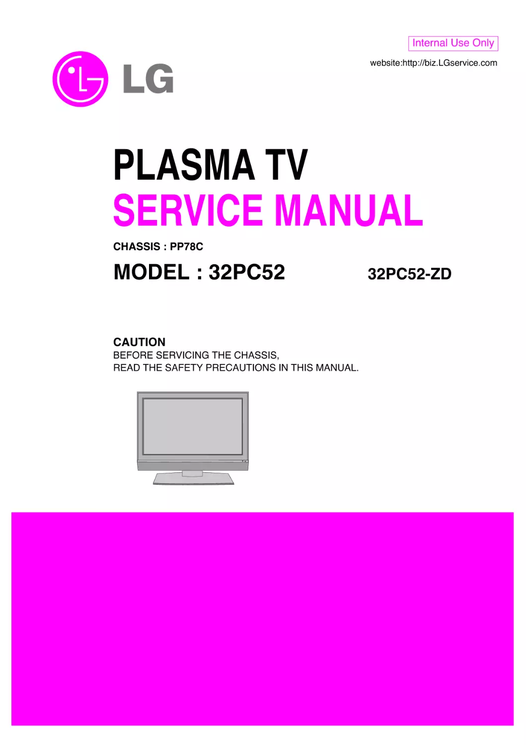
                    PLASMA TV
SERVICE MANUAL
CAUTION
BEFORE SERVICING THE CHASSIS,
READ THE SAFETY PRECAUTIONS IN THIS MANUAL.
CHASSIS : PP78C
MODEL : 32PC52
32PC52-ZD
website:http://biz.LGservice.com
Internal Use Only

-2-
LGE Internal Use Only
Copyright©2008 LG Electronics. Inc. All right reserved.
Only for training and service purposes
CONTENTS
CONTENTS .............................................................................................. 2
SAFETY PRECAUTIONS ..........................................................................3
SPECIFICATION ........................................................................................4
ADJUSTMENT INSTRUCTION .................................................................6
TROUBLE SHOOTING ............................................................................13
BLOCK DIAGRAM...................................................................................20
EXPLODED VIEW .................................................................................. 22
SVC. SHEET ...............................................................................................
PRINTED CIRCUIT DIAGRAM ....................................................................

-3-
LGE Internal Use Only
Copyright©2008 LG Electronics. Inc. All right reserved.
Only for training and service purposes
SAFETY PRECAUTIONS
Many electrical and mechanical parts in this chassis have special safety-related characteristics. These parts are identified by in the
Schematic Diagram and Replacement Parts List.
It is essential that these special safety parts should be replaced with the same components as recommended in this manual to prevent
X-RADIATION, Shock, Fire, or other Hazards.
Do not modify the original design without permission of manufacturer.
General Guidance
An isolation Transformer should always be used during the
servicing of a receiver whose chassis is not isolated from the AC
power line. Use a transformer of adequate power rating as this
protects the technician from accidents resulting in personal injury
from electrical shocks.
It will also protect the receiver and it's components from being
damaged by accidental shorts of the circuitry that may be
inadvertently introduced during the service operation.
If any fuse (or Fusible Resistor) in this monitor is blown, replace it
with the specified.
When replacing a high wattage resistor (Oxide Metal Film Resistor,
over 1W), keep the resistor 10mm away from PCB.
Keep wires away from high voltage or high temperature parts.
Due to high vacuum and large surface area of picture tube,
extreme care should be used in handling the Picture Tube.
Do not lift the Picture tube by it's Neck.
Leakage Current Cold Check(Antenna Cold Check)
With the instrument AC plug removed from AC source, connect an
electrical jumper across the two AC plug prongs. Place the AC
switch in the on position, connect one lead of ohm-meter to the AC
plug prongs tied together and touch other ohm-meter lead in turn to
each exposed metallic parts such as antenna terminals, phone
jacks, etc.
If the exposed metallic part has a return path to the chassis, the
measured resistance should be between 1MΩ and 5.2MΩ.
When the exposed metal has no return path to the chassis the
reading must be infinite.
An other abnormality exists that must be corrected before the
receiver is returned to the customer.
Leakage Current Hot Check (See below Figure)
Plug the AC cord directly into the AC outlet.
Do not use a line Isolation Transformer during this check.
Connect 1.5K/10watt resistor in parallel with a 0.15uF capacitor
between a known good earth ground (Water Pipe, Conduit, etc.)
and the exposed metallic parts.
Measure the AC voltage across the resistor using AC voltmeter
with 1000 ohms/volt or more sensitivity.
Reverse plug the AC cord into the AC outlet and repeat AC voltage
measurements for each exposed metallic part. Any voltage
measured must not exceed 0.75 volt RMS which is corresponds to
0.5mA.
In case any measurement is out of the limits specified, there is
possibility of shock hazard and the set must be checked and
repaired before it is returned to the customer.
Leakage Current Hot Check circuit
1.5 Kohm/10W
To Instrument's
exposed
METALLIC PARTS
Good Earth Ground
such as WATER PIPE,
CONDUIT etc.
AC Volt-meter
IMPORTANT SAFETY NOTICE
0.15uF

-4-
LGE Internal Use Only
Copyright©2008 LG Electronics. Inc. All right reserved.
Only for training and service purposes
SPECIFICATIONS
NOTE : Specifications and others are subject to change without notice for improvement.
V Application Range
This spec is applied to the 32" PLASMA TV used PP78C Chassis.
V Specification
Each part is tested as below without special appointment.
1) Temperature : 25±5°C (77±9°F), CST : 40±5
2) Relative Humidity: 65±10%
3) Power Voltage: Standard Input voltage (100-240V~, 50/60Hz)
* Standard Voltage of each product is marked by models.
4) Specification and performance of each parts are followed each drawing and specification by part number in accordance with SBOM.
5) The receiver must be operated for about 20 minutes prior to the adjustment.
V Test Method
1) Performance : LGE TV test method followed.
2) Demanded other specification
Safety : CE, IEC specification
EMC : CE, IEC
V General Specification ( 32"WVGA )
Display Screen Device
Aspect Ratio
PDP Module
Operating Environment
Storage Environment
Input Voltage
1
2
3
4
5
6
No
Item
Specification
Remark
32" Wide Color Display Module
16:9
PDP32F1,
RGB Closed Type
1)Temp. : 0~40deg
2)Humidity : 0~85%
3)Temp. : -20~60deg
4)Humidity : 0~85%
100-240V~, 50/60Hz
Plasma Display Panel
Glass Filter
LGE SPEC.
Maker : LG
Chassis
PP78C
32PC52-ZD
EU
LG
PSU Segregation
Model
Model Name
Market
Brand
Remark
32PC52-ZD
Safety : IEC/EN60065,
EMI : EN55013,
EMS : EN55020
EU
Model
Appliance
Market
PSU Segregation
Model
Remark

-5-
LGE Internal Use Only
Copyright©2008 LG Electronics. Inc. All right reserved.
Only for training and service purposes
V General Specification2
Market
Broadcasting system
Available Channel
Receiving system
SCART Jack(2EA)
Component Input (1EA)
RGB Input(1EA)
HDMI Input(1EA)
Audio Input (4EA)
Audio variable out(1EA)
1
2
3
4
5
6
7
8
9
10
No
Item
Specification
Remark
EU
PAL-BG/I/DK, SECAM
BAND
PAL
NTSC
VHF/UHF C1~C69
2~83
CATV
S1~S47
1~71
Upper Heterodyne
PAL, SECAM, NTSC
Y/Cb/Cr, Y/Pb/Pr
RGB-PC
HDMI-DTV
PC Audio, Component(1EA),
Full SCART, Half SCART
HDMI PC spec out
L/R Input
Display area
Outline dimension
Number of Pixels
Cell pitch
Pixel type
Weight(net)
Weight(gross)
Operation Environment Temperature
Humidity
Pressure
Storage Environment
Temperature
Humidity
Pressure
I mage stick minimization Start time
mode
Low Brightness
Arrival Time
708.0.1(H) x 398.4(V) ± 0.5mm
790(H) x 466.5(V) x 59.1(D) ± 1mm
852(H) x 480(V)
831um(H) x 830um(V)
RGB closed type
7.55
8.05
8.55
118.5 123.5
128.5
0~40
20~80
800 ~ 1100
-20~60
10~90
700 ~ 1100
4.5
5
5.5
14
15
16
1
2
3
4
5
6
7
8
9
10
No
Item
Remark
1Pixel=3RGB Cells
1Pixel=3RGB Cells
12 1Box
Altitude : 0 to 2000M
Altitude : 0 to 3000M
mm
mm
um
Kg
Kg
deg
%
hPa
deg
%
hPa
min
min
Min
Typ
Max
Unit
V Module Specification ( PDP32F1 )

-6-
LGE Internal Use Only
Copyright©2008 LG Electronics. Inc. All right reserved.
Only for training and service purposes
ADJUSTMENT INSTRUCTION
1. Application Object
These instructions are applied all of the 32" PLASMA TV,
PP78C Chassis.
2. Note
(1) Because this is not a hot chassis, it is not necessary to use
an isolation transformer. However, the use of isolation
transformer will help protect test instrument.
(2) Adjustment must be done in the correct order.
(3) The adjustment must be performed in the circumstance of
25±5°C of temperature and 65±10% of relative humidity if
there is no specific designation.
(4) The input voltage of the receiver must keep 100-220V~,
50/60Hz.
(5) Before adjustment, execute Heat Run for 30 minutes.
3. Adjustment items
3.1. PCB assembly adjustment items
(1) Download the VCTP main software (IC500,VCT_Pro)
(2) Color carrier Adjustment
3.2. SET assembly adjustment items
(1) DDC Data input.
(2) Adjustment of White Balance.
(3) Factoring Option Data input.
4. PCB assembly adjustment method
(Using VCTP Download program)
4-1. Download program installation
(1) Extract a Zip file.
(2) Visual I2C & LPT Driver Installation.
LPT Port Driver (LptDrv) Setups : Program Files > Micronas >
Visual I2C > Port_Driver
*Use for Windows 95/98 : Setup_LptDrv_v0104_9x.exe
*Use for Windows 2000/XP : Setup_LptDrv_v0202_XP_2000.exe
*Use for Windows NT : Setup_LptDrv_v0104_NT.exe
(3) Verification.(Start > Programs > Micronas > Visual I2C or
LptDrv)
(4) LPT delay setting.(File > Preference > LPT preferences)
(5) Exchange the "bootloader.bat" file.
Install the LPT Driver
Install the Visual I2C
*LPT SETTING
-Delay=>1
-Timeout=>500ms
G Double click the Red area

-7-
LGE Internal Use Only
Copyright©2008 LG Electronics. Inc. All right reserved.
Only for training and service purposes
G Select the "Bootloader.bat" file.
(install > VCTP_download > Bootloader)
G Push "OK".
G Finish the program, after saving the file "download_cs.vi2c".
(if you click , the massage appears automatically)
5. S/W program download
5-1. Download method 1 (PCB Ass'y)
(1) Connect the download jig to D-sub jack.
(2) Execute 'Download.vi2c' program in PC, then a main
window will be opened.
(3) Double click the blue box and confirm "Bootloader Version" as 42.
(4) Click the "Erase Flash" button.
(5) Double click the download file low, then "edit" window will
be opened.
(6) Click the choice button in the "edit window", then "file
choice window" will be opened.
(7) Choose the Hex file in folder and execute downloading
with click " open" button.
(8) Click OK button at the "edit window".
(9) Under Downloading process.
(10) If download is failed, for example "No acknowledge from
slave". Execute download again from(1).
x
Shortcut to
download
Double click

-8-
LGE Internal Use Only
Copyright©2008 LG Electronics. Inc. All right reserved.
Only for training and service purposes
5-2.Download method 2 (Set)
(1) Push the "Tilt" button in an Adjust Remocon Then the
PLASMA TV will change a "slave mode".
(2) Connect Zig to TV using a D-sub cable.
(3) Execute 'Download_CS.vi2c' program in PC, then a main
widow will be opened.
(4) Click "GO" button.
If you don't push the "go", the Hex file would not be
downloaded although the download proceeds normally at
first glance.
(5) Double click the blue box and confirm "Bootloader Version"
as 42.
(6) Click the "Erase Flash" button.
(7) Double click the download file low then, "edit" window will
be opened.
(8) Chick the choice button I n the "edit window", then "file
choice window' will be opened.
(9) Click the "load > flash" button.
(10) Click OK button at the "edit window".
(11) Under Downloading progress.
(12) If download is failed, for example "No acknowledge from
slave", execute download again from (1).
Shortcut to
download_cs
Double click

-9-
LGE Internal Use Only
Copyright©2008 LG Electronics. Inc. All right reserved.
Only for training and service purposes
6. Tool Option Area Option Change
6-1. Adjustment method
Before PCB check, have to change the Tool option and Area option.
Option values are below.
(If on changed the option, the input menu can differ the model spec.)
The input methods are same as other chassises.(Use adj Key
on the Adjust Remocon)
7. Color carrier Adjustment
(Inspection process)
(1) tuning the RF signal
ZB, TB/TD : PAL Philips Pattern (with Color Bar)
(2) push the "adj" key in the adjustment remocon.
8. EDID(The Extended Display Identification Data )
/DDC(Display Data Channel) download
8-1. EDID Data
<EDID Data Analog Set : 128Bytes >
<EDID Data HDMI1 Set : 256Bytes >
<EDID Data HDMI2 Set : 256Bytes >
=> Detail EDID Options are below([1],[2],[3],[4],[5])
1. [1]-Product ID
2. [2]-Serial No : Controlled on production line
3. [3]-Month, Year : Controlled on production line
ex) Monthly: '03' => '03'
Year: '2005' => '0F'
4. [4]-Model Name : model name -> LG TV
-LGTV
5. [5]-Checksum (7EH) -> Changeable by total EDID data.
- Use the proper signal cable for EDID Download.
- Never connect HDMI & D-SUB Cable at the same time.
- Use the proper cables below for EDID Writ.
32(VGA)
Area Option
Tool Option
ZB
TB/TD
04164(PCB P/N : EAX37454301~4304)
4292(PCB P/N : EAX37484306)
5572(PCB P/N : EAX49008601~)
Depend on PR
For RGB EDID
For HDMI EDID
No
1
2
3
Item
Manufacturer ID
Version
Revision
Condition
GSM
Digital : 1
Digital : 2
Hex Data
1E6D
01
03
2D
Model
Name
32PC5R
32PC52
DEC
30168(A)
30169(D)
55413(A)
55669(D)
Product ID
HEX
75D8
75D9
75D8
75D9
EDID table
D875
D975
D875
D975
32PC5R
000000FD003A3F1F3209000A202020202020
Model Name
Model Name(HEX)

-10-
LGE Internal Use Only
Copyright©2008 LG Electronics. Inc. All right reserved.
Only for training and service purposes
8-2. Required Test Equipment
(1) Adjusting PC with S/W for writing EDID Data.
(S/W : EDID TESTER Ver.2.5)
(2) A Jig for EDID Download.
(3) Cable : Serial(9Pin or USB) to D-sub 15Pin cable, D-sub
15Pin cable, DVI to HDMI cable.
8-3. Preparation for Adjustment
(1) As above (Fig. 2), Connect the Set, EDID Download Jig,
PC & Cable.
(2) Turn on the PC & EDID Download Jig. And Execute the
S/W : EDID TESTER Ver 2.5.
(3) Set up S/W option.
Repeat Number : 5
Device Address : A0
PageByte : 8
(4) Power on the Set.
8-4. Sequence of Adjustment
(1) DDC data of Analog-RGB
1) Init the data.
2) Load the EDID data.(Open File).
[ Analog-RGB : PP78C_RGB.ANA ]
[ Digital-HDMI1 : PP78C_HDMI1.DVI ]
[ Digital-HDMI2 : PP78C_HDMI2.DVI ]
3) Set the S/W as below.
4) Push the "Write Data & Verify"button. And confirm "Yes".
5) If the writing is finished, you will see the "OK" message.
(Fig. 2) Connection Diagram of DDC download
Open File

-11-
LGE Internal Use Only
Copyright©2008 LG Electronics. Inc. All right reserved.
Only for training and service purposes
9. Adjustment of White Balance
9-1. Purpose and Principle for adjustment
of the color temperature
(1) Purpose : Adjust the color temperature to reduce the
deviation of the module color temperature.
(2) Principle : To adjust the white balance without the
saturation, Fix the one of R/G/B gain to 80 and decrease
the others.
9-2.Adjustment mode
: Two modes of Cool and Warm.(Medium data is
automatically calibrated by the cool data)
9-3. Required Equipment
(1) Remote control for adjustment.
(2) Color Analyzer : CA-100+, CA210 or same product.
- Plasma TV(ch : 10)
(3) Auto W/B adjustment instrument.(only for Auto adjustment)
9-4. Connecting diagram of equipment for
measuring (For Automatic Adjustment)
(1) Enter the DDC adjust mode.
- Enter the white balance adjustment mode at the same
time heat-run mode when pushing the power on by power
only key.
- Maintain the white balance adjustment mode with same
condition of Heat-run.
-> Maintain after AC off/on in status of Heat-run pattern display.
(2) Release the DDC adjust mode.
- Release the adjust mode after AC off/on or std-by off/on
in status of finishing the Hear-run mode.
- Release the Adjust mode when receiving the aging off
command(F3 00 00) from adjustment equipment.
- Need to transmit the aging off command to TV set after
finishing the adjustment.
* Standard color coordinate and temperature when using the
CA-100+ or CA210 equipment.
* Synchronization relation between PSM and CSM.
(3) DDC adjustment support command set.
* R/G/B GAIN max value : 80
9-5. Adjustment of White Balance
(For Manual adjustment)
- Adjustment mode : Two modes of Cool (Dynamic) and
Warm(Mild).
(Medium data is automatically calibrated by the cool data)
- Color analyzer(CA110, CA210) should be used in the
calibrated ch by CS-1000.(PDP : CH10)
- Operate the zero-calibration of the CA-110 or CA-210, then
stick sensor to the module when adjusting.
- For manual adjustment, it is also possible by the following
sequence.
(1) Select RF no signal by pressing "POWER ON" key on
remote control for adjustment then operate heat run more
than 15 minutes.
(If not executed this step, the condition for W/B will be differ.)
(2) Changing to the av mode by pushing the input or front av
key.(av mode : av1 or av2 or av3)
(3) Display the internal pattern of the VCT-Pro IC by pushing
the IN-START.
(4) Stick sensor to center of the screen and select each items
(Red/Green/Blue Gain and Offset) using D/E (CH+/-) key
on R/C.
(5) Adjust R Gain / B Gain using F/G (VOL+/-) key on R/C.
(6) Adjust two modes of Cool(Dynamic) and Warm(Mild) as
below figure.
(Fix the one of R/G/B and change the others)
1. Push the one time the in-start key : Dynamic(Cool)
2. Push the two more the in-start key : Mild(Warm)
Color Coordinate
xy
0.283±0.003
0.295±0.003
0.329±0.003
11,000K
9,300K
6,500K
0.000
0.000
0.003
0.276±0.003
0.283±0.003
0.313±0.003
COOL
MEDIUM
WARM
Mode
Temp
uv
CSM
Remark
Cool
Normal
Warm
Dynamic
Standard
Mild
PSM
Adjustment
Aging On/Off
Input select
R GAIN
G GAIN
B GAIN
R GAIN
G GAIN
B GAIN
R GAIN
G GAIN
B GAIN
CMD(HEX)
F3
F4
16
18
1A
16
18
1A
16
18
1A
ADR
00
00
00
01
02
VALUE
FF/00
00-FE
00-FE
00-FE
00-FE
00-FE
00-FE
00-FE
00-FE
00-FE
Detail
OO:OFF
01 :ON
FF : WB Ready
0x10 : TV
0x20 : AV1
0x21 : AV2
0x23 : AV3
0x40 : Component1
0x50 : RGB DTV
0x60 : RGB PC
0x90 : HDMI1 DTV
GAIN adjustment
CSM COOL
GAIN adjustment
CSM NORMAL
GAIN adjustment
CSM WARM

-12-
LGE Internal Use Only
Copyright©2008 LG Electronics. Inc. All right reserved.
Only for training and service purposes
* Refer to the below case to know what value is fixed.
* CASE
- First adjust the coordinate much away from the target
value(x, y).
1)x,y>target
(1) Decrease the R, G.
2)x,y< target
(1) First decrease the B gain.
(2) Decrease the one of the others.
- In case of decreasing the x, decreasing the R : fix G
- In case of decreasing the y , decreasing the G : fix R
3)x >target, y<target
(1) First decrease B, so make y a little more than the
target.
(2) Adjust x value by decreasing the R.
4)x<target, y>target
(1) First decrease B, so make x a little more than the
target.
(2) Adjust x value by decreasing the G.
(7) When adjustment is completed, Exit adjustment mode
using EXIT key on R/C.
10. Default Value in Adjustment mode
(Default values maybe modified the module condition)
10-1. White Balance
11. Internal press test
12. Sound spec.
13. POWER PCB Assy Voltage
Adjustments (Va, Vs Voltage adjustments)
13-1. Profile
: To supply the Va, Vs voltage that the module want.
13-2. Required Test Equipment
(1) Stick for adjustment.
(2) DMM.
13-3. Connection Diagram for Measuring
: refer to (Fig. 1)
13-4. Adjustment Method
(1) Va Adjustment
1) After receiving 100% Full White Pattern, HEAT RUN.
2) Connect + terminal of D. M..M. to Va pin of P812, connect
-terminal to GND pin of P812.
3) After turning VR901,voltage of D.M.M adjustment as
same as Va voltage which on label of panel right/top.
(deviation; ±0.5V)
(2) Vs Adjustment
1) Connect + terminal of D. M..M. to Vs pin of P812, connect
-terminal to GND pin of P812.
2) After turning VR851, voltage of D.M.M adjustment as
same as Vs voltage which on label of panel right/top.
(deviation ; ±0.5V)
14. Input the Shipping Option Data
(1) Push the ADJ key in a Adjust Remote control.
(2) Input the Option Number that was specified in the BOM,
into the Shipping area.
(3) The work is finished, Push A Key.
Item
Dielectric Voltage (AC <-> FG)
Dielectric Voltage (Without FG)
Value
1.5
1.5
3
3
Unit
kV
kV
Remark
At 100mA for 1sec (Line)
At 100mA for 1min (OQC)
At 100mA for 1sec (Line)
At 100mA for 1min (OQC)
Item
Min Typ Max Unit Remark
Audio Practical Max Output, L(Mono)/R 9 10 12 W
<Default Value on OSD>
Color Coordinate
xy
0.283±0.003
0.295±0.003
0.329±0.003
11,000K
9,300K
6,500K
0.000
0.000
0.003
0.276±0.003
0.283±0.003
0.313±0.003
COOL
MEDIUM
WARM
Mode
Temp
uv
(Fig. 1) Connection Diagram of power adjustment for measuring.
Each PCB assembly must be checked by check JIG set.
(Because power PCB Assembly damages to PDP Module,
especially be careful)

-13-
LGE Internal Use Only
Copyright©2008 LG Electronics. Inc. All right reserved.
Only for training and service purposes
TROUBLESHOOTING
1. No power
(1) Symptom
1) Minute discharge does not occur at module.
2) Front LED does not activate.
(2) Press check
Plug in the power cord
Start Check
No
Yes
Is the power cord
plugged in?
Connect the cable.
Plasma(CN1)
No
Yes
Are the line filter and
PSU connected?
Replace the fuse.
No
Yes
Is the correct fuse for
the PSU in place?
Plasma(F101)
Connect the 15pin cable.
Next remove all cables connected to the PSU and
switch the AV voltage to manual.
If the ST-by 5V does not operate, replace the PSU.
No
Yes
Is the PSU and 15pin
cable connected to the
VSC board?

-14-
LGE Internal Use Only
Copyright©2008 LG Electronics. Inc. All right reserved.
Only for training and service purposes
2. Protect mode
(1) Symptom
1) After lighting once it does not discharge minutely from the module.
2) The relay falls.(there is an audible "Click".)
3) The color of the front LED turns from green to red.
(2) Follow check
Is the Power Board
normal ?
Replace Power Board.
Is the output the normal Low/High
voltage except for the Stand-by 5V?
Yes
No
No
Are all the connectors
normal?
Replace the connector.
Replace the fuse.
Replace the Y-Board.
After checking each connector does
is operate correctly?
Yes
No
No
Is the Y-Board
normal?
Is the
appropriate
fuse (FS2,FS1) on the
Y-B/D?
Is the output voltage
normal after removing the
P1 connector of the Y-B/D?
Yes
No
No
Is the X- Board
normal?
Is the
output voltage normal
after removing the P11, P12,
P13 connector of
the X-B/D?
After removing the P12 and the output
voltage is normal : Replace the Right X-B/D
After removing the P11, P13 and the output
voltage is normal : Replace the Left X-B/D
No
Yes
Start Check

-15-
LGE Internal Use Only
Copyright©2008 LG Electronics. Inc. All right reserved.
Only for training and service purposes
3. No Raster
(1) Symptom
1) No OSD or image are displayed on the screen.
2) The front LED remains green.
(2) Follow check
4. In the case an unusual display in RF mode.
Check the PDP Module
Replace the
Power board.
Does
minute discharge
at Module?
Is the inverter
/VaVs on?
Is output the normal
Low/High voltage except
for the Stand-by 5V?
Yes
No
No
Is the output for the
IC500 normal?
Replace the VSC.
No
Yes
Check the power.(L1103)
Is the
video output of the
Tuner normal? (Check
TU400_Pin13)
Is the
input voltage
normal?(Check
Pin3)
Is the I2C communication normal?
(Check Pin9, Pin10)
Yes
No
Yes
Is the LVDS
Pattern connected?
Yes
Change the IC(IC500)
Connect again
the Pattern.
No
No
Check the Tuner.
No
A
Start Check

-16-
LGE Internal Use Only
Copyright©2008 LG Electronics. Inc. All right reserved.
Only for training and service purposes
5. In the case of an unusual display in rear AV mode.
Is video input of
the A/V jack normal?
(Check R113)
Yes
Sam as Block A
Check the input source.
No
8. In the case of an unusual display in SCART 1 mode.
Is the video input
of the A/V jack normal?
(Check R113)
Yes
Sam as Block A
Check the input source.
No
9. In the case of an unusual display in SCART 1_RGB mode.
Is the
video input of
the A/V jack normal?(Check
R115,R116,
R117)
Yes
Sam as Block A
Check the input source.
No
10. In the case of an unusual display in SCART 2 mode.
Is the video input of
the A/V jack normal?
(Check R149)
Yes
Sam as Block A
Check the input source.
No

-17-
LGE Internal Use Only
Copyright©2008 LG Electronics. Inc. All right reserved.
Only for training and service purposes
11. In the case of an unusual display in component 1 mode.
Is the video
input of the A/V jack
normal? (Check R235,
R236,R250)
Yes
Change the IC(IC500)
Check the input source.
No
12. In the case of an unusual display in component 2 mode.
Yes
Change the IC(IC500)
Check the input source.
No
Is the video
input of the A/V Jack
normal? (Check R243,
R244, R245)
13. In the case of an unusual display in RGB mode.
Yes
Change the IC(IC500)
Check the input source.
No
Is the
R, G, B input
andH,Vsyncofthe
JK201 normal?(Check R223,
R224, R225, R221,
R222)

-18-
LGE Internal Use Only
Copyright©2008 LG Electronics. Inc. All right reserved.
Only for training and service purposes
14. No Sound
(1) Symptom
1) LED is green.
2) There is a picture but no sound.
(2) Follow check
Is there sound in any
mode?
Is the speaker
on?
Yes
Yes
Is the speaker
cable normal?
Yes
Yes
Is there no sound
only for HDMI?
Yes
Is there no
sound only AV
/COM2/PC?
Is the output
of IC600(R609, R608)
normal?
Yes
Is there no sound
only for RF?
No
No
No
No
Download the EDID data.
Set speaker on
in the menu.
No
Replace the
IC600
No
Check the Speaker
cable
No
Is the IC500
operating normal?
Replace the IC500
No
Yes
Is the IC601
operating normal?
Replace the IC601
Replace the VSC BD
Yes
Check the signal after IC600.
refer to circuit diagram.
Check the Tuner In/Out.
No

-19-
LGE Internal Use Only
Copyright©2008 LG Electronics. Inc. All right reserved.
Only for training and service purposes
15. HDMI mode
Is only video
normal?
Is only audio
normal?
No
Yes
Download EDID data each port.
Check the TMDS line wave.
(R312~E3273)
1. Check the HDMI receiver's status register. (0x60, offset 0x66)
- If the value is 0xf or 0x8, it is normal.
2. Check the HDCP register. (0x6, offset 0x32)
- Enable bit 6 : HDCP key loaded
- Enable bit 5 : HDCP decryption active
- Enable bit 4 : HDCP authentication attempted
Reset TMDS power down/ on register.
- 0x60, offset 0x3f => 0xff
Check HDMI source.
Change to another source or cable.
Yes
Is the wave
continuous?
Normal video,
Normal audio?
No
Yes
Replace the IC303.
No
1. Check TV input mode.
(HDMI 1 port support HDMI and DVI.
So if you input DVI signal and PC audio from
phone jack, You can hear PC audio.)
2. Unplug and plug in the HDMI cable.
(sometimes ESD surge occurred at HDMI port.)
3. Check the HDMI Mute register. (0x68, offset 0x37)
4. Check the Audio-out channel mute register (0x68,
offset 0x32) is appropriately enabled.
Yes

-20-
LGE Internal Use Only
Copyright©2008 LG Electronics. Inc. All right reserved.
Only for training and service purposes
BLOCK DIAGRAM
PC_Audio
RF
SCART1,2
COMP1
HDMI1
(DTV)
RCA1
RCA2
RGB
(PC)
VARIABLE AUDIO OUT
32PDP BLOCK DIAGRAM
EU-OPTION
COMP2
HDMI2
(DTV)
NONEU-OPTION
VCT_Pro
(Lip-sync)
EEPROM
24C02
SYNC SW
74ACT253
DSUB_SCL/SDA
PC_R/G/B
PC_SER_DATA/CLK
PC_VS/HS
HDMI Rx
ANX9021
#1 RX 0/1/2/CLK±
CEC
EEPROM
24C02
DDC1_SCL/SDA
EEPROM
24C02
#2 RX 0/1/2/CLK±
CEC
DDC2_SCL/SDA
VS/HS
DRI/DGI/DBI/[0-7]
PC_R/G/B
CEC
COMP1_Y/Pb/Pr
COMP1_L/R
COMP2_Y/Pb/Pr
COMP2_L/R
SC1_V
SC1_L/R
MNT_VOUT
MNT_L/ROUT
COMP SW
STMAV340
COMP1_Y/Pb/Pr
COMP2_Y/Pb/Pr
SC1_R/G/B
SC_R/G/B_COMP/Y/Pb/Pr
AUDIO SW
TEA6420
PC_AUDIO_L/R
SC1_L/
R
SC2_L/
R
COMP2_L/R
AV_AUDIO_L/
R
AM_AUDIO_L/R
COMP1_L/R
TV_L/ROUT
MNT_L/ROUT
MNT_VOUT
TUNER
TV_
V
TV_VOU
T
AM_AUDIO
SIF
SC1_V
SC1_R/G/B/FB/ID
SC1_L/R
TV_VOU
T
TV_L/ROUT
SC2_V
SC2_ID
SC2_L/R
MNT_VOUT
MNT_L/ROUT
SC1/2_ID
SC1/2_V
SC1_FB
HDMI_R/G/B
PC_Audio_L/R
HEAD_L/R
EEPROM
24C32
AMP
TPA3107D
2
SPK_L/R
SPK_L-/+
SPK_R-/+
I2C
I2C
I2C
I2C
I2C
PDP ASIC
4007
RA1/RB1/RC1/RD1/RE+-
I2C
DISP_EN
PC_SER_DATA/CLK
FLASH(16 M)
MX29LV160
TEMP IC
ADT75ARZ
XDRV_OUT[0-79]
X1_CLK_A1/2_B1/2
YSUS/ER
_UP/DN
BUFFER
74ACT54
BUFFER
74ACT54
YRAMP_
UP/DN
BUFFER
74ACT54
ZSUS/ER
_UP/DN
YSUS/ER
_UP/DN
YRAMP_
UP/DN
ZSUS/ER
_UP/DN

MEMO
-21-
LGE Internal Use Only
Copyright©2008 LG Electronics. Inc. All right reserved.
Only for training and service purposes

-22-
LGE Internal Use Only
Copyright©2008 LG Electronics. Inc. All right reserved.
Only for training and service purposes
EXPLODED VIEW
A21
A2
300
570
560
120
301
302
303
304
305
200
240
580
250
400
520
590
201
202
204
203
900

LGE Internal Use Only
Copyright©2008 LG Electronics. Inc. All right reserved.
Only for training and service purposes

LGE Internal Use Only
Copyright©2008 LG Electronics. Inc. All right reserved.
Only for training and service purposes

LGE Internal Use Only
Copyright©2008 LG Electronics. Inc. All right reserved.
Only for training and service purposes
MAIN(TOP)
MAIN(BOTTOM)
CONTROL(TOP)
CONTROL(BOTTOM)
PRE-AMP(BOTTOM)
PRE-AMP(TOP)
PRINTED CIRCUIT BOARD

Apr., 2008
Printed in Korea
P/NO : MFL40431012