/


Author: Hunnicutt R.P.
Tags: military affairs military equipment combat vehicles military art
ISBN: 0-89141-694-3
Year: 1999

Text
A History of American
Fighting and Support Vehicles
By R. P. Hunnicutt
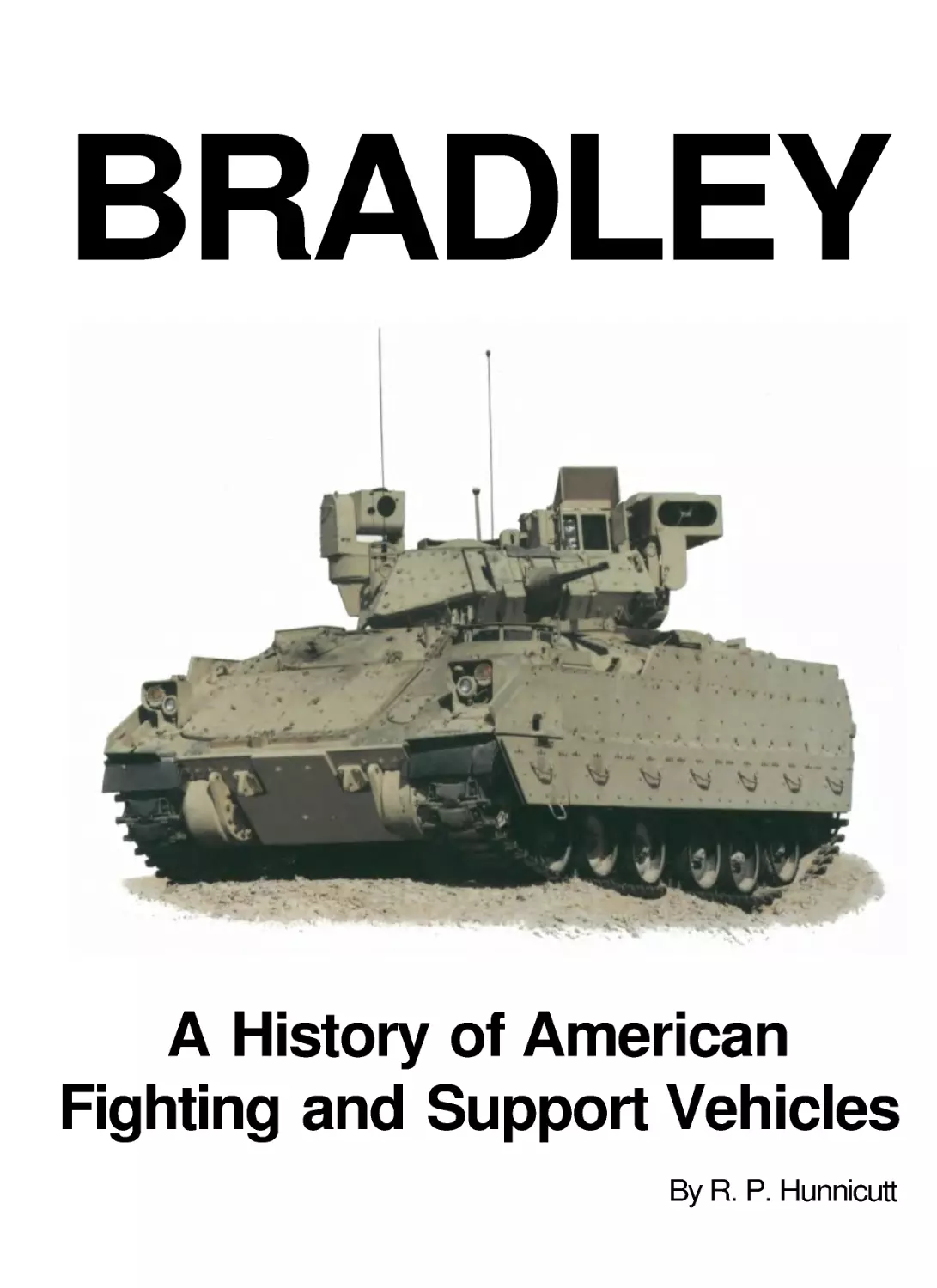
BRADLEY
BRADLEY
A HISTORY OF AMERICAN
FIGHTING AND SUPPORT VEHICLES
by
R.P. Hunnicutt
FOREWORD
by
Major General Stan R. Sheridan, USA Retired
PRESIDIO
Copyright © 1999 By R. P . Hunnicutt
First Edition
Published by Presidio Press
505B San Marin Drive, Suite 300
Novato,CA 94945-1340
All rights reserved. No part of this book may be reproduced or utilized in any
form or by any means, electronic or mechanical, including photocopying,
recording or by any information storage and retrieval systems, without
permission in writing from the Publisher. Inquiries should be addressed to
Presidio Press, 505B San Marin Drive, Suite 300, Novato, CA 94945-1340.
Library of Congress Cataloging-Publication-Data
Hunnicutt, R. P ., 1926-
Bradley: A history of American fighting and support vehicles/
R. P . Hunnicutt ; foreword by Stan Sheridan.
p. cm.
Includes bibliographical references and index.
ISBN 0-89141-694-3
1. Armored vehicles, Military- -United States- -History.
2. Vehicles, Military- -United States- -History. 3 . M2 Bradley
infantry fighting vehicle. I. Title
UG446.5.H84423 1999
623.7'475--dc21
Printed in the United States of America
CONTENTS
Foreword
4
Acknowledgements
6
PART I DEVELOPMENT OF SUPPORT
VEHICLES DURING WORLD
WAR II
7
Armored Personnel and Cargo Carriers
9
Armored Command and Reconnaissance Vehicles 14
High Speed Tractors
16
Low Ground Pressure Vehicles
22
PART II EARLY POSTWAR DEVELOPMENT.. 27
New Armored Personnel Carriers
29
A Lower Cost Armored Personnel Carrier
50
High Speed Tractors and Cargo Carriers
66
Low Ground Pressure Vehicles
72
PART III A NEW FAMILY OF TRACKED
CARRIERS
75
New Lightweight Designs
77
M113Series of Armored Personnel Carriers
81
A Universal Chassis Based upon the M113 Series.... 110
Low GroundPressure Vehicles
128
Fire Support Vehicles
139
Command Post, Control, and Communication
Vehicles
161
Antitank Vehicles
174
Antiaircraft Vehicles
186
Engineer Vehicles
203
Recovery and Maintenance Vehicles
208
Chemical Warfare Vehicles
213
Command andReconnaissance Vehicles
222
PART IV INFANTRY AND CAVALRY
FIGHTING VEHICLES
249
Improvised Fighting Vehicles
251
A New Armored Infantry Fighting Vehicle
261
The Mechanized Infantry Combat Vehicle
274
The Appearance of the Bradley
282
Vehicles Based upon the Bradley
303
The Fighting Vehicle Systems Carrier
308
Composite Armored Vehicles
318
PART V LANDING VEHICLES
321
The Legacy of World War II
323
Postwar Development
325
The LVTP5 Family
331
The LVTP7 Family
343
The Advanced Assault Amphibian Vehicle
358
PART VI ACTIVE SERVICE
365
World War II
367
Korea
368
Vietnam
373
War in the Persian Gulf
392
Worldwide Service
398
The Future
407
PART VII REFERENCE DATA
411
Color Section
413
Data Sheets
421
References and Selected Bibliography
466
Index
467
FOREWORD
by
Major General Stan R. Sheridan, USA Retired
CHARIOTS OF FIRE may be the title of an award
winning Hollywood movie, but it is also a fitting
description of the many "soldier carrying" vehicles de-
scribed in this latest work on armored vehicles by Dick
Hunnicutt. In fact, chariots of one kind or another have
carried soldiers into battle throughout the history of
warfare, dating as far back as the early Egyptians and
Romans. So it is appropriate that this latest in Dick
Hunnicutt's series of volumes on Fighting Vehicles
should now focus on the armored carriers, both fighting
and support, that inhabit today's modern battlefield.
While this eminently qualified author covers the spec-
trum of these vehicles in this newest volume, as the title
suggests, the thrust of this work is the U.S. Army's
Infantry and Cavalry Fighting Vehicles and their deriv-
atives - The BRADLEY. While I find this entire volume
intriguing and a true and factual reference for the
scholar of fighting vehicles, as the U.S. Army's first
Program Manager for what has become known to the
world as the BRADLEY Fighting Vehicle System, it
appears appropriate for me to comment on the title-
subject of Dick Hunnicutt's latest work.
The history of the BRADLEY was long and
tortured, and today we take the design and the out-
standing war fighting performance of the vehicle for
granted - the two man turret, the two TOW antitank
missile launcher, the highly effective 25mm cannon
system, the very reliable power train, its outstanding
cross country mobility, and the overall fightability of the
system. This was not always so. In the beginning, in the
late 1960s and early 1970s, the Army was struggling to
determine and define just what it wanted as the replace-
ment for the M113 Armored Personnel Carrier (APC)
that was a workhorse during the Vietnam War and the
backbone of the Army's mechanized infantry. Was the
replacement to be another APC that brought fighting
men to the battle in a protected "battlefield taxi" and
then placed them in harms way to fight on foot; or was it
to be a true fighting vehicle, giving the soldier a pro-
tected place from which to assault, fight, and kill the
enemy? The result, in the early 1970s, was the latter, a
fighting vehicle concept called the Mechanized Infantry
Combat Vehicle or MICV, which, when translated into
an all-up prototype in the mid 1970s, was unfightable:
i.e ., the gunner was in a one man turret; the vehicle
commander was in the hull behind the driver where he
could not see to command or fight the vehicle; the
crew/squad compartment was an unfightable and
crowded "arms room"; and the main armament was a
20mm cannon with no armor killing capability.
In 1975 the MICV program was reoriented and
combined with the Army's SCOUT and BUSH-
MASTER (25mm cannon) programs into a single
vehicle program, named the Infantry and Cavalry
Fighting Vehicle Program, which was later renamed in
1981 for General of the Army Omar N. Bradley. With
that reorientation came a reaffirmation of the Army's
requirement and a redesign to today's BRADLEY
Fighting Vehicle with its two man turret which places
the vehicle commander up high where he can see,
command, and fight the vehicle; the addition of a two
TOW antitank missile launcher to give the Infantry
Battalion a long range, front line, tank killing capability
without increasing the Army's force structure; a re-
stowed and redesigned crew compartment into a fighting
compartment from which mounted infantrymen can
fight; and the replacement of the less than capable
20mm cannon with the battlefield worthy 25mm cannon
and its armor piercing and high explosive multipurpose
ammunition. With this redesign and reorientation it
became readily apparent that the technical design
challenge for the developer of the new vehicle was on a
par with that of designing a tank; but with the added
human factors of carrying an infantry squad, allowing
the vehicle to swim, and ultimately making it truly
fightable for the mounted infantryman. At the same
time, from a doctrine standpoint, the Mechanized
Infantry found itself in much the same position as the
horse mounted Cavalry when the machine gun was
introduced to the battlefield. The design of the new
mobile weapon system, when translated into fightable
hardware, required a mounted infantry doctrine change
and the development of new operational concepts and
tactics in order to take full advantage of the new and
added battlefield capabilities of a fighting vehicle. As an
example, firing on moving targets with the 25mm
cannon now required the infantry gunner to use tank
gunnery techniques, totally foreign to the infantryman of
the late 1970s and early 1980s whose largest automatic
weapon until then was a .50 caliber machine gun. As a
result of this and other operational capabilities and
requirements of the new system, totally new training
packages also were required for the mounted infantry-
man who would fight in the BRADLEY. To the Army's
4
credit, it bridged the doctrine, training, and tactics gaps
and has produced the world's most capable and finest
mounted warriors.
With this new concept, design, and training
direction in hand, the vehicle development program
proceeded successfully through the 1970s and early
1980s fighting off the "Too Big, Too Bulky, Too High"
nay-sayers, a Presidential program cancellation, and
three General Officer Reviews (1976, 77, and 78) by the
Army. With the program restart after the Presidential
cancellation in 1977, and the reaffirmation of the
requirement, the design, and the concept by the three
General Officer Reviews, the program proceeded to
meet its congressionally mandated first production
delivery date of May 1981 without further hitches or
delays. In fact, the BRADLEY was the first, and I
believe the only, tracked vehicle to be approved for
production by the Army and the Office of the Secretary
of Defense on the first request. This was due primarily
to the vehicle exceeding its overall system Reliability-
Availability-Maintainability (RAM) requirements during
independent government acceptance testing.
But there is more to the BRADLEY story than
development, great designed-in system RAM, doctrinal
changes, and the final Army acceptance and production
go-ahead. The real questions facing the BRADLEY
were: What do soldiers think of the vehicle? Is it really
fightable? Does it meet the Army's needs? And how
does it do in combat? The proof of any piece of combat
equipment issued to soldiers is its performance and
soldier acceptance in combat, and the BRADLEY was
no exception. The real proof then of the BRADLEY was
Desert Storm where it received not only its baptism of
fire in combat, but complete soldier acceptance. The
experience of the lead brigade of the 24
th
Mechanized
Infantry Division's "Left Hook" operation is typical of
the BRADLEY'S superb combat performance in the 100
hours of Desert Storm. The brigade's 120 BRADLEYS
traveled 360 miles, fighting all the way, with no vehicle
drop-outs or losses. While the 25mm armor piercing
round did kill some T72 tanks from the side and rear, it
was an over-kill against the Iraqi's infantry carriers
(BMP), passing right through the BMPs and calling for
the use of the more appropriate HEAT-MP round (High
Explosive Antitank Multi-Purpose). The BRADLEY
soldiers of Desert Storm, and those using the vehicle in
places like Somalia and Bosnia, have resoundingly
endorsed the system and put to bed the nay-sayers, the
questioners, and the critics by affirming that the
BRADLEY is a highly mobile and effective battlefield
killing machine; it is not an APC or battlefield taxi, but
it does take soldiers to the battle and lets them fight
while mounted and protected; it is not a tank, nor is it
heavily armored, but it does have a long range tank
killing capability; and it exceeds the tank's cross country
mobility and effectively compliments the tank on the
battlefield. Today, with 6724 Infantry and Cavalry
Fighting Vehicles in the hands of U.S . Army soldiers
around the world, the BRADLEY is justly touted as the
finest fighting vehicle of its kind in the world.
Looking back and forgetting the pain along the
way, one can say that the BRADLEY was a success
story, primarily because of the Army's belief in, and
support for, a fighting vehicle and the dedicated and
hand-in-hand team effort by all those directly involved
in its development, production, and fielding - the Army
Program Manager's Office, the Army Infantry and
Cavalry users, and all of the many dedicated civilian
contractors. A widely used development buzzword today
is PARTNERING, or joining together of all those in-
volved in a development program toward a common
goal; but without knowing it, that is what was done with
the BRADLEY in the 1970s and early 1980s, long
before the word or the thought was in vogue in the
Defense Department.
And what of the BRADLEY derivatives, or support
vehicles, during this process? In 1975, the Army had a
need for a tracked vehicle platform for the Multiple
Launch Rocket System (MLRS) and the fighting vehicle
chassis was chosen as the candidate platform, in reality,
what the Army really wanted was a highly mobile
tracked "pick-up truck" whose "truck bed" could be
used for many battlefield missions; but at the time, the
only money available was for the development of a
MLRS carrier. Taking its lead from the very successful
and reliable automotive and suspension components of
the original MICV chassis, the MLRS carrier was
developed, tested, accepted, and fielded with almost
complete commonality with the chassis of its sister
fighting vehicle. The differences between the two being
in the physical rather than the mechanical aspects of the
chassis. Again, the proof of this derivative was its
complete success and soldier acceptance in the combat
of Desert Storm. At the same time, the Army got its
"pick-up truck". Today the derivative carrier's time has
come for, among other uses, it is being strongly
considered by the Army as a command and control
vehicle, an ambulance, and a communications vehicle.
5
ACKNOWLEDGEMENTS
It would be difficult, if not impossible, to list all of
the sources that provided information during the
research for this volume. However, the most important
of these must include Major General Stan Sheridan who
also was kind enough to write the foreword for the book.
Once again, my thanks go to General Donn A.
Starry for permission to quote from his book Mounted
Combat in Vietnam.
At the Tank Automotive and Armament Command,
Dr. Richard McClelland and others were a great help in
obtaining material for the data sheets. Roland Asoklis
provided information on the Future Scout and Cavalry
System.
The Patton Museum at Fort Knox was an important
source of both data and photographs. John Purdy and
Charles Lemons spent a lot of time helping me sort out a
number of problems.
At Aberdeen Proving Ground, Dr. William F.
Atwater, Director of the Ordnance Museum, and Alan
Killinger located much of the information on some of
the earlier vehicles.
At United Defense (formerly FMC), William
Highlander put me in touch with many of the people
who worked on their vehicles. Mr. Adolf Quilici
provided information on the early development of the
FMC personnel carriers. John Giacomazzi and Bruce
Heron were particularly helpful in locating drawings and
data. Linda Johns and Pat Elliott found many photo-
graphs and technical manuals required for the project.
At the Land Systems Division of General
Dynamics, Dr. Philip W. Lett obtained information on
their advanced amphibian assault vehicle.
Kenneth Smith-Christmas of the U.S . Marine Corps
Museum at Quantico, Virginia provided data on the
LVTP-5 .
My old friend Fred Crismon was the source for
many very rare photographs.
Many of the field modifications to the various
vehicles in Vietnam are illustrated by photographs taken
by the late James Loop during his service in that
country.
Michael Green, Greg Stewart, Jim Mesko, Hans
Halberstadt and Scott Gourley also provided photo-
graphs of several vehicles. There would have been
several more gaps in the data sheets without the help of
Jacques Littlefield and his incredible collection of
armored vehicles. Dean and Nancy Kleffman came up
with some new photographs that were particularly
helpful to the research program.
My thanks go to Jon Clemens of Armor magazine
for his help with the photographs and his permission to
quote from Armor.
Special thanks also go to Becky Page for the
preparation of the dust jacket for this volume.
6
PART I
DEVELOPMENT OF SUPPORT VEHICLES
DURING WORLD WAR II
During World War II, the standard armored personnel carrier was the open top, lightly armored, half-track vehicle. Above the M3A1 personnel
carriers of the Third Armored Division cross the Seine River in France on 26 August 1944.
ARMORED PERSONNEL AND CARGO CARRIERS
During World War II, armored personnel carriers
appeared under a variety of names. These included
tractors, cargo carriers, and armored utility vehicles.
When used to tow an artillery piece, they were referred
to as prime movers. The armored half-track was stan-
dardized during this period as the carrier for infantry in
the armored divisions of the U.S. Army. These lightly
armored, open top, vehicles served in many roles
including personnel carriers, mortar carriers, and self-
propelled artillery. Although they were intended to
combine the best features of the wheeled and full-
tracked vehicles, it also was true that they combined the
worst characteristics of each. They were not as efficient
on roads as armored cars and they lacked the cross-
country mobility of the full-tracked vehicles.
The introduction of the Sexton 25 pounder self-
propelled gun resulted in the replacement of the early
105mm howitzer motor carriage M7 in the British
forces. Many of these surplus vehicles were then
converted to armored personnel carriers by removing the
howitzer and modifying the armor and the stowage
arrangement. This conversion provided a full-tracked
armored personnel carrier that could easily keep up with
the tanks in cross-country operations.
When the Canadian Army was equipped with
Sherman tanks, a large number of the earlier Ram tanks
became available for conversion to other duties. With
the turret removed and the interior modified, they
became personnel carriers with mobility and armor
protection equal to that of the medium tank. Some old
Sherman III (M4A2) medium tanks also had their turrets
removed and were converted to armored personnel
carriers by the British forces. All of these converted
vehicles were referred to as Kangaroos.
9
The armored utility vehicle M39 is sketched above towing an antitank gun.
The appearance of the high performance 76mm gun
motor carriage Ml8 as a self-propelled tank destroyer
revealed the need for an equivalent vehicle to serve as a
personnel carrier, reconnaissance vehicle, and prime
mover for the towed guns in the tank destroyer
battalions. The Ml8 chassis was modified by removing
the turret and changing the stowage to provide a suitable
vehicle. Standardized as the armored utility vehicle
M39, it served in the U.S . Army until the end of the war
in Korea. However, its very light armor was vulnerable
to rifle caliber fire at close range and the open top
exposed the crew to artillery air bursts.
Numerous wartime development programs were
initiated to provide full-tracked, armored, personnel and
ammunition carriers as companion vehicles for the self-
propelled artillery mounted on the chassis of the
medium and light tanks. These companion vehicles also
were conversions of the same chassis used to mount the
self-propelled weapon.
The T14 cargo carrier, based upon the medium tank
chassis, was modernized and standardized as the cargo
carrier M30. It saw action as the companion vehicle to
the 155mm gun motor carriage M12. With the
introduction of the 155mm gun motor carriage M40, a
new companion vehicle was designed using the same
chassis. Originally designated as the cargo carrier T30,
it was modified to permit the stowage of either 155mm,
8 inch, or 240mm ammunition. This modified version
was designated as the cargo carrier T30E1. However,
with the decision to use unarmored, high speed, tractors
as the companion vehicles for the heavy self-propelled
artillery, production plans for the T30E1 were canceled.
A similar fate befell the cargo carrier T31. This vehicle
was designed to accompany the 8 inch howitzer motor
carriage T84. The chassis of both the T84 and the T31
was based upon components of the M26 Pershing tank.
Companion vehicles for the self-propelled artillery
utilizing the light tank chassis followed the same
pattern. The cargo carrier T22 was designed as the
companion vehicle for the 4.5 inch gun motor carriage
T16 or the 155mm howitzer motor carriage T64. Like
the artillery motor carriages, the T22 was based upon the
light tank M5A1. The cargo carrier T23 also used the
chassis of the M5A1 and was intended to accompany the
40mm gun motor carriage T65. When the artillery motor
carriages were redesigned to utilize the chassis of the
later light tank M24, a similar change was made in the
cargo carriers. They now became the cargo carriers
T22E1 and T23E1. However, neither vehicle was placed
in production.
The heavy tractors T2 and T16 were early prime
movers intended to serve as armored personnel carriers
for the crew of the heavy artillery pieces to which they
were assigned. Based upon the early medium tank,
neither the T2 nor the T16 proved to be satisfactory and
they never entered production. Later, in December 1943,
some M31 and M32B1 tank recovery vehicles were
converted into prime movers for use with the 8 inch gun
and the 240mm howitzer. The turret, armament, and
recovery equipment was removed and they were
designated as the prime movers M33 and M34
respectively. In January 1944, 209 M10A1 tank
destroyers also were converted to M35 prime movers for
the heavy artillery by removing the turret. All of these
served as armored personnel carriers for the artillery
crews.
10
Production of the cargo carrier T16 by the Ford
Motor Company began in March 1943. This vehicle, a
redesigned version of the British universal carrier, was
later designated as the universal carrier T16 to provide
uniformity with the British nomenclature. It differed
from the British vehicle in several features. The T16
suspension consisted of four road wheels in two bogies
per side compared to one two wheel bogie and a single
independently sprung road wheel on the earlier vehicle.
The springs on the suspension bogies of the T16 were
aligned in opposite directions. The T16 was powered by
a Ford V-8 gasoline engine developing 102 net
horsepower at 4,000 rpm. Manned by a crew of four, it
was used as a prime mover for light antitank guns and as
11
a carrier for a variety of weapons. With a combat weight
of about five tons, the T16 had a maximum road speed
of 30 miles per hour and a cruising range of
approximately 150 miles. The open top vehicle was
protected by steel armor ranging in thickness from
9
/32 to
7
/32 inches.
A modified version of the T16 was designated as
the universal carrier T16E2. An obvious difference
between the two vehicles was the reversal of the rear
suspension bogie on the T16E2 so that the springs were
aligned in the same direction as on the front bogie. The
upper front armor also was increased in thickness to
25
/64
inches. Production of the T16E2 began in 1945.
A total of 13,893 T16 series universal carriers were
built by the Ford Motor Company ending in July 1945.
An additional 5714 universal carriers were procured
from War Supplies, Ltd. bringing the total to 19,607
vehicles. A total of 19,193 carriers were distributed
under the Lend-Lease program with 19,079 going to
Britain and 96 to the Soviet Union. None were issued to
the U.S. Army.
The light tractor T18 was based upon the light
airborne tank T9. Intended as the prime mover for the
M3 105mm howitzer, it carried 25 rounds of 105mm
ammunition in addition to the five man crew. With a
combat weight of less than eight tons, the open top T18
had armor protection ranging from 1⁄2 inch on the front
and sides to
3
/8 inches on the rear. It utilized the power
train and suspension of the light tank T9. The air-cooled
Lycoming engine drove the T18 at a maximum road
speed of 40 miles per hour and the 55 gallon fuel tank
provided a cruising range of about 200 miles. Converted
by Marmon-Herrington, the second of the two pilot T18s
was under test at Aberdeen Proving Ground during
March 1943, but it was not released for production.
At the left is the pilot number 2 of the light tractor T18 during
evaluation at Aberdeen Proving Ground. This photograph was dated
26 March 1943.
Above, the universal carrier T16, vehicle number 26, is at Aberdeen Proving Ground on 31 May 1943. The universal carrier T16E2 appears at
the left below. Note the change in the spring arrangement on the rear bogie.
The armored utility vehicle T9 appears above on 9 July 1945. The exhaust grill can be seen in the left wall of the hull.
On 21 July 1944, Item 24520 of the Ordnance
Committee Minutes (OCM), approved the procurement
of two pilot T9 armored utility vehicles. Although two
were originally authorized, only one was completed by
the Chevrolet Division of General Motors Corporation.
The objective of this program was to develop a prime
mover for the 90mm gun carriage T9E1. The vehicle
also was to be evaluated as an infantry carrier. In the
latter respect, some features of the T9 foreshadowed
those of the postwar armored personnel carriers.
Although it had an open top, the box-like hull was fitted
with a rear door through which the crew could dismount,
even though the internal stowage made this somewhat
difficult. The driver and the assistant driver were seated
in the front of the vehicle on the left and right
respectively. Armored flaps on the front could be
lowered and replaced by windshields when not in a
combat area. When not in use, the windshields were
stowed on the bulkhead behind the drivers. The engine
was installed immediately behind the driving com-
partment and another bulkhead behind the engine
separated it from the personnel in the rear of the vehicle.
The air-cooled Lycoming O-435-TA engine was a
slightly modified version of the O-435-T in the light
tank M22. This six cylinder, horizontally opposed,
power plant developed 165 net horsepower at 3,000
rpm. It drove the T9 through a Spicer synchromesh
transmission, a controlled differential, the final drives,
Exhaust stacks for deep water fording have been installed on the armored utility vehicle T9 in these views. The open rear door shows the access
to the rear of the vehicle.
The bottom hinged rear door of the armored utility vehicle T9 number 1 is shown above in the closed position.
and the sprockets at the front of each track. The torsion
bar suspension carried the vehicle on four 25 inch
diameter road wheels and a 341⁄4 inch diameter trailing
idler on each side. The single pin, rubber bushed, steel
tracks were 16 inches wide. A 10,000 pound line pull
winch was installed in the left rear of the personnel
compartment. With a loaded weight of ten tons, the
maximum road speed of the T9 was 30 miles per hour.
All hull openings were fitted with rubber seals and the
fording depth was limited to 41 inches by the engine and
cooling air exhaust grills on each side. Exhaust stacks
could be installed on these grills to increase the fording
depth.
A crew of 12 was specified for the T9 including the
drivers. However, the rear compartment was extremely
crowded with ten men. The vehicle was lightly armored
with 1⁄4 inch thick steel plate on the front, sides, and rear.
Thus it could have been penetrated by small arms fire at
close range and the open top exposed the crew to attack
from above. The tests at Aberdeen revealed numerous
mechanical problems, most of which could have been
corrected. However, the war was over by the time the
tests were completed and the project was terminated by
OCM 30424 dated 11 April 1946. Already, the need for
overhead protection had become obvious and new
designs for armored personnel carriers were under study.
The interior arrangement of the armored utility vehicle T9 appears in the views below.
Front views of the light armored car M8, reconnaissance vehicle T8E1, reconnaissance vehicle T8, light tank M5A1, and the 75mm howitzer
motor carriage M8 can be compared from left to right above.
ARMORED COMMAND AND RECONNAISSANCE VEHICLES
The use of medium and light tanks as command
vehicles was standard practice in the armored units. On
most of these, the modifications consisted of little more
than the installation of additional radios and signaling
equipment. Some other vehicles received extensive
rework. For example, Brigadier General George Read,
the Assistant Division Commander of the 6th Armored
Division, used a highly modified M8 75mm howitzer
motor carriage as his command vehicle. The turret on
the M8 was removed and replaced by a fixed armor
superstructure fitted with .50 caliber machine gun.
A wide variety of armored vehicles were used to
perform the reconnaissance mission. These included
armored cars, half-tracks, and light tanks. One
experimental program attempted to develop a full-
tracked armored vehicle specifically for reconnaissance
duties. This development was required by a letter from
the Headquarters, Army Ground Forces dated 21
December 1943. In response, OCM 22941 of 17
February 1944 directed that two M5A1 light tanks be
converted to reconnaissance vehicles. These vehicles
evaluated two different designs and were designated as
the reconnaissance vehicles T8 and T8E1. In both cases,
the turrets were removed and an M49C ring mount was
installed for a .50 caliber machine gun. On the T8, this
mount was high above the right rear of the open fighting
compartment. The T8E1 carried the same mount lower
and concentric with the turret ring opening. The T8E1
was fitted with 16 inch wide Burgess-Norton steel tracks
while the T8 retained the original 1 !
5
/8 inch wide rubber
tracks. With a six man crew, the T8 and T8E1 had
combat weights of 28,200 pounds and 30,900 pounds
respectively. Both vehicles carried the SCR 506 radio in
the left sponson and the SCR 528 in the right. A rack for
ten antitank mines was attached to the outside of the
right sponson and a 2 inch smoke mortar was located in
the hull roof between the driver and the assistant driver.
Evaluated at Fort Knox, the T8E1 was considered
to be a satisfactory reconnaissance vehicle and superior
to the T8. However, the Armored Force Board rec-
ommended that the light tank M24 be used as the
primary reconnaissance vehicle because of the greater
firepower of its 75mm gun.
14
Brigadier General George W. Read, Jr., the assistant division com-
mander of the 6th Armored Division, is at the left in his command
vehicle converted from a 75mm howitzer motor carriage M8.
Above, the armored utility vehicle T41E1 appears at the left and the first Canadian Armored Tracked Jeep produced by Willys Overland is at
the right. This photograph was dated 20 May 1944.
As mentioned previously, the armored utility
vehicle T41 was standardized as the M39 and was
intended to be the prime mover for the 90mm gun
carriage T5E1 in the Tank Destroyer Command. Ten
vehicles were designated as the armored utility vehicle
T41E1 and fitted out as command and reconnaissance
vehicles. These were equipped with SCR 506 and SCR
508 radios in the left and right sponsons respectively.
To provide power for the additional radios, an auxiliary
generator was installed in the right front sponson. Like
the M39, the open top T41E1 was vulnerable to artillery
air bursts and the Tank Destroyer Command proposed
armor covers for both vehicles late in World War II.
Several interesting vehicles were produced for
Canada by Marmon-Herrington and Willys-Overland
Motors, Inc. utilizing power train components from the
I
A ton truck. Dubbed the Canadian Armored Tracked
Jeep Mark I, it was a two man, open top, vehicle
armored for protection against small arms ball
ammunition at close range or .303 caliber AP rounds at a
range of 250 yards. The proposed armament was a Bren
light machine gun mounted in the center of the front
armor plate. The engine and transmission were installed
transversely at the rear of the hull and drove the rear
mounted sprockets through a controlled differential. The
suspension consisted of four road wheels in two bogies
plus an independently sprung leading road wheel on
each side. The vehicle was considered to be amphibious,
but since it was only propelled in the water by track
action, the maximum speed was 1-2 miles per hour.
With all of the power train in the rear, the vehicle was
down by the stern in the water. Two of the Mark I
vehicles were built, but they were soon succeeded by a
modified design. The weight distribution was improved
in the new version with the engine and transmission
relocated to the front of the vehicle and connected by a
drive shaft to the differential at the rear. Six of the
modified vehicles were completed.
A third design, referred to as the Canadian-
American Tracked Jeep Mark II, had a larger hull which
would have increased the internal volume and, no doubt,
improved its flotation. Five of these were completed, but
with the end of the war there was no further production
of any of the tracked jeep vehicles.
Below, the later Canadian Tracked Jeep with the relocated power train is at the left and the Mark II version is at the right.
15
The high speed tractor M4 appears in the photographs above. Note the original narrow tracks on the horizontal volute spring suspension.
HIGH SPEED TRACTORS
Early in World War II, a large number of high
speed tractors were evaluated for military use. Some of
these were developed at Rock Island Arsenal and others
were commercial vehicles, hi February 1941, the 7 ton
high speed tractor M2 was standardized. Built by the
Cleveland Tractor Company to Ordnance specifications,
it was driven by a Hercules WXLC3, six cylinder,
gasoline engine. Its maximum speed was about 22 miles
per hour on level roads. Used primarily by the Army Air
Force to tow heavy aircraft, the M2 was driven by one
man although seats were provided for three. A total of
8,510 M2s were produced at the Oliver Company
(formerly the Cleveland Tractor Company) and the
subcontractor, John Deere & Company.
During 1941, the medium tractor T9 was evaluated
at Aberdeen Proving Ground. Built by the Allis-
Chalmers Manufacturing Company, it had a loaded
weight of 35,280 pounds. With a General Motors 6-71
diesel engine and a torque converter transmission, the
T9 had a maximum road speed of 33 miles per hour.
However, in 1942, the decision was made to replace the
diesel engine with a 225 horsepower Waukesha gasoline
engine and the designation was changed to the medium
tractor T9E1. This was the vehicle standardized as the
18 ton high speed tractor M4. Designed for artillery
towed loads of 18,000 to 30,000 pounds, the M4 could
tow a 90mm gun at 33 miles per hour on a level road.
The high speed tractor M2 is at the right.
With a fuel capacity of 125 gallons, the cruising range
was about 180 miles. The M4 was designated as Class A
when carrying an ammunition box with racks for 3 inch
or 90mm rounds. The Class B designation applied when
carrying a cargo box with racks for 155mm howitzer, 8
inch howitzer, or 240mm howitzer ammunition. A swing
crane and hoist were provided for lifting shells into the
cargo box. The cab was divided into two compartments
with space for the driver and two men in front and
double seats for eight additional men in the rear. The
vehicle was equipped with a winch having a maximum
30,000 pound pull and 300 feet of 3/4 inch wire cable. An
M49C ring mount for a .50 caliber machine gun was
provided for antiaircraft protection. Allis-Chalmers
produced 5,552 M4s in the production period lasting
from March 1943 through June 1945.
16
The general arrangement of the high speed tractor M4 can be seen in the top view at the left above and the driver's controls appear at the upper
right. The 155mm ammunition stowage in the passenger compartment of the M4C is shown below.
Tests by the Field Artillery Board indicated that it
was feasible to install a spaced out suspension and
tracks with extended end connectors on the M4. This
increased the track width from \69/\6 inches to 20V8
inches with the extended end connectors on only one
side of the tracks. If they were installed on both sides,
the track width increased to 23n/i6 inches. On 28
November 1944, OCM 26329 recommended the
standardization of the vehicle with the spaced out
suspension as the 18 ton high speed tractor M4A1. The
M4 was then reclassified as Limited Standard. This
action was approved on 11 January 1945. A total of 259
M4Als were built during the period June through
August 1945.
The M4 and the M4A1 continued to serve into the
postwar period. When the vehicles were modified to
carry projectiles and fuzes in the crew compartment, the
designations were changed to M4C and M4A1C. The
number of personnel carried in these vehicles was
reduced from eleven to eight. When the new M8 series
cargo tractor was in short supply in 1954, Bowen-
McLaughlin received a contract to refurbish and mod-
ernize some of the M4 series tractors. These vehicles
were designated as the 18 ton high speed tractor M4A2.
The unarmored cargo carrier T13 was a high speed
tractor developed by the International Harvester Com-
pany as a companion vehicle to the 3 inch gun motor
carriage M5. Development was approved by Ordnance
Committee action in March 1942. The T13 used the
Continental R6572 gasoline engine and a modified M3
light tank suspension. Manned by a crew of four, it had
a combat weight of about 25,000 pounds. The maximum
road speed was 35 miles per hour and the cruising range
was approximately 150 miles. It was designed to carry
113 rounds of 3 inch ammunition. When the 3 inch gun
motor carriage M5 project was canceled, the T13
program was terminated in the Spring of 1943.
17
The high speed tractors M4A2 and T13 are illustrated below and at
the right respectively.
These views show the high speed tractor M5 above and the high
speed tractor M5A1 below. Details of the suspension are shown at
the bottom right.
The experience gained on the T13 project was
applied to the development of the 13 ton high speed
tractor M5. This was a prime mover for artillery pieces
weighing up to 16,000 pounds. These included the
105mm howitzer carriage M2, the 4.5 inch gun carriage
Ml, and the 155mm howitzer carriage Ml. The M5 had
a loaded weight of 28,300 pounds and was driven by the
same Continental R6572 gasoline engine as the T13.
This was a six cylinder, in-line, power plant developing
235 net horsepower at 2,900 rpm. Like the T13, the M5
used the tracks and a modified suspension from the light
tank M3. The maximum road speed was 35 miles per
hour and the 100 gallon fuel capacity provided a
cruising range of approximately 125 miles. A folding
top with side curtains was installed and the vehicle had
space for nine men including the driver. A front
mounted winch had a capacity of 17,000 pounds. The
only armament was a .50 caliber machine gun on an
M49C ring mount. The M5 was manufactured by the
International Harvester Company. A total of 5,290
vehicles were produced during a run from May 1943
through May 1945.
When fitted with a new steel cab carrying eleven
men, the vehicle was designated as the 13 ton high speed
tractor M5A1. The overall length was increased from
191 1/8 inches to 1963/8inches. Production of the M5A1
totaled 589 during the period May through August 1945.
Like the 18 ton high speed tractor M4, the M5
continued to serve well into the postwar period and it
was subject to additional modifications. The most
important of these was the installation of a new
horizontal volute spring suspension replacing the earlier
vertical volute spring suspension. The new suspension
was fitted with 21 inch wide, center guide, tracks
replacing the 11 5/8 inch wide, outside guide, tracks on
the earlier vehicle. After modification, the M5 and
M5A1 were designated as the 13 ton high speed tractors
M5A2 and M5A3 respectively.
18
The high speed tractor M5 can be seen above with the doors and covers closed (left) and open (right). The driver's controls are at the right
below.
At the left, above and below, are views of the high speed tractor M5A2. Note the new wide track horizontal volute spring suspension. The high
speed tractor M5A3 is shown below at the right.
19
The heavy tractor T22 above is towing a 240mm howitzer tube. The
early volute spring suspension on the T22 at the top right can be
compared with the later design below.
In February 1942, Ordnance Committee action
initiated the development of the heavy tractors T22 and
T23. The T22 was designed with a fifth wheel on the
rear deck for semi-trailing transport wagons of the
240mm howitzer M1 and the 8 inch gun M1. The heavy
tractor T23 was identical to the T22 except that the fifth
wheel on the rear deck was replaced by a large cargo
box for ammunition and equipment. The T23 was
intended to be the prime mover for the 4.7 inch
antiaircraft gun T1. The decision by the Field Artillery
Board to carry the 240mm howitzer and the 8 inch gun
on full-trailed transport wagons eliminated the need for
a fifth wheel on the prime mover. The T22 was dropped
and the T23 was standardized in June 1943 and
designated as the 38 ton high speed tractor M6. It could
tow artillery loads of 30,000 to 60,000 pounds and
carried eleven men in two rows of seats as well as
ammunition and equipment. Two Waukesha 145GZ
gasoline engines supplied the power through torque
converters and a constant mesh transmission. The
vehicle rode on a horizontal volute spring suspension
with three, two wheel, bogies per side and a large
trailing idler. The double pin, center guide, tracks were
21 9/16 inches wide. Towing the tube of the 240mm
howitzer M1, the M6 could reach 20 miles per hour on a
level road. A 250 gallon fuel tank provided a cruising
range of about 110 miles. The vehicle also was equipped
with a 60,000 pound capacity winch. An M49C ring
mount for a .50 caliber machine gun was on the roof.
Dimensions in inches
The high speed tractor M6 is illustrated in the views below and the dimensions of the vehicle are shown in the sketch above.
20
Further details of the high speed tractor M6 can be seen above. Below, a bottom view of the M6 appears at the left and the driver's controls are
at the right.
The .50 caliber machine gun M2 is installed on the M49C ring mount
at the right.
Depending upon the weapon involved, the ammunition
stowage on the M6 was 24 rounds of 4.7 inch, 20 rounds
of 240mm, or 24 rounds of 8 inch. Production of the M6
was at the Allis-Chalmers Manufacturing Company
from February 1944 through August 1945 for a total of
1,235 vehicles.
OCM 26899, dated 8 March 1945, recommended
the development of the full-tracked, high speed, crane
T9 for use with the 240mm howitzer Ml and the 8 inch
gun M1. The procurement of two pilots was not
approved until March 1947. At that time, a contract was
negotiated with the Milwaukee Excavator Company to
construct the two T9s. The T9s were converted from the
38 ton high speed tractor M6 by replacing the rear cargo
boxes with a 20 ton capacity crane and telescopic
outriggers. The first pilot was shipped to Aberdeen
Proving Ground in October 1947 for testing. The second
was completed in early 1948.
The high speed crane T9, based upon the M6 tractor, is shown above.
21
Above, the snow tractor M7 is at the left and the snow tractor T36 is at the right.
LOW GROUND PRESSURE VEHICLES
A number of snow tractors were evaluated during
World War II for use in Alaska and along the Alcan
Highway. However, only one was standardized. The
snow tractor M7 was a half-track vehicle with front
wheels that could be replaced by skis. With a crew of
two, the vehicle weighed 3,049 pounds and the ground
pressure on skis was only 0.75 pounds per square inch.
Using the standard engine and transmission from the 1/4
ton truck, the vehicle could reach 40 miles per hour. The
M7 could be used with the 1 ton snow trailer M19 which
could operate on either wheels or skis. Allis-Chalmers
Manufacturing Company built 291 M7s from February
through August 1944.
The snow tractor T36 was approved for limited
procurement in September 1944. Another two man
vehicle, it was driven by the same 99 horsepower engine
used in the Dodge 3/4 ton truck. With a loaded weight of
7,500 pounds, it had a ground pressure of 1.73 pounds
per square inch. A total of 36 of these snow tractors
were built by the Iron Fireman Manufacturing Company
during 1944. A few other snow tractors were procured
for evaluation. These included 6 T26s, 13 T27s, 12
T28s, 6 T29s, and 6 T30s. None of the snow tractors
were suitable for combat use and were mainly employed
in rescue and supply operations.
The requirement for good mobility over snow
covered terrain resulted in the development of an
excellent low ground pressure vehicle. In May 1942, the
Studebaker Corporation was requested to design and
build such a vehicle in time for use by the Special
Service Force in Norway during the Winter of 1942/43.
In response to this request, Studebaker developed and
tested the T15 cargo carrier later standardized as the
M28. Although the operation in Norway was canceled,
the M28, named the Weasel, was used during the
occupation of Kiska in August 1943.
Below, the details of the two man cargo carrier T15 can be seen with some of the stowage required for the over the snow mission in Norway.
22
The standardized cargo carrier M28 is shown in the sectional drawing and photograph above.
Further development of the Weasel produced an
improved vehicle designated as the cargo carrier T24
and later standardized as the cargo carrier M29.
Although the M29 could float, it was easily swamped
because of the low freeboard. To obtain satisfactory
amphibious performance, flotation cells were added to
the front and rear of the vehicle and the modified
version was designated as the cargo carrier M29C. Both
the M29 and the M29C retained the name Weasel and
they remained in service long after World War II.
With a 1,200 pound load and a track width of 20
inches, the M29 and the M29C had ground pressures of
1.69 and 1.91 pounds per square inch respectively.
Carrying four men including the driver, both vehicles
had a cruising range on roads of 175 miles. Powered by
a six cylinder, liquid-cooled, gasoline engine developing
75 net horsepower at 3,800 rpm, the Weasel had a
maximum road speed of about 36 miles per hour. The
M29C could reach 4 miles per hour in calm water. Both
vehicles had excellent performance in snow, mud, or
swampy terrain. Production of the Weasel ended in
August 1945 with totals of 766 M28s, 4,476 M29s, and
10,647 M29Cs. Both the M29 and the M29C retained
the Standard A classification until July 1958 when they
were reclassified as Standard B.
The early production cargo carrier M29 is depicted in these photo-
graphs and the sectional drawing. Note the relocation of the power
train compared to the M28.
23
Above is the later production (after vehicle serial number 3102) cargo carrier M29.
The amphibious cargo carrier M29C appears in these views and the
sectional drawing. Note that it is essentially the same as the M29 with
the addition of the bow and stern flotation cells.
24
Cargo carrier M29, serial number 2581, is shown above on 17 March
1944. Note the relocation of the radio antenna compared to the
photograph on page 23.
Cargo carrier M29C, serial number 4913, can be seen at the right and
below. These photographs were dated 24 August 1944.
The light tractor T39 is shown above and at the right.
The war in the Pacific frequently involved oper-
ations in swampy areas and there was a requirement for
a prime mover with low ground pressure to operate
under these conditions. Five pilots of the light tractor
T39 were built by the Lima Locomotive Works and one
was shipped to the Tank Destroyer Board in February
1945 for evaluation as the prime mover for the 90mm
antitank gun.
Powered by a 110 net horsepower Cadillac V8
engine with a Hydramatic transmission, the T39 had a
maximum road speed of 35 miles per hour. The vehicle
was supported by a flat track, torsion bar, suspension
with four road wheels per side. The loaded weight of the
T39 was about 9 tons and the 19 1/2 inch wide tracks held
the ground pressure to 4.4 pounds per square inch. It
carried an eight man crew and was armed with a single
.50 caliber machine gun. With the end of the war, the
T39 did not go into production. An alternate design
replaced each of the two center road wheels with a two
wheel bogie and added two support rollers per side. This
version was designated as the light tractor T39E1.
Another vehicle based upon the T39 light tractor
was the amphibian carrier T34. It was essentially a T39
fitted with an amphibian hull using the same Cadillac
V8 engine and Hydramatic transmission. The T34, also
referred to as the Paddy Vehicle, had a payload of 3,000
pounds. Its ground pressure was 4.5 pounds per square
inch. The maximum speed was 20 miles per hour on
roads and about 4 miles per hour in water. The T34 was
constructed by the Lima Locomotive Works. With the
end of the war, there was no production of the T34.
The amphibian carrier T34 "Paddy Vehicle" is at the left and below.
Note the track skirts added to improve performance in the water.
26
PART II
EARLY POSTWAR DEVELOPMENT
Above is a concept drawing of the armored utility vehicle T13.
NEW ARMORED PERSONNEL CARRIERS
As mentioned earlier, the limited mobility and
protection provided by the open top half-track vehicles
was recognized long before the end of World War II. in
the Fall of 1944, a design study at the Office, Chief of
Ordnance-Detroit proposed the development of a new
vehicle to solve this problem based upon the power train
and suspension components of the light tank M24. OCM
25696, dated 9 November 1944, approved the develop-
ment and assigned the designation armored utility
vehicle T13. It also was proposed to adapt the new
vehicle to a variety of roles. These were an armored
personnel carrier, an armored reconnaissance vehicle, an
armored cargo carrier, and an armored prime mover.
As originally proposed, the T13 carried 18 or 22
men depending upon the internal arrangement. This
compared to the 13 men in the half-track carrier which
consisted of a driver and a 12 man infantry squad. Thus
the capacity of the new vehicle did not correspond to the
tactical units that it might be expected to carry. With an
estimated combat weight of 39,000 pounds, the T13 was
driven by the standard power pack from the M24 light
tank consisting of two Cadillac V-8 engines with
Hydramatic transmissions. The estimated maximum
road speed was 35 miles per hour with a cruising range
of about 250 miles. This design introduced the covered
box-like hull that was to be characteristic of postwar
armored personnel carriers. The driver and assistant
driver were seated in the front on the left and right
respectively. A .50 caliber machine gun on a ring mount
over the assistant driver's hatch provided the only
armament. Steel armor, 1/2 inch thick, was proposed for
all surfaces.
29
sponsons. The driver and bow gunner rode in the front
hull on the left and right of the engine compartment. The
vehicle commander was located under a cupola on the
roof just behind the engine compartment. Seats for 24
men were provided on four benches mounted in the
center and along each side of the personnel compart-
ment. A hatch with a .50 caliber machine gun on a T107
mount was installed on the rear of the hull roof. The
bow gunner's .30 caliber machine gun could be relocated
Below, the M44 (T16) driver's station appears at the left and the bow gunner's compartment is at the right.
30
The exterior components of the armored utility vehicle M44 (T16) are identified in the photographs above and below. Note the bow machine
gun on this vehicle.
An unarmored cargo tractor version of the T13
designated as the T33 also was proposed. Further studies
indicated that the M24 power plant was inadequate for
this projected cargo tractor. As a result, the T13 project
was terminated by OCM 27033 on 22 March 1945 and
the development of a new vehicle was recommended
utilizing the power train of the 76mm gun motor
carriage M18. This action was approved by OCM
27227, dated 5 April 1945, which assigned the new
designation armored utility vehicle T16. At this time, it
was planned to use the T16 as the basis for the 4.2 inch
mortar carrier T35. However, because of delays in the
design and production program, the T35 was canceled in
favor of the 4.2 inch mortar carrier T38 based upon the
105mm howitzer motor carriage M37.
The armored utility vehicle T16 was an even larger
vehicle than the T13 with an overall length exceeding 20
feet. It now carried a crew of 27 consisting of the
commander, driver, bow gunner, and 24 men in the
personnel compartment. The welded hull was assembled
from rolled steel armor ranging in thickness from 5/8
inches on the front to 1/4 inch on the bottom of the
Above, the interior of the M44 (T16) troop compartment can be seen looking toward the rear (left) and toward the front (right).
to any one of four socket mounts next to the two side
escape doors. The upper half of these doors opened up
and the lower half opened out. Four pistol ports with
sliding covers were on each side of the hull. Two large
doors in the rear permitted rapid exit from the vehicle.
Each door had a pistol port with a sliding cover. A fixed
periscope was located in the rear wall outboard of each
rear door. The driver and bow gunner each had three
periscopes to the front and sides of their hatches. The
commander's cupola was fitted with six periscopes for
all round vision.
The air-cooled Continental R-975-D4 radial engine
was mounted in the center front hull of the T16 with the
crankshaft vertical. It drove the vehicle through a bevel
gear, a 900AD combined torque converter and trans-
mission, a controlled differential, and two final drives
and sprockets mounted at the front. The torsion bar
suspension supported the T16 on six dual road wheels
per side with 21 inch wide, single pin, tracks. An
adjustable idler was at the rear of each track. Shock
absorbers were fitted on the first two and last two road
wheel arms on each side. The fuel tanks, batteries, oil
coolers, and auxiliary generator were located in the hull
beneath the personnel compartment.
Details of the suspension and tracks on the M44 (T16) are shown
above. Below, the engine and power train are installed in the vehicle
at the left and right respectively.
31
A M44 (Tl6), registration number 40226288, is shown above and below during its evaluation by the Army Ground Forces Board Number 2.
Note the socket mounted .30 caliber machine gun on the right side of the roof.
On 12 April 1945, OCM 27295 recommended
limited procurement of the T16. Manufactured by the
Cadillac Motor Car Division of General Motors
Corporation, the delivery of the first six vehicles was
scheduled for June 1945. With the end of the war in
August, the requirement was no longer urgent and the
T 16s were under test at Aberdeen Proving Ground and
Fort Knox for use in the postwar army. Now designated
as the armored utility vehicle M44 (T16), it was
evaluated as an armored infantry carrier. However,
doctrine required a squad size vehicle for this appli-
cation and the M44, with its capacity of 27 men, was far
too large.
Below, M44 (T16), registration number 40226289, is at Fort Knox during its test program.
Additional views of M44 (T16), registration number 40226289, are shown here during the evaluation at Fort Knox. Note that the machine guns
are not mounted on the vehicle.
Armored utility vehicle M44 (T16), registration number 40226287, was photographed on 29 March 1946 at Aberdeen Proving Ground. It was
listed as experimental vehicle number 2 at Aberdeen.
34
35
Further details of the armored utility vehicle M44 (T16)
can be seen in the photographs above and below taken at
Aberdeen Proving Ground. The dimensions of the vehicle
are shown in the sketch at the right.
Dimensions in inches
The interior arrangement of the armored utility vehicle M44 (T16) can be seen in these drawings.
36
Above and at the right are photographs of the armored utility vehicle
M44E1. Note the new front hull and the elimination of the bow
machine gun.
On 31 October 1946, OCM 31172 approved the
modification of one pilot M44 (T16) to incorporate
various improvements resulting from the proving ground
tests and the availability of new components. Designated
as the armored utility vehicle M44E1, it was powered by
the 500 gross horsepower Continental AOS-895-1, air-
cooled, engine with the CD-500 cross drive trans-
mission. It was fitted with 21 inch wide, double pin, T87
tracks. Other changes included roof sections that could
be opened eliminating the need for the side escape doors
and pistol ports. The bow machine gun mount also was
eliminated. However, it was still the same oversize
vehicle and it was not considered for production.
Additional views of the armored utility vehicle M44E1 are at the
right and below. The pistol ports have been welded shut.
Above, the mock-up of the armored utility vehicle T18 appears at the left and the T18 pilot number 1, registration number 9200889, is at the
right. The .50 caliber machine gun remote control mounts have been added by an artist.
Even before the end of World War II, the need for a
squad size armored personnel carrier was obvious. On
21 September 1945, a requirement was established for a
full-tracked, 12 man, armored personnel carrier to be
based upon the chassis of the cargo tractor T43. The
development of the T43 had been approved by OCM
27382 on 19 April 1945. However, the T43 design
utilized a volute spring suspension instead of the
preferred torsion bar system. Since it was now planned
to adapt the cargo tractor for a variety of vehicles, it was
redesigned to use a torsion bar suspension and des-
ignated as the cargo tractor T43E1. It was the chassis of
this later vehicle that provided the basis for the new
armored personnel carrier. OCM 31057, dated 26
September 1946, approved the development of the
armored utility vehicle T18 and the construction of four
pilots. International Harvester Company (IHC) was
awarded a contract to build the four pilots which
differed in some details.
The original mock-up of the T18 located the driver
and an assistant driver under separate hatches in the
front hull on the left and right sides of the power plant.
The vehicle commander was provided with a cupola on
the hull roof just to the rear of the engine compartment.
Two .50 caliber machine guns in separate remote control
mounts were installed on the hull roof to the left and
right of the commander's cupola. Three independent
sights were provided to control the machine guns, any
one of which could aim one or both of the .50 caliber
weapons. One sight was for use by the vehicle
commander. Two gunners rode in special seats installed
below the other two sighting positions. The remaining
personnel were seated in four rows in the rear com-
partment. A total crew of 14 was specified under the
original design concept.
Details of the .50 caliber machine gun remote control mounts are
shown at the left and the controls for the vehicle commander and the
two gunners can be seen below.
38
Above are two top views of the armored utility vehicle T18. The remote control .50 caliber machine guns are mounted in the left photograph.
Below are two additional views of T18 pilot number 1.
As constructed, the pilot vehicles differed in
several details from the mock-up. The T18 was still
armed with the two remote control .50 caliber machine
guns, but the assistant driver position was eliminated on
this and all the other pilots.
The original T18E1 pilot was unarmed with a high
cupola installed in the hull roof for the vehicle
commander. The T18E2 was fitted with the T122
machine gun mount in place of the commander's cupola.
This mount could be armed with either .30 caliber or .50
caliber machine guns. On both the T18E1 and the
T18E2, a special seat was installed for the vehicle
commander below the cupola or machine gun mount.
The remaining personnel were seated in three lon-
gitudinal rows in the rear compartment. At this stage, a
total crew of 13 was specified.
Armored utility vehicle T18E1, registration number 9200891, is shown below during its evaluation at Fort Knox. Note the high cupola on this
vehicle. Here it is marked as pilot number 4.
39
The general arrangement of the pilot armored utility vehicle T18E1 is shown in the drawing above. The internal layout of this vehicle can be
seen in the drawing below.
40
Above at the left, armored utility vehicle T18E1, registration number 9200891, is equipped with a dozer blade. It is now marked as pilot
number 2. At the top right is armored utility vehicle T18E2, registration number 9200892, armed with two .50 caliber machine guns in the
T122 mount. It is marked as T18E2 pilot number 1. Below are two additional views of the T18E2, but the .50 caliber machine guns are not
installed.
Another view of the armored infantry vehicle T18E2 is at the right.
Note the discoloration in the center of the side grill. The early pilot
vehicles directed the engine exhaust out through this grill along with
the engine cooling air. The hot exhaust discolored the center of the
grill. Below are two views of the production pilot T18E1 with a
separate engine exhaust pipe and the low silhouette cupola for the
vehicle commander.
Details of the armored utility vehicle T18E1 production pilot are shown in these drawings.
42
The top of the armored utility vehicle T18E1 production pilot can be seen above with the hatches open and closed. Note the new engine
exhaust pipe extending from the center front to the right side of the roof. The low silhouette commander's cupola is clearly visible.
Although the original T18E1 pilot was unarmed,
the commander's cupola was replaced on later vehicles
by a variety of machine gun mounts. When the T18E1
was selected for production, a low silhouette com-
mander's cupola with six vision blocks was installed. It
was fitted with a .50 caliber machine gun on an external
mount. The small T10 (No. 8396700) domed cupola
with an internally mounted .30 caliber machine gun was
installed experimentally. Later, the M13 cupola armed
Below, the small T10 cupola armed with a .30 caliber machine gun is
installed on the T18E1. At the right, the vehicle is fitted with an
Aircraft Armament Model 15 cupola mounting a .50 caliber machine
gun.
with a .50 caliber machine gun was evaluated on the
T18E1. The pilots had a small oil filter access cover in
the front upper hull door, but it was eliminated on the
production vehicles. Some pilots also had a small
ventilation grill at the top rear of the hull side armor.
The pilots were fitted with two large folding doors in the
roof of the personnel compartment. On production
vehicles, they were replaced by two smaller, non-
folding, doors, one on each side of the roof.
The power pack of the T18E1, consisting of the Continental AOS-895 engine and the Allison CD-500 transmission, is shown above removed
from the vehicle. The disconnect points are indicated in the left photograph.
The original pilots were powered by the six
cylinder, air-cooled, AO-895-2 Continental engine. The
mufflers for this engine were located in the cooling air
exhaust ducts behind the power plant. The engine
exhaust was then discharged with the cooling air
through the hull side grilles. The later AO-895-4 engine
was installed in the production vehicles with a single
muffler on top of the engine. A separate tail pipe carried
the engine exhaust through the hull roof and to the right
side of the vehicle. Later, the brush guard for the right
headlight group was extended to protect the tail pipe.
The AO-895 engine developed 375 gross horsepower
and was coupled to a CD-500 cross drive transmission.
The torsion bar suspension supported the vehicle on five
dual road wheels per side with a compensating idler at
the rear of each track. Three track support rollers were
on each side. The 21 inch wide, single pin, tracks were
driven by the front mounted sprockets. Later, a flat track
suspension without support rollers was evaluated on the
T18.
Production order T-24478, dated 11 January 1950,
authorized procurement of five T18 type vehicles for the
Field Service Division. This was reduced to two on 3
January 1952 and the remaining three were completed as
T73 armored infantry vehicles.
An auxiliary generator and a personnel heater were
installed in the right front hull alongside the engine
compartment on the early production T18E1s. Later,
they were removed and they were not included on the
later production vehicles. On 18 January 1951, OCM
33541 changed the nomenclature from armored utility
vehicles T18, T18E1, and T18E2 to full-tracked armored
infantry vehicles T18, T18E1, and T18E2. Standardized
later as the full-tracked armored infantry vehicle M75,
the T18E1 entered production at the International
Harvester Company (IHC) and at the Food Machinery
and Chemical (FMC) Corporation. The initial contracts
were for 1,000 vehicles at IHC and 730 at FMC. Later,
FMC produced an additional 50 vehicles bringing the
total production run to 1,780.
Exterior components on the M75 armored utility vehicle are identified in the photographs below. These views represent the earlier vehicles
with serial numbers 7 through 376 (IHC) and 1007 through 1326 (FMC).
44
Early production armored infantry vehicle M75
Numerous changes were introduced during the
production run, although the vehicle designation re-
mained the same. Serial numbers 7 - 376 (IHC) and
1007 - 1326 (FMC) followed the early design con-
figuration while serial numbers 377 - 1006 (IHC) and
1327 - 1736 (FMC) included the later modifications.
Serial numbers 1-6 were assigned to the original four
pilots and the two vehicles procured under production
order T-24478.
Among the external changes appearing on serial
numbers 377 and 1327 was the elimination of the front
and side sand shields. The shock absorbers were re-
moved from road wheel arms two and four leaving only
two per side. The cushion stops for the intermediate
road wheel arms on the early vehicles were replaced by
fixed steel stops. The recesses for the taillights and the
external fire extinguisher control were eliminated and
welded steel guards were installed. A new domed fuel
filler cover replaced the earlier design. When the
auxiliary generator was dropped, a new flat top access
cover replaced the earlier type with the outlet for the
auxiliary generator engine exhaust pipe. The side access
door on the early production vehicles had a semicircular
recess for the door handle. Later vehicles were fitted
with a flat side access door and a new design door
handle.
Above, the early suspension of the M75 armored infantry vehicle appears at the left and the later suspension is at the right. Note the reduced
number of shock absorbers on the later version. Below are photographs of the later M75, serial numbers 377 through 1006 (IHC) and 1327
through 1736 (FMC).
45
46
Above are top views of the armored infantry vehicle M75 with serial numbers 7 through 376 (IHC) and 1007 through 1326 (FMC) at the left.
Serial numbers 377 through 1006 (IHC) and 1327 through 1736 (FMC) are at the right. Note the elimination of the auxiliary engine on the
later vehicles.
Other modifications included a welded internal hull
structure replacing the earlier riveted version. The hull
drain valves were eliminated and drain plugs were
installed. The two 75 gallon rubber fuel tanks were
replaced by a single 150 gallon metal tank in the newer
vehicles. New controls were fitted for the rear and roof
doors and a redesigned fire extinguisher system was
installed. The new instrument panel included a tachome-
ter.
The bottom of the armored infantry vehicle M75 is above at the right, looking from the front to the rear. Below, at the left, the rear doors of the
M75 are open. The driver's controls on the M75 are at the bottom right.
Above are interior views of the rear door controls on the armored infantry vehicle M75 with serial numbers 7 through 376 (IHC) and 1007
through 1326 (FMC) at the left. Serial numbers 377 through 1006 (IHC) and 1327 through 1736 (FMC) are at the right. The radio installation
in the M75 can be seen below at the right.
Above is the auxiliary engine cover on the early M75 and the driver's
hatch is at the right. Below, the driver's instrument panel for vehicles
7 through 376 (IHC) and 1007 through 1326 (FMC) is at the left. The
later instrument panel for vehicles 377 through 1006 (IHC) and 1327
through 1736 (FMC) is at the right.
47
At the right, the 4.2 inch mortar is installed in the T64 carrier.
48
The 4.2 inch tracked mortar carrier T64 appears in the photographs above and below. Note that a canvas cover replaced the armor roof on the
rear of the vehicle.
Studies at the Infantry School and the Armor
School indicated a requirement for a full-tracked,
armored, carrier for the 81mm, 105mm, and 4.2 inch
mortars. Since it was desirable to use the M75 chassis as
the basis for a family of vehicles, it was selected for this
application. The designations 81mm mortar tracked
carrier T62, 105mm mortar tracked carrier T63, and 4.2
inch mortar tracked carrier T64 were assigned for these
vehicles. The mount was designed to handle the firing
loads of the 4.2 inch mortar and it could be used with
the 81mm and 105mm mortars by means of an adapter.
The armor on the top and sides of the M75 was cut back
at the rear of the vehicle to provide an open area for the
mortar. A single pilot T64 was converted from an M75
and evaluated at Aberdeen and Fort Knox. By the time
the tests were complete, no further production of the
M75 was planned and interest shifted to developing a
mortar carrier based upon the M59 personnel carrier.
Although the design work was completed on the T62
and T63, no pilots were converted.
The M75 armored infantry vehicle was deployed to
Korea in the Summer of 1953 and was effectively used
during the final stages of the fighting. It was particularly
valuable in resupplying outposts and in the evacuation
of troops and wounded from isolated front line
positions. Troop tests in the United States also
confirmed the value of this type of armored personnel
carrier. However, it was extremely expensive with unit
costs of approximately $72,000. In view of this high
cost, a program was initiated to develop a less expensive
armored personnel carrier.
Details of the 4.2 inch mortar installation in the T64 carrier are shown in the drawings above.
These photographs show the 4.2 inch tracked mortar carrier T64, registration number 9211417, during its evaluation at Fort Knox.
Above are the pilot armored infantry vehicles T59 (left) and T59E1 (right). The T59E1 is fitted with the large, hydraulically operated, trim
vane.
A LOWER COST ARMORED PERSONNEL CARRIER
Although it was generally satisfactory, the armored
infantry vehicle T18E1 (M75) was too costly for pro-
curement in large numbers. On 8 November 1951, OCM
33981 initiated a program to develop a less expensive
vehicle for the role of the T18E1 (M75). The OCM
authorized the procurement of six pilot vehicles (F1 -
F6) which were proposed and manufactured by FMC
Corporation. The first four were powered by the six
cylinder GMC Model 302 engine then used in the 6 x 6
truck Ml35. The last two utilized the Cadillac, Model
331, V8 engine. All pilots were fitted with a modified
version of the truck Hydramatic transmission and a
controlled differential. The first four pilots were
designated as the armored infantry vehicle T59 and the
last two became the armored infantry vehicle T59E1. In
both cases, each vehicle was powered by two engines
which were installed with their transmissions in the left
and right sponsons of the box shaped hull. Power passed
through each transmission to a right angle drive at the
front of each sponson and then to the controlled dif-
ferential located in the center front of the hull. Propeller
shafts from the differential drove the final drives and
sprockets at the front of the tracks. The vehicle was
steered using the brake levers operating the controlled
differential. The torsion bar suspension supported the
vehicle with five dual road wheels per side on the 21
inch wide, single pin, tracks. These were the same
T91E3 tracks used on the T18E1 (M75) and the 76mm
gun tank M41.
The driver and vehicle commander rode in the front
hull on the left and right respectively in both the T59
and T59E1. Three periscopes were located in front of
Another photograph of the armored infantry vehicle T59E1 appears
at the right
the driver's hatch and the commander had a cupola with
six vision blocks providing a 360 degree view. This
cupola was fitted with an external mount for a .50
caliber machine gun. A five man folding seat on each
side of the personnel compartment provided space for a
ten man infantry squad. An hydraulically actuated ramp
with a small vision port formed the rear wall of the hull.
When opened, it provided rapid, unobstructed, access to
the interior of the vehicle. With the ramp opened and the
personnel seats folded down, a jeep could be driven
inside. Roof hatches also were installed in the personnel
compartment, however, their configuration varied on the
six pilots. The vehicles were assembled with welded
homogeneous steel armor 5/8 inches thick on the front,
sides, and rear. It was 3/8 inches thick on the roof and 1
inch thick on the floor providing good mine protection.
Both the T59 and T59E1 were designed to be
amphibious and the rear ramp was fitted with a rubber
seal. The vehicles were propelled by track action in the
water and a folding trim vane was mounted on the front.
The short, manually operated, trim vane on pilots 1
through 4 was replaced by a larger, hydraulically
operated, design on pilots 5 and 6. A number of other
features varied among the pilots as indicated in the
table.
ITEM
Air Compressor
Bumper Spring
Cargo Access Cover
Choke Installation
Commander's Cupola
Engine
Engine Access Panels
Front & Rear Bogie
Generator &
Regulator
Hull Fastenings (or
Suspension
Rubber Wheels Drive
Sprocket
Sand Shield
Torsion Bar Anchors
Trim Vane
Welding Rod Used
PILOT MODEL
NO. 1 (T59)
None
Volute Springs on
IbS. Solid stops
on2,364.
Single Hatch Dwg.
#1013113
Hand Choke
T18
#7952500
GMC
Has 4
Splined to Trunnion
& Welded
Delco 25 Amp.
Nuts Welded to
Hull
Has
Long-1010228
1010197 Right
1010196 Left
Manual Short
Austenitic
PILOT MODEL
NO. 2 (T59)
None
Volute Springs
Double Hatch Dwg.
#1011454
Hand Choke
T18
#7952500
GMC
Has 4
Splined to Trunnion
& Welded
Delco 25 Amp.
Hull Tapped
None
Short-1014049
1010197
Manual Short
Ferretic
PILOT MODEL
NO. 3 (T59)
None
Volute Springs
Double Hatch Dwg.
#1013454
Hand Choke
T18
#7952500
GMC
Has 4
Splined to Trunnion
& Welded
Delco 25 Amp.
Hull Tapped
None
Short-1014049
1010197
Manual Short
Ferretic
PILOT MODEL
NO. 4 (T59)
Midland Stl. Prod.
Co.
-
#N-4025
Ser. #XN4025E8088
Volute Springs
Double Hatch Back
Half Hinged Dwg.
#1013455
Hand Choke
T18
#7952500
GMC
6 (2 Cover Fan
Compartment)
Shrink Fit to Trun-
nion & Welded
Delco 25 Amp.
Hull Tapped
None
Short-1014049
1010197
Manual Short
Ferretic
PILOT MODEL
NO. 5 (T59E1)
None
Same as #1
Same as #4
Automatic Choke
T18
#7952500
Cadillac
Has 4
Splined to Trunnion
& Welded
70 Amp.
Hull Tapped
None
Long-1010228
1010197
Hydraulic Long
Ferretic
PILOT MODEL
NO. 6 (T59E1)
None
Same as #1
Same as #4
Automatic Choke
Pac. Car & Fdry.
#7993247
Cadillac
Has 4
Shrink Fit to Trun-
nion - No Weld
70 Amp.
Hull Tapped
Has
Long-1010228
1010197
Hydraulic Long
Austenitic
The general arrangement of the armored infantry vehicle T59 is shown in these drawings.
52
inches
The armored infantry vehicle T59 number 1 is shown above and at
the right at Aberdeen Proving Ground on 8 September 1952.
As completed, the pilots had a loaded weight of
about 21 tons. The GMC Model 302 in the T59
developed 146 gross horsepower compared to 192 gross
horsepower for each of the Cadillac Model 331 engines
in the T59E1. Thus, the T59 had a gross power to
weight ratio of about 13.7 horsepower per ton compared
to 18.4 horsepower per ton for the T59E1. Both had a
maximum design road speed of 32 miles per hour.
However, in water, the track propulsion gave the T59 a
maximum speed of 4.3 miles per hour compared to 5.0
miles per hour for the T59E1.
The rear of T59 pilot number 1 can be seen above open and closed. Note that there is a vision port but no door in the rear ramp. Below are top
views of T59 number 1 showing the hatches open and closed.
The armored infantry vehicle T73 above is at Fort Knox during the test program
It also was desirable to consider a less expensive
version of the armored infantry vehicle T18E1 (M75)
then in production, in response to a verbal request from
the Assistant Chief of Staff, G4, a work directive, dated
3 January 1952, was issued to complete the three
remaining T18E1s under production order T-24478 as
lower cost vehicles. Built by the International Harvester
Company, they were subsequently designated as the
armored infantry vehicle T73. The cost reduction was
achieved by using a less expensive version of the
Continental AO-895-4 engine, the Allison XT-500
transmission, and a modified hull structure. The T73
retained the T18E1's homogeneous steel armor 5/8 inches
thick on the front, sides, and rear. The top and floor
were still 1/2 and 1 inch thick respectively. The driver
rode in the left front above the sponson alongside the
engine compartment. Four periscopes were installed
around his hatch. The vehicle commander was in the left
center under a cupola with six vision blocks and an
external mount for a .50 caliber machine gun. The
personnel compartment seated ten infantrymen on two
Additional photographs of the armored infantry vehicle T73 at Fort
Knox are at the right and below. Note the low silhouette of this
vehicle.
folding benches along the side walls. A single large door
in the rear with a pistol port provided access to the
vehicle. Two roof doors could be opened for loading
cargo or to permit the troops to fire from the vehicle.
With the roof doors locked in the open position, a six
inch firing space remained between the bottom of the
doors and the hull roof.
The T73, with its 375 gross horsepower AO-895-4
engine had a gross power to weight ratio of 18.5 horse-
power per ton compared to the 13.7 horsepower per ton
for the T59 and 18.4 horsepower per ton for the T59E1.
However, it was not amphibious and access from the
rear was limited to the single door unlike the ramp
which opened the entire rear of the T59 and T59E1. The
latter vehicles also were much quieter in operation.
54
Exterior components of the armored infantry vehicle T73 are iden-
tified in the views above and at the left below. At the right is the
driver's station in the T73.
The commander's station in the T73 appears at the right and the front
and rear of the vehicle can be seen below.
55
Above, from left to right, are the armored infantry vehicles T73, T59, and T18E1 at Aberdeen Proving Ground on 3 October 1952. Note the
low silhouette of the T73 compared to the other vehicles.
After service tests, the Army selected the T59 as the
new armored infantry vehicle and further development
of the T73 was canceled. On 24 May 1953, the Assistant
Chief of Staff, G4, directed that the armored infantry
vehicle M59 (T59) be classified as standard and the
armored infantry vehicle M75 (T18E1) also be retained
as standard. A contract was awarded to FMC Corpo-
ration for production of the M59 which sub-sequently
was designated as the armored personnel carrier M59.
The first production configuration vehicle was delivered
in August 1953. The initial contract was for 2,385
M59s, but over 6,300 were produced by the time
production ended in 1960.
The production M59 differed from the pilots by the
installation of an escape hatch door in the rear ramp.
The small vision port in the ramp was shifted to one side
of the door. This door was installed in vehicles F7 - F31
and F41 up. M59s F32 - F40 replaced the escape hatch
door with a small rectangular escape hatch. The vision
port on these vehicles was moved back to the top center
of the ramp. This vision port was eliminated on the later
production vehicles. The roof of the personnel com-
partment consisted of two hatches (one front and one
rear) bolted to the hull. Since they were hinged to each
other, either hatch could be unbolted and folded on top
of the other to permit loading of cargo. The front hatch
had a door on the left side and the rear hatch had one on
the right.
The production vehicles were fitted with a re-
designed, manually operated, trim vane. The control
handle for the trim vane was on the outside upper front
armor within reach of either the driver or the vehicle
commander. The GMC Model 302 engines were coupled
to Model 300MG Hydramatic transmissions in vehicles
F7 - F590. In M59s F591 up, Hydramatic transmissions
Model 301MG were installed. These transmissions had
four automatic forward and one reverse speeds which
were transmitted through two differential speed ranges,
The early production armored infantry vehicle M59 is shown at the
right and below. Note the vision port in the rear ramp to the left of
the door.
56
A sectional drawing of the armored infantry vehicle M59 appears at
the top of the page. Above, the small escape hatch on M59s F32
through F40 is compared to the escape hatch door on the later,
vehicles. Details of the roof hatches can be seen at the right and
below
Armored Infantry Vehicle M59
57
Above is one of the two folding troop seats inside the M59. When
both were folded up, a jeep could be driven inside the vehicle. At the
right is the M59 driver's station. Below are exterior and interior
views of the driver's hatch.
a high range and a low range. The driver's shift lever
was used to control both the transmission and the
differential. In addition to neutral, there were three
transmission ranges in both the high and low differential
ranges. These were DRIVE, HILLY, and reverse (REV).
The transmission shifted automatically to the appro-
priate speed in each range. Early vehicles also had a
neutral position for only the transmission in each
differential range. The left and right auxiliary shifting
levers were used to engage the transmission without
engaging the controlled differential. This permitted the
drive shafts to rotate without moving the vehicle,
providing power for the ramp hydraulic system. The
M59 could be operated on one engine in the low
differential range. The drive shaft to the dead engine
was removed to avoid damage to the Hydramatic
transmission. However, in an extreme emergency, the
vehicle could be operated by removing the cross shaft
locking pin and lowering the auxiliary shifting lever to
the disengaged position. The ignition for the dead
engine should be turned off in all cases and the fuel
shut-off valves should be closed on vehicles F7 - F786.
Later vehicles did not have fuel shut-off valves.
The commander's platform was adjustable in height
and was attached, along with a folding seat, to the seat
post under the commander's cupola on vehicles F7 -
F2941. On F7 - F1312, the cupola was the same as on
the pilots with six vision blocks and an external rotating
mount for a .50 caliber machine gun. On F1313 - F2941,
a new cupola was installed with four M17 periscopes
58
replacing the vision blocks. This cupola also carried a
.50 caliber machine gun on an external mount with 360
degree rotation. Beginning with vehicle F2942, the M13
cupola was provided for the vehicle commander. This
cupola was armed with an internally mounted, turret
type. .50 caliber machine gun. The weapon was elevated
and the cupola rotated manually. The ammunition
system consisted of a 735 round ammunition box with
the commander's seat attached. It was installed on a slip
ring on the hull floor and connected to the cupola
through a torque mount so that it could rotate with the
cupola. An electric system fired the machine gun and
powered the ammunition booster. The cupola contained
four vision blocks with two in the body and two in the
door. An M28 periscope sight in the cupola roof was
used to aim the .50 caliber machine gun.
At the left is the commander's seat and platform on the early M59s.
Above is the commander's seat with the M13 cupola and ammunition
system on the late vehicles.
59
At the right are exterior and interior views of the commander's
cupola on the intermediate M59 armored infantry vehicles, F1313
through F2941.
Above are exterior and interior views of the commander's M13
cupola installed on F2942 and later M59s. At the lower right, a late
M59 is swimming.
The M59 was used for a number of experimental
installations. The French SS-10 and SS-11 antitank mis-
sile systems were mounted on the vehicle for evaluation.
A remote controlled .50 caliber machine gun also was
installed experimentally over the commander's station
on another M59. Other test programs included a flat
track suspension eliminating the track support rollers.
The photographs at the left show the M59 with missile armament.
The upper view shows the installation of the SS-10 missile system
during its tests at Fort Knox. In the lower photograph, the M59 is
armed with SS-11 missiles. Below is an experimental installation of a
. 50 caliber machine gun in a remote control mount on the M59.
60
The requirement still existed for a full tracked
mortar carrier. In March 1953, a project was initiated to
cömert the armored infantry vehicle T59 (M59) into
carriers for the 81mm, 105mm, and 4.2 inch mortars.
These vehicles were designated as the T82, T83, and
T84 respectively. The initial effort was concentrated on
the T84 and it was completed before work began on the
T82 and T83. By this time, the requirement for the
105mm mortar had been dropped and the T83 project
was terminated. Work continued on the 81mm self-
propelled mortar T82, but it also was canceled in favor
The 4.2 inch self-propelled mortar M84, based upon the armored
infantry vehicle M59, is shown above and at the left.
of a self-propelled mortar based upon the new M113
armored personnel carrier.
The 4.2 inch self-propelled mortar T84 consisted of
the 4.2 inch M30 mortar installed on a modified M59.
The roof hatches on the personnel compartment were
redesigned to include a front hatch, a center hatch, and a
rear hatch. The front hatch was bolted to the hull and
connected to the center hatch by a torsion hinge. The
center and rear hatches also were hinged together and
they could be folded up on top of the front hatch
providing an open area for the mortar. Hatch doors were
located in the front and rear roof hatches. The escape
door in the rear ramp was shifted to the right as viewed
from the outside. This provided stowage space on the
left rear for the base plate and rotator assembly from the
M24A1 ground mount for the 4.2 inch mortar. OCM
36027, dated 25 November 1955, standardized the new
vehicle as the 4.2 inch, full-tracked, self-propelled
mortar M84.
Below, the 4.2 inch mortar installation can be seen through the open rear ramp at the left and from the open top at the right. Note the folding
roof hatch which could be closed to provide armor protection when the mortar was not in action.
61
The two photographs on this page show the early 4.2 inch self-propelled mortar T84 during the test program at Fort Knox.
The M84 was manned by a crew of six consisting
of the commander, driver, gunner, loader, and two
ammunition handlers. It carried 88 rounds of 4.2 inch
ammunition. The combat weight of the M84 was about
4500 pounds heavier than the M59. As a result, the
freeboard was reduced when the vehicle was afloat. To
keep water out of the cooling air intake and exhaust
grilles, folding snorkels were installed. These were to be
erected around the grilles prior to entering the water.
Other features of the M84 were the same as the late
production M59 including the M13 cupola for the
vehicle commander. Production of the M84 at FMC
Corporation began in January 1957.
With a cost approximately 1/3 that of the M75, the
M59 was popular with the Army. However, operations
with the troops revealed some shortcomings. With its
inexpensive commercial engines, it was somewhat
underpowered. The low power was particularly obvious
with the heavier M84 which had its maximum speed
reduced to 27 miles per hour on land and 3.5 miles per
hour in water. The cruising range also was considered to
be inadequate. FMC proposed modifications to correct
these problems, but they were rejected by the army since
interest had shifted to a new vehicle then under
development. It would eventually appear as the armored
personnel carrier M113.
The late production armored infantry vehicle M59 with the M13 cupola machine gun mount above can be compared with the early vehicle
below armed with external .50 caliber machine gun.
The sectional drawing and model above depict the TS 28 concept for a lightweight version of the M59 armored infantry vehicle proposed at the
Questionmark III conference.
It is interesting to note that a concept for a
lightweight version of the M59 was proposed by the
Ordnance Tank Automotive Command during the
Questionmark III conference in June 1954. With an
estimated combat weight of 34,260 pounds, it was to
utilize the power train originally installed in the T59E1.
These more powerful engines would have improved the
performance and the cruising range was estimated to be
177 miles.
During the early 1950s, the Tractor Division of the
Allis-Chalmers manufacturing Company produced two
small personnel carriers. Designated as the infantry
tracked utility vehicles T55 and T56, they differed only
in length. The T55 with an overall length of 148 inches
was intended to carry six men including the driver. The
T56, increased in length to 184 1/2 inches, was designed
for ten men including the driver. Driven by a General
Motors type 302, liquid-cooled, gasoline engine and an
Allison XT-90 transmission, the T55 had a maximum
road speed of about 30 miles per hour and a cruising
range of approximately 150 miles. The space inside
these vehicles was extremely limited and they were not
amphibious. Although they did not prove suitable as
personnel carriers, the T55 provided the basis for the
Ontos antitank vehicle armed with the 106mm recoilless
rifle.
64
The drawings below show the infantry tracked utility vehicles T55 (left) and T56 (right). Note the extremely limited space inside these
vehicles.
The ten man infantry tracked utility vehicle T56 above can be compared with the smaller six man T55 below.
At the left, the top armor has been removed from the infantry tracked
utility vehicle T55 revealing the engine and power train. Again, note
the limited space inside the vehicle. Below, the driver's controls can
be seen in his station alongside the engine.
65
Above is the cargo tractor M8 (T42).
HIGH SPEED TRACTORS AND CARGO CARRIERS
To provide improved prime movers for the artillery,
three new high speed tractors were authorized early in
1945. Designated as the cargo tractors T42, T43, and
T44, their respective payload capacities were specified
as 15,000, 6,000, and 30,000 pounds. The T42 paralleled
the development of the armored utility vehicle T16 and
used the same power train and suspension components.
Like the T16, the T42 replaced an earlier design
concept, in its case designated as the T33, which had
been based upon the components of the light tank M24.
However, the light tank engine did not have sufficient
power and it was replaced in the T16 and the T42 by the
power train from the 76mm gun motor carriage M18. As
an artillery prime mover, the T42 was intended for use
with towed loads of 18,000 to 32,000 pounds. Six pilot
T42s were built and the vehicle was standardized as the
cargo tractor M8 in December 1945. Three of the pilots
were rebuilt replacing the air-cooled R-975-D4 radial
engine, the 900AD combined torque converter-
transmission, and the controlled differential with the
power train from the light tank T41. This consisted of
the air-cooled AOS-895 engine with the CD-500
transmission. The new version was designated as the
cargo tractor M8E1. Further modification included a
new version of the engine and transmission then being
installed in the latest model of the light tank. These were
the AOS-895-3 and the CD-500-3. The vehicle also was
redesigned to insure maximum interchangeability of
parts between the light tank and the cargo tractor. With
the new designation cargo tractor M8E2, 480 vehicles
were authorized for production at the Allis-Chalmers
Manufacturing Company on 31 July 1950. Later, the
M8E2 was standardized as the cargo tractor M8A1.
When the M8A1 was fitted with the AOSI-895-5 fuel
injection engine, it was reclassified as the full-tracked,
high speed tractor M8A2.
At the left is the cargo tractor T42.
66
Above and below, the cargo tractor M8E1 appears at the left and the M8E2 (M8A1) is at the right. Both vehicles are equipped with a dozer
blade in the upper photographs.
Dimensions in inches
The high speed wrecker T4 is shown above and in the drawing at the
right.
In April 1946, OCM 30587 approved the develop-
ment of a wrecker suitable for use by artillery, cavalry,
armor, and tank destroyer units. Designated as the full-
tracked, high speed, wrecker T4, the wrecker equipment
was installed on the chassis of the cargo tractor M8E1.
Hydraulic failures during the test program resulted in
modifications and the new wrecker equipment was
mounted on two M8E2 cargo tractors. The new wrecker
was designated as the T4E1.
67
The high speed tractor T4E1 appears at the right.
68
The photographs above and below show the cargo tractor T43E1 during its test program at the Army Field Forces Board Number 2.
The cargo tractor T43 was designed as a prime
mover for the 155mm howitzer and lighter artillery
loads. As originally designed, it utilized a bogie type
suspension with volute springs. Since it was desirable to
use the latest type suspension on the entire new family
of vehicles, it was redesigned to use the same type of
torsion bar suspension employed on the light tank T41.
It also was powered by the AOS-895-2 engine with the
CD-500-2 transmission. Pilots of the original T43 design
were never built and the new version was designated as
the cargo tractor T43E1. This same chassis serve as the
basis for the armored utility vehicle T18. The first of
three T43E1 pilots was completed at the International
Harvester Company in January !949. Engineering and
service tests revealed the need for numerous mod-
ifications. The CD-500-2 transmission was replaced by
the Allison XT-500-3. The designation was now
changed to the cargo tractor T43E2. Twelve of the
T43E2s were ordered. Five of these were additional test
Below is a sectional drawing of the high speed tractor T43E1
The cargo tractor T43E2 appears in the views above and below. The dimensions of the T43E2 are shown in the sketch below.
Dimensions in inches
69
Dimensions in inches
Below are a dimensional sketch and a photograph of the high speed
wrecker T5E1.
pilots and the remaining seven were allocated to the U.
S. Marine Corps.
OCM 31160, dated 24 October 1946, approved the
procurement of the full-tracked, high speed, wrecker T5
based upon the T43E1 cargo tractor. The hydraulic
failures during the test of the T4 wrecker resulted in the
adaptation of commercial wrecker equipment which was
now installed on the chassis of the cargo tractor T43E2.
Designated as the full-tracked, high speed, wrecker
T5E1, two pilots were procured for evaluation.
The cargo tractor T44 is shown in the photographs above and below as well as in the dimensional sketch.
The cargo tractor T44 was developed to provide a
high speed prime mover for artillery towed loads of
40,000 to 65,000 pounds. Although six pilots were
authorized originally, the number was reduced to two in
March 1946. The design was modified to use the new
Continental AV-1790-3 air-cooled engine with the CD-
850-1 cross-drive transmission. The engine developed
810 gross horsepower at 2,800 rpm. A new vertical
drum winch also was included. With a crew of two, the
combat weight of the T44 was 99,075 pounds. Later, the
number of pilots was increased to four, all of which
were built at Detroit Arsenal.
After the outbreak of war in Korea, the T44 was
redesigned by the Pacific Car and Foundry Company to
use the latest components such as the AV-1790-5B
engine and the CD-850-4A transmission. The redesigned
vehicle was designated as the cargo tractor T44E1, but
no pilots were built. However, two T6 high speed
wreckers were built based upon the T44E1 design. The
T6 was fitted with a crane and was intended for units
that would be equipped with the T44E1 cargo tractors.
The crane also could be used to emplace the 240mm
howitzer and the 8 inch gun.
70
Dimensions in inches
Above, the cargo tractor T85 is at the left and the cargo tractor T86 is at the right.
Although the tests of the cargo tractors were not
complete, a study indicated that it would be more
economical to replace the T43, M8, and the T44 series
of vehicles with a new line of two tractors as prime
movers for the medium, heavy, and very heavy artillery.
Two separate approaches were followed to achieve this
objective. The first involved modification of the tractors
already under development. This produced two vehicles
designated as the cargo tractors T85 and T86 which
were based upon the cargo tractors T43E2 and the
M8E2 respectively. International Harvester Company
assembled four pilots of the T85 using many com-
ponents from the T43E2. Combat loaded, it had a weight
of 41,000 pounds including a payload of 12,000 pounds.
OTCM 36445, dated 14 February 1957, standardized the
T85 as the cargo tractor M85.
Allis-Chalmers Manufacturing Company modified
two M8E2 cargo tractors to meet the T86 specification
and they were submitted for test. Intended for use with
the heavy or very heavy artillery having towed loads of
53,000 to 62,500 pounds, the T86 had a payload
capacity of 12,000 pounds.
The second approach to obtaining two tractors that
could meet all of the requirements involved the
development of two new designs. Both of these were
intended to provide lower cost prime movers for the
artillery.
For medium and heavy artillery loads, the cargo
tractor T93 was proposed based upon major components
from the armored infantry vehicle M59. With an
estimated combat weight of 42,750 pounds, the T93 was
powered by a Chrysler V8, liquid-cooled, engine
producing 400 gross horsepower at 4,200 rpm. Built by
FMC, the T93 utilized the suspension and tracks from
the M59. Four pilots were authorized and two of these
were fitted with solid sides and hatch seals to permit
amphibious operation. The amphibious vehicles were
designated as the cargo tractor T93E1.
The proposed low cost prime mover for the very
heavy artillery was designated as the cargo tractor T94.
A new design by the Allis-Chalmers Manufacturing
Company, it had an estimated combat weight of 72,000
pounds with a 12,000 payload. The T94 was powered by
the AOSI-895, air-cooled, engine developing 525 gross
horsepower at 2,800 rpm. It used the XT-500
transmission. Four pilots were authorized for con-
struction.
The cargo tractor T93E1 is above and the cargo tractor T94 is below.
71
LOW GROUND PRESSURE VEHICLES
As early as April 1945, the Army Ground Forces
had requested the development of an amphibious cargo
carrier with a payload capacity of 1/2 tons. The T34
Paddy Vehicle had been a partial response to that
requirement. On 16 August 1945, OCM 28777 approved
the development of the 1/2 ton amphibian carriers T37
and T37E1. The requirement also was included in the
War Department Equipment Board Report. On 30
October 1947, OCM 31792 recommended that two
pilots of the amphibian cargo carrier T46 be built in lieu
of development of the P/2 ton amphibian carriers T37
and T37E1. The objective of this program was to
provide a light amphibian carrier and prime mover,
convertible to a winterized vehicle, suitable for cargo or
personnel and capable of being transported by air.
General Motors Corporation was awarded the contract
to design and build the two pilot vehicles. Later, the
number of pilots was reduced to one when it became
necessary to redesign the suspension and transmission.
The initial configuration used a trailing idler, flat track,
torsion bar suspension with five dual road wheels per
side. Each road wheel was fitted with a 6:00 x 12
pneumatic tire. The sectional, band type, tracks were
28/2 inches wide. The boat-like hull had the engine
compartment in the front, the crew compartment for the
driver and assistant driver in the center, and the cargo
compartment in the rear. A door in the rear of the cargo
compartment was hinged at the bottom and could be
swung down to serve as a loading platform. The pilot
vehicle was powered by the Continental AO-268-2, air-
cooled, engine with the CD-150-1 transmission. A
wobble stick control was used with this transmission.
The T46 was driven in the water by two shrouded
propellers at the rear which could be folded up for land
operation.
The first modification to the new carrier was to the
suspension. The trailing idler was eliminated and
replaced by a small raised idler. The remaining four dual
road wheels per side retained the 6:00 x 12 pneumatic
tires and rode on the same 28/2 inch wide tracks. At this
stage, an access ladder was attached to the left side of
the vehicle and a spare wheel was mounted on the left
side at the rear. The engine exhaust pipe came out of the
The early configuration of the cargo carrier T46 is illustrated in the
photograph above and the dimensional sketch below. Note the trail-
ing idler suspension.
Dimensions in inches
engine compartment, extended toward the rear along the
left side and then up to the top.
Additional changes replaced the two propellers
with a single propeller and a late model CD-150
transmission was installed which was controlled by a
72
Dimensions in inches
handle bar. The earlier engine was replaced by the AO-
268-3 and the fuel cells were mounted on the outside
with one on each side of the hull. The engine exhaust
pipe was relocated now extending inside the hull up
through the roof. The suspension rode on 6.60 x 15
pneumatic tires and the track width was increased to 30
inches. The rebuilt vehicle was designated as the
amphibious cargo carrier T46E1 and it was shipped to
Aberdeen Proving Ground for tests in November 1949.
After a successful test program, production of the
T46E1 began at the Pontiac Division of General Motors
in January 1951 and continued until June 1954.
Standardization was approved in March 1953 as the
amphibious cargo carrier M76 and it was named the
Otter.
Further modifications were made during the
production run. The external fuel cells installed near the
center of each side were shifted toward the rear on the
later vehicles. This required the relocation of the fuel
and water cans, spare wheel, pioneer kit, and shutter
stowage cover. A folding propeller guard was provided
for water operation. The steps on the rear were moved
lightly and a swivel type towing pintle was installed on
the late vehicles. The hull was assembled by riveting
aluminum alloy sheet and the production vehicles were
equipped with the AOI-268-3A fuel injection engine. A
5,000 pound capacity winch was located under the rear
seat in the cargo compartment.
The modified cargo carrier T46 appears above and in the dimensional
sketch at the left. Note the new suspension. Below is a photograph of
the cargo carrier T46E1.
The cargo carrier T46E1 is shown above and below with a dimen-
sional sketch at the bottom left. Note the single propeller.
Dimensions in inches
The early and late production versions of the cargo carrier M76 (T46E1) are shown above and below at the left and right respectively. Note the
relocation of the fuel cells and the external stowage.
74
The Otter had a combat weight of 12,045 pounds
and a rated payload of 3,000 pounds resulting in a
ground pressure of 2.0 psi. It had space for ten men
including the two man crew. The maximum speed was
28 miles per hour on roads and 4 1/2 miles per hour in
water. A fuel capacity of 70 gallons provided a cruising
range on roads of about 200 miles.
Details of the M76 suspension can be seen above at the right and top views of the early (left) and late (right) production M76 (T46E1) vehicles
are shown below.
PART III
A NEW FAMILY OF TRACKED CARRIERS
A model and a sectional drawing of the proposed 10 man armored, wheeled, carrier are shown above.
NEW LIGHTWEIGHT DESIGNS
In June 1954, Detroit Arsenal initiated concept
studies for a series of lightweight combat vehicles
utilizing the same universal chassis. These vehicles were
to be not only suitable for air transport, but also capable
of being dropped by parachute during phase 1 of air-
borne operations. On 30 September 1954, the Army
Field Forces issued military characteristics for a family
of two armored carriers with weights of 16,000 pounds
and 8,000 pounds. The heavier vehicle was intended to
carry a ten man infantry unit and to provide a suitable
chassis for self-propelled weapons, a cargo carrier, and
an ambulance. The lighter vehicle was to carry a four
man crew and be used as a command and reconnais-
sance vehicle or as a mount for the battalion antitank
rifle. Both vehicles could be wheeled or tracked and
were to be amphibious with all round light armor
protection. The 16,000 pound tracked vehicle corres-
ponded to the universal chassis design concept already
under study at Detroit Arsenal.
Above is a model of the proposed ten man armored, tracked, carrier.
Below, a model of a proposed four man armored, wheeled, carrier is
at the left armed with a recoilless rifle. At the bottom right is a model
of a proposed four man armored, tracked, vehicle intended for use as
a command post.
77
At the right is a mock-up of the armored, wheeled, personnel carrier
T115.
Preliminary mock-ups of the various vehicle con-
figurations were completed at the Arsenal and presented
to the Continental Army Command (CONARC) in June
1955. At that time, the wheeled version of the ten man
vehicle was dropped from further consideration because
of cross-country mobility requirements. The original
design of the larger tracked vehicle also was modified to
carry 12 men in addition to the driver. On 5 January
1956, Item 36049 of the Ordnance Technical Committee
Minutes (OTCM) officially initiated the development
and defined the military characteristics of the air trans-
portable, armored, multi-purpose vehicle family. These
vehicles were designated as the T113 armored, full-
tracked, personnel carrier (13 men), the T114 armored,
full-tracked, personnel carrier (4 men), and the T115
armored, wheeled, personnel carrier (4 men). However,
the T115 was abandoned without further development,
although a mock-up was completed.
Following a meeting at the Pentagon in May 1956,
a contract was awarded to FMC Corporation for the
development of the new vehicle and it authorized the
construction of 16 pilots. They were to consist of ten
armored personnel carriers, two 81mm self-propelled
mortars (later designated as the T257), three carriers for
the Dart antitank missile (later designated as the T149),
and one basic chassis for experimental use. To obtain
the maximum amount of information, CONARC
requested that eight of the pilots be fabricated using
aluminum alloy armor and be powered by a standard
Ordnance air-cooled engine. The remaining eight
vehicles were to be assembled with steel armor and a
commercial liquid-cooled engine. FMC completed the
mock-up of the T113 which was inspected in October
1956 and approval was received for the construction of
the pilot personnel carriers and self-propelled mortars.
Two versions of the armored personnel carrier were
completed during 1957. One of these was the original
Tl 13 with aluminum alloy armor powered by the AOSI-
314-2, air-cooled, engine with a geared steering, X-
drive, transmission. The other utilized steel armor and
was driven by a Ford Model 368-UC, liquid-cooled, V8
engine using the same transmission. To avoid confusion
with the T113, this vehicle was designated as the
armored personnel carrier T117. Five T113s and five
T117s were manufactured by FMC. In addition, one
aluminum T113 hull and one steel T117 hull were
delivered for ballistic tests. Consideration also was
given to the use of 2 inch thick magnesium alloy armor
on the Tl 13. However, this project was canceled.
With gross weights of 17,600 pounds and 19,530
pounds respectively, the T113 and T117 were very
similar in appearance. External stiffeners were fitted on
the thinner roof of the T117 and the towing eyes welded
to the front hull also were thinner on the steel vehicle.
Both the T113 and the T117 could be dropped by
parachute. Engineering and service tests of both types
began in the Fall of 1957.
Below, the armored personnel carrier T113, pilot number 2, is at the left with aluminum alloy armor. The steel armored personnel carrier T117,
pilot number 2 is below at the right. Note the heavier towing eyes on the aluminum vehicle.
Additional views of the armored personnel carrier T113, pilot number 2, and the armored personnel carrier T117, pilot number 2, are shown at
the left and right respectively above and below.
Top views of the T113 and T117 number 2 pilots are shown above at the left and right respectively. Note the stiffener on the roof of the T117
steel vehicle. The interior of the two vehicles can be seen below through the open ramps. The T113 is on the left and the T117 is on the right.
The photograph above shows the launching of a Dart antitank missile. The concept drawing is a proposed installation of the Dart missile on the
armored personnel carrier. Below at the right, the armored personnel carrier T113, pilot number 3, is swimming.
Above, the armored personnel carrier T113, pilot number 3, is under
test by the Infantry Board. At the right is another T113 pilot. Below,
a T117 pilot is at the left. The roof stiffener and the smaller towing
eyes are clearly visible on the T117.
80
The armored personnel carrier T113E1 is shown above. Note the change in the front hull configuration. These early vehicles were all armed
with a .30 caliber machine gun on the commander's hatch.
M113 SERIES OF ARMORED PERSONNEL CARRIERS
By late 1957, CONARC requirements for the new
armored personnel carrier had changed. A lower cost
power package was preferred and improved armor
protection was desired, even if there was a weight
penalty. To meet these revised requirements, two new
vehicles were proposed, both with aluminum alloy
armor. The first, with an air drop weight of less than
17,500 pounds, was intended for use by the airborne
forces and the second, with heavier armor and a max-
imum combat weight of 24,000 pounds, was to equip the
armored divisions. Its armor was to be equal or superior
to that on the armored personnel carrier M59. On 9
October 1958, OTCM 36890 assigned the designations
armored personnel carriers T113E1 and T113E2 to the
lighter and heavier vehicles respectively. The project for
the T149 Dart missile carrier was canceled and its
resources transferred to the new T113E1/T113E2 pro-
gram. Eight pilots were authorized consisting of four
T113Els and four T113E2s. Delivery of the new
vehicles was complete in November 1958.
The T113E1 and T113E2 differed from the original
T113 pilots in several ways. The most obvious external
changes were the new configuration of the front armor
and the suspension system. The blunt vertical bow with
the narrow trim vane on the T113 was replaced by a
sloping upper front plate extending down to the top of
the tracks and a much larger trim vane was installed. A
Another view of the armored personnel carrier T113E1 is at the right.
modified suspension with a separate idler replaced the
trailing idler suspension on the T113. Tests on the T113
had shown that the aluminum alloy towing eyes
frequently failed so they were replaced with cast steel
towing eyes bolted to the armor plate. The new vehicles
were powered by the Chrysler Model 361B, liquid-
cooled, gasoline engine with the Allison TX200-2
transmission. Later, the Chrysler engine was designated
as the 75M.
81
These photographs show the armored personnel carrier T113E2. It is
noted that the T113E1 and T113E2 have steel towing eyes bolted to
the front hull.
Service tests by the Armor and Infantry Boards
were completed in January 1959. After evaluating these
tests, CONARC concluded that the T113E2 could meet
both requirements if its weight could be reduced by 400
pounds. This weight reduction was achieved by reducing
the armor thickness on the floor and rear of the vehicle
as well as on the bottom of the sponsons. The modified
T113E2 was classified as the full-tracked armored
personnel carrier M113, Standard A, by OTCM 37037
dated 2 April 1959. The M59 armored personnel carrier
was reclassified as Standard B. After completion of two
preproduction pilots, full production of the M113 began
at FMC Corporation in January 1960.
The external configuration of the production M113
vehicles followed that of the T113E2. The driver's
station was in the left front hull alongside the power
plant. His hatch in the hull roof was surrounded by four
M17 periscopes and the hatch cover was fitted for the
installation of an M19 infrared periscope. The com-
mander was located in the center of the vehicle behind
the driver and the power plant compartment. The
commander's cupola in the hull roof had five Ml7
periscopes and was armed with a .50 caliber machine
gun on a rotating mount replacing the .30 caliber
weapon on the early pilots. A platform for the
commander was adjustable in height and the seats for
82
Exterior components on the armored personnel carrier M113 are identified in the photographs above. The operation of the trim vane controls is
illustrated below at the right.
both the driver and commander also were adjustable in
height to permit operation with their heads exposed in
the open hatches. The remaining 11 crew members were
seated on folding benches on each side of the troop
compartment and on a jump seat in the center behind the
commander's seat.
Armored Personnel Carrier M113
The crew seating arrangement in the M113 can be seen
in the top view at the right.
83
Dimensions in inches
The box-like hull was assembled by welding 5083
aluminum alloy rolled plate 1 1/2 inches thick on the roof,
front, and rear. The sides and floor were 1 3/4 and 1 1/8
inches thick respectively. The ramp at the rear was
hydraulically operated and also contained a door for use
when the ramp was closed. All openings had watertight
seals to permit amphibious operation. The power pack
was in the right front hull consisting of the Chrysler
Model 75M, liquid-cooled, gasoline engine with the
Allison TX200-2 transmission. This V8 engine de-
veloped 215 gross horsepower at 4,000 rpm. It was
connected to the transmission through a transfer case
with a 1:1 gear ratio. The transmission had six forward
speeds and one reverse and it shifted automatically
Components on the top and inside the armored personnel carrier
M113 are identified in these photographs.
between the speeds in each shift range. These ranges
were 1-2, 3-4, 3-5, 3-6, reverse, and neutral. To provide
steering, the power was transmitted through a controlled
differential at the front of the power plant compartment
and then to the final drives and sprockets at the front of
each track. The vehicle was supported on a flat track
torsion bar suspension with five dual road wheels per
side. Track tension was maintained by an hydraulically
adjusted idler at the rear of each track. The single pin,
center guide, steel tracks were 15 inches wide and were
fitted with detachable rubber pads. The air drop weight
of the M113 was 18,600 pounds and its combat weight
was estimated to be 22,900 pounds. With a fuel capacity
of 80 gallons, the cruising range was about 200 miles. It
The internal dimensions of the M113 are shown below at the left. At the bottom right, the power flow is illustrated
from the engine through the transmission, differential, and final drives to the tracks.
84
The Chrysler 75M liquid cooled engine is shown above removed from the M113. Below is a view of the power plant compartment with the
engine and other power train components installed.
could reach a maximum speed of 40 miles per hour on a
level road. In water, the freeboard was about 14 inches
when combat loaded. Propelled by track action in the
water, the M113 could reach a forward speed of
approximately 31/2miles per hour. Needless to say,
amphibious operations were restricted to calm water as
the vehicle was not intended for use in surf or rough
water.
For cold weather operation, a winterization kit was
provided. This consisted of a personnel heater installed
in the right front of the troop compartment. Ducts
distributed heat to the troop compartment and to the
battery box at the right rear. Hot air could be diverted
from the troop compartment to the power plant
compartment to aid starting in cold weather.
To use the carrier as an ambulance, a kit was
available to install four litters in the troop compartment.
These litters were supported by chains attached to the
roof and floor.
A total of 14,813 M113s were built by the time
production ended in 1968. United States forces received
4,974 vehicles and 9,839 were allocated to foreign
military sales.
Details of the suspension on the M113 armored personnel carrier can
be seen below. At the right is a view through the open ramp of the
M113 with the litter kit installed.
85
Above at the right, the M113 is fitted with windshields for the driver and vehicle commander. Below, note that this M113 has two additional
periscopes installed, one on each side of the troop compartment.
Above are the left and right sides of the M113 driver's station. Below at the left is the radio installation.
The internal stowage on each side of the M113 can be seen in the two
photographs above. A view of the personnel heater is at the left.
The drawing above shows the ducts used to distribute the warm air
from the personnel heater. Note the duct leading to the batteries in
the right rear sponson. Below is a photograph of the M113 armored
personnel carrier swimming.
These two photographs show the M113 armored personnel carrier during test operations.
88
At the right is the power pack consisting of the 6V53 diesel engine
and the XTG-90 -2 transmission used in the M113E1 armored per-
sonnel carrier.
In June 1959, even before production began on the
M113, a contract was awarded to evaluate the use of a
commercial, compression ignition, engine in the new
armored personnel carrier. This was in line with the
policy to develop a line of diesel powered combat
vehicles. This study concluded that the M113 could
easily be modified to use the General Motors 6V53,
liquid-cooled, diesel engine. Various data sheets rated
this V6, two stroke cycle, power plant at 210-215 gross
horsepower at 2,800 rpm. A 212 horsepower figure was
used for the data sheets in this volume. The engine was
coupled to the Allison XTG-90 -2 transmission which
incorporated a torque converter with four manually
selected speeds forward and one reverse. It included
geared steering in the 2
nd
,3
rd
, and4
th
forward speed
ranges and clutch brake steering in 1
st
and reverse. This
eliminated the need for the controlled differential
required in the M113. It was expected that the
elimination of the controlled differential would com-
pensate for the heavier weight of the diesel engine.
FMC Corporation built three engineering pilot
vehicles using the new power train and they were
designated as the armored personnel carrier M113E1.
Tests at Aberdeen Proving Ground, Fort Knox, and Fort
Greely revealed numerous transmission failures re-
sulting in its modification and a new designation as the
XTG-90-2A . The tests also revealed that the per-
formance with the new power train was superior in all
respects to that of the M113. Fuel economy of the new
diesel engine increased the cruising range of the
M113E1 to about 250 miles compared to the 200 miles
of the M113 using the same 80 gallon fuel tank. The use
of diesel fuel also reduced the fire danger.
During this same period, FMC Corporation pro-
posed the construction of additional pilots powered by
the 6V53 engine with an Allison TX-100 automatic
transmission. Since steering was not incorporated in the
TX-100, the use of the DS-200 controlled differential
was required as in the M113. It was expected that this
power train would reduce manufacturing costs. The
proposal was approved and FMC built three pilot
vehicles designated as the armored personnel carrier
M113E2. The fuel tank capacity in the M113E2 also
was increased to 95 gallons providing a cruising range
of about 300 miles. Tests of the M113E2 were highly
successful and it was classified as the full-tracked
armored personnel carrier M113A1, Standard A, by
Army Materiel Command Technical Committee Minutes
(AMCTCM) Item 950 on 16 May 1963. After com-
pletion of two preproduction pilots, full production of
the M113A1 began at FMC in late 1964.
The armored personnel carrier M113E2 appears in the two photographs below.
89
These views show details of the armored personnel carrier M113E2. The new power pack is installed in the power plant compartment at the
bottom right.
90
The M113A1 armored personnel carrier is above. The new power train is shown below along with the tracks and suspension.
Except for the power train and fuel tank, the
configuration of the M113A1 was identical to the M113.
Since there was no ignition switch, a fuel cutoff control
was provided to stop the diesel engine. The TX-100
transmission consisted of an hydraulic torque converter
with a lock-up clutch and a basic three speed, constant
mesh, planetary gear train. The drive ranges were 1, 1-2,
1-3, neutral, and reverse. It shifted automatically to the
appropriate speed in ranges 1-2 and 1-3 . Steering was
provided by the brake levers on the controlled
differential as in the M113.
The left and right sides of the driver's station in the M113A1 can be
seen below.
91
The M113Al armored personnel carrier appears above and the drawing below depicts the hospital hood protectors connected to the M8A3 gas
particulate filter unit used when the litter kit was installed.
The personnel heater kit was retained on the
M113A1 for cold weather operation, but it no longer
supplied hot air for the battery box or the power plant
compartment. An engine coolant heater kit warmed and
circulated coolant through the engine and the battery
box heat exchanger. A windshield kit was available to
protect the driver from cold wind when driving with his
head exposed in the open hatch. An M8A3 gas par-
ticulate filter unit could be installed to provide purified
air to four M14A1 gas masks or four hospital hood
protectors when the litter kit was installed.
The two photographs below show the driver's windshield kit installed. The hatch could be opened and closed without interfering with the
windshield.
Dimensions in inches (meters)
Armored Personnel Carrier M113A1
93
Experience in Vietnam had shown the value of
sprocket mounted capstans on the carriers. Use of these
capstans with anchors allowed a bogged vehicle to pull
itself out of swampy areas without assistance. In line
with this experience, a capstan and marine recovery kit
was provided for the M113A1. It consisted of two
ground anchors with nylon ropes which wound onto the
two capstan drums attached to the final drives.
A machine gun stowage kit allowed the .50 caliber
machine gun on the M113A1 to be removed from the
commander's cupola and stowed on the top deck. When
the machine gun was stowed, a ground laser locator
designator (GLLD) was mounted in its place on the
cupola. When the GLLD was installed, the cupola was
locked to the top deck by the cupola lock kit to prevent
any rotation.
The combat weight of the M113A1 increased to
over 12 tons with the heavier diesel engine and the 95
gallon fuel capacity. However, the maximum speed was
now over 40 miles per hour on level roads. The
maximum water speed remained at about 3 1/2 miles per
hour.
Production of the M113A1 continued at FMC into
1979 for a total of 23,576 vehicles for the United States
and foreign military sales. Additional vehicles were
produced for direct sales by FMC.
The interior dimensions of the M113A1 armored personnel carrier
can be seen above at the left. The use of the capstan drums to extri-
cate the vehicle from boggy areas is shown in the sketch above.
The stowage of the .50 caliber machine gun when using the GLLD is
illustrated below.
94
Components of the vulnerability reduction kit are shown alongside
the vehicle at the right.
As a result of experience with mines in Vietnam, a
vulnerability reduction kit was developed for the
armored personnel carriers. This kit included a steel
belly armor plate installed under the front of the vehicle
and armored exterior fuel tanks mounted on the rear.
The fuel lines also were rerouted away from the floor.
Buoyancy cells were attached to the trim vane and on
each side of the hull front to maintain the vehicle trim
when afloat. An emergency ramp release also was
provided as well as a shoulder harness for the driver.
The photographs above and below show the vulnerability reduction kit installed on the armored personnel carrier. Note the scales painted on
the side of the vehicle to determine the freeboard when swimming with the extra weight of the vulnerability reduction kit.
Another effort to minimize mine damage resulted in
the development of a version of the M113A1 with a
double floor during 1968. This increased the height of
the vehicle requiring longer road wheel arms and
adjustment of the torsion bars to maintain the ground
clearance. However, this version of the vehicle did not
enter production.
The mine resistant M113A1 with the double bottom can be seen in
the two top photographs. Note that the suspension is fitted with track
return rollers. At the left, the tall double bottom vehicle can be com-
pared with the standard M113A1.
Low speed and limited maneuverability when afloat
were always a problem for the armored personnel car-
riers. One attempt to improve the swimming perform-
ance resulted in the installation of two water-jet
propulsion units on the rear of the personnel carrier. The
water-jets were driven by propeller shafts on top of the
vehicle. Steering vanes on the water-jets improved the
maneuverability in the water, but the new propulsion
system was not installed on the production vehicles.
Below is the armored personnel carrier with the water-jets installed to improve the performance when swimming. The propeller shafts for the
water-jets can be seen along the top at the right side and the rear of the vehicle.
Although the M113Al was extremely reliable,
work continued to improve both the reliability and the
performance. Four major areas were under consid-
eration. These were the engine cooling system, the
suspension, the fuel system, and the power train. Five
prototype vehicles incorporating improvements in all
four areas were constructed and designated as the
armored personnel carrier M113A1E1.
The engine cooling system was modified by
reversing the location of the fan and the radiator. The
installation included a new fan and a radiator with
increased capacity and a separate expansion tank. The
new arrangement drew fresh ambient air through the
radiator before it was warmed by passing over the
engine and increased the cooling efficiency for both the
engine and transmission. The new location also reduced
the buildup of dust and oil on the radiator core and
provided an approximate ten degree Fahrenheit
reduction in the coolant temperature during normal
operating conditions.
A new suspension system was introduced with high
strength torsion bars which increased the road wheel
travel from six to nine inches. A stronger rear idler
assembly was installed and raised two inches to reduce
the chance of ground impact. The overall ground
clearance also was increased from 16 to 17 inches. New
shock absorbers were located on road wheels one, two,
and five compared to the old shock absorbers on road
wheels one and five on the M113A1. These changes
greatly improved the cross-country performance re-
sulting in a three to ten mile per hour increase in speed
depending upon the terrain.
External fuel tanks similar to those developed for
the reduced vulnerability kit replaced the internal fuel
tank in the M113A1E1. These two tanks had the same
95 gallon total capacity as the internal tank and they
were armored for equivalent ballistic protection. The
new tanks were installed on the rear of the vehicle with
one on each side of the ramp opening. In addition to
improved safety, the use of the external tanks increased
the space inside the vehicle by 16 cubic feet. The tanks
were interchangeable and were bolted in place to permit
rapid replacement in the field. The installation of the
external fuel tanks increased the weight of the
M113A1E1 by about 900 pounds and the length by 17
inches.
97
Above, the cooling system on the M113A1E1 on the right is com-
pared to that of the M113A1 on the left. The new suspension appears
below and the external fuel tanks are at the bottom right.
At the right is a photograph of the M113A1E1 armored personnel
carrier.
The new power pack consisting of the 6V53T diesel engine and the
X200-3 transmission is shown above. The driver's controls in the
M113A1E1 are at the right.
The power train in the M113A1 was replaced in the
M113A1E1 by the turbocharged 6V53T diesel engine
with the Allison X200-3 cross drive transmission. The
new engine developed 275 gross horsepower at 2,800
rpm and had an improved cooling system. The cross
drive transmission had four forward speeds compared to
three in the Allison TX-100. It also included hydrostatic
steering, eliminating the need for the controlled
differential in the earlier vehicle. The steering brake
levers in the M113A1 were replaced by a steering wheel
and a brake pedal. The vehicle now had neutral steer
capability allowing it to pivot in its own length. The five
prototype vehicles with the new components, completed
development tests in October 1978 followed by oper-
ational tests ending in May 1979.
Although further development was required for the
new power train, the revised engine cooling system,
improved suspension, and optional external fuel tanks
were introduced into production during the latter half of
1979. With these improvements, the vehicle was now
designated as the full tracked armored personnel carrier
M113A2.
A smoke grenade launcher kit was provided for the
M113A2. This kit consisted of two, four tube, smoke
Components of the M113A2 without the optional external fuel tanks are identified below.
98
The various components inside the M113A2 armored personnel
carrier are identified in the drawings above. A photograph of the
M113A2 with the external fuel tanks is below.
The dimensions of the M113A2 with and without the external fuel
tanks can be seen below.
grenade launchers. One launcher was installed on each
side of the front hull below the headlights. The control
box for the launchers was mounted on the fire wall in
the troop compartment.
Without the external fuel tanks, the combat weight
of the M113A2 had now increased to about 12 1/2 tons.
This, of course, reduced the freeboard of the vehicle
when it was afloat. As a result, the Training and
Doctrine Command (TRADOC) dropped the swimming
requirement for these personnel carriers and banned
swimming the vehicle during training operations. The
marginal swimming capability was retained for emer-
gency use during wartime. Such use required extreme
care and attention to weight distribution when in the
water. Inflatable flotation cells also were evaluated for
use with these vehicles.
Above are photographs of the armored personnel carrier M113A3. The external fuel tanks are now standard equipment. Also, note the high
buoyancy trim vane.
The development program continued and additional
modifications replaced the X200-3 transmission with the
X200-4 and later the X200-4A. The latter would permit
future engine upgrades to 350 horsepower. Sliding Kev-
lar spall liners were installed on both sides in the troop
compartment to reduce the effect of any armor pene-
tration. Evaluation of the vehicle, now designated as the
M113A2E1, indicated that the performance was much
improved over the Ml 13A2. Despite a combat weight of
over13 1/2 tons, the new turbocharged engine provided a
power to weight ratio of over 20 gross horsepower per
ton.. After some minor modifications, the M113A2E1
was standardized as the full tracked armored personnel
carrier M113A3. The new power train components were
referred to as the RISE (Reliability Improvements for
Selected Equipment) package. FMC also provided a
hydrostatic steer differential as a kit to replace the DS-
200 controlled differential in the M113A1 and M113A2.
Used with the TX-100 transmission, the brake levers
were replaced by a steering wheel and the earlier
vehicles were provided with a neutral steer capability.
Except for the external fuel tanks on the rear, the
outward appearance of the M113A3 was about the same
as the original M113. The next modification was to
drastically change that appearance. To improve the
survivability of the M113A3 on the battlefield, FMC
offered the P-900 applique armor kit as an option.
100
At the left are views of the M113A3 with the trim vane raised and
lowered. Note the attachment points on the side for applique armor.
The drawing below shows the hydrostatic steer differential provided
as a kit for installation in the M113A1 and M113A2.
Bolted to the aluminum armor on the front, sides, and
rear, this kit greatly increased the protection level on the
M113A3. Mine protection also was enhanced by steel
armor in the floor. However, the extra armor did add
two tons to the weight of the vehicle. Thus the
performance with the new 275 horsepower engine was
about the same as the M113A2 when the armor kit was
installed. The armor gun shield kit, originally supplied
for the armored cavalry assault vehicle (ACAV), was
installed around the commander's hatch.
101
The armored personnel carrier M113A3 is fitted here with the P900
applique armor kit and the armor shields to protect the vehicle com-
mander when firing the .50 caliber machine gun.
Additional views of the M113A3 show the rear of the armored
personnel carrier and the applique armor added to the ramp.
The drawings above show the dimensions of the M113A3 armored personnel carrier without the applique armor or the commander's armor
shields. Below, the M113A3 driver's station is at the left and the troop compartment is at the right. Note the spall liners installed in the latter.
102
The drawings above show the dimensions of the M113A3 armored personnel carrier with the applique armor and the commander's annor
shields installed. Below, the rear applique armor can be seen at the left and a close view of the commander's armor shields is at the right.
Needless to say, the open hatch cover protected his back.
103
Above, the U.S . Marine Corps armored personnel carrier at the left has been fitted with ceramic tile armor. The vehicle at the right has Israeli
EAAK applique armor on the sides.
Efforts to improve the level of protection on the
M113 family included numerous applique armor kits as
well as field modifications. In addition to the P-900 kit
described previously, other passive armor upgrades
utilized titanium and composite armor to provide
protection against 14.5mm projectiles and in some cases
against 30mm rounds. Reactive armor was designed to
defeat the shaped charge warheads of the rocket
propelled grenades (RPG). Other improvements under
consideration included the battlefield combat identi-
fication system (BCIS), the AN/VVS-2(V)1A night
viewer for the driver, the enhanced position locating
reporting system (EPLRS), the M13 gas particulate filter
unit, the improved cold start system, laser protection for
the M17 unity optical devices, the TM 10-4 quick erect
antenna mast (QEAM), the M113A3 pontoon swim
system kit, brackets for the precision lightweight GPS
receiver (PLGR), the new solid state vehicle inter-
communication system (VIS), a water/ration heater, and
a new tie down design to improve transportability.
On several occasions, completely enclosed turrets
were proposed for the vehicle commander permitting
him to fire the .50 caliber machine gun without exposure
to enemy fire. Other armament combinations also were
considered for the commander including twin 7.62mm
machine guns, in Vietnam, a United States Navy turret
armed with twin 7.62mm machine guns was installed as
a field modification.
Here are two more examples of Israeli applique armor installed on
the personnel carrier, both by Rafael.
Two enclosed turrets for the vehicle commander of the armored personnel carrier are shown below. At the left, the turret is armed with a single
.50 caliber machine gun. At the right, the armament consists of two 7.62mm machine guns.
105
The drawing above at the left shows the pontoon swim system kit for the M113A3. Below at the left is a sketch of the quick erect antenna mast.
At the right another applique armor kit is illustrated in the photograph (above) and the drawing (below).
Improvements incorporated into the M113A3 armored personnel carrier are illustrated above. Below, the attachment of a reactive armor kit is
shown in the drawing at the left. At the right below, an armored personnel carrier has the Urdan Industries Ltd. applique armor installed.
The stretched M113A1 is shown below with the rear ramp and the troop compartment roof hatch in the open position.
The photographs on this page show the stretched M113A1 using the components from the Ml 13A1E1. Note that the vehicle is fitted with the
high flotation trim vane.
The M113 series of armored personnel carriers
provided the basic chassis for a wide variety of vehicles.
A lengthened version of the M113A1E1 was referred to
as the stretched M113A1. It utilized the same high
strength torsion bar suspension and power train as the
original M113A1E1. The stretched vehicle had six road
wheels per side and the length of the hull was extended
by 26 1/2 inches. The payload was doubled compared to
the M113A1 allowing it to carry over 6,700 pounds of
cargo in an additional 70 cubic feet of cargo space. Two
of the lengthened M113A1E1s were produced and one
was evaluated at Fort Knox and the other at Aberdeen
Proving Ground. The stretched vehicle concept also was
The stretched M113Al above is at Fort Knox during its evaluation.
At the right is a concept drawing of an even longer version with
seven road wheels per side and wider tracks.
applied to other variants of the M113 family. Design
studies were completed for even longer vehicles with
seven road wheels per side.
Although the stretched M113A1 did not go into
production, it provided valuable information for future
designs. One of these, also constructed by FMC, was the
The dimensions of the stretched M113A1 appear on the drawing
below.
107
Dimensions in inches (meters)
In the drawings above are a number of proposed applications for the stretched M113A3. Below, the drawing shows the length of the mobile
tactical vehicle light.
Dimensions in inches
108
The mobile tactical vehicle light appears in the photographs above. Note that the vehicle was not fitted with a trim vane as it was not intended
to swim.
mobile tactical vehicle light (MTVL) with six road
wheels per side. The suspension was improved pro-
viding more than 15 inches of wheel travel. Powered by
an upgraded version of the 6V53T diesel engine that
developed 350 horsepower at 2,800 rpm, it drove the
vehicle through the X200-4A transmission. The gross
vehicle weight was 36,000 pounds, but the maximum
road speed was 41 miles per hour with the new power
train. A fuel capacity of 120 gallons provided a cruising
range of about 300 miles. As on the standard M113s, the
hull was constructed of 5083 aluminum alloy plate.
However, the protection could be improved by the use
of titanium applique armor on the upper front and sides.
Spaced, expanded steel, armor could be added to the
rear and the bottom could be reinforced by steel lam-
inate armor.
The Opposing Forces Surrogate Vehicle is shown in the photographs
above and below.
Although new members of the M113 family
continue to appear, one variant makes use of the older
vehicles of the series. These were modified to resemble
the BMP-2 infantry fighting vehicle used in many parts
of the world. Designated as the Opposing Forces
(OPFOR) SurrogateVehicle/BMP-2, they were intended
for use at the National Training Center. Converted at the
Red River Army Depot, the OSV (BMP-2) will replace
the M551 Sheridans modified to resemble the BMP-1.
Equipped with the RISE power package, the new OSVs
used 50 per cent less fuel than the M551s and had
improved reliability. Although converted from M113
series vehicles, the OSVs utilized components from the
Bradley Fighting Vehicle for the turret. In January 1996,
the requirement was projected to be 190 vehicles, all for
use at theNTC.
Below is the M113 referred to as the "Hot Rod". It was powered by two 440 cubic inch Chrysler gasoline engines driving through two
modified 727 transmissions. During tests at Fort Knox in September 1979, the "Hot Rod" reached an average speed of 75.76 miles per hour
over a 500 foot gravel track.
109
The high speed tractor T122 is shown in the two photographs above.
A UNIVERSAL CHASSIS BASED UPON THE M113 SERIES
Early in the development program, it was obvious
that a successful armored personnel carrier would
provide the basis for an entire family of vehicles. Such a
family would utilize many of the same components
greatly simplifying logistical support. Although the
T149 was dropped along with the Dart missile, another
antiaircraft weapon was under development which
would make use of the T113 type chassis. This was the
37mm gun T250, a six barrel Gatling type gun being
developed both as a towed weapon, Vigilante A, and as
a self-propelled gun, Vigilante B. A modified version of
the T113E1/E2 armored personnel carrier was proposed
as the prime mover for the Vigilante A. Designated as
the high speed, full-tracked, tractor T122, it retained the
suspension, tracks, and power train of the personnel
carrier. The driver and the engine compartment in the
front hull were protected by aluminum alloy armor as
were the two fuel cells located in the open top rear
compartment. These cells were installed in the rear
corners of the compartment on each side of the fifth
wheel support. The contents of the rear compartment
could be protected by the installation of an armor
blanket on three aluminum bows. This blanket consisted
of 12 ply, unbonded nylon, bar laminate, armor cloth.
The high speed tractor T122 is at the left below with the cargo area open. The driver's compartment in the T122 is at the right below.
110
The engine compartment of the high speed tractor T122 can be seen
above. Below are two views of the self-propelled gun chassis T249.
111
FMC received a contract on 9 June 1958 to build a
prototype and two pilot tractors. The prototype was
accepted for test in July 1959 and the first pilot was
scheduled for completion in March 1960. However,
fonds were not available for the second pilot. With the
termination of the Vigilante weapon system, the T122
project also was canceled.
The self-propelled Vigilante B was installed on a
low silhouette armored vehicle based upon the same
components as the personnel carrier. Designated as the
self-propelled gun chassis T249, it was slightly longer
than the other vehicles with the ground contact length
increased from 105 inches to 1103⁄4 inches. Additional
details of the T249 appear in the section on antiaircraft
vehicles.
Dimensionsininches
High Speed Tractor T122
Two views of the missile equipment carrier XM474 are at the left.
Above, the vehicle is fitted with the amphibious kit and is emerging
from the water after swimming.
During the initial development of the Pershing
guided missile system, it was intended to use two types
of tracked vehicles to transport the missile and its
support equipment. The missile equipment carrier was
designated as the XM474 and was based upon
components from the T113 series of vehicles developed
by FMC. The servicing equipment carrier was des-
ignated as the XM476 and it was based upon the T116
amphibious cargo carrier. This was the vehicle stan-
dardized later as the M116 Husky. It was developed and
Missile Equipment Carrier XM474
Dimensions in inches
112
Above, the XM476 carrier is at the left and the basic XM474 vehicle is at the right.
manufactured by the Pacific Car and Foundry Company.
Prototypes were constructed of both the XM474 and the
XM476, but further analysis indicated that the XM474
could meet all of the ground transportation requirements
of the Pershing system. As a result, the XM476 program
was terminated. Further development resulted in
changes to the XM474. To meet air transport require-
ments, the vehicle was reduced in width from 102 inches
to 100 inches and it was lengthened, increasing the
ground contact length to 111 inches. The first modified
design concept was designated as the XM474E1, but the
final, lengthened, version became the XM474E2.
Four of the XM474E2s, equipped with bolt-in kits
were required to transport the complete Pershing system.
This included the missile itself on the transporter-
erector-launcher, the communications hut, the fire
control hut, the reentry unit with the warhead, and the
personnel and miscellaneous hardware required to
launch the missile.
The XM474E2 was a low silhouette, unarmored,
vehicle assembled by welding 5083 aluminum alloy with
the same suspension, tracks, and power train com-
ponents as the M113 armored personnel carrier. As on
the M113, the driver rode in the left front with the
engine and transmission on the right. Without the
missile system components, the XM474E2 weighed
about 11,900 pounds. The vehicle had a maximum
fording depth of 42 inches, but it could be made
amphibious by the installation of a kit.
The Pershing missile system was deployed initially
using the XM474E2. However its primary theater of
operation was in Europe. Here, the excellent road
system did not require the use of transporters with good
cross-country performance. As a result by 1967, the
Pershing system was being deployed using five 5 ton 8 x
8 trucks.
113
These three photographs show the XM474E2 carrier.
Above, the XM474E2 is carrying its Pershing missile. At the left below, the missile is being launched. The basic XM474 carrier could swim if
fitted with the flotation kit as seen at the right below.
Missile System Carrier XM474E2
Dimensions in inches
114
At the left above, the XM474, the T122, and the M113 are lined up left to right. At the top right, the XM474E2 is loaded with the
communications pack number 7.
Following the T122 and the XM474 series de-
velopment, numerous proposals were presented for a
variety of carriers using the components of the M113.
One concept combined the armored front section of the
T122 with an unarmored rear section based upon the
XM474E1 design. Later, a similar approach combined
the armored front section from an M113 with an
unarmored rear cargo body from the XM474E2.
In 1960, a Signal Corps requirement resulted in the
development by FMC of what would be a truly universal
carrier based upon the earlier work on the XM474E2.
Designated as the XM548, it was intended to carry the
control center and crew of the AN/MPQ-32 counter-
battery radar system. When the control center was re-
moved from the vehicle, it would then serve as a cargo
carrier. However, weight increases during the develop-
ment of the radar system soon exceeded the capacity of
the M113 suspension on the XM548 and it was no
longer suitable for that application. Although six pilot
vehicles had been ordered, only two were delivered. One
of these was under test by the Electronics Command and
the other was used as a cargo carrier during Exercise
Swamp Fox II. The latter vehicle, fitted with roll bars
instead of a cab, was dubbed "Catamount" and it
showed excellent performance during the exercise. This
pilot was then evaluated at Fort Sill to provide
information for further development. It was eventually
returned to FMC and converted into a 5 ton wrecker.
The pilot XM548 "Catamount" is shown at the left above. Views of
the XM548 with the cab are above and at the left.
The diesel powered XM548E1 cargo carrier is shown above during its test operations.
Item 2182 of the Army Materiel Command
Technical Committee Minutes (AMCTCM), dated 25
June 1964, initiated the development of a new version of
the vehicle designated as the 6 ton tracked cargo carrier
XM548E1. This vehicle utilized the power train and
running gear of the M113A1 armored personnel carrier.
With a fuel capacity of 105 gallons, the new diesel
powered vehicle had a cruising range of about 300
miles. Standardized as the cargo carrier M548, the
unarmored vehicle had a combat weight of slightly over
14 tons including its 6 ton payload.
The hull of the M548 was a watertight welded
assembly of 5083 aluminum alloy and the open top bed
was 130 5/8 inches in length and 63 3/4 inches wide
between the sponsons. The bed could be raised to the
sponson level providing a full width of 96 1/2 inches. In
the lower position, the bed was only 261⁄2 inches above
ground level. Access to the rear of the cargo
compartment was provided by two watertight tailgates.
The lower tailgate was hinged at the bottom and the
At the right is another view of the XM548E1 cargo carrier.
upper tailgate could be swung open from either end.
With the tailgates and track shrouds in place, the vehicle
was amphibious. In water, the freeboard ranged from 24
inches unloaded to 12 inches with a full 6 ton load. The
M548 was equipped with six aluminum bows and a
vinyl coated cover for the cargo area. Tie down eyes
were provided to secure the cargo. Four men could be
seated in the cab under a vinyl coated fabric cab cover.
An M49A1 or an M66 ring mount for a machine gun
could be installed over the center of the cab. An opening
in the cab roof provided access to the machine gun
mount. A winch with a 20,000 pound line pull was
installed in the center front hull below the driving
compartment. The maximum speed of the M548 was 38
miles per hour on hard roads and about 3 1/2 miles per
hour in water.
An additional photograph of the XM548E1 is above. The standard
M548 cargo carrier can be seen at the right and below.
117
118
Cargo Carrier M548
Dimensions in inches (meters)
The ammunition loads for the M548 in its role as an accompanying vehicle for the self-propelled artillery are shown above.
The initial application of the M548 was as an
accompanying vehicle for the self-propelled artillery.
Specifically, it was intended to carry ammunition and
the extra crew members for the 175mm self-propelled
gun M107, the 105mm self-propelled howitzer M108,
the 155mm self-propelled howitzer M109, and the 8
inch self-propelled howitzer M110. For the M107 and
theM110,it carried 36 complete rounds of 175mm or 8
inch ammunition as well as eight men including the
driver. Operating with the M108, the M548 carried 200
105mm rounds and the driver. For the M109, the load
was 80 rounds of 155mm ammunition and four men
including the driver.
The role of the ammunition carrier was only the
beginning for the M548. It was proposed for a wide
range of applications and many of them were adopted.
The M548 chassis was modified for a variety of special
tasks, many of which are described in later sections.
Numerous kits also were developed to extend the
capability of the vehicle.
Two views of the cargo carrier M548 are shown below.
119
155-MM AMMUNITION LOAD
80-ROUNDS CAPACITY
8-IN AMMUNITION LOAD
36-ROUNDS CAPACITY
175-MM AMMUNITION LOAD
36-ROUNDS CAPACITY
105-MM AMMUNITION LOAD
200-ROUNDS CAPACITY
The front and rear of the cargo carrier M548 are shown above. Below
is the driver's station and at the right is the .50 caliber machine gun
mount.
Above is the hoist installation on the M548. At the upper right, an
M60 machine gun has been installed. Below, the early (left) and late
(right) power plant compartment access covers are shown.
120
The installation of the personnel heater kits for the cab (left) and the cargo area (right) can be seen in the sketches above. Below, the insulated
cab is at the left and the insulated cargo cover is at the right.
At the right is the curtain guard on the cargo area heater exhaust
attached at the center of the cargo area door. The insulation provided
in the cab (left) and the cargo area (right) can be seen in the
photographs below.
121
With the introduction of the improved engine
cooling system and suspension on the M113A2 armored
personnel carrier, these modifications also were applied
to the M548 and it was designated as the M548A1.
These features were introduced into new production and
the depot rebuilt vehicles in 1982. A 1,500 pound
capacity chain hoist was mounted on an I-beam attached
to the second and rear cargo cover bows. This hoist
could lift loads within three feet of the tailgate and
position them anywhere within the cargo area.
Installation of the RISE power pack was initiated
on the depot rebuild line in 1994 converting the
M548A1 to the M548A3. This power pack, consisting of
the 275 horsepower 6V53T engine and the Allison
X200-4 transmission, increased the vehicle performance
and simplified driver training. These changes provided
the M548A3 mobility comparable to the M1 tank and
the M2/M3 Bradley fighting vehicle.
The early and late engine compartment covers are installed at the left
and right respectively. The winch and its drive are shown below.
122
The cargo carrier M548A1 is at the left below.
Like the armored personnel carrier, the M548 was
lengthened with the addition of a sixth road wheel on
each side. In 1978, a stretched version was designed
with either an open cargo compartment or a closed,
armor protected, body. The bed of the unarmored
version was increased in length to 1507/8inches. The
width dimensions remained the same as on the standard
M548. The General Motors 6V53T diesel engine was
installed developing 275 gross horsepower. It drove the
vehicle through an Allison X200-3 transmission. The
payload for the unarmored stretched vehicle was
increased to 8 tons and the speed and cruising range
remained the same as on the standard M548. The
combat weight of the lengthened vehicle was 33,300
pounds.
Dimensions in inches (meters)
The stretched M548 is shown in these photographs. The armored
version is at the right. Dimensions of both types can be seen in the
drawings below.
The armored version of the stretched M548 also
had a combat weight of 33,300 pounds, but the payload
remained at the 6 tons of the standard vehicle. The
overall bed length for the armored, stretched, M548 was
132 7/8 inches with a bed width of 100 inches. It had the
same power train as the unarmored vehicle and its
performance was the same. One of the armored stretched
vehicles, sometimes referred to as the M548-S, was
completed and shipped to Fort Sill for evaluation.
123
The guided missile equipment carrier M667 appears in the two photographs above. The various components of the carrier can be seen in the
drawings below.
8 Left headlight cluster
9 Track
10 Drive sprocket
11 Towing hook
12 Right headlight cluster
13 Front power plant access
A modified version of the M548 was proposed as a
carrier for the Little John missile system. However, a 2/2
ton 6x6 truck and wheeled trailers were used to handle
the 318mm M51 rocket.
The introduction of the Lance missile required a
lightweight, unarmored, tracked vehicle to provide
adequate battlefield mobility. Three carriers were used
to support the missile system. Using the power train and
suspension components from the M548, the basic
vehicle was designated as the M667. It had a
counterbalanced rear ramp to provide easy access to the
interior of the carrier. A suspension lockout system
stabilized the vehicle for missile launching or loading
operations. The basic M667 was easily adapted to meet
the requirements of the self-propelled launcher M752 or
the loader transporter M688.
Production of the M667 at FMC totaled 168
vehicles for the United States and 163 for allied nations.
After the Lance missile was declared obsolete, the Army
directed the disposal of the missile and carrier hardware
in January 1992.
1 Rear lifting eye
2 Ramp lock handle
3 Tiedown hook
4 Track shroud
5 Road wheel
6 Idler wheel
7 Right swim vane
8 Tow pintle
9 Left swim vane
10 Reflector (late models)
11 Stop light - taillight - turn
signal light (late models)
124
1 Front cover
2 Bumper
3 Cover and bow stowage arm
4 Cargo compartment cover
5 Front lifting eye
6 Fire extinguisher outside handle and guard
7 Fuel filler
1 Driver's cab
2 Engine access panel
3 Differential access panel
4 Coolant filler cover
5 Exhaust guard
6 Exhaust grille
7 Battery box
8 Dome light
9 Stop light - tail light (early models)
10 Ramp
11 Ramp blast plate
12 Rear power plant access cover
13 Auxiliary power receptacle
14 Air inlet grille
Above, the loader transporter M688 for the Lance guided missile
system is at the left and the self-propelled launcher M752 is at the
right. Below, the left swim vane is shown stowed (left) and extended
(right).
the Lance missile is shown on the self-propelled launcher below and
at the right.
Dimensions in inches
The successful development of the multiple launch
rocket system (MLRS) emphasized the need for a lighter
weight system that could be transported in C130 aircraft
and lifted by the CH47D helicopter. In May 1983, the
Vought Corporation evaluated several concepts to meet
this requirement. They included tracked and wheeled
carriers as well as a trailer mounted launcher. After the
study was complete, the concept proposed was based
upon the M113 family of vehicles. It utilized the
suspension and power train from the M113A2 armored
personnel carrier. A fire-from-cab capability was
attained by the installation of a cab similar to that on the
full size MLRS. The single launcher module with six
rockets was mounted on the rear deck of the vehicle.
With a combat loaded weight of 23,200 pounds, the
lightweight MLRS had an estimated maximum road
speed of 38 miles per hour. Its cruising range was about
300 miles. Without the rocket pod, the weight was
18,190 pounds and it could be carried by the CH47D
helicopter. It also could be transported in the C130
aircraft and landed using the low altitude parachute
extraction system (LAPES).
A further development of the concept vehicle above
was the XM1108 universal carrier. It utilized many
components from the M113 family as well as those from
other development programs. The lower part of a
stretched, late model, M113 series hull was combined
with the crew compartment from the M993 multiple
launch rocket system (MLRS). The cab provided space
for three men with the same protection as on the
M113A3 armored personnel carrier. With a payload
capacity of 15,700 pounds, the XM1108 was proposed
as a carrier for several missile systems or as an upgraded
cargo carrier.
The dimensions of the XM1108 universal carrier are shown in the drawing below.
126
Dimensions in inches (centimeters)
The lightweight multiple launch rocket system is depicted in the
drawing above and by the model at the right.
The universal carrier XM1108 appears in these photographs. Below
at the left, the cab is tilted forward exposing the engine and at the
right is a view of the driver's controls.
Above are two views of a pilot amphibian cargo carrier T107.
LOW GROUND PRESSURE VEHICLES
The Army Equipment Development Guide in 1950
listed the requirement for three new amphibious cargo
carriers. They were to have payload capacities of 1/2, 1 1/2,
and 2 1/2 tons, but the ground pressure was not to exceed
2 pounds per square inch. Although its ground pressure
was slightly above the specified 2 pounds, the T46E1
then under development generally met the requirement
for the 11/2ton payload vehicle. To develop a successor
to the Weasel, Studebaker Corporation was awarded a
contract to build a new 1/2ton amphibious cargo carrier.
Designated as the T107, two pilots were built and tested
at Aberdeen Proving Ground and the Arctic Test Branch
of CONARC. These engineering tests lasted from June
1954 to August 1956. Although the T107 had a more
powerful engine and a larger fuel capacity than the
M29C, it was heavier and its speed and cruising range
were not much better. The ground pressure also was 2.4
pounds per square inch. The tests concluded that the
T107 was less durable and reliable than either the M29C
or the M76.
Even before the test program was complete a
meeting was held in Washington between represent-
atives of the Chief of Staff, the Chief of Ordnance, and
CONARC to review the status of the Weasel replace-
ment program. Three solutions to the problem were
The spaced-link track test rig for the amphibian cargo carrier T60 is
at the right for tests at Aberdeen Proving Ground on 7 October 1953.
under consideration. The first was to redesign the T107
to improve its performance and the second was to
continue the development of the T60 cargo carrier for
this application. The T60 was a light vehicle evaluating
the spaced link track concept. The third option was to
adapt the Canadian Beaver, 3/4 ton, cargo carrier for
American manufacture. However, none of these alter-
natives were accepted. As a result, the T107 project was
terminated and on 15 November 1956, a new devel-
opment program was initiated for the amphibious cargo
carrier T116. On 22 May 1957, a contract was awarded
to the Pacific Car and Foundry Company for the design
and construction of four pilot vehicles. The first pilot
T116 was shipped to Aberdeen Proving Ground on 27
November 1958 and the second went to the CONARC
Arctic Test Board on 22 December 1958. These vehicles
were powered by the Continental 8AO-198, air-cooled
engine with the Hydramatic 198-M transmission.
Because of production costs and problems during the
service tests, it was directed that the power pack be
replaced by a Chevrolet V8, liquid-cooled, engine with a
128
The amphibian cargo carrier M116 is shown above.
liquid-cooled Chevrolet engine developed 160 gross
horsepower at 4,600 rpm and it drove the vehicle
through a Hydramatic 305-MC transmission. The Husky
had a maximum speed of 37 miles per hour on roads and
4 miles per hour in water. Propulsion in water was by
the action of the shrouded tracks. The cruising range
was about 300 miles on land and approximately 22 miles
in water. Space was available for 10 men in winter gear
or 13 men in summer gear in addition to the driver. The
M116 was easily transported by air or dropped by
parachute.
129
military standard Hydramatic transmission. The modi-
tied pilots were designated as the amphibious cargo
carrier T116E1. After further tests, the Tl 16E1 was type
classified as the amphibious cargo carrier M116, Stan-
dard A, on 15 December 1960. The rated payload ca-
pacity of the vehicle also was increased from 1/2 to 1 1/2
tons. The M116 was named Husky and a contract was
awarded to the Pacific Car and Foundry Company to
build three preproduction pilots. However, Blaw-Knox
Company received the initial production contract on 15
December 1961 for a run of 197 vehicles.
Empty, the M116 weighed 6,700 pounds. With a
driver and fuel, this weight increased to about 7,600
pounds resulting in a ground pressure of approximately
1.9 pounds per square inch. Adding a 3,000 pound
payload increased the weight to 10,600 pounds and the
ground pressure to 2.6 pounds per square inch. The
The cargo cover is installed on the M116 at the right. The cargo door
is shown open and closed below.
Above are the driver's controls in the amphibian cargo carrier M116
and at the right is a top view of the vehicle.
The watertight aluminum alloy hull was assembled
by welding. The driver was located in the left front of
the fiberglass cab. Access to the driving compartment
was through two hatches in the cab roof. The engine was
just behind the driver in the power plant well that
extended across the full width of the cab. The engine air
intake grille was in the center of the cab roof. Both the
cooling air and the engine exhaust exited the vehicle
through a grille on the right side of the cab. Power
passed from the transmission through the geared steer
unit to the front drive sprockets on each side of the
vehicle. The 20 inch wide, band type, tracks were
carried on a flat track, torsion bar, suspension with five
dual road wheels per side. Track tension was maintained
by an adjusting idler at the rear of each track. A winch
with a bare drum capacity of 5,000 to 6,000 pounds was
installed in the front of the vehicle. The cargo com-
partment in the rear had a movable center deck that
could be raised to provide a flat cargo deck across the
full width of the hull. Entrance or exit from the cargo
compartment was through a hinged door at the rear. The
65 gallon fuel tank was under the cargo compartment
with the filler cap on the left side of the hull. Cargo
compartment closure kits were available for both winter
and summer operation. The winter kit could be fitted
with ski racks on the top. The summer kit was a canvas
cover installed over three bows. A personnel cushion kit
was available for installation in the cargo compartment.
A litter kit allowed four litters to be carried in the cargo
compartment.
Below, details of the suspension on the M116 can be seen at the left and the vehicle is swimming at the right.
130
The summer closure kit on the M116 is at the top left and the winter
closure kit is above.
Above, the interior of the winter closure kit is at the left and the roof ski rack is at the right. Below is a view of the M116 with the winter
closure kit during test operations.
The M116 amphibian cargo carrier is fitted with the summer closure
kit in the top photographs and the cargo compartment is open at the
right and below. The "Davy Crockett" nuclear weapon system has
been installed in the vehicle in the bottom photograph.
132
Above, the aluminum armor test rig is at the left and the armored assault vehicle test rig is at the right. Both were assembled from welded
aluminum alloy armor.
The M116 provided the basic chassis for a number
of experimental programs. One of these was the
aluminum armor test rig fabricated at the Tank
Automotive Center in 1962. This was a lightweight
vehicle armed with two machine guns and manned by a
crew of two. Later, it was dubbed the armored assault
vehicle test rig and evaluated at Aberdeen Proving
Ground during July 1965 to determine its trans-
portability by the CH-47 helicopter. The test results
indicated that with additional changes, it would be an
effective combat vehicle for the Air Mobile Division in
Southeast Asia.
These additional views of the armored assault vehicle test rig were taken at Aberdeen Proving Ground on 2 August 1965.
133
The armored assault vehicle XM729 is shown above. Like the test rigs, it was protected by welded aluminum alloy armor. The dimensions of
the XM729 can be seen in the drawing at the bottom of the page.
After modification, the little vehicle was fitted with
a new twin gun cupola and a commander's station. This
station had a 360 degree view through a ring of vision
blocks. The cupola was armed with a 7.62mm M73E1
machine gun and a 40mm M75 grenade launcher. An
additional 7.62mm M73E1 machine gun was installed in
a ball mount in the center of the front hull for use by the
driver although some drawings show it offset to the left.
Designated as the armored assault vehicle XM729, it
was intended for counter-insurgency operations in
Southeast Asia. With its two man crew, The XM729 had
a combat weight of 10,500 pounds. Its performance was
similar to that of the M116 with a maximum speed of 37
miles per hour on roads and 3 1/2 miles per hour in water.
134
Dimensions in inches
Above, this armored M116 cargo carrier is armed with an M60
machine gun and a 40mm automatic grenade launcher. The armored
M116 at the right and below is provided with two M60 machine
guns, one of which is mounted in an open top turret.
In February 1965, the Army initiated the devel-
opment of the XM733 assault vehicle as part of the
Remote Area Mobility Study (RAMS). This was the
same study that resulted in the XM729. The XM733 was
essentially an armored M116. It was an open top vehicle
armed with 7.62mm and .50 caliber machine guns. A
40mm grenade launcher also could be installed. On the
XM733E1, a cupola was provided to protect the gunner.
Below, the XM733 is at the left and the XM733E1 is at the right. Needless to say, the troops installed a wide variety of armament in these
vehicles.
135
One of the many combinations of armament applied to the XM733 is shown in the top view at the left above. Above at the right is another of
the many lightweight armored vehicles proposed during this period. This one was the Thiokol Spryte 1301.
These five photographs show the XM733 during its evaluation. Here
it is apparently fitted with a single M60 machine gun in addition to
the 40mm automatic grenade launcher.
Here is another photograph of XM733, registration number 13B084. It is now armed with two M60 machine guns. Below are two views of
XM733, registration number 13B049. Note the five machine gun armament.
Below is another variant designated as the XM755 armed with an
81mm mortar. At the bottom right is another lightweight armored
assault vehicle. This one is armed with a cupola mounted .50 caliber
machine gun and a 7.62mm weapon in the bow.
When the XM733 reached the troops, they installed their own armament. On the U.S. Marine Corps vehicles above and below, note the .50
caliber machine guns in the top photos and the rear firing mortar below.
The Army canceled the XM733 program in
October 1966, but the Pacific Car and Foundry
Company received a contract to manufacture 93 of the
light armored vehicles for the U. S. Marine Corps. On
22 December 1966, Pacific Car and Foundry was
awarded another contract to build 111 unarmored
XM733s for the U.S. Navy and Marine Corps. Since an
unarmored XM733 was essentially an M116, these
vehicles were designated as the M116A1 to avoid
confusion. The first production M116A1 was delivered
to Aberdeen Proving Ground in December 1967.
The M116 also was proposed as a carrier for the
M29 Davy Crockett Battle Group Atomic Weapon
System.
The "Davy Crockett" nuclear weapon system is mounted on the M116 carrier below.
Above is the pilot 81mm self-propelled mortar T257 based upon the early T113 armored personnel carrier.
FIRE SUPPORT VEHICLES
As mentioned earlier, construction was authorized
in May 1955 for two experimental self-propelled
mortars along with the original T113 pilots. In October
956. the preliminary design was reviewed and
approved for development by FMC. The new vehicle,
based upon the T113 armored personnel carrier, was
lesignated as the 81mm, full-tracked, self-propelled
mortar T257 in August 1957. At that time, further
development of the T82 self-propelled mortar was
canceled. The T257 pilots constructed at FMC were
delivered in March 1958. These self-propelled mortars
used the basic chassis of the T113 with aluminum alloy
armor and the trailing idler suspension. Like the T113,
they were powered by the AOSI-314-2 air-cooled engine
with the X-drive transmission. The vehicles were armed
with the 81mm mortar M29 on an M23A1 mount in the
The mortar can be seen through the open ramp of the 81mm self-
propelled mortar T257 at the right.
troop compartment. A circular folding roof hatch opened
to provide a clear field of fire for the mortar. A beam
across the bottom of the troop compartment supported
the mortar mount to absorb the shock loads from firing.
At first this was a steel beam, but it was replaced later
by an aluminum beam welded into the hull structure. A
circular base for the rotator was welded on top of the
beam. The rotator itself was secured by a retaining ring
bolted to the circular base. This ring had 56 teeth on the
that the 81mm and 4.2 inch mortars be interchangeable
in the new carrier. FMC constructed a mock-up of the
modified vehicle now designated as the 81mm/4.2 inch
self-propelled mortar T257E1. Based upon the M113
armored personnel carrier, it was powered by the same
Chrysler 75M engine with the Allison TX200-2
The mock-up of the 81mm/4.2 inch self-propelled mortar T257E1 is shown below with the 4.2 inch mortar installation on the left and the
81mm mortar installed on the right.
The two additional views above show the mortar installation in the 81mm self-propelled mortar T257. The internal arrangement of the T257
can be seen in the drawing below.
inside surface to lock the rotator in any one of 56
positions in the 360 degrees of traverse. The traversing
mechanism in the mortar mount permitted further
adjustment of the mortar in traverse. The feet of the
mortar mount bipod were secured by locking pins in a
supporting bracket. This bracket held the mortar in
firing position or the weapon could be lowered to a
stowed or travel position. A separate base plate was
carried so that the mortar could be removed from the
vehicle and fired from the ground.
Tests during 1958 revealed some slight deformation
in the rotator base ring after firing and modifications
were recommended. After evaluation by CONARC, the
T257 was considered suitable for troop use. However,
the T113 upon which it was based had been superseded
by the modified T113E2 now standardized as the M113
armored personnel carrier. A new directive also required
Although the vehicle above is still marked T257E1, it is armed with the 4.2 inch mortar and should be correctly designated as the XM106.
Note the new front hull configuration based upon the M113 armored personnel carrier.
transmission. The split circular hatch in the troop
compartment roof consisted of a single section opening
to the left and a folding double section opening to the
right. As on the T257, the 81mm mortar had a 360
degree traverse. When the 4.2 inch mortar was installed,
it fired toward the rear with a maximum 90 degree
traverse. About this time, the 4.2 inch mortar M30 was
designated as the 107mm mortar M30 in line with the
policy to convert all weapon calibers from inches to
millimeters.
To avoid confusion when armed with the two
different weapons, separate designations were assigned
to the carrier. When fitted with the 81mm mortar M29, it
remained the 81mm self-propelled mortar T257E1.
Below and at the right is the 107mm (4.2 inch) self-propelled mortar
XM106. The perforated metal attached to the ramp surface was to
provide better footing during wet or freezing weather.
Using the 107mm mortar M30, it became the 107mm
self-propelled mortar XM106. The new system elim-
inating the T designations had now gone into effect.
FMC built three pilots of the T257E1/XM106 and the
first was delivered to Aberdeen Proving Ground in May
1961 for engineering tests. The remaining two were
shipped to Fort Benning and Fort Knox in July 1961 for
service tests.
141
Above are two photographs of the 81mm self-propelled mortar M125A1.
The introduction of the diesel engine in the
M113A1 armored personnel carrier resulted in similar
modifications to the mortar carriers. When powered by
the power pack from the Ml13A1, they were designated
as the 81mm self-propelled mortar T257E2 and the
107mm self-propelled mortar XM106E1. In October
1964, the T257E1 was type classified as the 81mm self-
propelled mortar M125, Standard B and the T257E2
became the 81mm self-propelled mortar M125A1,
Standard A. In a similar manner, the XM106 became the
107mm self-propelled mortar M106, Standard B and the
XM106E1 was type classified as the 107mm self-
propelled mortar M106A1, Standard A.
The M125 and the M125A1 carried 114 rounds of
81mm ammunition. A total of 88 rounds of 107mm
ammunition was stowed in the M106 and the M106A1.
Both types of mortar carriers were manned by a crew of
six including the driver.
81mm Self-propelled Mortar M125A1
Dimensions in parentheses () are in meters;
all other dimensions are in inches.
142
CENTER OF GRAVITY AT COMBAT-LOADED WEIGHT
The 107mm (4.2 inch) self-propelled mortar M106A1 is shown above. The drawing at the left indicates the dimensions of the space available
inside the vehicle.
143
Limited production of the XM106 was authorized
prior to standardization. A total of 860 M106 vehicles
were produced including 589 for United States forces.
They were followed by 1,316 M106A1s of which 982
were allocated to United States forces. The M125 was
not released for production, but a total of 2,252
M125A1s were completed including 460 for United
States forces.
SECTION AA
THROUGH ADAPTABLE SPACE
TOP PLATE OVER ADAPTABLE SPACE
SIDE VIEW OF ADAPTABLE SPACE
107mm Self-propelled Mortar M106A1
Dimensions in parentheses ( ) are in meters;
all other dimensions are in inches.
Details of the 81mm self-propelled mortar M125A2 can be seen
the drawings above and the photograph at the left.
144
The drawings below show the internal arrangement and the mortar
mount in the 81mm self-propelled mortar M125A2.
When the M113A2 armored personnel carrier
appeared with the improved suspension and engine
cooling system, these features also were applied to the
mortar carriers and they were designated as the 81mm
self-propelled mortar M125A2 and the 107mm self-
propelled mortar M106A2. Other features remained the
same as on the earlier models.
The internal stowage and the mortar mount are visible in these views of the 81mm self-propelled mortar M125A2.
A wide variety of weapons were proposed for the M113. Above the turret mounted type 763 Hispano Suiza 20mm gun is installed. Below the
General Electric version of the Oerlikon 20mm gun has been mounted on this photograph dated 21 August 1975.
In these four photographs, the 40mm automatic grenade launcher XM182 is turret mounted on an M113. Note the counterweight on the rear of
the turret for balance. These photographs were dated 26 September 1968.
The drawing above and the photograph at the left show the 107mm
(4.2 inch) self-propelled mortar M106A2. The drawings at the bot-
tom show the internal stowage and the mortar installation in the
vehicle.
146
The 107mm self-propelled mortar M106A2 is shown in these photo-
graphs.
147
The 120mm self-propelled mortar M1064 is shown in the photograph
and drawings on this page.
Later, some of the 107mm mortar carriers were
upgraded by modifying the turntable and ammunition
racks and installing the 120mm mortar M121. As on the
earlier vehicles, a separate base plate was carried to
permit firing the mortar from the ground. Designated as
the 120mm self-propelled mortar carrier M1064, it was
manned by a crew of four including the driver. Like on
the 107mm mortar carrier, the 120mm weapon fired
toward the rear with a maximum traverse of 90 degrees.
The M1064 also was fitted with the external fuel tanks.
When the RISE power train was installed in the
vehicles, the designation was changed to the 120mm
self-propelled mortar carrier M1064A3.
148
A turret armed with the Royal Ordnance 120mm
breech loading mortar was installed experimentally on
an M113A2 in 1987. This carrier was fitted with
flotation cells on the sides and a new high displacement
trim vane to compensate for the increased weight. The
external fuel tanks also were installed.
These views show the turret mounted Royal Ordnance 120mm mortar
installed on the armored personnel carrier M113A2.
149
The army's nuclear weapon, referred to as the "Davy Crockett" heavy weapon system, was stowed aboard an Ml 13 armored personnel carrie
The M113 and the M113A1 also were adapted as
the carrier for the Davy Crockett nuclear weapon. Des-
ignated as the Battle Group Atomic Weapon System
M29 (XM29) heavy, vehicle mounted, it consisted of the
155mm recoilless gun M64 (XM64E2) with the spotting
gun XM77E1 and the recoilless gun tripod mount M121
(XM121). The 155mm recoilless gun was an open
breech, single shot, smooth bore, muzzle loaded
weapon. The 37mm smooth bore spotting gun was
mounted coaxially under the M64 gun. The XM388
Davy Crockett projectile was 30 inches long, 11 inches
in diameter, and weighed 76 pounds. The yield could be
selected up to 250 tons. Obviously too large to fit in the
155mm tube, the projectile was propelled by a launching
piston in the recoilless gun. The maximum range was
4,000 meters.
Note that the "Davy Crockett" was removed from the vehicle and fired from the tripod. The internal stowage of the vehicle can be seen above
and at the bottom right.
150
Dimensions in inches
Above, the 105mm howitzer XM103 is mounted on top of an M113 series armored personnel carrier.
The M113 series was an extremely popular carrier
for self-propelled weapons. It provided the basic chassis
for a wide variety of fire support vehicles, some of
which could have been classified as self-propelled
artillery, tank destroyers, or light tanks. One proposal
mounted the standard 105mm howitzer M2A1 in the
open top of the crew compartment on an M113. A later
concept study placed the lightweight XM103 105mm
howitzer on top of an Ml 13 using components from the
XM104 self-propelled howitzer. Another fire support
combat vehicle concept installed a howitzer in the front
armor of a modified Ml 13. Firing ports were located in
the side walls for the crew and a 7.62mm machine gun
was carried on an external mount at the commander's
hatch.
The fire support vehicle concept is illustrated by the photograph above and the drawing below.
151
Above is the Australian modification of the M113A1 armored personnel carrier to mount the turret from the British Saladin armored car.
A large number of turret mounted weapons were
installed on the M113 series both in the United States
and abroad. In fact, it seems that anyone with a turret
mounted weapon proposed its installation on the M113,
no doubt influenced by the large numbers of these
vehicles in service worldwide. In Australia, the turret
from the Saladin armored car, armed with a 76mm gun,
was adapted to the M113A1. Later, a similar installation
used the turret from the British Scorpion reconnaissance
vehicle which was armed with a later model of the
76mm gun. This conversion also utilized the M113A1
chassis and the vehicle retained its swimming capacity
with the addition of side flotation cells and a high
displacement trim vane.
The LP90 Cadillac Gage turret from the V-300
armored car was mounted on the roof of the M113A1.
Armed with the Cockerill Mark III 90mm gun and a
coaxial 7.62mm machine gun, it was described as the
fire support vehicle M113 with 90mm cannon. This
90mm gun had a short 12 inch recoil and weighed only
about 1,000 pounds. The combination of the turret and
mount weighed approximately 4,900 pounds including
ammunition and a two man crew. The cannon was fitted
with a muzzle brake to reduce the recoil force. The total
90mm ammunition stowage was 42 rounds. In addition
to the coaxial machine gun, another 7.62mm weapon
was mounted on the turret roof.
An agreement between GIAT in France and FMC
resulted in the installation of the GIAT TS90 turret on
the M113A2. This turret carried the GIAT CS90 90mm
gun. An initial concept drawing showed this vehicle
with side flotation cells and a high displacement trim
vane. However, both were eliminated from the test
vehicle.
Below is the M113A1 armored personnel carrier modified by the installation of the turret from the British Scorpion reconnaissance vehicle.
Note the flotation cells on the sides and the high displacement trim vane.
152
The drawing above and the photographs below show the M113 series vehicle armed with a turret mounted 90mm Cockerill cannon. The
vehicle is fitted with the external fuel tanks and the high displacement trim vane.
Below, the M113A2 has been fitted with the GIAT TS 90 turret
Dimensions in inches
154
The photographs on this page show the installation of the turret mounted Israeli Military Industries 60mm high velocity gun on the M113A1.
The drawings at the bottom show the alternate turret arrangements.
Development of the 60mm automatic gun by Israeli
Military Industries (IMI), resulted in another variant of
the M113A1. Designated as the Hyper-Velocity Medium
Support (HVMS) weapon system, it was installed in a
turret mount on the M113A1. Firing an armor piercing,
fin stabilized, discarding sabot (APFSDS) round at a
muzzle velocity of 1,620 meters per second (5,315 feet
per second), it could penetrate the front armor of the
Soviet T62 tank at a range of 2,000 meters. With a rifled
barrel 70 calibers in length, the IMI 60mm gun could
fire a three round burst automatically in 1.5 seconds or
semiautomatically fire five to six rounds per minute.
Two designs for the automatic loader were proposed.
The first mounted two magazines holding three rounds
each on the gun just back of the breech ring. The second
design was more complex with four seven round mag-
azines permitting the use of four types of ammunition.
With both designs, the commander was located on the
left side of the cannon and the gunner was on the right.
Above is a turret mounted 20mm cannon on an M113 series armored
personnel carrier. The drawing at the right shows the installation of
the 20mm Hispano Suiza cannon in the Ml 13.
Numerous efforts were made to increase the
firepower of the M113 family by replacing the
commander's .50 caliber machine gun with a heavier
automatic weapon. Some of these were on open mounts
and others were installed in turrets. The Hispano-Suiza
HS-820 20mm gun was evaluated by the United States
Army in a variety of mounts on the M113 for use against
both ground and air targets. Other 20mm weapons were
proposed for installation on the Ml 13 family both in the
United States and abroad. The 40mm automatic grenade
launcher was fitted experimentally in an open top turret.
A later turret was armed with the grenade launcher and a
. 50 caliber machine gun in a coaxial mount.
155
Below are photographs of the 20mm Hispano Suiza cannon on the
type 502 ring mount installed in the M113.
A wide variety of weapons were proposed for the M113. Above the turret mounted type 763 Hispano Suiza 20mm gun is installed. Below the
General Electric version of the Oerlikon 20mm gun has been mounted on this photograph dated 21 August 1975.
In these four photographs, the 40mm automatic grenade launcher XM182 is turret mounted on an M113. Note the counterweight on the rear of
the turret for balance. These photographs were dated 26 September 1968.
The armored personnel carrier M113A3, above and below, is armed with a turret mounted 40mm automatic grenade launcher and a .50 caliber
machine gun. Two 4 tube smoke grenade launchers are installed on the turret.
The drawing at the left and the three photographs above and below
show the one man electric drive turret armed with the 25mm M242
cannon installed on the M113 series vehicle.
158
Above, the mock-up at the left shows the British Fox turret armed with the Rarden gun installed on the M113 and at the right, the M113 is
modified to accept the Rh 202 turret.
A one man electric drive turret was installed by
FMC. This turret was armed with an M242 25mm gun
and a coaxial M240 7.62mm machine gun. The M242
was an externally powered weapon known as the
Bushmaster or Chain Gun (A trademark of the
McDonnell Douglas Helicopter Company). It fired
single shots or automatically at rates of 100, 200, or 500
shots per minute. Combat loaded, this turret weighed
3,100 pounds without the gunner. A total of 165 ready
rounds of 25mm ammunition were provided.
The M113A2 in these photographs is fitted with the two man turret armed with the 25mm M242 cannon and a 7.62 coaxial machine gun. Note
the similarity to the Bradley turret minus the TOW missile launcher.
159
A two man turret armed with the same 25mm gun
and 7.62mm coaxial machine gun also was under test.
This turret was essentially the same as on the Bradley
fighting vehicle without the launcher for the TOW
missile, although the latter was offered as an option. The
turret was assembled from 5083 and 7039 aluminum
alloy plate with steel applique armor. Mounted on the
M113A2 armored personnel carrier, the vehicle weight,
without the crew, was 26,840 pounds. The weapon was
provided with 300 25mm ready rounds and an additional
600 rounds were stowed.
The dimensions of the M113A2 with the two man turret can be seen
in the drawing below.
Dimensions in millimeters (inches)
The Emerson Electric Company developed a mount
for the M242 cannon utilizing the M27 mount pre-
viously used with the 20mm gun on the M114A1E1
tracked carrier. This mount, referred to as the TAT 251,
could be installed on the M113 series of armored
personnel carriers. A later turret installation of the
Bushmaster by Emerson Electric was referred to as the
TAT 252. It also could be mounted on the M113 series.
The ASP-30 automatic, self-powered, cannon pro-
duced by the McDonnell Douglas Helicopter Company
was installed for test as a replacement for the com-
mander's .50 caliber machine gun on the M113 series
vehicles. This 30mm weapon weighed 115 pounds and
had a muzzle velocity of 2,700 feet per second. It could
fire single shots or automatically at a rate of 400 to 450
rounds per minute.
The CVAST (Combat Vehicle Armament Systems
Technolgy) turret developed for the Bradley fighting
vehicle was installed experimentally on the M113. This
was a cleft turret mounting a 35mm Ares automatic gun
and it is described in the section on the Bradley.
160
Here the M113 is fitted with the CVAST turret (below) and the ASP-
30 in a protected mount (upper and lower right).
The M113 appears here with the TAT 252 turret (above), the LAV 25
turret (top right), and the ASP-30 on an open mount (lower right).
Above are two views of the command post carrier XM577. Note the raised top on the rear of the vehicle to provide headroom.
COMMAND POST, CONTROL, AND COMMUNICATION VEHICLES
In September 1959, CONARC transmitted the
military characteristics of four command post vehicles
to the Chief of Research and Development. They
consisted of a command post trailer, a light tracked
command post carrier, a light wheeled command post
carrier, and a medium wheeled command post carrier.
The Chief of Research and Development approved only
the light tracked command post carrier rejecting the
wheeled carriers and the trailer. Subsequently,
CONARC reaffirmed the requirement for the command
post trailer and the medium wheeled command post
carrier, but they are outside the scope of this history.
OTCM 37465, dated 7 July 1960, recorded the approved
characteristics of a light, tracked, command post carrier.
Since such a vehicle was urgently required by the U. S.
Army in Europe, CONARC recommended its immediate
type classification without service tests and requested
that the four prototype vehicles under construction be
delivered at the earliest possible date. On 14 December
1961, OTCM 37932 type classified the light tracked
command post carrier XM577 for limited production. It
was intended to replace the M59 armored personnel
carriers modified in the field as command post vehicles.
The XM577 command post carrier can be seen at the right. Note the
auxiliary generator on the top front.
161
The interior of the command post carrier M577 can be seen through the open ramp in the photographs above. Note the tent stowed on the top
rear.
The four pilot vehicles, modified from M113s,
were completed at Detroit Arsenal on 1 February 1962.
The first was shipped to Aberdeen Proving Ground in
March for engineering tests. The remaining three went
to the Armor, Infantry, and Artillery Boards in February
for a two month service evaluation. Acceptance of the
first production lot of 270 XM577s began in December
1962 and was complete in May 1963. In March 1963,
AMCTCM Item 640 classified the M577 command post
carrier as Standard A. Acceptance of a second produc-
tion run of 674 M577s began in November 1963 and
was completed in mid 1964.
Compared to the M113, the most obvious dif-
ference of the M577 was the high silhouette necessary to
provide adequate headroom in the personnel compart-
ment. The front of the vehicle extending to the rear of
the driving and engine compartments was identical to
the M113. In the personnel compartment, the height of
the hull was increased by 25 1/4 inches providing head-
room inside the vehicle of 74 3/4 inches. The single 80
gallon fuel tank of the M113 was replaced by two 60
gallon tanks installed with one on each side of the
personnel compartment. Each tank served as the support
for a 90 inch folding table. The commander's seat and
cupola with the .50 caliber machine gun on the M113
were eliminated. They were replaced by a folding plat-
form and a circular hatch at the commander's station
without any vision devices. The vehicle was equipped
with a crew compartment heater, rifle racks, eight
interior lights, and two blue blackout lights. A five man
troop seat could be attached to either side of the per-
sonnel compartment and provision was made on the
right side for a large map board. Radios were installed
on a shelf along the left wall and on the right front wall.
To provide adequate electric power, a 28 volt, 150
ampere, auxiliary generator was carried on the outside
front wall of the personnel compartment. It could be
operated in that location or dismounted for use on the
ground. A lifting davit and a 50 foot generator cable
were provided for dismounted operation.
To extend the working area, a tent could be
attached to the rear of the vehicle providing an
additional 120 square feet of floor space. Fitted with a
blackout entrance, it could be used to connect two or
more vehicles for command post operation. When not in
use, the tent was stowed on the top rear of the vehicle.
Manned by a crew of five including the driver, the
M577 was initially issued on a basis of seven vehicles to
tank or mechanized infantry battalions, six per brigade
headquarters, and two per division headquarters. At the
battalion level, they replaced the M113s used by the S-3,
S-3 air, S-2, S-l/4, communications officer, mortar
platoon fire direction center, and the medical aid station.
With the introduction of the diesel engine in the
M113A1 armored personnel carrier, similar changes
were made in the command post carrier. Powered by the
6V53 diesel engine, it retained the original 120 gallon
fuel capacity resulting in a cruising range increase from
approximately 270 miles to about 370 miles. The new
vehicle retained the gasoline driven auxiliary generator.
At the right, two M577s have their tents connected to form a large
commandpost.
Dimensions in inches (meters)
163
Command Post Carrier M577A1
Dimensions in parentheses ( ) are in meters;
all other dimensions are in inches.
* Vertical Dimension.
(The vehicle ıs equipped with a tent extension at the
rear, allowing the working area of the Command Post
to be more than doubled.)
The dimensions of the interior space in the command post carrier
M577 can be seen in the drawing at the right.
On 16 December 1963, AMCTCM Item 1807 type
classified the diesel powered vehicle as the M577A1
command post carrier, Standard A and reclassified the
M577 as Standard B. Production of the M577A1 began
in September 1964 with an initial run of 1,225 vehicles.
The XM15 collective protection equipment was
intended for use with the M577 and M577A1. It
provided protection for the personnel inside the
command post carriers without the necessity of wearing
individual masks or protective clothing. Operating off of
the engine generator, the XM15 consisted of a gas
particulate filter unit, a pressure sensing control
network, and a protective entrance. The latter was an
airlock that allowed contamination free entrance and
exit from the vehicle.
When the improved engine cooling system and the
new suspension were installed on the M113A2 armored
personnel carrier, these changes also were applied to the
command post carrier and it was designated as the
M577A2. Production of new M577A2s began in July
1979 and the modifications were introduced during
depot overhaul of the earlier vehicles in August 1979.
Like the other models of the command post carrier, the
M577A2 was air transportable, but it was not air
droppable. Like the M113A2 and later vehicles,
swimming the M577A2 was prohibited during peace-
time operations.
Incorporation of the RISE power pack and new
driver's controls resulted in another change of
designation. The vehicle now became the M577A3
command post carrier. In addition, the gasoline powered
4.2 kW auxiliary generator could be replaced by a 5 kW
diesel driven auxiliary generator. Other improvements
could include armor enhancements, the BCIS, contact
spall liners, the driver's night viewer, and other
modifications proposed for the armored personnel
carrier. The M577A3 conversion program began in
1994.
Below, the command post carrier M577 at the left is fitted with the NBC collective protector. At the bottom right is the command post carrier
M577A2.
164
FRONT OF CARGO AREA
SECTION THROUGH REAR
OF CARGO AREA
REAR OF VEHICLE
SIDE VIEW
Details of the command post carrier M577A2 can be seen in the drawings above and below.
Below, the water barrier curtain is in the stowed position at the left and details of the map board
and table are shown at the right.
165
The command post carrier M577A3 is shown in these two photographs.
The M1068 standard integrated command post
system (SICPS) was a modified version of the M577A2.
Intended to accommodate the army tactical command
and control system (ATCCS), it was manned by a crew
of four consisting of a commander, driver, and two
command post operators. In addition to the ATCCS
equipment, the M1068 carried the 5 kW diesel auxiliary
generator, a power/data distribution system, and a ten
meter antenna mast. A new extension tent with lighting
was stowed on top of the vehicle. It was intended that
roughly two thirds of the M577A2 fleet would be
converted to the M1068 configuration. When the M1068
was fitted with the RISE power pack, it was designated
as the M1068A3 standard integrated command post
system.
The interior of the M1068 standard integrated command post system can be seen above. The drawings below show the details of the M1068.
167
The XM577A4 stretch command and control vehicle appears in the two photographs above. The interior of the vehicle is shown below.
A stretched version of the M577A3 was developed
by United Defense L. P . (formerly FMC) as an inde-
pendent research and development program. Referred to
as the XM577A4 stretch armored tactical command and
control system, it had six road wheels per side and a
longer hull for increased interior space and payload
capacity. It also could be fitted with bolt-on armor as
well as spall liners for additional side and roof pro-
tection. The XM577A4 stretch had an interior volume
of 502 cubic feet and a payload capacity of over 5,000
pounds. It also was considered as a platform for a
hazardous materials recovery vehicle and an armored
medical treatment vehicle.
The photograph at the left shows the hazardous material response
vehicle based upon the XM577A4. In the drawing at the left bottom,
the vehicle is equipped with a dozer blade and a recovery arm. Below
is a sketch of the proposed armored medical treatment vehicle.
168
Dimensions in inches (centimeters)
The views on this page show the proposed tactical operations center vehicle based upon the late M113 series. In the bottom photographs, the
vehicle is open and the map board extended for use.
A modified version of the late model M113 series
was proposed as a tactical operations center vehicle.
With the normal silhouette of an M113, it could not be
easily distinguished from the standard armored per-
sonnel carrier on the battlefield. Manned by a crew of
six, it provided stowage space for radios and map
boards. The latter could be used standing in the open
cargo hatch. The vehicle was fitted with external stow-
age racks on each side and was equipped with the
external fuel tanks.
169
Above, a FIST-V pilot appears at the left and an early FIST-V at Emerson Electric Company is at the right. The major FIST-V assemblies can
be seen below.
The 1975 recommendations of the Close Support
Study Group resulted in the development of the fire
support team vehicle (FIST-V) to provide field artillery
support to armor/cavalry and mechanized infantry units.
Developed by the Emerson Electric Company, it utilized
many components from M901 improved TOW vehicle
then in production. The chassis was that of the M113A2
armored personnel carrier equipped with the external
fuel tanks. The hammer head TOW launcher was used to
mount the ground/vehicle laser locator designator
(G/VLLD) as well as the AN/TAS-4 night sight and the
north seeking gyrocompass. Originally designated as the
XM981, it was standardized as the M981 fire support
team vehicle. In appearance, it was almost identical to
the M901 improved TOW vehicle. The early pilot used a
different design for the hammerhead, but the production
vehicles differed only slightly from the M901. When the
RISE power pack was installed in the vehicle, it was
designated as the M981A3.
The FIST-V appears below with the hammer head in the stowed
position (left) and erected (right).
170
Fire Support Team Vehicle M981
Dimensions in inches
171
Below, the FIST-V at the left has the late M901 front plate on the
hammer head. The later design can be seen below at the right.
Above and at the top right are vehicles with the two versions of the
hammer head front plate. At the right is an interior view of the FIST-
V. The various components of the FIST-V are identified in the
drawings below.
172
The AN/MPS-30 radar appears at the left on the M106 chassis.
Above is the elevated target acquisition system installed on the
M113A1 armoredpersonnel carrier.
In June 1961, an XM106 mortar carrier was used to
carry an AN/TPS-25 radar set. Designated as the
AN/MPS-30 mobile surveillance radar, it was intended
to provide armor protected, mobile, electronic ground
surveillance for the field forces. The roof door on the
XM106 allowed the radome and antenna to be easily
raised and retracted.
The elevated target acquisition system (ETAS) with
a 50 foot quick erecting mast was evaluated on the
M113A1 armored personnel carrier.
The M1015 electronic warfare shelter carrier was
developed under a Signal Warfare Laboratory contract.
It utilized the chassis of the M548 cargo carrier
modified with 16 components. The major two of these
were a ground rod driver and a 60 kW, 400 Hz,
generator driven off of the vehicle transfer case.
Originally intended as a carrier for the TACJAM
electronic warfare system, the program was expanded to
include the TEAMPACK and TRAILBLAZER systems.
When the cooling and suspension improvements
from the M113A2 armored personnel carrier were
applied, the vehicle was designated as the M1015A1.
Approximately 250 vehicles were converted under
the M1015 program. After the TACJAM and TEAM-
PACK systems were declared obsolete and the TRAIL-
BLAZER system shifted to a wheeled carrier, the
M1015 and M1015A1 were no longer in use.
At the right, the TEAMPACK is mounted on the M1015 electronic
warfare shelter carrier.
173
Above is the mock-up of the Til 5 wheeled carrier armed with the 106mm recoilless rifle to meet the requirement for the battalion antitank
weapon system.
ANTITANK VEHICLES
As mentioned previously, when the lightweight
carriers were originally proposed, both the T114
(tracked) and the T115 (wheeled) vehicles were to be
adapted as carriers for the 106mm M40A1 recoilless
rifles to meet the requirement for the infantry battalion
antitank (BAT) weapon system, in June 1957, mock-ups
of the T114 and T115 were demonstrated. However,
they were considered to be unsatisfactory because the
external mount for the recoilless rifle exposed the
gunner during loading and firing. At this point, the
wheeled T115 vehicle was dropped, but further develop-
ment continued on the T114. Six pilots of the T114 were
ordered with the first four to be completed as command
and reconnaissance vehicles and the last two to be
armed with the 106mm recoilless rifle equipped with a
semiautomatic loader. Both types had the same chassis
and the large cupola with the .50 caliber machine gun on
the command and reconnaissance vehicle was replaced
by a one man turret mounting the 106mm recoilless rifle
for the BAT weapon system. Pilot number 5 was
shipped to Aberdeen Proving Ground for firing tests
with the 106mm rifle and the semiautomatic loader.
These tests began on 2 December 1960 and continued
until 13 January 1961.
Below is the T114, pilot number 5, with the 106mm recoilless rifle and semiautomatic loader. These photographs were taken at Aberdeen
Proving Ground during the firing tests.
174
Two types of ammunition were provided for the
106mm rifle. These were the high explosive plastic with
tracer (HEP-T) M346 and the high explosive antitank
(HEAT) M344. The first of these was a squash head
projectile with the plastic explosive enclosed inside a
thin metal case. It was fitted with a pre-engraved ro-
tating band to engage the rifling in the cannon. Two
indexing buttons on the shell were used to align the
rotating band with the rifling grooves. The HEAT M344
round was a fin stabilized, shaped charge, projectile that
did not have a rotating band. It was fitted with rear
bourrelet to support the projectile in the tube.
On the two man BAT vehicle, the modified M40A1
106mm recoilless rifle was mounted in an armored pod
on the right side of the one man turret along with a .50
caliber M8 spotting rifle. The semiautomatic loader with
a three round magazine was installed in the pod
outboard of the rifle and there was access to the weapon
and the loader from inside the turret. The ammunition in
the loader's three round magazine could be replenished
from inside the turret and the rifle could be loaded
manually. In fact, it was necessary to load the HEP
round manually in order to engage the rifling grooves
with the pre-engraved rotating band. A
.50 caliber
T175E1 machine gun was specified for installation on
an external mount at the commander's station. Two M14
rifles were stowed internally. Ammunition stowage
included 26 rounds 106mm, 150 rounds .50 caliber
spotting rifle, and 480 rounds .50 caliber machine gun.
These are additional views of T114 pilot number 5, registration
number 12M653, at Aberdeen Proving ground. The openings in the
breech of the recoilless rifle for the back blast are clearly visible.
Below are the two types of ammunition available for the modified
M40A1 recoilless rifle. The HEP-T M346 is at the left and the HEAT
M344 is at the right.
175
Although there were some problems with the
semiautomatic loader, the tests at Aberdeen concluded
that there was no degradation of accuracy when firing
the turret mounted recoilless rifle. However, in March
1961, the Materiel Requirement Review Committee
decided that there was no longer a requirement that
justified the development of an antitank version of the
T114 and that all time and assets should be allocated to
the development of the command and reconnaissance
vehicle. The two antitank pilots were then converted to
the revised design of the command and reconnaissance
vehicle for user evaluation.
After introduction of the M113 armored personnel
carrier, there were several proposals for the installation
of recoilless rifles as armament. In Vietnam, the 106mm
recoilless rifle was mounted on the M113 as a field
modification. However, all of these installations were to
provide support firepower and were not directly
intended for antitank use.
In November 1951, the Army established a
requirement for an antitank guided missile. The
development program for the Dart missile was in
response to this requirement. The Dart was a wire
guided missile with a seven inch diameter, 20 pound,
shaped charge warhead. It flew at about 350 feet per
second with a maximum range of approximately 6,000
yards. However, the effective range was probably about
2,000 yards. As mentioned before, it was proposed for
installation on the early T113 armored personnel carrier.
However, the Dart was canceled in 1958 because of
increasing weight and complexity.
The operating sequence of the semiautomatic loader is illustrated at
the right. Below is an artist's concept (left) and an actual installation
of the 106mm recoilless rifle on the M113 armored personnel carrier.
176
Above, the Dart antitank missile is on an early launcher at the White
Sands Missile range on 28 October 1955. At the right, the SS-11
(upper) and SS-10 (lower) missiles can be seen.
177
The photographs below and at the right above show the SS-11 missiles installed on the T113E2 armored personnel carrier. The .50 caliber
machine gun was retained on a new mount.
The French SS-10 wire guided missile was built
under license in the United States by the General
Electric Company. The 6.46 inch diameter, 32.75 inch
long missile had a wingspan of 29.55 inches. Weighing
only 33.1 pounds, it had an maximum range of 1,500
meters at a speed of about 180 mile per hour. The SS-10
was installed experimentally on the M59 armored
personnel carrier.
The French SS-11 missile also was produced in the
United States by the General Electric Company. Larger
than the SS-10, it was 42.5 inches long, but the
wingspan was reduced to 20.45 inches. Weighing 63
pounds, the wire guided missile had an effective range
of about 3,600 meters traveling at a speed of approxi-
mately 425 miles per hour. Intended for use on both
helicopters and ground vehicles, it was installed exper-
imentally on the M59 and T113E2 armored personnel
carriers.
The top of the T113E2 carrier armed with the SS-11 missiles is
above. Note the new hatch and machine gun mount. The stowage of
the SS-11 missiles inside the Tl 13E2 can be seen at the right.
The development of the TOW (tube launched,
optically tracked, wire guided) missile provided a
powerful antitank weapon for both ground mounts and
helicopters. Introduced late in the Vietnam War, it was
an obvious candidate for a vehicle mount that would
provide mobility and armor protection for its crew.
Development of the XM233E1 kit allowed the TOW
system to be installed in an M113 and fired from the
open cargo hatch. Standardized as the M233, this kit
consisted of a pedestal mount for the TOW system that
could be retracted inside the vehicle when not in use.
Also, the TOW could be quickly removed from the
vehicle and fired from the ground.
A problem with the M233 installation was that the
gunner was exposed in the open vehicle hatch when
loading or firing the missile. A protective framework
with ballistic nylon/Kevlar panels was developed as an
interim solution by the Army Natick Laboratories.
Mounted on top of the vehicle, it gave some top and side
protection, but it was open at the front and rear. It also
restricted the traverse of the launcher. Designated as the
TOW CAP (TOW cover, artillery protection), it was
obviously a stopgap measure.
The TOW missile launcher installed on the M113 is shown above
and below. At the bottom left, the missile has been launched.
178
Efforts to provide a better carrier mount for the
TOW were in progress by early 1972. In March, a twin
tube launcher was installed on an M113 using a
pivoting, ten foot, vertical boom. Named the Elevated
Antitank Missile Launcher Test Rig, it was intended to
permit firing the missile with vehicle in hull defilade.
The boom pivoted down to ground level for reloading,
but it could only be done from outside the vehicle. By
late 1975, a version of the M113A1 modified as the
armored cavalry TOW vehicle (ACTV) was being
evaluated at Fort Knox along with the armored cavalry
cannon vehicle (ACCV) described in a later section. The
ACTV carried an XM65 dual pod TOW launcher,
normally used on the AH-1Q Cobra helicopter, on an
elevating mount. It was attached on top of the M27
cupola from the M114A1E1 command and recon-
naissance vehicle. A flexible fiber optic bundle trans-
ferred the image from the sight to the gunner in the
cupola. It could operate from behind terrain features
with only the launch tubes exposed and could be
reloaded from within the vehicle by tilting the launcher
back over the open cargo hatch. By the Spring of 1976,
contracts had been awarded for the development of a
new TOW vehicle. The ACTV configuration was as-
signed to Northrop Corporation and Chrysler designed a
prototype with two launchers in a rotating turret, but
they could not be extended above the vehicle. Since an
elevating mount was considered to be a desirable fea-
ture, the Chrysler design was a backup in the event of
failure with the more complicated arrangement.
At the top right is the Elevated Antitank Missile Launcher Test Rig.
At the right center and bottom is the armored cavalry TOW vehicle
and below is the Chrysler TOW vehicle.
179
Above, a new elevating launcher, similar to the ACTV, is at the left and the Emerson Electric Company TOW vehicle is at the right. The latter
photograph was dated 15 December 1976.
A third candidate was proposed by the Emerson
Electric Company. It also made use of a modified M27
cupola. This version had an armored launcher assembly
with two missile tubes and sighting equipment attached
to the top of a vertical pivoting arm installed on the M27
cupola. This armored launcher assembly was aimed
toward the front and tilted back for reloading from the
partially open cargo hatch. During loading, the operator
was protected by the hatch cover and armor side flaps.
For stowage, the launcher assembly was aimed toward
the rear and tilted down to minimize the height. The
firing position was at the maximum height. This per-
mitted the missiles to be launched from hull defilade
with only the launcher assembly exposed. The appear-
ance of the launcher assembly resulted in it being re-
ferred to as the hammerhead.
The second Emerson Electric prototype vehicle can be seen below.
Above is the M901 improved TOW vehicle. Note the smoke grenade launchers on the front hull.
After evaluation, the Emerson Electric Company
design entered production and was designated as the
M901 improved TOW vehicle (ITV). With the armored
launcher assembly installed on the chassis of the
M113A1 or the M113A2, the M901 was manned by a
crew of four in the mechanized infantry and by a crew of
five in the armored cavalry. In both cases that included
the driver. Secondary armament on the M901 was an
M60 7.62mm machine gun on an external mount
attached to a traversing rail around the M27 cupola.
Stowage space was provided for ten TOW missiles in
the hull. In addition, two missiles could be carried in the
launcher. The performance of the M901 was essentially
the same as that of the M113A1 or the M113A2. The
height of the vehicle with the launcher erected in the
firing position was 1331/3inches on the M113A1 chassis
and it increased to 1341/4on the M113A2 because of the
1 inch increase in ground clearance. Combat loaded,
both vehicles weighed about 13 tons.
When the launch system was upgraded to handle
the later TOW 2 and TOW 2A missiles, the vehicle was
designated as the M901A1. Like the M901, the M901A1
could be based upon either the M113A1 or the M113A2.
Installation of the RISE power pack and new driver's
controls resulted in another change. It now became the
M901A3 improved TOW vehicle.
181
The armored infantry fighting vehicle can be seen above and at the
right equipped with the TOW missile launcher.
The TOW vehicle launcher also was installed on
other vehicles. These included the armored infantry
fighting vehicle and the mechanized infantry combat
vehicle, both developed by FMC. FMC in collaboration
with Hughes and the Cadillac Gage Company designed a
two tube turret launcher for installation on the M113
series as well as other chassis. In Norway, Kvaerner
Eureka produced a twin tube armored launching turret
for installation on the M113 series vehicles in the
Norwegian Army. Neither of these turrets had the
elevating feature and were exposed during firing.
Below, the FMC-Hughes TOW launcher is at the left and the Kvaerner Eureka launcher is at the right. Both were installed on the M113 series
armored personnel carrier.
The two drawings at the top identify the components on the M901A3
improved TOW vehicle. Note the external fuel tanks on the rear. The
rear view at the right shows the M901 or M901A1 improved TOW
vehicle without the external fuel tanks. Note the vision block in the
ramp door. This was a characteristic of the improved TOW vehicles.
Components of the turret assembly can be seen at the left and are
identified below.
1. Weapon station emergency power battery
2. Slip ring assembly
3. Missile guidance set
4. Gunner's seat
5. Erection arm
6. Day sight/tracker
7. Nightsight
8. Image transfer assembly (3 channel periscope)
9. 3x telescope
10. Gunner's hatch cover
11. Machine gun traversing rail
12. Vision block (7)
13. Machine gun pintle mount
183
The various positions of the turret assembly (hammer head) are shown above.
Early TOW missiles, then designated as the XM26,
were deployed to Vietnam during the Spring of 1972.
Launched from a Bell UH-1B helicopter, they went into
action for the first time on 9 May destroying three PT76
light tanks. During its long service, the TOW went
through numerous modifications. The most important
production missiles were the BGM-71A basic TOW
with its 5 inch diameter warhead, the BGM-71C
improved TOW with an improved 5 inch diameter
warhead and an extensible stand-off probe, the BGM-
71D TOW 2 with a new 6 inch diameter warhead and an
extensible stand-off probe, and the BGM-71E TOW 2A
with a small precursor warhead in the stand-off probe to
defeat explosive reactive armor. Beginning with the
TOW 2 in 1983, improvements in the guidance system
The armor protection while loading the missile launcher is shown
above. At the right are various models of the TOW missile. Below is
the TOW 2B top attack missile.
permitted operations by day or night and through dust or
smoke. A high intensity thermal beacon was added to
the aft end of the TOW 2 to provide an infrared tracking
source. A more powerful flight motor compensated for
the increased weight of the TOW 2.
The TOW 2B differed from the earlier versions of
the missile as it was designed to overfly the target and
fire two downward aimed 6 inch diameter warheads. It
was easily identified by the lack of a stand-off probe.
184
Above are sectional views of the TOW 2B at the left and the TOW 2A at the right.
The air to ground Hellfire missile was effectively
employed during the war in the Persian Gulf. This
AGM-114A laser guided missile with its 7 inch diameter
shaped charge warhead also was adapted for ground
launching from mounts on trucks, trailers, and the M113
armored personnel carrier. The Electronics and Space
Corporation (ESCO) installed a turret carrying eight
Hellfire missiles in two armored pods on the hull of an
M113 series vehicle. The same turret also was proposed
for installation on the Bradley fighting vehicle and the
wheeled light armored vehicle. This two man turret
carried the gunner on the left side and the commander
on the right. It was armed with a machine gun for local
protection. The U. S. Army ground locator designator
(GLLD) and the U. S . Marine Corps modular universal
laser equipment (MULE) were used to designate targets.
The early AGM-114A Hellfire missile was 64
inches long with a diameter of 7 inches. It weighed 95
pounds. A later version, the AGM-114F, was fitted with
a small precursor warhead to defeat explosive reactive
armor. This increased the length a little over 7 inches
and the weight went up to about 107 pounds.
The air defense antitank system (ADATS)
produced by Oerlikon-Buehrle also was installed on the
M113 series chassis. This was a self-contained system
armed with eight missiles, four on each side of the
turret. The 6 inch diameter missile was 82 inches long
and weighed about 113 pounds at launch. Detonated by
an impact fuze for armored targets, the dual purpose
warhead combined the penetration performance of the
shaped charge with fragmentation effects. Additional
details of this vehicle are in the following section.
At the left, the Hellfire missile is being launched from one of the two,
4 tube, launchers on the M113 series carrier. Details of the Hellfire
AGM-114A missile can be seen above. The AGM-114F is below.
Note the precursor warhead on the latter.
185
Above are two views of a pilot 37mm self-propelled antiaircraft gun T249, Vigilante B, registration number 12L701.
ANTIAIRCRAFT VEHICLES
In 1952, the Army outlined a three phase program
to develop improved light antiaircraft weapons capable
of dealing with high speed jet aircraft. The first phase of
the program involved the upgrade of the existing twin
40mm self-propelled gun T141 (later the M42) by the
addition of a range only radar. This project, nicknamed
Raduster, was unsuccessful and it was finally canceled.
The second phase of the program resulted in the
development of a 37mm, six barrel, Gatling type gun
named the Vigilante. This weapon was proposed in two
versions, the towed Vigilante A and the self-propelled
Vigilante B. The final phase of the search for a new
antiaircraft weapon was devoted to a new self-propelled
guided missile system named Mauler.
Initially, it was intended to produce four pilots of
both the Vigilante A and the Vigilante B. However, the
number of pilots was subsequently reduced to three in
each case.
Designated as the 37mm antiaircraft, full tracked,
self-propelled gun T249, the Vigilante B utilized a low
silhouette armored chassis based upon the M113
armored personnel carrier. Mounted in an armored
turret, the weapon itself consisted of the 37mm gun
T250, the 37mm gun mount T194, the fire control
system T51 including the XM17 radar target alarm
group, and the XM8 constant speed control generator-
At the right is the self-propelled gun chassis T249.
transmission. The aluminum alloy armor on the T249
was equivalent to that on the M113 armored personnel
carrier. Although using the same power train com-
ponents as the M113, the chassis was lengthened
increasing the ground contact length to 110 3/4 inches and
the height without the turret could be reduced to 52
inches. The suspension incorporated a lock-up system to
stabilize the vehicle when firing.
The turret mounted 37mm gun T250 had a muzzle
velocity of 3,000 feet per second and a firing rate of
3,000 rounds per minute. For ground targets, the latter
was reduced to 120 rounds per minute. The magazine on
the weapon had a maximum capacity of 192 rounds and
it was reloaded manually.
By 1960, the pilots had been completed and were
being evaluated. However, other automatic weapon
systems were now under consideration and the Vigilante
never reached production.
186
Additional views of the Vigilante B are above and at the right. This
pilot vehicle has the registration number 12L702.
Self-propelled Gun Chassis T249
Dimensions in inches
187
A triple mount of the Hispano-Suiza HS820 20mm
gun was proposed for installation on the M113 armored
personnel carrier and the M548 cargo carrier. Each of
the three weapons had a firing rate of 1,000 rounds per
minute providing a total rate for the triple mount of
3,000 rounds per minute. Adaptation of the Air Force
Vulcan 20mm Gatling type gun to a ground mount also
was in progress at Rock Island Arsenal beginning in
1964. The ground version of this weapon was elec-
trically driven with a maximum firing rate of 3,000
rounds per minute. Installed on a modified M113A1
chassis, the new weapon was designated as the 20mm
self-propelled antiaircraft artillery gun XM163. It con-
sisted of the 20mm gun XM168, the gun mount XM157,
the radar set AN/VPS-2, and the automatic lead com-
puting sight XM61. It also was referred to as the Vulcan
Air Defense System (VADS).
Standardized as the M163, and after some modi-
fication of the gun mount as the M163A1, the VADS
began production at the General Electric Company in
1967. The modified M113A1 armored vehicle used to
carry the weapon system was designated as the M741. It
utilized the same power train and suspension system as
Below are photographs of two 20mm self-propelled antiaircraft guns XM163.
Above are two views of an experimental triple mount armed with
Hispano Suiza 20mm guns on the M113A1. At the right is an artist's
concept of a 20mm gun triple mount on a M548 cargo carrier.
188
Above, details of the 20mm gun M168 can be seen at the left and the weapon is installed in the M157 mount at the right.
the M113A1 except that it was equipped with a lock-up
device to stabilize the vehicle when firing. The weight
of the weapon greatly reduced the freeboard of the
vehicle when afloat. To retain its swimming capability,
flotation cells were installed on each side of the M741
and a high displacement trim vane was fitted. When the
improved engine cooling system was introduced on the
M113A2 armored personnel carrier, a similar instal-
lation was made on the M741 and it was designated as
the M741A1. The later suspension with the increased
wheel travel was not applied to the vehicle since it was
incompatible with the lock-up system required for the
weapon.
The XM163 Vulcan air defense system appears above and at the left below. The standard M163 is at the right below. Note the flotation cells on
the sides of the vehicles as well as the high displacement trim vane.
1. 20mm cannon M168
2. Radar antenna (Unit!)
3. Sight M61
4. Mount M157A1
5. Chassis M741
6. Air intake grill
7. Fire extinguisher handle
8. Driver's hatch
9.
10.
11.
12.
13.
14.
15.
16.
Periscope M17
Trim vane
Towing eyes
Drive sprocket
Lights
Engine exhaust
Exhaust grill
Heater exhaust
1. Radio antennas
2. Telescope M134
3. Night sight AN/TVS-2B
4. Commander's hatch
5. Bilge outlet
6. Rear light
7. Idler wheel
8. Towing pintle
9. Ramp
10. Personnel door
11. Track shroud
12. Road wheel
13. Flotation pod
14. Track
15. Link chute cover
Components of the M163A1 Vulcan air defense system are identified in the drawings above.
The major components of the M163A1 20mm self-
propelled air defense gun consisted of the M741 or the
M741A1 tracked chassis, the M168 20mm gun, the M61
sight, the M157A1 mount, and the AN/VPS-2 radar set.
In addition to the high firing rate of 3,000 rounds per
minute, the M168 gun could fire at a low rate of 1,000
rounds per minute. At the high rate, bursts were limited
to 10, 30, 60, or 100 rounds. Full stowage of 20mm
ammunition was 1,031 rounds. Combat loaded, the self-
propelled Vulcan system weighed 27,542 pounds. Its
performance was similar to that of the M113A1 and in
water, the freeboard was 11 inches with the side flo-
tation cells and the high displacement trim vane.
The Vulcan air defense system entered into service
in 1969 parallel with the Chaparral guided missile
system. Together, they armed the air defense artillery
battalions in the armored divisions.
The Vulcan air defense system is firing at the left. Below is a
photograph of the 20mm gun M168.
190
The dimensions of the M168 gun in the M157A1 mount can be seen above. Close-up views of the gun and mount are shown below.
The M163A1 Vulcan air defense system is shown in the two photographs below.
191
Dimensions in inches (millimeters)
The product improved Vulcan air defense system is shown above. The components are identified by the numbers. 1. elevation synchro,
2. control panel, 3. elevation drive, 4. servo amplifiers, 5. distribution box, 6. azimuth drive, 7. electronics unit, 8. radar power supply,
9. voltage converter, 10 and 11. radar unit, 12. director gunsight.
Later modifications included the product improved
Vulcan air defense system (PIVADS) which was a kit
developed by the Lockheed Electronics Company. Its
major components were a director type sight, a digital
microprocessor, and a low backlash azimuth drive
system. Installation of this kit reduced the gunner's work
load and eliminated inaccuracies in the existing Vulcan
system.
The Vulcan Stinger hybrid combined a four tube
Stinger missile launcher with the Vulcan gun system. It
eliminated the Vulcan's range only radar reducing its
vulnerability to electronic countermeasures and anti-
radiation missiles. It was replaced by an integrated fire
control sensor package. This package included an
imagery sensor from the M1 main battle tank, the M65
laser augmented airborne TOW fire control system, and
the automatic video target tracker from the Maverick
missile.
Other self-propelled antiaircraft gun systems
included the XM166. This consisted of a modified
M4A1 twin 40mm gun mount installed on the M548
cargo carrier. The modifications reduced the weight of
the standard M4A1 mount by about 1,000 pounds. The
standard mount was that used on the twin 40mm self-
propelled gun M42. Assembled by FMC, it was
amphibious and was proposed as a low cost, highly
mobile, self-propelled air defense weapon.
192
At the right are the Vulcan Stinger hybrid (upper) and the twin 40mm
self-propelled antiaircraft gun XM166 with the M4A1 mount on the
cargo carrier M548 (lower).
The twin 40mm self-propelled gun XM166 is
shown above and in the drawing at the right.
Dimensions in inches (meters)
193
In 1979, Ares, Incorporated completed a prototype
of the Eagle air defense system. Armed with two high
velocity Talon 35mm guns, it utilized the modified
chassis of the M548 cargo carrier. With a muzzle
velocity of 1,175 meters per second (3,855 feet per
second), the two guns had a combined firing rate of
1,200 rounds per minute. The self-propelled weapon was
equipped with an optical sight, a laser range finder, a
digital ballistic computer, a digital fire control system,
and a hydraulic servo drive system.
The photographs below show the Ares Eagle air defense system armed with the twin Talon 35mm guns on the M548 cargo carrier.
Above, Hawk missiles on the launcher M754 are shown installed on the M727 carrier.
The development program that resulted in the
Hawk surface to air missile system began in 1954 and it
became operational in the U. S. Army in 1959. The
MIM-23A Hawk was a radar guided missile propelled
by a dual grain solid rocket motor. The fast burning
center grain boosted the missile to about Mach 2.5 .
When it burned out, the slower burning outer grain
sustained the missile for the remainder of the flight. The
MIM-23A was 198 inches long with a diameter of 14
inches and it weighed 1,295 pounds. A later version, the
improved Hawk, became operational in November 1972.
The improved Hawk, the MIM-23B, was increased in
length to 201.6 inches and in weight to 1,380 pounds.
The maximum ranges for the MIM-23A and the MIM-
23B were 22 miles and 25 miles respectively.
The complete Hawk system included a battery
control center with two radar units as well as trailer
mounted triple launchers for the missiles. The small
tracked M501 (XM501E2) loader-transporter was used
to move the missiles from the preparation site to the
launcher. Later, the guided missile launcher M754 was
installed on the M727 carrier vehicle using the power
train and suspension from the M548 cargo carrier. This
unarmored vehicle had a lock-up system on the sus-
pension to provide stability when loading and firing the
missiles. An upper steel blast deflector protected the cab
top and the power plant compartment during firing. The
lower steel blast deflector was hinged to and folded
against the upper deflector when in the travel position.
When launching, the lower blast deflector was lowered
onto the hull brackets. An aluminum alloy blast cover
protected the windshield during launching operations
and it was stowed on top of the cab for travel. The
driver's seat was at the extreme left of the cab with
space for three additional passengers. The vehicle was
not amphibious, but all hull openings including the full
tailgate were provided with watertight seals allowing the
vehicle to ford water 42 inches deep.
194
At the left, the M727 carriers of a Hawk missile battery are on the
move.
Above, the Hawk missiles are loaded on their M727 carrier. Below, the M727 guided missile carrier is shown without the M754 launcher. At
the bottom right, the carrier is shown with the blast deflector raised. The Hawk loader-transporter M501 is at the bottom left.
195
Hawk Missile Carrier M727
Dimensions in inches (meters)
196
Above, an early concept of the Mauler self-propelled guided missile system is at the left and at the right, a mock-up of the Mauler system is
installed on the XM546 carrier.
Phase three of the Army's low altitude, lightweight,
antiaircraft weapon program began in March 1960. This
was the development of the Mauler self-propelled
guided missile system. It was intended to provide a
complete system on a single vehicle that could maneuver
with the armored units and be operated by one man. The
Mauler was expected to deliver a solid propellant
missile with a blast fragmentation warhead out to a slant
range of 5,000 meters and up to an altitude of 10,000
feet. It was to defend the field army against low altitude,
high speed, aircraft and missiles. The missile system
itself was under development by the Convair Division of
General Dynamics and the XM546 carrier, built by
FMC, was based upon the M113 armored personnel
carrier.
The configuration of the Mauler system varied
during the development program. Early proposal
sketches show a 12 missile launcher with two rows of
six and a different radar system. By late 1963, the first
engineering model was under test and it was fitted with
nine missiles in three rows of three each. The radar
configuration was modified, now consisting of a flat
rectangular acquisition antenna on an A-frame support
structure. The track-illuminator radar used two parabolic
antennas. These were a 20 inch diameter transmitter
antenna and a 15 inch diameter receiver antenna on the
right and left sides of the launching rack respectively.
An infrared scanner could be used along with the radar
or independently to avoid detection by enemy counter-
measures. The track evaluation computer had the
capacity to handle 15 target tracks at the same time. The
system was designed to operate automatically, but the
firing sequence could be interrupted or modified by the
one man crew.
Originally, the solid rocket Mauler missile was 5 1/2
inches in diameter, 77 inches long, and weighed about
120 pounds. Later versions increased in length to about
81 inches.
At the left, an engineering model of the Mauler is installed on its
carrier. This photograph was dated 15 November 1962.
197
Above are two views of the XMIM-46A Mauler system on its
XM546 carrier.
Dimensions in inches
198
The XM546 carrier was a lengthened version of the
M113 armored personnel carrier with slightly thinner
aluminum alloy armor. The original concept called for a
stretched vehicle with six road wheels per side.
However, this version was dropped at an early stage and
the XM546 was fitted with the usual five road wheels
per side, but they were spaced out to give a ground
contact length of 111 inches. The driver and the power
train were in their usual location, but the top of the
cargo compartment was open and extended to the rear.
The ramp in the sloped rear wall did not have a
personnel door. The open cargo compartment was fitted
for the installation of the Mauler weapon pod.
Development of the Mauler continued into the late
1960s, but other, less complicated, systems were be-
coming available and it did not go into production.
The components of the early Mauler design as on the mock-up appears in the drawing above. Compare with the final design in the photographs
at the top. The dimensions of the XM546 carrier are shown in the drawing below.
Above, the MTM-72 Chaparral missile system is installed on the modified XM548E1 carrier which was later designated as the M750. At the
bottom of the page, the gunner's station and many of the components can be seen at the left and the production model Chaparral system is at
the right.
until the infrared seeker locked onto the target. When
fired, the missile automatically homed onto the target
without any further effort from the gunner. Named the
Chaparral, the missile system installed on the M730
consisted of the M54 launch and control station with
four MIM-72 missiles on launch rails. The complete unit
was designated as the M48. Eight additional missiles
were stowed on the carrier. The Chaparral missile itself
was 113 inches long with a launch weight of 195
pounds. Its range was about 11 miles.
The unarmored M730 carrier retained the power
train and suspension of the M548 cargo carrier and the
cargo compartment was adapted for the installation of
199
The successful development and deployment of the
Sidewinder, infrared guided, air to air missile indicated
that it could be employed in the ground to air role. It
offered a simple solution to the low altitude air defense
problem compared to the highly complex Mauler
system. The Aeroneutronics Division of Ford Aerospace
(then Philco-Ford) received a contract in early 1965 to
adapt the Sidewinder 1C as an ground to air missile.
Prototype units were under test during the Summer of
1965 and missile production began in April 1966. The
missiles used a four rail launcher installed on the M730
carrier which was based upon the M548 cargo carrier.
The gunner had only an optical sight to aim the system
the missile system. The vehicle could ford water 40
inches deep without any preparation and with the
installation of a flotation curtain, it was amphibious. A
cargo compartment cover with six bows was provided to
cover the missile system during travel. When prepared
for action, the cargo compartment cover was removed
and the bows were stowed on the front of the vehicle. A
stationary blast shield in the front of the cargo
compartment protected the power plant and blast covers
were stowed on top of the power plant compartment.
Before launching, these blast covers were unfolded to
extend over the cab and the power plant compartment.
The crew consisted of five men including the driver. A
20,000 pound capacity winch was installed in the front
of the carrier.
When the improved engine cooling system and
suspension were introduced on the M548, similar
changes were made to the M730 and it was designated
as the M730A1. The later introduction of the RISE
power package and a nuclear, biological, chemical
A close-up view of the Chaparral launcher is at the left and the
missile is launching above.
(NBC) collective protection system changed the
designation to the M730A2 guided missile equipment
carrier. The M730A2 was the first vehicle in the M113
family to use the RISE package. It was required to
transport the heavier, improved, M54A2 Chaparral
aerial intercept guided missile pallet. Approximately
500 M730A1 carriers were converted to the M730A2 in
a program ending in the third quarter of fiscal year 1993.
One modification to the M730A2 was the
elimination of the winch in the front of the vehicle. The
missile also was improved. A new M121 smokeless
solid rocket motor eliminated the smoke plume of the
original rocket and a more lethal M250 blast-
fragmentation warhead replaced the earlier expanding
rod warhead. Other improvements to the Chaparral
included the introduction of a forward looking infrared
(FLIR) night sight. This permitted operation at night and
in all but the worst weather conditions. The advanced
Chaparral multi-weapons platform was demonstrated on
the XM1108 universal carrier during 1993.
Guided Missile
Equipment Carrier
M730A1
Dimensions in inches (meters)
The drawings on this page show the components of the guided
missile equipment carrier M730A2.
At the right is the product improved Chaparral system with a forward
looking infrared pod on the left side of the mount.
201
Above is the Oerlikon-Buehrle air defense antitank system installed
on the M113 series carrier. At the right, the missile has been
launched.
As mentioned before, the Oerlikon-Buehrle
ADATS was a combined antiaircraft antitank weapon
system. Installed on the M113 series vehicle, it could
use its own radar to detect low flying aircraft and pass
the target to its passive optical tracking system. The
Mach 3+ missile was then guided to the target by a
coded carbon dioxide laser beam. A proximity fuze
detonated the dual purpose warhead for airborne targets.
On the M113A2 carrier, the missile system weighed
over 16 tons including eight spare missiles.
The components of the ADATS missile are shown in the sketch above. The ADATS in service with the Canadian armed forces is below at the
left. The ADATS at the bottom right was produced for Saudi Arabia.
202
Above, the armored personnel carrier is equipped with a 104 inch wide aluminum alloy dozer blade raised into the travel position.
ENGINEER VEHICLES
Vehicles of the M113 family were adapted to
perform many engineer tasks. The bulldozer conversion
kits XM10 and XM11 were developed for use with the
M113 and M113A1 armored personnel carriers re-
spectively. The major differences between the two kits
were in the mounting of the hydraulic pumps and the
routing of the hydraulic lines. Each kit consisted of a
104 inch wide aluminum alloy blade with a bolt-on,
replaceable, steel cutting edge. The hollow blade was
filled with closed cell polyurethane foam and it added
buoyancy to the vehicle, in the fully raised position, the
blade acted as a trim vane when swimming the carrier.
The blade could be raised 35 inches above or lowered 6
inches below ground level. It also could float following
the ground contour for grading operations. The blade
was operated by a single control in the driver's
compartment and the 30 gallon capacity tank for the
hydraulic system was located in the right front sponson
in the personnel compartment. With the bulldozer
installed and the full 13 man crew, the combat weights
of the M113 and the M113A1 were 25,010 pounds and
25,720 pounds respectively.
Below at the left, the dozer blade is lowered to the ground. Note the high displacement blade that served as a trim vane when the vehicle was
swimming. At the bottom right, the dozer is in operation.
203
Another bulldozer conversion kit for the Ml 13 and
M113A1 provided a 116 inch wide aluminum alloy
blade which could be angled 30 degrees to the right side
for clearing snow. As with the XM10 and the XM11, the
buoyant blade was filled with polyurethane foam and
fitted with a replaceable steel cutting edge. The wide
blade kit used the same hydraulic system and controls as
the XM10 and the XM11.
Dimensions in parentheses ( ) are in meters;
all other dimensions are in inches.
The drawing above shows the 104 inch wide blade mounted on the
armored personnel carrier. The wide blade is sketched at the top left.
At the right, the dozer equipped armored personnel carrier is swim-
ming. Note the use of the dozer blade as a trim vane.
204
The armored personnel carrier at the right is fitted with the 116 inch
wide dozer blade.
The photographs above show the engineer vehicle based upon the
M113 series armored personnel carrier. The dozer blade is extended
in the operating position and at the top right, the hydraulic powered
earth auger is ready for use. Below, the ramp restraining chains are
installed to permit its use as a work area.
205
General Motors of Canada developed a kit to
convert the M113 series of personnel carriers to an
engineer vehicle. The vehicle was equipped with the
wide blade bulldozer previously described and featured
an improved layout for personnel, supplies, tools, and
equipment. The external fuel tanks were installed
leaving additional space inside the vehicle. An hydraulic
powered earth auger was mounted on the left side of the
roof and the hydraulic system used to power the
bulldozer and the earth auger also could be used to
operate hydraulic tools such as a jack hammer, a chain
saw, or an impact wrench. Recognizing the fact that the
crew frequently used the open ramp as a work area, a
restraining system was installed capable of supporting a
1,100 pound load to prevent any damage. Box type seats
used for stowage space replaced the folding seats in the
original vehicle and the communication equipment was
relocated to provide easy access for the driver and the
commander. The converted engineer vehicle had space
for a crew of eight including the driver and the
commander.
The Volcano mine dispensing kit was installed on
an M548A3 cargo carrier fitted with the RISE power
package. The Volcano was a special purpose kit
installed and removed by the operators in U.S . Army
engineer units.
Below, the Volcano mine dispensing kit is installed at the left on an M548A3 cargo carrier and at the right, the Giant Viper mine clearing
system is being towed in its trailer by an armored personnel carrier.
The lightweight folding assault bridge can be seen above stowed for travel on its M113 carrier. The launching sequence is shown in the
photographs below.
Operations in Vietnam revealed the need for a
lightweight assault bridge that could be carried on the
M113 armored personnel carrier. Such a bridge was
developed by the U.S. Army Mobility Equipment
Research and Development Center at Fort Belvoir. This
aluminum alloy folding bridge weighed 2,700 pounds
and it was designed to support 15 ton loads over spans
up to 33 feet. Carried on top of the armored personnel
carrier, it was operated hydraulically and could be
placed in position in less than two minutes without
exposing the personnel. With the folded bridge on
board, the armored personnel carrier retained its normal
performance and its amphibious capability.
The M113A3+ combat engineer squad vehicle
(CESV) was developed to transport an eight man
engineer squad with all of their equipment. It also could
be adapted to carry the Volcano mine dispensing system,
the pathfinder marking system, or for towing the mine
clearing line charge (MICLC) trailer. The CESV was a
stretched M113A3 with six road wheels per side. It was
powered by a 6V53TA diesel engine developing 350
gross horsepower at 2,800 rpm through the Allison
X200-4A transmission. The basic 5083 aluminum alloy
armor was reinforced by titanium applique armor on the
sides and upper front. Spaced expanded steel armor was
added to the rear and the bottom was reinforced with
steel laminate armor. The CESV had a gross weight of
about 18 tons and a maximum road speed of 41 miles
per hour. A fuel capacity of 120 gallons provided a
cruising range of about 300 miles.
The combat engineer squad vehicle appears above and below. In the
lower photograph, an armor shield has been installed for the .50
caliber machine gun.
The dimensions of the combat engineer squad vehicle are shown below.
Dimensions in inches
207
The light recovery vehicle XM696 appears above. This was the vehicle converted from the XM548 prototype.
RECOVERY AND MAINTENANCE VEHICLES
The gasoline powered XM548 prototype was
rebuilt at FMC as a wrecker or recovery vehicle.
Designated as the XM696 full tracked light recovery
vehicle, it was intended to serve as a prototype for a
recovery vehicle based upon the diesel powered M548.
It was fitted with the crane from the 5 ton M543 wrecker
truck and the hoist from the M578 armored recovery
vehicle was used as a tow winch. It retained the XM548
winch in the front of the vehicle. The prototype weighed
24,900 pounds.
The XM806E1 recovery vehicle was a modification
of the M113A1 armored personnel carrier. A 20,000
pound capacity, hydraulically driven, winch was located
inside the personnel compartment for use in retrieving
disabled vehicles. The vehicle was anchored during
recovery operations by two spades mounted on the rear.
A third spade could be installed if required in soft soil.
A 3,000 pound capacity crane was installed on top of the
vehicle to handle and place heavy components. Manned
by a crew of three, the combat weight of the XM806E1
was 25,200 pounds. It was armed with a .50 caliber
machine gun on the commander's cupola.
208
These views show the XM806E1 recovery vehicle. Note the ex-
panded metal shield to protect the winch operator at the bottom left.
Dimensions in inches (meters)
Light Recovery Vehicle XM806E1
209
A combination maintenance and recovery vehicle
was assembled by FMC based upon the M113A2
armored personnel carrier. Like the XM806E1, it uti-
lized the 20,000 pound capacity winch located inside the
vehicle with the rear mounted spades to anchor it in
place. A larger crane was installed with a capacity of
6,800 pounds. With a three man crew, the vehicle had a
combat weight of 26,950 pounds and was armed with a
.50 caliber machine gun at the commander's hatch.
The fitter's vehicle was a modified M113A1
armored personnel carrier equipped with a large roof
hatch and a 6,800 pound capacity crane. The large roof
hatch and crane allowed the vehicle to transport and
handle large components such as a complete power
package. Depending upon the user requirements, radios,
spare parts, or special maintenance tools could be
accommodated. A two man crew could operate the
fitter's vehicle and its equipment. However, space was
provided for nine men including the driver. The fitter's
vehicle was in production at FMC from 1964 through
1978.
The combination maintenance and recovery vehicle appears in the
views above and below. Note the larger crane on this vehicle.
210
The fitter's vehicle is shown at the right and below. The use of the
large roof hatch can be seen below.
Fitter's Vehicle
211
Dimensions in inches (meters)
Above, the maintenance and recovery vehicle is lifting the turret off of an armored infantry fighting vehicle at the left and at the right, a fitter's
vehicle is swimming.
In June 1985, a new armored maintenance vehicle
was evaluated by the Army at Fort Hood, Texas. Two
prototype vehicles were available with one based upon
the M113A1E1 stretched vehicle and the other upon the
fighting vehicle system (FVS) carrier. A module was
installed on each with a telescoping crane capable of
lifting over 5 tons. This permitted the vehicle to replace
the power packs from heavy vehicles as well as handle
other very heavy components. In addition to the crane,
the vehicle was equipped with a work bench, an air
compressor, an hydraulic pump, and a stowage area for
parts and tools.
The armored maintenance vehicle based upon the stretched M113A1E1 is shown in the drawing below.
212
•
Air transportable in C130 aircraft
• Meets railroad clearances
Dimensions in inches
The self-propelledflame thrower Ml32 is shown above. Note the coaxial 7.62mm M73 machine gun.
CHEMICAL WARFARE VEHICLES
In June 1954, the Chemical Research and
Development Laboratories (CRDL) began a study of a
mechanized flame thrower based upon tanks or other
armored vehicles. The development of the E31-E36
flame thrower kit was a result of this study. This
nomenclature indicated that the flame thrower consisted
of the E31 fuel and pressure unit and the E36 flame gun
or cupola group. Three of the kits were installed in M59
tracked armored infantry vehicles for evaluation. The
flame gun fuel capacity was 400 gallons in the M59
providing about 70 seconds of firing time. As a result of
the test program, some modifications were made and the
improved flame thrower was designated as the E31R1-
E36R1. This version was designed for installation in
either the M59 or the new M113 armored personnel
carrier. In April 1959, a contract was awarded for the
installation of three E31R1-E36R1 flame throwers in
M113s and the work on the M59 installation was
terminated.
The three pilot vehicles were armed with the
E36R1 flame gun in a cupola mount with a .50 caliber
M85 machine gun. This mount replaced the com-
mander's cupola on the M113. The E31R1 fuel and
pressure unit was installed in the personnel com-
partment. Two of the pilots were tested at Fort Benning
and Fort Greely during 1961-61. The cupola mounted
M85 .50 caliber machine gun was unsatisfactory in this
application and it was replaced by a 7.62mm M73
machine gun. On 20 March 1962, the Chemical Corps
Technical Committee standardized the E31R1-E36R1 as
the main armament mechanized flame thrower M10-8 .
As before, the nomenclature indicated the M10 fuel and
pressure unit and the M8 cupola group with the flame
gun. On 21 March 1963, the AMCTC type classified the
self-propelled flame thrower M132 as Standard A.
Since the increased cruising range of the M113A1
armored personnel carrier was a desirable feature, the
M10-8 flame thrower was installed in the diesel
powered vehicle. On 16 December 1963, the AMCTC
type classified the self-propelled flame thrower M132A1
as Standard A and reclassified the M132 as Standard B.
The M10-8 flame thrower was identical in both vehicles.
213
the flame gun had an elevation range of +55 to -15
degrees. The range for the flame gun extended from
about 11 meters to 200 meters. The cupola was equipped
with four vision blocks and an M28D sight for the flame
gun operator.
Self-propelled Flame Thrower M132A1
Dimensions in inches (meters)
214
The cupola mounting the flame gun and the coaxial machine gun can
be clearly seen in these views of the self-propelled flame thrower
M132.
Combat loaded with the two man crew, the M132
weighed 23,330 pounds compared to 23,895 pounds for
the M132A1. The flame gun fuel capacity was 200
gallons providing a firing time of 32 seconds. The
cupola was traversed manually through 360 degrees and
1. Exhaust grill
2. M10 -8 flame gun
3. Driver's hatch
4. I .R . periscope (M19)
5. Driver's penscope (M17)
6. Cupola periscope guard
7. Flame thrower cupola
8. Cargo hatch
9. Personnel compartment air inlet ventilator
10. Fuel cap cover
11. Track shroud
12. Track idler wheel
13. Track
14. Road wheel
15. Fire extinguisher pull handle
16. Front bilge pump outlet
17. Lifting eye
18. Left headlight cluster
19. Drive sprockets
20. Spare track shoe
21. Towing eye
22. Trim vane latch
23. Trim vane control handle
24. Trim vane
25. Right headlight cluster
26. Horn
1. Fuel filler
2. Personnel compartment air inlet ventilator
3. Antenna guard
4. Flame thrower cupola
5. Cupola periscope guard
6. Flame thrower M10-8
7. 7 .62 machine gun
8. Track shroud
9. Track
10. Rear bilge pump outlet
11. Tail light
12. Water can
13. Tow cable
14. Ramp hinge
15. Trailer electrical connection
16. Towing pintle
17. Rear ramp
18. Lifting eye
Components of the self-propelled flame throwers Ml32 and M132A1 are identified in the drawings above. Below, the self-propelled flame
thrower is firing.
215
The M10 fuel and pressure unit installed in the
personnel compartment consisted of four spherical 50
gallon fuel tanks, each with a spherical compressed air
tank on too. The latter were pressurized to 3,000 pounds
per square inch. The fuel tanks were pressurized to
about 325 pounds per square inch and connected in
series with the last tank connected to the rotating joint of
the cupola group. The four compressed air tanks, also
connected in series, supplied high pressure air to the
pneumatic control unit and from it to the fuel tanks. The
flame gun fuel was gasoline thickened by either M1 or
M4 thickener. Production of the mechanized flame
throwers by FMC totaled 201 M132s and 150 M132Als.
1. Carrier fuel compartment
2. Radio control box
3. Dome light
4. Fixed fire extinguisher
5. Intercom box
6. Rear power plant access panel
7. Flame thrower unit M10-8
8. Battery box
9. Flame thrower tanks
10. Flame hoses
11. Tank mounting frame
Above, the open rear of the M132 appears at the left and details of
the air and fuel tanks can be seen at the right. Components on the
inside and on the rear of the self-propelled flame thrower M132 are
identified in the drawings below.
1. Driver's compartment
2. Rear cargo hatch
3. Rear bilge pump outlet
4. Lifting eye
5. Telephone connector
8. Tail light
7. Water can
8. Tank hoses
9. Flame thrower tanks
10. Tank mounting frame
11. Ramp lock
12. Ramp door handle
216
Above is the flame thrower service vehicle XM45E1 based upon the cargo carrier M548.
To support the mechanized flame throwers in the
forward combat areas, a number of M548 cargo carriers
were modified as resupply vehicles. Steel armor 1/4 inch
thick was added to the hull and an armored cab was
installed with windshields 2 1/4 inches thick. Designated
as the XM45E1, the vehicle was intended to mix and
transfer thickened fuel and compressed air to the
mechanized flame throwers. A power take-off was
added to drive an air compressor and the vehicle cooling
system was modified to cool the compressor and heat
the fuel during mixing. A
. 50 caliber machine gun was
mounted over the driving compartment.
Details of the XM45E1 flame thrower service vehicle can be seen
below and at the right.
217
The M1059 smoke generator carrier appears above and below at the right.
The M1059 smoke generator carrier was based
upon the M113A2 armored personnel carrier. It was
modified to carry a single M157 smoke generator set
consisting of two M54 smoke generators. The latter
were mounted on the roof of the vehicle with armor
protection. A 120 gallon tank inside the vehicle supplied
fog oil for the smoke generators for about one hour
without refueling. The two M54 smoke generators used
MOGAS to fuel a pulse jet engine and produce heat to
vaporize the fog oil. When the vaporized oil was
released into the air, it condensed to form large clouds
of white, visual obscurant, smoke. The M1059 was
manned by a crew of three consisting of the commander,
the driver, and the smoke generator operator. Remote
controls permitted operation of the smoke generators
from inside the vehicle. Fielding of the M1059 began in
1988 and was complete in 1990 for about 275 vehicles.
Components of the M1059 smoke generator carrier are identified in
the drawings below.
218
Interior details of the M1059 smoke generator carrier can be seen in
the cutaway drawing at the left. Below is a view of the smoke gener-
ator carrier M1059A3. Note the external fuel tanks.
Below, the M1059A3 is making smoke.
The M105 9A3 was an upgraded version of the
M1059 smoke generator carrier. The new vehicle was
based upon the M113A3 armored personnel carrier
incorporating the RISE power package. Like the
M113A3, it was fitted with the external fuel tanks. The
M1059A3 utilized the M157A2 smoke generator set
which produced multi-fuel options including diesel for
smoke generation. The M1059A3 smoke generator
carriers were classified as Standard A on 15 December
1994.
Above is the large area mobile protected smoke system XM1101 after assembly at Red River Army Depot.
In early 1992, the Army initiated a project to
investigate a new type of smoke generator. Referred to
as the larae area mobile Drotected smoke svstem
(LAMPSS), it was to be capable of tailoring the smoke
it produced for specific screening purposes. For
example, to defeat infrared sighting equipment, thermal
viewers, or image intensifiers, carbon particles were
injected into the oil that was used to create the smoke.
Another version was intended to provide a screen
against millimeter wave seekers on some guided
weapons. A demonstration vehicle was assembled in 45
days at the Red River Army Depot by converting an
M901 improved TOW vehicle. The TOW launcher was
replaced by an XM254 launcher for 38 2.75 inch Hydra-
70 smoke rockets. These smoke rockets were intended to
augment screens projected by mortars or the field
artillery. In addition, a turbine smoke generator was
capable of providing 90 minutes of visual or 30 minutes
of infrared screening without refueling. The vehicle was
operated by the same three man crew as the M1059.
The LAMPSS was now designated as the XM1101
and four prototypes were authorized for further eval-
uation. These vehicles were to be powered by the 350
horsepower 6V53TA engine with the Allison X200-4A
transmission using the new driver's controls. These
systems were road tested for over 5,000 miles at the
Yuma Proving Ground, Arizona. However, the project
was suspended in October 1993.
Further details of the XM1101 can be seen in the photographs below. Note the 38 tube launcher for the 2.75 inch Hydra-70 smoke rockets.
220
The smoke generator carrier M58 appears above with the side door open. Note the smoke grenade launchers on the front hull.
Operation Desert Storm had revealed the need to
improve the mobility of the M1059 smoke generator
carrier to permit it to operate with vehicles such as the
Abrams tank and the Bradley fighting vehicle, in April
1993, an upgrade for both the vehicle and the smoke
generating system was approved. Now designated as the
M58 smoke generator carrier, the new vehicle was
powered by the 275 horsepower 6V53TA RISE engine
with the Allison X200-4A transmission. Named the
Wolf, it was fitted with the turbine powered large area
obscuration system. This was the system that provided
90 minutes of visual or 30 minutes of infrared ob-
scuration without resupply. The millimeter wave ca-
pability was to be added as a future change. Pro-
curement of 140 M58 systems was planned as re-
placements for the M1059s with the first unit to be
equipped by the 4
th
quarter of fiscal year 1997.
As a possible solution to the problem of nuclear,
biological, and chemical (NBC) hazards, the XM87
NBC reconnaissance system was under test during 1987.
Based upon the M113A3 armored personnel carrier, the
XM87 was equipped with sensors to detect and identify
various NBC agents. The Ml 13A3 was modified by the
installation of two 200 ampere alternators to support the
specialized equipment and the rear ramp was replaced
by one that allowed the taking of surface samples. The
mission of the XM87 was to be the detection, iden-
tification, and reporting of all NBC hazards.
Below, the M58 smoke generator carrier is moving at high speed and
generating smoke. At the right is the XM87 NBC reconnaissance
system.
Above is pilot number 3 of the command and reconnaissance vehicle T114, registration number 12M651, at Fort Knox during its evaluation.
COMMAND AND RECONNAISSANCE VEHICLES
The military characteristics for the new family of
light armored vehicles issued by the Army Field Forces
on 30 September 1954 described an 8,000 pound, four
man, carrier to be used as a command and recon-
naissance vehicle. It also was to provide a mount for the
battalion antitank (BAT) rifle and be suitable for use as
a front line litter carrier. In addition to the 8,000 pound
weight limit, the little vehicle was to have a top speed of
45 miles per hour, a cruising range of at least 200 miles,
and be able to tow a vehicle of its own weight on
improved roads. Detroit Arsenal studied various
concepts of tracked and wheeled, four man, carriers and
recommended that mock-ups be constructed of both
types for evaluation. As mentioned before, the des-
ignations T114 and T115 were assigned to the tracked
and wheeled design concepts respectively. The mock-up
of the T114 was built by the Cadillac Division of
General Motors Corporation and the T115 mockup was
completed by Chrysler at Detroit Arsenal. Because of
delays in negotiating the General Motors contract, both
mock-ups were not available for evaluation until June
1957. At that time, the decision was made to abandon
the wheeled vehicle and proceed with the development
of the tracked T114. Also in June 1957, a contract was
awarded to the Cadillac Division of General Motors to
design the T114. It was amended in June 1958 to include
the construction of six pilot vehicles. The first four were
to be completed as command and reconnaissance
vehicles and numbers 5 and 6 were to be carriers for the
BAT weapon. The latter development is described in the
section on antitank vehicles. The four command and
reconnaissance vehicle pilots were completed during
1960 and one was retained by the manufacturer for tests.
The other three were shipped to Aberdeen Proving
Ground, the Arctic Test Board, and Fort Knox.
At the left is the mock-up of the four man, wheeled, armored carrier
T115. The only armament proposed was a .50 caliber machine gun
for the vehicle commander.
222
The photographs on this page show additional views of T114 command and reconnaissance vehicle pilot number 3. The interior of the vehicle
can be seen below at the left through the open rear door.
The early production command and reconnaissance vehicle T114 appears above and below. Note the flat roof and box-like hull compared to
the pilot vehicles.
In February 1961, a meeting to review the de-
velopment of the T114 concluded that the estimated
production costs of the T114 were excessive and
recommended a redesign to reduce these costs. A mock-
up of the revised design was inspected in May 1961.
Several changes were obvious. The hull roof on the
original pilots was sloped at the sides and rear. This was
replaced by a flat roof providing a simple box-like shape
to the rear part of the hull. The vehicle was a welded
assembly of 5083 aluminum alloy armor plate. On the
224
On the early production command and reconnaissance vehicle T114 above, a cupola with a .50 caliber machine gun has replaced the small
turret on the pilots.
front hull, a wider trim vane or surfboard was installed
with cutouts around the headlight groups. The rec-
tangular door with round corners in the rear wall was
replaced by a circular door. The complex two man turret
armed with the M85 .50 caliber machine gun was
eliminated and replaced by a simple one man turret for
the commander on the left side of the hull roof behind
the driver. It was armed with an externally mounted
M2HB .50 caliber machine gun. The commander had a
360 degree view through eight vision blocks. A flat
hatch on the right rear of the hull roof was for the
observer. Periscopes were installed in the hull roof just
forward and behind the observers hatch and two pedestal
mounts for a .30 caliber machine gun were located on
the roof adjacent to the hatch. The driver remained in his
position in the left front hull. For closed hatch operation,
he was provided with three hull mounted M26 peri-
scopes and his hatch was fitted for the installation of the
M19 infrared periscope.
225
The round rear door on the production T114 can be seen below and
the arrangement of the various components is shown in the drawing
at the left.
The command and reconnaissance vehicle M114 appears above. A 7 .62mm M60 machine gun is on the rear pedestal by the observer's hatch.
Although the T114 was operated by a three man
crew consisting of the driver, commander, and observer,
a jump seat was provided for a fourth man. The
Chevrolet V8 gasoline engine developed 160 gross
horsepower at 4,200 rpm. This liquid-cooled engine was
installed in the right front hull with the 305MC
Hydramatic transmission and the geared steer unit. The
front mounted sprockets drove the vehicle on the 16 1/2
inch wide, band type, tracks. The flat track, torsion bar,
suspension supported the vehicle on four road wheels
per side. Track tension was adjusted by an idler at the
rear of each track. The vehicle was amphibious without
any special preparation and it was propelled in the water
by the tracks.
OTCM 37970, dated 29 December 1961, classified
the T114 as a limited production type and 615 of the
vehicles were produced during 1962. Some additional
changes were made in the production vehicle. The roof
mounted periscopes for the observer were eliminated
and replaced by a single rotating M13 periscope in his
hatch cover. The .30 caliber pedestal mounted weapon
was replaced by a 7.62mm M60 machine gun.
Below, components of the Ml 14 are identified by the numbers in the left drawing: 1. Lights, 2. Trim vane, 3. Steer unit access, 4. Bilge pump, 5. Air inlet and
exhaust grille, 6. M19 periscope, 7. Machine gun support, 8. M60 machine gun, 9. Gun mount M142, 10. M13 periscope, 11. Observers hatch, 12. Air vent, 13.
Crow bar, 14. Fixed fire extinguisher, 15. Fuel cap cover, 16. M26 periscope, 17. Driver's hatch, 18. Power plant warning light, 19. Suspension and tracks, 20.
Towing lug. In the right drawing the numbers indicate the following: 1. Parking brake, 2. Steering selector, 3. Radiator filler cap, 4. Batteries, 5. Engine oil dip
stick, 6-7. Transmission oil filler tube, 8. Transmission shaft, 9. V -belt drives, 10. NBC filter unit, 11. Personnel heater control, 12. Observer's seat,
13. Intercom, 14. Dome light, 15. Tow pintle kit, 16. Rear door, 17. Passenger seat, 18. Radio, 19. Fire extinguisher, 20. Throttle, 21. Choke, 22. Driver's seat,
23. Steer bar, 24. Instrument panel, 25. Brakes, 26. Fuel shut-off, 27. Accelerator, 28. Auxiliary power receptacle, 29. Accessory receptacle, 30. Fuel drain, 31.
Air cleaner, 32. Geared steer oil filler tube.
226
The command and reconnaissance vehicle M114 appears in these photographs during its test at Fort Knox.
Below, the command and reconnaissance vehicle M114 is swimming.
The controls and instruments for the driver (left) and the commander (right) in the M114 command and reconnaissance vehicle are identified
above. The pilot T114s were used to evaluate a variety of armament. Below, the 20mm Hispano Suiza gun is installed in a ring mount (left) and
in the turret mount KuKa 763 (right).
The T114 pilots were popular for testing armament. Below, T114, registration number 12M651, is armed with the 20mm Oerlikon gun in an
open mount (left) and in a small turret (right).
229
The command and reconnaissance vehicle M114A1 appears above
and the components at the commander's station are identified at the
right.
Several weapons and mounts were evaluated to
improve the firepower of the T114. Some of these were
tested on the early pilot vehicles. This program resulted
in the development of a new Model X commander's
station which was introduced to replace the turret.
Initially, the new station was armed with a turret type
M2HB .50 caliber machine gun and it could be aimed
and fired from inside the vehicle without exposing the
commander. The machine gun was elevated and trav-
ersed manuallv and could be fired electricallv or
manually. When fitted with the new commander's
station, the vehicle was designated as the T114E1. The
remaining 600 vehicles in the original production order
of 1,215 were completed as T114E1s during 1962. On
16 May 1963, AMCTCM Item 966 type classified the
T114 and the T114E1 as the armored command and
reconnaissance carriers M114 and M114A1 respec-
tively. A total of 2,495 M114Als were delivered during
1963 and 1964 bringing the total run to 3,710 vehicles.
The numbers indicate the components at the commander's station below. The M114 is at the left: 1. .50 caliber flexible machine gun, 2 . Commander's hatch
cover, 3 . Commander's seat, 4-5 . Hatch cover support and ring, 6 . Machine gun pintle support. The M114A1 is at the right: 1. .50 caliber turret type machine
gun, 2 . Traverse mechanism, 3 . Commander's hatch cover, 4 . Commander's seat, 5 . Elevating mechanism, 6 . Fire control box, 7 . Machine gun travel lock.
Above and at the right is the command and reconnaissance vehicle
M114A1 with the turret type .50 caliber machine gun M2 HB in the
XM26 commander's station. Below, the .50 caliber machine gun has
been replaced by the 20mm gun M139.
Below are additional views of the command and reconnaissance
vehicle armed with the 20mm gun M139. The cupola mount is now
designated as the XM27.
The command and reconnaissance vehicle M114A1E1 is shown in
these photographs.
Additional photographs of the M114A1E1 are below. Note the exten-
sion of the front hull beyond the tracks.
On 2 November 1961, OTCM 37905 had initiated
the development of the vehicle rapid fire weapon system
(VRFWS) including a 20mm high performance gun
suitable for use on armored vehicles such as the
command and reconnaissance carriers. This weapon was
intended for use with the new commander's station, but
it was still under development when the station was
authorized for installation on the T114E1. When the
new 20mm gun became available, the designation of the
commander's station was changed. It now became the
XM26 when armed with the .50 caliber machine gun
and the XM27 when fitted with the 20mm gun M139.
On 22 August 1963, a meeting at Aberdeen Proving
Ground decided that the manual controls on the XM26
and XM27 cupolas should be replaced by hydraulic
power controls. When the new XM27 cupola with the
20mm gun was installed on the M114 and M114A1,
they were designated as the armored command and
reconnaissance carriers M114E2 and the M114A1E1
respectively. Later, both of these cupola mounts were
standardized as the M26 and M27.
The M114 and the M114A1 had combat weights of
15,093 pounds and 15,276 pounds respectively. On the
M114A1E1, the combat weight increased to 15,455
pounds. The M114 series had a maximum speed of 36
miles per hour on roads and 3.6 miles per hour in water.
The cruising range on roads was about 275 miles.
Above is the command and reconnaissance vehicle M114A1. At the bottom of the page, an M114 has its nose buried in a ditch. This illustrates
the problem presented by the front hull overhang to cross-country mobility.
The M114 series was deployed with armored
cavalry units in both the United States and Europe. They
also were provided to the Army of the Republic of
Vietnam (ARVN). A total of 80 M114s were shipped to
Vietnam to equip four ARVN armored cavalry squad-
rons and to provide vehicles for the ARVN Armor
School. The performance of the M114 was evaluated for
a year by the Army Concept Team. Although there were
no important organizational or logistical problems, a
serious flaw in the design of the M114 soon became
obvious. The vehicle was limited in its ability to move
cross-country and had difficulty in entering and leaving
waterways. Part of the problem was the fact that the
front hull of the M114 extended out in front of the
tracks. On a steep bank, the hull would contact the bank
before the tracks and prevent the vehicle from climbing
out. This greatly limited the usefulness of the vehicle in
Vietnam and they were soon replaced by M113 armored
personnel carriers. This performance was not lost on
General Creighton Abrams and when he became Chief
of Staff of the U. S. Army he ordered the vehicle retired
from service in 1973.
The armored cavalry cannon vehicle appears at the right.
233
After the M114 reconnaissance vehicle was retired
from service, the M113 was modified to provide an
interim armored cavalry reconnaissance vehicle. One
such modification evaluated at Fort Knox during 1975
was the armored cavalry cannon vehicle (ACCV). This
was an M113A1 fitted with the M27 weapon station
formerly used on the M114A1E1. On this weapon
station, the 20mm gun M139 could be aimed and fired
without opening the cupola and exposing the gunner.
In early 1963, FMC had presented a new armored
command and reconnaissance vehicle based upon the
components of the highly successful M113 armored
personnel carrier. The initial design offered the choice
of either the gasoline or diesel engine. However, the
vehicle was developed using the diesel power package
from theM113A1 armored personnel carrier. Sometimes
referred to as the M113A1 1/2, the command and recon-
naissance vehicle was smaller than the M113A1 and it
was manned by a crew of three. The driver and observer
were in the front hull on the left and right respectively.
The commander's station was in the center of the
vehicle. On the early pilot, this was a mock-up of the
Model X commander's cupola fitted with a dummy
20mm gun. Each crew member had a hatch above his
station. The driver and observer each had four M17
periscopes in the hull roof around their hatch. The
driver's hatch cover was fitted for the installation of an
M19 infrared periscope. With the M26 cupola, the
commander had eight vision blocks for a 360 degree
view. An access door was in the right side of the hull
adjacent to the commander's station.
The photographs below and the two views above at the right show the command and reconnaissance vehicle developed by FMC, the so-called
M113 1/2. Note the snub nose with little front overhang.
The driver's station in the FMC command and reconnaissance vehi-
cle is above and the side access door in the hull is at the right.
The command and reconnaissance vehicle was
assembled by welding aluminum alloy armor plate with
a thickness of 1/4 inches on the top, sides, rear, and
upper front. The lower front and the floor were 1 3/4
inches and 1 inch thick respectively. The vehicle was
amphibious without any special preparation. A trim vane
was installed on the front hull and folding water shields
or snorkels were fitted around the intake and exhaust
grilles on the hull roof.
On this little, rear engine, front drive vehicle, the
General Motors 6V53 diesel engine and the Allison TX-
100 transmission were installed in the rear hull. Power
was transmitted by a propeller shaft to the DS200
controlled differential in the front and then through the
final drives to the sprockets for each track. The vehicle
rode on the same 15 inch wide T130E1 tracks as the
M113 series. The flat track, torsion bar, suspension had
four road wheels per side. An adjustable idler was at the
rear of each track. The command and reconnaissance
vehicle had an overall width of only 95 inches. As a
result, the torsion bars were shorter than those on the
M113 suspension. When completed, the armament was a
. 50 caliber machine gun in an M26 cupola mount for the
vehicle commander. This could be replaced by the M27
cupola mount with the 20mm gun M139, the Model 74
cupola with two 7.62mm M73 machine guns, the Model
100-E cupola with a single 7.62mm machine gun, or the
. 50 caliber machine gun on the external mount used on
the M113 armored personnel carrier. Experimental
mounts also were proposed for weapons up to 25mm
which could be loaded, aimed, and fired from within the
vehicle. Another option was the installation of a 7.62mm
M60 machine gun on an external mount in front of the
observer's hatch. Other remote control 20mm gun
mounts were proposed for the commander's station as
well as Entac or TOW missile installations.
Below, the armor thickness on various parts of the FMC command and reconnaissance vehicle is shown at the left and the power train,
suspension, and tracks are at the right.
234
Above are two views of the FMC command and reconnaissance vehicle fitted with the XM26 cupola armed with the .50 caliber machine gun.
Below at the left, the machine gun has been replaced by the 20mm gun M139.
Combat loaded, the command and reconnaissance
vehicle weighed 18,650 pounds. The maximum speed
was 40 miles per hour on roads and 4.1 miles per hour in
water. The cruising range on roads was approximately
325 miles. The blunt front hull exposed the tracks
allowing the vehicle to climb steep banks and easily exit
from most waterways.
Unfortunately, by the time the FMC command and
reconnaissance vehicle appeared, the M114 was already
in full production and it was not procured for the U. S.
Army.
FMC Command and Reconnaissance Vehicle
Dimensions in inches
Above, the FMC command and reconnaissance vehicle is fitted with the Model 74 cupola armed with two 7.62mm machine guns. Below, the
Model 100-E cupola is at the left mounting a single 7.62mm machine gun and at the right is an artist's concept of a proposed remote control
.50 caliber machine gun mount that could be retracted inside the vehicle for reloading.
Above is an experimental 20mm gun installation on the command and reconnaissance vehicle at the left and at the right is an artist's concept of
a 20mm gun cupola proposed by Cadillac Gage. Below are artist concept drawings of the vehicle armed with Entac missiles (left) and the TOW
missile (right).
The FMC command and reconnaissance vehicle above has the cupola with the external mount for the .50 caliber machine gun. The snorkel
water shields are erected around the grilles for swimming. Below, the vehicle is fitted with the M26 cupola mount for the .50 caliber machine
gun.
The FMC command and reconnaissance vehicle Lynx appears in the photographs on this page. Note the new crew arrangement compared to
the earlier vehicle. The vehicle is armed with a .50 caliber machine gun in the M26 cupola mount. In the top photograph, a .30 caliber machine
gun is provided for the observer. At the bottom right, the .30 caliber weapon has been replaced by a 7.62mm M60 machine gun.
Although it never served in the U. S. Army, the
FMC command and reconnaissance vehicle was pur-
chased by the Netherlands and in a modified form by
Canada. The Netherlands ordered over 260 of the little
vehicles and the first was completed in September 1966.
During their service, they were fitted with a variety of
armament including an Oerlikon turret armed with a
25mm gun.
The last of the 174 Canadian vehicles was de-
livered at the end of October 1968. Named the armored,
full tracked, command and reconnaissance carrier Lynx,
these vehicles differed in several respects from the
original FMC vehicle. The most obvious change was the
relocation of the three man crew. The driver remained in
his original position in the left front hull, but the
observer, now called the radioman-observer, was relo-
cated to the left side of the hull behind the driver. The
driver had five M17 periscopes in the hull roof around
his hatch and his hatch cover was fitted for the
installation of the M19 infrared periscope. The radio-
man-observer had three M17 and two M17C periscopes
in the hull roof around his hatch. A 7.62mm machine
gun was on an external mount behind his hatch. The
commander-gunner in his M26 cupola with the .50
caliber machine gun and eight vision blocks, was offset
to the right center of the hull. The side access door on
the earlier vehicle was eliminated and a floor escape
hatch was installed in the crew compartment. Two
Above and at the right, components on the FMC command and
reconnaissance vehicle Lynx are identified. Note that this vehicle is
armed with a .30 caliber machine gun for the observer.
smoke grenade launchers were mounted, one behind
each headlight group. The Lynx had a combat loaded
weight of 19,340 pounds and an air-drop weight of
17,030 pounds. Its performance was essentially the same
as the earlier command and reconnaissance vehicle.
FMC Command and Reconnaissance Vehicle Lynx
Dimensions in parentheses () are in meters;
all other dimensions are in inches.
239
Above, the fuel system on the Lynx is sketched on the left and the air flow through the engine radiators is shown at the right.
In 1970, a prototype for a new version of the
command and reconnaissance vehicle was built by FMC.
Utilizing the experience obtained during the devel-
opment of the PI M113A1, it was powered by the
turbocharged 6V53T diesel engine developing 260
horsepower. A torsion tube-over-bar suspension was
installed improving the cross-country performance.
Referred to as the Recon or the PI MllSAlV-j, it was
evaluated along with other candidates for a new com-
mand and reconnaissance vehicle.
240
At the right is a model of a proposed FMC command and recon-
naissance vehicle with a turret mounted gun. Below is the product
improved M113A1 1/2 or Recon vehicle.
The drawings above show the two versions of the armored reconnaissance scout vehicle. The wheeled XM800W is at the left and the tracked
XM800T is at the right.
The disappointing performance of the M114
resulted in concept studies for a new command and
reconnaissance vehicle. Beginning in 1966, these studies
evolved into a requirement for a three man, lightly
armored, vehicle weighing about 7 tons. It would be
armed with the 20mm gun M139 and be suitable for
mounting the vehicle rapid fire weapon system
(VRFWS) when its development was complete. The
proposed vehicle was assigned the designation XM800
armored reconnaissance scout vehicle (ARSV) and it
could be either tracked or wheeled. The Army issued a
request for proposals in the latter part of 1971 and
received six concepts for evaluation. The six
competitors were Chrysler, CONDEC, FMC, Ford,
Lockheed, and Teledyne-Continental Motors. Chrysler,
FMC, and Teledyne-Continental proposed a tracked
vehicle while CONDEC, Ford, and Lockheed offered a
wheeled design. On 23 May 1972, contracts were
awarded for the development of one wheeled and one
tracked design. The wheeled vehicle, now referred to as
the XM800W, was that proposed by the Lockheed
Missiles and Space Company. The tracked design, the
XM800T, was to be developed by FMC. Each contract
called for the detailed design, development, and con-
struction of four pilot vehicles in addition to providing a
hull for ballistic tests. One of the prototype vehicles
would remain with the manufacturer and the other three
would be submitted to the Army for evaluation. The
final requirements in the request for proposal specified a
vehicle weight of 17,000 pounds, a maximum speed not
less than 50 miles per hour, a cruising range of 300
miles, inherent flotation with a minimum 10 inch
freeboard, armament consisting of the 20mm M139 gun
with the capability of mounting the 20-30mm Bush-
master when available, and a stabilized weapon system
with a laser range finder.
Below are two views of the wheeled armored reconnaissance scout vehicle XM800W built by the Lockheed Missiles and Space Company.
241
As originally proposed, the three man Lockheed
XM800W was a six wheel vehicle weighing 16,972
pounds. Based upon the earlier XM808 Twister, it was a
two body vehicle with roll articulation between the two
bodies. The front body mounted the two wheel steerable
front suspension and it contained the fuel tank, drive
line, and front differential. The driver's station, turret,
engine, transmission, drive lines, rear differential, and
walking beam suspension with four wheels were
installed in the rear body. The lightweight two man
turret was armed with the 20mm gun M139. An M60D
7.62mm machine gun was carried on an external mount.
The hull was assembled from aluminum alloy armor
with dual hardness steel and aluminum applique. The
turret was cast aluminum and dual hardness steel. The
vehicle was driven by the 6V53T diesel engine with an
aluminum block and it developed 300 horsepower at
2,800 rpm. This was the engine used in the M551
Sheridan. The Allison MT650 transmission had five
speeds forward and two in reverse. The maximum road
speed was estimated as 65 miles per hour and the 90
gallon fuel tank provided a cruising range of
approximately 450 miles. The Aerojet water-jet pro-
pulsion unit was expected to drive the vehicle at a
maximum speed of 5 miles per hour in water.
242
The components of the XM800W armored reconnaissance scout
vehicle are identified above and the dimensions are shown at the
right.
The prototype XM800W is swimming at the right.
The external components of the armored reconnaissance scout vehicle XM800T built by FMC are identified in the views above. Details of the
turret armed with 20mm gun M139 can be seen below at the right.
The FMC XM800T also was a three man vehicle
with the driver located in the center front hull. It had an
estimated weight of 18,188 pounds. The hull and turret
were assembled from 5083, 7039, and Kalshield dual
hardness aluminum armor. As on the Lockheed vehicle,
the two man turret was armed with the M139 20mm gun
and an externally mounted M60D 7.62mm machine gun.
The XM800T also was powered by the Sheridan engine
although it was derated to 285 horsepower to improve
reliability. It drove the vehicle through the Allison X200
transmission with hydrostatic steering. The sprockets
were at the rear of the 19 inch wide, double pin, tracks.
The torsion bar suspension supported the vehicle on four
dual road wheels per side. The estimated performance
included a maximum road speed of 52 miles per hour
with a cruising range of 450 miles. In water, track
propulsion was expected to drive the vehicle at 4.5 miles
per hour.
Details of the 7.62mm M60D machine gun and mount appear at the
right. Below, the driver's station and the commander's station in the
XM800T are at the left and right respectively.
243
The XM800T armored reconnaissance scout vehicle is shown above
during its test program. At the right it is climbing an obstacle.
From June through August 1974, the XM800T and
the XM800W were compared with and without their
turrets against several other vehicles during the force
development test and evaluation (FDTE). The other
vehicles in the comparison test included the M113A1
armored personnel carrier which was used to provide a
baseline, the M113A1 AIFV, the Canadian Lynx, the PI
M113A11/2with the turbocharged engine and the tube-
over-bar suspension, a British Scimitar reconnaissance
vehicle, a modified M551 Sheridan, an XR-311 Dune
Buggy four wheel drive vehicle, and a V-150 armored
car. In comparing the two XM800 vehicles with the
baseline M113A1, the test report concluded that the
XM800T was superior to both the M113A1 and the
XM800W in overall performance as an ARSV. The
XM800W performed well on roads and its quiet
operation and high road speed were goals to be achieved
for future scout vehicles. However, its limited cross-
country capability and safety hazards associated with
lateral instability and directional control made it less
effective than the M113A1.
At the right, the XM800T is crossing a simulated trench.
The photographs on this page show the armored reconnaissance scout vehicle XM800T during the tests by the Army Test and Evaluation
Command. Note the open driver's hatch in the view above.
As frequently happens during a development
program, the final version of the XM800T was heavier
and its performance somewhat different from the
original estimates. The combat weight had increased to
19,600 pounds decreasing the freeboard to about 8
inches when afloat. The maximum road speed was 55
miles per hour and the maximum water speed was 4.2
miles per hour. The cruising range remained at about
450 miles.
Despite its successful performance, the ARSV did
not go into production. Budget limitations required the
cavalry scout vehicle program to be merged with that for
the new infantry fighting vehicle. Thus the new scout
eventually emerged as the M3 cavalry fighting vehicle.
The XM800T armored reconnaissance scout vehicle is shown in both of these photographs. The vehicle is swimming below.
Details of the top and rear can be seen on the XM800T armored reconnaissance scout vehicle in these two photographs. Note the external sight
for the 20mm gun.
Another pilot XM800T armored reconnaissance scout vehicle is shown in these photographs. The vehicle appears to be fully stowed and the
7.62mm machine gun is mounted on top of the turret.
PART IV
INFANTRY AND CAVALRY
FIGHTING VEHICLES
The armored personnel carrier M113A1 above has the kit installed for use as the armored cavalry assault vehicle (ACAV). The shields in this
prototype kit are soft steel not armor.
IMPROVISED FIGHTING VEHICLES
The M113 armored personnel carrier was intro-
duced into Vietnam when two ARVN (Army of the
Republic of Vietnam) companies were organized and
equipped in April 1962. Although it violated the
doctrine promulgated by their American advisors, the
Vietnamese insisted on fighting mounted in their
vehicles, using them as light tanks. The M113's normal
armament of one .50 caliber machine gun was supple-
mented by additional weapons mounted on top of the
vehicle. This method of operation proved to be
extremely effective under the conditions prevailing in
Vietnam and eventually it was adopted by the American
advisors. However, by early 1963, it was obvious that
shields had to be provided to protect the gunner using
the externally mounted weapons. At first, they were
fabricated locally and consisted of a variety of
configurations. Later, they were manufactured on
Okinawa and shipped to Vietnam. On 6 April 1966,
FMC was authorized to design and manufacture two
prototype shield kits from mild steel. Design work began
under Group Leader Cal Walker and Senior Project
Engineer John Giacomazzi using drawings with
Vietnamese captions and penciled in translations. They
also had a description of the combat requirements and
five photographs of the shields improvised in Vietnam.
That shield consisted of three pieces of armor, one in
front and one on each side of the commander's hatch.
The rear was protected by the open hatch cover. The
FMC kit followed this arrangement, but the two pieces
of flat angular side armor were replaced by curved
sections. The design team also added a 7.62mm machine
gun mount on each side of the cargo hatch. A shield was
provided for each bringing the total number of armor
components to five. One of the 7.62mm machine guns
could be shifted with its shield to a removable pintle
mount on the open cargo hatch cover allowing fire to the
rear of the vehicle. This complete set of armor shields
was designated as the A kit. Another version, consisting
of only the three piece shield for the commander's hatch
and the .50 caliber machine gun, was designated as the
B kit. The latter was provided for installation on the
mortar carriers.
251
After inspection of the two soft steel prototypes,
FMC received a contract to produce 385 kits. Later, this
initial contract was increased to 476 kits and all were
shipped by 15 July 1966. Some of these were installed
on the M113A1 armored personnel carriers being
converted for use as fighting vehicles by the 11
th
Armored Cavalry Regiment. With this armament, they
were referred to as the armored cavalry assault vehicle
(ACAV) and were used by the 11
th
ACR when they
deployed to Vietnam. The kits were then used to convert
many of the M113 series vehicles to the ACAV
configuration. The normal crew for the ACAV was five
or six consisting of the driver, commander, two or three
machine gunners, and a grenadier armed with a 40mm
M79 grenade launcher. Other weapons that could be
installed on the ACAV included the 40mm XM175
automatic grenade launcher and various recoilless rifles.
Above are additional views of the soft steel prototype shield kit in-
stalled on the M113A1. Below, a 7.62mm M60 machine gun is
mounted on the bottom of the open roof hatch.
Below, the ACAV kit is installed on the armored personnel carrier
with the crew in place.
Dimensions in inches (meters)
Dimensions in inches (meters)
253
During 1964, FMC studied several concepts of the M113 modified as a fighting vehicle for counterinsurgency use. Some of these mounted the
Model 100E cupola armed with a single .30 caliber M1919A4 machine gun. Vision blocks or periscopes were added to permit a view to the
sides or rear. Two of the concepts are shown on this page.
If one Model 100E cupola was good, perhaps more would be better. Here the M113 is equipped with two or four of the machine gun cupolas.
254
Dimensions in inches (meters)
Dimensions in inches (meters)
Above the ACAV has the .50 caliber machine gun replaced by a
40mm automatic grenade launcher. At the right is a close-up view of
the 7.62mm M60 machine gun with its shield.
As described earlier, a vulnerability reduction kit
was developed to reduce the damage from mine explo-
sions. This kit included a steel armor plate installed on
the bottom front of the vehicle. It was attached by four
bolts to the lower front armor and it extended back
under the hull past the second road wheel suspension
arm. Brackets secured the armor plate to the hull side
armor.
Below are two views of the searchlight installation on the ACAV.
Note that this vehicle is fitted with a high displacement trim vane.
Above, the early XM734 with wooden mock-up firing ports is at the
left and two views of the actual XM734, registration number
12FC53, are at the right.
In December 1963, the Army Combat Develop-
ments Command published "A Study of Alternatives for
a Post 1965 Infantry Combat Carrier".
Later, this
became the mechanized infantry combat vehicle
(MICV). Since this vehicle would not be available for
several years, the M113 received numerous modi-
fications to provide an interim fighting vehicle. The first
approach was to install firing ports and vision blocks in
the side armor and rear ramp of the M113 to allow the
troops to orient themselves and use their individual
weapons. The first of the modified vehicles had four sets
of firing ports and vision blocks on the right side, but
only three sets on the left because of the interference of
the fuel tank in the left rear sponson. Two sets of firing
ports and vision blocks were in the rear ramp. The firing
ports and vision blocks protruded from the side armor
slightly increasing the width of the vehicle. Several
mounts were installed at the commander's station. These
included the standard commander's cupola from the
M113 armed with the external .50 caliber machine gun.
The A kit of armor shields was mounted on at least one
vehicle. The Model 74 twin machine gun cupola also
was installed as well as the M27 cupola armed with the
20mm gun M139. This vehicle was the first of several
designated as the XM734.
Below are two photographs of the XM734. Note that there are only three firing ports on the left side. This was because of the space occupied
by the fuel tank in the left sponson.
Above and below are views of XM734, registration number 12FC55, fitted with the armor shield kit used on the armored cavalry assault
vehicle. The firing ports in the rear ramp are visible at the right below.
Below is XM734, registration number 12FC31, fitted with the Model 74 cupola armed with two 7.62mm machine guns.
Additional photographs of XM734, registration number 12FC31, are shown above and below.
Below is another view of XM734, registration number 12FC53, but it is now armed with a 20mm gun in the cupola mount.
In December 1965, FMC received work directives
to modify six M113s as infantry fighting vehicles. The
modifications included the installation of four sets of
vision blocks and firing ports in each side and two sets
in the rear ramp. The side mounted vision blocks and
firing ports were recessed so that they did not increase
the vehicle width. The original sponson mounted fuel
tank was replaced by a 100 gallon fuel tank installed in
the center of the vehicle. The crew seats were relocated
along the center facing outward toward the gun ports
and the personnel capacity was reduced from 13 to 12
men. A personnel compartment ventilation blower was
installed. The original M113 type cupola was removed
and replaced by a Model 74c cupola armed with two
manually operated .30 caliber machine guns. Two of the
six vehicles were fitted with bar armor for protection
against shaped charge (HEAT) projectiles. The con-
version of the six vehicles was completed in March
1966 and they were submitted for troop evaluation.
259
Above and at the right are photographs of the M113 converted to an
infantry fighting vehicle. With the new center fuel tank there are now
four firing ports and vision blocks on each side. The machine guns
have not been installed in the Model 74 cupola.
At the right is a rear view of the infantry fighting vehicle converted
from the M113 armored personnel carrier. Note the firing ports and
vision blocks in the rear ramp.
Interior views of the infantry fighting vehicle converted from the
M113 are shown above. The new fuel tank can be seen under the
center seats. The view at the top right shows the bar armor installed
on some of the vehicles. At the right the vehicle is swimming.
The bar armor has been installed on the converted infantry fighting
vehicle in these photographs. Above at the right, the bar armor and
trim vane have been folded forward to permit access to the power
train. At the right, the vehicle with the bar armor is swimming.
260
The original version of the XM765 infantry fighting vehicle is shown above. Note the M27 cupola mount for the 20mm gun Ml 39 and the
spaced laminate armor bolted onto the vertical sides and front.
A NEW ARMORED INFANTRY FIGHTING VEHICLE
In 1967, FMC received a contract to modify two
M113A1 armored personnel carriers as prototypes to
evaluate the "fight-from-the-vehicle" concept. Desig-
nated as the XM765, these vehicles retained the power
train, suspension, and tracks of the standard M113A1.
The upper rear side armor was sloped and four sets of
firing ports and vision blocks were installed on each
side. Two more sets were in the rear ramp bringing the
total to ten. An M27 powered weapon station armed
with the 20mm gun M139 was provided for the
commander. Protection was increased by the installation
of spaced laminate steel armor on the front and sides. A
These are additional views of the XM765 infantry fighting vehicle in
its original configuration. The sloped upper side armor with four
vision blocks and firing ports per side are clearly visible in the top
view at the right. Below are photographs of the original XM765
during test operations.
100 gallon fuel tank was located in the center of the
vehicle under the troop seats. After completion, each of
these vehicles was tested for 4,000 miles, one at
Aberdeen Proving Ground and the other at Fort
Benning.
The modified XM765 infantry fighting vehicle is shown on this page. The spaced laminate armor has been removed and the 20mm gun is
replaced by a .50 caliber, turret type, machine gun in the cupola mount.
Although the tests were generally successful, the
automotive performance was reduced because of the
additional weight. Two other problems also were noted.
The first was the inadequate removal of fumes when
weapons were fired from inside the crew compartment
and the second was the danger presented by the
internally mounted fuel tank. As a result, the XM765 at
Aberdeen was returned to FMC for further modification.
To reduce the weight, the bolt-on, spaced laminate,
armor was removed leaving the vehicle with the same
level of protection as the M113A1. The 20mm gun was
replaced by a .50 caliber M2 machine gun in the same
mount. The 100 gallon fuel tank was removed from the
crew compartment and two armored external tanks were
installed at the rear, one on each side of the ramp. The
troop seats were replaced by ten individual seats that
were rotatable and adjustable in height. Two additional
ventilation fans were installed in the crew compartment
bringing the total to four. The modified XM765 was
then returned to the Army for further evaluation.
262
Details of the modified XM765 can be seen above and the interior with the crew in place appears in the view through the open ramp below.
Based upon the lessons learned with the XM765, a
new prototype was built by FMC during 1970. Referred
to as the product improved (PI) M113A1, it was
powered by the turbocharged 6V53T diesel engine
developing 260 gross horsepower. A new torsion tube-
over-bar suspension increased the road wheel travel
improving the cross-country performance. Lightweight
bolt-on armor increased the protection over that of the
M113A1. Polyurethane foam inside this spaced laminate
steel armor increased the displacement to maintain the
vehicle flotation in water. A high displacement trim
vane also was installed. The driver remained in his usual
position in the left front hull with four periscopes
around his hatch. A low silhouette weapon station,
operated from inside the vehicle, was installed in the
center of the roof just behind the power plant
compartment. It was either a manually operated mount
with a .50 caliber machine gun or a power operated
station fitted with a 20mm gun M139. The gunner in this
station was provided with a unity/6 power periscopic
monocular sight and seven M27 periscopes. The vehicle
commander was located under a cupola in the center
rear of the vehicle just behind the weapon station. His
cupola was equipped with a 6 power binocular sight and
four wide angle, unity power, periscopes. The com-
mander's forward view was blocked only to a limited
extent by the weapon station. Individual seats were
provided for ten men with four on each side and two in
the center. Three vision blocks and two firing ports were
installed on each side of the hull. Experience with the
XM765 had shown that no more than two men could fire
from each side without interfering with each other. A
single firing port was located in the right side of the rear
ramp and a periscope was installed in the hull roof
above this port. A personnel access door was located in
the left side of the rear ramp. The external fuel tanks
were mounted on the hull at each side of the ramp.
Two additional views ofthe product improved M113A1 are shown below. Note the extremely high displacement trim vane.
The product improved M113A1 appears above and at the right. Note
the redesigned hull with two firing ports per side and the 20mm gun
on the weapon station. The commander's cupola can be seen just
behind the weapon station.
Above, the product improved M113A1 at the left is armed with a .50 caliber M85 machine gun on a remote control mount and at the right, the
interior of the vehicle can be seen through the open ramp.
The PI M113A1 was developed as a private venture
by FMC and four were ordered for evaluation by the
Royal Netherlands Army. Delivered in 1974, they were
tested extensively to determine the modifications nec-
essary to meet the Dutch requirements. These changes
included shifting the weapon station to the right side of
the vehicle and relocating the commander alongside it
just behind the driver. The driver had four M27 peri-
scopes around his hatch and one Type UA9630 uni-
versal passive periscope for night operations. The com-
ber's cupola was slightly raised to permit forward
vision over the driver's station. It was equipped with
four M17 periscopes and one M20 or M20A1 periscope.
Now referred to as the armored infantry fighting vehicle
(AIFV), it was armed with the 25mm Oerlikon KBA
cannon coaxial with a 7.62mm MAG machine gun in a
one man turret. The latter also was referred to as the
enclosed weapon station (EWS). The Rheinmetall
RH202 20mm gun was offered as an alternate weapon.
The gunner was provided with a Phillips sight, an open
antiaircraft emergency gun sight, and a 150 watt infra-
red/white searchlight. He had four M27 periscopes in
The FMC armored infantry fighting vehicle (AIFV) appears below armed with the 25mm Oerlikon cannon and a 7.62mm MAG machine gun
in the enclosed weapon station.
The FMC armored infantry fighting vehicle can be seen in the
photographs on this page. The armor arrangement on the AIFV is
shown above.
the weapon station. With a ten man crew, the combat
loaded weight of the AIFV was 30,175 pounds. Two
firing ports and two Ml7 periscopes were installed in
the sloped armor on each side. An additional firing port
was located in the right side of the rear ramp. Later, it
was relocated to the personnel door in the left side of the
ramp. An M27 periscope was mounted in the hull roof
above the rear firing port. The usual cargo hatch was
installed in the hull roof behind the weapon station and
the commander's cupola.
The FMC armored infantry fighting vehicle is above. The seating arrangement inside the vehicle can be seen in the drawing below.
FMC Armored Infantry Fighting Vehicle
Dimensions in millimeters (inches)
267
The FMC armored infantry fighting vehicle is above. Note the variation in the gun mounts on these vehicles. At the bottom of the page is the
family of vehicles based upon the armored infantry fighting vehicle.
In April 1975, FMC received a production contract
from the Netherlands with the first deliveries in 1977.
The AIFV was designated as the YPR-765 in reference
to the XM765 that started this line of development. The
Y indicated Dutch production. The P was for pantser
(armored) and the R was for rups (tracked). FMC
delivered the basic vehicle, but Dutch companies made
the final assembly, produced certain components, and
completed any modifications. Although the AIFV was
the prime vehicle, the chassis provided the basis for a
family of vehicles. Initially, there were ten variants of
the basic vehicle. These were the AIFV or squad
vehicle, the company command vehicle, the C1 battalion
commander's vehicle, the C2 command vehicle for the
battalion gunnery center, the C3 command vehicle for
mortar fire control, the C4 command vehicle for
antiaircraft artillery, the radar vehicle, the mortar
vehicle, the cargo vehicle, and the ambulance vehicle.
The FMC armored infantry fighting vehicle produced for the Netherlands is shown above and its components are identified. Below, the
enclosed weapon station armed with the 25mm Oerlikon cannon is at the left and a drawing of the power train, suspension, and tracks is at the
right.
The squad vehicle and the company command
vehicle both carried the EWS armed with the 25mm
cannon and the coaxial 7.62mm machine gun. Both
vehicles had a safety screen around the rotating weapon
station. The squad vehicle carried the driver, com-
mander, gunner, and a seven man infantry squad. The
double bench type troop seats were in the center of the
vehicle with stowage space underneath. The company
command vehicle was fitted with a tip-up work table in
the center between four individual seats. An additional
seat was installed between the weapon station and the
commander's seat.
The drawings below show the internal arrangement of the squad vehicle (left) and the company command vehicle (right).
269
One of the command vehicles is above. The interior arrangement of
the various command vehicles, C1 through C4, can be seen in the
drawings from top to bottom at the right.
The C1 battalion commander's vehicle was armed
with a .50 caliber machine gun in an M26 cupola mount.
An adapter ring was required to fit the 34 inch diameter
cupola mount into the 40 inch diameter opening for the
EWS. A fold-up work table was in the center with two
side mounted troop seats on the right and a bench seat
on the left. A single floor mounted troop seat was
installed between the gunner's seat and the com-
mander's station. Either the M20 or the M27 periscope
could be mounted in the front port of the commander's
hatch ring.
The C2 battalion fire direction center command
vehicle also was armed with the .50 caliber machine gun
in the M26 cupola mount. As on the C1, the fold-up
work table had two seats on the right and a bench type
seat on the left. Also, either the M20 or the M27
periscope could be installed for the commander.
The C3 mortar fire control command vehicle also
was adapted to carry the M26 cupola mount for the .50
caliber machine gun. A tip-up work table in the center
had two seats on the left. The normal crew was the
driver plus three men.
The C4 antiaircraft artillery command vehicle had
the tip-up work table in the center with a bench type
troop seat on the left. A floor mounted troop seat was
located between the gunner's seat and the commander's
station. It also carried the M26 cupola mount. The
normal crew consisted of the driver, commander,
gunner, and four squad members.
The radar vehicle was intended to transport the
radar unit including a radar mast assembly. The vehicle
was armed with the .50 caliber machine gun in the M26
cupola mount. A tip-up work table was in the center
with two troop seats on the left. An additional troop seat
was installed between the gunner and the commander.
270
The drawings above show the internal arrangement of the radar vehicle (left) and the mortar vehicle (right). Below, the interior of the mortar
vehicle is at the left and at the right, the vehicle serves as a prime mover for the 120mm mortar.
The mortar vehicle was armed with a .50 caliber
machine gun in the M26 cupola mount or on the external
mount from the M113A1 armored personnel carrier. If
the latter was used, another adapter ring was required to
install the 30 inch diameter mount into the 40 inch
diameter opening. Needless to say, the M26 mount
required the 34 to 40 inch diameter adapter ring as on
the C1 through C4 command vehicles. The main
function of the mortar vehicle was to act as prime mover
and carry ammunition for the 120mm towed mortar. The
main ammunition rack in the right rear of the vehicle
At the right is the mortar vehicle. Note the cupola from the M113A1
armored personnel carrier armed with the .50 caliber machine gun on
the external mount.
stowed 45 rounds. An additional six rounds were carried
in a smaller rack in the left sponson. A bench type troop
seat was on the left side of the crew compartment and a
single troop seat was located between the gunner and the
commander.
271
The drawings above show the cargo vehicle at the left and the ambulance at the right. Below, the cargo vehicle is being loaded at the left and a
view of the ambulance is at the right.
The cargo vehicle was armed with a .50 caliber
machine gun on the external mount of the Ml 13A1 type
cupola. The 30 to 40 inch diameter adapter ring was
required. The commander's cupola was removed and a
cover installed over the opening. The two man crew
consisted of the driver and the gunner. A security screen
separated both men from the cargo area.
The ambulance vehicle was, of course, unarmed
and the weapon station opening was closed by a cover
plate. An M27 periscope was installed in the front of the
commander's hatch ring. There were two supports and
four chain and hook assemblies to carry four litters in
the crew compartment. Two forward facing seats were
located on the left side behind the commander's station.
Two additional vehicles were part of the AIFV
family. These were the antitank vehicle with two TOW
At the right is the antitank vehicle equipped with the twin TOW
missile launcher designed by FMC.
missile launchers and the recovery vehicle. Several
experimental configurations for the TOW launcher were
considered prior to the adoption of the Emerson Electric
type launcher as used on the M901 improved TOW
vehicle. The modification of the vehicles and the
installation of the launchers were carried out by RSV
Defense Engineering in Rotterdam.
272
Above, the antitank vehicle mounting the Emerson Electric type launcher is shown in the photograph at the left and the drawing at the right.
The recovery vehicle appears in the view below at the right.
273
Although the recovery vehicle was considered to be
part of the family, it had the same appearance as the
standard M113A1 recovery vehicle with the vertical side
armor. In fact, the only difference was the AIFV power
train and improved suspension. The recovery vehicle
was fitted with side flotation cells and a high
displacement trim vane to increase the freeboard when
afloat.
Other variants of the AIFV proposed by FMC
included the installation of one or two man turrets armed
with the Bushmaster M242 25mm cannon. A turret
armed with the Cockerill 90mm gun also was mounted
upon the AIFV chassis.
Below are two photographs of the FMC armored infantry fighting vehicle mounting the two man turret similar to that on the Bradley fighting
vehicle, but without the TOW missile launcher. It is armed with the same 25mm cannon M242.
THE MECHANIZED INFANTRY COMBAT VEHICLE
In August 1963, the United States and the Federal
Republic of Germany signed an agreement to develop a
new main battle tank for use by both nations. Referred
to as the MBT70, its high performance was expected to
far exceed that of the M113 armored personnel carrier.
The 1963 publication "A Study of Alternatives for a
Post 1965 Infantry Combat Vehicle" envisioned a new
high performance mechanized infantry combat vehicle
(MICV) that could operate with the new main battle
tank. Dubbed the MICV-70, it was not expected to be
available before the end of the decade, in the meantime,
the Combat Developments Command submitted a re-
quirement for an interim MICV to be built prior to the
availability of the MICV-70. This was approved in
March 1964 and in June, a contract was awarded to the
Pacific Car and Foundry Company for the design and
fabrication of a prototype and five pilots of the
mechanized infantry combat vehicle XM701. It also was
referred to as the MICV-65.
Using many components from the M107/M110
self-propelled artillery vehicles then in production,
Pacific Car and Foundry was able to deliver the
prototype in May 1965 followed shortly by the pilot
vehicles. The prototype, registration number 12FP14,
differed in some respects from the five pilot vehicles,
At the right is the prototype XM701 mechanized infantry vehicle
pilot number 4, registration number 12FP14.
274
registration numbers 12FP15 through 12FP19. Obvious
recognition differences included the steps near the front
of the left side armor and the location of the headlights
at the extreme edge of the vehicle front.
The first three pilots (P1 through P3) had steel hulls
while P4 and P5 had aluminum alloy hulls. The turret
was steel armor for all five vehicles. This hydraulically
operated two man turret was armed with a 20mm M139
gun and a 7.62mm M73 coaxial machine gun. Other
armament included two 7.62mm M60 machine guns and
five 7.62mm M14 rifles at seven firing stations in the
squad compartment. Two firing stations were located on
each side, one in each rear corner, and one in the rear
ramp. Vision blocks were mounted above the side and
corner firing stations and an M27 periscope was in-
stalled in the hull roof above the ramp firing station.
Above, the artist's concept at the left and the drawing at the right show the proposed mechanized infantry combat vehicle 1965 (MICV-65).
Dimensions in inches
Above is the prototype XM701 mechanized infantry combat vehicle armed with the 20mm gun M139. Note the suspension components from
the M107/M110 self-propelled artillery vehicles.
an 8V71T diesel engine with an Allison XTG-411-2A
transmission. The turbocharged engine developed 425
gross horsepower at 2,300 rpm. When the vehicle was
afloat, the engine compartment was completely sealed
and water from the outside was used to cool the engine.
The flat track torsion bar suspension had five dual road
wheels per side. The rear road wheel served as an
adjustable trailing idler to maintain track tension. The
15 inch wide, double pin, tracks were driven by the
sprockets at the front of the vehicle. The XM701 was
fitted with the E51 NBC gas particulate filter unit. This
was a modification of the collective protector designed
for the MBT70. The unit pressurized the entire vehicle
so that the crew did not need to wear individual masks.
An auxiliary power unit was installed in the engine
The mechanized infantry combat vehicle XM701, pilot number 2, appears below. Note the differences compared to the prototype vehicle at the
top ofthe page.
Pilots P1 and P4 had ball mounts for the rifles and
the remainder had firing ports. The M60 machine guns
had ball mounts on all of the pilots. The 12 man crew
consisted of the commander and the gunner in the turret,
the driver, and nine infantrymen. The driver had one
M27 andfour M17 periscopes around his hatch and his
hatch cover was fitted for the installation of an M24
infrared periscope. In addition to the door in the rear
ramp, hatches were provided for the driver and on top of
the turret and the squad compartment. The commander
had a 360 degree view through eight vision blocks in the
turret and the gunner was equipped with an M34C
periscope. Combat loaded, the steel hull version had a
weight of 54,050 pounds and the aluminum hull vehicle
weighed 50,750 pounds. The XM701 was powered by
Above and at the right are views of the XM701 mechanized infantry
combat vehicle pilot number 4, registration number 12FP18.
compartment for starting the engine in cold weather and
charging the batteries during radio watches. Because the
XM701 was expected to operate for 24 hours in the
buttoned-up condition, a stove and toilet were included.
Although weight and space restrictions eliminated the
installation of a winch, two capstans were provided for
attachment to the drive sprockets. When not in use, they
were stowed on the rear of the vehicle to the left of the
ramp. Two 150 foot lengths of nylon line were carried in
the squad compartment for use with the capstans.
At the right is another photograph of XM701 pilot number 4. Pilot
number 5 is below. Note the machine gun in the ball mount on the
latter vehicle.
Mechanized infantry combat vehicle XM701 pilot number 5, regis-
tration number 12FP19, appears above and at the right. Details of the
turret and gun mount can be seen in the top view.
The vehicle had a maximum speed of 40 miles per
hour on roads and 3.8 miles per hour in water. When
afloat, the freeboard varied from about 6 inches for the
steel hull vehicles to approximately 10 inches for the
aluminum hull version. The cruising range on roads was
about 3 50 miles.
Pilots P1 and P5 arrived at Aberdeen Proving
Ground during the Summer of 1965 for engineering
tests. P5 was then shipped to Fort Henning. P2 and P4
went to Fort Knox and P3 was shipped to the Yuma
Proving Ground for desert tests. Although the XM701
was an interim vehicle that never went into production,
its development and test provided useful information for
the MICV-70 program.
XM701, pilot number 5, is on a test run at the right. Below, the rear
ramp and the power train compartment cover are open on this
XM701.
277
The mock-up of the mechanized infantry combat vehicle XM723 is shown in the two photographs above.
A project with the title "Mechanized Infantry
Combat Vehicle Family - 1970" was initiated in October
1965. As the title indicated, this project envisioned the
development of a vehicle family paralleling that based
upon the M113 armored personnel carrier. It would
include weapon carriers, command posts, communi-
cation vehicles, ambulances, and other vehicles in
addition to the basic MICV. A design and cost effec-
tiveness study began immediately with the objective of
type classification in 1970 parallel with the MBT70.
Like its ill fated companion, the MICV-70 program was
to be drastically modified. The diversion of resources to
support the war in Vietnam resulted in serious delays to
all of the modernization programs. Unlike other wars
that accelerated weapons development, this one slowed
its progress.
After the end of the MBT70/XM803 program in
1972, the Army Tank Automotive Command (TACOM)
requested proposals from industry for the new MICV
which much earlier had been designated as the
mechanized infantry combat vehicle XM723. Pacific
Car and Foundry Company, Chrysler Corporation, and
FMC responded with proposals. The FMC concept was
accepted and they were awarded a contract in late 1972
to construct three prototypes, a ballistic vehicle, and 12
pilots.
The first prototype was delivered in 1974 and all
three were completed by the Summer of 1975. In many
ways, they resembled the FMC AIFV, although they
were larger and heavier. The Cummins VTA903 diesel
engine was installed in the right front hull. Developing
450 gross horsepower at 2,600 rpm, it was coupled to a
General Electric HMPT-500 hydromechanical trans-
mission. The front mounted final drives and sprockets
drove the 21 inch wide, single pin, tracks. A torsion
tube-over-bar suspension supported the vehicle on six
dual road wheels per side with return rollers.
The XM723 was assembled using 5083 aluminum
alloy armor except for the sloped sides. These were
7039 aluminum alloy armor. Spaced laminate steel
Below is a pilot mechanized infantry combat vehicle XM723.
Additional views of the pilot mechanized infantry combat vehicle
XM723 are shown on this page.
armor was added to the vertical sides and rear. Frontal
protection was enhanced by a the trim vane. At least two
different high displacement trim vanes were installed on
the prototypes. The crew arrangement was similar to
that in the AIFV with the driver in the left front hull and
the commander immediately behind him. The driver was
provided with four periscopes and the commander with
five periscopes in the hull roof around their hatches. The
gunner was in the turret just behind the power plant
compartment. He had six periscopes around his hatch
280
Dimensions in inches
The dimensions of the mechanized infantry combat vehicle XM723 are shown in the drawing above. The design of the tube-over-bar
suspension can be seen in the drawing below at the right.
and an M36E2 periscopic sight. Eight infantry soldiers
were seated in the squad compartment. Six firing ports
and periscopes were located two on each side and two in
the rear ramp. Six .45 caliber M3A1 submachine guns
were carried for use as firing port weapons. The turret
armament varied during the test program. Although the
25mm Bushmaster was specified as the main armament,
it was not yet available. The 20mm gun M139 and the
20mm gun XM236 were installed at different times. In a
similar manner, the 7.62mm M219 coaxial machine gun
was replaced by the 7.62mm XM238 machine gun. The
latter was a modified version of the 7.62mm M60
machine gun.
Above, the drawing of the turret on the XM723 is at the left and the performance of the spaced laminate armor is illustrated at the right. The
drawing below shows the seating arrangement inside the XM723.
The XM723 appears above and at the right. The bottom photograph
shows a TOW missile launcher on the turret.
Combat loaded, the XM723 weighed about 43,000
pounds. Its maximum road speed was 45 miles per hour
and it could swim, propelled by track action, at about 5
miles per hour. The cruising range on roads was ap-
proximately 300 miles.
The tests of the XM723 continued into 1976.
Although there were some problems with the new
transmission and suspension system, they were resolved
after a few months delay in the program. However, the
greatest concern was the high cost of the new vehicle
compared to the familiar M113 series.
The mock-up of the T-BAT-II is shown above, but the missile launcher can hardly be seen from this side.
THE APPEARANCE OF THE BRADLEY
In August 1976, a Task Force was established to
evaluate the MICV program and to determine if it would
meet the future requirements of the Army. The
recommendations of the Task Force were accepted by
the Army in October 1976. In response to these
recommendations, a common vehicle would be devel-
oped to meet the requirements for a mechanized infantry
vehicle and a cavalry scout vehicle. By this time, the
XM800 armored reconnaissance scout vehicle had been
canceled. The new vehicle would be armed with the
TOW antitank guided missile system in addition to the
Bushmaster 25mm cannon in a two man turret. This new
turret was referred to as the TBAT-II (TOW Bushmaster
armored turret, two man). The new vehicle would retain
the hull firing ports, have the same armor protection as
the XM723, and it would be amphibious. With the
acceptance of these recommendations, the XM723
served as the basis for a new program that would
eventually produce the Bradley fighting vehicle.
The T-BAT-II can be seen at the right with the TOW launcher in the
firing position.
In November 1976, the development of the MICV
TBAT-II was approved and FMC began the design and
mock-up construction of the new vehicle. The mock-up
review was at FMC in March 1977 and the basic design
was approved. The MICV TBAT-II was designed to
carry nine men. In the new vehicle, the driver remained
in the left front alongside the power plant compartment.
The commander was relocated to the right side of the
new, two man, turret with the gunner on the left. In his
282
The T-BAT -II turret configuration appears in the drawing at the left
and the vehicle itself is above.
position, the commander had 360 degree vision
through eight unity power periscopes around his hatch.
The integrated day/night sight and two adjacent
periscopes in front of his hatch provided frontal vision
for the gunner. The primary armament was the 25mm
automatic gun. At this time, two weapons were under
consideration. These were the self powered 25mm gun
XM241 and the externally powered 25mm gun XM242.
The latter was the Chain Gun developed by Hughes
Helicopter Company (later the McDonnell Douglas
Helicopter Company). A coaxial 7.62mm MAG58 (later
M240) machine gun was installed on the right side of
the gun mount. An armored, twin tube, launcher on the
left side of the turret carried two TOW missiles. Folded
down against the side of the turret for travel, this
launcher was raised to the firing position by an electric
actuator. The launcher could be reloaded under partial
protection by tilting it back toward the cargo hatch. The
electric powered turret was stabilized in both azimuth
and elevation. The radio equipment was located in the
turret with two antennas mounted on the left rear and the
right side. A four tube smoke grenade launcher was
installed on each side of the turret front.
The new turret was shifted to the right and as far
forward as possible to maximize the space in the squad
compartment. The right fuel tank was reshaped and the
engine cooling fan and radiator were moved forward
two inches. The hull top plate and exhaust grille were
modified to fit the new turret. The fuel was relocated
from the left rear to a forward tank below the turret. One
squad member was seated just to the rear of the driver
and the remaining five were to the rear of the turret. The
firing ports and periscopes were relocated, but the
number remained the same with two on each side and
two in the rear ramp. Five dual purpose stowage racks
for TOW or Dragon missiles were in the left rear of the
squad compartment with three horizontal and two
vertical. Three light antitank weapon (LAW) missiles
also were stowed horizontally on the left side. The cargo
hatch was reshaped and lengthened by two inches to
permit reloading the TOW launcher. It also was shifted
toward the rear to accommodate the larger turret.
The scout version of the new vehicle was similar to
the MICV except that the firing ports were deleted. The
crew was reduced to five men consisting of the driver,
commander, gunner, and two observers. A small scout
motorcycle was stowed on the left side of the squad
compartment. The TOW missile stowage was increased
to ten plus the two in the launcher and the 25mm
ammunition supply was increased from 900 to 1,500
rounds.
283
The XM 241 self powered 25mm cannon is at the left and the exter-
nally powered XM242 25mm weapon is below.
In May 1977, the program received a new name.
The two versions were now referred to as the fighting
vehicle systems (FVS) and the MICV and the scout
vehicle became the XM2 infantry fighting vehicle (IFV)
and the XM3 cavalry fighting vehicle (CFV) respec-
tively. In June 1977, the program was expanded to
include the ground support rocket system (GSRS). Later,
this became the multiple launch rocket system (MLRS).
The basic vehicle was referred to as the fighting vehicle
system (FVS) carrier. It had the same power train and
suspension as the two fighting vehicles.
The XM2 and XM3 differed slightly from the
TBAT-II design. The configuration along the left side
was changed. The top of the spaced laminate armor was
now a straight line extending to the rear and the armor
around the firing ports was modified. On the right side,
the spaced laminate armor had the same stepped
configuration as on the XM723, but it did not extend as
high alongside the engine compartment and the turret.
Above are photographs of the mock-up for the XM2 infantry fighting
vehicle and below the automotive test rig is moving at high speed.
A later mock-up of the XM2 infantry fighting vehicle is shown be-
low. Note the change in the hull configuration compared to the
XM723.
Above is an early XM2 infantry fighting vehicle and its dimensions can be seen in the drawing at the bottom of the page.
A larger driver's hatch was installed with the four
periscopes mounted in the hatch cover itself. A new
torsion bar suspension replaced the tube-over-bar design
on the XM723. The front three road wheels were moved
four inches forward increasing the ground contact length
from 150 to 154 inches. Modifications also were made
to the idler wheel mounting, shock absorbers, track
return rollers, track guides, final drives, and sprockets.
The first two XM2 prototypes were delivered by
FMC in December 1978 and six more followed in
March of 1979. After further tests, the vehicles were
type classified as the infantry fighting vehicle M2 and
the cavalry fighting vehicle M3 in December 1979. Full
production was authorized in January 1980 and the first
production vehicle was delivered in May 1981. Initially,
it was proposed to name the M2 after General of the
Army Omar N. Bradley and to name the M3 after
General Jacob L. Devers. However, because of the great
similarity between the two vehicles, both were named
the Bradley fighting vehicle in October 1981.
Dimensions in inches
285
The armored, two tube, TOW missile launcher was
hinged to the left side of the turret. When raised to the
firing position, the launcher had a separate elevating
mechanism with a range of +29 to -19 degrees. Two
TOW missiles were carried in the launcher. The M2
carried five TOW or Dragon missiles in the hull stowage
racks at the left rear of the squad compartment. On the
M3, ten TOW missiles were stowed in the hull racks.
The TOW missiles could be launched only when the
vehicle was stopped. Both vehicles carried three LAW
missiles in the hull.
286
The drawing at the right shows the dimensions of the 25mm XM242
cannon.
The production M2 and M3 fighting vehicles were
almost identical in outward appearance. The only
obvious difference was the blanked off firing ports on
the M3. The driver in both vehicles was in the left front
with the four periscope hatch cover. The gunner and
commander rode in the turret on the left and right
respectively. The 25mm M242 Bushmaster cannon was
mounted to the left of the coaxial 7.62mm M240C
machine gun. The Bushmaster was an externally pow-
ered weapon which fired single shots or at rates of 100
or 200 rounds per minute. The weapon was chain driven
by a 1.5 horsepower electric motor. Hence the name
Chain Gun, a registered trade mark of the manufacturer.
The M242 fired both high explosive (HE) and armor
piercing discarding sabot (APDS) ammunition. With a
muzzle velocity of 4,460 feet per second, the APDS
round could defeat the armor on the Soviet BMP turret
at 45 degrees obliquity and at a distance greater than the
800 meter effective range of that vehicle's 73mm gun.
The dual feed mechanism of the M242 permitted the
gunner to switch instantly from one type of ammunition
to the other. The 25mm gun had an elevation range from
+59 to -9 degrees and a high speed slew rate of 60
degrees per second to permit the rapid engagement of
alternate targets such as helicopters. The all electric
turret drive and stabilization system allowed the
accurate engagement of targets while the vehicle was
moving. A total of 300 25mm ready rounds were carried
in the turret. The M2 and M3 stowed an additional 600
and 1,200 25mm rounds respectively in the hull.
Features of the M2, M2A1, M3 and M3A1 Bradley fighting vehicles are combined in the drawings above from the technical manual. Note, for
example, the periscopes in the troop compartment hatch cover that apply only to the M3A1. The gunner's station in the Bradley is shown in the
photograph below.
Close-up views of the Bradley turret with the TOW launcher in the firing position are above. The vehicle commander's station is below on the
right side of the turret.
The gunner had a 180 degree view toward the front
through two unity power periscopes in front of his hatch.
A 4x and 12x day/night (thermal) sight was provided as
the primary sight for the guns and the TOW missile. A
5x auxiliary sight also was installed to be shared by the
gunner and the vehicle commander. The vehicle
commander had 360 degree vision through seven unity
power periscopes around his hatch and an optical relay
permitted him to see through the gunner's day/night
(thermal) sight. An external sight also was installed for
open hatch firing. The vehicle radios were located in the
turret bustle.
Below is a cutaway drawing of the Bradley turret.
Above, a view through the open rear ramp shows the seating arrangement inside the M2 (left) and the M3 (right) Bradley fighting vehicles.
These seating arrangements also are shown in the drawings below.
The 5.56mm M231 firing port weapon used in the M2 infantry
fighting vehicle can be seen at the left. The fire from the various
weapons in the M2 Bradley is illustrated below.
The advantage of a large depression angle in seeking cover behind
terrain features is shown above. However, the Bradley had a maxi-
mum depression of 9 degrees. The drawing below shows the power
train, suspension, and tracks in the Bradley.
Below, the driver's station in the Bradley appears at the left and the
vehicle is swimming at the right.
289
The type of armor on the Bradley fighting vehicle is shown in the
sketch at the right.
The M2 infantry fighting vehicle provided space
for six soldiers in the squad compartment. Six M231
5.56mm firing port weapons were carried for use in the
six firing ports. Two of these were located in each side
and two in the rear ramp. The M3 cavalry fighting
vehicle had space for two observers in the rear hull. No
firing port weapons were carried and the ports were
blanked off. On both vehicles, three periscopes were
installed in the hull roof between the cargo hatch and the
rear ramp. Two additional periscopes were mounted on
each side above the firing port locations. The small
scout motorcycle originally proposed for the M3 was
eliminated.
The hull and turret on the Bradley were assembled
from 5083 and 7039 aluminum alloy armor combined
with steel spaced laminate armor. The latter consisted of
two1/4inch thick, high hardness, steel plates spaced one
inch apart and mounted 3 1/2 inches outboard of the one
inch thick aluminum armor. This provided protection
against the Soviet 14.5mm armor piercing round and
fragments from the 152mm high explosive shell. A 3/8
inch thick steel armor plate was installed on the front
third of the hull bottom for mine protection.
The Cummins VTA-903 diesel engine, now rated at
500 gross horsepower at 2,600 rpm, was installed in the
right front with the General Electric HMPT-500
hydromechanical transmission. The final drives and
sprockets were at the front and the vehicle was
supported on a torsion bar suspension with six dual road
wheels per side. One dual and two single track return
rollers supported the upper run of the 21 inch wide,
single pin, track. The vehicle was amphibious after
erection of the trim vane and the water barrier. Combat
loaded, the M2 and M3 weighed 50,259 pounds and
49,945 pounds respectively. The maximum speed was
41 miles per hour on roads and 4.5 miles per hour in
water. The cruising range on roads was about 300 miles.
Above, suspension and track components on the Bradley are shown in the drawing at the left and at the right, the water barrier is erected to
prepare the vehicle for swimming. The trim vane supports the water barrier in front.
Above, the water barrier is being erected on the Bradley at the left and the vehicle is swimming at the right. Below, the Bradley is fording in
shallow water.
Above, the Bradley is launching a TOW missile.
With the Bradley in full production and service
experience available, work continued to develop im-
provements to the basic vehicle. These were the Block I
modifications that combined three major development
programs with some minor modifications. The three
major programs were the introduction of the TOW 2
missile system, the installation of a gas particulate fïlter
unit (GPFU) for NBC protection, and various IFV/CFV
design changes. The minor modifications were primarily
electrical to reduce the logistics problem resulting from
multiple configurations. By late 1984, prototypes incor-
porating many of the improvements were under eval-
uation at Aberdeen Proving Ground. These prototypes,
converted from M2 and M3 vehicles, were designated as
the M2E1 and M3E1 and they combined a mixture of
old and new features.
The new TOW 2 missile system was installed on
both the M2E1 and the M3E1. The TOW 2, with its full
At the right is the M2E1 infantry fighting vehicle during tests at
Aberdeen Proving Ground. Below are two views of the M3E1
cavalry fighting vehicle. Note that the firing ports have been covered
on this vehicle.
six inch diameter warhead, provided a more powerful
weapon for frontal attack on the latest Soviet main battle
tanks. The earlier TOW missiles also could be launched
from the new system. At one time, the replacement of
the twin tube launcher by two separate launchers was
under consideration. These new armored launchers were
of cast construction compared to the riveted assembly of
the twin tube launcher and they were to be installed with
one on each side of the turret. The twin tube launcher
was canted slightly inward to allow the tracker to
acquire the missile more rapidly. However, tests indi-
cated that this was unnecessary and the two separate
launchers were not to be canted. After further eval-
uation, the separate launchers were not adopted and the
twin tube design was retained.
The drawings above show the seating arrangement in the M2A1 infantry fighting vehicle (left) and the M3A1 cavalry fighting vehicle (rig
At the bottom of the page are two views of the M3A1 Bradley. Note the extra smoke grenade launchers on these vehicles.
The installation of the gas participate filter unit
differed on the IFV and the CFV. On the M2E1, face
masks and hoses connected to the central filter unit were
provided only for the driver, gunner and vehicle com-
mander. The infantrymen in the squad compartment had
individual masks and filter units built into their
protective suits. This permitted them to leave the vehicle
for dismounted operations. On the M3E1, all five crew
members had masks connected to the central filter unit.
On the new CFV, the three periscopes in the hull
roof behind the cargo hatch were eliminated and re-
placed by four periscopes installed in the cargo hatch
cover. The two periscopes on the right side of the squad
compartment also were deleted on the CFV. The new
IFV retained the original periscope arrangement, but the
number of soldiers in the squad compartment was
increased from six to seven. The stowage and seating
arrangements in both vehicles also were modified.
The first of the Block I improvements introduced
on the production line was the central gas particulate
filter unit beginning in May 1986. The TOW 2 missile
system appeared on new vehicles in early 1987. When
both improvements were installed, the vehicles were
designated as the M2A1 IFV and the M3A1 CFV. The
new equipment was retrofitted on many of the earlier
vehicles.
Above, the M3A1 cavalry fighting vehicle is shown with the hatches open and the missile launcher retracted into the travel position (left) and
with the hatches closed and the launcher erected in the firing position (right). Note that this is the same M3A1 with the extra smoke grenade
launchers.
293
These drawings show the survivability improvements applied to the M2A1 and M3A1 Bradley fighting vehicles.
The drawings above identify the components on the M2A2 infantry fighting vehicle. The photograph at the bottom of the page shows the
M3A2 cavalry fighting vehicle. Note the periscope in the troop compartment hatch cover.
During 1983/84, the Bradley was subjected to
considerable criticism in Congress, much of which was
directed at the armor protection. Some people felt that if
it was going to operate with tanks, it should be armored
like one. This was, of course, impractical within reason-
able cost and weight limitations. However, a program
was launched to improve the survivability of the Bradley
in the battlefield environment. This resulted in the Block
II or A2 modifications.
Unlike the Block I improvements, the new modifi-
cations changed the external appearance of the Bradley.
On the hull, the trim vane was omitted and steel
applique armor was installed on the front, vertical sides,
and the bottom. Spaced laminate steel armor was added
to the rear and spaced laminate steel skirts protected the
lower sides. Sections of steel applique armor were
attached to the front and sides of the turret and the
shroud was removed from the barrel of the 7.62mm
M240C coaxial machine gun. A circular shield attached
to the bustle acted as spaced armor for the rear of the
turret and provided additional stowage space. Fittings on
the steel applique armor were provide for the attachment
of passive armor tiles or explosive reactive armor.
Kevlar spall liners were installed to protect critical areas
inside the new vehicle.
Above are views of the Bradley A2 turret without (left) and with
(right) reactive armor tiles. The attachment points for the tiles can be
seen on the Bradley below.
The reactive armor tiles are installed on the A2 Bradley in the draw-
ing at the left, however, the headlights are incorrect. The A2 Bradley
below also has the attachment points for the tiles. Note the lack of a
trim vane.
Designated as the M2A2 IFV and the M3A2 CFV,
the new vehicles initially retained the same seating
arrangement as in the M2A1 and the M3A1. However,
the infantry squad in the M2A2 was reduced to six men
with the elimination of the soldier seated with his back
to the driver. The steel armor on the sides blanked off
the side firing ports, but the two in the rear ramp were
retained. The front periscope on the left side was
deleted, but the one at the left rear was retained. Both
periscopes on the right side of the squad compartment
remained as on the M2A1 as well as the three roof
periscopes behind the cargo hatch. A protective metal
cover was installed over the driver's periscopes and wire
guards were on each side in front of his hatch. These
guards were to protect the driver from wires stretched
across the road when he was driving with an open hatch.
Since there was no trim vane to serve as a work platform
for the power plant compartment, a maintenance stand
was provided. This stand was stowed on the left side of
the hull alongside the turret. The stand could be
mounted on the front of the vehicle to provide a working
surface during maintenance in the power plant com-
partment. The flotation or water barrier was stowed
around the periphery of the vehicle and the components
of its support structure were stowed under the main-
tenance stand on the left side and on the top right rear of
the hull. New headlight groups also were installed on the
M2A2 and the M3A2.
The original seating arrangement in the M2A2 (left) and the M3A2
(right) Bradley fighting vehicles can be seen in the drawings above.
The maintenance stand on the A2 Bradley above can be compared
with the trim vane as a work stand on the earlier vehicles at the left.
Dimensions of the A2 Bradley are shown below.
Dimensions in inches (centimeters)
296
In these views, the applique armor kit has been installed on the A2 Bradley fighting vehicle. In the bottom photograph, the troop compartment
hatch cover periscopes and the lack of ramp firing ports identify the M3A2 cavalry fighting vehicle.
Above, the new seating arrangements in the M2A2 (left) and M3A2 (right) Bradley fighting vehicles are shown in these drawings after the
vehicles were restowed.
Combat loaded, the weight of the M2A2 and the
M3A2 was about 30 tons. This increased to approx-
imately 33 tons with the installation of the armor tile kit.
The weight could be reduced to 22 tons for air
transportation. Obviously, this heavier weight would
have reduced the performance without an increase in the
available power. Such an increase was obtained by the
installation of an upgraded power train. This consisted
of the Cummins VTA-903T diesel engine now devel-
oping 600 gross horsepower. It was coupled to the im-
proved HMPT-500-3 transmission. With this power
train, the maximum speed was 35 miles per hour on
roads and 4 miles per hour in water. The 175 gallon fuel
tank provided a cruising range of about 250 miles on
roads.
Live fire testing of the Bradley, completed in early
1987, evaluated the improvements introduced in the
M2A1 and M3A1. The test program also included a so-
called minimum casualty version of the vehicle. This
vehicle stowed much of the fuel and ammunition outside
of the crew compartment to protect them from secondary
fires and explosions.
The results of the live fire tests led to further
modification of the M2A2 and the M3A2. The seating
was rearranged in the squad compartment and the
vehicle was restowed to reduce the vulnerability. The
infantry squad in the M2A2 was increased again from
six to seven men. Three men were located on bench
seats on each side of the squad compartment. The
seventh man was seated facing toward the rear just
behind the driver. In the M3A2, the two observers were
moved to a bench seat on the left side of the squad
compartment. The missile stowage was changed with the
introduction of the Javelin to replace the earlier Dragon
missile. In the restowed M2A2, either five TOW
missiles or three TOWs and two Javelins could be
carried. In a similar manner, the three LAW missiles
were replaced by three AT4 missiles in the restowed
M2A2 and M3A2. On later M2A2 vehicles with the
MANPAD kit, six Stinger missiles were carried in the
right rear of the squad compartment.
When production ended in 1994, United Defense
Limited Partnership (formerly FMC Corporation) had
produced 6,724 Bradleys. They consisted of 4,641 IFVs
and 2,083 CFVs. The production run included 2,300
M2s and M3s, 1,371 M2Als and M3Als, and 3,053
M2A2s and M3A2s. Many of the earlier vehicles were
converted to the -A2 configuration.
Below are views of the minimum casualty version of the Bradley with external stowage of the fuel and ammunition.
The improvements introduced on the Bradley after Operation Desert Storm can be seen in the views above of the A2ODS. Note the missile
countermeasures device on top of the turret.
Following Operation Desert Storm (ODS) in the
Persian Gulf, several field retrofits were made on the
Bradley. Referred to as the ODS upgrade, these mod-
ifications included an eye-safe carbon dioxide laser
rangefmder, a global positioning system with a compass,
a combat identification system, a driver's thermal
viewer, and a missile countermeasure device. With these
changes, the vehicles were designated as the M2A2ODS
and the M3A2ODS.
The lessons of Operation Desert Storm combined
with the fielding of the fully digitized M1A2 main battle
tank clearly indicated the need for an improved version
of the Bradley. In Fiscal Year 1995, a development
contract was awarded to United Defense Limited Part-
nership (UDLP) to upgrade the Bradley. A new vehicle
designated as the M2A3 infantry fighting vehicle incor-
porated a databus, a central processing unit, a mass
memory unit, and information displays for the com-
mander, driver, and squad leader. This data system was
compatible with the intervehicular information system in
the M1A2 tank and the Apache Longbow helicopter.
The upgrade included an independent thermal viewer for
the vehicle commander permitting the use of hunter-
killer tactics. An improved integrated sight unit was
installed and it featured automatic dual target tracking,
automatic gun target adjustment, and automatic bore
sighting. Titanium alloy roof armor provided fragmen-
tation protection.
299
The M2A3 infantry fighting vehicle appears at the right and in the
drawing below. The commander's independent thermal viewer is
mounted on the right side of the turret and the hull is fitted with
attachment points for applique armor.
Dimensions in inches (centimeters)
Additional views of the M2A3 Bradley are above and at the right.
Below at the right is the Bradley Stingray. The armored housing for
the laser can be seen on the right side of the turret.
As of late 1996, it was planned to remanufacture
1,602 -A2 vehicles to the -A3 configuration with field-
ing to begin in 2001.
In early 1990, a strap-on prototype of a battlefield
laser was tested at Fort Bliss, Texas. Referred to as the
Stingray laser self-protection system, it was intended to
blind or disable the optical sights and periscopes of
enemy vehicles. Under development by Martin Marietta
since 1982, a demonstration version was tested during
1986/87. The strap-on prototype was enclosed in an
armored housing hinged to the right side of the Bradley
turret. It was equipped with an internal display and a
joystick control. The Stingray was under development as
part of the Army Armored Systems Modernization
Program.
As early as 1981, studies began to upgrade the
firepower of the Bradley. Initially, this involved the
installation of the 35mm Talon automatic cannon
developed by Ares, Incorporated as part of the Eagle air
defense system. Under the Combat Vehicle Armament
System Technology (CVAST) program, the 35mm
weapon was installed in a two man cleft turret on the
Bradley chassis. Use of the cleft turret minimized the
vehicle height and allowed the Bradley with the CVAST
turret to be carried in the C130 transport aircraft.
Although the experimental CVAST turret was fired
successfully during tests, it did not go into full scale
development. Interest had now shifted to the use of case
telescoped ammunition (CTA) for the new weapon and
the project was now designated as the Combat Vehicle
Armament Technology (COMVAT) program. The new
telescoped ammunition had the projectile inside a
control tube surrounded by the main propellant charge.
The CVAST test bed demonstrator is shown in the drawing below.
300
Above are two views of the Bradley fitted with the two man cleft
CVAST turret. At the right, the COMVAT turret is installed with the
45mm weapon using case telescoped ammunition.
This complete assembly was inserted into a cylindrical
cartridge case. When fired, the primer ignited a booster
charge in the base of the control tube forcing the
projectile into the bore of the gun. Once the projectile
cleared the control tube, the main propellant charge
ignited. Use of the cylindrical rounds greatly simplified
feeding the ammunition to the gun. With the rotating
breech designed by Ares, the ammunition could be fed
into the weapon through the hollow trunnions. After
each round was fired, the empty case was pushed out as
the next round was loaded. The initial development was
for a 30mm weapon, but this was soon changed to a
45mm gun. A two man turret armed with the new 45mm
weapon was designed to fit the 60 inch diameter ring on
the Bradley. The studies also included an unmanned
turret for the same installation.
Another approach to improving the firepower of the
Bradley was the installation of the 30mm Bushmaster II
cannon using GAU-8 ammunition. Although the 30mm
weapon was 1373/4inches long compared to 108 inches
for the 25mm M242, it could be installed in the standard
Bradley turret with very little modification. The Bush-
master II weighed 325 pounds compared to 244 pounds
for the 25mm weapon. With the armor piercing round,
the muzzle velocity of the 30mm cannon was about
4,000 feet per second.
In addition to the Bushmaster II, a 35mm
Bushmaster III and a 40mm Bushmaster IV were under
development. A 50mm barrel also was under develop-
ment for installation on the Bushmaster III permitting it
to fire an APFSDS round referred to as the 50mm
Supershot. The 35mm Bushmaster III was installed in
the Bradley turret for evaluation.
301
Below, the standard 25mm M242 Bushmaster cannon and its ammu-
nition are compared with the 30mm Bushmaster II. At the right, the
Bradley is armed with the 30mm weapon.
Above, the 35mm Bushmaster III is installed in the Bradley. Below is
a drawing of the weapon itself.
At the right, the standard 35mm Oerlikon ammunition is compared
with the 50mm supershot.
Above is the A2ODS Bradley modified for use as a battle command vehicle. Note that it retains the full armament of the Bradley.
VEHICLES BASED UPON THE BRADLEY
The Bradley also was modified to provide a battle
command vehicle (BCV) for use by task force, battalion,
and brigade commanders. Battle experience during Op-
eration Desert Storm (ODS) clearly indicated the need
for such a vehicle that would provide the commanders
the protected mobility required to operate with the fast
moving combined arms units.
The external appearance of the BCV was identical
to that of the -A2ODS Bradley except for the additional
antennas required for the communications equipment. In
addition to the vehicle crew, the BCV carried the
commander and a small staff of up to three officers.
These could be operations, fire support, intelligence, air
liaison, or logistics officers depending upon the partic-
ular mission requirements.
The extra radio antennas are obvious on the Bradley battle command
vehicle at the right.
The BCV retained its full armament of the 25mm
M242 cannon and coaxial machine gun as well as the
TOW missile launcher. However, the ammunition
supply was reduced to provide space inside the vehicle.
303
The XM7 Bradley fire support team vehicle (FIST-V) appears above. Note the FIST equipment installation replacing the TOW launcher.
The M981 FIST-V based upon the M113 series
armored personnel carrier provided essential field
artillery support for the maneuver forces. With the
introduction of the M1 main battle tank and the Bradley
fighting vehicle, it was obvious that a new fire support
team vehicle with comparable performance was re-
quired. Such a vehicle, designated as the XM7 FIST-V
was built by United Defense based Upon the Bradley -
A2ODS. The XM7 was equipped with the AN/TVQ-2
ground vehicle laser locator designator, the AN/TAS-4
TOW night sight, and an inertial navigation system. The
armored enclosure normally used for the TOW missile
launchers was modified to house the FIST equipment
except for the SINCGARS radios. The 25mm M242
cannon and the coaxial 7.62mm machine gun were
retained for self-defense. A further development of the
FIST-V vehicle based upon the -A3 Bradley was as-
signed the designation XM7A1.
The dimensions of the XM7 Bradley FIST-V can be seen below.
Dimensions in inches (centimeters)
304
The model and the artist's concept above show the line of sight antitank weapon system (LOSAT) on the Bradley chassis. In both of these
views, the four tube retractable launcher is erected in the firing position.
The Bradley was considered as a carrier for the
kinetic energy missile (KEM). The KEM, also referred
to as the hypervelocity missile, was not fitted with an
explosive warhead, but depended upon a heavy metal
penetrator rod moving at about 5,000 feet per second to
destroy the target. The rocket propelled, beam riding,
missile was about 6.4 inches in diameter, 113 inches
Photographs of the LOSAT trials vehicle are shown here. Below the
launcher is retracted.
long, and weighed approximately 170 pounds. Installed
in a four missile retractable launcher on the Bradley
chassis, it was referred to as the line of sight antitank
(LOSAT) weapon system. The forward looking infrared
(FLIR) sensor was mounted on top of the launcher.
Manned by a crew of three, the LOSAT was intended to
replace the TOW vehicles in the army antitank units.
305
The ADATS missile is being launched in the views above and at the
right.
A combined antitank, antiaircraft weapon system
also was installed on the Bradley chassis. After termi-
nation of the Sergeant York program, the air defense/
antitank system (ADATS) was selected to meet the
requirement of the forward area air defense system
(FAADS) for a line of sight-forward-heavy (LOS-F -H)
weapon. The ADATS, produced by Oerlikon-Buehrle,
also was mounted on the M113 series chassis and is
described in that section. On the Bradley chassis, four
missile launchers were installed on each side of a new
turret which could be armed with an M242 25mm
cannon. A radar antenna was mounted on the rear of the
turret. Although the ADATS was equipped with a radar
system for volume searching and could track ten targets
simultaneously, its primary electro-optical fire control
equipment consisted of a forward looking infrared target
acquisition and tracking system, laser beam riding mis-
sile guidance, and laser ranging. As such, it was virtu-
ally immune to electronic countermeasures and antiradar
missiles.
Although the initial tests of the ADATS were
promising, later evaluations revealed a number of
reliability problems. That, combined with a reduction in
available funds, resulted in the termination of the
Bradley ADATS program.
Another antiaircraft weapon based upon the
Bradley chassis was the tracked Rapier. It participated in
the original competition that selected the ADATS.
Below, the air defense antitank system is installed on the Bradley chassis. Note that the ADATS at the bottom right also is armed with the
25mm M242 cannon.
306
As an interim air defense measure, Stinger anti-
aircraft missiles were deployed on the standard Bradley
infantry fighting vehicle. General Electric proposed the
installation of the Blazer antiaircraft turret on the Brad-
ley chassis. This turret was armed with two, four tube,
Stinger missile launchers as well as a GAU-12/U 25mm
Gatling type gun. The 25mm gun was provided with 360
ready rounds and Hydra-70 2.75 inch rockets also could
be carried.
During April and May 1996, a new air defense
version of the Bradley armed with the Stinger missile
was under limited operational testing at Eglin Air Force
Base, Florida. Referred to as the Bradley Stinger
fighting vehicle-enhanced (BSFV-E), it also was named
Linebacker. The Army procured eight Linebackers for
evaluation. Utilizing the Avenger air defense system
hardware and software, the Bradley Linebacker was
armed with a four missile armored launcher on the left
side of the turret. It retained the 25mm Bushmaster
cannon and the 7.62mm coaxial machine gun. The tests
at Eglin and the following June at Roving Sands, New
Mexico were highly successful and funds were available
in late 1996 for the procurement of 51 additional
Linebacker fire units.
At the right and below is the Bradley Linebacker armed with the four
tube Stinger launcher replacing the TOW missile system.
The fighting vehicle systems carrier appears in the photographs above.
THE FIGHTING VEHICLE SYSTEM CARRIER
As mentioned earlier, the fighting vehicle systems
program was expanded in June 1979 to include a third
vehicle in addition to the XM2 and XM3. The new
member of the family was the general support rocket
system (GSRS) carrier. As its title indicated, it was
intended to transport a mobile long range artillery rocket
system to support fast moving combined arms forces.
The new vehicle used a lengthened chassis based upon
the components of the XM2 and XM3 fighting vehicles.
In fact, the vehicle was soon referred to as the fighting
vehicle system (FVS) carrier. It was to be the basis for a
family of vehicles related to the M2 and M3 in much the
same way that the M548 series was related to the M113
family, although the new carrier was armored.
The three man armored cab on the FVS carrier was
located just in front of the 500 gross horsepower VTA-
903 diesel engine and above the HMPT-500 trans-
mission and final drives. The cab tilted forward to
permit access to the power train. The Bradley torsion
bar suspension was used with six dual road wheels per
side. However, the road wheels were spaced out in
groups of two increasing the ground contact length to
170.5 inches and the upper track run was supported by
two dual and two single track return rollers. If required,
a lock-out system could be installed on the suspension to
stabilize the vehicle. The Bradley's 21 inch wide tracks
were used with 89 and 88 track shoes on the left and
right respectively compared to 84 and 82 on the M2 and
The lengthened chassis of the fighting vehicle systems carrier is obvious in the view below.
The ventilation air flow through the cab appears in the drawing at the
left and the cab louvers on the vehicle are shown in the open, closed,
and stowed positions above.
309
M3. The hull itself was fabricated from 5083 aluminum
alloy armor. The cab was assembled using 7039 alumi-
num alloy armor and the windows were fitted with
armor glass. Armor louvers could be lowered to protect
the windows during operations. They were opened and
closed by levers from inside the cab. When not in use,
the louvers could be stowed to permit unobstructed
vision. An overpressure ventilation system was installed
in the cab for NBC protection.
The dimensions of the fighting vehicle systems carrier are shown in
the drawing above. The crew location in the cab can be seen in the
drawing below.
Closed
Open
Stowed
Dimensions in inches (centimeters)
The various components on the M993 multiple launch rocket system
carrier are identified in the drawings above and at the right.
The FVS carrier, now designated as the XM987,
was proposed for a wide variety of applications in-
cluding maintenance and recovery vehicles, forward
area resupply vehicles, mine launchers, command post
and communication vehicles, antiaircraft vehicles, and
various missile launchers. The originally proposed gen-
eral support rocket system (GSRS) was the first to be
developed. As far back as September 1977, contracts
had been awarded to the Boeing Aerospace Company
and the Vought Corporation to develop prototypes of the
GSRS. In both cases, the prototypes, as finally devel-
oped, used the FVS carrier as the basic vehicle. When
modified for this application, the carrier was designated
as the XM993. Originally, 210mm diameter rockets
were specified for the new system. However, nego-
Below, the Boeing multiple launch rocket system (MLRS) prototype is at the left and the Vought MLRS is at the right.
tiations with NATO resulted in changes to ensure
adoption by the various member nations. The rockets
were enlarged to a diameter of 227mm to permit them to
carry the German AT2 antitank mine.
Above, the M270 ground vehicle mounted rocket launcher is installed on the M993 MLRS carrier. It is shown in the travel position (left) and
the firing position (right).
The prototypes were under test from December
1979 through February 1980 and after their evaluation,
the Vought candidate was selected in May 1980. The
new weapon was designated as the multiple launch
rocket system (MLRS) that same year. Low initial rate
production began in early 1982 and the first firing
batteries were equipped in the 1
st
Infantry Division in
early 1983.
The production MLRS consisted of the M270
ground vehicle mounted rocket launcher on the multiple
launch rocket system carrier M993. Suspension lock-out
was installed on the 1
st
,5
th
, and 6th
road wheel arms.
The M270 launcher carried two rocket pods each loaded
with six 227mm M26 rockets. Each rocket was about
12.9 feet in length and weighed 676.5 pounds. Carrying
644 M77 submunitions, the M26 rocket had a range of
about 32 kilometers. The solid fuel rocket was supported
by a sabot and studs on helical rails inside the launch
The multiple launch rocket system (MLRS) is at the right and below,
one of the rockets is being launched.
tube. This imparted a slight spin to the rocket when it
was launched. Other payloads included 28 AT2 antitank
mines or six SADARM (sense and destroy armor) sub-
munitions. The rockets could be fired one at a time or in
rapid sequence up to the full load. The combat weight of
the MLRS was 52,990 pounds. It had a maximum road
speed of 40 miles per hour and a cruising range of about
300 miles. The three man crew consisted of the driver,
gunner, and section leader.
Above, the MLRS is moving at speed and at the right the launcher is
raised to the firing position. Note that one rocket pod is empty.
Below, the rocket pods are being loaded into the launcher.
Below are two views of the MLRS launching the 227mm M26 rocket.
312
The series of photographs at the right show the launch of the M39
army tactical missile system.
The M39 army tactical missile system (ATACMS)
also was designed for use with the M270 launcher on the
MLRS. Development testing of the ATACMS was
completed during the Spring of 1990 and the first
production missiles were delivered in March. The
missile measured 13 feet in length and 2 feet in
diameter. Each was enclosed in a sealed pod having the
same external dimensions as the six rocket pod used in
the MLRS. Thus two ATACMS missiles could be
loaded into the M270 launcher. The Block 1 missile
with the M74 submunition warhead weighed 3,687
pounds and had a maximum range of over 100
kilometers.
As a result of studies carried out in 1984/85, the
Army considered that the FVS carrier was suitable as a
replacement for the M1015 electronic warfare shelter
carrier based upon the M548 cargo carrier. FMC, using
their own funds, designed and built a prototype based
upon the M987 carrier. Tests of this vehicle began in
August 1986. Designated as the XM1070 electronic
fighting vehicle system (EFVS), it was fitted with a
large enclosure fabricated from aluminum alloy armor.
Modular armor kits also were available for increased
protection. Manned by a crew of six including the
driver, the XM1070 was fitted with a 6BT5.9 Cummins
diesel engine in the enclosure as the primary power
source for the electronic equipment. This engine drove a
generator providing 60 kilowatts of AC power. The
vehicle engine also could be used a back-up power
source for the electronic equipment. A retractable
antenna mast was installed on the left rear of the
enclosure. It could be extended to a maximum height of
20 meters. The crew compartment was slightly pres-
surized for NBC protection.
The electronic fighting vehicle system XM1070 can be seen below.
Dimensions of the electronic fighting vehicle system XM1070 are
shown above. The vehicle itself is below and at the right is the
ground based common sensor-heavy XM5.
The FVS carrier also provided a mobile platform
for the Hughes VSTAR variable search and track air
defense radar system. This system used a large
stationary antenna with electronic scanning. The antenna
rotated to provide 360 degree coverage. When not in
use, the antenna was stowed in a horizontal position on
top of the vehicle. For operation, it was raised to a
vertical position.
314
Below, the Hughes VSTAR system is installed on the fighting
vehicle systems carrier. The view at the bottom left shows the
antenna raised for operation.
The XM4 command and control vehicle (C2V) was
intended to replace the M577 command post carrier in
corps through battalion headquarters of heavy force
units. Using the MLRS chassis, the C2V was powered
by the 600 gross horsepower VTA-903T engine with the
HMPT-500-3EC transmission. It provided space for nine
men including the driver. A telescoped antenna mast
could be extended up to a maximum of 10 meters in 30
seconds. The aluminum alloy armor enclosure was
provided with a heating and cooling system as well as
NBC protection. The XM4 was capable of closed oper-
ation for up to 24 hours and it was fully operational
while moving. The vehicle had a maximum road speed
of 40 miles per hour.
The XM4 command and control vehicle is shown in the photographs
on this page.
Three configurations of the proposed armored treatment and transport vehicle are illustrated above.
tons. As an armored ammunition rearm vehicle, it could
carry six pallets of tank ammunition or as an armored
refuel vehicle, it could transport 2,000 gallons of fuel. It
could be converted from one type to the other in only
one hour. The armored maintenance vehicle carried
welding equipment, an air compressor, an hydraulic
pump, a work bench, and other tools and repair
equipment. Seating was provided in the enclosure for
three additional crewmen.
Another proposed application for the carrier was as
an armored treatment and transport vehicle (ATTV). It
was intended to serve as an armored ambulance to
evacuate casualties from the forward area and provide
early treatment. The ATTV used the same power train as
the XM4 C2V and a similar armored enclosure. In a
litter patient configuration, it could transport nine
patients on litters plus a three man crew consisting of
the driver and two medical personnel. Arranged for
ambulatory patients, it could carry 12 plus the same
crew of three.
FMC proposed three types of vehicles based upon
the M987 as the forward area armored logistics system
(FAALS). These three were an armored rearm vehicle,
an armored refuel vehicle, and an armored maintenance
vehicle. All three had a large aluminum alloy armored
enclosure installed on the rear of the M987 chassis. It
was fitted with a crane capable of lifting more than five
At the right is the proposed forward area armored logistics system.
Below, a FAALS is rearming an M1 tank.
A side view of the proposed forward area armored logistics system is above. Below, the armored maintenance vehicle is set up for operation.
Above, a concept drawing of a composite hull for the infantry fighting vehicle appears at the left and a composite hull for the Bradley is under
construction at the right.
COMPOSITE ARMORED VEHICLES
In 1983, the U. S . Marine Corps awarded contracts
for the construction of two M113 type vehicles in which
the aluminum armor was replaced by a non-metallic
composite material. FMC in collaboration with Owens-
Corning Fiberglas delivered the composite vehicle in
October 1985. The hull was a sandwich structure
consisting of inner and outer skins of resin bonded E-
glass. The two layers were separated by closed cell
polyurethane foam. Aluminum oxide ceramic tiles
attached to the outside provided additional ballistic
protection. The composite hull weighed about the same
as the standard aluminum alloy hull and the ballistic
protection was somewhat improved.
FMC also developed a composite turret for the
Bradley starting in 1983 and assembled five turrets by
the Summer of 1987. These turrets used a single
thickness of S-glass bonded with a polyester resin. The
single piece turret body retained the configuration of the
standard Bradley turret. The composite Bradley turret
was subjected to firing tests at Camp Roberts, California
in the Fall of 1986.
In September 1986, FMC received a contract from
the U. S. Army Materials Technology Laboratory to
develop a composite hull for the Bradley. Completed by
March 1989, the new hull had single thickness walls
consisting of polyester resin bonded S-2 glass fiber. The
hull was molded in two halves and the thickness varied
depending upon the number of preimpregnated glass
fiber sheets. This provided the maximum ballistic
protection in critical areas. The two halves of the hull
The composite hull Bradley can be seen in the two photographs below. The driver's hatch is open in the right hand view of the demonstration
vehicle.
318
The armor tiles and skirts have not yet been installed on the composite hull Bradley demonstration vehicle above.
were joined with an aluminum alloy frame and turret
cage by bonding and bolting. The belly of the vehicle
was formed by a single composite panel. The aluminum
alloy frame provided attachment points for the road
wheel suspension arms distributing the resulting stresses
to the hull. The ballistic protection was enhanced by the
installation of ceramic tiles in the critical areas.
Tests indicated that the composite hull provided
better protection against explosive blast and greatly
reduced spalling. The low thermal conductivity of the
composite material simplified the problem of heating or
cooling the interior of the vehicle. It was estimated that
the composite hull was about 27 per cent lighter than the
standard hull.
Following a composite armored vehicle (CAV)
study project in 1992, United Defense received a con-
tract for the construction of an advanced technology
demonstrator in December 1993. The proposed CAV-
ATD was a 22 ton vehicle intended to develop manu-
facturing techniques that could be applied to a wide
range of armored vehicles. A single production sequence
was to integrate the lay up of the S-2 glass laminate hull
structure and its ceramic armor with the signature
management materials. The composite hull was divided
into upper and lower halves. A two man, titanium alloy,
crew capsule was located between the transmission in
front and the engine in the center of the hull. Space for
six men was provided in the rear hull. Protection from
30mm APDS ammunition was to be provided in the 60
degree frontal arc and the sides were to be proof against
14.5mm projectiles. The top and bottom were to protect
against artillery submunitions and antipersonnel mines
The composite armored vehicle advanced technology demonstrator (CAV-ATD) is shown below.
319
The drawing above shows the dimensions of the CAV-ATD and the
layout of the vehicle appears in the drawing at the right.
respectively. Initially, the CAV-ATD was to be powered
by the 530 gross horsepower General Motors 6V92TIA
diesel engine coupled to a Lockheed Martin (formerly
General Electric) HMPT-500-3EC transmission. Future
investigations were to include the evaluation of an
electric drive system. The vehicle was provided with a
flat track, in-arm, hydropneumatic suspension system
with 15 inch wide T150 tracks. Two hulls were sched-
uled for construction with one to be used for structural
and ballistic tests. The other was intended for durability
testing and would initially be fitted with the 25mm
320
Bushmaster cannon. Later, it would be used to evaluate
other weapon systems.
The roll-out of the new CAV-ATD was at the
United Defense plant in San Jose, California on 19
February 1997.
The internal arrangement of the CAV-ATD can be seen in the cutaway drawing at the lower left. At the bottom right, the vehicle has been
modified to reduce its detection level.
PART V
LANDING VEHICLES
Above, the LVT3 appears at the left and the LVTA5 is at the right.
THE LEGACY OF WORLD WAR II
At the end of World War II, large numbers of
landing vehicles, tracked (LVTs) were in use by the U.
S. Army, Navy, and Marine Corps. At that time, all
production of new LVTs was stopped. The majority of
the latest versions, the LVT3 and the LVTA5, were still
in the United States. Since they represented sufficient
numbers for the expected postwar requirements, most of
the earlier vehicles were disposed of as surplus.
However, even these new vehicles had open tops and
were not only vulnerable to artillery air bursts, but also
it was impossible to keep personnel and cargo dry when
operating in rough water.
Two standard LVT3s were modified for arctic
operations during 1947 by the U. S. Naval Engineering
Experiment Station. Living quarters were installed in the
At the right is a top view of the LVT3. Below are the winterized
LVT3s. The single track vehicle is at the left and the double track
vehicle is on the right.
cargo compartments of both vehicles. Double tracks
were fitted on one of the vehicles to lower the ground
pressure and improve performance on soft terrain.
Although the double tracks did reduce the ground
pressure, the increased friction load resulted in a
decrease in the power available for propulsion. As a
result, the maneuverability of the double track vehicle
was inferior to that of the standard LVT3.
323
The LVT3C prototype is above and the LVT3C is at the top right. At
the right is the LVTA5 modified by Continental Aviation and
Engineering Corporation.
In 1949, Continental Aviation and Engineering
Corporation modified an LVT3 to provide overhead
protection for the troops and cargo. The modifications
included a higher deck, cargo covers, and escape
hatches. A later change sloped the rear deck to provide
clearance when leaving an LST. The power train,
suspension, and tracks of the standard LVT3 were
retained, in 1950, 1,200 of the LVT3s were modified to
the new configuration and designated as the LVT3C.
The cargo covers were fabricated from aluminum alloy
and a turret armed with a machine gun was installed on
the top front of the vehicle. Portable side armor plate
added 860 pounds to the loaded weight of 39,190
pounds. The cargo carrying capacity was 6,100 pounds.
in 1951, the Continental Aviation and Engineering
Corporation modified an LVTA5 to obtain data on
underwater track return systems. They also replaced the
standard 250 horsepower air-cooled engine with a Ford
GAA, liquid-cooled, engine. This 500 gross horsepower
engine was the same as used in the M4A3 Sherman tank.
The new suspension consisted of four, two wheel,
bogies on each side with torsilastic spring assemblies.
Shrouds enclosed the upper track run for the underwater
track return. The test of this vehicle did not show any
improvement in performance with the new suspension
arrangement.
Also in 1951, FMC modified two LVTA5s in the
hope of improving the performance. A large curved bow
was installed on one of the vehicles extending out to the
front and down to about 30 inches above the hull
bottom. A fairing on top stretched from the bow back to
the cab top deck. The second LVTA5 was fitted with an
out-of-the-water bow cap covering the bow from the
bumper back to the top deck of the cab. Detachable
tanks were installed on the front simulating a rounded or
a flat bow for test purposes. After evaluation an armored
cover was added to the open top turret and the LVTA5s
in stock were brought up to the new standard.
The LVTA5 modified by FMC is shown below. Note the new bow.
Above, the LVTPX3 appears above. At the top right, the vehicle is climbing a 60 per cent grade during the test program.
POSTWAR DEVELOPMENT
Early in 1946, FMC began a development program
under contract to the Bureau of Ships for an improved
LVT. Designated as the LVTPX3, it had a new
submerged track suspension fitted with center guide
tracks. A monocoque type hull was welded from 3/8 to 3/4
inch thick steel armor plate. The cargo compartment was
covered and the rear consisted of a two section ramp.
When closed, the upper section of this ramp sloped
forward and upward from the water line. The vehicle
was powered by an Allison V1710E32, liquid-cooled,
engine. It drove the vehicle through a Twin Disc, direct
drive, torque converter, the planetary gears of a Torq-
matic transmission from an M26 tank, and the controlled
differential from an M18 gun motor carriage. The latter
was shortly replaced by the M26 tank controlled
differential. Later, a new power train was installed
consisting of the Continental AV-1790-5B air-cooled
engine with the Allison CD-850-4 transmission. The
maximum road speed of the LVTPX3 was 30 miles per
hour. Apparently the Twin Disc torque converter and the
controlled differential were more efficient in water than
the CD-850-4 transmission. The maximum water speed
dropped from about 8 miles per hour to 5.5 miles per
hour with the later transmission. Six dual road wheels
per side were suspended by internally mounted
torsilastic springs. The drive sprockets were at the rear
and the compensating idlers were at the front of the 25
inch wide, center guide, tracks. The single prototype
LVTPX3 completed in December 1950 weighed 52,890
pounds and had a payload of 10,000 pounds. A fuel
capacity of 328 gallons allowed a cruising time of ten
hours on land or six hours in water. The vehicle was
manned by a crew of three.
During 1946, the Bureau of Ships also awarded a
contract to the Pacific Car and Foundry Company to
design and develop a new LVT. Referred to as the
prototype A 105mm gun carrier, it actually was armed
with a turret mounted 105mm howitzer. The vehicle hull
was a welded assembly of steel armor plate varying in
thickness from 3/8 to 5/8 inches.
The single prototype A was delivered in early 1949.
Like with the LVTPX3, a variety of power train com-
ponents were evaluated before selecting the Continental
AV-1790-5A engine and the Allison CD-850-4A trans-
mission. Several bow designs also were tested. The
torsilastic suspension supported the vehicle at nine
individually sprung road wheel stations per side. Several
tracks were tested with the final choice being the type
VIII, center guide, track with a width of 20 3/4 inches.
The vehicle had a combat weight of about 75,000
pounds and it was manned by a crew of five. The
maximum speed was 33 miles per hour on land and 7.6
miles per hour in water.
At the left and below are photographs of the so-called 105min gun
carrier which was armed with a 105mm howitzer.
Above, the Continental Aviation and Engineering Corporation lightweight cargo carrier is shown at the left and the prototype LVTPX1 built
by Baldwin-Lima-Hamilton is at the right.
In 1949, the Continental Aviation and Engineering
Corporation received a contract from the Bureau of
Ships to design and construct a prototype lightweight
cargo carrier. The vehicle was assembled using alumi-
num alloy plate ranging in thickness from 3/16 to 3/8
inches. Delivered in 1950, the vehicle was powered by
the Ford GAA engine with a three speed transmission. It
rode on a torsilastic suspension with 12 road wheel
stations per side. The empty weight of 26,000 pounds
exceeded the Bureau Ships specification by 8,000
pounds effectively reducing the cargo capacity to zero.
Only limited testing was performed, but the maximum
speed was estimated to be 25 miles per hour on land and
about 8 miles per hour in water. A fuel capacity of 660
gallons provided an estimated cruising range of 250
miles on land and 100 miles in water.
Under the direction of the Bureau of Ships,
Baldwin-Lima-Hamilton initiated a program in 1949 to
develop an improved track for heavy amphibious
vehicles. Included in this program was the construction
of a prototype vehicle designated as the LVTPXl. The
hull of this vehicle was welded from steel armor plate
using a double wall construction. This design provided
spaced armor giving protection equivalent to 7/8 to 1 1/4
inch thick armor at approximately two thirds the weight
of a single thickness plate. Also, non-critical items could
be stowed between the two shells providing additional
space inside the vehicle. An hydraulically operated ramp
was located at the rear and two manually operated,
double folding, cargo doors were on top. The bow was
cut away on each side to improve the driver's vision
when operating on land. The LVTPX1 was powered by
the Ford GAF, V8, liquid-cooled engine developing 500
gross horsepower. The T900, six speed, semiautomatic
transmission was installed initially, but it was replaced
later by a Torqmatic transmission. The torsilastic sus-
pension had seven road wheel stations per side and it
was fitted with Type VIII center guide tracks 20 3/4 inches
in width. With a crew of four, the vehicle weight was
66,000 pounds including a payload of 7,000 pounds. The
contract for the prototype was terminated in June 1952
and only limited testing was performed. The maximum
Below are additional views of the LVTPX1 prototype.
326
The LVTUX1 appears above and at the right. Note the hydraulically
operated ramp in the rear view above.
speed was 23 miles per hour on land and 6.3 miles per
hour in water. The estimated cruising range was 600
miles on land and 100 miles in water.
Another unsuccessful development program in
1951 was the LVTUX1 built by Baldwin-Lime-
Hamilton for the Bureau of Ships. This unarmored cargo
carrier was driven by the 500 horsepower Ford GAF
engine using the T1200, eight speed, automatic
transmission. The torsilastic suspension had ten road
wheel stations per side and rode on 20 5/8 inch wide Type
XIX tracks. The welded steel hull had an inverted V
bottom and an internal tubular framework. Three men
were accommodated in an enclosed cab at the front. The
original design weight objective was 30,000 pounds, but
the completed vehicle weighed 54,000 pounds empty.
An hydraulically operated ramp at the rear was of two
piece construction. When loading or unloading, it un-
folded to provide a small angle of approach. Only a few
tests were completed prior to the termination of the
contract. The maximum speed was estimated to be 30
miles per hour on land and 5 miles per hour in water.
The cruising range was expected to be 300 miles on land
and 100 miles in water.
Another ill-fated LVT was the 76mm gun carrier
produced by the Marmon-Herrington Company in 1951.
This one was not completed before the contract was
terminated and it was consigned to the LVT Museum at
Camp Pendleton. The hull of the vehicle was con-
structed of an aluminum alloy ranging in thickness from
3/4 to 1 1/2 inches. The Ford GAF engine and the Jered
Model 900 transmission were proposed, but they were
never installed. The torsilastic suspension had eight road
wheel stations per side. The vehicle was armed with a
turret mounted 76mm gun.
Below are photographs of the 76mm gun carrier produced by Marmon-Herrington.
327
FMC submitted a proposal to the Bureau of Ships
in 1951 for a new LVT based upon the components of
the T59/T59E1 armored infantry vehicles. Designated as
the LVTPX2, five prototypes were built between 1952
and 1955. Three types of power trains were evaluated.
These included two Cadillac Model 331 engines (pilot
number 1) or two GMC Model 302 truck engines (pilots
number 2 and 3) each with Hydramatic transmissions.
As on the armored infantry vehicles, the engines were
mounted with their transmissions, one in each sponson.
Pilot number 4 was powered by two Chrysler V8 en-
gines coupled to Powerflyte transmissions. Prototype
number 5 was fitted with two modified Chrysler Model
G 24A engines and it was considered to be the pro-
duction pilot. The engines powered the vehicle through
the two automatic transmissions connected to the con-
trolled differential in front as on the T59. The front
mounted sprockets drove the 21 inch wide T91E3 tracks
that were fitted with side wings for water propulsion.
The LVTP6 is shown above and below. The interior is visible through the open ramp in the view above.
The LVTPX2, prototype number 3, built by FMC can be seen at the
left.
The torsion bar suspension had five dual road wheels
per side. The cargo compartment was fitted with alumi-
num alloy top covers and an hydraulically operated rear
ramp. Emergency escape hatches were provided in each
side. The weight of the LVTPX2 was 44,000 pounds in-
cluding a 7,000 payload. The maximum speed was 35
miles per hour on land and about 5 miles per hour in
water. The vehicle was type classified as the LVTP6,
but it was not put into production. The driver was lo-
cated in the left front of the hull with a roof hatch. The
vehicle commander in the right front hull was provided
with the small G-1 cupola armed with a single .30
caliber machine gun.
A single LVTHX4 was built based upon the
LVTPX2. It had a turret armed with the 105mm
howitzer T96E1 in the mount T67E1. The vehicle was
manned by a crew of seven with the driver and assistant
driver in the front hull. Escape hatches were located in
each side of the hull. Other hatches were provided for
the driver and the assistant driver, the turret crew, and
on the rear deck. The LVTHX4 was powered by the
same two sponson mounted Chrysler V8 engines, each
developing 200 gross horsepower. The sprockets drove
the same T91E3 tracks with side wings as on the
The G1 cupola mount installed on the LVTP6 is at the left and two
views of the 105mm howitzer armed LVTHX4 are shown below.
LVTP6. The loaded weight of the vehicle was 47,300
pounds for water operation and 49,300 pounds for
operation on land. The maximum speed was 31 miles
per hour on land and 5.7 miles per hour in water.
Another prototype based upon the LVTPX2 was
the LVTAAX2. Three of these vehicles were assembled
by FMC. Basically, they consisted of the LVTPX2 with
the M4E1 twin 40mm gun turret installed. This was the
turret normally used on the twin 40mm self-propelled
gun M42. The vehicle performance was essentially the
same as the LVTPX2.
The antiaircraft version of the LVTPX2, the LVTAAX2, appears in the two photographs below.
329
The LVTUX2 is above and at the right. It can be seen afloat at the
lower right.
In 1951, the Bureau of Ships awarded a contract to
the Pacific Car and Foundry Company to develop a large
amphibious cargo carrier capable of transporting heavy
vehicles and large quantities of supplies. Designated as
the LVTUX2, it was completed in 1957. The steel hull
was 1/8 inch thick with 3/8 inch thick steel armor on the
crew compartment. The vehicle had an open top cargo
well with the ramp in the front. Two 500 gross horse-
power Continental AOS-895-3 engines were installed in
the rear with Allison XT-1400 transmissions. The
vehicle rode on four 36 inch wide tracks with each track
carrying a set of 30 inch by 7.5 inch dual road wheels.
The vehicle was supported by a torsilastic suspension.
The weight of the LVTUX2 was 296,000 pounds
including a payload of 120,000 pounds. The maximum
speed was about 13 miles per hour on land and 7 miles
per hour in water.
Development began at FMC in May 1960 of a
lightweight, unarmored, full tracked, personnel and
cargo carrier. Referred to as a landing craft, assault
(LCA), its official designation was the LCAX1. It was
intended to transport 30 tons of cargo from landing ships
to shore through rough water, surf, reefs, sand dunes,
and other obstacles. The cargo was carried in a large,
unobstructed, open top well deck that was closed at the
rear by a ramp. Two large propellers, one on each side
of the rear ramp, folded down for water propulsion. On
land, they were folded up against the hull to prevent
damage. The open well deck could accommodate three
M113 armored personnel carriers.
Below are photographs of the assault landing craft LCAX1. Note the three M113 armored personnel carriers in the open well deck.
330
A. Engine compartment hatch, B. Antenna, C. Crew compartment hatch, D.
Turret, E. Cupola cover, F. Horn, G. Mooring bitt H. Driver's station, J.
Ramp, K. Boarding steps, L. Starboard radiator compartment.
A. Detachable driving light, B. Turret, C. Blackout bow marker light, D.
Periscope, E. Fire extinguisher pull handle, F. Hand rails, G. Port radiator
compartment, H. Escape hatch, J. Boarding steps, K. Idler wheel, L. Towing
eye, M. Ramp.
Components of the LVTH6 are identified in the photographs on this page.
THE LVTP5 FAMILY
After the outbreak of war in Korea during the
Summer of 1950, a crash program was launched to
produce a new LVT that would serve as the basis for a
family of vehicles. The basic vehicle was to incorporate
the best features resulting from the postwar development
program. In December 1950, the Bureau of Ships se-
lected the Ingersoll Products Division of Borg-Warner
Corporation to serve as the central design agent on the
crash program. Design studies began in January 1951
and the following August, the first production pilot
drove off the assembly line under its own power. This
was the LVTH6 armed with the turret mounted 105mm
howitzer. It was the first vehicle of what was to become
the LVTP5 family.
The LVTH6 was a large barge shaped vehicle with
the hull assembled by welding steel armor plate varying
from 1/4 to 5/8 inches in thickness. It had an inverted V
shaped bow and bottom for more efficient water op-
eration. An hydraulically operated ramp was installed in
the bow. This ramp was composed of inner and outer
steel plates separated by equally spaced webs. The crew
and stowage compartment at the forward end of the hull
was separated from the engine compartment at the rear
by a transverse bulkhead. The driver and the crew chief
(assistant driver) were located under cupolas with five
periscopes at the front on the left and right respectively.
331
L Howitzer travel lock, B. Lifting eye, C. Bilge outlet, D. Auxiliary
Generator exhaust cover, E. Radiator intake grille cover, F Engine air intake
cover, G. Engine exhaust outlet, H. Engine compartment hatch, J. Stern light,
K. Wire tow rope, L. Stem tow hitch, M. Tow hitch quick release, N. External
interphone, P. Engine hatch, Q. Blackout stop light, R. Scavenger blower
cover, S Auxiliary bilge outlet, T. Engine coolant filler cover, U. Fuel filler
cover, V. Crew compartment hatch.
At the top, the howitzer is shown unlocked (left) and locked (right).
At the right and below are interior views of the LVTH6.
The turret, armed with an M49 (T96E1) 105mm
howitzer and a coaxial .30 caliber machine gun in the
T172 mount, was located just forward of the vehicle
center. The turret was traversed and the howitzer was
elevated both manually and by electric power. The
howitzer was stabilized in elevation. A
. 50 caliber
machine gun on a pintle mount was installed on top of
the turret. The seven man crew consisted of the driver,
the crew chief, the vehicle commander, the gunner, the
loader, and two ammunition passers. Seats for the
commander, gunner, and loader were provided in the
turret basket. The gunner was at the right front just
forward of the commander. The gunner had a T149E2
panoramic telescope and a T150E2 direct fire telescope.
The commander's cupola was fitted with five peri-
scopes. The loader was on the left side of the turret with
his own hatch. Two vision blocks and a pistol port were
installed in the left side of the turret and one vision
block was on the right. An escape hatch was located in
each side of the hull and an access hatch was in the hull
roof just behind the turret. Stowage racks were provided
for 151 rounds of 105mm ammunition. A 12 round
ready rack was at the loader's station in the turret and
two 24 round ready racks were mounted on the trans-
verse bulkhead, one on each side of the engine access
hatch. Five additional racks stowed 91 rounds of am-
munition in canisters. For water operation, the number
of 105mm rounds in canisters was reduced to 40.
332
The dimensions of the LVTH6 are shown above and the liquid-
cooled LV-1790-1 engine is below.
A. Coolant line, B. Aspiration air duct, C. Fan drive shaft, D . Flexible con-
nector, E. Air cleaner, F. Cross-drive oil cooler, G. Fuel fill.
The engine compartment of the LVTH6 appears above and details of
the tracks and suspension are below.
333
The Continental LV-1790-1, V12, engine and the
Allison CD-850-4B transmission powered the vehicle
through the final drives at the aft end of the engine
compartment. The 810 gross horsepower, liquid-cooled,
engine was connected to two radiator assemblies
mounted in watertight compartments on each side at the
forward end of the engine compartment. When operating
on land, the radiators were cooled by engine driven fans.
When the vehicle was swimming, approximately two-
thirds of the recessed radiator compartments were
immersed and the fans were shut off by the driver. The
radiators were then cooled by the water. The final drives
and the sprockets at the rear of the vehicle drove the
20 3/4 inch wide steel tracks. Each track consisted of 134
blocks held together by inner and outer track pins. Each
track block had an inverted grouser that served as a
center guide and propelled the vehicle in the water. A
compensating idler was at the front of each track. In
addition to the transverse bulkhead hatch, access to the
engine compartment was through two hatches on top of
the rear hull with one on each side.
Combat loaded for land operations, the LVTH6
weighed 86,600 pounds. For water operations, the
weight was reduced to 84,200 pounds by limiting the
05mm ammunition supply to 100 rounds. The maxi-
mum speed of the LVTH6 was 30 miles per hour on
land and 6.8 miles per hour in water. The cruising range
was about 190 miles on land or 57 miles in water.
A. Engine compartment, B. Antenna, C. Crew compartment hatch, D. Cargo
hatch, E. Cupola cover, F. Horn, G. Mooring bitt, H. Driver's station, J.
Ramp, K. Boarding steps, L. Starboard radiator compartment.
A. Detachable driving light, B. Turret, C. Blackout bow marker light, D.
Periscope, E. Fire extinguisher pull handle, F. Hand rails, G. Port radiator
compartment, H. Escape hatch, J. Boarding steps, K. Idler wheel, L. Towing
eye, M. Ramp.
Components on the LVTP5 are identified in the photographs above and below.
A. Cargo hatch locks, B. Lifting eye, C. Bilge outlet, D. Cargo hatch door
hook, E. Aux. gen. Exhaust cover, F. Engine air intake covers, G. Radiator air
intake grille, H. Engine exhaust outlet, J. Stern light, K. Wire tow rope, L.
Stem tow hitch, M. Tow hitch quick release, N, Engine hatch, P. Blackout
stop light, Q. Scavenger blower cover, R. Auxiliary bilge outlet, S. Engine
coolant filler cover, T. Fuel filler cover, U. Crew compartment air vents, V.
Crew compartment blower cover, W . Entrance hatches.
The LVTP5 was the basic vehicle of the family.
The hull was similar in construction to the LVTH6 and
the power train, suspension, and tracks were identical. It
had the same inverted V configuration on the front ramp
and the hull bottom. The driver remained in the left front
above the port track channel. The vehicle commander
was now located in the right front above the starboard
track channel. Both had cupolas with five periscopes
consisting of four short M17 periscopes on the outboard
side and one longer M17C periscope on the inboard
side. The latter permitted a view over the raised center
of the hull roof. A cupola mount for a .30 caliber
machine gun could be installed in the center between the
driver and the commander. The cupola mount was
manually operated and was equipped with five vision
blocks and a periscopic sight. Two periscopes were
installed in the front of the blister supporting the cupola
mount. As on the LVTH6, an escape hatch was located
in each side of the hull in the personnel and cargo
compartment. Four access hatches and a large cargo
hatch were in the hull roof. Two of the access hatches
were over the personnel and cargo compartment just to
the rear of the cargo hatch. The remaining two were in
the roof over the rear of the engine compartment. The
large cargo hatch had two folding covers with boarding
ladders stowed on the outside. Two sets of folding troop
seats were installed in the personnel and cargo com-
partment along the outside walls. Two additional sets of
seats were mounted in the center and an adjustable stand
could be installed in the front for the cupola gunner. The
seats and the stand could be removed when the vehicle
was used as a cargo carrier.
The crew of the LVTP5 consisted of the driver, the
assistant driver, and the commander. Although space
was provided for 34 troops with combat equipment, the
number was reduced to 25 during operations on water.
334
The combat loaded weight of the LVTP5 on land
was 87,780 pounds. In water, the weight was limited to
81,780 pounds.
The driver's station in the LVTP5 is at the top left and the com-
mander's station is above.
A. Cargo hatch lock, B. Engine compartment access hatch, C. Cargo pad eye,
D. Distribution and control box, E. Radio sets, F. Driver's station, G. Cargo
lashing rings, H. Battery compartment, J. Pioneer tool rack, K. Fuel transfer
valves, L. Auxiliary generator engine.
An interior view of the LVTP5 is above and exterior (upper) and
interior (lower) views of the cupola are at the left. Below are the
dimensions of the LVTP5.
335
The cargo hatch cover is shown closed (above) and open (below).
Note the boarding ladders stowed on the hatch cover. At the right, the
boarding ladders are ready for use.
The LVTP5 chassis provided the basis for several
specialized amphibious vehicles in addition to the
LVTH6. One of these was the LVTAAX1. As its
designation indicated, it was an antiaircraft vehicle and
it was armed with the gun mount from the twin 40mm
self-propelled gun M42. The mount itself was sur-
rounded by a rotating ready ammunition rack to
facilitate the transfer of ammunition from the stowage
racks in the cargo compartment. The circular ready rack
had eight compartments each holding seven, four round,
clips for a total of 224 rounds. The hull racks held 776
rounds bringing the total ammunition stowage to 1,000
rounds. During water operations, the total ammunition
stowage was reduced to 800 rounds to improve the
buoyancy. The LVTAAX1 was manned by a crew of
eight including the gunners. Combat loaded, the vehicle
weighed 85,760 pounds. Its performance was essentially
the same as the LVTP5. A single pilot LVTAAX1 was
built by Ingersoll Kalamazoo Division in 1954.
Thephotographsbelow show the LVTAAX1.
336
At the right is a photograph of the LVTRX1.
At the left is a view of the LVTCRX1 and the interior of the vehicle
is above. The dimensions of the LVTP5 (CMD) can be seen in the
sketch at the left.
addition to welding, served as a battery charger and
provided extra power to the starter for cold weather
operations. An air compressor with an output of 5 cubic
feet per minute also was provided.
The production LVTR1 utilized the standard
LVTP5 power train, suspension, and tracks. The driver
remained in his usual position above the port side track
channel. The crane operator (crew chief) was located in
the right front over the starboard track channel. A rigger
completed the three man crew. The combat weight of
the LVTR1 was 82,200 pounds and its performance
paralleled that of the LVTP5.
337
A command radio version of the LVTP5 was
designed by the Ingersoll Kalamazoo Division in 1955.
Designated as the LVTCRX1, the personnel and cargo
compartment was modified for the installation of nine
radios in two racks. One rack was located just in front of
the transverse bulkhead and the other was above the port
side track channel just behind the driver. Troop seats
and two stools were provided for six radio operators.
Three operators sat on the outboard troop seats and the
other three on the two stools and the center troop seat.
The vehicle was manned by a crew of ten including the
radio operators. The combat loaded weight of the
LVTCRX1 was 72,460 pounds and its performance was
the same as the LVTP5. Later, the command radio
vehicles modified from the LVTP5 were designated as
the LVTP5(CMD).
In 1954, FMC designed a modified version of the
LVTP5 to serve as a maintenance and recovery vehicle.
Designated as the LVTRX1, it was fitted with a 60,000
pound line pull capacity winch powered by the standard
engine from the M38A1 1/4 ton truck. A boom was
mounted on the front of the vehicle for use in removing
or installing power packs and handling other heavy
loads. A General Electric welder was installed which, in
A. Mooring bitts, B. Cargo hatch, C. Sliding sheave and retrieving line, D.
Kingpost, E. Side stay, F. Crane boom, G. Power traversing line, H. Vang
line, J. Block, K. Ramp, L. Ramp chain, M. Crane operators cupola, N.
Exterior work bench.
A. Bow fairleader, B. Kingpost erecting strut, C. Kingpost, D. Crane boom, E.
Sliding sheave housing, F. Stern Fairleader, G. Hand rails, H. Port radiator
compartment, J. Escape hatch, K. Boarding steps, L. Fire extinguisher pull
handle, M. Towing eye, N. Ramp, P. Signalling searchlight, Q. Detachable
driving light, R. Side stay.
Components on the LVTRl are identified in the photographs above and below. The interior components are shown in the drawing below.
A. Cargo hatch, B. Driver's hatch, C. Kingpost back brace, D. Crane
operator's hatch, E. Top access hatches, F. Engine air intake covers, G.
Sliding sheave housing, H. Fan compartment doors, J. Power package lifting
sling, K. Tow cable, L. Quick release hitch, M. Stem fairleaders, N. Engine
compartment doors, P. Lifting eyes, Q. Engine hatch, R. Fuel filler covers.
At the right is the crane operator's station in the LVTRl
338
The LVTEX1 appears in the views above. At the top right, the line charge pallet is raised into the firing position.
A single LVTEX1 was built in 1955 as an engineer
version of the LVTP5. It was intended to excavate
mines, fire line charges, remove obstacles, and transport
combat engineers and their equipment. A large V shaped
excavator blade was mounted on the front of the vehicle
for clearing or detonating mines in a path 16 inches deep
and about 12 feet wide. The excavator was constructed
of steel and aluminum alloy and it weighed about 10,000
pounds. Flotation tanks filled with plastic foam were
attached behind the blade to maintain the vehicle trim in
the water. Two pallets, each containing a line charge and
a rocket motor, were stowed in the personnel and cargo
compartment. A lifting mechanism raised one pallet at a
time through the top deck to the firing position. After
firing, the empty pallet was ejected over the right side.
The LVTEX1 had a combat weight of 94,470 pounds
and it was manned by a crew of five. The maximum
speed was 27 miles per hour on land and 5.4 miles per
hour in water. The cruising range was 250 miles on land
and 55 miles in water.
The later production LVTEl was powered by the
air-cooled AVI-1790-8 engine with the CD-850-5
transmission. The most obvious identification differ-
ences were the lack of recessed radiator compartments
on each side and the armor cover plates for the engine
cooling air intake and exhaust valves on the rear deck. A
.30 caliber machine gun in the cupola mount was
installed on the top between the driver and the vehicle
commander. The crew now consisted of the driver, the
commander, and the gunner plus four or five combat
engineers. The combat loaded weight of the LVTE1 was
96,200 pounds. The maximum speed was about 25 miles
per hour on land and 6.2 miles per hour in water. A 560
gallon fuel tank provided a cruising range of
approximately 210 miles on land. The endurance in
water was 101/2hours.
The dimensions of the LVTEl are shown in the drawing above. Although poor in quality, the views below identify the various components of
the LVTE1.
339
The components on the top rear of the LVTE1 can be seen at the top
left. Above is the driver's station in the vehicle.
Above, the machine gun cupola on the LVTE1 is at the left and the AVI-1790-8 air-cooled engine is at the right. Below the excavator on the
LVTEl is raised into the travel position. The machine gun has not been mounted in the cupola in the latter view.
Above, one of the few U.S. Army LVTP5A1s is climbing out of the water. The LVTH6A1 is below. Note the air intake and exhaust
superstructure on the rear deck of the A1 vehicles.
for the modified vehicles was the superstructure on the
rear deck over the engine compartment. This super-
structure housed the modified air intake and exhaust
system.
Later modifications to the LVTP5, the LVTH6, and
the LVTR1 resulted in a change of the designations.
They now became the LVTP5A1, the LVTH6A1, and
the LVTR1A1. The most obvious identification feature
The LVTRl Al appears here. The crane is in the operating position in
the right view above.
In 1966, FMC modified two LVTP5A1 vehicles to
use the air-cooled AVDS-1790 diesel engine. Like the
LVTE1, these vehicles could be identified by the
absence of the recessed radiator compartments on the
sides and the armor plate covers for the cooling air
intake and exhaust valves on the rear deck. They were
designated as the LVTPXDl.
The LVTP5 family was successfully employed in
Vietnam. However, by this time, a new development
program was in progress that would produce its
successor.
342
The diesel powered LVTPXD1 is below. Note the absence of radiator
louvers on the sides and the changes in the deck superstructure.
The engine compartment was located in the center at the
forward end of the hull. It housed the General Motors
8V53T diesel engine with the HS-400 transmission. The
liquid-cooled V8 engine developed 400 gross horse-
power at 2,800 rpm. The semiautomatic transmission
had four speeds forward and two in reverse with
hydrostatic steering. The front mounted drive sprockets
drove the 21 inch wide, single pin, steel tracks. A
torsion tube-over-bar suspension supported the vehicle
on six dual road wheels per side with an adjustable idler
at the rear. In water, the LVTPX12 was driven by two
The LVTPX12, pilot number 3, appears below. Note the troop commander's cupola just behind the driver's station.
An artist's concept (left) and a model (right) of the LVTPX12 are shown above. Note the 20mm gun provided as armament.
THE LVTP7 FAMILY
Design studies for an improved LVT started in
1964 and in February 1966, engineering development
began at FMC. The first of 12 prototypes of the new
vehicle, designated as the LVTPX12, was completed
during the Summer of 1967. It was vastly different from
the LVTP5. Assembled from 5083 aluminum armor
plate, the level of protection was approximately the
same as that of the Ml 13 armored personnel carrier. The
LVTPX12 was a front drive vehicle with a ramp in the
rear. The interior was divided between the crew and
personnel compartment and the engine compartment.
The LVTPX12 pilot above is moving through sandy terrain during its test program.
water-jet propulsion units at the rear. These units were
connected by drive shafts through two power transfer
assemblies to the power take-off on the transmission.
Water-jet deflectors on the propulsion units steered the
vehicle in the water.
The driver, assistant driver, vehicle commander,
troop commander, and 24 troops were accommodated in
the crew and personnel compartment. The driver rode in
the left front on the port sponson with the troop
commander just behind him. The driver and the troop
commander each had a cupola with seven vision blocks
around the hatch. In addition, the driver had an M24
infrared periscope and the troop commander had an
M17C periscope. The latter permitted forward vision
over the driver's cupola. The vehicle commander was
located in the weapon station at the right front on the
starboard sponson. The weapon station was armed with
an M139 20mm gun and an M73E1 7.62mm coaxial
machine gun. It was fitted with six vision blocks and a
periscope. The assistant driver was seated on the port
sponson behind the troop commander. The 24 troops
were seated in three rows of eight. A seat was attached
to each side wall and the third was in the center. All of
these seats could be stowed away to provide a clear
space for cargo. A large cargo hatch was in the hull roof
above the crew and personnel compartment.
The LVTPX12 had a maximum speed of 40 miles
per hour on land and 8.4 miles per hour in water. The
At the right is an artist's concept drawing of the proposed LVTHX5.
cruising range on land was about 300 miles and the
endurance in water was 7 hours. The combat loaded
weight was 48,500 pounds.
Like the LVTP5, the LVTPX12 was intended to
provide the basis for a family of vehicles. Initially, four
variants of the basic vehicle were proposed. These were
the LVTCX2 command vehicle, the LVTRX2 recovery
vehicle, the LVTEX3 engineer vehicle, and the
LVTHX5 armed with a turret mounted 105mm howitzer.
However, the latter was never built.
The LVTPX12 prototypes were tested at Aberdeen
Proving Ground, the Yuma Proving Ground, Fort
Greely, and in Panama. High surf tests were carried out
at Camp Pendleton and Monterey, California. One of the
specification requirements was the ability to operate in a
10 foot high plunging surf. Under high surf conditions,
the vehicle frequently was fully submerged for 10 to 15
seconds.
After successful completion of the test program, the
vehicle was type classified as the LVTP7 and the first
production vehicle was delivered in the Fall of 1971.
The first U. S. Marine Corps units were equipped with
the LVTP7 in 1972.
The flat track suspension on the LVTP7 is clearly visible in the
photograph below.
Components on the LVTP7 are identified in the drawings above and
at the right.
On the production LVTP7, a new electric-hydraulic
powered weapon station was installed for the vehicle
commander. It was armed with a single .50 caliber M85
machine gun and fitted with nine vision blocks for a 360
degree view. An 8 power optical sight was provided for
the machine gun. The combat loaded weight of the
LVTP7 had increased to 50,350 pounds, but the
performance remained the same. FMC produced 971
LVTP7s starting in 1971.
DRIVER'S STATION
POWER TRAIN SYSTEM
1. Magnetic navigation set (MNS) indicator, 2. Upper instrument panel, 3 .
Lower instrument panel, 4. Steering wheel, 5. Control console, 6. Vent
control, 7. Power train control, 8. Ramp lock handle, 9. Ramp control, 10.
Parking brake handle, 11. Accelerator pedal, 12. Brake pedal, 13. Beam
selector switch, 14. Driver's seat latch, 15. Audio warning connector, 16.
CBR hose, 17. Dome light, 18 . Blackout cover hook tape, 19. Direct vision
block (7)
1. Right angle drive (2), 2. Power takeoff, 3. Engine, 4. Muffler, 5. Wate j
propulsion unit (2), 6. Water-jet deflector (2), 7. Midship bearing and seal (I),
8. Longitudinal drive shaft (2), 9. Final drive (2), 10. Universal joint (2), 11. j
Lateral drive shaft (2), 12. Transmission
Components of the LVTP7 are identified in these drawings.
INTERIOR VIEW - PORT SIDE
INTERIOR VIEW — STARBOARD SIDE
1. Troop seats, 2. Fuel tank internal drain cock, 3. Fuel tank drain plug, 4.
Fuel tank external drain cock, 5. Electrical transient suppressor, 6. Fixed fire
extinguisher, 7. Portable fire extinguisher, 8. Personnel heater and control
box, 9. CBR unit and control panel, 10. Personnel heater exhaust closure
valve, 11. Intercommunication control C-2298/VRC (3), 12. Frequency
selector control C-2742/VRC, 13. Driver's seat, 14. Fuel shutoff valve, 15.
Troop commander's seat, 16. Right angle drive (2), 17. Assistant driver's seat
346
I. Intercommunication control C-2298/VRC, 2. Frequency selector control C-
2742/VRC, 3. Vehicle commander's seat, 4. Audio frequency amplifier AM-
1780/VRC, 5. Distribution box, 6. Loudspeaker LS-454/U, 7. Aft dome light,
8. Aft slave receptacle, 9. Receiver-transmitter RT-524/VRC, 10 . Troop seat,
11. Receiver R-442/VRC (2), 12. Receiver-transmitter RT-246/VRC, 13.
Battery box, 14. Air cleaner access cover, 15. Rear lower access cover, 16.
Port side lower access cover, 17. Port side upper access cover, 18. Panel, 19.
Cover, 20. Rear upper access cover, 21. Exhaust plenum, 22. Personnel
compartment ventilation control, 23. Air cleaner indicator
U.S . Marine Corps LVTP7s are shown above during training operations. Note that the .50 caliber machine gun M85 has replaced the 20mm
gun on the LVTPX12.
The LVTCX2 command vehicle appears above. Note the large number of antennas on this vehicle.
A single prototype LVTCX2 command vehicle was
completed in 1969. The exterior of the vehicle was
similar in appearance to the LVTPX12 and it was fitted
with the same weapon station armed with the M139
20mm gun and the coaxial M73E1 7.62mm machine
gun. Obvious differences were the extra radio antennas
and the blackout shelter stowed on the top rear. The
driver was in his usual position in the port sponson. The
vehicle commander was under the cupola just to the rear
of the driver. The assistant driver was seated on the
sponson to the rear of the vehicle commander. When
required, the vehicle commander manned the weapon
station, in addition, the vehicle carried the unit
commander, four staff personnel, and five communi-
cation systems operators. A five seat module and a
folding staff desk were installed on the right side along
with a sliding map board assembly. The unit commander
was located at the forward end of the staff desk. A five
The arrows in the sketch at the right indicate the various antennas on
the LVTCX2.
seat module for the communication systems operators
was located on the left side along with the radios,
telephone switchboard, and interchange boxes. The
receiving and transmitting equipment was installed
behind the sliding map board on the right side. Two
jump seats were provided, one in the front and one at the
left rear of the crew and personnel compartment.
348
The photographs on this page show the LVTC7 command vehicle. As on the LVTP7, the 20mm gun has been replaced by the M85 .50 caliber
machine gun.
After type classification, the LVTCX2 was desig-
nated as the LVTC7. On these production vehicles, the
original weapon station was replaced by the later version
armed with a single .50 caliber M85 machine gun. Later,
this weapon station also was replaced by an unarmed
cupola with nine vision blocks and it was occupied by
the vehicle commander. The unit commander now had
two alternate positions. The first was the cupola just
behind the driver and the second was at the head of the
staff desk on the right side of the crew and personnel
compartment. In addition to the unit commander's seat,
only three seats were now installed at the staff desk. The
five seat module for the communication systems oper-
ators was retained on the left side of the compartment.
FMC produced 85 LVTC7 command vehicles starting in
1972.
Two LVTRX2 recovery vehicles were completed
based upon the LVTPX12. The recovery vehicle was
manned by the usual crew consisting of the driver,
assistant driver, and vehicle commander plus main-
tenance personnel. The weapon station on the LVTPX12
was eliminated and replaced by an unarmed cupola with
nine vision blocks. A recovery winch with a maximum
line pull capacity of 30,000 pounds was installed on the
top rear of the vehicle. A crane with a maximum boom
load capacity of 6,000 pounds was mounted on the top
just behind the engine compartment. The controls and a
seat for the operator were attached to one side of the
crane. A portable electric welder, an air compressor, a
portable AC electric generator, as well as maintenance
tools and equipment were carried inside the vehicle. The
LVTRX2 was type classified as the LVTR7 and 58 were
built by FMC.
The prototype LVTRX2 appears above and the LVTR7 is shown below. Note the lack of armament on these vehicles.
350
351
The drawings on this page identify the components on the LVTR7. A
photograph of the LVTR7 is shown below.
The prototype LVTEX3 can be seen above. Note that it has the same 20mm gun as the LVTPX12. At the bottom of the page is the LVTE7
with the rocket propelled line charges raised for launching.
Two prototype LVTEX3 engineer vehicles were
assembled by FMC in 1970. The original pilots were
fitted with the weapon station from the LVTPX12 armed
with the M139 20mm gun and the coaxial M73E1
7.62mm machine gun. A dozer blade was installed on
the front and the vehicle carried three rocket propelled
line charges that could be launched, one at a time, from
the top of the vehicle. The prototypes were modified to a
production standard under the designation LVTE7. As
with the other family members, the original weapon
station was replaced by the later version armed with the
single M85 .50 caliber machine gun. However, the
LVTE7 did not enter production.
The LVTP7 proved to be one of the most
successful acquisition programs of that period coming in
on schedule and below the estimated cost. At that time,
The LVTP7A1 appears in the photographs above with the new electric powered weapon station still armed with the .50 caliber machine gun
M85. Details of the weapon station can be seen in the drawing at the bottom of the page.
the service life was projected to be ten years. However,
in the early 1980s, a service life extension program
(SLEP) was initiated to extend the service life of the
LVTP7 family for an additional eight years. As it turned
out, it was to be even longer than that. In addition to the
increase in service life, SLEP included improvements in
reliability, communication capability, and safety.
After the SLEP modifications, the three vehicles in
the family were designated as the LVTP7A1,
LVTC7A1, and LVTR7A1. A major change under the
program was the installation of the Cummins multifuel
VT400 diesel engine. This liquid-cooled, turbocharged,
V8 engine developed 400 gross horsepower at 2,800
rpm. It was coupled to the FMC HS400-3A1 trans-
mission. The new vehicle still used the twin water-jets
for propulsion when afloat. A new electric drive weapon
station armed with the M85 .50 caliber machine gun was
installed on the LVTP7A1. On the LVTC7A1 and the
LVTR7A1, an unarmed cupola was installed with nine
vision blocks. The suspensions on all of the upgraded
vehicles were fitted with improved shock absorbers and
additional shock absorbers were added at the second
road wheel arm. An improved instrument panel was
provided for the driver. A non-integral fuel tank that was
less susceptible to damage from hull flexing replaced the
integral fuel tank in the earlier vehicles. A smoke
generator system was installed that injected fuel into the
exhaust manifold. The new weapon station on the
LVTP7A1 was fitted with launchers for eight smoke
grenades. A mine clearing line charge (MICLIC) kit also
was developed for installation in the troop compartment
of the LVTP7A1. It consisted of three, 350 foot, rocket
propelled line charges that could be launched, one at a
time, from the top of the vehicle. Another device
intended for installation in the LVT7A1 was the catapult
launched fuel-air explosive (CATFAE) surf zone mine
clearing system. It consisted of 21 fuel-air explosive
rounds and a fire control system installed in the troop
compartment. The equipment could fire 234 pound
propylene oxide fuel-air explosive rounds onto a
minefield destroying surface laid mines. It could destroy
mines in the surf zone while afloat and moving up to 6.2
miles per hour or on shore while moving at up to 15
miles per hour. A cleared lane 20 meters wide and 300
meters long could be created in 90 seconds or less.
353
1. Ejection chute door control knob, 2. Feed chute, 3. Weapon charger
ratchet, 4. Electronic control unit, 5. Slip ring assembly, 6. Smoke grenade
stowage box, 7. Low ammunition switch, 8. Magazine, 9. Charger, 10. Safety
lever, 11. Hand charger.
The electric drive weapon station is at the right.
1 Horn
2 Ramp
3 Ramp vision block
4 Fuel fill cover
5 Engine exhaust outlet
6 Troop commander's hatch
7 Driver's hatch
8 Cooling system filler cap
9 Direct vision block (8)
10 Exhaust air outlet
11 Taillight-stoplight (2)
12 Tow cable
13 Pintle
14 Towing eye and ramp hinge (2)
15 Personnel door
Other improvements included a night vision device for
the driver, a new ventilation system, and improved
sealing and plenum drainage to reduce and dispose of
water entering the vehicles during sea operations. The
combat weights of the vehicles were 52,770 pounds for
the LVTP7A1, 47,517 pounds for the LVTC7A1, and
52,069 pounds for the LVTR7A1. The maximum speed
for all three vehicles was 45 miles per hour on land and
8 miles per hour in water. The cruising range was about
300 miles on land and the endurance in water was 7
hours.
1 Air Intake grille
2 Ventilator-aspirator valve
3 Ejection chute door
4 Air exhaust grille
5 Receiving antenna
6 Cargo hatch support (4)
7 Cargo hatch center beam
8 Cargo hatch cover (2)
9 Antenna AS-1729/VRC (2)
10 Sea tow quick-release
11 Bilge outlets (4)
12 Fire extinguisher outside release handle
13 Personnel heater exhaust outlet
14 Track shroud (2)
15 Towing eye (2)
1 Weapon station hatch
2 Camouflage net (stow as needed)
3 Periscope
4 Searchlight power receptacle
5 Searchlight pintle
6 Mooring cleat (4)
7 Handrail
8 Service headlight (4)
9 Blackout (BO) marker (2)
10 Blackout (BO) light (2)
11 Caliber .50 M85 machine gun
12 Smoke grenade launcher (2)
The front of the LVTP7A1 can be seen in the photograph at the left.
354
Components on the LVTP7A1 are identified in the drawings on this
page.
Dimensions of the LVTP7A1 (above) and the LVTC7A1 (below) are shown in these drawings.
The dimensions of the LVTR7A1 appear in the drawing below.
355
FMC built 333 new LVTPTAls starting in 1983.
They also converted 853 LVTP7s to the LVTP7A1
standard. The older command and recovery vehicles also
were upgraded with 77 LVTC7s and 54 LVTR7s being
converted to LVTC7Als and LVTR7Als.
In late 1984, the Marine Corps changed the nomen-
clature and the LVTP7A1 became the assault amphibian
vehicle personnel Model 7A1 (AAVP7A1). The other
two vehicles now became the AAVC7A1 and the
AAVR7A1. A new Cadillac Gage weapon station was
installed on the AAVP7A1 armed with both a .50 caliber
Below, the LVTC7A1 is at the left and the LVTR7A1 is at the right.
356
M2 machine gun and a 40mm Mark 19 automatic
grenade launcher. The combat weight had now increased
to 56,552 pounds for the AAVP7A1, 48,813 pounds for
the AAVC7A1, and 52,123 pounds for the AAVR7A1.
The performance remained essentially the same.
Applique armor packages also were available to
enhance survivability. A bow plane kit was provided to
improve the performance when operating in water with
the applique armor. Concept studies also considered the
installation of more powerful weapons to enhance the
performance as a land fighting vehicle.
At the top left are the driver's controls of the LVTP7A1 and the mine
clearance kit appears above. At the left is the seating arrangement in
the LVTP7A1.
Dimensions in inches (centimeters)
Above is a dimensional sketch of the AAV7A1 and a photograph of
the vehicle is at the right. Below, an applique armor kit produced by
Rafael has been installed on the AAV7A1 and at the right the steel
mesh applique armor has been applied. The latter photograph was
taken by Greg Stewart.
Below, an artist's concept of an amphibious assault vehicle with a 25mm cannon turret is at the left and a model of an AAV with the Bradley
turret is at the right.
357
The drawing above is an artist's concept of the LVT(X) landing on a hostile shore.
THE ADVANCED ASSAULT AMPHIBIAN VEHICLE
Under ideal conditions, an amphibious assault
would move from ship to shore and then on to the final
objective without a pause at the shoreline. Thus the
assault vehicle would be both a landing craft and a land
fighting vehicle. As early as October 1978, the U. S .
Marine Corps was considering three alternative systems
to meet the requirements for such an assault vehicle. The
first of the three was to be a high speed amphibian with
water speeds of 25 to 40 miles per hour. It was referred
to as the landing vehicle, assault (LVA). However, it
was not considered practical at that time to develop such
a vehicle with the limited funds available. The second
approach was to use the new M2 infantry fighting
vehicle for this role. This was not feasible because of its
limited troop capacity and its inability to operate in surf.
The third alternative, referred to as the LVT(X), was
then the preferred solution. It was to be a displacement
hull amphibian with water speeds exceeding 10 miles
per hour and was expected to provide improvements in
firepower, survivability, and mobility compared to the
A cutaway drawing of the stratified charge rotary combustion engine
is at the right.
LVTP7 family at an affordable price. The LVT(X) was
to be the basis of a family of amphibious vehicles that
could operate on land as an infantry fighting vehicle and
survive in an NBC environment.
Although the original LVA program was ter-
minated, one part of it remained. This was the de-
velopment of the stratified charge rotary combustion
(SCRC) engine. The SCRC was a four rotor 1,500
358
Above are concepts of the LVT assault personnel carrier proposed by FMC.
horsepower engine. The engine program was continued
because of its possible application to other vehicles. It
was expected to provide a lighter, more compact, power
plant than the diesel engine for equivalent horsepower
and it would be quieter and have a multi-fuel capability.
A number of concepts were studied for application
to the LVT(X) requirement. FMC also proposed a
vehicle based upon components of the M113A2 armored
personnel carrier. It was intended to carry a squad size
unit from ship to shore and on to the final objective.
Although it was small and did not meet the 10 miles per
hour water speed requirement of the LVT(X), it could
be armed with a variety of weapons and serve both as an
assault landing vehicle and as a land fighting vehicle.
Dubbed the LVT assault personnel carrier, it was
intended to serve as the basis of a family of vehicles.
Assembled from aluminum alloy armor plate, the
proposed LVT assault personnel carrier was to be man-
nedbyacrewoftwoandcarrya13mansquadinthe
rear compartment. The hydraulically operated rear ramp
had a door for personnel and a cargo hatch was located
over the rear compartment. The driver was in the left
front and the vehicle commander was in the cupola. The
latter could be anything from the M113A1 type cupola
with an externally mounted .50 caliber machine gun to a
one man weapon station armed with a .50 caliber
machine gun or a 25mm Bushmaster cannon. The
vehicle was to be powered by the 300 horsepower
6V53T diesel engine using the Allison TX100-1A
transmission with a hydrostatic steering differential. The
M113A2 suspension was used on the lengthened vehicle
with six road wheels per side. It rode on 17 inch wide
tracks. When afloat, the vehicle was propelled by two
water-jets powered by two fixed displacement hydraulic
motors driven by the hydrostatic steering pump. This
arrangement eliminated the need for drive shafts and
gear boxes in the crew compartment. The tracks and
water-jets could be operated simultaneously. Combat
loaded, the estimated weight was about 33,000 pounds
including a 5,000 payload. The maximum speed was
expected to be 38 miles per hour on land and 7 miles per
hour in water with a cruising range on roads of about
300 miles.
A larger, two man, turret also was proposed for
installation on the hull of the LVT assault personnel
carrier. Armed with a 90mm Cockerill cannon and a
coaxial 7.62mm machine gun, the turret also had an
external mount for an additional 7.62mm machine gun at
the commander's hatch. Eight 90mm ready rounds were
stowed in the turret with an additional 32 rounds in the
hull. The crew now consisted of the driver in the left
front hull with the commander and the loader in the
turret. Six squad members also could be accommodated
in the rear compartment.
The dimensions of the LVT assault personnel carrier proposed by FMC are shown below.
Dimensions in inches
359
The high water speed technology demonstrator is shown above and it is operating at high speed in the water at the bottom of the page.
By the late 1980s, U. S. Marine Corps doctrine
envisioned over-the-horizon (OTH) landings for future
amphibious assaults. The OTH concept allowed the
transport vessels to remain 20 to 25 miles at sea
reducing theirvulnerability to shore based weapons.
However, this doctrine immediately reinstated the high
water speed requirement for the landing vehicles. The
combination of a high water speed and the capability to
operate as a fighting vehicle ashore presented a difficult
design problem. A request for information was issued to
industry in September 1988 followed in the Spring of
1989 by a formal request for proposals. After the review
of a large number of proposals, General Dynamics Land
System (GDLS) Division and the Ground Systems
Division of FMC were awarded development contracts
for a new advanced assault amphibian vehicle (AAAV).
The new AAAV was to be manned by a crew of
three consisting of the driver, assistant driver, and the
commander/gunner. It would be able to transport a
reinforced Marine rifle squad of 18 men. The length and
width of the vehicle could not exceed 30 and 12 feet
respectively. It would have a maximum water speed of
25 to 30 miles per hour and a range of 75 miles. The
maximum speed would have to be maintained in Sea
State 3 conditions and the vehicle would have to survive
Sea State 5 conditions including the ability to right itself
after a 100 degree roll. Like the LVTP7, the AAAV
would have to operate in a 10 foot plunging surf. On
land, the AAAV was required to have mobility com-
parable to the Abrams main battle tank and its armor
would have to withstand attack from 14.5mm projectiles
and protection against 30mm projectiles was desired.
The turret mounted main armament was to be 25mm,
30mm, or 35mm in caliber firing conventional am-
munition.
Initially, the contractors followed two different
approaches. GDLS working with AAI Corporation
considered a planing hull to obtain the necessary water
speed. Several test rigs were constructed including a
high water speed technology demonstrator (HWSTD)
The photographs on this page show the advanced assault amphibian vehicle (AAAV) test rig built by United Defense (formerly FMC). At the
bottom of the page, the AAAV test rig is demonstrating its high water speed.
and a propulsion system demonstrator (PSD). The
HWSTD reached 29 miles per hour in some of its tests.
FMC proposed a hydrofoil assisted planing hull to
achieve the high speed. Early tests with a half size
model had reached 37 miles per hour. This approach
required the use of hydrofoils that could be extended
into the water when the vehicle was underway and then
retracted for land operations. The planing hull approach
also was complicated, requiring the extension of a
folding bow assembly and the retraction of the running
gear against the hull. After further tests, the Marine
Corps indicated a preference for the planing hull
approach and the FMC candidate also utilized that
design.
On 13 June 1996, the Marine Corps selected GDLS
to develop the AAAV. Up to three prototypes will be
built during the development phase of the program.
The AAAV test rig produced by General Dynamics Land Systems
appears in these views.
362
The drawing above portrays an assault landing spearheaded by the AAAV.
364
PART VI
ACTIVE SERVICE
During World War II, the development of the armored personnel carrier progressed from the half-track carrier at the top left to the full tracked
armored utility vehicle M39 at the top right. Neither vehicle had overhead protection as originally built.
WORLD WAR II
The widely used high speed tractor M4 at the right provided valuable
sen ice during World War II both as a carrier and as a prime mover.
Below, the M29 Weasel (left) and the amphibian M29C (right) could
operate where no other vehicles could. The M29 is in France and the
M29C is in the Solomon Islands.
Although it was originally designed for operations
in snow, the low ground pressure of the Weasel made it
extremely useful in mud or swampy areas. It was
deployed to both the European and Pacific theaters of
operation late in the war. On Okinawa, the Weasel was
particularly effective during the heavy rains that made
the roads impassable for wheeled vehicles and extremely
difficult for many tracked carriers.
367
The armored half-track vehicle was the standard
personnel carrier for armored infantry during World
War II. Despite its limitations, it also was used as a
prime mover and a motor carriage for self-propelled
weapons. A few full tracked armored personnel carriers
and prime movers were improvised using the chassis of
tanks and self-propelled guns. The M39 armored utility
vehicle was used both as a prime mover and a personnel
carrier by the tank destroyer units. The field artillery
standardized the unarmored high speed tractor as the
prime mover and personnel carrier for both field and
antiaircraft artillery units.
Above, the 7
th
Marine Regiment comes ashore at Wonsan, Korea with their LVT3C carriers.
KOREA
Most of the support vehicles that served in Korea
were of World War II vintage or modified versions of
these. Among the latter were the landing vehicles
LVT3C and LVTA5. Both of these were used in Korea,
particularly during the landings at Inchon and the
crossing of the Han River.
At the right, an LVT3C of the 7
th
Marines is operating on the Imjin
River in Korea. Below, an LVT3C is at the left and another is swim-
ming in an icy Korean river at the right during December 1952.
Above, the crew of an LVT3C from the 1
st
Marine Division observes an air strike in Korea on 1 June 1952. At the left below is another
LVT3C.
At the right and below are the U.S. Marine Corps modified LVTA5s
in action in Korea.
The M75 armored infantry vehicle above has arrived in Korea. This photograph was dated 15 May 1953.
The new generation of armored personnel carriers
received its baptism of fire in Korea. This was the M75,
a few of which had been deployed to Korea in the
Summer of 1953. Here it was used, along with the
earlier open top M39, to support front line troops prior
to the armistice on 27 July 1953. The importance of the
M75 and the M39 was clearly illustrated in an article by
Lieutenant John C. McLaughlin that appeared in the
Armor Magazine issue of January-February 1954. This
article described operations of the carriers in supporting
the 7
th
Infantry Division outpost on Porkchop Hill during
the last days before the armistice. The following are
excerpts from that article.
"The background of how the M75 came to
play its part in the battle for Porkchop during
the period 6 to 11 July 1953 is worth exploring.
Porkchop, a company size outpost, was located
forward of the friendly Main Battle Positions.
All logistical support for the elements oc-
cupying the position had to be transported along
a one lane road which had only a few places
wide enough for two vehicles to pass. The road
was under direct enemy observation from po-
sitions on the Baldy hill mass and from the
Hasakkol complex. By virtue of this obser-
vation, the enemy was able to place extremely
accurate artillery and mortar fire, as well as
direct fire, along the supply route. His direct fire
weapons, located on Baldy some 1,800 meters
to the southwest of Porkchop, made the use of
general purpose vehicles impracticable. Further,
the road, due to constant shelling, was traffic-
370
At the right, the M39 armored utility vehicle is operating along the
Erie Trail in Korea.
able only to tracked vehicles. Maintenance of
the road by the engineers was normally ac-
complished under fire by dumping sandbags
filled with rocks out of M39 personnel
carriers....
Late that first night, Lt. Raymond
Devereaux, platoon leader in the 17th
Tank
Company, received the order to move all of his
M75s and M39s to an assembly area in read-
iness to start hauling supplies out the tortuous
road to the men holding Porkchop. In a short
time he had his platoon consolidated in a
forward assembly area. The first calls for
support were not long in coming in. 'We need
ammunition of all types and grenades. We have
some wounded that need to be evacuated.'
The platoon leader, through the operation
of a checkpoint, controlled the flow of vehicles
to and from the outpost. The M75s and M39s
started to roll. Supplies went out to the
defenders on 'the Chop', wounded were brought
back to the checkpoint for further evacuation to
forward battalion aid stations. Along the rutted
road the drivers moved the vehicles in complete
darkness, broken only by the flash of exploding
artillery and mortar shells. The heavy rains had
made the road and the steep approach to the
landing on 'the Chop' a mire of mud, but the
M75 was up to the test and got through....
Fresh troops were loaded aboard the M75s
and transported to the outpost. The APCs
provided cover for the men going out and
protection for the battle weary men who were
being brought off the outpost. That this saved
numerous casualties is without question. Infan-
try units moving on foot to the beleaguered
outpost would have suffered tremendous casu-
alties from the very heavy enemy fire being laid
down even as far back as the assembly area....
On the 11
th
of July, a decision was made
that the outpost was of no further value and had
served its purpose-that of stemming a Chinese
attack which most certainly would have
smashed into our Main Battle Positions had the
At the right, wounded are being loaded into an M75 armored infantry
vehicle in Korea.
Reds been able to overrun Porkchop in their
initial attack. The enemy had expended three of
his regiments and, in doing so, was now unable
to attempt penetration of our Main Line of
Resistance....
The APCs brought out engineer demolition
teams and began evacuation of elements of the
32nd
Infantry Regiment, which had taken over
the defense of the sector from the 17th
. Friendly
artillery and tanks shifted their fires closer and
closer until finally they were falling on the
outpost itself. As mortar and artillery rounds
peppered the flaming battleground, the APCs
rumbled up 'the Chop' to the remaining
defenders. The steel fortresses backed right up
to the caves and bunkers and the infantry
climbed aboard. So skillful was the evacuation
that intelligence reported the Chinese were
confused to the point of believing that
reinforcements were being brought to the
outpost and that our artillery was mistakenly
firing on our own men. The engineers set their
demolitions and they too were brought back in
the APCs. Porkchop had been successfully
defended and successfully evacuated. Terming
the bold withdrawal an 'historical example of
skillful abandonment' General Trudeau said,
'with the M39 it would have been extremely
difficult. Without either type it would have been
impossible.'
The M75 did the job it was designed to do
and performed all through the action in a
manner that left little to be desired."
371
The problem of dismounting from the M39 armored utility vehicle is well illustrated above. This photograph was taken in Korea on 15 October
1953 after the fighting had stopped. At the bottom of the page, troops are training with the M75 armored infantry vehicle on 31 August 1953.
The greater protection provided by the M75
compared to the open top M39 was an important factor
in reducing casualties in these operations. The rear
doors also allowed safer entrance and exit from the
vehicle compared to jumping over the sides as on the
M39. The design concept of a fully enclosed armored
personnel carrier with rear entrance doors was fully
justified.
Above is an early M113 armored personnel carrier supplied to the Army of the Republic of Vietnam (ARVN). Note the lack of a shield on the
.50 caliber machine gun.
VIETNAM
When the first U. S. Army advisors arrived in
Vietnam, the Vietnamese armored units were equipped
with a variety of World War II vehicles inherited from
the French. These included M24 light tanks, M3 half-
tracks, M3 scout cars, and M8 armored cars. To provide
some modern equipment, it was recommended in late
1961 that the M113 armored personnel carrier be
provided to the Vietnamese forces. As a result, two
Vietnamese companies were equipped with the M113.
Originally, each company consisted of three platoons
with three vehicles each. Four additional armored
personnel carriers were in a support platoon and two
were in the headquarters section bringing the company
total to 15.
Operations carried out by the two companies
showed the value of the maneuverable, lightly armored,
vehicles as well as the need for some modifications. The
At the right is an ARVN M114 armored reconnaissance vehicle. Note
the shield added to the observer's machine gun. This photograph was
dated 20 March 1963.
latter included an armor shield for the gunner manning
the .50 caliber machine gun and additional weapons to
increase the firepower. As a result of the successful
performance, additional M113s as well as M114
armored reconnaissance vehicles were shipped to
Vietnam. However, as described earlier, the M114
proved to be unsatisfactory and it was soon replaced by
additional M113s.
The photographs above and below show an ARVN M113 armored personnel carrier during October 1968. These photographs and those on the
following four pages were taken by James Loop during his service in Vietnam.
374
The cupola armed with two 7.62mm machine guns has been installed on the ARVN M113 above. This is the same vehicle as on the previous
page. Below, an improvised shield for the .50 caliber machine gun has been mounted on this M113.
375
The M113 m these photographs has been fitted with a shield for the .50 caliber machine gunner and helicopter seats have been installed on the
vehicle roof. These photographs were taken by James Loop during August 1968.
These M113s also are fitted with a .50 caliber machine gun shield and helicopter seats on the roof. The track on the M113 below is being
replaced. Note the M41 76mm gun tank in the background of the latter photograph.
The M113 shown here was photographed by James Loop in Vietnam during August 1968. The .50 caliber machine gun on this vehicle has
been replaced by a 57mm recoilless rifle.
James Loop photographed this M132 self-propelled flame thrower in Vietnam during February 1969. The coaxial 7.62 machine gun has not
been installed in the cupola. Note the gun shields mounted on each side of the roof.
Above, a U.S. Army armored cavalry assault vehicle (ACAV) is moving along a road in Vietnam during February 1969.
Prior to Vietnam, the U. S . Army regarded the
armored personnel carrier as a protected means of
transporting infantry to the battle area where they would
fight dismounted. After the adoption of the Vietnamese
tactics of fighting mounted, the vehicle itself became an
important weapon. The effective use of the M113 in this
new role by the U. S . Army was illustrated by the action
of Troop A, 1
st
Squadron, 4
th
Cavalry at Ap Bau Bang on
11-12 November 1965. The following excerpts were
taken from "Mounted Combat in Vietnam" by General
Donn A. Starry.
"A task force of the 2
nd
Battalion, 2
nd
Infantry, consisting of the battalion's three rifle
companies, its reconnaissance platoon, and
Troop A ... was ordered to sweep and secure
Highway 13 from the fire base at Lai Khe to
Bau Long Pond, fifteen kilometers north. The
purpose of Operation Roadrunner was to secure
safe passage for a South Vietnamese infantry
regiment and provide security for Battery C, 2
nd
Battalion, 33
rd
Artillery, which was moving
north to support the South Vietnamese regiment.
On 10 and 11 November 1965 the road was
cleared without incident; medical teams even
visited the village of Bau Bang as part of a
medical civic action program.
During the afternoon of 11 November,
Troop A, the artillery battery, the command
group, and Company A of the infantry battalion
moved into a defensive position south of Bau
Bang. Concertina wire was installed, individual
foxholes were dug, and patrols were set up for
ambushes. Dragging the hull of a destroyed
armored personnel carrier around the perimeter,
Troop A knocked down bushes and young
rubber trees to clear fields of fire. The night
At the right, an M106 self-propelled mortar of the 4
th
Cavalry is
operating in Vietnam.
380
The ACAV above has taken a hit from the shaped charge warhead of a rocket propelled grenade. Note the splatter pattern around the hole in
the side. James Loop photographed this vehicle during July 1968.
passed with only a light enemy probe, but within
minutes after the early dawn stand-to (a term
applied by armored units to first-light readiness
of men, vehicles, and radios) fifty to sixty
mortar rounds exploded inside the perimeter. In
the first few minutes, Troop A had two men
wounded. Half an hour later, a violent hail of
automatic weapons and small arms fire was
added to the mortar fire. Under cover of this
fire, the Viet Cong moved to within forty meters
of the defensive positions. While the cavalry-
men returned the fire, M113s of the 3
rd
platoon
roared out and assaulted the enemy. The
violence of this unexpected mounted counter-
attack disrupted the Viet Cong attack and the
M113s returned to the perimeter. The troop
suffered three more wounded and one killed
when ammunition in a mortar carrier exploded
after being hit by enemy mortar fire.
The Viet Cong made their second assault
from the jungle and rubber trees south of the
perimeter. Again supported by mortars and
automatic weapons, they crawled through the
waist high bushes of a peanut field and rushed
the concertina wire. One of the M113s in that
section of the perimeter was driven by Specialist
4 William D. Burnett, a mechanic. When the .50
caliber machine gun on his APC failed to
The two M106 self-propelled mortars below were photographed by James Loop in Vietnam during September 1968. Note that both vehicles
have been fitted with machine gun shields.
381
Early example of shields fabricated for the ,50 caliber machine gun appear above. The shield at the top right is one of those manufactured on
Okinawa.
function, Specialist Burnett jumped from the
cover of the driver's compartment to the top of
the vehicle, cleared the weapon, and opened fire
on the charging Viet Cong, killing fourteen. For
this and other actions during the battle,
Specialist Burnett was awarded the Distin-
guished Service Cross. The heavy fire from
Burnett's machine gun and those of the Ml 13s
near him broke the enemy assault.
The Viet Cong next attacked west from
Highway 13 and again were repulsed by .50
caliber and small arms fire. Several times,
Ml 13s were moved to weak points on the
perimeter so that their machine guns could fire
into the enemy's ranks at point-blank range. At
0645 an air strike directed by an airborne
forward air controller dropped bombs and raked
the wooded area north of the task force with
20mm cannon fire....
The battle of Ap Bau Bang went on for
more than six hours before the enemy withdrew
to the northwest, leaving behind his wounded
and dead. Troop A, commanded by Second
Lieutenant John Garcia, suffered seven killed
and thirty-five wounded; two Ml 13s and three
M106 mortar carriers were destroyed and three
Ml 13s were damaged. Procedures and tech-
niques learned in training had been proven in
battle. The clearing of fields of fire and the pre-
dawn stand-to had insured the full application of
Troop A's firepower. The 3
rd
Platoon's foray
into the enemy position and the positioning of
M113s on the perimeter had demonstrated the
unit's flexibility, and artillery and aerial fire
support had provided depth to the defense. The
enemy had begun the fight; the combined arms
team had ended it."
The action at Ap Bau Bang illustrated the effec-
tiveness of combined arms in jungle terrain and paved
the way for the deployment of additional armored units
to Vietnam.
382
The .50 caliber machine gun shield fabricated on Okinawa can be
seen on the M113 at the right.
The armored cavalry assault vehicles on this page are fitted with the machine gun shield kit manufactured by FMC.
383
Above, this armored cavalry assault vehicle was photographed by James Loop during September 1969. Note the extra equipment stowed on the
vehicle.
The last major tactical unit sent to Vietnam arrived
in mid-1968. This was the 1
st
Brigade, 5
th
Infantry
Division (Mechanized). The 1
st
Brigade found the use of
the M113 to be particularly effective in countering the
night infiltration tactics of the Viet Cong. Their op-
erations in late 1968 are described in the following
excerpt, also from "Mounted Combat in Vietnam".
"After the early encounters, combat in the
1st
Brigade's area of operation was light. Since
lack of vegetation made the M113 visible for
hundreds of yards, particularly on a moonlit
night, it was a simple matter for the enemy to
bypass the vehicles. The brigade countered this
tactic by saturating an area with four-man
patrols. Each mechanized infantry company was
required to have a minimum of twenty ambush
patrols of four men each. Commanders briefed
their troops at the noon meal; patrols then
mounted armored personnel carriers and were
taken on a ground reconnaissance of each
position. At dusk, while they were still visible to
enemy in the area, the M113s were again
dispatched on designated reconnaissance routes.
Immediately after dark, while the APCs were
moving, each four-man patrol dismounted and
established its ambush position. This technique
made it difficult for an observing enemy to
detect ambush positions because the vehicles
never stopped moving during the reconnais-
sance.
After the patrols were in place, the M113s
formed platoon night defensive positions and
prepared to move to the assistance of any patrol
that ambushed an enemy force. Because the
ambush patrols were close together, usually
separated by a rice paddy or a dike, the enemy
could not bypass all of them. Establishing four-
man patrols was a calculated risk since they had
little staying power, but once the patrols had
engaged the enemy, reinforcements moved
according to plan. Upon hearing the first round
fired, the vehicles nearest the ambush took the
most direct route to the fight, with headlights
blazing. Later, a tabulation of all fights during
the use of this technique showed that the longest
time lapse, from the first round fired to the
arrival of the armored cavalry assault vehicles,
was less than four minutes. It was the speed of
the M113 that permitted the American forces to
take the risk of setting up four-man patrols."
The ACAVs below are in action in Vietnam.
The armament on the ACAV above is worth noting. An M60 machine gun is mounted on the bottom of the open roof hatch cover and a .50
caliber machine gun has replaced the 7.62mm weapon on the right roof mount. The usual ACAV M60 machine gun with shield has been
retained on the left roof mount as well as the .50 caliber weapon in the shielded commander's station. The ACAV in the background is armed
with a 106mm recoilless rifle. Below, the five man crew of the ACAV above appear at the right. Note the 40mm M79 grenade launcher carried
bytheman attheright.
The firepower of the M113s was increased by
numerous field installations. These included the 7.62mm
Gatling type minigun, recoilless rifles ranging from
57mm to 106mm, and additional .50 caliber machine
guns. A smaller version of the Claymore antipersonnel
mine could be attached to the sides of the vehicle for
protection against enemy infantry. The full size Clay-
more itself could not be used as the blast would damage
the vehicle. Various techniques were developed to cross
difficult terrain. As mentioned before, capstans attached
to the drive sprockets were used to extricate the vehicle
when it was bogged. A cooperative effort of several
vehicles often allowed them to cross difficult areas and
the bridge carrying M113 was particularly valuable.
The M113s below and at the right are armed with the six barrel
7.62mm Minigun. The vehicle at the right was photographed by
James Loop on 9 December 1968.
The M163 Vulcan air defense system also served in Vietnam, but the lack of enemy air activity restricted it to the ground role. The M16!
above was photographed by James Loop on 9 December 1968. The M163 below is climbing out of the water after swimming. Note that the
trim vane is still extended.
386
Below, an M132 self-propelled flame thrower is being refueled at the
left from an XM45E1 service vehicle. At the right, the flame thrower
is firing.
387
Above, one of the XM734 infantry fighting vehicles shipped to Vietnam appears at the left and an M548 cargo carrier with a quad .50 caliber
machine gun mount is at the right. Below, an 81mm self-propelled mortar can be seen at the right.
The first armored personnel carriers deployed to
Vietnam were the gasoline powered M113. Later the
diesel powered M113A1 was introduced and by 1 July
1968, the entire fleet was converted to diesel power
reducing the fire hazard of the earlier vehicle. Other
members of the M113 family in Vietnam included the
M125A1 81mm mortar carrier and, as indicated in the
action at Ap Bau Bang, the 4.2 inch mortar carrier
M106. In August 1962, a flame thrower was installed in
an M113, but it saw only limited use. In December
1964, two M132 flame thrower vehicles were assigned
to the Vietnamese 1
st
Armored Cavalry. They were
employed effectively and it was recommended that four
M132s be issued to each Vietnamese armored regiment.
Later, the M132A1 self-propelled flame thrower was
deployed for use by the U. S. Army. The XM45E1 flame
thrower resupply vehicle also was used to refuel the
M132Als.
Above, an M577 command post carrier has a roof mounted 7.62mm machine gun and shield. Note the use of the trim vane to carry supplies.
Below, these M577s of the 4
th
Cavalry have roof mounted helicopter seats. Both photographs were taken by James Loop during June-July
1968.
As can be seen in these photographs by James Loop, the M548 cargo carrier was widely used in Vietnam. The .50 caliber machine gun ring
mount was installed on both vehicles.
U.S. Marine Corps LVTP5A1 landing vehicles are shown on this page during operations in Vietnam.
The LVTP5A1 family of vehicles was deployed to
Vietnam by the U. S . Marine Corps. These vehicles
belonged to the 1
st
and 3rd
Amphibian Tractor Battalions
which by some strange circumstance were attached to
the 3
rd
and 1
st
Marine Divisions respectively. In addition
to the LVTP5A1 itself, these units were equipped with
the LVTP5A1 command vehicle, the howitzer armed
LVTH6A1, and the LVTE1 engineer vehicle. These
vehicles were particularly vulnerable to mine explosions
because of the gasoline filled fuel cells in the bottom. As
a result, their use in land operations was limited.
The Marine Corps also used the M76 Otter in
Vietnam. However, it could only be employed in safe
areas since it was unarmored and the pneumatic tires
were vulnerable to enemy fire.
390
Above, a U.S. Marine Corps LVTH6 is firing its howitzer in Vietnam. Below are two views of the LVTEl supporting Marine infantry.
Below, an LVTR1 is removing a power pack from another vehicle. A
U.S . Marine Corps M76 Otter is armed with a .50 caliber machine
gunat the right.
391
WAR IN THE PERSIAN GULF
After the invasion of Kuwait by Iraq in August
1990, Operation Desert Shield deployed United States
forces to Saudi Arabia to protect that country from
attack. When Iraq refused to withdraw from Kuwait,
major forces were transferred to the area by the United
States and the allied coalition in preparation for
Operation Desert Storm. During this buildup, many
earlier types of equipment in the initial deployment were
replaced by the latest models direct from the United
States. The ground part of Desert Storm launched in late
February 1991 provided valuable information on the
effectiveness of the new weapons.
At the right, an M2A2 Bradley infantry fighting vehicle is being
unloaded at a port in Saudi Arabia.
Above, an A2 Bradley is concealed under a camouflage net in Saudi Arabia.
Above, M3A2 cavalry fighting vehicles are being prepared for combat in Saudi Arabia. Below, the Bradleys are in the desert during Operation
Desert Shield.
The photographs on this page show the A2 Bradley fighting vehicle in the desert. Note the extra stowage on the vehicles, typical of troops in
combat.
Two Bradleys are shown above and below during operations in the Persian Gulf.
Above, the M113 series vehicles used by the medical units of the 3
rd
Infantry Division are lined up. Below, 3
rd
Infantry Division M577
command post carriers are operating in the desert. At the left, the vehicles with their tents are arranged to form a large command post.
Below are two views of the multiple launch rocket system. The
launchers on both vehicles have their full load of twelve rockets.
396
Other vehicles serving in the Persian Gulf included the Chaparral missile system above and the M163 Vulcan air defense system below at the
right.
Above at the left and below are photographs of the U.S. Marine Corps AAVP7A1 in the Persian Gulf.
397
The M59 armored infantry vehicle above is on Cold War duty near Baumholder, Germany on 20 July 1956. This vehicle belonged to Company
C, 12
th
Armored Infantry Battalion.
WORLDWIDE SERVICE
The major point of danger during the Cold War was
always considered to be in Europe. As a result, the
greatest allocation of troops and equipment was to this
area in support of NATO. The new series of armored
personnel carriers followed this pattern with the M75,
the M59, and later the M113 family. When the new
generation of Bradley fighting vehicles appeared, the
troops in Europe still had priority for the latest
equipment. This practice of forward deployment of the
latest weapon systems continued until demise of the
Soviet Union and the breakup of the Warsaw Pact.
At the right, the M59s of the 3
rd
Armored Division are on duty near
Frankfurt Germany on 21 June 1956.
398
The many applications of the M59 are illustrated above. Its use can be seen as an armored infantry vehicle, a medical evacuation vehicle, a
supply carrier, and a prime mover. Below, the M59 shows off its swimming ability.
399
Above, an M113 of the 7
th
Infantry Division is training in Korea on 8 December 1961. Below at the left, troops are dismounting from an M113
during training.
Above at the right, M113, registration number 12L890, moves through a lightly wooded area at Fort Richardson, Alaska on 22 November
1961. Below, an M113 swims the Main River in Germany.
Above, M113s are gathered for REFORGER 86 on 2 January 1986. At the left below, an M113 crosses the Rhine River on 28 September 1983.
At the right below is an M113 from the 2
nd
Armored Division during REFORGER 87. At the bottom right, an M113 crashes through a store
front during Operation Just Cause in Panama during December 1989.
Above, this Bradley was photographed by Michael Green at Camp Roberts, California on 23 August 1988. The Bradley below has just
launched a TOW missile.
The Bradleys on this page are from the 11
th
Armored Cavalry Regiment in Germany and they were photographed by Michael Green in May
1985.
The Bradley above was photographed by Michael Green in Germany during REFORGER 88 in September 1988. The A2 Bradley is moving at
high speed in the view below.
The A2 Bradley above is fitted with dummy reactive armor. Below, a U.S. Marine Corps LVTP7A1 is operating with an M60A1 main battle
tank.
The AAV7A1 with the steel mesh applique armor above is operating in the surf. It was photographed by Greg Stewart. Below, an LVTP7A1 is
afloat.
The A3 version of the Bradley fighting vehicle appears above. The commander's independent thermal viewer on the right side of the turret is
an obvious point of identification. The various components installed on the A3 are identified in the cutaway drawing at the top right.
THE FUTURE
The Bradley fighting vehicle will continue to serve
in the U.S . Army into the foreseeable future. The A3
version with its digital electronics architecture and
improved command and control equipment will operate
effectively with other 21
st
century weapons such as the
late models of the M1A2 main battle tank and the
Crusader artillery system.
The Crusader advanced field artillery system con-
sists of the XM2001 self-propelled 155mm howitzer and
the XM2002 armored resupply vehicle. Both the self-
propelled howitzer and the resupply vehicle are fully
automated with each requiring only a three man crew.
The XM297E2, integral midwall cooled (IMC), 155mm
cannon utilizes a modular charge solid propellant sys-
tem. The XM2001 self-propelled howitzer is designed to
fire its 60 rounds of 155mm ammunition at rates up to
10 rounds per minute with a maximum range of over 40
kilometers. The XM2002 armored resupply vehicle can
transfer fuel and 60 rounds of ammunition to the self-
propelled howitzer in only 12 minutes.
The Crusader advanced field artillery system is illustrated at the right.
The self-propelled 155mm howitzer is followed by the armored
resupply vehicle.
407
Below, the arrangement of the 155mm howitzer and the ammunition magazines appears at the left and details of the howitzer and mount can be
seen at the right.
408
Four Crusader prototypes have been authorized.
They consist of two self-propelled howitzers and two
armored resupply vehicles. The first prototype, sched-
uled for delivery in June 1999, is an automotive test rig
based upon the armored resupply vehicle. It is desig-
nated as the RSV(-) and is provided with only one
complete crew station. Weights are added to simulate a
fully loaded and equipped vehicle for the automotive
tests of the hull structure and suspension system. During
August 2000, delivery is scheduled for the first self-
propelled howitzer (SPH1) and the complete armored
resupply vehicle (RSV1). The final prototype self-
propelled howitzer (SPH2) is scheduled for delivery in
November 2000.
Models of the Crusader self-propelled howitzer and armored resupply vehicle can be seen above. The cutaway drawings below show the
internal components of the self-propelled howitzer (left) and the armored resupply vehicle (right).
Above, the armored resupply vehicle is in position to transfer
ammunition to the self-propelled howitzer. The arrangement of the
three man crew in the Crusader is shown at the right. Below, the
components of the modular artillery charge system (MACS) for the
155mm howitzer is illustrated showing the combinations required for
the various range bands.
409
Above, the early concept of a scout vehicle based upon components from the M113 armored personnel carrier is illustrated at the left. At the
right, a hypothetical future scout vehicle is depicted emphasizing its role as a carrier of sensors. Also, note the low silhouette obtainable with
the use of the externally mounted main armament.
When the XM800 program was terminated, the
reconnaissance role was divided between the M3
cavalry fighting vehicle and the M1114 high mobility,
multipurpose, wheeled vehicle (HMMWV). Although
they performed successfully, neither was designed
specifically for the job. A study program was initiated to
consider the design of a new future scout vehicle.
Among the early concepts examined was the use of
M113 components resulting in a vehicle similar in
appearance to the XM800T with space for a four man
crew and a rear exit from the hull.
On 7 July 1998, a memorandum of understanding
was signed by the United States and the United King-
dom to jointly develop a new reconnaissance vehicle. It
was referred to in the United States as the future scout
and cavalry system (FSCS). In the United Kingdom, it
was the tactical reconnaissance armoured combat equip-
ment requirement (TRACER), proving that the first task
for any program is to select a good acronym.
As in the old XM800 program, proposals for the
scout vehicle could utilize either wheels or tracks. A
single vehicle should be transportable in a C130 aircraft
and the C17 should be able to carry three. Desired char-
acteristics included a speed of 90 kilometers per hour
forward and 50 kilometers per hour in reverse with a
range of 600 kilometers at optimum fuel efficient speed.
A fording depth of one meter was required and swim-
ming was desirable. The vehicle should have a minimum
ground clearance of 45 centimeters, the ability to cross a
two meter trench and climb a 60 centimeter vertical
wall. These requirements were intended to give it supe-
rior mobility compared to the main battle tanks and
infantry fighting vehicles. Armament was specified for
the FSCS/TRACER as an automatic medium cannon for
defense in addition to secondary armament.
On 29 January 1999, contracts were awarded to two
competing British-American groups for the development
of prototypes for the new scout vehicle. The SIKA Inter-
national group consisted ofBritishAerospace, Lockheed
Martin Corporation, Vickers Defence Systems, and
General Dynamics Land Systems Division. The
LANCER group was composed of GEC-Marconi,
United Defense, Raytheon-TI, and ALVIS. Based upon
the results of these initial contracts, a single contractor
will be selected to complete the development and bring
the vehicle into production. Fielding of the new scout
vehicle is anticipated during the period late 2007 to
early 2008.
410
PART VII
REFERENCE DATA
413
This is the Bradley M2A3 infantry fighting vehicle with the twin tube TOW launcher raised into the firing position. The commander's
independent thermal viewer can be seen on the opposite side of the turret from the missile launcher.
The TOW missile launcher on the A2 Bradley above is raised to the firing position. The applique armor is installed on this vehicle.
414
Details of the front and side armor on the A2 Bradley can be seen above. Below, the high power to weight ratio of the early Bradley is obvious
in this photograph.
The early M2 Bradley infantry fighting vehicle appears in these two photographs.
An M113 armored personnel carrier, operating with its infantry, is shown above. Below, an M113 fire support vehicle is armed with a
Cockerill 90mm gun in a Cadillac Gage turret.
Above the M113A3 armored personnel carrier is fitted with the external fuel tanks and a high displacement trim vane. Below, the applique
armor and the shields for the .50 caliber machine gunner have been installed on this M113A3.
Above, the 20mm gun M139 has been mounted on the M114A1 command and reconnaissance vehicle changing its designation to M114A1E1.
Below, the FMC command and reconnaissance vehicle "M1131⁄2" also is armed with the 20mm gun.
The U.S. Marine Corps AAVP7A1 amphibian assault vehicle appears in these two photographs by Greg Stewart. Note the pierced steel
applique armor on the sides. Details of the turret and armament can be seen below.
420
DATA SHEETS
Details of the main production vehicles described
in this volume are tabulated in the following data sheets.
Vehicle dimensions were taken from the original
vehicle drawings when these were available. Other
sources were the official characteristics sheets, proving
ground test reports, and manufacturer's data. Some
dimensions such as height or ground clearance vary de-
pending upon the vehicle load and resulting spring
compression. The design reference values are quoted in
these cases to permit comparison between vehicles.
Clarification of some of the terms used in the data
sheets may be desirable. The tread is the distance be-
tween the track centerlines. The ground contact length is
the distance between the centers of the front and rear
road wheels. This value is used to calculate the ground
contact area and the ground pressure of the vehicle. The
vehicle combat weight is used in the latter calculation.
The combat weight included the crew with a full load of
fuel, stowage, and ammunition. If available, the exact
weight of an experimental vehicle is shown, in some
cases only approximate weights were available. For
production vehicles, the average weight is often rounded
off to the nearest 1000 pounds. The terms left and right
are used from the perspective of someone seated in the
vehicle driver's seat.
When available, the maximum values are quoted
for the gross and net engine horsepower and torque. The
gross horsepower and torque are the values obtained
with only the accessories essential to engine operation
without the effect of items such as air cleaners or
generators. The net values reflect the operation of the
engine as installed in the vehicle with all of its acces-
sories. The power to weight ratios were calculated using
the combat weight. During the operational life of the
vehicle, the stowage items and arrangement frequently
varied resulting in weight and some performance
changes. In such cases, the stowage specified when the
vehicle was new or during its period of greatest use is
shown. Some items may have been omitted because of
security restrictions.
Security restrictions also limit information avail-
able on certain vehicles. This particularly applies to the
use of composite special armor. On the early vehicles,
the armor is specified by type, thickness, and angle with
the vertical. This angle is measured between a vertical
plane and the armor plate surface as indicated by the
angle alpha in the sketch. In this two dimensional
drawing, the angle beta is the angle of obliquity defined
as the angle between a line perpendicular to the armor
plate and the path of a projectile impacting the plate.
421
ARMORED UTILITY VEHICLE T16 (M44)
27
256.3
119.6
100.0
96.0
18.3
GENERAL DATA
Crew: (driver, bow gunner, commander, 24 infantry)
Length:
Width:
Height: Over cupola
Tread:
Ground Clearance:
Weight, Combat Loaded:
Weight, Unstowed:
Power to Weight Ratio: Net
Gross
Ground Pressure: Zero penetration
ARMOR
Type: Hull, rolled and cast homogeneous steel; Welded assembly
men
inches
inches
inches
inches
inches
51,000 pounds
41,000 pounds
15.7 hp/ton
18.0 hp/ton
8.1 psi
Hull Thickness:
Front, Upper
Middle
Lower
Sides, Upper
Lower
Rear, Upper
Lower
Top, Front
Center
Sides
Sponson Floor
Floor
Actual
0.375 inches (10mm)
0.625 inches (16mm)
0.50 inches (13mm)
0.50 inches (13mm)
0.375 inches (10mm)
0.50 inches (13mm)
0.375 inches (10mm)
0.375 inches (10mm)
0.375 inches (10mm)
0.375 inches (10mm)
0.375-0.25 inches (10-6mm)
0.3125 inches (8mm)
Angle w/Vertical
60 degrees
10 degrees
0 to 68 degrees
0 degrees
0 degrees
0 degrees
53 degrees
82 degrees
90 degrees
70 degrees
90 degrees
90 degrees
ARMAMENT
(1) .50 caliber MG HB M2 flexible in T107 mount on roof
(1) .30 caliber MG M1919A4 in bow mount
Provision for (2) .45 caliber SMG M3 or .30 caliber Carbine Ml
Provision for (25) .30 caliber Rifle Ml
(1) 2.36 inch Rocket Launcher M9
AMMUNITION
550 rounds .50 caliber
420 rounds .45 caliber or 480 rounds .30 caliber (carbine)
1000 rounds .30 caliber (machine gun)
10 rockets 2.36 inch HEAT
4 smoke pots
12 hand grenades
VISION EQUIPMENT
Vision Devices:
Driver
Bow Gunner
Commander
Troop Compartment
Direct
Hatch
Hatch
Hatch
Hatch and
pistol ports (10)
Indirect
Periscope T24 (3)
Periscope T24 (3)
Periscope T24 (6)
Periscope T24 (2)
Total Periscopes: T24 (14)
Total Pistol Ports: (10)
ENGINE
Make and Model: Continental R-975-D4
Type: 9 cylinder, 4 cycle, radial
Cooling System: Air
Ignition: Magneto
Displacement:
973 cubic inches
Bore and Stroke:
5x5.5 inches
Compression Ratio:
5.7:1
Net Horsepower: (max)
400 hp at 2400 rpm
Gross Horsepower: (max)
460 hp at 2400 rpm
Net Torque: (max)
940 ft-lb at 1700 rpm
Gross Torque: (max)
1025 ft-lb at 1800 rpm
Weight:
1212 pounds, dry
Fuel: 80 octane gasoline
250 gallons
Engine Oil:
36 quarts
POWER TRAIN
Bevel Gear Ratio: 1.29:1
Transmission: Torqmatic, 3 speeds forward, 1 reverse
Gear Ratios: 1st 1.000:1
3rd
0.244:1
2nd 0.421:1
reverse 0.756:1
Torque Converter: Detroit Transmission 900AD
Ratio: (max) 4.7:1
Steering: Controlled differential, steering brake levers
Bevel Gear Ratio: 3.133:1
Steering Ratio: 1.6:1
Brakes: Mechanical, external contracting
Final Drive: Spur gear
Gear Ratio: 3.82:1
Drive Sprocket: At front of vehicle with 14 teeth
Pitch Diameter: 26.52 inches
RUNNING GEAR
Suspension: Torsion bar
12 individually sprung dual road wheels (6/track)
Tire Size: 25.5x4.5 inches
8 dual track return rollers (4/track)
Dual adjustable idler at rear of each track
Idler Size: 25.7 inches, steel, no tire
Shock absorbers on first two and last two road wheels on each side
Tracks: Center guide
Type: Single pin, 21 inch width, cast steel chevron
Pitch: 6.0 inches
Shoes per Vehicle: 166 (83/track)
Ground Contact Length: 149.1 inches
ELECTRICAL SYSTEM
Nominal Voltage: 24 volts DC
Main Generator: (1) 24 volts, 50 amperes, driven by main engine
Auxiliary Generator: (1) 24 volts, 50 amperes, driven by auxiliary engine
Battery: (2) 12 volts in series
COMMUNICATIONS
Radio: SCR 506 and SCR 508; SCR 508 and AN/VRC-3; SCR 506, SCR
510, and RC 99; SCR 508, SCR 506, AN/URC-1, and AN/VRC-3; or SCR
506, SCR 510, AN/VRC-3 , and RC99
FIRE AND GAS PROTECTION
(3) 10 pound carbon dioxide, fixed
(2) 4 pound carbon dioxide, portable
(1) 1 1/2 quart decontaminating apparatus M2
PERFORMANCE
Maximum Speed: Level road
32 miles/hour
Maximum Tractive Effort: TE at stall
49,000 pounds
Per Cent of Vehicle Weight: TE/W
96 per cent
Maximum Grade:
60 per cent
Maximum Trench:
7 feet
Maximum Vertical Wall:
24 inches
Maximum Fording Depth:
40 inches
Minimum Turning Circle: (diameter)
44 feet
Cruising Range: Roads
approx. 180 miles
422
ARMORED INFANTRY VEHICLE T18E1 (M75)
GENERAL DATA
Crew: (driver, commander, 10 infantry)
12 men
Length:
204.5 inches
Width: Over sandshields
112.0 inches
Height: Over cupola
108.5 inches
Tread:
97.0 inches
Ground Clearance:
18.0 inches
Weight, Combat Loaded :
41,500pounds
Weight,
Unstowed:
36,669 pounds
Power to Weight Ratio: Net
14.3 hp/ton
Gross
18.1 hp/ton
Ground Pressure: Zero penetration
8.5 psi
ARMOR
Type: Hull, rolled and cast homogeneous steel; Welded assembly
Hull Thickness:
Front, Upper
Middle
Lower
Sides
Rear
Top, Early
Late
Sponson Floor
Floor, Early
Late
Actual
0.50 inches (13mm)
0.625 inches ( 16mm)
0.625 inches (16mm)
0.625 inches (16mm)
0.625 inches (16mm)
0.375 inches (10mm)
0.50 inches (13mm)
0.50 inches (13mm)
1.25 inches (32mm)
1.00 inches (25mm)
Angle w/Vertical
73 degrees
33 degrees
27 degrees
0 degrees
0 degrees
90 degrees
90 degrees
90 degrees
90 degrees
90 degrees
ARMAMENT
(1) .50 caliber MG HB M2 flexible on commander's cupola
Provision for (1) .45 caliber SMG M3A1
(1) 3.5 inch Rocket Launcher M20
AMMUNITION
1800rounds .50 caliber
180 rounds .45 caliber
10 rockets 3.5 inch M35
VISION EQUIPMENT
Vision Devices:
Driver
Direct
Hatch
Commander
Hatch and
6 vision blocks
Troop Compartment Roof Hatch
Total Periscopes: M17 (4), M19 (infrared) (1)
Total Vision Blocks. (6) in cupola
Indirect
Periscope M17 (4)
Periscope M19 (infrared) (1)
late vehicles only
None
895.9 cubic inches
5.75 x 5.75 inches
6.5:1
295 hp at 2800 rpm
375 hp at 2800 rpm
640ft-lb at 1800 rpm
775ft-lb at 2100rpm
1765 pounds (dry)
150 gallons
44 quarts
ENGINE
Make and Model: Continental AO-895-4
Type: 6 cylinder, 4 cycle, opposed
Cooling System: Air
Ignition: Magneto
Displacement:
Bore and Stroke:
Compression Ratio:
Net Horsepower: (max)
Gross Horsepower: (max)
Net Torque: (max)
Gross Torque: (max)
Weight:
Fuel: 80 octane gasoline
Engine Oil:
POWER TRAIN
Transmission: Cross-drive CD-500-4, 2 ranges forward, 1 reverse
Single stage hydraulic torque converter
Stall multiplication: 4:1
Overall Usable Ratios:
low 15.6:1
reverse 15.6:1
high 4.1:1
Steering Control : Mechanical, T -bar
Steering Rate: 6.5 rpm
Brakes: Multiple disc
Final Drive: Spur gear
Gear Ratio: 4.1:1
Drive Sprocket: At front of vehicle with 12 teeth
Pitch Diameter: 23.422 inches
RUNNING GEAR
Suspension: Torsion bar
10 individually sprung dual road wheels (5/track)
Tire Size: 25.5 x 4.5 inches
6 dual track return rollers (3/track)
Dual compensating idler at rear of each track
Idler Size: 22.5 x 4.5 inches, steel, no tire
Shock absorbers on 1 st 2 and last 2 road wheels per side (early vehicles)
on 1st and last road wheels per side (late vehicles)
Tracks: Center guide, T91E3
Type: Single pin, 21 inch width, steel w/detachable rubber pad
Pitch: 6 inches
Shoes per Vehicle: 140 (70/track)
Ground Contact Length: 115.75 inches
ELECTRICAL SYSTEM
Nominal Voltage; 24 volts DC
Main Generator: (1) 24 volts, 150 amperes, driven by main engine
Auxiliary Generator: 28 volts, 300 amperes, early vehicles only, later removed
Battery: (2) 12 volts in series
COMMUNICATIONS
Radio: AN/GRC-3 thru 8, AN/VRC-13 thru 15, AN/VRC-7, or AN/VRQ-1
thru 3
Interphone: AN/UIC-1, 3 stations
FIRE PROTECTION
(2) 10 pound carbon dioxide, fixed
(1) 5 pound carbon dioxide, portable
PERFORMANCE
Maximum Speed: Level road
Maximum Tractive Effort: TE at stall
Per cent of Vehicle Weight: TE/W
Maximum Grade:
Maximum Trench:
Maximum Vertical Wall:
Maximum Fording Depth: w/o kit
w/kit
Minimum Turning Circle: (diameter)
Cruising Range : Roads
approx
44 miles/hour
35,300 pounds
85 per cent
60 per cent
5.5 feet
24 inches
48 inches
80 inches
pivot
115 miles
423
ARMORED INFANTRY VEHICLE T73
424
GENERAL DATA
Crew: (driver, commander, 10 infantry)
12 men
Length:
212 inches
Width:
108 inches
Height: Over cupola
90 inches
Tread:
87 inches
Ground Clearance:
18 inches
Weight, Combat Loaded:
40,500 pounds
Weight, Unstowed:
36,400 pounds
Power to Weight Ratio: Net
14.6 hp/ton
Gross
18.5 hp/ton
Ground Pressure: Zero penetration
8.0 psi
ARMOR
Type: Hull, rolled and cast homogeneous steel; Welded assembly
Hull Thickness:
Actual
Angle w/Vertical
Front, Upper
0.625 inches (16mm)
33 degrees
Driver's Cupola
0.625 inches (16mm)
46 degrees
Lower
0.625 inches (16mm) 0 to 27 degrees
Sides
0.625 inches (16mm)
0 degrees
Rear
0.625 inches (16mm)
0 degrees
Top, Front
0.5 inches (13 mm)
81 degrees
Center
0.5 inches (13mm)
90 degrees
Sides
0.5 inches (13mm)
80 degrees
Sponson Floor
0.375 inches (10mm)
90 degrees
Floor
1.0 inches (25mm)
90 degrees
ARMAMENT
(1) .50 caliber MG HB M2 flexible on commander's cupola
Provision for (1) .45 caliber SMG M3A1
(1) 3.5 inch Rocket Launcher M20
AMMUNITION
1800 rounds .50 caliber
180 rounds .45 caliber
10 rockets 3.5 inch M35
VISION EQUIPMENT
Vision Devices:
Direct
Indirect
Driver
Hatch
Periscope Ml7 (4)
Commander
Vision blocks (6)
None
in cupola, hatch
Troop compartment Hatch and pistol
None
port(l)
Total Periscopes: Ml7 (4)
Total Vision Blocks: (6) in cupola
Total Pistol Ports: (1)
ENGINE
Make and Model: Continental AO-895-4
Type: 6 cylinder, 4 cycle, opposed
Cooling System: Air
Ignition: Magneto
Displacement:
895.9 cubic inches
Bore and Stroke:
5.75 x 5.75 inches
Compression Ratio:
6.5:1
Net Horsepower: (max)
295 hp at 2800 rpm
Gross Horsepower: (max)
375 hp at 2800 rpm
Net Torque: (max)
640 ft-lb at 1800 rpm
Gross Torque: (max)
775 ft-lb at 2100 rpm
Weight:
1765 pounds, dry
Fuel: 80 octane gasoline
150 gallons
Engine Oil:
44 quarts
POWER TRAIN
Transmission: Cross-drive XT-500-3, 3 ranges forward, 1 reverse
Single stage hydraulic torque converter
Stall Multiplication: 4:1
Overall Usable Ratios: low
5.57:1
high 1.27:1
intermediate 2.56:1
reverse 6.43:1
Steering Control: Mechanical, steering brake levers
Brakes: Multiple disc
Final Drive: Spur gear
Gear Ratio: 4:1
Drive Sprocket: At front of vehicle with 12 teeth
Pitch Diameter: 28.8 inches
RUNNING GEAR
Suspension: Torsion bar
10 individually sprung dual road wheels (5/track)
Tire Size: 25.5 x 4.5 inches
6 dual track return rollers (3/track)
Dual compensating idler at rear of each track
Idler Tire Size: 25.5 x 4.5 inches
Shock absorbers on first and last road wheels on each side
Tracks: Center guide, T91E3
Type: Single pin, 21 inch width, steel w/detachable rubber pad
Pitch: 6 inches
Shoes per Vehicle: 144 (72/track)
Ground Contact Length: 120 inches
ELECTRICAL SYSTEM
Nominal Voltage: 24 volts DC
Main Generator: (1) 24 volts, 100 amperes, driven by main engine
Auxiliary Generator: None
Battery: (2) 12 volts in series
COMMUNICATIONS
Radio: AN/GRC-3 thru 8, AN/VRC-13 thru 15, AN/VRC-7 , or AN/VRQ-1
thru 3
Interphone: AN/UIC-1 , 2 stations
FIRE PROTECTION
(2) 10 pound carbon dioxide, fixed
(1) 5 pound carbon dioxide, portable
PERFORMANCE
Maximum Speed: Level road
38 miles/hour
Maximum Tractive Effort: TE at stall
32,200 pounds
Per Cent of Vehicle Weight: TE/W
80 per cent
Maximum Grade:
60 per cent
Maximum Trench:
6.5 feet
Maximum Vertical Wall:
18 inches
Maximum Fording Depth:
60 inches
Minimum Turning Circle: (diameter)
18 feet
Cruising Range: Roads
approx. 115 miles
ARMORED PERSONNEL CARRIER M59 (T59)
GENERAL DATA
Crew: (driver, commander, 10 infantry)
Length: Overall
Width: Over track shrouds
Height: Vehicles F7-F1312 over MG
Vehicles Fl313-F2941 over MG
Vehicles F2942 up, over M13 cupola
Tread:
Ground Clearance:
Weight, Combat Loaded:
Weight, Unstowed:
Power to Weight Ratio: Net
12 men
221.0 inches
128.5 inches
102.6 inches
112.5 inches
109.0 inches
103.0 inches
18.0 inches
42,600 pounds
39,500 pounds
11.9 hp/ton
13.7 hp/ton
8.4 psi
Ground Pressure: Zero penetration
ARMOR
Type: Hull, rolled and cast homogeneous steel; Welded assembly
Actual
Angle w/Vertical
0.625 inches ( 16mm)
0.625 inches (l6mm)
0.625 inches (16mm)
0.625 inches (16mm)
0.625 inches (16mm)
0.375 inches (10mm)
1.0 inches (25mm)
50 degrees
0 degrees
55 degrees
0 degrees
7 degrees
90 degrees
90 degrees
Hull Thickness:
Front, Upper
Middle
Lower
Sides
Rear
Top
Floor
ARMAMENT
(1) .50 caliber MG HB M2 on commander's cupola, vehicles F7-F2941
(1) .50 caliber MG HB TT in Ml 3 cupola, vehicles F2942 up
Provision for (1) .45 caliber SMG M3A1
AMMUNITION
1470 rounds .50 caliber, vehicles F7-F2941
2205 rounds .50 caliber, vehicles F2942 up
180 rounds .45 caliber
VISION EQUIPMENT
Vision Devices:
Driver
Direct
Hatch
Indirect
Periscope M17 (3)
Periscope M19 (infrared) (1)
Commander, F7-F1312 Vision blocks (6) None
in cupola, hatch
F1313-2941 Hatch
Periscope M17 (4)
F2942 up Vision blocks (4) Periscope sight M28 (1)
in cupola, hatch
TroopCompartment
Roof hatch (2)
None
Total Periscopes: F7-F1312, M17 (3), M19 (infrared (1)
F1313-F2941, M17 (7), M19 (infrared) (1)
F2942 up, M17 (3), M19 (infrared) (1), M28 (1)
Total Vision Blocks: F7-F1312, (6) in cupola
F1313-F2941,None
F2942 up, (4) in cupola
ENGINE
Make and Model: GMC Model 302 (two)
Type: 6 cylinder, 4 cycle, in-line
Cooling System: Liquid
Ignition: Delco
301.6 cubic inches
4.0 x 4.0 inches
7.2:1
127hp at 3350rpm
146hp at 3600rpm
254ft-lb at 1800rpm
265 ft-lb at 1800 rpm
630 pounds, dry
135 gallons
11 quarts
Displacement: (each)
Bore and Stroke:
Compression Ratio:
Net Horsepower: (each max)
Gross Horsepower: (each max)
Net Torque: (each max)
Gross Torque: (each max)
Weight: (each)
Fuel: 80 octane gasoline
Engine Oil: (each)
POWER TRAIN
Transmission: Hydramatic (two), 4 speeds forward, 1 reverse
F7-F590 Model 300MG, F591 up Model 301MG
Overall Usable Ratios: 1st 4.09:1
4th
1:1
2nd 2.63:1
reverse 4.54:1
3rd 1.55:1
Right Angle Drive: (two) Gear Ratio: 1.9:1
Steering: Controlled differential, steering brake levers
High Range: 1:1.092
Low Range: 2.359:1
Final Drive: Spur gear Gear Ratio: 4.25:1
Drive Sprocket: At front of vehicle with 12 teeth
Pitch Diameter: 23.422 inches
RUNNING GEAR
Suspension: Torsion bar
10 individually sprung dual road wheels (5/track)
Tire Size: 25.5 x 4.5 inches
6 dual track return rollers (3/track)
Dual compensating idler at rear of each track
Idler Tire Size: 25.5 x 4.5 inches
Shock absorbers on first and last road wheels on each side
Tracks: Center guide, T91E3
Type: Single pin, 21 inch width, steel w/detachable rubber pads
Pitch: 6 inches
Shoes per Vehicle: 144 (72/track)
Ground Contact Length: 121.25 inches
ELECTRICAL SYSTEM
Nominal Voltage: 24 volts DC
Main Generator: (1) 28 volts, 100 amperes, driven by main engine
Auxiliary Generator: None
Battery: (2) 12 volts in series
COMMUNICATIONS
Radio: AN/GRC-3 thru 8 or AN/VRC-13 thru 22
Interphone: AN/UIC-1 , 2 stations
FIRE PROTECTION
(2) 10 pound carbon dioxide, fixed
(1) 5 pound carbon dioxide, portable
PERFORMANCE
Maximum Speed: Level road
32 miles/hour
Water
4.3 miles/hour
Maximum Tractive Effort: TE at stall
30,000 pounds
Per Cent of Vehicle Weight: TE/W
70 per cent
Maximum Grade:
60 per cent
Maximum Trench:
5.5 feet
Maximum Vertical Wall:
18 inches
Maximum Fording Depth:
floats
Minimum Turning Circle: (diameter)
30 feet
Cruising Range: Roads
approx.
120 miles
425
4.2 inch SELF-PROPELLED MORTAR M84
GENERAL DATA
Crew:
6 men
Length: Overall
221.0 inches
Width: Over track shrouds
128.5 inches
Height: Over M13 cupola
109.0 inches
Tread:
103.0 inches
Ground Clearance:
18.0 inches
Weight, Combat Loaded:
47,100 pounds
Weight, Unstowed:
41,122 pounds
Power to Weight Ratio: Net
10.8 hp/ton
Gross
12.4 hp/ton
Ground Pressure: Zero penetration
9.2 psi
ARMOR
Type: Hull, rolled and cast homogeneous steel, Welded assembly
Hull Thickness:
Actual
Angle w/Vertical
Front, Upper
0.625 inches (16mm)
50 degrees
Middle
0.625 inches (16mm)
0 degrees
Lower
0.625 inches (16mm)
55 degrees
Sides
0.625 inches (16mm)
0 degrees
Rear
0.625 inches (16mm)
7 degrees
Top
0.375 inches (10mm)
90 degrees
Floor
1.0 inches (25mm)
90 degrees
ARMAMENT
Primary: 4.2 inch mortar M30 on mount 8731738 in rear hull
M24A1 ground mount stowed on rear hull
Traverse: Manual
50 degrees (25 degrees to left or right)
Elevation: Manual
+45 to +59 degrees
Loading System:
Manual
Secondary:
(1) .50 caliber MG HB TT in M13 cupola
(1) .30 caliber MG M1919A4
Provision for (1) .45 caliber SMG M3A1
Provision for (2) .30 caliber Rifles Ml
Provision for (1) .30 caliber Carbine M2
(1) 3.5 inch Rocket Launcher M20
AMMUNITION
88 rounds 4.2 inch
2205 rounds .50 caliber
3000 rounds .30 caliber (machine gun)
180 rounds .45 caliber
64 rounds .30 caliber (rifle)
360 rounds .30 caliber (carbine)
FIRE CONTROL AND VISION EQUIPMENT
Primary Weapon:
Indirect
Sight Unit M34A2
Gunner's Quadrant M1A1
Fuze Setter M27
Vision Devices:
Direct
Indirect
Driver
Hatch
Periscope M17 (3)
Periscope M19 (infrared) (1)
Commander
Vision blocks (4) Periscope sight M28 (1)
in cupola, hatch
Mortar Crew
Roof hatch
None
Total Periscopes: M17 (3), M19 (infrared) (1), M28 (1)
Total Vision Blocks: (4) in Ml 9 cupola
ENGINE
Make and Model: GMC Model 302 (two)
Type: 6 cylinder, 4 cycle, in-line
Cooling System: Liquid
Ignition: Delco
Displacement:
301.6 cubic inches
Bore and Stroke:
4.0
x 4.0 inches
Compression Ratio:
7.2:1
Net Horsepower: (each max)
127 hp at 3350 rpm
Gross Horsepower: (each max)
146 hp at 3600 rpm
Net Torque: (each max)
254 ft-lb at 1800 rpm
Gross Torque: (each max)
265 ft-lb at 1800 rpm
Weight: (each)
630 pounds, dry
Fuel: 80 octane gasoline
135 gallons
Engine Oil: (each)
11 quarts
POWER TRAIN
Transmission: Hydramatic Model 301MG (two), 4 speeds forward,
1 reverse
Overall Usable Ratios: 1st 4.09:1
4th
1:1
2nd 2.63:1
reverse 4.54:1
3rd 1.55:1
Right Angle Drive: (two) Gear Ratio: 1.9:1
Steering: Controlled differential, steering brake levers
High Range: 1:1.092 Low Range: 2.359:1
Final Drive: Spur gear Gear Ratio: 4.25:1
Drive Sprocket: At front of vehicle with 12 teeth
Pitch Diameter: 23.422 inches
RUNNING GEAR
Suspension: Torsion bar
10 individually sprung dual road wheels (5/track)
Tire Size: 25.5 x 4.5 inches
6 dual track return rollers (3/track)
Dual compensating idler at rear of each track
Idler Tire Size: 25.5 x 4.5 inches
Shock absorbers on first and last road wheels on each side
Tracks: Center guide, T91E3
Type: Single pin, 21 inch width, steel w/detachable rubber pads
Pitch: 6 inches
Shoes per Vehicle: 144 (72/track)
Ground Contact Length: 121.25 inches
ELECTRICAL SYSTEM
Nominal Voltage: 24 volts DC
Main Generator: (1) 28 volts, 100 amperes, driven by main engine
Auxiliary Generator: None
Battery: (2) 12 volts in series
COMMUNICATIONS
Radio: AN/GRC-3 thru 8 or AN/VRC-13 thru 22
Interphone: AN/UIC-1 , 2 stations
FIRE PROTECTION
(2) 10 pound carbon dioxide, fixed
(1) 5 pound carbon dioxide, portable
PERFORMANCE
Maximum Speed: Level road
27 miles/hour
Water
3.5 miles/hour
Maximum Tractive Effort: TE at stall
30,000 pounds
Per Cent of Vehicle Weight: TE/W
64 per cent
Maximum Grade:
60 per cent
Maximum Trench:
5.5 feet
Maximum Vertical Wall:
18 inches
Maximum Fording Depth:
floats
Minimum Turning Circle: (diameter)
30 feet
Cruising Range: Roads
approx.
100 miles
426
ARMORED PERSONNEL CARRIER M113
GENERAL DATA
Crew: (driver, commander, 11 infantry)
13 men
Length: Overall
191.5 inches
Width: Over track shrouds
105.75 inches
Height: Over MG
98.25 inches
Tread:
85.0 inches
GroundClearance:
16.1 inches
Weight,Combat Loaded:
22,900 pounds
Weight, Unstowed:
20,160 pounds
Power to Weight Ratio: Gross hp
18.8 hp/ton
Ground Pressure: Zero penetration:
7.3 psi
ARMOR
Type: Hull, rolled 5083/5086 H32 aluminum armor,
Welded assembly
HullThickness:
Actual
Angle w/Vertical
Front, Upper
1.50 inches (38mm)
45 degrees
Lower
1.50 inches (38mm)
30 degrees
Sides, Upper
1.75 inches (44mm)
0 degrees
Lower
1.25 inches (32mm)
0 degrees
Rear, On Ramp
1.50 inches (38mm)
8 degrees
Off Ramp
1.50 inches (38mm)
9 degrees
Top
1.50 inches (38mm)
90 degrees
Floor
1.125 inches (29mm)
90 degrees
ARMAMENT
(1).50 caliber MG HB M2 on commander's cupola
AMMUNITION
2000 rounds .50 caliber
VISION EQUIPMENT
Vision Devices
Direct
Indirect
Driver
Hatch
Periscope M17 (4)
Periscope M19 (infrared) (1)
Commander
Hatch
Periscope M17 (5)
Troop Compartment Roof Hatch
None
Total Periscopes: M17 (9), M19 (infrared) (1)
Ignition: Battery
360.8 cubic inches
4.125x3.375 inches
7.8:1
215hp at 4000rpm
332 ft-lb at 2800 rpm
688 pounds, dry
80 gallons
10 quarts
ENGINE
Make and Model: Chrysler 75M
Type: 8 cylinder, 4 cycle, vee
Cooling System: Liquid
Displacement:
Bore and Stroke:
Compression Ratio:
Gross Horsepower: (max)
Gross Torque: (max)
Weight:
Fuel: gasoline, MIL G-3056B
Engine Oil:
POWER TRAIN
Transfer Case: Gear Ratio 1.00:1
Transmission: Allison TX-200-2A
Torque Converter: Hydraulic, single stage, multiphase w/lockup
Torque Converter Stall Ratio: 3.0:1
Transmission Ratios: 1st
5.296:1
5th
1.39:1
2nd
3.81:1
6th
1.00:1
3rd
2.69:1
reverse
6.042:1
4th
1.936:1
Steering: DS200 controlled differential, steering brake levers
Input Ratio: 1.28:1
Steering Ratio: 1.1 to 1.786:1
Brakes: Differential band
Final Drive: Spur gear
Gear Ratio: 3.928:1
Drive Sprockets: At front of vehicle with 10 teeth
Pitch Diameter: 19.618 inches
RUNNING GEAR
Suspension: Flat track, torsion bar
10 individually sprung dual road wheels (5/track)
Tire Size: 24x2.1 inches
Dual adjustable idler at rear of each track
Idler Size: 21 x2.1 inches
Shock absorbers on first and last road wheels on each side
Tracks: Center guide, T130E1
Type: Single pin, 15 inch width, steel w/detachable rubber pad
Pitch: 6 inches
Shoes per Vehicle: 127 (63 left, 64 right)
Ground Contact Length: 105 inches
ELECTRICAL SYSTEM
Nominal Voltage: 24 volts DC
Main Generator: (1) 28 volts, 100 amperes, driven by main engine
Auxiliary Generator: None
Battery: (2) 12 volts in series
COMMUNICATIONS
Radio: AN/GRC-3 thru 8, AN/VRC-24 , AN/GRC-19, AN/VRQ-1 thru 3,
AN/PRC-8 thru 10, AN/GRR-5 or AN/VRC-12
Interphone: AN/UIC-1, 2 stations
FIRE PROTECTION
(1) 5 pound carbon dioxide, fixed
(1) 5 pound carbon dioxide, portable
PERFORMANCE
Maximum Speed: Level road
40 miles/hour
Water
3.5 miles/hour
Maximum Tractive Effort: TE at stall
18,000 pounds
Per Cent of Vehicle Weight: TE/W
79 per cent
Maximum Grade:
60 per cent
Maximum Trench:
5.5 feet
Maximum Vertical Wall:
24 inches
Maximum Fording Depth:
floats
Minimum Turning Circle: (diameter)
26 feet
Cruising Range: Roads
approx. 200 miles
427
ARMORED PERSONNEL CARRIER M113A1
GENERAL DATA
Crew: (driver, commander, 11 infantry)
13 men
Length: Overall
191.5 inches
Width: Over track shrouds
105.75 inches
Height: Over MG
98.25 inches
Tread:
85.0 inches
Ground Clearance:
16.1 inches
Weight, Combat Loaded:
24,080 pounds
Weight, Unstowed:
20,870 pounds
Weight, Air Drop:
18,860 pounds
Power to Weight Ratio:
17.6 hp/ton
Ground Pressure: Zero penetration
7.6 psi
ARMOR
Type: Hull, rolled 5083/5086 H32 aluminum armor,
Welded assembly
Hull Thickness:
Actual
Angle w/Vertical
Front, Upper
1.50 inches (38mm)
45 degrees
Lower
1.50 inches (38mm)
30 degrees
Sides, Upper
1.75 inches (44mm)
0 degrees
Lower
1.25 inches (32mm)
0 degrees
Rear, On Ramp
1.50 inches (3 8mm)
8 degrees
Off Ramp 1.50 inches (38mm)
9 degrees
Top
1.50 inches (3 8mm)
90 degrees
Floor
1.125 inches (29mm)
90 degrees
ARMAMENT
(1) 50 caliber MG HB M2 on commander's cupola
AMMUNITION
2000 rounds. 50 caliber
VISION EQUIPMENT
Vision Devices
Direct
Indirect
Driver
Hatch
Periscope M17 (4)
Periscope M19 (infrared) (1)
Commander
Hatch
Periscope M17 (5)
Troop Compartment Roof Hatch
None
Total Periscopes: M17 (9), M19 (infrared) (1)
Ignition: Compression
318 cubic inches
3.875 x 4.5 inches
17.0:1
212 hp at 2800rpm
492 ft-lb sat 1300rpm
1310 pounds, dry
95 gallons
22 quarts
ENGINE
Make and Model: General Motors 6V53
Type: 6 cylinder, 2 cycle, vee
Cooling System: Liquid
Displacement:
Bore and Stroke:
Compression Ratio:
Gross Horsepower: (max)
Gross Torque: (max)
Weight:
Fuel: diesel oil MIL-VV-F-800
Engine Oil:
POWER TRAIN
Transfer Case: Overall ratio 1.286:1 overdrive
Transmission: Allison TX-100
Torque Converter: Hydraulic, single stage, multiphase w/lockup
Torque Converter Stall Ratio: 3.5:1
Transmission Ratios: 1st
3.81:1
3rd
1.00:1
2nd 1.936:1
reverse
4.35:1
Steering: DS200 controlled differential, steering brake levers
Input ratio: 1.28:1
Steering Ratio: 1.1 to 1.786:1
Brakes: Differential band
Final Drive: Spur gear
Gear Ratio: 3.928:1
Drive Sprockets: At front of vehicle with 10 teeth
Pitch Diameter: 19.618 inches
RUNNING GEAR
Suspension: Flat track, torsion bar
10 individually sprung dual road wheels (5/track)
Tire Size: 24 x 2.1 inches
Dual adjustable idler at rear of each track
Idler Size: 21 x 2.1 inches
Shock absorbers on first and last road wheels on each side
Tracks: Center guide T130E1
Type: Single pin, 15 inch width, steel w/detachable rubber pad
Pitch: 6 inches
Shoes per Vehicle: 127 (63 left, 64 right)
Ground Contact Length: 105 inches
ELECTRICAL SYSTEM
Nominal Voltage: 24 volts DC
Main Generator: (1) 28 volts, 100 amperes, driven by main engine
Auxiliary Generator: None
Battery: (2) 12 volts in series
COMMUNICATIONS
Radio: AN/GRC-3 thru 8, AN/VRC-24, AN/GRC-19, AN/VRQ-1 thru 3,
AN/PRC-8 thru 10, AN/GRR-5 or AN/VRC-12
Interphone: AN/U1C-1, 2 stations
FIRE PROTECTION
(1) 5 pound carbon dioxide, fixed
(1) 5 pound carbon dioxide, portable
PERFORMANCE
Maximum Speed: Level road
Water
Maximum Tractive Effort: TE at stall
Per Cent of Vehicle Weight: TE/W
Maximum Grade:
Maximum Trench:
Maximum Vertical Wall:
Maximum Fording Depth:
Minimum Turning Circle: (diameter)
Cruising Range: Roads
approx.
40 miles/hour
3.6 mile/hour
19,800 pounds
82 per cent
60 per cent
5.5 feet
24 inches
floats
26 feet
300 miles
428
ARMORED PERSONNEL CARRIER M113A2
GENERAL DATA
Crew: (driver, commander, 11 infantry)
Length: Overall w/o external fuel tanks
Overall w/external fuel tanks
Width: Over track shrouds
Height: Over MG
Tread:
Ground Clearance:
Weight, Combat Loaded: w/o external tanks
w/external tanks
Weight, Unstowed: w/o external tanks
w/extemal tanks
Power to Weight Ratio: w/o external tanks
w/external tanks
Ground Pressure: Zero penetration w/o ext tanks
w/ext tanks
ARMOR
Type: Hull, rolled 5083/5086 H32 aluminum armor,
Welded assembly
13
191.5
208.5
105.75
99.25
85.0
17.1
men
inches
inches
inches
inches
inches
inches
25,007 pounds
25,880 pounds
21,887 pounds
22,760 pounds
17.0 hp/ton
16.4 hp/ton
7.9 psi
8.2 psi
Angle w/Vertical
45 degrees
30 degrees
0 degrees
0 degrees
8 degrees
degrees
degrees
9
90
Hull Thickness:
Front, Upper
Lower
Sides, Upper
Lower
Rear, On Ramp
Off Ramp
Top
Floor
1.125 inches (29mm)
90 degrees
ARMAMENT
(1) .50 caliber MG HB M2 on commander's cupola
AMMUNITION
2000 rounds. 50 caliber
VISION EQUIPMENT
Vision Devices
Direct
Indirect
Driver
Hatch
Periscope M17 (4)
Periscope M19 (infrared) (1)
Commander
Hatch
Periscope M17 (5)
Troop Compartment Roof Hatch
None
Total Periscopes: M17 (9), M19 (infrared) (1)
Actual
1.50 inches (38mm)
1.50 inches (38mm)
1.75 inches (44mm)
1.25 inches (32mm)
1.50 inches (38mm)
1.50 inches (38mm)
1.50 inches (38mm)
1.125 inches (29mm)
Ignition: Compression
318 cubic inches
3.875 x 4.5 inches
17.0:1
212 hp at 2800rpm
492 ft-lbs at 1300rpm
1310 pounds, dry
95 gallons
22 quarts
ENGINE
Make and Model: General Motors 6V53
Type: 6 cylinder, 2 cycle, vee
Cooling System: Liquid
Displacement:
Bore and Stroke:
Compression Ratio:
Gross Horsepower: (max)
Gross Torque: (max)
Weight:
Fuel: diesel oil MIL-VV-F-800
Engine Oil:
POWER TRAIN
Transfer Case: Overall ratio 1.286:1 overdrive
Transmission: Allison TX-100
Torque Converter: Hydraulic, single stage, multiphase w/lockup
Torque Converter Stall Ratio: 3.5:1
Transmission Ratios: 1st 3.81:1
3rd
1.00:1
2nd 1.936:1
reverse 4.35:1
Steering: DS200 controlled differential, steering brake levers
Input Ratio: 1.28:1
Steering Ratio: 1.1 to 1.786:1
Brakes: Differential band
Final Drive: Spur gear
Gear Ratio: 3.928:1
Drive Sprockets: At front of vehicle with 10 teeth
Pitch Diameter: 19.618 inches
RUNNING GEAR
Suspension: Flat track, torsion bar
10 individually sprung dual road wheels (5/track)
Tire Size: 24 x 2.1 inches
Dual adjustable idler at rear of each track
Idler Size: 21 x 2.1 inches
Shock absorbers on first 2 and last road wheels on each side
Tracks: Center guide, T130E1 and T150
Type: T130E1, Single pin, 15 inch width, steel w/detachable rubber pad
Tl 50, Double pin, 14.81 inch width, steel w/chevron rubber pad
Pitch: 6 inches
Shoes per Vehicle: 127 (63 left, 64 right)
Ground Contact Length: 105 inches
ELECTRICAL SYSTEM
Nominal Voltage: 24 volts DC
Main Generator: (1) 28 volts, 100 amperes, driven by main engine
Auxiliary Generator: None
Battery: (2) 12 volts in series
COMMUNICATIONS
Radio: AN/GRC-3 thru 8, AN/VRC-24, AN/GRC-19, AN/VRQ-1 thru 3,
AN/PRC-8 thru 10, AN/GRR-5 or AN/VRC-12
Interphone: AN/UIC-1, 2 stations
FIRE AND NBC PROTECTION
(1) 5 pound carbon dioxide, fixed
(1) 5 pound carbon dioxide, portable
Gas participate filter unit
PERFORMANCE
Maximum Speed: Level road
40 miles/hour
Water
3.6 miles/hour
Maximum Tractive Effort: TE at stall
19,800 pounds
Per Cent of Vehicle Weight: TE/W
79 per cent*
Maximum Grade:
60 per cent
Maximum Trench:
5.5 feet
Maximum Vertical wall:
24 inches
Maximum Fording Depth:
floats
Minimum Turning Circle: (diameter)
26 feet
Cruising Range: Roads
approx. 300 miles
* without external fuel tanks
429
ARMORED PERSONNEL CARRIER M113A3
GENERAL DATA
Crew: (driver, commander, 11 infantry)
13 men
Length: Overall
208.5 inches
Width: Over track shrouds w/o applique armor
105.75 inches
w/applique armor
120.0 inches
Height: Over MG w/o shield
99.25 inches
Over MG w/shield
100.43 inches
Tread:
85.0 inches
Ground Clearance:
17.1 inches
Weight, Combat Loaded: w/o applique armor
27,200 pounds
w/applique armor
31,000 pounds
Weight, Unstowed: w/o applique armor
23,880 pounds
Weight, Air Drop:
22,128 pounds
Power to Weight Ratio: w/o applique armor
20.2 hp/ton
w/applique armor
17.7 hp/ton
Ground Pressure: w/o applique armor
8.6 psi
w/applique armor
9.8 psi
ARMOR
Type: Basic hull structure, rolled 5083/5086 H32 aluminum armor,
Welded assembly
Hull Thickness:
Actual
Angle w/Vertical
Front, Upper
1.50 inches (38mm)
45 degrees
Lower
1.50 inches (38mm)
30 degrees
Sides, Upper
1.75 inches (44mm)
0 degrees
Lower
1.25 inches (32mm)
0 degrees
Rear, On Ramp
1.50 inches (38mm)
8 degrees
Off Ramp
1.50 inches (38mm)
9 degrees
Top
1.50 inches (3 8mm)
90 degrees
Floor
1.125 inches (29mm)
90 degrees
Steel armor incorporated in floor for blast protection.
Attachment points on hull for applique armor to provide
Protection against 14.5 mm ammunition.
Spall protection liners inside crew compartment.
ARMAMENT
(1).50 caliber MG HB M2 on commander's cupola
Gun shield kit available for installation on cupola
AMMUNITION
2000 rounds .50 caliber
VISION EQUIPMENT
Vision Devices
Driver
Commander
Hatch
Troop Compartment
Roof Hatch
Total Periscopes: M17 (9), M19 (infrared) (1)
Direct
Indirect
Hatch
Periscope M17 (4)
Periscope M19 (infrared) (1)
Periscope M17 (5)
None
ENGINE
Make and Model: General Motors 6V53T
Type: 6 cylinder, 2 cycle, vee, turbosupercharged
Cooling System: Liquid
Displacement:
Bore and Stroke:
Compression Ratio:
Gross Horsepower: (max)
Gross Torque: (max)
Weight:
Fuel: diesel oil MIL-VV -F-800
Engine Oil:
POWER TRAIN
Transmission: Allison X-200 -4 or X-200 -4A
Torque Converter: Hydraulic, single stage, multiphase w/lockup
Torque Converter Stall Ratio: 2.72:1 to 3.32:1
Ignition: Compression
318 cubic inches
3.875x4.5 inches
18.0:1
275 hp at 2800 rpm
627 ft-lbs at 1600 rpm
1495 pounds, dry
95 gallons
22 quarts
Transmission Ratios: 1st
2nd
3rd
4.16:1
2.34:1
1.46:1
4th
reverse 1
reverse 2
1.04:1
6.62:1
2.16:1
Steering: Hydrostatic, steering yoke
Steering Ratios:
1st
2.15:1
4th
1.20:1
2nd
1.52:1
reverse 1 3.76:1
3rd
1.29:1
reverse 2 1.47:1
Brakes: Multiple plate, oil cooled
Final Drive: Spur gear
Gear Ratio: 3,928:1
Drive Sprockets: At front of vehicle with 10 teeth
Pitch Diameter: 19.618 inches
RUNNING GEAR
Suspension: Flat track, torsion bar
10 individually sprung dual road wheels (5/track)
Tire Size: 24x2.1 inches
Dual adjustable idler at rear of each track
Idler Size: 21 x 2.1 inches
Shock absorbers on first 2 and last road wheels on each side
Tracks: Center guide T130E1 and T150
Type: Tl 30E1, Single pin, 15 inch width, steel w/detachable rubber pad
T150, Double pin, 14.81 inch width, steel w/chevron rubber pad
Pitch: 6 inches
Shoes per Vehicle: 127 (63 left, 64 right)
Ground Contact Length: 105 inches
ELECTRICAL SYSTEM
Nominal Voltage: 24 volts DC
Main Generator: (alternator) 28 volts, 200 amperes driven by main engine
Auxiliary Generator: None
Battery: (4) 12 volts, 2 sets of 2 in series connected in parallel
COMMUNICATIONS
Radio: AN/VRC-12
Interphone: AN/UIC-1, 2 stations
FIRE AND NBC PROTECTION
(1) 5 pound carbon dioxide, fixed
(1) 5 pound carbon dioxide, portable
Gas particulate filter unit
PERFORMANCE
Maximum Speed: Level road
Water
Maximum Grade:
Maximum Trench:
Maximum Vertical Wall
Maximum Fording Depth:
40 miles/hour
3.6 miles/hour
60 per cent
5.5 feet
24 inches
Floats, but restricted to 40 inches
Minimum Turning Circle: (diameter
Cruising Range: Roads
approx.
pivot
300 miles
430
ARMORED SELF-PROPELLED 81mm MORTAR CARRIER M125A2
(Based upon the APC M113A2)
431
GENERAL DATA
Crew:
6 men
Length: Overall
191.5 inches
Width: Overall
105.75 inches
Height: Over MG
99.25 inches
Tread:
85.0 inches
Ground Clearance:
17.1 inches
Weight, Combat Loaded:
25,410 pounds
Weight, Unstowed:
23,970 pounds
Weight, Air Transport:
20,780 pounds
Power to Weight Ratio:
16.7 hp/ton
Ground Pressure: Zero penetration
8.1 psi
ARMOR
Type: Hull, rolled 5083/5086 H32 aluminum armor,
Welded assembly
Hull Thickness:
Actual
Angle w/Vertical
Front, Upper
.50
inches (38mm)
45 degrees
Lower
.50
inches (38mm)
30 degrees
Sides, Upper
. 75 inches (44mm)
0 degrees
Lower
.25
inches (32mm)
0 degrees
Rear, On Ramp
.50
inches (38mm)
8 degrees
Off Ramp
.50
inches (38mm)
9 degrees
Top
.50
inches (38mm)
90 degrees
Floor
1.125 inches (29mm)
90 degrees
ARMAMENT
Primary: 81mm mortar M252
Secondary:
(1) .50 caliber MG HB M2 on cupola
AMMUNITION
114 rounds 81mm
600 rounds .50 caliber
VISION EQUIPMENT
Vision Devices:
Direct
Indirect
Driver
Hatch:
Periscope M17 (4)
Periscope M19 (infrared) (1)
Commander
Hatch
Periscope M17 (5)
Crew Compartment
Roof Hatch
None
Total Periscopes: M17 (9), M19 (infrared) (1)
ENGINE
Make and Model: General Motors 6V53
Type: 6 cylinder, 2 cycle, vee
Cooling System: Liquid
Ignition: Compression
Displacement:
318 cubic inches
Bore and Stroke:
3.875 x 4.5 inches
Compression Ratio:
17.0:1
Gross Horsepower: (max)
212 hp at 2800 rpm
Gross Torque: (max)
492 ft-lbs at 1300 rpm
Weight:
1310 pounds, dry
Fuel: diesel oil MIL-VV -F -800
95 gallons
Engine Oil:
22 quarts
POWER TRAIN
Transfer Case: Overall ratio 1.286:1 overdrive
Transmission: Allison TX-100
Torque Converter: Hydraulic, single stage, multiphase w/lockup
Torque Converter Stall Ratio: 3.5:1
Transmission Ratios: 1st 3.81:1
3rd
1.00:1
2nd 1.936:1
reverse
4.35:1
Steering: DS200 controlled differential, steering brake levers
Input Ratio: 1.28:1
Steering Ratio: 1.1 to 1.786:1
Brakes: Differential band
Final Drive: Spur gear
Gear Ratio: 3.928:1
Drive Sprockets: At front of vehicle with 10 teeth
Pitch Diameter: 19.618 inches
RUNNING GEAR
Suspension: Flat track, torsion bar
10 individually sprung dual road wheels (5/track)
Tire Size: 24x2.1 inches
Dual adjustable idler at rear of each track
Idler Size: 21 x 2.1 inches
Shock absorbers on first 2 and last road wheels on each side
Tracks: Center guide, T130E1 and T150
Type: T130E1, Single pin, 15 inch width, steel w/detachable rubber pad
T150, Double pin, 14.81 inch width, steel w/chevron rubber pad
Pitch: 6 inches
Shoes per vehicle; 127 (63 left, 64 right)
Ground Contact Length: 105 inches
ELECTRICAL SYSTEM
Nominal Voltage: 24 volts DC
Main generator: (1) 28 volts, 100 amperes, driven by main engine
Auxiliary Generator: None
Battery: (2) 12 volts in series
COMMUNICATIONS
Radio: AN/GRC-3 thru 8, AN/VRC-24, AN/GRC-19, AN/VRQ-1 thru 3
AN/PRC-8 thru 10, AN/GRR-5 or AN/VRC-12
Interphone: AN/UlC-1 , 4 stations
FIRE AND NBC PROTECTION
(1) 5 pound carbon dioxide, fixed
(1) 5 pound carbon dioxide, portable
Gas particulate filter unit
PERFORMANCE
Maximum Speed: Level road
40 mile/hour
Water
3.6 miles/hour
Maximum Tractive Effort: TE at stall
19,800 pounds
Per Cent of Vehicle weight: TE/W
78 per cent
Maximum Grade:
60 per cent
Maximum Trench:
5.5 feet
Maximum Vertical Wall:
24 inches
Maximum Fording Depth:
floats
Minimum Turning Circle: (diameter)
26 feet
Cruising Range: Roads
approx. 300 miles
ARMORED SELF-PROPELLED 107mm MORTAR CARRIER M106A2
(Based upon the APC M113A2)
GENERAL DATA
Crew:
6 men
Length: Overall
194 inches
Width: Overall
112.75 inches
Height: Over MG
99.25 inches
Tread:
85.0 inches
Ground Clearance:
17.1 inches
Weight, Combat Loaded:
26,910 pounds
Weight, Unstowed:
24,604 pounds
Weight, Air Transport:
20,620 pounds
Power to Weight Ratio:
15.8 hp/ton
Ground Pressure: Zero penetration
8.5 psi
ARMOR
Type: Hull, rolled 5083/5086 H32 aluminum armor,
Welded assembly
Actual
1.50 inches (3 8mm)
1.50 inches (38mm)
1.75 inches (44mm)
1.25 inches (32mm)
1.50 inches (3 8mm)
1.50 inches (38mm)
1.50 inches (38mm)
1.125 inches (29mm)
Hull Thickness:
Front, Upper
Lower
Sides, Upper
Lower
Rear, On Ramp
Off Ramp
Top
Floor
ARMAMENT
Primary: 107mm (4.2 inch) mortar M30
Secondary:
(1) .50 caliber MG HB M2 on cupola
AMMUNITION
88 rounds 107mm (4.2 inch)
600 rounds .50 caliber
VISION EQUIPMENT
Vision Devices
Direct
Driver
Hatch
Angle w/Vertical
45 degrees
30 degrees
0 degrees
0 degrees
8 degrees
9 degrees
90 degrees
90 degrees
Commander
Crew Compartment
Hatch
Roof Hatch
Indirect
Periscope M17 (4)
Periscope M19 (infrared) (1)
Periscope M17 (5)
None
Total Periscopes: M17 (9), M19 (infrared) (1)
Ignition: Compression
318 cubic inches
3.875x4.5 inches
17.0:1
212 hp at 2800rpm
492 ft-lbs a tl300rpm
1310 pounds, dry
95 gallons
22 quarts
ENGINE
Make and Model: General Motors 6V53
Type: 6 cylinder, 2 cycle, vee
Cooling System: Liquid
Displacement:
Bore and Stroke:
Compression Ratio:
Gross Horsepower: (max)
Gross Torque: (max)
Weight:
Fuel: diesel oil MIL-VV-F -800
Engine oil:
POWER TRAIN
Transfer Case: Overall ratio 1.286:1 overdrive
Transmission: Allison TX-100
Torque Converter: Hydraulic, single stage, multiphase w/lockup
Torque Converter Stall Ratio: 3.5:1
Transmission Ratios: 1st 3.81:1
3rd
1.00:1
2nd 1.936:1
reverse 4.35:1
Steering: DS200 controlled differential, steering brake levers
Input Ratio: 1.28:1
Steering Ratio: 1.1 to 1.786:1
Brakes: Differential band
Final Drive: Spur gear
Gear Ratio: 3.928:1
Drive Sprockets: At front of vehicle with 10 teeth
Pitch Diameter: 19.618 inches
RUNNING GEAR
Suspension: Flat track, torsion bar
10 individually sprung dual road wheels (5/track)
Tire Size: 24 x 2.1 inches
Dual adjustable idler at rear of each track
Idler Size: 21 x 2.1 inches
Shock absorbers on first 2 and last road wheels on each side
Tracks: Center guide, T130E1 and Tl 50
Type: T130E1, Single pin, 15 inch width, steel w/detachable rubber pad
T150, Double pin, 14.81 inch width, steel w/chevron rubber pad
Pitch: 6 inches
Shoes per Vehicle: 127 (63 left, 64 right)
Ground Contact Length: 105 inches
ELECTRICAL SYSTEM
Nominal Voltage: 24 volts DC
Main Generator: (1) 28 volts, 100 amperes, driven by main engine
Auxiliary Generator: None
Battery: (2) 12 volts in series
COMMUNICATIONS
Radio: AN/GRC-3 thru 8, AN/VRC-24, AN/GRC-19, AN/VRQ-1 thru 3,
AN/PRC-8 thru 10, AN/GRR-5 or AN/VRC-12
Interphone: AN/UIC-1 , 4 stations
FIRE AND NBC PROTECTION
(1) 5 pound carbon dioxide, fixed
(1) 5 pound carbon dioxide, portable
Gas particulate filter unit
PERFORMANCE
Maximum Speed: Level road
40 miles/hour
Water
3.6 miles/hour
Maximum Tractive Effort: TE at stall
19,800 pounds
Per Cent of Vehicle Weight: TE/W
74 per cent
Maximum Grade:
60 per cent
Maximum Trench:
5.5 feet
Maximum Vertical Wall:
24 inches
Maximum Fording Depth:
floats
Minimum Turning Circle: (diameter)
26 feet
Cruising Range: Roads
approx. 300 miles
432
ARMORED SELF-PROPELLED 120mm MORTAR CARRIER M1064A3
(Based upon the APC M113A3)
433
GENERAL DATA
Crew:
4 men
Length: Overall
209.4 inches
Width:Over track shrouds
105.75 inches
Height: Over MG
99.25 inches
Tread:
85.0 inches
Ground Clearance:
17.1 inches
Weight, Combat Loaded:
28,900 pounds
Weight, Unstowed:
23,360 pounds
Power to Weight Ratio:
19.0 hp/ton
Ground Pressure: Zero penetration
9.2 psi
ARMOR
Type: Hull, rolled 5083/5086 H32 aluminum armor,
Welded assembly
Hull Thickness:
Actual
Angle w/Vertical
Front, Upper
1.50 inches (38mm)
45 degrees
Lower
1.50 inches (38mm)
30 degrees
Sides, Upper
1.75 inches (44mm)
0 degrees
Lower
1.25 inches (32mm)
0 degrees
Rear, On Ramp
1.50 inches (38mm)
8 degrees
Off Ramp
1.50 inches (38mm)
9 degrees
Top
1.50 inches (38mm)
90 degrees
Floor
1.125 inches (29mm)
90 degrees
ARMAMENT
Primary: 120mm mortar M121
Secondary:
(1) .50 caliber MG HB M2 on cupola
AMMUNITION
69 rounds 120mm
600 rounds .50 caliber
VISION EQUIPMENT
Vision Devices
Direct
Indirect
Driver
Hatch
Periscope M17 (4)
Periscope M19A1 (infrared) (1)
Commander
Hatch
Periscope M17 (5)
Crew Compartment
Roof Hatch
None
Total Periscopes: Ml 7 (9), M19A1 (infrared) (1)
ENGINE
Make and Model: General Motors 6V53T
Type: 6 cylinder, 2 cycle, vee, turbosupercharged
Cooling System: Liquid
Ignition: Compression
Displacement:
318 cubic inches
Bore and Stroke:
3.875 x 4.5 inches
Compression Ratio:
18.0:1
Gross Horsepower: (max)
275 hp at 2800 rpm
Gross Torque: (max)
627 ft-lbs at 1600 rpm
Weight:
1495 pounds, dry
Fuel: diesel oil MIL VV-F-800
95 gallons
Engine Oil:
22 quarts
POWER TRAIN
Transmission: Allison X-200-4 or X-200-4A
Torque Converter: Hydraulic, single stage, multiphase w/lockup
Torque Converter Stall ratio: 2.72:1 to 3.32:1
Transmission Ratios: 1st
4.16:1
4th
1.04:1
2nd 2.34:1
reverse 1 6.62:1
3rd
1.46:1
reverse 2 2.16:1
Steering: Hydrostatic, steering yoke
Steering Ratios:
1st
2.15:1
4th
1.20:1
2nd 1.52:1
reverse! 3.76:1
3rd
1.29:1
reverse 2 1.47:1
Brakes: Multiple plate, oil cooled
Final Drive: Spur gear
Gear Ratio: 3.928:1
Drive Sprockets: At front of vehicle with 10 teeth
Pitch Diameter: 19.618 inches
RUNNING GEAR
Suspension: Flat track, torsion bar
10 individually sprung dual road wheels (5/track)
Tire Size: 24 x 2.1 inches
Dual adjustable idler at rear of each track
Idler Size: 21 x 2.1 inches
Shock absorbers on first 2 and last road wheels on each side
Tracks: Center guide, T130E1 and T150
Type: T130E1, Single pin, 15 inch width, steel w/detachable rubber pad
T150, Double pin, 14 .81 inch width, steel w/chevron rubber pad
Pitch: 6 inches
Shoes per Vehicle: 127 (63 left, 64 right)
Ground Contact Length: 105 inches
ELECTRICAL SYSTEM
Nominal Voltage: 24 volts DC
Main Generator: (alternator) 28 volts, 200 amperes, driven by main engine
Auxiliary Generator: None
Battery: (4) 12 volts, 2 sets of 2 in series connected in parallel
COMMUNICATIONS
Radio: AN/VRC-12
Interphone: AN/UIC-1, 2 stations
FIRE AND NBC PROTECTION
(1) 5 pound carbon dioxide, fixed
(1) 5 pound carbon dioxide, portable
Gas particulate filter unit
PERFORMANCE
Maximum Speed: Level road
40 miles/hour
Water
3.6 miles/hour
Maximum Grade:
60 per cent
Maximum Trench:
5.5 feet
Maximum Vertical Wall:
24 inches
Maximum Fording Depth: Floats, but restricted to 40 inches
Minimum Turning Circle: (diameter)
pivot
Cruising Range: Roads
approx. 300 miles
FIRE SUPPORT TEAM VEHICLE (FIST-V) M981
(Based upon the APC M113A2)
GENERAL DATA
Crew:
Length: Overall
Width: Over track shrouds
Height: Head erected
Head stowed
Air transport
Tread:
Ground Clearance:
Weight, Combat Loaded:
Weight, Unstowed:
Power to Weight ratio:
Ground Pressure: Zero penetration
ARMOR
Type: Hull, rolled 5083/5086 H32 aluminum armor
Welded assembly
4
208.5
105.75
134.25
115.75
103.5
85.0
17.1
men
inches
inches
inches
inches
inches
inches
inches
27,900 pounds
26,200 pounds
15.2 hp/ton
8.9 psi
Actual
1.50 inches (38mm)
1.50 inches (38mm)
1.75 inches (44mm)
1.25 inches (32mm)
1.50 inches (3 8mm)
1.50 inches (38mm)
1.50 inches (38mm)
1.125 inches (29mm)
Hull Thickness:
Front, Upper
Lower
Sides, Upper
Lower
Rear, On Ramp
Off Ramp
Top
Floor
ARMAMENT
(1) 7.62mm M60 MG on operator's cupola
(3) 5.56mm M16A1 rifles stowed
(2) 4 tube smoke grenade launchers
AMMUNITION
800 rounds 7.62mm
840 rounds 5.56mm
16 smoke grenades
FIRE DIRECTION AND VISION EQUIPMENT
Ground/vehicular laser locator designator (G/VLLD)
AN/TAS-4 night sight
Targeting station controls and displays
Angle w/Vertical
45 degrees
30 degrees
0 degrees
0 degrees
8 degrees
9 degrees
90 degrees
90 degrees
Vision Devices
Driver
Direct
Indirect
Hatch
Periscope M17 (4)
Periscope M19 (infrared) (1)
Panoramic telescope
Tank periscope
Commander
None
Operator
Hatch and
7 vision blocks
Crew Compartment vision block in Periscope M26 (2)
rear ramp
Total Periscopes: M17 (4), M19 (infrared) (1), M26 (2)
Tank Periscope (1), Panoramic Telescope (1)
Ignition: Compression
318 cubic inches
3.875 x 4.5 inches
17.0:1
212 hp at 2800rpm
492 ft-lbs at 1300rpm
1310 pounds, dry
95 gallons
22 quarts
ENGINE
Make and Model: General Motors 6V53
Type: 6 cylinder, 2 cycle, vee
Cooling System: Liquid
Displacement:
Bore and Stroke:
Compression Ratio:
Gross Horsepower: (max)
Gross Torque: (max)
Weight:
Fuel: diesel oil M1LVV-F-800
Engine Oil:
POWER TRAIN
Transfer Case: Overall ratio 1.286:1 overdrive
Transmission: Allison TX-100
Torque Converter: Hydraulic, single stage, multiphase w/lockup
Torque Converter Stall Ratio: 3.5:1
Transmission Ratios: 1st 3.81:1
3rd
1.00:1
2nd 1.936:1
reverse
4.35:1
Steering: DS200 controlled differential, steering brake levers
Input Ratio: 1.28:1
Steering Ratio: 1.1 to 1.786:1
Brakes: Differential band
Final Drive: Spur gear
Gear Ratio: 3.928:1
Drive Sprockets: At front of vehicle with 10 teeth
Pitch Diameter: 19.618 inches
RUNNING GEAR
Suspension: Flat track, torsion bar
10 individually sprung dual road wheels (5/track)
Tire Size: 24 x 2.1 inches
Dual adjustable idler at rear of each track
Idler Size: 21 x 2.1 inches
Shock absorbers on first 2 and last road wheels on each side
Tracks: Center guide, T130E1 and T150
Type: T130E1, Single pin, 15 inch width, steel w/detachable rubber pad
T150, Double pin, 14.81 inch width, steel w/chevron rubber pad
Pitch: 6 inches
Shoes per Vehicle: 127 (63 left, 64 right)
Ground Contact Length: 105 inches
ELECTRICAL SYSTEM
Nominal Voltage: 24 volts DC
Main Generator: (1) 28 volts, 100 amperes, driven by main engine
Auxiliary Generator: None
Battery: (4) 12 volts, 2 sets of 2 in series connected in parallel
COMMUNICATIONS
Radio: AN/VRC-46 , AN/GRC-160 (3), AN/PSG-5 , AN/PSG-2A,
AN/GRA-39, TSEC/KY-57
Interphone: 4 stations
FIRE AND NBC PROTECTION
(1) 5 pound carbon dioxide, fixed
(1) 5 pound carbon dioxide, portable
Gas particulate filter unit
PERFORMANCE
Maximum Speed: Level road
40 miles/hour
Water
3.6 miles/hour
Maximum Tractive Effort: TE at stall
19,800 pounds
Per Cent of Vehicle Weight: TE/W
71 per cent
Maximum Grade:
60 per cent
Maximum Trench:
5.5 feet
Maximum Vertical Wall:
24 inches
Maximum Fording Depth:
floats
Minimum Turning Circle: (diameter)
26 feet
Cruising Range: Roads
approx. 300 miles
434
ARMORED COMMAND POST CARRIER M577A2
GENERAL DATA
Crew:
5 men
Length: Overall
191.5 inches
Width: Over track shrouds
105.75 inches
Height: Over antenna guards
106.5 inches
Tread:
85.0
Ground Clearance:
17.1 inches
Weight, Combat Loaded:
25,450 pounds
Weight,
Unstowed:
24,247 pounds
Weight, Air Transport:
23,120 pounds
Power to Weight Ratio:
16.7 hp/ton
Ground Pressure: Zero penetration
8.1 psi
ARMOR
Type: Hull, rolled 5083/5086 H32 aluminum armor
Welded assembly
Hull Thickness:
Front, Upper
Middle
Lower
Sides, Upper
Lower
Rear, On Ramp
Off Ramp
Top
Floor
ARMAMENT
(6) 7.62mm M14 rifles stowed
AMMUNITION
720 rounds 7.62mm, rifle
VISION EQUIPMENT
Vision Devices
Direct
Driver
Hatch
Actual
1.75 inches (44mm)
1.50 inches (3 8mm)
1.50 inches (3 8mm)
1.75 inches (44mm)
1.25 inches (32mm)
1.50 inches (38mm)
1.50 inches (38mm)
1.50 inches (38mm)
1.125 inches (29mm)
Angle w/Vertical
0 degrees
45 degrees
30 degrees
0 degrees
0 degrees
8 degrees
9 degrees
90 degrees
90 degrees
Crew Compartment
Roof Hatch
Total Periscopes: M17 (4), M19 (infrared) (1)
Indirect
Periscope M17 (4)
Periscope M19 (infrared) (1)
None
Ignition: Compression
318 cubic inches
3.875x4.5 inches
17.0:1
212 hp at 2800 rpm
492 ft-lbs at 1300 rpm
1310 pounds, dry
120 gallons
22 quarts
ENGINE
Make and Model: General Motors 6V53
Type: 6 cylinder, 2 cycle, vee
Cooling System: Liquid
Displacement:
Bore and Stroke:
Compression Ratio:
Gross Horsepower: (max)
Gross Torque: (max)
Weight:
Fuel: diesel oil MIL-VV -F-800
Engine Oil:
POWER TRAIN
Transfer Case: Overall ratio 1.286:1 overdrive
Transmission: Allison TX-100
Torque Converter: Hydraulic, single stage, multiphase w/lockup
Torque Converter Stall Ratio: 3.5:1
Transmission Ratios:
1st 3.81:1
3rd
1.00:1
2nd 1.936:1
reverse 4.35:1
Steering: DS200 controlled differential, steering brake levers
Input Ratio: 1.28:1
Steering Ratio: 1.1 to 1.786:1
Brakes: Differential band
Final Drive: Spur gear
Gear Ratio: 3.928:1
Drive Sprockets: At front of vehicle with 10 teeth
Pitch Diameter: 19.618 inches
RUNNING GEAR
Suspension: Flat track, torsion bar
10 individually sprung dual road wheels (5/track)
Tire Size: 24 x 2.1 inches
Dual adjustable idler at rear of each track
Idler Size: 21 x2.1 inches
Shock absorbers on first 2 and last road wheels on each side
Tracks: Center guide T130E1 and T150
Type: T130E1, Single pin, 15 inch width, steel w/detachable rubber pad
Tl 50, Double pin, 14.81 inch width, steel w/chevron rubber pad
Pitch: 6 inches
Shoes per Vehicle: 127 (63 left, 64 right)
Ground Contact Length: 105 inches
ELECTRICAL SYSTEM
Nominal Voltage: 24 volts DC
Main Generator: (1) 28 volts, 100 amperes, driven by main engine
Auxiliary Generator: (1) 28 volts, 150 amperes, driven by auxiliary engine
Battery: (2) 12 volts in series
FIRE PROTECTION
(1) 5 pound carbon dioxide, fixed
(1) 5 pound carbon dioxide, portable
PERFORMANC
Maximum Speed: Level road
40 miles/hour
Water
3.6 miles/hour
Maximum Tractive Effort: TE at stall
19,800 pounds
Per Cent of Vehicle Weight: TE/W
78 per cent
Maximum Grade:
60 per cent
Maximum Trench:
5.5 feet
Maximum Vertical Wall:
24 inches
Maximum Fording Depth:
floats
Minimum Turning Circle: (diameter)
26 feet
Cruising Range: Roads
approx. 370 miles
435
STANDARD INTEGRATED COMMAND POST SYSTEM CARRIER M1068A3
436
GENERAL DATA
Crew:
4 men
Length: Overall
202 inches
Width: Over track shrouds
105.75 inches
Height: Over antenna guards
106.5 inches
Tread:
85.0 inches
Ground Clearance:
17.1 inches
Weight, Combat Loaded:
27,130 pounds
Weight: Unstowed:
25,508 pounds
Power to Weight Ratio:
20.3 hp/ton
Ground Pressure: Zero penetration
8.6 psi
ARMOR
Type: Hull, rolled 5083/5086 H32 aluminum armor,
Welded assembly
Hull Thickness:
Actual
Angle w/Vertical
Front, Upper
1.75 inches (44mm)
0 degrees
Middle
1.50 inches (38mm)
45 degrees
Lower
.50
inches (38mm)
30 degrees
Sides, Upper
. 75 inches (44mm)
0 degrees
Lower
.25
inches (32mm)
0 degrees
Rear, On Ramp
.50
inches (38mm)
8 degrees
Off Ramp
.50
inches (3 8mm)
9 degrees
Top
.50
inches (3 8mm)
90 degrees
Floor
1.125 inches (29mm)
90 degrees
ARMAMENT
(4) 5.56mm M16A1 rifles stowed
AMMUNITION
600 rounds 5.56mm
VISION EQUIPMENT
Vision Devices
Direct
Indirect
Driver
Hatch
Periscope Ml7 (4)
Periscope M19A1 (infrared) (1)
Crew Compartment
Hatch
None
Total Periscopes: M17 (4), M19A1 (infrared) (1)
ENGINE
Make and Model: General Motors 6V53T
Type: 6 cylinder, 2 cycle, vee, turbosupercharged
Cooling System: Liquid
Ignition: Compression
Displacement:
318 cubic inches
Bore and Stroke:
3.875x4.5 inches
Compression Ratio:
18.0:1
Gross Horsepower: (max)
275 hp at 2800 rpm
Gross Torque: (max)
627 ft-lbs at 1600 rpm
Weight:
1495 pounds, dry
Fuel: diesel oil MIL-VV -F -800
120 gallons
Engine Oil:
22 quarts
POWER TRAIN
Transmission: Allison X-200 -4 or X-200-4A
Torque Converter: Hydraulic, single stage, multiphase w/lockup
Torque Converter Stall ratio: 2.72:1 to 3.32:1
Transmission ratios: 1st
4.16:1
4th
1.04:1
2nd 2.34:1
reverse!
6.62:1
3rd 1.46:1
reverse 2 2.16:1
Steering: Hydrostatic, steering yoke
Steering Ratios:
1st
2.15:1
4th
1.20:1
2nd 1.52:1
reverse 1 3.76:1
3rd
1.29:1
reverse 2 1.47:1
Brakes: Multiple plate, oil cooled
Final Drive: Spur gear
Gear Ratio: 3.928:1
Drive Sprockets: At front of vehicle with 10 teeth
Pitch Diameter: 19.618 inches
RUNNING GEAR
Suspension: Flat track, torsion bar
10 individually sprung dual road wheels (5/track)
Tire Size: 24 x 2.1 inches
Dual adjustable idler at rear of each track
Idler Size: 21 x 2.1 inches
Shock absorbers on first 2 and last road wheels on each side
Tracks: Center guide, T130E1 and T150
Type: T130E1, Single pin, 15 inch width, steel w/detachable rubber pad
T150, Double pin, 14.81 inch width, steel w/chevron rubber pad
Pitch: 6 inches
Shoes per Vehicle: 127 (63 left, 64 right)
Ground Contact Length: 105 inches
ELECTRICAL SYSTEM
Nominal Voltage: 24 volts DC
Main Generator: (alternator) 28 volts, 200 amperes, driven by main engine
Auxiliary Generator: (1) 28 volts, 150 amperes, driven by auxiliary engine
Battery: (4) 12 volts, 2 sets of 2 in series connected in parallel
FIRE AND NBC PROTECTION
(1) 5 pound carbon dioxide, fixed
(1) 5 pound carbon dioxide, portable
Gas particulate filter unit
PERFORMANCE
Maximum Speed: Level road
40 miles/hour
Water
3.6 miles/hour
Maximum Grade:
60 per cent
Maximum Trench:
5.5 feet
Maximum Vertical Wall:
24 inches
Maximum Fording Depth: Floats, but restricted to 40 inches
Minimum Turning Circle: (diameter)
pivot
Cruising Range: Roads
approx. 370 miles
ANTITANK COMBAT VEHICLE, IMPROVED TOW VEHICLE M901A1
(Based upon the APC M113A2)
GENERAL DATA
Crew. Mechanized infantry
Armored cavalry
Length: Overall
Width: Over track shrouds
Height: Head erected
Head stowed
Air transport
Tread:
Ground Clearance:
Weight, Combat Loaded:
approx.
Power to Weight Ratio:
Ground Pressure: Zero penetration
ARMOR
Type: Hull, rolled 5083/5086 H32 aluminum armor
Welded assembly
4
5
191.5
105.75
134.25
115.75
103.5
men
men
inches
inches
inches
inches
inches
85.0 inches
17.1 inches
26,000 pounds
16.3 hp/ton
8.3 psi
Actual
1.50 inches (38mm)
1.50 inches (38mm)
1.75 inches (44mm)
1.25 inches (32mm)
1.50 inches (3 8mm)
1.50 inches (3 8mm)
1.50 inches (38mm)
1.125 inches (29mm)
Hull Thickness:
Front, Upper
Lower
Sides, Upper
Lower
Rear, On Ramp
Off Ramp
Top
Floor
ARMAMENT
Primary: TOW missile launcher
Secondary:
(1) 7.62 mm M60 MG on gunner's cupola
(2) 5.56 mm M16A1 rifles stowed
(2) 4 tube smoke grenade launchers
AMMUNITION
10TOW2missiles
800 rounds 7.62mm
560 rounds 5.56mm
16 smoke grenades
FIRE DIRECTION AND VISION EQUIPMENT
Primary Weapon: TOW2 guidance system
Angle w/Vertical
45 degrees
30 degrees
0 degrees
0 degrees
8 degrees
9 degrees
90 degrees
90 degrees
Vision Devices
Driver
Direct
Indirect
Hatch
Periscope M17 (4)
Periscope M19 (infrared) (1)
Panoramic telescope
TOW sight assembly
Commander
None
Gunner
Hatch and
7 vision blocks
Crew compartment
vision block in
Periscope M26 (2)
rear ramp
Total Periscopes: M17 (4), M19 (infrared) (1), M26 (2)
TOW sight assembly, panoramic telescope
Total Vision Blocks: (8)
Ignition: Compression
318 cubic inches
3.875 x 4.5 inches
17.0:1
212 hp at 2800 rpm
492 ft-lbs at 1300 rpm
1310 pounds, dry
95 gallons
22 quarts
ENGINE
Make and Model: General Motors 6V53
Type: 6 cylinder, 2 cycle, vee
Cooling System: Liquid
Displacement:
Bore and stroke:
Compression Ratio:
Gross Horsepower: (max)
Gross Torque: (max)
Weight:
Fuel: diesel oil MIL-VV -F -800
Engine Oil:
POWER TRAIN
Transfer Case: Overall ratio 1.286:1 overdrive
Transmission: Allison TX-100
Torque Converter: Hydraulic, single stage, multiphase w/lockup
Torque Converter Stall Ratio: 3.5:1
Transmission Ratios: 1st 3.81:1
3rd
1.00:1
2nd 1.936:1
reverse
4.35:1
Steering: DS200 controlled differential, steering brake levers
Input Ratio: 1.28:1
Steering Ratio: 1.1 to 1.786:1
Brakes: Differential band
Final Drive: Spur gear
Gear Ratio: 3.928:1
Drive Sprockets: At front of vehicle with 10 teeth
Pitch Diameter: 19.618 inches
RUNNING GEAR
Suspension: Flat track, torsion bar
10 individually sprung dual road wheels (5/track)
Tire Size: 24 x 2.1 inches
Dual adjustable idler at rear of each track
Idler Size: 21 x 2.1 inches
Shock absorbers on first 2 and last road wheels on each side
Tracks: Center guide, Tl30E1 and Tl 50
Type: T130E1, Single pin, 15 inch width, steel w/detachable rubber pad
T150, Double pin, 14.81 inch width, steel w/chevron rubber pad
Pitch: 6 inches
Shoes per Vehicle: 127 (63 left, 64 right)
Ground Contact Length: 105 inches
ELECTRICAL SYSTEM
Nominal Voltage: 24 volts DC
Main Generator: (1) 28 volts, 100 amperes, driven by main engine
Auxiliary Generator: None
Battery: (4) 12 volts, 2 sets of 2 in series connected in parallel
COMMUNICATIONS
Radio: AN/VRC-64, AN/GRC-160
Interphone: 5 stations
FIRE AND NBC PROTECTION
(1) 5 pound carbon dioxide, fixed
(1) 5 pound carbon dioxide, portable
Gas particulate filter unit
PERFORMANCE
Maximum Speed: Level road
40 miles/hour
Water
3.6 miles/hour
Maximum Tractive Effort: TE at stall
19,800 pounds
Per cent of Vehicle Weight: TE/W
76 per cent
Maximum Grade:
60 percent
Maximum Trench:
5.5 feet
Maximum Vertical Wall:
24 inches
Maximum Fording Depth:
floats
Minimum Turning Circle: (diameter)
26 feet
Cruising Range: Roads
approx. 300 miles
437
20mm SELF-PROPELLED AIR DEFENSE GUN M163A1
VULCAN AIR DEFENSE SYSTEM
(Carrier M741A1)
GENERALDATA
Crew:
4 men
Length:
191.5 inches
Width: Over flotation pods
112.4 inches
Height: Overall
115 inches
Tread:
85 inches
Ground Clearance:
16.1 inches
Weight, Combat Loaded:
27,542 pounds
Power to Weight Ratio:
15.4 hp/ton
Ground Pressure: Zero penetration
8.7 psi
ARMOR
Type: Hull, rolled 5083/5086 H32 aluminum armor,
Welded assembly
Actual
1.50 inches (38mm)
1.50 inches (38mm)
1.75 inches (44mm)
1.25 inches (32mm)
1.50 inches (38mm)
1.50 inches (38mm)
1.50 inches (38mm)
1.125 inches (29mm)
Angle w/Vertical
45 degrees
30 degrees
0 degrees
0 degrees
8 degrees
9 degrees
90 degrees
90 degrees
Hull Thickness:
Front, Upper
Lower
Sides, Upper
Lower
Rear, On Ramp
Off Ramp
Top
Floor
ARMAMENT
Primary: 20mm cannon M168 in mount M157A1
Traverse: Electric
Traverse Rate: (max)
Elevation: Electric
Elevation Rate: (max)
Firing Rate: High
Low
Burst Limits: High rate only
Secondary:
(4) 5.56mm M16A1 rifles stowed
AMMUNITION
2100 rounds 20mm
800 rounds 5.56mm
FIRE CONTROL AND VISION EQUIPMENT
Primary Weapon: Sight M61, night sight AN/TVS-2B , Telescope M134,
AN/VPS-2 radar set
Vision Devices
Direct
Driver
Hatch
360 degrees
4.8 seconds/360 degrees
+80 to -5 degrees
60 degrees/second
3000 rounds/minute
1000 rounds/minute
10, 30 , 60, or 100 rounds
Commander
Hatch
Gunner
open turret
Crew Compartment
None
Total Periscopes: M17 (4), M19 (infrared)(l)
Indirect
Periscope M17 (4)
Periscope M19 (infrared) (1)
None
None
None
Ignition: Compression
318 cubic inches
3.875 x 4.5 inches
17.0:1
212 hp at 2800 rpm
492 ft-lbs at 1300 rpm
1310 pounds, dry
95 gallons
22 quarts
ENGINE
Make and Model: General Motors 6V53
Type: 6 cylinder, 2 cycle, vee
Cooling System: Liquid
Displacement:
Bore and Stroke:
Compression Ratio:
Gross Horsepower: (max)
Gross Torque: (max)
Weight:
Fuel: diesel oil MIL-VV -F-800
Engine Oil:
POWER TRAIN
Transfer Case: Overall Ratio 1.286:1 overdrive
Transmission: Allison TX-100
Torque Converter: Hydraulic, single stage, multiphase w/lockup
Torque Converter Stall Ratio: 3.5:1
Transmission Ratios: 1st 3.81:1
3rd
1.00:1
2nd 1.936:1
reverse
4.35:1
Steering: DS200 controlled differential, steering brake levers
Input Ratio: 1.28:1
Steering Ratio: 1.1 to 1.786:1
Brakes: Differential band
Final Drive: Spur gear
Gear Ratio: 3.928:1
Drive Sprockets: At front of vehicle with 10 teeth
Pitch Diameter: 19.618 inches
RUNNING GEAR
Suspension: Flat track, torsion bar w/hydraulic lockout
10 individually sprung dual road wheels (5/track)
Tire Size: 24 x 2.1 inches
Dual adjustable idler at rear of each track
Idler Size: 21 x 2.1 inches
Shock absorbers on first and last road wheels on each side
Tracks: Center guide, T130E1
Type: Single pin, 15 inch width, steel w/detachable rubber pad
Pitch: 6 inches
Shoes per Vehicle: 127 (63 left, 64 right)
Ground Contact Length: 105 inches
ELECTRICAL SYSTEM
M741 vehicle:
Nominal Voltage: 24 volts DC
Main Generator: (1)28 volts, 100 amperes, driven by main engine
Battery: (2) 12 volts in series
M157A1 gun mount:
Battery: (3) 24 volts in parallel
FIRE PROTECTION
(1)5 pound carbon dioxide, fixed
(1)5 pound carbon dioxide, portable
PERFORMANCE
Maximum Speed: Level road
Water
Maximum Tractive Effort: TE at stall
Per Cent of Vehicle Weight: TE/W
Maximum Grade:
Maximum Trench:
Maximum Vertical Wall:
Maximum Fording Depth:
Minimum Turning Circle: (diameter)
Cruising Range: Roads
approx.
40 miles/hour
3.6 miles/hour
19,800 pounds
72 per cent
60 per cent
5.5 feet
24 inches
floats
26 feet
300 miles
438
CHAPARRAL AERIAL INTERCEPT GUIDED MISSILE SYSTEM
ON
GUIDED MISSILE EQUIPMENT CARRIER M730A2
5
239.88
105.75
113.88
85.0
17.1
GENERAL DATA
Crew: (in cab)
Length: Overall
Width: Over track shrouds
Height: Over canopy bows
Tread:
Ground Clearance:
Weight, Combat Loaded:
Weight, Without Missile Pallet:
Power to Weight Ratio:
Ground Pressure: Zero penetration
ARMOR
None
ARMAMENT
The M54A2 Chaparral guided missile pallet armed with 4 MIM-72 missiles
AMMUNITION
12 MIM-72 Chaparral missiles (including 4 on launcher)
VISION EQUIPMENT
Windows in cab or open top vehicle
men
inches
inches
inches
inches
inches
29,300 pounds
14,691 pounds
18.8 hp/ton
8.8 psi
ENGINE
Make and Model: General Motors: 6V53T
Type: 6 cylinder, 2 cycle, vee, turbosupercharged
Cooling System: Liquid
Displacement:
Bore and Stroke:
Compression Ratio:
Gross Horsepower: (max)
Gross Torque: (max)
Weight:
Fuel: diesel oil MIL-VV-F-800
Engine Oil:
POWER TRAIN
Transmission: Allison X-200 -4
Torque Converter: Hydraulic, single stage, multiphase w/lockup
Torque Converter Stall Ratio: 2.72:1 to 3.32:1
Transmission Ratios:
Ignition: Compression
318 cubic inches
3.875x4.5 inches
18.0:1
275 hp at 2800 rpm
627 ft-lbs at 1600 rpm
1495 pounds, dry
111 gallons
22 quarts
1st
2nd
3rd
1st
2nd
3rd
4.16:1
2.34:1
1.46:1
2.15:1
1.52:1
1.29:1
4th
reverse 1
reverse 2
4th
reverse 1
reverse 2
1.04:1
6.62:1
2.16:1
1.20:1
3.76:1
1.47:1
Steering: Hydrostatic, steering yoke
Steering Ratios:
Brakes: Multiple plate, oil cooled
Final Drive: Spur gear
Gear Ratio: 3.928:1
Drive Sprockets: At front of vehicle with 10 teeth
Pitch Diameter: 19.618 inches
RUNNING GEAR
Suspension: Flat track, torsion bar
10 individually sprung dual road wheels (5/track)
Tire Size: 24 x 2.1 inches
Dual adjustable idler at rear of each track
Idler Size: 21 x2.1 inches
Shock absorbers on first 2 and last road wheels on each side
Tracks: Center guide, T130E1
Type: Single pin, 15 inch width, steel w/detachable rubber pad
Pitch: 6 inches
Shoes per Vehicle: 130 (65/track)
Ground Contact Length: 111 inches
ELECTRICAL SYSTEM
Nominal Voltage: 24 volts DC
Main Generator: (alternator) 28 volts, 200 amperes, driven by main engine
Auxiliary Generator: None
Battery: (4) 12 volts, 2 sets of 2 in series connected in parallel
FIRE AND NBC PROTECTION
(1) 5 pound carbon dioxide, fixed
(1) 5 pound carbon dioxide, portable
Gas particulate filter unit
PERFORMANCE
Maximum Speed: Level road
37 miles/hour
Maximum Grade:
60 per cent
Maximum Trench:
5.5 feet
Maximum Vertical Wall:
24 inches
Maximum Fording Depth:
40 inches
Minimum Turning Circle: (diameter)
28 feet
Cruising Range: Roads
255 miles
439
SELF-PROPELLED FLAME THROWER CARRIER M132A1
(Based upon the APC M113A1)
GENERAL DATA
Crew: (driver, flame thrower operator)
2 men
Length: Overall
191.5 inches
Width: Over track shrouds
105.75 inches
Height: Over cupola periscope guard
95.75 inches
Tread:
85.0 inches
Ground Clearance:
16.1 inches
Weight, Combat Loaded:
23,895 pounds
Weight, Air Transport:
20,885 pounds
Power to Weight ratio:
17.7 hp/ton
Ground Pressure: Zero penetration
7.6 psi
ARMOR
Type: Hull, rolled 5083/5086 H32 aluminum armor,
Welded assembly
Hull Thickness:
Front, Upper
Lower
Sides, Upper
Lower
Rear, On Ramp
Off Ramp
Top
Floor
ARMAMENT
Primary: M10-8 flame thrower in cupola mount
Traverse:
360 degrees
Elevation:
+55 to -15 degrees
Duration of
fire:
32 seconds
Secondary:
(1) 7.62mm M73 MG coaxial w/flame gun in cupola
AMMUNITION
200 gallons flame fuel
200 rounds 7.62mm
FIRE CONTROL AND VISION EQUIPMENT
Primary Weapon Sight: Periscope in cupola
Vision Devices
Direct
Indirect
Driver
Hatch
Periscope M17 (4)
Flame Operator
Hatch and
Periscope sight M28D
(4) vision blocks
Total Periscopes: M17 (4), Periscope sight (1)
Total Vision Blocks: (4) in cupola
Actual
1.50 inches (38mm)
1.50 inches (38mm)
1.75 inches (44mm)
1.25 inches (32mm)
1.50 inches (38mm)
1.50 inches (38mm)
1.50 inches (38mm)
1.125 inches (29mm)
Angle w/Vertical
45 degrees
30 degrees
0 degrees
0 degrees
8 degrees
9 degrees
90 degrees
90 degrees
Ignition: Compression
318 cubic inches
3.875 x 4.5 inches
17.0:1
212 hp at 2800 rpm
492 ft-lbs at 1300 rpm
1310 pounds, dry
95 gallons
22 quarts
ENGINE
Make and Model: General Motors 6V53
Type: 6 cylinder, 2 cycle, vee
Cooling System: Liquid
Displacement:
Bore and Stroke:
Compression Ratio:
Gross Horsepower: (max)
Gross Torque: (max)
Weight:
Fuel: diesel oil MTL-VV-F-800
Engine Oil:
POWER TRAIN
Transfer Case: Overall Ratio 1.286:1 overdrive
Transmission: Allison TX-100
Torque Converter: Hydraulic, single stage, Multiphase w/lockup
Torque Converter Stall Ratio: 3.5:1
Transmission Ratios: 1st
3.81:1
3rd
1.00:1
2nd 1.936:1
reverse 4.35:1
Steering: DS200 controlled differential, steering brake levers
Input Ratio: 1.28:1
Steering Ratio: 1.1 to 1.786:1
Brakes: Differential band
Final Drive: Spur gear
Gear Ratio: 3.928:1
Drive Sprockets: At front of vehicle with 10 teeth
Pitch Diameter: 9.618 inches
RUNNING GEAR
Suspension: Flat track, torsion bar
10 individually sprung dual road wheels (5/track)
Tire Size: 24x2.1 inches
Dual adjustable idler at rear of each track
Idler Size: 21 x 2.1 inches
Shock absorbers on first and last road wheels on each side
Tracks: Center guide, T130E1
Type: Single pin, 15 inch width, steel w/detachable rubber pad
Pitch: 6 inches
Shoes per Vehicle: 127 (63 left, 64 right)
Ground Contact Length: 105 inches
ELECTRICAL SYSTEM
Nominal Voltage: 24 volts DC
Main Generator: (1) 28 volts, 100 amperes, driven by main engine
Battery: (2) 12 volts in series
COMMUNICATIONS
Radio: AN/GRC-3 thru 8, AN/VRC-24 , AN/GRC-19, AN/VRQ-1 thru 3
AN/PRC-8 thru 10, AN/GRR-5 or AN/VRC-12
Interphone: AN/UIC-1, 2 stations
FIRE PROTECTION
(1) 5 pound carbon dioxide, fixed
(1) 5 pound carbon dioxide, portable
PERFORMANCE
Maximum Speed: Level road
40 miles/hour
Water
3.6 miles/hour
Maximum Tractive Effort: TE at stall
19,800 pounds
Per Cent of Vehicle Weight: TE/W
83 per cent
Maximum Grade:
60 per cent
Maximum Trench:
5.5 feet
Maximum Vertical Wall:
24 inches
Maximum Fording Depth:
floats
Minimum Turning Circle: (diameter)
26 feet
Cruising Range: Roads
approx. 300 miles
440
SMOKE GENERATOR CARRIER M1059
(Based upon the APC M113A2)
GENERAL DATA
Crew: (driver, commander, operator)
3 men
Length: Overall
191.5 inches
Width: Over track shrouds
105.75 inches
Height: Over smoke generators
100.75 inches
Tread:
85.0 inches
Ground Clearance:
17.1 inches
Weight, Combat Loaded:
24,400 pounds
Power to Weight Ratio:
17.4 hp/ton
Ground Pressure: Zero penetration
7.7 psi
ARMOR
Type: Hull, rolled 5083/5086 H32 aluminum armor,
Welded assembly
Actual
1.50 inches (38mm)
1.50 inches (38mm)
1.75 inches (44mm)
1.25 inches (32mm)
1.50 inches (38mm)
1.50 inches (38mm)
1.50 inches (38mm)
1.125 inches (29mm)
Hull Thickness:
Front, Upper
Lower
Sides, Upper
Lower
Rear, On Ramp
Off Ramp
Top
Floor
ARMAMENT
(1) .50 caliber MG HB M2 on commander's cupola
AMMUNITION
2000 rounds .50 caliber
SMOKE EQUIPMENT
Smoke generator system M157
(2) Smoke generators M54
(1) air compressor assembly
(1) control panel assembly
(1) fog oil pump tank assembly, 120 gallon
(2) 5 gallon fuel cans w/special plugs
VISION EQUIPMENT
Angle w/Vertical
45 degrees
30 degrees
0 degrees
0 degrees
8 degrees
9 degrees
90 degrees
90 degrees
Vision Devices:
Driver
Direct
Hatch
Commander
Hatch
Smoke Operator
Hatch and
vision block (1)
Total Periscopes: M17 (9), M19 (infrared) (1)
Total Vision Blocks: (1) in rear ramp
Indirect
Periscope M17 (4)
Periscope M19 (infrared) (1)
Periscope M17 (5)
None
Ignition: Compression
318 cubic inches
3.875 x 4.5 inches
17.0:1
212 hp at 2800 rpm
492 ft-lbs at 1300 rpm
1310 pounds, dry
95 gallons
22 quarts
ENGINE
Make and Model: General Motors 6V53
Type: 6 cylinder, 2 cycle, vee
Cooling System: Liquid
Displacement:
Bore and Stroke:
Compression Ratio:
Gross Horsepower: (max)
Gross Torque: (max)
Weight:
Fuel: diesel oil MIL-VV -F-800
Engine Oil:
POWER TRAIN
Transfer Case: Overall ratio 1.286:1 overdrive
Transmission: Allison TX-100
Torque Converter: Hydraulic, single stage, multiphase w/lockup
Torque Converter Stall Ratio: 3.5:1
Transmission Ratios: 1st
3.81:1
3rd
1.00:1
2nd 1.936:1
reverse 4.35:1
Steering: DS200 controlled differential, steering brake levers
Input Ratio: 1.28:1
Steering Ratio: 1 1 to 1.786:1
Brakes: Differential band
Final Drive: Spur gear
Gear Ratio: 3.928:1
Drive Sprockets: At front of vehicle with 10 teeth
Pitch Diameter: 19.618 inches
RUNNING GEAR
Suspension: Flat track, torsion bar
10 individually sprung dual road wheels (5/track)
Tire Size: 24 x 2.1 inches
Dual adjustable idler at rear of each track
Idler Size: 21 x 2.1 inches
Shock absorbers on first 2 and last road wheels on each side
Tracks: Center guide, T130E1 and T150
Type: T130E1, Single pin, 15 inch width, steel w/detachable rubber pad
T150, Double pin, 14.81 inch width, steel w/chevron rubber pad
Pitch: 6 inches
Shoes per Vehicle: 127 (63 left, 64 right)
Ground Contact Length: 105 inches
ELECTRICAL SYSTEM
Nominal Voltage: 24 volts DC
Main Generator: (1) 28 volts, 100 amperes, driven by main engine
Auxiliary Generator: None
Battery: (2) 12 volts in series
COMMUNICATIONS
Radio: AN/VRC-46, AN/GRC-160
Interphone: 2 stations
FIRE AND NBC PROTECTION
(3) 5 pound carbon dioxide, fixed
(1) 5 pound carbon dioxide, portable
Gas particulate filter unit
PERFORMANCE
Maximum Speed: Level road
40 miles/hour
Water
3.6 miles/hour
Maximum Tractive Effort: TE at stall
19,800 pounds
Per Cent of Vehicle Weight: TE/W
81 per cent
Maximum Grade:
60 per cent
Maximum Trench:
5.5 feet
Maximum Vertical Wall:
24 inches
Maximum Fording Depth:
floats
Minimum Turning Circle: (diameter)
26 feet
Cruising Range: Roads
approx. 300 miles
441
ARMORED COMMAND AND RECONNAISSANCE CARRIERS M114 AND M114A1
GENERAL DATA
Crew: (driver, commander, observer)
Jump seat provided for one passenger
Length: Overall
Width: Over track shrouds
Height: Over M2 MG, M114
M114A1
Tread:
Ground Clearance:
Weight, Combat Loaded: M114
M114A1
Weight, Unstowed: M114
M114A1
Power to Weight Ratio: Net M114
M114A1
Gross M114
M114A1
Ground Pressure: Zero penetration, M114
M114A1
ARMOR
Type: Hull, rolled aluminum armor, Welded assembly
3 men
175.75
91.75
94.1
84.9
72.75
14.25
inches
inches
inches
inches
inches
inches
15,093 pounds
15,276 pounds
12,354 pounds
12,537 pounds
15.2 hp/ton
15.0 hp/ton
21.2 hp/ton
20.9 hp/ton
5.0 psi
5.1 psi
Actual
1.25 inches (32mm)
1.75 inches (44mm)
1.25 inches (32mm)
0.75 inches (19mm)
1.25 inches (32mm)
1.5 inches (38mm)
1.00 inches (25mm)
Angle w/Vertical
70 degrees
28 degrees
0 degrees
0 degrees
0 degrees
90 degrees
90 degrees
Hull Thickness:
Front, Upper
Lower
Sides, Upper
Lower
Rear
Top
Floor
ARMAMENT
(1) .50 caliber MG HB M2 on commander's cupola, M114
(1) .50 caliber MG HB M2 TT on commander's station, M114A1
(1) 7.62mm MG M60 at observer's station
(1) 7.62mm rifle M14, stowed
(1) 40mm grenade launcher M79, stowed
AMMUNITION
1000 rounds .50 caliber
3000 rounds 7.62mm for M60 MG
150 rounds 7.62mm for M14 rifle
48 rounds 40mm for M79 grenade launcher
3 66mm M72 light antitank weapon (LAW)
VISION EQUIPMENT
8 hand grenades
Vision Devices
Driver
Commander
Direct
Hatch
Hatch and
8 vision blocks
Hatch
Observer
Total Periscopes: M13 (1), M19 (infrared) (1), M26 (3)
Total Vision Blocks: (8)
Indirect
Periscope M26 (3)
Periscope M19 (infrared)(l)
None
Periscope M13 (1)
Ignition: Delco
283 cubic inches
3.875 x 3 inches
8:1
115 hp at 3600 rpm
160 hp at 4200 rpm
210 ft-lb at 2400 rpm
240 ft-lb at 2800 rpm
110 gallons
7 quarts
4th
1.00:1
reverse 4.54:1
ENGINE
Make and Model: Chevrolet 283-V8 Military
Type: 8 cylinder, 4 cycle, vee
Cooling System: Liquid
Displacement:
Bore and Stroke:
Compression Ratio:
Net Horsepower: (max)
Gross Horsepower: (max)
Net Torque: (max)
Gross Torque: (max)
Fuel: 80 octane gasoline
Engine Oil:
POWER TRAIN
Transmission: Hydramatic Model 305MC
Automatic, 4 speeds forward, 1 reverse
Gear Ratios:
1st
4.09:1
2nd 2.63:1
3rd 1.55:1
Steering: Allison GS 100-3, geared, clutch-brake, steer bar
Brakes: Multiple plate, oil cooled
Final Drive: Integral w/GS 100-3
Gear Ratio: 4.17:1
Drive Sprockets: At front of vehicle with 11 teeth
Pitch Diameter: 14.00 inches
RUNNING GEAR
Suspension: Flat track, torsion bar
8 individually sprung dual road wheels (4/track)
Tire Size: 22 x 2 inches
Dual adjustable idler at rear of each track
Idler Size: 13.25 x 1.75 inches
Shock absorbers on first and last road wheels on each side
Tracks: Double center guide
Type: Band type, 16.5 inch width
Pitch: Cross bar, 4 inches, 8 cross bars/32 inch section
Sections per Vehicle: 20 (10/track)
Ground Contact Length: 91 inches
ELECTRICAL SYSTEM
Nominal Voltage: 24 volts DC
Main Generator: (alternator) 24 volts, 100 amperes, driven by main engine
Auxiliary Generator: None
Battery: Early (2) 12 volts in series
Late (4) 12 volts, 2 sets of 2 in series connected in parallel
COMMUNICATIONS
Radio: AN/PRC 8, 9, 10 & 25; AN/VRC 12, 24, 43, 45, 46 & 47;
AN/VRC8,9,13,15,16,17,18&35;AN/GRC3,4,7,8,&15;
AN/VRQ 1 thru 3; AN/GRR 5
Interphone: AN/UIC 1 or AN/VIC 1, 3 stations
FIRE PROTECTION
(1) 5 pound carbon dioxide, fixed
(1) 5 pound carbon dioxide, portable
PERFORMANCE
Maximum Speed: Level road
Water
Maximum Tractive Effort: TE at stall
Per Cent of Vehicle Weight: TE/W M114
M114A1
Maximum Grade:
Maximum Trench:
Maximum Vertical Wall:
Maximum Fording Depth:
Minimum Turning Circle: (diameter)
Cruising Range: Roads
approx.
36 miles/hour
3.4 miles/hour
9500 pounds
63 per cent
62 per cent
60 per cent
5 feet
20 inches
floats
16 feet
275 miles
442
FMC ARMORED COMMAND AND RECONNAISSANCE CARRIER
(Dutch and Canadian Lynx configurations)
GENERAL DATA
Crew: ( driver, commander, observer)
3 men
Length: Overall
181 inches
Width: Over track shrouds
95 inches
Height: Over .50 caliber MG on M26 cupola
85.5 inches
Tread:
74.25 inches
Ground Clearance:
16.1 inches
Weight, Combat Loaded: Dutch
18,650 pounds
Lynx
19,340 pounds
Weight, Air Drop: Dutch
16,300 pounds
Lynx
17,030 pounds
Power to Weight Ratio: Dutch
22.7 hp/ton
Lynx
21.9 hp/ton
Ground Pressure: Dutch
6.6 psi
Lynx
6.9 psi
ARMOR
Type: Hull, rolled 5086 aluminum armor
Welded assembly
Hull Thickness:
Actual
Angle w/Vertical
Front, Upper
1.25 inches (32mm)
60 degrees
Lower
1.75 inches (44mm)
29 degrees
Sides, Upper
1.25 inches (32mm)
0 degrees
Lower
0.75 inches (19mm)
0 degrees
Rear, Upper
1.25 inches (32mm)
0 degrees
Lower
1.25 inches (32mm)
30 degrees
Top
1.25 inches (32mm)
90 degrees
Floor
1.00 inches (25mm)
90 degrees
ARMAMENT
(1) .50 caliber MG HB M2 TT on cupola M26
(1) 7.62mm MG at observers station
AMMUNITION
1155 rounds .50 caliber
8 hand grenades
2000 rounds 7.62mm
3 66mm M72 light antitank weapon (LAW)
VISION EQUIPMENT
Vision Devices
Direct
Indirect
Driver, Dutch
Hatch
Periscope M17 (4)
Periscope M19 (infrared) (1)
Driver, Lynx
Hatch
Periscope M17 (5)
Periscope M19 (infrared) (1)
None
None
Commander, Dutch Hatch and
8 vision blocks
Commander, Lynx Hatch and
8 vision blocks
Observer, Dutch
Hatch
Observer, Lynx
Hatch
Periscope M17 (4)
Periscope M17 (3)
Periscope M17C (2)
Total Periscopes: Dutch, M17 (8), M19 (infrared) (1)
Lynx, M17 (8), M17C (2), M19 (infrared) (1)
Total Vision Blocks: 8 in cupola M26
Ignition:Compression
318 cubic inches
3.875x4.5 inches
17.0:1
212 hp at 2800 rpm
492 ft-lbs at 1300 rpm
1310 pounds, dry
87 gallons
80 gallons
22 quarts
ENGINE
Make and Model: General Motors 6V53
Type: 6 cylinder, 2 cycle, vee
Cooling System: Liquid
Displacement:
Bore and Stroke:
Compression Ratio:
Gross Horsepower: (max)
Gross Torque: (max)
Weight:
Fuel: diesel oil, Dutch
Lynx
Engine Oil:
POWER TRAIN
Transfer Case: Overall Ratio 1.286:1 overdrive
Transmission: Allison TX-100
Torque Convener: Hydraulic, single stage, multiphase w/lockup
Torque Converter Stall Ratio: 3.5:1
Transmission Ratios: 1st 3.81:1
3rd
1.00:1
2nd 1.936:1
reverse 4.35:1
Steering: DS200 controlled differential, steering brake levers
Input Ratio: 1.28:1
Steering Ratio: 1.1 to 1.786:1
Brakes: Differential band
Final Drive: Spur gear
Gear Ratio: 3.928:1
Drive Sprockets: At front of vehicle with 10 teeth
Pitch Diameter: 19.618 inches
RUNNING GEAR
Suspension: Flat track, torsion bar
8 individually sprung dual road wheels (4/track)
Tire Size: 24x2.1 inches
Dual adjustable idler at rear of each track
Idler Size: 21 x 2.1 inches
Shock absorbers on first and last road wheels on each side
Tracks: Center guide, T130E1
Type: Single pin, 15 inch width, steel w/detachable rubber pad
Pitch: 6 inches
Shoes per Vehicle: 119 (59 left, 60 right)
Ground Contact Length: 94 inches
ELECTRICAL SYSTEM
Nominal Voltage: 24 volts DC
Main Generator: (1) 28 volts, 100 amperes, driven by main engine
Auxiliary Generator: None
Battery: (2) 12 volts in series
COMMUNICATIONS
Radio: AN/VRC-46 , AN/VRC-49, AN/GRC-125
Interphone: AN/UIC-1 , 3 stations
FIRE PROTECTION
(1) 5 pound carbon dioxide, fixed
(1) 5 pound carbon dioxide, portable
PERFORMANCE
Maximum Speed: Level road
Water
Maximum Grade:
Maximum Trench:
Maximum Vertical Wall:
Maximum Fording Depth:
Minimum Turning Circle: (diameter)
Cruising Range: Roads
approx.
40 miles/hour
4 miles/hour
60 per cent
5 feet
24 inches
floats
24 feet
325 miles
443
ARMORED CAVALRY ASSAULT VEHICLE (ACAV)
(Based upon the APC M113A1)
GENERAL DATA
Crew:
5to9 men
Length: Overall:
191.5 inches
Width: Over track shrouds
105.75 inches
Height: Over MG shields
99.43 inches
Tread:
85.0 inches
Ground Clearance:
16.1 inches
Weight, Combat Loaded:
approx. 24 ,000 pounds
Weight, Unstowed:
approx. 21,000 pounds
Power to Weight ratio:
17.7 hp/ton
Ground Pressure: Zero penetration
7.6 psi
ARMOR
Type: Hull, rolled 5083/5086 H32 aluminum armor,
Welded assembly
Hull Thickness:
Actual
Angle w/Vertical
Front, Upper
1.50 inches (38mm)
45 degrees
Lower
1.50 inches (38mm)
30 degrees
Sides, Upper
1.75 inches (44mm)
0 degrees
Lower
1.25 inches (32mm)
0 degrees
Rear, On Ramp
1.50 inches (38mm)
8 degrees
Off Ramp
1.50 inches (38mm)
9 degrees
Top
1.50 inches (38mm)
90 degrees
Floor
1.125 inches (29mm)
90 degrees
Steel armor shields provided for .50 caliber and 7.62mm MG.
Ballistic plate added to bottom front of hull.
ARMAMENT
(1) .50 caliber MG HB M2 on commander's cupola
(2) 7.62mm M60 MG on hull roof
(1) 40mm M79 grenade launcher in troop compartment
AMMUNITION
2000 rounds .50 caliber
4000 rounds 7.62mm for M60 MG
48 rounds 40mm for M79 grenade launcher
VISION EQUIPMENT
Vision Devices
Direct
Driver
Hatch
Commander
Troop Compartment
Hatch
Roof Hatch
Indirect
Periscope M17 (4)
Periscope M19 (infrared) (1)
Periscope M17 (5)
None
Total Periscopes: M17 (9), M19 (infrared) (1)
Ignition: Compression
318 cubic inches
3.875x4.5 inches
17.0:1
212 hp at 2800 rpm
492 ft-lbs at 1300 rpm
1310 pounds, dry
95 gallons
22 quarts
ENGINE
Make and Model: General Motors 6V53
Type: 6 cylinder, 2 cycle, vee
Cooling System: Liquid
Displacement:
Bore and Stroke:
Compression Ratio:
Gross Horsepower: (max)
Gross Torque: (max)
Weight:
Fuel: diesel oil MTN-VV -F-800
Engine Oil:
POWER TRAIN
Transfer Case: Overall ratio 1.286:1 overdrive
Transmission: Allison TX-100
Torque Converter: Hydraulic, single stage, multiphase w/lockup
Torque Converter Stall Ratio: 3.5:1
Transmission Ratios: 1st
3.81:1
3rd
1.00:1
2nd 1.936:1
reverse
4.35:1
Steering: DS200 controlled differential, steering brake levers
Input Ratio: 1.28:1
Steering Ratio: 1.1 to 1.786:1
Brakes: Differential band
Final Drive: Spur gear
Gear Ratio: 3.928:1
Drive Sprockets: At front of vehicle with 10 teeth
Pitch Diameter: 19.618 inches
RUNNING GEAR
Suspension: Flat track, torsion bar
10 individually sprung dual road wheels (5/track)
Tire Size: 24 x 2.1 inches
Dual adjustable idler at rear of each track
Idler Size: 21 x 2.1 inches
Shock absorbers on first and last road wheels on each side
Tracks: Center guide T130E1
Type: Single pin, 15 inch width, steel w/detachable rubber pad
Pitch: 6 inches
Shoes per Vehicle: 127 (63 left, 64 right)
Ground Contact Length: 105 inches
ELECTRICAL SYSTEM
Nominal Voltage: 24 volts DC
Main Generator: (1) 28 volts, 100 amperes, driven by main engine
Auxiliary Generator: None
Battery: (2) 12 volts in series
COMMUNICATIONS
Radio: AN/GRC -3 thru 8, AN/VRC-24 , AN/GRC-19, AN/VRQ-1 thru 3
AN/PRC-8 thru 10, AN/GRR-5 or AN/VRC-12
Interphone: AN/UIC-1 , 2 stations
FIRE PROTECTION
(1) 5 pound carbon dioxide, fixed
(1) 5 pound carbon dioxide, portable
PERFORMANCE
Maximum Speed: Level road
Water
Maximum Tractive Effort: TE at stall
Per cent of Vehicle Weight: TE/W
Maximum Grade:
Maximum Trench:
Maximum Vertical Wall:
Maximum Fording Depth:
Minimum Turning Circle: (diameter)
Cruising Range: Roads
40 miles/hour
3.6 miles/hour
19,800 pounds
82 per cent
60 per cent
5.5 feet
24 inches
floats
26 feet
appro 300 miles
444
FMC ARMORED INFANTRY FIGHTING VEHICLE
(Dutch configuration, Squad Vehicle)
GENERAL DATA
Crew:
10 men
Length: Overall
207 inches
Width: Overall
111 inches
Height: Over weapon station
110 inches
Tread:
85 inches
GroundClearance:
17 inches
Weight, Combat Loaded:
30,175 pounds
Weight,
Unstowed:
25,075 pounds
Power to Weight Ratio:
17.2 hp/ton
Ground Pressure: Zero penetration
9.6 psi
ARMOR
Type: Hull, rolled 5083/5086 H32 aluminum armor,
Welded assembly
Hull Thickness:
ENGINE
Make and Model: General Motors 6V53T
Type: 6 cylinder, 2 cycle, vee , turbosupercharged
Angle w/Vertical
45 degrees
degrees
degrees
degrees
degrees
degrees
degrees
degrees
30
0
0
8
9
90
90
Actual
Front, Upper
1.50 inches (38mm)
Lower
1.50 inches (38mm)
Sides, Upper
1.75 inches (44mm)
Lower
1.25 inches (32mm)
Rear, On Ramp
1.50 inches (38mm)
Off Ramp
1.50 inches (38mm)
Top
1.50 inches (38mm)
Floor
1.125 inches (29mm)
Steel spaced laminate armor on hull front, sides, and rear and on
the sides of the weapon station turret.
ARMAMENT
(1) 25mm Oerlikon KBA cannon in turret weapon station
(1) 7.62mm MAG MG in turret weapon station
AMMUNITION
315 rounds 25mm
1840 rounds 7.62mm
VISION EQUIPMENT
Vision Devices
Direct
Indirect
Driver
Hatch
Periscope M27 (4)
Passive Periscope UA9630 (1)
Commander
Hatch
Periscope M17 (4)
Periscope M20A1 (1)
Gunner
Hatch
Periscope M27 (4)
Troop Compartment Roof Hatch
Periscope M17 (4)
Firing Ports (5) Periscope M27 (1)
Total Periscopes: M17 (8), M20A1 (1), M27 (9), Passive UA9630 (1)
Ignition: Compression
318 cubic inches
3.875 x 4.5 inches
1 7.0:1
260 hp at 2800 rpm
570 ft-lbs at 1300 rpm
1495 pounds, dry
110 gallons
22 quarts
Cooling System: Liquid
Displacement:
Bore and Stroke:
Compression Ratio:
Gross Horsepower: (max)
Gross Torque: (max)
Weight:
Fuel: diesel oil MTL-VV -F -800
Engine Oil:
POWER TRAIN
Transfer Case: Overall ratio 1.286:1 overdrive
Transmission: Allison TX-100A
Torque Converter: Hydraulic, single stage, multiphase w/lockup
Torque Converter Stall Ratio: 3.5:1
Transmission Ratios: 1st
3.81:1
3rd
1.00:1
2nd 1.936:1
reverse 4.35:1
Steering: DS200 controlled differential, steering brake levers
Input Ratio: 1.28:1
Steering Ratio: 1.1 to 1.786:1
Brakes: Differential band
Final Drive: Spur gear
Gear Ratio: 4.31:1
Drive Sprockets: At front of vehicle with 10 teeth
Pitch Diameter: 19.618 inches
RUNNING GEAR
Suspension: Flat track, torsion tube over bar
10 individually sprung dual road wheels (5/track)
Tire Size: 24 x 2.1 inches
Dual adjustable idler at rear of each track
Idler Size: 21 x 2.1 inches
Shock absorbers on first and last road wheels on each side
Tracks: Center guide Tl 30E1
Type: Single pin, 15 inch width, steel w/detachable rubber pad
Pitch: 6 inches
Shoes per Vehicle: 127 (63 left, 64 right)
Ground Contact Length: 105 inches
ELECTRICAL SYSTEM
Nominal Voltage: 24 volts DC
Main Generator: (1) (alternator) 28 volts, 180 amperes driven by
main engine
Auxiliary Generator: None
Battery: (2) 12 volts in series
COMMUNICATIONS
Radio: AN/VRC-47, AN/VRC-64
Interphone: AN/VIC-1 , 5 stations plus external phone
FIRE PROTECTION
(1) 5 pound carbon dioxide, fixed
(1) 5 pound carbon dioxide, portable
PERFORMANCE
Maximum Speed: Level road
40 miles/hour
Water
3.9 miles/hour
Maximum Grade:
60 per cent
Maximum Trench:
5.5 feet
Maximum Vertical Wall:
25 inches
Maximum Fording Depth:
floats
Minimum Turning Circle: (diameter)
28 feet
Cruising Range: Roads
approx. 300 miles
445
MECHANIZED INFANTRY COMBAT VEHICLE XM701
GENERAL DATA
Crew:
12 men
Length: Overall
245 inches
Width: Overall
124 inches
Height: Overall
113 inches
Tread:
106 inches
Ground Clearance:
18 inches
Weight, Combat Loaded: Steel
54,050 pounds
Aluminum
50,750 pounds
Weight, Unstowed: Steel
49,670 pounds
Aluminum
46,370 pounds
Power to Weight Ratio: Net hp, Steel
12.8 hp/ton
Aluminum
13.6 hp/ton
Power to Weight ratio: Gross hp, Steel
15.7 hp/ton
Aluminum
16.8 hp/ton
Ground Pressure: Zero penetration, Steel
11.1 psi
Aluminum
10.4 psi
ARMOR
Type: (all five pilots) Turret rolled homogeneous steel armor,
Welded assembly
Turret Thickness
Actual
Angle w/Vertical
Front
0.75 inches (19mm) 60 degrees
Sides
1.625 inches (41mm) Oto 23 degrees
Rear
1.437 inches (36mm) 30 degrees
Top
0.687 inches (17mm) 90 degrees
Type: (pilots 1,2,3) Hull rolled homogeneous steel armor
Welded assembly
Hull Thickness
Actual
Angle w/Vertical
Front, Upper
0.687 inches (17mm) 60 degrees
Middle
0.625 inches (16mm) 50 degrees
Lower
0.625 inches (16mm) 70 degrees
Sides, Upper
0.687 inches (17mm) 50 degrees
Above Sponson 1.50 inches (38mm)
0 degrees
Below Sponson 1.25 inches (32mm)
0 degrees
Sponson Bottom
0.375 inches (10mm) 90 degrees
Rear
1.25 inches (32mm) 15 degrees
Top
0.625 inches (16mm) 90 degrees
Floor, Front
0.625 inches (16mm) 90 degrees
Rear
0.375 inches (10mm) 90 degrees
Type: (pilots 4,5) Hull rolled aluminum armor, Welded assembly
Hull Thickness
Actual
Angle w/Vertical
Front, Upper
1.565 inches (40mm) 60 degrees
Middle
1.75 inches (44mm) 50 degrees
Lower
1.75 inches (44mm) 70 degrees
Sides, Upper
1.687 inches (43mm) 50 degrees
Above Sponson 3.5 inches (89mm)
0 degrees
Below Sponson 2.875 inches (73mm)
0 degrees
Sponson Bottom
1.062 inches (27mm) 90 degrees
Rear
2.875 inches (73mm) 15 degrees
Top
1.656 inches (42mm) 90 degrees
Floor, Front
1.75 inches (44mm) 90 degrees
Rear
1.062 inches (27mm) 90 degrees
ARMAMENT
(1) 20mm Hispano Suiza 820 cannon in turret weapon station
(1) 7.62mm M73 MG coaxial w/20mm cannon
(2) 7.62mm M60 MG in hull ball mounts
(10) 7.62mm M14 rifled, stowed, five firing ports
(2) 40mm M79 grenade launchers, stowed
(8) fixed smoke grenade launchers
AMMUNITION
1250 rounds 20mm
16 smoke grenades
1.500 rounds 7.62mm for M73 MG
16 hand grenades
3000 rounds 7.62mm for M60 MG
1200 rounds 7.62mm for M14 rifles
96 rounds 40mm for M79 launcher
VISION EQUIPMENT
Vision Devices
Driver
Commander
Direct
Indirect
Hatch
Periscope M17 (4)
Periscope M27(l)
Periscope M24 (infrared) (1)
None
Hatch and
8 vision blocks
Gunner
Hatch
Periscope M34C
Troop Compartment Roof hatch and Periscope M27 (1)
6 vision blocks
Total Periscopes: M17 (4), M24 (infrared) (1), M27 (2), M34C (1)
Total Vision Blocks: (14)
ENGINE
Make and Model: General Motors 8V71T
Type: 8 cylinder, 2 cycle, vee, turbosupercharged
Cooling System: Liquid
Ignition: Compression
Displacement:
567.5 cubic inches
Bore and Stroke:
4.25 x 5 inches
Compression Ratio:
17:1
Net Horsepower: (max)
345 hp at 2300 rpm
Gross Horsepower: (max)
425 hp at 2300 rpm
Net Torque: (max)
895 ft-lbs at 1700 rpm
Gross Torque: (max)
980 ft-lbs at 1700 rpm
Weight:
2422 pounds, dry
Fuel: diesel oil MIL-VV-F -800
275 gallons
Engine Oil:
37 quarts
POWER TRAIN
Transmission: Allison XTG-411 -2A
Torque Converter: Hydraulic, single stage, multiphase w/lockup
Torque Converter Stall Ratio: 3.5:1
Transmission Ratios: 1st
4.69:1
4th
0.794:1
2nd 3.18:
reverse 1 5.6:1
3rd 1.59:1
reverse 2 3.79:1
Steering: 1st, 2nd and 1st reverse, clutch-brake steering
3rd, 4th and 2nd reverse, geared steering
Brakes: Multiple plate, oil cooled
Final Drive: Planetary gear
Gear Ratio: 5.35:1
Drive Sprockets: At front of vehicle with 11 teeth
Pitch Diameter: 21 inches
RUNNING GEAR
Suspension: Flat track, torsion bar
10 individually sprung dual road wheels (5/track)
Tire Size: 32 x 4 inches
The rear road wheel serves as an adjustable idler
Tracks: Center guide
Type: Double pin , 15 inch width, steel w/detachable rubber pad
Pitch: 6 inches
Ground Contact Length: 163 inches
ELECTRICAL SYSTEM
Nominal Voltage: 24 volts DC
Main Generator: (1) (alternator) 28 volts, 100 amperes, driven by
main engine
Auxiliary Generator: (1) 28 volts, 100 amperes, driven by auxiliary
engine
Battery: (4) 12 volts, 2 sets of 2 in series connected in parallel
COMMUNICATIONS
Radio: AN/VRC-47
Interphone: 3 stations plus external phone and loudspeaker
FIRE AND NBC PROTECTION
(1) 5 pound carbon dioxide, fixed
(1) 5 pound carbon dioxide, portable
E51 collective protector
PERFORMANCE
Maximum Speed: Level road
40 miles/hour
Water
3.8 miles/hour
Maximum Grade:
60 per cent
Maximum Trench:
8 feet
Maximum Vertical Wall:
36 inches
Maximum Fording Depth:
floats
Minimum Turning Circle: (diameter)
pivot
Cruising Range: Roads
approx. 350 miles
446
MECHANIZED INFANTRY COMBAT VEHICLE XM723
GENERAL DATA
Crew:
(12 optional) 11 men
Length:Overall
245 inches
Width: Overall
126 inches
Height: Overall
109 inches
Tread:
96 inches
Ground Clearance:
19 inches
Weight, Combat Loaded:
43,000 pounds
Weight, Unstowed:
39,000 pounds
Weight, Air Transport:
35,000 pounds
Power to Weight ratio: Gross hp
20.9 hp/ton
Ground Pressure: Zero penetration
6.8 psi
ARMOR
The turret is protected by a combination of steel, 5083 aluminum,
and 7039 aluminum armor.
The hull is assembled with spaced laminate armor on the vertical
sides and rear. The side slopes are 7039 aluminum armor. The top,
bottom and front are 5083 aluminum armor. Steel applique armor
is installed on the bottom front for mine protection.
ARMAMENT
Primary: 20mm automatic gun M139 or XM236 in turret mount
Traverse: Electrohydraulic and manual
360 degrees
Traverse Rate: (max)
6 seconds/360 degrees
Elevation: Electrohydraulic and manual
+60 to -10 degrees
Elevation Rate: (max)
60 degrees/second
Firing Rate:
850 to 1050 rounds/minute
Stabilizer System
azimuth and elevation
Secondary:
(1) 7.62mm M219 or XM238 MG coaxial w/20mm gun in turret
(6) .45 caliber SMG M3A1 ball mounted in firing ports
AMMUNITION
600 rounds 20mm
3400 rounds 7.62mm
4000 rounds .45 caliber
FIRE CONTROL AND VISION EQUIPMENT
Primary Weapon Sights:
VisionDevices
Direct
Driver
Hatch
Commander
Hatch
Gunner
Hatch
Troop Compartment Roof Hatch
Total Periscopes: (22)
Periscope M36E2 (day/night)
External ring sight
Indirect
Periscope (4)
Periscope (5)
Periscope (7)
Periscope (6)
ENGINE
Make and Model: Cummins VTA-903T
Type: 8 cylinder, 4 cycle, vee, turbosupercharged
Cooling System: Liquid
Ignition: Compression
Displacement:
903 cubic inches
Bore and Stroke:
5.5 x 4.75 inches
Compression Ratio:
15.5:1
Gross Horsepower: (max)
500 hp at 2600 rpm
Gross torque: (max)
1025 ft-lbs at 2350 rpm
Weight:
2450 pounds, dry
Fuel: diesel oil MIL-VV -F -800
197 gallons
Engine Oil:
22 quarts
POWER TRAIN
Transmission: General Electric HMPT-500
Hydromechanical, automatic range selection
Steering: Hydrostatic, steering yoke
Brakes: Multiple plate, oil cooled
Final Drive: Spur gear
Gear Ratio: 4.959:1
Drive Sprockets: At front of vehicle with 11 teeth
Pitch Diameter: 21 inches
RUNNING GEAR
Suspension: Torsion tube over bar
12 individually sprung dual road wheels (6/track)
Tire Size: 24 x 4 inches
2 single and 1 dual track return rollers per track
Dual adjustable idler at rear of each track
Idler Size: Outer, 20.0 x 3.7 inches
Inner, 19.9 x 5.7 inches
Shock absorbers on first 2 and last road wheels on each side
Tracks: Center guide
Type: Single pin, 21 inch width, steel w/detachable rubber pads
Pitch: 6 inches
Shoes per Vehicle: 166 (83/track)
Ground Contact Length: 150 inches
ELECTRICAL SYSTEM
Nominal Voltage: 24volts DC
Main Generator: 28 volts, 220 amperes, driven by main engine
Auxiliary Generator: None
Battery: (4) 12 volts, 2 sets of 2 in series connected in parallel
COMMUNICATIONS
Radio: AN/VRC-47, AN/VRC-64
Interphone: AN/VIC-1, 5 stations
FIRE PROTECTION
(1) 7 pound Halon, fixed in engine compartment
(1) 5 pound Halon, fixed in crew compartment
(1) 5 pound carbon dioxide, portable
PERFORMANCE
Maximum Speed: Level road
45 miles/hour
Water
5 miles/hour
Maximum Grade:
60 per cent
Maximum Trench:
8.3 feet
Maximum Vertical Wall:
36 inches
Maximum Fording Depth:
floats
Minimum Turning Circle: (diameter)
pivots
Cruising Range: Roads
approx. 300 miles
447
INFANTRY FIGHTING VEHICLES M2 AND M2A1
GENERAL DATA
Crew: M2
9 men
M2A1
10 men
Length: Overall
254 inches
Width: overall
126 inches
Height: Over commander's hatch
117 inches
Tread:
96 inches
Ground Clearance:
18 inches
Weight, Combat Loaded: M2
50,259 pounds
M2A1
50,261 pounds
Weight, Unstowed: M2
42,289 pounds
M2A1
43,500 pounds
Weight, Air Transport:
40,775 pounds
Power to Weight Ratio: Gross hp , M2
19.9 hp/ton
M2A1
19.9 hp/ton
Ground Pressure: Zero penetration, M2
7.8 psi
M2A1
7.8 psi
ARMOR
The turret is armored by a combination of steel, 5083 aluminum,
and 7039 aluminum armor.
The hull is assembled with spaced laminate armor on the vertical
sides and rear. This consists of two 0.25 inch thick steel plates
one inch apart spaced 31/2inches from the 1 inch thick aluminum
armor. The side slopes are 7039 aluminum armor. The top, bottom
and front are 5083 aluminum armor. Steel applique armor 0.375
inches thick is installed on the front third of the bottom for mine
protection.
ARMAMENT
Primary: 25mm automatic gun M242 in turret mount
Traverse: Electric and manual
360 degrees
Traverse Rate: (max)
6 seconds/360 degrees
Elevation: M2, Electric and manual
+59 to -9 degrees
M2A1, Electric and manual +57 to -9 degrees
Elevation Rate: (max)
60 degrees/second
Firing Rate:
Single shot, 100 , 200 rounds/minute
Stabilizer System:
Electric, azimuth and elevation
Primary: TOW missile system dual launcher on turret
Traverse: w/turret
360 degrees
Elevation:
+29 to -19 degrees
Elevation Rate: (max)
15 degrees/second
Secondary:
(1) 7.62mm M240C MG coaxial w/25mm gun in turret
(6) 5.56 M231 firing port weapons
(1) 7.62mm M60 MG stowed
(9) 5.56mm M16A1 rifles, M2 only
(10) 5.56mm M16A1 rifles, M2A1 only
AMMUNITION
900 rounds 25mm
2200 rounds 7.62mm (M240C)
2200 rounds 7.62mm (M60)
4200 rounds 5.56mm (M231)
2520 rounds 5.56mm (M16A1), M2 only
2800 rounds 5.56mm (M16A1), M2A1 only
3 66mm M72A2 light antitank weapons (LAW)
5 TOW or Dragon missiles, M2 only + 2 TOW in launcher
5 TOW 2 or Dragon missiles, M2A1 only + 2 TOW 2 in launcher
FIRE CONTROL AND VISION EQUIPMENT
Primary Weapon Sights:
Vision Devices
Driver
Commander
Gunner
Troop compartment
Total Periscopes: (21)
Integrated sight unit (day/night)
5x auxiliary sight, late vehicles
External ring sight
Direct
Hatch
Hatch
Hatch
Roof Hatch
Indirect
Periscopes (4)
Periscope M17 (7) early
Periscope M17 (6) late
Periscope M27 (1)
Periscope (2)
Periscope (7)
ENGINE
Make and Model: Cummins VTA-903T
Type: 8 cylinder, 4 cycle, vee, turbosupercharged
Cooling System: Liquid
Ignition: Compression
Displacement:
903 cubic inches
Bore and Stroke:
5.5 x 4.75 inches
Compression Ratio:
15.5:1
Gross Horsepower: (max)
500 hp at 2600 rpm
Gross Torque: (max)
1025 ft-lbs at 2350 rpm
Weight:
2450 pounds, dry
Fuel: diesel oil MIL-VV -F-800
197 gallons
Engine Oil:
22 quarts
POWER TRAIN
Transmission: General Electric HMPT-500
Hydromechanical, automatic range selection
Steering: Hydrostatic, steering yoke
Brakes: Multiple plate, oil cooled
Final Drive: Spur gear
Gear Ratio: M2, 4 .959:1
M2A1, 5 .561:1
Drive Sprockets: at front of Vehicle with 11 teeth
Pitch Diameter: 21 inches
RUNNING GEAR
Suspension Torsion bar
12 individually sprung dual road wheels (6/track)
Tire Size: 24 x 4 inches
2 single and 1 dual track return rollers per track
Dual adjustable idler at rear of each track
Idler Size: Outer, 20.0 x 3.7 inches
Inner, 19.9 x 5.7 inches
Shock absorbers on first 3 and last road wheels on each side
Tracks: Center guide
Type: Single pin, 21 inch width, steel w/detachable rubber pad
Pitch: 6 inches
Shoes per Vehicle: 166 (84 left, 82 right)
Ground Contact Length: 154 inches
ELECTRICAL SYSTEM
Nominal Voltage: 24 volts DC
Main Generator: 28 volts, 220 amperes, driven by main engine
Auxiliary Generator: None
Battery: (4) 12 volts, 2 sets of 2 in series connected in parallel
COMMUNICATIONS
Radio: AN/VRC-46, AN/GRC-160, M2 and M2A1
Interphone:
FIRE PROTECTION AND NBC PROTECTION
(1) 7 pound Halon, fixed in engine compartment
(2) 5 pound Halon, fixed in crew compartment
(2) 2.75 pound Halon, portable
Gas particulate filter unit, M2A1 only
PERFORMANCE
Maximum Speed: Level road
41 miles/hour
Water
4.5 miles/hour
Maximum Grade:
60 per cent
Maximum Trench:
8.3 feet
Maximum Vertical Wall:
36 inches
Maximum Fording Depth:
floats
Minimum Turning Circle: (diameter)
pivot
Cruising Range: Roads
approx. 300 miles
448
CAVALRY FIGHTING VEHICLES M3 AND M3A1
GENERAL DATA
Crew:
5 men
Length: Overall:
254 inches
Width: Overall
126 inches
Height: Over commander's hatch
117 inches
Tread:
96 inches
Ground Clearance:
18 inches
Weight Combat Loaded: M3
49,945 pounds
M3A1
50,510 pounds
Weight, Unstowed: M3
41,975 pounds
M3A1
43,600 pounds
Weight, AirTransport:
40,775 pounds
Power to Weight Ratio: Gross hp, M3
20.0 hp/ton
M3A1
19.8 hp/ton
Ground Pressure: Zero penetration, M3
7.7 psi
M3A1
7.8 psi
ARMOR
The turret is armored by a combination of steel, 5083 aluminum,
and 7039 aluminum armor.
The hull is assembled with spaced laminate armor on the vertical
sides and rear. This consists of two 0.25 inch thick steel plates
one inch apart spaced 3 1/2 inches from the 1 inch thick aluminum
armor. The side slopes are 7039 aluminum armor. The top, bottom
and front are 5083 aluminum armor. Steel applique armor 0.375
inches thick is installed on the front third of the bottom for mine
protection.
ARMAMENT
Primary: 25mm automatic gun M242 in turret mount
Traverse. Electric and manual
360 degrees
Traverse Rate: (max)
6 seconds/360 degrees
Elevation: M3, Electric and manual
+59 to -9 degrees
M3A1, Electric and manual +57 to -9 degrees
Elevation Rate: (max)
60 degrees/second
Firing Rate:
Single shot, 100 , 200 rounds/minute
Stabilizer System
Electric, azimuth and elevation
Primary: TOW missile system dual launcher on turret
Traverse: w/turret
360 degrees
Elevation:
+29 to -19 degrees
Elevation Rate: (max)
15 degrees/second
Secondary:
(1) 7.62mm M240C MG coaxial w/25mm gun in turret
(1) 7.62mm M60 MG stowed
(5) 5.56mm M16A1 rifles stowed
AMMUNITION
1500 rounds 25mm
4400 rounds 7.62mm (M240C)
3200 rounds 7.62mm (M60)
1680 rounds 5.56mm (M16A1)
3 66mm M72A2 light antitank weapons (LAW)
12 TOW missiles, M3
12 TOW 2 missiles M3A1
FIRE CONTROL AND VISION EQUIPMENT
Primary Weapon sights:
Integrated sight unit (day/night)
5x auxiliary sight, late vehicles
External ring sight
Vision Devices
Direct
Indirect
Driver
Hatch
Periscope (4)
Commander
Hatch
Periscope Ml 7 (7) early
(6) late
Periscope M27 (1)
Gunner
Hatch
Periscope (2)
Troop Compartment
Roof Hatch
Periscope (7) M3
Periscope (6) M3A1
Total Periscopes: (21) M3, (20) M3A1
ENGINE
Make and Model: Cummins VTA-903T
Type: 8 cylinder, 4 cycle, vee, turbosupercharged
Cooling System: Liquid
Ignition: Compression
Displacement:
903 cubic inches
Bore and Stroke:
5.5 x 4.75 inches
Compression Ratio:
15.5:1
Gross Horsepower: (max)
500 hp at 2600 rpm
Gross Torque: (max)
1025 ft-lbs at 2350 rpm
Weight:
2450 pounds, dry
Fuel: diesel oil MIL-VV -F-800
197 gallons
Engine Oil:
22 quarts
POWER TRAIN
Transmission: General Electric HMPT-500
Hydromechanical, automatic range selection
Steering: Hydrostatic, steering yoke
Brakes: Multiple plate, oil cooled
Final Drive: Spur gear
Gear Ratio: M3, 4 .959:1
M3AI, 5 .561:1
Drive Sprockets: At front of vehicle with 11 teeth
Pitch Diameter: 21 inches
RUNNING GEAR
Suspension: Torsion bar
12 individually sprung dual road wheels (6/track)
Tire Size: 24 x 4 inches
2 single and 1 dual track return rollers per track
Dual adjustable idler at rear of each track
Idler Size: Outer, 20.0 x 3.7 inches
Inner, 19.0 x 5.7 inches
Shock absorbers on first 3 and last road wheels on each side
Tracks: Center guide
Type, Single pin, 21 inch width, steel w/detachable rubber pad
Pitch: 6 inches
Shoes per Vehicle: 166 (84 left, 82 right)
Ground Contact Length: 154 inches
ELECTRICAL SYSTEM
Nominal Voltage: 24 volts DC
Main Generator: 28 volts, 220 amperes, driven by main engine
Auxiliary Generator: None
Battery: (4) 12 volts, 2 sets of 2 in series connected in parallel
COMMUNICATIONS
Radio: AN/VRC-12 , AN/PRC-77
Interphone:
FIRE AND NBC PROTECTION
(1) 7 pound Halon, fixed in engine compartment
(2) 5 pound Halon, fixed in crew compartment
(2) 2.75 pound Halon, portable
Gas particulate filter unit, M3A1 only
PERFORMANCE
Maximum Speed: Level road
41 miles/hour
Water
4.5 miles/hour
Maximum Grade:
60 per cent
Maximum Trench:
8.3 feet
Maximum Vertical Wall:
36 inches
Maximum Fording Depth:
floats
Minimum Turning Circle: (diameter)
pivot
Cruising Range: Roads
approx. 300 miles
449
INFANTRY FIGHTING VEHICLES M2A2 AND M2A2 RESTOW
GENERAL DATA
Crew: M2A2
9 men
M2A2 Restow
10 men
Length: Overall
258 inches
Width: w/armor tile kit
142 inches
w/o armor tile kit
129 inches
Height: Over commander's hatch
117 inches
Tread:
96 inches
Ground Clearance:
18 inches
Weight, Combat Loaded: w/armor tile kit approx. 66,000 pounds
w/o armor tile kit approx. 60,000 pounds
Weight, Air Transport:
approx. 44,000 pounds
Power to Weight Ratio: w/armor tile kit
18.2 hp/ton
w/o armor tile kit
20.0 hp/ton
Ground Pressure: Zero penetration, w/armor tile kit
10.2 psi
w/o armor tile kit
9.3 psi
ARMOR
Turret: 5083 aluminum armor structure with steel applique armor.
Provision for the installation of armor tiles on the front and right side.
Hull: 5083 and 7039 aluminum armor structure with steel applique
armor on the front, sides and bottom. Spaced laminate steel armor
on rear and lower side skirts. Provision for the installation of armor
tiles on the upper front and vertical sides.
ARMAMENT
Primary: 25mm automatic gun M242 in turret mount
Traverse: Electric and manual
360 degrees
Traverse Rate: (max)
6 seconds/360 degrees
Elevation: Electric and manual
+57 to -9 degrees
Elevation Rate: (max)
60 degrees/second
Firing Rate:
Single shot, 100 , 200 rounds/minute
Stabilizer System:
Electric, azimuth and elevation
Primary: TOW missile system dual launcher on turret
Traverse: w/turret
360 degrees
Elevation:
+29 to -19 degrees
Elevation Rate: (max)
15 degrees/second
Secondary:
(1) 7.62mm M240C MG coaxial w/25mm gun in turret
(2) 5.56mm M231 firing port weapons
(1) 7.62mm M60 MG stowed
(9) 5.56mm M16A1 rifles stowed, M2A2 only
(10) 5.56mm M16A1 rifles stowed, M2A2 restow only
AMMUNITION
900 rounds 25mm
2200 rounds 7.62mm (M240C)
2200 rounds 7.62mm (M60)
2520 rounds 5.56mm (M231)
2520 rounds 5.56mm (M16A1), M2A2
2800 rounds 5.56mm (M16A1), M2A2 restow
3 66mm M72A2 light antitank weapons (LAW)
3 AT4 missiles, M2A2 restow only
6 Stinger missiles, M2A2 w/MAN/PADS only
5 TOW 2 or Dragon missiles + 2 TOW 2 in launcher
or
5 TOW 2 or 3 TOW 2 and 2 Javelin missiles, M2A2 restow only
+ 2 TOW 2 in launcher
FIRE CONTROL AND VISION EQUIPMENT
Primary Weapon Sights:
Vision Devices
Driver
Commander
Gunner
Troop Compartment
Total Periscopes (19)
Integrated sight unit (day/night)
5x auxiliary sight
External ring sight
Direct
Hatch
Hatch
Hatch
Roof Hatch
Indirect
Periscope (4)
Periscope M17 (6)
Periscope M27 (1)
Periscope (2)
Periscope (6)
ENGINE
Make and Model: Cummins VTA-903T
Type: 8 cylinder, 4 cycle, vee, turbosuperchsrged
Cooling System: Liquid
Ignition: Compression
Displacement:
903 cubic inches
Bore and Stroke:
5.5 x 4.75 inches
Compression Ratio:
14.5:1
Gross Horsepower: (max)
600 hp at 2600 rpm
Gross torque: (max)
1225 ft-lbs at 2300 rpm
Weight:
2650 pounds, dry
Fuel: diesel oil MIL-VV-F -800
175 gallons
Engine Oil:
26 quarts
POWER TRAIN
Transmission: General Electric HMPT-500-3 or HMPT-500-3EC
Hydromechanical, automatic range selection
Steering: Hydrostatic, steering yoke
Brakes: Multiple plate, oil cooled
Final Drive: Spur gear
Gear Ratio: 5.561:1
Drive Sprockets: At front of vehicle with 11 teeth
Pitch Diameter: 21 inches
RUNNING GEAR
Suspension: Torsion bar
12 individually sprung dual road wheels (6/track)
Tire Size: 24 x 4 inches
2 single and 1 dual track return rollers per track
Dual adjustable idler at rear of each track
Idler Size: Outer, 20.0 x 3.7 inches
Inner, 19.9 x 5.7 inches
Shock absorbers on first 3 and last road wheels on each side
Tracks: Center guide
Type: Single pin, 21 inch width, steel w/detachable rubber pad
Pitch: 6 inches
Shoes per Vehicle: 166 (84 left, 82 right)
Ground Contact Length: 154 inches
ELECTRICAL SYSTEM
Nominal Voltage: 24 volts DC
Main Generator: 28 volts, 300 amperes, driven by main engine
Auxiliary Generator: None
Battery: (4) 12 volts, 2 sets of 2 in series connected in parallel
COMMUNICATIONS
Radio: AN/VRC-46, AN/GRC-160
Interphone:
FIRE AND NBC PROTECTION
(1) 7 pound Halon, fixed in engine compartment
(2) 5 pound Halon, fixed in crew compartment
(2) 2.75 pounds Halon, portable
Gas particulate filter unit
PERFORMANCE
Maximum Speed: Level road
Water
Maximum Grade:
Maximum Trench:
Maximum Vertical Wall:
Maximum Fording Depth:
Minimum Turning Circle: (diameter)
Cruising Range: Roads
approx.
35 miles/hour
4.0 miles/hour
60 per cent
7 feet
30 inches
floats
pivot
250 miles
450
CAVALRY FIGHTING VEHICLES M3A2 AND M3A2 RESTOW
GENERAL DATA
Crew:
5 men
Length: Overall
258 inches
Width: w/armor tile kit
142 inches
w/o armor tile kit
129 inches
Height: Over commander's hatch
117 inches
Tread:
96 inches
Ground Clearance:
18 inches
Weight, Combat Loaded: w/armor tile kit approx. 66,000 pounds
w/o armor tile kit approx. 60 ,000 pounds
Weight, Air Transport:
approx. 44,000 pounds
Power to Weight Ratio: w/armor tile kit
18.2 hp/ton
w/o armor tile kit
20.0 hp/ton
Ground Pressure: Zero penetration, w/armor tile kit 10.2 psi
w/o armor tile kit 9.3 psi
ARMOR
Turret: 5083 aluminum armor structure with steel applique armor.
Provision for the installation of armor tiles on the front and right side.
Hull: 5083 and 7039 aluminum armor structure with steel applique
armor on the front, sides and bottom. Spaced laminate steel armor
on rear and lower side skirts. Provision for the installation of armor
tiles on the upper front and vertical sides.
ARMAMENT
Primary: 25mm automatic gun M242 in turret mount
Traverse: Electric and manual
360 degrees
Traverse Rate: (max)
6 seconds/360 degrees
Elevation: Electric and manual
+57 to -9 degrees
Elevation Rate: (max)
60 degrees/second
Firing Rate:
Single shot, 100, 200 rounds/minute
Stabilizer System:
Electric, azimuth and elevation
Primary: TOW missile system dual launcher on turret
Traverse: w/turret
360 degrees
Elevation:
+29 to -19 degrees
Elevation Rate: (max)
15 degrees/second
Secondary:
(1) 7.62mm M240C MG coaxial w/25mm gun in turret
(1) 7.62mm MG M60 MG stowed
(5) 5.56 mm M16A1 rifles stowed
AMMUNITION
1500 rounds 25mm
4200 rounds 7.62mm (M240C)
3400 rounds 7.62mm (M60)
1680 rounds 5.56mm (M16A1)
3 66mm M72A2 light antitank weapons (LAW)
3 AT4 missiles, M3A2 restow only
12 TOW missiles
FIRE CONTROL AND VISION EQUIPMENT
Primary Weapon Sights:
Vision Devices
Driver
Commander
Gunner
Troop Compartment
Total Periscopes: (18)
Integrated sight unit (day/night)
5x auxiliary sight
External ring sight
Direct
Hatch
Hatch
Hatch
Roof Hatch
Indirect
Periscope (4)
Periscope M17 (6)
Periscope M27 (1)
Periscope (2)
Periscope (5)
ENGINE
Make and Model: Cummins VTA-903T
Type: 8 cylinder, 4 cycle, vee , turbosupercharged
Cooling System: Liquid
Ignition: Compression
Displacement:
903 cubic inches
Bore and Stroke:
5.5 x 4.75 inches
Compression Ratio:
14.5:1
Gross Horsepower: (max)
600 hp at 2600 rpm
Gross Torque: (max)
1225 ft-lbs at 2300 rpm
Weight:
2650 pounds, dry
Fuel: diesel oil MIL-VV-F-800
175 gallons
Engine Oil:
26 quarts
POWER TRAIN
Transmission: General Electric HMPT-500 -3 or HMPT-500-3EC
Hydromechanical, automatic range selection
Steering: Hydrostatic, steering yoke
Brakes: Multiple plate, oil cooled
Final Drive: Spur gear
Gear Ratio: 5.561:1
Drive Sprockets: At front of vehicle with 11 teeth
Pitch Diameter: 21 inches
RUNNING GEAR
Suspension: Torsion bar
12 individually sprung dual road wheels (6/track)
Tire Size: 24 x 4 inches
2 single and 1 dual track return rollers per track
Dual adjustable idler at rear of each track
Idler Size: Outer, 20.0 x 3.7 inches
Inner, 19.9 x 5.7 inches
Shock absorbers on first 3 and last road wheels on each side
Tracks: Center guide
Type: Single pin, 21 inch width, steel w/detachable rubber pad
Pitch: 6 inches
Shoes per Vehicle: 166 (84 left, 82 right)
Ground Contact Length: 154 inches
ELECTRICAL SYSTEM
Nominal Voltage: 24 volts DC
Main Generator: 28 volts, 300 amperes, driven by main engine
Auxiliary Generator: None
Battery: (4) 12 volts, 2 sets of 2 in series connected in parallel
COMMUNICATIONS
Radio: AN/VRC-46 , AN/VRC-47, AN/PRC-77 , AN/GRC-160
Interphone:
FIRE AND NBC PROTECTION
(1)7 pound Halon, fixed in engine compartment
(2) 5 pound Halon, fixed in crew compartment
(2) 2.75 pound Halon, portable
Gas particulate filter unit
PERFORMANCE
Maximum Speed: Level road
35 miles/hour
Water
4.0 miles/hour
Maximum Grade:
60 per cent
Maximum Trench:
7 feet
Maximum Vertical Wall
30 inches
Maximum Fording Depth:
floats
Minimum Turning Circle: (diameter)
pivot
Cruising Range: Roads
approx. 250 miles
451
INFANTRY FIGHTING VEHICLES M2A2ODS AND M2A3
GENERAL DATA
Crew:
Length: Overall:
Width: w/armor tile kit
w/o armor tile kit
Height: Over commander's hatch
Tread:
Ground Clearance:
10 men
258 inches
142 inches
129 inches
117 inches
96 inches
18 inches
Weight, Combat Loaded: w/armor tile kit approx. 67,000 pounds
w/o armor tile kit approx.
61,000 pounds
Weight, Air Transport:
approx. 45,000 pounds
Power to Weight Ratio: w/armor tile kit
17.9 hp/ton
w/o armor tile kit
19.7 hp/ton
Ground Pressure: Zero penetration, w/armor tile kit
10.4 ps
w/o armor tile kit
9.4 psi
ARMOR
Turret: 5083 aluminum armor structure with steel applique armor.
Provision for the installation of armor tiles on the front and right side.
Hull: 5083 and 7039 aluminum armor structure with steel applique
armor on the front, sides, and bottom. Spaced laminate steel armor
on rear and lower side skirts. Provision for the installation of armor
tiles on the upper front and vertical sides.
ARMAMENT
Primary: 25mm automatic gun M242 in turret mount
Traverse: Electric and manual
360 degrees
Traverse Rate: (max)
6 seconds/360 degrees
Elevation: Electric and manual
+57 to -9 degrees
Elevation Rate: (max)
60 degrees/second
Firing Rate:
Single shot, 100, 200 rounds/minute
Stabilizer System:
Electric, azimuth and elevation
Primary: TOW missile system dual launcher on turret
Traverse: w/turret
360 degrees
Elevation:
+29 to -19 degrees
Elevation Rate: (max)
15 degrees/second
Secondary:
(1) 7.62mm M240C MG coaxial w/25mm gun in turret
(2) 5.56mm M231 firing port weapons
(1) 7.62mm M60 MG stowed
(10) 5.56mm M16A1 rifles stowed
AMMUNITION
900 rounds 25mm
2200 rounds 7.62mm (M240C)
2200 rounds 7.62mm (M60)
2520 rounds 5.56mm (M231)
2800 rounds 5.56mm (M16A1)
3 66mm M72A2 light antitank weapons (LAW)
3 AT4 missiles
5 TOW2 or 3 TOW2 and 2 Javelin missiles + 2 TOW2 in launcher
FIRE CONTROL AND VISION EQUIPMENT
Primary Weapon Sights:
Integrated sight unit (day/night)
5x auxiliary sight
External ring sight
Laser range finder
Target acquisition system, M2A3 only
Vision Devices
Direct
Indirect
Driver
Hatch
Periscope (4)
Thermal viewer
Commander
Hatch
Periscope M17 (6)
Periscope M27 (1)
Independent viewer, M2A3 only
Forward looking infrared system
Gunner
Hatch
Periscope (2)
Troop Compartment Roof Hatch
Periscope (6)
Total Periscopes: (19)
ENGINE
Make and Model: Cummins VTA-903T
Type: 8 cylinder, 4 cycle, vee, turbosupercharged
Cooling System: Liquid
Ignition: Compression
Displacement:
903 cubic inches
Bore and Stroke:
5.5 x 4.75 inches
Compression Ratio:
14.5:1
Gross Horsepower: (max)
600 hp at 2600 rpm
Gross Torque: (max)
1225 ft-lbs at 2300 rpm
Weight:
2650 pounds, dry
Fuel: diesel oil MIN-VV-F-800
175 gallons
Engine Oil:
26 quarts
POWER TRAIN
Transmission: General Electric HMPT-500-3EC
Hydromechanical, automatic range selection
Steering: Hydrostatic, steering yoke
Brakes: Multiple plate, oil cooled
Final Drive: Spur gear
Gear Ratio: 5.561:1
Drive Sprockets: At front of vehicle with 11 teeth
Pitch Diameter: 21 inches
RUNNING GEAR
Suspension: Torsion bar
12 individually sprung dual road wheels (6/track)
Tire Size: 24 x 4 inches
2 single and 1 dual track return rollers per track
Dual adjustable idler at rear of each track
Idler Size: Outer, 20.0 x 3.7 inches
Inner, 19.9 x 5.7 inches
Shock absorbers on first 3 and last road wheels on each side
Tracks: Center guide
Type: Single pin, 21 inch width, steel w/detachable rubber pad
Pitch: 6 inches
Shoes per Vehicle: 166 (84 left, 82 right)
Ground Contact Length: 154 inches
ELECTRICAL SYSTEM
Nominal Voltage: 24 volts DC
Main Generator: 28 volts, 300 amperes, driven by mam engine
Auxiliary Generator: None
Battery: (4) 12 volts, 2 sets of 2 in series connected in parallel
COMMUNICATIONS AND NAVIGATION
Radio: SINCGARS w/SIP/INC
Pos/Nav w/inertial GPS system
Commander's tactical display w/map graphics
Squad tactical display /FLIR monitor
Enhanced position location reporting system
Combat identification system
Vehicular intercommunication system (VIS)
FIRE AND NBC PROTECTION
(1)7 pounds Halon, fixed in engine compartment
(2) 5 pound Halon, fixed in crew compartment
(2) 2.75 pound Halon, portable
PERFORMANCE
Maximum Speed: Level road
35 miles/hour
Water
4.0 miles/hour
Maximum Grade:
60 per cent
Maximum Trench:
7 feet
Maximum Vertical Wall:
30 inches
Maximum Fording Depth:
floats
Minimum Turning Circle: (diameter)
pivot
Cruising Range: Roads
approx. 250 miles
452
ARMORED VEHICLE MOUNTED ROCKET LAUNCHER M270
(Rocket Launcher M269 on Carrier M993)
3
274.5
117
102
232
96
17
men
inches
inches
inches
inches
inches
inches
52,990 pounds
52,428 pounds
42,800 pounds
32,200 pounds
18.9 hp/ton
7.4 psi
GENERAL DATA
Crew: (driver, commander, gunner)
Length:Overall:
Width: Overall-
Height: w/launcher stowed
w/launcher fully elevated
Tread:
Ground Clearance:
Weight, Combat Loaded: w/12 rockets
w/2 missiles
Weight, Empty:
Weight, M993 Carrier Only:
Power to Weight Ratio: w/12 rockets
Ground Pressure: Zero penetration, w/12 rockets
ARMOR
Both the carrier and launcher are lightly armored.
The cab is 7039 aluminum armor and the hull is 5083 aluminum armor.
The cab windows are armor glass with louvers for splinter protection.
ARMAMENT
The launcher is armed with 2 rocket pods of 6 rockets each or 2
missile pods each carrying a single missile
(1) 5.56mm M16A1 rifle stowed
AMMUNITION
12 227mm M26 rockets
or
2 Army tactical missile systems (ATACMS) M39
FIRE CONTROL AND VISION EQUIPMENT
Computer controlled fire control system that can be quickly
programmed to operate with several types of rockets and
missiles.
Vision Devices:
Armor glass windows in cab
A vision block is installed on each side of the cab
ENGINE
Make and Model: Cummins VTA-903T
Type: 8 cylinder, 4 cycle, vee, turbosupercharged
Cooling System: Liquid
Ignition: Compression
Displacement:
903 cubic inches
Bore and Stroke:
5.5 x 4.75 inches
Compression Ratio:
15.5:1
Gross Horsepower: (max)
500 hp at 2600 rpm
Gross Torque: (max)
1025 ft-lbs at 2350 rpm
Weight:
2450 pounds, dry
Fuel : diesel oil MIL-V V-F -800
163 gallons
Engine Oil:
22 quarts
POWER TRAIN
Transmission: General Electric HMPT-500
Hydromechanical, automatic range selection
Steering: Hydrostatic, steering yoke
Brakes: Multiple plate, oil cooled
Final Drive: Spur gear
Gear Ratio: 5.561:1
Drive Sprockets: At front of vehicle with 11 teeth
Pitch Diameter: 21 inches
RUNNING GEAR
Suspension: Torsion bar
12 individually sprung dual road wheels (6/track)
Tire Size: 24 x 4 inches
2 single and 2 dual track return rollers per track
Dual adjustable idler at rear of each track
Idler Size: Outer, 20.0 x 3.7 inches
Inner, 19.9 x 5.7 inches
Shock absorbers on first 2 and last road wheels on each side
Suspension lock-out to stabilize the vehicle during loading
or launching operations.
Tracks: Center guide
Type: Single pin, 21 inch width, steel w/detachable rubber pad
Pitch: 6 inches
Shoes per Vehicle: 177 (89 left, 88 right)
Ground Contact Length: 170.5 inches
ELECTRICAL SYSTEM
Nominal Voltage: 24 volts DC
Main Generator: 28 volts, 300 amperes, driven by main engine
Auxiliary Generator: 28 volts, 300 amperes driven by power
take-off from transmission
Battery: (4) 12 volts, 2 sets of 2 in series connected in parallel
COMMUNICATIONS
Radio: RT-524A/VRC, R -442/VRC
FIRE AND NBC PROTECTION
(1) 7 pound Halon, fixed in engine compartment
(1) 2.75 pound Halon, portable
Gas particulate filter unit
PERFORMANCE
Maximum Speed: level road
40 miles/hour
Maximum Grade:
60 per cent
Maximum Trench:
7.6 feet
Maximum Vertical Wall:
30 inches
Maximum Fording Depth:
40 inches
Minimum Turning Circle:
pivot
Cruising Range: Roads
approx. 300 miles
453
CARGO CARRIERS M29 AND M29C "WEASEL"
GENERAL DATA
Crew:
2to4 men
Length: Overall, M29
125.75 inches
M29C
192.1 inches
Width: Overall, M29
66 inches
M29C
67.25 inches
Height: Over windshield
70.6 inches
Tread:
45.0 inches
Ground Clearance: M29
11.0 inches
M29C
10.5 inches
Weight, Combat Loaded: M29
5277 pounds
M29C
5971 pounds
Weight, Unstowed: M29
4077 pounds
M29C
4771 pounds
Power to Weight Ratio: Net, M29
24.6 hp/ton
M29C
21.8 hp/ton
Ground Pressure: Zero penetration: M29
1.7 psi
M29C
1.9 psi
ARMOR
None
ARMAMENT
None
AMMUNITION
None
VISION EQUIPMENT
Open top vehicle
ENGINE
Make and Model: Studebaker 6-170
Type: 6 cylinder, 4 cycle, L-head, in-line
Ignition: Battery
169.6 cubic inches
3x4inches
7:1
65 hp at 3600 rpm
130 ft-lbs at 1800 rpm
500 pounds, dry
35 gallons
5 quarts
Cooling System: Liquid
Displacement:
Bore and Stroke:
Compression Ratio:
Net Horsepower: (max)
Net Torque: (max)
Weight:
Fuel: 80 octane gasoline
Engine Oil:
POWER TRAIN
Clutch: Dry disc
Transmission: Synchromesh (2nd and 3rd), 3 speeds forward, 1 reverse
Gear Ratios:
1st
2.66:1
3rd
1.00:1
2nd 1.49:1
reverse 3.55:1
Transfer Case: Dual speed
Gear Ratios:
High 0.866:1
Low 2.74:1
Steering: Controlled differential
Gear Ratio: 4.87:1
Steering Ratio: 1.73:1
Brakes: Differential band
Drive Sprockets: At rear of vehicle with 9 teeth
RUNNING GEAR
Suspension: Transverse leaf spring
16 dual wheels in 8 bogies (4 bogies/track)
Wheel Size: 8 x 1.25 inches
Dual Idler at front of each track
Idler Size: 11.75 x 7 inches
4 dual track return rollers (2/track)
Tracks: Center guide, T76E1
Type: Rubber band, single piece, 20 inch width
Pitch: Cross bar, 4.5 inches
Shoes per Vehicle: Cross bars 112 (56/track)
Ground Contact Length: 78.1 inches
ELECTRICAL SYSTEM
Nominal Voltage: 12 volts DC
Main Generator: (1)12 volts, 40 amperes, driven by main engine
or if radios are installed
(1)12 volts, 55 amperes, driven by main engine
Auxiliary Generator: None
Battery: (2) 6 volts in series
COMMUNICATIONS
Radio: SCR 506, 508, 510, 528, 608, 610, 628, 694, 714 or
British Number 19
Interphone: None
FIRE PROTECTION
(1) 1 quart carbon tetrachloride, portable
PERFORMANCE
Maximum Speed: Level road
36 miles/hour
Water, M29C only
4 miles/hour
Maximum Tractive Effort: TE at stall
4200 pounds
Per Cent of Vehicle Weight: TE/W, M29
80 per cent
M29C 70 per cent
Maximum Grade:
100 per cent
Maximum Trench:
3 feet
Maximum Vertical Wall:
10 inches
Maximum Fording Depth: M29C
floats
Minimum Turning Circle: (diameter)
24 feet
Cruising Range: Roads
approx. 175 miles
454
AMPHIBIOUS CARGO CARRIER M76 "OTTER"
2
8
195.3
98
103.3
68
14.7
GENERAL DATA
Crew:
Passengers:
Length: Overall
Width: Over tracks
Height: Overall
Tread:
Ground Clearance:
Weight, Combat Loaded:
Weight, Unstowed:
Power to Weight Ratio: Net
Gross
Ground Pressure: Zero penetration
ARMOR
None
ARMAMENT
(1) .50 caliber MG HB M2 over assistant driver's hatch
AMMUNITION
630 rounds .50 caliber
VISION EQUIPMENT
Windows in cab
WINCH
Located in cargo compartment under the rear seat
Capacity: 5000 pounds
Cable Size: 3/8 inches x 85 feet
men
men
inches
inches
inches
inches
inches
12,045 pounds
8,329 pounds
18.3 hp/ton
22.4 hp/ton
2.0 psi
ENGINE
Make and Model: Continental AOI-268-3A
Type: 4 cylinder, 4 cycle, opposed, fuel injection
Ignition: Magneto
268.8 cubic inches
4.625 x 4.000 inches
6.9:1
110 hp at 3200 rpm
135 hp at 3200 rpm
208 ft-lbs at 2200 rpm
222 ft-lbs at 2600 rpm
620 pounds.dry
70 gallons
12 quarts
Cooling System: Air
Displacement:
Bore and Stroke:
Compression Ratio:
Net Horsepower: (max)
Gross Horsepower: (max)
Net Torque: (max)
Gross Torque: (max)
Weight:
Fuel: 80 octane gasoline
Engine Oil:
POWER TRAIN
Transmission: Cross drive CD-I 50
Torque Converter: Hydraulic, single stage
Torque Converter Stall Ratio: 4.04:1
Overall Usable Ratios: Low 7.96:1
reverse 9.36:1
High 5.2:1
Steering: Land, mechanical steering bar
Water, hydraulic, steering shaft
Brakes: Mechanical
Final Drive: Planetary gear
Gear Ratio: 4.105:1
Drive Sprockets: At front of vehicle with 12 teeth
Pitch Diameter: 7.639 inches
RUNNING GEAR
Suspension: Torsion bar
8 individually sprung dual road wheels (4/track)
Tire Size: 6.60 x 15.00 pneumatic
Dual idler at rear of each track
Double acting shock absorbers on first and last road wheels
Tracks: Double center and outside guides
Type: Band type, sectional,30 inch width
Section Length: 44 or 88 inches
Pitch: Cross bar, 4 inches
Shoes per Vehicle: Cross bars 176 (88/track)
Ground Contact Length: 98.6 inches
ELECTRICAL SYSTEM
Nominal Voltage: 24 volts DC
Main Generator: (1) 28 volts, 25 amperes, driven by main engine
Auxiliary Generator: None
Battery: (2) 12 volts in series
COMMUNICATIONS
Radio: AN/GRC-3 thru 8, AN/VRQ-1 thru 3, AN/VRC-7 ,
AN/VRC-16 thru 18, or AN/GRC-9
Interphone: None
FIRE PROTECTION
(1) 5 pound carbon dioxide, portable
PERFORMANCE
Maximum Speed: Level road
28 miles/hour
Water
4.5 miles/hour
Maximum Tractive Effort: TE at stall
8900 pounds
Per Cent of Vehicle Weight: TE/W
74 per cent
Maximum Grade:
60 per cent
Maximum Trench:
5 feet
Maximum Vertical Wall:
18 inches
Maximum Fording Depth:
floats
Minimum Turning Circle: (diameter)
pivot
Cruising Range: Roads
approx. 200 miles
Water
approx.
5.8 hours
455
CARGO CARRIER M116 "HUSKY"
AND
AMPHIBIOUS ASSAULT VEHICLE XM733
GENERAL DATA
Crew: M116
XM733 (driver, 5 gunners)
Passengers: M116 only, Summer gear
Winter gear
Length: Overall, M116
XM733
Width: Over track shrouds
Height: M116, Over cab
XM733, Overall
Tread:
Ground Clearance:
Weight, Combat Loaded: M116
XM733
Weight, Unstowed: M116
XM733
Power to Weight Ratio: M116
XM733
Ground Pressure: Zero penetration, M116
XM733
ARMOR
M116: None
XM733: Light steel armor bolted to the aluminum
ARMAMENT
M116
(1) 7.62mm rifle M14, stowed
XM733
(4) 7.62mm MG M60D
(1) 7.62mm rifle M14
(1) 40mm automatic grenade launcher M175
or
(1) 7.62mm automatic gun (minigun)
AMMUNITION
M116
180 rounds 7.62mm
XM733
1200 rounds 7.62mm, M60D
180 rounds 7.62mm, rifle
100 rounds 40mm M384
or
500 rounds 7.62mm, linked (minigun)
VISION EQUIPMENT
Windows in cab (M116) or open top vehicle
WINCH
Located in the hull front
Capacity: 5000 to 6000 pounds
Cable Size: 3/8 inches x 100 feet
1
6
13
10
188.1
195
82.1
79.1
68
58.5
14
10,600
11,650
6,700
10,000
30.2
27.5
2.6
2.8
man
men
men
men
inches
inches
inches
inches
inches
inches
inches
pounds
pounds
pounds
pounds
hp/ton
hp/ton
psi
psi
hull
Ignition:Delco
283 cubic inches
3.875 x 3 inches
8:1
115 hp at 3600 rpm
160 hp at 4200 rpm
210 ft-lbs a t2400 rpm
240 ft-lbs at 2800 rpm
65 gallon + 10 gallons stowed
7 quarts
4th
reverse
1.00:
4.54.1
ENGINE
Make and Model: Chevrolet 283-V8 Military
Type: 8 cylinder, 4 cycle, vee
Cooling System: Liquid
Displacement:
Bore and Stroke:
Compression Ratio:
Net Horsepower: (max)
Gross Horsepower: (max)
Net Torque: (max)
Gross Torque: (max)
Fuel: 80 octane gasoline
Engine Oil:
POWER TRAIN
Transmission: Hydramatic Model 305MC
Automatic: 4 speeds forward, 1 reverse
Gear Ratios:
1st
4.09:1
2nd 2.63:1
3rd
1.55:1
Steering: Allison GS 100-3, geared, clutch-brake, steering wheel
Brakes: Multiple plate, oil cooled
Final Drive: Integral w/GS 100-3
Gear Ratio: 4.17:1
Drive Sprockets: At front of vehicle with 11 teeth
Pitch Diameter: 14.00 inches
RUNNING GEAR
Suspension: Flat track, torsion bar
10 individually sprung dual road wheels (5/track)
Tire Size: 22 x 2 inches
Dual adjustable idler at rear of each track
Rotary shock absorbers on first and last road wheels on each side
Tracks: Double center guide
Type: Band type, 20 inch width
Pitch: Cross bar, 4 inches, 8 cross bars/32 inch section
Sections per Vehicle: 22 (1 I/track)
Ground Contact Length: 103 inches
ELECTRICAL SYSTEM
Nominal Voltage: 24 volts DC
Main Generator: (alternator) 24 volts, 100 amperes, driven by main engine
Auxiliary Generator: None
Battery: (4) 2 sets of 2 in series connected in parallel
COMMUNICATIONS
Radio: M116, AN/GRC -3 thru 9, AN/GRC -19, AN/GRR -5, AN/VRC -9,
AN/VRC-10 , AN/VRC -18, AN/VRC -24, AN/VRC-35,
or AN/VRQ-1 thru 3
XM733, AN/GRC -125, AN/VRC -46
Interphone: AN/UIC-1, 2 stations
FIRE PROTECTION
(1) 5 pound carbon dioxide, portable
PERFORMANCE
Maximum Speed: Level road
Water
Maximum Tractive Effort: TE at Stall
Per Cent of Vehicle Weight: TE/W, M116
XM733
Maximum Grade:
Maximum Trench:
Maximum Vertical Wall:
Maximum Fording Depth:
Minimum Turning Circle: (diameter)
37 miles/hour
4.2 miles/hour
9100 pounds
86 per cent
78 per cent
60 per cent
4.8 feet
18 inches
floats
16 feet
Cruising Range: Roads
approx. 300 miles
456
CARGO CARRIER M548A1
4
232
105.75
110.75
85.0
17.1
GENERAL DATA
Crew: (driver, 3 passengers in cab)
Length: Overall
Width: Over track shrouds
Height: Over canopy bows
Tread:
Ground Clearance:
Weight, Combat Loaded:
Weight, Unstowed:
Power to Weight ratio:
Ground Pressure: Zero penetration
ARMOR
None
ARMAMENT
Optional, (1) .50 caliber MG HB M2 on M66 mount over cab
AMMUNITION
Optional, 600 rounds .50 caliber
VISION EQUIPMENT
Windows in cab or open top vehicle
men
inches
inches
inches
inches
inches
28,300 pounds
16,300 pounds
15.0 hp/ton
8.5 psi
Ignition: Compression
318 cubic inches
3.875 x 4.5 inches
17.0:1
212 hp at 2800 rpm
492 ft-lbs at 1300 rpm
1310 pounds, dry
105 gallons
22 quarts
ENGINE
Make and Model: General Motors 6V53
Type: 6 cylinder, 2 cycle, vee
Cooling System: Liquid
Displacement:
Bore and Stroke:
Compression Ratio:
Gross Horsepower: (max)
Gross Torque: (max)
Weight:
Fuel: diesel oil MIL-VV-F -800
Engine Oil:
POWER TRAIN
Transfer Case: Overall ratio 1.286:1 overdrive
Transmission: Allison TX-100
Torque Converter: Hydraulic, single stage, multiphase w/lockup
Torque Converter Stall ratio: 3.5:1
Transmission Ratios: 1st
3.81:1
3rd
1.00:1
2nd 1.936:1
reverse 4.35:1
Steering: DS200 controlled differential, steering brake levers
Input Ratio: 1.28:1
Steering Ratio: 1.1 to 1.786:1
Brakes: Differential band
Final Drive: Spur gear
Gear Ratio: 3.928:1
Drive Sprockets: At front of vehicle with 10 teeth
Pitch Diameter: 19.618 inches
RUNNING GEAR
Suspension: Flat track, torsion bar
10 individually sprung dual road wheels (5/track)
Tire Size: 24 x 2.1 inches
Dual adjustable idler at rear of each track
Idler Size: 21 x 2.1 inches
Shock absorbers on first 2 and last road wheels on each side
Tracks: Center guide, T130E1
Type: Single pin, 15 inch width, steel w/detachable rubber pad
Pitch: 6 inches
Shoes per Vehicle: 130 (65/track)
Ground Contact Length: 111 inches
ELECTRICAL SYSTEM
Nominal Voltage: 24 volts DC
Main Generator: (1) 28 volts, 100 amperes, driven by main engine
Auxiliary Generator: None
Battery: (2) 12 volts in series
COMMUNICATIONS
Radio: None
FIRE PROTECTION
(1) 5 pound carbon dioxide, fixed
(1) 5 pound carbon dioxide, portable
PERFORMANCE
Maximum Speed: Level road
Maximum Grade:
Maximum Trench:
Maximum Vertical Wall:
Maximum Fording Depth:
Minimum Turning Circle: (diameter)
Cruising Range: Roads
35 miles/hour
60 per cent
5.5 feet
24 inches
40 inches
28 feet
approx. 300 miles
457
18 TON HIGH SPEED TRACTORS M4, M4C, M4A1, M4A1C, AND M4A2
GENERAL DATA
Crew:
1
Passengers:
10
Length:
203
Width: M4, M4C
97
M4A1, M4A1C, M4A2
111
Height:
99
Tread: M4, M4C
80
M4A1.M4A1C, M4A2
87.1
Ground Clearance:
20
Weight, Combat Loaded: M4, M4C
36,000
M4A1, M4A1C
36,500
M4A2
38,000
Power to Weight Ratio: M4, M4C
11.7
M4A1,M4A1C
11.5
M4A2
11.1
Ground Pressure: Zero penetration, M4, M4C
8.8
M4A1,M4A1C
6.2
M4A2
6.5
ARMOR
None
ARMAMENT
(1) .50 caliber MG HB M2 on mount M49C or M66
AMMUNITION
500 rounds .50 caliber
one of the following in M4 and M4A1
54 rounds 90mm
30 rounds 155mm gun
20 rounds 8 inch howitzer
12 rounds 240mm howitzer
M4C and M4A1C carry additional rounds
VISION EQUIPMENT
Windows in cab
WINCH
Gar Wood Model 4M718 located in rear hull
Capacity: 30,000 pounds
Cable Size:3/4 inches x 300 feet
man
men
inches
inches
inches
inches
inches
inches
inches
pounds
pounds
pounds
hp/ton
hp/ton
hp/ton
psi
psi
psi
Ignition: Battery
817 cubic inches
5.375 x 6 inches
5.95:1
210 hp at 2100 rpm
585 ft-lbs at 1500 rpm
2150 pounds, dry
125 gallons
18 quarts
ENGINE
Make and Model: Waukesha 145GZ
Type: 6 cylinder, 4 cycle, in-line
Cooling System: Liquid
Displacement:
Bore and Stroke:
Compression Ratio:
Net Horsepower: (max)
Net Torque: (max)
Weight:
Fuel: 70 octane gasoline
Engine Oil:
POWER TRAIN
Torque Converter: Twin-Disk Model T-10010
Torque Converter Gear Ratio: 1.372:1
Transmission: Selective
GearRatios: 1st 2.166:1
3rd 0.437:1
2nd 1.555:1
reverse 1.822:1
Steering: Controlled Differential, steering levers
Gear Ratio: 2.666:1
Steering Ratio: 1.747:1
Brakes: Mechanical on controlled differential
Final Drive: Spur gear
Gear Ratio: 2.764:1
Drive Sprockets: At front of vehicle with 13 teeth
Pitch Diameter: 25.038 inches
RUNNING GEAR
Suspension: Horizontal volute spring
8 wheels in 4 bogies (2 bogies/track)
Tire Size: 20 x 9 inches
4 track return rollers (2/track)
Adjustable trailing idler at rear of each track
Idler Size: 32 x 9 inches
Tracks: Outside guide, T48, T49, T54E1
Type: T48, Double pin, 16.56 inch width, rubber block
T49, T54E1, double pin 16.56 inch width, steel
On M4A1, M4A1C and M4A2 extended end
connectors increase track width to 23.69 inches.
Pitch: 6 inches
Shoes per Vehicle: 130 (65/track)
Ground Contact Length: 124 inches
ELECTRICAL SYSTEM
Nominal Voltage: 12 volts DC
Main Generator: (1) 15 volts, 26 amperes, driven by main engine
Auxiliary generator: None
Battery: (1) 12 volts
COMMUNICATIONS
Radio: None
Interphone: None
FIRE AND GAS PROTECTION
(2) 4 pound carbon dioxide, portable
(1) 1 1/2 quart decontaminating apparatus M2
PERFORMANCE
Maximum Speed: Level road towing a 90mm gun
Maximum Grade:
Maximum Trench:
Maximum Vertical Wall:
Maximum Fording Depth:
Minimum Turning Circle:
Cruising Range: Roads
approx
33 miles/hour
60 per cent
5 feet
29 inches
41 inches
39 feet
180 miles
458
13 TON HIGH SPEED TRACTORS M5, M5A1, M5A2, AND M5A3
GENERAL DATA
Crew:
1 man
Passengers: M5, M5A2
8 men
M5A1, M5A3
10 men
Length: M5, M5A2
191.1 inches
M5A1, M5A3
196.4 inches
Width: M5, M5A1
100.0 inches
M5A2, M5A3
114.5 inches
Height: M5, M5A2, w/o MG
104 inches
M5A1, M5A3
114.5 inches
Tread: M5, M5A1
83 inches
M5A2, M5A3
94.5 inches
Ground Clearance:
19.8 inches
Weight, Combat Loaded: M5
28,572 pounds
M5A1
30,405 pounds
M5A2
26,149 pounds
M5A3
30,350 pounds
Weight, Unstowed: M5
23,308 pounds
M5A1
24,438 pounds
M5A2
20,885 pounds
M5A3
23,025 pounds
Power to Weight Ratio: M5
16.7 hp/ton
M5A1
15.5 hp/ton
M5A2
18.0 hp/ton
M5A3
15.5 hp/ton
Ground Pressure: Zero penetration, M5
11.4 psi
M5A1 12.1 psi
M5A2
5.7 psi
M5A3
6.7 psi
ARMOR
None
ARMAMENT
(1) .50 caliber MG HB M2 on mount M49C
Field modification required on M5 and M5A2
AMMUNITION
400 rounds .50 caliber
one of the following
56 rounds 105mm howitzer
24 rounds 155mm howitzer
VISION EQUIPMENT
Windows in cab or open top vehicle
Ignition: Delco
571.7 cubic inches
4.75 x 5.375 inches
6.5:1
235 hp at 2900 rpm
490 ft-lbs at 1600 rpm
2026 pounds, dry
100 gallons
22 quarts
High 1.00:1
4th
1.00:1
reverse 5.36:1
ENGINE
Make and Model: Continental R6572
Type: 6 cylinder, 4 cycle, in-line
Cooling System: Liquid
Displacement:
Bore and Stroke:
Compression Ratio:
Net Horsepower: (max)
Net Torque: (max)
Weight:
Fuel: 70 octane gasoline
Engine Oil:
POWER TRAIN
Clutch/Transfer Case:
Gearratio: Low 1.71:1
Transmission: Constant mesh
Gear Ratio: 1st
5.43:1
2nd 3.20:1
3rd
1.71:1
Steering: Controlled differential, steering brake levers
Gear Ratio: 2.60:1
Steering Ratio: 1.844:1
Brakes: Mechanical on controlled differential
Final Drive: Spur gear
Gear Ratio: 2.35:1
Drive Sprockets: At front of vehicle with 14 teeth
Pitch Diameter: 24.56 inches
RUNNING GEAR
Suspension: M5, M5A1, Vertical volute spring
M5A2, M5A3, Horizontal volute spring
M5, M5A1, 8 wheels in 4 bogies (2 bogies/track)
Tire Size: 20 x 6 inches
4 track return rollers (2/track)
Adjustable trailing idler at rear of each track
Idler Size: 28 x 6 inches
M5A2, M5A3, 8 dual wheels in 4 bogies (2 bogies/track)
4 dual track return rollers (2/track)
Adjustable dual trailing idler at rear of each track
Tracks: M5, M5A1, Outside guide, M5A2, M5A3, Center guide
Type: M5, M5A1, Double pin, 11.6 inch width, steel
M5A2, M5A3, Single pin, 21 inch width, steel
Pitch: 5.5 inches
Shoes per Vehicle: M5, M5A1, 124 (62/track)
M5A2, M5A3, 126 (63/track)
Ground Contact Length: 108.5 inches
ELECTRICAL SYSTEM
Nominal Voltage: 12 volts DC
Main Generator: (1)12 volts, driven by main engine
Auxiliary Generator: None
Battery: (1) 12 volts
COMMUNICATIONS
Radio: None
Interphone: None
FIRE PROTECTION
(1) 4 pound carbon dioxide, portable
PERFORMANCE
Maximum Speed: Level roads
Maximum Grade:
Maximum Trench:
Maximum Vertical Wall:
Maximum Fording Depth:
Minimum Turning Circle: (diameter)
35 miles/hour
72 per cent
5.5 feet
18 inches
53 inches
36 feet
Cruising Range: Roads
approx. 125 miles
459
38 TON HIGH SPEED TRACTOR M6
GENERAL DATA
Crew:
1 man
Passengers:
10 men
Length.
257.8 inches
Width:
120.5 inches
Height.
104.1 inches
Tread:
98.5 inches
Ground Clearance:
20 inches
Weight, Combat Loaded:
75,000 pounds
Weight, Unstowed:
60,000 pounds
Power to Weight Ratio: Net
10.2 hp/ton
Ground Pressure: Zero penetration
9.9 psi
ARMOR
None
ARMAMENT
(1) 50 caliber MG HB M2 on mount M49C or M66
AMMUNITION
600 rounds .50 caliber
one of the following
24 rounds 120mm gun
24 rounds 8 inch gun
20 rounds 240mm howitzer
VISION EQUIPMENT
Windows in cab
WINCH
Gar Wood Model 6M823 located in rear hull
Capacity: 55,000 pounds
Cable Size: 1 inch x 300 feet
ENGINE
Make and Model: (2) Waukesha 145GZ
Type: 6 cylinder, 4 cycle, in-line
Cooling System: Liquid
Displacement:
Bore and Stroke:
Compression Ratio:
Net Horsepower: (max)
Net Torque: (max)
Weight:
Ignition: Battery
1634 cubic inches
(817 cubic inches/engine)
5.375 x 6 inches
5.95:1
382hpat2100rpm
(191 hp/engine)
1078 ft-lbs at 1500 rpm
(539 ft-lbs/engine)
4300 pounds, dry
(2150 pounds/engine)
250 gallons
18 quarts/engine
Fuel: 70 octane gasoline
Engine Oil:
POWER TRAIN
Torque Converter: Twin Disk Model T-10010
Torque Converter Gear Ratio: 4.5:1
Transmission: Constant mesh
Gear ratios: 1st
2.12:1
reverse 2.76:1
2nd 1.05:1
Steering: Controlled differential, steering levers
Steering Ratio: 1.6:1
Brakes: Mechanical on controlled differential
Final Drive: Herringbone gear
Gear Ratio: 3.06:1
Drive Sprockets: At front of vehicle with 13 teeth
Pitch Diameter: 25.038 inches
RUNNING GEAR
Suspension: Horizontal volute spring
12 dual wheels in 6 bogies (3 bogies/track)
Tire Size: 20 x 6 inches
6 dual track return rollers (3/track)
Adjustable dual trailing idler at rear of each track
Idler Size: 32 x 6 inches
Tracks: Center guide
Type: Double pin, 21.56 inch width, steel chevron
Pitch: 6 inches
Shoes per Vehicle: 168 (84/track)
Ground Contact Length: 176.375 inches
ELECTRICAL SYSTEM
Nominal Voltage: 12 volts DC
Main Generator: (1) 15 volts, 25 amperes, driven by right engine
Auxiliary Generator: None
Battery: (2) 12 volts in parallel
COMMUNICATIONS
Radio: None
Interphone: None
FIRE PROTECTION
(2) 4 pound carbon dioxide, portable
PERFORMANCE
Maximum Speed: Level road
21 miles/hour
Maximum Grade:
60 per cent
Maximum Trench:
8 feet
Maximum Vertical Wall:
30 inches
Maximum Fording Depth:
54 inches
Minimum Turning Circle: (diameter)
53 feet
Cruising Range: Roads
approx. 110 miles
460
CARGO TRACTORS M8A1 AND M8A2
GENERAL DATA
Crew:
2
Length:
265.1
Width:
130.5
Height:
117.25
Tread:
102.5
Ground Clearance:
18.8
Weight, Combat Loaded:
63,000
Weight, Unstowed:
44,500
Power to Weight Ratio : Net
11.5
Gross
15.9
Ground Pressure: Zero penetration
9.5
ARMOR
None
ARMAMENT
(1) .50 caliber MG HB M2 on ring mount
(2) .30 caliber carbine stowed
(1) 3.5 inch rocket launcher stowed
AMMUNITION
500 rounds .50 caliber
360 rounds .30 caliber, carbine
10 rounds 3.5 inch rockets
VISION EQUIPMENT
Windows in cab
men
inches
inches
inches
inches
inches
pounds
pounds
hp/ton
hp/ton
psi
ENGINE
Make and Model: M8A1, Continental AOS-895-3
M8A2, Continental AOS1-895-5
Type: AOS-895-3, 6 cylinder, 4 cycle, opposed, supercharged
AOSI-895-5, 6 cylinder, 4 cycle, opposed, supercharged,
w/ fuel injection
Ignition: Magneto
895.9 cubic inches
5.75 x 5.75 inches
5.5:1
363 hp at 2800 rpm
500 hp at 2800 rpm
760 ft-lbs at 2060 rpm
985 ft-lbs at 2300 rpm
1900 pounds, dry
225 gallons
44 quarts
approx
Cooling System: Air
Displacement:
Bore and Stroke:
Compression Ratio:
Net Horsepower: (max)
Gross Horsepower: (max)
Net Torque: (max)
Gross Torque: (max)
Weight:
Fuel: 80 octane gasoline
Engine Oil:
POWER TRAIN
Transmission: Allison CD-500-3, 2 speeds forward, 1 reverse
w/automatic lockup in high
Single stage hydraulic torque converter
Stall Multiplication: 4:1
Overall Usable Ratios: Low 15.3:1
direct
1:1
High 4.1:1
reverse 15.3:1
Steering: Mechanical, T-bar
Brakes: Multiple plate, oil cooled
Final Drive: Spur gear
Gear Ratio: 4.69:1
Drive Sprockets: At front of vehicle with 12 teeth
Pitch Diameter: 23.422 inches
RUNNING GEAR
Suspension: Torsion bar
12 dual road wheels (6/track)
Tire Size: 25.5x4.5 inches
8 dual track return rollers (4/track)
Adjustable idler at rear of each track
Tracks: Center guide T91E3
Type: Single pin, 21 inch width, steel chevron
Pitch: 6 inches
Shoes per Vehicle: 174 (87/track)
Ground Contact Length: 157.1 inches
ELECTRICAL SYSTEM
Nominal Voltage: 24 volts DC
Main Generator: (1) 24 volts, 150 amperes, driven by main engine
Auxiliary Generator: None
Battery: (2) 12 volts in series
COMMUNICATIONS
Radio: AN/VRC-8 to 10, AN/GRR-5
Interphone: None
FIRE PROTECTION
(3) 10 pound carbon dioxide, fixed
(1)5 pound carbon dioxide, portable
PERFORMANCE
Maximum Speed: Level road
41 miles/hour
Maximum Tractive Effort: TE at stall
51,600 pounds
Per Cent of Vehicle Weight: TE/W
81 per cent
Maximum Grade:
60 per cent
Maximum Trench:
7 feet
Maximum Vertical Wall:
30 inches
Maximum Fording Depth:
42 inches
Minimum Turning Circle: (diameter)
pivot
Cruising Range: Roads
approx. 180 miles
461
LANDING VEHICLES TRACKED PERSONNEL
LVTP5 AND LVTP5A1
(Armored Amphibian Assault Personnel and Cargo Carrier)
GENERAL DATA
Crew:
3 men
Passengers:
34 men
Length: Overall
356 inches
Width: Overall
140.5 inches
Height: Over MG cupola
120.5 inches
Tread:
116.7 inches
Ground Clearance: Center
18 inches
Sides
11 inches
Weight, Combat Loaded: Land operation
87,780 pounds
Water operation
81,780 pounds
Weight: Unstowed:
64,200 pounds
Power to Weight Ratio: Land operation
18.5 hp/ton
Water operation
19.8 hp/ton
Ground Pressure: Zero penetration
9.2 psi
ARMOR
Steel armor 0.25 to 0.625 inches in thickness,
Welded assembly
ARMAMENT
(1) .30 caliber MG M1919A4 in cupola mount
ENGINE
Make and Model: Continental LV-1790-1
Type: 12 cylinder, 4 cycle, 90 degree vee
Traverse: Manual
Elevation:Manual
AMMUNITION
250 rounds .30 caliber
VISION EQUIPMENT
Vision Devices:
Driver
360 degrees
+60 to -15 degrees
Direct
Hatch
Vehicle Commander Hatch
MG Cupola
Hatch and
5 vision blocks
Troop Commander
None
Total Periscopes: M17 (10), M17C (2)
Total Vision Blocks: (5) in MG cupola
Indirect
Periscope M17 (4)
Periscope M17C(1)
Periscope M17 (4)
Periscope M17C (1)
None
Periscopes M17 (2)
Ignition: Magneto
1791.7 cubic inches
5.75x5.75 inches
6.5:1
704 hp at 2800 rpm
810 hp at 2800 rpm
1440 ft-lbs at 2000 rpm
1610 ft-lbs at 2200 rpm
456 gallons
64 quarts
Cooling System: Liquid
Displacement:
Bore and stroke:
Compression Ratio:
Net Horsepower: (max)
Gross Horsepower: (max)
Net Torque: (max)
Gross Torque: (max)
Fuel: 80 octane gasoline
Engine Oil:
POWER TRAIN
Transmission: Allison CD-850 -4A or CD-850-4B
2 ranges forward, 1 reverse
Single stage, multiphase, hydraulic torque converter
Stall Multiplication: 4.3:1
Overall Usable Ratios: low 13.0:1
reverse 17.8:1
high 4.5:1
Steering: Mechanical, wobble stick
Brakes: Multiple plate, oil cooled
Final Drive: ..LVTP5, Planetary gear
LVTP5A1, Spur gear
Drive Sprockets: At rear of vehicle with 17 teeth
Pitch Diameter: approx. 26.5 inches
RUNNING GEAR
Suspension: Torsilastic
18 pairs of dual road wheels (9 pairs/track)
Tire Size: 19.4 x 6 inches
10 dual track return rollers (5/track)
Dual compensating idler at front of each track
Idler Size: 22 x 2.5 inches
Tracks: Center guide (inverted grouser)
Type: Single pin, 20 .75 inch width, steel
Pitch: 5 inches
Shoes per Vehicle: 268 (134/track)
Ground Contact Length: 229.25 inches
ELECTRICAL SYSTEM
Nominal Voltage: 24 volts DC
Main Generator: (1) 24 volts, 300 amperes, driven by main engine
Auxiliary generator: (1) 28.5 volts, 175.5 amperes, driven by auxiliary engine
Battery: (4) 12 volts, 2 sets of 2 in series connected in parallel
COMMUNICATIONS
Radio: AN/GRC-5, AN/GRC-7 or AN/PRC-8 thru 10
Interphone: 3 stations
FIRE PROTECTION
(3) 5 pound carbon dioxide, fixed
(1) 5 pound carbon dioxide, portable
PERFORMANCE
Maximum Speed: Level Road
30 miles/hour
Water
6.8 miles/hour
Maximum Grade:
70 per cent
Maximum Trench:
12 feet
Maximum Vertical Wall:
36 inches
Maximum Fording Depth:
floats
Minimum Turning Circle: (diameter)
pivot
Cruising Range: Roads
approx. 190 miles
Water
approx. 57 miles
462
LANDING VEHICLES TRACKED HOWITZER
LVTH6 AND LVTH6A1
(Armored Amphibian Assault Howitzer Carriage)
inches
inches
inches
inches
inches
pounds
84,200 pounds
74,210 pounds
18.7 hp/ton
19.2 hp/ton
9.1 psi
77.75
17
11
86,600
GENERAL DATA
Crew:
7 men
Length: Overall
356 inches
Width: Overall
140.5 inches
Height: Over .50 caliber MG
160.5
Tread:
116.7
Turret Ring Diameter: (inside)
Ground Clearance: Center
Sides
Weight, Combat Loaded: Land operation
Water operation
Weight,Unstowed:
Power to Weight Ratio: Land operation
Water operation
Ground Pressure: Zero penetration
ARMOR
Type: Turret, rolled homogeneous steel; Hull rolled homogeneous
steel; Welded assembly
Hull Thickness: 0.25 to 0.625 inches
Turret Thickness: Front 1 inch, Sides .075 inches, Top 0.25 inches
ARMAMENT
Primary: 105mm howitzer M49 in mount T172 in turret
Traverse: Hydraulic and manual
360 degrees
Traverse Rate: (max)
17 seconds/360 degrees
Elevation: Manual
+59 to -4 .1 degrees
Firing Rate: (max)
Loading System:
Manual
Stabilizer System:
Elevation only
Secondary:
(1) .50 caliber MG HB M2 on turret
(1) .30 caliber MG M1919A4E1 coaxial w/howitzer
AMMUNITION
151 rounds 105mm, land operation
or
100 rounds 105mm, water operation
1050 rounds .50 caliber
2000 rounds .30 caliber
FIRE CONTROL AND VISION EQUIPMENT
ENGINE
Make and Model: Continental LV-1790-1
Type: 12 cylinder, 4 cycle, 90 degree vee
Primary Weapon:
Vision Devices:
Driver
Asst. Driver
Commander
Gunner
Loader
Direct
Telescope T150E2
Periscope M23 (T38)
Hatch
Hatch
Hatch
Vision block (1)
Hatch and
pistol port
Vision block (2)
Total Periscopes: M17 (12), M17C (3), M23 (T28) (1),
Total Vision Blocks: (3) in turret side walls
Indirect
Telescope T149E2
Azimuth Indicator T24
Gunner's Quadrant M1A1
Periscope M17 (4)
Periscope M17C(1)
Periscope M17 (4)
Periscope Ml7C (1)
Periscope M17 (4)
Periscope M17C(1)
Periscope M23 (T38)
Telescope T149E2
None
Ignition: Magneto
1791.7 cubic inches
5.75 x 5.75 inches
6.5:1
704 hp at 2800 rpm
810 hp at 2800 rpm
1440 ft-lbs at 2000 rpm
1610 ft-lbs at 2200 rpm
456 gallons
64 quarts
Cooling System: Liquid
Displacement:
Bore and Stroke:
Compression Ratio:
Net Horsepower: (max)
Gross Horsepower: (max)
Net Torque: (max)
Gross Torque: (max)
Fuel: 80 octane gasoline
Engine Oil:
POWER TRAIN
Transmission: Allison CD-850-4A or CD-850-4B
2 ranges forward, 1 reverse
Single stage, multiphase, hydraulic torque converter
Stall Multiplication: 4.3:1
Overall Useable Ratios: low 13.0:1
reverse 17.8:1
high 4.5:1
Steering: Mechanical, wobble stick
Brakes: Mechanical, oil cooled
Final Drive: LVTH6, Planetary gear
LVTH6A1, Spur gear
Drive Sprockets: At rear of vehicle with 17 teeth
Pitch Diameter: approx. 26.5 inches
RUNNING GEAR
Suspension: Torsilastic
18 pairs of dual road wheels (9 pairs/track)
Tire Size: 19.4 x 6 inches
10 dual track return rollers (5/track)
Dual compensating idler at front of each track
Idler Size: 22 x 2.5 inches
Tracks: Center guide (inverted grouser)
Type: Single pin, 20 .75 inch width, steel
Pitch: 5 inches
Shoes per Vehicle: 268 (134/track)
Ground Contact Length: 229.25 inches
ELECTRICAL SYSTEM
Nominal Voltage: 24 volts DC
Main Generator: (1) 24 volts, 300 amperes, driven by main engine
Auxiliary Generator: (1) 28.5 volts, 175.5 amperes, driven by auxiliary engine
Battery: (4) 12 volts, 2 sets of 2 in series connected in parallel
COMMUNICATIONS
Radio: AN/GRC-5
Interphone: AN/VIA-1, 5 stations
FIRE PROTECTION
(3) 5 pound carbon dioxide, fixed
(1) 5 pound carbon dioxide, portable
PERFORMANCE
Maximum Speed: Level road
30 miles/hour
Water
6.8 miles/hour
Maximum Grade:
60 per cent
Maximum Trench:
12 feet
Maximum Vertical Wall:
36 inches
Maximum Fording Depth:
floats
Minimum Turning Circle: (diameter)
pivot
Cruising Range: Roads
approx. 190 miles
Water
approx. 57 miles
463
LANDING VEHICLE TRACKED PERSONNEL LVTP7
GENERAL DATA
Crew:
3 men
Passengers:
25 men
Length:
312.75 inches
Width:
128.72 inches
Height:
128.5 inches
Tread:
123.8 inches
Ground Clearance:
16 inches
Weight, Combat Loaded:
50350 pounds
Weight, Unstowed:
38451 pounds
Power to Weight Ratio:
15.9 hp/ton
Ground Pressure: Zero penetration
7.7 psi
ARMOR
Type: 5083 aluminum alloy armor,
Welded assembly
ARMAMENT
(1) .50 caliber MG M85 in armament station
Traverse: electrohydraulic and manual
360 degrees
Traverse Rate: (max)
6 seconds/360 degrees
Elevation: electrohydraulic and manual +60 to -15 degrees
Elevation Rate: (max)
60 degrees/second
AMMUNITION
400 rounds .50 caliber
FIRE CONTROL AND VISION EQUIPMENT
Armament Station: 8x optical sight and ring sight
Vision devices:
Driver
Commander
Gunner
Rear Ramp
Direct
Hatch and
7 vision blocks
Hatch and
7 vision blocks
Hatch and
9 vision blocks
1 vision block
Indirect
Periscope M24 (infrared) (1)
Periscope M27 (1)
None
None
ENGINE
Make and Model: General Motors 8V53T
Type: 8 cylinder, 2 cycle, vee, turbosupercharged
Cooling System: Liquid
Ignition: Compression
424 cubic inches
3.875 x 4.5 inches
17.0:1
400 hp at 2800 rpm
825 ft-lbs at 2150 rpm
2300 pounds, dry
180 gallons
22 quarts
Displacement:
Bore and Stroke:
Compression Ratio:
Gross Horsepower: (max)
Gross Torque: (max)
Weight:
Fuel: diesel oil MIL-VV -F-800
Engine Oil:
POWER TRAIN
Transmission: FMC HS-400 -3
Manually selected, full power shifting
4 speeds forward, 2 reverse
Steering: Hydrostatic
Brakes: Mechanical
Final Drive: Spur gear
Gear Ratio: 3.06:1
Drive Sprockets: At front of vehicle with 11 teeth
Pitch Diameter: 21 inches
Water Propulsion:
Primary: Waterjets
Secondary: Tracks
RUNNING GEAR
Suspension: Flat track, torsion tube over bar
12 dual road wheels (6/track)
Tire Size: 26 x 4 inches
Dual adjustable idler at rear of each track
Idler Size: 20 x 3.25 inches
Shock absorbers on first and last road wheels on each side
Tracks: Center guide
Type: Single pin, 21 inch width, steel w/detachable rubber pad
Pitch: 6 inches
Shoes per Vehicle: 168 (84/track)
New Vehicle, 170 (85/track)
Ground Contact Length: 155 inches
ELECTRICAL SYSTEM
Nominal Voltage: 24 volts DC
Main Generator: (1) 24 volts, 180 amperes, driven by main engine
Auxiliary Generator: None
Battery: (4) 12 volts, 2 sets of 2 in series connected in parallel
COMMUNICATIONS
Radio: AN/VRC-44 , AN/VRC-46
Interphone: C-2298/VRC, 5 stations
FIRE PROTECTION
(1)17 pound Halon, fixed
(1) 2.75 pound Halon, portable
PERFORMANCE
Maximum Speed: Level road
Water
Maximum Grade:
Maximum Trench:
Maximum Vertical Wall:
Maximum Fording Depth:
Minimum Turning Circle: (diameter)
Cruising Range: Roads
40 miles/hour
8.4 miles/hour
60 per cent
8 feet
36 inches
floats
pivot
approx. 300 miles
Water endurance
7 hours
464
ASSAULT AMPHIBIAN VEHICLE PERSONNEL AAVP7A1 (LVTP7A1)
GENERAL DATA
Crew:
3 men
Passengers:
25 men
Length:
321.3 inches
Width:
128.7 inches
Height:
130.5 inches
Tread:
123.8 inches
Ground Clearance:
16 inches
Weight, Combat Loaded: w/o applique armor 56,552 pounds
Weight, Unstowed:
42,108 pounds
Power to Weight ratio:
14.1 hp/ton
Ground Pressure: Zero penetration
8.7 psi
ARMOR
Type: 5083 aluminum alloy armor,
Welded assembly
Steel applique armor can be installed on sides of the vehicle.
ARMAMENT
(1) .50 caliber MG HB M2 in weapon station
(1) 40mm automatic grenade launcher Mk 19 in weapon station
Traverse: Electric and manual
360 degrees
Traverse Rate: (max)
Elevation: Electric and manual
+60 to -15 degrees
Elevation Rate: (max)
(2) 4 tube smoke grenade launchers on rear of weapon station
AMMUNITION
250 rounds .50 caliber, ready
48 rounds 40mm, ready
FIRE CONTROL AND VISION EQUIPMENT
Weapon Station: Periscope sight
ENGINE
Make and Model: Cummins VT400
Type: 8 cylinder, 4 cycle, vee, turbosupercharged
Vision Devices
Driver
Commander
Gunner
Rear ramp
Direct
Hatch and
7 vision blocks
Hatch and
7 vision blocks
Hatch and
vision blocks
1 vision block
Indirect
Night vision viewer
AN/VVS-2(V)1A
Periscope M27 (1)
Periscope sight
None
Ignition: Compression
903 cubic inches
5.5 x 4.75 inches
15.5:1
400 hp at 2800 rpm
825 ft-lbs at 2050 rpm
2450 pounds, dry
171 gallons
26 quarts
Cooling System: Liquid
Displacement:
Bore and Stroke:
Compression Ratio:
Gross Horsepower: (max)
Gross torque: (max)
Weight:
Fuel: diesel oil MIL-VV -F-800
Engine Oil:
POWER TRAIN
Transmission: FMC HS-400 -3A1
Manually selected, full power shifting
4 speeds forward, 2 reverse
Steering: Hydrostatic
Brakes: Mechanical
Final Drive: Spur gear
Gear Ratio: 3.06:1
Drive Sprockets: At front of vehicle with 11 teeth
Pitch Diameter: 21 inches
Water Propulsion:
Primary: Water jets, 14,000 gallons/minute
Secondary: Tracks
RUNNING GEAR
Suspension: Flat track, torsion tube over bar
12 dual road wheels (6/track)
Tire Size: 26 x 4 inches
Dual adjustable idler at rear of each track
Idler Size: 20 x 3.25 inches
Shock absorbers on first and last road wheels on each side
Tracks: Center guide
Type: Single pin, 21 inch width, steel w/detachable rubber pads
Pitch: 6 inches
Shoes per vehicle: 168 (84/track)
New vehicle, 170 (85/track)
Ground Contact Length: 155 inches
ELECTRICAL SYSTEM
Nominal Voltage: 24 volts DC
Main Generator: (1) 24 volts, 300 amperes, driven by main engine
Auxiliary Generator: None
Battery: (4) 12 volts, 2 sets of 2 in series connected in parallel
COMMUNICATIONS
Radio: AN/VRC-44 , AN/VRC-46
Interphone: CC2298/VRC, 5 stations
FIRE PROTECTION
(2) 7 pound Halon, fixed
(1) 17 pound Halon, fixed
(1) 2.75 pound Halon, portable
PERFORMANCE
Maximum Speed: Level road
45 miles/hour
Water
8.2 miles/hour
Maximum Grade:
60 per cent
Maximum Trench:
8 feet
Maximum Vertical Wall:
36 inches
Maximum Fording Depth:
floats
Minimum Turning Circle: (diameter)
pivot
Cruising Range: Roads
approx. 300 miles
Water endurance
7 hours
465
REFERENCES AND SELECTED BIBLIOGRAPHY
Books and Published Articles
Flint, Captain Glenwood W. and Tixier, Captain Lewis B., "The M59",
Armor, March-April 1954, p6
McLaughlin, Lieutenant John C, "The M75 Armored Personnel Carrier" ,
Armor, January-February 1954, p6
Starry, General Donn A., "Mounted Combat in Vietnam", Department of the
Army, Washington, D.C . , 1978
Reports and Official Documents
"Fleet Marine Force Manual FMFM 9-2 Amphibian Vehicles", U.S. Marine
Corps, Washington, D.C ., 17 September 1964
"Notes on Materiel Armored Utility Vehicle T16 (M44)", Cadillac Motor Car
Division, General Motors Corporation, Detroit, Michigan, 1 May 1947
"Notes on Development Type Materiel Infantry Vehicle, Armored, Tracked,
T59 and Infantry Vehicle, Armored, Tracked, T59E1", Food Machinery
and Chemical Corporation, San Jose, California, June 1952
"Notes on Development Type Materiel Armored Infantry Vehicle T73"
International Harvester Company, Melrose Park, Illinois, 1 August 1952
"Research, Investigation & Experimentation in the Field of Amphibian
Vehicles for the U.S. Marine Corps", Final Report, Ingersoll Kalamazoo
Division, Borg-Warner Corporation, Kalamazoo, Michigan, December
1957
"Technical Manual TM9-772 Carrier, Cargo, M29 & Carrier, Cargo M29C",
War Department, Washington, D.C., 5 July 1944
"Technical Manual TM9-785 18-ton High Speed Tractors M4, M4A1, M4C,
and M4A1C", Department of the Army, Washington, D.C., April 1952
"Technical Manual TM9-786 13-ton High Speed Tractors MS, M5A1, M5A2,
and M5A3" Department of the Army, Washington, D.C ., April 1950
"Technical Manual TM9-788 38-ton High Speed Tractor M6", Department of
the Army, Washington, D .C. , May 1952
"Technical Manual TM9-1425 -646-10-1 Operator's Manual Launcher,
Rocket, Armored Vehicle Mounted M270, Volume 1", Department of the
Army, Washington, D .C ., 5 April 1990
"Technical Manual TM9-1450-646-10 Technical Manual Operator's Manual
for Carrier, Multiple Launch Rocket System M993", Department of the
Army, Washington, D.C ., August 1984
"Technical Manual TM9-2300-203-12 Operation and Organizational
Maintenance Full Tracked Armored Personnel Carrier M59 (T59) and 4.2
inch Full Tracked Self-propelled Mortar M84", Department of the Army,
Washington, D.C . , October 1958
"Technical Manual TM9-2300 -224 -10 Operators Manual for Carrier,
Personnel, Full Tracked; Armored, Ml 13" Department of the Army,
Washington, D.C., 7 November 1961
"Technical Manual TM9-2300-224 -20 Organizational Maintenance Manual
for Carrier, Personnel, Full Tracked, Armored, Ml 13" Department of the
Army, Washington, D .C. , 15 December 1961
"Technical Manual TM9-2300-257-10 Operator's Manual for Carrier,
Personnel, Full Tracked, Armored M113A1, Carrier, Command Post,
Light, Tracked M577A1, Carrier, Mortar, 107mm, Self-propelled
M106A1, Carrier, Mortar, 81mm, Self-propelled M125A1, Carrier,
Flame Thrower, Self-propelled M132A1" Department of the Army,
Washington, D.C ., November 1983
"Technical Manual TM9-2320 -223 -10 Operator's Manual for Cartier, Cargo,
Amphibious: Tracked, M116 (T116E1)", Department of the Army,
Washington, D.C . , 9 July 1962
"Technical Manual TM9-2320 -224 -10 Operator's Manual for Cartier,
Command and Reconnaissance: Armored Ml 14 and M114A1",
Department of the Army, Washington, D.C ., 25 November 1964
"Technical Manual TM9-2350 -247-10 Operator's Manual Carrier, Cargo,
Tracked, 6-ton M548", Department of the Army, Washington, D.C., May
1974
"Technical Manual TM9-2350-252 -10 -1 Technical Manual Operator's
Manual for Fighting Vehicle, Infantry M2, M2A1 and Fighting Vehicle
Cavalry M3, M3A1, Hull", Department of the Army, Washington, D.C. ,
November 1986
"Technical Manual TM9-2350-259-10 Operator's Manual for Combat
Vehicle, Antitank, Improved TOW Vehicle M901 and M901A1"
Department of the Army, Washington, D. C ., 29 June 1979
"Technical Manual TM9-2350-261-10 Operator's Manual for Carrier,
Personnel, Full Tracked, Armored M113A2, Carrier, Command Post,
Light, . Tracked M577A2, Cartier, Mortar, 107mm M30, Self-propelled
M106A2, Carrier, Mortar, 81mm M29A1, Self-propelled M125A2,
Carrier, Smoke Generator, Full Tracked M1059, Carrier Mortar, 120mm
Self-propelled M1064, Carrier, Standardized Integrated Command Post
System M1068" Department of the Army, Washington, D.C., 19 August
1993
"Technical Manual TM9-23 50-277-10 Operator's Manual for Carrier,
Personnel, Full Tracked, Armored M113A3, Carrier Command Post,
Light, Tracked M577A3, Carrier, Antitank (TOW), Full Tracked,
Armored M901A3, Carrier, Fire Support Personnel, Full Tracked,
Armored M981A3, Carrier, Smoke Generator, Full Tracked M1059A3,
Carrier, Mortar, 120mm, Self-propelled M1064A3, Carrier, Standardized
Integrated Command Post System M1068A3", Department of the Army,
Washington, D .C ., 2 5 July 1994
"Technical Manual TM9-2350 -284 -10-1 Technical Manual Operator's
Manual High Survivability for Fighting Vehicle, Infantry M2A2 and
Fighting Vehicle, Cavalry M3A2, Hull" Department of the Army,
Washington, D.C ., January 1996
"Technical Manual TM9-2350-284-10 -2 Operator's Manual High
Survivability Fighting Vehicle, Infantry M2A2 and Fighting Vehicle,
Cavalry M3A2, Turret", Department f the Army, Washington, D.C ., 16
July 1996
"Technical Manual TM9-2350-300 -10 Operation and Maintenance Manual
for Gun, Air Defense artillery, Self-propelled, 20mm M163A1"
Department of the Army, Washington, D.C. , May 1976
"Technical Manual TM9-7418 Armored Full Tracked Personnel Carrier
M75", Department of the Army , Washington, D.C., 30 January 1956
"Technical Manual TM9-7604 Amphibious Cargo Carrier M76", Department
of the Army, Washington, D.C., March 1957
"U.S . Marine Corps Maintenance Manual USMC-ORD-MM -7000 for
Landing Vehicle Tracked LVTP5", U.S . Marine Corps, Washington,
D.C .May 1955
"U.S . Marine Corps Maintenance Manual USMC-ORD-MM-7001 for
Landing Vehicle Tracked LVTH6", U.S . Marine Corps, Washington,
D.C ., May 1958
"U.S. Marine Corps Technical Manual TM 02642A-10/2 Landing Vehicle
Tracked Engineer Model l LVTE1", U .S. Marine Corps, Washington,
D.C .November 1966
"U.S. Marine Corps Technical Manual TM-00512C -10/1 for Landing Vehicle
Tracked Howitzer Model H6A1 LVTH6A1" U.S . Marine Corps,
Washington, D.C ., January 1965
"U.S . Marine Corps Technical Manual TM-07007A-10A Operator's Manual
for Landing Vehicle Tracked, Personnel, Model 7 LVTP7" U.S . Marine
Corps, Washington, D.C ., 1 August 1978
"U.S. Marine Corps Technical Manual TM-07007B-10 Operator's Manual
for Landing Vehicle Tracked, Personnel, Model 7A1 LVTP7A1" U.S .
Marine Corps, Washington, D.C ., 1 June, 1983
"U.S. Marine Corps Technical Manual TM-07267A-10/1 Operator's Manual
for Landing Vehicle Tracked, Recovery, Model 7 LVTR7" U.S. Marine
Corps, Washington, D.C ., August 1980
"U.S. Marine Corps Technical Manual TM-08600A-10 Operator's Manual
for Electric Drive M85 Weapon Station Assault Amphibian Vehicle,
Personnel, Model 7A1, AAVP7A1", U.S . Marine Corps, Washington,
D.C ., December 1984
466
INDEX
AAI Corp. 360
ACAV, 252, 255 , 380-381, 383-385. .444
AIFV (FMC), 265 -273, 445
Allis Chalmers Manufacturing Co., 16,
21-22, 64, 66, 71
Allison, 325
Aluminum armor test rig, 133
Antiaircraft vehicles, 186-202, 306
ADATS, 306
Avenger ADS, 307
Bradley Stinger (BSFV-E), 307
Chaparral, 199-201, 397, 439
FAADS, 306
Linebacker, 307
M163, M163A1 Vulcan ADS, 188 -192,386 ,
397, 438
Mauler, 186, 197-198
PIVADS, 192
Rapier, tracked, 306
Vigilante A, 186
Vigilante B, 186 -187
Vulcan ADS, 188 -192, 438
Vulcan Stinger hybrid, 192
Antitank vehicles, 174-185
ACTV, 179
ADATS, 306
AIFV-AT , 272
Battalion antitank (BAT) weapon system,
174-176,222
Improved TOW vehicle, 179-184, 305
M901, 181 , 183-184
M901A1, 181 , 183 -184 , 272, 437
LOSAT, 305
TOW launchers, experimental, 179-180
TOW missile kit for M113, 178
Ares Inc. 160 , 193,300
Armored assault vehicle test rig, 133
Armored assault vehicle XM729, 134 -135
Armored assault vehicle XM733, 135 -138,
456
Armored assault vehicle XM733E1, 135
Armored assault vehicle XM735, 137
Armored cavalry assault vehicle, 252 , 255 ,
380-381 ,383 -385 ,444
early gun shields, 251, 382
Armored infantry vehicles
M59, 56-64 , 71, 398-399, 425
M75, 44 -48 , 50, 54, 398
T18E1 AUV, 39-44 , 50, 423
T59, 50-53, 56, 425
T59E1, 50-53
T73, 54 -56 , 424
Armored medical treatment vehicle, 168
Armored personnel carriers
British universal, 11
Converted APCs, 9
Half-tracks, 9, 367, 373
Kangaroos, 9
Lightweight 4 man, 77
Lightweight 10 man, 77
M33 prime mover, 10
M34 prime mover, 10
M35 prime mover, 10
M39 AUV, 10, 367, 370-372
M44E1 AUV, 37
M59.56 -64 , 71, 81-82, 161 , 177, 213 , 398-
399,425
lightweight, 64
M75 AUV, 44-48, 62, 370-372, 398
M113, 61 -62 , 82 -89, 91, 140, 150 -152 , 155-
155, 158, 162, 169, 186, 188, 203-206,
213, 232 -233 , 251 -252 , 256 , 278, 281
308, 330, 343 , 373-378, 382 -385 , 396,
398,400-401,427
Medical vehicles, 396
M113 TOC, 169
M113 w/TOW missile, 178
M113 vulnerability reduction kit, 95, 255
M113 waterjet propulsion, 96
M113 w/30mm ASP gun, 160
M113 w/40mm grenade launcher, 156, 255
M1131/2, 233
M113E1, 89
M113E2, 89
M113A1, 89-98, 150, 152-154, 162 , 173,
188, 203-206, 210, 213, 233, 244, 252, 261-
262,264,271,428
M113A1 double floor, 96
M113A1 w/Cadillac Gage 90mm turret, 152-
153
M113A1 w/Israeli 60mm gun, 154
M113A1 w/Saladin turret, 152
M113A1 w/Scorpion turret, 152
M113A11/2,233
M113A1 stretched, 106 -107
M113A1E1,97, 106
M113A1E1 stretched, 212
M113A2, 98-101 , 152 -153 , 159, 164 , 170,
173, 189, 202, 210, 218, 359, 429
M113A2 W/M242 cannon, 159-160
M113A2 w/Giat TS90 turret, 152-153
M113A2E1, 100
M113A3, 100 -104 , 157,207,219,430
M113A3 w/40mm grenade launcher, 157
M113A3 stretched, 108, 207
Mobile tactical vehicle light, 108
PI M113A1, 264-265
T2 heavy tractor, 10
T9AUV, 12 -13
T13 AUV, 29-30
T16 heavy tractor, 10
T16 (M44) AUV, 30 -37, 66 , 422
T16 universal, 11
T16E2 universal, 11
T18AUV, 38-39, 44, 68
T18E1 AUV, 39-44 , 50, 423
T18E2 AUV, 39, 41,44
T55 ITUV, 64 -65
T56 ITUV, 64 -65
T59, AIV 50-53 , 328
T59E1 AIV, 50 -53 , 64, 328
T73 AIV, 54 -56 , 424
1113,78-81,139
Tl 13 w/magnesium alloy armor, 78
T113E1.81
T113E2, 81 -82 , 177
T114, 78, 174,222-226,229
T115, 78, 174,222
T117, 78-80
Armored units, U .S .
4th Cavalry, 380-382
6th Armored Division, 14
11th ACR, 252, 403
Armored utility vehicles
M39, 10, 15,367,370-372
M44E1.37
M75, 44-48, 62, 370-372, 398
T9, 12 -13
T13, 29-30
T16(M44), 30 -37, 66 , 422
Tl 8, 38 -39,44
T18E1, 39-44 , 50 , 423
T18E2, 39, 41,44
T41, 15
T41E1, 15
ARVN, 251 , 251 , 373-379, 387
1st Armored Cavalry, 387
ATTV, 316
Battle command vehicle, 303
BAT rifle, 174-176,222
Blaw-Knox Company, 129
Boeing Aerospace Co. 310
Borg-Wamer Corp., 33 1, 336
Bowen-McLaughlin, 17
Baldwin-Lime-Hamilton, 326 -327
Bradley fighting vehicle, 122, 282 -308 , 392-
395, 398, 402 -405, 407
Composite vehicle, 318-319
Live fire tests, 298
Production numbers, 298
w/reactive armor, 295
Bradley, General of the Army Omar N. 285
Bridge, folding assault, 206
Bulldozer kits, 203-205
Burnett, SP4 William D. 381 -382
Cadillac Gage, 356
Cadillac Motor Car Division, 32, 222, 328
Canadian tracked jeep, 15
Cannon
Bushmaster 25mm gun, 158-160, 241, 273,
286,301 ,359
Bushmaster II 30mm gun, 301
Bushmaster III, 35/50mm gun, 301-302
Bushmaster IV, 40mm gun, 301
CVAST, 160 ,300 -301
Rarden gun, 158
VRFWS, 241
20mmHS-820, 155, 188
20mm Oerlikon gun, 156
20mm M139, 231 , 233-234, 241 -243 , 256,
258, 261, 264 , 274, 280, 344, 348, 352
20mm M168, 190
20mm RH202, 265
20mmXM168, 188
20mm XM236, 280
20mm XM241,283
20mm XM242, 282-283
25mm GAU-12/U, 307
25mm M242, 158-160, 273, 286 , 301 , 303,
306-307
25mm Oerlikon KBA, 265
30mm ASP, 160
35mm Ares, 160, 193,300
37mm gun T250, 110 , 186
40mm grenade launcher, 156-157, 252
45mm COMVAT program, 300 -301
60mm MI HVMS gun, 154
81mm mortar M29, 48, 61, 141
90mm Cockerill gun, 152-153, 273, 359
90mm Giat CS90, 152-153
105mm howitzer M49, 332
105mm howitzer T96E1, 329, 332
105mm howitzer XM103, 151
105mm mortar, 43, 61
467
106mm rifle M40A1, 174-176
107mm mortar M30, 141
120mm mortar M121, 148
120mm Royal Ordnance mortar, 149
155mm XM297E2 howitzer, 407-409
240mm howitzer, 10, 20-21, 70
240mm howitzer Ml, 20-21
4.2 inch mortar M30, 48-49, 61, 141
4.7 inch gun T 1,20-21
8 inch gun, 10,20-21,70
8 inch gun Ml, 20-21
Cargo carriers
M28, 22-23
M29, 23-25, 367, 454
M29C, 23-25, 128, 367, 454
M30, 10
M76 amphibious (Otter), 73-74, 128, 390-
391,455
M116 amphibious (Husky), 112, 129-133
armored, 135-138,456
w/Davy Crocket atomic weapon, 138
M116A1 amphibious, 138
M501 Hawk loader transporter, 194
M548, 116-122, 173, 188, 192, 194, 199,
208,308,313,387,389
M548 stretched, 123
M548A1, 122,457
M548A3, 122,205
M727 Hawk carrier, 194-196
M730 Chaparral carrier, 199-201
M730A1 Chaparral carrier, 200
M730A2 Chaparral carrier, 200
M741 Vulcan carrier, 188-189
M741A1 Vulcan carrier, 189-190
T13, 17-18
T14, 10
T15, 22
T16, 11
T16E2, 11
T22, 10
T22E1, 10
T23, 10
T23E1, 10
T24, 23
T30E1, 10
T31, 10
T34 amphibian (Paddy vehicle), 26, 72
T37 amphibian, 72
T37E1 amphibian, 72
T46 amphibian, 72-73
T46E1 amphibian, 73-74
T60, 128
T107 amphibious, 128
T116 amphibious, 112, 128
T116E1, amphibious, 129
XM45E1 resupply vehicle, 217
XM546 Mauler carrier, 197-198
XM548, 115,208
XM548E1, 116-117
XM1108 universal, 126-127, 200
XM2002 Crusader resupply vehicle, 407-409
Catamount, 115
CATFAE, 353
Cavalry fighting vehicle, 245, 256
M3, 245, 285-291,308, 449
M3A1, 292-293, 449
M3A2, 294, 296-298, 451
M3A2 ODS, 299
M3A2 restowed, 298, 451
M3A3, 407
M3E1, 291
XM3, 284, 308
Chrysler Corp. 179, 222, 241, 278, 328-329
Cleveland Tractor Company, 16
Combat engineer squad vehicle (CESV), 207
Command and reconnaissance vehicles, 222-
248
ACCV, 179,233
Converted C&R vehicles, 14
FMC C&R vehicle, 233-238, 443
FMC Lynx, 238-239, 244, 443
M3 Cavalry fighting vehicle, 245
M3 scout cars, 373
M8 armored cars, 373
M114, 227-229, 231-233, 241, 373, 442
M114A1, 229-233, 442
M114A1E1, 160, 179,231
M114E2, 231
M551 modified, 244
M1114 HMMWV, 410
PI M113A1,240
PI M113A1 1/2, 240, 244
Recon, 240
Scimitar, 244
T8, 14
T8E1, 14
T41E1 AUV, 15
T114, 78, 174, 222-226, 228-229
T114E1.229, 231
V-150 armored car, 244
XM800 (ARSV), 241-248, 282,410
XM800T, 241, 243-248, 282, 410
XM800W, 241-242, 244
XM808 Twister, 242
XR-311 Dune Buggy, 244
Command post carriers
M577, 162-164, 388, 396
M577A1, 164
M577A2, 164-165, 167,435
M577A3, 164, 166
M1068, 167
M1068A3, 167,436
XM4C2V, 315
XM577, 161-162
XM577A4, 168
Composite armored vehicle, 318-320
CAV-ATD, 319-320
COMVAT program, 300
CONDEC, 241
Continental Aviation & Engr. Corp., 17, 31,
37, 44, 324-326, 330, 333, 339
Counterinsurgency vehicles, 253-254
Crusader artillery system, 407-409
Cummins Engine Co. 278, 289, 298, 308, 315,
353
CVAST, 160, 300-301
Davy Crockett atomic weapon system, 138,
150
M29 heavy, 150
Desert Storm, Operation, 392-397
Devers, General Jacob L., 285
Electronic warfare systems
TACJAM, 173
TEAMPACK, 173
TRAILBLAZER, 173
Carrier M1015, 173,313
Carrier M1015A1, 173
EFVSXM1070, 313
VSTAR, 314
Electronics and Space Corp. 185
Emerson Electric Co. 160, 170, 180-182,272
Engineer vehicles, 203-207
Engines
Allison AV-1710E32, 325
Cadillac V-8, 26, 29, 50, 53, 328
Chevrolet V-8, 128-129
Chrysler V-8, 71,328-329
Chrysler 75M (Model 361B), 81, 84-85, 140
Continental 8AO-198, 128
Continental AO-268 -2, 72
Continental AO-268 -3, 73
Continental AOI-268 -3A, 73
Continental AOS1-314-2, 78, 139
Continental AOS-895-1, 37
Continental AOS-895-2, 44, 68
Continental AOS-895-3, 66, 330
Continental AOS-895-4, 44, 54
Continental AOSI-895-5, 66
Continental AV-1790-3, 70
Continental AV-1790-5A, 325
Continental AV-1790-5B, 70, 325
Continental AV-1790-8, 339
Continental LV-1790-1, 333
Continental R-975-D4, 31, 66
Cummins VT400, 353
Cummins VTA903, 278, 289, 308
Cummins VTA903T, 298, 315
Ford GAA, 324, 326
Ford GAF, 326
Ford V-8, 11
Ford 368-UC V-8, 78
General Motors 6V53, 89, 162, 234
General Motors 6V53T, 98, 122, 240,242-
243, 264, 359
General Motors 6V53TA, 207, 220
General Motors 6V92TIA, 320
General Motors 8V71T, 275, 343
CMC Model 302, 50, 53, 56, 64, 328
Lycoming, 11-12
Lycoming O-435 -T, 12
Lycoming O-435 -TA, 12
RISE power pack, 122, 164, 170, 205, 219,
221
SCRC, 358
FAALS, 316-317
Fighting vehicle system carrier, 212, 308-310,
313,315-317
ATTV, 316
XM4C2V, 315-316
XM987.310, 313, 315-316
XM993, 310
Fire Support Team Vehicle (FIST-V)
M981, 170-172,304,434
M981A3, 170
XM7, 304
XM7A1, 304
XM981, 170
Fitter's vehicle, 210-212
Flamethrower SP, 213-217, 387, 440
M132, 213-216, 379,387
M132A1, 213-216, 379, 387, 440
XM45E1 resupply vehicles, 217, 387
Food Machinery and Chemical Corp.(FMC),
44-45, 50, 71, 78, 82, 89, 94, 115, 124, 140-
468
141, 241 , 243 , 251-254, 259, 261-262, 264-
265, 278, 282, 299, 318 , 324 -325, 328 -330 ,
337, 343 , 345, 349-350, 352-353, 356, 359-
361
Ford Aerospace, 199
Ford Motor Company, 11, 78, 241, 324, 326
Future scout vehicle, 410
General Dynamics, 197, 360-361
General Electric Company, 177 , 188, 278
General Motors Corporation, 16 , 32, 72 -73 ,
328, 343
General Motors of Canada, 205
Germany, Federal Republic, 274
Giacomazzi, John, 251
GSRS, 308
Hazardous materials recovery vehicle, 168
Hercules, 16
High speed crane T9, 21
Hughes Helicopter Co. 283
Improved TOW vehicle
M901, 170,220,272
Infantry fighting vehicles, 256-302
AIFV (FMC), 265-273, 278 -279, 445
M2, 285-291, 308 , 358, 448
M2A1.292, 448
M2A2, 294-298, 450
M2A2 ODS, 299, 452
M2A2 restowed, 298, 450
M2A3, 299, 407 , 452
M2E1, 291
PI M113A1, 264-265
XM2, 284-285, 308
XM701, 274 , 277-278 ,446
XM723, 278-282, 447
XM734, 256-258, 387
XM765, 261-264 , 268
YPR765, 268 , 445
Infantry tracked utility vehicles
T55, 64 -65
T56, 64 -65
Infantry units, U.S .
7th Infantry Division, 370
5th Infantry Division (Mech), 384
Ingersoll Kalamazoo Division, 331, 336
International Harvester, 17 -18 , 38, 44-45, 68 ,
71
Iraq, 392
Iron Fireman Manufacturing Co. , 22
John Deere & Company, 16
Kinetic energy missile, 305
Kiska, 22
Kuwait, 392
Korea, 70, 331, 368 -372
LAMPSS, 220
Landing vehicles, 323-364
AAAV, 358-364
AAVC7A1, 356
AAVP7A1, 356-357, 397, 465
w/applique armor, 357
w/25mm turret, 357
w/Bradley turret, 357
AAVR7A1.356
HWSTD, 360 -361
LCAX1.330
LVA, 358
LVT3, 323-324
LVT3C, 324 , 368-369
LVTA5, 323-324 , 368 -369
LVTAAX1, 336
LVTAAX2, 329
LVTC7, 349
LVTC7A1, 353-356
LVTCX2, 344, 348 -349
LVTCRX1, 337
LVTE1, 337 -338 , 342 , 390-391
LVTE7, 352
LVTEX1, 339
LVTEX2, 344
LVTEX3, 352
LVTH6, 331-334, 336 , 463
LVTH6A1, 341, 390-391, 463
LVTHX4, 329
LVTHX5, 344
LVTP5, 331 , 334 -337, 339, 342 , 343-344,
462
LVTP5 (CMD), 337
LVTP5A1, 341-342, 390, 462
LVTP5A1 (CMD), 390
LVTP6, 328
LVTP7, 344 -347, 352-353, 358,464
SLEP, 353
LVTP7A1, 353-356, 405-406, 465
LVTPXD1, 342
LVTPX1, 326
LVTPX2, 328 -329
LVTPX3, 325
LVTPX12, 343 -344 , 348 , 350, 352
LVTR1, 337-338, 391
LVTR1A1, 341-342
LVTR7, 350-351
LVTR7A1, 353-356
LVTRX1.337
LVTRX2, 344, 350
LVTUX1, 327
LVTUX2, 330
LVT(X), 358-359
76mm gun carrier, 327
Prototype A 105mm gun carrier, 325
Lend-Lease program, 11
Lima Locomotive Works, 26
Linebacker, 307
Lockheed, 241 -243
LOSAT, 305
Lycoming, 11-12
Maintenance vehicle, 212
Marmon-Herrington, 11 , 327
McDonnell Douglas Helicopter Co. , 158, 160 ,
283
McLaughlin, Lt. John C., 3 7 0
Mechanized infantry combat vehicle,(MICV),
256, 274-282
M1CV-65, 274
MICV-70, 274 , 277 -278
XM701, 274-277, 446
XM723, 278-282, 447
MICLIC, 207 , 353
Milwaukee Excavator Company, 21
Mine clearing line charge trailer, 207
Missiles
Chaparral, 199-201 ,397
ADATS, 185,202 ,306
Dart, 78, 80-81 , 110, 176
Dragon, 283 , 286, 298
Entac, 234, 236
Hawk, 194-196
Hellfire, 185
Hydra-70 , 307
Javelin, 298
Kinetic energy (KEM), 305
Lance, 124
LAW, 283, 286, 298
Little John, 124
Mauler, 186, 197-199
M26 227mm rockets, 311
M39ATACMS, 313
M270 MLRS launcher, 311-313, 396, 453
M667 missile carrier, 124-125
M688 loader transporter, 124 -125
M730 Chaparral carrier, 199-201
M752 SP Lance launcher, 124-125
SS-10 antitank, 60, 177
SS-11 antitank, 60, 177
Stinger, 192,298,305
T149 Dart missile carrier, 78 , 80-81, 110 ,
176
TOW missiles, 178-184 , 234, 236 , 272, 283 ,
291,298,303
M233 kit for M113, 178 ,286
XM233E1 kit for M113, 178
TOW 2, 291
XM474 Pershing missile carrier, 112 -115
XM474E1 missile equipment carrier, 113,
115
XM474E2 missile equipment carrier, 113 -
115
XM476 missile equipment carrier, 112-113
XM546 Mauler carrier, 197-198
Multiple launch rocket system (MLRS), 126 -
127, 396, 453
M993, 126, 453
Lightweight MLRS, 126
NBC gas paniculate filter, 275, 291-292
NBC reconnaissance system XM87, 221
Netherlands, 265, 268
North Africa, 367
Northrop Corp, 179
Norway, 22
Oerlikon-Buehrle, 185, 202
Okinawa, 251, 367
Oliver Company, 16
Opposing Forces Surrogate Vehicle, 109
Owens-Corning Fiberglas, 318
Pacific Car & Foundry Company, 70 , 128-129,
138,274,278 ,325,330
Paddy vehicle, 26 , 72
Pontiac Division GMC, 73
Porkchop Hill, 370-371
Prime movers
M33, 10
M34, 10
M35, 10
T2 heavy tractor, 10
T16 heavy tractor, 10
T41 AUV, 15
T42 cargo tractor, 66
T43 cargo tractor, 66
T44 cargo tractor, 66
Tl 22 high speed, 110-111
Recovery vehicles, 208 -209, 273
M578, 208
XM696, 208
XM806E1, 208-209
Recovery and maintenance vehicles, 208 -212
Read, Brigadier General George, 14
469
Recovery vehicles
M32, 10
M32B1, 10
RSV Defense Engineering, 272
Saudi Arabia, 392
Self-propelled artillery
Eagle 35mm air defense system, 193
Fire support combat vehicle, 151
M53 inchGMC, 17
M7 105mmHMC, 9
M8 75mm HMC, 14
M10A1 3 inch GMC, 10
M12 155mm GMC, 10
Ml8 76mm GMC, 10, 30, 66, 325
M37 105mm HMC, 30
M40 155mm GMC, 10
M42 twin 40mm SPG, 186 , 192, 329, 336
M84 4.2 inch SP mortar, 61 -62 , 426
M106 107mm SP mortar, 142 -143 , 381-382,
387
M106A1 107mm SP mortar, 142 -143
M106A2 107mm SP mortar, 144 , 146-147,
432
M107 175mm SPG, 119
M108 105mm SPH, 119
M109 155mm SPH, 119
M110 8 inch SPH, 119
M113 APC w/105mm howitzer XM103, 151
M113A2 APC w/ 120mm mortar, 149
M125 81mm SP mortar, 142-143
M125A1 81mm SP mortar, 142-143, 387
M125A2 81mm SP mortar, 144-145, 431
Ml63 20mm Vulcan ADS, 188-189
M163A1 20mm Vulcan ADS, 189-192
M1064 120mm SP mortar, 148
M1064A3 120mm SP mortar, 148 , 433
Sexton 25 pounder GMC, 10
T16 4.5 inch GMC, 10
T35 4.2 inch mortar carrier, 30
T38 4.2 inch mortar carrier, 30
T62 81mm mortar carrier, 48
T63 105mm mortar carrier, 48
T64 4.2 inch mortar carrier, 48 -49
T64 155mm HMC, 10
T65 twin 40mm GMC, 10
T82 81mm mortar carrier, 61
T83 105mm mortar carrier, 61
T84 4.2 inch mortar carrier, 61
T848inchHMC, 10
T141 40mm SPG, 186
T249 SP gun chassis, 111 , 186
T257 81mm mortar carrier, 78, 139-140
T257E1 81mm/ 4.2 inch mortar carrier, 140-
142
T257E2 81mm SP mortar , 142
Vigilante B, 110 -111
XM104SPH, 151
XM106 4.2 inch/107 SP mortar, 141 -142 ,
173
XM106E1 107mm SP mortar, 142
XM166 twin 40mm SPG, 192-193
XM2001 155mm SPH Crusader, 407 -409
Smoke generator carriers, 218-221, 441
M58, 221
M1059, 218 -221,441
M1059A3, 219
XM1101.220
Snow tractors
M7, 22
M19, 22
T26, 22
T27, 22
T28, 22
T29, 22
T30, 22
Special Service Force, 22
Starry, General Donn A., 3 80
Stingray, 300
Studebaker Corporation,22
Tactical Operations Center Vehicle, 169
Tanks, U .S .
Light tank M3, 17 -18
Light tank M5A1, 10 , 14
Light tank M22 airborne, 12
Light tank M24, 10 , 14, 29-30 , 373
Light tank T9 airborne, 11
Light tank T41, 68
MBT70, 274 , 278
MBT XM803, 278
MBT M1A2, 299, 407
MBT M60A1,405
Medium tank M4A2, 9
Medium tank M4A3, 324
Medium tank M26, 10 , 325
76mm gun tank M41, 50
TBAT-I1 , 282 , 284
Teledyne continental Motors, 241
TRACER, 410
Tractors
M2 high speed, 16
M4 high speed, 16-18 , 367, 458
M4C high speed, 17,458
M4A1 highspeed, 17,458
M4A1C, highspeed, 17,458
M4A2 high speed, 17,458
M5 high speed, 18-19,459
M5A1 highspeed, 18,459
M5A2 high speed, 18-19,459
M5A3, high speed, 18 -19, 459
M6, highspeed, 20-21,460
M8 cargo, 17 ,66, 71
M8E1 cargo, 66 -67
M8E2 cargo, 66 -67 , 71
M8A1 cargo, 66-67 , 461
M8A2 cargo, 66 , 461
M85 cargo, 71
T2 heavy, 10
T9 medium, 16
T9E1 medium, 16
T16 heavy, 10
Tl8 light, 11
T22 heavy, 20
T23 heavy, 20
T33 cargo, 30 , 66
T39 light, 26
T39E1 light, 26
T42, cargo, 66
T43 cargo, 38, 66 ,68 , 71
T43E1 cargo, 38 , 68-69, 71
T43E2, cargo, 68 -69, 71
T44 cargo, 66 , 70 -71
T44E1 cargo,70 -71
T85 cargo, 71
T86 cargo, 71
T93 cargo, 71
T93E1 cargo, 71
T94 cargo, 71
United Defense LP, 299, 319-320
United Kingdom, 410
U.S. Marine Corps, 68, 138 , 318 , 344, 356,
358,360-361,390
1st Amphibian Tractor Battalion, 390
3rd Amphibian Tractor Battalion, 390
U.S. Navy, 138
Universal carriers
British, 11
T16, 11
T16E2, 11
Vietnam, 251-252, 342, 373 -391
Volcano mine dispensing kit, 205
Vought Corp., 31 0-311
Walker, Cal, 251
Waukesha, 16 , 20
Weasel, 22 -25, 367 , 454
Wreckers
T4 high speed, 67 , 69
T4E1 high speed, 67
T5 high speed, 69
T5E1 high speed, 69
T6 high speed, 70
T6E1 high speed, 70
XM15 collective protection equip. , 164
470