/


Similar


Text
REAFFIRMED 2004
FOR CURRENT COMMITTEE PERSONNEL
PLEASE E-MAIL CS@asme.org
--`,``,,`,`,,,,,`,``,`,,```,``,-`-`,,`,,`,`,,`---
Copyright ASME International
Provided by IHS under license with ASME
Document provided by IHS Licensee=Visteon/5939448001, 02/04/2005 01:00:31 MST
Questions or comments about this message: please call the Document Policy Group
at 303-397-2295.
AN ASME NATIONAL
ENGINEERING
STANDARD
DRAWING
AND RELATED DOCUMENTATION
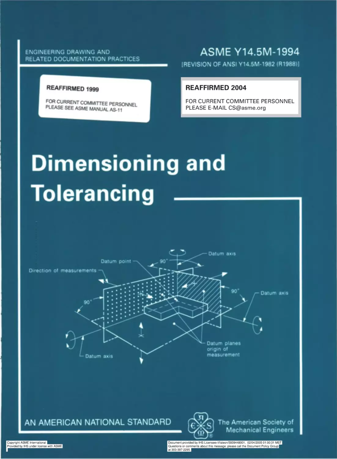
Dimensioning
PRACTICES
and
Tolerancing
--`,``,,`,`,,,,,`,``,`,,```,``,-`-`,,`,,`,`,,`---
ASME Y14.5M-1994
[REVISION
OF ANSI Y14.5M-1982
(RI98811
The American Society of
Mechanical Engineers
345 East 47 th Street, New York, N.Y.
Copyright ASME International
Provided by IHS under license with ASME
Document provided by IHS Licensee=Visteon/5939448001, 02/04/2005 01:00:31 MST
Questions or comments about this message: please call the Document Policy Group
at 303-397-2295.
Date of Issuance: January 23, 1995
--`,``,,`,`,,,,,`,``,`,,```,``,-`-`,,`,,`,`,,`---
This Standard will be revised when the Society approves the issuance of a
new edition. There will be no addenda or written interpretations of the requirements of this Standard issued to this edition.
ASME is the registered trademark of The American Society of Mechanical Engineers.
This code or standard was developed under procedures accredited as meeting the criteria for
American National Standards. The Consensus Committee that approved the code or standard was
balanced to assure that individuals from competent and concerned interests have had an opportunity to participate. The proposed code or standard was made available for public review and
comment which provides an opportunity for additional public input from industry, academia,
regulatory agencies, and the public-at-large.
ASME does not “approve,” “ rate,” or “endorse” any item, construction, proprietary device, or
activity.
ASME does not take any position with respect to the validity of any patent rights asserted in
connection with any items mentioned in this document, and does not undertake to insure anyone
utilizing a standard against liability for infringement of any applicable Letters Patent, nor assume
any such liability. Users of a code or standard are expressly advised that determination of the
validity of any such patent rights, and the risk of infringement of such rights, is entirely their own
responsibility.
Participation by federal agency representative(s) or person(s) affiliated with industry is not to
be interpreted as government or industry endorsement of this code or standard.
ASME accepts responsibility for only those interpretations issued in accordance with governing
ASME procedures and policies which preclude the issuance of interpretations by individual
volunteers.
No part of this document may be reproduced in any form,
in an electronic retrieval system or otherwise,
without the prior written permission of the publisher.
THE AMERICAN
Copyright ASME International
Provided by IHS under license with ASME
Copyright 0 1995 by
SOCIETY OF MECHANICAL
All Rights Reserved
Printed in the U.S.A.
ENGINEERS
Document provided by IHS Licensee=Visteon/5939448001, 02/04/2005 01:00:31 MST
Questions or comments about this message: please call the Document Policy Group
at 303-397-2295.
--`,``,,`,`,,,,,`,``,`,,```,``,-`-`,,`,,`,`,,`---
(This Foreword is not a part of ASME Y14.5M-1994.)
Additions,modifications,and clarification containedin this revision of ANSI Y 14.5M1982 are intendedto improve national and internationalstandardizationand to harmonize
the United Statespracticesand methodology with the universal standardstrend toward
more efficient worldwide technical communication.Coordinating and integrating these
techniquesinto and via computer graphicsand other electronic data systemsfor design,
manufacture,verification, and similar processesis also a prime objective.
Incorporatingthis Standardas a vehicle to assistthe United States’active participation
and competitivenessin the world marketplaceis a major goal. The emergenceof priorities
on total quality management,world-class engineering, and emphasison compatibility
with the International Organization for Standardization(ISO) 9000 series of quality
standardshashad a significantinfluence in the work of the Y14.5 Subcommittee.
This revision was initiated immediately after the official release of ANSI Y14.5M1982 in December 1982 in responseto deferred comments from that revision, new
conceptual developments, new symbology, and international standards expansion.
Twenty-three Subcommittee meetings and numerous working group meetings of the
ASME Y 14.5 Subcommitteewere convenedduring the developmentalperiod. The meetings were held in various cities aroundthe United States.The Subcommittee’s work was
coordinatedas much as possiblewith other related ASME committeesand other standard
developing bodies that share a common purpose on dimensioning and tolerancing or
related standards.Particularly close alliance and liaison were sought with the ASME
B89 Committee on “Dimensional Metrology,” and new committeesASME Y14.5.1 on
“Mathematical Definition of Y 14.5,” and ASME Y14.5.2 on “Certification of GD&T
Professionals.”
Of high priority was the continuingUnited Statesparticipationin the developmentof
IS0 standardsthrough its U.S. member body, the American National StandardsInstitute
(ANSI). Some members of the Y14.5 Subcommitteehave attendedand participatedin
numerousinternationalmeetingsand activities during and since the last revision of this
Standard.Meetings were attendedin Paris, France (1981), West Berlin, Germany (1982);
New York City, New York (1984), West Berlin, Germany (1987), Zurich, Switzerland
(1989), Orlando, Florida (1991), and Carmel, California (1992). United Statesdelegates
have served as members and convenersof Working Groups, chaired some TClO/SCS
...
111
Copyright ASME International
Provided by IHS under license with ASME
Document provided by IHS Licensee=Visteon/5939448001, 02/04/2005 01:00:31 MST
Questions or comments about this message: please call the Document Policy Group
at 303-397-2295.
internationalmeetingsand have participatedin all IS0 standardsprojects on the subject
of dimensioningand tolerancing during this period.
In addition to past participation in developing and maintaining all of such IS0 standardsas IS0 5458, IS0 5459, IS0 2692, IS0 3040, IS0 TR 5460, IS0 1660, IS0 406,
IS0 129, IS0 8015, and IS0 7083, U.S. delegateshave also participatedin all new IS0
standardsdevelopmentprojects. U.S. delegateshave provided convenership(chairmanship) to the developmentof ISO/2692: 1988 DAM1 on “Least Material Condition,” IS0
10578 on “Projected Tolerance Zone,” and IS0 10579 on “Nonrigid Parts.” Current
projectsrelated to the revision of IS0 1101, “Technical Drawings, Geometrical Tolerancing” and IS0 5458, “Positional Tolerancing” also have participation and input by U.S.
delegates.Current new work on a revision to IS0 2692 includes considerationof the
“principle of reciprocity” (symbol 8) that was originally put forth by the U.S. and Japan
in the early 1970’s as a proposedstandard.It was consideredby some countriesto be
premature for inclusion then and zero positional tolerancing was adopted as a near
substitute.
As a recent significant development, the United States, through its member body,
ANSI, has received the ISO/TClO/SC5 Secretariat. Thus, the U.S. inherits the world
leadership for standardsdevelopment on “Technical drawings, product definition and
related documentation,geometrical dimensioningand tolerancing.” Work will continue
on maintenanceof existing standardsand the development of new standardsrelated to
geometrical tolerancing.
The conflict in principle regarding limits of size between the “envelope principle”
(Taylor Principle, Rule #l) and the “independencyprinciple” continues,althoughsomewhat abated.Issuanceof IS0 8015:1985, “Technical Drawings-FundamentalTolerancing
Principle,” features the independencyprinciple but allows the option of the envelope
principle by either reference to a national standard(for example, ASME Y14.5M-1994)
on the drawing, or by invoking the symbol 6. The Y 14.5 Standardcontinuesto advocate
and use the envelope principle (boundary of perfect form at MMC of the individual
feature) that has been traditionally used in the U.S. and widely acceptedelsewhere.
The least material condition 0 conceptis expanded.More complete coverage on this
subjectis to be consideredin future revisions as the state of the art progresses.
Significant stepsare taken in this revision to resolve some long-standingdifferences
between the Y14.5 and IS0 practices.As U.S. delegatesalso play a significant role in
the developmentand maintenanceat the level of internationalstandards,thesedifferences
are eventually temperedand resolved by a merging of these dual objectives.In addition,
some long-rangeplanning by the Y 14.5 activity has also now materialized in the transition to eliminating these differences. Two significant changesfound in this revision are
adoptionand extensionof the universal datum feature symbol and discontinuanceof the
use of the RFS symbol 0. Other changes,additions,extensionsof principles,and resolution of differences are listed in Appendix A, “Principal Changesand Improvements.”
The technical expertise and experience of the Y14.5 Subcommitteeare provided by
the dedicated interests and resourcesof its personnel. Its members represent a broad
cross section of U.S. industry, the Department of Defense (DOD), educationalinstitutions, national laboratories,professional societies, and members of the private sector.
The Subcommittee encouragesparticipation by all and works diligently to achieve a
consensuson all matters. It seeks a balance between past practices, state of the art,
nationaland internationalstandards,new technology,computerand electronicintegration,
and most importantly, the understandabilityof the technical data containedin the Standard itself. Since membersare also usersof the Standard,a “jury of peers”is constantly
presentto ensure,as well as possible,that all voices are heard and satisfactorycompromises are made in the interestsof all users.Through the due processof final approval
iv
--`,``,,`,`,,,,,`,``,`,,```,``,-`-`,,`,,`,`,,`---
Copyright ASME International
Provided by IHS under license with ASME
Document provided by IHS Licensee=Visteon/5939448001, 02/04/2005 01:00:31 MST
Questions or comments about this message: please call the Document Policy Group
at 303-397-2295.
--`,``,,`,`,,,,,`,``,`,,```,``,-`-`,,`,,`,`,,`---
proceduresvia ASME, ANSI, DOD, and public review, the Standardachieves its final
make-up as the result of the voluntary consensusstandardsystem.
The expansion and extension of principles of the composite positional tolerancing
concept occupied a sizable segmentof the Subcommittee’s time and resourcesduring
this revision. This valuable concept,originally born out of need for a convenientmethod
to state two requirementstogether for a pattern of features, one the “pattern-locating
tolerance” (larger tolerance) and the other the “feature-relating tolerance” (smaller tolerance), gave rise to the need for further clarification and coverage in this revision. As
theseprinciplesare extendedfrom the original examples,first introducedin ANSI Y 14.5
1973, varying interpretationsare possiblewhere a secondarydatum feature is added to
the feature-relating tolerance zone frame. Since the original coverage in ANSI Y14.5
1973 made no attempt to indicate clearly an interpretationrepresentingthis extensionof
principle, varied applicationsand interpretationshave occurred during the interim, each
supposedlyhaving some support from the original Standard example and text. ANSI
Y14SM-1982 repeatedthe same examples, added two figures (Figs. 142 and 143), and
made a slight change of words in the text. The changesand additionsin this revision
eventually highlighted the areas of question and the Subcommittee debated this issue
with many prolonged and in-depth discussions.As a result, the composite tolerancing
text and figures have now been expandedto enhanceand clarify applicability. To effect
this clarification and expansion,and to “set the standard,”an explicit meaning has been
assignedto the feature-relatingtoleranceframe for compositepositionaltolerancingcontrol. The feature-relatingtolerance can no longer be interpretedas including location of
the pattern. Section 5 clarifies the application of compositetolerancing and contrastsit
with the use of two single-segmentfeature control frames.
Since profile compositetolerancing is now also introducedinto the Standard,its feature-relatingtoleranceframe likewise controlsthe orientationof the profile to the datums
without regard to the basic dimensionsthat locate the profile. Section 6 further explains
the details of compositeprofile tolerancing.
Although the continuity and stability of the technical content of the Standard are
paramount, numerous changes, additions, and clarifications have taken place in this
revision. To meet the objectives and purposesof the Standardas before referenced, it
must remain dynamic and is, thus, subjectto modification as deemednecessary.For help
in using this Standardand to isolate those areas and subjectsinvolving any changesor
additionsof consequence,refer to Appendix A. A detailed compendiumof changesand
additionsis provided.
Suggestionsfor improvement of this Standardwill be welcomed. They shouldbe sent
to The American Society of Mechanical Engineers; Attention: Secretary, Y14 Main
Committee; 345 East 47th Street; New York, NY 10017.
This revision was approved as an ASME Standard on March 14, 1994, and as an
American National Standardon January 5, 1995.
V
Copyright ASME International
Provided by IHS under license with ASME
Document provided by IHS Licensee=Visteon/5939448001, 02/04/2005 01:00:31 MST
Questions or comments about this message: please call the Document Policy Group
at 303-397-2295.
--`,``,,`,`,,,,,`,``,`,,```,``,-`-`,,`,,`,`,,`---
Copyright ASME International
Provided by IHS under license with ASME
Document provided by IHS Licensee=Visteon/5939448001, 02/04/2005 01:00:31 MST
Questions or comments about this message: please call the Document Policy Group
at 303-397-2295.
Engineering
ASME STANDARDS COMMI-ITEE Y14
Drawing and Related Documentation
Practices
(The following is the roster of the Committee at the time of approval of this Standard.)
OFFICERS
P. E. McKim, Chairman
F. Bakos, Jr., Vice Chairman
C. J. Gomez, Secretary
COMMITTEE
PERSONNEL
A. R. Anderson, Trikon Corp.
F. Bakos, Jr., Eastman Kodak Co.
T. D. Benoit, Alternate, Pratt & Whitney CEB
D. E. Bowerman, Copeland Corp.
J. V. Burleigh, The Boeing Co.
L. Burns
R. A. Chadderdon, Southwest Consultants
F. A. Christiana, ASEA Brown Boveri Combustion Engineering Systems
M. E. Curtis, Jr., Rexnord Corp.
R. W. DeBolt, Motorola Inc., Government and Space Technology Group
H. L. Dubocq
L. W. Foster, L. W. Foster Associates, Inc.
C. J. Gomez, The American Society of Mechanical Engineers
D. Hagler, E-Systems, Inc., Garland Division
E. L. Kardas, Pratt b Whitney CEB
C. G. Lance, Santa Cruz Technology Center
W. J. McGee, National Standards Educators Association
P. E. McKim, Caterpillar Inc.
C. D. Merkley, IBM Corp.
E. Niemiec, Westinghouse Electric Corp.
R. J. Polizzi
D. L. Ragon, Deere b Company, John Deere Dubuque Works
R. L. Tennis, Caterpillar Inc.
R. P. Tremblay, U.S. Department of the Army, ARDEC
R. K. Walker, Westinghouse Marine
G. H. Whitmire, TEOTREND
K. E. Wiegandt, Sandia National Laboratory
P. Wreede, E-Systems, Inc.
PERSONNEL OF SUBCOMMllTEE
5-
DIMENSIONING
AND TOLERANCING
L. W. Foster, Chairman, L. W. Foster Associates, Inc.
D. J. Buchman, Vice Chairman, University of Cincinnati/GE Aircraft Engines
C. G. Lance, Vice Chairman, Santa Cruz Technology Center
vii
--`,``,,`,`,,,,,`,``,`,,```,``,-`-`,,`,,`,`,,`---
Copyright ASME International
Provided by IHS under license with ASME
Document provided by IHS Licensee=Visteon/5939448001, 02/04/2005 01:00:31 MST
Questions or comments about this message: please call the Document Policy Group
at 303-397-2295.
Y14/SC 5 Editing and Illustrations
Group
L. S. Darcy, Herman Miller, Inc.
R. M. Evans, Boeing Commercial Airplane Group
C. W. Ferguson, Steelcase, Inc.
A. L. Herpich. Xerox Corp.
A. Krulikowski, General Motors Corp., Powertrain Division
W. M. Stites, Accratronics Seals Corp.
B. A. Wilson, McDonnell Douglas Corp.
J. E. Winconek, Allied-Signal Aerospace
P. Wreede, E-Systems, Inc.
...
VU1
Copyright ASME International
Provided by IHS under license with ASME
Document provided by IHS Licensee=Visteon/5939448001, 02/04/2005 01:00:31 MST
Questions or comments about this message: please call the Document Policy Group
at 303-397-2295.
--`,``,,`,`,,,,,`,``,`,,```,``,-`-`,,`,,`,`,,`---
A. R. Anderson, Secretary, General Motors Corp., Power-train Division/Trikon Corp.
F. Bakos, Jr., Eastman Kodak Co.
T. D. Benoit, Alternate, Pratt b Whitney CEB
D. E. Bowerman, Copeland Corp.
R. A. Chadderdon, Southwest Consultants
R. E. Coombes, Caterpillar Inc.
N. W. Cutler, Polaroid Corp.
G. P. Gooldy, GPG Consultants, Inc.
W. A. Haefele, Williams Creek Graphics
B. W. Heathcotte, Geometries Consulting
A. M. Johnson, The Boeing Co.
E. L. Kardas, Pratt 8 Whitney CEB
D. P. Karl, Ford Motor Co.
K. S. King, Dahlgren Division, Naval Surface Warfare Center
C. D. Merkley, IBM Corp.
T. C. Miller, Los Alamos National Laboratory
A. G. Neumann, Technical Consultants, Inc.
E. Niemiec, Westinghouse Electric Corp.
J. M. Palmer, Jr., Garrett Turbine Engine Co.
D. L. Ragon, Deere b Company, John Deere Dubuque Works
D. W. Shepherd, Shepherd Industries/Northern Illinois University
G. S. Tokunaga, Lawrence Livermore National Laboratory
R. P. Tremblay, U.S. Department of the Army, ARDEC
B. A. Wilson, McDonnell Douglas Corp.
J. E. Winconek, Allied-Signal Aerospace
CONTENTS
111
vii
1
Scope, Definitions, and General Dimensioning ........................
General ...........................................................
1.1
1.2
References.........................................................
1.3
Definitions ........................................................
FundamentalRules.................................................
1.4
Units of Measurement..............................................
1.5
Types of Dimensioning.............................................
1.6
1.7
Application of Dimensions .........................................
1.8
Dimensioning Features.............................................
Location ofFeatures ...............................................
1.9
1
1
1
2
4
4
5
6
10
18
2
General Tolerancing and Related Principles ...........................
2.1
General ...........................................................
Direct Tolerancing Methods ........................................
2.2
Tolerance Expression...............................................
2.3
2.4
Interpretation ofLimits .............................................
Single Limits ......................................................
2.5
2.6
Tolerance Accumulation. ...........................................
Limits of Size.. ...................................................
2.7
2.8
Applicability of RFS, MMC, and LMC ..............................
2.9
Screw Threads. ....................................................
2.10 Gears and Splines..................................................
2.11 VirtuaVResultantCondition .........................................
2.12 Angular Surfaces...................................................
2.13 Conical Tapers. ....................................................
2.14 Flat Tapers ........................................................
2.15 Radius.. ..........................................................
2.16 StatisticalTolerancing ..............................................
23
23
24
24
25
25
25
26
28
29
29
29
29
29
37
38
38
3
Symbology
3.1
3.2
3.3
3.4
3.5
3.6
3.7
.............................................................
General ...........................................................
Use of Notes to SupplementSymbols ...............................
Symbol Construction...............................................
Geometric Tolerance Symbols ......................................
Feature Control Frame Placement ...................................
Definition of the Tolerance Zone. ...................................
Tabulated Tolerances...............................................
41
41
41
41
47
48
48
50
ix
Copyright ASME International
Provided by IHS under license with ASME
Document provided by IHS Licensee=Visteon/5939448001, 02/04/2005 01:00:31 MST
Questions or comments about this message: please call the Document Policy Group
at 303-397-2295.
--`,``,,`,`,,,,,`,``,`,,```,``,-`-`,,`,,`,`,,`---
Foreword . . . . . . . . . . . . . . . . . . . . . . . . . . . . . . . . . . . . . . . . . . . . . . . . . . . . . . . . . . . . . . . . . . . .
StandardsCommittee Roster . . . . . . . . . . . . . . . . . . . . . . . . . . . . . . . . . . . . . . . . . . . . . . . . . .
--`,``,,`,`,,,,,`,``,`,,```,``,-`-`,,`,,`,`,,`---
51
51
51
52
52
55
70
4
Datum Referencing .....................................................
General.. .........................................................
4.1
Immobilization of Part .............................................
4.2
DatumFeatures ....................................................
4.3
Specifying Datum Featuresin an Order of Precedence................
4.4
EstablishingDatums ...............................................
4.5
DatumTargets .....................................................
4.6
5
Tolerances of Location .................................................
General.. .........................................................
5.1
Positional Tolerancing ..............................................
5.2
5.3
FundamentalExplanation of Positional Tolerancing ..................
Feature Pattern Location. ...........................................
5.4
Projected Tolerance Zone. ..........................................
5.5
5.6
Nonparallel Holes. .................................................
CounterboredHoles ................................................
5.7
Closer Control at One End of a Feature .............................
5.8
5.9
Bidirectional Positional Tolerancing of Features......................
5.10 Noncircular Features ...............................................
5.11 Coaxiality Controls ................................................
5.12 Concentricity ......................................................
5.13 Positional Tolerancing for Symmetrical Relationships.................
5.14 Symmetry Tolerancing to Control the Median Points of Opposedor
Correspondingly-LocatedElements of Features.......................
5.15 Spherical Features..................................................
81
81
81
81
93
115
135
135
135
135
139
142
144
149
Tolerances of Form, Profile, Orientation, and Runout .................
6.1
General ...........................................................
6.2
Form and orientation Control. ......................................
Specifying Form and Orientation Tolerances.........................
6.3
6.4
FormTolerances ...................................................
6.5
Profile Control.....................................................
6.6
Orientation Tolerances .............................................
6.7
Runout............................................................
6.8
Free State Variation. ...............................................
157
157
157
157
157
163
174
189
191
6
149
149
Appendices
A
Principal Changes and Improvements ..................................
Al
General ...........................................................
A2
Figures............................................................
Section 1, Scope, Definitions, and General Dimensioning. ............
A3
A4
Section 2, General Tolerancing and Related Principles ...............
A5
Section 3, Symbology ..............................................
Section 4, Datum Referencing ......................................
A6
A7
Section 5, Tolerances of Location ...................................
A8
Section 6, Tolerances of Form, Profile, Orientation, and Runout. ......
Appendix A, Principal Changesand Improvements. ..................
A9
A10 Appendix B, Formulas for Positional Tolerancing ....................
Al 1 Appendix C, Form, Proportion, and Comparisonof Symbols. .........
Al2
Appendix D, Former Practices......................................
197
197
197
197
198
199
199
200
202
202
203
203
203
X
Copyright ASME International
Provided by IHS under license with ASME
Document provided by IHS Licensee=Visteon/5939448001, 02/04/2005 01:00:31 MST
Questions or comments about this message: please call the Document Policy Group
at 303-397-2295.
Al3
Appendix E, Decision Diagrams for Geometric Control. ..............
203
Formulas for Positional Tolerancing ...................................
General ...........................................................
Bl
Formula Symbols ..................................................
B2
Floating FastenerCase .............................................
B3
Fixed FastenerCase When Projected Tolerance Zone Is Used. ........
B4
provision for Out-of-SquarenessWhen Projected Tolerance Zone is
B5
Not Used .......................................................
Coaxial Features. ..................................................
B6
Limits andFits ....................................................
B7
205
205
205
205
205
C
Form, Proportion, and Comparison of Symbols .......................
General ...........................................................
Cl
Form andProportion ...............................................
c2
Comparison .......................................................
c3
209
209
209
209
D
Former Practices .......................................................
General ...........................................................
Dl
Definition for Feature of Size. ......................................
D2
Applicability of RFS, MMC, and LMC ..............................
D3
Tangent Radii .....................................................
D4
Datum Feature Symbol .............................................
D5
ProjectedToleranceZone ...........................................
D6
215
215
215
215
215
215
215
E
Decision Diagrams for Geometric Control .............................
Purpose.. .........................................................
El
Functional Requirements ...........................................
E2
Reference to Standard..............................................
E3
GeometricControls ................................................
E4
ChoosingOther Controls ...........................................
E5
Use of Modifiers ...................................................
E6
Datums............................................................
E7
219
219
219
219
219
219
219
219
B
206
207
207
Index . . . . . . . . . . . . . . . . . . . . . . . . . . . . . . . . . . . . . . . . . . . . . . . . . . . . . . . . . . . . . . . . . . . . . . . 229
--`,``,,`,`,,,,,`,``,`,,```,``,-`-`,,`,,`,`,,`---
Copyright ASME International
Provided by IHS under license with ASME
xi
Document provided by IHS Licensee=Visteon/5939448001, 02/04/2005 01:00:31 MST
Questions or comments about this message: please call the Document Policy Group
at 303-397-2295.
--`,``,,`,`,,,,,`,``,`,,```,``,-`-`,,`,,`,`,,`---
Copyright ASME International
Provided by IHS under license with ASME
Document provided by IHS Licensee=Visteon/5939448001, 02/04/2005 01:00:31 MST
Questions or comments about this message: please call the Document Policy Group
at 303-397-2295.
ASME Y14.5M-1994
ENGINEERING
DRAWING
AND RELATED DOCUMENTATION
DIMENSIONING
1
Scope,
Definitions,
AND
PRACTICES
TOLERANCING
and General
Dimensioning
1 .I.5 Notes. Notes herein in capital letters are
intended to appear on finished drawings. Notes in
lower case letters are explanatory only and are not
intended to appear on drawings.
1.1 GENERAL
This Standard establishesuniform practices for
stating and interpreting dimensioning, tolerancing,
and related requirements for use on engineering
drawingsand in related documents.For a mathematical explanationof many of the principlesin this Standard, see ASME Y 14.5.1M. Practicesunique to architectural and civil engineering and welding
symbology are not included.
1.1.6 Reference to Gaging. This document is
not intended as a gaging standard.Any reference to
gaging is included for explanatory purposesonly.
1 .I .7 Symbols. Adoption of the symbolsindicating dimensionalrequirements,as shown in Fig. C-2
of Appendix C, doesnot preclude the use of equivalent terms or abbreviationswhere symbology is consideredinappropriate.
1.1.1 Section 1, General. This Section establishes definitions, fundamental rules, and practices
for general dimensioningthat apply to coordinateas
well as geometric dimensioningmethods.For tolerancing practices,see Sections2 through 6.
1.1.2 Units. The International System of Units
(SI) is featured in this StandardbecauseSI units are
expected to supersedeUnited States (U.S.) customary units specifiedon engineeringdrawings.Customary units could equally well have been used without
prejudice to the principles established.
1.2 REFERENCES
When the following American National Standards
referred to in this Standardare supersededby a revision approved by the American National Standards
Institute, Inc., the revision shall apply.
American National Standards
ANSI B4.2-1978, Preferred Metric Limits and Fits
ANSI B5.10-1981, Machine Tapers - Self Holding and Steep Taper Series
ANSI/ASME B46.1-1985, Surface Texture (Surface Roughness,Waviness, and Lay)
ANSI B89.3.1-1972, Measurement of Out-ofRoundness
ANSI B92.1-1970,’ Involute Splines and Inspection, Inch Version
ANSI B92.2M-1980,’ Metric Module, Involute
Splines
ANSI/ASME B94.6-1984, Knurling
ANSI B94.11M-1979, Twist Drills
ANSI Y14.1-1980, Drawing Sheet Size and
Format
1.1.3 Reference to this Standard. Where drawings are based on this Standard, this fact shall be
noted on the drawings or in a document referenced
on the drawings. References to this Standard shall
stateASME Y 14.5M-1994.
1.1.4 Figures. The figures in this Standard are
intendedonly as illustrationsto aid the userin understandingthe principlesand methodsof dimensioning
and tolerancingdescribedin the text. The absenceof
a figure illustratingthe desiredapplicationis neither
reasonto assumeinapplicability, nor basisfor drawing rejection. In some instances,figures show added
detail for emphasis.In other instances,figures are
incomplete by intent. Numerical values of dimensionsand tolerancesare illustrative only.
NOTE: To assistthe usersof this Standard,a listing of the para-
graph(s) that refer to an illustration appearsin the lower righthand comer of each figure. This listing may not be all-inclusive.
The absenceof a listing is not a reasonto assumeinapplicability.
’ SAE standardsare available from the Society of Automotive
Engineers,400 Warrendale Drive, Warrendale, PA 15096.
1
--`,``,,`,`,,,,,`,``,`,,```,``,-`-`,,`,,`,`,,`---
Copyright ASME International
Provided by IHS under license with ASME
Document provided by IHS Licensee=Visteon/5939448001, 02/04/2005 01:00:31 MST
Questions or comments about this message: please call the Document Policy Group
at 303-397-2295.
DIMENSIONING
ASME Y14.5M-1994
AND TOLERANCING
departure from its specified material condition. See
Figs. 2-9 through 2-12.
ASME Y14.2M-1992, Line Conventions and
Lettering
ASME Y14.5.1M-1994, Mathematical Definition
of Dimensioning and Tolerancing Principles
ANSI Y 14.6-1978, Screw Thread Representation
ANSI Y 14.6aM-1981, Screw Thread Representation (Metric Supplement)
ANSI Y14.7.1-1971, Gear Drawing StandardsPart 1: For Spur, Helical, Double Helical, and Rack
ANSI Y14.7.2-1978, Gear and Spline Drawing
Standards- Part 2: Bevel and Hypoid Gears
ASME Y14.8M-1989, Castingsand Forgings
ANSI Y 14.36-1978, Surface Texture Symbols
ANSI/IEEE 268-1992,2 Metric Practice
1.3.3 Datum. A theoretically exact point, axis, or
plane derived from the true geometric counterpartof
a specifieddatum feature. A datum is the origin from
which the location or geometric characteristicsof
features of a part are established.
1.3.4 Datum Feature. An actualfeature of a part
that is used to establisha datum.
1.3.5 Datum Feature Simulator. A surface of
adequately precise form (such as a surface plate, a
gage surface, or a mandrel) contacting the datum
feature(s) and used to establish the simulated
datum(s).
1.2.1 Additional Sources (Not Cited)
ANSI/ASME B1.2-1983, Gages and Gaging for
Unified Inch Screw Threads
ANSI B4.4M-1981 (R1987), Inspection of
Workpieces
ASME Y 1.1-1989, Abbreviations - For Use on
Drawings and in Text
ASME Y14.3M-1994, Multiview and Sectional
View Drawings
NOTE: Simulated datum features are used as the practical embodiment of the datumsduring manufactureand inspection.
1.3.6 Datum, Simulated. A point, axis, or plane
establishedby processingor inspection equipment,
such as the following simulators:a surface plate, a
gage surface, or a mandrel. See paras. 4.4.1 and
4.4.2.
1.3.7 Datum Target. A specified point, line, or
area on a part used to establisha datum.
1.3.8 Dimension. A numerical value expressed
in appropriateunits of measure and used to define
the size, location, geometriccharacteristic,or surface
texture of a part or part feature.
1.3 DEFINITIONS
1.3.9 Dimension, Basic. A numericalvalue used
to describethe theoreticallyexact size, profile, orientation, or location of a feature or datum target. See
Fig. 3-7. It is the basisfrom which permissiblevariations are establishedby toleranceson other dimensions,in notes,or in feature control frames. See Figs.
2-14, 2-15, and 3-25.
The following terms are defined as their use applies in this Standard. Additionally, definitions
throughoutthe Standardof italicized terms are given
in sectionsdescribingtheir application. Their location may be identified by referring to the index.
1.3.1 Boundary, Inner. A worst case boundary
(that is, locus) generated by the smallest feature
(MMC for an internal feature and LMC for an external feature) minus the statedgeometrictoleranceand
any additional geometric tolerance (if applicable)
from the feature’s departurefrom its specifiedmaterial condition. See Figs. 2-9 through 2-12.
1.3.10 Dimension, Reference. A dimension,
usually without tolerance, used for information purposes only. A reference dimension is a repeat of a
dimensionor is derived from other values shown on
the drawing or on related drawings.It is considered
auxiliary information and doesnot governproduction
or inspectionoperations.See Figs. 1-17 and 1-18.
1.3.2 Boundary, Outer. A worst case boundary
(that is, locus) generatedby the largestfeature (LMC
for an internal feature and MMC for an external feature) plus the geometric toleranceand any additional
geometrictolerance(if applicable)from the feature’s
1.3.11 Envelope, Actual Mating. This term is
defined accordingto the type of feature, as follows:
(a) For un External Feature. A similar perfect
feature counterpartof smallestsize that can be circumscribedabout the feature so that it just contacts
the surface at the highest points. For example, a
smallest cylinder of perfect form or two parallel
z IEEE standardsare availablefrom the Institute of Electrical and
Electronics Engineers, Service Center, 445 Hoes Lane, Piscataway, NJ 08854.
2
--`,``,,`,`,,,,,`,``,`,,```,``,-`-`,,`,,`,`,,`---
Copyright ASME International
Provided by IHS under license with ASME
Document provided by IHS Licensee=Visteon/5939448001, 02/04/2005 01:00:31 MST
Questions or comments about this message: please call the Document Policy Group
at 303-397-2295.
DIMENSIONING
AND TOLERANCING
ASME Y14.5M-1994
planes of perfect form at minimum separationthat
just contact(s)the highestpoints of the surface(s).
For featurescontrolledby orientationor positional
tolerances,the actualmating envelope is orientedrelative to the appropriatedatum(s), for example, perpendicularto a primary datum plane.
(b) For an Internal Feature. A similar perfect feature counterpartof largest size that can be inscribed
within the feature so that it just contactsthe surface
at the highestpoints. For example, a largestcylinder
of perfect form or two parallel planesof perfect form
at maximum separationthat just contact(s)the highest points of the surface(s).
For featurescontrolledby orientationor positional
tolerances,the actualmating envelopeis orientedrelative to the appropriatedatum(s).
1.3.20 Maximum Material Condition (MMC).
The condition in which a feature of size containsthe
maximum amountof material within the statedlimits
of size - for example, minimum hole diameter,
maximum shaft diameter.
1.3.21 Plane, Tangent. A theoretically exact
plane derived from the true geometric counterpartof
the specified feature surface.
1.3.22 Regardless
of Feature
Size (RFS). The
term used to indicate that a geometric tolerance or
datum reference applies at any increment of size of
the feature within its size tolerance.
--`,``,,`,`,,,,,`,``,`,,```,``,-`-`,,`,,`,`,,`---
1.3.23 Resultant Condition.
The variable
boundarygeneratedby the collective effects of a size
feature’s specifiedMMC or LMC material condition,
the geometric tolerance for that material condition,
the size tolerance,and the additionalgeometrictolerance derived from the feature’s departure from its
specified material condition. See Figs. 2-9 through
2-12.
1.3.12 Feature. The general term applied to a
physical portion of a part, suchas a surface,pin, tab,
hole, or slot.
1.3.13 Feature, Axis Of. A straightline that coincides with the axis of the true geometric counterpart of the specified feature.
1.3.24 Size, Actual. The generalterm for the size
of a producedfeature. This term includesthe actual
mating size and the actual local sizes.
1.3.14 Feature, Center Plane Of. A plane that
coincideswith the center plane of the true geometric
counterpartof the specified feature.
1.3.25 Size, Actual Local. The value of any individual distanceat any crosssectionof a feature.
1.3.15 Feature, Derived Median Plane Of. An
imperfect plane (abstract) that passesthrough the
center points of all line segmentsbounded by the
feature. These line segmentsare normal to the actual
mating envelope.
1.3.26 Size, Actual Mating. The dimensional
value of the actual mating envelope.
1.3.27 Size, Limits Of. The specified maximum
and minimum sizes. See para. 2.7.
1.3.28 Size, Nominal. The designationused for
purposesof general identification.
1.3.16 Feature, Derived Median Line Of. An
imperfect line (abstract)that passesthroughthe center points of all cross sectionsof the feature. These
cross sectionsare normal to the axis of the actual
mating envelope. The crosssectioncenter points are
determined as per ANSI B89.3.1.
1.3.29 Size, Resultant Condition. The actual
value of the resultantcondition boundary.
1.3.30 Size, Virtual Condition. The actualvalue
of the virtual condition boundary.
1.3.17 Feature of Size. One cylindrical or spherical surface, or a set of two opposed elements or
opposed parallel surfaces, associated with a size
dimension.
1.3.31 Tolerance. The total amount a specific
dimensionis permitted to vary. The tolerance is the
difference between the maximum and minimum
limits.
1.3.18 Full Indicator Movement (FIM). The total movement of an indicator where appropriately
applied to a surfaceto measureits variations.
1.3.32 Tolerance,
Bilateral.
A tolerance in
which variation is permitted in both directions from
the specified dimension.
1.3.19 Least Material Condition
(LMC). The
condition in which a feature of size containsthe least
amountof material within the statedlimits of size for example, maximum hole diameter, minimum
shaft diameter.
1.3.33 Tolerance, Geometric. The general term
applied to the category of tolerancesused to control
form, profile, orientation, location, and runout.
1.3.34
Tolerance,
Unilateral.
A tolerance in
3
Copyright ASME International
Provided by IHS under license with ASME
Document provided by IHS Licensee=Visteon/5939448001, 02/04/2005 01:00:31 MST
Questions or comments about this message: please call the Document Policy Group
at 303-397-2295.
DIMENSIONING
ASME Y14.5M-1994
which variation is permitted in one direction from
the specified dimension.
where manufacturing,processing,quality assurance,
or environmentalinformation is essentialto the definition of engineeringrequirements,it shall be specified on the drawing or in a documentreferenced on
the drawing.
cf) It is permissibleto identify as nonmandatory
certain processingdimensionsthat provide for finish
allowance,shrinkallowance,and other requirements,
provided the final dimensionsare given on the drawing. Nonmandatory processingdimensionsshall be
identified by an appropriate note, such as NONMANDATORY (MFG DATA).
(g) Dimensionsshouldbe arrangedto provide required information for optimum readability. Dimensionsshouldbe shownin true profile views and refer
to visible outlines.
(h) Wires, cables,sheets,rods, and other materials
manufacturedto gage or code numbersshall be specified by linear dimensionsindicatingthe diameter or
thickness.Gage or code numbersmay be shown in
parenthesesfollowing the dimension.
(i) A 90” angle applies where center lines and
lines depicting features are shown on a drawing at
right angles and no angle is specified. See para.
2.1.1.2.
(j) A 90” basic angle applies where center lines
of features in a pattern or surfaces shown at right
angleson the drawing are located or defined by basic
dimensionsand no angle is specified.
(k) Unless otherwisespecified, all dimensionsare
applicable at 20°C (68°F). Compensation may be
made for measurementsmade at other temperatures.
(1) All dimensionsand tolerancesapply in a free
statecondition. This principle doesnot apply to nonrigid parts as defined in paras. 2.7.1.3(b) and 6.8.
(m) Unless otherwise specified, all geometric tolerancesapply for full depth, length, and width of the
feature.
(n) Dimensions and tolerancesapply only at the
drawing level where they are specified.A dimension
specifiedfor a given feature on one level of drawing,
(for example, a detail drawing) is not mandatory for
that feature at any other level (for example, an assembly drawing).
1.3.35 True Geometric Counterpart. The theoretically perfect boundary(virtual condition or actual
mating envelope) or best-fit (tangent) plane of a
specified datum feature. See Figs. 4-l 1 and 4-10.
Also see paras. 1.3.5 and 1.3.6 regarding the simulated datum.
1.3.36 True Position. The theoretically exact location of a feature establishedby basic dimensions.
--`,``,,`,`,,,,,`,``,`,,```,``,-`-`,,`,,`,`,,`---
1.3.37 Virtual Condition. A constantboundary
generatedby the collective effects of a size feature’s
specified MMC or LMC material condition and the
geometric tolerance for that material condition. See
Figs. 2-9 through 2-12.
1.4 FUNDAMENTAL
AND TOLERANCING
RULES
Dimensioning and tolerancing shall clearly define
engineering intent and shall conform to the
following.
(a) Each dimensionshall have a tolerance,except
for those dimensionsspecifically identified as reference, maximum, minimum, or stock (commercial
stock size). The tolerance may be applied directly
to the dimension (or indirectly in the case of basic
dimensions),indicated by a general note, or located
in a supplementaryblock of the drawing format. See
ANSI Y14.1.
(b) Dimensioning and tolerancing shall be complete so there is full understandingof the characteristics of each feature. Neither scaling (measuringthe
size of a feature directly from an engineeringdrawing) nor assumptionof a distanceor size is permitted,
except as follows: Undimensioneddrawings,suchas
loft, printed wiring, templates, and master layouts
prepared on stable material, are excluded provided
the necessarycontrol dimensionsare specified.
(c) Each necessarydimension of an end product
shall be shown.No more dimensionsthan thosenecessary for complete definition shall be given. The
use of reference dimensionson a drawing shouldbe
minimized.
(d) Dimensions shall be selectedand arrangedto
suit the function and mating relationshipof a part and
shall not be subjectto more than one interpretation.
(e) The drawing should define a part without
specifying manufacturing methods. Thus, only the
diameter of a hole is given without indicating
whether it is to be drilled, reamed, punched,or made
by any other operation. However, in those instances
1.5 UNITS OF MEASUREMENT
For uniformity, all dimensionsin this Standardare
given in SI units. However, the unit of measurement
selected should be in accordancewith the policy of
the user.
1.5.1 SI (Metric) Linear Units. The commonly
4
Copyright ASME International
Provided by IHS under license with ASME
Document provided by IHS Licensee=Visteon/5939448001, 02/04/2005 01:00:31 MST
Questions or comments about this message: please call the Document Policy Group
at 303-397-2295.
DIMENSIONING
ASME Y14.5M-1994
AND TOLERANCING
used SI linear unit used on engineeringdrawings is
the millimeter.
1.5.2 U.S. Customary Linear Units. The commonly usedU.S. customarylinear unit usedon engineering drawingsis the decimal inch.
1.5.3 Identification of Linear Units. On drawings where all dimensionsare either in millimeters
or inches, individual identification of linear units is
not required. However, the drawing shall contain a
note stating UNLESS OTHERWISE SPECIFIED,
ALL DIMENSIONS ARE IN MILLIMETERS (or IN
INCHES, as applicable).
$s,,.
,
1.5.3.1 Combination SI (Metric) and U.S.
Customary Linear Units. Where some inch dimensions are shown on a millimeter-dimensioned
drawing, the abbreviation IN. shall follow the inch
values. Where some millimeter dimensions are
shown on an inch-dimensioneddrawing, the symbol
mm shall follow the millimeter values.
FIG. l-l
1.5.4 Angular Units. Angular dimensionsare expressedin either degreesand decimal parts of a degree or in degrees,minutes,and seconds.These latter
dimensionsare expressedby symbols:for degrees‘,
for minutes ‘, and for seconds“. Where degreesare
indicated alone, the numerical value shall be followed by the symbol.Where only minutesor seconds
are specified,the number of minutesor secondsshall
be preceded by 0” or O”O’, as applicable. See Fig.
l-l.
-IIl-t
1.6 TYPES OF DIMENSIONING
Decimal dimensioningshall be used on drawings
except where certain commercial commodities are
identified by standardized nominal designations,
such as pipe and lumber sizes.
NOTE: This practice differs for tolerancesexpressedbilaterally
or as limits. See paras. 2.3.1(b) and (c).
Copyright ASME International
Provided by IHS under license with ASME
UNITS
0.9
It-
1.7
11.5
$816.4
r-36l
I
FIG. 1-2
MILLIMETER
DIMENSIONS
(d) Neither commas nor spacesshall be used to
separatedigits into groups in specifying millimeter
dimensionson drawings.
1.6.2 Decimal Inch Dimensioning. The following shall be observedwhere specifying decimal inch
dimensionson drawings:
(a) A zero is not used before the decimal point
for values less than one inch.
(b) A dimensionis expressedto the samenumber
of decimal places as its tolerance. Zeros are added
Document provided by IHS Licensee=Visteon/5939448001, 02/04/2005 01:00:31 MST
Questions or comments about this message: please call the Document Policy Group
at 303-397-2295.
--`,``,,`,`,,,,,`,``,`,,```,``,-`-`,,`,,`,`,,`---
1.6.1 Millimeter Dimensioning. The following
shall be observed where specifying millimeter dimensionson drawings:
(a) Where the dimensionis lessthan one millimeter, a zero precedesthe decimal point. See Fig. l-2.
(b) Where the dimensionis a whole number, neither the decimal point nor a zero is shown. See Fig.
l-2.
(c) Where the dimensionexceedsa whole number
by a decimal fraction of one millimeter, the last digit
to the right of the decimal point is not followed by
a zero. See Fig. l-2.
ANGULAR
ASME Y14.5M-1994
DIMENSIONING
AND TOLERANCING
.50
r
,750
+I
1
,312
so
r
11.7.1.1
G.745
t-t
FIG. l-5
GROUPING
OF DIMENSIONS
I-‘.“‘ -I
FIG. l-3
DECIMAL
--`,``,,`,`,,,,,`,``,`,,```,``,-`-`,,`,,`,`,,`---
f
1.6.4 Conversion and Rounding of Linear
Units. For information on conversionand rounding
of U.S. customarylinear units, see ANSI/IEEE 268.
INCH DIMENSIONS
1.7 APPLICATION OF DIMENSIONS
Dimensions are applied by means of dimension
lines, extension lines, chain lines, or a leader from
a dimension, note, or specification directed to the
appropriatefeature. See Fig. l-4. General notes are
used to convey additional information. For further
information on dimension lines, extension lines,
chain lines, and leaders,see ASME Y14.2M.
t
20
1.7.1 Dimension Lines. A dimension line, with
its arrowheads,shows the direction and extent of a
dimension.Numerals indicate the number of units of
a measurement.Preferably, dimension lines should
be broken for insertionof numeralsas shownin Fig.
l-4. Where horizontal dimension lines are not broken, numerals are placed above and parallel to the
dimensionlines.
c
FIG. 1-4
APPLICATION
NOTE: The following shall not be used as a dimension line: a
center line, an extensionline, a phantom line, a line that is part
of the outline of the object, or a continuationof any of these
lines. A dimension line is not used as an extensionline, except
where a simplified method of coordinate dimensioning is used
to define curved outlines. See Fig. l-33.
OF DIMENSIONS
to the right of the decimal point where necessary.
See Fig. l-3 and para. 2.3.2.
1.7.1.1 Alignment. Dimension lines shall be
aligned if practicable and grouped for uniform appearance.See Fig. l-5.
1.6.3 Decimal Points. Decimal points must be
uniform, dense,and large enoughto be clearly visible
and meet the reproduction requirements of ASME
Y14.2M. Decimal points are placed in line with the
bottom of the associateddigits.
1.7.1.2 Spacing. Dimension lines are drawn
parallel to the direction of measurement.The space
between the first dimensionline and the part outline
should be not less than 10 mm; the space between
6
Copyright ASME International
Provided by IHS under license with ASME
Document provided by IHS Licensee=Visteon/5939448001, 02/04/2005 01:00:31 MST
Questions or comments about this message: please call the Document Policy Group
at 303-397-2295.
--`,``,,`,`,,,,,`,``,`,,```,``,-`-`,,`,,`,`,,`---
DIMENSIONING
FIG. l-6
ASME Y14.5M-1994
AND TOLERANCING
SPACING
OF DIMENSION
LINES
FIG. 1-8
OBLIQUE EXTENSION
LINES
1.7.1.4 Crossing Dimension Lines. Crossing
dimensionlines shouldbe avoided. Where unavoidable, the dimension lines are unbroken.
FIG. 1-7
STAGGERED
1.7.2 Extension (Projection) Lines. Extension
lines are used to indicate the extension of a surface
or point to a location preferably outsidethe part outline. See para. 1.7.8. Extensionlines startwith a short
visible gap from the outline of the part and extend
beyond the outermost related dimension line. See
Fig. l-6. Extension lines are drawn perpendicularto
dimension lines. Where space is limited, extension
lines may be drawn at an oblique angle to clearly
illustrate where they apply. Where oblique lines are
used, the dimensionlines are shown in the direction
in which they apply. See Fig. 1-8.
DIMENSIONS
1.7.2.1 Crossing Extension Lines. Wherever
practicable,extensionlines shouldneither crossone
anothernor crossdimensionlines. To minimize such
crossings,the shortestdimensionline is shownnearest the outline of the object. See Fig. l-7. Where
extension lines must crossother extension lines, dimension lines, or lines depicting features, they are
not broken. Where extensionlines crossarrowheads
or dimension lines close to arrowheads,a break in
the extension line is permissible.See Fig. l-9.
succeedingparallel dimension lines should be not
less than 6 mm. See Fig. l-6.
NOTE: These spacingsare intended as guides only. If the drawing meetsthe reproductionrequirementsof the acceptedindustry
or military reproductionspecification,nonconformanceto these
spacingrequirementsis not a basisfor rejection of the drawing.
Where there are several parallel dimension lines,
the numeralsshouldbe staggeredfor easier reading.
See Fig. l-7.
1.7.2.2 Locating Points. Where a point is located by extension lines only, the extension lines
from surfacesshouldpassthroughthe point. See Fig.
l-10.
1.7.1.3 Angle Dimensions. The dimension
line of an angle is an arc drawn with its center at the
apex of the angle. The arrowheadsterminate at the
extensionsof the two sides.See Figs. l-l and l-4.
1.7.3 Limited Length or Area Indication.
Where it is desired to indicate that a limited length
7
Copyright ASME International
Provided by IHS under license with ASME
Document provided by IHS Licensee=Visteon/5939448001, 02/04/2005 01:00:31 MST
Questions or comments about this message: please call the Document Policy Group
at 303-397-2295.
ASME Y14.5M-1994
DIMENSIONING
w
i-7
-I
F
h
AND TOLERANCING
(4
[ 1.721
FIG. 1-9
BREAKS IN EXTENSION
FIG. l-10
LINES
FIG. l-11
POINT LOCATIONS
or area of a surfaceis to receive additionaltreatment
or considerationwithin limits specified on the drawing, the extent of these limits may be indicated by
use of a chain line. See Fig. l-l 1.
LIMITED LENGTH OR AREA INDICATION
place on the drawing. Normally, a leader terminates
in an arrowhead. However, where it is intended for
a leader to refer to a surface by ending within the
outline of that surface, the leader should terminate
in a dot. A leader shouldbe an inclined straightline
except for a shorthorizontal portion extendingto the
mid-height of the first or last letter or digit of the
note or dimension.Two or more leadersto adjacent
areas on the drawing should be drawn parallel to
each other. See Fig. 1-12.
1.7.3.1 Chain Lines. In an appropriateview or
section,a chain line is drawn parallel to the surface
profile at a short distance from it. Dimensions are
addedfor length and location. If applied to a surface
of revolution, the indication may be shown on one
side only. See Fig. 1-11(a).
1.7.4.1
Leader
Directed
Dimensions.
Leader directed dimensionsare specified individually to avoid complicated leaders. See Fig. l- 13. If
too many leaders would impair the legibility of the
drawing, lettersor symbolsshouldbe usedto identify
features. See Fig. 1-14.
1.7.3.2 Omitting Chain Line Dimensions. If
the chain line clearly indicatesthe location and extent
of the surfacearea, dimensionsmay be omitted. See
Fig. 1-11(b).
1.7.3.3 Area Indication
Identification.
Where the desiredarea is shownon a direct view of
the surface,the area is sectionlined within the chain
line boundary and appropriately dimensioned. See
Fig. l-l l(c).
1.7.4.2 Circle and Arc. Where a leader is directed to a circle or an arc, its direction should be
radial. See Fig. 1-15.
1.7.4 Leaders (Leader Lines). A leader is used
to direct a dimension,note, or symbol to the intended
1.7.5 Reading Direction. Reading direction for
the following specificationsapply:
8
--`,``,,`,`,,,,,`,``,`,,```,``,-`-`,,`,,`,`,,`---
Copyright ASME International
Provided by IHS under license with ASME
Document provided by IHS Licensee=Visteon/5939448001, 02/04/2005 01:00:31 MST
Questions or comments about this message: please call the Document Policy Group
at 303-397-2295.
DIMENSIONING
AND TOLERANCING
ASME Y14.5M-1994
r1.7.4.2
11.7.4
FIG. 1-12
FIG. 1-15
LEADER DIRECTIONS
LEADERS
2
24f
45
4
60
I+‘“-?
\
[
7
36
40
c
11.7.5.:
FIG. 1-16
READING
DIRECTION
1 1.7.4.1
FIG. 1-13
LEADER-DIRECTED
DIMENSIONS
1.7.5.1 Notes. Notes shouldbe placed to read
from the bottom of the drawing with regard to the
orientation of the drawing format.
1.7.5.2 Dimensions. Dimensions shown with
dimensionlines and arrowheadsshouldbe placed to
read from the bottom of the drawing. See Fig. 1-16.
1.7.5.3 Baseline Dimensioning. Baseline dimensionsare shown aligned to their extensionlines
and read from the bottom or right side of the drawing. See Fig. l-49.
1.7.6 Reference Dimensions. The method for
identifying a reference dimension(or reference data)
on drawings is to enclose the dimension (or data)
within parentheses.See Figs. 1-17 and 1-18.
1.7.7 Overall Dimensions. Where an overall dimension is specified, one intermediatedimension is
omitted or identified as a reference dimension. See
11.7.4.
FIG. 1-14
MINIMIZING
LEADERS
9
--`,``,,`,`,,,,,`,``,`,,```,``,-`-`,,`,,`,`,,`---
Copyright ASME International
Provided by IHS under license with ASME
Document provided by IHS Licensee=Visteon/5939448001, 02/04/2005 01:00:31 MST
Questions or comments about this message: please call the Document Policy Group
at 303-397-2295.
ASME Y14.5M-1994
DIMENSIONING
11.8.1
1.7.7
1.7.6
1.3.10
FIG. 1-17
INTERMEDIATE
AND TOLERANCING
FIG. 1-19
DIAMETERS
REFERENCE DIMENSION
manually or on an interactivecomputergraphicssystem, and it is not feasible to update the pictorial
view of the feature, the defining dimension is to be
underlined with a straightthick line.
(b) Where the sole authority for the product definition is a datasetprepared on a computer graphics
system, agreementshall be maintained between the
defining dimension and the graphicspresentationof
the feature, in all views. The defining dimensionand
the true size, location, and direction of the feature
shall always be in complete agreement.
1.7.7
1.7.6
1.3.1c
FIG. 1-18
1.8 DIMENSIONING
FEATURES
Various characteristicsand features of parts require unique methodsof dimensioning.
OVERALL REFERENCE DIMENSION
1.8.1 ,Diameters. The diameter symbol precedes
all diametral values. See Fig. 1-19 and para. 3.3.7.
Where the diameter of a spherical feature is specified, the diametral value is precededby the spherical
diameter symbol. See Fig. 3-8 and para. 3.3.7. Where
the diametersof a number of concentric cylindrical
features are specified, such diameters should be dimensionedin a longitudinal view if practicable.
Fig. l- 17. Where the intermediate dimensions are
more importantthan the overall dimension,the overall dimension, if used, is identified as a reference
dimension. See Fig. 1-18.
1.7.8 Dimensioning
Within the Outline of a
View. Dimensions are usually placed outside the
outline of a view. Where directnessof application
makesit desirable,or where extensionlines or leader
lines would be excessively long, dimensionsmay be
placed within the outline of a view.
--`,``,,`,`,,,,,`,``,`,,```,``,-`-`,,`,,`,`,,`---
1.8.2 Radii. Each radius value is precededby the
appropriate radius symbol. See Figs. l-20 and 3-8
and para. 3.3.7. A radius dimension line uses one
arrowhead, at the arc end. An arrowhead is never
used at the radius center. Where location of the center is important and spacepermits, a dimensionline
is drawn from the radius center with the arrowhead
touching the arc, and the dimension is placed between the arrowheadand the center. Where spaceis
limited, the dimension line is extended through the
radius center. Where it is inconvenient to place the
1.7.9 Dimensions
Not to Scale. Agreement
should exist between the pictorial presentationof a
feature and its defining dimension.Where a change
to a feature is made, the following, as applicable,
must be observed.
(a) Where the sole authority for the product definition is a hard copy original drawing preparedeither
10
Copyright ASME International
Provided by IHS under license with ASME
Document provided by IHS Licensee=Visteon/5939448001, 02/04/2005 01:00:31 MST
Questions or comments about this message: please call the Document Policy Group
at 303-397-2295.
DIMENSIONING
AND TOLERANCING
--`,``,,`,`,,,,,`,``,`,,```,``,-`-`,,`,,`,`,,`---
R3
ASME Y14.5M-1994
+-R3
11.8.2.1
FIG. l-20
RADII
FIG. 1-22
RADII WITH UNLOCATED
CENTERS
8
FIG. 1-21
RADIUS WITH LOCATED CENTER
11.8.2.;
FIG. l-23
arrowhead between the radius center and the arc, it
may be placed outside the arc with a leader. Where
the center of a radius is not dimensionally located,
the center shall not be indicated. See Fig. l-20.
FORESHORTENED
RADII
controlledby other dimensionedfeaturessuchas tangent surfaces.See Fig. l-22.
1.8.2.1 Center of Radius. Where a dimension
is given to the center of a radius, a small cross is
drawn at the center. Extension lines and dimension
lines are used to locate the center. See Fig. 1-21.
Where location of the center is unimportant, the
drawing must clearly show that the arc location is
1.8.2.2 Foreshortened Radii. Where the center of a radius is outside the drawing or interferes
with another view, the radius dimension line may
be foreshortened.See Fig. l-23. That portion of the
dimension line extending from the arrowheadis ra11
Copyright ASME International
Provided by IHS under license with ASME
Document provided by IHS Licensee=Visteon/5939448001, 02/04/2005 01:00:31 MST
Questions or comments about this message: please call the Document Policy Group
at 303-397-2295.
DIMENSIONING
ASME Y14.5M-1994
TRUE
AND TOLERANCING
R20
d
11.8.2.:
FIG. 1-24
TRUE RADIUS
pq
Angle
11.8.
FIG. 1-26
_._FIG. l-25
--.
DIMENSIONING
.--.-. -.. ._
CHORDS, ARCS, AND ANGLES
11.8.2.:
SPHERICAL RADIUS
r4+-b
m
dial relative to the arc. Where the radius dimension
line is foreshortened and the center is located by
coordinate dimensions,the dimension line locating
the center is also foreshortened.
11.8.4
FIG. l-27
1.8.2.3 True Radius. Where a radiusis dimensioned in a view that does not show the true shape
of the radius, TRUE R is added before the radius
dimension. See Fig. l-24.
FULLY ROUNDED
sioned. See Fig. l-27. For features with partially
rounded ends, the radii are dimensioned. See Fig.
l-28.
1.8.2.4 Multiple Radii. Where a part has a
number of radii of the same dimension, a note may
be used instead of dimensioning each radius
separately.
1.8.5 Rounded Corners. Where corners are
rounded, dimensionsdefine the edges, and the arcs
are tangent. See Fig. l-29.
1.8.6 Outlines Consisting of Arcs. A curved
outline composedof two or more arcsis dimensioned
by giving the radii of all arcs and locating the necessary centerswith coordinatedimensions.Other radii
are located on the basis of their points of tangency.
See Fig. l-30.
1.8.2.5 Spherical Radii. Where a spherical
surfaceis dimensionedby a radius,the radiusdimension is precededby the symbol SR. See Fig. l-25.
1.8.3 Chords, Arcs, and Angles. The dimensioningof chords,arcs, and anglesshall be as shown
in Fig. l-26.
1.8.7 Irregular Outlines. Irregular outlines may
be dimensioned as shown in Figs. 1-31 and l-32.
Circular or noncircularoutlines may be dimensioned
by the rectangularcoordinate or offset method. See
1.8.4 Rounded Ends. Overall dimensions are
used for features having rounded ends. For fully
rounded ends, the radii are indicated but not dimen12
--`,``,,`,`,,,,,`,``,`,,```,``,-`-`,,`,,`,`,,`---
Copyright ASME International
Provided by IHS under license with ASME
ENDS
Document provided by IHS Licensee=Visteon/5939448001, 02/04/2005 01:00:31 MST
Questions or comments about this message: please call the Document Policy Group
at 303-397-2295.
ASME Y14.5M-1994
AND TOLERANCING
FIG. 1-28
PARTIALLY ROUNDED
ENDS
FIG. 1-31
FIG. 1-29
ROUNDED
COORDINATE
CORNERS
FIG. l-32
FIG. I-30
OR OFFSET OUTLINE
TABULATED
OUTLINE
CIRCULAR ARC OUTLINE
1.8.8 Symmetrical
Outlines. Symmetrical outlines may be dimensionedon one side of the center
line of symmetry. Such is the case where, due to the
size of the part or spacelimitations, only part of the
outline can be conveniently shown. See Fig. l-33.
One-half the outline of the symmetrical shape is
shown and symmetry is indicated by applying symbols for part symmetry to the center line. See ASME
Y 14.2M.
Fig. 1-31. Coordinates are dimensioned from base
lines. Where many coordinatesare requiredto define
an outline, the vertical and horizontal coordinatedimensionsmay be tabulated,as in Fig. l-32.
1.8.7.1 Grid System. Curved pieces that representpatternsmay be defined by a grid systemwith
numberedgrid lines.
13
Copyright ASME International
Provided by IHS under license with ASME
Document provided by IHS Licensee=Visteon/5939448001, 02/04/2005 01:00:31 MST
Questions or comments about this message: please call the Document Policy Group
at 303-397-2295.
--`,``,,`,`,,,,,`,``,`,,```,``,-`-`,,`,,`,`,,`---
DIMENSIONING
DIMENSIONING
ASME Y14.5M-1994
AND TOLERANCING
1.8.13 Spotfaces. The diameter of the spotfaced
area is specified. Either the depth or the remaining
thicknessof material may be specified. See Fig. l40. A spotface may be specified by note only and
need not be delineated on the drawing. If no depth
or remaining thicknessof material is specified, the
spotfaceis the minimum depthnecessaryto clean up
the surfaceto the specified diameter.
1.8.14 Machining
Centers. Where machining
centers are to remain on the finished part, they are
indicated by a note or dimensionedon the drawing.
See ANSI B94.11M.
FIG. 1-33
SYMMETRICAL
1.8.15 Chamfers. Chamfers are dimensionedby
a linear dimension and an angle, or by two linear
dimensions.See Figs. 1-41 through l-44. Where an
angle and a linear dimensionare specified,the linear
dimensionis the distancefrom the indicated surface
of the part to the start of the chamfer. See Fig. 1-41.
OUTLINES
1.8.9 Round Holes. Round holes are dimensioned as shown in Fig. l-34. Where it is not clear
that a hole goes through, the abbreviation THRU
follows a dimension.The depth dimensionof a blind
hole is the depth of the full diameter from the outer
surfaceof the part. Where the depth dimensionis not
clear, as from a curved surface,the depth shouldbe
dimensioned.For methodsof specifying blind holes,
see Fig. l-34.
1.8.15.1 Chamfers Specified by Note. A
note may be usedto specify 45” chamfers,as in Fig.
l-42. This method is used only with 45” chamfers,
as the linear value applies in either direction.
1.8.15.2 Round Holes. Where the edge of a
round hole is chamfered, the practice of para.
1.8.15.1 is followed, except where the chamfer diameter requiresdimensionalcontrol. See Fig. 1-43. This
type of control may also be applied to the chamfer
diameter on a shaft.
1.8.10 Slotted Holes. Slotted holes are dimensionedas shownin Fig. l-35. The end radii are indicated but not dimensioned.
1.8.15.3 Intersecting Surfaces. Where chamfers are required for surfaces intersecting at other
than right angles, the methods shown in Fig. l-44
are used.
1.8.11 Counterbored
Holes.
Counterbored
holes may be specifiedas shownin Fig. l-36. Where
the thicknessof the remaining material has significance,this thickness(rather than the depth) is dimensioned.For holes having more than one counterbore,
see Fig. l-37.
1.8.16 Keyseats. Keyseats are dimensionedby
width, depth, location, and if required, length. The
depth is dimensionedfrom the opposite side of the
shaft or hole. See Fig. l-45.
1.8.12 Countersunk
and
Counterdrilled
Holes. For countersunkholes, the diameter and included angle of the countersink are specified. For
counterdrilled holes, the diameter and depth of the
counterdrill are specified. Specifying the included
angle of the counterdrill is optional. See Fig. l-38.
The depthdimensionis the depth of the full diameter
of the counterdrill from the outer surfaceof the part.
1.8.17 Knurling. Knurling is specified in terms
of type, pitch, and diameterbefore and after knurling.
Where control is not required, the diameter after
knurling is omitted. Where only a portion of a feature
requires knurling, axial dimensioning is provided.
See Fig. l-46.
1.8.12.1
Chamfered
and
Countersunk
Holes on Curved Surfaces. Where a hole is cham-
1.8.17.1 Knurling for Press Fit. Where required to provide a pressfit between parts, knurling
is specified by a note that includesthe type of knurl
required,its pitch, the toleranceddiameterof the feature before knurling, and the minimum acceptable
diameter after knurling. See Fig. l-47.
fered or countersunkon a curved surface,the diameter specified on the drawing applies at the minor
diameter of the chamfer or countersink.See Fig. l39.
14
--`,``,,`,`,,,,,`,``,`,,```,``,-`-`,,`,,`,`,,`---
Copyright ASME International
Provided by IHS under license with ASME
Document provided by IHS Licensee=Visteon/5939448001, 02/04/2005 01:00:31 MST
Questions or comments about this message: please call the Document Policy Group
at 303-397-2295.
DIMENSIONING
ASME Y14.5M-1994
AND TOLERANCING
FIG. l-34
--`,``,,`,`,,,,,`,``,`,,```,``,-`-`,,`,,`,`,,`---
(4
ROUND HOLES
BfRI
6 X 22
2x R
f
u@14
l!Q!!L
+
(b)
1 1.8.11
FIG. 1-36
(c)
I
COUNTERBORED
HOLES
F
1.9.6
1.6.10
FIG. l-35
SLO-ITED HOLES
15
Copyright ASME International
Provided by IHS under license with ASME
Document provided by IHS Licensee=Visteon/5939448001, 02/04/2005 01:00:31 MST
Questions or comments about this message: please call the Document Policy Group
at 303-397-2295.
ASME Y14.5M-1994
DIMENSIONING
AND TOLERANCING
+
fE@k
@5
U#7
U@l4
3
10
13
THIS
ON THE DRAWING
MEANS
THIS
#4313
U#6F10
U@lOTT3
3
10
13
1 1.6.11
FIG. 1-37
COUNTERBORED
--`,``,,`,`,,,,,`,``,`,,```,``,-`-`,,`,,`,`,,`---
Countersunk
Counterdrilled
FIG. 1-38
COUNTERSUNK
HOLES
holes
holes
AND COUNTERDRILLED
HOLES
16
Copyright ASME International
Provided by IHS under license with ASME
Document provided by IHS Licensee=Visteon/5939448001, 02/04/2005 01:00:31 MST
Questions or comments about this message: please call the Document Policy Group
at 303-397-2295.
DIMENSIONING
ASME Y14.5M-1994
AND TOLERANCING
of countersink
on
--`,``,,`,`,,,,,`,``,`,,```,``,-`-`,,`,,`,`,,`---
11.8.12.1
FIG.
1-39
CUUNTtRSINK
UN
A CUliVtlJ
SlJHFAl;t
or
\
I
8
FIG. 1-42
45 DEGREE CHAMFER
L
FIG. l-40
SPOTFACED
HOLES
1
1.8.15
FIG. 1-41
CHAMFERS
FIG.
Copyright ASME International
Provided by IHS under license with ASME
1-43
INTtRNAL
CHAMFERS
Document provided by IHS Licensee=Visteon/5939448001, 02/04/2005 01:00:31 MST
Questions or comments about this message: please call the Document Policy Group
at 303-397-2295.
DIMENSIONING
ASME Y14.5M-1994
AND TOLERANCING
PITCH 0.8 RAISED DIAMOND
@qp
2
2
1.8.15.9
1.8.15
12 FULL KNURL
FIG. l-44
CHAMFERS BETWEEN SURFACES
AT OTHER THAN 90 DEGREES
pxi7
FIG. l-46
--`,``,,`,`,,,,,`,``,`,,```,``,-`-`,,`,,`,`,,`---
3.98
w
KNURLS
-it-
0.8 STRAIGHT KNURL
@SO MIN AFTER KNURLING
9.3
---l”i-
7
17.4
+
@
12 FULL KNURL
r1.8.18
FIG. l-45
1 1.8.17.1
KEYSEATS
FIG. 1-47
KNURLS FOR PRESS FITS
1.8.17.2 Knurling Standard. For information
on inch knurling, see ANWASME B94.6.
ASME Y14.7 seriesof standards.Methods of specifying involute splinerequirementsare covered in the
ANSI B92 seriesof standards.
1.8.18 Rods and Tubing Details. Rods and tubing are dimensioned in three coordinate directions
and tolerancedusinggeometricprinciplesor by specifying the straightlengths,bendradii, anglesof bend,
and anglesof twist for all portionsof the item. This
may be done by meansof auxiliary views, tabulation,
or supplementarydata.
1.8.22 Castings and Forgings. Methods of
specifying requirements peculiar to castings and
forgings are covered in ASME Y14.8M.
1.8.19 Screw Threads. Methods of specifying
and dimensioningscrewthreadsare coveredin ANSI
Y14.6 and ANSI Y14.6aM.
1.9 LOCATION OF FEATURES
Rectangularcoordinateor polar coordinatedimensionslocate featureswith respectto one another,and
as a group or individually, from a datum or an origin.
The featuresthat establishthis datum or origin must
be identified. See para. 5.2.1.3. Round holes or other
featuresof symmetricalcontourare locatedby giving
distances,or distancesand directions to the feature
centers.See Figs. l-48 through l-56.
1.8.20 Surface Texture. Methods of specifying
surface texture requirements are covered in ANSI
Y14.36. For additional information, see ANSI/
ASME B46.1.
1.8.21 Gears and Involute Splines. Methods
of specifying gear requirementsare covered in the
18
Copyright ASME International
Provided by IHS under license with ASME
Document provided by IHS Licensee=Visteon/5939448001, 02/04/2005 01:00:31 MST
Questions or comments about this message: please call the Document Policy Group
at 303-397-2295.
DIMENSIONING
AND TOLERANCING
ASME Y14.5M-1994
FIG. l-48
45-i
IF1
RECTANGULAR
I
'
&
38
I^
Jc
I
COORDINATE
DIMENSIONING
I
b
Ic
30L
ll”LL
)u
1 A
1 7
1 0
1 C
1 D
1 4.6
1 3.6
1 3.1
11
6
FIG. 1-49
RECTANGULAR
COORDINATE
DIMENSIONING
1.9.1 Rectangular Coordinate Dimensioning.
Where rectangularcoordinate dimensioningis used
to locate features,linear dimensionsspecify distances
in coordinatedirections from two or three mutually
perpendicularplanes. See Fig. l-48. Coordinate dimensioningmust clearly indicate which features of
the part establishthese planes. For methods to accomplish this, see Section 4.
WITHOUT
DIMENSION
LINES
as zero coordinates,or they may be labeled as X, Y,
and Z. See Figs. l-49 and l-50.
1.9.3 Tabular Dimensioning. Tabular dimensioning is a type of rectangular coordinate dimensioning in which dimensionsfrom mutually perpendicular planes are listed in a table on the drawing,
rather than on the pictorial delineation. See Fig. l50. This method is used on drawings that require
the location of a large number of similarly shaped
features.Tables are preparedin any suitablemanner
that adequatelylocatesthe features.
1.9.2 Rectangular Coordinate Dimensioning
Without Dimension Lines. Dimensions may be
shown on extension lines without the use of dimension lines or arrowheads.The baselines are indicated
19
--`,``,,`,`,,,,,`,``,`,,```,``,-`-`,,`,,`,`,,`---
Copyright ASME International
Provided by IHS under license with ASME
Document provided by IHS Licensee=Visteon/5939448001, 02/04/2005 01:00:31 MST
Questions or comments about this message: please call the Document Policy Group
at 303-397-2295.
ASME Y14.5M-1994
DIMENSIONING
AND TOLERANCING
FROM
X
Y
Z
Al
X,Y
64
38
18
--`,``,,`,`,,,,,`,``,`,,```,``,-`-`,,`,,`,`,,`---
HOLE
I
45
FIG. l-50
RECTANGULAR
COORDINATE
DIMENSIONING
IN TABULAR
FIG. l-52
FIG. 1-51
POLAR COORDINATE
FORM
REPETITIVE FEATURES
DIMENSIONING
the use of an X in conjunction with a numeral to
indicate the “number of places” required. See Figs.
1-52 through l-56. Where used with a basic dimension, the X may be placed either inside or outside
the basic dimensionframe. See Figs. 4-26 and 5-14.
1.9.4 Polar Coordinate Dimensioning.
Where
polar coordinatedimensioningis used to locate features, a linear and an angular dimension specifies a
distance from a fixed point at an angular direction
from two or three mutually perpendicularplanes.The
fixed point is the intersection of these planes. See
Fig. 1-51.
1.9.5.1 Series and Patterns. Features, such
as holes and slots, that are repeated in a series or
pattern, may be specified by giving the required
number of features and an X followed by the size
dimension of the feature. A space is used between
the X and the dimension. See Figs. l-52 through
l-56.
-1.9.5 Fjesetitive Features or Dimensions. Repetitive.features or dimensionsmay be specified by
20
Copyright ASME International
Provided by IHS under license with ASME
Document provided by IHS Licensee=Visteon/5939448001, 02/04/2005 01:00:31 MST
Questions or comments about this message: please call the Document Policy Group
at 303-397-2295.
AND TOLERANCING
ASME Y14.5M-1994
1.9.5.1
1.9.5
1.9
FIG. 1-55
REPETITIVE FEATURES AND DIMENSIONS
1.9.5.1
1.9.5
1.9
FIG. 1-53
REPETITIVE FEATURES
16X $87
4
7
7’
d
15
(16)
4
17X 16 (=272)
1.9.5.2
1.9.5.2
1.9.5.1
1.9.5
1.9.5.1
1.9
1.9.5
1.9
FIG. 1-54 ’ REPETITIVE FEATURES AND DIMENSIONS
FIG. 1-56
1.9.5.2 Spacing. Equal spacingof features in
a series or pattern may be specified by giving the
required number of spacesand an X, followed by
the applicable dimension. A space is used between
the X and the dimension. See Figs. 1-54 through l56. Where it is difficult to distinguishbetween the
dimension and the number of spaces,as in Fig. l54, one spacemay be dimensionedand identified as
reference.
REPETITIVE FEATURES AND DIMENSIONS
1.9.6 Use of X to Indicate “By.” An X may be
usedto indicate “by” betweencoordinatedimensions
as shown in Figs. 1-35(b) and l-42. In such cases,
the X shall be precededand followed by one character space.
NOTE: Where the practicesdescribedin paras. 1.9.5 and 1.9.6
are used on the same drawing, care must be taken to be sure
each usageis clear.
21
Copyright ASME International
Provided by IHS under license with ASME
Document provided by IHS Licensee=Visteon/5939448001, 02/04/2005 01:00:31 MST
Questions or comments about this message: please call the Document Policy Group
at 303-397-2295.
--`,``,,`,`,,,,,`,``,`,,```,``,-`-`,,`,,`,`,,`---
DIMENSIONING
--`,``,,`,`,,,,,`,``,`,,```,``,-`-`,,`,,`,`,,`---
Copyright ASME International
Provided by IHS under license with ASME
Document provided by IHS Licensee=Visteon/5939448001, 02/04/2005 01:00:31 MST
Questions or comments about this message: please call the Document Policy Group
at 303-397-2295.
DIMENSIONING
ASME Y14.5M-1994
AND TOLERANCING
2
General Tolerancing
and Related Principles
2.1 GENERAL
This Section establishespractices for expressing
toleranceson linear and angulardimensions,applicability of material conditionmodifiers, and interpretations governing limits and tolerances.
CAUTION: If CAD/CAM database models are used and they do
not include tolerances,then tolerancesmust be expressedoutside
of the databaseto reflect design requirements.
2.1.1 Application. Tolerancesmay be expressed
as follows:
(a) as direct limits or as tolerance values applied
directly to a dimension (see para. 2.2);
(b) as a geometric tolerance, as describedin Sections 5 and 6;
(c) in a note referring to specific dimensions;
(d) as specified in other documentsreferencedon
the drawing for specific features or processes;
(e) in a general tolerance block referring to all
dimensionson a drawing for which tolerances are
not otherwise specified; see ANSI Y 14.1
2.1.1.1 Positional Tolerancing Method.
Preferably, toleranceson dimensionsthat locate features of size are specifiedby the positionaltolerancing method describedin Section 5. In certain cases,
suchas locating irregular-shapedfeatures,the profile
tolerancing method described in Section 6 may be
used.
G7.5 - 7.6
l3im
2.1.1.2 Implied 90” Angle. By convention,
where center lines and surfacesof features of a part
are depicted on engineeringdrawingsintersectingat
right angles,a 90” angle is not specified.Implied 90”
angles are understood to apply. The tolerance on
these implied 90” anglesis the same as for all other
angular features shown on the field of the drawing
governed by general angular tolerance notes or general tolerance block values. Where center lines and
surfacesof a part are depicted on engineeringdrawings intersectingat right anglesand basicdimensions
or geometric controls have been specified, implied
90” basic anglesare understoodto apply. The tolerance on the feature associatedwith theseimplied 90
basic angles is provided by feature control frames
12.:
FIG. 2-l
LIMIT DIMENSIONING
--`,``,,`,`,,,,,`,``,`,,```,``,-`-`,,`,,`,`,,`---
Copyright ASME International
Provided by IHS under license with ASME
Document provided by IHS Licensee=Visteon/5939448001, 02/04/2005 01:00:31 MST
Questions or comments about this message: please call the Document Policy Group
at 303-397-2295.
DIMENSIONING
ASME Y14.5M-1994
AND TOLERANCING
4.3 -1
p-
b)
12+Y
P
(c)
FIG. 2-3
(a) Unilateral
2.2.1.2 Tolerance Symbol and Limits. As
experience is gained, the method shown in Fig. 23(b) may be used. When the system is established
and standardtools, gages, and stock materials are
available with size and symbol identification, the
method shown in Fig. 2-3(c) may be used.
/+“.‘.
FIG. 2-2
FOR METRIC LIMITS
2.2.1 .l Limits and Tolerance Symbols. The
method shown in Fig. 2-3(a) is recommendedwhen
the systemis introducedby an organization. In this
case, limit dimensionsare specified, and the basic
size and tolerancesymbol are identified as reference.
221:::
-_I
(b) Bilateral
SYMBOLS
AND FITS
by a basic size and tolerance symbol as in Fig. 23. See ANSI B4.2 for complete information on this
system.
tolerancing
I_ 22ko.21
[--
INDICATING
2.2.1.2
E2.2.1.1
30 f7
2.3 TOLERANCE EXPRESSION
tolerancing
The conventions shown in the following paragraphsshall be observedpertainingto the number of
decimal places carried in the tolerance.
PLUS AND MINUS TOLERANCING
that govern the location, orientation, profile, or runout of features of the part. See paras. 1.4 (i) and (j).
2.2 DIRECT TOLERANCING METHODS
Limits and directly applied tolerance values are
specified as follows.
(a) Limit Dimensioning. The high limit (maximum value) is placed above the low limit (minimum
value). When expressedin a singleline, the low limit
precedesthe high limit and a dash separatesthe two
values. See Fig. 2-l.
(b) Plus and Minus Tolsrancing. The dimension
is given first and is followed by a plus and minus
expressionof tolerance. See Fig. 2-2.
2.2.1 Metric Limits and Fits For metric application of limits and fits, the tolerancemay be indicated
2.3.1 Millimeter Tolerances. Where millimeter
dimensionsare used on the drawings,the following
apply.
(a) Where unilateral tolerancingis usedand either
the plus or minus value is nil, a single zero is shown
without a plus or minus sign.
EXAMPLE:
0
32-o-02
or
(b) Where bilateral tolerancing is used, both the
plus and minusvalueshave the samenumberof decimal places, using zeros where necessary.
EXAMPLE:
+0.25
+0.25
32-o.10
not
24--`,``,,`,`,,,,,`,``,`,,```,``,-`-`,,`,,`,`,,`--Copyright ASME International
Provided by IHS under license with ASME
32-o.1
(c) Where limit dimensioningis used and either
the maximum or minimum value hasdigits following
a decimal point, the other value has zeros added for
uniformity.
Document provided by IHS Licensee=Visteon/5939448001, 02/04/2005 01:00:31 MST
Questions or comments about this message: please call the Document Policy Group
at 303-397-2295.
DIMENSIONING
AND TOLERANCING
ASME Y14.5M-1994
EXAMPLE:
25.45
25.00
EXAMPLES:
12.2
12.0
12.01
25.45
not
(d) Where basic dimensionsare us::, associated
with
2.4.1 Plated or Coated Parts. Where a part is
to be plated or coated, the drawing or referenced
document shall specify whether the dimensionsare
before or after plating. Typical examplesof notesare
the following:
(a) DIMENSIONAL LIMITS APPLY AFTER
PLATING.
(b) DIMENSIONAL LIMITS APPLY BEFORE
PLATING.
(For processesother than plating, substitutethe
appropriateterm.)
not
2.3.2 Inch Tolerances. Where inch dimensions
are used on the drawing, the following apply:
(a) Where unilateral tolerancingis usedand either
the plus or minus value is nil, its dimensionshall be
expressedwith the same number of decimal places,
and the appropriateplus or minus sign.
EXAMPLE:
+.005
.500+‘oo5
not
.500- .ooo
0
(b) Where bilateral tolerancing is used, both the
plus and minus values and the dimension have the
same number of decimal places.
EXAMPLE:
.500 k.005
not
.50 k.005
2.5 SINGLE LIMITS
MIN or MAX is placed after a dimension where
other elementsof the designdefinitely determinethe
other unspecifiedlimit. Features, such as depths of
holes, lengthsof threads,corner radii, chamfers,etc.,
may be limited in this way. Single limits are used
where the intent will be clear, and the unspecified
limit can be zero or approach infinity and will not
result in a condition detrimental to the design.
(c) Where limit dimensioningis used and either
the maximum or minimum value has digits following
a decimal point, the other value has zeros added for
uniformity.
EXAMPLE:
.750
.75
not
.748
.748
(d) Where basic dimensionsare used, associated
tolerancescontain the numberof decimal placesnecessaryfor control. The basic dimensionvalue is expressedwith the same number of decimal places as
the tolerance.
EXAMPLE:
z
[$~~.005@~A~B~C~
not
12.20...0
12.00...0
12.010...0
To determine conformance within limits, the measured value is compared directly with the specified
value and any deviation outsidethe specifiedlimiting
value signifies nonconformancewith the limits.
tolerancescontain the numberof decimal placesnecessary for control. The basic dimension value observesthe practicesof para. 1.6.1.
EXAMPLE:
(251
means
means
means
2.6 TOLERANCE ACCUMULATION
Figure 2-4 comparesthe tolerancevaluesresulting
from three methodsof dimensioning.
(a) Chain Dimensioning.The maximum variation
betweentwo featuresis equal to the sum of the tolerances on the intermediate distances;this results in
the greatest tolerance accumulation.In Fig. 2-4(a),
the tolerance accumulationbetween surfacesX and
Y is i0.15.
(b) Base Line Dimensioning.The maximum variation between two featuresis equal to the sum of the
toleranceson the two dimensionsfrom their origin
to the features;this resultsin a reductionof the tolerance accumulation.In Fig. 2-4(b), the toleranceaccumulation between surfacesX and Y is *O. 1.
(c) Direct Dimensioning.The maximum variation
between two features is controlled by the tolerance
on the dimension between the features; this results
in the least tolerance. In Fig. 2-4(c), the tolerance
between surfacesX and Y is 20.05.
E
~+&~~.005@~A~B~C~
2.3.3 Angle Tolerances. Where angle dimensions are used, both the plus and minus values and
the angle have the same number of decimal places.
EXAMPLE:
25.0” k.2”
25” 2.2”
not
2.4 INTERPRETATION OF LIMITS
All limits are absolute.Dimensionallimits, regardless of the number of decimal places, are used as if
they were continued with zeros.
--`,``,,`,`,,,,,`,``,`,,```,``,-`-`,,`,,`,`,,`---
25
Copyright ASME International
Provided by IHS under license with ASME
Document provided by IHS Licensee=Visteon/5939448001, 02/04/2005 01:00:31 MST
Questions or comments about this message: please call the Document Policy Group
at 303-397-2295.
DIMENSIONING
ASME Y14.5M-1994
AND TOLERANCING
THIS ON THE DRAWING
~10~0.05~6~0.05~10t0.05~
lOf.O.05
r
b
X
MEANS THIS
(a) Chain dimensioning -greatest tolerance
accumulation between X and Y.
Tolerance zone
1
11.6 -I
Indicated origin plane
NOT THIS
X
(b) Base line dimensioning -lesser tolerance
accumulation between X and Y.
used as the origin
FIG. 2-5
7
LIMITS TO AN ORIGIN
two parallel surfaces of unequal length is to be
mounted on the shortersurface.In this example, the
dimension origin symbol described in para. 3.3.16
signifiesthat the dimensionoriginatesfrom the plane
establishedby the shorter surface and dimensional
limits apply to the other surface.Without such indication, the longer surfacecould have been selectedas
the origin, thuspermitting a greaterangularvariation
between surfaces.
XI
t--26+0.05.-4
(c) Direct dimensioning - least tolerance
between X and Y.
FIG. 2-4
RELATING DIMENSIONAL
--`,``,,`,`,,,,,`,``,`,,```,``,-`-`,,`,,`,`,,`---
\
TOLERANCE ACCUMULATION
2.7 LIMITS OF SIZE
2.6.1 Dimensional Limits Related to an Origin. In certain cases,it is necessaryto indicate that
a dimension between two features shall originate
from one of these features and not the other. The
high points of the surface indicated as the origin
define a plane for measurement.The dimensionsrelated to the origin are taken from the plane or axis
and define a zone within which the other features
must lie. This concept does not establish a datum
reference frame as described in Section 4. Such a
case is illustrated in Fig. 2-5, where a part having
Unless otherwise specified, the limits of size of a
feature prescribe the extent within which variations
of geometric form, as well as size, are allowed. This
control applies solely to individual features of size
as defined in pat-a.1.3.17.
2.7.1 Individual Feature of Size (Rule #l).
Where only a toleranceof size is specified,the limits
of size of an individual feature prescribe the extent
to which variationsin its geometric form, as well as
size, are allowed.
26
Copyright ASME International
Provided by IHS under license with ASME
Document provided by IHS Licensee=Visteon/5939448001, 02/04/2005 01:00:31 MST
Questions or comments about this message: please call the Document Policy Group
at 303-397-2295.
DIMENSIONING
AND TOLERANCING
THIS ON THE DRAWING
ASME Y14.5M-1994
ALLOWS THIS
g20.1
20.0
rt
[I;;
bpoe::&
-jiJ::::::
al
$320 (LMC)
FIG. 2-6
EXTREME VARIATIONS
OF FORM ALLOWED
2.7.1.1 Variations of Size. The actual local
size of an individual feature at each cross section
shall be within the specified tolerance of size.
$320 (LMC)
BY A SIZE TOLERANCE
dustry or government standardsthat prescribelimits
for straightness,flatness,and other geometriccharacteristics. Unless geometric tolerances are specified
on the drawing of a part made from these items,
standardsfor these items govern the surfaces that
remain in the as-furnishedcondition on the finished
Pat-t.
(b) partssubjectto free statevariation in the unrestrainedcondition. See pat-a.6.8.
2.7.1.2 Variations of Form (Envelope Principle). The form of an individual feature is controlled by its limits of size to the extent prescribed
in the following paragraphsand illustrated in Fig.
2-6.
(a) The surface or surfacesof a feature shall not
extendbeyond a boundary(envelope) of perfect form
at MMC. This boundary is the true geometric form
representedby the drawing. No variation in form is
permitted if the feature is producedat its MMC limit
of size except as specified in para. 6.4.1.1.2.
(b) Where the actual local size of a feature has
departed from MMC toward LMC, a variation in
form is allowed equal to the amount of such
departure.
(c) There is no requirementfor a boundaryof perfect form at LMC. Thus, a feature produced at its
LMC limit of size is permitted to vary from true
form to the maximum variation allowed by the
boundary of perfect form at MMC.
2.7.2 Perfect Form at MMC Not Required.
Where it is desiredto permit a surfaceor surfacesof
a feature to exceed the boundary of perfect form at
MMC, a note such as PERFECT FORM AT MMC
NOT REQD is specified, exempting the pertinent
size dimensionfrom the provisionof para. 2.7.1.2(a).
2.7.3 Relationship Between Individual Features. The limits of size do not control the orientation or location relationshipbetween individual features. Features shown perpendicular, coaxial, or
symmetrical to each other must be controlled for location or orientation to avoid incomplete drawing
requirements. These controls may be specified by
one of the methods given in Sections 5 and 6. If it
is necessaryto establisha boundary of perfect form
at MMC to control the relationshipbetween features,
the following methodsare used.
(a) Specify a zero tolerance of orientation at
MMC, including a datum reference (at MMC if,ap-
2.7.1.3 Form Control Does Not Apply (Exceptions to Rule #l). The control of geometric
form prescribedby limits of size does not apply to
the following:
(a) stock, such as bars, sheets,tubing, structural
shapes,and other items produced to establishedin27
--`,``,,`,`,,,,,`,``,`,,```,``,-`-`,,`,,`,`,,`---
Copyright ASME International
Provided by IHS under license with ASME
Document provided by IHS Licensee=Visteon/5939448001, 02/04/2005 01:00:31 MST
Questions or comments about this message: please call the Document Policy Group
at 303-397-2295.
DIMENSIONING
ASME Y14.5M-1994
AND TOLERANCING
ante is applied on an MMC basis,the allowed tolerance is dependenton the actual mating size of the
considered feature. The tolerance is limited to the
specifiedvalue if the feature is producedat its MMC
limit of size. Where the actual mating size of the
feature has departedfrom MMC, an increasein the
tolerance is allowed equal to the amount of such
departure.The total permissiblevariation in the specific geometric characteristicis maximum when the
feature is at LMC. Likewise, referencing a datum
feature on an MMC basis means the datum is the
axis or center plane of the feature at the MMC limit.
Where the actual mating size of the datum feature
has departedfrom MMC, a deviation is allowed between its axis or center plane and the axis or center
plane of the datum.
--`,``,,`,`,,,,,`,``,`,,```,``,-`-`,,`,,`,`,,`---
plicable), to control angularity, perpendicularity, or
parallelism of the feature. See para. 6.6.1.2.
(b) Specify a zero positional tolerance at MMC,
including a datum reference (at MMC if applicable)
to control coaxial or symmetricalfeatures.See paras.
5.11.1.3 and 5.13.2.
(c) Indicate this control for the features involved
by a note such as PERFECT ORIENTATION (or
COAXIALITY or LOCATION OF SYMMETRICAL
FEATURES) AT MMC REQUIRED FOR RELATED FEATURES.
(d) Relate dimensionsto a datum reference frame
by a local or general note indicating datum precedence. See para. 4.4. The noted dimensionsdefine
only the maximum material condition envelope related to the datum reference frame defined by the
datums.For LMC, see para. 2.7.1.2(c).
2.8.3 Effect of Zero Tolerance at MMC. Where
a tolerance of position or orientation is applied on a
zero tolerance at MMC basis,the tolerance is totally
dependenton the actualmating size of the considered
feature. No tolerance of position or orientation is
allowed if the feature is produced at its MMC limit
of size; and in this case, it must be located at true
position or be perfect in orientation, as applicable.
Where the actual mating size of the consideredfeature has departedfrom MMC, a tolerance is allowed
equal to the amount of suchdeparture.The total permissible variation in position or orientation is maximum when the feature is at LMC, unlessa maximum
is specified. See Figs. 6-41 and 6-42.
2.8 APPLICABILITY OF RFS, MMC, AND LMC
Applicability of RFS, MMC, and LMC is limited
to featuressubjectto variationsin size. They may be
datum featuresor other featureswhose axesor center
planesare controlled by geometric tolerances.In the
case of straightnesscovered in paras. 6.4.1.1.2 and
6.4.1.1.3, it is the derived median line and the derived median plane, rather than the axis and center
plane that are controlled. In all cases,the following
practicesapply for indicatingRFS, MMC, and LMC:
(a) All Applicable Geometric Tolerances (Rule
#2). RFS applies,with respectto the individual tolerance, datum reference, or both, where no modifying
symbol is specified.MMC or LMC must be specified
on the drawing where it is required.
2.8.4 Effect of LMC. Where a positional tolerance is applied on an LMC basis,the allowed tolerance is dependenton the actual mating size of the
considered feature. The tolerance is limited to the
specified value if the feature is producedat its LMC
limit of size. Where the actual mating size of the
feature has departed from LMC, an increase in the
tolerance is allowed equal to the amount of such
departure.The total permissiblevariation in position
is maximum when the feature is at MMC. Likewise,
referencing a datum feature’on an LMC basismeans
the datum is the axis or center plane of the feature
at the LMC limit. Where the actualmating size of the
datum feature has departedfrom LMC, a deviation is
allowed between its axis or center plane and the axis
or center plane of the datum.
NOTE: Circularrunout,total runout,concentricity,and symmetry
are applicable only on an RFJSbasis and cannot be modified to
MMC or LMC.
(b) Alternative Practice. For a tolerance of position (Rule #2a), RFS may be specified on the drawing with respect to the individual tolerance, datum
reference, or both, as applicable. See Appendix D
(Fig. D-l).
2.8.1 Effect of RFS. Where a geometrictolerance
is applied on an RFS basis, the specified tolerance
is independentof the actual size of the considered
feature. The toleranceis limited to the specifiedvalue
regardlessof the actual size of the feature. Likewise,
referencing a datum feature on an RFS basismeans
that a centeringabout its axis or center plane is necessary,regardlessof the actual size of the feature.
2.8.5 Effect of Zero Tolerance at LMC. Where
a tolerance of position or orientation is applied on a
zero tolerance at LMC basis,the tolerance is totally
dependenton the size of the consideredfeature. No
tolerance of position or orientation is allowed if the
2.8.2 Effect of MMC. Where a geometric toler28
Copyright ASME International
Provided by IHS under license with ASME
Document provided by IHS Licensee=Visteon/5939448001, 02/04/2005 01:00:31 MST
Questions or comments about this message: please call the Document Policy Group
at 303-397-2295.
DIMENSIONING
AND TOLERANCING
ASME Y14.5M-1994
feature is producedat its LMC limit of size; and in
this case, it must be located at true position or be
perfect in orientation,as applicable.Where the actual
mating size of the consideredfeature has departed
from LMC, a tolerance is allowed equal to the
amountof suchdeparture.The total permissiblevariation in positionor orientationis maximum when the
feature is at MMC unless a maximum is specified.
See Figs. 5-13, 5-14, and 6-42.
2.11.2 Resultant Condition. From para. 2.11
considerations,the worst case inner locus and worst
caseouter locus values are derived and termed resultant condition. See Figs. 2-7 through 2-12.
2.11.3 Datum Features at Virtual Condition.
A virtual condition exists for a datum feature of size
where its axis or center plane is controlled by a geometric tolerance. In such cases, the datum feature
appliesat its virtual conditioneven thoughit is referenced in a feature control frame at MMC or LMC.
Where a virtual conditionequal to the maximum material condition or the least material condition is the
design requirement, a zero tolerance at MMC or
LMC is specified. See Sections4, 5, and 6.
2.9 SCREW THREADS
Each tolerance of orientation or position and datum reference specified for a screw thread appliesto
the axis of the threadderived from the pitch cylinder.
Where an exception to this practice is necessary,the
specificfeature of the screwthread(suchas MAJOR
DIA or MINOR DIA) shall be stated beneath the
feature control frame, or beneath or adjacent to the
datum feature symbol, as applicable. See Fig. 5-62.
2.12 ANGULAR SURFACES
Where an angularsurfaceis defined by a combination of a linear dimensionand an angle, the surface
must lie within a tolerance zone representedby two
nonparallelplanes.See Fig. 2- 13. The tolerancezone
will widen as the distancefrom the apex of the angle
increases. Where a tolerance zone with parallel
boundariesis desired,a basic angle may be specified
as in Fig. 2-14. The dimensionsrelated to the origin
are then used in the same manner describedin pat-a.
2.6.1. Additionally, an angularity tolerance may be
specified within these boundaries.See Fig. 6-27.
2.10 GEARS AND SPLINES
--`,``,,`,`,,,,,`,``,`,,```,``,-`-`,,`,,`,`,,`---
Each tolerance of orientation or position and datum reference specified for featuresother than screw
threads, such as gears and splines, must designate
the specific feature of the gear or spline to which
each applies (such as MAJOR DIA, PITCH DIA, or
MINOR DIA). This information is statedbeneaththe
feature control frame or beneath the datum feature
symbol, as applicable.
2.11 VIRTUAL/RESULTANT
2.13 CONICAL TAPERS
Conical tapers include the category of standard
machinetapersusedthroughoutthe tooling industry,
classified as American Standard Self-Holding and
SteepTaper series.See ANSI B5.10. American Standard machine tapers are usually dimensioned by
specifying the taper name and number. See Fig. 216(b). The diameter at the gage line and the length
may also be specified. The taper in inches per foot
and the diameter of the small end may be shown as
reference. A conical taper may also be specified by
one of the following methods:
(a) a basic taper and a basic diameter (see Fig.
2-15);
(b) a size tolerance combined with a profile of
a surface tolerance applied to the taper (see para.
6.5.8);
(c) a toleranced diameter at both ends of a taper
and a tolerancedlength. See Fig. 2-16(a).
CONDITION
Depending upon its function, a feature is controlled by size and applicable geometric controls.
Material condition (MMC or LMC) may also be applicable. Considerationmust be given to the collective effects of MMC and applicable tolerances in
determining the clearance between parts (fixed or
floating fastener formula) and in establishinggage
feature sizes.Considerationmust be given to the collective effects of LMC and applicable tolerancesin
determining guaranteed area of contact, thin wall
conservation,and alignment hole location in establishing gage feature sizes.
2.11 .l Virtual Condition. From para. 2.11 considerations,constantvalue outer locus and constant
value inner locus values are derived and termed virtual condition. See Figs. 2-7 through 2-12.
NOTE: The method describedin (c) above is applicablefor noncritical tapers,suchas the transitionbetweendiametersof a shaft.
(d) a compositeprofile tolerance.
29
Copyright ASME International
Provided by IHS under license with ASME
Document provided by IHS Licensee=Visteon/5939448001, 02/04/2005 01:00:31 MST
Questions or comments about this message: please call the Document Policy Group
at 303-397-2295.
DIMENSIONING AND TOLERANCING
ASME Y14.5M-1994
I
INTERNAL FEATURE
I
I
EXTERNAL FEATURE
($30.5
30.1
I+
I
29.9
# 29.5
I@o.i@jAIBICI
I+
%
I@o.I@IAIBIcI
--`,``,,`,`,,,,,`,``,`,,```,``,-`-`,,`,,`,`,,`---
@
The virtual condition of an internal feature
is a constant value equal to its maximum
material condition size MINUS its applicable
tolerance of location.
The virtual condition of an external feature
is a constant value equal to its maximum
material condition size PLUS its applicable
tolerance of location.
The resultant condition of an internal feature
is a variable value equal to its actual
mating envelope size PLUS its applicable
tolerance of location.
The resultant condition of an external feature
is a variable value equal to its actual
mating envelope size MINUS its applicable
tolerance of location.
FIG. 2-7
MMC CONCEPT -
VIRTUAL AND RESULTANT CONDITION
30
Copyright ASME International
Provided by IHS under license with ASME
Document provided by IHS Licensee=Visteon/5939448001, 02/04/2005 01:00:31 MST
Questions or comments about this message: please call the Document Policy Group
at 303-397-2295.
DIMENSIONING AND TOLERANCING
INTERNAL FEATURE
EXTERNAL FEATURE
I
i
VIRTUAL
CONDITION
RESULTANT
CONDITION
1
1
CONSTANT
VALUE
VARIABLE
VALUE
1
1
OUTER
BOUNDARY
(LOCUS)
INNER
BOUNDARY
(LOCUS)
1
The virtual condition of an internal feature
is a constant value equal to its least
material condition size PLUS its applicable
tolerance of location.
The virtual condition of an external feature
is a constant value equal to its least
material condition size MINUS its applicable
tolerance of location.
The resultant condition of an internal feature
is a variable value equal to its actual
mating envelope size MINUS its applicable
tolerance of location.
The resultant condition of an external feature
is a variable value equal to its actual
mating envelope size PLUS its applicable
tolerance of location.
FIG. 2-8
LMC CONCEPT -
VIRTUAL AND RESULTANT CONDITION
31
Copyright ASME International
Provided by IHS under license with ASME
Document provided by IHS Licensee=Visteon/5939448001, 02/04/2005 01:00:31 MST
Questions or comments about this message: please call the Document Policy Group
at 303-397-2295.
--`,``,,`,`,,,,,`,``,`,,```,``,-`-`,,`,,`,`,,`---
I
ASME Y14.5M-1994
ASME Y14.5M-1994
DIMENSIONING AND TOLERANCING
fl30.1 Hole shown at
4 maximum possible
locations
#30.1
-u
@30
zone at MMC
MMC Size of feature
Postional zone at MMC
Virtual condition (Inner boundary)
VIRTUAL CONDITION BOUNDARY
Hole shown at
g30.5
+p 0.5
#3t
1.3.2
1.3.1
FIG. 2-9
Positional
zone at LMC
LMC Size of feature
Postional zone at LMC
Resultant condition (Outer boundary)
RESULTANT CONDITION BOUNDARY
VIRTUAL AND RESULTANT CONDITION BOUNDARIES USING MMC CONCEPT INTERNAL FEATURE
32
Copyright ASME International
Provided by IHS under license with ASME
Document provided by IHS Licensee=Visteon/5939448001, 02/04/2005 01:00:31 MST
Questions or comments about this message: please call the Document Policy Group
at 303-397-2295.
--`,``,,`,`,,,,,`,``,`,,```,``,-`-`,,`,,`,`,,`---
00.5
fl30.5
ASME Y14.5M-1994
DIMENSIONING AND TOLERANCING
30.5
+
Positional
zone at LMC
$830.5 Hole
4 maximu
locations
fl 30.1
]Bo.I@~AIB]CI
\
fl30.5
+$ 0.1
630.6
LMC Size of feature
Postional zone at LMC
Virtual condition (Outer boundary)
VIRTUAL CONDITION BOUNDARY
d
I
’
A
G30.1 Hole shown at
4 maximum possible
locations
zone at MMC
I
I
g30.1 MMC Size of feature
- # 0.5 Postional zone at MMC
1629.6 Resultant condition (Inner boundary)
RESULTANT CONDITION BOUNDARY
FIG. 2-10
VIRTUAL AND RESULTANT CONDITION BOUNDARIES USING LMC CONCEPT INTERNAL FEATURE
33
--`,``,,`,`,,,,,`,``,`,,```,``,-`-`,,`,,`,`,,`---
Copyright ASME International
Provided by IHS under license with ASME
Document provided by IHS Licensee=Visteon/5939448001, 02/04/2005 01:00:31 MST
Questions or comments about this message: please call the Document Policy Group
at 303-397-2295.
ASME Y14.5M-1994
DIMENSIONING
e29.9
AND TOLERANCING
Pin shown at
zone
fl29.9
+m
#30
MMC Size of feature
Postional zone at MMC
Virtual
VIRTUAL
4
A
(Outer
CONDITION
boundary)
BOUNDARY
zone
fly
Postional
zone
Resultant
condition
RESULTANT
FIG. 2-11
condition
$829.5 Pi
4 maxi
locatio
- @ 0.5
VIRTUAL AND RESULTANT
CONDITION
EXTERNAL
at LMC
CONDITION
BOUNDARIES
(Inner
boundary)
BOUNDARY
USING MMC CONCEPT -
FEATURE
34
--`,``,,`,`,,,,,`,``,`,,```,``,-`-`,,`,,`,`,,`---
Copyright ASME International
Provided by IHS under license with ASME
at MMC
Document provided by IHS Licensee=Visteon/5939448001, 02/04/2005 01:00:31 MST
Questions or comments about this message: please call the Document Policy Group
at 303-397-2295.
at LMC
ASME Y14.5M-1994
DIMENSIONING AND TOLERANCING
+
i‘:
pr29.9
29.5
+
9
I@o.~OIA[BICI
1629.5 Pi
4 maxi
locatio
zone at LMC
El
fl29.5
-p
0.1
1629.4
cl
B
4
A
VIRTUAL CONDITION BOUNDARY
$829.9 Pi
4 maxi
locatio
zone at MMC
2.11.2
2.11.1
1.3.37
1.3.23
1.3.2
1.3.1
FIG. 2-12
LMC Size of feature
Postional zone at LMC
Virtual condition (Inner boundary)
fi29.9 MMC Size of feature
+p 0.5 Postional zone at MMC
$830.4 Resultant condition (Outer boundary)
RESULTANT CONDITION BOUNDARY
VIRTUAL AND RESULTANT CONDITION BOUNDARIES USING LMC CONCEPT EXTERNAL FEATURE
35
--`,``,,`,`,,,,,`,``,`,,```,``,-`-`,,`,,`,`,,`---
Copyright ASME International
Provided by IHS under license with ASME
Document provided by IHS Licensee=Visteon/5939448001, 02/04/2005 01:00:31 MST
Questions or comments about this message: please call the Document Policy Group
at 303-397-2295.
ASME Y14.5M-1994
DIMENSIONING AND TOLERANCING
THIS ON THE DRAWING
THIS ON THE DRAWING
--`,``,,`,`,,,,,`,``,`,,```,``,-`-`,,`,,`,`,,`---
12.12
MEANS THIS
MEANS THIS
Indicated origin plane
The
may
with
than
Indicated origin plane
surface controlled by the angular dimension
be anywhere within the tolerance zone
one restriction: its angle must not be less
29’30’ nor more than 30”30’.
The surface controlled by the angular dimension
may lie anywhere within the tolerance zone
having parallel boundaries inclined at the basic
angle.
FIG. 2-43 TOLERANCING AN ANGULAR SURFACE USING
A COMBINATION OF LINEAR AND ANGULAR DIMENSIONS
FIG. 2-14
TOLERANCING AN ANGULAR SURFACE WITH
A BASIC ANGLE
36
Copyright ASME International
Provided by IHS under license with ASME
Document provided by IHS Licensee=Visteon/5939448001, 02/04/2005 01:00:31 MST
Questions or comments about this message: please call the Document Policy Group
at 303-397-2295.
DIMENSIONING
ASME Y14.5M-1994
AND TOLERANCING
THIS ON THE DRAWING
--`,``,,`,`,,,,,`,``,`,,```,``,-`-`,,`,,`,`,,`---
The slope of the taper may be given
as a reference to aid manufacturing.
The basic diameter controls the size of the tapered
section as well as its longitudinal
position in relation
to some other surface.
3.3.17
(a)
Non-critical
taper
2.13
AMERICAN STANDARD
TAPER #4 (.6232 IN/FT)
1.3.9
MEANS
THIS
t
0.03
Radial
tolerance
zone
(# 27.4)
(b)
The taper must fall within the zone created by the
basic taper and the locating dimension of the basic
diameter.
FIG. 2-15
SPECIFYING
Standard taper
12.13
FIG. 2-16
SPECIFYING
TAPERS
A BASIC TAPER AND A BASIC
DIAMETER
2.14 FLAT TAPERS
Conical taper is defined as the ratio of the difference in the diametersof two sections(perpendicular
to the axis) of a cone to the distancebetween these
sections.
Thus, taper = (D - q/L.
A flat taper may be specifiedby a tolerancedslope
and a toleranced height at one end. See Fig. 2-17.
Slopemay be specifiedas the inclination of a surface
expressedas a ratio of the difference in the heights
at each end (above and at right anglesto a base line)
to the distancebetween those heights.
Thus, slope = (H - h)/L.
The symbol for a conical taper is shown in Fig.
2-15.
The symbol for slope is shown in Fig. 2-17.
37
Copyright ASME International
Provided by IHS under license with ASME
Document provided by IHS Licensee=Visteon/5939448001, 02/04/2005 01:00:31 MST
Questions or comments about this message: please call the Document Policy Group
at 303-397-2295.
DIMENSIONING
ASME Y14.5M-1994
THIS ON THE DRAWING
MEANS
AND TOLERANCING
THIS
Minimum
radius
2.1
Part contour
,
[ 2.15.2
FIG. 2-19
THIS
RADIUS
SPECIFYING A FLAT TAPER
ON THE DRAWING
MEANS
THIS
Minimum
2.16 STATISTICAL TOLERANCING
radius
2.1
Statistical tolerancing is the assigning of tolerances to related componentsof an assemblyon the
basisof soundstatistics(such as the assemblytolerance is equal to the square root of the sum of the
squaresof the individual tolerances).
2.16.1 Application to Assemblies. The tolerances assignedto component items of an assembly
are determinedby arithmetically dividing the assembly tolerancesamong the individual componentsof
the assembly.When tolerancesassignedby arithmetic stackingare restrictive, statisticaltolerancingmay
be used for increased individual feature tolerance.
The increased tolerance may reduce manufacturing
cost, but shall only be employed where the appropriate statistical process control will be used. For
application see appropriate statisticsor engineering
design manuals.
12.15.1
FIG. 2-18
SPECIFYING A RADIUS
2.15 RADIUS
A radius is any straight line extending from the
center to the periphery of a circle or sphere.
2.15.1 Radius Tolerance. A radius symbol R
creates a zone defined by two arcs (the minimum
and maximum radii). The part surfacemust lie within
this zone. See Fig. 2-18.
2.16.2 Identification. Statisticaltoleranceson dimensionsare designatedas illustrated in Figs. 2-20
through 2-22.
(a) A note such as the following shall be placed
on the drawing: FEATURES IDENTIFIED AS STATISTICALLY TOLERANCED @
SHALL BE
PRODUCED WITH STATISTICAL PROCESS
CONTROLS. See Fig. 2-20.
(b) It may be necessaryto designateboth the statistical limits and the arithmetic stackinglimits when
the dimensionhas the possibility of being produced
without statisticalprocesscontrol (SPC). A note such
as the following shall be placed on the drawing:
FEATURES IDENTIFIED AS STATISTICALLY
TOLERANCED (ST) SHALL BE PRODUCED
WITH STATISTICAL PROCESS CONTROLS,
OR TO THE MORE RESTRICTIVE ARITHMETIC
LIMITS. See Fig. 2-21.
NOTE: This is a changefrom the previouseditipns of this Standard. See Appendix D.
2.15.2 Controlled Radius Tolerance. A controlled radius symbol CR creates a tolerance zone
defined by two arcs (the minimum and maximum
radii) that are tangentto the adjacentsurfaces.When
specifying a controlled radius, the part contour
within the crescent-shapedtolerance zone must be a
fair curve without reversals.Additionally, radii taken
at all points on the part contour shall neither be
smaller than the specified minimum limit nor larger
than the maximum limit. See Fig. 2-19. Where it is
necessaryto apply further restrictionsto the part radius, they shall be specified on the drawing or in a
documentreferenced on the drawing.
38
Copyright ASME International
Provided by IHS under license with ASME
Document provided by IHS Licensee=Visteon/5939448001, 02/04/2005 01:00:31 MST
Questions or comments about this message: please call the Document Policy Group
at 303-397-2295.
--`,``,,`,`,,,,,`,``,`,,```,``,-`-`,,`,,`,`,,`---
FIG. 2-17
SPECIFYING A CONTROLLED
DIMENSIONING
AND TOLERANCING
ASME Y14.5M-1994
A note such as the following must be placed on the drawing:
FEATURES IDENTIFIED AS STATISTICALLY TOLERANCED (ST) SHALL BE
PRODUCED WITH STATISTICAL PROCESS CONTROLS.
F
3.3.1c
2.151
FIG. 2-20
STATISTICAL
TOLERANCING
A note such as the following must be placed on the drawing:
FEATURES IDENTIFIED AS STATISTICALLY TOLERANCED @SHALL
BE
PRODUCED WITH STATISTICAL PROCESS CONTROLS, OR TO THE MORE
RESTRICTIVE ARITHMETIC LIMITS.
FIG. 2-21
STATISTICAL
C
q
TOLERANCING
WITH ARITHMETIC
LIMITS
+
B
~p110.14+0.05 Q
f-
w
!i!B
l-0
A
12.16.;
FIG. 2-22
STATISTICAL
TOLERANCING
WITH GEOMETRIC
CONTROLS
39
--`,``,,`,`,,,,,`,``,`,,```,``,-`-`,,`,,`,`,,`---
Copyright ASME International
Provided by IHS under license with ASME
Document provided by IHS Licensee=Visteon/5939448001, 02/04/2005 01:00:31 MST
Questions or comments about this message: please call the Document Policy Group
at 303-397-2295.
--`,``,,`,`,,,,,`,``,`,,```,``,-`-`,,`,,`,`,,`---
Copyright ASME International
Provided by IHS under license with ASME
Document provided by IHS Licensee=Visteon/5939448001, 02/04/2005 01:00:31 MST
Questions or comments about this message: please call the Document Policy Group
at 303-397-2295.
DIMENSIONING
AND TOLERANCING
ASME Y14.5M-1994
3
--`,``,,`,`,,,,,`,``,`,,```,``,-`-`,,`,,`,`,,`---
3.1
Symbology
GENERAL
other locationsof a drawing, it need not be identified
as reference. The datum feature symbol is applied to
the concernedfeature surfaceoutline, extensionline,
dimensionline, or feature control frame as follows:
(a) placed on the outline of a feature surface, or
on an extension line of the feature outline, clearly
separatedfrom the dimension line, when the datum
feature is the surfaceitself. See Fig. 3-3.
(b) placed on an extension of the dimension line
of a feature of size when the datum is the axis or
center plane. If there is insufficient spacefor the two
arrows, one of them may be replaced by the datum
feature triangle. See Figs. 3-4(a) through (c).
(c) placed on the outline of a cylindrical feature
surface or an extension line of the feature outline,
separatedfrom the size dimension, when the datum
is the axis. For CAD systems,the triangle may be
tangent to the feature. See Figs. 3-4(d) and (f)
(d) placed on a dimension leader line to the feature size dimension where no geometrical tolerance
and feature control frame are used. See Figs. 3-4(e)
and 5-2.
(e) placed on the planesestablishedby datum targets on complex or irregular datum features (see
para. 4.6.7), or to reidentify previously established
datum axesor planeson repeatedor multisheetdrawing requirements.
cf) placed above or below and attachedto the feature control frame when the feature (or group of features) controlled is the datum axis or datum center
plane. See Figs. 3-5 and 3-23.
This Section establishesthe symbols for specifying geometriccharacteristicsand other dimensional
requirements on engineering drawings. Symbols
should be of sufficient clarity to meet the legibility
and reproducibility requirementsof ASME Y 14.2M.
Symbols are to be used only as describedherein.
3.2 USE OF NOTES TO SUPPLEMENT
SYMBOLS
Situationsmay arise where the desired geometric
requirements cannot be completely conveyed by
symbology. In such cases, a note may be used to
describethe requirement,either separatelyor to supplement a geometric symbol. See Figs. 5-18 and 644.
3.3 SYMBOL
CONSTRUCTION
Information related to the construction,form, and
proportion of individual symbolsdescribedherein is
containedin Appendix C.
3.3.1 Geometric Characteristic
Symbols. The
symbolic meansof indicating geometric characteristics are shown in Fig. 3-l.
3.3.2 Datum Feature Symbol. The symbolic
means of indicating a datum feature consistsof a
capital letter enclosedin a squareframe and a leader
line extending from the frame to the concernedfeature, terminating with a triangle. The triangle may
be filled or not filled. See Fig. 3-2. Letters of the
alphabet (except I, 0, and Q) are used as datum
identifying letters. Each datum feature of a part requiring identification shall be assigneda different
letter. When datum features requiring identification
on a drawing are so numerousas to exhaustthe single
alpha series, the double alpha series (AA through
AZ, BA throughBZ, etc.) shall be usedand enclosed
in a rectangularframe. Where the samedatumfeature
symbol is repeated to identify the same feature in
3.3.3 Datum Target Symbol. The symbolic
meansof indicatinga datum target is a circle divided
horizontally into halves. See Fig. 3-6. The lower half
contains a letter identifying the associateddatum,
followed by the target number assignedsequentially
starting with 1 for each datum. See Fig. 4-30. A
radial line attached to the symbol is directed to a
target point, target line, or target area, as applicable.
See pat-a.4.6.1. Where the datum target is an area,
the area size is entered in the upper half of the symbol; otherwise, the upper half is left blank. If there
is not sufficient space within the compartment,the
41
Copyright ASME International
Provided by IHS under license with ASME
Document provided by IHS Licensee=Visteon/5939448001, 02/04/2005 01:00:31 MST
Questions or comments about this message: please call the Document Policy Group
at 303-397-2295.
ASME Y14.5M-1994
DIMENSIONING
TYPE OF
TOLERANCE
FOR
INDIVIDUAL
FEATURES
FORM
FOR
INDIVIDUAL
OR RELATED
FEATURES
PROFILE
SYMBOL
CHARACTERISTIC
AND TOLERANCING
SEE:
I
STRAIGHTNESS
I
-
1 6.4.1
1
FLATNESS
1
D
1 6.4.2
1
n
6.5.2
ANGULARITY
/
6.6.2
CONCENTRICITY
0
-
PROFILE
OF A SURFACE
(a)
ORIENTATION
*/
FOR
RELATED
FEATURES
LOCATION
SYMMETRY
CIRCULAR
RUNOUT
f’
5.11.3
5.13
6.7.1.2.1
RUNOUT
TOTAL
’ ARROWHEADS
MAY BE FILLED
FIG. 3-1
RUNOUT
GEOMETRIC
rixil
CHARACTERISTIC
SYMBOLS
3.3.6 Projected Tolerance Zone Symbol. The
symbolic means of indicating a projected tolerance
zone is shown in Fig. 3-8. The use of the symbol in
local and general notes is prohibited.
3.3.7 Diameter and Radius Symbols. The
symbolsused to indicate diameter, sphericaldiameter, radius, sphericalradius,and controlledradiusare
shown in Fig. 3-8. These symbolsprecede the value
of a dimension or tolerance given as a diameter or
radius, as applicable. The symbol and the value are
not separatedby a space.
Datum feature triangle may be filled or not filled.
Leader may be appropriately directed to a feature.
DATUM
6.7.1.2.2
OR NOT FILLED
Datum identifying letter
FIG. 3-2
I?.’
FEATURE SYMBOL
is not sufficient space within the compartment,the
area size may be placed outsideand connectedto the
compartmentby a leader line. See Fig. 4-29.
3.3.8 Reference Symbol. The symbolic means
of indicating a dimensionor other dimensionaldata
as referenceis by enclosingthe dimension(or dimensional data) within parentheses.See Fig. 3-8. In written notes,parenthesesretain their grammaticalinterpretation unlessotherwise specified.
3.3.4 Basic Dimension Symbol. The symbolic
means of indicating a basic dimension is shown in
Fig. 3-7.
3.3.5 Material Condition Symbols. The symbolic means of indicating “at maximum material
condition” and “at least material condition” are
shownin Fig. 3-8. The use of these symbolsin local
and general notes is prohibited.
3.3.9 Arc Length Symbol. The symbolic means
of indicating that a linear dimensionis an arc length
measuredon a curved outline is shown in Fig. 3-8.
The symbol is placed above the dimension.
--`,``,,`,`,,,,,`,``,`,,```,``,-`-`,,`,,`,`,,`---
42
Copyright ASME International
Provided by IHS under license with ASME
Document provided by IHS Licensee=Visteon/5939448001, 02/04/2005 01:00:31 MST
Questions or comments about this message: please call the Document Policy Group
at 303-397-2295.
DIMENSIONING
AND TOLERANCING
ASME Y14.5M-1994
13.3.:
FIG. 3-3
DATUM
FEATURE SYMBOLS
ON A FEATURE SURFACE-AND
--`,``,,`,`,,,,,`,``,`,,```,``,-`-`,,`,,`,`,,`---
(-4
03
(d)
(e)
FIG. 3-4
PLACEMENT
OF DATUM
FEATURE SYMBOLS
AN EXTENSION
LINE
ON FEATURES OF SIZE
43
Copyright ASME International
Provided by IHS under license with ASME
Document provided by IHS Licensee=Visteon/5939448001, 02/04/2005 01:00:31 MST
Questions or comments about this message: please call the Document Policy Group
at 303-397-2295.
DIMENSIONING
ASME Y14.5M-1994
AND TOLERANCING
FIG. 3-5
PLACEMENT OF DATUM FEATURE SYMBOL IN
CONJUNCTION WITH A FEATURE CONTROL FRAME
3.3.10 Statistical Tolerancing
Target area size, where applicable
Symbol. The
symbolicmeansof indicatingthat a toleranceis
basedon statistical
tolerancingis shownin Fig. 3-8.
If the toleranceis a statisticalgeometrictolerance,
the symbolis placedin the featurecontrolframe
followingthe statedtoleranceandany modifier.See
Fig. 3-9. If thetoleranceis a statistical
sizetolerance,
the symbolis placedadjacentto the sizedimension.
SeeFigs.2-20 and3-10.
n”mber
/
or
ii!?&
Target
3.3.11 Between Symbol. The symbolicmeans
of indicatingthat a toleranceappliesto a limited
segmentof a surfacebetweendesignated
extremities
is shownin Figs. 3-8, 3-11, 6-13, and 6-14. In Fig.
3-11,for example,thetoleranceappliesonlybetween
pointG andpoint H.
number
FIG. 3-6
DATUM TARGET SYMBOL
3.3.12 Counterbore or Spotface Symbol. The
symbolicmeansof indicatinga counterboreor a
spotfaceis shownin Fig. 3-12.The symbolprecedes,
with no space,the dimensionof the counterbore
or
spotface.
3.3.13 Countersink Symbol. The symbolic
meansof indicatinga countersinkis shownin Fig.
3-13. The symbolprecedes,with no space,the dimensionsof the countersink.
4
3.3.14 Depth Symbol. The symbolicmeansof
indicatingthat a dimensionappliesto the depthof a
featureis to precedethat dimensionwith the depth
symbol,as shownin Fig. 3-14. The symbolandthe
valuearenot separated
by a space.
33.4
11.3.9
FIG. 3-7
BASIC DIMENSION
1
SYMBOL
44
Copyright ASME International
Provided by IHS under license with ASME
Document provided by IHS Licensee=Visteon/5939448001, 02/04/2005 01:00:31 MST
Questions or comments about this message: please call the Document Policy Group
at 303-397-2295.
--`,``,,`,`,,,,,`,``,`,,```,``,-`-`,,`,,`,`,,`---
$EATarget
AND TOLERANCING
ASME Y14.5M-1994
TERM
SYMBOL
SEE:
AT MAXIMUM MATERIAL CONDITION
@
3.3.5
AT LEAST MATERIAL CONDITION
0
3.3.5
PROJECTED TOLERANCE ZONE
@
3.3.6
FREE STATE
0
3.3.19
TANGENT PLANE
0
3.3.20
QI
3.3.7
SQI
3.3.7
R
3.3.7
SPHERICAL RADIUS
SR
3.3.7
CONTROLLED RADIUS
CR
3.3.7
REFERENCE
(
3.3.8
DIAMETER
SPHERICAL DIAMETER
RADIUS
>
ARC LENGTH
3.3.9
STATISTICAL TOLERANCE
3.3.10
BETWEEN
3.3.11
FIG. 3-8
MODIFYING
--`,``,,`,`,,,,,`,``,`,,```,``,-`-`,,`,,`,`,,`---
DIMENSIONING
SYMBOLS
nl0.i
IAIBIC\
G-H
L
Between
symbol
13.3.1(
13.3.11
FIG. 3-9
SYMBOL INDICATING THE SPECIFIED
TOLERANCE IS A STATISTICAL GEOMETRIC TOLERANCE
FIG. 3-11
BETWEEN SYMBOL
I
FIG. 3-10
STATISTICAL
iymdol
TOLERANCE SYMBOL
FIG. 3-12
Copyright ASME International
Provided by IHS under license with ASME
COUNTERBORE
OR SPOTFACE SYMBOL
Document provided by IHS Licensee=Visteon/5939448001, 02/04/2005 01:00:31 MST
Questions or comments about this message: please call the Document Policy Group
at 303-397-2295.
DIMENSIONING
ASME Y14.5M-1994
7
.@6.5 THRU
V@lO
x 90”
1520.1
AND TOLERANCING
3o"+lo
,'\
2oto.3
--L
3.04
--`,``,,`,`,,,,,`,``,`,,```,``,-`-`,,`,,`,`,,`---
Countersink
symbol
-L
--L2.g6
6kO.2
Dimension
origin symbol1
-7
’
7
13.3.1e
FIG. 3-16
FIG. 3-13
COUNTERSINK
t
ORIGIN SYMBOL
SYMBOL
-
r
#9.4 9.0
+20
DIMENSION
Symbol for all around
I
Pn
Depth symbol
0.6
A
J
13.3.16
FIG. 3-17
SYMBOL
FOR ALL AROUND
13.3.14
FIG. 3-14
3.3.17 Taper and Slope Symbols. The symbolic meansof indicatingtaper and slope for conical
and flat tapers are shown in Figs. 2-15 and 2-17.
These symbols are always shown with the vertical
leg to the left.
DEPTH SYMBOL
3.3.18 All Around Symbol. The symbolicmeans
of indicating that a tolerance applies to surfacesall
around the part is a circle located at the junction of
the leader from the feature control frame. See Fig.
3-17.
13.3.15
FIG. 3-15
3.3.19 Free State Symbol. For featuressubject
to free state variation as defined in para. 6.8, the
symbolic meansof indicating that the geometric tolerance appliesin its “free state” is shownin Fig. 38. The symbol is placed in the feature control frame
following the statedtolerance and any modifier. See
Fig. 3-18.
SOUARE SYMBOL
3.3.15 Square Symbol. The symbolic means of
indicatingthat a singledimensionappliesto a square
shape is to precede that dimension with the square
symbol, as shown in Fig. 3-15. The symbol and the
value are not separatedby a space.
3.3.20 Tangent Plane Symbol. The symbolic
meansof indicatinga tangentplane is shown in Fig.
3-8. The symbol is placed in the feature control
frame following the statedtoleranceas shownin Fig.
6-43. Also see paras. 1.3.21 and 6.6.1.3.
3.3.16 Dimension Origin Symbol. The symbolic meansof indicatingthat a toleranceddimension
between two features originates from one of these
features and not the other is shown in Figs. 2-5 and
3-16.
3.3.21 Surface Texture Symbols. For information on the symbolic means of specifying surface
texture, see ANSI Y14.36.
46
Copyright ASME International
Provided by IHS under license with ASME
Document provided by IHS Licensee=Visteon/5939448001, 02/04/2005 01:00:31 MST
Questions or comments about this message: please call the Document Policy Group
at 303-397-2295.
DIMENSIONING
ASME Y14.5M-1994
AND TOLERANCING
Geometric
characteristic
symbol 1
$
Tolerance
Free state symbol
6.6.1
3.3.19
FIG. 3-18
FEATURE CONTROL FRAME WITH FREE
STATE SYMBOL
Datum reference
letter
Diameter symbol
I- Material condition
symbol
1.142
FIG. 3-20
lolo.osI
\
FEATURE CONTROL FRAME INCORPORATING
A DATUM REFERENCE
Tolerance
[a) One
datum
reference
Diameter symbol 1
L
Material condition
symbol
Multiple datum
primary
lfl0.05+B]
13.4.2
1
FIG. 3-19
(b) Two
datum
references
FEATURE CONTROL FRAME
3.3.22 Symbols for Limits and Fits. For information on the symbolic means of specifying metric
limits and fits, see para. 2.2.1.
(c) Three
datum
references
[ +& I#oA@ (F I-E I D]
3.4 GEOMETRIC TOLERANCE SYMBOLS
Geometric characteristic symbols, the tolerance
value, and datum reference letters, where applicable,
are combined in a feature control frame to expressa
geometric tolerance.
FIG. 3-21
3.4.1 Feature Control Frame. A geometric tolerancefor an individual feature is specifiedby means
of a feature control frame divided into compartments
containing the geometric characteristicsymbol followed by the tolerance. See Fig. 3-19. Where applicable, the toleranceis precededby the diameter symbol and followed by a material condition symbol.
ORDER OF PRECEDENCE OF DATUM
REFERENCE
an axis establishedby two datum diameters - both
datum reference letters, separatedby a dash, are entered in a single compartment. Where applicable,
each datum reference letter is followed by a material
condition symbol. See Figs. 3-21(a) and 4-19 and
para. 4.5.7.
3.4.2 Feature Control Frame Incorporating
One Datum Reference. Where a geometric tolerance is related to a datum, this relationshipis indicatedby enteringthe datumreference letter in a compartment following the tolerance. Where applicable,
the datum reference letter is followed by a material
condition symbol. See Fig. 3-20. Where a datum is
establishedby two datum features for example,
3.4.3 Feature Control Frame Incorporating
Two or Three Datum References. Where more
than one datum is required, the datum reference letters (each followed by a material condition symbol,
where applicable) are entered in separatecompartments in the desired order of precedence,from left
to right. See Figs. 3-21(b) and (c). Datum reference
47
--`,``,,`,`,,,,,`,``,`,,```,``,-`-`,,`,,`,`,,`---
Copyright ASME International
Provided by IHS under license with ASME
Document provided by IHS Licensee=Visteon/5939448001, 02/04/2005 01:00:31 MST
Questions or comments about this message: please call the Document Policy Group
at 303-397-2295.
ASME Y14.5M-1994
DIMENSIONING
AND TOLERANCING
m
659.1
(a) Composite
E
5.4.1
--`,``,,`,`,,,,,`,``,`,,```,``,-`-`,,`,,`,`,,`---
FIG. 3-23
COMBINED
DATUM
FEATURE CONTROL FRAME AND
FEATURE SYMBOL
(b) Two single segments
FIG. 3-22
MULTIPLE
1+
FEATURE CONTROL FRAMES
I@0.5@@16[AIB@I
f
/
Minimum projected height of
tolerance zone
Projected tolerance zone symbol
lettersneed not be in alphabeticalorder in the feature
control frame.
13.4.7
FIG. 3-24
FEATURE CONTROL FRAME WITH A
PROJECTED TOLERANCE ZONE SYMBOL
3.4.4 Composite Feature Control Frame. The
compositefeature control frame containsa singleentry of the geometric characteristicsymbol followed
by each toleranceand datum requirement,one above
the other. See Figs. 3-22(a) and paras. 5.4.1 and
6.5.9.
and any modifier. See Fig. 3-24. Where necessaryfor
clarification, the projectedtolerancezone is indicated
with a chain line and the minimum height of the
tolerance zone is specified in a drawing view. The
height dimensionmay then be omitted from the feature control frame. See Fig. 5-34.
3.4.5 Two Single-Segment Feature Control
Frames. The symbolic means of representingtwo
single-segmentfeature control frames is shown in
Fig. 3-22(b). Application of this control is described
in para. 5.4.1.3.
3.4.6 Combined Feature Control Frame and
Datum Feature Symbol. Where a feature or pattern of features controlled by a geometric tolerance
also serves as a datum feature, the feature control
frame and datum feature symbol are combined. See
Fig. 3-23. Wherever a feature control frame and datum feature symbol are combined,datumsreferenced
in the feature control frame are not consideredpart of
the datum feature symbol. In the positionaltolerance
example, Fig. 3-23, a feature is controlled for position in relation to datumsA and B, and identified as
datum feature C. Whenever datum C is referenced
elsewhere on the drawing, the reference applies to
datum C, not to datumsA and B.
3.5 FEATURE CONTROL FRAME
PLACEMENT
The feature control frame is related to the considered feature by one of the following methodsand as
depicted in Fig. 3-25:
(a) locating the frame below or attached to a
leader-directedcallout or dimensionpertainingto the
feature;
(b) running a leader from the frame to the feature;
(c) attaching a side or an end of the frame to an
extensionline from the feature, provided it is a plane
surface;
(d) attachinga side or an end of the frame to an
extension of the dimensionline pertaining to a feature of size.
3.4.7 Feature Control Frame With a Projected Tolerance Zone. Where a positional or an
orientationtoleranceis specifiedas a projectedtolerance zone, the projected tolerance zone symbol is
placed in the feature control frame, along with the
dimensionindicatingthe minimum height of the tolerance zone. This is to follow the stated tolerance
3.6 DEFINITION OF THE TOLERANCE ZONE
Where the specifiedtolerancevalue representsthe
diameter of a cylindrical or sphericalzone, the diam48
Copyright ASME International
Provided by IHS under license with ASME
Document provided by IHS Licensee=Visteon/5939448001, 02/04/2005 01:00:31 MST
Questions or comments about this message: please call the Document Policy Group
at 303-397-2295.
ASME Y14.5M-1994
AND TOLERANCING
,-M42
~
,
r;:y
/
X 1.5-6~
1$
IeO.l@iB@
rl
$20.00
f
- 20.13
IO.14 1A 1C 1
44.60
@44.45
I
I
@31.6 1
31.6
pqiqq
FIG. 3-25
FEATURE CONTROL FRAME PLACEMENT
49
Copyright ASME International
Provided by IHS under license with ASME
Document provided by IHS Licensee=Visteon/5939448001, 02/04/2005 01:00:31 MST
Questions or comments about this message: please call the Document Policy Group
at 303-397-2295.
--`,``,,`,`,,,,,`,``,`,,```,``,-`-`,,`,,`,`,,`---
DIMENSIONING
DIMENSIONING
ASME Y14.5M-1994
AND TOLERANCING
[fITOLC]R-SI
Datum reference letters
L
Tabulated tolerance letter designation
Tabulated column heading
i
PART NUMBER
A
B
C
D
E
F
I
I
I
I
I
FIG. 3-26
1.17
TABULATED
TOLERANCES
3.7 TABULATED TOLERANCES
Where the tolerance in a feature control frame is
tabulated, a letter representing the tolerance, preceded by the abbreviationTOL, is entered as shown
in Fig. 3-26.
50
Copyright ASME International
Provided by IHS under license with ASME
Document provided by IHS Licensee=Visteon/5939448001, 02/04/2005 01:00:31 MST
Questions or comments about this message: please call the Document Policy Group
at 303-397-2295.
--`,``,,`,`,,,,,`,``,`,,```,``,-`-`,,`,,`,`,,`---
eter or spherical diameter symbol shall precede the
tolerance value. Where the tolerance zone is other
than a diameter, identification is unnecessary,and
the specified tolerance value representsthe distance
between two parallel straight lines or planes, or the
distancebetweentwo uniform boundaries,as the specific case may be.
ASME Y14.5M-1994
AND TOLERANCING
4
Datum Referencing
and dimensionsverified. See Figs. 4-11 and 4-12.
When magnified surfacesof manufacturedparts are
seen to have irregularities, contact is made with a
simulateddatum at a number of surface extremities
or high points.
4.1 GENERAL
This Section establishesthe principles of identifying features of a part as datum features for the
purpose of establishinggeometric relationshipsimposedby a feature control frame. Datums are theoretically exact points, axes, and planes.These elements
exist within a framework of three mutually perpendicular intersectingplanesknown as the dutum reference frame. See Fig. 4-1. This Section also establishes the criteria for establishingdatums and the
datum reference frame from datum features.
4.2 IMMOBILIZATION
4.2.2 Datum Reference Frame. Sufficient datum features, those most important to the design of
a part, or designatedportions of these features are
chosento positionthe part in relation to a set of three
mutually perpendicularplanes,jointly called a datum
referenceframe. This referenceframe existsin theory
only and not on the part. Therefore, it is necessary
to establisha method of simulating the theoretical
reference frame from the actual features of the part.
This simulationis accomplishedby positioning specifically identified features in contact with appropriate datum simulators,in a stated order of precedence, to restrict motion of the part and to relate the
part adequately to the datum reference frame. See
Fig. 4-l.
OF PART
Where features of a part have been identified as
datum features,the part is oriented and immobilized
relative to the three mutually perpendicular planes
of the datum reference frame in a selectedorder of
precedence.This in mm makes the geometric relationshipsthat exist between the featuresmeasurable.
A true geometric counterpart of a feature used to
establisha datum may be:
(a) a plane;
(b) a maximum material condition boundary
(MMC concept);
(c) a least material condition boundary (LMC
concept);
(d) a virtual condition boundary;
(e) an actual mating envelope;
cf3 a mathematically defined contour.
4.2.2.1 Mutually Perpendicular Planes. The
planes of the datum reference frame are simulated
in a mutually perpendicularrelationship to provide
direction as well as the origin for related dimensions
and measurements.Thus, when the part is positioned
on the datum reference frame (by physical contact
between each datum feature and its counterpart in
the associatedprocessingequipment),dimensionsrelated to the datum reference frame by a feature control frame or note are thereby mutually perpendicular. This theoretical reference frame constitutesthe
three-plane dimensioning system used for datum
referencing.
4.2.1 Application. As measurementscannot be
made from a true geometric counterpartthat is theoretical, a datum is assumedto exist in and be simulated by the associatedprocessingequipment. For
example, machine tables and surface plates, though
not true planes, are of such quality that the planes
derived from them are used to simulate the datums
from which measurementsare taken and dimensions
verified. See Fig. 4-10. Also, for example, ring and
plug gages,and mandrels,though not true cylinders,
are of such quality that their axes are used as simulated datums from which measurementsare taken
4.2.2.2 Number of Datum Reference
Frames. In some cases, a single datum reference
frame will suffice. In others, additional datum reference frames may be necessarywhere physical separation or the functional relationship of features requires that datum reference frames be applied at
specific locations on the part. In such cases, each
feature control frame must contain the datum feature
referencesthat are applicable. Any difference in the
51
Copyright ASME International
Provided by IHS under license with ASME
Document provided by IHS Licensee=Visteon/5939448001, 02/04/2005 01:00:31 MST
Questions or comments about this message: please call the Document Policy Group
at 303-397-2295.
--`,``,,`,`,,,,,`,``,`,,```,``,-`-`,,`,,`,`,,`---
DIMENSIONING
ASME Y14.5M-1994
DIMENSIONING AND TOLERANCING
I
Direction of measurements
axis
uL
“I
Datum axis
FIG. 4-1
Datum planes
origin of
measurement
4.2.2
4.1
DATUM REFERENCEFRAME
order of precedenceor in the material condition of
any datum features referenced in multiple feature
control frames requires different datum simulation
methods and, consequently, establishesa different
datum reference frame. See para. 4.5.11.
4.3 DATUM FEATURES
A datum feature is selected on the basis of its
geometric relationshipto the toleranced feature and
the requirementsof the design.To ensureproper assembly, correspondinginterfacing featuresof mating
parts shouldbe selectedas datum features.However,
a datum feature shouldbe accessibleon the part and
be of sufficient size to permit its use. Datum features
must be readily discernibleon the part. Therefore, in
the case of symmetrical parts or parts with identical
features,physical identification of the datum feature
on the part may be necessary.
4.3.1 Temporary and Permanent Datum Features. Selected datum features of in-processparts,
such as castings, forgings, machinings, or fabrications, may be used temporarily for the establishment
of machined surfacesto serve as permanent datum
features.Such temporary datum featuresmay or may
not be subsequentlyremoved by machining. Permanent datum features shouldbe surfacesor diameters
not appreciably changed by subsequentprocessing
operations.
4.3.2 Datum Feature Identification. Datum
features are identified on the drawing by means of
a datum feature symbol. The datum feature symbol
identifies physical features and shall not be applied
to center lines, center planes, or axes except as defined in paras. 4.6.6 and 4.6.7.
4.3.3 Datum Feature Controls. Measurements
made from a datum reference frame do not take into
accountany variationsof the datumfeatures.Consideration shall be given to controlling the desiredaccuracy of the datum features by applying appropriate
geometric tolerances.Where a control of an entire
feature becomesimpracticable,use of datum targets
may be consideredor a partial surfacemay be designated as the datum feature. See paras.4.5.10 and 4.6.
4.4 SPECIFYING DATUM FEATURES IN AN
ORDER OF PRECEDENCE
Datum features must be specified in an order of
precedenceto position a part properly on the datum
reference frame. Figure 4-2 illustrates a part where
the datum features are plane surfaces.The desired
order of precedenceis indicated by entering the appropriate datum feature reference letters, from left to
right, in the feature control frame. In Fig. 4-2(a), the
datum features are identified as surfacesD, E, and
F. These surfacesare most important to the design
and function of the part, as illustratedby Fig. 4-2(b).
Surfaces D, E, and F are the primary, secondary,
and tertiary datum features, respectively, since they
appear in that order in the feature control frame.
NOTE: When necessaryto relate linear and angulardimensions
to a datum referenceframe, the desiredorder of precedencemay
be indicatedby a note suchas: UNLESS OTHERWISE SPECI-
--`,``,,`,`,,,,,`,``,`,,```,``,-`-`,,`,,`,`,,`---
Copyright ASME International
Provided by IHS under license with ASME
F
Document provided by IHS Licensee=Visteon/5939448001, 02/04/2005 01:00:31 MST
Questions or comments about this message: please call the Document Policy Group
at 303-397-2295.
DIMENSIONING
AND TOLERANCING
ASME Y14.5M-1994
First datum
plane
(a)
L 2X
Second
datum
plane
g7.0 - 7.2
[-+]@0.2@]DIEIFI
(cl
FIG. 4-3
UN
FIG. 4-2
PART WHERE DATUM FEATURES ARE PLANE
SURFACES
mar-y datum feature relates the part to the datum
reference frame by bringing a minimum of three
pointson the surfaceinto contactwith the first datum
plane. See Fig. 4-3(a). The part is further related
to the frame by bringing at least two points of the
secondarydatum feature into contactwith the second
datum plane. See Fig. 4-3(b). The relationship is
completed by bringing at least one point of the tertiary datum feature into contactwith the third datum
plane. See Fig. 4-3(c). As measurementsare made
from simulateddatum planes,positioningof the part
on a datum reference frame in this manner ensures
a common basisfor measurements.
FIED, DIMENSIONS
ARE RELATED TO DATUM A (PRIMARY), DATUM 6 (SECONDARY),
AND DATUM C (TERTIARY). This note is not to be used in lieu of indicating datum
references in a feature control frame for geometric tolerancing
applications.
4.4.1
Datum
Positioning
Parts With Plane Surface
Features on Datum Reference Frame.
Figure 4-3 illustratesthe sequencefor positioningthe
part shown in Fig. 4-2 on a datum reference frame
that is simulatedby the processingequipment.Where
a surfaceis specifiedas a datumfeature without qualification, a high point or points anywhere on the entire surface must contact the datum plane. The pri-
4.4.1.1 Parts With Inclined Datum FeaFor parts with inclined datum features as
shownin Fig. 4-4, a true contactingplane is oriented
at the basic angle of the feature. The corresponding
plane of the datumreference frame is rotated through
tures.
53
--`,``,,`,`,,,,,`,``,`,,```,``,-`-`,,`,,`,`,,`---
Copyright ASME International
Provided by IHS under license with ASME
r4.4.1
SEQUENCE OF DATUM FEATURES RELATES
PART TO DATUM REFERENCE FRAME
Document provided by IHS Licensee=Visteon/5939448001, 02/04/2005 01:00:31 MST
Questions or comments about this message: please call the Document Policy Group
at 303-397-2295.
ASME Y14.5M-1994
DIMENSIONING AND TOLERANCING
THIS ON THE DRAWING
14.4.1.1
MEANS THIS
First datum plane
-t
Third datum plane
True geometric counterpart
of datum feature C
Second datum
FIG. 4-4
INCLINED DATUM FEATURES
54
--`,``,,`,`,,,,,`,``,`,,```,``,-`-`,,`,,`,`,,`---
Copyright ASME International
Provided by IHS under license with ASME
Document provided by IHS Licensee=Visteon/5939448001, 02/04/2005 01:00:31 MST
Questions or comments about this message: please call the Document Policy Group
at 303-397-2295.
DIMENSIONING
AND TOLERANCING
ASME Y14.5M-1994
Primary datum feature K relates the part to the first
datum plane. Since secondary datum feature M is
cylindrical, it is associated with two theoretical
planes, the second and third in a three-plane
relationship.
4.4.2.2 Datum Axis and Two Planes. These
two theoretical planes are representedon a drawing
by center lines crossingat right angles,as in Fig. 45(a). The intersectionof theseplanes coincideswith
the datumaxis. See Fig. 4-5(b). Once established,the
datumaxis becomesthe origin for related dimensions
while the secondand third planes indicate the direction of measurements.
L 4X (89.5 - 9.6
I+
I@0.2@IKIM@]
(a)
KDatum
FIG. 4-5
14.4.2.2
axis
PART WITH CYLINDRICAL
DATUM
4.4.2.3 Orientation
of Two Planes. In Fig.
4-5, the rotational orientationof the secondand third
planesof the datum reference frame is not specified,
as rotation of the pattern of holes about the datum
axis has no effect on the function of the part. In such
cases,only two datum featuresare referenced in the
feature control frame:
(a) primary datum feature K, that establishesa
datum plane; and
(b) secondarydatum feature M, that establishesa
datum axis perpendicular to datum plane K. This
axis is the intersectionof the secondand third datum
planes.
4.4.3 Rotational Orientation. To establishrotational orientation of two planes about a datum axis,
a third or tertiary datum feature is referenced in the
feature control frame.
(a) Figure 4-6 illustratesrotational orientation of
the two planesintersectingthrough shaft B, the secondary datumfeature, establishedby the center plane
of slot C, the tertiary datum feature. Figure 4-7 illustratesthe developmentof the theoreticaldatum reference frame for the positional tolerance of the three
holes in Fig. 4-6.
(b) Figure 4-8 illustratesrotational orientation of
the two planes intersectingthrough hole B, the secondary datum feature. Orientation is establishedby
the width of hole C, the tertiary datumfeature. Figure
4-9 illustratesthe developmentof the theoretical datum reference frame for the positional tolerance of
the other holes applied in Fig. 4-8.
FEATURE
this same basic angle to be mutually perpendicular
to the other two planes.For this method of establishing a datum reference frame, the angle must be indicated as basic.
4.4.2 Parts With Cylindrical Datum Features.
A cylindrical datumfeature is always associatedwith
two theoretical planes intersectingat right angleson
the datum axis. The datum of a cylindrical surface
is the axis of the true geometric counterpartof the
datum feature (for example, the actual mating envelope or the virtual condition boundary), and simulated by the axis of a cylinder in the processing
equipment.This axis servesas the origin of measurement from which other features of the part are located. See Figs. 4-5, 4-11, and 4-12.
4.5
ESTABLISHING
DATUMS
The following paragraphsdefine the criteria for
establishingdatumsfrom datum features.
4.5.1 Datum Features Not Subject to Size
Variations. Where a nominally flat surfaceis speci-
4.4.2.1 Cylindrical Datum Feature. Figure 45 illustratesa part having a cylindrical datumfeature.
55
--`,``,,`,`,,,,,`,``,`,,```,``,-`-`,,`,,`,`,,`---
Copyright ASME International
Provided by IHS under license with ASME
Document provided by IHS Licensee=Visteon/5939448001, 02/04/2005 01:00:31 MST
Questions or comments about this message: please call the Document Policy Group
at 303-397-2295.
ASME Y14.5M-1994
DIMENSIONING
AND TOLERANCING
25.6
rzr25.4
(a)
Key
(b)
_.-
I-L
.-
4-6
-.--__
.._
PART WHERE ANGULAR
14.4.3
ORIENTATION
IS IMPORTANT
4.5.3 Specifying Datum Features RFS. Where
a datum feature of size is applied on an RFS basis,
the datum is establishedby physical contactbetween
the feature surface(s)and surface(s)of the processing
equipment. A machine element that is variable in
size (such as a chuck, mandrel, vise, or centering
device) is usedto simulatea true geometric counterpart of the feature and to establishthe datum axis or
center plane.
(a) Primary Datum Feature - Diameter RFS.
The simulateddatumis the axis of the true geometric
counterpartof the datum feature. The true geometric
counterpart(or actual mating envelope) is the smallest circumscribed(for an external feature) or largest
inscribed (for an internal feature) perfect cylinder
that contactsthe datum feature surface.See Figs. 411 and 4-12.
(b) Primary Datum Feature - Width RFS. The
simulateddatum is the center plane of the true geo-
fied as a datum feature, the correspondingdatum is
simulated by a plane contacting points of that surface. See Fig. 4-10. The extent of contact depends
on whether the surfaceis a primary, a secondary,or
a tertiary datum feature. See para. 4.4. If irregularities on the surfaceof a primary or secondarydatum
feature are such that the part is unstable (that is, it
wobbles) when brought into contactwith the correspondingsurfaceof a fixture, the part may be adjusted
to an optimum position, if necessary,to simulatethe
datum. See para. 4.3.3.
4.5.2 Datum Features Subject to Size Variations. Datum features,suchas diametersand widths,
differ from singularflat surfacesin that they are subject to variations in size as well as form. Because
variations are allowed by the size tolerance, it becomes necessaryto determine whether FWS, MMC,
or LMC applies in each case. See para. 2.8.
--`,``,,`,`,,,,,`,``,`,,```,``,-`-`,,`,,`,`,,`---
56
Copyright ASME International
Provided by IHS under license with ASME
Document provided by IHS Licensee=Visteon/5939448001, 02/04/2005 01:00:31 MST
Questions or comments about this message: please call the Document Policy Group
at 303-397-2295.
DIMENSIONING AND TOLERANCING
ASME Y14.5M-1994
True geometric counterpart of datum feature B
cylinder perpendicular to
datum feature A
datum feature B
(True geometric
counterpart of
datum feature A)
datum feature C
(a) Datum features
True geometric counterpart
of datum feature C
(MMC virtual condition width
perpendicular to datum
plane A. Center plane
aligned with datum axis B)
(b) True geometric counterparts
Datum reference
frame
Datum axis B
Datum center plane C
(c) Datum planes and axis established from the true
geometric counterparts
metric counterpart of the datum feature. The true
geometric counterpart(or actual mating envelope) is
two parallel planes at minimum separation(for an
external feature) or maximum separation(for an internal feature) that contact the correspondingsurfaces of the datum feature. See Figs. 4-13 and 4-14.
(c) SecondaryDatum Feature RFS - Diameter
or Width. For both external and internal features,the
secondarydatum (axis or center plane) is established
in the samemanner as indicatedin (a) and (b) above
with an additionalrequirement:The contactingcylinder or parallel planes of the true geometric counterpart must be oriented to the primary datum (usually
a plane) - that is, the actual mating envelope relative to the primary datum. Datum B in Fig. 4- 15
illustratesthis principle for diameters;the sameprinciple applies for widths.
(d) Tertiary Datum Feature - Diameter or Width
RFS. For both external and internal features,the tertiary datum (axis or center plane) is establishedin
the same manner as indicated in (c) above with an
additional requirement: The contacting cylinder or
parallel planes must be oriented in relation to both
the primary and the secondarydatum - that is, the
actual mating envelope relative to the primary and
secondarydatum. The tertiary datum feature may be
aligned with a datum axis as in Fig. 4-15 or offset
from a plane of the datum reference frame.
4.5.4 Specifying Datum Features at MMC.
Where a datum feature of size is applied on an MMC
basis,machineand gagingelementsin the processing
equipmentthat remain constantin size may be used
to simulate a true geometric counterpartof the feature and to establishthe datum. In each case,the size
of the true geometric counterpartis determined by
the specifiedMMC limit of size of the datumfeature,
or its MMC virtual condition, where applicable.
4.5.4.1 Size of a Primary or Single Datum
Feature. Where a primary or single datum feature
57
Copyright ASME International
Provided by IHS under license with ASME
14.4.3
DEVELOPMENT OF A DATUM REFERENCEFRAME FOR PART IN FIG. 4-6
Document provided by IHS Licensee=Visteon/5939448001, 02/04/2005 01:00:31 MST
Questions or comments about this message: please call the Document Policy Group
at 303-397-2295.
--`,``,,`,`,,,,,`,``,`,,```,``,-`-`,,`,,`,`,,`---
FIG. 4-7
(d) Datum reference frame
ASME Y14.5M-1994
DIMENSIONING
FIG. 4-8
ORIENTATION
OF TWO DATUM
--`,``,,`,`,,,,,`,``,`,,```,``,-`-`,,`,,`,`,,`---
of size is controlled by a roundnessor cylindricity
tolerance, the size of the true geometric counterpart
used to establishthe simulated datum is the MMC
limit of size. Where a straightnesstolerance is applied on an MMC basis,the size of the true geometric
counterpartis the MMC virtual condition. See Fig.
6-3. Where a straightnesstolerance is applied on an
RFS basis,the size of the true geometric counterpart
is the applicable inner or outer boundary. See Fig.
6-2.
PLANES THROUGH
AND TOLERANCING
A HOLE
sary in determining the size for simulating its true
geometric counterpart.Considerationmust be given
to the effects of the difference in size between the
applicable virtual condition of a datum feature and
its MMC limit of size. Where a virtual condition
equal to MMC is the designrequirement,a zero geometric toleranceat MMC is specified.See para. 5.3.3
and Fig. 6-41.
4.5.5 Specifying Datum Features at LMC.
Where a datum feature of size is specified on an
LMC basis, a primary datum may be establishedas
the axis or center plane of the LMC boundary. A
secondary or tertiary datum may be establishedas
the axis or centerplane of the true geometriccounterpart of the feature’s virtual condition size. See para.
2.11 and Fig. 4-17. This example illustratesboth secondary and tertiary datum featuresspecified at LMC
but simulatedat virtual conditions.
4.5.4.2 Size of a Secondary or Tertiary Datum Feature. Where secondary or tertiary datum
features of size in the same datum reference frame
are controlled by a specified tolerance of location or
orientation with respect to each other, the size of
the true geometric counterpartused to establishthe
simulateddatum is the virtual condition of the datum
feature. See para. 2.11.1 and Fig. 4-16. This example
illustratesboth secondaryand tertiary datum features
specified at MMC but simulatedat virtual condition.
4.5.6 Effects of Datum Precedence and Material Condition. Where datumsspecified in an order
of precedenceinclude a feature of size, the material
condition at which the datum feature appliesmust be
4.5.4.3 Determining Size. An analysisof tolerance controls applied to a datum feature is neces58
Copyright ASME International
Provided by IHS under license with ASME
Document provided by IHS Licensee=Visteon/5939448001, 02/04/2005 01:00:31 MST
Questions or comments about this message: please call the Document Policy Group
at 303-397-2295.
DIMENSIONING
AND TOLERANCING
ASME Y14.5M-1994
Secondary datum
Primary datum
True geometric counterpart
of datum feature B
(MMC virtual condition
cylinder perpendicular
to datum plane A)
of datum feature A)
--`,``,,`,`,,,,,`,``,`,,```,``,-`-`,,`,,`,`,,`---
True geometric counterpart
of datum feature C
(MMC virtual condition width
perpendicular to datum plane A
Center plane aligned with
datum axis 8)
(a) Datum features
(b) True geometric counterparts
(c) Datum planes and axis established
from the true geometric counterparts
FIG. 4-9
DEVELOPMENT
OF A DATUM
(d) Datum reference frame
14.4.3
REFERENCE FRAME FOR PART IN FIG. 4-8
determined.See para. 4.5.2. The effect of its material
condition and order of precedenceshouldbe considered relative to fit and function of the part. Figure 418(a) illustratesa part with a patternof holes located
in relation to diameterA and surfaceB. As indicated
by asterisks,datum requirementsmay be specified
in three different ways.
cylinder that contactsdiameter A and is perpendicular to the datum plane - that is, the actual mating
envelope of a diameterthat is perpendicularto datum
plane B. In addition to size variations, this cylinder
encompassesany variation in perpendicularity between diameter A and surfaceB, the primary datum
feature.
4.5.6.1 Cylindrical Feature at RFS Primary.
In Fig. 4-18(b), diameter A is the primary datum
feature and RFS is applied; surfaceB is the secondary datum feature. The datum axis is the axis of the
smallestcircumscribedcylinder that contactsdiameter A - that is, the actual mating envelope of diameter A. This cylinder encompassesvariations in the
size of A within specifiedlimits. However, any variation in perpendicularitybetween surface B and diameter A, the primary datum feature, will affect the
degree of contact of surfaceB with its datum plane.
4.5.6.3 Cylindrical Feature at MMC SecIn Fig. 4-18(d), surface B is the primary
datum feature; diameter A is the secondary datum
feature and MMC is applied. The datum axis is the
axis of a virtual condition cylinder of fixed size that
is perpendicularto the datum plane B. Variations in
the size and perpendicularityof datum feature A are
permitted to occur within this cylindrical boundary.
Furthermore,as the actual mating envelope of datum
feature A departsfrom its MMC size, a displacement
of its axis relative to the datum axis is allowed. See
para. 5.3.2.2.
ondary.
4.5.6.2 Surface Primary. In Fig. 4-18(c), surface B is the primary datum feature; diameter A is
the secondarydatum feature and RFS is applied.The
datum axis is the axis of the smallestcircumscribed
4.5.7 Multiple Datum Features. Where more
than one datum feature is used to establisha single
datum, the appropriate datum reference letters and
59
Copyright ASME International
Provided by IHS under license with ASME
Document provided by IHS Licensee=Visteon/5939448001, 02/04/2005 01:00:31 MST
Questions or comments about this message: please call the Document Policy Group
at 303-397-2295.
DIMENSIONING AND TOLERANCING
ASME Y14.5M-1994
THIS ON THE DRAWING
i----a’
2::
1.3.35
MEANS THIS
of datum feature A)
Datum feature A
Datum Feature Simulator
Simulated datum plane A
(Plane derived from the
datum feature simulator)
Simulated datum feature
(Surface of manufacturing or
verification equipment)
Datum feature A
Workpiece
--\
Datum Feature Simulator
Simulated datum plane A
(Plane derived from the
datum feature simulator)
(True geometric counterpart
of datum feature A)
(b) Workpiece & datum feature simulator in contact
FIG. 4-10
DATUM FEATURE, SIMULATED DATUM, AND
THEORETICAL DATUM PLANE
60
Copyright ASME International
Provided by IHS under license with ASME
Document provided by IHS Licensee=Visteon/5939448001, 02/04/2005 01:00:31 MST
Questions or comments about this message: please call the Document Policy Group
at 303-397-2295.
--`,``,,`,`,,,,,`,``,`,,```,``,-`-`,,`,,`,`,,`---
(a) Workpiece & datum feature simulator prior to contact
DlMENSlONlNG AND TOLERANCING
ASME Y14.5M-1994
THIS ON THE DRAWING
--`,``,,`,`,,,,,`,``,`,,```,``,-`-`,,`,,`,`,,`---
tr
4.5.3
4.4.2
4.2.1
1.3.31
MEANS THIS
NOTE: Simulated datum feature
not shown for clarity
Datum feature simulator
I
True geometric
counterpart of datum
feature A
(Smallest circumscribed
cylinder)
J
L Datum axis A
(Axis of true
geometric counterpart)
FIG. 4-11
L Datum feature A
PRIMARY EXTERNAL DATUM DIAMETER -
RFS
61
Copyright ASME International
Provided by IHS under license with ASME
Document provided by IHS Licensee=Visteon/5939448001, 02/04/2005 01:00:31 MST
Questions or comments about this message: please call the Document Policy Group
at 303-397-2295.
ASME Y14.!5M-1994
DIMENSIONING AND TOLERANCING
THIS ON THE DRAWING
MEANS THIS
Datum feature A
True geometric counterpart
of datum feature A (Largest
inscribed cylinder)
Datum feature simulator
t
L Datum axis A
(Axis of true
geometric counterpart)
FIG. 4-12
NOTE: Simulated datum feature
not shown for clarity
PRIMARY INTERNAL DATUM DIAMETER -
RFS
62
--`,``,,`,`,,,,,`,``,`,,```,``,-`-`,,`,,`,`,,`---
Copyright ASME International
Provided by IHS under license with ASME
Document provided by IHS Licensee=Visteon/5939448001, 02/04/2005 01:00:31 MST
Questions or comments about this message: please call the Document Policy Group
at 303-397-2295.
ASME Y14.5M-1994
DIMENSIONING AND TOLERANCING
THIS ON THE DRAWING
A
J=
14.5.3
WEANS THIS
NOTE: Simulated datum feature
not shown for clarity
-
Datum feature A
True geometric counterpart
of datum feature A.
(Parallel planes at
minimum separation)
Datum plane A 2-(Center plane of
true geometric
counterpart)
Datum feature simulator
PRIMARY EXTERNAL DATUM WIDTH -
RFS
--`,``,,`,`,,,,,`,``,`,,```,``,-`-`,,`,,`,`,,`---
FIG. 4-13
63
Copyright ASME International
Provided by IHS under license with ASME
Document provided by IHS Licensee=Visteon/5939448001, 02/04/2005 01:00:31 MST
Questions or comments about this message: please call the Document Policy Group
at 303-397-2295.
ASME Y14.5M-1994
DIMENSIONING AND TOLERANCING
THIS ON THE DRAWING
14.5.:
NOTE: Simulated datum feature
not shown for clarity
-Datum
I
feature A
__i‘
4
Datum feature simulator
Datum plane A _3-(Center plane of
true geometric
counterpart)
True geometric counterpart
of datum feature A.
(Parallel planes at
maximum separation)
-
t
PRIMARY
FIG. 4-14
INTERNAL DATUM
WIDTH -
RFS
MEANS THIS
THIS ON THE DRAWING
:r
I
True geometric counterpart
of datum feature C
(Parallel planes at maximum
separation perpendicular to
datum plane A. Center plane
aligned with datum axis B)
-K
Datum center plane C
Datum axis B
a
.l # 0.1 @I
4x
$37.7 - 7.8
1 +j+ 1#0.2@IAIBICj
I
A
cl
A
True geometric counterpart
of datum feature B
(Largest inscribed cylinder
perpendicular to datum
1 plane A)
r
I
B
L Datum plane A
(True geometric counterpart
of datum feature A)
14.5.3
FIG. 4-15
SECONDARY AND TERITIARY DATUM FEATURES RFS
64
Copyright ASME International
Provided by IHS under license with ASME
--`,``,,`,`,,,,,`,``,`,,```,``,-`-`,,`,,`,`,,`---
MEANS THIS
Document provided by IHS Licensee=Visteon/5939448001, 02/04/2005 01:00:31 MST
Questions or comments about this message: please call the Document Policy Group
at 303-397-2295.
DIMENSIONING AND TOLERANCING
ASME Y14.5M-1994
THIS ON THE DRAWING
MEANS THIS
J
-K
8
,
I
True geometric counterpart
of datum feature C
(MMC virtual condition
width perpendicular to
datum plane A. Center plane
aligned with datum axis B)
Datum center plane C
Datum axis B
f
q
(True geometric counterpart
of datum feature A)
14.5.4.2.
FIG. 4-18
True geometric counterpart
of datum feature B
(MMC virtual condition
cylinder perpendicular to
datum plane A)
SECONDARY AND TERITIARY DATUM FEATURES AT MMC
MEANS THIS
THIS ON THE DRAWING
True geometric counterpart
of datum feature C
(LMC virtual condition
width perpendicular to
datum plane A. Center plane
ned with datum axis B)
Datum center plane C
Datum axis B
True geometric counterpart
of datum feature B
(LMC virtual condition
, cylinder perpendicular to
datum plane A)
(True geometric counterpart
of datum feature A)
FIG. 4-17
SECONDARY AND TERITIARY DATUM FEATURES AT LMC
65
Copyright ASME International
Provided by IHS under license with ASME
Document provided by IHS Licensee=Visteon/5939448001, 02/04/2005 01:00:31 MST
Questions or comments about this message: please call the Document Policy Group
at 303-397-2295.
--`,``,,`,`,,,,,`,``,`,,```,``,-`-`,,`,,`,`,,`---
erl2
DIMENSIONING AND TOLERANCING
ASME Y14.5M-1994
*See
below
(4
14.5.6
Datum feature A
datum feature B
(Perpendicular to
(True geometric
datum feature B)
-datum
Datum feature B
Datum feature B
Datum feature B
Datum axis A
Datum axis A
Datum axis A
counterpart of
datum feature A
(Smallest
circumscribed
cylinder)
FIG. 4-18
counterpart of
datum feature A
(Smallest circumscribed
cylinder perpendicular
to datum plane B)
Virtual condition
cylinder
perpendicular to
datum plane B
(d)
EFFECT OF MATERIAL CONDITION AND DATUM PRECEDENCE
66
Copyright ASME International
Provided by IHS under license with ASME
Document provided by IHS Licensee=Visteon/5939448001, 02/04/2005 01:00:31 MST
Questions or comments about this message: please call the Document Policy Group
at 303-397-2295.
--`,``,,`,`,,,,,`,``,`,,```,``,-`-`,,`,,`,`,,`---
(b)
feature B)
--`,``,,`,`,,,,,`,``,`,,```,``,-`-`,,`,,`,`,,`---
DIMENSIONING
ASME Y14.5M-1994
AND TOLERANCING
-,457
FIG. 4-19
TWO DATUM
FEATURES, SINGLE DATUM
AXIS
modifiers, separatedby a dash,are entered
in one compartmentof the feature control frame. See
para. 3.4.2 and Fig. 4-19. Since the features have
equal importance,datumreference lettersmay be entered in any order within this compartment.
associated
THIS
ON THE DRAWING
AB
B
4.5.7.1 Simulation
of a Single
Datum
Plane. Figure 4-20 is an example of a’single datum
?3l
plane simulated, as explained in para. 4.5.1, by simultaneouslycontactingthe high points of two surfaces. Identification of two features to establish a
singledatumplane may be requiredwhere separation
of the features is causedby an obstruction,such as
in Fig. 4-20, or by a comparableopening (for example, a slot) of sufficient width. Where appropriate,
an extensionline may be usedto indicate a continuation of one datumfeature acrossslotsor obstructions.
For controlling coplanarity of these surfaces, see
para. 6.5.6.
,
4.5.7.1
MEANS
THIS
Datum
plane
A-B
Datum
feature
;
B
--
4.5.7.2 Single Axis of Two Coaxial FeaFigure 4-21 is an example of a single datum
axis establishedby two coaxial diameters.The datum
axis is simulated by simultaneouslycontacting the
high points of both surfaceswith two coaxial cylintures.
FIG. 4-20
TWO DATUM FEATURES, SINGLE DATUM
PLANE
67
Copyright ASME International
Provided by IHS under license with ASME
Document provided by IHS Licensee=Visteon/5939448001, 02/04/2005 01:00:31 MST
Questions or comments about this message: please call the Document Policy Group
at 303-397-2295.
DIMENSIONING AND TOLERANCING
ASME Y14.5M-1994
ence, the datum axis is derived from the pitch cylinder, unlessotherwisespecified. See para. 2.9. Where
a gear or spline is specified as a datum reference, a
specific feature of the gear or spline must be designated to derive a datum axis. See para. 2.10. In general, thesetypesof datumfeaturesshouldbe avoided.
THIS ON THE DRAWING
14.5.7.2
MEANS THIS
Datum axis A-B
--`,``,,`,`,,,,,`,``,`,,```,``,-`-`,,`,,`,`,,`---
I- Datum
feature 6
J
4.5.10.1 Mathematically Defined Surface.
It is sometimes necessaryto identify a compound
curve or a contouredsurfaceas a datumfeature. Such
a feature can be used as a datum feature only when
it can be mathematically defined and can be related
to a three-plane datum reference frame. In such
cases,the theoretically true geometric counterpartof
the shapeis used to establishthe datum.
4
Smallest pair of
coaxial circumscribed
cylinders
FIG. 4-21
TWO DATUM FEATURES AT RFS, SINGLE
DATUM AXIS
ders, as explained in para. 4.5.3(a). A datum axis
establishedby coaxial datum features is normally
used as a primary datum. For one possible method
of controlling the coaxiality of these diameters, see
para. 6.7.1.3.4
4.5.8 Pattern of Features. Multiple features of
size, such as a pattern of holes at MMC, may be
usedas a group to establisha datum when part function dictates. See Fig. 4-22. In this case, individual
datum axes are establishedat the true position of
each hole. These are the axes of true cylinders that
simulatethe virtual condition of the holes. When the
part is mounted on the primary datum surface, the
pattern of holes establishesthe secondand third datum planesof the datum reference frame. Where the
secondarydatumfeature is referencedat MMC in the
feature control frame, the axis of the feature pattern
establishedby all the holes may depart from the axis
of the datum reference frame as the datum feature
departsfrom MMC.
4.5.9 Screw Threads, Gears, and Splines.
Where a screw thread is specified as a datum refer-
Copyright ASME International
Provided by IHS under license with ASME
4.5.10 Partial Surfaces as Datum Features. It
is often desirable to specify only part of a surface,
insteadof the entire surface,as defined in para. 4.4.1,
to serve as a datum feature. This may be indicated
by meansof a chain line drawn parallel to the surface
profile (dimensionedfor length and location) as in
Fig. 4-23, specifiedin note form, or by a datumtarget
area as describedin para. 4.6.1.3. Figure 4-23 illustrates a long part where holes are located only on
one end.
4.5.11 Multiple Datum Reference Frames.
More than one datum reference frame may be necessary for certain parts, dependingupon functional requirements.In Fig. 4-24, datum features A, B, and
C establishone datum reference frame, while datum
features D, B, and C and datum features D, E, and
B establishdifferent datum reference frames.
4.5.11.1 Functional Datum Features. Only
the required datum features should be referenced in
feature control frames when specifying geometric
tolerances.An understandingof the geometric control provided by these tolerances (as explained in
Sections 5 and 6) is necessaryto determine effectively the number of datum referencesrequired for a
given application. Additionally, functional requirements of the design shouldbe the basisfor selecting
the related datum features to be referenced in the
feature control frame. Figure 4-25 illustrates a part
where three geometric tolerancesare specified, each
having the required number of datumreferences.Although common datum identifying letters appear in
each frame, each combinationis a different and independentrequirement.
4.5.12 Simultaneous Requirements. Where
two or more features or patternsof features are located by basic dimensionsrelated to common datum
Document provided by IHS Licensee=Visteon/5939448001, 02/04/2005 01:00:31 MST
Questions or comments about this message: please call the Document Policy Group
at 303-397-2295.
DIMENSIONING
ASME Y14.5M-1994
AND TOLERANCING
MEANS THIS
THIS ON THE DRAWING
Datum axis B
Second and third
planes of the
I fl
7
---7
LMC holes at
Virtual condition of
’
hole perpendicular to
primary datum plane A
(First plane)
FIG. 4-22
HOLE PATTERN IDENTIFIED
--lb
Possible displacement
(rotation is shown) of
the hole pattern axis
with respect to the datum
reference frame
14.5.E
AS DATUM
THIS ON THE DRAWING
6.3.1.4
4.5.10
counterpart
FIG. 4-23
+
+
+- +
jsI3
of A
PARTIAL DATUM
6.6.1
f=
4.5.1’
FIG. 4-24
INTERRELATED
DATUM
REFERENCE FRAMES
69
--`,``,,`,`,,,,,`,``,`,,```,``,-`-`,,`,,`,`,,`---
Copyright ASME International
Provided by IHS under license with ASME
Document provided by IHS Licensee=Visteon/5939448001, 02/04/2005 01:00:31 MST
Questions or comments about this message: please call the Document Policy Group
at 303-397-2295.
DIMENSIONING
ASME Y14.5M-1994
4.6
DATUM
AND TOLERANCING
TARGETS
Datum targets designatespecific points, lines, or
areasof contacton a part that are usedin establishing
a datumreference frame. Becauseof inherentirregularities, the entire surfaceof some featurescannotbe
effectively used to establisha datum. Examples are
nonplanar or uneven surfacesproduced by casting,
forging, or molding; surfacesof weldments;and thinsectionsurfacessubjectto bowing, warping, or other
inherent or induced distortions. Datum targets and
datum features (as described earlier) may be combined to establisha datum reference frame.
4.6.1 Datum Target Symbols. Points,lines, and
areason datum featuresare designatedon the drawing by means of a datum target symbol. See Fig. 36. The symbol is placed outsidethe part outline with
a radial (leader) line directed to the target. The use
of a solid radial (leader) line indicatesthat the datum
target is on the near (visible) surface. The use of a
dashedradial (leader) line, as in Fig. 4-38, indicates
that the datum target is on the far (hidden) surface.
The datum feature itself is usually identified with a
datum feature symbol.
4.6.1 .l Datum Target Points. A datumtarget
point is indicatedby the target point symbol, dimensionally located on a direct view of the surface.
Where there is no direct view, the point location is
dimensionedon two adjacentviews. See Fig. 4-27.
(4.5.11.’
MULTIPLE
DATUM
4.6.1.2 Datum Target Lines. A datum target
line is indicated by the target point symbol on an
edge view of the surface,a phantomline on the direct
view, or both. .SeeFig. 4-28. Where the length of the
datum target line must be controlled, its length and
location are dimensioned.
REFERENCE FRAMES
featuresreferenced in the same order of precedence
and at the same material condition, as applicable,
they are considereda compositepatternwith the geometric tolerances applied simultaneously as illustrated by Fig. 4-26, If such interrelationshipis not
required, a notation such as SEP REQT is placed
adjacentto each applicablefeature control frame. See
para. 5.3.6.2, and Fig. 5-18.
4.5.12.1 Simultaneous
posite
Feature
Control
4.6.1.3 Datum Target Areas. Where it is determined that an area or areasof contactis necessary
to assureestablishmentof the datum (that is, where
spherical or pointed pins would be inadequate), a
target area of the desired shapeis specified.The datum target area is indicated by sectionlines inside a
phantom outline of the desired shape,with controlling dimensionsadded:The diameterof circular ,areas
is given in the upper half of the datumtarget symbol.
See Fig. 4-29(a). Where it becomesimpracticableto
delineatea circular target area, the method of indication shown in Fig. 4-29(b) may be used.
Requirement, ComFrames. The principle
stated in para. 45.12 does not apply to the lower
segmentsof composite feature control frames. See
pat-as.5.3.6.2, 5.4.1, and 6.5.9. If a simultaneousrequirement is desired for the lower segmentsof two
or more compositefeature control frames, a notation
suchas SIM REQT is placed adjacentto each applicable lower segmentof the feature control frames.
4.6.a Datum Target Dimensions. The location
and size, where applicable, of datum targetsare defined with either basic or toleranced dimensions.If
defined with basicdimensions,establishedtooling or
70
Copyright ASME International
Provided by IHS under license with ASME
Document provided by IHS Licensee=Visteon/5939448001, 02/04/2005 01:00:31 MST
Questions or comments about this message: please call the Document Policy Group
at 303-397-2295.
--`,``,,`,`,,,,,`,``,`,,```,``,-`-`,,`,,`,`,,`---
FIG. 4-25
DIMENSIONING
AND TOLERANCING
THIS
ON THE
ASME Y14.5M-1994
DRAWING
-+--0) +
-c
I+
-A
_--_
t
F
~~0.5@~A~B@~
4.5.12
1.9.5
MEANS
THIS
2X ti7.7
Virtual condition
(#l3-0.3
=#7.7)
holes
.8 Virtual condition holes
(@12.3 - 0.5 = Jz111.8)
Part outline
Profile
FIG. 4-28
Tol = 1
SIMULTANEOUS
POSITION
TOLERANCES
AND PROFILE
71
--`,``,,`,`,,,,,`,``,`,,```,``,-`-`,,`,,`,`,,`---
Copyright ASME International
Provided by IHS under license with ASME
Document provided by IHS Licensee=Visteon/5939448001, 02/04/2005 01:00:31 MST
Questions or comments about this message: please call the Document Policy Group
at 303-397-2295.
ASME Y14.5M-1994
DIMENSIONING
AND TOLERANCING
THIS ON THE DRAWING
--`,``,,`,`,,,,,`,``,`,,```,``,-`-`,,`,,`,`,,`---
4
THIS ON THE DRAWING
P
14.6.1.2
MEANS THIS
Part
I4.6.1.1
MEANS THIS
+
+?7Q
Locating pin
basic location
FIG. 4-28
Locating pin
FIG. 4-27
DATUM
DATUM TARGET LINE
TARGET POINT
72
Copyright ASME International
Provided by IHS under license with ASME
Document provided by IHS Licensee=Visteon/5939448001, 02/04/2005 01:00:31 MST
Questions or comments about this message: please call the Document Policy Group
at 303-397-2295.
DIMENSIONING
ASME Y14.5M-1994
AND TOLERANCING
tance between the surfaces).Profile tolerancingmay
be usedon the offset surfacein lieu of the toleranced
dimension and dimension origin symbol. Curved or
free-form surfacesmay require datum planes completely offset from the datum targets. See Fig. 4-39.
(4
4.6.4 Primary Datum Axis. Two sets of three
equally spaced targets may be used to establish a
datum axis for a primary datum feature (RFS). See
Figs. 4-34 and 4-35. The two target setsare spaced
as far apart as practicableand dimensionedfrom the
secondarydatum.The centeringdevice usedto establish the datum axis has two sets of three equally
spacedcontacting features capable of moving radially at an equal rate from a common axis. Where
two cylindrical datum features are used to establish
a datum axis, as in Fig. 4-35, each datum feature is
identified with a different datum feature symbol.
Each target set containsdifferent datum identifying
letters.
14.6.1.3
Targets.
4.6.4.1 Circular and Cylindrical
Circular target lines and cylindrical target areasmay
be used to establisha datum axis on rotating parts.
See Fig. 4-36.
4.6.1.3
3.3.3
FIG. 4-29
DATUM
4.6.5 Secondary Datum Axis. For a secondary
datum feature (RFS), a set of three equally spaced
targets may be used to establisha datum axis. See
Fig. 4-37. The centeringdevice usedto establishthe
datum axis has a set of three equally spaced contacting features capable of moving radially at an
equal rate from a common axis that is perpendicular
to the primary datum plane. In this example, the datum targets and the contacting features are oriented
relative to a tertiary datum feature.
TARGET AREA
gagingtolerancesapply. Figure 4-30 illustratesa part
where datum target points are located by means of
basicdimensions.In this example, the three mutually
perpendicularplanes of the datum reference frame
are establishedby three target points on the primary
datum feature, two on the secondary,and one on the
tertiary.
4.6.6 Equalizing Datums. Where a part configuration is suchthat roundedfeatureson oppositeends
are used to establishdatums, pairs of datum target
points or lines are indicated on these surfaces,as in
Fig. 4-38. Equalizing pin locations are intended
where targetpointsare coordinatelydimensioned.Vtype equalizers are intended where target points are
defined by angles shown tangent to the surface.
Where target lines are defined by a dimensionfrom
another datum plane, as in Fig. 4-38 for lines Bl
and B2, knife edge V-type equalizers are intended,
whereas V-type planes may be indicated by only
showingthe lines in the top view. Equalizing datums
may be applied to other suitablepart configurations.
It is permissible, in such a case, to use the datum
feature symbol to identify the equalized theoretical
planes of the datum reference frame. It should be
noted however, that this is an exception, and is to be
4.6.3 Datum Planes Established by Datum
A primary datum plane is establishedby
at least three target points or areasnot on a straight
line. See Fig. 4-31. A secondarydatum plane is usually established by two targets. A tertiary datum
plane is usually establishedby one target. A combination of target points, lines, and areasmay be used.
See Fig. 4-32. For irregular or step surfaces,the datum plane should contain at least one of the datum
targets.
Targets.
4.6.3.1 Stepped Surfaces. A datum plane
may also be establishedby targets located on step
surfaces,as in Fig. 4-33. The basicdimensiondefines
the offset between the target points (the toleranced
linear dimension in this example controls the dis73
Copyright ASME International
Provided by IHS under license with ASME
Document provided by IHS Licensee=Visteon/5939448001, 02/04/2005 01:00:31 MST
Questions or comments about this message: please call the Document Policy Group
at 303-397-2295.
--`,``,,`,`,,,,,`,``,`,,```,``,-`-`,,`,,`,`,,`---
(b)
ASME Y14.5M-1994
DIMENSIONING
AND TOLERANCING
W
FIG. 4-30
THIS
ON THE
DIMENSIONING
DRAWING
DATUM
TARGETS
MEANS
THIS
--`,``,,`,`,,,,,`,``,`,,```,``,-`-`,,`,,`,`,,`---
v
Area contact
Al, A2, A3
/i
L
Datum
FIG. 4-31
PRIMARY
DATUM
PLANE ESTABLISHED
plane
Datum
A
BY THREE DATUM TARGET AREAS
74
Copyright ASME International
Provided by IHS under license with ASME
Document provided by IHS Licensee=Visteon/5939448001, 02/04/2005 01:00:31 MST
Questions or comments about this message: please call the Document Policy Group
at 303-397-2295.
feature
surface
DIMENSIONING
ASME Y14.5M-1994
AND TOLERANCING
THIS ON THE DRAWING
MEANS THIS
I
Point contact
PRIMARY
DATUM
PLANE ESTABLISHED BY TWO DATUM
ONE DATUM TARGET LINE
TARGET POINTS AND
--`,``,,`,`,,,,,`,``,`,,```,``,-`-`,,`,,`,`,,`---
FIG. 4-32
Al, A2
FIG. 4-33
STEP DATUM
FEATURE
75
Copyright ASME International
Provided by IHS under license with ASME
Document provided by IHS Licensee=Visteon/5939448001, 02/04/2005 01:00:31 MST
Questions or comments about this message: please call the Document Policy Group
at 303-397-2295.
ASME Y14.5M-1994
DIMENSIONING
AND TOLERANCING
ee
Al
--`,``,,`,`,,,,,`,``,`,,```,``,-`-`,,`,,`,`,,`---
FIG. 4-34
PRIMARY
DATUM AXIS ESTABLISHED BY DATUM
SINGLE CYLINDRICAL FEATURE
A4
TARGET POINTS ON A
Q
Al
FIG. 4-35
PRIMARY
DATUM
AXIS ESTABLISHED BY DATUM TARGET POINTS ON TWO
CYLINDRICAL FEATURES
76
Copyright ASME International
Provided by IHS under license with ASME
Document provided by IHS Licensee=Visteon/5939448001, 02/04/2005 01:00:31 MST
Questions or comments about this message: please call the Document Policy Group
at 303-397-2295.
DIMENSIONING
AND TOLERANCING
ASME Y14.5M-1994
Cylindrical datum target area
FIG. 4-36
DATUM
TARGET LINES AND AREAS
14.6.5
FIG. 4-37
SECONDARY
DATUM
AXIS
77
--`,``,,`,`,,,,,`,``,`,,```,``,-`-`,,`,,`,`,,`---
Copyright ASME International
Provided by IHS under license with ASME
Document provided by IHS Licensee=Visteon/5939448001, 02/04/2005 01:00:31 MST
Questions or comments about this message: please call the Document Policy Group
at 303-397-2295.
ASME Y14.5M-1994
DIMENSIONING
AND TOLERANCING
--`,``,,`,`,,,,,`,``,`,,```,``,-`-`,,`,,`,`,,`---
FIG. 4-38
APPLICATIONS
OF EQUALIZING
DATUMS
78
Copyright ASME International
Provided by IHS under license with ASME
Document provided by IHS Licensee=Visteon/5939448001, 02/04/2005 01:00:31 MST
Questions or comments about this message: please call the Document Policy Group
at 303-397-2295.
DIMENSIONING
ASME Y14.5M-1994
AND TOLERANCING
\K
\\
8
‘
Al
4.6.7
4.6.3.1
FIG. 4-39
DATUM
TARGETS
USED TO ESTABLISH
COMPLEX PART
DATUM
REFERENCE FRAME FOR
done only when necessaryand in conjunction with
datum targets.
4.6.7 Datums Established From Complex or
Irregular Surfaces. The datum feature symbol
should be attached only to identifiable datum features. Where datums are establishedby targets on
complex or irregular surfaces, the datum feature
symbol is not required. See Fig. 4-39. In this example, although the datum targets establish a proper
datum reference frame (A,B,C), no surface of the
part can be identified as a datum feature. Where a
datum reference frame has been properly established
but its planes are unclear, the datum feature symbol
may be applied to appropriate extension or center
lines as needed.
79
--`,``,,`,`,,,,,`,``,`,,```,``,-`-`,,`,,`,`,,`---
Copyright ASME International
Provided by IHS under license with ASME
Document provided by IHS Licensee=Visteon/5939448001, 02/04/2005 01:00:31 MST
Questions or comments about this message: please call the Document Policy Group
at 303-397-2295.
--`,``,,`,`,,,,,`,``,`,,```,``,-`-`,,`,,`,`,,`---
Copyright ASME International
Provided by IHS under license with ASME
Document provided by IHS Licensee=Visteon/5939448001, 02/04/2005 01:00:31 MST
Questions or comments about this message: please call the Document Policy Group
at 303-397-2295.
ASME Y14.5M-1994
AND TOLERANCING
5
Tolerances
of Location
(a) applying the basic dimension symbol to each
of the basic dimensions[see Figs. 5-l(a) and (b)];
(b) specifying on the drawing (or in a document
referenced on the drawing) the general note: UNTOLERANCED DIMENSIONS LOCATING TRUE
POSITION ARE BASIC. See Fig. S-l(c).
5.1 GENERAL
This Section establishesthe principles of tolerancesof location. Included are position, concentricity, and symmetry used to control the following
relationships:
(a) center distancebetweensuchfeaturesas holes,
slots,bosses,and tabs;
(b) location of features [such as in (a) above] as
a group, from datum features, suchas plane and cylindrical surfaces;
(c) coaxiality of features;
(d) concentricity or symmetry of features- center distancesof correspondingly-locatedfeature elements equally disposedabout a datum axis or plane.
5.2.1.2 Use of Feature Control Frame. A
feature control frame is added to the callout used to
specify the size and number of features.See Figs. 52 through 5-4. These figures show different types of
feature pattern dimensioning.
5.2.1.3 Identifying Features to Establish
Datums. It is necessaryto identify features on a
part to establishdatumsfor dimensionslocating true
positions. For example, in Fig. 5-2, if datum referenceshad been omitted, it would not be clear whether
the inside diameter or the outside diameter was the
intended datum feature for the dimensionslocating
true positions.The intendeddatum featuresare identified with datum feature symbols,and the applicable
datum referencesare included in the feature control
frame. For information on specifying datums in an
order of precedence,see para. 4.4.
5.2 POSITIONAL TOLEBANCING
A positional tolerance defines:
(a) a zone within which the center, axis, or center
plane of a feature of size is permitted to vary from
a true (theoretically exact) position; or
(b) (where specified on an MMC or LMC basis)
a boundary, defined as the virtual condition,located
at the true (theoretically exact) position,that may not
be violated by the surfaceor surfacesof the considered feature.
Basic dimensionsestablishthe true position from
specified datum features and between interrelated
features. A positional tolerance is indicated by the
position symbol, a tolerance value, applicablematerial conditionmodifiers, and appropriatedatumreferencesplaced in a feature control frame.
5.2.2 Application to Base Line and Chain Dimensioning. True positiondimensioningcan be applied as base line dimensioningor as chain dimensioning. For positional tolerancing, unlike plus and
minus tolerancingas shownin Fig. 2-4, basic dimensions are used to establishthe true positionsof features. Assuming identical positional tolerances are
specified, the resultant tolerance between any two
holes will be the samefor chain dimensioningas for
base line dimensioning.This also applies to angular
dimensions,whether base line or chain type.
52.1 Method. The following paragraphsdescribe
methodsused in expressingpositional tolerances.
5.2.1 .l Basic Dimensions and General Tolerances. The location of each feature (hole, slot,
stud,etc.) is given by basic dimensions.Many drawings are based on a scheduleof general tolerances,
usually provided near the drawing title block. Dimensions locating true position must be excluded
from the general tolerance in one of the following
ways:
5.3 FUNDAMENTAL EXPLANATION OF
POSITIONAL TOLEBANCING
The following is a general explanation of positional tolerancing.
81
Copyright ASME International
Provided by IHS under license with ASME
Document provided by IHS Licensee=Visteon/5939448001, 02/04/2005 01:00:31 MST
Questions or comments about this message: please call the Document Policy Group
at 303-397-2295.
--`,``,,`,`,,,,,`,``,`,,```,``,-`-`,,`,,`,`,,`---
DIMENSIONING
ASME Y14.5M-1994
DIMENSIONING
AND TOLERANCING
(4 Basic dimensions
in polar coordinates.
(b) Basic dimensions in rectangular coordinates.
9.19
j.L+Hq- 9.19
134J--&13
NOTE: UNTOLERANCED DIMENSIONS
LOCATING TRUE POSITION ARE BASIC
(c) Basic dimensions identified by a note.
I 5.2.1.1
FIG. 5-1
IDENTIFYING
BASIC DIMENSIONS
82
--`,``,,`,`,,,,,`,``,`,,```,``,-`-`,,`,,`,`,,`---
Copyright ASME International
Provided by IHS under license with ASME
Document provided by IHS Licensee=Visteon/5939448001, 02/04/2005 01:00:31 MST
Questions or comments about this message: please call the Document Policy Group
at 303-397-2295.
DIMENSIONING
ASME Y14.5M-1994
AND TOLERANCING
t-
8-
A
-lo-
q
I
%
/
t
7‘
----
----
0.:
9.1
--
----
----
--`,``,,`,`,,,,,`,``,`,,```,``,-`-`,,`,,`,`,,`---
1:
-I(
NOTE: UNTOLERANCED DIMENSIONS
FIG. 5-2
POSITIONAL
LOCATING TRUE POSITION ARE BASIC
TOLERANCING
WITH DATUM
I
1
5.2.1.:
5.2.1.:
3.3.2
REFERENCES
83
Copyright ASME International
Provided by IHS under license with ASME
Document provided by IHS Licensee=Visteon/5939448001, 02/04/2005 01:00:31 MST
Questions or comments about this message: please call the Document Policy Group
at 303-397-2295.
ASME Y14.5M-1994
DIMENSIONING
1$
AND TOLERANCING
1@0.4@IAIBIC]
co
A
15.2.1.2
FIG. 5-3
POSITIONAL
TOLERANCING
RELATIVE TO PLANE DATUM
4x
*
.
I+
FEATURE SURFACES
pi4+;.25
I@0.25@IAIB@IC@j
A
q
I 5.2.1.2
FIG. 5-4
POSITIONAL
TOLERANCING
--`,``,,`,`,,,,,`,``,`,,```,``,-`-`,,`,,`,`,,`---
Copyright ASME International
Provided by IHS under license with ASME
AT MMC RELATIVE TO DATUM
FEATURE CENTER PLANES
84
Document provided by IHS Licensee=Visteon/5939448001, 02/04/2005 01:00:31 MST
Questions or comments about this message: please call the Document Policy Group
at 303-397-2295.
DIMENSIONING
AND TOLERANCING
ASME Y14.5M-1994
5.3.1 Material Condition Basis. Positional tolerancingis applied on an MMC, RFS, or LMC basis.
When MMC or LMC is required, the appropriate
modifier follows the specifiedtolerance and applicable datum reference in the feature control frame. See
para. 2.8.
Hole position may vary
but no point on its surface shall be
inside theoretical boundary.
--`,``,,`,`,,,,,`,``,`,,```,``,-`-`,,`,,`,`,,`---
5.3.2 MMC as Related to Positional Tolerancing. The positionaltoleranceand maximum material condition of mating featuresare consideredin
relation to each other. MMC by itself meansa feature
of a finished product containsthe maximum amount
of material permitted by the toleranced size dimension for that feature. For holes, slots,and other internal features, maximum material is the condition
where these featuresare at their minimum allowable
sizes. For shafts,bosses,lugs, tabs, and other external features, maximum material is the condition
where these features are at their maximum allowable sizes.
Theoretical boundary(Virtual condition)
minimum diameter of hole IMMCI
minus the positional tolerance. ’
FIG. 5-5
BOUNDARY
FOR SURFACE OF HOLE AT MMC
be positioned relative to a datum feature at MMC.
See Fig. 5-8. Where datum feature B is at MMC, its
axis determinesthe location of the patternof features
as a group. Where datum feature B departs from
MMC, its axis may be displacedrelative to the location of the datum axis (datum B at MMC) in an
amount equal to one-half the difference between its
actual mating size and MMC size.
5.3.2.1 Explanation of Positional Tolerance
at MMC. A positional tolerance applied at MMC
may be explained in either of the following ways.
(a) In Terms of the S&ace of a Hole. While
maintaining the specified size limits of the hole, no
element of the hole surfaceshall be inside a theoretical boundary located at true position. See Fig. 5-5.
(b) In Terms of the Axis of a Hole. Where a hole
is at MMC (minimum diameter), its axis must fall
within a cylindrical tolerance zone whose axis is located at true position. The diameter of this zone is
equal to the positionaltolerance.See Figs. 5-6(a) and
(b). This tolerance zone also defines the limits of
variation in the attitude of the axis of the hole in
relation to the datum surface. See Fig. 5-6(c). It is
only where the hole is at MMC that the specified
tolerance zone applies. Where the actual mating size
of the hole is larger than MMC, additionalpositional
toleranceresults.See Fig. 5-7. This increaseof positional tolerance is equal to the difference between
the specified maximum material condition limit of
size (MMC) and the actual mating size of the hole.
Where the actual mating size is larger than MMC,
the specified positional tolerance for a hole may be
exceeded and still satisfy function and interchangeability requirements.
NOTE: If a functional gage is used to check the part, this shift
of the axis of the datum feature is automaticallyaccommodated.
However, if open set-up inspection methods are used to check
the locationof the featurepatternrelative to the axis of the datum
feature’s actualmating envelope,this mustbe taken into account.
Since the axis of the datumfeature’s actualmating
envelope must serve as the origin of measurements
for the pattern of features,the featuresare therefore
viewed as if they, as a group, had been displaced
relative to the axis of the datum feature’s actualmating envelope. This relative shift of the pattern of
features, as a group, with respect to the axis of the
datum feature doesnot affect the positionaltolerance
of the features relative to one another within the
pattern.
5.3.2.3 Calculating Positional Tolerance.
Figure 5-9 showsa drawing for one of two identical
plates to be assembledwith four 14 mm maximum
diameter fasteners. The 14.25 minimum diameter
clearanceholes are selectedwith a size tolerance as
shown. Using conventional positional tolerancing,
the required tolerance is found by the equation as
given in para. B3 of Appendix B.
NOTE: In certain casesof extreme form deviation (within limits
of size) or orientationdeviation of the hole, the tolerancein terms
of the axis may not be exactly equivalent to the tolerance in
terms of the surface.In suchcases,the surfaceinterpretationshall
take precedence.
T=H-F
5.3.2.2 Displacement Allowed by Datum
Features at MMC. In many instances,a group of
features (such as a group of mounting holes) must
= 14.25
-
14
= 0.25 diameter
85
Copyright ASME International
Provided by IHS under license with ASME
Document provided by IHS Licensee=Visteon/5939448001, 02/04/2005 01:00:31 MST
Questions or comments about this message: please call the Document Policy Group
at 303-397-2295.
DIMENSIONING AND TOLERANCING
ASME Y14.5M-1994
Cylindrical tolerance zone (equal to positional tolerance)
r
Axis of hole at true position
*
Extreme positional variation
Extreme attitude variation
Minimum hole diameter
L Axis of hole
Axis of hole is
coincident with
true position axis.
(a)
V
True position axes
Axis of hole is located
at extreme position to
the left of true position
axis (but within tolerance zone).
Axis of hole is inclined
to extreme attitude
within tolerance zone.
(b)
(c)
Note that the length of the tolerance zone is equal to the length of the feature,
unless otherwise specified on the drawing.
HOLE AXES IN RELATION TO POSITIONAL TOLERANCE ZONES
--`,``,,`,`,,,,,`,``,`,,```,``,-`-`,,`,,`,`,,`---
FIG. 5-6
6.2
5.3.2.1
86
Copyright ASME International
Provided by IHS under license with ASME
Document provided by IHS Licensee=Visteon/5939448001, 02/04/2005 01:00:31 MST
Questions or comments about this message: please call the Document Policy Group
at 303-397-2295.
DIMENSIONING AND TOLERANCING
J
ASME Y14.5M-1994
Tolerance zone when hole is at MMC
(minimum diameter)
Tolerance zone increased by an
amount equal to departure from MMC
(larger than minimum diameter)
True position _/
Hole at MMC
Actual hole
(larger than minimum diameter)
\
1 5.3.2.1
FIG. 5-7
INCREASE IN POSITIONAL TOLERANCE WHERE HOLE IS NOT AT MMC
87
--`,``,,`,`,,,,,`,``,`,,```,``,-`-`,,`,,`,`,,`---
Copyright ASME International
Provided by IHS under license with ASME
Document provided by IHS Licensee=Visteon/5939448001, 02/04/2005 01:00:31 MST
Questions or comments about this message: please call the Document Policy Group
at 303-397-2295.
ASME Y14.5M-1994
DIMENSIONING
&$+I
m.4
15.3.2.2
FIG. 5-6
DATUM
AND TOLERANCING
FIG. 5-9
FEATURE AT MMC
Note that if the clearanceholes were located exactly
at true position, the parts would still assemblewith
clearance holes as small as 14 diameter (or slightly
larger). However, otherwise usable parts having
clearance holes smaller than 14.25 diameter would
be rejected for violating size limits.
CONVENTIONAL POSITIONAL
AT MMC
fastener.This resultsin an increasein the size tolerance for the clearanceholes, the increasebeing equal
to the conventionalpositional tolerance specified in
Fig. 5-9. Although the positional tolerance specified
in Fig. 5-10 is zero at MMC, the positionaltolerance
allowed is in direct proportionto the actualclearance
hole size as shown by the following tabulation:
5.3.3 Zero Positional Tolerance at MMC. In
the preceding explanation, a positional tolerance of
some magnitudeis specified for the location of features.The applicationof MMC permits the tolerance
to exceed the value specified, provided features are
within size limits, and the feature locationsare such
as to make the part acceptable.However, rejection
of usable parts can occur where these features are
actually located on or close to their true positions,
but produced to a size smaller than the specified
minimum (outside of limits). The principle of positional tolerancingat MMC can be extendedin applicationswhere it is necessaryto provide greater tolerance within functional limits than would otherwise
be allowed. This is accomplishedby adjusting the
minimum size limit of a hole to the absoluteminimum required for insertionof an applicablefastener
located precisely at true position, and specifying a
zero positional tolerance at MMC. In this case, the
positional tolerance allowed is totally dependenton
the actual mating size of the consideredfeature, as
explained in para. 2.8.3.
Clearance
Hole Diameter
(Feature Actual
Mating Size)
Positional Tolerance
Diameter Allowed
14
14.1
14.2
14.25
14.3
14.4
14.5
0
0.1
0.2
0.25
0.3
0.4
0.5
5.3.4 RFS as Related to Positional Tolerancing. In certain cases,the designor function of a part
may require the positional tolerance, datum reference, or both, to be maintainedregardlessof feature
actual mating sizes. RFS, where applied to the positional toleranceof circular features,requiresthe axis
of each feature to be located within the specified
positional toleranceregardlessof the size of the feature. This requirement imposes a closer control of
the featuresinvolved and introducescomplexities in
verification.
5.3.3.1 Example of Zero Positional Tolerance at MMC. Figure 5-10 showsa drawing of the
5.3.4.1 RFS Applied to a Pattern of Holes.
In Fig. 5- 11, the six holes may vary in size from 25
to 25.6 diameter. Each hole must be located within
the specified positional tolerance regardlessof the
size of that hole. A hole at LMC (25.6 diameter) is
same part with a zero positional tolerance at MMC
specified. Note that the maximum size limit of the
clearance holes remains the same but the minimum
was adjustedto correspondwith a 14 mm diameter
88
--`,``,,`,`,,,,,`,``,`,,```,``,-`-`,,`,,`,`,,`---
Copyright ASME International
Provided by IHS under license with ASME
TOLERANCING
Document provided by IHS Licensee=Visteon/5939448001, 02/04/2005 01:00:31 MST
Questions or comments about this message: please call the Document Policy Group
at 303-397-2295.
DIMENSIONING
AND TOLERANCING
ASME Y14.5M-1994
4x #14'f5
THRU
I+
BOTH
SIDES
[@0@l~l6lcl
/
FIG. 5-10
ZERO POSITIONAL
TOLERANCING
AT MMC
as accurately located as a hole at MMC (25 diameter). This positional control is more restrictive than
the MMC principle.
5.3.4.2 Datum Features at RFS. The functional requirementsof somedesignsmay require that
RFS be applied to a datum feature. That is, it may
be necessaryto require the axis of an actual datum
feature (such as datum diameter B in Fig. 5-11) to
be the datum axis for the holes in the patternregardless of the datum feature’s size. The RFS application
does not permit any shift between the axis of the
datum feature and the patternof features,as a group,
where the datum feature departsfrom MMC.
5.3.5 LMC as Related to Positional Tolerancing. Where positional tolerancing at LMC is specified, the statedpositionaltoleranceapplieswhere the
feature containsthe least amount of material permitted by its tolerancedsize dimension.Specificationof
LMC requiresperfect form at LMC. Perfect form at
MMC is not required.Where the feature departsfrom
its LMC limit of size, an increasein positionaltolerance is allowed, equal to the amount of such departure. See Fig. 5-12. LMC may be specified in positional tolerancingapplicationswhere MMC does not
provide the desiredcontrol and RFS is too restrictive.
See Figs. 5-13 through 5-15. LMC is used to maintain a desired relationshipbetween the surface of a
feature and its true position at tolerance extremes.
Considerations critical to the design are usually
involved.
5.3.5.1 LMC to Protect Wall Thickness. Figure 5-13 illustratesa bossand hole combinationlocated by basic dimensions.Wall thicknessis mini-
SECTION
A-A
5.3.4.1
FIG. 5-11
RFS APPLIED TO A FEATURE AND DATUM
mum where the bossand hole are at their LMC sizes
and both featuresare displacedin oppositeextremes.
Since positionaltolerancesare specified on an LMC
basis, as each feature departs from LMC, the wall
thicknessincreases.This permits a correspondingincrease in the positional tolerance, thus maintaining
the desired minimum material thickness between
these surfaces.
5.3.5.2 LMC Applied to a Radial Pattern of
Slots. In Fig. 5-14, a radial patternof slotsis located
relative to an end face and a center hole. LMC is
specified to maintain the desired relationship between the side surfacesof the slotsand the true position, where rotational alignmentwith the mating part
may be critical.
5.3.5.3 LMC Applied to Single Features.
LMC may also be applied to single features,suchas
the hole shown in Fig. 5-15. In this example, the
position of the hole relative to the inside web is critical. RFS can be specified.However, LMC is applied,
permitting an increasein the positional tolerance in
specifying the design considerations.
--`,``,,`,`,,,,,`,``,`,,```,``,-`-`,,`,,`,`,,`---
Copyright ASME International
Provided by IHS under license with ASME
5.3.4.2
Document provided by IHS Licensee=Visteon/5939448001, 02/04/2005 01:00:31 MST
Questions or comments about this message: please call the Document Policy Group
at 303-397-2295.
DIMENSIONING AND TOLERANCING
ASME Y14.5M-1994
Tolerance zone when hole is at LMC
(maximum diameter)
Tolerance zone increased by an amount
equal to departure from LMC (smaller
than maximum diameter)
Hole at LMC
(maximum diameter)
--`,``,,`,`,,,,,`,``,`,,```,``,-`-`,,`,,`,`,,`---
maximum diameter)
True position f
15.3.f
FIG. 5-12
INCREASE IN POSITIONAL TOLERANCE WHERE HOLE IS NOT AT LMC
90
Copyright ASME International
Provided by IHS under license with ASME
Document provided by IHS Licensee=Visteon/5939448001, 02/04/2005 01:00:31 MST
Questions or comments about this message: please call the Document Policy Group
at 303-397-2295.
DIMENSIONING AND TOLERANCING
ASME Y14.5M-1994
rHlS ON THE DRAWING
5.3.5.1
5.3.5
2.8.5
MEANS THIS AT MMC
MEANS THIS AT LMC
Boss tolerance zone
Boss tolerance zone
Hole tolerance zone
Hole tolerance zone
0
4.125
0
4.125
FIG. 5-13
LMC APPLIED TO BOSS AND HOLE
91
--`,``,,`,`,,,,,`,``,`,,```,``,-`-`,,`,,`,`,,`---
Copyright ASME International
Provided by IHS under license with ASME
Document provided by IHS Licensee=Visteon/5939448001, 02/04/2005 01:00:31 MST
Questions or comments about this message: please call the Document Policy Group
at 303-397-2295.
ASME Y14.5M-1994
rHlS
ON THE
DIMENSIONING
AND TOLERANCING
DRAWING
5.3.5.2
5.3.5
2.8.5
1.9.5
tiEANS
MEANS
THIS AT LMC
center
THIS
AT MMC
line
Exact center
(datum axis B)
FIG. 5-14
Exact center
(datum axis B)
LMC APPLIED TO PAlTERN
OF SLOTS
5.3.6 Multiple Patterns of Features Located
by Basic Dimensions Relative to Common Daturns. Where two or more patterns of features are
located by basic dimensionsrelative to common datum features referenced in the same order of precedence, and at the same material conditions,the following apply.
ir 4
5.3.6.1 Simultaneous Requirement - RFS.
Where multiple patternsof featuresare located relative to common datum features not subject to size
tolerances, or to common datum features of size
specified on an RFS basis,they are consideredto be
a single pattern. For example, in Fig. 5-16 each pattern of featuresis located relative to common datum
featuresnot subjectto size tolerances.Since all locating dimensionsare basic and all measurementsare
402 0.07
502 0.07
FIG. 5-15
(5.3.5.3
LMC APPLIED TO A SINGLE FEATURE
--`,``,,`,`,,,,,`,``,`,,```,``,-`-`,,`,,`,`,,`---
92
Copyright ASME International
Provided by IHS under license with ASME
Document provided by IHS Licensee=Visteon/5939448001, 02/04/2005 01:00:31 MST
Questions or comments about this message: please call the Document Policy Group
at 303-397-2295.
AND TOLERANCING
ASME Y14.5M-1994
--`,``,,`,`,,,,,`,``,`,,```,``,-`-`,,`,,`,`,,`---
DlMENSlONlNG
1 5.3.6.1
FIG. 5-16
MULTIPLE
PATTERNS OF FEATURES
from a common datum reference frame, verification
of positional tolerance requirementsfor the part can
be collectively accomplishedin a single setup or
gage as illustrated by Fig. 5-17. The actual centers
of all holes must lie on or within their respective
tolerance zones when measuredfrom datumsA, B,
and C.
ence frame for each pattern of features, as a group.
These datum reference frames may shift independently of each other, resultingin an independentrelationshipbetweenthe patterns.This principle doesnot
apply to the lower segmentsof composite feature
control frames except as noted in para. 4.5.12.1.
NOTE: The explanation given in Fig. 5-17 still applies where
independentverification of pattern locationsbecomesnecessary
due to size or complexity of the part.
5.4 FEATURE PAlTERN LOCATION
5.3.6.2 Simultaneous
Requirement
MMC. Where any of the commondatumsin multiple
patterns of features is specified on an MMC basis,
there is an option whether the patternsare to be considered as a single pattern or as having separaterequirements. If no note is added under the feature
control frames, the patterns are to be treated as a
single pattern. Where it is desired to permit the patterns to be treated as separatepatterns, a notation
such as SEP REQT is placed beneath each feature
control frame. See Fig. 5-18. This allows the datum
features of size to establisha separatedatum refer-
Where design requirementspermit a Feature-Relating Tolerance Zone Framework (FRTZF) to be
located and oriented within limits imposed upon it
by a Pattern-Locating Tolerance Zone Framework
(PLTZF), composite positional tolerancing is used.
(The acronymsare pronounced“Fritz” and “Plahtz.“)
5.4.1 Composite Positional Tolerancing. This
provides a compositeapplicationof positional tolerancing for the location of feature patternsas well as
the interrelation(position and orientation) of features
within thesepatterns.Requirementsare annotatedby
93
Copyright ASME International
Provided by IHS under license with ASME
Document provided by IHS Licensee=Visteon/5939448001, 02/04/2005 01:00:31 MST
Questions or comments about this message: please call the Document Policy Group
at 303-397-2295.
ASME Y14.5M-1994
DIMENSIONING AND TOLERANCING
I
32
16
D
\
go.8 tolerance zone
at LMC of 4 holes
I
go.5 tolerance zone
at MMC of 4 holes
24
go.3 tolerance zone
at LMC of 6 holes
go.1 tolerance zone
at MMC of 6 holes
Datum plane C
5.3.6.1
FIG. 5-17
TOLERANCE ZONES FOR PATTERNS SHOWN IN FIG. 5-16
94
Copyright ASME International
Provided by IHS under license with ASME
Document provided by IHS Licensee=Visteon/5939448001, 02/04/2005 01:00:31 MST
Questions or comments about this message: please call the Document Policy Group
at 303-397-2295.
--`,``,,`,`,,,,,`,``,`,,```,``,-`-`,,`,,`,`,,`---
Datum plane B
DIMENSIONING
AND TOLERANCING
ASME Y14.5M-1994
5.3.6.2
4.5.12
3.2
FIG. 5-18
MULTIPLE PATTERNS
OF FEATURES,
the use of a composite feature control frame. See
para. 3.4.4 and Fig. 3-22(a). The position symbol
is entered once and is applicable to both horizontal
segments.Each complete horizontal segmentin the
feature control frames of Figs. 5 19 and 5-20 may be
verified separately,but the lower segmentis always a
subsetof the upper segment.
(a) Pattern-Locating Tolerance Zone Framework
(PLTZF). Where composite controls are used, the
upper segmentis referred to as the pattern-locating
control. The PLTZF is locatedfrom specifieddatums
by basicdimensions.It specifiesthe larger positional
tolerancefor the location of the patternof featuresas
a group. Applicable datumsare specifiedin a desired
order of precedence,and serve to relate the PLTZF
to the datum reference frame. See Figs. 5-19(a) and
5-20(a).
(b) Feature-Relating Tolerance Zone Framework
(FRTZF). The lower segment is referred to as the
feature-relating control. It governsthe smaller positional tolerance for each feature within the pattern
(feature-to-feature relationship). Basic dimensions
usedto relate the PLTZF to specified datumsare not
applicable to the FRTZF. See Figs. 5-19(b) and 520(b). Where datum references are not specified in
SEPARATE
REQUIREMENTS
the lower segmentof the compositefeature control
frame, the FRTZF is free to be located and oriented
(shift and/or tilt) within the boundariesestablished
and governedby the PLTZF. If datumsare specified
in the lower segment,they govern the orientation of
the FRTZF relative to the PLTZF. See Figs. 5-19(c)
and 5-20(c). Where datum references are specified,
one or more of the datums specified in the upper
segmentof the frame are repeated,as applicable,and
in the sameorder of precedence,to govern the orientation of the FRTZF.
NOTE: If different datums, different datum modifiers, or the
same datums in a different order of precedenceare specified,
this constitutesa different datum reference frame and design
requirements.This is not to be specified using the composite
positionaltolerancingmethod, sincesucha requirementno longer
representsa liberation-within-given-limitsof the FRTZF. A separately-specifiedfeature-relatingtolerance,using a secondsinglesegment feature control frame is used, including applicable daturns, as an independentrequirement.See Fig. 5-28.
5.4.1.1 Primary Datum Repeated in Lower
Segment. As can be seen from the sectionalview
of the tolerance zones in Fig. 5-19(d), since datum
plane A has been repeated in the lower segmentof
the compositefeature control frame, the axes of both
the PLTZF and FRTZF cylinders are perpendicular
95
--`,``,,`,`,,,,,`,``,`,,```,``,-`-`,,`,,`,`,,`---
Copyright ASME International
Provided by IHS under license with ASME
Document provided by IHS Licensee=Visteon/5939448001, 02/04/2005 01:00:31 MST
Questions or comments about this message: please call the Document Policy Group
at 303-397-2295.
ASME Y14.5M-1994
DIMENSIONING
I--
AND TOLERANCING
6X $7hO+;‘25
E
5.4.1.1
54.1.:
5.4.1:
5.4.1
HOLE PATTERNS LOCATED BY COMPOSITE
POSITIONAL
TOLERANCING
--`,``,,`,`,,,,,`,``,`,,```,``,-`-`,,`,,`,`,,`---
FIG. 5-19
96
Copyright ASME International
Provided by IHS under license with ASME
Document provided by IHS Licensee=Visteon/5939448001, 02/04/2005 01:00:31 MST
Questions or comments about this message: please call the Document Policy Group
at 303-397-2295.
ASME Y14.5M-1994
DIMENSIONING AND TOLERANCING
ZLF
[+160.8
SALLOUT MEANS THIS:
go.8 pattern-locating
tolerance zone cylinder
at MMC (three zones
basically related to
each other and basically
located to the datum@
reference frame
Pattern-locating tolerance zone framework
(PLTZF) basically located relative to the
specified datum reference frame.
e,.,
w
CALLOUT MEANS THIS:
f2J0.25 feature-relating
tolerance zone cylinder
at MMC (three zones
basically related to
each other)
/
Feature-relating
FIG. 5-19
tolerance
zone framework (FRTZF)
HOLE PATTERNS LOCATED BY COMPOSITE
POSITIONAL TOLERANCING (CONT’D)
Tolerance
Zones for Three-Hole
Pattern
97
--`,``,,`,`,,,,,`,``,`,,```,``,-`-`,,`,,`,`,,`---
Copyright ASME International
Provided by IHS under license with ASME
Document provided by IHS Licensee=Visteon/5939448001, 02/04/2005 01:00:31 MST
Questions or comments about this message: please call the Document Policy Group
at 303-397-2295.
ASME Y14.5M-1994
DIMENSIONING AND TOLERANCING
ADDITIONALLY, SECOND
PART OF CALLOUT MEANS THIS:
--`,``,,`,`,,,,,`,``,`,,```,``,-`-`,,`,,`,`,,`---
Pattern-locating
tolerance zone
cylinder
1
L
Feature-relating
tolerance zone
cylinder
One possible displacement of feature-relating
tolerance zone framework (FRTZF) relative to
pattern-locating tolerance zone framework (PLTZF).
ADDITIONALLY, SECOND ’
’
PART OF CALLOUT MEANS THIS:
-
’
Pattern-locating
tolerance zone
cylinder
Actual hole ax
within both zo
Parallel
4
It-
erg.25
Feature-relating
tolerance zone
cylinder
t-d- 00.8
Datum plane A _I
Actual hole axis within both
zones shown at its maximum
inclination to datum plane A
One possible displacement
of actual feature pattern
FIG. 5-19
HOLE PATTERNS LOCATED BY COMPOSITE
POSITIONAL TOLERANCING (CONT’D)
Tolerance Zones for Three-Hole Pattern (Cont’d)
98
Copyright ASME International
Provided by IHS under license with ASME
Document provided by IHS Licensee=Visteon/5939448001, 02/04/2005 01:00:31 MST
Questions or comments about this message: please call the Document Policy Group
at 303-397-2295.
DIMENSIONING AND TOLERANCING
ASME Y14.5M-1994
1FIG. 5-19(e) 1
GO.8 pattern-locating tolerance
zone cylinder (4 zones,
related to each other and
basically located to the datum+
--`,``,,`,`,,,,,`,``,`,,```,``,-`-`,,`,,`,`,,`---
90.25 feature-relating
tolerance zone cylinder
(4 zones, basically related
to each other and oriented
to the datums)
I
L
38
I
Feature axes must
simultaneously lie
within both tolerance
zone cylinders
38
10
from datum 6
.J
from datum C
One possible displacement
of actual feature pattern.
FIG. 5-19
HOLE PATTERNS LOCATED BY COMPOSITE
POSITIONAL TOLERANCING (CONT’D)
Tolerance Zones for Four-Hole Pattern
99
Copyright ASME International
Provided by IHS under license with ASME
Document provided by IHS Licensee=Visteon/5939448001, 02/04/2005 01:00:31 MST
Questions or comments about this message: please call the Document Policy Group
at 303-397-2295.
DIMENSIONING AND TOLERANCING
ASME Y14,5M-1994
--`,``,,`,`,,,,,`,``,`,,```,``,-`-`,,`,,`,`,,`---
go.25 feature-relating
tolerance zone cylinders
(6 zones, basically related
to each other and oriented
to the datum)
from datum B
LActual feature axes
must simultaneously
lie within both
tolerance zones
L Q0.6 pattern-locating
tolerance zone cylinders
(6 zones, basically related
to each other, basically
located to the datums)
One possible displacement
FIG. 5-19
of actual feature pattern.
HOLE PATTERNS LOCATED BY COMPOSITE
POSITIONAL TOLERANCING (CONT’D)
Tolerance Zones for Six-Hole Pattern
100
Copyright ASME International
Provided by IHS under license with ASME
Document provided by IHS Licensee=Visteon/5939448001, 02/04/2005 01:00:31 MST
Questions or comments about this message: please call the Document Policy Group
at 303-397-2295.
DIMENSIONING AND TOLERANCING
ASME Y14.5M-1994
No portion of the surface of any hole is permitted to be inside its
respective g4.2 pattern-locating boundary, each boundary being
basically located in relation to the specific datum reference frame.
w
FIG.
SECOND PART OF
CALLOUT MEANS THI
No portion of the surface of any hole is permitted to be
respective ti4.75 feature-relating
boundary, each boundary being
basically related to the other and basically oriented to datum plane A.
-FIG.
- 2x.B
MMC of hole
pattern-locating
- gZ.25
tolerance
FIG. 5-19
tolerance
Feature-relating
boundary shown
with hole at its maximum inclination
in relation to datum plane A.
Pattern-locating boundary
shown with hole nearing its
maximum positional shift.
(Note:
MMC of hole
feature-locating
Verifications are made independent
of each other)
HOLE PAT-TERNSLOCATED BY COMPOSITE POSITIONAL TOLERANCING (CONT’D)
Acceptance Boundaries for Three-Hole Pattern
101
Copyright ASME International
Provided by IHS under license with ASME
Document provided by IHS Licensee=Visteon/5939448001, 02/04/2005 01:00:31 MST
Questions or comments about this message: please call the Document Policy Group
at 303-397-2295.
--`,``,,`,`,,,,,`,``,`,,```,``,-`-`,,`,,`,`,,`---
reference frame
ZALLOUT MEANS THIS:
ASME Y14.5M-1994
DIMENSIONING
AND TOLERANCING
F
5.4.1.2
5.4.1.1
I-.
15.4.1
FIG. 5-20
HOLE PAlTERNS
OF FIG. 5-19 WITH SECONDARY
OF COMPOSITE
DATUMS
IN FEATURE-RELATING
SEGMENTS
FEATURE CONTROL FRAMES
--`,``,,`,`,,,,,`,``,`,,```,``,-`-`,,`,,`,`,,`---
102
Copyright ASME International
Provided by IHS under license with ASME
Document provided by IHS Licensee=Visteon/5939448001, 02/04/2005 01:00:31 MST
Questions or comments about this message: please call the Document Policy Group
at 303-397-2295.
ASME Y14.5M-1994
DIMENSIONING AND TOLERANCING
m
ZAF
CALLOUT MEANS THIS:
go.8 pattern-locating
tolerance zone cylinder
at MMC (three zones
basically related to
each other and basically
located to the datum@
reference frame
--`,``,,`,`,,,,,`,``,`,,```,``,-`-`,,`,,`,`,,`---
datum B
l/t-
78 from&20&204
datum C
+
Pattern-locating tolerance zone framework
(PLTZF) basically located relative to the
specified datum reference frame.
ETOF
M
CALLOUT MEANS THIS:
flO.25 feature-relating
tolerance zone cylinder
at MMC (three zones
basically related to
each other)
Feature-relating
tolerance zone framework (FRTZF)
FIG. 5-20 HOLE PATTERNS OF FIG. 5-19 WITH SECONDARY DATUMS
IN FEATURE-RELATINGSEGMENTS OF COMPOSITE FEATURE CONTROL FRAMES (CONT’D)
Tolerance Zones for Three-Hole Pattern
103
Copyright ASME International
Provided by IHS under license with ASME
Document provided by IHS Licensee=Visteon/5939448001, 02/04/2005 01:00:31 MST
Questions or comments about this message: please call the Document Policy Group
at 303-397-2295.
ASME Yl4.5M-1994
DIMENSIONING AND TOLERANCING
ADDITIONALLY, SECOND
PART OF CALLOUT MEANS THIS:
Pattern-locating
tolerance zone
cylinder
Parallel
7
--`,``,,`,`,,,,,`,``,`,,```,``,-`-`,,`,,`,`,,`---
L
Feature-relating
tolerance zone
cylinder
One possible displacement of feature-relating
tolerance zone framework (FRTZF) relative to
pattern-locating tolerance zone framework (PLTZF).
ADDITIONALLY, SECOND
PART OF CALLOUT MEANS THIS:
Pattern-locating
tolerance zone
cylinder
n both zones
Feature-relating
tolerance zone
Actual hole axis within both
zones shown at its maximum
inclination to datum plane A
One possible displacement of actual feature pattern.
FIG. 5-20 HOLE PATTERNS OF FIG. 5-19 WITH SECONDARY DATUMS
IN FEATURE-RELATINGSEGMENTS OF COMPOSITE FEATURE CONTROL FRAMES (CONT’D)
Tolerance Zones for Three-Hole Pattern (Cont’d)
104
Copyright ASME International
Provided by IHS under license with ASME
Document provided by IHS Licensee=Visteon/5939448001, 02/04/2005 01:00:31 MST
Questions or comments about this message: please call the Document Policy Group
at 303-397-2295.
ASME Y14.5M-1994
DIMENSIONING AND TOLERANCING
FIG. 5-20(e)]
60.8 pattern-locating tolerance 7
zone cylinder (4 zones, basically
related to each other and
basically located to the datums)
go.25 feature-relating
tolerance zone cylinder
(4 zones, basically related
to each other and oriented
to the datums)
Feature axes must
simultaneously lie
within both tolerance
zone cylinders
One possible displacement
38
of actual feature pattern.
FIG. 5-20 HOLE PATTERNS OF FIG. 5-19 WITH
SECONDARY DATUMS IN FEATURE-RELATINGSEGMENTS
OF COMPOSITE FEATURE CONTROL FRAMES (CONT’D)
Tolerance Zones for Four-Hole Pattern
105
Copyright ASME International
Provided by IHS under license with ASME
Document provided by IHS Licensee=Visteon/5939448001, 02/04/2005 01:00:31 MST
Questions or comments about this message: please call the Document Policy Group
at 303-397-2295.
--`,``,,`,`,,,,,`,``,`,,```,``,-`-`,,`,,`,`,,`---
L
DIMENSIONING AND TOLERANCING
ASME Y14.5M-1994
250.25 feature-relating
tolerance zone cylinders
(6 zones, basically related
to each other and oriented
to the datum)
!356
/
Parallel 31
1
--`,``,,`,`,,,,,`,``,`,,```,``,-`-`,,`,,`,`,,`---
’ /
125
from datum B
L Actual feature axes
must simultaneously
lie within both
tolerance zones
L GO.6 pattern-locating
tolerance zone cylinders
(6 zones, basically related
to each other, basically
located to the datums)
One possible displacement
of actual feature pattern.
FIG. 5-20 HOLE PATTERNS OF FIG. 5-19 WITH
SECONDARY DATUMS IN FEATURE-RELATINGSEGMENTS
OF COMPOSITE FEATURE CONTROL FRAMES (CONT’D)
Tolerance Zones for Six-Hole Pattern
to datum plane A and therefore, parallel to each
other. In certain instances,portions of the smaller
zones may fall beyond the peripheriesof the larger
tolerance zones. However, these portions of the
smaller tolerance zones are not usable because the
axes of the featuresmust not violate the boundaries
of the larger tolerance zones. The axes of the holes
must lie within the larger tolerancezones and within
the smaller tolerance zones. The axes of the actual
holes may vary obliquely (out of perpendicularity)
only within the confines of the respective smaller
positional tolerance zones (FRTZF). Figure 5-19(e)
repeatsthe heretofore-describedrelationshipsfor the
four-hole pattern, and Fig. 5-19(f) for the six-hole
pattern of features shown in Fig. 5-19.
at MMC of the features.The large zones would increasein size
by the amount the features depart from MMC, as would the
smaller zones; the two zones are not cumulative.
5.4.1.2 Primary
Repeated
and Secondary
Datums
in Lower Segment. Figure 5-20 repeats
the hole patternsof Fig. 5-19. In Fig. 5-20, the lower
segment of the composite feature control frame repeatsdatumsA and B. Figure 5-20(c) showsthat the
tolerance cylinders of the FRTZF may be displaced
from the true position locations(as a group) as governed by the tolerancecylinders of the PLTZF, while
remainingperpendicularto datum plane A and parallel to datum plane B. Figure 5-20(d) showsthat the
actual axes of the holes in the actual feature pattern
must residewithin both the tolerancecylinders of the
FRTZF and the PLTZF. Figure 5-20(e) repeats the
heretofore-describedrelationshipsfor the four-hole
NOTE: The zones in Figs. 5-19 and 5-20 are shown as they exist
106
Copyright ASME International
Provided by IHS under license with ASME
Document provided by IHS Licensee=Visteon/5939448001, 02/04/2005 01:00:31 MST
Questions or comments about this message: please call the Document Policy Group
at 303-397-2295.
DIMENSIONING
ASME Y14.5M-1994
AND TOLERANCING
,-
6X #10+;m25
I 5.4.1.3
FIG. 5-21
HOLE PAlTERNS OF FIG. 5-19. TWO SINGLE-SEGMENT FEATURE CONTROL
FRAMES WITH SECONDARY DATUM IN LOWER FEATURE CONTROL FRAME
tolerance cylinders of the FRTZF and the PLTZF.
Figure 5-21(e) repeatsthe heretofore-describedrelationshipsfor the four-hole pattern, and Fig. 5-21(f)
for the six-hole pattern of features shown in Fig.
5-21.
pattern, and Fig. 5-20(f) for the six-hole pattern of
features shown in Fig. 5-20.
5.4.1.3 Two Single-Segment
Feature ConFrames. Where it is desired to invoke basic
dimensionsalong with the datum references,singlesegmentfeature control frames are used. See Fig. 322(b). Figure 5-21 showstwo single-segmentfeature
control frames. The lower feature control frame repeatsdatumsA and B. Figure 5-21(c) showsthat the
tolerance cylinders of the FRTZF (as a group) are
free to be displacedto the left or right as governed
by the basically-located tolerance cylinders of the
PLTZF, while remaining perpendicular to datum
plane A and parallel to datum plane B. Figure 521(d) shows that the actual axes of the holes in the
actual feature pattern must reside within both the
trol
5.4.1.4 In Terms of Hole Surfaces. Figures
5-19(g) through(i) illustratethe samethree-holepattern of Figs. 5-19(a) through (d), explained in terms
of hole surfacesrelative to acceptanceboundaries.
See para. 5.3.2.1(a). By comparingFig. 5-19(d) with
Fig. 5-19(i), it can be seenthat the result is the same
for both axis and surface explanations except as
noted in para. 5.3.2.1(b).
5.4.1.5 Applied to Circular Patterns of Features. Compositepositionaltolerancingmay be ap-
--`,``,,`,`,,,,,`,``,`,,```,``,-`-`,,`,,`,`,,`---
107
Copyright ASME International
Provided by IHS under license with ASME
Document provided by IHS Licensee=Visteon/5939448001, 02/04/2005 01:00:31 MST
Questions or comments about this message: please call the Document Policy Group
at 303-397-2295.
DIMENSIONING AND TOLERANCING
ASME Y14.5M-1994
l+lp(o.8
ZAF
--`,``,,`,`,,,,,`,``,`,,```,``,-`-`,,`,,`,`,,`---
CALLOUT MEANS THIS:
flO.5 pattern-locating
tolerance zone cylinder
at MMC (three zones
basically related to
each other and basically
located to the datums)
related to datum
reference frame
datum B
_
76 from~2O~2O-J
datum C
i
Pattern-locating tolerance zone framework
(PLTZF) basically located relative to the
specified datum reference frame.
ETOF
m
CALLOUT MEANS THIS:
go.25 feature-relating
tolerance zone cylinder
at MMC (three zones
basically related to
#-+
_
76 from~20
datum C
does not
apply
Feature-relating
tolerance zone framework (FRTZF)
FIG. 5-21 HOLE PATTERNS OF FIG. 5-19. TWO SINGLE-SEGMENT FEATURE CONTROL
FRAMES WITH SECONDARY DATUM IN LOWER FEATURE CONTROL FRAME (CONT’D)
Tolerance Zones for Three-Hole Pattern
108
Copyright ASME International
Provided by IHS under license with ASME
Document provided by IHS Licensee=Visteon/5939448001, 02/04/2005 01:00:31 MST
Questions or comments about this message: please call the Document Policy Group
at 303-397-2295.
DIMENSIONING AND TOLERANCING
ASME Y14.5M-1994
ADDITIONALLY, SECOND
PART OF CALLOUT MEANS THIS:
Pattern-locating
tolerance zone
cvlinder
7
Feature-relating
tolerance zone
apply
One possible displacement of feature-relating
tolerance zone framework (FRTZF) relative to
pattern-locating tolerance zone framework (PLTZF).
(1
ADDITIONALLY. SECOND
PART OF CALLGUT MEANS THIS:
r
Actual hole axis
within both zones7
Pattern-locating
tolerance zone cylinder
L
Feature-relating
tolerance zone
cylinder
Actual hole axis within both
zones shown at its maximum
inclination to datum plane A
One possible displacement
of actual feature pattern.
FIG. 5-21 HOLE PATTERNS OF FIG. 5-19. TWO SINGLE-SEGMENT FEATURE CONTROL
FRAMES WITH SECONDARY DATUM IN LOWER FEATURE CONTROL FRAME (CONT’D)
Tolerance Zones for Three-Hole Pattern (Cont’d)
109
--`,``,,`,`,,,,,`,``,`,,```,``,-`-`,,`,,`,`,,`---
Copyright ASME International
Provided by IHS under license with ASME
Document provided by IHS Licensee=Visteon/5939448001, 02/04/2005 01:00:31 MST
Questions or comments about this message: please call the Document Policy Group
at 303-397-2295.
ASME Y14.5M-1994
DIMENSIONING AND TOLERANCING
LFIG. 5-21(e)]
60.8 pattern-locatino tolerance I
zone cylinder (4 zonk
basically
related to each other and
basically located to the datums)
go.25 feature-relating
tolerance zone cylinder
(4 zones, basically related
to each other and oriented
to the datums)
L
7/L
12.5 (_I_
from datum C
does not apply
-+
12.5 -Lfrom datum C
Feature axes must
simultaneously lie
within both tolerance
zone cylinders
25
38
from datum B
$
25 -7
One possible displacement
of actual feature pattern.
FIG. 5-21 HOLE PATTERNS OF FIG. 5-19. TWO SINGLE-SEGMENT
FEATURE CONTROL FRAMES WITH SECONDARY DATUM IN LOWER
FEATURE CONTROL FRAME (CONT’D)
Tolerance Zones for Four-Hole Pattern
110
--`,``,,`,`,,,,,`,``,`,,```,``,-`-`,,`,,`,`,,`---
Copyright ASME International
Provided by IHS under license with ASME
Document provided by IHS Licensee=Visteon/5939448001, 02/04/2005 01:00:31 MST
Questions or comments about this message: please call the Document Policy Group
at 303-397-2295.
ASME Y14.5M-1994
DIMENSIONING AND TOLERANCING
go.25 feature-relating
tolerance zone cylinders
(6 zones, basically related
to each other and oriented
to the datum)
--`,``,,`,`,,,,,`,``,`,,```,``,-`-`,,`,,`,`,,`---
from 125
datum 6
1
/
P
IX’
’
’
Actual feature axes
must simultaneously
lie within both
tolerance zones
;I :i.
%
Parallel
1 go.6
pattern-locatin’g
tolerance zone cylinders
(6 zones, basically related
to each other, basically
located to the datum@
One possible displacement
of actual feature pattern.
FIG. 5-21 HOLE PAT-TERNSOF FIG. 5-19. TWO SINGLE-SEGMENT
FEATURE CONTROL FRAMES WITH SECONDARY DATUM IN LOWER
FEATURE CONTROL FRAME (CONT’D)
Tolerance Zones for Six-Hole Pattern
I
plied to patternsof featureson circular parts.See Fig.
5-22. With datumA repeatedin the lower segmentof
the composite feature control frame, Figs. 5-22(c)
and (d) showsthe tolerance cylinders of the FRTZF
displaced(as a group) from the basiclocationswithin
the bounds imposed by the PLTZF, while maintaming a perpendicularity relationship with datum
plane A. Figure 5-23 showstwo single-segmentfeature control frames. These are used where it is desired to establish a coaxiality relationship between
the FRTZF and the PLTZF. Figure 5-23(c) shows
that the FRTZF may rotate relative to the PLTZF.
Figure 5-23(d) showsthat the actual hole axes of the
actual feature pattern must reside within both the
tolerance cylinders of the FRTZF and the PLTZF.
1_0
B
-
050+:,
y*
y,,,
. . .
FIG. 5-22
COMPOSITE POSITIONAL TOLERANCING OF A
CIRCULAR PATTERN OF FEATURES
111
Copyright ASME International
Provided by IHS under license with ASME
Document provided by IHS Licensee=Visteon/5939448001, 02/04/2005 01:00:31 MST
Questions or comments about this message: please call the Document Policy Group
at 303-397-2295.
ASME Y14.5M-1994
DIMENSIONING AND TOLERANCING
Datum axis B 7
FIRST PART OF
CALLOUT MEANS THIS:
Datum plane A 7
\
#l pattern-locating
tolerance zone
cylinders
--`,``,,`,`,,,,,`,``,`,,```,``,-`-`,,`,,`,`,,`---
Pattern-locating tolerance zone
framework (PLTZF). #l tolerance
cylinders basically located and
oriented relative to each other
and to the specified datum
reference frame.
SECOND PART OF
CALLOUT MEANS THIS:
f2J0.5 feature-relating
tolerances zone
cylinders
Feature-relating tolerance zone framework (FRTZF).
go.5 tolerance cylinders basically located
and oriented relative to each other.
FIG. 5-22 COMPOSITE POSITIONAL TOLERANCING OF A
CIRCULAR PATTERN OF FEATURES (CONT’D)
112
Copyright ASME International
Provided by IHS under license with ASME
Document provided by IHS Licensee=Visteon/5939448001, 02/04/2005 01:00:31 MST
Questions or comments about this message: please call the Document Policy Group
at 303-397-2295.
DIMENSIONING AND TOLERANCING
ASME Y14.5M-1994
ADDITIONALLY, SECOND PART OF
CALLOUT MEANS THIS:
91 pattern-locating
tolerance zone cylinders
7
Datum plane A
L go.5 feature-relating
tolerance zone cylinders
One possible location and orientation of feature-relating
tolerance zone framework (FRTZF) relative to
pattern-locating tolerance zone framework (PLTZF).
FIG. 5-22 COMPOSITE POSITIONAL TOLERANCING OF A
CIRCULAR PAlTERN OF FEATURES (CONT’D)
113
--`,``,,`,`,,,,,`,``,`,,```,``,-`-`,,`,,`,`,,`---
Copyright ASME International
Provided by IHS under license with ASME
Document provided by IHS Licensee=Visteon/5939448001, 02/04/2005 01:00:31 MST
Questions or comments about this message: please call the Document Policy Group
at 303-397-2295.
ASME Y14.5M-1994
DIMENSIONING AND TOLERANCING
ADDITIONALLY, SECOND PART OF
CALLOUT MEANS THIS:
Actual feature pattern. All
feature axes must simultaneously
lie within both the pattern and
feature locating tolerance zones
Pattern-locating
tolerance zone
cylinder
--`,``,,`,`,,,,,`,``,`,,```,``,-`-`,,`,,`,`,,`---
Feature-relating
tolerance zone cylinder
I
One possible location and orientation of actual feature pattern.
Parallel
Actual hole axis within both zones
shown at its maximum inclination
relative to datum plane A
FIG. 5-22 COMPOSITE POSITIONAL TOLERANCING OF A
CIRCULAR PATTERN OF FEATURES (CONT’D)
114
Copyright ASME International
Provided by IHS under license with ASME
Document provided by IHS Licensee=Visteon/5939448001, 02/04/2005 01:00:31 MST
Questions or comments about this message: please call the Document Policy Group
at 303-397-2295.
DIMENSIONING
AND TOLERANCING
ASME Y14.5M-1994
5.4.1.6 Radial Hole Pattern.
Figure 5-24
showsan example of a radial hole pattern where the
plane of the PLTZF is located from a datum face by
a basic dimension. Where datum references are not
specifiedin the lower segmentof a compositefeature
control frame, the FRTZF is free to be located and
oriented (shift and/or tilt) as governed by the tolerance zones of the PLTZF. The same explanation
given in para. 5.4.1 also applies to Fig. 5-24. With
datum plane A referenced in the lower segment of
the composite feature control frame, the tolerance
zones of the FRTZF (as a group) are parallel to datum plane A and may be displacedas governed by
the tolerancezonesof the PLTZF. Figure 5-26 shows
two single-segmentfeature control frames. These are
usedwhere it is desiredto specify a need for a coaxiality relationship between the FPTZF and the
PLTZF. A secondarydatum reference is shown in
the lower feature control frame. Figure 5-26(c)
shows that the tolerance zones of the FRTZF are
parallel to datumplane A and concentricaboutdatum
axis B. While remaining parallel and concentric,the
FRTZF may be displaced rotationally, as governed
by the tolerance cylinders of the PLTZF. The axes
of the features in the actual feature pattern may be
displaced, individually or in concert, within the
boundariesof the smaller tolerance cylinders. Portions of the smaller tolerance zones located outside
the larger tolerance zones are not usable, since the
actual feature axes must reside within the boundaries
of both zones. Where two single-segmentfeature
control frames are used and it is desired to avoid a
reorientation of the workpiece in mid-operation, the
same datums in the same order of precedence are
specified to apply in the upper and lower feature
control frames.
A
w
Ul
,54,5
.
.
the relationshipsestablishedby two single-segment
feature control frames.
--`,``,,`,`,,,,,`,``,`,,```,``,-`-`,,`,,`,`,,`---
5.5 PROJECTED
TOLERANCE
ZONE
The application of this concept is recommended
where the variation in perpendicularityof threadedor
press-fit holes could causefasteners,suchas screws,
studs,or pins, to interfere with mating parts.See Fig.
5-31. An interferencecan occur where a tolerance is
specified for the location of a threaded or press-fit
hole, and the hole is inclined within the positional
limits. Unlike the floating fastener application involving clearanceholes only, the attitude of a fixed
fastener is governed by the inclination of the producedhole into which it assembles.Figure 5-32 illustrateshow the projected tolerancezone conceptrealistically treatsthe conditionshownin Fig. 5-3 1. Note
that it is the variation in perpendicularityof the portion of the fastener passingthrough the mating part
that is significant.The location and perpendicularity
of the threadedhole are only of importance insofar
as they affect the extended portion of the engaging
fastener. Where design considerations require a
closer control in the perpendicularity of a threaded
hole than that allowed by the positional tolerance,
a perpendicularity tolerance applied as a projected
tolerance zone may be specified. See Fig. 6-38.
be specifiedwhere radial orientationis important,yet
the design permits a feature-relating tolerance zone
to be displaced within the bounds governed by a
pattern-locatingtolerance zone, while held parallel
and perpendicularto the three mutually perpendicular planes of the datum reference frame.
5.4.1.8 Difference
Between Composite PoTolerance
and Two Single-Segment
Control Frames. Figure 5-29 explains the
5.5.1 Clearance Holes in Mating Parts. Specifying a projected tolerance zone will ensure that
fixed fasteners do not interfere with mating parts
having clearancehole sizesdeterminedby the formulas recommendedin Appendix B. Further enlarge-
relationshipsof the FRTZF to the PLTZF established
by a two-segmentfeature control frame having a single positionaltolerancesymbol (compositepositional
tolerance). Two different part configurations are
shown for comparison.In contrast,Fig. 5-30 shows
115
Copyright ASME International
Provided by IHS under license with ASME
.
FIG. 5-23
POSITIONAL TOLERANCING WITH MULTIPLE
SINGLE-SEGMENT FEATURE CONTROL FRAMES
5.4.1.7 Where Radial Location is Important. The control shownin Figs. 5-25 and 5-27 may
sitional
Feature
r-J
Document provided by IHS Licensee=Visteon/5939448001, 02/04/2005 01:00:31 MST
Questions or comments about this message: please call the Document Policy Group
at 303-397-2295.
ASME Y14.5M-1994
DIMENSIONING AND TOLERANCING
--`,``,,`,`,,,,,`,``,`,,```,``,-`-`,,`,,`,`,,`---
i FIG. 5-23(a)l
Datum axis B
FIRST PART OF
CALLOUT MEANS THIS:
7
Datum plane A7
\
$0.8 pattern-locating
tolerance zone
cylinders
Datum plane C
--
--
Pattern-locating tolerance zone
framework (PLTZF). go.8 tolerance
cylinders basically located and
oriented relative to each other
and to the specified datum
reference frame. Verification is
independent of the lower segment.
1FIG. 5-23(b)l
SECOND PART OF
CALLOUT MEANS THIS:
gd0.25 feature-relating
tolerances zone
cylinders
Feature-relating tolerance zone framework (FRTZF).
go.25 tolerance cylinders basically located
and oriented relative to each other. Verification is
independent of the upper segment.
FIG. 5-23 POSITIONAL TOLERANCING WITH MULTIPLE
SINGLE-SEGMENT FEATURE CONTROL FRAMES (CONT’D)
Multiple Single-Segment Tolerancing of a Circular Pattern
of Features
116
Copyright ASME International
Provided by IHS under license with ASME
Document provided by IHS Licensee=Visteon/5939448001, 02/04/2005 01:00:31 MST
Questions or comments about this message: please call the Document Policy Group
at 303-397-2295.
ASME Y14.5M-1994
DIMENSIONING AND TOLERANCING
1FIG. 5-23(c)l
ADDITIONALLY, SECOND PART OF
CALLOUT MEANS THIS:
Feature-relating tolerance
zone cylinders. Portions
of the feature-relating
tolerance zone cylinders
that fall outside of the
pattern locating cylinders
are not usable
Datum plane A
Pattern-locating
tolerance zone
cylinders
One possible displacement of feature-relating
tolerance zone framework (FRTZF) relative to
pattern-locating tolerance zone framework (PLTZF).
FIG. 5-23 POSITIONAL TOLERANCING WITH MULTIPLE
SINGLE-SEGMENT FEATURE CONTROL FRAMES (CONT’D)
Multiple Single-Segment Tolerancing of a Circular Pattern
of Features (Cont’d)
117
--`,``,,`,`,,,,,`,``,`,,```,``,-`-`,,`,,`,`,,`---
Copyright ASME International
Provided by IHS under license with ASME
Document provided by IHS Licensee=Visteon/5939448001, 02/04/2005 01:00:31 MST
Questions or comments about this message: please call the Document Policy Group
at 303-397-2295.
--`,``,,`,`,,,,,`,``,`,,```,``,-`-`,,`,,`,`,,`---
ASME Y14.5M-1994
1FIG.
DIMENSIONING AND TOLERANCING
5-23(d)l
ADDITIONALLY, SECOND PART OF
CALLOUT MEANS THIS:
Feature-relating
tolerance zone
-,
Pattern-locating
tolerance zone
Actual feature pattern. All
feature axes must simultaneously
lie within both the pattern and
feature locating tolerance zones
Parallel
Actual hole axis within both zones
shown at its maximum inclination
relative to datum plane A
One possible displacement of actual feature pattern.
FIG. 5-23 POSITIONAL TOLERANCING WITH MULTIPLE
SINGLE-SEGMENT FEATURE CONTROL FRAMES (CONT’D)
Multiple Single-Segment Tolerancing of a Circular Pattern
of Features (Cont’d)
118
Copyright ASME International
Provided by IHS under license with ASME
Document provided by IHS Licensee=Visteon/5939448001, 02/04/2005 01:00:31 MST
Questions or comments about this message: please call the Document Policy Group
at 303-397-2295.
DIMENSIONING
ASME Y14.5M-1994
AND TOLERANCING
I-
.
.
1 5.4.1s
.
FIG. 5-24
RADIAL HOLE PAlTERN LOCATED BY
COMPOSITE POSITIONAL TOLERANCING
119
--`,``,,`,`,,,,,`,``,`,,```,``,-`-`,,`,,`,`,,`---
Copyright ASME International
Provided by IHS under license with ASME
Document provided by IHS Licensee=Visteon/5939448001, 02/04/2005 01:00:31 MST
Questions or comments about this message: please call the Document Policy Group
at 303-397-2295.
ASME Y14.5M-1994
G.1
DIMENSIONING AND TOLERANCING
PATTERN-LOCATING TOLERANCE ZONE FRAMEWORK
to datum plane A
and datum axis B)
Applicability of tolerance zones specified
in the upper entry of the composite
feature control frame.
G.1
FEATURE-RELATING TOLERANCE ZONE FRAMEWORK
w
4X go.25 featurerelating tolerance
zone cylinders at MMC
lt-
ri
t
1+1
i--f
r--7
[I
I
4’
r--7
L
‘ T-f-
-_
--`,``,,`,`,,,,,`,``,`,,```,``,-`-`,,`,,`,`,,`---
t
True position
axis
;+j
LJ
Rotation
uncontrolled
&
[‘I
LJ
I
Applicability of tolerance zones specified
in the lower entry of the composite
feature control frame.
FIG. 5-24
RADIAL HOLE PAlTERN LOCATED BY COMPOSITE POSITIONAL TOLERANCING (CONT’D)
Tolerance Zones for Radial Hole Pattern
120
Copyright ASME International
Provided by IHS under license with ASME
Document provided by IHS Licensee=Visteon/5939448001, 02/04/2005 01:00:31 MST
Questions or comments about this message: please call the Document Policy Group
at 303-397-2295.
DIMENSIONING AND TOLERANCING
l?iGxGl
ASME Y14.5M-1994
-1
4X go.8 pattern-locating tolerance zone cylinders
at MMC. Pattern-locating tolerance zone framework
(PLTZF) is located and oriented relative to datum
plane A and datum axis 6 (no rotational requirements)
4X eO.25 feature-relating tolerance zone cylinders
at MMC. Feature-relating tolerance zone framework
(FRTZF) is oriented to datum plane A
[; 1
I
LlrJ
-I!
t----c+
I+
Rotation of fiO.25 featurerelating tolerance zone
cylinders governed by go.8
pattern-locating tolerance
zone cylinders
area
area
t:
‘
LJ
One possible displacement of feature-relating tolerance
zone framework (FRTZF) relative to pattern-locating
tolerance zone framework (PLTZF).
--`,``,,`,`,,,,,`,``,`,,```,``,-`-`,,`,,`,`,,`---
One possible displacement of actual feature
axis at MMC. The actual feature axis
must be within both tolerance cylinders.
The feature pattern, as a group, may be
displaced within the usable confines of
the feature-relating tolerance cylinders
IFIG.
Feature
Actual feature
axis shown at
maximum inclination
Pattern-locating
tolerance zone
cylinder
Feature-relating
tolerance zone
cylinder
One possible displacement of actual feature pattern (one hole shown).
FIG. 5-24
RADIAL HOLE PAT-TERNLOCATED BY COMPOSITE POSITIONAL TOLERANCING (CONT’D)
Tolerance Zones for Radial Hole Pattern (Cont’d)
121
Copyright ASME International
Provided by IHS under license with ASME
Document provided by IHS Licensee=Visteon/5939448001, 02/04/2005 01:00:31 MST
Questions or comments about this message: please call the Document Policy Group
at 303-397-2295.
I
DIMENSIONING
ASME Y14.5M-1994
AND TOLERANCING
.7
.6
FIG. 5-25
RADIAL HOLE PATTERN LOCATED
COMPOSITE POSITIONAL TOLERANCING
BY
122
--`,``,,`,`,,,,,`,``,`,,```,``,-`-`,,`,,`,`,,`---
Copyright ASME International
Provided by IHS under license with ASME
Document provided by IHS Licensee=Visteon/5939448001, 02/04/2005 01:00:31 MST
Questions or comments about this message: please call the Document Policy Group
at 303-397-2295.
ASME Y14.5M-1994
DIMENSIONING AND TOLERANCING
PATTERN-LOCATING TOLERANCE ZONE FRAMEWORK
--`,``,,`,`,,,,,`,``,`,,```,``,-`-`,,`,,`,`,,`---
FIG.1
Datum center
and oriented
to datum plane A,
datum axis 0 and
datum center plane C)
Applicability of tolerance zones specified
in the upper entry of the composite
feature control frame.
FEATURE-RELATING TOLERANCE ZONE FRAMEWORK
-FIG.
-1
4X eO.25 featurerelating tolerance
zone cylinders at MMC
It+
ri
I
L,1
ri
I
L+1
r--7+
L--d
r---7
ET
-t
True position
axis
[‘I
LJ
Rotation
uncontrolled
-&
Applicability of tolerance zones specified
in the lower entry of the composite
feature control frame.
FIG. 5-25
RADIAL HOLE PATTERN LOCATED BY COMPOSITE POSITIONAL TOLERANCING (CONT’D)
Tolerance Zones for Radial Hole Pattern
123
Copyright ASME International
Provided by IHS under license with ASME
Document provided by IHS Licensee=Visteon/5939448001, 02/04/2005 01:00:31 MST
Questions or comments about this message: please call the Document Policy Group
at 303-397-2295.
DIMENSIONING AND TOLERANCING
ASME Y14.5M-1994
4X 40.8 pattern-locating tolerance zone cylinders
at MMC. Pattern-locating tolerance zone framework
(PLTZF) is located and oriented relative to datum
plane A, datum axis B and datum center plane C
4X tiO.25 feature-relating
tolerance zone cylinders
at MMC. Feature-relating tolerance zone framework
(FRTZF) is oriented to datum plane A, datum axis B
and datum center plane C
Rotation controlled
by datum axis B and
datum center plane C
One possible displacement of feature-relating tolerance
zone framework (FRTZF) relative to pattern-locating
tolerance zone framework (PLTZF).
One possible displacement of actual feature
axis at MMC. The actual feature axis
must be within both tolerance cylinders.
The feature pattern, as a group, may be
displaced within the usable confines of
the feature-relating tolerance cylinders
7
Feature
Unusable
area
axis shown at its
maximum inclination
Feature-relating
tolerance zone
cylinder
-
One possible displacement of actual feature pattern (one hole shown).
FIG. 5-25
RADIAL HOLE PATTERN LOCATED BY COMPOSITE POSITIONAL TOLERANCING (CONT’D)
Tolerance Zones for Radial Hole Pattern (Cont’d)
124
--`,``,,`,`,,,,,`,``,`,,```,``,-`-`,,`,,`,`,,`---
Copyright ASME International
Provided by IHS under license with ASME
Document provided by IHS Licensee=Visteon/5939448001, 02/04/2005 01:00:31 MST
Questions or comments about this message: please call the Document Policy Group
at 303-397-2295.
ASME Y14.5M-1994
AND TOLERANCING
--`,``,,`,`,,,,,`,``,`,,```,``,-`-`,,`,,`,`,,`---
DIMENSIONING
FIG. 5-26
RADIAL HOLE PATTERN LOCATED BY TWO SINGLE-SEGMENT
CONTROL FRAMES
FEATURE
125
Copyright ASME International
Provided by IHS under license with ASME
Document provided by IHS Licensee=Visteon/5939448001, 02/04/2005 01:00:31 MST
Questions or comments about this message: please call the Document Policy Group
at 303-397-2295.
ASME Y14.5M-1994
DIMENSIONING AND TOLERANCING
Datum center
and oriented
to datum plane A,
datum axis B and
datum center plane C)
Applicability of tolerance zones specified
in the upper entry of the single segment
feature control frame.
--`,``,,`,`,,,,,`,``,`,,```,``,-`-`,,`,,`,`,,`---
Applicability of tolerance zones specified
in the lower entry of the single segment
feature control frame.
FIG. 5-26
RADIAL HOLE PATTERN LOCATED BY TWO SINGLE-SEGMENT FEATURE
CONTROL FRAMES (CONT’D)
Tolerance Zones for Radial Hole Pattern
126
Copyright ASME International
Provided by IHS under license with ASME
Document provided by IHS Licensee=Visteon/5939448001, 02/04/2005 01:00:31 MST
Questions or comments about this message: please call the Document Policy Group
at 303-397-2295.
DIMENSIONING AND TOLERANCING
ASME Y14.5M-1994
4X go.8 pattern-locating tolerance zone cylinders
at MMC, located and oriented relative to datum
plane A, datum axis 6 and datum center plane C
4X GO.25 feature-relating tolerance zone cylinders
at MMC, located and oriented relative to datum
plane A and datum axis B
--`,``,,`,`,,,,,`,``,`,,```,``,-`-`,,`,,`,`,,`---
Rotation controlled by
datum center plane C
area
area
One possible displacement of feature-relating tolerance
zone framework (FRTZF) relative to pattern-locating
tolerance zone framework (PLTZF).
One possible displacement of actual feature
axis at MMC. The actual feature axis
must be within both tolerance cylinders.
The feature pattern, as a group, may be
displaced within the usable confines of
the feature-relating
tolerance cylinders
-1
Feature
Actual feature
axis shown at
maximum inclination
Pattern-locating
tolerance zone
cylinder
Feature-relating
tolerance zone
cylinder
One possible displacement of actual feature pattern (one hole shown).
FIG. 5-26
RADIAL HOLE PATTERN LOCATED BY TWO SINGLE-SEGMENT FEATURE
CONTROL FRAMES (CONT’D)
Tolerance Zones for Radial Hole Pattern (Cont’d)
127
Copyright ASME International
Provided by IHS under license with ASME
Document provided by IHS Licensee=Visteon/5939448001, 02/04/2005 01:00:31 MST
Questions or comments about this message: please call the Document Policy Group
at 303-397-2295.
DIMENSIONING AND TOLERANCING
ASME Y14.5M-1994
THIS ON THE DRAWING
43180
1 5.4.1.7
MEANS THIS
Datum plane C
Feature-relating
tolerance zone
cylinder
Pattern-locating
tolerance zone
One possible displacement
FIG. 5-27
of the actual feature.
ORIENTATION RELATIVE TO THREE DATUM PLANES
128
--`,``,,`,`,,,,,`,``,`,,```,``,-`-`,,`,,`,`,,`---
Copyright ASME International
Provided by IHS under license with ASME
Document provided by IHS Licensee=Visteon/5939448001, 02/04/2005 01:00:31 MST
Questions or comments about this message: please call the Document Policy Group
at 303-397-2295.
DIMENSIONING
ASME Y14.5M-1994
AND TOLERANCING
1
r
4X
#12.5-12.8
fr
/’ +--4
?
_---
FIG. 5-28
MULTIPLE POSITIONAL
TOLERANCING
129
Copyright ASME International
Provided by IHS under license with ASME
FOR A PAlTERN
OF FEATURES
--`,``,,`,`,,,,,`,``,`,,```,``,-`-`,,`,,`,`,,`---
Document provided by IHS Licensee=Visteon/5939448001, 02/04/2005 01:00:31 MST
Questions or comments about this message: please call the Document Policy Group
at 303-397-2295.
DIMENSIONING AND TOLERANCING
ASME Y14.5M-1994
possible displacement
Pattern-locating
tolerance zone cylinders
tolerance zone cylinders
Feature pattern not shown
3-Datum-plane
Pattern-locating
reference system
)
tolerance zone framework (PLTZF)
Tolerance zones of PLTZF (as a group) are
perpendicular to A and basically related to B and C
Tolerance zones of PLTZF (as a group) are
,
(as a group) are perpendicular
to A
Tolerance zones of FRTZF (as a group)
are perpendicular to A and parallel to B
Feature-relating
tolerance zone framework (FRTZF)
15.4.1.E
130
Copyright ASME International
Provided by IHS under license with ASME
Document provided by IHS Licensee=Visteon/5939448001, 02/04/2005 01:00:31 MST
Questions or comments about this message: please call the Document Policy Group
at 303-397-2295.
--`,``,,`,`,,,,,`,``,`,,```,``,-`-`,,`,,`,`,,`---
FIG. 5-29 RELATIONSHIPS OF FEATURE-RELATINGTOLERANCE ZONE FRAMEWORK
(FRTZF) TO PATTERN-LOCATINGTOLERANCE ZONE FRAMEWORK (PLTZF)
ASME Y14.5M-1994
DIMENSIONING AND TOLERANCING
One possible displacement J
of Feature-relating
tolerance cylinders
,- Datum plane A
center plane C
Pattern-locating
tolerance cylinders
Feature pattern not shown
3-Datum-plane
Pattern-locating
reference system
tolerance zone framework (PLTZF)
Tolerance zones of PLTZF (as a group) are
perpendicular to A, positioned to B, and fixed on C
Tolerance zones of PLTZF (as a group) are
(as a group) are perpendicular to A
Tolerance zones of FRTZF (as a group)
are perpendicular to A andoriented to B and C
b-
Feature-relating
tolerance zone framework (FRTZF)
FIG. 5-29 RELATIONSHIPS OF FEATURE-RELATINGTOLERANCE ZONE FRAMEWORK
(FRTZF) TO PAT-TERN-LOCATINGTOLERANCE ZONE FRAMEWORK (PLTZF) (CONT’D)
131
Copyright ASME International
Provided by IHS under license with ASME
Document provided by IHS Licensee=Visteon/5939448001, 02/04/2005 01:00:31 MST
Questions or comments about this message: please call the Document Policy Group
at 303-397-2295.
--`,``,,`,`,,,,,`,``,`,,```,``,-`-`,,`,,`,`,,`---
Datum axis B ---_)(
FIG. 5-29(b)]
ASME Y14.5M-1994
DIMENSIONING AND TOLERANCING
One possible displacement
of Feature-relating
tolerance zone cylinders
Feature pattern not shown
3-Datum-plane
Pattern-locating
reference system
tolerance zone framework (PLTZF)
Tolerance zones of PLTZF (as a group) are
perpendicular to A and basically related to B and C
-$
$8
0.8 @I
A
B
C
,
(as a group) are perpendicular
to A
Tolerance zones of FRTZF (as a group)
are perpendicular to A and basically related to B
Feature-relating
tolerance zone framework (FRTZF)
I5.4.1.8
FIG. 5-30 RELATIONSHIPS OF FEATURE-RELATINGTOLERANCE ZONE FRAMEWORK
(FRTZF) TO PATTERN-LOCATINGTOLERANCE ZONE FRAMEWORK (PLTZF)
132
--`,``,,`,`,,,,,`,``,`,,```,``,-`-`,,`,,`,`,,`---
Copyright ASME International
Provided by IHS under license with ASME
Document provided by IHS Licensee=Visteon/5939448001, 02/04/2005 01:00:31 MST
Questions or comments about this message: please call the Document Policy Group
at 303-397-2295.
ASME Y14.5M-1994
DIMENSIONING AND TOLERANCING
Datum axis B
Pattern-locating
tolerance cylinders
One possible displacement
of Feature-relating
tolerance cylinders
center plane C
Feature pattern not shown
3-Datum-plane
Pattern-locating
reference system
c
tolerance zone framework (PLTZF)
Tolerance zones of PLTZF (as a group) are
perpendicular to A and positioned to B
(as a group) are perpendicular to A
Tolerance zones of FRTZF (as a group)
are perpendicular to A and positioned to B
Feature-relating
tolerance zone framework (FRTZF)
FIG. 5-30 RELATIONSHIPS OF FEATURE-RELATINGTOLERANCE ZONE FRAMEWORK
(FRTZF) TO PATTERN-LOCATINGTOLERANCE ZONE FRAMEWORK (PLTZF) (CONT’D)
--`,``,,`,`,,,,,`,``,`,,```,``,-`-`,,`,,`,`,,`---
Copyright ASME International
Provided by IHS under license with ASME
133
Document provided by IHS Licensee=Visteon/5939448001, 02/04/2005 01:00:31 MST
Questions or comments about this message: please call the Document Policy Group
at 303-397-2295.
DIMENSIONING
ASME Y14.5M-1994
AND TOLERANCING
THIS ON THE DRAWING
-+-
Interference
x
Positional
tolerance zone
MEANS THIS
area
tolerance zone
True position axis
L
Tolerance zone is equal to
length of threaded hole
) \R,
Axis of threaded
Axis of
threaded hole
14 minimum
projected
tolerance zone
height
(5.!
FIG. 5-31
INTERFERENCE DIAGRAM,
HOLE
FASTENER AND
FIG. 5-33
-A-
2-
Positional
tolerance zone
PROJECTED TOLERANCE
ZONE SPECIFIED
THIS ON THE DRAWING
6X M20X2-6H
#0.4@@
t
35 MIN
A 0 C
MEANS THIS
eO.4 positional
tolerance zone
True position axis 7
l-Minimum tolerance zone
height is equal to maximum
thickness of mating part
Axis of
threaded hole
L
FIG. 5-32
BASIS FOR PROJECTED TOLERANCE
Axis of threaded
hole
i
15.5
35 minimum projetted tolerance
ZONE
FIG. 5-34
PROJECTED TOLERANCE ZONE INDICATED
WITH CHAIN LINE
134
--`,``,,`,`,,,,,`,``,`,,```,``,-`-`,,`,,`,`,,`---
Copyright ASME International
Provided by IHS under license with ASME
Datum
plane A
Document provided by IHS Licensee=Visteon/5939448001, 02/04/2005 01:00:31 MST
Questions or comments about this message: please call the Document Policy Group
at 303-397-2295.
--`,``,,`,`,,,,,`,``,`,,```,``,-`-`,,`,,`,`,,`---
DIMENSIONING
AND TOLERANCING
ASME Y14.5M-1994
ment of clearance holes to provide for an extreme
variation in perpendicularity of the fastener is not
necessary.
5.5.2 Application. Figures 5-33 and 5-34 illustrate the applicationof a positionaltoleranceusing a
projected tolerancezone. The specified value for the
projected tolerance zone is a minimum and represents the maximum permissible mating part thickness, or the maximum installed length or height of
the components,suchas screws,studs,or dowel pins.
See para. 55.3. The direction and height of the projected tolerancezone are indicatedas illustrated.The
minimum extent and direction of the projectedtolerance zone are shown in a drawing view as a dimensioned value with a heavy chain line drawn closely
adjacentto an extensionof the center line of the hole.
FIG. 5-35
5.5.3 Stud and Pin Application. Where studs
or press-fit pins are located on an assemblydrawing,
the specified positionaltolerance appliesonly to the
height of the projecting portion of the stud or pin
after installation,and the specificationof a projected
tolerance zone is unnecessary.However, a projected
tolerance zone is applicablewhere threadedor plain
holes for studsor pins are located on a detail part
drawing. In these cases, the specified projected
height shouldequal the maximum permissibleheight
of the stud or pin after installation, not the mating
part thickness.See Fig. 5-35.
PROJECTED TOLERANCE ZONE APPLIED FOR
STUDS OR DOWEL PINS
One feature control frame is placed under the callout
specifying hole requirementsand the other under the
callout specifyingcounterborerequirements.See Fig.
5-38. Different diametertolerancezonesfor hole and
counterboreare coaxially located at true positionrelative to the specified datums.
(c) Where positionaltolerancesare used to locate
holes and to control individual counterbore-to-hole
relationships(relative to different datum features),
two feature control frames are used as in (b) above.
In addition, a note is placed under the datum feature
symbol for the hole and under the feature control
frame for the counterbore,indicating the number of
places each applies on an individual basis. See Fig.
5-39.
5.6 NONPARALLEL HOLES
Positional tolerancing lends itself to patterns of
holes where axes are not parallel to each other and
where axes are not normal to the surface. See Fig.
5-36.
5.8 CLOSER CONTROL AT ONE END OF A
FEATURE
Where design permits, different positional tolerances may be specified for the extremities of long
holes;this establishesa conical rather than a cylindrical tolerance zone. See Fig. 5-40.
5.7 COUNTERBORED HOLES
Where positional tolerancesare used to locate coaxial features, such as counterboredholes, the following practicesapply.
(a) Where the same positional tolerance is used
to locate both holesand counterbores,a singlefeature
control frame is placed under the calloutsspecifying
hole and counterbore requirements. See Fig. 5-37.
Identical diametertolerancezonesfor hole and counterbore are coaxially located at true position relative
to the specified datums.
(b) Where different positionaltolerancesare used
to locate holes and counterbores(relative to common
datum features),two feature control frames are used.
5.9 BIDIRECTIONAL POSITIONAL
TOLERANCING OF FEATURES
Where it is desired to specify a greater tolerance
in one direction than another,bidirectionalpositional
tolerancing may be applied. Bidirectional positional
tolerancingresultsin a noncylindricaltolerancezone
for locatinground holes;therefore, the diametersymbol is omitted from the feature control frame in these
applications.
135
Copyright ASME International
Provided by IHS under license with ASME
Document provided by IHS Licensee=Visteon/5939448001, 02/04/2005 01:00:31 MST
Questions or comments about this message: please call the Document Policy Group
at 303-397-2295.
ASME Y14.5M-1994
DIMENSIONING
\
AND TOLERANCING
4x fzJ12+$!.4
PI
6X 60’
4-L +-I
NONPARALLEL
HOLES INCLUDING
THOSE NOT NORMAL
TO SURFACE
--`,``,,`,`,,,,,`,``,`,,```,``,-`-`,,`,,`,`,,`---
FIG. 5-36
136
Copyright ASME International
Provided by IHS under license with ASME
Document provided by IHS Licensee=Visteon/5939448001, 02/04/2005 01:00:31 MST
Questions or comments about this message: please call the Document Policy Group
at 303-397-2295.
DIMENSIONING
AND TOLERANCING
ASME Y14.5M-1994
--`,``,,`,`,,,,,`,``,`,,```,``,-`-`,,`,,`,`,,`---
THIS
ON THE DRAWING
THIS ON THE DRAWING
15.7
MEANS THIS
15.7
True position axis
MEANS
THIS
True position
eO.25 positional
tolerance zone for
hole and counterbore
at MMC
7
axis
90.5 positional
tolerance
zone for
counterbore
at MMC
pJ0.25 positional
tolerance
zone for
hole at MMC
Datum plane A
plane
FIG. 5-37
SAME POSITIONAL TOLERANCE FOR HOLES
AND COUNTERBORES, SAME DATUM REFERENCES
A
FIG. 5-38
DIFFERENT POSITIONAL TOLERANCES FOR
HOLES AND COUNTERBORES, SAME DATUM REFERENCES
137
Copyright ASME International
Provided by IHS under license with ASME
Document provided by IHS Licensee=Visteon/5939448001, 02/04/2005 01:00:31 MST
Questions or comments about this message: please call the Document Policy Group
at 303-397-2295.
ASME Y14.5M-1994
DIMENSIONING
THIS
THIS
ON THE
AND TOLERANCING
ON THE DRAWING
DRAWING
B
LJ@9.4-9.SJ5.6-6.0
140.34
@ 148.08
SURF
C
7-
1 $1 !d 0.15 0 1c
8X INDIVIDUALLY
8X INDlVlDUALLl
MEANS
THIS
Possible location
counterbore
axis
of
15.8
MEANS
THIS
tolerance
zone for
counterbore
at MMC
True
axis
position
tolerance
zone
Length is equal
to feature size
at MMC
Datum
axis C
FIG. 5-39
POSITIONAL TOLERANCES FOR HOLES AND
COUNTERBORES, DIFFERENT DATUM REFERENCES
Surface
DJj~o’
Hole at MMC
FIG. 5-40
DIFFERENT POSITIONAL TOLERANCE AT EACH
END OF LONG HOLE
138
--`,``,,`,`,,,,,`,``,`,,```,``,-`-`,,`,,`,`,,`---
Copyright ASME International
Provided by IHS under license with ASME
Document provided by IHS Licensee=Visteon/5939448001, 02/04/2005 01:00:31 MST
Questions or comments about this message: please call the Document Policy Group
at 303-397-2295.
DIMENSIONING AND TOLERANCING
ASME Y14.5M-1994
THIS ON THE DRAWING
10.4@IAjBICw
-3X
+
1 + 10.2@IAIB]CI
--`,``,,`,`,,,,,`,``,`,,```,``,-`-`,,`,,`,`,,`---
3X I+
MEANS THIS
True position
related to datum reference frame
0.4 wide tolerance
zone at MMC
A
60
-+66-V
60
from
datum C
30 from
datum B
zone at MMC
Axes of holes must lie within the 0.4 X 0.2 rectangular tolerance
zone basically located in relation to the specified datum reference frame
FIG. 5-41
BIDIRECTIONALPOSITIONAL TOLERANCING, RECTANGULARCOORDINATE METHOD
tolerancezone hasbeen specified.The positionaltolerance values representdistancesbetween two concentric arc boundariesand two parallel planes, respectively, equally disposedabout the true position.
Coordinate hole-locating dimensions, indicated as
reference,may be includedon the drawing for manufacturing convenience.
NOTE: A further refinement of perpendicularitywithin the positional tolerance may be required.
5.9.1 Rectangular Coordinate Method. For
holes located by rectangularcoordinatedimensions,
separatefeature control frames are used to indicate
the direction and magnitudeof each positionaltolerance relative to specified datums.See Fig. 5-41. The
feature control frames are attachedto dimensionlines
applied in perpendicular directions. Each tolerance
value represents a distance between two parallel
planes equally disposedabout the true position.
5.10 NONCIRCULAR FEATURES
5.9.2 Polar Coordinate Method. Bidirectional
positional tolerancing is also applied to holes, such
as gear-mountingcenterslocatedby polar coordinate
dimensions relative to specified datums, where a
smaller tolerance is desired in the direction of the
line-of-centersrather than at right anglesto the lineof-centers. See Fig. 5-42. In this application,one dimension line is applied in a radial direction and the
other at right anglesto the line-of-centers. A further
requirementof perpendicularitywithin the positional
The fundamentalprinciplesof true positiondimensioning and positional tolerancing for circular features, suchas holes and bosses,apply also to noncircular features, such as open-end slots, tabs, and
elongated holes. For such features of size, a positional tolerance is used to locate the center plane
establishedby parallel surfacesof the feature. The
tolerance value representsa distance between two
parallel planes.The diameter symbol is omitted from
the feature control frame. See Figs. 5-43 and 5-44.
139
Copyright ASME International
Provided by IHS under license with ASME
Document provided by IHS Licensee=Visteon/5939448001, 02/04/2005 01:00:31 MST
Questions or comments about this message: please call the Document Policy Group
at 303-397-2295.
DIMENSIONING AND TOLERANCING
ASME Y14.5M-1994
--`,``,,`,`,,,,,`,``,`,,```,``,-`-`,,`,,`,`,,`---
THlS ON THE DRAWING
(5.9.:
MEANS THIS
0.04 wide tolerance zone
True position related to
datum reference frame
Datum plane A
-Y
0.2 wide tolerance zone
Datum plane B
-1
datum D
Axis of hole must be perpendicular to datum A as specified, and
must totally lie within the segment of a ring-shaped tolerance zone
basically located in relation to the specified datum reference frame.
FIG. 5-42
BIDIRECTIONALPOSITIONAL TOLERANCING, POLAR COORDINATE METHOD
140
Copyright ASME International
Provided by IHS under license with ASME
Document provided by IHS Licensee=Visteon/5939448001, 02/04/2005 01:00:31 MST
Questions or comments about this message: please call the Document Policy Group
at 303-397-2295.
DIMENSIONING
ASME Y14.5M-1994
AND TOLERANCING
Slot position may vary as shown, but no point
on either side surface shall be inside of W
Theoretical boundary (equal to
minimum width of slot minus
the positional tolerance)
-True
position (center plane of W)
(a)
r-Side surfaces of slot may vary in attitude,
provided W is not violated and slot width
is within limits of size
POSITIONAL
TOLERANCING
OF TABS
FIG. 5-44
POSITIONAL
TOLERANCING
OF SLOTS
(cl
5.10.1 Noncircular
Features at MMC. Where
a positionaltoleranceof a noncircularfeature applies
at MMC, the following apply.
(a) In Terms of the Surfaces of a Feature. While
maintainingthe specified width limits of the feature,
no element of its side surfacesshall be inside a theoretical boundary defined by two parallel planes
equally disposedabout true position and separated
by a distanceequal to that shownfor W in Fig. 5-45.
FIG. 5-45
BOUNDARY FOR SURFACES OF SLOT AT MMC
tude of the center plane of the feature must be
confined.
(c) In Terms of the Boundary for an Elongated
Feature. While maintainingthe specified size limits
of the elongated feature, no element of its surface
shall be inside a theoretical boundary of identical
shapelocated at true position.The size of the boundary is equal to the MMC size of the elongatedfeature
minus its positional tolerance. To invoke this concept, the term BOUNDARY is placed beneath the
feature control frames. See Fig. 5-47. In this example, a greater positional tolerance is allowed for its
length than for its width. Where the same positional
(b) In Terms of the Center Plane of a Feature.
While maintaining the specified width limits of the
feature, its center plane must be within a tolerance
zone defined by two parallel planesequally disposed
abouttrue position,having a width equal to the positional tolerance. See Fig. 5-46. This tolerance zone
also definesthe limits within which variationsin atti141
Copyright ASME International
Provided by IHS under license with ASME
1 510.1
Document provided by IHS Licensee=Visteon/5939448001, 02/04/2005 01:00:31 MST
Questions or comments about this message: please call the Document Policy Group
at 303-397-2295.
--`,``,,`,`,,,,,`,``,`,,```,``,-`-`,,`,,`,`,,`---
FIG. 5-43
ASME Y14.5M-1994
DIMENSIONING
amount of permissiblevariation from coaxiality may
be expressedby a positional tolerance or a runout
tolerance. Selection of the proper control depends
on the nature of the functional requirementsof the
design.
Center plane of slot
True position
(Center plane of tolerance zone)
Minimum slot width
5.11 .l Positional Tolerance Control. Where
the surfacesof revolution are cylindrical and the control of the axescan be appliedon a material condition
basis,positional tolerancingis recommended.
Extreme positional variation
(for slot at minimum width)
P
(a)
5.11.1 .l Coaxial Relationships. A coaxial relationship may be controlled by specifying a positional tolerance at MMC. See Fig. 5-48. A coaxial
relationshipmay also be controlled by specifying a
positional tolerance at RFS. See Fig. 5-55. The datum feature may be specified on either an MMC or
an RFS basis, depending upon the design requirements. In Fig. 5-48, the datum feature is specified
on an MMC basis.In suchcases,any departureof the
datumfeature from MMC may result in an additional
displacementbetween its axis and the axis of the
consideredfeature. See the condition shown in Fig.
5-49(c). Where two or more features are coaxially
related to sucha datum - for example, a shaft having several diameters- the consideredfeatures are
displacedas a group relative to the datum feature, as
explained in para. 5.3.2.2 for a pattern of features.
Tolerance zone
(equal to positional tolerance)
Center plane of slot
Extreme attitude variation
--`,``,,`,`,,,,,`,``,`,,```,``,-`-`,,`,,`,`,,`---
5.11.1.2 Verification. The positionaltolerance
control shown in Fig. 5-48 usually permits, but does
not dictate the use of a simple receiver gage for inspection.The applicationof sucha gageis illustrated
in Fig. 5-49, that shows:
(a) both the consideredfeature and the datumfeature at MMC;
(b) the consideredfeature at LMC and the datum
feature at MMC;
(c) both the consideredfeature and the datum feature at LMC, displacedin oppositeextremes.
(b)
FIG. 5-46
AND TOLERANCING
TOLERANCE ZONE FOR CENTER PLANE OF
SLOT AT MMC
5.11 .1.3 Coaxial
Features
Controlled
Within Limits of Size. Where it is necessaryto
control coaxiality of related featureswithin their limits of size, a zero positional tolerance at MMC is
specified. The datum feature is normally specified
on an MMC basis.See Fig. 5-50. Boundariesof perfect form are thereby establishedthat are truly coaxial, where both features are at MMC. Variations in
coaxiality are permitted only where the features depart from their MMC size toward LMC.
tolerance can be allowed for both, only one feature
control frame is necessary,directed to the feature by
a leader and separatedfrom the size dimensions.
NOTE: This boundaryconceptcan also be applied to other irregularly shapedfeatures- such as a D-shaped hole (with a flattened side) - where the center is not conveniently identifiable.
See para. 6.5.5.1.
5.11.1.4 Alignment of Coaxial Holes. A
compositepositional tolerance may be used to control the alignmentof two or more coaxial holes. This
method allows specific control of feature-to-feature
5.11 COAXIALITY CONTROLS
Coaxiality is that condition where the axes of two
or more surfacesof revolution are coincident. The
142
Copyright ASME International
Provided by IHS under license with ASME
Document provided by IHS Licensee=Visteon/5939448001, 02/04/2005 01:00:31 MST
Questions or comments about this message: please call the Document Policy Group
at 303-397-2295.
DIMENSIONING
AND TOLERANCING
ASME Y14.5M-1994
THIS ON THE DRAWING
-
3x 7+;.*
I+
10.25@IAIBIC[
BOUNDARY
+
e
3x 14+;.4
--`,``,,`,`,,,,,`,``,`,,```,``,-`-`,,`,,`,`,,`---
15.10.1
MEANS
THIS
7.00
-0.25
6.75
Datum
plane
14.0
1.5
MMC width of slot
Positional tolerance
Wide boundary
MMC length of slot
Positional tolerance
C
FIG. 5-47
POSITIONAL
TOLERANCING
OF ENLONGATED
HOLES, BOUNDARY
CONCEPT
143
Copyright ASME International
Provided by IHS under license with ASME
Document provided by IHS Licensee=Visteon/5939448001, 02/04/2005 01:00:31 MST
Questions or comments about this message: please call the Document Policy Group
at 303-397-2295.
ASME Y14.5M-1994
DIMENSIONING
AND TOLERANCING
coaxiality without excessivelyrestrictingthe patternlocating tolerance.
5.11.1.5 Two or More Features in PatternTolerance. Controls, such as are shown
in Fig. 5-5 1, may be specified where it is desiredto
produce two or more coaxial features within a relatively larger pattern-locating tolerance zone. The
central axis of the PLTZF cylinders is parallel to
datums A and B. Since the lower (feature-relating)
segmentof the feature control frame doesnot invoke
orientation datums, the central axis of the FRTZF
cylinders may be skewed relative to the central axis
of the PLTZF cylinders. Depending upon the actually-producedsize of each coaxial feature, each individual feature axis may be inclined within its respective tolerance zone cylinder.
Locating
THIS ON THE DRAWING
MEANS THIS
5.11 .1.5.1 Orientation of Feature-RelatWhere it is desired to refine the
orientation of the FRTZF cylinders as governed by
the boundary establishedby the PLTZF cylinders,
datum references specified in the upper segmentof
the frame are repeated,as applicable,and in the same
order of precedence, in the lower segment of the
feature control frame. See Fig. 5-52. Since the lower
(feature-relating) segment of the feature control
frame invokes datumsA and B, the common axis of
the FRTZF cylinders mustbe parallel to the common
axis of the PLTZF cylinders.
ing Tolerances.
- Maximum allowable distance
between axis of datum feature
and axis of considered feature
Eay;;Fred
sizes
14
13.96 13.96 13.94 13.92 13.9
25
0.2
0.21
0.22
0.23
0.24
0.25
24.9
0.25
0.26
0.27
0.26
0.29
0.3
24.6
0.3
0.31
0.32
0.33
0.34
0.35
24.7
0.35
0.36
0.37
0.36
0.39
0.4
24.6
0.4
0.41
0.42
0.43
0.44
0.45
24.5
0.45
0.46
0.47
0.46
0.49
0.5
FIG. 5-48
5.11.1.6 Holes of Different Sizes. Where
holes are of different specified sizes and the same
requirementsapply to all holes, a single feature control symbol, supplementedby a notation such as
TWO COAXIAL HOLES is used.See Fig. 5-53. The
same tolerance zone relationshipsapply as for Fig.
5-51.
Datum feature sizes
POSITIONAL
TOLERANCING
5.11.2 Runout Tolerance Control. Where a
combination of surfacesof revolution is cylindrical
or conical relative to a commondatumaxis, or spherical relative to a commondatumpoint, a runout tolerance is recommended. See para. 6.7. MMC is not
applicable where a runout tolerance is specified,because runout controls the surface elements of a feature. See para. 2.8.
FOR COAXIALITY
5.12 CONCENTRICITY
Concentricityis that condition where the median
points of all diametrically opposedelementsof a figure of revolution (or correspondingly-locatedelements of two or more radially-disposedfeatures) are
--`,``,,`,`,,,,,`,``,`,,```,``,-`-`,,`,,`,`,,`---
Copyright ASME International
Provided by IHS under license with ASME
144
Document provided by IHS Licensee=Visteon/5939448001, 02/04/2005 01:00:31 MST
Questions or comments about this message: please call the Document Policy Group
at 303-397-2295.
--`,``,,`,`,,,,,`,``,`,,```,``,-`-`,,`,,`,`,,`---
DIMENSIONING
AND TOLERANCING
ASME Y14.5M-1994
datum
at LMC
L Gage
(a)
(b)
5.11.1.2
(a
FIG. 549
VARIOUS
CONDITIONS
OF PART SHOWN
IN FIG. 5-49
145
Copyright ASME International
Provided by IHS under license with ASME
Document provided by IHS Licensee=Visteon/5939448001, 02/04/2005 01:00:31 MST
Questions or comments about this message: please call the Document Policy Group
at 303-397-2295.
5.11.1.1
ASME Y14.5M-1994
DIMENSIONING
AND TOLERANCING
congruentwith the axis (or center point) of a datum
feature.
5.12.1 Concentricity Tolerancing. A concentricity tolerance is a cylindrical (or spherical) tolerancezone whoseaxis (or centerpoint) coincideswith
the axis (or center point) of the datumfeature(s). The
median points of all correspondingly-locatedelements of the feature(s) being controlled, regardless
of feature size, must lie within the cylindrical (or
spherical) tolerance zones. The specified tolerance
and the datum reference can only apply on an RFS
basis. See Fig. 5-54. Unlike the control covered by
para. 5.11.1, where measurementstaken along a surface of revolution are made to determinethe location
(eccentricity) of the axis or center point of the actual
mating envelope, a concentricity tolerance requires
the establishmentand verification of the feature’s
median points.
THIS ON THE DRAWING
MEANS THIS
NOTE: Irregularities in the form of an actual feature to be inspected may make it difficult to establish the location of that
feature’s median points. For example, a nominally cylindrical
surfaceof revolution may be bowed or out of round in addition
to being displacedfrom its datum axis. In suchinstances,finding
the median points of the feature may entail a time-consuming
analysisof surfacevariations.Therefore, unlessthere is a definite
need for the control of the feature’s median points, it is recommended that a control be specified in terms of a runout tolerance
or a positional tolerance.
A
c
- Maximum allowable distance
between axis of datum feature
and axis of considered feature
Considered
feature
sizes
Datum feature sizes
14
13.96 13.96 13.94 13.92 13.9
25
0
0.01
0.02
0.03
0.04
0.05
24.9
0.05
0.06
0.07
0.06
0.09
0.1
24.6
0.1
0.11
0.12
0.13
0.14
0.15
24.7
0.15
0.16
0.17
0.16
0.19
0.2
24.6
0.2
0.21
0.22
0.23
0.24
0.25
24.5
0.25
0.26
0.27
0.26
0.29
0.3
FIG. 5-50
5.12.2 Difference Between Coaxiality Controls and Concentricity. The items shownin Figs.
5-56 and 5-57 are two possibleacceptableconfigurations of the item depicted in Fig. 5-55. In Fig. 556, the axis of the controlled feature’s actual mating
envelope has been displaced0.2 to the left, relative
to the axis of datum feature A, and 0.5 material has
been removed from the right side of the feature’s
surface. In Fig. 5-57, the axis of the controlled feature’s actualmating envelopehas alsobeen displaced
0.2 to the left, relative to the axis of datum feature
A, while 0.25 material has been removed from the
upper side of the feature’s surfaceand 0.25 material
has been removed from the lower side of the feature’s surface. Since the actual mating size of the
controlled features in Figs. 5-56 and 5-57 is 25.0
diameter, the controlled features remain within acceptable limits of size. For coaxial positional tolerance, the location of the axis of the feature’s actual
mating envelope is controlled relative to the axis of
the datumfeature. Where checkedfor a coaxial positional tolerance relationship, the items depicted in
Figs. 5-56 and 5-57 are acceptable.For concentricity,
the locationsof themidpointsof diametricallyopposed
(or correspondingly-located)featureelementsarecontrolled relative to the axis of the datum feature.
ZERO POSITIONAL TOLERANCING
FOR COAXIALITY
AT MMC
146
--`,``,,`,`,,,,,`,``,`,,```,``,-`-`,,`,,`,`,,`---
Copyright ASME International
Provided by IHS under license with ASME
Document provided by IHS Licensee=Visteon/5939448001, 02/04/2005 01:00:31 MST
Questions or comments about this message: please call the Document Policy Group
at 303-397-2295.
ASME Y14.5M-1994
DIMENSIONING AND TOLERANCING
F
511.1
5.11.I
MEANS THIS
L#0.25
at MMC, four
coaxial tolerance zones
located at true position
relative to the specified
datums within which the
axes of the holes, as a
group, must lie
Lf30.15 at MMC, four
coaxial tolerance
zones within which
the axes of the holes
must lie relative to
each other
FIG. 5-51 POSITIONAL TOLERANCING FOR
COAXIAL HOLES OF SAME SIZE
147
Copyright ASME International
Provided by IHS under license with ASME
Document provided by IHS Licensee=Visteon/5939448001, 02/04/2005 01:00:31 MST
Questions or comments about this message: please call the Document Policy Group
at 303-397-2295.
--`,``,,`,`,,,,,`,``,`,,```,``,-`-`,,`,,`,`,,`---
THIS ON THE DRAWING
ASME Y14.5M-1994
DIMENSIONING AND TOLERANCING
THIS ON THE DRAWING
~511.15:
MEANS THIS
L @0.15
L#0.25
at MMC, four
coaxial tolerance zones
located at true position
relative to the specified
datums within which the
axes of the holes, as a
group, must lie
at MMC, four
coaxial tolerance
zones within which
the axes of the holes
must lie relative to
each other
FIG. 5-52 POSITIONAL TOLERANCING FOR COAXIAL
HOLES OF SAME SIZE, PARTIAL (PARALLELISM)
REFINEMENT OF FEATURE-RELATINGAXIS
148
--`,``,,`,`,,,,,`,``,`,,```,``,-`-`,,`,,`,`,,`---
Copyright ASME International
Provided by IHS under license with ASME
Document provided by IHS Licensee=Visteon/5939448001, 02/04/2005 01:00:31 MST
Questions or comments about this message: please call the Document Policy Group
at 303-397-2295.
DIMENSIONING
AND TOLERANCING
ASME Y14.5M-1994
See Fig. 5-58. Where the items depictedin Figs. 5-56
and 5-57 are checkedfor a concentricityrelationship,
only the part depicted in Fig. 5-57 would be acceptable, sincethe midpointsof someof the diametrically
opposed elements in Fig. 5-56 would exceed the
boundary of the 0.4 diameter concentricity tolerance
cylinder.
5.13 POSITIONAL
SYMMETRICAL
TWO COAXIAL HOLES
#6+;“5,
\
TOLERANCING
FOR
RELATIONSHIPS
Positional tolerancing for symmetrical relationshipsis that condition where the center plane of the
actual mating envelope of one or more features is
congruent with the axis or center plane of a datum
feature within specified limits. MMC, LMC, or RFS
modifiers may be specifiedto apply to both the tolerance and the datum feature.
FIG. 5-53
5.14
5.13.1 Positional Tolerancing at MMC for Assemblability.
A symmetrical relationship may be
controlled by specifying a positional tolerance at
MMC as in Fig. 5-59. The explanations given in
paras.5.10.1(a) and (b) apply to the consideredfeature. The datum feature may be specified either on
an MMC, LMC, or RFS basis, dependingupon the
designrequirements.
POSITIONAL TOLERbNCING FOR COAXIAL
HOLES OF DIFFERENT SIZE
SYMMETRY
TOLERANCING
TO
CONTROL THE MEDIAN POINTS OF
OPPOSED OR CORRESPONDINGLYLOCATED ELEMENTS OF FEATURES
Symmetry is that condition where the median
points of all opposedor correspondingly-locatedelements of two or more feature surfacesare congruent
with the axis or center plane of a datum feature.
Where designrequirementsdictate a need for the use
of a symmetry tolerance and symbol, the method
shownin Fig. 5-61 may be followed. The explanation
given in para. 5.12 applies to the considered feature(s), since symmetry and concentricity controls
are the same concept, except as applied to different
part configurations.Symmetry tolerance and the datum reference can only apply on an RFS basis.
5.13.2 Zero Positional Tolerancing at MMC
for Symmetrical
Relationships.
Where it is necessaryto control the symmetricalrelationshipof related featureswithin their limits of size, a zero positional tolerance at MMC is specified. The datum
feature is normally specified on an MMC basis.
Boundaries of perfect form are thereby established
that are truly symmetricalwhere both featuresare at
MMC. Variations in position are permitted only
where the features depart from their MMC size toward LMC. This application is the same as that
shown in Fig. 5-50 except that it applies a tolerance
to a center plane location.
5.15
SPHERICAL
FEATURES
A positional tolerance may be used to control the
location of a sphericalfeature relative to other features of a part. See Fig. 5-62. The symbol for spherical diameter precedesthe size dimensionof the feature and the positional tolerance value, to indicate a
spherical tolerance zone. Where it is intended for
the tolerance zone shapeto be otherwise, a special
indication is shown, similar to the example shown
for a bidirectional tolerance zone of a cylindrical
hole. See Fig. 5-41.
RFS for As5.13.3 Positional Tolerancing
semblability.
Some designsmay require a control
of the symmetrical relationshipbetween featuresregardlessof their actual sizes.In suchcases,both the
specified positional tolerance and the datum reference apply on an RFS basis.See Fig. 5-60.
149
--`,``,,`,`,,,,,`,``,`,,```,``,-`-`,,`,,`,`,,`---
Copyright ASME International
Provided by IHS under license with ASME
Document provided by IHS Licensee=Visteon/5939448001, 02/04/2005 01:00:31 MST
Questions or comments about this message: please call the Document Policy Group
at 303-397-2295.
DIMENSIONING AND TOLERANCING
ASME Y14.5M-1994
THIS ON THE DRAWING
15.12..
MEANS THIS
Extreme locational
Extreme attitude
--`,``,,`,`,,,,,`,``,`,,```,``,-`-`,,`,,`,`,,`---
of this surface
Median points derived
from this surface must lie within
the 0.1 diameter tolerance zone
Axis of datum feature A
Within the limits of size and regardless of feature size, all median points of
diametrically-opposed
elements of the feature must lie within a go.1 cylindrical tolerance
zone. The axis of the tolerance zone coincides with the axis of datum feature A. The
specified tolerance and the datum reference apply only on an RFS basis.
FIG. 5-54
CONCENTRICITYTOLERANCING
150
Copyright ASME International
Provided by IHS under license with ASME
Document provided by IHS Licensee=Visteon/5939448001, 02/04/2005 01:00:31 MST
Questions or comments about this message: please call the Document Policy Group
at 303-397-2295.
DIMENSIONING
AND TOLERANCING
ASME Y14.5M-1994
--`,``,,`,`,,,,,`,``,`,,```,``,-`-`,,`,,`,`,,`---
FIG. 5-55
ITEM CONTROLLED WITH POSITIONAL
TOLERANCE FOR COAXIALITY RFS-RFS
Datum
axis A
7
Axis of actual
mating envelope7
A
-----
---
#25
I
L Datum
e
axis A
g24.5
_I
\
#0.4
RFS Coaxial
tolerance
zone within
which the axis must lie
1 512.2
FIG. 5-56
ONE POSSIBLE ACCEPTABLE CONFlG,URATlON OF PART DEPICTED IN FIG. 5-55
151
Copyright ASME International
Provided by IHS under license with ASME
Document provided by IHS Licensee=Visteon/5939448001, 02/04/2005 01:00:31 MST
Questions or comments about this message: please call the Document Policy Group
at 303-397-2295.
DIMENSIONING AND TOLERANCING
ASME Y14.5M-1994
--`,``,,`,`,,,,,`,``,`,,```,``,-`-`,,`,,`,`,,`---
Datum axis A
7
Axis of actual
mating envelope
7
h
-__
_-_--
Datum axis A
b-225
go.4 RFS Coaxial
tolerance zone within
which the axis must lie
FIG. 5-57
ONE POSSIBLE ACCEPTABLE CONFIGURATION OF PART DEPICTED IN FIG. 5-55
152
Copyright ASME International
Provided by IHS under license with ASME
Document provided by IHS Licensee=Visteon/5939448001, 02/04/2005 01:00:31 MST
Questions or comments about this message: please call the Document Policy Group
at 303-397-2295.
DIMENSIONING AND TOLERANCING
ASME Y14.5M-1994
THIS ON THE DRAWING
15.12
MEANS THIS
- Median points of
diametricallyopposed elements
h-
Datum axis A
L JdO.4 RFS Coaxial
tolerance zone within
which all median points
must lie
FIG. 5-58
ITEM DEPICTED IN FIG. 5-55 CONTROLLED FOR CONCENTRICITY
153
--`,``,,`,`,,,,,`,``,`,,```,``,-`-`,,`,,`,`,,`---
Copyright ASME International
Provided by IHS under license with ASME
Document provided by IHS Licensee=Visteon/5939448001, 02/04/2005 01:00:31 MST
Questions or comments about this message: please call the Document Policy Group
at 303-397-2295.
ASME Y14.5M-1994
DIMENSIONING
AND TOLERANCING
THIS ON THE DRAWING
7.8 - 8.2
@
)
15.6
15.13.3
L
15.8
15.6
MEANS THIS
The center plane of datum
feature B is perpendicular
to datum plane A
0.6 wide tolerance
zone
The center plane of the actual mating envelope
of the slot must lie between two parallel planes
0.8 apart, equally disposed about the center plane
of datum B. The specified tolerance and the datum
reference can only apply on an RFS basis.
5-59
POSITIONAL TOLERANCING AT MMC FOR
SYMMETRICAL FEATURES
FIG. 5-60
POSITIONAL TOLERANCING RFS-RFS FOR
SYMMETRICAL FEATURES
154
Copyright ASME International
Provided by IHS under license with ASME
Document provided by IHS Licensee=Visteon/5939448001, 02/04/2005 01:00:31 MST
Questions or comments about this message: please call the Document Policy Group
at 303-397-2295.
--`,``,,`,`,,,,,`,``,`,,```,``,-`-`,,`,,`,`,,`---
IG.
‘
DIMENSIONING
AND TOLERANCING
ASME Y14.5M-1994
THIS ON THE DRAWING
THIS ON THE DRAWING
P
A
--`,``,,`,`,,,,,`,``,`,,```,``,-`-`,,`,,`,`,,`---
69
1
@MAJOR
DIA
m
12.9
MEANS THIS
MEANS THIS
0.8 diameter
spherical tolerance zone
The center plane of
datum feature A
True position
spherical
feature
-f
44
Derived median -/
points
Within the limits of size and regardless of feature
size, all median points of opposed elements of the
slot must lie between two parallel planes 0.8 apart,
the two planes being equally disposed about datum
plane A. The specified tolerance and the datum
reference can only apply on an RFS basis.
FIG. 5-61
SYMMETRY
P
Datum axis B
Regardless of feature size, the center of the
feature must lie within a spherical zone 0.8
diameter which is located at true position.
TOLERANCING
FIG. 5-62
SPHERICAL FEATURE LOCATED BY
POSITIONAL TOLERANCING
155
Copyright ASME International
Provided by IHS under license with ASME
Document provided by IHS Licensee=Visteon/5939448001, 02/04/2005 01:00:31 MST
Questions or comments about this message: please call the Document Policy Group
at 303-397-2295.
--`,``,,`,`,,,,,`,``,`,,```,``,-`-`,,`,,`,`,,`---
Copyright ASME International
Provided by IHS under license with ASME
Document provided by IHS Licensee=Visteon/5939448001, 02/04/2005 01:00:31 MST
Questions or comments about this message: please call the Document Policy Group
at 303-397-2295.
ASME Y14.5M-1994
AND TOLERANCING
6
Tolerances of Form, Profile, Orientation,
6.1 GENERAL
and Runout
of the surface,rather than control of the total surface.
In theseinstances,the area or length, and its location
are indicated by a heavy chain line drawn adjacent
to the surfacewith appropriatedimensioning.Where
so indicated, the specified tolerance applies within
these limits insteadof to the total surface. See para.
4.5.10 and Fig. 4-23.
This Section establishesthe principles and methods of dimensioningand tolerancingto control form,
profile, orientation, and runout of various geometrical shapesand free statevariations.
6.2 FORM AND ORIENTATION CONTROL
6.3.1.3 Identifying Datum References. It is
necessaryto identify features on a part to establish
datums from which dimensionscontrol orientation,
runout, and when necessary,profile. For example, in
Fig. 6-22, if datum references had been omitted,.it
would not be clear whether the larger diameter or
the smaller diameter was the intendeddatum feature
for the dimensionscontrolling profile. The intended
datum features are identified with datum feature
symbolsand the applicabledatum referencesare included in the feature control frame. For information
on specifying datumsin an order of precedence,see
para. 4.4.
Form tolerancescontrol straightness,flatness,circularity, and cylindricity. Orientationtolerancescontrol angularity, parallelism, and perpendicularity. A
profile tolerance may control form, orientation, size,
and location dependingon how it is applied. Since,
to a certain degree, the limits of size control form
and parallelism, and tolerances of location control
orientation, the extent of these controls should be
considered before specifying form and orientation
tolerances.See para. 2.7 and Figs. 2-6 and 5-6.
6.3 SPECIFYING FORM AND ORIENTATION
TOLERANCES
6.4 FORM TOLERANCES
Form and orientationtolerancescritical to function
and interchangeabilityare specified where the tolerances of size and location do not provide sufficient
control. A tolerance of form or orientation may be
specified where no tolerance of size is given, for
example, in the control of flatnessafter assemblyof
the parts.
Form tolerancesare applicable to single (individual) featuresor elementsof singlefeatures;therefore,
form tolerancesare not related to datums. The following subparagraphscover the particulars of the
form tolerances- straightness,flatness,circularity,
and cylindricity.
6.3.1 Form and Orientation Tolerance Zones.
A form or orientation tolerance specifies a zone
within which the considered feature, its line elements,its axis, or its center plane must be contained.
6.4.1 Straightness. Straightnessis a condition
where an element of a surface, or an axis, is a
straightline.
6.4.1.1
Straightness
Tolerance.
A
straightnesstolerance specifies a tolerance zone
within which the consideredelement or derived median line must lie. A straightnesstoleranceis applied
in the view where the elements to be controlled are
representedby a straightline.
6.3.1 .I Cylindrical Tolerance Zone. Where
the tolerancevalue representsthe diameterof a cylindrical zone, it is preceded by the diameter symbol.
In all other cases, the tolerance value representsa
total linear distancebetween two geometric boundaries and no symbol is required.
6.4.1 .I .I Cylindrical Features. Figure 6-l
showsan example of a cylindrical feature where all
circular elementsof the surface are to be within the
6.3.1.2 Limited Area and Length. Certain
designsrequire control over a limited area or length
157
Copyright ASME International
Provided by IHS under license with ASME
Document provided by IHS Licensee=Visteon/5939448001, 02/04/2005 01:00:31 MST
Questions or comments about this message: please call the Document Policy Group
at 303-397-2295.
--`,``,,`,`,,,,,`,``,`,,```,``,-`-`,,`,,`,`,,`---
DIMENSIONING
ASME Y14.5M-1994
DIMENSIONING
THIS ON THE DRAWING
@
AND TOLERANCING
THIS ON THE DRAWING
+%+
1 6.4.1.1.1
6.4.1.1.;
4.5.4.1
MEANS THIS
MEANS THIS
(al -=yi+
0.02 wide tolerance zone
J
V
0.04 diameter tolerance zone
W
- g16.04 outer boundary
--`,``,,`,`,,,,,`,``,`,,```,``,-`-`,,`,,`,`,,`---
The derived median line of the feature’s actual
local size must lie within a cylindrical tolerance
zone of 0.04 diameter, regardless of the feature
size. Each circular element of the surface must
be within the specified limits of size.
FIG. 6-2
Each longitudinal element of the surface must lie
between two parallel lines (0.02 apart) where the
two lines and the nominal axis of the part share a
common plane. The feature must be within the
specified limits of size and the boundary of
perfect form at MMC (16.00).
SPECIFYING STRAIGHTNESS
ELEMENTS
STRAIGHTNESS
6.4.1.1.2 Violation of MMC Boundary.
Figures 6-Z and 6-3 show examples of cylindrical
features where all circular elements of the surface
are to ,be within the specified size tolerance; however, the boundary of perfect form at MMC may be
violated. This violation is permissiblewhen the feature control frame is associatedwith the size dimension or attached to an extension of the dimension
line. In this instance,a diameter symbol precedesthe
tolerancevalue and the toleranceis applied on either
an RFS or MMC basis.Where necessaryand when
not used in conjunctionwith an orientation or position tolerance, the straightnesstolerance may be
greater than the size tolerance. Where the
straightnesstolerance is usedin conjunctionwith an
orientation tolerance or a position tolerance, the
specified straightnesstolerance value shall not be
greater than the specified orientation or position tolerance values. The collective effect of size and form
variation can produce a virtual condition or outer
or inner boundary equal to the MMC size plus the
straightnesstolerance. When applied on an RFS ba-
OF SURFACE
specified size tolerance. Each longitudinal element
of the surface must lie between two parallel lines
separated by the amount of the prescribed
straightnesstolerance and in a plane common with
the nominal axis of the feature. The feature control
frame is attachedto a leader directed to the surface
or extension line of the surface but not to the size
dimension. The straightnesstolerance must be less
than the size tolerance. Since the limits of size must
be respected,the full straightnesstolerance may not
158
Copyright ASME International
Provided by IHS under license with ASME
RFS
be available for opposite elements in the case of
waisting or barreling of the surface. See Fig. 6-l.
Note: Waisting (b) or barreling (c) of the surface,
though within the straightness tolerance, must
not exceed the limits of size of the feature.
FIG. 6-l
SPECIFYING
Document provided by IHS Licensee=Visteon/5939448001, 02/04/2005 01:00:31 MST
Questions or comments about this message: please call the Document Policy Group
at 303-397-2295.
DIMENSIONING
ASME Y14.5M-1994
AND TOLERANCING
ACCEPTANCE BOUNDARY
THIS ON THE DRAWING
FCJ7$!?t
(a)
(MEAN;THls Eq
I
rgl6.04
virtual condition
I
(b)
I
Feature
size
Diameter tolerance
16.00
15.99
15.96
15.90
15.69
Meanings:
1
0.14
0.15
The derived median line of the feature actual
local sizes must lie within a cylindrical
tolerance zone of 0.04 diameter at MMC.
As each actual local size departs from MMC,
an increase in the local diameter of the
tolerance cylinder is allowed which is equal
to the amount of such departure. Each
circular element of the surface must be
within the specified limit of size.
FIG. 6-3
SPECIFYING
The maximum diameter of the pin
with perfect form is shown in a
gage with a 16.04 diameter hole;
(b)
with the pin at maximum diameter
(16.00), the gage will accept the
pin with up to 0.04 variation in
straightness;
(c)
with the pin at minimum diameter
(15.89). the gage will accept the
pin with up to 0.15 variation in
straightness.
STRAIGHTNESS
159
Copyright ASME International
Provided by IHS under license with ASME
(a)
AT MMC
--`,``,,`,`,,,,,`,``,`,,```,``,-`-`,,`,,`,`,,`---
Document provided by IHS Licensee=Visteon/5939448001, 02/04/2005 01:00:31 MST
Questions or comments about this message: please call the Document Policy Group
at 303-397-2295.
ASME Y14.5M-1994
DIMENSIONING AND TOLERANCING
THIS ON THE DRAWING
16.4.1.1.4
MEANS THIS
0.4 diameter
tolerance
zone
k-225-q
0.1 diameter tolerance zone
in each 25 mm of length
$816.4 outer boundary
The derived median line of the feature’s actual local size must
lie within a cylindrical tolerance zone of 0.4 diameter for the
total 100 mm of length and within a 0.1 cylindrical tolerance
zone for any 25 mm length, regardless of feature size. Each
circular element of the surface must be within the specified
limits of size.
SPECIFYING STRAIGHTNESS PER UNIT LENGTH WITH SPECIFIED TOTAL
STRAIGHTNESS, BOTH RFS
sis, as in Fig. 6-2, the maximum straightnesstolerance is the specified tolerance. When applied on an
MMC basis,as in Fig. 6-3, the maximum straightness
tolerance is the specified tolerance plus the amount
the actual local size of the feature departsfrom its
MMC size. The derived median line of an actual
feature at MMC must lie within a cylindrical tolerance zone as specified. As each actual local size departs from MMC, an increasein the local diameter
of the tolerance zone is allowed that is equal to the
amount of such departure.Each circular element of
the surface (that is, actual local size) must be within
the specified limits of size.
6.4.1.1.3 Application of RFS or MMC to
Noncylindrical Features. As an extension of the
principles of para. 6.4.1.1.2, straightnessmay be applied on an RFS or MMC basis to noncylindrical
featuresof size. In this instance,the derived median
plane must lie in a tolerancezone betweentwo parallel planes separatedby the amount of the tolerance.
Feature control frame placementand arrangementas
describedin para. 6.4.1.1.2 apply, except the diame-
ter symbol is not used since the tolerance zone is
noncylindrical.
6.4.1.1.4
Applied
on
Unit
Basis.
Straightnessmay be applied on a unit basis as a
means of preventing an abrupt surface variation
within a relatively short length of the feature. See
Fig. 6-4. Caution should be exercised when using
unit control without specifying a maximum limit becauseof the relatively large theoreticalvariationsthat
may result if left unrestricted.If the unit variation
appearsas a “bow” in the tolerancedfeature, and the
“bow” is allowed to continue at the same rate for
several units, the overall tolerance variation may result in an unsatisfactorypart. Figure 6-5 illustrates
the possible condition where straightnessper unit
length given in Fig. 6-4 is used alone, that is, if
straightnessfor the total length is not specified.
--`,``,,`,`,,,,,`,``,`,,```,``,-`-`,,`,,`,`,,`---
FIG. 6-4
6.4.1 .I .5 Straightness of Line Elements.
Figure 6-6 illustratesthe use of straightnesstolerance
on a flat surface.Straightnessmay be applied to control line elementsin a single direction on a flat sur160
Copyright ASME International
Provided by IHS under license with ASME
Document provided by IHS Licensee=Visteon/5939448001, 02/04/2005 01:00:31 MST
Questions or comments about this message: please call the Document Policy Group
at 303-397-2295.
DIMENSIONING
ASME Y14.5M-1994
AND TOLERANCING
THIS ON THE DRAWING
1 6.4.1.1.5
MEANS THIS
0.1 tolerance
0.05 tolerance
FIG. 6-5
POSSIBLE RESULTS OF SPECIFYING
STRAIGHTNESS PER UNIT LENGTH RFS,
WITH NO SPECIFIED TOTAL
Each longitudinal element of the surface must lie
between two parallel lines 0.05 apart in the left
view and 0.1 in the right view of the drawing.
face; it may also be applied in two directions as
shown.Where function requiresthe line elementsto
be related to a datum feature(s), profile of a line
shouldbe specifiedrelated to datums.See Fig. 6-18.
FIG. 6-6
6.4.2 Flatness. Flatnessis the condition of a surface having all elementsin one plane.
THIS ON THE DRAWING
6.4.2.1 Flatness Tolerance. A flatnesstolerance specifiesa tolerancezone defined by two parallel planes within which the surface must lie. When
a flatness tolerance is specified, the feature control
frame is attachedto a leader directed to the surface
or to an extensionline of the surface.It is placed in
a view where the surface elements to be controlled
are representedby a line. See Fig. 6-7. Where the
consideredsurface is associatedwith a size dimension, the flatnesstolerancemust be lessthan the size
tolerance.
SPECIFYING STRAIGHTNESS
OF FLAT SURFACES
MEANS THIS
6.4.2.1.1 Applied on Unit Basis. Flatness
may be applied on a unit basis as a means of preventing an abruptsurfacevariation within a relatively
small area of the feature. The unit variation is used
either in combinationwith a specifiedtotal variation,
or alone. Caution should be exercised when using
unit control alone for the reasons given in para.
6.4.1.1.4. Since flatness involves surface area, the
size of the unit area, for example 25 X 25, is speci-
The surface must lie between two parallel planes
0.25 apart. The surface must be within the
specified limits of size.
FIG. 6-7
SPECIFYING
FLATNESS
--`,``,,`,`,,,,,`,``,`,,```,``,-`-`,,`,,`,`,,`---
Copyright ASME International
Provided by IHS under license with ASME
161
Document provided by IHS Licensee=Visteon/5939448001, 02/04/2005 01:00:31 MST
Questions or comments about this message: please call the Document Policy Group
at 303-397-2295.
ASME Y14.5M-1994
DIMENSIONING AND TOLERANCING
THIS ON THE DRAWING
1 6.4.3.1
MEANS THIS
.25 wide tolerance zone
+A
0.25 wide tolerance zone
SECTION A-A
+A
SECTION A-A
Each circular element of the surface in a plane perpendicular to an
axis must lie between two concentric circles, one having a radius
0.25 larger than the other. Each circular element of the surface
must be within the specified limits of size.
^^
^__^._.~._.^ ^.--...
SrtL;ltYINti
_-.-.
CIKCULARITY
fied to the right of the flatness tolerance, separated
by a slash.For example:
---
. -... ._.---
FOR A CYLINDER
--
--_.-
OR CONE
6-8 and 6-9. The circularity tolerance must be less
than the size tolerance,except for thoseparts subject
to free state variation. See para. 6.8.
NOTE: See ANSI B89.3.1 for further informationon this subject.
6.4.4 Cylindricity.
Cylindricity is a condition of
a surface of revolution in which all points of the
surface are equidistantfrom a common axis.
6.4.3 Circularity (Roundness). Circularity is a
condition of a surfacewhere:
(a) for a feature other than a sphere,all points of
the surfaceintersectedby any plane perpendicularto
an axis are equidistantfrom that axis;
(b) for a sphere, all points of the surface intersectedby any plane passingthrough a common center are equidistantfrom that center.
6.4.4.1 Cylindricity Tolerance. A cylindricity
tolerance specifiesa tolerance zone boundedby two
concentric cylinders within which the surface must
lie. In the caseof cylindricity, unlike that of circularity, the tolerance applies simultaneouslyto both circular and longitudinal elements of the surface (the
entire surface). See Fig. 6-10. The leader from the
feature control frame may be directedto either view.
The cylindricity tolerance must be less than the size
tolerance.
6.4.3.1 Circularity Tolerance. A circularity
tolerance specifiesa tolerance zone boundedby two
concentriccircles within which each circular element
of the surfacemust lie, and appliesindependentlyat
any plane describedin (a) and (b) above. See Figs.
NOTE: The cylindricity toleranceis a compositecontrol of form
that includes circularity, straightness,and taper of a cylindrical
feature.
162
Copyright ASME International
Provided by IHS under license with ASME
--`,``,,`,`,,,,,`,``,`,,```,``,-`-`,,`,,`,`,,`---
r,,.
t-lb. b-8
Document provided by IHS Licensee=Visteon/5939448001, 02/04/2005 01:00:31 MST
Questions or comments about this message: please call the Document Policy Group
at 303-397-2295.
DIMENSIONING AND TOLERANCING
ASME Y14.5M-1994
Tl-IIS ON THE DRAWING
THIS ON THE DRAWING
/- g25kO.4
S 162520.4
(ol[
+
d
16.4.3.1
ME:ANS THIS
A
1
MEANS THIS
/-
0.25 wide tolerance zone-
A9
0.25 wide tolerance zone
SECTION A-A
The cylindrical surface must lie between two
concentric cylinders, one having a radius 0.25
larger than the other. The surface must be
within the specified limits of size.
Each circular element of the surface in a plane
passing through a common center must lie
between two concentric circles, one having a
radius 0.25 larger than the other. Each circular
element of the surface must be within the
specified limits of size.
FIG. 6-9
6.5
FIG. 6-10
SPECIFYING CYLINDRICITY
SPECIFYING CIRCULARITY FOR A SPHERE
(b) Depending on designrequirements,the tolerance may be divided bilaterally to both sides of the
true profile or applied unilaterally to either side of
the true profile. Where an equally disposedbilateral
tolerance is intended, it is necessaryto show only
the feature control frame with a leader directed to
the surface.For an unequally disposedor a unilateral
tolerance, phantom lines are drawn parallel to the
true profile to indicate the tolerance zone boundary.
One end of a dimension line is extended to the feature control frame. The phantom line should extend
only a sufficient distance to make its application
clear. See Fig. 6-l 1.
(c) Where a profile tolerance applies all around
the profile of a part, the symbol used to designate
“all around”is placed on the leader from the feature
control frame. See Fig. 6-12. Where segmentsof a
profile have different tolerances,the extent of each
profile tolerancemay be indicatedby the useof reference letters to identify the extremities or limits of
each requirement. See Fig. 6-13. Similarly, if some
segmentsof the profile are controlled by a profile
tolerance and other segmentsby individually toleranced dimensions,the extent of the profile tolerance
must be indicated. See Fig. 6-14.
PROFILE CONTROL
A profile is the outline of an object in a given
plane (two-dimensional figure). Profiles are formed
by projecting a three-dimensionalfigure onto a plane
or by taking cross sectionsthrough the figure. The
elementsof a profile are straightlines, arcs,and other
curved lines. If the drawing specifiesindividual tolerancesfor the elementsor points of a profile, these
elements or points must be individually verified.
Such a procedure may be impracticable in certain
cases,particularly where accuracy of the entire profile, rather than elements of a profile, is a design
requirement.With profile tolerancing,the true profile
may be defined by basic radii, basic angular dimensions,basiccoordinatedimensions,basic size dimensions,undimensioneddrawings,or formulas.
6.5.1 Profile Tolerancing. The profile tolerance
specifies a uniform boundary along the true profile
within which the elementsof the surfacemust lie. It
is usedto control form or combinationsof size, form,
orientation,and location.Where usedas a refinement
of size, the profile tolerance must be contained
within the size limits. Profile tolerancesare specified
as follows.
(a) An appropriateview or sectionis drawn showing the desiredbasic profile.
Copyright ASME International
Provided by IHS under license with ASME
6.5.2 Tolerance Zone. A profile tolerance may
be applied to an entire surface or to individual pro163
Document provided by IHS Licensee=Visteon/5939448001, 02/04/2005 01:00:31 MST
Questions or comments about this message: please call the Document Policy Group
at 303-397-2295.
--`,``,,`,`,,,,,`,``,`,,```,``,-`-`,,`,,`,`,,`---
f
DIMENSIONING AND TOLERANCING
ASME Y14.5M-1994
(a) Bilateral tolerance
(b) Unilateral tolerance
(inside)
(c) Unilateral tolerance
(outside)
(d) Bilateral tolerance
unequal distribution
WEANS THIS
0.8 wide tolerance zone entirely
disposed on one
side of the true
profile, as indicated
True profile relative
to datum A
True profile relative to datum A
0.8 wide tolerance zone
unequally disposed on
one side of the true
profile, as indicated
True profile relative to datum A
FIG. 6-11 APPLICATION OF PROFILE OF A SURFACE
TOLERANCE TO A BASIC CONTOUR
164
Copyright ASME International
Provided by IHS under license with ASME
Document provided by IHS Licensee=Visteon/5939448001, 02/04/2005 01:00:31 MST
Questions or comments about this message: please call the Document Policy Group
at 303-397-2295.
--`,``,,`,`,,,,,`,``,`,,```,``,-`-`,,`,,`,`,,`---
HIS
‘
ON THE DRAWING
DIMENSIONING AND TOLERANCING
ASME Y14.5M-1994
THIS ON THE DRAWING
--`,``,,`,`,,,,,`,``,`,,```,``,-`-`,,`,,`,`,,`---
UNTOLERANCED DIMENSIONS ARE BASIC
6.5.:
6.5.:
6.5.’
MEANS THIS
The surfaces, all around the part outline, must lie between two parallel boundaries
0.6 apart perpendicular to datum plane A and equally disposed about the true profile.
Radii of part corners must not exceed 0.2.
FIG. 6-12
SPECIFYING PROFILE OF A SURFACE ALL AROUND
165
Copyright ASME International
Provided by IHS under license with ASME
Document provided by IHS Licensee=Visteon/5939448001, 02/04/2005 01:00:31 MST
Questions or comments about this message: please call the Document Policy Group
at 303-397-2295.
ASME Y14.5M-1994
FIG. 6-13
DIMENSIONING AND TOLERANCING
SPECIFYING DIFFERENT PROFILETOLERANCES ON SEGMENTS OF A PROFILE
THIS ON THE DRAWING
MEANS THIS
The surface between points D and E
must lie between two profile boundaries 0.25 apart, perpendicular to
datum plane A, equally disposed
about the true profile and positioned
with respect to datum planes B and C.
FIG. 6-14
SPECIFYING PROFILE OF A SURFACE BETWEEN POINTS
166
--`,``,,`,`,,,,,`,``,`,,```,``,-`-`,,`,,`,`,,`---
Copyright ASME International
Provided by IHS under license with ASME
Document provided by IHS Licensee=Visteon/5939448001, 02/04/2005 01:00:31 MST
Questions or comments about this message: please call the Document Policy Group
at 303-397-2295.
DIMENSIONING AND TOLERANCING
ASME Y14.5M-1994
E
MEANS THIS
0.4 wide tolerance zone
The surfaces all around must lie between two profile boundaries 0.4
apart, one coincident with and the
other outside the true profile, and
both perpendicular to datum plane
A. The tolerance zone extends to
the intersection of the boundary
Outside boundary lines
FIG. 6-15
SPECIFYING PROFILE OF A SURFACE FOR SHARP CORNERS
files taken at various crosssectionsthroughthe part.
These two casesare provided for as follows.
(Q) Profile ofa Sulfate. The tolerancezone established by the profile of a surfacetolerance is threedimensional, extending along the length and width
(or circumference) of the consideredfeature or features.This may be applied to partshaving a constant
crosssectionas in Fig. 6-12, to partshaving a surface
of revolution, or to parts (such as castings)defined
by profile tolerancesapplying “ALL OVER” as indicated below the feature control frame.
(b) Profile of a Line. The tolerance zone establishedby the profile of a line toleranceis two-dimensional, extending along the length of the considered
feature. This applies to the profiles of parts having
a varying crosssection, such as the tapered wing of
an aircraft, or to random crosssectionsof partsas in
Fig. 6-18, where it is not desiredto control the entire
surface of the feature as a single entity.
6.5.3 Explanation of Profile Tolerance. The
tolerance value representsthe distancebetween two
boundariesequally or unequally disposedabout the
true profile or entirely disposedon one side of the
true profile. Profile tolerancesapply normal (perpendicular) to the true profile at all points along the
profile. The boundariesof the tolerance zone follow
the geometric shape of the true profile. The actual
surfaceor line element must be within the specified
tolerance zone, and all variations from the true profile must blend. Where a profile tolerance encompassesa sharpcorner, the tolerance zone extendsto
the intersection of the boundary lines. See Fig. 615. Since the intersectingsurfacesmay lie anywhere
within the converging zone, the actual part contour
could conceivably be rounded.If this is undesirable,
the drawing must indicate the design requirements,
suchas by specifying the maximum radius. See Fig.
6-12.
167
Copyright ASME International
Provided by IHS under license with ASME
Document provided by IHS Licensee=Visteon/5939448001, 02/04/2005 01:00:31 MST
Questions or comments about this message: please call the Document Policy Group
at 303-397-2295.
--`,``,,`,`,,,,,`,``,`,,```,``,-`-`,,`,,`,`,,`---
THIS ON THE DRAWING
ASME Y14.5M-1994
DIMENSIONING AND TOLERANCING
THIS ON THE DRAWING
I
jnj0.4IAIBI
16.55
MEANS THIS
r
r 0.12 wide tolerance zone at each cross section
0.4 wide tolerance zone
Section A-A
The surface between C and D must lie between two profile boundaries 0.4 apart, one coincident with and the other
nside of the true profile, and positioned with respect to datum planes A and B. Each line element of the considsred surface, parallel to datum plane B, must lie between two lines 0.12 apart which are parallel to datum plane A.
SPECIFYING COMBINED PROFILE AND PARALLELISMTOLERANCES
ante and the circular elements must be within the
specified runout tolerance. Figure 6-18 illustrates a
part with a profile of a line tolerance where size is
controlled by a separatetolerance. Line elementsof
the surfacealong the profile must lie within the profile tolerance zone and within a size limiting zone.
In certain instances,a portion of the profile tolerance
zone may fall beyond the boundary of the size limiting zone. However, this portion of the profile tolerance zone is not usablebecausethe line elementsof
the surfacemust not violate the size limiting zone.
6.5.4 Application of Datums. In most cases,
profile of a surface tolerance requires reference to
datumsin order to provide proper orientation, location, or both, of the profile. With profile of a line
tolerance, datumsmay be used under some circumstancesbut would not be usedwhen the only requirement is the profile shapetaken crosssectionby cross
section. An example is the shape of a continuous
extrusion.
6.5.5 Combined Controls. Profile tolerancing
may be combined with other types of geometric tolerancing. Figure 6-16 illustratesa surfacethat has a
profile tolerance refined by a parallelism tolerance.
The surfacemust not only be within the profile tolerance, but each straight line element of the surface
must also be parallel to the datum within the tolerance specified. Figure 6-17 illustratesa surface that
has a profile tolerancerefined by a runout tolerance.
The entire surface must be within the profile toler-
6.5.5.1 Boundary Control for a Noncylindrical Feature. Profile tolerancing may be combined with positional tolerancing where it is necessary to control the boundary of a noncylindrical
feature. See Fig 6-19. In this example, the basic dimensionsand the profile tolerance establisha tolerancezone to control the shapeand size of the feature.
Additionally, the positional tolerance establishesa
168
Copyright ASME International
Provided by IHS under license with ASME
Document provided by IHS Licensee=Visteon/5939448001, 02/04/2005 01:00:31 MST
Questions or comments about this message: please call the Document Policy Group
at 303-397-2295.
--`,``,,`,`,,,,,`,``,`,,```,``,-`-`,,`,,`,`,,`---
FIG. 6-16
DIMENSIONING AND TOLERANCING
ASME Y14.5M-1994
THIS ON THE DRAWING
--`,``,,`,`,,,,,`,``,`,,```,``,-`-`,,`,,`,`,,`---
16.5.5
MEANS THIS
0.25 Profile zone
0.15 Runout zone
datum axis N
The surface between points A and B must lie between two profile
boundaries 0.25 apart, equally disposed about the true profile and
positioned with respect to primary datum plane M and secondary
datum axis N. Additionally, each circular element of the surface
must fall within the 0.15 runout tolerance.
FIG. 6-17
PROFILE OF A SURFACE OF REVOLUTION
169
Copyright ASME International
Provided by IHS under license with ASME
Document provided by IHS Licensee=Visteon/5939448001, 02/04/2005 01:00:31 MST
Questions or comments about this message: please call the Document Policy Group
at 303-397-2295.
DIMENSIONING
ASME Y14.5M-1994
AND TOLERANCING
THIS ON THE DRAWING
FFs&m+J7,
I
I
1
ID
mfY?!f
_ 7
IC
C
402 0.5
38t 0.25
I--
30?0.12+/
m
8.5.5
65.2
6.4.1 .1.5
MEANS THIS
R12.7
L ’
0.16 wide
tolerance
zone
Datum plane A
4OkO.5 Size tolerance zone
Profile tolerance zone
Each line element of the surface between points C and D, at any cross
section, must lie between two profile boundaries 0.16 apart in relation to
datum planes A and B. The surface must be within the specified limits of
size.
FIG. 6-18
PROFILE OF A LINE AND SIZE CONTROL
170
Copyright ASME International
Provided by IHS under license with ASME
Document provided by IHS Licensee=Visteon/5939448001, 02/04/2005 01:00:31 MST
Questions or comments about this message: please call the Document Policy Group
at 303-397-2295.
--`,``,,`,`,,,,,`,``,`,,```,``,-`-`,,`,,`,`,,`---
J-Y-
DIMENSIONING AND TOLERANCING
ASME Y14.5M-1994
THIS ON THE DRAWING
LMC of feature
MMC of feature
(at basic location)
MMC of feature
Profile Control
Postion Control
No portion of the surface may be permitted
to lie within the boundary of MMC contour
minus the positional tolerance when positioned
with respect to datum planes A, B and C.
The surface, all around, must lie between two
profile boundaries 1.2 apart equally disposed
about the true profile.
BOUNDARY PRINCIPLE USED WITH PROFILE CONTROLS
single interruptedor noncontinuoussurface.In this
case, a control is provided similar to that achieved
by a flatnesstolerance applied to a single plane surface. As shown in Fig. 6-20, the profile of a surface
toleranceestablishesa tolerancezone defined by two
parallel planes within which the consideredsurfaces
must lie. No datum reference is statedin Fig. 6-20,
as in the case of flatness,since the orientation of the
tolerancezone is establishedfrom contactof the part
againsta reference standard;the plane is established
by the consideredsurfacesthemselves.Where two
or more surfacesare involved, it may be desirableto
identify which specific surface(s) are to be used as
the datum feature(s). Datum feature symbolsare applied to these surfaceswith the appropriatetolerance
for their relationshipto each other. The datum reference letters are added to the feature control frame
theoretical boundary shapedidentically to the basic
profile. For an internal feature, the boundary equals
the MMC size of the profile minus the positional
tolerance,and the entire feature surfacemust lie outsidethe boundary.For an external feature, the boundary equalsthe MMC size of the profile plus the positional tolerance, and the entire feature surface must
lie within the boundary. To invoke this concept, the
term BOUNDARY is placed beneath the positional
tolerance feature control frame.
a
6.5.6 Coplanarity.
Coplanarity is the condition
of two or more surfaceshaving all elements in one
plane.
6.5.6.1 Profile Tolerance For Coplanar Surfaces. A profile of a surfacetolerance may be used
where it is desired to treat two or more surfacesas
171
Copyright ASME International
Provided by IHS under license with ASME
Document provided by IHS Licensee=Visteon/5939448001, 02/04/2005 01:00:31 MST
Questions or comments about this message: please call the Document Policy Group
at 303-397-2295.
--`,``,,`,`,,,,,`,``,`,,```,``,-`-`,,`,,`,`,,`---
FIG. 9-19
datum plane B
ASME Y14.5M-1994
DIMENSIONING
--`,``,,`,`,,,,,`,``,`,,```,``,-`-`,,`,,`,`,,`---
6.5.9.1 Composite Profile Tolerancing. This
provides a compositeapplicationof profile tolerancing for location of a profiled feature as well as the
requirement of form, orientation, and in some instances,the size of the feature, within the larger profile locating tolerance zone. Requirementsare annotatedby the use of a compositeprofile feature control
frame similar to that shown in Fig. 3-22(a). Each
complete horizontal segmentof a compositeprofile
feature control frame constitutesa separatelyverifiable component of a pair of interrelated requirements. The profile symbol is entered once and is
applicable to both horizontal segments.The upper
segmentis referred to as the profile locating control.
It specifiesthe larger profile tolerance for the location of the profiled feature. Applicable datums are
specifiedin a desiredorder of precedence.The lower
segmentis referred to as a profile size/forrn/orientation refinement control. It specifiesthe smaller profile tolerance for the feature within the profile locating zone (form and orientation refinement).
THIS ON THE DRAWING
n
w
O.Q8
2 SURFACES
1 656.1
MEANS
THIS
+*iL&
0.06
wide tolerance zone
Each surface must lie between two common
parallel planes 0.06 apart. Both surfaces must
be within the specified limits of size.
FIG. 6-20
AND TOLERANCING
6.5.9.1 .l Explanation of Composite Profile Tolerance. Each feature is located from speci-
SPECIFYING PROFILE OF A SURFACE FOR
COPLANAR SURFACES
fied datumsby basic dimensions.Datum referencing
in the upper segmentof a compositeprofile feature
control frame servesto locate the feature profile locating tolerance zone relative to specified datums.
See Figs. 6-25 and 6-26. Datum referencing in the
lower segmentservesto establishthe limits of size,
form, and orientation of the profile form/orientation
tolerance zone, relative to the profile locating tolerance zone. See Figs. 6-25 and 6-26. The tolerance
valuesrepresentthe distancebetweentwo boundaries
disposedaboutthe true profile as defined by the basic
dimensions and respective applicable datums. The
actual surface of the controlled feature must lie
within both the profile locating tolerance zone and
the profile form/orientation tolerance zone.
for the featuresbeing controlled. The tolerancezone
thus establishedapplies to all coplanar surfacesincluding datum surfaces.See Fig. 6-21.
6.5.7 Profile Tolerance for Plane Surfaces.
Profile tolerancingmay be used to control form and
orientation of plane surfaces.In Fig. 6-22, profile of
a surface is used to control a plane surfaceinclined
to a datum feature.
6.5.8 Profile Tolerance for a Conical Feature.
A profile tolerance may be specified to control the
conicity of a surface in either of two ways: as an
independentcontrol of form, or as a combined control of form and orientation. Figure 6-23 depicts a
conical feature controlled by a profile of a surface
tolerance where conicity of the surface is a refinement of size. In Fig. 6-24, the samecontrol is applied
but is oriented to a datum axis. In each case, the
feature must be within size limits.
6.5.9.1.2 Control of Orientation.
Other
applicationsfor compositeprofile tolerancing occur
when the upper segmentof the feature control frame
contains only an orientation datum(s). It specifies
the larger profile tolerance for the orientation of the
profiled feature. Applicable datums are specified in
a desiredorder of precedence.The lower segmentis
a form refinement control and does not specify a
datum. It specifies the smaller profile tolerance for
the feature within the profile orientation zone (form
retipement).
6.5.9 Composite Profile. Where designrequirements permit a feature locating tolerance zone to be
larger than the tolerance zone that controls the feature size, a compositeprofile tolerancemay be used.
172
Copyright ASME International
Provided by IHS under license with ASME
Document provided by IHS Licensee=Visteon/5939448001, 02/04/2005 01:00:31 MST
Questions or comments about this message: please call the Document Policy Group
at 303-397-2295.
DIMENSIONING
AND TOLERANCING
ASME Y14.5M-1994
rHlS ON THE DRAWING
2 SURFACES
I
I
2 SURFACES
1 6.5.6.’
MEANS THIS
I-
Simulated datum A-B
l- 0.06 wide tolerance zone
The datum features A and B must lie between two common planes 0.04
apart. The two designated surfaces must lie between two parallel planes
equally disposed about datum plane A-B. All surfaces must lie within the
specified limits of size.
FIG. 6-21
SPECIFYING PROFILE OF A SURFACE FOR
COPLANAR SURFACES TO A DATUM ESTABLISHED BY
TWO SURFACES
173
Copyright ASME International
Provided by IHS under license with ASME
Document provided by IHS Licensee=Visteon/5939448001, 02/04/2005 01:00:31 MST
Questions or comments about this message: please call the Document Policy Group
at 303-397-2295.
--`,``,,`,`,,,,,`,``,`,,```,``,-`-`,,`,,`,`,,`---
L Datum plane A-B
DIMENSIONING AND TOLERANCING
ASME Y14.5M-1994
THIS ON THE DRAWING
--`,``,,`,`,,,,,`,``,`,,```,``,-`-`,,`,,`,`,,`---
THIS ON THE DRAWING
A
-4
#20+0.05
MEANS THIS
0.02 wide tolerance zone
MEANS THIS
The surface must lie between two coaxial
boundaries 0.02 apart having an included angle of
15’. The surface must be within the specified limits
of size.
Datum axis A
FIG. 6-23
SPECIFYING PROFILE OF A CONICAL FEATURE
perpendicularity, and parallelism, when applied to
plane surfaces,control flatnessif a flatnesstolerance
is not specified.
The surface must lie between two parallel planes 0.05
apart, equally disposed about a true plane which is
basically oriented in relation to the specified datums.
Angularity, parallelism, perpendicularity, and in
some instances,profile are orientationtolerancesapplicable to related features. These tolerancescontrol
the orientation of features to one another.
6.6.1.1 Tolerance Zones. Tolerance zonesare
total in value requiring an axis, or all elementsof the
consideredsurface,to fall within this zone. Where it
is a requirement to control only individual line elements of a surface, a qualifying notation, such as
EACH ELEMENT or EACH RADIAL ELEMENT,
is added to the drawing. See Figs. 6-44 and 6-45.
This permits control of individual elements of the
surface independently in relation to the datum and
does not limit the total surface to an encompassing
zone.
6.6.1 Specifying Orientation Tolerances in
Relation to Datum Features. In specifying orientation tolerances to control angularity, parallelism,
perpendicularity,and in somecases,profile, the consideredfeature is related to one or more datum features.See Fig. 4-24. Relation to more than one datum
feature is specified to stabilize the tolerance zone in
more than one direction. For a method of referencing
datum features, see para. 3.4.2. Note that angularity,
6.6.1.2 Application of Zero Tolerance at
MMC. Where no variations of orientation, such as
perpendicularity,are permittedat the MMC size limit
of a feature, the feature control frame containsa zero
for the tolerance,modified by the symbol for MMC.
If the feature is finished at its MMC limit of size, it
must be perfect in orientation with respect to the
datum. A tolerance can exist only as the feature departs from MMC. The allowable orientation toler-
FIG. 6-22
SPECIFYING PROFILEOF A SURFACE FOR A
PLANE SURFACE
6.6 ORIENTATION TOLERANCES
174
Copyright ASME International
Provided by IHS under license with ASME
Document provided by IHS Licensee=Visteon/5939448001, 02/04/2005 01:00:31 MST
Questions or comments about this message: please call the Document Policy Group
at 303-397-2295.
DIMENSIONING AND TOLERANCING
ASME Y14,5M-1994
planes or a datum axis, within which the axis of the
consideredfeature must lie. See Fig. 6-28.
(c) a cylindrical tolerance zone at the specified
basic angle from one or more datum planes or a
datum axis, within which the axis of the considered
feature must lie. See Fig. 6-29.
(d) a tolerance zone defined by two parallel lines
at the specified basic angle from a datum plane or
axis, within which the line element of the surface
must lie.
THIS ON THE DRAWING
MEANS THIS
6.6.3 Parallelism. Parallelism is the condition of
a surface or center plane, equidistant at all points
from a datum plane; or an axis, equidistantalong its
length from one or more datum planes or a datum
axis.
0.02 wide
6.6.3.1 Parallelism Tolerance. A parallelism
tolerance specifiesone of the following:
(a) a tolerancezone defined by two parallel planes
parallel to a datum plane or axis, within which the
surfaceor centerplane of the consideredfeature must
lie. See Fig. 6-30.
(b) a tolerancezone defined by two parallel planes
parallel to a datum plane or axis, within which the
axis of the consideredfeature must lie. See Fig. 6-3 1.
(c) a cylindrical tolerance zone parallel to one or
more datum planes or a datum axis, within which
the axis of the feature must lie. See Figs. 6-32 and
6-33.
(d) a tolerance zone defined by two parallel lines
parallel to a datum plane or axis, within which the
line element of the surfacemust lie. See Fig. 6-45.
The surface must lie between two coaxial
boundaries 0.02 apart having an included angle of
15”; the axis of the boundaries are coaxial with the
datum axis A. The diameter of the surface must
also be within the stated limits of size.
FIG. 6-24
PROFILETOLERANCING OF A CONICAL
FEATURE, DATUM RELATED
6.6.4 Perpendicularity.
Perpendicularity is the
condition of a surface,center plane, or axis at a right
angle to a datum plane or axis.
ante is equal to the amount of such departure. See
Figs. 6-41 and 6-42.
6.6.1.3 Tangent Plane. Where it is desiredto
control a feature surface establishedby the contacting points of that surface,the tangentplane symbol is added in the feature control frame after the
statedtolerance. See Fig. 6-43.
--`,``,,`,`,,,,,`,``,`,,```,``,-`-`,,`,,`,`,,`---
6.6.4.1 Perpendicularity
Tolerance. A perpendicularity tolerance specifies one of the
following:
(a) a tolerancezone defined by two parallel planes
perpendicularto a datum plane or axis, within which
the surfaceor center plane of the consideredfeature
must lie. See Figs. 6-34 through 6-36.
(b) a tolerancezone defined by two parallel planes
perpendicularto a datum axis, within which the axis
of the consideredfeature must lie. See Fig. 6-37.
(c) a cylindrical tolerancezone perpendicularto a
datumplane, within which the axis of the considered
feature must lie. See Figs. 6-38 through 6-42.
(d) a tolerance zone defined by two parallel lines
perpendicularto a datum plane or axis, within which
the line element of the surface must lie. See Fig.
6-44.
6.62 Angularity. Angularity is the condition of
a surface, center plane, or axis at a specified angle
(other than 90”) from a datum plane or axis.
6.6.2.1 Angularity Tolerance. An angularity
tolerance specifiesone of the following:
(a) a tolerancezone defined by two parallel planes
at the specifiedbasic angle from one or more datum
planes or a datum axis, within which the surface or
center plane of the consideredfeature must lie. See
Fig. 6-27.
(b) a tolerancezone defined by two parallel planes
at the specifiedbasic angle from one or more datum
175
Copyright ASME International
Provided by IHS under license with ASME
Document provided by IHS Licensee=Visteon/5939448001, 02/04/2005 01:00:31 MST
Questions or comments about this message: please call the Document Policy Group
at 303-397-2295.
ASME Y14.5M-1994
DIMENSIONING
AND TOLERANCING
THIS ON THE DRAWING
MEANS THIS
0.8 wide tolerance
zone
I
L-
-
wide tolerance tF
zone
-
~
Datum plane B
Datum plane A J
The feature shall be located within a larger boundary (0.8) relative
to the primary datum A, secondary datum 8, and tertiary datum C.
Once the feature is located within the larger boundary (0.8) its size
shall be controlled relative to the basic feature defining dimensions
and to the primary datum A within the smaller boundary (0.1).
FIG. 6-25
COMPOSITE PROFILE TOLERANCING
IRREGULAR SURFACE
OF AN
176
--`,``,,`,`,,,,,`,``,`,,```,``,-`-`,,`,,`,`,,`---
Copyright ASME International
Provided by IHS under license with ASME
Document provided by IHS Licensee=Visteon/5939448001, 02/04/2005 01:00:31 MST
Questions or comments about this message: please call the Document Policy Group
at 303-397-2295.
DIMENSIONING
ASME Y14.5M-1994
AND TOLERANCING
THIS ON THE DRAWING
P
-
A
[ 659.1 .l
Datum
plane C
Datum plane B
G/-
Datum
plane A
III I
III I
III I
The feature shall be located within a larger boundary (0.8) relative
to the primary datum A, secondary datum B, and tertiary datum C.
Once the feature is located within the larger boundary (0.8) its size
shall be controlled relative to the basic feature defining dimensions
and to the primary datum A for perpendicularity and secondary
datum B for parallelism within the smaller boundary (0.2).
FIG. 6-26
COMPOSITE
PROFILE TOLERANCING
FEATURE
OF A
177
Copyright ASME International
Provided by IHS under license with ASME
Document provided by IHS Licensee=Visteon/5939448001, 02/04/2005 01:00:31 MST
Questions or comments about this message: please call the Document Policy Group
at 303-397-2295.
--`,``,,`,`,,,,,`,``,`,,```,``,-`-`,,`,,`,`,,`---
MEANS THIS
ASME Y14.5M-1994
DIMENSIONING AND TOLERANCING
THIS ON THE DRAWING
THIS ON THE DRAWING
--`,``,,`,`,,,,,`,``,`,,```,``,-`-`,,`,,`,`,,`---
MEANS THIS
6.6.2.1
2.12
0.2 wide tolerance zor
Possible orien tation
of the feature axis
MEANS THIS
0.4 wide tolerance zone
Possible orientation
actual surface
Regardless of feature size, the feature axis mlust
lie between two parallel planes 0.2 apart whit :h are
inclined 60’ to datum plane A. The feature a:xis
must be within the specified tolerance of loca tion.
The surface must lie between two parallel planes 0.4
apart which are inclined at 30’ to datum plane A.
The surface must be within the specified limits of
size. See figure 2-14.
FIG. 6-27
Note: This control applies only to the view OIn
which it is specified.
FIG. 6-28
SPECIFYING ANGULARITY FOR A PLANE
SURFACE
SPECIFYING ANGULARITY FOR AN AXIS
(FEATURE RFS)
178
Copyright ASME International
Provided by IHS under license with ASME
Document provided by IHS Licensee=Visteon/5939448001, 02/04/2005 01:00:31 MST
Questions or comments about this message: please call the Document Policy Group
at 303-397-2295.
DIMENSIONING AND TOLERANCING
ASME Y14.5M-1994
THIS ON THE DRAWING
THIS ON THE DRAWING
//
IO.12 1A 1
A
P
1 6.6.3.1
MEANS THIS
0.2 diameter
tolerance zone
0.12 wide tolerance zone
Possible orientation
the feature axis
Possible orientation
of the surface
/
60”
Datum plane A
L Datum plane A
The surface must lie between two parallel planes
0.12 apart which are parallel to datum plane A. The
surface must be within the specified limits of size.
Regardless of feature size, the feature axis must lie
within a 0.2 diameter cylindrical zone inclined 60’
to datum plane A. The feature axis must be within
the specified tolerance of location.
FIG. 6-29
FIG. 6-30
SPECIFYING PARALLELISM FOR A PLANE
SURFACE
SPECIFYING ANGULARITY FOR AN AXIS
(FEATURE RFS)
179
Copyright ASME International
Provided by IHS under license with ASME
Document provided by IHS Licensee=Visteon/5939448001, 02/04/2005 01:00:31 MST
Questions or comments about this message: please call the Document Policy Group
at 303-397-2295.
--`,``,,`,`,,,,,`,``,`,,```,``,-`-`,,`,,`,`,,`---
MEANS THIS
ASME Y14.5M-1994
DIMENSIONING
AND TOLERANCING
--`,``,,`,`,,,,,`,``,`,,```,``,-`-`,,`,,`,`,,`---
THIS ON THE DRAWING
THIS ON THE DRAWING
[ 66.3.’
I
-
MEANS THIS
I 663.1
MEANS THIS
ho.12
wide
Possible orientation
of feature axis
0.2 diameter
tolerance zone
Possible
orientation
._
of feature axis
Datum plane A
Datum axis A
Regardless of feature size, the feature axis must lie
between two parallel planes 0.12 apart which are
parallel to datum plane A. The feature axis must be
within the specified tolerance of location.
FIG. 6-31
SPECIFYING PARALLELISM
(FEATURE RFS)
Regardless of feature size, the feature axis must lie
within a 0.2 diameter cylindrical zone parallel to
datum axis A. The feature axis must be within the
specified tolerance of location.
FOR AN AXIS
FIG. 6-32
SPECIFYING PARALLELISM FOR AN AXIS
(BOTH FEATURE AND DATUM FEATURE RFS)
180
Copyright ASME International
Provided by IHS under license with ASME
Document provided by IHS Licensee=Visteon/5939448001, 02/04/2005 01:00:31 MST
Questions or comments about this message: please call the Document Policy Group
at 303-397-2295.
DIMENSIONING
AND TOLERANCING
ASME Y14.5M-1994
THIS ON THE DRAWING
THIS ON THE DRAWING
--`,``,,`,`,,,,,`,``,`,,```,``,-`-`,,`,,`,`,,`---
MEANS THIS
A
P
J
r
Possible orientation
of feature axis
L Datum axis A
16.6.4.1
MEANS THIS
Feature
size
Diameter
tolerance zone
allowed
10.000
10.001
10.002
0.05
0.051
0.052
4
10.021
10.022
0.071
0.072
Possible orientation
of the surface
0.12 wide
tolerance
zone
Yf
Datum plane A
The surface must lie between two parallel
planes 0.12 apart which are perpendicular
to datum plane A. The surface must be
within the specified limits of size.
FIG. 6-34
Where the feature is at maximum material
condition (lO.OO), the maximum parallelism
tolerance is 0.05 diameter. Where the feature
departs from its MMC size, an increase in the
parallelism tolerance is allowed which is equal to
the amount of such departure. The feature axis
must be within the specified tolerance of location.
SPECIFYING PERPENDICULARITY
PLANE SURFACE
FOR A
FIG. 6-33
SPECIFYING PARALLELISM FOR AN AXIS
(FEATURE AT MMC AND DATUM FEATURE RFS)
181
Copyright ASME International
Provided by IHS under license with ASME
Document provided by IHS Licensee=Visteon/5939448001, 02/04/2005 01:00:31 MST
Questions or comments about this message: please call the Document Policy Group
at 303-397-2295.
ASME Y14.5M-1994
DIMENSIONING AND TOLERANCING
THIS ON THE DRAWING
1 6.6.4.1
MEANS THIS
Datum plane B
(Secondary)
Datum plane A
(Primary)
The surface must lie between two parallel
planes 0.12 apart which are perpendicular to
datum planes A and 8. The surface must be
within the specified limits of size.
FIG. 6-35
SPECIFYING PERPENDICULARITYFOR A PLANE SURFACE RELATIVE TO TWO DATUMS
182
--`,``,,`,`,,,,,`,``,`,,```,``,-`-`,,`,,`,`,,`---
Copyright ASME International
Provided by IHS under license with ASME
Document provided by IHS Licensee=Visteon/5939448001, 02/04/2005 01:00:31 MST
Questions or comments about this message: please call the Document Policy Group
at 303-397-2295.
1
DIMENSIONING
ASME Y14.5M-1994
AND TOLERANCING
--`,``,,`,`,,,,,`,``,`,,```,``,-`-`,,`,,`,`,,`---
rHlS ON THE DRAWING
THIS ON THE DRAWING
1 6.6.4:
MEANS THIS
MEANS THIS
Possible orientation
of the feature
0.12 wide
Datum axis A
Possible orientation
of the feature axis
Regardless of feature size, the feature axis must lie
between two parallel planes 0.2 apart which are
perpendicular to datum axis A. The feature axis
must be within the specified tolerance of location.
Regardless of feature size, the feature
center plane must lie between two parallel
planes 0.12 apart which are perpendicular
to datum plane A. The feature center plane
must be within the specified tolerance
of location.
FIG. 6-36
SPECIFYING PERPENDICULARITY
CENTER PLANE (FEATURE RFS)
Note: This applies only to the view on which it is
specified.
FIG. 6-37
SPECIFYING PERPENDICULARITY FOR AN AXIS
(BOTH FEATURE AND DATUM FEATURE RFS)
FOR A
183
Copyright ASME International
Provided by IHS under license with ASME
Document provided by IHS Licensee=Visteon/5939448001, 02/04/2005 01:00:31 MST
Questions or comments about this message: please call the Document Policy Group
at 303-397-2295.
ASME Y14.5M-1994
DIMENSIONING
AND TOLERANCING
THIS ON THE DRAWING
THIS ON THE DRAWING
MEANS THIS
--`,``,,`,`,,,,,`,``,`,,```,``,-`-`,,`,,`,`,,`---
0.3 diameter tolerance
zone
i
[‘
6.6.4.1
14 specified
projected height
MEANS THIS
Tf
0.4 diameter
tolerance zone
Datum
plane A
Datum
plane A
Possible orientation
of feature axis
Where the thread profile is at MMC, the feature axis
must lie within a cylindrical zone 0.3 diameter
which is perpendicular to and projects from datum
plane A for the 14 specified height. The feature
axis must be within the specified tolerance of
location over the projected height.
Possible orientation
of feature axis
Regardless of feature size, the feature axis must lie
within a cylindrical zone 0.4 diameter which is
perpendicular to and projects from datum plane A
for the feature height. The feature axis must be
within the specified tolerance of location.
Note: A threaded hole is located and gaged from
its thread profile at MMC. Consideration must be
given to the additive tolerance which results from
the departure from MMC. The centering effect of
the fastener at assembly, however, may reduce or
negate such added tolerance.
FIG. 6-39
SPECIFYING PERPENDICULARITY
(PIN OR BOSS RFS)
FIG. 6-38
SPECIFYING PERPENDICULARITY FOR AN AXIS
AT A PROJECTED HEIGHT (THREADED HOLE OR INSERT
AT MMC)
184
Copyright ASME International
Provided by IHS under license with ASME
Document provided by IHS Licensee=Visteon/5939448001, 02/04/2005 01:00:31 MST
Questions or comments about this message: please call the Document Policy Group
at 303-397-2295.
FOR AN AXIS
DIMENSIONING AND TOLERANCING
THIS ON THE DRAWING
ASME Y14.5M-1994
MEANS THIS
tolerance
15.967
15.966
zone
0.067
0.066
Possible orientation
of the feature axis
Where the feature is at maximum material condition (15.964), the maximum perpendicularity tolerance
is 0.05 diameter. Where the feature departs from its MMC size, an increase in the perpendicularity
tolerance is allowed which is equal to the amount of such departure. The feature axis must be within
the specified tolerance of location.
ACCEPTANCE BOUNDARY
Datum
plane A
1
Meaning:
(b)
(c)
(a)
The maximum diameter pin with perfect orientation is shown in a gage with a
16.034 diameter hole;
(b) with the pin at maximum diameter (15.964), the gage will accept the part with
up to 0.05 variation in perpendicularity;
(c) the pin is at minimum diameter (15.966), and the variation in perpendicularity
may increase to 0.066 and the part will be acceptable.
FIG. 6-40
SPECIFYING PERPENDICULARITYFOR AN AXIS SHOWING ACCEPTANCE
BOUNDARY (PIN OR BOSS AT MMC)
185
Copyright ASME International
Provided by IHS under license with ASME
Document provided by IHS Licensee=Visteon/5939448001, 02/04/2005 01:00:31 MST
Questions or comments about this message: please call the Document Policy Group
at 303-397-2295.
--`,``,,`,`,,,,,`,``,`,,```,``,-`-`,,`,,`,`,,`---
(a)
ASME Y14.5M-1994
DIMENSIONING
THIS ON THE DRAWING
THIS ON THE DRAWING
MEANS THIS
MEANS THIS
AND TOLERANCING
Possible orientation
of the feature axis
Possible orientation
of the feature axis
tolerance zone
50.16
1
0.16
Where the feature is at maximum material
condition (50.00) its axis must be
perpendicular to datum plane A. Where the
feature departs from MMC, a perpendicularity
tolerance is allowed which is equal to the
amount of such departure. The feature axis
must be within the specified tolerance of
location.
FIG. 6-41
Where the feature is at maximum material
condition (50.00), its axis must be
perpendicular to datum plane A. Where the
feature departs from MMC, a perpendicularity
tolerance is allowed which is equal to the
amount of such departure, up to the 0.1
maximum. The feature axis must be within
the specified tolerance of location.
SPECIFYING PERPENDICULARITY FOR AN AXIS
(ZERO TOLERANCE AT MMC)
SPECIFYING PERPENDICULARITY FOR AN AXIS
FIG. 6-42
(ZERO TOLERANCE AT MMC WITH A MAXIMUM
SPECIFIED)
186
--`,``,,`,`,,,,,`,``,`,,```,``,-`-`,,`,,`,`,,`---
Copyright ASME International
Provided by IHS under license with ASME
Document provided by IHS Licensee=Visteon/5939448001, 02/04/2005 01:00:31 MST
Questions or comments about this message: please call the Document Policy Group
at 303-397-2295.
ASME Y14.5M-1994
AND TOLERANCING
--`,``,,`,`,,,,,`,``,`,,```,``,-`-`,,`,,`,`,,`---
DIMENSIONING
THIS ON THE DRAWING
r/
2.58-10.25
I
I-
MEANS THIS
r
Tangent plane
I
L,
( Lo’1
zance
A plane contacting the high points of the surface shall lie within two parallel
planes 0.1 apart. The surface must be within the specified limits of size.
FIG. 6-43
SPECIFYING
A TANGENT
PLANE
187
Copyright ASME International
Provided by IHS under license with ASME
Document provided by IHS Licensee=Visteon/5939448001, 02/04/2005 01:00:31 MST
Questions or comments about this message: please call the Document Policy Group
at 303-397-2295.
ASME Y14.5M-1994
DIMENSIONING
THIS ON THE DRAWING
AND TOLERANCING
THIS ON THE DRAWING
//
IO.02 1A 1B 1.
ACH RADIAL ELEMENT
, s5.L
MEANS THIS
MEANS THIS
Possible orientation of
radial element
Possible orientation of
radial element
0.02 wide tolerance zone
0.02 wide tolerance zone
Datum axis A
Datum plane A
Each radial element of the surface must lie between
two parallel lines 0.02 apart which are perpendicular
to datum axis A. The surface must be within the
specified limits of size.
SPECIFYING PERPENDICULARITY
RADIAL ELEMENT OF A SURFACE
FOR A
FIG. 6-45
SPECIFYING PARALLELISM FOR A RADIAL
ELEMENT OF A SURFACE
188
Copyright ASME International
Provided by IHS under license with ASME
Document provided by IHS Licensee=Visteon/5939448001, 02/04/2005 01:00:31 MST
Questions or comments about this message: please call the Document Policy Group
at 303-397-2295.
--`,``,,`,`,,,,,`,``,`,,```,``,-`-`,,`,,`,`,,`---
FIG. 6-44
Each radial element of the surface must lie
between two parallel lines 0.02 apart which
are parallel to datum A. The surface must be
within the specified limits of size.
DIMENSIONING
AND TOLERANCING
ASME Y14.5M-1994
Surfaces at right angles
to the datum axis
Datum axis
(Established from
datum feature)
FIG. 6-46
Surfaces constructed
around the datum axis
Datum feature
I-z-z
FEATURES APPLICABLE TO RUNOUT TOLERANCING
out may be usedto control the cumulative variations
of circularity and coaxiality. Where applied to surfaces constructedat right angles to the datum axis,
circular runout controls circular elementsof a plane
surface (wobble).
6.7 RUNOUT
Runout is a composite tolerance used to control
the functional relationship of one or more features
of a part to a datum axis.
6.7.1 Runout Tolerance. The types of features
controlled by runout tolerances include those surfaces constructedarounda datum axis and thoseconstructedat right anglesto a datumaxis. See Fig. 6-46.
6.7.1.2.2 Total Runout for Composite
Control of Surfaces. Total nmout provides composite control of all surfaceelements.The tolerance
is applied simultaneouslyto all circular and profile
measuringpositionsas the part is rotated 360”. See
Fig. 6-48. Where applied to surface, constructed
around a datum axis, total runout is used to control
cumulative variationsof circularity, straightness,coaxiality, angularity, taper, and profile of a surface.
Where applied to surfacesat right anglesto a datum
axis, total runout controls cumulative variations of
perpendicularity (to detect wobble) and flatness (to
detect concavity or convexity).
6.7.1.1 Basis of Control. The datum axis is
establishedby a diameter of sufficient length, two
diametershaving sufficient axial separation,or a diameter and a face at right anglesto it. Featuresused
as datumsfor establishingaxes shouldbe functional,
such as mounting features that establishan axis of
rotation.
6.7.1.1.1 Rotation About an Axis. Each
consideredfeature must be within its runout tolerance when the part is rotated about the datum axis.
This may also include the datum features as a part
of the runout tolerance control where so designated.
The tolerancespecifiedfor a controlled surfaceis the
total tolerance or full indicator movement (FIM).
6.7.1.2.3 Applied to Portion of Surface.
Where a runout toleranceappliesto a specificportion
of a surface, a thick chain line is drawn adjacentto
the surfaceprofile on one side of the datum axis for
the desiredlength. Basic dimensionsare used to define the extent of the portion so indicated. See Fig.
6-47.
6.7.1.2 Types of Runout Control. There are
two types of runout control, circular runout and total
runout. The type used is dependentupon design requirementsand manufacturingconsiderations.Circular runout is normally a less complex requirement
than total runout. The following paragraphsdescribe
both types of runout.
6.7.1.3 Application. The following methods
are used to specify a nmout tolerance.
6.7.1.3.1 Control of Diameters to Datum
Axis. Where features to be controlled are diameters
related to a datum axis, one or two of the diameters
are specified as datums to establishthe datum axis,
and each related surface is assigneda runout tolerance with respectto thisdatumaxis. Figures6-47 and
6-48 illustrate the fundamentalprinciple of relating
features in a runout tolerance to a datum axis as
establishedfrom a single datum diameter (cylinder)
6.7.1.2.1 Control of Circular Elements.
Circular runout providescontrol of circular elements
of a surface. The tolerance is applied independently
at each circular measuring position as the part is
rotated 360”. See Fig. 6-47. Where applied to surfaces constructedaround a datum axis, circular run189
--`,``,,`,`,,,,,`,``,`,,```,``,-`-`,,`,,`,`,,`---
Copyright ASME International
Provided by IHS under license with ASME
Document provided by IHS Licensee=Visteon/5939448001, 02/04/2005 01:00:31 MST
Questions or comments about this message: please call the Document Policy Group
at 303-397-2295.
ASME Y14.5M-1994
DIMENSIONING AND TOLERANCING
I THIS ON THE DRAWING
THIS ON THE DRAWING
6.7.1.3.1
6.7.1.2.3
6.7.1.2.1
MEANS THIS
fi
0.02 FIM
Single circular
elements
0.02 FIM
r
4
Datum axis A
c
_-_!lr
1
Rotate
part
.Applies to portion
I
of surface indicated +
I
I
*
I
Datum axis A
.*02
‘
w
---
;~ZItZX&j=
c
Rotate
part
0.02 FIM
At any measuring position, each circular element of
these surfaces must be within the specified runout
tolerance (0.02 full indicator movement) when the
part is rotated 360’ about the datum axis with the
indicator fixed in a position normal to the true
geometric shape. The feature must be within the
specified limits of size.
The entire surface must lie with the specified runout
tolerance zone (0.02 full indicator movement) when
the part is rotated 360’ about the datum axis with
the indicator placed at every location along the
surface in a position normal to the true geometric
shape without reset of the indicator. The feature
must be within the specified limits of size.
(This controls only the circular elements of the
surfaces, not the total surfaces.)
FIG. 6-47
FIG. 6-48
SPECIFYING CIRCULAR RUNOUT RELATIVE TO
A DATUM DIAMETER
SPECIFYING TOTAL RUNOUT RELATIVETO A
DATUM DIAMETER
190
Copyright ASME International
Provided by IHS under license with ASME
Document provided by IHS Licensee=Visteon/5939448001, 02/04/2005 01:00:31 MST
Questions or comments about this message: please call the Document Policy Group
at 303-397-2295.
--`,``,,`,`,,,,,`,``,`,,```,``,-`-`,,`,,`,`,,`---
I
MEANS THIS
DIMENSIONING
ASME Y14.5M-1994
AND TOLERANCING
FIG. 6-49
SPECIFYING RUNOUT
RELATIVE TO TWO DATUM
DIAMETERS
of sufficient length. Figure 6-47 incorporates the
principle of circular runout tolerancingand illustrates
the control of circular elements of a surface.Figure
6-48 incorporatesthe principle of total runout tolerancing and illustratesthe control of an entire surface.
relationship to each other rather than to a common
datum axis are indicatedby appropriatedatum references within the feature control frame. See Fig. 651. In this example, the runout tolerance of the hole
is related to datum E rather than the axis C-D.
6.7.1.3.2 Two Datum Diameters. Figure
6-49 illustrates application of runout tolerances
where two datum diameters collectively establisha
single datum axis to which the features are related.
6.7.1.4 Surface Relationship. Where two surfaces are related to a common datumby runout tolerances, the permissiblerunout between the two surfaces is equal to the sum of their individual runout
toleranceswith respectto the datum.
6.7.1.3.3 Diameter
and Face Datums.
Where featuresto be controlled are related to a diameter and a face at right angles to it, each related
surface is assigneda runout tolerance with respect
to thesetwo datums.The datumsare specified separately to indicate datum precedence.See Fig. 6-50.
This figure incorporatesthe principlesof both methods of specifying runout tolerances.
6.7.1.5 Specification. Multiple leadersmay be
used to direct a feature control frame to two or more
surfaceshaving a commonrunouttolerance.Surfaces
may be specified individually or in groups without
affecting the runout tolerance. See Fig. 6-51.
6.8
6.7.1.3.4 Control of Individual
Datum
Surfaces. It may be necessaryto control individual
datum surfacevariationswith respectto flatness,circularity, parallelism, straightness,or cylindricity.
Where suchcontrol is required,the appropriatetolerance is specified. See Figs. 6-51 and 6-52 for examples applying cylindricity and flatnessto the datums.
FREE STATE VARIATION
Free state variation is a term used to describe
distortion of a part after removal of forces applied
duringmanufacture.This distortionis principally due
to weight and flexibility of the part and the release
of internal stressesresultingfrom fabrication. A part
of this kind, for example, a part with a very thin
wall in proportion to its diameter, is referred to as a
nonrigid part. In some cases,it may be required that
the part meet its tolerancerequirementswhile in the
free state. See Fig. 6-53. In others, it may be necessary to simulatethe mating part interface in order to
verify individual or related feature tolerances.This
is done by restrainingthe appropriatefeatures, such
as the datum features in Fig. 6-54. The restraining
6.7.1.3.5 Control of Runout to a Datum
Where datum features are required by
function to be included in the runout control, runout
tolerancesmust be specified for these features. See
Figs. 6-51 and 6-52.
Feature(s).
6.7.1.3.6 Relationship of Features Based
Sequence. Features having a specific
on Datum
191
Copyright ASME International
Provided by IHS under license with ASME
Document provided by IHS Licensee=Visteon/5939448001, 02/04/2005 01:00:31 MST
Questions or comments about this message: please call the Document Policy Group
at 303-397-2295.
--`,``,,`,`,,,,,`,``,`,,```,``,-`-`,,`,,`,`,,`---
1 6.7.1.3.2
ASME Y14.5M-1994
DIMENSIONING AND TOLERANCING
THIS ON THE DRAWING
16.7.1.3.3
MEANS THIS
Datum plane C
At any measuring position, each circular
element (for circular runout) and each surface
(for total runout) must be within specified
runout tolerance when the part is mounted
on datum surface C and rotated 360’ about
datum axis D.
f!k
--`,``,,`,`,,,,,`,``,`,,```,``,-`-`,,`,,`,`,,`---
c
&
[““““”
me
Rotate
part
jj%&06~~e_t$e~n$!ar
part
4
0.04 wide tolerance
zone along surface
0.02 wide tolerance zone
at each circular element
It+
cRotate
part
&
FIG. 6-50
\
-
r_
II
&F
Rotate
part
SPECIFYING RUNOUT RELATIVE TO A DATUM SURFACE AND A DIAMETER
192
Copyright ASME International
Provided by IHS under license with ASME
Document provided by IHS Licensee=Visteon/5939448001, 02/04/2005 01:00:31 MST
Questions or comments about this message: please call the Document Policy Group
at 303-397-2295.
DIMENSIONING
AND TOLERANCING
FIG. 6-51
SPECIFYING
ASME Y14.5M-1994
RUNOUT RELATIVE TO TWO DATUM
CONTROL SPECIFIED
DIAMETERS
WITH FORM
193
--`,``,,`,`,,,,,`,``,`,,```,``,-`-`,,`,,`,`,,`---
Copyright ASME International
Provided by IHS under license with ASME
Document provided by IHS Licensee=Visteon/5939448001, 02/04/2005 01:00:31 MST
Questions or comments about this message: please call the Document Policy Group
at 303-397-2295.
ASME Y14.5M-1994
DIMENSIONING AND TOLERANCING
THIS ON THE DRAWING
16.7.1.3.4
MEANS THIS
Secondary datum
cylinder D perpen
to datum plane C
Flat within
0.02 total 7
t
L Primary datum
plane C
Secondary datum axis D
FIG. 6-52
SPECIFYING RUNOUT RELATIVE TO A DATUM SURFACE AND DIAMETER WITH
FORM CONTROL SPECIFIED
194
Copyright ASME International
Provided by IHS under license with ASME
Document provided by IHS Licensee=Visteon/5939448001, 02/04/2005 01:00:31 MST
Questions or comments about this message: please call the Document Policy Group
at 303-397-2295.
--`,``,,`,`,,,,,`,``,`,,```,``,-`-`,,`,,`,`,,`---
When mounted on datums C and D, designated surfaces
must be within specified runout tolerance.
THIS
AND TOLERANCING
ON THE DRAWING
ASME Y14.5M-1994
MEANS
THIS
tolerance
Average
[ollool
diameter
zone
=
Average
diameter
--`,``,,`,`,,,,,`,``,`,,```,``,-`-`,,`,,`,`,,`---
DIMENSIONING
=
1190 + 1210
= 1200
2
1185 + 1205 = 11g5
2
(a)
(b)
6.8.3
6.8.1
Note:
Both extremes
are shown
but cannot
occur
in the same cross section.
6.8
FIG. 6-53
NOTE
1
SPECIFYING
CIRCULARITY
IN A FREE STATE WITH AVERAGE
DIAMETER
THIS TOLERANCE
APPLIES WHEN DATUM FEATURE A IS MOUNTED AGAINST A FLAT
SURFACE USING 64-M6Xl
BOLTS TORQUED TO 9-15 N-m WHILE RESTRAINING
DATUM
FEATURE B TO THE SPECIFIED
SIZE LIMIT
6.8.2
6.8.1
6.8
FIG. 6-54
SPECIFYING
RESTRAINT FOR NONRIGID
PARTS
195
Copyright ASME International
Provided by IHS under license with ASME
Document provided by IHS Licensee=Visteon/5939448001, 02/04/2005 01:00:31 MST
Questions or comments about this message: please call the Document Policy Group
at 303-397-2295.
--`,``,,`,`,,,,,`,``,`,,```,``,-`-`,,`,,`,`,,`---
ASME Y14.5M-1994
DIMENSIONING
forces are those that would be exerted in the assembly or functioningof the part. However, if the dimensions and tolerancesare met in the free state, it is
usually not necessaryto restrain the part unlessthe
effect of subsequentrestraining forces on the concernedfeaturescould causeother featuresof the part
to exceed specified limits. Free state variation of
nonrigid parts may be controlled as describedin the
following paragraphs.
6.8.1 Specifying Geometric Tolerances on
Features Subject to Free State Variation.
Where an individual form or location tolerance is
appliedto a feature in the free state,specify the maximum allowable free state variation with an appropriate feature control frame. See Fig. 6-53. The free
statesymbol may be placed within the feature control
frame, following the tolerance and any modifiers, to
clarify a free state requirement on a drawing containing restrainedfeature notes, or to separatea free
staterequirementfrom associatedfeatureshaving restrainedrequirements.See Figs. 3-18 and 6-54.
6.8.2 Specifying Geometric Tolerances on
Features to Be Restrained. Where orientation,
runout, or location tolerancesare to be verified with
the part in a restrainedcondition, select and identify
the features (pilot diameter, bosses,flanges, etc.) to
be used as datum surfaces.Since these surfacesmay
be subject to free state variation, it is necessaryto
AND TOLERANCING
specify the maximum force necessaryto restraineach
of them. Determine the amount of the restrainingor
holding forces and other requirementsnecessaryto
simulate expected assembly conditions. Specify on
the drawing that if restrained to this condition, the
remainderof the part or certain featuresthereof shall
be within statedtolerances.See Fig. 6-54.
6.8.3 Average Diameter. Where form control,
such as circularity, is specified in a free state for a
circular or cylindrical feature, the pertinent diameter
is qualified with the abbreviationAVG. See Fig. 653. Specifying circularity on the basisof an average
diameter on a nonrigid part is necessaryto ensure
that the actual diameter of the feature can be restrainedto the desiredshapeat assembly.An average
diameteris the averageof severaldiametral measurements acrossa circular or cylindrical feature. Normally, enough(at least four) measurementsare taken
to assurethe establishmentof an average diameter.
If practicable, an average diameter may be determined by a peripheral tape measurement.Note that
the free statecircularity tolerance is greater than the
size tolerance on the diameter. Figures 6-53(a) and
(b), simplified by showing only two measurements,
give the permissiblediameters in the free state for
two extreme conditionsof maximum averagediameter and minimum averagediameter,respectively.The
same method applies when the average diameter is
anywhere between maximum and minimum limits.
196
Copyright ASME International
Provided by IHS under license with ASME
Document provided by IHS Licensee=Visteon/5939448001, 02/04/2005 01:00:31 MST
Questions or comments about this message: please call the Document Policy Group
at 303-397-2295.
--`,``,,`,`,,,,,`,``,`,,```,``,-`-`,,`,,`,`,,`---
Copyright ASME International
Provided by IHS under license with ASME
Document provided by IHS Licensee=Visteon/5939448001, 02/04/2005 01:00:31 MST
Questions or comments about this message: please call the Document Policy Group
at 303-397-2295.
described in Section 3 and Appendix C, is included in the figures.
feature of size
plane, tangent
resultantcondition
true geometric counterpart
virtual condition
The term size has been expanded to give more
explicit meaning and applicationto the following:
size, actual
size, actual local
size, actual mating
size, nominal
size, resultantcondition
size, virtual condition
Expansion of figures for “Countersink on a
Curved Surface” is provided.
A4 SECTION 2, GENERAL TOLERANCING
AND RELATED PRINCIPLES
Notation is made that if CAD/CAM database
models are used and they do not include tolerances, then tolerancesmust be expressedoutside
of the databaseto reflect design requirements.
Fundamentalrules added:
Unless otherwise specified, all dimensionsand
tolerances apply in a free state condition except
as specified under certain conditionsas described
in Section 6.
Unless otherwise specified, all geometric tolerances apply for full depth, length, and width of
the feature.
Dimensions and tolerances apply only at the
drawing level where they are specified. A dimension specified for a given feature on one level
of drawing (for example, a detail drawing) is not
mandatoryfor that feature at any other level (for
example, an assemblydrawing).
Notation is made that tolerances on dimensions
that locate featuresof size are preferably specified
by the positional tolerancingmethod describedin
Section 5. However, in certain cases,such as locating irregular-shapedfeaturesindividually or in
patterns, the profile tolerancing method as describedin Section 6 may be used.
Clarified and expanded the meaning of implied
90” center lines and surfacesof a part as depicted
on engineering drawings versus the meaning of
implied 90” basic dimensions when geometric
controls are specified.
Paragraphand subparagraphnumberingis revised
to accommodatenew and rearrangedtext. Subparagraphheadingsare addedto identify subjectmatter more clearly. Some subparagraphsare condensedinto preceding paragraphsfor clarity and
flow of subjectmatter.
The number of decimal places to be used in a
dimensionand associatedtolerancesfor unilateral,
bilateral, basic, or limit dimensioningis presented
for both metric or inch applications.
The number of decimal places to be used with
angle dimensionsis presented.
Explanation and use of leader lines is expanded
and clarified.
Changesunder “limits of size” Rule #l:
Variations in size, referred to as “the actual size
of an individual feature” are now referred to as
“the actual local size of an individual feature” at
each crosssection.
In numerous places where the term size was
used in the previous Standard, the terms actual
local size, actual mating size, and actual mating
envelopeare substitutedas appropriatefor design
intent and the expansionin distinguishingbetween
the different usesof the term size.
Dimensions “not to scale” coverage is expanded
to accommodate differing methods of drawing
preparation from manual to computer graphics
systemsfor product definition.
Explanation of round holes and application of a
depth dimensionis expandedand clarified in text
and illustrations.
Explanation of counterbored holes is expanded
and clarified in text and illustrations.
For methods of specifying requirementspeculiar
to castings and forgings, a reference to ASME
Y14.8M is added.
Regardingapplicability of RFS and MMC in controlling straightnessof an axis or center plane, the
tolerance zone must contain the “derived median
line” or the “derived median plane” rather than
To replace words on the drawing, symbology, as
198
Copyright ASME International
Provided by IHS under license with ASME
--`,``,,`,`,,,,,`,``,`,,```,``,-`-`,,`,,`,`,,`---
New figures are added to expand coverage on
“Counterbored Holes” and “Countersunk and
Counterdrilled Holes.”
Document provided by IHS Licensee=Visteon/5939448001, 02/04/2005 01:00:31 MST
Questions or comments about this message: please call the Document Policy Group
at 303-397-2295.
the “derived axis”, “center line”, or “derived center plane” of the previous Standard.
symbol formerly used to specify a tangent radius
without flats and reversals.The existing “radius”
symbol is retained, but its meaning now permits
flats and reversalsin the surfacecontour.
Changesunder Rules #2 and #3:
Former Rules #2 and #3 regardingapplicability
of RFS, MMC, or LMC are replaced by a new
Rule #2 that statesthat for all applicablegeometric
tolerances,“regardlessof feature size” (RFS) applies with respectto the individual tolerance, datum reference, or both, where no modifying symbol is specified.
Maximum material condition (MMC) or least
material condition (LMC) must be specified on
the drawing where it is required.
l
A standardmethod is added for identifying tolerancesthat apply usinga statisticalbasis.The “statistical tolerance” symbol is introduced.
l
A5 SECTION 3, SYMBOLOGY
The universal (ISO) datum feature symbol is
adoptedand replacesthe previous one. Construction and application of the datum feature symbol
and its use when establishingdatums are added.
The datum feature symbol is applied to the concerned feature surface outline, extension line, dimension line, feature control frame, dimension
leader line, etc., in keeping with the principles
establishedand the options provided.
Since the “regardlessof feature size” condition is
implied on all applicablegeometrictolerancingfor
featuresof size, the RFS symbol is no longer necessary. This harmonizesU.S. practiceswith universal international(ISO) practices.
As an alternative interim practice (Rule 2a),
RFS may be specified on the drawing as in the
previous Standard.
l
Explanation is added for placement of a datum
target area size outside the datum target symbol
when there is insufficient space within the symbol’s upper compartment.
The “symmetry” characteristicis reactivated and
may be applied only on an RFS basis. Likewise,
circular runout, total runout, and concentricity are
reaffirmed as applicable only at RFS and cannot
be modified to MMC or LMC.
l
0
Application and explanation of zero tolerance at
least material condition (LMC) are added.
l
Virtual conditionexplanationis expandedand described as a constant value and as it relates to
resultant condition as a worst case value. Inner
boundaryand outer boundarytermsare alsointroduced as an associatedmethod of identifying extreme limits of the concernedfeature tolerances.
l
Resultantconditionis introducedand explained as
a worst case inner locus or outer locus condition.
l
Added figures to explain virtual conditionboundary and resultant condition boundary as derived
from the material condition specified at MMC or
LMC.
l
“Datum features at virtual condition” explanation
is expanded to include the use of zero tolerance
at MMC or LMC where a virtual condition equal
to the maximum material condition is desired.
l
The “dimension origin” symbol and method are
expandedfor use with angular features.
0
The definition of radius is added.
l
A new “controlled radius” symbol replaces the
Use of the material condition symbol for RFS is
no longer necessary.The “regardless of feature
size” condition applies where the symbols for
MMC or LMC are not statedon size features.
New symbols introducedand explained:
controlled radius
statisticaltolerance
between
free state
tangentplane
The “symmetry” characteristicand symbol are reactivated from earlier standards.
The “all around” symbol explanation is added to
the text.
The “projected tolerance zone” symbol is now
placed in the feature control frame, following the
statedtolerance and any modifier. The dimension
indicating the minimum height of the tolerance
zone is also placed in the feature control frame,
following the “projected tolerance zone” symbol.
A6 SECTION 4, DATUM REFERENCING
l
The introductory paragraphshave been reorganized and rewritten to expand and clarify the prin-
199
--`,``,,`,`,,,,,`,``,`,,```,``,-`-`,,`,,`,`,,`---
Copyright ASME International
Provided by IHS under license with ASME
Document provided by IHS Licensee=Visteon/5939448001, 02/04/2005 01:00:31 MST
Questions or comments about this message: please call the Document Policy Group
at 303-397-2295.
ciples of identifying features of a part as datum
features.
two or more features, or patternsof features, are
related to common datums in the same order of
precedence,is expandedand illustrated. Clarified
that this principle doesnot apply to the lower segments of compositefeature control frames unless
specific notation is added.
All illustrations have been revised to show the
universal IS0 datum feature symbol and remove
the RFS material condition symbol.
Immobilization of the part relative to three mutually perpendicularplanes in the datum reference
frame is discussedand applicationrelative to the
“true geometric counterpart”is expanded.
--`,``,,`,`,,,,,`,``,`,,```,``,-`-`,,`,,`,`,,`---
Where datum targets or equalizing datums are
usedon more complex partsand the datumfeature
symbol cannot be conveniently tied to a specific
feature, the datum feature symbol is not required.
The datum reference frame will be establishedby
the collective points, lines, areas, or portions of
the surfacesinvolved.
A true geometriccounterpart of a feature is further explained and examples are provided.
Subparagraphtitles have been added for clarity
and organizationof subjectmatter.
On equalizing datums,it is permissibleto use the
datum feature symbol to identify the equalized
theoretical center planes of the datum reference
frame established.This is an exception and should
be done only when necessaryand in conjunction
with datum targets.
A mathematicallydefined surface,suchas a compound curve or contoured surface, can be used
as a datum feature relative to a datum reference
frame.
The use of “parts with inclined datum features”is
introduced and explained in establishinga datum
reference frame.
For irregular or step datum surfaces, the datum
plane should contain at least one of the datum
targets.
More explicit terms are provided to describeand
explain the datum of a cylindrical feature. The
datum of a cylindrical surface is the axis of the
true geometric counterpart of the datum feature
(for example, the actual mating size or the virtual
condition boundary).
In expansion of the datum nomenclature,all appropriate figures were expandedor revised to include explanationof the relationshipsbetween the
datum feature; simulateddatum feature; simulated
datum plane, axis, or center plane; datum feature
simulator; true geometric counterpart;and datum
plane, axis, or center plane.
Paragraphsdescribingand explaining datum features “not subject to size variations” and datum
features “subject to size variation” are reorganized, explained, and clarified.
Numerousfigures were expandedto provide more
information.
New figures were addedfor “Inclined Datum Features”, “Orientation of Two Datum Planes
Through a Hole”, “Secondaryand Tertiary Datum
Featuresat LMC”, “Hole PatternIdentified as Datum”, “SimultaneousPosition and Profile Tolerances” , “Datum Targets Used to EstablishDatum
Reference Frame for Complex Part”, and “Two
Datum Features,Single Datum Axis.”
The role of the “simulated datum” is clarified.
The term actual mating envelopeis insertedwhere
appropriate.
Text on primary, secondary,and tertiary datums
for diameter or width features, and under RFS,
MMC, or LMC conditions, is expanded and explained using the terms simulated datum, actual
mating envelope,true geometriccounterpart,virtual condition, and least material condition.
Expansionof an explanationfor the establishment
of a singledatumplane from two or more coplanar
featuresis included.
An explanation of the use of a pattern of features
as a single datum reference is expanded and
illustrated.
A7 SECTION 5, TOLERANCES OF LOCATION
l
l
The “simultaneousrequirements”principle, where
l
Subparagraphheadingsare addedto identify subject matter more clearly.
The universal IS0 datum feature symbol is inserted in all illustrations replacing the previous
datum feature symbol.
The terms actual mating size and actual mating
200
Copyright ASME International
Provided by IHS under license with ASME
Document provided by IHS Licensee=Visteon/5939448001, 02/04/2005 01:00:31 MST
Questions or comments about this message: please call the Document Policy Group
at 303-397-2295.
envelopeare substitutedfor actual size wherever
appropriatethroughoutthe section.
l
A note is added to acknowledgethat the axis and
surface explanations for positional tolerance at
MMC do not always yield equivalent results. In
such cases, the surface interpretation shall take
precedence.
l
The explanation of “multiple patternsof features
located by basic dimensionsrelative to common
datums”is expandedand explained.
l
The differencesin meaningbetween“common datum featuresnot subjectto size tolerancesor size
features specified on an RFS basis”and “patterns
of features specified on an MMC basis” is
explained.
l
A numberof new illustrationsare addedto expand
the explanation of composite positional
tolerancing.
l
The composite positional tolerancing text is revised, expanded,and rewritten.
0
The relationship of the Pattern-Locating Tolerance Zone Framework (PLTZF) and the FeatureRelating Tolerance Zone Framework (FRTZF) is
expandedand explainedin new text and numerous
illustrations.
The PLTZF is located by basic dimensionsfrom
specified datums and the datum reference frame.
It specifies the larger positional tolerance for the
location of the pattern of features as a group.
l
The FRTZF governs the smaller positional tolerance for each feature within the pattern (featureto-feature relationship).Basic dimensionsthat locate the PLTZF from datums are not applicable
to the FRTZF.
l
a
--`,``,,`,`,,,,,`,``,`,,```,``,-`-`,,`,,`,`,,`---
l
l
applicable and in the same order of precedence
as the PLTZF, to govern the orientation of the
FRTZF.
Where datum references are not specified in the
lower segment of a composite feature control
frame, the FRTZF is free to be located and oriented (shift and/or tilt) within the boundariesestablishedand governed by the PLTZF.
If datums are specified in the lower segment of
the compositefeature control frame, they govern
the orientationonly of the FRTZF to the specified
datumsand relative to the PLTZF.
Where datumreferencesare specifiedin the lower
segment of the composite feature control frame,
one or more of the datumsspecified in the upper
segmentof the compositeframe are repeated, as
l
If different datumreferences,different datummodifiers, or the same datumsin a different order of
precedenceare contemplatedas upper and lower
segmentsof a compositefeaturecontrol frame, this
constitutesa different datum reference frame and
is not to be specifiedusingthe compositetolerance
method, In suchcases,separatelyspecifiedsinglesegmentfeature control frames are used, each including applicabledatums.Each single segmentis
an independentseparaterequirement.
l
Explanationof the use of two single-segmentfeature control frames is expandedto denote(or specify) design requirements for independent basicdimension-relatedverifications.
l
“Radial hole pattern located by composite tolerancing”illustrationsare shownusinga more common application where the primary datum is a
plane feature rather than a size feature.
l
Text and illustrations are added where the compositetolerancingprinciple is extendedto addition
of a secondarydatum in the lower segmentof the
feature control frame.
l
Distinction is made between use of compositepositional tolerancing with primary and secondary
datums in the lower segment in an “orientation
only” requirement versus use of two single-segment feature control frames to depict separateindependentdesignrequirements.
l
The use of the “projected tolerance zone” symbol
within the feature control frame, following the geometrical tolerance and any material condition
symbol, is presented.
l
To invoke the boundary positional tolerancing
conceptas a requirementon an elongatedor irregular feature of size, the term BOUNDARY is
placed beneaththe feature control frame.
0
Clarification and expansionof “Positional Tolerancing for Coaxial Holes of Same Size” and for
different size, usingcompositepositionaltolerancing are provided.
l
The definition of concentricity is revised and
refined.
l
A distinctionis made between runout (RFS) as a
control for elements of a surface of revolution;
positional tolerance, either MMC or RFS, to de-
201
Copyright ASME International
Provided by IHS under license with ASME
Document provided by IHS Licensee=Visteon/5939448001, 02/04/2005 01:00:31 MST
Questions or comments about this message: please call the Document Policy Group
at 303-397-2295.
termine the axis of the actual mating envelope;
and concentricity, requiring the establishmentand
verification of the feature’s medianpointsand median line. Illustrationswere either revisedor added
to explain theseprinciples.
l
The requirementsimposedby circularity tolerancing are relaxed and applicability broadened.
l
Explanationand illustrationare addedfor combining profile tolerancingwith positional tolerancing
to control the boundary of a noncylindrical feature. To invoke this control, the term BOUNDARY is placed beneath the positional tolerance
feature control frame.
l
Composite profile tolerance explanation, application, methodology, and illustrationsare added.
l
The “tangentplane” conceptand symbol are introduced, explained, and illustrated.
l
Angularity tolerance using a cylindrical tolerance
zone is added.
l
Angularity tolerance using a tolerance zone defined by two parallel lines is added.
l
Parallelism tolerance zone coverage is expanded
to include a center plane relative to the datum
plane.
l
On specifying straightnessat RFS or MMC, the
term derived median line of the feature actual local sizes replacesderived axis or center line of the
The “symmetry” characteristicand symbol are reactivated from previous standards.
A distinction is made between positional tolerance for symmetrical relationships, either MMC
or RFS, to determinethe center plane of the actual
mating envelope; and symmetry, requiring establishment and verification of the feature’s median
points. Illustrations were either revised or added
to explain these principles.
The “spherical diameter” symbol is introducedas
used in the feature control frame to indicate a
sphericaldiameter tolerance zone.
A8 SECTION 6, TOLERANCES OF FORM,
PROFILE, ORIENTATION, AND RUNOUT
Subparagraphsare given titles for clarity and organization of subjectmatter.
actual feature.
The universal IS0 datum feature symbol is insertedto replace all former datum feature symbols
in illustrations.
l
An example is addedfor profile bilateral tolerance
with unequal distribution.
The “between” symbol is illustrated.
l
Coverage is added to emphasizethe necessityto
identify datum features on a part from which dimensions controlling orientation, runout, and
where necessary,profile are related.
An example is added for “profile of a surface for
coplanar surfacesto a datum establishedby two
surfaces.”
l
“Compositeprofile tolerancingof an irregular surface” and “composite profile of a surface” examples are added.
The term derived median line replacesaxis in the
definition of a straightnesstolerance.
l
The “free state” symbol is introduced and explained. It is to be used instead of the previous
equivalent note.
A straightnesstolerance on a feature of size, normally permitting a violation of the MMC boundary, is not allowed when usedin conjunctionwith
an orientationor positiontolerance.In sucha case,
the specifiedstraightnesstolerancevalue shall not
be greater than the specified orientation or position tolerance values.
--`,``,,`,`,,,,,`,``,`,,```,``,-`-`,,`,,`,`,,`---
l
The option is added, where appropriate, to use
profile tolerancing for location of features.
A9 APPENDIX A, PRINCIPAL CHANGES AND
IMPROVEMiNTS
A new Appendix A is added to provide a list of
changes,additions, extensionsof principles, and
resolutionsof differences found in this revision
compared to the previous issue, ANSI Y14SM1982.
The term actual local size is inserted where
appropriate.
Where function requires straightline elements to
be related to a datum feature, profile of a line,
related to datums,should be specified.
In the 1982 issue,Appendix A was titled “Dimensioning for Computer-Aided Design and Com202
Copyright ASME International
Provided by IHS under license with ASME
Document provided by IHS Licensee=Visteon/5939448001, 02/04/2005 01:00:31 MST
Questions or comments about this message: please call the Document Policy Group
at 303-397-2295.
The universalIS0 datum feature symbol replaces
the former one. The “symmetry” symbol is reinstated and the “regardlessof feature size” (RFS)
symbol is removed.
puter-Aided Manufacturing Mode.” It provided
guidelinesapplicableto the newly evolving CAD/
CAM mode of preparing engineering drawings.
Now, with interactive computer graphicssystems
more fully matured,national and internationalacceptancehasbeen achieved.Correspondingly,this
has resulted in recognition that the ASME Y14
seriesstandardsare the appropriatesourcefor providing the definition of products, regardless of
whether a computer or noncomputer (manual)
method is used. Thus, special CAD/CAM explanation is reduced to very basic coverage within
the body of the Standard.
New symbolsintroduced:
tangentplane
free state
controlled radius
between
statisticaltolerance
A10 APPENDIX B. FORMULAS FOR
POSlTlONAi TOLERANCING
Additional formula symbolsare added:
D = minimum depthof threador minimum thicknessof part with restrainedor fixed fastener
P = maximum thicknessof part with clearance
hole, or maximum projection of fastener,
such as a stud
In the fixed fastener case, clarification is made
that “the same positional tolerance in each of the
partsto be assembled”applieswhen the formulas
under para. B4 are used.Also clarified is the point
that the total positional tolerancesof both holes
(273 can be separatedinto Ti and T2 in any appropriate manner such that 2T = Tl + T2.
Al2
l
APPENDIX D, FORMER PRACTICES
Information on significant former practices once
featured in the 1982 issueof this Standardis provided along with related illustrations.
New coverageand formulasreplace and are added
giving “provision for out-of-squarenesswhen projected tolerancezone is not used”on featuressuch
as threadedholes or dowel holes.
All
l
Al3
l
APPENDIX C, FORM, PROPORTION,
AND COMPARISON OF SYMBOLS
The explanatory text is reworded and condensed
for clarity.
APPENDIX E, DECISION DIAGRAMS
FOR GEOMETRIC CONTROL
A new appendixis addedto assistin the selection
of proper geometric tolerancing controls and application. The diagram display will aid in the understandingof the coordinatedflow of the geometric dimensioningand tolerancing system.
203
Copyright ASME International
Provided by IHS under license with ASME
Document provided by IHS Licensee=Visteon/5939448001, 02/04/2005 01:00:31 MST
Questions or comments about this message: please call the Document Policy Group
at 303-397-2295.
--`,``,,`,`,,,,,`,``,`,,```,``,-`-`,,`,,`,`,,`---
Symbolsaddedunderthe IS0 column in me Comparison of Symbols chart:
all around (proposed)
least material condition
tangentplane (proposed)
free state
dimensionorigin
arc length
sphericalradius
sphericaldiameter
--`,``,,`,`,,,,,`,``,`,,```,``,-`-`,,`,,`,`,,`---
Copyright ASME International
Provided by IHS under license with ASME
Document provided by IHS Licensee=Visteon/5939448001, 02/04/2005 01:00:31 MST
Questions or comments about this message: please call the Document Policy Group
at 303-397-2295.
APPENDIX
FORMULAS
B
FOR POSITIONAL
TOLERANCING
(This Appendix is not a part of ASME Y14.5M-1994.)
H=F+T
Bl GENERAL
or
The purposeof this Appendix is to presentformulas for determiningthe required positionaltolerances
or the required sizesof mating featuresto ensurethat
parts will assemble.The formulas are valid for all
types of featuresor patternsof featuresand will give
a “no interference, no clearance” fit when features
are at maximum material condition with their locations in the extreme of positional tolerance. Consideration mustbe given for additionalgeometricconditions that could affect functionsnot accountedfor in
the following formulas.
T=H-F
EXAMPLE: Given that the fastenersin Fig. B-l
are 3.5 diameter maximum and the clearance holes
are 3.94 diameter minimum, find the required positional tolerance:
= 0.44 diameter for each part
Any number of parts with different hole sizes and
positionaltolerancesmay be mated,provided the formulaH=F+TorT=H-Fisappliedtoeachpart
individually.
B2 FORMULA SYMBOLS
Formulas given herein use the five symbolslisted
below:
D = minimum depthof threador minimum thicknessof part with restrainedor fixed fastener
F = maximum diameter of fastener(MMC limit)
H = minimum diameter of clearance hole
(MMC limit)
P = maximum thicknessof part with clearance
hole, or maximum projection of fastener,
such as a stud
T = positional tolerance diameter
84 FIXED FASTENER CASE WHEN
PROJECTED TOLERANCE ZONE IS USED
Where one of the parts to be assembledhas restrainedfasteners,suchas screwsin tapped holes or
studs,it is termed the fzxed fastener case. See Fig.
B-2. Where the fastenersare of the same diameter
and it is desiredto use the samepositionaltolerance
in each of the parts to be assembled,the following
formula applies:
Subscriptsare usedwhere more than one size feature
or tolerance is involved.
H=F+2T
B3 FLOATING FASTENER CASE
or
Where two or more parts are assembledwith fasteners, such as bolts and nuts, and all parts have
clearanceholes for the bolts, it is termed the floating
fastener case. See Fig. B-l. Where the fastenersare
of the same diameter, and it is desired to use the
same clearance hole diameters and the same positional tolerancesfor the parts to be assembled,the
following formula applies:
TzH-F
2
Note that the allowable positional tolerance for each
part is one-half that for the comparablefloating fastener case.
205
Copyright ASME International
Provided by IHS under license with ASME
Document provided by IHS Licensee=Visteon/5939448001, 02/04/2005 01:00:31 MST
Questions or comments about this message: please call the Document Policy Group
at 303-397-2295.
--`,``,,`,`,,,,,`,``,`,,```,``,-`-`,,`,,`,`,,`---
T = 3.94 - 3.5
L
FIG. B-2
FIG. B-l
FLOATING FASTENERS
EXAMPLE: Given that the fastenersin Fig. B-2
have a maximum diameter of 3.5 and the clearance
holes have a minimum diameter of 3.94, find the
required positional tolerance:
T = 3.94 - 3.5
2
= 0.22
FIXED FASTENERS
used, it is required to select a positional tolerance
and clearancehole combinationthat compensatesfor
the allowable out-of-squarenessof the part that contains the fixed fastener. The following formula is
applicable:
H=F+T,+T,
diameterfor each part
(
1,:
where
Tl = positional tolerance diameter of clearance
hole
T2 = positional tolerance diameter of tapped or
tight fitting holes
D = the minimum depth of engagement of
threadedor tight fitting member
P = maximum projection of fastener
Where it is desired that the part with tapped holes
have a larger positional tolerance than the part with
clearanceholes, the total positionaltoleranceof both
holes (27’) can be separatedinto TI and T2 in any
appropriatemanner such that
2T = TI + T2
EXAMPLE: Given that the fastenersin Fig. B-2
have the maximum diameter of 6.35 (fl, the positional tolerance of the clearancehole is 0.2 (T,), the
positional tolerance of the tapped hole is 0.4 (T,),
the maximum thicknessof the plate with the clearance hole is 12.0 (P), and the minimum thicknessof
the plate with the tapped hole is 8.0 (D), find the
required clearancehole size (H).
EXAMPLE: Tl could be 0.18, then T2 would be
0.26.
The general formula for the fixed fastener case
where two mating partshave different positionaltolerancesis
--`,``,,`,`,,,,,`,``,`,,```,``,-`-`,,`,,`,`,,`---
H=F+T,+T,
The preceding formulas do not provide sufficient
clearance for the fixed fastener case when threaded
holes or holes for tight fitting members,suchas dowels, are out of square.To provide for this condition,
the projectedtolerancezone methodof positionaltolerancingshouldbe applied to threadedholes or tight
fitting holes. See Section 5.
H=F+T
1
+T
2
= 6.35 + 0.2 + 0.4
= 6.35 + 0.2 + 0.4 (1 + 3)
= 6.35 + 0.2 + 0.4 (4)
B5 PROVISION FOR OUT-OF-SQUARENESS
WHEN PROJECTED TOLERANCE ZONE IS
NOT USED
= 6.35 + 0.2 + 1.6
When the projected tolerance zone system is not
= 8.15
206
Copyright ASME International
Provided by IHS under license with ASME
)
Document provided by IHS Licensee=Visteon/5939448001, 02/04/2005 01:00:31 MST
Questions or comments about this message: please call the Document Policy Group
at 303-397-2295.
B6 COAXIAL FEATURES
The formula previously given for the floating fastener case also applies to mating parts having two
coaxial featureswhere one of these featuresis a datum for the other. See Fig. B-3. Where it is desired
to divide the available tolerance unequally between
the parts, the following formula is useful:
--`,``,,`,`,,,,,`,``,`,,```,``,-`-`,,`,,`,`,,`---
Part No. 1
H, + H2 = F, + F2 + T, + T2
(This formula is valid only for simple two-feature
partsas shownhere. Considerationmustbe given for
other geometric conditionsthat may be required for
function.)
EXAMPLE: Given the information shown in Fig.
B-3, solve for T1 and T2:
Part No. 2
H, + H2 = F, + F2 + T, + T2
T, + T2 = (H, + Hz) - (F, + F,)
= (20 + 10) - (19.95 + 9.95)
= 0.1 total available tolerance
If Tl = 0.06, then T2 = 0.04.
FIG. B-3
COAXIAL
FEATURES
87 LIMITS AND FITS
The formulas for positional tolerancing are also
applicablewhere requirementsfor the size and fit of
mating featuresare specified by symbols. See ANSI
B4.2, which explains the use of symbols. For preferred sizes and fits, tables are provided therein giving the appropriateMMC limits. For other fit conditions, these limits must be calculatedusing tables in
the appendix that list deviations from the basic size
for each tolerance zone symbol (alphanumeric
designation).
EXAMPLE: Given the parts shown in Fig. B-3,
where requirementsfor mating featuresare specified
as follows:
10&J in place of 9.95J.05
Tables A5 and Al4 of ANSI B4.2 show the
following.
(a) For basic sizes 20 and 10,
Fundamental Deviation H = 0
(b) For basic size 20,
Fundamental Deviation d = -0.065
(c) For basic size 10,
2OH9 in place of 20+to5
Fundamental Deviation d = -0.040
2Od9 in place of 19.95_&)5
These deviationsmust be applied to the basic size to
obtain the MMC limits.
H, = 20 + 0 = 20
lOH9 in place of 10+to5
207
Copyright ASME International
Provided by IHS under license with ASME
Document provided by IHS Licensee=Visteon/5939448001, 02/04/2005 01:00:31 MST
Questions or comments about this message: please call the Document Policy Group
at 303-397-2295.
H2 = 10 + 0 = 10
F, = 20.000 - 0.065 = 19.935
F, = 10.000 - 0.040 = 9.960
Note that the above calculated values can be found
directly in Table 2 of ANSI B4.2 since the requirements for this example are preferred sizes and fits.
These MMC values are inserted in the formula as
before:
TI + T, = (20 + 10) - (19.935 + 9.960)
--`,``,,`,`,,,,,`,``,`,,```,``,-`-`,,`,,`,`,,`---
= 0.105
= 0.1 roundeddownward
This total available tolerance may be divided in any
desiredmanner, such as
TI = 0.06
T2 = 0.04
208
Copyright ASME International
Provided by IHS under license with ASME
Document provided by IHS Licensee=Visteon/5939448001, 02/04/2005 01:00:31 MST
Questions or comments about this message: please call the Document Policy Group
at 303-397-2295.
APPENDIX
FORM, PROPORTION,
C
AND COMPARISON
OF SYMBOLS
(This Appendix is not a part of ASME Y14.5M-1994.)
height selectedfor use within the enclosingsymbols.
See ASME Y14.2M for line weights, letter heights,
and arrow head proportions.
EXAMPLE:
Cl GENERAL
The purpose of this Appendix is to present the
recommendedform and proportionfor symbolsused
in dimensioningand tolerancing applications.
ABC...123...
_
?-
h = Letter
height
C2 FORM AND PROPORTION
Figures C-l and C-2 illustrate the preferred form
and proportion of symbols establishedby this Standard for use on engineeringdrawings.The symbols
are grouped to illustrate similarities in the elements
of their construction.In both figures, symbol proportions are given as a factor of h, where h is the letter
C3 COMPARISON
Figure C-3 provides a comparisonof the symbols
adoptedby this Standardwith those containedin international standardssuch as IS0 1101, 129, and
3040.
--`,``,,`,`,,,,,`,``,`,,```,``,-`-`,,`,,`,`,,`---
209
Copyright ASME International
Provided by IHS under license with ASME
Document provided by IHS Licensee=Visteon/5939448001, 02/04/2005 01:00:31 MST
Questions or comments about this message: please call the Document Policy Group
at 303-397-2295.
--`,``,,`,`,,,,,`,``,`,,```,``,-`-`,,`,,`,`,,`---
ANY DESIRED
LENGTH
DATUM FEATURE
DATUM TARGET
TARGET POINT
r FRAME HEIGHT
CONCENTRICITY
CIRCULARITY
FREE
STATE
MMC
c-c-
STRAIGHTNESS
ALL AROUND
PARALLELISM
PROFILE SURFACE
FLATNESS
PROFILE LINE
LMC
1.5 h
PROJECTED
TOLERANCE
ZONE
4
CYLINDRICITY
DIAMETER
SYMMETRY
b+-1Sh
PERPENDICULARITY
TANGENT
PLANE
POSITION
BETWEEN
?
ANGULARITY
RUNOUT
CIRCULAR
+j
1.1 h b
RUNOUT
TOTAL
*MAY BE FILLED OR NOT FILLED
FIG. C-l
FORM AND PROPORTION OF GEOMETRIC TOLERANCING SYMBOLS
210
Copyright ASME International
Provided by IHS under license with ASME
=
Document provided by IHS Licensee=Visteon/5939448001, 02/04/2005 01:00:31 MST
Questions or comments about this message: please call the Document Policy Group
at 303-397-2295.
1.5h
--ihi.-
2h
r1
_-i
h
I.-J
f
--`,``,,`,`,,,,,`,``,`,,```,``,-`-`,,`,,`,`,,`---
DEPTH
(OR DEEP)
COUNTERSINK
COUNTERBORE
OR SPOTFACE
DIMENSION
ORIGIN
CONICAL TAPER
REFERENCE
ARC LENGTH
SQUARE
(SHAPE)
STATISTICAL
TOLERANCE
SLOPE
= LETTER HEIGHT
R
SR
S@
CR
X
RADIUS
SPHERICAL
RADIUS
SPHERICAL
DIAMETER
CONTROLLED
RADIUS
PLACES
OR BY
FIG. C-2
FORM AND PROPORTION OF DIMENSIONING SYMBOLS AND LEll-ERS
211
Copyright ASME International
Provided by IHS under license with ASME
Document provided by IHS Licensee=Visteon/5939448001, 02/04/2005 01:00:31 MST
Questions or comments about this message: please call the Document Policy Group
at 303-397-2295.
ANGULARITY
--`,``,,`,`,,,,,`,``,`,,```,``,-`-`,,`,,`,`,,`---
l
FIG. C-3
MAY BE FILLED OR NOT FILLED
COMPARISON OF SYMBOLS
212
Copyright ASME International
Provided by IHS under license with ASME
Document provided by IHS Licensee=Visteon/5939448001, 02/04/2005 01:00:31 MST
Questions or comments about this message: please call the Document Policy Group
at 303-397-2295.
ASME Y14.5M
DIMENSION ORIGIN
IS0
@-+
FEATURE CONTROL FRAME
4+
j+I#0.5@IAjB(CI
I$1@0.5@(AIB(CI
CONICAL TAPER
SLOPE
COUNTERBORE/SPOTFACE
I
COUNTERSINK
l-l
v
I
I
DEPTH/DEEP
I
(proposed)
v
(proposed)
;G
‘
(proposed)
SQUARE
I
cl
DIMENSION NOT TO SCALE
15
15
NUMBER OF PLACES
8X
8X
R
R
SR
SR
CR
NONE
ARC LENGTH
RADIUS
SPHERICAL RADIUS
I
SPHERICAL DIAMETER
CONTROLLED RADIUS
l-
BETWEEN
STATISTICAL TOLERANCE
NONE
NONE
(ST)
DATUM TARGET
@or@”
@Jrv
X
TARGET POINT
X
l
FIG. C-3
MAY BE FILLED OR NOT FILLED
COMPARISON OF SYMBOLS (CONT’D)
213
Copyright ASME International
Provided by IHS under license with ASME
Document provided by IHS Licensee=Visteon/5939448001, 02/04/2005 01:00:31 MST
Questions or comments about this message: please call the Document Policy Group
at 303-397-2295.
--`,``,,`,`,,,,,`,``,`,,```,``,-`-`,,`,,`,`,,`---
SYMBOL FOR:
--`,``,,`,`,,,,,`,``,`,,```,``,-`-`,,`,,`,`,,`---
Copyright ASME International
Provided by IHS under license with ASME
Document provided by IHS Licensee=Visteon/5939448001, 02/04/2005 01:00:31 MST
Questions or comments about this message: please call the Document Policy Group
at 303-397-2295.
APPENDIX
D
FORMER PRACTICES
(This Appendix is not a part of ASME Y14.5M-1994.)
Dl
GENERAL
(b) All Other Geometric Tolerances (Rule #3).
RkS’applies with respectto the individual tolerance,
datum reference, or both, where no modifying symbol is specified. MMC must be specified on the
drawing where it is required.
For the presentRule #2, see para. 2.8(a).
The purpose of this Appendix is to identify and
illustrate former symbols,terms, and methodsof dimensioningfeatured in ANSI Y 145M-1982. For information on changesand improvements,seeAppendix A and the Foreword. The following information
is provided to assistin the interpretationof existing
drawings on which former practicesmay appear.
D4 TANGENT RADII
The definition of the tolerancezone for the former
term tangent radius, previously noted by the symbol
R is now meant to apply to a controlled radius (symbol CR). See Fig. D-2. For the method of indicating
a controlled radius, see para. 2.15.2. For the present
definition of the tolerance zone created by the term
radius (symbol R), see para. 2.15.1.
D2 DEFINITION FOR FEATURE OF SIZE
The former definition for a feature of size was
statedas follows: “One cylindrical or sphericalsurface, or a set of two plane parallel surfaces,each of
which is associatedwith a size dimension.”The former definition did not specify a requirement for the
two parallel surfacesto be opposed.For the present
definition, see para. 1.3.17.
D5 DATUM FEATURE SYMBOL
The former datum feature symbol consistedof a
frame containing the datum identifying letter preceded and followed by a dash.See Figs. D-3 and D4. For the current practice, see para. 3.3.2.
D3 APPLICABILITY OF RFS, MMC, AND LMC
In this issue of the Standard,the RFS symbol is
no longer required to indicate “regardlessof feature
size” for a tolerance of position. See Fig. D-l. Both
former Rules #2 and #3 have been replaced by a
single new Rule #2. Former Rules #2 and #3 were
statedas follows:
(a) Tolerances of Position (Rule #2). RFS, MMC,
or LMC must be specified on the drawing with respectto the individual tolerance,datum reference, or
both, as applicable.
D6 PROJECTED TOLERANCE ZONE
A former method of indicating a projected tolerance zone is illustrated in Fig. D-5. The projected
tolerance zone symbol was placed in a frame and
attachedto the lower edge of the applicable feature
control frame. For the present practice, see paras.
3.4.7 and 5.5.2.
215
--`,``,,`,`,,,,,`,``,`,,```,``,-`-`,,`,,`,`,,`---
Copyright ASME International
Provided by IHS under license with ASME
Document provided by IHS Licensee=Visteon/5939448001, 02/04/2005 01:00:31 MST
Questions or comments about this message: please call the Document Policy Group
at 303-397-2295.
FIG. D-l
THIS ON DRAWING
FORMER RFS SYMBOL APPLIED TO A
FEATURE AND DATUM
I
MEANS THIS
I
r
Minimum radius 2.1
Maximum radius 2.7
FIG. D-2
FORMER INTERPRETATION OF THE
TOLERANCE ZONE CREATED BY THE SYMBOL R
P
-B-
L
FIG. D-3
Former datum
feature symbol
FORMER DATUM
FEATURE SYMBOL
-A-
P
L 3X $86.6-6.7
I+
FIG. D-4
EXAMPLE
OF FORMER DATUM
I#O.2@)A)B@IC@]
FEATURE SYMBOL APPLICATIONS
216
Copyright ASME International
Provided by IHS under license with ASME
Document provided by IHS Licensee=Visteon/5939448001, 02/04/2005 01:00:31 MST
Questions or comments about this message: please call the Document Policy Group
at 303-397-2295.
--`,``,,`,`,,,,,`,``,`,,```,``,-`-`,,`,,`,`,,`---
Part contour radius
must be 2.1 min. to
2.7 max. without
flats or reversals
FORMER METHOD OF INDICATING
PROJECTED TOLERANCE ZONE
A
217
Copyright ASME International
Provided by IHS under license with ASME
Document provided by IHS Licensee=Visteon/5939448001, 02/04/2005 01:00:31 MST
Questions or comments about this message: please call the Document Policy Group
at 303-397-2295.
--`,``,,`,`,,,,,`,``,`,,```,``,-`-`,,`,,`,`,,`---
FIG. D-5
--`,``,,`,`,,,,,`,``,`,,```,``,-`-`,,`,,`,`,,`---
Copyright ASME International
Provided by IHS under license with ASME
Document provided by IHS Licensee=Visteon/5939448001, 02/04/2005 01:00:31 MST
Questions or comments about this message: please call the Document Policy Group
at 303-397-2295.
APPENDIX
DECISION
DIAGRAMS
E
FOR GEOMETRIC
CONTROL
(This Appendix is not a part of ASME Y14.5M-1994.)
a reminder to examinethe size limits before applying
additional form controls. See Fig. E-2. As statedin
para. 2.7.1, the dimensionallimits of a feature of size
may also serve to control the allowable variationsin
form (Rule #l). When this is the case, and the functional requirementsof the design are met, no additional form controls are needed.
El PURPOSE
The purposeof this Appendix is to assistthe user
in selectingthe correct geometric characteristicfor a
particular application. Decision diagramshave been
developedthat are basedon designrequirementsand
the application of datums, geometric controls, and
modifiers. The diagramsencouragethe user to think
in termsof designintent andfunctional requirements,
and assistin the developmentof the contentsof feature control frames.
E4.1 Choosing Form Controls. Assumingthat
form controls are necessary,the diagrams lead the
user through the various applicationsand suggesta
variety of possiblechoices,as dictatedby the design
function. See Fig. E-2.
E2 FUNCTIONAL REQUIREMENTS
When documenting design intent, the user must
consider both the stabilization of the part and the
functional requirements of the individual features.
See Fig. E-l. In dealing with Individual Features,
both Form and Profile controls must be considered.
If the application deals with Related Features, then
Location, Orientation, Runout, and Profile controls
must be considered.
E5 CHOOSING OTHER CONTROLS
Other aspectsof each feature of a part must be
consideredfor their location, orientation,nmout, and
profile as they relate to other features.The diagrams
shownin Figs. E-3 throughE-6 have been developed
to guide the user through the appropriate selection
processes.
E2.1 Type of Application. Once the type of application is determined, the user is directed to more
specific diagrams.These diagramsprompt additional
user decisions,such as what needs to be controlled
(center plane, axis, or surface), functional tolerance
to be met, applicablemodifiers, and necessarydatum
relationships.
E6 USE OF MODIFIERS
Modifiers are an integral part of geometric controls, but are only applicablewhen utilizing features
of size. If a modifier is not applicableto the geometric characteristic,modifiers are not included in the
decision diagrams. See Figs. E-2, E-3, E-4, and E7. In the cases where modifiers are applicable, the
diagramsprompt decisionsas to which modifiers are
appropriate.
E3 REFERENCE TO STANDARD
A reference is shown in many diagram boxes to
the appropriatesection within ASME Y14SM-1994
that contains specific information concerning that
control.
E7 DATUMS
Like modifiers, datumsdo not apply to all geometric characteristics.Datums do not apply to form controls. If datumsdo not apply, they are not addressed
E4 GEOMETRIC CONTROLS
The box titled “Consider Limits of Size” servesas
219
--`,``,,`,`,,,,,`,``,`,,```,``,-`-`,,`,,`,`,,`---
Copyright ASME International
Provided by IHS under license with ASME
Document provided by IHS Licensee=Visteon/5939448001, 02/04/2005 01:00:31 MST
Questions or comments about this message: please call the Document Policy Group
at 303-397-2295.
--`,``,,`,`,,,,,`,``,`,,```,``,-`-`,,`,,`,`,,`---
Design
Requirements
I
Establishing
Datums
(Para. 4.5)
I
1
1
5
I
For Individual
Features
For Related
Features
For Individual
or Related
Features
I
1
I
+
Use
Form Controls
-Straightness
-Flatness
-Circularity
-Cylindricity
See Fig. E-2
FIG. E-l
DESIGN REQUIREMENTS
220
Copyright ASME International
Provided by IHS under license with ASME
Document provided by IHS Licensee=Visteon/5939448001, 02/04/2005 01:00:31 MST
Questions or comments about this message: please call the Document Policy Group
at 303-397-2295.
I
Consider
Limits of Size
(Para. 2.7)
I
i
I
I
Surface
Elements
Axis or
Center plane
I
Consider
Material Conditions
(Para. 6.4.1.1.2)
L
FIG. E-2
FORM
221
Copyright ASME International
Provided by IHS under license with ASME
Document provided by IHS Licensee=Visteon/5939448001, 02/04/2005 01:00:31 MST
Questions or comments about this message: please call the Document Policy Group
at 303-397-2295.
--`,``,,`,`,,,,,`,``,`,,```,``,-`-`,,`,,`,`,,`---
Form
Location
+
0
I
v
-$
(Para. 5.12)
4
I
Axis
(Para. 5.14)
I
I
4
4
4
Threaded Feature
Cylindrical
Feature
I
Symmetry
e
(Para. 5.2)
Center plane
I
B
* Tolerance zone? 4
(Para. 5.5)
4
4
Tolerance
C Material Conditions 4
(Para. 53.1)
-7
See
Datum Selections
Fig. E-7
FIG. E-3
LOCATION
222
Copyright ASME International
Provided by IHS under license with ASME
Document provided by IHS Licensee=Visteon/5939448001, 02/04/2005 01:00:31 MST
Questions or comments about this message: please call the Document Policy Group
at 303-397-2295.
--`,``,,`,`,,,,,`,``,`,,```,``,-`-`,,`,,`,`,,`---
Concentricity
Position
1
4
Angularity
L
(Para. 6.6.2)
-
Parallelism
//
-
Perpendicularity
(Para. 6.6.3)
L
(Para. 6.6.4)
I
I
I
Consider Limits of Location w
4
4
+
Plane Surface
Threaded Feature
(Para. 2.9)
Diameter or Width
Projected
Tolerance zone? (Para. 5.5)
-
( tvlate~~~)tions
1
See
Datum Selections
Fig. E-7
FIG. E-4
ORIENTATION
223
Copyright ASME International
Provided by IHS under license with ASME
Document provided by IHS Licensee=Visteon/5939448001, 02/04/2005 01:00:31 MST
Questions or comments about this message: please call the Document Policy Group
at 303-397-2295.
--`,``,,`,`,,,,,`,``,`,,```,``,-`-`,,`,,`,`,,`---
Orientation
I
Runout
for
#I
(Para. 6.7)
Limits of Size
Datum Selections
--`,``,,`,`,,,,,`,``,`,,```,``,-`-`,,`,,`,`,,`---
FIG. E-5
RUNOUT
224
Copyright ASME International
Provided by IHS under license with ASME
Document provided by IHS Licensee=Visteon/5939448001, 02/04/2005 01:00:31 MST
Questions or comments about this message: please call the Document Policy Group
at 303-397-2295.
Limits of Size
--`,``,,`,`,,,,,`,``,`,,```,``,-`-`,,`,,`,`,,`---
I
1
1
I
Bilateral
Equal or Unequal
Unilateral
Inside or Outside
Datum Selections
FIG. E-6
PROFILE
225
Copyright ASME International
Provided by IHS under license with ASME
Document provided by IHS Licensee=Visteon/5939448001, 02/04/2005 01:00:31 MST
Questions or comments about this message: please call the Document Policy Group
at 303-397-2295.
4
t
Axis
Center plane
4
Consider
Material Conditions
(Para. 4.52)
i
4
4
RFS
(Para. 4.53)
Implied Condition
MMC
(Para. 4.5.4)
Specify @I
LMC
(Para. 4.55)
Specify @
1
1
FIG. E-7
DATUM
SELECTIONS
226
--`,``,,`,`,,,,,`,``,`,,```,``,-`-`,,`,,`,`,,`---
Copyright ASME International
Provided by IHS under license with ASME
Document provided by IHS Licensee=Visteon/5939448001, 02/04/2005 01:00:31 MST
Questions or comments about this message: please call the Document Policy Group
at 303-397-2295.
in the diagrams. When datums are applicable, the
user is referred to Fig. E-7.
E7.1 Datum Modifiers. When a feature of size
has been selected as a datum, a material condition
modifier must be considered. See Fig. E-7 and
para. 2.8.
--`,``,,`,`,,,,,`,``,`,,```,``,-`-`,,`,,`,`,,`---
E7.2 Multiple Datums. Some applications require only a primary datum, while others may need
secondaryand tertiary datums.When more than one
datum is needed, the diagrams loop back until the
datum reference framework is complete. See Fig.
E-7.
227
Copyright ASME International
Provided by IHS under license with ASME
Document provided by IHS Licensee=Visteon/5939448001, 02/04/2005 01:00:31 MST
Questions or comments about this message: please call the Document Policy Group
at 303-397-2295.
--`,``,,`,`,,,,,`,``,`,,```,``,-`-`,,`,,`,`,,`---
Copyright ASME International
Provided by IHS under license with ASME
Document provided by IHS Licensee=Visteon/5939448001, 02/04/2005 01:00:31 MST
Questions or comments about this message: please call the Document Policy Group
at 303-397-2295.
--`,``,,`,`,,,,,`,``,`,,```,``,-`-`,,`,,`,`,,`---
Copyright ASME International
Provided by IHS under license with ASME
Document provided by IHS Licensee=Visteon/5939448001, 02/04/2005 01:00:31 MST
Questions or comments about this message: please call the Document Policy Group
at 303-397-2295.
--`,``,,`,`,,,,,`,``,`,,```,``,-`-`,,`,,`,`,,`---
Copyright ASME International
Provided by IHS under license with ASME
Document provided by IHS Licensee=Visteon/5939448001, 02/04/2005 01:00:31 MST
Questions or comments about this message: please call the Document Policy Group
at 303-397-2295.
--`,``,,`,`,,,,,`,``,`,,```,``,-`-`,,`,,`,`,,`---
Copyright ASME International
Provided by IHS under license with ASME
Document provided by IHS Licensee=Visteon/5939448001, 02/04/2005 01:00:31 MST
Questions or comments about this message: please call the Document Policy Group
at 303-397-2295.
--`,``,,`,`,,,,,`,``,`,,```,``,-`-`,,`,,`,`,,`---
Copyright ASME International
Provided by IHS under license with ASME
Document provided by IHS Licensee=Visteon/5939448001, 02/04/2005 01:00:31 MST
Questions or comments about this message: please call the Document Policy Group
at 303-397-2295.
--`,``,,`,`,,,,,`,``,`,,```,``,-`-`,,`,,`,`,,`---
Copyright ASME International
Provided by IHS under license with ASME
Document provided by IHS Licensee=Visteon/5939448001, 02/04/2005 01:00:31 MST
Questions or comments about this message: please call the Document Policy Group
at 303-397-2295.
--`,``,,`,`,,,,,`,``,`,,```,``,-`-`,,`,,`,`,,`---
Copyright ASME International
Provided by IHS under license with ASME
Document provided by IHS Licensee=Visteon/5939448001, 02/04/2005 01:00:31 MST
Questions or comments about this message: please call the Document Policy Group
at 303-397-2295.
--`,``,,`,`,,,,,`,``,`,,```,``,-`-`,,`,,`,`,,`---
Copyright ASME International
Provided by IHS under license with ASME
Document provided by IHS Licensee=Visteon/5939448001, 02/04/2005 01:00:31 MST
Questions or comments about this message: please call the Document Policy Group
at 303-397-2295.
--`,``,,`,`,,,,,`,``,`,,```,``,-`-`,,`,,`,`,,`---
Copyright ASME International
Provided by IHS under license with ASME
Document provided by IHS Licensee=Visteon/5939448001, 02/04/2005 01:00:31 MST
Questions or comments about this message: please call the Document Policy Group
at 303-397-2295.
--`,``,,`,`,,,,,`,``,`,,```,``,-`-`,,`,,`,`,,`---
Copyright ASME International
Provided by IHS under license with ASME
Document provided by IHS Licensee=Visteon/5939448001, 02/04/2005 01:00:31 MST
Questions or comments about this message: please call the Document Policy Group
at 303-397-2295.