/


Tags: warfare
Year: 1945


Text
жв
WAR DEPARTMENT FIELD MANUAL
TENTS AND
TENT PITCHING
WAR DEPARTMENT • FEBRUARY 1945
FM 20-15
С 1
FIELD MANUAL
TENTS AND TENT PITCHING
Change! DEPARTMENT OF THE ARMY
No. 1 | Washington 25, D. C., 23 December 1947
FM 20-15,24 February 1945, is changed as follows:
3. TENT, SHELTER (NEW TYPE)
Ъ. Pitching. (Superseded) The tent, shelter, new type is pitched in
the same manner as the tent, shelter (old type (par. 2&), with the ex-
ception that after the front corner pins of the tent have been driven,
the even-numbered man pins down the front of the tent and then drives
the front guy pin so that it is two and one-half tent-pin lengths from
the front pin of the triangle.
*******
[AG 900.7 (12 Nov 47) ]
By order of the Secretary of the Army :
Official: DWIGHT D. EISENHOWER
EDWARD F. WITSELL Chief of Staff, United States Army
Major General
The Adjutant General
Distribution :
USAF (5); AGF (5); OS Maj Comds (2); Base Comd (2); MDW
(10); USAF Maj Comd (5) ; HD (2) ; Arm & Sv Bd (1); Tech
Sv (2); AMA (2); FC (1); BU (1); Gen & Sp Sv Sch (25);
USMA (2) ; ROTC (1); Tng Ctr (5) ; A (ZI) (25), (Oversea)
(10); CHQ (10); D (2); В (1); P (1); Bn (1); C (1); AF (2) ;
W (1) ;G (1); S (1).
For explanation of distribution formula, see TM 38-405.
AGO 1087B—Dec. 760722’—47
0. S. GOVERNMENT PRINTING OFFICE: 1047
WAR DEPARTMENT FIELD MANUAL
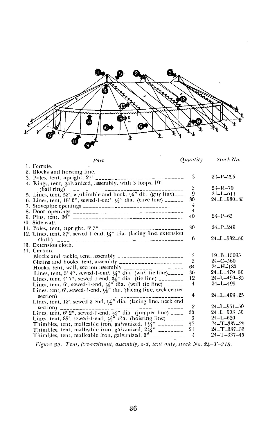
F M 2 0 — 15
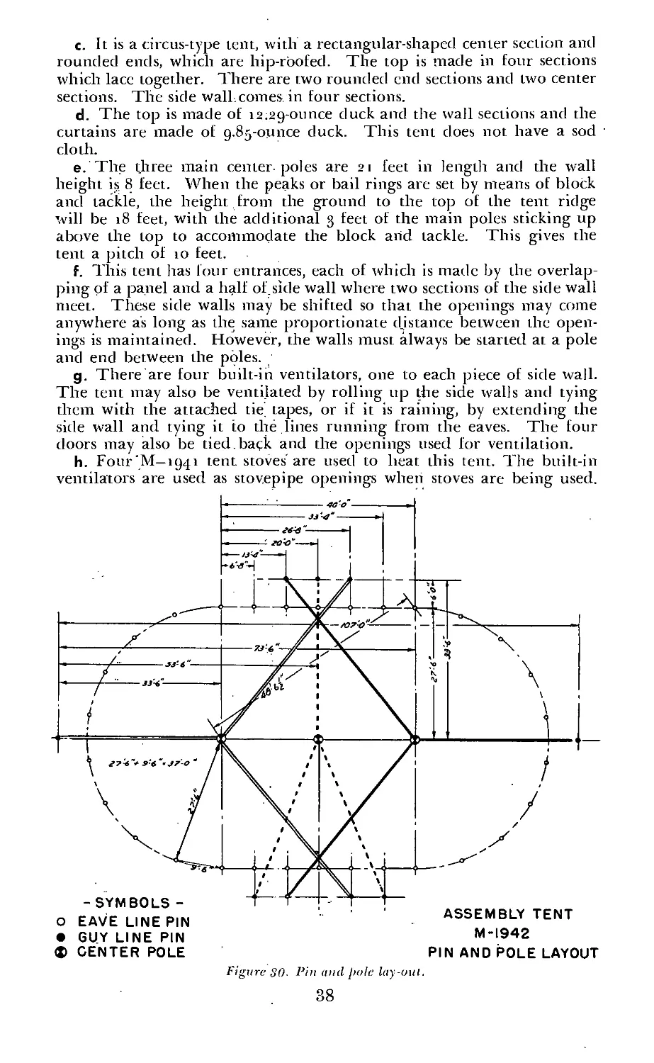
teSjts and
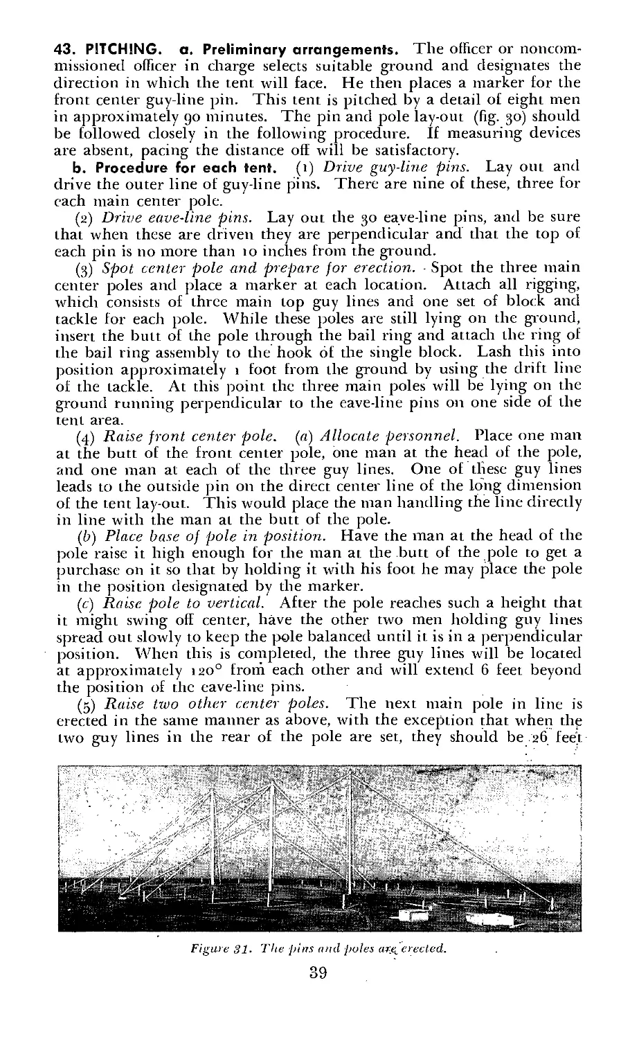
TENT PITCHING
WAR DEPARTMENT • F E В R U A R Y 19^5
United States Government Printing Office
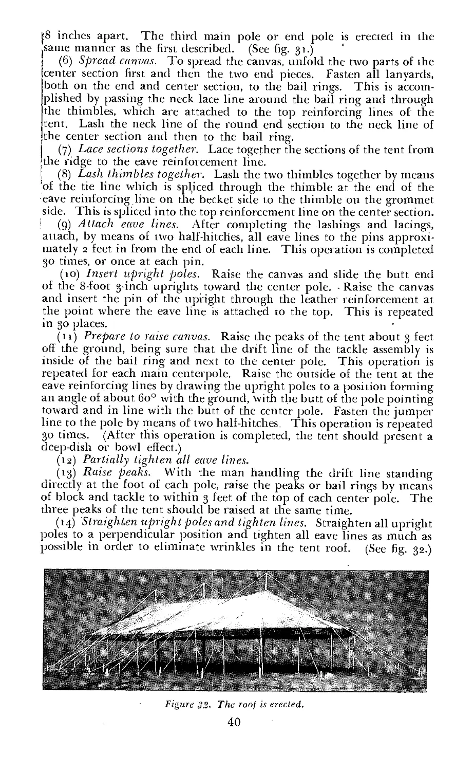
Washington : 191,5
...WAR DEPARTMENT
Washington 25, D. C., 24 February 1945
FM 20—15, Tents and Tent Pitching, is published for the information
and guidance of all concerned.
[AG 300.7 (5 Aug 44)]
By order of the Secretary of War:
Official:
J. A. ULIO
Major General
The Adjutant General
G. C. MARSHALL
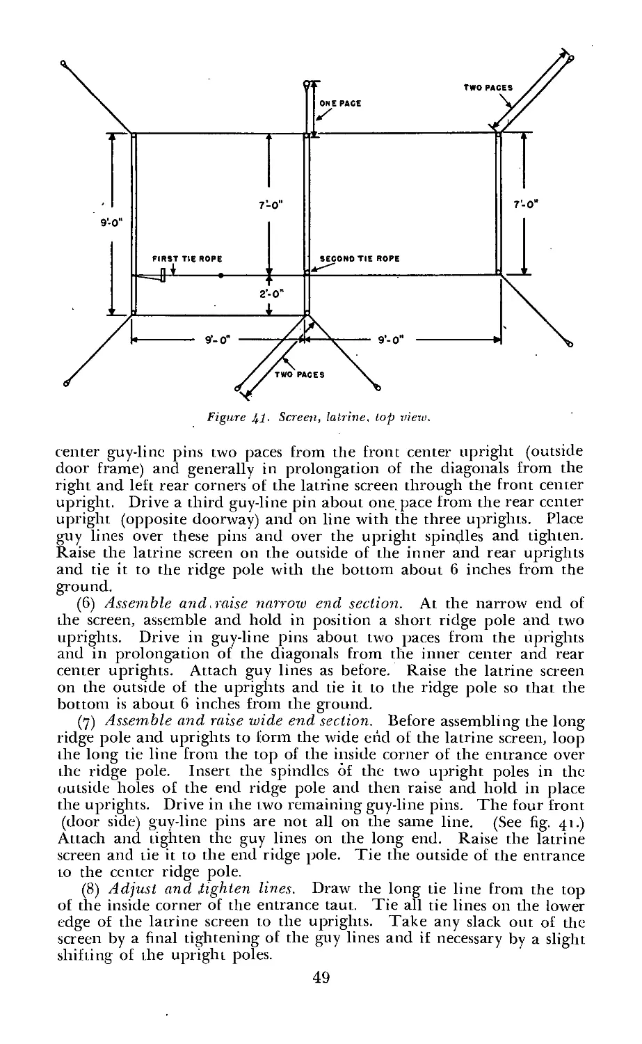
Chief of Staff
Distribution:
AAF (10); AGF (10); ASF (2); T of Opns (2); Arm & Sv Bd (2); Def
Comd (2); Tech Sv (2); SvC (10); HD (2); PC&S (i);Gen&SpSv
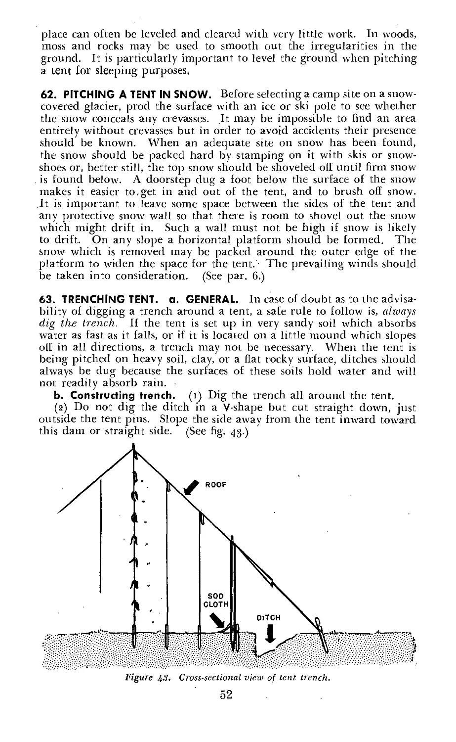
Sch (50); USMA (2); ROTC (1); A (10); CHQ (10); D (2) ; В (i);
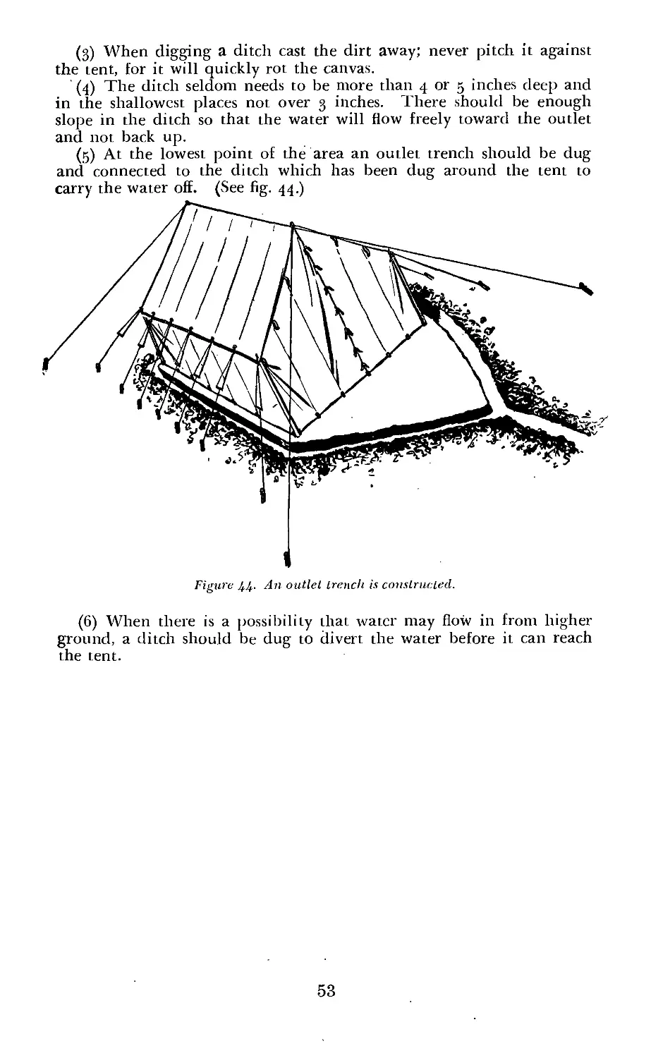
R (1); Bn (1); C (1); AF (2); W (i)‘; G (1) ; S (1).
For explanation of symbols, see FM 21—6.
II
FOREWORD
This manual contains information and instruction in the care and
handling of all tents being issued to the Army. It is an aid for training
personnel in the use of tents as well as a handy reference and guide in
the field.
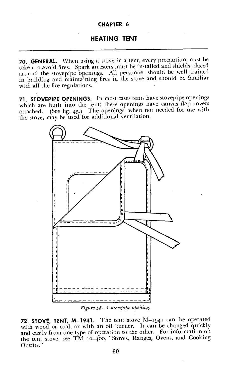
Thorough instruction in the care and handling of appropriate tentage
should be part of all unit training. One of the first jobs of any com-
manding officer is to learn the types of tents his unit will use and then
to see that the personnel under his command are trained to use them.
Complete information as to the tents issued to any unit may be
found in—
i. Table of Equipment 21—information on the issue of individual
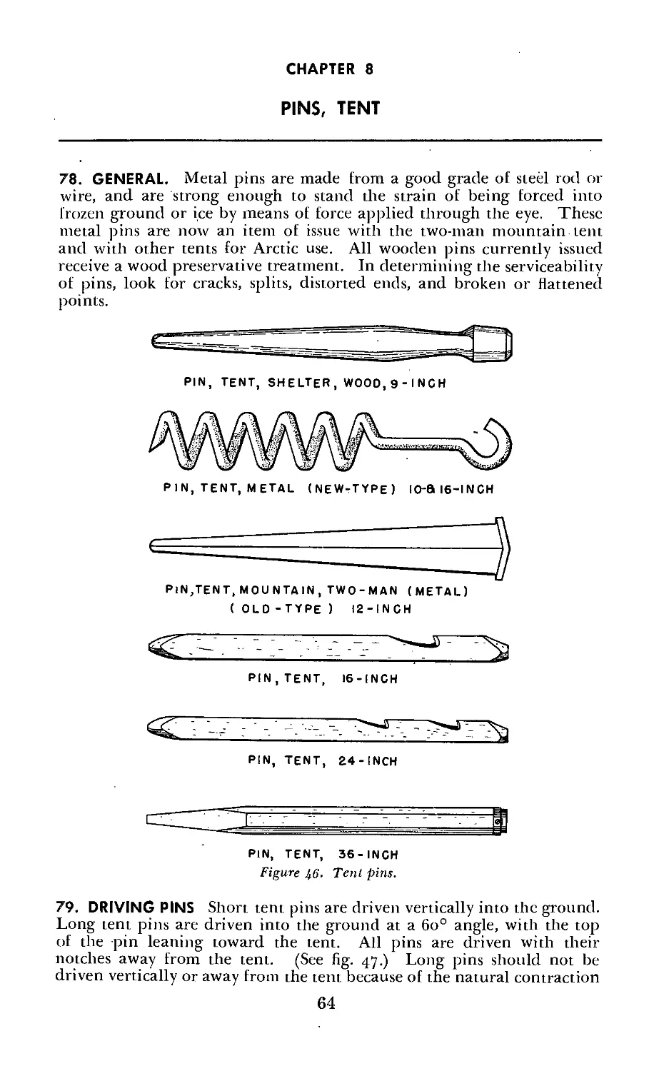
tentage.
2. Table of Organization and Equipment—number and type of tents
issued to particular units. (If the unit has no Table of Organization
and Equipment, this information can be found in the appropriate Table
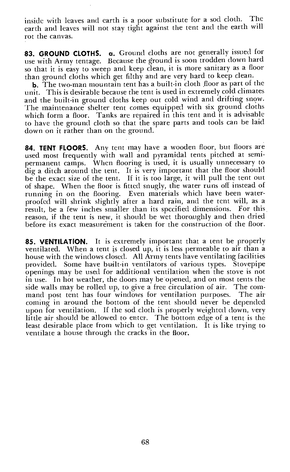
of Basic Allowances.)
3. Table of Allowances 20—issue of tentage to posts, camps and sta-
tions.
4. AR 30—3000, “Price List of Clothing and Equipage” (correct
nomenclature, stock number, unit and price).
Ill
CONTENTS
Paragraphs Pages
CHAPTER 1. INDIVIDUAL TENTS.
Section I. Tent, shelter________________________________________________ 1-3 1
II. Tent, mountain, two-man, complete with pins and poles 4-7 6
III. Hammock, jungle, complete____________________________________ 8—11 9
CHAPTER 2. WALL TENTS.
Section I. Tent, fire-resistant, wall, small, o-d_____________________ 12-13 15
II. Tent, fire-resistant, wall, large, o-d______________________________ 14—15 15
III. Tent, fire-resistant, storage, o-d__________________________________ 16-17 18
IV. Pitching and striking wall tents_____________________________________ 18-20 19
CHAPTER 3. GENERAL-PURPOSE TENTS. 22
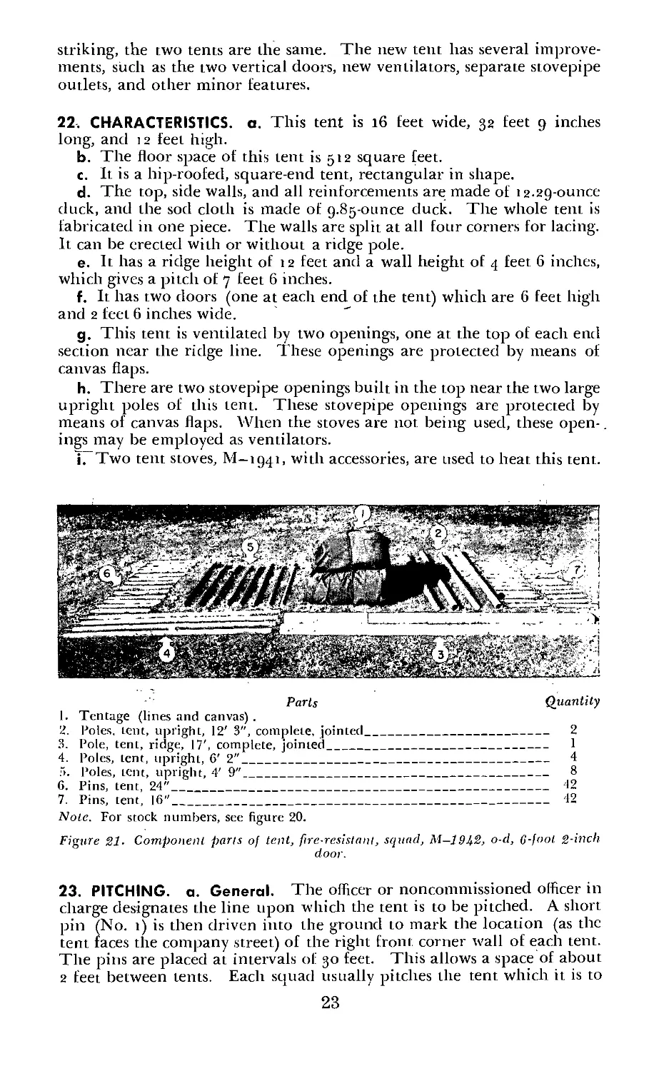
Section I. Tent, fire-resistant, squad, M—1942, o-d. 6-£oot 2-inch door 21—25 22
II. Tent, fire-resistant, pyramidal, M—1934, o-d________________________ 26-30 26
III. Tent, fire-resistant, command post, M—1942, o-d____________________ 31—35 29
IV. Tent, fire-resistant, hospital ward, o-d. 6-Eoot 2-inch door 36—40 33
V. Tent, fire-resistant, assembly, o-d, tent only_ 41—45 37
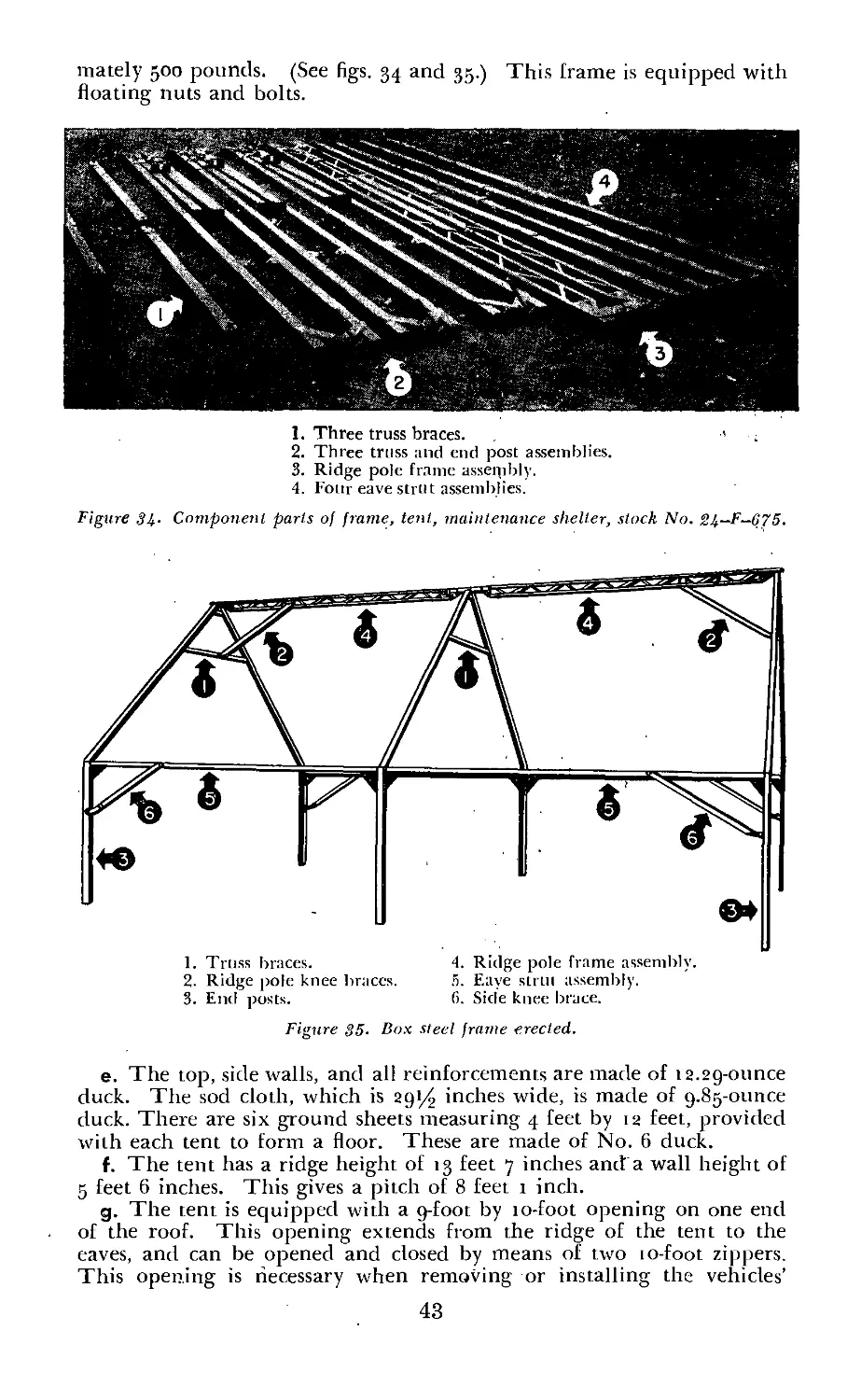
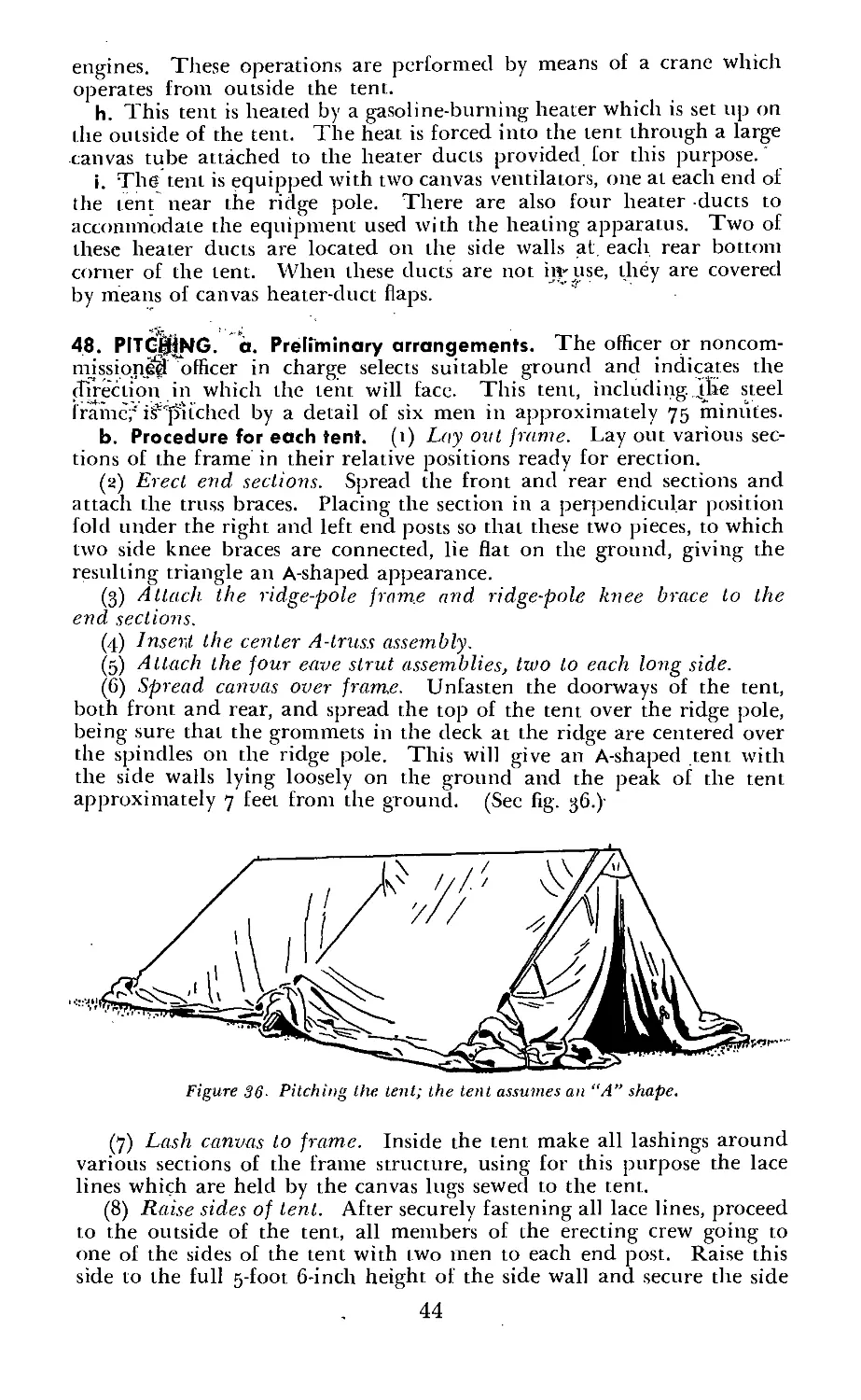
VI. Tent, fire-resistant, maintenance, shelter_________________________ 46-50' 42
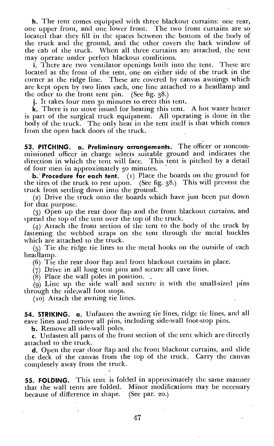
VII. Tent, fire-resistant, surgical truck, o-d______ 51—55 45
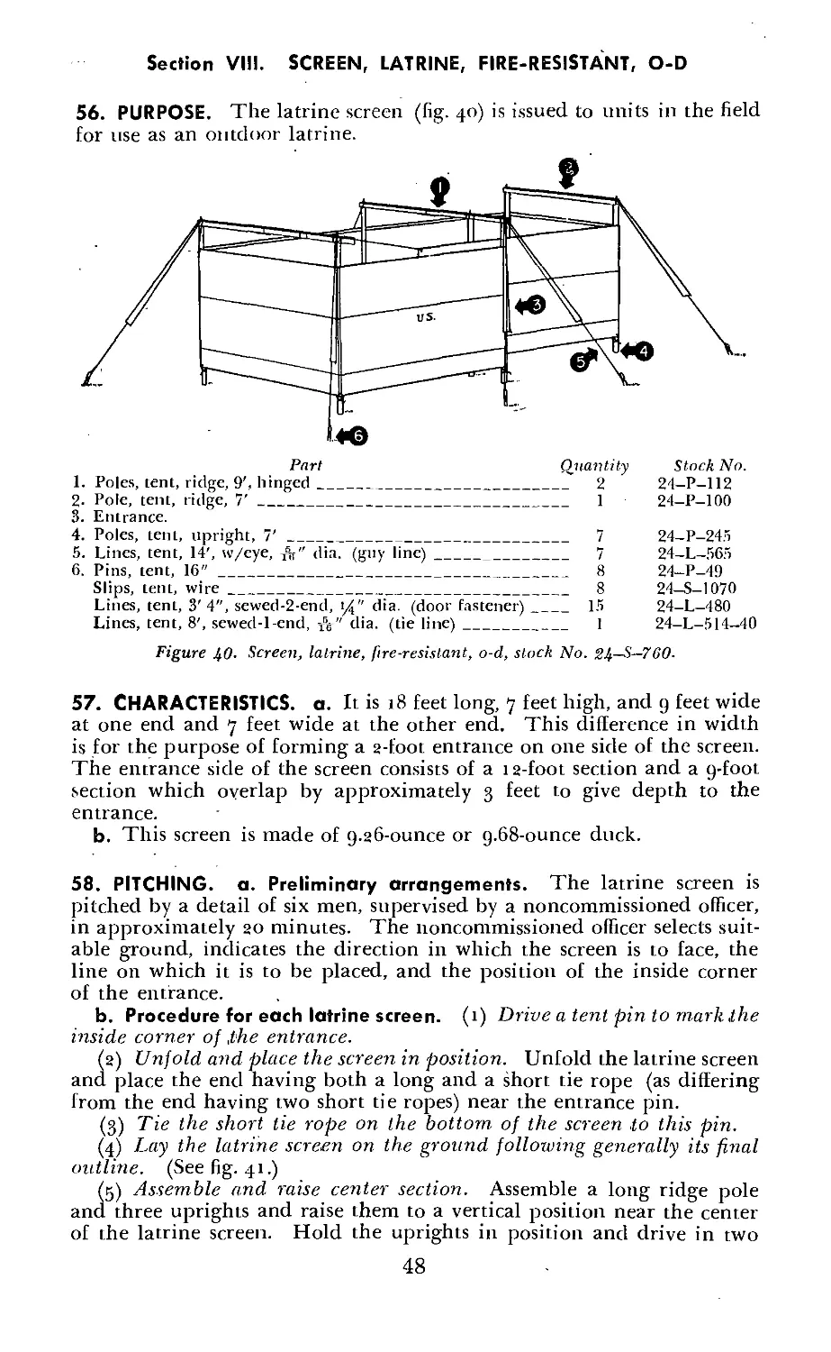
VIII. Screen, latrine, fire-resistant, o-d________________________________ 56-60 48
CHAPTER 4. TENT SITE_______________________________________________________ 61—63 51
CHAPTER 5. CARE OF TENTAGE___________________________________________ 64-69 54
CHAPTER 6. HEATING TENT______________________________________________________ 70-74 60
CHAPTER 7. LINES, TENT------------------------------------------------------- 75-77 62
CHAPTER 8. PINS, TENT________________________________________________________ 78-79 64
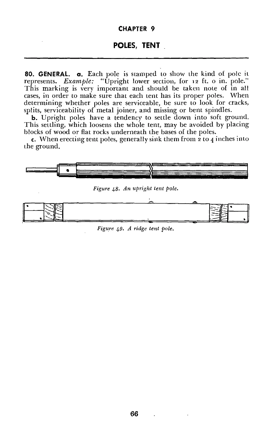
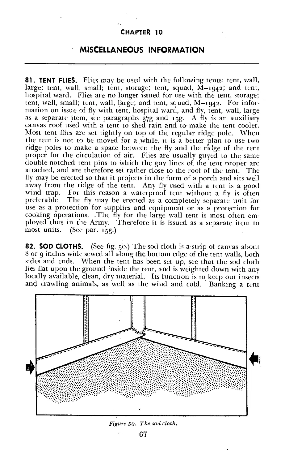
CHAPTER 9. POLES, TENT__________________________________________________________ 80 66
CHAPTER 10. MISCELLANEOUS INFORMATION_________________________________________ 81-85 67
APPENDIX. GLOSSARY--------------------------------------------------------------------69
IV
CHAPTER 1
INDIVIDUAL TENTS
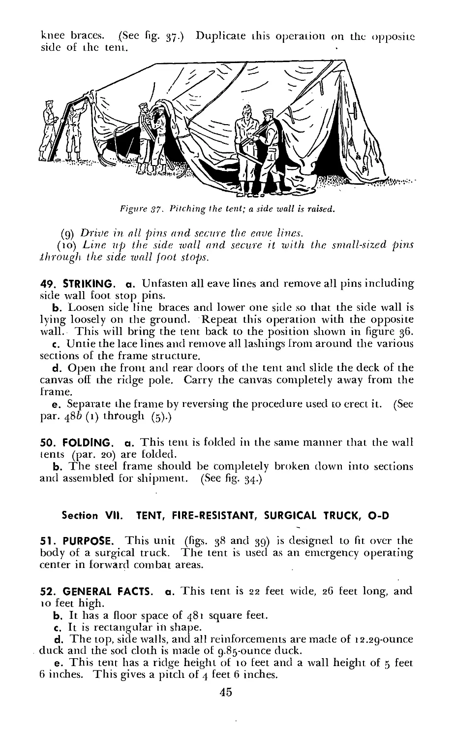
Section I. TENT, SHELTER
1. PURPOSE. When individual tents, shelter half, are authorized, the
normal basis of issue per individual is one tent, shelter half, with the
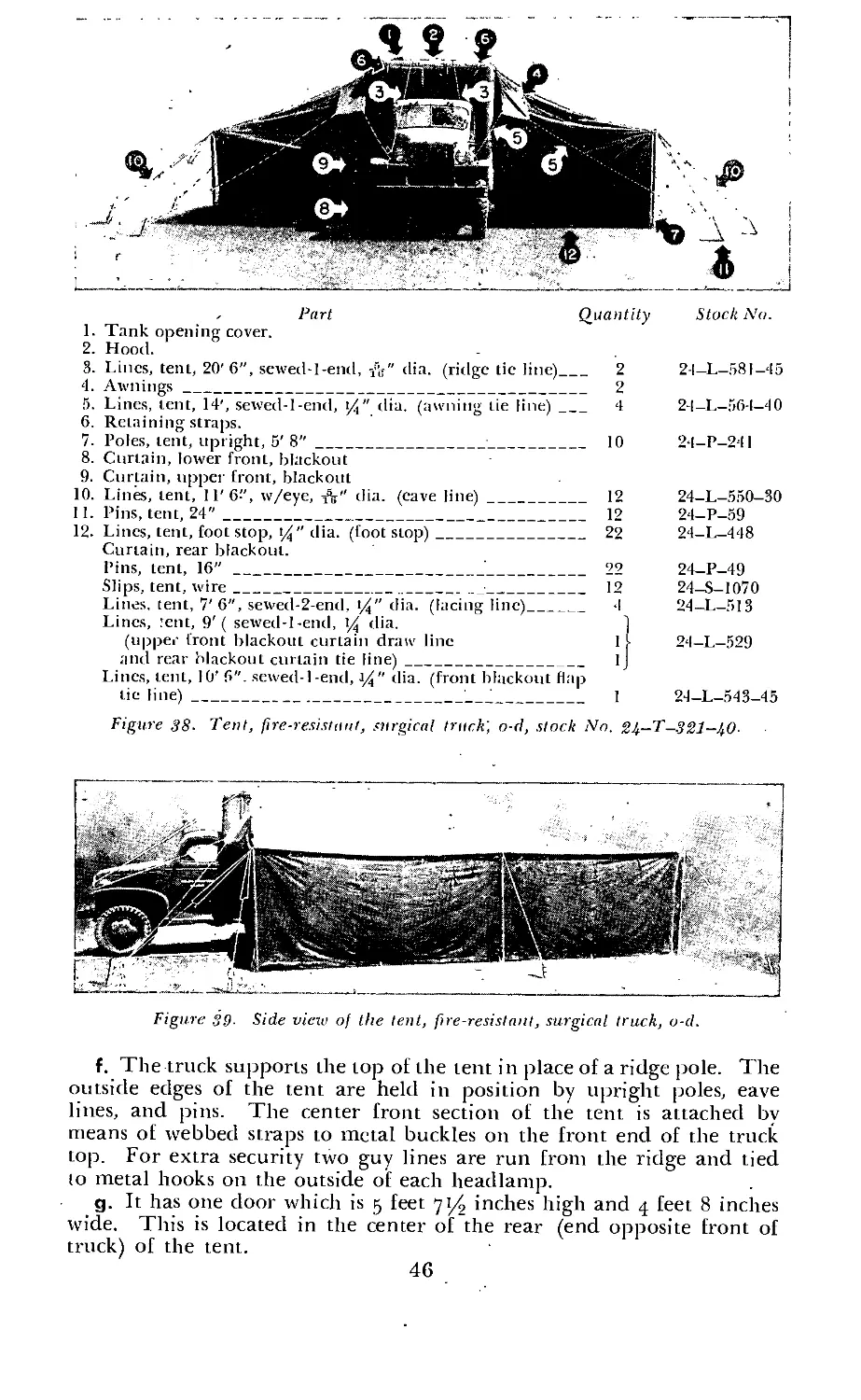
required number of Dins and poles. Thus, two individuals carry and
occupy one complete tent, shelter. There are two types of shelter half:
the tent, shelter half (old type) and the tent, shelter half, new type.
The tent, shelter half, new type is issued when available, but the old
type will be issued until the supply is exhausted. The only difference
between the two types is that the new type has a triangular piece at
both ends which makes it possible to close the tent completely. This
new type is superior, particularly for use in cold climates and for pro-
tection against wind and rain. In addition to its use as sleeping quarters,
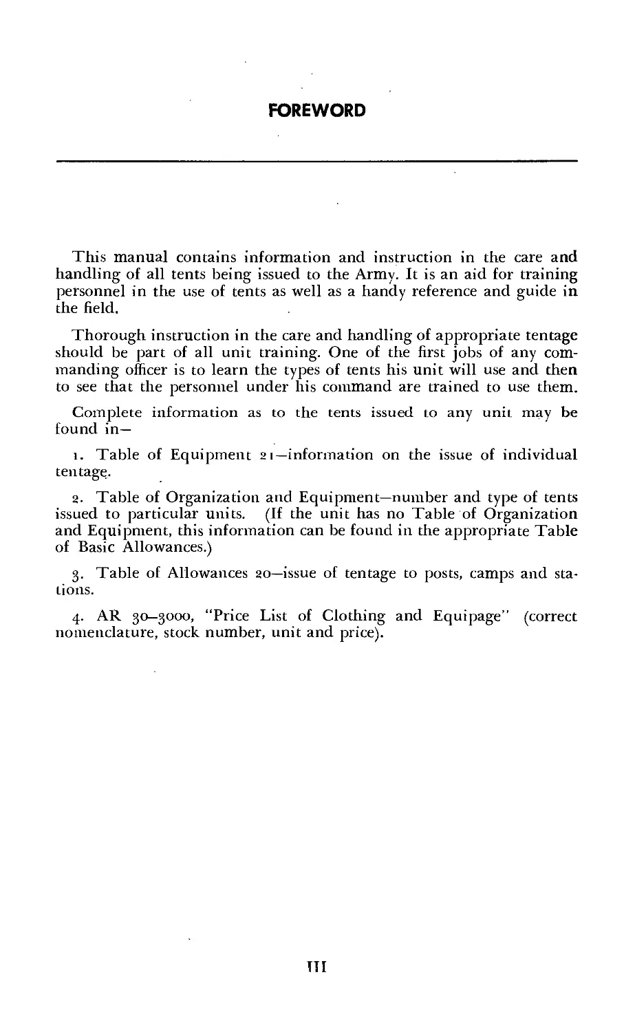
Figure 1. Shelter half used as fly.
the shelter half may also be used as a fly to protect a man while cooking.
(See fig. i.) A shelter half with the necessary number of pins and poles
is an individual item of issue. It becomes the responsibility of the
individual to whom it is issued and it will usually be carried as part
of the field pack.
1
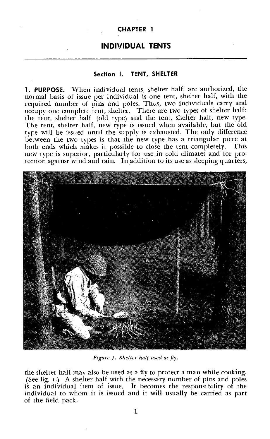
5. Triangular end piece.
6. Loop.
7. Buttons.
Figure 2- Tent, shelter (old type) (composed of two tents, shelter half (old type),
stock No. 74-T-100.)
2. TENT, SHELTER (OLD TYPE), a. Characteristics, (i) The back of the
tent is shaped like an inverted V, and the front is open.
(2) This tent is made of 33-inch wide, 7.9 ounce cotton duck material
which has been treated with aluminum acetate, wax, and soap to make
it highly water repellent. It comes in two sections which button together
to make it into a two-man tent.
(3) It has a ridge height of 43 inches.
(4) Added ventilation may be secured by opening the closed end of
the tent as desired.
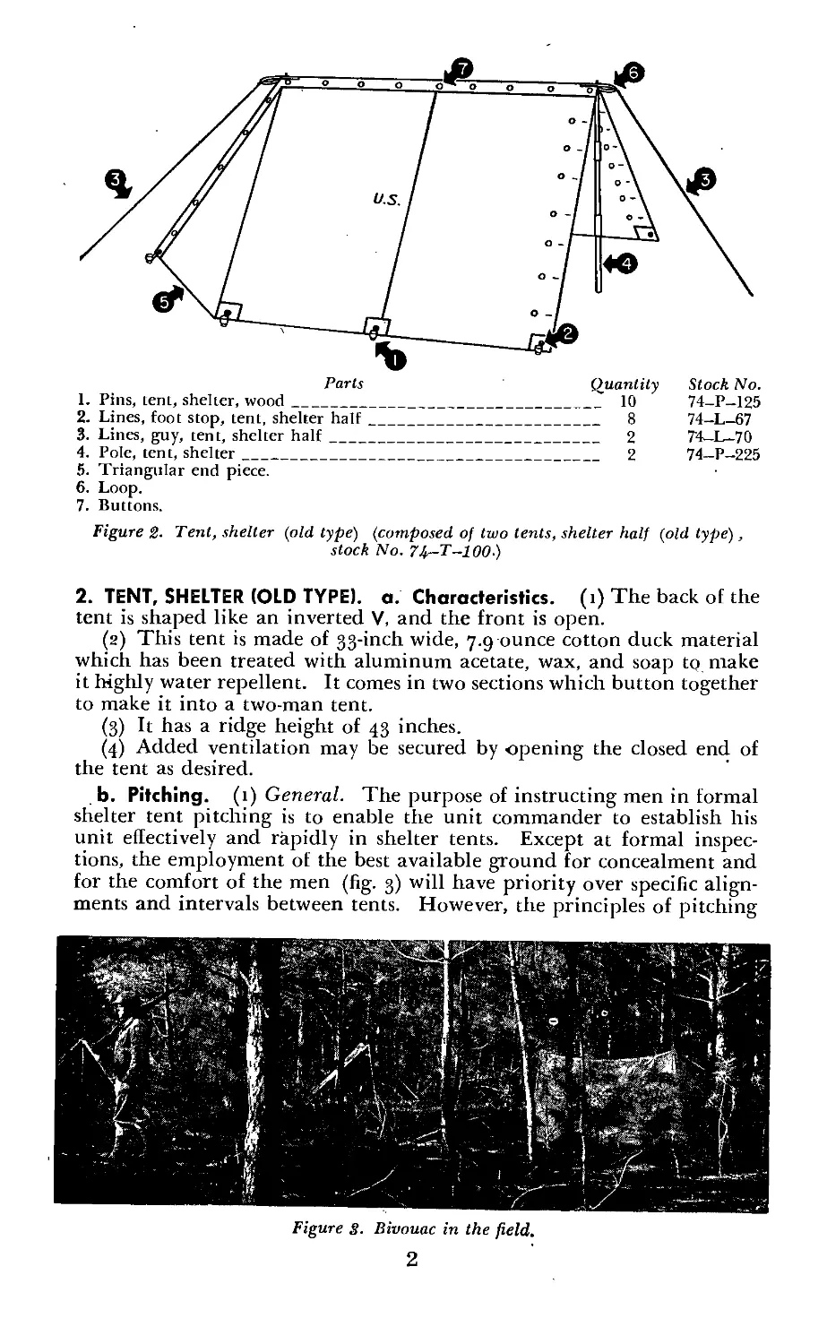
b. Pitching. (1) General. The purpose of instructing men in formal
shelter tent pitching is to enable the unit commander to establish his
unit effectively and rapidly in shelter tents. Except at formal inspec-
tions, the employment of the best available ground for concealment and
for the comfort of the men (fig. 3) will have priority over specific align-
ments and intervals between tents. However, the principles of pitching
Figure S. Bivouac in the field.
2
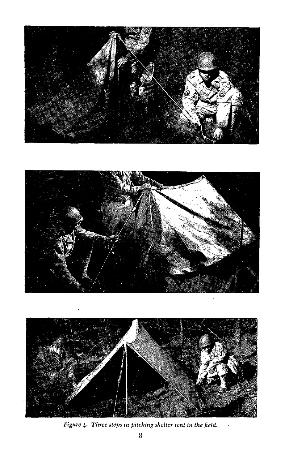
Figure 4. Three steps in pitching shelter tent in the field.
3
the tent will always be the same. (See fig. 4.) In the field, it takes one
man approximately 7 minutes to erect this tent, but it can be done in
much jess time when two men erect the tent. The officer or noncom-
missioned officer in charge indicates the area for each platoon (or section)
or the line on which its tents are to be pitched.
(2) Formal shelter tent pitching, (a) The platoons or sections are
formed for formal shelter tent pitching as prescribed in FM 22-5.
When directed by the officer in charge, each odd-numbered man marks
his position with the outside of his left heel near the instep. The
locations marked thus indicate the positions of the front tent poles.
Odd and even numbers (numbers 1 and 2, numbers 3 and 4, etc.) pitch
tents together.
(b) When the command for pitching tents is given, each man (if
armed with a rifle) steps off obliquely with the right foot a full pace to
the right front, and lays his rifle on the ground, muzzle to the front,
barrel to the left, butt near the toe of his right foot. He then steps
back into place. All men then unsling equipment and place their packs
(or rolls) on the ground in front of them, haversacks (saddlebags or
field canvas packs) up and to the front, the packs two paces in front
of the men’s positions. Each man then opens his pack and removes his
shelter half, poles, and pins. Each odd-numbered man places a pin in
the ground on the spot which he previously marked with his left heel.
Each man of each pair spreads his shelter half on the ground which the
tent is to occupy, buttons to the center, triangle to the rear, the even-
numbered man’s shelter half being on the left. It will be necessary to
see that one of the halves is right side out and that the other is inside
out, otherwise both rows of buttons and buttonholes will not match for
fastening. The right side of the tent can be determined by the letters
“U.S.” stamped thereon.
(c) They then button the halves together. The odd-numbered man
adjusts his pole through the eyelets in the front of the tent and holds
the pole upright in position beside the pin. The even-numbered man
pins down the front corner of the tent in line with the pins. He then
drives the front guy pin a tent-pole length ahead of the front pole.
The even-numbered man places the loop of the guy line over the front
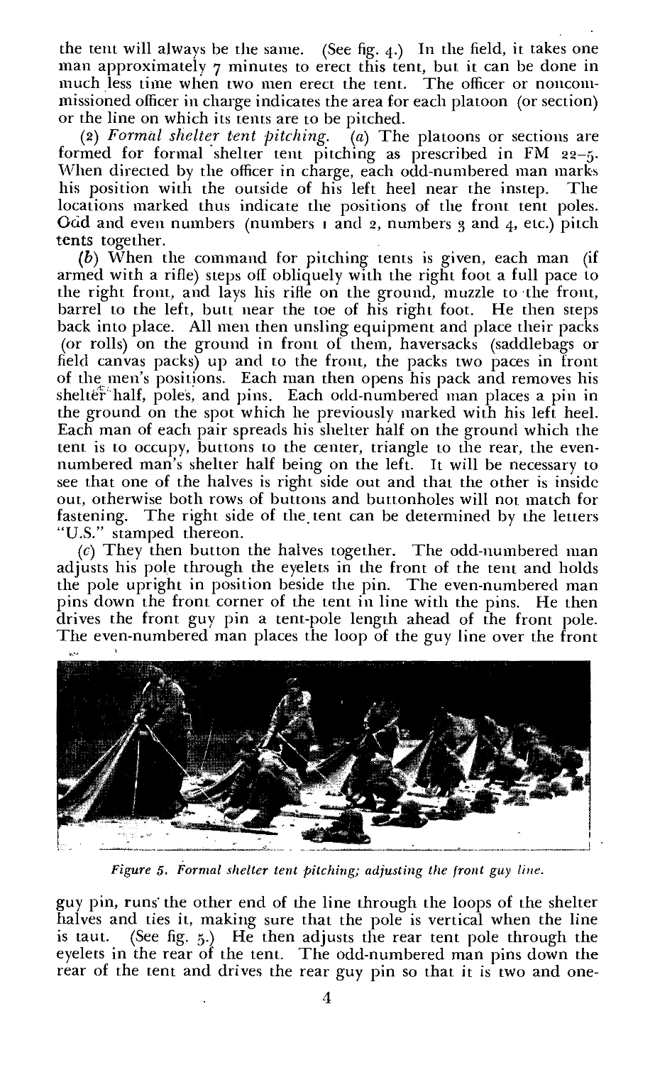
Figure 5. Formal shelter tent pitching; adjusting the front guy line.
guy pin, runs’ the other end of the line through the loops of the shelter
halves and ties it, making sure that the pole is vertical when the line
is taut. (See fig. 5.) He then adjusts the rear tent pole through the
eyelets in the rear of the tent. The odd-numbered man pins down the
rear of the tent and drives the rear guy pin so that it is two and one-
4
half tent-pin lengths from the rear pin of the triangle. He then adjusts
the guy line. The even-numbered man then drives the remaining pins
on the left of the shelter tent and the odd-numbered man drives them
on the right.
(3) Pitching double shelter tents. («) This tent may be pitched
singly, or two tents may be pitched together as a double shelter tent.
The double-tent camp is preferable to the single-tent camp in cold or
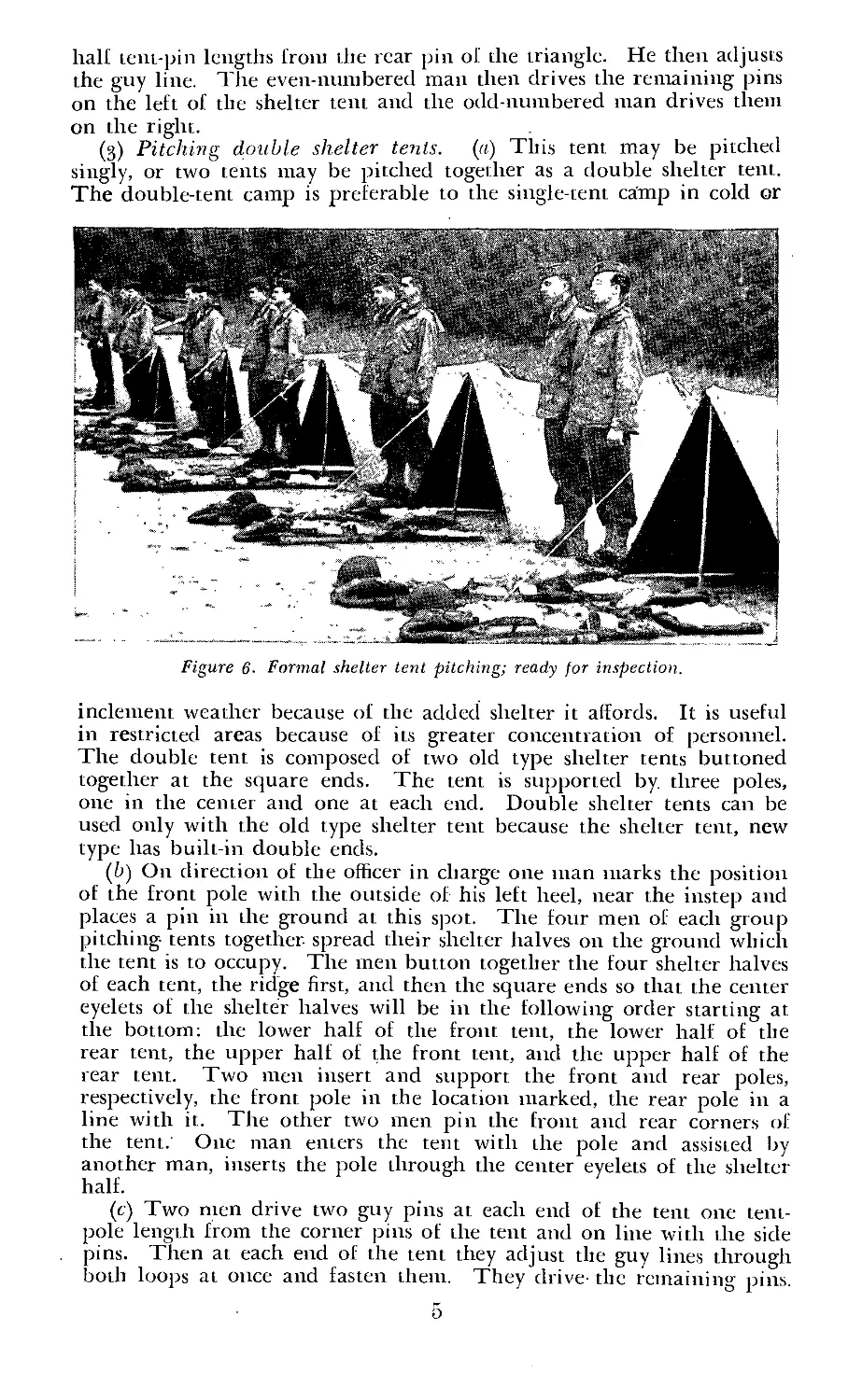
Figure 6- Formal shelter tent pitching; ready for inspection.
inclement weather because of the added shelter it affords. It is useful
in restricted areas because of its greater concentration of personnel.
The double tent is composed of two old type shelter tents buttoned
together at the square ends. The tent is supported by. three poles,
one in the center and one at each end. Double shelter tents can be
used only with the old type shelter tent because the shelter tent, new
type has built-in double ends.
(ft) On direction of the officer in charge one man marks the position
of the front pole with the outside of his left heel, near the instep and
places a pin in the ground at this spot. The four men of each group
pitching tents together spread their shelter halves on the ground which
the tent is to occupy. The men button together the four shelter halves
of each tent, the ridge first, and then the square ends so that the center
eyelets of the shelter halves will be in the following order starting at
the bottom: the lower half of the front tent, the lower half of the
rear tent, the upper half of the front tent, and the upper half of the
rear tent. Two men insert and support the front and rear poles,
respectively, the front pole in the location marked, the rear pole in a
line with it. The other two men pin the front and rear corners of
the tent. One man enters the tent with the pole and assisted by
another man, inserts the pole through the center eyelets of the shelter
half.
(c) Two men drive two guy pins at each end of the tent one tent-
pole length from the corner pins of the tent and on line with the side
pins. Then at each end of the tent they adjust the guy lines through
both loops at once and fasten them. They drive- the remaining pins.
5
c. Striking. То strike shelter tents, the men first unbutton sufficient
buttons to grasp the tent poles and then let them fall either to the
left or to the right. When the tent is flat on the ground they pull the
pins, unbutton the shelter halves, and roll their packs.
Parts Quantity Stock No.
I. Pins, tent, shelter, wood___________________________;____________ 10 74-P-125
2. Lines, foot stop, tent, shelter hull_____________________________ 10 74-L-67
3. Doors.
4. Tent, shelter lialf, new type____________________________________ 2 7 1—T-102
.5. Buttons.
6. Loop.
7. Lines, guy, tent, shelter half___________________________________ 2 74-1___70
Figure 7. Tent, shelter, new type (composed of two tents, shelter half, new type) .
3. TENT, SHELTER (NEW TYPE), a. Characteristics. The characteristics
of this tent are the same as those of the tent, shelter (old type) with
the following exceptions:
(i) It has an added V-section on the front end.
(2) It may be ventilated by opening one end or both ends as desired.
b. Pitching. The tent, shelter, new type is pitched in the same manner
as the tent, shelter (old type) (par. 2b) with the following exceptions:
(1) When spreading the shelter halves preparatory to buttoning
them together, both halves should be right side out with buttons to
the center and the even-numbered man’s shelter half on the left.
(2) After the front corner pins of the tent have been driven, the
even-numbered man pins down the front of the tent. He then drives
the front guy pin so that it is two and one-half tent-pin lengths from
the front pin of the triangle, or the distance from the base of the front
tent pole to one of the front tent pins.
c. Striking. See paragraph 2c.
Section II. TENT, MOUNTAIN, TWO-MAN, COMPLETE WITH
PINS AND POLES
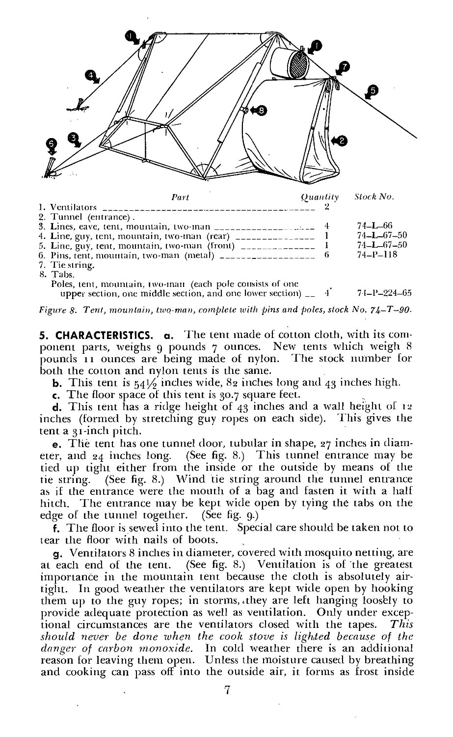
4. PURPOSE. The motmtain tent is a lightweight, waterproof, two-man
tent for use in cold climates. (See fig. 8.) It is reversible and may be
pitched with either the olive-drab or white side out, depending on
which will provide the better camouflage. The tent, shelter half, will
not be issued when the two-man mountain tent is issued.
6
2. Tunnel (entrance) .
3. Lines, eave, tent, mountain, two-tnan________________: 4 74—L—66
4. Line, guy, tent, mountain, two-tnan (rear)_______________ 1 74-L-67-50
5. Line, guy, tent, mountain, two-man (front) _______________ 1 74-L-67-50
6. Pins, tent, mountain, two-man (metal)_____________________ 6 74—P—118
7. Tie string.
8. Tabs.
Poles, tent, mountain, iwo-tnan (each pole consists of one
upper section, one middle section, and one lower section)_4 7 I—P—224—65
Figure 8- Tent, mountain, two-man, complete with pins and poles, stock No. 7i-—T—90.
5. CHARACTERISTICS, a. The lent macle of cotton cloth, with its com-
ponent parts, weighs 9 pounds 7 ounces. New tents which weigh 8
pounds 11 ounces are being made of nylon. The stock number for
both the cotton and nylon tents is the same.
b. This tent is 541/2 inches wide, 82 inches long and 43 inches high.
c. The floor space of this tent is 30.7 square feet.
d. This tent has a ridge height of 43 inches and a wall height of 12
inches (formed by stretching guy ropes on each side). This gives the
tent a 31-inch pitch.
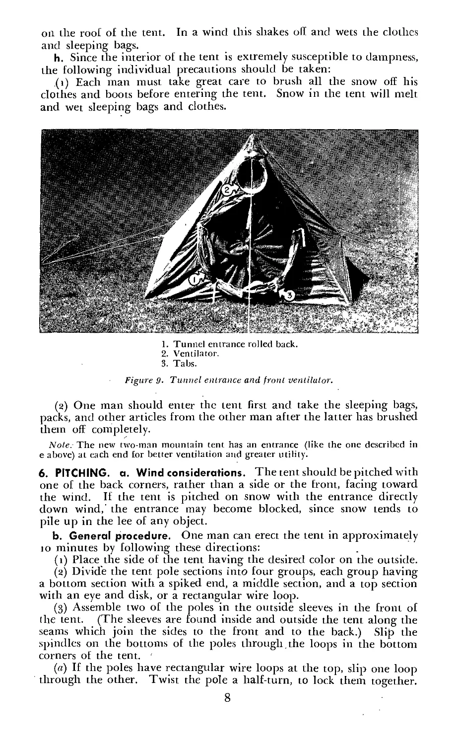
e. The tent has one tunnel door, tubular in shape, 27 inches in diam-
eter, and 24 inches long. (See fig. 8.) This tunnel entrance may be
tied up tight either from the inside or the outside by means of the
tie string. (See fig. 8.) Wind tie string around the tunnel entrance
as if the entrance were the mouth of a bag and fasten it with a half
hitch. The entrance may be kept wide open by tying the tabs on the
edge of the tunnel together. (See fig. 9.)
f. The floor is sewed into the tent. Special care should be taken not to
tear the floor with nails of boots.
g. Ventilators 8 inches in diameter, covered with mosquito netting, are
at each end of the tent. (See fig. 8.) Ventilation is of the greatest
importance in the mountain tent because the cloth is absolutely air-
tight. In good weather the ventilators are kept wide open by hooking
them up to the guy ropes; in storms, .they are left hanging loosfely to
provide adequate protection as well as ventilation. Only under excep-
tional circumstances are the ventilators closed with the tapes. This
should never be done when the cook stove is lighted because of the
danger of carbon monoxide. In cold weather there is an additional
reason for leaving them open. Unless the moisture caused by breathing
and cooking can pass off into the outside air, it forms as frost inside
7
on the roof of the tent. In a wind this shakes oh and wets the clothes
and sleeping bags.
h. Since the interior of the tent is extremely susceptible to dampness,
the following individual precautions should be taken:
(i) Each man must take great care to brush all the snow off his
clothes and boots before entering the tent. Snow in the tent will melt
and wet sleeping bags and clothes.
1. Tunnel entrance rolled back.
2. Ventilator.
3. Tabs.
Figure 9- Tunnel entrance and front ventilator.
(2) One man should enter the tent first and take the sleeping bags,
packs, and other articles from the other man after the latter has brushed
them off completely.
Note. The new two-man mountain tent has an entrance (like the one described in
e above) at each end for better ventilation and greater utility.
6. PITCHING, a. Wind considerations. The tent should be pitched with
one of the back corners, rather than a side or the front, facing toward
the wind. If the tent is pitched on snow with the entrance directly
down wind,' the entrance may become blocked, since snow tends to
pile up in the lee of any object.
b. General procedure. One man can erect the tent in approximately
to minutes by following these directions:
(1) Place the side of the tent having the desired color on the outside.
(2) Divide the tent pole sections into four groups, each group having
a bottom section with a spiked end, a middle section, and a top section
with an eye and disk, or a rectangular wire loop.
(3) Assemble two of the poles in the outside sleeves in the front of
(he tent. (The sleeves are found inside and outside the tent along the
seams which join the sides to the front and to the back.) Slip the
spindles on the bottoms of the poles through, the loops in the bottom
corners of the tent. '
(«) If the poles have rectangular wire loops at the top, slip one loop
through the other. Twist the pole a half-turn, to lock them together.
8
(h) If the poles have eyes and disks at the top, place the eyes over
each other. Slip the toggle through both eyes and through the grommet
at the peak of the tent. Lock the toggle.
(4) Assemble the rear poles similarly.
(5) Attach the guy ropes to the webbing loops on the front and rear
peaks of the tent.
(6) Stake out the front and rear guy ropes on tent pins.
(7) Attach side guys to loops on the sides of the tent.
(8) Stake out the side guy ropes on tent pins. Both ropes may be
attached to the same pin.
(g) To anchor the corners, tie ropes to the loops at the corners and
stake them to the front or back pin.
c. Special procedure. (1) In rocky terrain, it may be impossible to
drive the tent pins into the ground. In that case, attach the guy ropes
to rocks.
(2) If the snow on which the tent is pitched is loose and powdery, the
guy ropes may be attached to ski poles or ice axes, which are driven
down into the snow after it has been packed; or they may be attached
to a “dead man” anchor. This is made by burying a tent pin or stick
horizontally in a hole in the snow and stamping the snow on top of the
anchor until it is thoroughly packed.
d. When tent alone is used. It is not always necessary to carry the
complete unit. Occasionally in wooded terrain the tent alone is used
in order to achieve maximum mobility and to save weight. In such
cases, the corners are staked down with any sticks or stones that are
available; then the front and rear guy ropes are also staked with avail-
able sticks or rocks. If the ridge of the tent sags, it may be supported
by the loop which is in the center of the ridge. Skis and ski poles may
be used in place of tent poles and pins.
7. STRIKING AND FOLDING. When camp is broken, the mountain tent
must be handled carefully if it has frozen in place as a result of suc-
cessive thawing and freezing. Shovels must be used jvith the greatest
care, since it is easy to rip the tent while digging it out. Ice remaining
on the tent should be carefully removed before the tent is packed up.
Section III. HAMMOCK, JUNGLE, COMPLETE
8. PURPOSE. The jungle hammock has been developed for the use,of
troops operating in jungle areas where conditions are not desirable for
bivouac on the ground. (See fig. to.) It combines the functions of a
hammock, insect bar, and a waterproof tent fly. It enables men to sleep
off the ground and thus avoid dampness and vermin. The complete
jungle hammock weighs only 6 pounds, a minimum weight for sleeping
equipment. When authorized, the jtmgle hammock is issued in place
of' the tent, shelter half. It can be pitched as an individual tent when
the man is forced to sleep in treeless areas. It is insectproof and well-
ventilated when used as a-one-man tent. (See figs. 12 and 13.) When
a man must remain clothed'and ready to fight instantly, he can spread
his jungle hammock over him as a protection from rain and insects.
9. CHARACTERISTICS, a. The unit is stitched together. It can be slung
quickly between trees or other supports.
9
b. Two ю-foot lengths of rope are issued with each jungle hammock
to be tied to the supporting rings.
c. A false bottom is stitched under the hammock proper to prevent
insects from biting the sleeper’s back. This false bottom also makes a
still-air space below the sleeper which acts as an insulator.
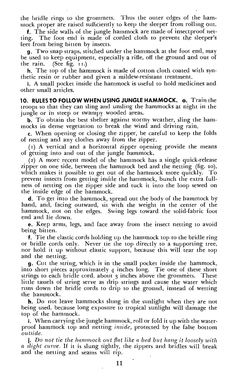
1. Spreader stick.
2. Grommets.
3. Fool end.
4. Snap straps.
5. Hammock top.
6. Loops.
7. Zipper opening.
8. Hammock rope.
9. Hammock or bridle ring.
10. Bowline knot.
11. Corner tie string.
12. Bridle.
13. Side wall.
14. Drip siring.
15. False bottom.
Figure 10. Hammock, jungle, complete, slock No. 74-H—60-
d. Corner tie strings are provided, one at each of the four corners of
the hammock top to tie in spreader sticks. The corner tabs are bound
close to the stick. The corner strings should not be used to tie the
top directly to bushes or vines as damage to the netting and the top
will result.
e. The bridle of the jungle hammock has cords of equal length from
Figure 11. Snap-straps keep equipment off the ground,
10
the bridle rings to the grommets. Thus the outer edges of the ham-
mock proper are raised sufficiently to keep the sleeper from rolling out.
f. The side walls of the jungle hammock are made of insectproof net-
ting. The foot end is made of corded cloth to prevent the sleeper’s
feet from being bitten by insects.
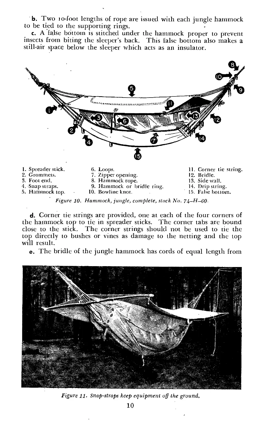
g. Two snap straps, stitched under the hammock at the foot end, may
be used to keep equipment, especially a rifle, off the ground and out of
the rain. (See fig. 11.)
h. The top of the hammock is made of cotton cloth coated with syn-
thetic resin or rubber and given a mildew-resistant treatment.
i. A small pocket inside the hammock is useful to hold medicines and
other small articles.
10. RULES TO FOLLOW WHEN USING JUNGLE HAMMOCK, a. Train the
troops so that they can sling and unsling the hammocks at night in the
jungle or in steep or swampy wooded areas.
b. To obtain the best shelter against stormy weather, sling the ham-
mocks in dense vegetation to break the wind and driving rain.
c. When opening or closing the zipper, be careful to keep the folds
of netting and any clothes away from the zipper.
(i) A vertical and a horizontal zipper opening provide the means
of getting into and out of the jungle hammock.
(2) A more recent model of the hammock has a single quick-release
zipper on one side, between the hammock bed and the netting (fig. 10),
which makes it possible to get out of the hammock more quickly. To
prevent insects from getting inside the hammock, bunch the extra full-
ness of netting on the zipper side and tuck it into the loop sewed on
the inside edge of the hammock.
d. To get into the hammock, spread out the body of the hammock by
hand, and, facing outward, sit with the weight in the center of the
hammock, not on the edges. Swing legs toward the solid-fabric foot
end and lie down.
e. Keep arms, legs, and face away from the insect netting to avoid
being bitten.
f. Tie the elastic cords holding up the hammock top to the bridle ring
or bridle cords only. Never tie the top directly to a supporting tree,
nor hold it up without elastic support, because this will tear the top
and the netting.
g. Cut the string, which is in the small pocket inside the hammock,
into short pieces approximately 4 inches long. Tie one of these short
strings to each bridle cord, about 3 inches above the grommets. These
little tassels of string serve as drip strings and cause the water which
runs down the bridle cords to drip to the ground, instead of wetting
the hammock..
h. Do not leave hammocks slung in the sunlight when they are not
being used, because long exposure to tropical sunlight will damage the
top of the hammock.
i. When carrying the jungle hammock, roll or fold it up with the water-
proof hammock top and netting inside, protected by the false bottom
outside.
j. Do not tie the hammock out flat like a bed but hang it loosely with
a slight, curve. If it is slung tightly, the zippers and bridles will break
and the netting and seams will rip.
11
11. USES OF HAMMOCK. The jungle hammock may be used in three
ways: as a hammock, a lent, or merely as a rainproof covering.
a. Slung as a hammock, (i) Tie the two hammock ropes to two trees
that are a „convenient distance apart. A satisfactory knot to use is the
clove hitch which may be untied in complete darkness with a single jerk.
(2) Tie the hammock rope to the bridle ring by means of a bow-
line knot.
(3) Tie two locally cut spreader sticks approximately 4 feet 6 inches
in length rather loosely across the ends vf the hammock top from the
fabric loops at the corners of the top. Pass these sticks completely
under the elastic cords supporting the hammock top in order to spread
out the top so that rain will not run into the hammock.
(4) Wrap the corner tie strings around both the spreader sticks and
corner loops of the hammock top. Always tie the strings with a simple
bowknot that can be quickly untied.
(5) If coolness is desired, tie in the spreader sticks above the ham-
mock bridle strings. If warmth or protection from driving rain is
required, tie the spreader sticks directly to the hammock bridle strings.
This will bring the top of the hammock down close over the sleeping
man, producing a smaller and more easily warmed air space above the
sleeper’s body.
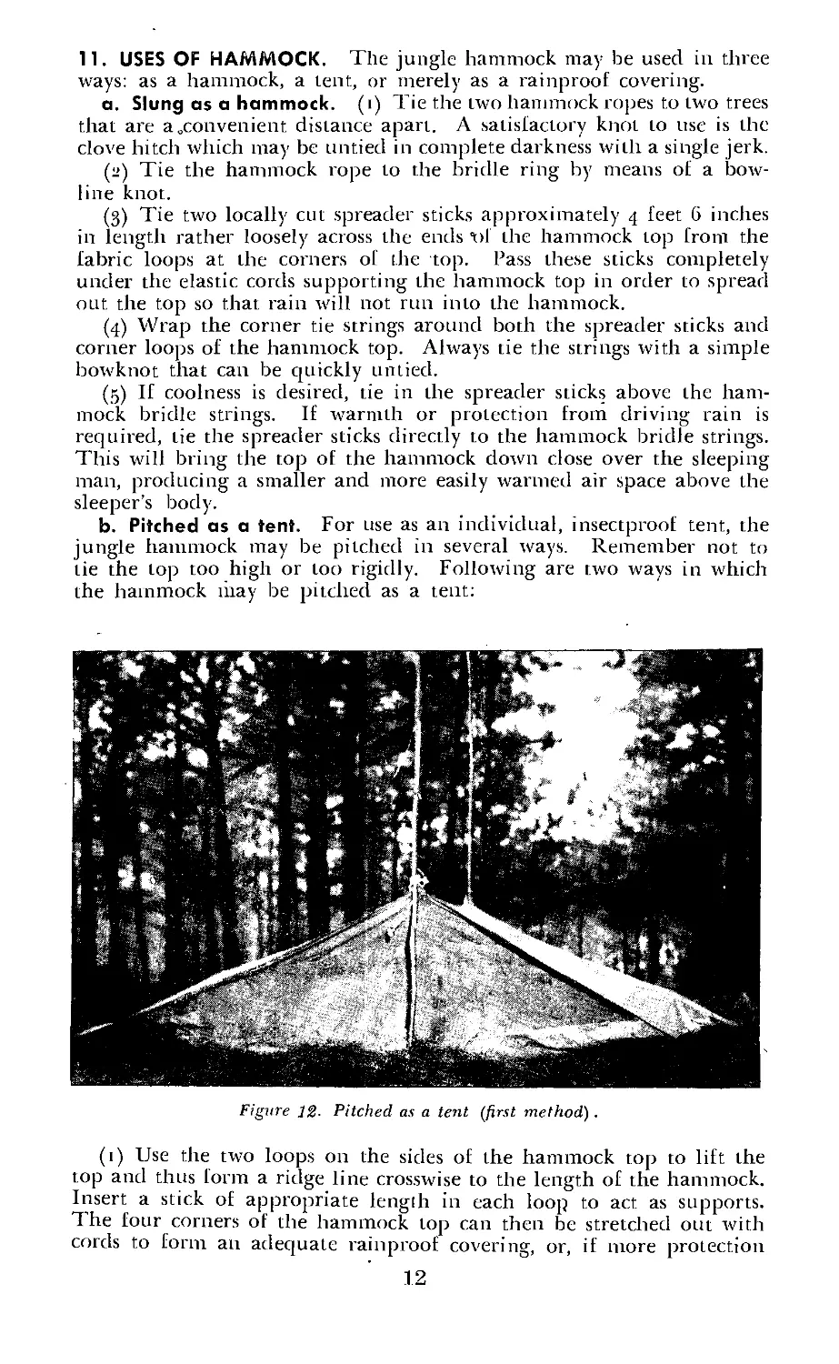
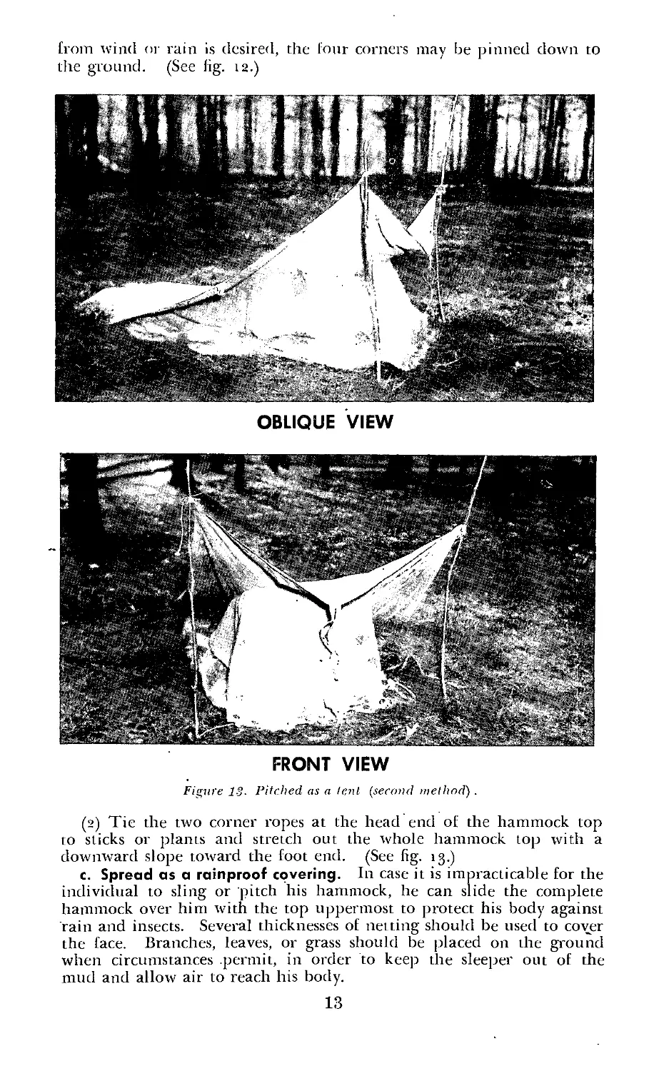
b. Pitched as a tent. For use as an individual, insectproof tent, the
jungle hammock may be pitched in several ways. Remember not to
tie the top too high or too rigidly. Following are two ways in which
the hammock may be pitched as a tent:
Figure 12- Pitched as a tent (first method).
(1) Use the two loops on the sides of the hammock top to lift the
top and thus form a ridge line crosswise to the length of the hammock.
Insert a stick of appropriate lengih in each loop to act as supports.
The four corners of the hammock top can then be stretched out with
cords to form an adequate rainproof covering, or, if more protection
12
from wind or rain is desired, the four corners may be pinned down to
the ground. (See fig. 12.)
OBLIQUE VIEW
FRONT VIEW
Figure 13. Pitched as a lent (second method') .
(2) Tie the two corner ropes at the head end of the hammock top
to sticks or plants and stretch out the whole hammock top with a
downward slope toward the foot end. (See fig. 13.)
c. Spread as a rainproof covering. In case it is impracticable for the
individual to sling or pitch his hammock, he can slide the complete
hammock over him with the top uppermost to protect his body against
rain and insects. Several thicknesses of netting should be used to cover
the face. Branches, leaves, or grass should be placed on the ground
when circumstances permit, in order to keep the sleeper out of the
mud and allow air to reach his body.
13
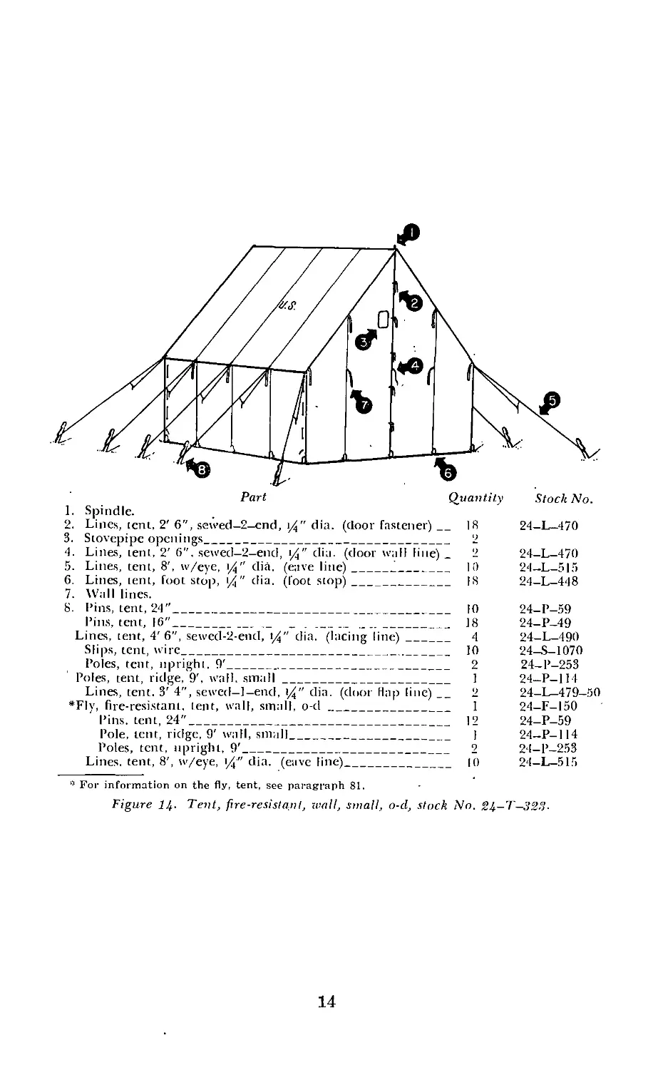
Part Quantity Stock No.
I. Spindle.
2. Lines, tent, 2'6", sewed-2-end, i/" dia. (door fastener)_18 24-L-470
3. Stovepipe openings________________________________________ 2
4. Lines, tent, 2'6". sewed-2-end, i/" dia. (door wall line) _ 2 24-L-470
5. Lines, tent, 8', w/eye, i/" dia. (eave line)_____________ 1!) 24-L-515
6. Lines, tent, foot stop, /i" dia. (foot stop)______________ IS 24—L—448
7. Wall lines.
8. Pins, tent, 24"___________________________________________ 10 24-P-59
Pins, tent, 16"______________ _ . ______ ______________ 18 24—P—49
Lines, tent, 4'6", sewed-2-end, (/" dia. (lacing line)__ 4 24-L-490
Slips, tent, wire_________________________________________ 10 24—S—1070
Poles, tent, upright. 9'___________________________________ 2 24—P—253
Poles, tent, ridge, 9', wall, small_________________________ 1 24—P—114
Lines, tent. 3' 4", sewed-l-end, 1%" dia. (door Hap line) __ 2 24-1—479-50
•Fly, fire-resistant, lent, wall, small, o-d__________________ 1 24-F-I50
Pins, tent, 24"_________________________________________ 12 24-P-59
Pole, lent, ridge, 9' wall, small________________________ I 24—P-114
Poles, tent, upright, 9'_________________________________ 2 24-P-253
Lines, tent, 8', w/eye, (4" dia. (eave line)______________ 10 24—L—515
•f For information on the fly, tent, see paragraph 81.
Figure lb- Tent, fire-resistant, wall, small, o-d, stock No. 2b—T—323-
14
CHAPTER 2
WALL TENTS
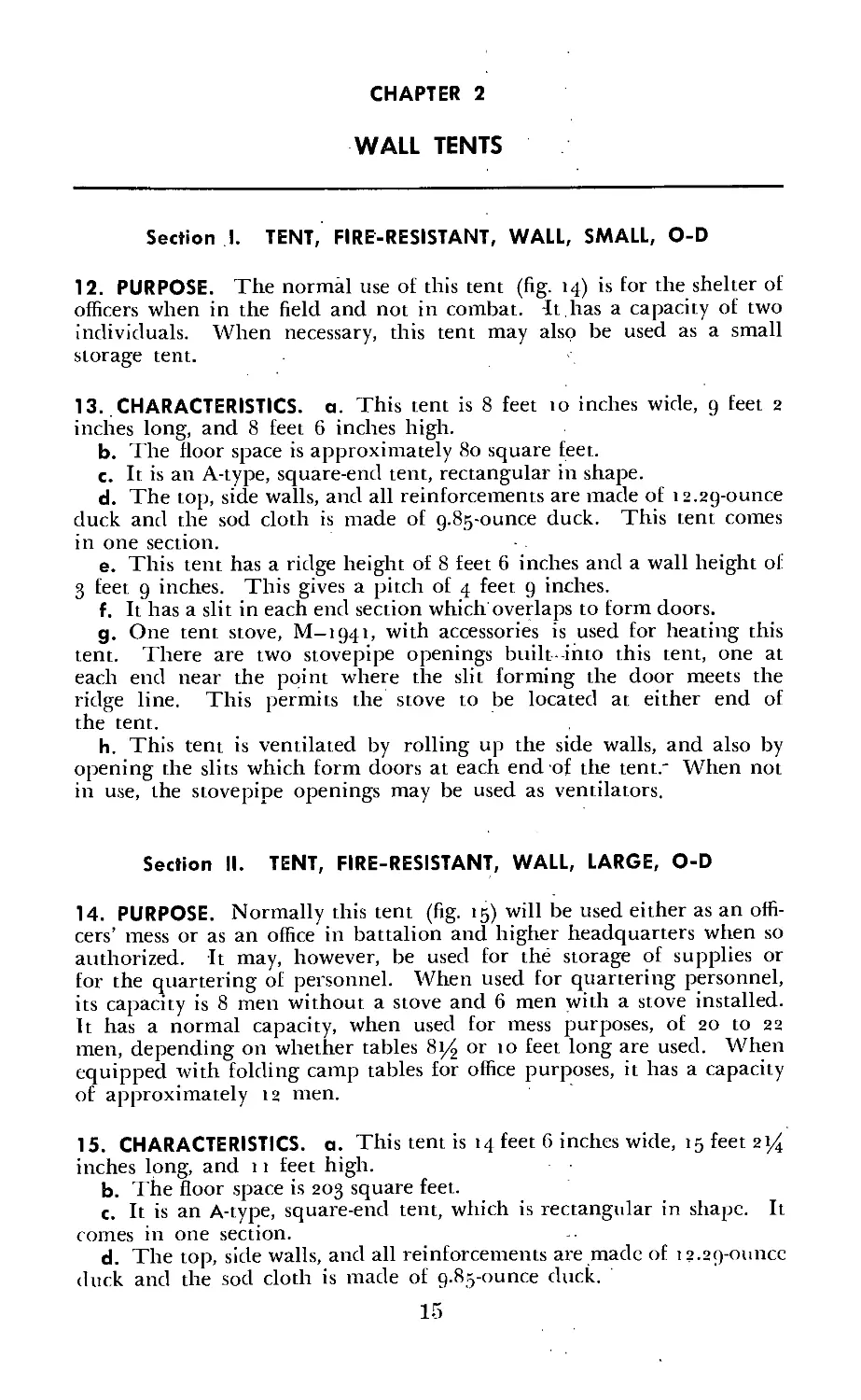
Section I. TENT, FIRE-RESISTANT, WALL, SMALL, O-D
12. PURPOSE. The normal use of this tent (fig. 14) is for the shelter of
officers when in the field and not in combat. It.has a capacity of two
individuals. When necessary, this tent may also be used as a small
storage tent.
13. CHARACTERISTICS, a. This tent is 8 feet to inches wide, 9 feet 2
inches long, and 8 feet 6 inches high.
b. The floor space is approximately 80 square feet.
c. It is an А-type, square-end tent, rectangular in shape.
d. The top, side walls, and all reinforcements are made of 12.29-ounce
duck and the sod cloth is made of g.Sg-ounce duck. This tent comes
in one section.
e. This tent has a ridge height of 8 feet 6 inches and a wall height of
3 feet 9 inches. This gives a pitch of 4 feet 9 inches.
f. It has a slit in each end section which overlaps to form doors.
g. One tent stove, M—1941, with accessories is used for heating this
tent. There are two stovepipe openings built-into this tent, one at
each end near the point where the slit forming the door meets the
ridge line. This permits the stove to be located at either end of
the tent.
h. This tent is ventilated by rolling up the side walls, and also by
opening the slits which form doors at each end of the tent." When not
in use, the stovepipe openings may be used as ventilators.
Section II. TENT, FIRE-RESISTANT, WALL, LARGE, O-D
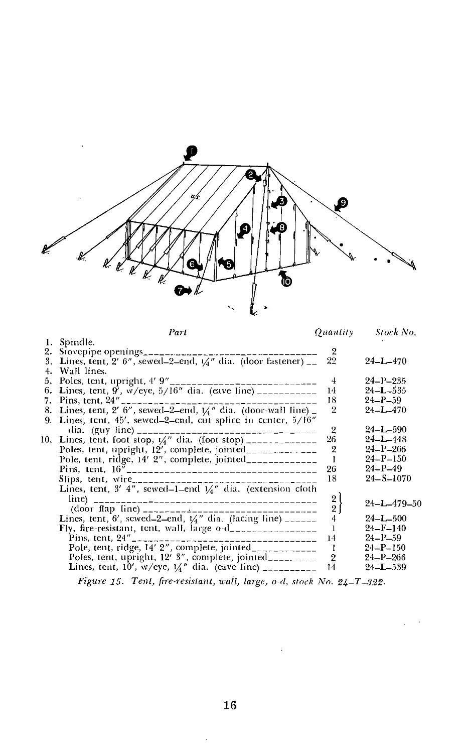
14. PURPOSE. Normally this tent (fig. 15) will be used either as an offi-
cers’ mess or as an office in battalion and higher headquarters when so
authorized. It may, however, be used for the storage of supplies or
for the quartering of personnel. When used for quartering personnel,
its capacity is 8 men without a stove and 6 men with a stove installed.
It has a normal capacity, when used for mess purposes, of 20 to 22
men, depending on whether tables 814 or to feet long are used. When
equipped with folding camp tables for office purposes, it has a capacity
of approximately 12 men.
15. CHARACTERISTICS, a. This tent is 14 feet 6 inches wide, 15 feet 214
inches long, and 11 feet high.
b. The floor space is 203 square feet.
c. It is an А-type, square-end tent, which is rectangular in shape. It
comes in one section.
d. The top, side walls, and all reinforcements are made of 12.29-ounce
duck and the sod cloth is made of 9.85-ounce duck.
Part Quantity Stock No.
1. Spindle.
2. Stovepipe openings_______________________________________ 2
3. Lines, tent, 2'6", sewed-2-end, t/" din. (door fastener)_ 22 24-L-470
4. Wall lines.
5. Poles, tent, upright, 4' 9"__________________________________ 4 24—P—235
6. Lines, tent, 9', w/eye, 5/16'' dia. (eave line)_____________ 14 24—L—535
7. Pins, tent, 24"_____________________________________________ 18 24—P—59
8. Lines, tent, 2' 6", sewed-2-end, \/4" dia. (door-wall line) _ 2 24-L-470
9. Lines, tent, 45', sewed-2-end, cut splice in center, 5/16"
dia. (guy line)____________________________________________ 2 24-L-590
10. Lines, tent, foot stop, 1%" dia. (loot stop)________________ 26 24-L-448
Poles, tent, upright, 12', complete, jointed_________________ 2 24-P-266
Pole, tent, ridge, 14' 2", complete, jointed_________________ 1 24-P-150
Pins, tent, 16"_____________________________________________ 26 24-P-49
Slips, tent, wire___________________________________________ 18 24—S—1070
Lines, tent, 3' 4", scwed-l-end \/4" dia. (extension cloth
’j7e) “Б---Г-—C-------------------------------------------- 9 I 24-L-479-50
(door flap hue)________________________________________ 2 J
Lines, tent, 6', scwed-2-end, t/4" dia. (lacing line)____ 4 24-L-500
Fly, fire-resistant, tent, wall, large o-d___________________ 1 24—F—140
Pins, tent, 24"___________________________________________ 14 24-P-59
Pole, tent, ridge, 14' 2", complete, jointed_______________ 1 24-P-150
Poles, tent, upright, 12' 3", complete, jointed____________ 2 24-P-266
Lines, tent, 10', w/eye, \/4" dia. (eave line)____________ 14 24-L-539
Figure 15- Tent, fire-resistant, wall, large, o-d, stock No. 24—T—322.
16
Figure 16- Pitching the tent fly.
17
e. It has ridge height of 11 feet and a wall height of 4 feet 6 inches,
which gives a pitch of 6 feet 6 inches.
f. Doors are formed by slits in the middle of each end section, which
are overlapped. These are tied with rope door fasteners.
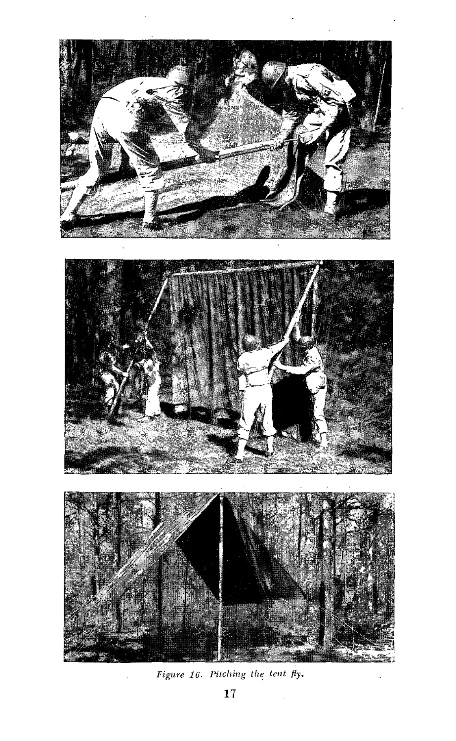
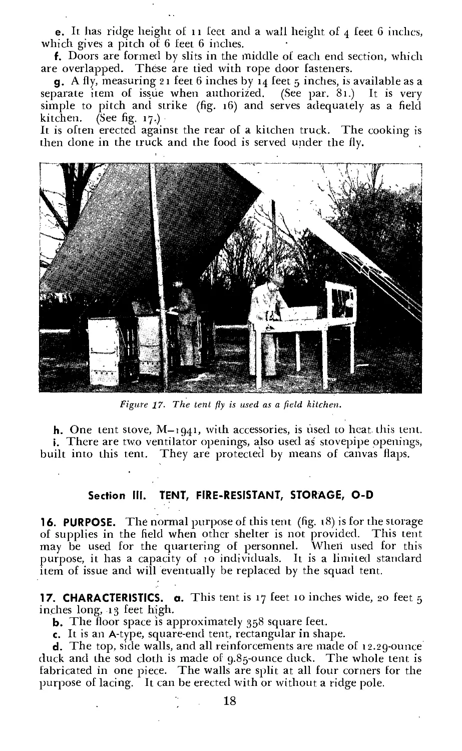
g. A fly, measuring 21 feet 6 inches by 14 feet 5 inches, is available as a
separate item of issue when authorized. (See par. 81.) It is very
simple to pitch and strike (fig. 16) and serves adequately as a field
kitchen. (See fig. 17.)
It is often erected against the rear of a kitchen truck. The cooking is
then done in the truck and the food is served under the fly.
Figure 17- The tent fly is used as a field kitchen.
h. One tent stove, M—1941, with accessories, is used to heat this tent.
i. There are two ventilator openings, also used as' stovepipe openings,
built into this tent. They are protected by means of canvas flaps.
Section III. TENT, FIRE-RESISTANT, STORAGE, O-D
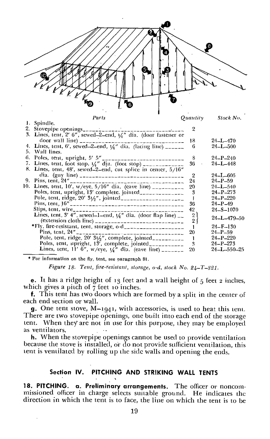
16. PURPOSE. The normal purpose of this tent (fig. 18) is for the storage
of supplies in the field when other shelter is not provided. This tent
may be used for the quartering of personnel. When used for this
purpose, it has a capacity of 10 individuals. It is a limited standard
item of issue and will eventually be replaced by the squad tent.
17. CHARACTERISTICS, a. This tent is 17 feet 10 inches wide, 20 feet 5
inches long, 13 feet high.
b. The floor space is approximately 358 square feet.
c. It is an А-type, square-end tent, rectangular in shape.
d. The top, side walls, and all reinforcements are made of 12.29-ounce
duck and the sod cloth is made of 9.85-ounce duck. The whole tent is
fabricated in one piece. The walls are split at all four corners for the
purpose of lacing. It can be erected with or without a ridge pole.
18
Parts Quantity Stock No.
1. Spindle.
2. Stovepipe openings____:______________________________ 2
3. Lines, tent, 2' 6", sewed-2-end, y4" dia. (door fastener or
door wall line)_____________________________________ 18 24—L—470
4. Lincs, tent, 6', sewed—2-end, 14" dia. (lacing line)__ 6 24-L-500
5. Wall lines.
(>. Poles, tent, upright, 5' 5"_____________________________ 8 24-P-240
7. Lines, tent, foot stop, 14" din. (foot stop)___________ 36 24-L-448
8. Lines, tent, 48', sewed-2-end, cut splice in center, 5/16"
dia. (guy line)_______________________________________ 2 24-L-605
9. Pins, tent, 24”________________________________________ 24 24-P-59
10. Lines, tent, 10', w/eyc, 5/16" dia. (cave line)________ 20 24-L-540
Poles, tent, upright, 13' complete, jointed_____________ 3 24-P-273
Pole, tent, ridge, 20' 3l4", jointed____________________ I 24-P-220
Pins, tent, .16"______________________________________ 36 24-P-49
Slips, tent, wire_____________________________________ 42 24-S-1070
Lines, tent, 3' 4", sewed-l-end, \/4" dia. (door flap line)_ 21 24-L-479-50
(extension cloth line)______________________________ 2 ]
*Fly, fire-resistant, tent, storage, o-d_________________ 1 24-F—130
Pins, tent, 24"______________________________________ 20 24-P-59
Pole, tent, ridge, 20' 3(/>", complete, jointed_______ 1 24-P-220
Poles, tent, upright, 13’, complete, jointed__________ 3 24-P-273
Lines, tent, 11' 6", w/eye, t/4" dia. (eave line)___ 20 24-1—550—25
For information on the fly, tent, see paragraph 81.
Figure 18- Tent, fire-resistant, storage, o-d, stock No. 24-T-321.
e. It has a ridge height of 13 feet and a wall height of 5 feet 2 inches,
which gives a pitch of 7 feet to inches.
f. This tent has two doors which are formed by a split in the center of
each end section or wall.
g. One tent stove, M—1941, with accessories, is used to heat this tent.
There are two stovepipe openings, one built into each end of the storage
tent. When they are not in use for this purpose, they may be employed
as ventilators.
h. When the stovepipe openings cannot be used to provide ventilation
because the stove is installed, or do not provide sufficient ventilation, this
tent is ventilated by rolling up the side walls and opening the ends.
Section IV. PITCHING AND STRIKING WALL TENTS
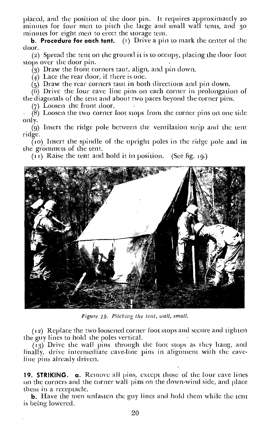
18. PITCHING, a. Preliminary arrangements. The officer or noncom-
missioned officer in charge selects suitable ground. He indicates the
direction in which the tent is to face, the line on which the tent is to be
19
placed, and the position of the door pin. It reejuires approximately 20
minutes for four men to pitch the large and small wall tents, and 30
minutes for eight men to erect the storage tent.
b. Procedure for each tent. (1) Drive a pin to mark the center of the
door.
(2) Spread the tent on the ground it is to occupy, placing the door foot
stops over the door pin.
(3) Draw the front corners taut, align, and pin down.
(4) Lace the rear door, if there is one.
(5) Draw the rear corners taut in both directions and pin down.
(6) Drive the four eave line pins on each corner in prolongation of
the diagonals of the tent and about two paces beyond the corner pins.
(7) Loosen the front door.
(8) Loosen the two corner foot stops from the corner pins on one side
only.
(9) Insert the ridge pole between the ventilation strip and the tent
ridge.
(10) Insert the spindle of the upright poles in the ridge pole and in
the grommets of the tent.
(11) Raise the tent and hold it in position. (See fig. 19.)
Figure 10. Pitching the lent, wall, small.
(12) Replace the two loosened corner loot stops and secure and tighten
the guy lines to hold the poles vertical.
(13) Drive the wall pins through the foot stops as they hang, and
finally, drive intermediate eave-line pins in alignment with the cave-
line pins already driven.
19. STRIKING, a. Remove all pins, except those of the four eave lines
on the corners and the corner wall pins on the down-wind side, and place
them in a receptacle.
b. Have the men unfasten the guy lines and hold them while the tent
is beintf lowered.
О
20
c. Lower the tent down wind.
d. Remove the poles and remaining corner wall pins. Fasten the poles
together and collect the remaining pins.
20. FOLDING, a. Spread the tent flat on the ground, folded at the ridge
so that the bottoms of the side walls are even, the sod cloth folded under,
and the ends of the tent forming triangles to the right and left.
b. Fold in the bottom of the wall approximately one foot.
c. Fold the triangular ends of the tent in toward the middle to form a
rectangle.
d. Fold the top over about g inches.
e. Fold the tent again by carrying the top fold over to the foot, and
again from the top to the foot.
f. Throw all the eave and guy lines onto the tent except the second
eave line from each end.
g. Fold the ends in so as to cover about two-thirds of the width of the
second panel.
h. Double the left fold over the number of times required to bring the
resulting bundle into position 3 to 5 inches from the right fold.
i. Place the right fold in position on top completing the bundle.
j. Tie the bundle with the two exposed eave lines.
21
CHAPTER 3
GENERAL-PURPOSE TENTS
Section I. TENT, FIRE-RESISTANT, SQUAD, M-1942, O-D,
6-FOOT 2-INCH DOOR
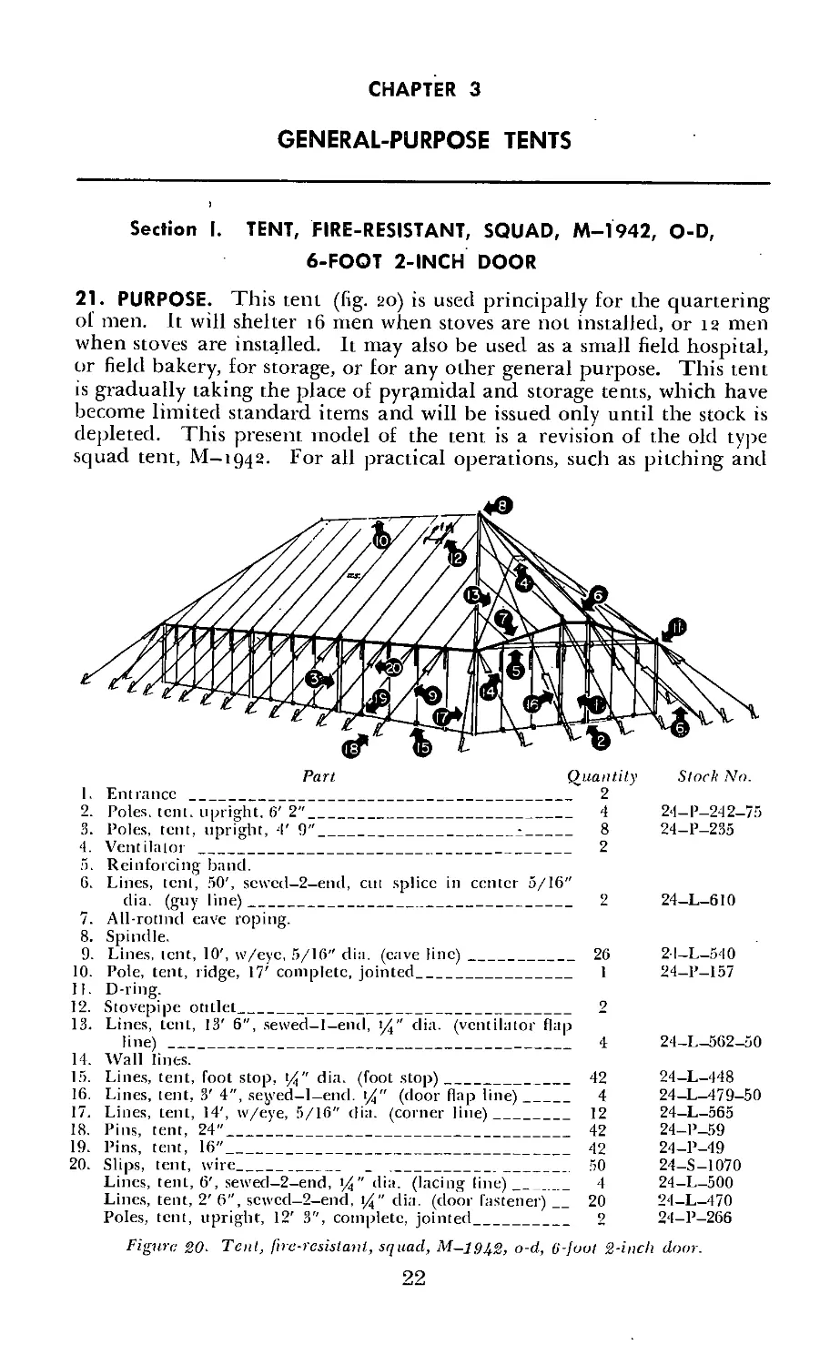
21. PURPOSE. This tent (fig. 20) is used principally for the quartering
of men. It will shelter 16 men when stoves are not installed, or 12 men
when stoves are installed. It may also be used as a small field hospital,
or field bakery, for storage, or for any other general purpose. This tent
is gradually taking the place of pyramidal and storage tents, which have
become limited standard items and will be issued only until the stock is
depleted. This present model of the tent is a revision of the old type
squad tent, M—1942. For all practical operations, such as pitching and
Part Quantity
I. Entrance ____________________________________________________ 2
2. Poles, tent, upright. 6’ 2"__________________________________ 4
3. Poles, tent, upright, 4' 9"_______________________•_______ 8
4. Ventilator __________________________________________________ 2
5. Reinforcing band.
G. Lines, tent, 50', scwcd-2-end, cut splice in center 5/16"
dia. (guy line)____________________________________________ 2
7. All-rotind eave roping.
8. Spindle.
9. Lines, tent, 10', w/eye, 5/16" dia. (cave line)___________ 26
10. Pole, tent, ridge, 17' complete, jointed_____________________ 1
II. D-ring.
Stock No.
24-P-242-75
24-P-235
24-L-610
2I-L-540
24—P—157
13. Lines, tent, 13' 6", sewed-l-end, 14" dia. (ventilator flap
line)_________________________________________________________ 4
14. Wall lints.
15. Lines, tent, foot stop, t%" dia. (foot stop)______________ 42
16. Lines, tent, 3' 4", sejyed-l-end. t/j" (door flap line)__ 4
17. Lines, tent, 14', w/eye, 5/16" dia. (corner line)________ 12
18. Pins, tent, 24"___________________________________________ 42
19. Pins, tent, 16"___________________________________________ 42
20. Slips, tent, wire____________ _ _________________________ 50
Lines, tent, 6', sewed-2-end, >/i" dia. (lacing line)_____ 4
Lines, tent, 2' 6", scwcd-2-end, 1%" dia. (door fastener)__20
Poles, tent, upright, 12' 3", complete, jointed___________ 2
24-L-5G2-50
24-L-448
24—L—479-50
24—L—565
24-P-59
24-P-49
24-S-1070
24—L—500
24-L-470
24-P-266
Figure 20- Tent, fire-resistant, squad, o-d, 6-foot 2-inch door.
22
striking, the two tents are the same. The new tent has several improve-
ments, such as the two vertical doors, new ventilators, separate stovepipe
outlets, and other minor features.
22. CHARACTERISTICS, a. This tent is 16 feet wide, 32 feet 9 inches
long, and 12 feet high.
b. The floor space of this tent is 512 square feet.
c. It is a hip-roofed, square-end tent, rectangular in shape.
d. The top, side walls, and all reinforcements are made of 12.29-ounce
duck, and the sod cloth is made of 9.85-ounce duck. The whole tent is
fabricated in one piece. The walls are split at all four corners for lacing.
It can be erected with or without a ridge pole.
e. It has a ridge height of 12 feet and a wall height of 4 feet 6 inches,
which gives a pitch of 7 feet 6 inches.
f. It has two doors (one at each end of the tent) which are 6 feet high
and 2 feet 6 inches wide.
g. This tent is ventilated by two openings, one at the top of each end
section near the ridge line. These openings are protected by means of
canvas flaps.
h. There are two stovepipe openings built in the top near the two large
upright poles of this tent. These stovepipe openings are protected by
means of canvas flaps. When the stoves are not being used, these open-
ings may be employed as ventilators.
i. Two tent stoves, M—1941, with accessories, are used to heat this tent.
Parts Quantity
1. Tentage (lines and canvas) .
2. Poles, tent, upright, 12' 3", complete, jointed___________________________ 2
3. Pole, tent, ridge, 17', complete, jointed_________________________________ 1
4. Poles, tent, upright, 6' 2"________________________________________________ 4
">. Poles, tent, upright, 4' 9"_______________________________________________ 8
6. Pins, tent, 24"___________________________________________________________ 42
7. Pins, tent, 16"__~________________________________________________________ 42
Note. For stock numbers, see figure 20.
Fi gure 21. Component parts of tent, fire-resistant, squad, M—19U2, o-d, C-foot 2-inch
door.
23. PITCHING, a. General. The officer or noncommissioned officer in
charge designates the line upon which the tent is to be pitched. A short
pin (No. 1) is then driven into the ground to mark the location (as the
tent faces the company street) of the right front corner wall of each tent.
The pins are placed at intervals of 30 feet. This allows a space of about
2 feet between tents. Each squad usually pitches the tent which it is to
23
occupy. Eight men can erect this tent in approximately 45 minutes. (See
fig. 22 for the placing of the tent pins.)
b. Procedure. (1) Spread canvas. Unfold and spread the tent on the
ground in the approximate position it is to occupy. See that corners are
laced together and the doors tied.
(2) Place the right front corner foot stop over the pin.
(3) Insert short corner tent pins. («) Insert a short tent pin (No. 2)
in the left front corner foot stop. Leaving a small amount of slack in the
left front wall, place this pin on the line established by the right front
corner wall pins and drive it into the ground.
24
(fi) Insert a short tent pin (No. 3) in the right rear corner foot stop.
Leaving a small amount of slack in the lower right wall, place the pin so
that the right side of the tent is perpendicular to the line of front corner
wall pins, and then drive the pin into the ground.
(c) Insert a short tent pin (No. 4) in the left rear corner foot stop.
Then place the pin so that the left and rear sides of the tent are perpen-
dicular, respectively, to the front and right sides of the tent and drive it
into the ground.
(4) Drive corner-line pins. Drive into the ground eight temporary
corner-line pins, А, В, C, D, E, F, G, and H (as shown in fig. 22), two for
each corner. Drive these pins three long-pin lengths from pins, Nos. 1,
2, 3, and 4. Leave about two long-pin lengths between A and E, В and F,
C and G, and D and H (after the tent has been erected these temporary
corner-line pins must be shifted so that each of the two (for each corner)
shall be three long-pin lengths from the corner tent pins, 1, 2, 3 and 4
respectively, and one long-pin length on either side of the prolongation
of the line extending from the end of the center upright pole to the top
of the corner upright tent pole). Drive I, J, K, and L, the corner-line
door pins, on line with A and D and В and C, respectively.
(5) Drive guy-line pins. Drive pins M, N, O, and P an equal distance
from and on line with J and A, C and K, L and B, and D and I, respec-
tively.
(6) Insert ridge pole. Join together the two sections of the ridge pole
and insert the pole through one of the ventilating openings of the tent
with the rounded edge of the ridge pole next to the ridge of the tent.
(7) Insert upright poles in ridge pole. With the spindle foremost,
push the two upright poles under the right (left) edge of the tent. Have
two men crawl under the tent, one at each upright pole, and insert the
spindle of the upright pole through the hole in the ring of the chain and
plate assembly. Place the loop of each guy line over the spindle of each
upright pole.
(8) Raise tent. Designate six men, one for each end of the two guy
lines, and one at the ground end of each upright pole, to assist the two
men under the tent in raising and steadying it. When all is ready, have
the two men under the tent, assisted by the men at the ground end of
the upright poles, raise the upright poles at the ridge end, and each man
holding a guy line assist by pulling on his line. When the four men have
placed the upright poles in a vertical position, have the four men on the
guy lines place them over their respective pins, and tighten the lines
equally, so as to hold the tent in its upright position. Then, have the
corner lines placed over their pins.
(g) Drive remaining short pins. Insert the remaining short tent pins
in their foot stops at the bottom of the wall, and drive them into the
ground on the lines established by the four corner wall pjns.
(10) Drive remaining long pins. Drive the remaining long pins into
the ground opposite each eave line. Place the loop of each.tent line in
the lower notch of the pin.
(11) Place side-wall upright poles. Place the eight side-wall upright
poles, two at each door and one at each corner, in a vertical position
with the spindle inserted through the grommet.
(12) Shift temporary corner pins. Shift the temporary corner pins as
explained in (4) above. Then equally tighten all tent lines.
(13) Final adjustments. Adjust the ventilators and stovepipe openings
and tie their lines to the appropriate tent lines.
25
24. STRIKING, a. Close all openings. Lace the four corner wall open-
ings. Close the doors and tie together all door fasteners.
b. Remove pins and side wall upright poles. Remove all pins except
the left front and left rear corner wall pins and the corner and guy-line
pins, and pile them in front of the tent. Remove the eight side-wall
upright poles and pile them at the front of the tent.
c. Lower tent. With a man at each upright pole and at the guy and
corner lines on the right side, lower the tent gently to the left.
d. Remove remainder of pins and poles. Remove the two upright
poles, the ridge pole, and the guy and corner-line pins and pile them in
front of the tent.
25. FOLDING, a. Arrange canvas for folding. Grasp the tent at the
ridge, pull it to the left until the under side is smooth. Grasp the top
(right) front corner foot stop and pull it toward the rear of the tent until
the front side of the tent is smooth; then return the corner to a position
over the lower (left) front corner foot stop. Do the same with the corner
of the top (right) rear wall. Make sure the sod cloth is folded under.
All wrinkles should then be removed from the tent.
b. Arrange lines on tent. Neatly coil the two guy lines and place them
on the tent along the ridge so that the distance between the two coils is
the same as their distance from the ends of the ridge. Lay all exposed
eave lines on the tent, except the two center eave lines on the under side.
c. Fold tent lengthwise. Fold in the bottom of the wall approximately
t foot. Beginning at the ridge, make a fold one and one-fourth long-pin
lengths wide and continue folding until the edge of the last fold is even
with the bottom edge of the wall.
d. Complete folding. Beginning at the front end of the tent, make a
fold to the second panel and continue folding toward the center of the
tent, the edge of- the last fold extending about one-fourth panel’s width
beyond the nearest center panel. Do the same with the rear end of the
tent, and then place all of the folded rear end on top of the folded front
end.
e. Tie bundle. Pull the two tent lines which were left outside toward
each other, cross them at right angles, and wrap them around the sides of
the folded tent.. Cross the lines again at right angles on the bottom side
and pull them up over the ends of the tent. Insert the end of one line
through the loop of the other, pull it tight, and then tie it with a slipknot.
Se ction II. TENT, FIRE-RESISTANT, PYRAMIDAL, M-1934, O-D
26. PURPOSE. The main purpose of this tent (fig. 23) is for the quarter-
ing of personnel. The maximum capacity of the tent is eight men when
the tent stove "is not used. However, for reasons of greater comfort and
sanitation, it is limited to six men when the supply of tentage permits.
When the tent stove is used, the maximum capacity is six men. Because
of its distinctive shape, it is easily observed from the air; for this reason
more than usual care should be taken to camouflage it properly. This
tent is a limited standard item of issue and will eventually be replaced
by the squad tent," M—1942.
27. CHARACTERISTICS, a. This tent is 16 feet wide, 16 feet long, and 11
feet high.
b. The floor space is 256 square feet.
26
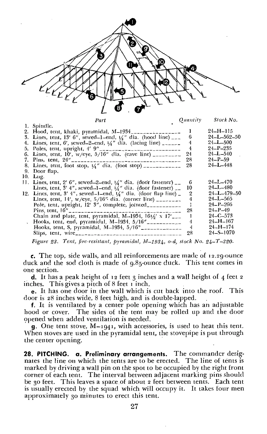
Part Quantity
1. Spindle.
2. Hood, tent, khaki, pyramidal, M-1934___________________ 1
3. Lines, tent, 13' 6", sewed-l-end, \/4" dia. (hood line)_ G
4. Lines, tent, 6', sewed-2-end, (4" dia. (lacing line)____ 4
5. Poles, tent, upright, 4' 9"___________________________________ 4
6. Lines, tent, 10', w/eye, 5/16" dia. (eave line)______________ 24
7. Pins, tent, 24"_________________________________________ 28
8. Lines, tent, foot stop, J4" dia. (foot stop)_________________ 28
9. Door flap.
10. Lug.
II. Lines, tent, 2'6", sewed—2-end, i%" dia. (door fastener)_ 6
Lines, tent, 3' 4", sewed-l-end, t/4" dia. (door fastener)_10
12. Lines, tent, 3' 4'', sewed-l-end, i%" dia. (door flap line) _ 2
Lines, tent, 14', w/eye, 5/16" dia. (corner line)____________ 4
Pole, tent, upright, 12' 3", complete, jointed__________ 1
Pins, tent, 16"_________________________________________ 28
Chain and plate, tent, pyramidal, M—1934, 161/4' x 17'__ 1
. Hooks, tent, end, pyramidal, M-1934, 5/16"________________ 4
Hooks, tent, S, pyramidal, M-1934, 5/16"________________ 4
Slips, tent, wire_______________________________________ 28
Stock No.
24-H-115
24-L-562-50
24-L-500
24-P-235
24-L-540
24-P-59
24-L-448
24-L-470
24-L-480
24-L-479-50
24-L-565
24-P-266
24-P-49
24-C-573
24-H-I67
24-H-174
24-S-1070
Fig ure 23. Tent, fire-resistant, pyramidal, M-1934, o-d, stock No. 24—T—320.
c. The top, side walls, and all reinforcements are made of ia.2g-ounce
duck and the sod cloth is made of g.Sg-ounce duck. This tent comes in
one section.
d. It has a peak height of 12 feet 3 inches and a wall height of 4 feet 2
inches. This gives a pitch of 8 feet 1 inch.
e. It has one door in the wall which is cut back into the roof. This
door is 28 inches wide, 8 feet high, and is double-lapped.
f. It is ventilated by a center pole opening which has an adjustable
hood or cover. The sides of the tent may be rolled up and the door
opened when added ventilation is needed.
g. One tent stove, M— ig4i, with accessories, is used to heat this tent.
When stoves are used in the pyramidal tent, the stovepipe is put through
the center opening.
28. PITCHING, a. Preliminary arrangements. The commander desig-
nates the line on which the tents are to be erected. The line of tents is
marked by driving a wall pin on the spot to be occupied by the right front
corner of each tent. The interval between adjacent marking pins should
be 30 feet. This leaves a space.of about 2 feet between tents. Each tent
is usually erected by the squad which will occupy it. It takes four men
approximately 30 minutes to erect this tent.
27
b. Procedure. (i) Spread canvas. Spread the tent on the ground
which it is to occupy, door to the front. Lace the corners of the tent wall,
tie the door fasteners, ahd place the right front corner foot stop over the
corner pin already driven.
(2) Drive left front corner wall pin. Carry the left front corner foot
stop as far to the left as it will go and drive a short pin through it in line
with the right corner pin already driven.
(3) Drive rear corner wall pins. Pull the rear corner foot stops to the
rear and outward, so that the bottom of the rear wall of the tent will
stretch to complete the square. Then drive the pins through these foot
stops with each rear corner pin directly to the rear of its corresponding
front corner pin, forming the square. Unless the canvas is wet, allow a
small amount of slack before driving the corner pins.
(4) Adjust center pole and hood. Have three men crawl under the
tent and fit the center pole into the plate of the chain and plate assembly.
Adjust the hood.
(5) Raise tent. With a man steadying each corner line, have the men
underneath the tent, raise the tent.
(6) Adjust corner lines. Place the four corner lines over the lower
notches of the large pins, which are driven in prolongation of the diag-
onals at such distances as to hold the walls and ends of the tent vertical
and smooth when the eave lines are drawn taut.
(7) Insert side-wall upright poles. Place the four side-wall upright,
poles, one at each corner, in a vertical position with the spindle inserted
through the grommet in the tent.
(8) Drive remaining pins and adjust lines. Drive a small wall pin
through each remaining foot stop and a large pin for each eave line in
line with the four corner-line pins already driven. Place the eave lines
over the lower notches of the large pins and draw all the lines taut.
29. STRIKING, a. Remove pins. Remove all pins except those of the
four corner lines and the two rear corner wall pins. Pile them, or place
them in a container.
b. Remove the four side-wall upright poles.
c. Lower tent. With one man holding each corner line, slowly lower
the tent to the rear. Fasten the poles together and collect the remaining
pins.
30. FOLDING, a. Procedure for each tent. (1) Pull canvas smooth.
Pull the back wall and top canvas out smooth. This is done by leaving
the rear corner wall pins in the ground with the foot stops attached. One
man at each corner line and one or two men holding the chain and plate
assembly perpendicular, pull the canvas to its limit away from the former
front of the tent. This places the three remaining sides of the tent on
top of the rear side, with the door side in the middle.
(2) Straighten right side of tent. To straighten the right side wall and
top canvas, carry the right front corner over and lay it on the left front
corner. Pull the canvas smooth and the bottom edges even. Throw the
eave lines toward the chain and plate’assembly. Return the right front
corner to the right in order to cover the right rear corner. This folds the
right, side of lhe tent on itself with a crease in the middle. This fold will
now be under the front side of the tent.
(3) Straighten left side of tent. To straighten the left side wall and
28
lop canvas, carry the left front corner to the right and rear in a similar
fashion. This will leave the front and rear sides of the tent lying smooth,
and flat and the two side walls folded inward, each on itself.
(4) Make sure the sod doth is folded under all around the tent.
(5) Fold tent lengthwise. Fold in the bottom of the wall approxi-
mately 1 foot. Fold the chain and plate assembly downward toward the
bottom of the tent. Place the hood on the chain and plate assembly. The
tent is now folded with the chain and plate assembly as a core, all folds
being placed down flat and smooth and parallel to the bottom of the lent.
If each fold is compactly made and the canvas is kept smooth, the last
fold will exactly cover the lower edge of the canvas.
(6) Arrange lines on tent. Lay all the exposed eave lines, except the
two on the center panel, along the folded canvas. Pull these two out
and away from the bottom edge to their extreme length so that they
may be used later for the final tying of the bundle.
(7) Complete folding of bundle. Fold the bundle from one end
toward the center at the first seam (that is, the seam joining the first
and second panels). Fold the bundle again toward the center so that
the canvas already folded will come within about 3 inches of the middle
panel. Fold the bundle once again to the far seam of the middle panel.
Starting from the opposite end of the bundle, fold the first panel width
in half. Fold this again. This will bring it about 4 or 5 inches from
the part of the tent already folded from the first end. Throw this second
fold completely over the part already folded.
(8) Tie bundle. Draw the exposed eave lines taut toward and across
one another so that they are at right angles. Turn the bundle over on
the eave lines. Cross the lines again on the new top of the bundle.
Turn the bundle over again on the crossed lines and tie the lines with
a slipknot.
b. Bundle. (1) When properly tied and pressed together the bundle
will be about 11 by 23 by 34 inches.
(2) The unit designation, stenciled on the upper half of the middle
width of canvas in the back wall, will appear on the exposed top of
the bundle,
Section III. TENT, FIRE-RESISTANT, COMMAND POST, M-1942 O-D
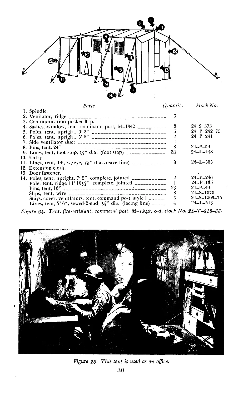
31. PURPOSE. This tent (fig. 24) is used in theatres of operation to pro-
vide office shelter for stall sections of the several command echelons.
(See fig. 25.) It will eventually take the place of the small wall tent.
The command post tent is constructed so that it may be completely
blacked out, and for this reason it may be safely used in the combat
area without fear of observation. When necessary, this tent may be used
for the quartering of two officers.
32. CHARACTERISTICS, a. This tent is 7 feel wide, 11 feet 101/9 inches
long, and 7 feet high.
b. The floor space is 84 square feet.
c. The tent has an entry 26 inches wide which extends along one end
and partly along one side.
d. The top, side walls, and all reinforcements are made of i2.2g-ounce
duck and the sod cloth is made of 9.85-ounce duck. This tent comes in
29
Stock No.
Parts Quantity
1. Spindle.
2. Venilaior, ridge___________________________________________ 3
3. Communication pocket flap.
4. Sashes, window, lent, command post, M-1942 ________________ 8
5. Poles, tent, upright, 6' 2"________________________,1______ 6
6. Poles, tent, upright, 5' 8"________________________________ 2
7. Side ventilator duct_______________________________________ 4
8. Pins, tent, 24"____________________________________________ 8'
9. Lines, tent, foot stop, %" dia. (foot stop)________________ 23
10. Entry.
11. Lines, tent, 14', w/eye, A" dia. (eave line)______________ 8
12. Extension cloth.
13. Door fastener.
14. Poles, tent, upright, 7' 2". complete, jointed____________ 2
Pole, tent, ridge II' lOi/j", complete, jointed____________ I
Pins, tent, 16"_____:________________________;_____________ 23
Slips, tent, wire__________________________________________ 8
Stays, cover, ventilators, tent, command post, style I_____ 3
Lines, tent, 7'6”, sewed-2-end, i/" dia. (lacing line)_____ 4
24-S-575
24-P-242-75
24-P-241
24—P-59
24-L-448
24-L-565
24-P-246
24-P-I35
24-P-49
24-S-1070
24-S-1263-75
24-L-513
Figure 24- Tent, fire-resistant, command post, M-1942, o-d, stock No. 24—T—318-33-
Figure 25- This tent is used as an office.
30
one section, the entry being attached. There is an extension cloth on
the rear end wall which makes it possible to combine two command
post tents when a larger tent is desired.
e. It has a ridge height of 7 feel and a wall height of 6 feet. This gives
a pitch of 1 foot. This makes an almost flat top with just sufficient
pitch to shed water.
f. There are twodoors, one at each end of the tent. They are formed
by slits in the middle of the encl sections which are overlapped.
g. It has four 18-inch square windows made of flexible glass material.
These windows are attached to the tent by snaps. Each window has
a flap which, when rolled up, is held in place by means of tie tapes,
and when rolled down, is held by means of snap fasteners. These flaps
are necessary for use in a blackout. An extra set of four windows is
issued with each tent. These are kept in the spare sash pocket located
on the inside of the front end wall.
h. There are two circular sleeves, one in each side wall, through which
messages are dropped into the tent. These are located between the
two windows on either side. They have canvas flaps which hang down
and cover the openings. The circular sleeves are inside the tent. The
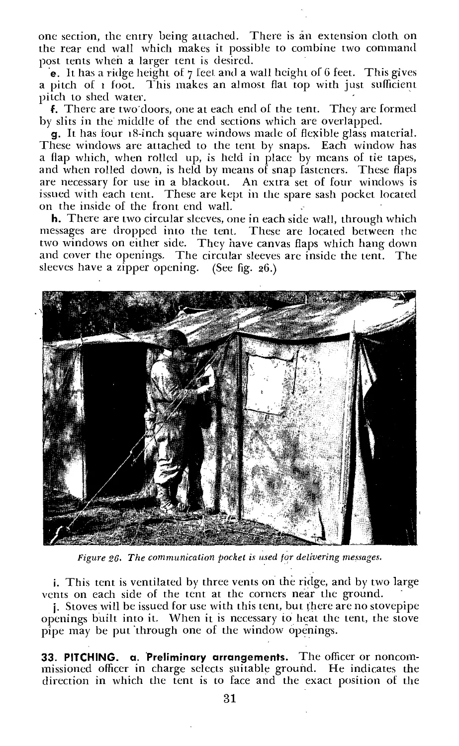
sleeves have a zipper opening. (See fig. 26.)
Figure 26- The communication pocket is used for delivering messages.
i. This tent is ventilated by three vents on the ridge, and by two large
vents on each side of the tent at the corners near the ground.
j. Stoves will be issued for use with this tent, but there are no stovepipe
openings built into it. When it is necessary to heat the tent, the stove
pipe may be put through one of the window openings.
33. PITCHING, a. Preliminary arrangements. The officer or noncom-
missioned officer in charge selects suitable ground. He indicates the
direction in which the tent is to face and the exact position of the
31
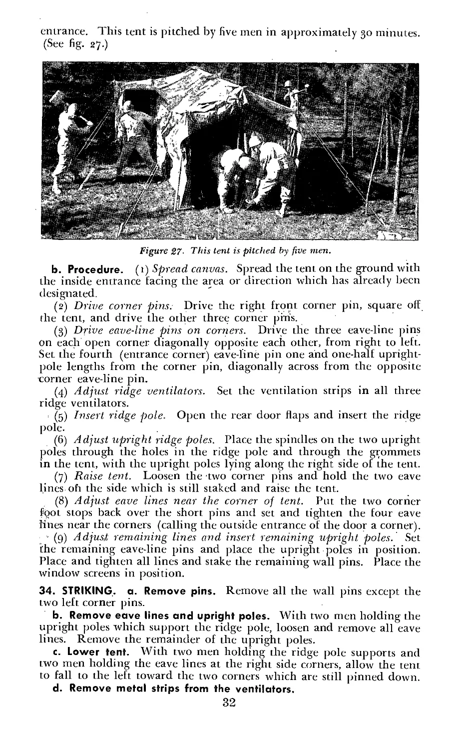
entrance. This tent is pitched by five men in approximately 30 minutes.
(See fig. 27.)
Figure 27- This tent is pitched by five men.
b. Procedure. (1) Spread canvas. Spread the tent on the ground with
the inside entrance facing the area or direction which has already been
designated.
(2) Drive corner pins. Drive the right front corner pin, square off
the tent, and drive the other three corner pin's.
(3) Drive eave-line pins on corners. Drive the three eave-line pins
on each open corner diagonally opposite each other, from right to left.
Set the fourth (entrance corner) eave-line pin one and one-half upright-
pole lengths from the corner pin, diagonally across from the opposite
corner eave-line pin.
(4) Adjust ridge ventilators. Set the ventilation strips in all three
ridge ventilators.
(5) Insert ridge pole. Open the rear door flaps and insert the ridge
pole.
(6) Adjust upright ridge poles. Place the spindles on the two upright
poles through the holes in the ridge pole and through the grommets
in the tent, with the upright poles lying along the right side of the tent.
(7) Raise tent. Loosen the two corner pins and hold the two eave
lines oh the side which is still staked and raise the tent.
(8) Adjust eave lines near the corner of tent. Put the two corner
foot stops back over the short pins and set and tighten the four eave
lines near the corners (calling the outside entrance of the door a corner).
’ (g) Adjust remaining lines and insert remaining upright poles. Set
the remaining eave-line pins and place the upright poles in position.
Place and tighten all lines and stake the remaining wall pins. Place the
window screens in position.
34. STRIKING, a. Remove pins. Remove all the wall pins except the
two left corner pins.
b. Remove eave lines and upright poles. With two men holding the
upright poles which support the ridge pole, loosen and remove all eave
lines. Remove the remainder of the upright poles.
c. Lower tent. With two men holding the ridge pole supports and
two men holding the eave lines at the right side corners, allow the tent
to fall to the left toward the two corners which are still pinned down.
d. Remove metal strips from the ventilators.
32
35. FOLDING, a. Straighten canvas. Pull the ridge corners away from
the pinned down side so that the bottoms of the side walls arc even, the
sod cloth folded under, and the ends of the tent forming a triangle to
the left and right.
b. Remove two remaining corner pins.
c. Fold entrance. Fold the outside entrance across the tent side.
d. Place the loose-side eave lines on the tent.
e. Fold the tent lengthwise. Grasp each corner of the ridge and fold
i he tent lengthwise to a position t foot from the bottom of the wall.
Fold in the bottom of the wall approximately t foot.
f. Place remaining lines on tent. Place all loose eave lines still show-
ing, except the second from each end, on the tent fold.
g. Complete folding. Fold each end over almost to the center and
then fold together, making a neat bundle approximately 15 x 28 x 30
inches.
h. Tie bundle. Tie the bundle using the two eave lines which were
left loose for this purpose.
Section IV. TENT, FIRE-RESISTANT, HOSPITAL WARD, O-D,
6-FOOT 2-INCH DOOR
36. PURPOSE. This tent is used as a section of a field hospital. It is
standard equipment for clearing companies, surgical hospitals, evacua-
tion hospitals, convalescent hospitals, and certain veterinary installations.
Its capacity is 20 canvas cots or 25 litters. It replaces an earlier model
which will be issued until the present supply is exhausted. For all
practical purposes the two tents are-the same except that the doors
are no longer cut back into the tent. This new model has two 6-foot
2-inch vertical doors. (See fig. 28.)
37. CHARACTERISTICS, a. This tent is 16 feet wide, 50 feet long, and
12 feet high.
b. The floor space is 800 square feet.
c. It is hip-roofed, has square ends, and is rectangular in shape.
d. The top, side walls, and all reinforcements are made of 12.29-ounce
duck and the sod cloth is made of 9.85-ounce duck.
e. This tent has a ridge height of 11 feet and a wall height of 4 feet
6 inches. This gives a 6-foot 6-inch pitch.
f. It has two 6-foot 2-inch vertical doors which are located in the center
of each end section.
g. A fly, which measures 26 feet 1/2 inch by 53 feet, 111/9 inches is
available for issue with this tent in theaters of operations. It will not
be issued in the continental United States except for tents used to house
patients.
h. The tent is ventilated through round holes at the top of the center
poles, through the stovepipe openings when not in use with the stove,
and through the doors at either end of the tent.
i. Three tent stoves, M—1941, with accessories, are provided for use
with 1 his tent. There are three stovepipe openings built into this tent.
They are all located on one side of the ridge line and are protected by
means of canvas flaps.
33
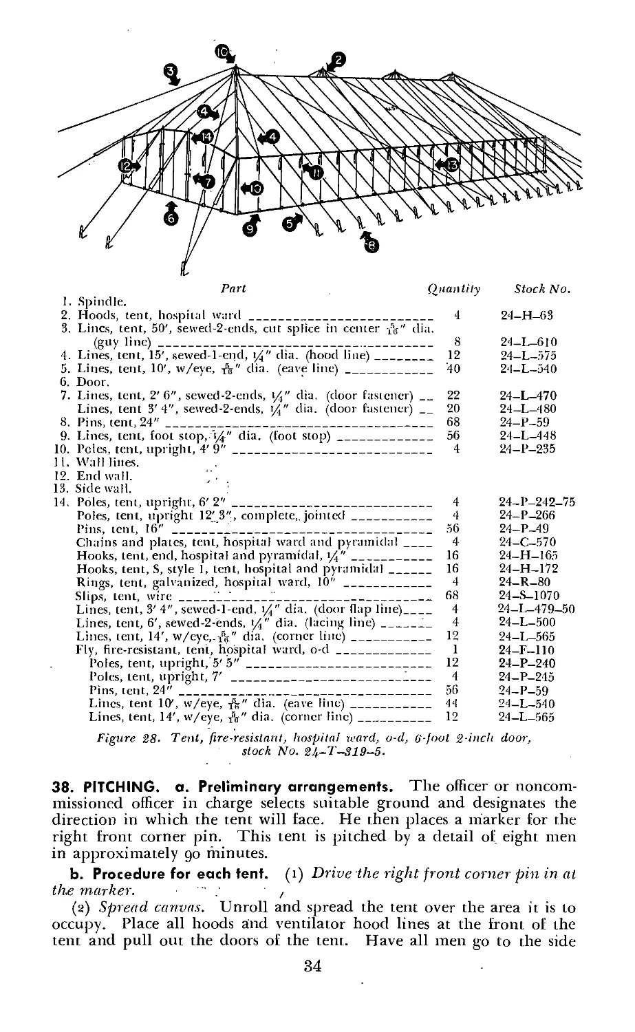
Part Quantity Stock No.
1. Spindle.
2. Hoods, tent, hospital ward________________________________ 4 24-H-63
3. Lines, tent, 50', sewecl-2-ends, cut splice in center -ft" dia.
(guy line)_____________________________________________ 8 24-L-610
4. Lines, tent, 15', sewed-l-end, i/" dia. (hood line)________ 12 24-L-575
5. Lines, tent, 10', w/eye, dia. (eave line)__________________ 40 24-L-540
6. Door.
7. Lines, tent, 2'6", sewed-2-ends, 1Д" dia. (door fastener) __ 22 24-L-470
Lines, tent 3'4", sewed-2-ends, %" dia. (door fastener)_ 20 24-L-480
8. Pins, tent, 24"____________________________________________ 68 24-P-59
9. Lines, tent, foot stop,n/t" dia. (foot stop)_______________ 56 24-L-448
10. Poles, tent, upright, 4'9"_________________________________ 4 24-P-235
11. Wall lines.
12. End wall.
13. Side wall.
14. Poles, tent, upright, 6' 2"________________________________ 4 24-P-242-75
Poles, tent, upright 12'3", complete,, jointed______________ 4 24-P-266
Pins, tent, 16"___________________________________________ 56 24-P-49
Chains and plates, tent, hospital ward and pyramidal______ 4 24-C-570
Hooks, tent, end, hospital and pyramidal, %"_______________ 16 24-H-165
Hooks, tent, S, style 1, tent, hospital and pyramidal_____ 16 24-H-172
Rings, tent, galvanized, hospital ward, 10"_________________ 4 24-R-80
Slips, tent, wire_____”___’_______________________________ 68 24—S-1070
Lines, tent, 3' 4", sewed-l-end, %" dia. (door (lap line)_ 4 24-L-479-50
Lines, tent, 6', sewed-2-ends, J4" dia. (lacing line)_____1_ 4 24-L-500
Lines, tent, 14', w/eye,.-ft" dia. (corner line)___________ 12 24-L-565
Fly, fire-resistant, tent, hospital ward, o-d_______________ 1 24-F—110
Poles, tent, upright, 5'5"_______________________________ 12 24-P-240
Poles, tent, upright, 7' __________________________1____ 4 24-P-245
Pins, tent, 24"__________________________________________ 56 24-P-59
Lincs, tent 10', w/eye, dia. (eave line)______________ 44 24-L-540
Lines, tent, 14', w/eye, dia. (corner line)____________ 12 24-L-565
Figure 28. Tent, fire-resistant, hospital ward, o-d, (>'-foot 2-inch door,
stock No. 2U-T-319-5.
38. PITCHING, a. Preliminary arrangements. The officer or noncom-
missioned officer in charge selects suitable ground and designates the
direction in which the tent will face. He then places a marker for the
right front corner pin. This tent is pitched by a detail of eight men
in approximately go fninutes.
b. Procedure for each tent, (i) Drive the right front corner pin in at
the marker. ,
(2) Spread canvas. Unroll and spread the tent over the area it is to
occupy. Place all hoods and ventilator hood lines at the front of the
tent and pull out the doors of the tent. Have all men go to the side
34
of the tent, grasp the wall which is on top, anil pull it to the left so
that the inner surface of the tent is on the ground. Then have the
men drop the wall, walk to the other side, grasp the other side of ’the
wall, and pull it into position so that the right front corner wall foot
stop can be put on the right front corner pin.
(3) Tie doors. Tie the doors by overlapping the folds and insert a
short pin through the foot stops on each side of the junction of the
door.
(4) Drive left front corner pin. Insert the short pin through the
left front corner foot stop and ptdl the front of the tent taut. When the
officer or noncommissioned officer in charge aligns the tent, move the
pin in 16 inches toward the right front corner for slack, and drive it in.
(5) Drive left rear corner pin. Stretch the tent to the left and rear
to the fullest extent and insert a short pin through the left rear corner
foot stop. Move the left rear corner foot stop 8 inches toward the
center of the tent, and drive the pin in.
(6) Unroll hoods and ventilator hood lines.
(7) Drive remainder of pins. Secure pins for the sides and ends of
the tent, long pins for each eave line along the eave-pin line and short
pins for the others. The position of the corner-line pins is four and
one-half long-pin lengths from the corner pins and in line with the
eighth foot stop of the opposite side of the tent. Drive the wall pins
straight into the ground, one for each foot stop. ‘In driving the eave-
line pins, drive one in line with each foot stop and on the line of eave-
line pins which extends between all corner-line pins.
(8) Adjust guy lines. Place the guy lines, fully slackened and in
proper order, under the second notch of the guy pins. Make certain
that the correct line—the one sewed into the canvas and extending to
the chain and plate assembly—is used as the corner guy line.
(g) Untie the doors and remove the four corner foot stops from the
corner wall pins.
(10) Insert center poles. Insert the center poles through their respec-
tive chain and plate assemblies, pulling the butt of the pole through
the assembly first, and then pushing the spindle back through the hole
in the center of the plate. Do this while the tent is flat on the ground
and the poles are in a horizontal position.
(11) Place the hoods on their poles with the openings to the left and
secure and place the two ventilator hood lines over the spindle of the
pole.
(12) Raise tent. Have all men go under the tent and raise each pole
about 4 feet. (The officer or noncommissioned officer in charge checks
the ventilator hood, and guy lines on each pole before the tent is
raised.) Raise the tent by elevating the poles to a vertical position, one
man raising each pole while another man walks forward to a position
directly under the chain and plate assembly, keeping the bottom of the
pole on the ground.
(13) Adjust lines. As soon as the tent is raised, place the corner lines
over the corner-wall pins and tighten them. Place all foot stops and
eave lines over appropriate pins without tightening.
(14) Place the corner wall poles and door poles in position.
39. STRIKING, a. Remove all foot stops and pull all wall pins except
those at the right front and right rear corners.
35
Stock No.
Part Quantity
1. Ferrule.
2. Blocks and hoisting line.
3. Poles, tent, upright. 21'___________________________________ 3
4. Rings, tent, galvanized, assembly, with 3 loops. 10"
(bail ring)____________________________________________________ 3
5. Lines, tent, 52'. w/tliimblc and hook, t/4'' dia (guy line)_ 9
6. Lines, tent, 18' 6", sewed-1-end, 1/9" dia. (eave line)_____ 30
7. Stovepipe openings___________________________________________ 4
8. Door openings________________________________________________ 4
9. Pins, tent, 36"____________________________________________ 40
10. Side wall.
II. Poles, lent, upright. 8'3"_________________________________ 30
12. ’Lines, tent, 27', scwcd-l-end, 1/" dia. (lacing line, extension
cloth) _______________________________________________________ 6
13. Extension cloth.
14. Curtain.
Blocks and tackle, tent, assembly___________________________ 3
Chains and hooks, lent, assembly____________________________ 3
Hooks, tent, wall, section assembly_________________________ 64
Lines, tent, 3' 4", scwcd-l-end. (4" dia. (wall tic line)___ 36
Lines, tent, 4' 7", sewed-l-end. 3/s" dia. (tie line)_______ 12
Lines, tent, 6', scwed-l-end, >/[" dia. (wall tie line)_____ 4
Lines, tent, 6', sewed-l-end, i/2" dia. (lacing line, neck center
section)___________________________________________________ 4
Lines, tent, 12', sewed-2-end, 1/" dia. (lacing line, neck end
section)___________________________________________________ 2
Lines, tent, 6' 2", sewed-l-end, t/(" dia. (jumper line)____ 30
Lincs, tent, 85', sewcd-l-cnd, i/2" dia. (hoisting line)____ 3
Thimbles, tent, malleable iron, galvanized, lyj" ________ 52
Thimbles, tent, malleable iron, galvanized, 2t/"_________ 21
Thimbles, tent, malleable iron, galvanized, 3"____________ 4
24-P-295
24-R—70
24-L-6II
24—L—580—85
24-P-65
24-P-24 9
24—L-582-50
19-B-13035
24-C-560
24—H—180
24—L—4 79-50
24-L-4 90-85
24-L-499
24—L—4 99-25
24—L—551—50
24-L-503-50
24-L-620
24—T—.337—25
24-T-3.37-.33
24-T-337-45
Figtire 29- Tent, fire-resistant, assembly, o-d, tent only, stock No. 2b-T-318.
36
b. Remove the corner wall poles and door poles and carry them and
also the short pins to the front of the tent.
c. Slacken all guy lines fully and untie all ventilator hood lines.
d. Have all men go into the tent and move the bottoms of the poles
about 24 inches to the left.
e. Have one person grasp the inner rope of the ventilator hood line
ready to pull the hood from the pole when the tent is struck.
f. Carry the poles to the left, out under the left side of the tent. Carry
the poles to the front of the tent and pile them.
g. Drop the hoods.
h. Remove all of the long pins, disengaging the eave lines from the
pins. Remove the pins in the same order they were driven (leaving
just the right front corner wall pin and right rear corner wall pin), and
bring them to the front of the tent.
i. Roll up the hoods and ventilator hood lines and bring them to the
front of the tent.
40. FOLDING, a. Drag the tent to the right as far as the two remain-
ing wall pins will permit. This action folds the tent with the inner
surfaces together.
b. Pull the remaining corner wall pins out.
c. Straighten out the door and the walls of the tent and fold the sod
cloth under.
d. Have all men walk in toward the center of the tent drawing the
doors in.
e. Have all men go to the bottom of the tent and, grasping the walls,
fold them inward until the inside of the eave seam is exposed.
f. Have all men now go to thejop of the tent, grasp it, and make two
18-inch folds, bringing the top of the tent to the edge of the upturned
wall.
g. Throw in all guy lines (except the front four), the hood lines, and
the ventilator hood lines. Distribute them along the tent.
h. Have the entire detail fold the top folds under the walls.
i. Force out all the air within the tent by taking short steps down
the tent.
j. Fold the tent into a drum-shaped roll starting from the rear.
k. Using the four loose guy lines, secure the tent roll by crossing the
lines at right angles about the roll. Tie with a slipknot.
Section V. TENT, FIRE-RESISTANT, ASSEMBLY, O-D,
TENT ONLY
41. PURPOSE. This tent (fig. 29) is authorized for the use of chaplains
in the field, but is also used for the showing of movies, for lectures, for
storage, for truck maintenance, or for any other purposes authorized
by the commanding officer. It has a seating capacity of approximately
five hundred. If the tent is used for quartering perormel it has an
approximate capacity of eighty.
42. CHARACTERISTICS, a. This tent is 40 feet wide, 80 feet long, and
18 feet high.
b. The floor space is approximately 2,857 square feet.
37
c. It is a circus-type tent, with a rectangular-shaped center section and
rounded ends, which are hip-rbofed. The top is made in four sections
which lace together. There are two rounded end sections and two center
sections. The side wall, comes in four sections.
d. The top is made of 12.29-ounce duck and the wall sections and the
curtains are made of g.8j-ounce duck. This tent does not have a sod
cloth.
e. The three main center-poles are 21 feet in length and the wall
height is 8 feet. When the peaks or bail rings are set by means of block
and tackle, the height from the ground to the top of the tent ridge
will be 18 feet, with the additional 3 feet of the main poles sticking up
above the top to accommodate the block arid tackle. This gives the
tent a pitch of 10 feet.
f. This tent has four entrances, each of which is made by the overlap-
ping of a panel and a half of.side wall where two sections of the side wall
meet. These side walls may be shifted so that the openings may come
anywhere as long as the same proportionate distance between the open-
ings is maintained. However, the walls must always be started at a pole
and end between the poles.
g. There are four built-in ventilators, one to each piece of side wall.
The tent may also be ventilated by rolling up the side walls and tying
them with the attached tie tapes, or if it is raining, by extending the
side wall and tying it to the lines running from the eaves. The four
doors may also be tied.ba<;k and the openings used for ventilation.
h. Four'M—1941 tent stoves are used to heat this tent. The built-in
ventilators are used as stovepipe openings wheri stoves are being used.
Figure 30. Pin and pule lay-oul.
38
43. PITCHING, a. Preliminary arrangements. The officer or noncom-
missioned officer in charge selects suitable ground and designates the
direction in which the tent will face. He then places a marker for the
front center guy-line pin. This tent is pitched by a detail of eight men
in approximately 90 minutes. The pin and pole lay-out (fig. 30) should
be followed closely in the following procedure. If measuring devices
are absent, pacing the distance off will be satisfactory.
b. Procedure for each tent. (1) Drive guy-line pins. Lay out and
drive the outer line of guy-line pins. There are nine of these, three for
each main center pole.
(2) Drive eave-line pins. Lay out the 30 eave-line pins, and be sure
that when these are driven they are perpendicular and that the top of
each pin is no more than 10 inches from the ground.
(3) Spot center pole and prepare for erection. - Spot the three main
center poles and place a marker at each location. Attach all rigging,
which consists of three main top guy lines and one set of block and
tackle for each pole. While these poles are still lying on the ground,
insert the butt of the pole through the bail ring and attach the ring of
the bail ring assembly to the hook of the single block. Lash this into
position approximately 1 foot from the ground by using the drift line
of the tackle. At this point the three main poles will be lying on the
ground running perpendicular to the eave-line pins on one side of the
tent area.
(4) Raise front center pole, (a) Allocate personnel. Place one man
at the butt of the front center pole, one man at the head of the pole,
and one man at each of the three guy lines. One of these guy lines
leads to the outside pin on the direct center line of the long dimension
of the tent lay-out. This would place the man handling the line directly
in line with the man at the butt of the pole.
(b) Place base of pole in position. Have the man at the head of the
pole raise it high enough for the man at the butt of the pole to get a
purchase on it so that by holding it with his foot he may place the pole
in the position designated by the marker.
(c) Raise pole to vertical. After the pole reaches such a height that
it might swing off center, have the other two men holding guy lines
spread out slowly to keep the pole balanced until it is in a perpendicular
position. When this is completed, the three guy lines will be located
at approximately 120° from each other and will extend 6 feet beyond
the position of the eave-line pins.
(5) Raise two other center poles. The next main pole in line is
erected in the same manner as above, with the exception that when the
two guy lines in the rear of the pole are set, they should be 26 feet
Figure 31. The pins and poles axe^ erected.
39
|8 inches apart. The third main pole or end pole is erected in the
jsame manner as the first described. (See fig. 31.)
(6) Spread canvas. To spread the canvas, unfold the two parts of the
center section first and then the two end pieces. Fasten all lanyards,
both on the end and center section, to the bail rings. This is accom-
plished by passing the neck lace line around the bail ring and through
the thimbles, which are attached to the top reinforcing lines of the
tent. Lash the neck line of the round end section to the neck line of
the center section and then to the bail ring.
(7) Lace sections together. Lace together the sections of the tent from
'the ridge to the eave reinforcement line.
{ (8) Lash thimbles together. Lash the two thimbles together by means
'of the tie line which is spliced through the thimble at the end of the
eave reinforcing line on the becket side to the thimble on the grommet
side. This is spliced into the top reinforcement line on the center section,
i (g) Attach eave lines. After completing the lashings and lacings,
attach, by means of two half-hitclies, all eave lines to the pins approxi-
mately 2 feet in from the end of each line. This operation is completed
30 times, or once at each pin.
(10) Insert upright poles. Raise the canvas and slide the butt end
of the 8-foot 3-inch uprights toward the center pole. - Raise the canvas
and insert the pin of the upright through the leather reinforcement at
the point where the eave line is attached to the top. This is repeated
in 30 places.
(11) Prepare to raise canvas. Raise the peaks of the tent about 3 feet
off the ground, being sure that the drift line of the tackle assembly is
inside of the bail ring and next to the center pole. This operation is
repeated for each main centerpole. Raise the outside of the tent at the
eave reinforcing lines by drawing the upright poles to a position forming
an angle of about 6o° with the ground, with the butt of the pole pointing
toward and in line with the butt of the center pole. Fasten the jumper
line to the pole by means of two half-hitches. This operation is repeated
30 times. (After this operation is completed, the tent should present a
deep-dish or bowl effect.)
(12) Partially tighten all eave lines.
(13) Raise peaks. With the man handling the drift line standing
directly at the foot of each pole, raise the peaks or bail rings by means
of block and tackle to within 3 feet of the top of each center pole. The
three peaks of the tent should be raised at the same time.
(14) Straighten upright polesand tighten lines. Straighten all upright
poles to a perpendicular position and tighten all eave lines as much as
possible in order to eliminate wrinkles in the tent roof. (See fig. 32.)
Figure 32. The roof is erected.
40
(15) Attach side walls. Attach the side walls by hooking the wall
hooks on the top of the side walls through the wall ring chapes which
are attached 10 the top.
44. STRIKING, a. Check guy lines. Check all main pole guy lines,
being sure they are lashed to the poles and are taut.
b. Detach all side walls.
c. Adjust side pole uprights. Slant the butts of the side pole uprights
toward the butt of the center pole at a 6o° angle with the ground. (If
the weather is calm, untie the upright jumper rope. Do not untie this
rope in a high wind.)
d. Let down peaks. Let the peaks down to ground level and, as
quickly as possible, take out all side poles. Do not unfasten the cave
lines from the pins. This will keep the entire canvas area in such a
position that when sections are unlaced, there will be little difficulty
in rolling them up.
e. Untie guy lines. After the guy lines have been untied from the pins,
toss them on the canvas area, leaving out two lines on each section so
that they may be used to tie the canvas into compact bundles after
it has been properly folded anti rolled.
f. Strike center poles. To strike the center pole, place one man at
the butt of the pole and designate one person to man each of the three
guy lines. Untie all guy lines. Have two men with guy lines walk
slowly toward the center of the tent area, keeping lines taut to prevent
the pole from swaying. The man directly behind the man at the foot
of die pole walks slowly forward. This brings the pole to a horizontal
position on the ground.
g. Remove all side wall upright poles.
h. Remove all pins after disengaging all lines.
45. FOLDING, a. Unlace sections. Unlace the sections of the tent and
separate them for folding into separate bundles.
b. Fold each section lengthwise. Make a complete fold of each sec-
tion on its long axis and repeat this step, the folded edge being placed
even with the two edges of the canvas. After each fold smooth out the
canvas carefully.
c. Complete folding. Begin at one end and continue folding toward
the center of the tent, the edge of the last fold extending about one-fourth
of a seam’s width beyond the center of the last panel. Do the same
with the other end of the section and then place all of one folded end
on top of the other folded end. The sections of the side wall will be
folded in the same manner as the sections of the top. The sod cloth
should be folded under and the bottom of the wall folded in approxi-
mately 1 foot as the first fold.
d. Tie bundle. Tie each bundle with the two lines which were left
out for this purpose. Cross the two lines at right angles and wrap them
around the sides of the folded bundle. Cross them again at right angles
on the bottom side and pull them up over the ends of the tent. Insert
the end of one line through the loop of the other, pull it tight, and then
tie it with a slipknot.
41
Section VI. TENT, FIRE-RESISTANT, MAINTENANCE, SHELTER
46. PURPOSE. The maintenance shelter tent (fig. 33) was designed in
cooperation with the Ordnance Department to be used in theaters of
operations for the repair of M—3 tanks.
Part Quantity Stock No.
]. Spindle.
2. Ventilators_________________________________________________. 2
3. Lines, tent. 2'6". sewed-2-end, (4" dia. (door fastener)____ 20 24—L—470
4. Wall lines.
5. Lines, tent, 11'6". w/eye, fa" dia, (cave line)_____________ 14 24-L-550-30
6. Pins, tent, 24"_____________________________________________ 18 24-P-59
7. Lines, tent, foot stop, t/j" dia. (foot stop)_______________ 38 24—L—448
8. Heater ducts.
9. Water flaps.
10. Roof opening.
11. Upper and lower pull tabs.
12. Hookless fastener slide.
13. Roof opening extension flap.
Pins, tent, 16"_____________________________________________ 38 24-P-49
Lines, tent, 3'4", sewed-l-end, 14" dia. (door flap line)___ 4 24-L-479-50
Lines, tent, 4", sewed-l-end, 14" dia. (water flap line)____ 2 24-1 482-75
Lines, tent, 4'6", sewed-2-end, 14" dia. (door lacing line)_ 2 24-L-470
Lines, tent, 7’6”, sewed-2-end, >4" dia. (lacing line)______ 4 24-L-513
Lines, tent, 14', sewed-l -end, \/4" dia. (lower draw line)_ 2 24-L-564’-40
Lines, tent, 15', sewed-l-end, 1/" dia (opening flap lacing
line) ____________________________________________________ 1 24-L-575
Lines, tent, 17'6", sewed-l-end, 14" dia. (lacing line)_____ 2 24-L-580-20
Lines, tent, 19', sewed-l-end, (4" dia. (lacing line)_______ 2 24-L-581-25
Lines, tent, 27', unfinished-2-end, 1%" dia. (upper draw line) 2 24-L-583-2]
Lines, tent, 64', sewed-2-end, cut splice in center, &" dia.
(guy line)________________________________________________ 2 24-L-614
Frame, tent, maintenance shelter____________________________ 1 24-F-675
Figure 33. Tent, fire-resistant, maintenance shelter, stock No. 24-T-319-15.
47. CHARACTERISTICS, a. This tent is 18 feet 2 pi inches wide, 26 feet
2I/2 inches long, and J3 feet 7 inches high.
b. The floor space is 277 square feet.
c. It is an А-type, square-end tent, rectangular in shape. It is designed
to be erected over a steel frame which is supplied for this purpose.
d. The tent comes equipped with a box steel frame weighing approxi-
42
mately 500 pounds. (See figs. 34 and 35.) This frame is equipped with
floating nuts and bolts.
1. Three truss braces.
2. Three truss and end post assemblies.
3. Ridge pole frame asseipbly.
4. Four eave strut assemblies.
Figure 34- Component parts of frame, tent, maintenance shelter, slock No. 24—F—075.
1. Truss braces. 4. Ridge pole frame assembly.
2. Ridge pole knee braces. 5. Eave strut assembly.
3. Encl posts. 6. Side knee brace.
Figure 35. Box steel frame erected.
e. The top, side walls, and all reinforcements are made of t2.2g-ounce
duck. The sod cfoth, which is 2914 inches wide, is made of 9.85-ounce
duck. There are six ground sheets measuring 4 feet by 12 feet, provided
with each tent to form a floor. These are made of No. 6 duck.
f. The tent has a ridge height of 13 feet 7 inches and a wall height of
5 feet 6 inches. This gives a pitch of 8 feet 1 inch.
g. The tent is equipped with a g-foot by ю-foot opening on one end
of the roof. This opening extends from the ridge of the tent to the
eaves, and can be opened and closed by means of two 10-foot zippers.
This opening is necessary when removing or installing the vehicles’
43
engines. These operations are performed by means of a crane which
operates from outside the tent.
h. This tent is heated by a gasoline-burning heater which is set up on
the outside of the tent. The heat is forced into the tent through a large
canvas tube attached to the heater ducts provided for this purpose.'
i. The tent is equipped with two canvas ventilators, one at each end of
the tent near the ridge pole. There are also four heater ducts to
accommodate the equipment used with the heating apparatus. Two of
these heater ducts are located on the side walls at. each rear bottom
corner of the tent. When these ducts are not ijruse, they are covered
by means of canvas heater-duct flaps.
48. PITCHING. a. Preliminary arrangements. The officer or noncom-
mjssiope^ officer in charge selects suitable ground and indicates the
direction in which the tent will face. This tent, including, jhe steel
frame/if'piiched by a detail of six men in approximately 75 minifies.
b. Procedure for each tent. (1) Loy out frame. Lay out various sec-
tions of the frame in their relative positions ready for erection.
(2) Erect end sections. Spread the front and rear end sections and
attach the truss braces. Placing the section in a perpendicular position
fold under the right and left end posts so that these two pieces, to which
two side knee braces are connected, lie flat on the ground, giving the
resulting triangle an А-shaped appearance.
(3) Attach the ridge-pole frame and ridge-pole knee brace to the
end sections.
(4) Insert the center А-truss assembly.
(5) Attach the four eave strut assemblies, two to each long side.
(6) Spread canvas over frame. Unfasten the doorways of the tent,
both front and rear, and spread the top of the tent over the ridge pole,
being sure that the grommets in the deck at the ridge are centered over
the spindles on the ridge pole. This will give an А-shaped tent with
the side walls lying loosely on the ground and the peak of the tent
approximately 7 feet from the ground. (See fig. 36.)-
Figure 36' Pitching the tent; the tent assumes an “A” shape.
(7) Lash canvas to frame. Inside the tent make all lashings around
various sections of the frame structure, using for this purpose the lace
lines which are held by the canvas lugs sewed to the tent.
(8) Raise sides of lent. After securely fastening all lace lines, proceed
to the outside of the tent, all members of the erecting crew going to
one of the sides of the tent with two men to each end post. Raise this
side to the full 5-foot б-inch height of the side wall and secure the side
44
knee braces. (See fig. 37.) Duplicate this operation on the opposite
side of the tent.
Figure 37. Pitching the tent; a side wall is raised.
(g) Drive in all pins and secure the eave lines.
(to) Line tip the side wall and secure it with the small-sized pins
through the side wall foot stops.
49. STRIKING, a. Unfasten all eave lines and remove all pins including
side wall foot stop pins.
b. Loosen side line braces and lower one side so that the side wall is
lying loosely on the ground. Repeat this operation with the opposite
wall. This will bring the tent back to the position shown in figure 36.
c. Untie the lace lines and remove all lashings from around the various
sections of the frame structure.
d. Open the front and rear doors of the tent and slide the deck of the
canvas off the ridge pole. Carry the canvas completely away from the
frame.
e. Separate the frame by reversing the procedure used to erect it. (See
par. 48b (1) through (5).)
50. FOLDING, a. This tent is folded in the same manner that the wall
tents (par. 20) are folded.
b. The steel frame should be completely broken down into sections
and assembled for shipment. (See fig. 34.)
Section VII. TENT, FIRE-RESISTANT, SURGICAL TRUCK, O-D
51. PURPOSE. This unit (figs. 38 and 39) is designed to fit over the
body of a surgical truck. The tent is used as an emergency operating
center in forward combat areas.
52. GENERAL FACTS, a. This tent is 22 feet wide, 2G feet long, and
to feet high.
b. ft has a floor space of 481 square feet.
c. ft is rectangular in shape.
d. The top, side walls, and all reinforcements are made of 12.29-ounce
duck and the sod cloth is made of g.85-ounce duck.
e. This tent has a ridge height of 10 feet and a wall height of 5 feet
6 inches. This gives a pitch of 4 feet 6 inches.
45
Stock No.
, Part Quantity
1. Tank opening cover.
2. Hood.
3. Lincs, tent, 20'6", sewed-l-end, dia. (ridge tic line)_____ 2
4. Awnings____________________________________________________ 2
5. Lines, tent, 14', sewed-l-end, i/J" dia. (awning tie line)_ 4
6. Retaining straps.
7. Poles, tent, upright, 5' 8"________________________________ 10
8. Curtain, lower front, blackout
9. Curtain, upper front, blackout
10. Lines, tent, 1Г6-", w/eye, 7k" dia. (cave line)___________ 12
11. Pins, tent, 24"___________________________________________ 12
12- Lincs, tent, foot stop, i%" dia. (foot stop)______________ 22
Curtain, rear blackout.
Pins, tent, 16"____________________________________________ 22
Slips, tent, wire__________________________________________ 12
Lines, tent, 7'6", sewed-2-end, dia. (lacing line)_________ -I
Lincs, rent, 9'( sewed-l-end, 1/ dia. 4
(upper front blackout curtain draw line 1 i
and rear blackout curtain tie line)______________________ 1J
Lincs, tent, 10’ 6". sewed-l-end, dia. (front blackout flap
tie line)_____________________________________)__________ 1
21—L-581- 45
24—L—561—40
2*1—P—2-11
24-L-550-30
24-P-59
24-L-448
24-P-49
24-S-1070
24-L-513
24-L-529
24-L-543-45
Figure 38- Tent, fire-resistant, surgical truck', o-d, stock No. Si—T—SSl—iO-
Figure 39- Side view of the tent, fire-resistant, surgical truck, o-d.
f. The truck supports the top of the tent in place of a ridge pole. The
outside edges of the tent are held in position by upright poles, eave
lines, and pins. The center front section of the tent is attached by
means of webbed straps to metal buckles on the front end of the truck
top. For extra security two guy lines are run from the ridge and tied
to metal hooks on the outside of each headlamp.
g. It has one door which is 5 feet 7i/2 inches high and 4 feet 8 inches
wide. This is located in the center of the rear (end opposite front of
truck) of the tent.
46
h. The tent comes equipped with three blackout curtains: one rear,
one upper front, and one lower front. The two front curtains are so
located that they fill in the spaces between the bottom of the body of
the truck and the ground, and the other covers the back window of
the cab of the truck. When all three curtains are attached, the tent
may operate under perfect blackout conditions.
i. There are two ventilator openings built into the tent. These are
located at the front of the tent, one on either side of the truck in the
corner at the ridge line. These are covered by canvas awnings which
are kept open by two lines each, one line attached to a headlamp and
the other to the front tent pin. (See fig. 38.)
j. It takes four men 30 minutes to erect this tent.
k. There is no stove issued for heating this tent. A hot water heater
is part of the surgical truck equipment. All operating is done in the
body of the truck. The only heat in the tent itself is that which comes
from the open back doors of the truck.
53. PITCHING, a. Preliminary arrangements. The officer or noncom-
missioned officer in charge selects suitable ground and indicates the
direction in which the tent will face. This tent is pitched by a detail
of four men in approximately 30 minutes.
b. Procedure for each tent. (1) Place the boards on the ground for
the tires of the truck to rest upon. (See fig. 38.) This will prevent the
truck from settling down into the ground.
(2) Drive the truck onto the boards which have just been put down
for that purpose.
(3) Open up the rear door flap and the front blackout curtains, and
spread the top of the tent over the top of the truck.
(4) Attach the front section of the tent to the body of the truck by
fastening the webbed straps on the tent through the metal buckles
which are attached to the truck.
(5) Tie the ridge tie lines to the metal hooks on the outside of each
headlamp.
(6) Tie the rear door flap and front blackout curtains in place.
(7) Drive in all long tent pins and secure all eave lines.
(8) Place the wall poles in position. .
(9) Line up the side wall and secure it with the small-sized pins
through the side-.wall foot stops.
(to) Attach the awning tie lines.
54. STRIKING, a. Unfasten the awning tie lines, ridge tie lines, and all
eave lines and remove all pins, including side-wall foot-stop pins.
b. Remove all side-wall poles.
c. Unfasten all parts of the front section of the tent which are directly
attached to the truck.
d. Open the rear door flap and the front blackout curtains, and slide
the deck of the canvas from the top of the truck. Carry the canvas
completely away from the truck.
55. FOLDING. This tent is folded in approximately the same manner
that the wall tents are folded. Minor modifications may be necessary
because of difference in shape. (See par. 20.)
47
Section VIII. SCREEN, LATRINE, FIRE-RESISTANT, O-D
56. PURPOSE. The latrine screen (fig. 40) is issued to units in the field
for use as an outdoor latrine.
4. Poles, tent, upright, 7'__________________________________ 7 24-P-245
5. Lines, tent, 14', w/eye, /" <lia. (guy line)______________ 7 24-L-565
6. Pins, tent, 16"__________________________________________ 8 24-P-49
Slips, tent, wire________________________________________ 8 24-S-1070
Lines, tent, 3' 4", sewed-2-encl, 14" dia. (door fastener)_ 15 24-L-480
Lines, tent, 8', sewed-l-end, -fc" dia. (tie line)_________ 1 24-L-5I4-40
Figure 40- Screen, latrine, fire-resistant, o-d, stock No. 24—S—760-
57. CHARACTERISTICS, a. It is 18 feet long, 7 feet high, and 9 feet wide
at one end and 7 feet wide at the other end. This difference in width
is for the purpose of forming a 2-foot entrance on one side of the screen.
The entrance side of the screen consists of a 12-foot section and a 9-foot
section which overlap by approximately 3 feet to give depth to the
entrance.
b. This screen is made of 9.26-ounce or 9.68-ounce duck.
58. PITCHING, a. Preliminary arrangements. The latrine screen is
pitched by a detail of six men, supervised by a noncommissioned officer,
in approximately 20 minutes. The noncommissioned officer selects suit-
able ground, indicates the direction in which the screen is to face, the
line on which it is to be placed, and the position of the inside corner
of the entrance.
b. Procedure for each latrine screen. (1) Drive a tent pin to mark the
inside corner of the entrance.
(2) Unfold and place the screen in position. Unfold the latrine screen
and place the encl having both a long and a short tie rope (as differing
from the end having two short tie ropes) near the entrance pin.
(3) Tie the short tie rope on the bottom of the screen to this pin.
(4) Lay the latrine screen on the ground following generally its final
outline. (See fig. 41.)
(5) Assemble and raise center section. Assemble a long ridge pole
and three uprights and raise them to a vertical position near the center
of the latrine screen. Hold the uprights in position and drive in two
48
center guy-line pins two paces from the front center upright (outside
door frame) and generally in prolongation of the diagonals from the
right and left rear corners of the latrine screen through the front center
upright. Drive a third guy-line pin about one pace from the rear center
upright (opposite doorway) and on line with the three uprights. Place
guy lines over these pins and over the upright spindles and tighten.
Raise the latrine screen on the outside of the inner and rear uprights
and tie it to the ridge pole with the bottom about 6 inches from the
ground.
(6) Assemble and.raise narrow end section. At the narrow end of
the screen, assemble and hold in position a short ridge pole and two
uprights. Drive in guy-line pins about two paces from the uprights
and in prolongation of the diagonals from the inner center and rear
center uprights. Attach guy lines as before. Raise the latrine screen
on the outside of the uprights and tie it to the ridge pole so that the
bottom is about 6 inches from the ground.
(7) Assemble and raise wide end section. Before assembling the long
ridge pole and uprights to form the wide end of the latrine screen, loop
the long tie line from the top of the inside corner of the entrance over
the ridge pole. Insert the spindles of the two upright poles in the
outside holes of the end ridge pole and then raise and hold in place
the uprights. Drive in the two remaining guy-line pins. The four front
(door side) guy-line pins are not all on the same line. (See fig. 41.)
Attach and tighten the guy lines on the long end. Raise the latrine
screen and tie it to the end ridge pole. Tie the outside of the entrance
to the center ridge pole.
(8) Adjust and tighten lines. Draw the long tie line from the top
of the inside corner of the entrance taut. Tie all tie lines on the lower
edge of the latrine screen to the uprights. Take any slack out of the
screen by a final tightening of the guy lines and if necessary by a slight
shifting of the upright poles.
49
59. STRIKING. To strike the latrine screen, reverse the procedure for
pitching the screen.
(t) Untie all tie lines on the lower edge of the screen from the upright
poles.
(2) Untie the outside of the entrance from the center ridge pole.
(3) Disassemble wide end. At the wide end, untie the latrine screen
and drop it to the ground. Detach the guy lines at the wide end and
disassemble the ridge pole and two uprights and place them in a pile
at one side.
(4) Disassemble narrow end. Untie the narrow end of the latrine
screen. Detach the guy lines and place the ridge pole and uprights with
the poles previously placed to one side.
(5) Disassemble center section. Follow the same procedure with the
center ridge pole. Collect the eight tent pins and seven guy lines and
place them near the ridge poles and uprights.
60. FOLDING, a. Extend the screen on the ground and smooth it out.
b. Make first two folds. To make the first fold pull one end over to
the other. 'Repeat this step, placing the folded edge even with the two
ends of the screen. (The screen can be better controlled if the first two
folds are made into the wind.) Be sure to smooth out the canvas after
each fold.
c. Continue folding. Fold either the top or bottom edge over one-
third of the width of the latrine screen. Then fold the other edge com-
pletely over the first fold.
d. Place lines on screen. Tut the tie lines and all guy lines, except
one for tying the bundle, inside the folds at one end of the screen.
e. Form final bundle. To form the final bundle, make a 2-foot fold
from each end of the screen toward the center. Repeat this step twice
leaving the two folded sections 2 or 3 inches apart. Place one folded
section over the other and the bundle is ready to be tied.
f. Tie bundle. Lay the guy line over the center of the bundle and
turn the bundle over on the line. Cross the ends of the line over the
new top of the bundle and again turn the bundle over on the crossed
lines and tie them.
50
CHAPTER 4
TENT SITE
61. SELECTION OF SITE. Great care should be exercised in selecting the
correct tent. site. Battle needs, however, may often necessitate the use
of poor camp sites. For an illustration of the good tent site see figure 3.
Important points to remember are listed below:
a. The tent should be protected from wind and storms. Do not pitch
the tent in an open field or on a ridge which offers no protection. (See
fig. 48.) If the wind is cold and it is necessary to leave one end of the
Figure 42. The poor tent site.
tent open, pitch the closed e'fttl of the tent into the wind.
b. Choose high ground, if possible, because it will be drier.
c. If possible, choose an area having tough grass turf.
d. In hot weather, a shady area free of underbrush is desirable.
e. In the woods, avoid a location directly under dead trees or trees
with large dead branches..
f. If the tent is being pitched by a river, lake, or other body of water,
place it far enough back sb that it is above the high watermark.
g. In mountainous country, avoid camping in canyons and next to dry
creek beds. Such places have been known to fill up with rushing torrents
in a remarkably short time.
h. Do not camp at the base of a cliff or steep mountainside where there
may be danger from avalanches and rockfalls.
i. Choose level ground. The ground the tent is pitched on should be
level and free from projecting roots of trees and large embedded rocks
showing above the surface. This applies to an area extending about
a foot beyond all sides of the walls, where a ditch should be dug to
carry off water during a rain. When such a spot is not available, a
51
place can often be leveled and cleared with very little work. In woods,
moss and rocks may be used to smooth out the irregularities in the
ground. It is particularly important to level the ground when pitching
a tent for sleeping purposes.
62. PITCHING A TENT IN SNOW. Before selecting a camp site on a snow-
covered glacier, prod the surface with an ice or ski pole to see whether
the snow conceals any crevasses. It may be impossible to find an area
entirely without crevasses but in order to avoid accidents their presence
should be known. When an adequate site on snow has been found,
the snow should be packed hard by stamping on it with skis or snow-
shoes or, better still, the top snow should be shoveled off until firm snow
is found below. A doorstep dug a foot below the surface of the snow
makes it easier to,get in and out of the tent, and to brush off snow.
It is important to leave some space between the sides of the tent and
any protective snow wall so that there is room to shovel out the snow
which might drift in. Such a wall must not be high if snow is likely
to drift. On any slope a horizontal platform should be formed. The
snow which is removed may be packed around the outer edge of the
platform to widen the space for the tent. The prevailing winds should
be taken into consideration. (See par. 6.)
63. TRENCHING TENT. a. GENERAL. In case of doubt as to the advisa-
bility of digging a trench around a tent, a safe rule to follow is, always
dig the trench. If the tent is set up in very sandy soil which absorbs
water as fast as it falls, or if it is located on a little mound which slopes
off in all directions, a trench may not be necessary. When the tent is
being pitched on heavy soil, clay, or a flat rocky surface, ditches should
always be dug because the surfaces of these soils hold water and will
not readily absorb rain.
b. Constructing trench, (t) Dig the trench all around the tent.
(2) Do not dig the ditch in a V-shape but cut straight down, just
outside the tent pins. Slope the side away from the tent inward toward
this dam or straight side. (See fig. 43.)
52
(3) When digging a ditch cast the dirt away; never pitch it against
the tent, for it will quickly rot the canvas.
(4) The ditch seldom needs to be more than 4 or 5 inches deep and
in the shallowest places not over 3 inches. There should be enough
slope in the ditch so that the water will flow freely toward the outlet
and not back up.
(5) At the lowest point of the area an outlet trench should be dug
and connected to the ditch which has been dug around the tent to
(6) When there is a possibility that water may flow in from higher
ground, a ditch should be dug to divert the water before it can reach
the tent.
53
CHAPTER 5
CARE OF TENTAGE
64. GENERAL. The duck fabric currently procured for tentage is treated
in such a way as to make it resistant to fire, water, weather, and mildew.
This treatment thus reduces the danger of fire from any cause, and the
danger of mildew, one of the greatest enemies of tent fabric. The
coloring pigments give a dark olive-drab shade for protective coloration
and make the material practically lightproof. This treatment adds 40
to 50 percent more weight to the basic fabric. All components of the
tent such as rope, thread, and wood are now treated with preservatives.
a. Treatment in field. Despite all the treatments which tentage re-
ceives before issue, even the best types lose their properties somewhat
after prolonged weather exposure. The life of older tentage can be
extended greatly by the use of a suitable re-treating compound, “Com-
pound, Coloring, Type 1, Color C Green,” stock No. 51—C—1598 or
“Compound, Re-treating, Water, Weather, and Mildew Resistant (For
Cotton, Duck and Webbing),” stock No. 51—C—1608. This is a mixture
of waterproofing waxes, mildew inhibitors, and coloring pigments to
give the dark olive-drab shade, all carried in a volatile (also inflammable)
solvent.
b. Continual care. The life of a well made tent will be in direct pro-
portion to the care given it.' This care must be continual in packing
for shipment, handling during shipment, unpacking, unfolding, erecting,
taking down, folding, and storing. The main factors responsible for
the damage to tentage are weather, fire, mildew, and carelessness.
65. WEATHER. Wind and rain may cause extensive damage to tentage.
Inasmuch as they have different effects on tents, personnel will be in-
structed in precautionary measures for both.
a. Rain. Rain causes the canvas and rope on the tent to shrink.
Normally the lines on the tent are drawn taut to keep the tent erect.
As soon as the lines become water-soaked they may become tight enough
to tear the tent apart. Tents have been torn completely in two under
such circumstances. There are two things that can be done to forestall
such a mishap:
(1) Have the lines sufficiently loosened at all times so that when
they lighten in wet weather they will not become tight enough to tear
the tent. To compensate for shrinkage, all eave and corner lines should
have a free swing of approximately 18 inches at the middle of the line.
This does not give the tent its best appearance, but the tent serves its
purpose and needs no adjustments, in either wet or dry weather. For
inspection purposes, tent lines may be tightened.
(2) Place blocks, to be removed in the event of rain, underneath each
upright pole. Removing the blocks automatically loosens all tent lines.
b. Wind. . In a strong wind, all lines should be immediately tightened.
Door flaps should be closed, walls should be secured to foot-stop pins,
and all corner lacings laced. Guy ropes should be tight. These pre-
cautions will cause the wind to blow around rather than into tents.
54
66. FIRE. a. General. Tentage which has been given the treatment io
make it fire-resistant will not burst into flame but will burn and char
slowly. The fact that a tent is marked “Fire-resistant” does not signify
that it will not burn. Precautionary measures are still necessary. Tent
fires are usually caused either by some individual’s carelessness or by
failure to use the spark arresters generally issued with tent stoves. Do
not neglect to use them. Clean the screen-type arrester at regular inter-
vals. Be sure that the fire in the stove is out before removing the
arrester. If spark arresters are not available they must be improvised
from a fine-mesh wire screen or other suitable material.
b. Fire extinguishers. Use only those extinguishers whose contents
are not injurious to the fabric of tents. This is important to remember
because some fire extinguishers contain acids or solvents which will ruin
lent materials. Tent areas should be provided with fire extinguishers
which contain only water, or water and a harmless antifreeze.
67. MILDEW, a. General. More good tents have probably been ruined
by mildew than by any other single agent. Mildew has been known to
ruin the best of tents in g days. Canvas is at all times inoculated with
airborne micro-organisms which are ready to cause mildew and rot if
the proper conditions prevail. The conditions favorable to the develop-
ment of these micro-organisms are found in tentage which comes in
constant contact with die soil (lower portions of tent), in tentage
dragged across muddy or damp soil, and in tentage which has been
rolled up while wet. Because of their humidity and temperature, jungles
also favor the development of mildew. Mildew inhibitors are being
used in the treatment of all tentage at die present time, but they are
still not completely effective. Experimentation in this field is being
carried on constantly.
b. How to prevent mildew. If a tent is given the proper care, mildew
will not do much damage, except in tropical areas, even when the tentage
has not been treated. Follow the rules below at all times and damage
caused by mildew will be negligible:
(i) Never roll up a tent when wet. Even if it is only damp from dew,
it will mildew when stacked away.
(2) Be positive that die following parts of the tent are dry:
(a) The seams and the edges—the bottom edge particularly—where the
material is double.
(b) The sod cloth.
c. Do not roll up tent pins and poles with the tent. Keep them
separate.
d. If a tent is pitched under trees, inspect the roof frequently to see
that no harmful effects are resulting from drippings from branches or
leaves. Keep die tentage clean at all times. The growth of fungi or
mold is dependent to some degree on the nutrients (these may exist in
the form of oil, grease, starch, tree drippings, or sizing in the fabric)
which have accumulated on the surface of the tent.
e. When a tent is to be stored away, it should be hung off the ground
in midday sunlight. If necessary, however, it may be dried indoors.
If tentage is dried inside it should be done at a normal temperature in
a well-ventilated place high enough to permit the tent to be suspended
off the floor. A tent dried on the ground or left hanging outdoors until
sundown might absorb enough dampness to give mildew a start.
55
f. In order to prevent the deterioration of tentage by mildew while in
storage, the following precautionary measures should be taken:
(i) Tentage should not be dragged along the ground or permitted
to come in contact with the ground while in storage. It should be
stacked on dunnage, supported by 2- by 4-inch lumber.
(я) If the floor is hard-surfaced or wooden, the tentage should be at
least 4 inches from the floor.
(h) If the floor is earthen, the tentage should be at least 8 inches from
the floor.
(2) Only lumber that has been thoroughly cured should be used for
dunnage, since the moisture contained in green lumber will promote
the growth of mildew.
(3) Where dampness in the atmosphere is prevalent, dunnage should
be used between each course to permit circulation of air between the
blocks. The blocks should be separated and reduced to a minimum
number of courses to permit passage of air on all four sides.
(4) Tents stacked near ventilators, which permit the entrance of
moisture, or near any other opening where moisture in the air will con-
dense and settle on the tentage, should be packed in bags or wrapped
in waterproof coverings.
(5) Tentage received from the field should not be placed in bags
until the tents are thoroughly dried and all dirt removed by stiff brushes.
If any visible signs of mildew are present, the tent should be placed in
the open air, preferably in the sun.
(6) When tentage is issued, that which has been in storage the longest
should be issued first. To prevent the issue of newly stored tentage
before the older stocks are exhausted, blocks should be marked according
to the length of time the tentage has been in storage.
(7) When tentage is stored in open sheds or in tents, it should be
stacked well away from the sides and ends of the shelter (preferably
about 20. feet) and items not affected by moisture should be stacked
between the tentage and the outer edges of the shelter.
(8) Any tentage found to be infected by mildew will be withdrawn
from storage, brushed with a stiff brush, allowed to dry thoroughly, and
issued immediately to installations where driest atmospheric conditions
prevail. If there is no opportunity for immediate issue, this infected
tentage should be segregated from the sound tentage to prevent con-
tamination. Tents which have lost all serviceability should be salvaged
or if necessary destroyed.
(g) Depending on the facilities at hand, application of the re-treating
compound (par. 6a) may be done on tentage which has been erected
or which has been spread on the ground. Where spray equipment is
available, its use is recommended provided the spray coat is brushed in
thoroughly afterwards. The compound contains inflammable solvents
and all work including the opening of the containers, should be done in
the open away from all flame. No smoking should be allowed in the
vicinity.
(a) Tentage should be dry and brushed clean.
(h) Compound should be well stirred before using to produce a
uniform mixture. Clear white gasoline may be used for dilution if
necessary.
(c) A moderate application should be made by spray or brush to the
56
outside, followed by a good brushing to attain penetration. Particular
attention should be paid to the treating of seams and of areas where
water leakage has occurred.
(d) The tentage should be thoroughly dried after treatment, allow-
ing at least 2 hours for good drying conditions and more if necessary.
The odor of solvents should have completely disappeared before the
tentage is used, or rolled for storage.
(e) The solvents contained in the compound may tend to irritate the
skin somewhat, as gasoline does. Prolonged contact should be avoided.
The use of long handles on the brushes may prove convenient.
(to) Camouflage paints do not have the preservative function of the
re-treating compound. In fact, camouflage paints other than those spe-
cifically intended for textiles may be harmful, particularly in regard to
water resistance. When it is necessary to apply camouflage paint, or to
make hospital markings on tents, use only the oleo resinate paint with
water base furnished by the Engineer Corps for camouflage purposes.
The official nomenclature of this paint is “Paint, Camouflage, Oleo
Resinous, Emulsified, T—127g.” To use this paint on tentage, mix it
only with water, never with gasoline or spirit thinners.
68. CARELESSNESS, a. General. Probably the greatest amount of dam-
age to tentage is caused by carelessness. Forgetting to loosen the lines
when it starts raining, not bothering to use spark arresters, adjusting
ropes carelessly, driving pins in a slipshod manner, dragging tents over
rough ground—all of these cause the greatest harm to tentage. A few
precautions are listed below as reminders.
b. Rules to follow. Follow the procedures for pitching, striking, and
folding the various tents described in this manual. Do not try to take
short cuts unless sure that no damage will be done. When tents are
folded according to directions, the side walls rather than the top of
the tent will be exposed. This is important in order to protect the top
of the tent during handling and in storage.
(1) Observe reasonable care when pitching and striking the tent, for
the material might tear on protruding pins, overhanging branches, or
other objects.
(2) Never drag the tent along the ground or floor.
(3) Make sure that all the necessary parts and accessories for each tent
have been issued and that they are used for their intended purposes.
(4) Pack tents carefully for shipment. Some tents are issued com-
plete with bag. In this case, be sure to carry the tent in the bag. When
no bag is issued, the tent will arrive wrapped in osnaburg or burlap.
Save this material for rewrapping when the tent has to be moved again.
Normally a tent should never be transported without a covering of
some kind.
(5) Always pack pins and poles separately from the tent itself.
(6) Inspect the tentage at frequent intervals to make sure that it is
in serviceable condition. Particular attention should be given to seams,
bindings, lines, and all places where strain is exerted. Constantly be
on the lookout for—
(«) Any evidence of mildew.
(b) Any foreign matter which may have collected on the tent.
(c) Small rips and holes, splitting of seams, grommets which have
become loose, lines which are beginning to rot, or anything else which
57
does not appear to be in a normal condition. If not stire of the serious-
ness of the condition, never hesitate to call an officer or'noncommissioned
officer for confirmation of opinion.
69. REPAIR METHODS, a. General. There are three methods used in
the repair of tents:
(t) Cement patching for minor repairs in the field.
(2) Hand sewing which is done mostly in the field whep no equip-
ment such as sewing machines, grommet-setting dies; and other essential
machinery is available.
(3) Patching, or reconstruction by the use of sewing machines. This
is done in shops only.
b. Cement patches.' (1) Materials necessary. («) Either olive-drab
or clear cement to conform to the color of the tent.
(t»i) Circular patches.
(c) A roller.
(d) Brushes.'
(2) Size of patch. Three sizes of circtdar patches are used to repair
tents as follows:
Maximum size of hole or
Patch Nd. Diameter in inches rip in inches
(Diameter or length)
1 3 4/2
2 43% 2 7%
3 61% 43%
(3) Use. (a) In selecting the size of the patch to use, a minimum
overlap of inch on all sides of the hole or rip should be allowed.
(b) Foreign material such as dirt and grease should be completely
removed from the parts of the tent to be repaired.
(c) A thin coat of cement is then applied to that portion of the tent
to be covered by the patch, and to the entire surface of the patch. The
first coat should be allowed to dry to a tacky state (it will usually take
about 5 minutes), after which a second coat is applied. While still wet,
both surfaces are pressed together by means of the roller provided for
that purpose.
c. Hand sewing. In repairing a tent by hand, where no machines are
available, needle and thread are used. These hand-sewn patches when
properly stitched will outlast a patch put on by machine. A patch
must be stitched on any hole exceeding 414 inches in diameter.
(1) Material used, (я) No. 15 sailmaker’s needle.
(b) No. 5 ply, cotton, twine.
(c) Beeswax.
(d) Sewing palm.
(e) Duck, cotton, 12.29 ounces per square yard, olive-drab, fire, water,
and weather resistant, mildew resistant treated.
(2) Procedure. Cut a piece of duck sufficiently large to overlap the
hole (at least 1 inch on all sides plus i/2 inch for turning under the
ragged edge). Use the sewing palm and a needle with two strands of
well-waxed cord. Prepare the patch by turning under the four ragged
edges approximately i/2 inch and sewing them (to hold the turned edges
in place). Using a sailmaker’s stitch sew the patch onto the tent. Begin
at the top right-hand corner. For the first stitch, push the needle down
58
through the edge of the patch (and through the tent below) and out
through the patch at a point 14 inch diagonally below the point of entry.
For the second stitch, push the needle through the top of the patch again,
at a point 1/2 inch from the original point of entry. Continue in the
same manner until the patch has been sewed tightly against the tent.
A patch sewed with this stitch is water-repellent.
d. Machine sewing. When the hole or rip is so large that machine
sewing is necessary, send the tent to the nearest repair shop without delay.
59
CHAPTER 6
HEATING TENT
70. GENERAL. When using a stove in a lent, every precaution must be
taken to avoid fires. Spark arresters must be installed and shields placed
around the stovepipe openings. All personnel should be well trained
in building and maintaining fires in the stove and should be familiar
with all the fire regulations.
71. STOVEPIPE OPENINGS. In most cases tents have stovepipe openings
which are built into the tent; these openings have canvas flap covers
attached. (See fig. 45.) The openings, when not needed for use with
the stove, may be used for additional ventilation.
72. STOVE, TENT, M—1941. The tent stove M—1941 can be operated
with wood or coal, or with an oil burner. It can be changed quickly
and easily from one type of operation to the other. For information on
the tent stove, see TM 10—400, “Stoves, Ranges, Ovens, and Cooking
Outfits.”
60
73. HEATING INDIVIDUAL SHELTERS, a. General. Nothing is issued
by the Army for heating either the shelter tent or two-mah mountain tent.
b. Expedient measures. Since these individual tents are intended
for sleeping purposes, usually no heating devices are needed. However,
when men are forced to stay in them for long periods of time or when
the men are wet and need to dry off, they will have to use one of the
following expedient measures:
(i) Build a brush fire over the area on which the tent is to be erected
and keep it going for an hour or two. Clear the area of all coals and
sparks and set up the tent. The ground will remain warm for several
hours and the earth will be dry to sleep on.
(2) Collect stones which are 5 or 6 inches in diameter and put them
in a hot fire for 2 or 3 hours before using. Roll or lift them with forked
sticks into the tent. If a bucket or other metal container is handy, it
may be used to hold the rocks or it may be placed upside down over
them. These rocks will continue to give off heat for several hours. If
there is not sufficient room to pile hot rocks in the tent safely, dig a hole
and then bury the rocks even with or slightly below the surface.
(3) Although the one-burner cooking stoves issued are intended for
cooking purposes, their heat will also take the chill off the inside of one
of these small tents.
(4) Solidified alcohol in cans will heat a small shelter tent comfortably.
(5) A gasoline lantern is an excellent heater, and even candle lanterns
will take off the chill.
74. SHIELDS AND HOODS, a. General description. Shields and hoods
are made of metal and are used to protect the canvas around stovepipe
openings. Hoods are used with pyramidal tents and with the old type
hospital ward tents. All other tents using stoves are furnished with
either round or elliptical shields. The squad tent and the new type
hospital ward, tent, in which the stovepipe openings are on a sloping
surface, use the elliptical shields. All the other tents whose stovepipe
openings are in the side wall of the tent, use the round shields.
b. Painting tent shields and hoods. (1) General. Shields and hoods
are painted for camouflage purposes or for the reduction of glare. Mate-
rial needed for this painting will be requisitioned from the Ordnance
Department. An estimate of the amount of material needed to paint
approximately too hoods or 1,500 shields is 1 gallon of paint, class 101,
and 1 gallon of enamel, class 204, each mixed with 5 percent thinner.
(2) Instructions for use. The following instructions should be fol-
lowed when painting tent hoods and shields.
(fl) Take the tent hood from the tent. Paint will remove the water-
proofing materials from the tent fabric and cause it to leak.
(h) Clean the entire surface with naphtha, gasoline, or other suitable
solvents.
(c) When dry, apply a coat of material primer, class 101.
(d) Allow this to dry 12 hours before adding a coat of lusterless olive-
drab enamel, class 204.
(<?) When recoating, sand all rusted areas and give the old coat a
general roughing with sandpaper before applying an added cover coat,
class 204.
61
CHAPTER 7
LINES, TENT
75. GENERAL. Ropes are very important parts of tents and therefore
should be inspected carefully. The stability and safety of the tent may
depend upon the various lines used: guy lines, eave lines, foot stops, door
fasteners, and others.
76. RULES TO REMEMBER AND OBSERVE IN CARING FOR ROPES.
Deterioration in rope is of two kinds—mechanical and chemical. The
first comes either from surface wear or from internal friction between
the fibers. The second comes from exposure to weather conditions and
acids. Adherence to the following rules will help to prolong the life
of the rope:
a. Store rope properly. A dry, unheated building, or a room with
free air circulation is the best place to store rope not in use. Place the
rope in loose coils off the floor on wooden grating, or hang it on wooden
pegs. It is best to hang small rope in loose coils and to coil the larger
sizes loosely on a grating or platform raised from the floor to insure the
necessary circulation of air. Never store rope in a small, confined space,
without air circulation. Clean thoroughly before storing. Continuous
exposure to sunlight is injurious to rope. Improper storage conditions
frequently cause so called “dry-rot.”
b. Dry rope properly after wetting. Dry rot (chemical deterioration)
generally occurs when rope saturated with-water is not thoroughly dried
in the open air before being put in storage. Rope is dried best when
it is hung loosely between two trees, or other objects, so that it does not
come in contact with the ground.
c. Keep rope dean. If rope is dirty, it should be washed in clean
water and thoroughly dried. Grit from sand, mud, or other matter, if
allowed to remain and work into rope, will grind and wear the rope
fibers.
d. Protect rope from chemicals. Keep rope away from chemicals or
their fumes, especially acids or alkalis, because they are injurious to rope
fibers. Drying oils,-such as linseed oil, and paint will also damage rope.
Keep rope out of reach of animals, for contamination by animal excreta
will result in loss of rope strength.
e. Slack off guys. When ropes are used as guy lines or as other sup-
ports exposed to weather, slack them off to prevent overstrain because
of shortening from wetting, for all rope will shrink when wet.
f. Reverse ends. Reverse rope, end for end, periodically, so that all
sections of the rope will receive equal wear. When rope wear is localized
in a short section, periodical shortenings will present a new wearing
surface.
g. Splice rope. If a rope becomes damaged, cut and splice. A good
splice is safer than a damaged section. For the methods of splicing, see
TM 5—225, “Rigging and Engineer Hand Tools.”
h. Whip ends of rope to prevent unraveling.' See TM 5—225, “Rig-
ging and Engineer Hand Tools.”
62
i. Use largest ropes permissible and convenient. The limit of safety
on an undersized rope and on one made from poor material is quickly
reached. Therefore the safety and length of life of the larger rope
more than offsets any difference in the first cost.
77. KNOTS. The ability to tie a few knots will greatly simplify the work
involved in erecting and taking down a lent. For information on knots
see TM 5—225, “Rigging and Engineer Hand Tools.’’
63
CHAPTER 8
PINS, TENT
78. GENERAL. Metal pins are made from a good grade of steel rod or
wire, and are strong enough to stand the strain of being forced into
frozen ground or ice by means of force applied through the eye. These
metal pins are now an item of issue with the two-man mountain tent
and with other tents for Arctic use. All wooden pins currently issued
receive a wood preservative treatment. In determining the serviceability
of pins, look for cracks, splits, distorted ends, and broken or flattened
points.
PIN, TENT, shelter, W000.9-INCH
PIN , TENT, 16-INCH
PIN, TENT, 24-INCH
PIN, TENT, 36-INCH
Figure 46. Tent pins.
79. DRIVING PINS Short tent pins are driven vertically into the ground.
Long tent pins are driven into the ground at a 6o° angle, with the top
of the pin leaning toward the tent. All pins are driven with their
notches away from the tent. (See fig. 47.) Long pins should not be
driven vertically or away from the tent because of the natural contraction
64
of canvas and ropes when exposed to dampness or rain. Such contraction
causes high tension which may become strong enough to tear canvas or
break ropes and pins. With the tent properly staked, the pin will pull
out of the ground and damage will be avoided. An exception to this
rule is the assembly tent. The long-pins of this tent are driven vertically
into the ground. (See par. 43b (2).) It is not safe to allow the pins of
Figure 47, Driving tent pins,
such a large tent to pull out of the ground due to the damage which
would be caused if the tent collapsed. The danger of tearing canvas or
breaking pins and lines is avoided by loosening the lines from within
the tent, thus relieving the tension on the pins. To do this the tent is
lowered or raised by adjusting the drift lines which are attached to the
block and tackle assemblies on each main pole.
65
CHAPTER 9
POLES, TENT
80. GENERAL, a. Each pole is stamped to show the kind of pole it
represents. Example: “Upright lower section, for 12 ft. о in. pole.’’
This marking is very important and should be taken note of in all
cases, in order to make sure that each tent has its proper poles. When
determining whether poles are serviceable, be sure to look for cracks,
splits, serviceability of metal joiner, and missing or bent spindles.
b. Upright poles have a tendency to settle down into soft ground.
This settling, which loosens the whole tent, may be avoided by placing
blocks of wood or flat rocks underneath the bases of the poles.
c. When erecting tent poles, generally sink them from 2 to 4 inches into
the ground.
Figure 48. An upright tent pole.
Figure ^9, A ridge tent pole.
66
CHAPTER 10
MISCELLANEOUS INFORMATION
81. TENT FLIES. Flies may be used with the following tents: tent, wall,
large; tent, wall, small; tent, storage; tent, squad, M—1942; and tent,
hospital ward. Flies are no longer issued for use with the tent, storage;
tent, wall, small; tent, wall, large; and tent, squad, M—1942. For infor-
mation on issue of fly with tent, hospital ward, and fly, tent, wall, large
as a separate item, see paragraphs 37g and 15g. A fly is an auxiliary
canvas roof used with a tent to shed rain and to- make the tent cooler.
Most tent flies are set tightly on top of the regular ridge pole. When
the tent is not to be moved for a while, it is a better plan to use two
ridge poles to make a space between the fly and the ridge of the tent
proper for the circulation of air. Flies are usually guyed to the same
double-notched tent pins to which the guy lines of. the tent proper are
attached, and are therefore set rather close to the roof of the tent. The
fly may be erected so that it projects in the form of a porch and sits well
away from the ridge of the tent. Any fly used with a tent is a good
wind trap. For this reason a waterproof tent without a fly is often
preferable. The fly may be erected as a completely separate unit for
use as a protection for supplies and equipment or as a protection for
cooking operations. .The fly for the large wall tent is most often em-
ployed thus in the Army. Therefore it is issued as a separate item to
most units. (See par. 15g.)
82. SOD CLOTHS. (See fig. 50.) The sod cloth is a-strip of canvas about
8 or 9 inches wide sewed all along the bottom edge of the tent walls, both
sides and ends. When the tent has been set-up, see that the sod cloth
lies flat upon the ground inside the tent, and is weighted down with any
locally available, clean, dry material. Its function is to keep out insects
and crawling animals, as well as the wind and cold. Banking a tent
inside with leaves and earth is a poor substitute for a sod cloth. The
earth and leaves will not stay tight against the tent and the earth will
rot the canvas.
83. GROUND CLOTHS, a. Ground cloths are not generally issued for
use with Army tentage. Because the ground is soon trodden down hard
so that it is easy to sweep and keep clean, it is more sanitary as a floor
than ground cloths which get filthy and are very hard to keep clean.
b. The two-man mountain tent has a built-in cloth floor as part of the
unit. This is desirable because the tent is used in extremely cold climates
and the built-in ground cloths keep out cold wind and drifting snow.
The maintenance shelter tent comes equipped with six ground cloths
which form a floor. Tanks are repaired in this tent and it is advisable
to have the ground cloth so that the spare parts and tools can be laid
down on it rather than on the ground.
84. TENT FLOORS. Any tent may have a wooden floor, but floors are
used most frequently with wall and pyramidal tents pitched at semi-
permanent camps. When flooring is used, it is usually unnecessary to
dig a ditch around the tent. It is very important that the floor should
be the exact size of the tent. If it is too large, it will pull the tent out
of shape. When the floor is fitted snugly, the water runs off instead of
running in on the flooring. Even materials which have been water-
proofed will shrink slightly after a hard rain, and the tent will, as a
result, be a few inches smaller than its specified dimensions. For this
reason, if the tent is new, it should be wet thoroughly and then dried
before its exact measurement is taken for the construction of the floor.
85. VENTILATION. It is extremely important that a tent be properly
ventilated. When a tent is closed up, it is less permeable to air than a
house with the windows closed. All Army tents have ventilating facilities
provided. Some have built-in ventilators of various types. Stovepipe
openings may be used for additional ventilation when the stove is not
in use. In hot weather, the doors may be opened, and on most tents the
side walls may be rolled up, to give a free circulation of air. The com-
mand post tent has four windows for ventilation purposes. The air
coming in around the bottom of the tent should never be depended
upon for ventilation. If the sod cloth is properly weighted down, very
little air should be allowed to enter. The bottom edge of a tent is the
least desirable place from which to get ventilation. It is like trying to
ventilate a house through the cracks in the floor.
68
APPENDIX
GLOSSARY
BAIL RING. That part of an assembly tent through which the lifting
block and tackle is rigged to the main center poles and to which the
various sections of canvas are lashed. Bail rings are made of steel and
come in various sizes depending on the sizes of the tents with which they
are used.
BEESWAX. A yellow fatty solid substance (residue after honey is ex-
tracted from the honeycomb) which becomes pliable when worked. It
is applied to cord or thread to strengthen, waterproof, and preserve it.
BIGHT. A loop, or double part, of a tent rope.
CHAIN AND PLATE ASSEMBLY. An assembled piece of tent hardware
consisting of a circular metal plate with a hole in the center and four
equally spaced holes around the edge to which four chains are attached
by “S” hooks. Either a large end hook, “Old Style,” or a small end hook,
“New Style,” holds the chains to the triangles. These triangles, in turh,
are secured to the ventilator square at the top of the tent. This assembly
fits onto the spindle of a center pole supporting the tent and can be used
in any type of push-pole tent.
CHAPE. Any loop of leather or metal.
CONTLINE. The depression between the strands on the outside of a rope.
CORNER STRAP (WEBBING). A strap which secures the “D” ring or a
triangle to the corner of a tent.
CUT SPLICE. A loop spliced in the center of guy lines to fit over spindle
of pole which supports the top of a tent. This loop eye is generally
reinforced with leather.
DOOR FASTENERS. Short lines made of twisted cotton line or braided
sash cord. They are used to fasten together the overlapping door flaps
to close the door, or they may be used to hold the door flap open.
DOOR FLAP. That part of the tent which forms the covering to the
entrance.
EAVE. An extension of the edge of the roof beyond the wall of the tent.
EAVE LINE. The supporting line that extends from the eave of a tent to
the pin that is driven into the ground.
END HOOK (S-SHAPED), M-23, PYRAMIDAL. The link that connects the
chain and plate assembly to the triangle at the top of the tent.
69
END WALL. Either end of the storage and wall tents extending from
ridge to ground line.
EXTENSION CLOTH. A canvas strip added to one end of the roof on an
assembly, command post, large wall, or storage tent. It is used to prevent
leakage between units when two or more tents, or sections of the same
tent, are put together as one. The extension cloth overlaps the tent or
section of tent next to it.
EYE. A spliced loop on the ends of corner and eave lines.
FERRULE. A ring or cap, usually made of metal, put around a pole or
similar object to strengthen it, or to prevent splitting and wearing. It
is generally employed on pole tops where the spindle is inserted. It is
also used to reinforce the heads of heavy tent poles or pins.
FID. A tapered wooden tool, slightly dished at the center. It is used for
spreading rope strands when splicing and for rounding out hand-worked
holes.
FOOT STOP. A rope loop at the bottom of a side wall. This loop, fitted
over a pin driven into the ground, secures the side wall.
GROMMET. A metal eyelet consisting of two parts, grommet barrel and
washer, clamped securely on each side of the material, forming a ring.
These are used for attaching tie lines, eave lines, and supporting lines.
They can be of two styles: sheet grommet, the barrel of which can be
used either with a plain, flat sheet washer or a toothed washer; and spur
grommet, made, according to size, of a heavy-gauge metal with a rolled
rim. These are made with teeth attached.
GROMMET SETTING DIE. A cylindrical metal base formed to receive a
grommet, with a similarly, formed punch to receive the grommet washer.
This is a male and female die that clinches the grommet and washer
together, making them one metal ring secured in canvas or similar
material.
GUY LINE. A line used to hold the larger tent poles steady.
HOOD. A triangular-shaped piece of canvas used to close the ventilator
openings of hospital ward and pyramidal tents.
HOSPITAL WARD VENTILATOR RING. A i^-inch galvanized steel ring
to inches in diameter, without loops, with chain and plate assembly
forming bail ring for push pole.
JUMPER LINE. That part of a tent assembly which is fastened to the top
and used to lash the top to the upright poles. Its purpose is'to keep the
canvas .from jumping off the spindle of the upright, especially during
stormy weather.
LACING LINE (CORNER). The line used to lace the side walls of a tent
together at the corners.
70
LANYARD. Any length of rope, regardless of size, hand-whipped on one
end and reinforced by means of spliced eye and thimble. It is used to
make various lashings.
LUG. A piece of canvas which is doubled over with the edges folded
under, and stitched to the tent to hold ropes or lines. It is usually about
3 inches by 2 inches in size. Such a piece is often sewed next to the
doorway of the tent to hold the rope used to secure the door flap when
it is open.
OSNABURG. A stout coarse cotton fabric used to wrap up tentage for
shipment when no tent cover is provided.
PINS (STAKES). Wooden pegs 16 inches long with one notch, or 24
inches long with two notches, or 36 inches long with no notches. The
36-inch pin is used only with the assembly tent. The 16-inch and 24-inch
pins are approximately 2 inches wide and 1 inch thick. Pins are used
as anchors for corner, eave, or guy lines or foot stops.
PUNCH FOR GROMMET INSTALLATION. A hollow tubular-shaped metal
die, with a sharp edge, used to cut circular holes into which grommets
can be inserted.
REINFORCEMENTS. Various shaped patches of canvas, or any piece of
canvas, regardless of width or length, used to strengthen seams or joinings
where necessary.
RIDGE. The peak of the tent roof that extends between the center poles.
RINGS. These are made of metal, and may be of any size. They are
usually used to reinforce all points where supporting lines and poles
pass through the tent. They are hand-worked into the canvas with
waxed cord or twine.
ROLLER. A cylindrical piece of metal attached to a handle. It is so con-
structed that the cylinder rotates freely. It is used for smoothing out
patches and forcing excess cement from under the patches.
ROPE. A rope is composed of a certain number of stands; each strand
is made up of a number of single threads. Three strands, laid or twisted
together, form a “hawser-laid” rope, and three such hawsers similarly
make a “cable-laid” rope or cable. A “shroud-laid” rope usually consists
of four strands laid around a central strand or core. The prepared fiber
is twisted or spun to the right to form a yarn; the required number of
yarns receive a left-hand twist to make a strand; three strands twisted
to the right make a hawser; and three hawsers twisted to the left form
a cable. Thus, the twist in each operation is in.a different direction from
that of the preceding one, and this alteration of direction serves, to some
extent, to keep the rope in its proper form and to develop greater
tensile strength.
a. The following are various types of ropes:
(1) Cable. Three hawsers twisted together.
71
(г) Cord. Several threads twisted together.
(3) Hawser. A rope of three strands. They- are laid up left-handed
to form a cable.
(4) Rope. Several strands twisted together.
(5) Shroud-laid. A rope of four strands.
(6) Strand. Two or more large yarns twisted together. They are laid
up right-handed to form a rope.
(7) String. The same as thread, but a little larger yarns.
(8) Thread. Two or more small yarns twisted together.
(g) Yarn. Fibers twisted together. They are laid up left-handed to
form a strand.
b. Terms describing operations or conditions of rope:
(1) Haul. To pull on a rope.
(2) Laid. Strands twisted together.
(3) Paid. Painted, tarred, or greased to resist wet.
(4) Parceled. Wrapped with canvas.
(5) Seized. Two parts bound together by a yarn, thread, or string.
(6‘ ) Served. Covered by a yarn continuously and tightly wound
around it.
(7) Spliced. Joined to another rope or a part of the same rope by
interweaving of the strands.
(8) Taut. Drawn tight or strained.
(g) Whipped. The ends bound to prevent unraveling. On small
lines such as soft twisted cotton lines or braided sash cloth, whipping is
usually accomplished with light thread by means of a sewing machine.
On heavy ropes (sisal or manila), where more permanent fastening is
necessary, this operation is accomplished by means of a waxed twine,
sailmaker’s needle and palm.
SAIL NEEDLE. These vary in length from 1.% inches to 5 inches. A large
number designates a small-sized needle, and a small number a large-
sized needle. The needle is composed of three parts: the eye, the shank,
and the square. These needles are used by hand workers in many
operations of tentmaking. When hand working holes or hand roping,
the needles are forced through the canvas by the use of the sailmaker’s
palm.
SAILMAKER’S PALM. A tool made of leather. The palm is made of
hardened pigskin, built up on the under side with enough thicknesses
of softer leathers to form a pad for the palm of the hand. A leather
band is attached to the pigskin and shaped around the back of the hand
and around the thumb. That section of the palm around the thumb
is called the nozzle. The plate or thimble of the palm is pressed on
the face of the pigskin and surrounded by a sewed piece of pigskin at
the main body of the palm surface. It is used when roping large and
small tents, when reinforcing the seams and edges, when sewing on
patches in the field, and when working in rings by hand.
SHEAVE. A grooved wheel or pulley.
“S” HOOK. This is the link connecting the chain to the plate in the
chain and plate assembly. It is made of i/J-inch diameter galvanized
iron, shaped as an “S,” inches in length.
72
SIDE WALL. That part of the tent extending from below the eave to the
ground on all sides of the tent. It may be either part of or separate
from the top, depending upon the design of the tent.
SLIP. A device 4 inches long, made of steel wire inch in diameter, one
end twisted like a coil spring and the other end looped to form an eye.
These are used to adjust the eave or guy lines on all tents that have art
upright pole not longer than 6 feet.
SOD CLOTH. A canvas strip cut with the warp of the goods and sewed
into the hem at the bottom of the walls of all tents. It acts as a ground
flap, helping to keep the tent warm in winter and also preventing rain
from splashing into the tent.
TENT TOP. Any part of the tent supported by poles, above the side-wall
line.
THIMBLE. A metal insert, generally eggshaped and ranging in size from
114 inches to 4 inches, which fits into a spliced eye. These are used to
reinforce the ends of ropes, lanyards, tie lines, etc.
TRIANGLE. A triangular-shaped piece of metal of 14 inch diameter stock
with a galvanized finish. It has a base 2 inches wide. It is used as a
connecting link between the ventilator square and the chain and plate
assembly supporting the tent at the top. It is also used for corner line
connections.
TWINE. A string composed of two or more strands, known as folds, which
are twisted together loosely, one or more parts of which, when covered
with beeswax and twisted are used for hand-sewing.
VENTILATOR PLATE. A plate with a center hole and four corner holes for
the ventilator chains. This is used with the ventilators on pyramidal
and hospital ward tents.
WALL LINE. A piece of webbing approximately 29 inches in length sewed
into the seam of a tent, with half of the line inside and half outside the
tent. This line is used to tie up the side wall.
73
INDEX
Bail ring_ Paragraphs App. Pages 69
Chain and plate assemblies 23, 30, 38, App. 25, 28, 34, 69
Extension cloths • App. 70
Ferrules - App. 70
Fire extinguishers 66 55
Flies 15, 37, 81 16, 34, 67
Grommets - APP- 70
Ground cloths 83 68
Heating individual shelters 73 61
Hoods 74, App. 61, 70
Knots 77 63
Lines 75, 76 62
Door fasteners . APP- 69
Eave . App. 69
Guy - App. 70
Juniper . APP- 70
Lacing . APP- 70
Wall “ . APP- 73
Patches 69 58
Pins 78, App. 64,71
Driving 79 64
Poles.
Ridge 80 66
Upright 80 66
Repair, tent 69 58
Re-treating compound 64 54
Rope 75, 76, App. 62,71
Shields 74 61
Site, tent 61,62 51,52
Sleeves 6 8
Circular • . 32 31
.Slips APP- 73
Sod cloths . 82 67
Spark arresters 66, 70 55,60
Splices 76, App. 62,72
Stovepipe openings 71 60
Stove, tent, M—1941 . 72 60
Tents.
Assembly . 41-45 37
Command post . 31—35 29
Hammock, jungle 8, 11 9, 12
Hospital ward 40 33
Maintenance, shelter 46-50 42
Mountain, two-man 4-7 7
Pyramidal 26-30 26
Screen, latrine 56-60 48
Shelter-half . 1-3 1
Squad . 21-25 22
Storage 16-17 18
Surgical, truck 51-55 45
Wall, small 12-13 15
Wall, large 14-15 15
Thimbles . App. 73
Trenches, tent 63 52
Ventilation 85 68
Walls.
End App. 70
Side _ . App. 73
Whipping 76‘, App. 62, 72
•fr и. S. GOVERNMENT PRINTING OFFICE: 1945-628788
74