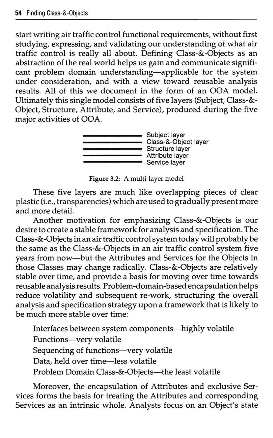
/


Text
SECOND EDITION
- -i
1 'L I
A
0i00a
r\ * o o a 0 0 a
u 0 0 a(00'
PETER COAD/ EDWARD YOURDON
YOURDDN PRESS COMPUTING SERIES
Object-Oriented Analysis
Selected titles from the YOUREDN PRESS COMPUTING SERIES
Ed Yourdon, Advisor
AUGUST JAD Joint Application Design
BAUDIN Manufacturing Systems Analysis with Application to Production Scheduling
BELLIN AND SUCHMAN Structured Systems Development Manual
BLOCK The Politics of Projects
BODDIE Crunch Mode: Building Effective Systems on a Tight Schedule
BOULDIN Agents of Change: Managing the Introduction of Automated Tools
BRILL Building Controls into Structured Systems
BRILL Techniques of EDP Project Management: A Book of Readings
CHANG Principles of Visual Programming Systems
COAD AND YOURDON Object-Oriented Analysis, 2/E
CONNELL AND SHAFER Structured Rapid Prototyping
CONSTANTINE AND YOURDON Structured Design
DeGRACE AND STAHL Wicked Problems/Righteous Solutions
DeMARCO Concise Notes on Software Engineering
DeMARCO Controlling Software Projects: Management, Measurement, and Estimates
DeMARCO Structured Analysis and System Specification
DeSALVO AND LIEBOWITZ Managing Artificial Intelligence and Expert Systems
FOLLMAN Business Applications with Microcomputers
FOURNIER Practice Guide to Structured System Development
FRANTZEN AND McEVOY A Game Plan for Systems Development
GLASS Software Conflict
GROCHOW SAA: A Guide to Implementing IBM's Systems Application Architecture
INMON Information Engineering for the Practitioner: Putting Theory into Practice
KELLER Expert Systems Technology: Development and Application
KELLER The Practice of Structured Analysis: Exploding Myths
KING Creating Effective Software: Computer Program Design Using the Jackson Method
KING Current Practices in Software Development: A Guide to Successful Systems
LIEBOWITZ AND DeSALVO Structuring Expert Systems: Domain, Design, and Development
McMENAMIN AND PALMER Essential System Analysis
ORR Structured Systems Development
PAGE-JONES Practical Guide to Structured Systems Design, 2/E
PETERS Software Design: Methods and Techniques
PINSON Designing Screen Interfaces in C
RIPPS An Implementation Guide to Real-Time Programming
RODGERS UNIX Database Management Systems
RUHL The Programmers Survival Guide: Career Strategies for Computer Professionals
SCHMITT The OS/2 Programming Environment
SCHLAER AND MELLOR Object-Oriented Systems Analysis: Modeling the World in Data
SHILLER Software Excellence
TOIGO Disaster Recovery Planning: Managing Risk and Catastrophe in Information Systems
VESELY Strategic Data Management: The Key to Corporate Competitiveness
WARD Systems Development Without Pain: A User's Guide to Modeling Organizational
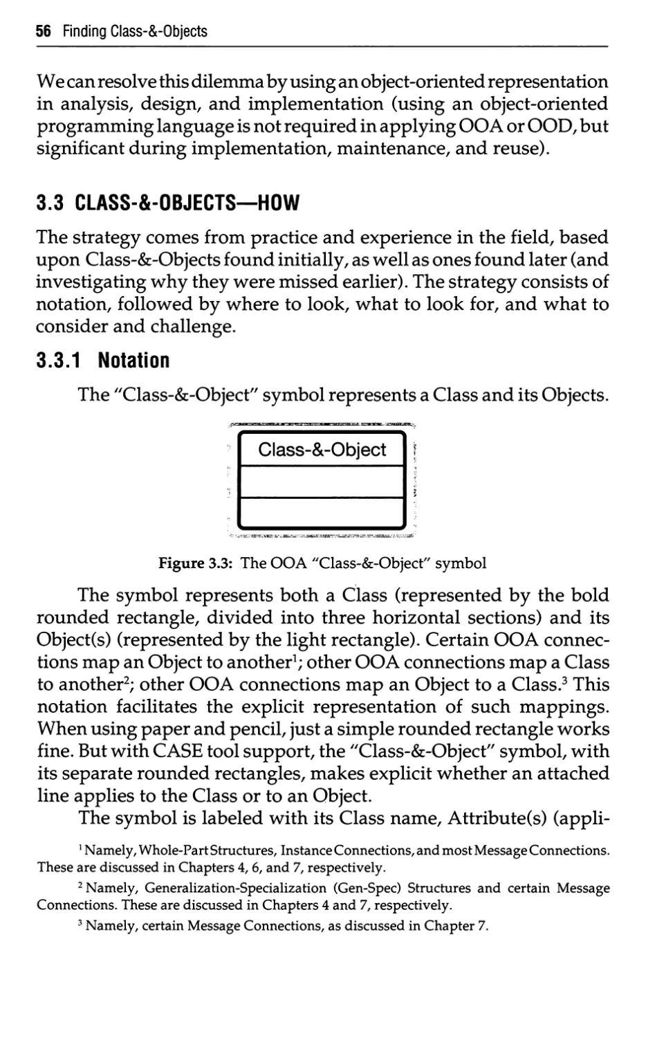
Patterns
WARD AND MELLOR Structured Development for Real-Time Systems. Volumes I, II, and III
WEAVER Using the Structured Techniques: A Case Study
WEINBERG Structured Analysis
YOURDON Classics in Software Engineering
YOURDON Managing the Structured Techniques, 4/E
YOURDON Managing the System Life Cycle, 2/E
YOURDON Modern Structured Analysis
YOURDON Structured Walkthroughs, 4/E
YOURDON Techniques of Program Structure and Design
Object-Oriented Analysis
Second Edition
Peter Coad and Edward Yourdon
YOURDDN PRESS
PRENTICE HALL BUILDING
ENGLEWOOD CLIFFS, NJ 07632
Editorial/production supervision: Barbara Marttine
Manufacturing buyer: Kelly Behr/Susan Brunke
Photos by: Don Rogers PHOTOGRAPHY-Austin, Texas USA
All OOA drawings in this text were developed using Object International's OOATool™.
© 1991,1990 by Object International, Inc
Published by Prentice-Hall, Inc
A Division of Simon & Schuster
Englewood Cliffs, New Jersey 07632
The publisher offers discounts on this book when ordered
in bulk quantities. For more information, write:
Special Sales/College Marketing
College Technical and Reference Division
Prentice Hall
Englewood Cliffs, New Jersey 07632
OOATool™, OOAdvisor™, and The Coad Letter™ are trademarks of Object International, Inc
Smalltalk/V® is a registered trademark of Digitalk, Inc
ClassicAda™ is a trademark of Software Productivity Solutions.
Apple® and Macintosh® are registered trademarks of Apple Computer, Inc.
IBM® is a registered trademark of International Business Machines.
Post-it™ is a trademark of 3M.
ObjectPlus™ is a trademark of Easyspec, Inc
Adagen™ is a trademark of Mark V Systems, Ltd.
All rights reserved. No part of this book may be
reproduced, in any form or by any means,
without permission in writing from the publisher.
Printed in the United States of America
10 9 8 7 6 5
ISBN D-ia-bE^fll-i*
Prentice-Hall International (UK) Limited, London
Prentice-Hall of Australia Pty. Limited, Sydney
Prentice-Hall Canada Inc, Toronto
Prentice-Hall Hispanoamericana, S.A., Mexico
Prentice-Hall of India Private Limited, New Delhi
Prentice-Hall of Japan, Inc, Tokyo
Simon & Schuster Asia Pte. Ltd., Singapore
Editora Prentice-Hall do Brasil, Ltda., Rio de Janeiro
Dedication
To Judy, my best friend—this achievement is ours.
With love,
PC
To the editors, proofreaders, artists, printers, and myriad others
behind the scenes without whose quiet, patient efforts
a book like this would never see the light of day.
EY
v
Contents
0 Introduction
0.1
0.2
0.3
0.4
0.5
0.6
Organization
Why Do We Need OOA?
Audience
Focus and History
Method and Tool
Future Advances in OOA
1 Improving Analysis
1.1
1.1.1
1.1.2
1.1.3
1.1.4
1.2
1.2.1
1.2.2
1.2.3
1.2.4
1.2.5
1.2.6
1.2.7
1.2.8
1.2.9
1.3
1.3.1
1.3.2
1.3.3
1.3.4
1.3.5
The Analysis Challenge
The Problem Domain and the System's
Responsibilities
Communication
Continual Change
Reuse
Principles for Managing Complexity
Abstraction
Encapsulation
Inheritance
Association
Communication with Messages
Pervading Methods of Organization
Scale
Categories of Behavior
Summary of Principles
Analysis Methods
Functional Decomposition
Data Flow Approach
Information Modeling
An Observation on Stability vs. Volatility
Object-Oriented
2 Experiencing an Object Perspective
2.1
2.2
2.3
2.4
Smalltalk
Smalltalk Objects
Smalltalk Messages
Smalltalk Classes
1
2
3
4
4
6
7
8
9
9
10
11
11
12
13
14
15
15
15
16
17
17
18
18
20
22
27
28
30
41
42
42
43
45
VII
viii Contents
2.5 Smalltalk Inheritance 47
2.6 Key Points 50
2.7 Terminology Map 50
Introduction to Chapters 3-7 51
3 Finding Class-&-Objects 52
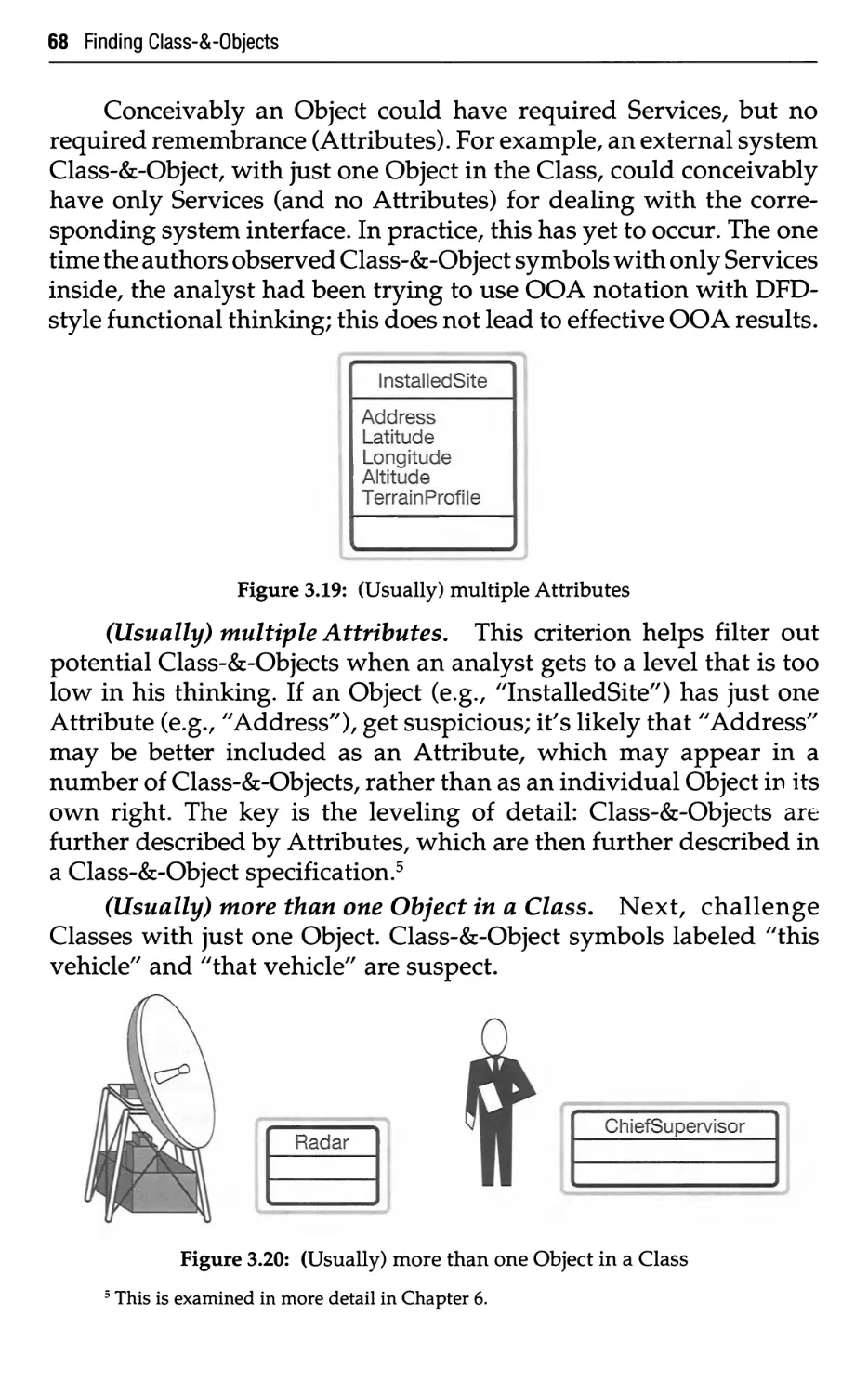
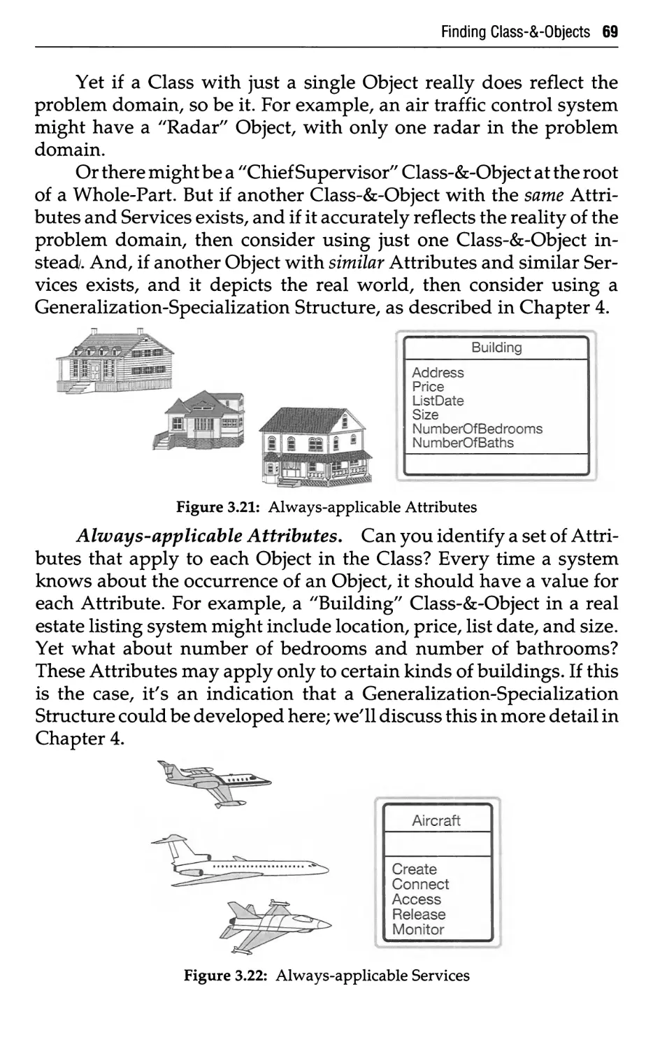
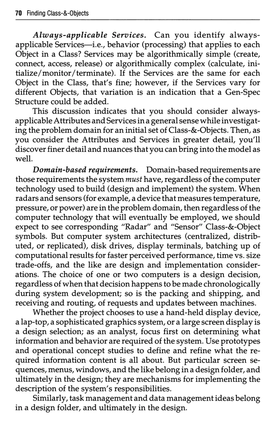
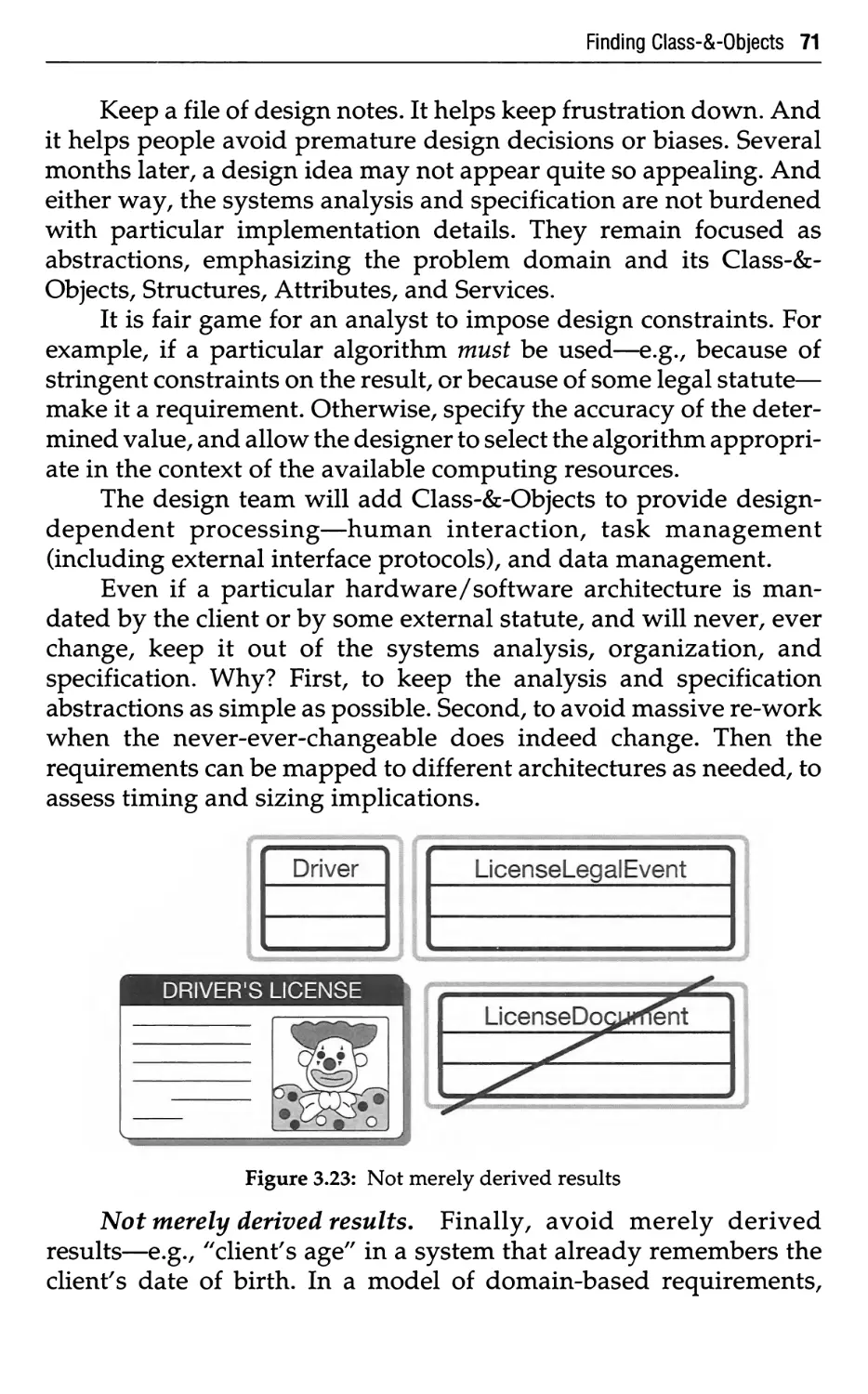
3.1 Class-&-Objects—What 52
3.2 Class-&-Objects—Why 53
3.3 Class-&-Objects—How 56
3.3.1 Notation 56
3.3.2 Where to Look 58
3.3.3 What to Look For 60
3.3.4 What to Consider and Challenge 66
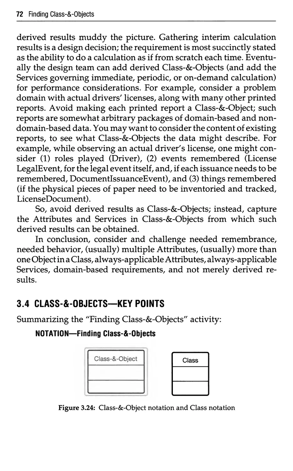
3.4 Class-&-Objects—Key Points 72
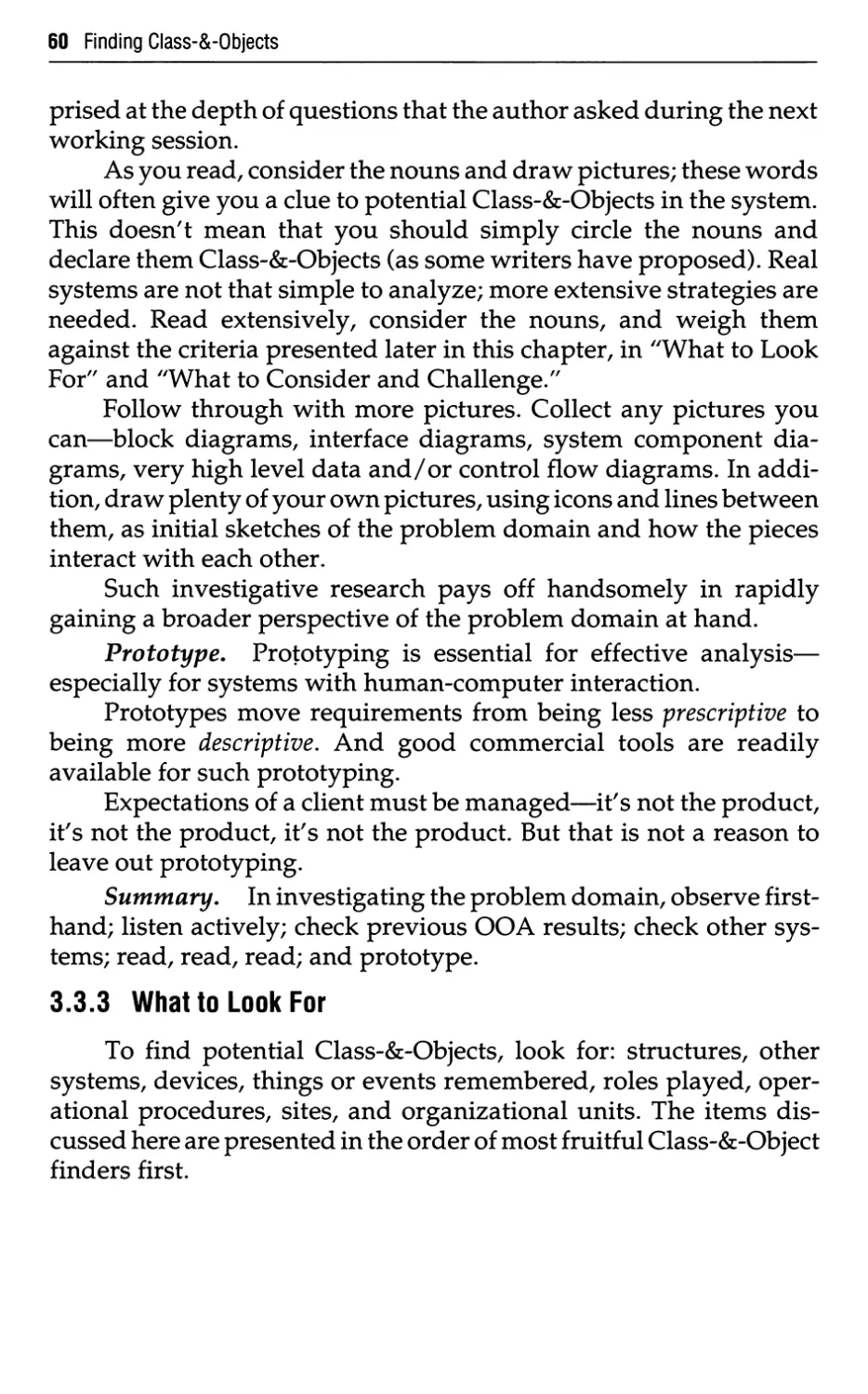
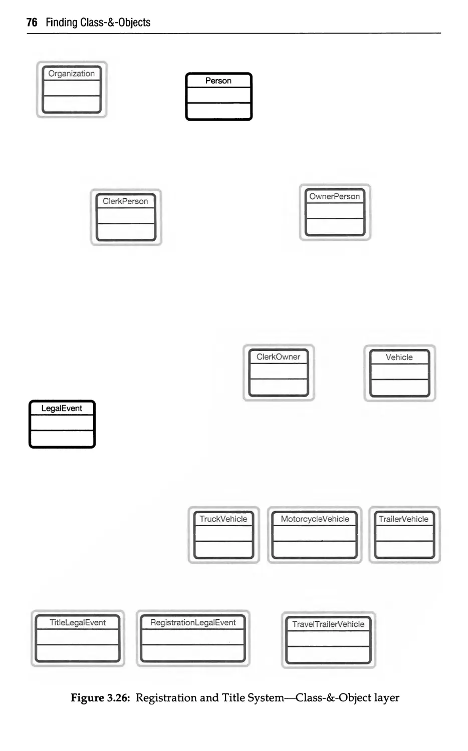
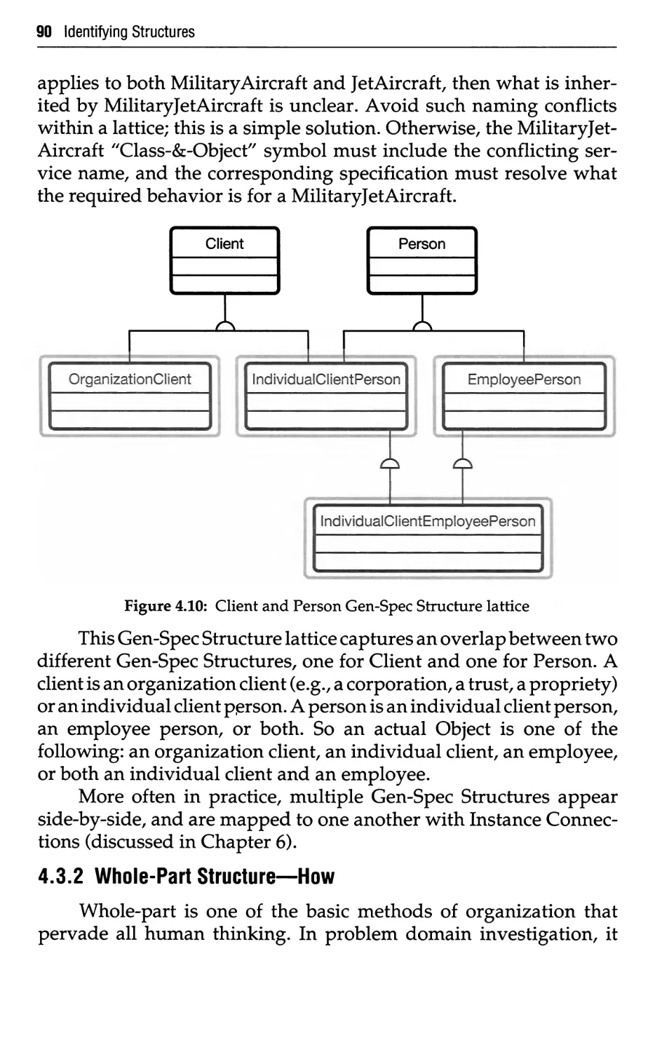
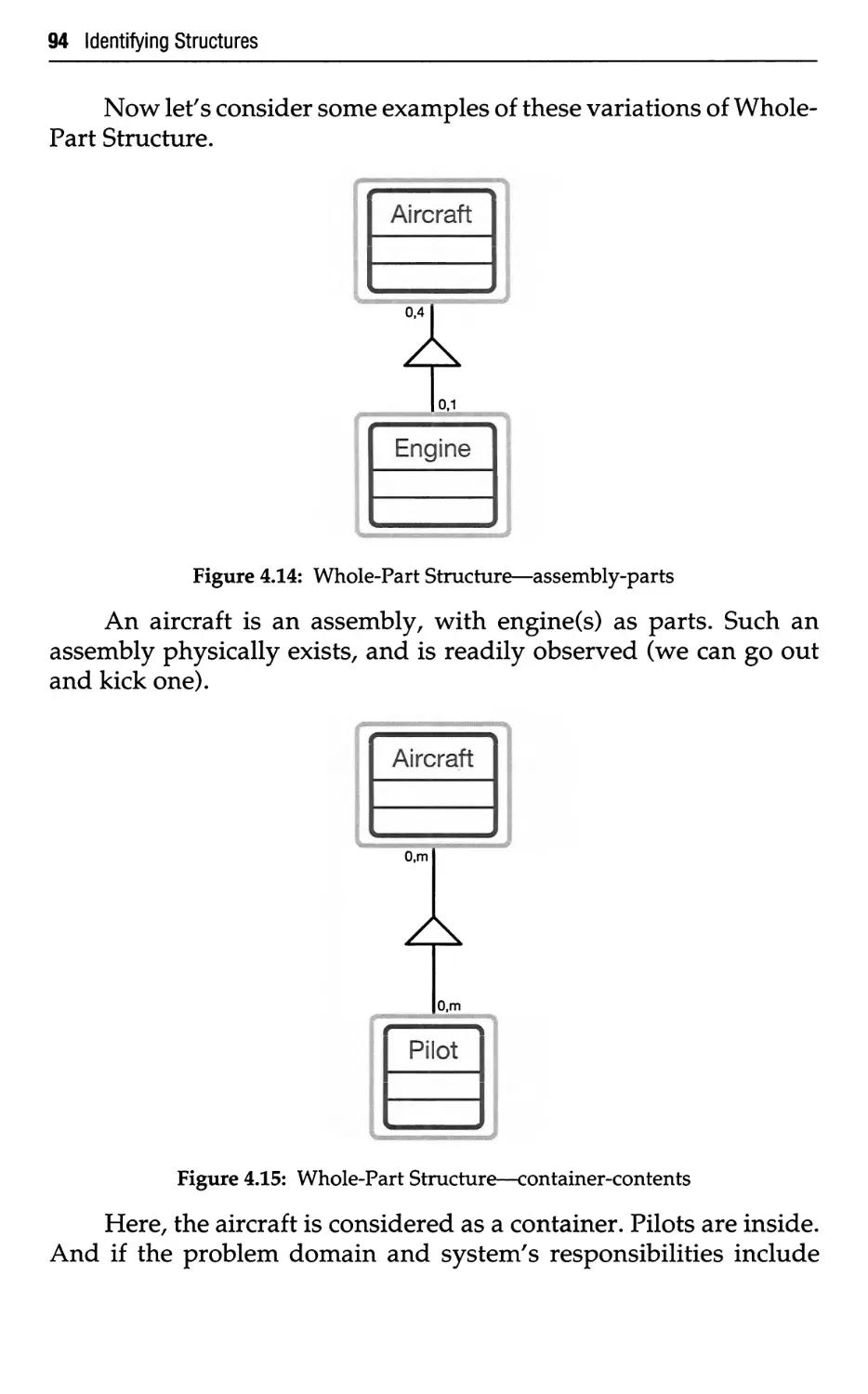
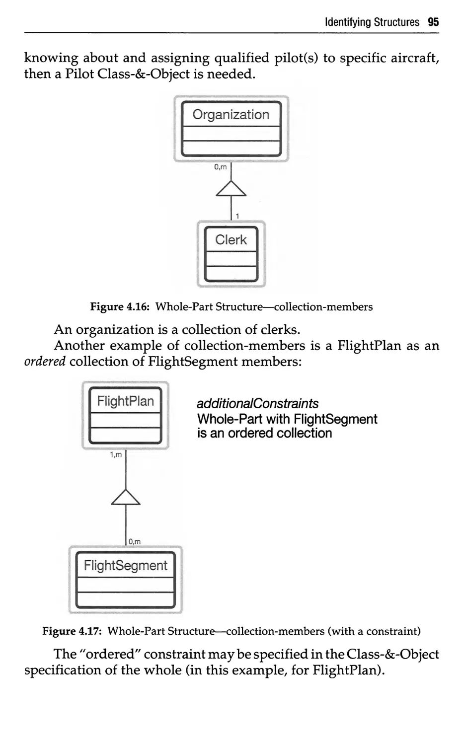
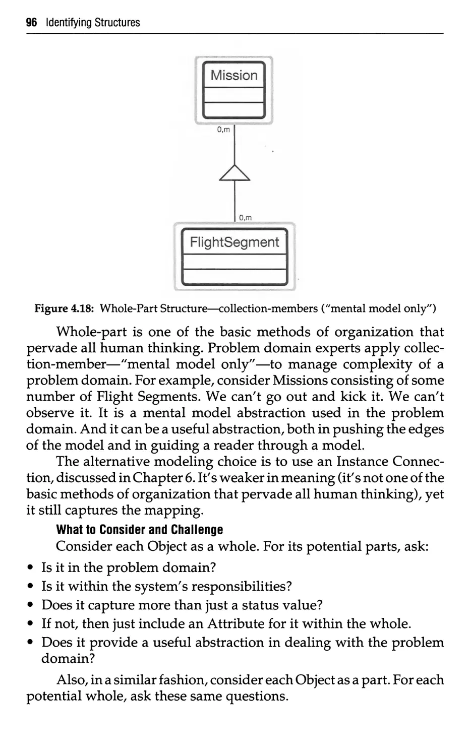
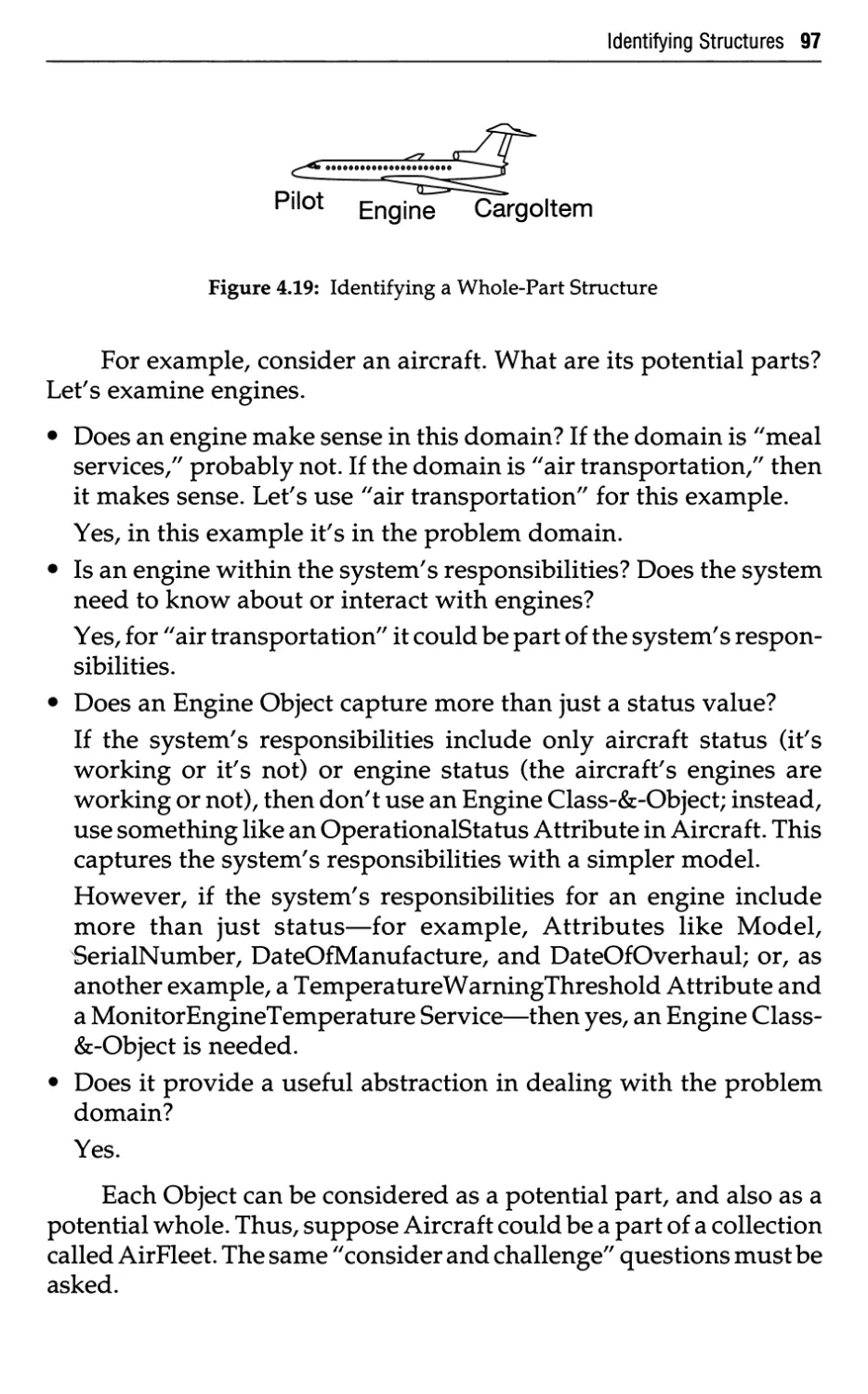
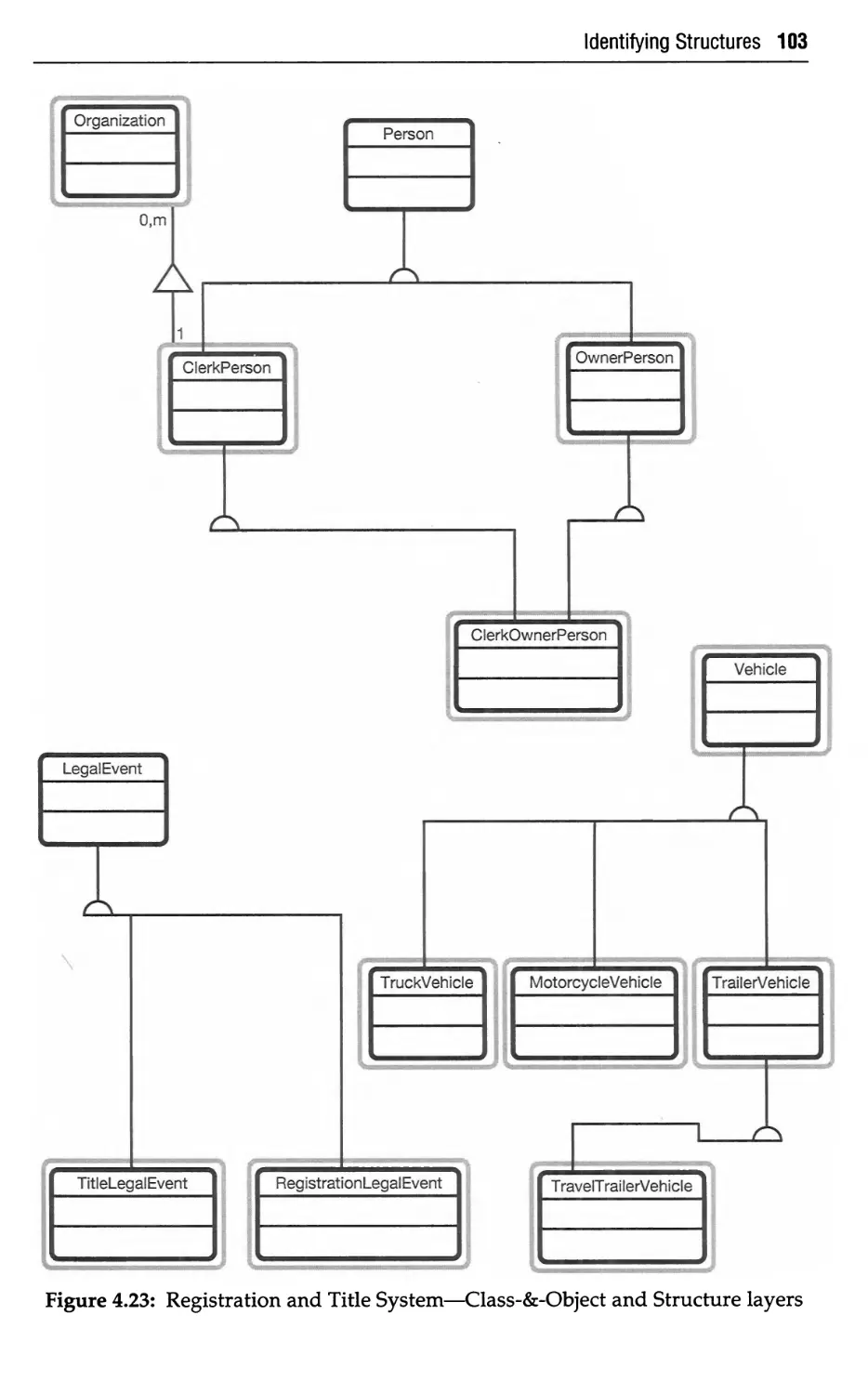
4 Identifying Structures 79
4.1 Structures—What 79
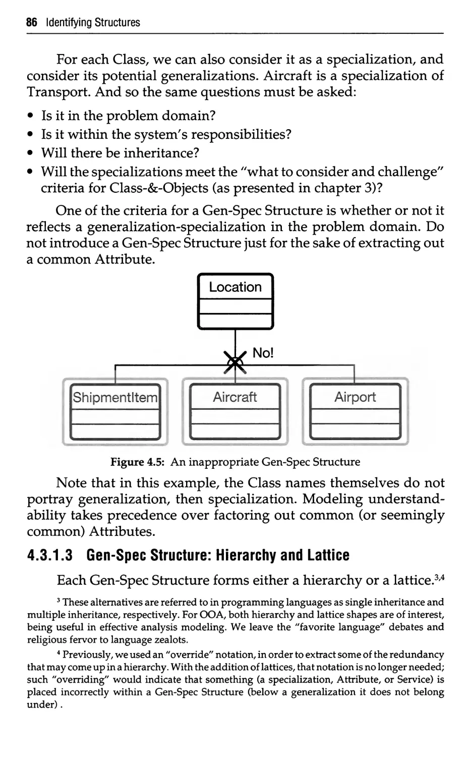
4.2 Structures—Why 80
4.3 Structures—How 80
4.3.1 Gen-Spec Structure—How 80
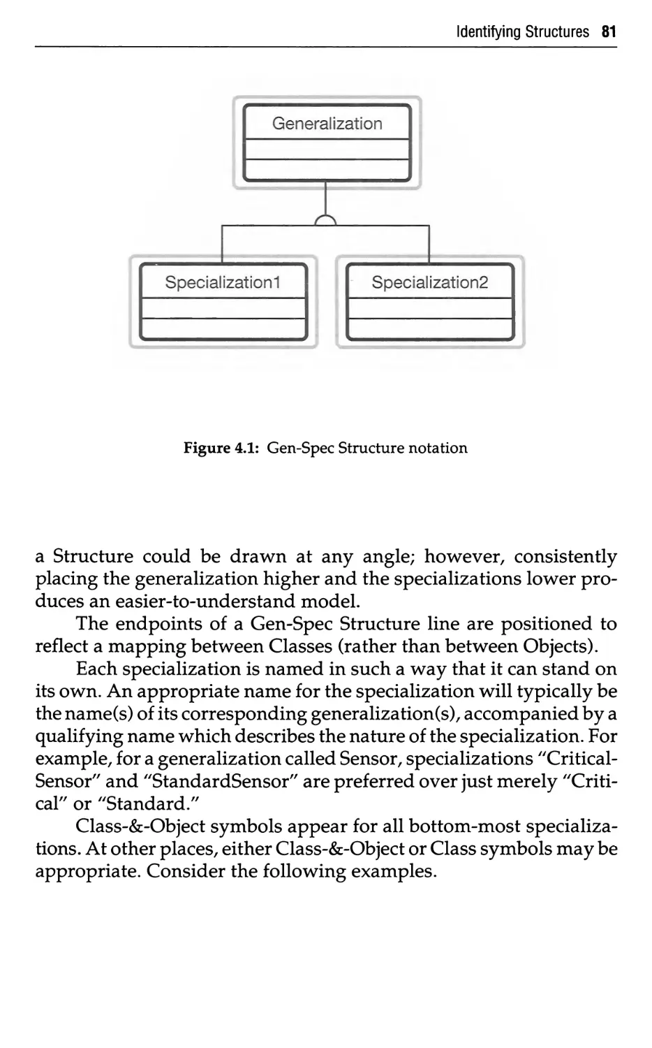
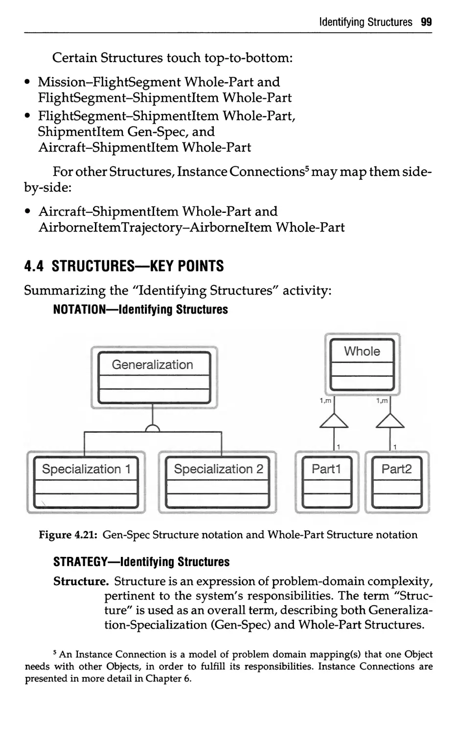
4.3.1.1 Gen-Spec Structure Notation 80
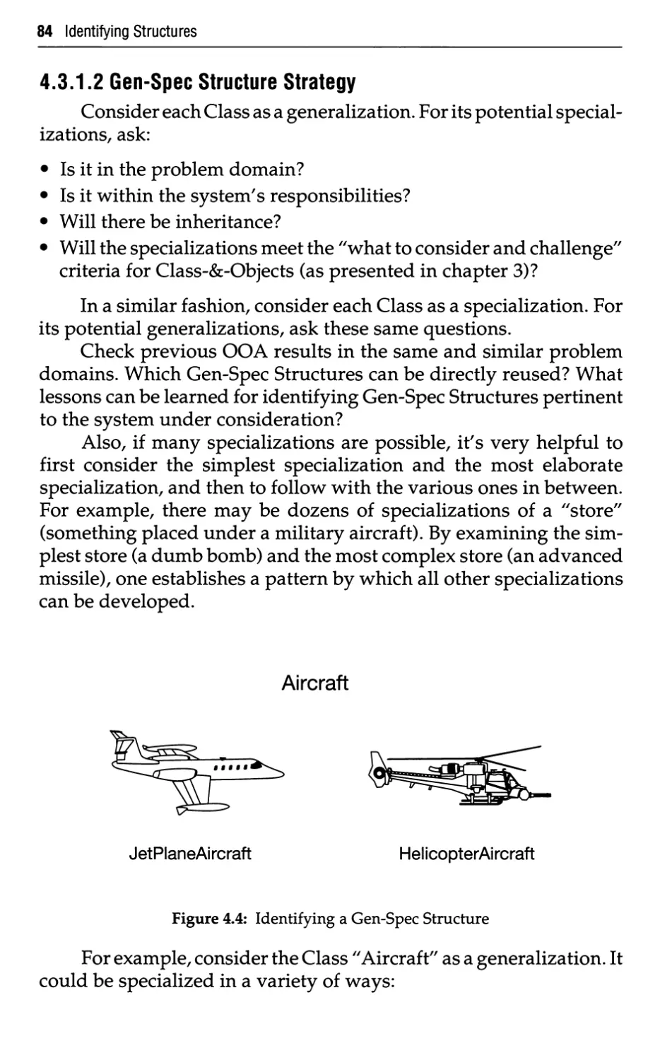
4.3.1.2 Gen-Spec Structure Strategy 84
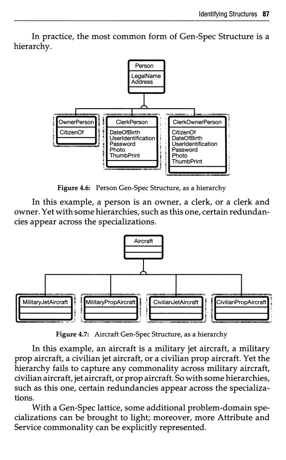
4.3.1.3 Gen-Spec Structure: Hierarchy and Lattice 86
4.3.2 Whole-Part Structure—How 90
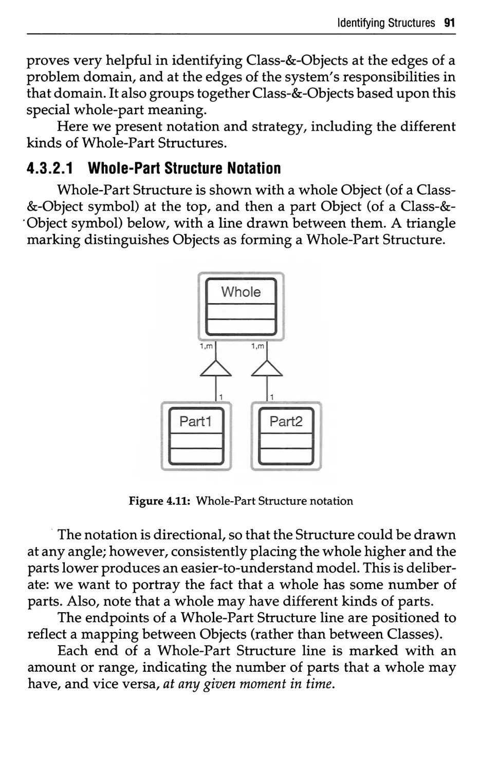
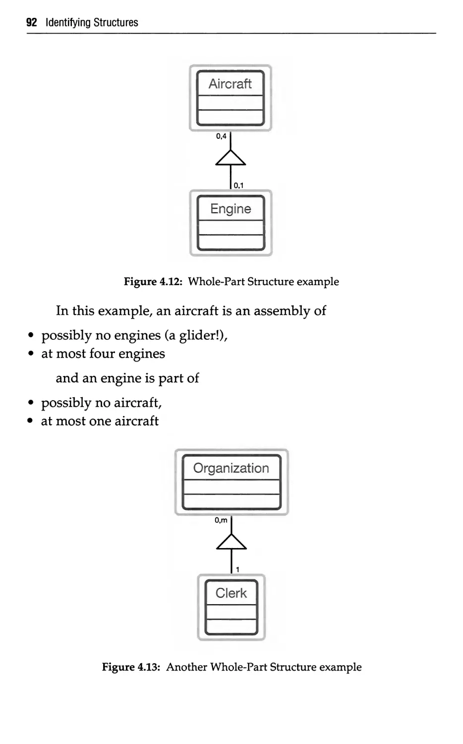
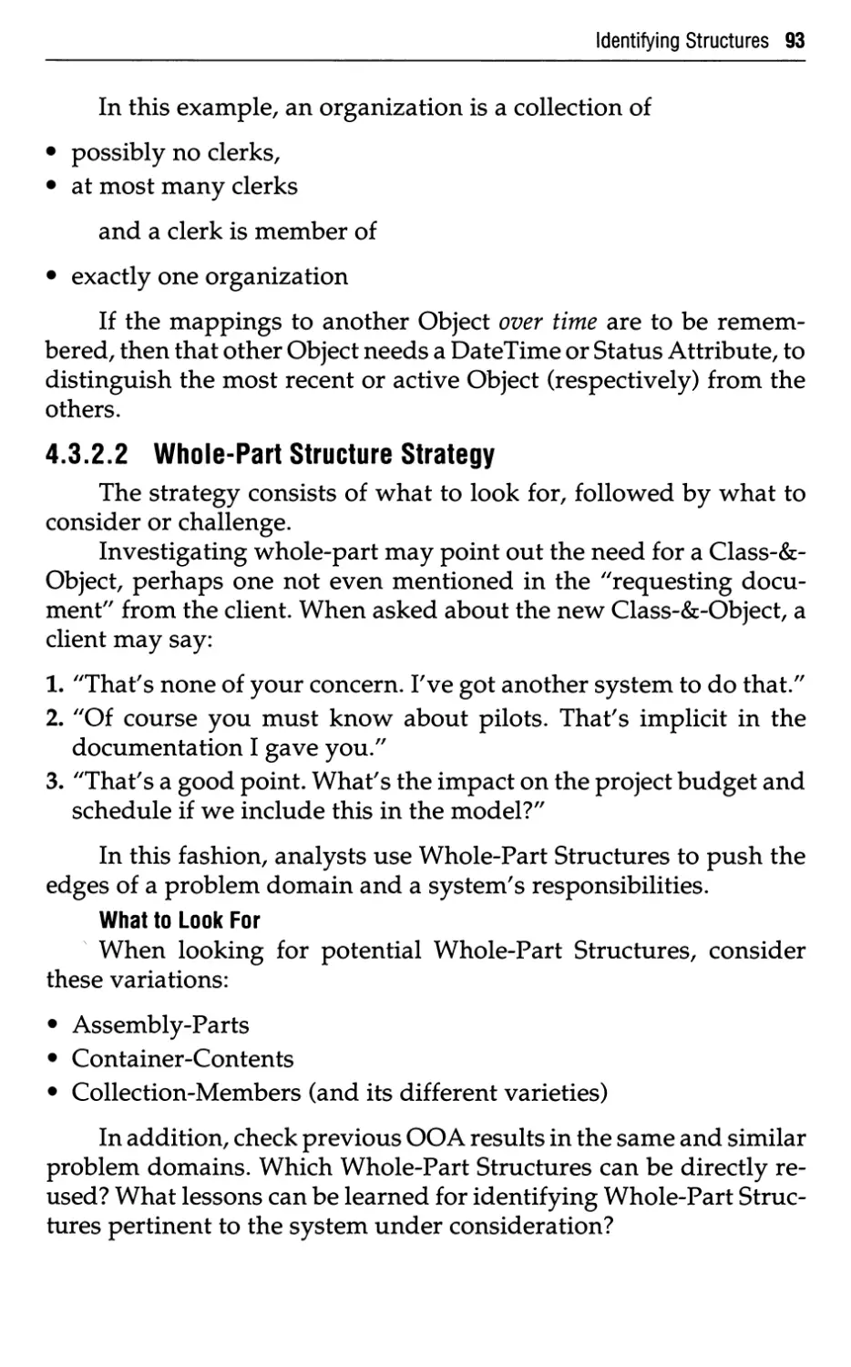
4.3.2.1 Whole-Part Structure Notation 90
4.3.2.2 Whole-Part Structure Strategy 93
4.3.3 Multiple Structures 98
4.4 Structures—Key Points 99
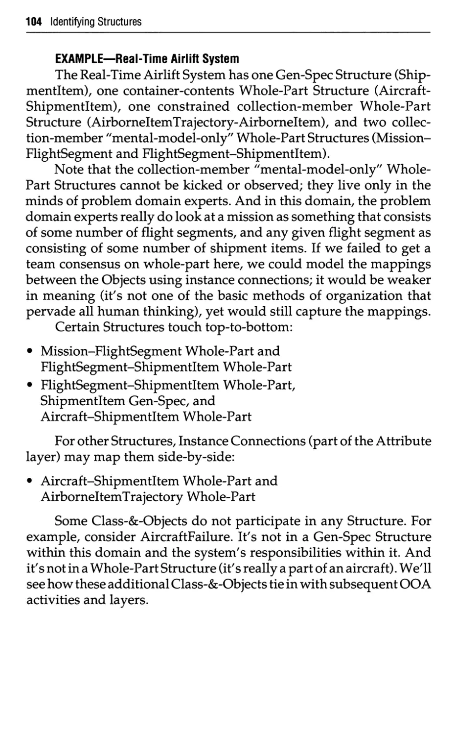
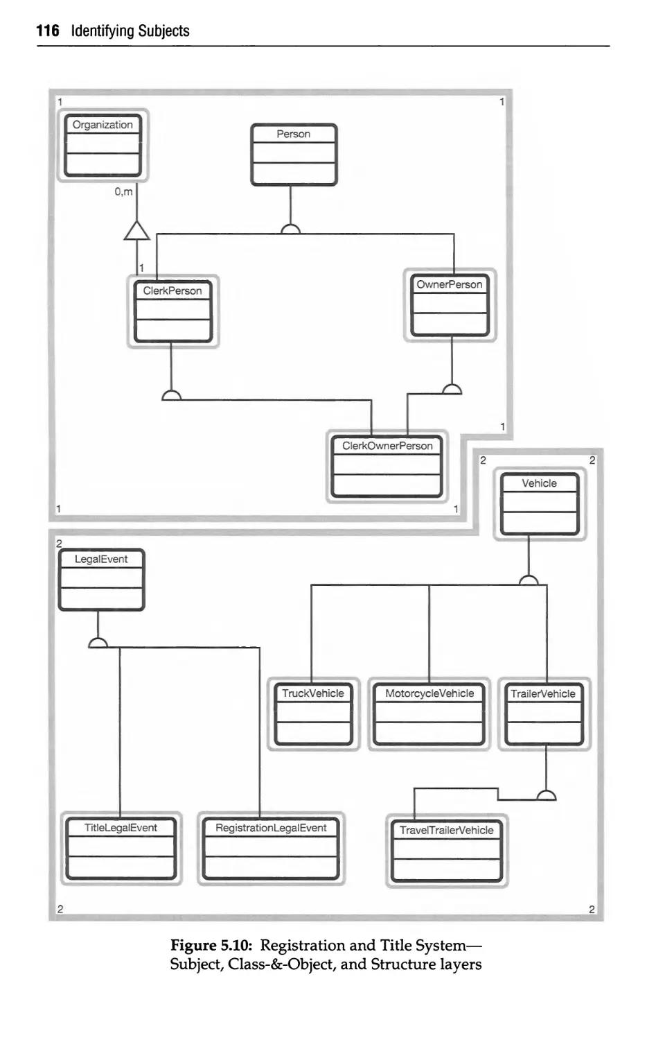
106
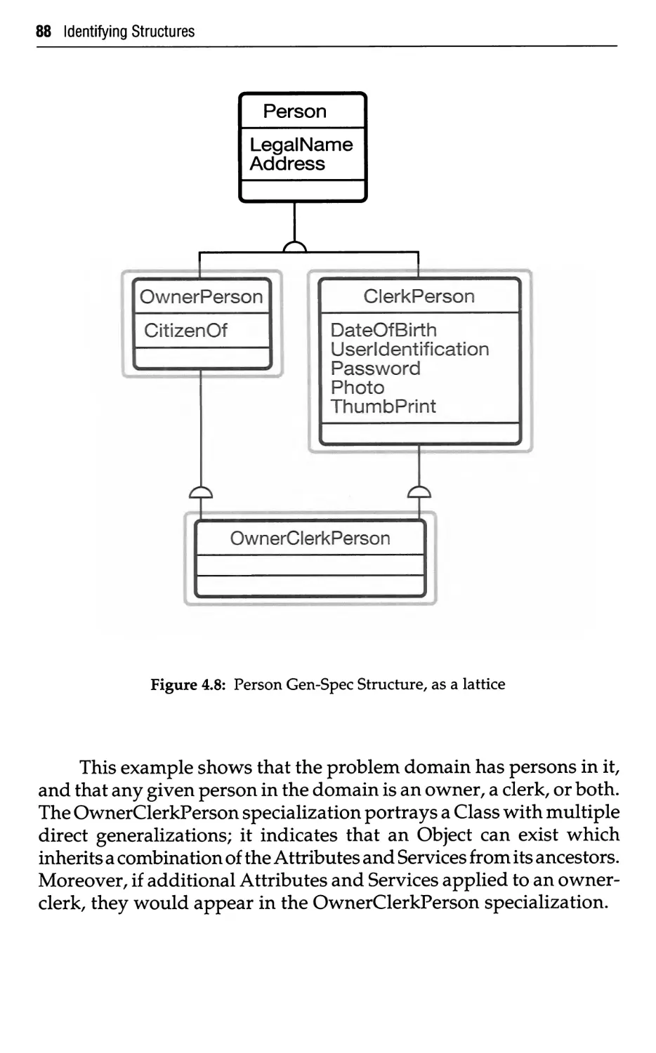
107
108
108
108
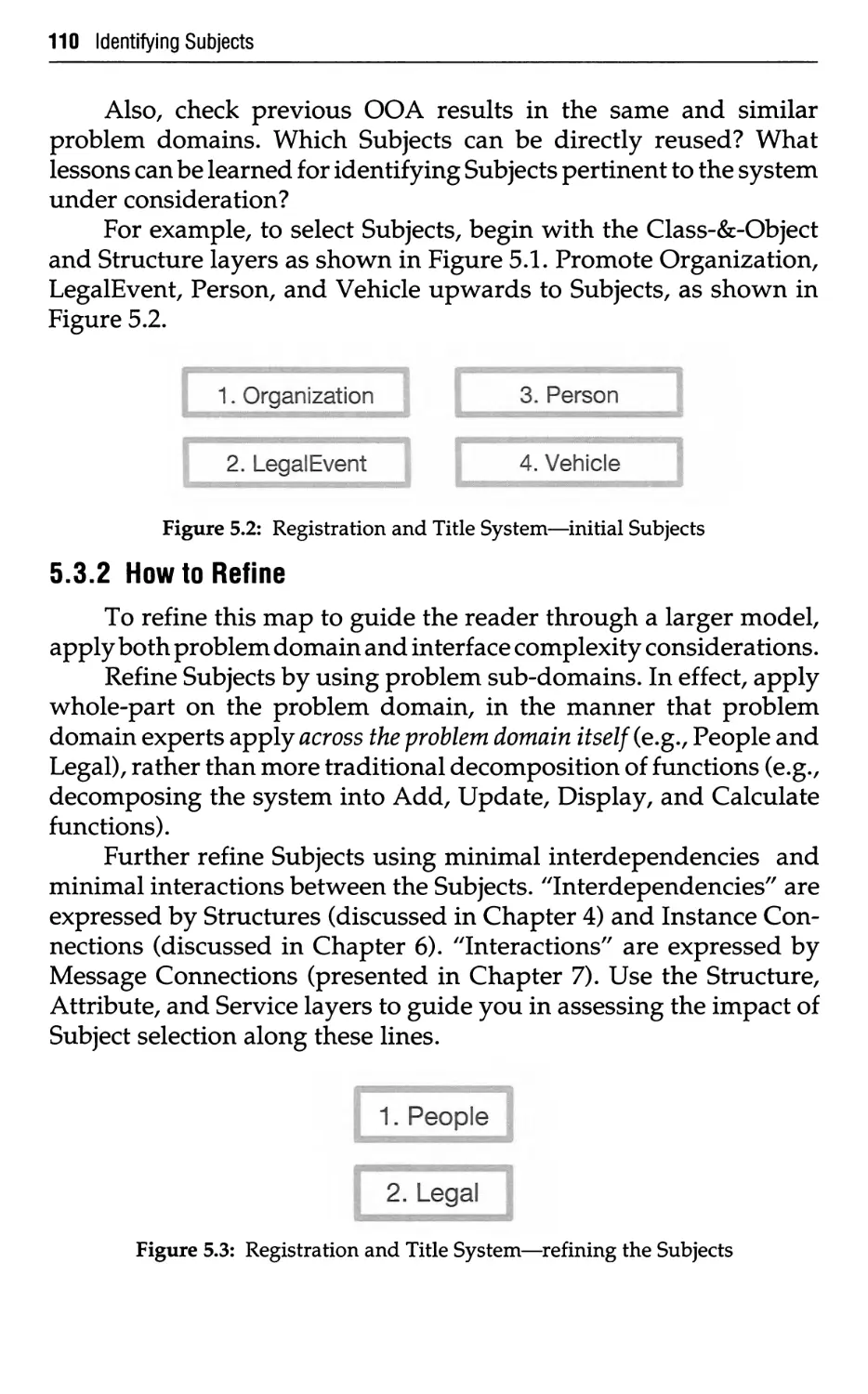
110
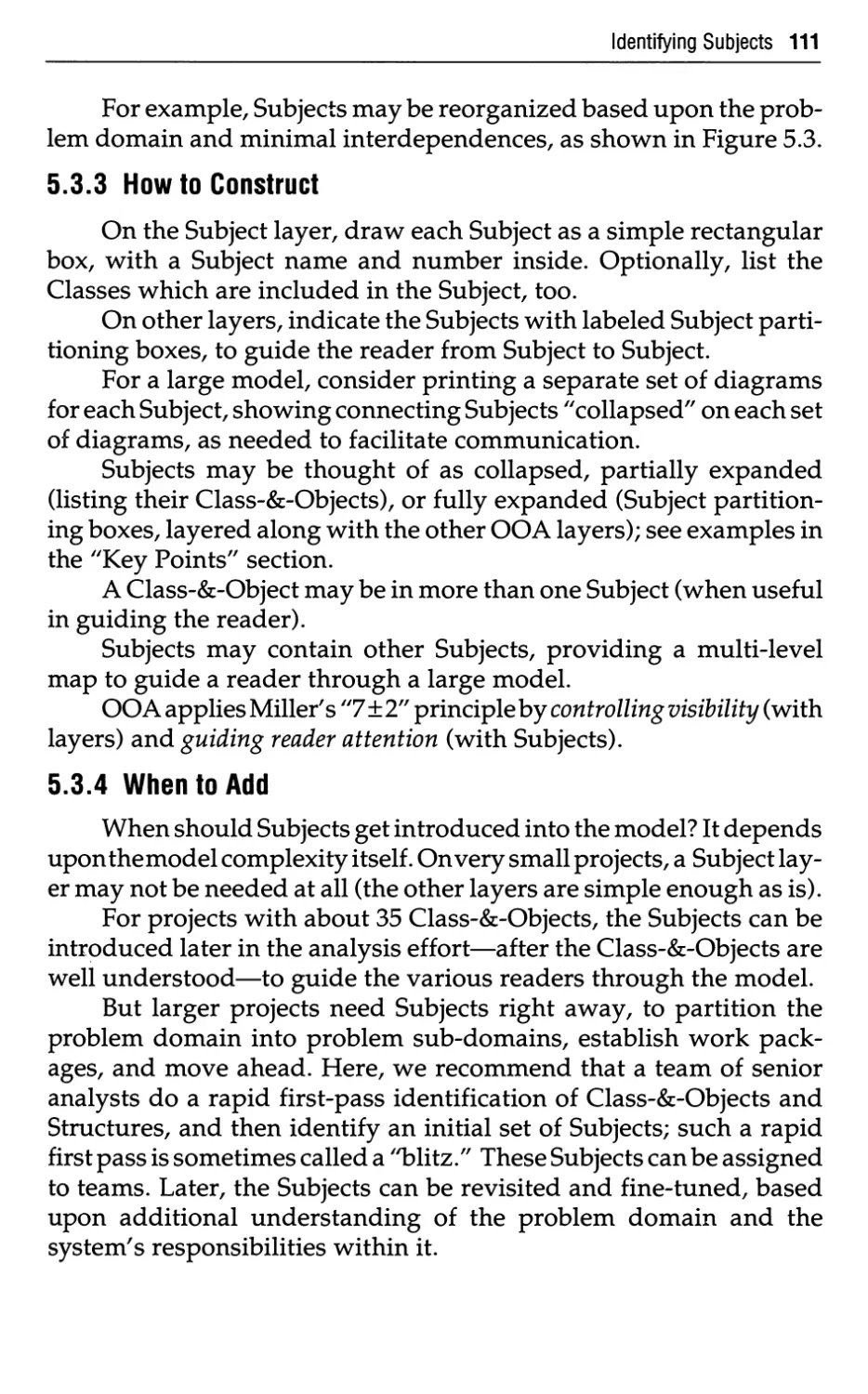
111
111
112
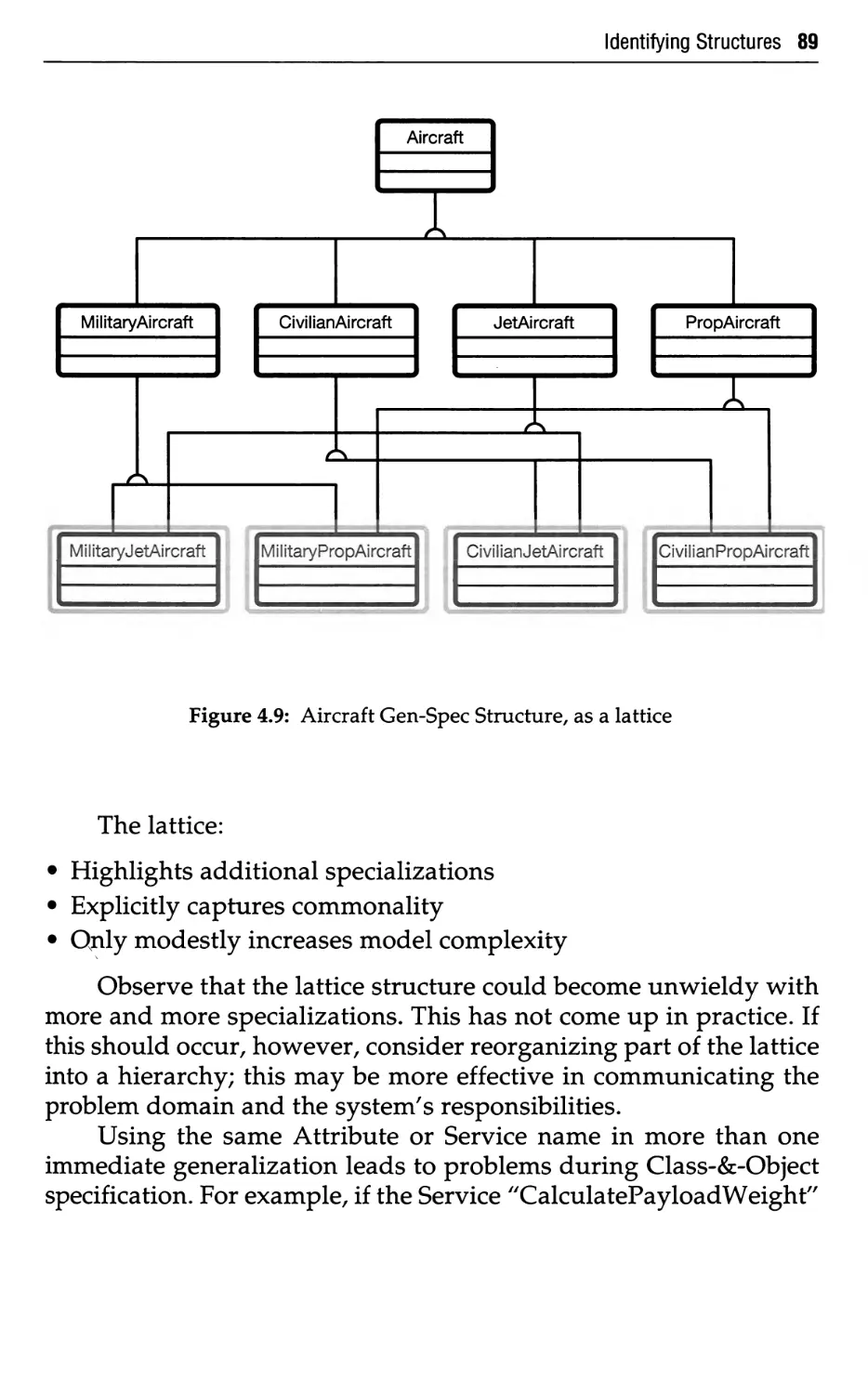
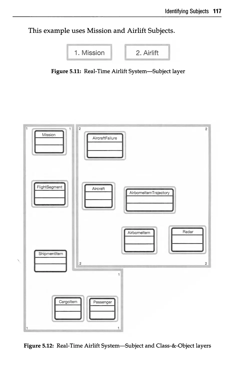
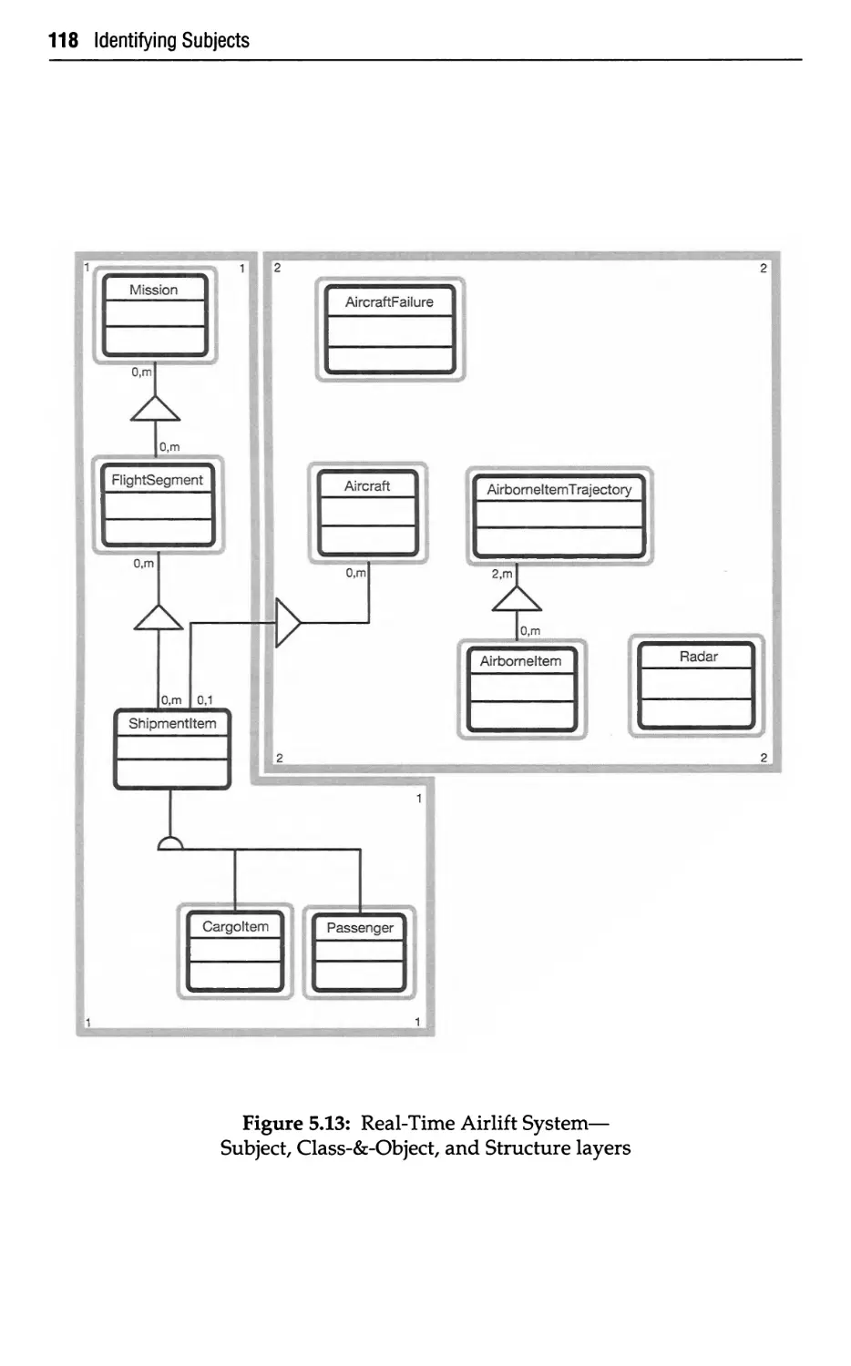
5 Identifying Subjects
5.1
5.2
5.3
5.3.1
5.3.2
5.3.3
5.3.4
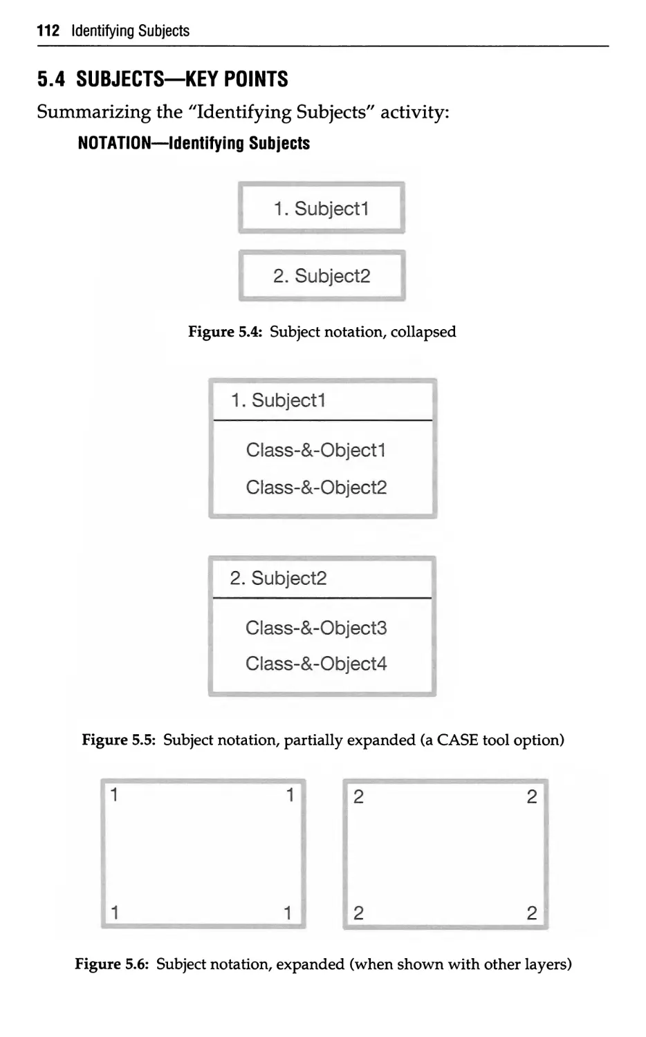
5.4
Subjects—What
Subjects—Why
Subjects—How
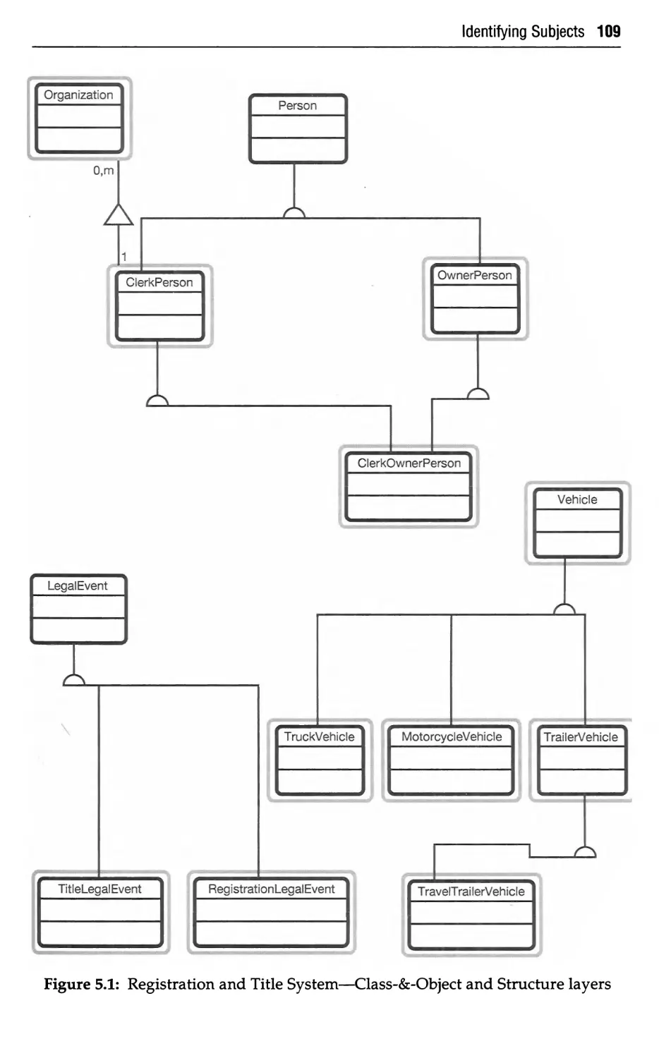
How to Select
How to Refine
How to Construct
When to Add
Subjects—Key Points
Contents ix
Defining Attributes
6.1
6.2
6.3
6.3.1
6.3.2
6.3.3
6.3.4
6.3.4.1
6.3.4.2
6.3.5
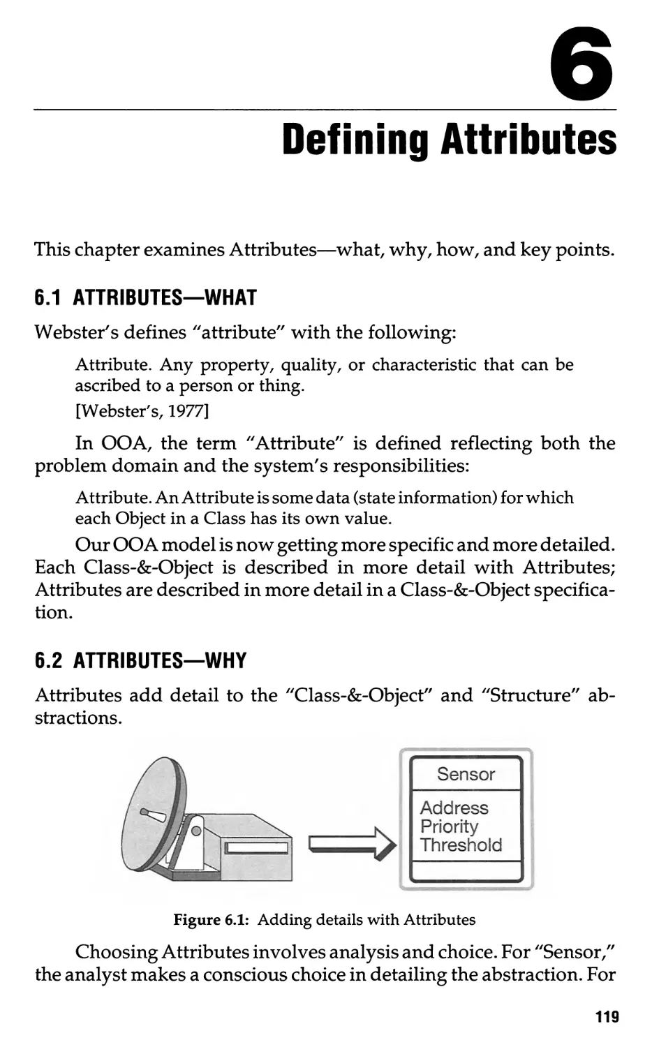
6.4
Attributes—What
Attributes—Why
Attributes—How
Identify the Attributes
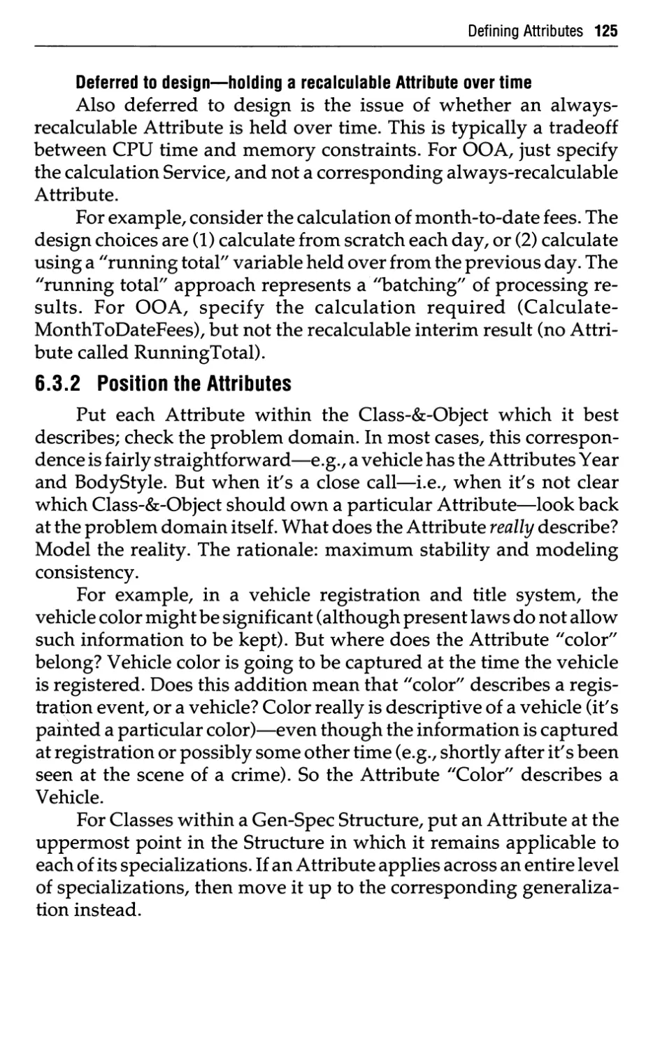
Position the Attributes
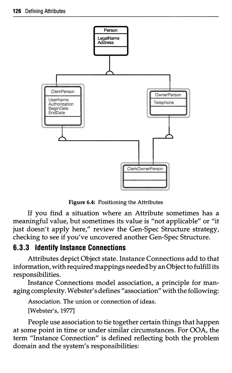
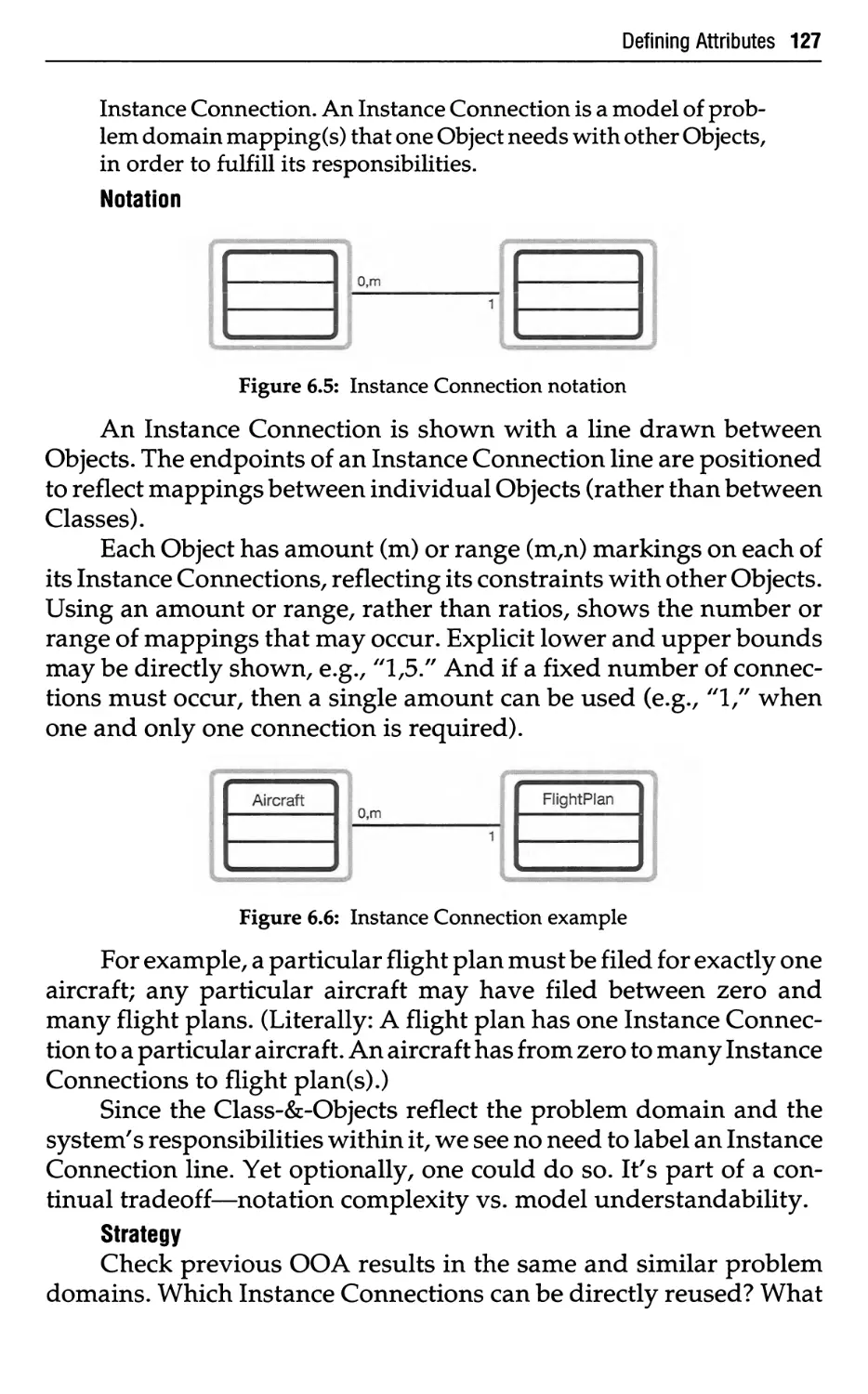
Identify Instance Connections
Check for Special Cases
Special Cases with Attributes
Special Cases with Instance Connections
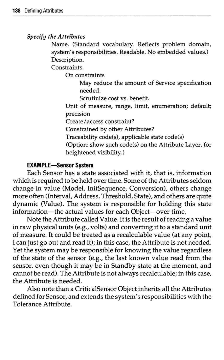
Specify the Attributes
Attributes—Key Points
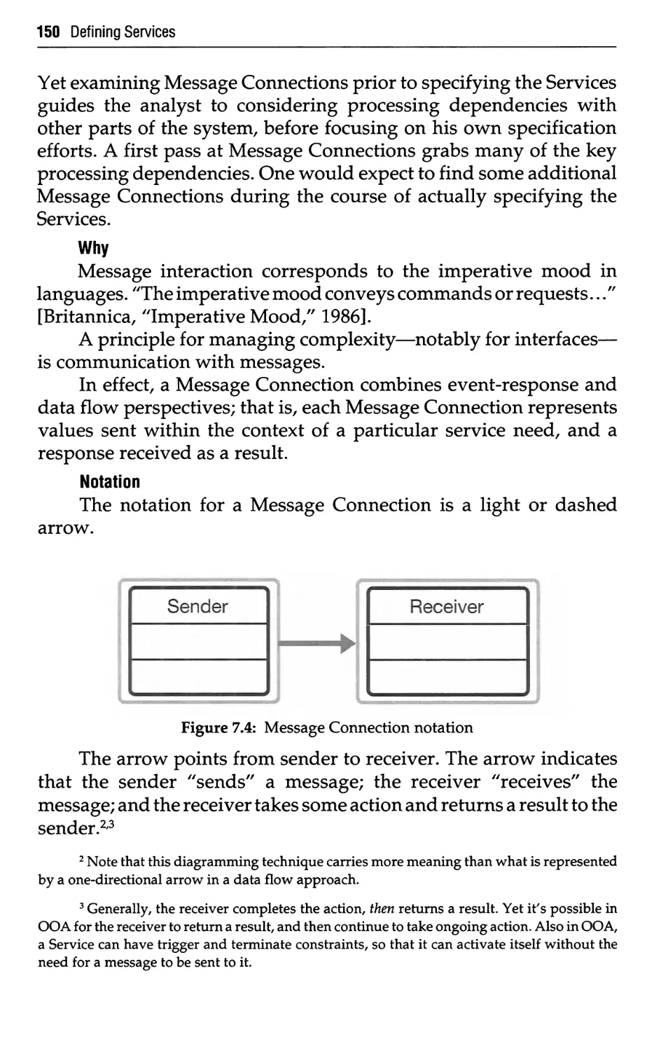
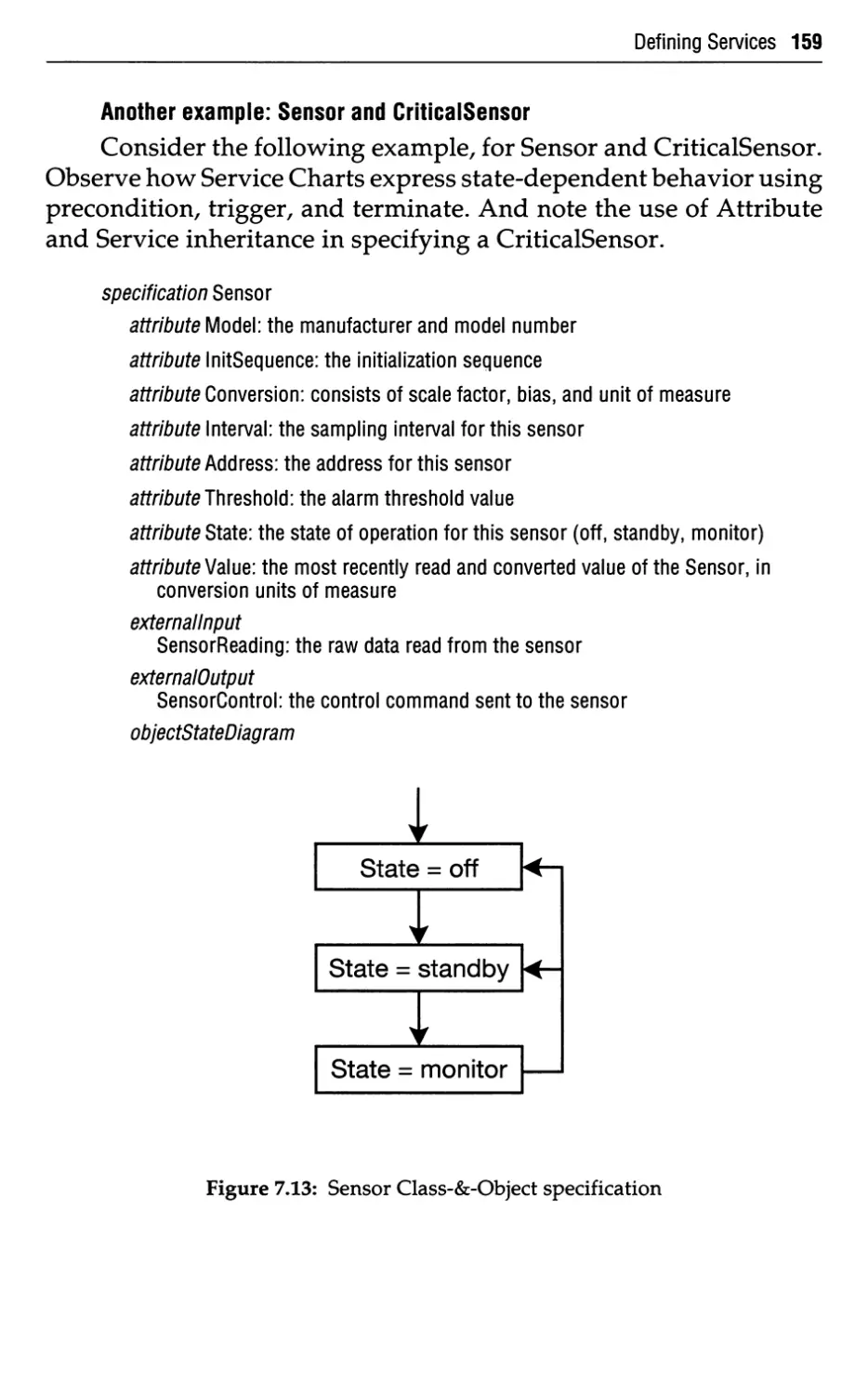
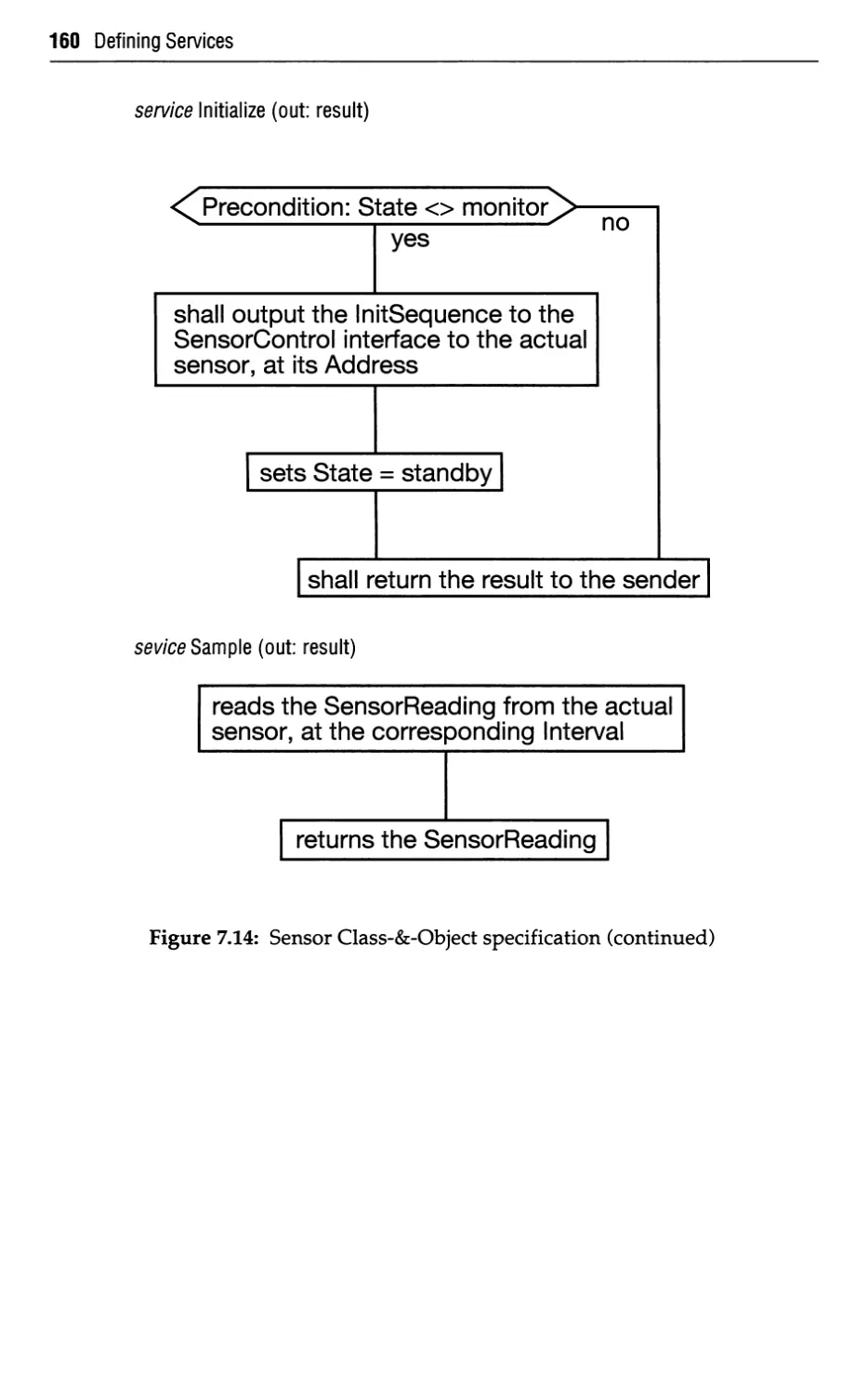
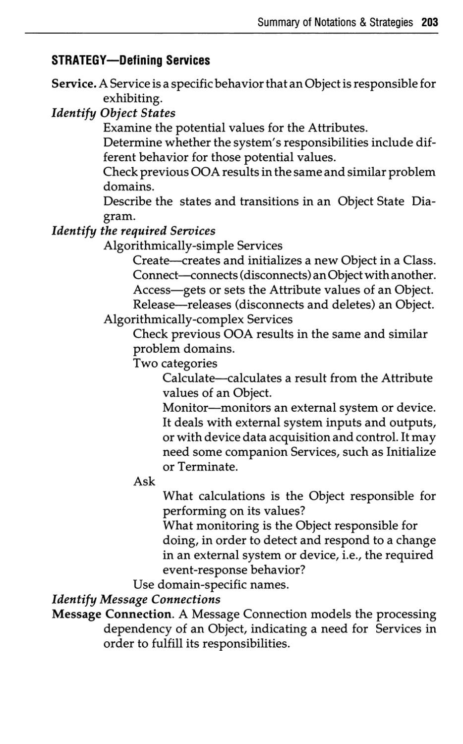
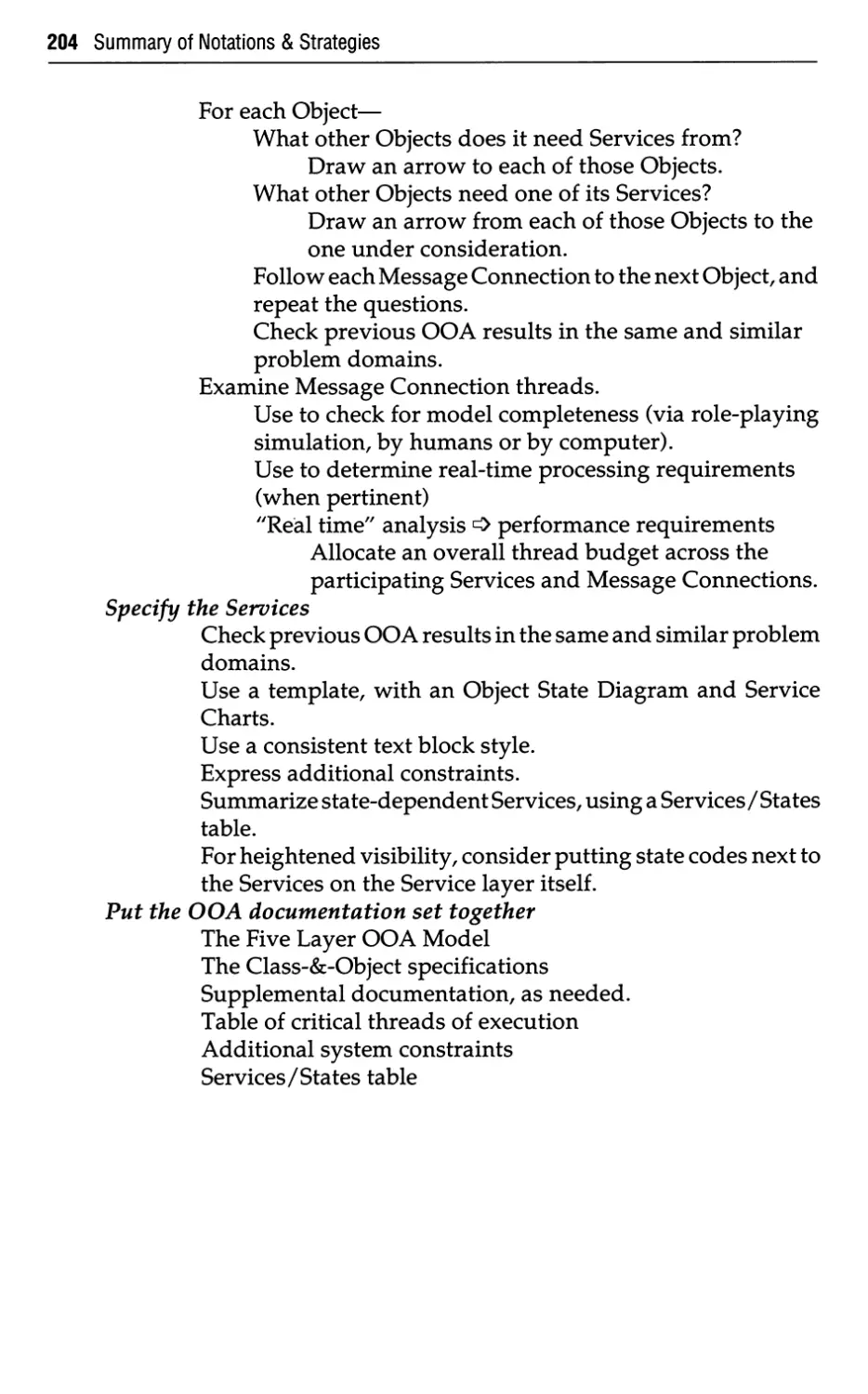
Defining Services
7.1
7.2
7.3
7.3.1
7.3.2
7.3.3
7.3.4
7.3.5
7.4
Services—What
Services—Why
Services—How
Identify the Object States
Identify the Required Services
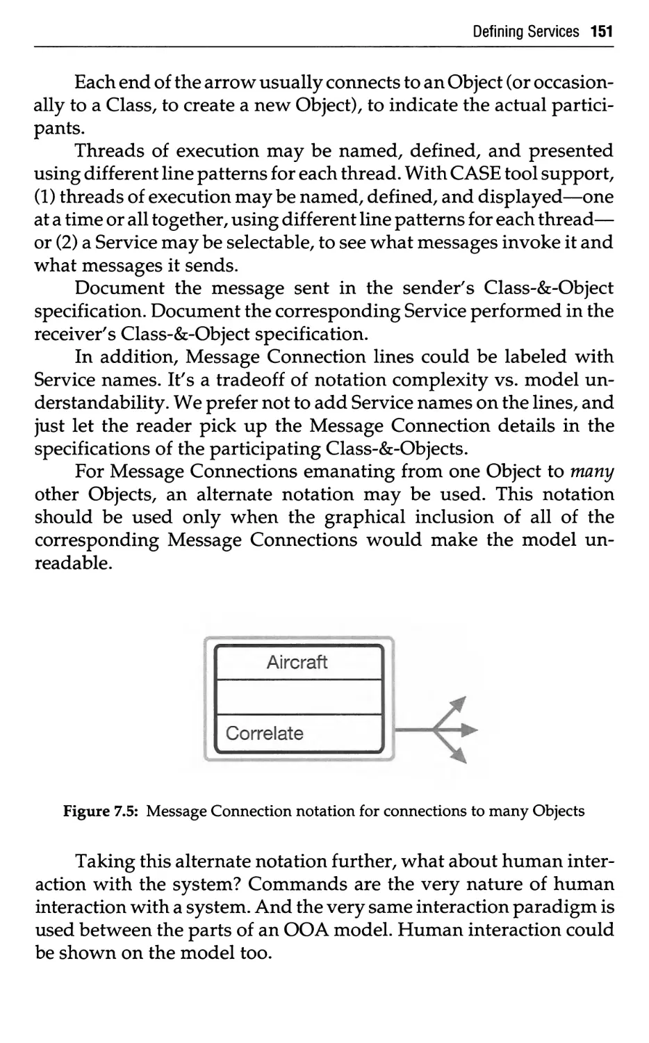
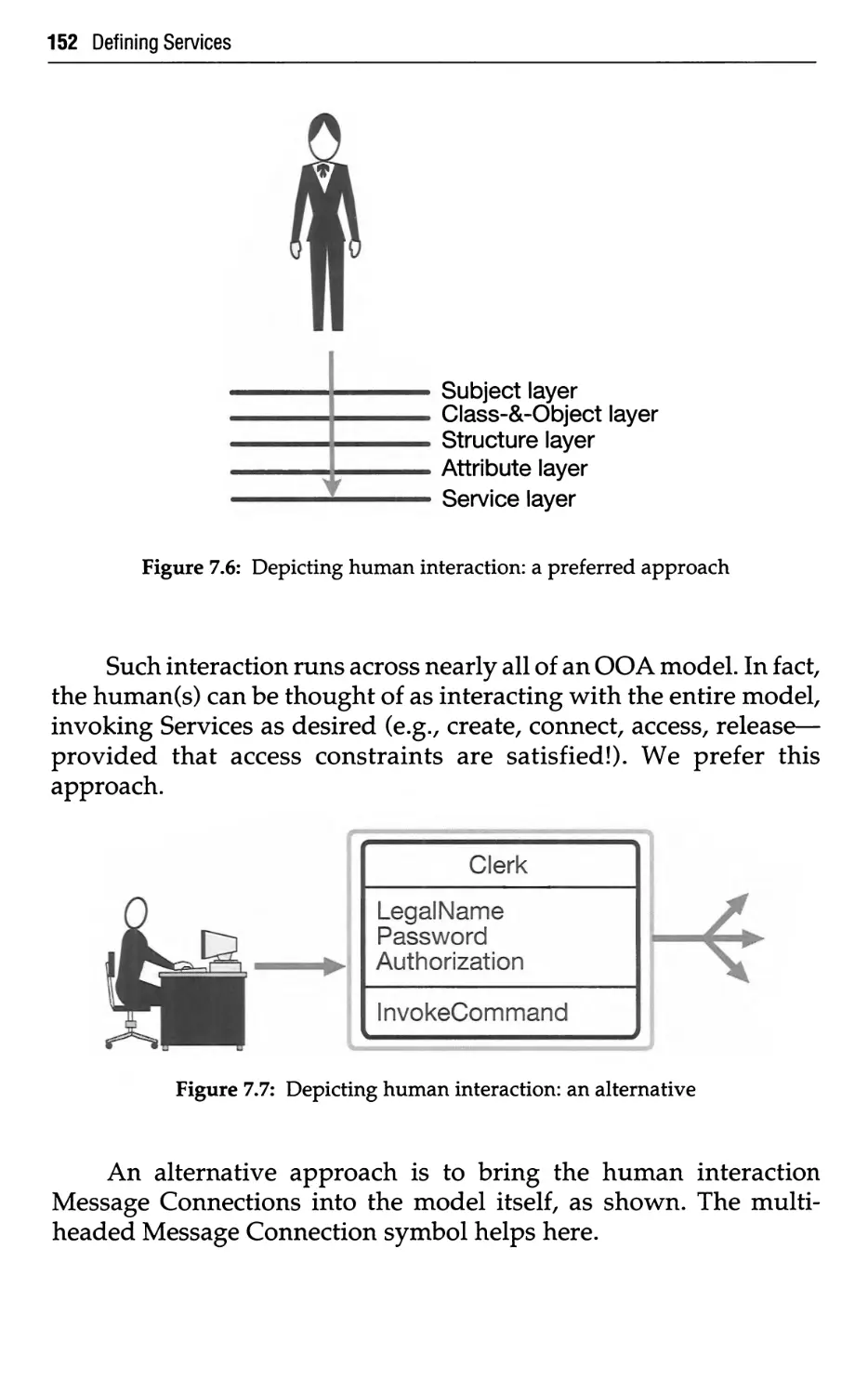
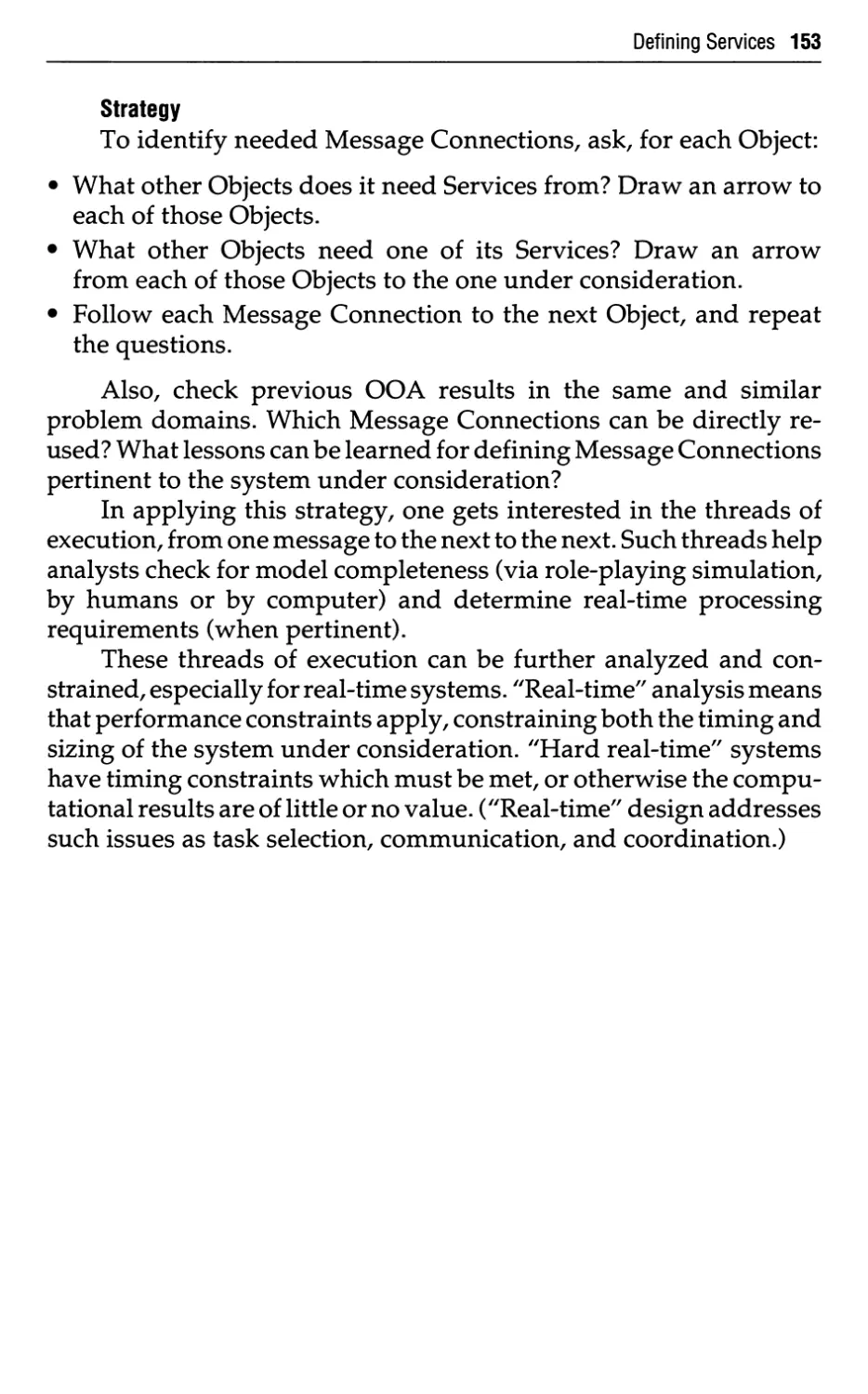
Identify Message Connections
Specify the Services
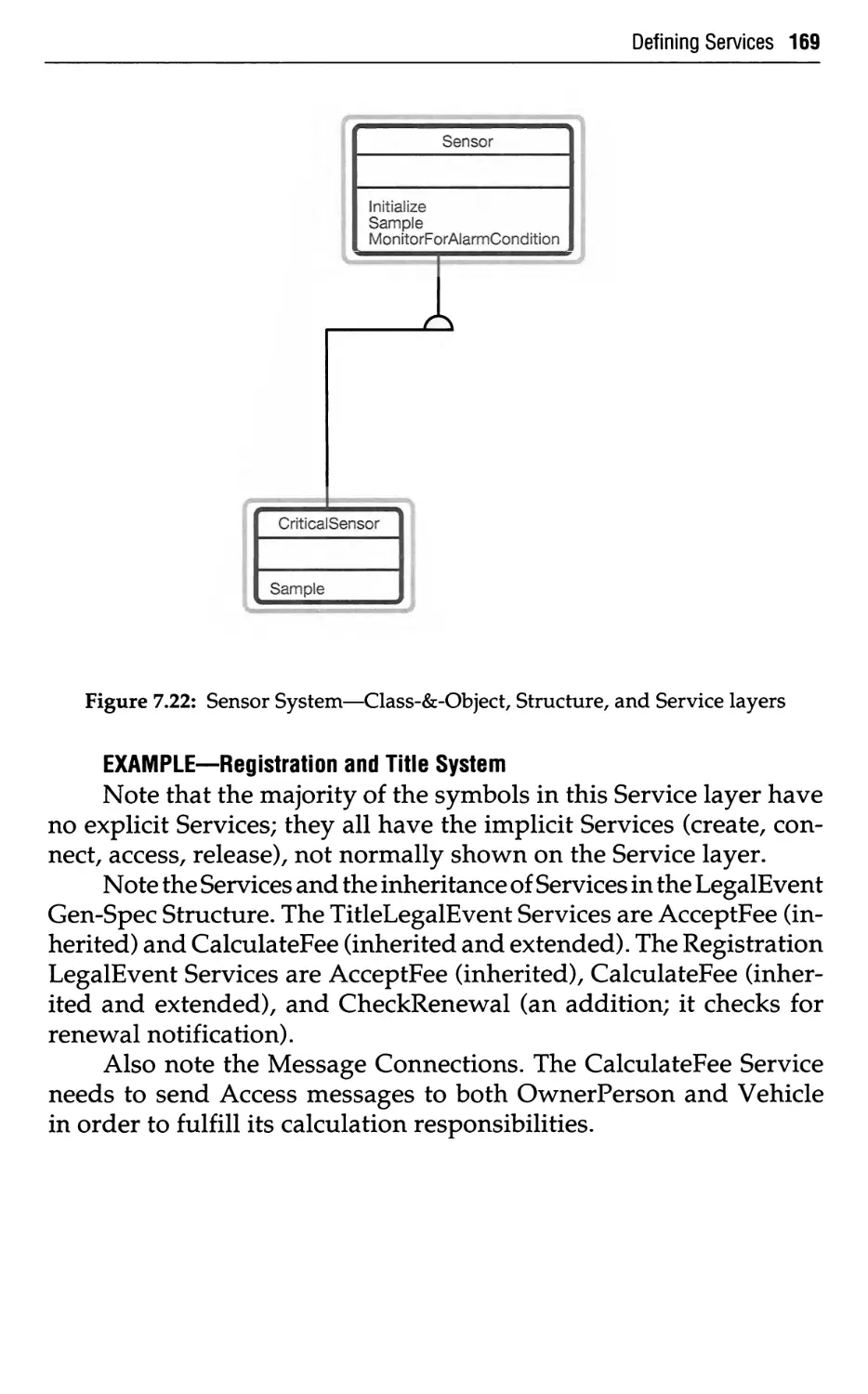
Put the OOA Documentation Set Together
Services—Key Points
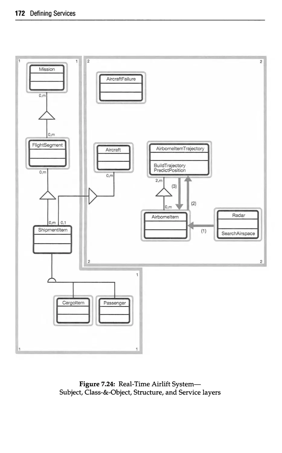
Selecting CASE for OOA
8.1
8.2
8.3
8.3.1
8.3.2
8.3.3
8.3.4
8.4
8.5
CASE—and Some Puzzling Questions
Expanding CASE
What's Needed for OOA
Notation
Layers
Advanced Features
Model Checks
What's Available
Additional Considerations
Moving to Object-Oriented Design
9.1
9.2
9.3
9.4
Looking Ahead to OOD
One Underlying Message
Analysis vs. Design
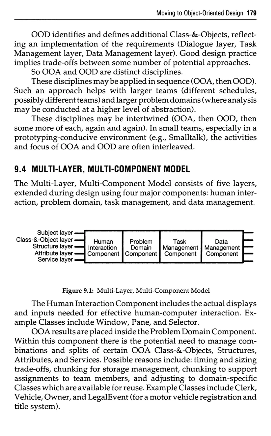
Multi-layer, Multi-Component Model
119
119
119
120
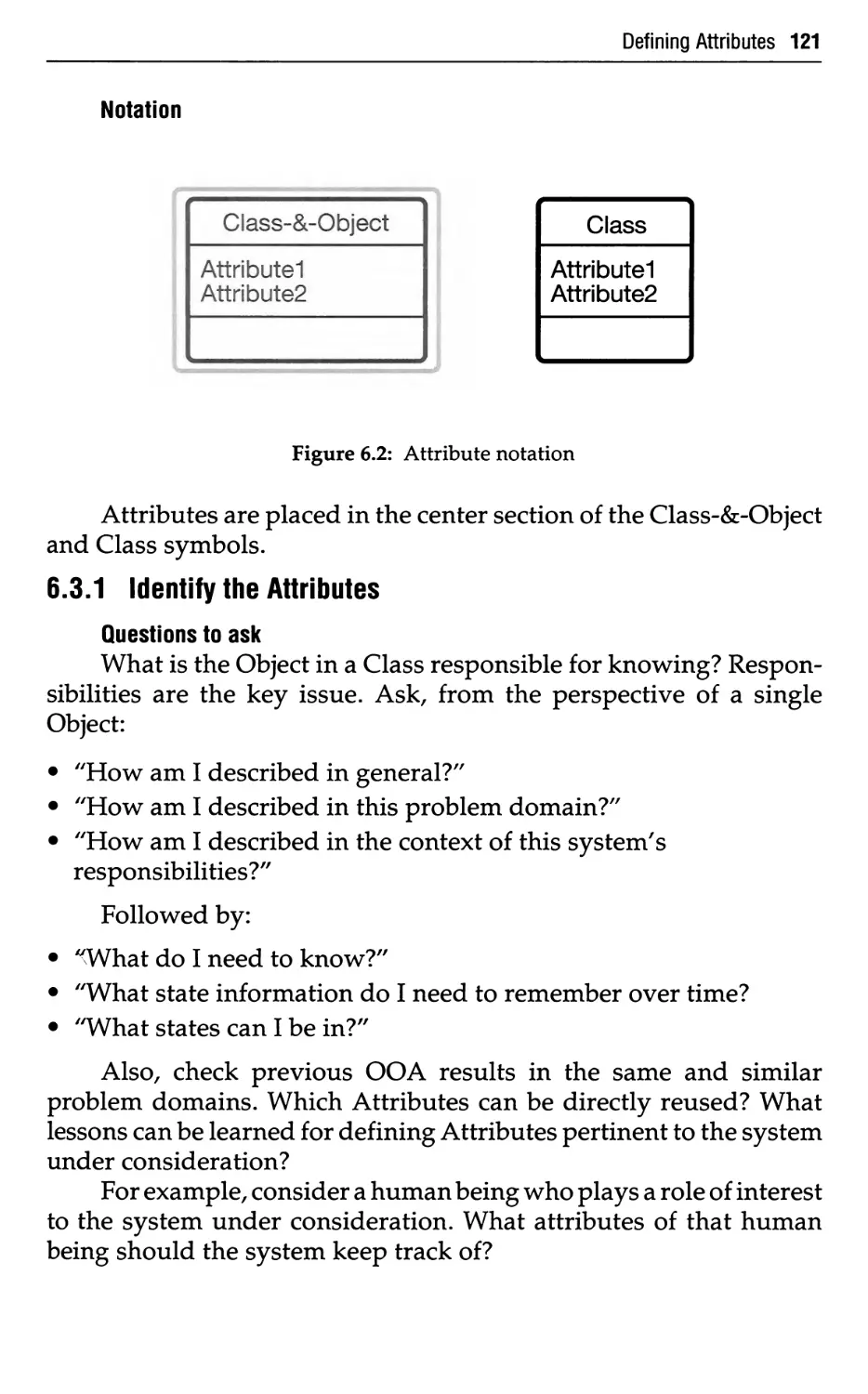
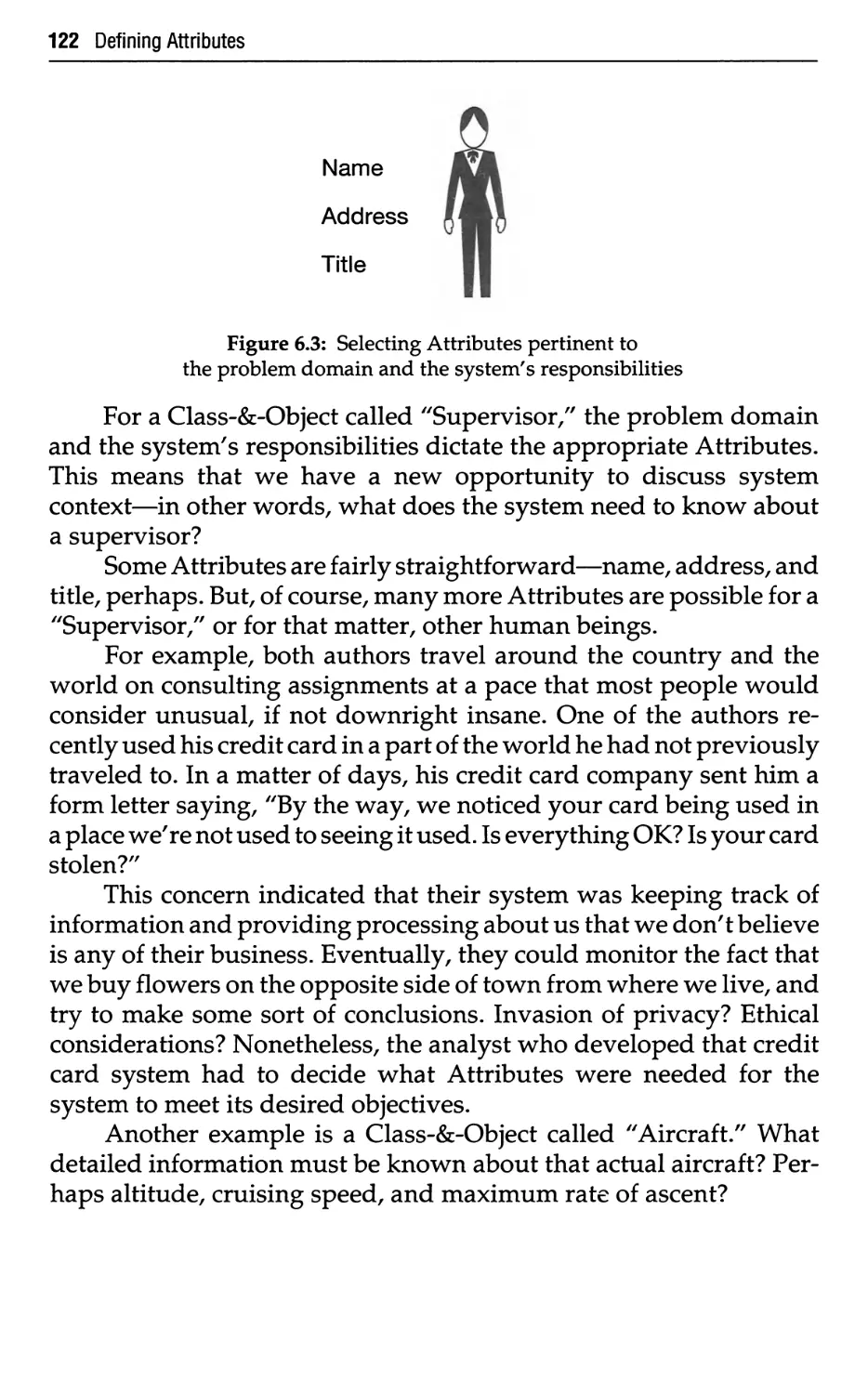
121
125
126
128
128
131
134
135
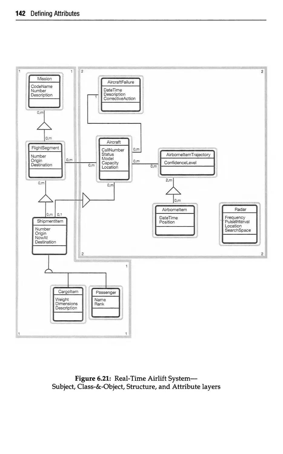
143
143
144
144
145
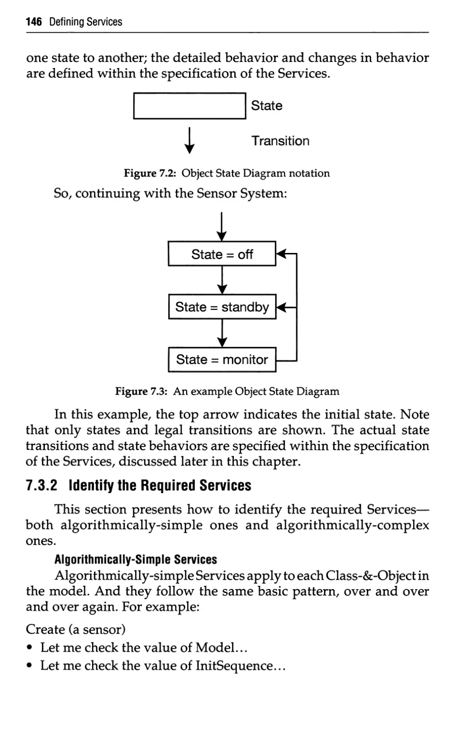
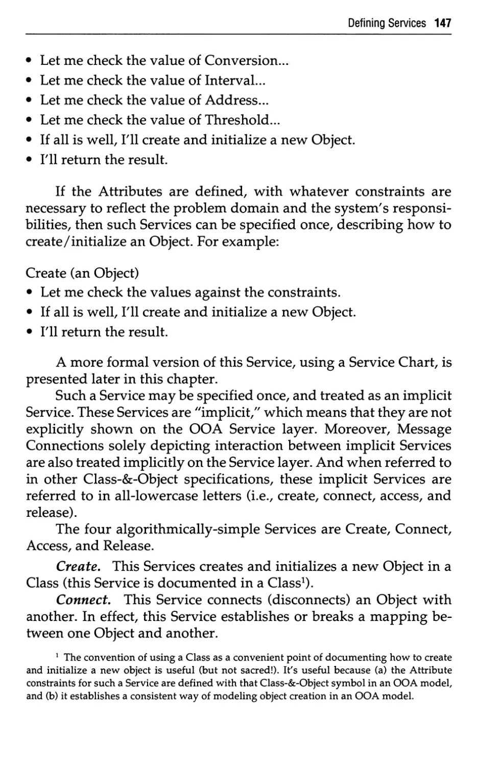
146
149
156
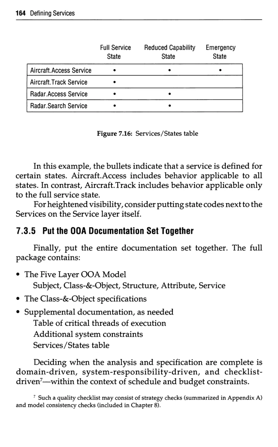
164
165
173
173
174
174
174
175
175
175
176
177
178
178
178
178
179
9.5 A Continuum of Representation 180
9.5.1 A Continuum: OOA to OOD to OOI to OOT 180
9.5.2 Less than a Continuum: What to Do 180
9.5.3 Programming Language Impact 182
9.6 Wrap Up 185
10 Getting Started with OOA 186
10.1 Is OOA the New Silver Bullet? 186
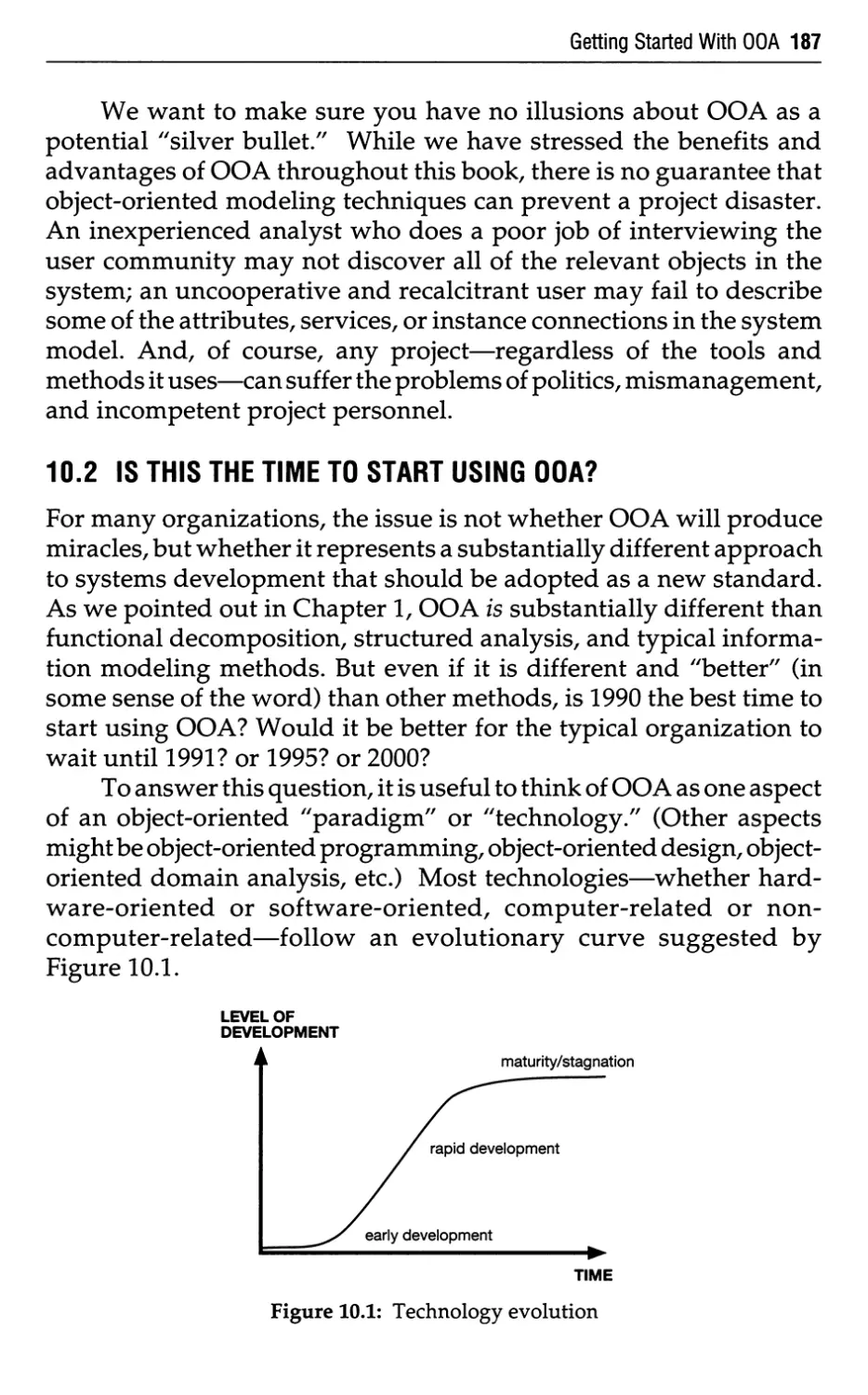
10.2 Is This the Time to Start Using OOA? 187
10.2.1 Is the Object-Oriented Paradigm Mature? 188
10.2.2 Is there a Good Object-Oriented Implementation 189
Technology?
10.2.3 Is the Organization Sophisticated Enough? 190
10.2.4 Is the Organization Building Systems the Will 191
Exploit the Object-Oriented Techniques?
10.3 Revolution versus Evolution 192
10.4 How Should We Begin? 194
10.5 Conclusion 195
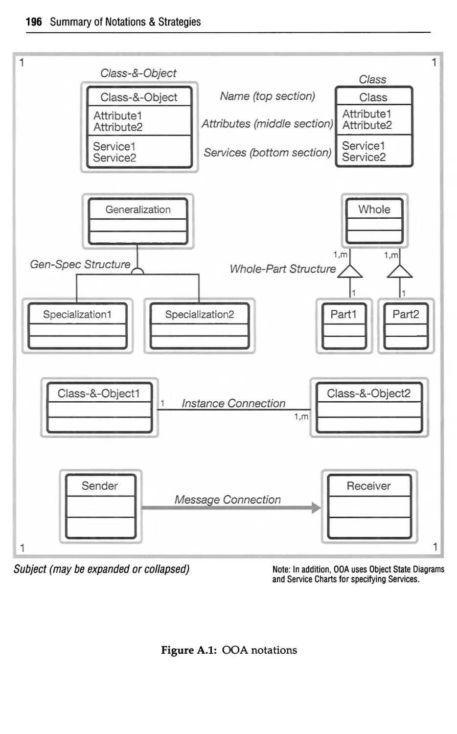
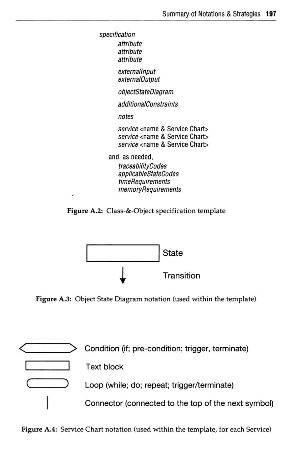
A Summary of Notations & Strategies 195
A.l OOA Notations 196
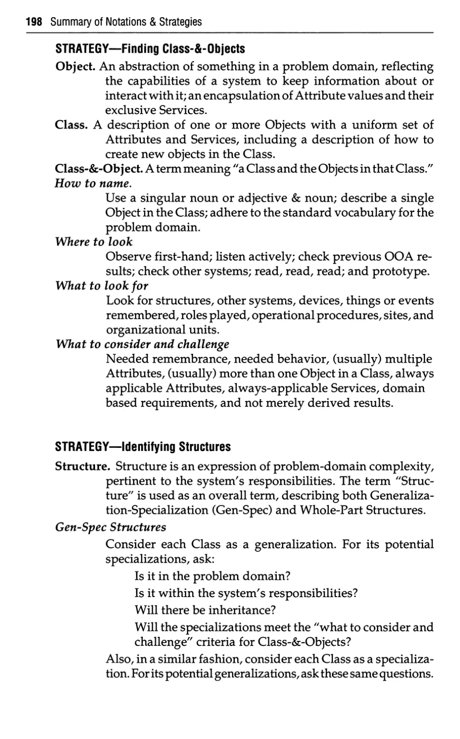
A.2 OOA Strategies 198
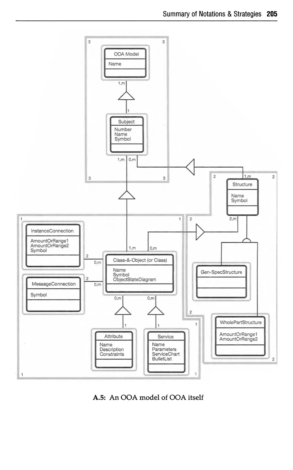
A.3 An OOA Model of OOA Itself 205
B Mapping OOA to DOD-STD-2167A 206
B.l DOD-STD-2167A 206
B.2 Benefits: Point/Counterpoint 206
B.3 Key Improvements with 2167A 208
B.3.1 Development Cycle Independence 208
B.3.2 Software Method Independence 209
B.4 2167A for Commercial Systems?
B.5 OOA and 2167A Documentation: An Overview 209
B.6 System/Segment Specifications (SSS) 210
B.7 System/Segment Design Documentation (SSDD) 211
B.8 Software Development Plan (SDP) 213
B.9 Software Requirements Specification (SRS) 215
B.10 Interface Requirements Specification (IRS) 216
B.ll Summary 217
Bibliography 218
Index 226
Preface to the Second Edition
OOA—Object-Oriented Analysis—is a relatively young method.
We are committed to the continued development of OOA—in practice
and in writing.
This second edition goes well beyond the first edition, incorporating
these major advances:
Terminology and Notation. The second edition defines and
applies the terms "class" and "object" in light of their meanings
established over the centuries (rather than in light of their meanings
established by analysts over a few decades). The OOA notation reflects
the distinction between class and object, too.
Finding Class-&-Objects. Chapter 3 expands and refines the
strategy of "where to look, what to look for, and what to consider or
challenge." The strategy places extra emphasis on examining the
problem domain and establishing the system's responsibilities in that
context.
Identifying Structures. Chapter 4 examines the concept of
Structure. Structure expresses the complexity of a problem domain,
pertinent to a system's responsibilities. "Structure" is used as an overall
term, describing both Generalization-Specialization (Gen-Spec)
Structure and Whole-Part Structure. Chapter 4 includes Gen-Spec Structure
hierarchies and lattices (i.e., single and multiple inheritance). It also
adds several variations of Whole-Part Structures—assembly-parts,
container-contents, and collection-members.
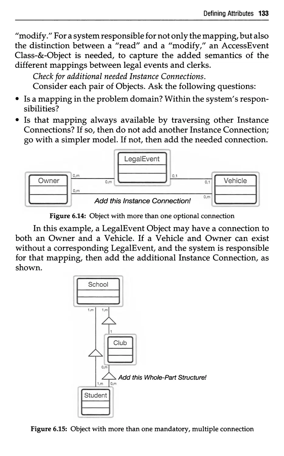
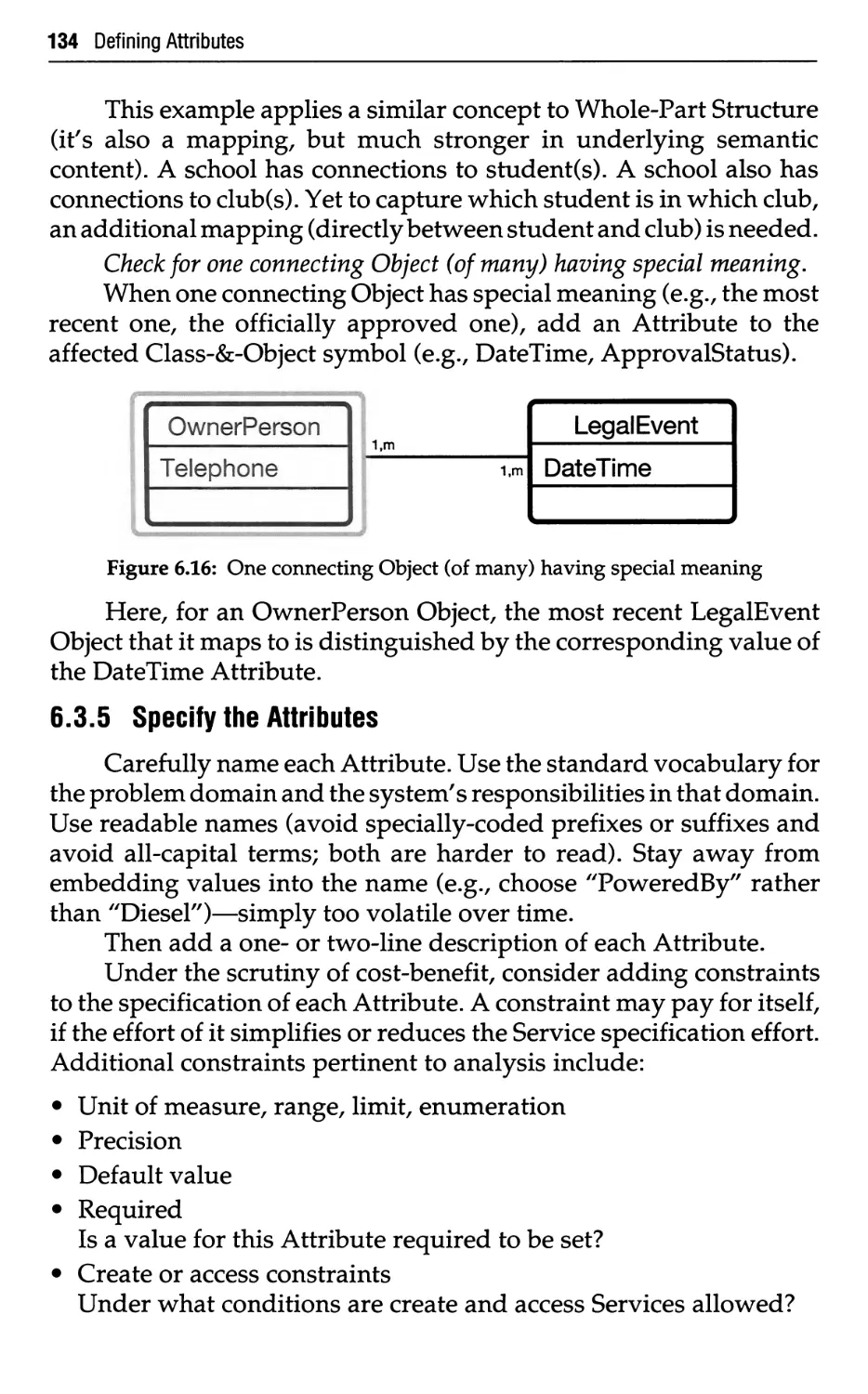
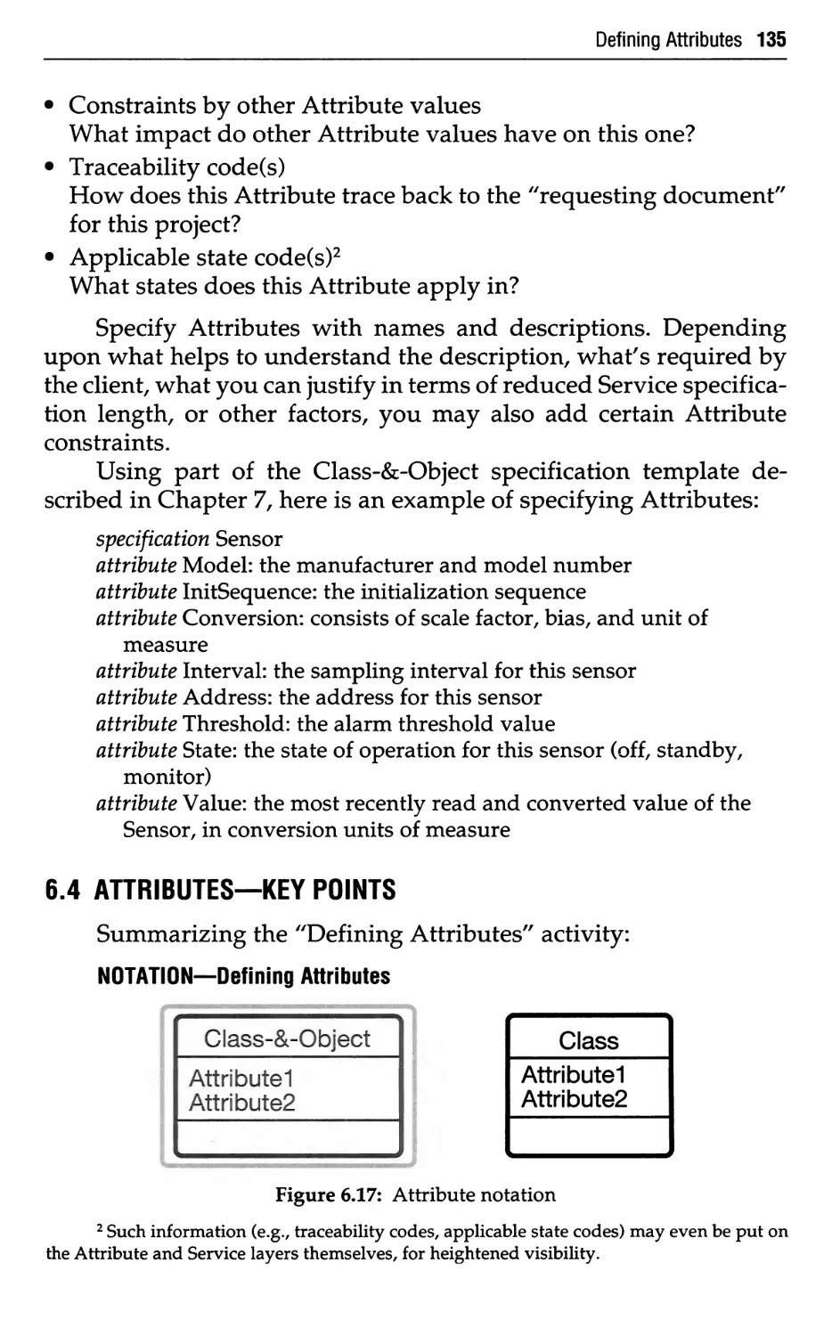
Defining Attributes. Chapter 6 adds strategy steps, stronger
Attribute constraints, and an overall emphasis on what an Object is
responsible for knowing over time (its state).
Defining Services. Chapter 7 adds both notation and strategy
steps, emphasizing what an Object is responsible for doing (its
behavior). The chapter adds Object State Diagrams and Service Charts; in
practice, the content of our specifications has improved significantly
with these additions.
xi
xii Preface
OOA & CASE. We used a CASE tool for all examples in the
second edition. The second edition includes a business reply card,
offering a small project edition of OOATool™ at nominal cost. With this,
we establish a trend for other authors to follow: here's a method and an
inexpensive tool—to accelerate the method into practice.
Moving to OOD. Chapter 9 presents an overview of our
investigative research into Object-Oriented Design, to be further expanded
in our upcoming book on this topic.
Getting Started with OOA. This chapter addresses key issues
related to introducing OOA into an organization.
We genuinely thank Prentice Hall for the opportunity to
incorporate these advances into this second edition.
Peter Coad
Object International, Inc.
Austin, Texas
USA
Edward Yourdon
New York City, New York
USA
Acknowledgments
From Peter Coad:
First, special thanks (and love) to two extraordinary teachers—
ones who have instilled a passion for excellent teaching within me—the
Drs. Mr. and Mrs. Peter Coad Sr. (Hi, Mom and Dad!).
Next, a warm thank you to my clients and seminar delegates in
Australia, Canada, Great Britain, Germany,France,Israel,Italy,Sweden,
and the United States. So much of what OOA is today is a direct result
of your thoughtful considerations and suggestions. I remain most
grateful to you.
I'm very thankful for those who have allowed me to work with
them on OOA, including Bob Holibaugh (Software Engineering
Institute), Charles Pitcher and Al Woolfrey (Canadian Imperial Bank of
Commerce), Trevor Moore (NSW State Rail, Australia), Christer Hoberg
and Mats Weidmar (Enea Data, Sweden), Margaret Jenny (Mitre), Tom
Turba and Linda Huebscher (Unisys), Aub Chapman (Westpac Banking
Corporation, Australia), Fred Hills (Software Productivity
Consortium), Dave Blue and Mike King (CTA), and Jay Crawford (Naval
Weapons Center).
And thank you to those who encouraged and helped me through
the years, including: Mark Mitchell, Larry Young, Tom Huchel
(Technology Training Corp.); Tammy Rimmer (JPL); Tom Jensen, Karen
Reynolds (Hughes Aircraft Company); Lin Conger (Marvelin Corp.);
Howard Metcalfe, Dick Brewer, Bruce Eckoff, Penny Bevier (Telos
Corp.); Bob Braden, Sandy Barling (Texas Dept. of Motor Vehicles);
Ralph Kirkley (Ralph Kirkley Associates); and Vicki Munro (Naval
Weapons Center).
From Ed Yourdon:
Thanks to a number of people who have urged me during the past
several years to focus more on an object-oriented view of the world:
Dave Bulman, Mike Silves, Larry Proctor, Steve and Greta Blash, and
the late Matt Flavin.
From both of us:
Thanks also to a group of authors whose work in the field over the
past decade has helped lay a foundation for our work in this book:
xiii
xiv Acknowledgments
Grady Booch, Brad Cox, Bertrand Meyer, Adele Goldberg, Michael
Jackson, Chris Gane, Ed Berard, and Ken Orr.
Thanks to the official reviewers of the first edition, for their patient
readings and valuable insights: Sam Adams (Knowledge Systems
Corporation), Alan Davis (George Mason University), Tom Jensen
(Hughes Aircraft Company), Charles McKay (University of Houston,
Clear Lake), Michael Rissman (Software Engineering Institute), and Ed
Seidewitz (Goddard Space Flight Center).
Thanks to Toni for her cheerful editing work. And thanks to the
Prentice Hall staff that worked so diligently with us in producing this
book, including Bernard Goodwin, Paul Becker, Barbara Marttine, and
Noreen Regina.
From both of us, in preparing the second edition:
We are very grateful to five special reviewers:
Sam Adams (Knowledge Systems Corporation)
Alan Davis (George Mason University)
Tom Jensen (Hughes Aircraft Company)
Jeff McKenna (McKenna Consulting Group)
Ragan Wilkinson (Object International, Inc.)
The second edition is far better as a result of their kind help and
valuable advice.
Thanks to our colleagues at Knowledge Systems Corporation—
Sam Adams, Ken Auer, Steve Burbeck, Reed Phillips, and S. Sridhar (plus
Larry Marran from HP). And thanks to Hermann Schindler (Advanced
Micro Devices).
Thank you to the Prentice Hall staff that worked together with us
on this second edition, including Bernard Goodwin, Paul Becker,
Barbara Marttine, and Noreen Regina. Plus, thanks to Karen Comstock
and her colleagues at Morgan-Cain & Associates (Tucson, Arizona
USA).
Introduction
OOA—Object-Oriented Analysis—is based upon concepts that we
first learned in kindergarten: objects and attributes, wholes and
parts, classes and members. Why it has taken us so long to apply these
concepts to the analysis and specification of information systems is
anyone's guess—perhaps we've been too busy "following the flow"
during the heyday of structured analysis to consider the alternatives.
As the Encyclopaedia Britannica points out:
In apprehending the real world, men [people] constantly employ
three methods of organization, which pervade all of their thinking:
(1) the differentiation of experience into particular objects and
their attributes—e.g., when they distinguish between a tree and
its size or spatial relations to other objects,
(2) the distinction between whole objects and their component
parts—e.g., when they contrast a tree with its component branches,
and
(3) the formation of and the distinction between different classes
of objects—e.g., when they form the class of all trees and the class
of all stones and distinguish between them.
[Britannica, "Classification Theory/' 1986]
The notation and approach of OOA builds upon these three
constantly employed methods of organization.
Several years ago, one of the authors consulted, during a two-
and-a-half year period, on the practical application of real-time
structured analysis on a major air traffic control project. His
observations were interesting and yet disturbing. One team of analysts (the
"DFD Team") started their projects using data flow diagrams to
develop an overall functional decomposition, as a framework for
further specification. Meanwhile, a second team of analysts (the
"Data Base Team") started by focusing on the information the system
needed to do its job and then building an information model (also
known as an Entity-Relationship Diagram or a Semantic Data Model).
1
2 Introduction
Over time, the DFD Team continued to struggle with basic problem
domain understanding (e.g., the details of what happens when one
controller hands off responsibility for an aircraft to another
controller). In contrast, the Data Base Team gained a strong, in-depth
understanding of air traffic control. Yet the results of the two teams
did not mesh together; worse, they contradicted each other. In
principle, these two models should somehow come together. Yet under
the pressures of schedule and budget, the results were pushed into
preliminary design, with the hope of resolving the discrepancies at
that time. Sadly, the Data Base Team was perceived as irksome, even
somewhat as troublemakers; people (and their careers) paid the price
for this major rift and its untidy resolution.
A few years later, the same author saw this same pattern develop
on projects at a federal government agency and a state government
agency. The DFD Team marched on, ahead in time and political
power. The Data Base Team gained tremendous insight, vital to
analysis but all too often ignored. And again, the Data Base Team and
its leader were perceived as troublemakers.
Repeatedly, in practice, separate notations and strategies for
different process and data models have kept the two forever apart.
Because of this chasm, we began the research and development of a
method—notations and strategies—that would help analysts gain
the much-needed problem domain understanding first, and then add
the behavior (processing) requirements within the framework of that
solid understanding. We put the method to work in practice, refining
and building the approach into a systematic method. Over the past
few years, both authors have presented the method to top
professionals in Austria, Australia, Brazil, Canada, Denmark, Great Britain,
Germany, France, Hong Kong, India, Israel, Italy, Japan, the
Netherlands, Singapore, South Africa, Spain, Sweden, and the United States,
receiving valuable feedback and insight from the delegates. In
applying OOA on actual projects, both clients and seminar participants
significantly contributed to the development of this method.
0.1 ORGANIZATION
This book presents OOA in ten chapters.
Chapters 1 and 2 lay the foundation. 'Improving Analysis''
examines the challenge of systems analysis, and then reviews some
principles for managing complexity. It then summarizes four popular
Introduction 3
analysis methods: Functional Decomposition, Data Flow, Information
Modeling, and Object-Oriented. Chapter 2, "Experiencing An Object
Perspective/' explores a fully object-oriented programming language
and environment to illustrate some key points for use in OOA.
Chapters 3 through 7 cover the OOA method in five major
activities: Finding Class-&-Objects, Identifying Structures,
Identifying Subjects, Defining Attributes, and Defining Services. Each
chapter is organized into What, Why, How, and Key Points (a concise
summary).
Chapter 8, "Selecting CASE for OOA," describes Computer-
Aided Software Engineering (CASE) support for OOA, showing
what is needed and what is currently available.
Chapter 9 moves into Object-Oriented Design (OOD),
describing design considerations and what happens to the OOA model as
OOD proceeds.
Finally, Chapter 10 addresses key issues related to introducing
OOA into an organization.
Appendix A presents a concise summary of OOA notations and
strategies. It also includes an OOA model of OOA itself.
Appendix B illustrates how to apply OOA when working with
the U.S. Defense Department's DOD-STD-2167A, Defense System
Software Development.
0.2 WHY DO WE NEED OOA?
The key motivations and benefits for OOA are presented here, to help
two kinds of readers. For the manager, this section highlights why he
might encourage his subordinates to use OOA. For the technical staff
member, this section presents rationale that he may use to convince
a manager to let him use OOA.
The motivations and benefits are as follows:
1. Tackle more challenging problem domains. OOA brings extra
emphasis to the understanding of problem domains.
2. Improve analyst and problem domain expert interaction. OOA
organizes analysis and specification using the methods of organization
which pervade people's thinking.
3. Increase the internal consistency of analysis results. OOA reduces the
bandwidth between different analysis activities, by treating
Attributes and Services as an intrinsic whole.
4 Introduction
4. Explicitly represent commonality. OOA uses inheritance to identify
and capitalize on commonality of Attributes and Services.
5. Build specifications resilient to change. OOA packages volatility
within problem-domain constructs, providing stability over
changing requirements and similar systems.
6. Reuse analysis results, accommodating both families of systems and
practical tradeoffs within a system. OOA organizes results based
upon problem domain constructs, for present reuse and for future
reuse.
7. Provide a consistent underlying representation for analysis (what is to
be built) and design (how it is to be built this time). OOA
establishes a continuum of representation, for systematically expanding
analysis results into a specific design.
0.3 AUDIENCE
We have aimed this book at the practicing systems analyst, the person
who has to tackle real-world systems development projects every
day. We assume a fundamental understanding of computer
technology and systems analysis concepts, and we expect that many of our
readers will have had some experience with such analysis tools as
data flow diagrams and entity relationship diagrams. Managers,
testers, standards bearers, and clients can read the book and expect to
profit from the overall approach to improving systems analysis.
For managers, we suggest that you begin with the key issues
related to introducing OOA into an organization (Chapter 10). Then
proceed to the chapters on improving analysis (Chapter 1) and on
CASE (Chapter 8). Finally, for added technical detail, read the other
chapters.
0.4 FOCUS AND HISTORY
Though it will become abundantly clear in the following chapters, we
should stress here that our concern in this book is with object-oriented
analysis, not Object-Oriented Programming (OOP) or Object-Oriented
Design (OOD). Systems analysts first must understand the problem
domain at hand; it makes little sense to run off and start writing air
traffic control functional requirements—let alone thinking about
design architectures or writing code—without first studying,
expressing, and validating our understanding of what air traffic control
Introduction 5
is really all about. Objects as abstractions of the real world provide a
focus on significant aspects of the problem domain and the system's
responsibilities; ultimately this knowledge results in a tangible,
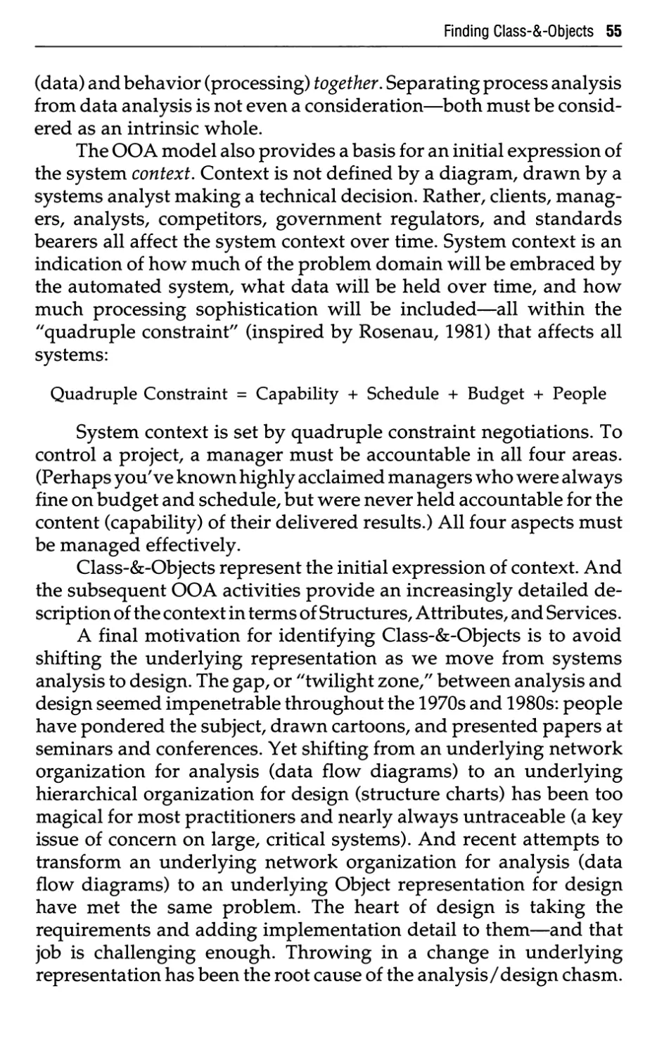
reviewable, and manageable collection of model layers (Subject,
Class-&-Object, Structure, Attribute, and Service) produced during
the five major activities of OOA.
We could argue that this perspective has always been important,
even if it has not been a terribly popular one. If this is the case, then
why this book on OOA? Why has the "object paradigm" finally come
of age? Why now?
Object-oriented programming was first discussed in the late 1960s
by those working with the SIMULA language. By the 1970s, it was an
important part of the Smalltalk language developed at Xerox PARC.
Meanwhile, the rest of the world bumbled along with languages like
COBOL and FORTRAN, and used functional decomposition methods
(which we will discuss in more detail in Chapter 1) to address
problems of design and implementation. Little, if any, discussion
focused on object-oriented design, and virtually none on object-
oriented analysis.
Four changes have occurred over the past decade, and are now
key factors as we enter the 1990s:
• The underlying concepts of an object-oriented approach have had
a decade to mature, and attention has gradually shifted from issues
of coding, to issues of design, to issues of analysis. The proponents
of functional decomposition spent a decade progressing from
structured programming to structured design to structured analysis;
we should not be surprised to see the same progression in the
object-oriented world.
• The underlying technology for building systems has become much
more powerful. Unfortunately, our way of thinking about systems
analysis is influenced by our preconceived ideas of how we would
design a system to meet its requirements; our ideas about design
are influenced by our preconceived ideas about how we would
write code; and our ideas about coding are strongly influenced by
the programming languages we have available. It was difficult to
think about structured programming (and thus difficult to think
about structured design and analysis) when the languages of
choice were assembler, Autocoder and FORTRAN; things became
easier with Pascal, PL/1, ALGOL, FORTRAN-77, Structured BASIC,
and newer versions of COBOL. Similarly, it was difficult to think
6 Introduction
about coding in an object-oriented fashion when the language of
choice was COBOL, FORTRAN, or plain-vanilla C; it has become
easier with C++, Objective-C, Smalltalk, and Ada.
• The systems we build today are different than they were ten or
twenty years ago. In every respect, they are larger and more
complex; they are also more volatile and subject to constant change.
We will argue in subsequent chapters that an object-oriented
approach to analysis (and design) is likely to lead to a more stable
system. Also, we find that today's on-line, interactive systems
devote much more attention to the user interface than the text-
oriented batch processing systems of the 1960s and 1970s. Some
observers, such as Bill Joy of Sun Microsystems, argue that as much
as 75 percent of the code in a modern system may be concerned
with the user interface—e.g., manipulating windows, pull-down
menus, icons, mouse movements, etc.; this is particularly evident
with the graphical user interface available on Apple Macintosh,
IBM OS/2 Presentation Manager, and Microsoft Windows. Our
experience has been that an object-oriented approach to such
systems—from analysis through design and into coding—is a
more natural way of dealing with such user-oriented systems.
• Many organizations find that the systems they build today are
more "data-oriented" than the systems they built in the 1970s and
1980s. Functional complexity is less of a concern than it was before;
modeling the data has become a higher priority.
0.5 METHOD AND TOOL
With this book, we'd like to set a trend: present a method and a low
cost drawing and checking tool to try it out. The tool presented in this
book is OOATool™.
To provide you with a small project version of OOATool™ at
nominal cost, a business reply card is included in this book (if the card
is gone, please write for details). Send the card to Peter Coad at Object
International, Inc., 3202 W. Anderson Lane, Suite 208-724, Austin,
Texas 78757-1022, USA.
All OOA examples in this book were developed using OOATool™.
Introduction 7
0.6 FUTURE ADVANCES IN OOA
OOA is a relatively young method; it will continue to evolve in
practice. So we implore you, the reader, not to come up to us at
computer conferences and say that you are developing systems
"compliant with the Coad/ Yourdon OOA standard/7 Rather, use this
book as a starting point for applying OOA—tailoring and expanding
the method to suit your specific organization or project needs.
To provide you with updates on OOA, a business reply card
offering free special reports, The Coad Letter™: New Advances in
Object-Oriented Analysis and Design, is included in this book (if the
card is gone, please write for details). Send the card to Peter Coad at
Object International, Inc., 3202 W. Anderson Lane, Suite 208-724,
Austin, Texas 78757-1022, USA.
In addition, ongoing developments in OOA and OOD are
discussed in Ed Yourdon7s monthly software journal, American
Programmer. For a complimentary sample issue, contact Ed Yourdon at
American Programmer, Inc., Dept. 13, 161 West 86th Street, New
York, NY 10024-3411.
We expect to further develop OOA over time. Some of the issues
under consideration include the following:
1. Putting together dozens of OOA models from other practitioners,
and describing the patterns observed and lessons learned across a
wide variety of problem domains.
2. Developing OOD as a multi-layer, multi-component model.
3. Developing cost estimation techniques specifically for Object-
Oriented Development.
4. Adding guidelines for risk identification, risk analysis, and risk
management specifically for Object-Oriented Development.
1
Improving Analysis
In this chapter, we examine the analysis challenge, principles for
managing complexity, and analysis methods, including an overview
of OOA.
1.1 THE ANALYSIS CHALLENGE
Systems analysis exhilarates and exasperates those who fall prey to
its siren song. What is so difficult about analysis? What is the
challenge? We feel that four major difficulties plague systems
analysts on all types of projects: problem domain understanding, person-
to-person communication, continual change, and reuse.
1.1.1 The Problem Domain and the System's Responsibilities
One of the biggest problems faced by analysts is studying the
problem domain and making discoveries about it.
In fact, analysts need to investigate the problem domain and the
system's responsibilities within that problem domain. The terms
"problem domain" and "system's responsibilities" help make a needed
distinction for effective analysis.
Problem, [to throw forward, to drive forward (Greek)] A
question proposed for solution or consideration
Domain, [right of ownership, dominion (Greek)] The sphere or
field of activity or influence; as the domain of art or politics
[Webster's, 1977]
And so—
Problem Domain. A field of endeavor under consideration.
Examples of problem domains include air space management,
avionics, finance, and law.
One aspect of OOA is gaining an understanding of the problem
domain. And then the analyst focuses in on those matters pertinent
8
Improving Analysis 9
to his work, namely, describing the responsibilities of the system
under consideration.
System, [to place together (Greek)] A set or arrangement of things
so related or connected as to form a unity or organic whole; as, a
solar system, irrigation system, supply system.
Responsibility, [requiring an answer (Greek)] The condition,
quality, fact, or instance of being responsible, answerable,
accountable, or liable, as for a person, trust, office, or debt.
[Webster's, 1977]
And so—
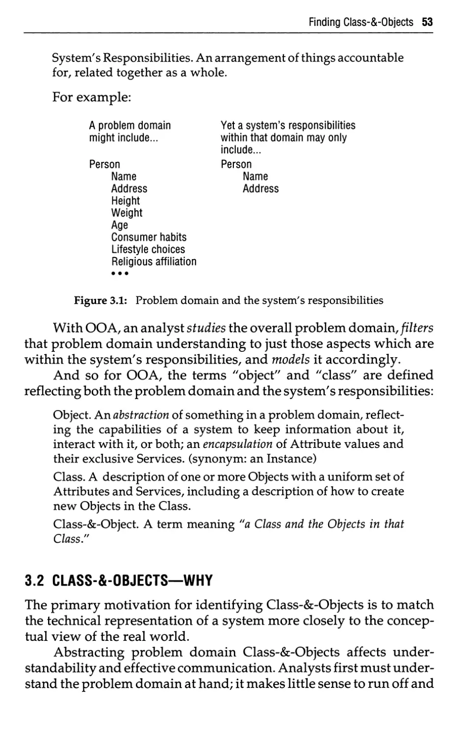
System's Responsibilities. An arrangement of things accountable
for, related together as a whole.
OOA is the challenge of understanding the problem domain,
and then the system's responsibilities in that light. As consultants, the
authors have usually experienced this problem in an extreme form:
we were dropped into a project for a week, a month, or occasionally
as long as a year. In most cases, we couldn't pretend at all to be subject
matter experts in the client's business or application. We needed to
grasp, to understand in depth, the problem domain—and we needed
to do it as quickly as possible. Of course, the situation is less extreme
for many systems analysts—but even if you happen to be a subject
matter expert as well as an analyst, you still need tools to effectively
communicate your expertise to others on your team. For example, if
you have been working with radar systems for the past 20 years, you
probably have intimate knowledge of the problem domain; if the time
has come to specify the requirements for yet another radar system,
your primary problem may be that of communicating with other
radar experts as well as project members who can't distinguish a
radar from a grapefruit.
Analysts must consider the problem domain in which they
work. For example, consider the problem of air traffic control. The
analyst needs to immerse himself in that problem domain, immerse
himself so deeply that he begins to discover nuances that even those
who live with air traffic control every day have not yet fully
considered. As another example, consider a business system that maintains
information about motor vehicle registrations and titles; an analyst
working on such a system would need to study and assimilate all
sorts of details—and many exceptions to the rules, resulting from
special interest group demands and the statutes that follow.
10 Improving Analysis
This discussion has described a major part of what it is to be an
effective analyst. It's much more than just writing some observable,
measurable functional requirements. Yes, an analyst needs to specify
requirements, concisely packaged so that fellow human beings can
read and understand what the analyst believes those requirements
are. But understanding the problem domain is really the crux of
systems analysis.
If an analyst simply assumes that he has subject matter
knowledge, he is likely to indulge in thinking that will lead to fuzzy
requirements. One of the authors was recently involved in a large air
traffic control project, in which requirements analysts were still
grappling with basic air traffic control concepts even after two years
of specifying software requirements. This situation should not have
occurred. Analysts need to understand and model the problem
domain, especially for large, complex systems; with such understanding,
the textual specification of measurable requirements can be done in
a fairly straightforward fashion.1
1.1.2 Communication
The analysis challenge also requires effective communication.
An analyst needs to communicate throughout the analysis effort. He
must communicate just to extract information about the problem
domain and requirements from the client. He thinks about all of this
communication and refines it himself. He interacts with his peers.
Ultimately, he needs to echo his problem domain understanding and
subsequent requirements back to the client, to validate his
understanding of the requirements. He may also need help in steering his
client away from requirements that cannot be met within budget and
schedule constraints.
A funny irony exists in the term "software engineering": though
the words conjure up images of formulas, algorithms, and "hard"
scientific approaches, software engineering is actually a very people-
oriented business. Recently, one of the authors spoke at a conference
in Chicago and was asked if OOA (and/or other software methods)
was the key to successful software development. The response? Yes,
having a consistent technical approach is very valuable. Yet software
methods are effective only to the extent that they help people to
1 Regardless of the method or modeling approach, it is unlikely that an analyst will fully
understand the problem domain and the system's responsibilities at the beginning of a project.
Analysis is a process of continual learning about the nuances of a problem domain and the
system's responsibilities.
Improving Analysis 11
communicate with one another. If the application of a software
engineering "method" produces a monument of paper, then
something is wrong—in the method, in the application of the method, or
perhaps both. If we lose sight of people and begin producing charts,
diagrams, and piles of paper as ends unto themselves, we fail to
effectively communicate. Software engineering is a people business.
People make the problems; people solve the problems. And we can
solve our systems development problems only by interacting with
each other.
At this same computer conference, the beleaguered author then
did a "bad" thing. He asked how many educators in the audience
required some interpersonal communications training as part of their
software engineering program. No hands were raised. Yet effective
communication—with management, peers, reviewers, standards
bearers, and clients—is vital to successful systems analysis.
Viable software methods must facilitate communication.
Successful software methods build upon human methods of
organization, rather than upon a contrived notation that works well for
computation (e.g., "follow the flow") but not for humans.
1.1.3 Continual Change
The requirements for a system will always be in a state of flux.
Management or clients may impose an artificial freezing of
requirements at a particular point in time. But the true requirements, the
needed system, will continue to evolve. Many forces affect this ever-
changing requirements set: clients, competition, regulators, approvers,
and technologists. As Gerhard Fischer points out [Fischer, 1989], "We
have to accept changing requirements as a fact of life, and not
condemn them as a product of sloppy thinking."
An analyst endeavors to organize his notations and strategies so
that his work is resilient to change. He seeks requirements packaging
that will remain stable over time. The explicit capture of commonality
is a great help here, for both data and processing. And as he finds
computer implementation issues and other design considerations, he
tucks them into a file folder, deferring added complexity until the
requirements are put forth.
1.1.4 Reuse
Our colleague Tony Wasserman encouraged us to investigate
reusable analysis results. And we've benefited greatly from Will
12 Improving Analysis
Tracz [Tracz, 1988a] during these investigations.
Reuse. To put or to bring into action or service again; to employ for
or apply to a given purpose again.
[From "re-" and "use/' Webster's, 1977]
In analysis, reuse is the act of incorporating previous analysis
results into the current one. Yet very little analysis reuse has
happened in the past. For example, one government contractor has built
systems within the same basic problem domain over a 25 year period.
The problem domain has changed very little in that much time; yet
such stability over time has not been applied as a framework for
communicating or reusing analysis results from one project to the
next.
More effective analysis requires the use of problem domain
constructs, both for present reuse and for future reuse.
Reusable analysis results carry the greatest potential for
improving system development—people delivering specific capabilities
within schedule and budget.
1.2 PRINCIPLES FOR MANAGING COMPLEXITY
This section sets forth these major principles for managing
complexity of a problem domain and the system's responsibilities within it:
• Abstraction
Procedural
Data
• Encapsulation
• Inheritance
• Association
• Communication with messages
• Pervading methods of organization
Objects and attributes
Whole and parts
Classes and members, and distinguishing
between them
• Scale
• Categories of behavior
Immediate causation
Change over time
Similarity of functions
Improving Analysis 13
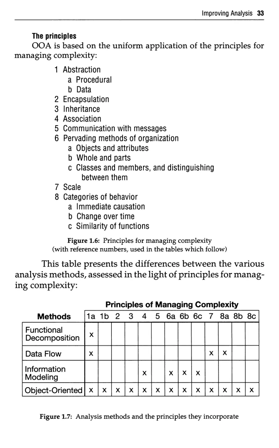
Various analysis methods incorporate some or all of these
principles. Here, the principles are examined. Later in the chapter,
various analysis methods are examined in light of which principles they
incorporate.
1.2.1 Abstraction
The first principle is abstraction:
Abstraction. The principle of ignoring those aspects of a subject
that are not relevant to the current purpose in order to concentrate
more fully on those that are. [Oxford, 1986]
This term means that even though an analyst knows about many
things, he chooses certain things over others.
Both authors have young children whose rooms are filled with
a variety of toys, many of which are small-scale replicas of airplanes,
cars, and exotic warriors. It's interesting to see how even little
children deal with the concept of abstraction: a little toy hook-and-
ladder fire truck, for example, could have been built with a hundred-
pound hose hanging off its side. But the abstraction would be out of
proportion, and rendered useless for its intended user. Yet we know,
and even the child knows, that the hose is there; we need its
complexity in the real system; but it would be inappropriate for the abstraction
our children play with on their bedroom floors.
Most of what we deal with in the real world—people, places,
things, and concepts—is intrinsically complex, far more complex
than we can cope with in one fell swoop. When we use abstraction, we
admit that what we are considering is complex; rather than try to
comprehend the entire thing, we select only part of it. We know it
contains additional details; we simply choose not to use them at this
time. This technique is an important way to manage complexity.
Procedural abstraction is one form of abstraction used
extensively by requirements analysts, as well as designers and
programmers. It's often characterized as "function/sub-function"
abstraction. You may be familiar with diagramming methods such as
structure charts, with the big box at the top—representing the entire
system or "thing" being considered—and the subordinate steps or
sub-functions shown as smaller boxes below the top-level box.
Procedural Abstraction. The principle that any operation that
achieves a well-defined effect can be treated by its users as a
14 Improving Analysis
single entity, despite the fact that the operation may actually be
achieved by some sequence of lower-level operations. [Oxford,
1986]
Breaking processing (e.g., aircraft tracking) down into sub-steps
is one basic method of handling complexity. But, as we will discuss in
more detail below, using such a breakdown for organizing an entire
analysis and specification is somewhat arbitrary and highly volatile.
(Procedural abstraction is not the primary form of abstraction for
OOA; however, it does come into play in OOA within the limited
context of specifying and describing Services.)
Another, more powerful abstraction mechanism is data
abstraction. This principle can be a basis for organization of thinking and of
specification of a system's responsibilities.
Data Abstraction. The principle of defining a data type in terms
of the operations that apply to objects of the type, with the
constraint that the values of such objects can be modified and
observed only by the use of the operations. [Oxford, 1986]
In applying data abstraction, an analyst defines Attributes. And
he defines Services that exclusively manipulate those Attributes. The
only way to get to the Attributes is via a Service.2 Attributes and their
Services may be treated as an intrinsic whole.
1.2.2 Encapsulation
Another principle for managing complexity is encapsulation:
Encapsulation (Information Hiding). A principle, used when
developing an overall program structure, that each component of a program
should encapsulate or hide a single design decision.... The interface to
each module is defined in such a way as to reveal as little as possible
about its inner workings. [Oxford, 1986]
This definition reflects the design work of David Parnas in the
early 1970s [Parnas, 1972].
The power and attractiveness of encapsulation is that it helps
minimize rework when developing a new system. If an analyst
encapsulates the parts of the analysis effort that are most volatile,
then the (inevitable) changing of requirements becomes less of a
threat to the overall effort. Localizing volatility is essential: whether
we like it or not, we as analysts live in an environment of continual
2 For those familiar with other forms of systems analysis, the term "Service" is equivalent
to the terms "function" or "process."
Improving Analysis 15
change. Encapsulation keeps related content together; it minimizes
traffic between different parts of the work; and it separates certain
specified requirements from other parts of the specification which
may use those requirements.
1.2.3 Inheritance
Inheritance is another underlying principle of OOA:
Inheritance. A mechanism for expressing similarity among Classes,
simplifying definition of Classes similar to one(s) previously
defined. It portrays generalization and specialization, making
common Attributes and Services explicit within a Class hierarchy
or lattice.
This principle forms the basis for a significant technique of
explicit expression of commonality. Inheritance allows an analyst to
specify common Attributes and Services once, as well as specialize
and extend those Attributes and Services into specific cases.
Thus, one might recognize a Vehicle Class as a generalization. A
TruckVehicle Class, as a specialization, inherits Attributes and
Services from "Vehicle." In addition, a specialization can add Attributes;
and a specialization can add Services or extend Services it inherits.
Thus, a "TruckVehicle" might have added Attributes such as
"NumberOf Axles" or "NumberOfWheels," and added Services such
as "Calculate MaxWeightPerAxle," which might not be relevant or
appropriate for "Vehicle" in general.
Inheritance may be applied to explicitly express commonality,
beginning with the early activities of analysis.
1.2.4 Association
Another principle for managing complexity is association.
Association. The union or connection of ideas.
[Webster's, 1977]
People use association to tie together certain things that happen
at some point in time or under similar circumstances.
1.2.5 Communication with Messages
Webster's defines a message with the following:
Message. Any communication, written or oral, sent between
persons.
[Webster's, 1977]
16 Improving Analysis
Message interaction corresponds to the imperative mood in
languages. 'The imperative mood conveys commands or requests...."
[Britannica, "Imperative Mood/' 1986].
A principle for managing complexity—notably for interfaces—
is communication with messages.
1.2.6 Pervading Methods of Organization
It would be intellectually satisfying to the authors if we could
report that we studied the philosophical ideas behind methods of
organization, from Socrates and Aristotle to Descartes and Kant.
Then, based on the underlying methods human beings use, we could
propose the basic constructs essential to an analysis method. But in
truth we cannot say that, nor did we do it.
However, we did approach the problem as practitioners and
investigators. We researched and applied various software subjects,
in particular semantic data modeling and object-oriented
programming languages. We began to ferret out some of the embellishments,
looking for the key principles that could be applied to organizing and
representing requirements. We looked for the concepts that gave the
greatest leverage in understanding and expressing problem domain
knowledge. And we boiled everything down to three key methods of
organization.
Also, we investigated Encyclopaedia Britannica, to read a concise
summary of how people organize their thinking. Here's what we
found:
In apprehending the real world, men [people] constantly employ
three methods of organization, which pervade all of their
thinking:
(1) the differentiation of experience into particular objects and
their attributes—e.g., when they distinguish between a tree and
its size or spatial relations to other objects,
(2) the distinction between whole objects and their component
parts—e.g., when they contrast a tree with its component branches,
and
(3) the formation of and the distinction between different classes
of objects—e.g., when they form the class of all trees and the class
of all stones and distinguish between them.
[Britannica, "Classification Theory," 1986]
Improving Analysis 17
Analysis notation and strategy can build upon these three
constantly employed methods of organization.3
It is worth noting that there are indeed three pervading methods
of organization—not just one. In practice, applying "objects and
attributes/' "whole and parts," and "classes, members, and
distinguishing between them" provides significantly greater insight into a
problem domain and a system's responsibilities than applying only
"objects and attributes."
1.2.7 Scale
A principle which applies the whole-part principle to help an
observer relate to something very large—without being
overwhelmed—is called "scale":
When the proportions of architectural composition are applied to
a particular building, the two-termed relationship of the parts to
the whole must be harmonized with a third term—the observer.
This three-termed relationship is called scale.
[Britannica, "Architecture, The Art of," 1986]
With scale, analysis notation and strategy can include ways to
guide a reader through a larger model.
1.2.8 Categories of Behavior
Shortly after finding the "pervading methods of organization"
statement, we were asked, "Yes, but what about the active side of
objects—what of their behavior?" Having gained such benefit from
Encyclopaedia Britannica before, we turned to it once again. The section
on human behavior was all too bewildering; however, we found a
useful set of behavior categories, just a few pages later:
Three types of behavior classification are used most commonly:
(1) on the basis of immediate causation,
(2) on similarity of evolutionary history [change over time], and
(3) on the similarity of function.
[Britannica, "Animal Behaviour," 1986]
3 In OOA, they are referred to, respectively, as Objects and Attributes, Whole-Part
Structures, and Classes (applying the aspect of "distinguishing between them" with
Generalization-Specialization Structures, Attributes, and Services).
18 Improving Analysis
A major advance in the 1980s (circa 1982) was the addition of an
event-response strategy to structured analysis; this was an
application of the first of these three categories of behavior.
1.2.9 Summary of Principles
So, major principles for managing complexity of a problem
domain and the system's responsibilities within it include:
• Abstraction
Procedural
Data
• Encapsulation
• Inheritance
• Association
• Communication with Messages
• Pervading methods of organization
Objects and attributes
Whole and parts
Classes and members, and distinguishing
between them
• Scale
• Categories of behavior
Immediate causation
Change over time
Similarity of functions
Various analysis methods incorporate some or all of these
principles. We'll examine this further in the pages which follow.
1.3 ANALYSIS METHODS
This section surveys four major approaches to analysis. These
approaches are thinking tools, used to help in the formulation of
requirements.
First, what is systems analysis? DeMarco offers the following
definition [DeMarco, 1978]: "Analysis is the study of a problem, prior
to taking some action/'
To us, analysis is the study of a problem domain, leading to a
specification of externally observable behavior; a complete, consis-
Improving Analysis 19
tent, and feasible statement of what is needed; a coverage of both
functional and quantified operational characteristics (e.g., reliability,
availability, performance).
Analysis means the process of extracting the "needs" of a
system—what the system must do to satisfy the client, not how the system
will be implemented. Systems analysis usually begins with a
requesting document (from the client, or perhaps from the marketing
division) and a series of discussions. In any case, the audience includes
clients, problem domain experts, developers, and possibly other
interested parties (e.g., auditors, contracting officers, etc.) who may
need to understand and agree with the proposed set of requirements.
The requirements document should communicate a complete,
consistent, and feasible statement of what is needed in the system. It
should be manageable both before and after it is produced.
Requirements include functional operations and (quantified!) operational
characteristics such as ease of use, reliability, availability,
maintainability, and performance. Requirements also include interfaces that
the software must deal with, environments the software must
accommodate, and any other applicable design constraints.
A requirements document has two purposes: (1) it formalizes
the needs of the client, and (2) it establishes a list of mandates.
The first three approaches to analysis presented in this section—
functional decomposition, data flow, and information modeling—
have been discussed and practiced in the systems development
profession for a decade or more. We have personally used all three
methods on large systems, sometimes with successful results and
sometimes with abject failure. The strengths of these first three
methods have their place in specific contexts in the fourth method
discussed in this section, OOA. We feel it is important to emphasize
that we are not trying to abolish the underlying principles behind the
older, more established methods. Software methods should be
utterly pragmatic, without religious fervor. An analyst needs all the
help he can get. What we are attempting to do is to incorporate the
best ideas of the first three methods in a more comprehensive, all-
encompassing method—OOA.
Rather than endlessly argue about which method is best, we
prefer to take a pragmatic view, using whatever combination of
approaches helps in a given situation, no matter which methods they
come from.
20 Improving Analysis
Each approach is defined below with an equation, for easy
recognition of the method. Each approach is also examined in light of
large project experience.
1.3.1 Functional Decomposition
Functional decomposition is readily recognized with its steps
and sub-steps. An equation representation useful in identifying this
method is:
Functional Decomposition = Functions
+ Sub-functions
+ Functional interfaces
This representation illustrates how we recognize that something
has been functionally decomposed.
The underlying strategy of functional decomposition consists of
selecting the processing steps and sub-steps anticipated for a new
system. Analysts use previous experience from similar systems,
combined at times with an examination of required outputs. The
focus is on what processing is required for the new system. The analyst
then specifies the processing and functional interfaces.
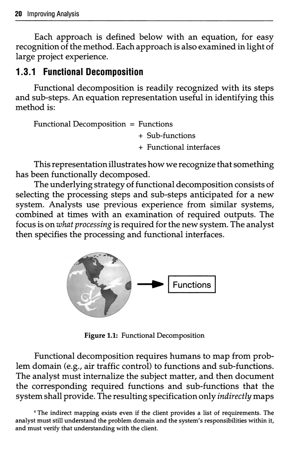
Functions
Figure 1.1: Functional Decomposition
Functional decomposition requires humans to map from
problem domain (e.g., air traffic control) to functions and sub-functions.
The analyst must internalize the subject matter, and then document
the corresponding required functions and sub-functions that the
system shall provide. The resulting specification only indirectly maps
4 The indirect mapping exists even if the client provides a list of requirements. The
analyst must still understand the problem domain and the system's responsibilities within it,
and must verify that understanding with the client.
Improving Analysis 21
back to the subject matter.4 Nothing explicitly maps the functionality
back to the subject matter itself. This method makes it difficult for the
analyst and the client to assess whether or not the requirements are an
accurate statement of what the new system is required to do. With
such an approach, problem domain understanding is neither
explicitly expressed nor verified for its accuracy; subtle aspects of the
problem domain are simply not uncovered.
Is functional decomposition bad? No! After all, eventually both
data and data processing must be specified. In fact, OOA uses
functional decomposition (gasp!), albeit in a very specific context:
defining a Service—a specific behavior that an Object is responsible
for exhibiting. In other words, it may be helpful to break up a large,
complicated Service into smaller pieces for convenience in stating
what is required. For example, an analyst will probably divide a
description of a "Monitor" Service into a number of smaller pieces.
He may also use a block diagram or data flow diagram fragment to
help guide the reader through the requirements of this Service. But
this definition is all done within a very limited context; the processing
steps are not used as the primary organizational framework during
analysis or specification; processing steps are too volatile over time.
Function/sub-function breakdowns are difficult to construct
(because of the indirect mapping) and highly volatile (because of the
continual change of functional capability which may be successfully
delivered within budget and schedule constraints). For these reasons,
we feel that the overall analysis approach should not be based on
function/sub-function; a more stable analysis viewpoint and
specification organization is needed.
In functional decomposition, analysts end up with system,
subsystem, function, and sub-function levels. The problem lies in
choosing the functions and knowing the potential volatility of system
functionality. Another problem facing the analyst is choosing the
functions and sub-functions in such a way that the interface
bandwidth is minimized, both now and over time. Though earlier
textbooks (see, for example, Yourdon and Constantine, 1979, and Page-
Jones, 1988) used the concepts of coupling and cohesion to describe the
composition of system components and the interfaces between those
components, many system developers had a difficult time
identifying sub-functions so that when a processing change came, they
captured the new requirements with a minimum of change to the
analysis and specification organization.
22 Improving Analysis
1.3.2 Data Flow Approach
Another method (and another way to map problem domain and
the system's responsibilities into a technical representation) is the
data flow approach, often described as "structured analysis." One
can recognize a data flow approach with this equation:
Data Flow Approach = Data (& control) flows
+ Data (& control) transformations
+ Data (& control) stores
+ Terminators
+ Process Specs (mini-specs)
+ Data Dictionary
This notation is basic. Sometimes an information model (by
various names, e.g., Entity-Relationship Diagrams) is used too; these
models will be discussed later in this chapter.
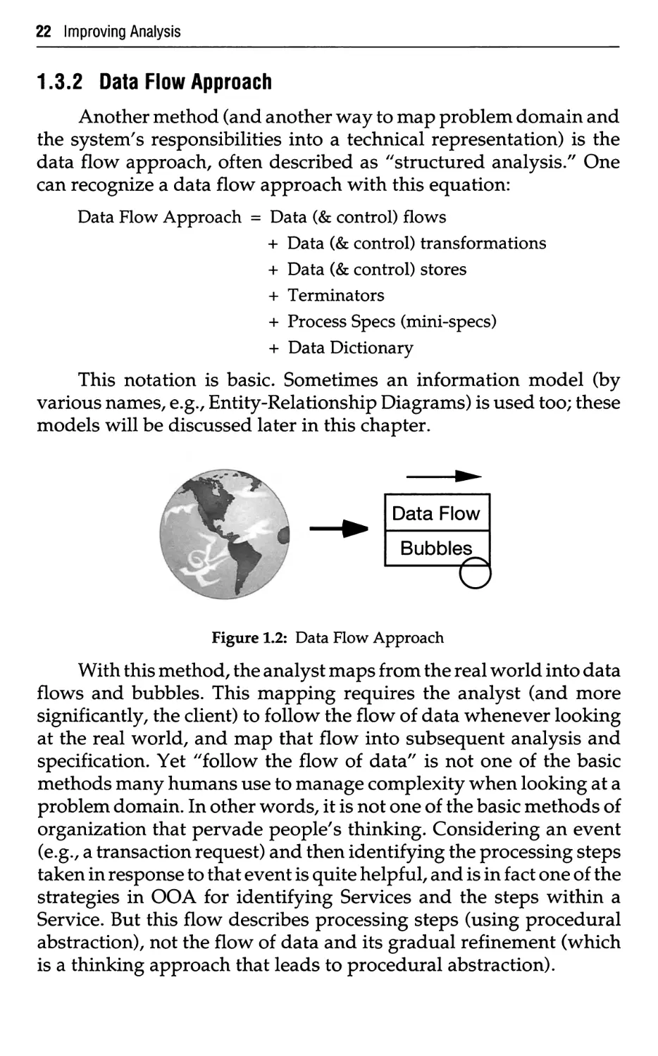
Data Flow
Bubbles
Figure 1.2: Data Flow Approach
With this method, the analyst maps from the real world into data
flows and bubbles. This mapping requires the analyst (and more
significantly, the client) to follow the flow of data whenever looking
at the real world, and map that flow into subsequent analysis and
specification. Yet "follow the flow of data" is not one of the basic
methods many humans use to manage complexity when looking at a
problem domain. In other words, it is not one of the basic methods of
organization that pervade people's thinking. Considering an event
(e.g., a transaction request) and then identifying the processing steps
taken in response to that event is quite helpful, and is in fact one of the
strategies in OOA for identifying Services and the steps within a
Service. But this flow describes processing steps (using procedural
abstraction), not the flow of data and its gradual refinement (which
is a thinking approach that leads to procedural abstraction).
Improving Analysis 23
Two major strategies predominate in structured analysis. The
"old" method (see DeMarco, 1978, and Gane and Sarson, 1977) maps
the current system to data flow diagrams, removes the physical
idiosyncrasies, adds new logical requirements, and then adds new
physical considerations.
For the current U.S. Air Traffic Control System, or for many
states' registration and title systems, the documentation of client
requirements of the existing system consisted of little more than source
code and patched object code from the late 1960s. Studying and
modeling such systems was, in effect, studying and modeling a prior
mapping of the problem domain, rather than the problem domain
itself. Analysts find it difficult to recover from this misplaced focus of
study.
The problems with this older strategy became apparent as team
after team got ensnared as they attempted to model the current
system, while time, budget, and patience wore out. Analysts just did
not know when to stop (and when in doubt, kept adding to the
model). As our colleague Steve McMenamin observes, many analysts
fell into the "current physical tarpit," never to emerge.
The "modern" structured analysis approach first appeared in
seminars as early as 1982, in books as early as 1984 (see, for example,
McMenamin and Palmer, 1984), and more recently in Modern
Structured Analysis in 1989 [Yourdon, 1989]. The strategy developed
because analysts had problems picking bubbles for their data flow
diagrams. So, to assist in picking the bubbles, the first step is to define
events. Events are those occurrences in the outside world that a
planned-response system must respond to.5 Each event corresponds
to a bubble; for a system with 150 events, draw 150 bubbles. Name
each bubble by deciding what the system does in response to the
event. Add appropriate input and output flows to each bubble. Place
data stores between bubbles that need to communicate with data held
over time. Then, group the bubbles into page-size bites. Next, draw
higher-level summaries, up two or three levels, the highest of which
is a "context diagram" in which the entire system is shown as a single
bubble. For lower-level bubbles, apply functional decomposition to
define even lower levels, as needed.
5 The actual interaction between the user and the system is message-based. The event list
documented in the "modern" approach to structured analysis is largely a documentation of the
individual requests made by human users, so that the event and data flow correspondence can
be expressed. Using a message-based interaction model expresses the correspondence directly.
24 Improving Analysis
The additional documentation needed includes specifying the
data flows and bottom-level transformations with a data dictionary
and process specifications, respectively. The upper level diagrams
exist to provide a big picture for the reader; the process specification
content expresses the detail. But much of the lower level detail must
be understood for the graphical summaries to make much sense.
The challenge is in how to pick the bubbles. Event-response
partitioning can help. But with too many events, the number of
bubbles gets out of hand. And little help is given on making groups
of higher levels to improve human understandability—the guideline
"group bubbles that deal with common data stores" sounds sensible,
but often breaks down in practice. Far too often organizations fight
"bubble wars" for extended periods of time, trying to decide which
partitioning is the best choice. Eventually the upper level bubbles
become such conglomerates that their names can say little more than
"Process <noun>."
Another problem with the data flow method is the size of the
data dictionary. If five levels of diagrams exist, hundreds of data flow
leveling equations may be required. Moreover, complex interfaces
(with other systems, devices, and humans) tend to aggravate the data
flow leveling equation problem, leading to project data dictionary
"explosions" of 1000+ pages of dictionary documentation. (The
authors have seen a number of large projects with this recurring
problem.) CASE tools can help get all the syntax in shape. But the
semantics, the underlying meaning, is beyond what any human
reviewer can digest. So communication, most vital in analysis, is
greatly weakened. Moreover, interfaces are volatile. The continual
change for systems with complex interfaces causes even further
syntactic and (more significant) semantic consistency problems.
The data flow approach still has a strong functional emphasis.
And thus it is subject to the same change resiliency weaknesses that
we discussed earlier.
The data flow approach has very weak data structure emphasis,
and this is one of the greater concerns. The data flow diagram gives
very weak emphasis to the data store. And this weakness is duly
acknowledged by many authors describing the data flow method. So,
many authors have tried to tie information modeling concepts into
data flow diagramming to compensate for the weakness. It's an
academically pleasing idea (two perspectives, one system under
Improving Analysis 25
«c
consideration). Yet even in books, the connection is very weak—for
example, Yourdon, 1989, discusses the tie-in, but the leverage
attainable in problem domain understanding from data modeling and its
influence on a data flow model is all but ignored. And, more
important than what a textbook says, in practice the connection seems virtually
non-existent. On large projects that we have observed at several
government contractors, as well as at a variety of business data
processing organizations, the same pattern emerges again and again:
• The analysts rush off to do data flow diagrams.
• After a while, out of synch in time and content, another team works
on an information model (this team is called the "database group").
• The second team gets great subject matter understanding.
• The first team likes the insight but resists the massive changes they
must make (having grabbed for functionality first).
• The functional (DFD) team wins out, and the results of the two
teams never get reconciled ("oh, we'll put it together in design").
Each analyst needs the benefit of both perspectives. In practice,
separate models keep critical issues too disjoint. And although CASE tool
support could help somewhat, the analyst with data flow diagrams
works primarily with a model that hides the impact of the data
structure.6
Another concern is that DFDs are not very helpful for systems or
parts of systems that primarily update and retrieve data. Unlike the
familiar transaction processing systems of the 1970s and early 1980s,
most real-world systems today follow this pattern: the diagrams
basically show a pair of bubbles, one bubble getting data and writing
into a store, and one bubble pulling information out of that store and
delivering the data. For example, an air traffic control system for the
most part uses one bubble to dump in the data, and another bubble to
later retrieve the data. Most of the system can be specified in this
fashion. Pretty bubble-to-bubble-to-bubble textbook transformations
are limited to fairly small aspects of the system, in which the
processing is extensive enough to warrant such a refinement of data from one
sub-step to the next and so on—for example, tracking calculations,
6 Seeing this need again and again spurred us on to develop a single, multiple-layered
notation for OOA; analysts can see the layers they want to see within one model, with the ability
to view Subjects, Class-&-Objects, Structures, Attributes, and Services as a unified whole.
26 Improving Analysis
where tracking is a very important but rather small part when
compared to the overall system to be analyzed and specified.
Another major concern about the data flow approach is moving
to design: the double burden of shifting the underlying method of
organization and adding implementation detail. This burden reminds
the authors of the cartoon that shows a wide planning chart
converging at one point, with a box reading "and then a miracle
happens/' followed by a wide path of planning charts emanating from
the box. The transition from analysis to design has been a constant
source of frustration. Many papers have been written; little progress
has been made. It's tough enough to add implementation-based
design considerations. Adding a substantial shift in underlying
representation has made this transition an untenable problem. Data
flows are a network representation of bubbles and stores; design-
oriented structure charts are a hierarchical representation of
modules. And no matter how many cute cartoons are drawn to depict the
transition, the radical change in underlying representation causes a
major chasm between analysis and design models. As Seidewitz
argues in an unpublished paper [Seidewitz, 1989], "Functional
analysis and specification techniques actually sacrifice closeness to the
problem domain in order to allow a smooth transition to functional
design methods/'
A similar problem plagues those who have tried to follow
structured analysis with object-oriented design; this trouble seems
especially popular with those wrestling with Ada-oriented methods.
However, if the object-oriented paradigm is so powerful as an
underlying design perspective, why not apply those concepts as a
foundation for improving analysis? This technique seems far more natural
than many of the 10-100 page papers we have seen on such a
transition, which in effect say, "Oh good. The analysts have done their
structured analysis stuff. Let's pick the pieces of their results to get a
first-cut, object-oriented view. Then on to the good stuff—design."
This shift in underlying representation causes an even larger gap
between analysis and design models. Such a gap is disastrous over
time: requirements documents are ignored, continual changes in
requirements are difficult to move into the design, and traceability—
a must in Government system acquisition—is left with only form, and
very little content.
For many years, analysts were stymied by the underlying
representation shift as they moved from analysis to design. It prevented
Improving Analysis 27
practitioners from systematically adding design-dependent detail to
the results of analysis. Design should consist solely of expanding the
requirements model to account for the complexities introduced in
selecting a particular implementation—e.g., human-computer
dialogue, task management, and data storage management. Problem
domain constructs, such as Aircraft, should continue from analysis
into design.
It's a matter of using the same underlying representation in
analysis and design.
1.3.3 Information Modeling
Information modeling has evolved over a number of years. The
primary modeling tool of information modeling—the
entity-relationship diagram—has evolved into semantic data models. Modeling the
world in data has helped capture problem domain content.
Here's an equation to help identify this method:
Information Modeling = Objects
+ Attributes
+ Relationships
+ Supertype/Sub-types
+ Associative Objects
Since the mid-70s, the information modeling discipline has used
the term "object" in a very non-standard way, when examined
against the use of the term over the centuries. As used within entity-
relationship modeling (e.g., Chen, 1976), information modeling (e.g.,
Flavin, 1981), and semantic data modeling (e.g., Shlaer and Mellor,
1988), an "object" is a symbol which represents one or more
occurrences of a real-world "entity."
Two strategies have been developed and applied. The older
strategy says: Develop an indented list of attributes. Put the attributes
into object buckets. Add relationships (mappings between
occurrences). Refine with supertype/sub-types (to extract common
attributes) and associative objects (to describe certain relationships). Then
normalize (a step-by-step approach to reduce data redundancy,
typically preparing for relational database implementation).
The newer strategy is much the same, except that the initial step
is to find objects in the real world, and describe them with attributes.
Otherwise, one proceeds in basically the same fashion.
28 Improving Analysis
L
Figure 1.3: Information Modeling
With the newer strategy, information modeling maps directly
from the problem domain to Objects in the model. This improvement
in mapping is large, but a more detailed mapping is needed.
Information modeling is a partial method. It is well presented in
several books (e.g., Shlaer and Mellor, 1988) and papers (e.g., Loomis,
Shaw, Rumbaugh, 1987). Here is a list of missing concepts:
1. Services: the behavior, encapsulated and treated with the Attributes
as an intrinsic whole.
2. Messages: a narrow, well-defined interface, depicting processing
interdependency.
3. Inheritance: explicit representation of Attribute and Service
commonality (more than just extracting common attributes into a
supertype).
4. Structure: Generalization-Specialization and Whole-Part Structures,
as fundamental human methods of organization, are not central
issues (but should be).
1.3.4 An Observation on Stability vs. Volatility
Stability vs. volatility7—at issue is the impact of additions,
extensions, changes, and deletions of features in the description of system
requirements. This is especially important when considering
"families" of systems—i.e., situations where a variety of implementations
may be needed. Stability is also important throughout the development
phase of a project, when over-optimistic goals need to be toned down
from a full implementation (with adequate time, money, and people)
to a lesser system—a phenomenon sometimes called "downsizing
requirements."
Eventually one must address processes and sub-processes
(functions/sub-functions). For example, Services will be needed to
7 This is an extension of Bertrand Meyer's comments on volatility [Meyer, 1988].
Improving Analysis 29
create an Object, connect an Object to other Objects, calculate a result,
and provide ongoing monitoring. Yet how much the players (client,
management, and technical staff) decide to automate this time and
how sophisticated the Services may be are both quite volatile; they are
continually subject to the quadruple constraint—people, capabilities,
schedule, and budget.
External interfaces are the next most likely components to change.
How smart or dumb are the devices? What do other systems need
from the system under consideration? What does this system need
from others? What requests will the human make as he uses the
system?
The next part likely to change includes the Attributes that
describe items in the problem domain. Yet these changes tend to
apply to a single "Class-&-Object" (a shortened way of saying "a Class
and the Objects in that Class"), e.g., "Aircraft" and its Attributes, such
as call number, serial number, location (latitude, longitude, altitude),
and status.
The most stable aspects of a system, those which are least
susceptible to potential change, are the Class-&-Objects which strictly
depict the problem domain and the system's responsibilities within
that domain. For example, whether one specifies a very low-budget
or a very sophisticated air traffic control system, one will still have the
same basic Class-&-Objects with which to organize the analysis and
ultimately the specification: "Aircraft," "Controller," "Airspace,"
and the like. A more expensive system will have more Attributes for
certain Class-&-Objects. Also, a more expensive version will have
more elaborate interfaces for monitoring devices and other systems
(and additional Class-&-Objects to model this). The more expensive
system will have more sophisticated Services defined for each
Classes-Object (e.g., "Aircraft" with an automated tracking Service,
"Aircraft.Track"). Also, the more expensive version may have some
additional Class-&-Objects (e.g., a "Radar" Class-&-Object, with
corresponding Attributes, plus Services such as "Radar.Interrogate").
Yet by and large, the very stable aspect of the system (Class-&-Objects
in the problem domain) will remain the same across what potentially
could be major changes in scope of a software requirements activity.8
So in terms of approach, it's not that an analyst does not specify
Services; this designation must be done, regardless of the simplicity
8 Of course, all systems are susceptible to change, and OOA systems are just as susceptible
as any other. But with OOA, the impact of the change is more easily identified, bounded, and
assessed.
30 Improving Analysis
or complexity of the system. It's what comes first, what
predominates. The key to understanding problem domain lies in deciding
what is the primary view and the overall organization,
communicating that understanding, and ultimately specifying requirements.
Underlying OOA is the idea of using encapsulation to hide the more
volatile elements; with OOA, analysts base the overall structure of
their thinking and specification on the more stable elements.
1.3.5 Object-Oriented
This section presents the basics, the principles, the approach, the
motivations and benefits, and a multi-layer example.
The basics
Terminology. "Object-Oriented" is a difficult term, because the
term "Object" has been used in different ways within two very
different disciplines:
• From Information Modeling, meaning a representation of some
real-world thing, and some number of occurrences of that thing.
• From Object-Oriented Programming Languages, meaning a
runtime instance of some processing and values, defined by a static
description called a "class."
Chapter 3 establishes definitions for both "object" and "class."
An equation for recognizing an object-oriented approach is:
Object-Oriented = Classes and Objects
+ Inheritance
+ Communication with messages9
With this equation, one can look at different languages,
environments, methods, and books and ask "Are they really object-
oriented?" Unfortunately, many times the answer is "no"; object-
oriented suffers from being a catchy marketing phrase, used at times
to mean "the good stuff."
Is Ada an object-oriented language? Not today. Genericity (that
is, typed parameters) is convenient, but no substitute for inheritance.
At some point, Ada itself is likely to include classes, objects, and
9 Communication with messages is a principle for managing complexity. Just because
one programming language has a language construct called "message" (as in Smalltalk) and
another has a language construct called "function" (as in C++) does not make either one more
or less object-oriented.
Improving Analysis 31
inheritance. In the interim, Software Productivity Solutions of
Melbourne, Florida markets ClassicAda™, a preprocessor which
provides the missing object-oriented constructs.
Is Information Modeling object-oriented (e.g., Object-Oriented
Systems Analysis [Shlaer and Mellor, 1988], a book better titled
"Making Semantic Data Modeling Practical")? No. Its "objects" are
data-only. Inheritance is missing. A uniform processing dependency
mechanism is missing.
Merging of Disciplines. OOA builds upon the best concepts
from Information Modeling, Object-Oriented Programming
Languages, and Knowledge-Based Systems—the concepts which have a
solid basis in underlying principles for managing complexity.
Entity-
Relationship
Diagrams
Semantic
Data
Modeling
(Information Modeling)
Object-Oriented
Programming Languages &
Knowledge-Based Systems
• Attributes
• Instance Connections
• Generalization-Specialization
• Whole-Part
Object-
Oriented
Analysis
• Attributes and Exclusive Services
• Communication with Messages
• Generalization-Specialization
• Inheritance
Figure 1.4: Merging of disciplines
From Information Modeling come constructs analogous to
Attributes, Instance Connections, Generalization-Specialization, and
Whole-Part. From Object-Oriented Programming Languages and
Knowledge-Based Systems come the encapsulation of Attributes and
exclusive Services, communication with messages, Generalization-
Specialization, and Inheritance.
32 Improving Analysis
*
-x*
l(,
\\
\U,
Figure 1.5: Object-Oriented
A direct mapping. OOA directly maps problem domain and
system responsibility directly into a model.
Instead of an indirect mapping from problem domain to
function/sub-function or problem domain to flows and bubbles, the
mapping is direct, from the problem domain to the model, e.g.,
Owner, Vehicle, LegalEvent, and Clerk.
When OOA may not be helpful. OOA is not very helpful for
systems with very limited responsibilities, or for systems with only
one or two Class-&-Objects.
For example, if a system takes an input stream, runs a ten page
algorithm on it, and produces an output stream, then just a flowchart,
a list of equations, and some terse text would be sufficient. The
system's responsibilities are very limited.
As another example, consider a system which manages a
collection of one Class and the Objects in that Class. With only one or two
OOA Class-&-Objects, the overall partitioning is not very exciting.
However, the discipline of defining Attributes and Services would be
very helpful. Yet the system has only one or two Class-&-Objects.
Don't be quick to assume that your system falls in a category
where OOA is not helpful. For example, consider an aircraft
simulation system. A traditional approach would be to build a single,
gigantic event-driven simulation (a big algorithm, not
well-partitioned). Yet an object-oriented approach partitions the system into
parallel subsystems (electrical, mechanical, hydraulic, and the like);
each subsystem follows a similar pattern; and each subsystem has
many Class-&-Objects.
Improving Analysis 33
The principles
OOA is based on the uniform application of the principles for
managing complexity:
1 Abstraction
a Procedural
b Data
2 Encapsulation
3 Inheritance
4 Association
5 Communication with messages
6 Pervading methods of organization
a Objects and attributes
b Whole and parts
c Classes and members, and distinguishing
between them
7 Scale
8 Categories of behavior
a Immediate causation
b Change overtime
c Similarity of functions
Figure 1.6: Principles for managing complexity
(with reference numbers, used in the tables which follow)
This table presents the differences between the various
analysis methods, assessed in the light of principles for
managing complexity:
Principles of Managing Complexity
Methods
Functional
Decomposition
Data Flow
Information
Modeling
Object-Oriented
1a 1b 2 3 4 5 6a 6b 6c 7 8a 8b 8c
X
X
X
X
X
X
X
X
X
X
X
X
X
X
X
X
X
X
X
X
X
Figure 1.7: Analysis methods and the principles they incorporate
34 Improving Analysis
The table summarizes the OOA constructs which utilize these
principles:
Principles for Managing Complexity
OOA Construct
Class-&-Object
Gen-Spec Structure
Whole-Part Structure
Attribute
Service
Instance Connection
Message Connection
Subject
1a 1b 2 3 4 5 6a 6b 6c 7 8a 8b 8c
X
X
X
X
X
X
X
X
X
X
X
X
X
X
X
X
X
X
X
X
X
X
X
X
X
Figure 1.8: OOA's application of principles for managing complexity
The approach
In an overall approach, OOA consists of five major activities:
Finding Class-&-Objects
Identifying Structures
Identifying Subjects
Defining Attributes
Defining Services1011
These are indeed activities, not sequential steps. The activities
guide the analyst from high levels of abstraction (e.g., problem-
domain Class-&-Objects) to increasingly lower levels of abstraction
(Structures, Attributes, and Services). And the ordering of these five
activities represents the most common overall approach.
At MCC (Austin, Texas), researchers have observed that
analysts/designers tend to work at a higher level of abstraction, then see
a detailed area, dive into it, investigate it, and return to a higher level
10 Note that we are applying one of the methods of organization which pervades all
human thinking—whole and part—in order to better communicate OOA itself!
11 To specially set apart the terms Class-&-Object, Structure, Subject, Attribute, and
Service, we capitalize the words whenever they are used throughout this book.
Improving Analysis 35
of abstraction. In fact, we've seen the same thing with our children.
And we've observed the same pattern as analysts apply OOA. Upon
finding a Class-&-Object (e.g., Radar), some analysts want to add in
a Service name (e.g., "I know I need SearchForAirborneltem in
here."). So they write that Service name down on the Service layer,
and then continue looking for another problem domain Class-&-
Object.
It's helpful as a general pattern to move from one activity to the
next, but it's not mandatory. In fact, some analysts prefer to go from
Class-&-Objects to Attributes to Structures to Services; others prefer
to go from Class-&-Objects to Services to Structures to Attributes.
And this is fine; these are indeed activities.
For more complex problem domains, the analyst may add a
Subject layer to guide readers through a larger model and partition
work packages.
The OOA model is presented and reviewed in five layers:
^^^^^^^^^ Subject layer
^^^—^^^^— Class-&-Object layer
———^— Structure layer
——^^^—— Attribute layer
———^— Service layer
Figure 1.9: The multi-layer model
These five layers are much like overlapping pieces of clear
plastic (i.e., transparencies) which gradually present more and more
detail.
Deciding when the analysis and specification is complete is
domain-driven, system-responsibility-driven, and checklist-driven12
—within the context of schedule and budget constraints.
The motivations and benefits
Why OOA? Seven prime motivations and benefits:
1. Tackle more challenging problem domains. OOA brings extra
emphasis to the understanding of problem domains.
12 Such a quality checklist may include strategy checks (summarized in Appendix A) and
model consistency checks (included in Chapter 8).
36 Improving Analysis
2. Improve analyst and problem domain expert interaction. OOA
organizes analysis and specification using the methods of organization
which pervade people's thinking.
3. Increase the internal consistency of analysis results. OOA reduces the
bandwidth between different analysis activities, by treating
Attributes and Services as an intrinsic whole.
4. Explicitly represent commonality. OOA uses inheritance to identify
and capitalize on commonality of Attributes and Services.
5. Build specifications resilient to change. OOA packages volatility
within problem-domain constructs, providing stability over
changing requirements and similar systems.
6. Reuse analysis results, accommodating both families of systems and
practical tradeoffs within a system. OOA organizes results based
upon problem domain constructs, for present reuse and for future
reuse.
7. Provide a consistent underlying representation for analysis (what is to
be built) and design (how it is to be built this time). OOA
establishes a continuum of representation, for systematically expanding
analysis results into a specific design.
A multi-layer example
An example based on a motor vehicle registration application
follows. This example lets you peek ahead; the notation and strategy
for building these layers are presented in Chapters 3 to 7.
| 1. People I
Figure 1.10: An OOA example—Subject layer
Improving Analysis 37
Organization
\ Person |
ClerkPerson
OwnerPerson
t=i
\ LegalEvent [
ClerkOwnerPerson
Vehicle
TruckVehicle
t=j
MotorcycleVehicle
TrailerVehicle
TitleLegalEvent
RegistrationLegalEvent
TravelTrailerVehicle
Figure 1.11: An OOA example—Subject and Class-&-Object layers
38 Improving Analysis
Organization
0,m
ClerkPerson
c±
\ Legal Event |
c±
TitleLegalEvent
Person
jC^_
OwnerPerson
j^
ClerkOwnerPerson
Vehicle
TruckVehicle
JZ\
MotorcycleVehicle
TrailerVehicle
T dz
RegistrationLegalEvent
TravelTrailerVehicle
Figure 1.12: An OOA example—Subject, Class-&-Object, and Structure layers
Improving Analysis 39
Organization
Name
Manager
Address
Telephone
0,m
0,m
ClerkPerson
UserName
Authorization
BeginDate
EndDate
Ol
LegalEvent
DateTime
1,m
i
\ Person |
I LegalName I
Address
jz±
OwnerPerson
1,ni | Telephone
j±*
ClerkOwnerPerson
Vehicle
1,2
Number
Year
Make
Model
BodyStyle
Color
Cost
TruckVehicle
Passengers
Mileage
GrossWeight
Powered By
TempGross
_£X
MotorcycleVehicle
Passengers
Mileage
TrailerVehicle
GrossWeight
i
TitleLegalEvent
RegistrationLegalEvent
Number
OwnershipEvidence
SurrenderedTitle
n
DateTimeStart
DateTimeEnd
Plate
Sticker
TravelTrailerVehicle
Passengers
Mileage
Powered By
BodyNumber
Length
Figure 1.13: An OOA example—Subject, Class-&-Object, Structure, and Attribute layers
40 Improving Analysis
Organization
0,m
4
ClerkPerson
ci.
I Legal Event
AcceptFee
l CalculateFee j
i
TitleLegal Event
CalculateFee
\ Person \
_^_
OwnerPerson
j^
ClerkOwnerPerson
Vehicle
TruckVehicle
^\
MotorcycleVehicle
TrailerVehicle
1 ds
RegistrationLegalEvent
CalculateFee
CheckRenewal
TravelTrailerVehicle
Figure 1.14: An OOA example—Subject, Class-&-Object, Structure, and Service layers
Experiencing an
Object Perspective
This chapter addresses some very specific concepts of object-
orientedness. To drive the concepts home experientially, we use the
language Smalltalk as a convenient vehicle of communication. This
usage does not suggest that Smalltalk itself is an OOA tool or that one
must use an object-oriented programming language in order to
practice OOA (although prototypes and demonstration programs used to
better understand requirements could be built from OOA models
using Smalltalk). Rather, the chapter uses Smalltalk, a fully object-
oriented language and environment, to elucidate certain critical
aspects that are object-oriented.
In 1987, the U.S. Naval Weapons Center asked one of the authors
to conduct a one-week workshop on Object-Oriented Software
Engineering. They wanted to explore what was so important about this
approach; in effect, they asked: what's the big deal about object-oriented
anything?
So we began to investigate the underlying object-oriented
principles that could be applied to programming languages, then to
design, and finally to analysis. We spent the first three days
immersing ourselves in a fully object-oriented language and environment:
Smalltalk. We executed many, many Smalltalk examples. Everything
in Smalltalk is object-oriented, so one gets fully immersed in an
object-oriented world.
Similarly, we recommend that you, the reader, take the time
to explore Smalltalk. For this exploration, we recommend Smalltalk/
V® from Digitalk, Inc. (El Segundo, California USA); their family of
products run on a variety of platforms, including IBM compatibles
(running DOS, Windows, or OS/2) and Macintosh; the software is
reasonably priced and comes with over 200 ready-to-run examples.
Although in a different price range, products from Pare Place
Systems (Mountain View, California USA) also are worth considering.1
1 This is not intended as an absolute endorsement of hardware platforms or different
versions of Smalltalk. It is a recommendation in terms of cost-effective learning tools.
41
42 Experiencing an Object Perspective
By working through a series of graduated examples, you can work
first-hand with a fully object-oriented language and environment.
The experience is worthwhile, even for those who no longer write
programs for a living.
The end of this chapter focuses on the key points for us as
requirements analysts, preparing to apply OOA in day-to-day work.
2.1 SMALLTALK
Welcome to Smalltalk, a fully object-oriented language and
environment.
In Smalltalk, everything is based on objects. For example,
integers are objects, panes (i.e., sub-areas of a display window) are
objects, and even the language syntax itself consists of objects. And
together with objects comes the notion of sending messages to objects
to get things done.
This fully object-oriented arena captures a fundamentally
different perspective than the one most programmers are familiar with.
The following sections will delve into it with examples of Smalltalk
objects, methods, messages, classes, and inheritance.
2.2 SMALLTALK OBJECTS
A Smalltalk object is an encapsulation of information and the
description of its manipulation. It has private variables and corresponding
methods that can be performed on those variables. In other words, an
object has data (state) inside, and knows what to do with that data.
m
Figure 2.1: An integer object
This figure is a representation of an integer object, with the value
4. The variables and methods are treated as an intrinsic whole. And
the interface is kept very narrow—the only way to manipulate the
variables is by using visible methods.
'this is fun'
Figure 2.2: A string object
Experiencing an Object Perspective 43
This object is a string object. It not only has the data structure
"this is fun" hidden inside it, but also knows what actions are
appropriate for the variables inside. The object knows, for example,
that it is meaningless to compute the square root of "this is fun," but
it is meaningful to compute the length of the string and return the
result as an integer.
#(76543)
Figure 2.3: An array of objects
This object is an array of objects (here the objects in the array all
happen to be integer objects). And the object shown in Figure 2.3
knows what to do with its internal variables, and what actions are
pertinent to arrays of objects.
aPane
Figure 2.4: A pane object
This object is more sophisticated. It's an object that corresponds
to a window on a display device. It hides variables inside, and knows
the actions that are appropriate for panes.
2.3 SMALLTALK MESSAGES
A Smalltalk message tells an object what to do.
A message says:
Here's the object that gets the message
(called the "receiver object").
Here's the method I want done now
(called the "method selector").
Here are the arguments to use.
The operation is named in the message, but what is done is
actually hidden (encapsulated) in the object that receives the message.
A Smalltalk message is a selection of one of the manipulations
that an object knows how to perform. A message says "do this one,"
and the object itself knows what actions to carry out in response.
This perspective is fundamentally different from the procedural
perspective almost all software engineers learned in their introduc-
44 Experiencing an Object Perspective
tory programming courses. When first using Smalltalk, many try to
map messages into a familiar function or procedure-call format. But
the mapping is hard to maintain. So after a while, one begins to think
of objects as strong encapsulations of data and processing on that
data; when a message is sent to the object, the object does its thing, and
then a response is received from the object.
Some examples follow.
factorial J^\ [T\
24 "U 1
Figure 2.5: The factorial example
In this example, the message "factorial" is sent to an integer
object. Hidden inside the object is its current value, 4. The message
tells the object what to do. The object has a corresponding method
describing what it is to do upon receipt of the message. Notice the
strong encapsulation of data and the processing on that data. The
object with the value 4 does its work, and then returns the result
(which is itself an object)—an integer object with the value 24. So
what it means to "compute factorial" is hidden inside the object; the
interface between the object and other objects is specified with visible
methods; and the means for getting things done is sending messages
to invoke methods.
size C^ I 'this is fun'
11U—I
Figure 2.6: The size example
In this example, the message "size" is being sent to a string
object. The object knows what to do upon receipt of such a message,
and it sends back a result (which happens to be an integer object).
at: 2 |^\ | #( 7 6 5 4 3)"
E
<
Figure 2.7: An example with an array object
Experiencing an Object Perspective 45
This third example involves an object with a little more
sophistication—it's an array object. It understands messages pertinent to its
variables. The message sent to the object is "at: two" (read as "at two"
by some, and "at colon two" by others), which is a method selector
and one argument. The object does its work, and returns an integer
object with the value 6 as the result.
popUp: aMenu ^Z^
aPane
menuSelection
Figure 2.8: A pane object
The fourth example hides even more elaborate data and
processing on that data. The message "popUp: aMenu" is sent, meaning
"here's the method (popUp) I want you to invoke and here's the
argument you'll need (aMenu)." The object does all of the work of
putting up the pop-up menu, getting a valid selection, removing the
pop-up menu, and returning an object containing the menu selection.
2.4 SMALLTALK CLASSES
In addition to objects and messages, Smalltalk has classes. All object-
oriented programming languages have such mechanisms. In
Smalltalk, it's a mechanism for c/assifying variables and methods according
to their similarities and special-case extensions.
Smalltalk classes express static descriptions of data and
methods. Objects are run-time instances of a class. For example, the
"Integer" class defines the hidden variables and the methods that
apply to integers. At run time, a programmer can create an object of
a class, give it a value (via a message) and start doing things with it
(again via messages).
Consider two Smalltalk class examples.
Pane
SubPane TopPane
GraphPane ListPane TextPane
Figure 2.9: An example of Smalltalk classes
46 Experiencing an Object Perspective
A pane is a window sub-area in a display device. A pane can be
specialized into a SubPane (which knows about scroll bars) and a
TopPane (which is responsible for an entire window). A SubPane is
further specialized (extended) into a GraphPane (with variables and
methods for graphics), a ListPane (with variables and methods for list
manipulation and item selection), and a TextPane (with variables and
methods for text editing). Observe that the classes organize the
definition of variables and methods according to their similarities at
a higher level, and then extend or specialize those variables and
methods at lower levels.
Collection contain a number of objects
Bag collection of unordered elements in which
duplicates are allowed
Indexed Collection collection with index
Fixed Size Collection fixed indexable sequence
Array fixed indexable sequence of objects
ByteArray fixed indexable sequence of bytes
String fixed indexable sequence of characters
Symbol unique fixed size sequence of characters
Ordered Collection collection which can grow
Sorted Collection collection sorted by instantiated compare code
Set unordered collection of unique objects
Dictionary collection of unique key & value pairs
SymbolSet collection of unique fixed size sequences of chars
Figure 2.10: Another example of Smalltalk classes
The second example of Smalltalk classes also illustrates the
theme of generalization-specialization, this time with some lower
level variables and methods. Remember that everything in Smalltalk
is set up with classes—it's where the variables and methods are
defined. So, again, observe the hierarchical patterning of general to
specific, or of basic capability to extension of that capability.
For an object-oriented programming language, tools are needed
to browse a class hierarchy—it may end up being five or more levels
deep, and may consist of 200 or more classes. With such depth of
classes, browsing tools are needed so that the "ripple effect" of a
change at a higher level can be controlled on lower levels.2 Usually
this type of control means displaying a class on the screen, along with
its inherited variables and methods; this area is one of continued
2 The number of classes in the OOA modeling domain is dependent upon the complexity
of the problem domain, and the system's responsibilities in that context. This results in much
fewer classes than one might use in an object-oriented programming language like Smalltalk.
Experiencing an Object Perspective 47
research. (However, such tools are not needed for OOA; in practice,
Gen-Spec Structures rarely exceed three levels).
2.5 SMALLTALK INHERITANCE
Hand-in-hand with Smalltalk classes comes Smalltalk inheritance.
Inheritance is a mechanism that simplifies the definition of
software components that are similar to those previously defined.
The benefit of inheritance in an object-oriented programming
language is that a designer /implementer can say, "Yes, I want to
reuse what you've got there, except that I want to add these variables,
and add to or extend the processing in this fashion. It's just like this,
but a little bit different." This attitude is vastly different than, and
worlds apart from, saying, "OK. So this is what you built. And I've
got to use it as-is, or else go off and write my own."
Inheritance is a significant mechanism for reuse, and for
explicitly capturing commonality. It consists of four major aspects:
1. For each class, the class inherits the variables defined in its
superclass(es) (those classes above it, working up through the
hierarchy).
Vehicle
I VIN
(Vehicle
Identification
Number)
TruckVehicle
Figure 2.11: Inheriting variables
For example, Vehicle Identification Number (VIN) is defined for
Vehicle, and inherited by TruckVehicle.
2. For each class, the class inherits the methods defined in its
superclass(es).
Vehicle
I vin
Access
TruckVehicle
Figure 2.12: Inheriting methods
48 Experiencing an Object Perspective
For example, Access is defined for Vehicle, and inherited by
TruckVehicle.
3. For each class, the class can add variables.
Vehicle
VIN
Access
TruckVehicle
PoweredBy
Figure 2.13: Adding variables
For example, PoweredBy is defined as applicable to a TruckVehicle,
but not to all vehicles.
4. For each class, the class can add or extend inherited methods.
Vehicle
VIN
Access
TruckVehicle
PoweredBy
Access
CalculateMaxWeightPerAxle
Figure 2.14: Adding and extending/overriding methods
For example, Access is defined for Vehicle, and then extended/
overridden for TruckVehicle; CalculateMaxWeightPerAxle is
defined for TruckVehicle, but not for all vehicles.
Thus, the bottom-line benefit of inheritance is that it gives us a
basis for explicitly capturing commonality of variables and exclusive
methods on those variables.
Here are some inheritance examples from Smalltalk:
Experiencing an Object Perspective 49
Pane
SubPane
Graph Pane
ListPane
TextPane
TopPane
menu, pop-up, font—for a window sub-area
scroll bar
bitmap
basic graphics tool (lines)
indexed collection of strings
strings
display, scroll, edit (append, search & replace)
color, border, frame, label
(a pane responsible for an entire window)
Figure 2.15: An example of Smalltalk inheritance
Panes know about variables and methods pertinent to a window
sub-area, and the corresponding menus, pop-ups, and fonts; Sub-
Panes add capability, with knowledge of the variables and methods
pertinent to scroll bars hidden inside; GraphPanes carry the variables
and methods even further, with a hidden bitmap and graphics tools;
and so on.
Note the generalization (commonality) at higher levels,
followed by the extension in special cases at lower levels, all expressed
succinctly with inheritance. Effectively, you see an elaboration of
variables and processing sophistication as you work your way down
the hierarchy.
Collection
Bag
Indexed Collection
Fixed Size Collection
Array
ByteArray
String
Symbol
Ordered Collection
Sorted Collection
Set ...
Dictionary
SymbolSet
add,
add,
...
add,
...
...
edit,
...
add,
add,
add,
add,
Figure 2.16: Another example of Smalltalk inheritance
The second example illustrates how one method, "add," gets
extended again and again as one moves down the hierarchy. New
methods can be added at whatever level is appropriate, e.g., the
"edit" method shown in the example.3
3 Just as in real life, a child may know or do more than his ancestors!
50 Experiencing an Object Perspective
2.6 KEY POINTS
So what are the key lessons to be extracted from this small taste of
Smalltalk4?
1. Variables and exclusive methods on the variables are treated as an
intrinsic whole.
2. The interface between objects is fully defined by the methods that
are visible to other objects. The only way one can access or
manipulate the values hidden inside an object is by sending a message to
an object, corresponding to a method defined for that object.
3. Classes and inheritance provide ways to model a problem domain
and explicitly depict generalization-specialization of variables and
methods.
2.7 TERMINOLOGY MAP
At this introductory stage, we feel it would be helpful to introduce a
"terminology map," specifically for those readers already familiar
with object-oriented programming languages or semantic data
modeling. Our rationale is to select a consistent set of terms that are descriptive
in the context of analysis and specification, but that do not imply a particular
implementation technology (e.g., the choice of a programming
language).
Semantic Data modeling OOPLs OOA (second edition)
Object
Attribute
—
Occurrence
Supertype/su
Aggregation
Relationship
—
ibtype
Class
Variable
Method
Object (Instance)
Superclass / subclass
—
—
Message
Class
Attribute
Service
Object (Instance)
Gen-Spec Structure
Whole-Part Structure
Instance Connection
Message Connection
4 In a study of programming languages, additional points are significant, such as the
need for dynamic binding. However, this chapter focuses just on those aspects of Smalltalk
which illuminate concepts pertinent to OOA.
Introduction to Chapters 3-7 51
INTRODUCTION TO CHAPTERS 3-7
The chapters that follow cover the five major activities of OOA.
Each chapter is structured into four sections:
• What
• Why
• How
• Key Points
The "Key Points" sections wrap up each chapter, with
• Notation
• Strategy
• Example—Sensor System
• Example—Registration and Title System
• Example—Real-Time Airlift System
3
Finding Class-&-Objects
The objects are just there for the picking. [Meyer, 19881
Nuts! Pertinent Class-&-Objects within a problem domain and
within the context of a system's responsibilities are rarely "just there
for the picking."
As analysts experienced in applying OOA across widely
divergent problem domains, we recognize certain patterns across systems.
And so at times it might seem that the Class-&-Objects are "just there
for the picking." But in fact we are applying specific points of
strategy, which are described in this chapter and supplemented by
the strategies in the chapters which follow.
This chapter presents specific guidelines for finding Class-&-
Objects. We begin by defining what we mean by "class" and "object,"
and then describe why they play such an important role in the
analysis and specification of a system. The meat of the chapter
includes notation) where to look for Class-&-Objects; what to look for; and
what to consider and challenge.
3.1 CLASS-&-OBJECTS—WHAT
"Object" and "class" are words with meanings established over
thousands of years.
Object, [something thrown in the way (Medieval Latin), a casting
before (Latin) 1 A person or thing to which action, thought, or
feeling is directed. Anything visible or tangible; a material product
or substance.
Class, [a division of the Roman people (Latin); a calling,
summons (Greek)] A number of people or things grouped together
because of certain likenesses or common traits.
[Webster's, 1977]
In OOA, these terms need to reflect both the "problem domain"
and the "system's responsibilities":
Problem Domain. A field of endeavor under consideration.
52
Finding Class-&-Objects 53
System's Responsibilities. An arrangement of things accountable
for, related together as a whole.
For example:
A problem domain
might include...
Person
Name
Address
Height
Weight
Age
Consumer habits
Lifestyle choices
Religious affiliation
• • •
Figure 3.1: Problem domain and the system's responsibilities
With OOA, an analyst studies the overall problem domain, filters
that problem domain understanding to just those aspects which are
within the system's responsibilities, and models it accordingly.
And so for OOA, the terms "object" and "class" are defined
reflecting both the problem domain and the system's responsibilities:
Object. An abstraction of something in a problem domain,
reflecting the capabilities of a system to keep information about it,
interact with it, or both; an encapsulation of Attribute values and
their exclusive Services, (synonym: an Instance)
Class. A description of one or more Objects with a uniform set of
Attributes and Services, including a description of how to create
new Objects in the Class.
Class-&-Object. A term meaning "a Class and the Objects in that
Class."
3.2 CLASS-&-OBJECTS—WHY
The primary motivation for identifying Class-&-Objects is to match
the technical representation of a system more closely to the
conceptual view of the real world.
Abstracting problem domain Class-&-Objects affects under-
standability and effective communication. Analysts first must
understand the problem domain at hand; it makes little sense to run off and
Yet a system's responsibilities
within that domain may only
include...
Person
Name
Address
54 Finding Class-&-Objects
start writing air traffic control functional requirements, without first
studying, expressing, and validating our understanding of what air
traffic control is really all about. Defining Class-&-Objects as an
abstraction of the real world helps us gain and communicate
significant problem domain understanding—applicable for the system
under consideration, and with a view toward reusable analysis
results. All of this we document in the form of an OOA model.
Ultimately this single model consists of five layers (Subject, Class-&-
Object, Structure, Attribute, and Service), produced during the five
major activities of OOA.
——^^-^^^^— Subject layer
^— Class-&-Object layer
—^^-^^^^— Structure layer
—^^-^^^^— Attribute layer
^— Service layer
Figure 3.2: A multi-layer model
These five layers are much like overlapping pieces of clear
plastic (i.e., transparencies) which are used to gradually present more
and more detail.
Another motivation for emphasizing Class-&-Objects is our
desire to create a stable framework for analysis and specification. The
Class-&-Objects in an air traffic control system today will probably be
the same as the Class-&-Objects in an air traffic control system five
years from now—but the Attributes and Services for the Objects in
those Classes may change radically. Class-&-Objects are relatively
stable over time, and provide a basis for moving over time towards
reusable analysis results. Problem-domain-based encapsulation helps
reduce volatility and subsequent re-work, structuring the overall
analysis and specification strategy upon a framework that is likely to
be much more stable over time:
Interfaces between system components—highly volatile
Functions—very volatile
Sequencing of functions—very volatile
Data, held over time—less volatile
Problem Domain Class-&-Objects—the least volatile
Moreover, the encapsulation of Attributes and exclusive
Services forms the basis for treating the Attributes and corresponding
Services as an intrinsic whole. Analysts focus on an Object's state
Finding Class-&-Objects 55
(data) and behavior (processing) together. Separating process analysis
from data analysis is not even a consideration—both must be
considered as an intrinsic whole.
The OOA model also provides a basis for an initial expression of
the system context. Context is not defined by a diagram, drawn by a
systems analyst making a technical decision. Rather, clients,
managers, analysts, competitors, government regulators, and standards
bearers all affect the system context over time. System context is an
indication of how much of the problem domain will be embraced by
the automated system, what data will be held over time, and how
much processing sophistication will be included—all within the
"quadruple constraint" (inspired by Rosenau, 1981) that affects all
systems:
Quadruple Constraint = Capability + Schedule + Budget + People
System context is set by quadruple constraint negotiations. To
control a project, a manager must be accountable in all four areas.
(Perhaps you've known highly acclaimed managers who were always
fine on budget and schedule, but were never held accountable for the
content (capability) of their delivered results.) All four aspects must
be managed effectively.
Class-&-Objects represent the initial expression of context. And
the subsequent OOA activities provide an increasingly detailed
description of the context in terms of Structures, Attributes, and Services.
A final motivation for identifying Class-&-Objects is to avoid
shifting the underlying representation as we move from systems
analysis to design. The gap, or "twilight zone," between analysis and
design seemed impenetrable throughout the 1970s and 1980s: people
have pondered the subject, drawn cartoons, and presented papers at
seminars and conferences. Yet shifting from an underlying network
organization for analysis (data flow diagrams) to an underlying
hierarchical organization for design (structure charts) has been too
magical for most practitioners and nearly always untraceable (a key
issue of concern on large, critical systems). And recent attempts to
transform an underlying network organization for analysis (data
flow diagrams) to an underlying Object representation for design
have met the same problem. The heart of design is taking the
requirements and adding implementation detail to them—and that
job is challenging enough. Throwing in a change in underlying
representation has been the root cause of the analysis/design chasm.
56 Finding Class-&-Objects
We can resolve this dilemma by using an object-oriented representation
in analysis, design, and implementation (using an object-oriented
programming language is not required in applying OOA or OOD, but
significant during implementation, maintenance, and reuse).
3.3 CLASS-&-OBJECTS—HOW
The strategy comes from practice and experience in the field, based
upon Class-&-Objects found initially, as well as ones found later (and
investigating why they were missed earlier). The strategy consists of
notation, followed by where to look, what to look for, and what to
consider and challenge.
3.3.1 Notation
The "Class-&-Object" symbol represents a Class and its Objects.
Class-&-Object Ij
Figure 3.3: The OOA "Class-&-Object" symbol
The symbol represents both a Class (represented by the bold
rounded rectangle, divided into three horizontal sections) and its
Object(s) (represented by the light rectangle). Certain OOA
connections map an Object to another1; other OOA connections map a Class
to another2; other OOA connections map an Object to a Class.3 This
notation facilitates the explicit representation of such mappings.
When using paper and pencil, just a simple rounded rectangle works
fine. But with CASE tool support, the "Class-&-Object" symbol, with
its separate rounded rectangles, makes explicit whether an attached
line applies to the Class or to an Object.
The symbol is labeled with its Class name, Attribute(s) (appli-
1 Namely, Whole-Part Structures, Instance Connections, and most Message Connections.
These are discussed in Chapters 4,6, and 7, respectively.
2 Namely, Generalization-Specialization (Gen-Spec) Structures and certain Message
Connections. These are discussed in Chapters 4 and 7, respectively.
3 Namely, certain Message Connections, as discussed in Chapter 7.
Finding Class-&-Objects 57
cable to each Object in the Class), and Service(s) (applicable to each
Object in the Class).
The Class name is a singular noun, or adjective and noun. A
Class-&-Object name should describe a single Object within the
Class—e.g., when each Object describes something that gets shipped,
use "Shipment Item" (each Object is one item) rather than
"Shipment" (which would describe an entire shipment, e.g., a truckload or
plane load).
Choose Class-&-Object names using standard vocabulary for
the subject matter. Stick with names the client is comfortable with. As
we learned on an air traffic control system, switching to more seman-
tically accurate terminology only frustrates the client. We replaced
terms such as "Minimum Safe Altitude Warning" with "Aircraft-to-
Airspace Conflict Alert," a "better" description of what was being
described. Each time we used our terms, we could almost see the
client mapping them into more familiar terminology. And every time
he spoke, he used his terms, along with "or whatever it is you're
calling it." Lesson learned: stick to standard vocabulary for the
subject matter.
Use readable names. Everyday uppercase and lowercase
conventions make names easier to read. Resist the urge to add prefix and
suffix codes; they're a bother to read and troublesome when they
change midstream. Sometimes prefixes are added to help group
related names together for lists. But this convention is not needed in
OOA. Attributes and Services are named within the context of a
Class-&-Object, and are specified in the corresponding Class-&-
Object specification.
One can think of a Class-&-Object symbol as a Class with one or
more Objects in the Class, picturing it something like this:
Figure 3.4: Picturing some number of Objects within a Class
58 Finding Class-&-Objects
A variation on the "Class-&-Object" symbol is the "Class"
symbol:4
Class
Figure 3.5: The OOA "Class" symbol
This symbol is used to represent a generalization Class from the
problem domain, whose corresponding Objects are portrayed by its
specializations which have Class-&-Object symbols. This symbol will
come into active use once we reach Chapter 4.
Concerning the number of Classes in an OOA model: it's
dependent upon the breadth and depth of the problem domain, and the
system's responsibilities within it. 35 Classes is average; 110 Classes
is large; and for problem domains with several problem sub-domains
(e.g., air traffic control), there might be four or five problem sub-
domains, with 50-100 Classes in each.
3.3.2 Where to Look
Investigate the problem domain: observe first-hand; listen
actively; check previous OOA results; check other systems; read, read,
read; and prototype.
Study the problem domain itself—the field of endeavor under
consideration. This examination involves investing some time in
investigative research.
Observe first-hand. Go for first-hand observation. Sit with an
overloaded air traffic controller for an entire shift. Fly an F-18 flight
simulator. Strive to get an intuitive feel for the challenges and
frustrations your client faces; put yourself in his shoes and stay there a
while. Especially for systems with humans in the loop, this is critical.
Actively listen to problem domain experts. Get in contact with
problem domain experts; such an expert may be a master, guru,
specialist, or veteran in the problem domain under consideration.
Actively listen to problem domain experts—listen, digest, play back
your understanding to them, and keep asking follow-up questions.
4 Sometimes this is referred to as an "abstract" class.
Finding Class-&-Objects 59
Ask them to talk about the domain—what makes it interesting, what
is most important (and why), what scenarios are most significant (and
why). Note: you need access to problem domain experts; recruit your
own, or get time commitments from ones in a client organization.
Ideally, the initial analysis team consists of 3 super-analysts and 3
problem domain experts (odd numbers help when it's time to vote!).
Check previous OOA results. Check previous OOA results in
the same and similar problem domains. Which Class-&-Objects can
be directly reused? What lessons can be learned for finding Class-&-
Objects pertinent to the system under consideration?
Check other systems. Similarly, check other systems in the
same and similar problem domains. What lessons can be learned for
finding Class-&-Objects pertinent to the system under consideration?
Read, read, read. Read the "requesting document." The client
may supply some form of "requesting document," a description
ranging in length from several sentences up to several reams. Identify
the purpose (mission) and critical success factors for the system
under consideration.
Ask the client for a concise summary of, say, 25,50, or even 100
pages about the problem domain.
Go to Encyclopaedia Britannica's Macropaedia for a 10-12 page
professionally-written description of the problem domain under
consideration; this is an excellent way to learn the terminology and
fundamentals of a topic, set within a wider context than the system
under consideration—e.g., air traffic control.
Check the US Library of Congress (or comparable) Subject
Classification System (available in print, or even better, on CD-ROM)
[Library of Congress, 1990]. It presents topics, along with
corresponding broader topics and narrower topics, forming a lattice of
potential Class-&-Objects. For problem domains which have been
written about, it's a valuable source for rapid identification of potential
Classes-&-Objects.
Scan whatever you can get your hands on, and set aside those
sections that especially illuminate the subject matter and deserve
detailed study and consideration. During an ongoing OOA
consultation, a client told one of the authors to read a best-selling novel, Red
Phoenix by Larry Bond (Warner Books, 1989), to learn how fighter
aircraft are actually used (with the comment that the novel was just
as accurate and much more concise than official government
documents!). He was right; problem domain experts seemed a bit sur-
60 Finding Class-&-Objects
prised at the depth of questions that the author asked during the next
working session.
As you read, consider the nouns and draw pictures; these words
will often give you a clue to potential Class-&-Objects in the system.
This doesn't mean that you should simply circle the nouns and
declare them Class-&-Objects (as some writers have proposed). Real
systems are not that simple to analyze; more extensive strategies are
needed. Read extensively, consider the nouns, and weigh them
against the criteria presented later in this chapter, in "What to Look
For" and "What to Consider and Challenge."
Follow through with more pictures. Collect any pictures you
can—block diagrams, interface diagrams, system component
diagrams, very high level data and/or control flow diagrams. In
addition, draw plenty of your own pictures, using icons and lines between
them, as initial sketches of the problem domain and how the pieces
interact with each other.
Such investigative research pays off handsomely in rapidly
gaining a broader perspective of the problem domain at hand.
Prototype. Prototyping is essential for effective analysis—
especially for systems with human-computer interaction.
Prototypes move requirements from being less prescriptive to
being more descriptive. And good commercial tools are readily
available for such prototyping.
Expectations of a client must be managed—it's not the product,
it's not the product, it's not the product. But that is not a reason to
leave out prototyping.
Summary. In investigating the problem domain, observe
firsthand; listen actively; check previous OOA results; check other
systems; read, read, read; and prototype.
3.3.3 What to Look For
To find potential Class-&-Objects, look for: structures, other
systems, devices, things or events remembered, roles played,
operational procedures, sites, and organizational units. The items
discussed here are presented in the order of most fruitful Class-&-Object
finders first.
Finding Class-&-Objects 61
Vehicle
Engine Transmission Brake
^L
Passenger Truck Trailer Bus
Vehicle Vehicle Vehicle Vehicle
Figure 3.6: Structure
Structures. Structure is so significant for finding Class-&-
Objects and representing problem domain complexity that it has its
own activity in the OOA method. (Identifying Structure, the next
activity in the OOA method, is discussed in Chapter 4.)
Generalization-Specialization Structures and Whole-Part Structures are most
fruitful; they bring strong intellectual leverage to the table. We will
discuss both forms of structure in detail in Chapter 4.
Aircraft
Figure 3.7: Other system
Other systems. What other system or "external terminator"
will the system under consideration interact with? This interaction
could be hard-wired (e.g., with a cabled external system),
transmission interaction (e.g., with an auto-altitude-reporting aircraft), or a
result of human-computer interaction (e.g., a user-described vehicle).
62 Finding Class-&-Objects
Sensor
Figure 3.8: Device
Devices. What devices will the system under study need to
interact with? Some devices may exchange data and control
information with the system.
Do not add implementation-specific computer components (e.g.,
disk drives and display terminals); defer such considerations,
keeping notes in a folder until the design phase of the project. You'll keep
the requirements simpler this way, and avoid major re-work when
the "unchangeable" computer components suddenly change on you.
The Class-&-Object symbol reflects Objects which the system
keeps information about, interacts with, or both. For external systems
or devices, this means that such a symbol is an abstraction of that real-
world external system or device—not the external system or device
itself.
To depict the system boundaries and external interfaces, and
make plain that the OOA symbols are abstractions of the system's
responsibilities for the actual person, external system, or device, one
may place icons alongside respective OOA Class-&-Object symbols.
Sensor
Figure 3.9: An actual sensor and the system's responsibilities for a sensor
Such icons apply only when an interface to an other system or
device is involved; the icons are optional, and may be used to improve
overall model understandability.
Finding Class-&-Objects 63
Airborneltem
n
r~r^
lJ
i K
RegistrationLegalEvent
Figure 3.10: Thing or event remembered
Things or events remembered. Next, consider the problem
domain for an event remembered. Is there a point in time or an historical
event that must be observed and recorded by the system? For
example, a motor vehicle registration system must remember the point
in time when someone gets a title for a motor vehicle; it's a legal event,
and certain data must be captured by statute, e.g., the type of
ownership evidence presented. On the other hand, if a system monitors a
nuclear reactor, and an incident occurs, then information must be
kept about that historical event, over time: who, what, when, where,
how, why.
\i
Supervisor
Figure 3.11: Role played
64 Finding Class-&-Objects
Roles played. What role or roles do human beings play in the
system under study? Class-&-Objects representing people occur in
two types: those representing users of the system (e.g., a clerk who
interacts with the system), and those representing people who do not
interact directly with the system, but about whom information is kept
by the system (e.g., a motor vehicle owner). Supervisors and Clerks
are both reasonably human, yet they may play different roles in the
system; subsequent investigation of Attributes and Services will
capture the distinction in detail.
?
—— —^— Subject layer
—— ^^^^— Class-&-Object layer
—— Structure layer
Attribute layer
-^^^—^^^^— Service layer
Figure 3.12: Depicting human interaction: a preferred approach
Yet what about human interaction? Such interaction runs across
nearly all of an OOA model. In fact, the human(s) can be thought of
as interacting with the entire model, invoking Services as desired—
e.g., create, connect, access, release—provided, of course, that any
corresponding Service preconditions are satisfied. And this is our
preference in OOA modeling.
Clerk
LegalName
Password
Authorization
InvokeCommand
Figure 3.13: Depicting human interaction: an alternative
Finding Class-&-Objects 65
However, if one wants to show this interaction on the OOA
model itself, it can be done as shown. With an icon representing a
person, one can also add a description of the operational concepts
(also known as the task flow or work flow) for a person playing that
role.
Note the multi-headed Message Connection arrow. This
notation should be used only when the graphical inclusion of all of the
corresponding Message Connections would make the model
unreadable.
OperationalProcedure
Figure 3.14: Operational procedure
Operational procedures. What operational procedure does the
system have to hold over time, to guide human-computer
interaction? This kind of Class-&-Object comes up when the system's
responsibilities includes needed remembrance of particular
operational or work-flow steps which (1) are sequences not inherent in the
problem domain constraints, but (2) are within the system's
responsibilities to hold over time. Attributes might include operational
procedure name, required authorization level, and a description of
the steps in the procedure.
InstalledSite
Figure 3.15: Site
Sites. What physical location, office, or site does the system
under consideration need knowledge of? For example, consider an
embedded system that will be set up and configured at a particular
latitude, longitude, altitude, and terrain profile. A site Class-&-Object
may represent one or many sites; it depends upon the problem
domain under consideration.
66 Finding Class-&-Objects
k
n
if
V
n n n n
RegionalDivision
Figure 3.16: Organizational unit
Organizational units. What organizational units do the
humans belong to? For example, a motor vehicle clerk works within a
county organization—so "County" should be considered as a
potential Class-&-Object. And if the system needs to keep track of
information about a county (e.g., manager name, address, fee percentages,
and the like) or provide processing pertinent to a county (e.g.,
determine how much money was collected today), then such a Class-
&-Object is needed.
In conclusion, look for structures, other systems, devices, things
or events remembered, roles played, operational procedures, sites,
and organizational units.
Once you find a candidate Class-&-Object, examine it in light of
"What to Consider and Challenge."
3.3.4 What to Consider and Challenge
You've found a candidate Class-&-Object. Perhaps you've found
one called "Vehicle." Should you include it as a Class-&-Object in
your model?
Consider and challenge potential Class-&-Objects with the
following criteria:
needed remembrance
needed behavior
(usually) multiple Attributes
(usually) more than one Object in a Class
always-applicable Attributes
always-applicable Services
domain-based requirements
not merely derived results
Finding Class-&-Objects 67
Think about these things when determining whether or not to
include a Class-&-Object in a model, and again when reviewing a
model.
| Clerk |
I Legal Name I
I Password I
Authorization
i i
Figure 3.17: Needed remembrance
Needed remembrance. Does the system need to remember
anything about the Objects in the Class? Look at the problem domain,
then the system's responsibilities. Can an Object in the Class be
described? What are some of the potential Attributes (capturing its
state)? For example, potential Attributes for a clerk include name,
password, and authorization. Is knowledge about that real world
person of interest to the system under consideration? Is there
something about that person that the system needs to remember? If not, the
validity and relevance of a corresponding Class-&-Object symbol is
suspect—remember, many Class-&-Objects in the real world may be
interesting, and may come up in discussions with the clients, but they
may not turn out to be relevant to the system under consideration.
Radar
Search
Figure 3.18: Needed behavior
Needed behavior. Does an Object need to provide some
behavior (processing)? As long as needed remembrance applies, then
Services will be needed—at the very least to create, connect, access,
and release an Object.
ii ♦.
N
68 Finding Class-&-Objects
Conceivably an Object could have required Services, but no
required remembrance (Attributes). For example, an external system
Class-&-Object, with just one Object in the Class, could conceivably
have only Services (and no Attributes) for dealing with the
corresponding system interface. In practice, this has yet to occur. The one
time the authors observed Class-&-Object symbols with only Services
inside, the analyst had been trying to use OOA notation with DFD-
style functional thinking; this does not lead to effective OOA results.
InstalledSite
Address
Latitude
Longitude
Altitude
TerrainProfile
Figure 3.19: (Usually) multiple Attributes
(Usually) multiple Attributes. This criterion helps filter out
potential Class-&-Objects when an analyst gets to a level that is too
low in his thinking. If an Object (e.g., "InstalledSite") has just one
Attribute (e.g., "Address"), get suspicious; it's likely that "Address"
may be better included as an Attribute, which may appear in a
number of Class-&-Objects, rather than as an individual Object in its
own right. The key is the leveling of detail: Class-&-Objects are
further described by Attributes, which are then further described in
a Class-&-Object specification.5
(Usually) more than one Object in a Class. Next, challenge
Classes with just one Object. Class-&-Object symbols labeled "this
vehicle" and "that vehicle" are suspect.
n
Radar
ChiefSupervisor
Figure 3.20: (Usually) more than one Object in a Class
5 This is examined in more detail in Chapter 6.
Finding Class-&-Objects 69
Yet if a Class with just a single Object really does reflect the
problem domain, so be it. For example, an air traffic control system
might have a "Radar" Object, with only one radar in the problem
domain.
Or there might be a "Chief Supervisor" Class-&-Object at the root
of a Whole-Part. But if another Class-&-Object with the same
Attributes and Services exists, and if it accurately reflects the reality of the
problem domain, then consider using just one Class-&-Object
instead. And, if another Object with similar Attributes and similar
Services exists, and it depicts the real world, then consider using a
Generalization-Specialization Structure, as described in Chapter 4.
Building 1
Address I
Price I
ListDate
Size
NumberOfBedrooms I
NumberOfBaths I
Figure 3.21: Always-applicable Attributes
Always-applicable Attributes. Can you identify a set of
Attributes that apply to each Object in the Class? Every time a system
knows about the occurrence of an Object, it should have a value for
each Attribute. For example, a "Building" Class-&-Object in a real
estate listing system might include location, price, list date, and size.
Yet what about number of bedrooms and number of bathrooms?
These Attributes may apply only to certain kinds of buildings. If this
is the case, it's an indication that a Generalization-Specialization
Structure could be developed here; we'll discuss this in more detail in
Chapter 4.
Aircraft
Create
Connect
Access
Release
Monitor
Figure 3.22: Always-applicable Services
N
s mi ±±'
■y -•; ji
70 Finding Class-&-Objects
Always-applicable Services. Can you identify always-
applicable Services—i.e., behavior (processing) that applies to each
Object in a Class? Services may be algorithmically simple (create,
connect, access, release) or algorithmically complex (calculate,
initialize/monitor/terminate). If the Services are the same for each
Object in the Class, that's fine; however, if the Services vary for
different Objects, that variation is an indication that a Gen-Spec
Structure could be added.
This discussion indicates that you should consider always-
applicable Attributes and Services in a general sense while
investigating the problem domain for an initial set of Class-&-Objects. Then, as
you consider the Attributes and Services in greater detail, you'll
discover finer detail and nuances that you can bring into the model as
well.
Domain-based requirements. Domain-based requirements are
those requirements the system must have, regardless of the computer
technology used to build (design and implement) the system. When
radars and sensors (for example, a device that measures temperature,
pressure, or power) are in the problem domain, then regardless of the
computer technology that will eventually be employed, we should
expect to see corresponding "Radar" and "Sensor" Class-&-Object
symbols. But computer system architectures (centralized,
distributed, or replicated), disk drives, display terminals, batching up of
computational results for faster perceived performance, time vs. size
trade-offs, and the like are design and implementation
considerations. The choice of one or two computers is a design decision,
regardless of when that decision happens to be made chronologically
during system development; so is the packing and shipping, and
receiving and routing, of requests and updates between machines.
Whether the project chooses to use a hand-held display device,
a lap-top, a sophisticated graphics system, or a large screen display is
a design selection; as an analyst, focus first on determining what
information and behavior are required of the system. Use prototypes
and operational concept studies to define and refine what the
required information content is all about. But particular screen
sequences, menus, windows, and the like belong in a design folder, and
ultimately in the design; they are mechanisms for implementing the
description of the system's responsibilities.
Similarly, task management and data management ideas belong
in a design folder, and ultimately in the design.
Finding Class-&-Objects 71
Keep a file of design notes. It helps keep frustration down. And
it helps people avoid premature design decisions or biases. Several
months later, a design idea may not appear quite so appealing. And
either way, the systems analysis and specification are not burdened
with particular implementation details. They remain focused as
abstractions, emphasizing the problem domain and its Class-&-
Objects, Structures, Attributes, and Services.
It is fair game for an analyst to impose design constraints. For
example, if a particular algorithm must be used—e.g., because of
stringent constraints on the result, or because of some legal statute—
make it a requirement. Otherwise, specify the accuracy of the
determined value, and allow the designer to select the algorithm
appropriate in the context of the available computing resources.
The design team will add Class-&-Objects to provide design-
dependent processing—human interaction, task management
(including external interface protocols), and data management.
Even if a particular hardware/software architecture is
mandated by the client or by some external statute, and will never, ever
change, keep it out of the systems analysis, organization, and
specification. Why? First, to keep the analysis and specification
abstractions as simple as possible. Second, to avoid massive re-work
when the never-ever-changeable does indeed change. Then the
requirements can be mapped to different architectures as needed, to
assess timing and sizing implications.
Driver
LicenseLegalEvent
DRIVER'S LICENS
LicenseDoc^.iient
Figure 3.23: Not merely derived results
Not merely derived results. Finally, avoid merely derived
results—e.g., "client's age" in a system that already remembers the
client's date of birth. In a model of domain-based requirements,
72 Finding Class-&-Objects
derived results muddy the picture. Gathering interim calculation
results is a design decision; the requirement is most succinctly stated
as the ability to do a calculation as if from scratch each time.
Eventually the design team can add derived Class-&-Objects (and add the
Services governing immediate, periodic, or on-demand calculation)
for performance considerations. For example, consider a problem
domain with actual drivers' licenses, along with many other printed
reports. Avoid making each printed report a Class-&-Object; such
reports are somewhat arbitrary packages of domain-based and non-
domain-based data. You may want to consider the content of existing
reports, to see what Class-&-Objects the data might describe. For
example, while observing an actual driver's license, one might
consider (1) roles played (Driver), (2) events remembered (License
LegalEvent, for the legal event itself, and, if each issuance needs to be
remembered, DocumentlssuanceEvent), and (3) things remembered
(if the physical pieces of paper need to be inventoried and tracked,
LicenseDocument).
So, avoid derived results as Class-&-Objects; instead, capture
the Attributes and Services in Class-&-Objects from which such
derived results can be obtained.
In conclusion, consider and challenge needed remembrance,
needed behavior, (usually) multiple Attributes, (usually) more than
one Object in a Class, always-applicable Attributes, always-applicable
Services, domain-based requirements, and not merely derived
results.
3.4 CLASS-&-OBJECTS—KEY POINTS
Summarizing the "Finding Class-&-Objects" activity:
NOTATION—Finding Class-&-Objects
Class-&-Object
Class
Figure 3.24: Class-&-Object notation and Class notation
Finding Class-&-Objects 73
STRATEGY—Finding Class-&-Objects
Object. An abstraction of something in a problem domain, reflecting
the capabilities of a system to keep information about or
interact with it; an encapsulation of Attribute values and their
exclusive Services.
Class. A collection of Objects which can be described with the same
Attributes and Services.
Class-&-Object. A term meaning "a Class and the Objects in that Class/'
How to name
Singular noun or adjective & noun; describe a single Object in
the Class; standard vocabulary for the problem domain.
Where to look
Observe first-hand; listen actively; check previous OOA
results; other systems; read, read, read; and prototype.
What to look for
Look for structures, other systems, devices, things or events
remembered, roles played, operational procedures, sites, and
organizational units.
What to consider and challenge
Needed remembrance, needed behavior, (usually) multiple
Attributes, (usually) more than one Object in a Class, always-
applicable Attributes, always-applicable Services, domain-
based requirements, and not merely derived results.
EXAMPLE—Sensor System
The example system monitors sensors and critical sensors; it also
reports problem conditions.
Problem Statement. Each sensor is described by its model
(manufacturer and model number), initialization sequence (sent to
the sensor to initialize it), conversion (scale factor, bias, and unit of
measure), sampling interval, location, state (on, off, or standby),
current value, and alarm threshold.
In addition, critical sensors are described by tolerance (the
tolerance of the sampling interval).
The system reports an alarm whenever a sensor threshold is met
or exceeded.
74 Finding Class-&-Objects
Observations. Potential Class-&-Objects include two devices
(Sensor, CriticalSensor), a thing/event remembered (AlarmEvent),
and a role played (Clerk). Yet for this example, the system's
responsibilities are going to be quite constrained: suppose that the client
wants to omit both alarm event remembrance (i.e., alarm history) and
roles played (i.e., accountability or access control).
So the model consists of Sensor and CriticalSensor. Additional
details will follow with subsequent OOA activities and layers.
Sensor
CriticalSensor
Figure 3.25: Sensor System—Class-&-Object layer
EXAMPLE—Registration and Title System
The registration and title example comes from practice, applying
object-oriented approaches during the development of a motor vehicle
registration and title system.6
Problem Statement. The registration and title system
maintains information on the following:
6 The details for such a system would be somewhat different in various states, provinces,
and countries.
Finding Class-&-Objects 75
Organization—name, manager, address, telephone
Clerk—legal name, address, user name, authorization, begin
date, end date
Owner—legal name, address, telephone
Title—number, ownership evidence, surrendered title, title date
& time, fee
Registration—date & time, date and time start, date and time
end, plate [issuer, year, type, number], sticker [year, type,
number], fee
Vehicle—number, year, make, model, body style, color, cost;
plus
for trucks: number of passengers, mileage, powered by,
temporary gross weight
for motorcycle: number of passengers, mileage
for trailers: gross weight
for travel trailer: number of passengers, mileage, powered by,
body number, length
Clerks are accountable for registrations and titles issued (plus
the fees accepted).
Each Clerk belongs to an organization (county, region, or
headquarters).
The system issues registration renewal notices.
Observations. The potential Class-&-Objects include another
system (Vehicle), events remembered (Legal Event, specializing into
TitleLegalEvent and RegistrationLegalEvent), roles played (Person,
specializing into OwnerPerson, ClerkPerson, ClerkOwnerPerson),
and an organization (Organization, anticipating that each
organization can be described with the same Attributes and Services;
otherwise, separate County, Region, and Headquarters Class-&-Object
symbols would apply here). Additional details will follow with
subsequent OOA activities and layers.
The notational difference between Class-&-Object and its
variation (called a Class) is discussed in the next chapter.
76 Finding Class-&-Objects
Organization
Person
ClerkPerson
OwnerPerson
t=i
LegalEvent
ClerkOwner
^M^HMMMBHHHH^
I Vehicle I
1 (
TruckVehicle I I MotorcycleVehicle I I TrailerVehicle
TitleLegal Event
RegistrationLegalEvent
TravelTrailerVehicle
Figure 3.26: Registration and Title System—Class-&-Object layer
Finding Class-&-Objects 77
EXAMPLE—Real-Time Airlift System
Another example is derived from a recently developed airlift
system.
Problem Statement. The Real-Time Airlift System (RTAS)
provides automated support for mission planners and airlift
personnel.
First, consider those things which concern mission planners.
Shipment items include both passengers (name, rank, number,
origin, now located at, destination) and cargo items (weight,
dimensions, description, number, origin, now located at, destination). Flight
segments (number, origin, destination) consist of some number of
shipment items. Missions (code name, number, description) consist
of some number of flight segments.
Airlift personnel assign aircraft (call number, status, model,
capacity, location) for each flight segment and keep track of which
shipment items are actually loaded into a corresponding aircraft;
they plan around aircraft failure (failure date and time, description,
corrective action).
Aircraft locations may be entered manually, or determined by
the following processing:
• Radar is commanded to search the airspace (radar parameters
include frequency, pulse interval, location, search space); it will
find airborne items (with date, time, and position).
• Trajectories (confidence level) are built, and future position can be
predicted.
• A trajectory and a known aircraft may be mapped, one to another.
RTAS is constrained to detect and report an airborne item within
550 ms. RTAS shall update and report the corresponding trajectory
(and matched aircraft, if any) within a subsequent 1100 ms.
Observations. Initial Class-&-Objects include other systems
(Aircraft, Radar), events remembered (Failure, possibly different
kinds of failures, AircraftFailure, and possibly different kinds of
aircraft failures), things remembered (Mission, FlightSegment, and
Shipment Item, specializing into PassengerShipmentltem and
CargoShipmentltem), and roles played (MissionPlanner, Airlift-
Person, and, again, PassengerShipmentltem).
Yet in this example, suppose that the client only wants to keep
track of aircraft failures, not others. Moreover, the client does not
want to control access or keep accountability information on
78 Finding Class-&-Objects
MissionPlanner or AirliftPerson. The result is shown in the
accompanying Class-&-Object layer. Additional details will follow with
subsequent OOA activities and layers.
Also, note that this system does have real-time performance
constraints. In practice, real-time constraints and critical threads of
execution often affect only a portion of the overall OOA model. Such
real-time constraints and the critical threads of execution will be
addressed in Chapter 7.
The notational difference between Class-&-Object and its
variation (called a Class) is discussed in the next chapter.
Mission
AircraftFailure
FlightSegment
Aircraft
AirbomeltemTrajectory
Shipmentltem
Cargoltem
,
[ Airborneltem |
| Passenger |
S^HHMI^IH^
Radar
Figure 3.27: Real-Time Airlift System—Class-&-Object layer
4
Identifying Structures
This chapter examines Generalization-Specialization (Gen-Spec) and
Whole-Part Structures—what, why, how, and key points.
4.1 STRUCTURES—WHAT
Webster's defines "structure" with the following:
Structure. A manner of organization.
[Webster's, 1977]
In OOA, the term "Structure" is defined reflecting both the
problem domain and the system's responsibilities:
Structure. Structure is an expression of problem-domain
complexity, pertinent to the system's responsibilities. The term
"Structure" is used as an overall term, describing both
Generalization-Specialization (Gen-Spec) Structure1 and Whole-Part
Structure.2
Generalization-Specialization (Gen-Spec) Structure may be
viewed as part of the "distinguishing between Classes" aspect of the
three basic methods of organization that pervade all human thinking.
An example is the generalization Vehicle, and the specialization
TruckVehicle. Less formally, a Gen-Spec Structure—from the
specialization's perspective—can be thought of as an "is a" or "is a
kind of" Structure, e.g., a TruckVehicle is a (is a kind of) Vehicle.
Within Gen-Spec Structures, inheritance applies, with an explicit
representation of more general Attributes and Services followed by
pertinent specializations.
1 Generalization-Specialization (Gen-Spec) Structure" replaces an earlier term,
"Classification Structure." While the older term is acceptable and consistent with the classification
schemes used in bibliographic cataloging, the actual Structure being depicted is more specifically
one of Generalization-Specialization.
2 "Whole-Part Structure" replaces an earlier term, "Assembly Structure." While
"Assembly Structure" is acceptable, it presents language translation problems (often meaning
something solely mechanical in nature). "Whole-Part" provides a better all-inclusive term,
covering the variety of such Structures presented in this chapter.
79
80 Identifying Structures
Whole-Part Structure is one of the three basic methods of
organization that pervade all human thinking. An example is the
whole Vehicle, and the part Engine. Less formally, a Whole-Part
Structure—from the whole's perspective—can be thought of as a "has
a" Structure, e.g., a Vehicle has an Engine.
4.2 STRUCTURES—WHY
Gen-Spec and Whole-Part Structures focus the attention of the
analyst and problem domain experts on the complexity of multiple
Classy-Objects.
Moreover, in using Structures, analysts push the edges of the
system's responsibilities within a domain, uncovering additional
Class-&-Objects (e.g., implicit in a "requesting document") that might
otherwise be missed.
In addition, for Gen-Spec Structure in particular, inheritance
applies, so that generalized Attributes and Services are identified and
specified once, then specialized appropriately.
4.3 STRUCTURES—HOW
For each Class-&-Object, examine each Class for Gen-Spec Structure,
and each Object for Whole-Part Structure.
4.3.1 Gen-Spec Structure—How
Here we present notation and strategy, and then Gen-Spec
Structure hierarchies and lattices.
4.3.1.1 Gen-Spec Structure Notation
Gen-Spec Structure is shown with a Generalization Class at the
top and Specialization Classes below, with lines drawn between
them. A semi-circle marking distinguishes Classes as forming a Gen-
Spec Structure.
The notation is directional—it uses a line drawn outward from
the semicircle midpoint to "point" to the generalization—so
Identifying Structures 81
Generalization
jCX.
Specializationl
Specialization2
Figure 4.1: Gen-Spec Structure notation
a Structure could be drawn at any angle; however, consistently
placing the generalization higher and the specializations lower
produces an easier-to-understand model.
The endpoints of a Gen-Spec Structure line are positioned to
reflect a mapping between Classes (rather than between Objects).
Each specialization is named in such a way that it can stand on
its own. An appropriate name for the specialization will typically be
the name(s) of its corresponding generalization(s), accompanied by a
qualifying name which describes the nature of the specialization. For
example, for a generalization called Sensor, specializations "Critical-
Sensor" and "StandardSensor" are preferred over just merely
"Critical" or "Standard."
Class-&-Object symbols appear for all bottom-most
specializations. At other places, either Class-&-Object or Class symbols may be
appropriate. Consider the following examples.
82 Identifying Structures
i
Sensor
"^^"■■■^
Model
InitSequence
Conversion
Interval
Address
Threshold
State
Value
Initialize
Monitor
s
S
1
1 CriticalSensor
Tolerance
Monitor
1
StandardSensor
l 9
Figure 4.2: Using a Class as a generalization
Here, an actual sensor is either a critical sensor or a standard
sensor. "Sensor" is a Class without any directly corresponding
Objects; instead, the corresponding Objects are reflected in those of its
specializations which are Class-&-Objects.
Since no added Attributes and no added or extended Services
apply to standard sensors, this particular Structure may be further
refined into the following:
Identifying Structures 83
Sensor
Model
InitSequence
Conversion
Interval
Address
Threshold
State
Value
Initialize
Monitor
jO^
CriticalSensor
Tolerance
Monitor
Figure 4.3: Using a Class-&-Object as a generalization
Here, an actual sensor is either a critical sensor or just a sensor.
So, again, in Gen-Spec notation, Class-&-Object symbols appear
for all bottom-most specializations; at other places, either Class-&-
Object or Class symbols may be appropriate. (Additional examples
are shown throughout this chapter.)
84 Identifying Structures
4.3.1.2 Gen-Spec Structure Strategy
Consider each Class as a generalization. For its potential
specializations, ask:
• Is it in the problem domain?
• Is it within the system's responsibilities?
• Will there be inheritance?
• Will the specializations meet the "what to consider and challenge"
criteria for Class-&-Objects (as presented in chapter 3)?
In a similar fashion, consider each Class as a specialization. For
its potential generalizations, ask these same questions.
Check previous OOA results in the same and similar problem
domains. Which Gen-Spec Structures can be directly reused? What
lessons can be learned for identifying Gen-Spec Structures pertinent
to the system under consideration?
Also, if many specializations are possible, if s very helpful to
first consider the simplest specialization and the most elaborate
specialization, and then to follow with the various ones in between.
For example, there may be dozens of specializations of a "store"
(something placed under a military aircraft). By examining the
simplest store (a dumb bomb) and the most complex store (an advanced
missile), one establishes a pattern by which all other specializations
can be developed.
Aircraft
JetPlaneAircraft HelicopterAircraft
Figure 4.4: Identifying a Gen-Spec Structure
For example, consider the Class "Aircraft" as a generalization. It
could be specialized in a variety of ways:
Identifying Structures 85
• JetPlaneAircraft and HelicopterAircraft
• CivilianAircraft and Military Aircraft
• JetAircraft and PropellerAircraft
• FixedWingAircraft and MovableWingAircraft
• CommercialAircraft and PrivateAircraft
Let's consider the potential specialization of jet aircraft and
propeller aircraft.
• Do the specializations JetPlaneAircraft and HelicopterAircraft
"make sense" as specializations within the problem domain at
hand? If the distinction is not in the problem domain, then the
specializations are not needed.
• Does the system need to recognize the difference between a
JetPlaneAircraft and a HelicopterAircraft? How are the system's
responsibilities for these specializations different? If no difference
exists, then the specializations are not needed.
• Will there be inheritance—meaning that some Attributes and
Services apply to all Aircraft, and then specialize into Attributes
and Services that apply just to JetPlaneAircraft, and others that
apply just to HelicopterAircraft?
• Will the specializations meet the "what to consider and challenge"
criteria for Class-&-Objects (as presented in chapter 3)? For this
example, let's consider some variations on what we might see at
this point:
If the only distinction between JetPlaneAircraft and Helicopter-
\ Aircraft is the aircraft type, then use Aircraft with an Attribute
(e.g., Type) with an enumeration of values (e.g., JetPlane or
Helicopter). No Gen-Spec Structure is needed here.
If the only distinction between the specializations is that the
system is responsible for knowing a jet plane aircraft's
maximum thrust (but not responsible for knowing this for a
helicopter), then use Aircraft with an Attribute (e.g., MaxThrust) with
values. No Gen-Spec Structure is needed here.
If a Specialization Class adds no Attributes or Services, it is not
needed—unless it portrays a Class with multiple direct
generalizations (portrayed in a Gen-Spec lattice; an example of this is
included later in this chapter).
86 Identifying Structures
For each Class, we can also consider it as a specialization, and
consider its potential generalizations. Aircraft is a specialization of
Transport. And so the same questions must be asked:
• Is it in the problem domain?
• Is it within the system's responsibilities?
• Will there be inheritance?
• Will the specializations meet the "what to consider and challenge"
criteria for Class-&-Objects (as presented in chapter 3)?
One of the criteria for a Gen-Spec Structure is whether or not it
reflects a generalization-specialization in the problem domain. Do
not introduce a Gen-Spec Structure just for the sake of extracting out
a common Attribute.
Location
No!
» *
Shipmentltem
Aircraft
Airport
Figure 4.5: An inappropriate Gen-Spec Structure
Note that in this example, the Class names themselves do not
portray generalization, then specialization. Modeling understand-
ability takes precedence over factoring out common (or seemingly
common) Attributes.
4.3.1.3 Gen-Spec Structure: Hierarchy and Lattice
Each Gen-Spec Structure forms either a hierarchy or a lattice.3-4
3 These alternatives are referred to in programming languages as single inheritance and
multiple inheritance, respectively. For OOA, both hierarchy and lattice shapes are of interest,
being useful in effective analysis modeling. We leave the "favorite language" debates and
religious fervor to language zealots.
4 Previously, we used an "override" notation, in order to extract some of the redundancy
that may come up in a hierarchy. With the addition of lattices, that notation is no longer needed;
such "overriding" would indicate that something (a specialization, Attribute, or Service) is
placed incorrectly within a Gen-Spec Structure (below a generalization it does not belong
under).
Identifying Structures 87
In practice, the most common form of Gen-Spec Structure is a
hierarchy.
Person
LegalName
Address
ClerkPerson
DateOfBirth
Userldentification
Password
Photo
Thumbprint
ClerkOwnerPerson
CitizenOf
DateOfBirth
Userldentification
Password
Photo
Thumbprint
Figure 4.6: Person Gen-Spec Structure, as a hierarchy
In this example, a person is an owner, a clerk, or a clerk and
owner. Yet with some hierarchies, such as this one, certain
redundancies appear across the specializations.
Aircraft
MilitaryJetAircraft
I
JZi.
MilitaryPropAircraft
\ \
CivilianJetAircraft
CivilianPropAircraft
Figure 4.7: Aircraft Gen-Spec Structure, as a hierarchy
In this example, an aircraft is a military jet aircraft, a military
prop aircraft, a civilian jet aircraft, or a civilian prop aircraft. Yet the
hierarchy fails to capture any commonality across military aircraft,
civilian aircraft, jet aircraft, or prop aircraft. So with some hierarchies,
such as this one, certain redundancies appear across the
specializations.
With a Gen-Spec lattice, some additional problem-domain
specializations can be brought to light; moreover, more Attribute and
Service commonality can be explicitly represented.
88 Identifying Structures
Person
Legal Name
Address
_£^_
OwnerPerson
CitizenOf
ClerkPerson
DateOfBirth
Userldentification
Password
Photo
Thumbprint
t
9
OwnerClerkPerson
Figure 4.8: Person Gen-Spec Structure, as a lattice
This example shows that the problem domain has persons in it,
and that any given person in the domain is an owner, a clerk, or both.
The OwnerClerkPerson specialization portrays a Class with multiple
direct generalizations; it indicates that an Object can exist which
inherits a combination of the Attributes and Services from its ancestors.
Moreover, if additional Attributes and Services applied to an owner-
clerk, they would appear in the OwnerClerkPerson specialization.
Identifying Structures 89
Aircraft
MilitaryAircraft
^.
CivilianAircraft
JetAircraft
^.
PropAircraft
2
^x
MilitaryJetAircraft
MilitaryPropAircraft
CivilianJetAircraft
CivilianPropAircraft
Figure 4.9: Aircraft Gen-Spec Structure, as a lattice
The lattice:
• Highlights additional specializations
• Explicitly captures commonality
• Only modestly increases model complexity
Observe that the lattice structure could become unwieldy with
more and more specializations. This has not come up in practice. If
this should occur, however, consider reorganizing part of the lattice
into a hierarchy; this may be more effective in communicating the
problem domain and the system's responsibilities.
Using the same Attribute or Service name in more than one
immediate generalization leads to problems during Class-&-Object
specification. For example, if the Service "CalculatePayloadWeight"
90 Identifying Structures
applies to both Military Aircraft and JetAircraft, then what is
inherited by MilitaryJetAircraft is unclear. Avoid such naming conflicts
within a lattice; this is a simple solution. Otherwise, the
MilitaryJetAircraft "Class-&-Object" symbol must include the conflicting
service name, and the corresponding specification must resolve what
the required behavior is for a MilitaryJetAircraft.
Client
Person
I
OrganizationClient
I
IndividualClientPerson
EmployeePerson
IndividualClientEmployeePerson
Figure 4.10: Client and Person Gen-Spec Structure lattice
This Gen-Spec Structure lattice captures an overlap between two
different Gen-Spec Structures, one for Client and one for Person. A
client is an organization client (e.g., a corporation, a trust, a propriety)
or an individual client person. A person is an individual client person,
an employee person, or both. So an actual Object is one of the
following: an organization client, an individual client, an employee,
or both an individual client and an employee.
More often in practice, multiple Gen-Spec Structures appear
side-by-side, and are mapped to one another with Instance
Connections (discussed in Chapter 6).
4.3.2 Whole-Part Structure—How
Whole-part is one of the basic methods of organization that
pervade all human thinking. In problem domain investigation, it
Identifying Structures 91
proves very helpful in identifying Class-&-Objects at the edges of a
problem domain, and at the edges of the system's responsibilities in
that domain. It also groups together Class-&-Objects based upon this
special whole-part meaning.
Here we present notation and strategy, including the different
kinds of Whole-Part Structures.
4.3.2.1 Whole-Part Structure Notation
Whole-Part Structure is shown with a whole Object (of a Class-
&-Object symbol) at the top, and then a part Object (of a Class-&-
' Object symbol) below, with a line drawn between them. A triangle
marking distinguishes Objects as forming a Whole-Part Structure.
Whole
Parti Part2
td td
Figure 4.11: Whole-Part Structure notation
The notation is directional, so that the Structure could be drawn
at any angle; however, consistently placing the whole higher and the
parts lower produces an easier-to-understand model. This is
deliberate: we want to portray the fact that a whole has some number of
parts. Also, note that a whole may have different kinds of parts.
The endpoints of a Whole-Part Structure line are positioned to
reflect a mapping between Objects (rather than between Classes).
Each end of a Whole-Part Structure line is marked with an
amount or range, indicating the number of parts that a whole may
have, and vice versa, at any given moment in time.
92 Identifying Structures
Aircraft
10,1
Engine
Figure 4.12: Whole-Part Structure example
In this example, an aircraft is an assembly of
• possibly no engines (a glider!),
• at most four engines
and an engine is part of
• possibly no aircraft,
• at most one aircraft
Organization
•x
Clerk
Figure 4.13: Another Whole-Part Structure example
Identifying Structures 93
In this example, an organization is a collection of
• possibly no clerks,
• at most many clerks
and a clerk is member of
• exactly one organization
If the mappings to another Object over time are to be
remembered, then that other Object needs a DateTime or Status Attribute, to
distinguish the most recent or active Object (respectively) from the
others.
4.3.2.2 Whole-Part Structure Strategy
The strategy consists of what to look for, followed by what to
consider or challenge.
Investigating whole-part may point out the need for a Class-&-
Object, perhaps one not even mentioned in the "requesting docu-
ment" from the client. When asked about the new Class-&-Object, a
client may say:
1. "That's none of your concern. Fve got another system to do that."
2. "Of course you must know about pilots. That's implicit in the
documentation I gave you."
3. "That's a good point. What's the impact on the project budget and
schedule if we include this in the model?"
In this fashion, analysts use Whole-Part Structures to push the
edges of a problem domain and a system's responsibilities.
What to Look For
When looking for potential Whole-Part Structures, consider
these variations:
• Assembly-Parts
• Container-Contents
• Collection-Members (and its different varieties)
In addition, check previous OOA results in the same and similar
problem domains. Which Whole-Part Structures can be directly
reused? What lessons can be learned for identifying Whole-Part
Structures pertinent to the system under consideration?
94 Identifying Structures
Now let's consider some examples of these variations of Whole-
Part Structure.
Aircraft
1=1
'X
0.1
Engine
Figure 4.14: Whole-Part Structure—assembly-parts
An aircraft is an assembly, with engine(s) as parts. Such an
assembly physically exists, and is readily observed (we can go out
and kick one).
Aircraft
0,m
Z\
0,m
Pilot
Figure 4.15: Whole-Part Structure—container-contents
Here, the aircraft is considered as a container. Pilots are inside.
And if the problem domain and system's responsibilities include
Identifying Structures 95
knowing about and assigning qualified pilot(s) to specific aircraft,
then a Pilot Class-&-Object is needed.
Organization
Clerk
Figure 4.16: Whole-Part Structure—collection-members
An organization is a collection of clerks.
Another example of collection-members is a FlightPlan as an
ordered collection of FlightSegment members:
FlightPlan
1,m
A
0,m
lightSegment
additionalConstraints
Whole-Part with FlightSegment
is an ordered collection
Figure 4.17: Whole-Part Structure—collection-members (with a constraint)
The "ordered" constraint may be specified in the Class-&-Object
specification of the whole (in this example, for FlightPlan).
96 Identifying Structures
Mission
0,m
Z\
0,m
FlightSegment
Figure 4.18: Whole-Part Structure—collection-members ("mental model only")
Whole-part is one of the basic methods of organization that
pervade all human thinking. Problem domain experts apply
collection-member—"mental model only"—to manage complexity of a
problem domain. For example, consider Missions consisting of some
number of Flight Segments. We can't go out and kick it. We can't
observe it. It is a mental model abstraction used in the problem
domain. And it can be a useful abstraction, both in pushing the edges
of the model and in guiding a reader through a model.
The alternative modeling choice is to use an Instance
Connection, discussed in Chapter 6. It's weaker in meaning (it's not one of the
basic methods of organization that pervade all human thinking), yet
it still captures the mapping.
What to Consider and Challenge
Consider each Object as a whole. For its potential parts, ask:
• Is it in the problem domain?
• Is it within the system's responsibilities?
• Does it capture more than just a status value?
• If not, then just include an Attribute for it within the whole.
• Does it provide a useful abstraction in dealing with the problem
domain?
Also, in a similar fashion, consider each Object as a part. For each
potential whole, ask these same questions.
Identifying Structures 97
Pllot Engine Cargoltem
Figure 4.19: Identifying a Whole-Part Structure
For example, consider an aircraft. What are its potential parts?
Let's examine engines.
• Does an engine make sense in this domain? If the domain is "meal
services," probably not. If the domain is "air transportation," then
it makes sense. Let's use "air transportation" for this example.
Yes, in this example it's in the problem domain.
• Is an engine within the system's responsibilities? Does the system
need to know about or interact with engines?
Yes, for "air transportation" it could be part of the system's
responsibilities.
• Does an Engine Object capture more than just a status value?
If the system's responsibilities include only aircraft status (it's
working or it's not) or engine status (the aircraft's engines are
working or not), then don't use an Engine Class-&-Object; instead,
use something like an OperationalStatus Attribute in Aircraft. This
captures the system's responsibilities with a simpler model.
However, if the system's responsibilities for an engine include
more than just status—for example, Attributes like Model,
SerialNumber, DateOfManufacture, and DateOfOverhaul; or, as
another example, a TemperatureWarningThreshold Attribute and
a MonitorEngineTemperature Service—then yes, an Engine Class-
&-Object is needed.
• Does it provide a useful abstraction in dealing with the problem
domain?
Yes.
Each Object can be considered as a potential part, and also as a
potential whole. Thus, suppose Aircraft could be a part of a collection
called AirFleet. The same "consider and challenge" questions must be
asked.
98 Identifying Structures
4.3.3 Multiple Structures
Multiple Structures include various combinations of Gen-Spec
Structures, Whole-Part Structures, or both.
Multiple Structures sometimes touch top-to-bottom; otherwise,
Instance Connections (part of the Attribute layer, presented in
Chapter 6) may map them, side-by-side.
For example:
Mission
CodeName
Number
Description
0,m
/\
0,m
FlightSegment
Number
| Origin
Destination
0,m
Z\
0,m 0,1
0,m
Shipmentltem
Number
Origin
NowAt
Destination
r\
0,m
■ Cargoltem I
Weight
Dimensions
Description
AircraftFailure
DateTime
Description
CorrectiveAction
Aircraft
CallNumber
Status
Model
Capacity
Location
0,m
0,m
0,m
n
u,m
1 AirborneltemTrajectory I
X
0,m
Airbomeltem
Radar
Frequency
Pulselnterval
Location
SearchSpace
Passenger
Name
Rank
Figure 4.20: Real-Time Airlift System—
Class-&-Object, Structure, and Attribute layers
Identifying Structures 99
Certain Structures touch top-to-bottom:
• Mission-FlightSegment Whole-Part and
FlightSegment-Shipmentltem Whole-Part
• FlightSegment-Shipmentltem Whole-Part,
Shipmentltem Gen-Spec, and
Aircraft-Shipmentltem Whole-Part
For other Structures, Instance Connections5 may map them side-
by-side:
• Aircraft-Shipmentltem Whole-Part and
AirborneltemTrajectory-Airborneltem Whole-Part
4.4 STRUCTURES—KEY POINTS
Summarizing the "Identifying Structures" activity:
NOTATION—Identifying Structures
Generalization
j^.
Specialization 1
Specialization 2
i
1,m
/
Whole
k
|l
| Parti
i
1,m|
k
\
1
Part2 |
Figure 4.21: Gen-Spec Structure notation and Whole-Part Structure notation
STRATEGY—Identifying Structures
Structure. Structure is an expression of problem-domain complexity,
pertinent to the system's responsibilities. The term
"Structure" is used as an overall term, describing both
Generalization-Specialization (Gen-Spec) and Whole-Part Structures.
5 An Instance Connection is a model of problem domain mapping(s) that one Object
needs with other Objects, in order to fulfill its responsibilities. Instance Connections are
presented in more detail in Chapter 6.
100 Identifying Structures
Gen-Spec Structures
Consider each Class as a generalization. For its potential
specializations, ask:
Is it in the problem domain?
Is it within the system's responsibilities?
Will there be inheritance?
Will the specializations meet the "what to consider and
challenge" criteria for Class-&-Objects?
Also, in a similar fashion, consider each Class as a
specialization. For its potential generalizations, ask these same
questions.
Check previous OOA results in the same and similar problem
domains.
If many specializations are possible, consider the simplest
specialization and the most elaborate specialization, and then
follow with the various ones in between.
The most common form of Gen-Spec Structure is a Gen-Spec
hierarchy.
Yet a lattice may be used to:
Highlight additional specializations
Explicitly capture commonality
Only modestly increase model complexity
If a lattice structure becomes unwieldy, consider
reorganizing part of it into a hierarchy, which may be more effective
in communicating the problem domain and the system's
responsibilities.
Avoid naming conflicts within a lattice. Otherwise, a
specialization which inherits with name conflicts must include the
conflicting names, and then resolve what is required in the
corresponding specification.
Whole-Part Structures
What to look for:
Consider these variations—
Assembly-Parts
Container-Contents
Collection-Members
Check previous OOA results in the same and similar problem
domains.
Identifying Structures 101
What to consider and challenge:
Consider each Object as a whole. For its potential parts, ask:
Is it in the problem domain?
Is it within the system's responsibilities?
Does it capture more than just a status value?
If not, then just include a corresponding Attribute within
the whole.
Does it provide a useful abstraction in dealing with the
problem domain?
Also, in a similar fashion, consider each Object as a part. For
each potential whole, ask these same questions.
Multiple Structures
Multiple Structures sometimes touch top-to-bottom;
otherwise, Instance Connections may map them, side-by-side.
EXAMPLE—Sensor System
The Sensor System has one Gen-Spec Structure. Each actual
sensor for which the system is responsible will be represented as a
Sensor Object or a CriticalSensor Object.
Sensor
-£^
CriticalSensor
Figure 4.22: Sensor System—Class-&-Object and Structure layers
102 Identifying Structures
EXAMPLE—Registration and Title System
The Registration and Title System has three Gen-Spec Structures
(Person, LegalEvent, and Vehicle) and one collection-members Whole-
Part Structure (Organization-ClerkPerson).
In the Gen-Spec Structures, note the generalizations and the use
of either a Class (Person, LegalEvent) or an Class-&-Object (Vehicle).
For Person, an Object is actually one of its specializations (Owner-
Person, ClerkPerson, ClerkOwner Person). For LegalEvent, an Object
is also one of its specializations (TitleLegalEvent or Registration-
LegalEvent). For Vehicle, an Object may be of the Class Vehicle itself,
or one of Vehicle's many specializations.
Also note that certain Structures touch top-to-bottom:
• Organization-ClerkPerson Whole-Part and
Person Gen-Spec
For other Structures, Instance Connections (part of the Attribute
layer) may map them side-by-side:
• Person Gen-Spec and
LegalEvent Gen-Spec
• LegalEvent Gen-Spec and
Vehicle Gen-Spec
Identifying Structures 103
Organization
r—I
0,m
ClerkPerson
Legal Event
£^
c±
TitleLegalEvent
Person
-C±
OwnerPerson
J^
ClerkOwnerPerson
Vehicle
TruckVehicle
^\
MotorcycleVehicle
TrailerVehicle
RegistrationLegalEvent
l ^
TravelTrailerVehicle
Figure 4.23: Registration and Title System—Class-&-Object and Structure layers
104 Identifying Structures
EXAMPLE—Real-Time Airlift System
The Real-Time Airlift System has one Gen-Spec Structure (Ship-
mentltem), one container-contents Whole-Part Structure (Aircraft-
Shipmentltem), one constrained collection-member Whole-Part
Structure (AirborneltemTrajectory-Airborneltem), and two
collection-member "mental-model-only" Whole-Part Structures (Mission-
FlightSegment and FlightSegment-Shipmentltem).
Note that the collection-member "mental-model-only" Whole-
Part Structures cannot be kicked or observed; they live only in the
minds of problem domain experts. And in this domain, the problem
domain experts really do look at a mission as something that consists
of some number of flight segments, and any given flight segment as
consisting of some number of shipment items. If we failed to get a
team consensus on whole-part here, we could model the mappings
between the Objects using instance connections; it would be weaker
in meaning (it's not one of the basic methods of organization that
pervade all human thinking), yet would still capture the mappings.
Certain Structures touch top-to-bottom:
• Mission-FlightSegment Whole-Part and
FlightSegment-Shipmentltem Whole-Part
• FlightSegment-Shipmentltem Whole-Part,
Shipmentltem Gen-Spec, and
Aircraft-Shipmentltem Whole-Part
For other Structures, Instance Connections (part of the Attribute
layer) may map them side-by-side:
• Aircraft-Shipmentltem Whole-Part and
AirborneltemTrajectory Whole-Part
Some Class-&-Objects do not participate in any Structure. For
example, consider AircraftFailure. It's not in a Gen-Spec Structure
within this domain and the system's responsibilities within it. And
it's not in a Whole-Part Structure (it's really a part of an aircraft). We'll
see how these additional Class-&-Objects tie in with subsequent OOA
activities and layers.
Identifying Structures 105
Mission
O.m
z\
0,1
FlightSegment
0,1 lp.1
Shipmentltem
£1.
Cargoltem
AircraftFailure
Aircraft
0,m
AirborneltemTrajectory
|0,m
Airborneltem
Passenger
t=i
Radar
Figure 4.24: Real-Time Airlift System—Class-&-Object and Structure layers
Identifying Subjects
This chapter examines Subjects—what, why, how, and key points.
5.1 SUBJECTS—WHAT
Webster's defines "subject" with the following:
Subject. That which is treated or handled in discussion, study,
writing, painting, etc.; a theme, a topic.
[Webster's, 1977]
In OOA, the term "Subject" is defined reflecting both the
problem domain and the system's responsibilities:
Subject. A Subject is a mechanism for guiding a reader (analyst,
problem domain expert, manager, client) through a large,
complex model. Subjects are also helpful for organizing work
packages on larger projects, based upon initial OOA investigations.
Subjects are strictly a means to an end—they give an overview
of a larger OOA model.
The principle behind subjects is an extension of whole-part,
called "scale":
When the proportions of architectural composition are applied to
a particular building, the two-termed relationship of the parts to
the whole must be harmonized with a third term—the observer.
This three-termed relationship is called scale.
[Britannica, "Architecture, The Art of," 19861
By incorporating both whole-part and scale principles, Subjects
are used to guide a reader through a large model.
The primary basis for identifying Subjects is problem domain
complexity, as identified by Gen-Spec Structures and Whole-Part
Structures. In this way, Subjects are parts used to communicate the
whole of an overall problem domain and the system's responsibilities.
Identifying Subjects 107
5.2 SUBJECTS—WHY
The number of Classes in an OOA model is dependent upon the
breadth and depth of the problem domain, and the system's
responsibilities within it. 35 Classes is average; 110 Classes is large; and for
problem domains with several problem sub-domains (e.g., air traffic
control), there may be four or five problem sub-domains, with 50-100
Classes in each.
One of the critical success factors for any method and its
application is its ability to facilitate communication, avoiding information
overload. So for larger models, the question is how to guide the reader
into different parts of the model.
Efforts to provide abstractions in the software engineering field
have been heavily influenced by George Miller's famous paper, 'The
magical number seven, plus or minus two: Some limits on our
capacity for processing information" [Miller, 1956]. Miller reported
that human short-term memory seems to be limited to about 5-9
things at a time (unless a person has been taught to use linked list
memory tricks).
Miller added to this work in 1975, with the paper "The magic
number seven after fifteen years" [Miller, 1975]. In that paper, Miller
reconsidered the matter, showing that, rather than seven plus or
minus two, the memory limit is better viewed as three "chunks" of up
to three items each.
Miller's results can be interpreted in different ways. One
interpretation is that we must control visibility to make a system model
understandable to the human reader. This control can be accomplished
by putting a limit on the number of items shown on a single drawing.
Classical structured analysis approaches, such as those popularized
in Structured Analysis and System Specification [DeMarco, 1978],
frequently took this approach. Indeed, certain CASE tools even enforce
such a guideline. Ugh!
Yet this guideline is a particular interpretation of Miller's
research. Its consequence is the need for many diagrams and many
levels of diagrams. In larger systems, this poses quite a problem—the
reader must digest all of the pictorial summaries to understand the
textual specifications at the bottom level. This interpretation of Miller's
concept controls how much a reader sees at one time—but its drawback
is the number of diagrams. For a complex, real-world system, the
burden is placed upon the reader to navigate through a hierarchy of
diagrams; only the bottom-most ones are described with text.
108 Identifying Subjects
Another interpretation of Miller's work is the need to guide reader
attention. This means guiding the reader through a large diagram,
using groupings on the diagram to help lead the reader from one area
of components to another. This approach is taken in Structured
Systems Analysis: Tools and Techniques [Gane and Sarson, 1977]. This
interpretation means fewer pieces of paper and fewer levels in the
hierarchy. For a system modeled with data flow diagrams, this
approach might result in a top-level context diagram with just one or
two large diagrams below it. The lower diagrams might be as large as
a double-size sheet of paper—but parts of the diagram are grouped
together to guide the reader's attention to different parts of the model.
So, the amount of complexity confronted by the reader is controlled,
but not with a vertical stack of diagrams.
Effective analysts package information concisely. Miller's work
gives us a guideline for such packaging. In OOA, we apply Miller's
concept in two ways: control visibility and guide reader attention. First,
we control visibility by controlling the number of layers visible to the
analyst or client. The layers can be freely turned on and off at will.1 For
example, the reader may choose to look only at the Class-&-Object
and Structure layers, reviewing and refining the model at that level
of abstraction. Later, the reader may want to consider just the Class-
&-Object and Service layers, examining Message Connection
interactions. And so the work can proceed at the level of abstraction one
chooses.
We also apply Miller's concept by guiding reader attention. OOA
adds a Subject layer, which presents the overall model from an even
higher perspective. The Subject layer helps a reader review the
model, succinctly summarizing the Subjects within the problem
domain and the system's responsibilities under consideration.
5.3 SUBJECTS—HOW
This section presents how to select, how to refine, and how to
construct.
5.3.1 How to Select
Promote the uppermost Class in each Structure upwards to a
Subject. Then promote each Class-&-Object not in a Structure
upwards to a Subject.
1 The actual flexibility of "turning on and turning off" layers of the model may be
supported by a CASE tool supporting OOA.
Identifying Subjects 109
Organization
0,m
A
ClerkPerson
c±
Person
jCI.
OwnerPerson
z^
ClerkOwnerPerson
Vehicle
LegalEvent
i
TitleLegalEvent
TruckVehicle
RegistrationLegalEvent
MotorcycleVehicle
f*\
TrailerVehicle
l ^
TravelTrailerVehicle
Figure 5.1: Registration and Title System—Class-&-Object and Structure layers
110 Identifying Subjects
Also, check previous OOA results in the same and similar
problem domains. Which Subjects can be directly reused? What
lessons can be learned for identifying Subjects pertinent to the system
under consideration?
For example, to select Subjects, begin with the Class-&-Object
and Structure layers as shown in Figure 5.1. Promote Organization,
LegalEvent, Person, and Vehicle upwards to Subjects, as shown in
Figure 5.2.
1. Organization 3. Person
2. LegalEvent 4. Vehicle
Figure 5.2: Registration and Title System—initial Subjects
5.3.2 How to Refine
To refine this map to guide the reader through a larger model,
apply both problem domain and interface complexity considerations.
Refine Subjects by using problem sub-domains. In effect, apply
whole-part on the problem domain, in the manner that problem
domain experts apply across the problem domain itself (e.g., People and
Legal), rather than more traditional decomposition of functions (e.g.,
decomposing the system into Add, Update, Display, and Calculate
functions).
Further refine Subjects using minimal interdependencies and
minimal interactions between the Subjects. "Interdependencies" are
expressed by Structures (discussed in Chapter 4) and Instance
Connections (discussed in Chapter 6). "Interactions" are expressed by
Message Connections (presented in Chapter 7). Use the Structure,
Attribute, and Service layers to guide you in assessing the impact of
Subject selection along these lines.
1. People
2. Legal
Figure 5.3: Registration and Title System—refining the Subjects
Identifying Subjects 111
For example, Subjects may be reorganized based upon the
problem domain and minimal interdependences, as shown in Figure 5.3.
5.3.3 How to Construct
On the Subject layer, draw each Subject as a simple rectangular
box, with a Subject name and number inside. Optionally, list the
Classes which are included in the Subject, too.
On other layers, indicate the Subjects with labeled Subject
partitioning boxes, to guide the reader from Subject to Subject.
For a large model, consider printing a separate set of diagrams
for each Subject, showing connecting Subjects "collapsed'' on each set
of diagrams, as needed to facilitate communication.
Subjects may be thought of as collapsed, partially expanded
(listing their Class-&-Objects), or fully expanded (Subject
partitioning boxes, layered along with the other OOA layers); see examples in
the "Key Points" section.
A Class-&-Object may be in more than one Subject (when useful
in guiding the reader).
Subjects may contain other Subjects, providing a multi-level
map to guide a reader through a large model.
OOA applies Miller's "7 ±2" principle by controlling visibility (with
layers) and guiding reader attention (with Subjects).
5.3.4 When to Add
When should Subjects get introduced into the model? It depends
uponthemodel complexity itself. On very small projects, a Subject
layer may not be needed at all (the other layers are simple enough as is).
For projects with about 35 Class-&-Objects, the Subjects can be
introduced later in the analysis effort—after the Class-&-Objects are
well understood—to guide the various readers through the model.
But larger projects need Subjects right away, to partition the
problem domain into problem sub-domains, establish work
packages, and move ahead. Here, we recommend that a team of senior
analysts do a rapid first-pass identification of Class-&-Objects and
Structures, and then identify an initial set of Subjects; such a rapid
first pass is sometimes called a "blitz." These Subjects can be assigned
to teams. Later, the Subjects can be revisited and fine-tuned, based
upon additional understanding of the problem domain and the
system's responsibilities within it.
112 identifying Subjects
5.4 SUBJECTS—KEY POINTS
Summarizing the "Identifying Subjects" activity:
NOTATION—Identifying Subjects
1. Subjectl
2. Subject2
Figure 5.4: Subject notation, collapsed
1. Subjectl
Class-&-Object1
Class-&-Object2
2. Subject2
Class-&-Object3
Class-&-Object4
Figure 5.5: Subject notation, partially expanded (a CASE tool option)
1 12 2
1 12 2
Figure 5.6: Subject notation, expanded (when shown with other layers)
Identifying Subjects 113
STRATEGY—Identifying Subjects
Subject. A Subject is a mechanism for guiding a reader (analyst, problem
domain expert, manager, client) through a large, complex
model. Subjects are also helpful for organizing work packages
on larger projects, based upon initial OOA investigations.
How to select
Promote the uppermost Class in each Structure upwards to a
Subject. Then, promote each Class-&-Object not in a Structure
upwards to a Subject. Check previous OOA results in the
same and similar problem domains.
How to refine
Refine Subjects by using problem sub-domains. Refine
Subjects by using minimal interdependencies (Structures, Instance
Connections) and minimal interactions (Message
Connections) between them; use the Structure, Attribute, and Service
layers to guide you.
How to construct
On the Subject layer, draw each Subject as a simple
rectangular box, with a Subject name and number inside. Optionally,
list the Classes which are included in the Subject, too.
On other layers, indicate the Subjects with labeled Subject
partitioning boxes, to guide the reader from Subject to Subject.
For a large model, as needed to facilitate communication,
consider using a separate set of layers for each Subject.
Subjects may be thought of as collapsed, partially expanded
(listing its Classes-&-Objects), and fully expanded (Subject
partitioning boxes, layered on top of other OOA layers).
A Class-&-Object may be in more than one Subject (when
useful in guiding the reader).
Subjects may contain other Subjects, providing multi-level
map to guide a reader through a large model.
When to Add
Add once an overall map is needed to guide the various
readers through the model.
EXAMPLE—Sensor System
The Sensor System model is so small that it has no need for a
mechanism for guiding a reader through a larger model. Hence, no
Subjects or Subject layer are needed.
1. Sensor
-izr^ss*t^zzzzzozl. :•.
Figure 5.7: Sensor System—Subject layer (if one is desired for this simple model)
However, if one wanted to include a Subject layer, a single
Subject would do just fine.
114 Identifying Subjects
Example—Registration and Title System
Promote uppermost Classes: Organization, Person, LegalEvent,
and Vehicle. Then refine, combining Subjects by problem sub-domains:
People, Legal.
Figure 5.8: Registration and Title System—Subject layer
Example—Real-Time Airlift System
Promote uppermost Classes:
• Mission, FlightSegment, Shipmentltem
• Aircraft, AircraftFailure
• AirborneltemTrajectory
• Radar
Refine, combining the Mission-FlightSegment-Shipmentltem
multiple Structure:
• Mission
• Aircraft, AircraftFailure
• AirborneltemTrajectory
• Radar
Either refine further, combining:
• by interaction
Radar
Airborneltem
AirborneltemTrajectory
(these interact; refer to Chapter 7 and the Service layer)
• by interdependency
Aircraft
AircraftFailure
(Aircraft is dependent upon AircraftFailure; refer to Chapter 6
and the Attribute layer)
• resulting in
Mission
Positioning
Aircraft
or refine further, combining by problem sub-domains:
• Mission
• Airlift
or use both approaches for such additional refining.
Identifying Subjects 115
Organization
Person
ClerkPerson
| OwnerPerson ]
ClerkOwnerPerson
1
2
Legal Event
Vehicle
\
| TruckVehicle \
MotorcycleVehicle
TrailerVehicle
TitleLegalEvent
RegistrationLegalEvent
TravelTrailerVehicle
Figure 5.9: Registration and Title System-
Subject and Class-&-Object layers
116 Identifying Subjects
[ Organization [
Person
0,m
ClerkPerson
<±L
jOi.
OwnerPerson
jC^
ClerkOwnerPerson
1
2 2
Vehicle
LegalEvent
i
TitleLegalEvent
1 I
_£x
TruckVehicle I I MotorcycleVehicle
TrailerVehicle
RegistrationLegalEvent
1 dz
TravelTrailerVehicle
Figure 5.10: Registration and Title System—
Subject, Class-&-Object, and Structure layers
Identifying Subjects 117
This example uses Mission and Airlift Subjects.
1. Mission
2. Airlift
Figure 5.11: Real-Time Airlift System—Subject layer
1 2
Mission
AircraftFailure
FlightSegment
Aircraft
AirborneltemTrajectory
Shipmentltem
Airborneltem
Radar
t=j
Cargoltem
Passenger
Figure 5.12: Real-Time Airlift System—Subject and Class-&-Object layers
118 Identifying Subjects
I Mission |
1 2
AircraftFailure
O.m
FlightSegment
O.m
z\
O.m 0,1
Shipmentltem
c±
p>
Aircraft
0,m
Cargoltem | Passenger |
AirbomeltemTrajectory
2,mj
0,m
Airborneltem
Radar
Figure 5.13: Real-Time Airlift System—
Subject, Class-&-Object, and Structure layers
6
Defining Attributes
This chapter examines Attributes—what, why, how, and key points.
6.1 ATTRIBUTES—WHAT
Webster's defines "attribute" with the following:
Attribute. Any property, quality, or characteristic that can be
ascribed to a person or thing.
[Webster's, 1977]
In OOA, the term "Attribute" is defined reflecting both the
problem domain and the system's responsibilities:
Attribute. An Attribute is some data (state information) for which
each Object in a Class has its own value.
Our OOA model is now getting more specific and more detailed.
Each Class-&-Object is described in more detail with Attributes;
Attributes are described in more detail in a Class-&-Object
specification.
6.2 ATTRIBUTES—WHY
Attributes add detail to the "Class-&-Object" and "Structure"
abstractions.
Sensor
Address
Priority
Threshold
Figure 6.1: Adding details with Attributes
Choosing Attributes involves analysis and choice. For "Sensor,"
the analyst makes a conscious choice in detailing the abstraction. For
^
119
120 Defining Attributes
example, sensor weight, color, and surface texture, while pertinent in
other contexts, are not part of the abstraction chosen in the example.
Instead, address, priority, and threshold represent in this system in more
detail what is meant by the abstraction "Sensor"; Services would use
these Attributes (i.e., the state information), perhaps monitoring the
actual sensor and producing an alarm notification whenever the
threshold is met or exceeded.
Attributes describe values (state) kept within an Object, to be
exclusively manipulated by the Services of that Object. We treat
Attributes and exclusive Services on those Attributes as an intrinsic
whole. If another part of the system needs to access or otherwise
manipulate the values in an Object, it must do so by specifying a
Message Connection corresponding to a Service defined for that
Object. In OOA, this is a specification discipline, with narrow, well-
defined interfaces between portions of the overall specification. And
so, encapsulation and data abstraction come into play as we move
along in the OOA method.
Note that, over time, the problem domain Classes remain quite
stable. However, Attributes are more likely to change. For example,
consider an "Aircraft" Class within the problem domain of air traffic
control. Currently, certain aircraft transmit both identification and
altitude. Several years from now, certain aircraft will report a much
broader bandwidth of data, including such things as rate of climb/
descent, aileron positions, and on-board sub-system status; the
system on the ground may know (by aileron positions) when an aircraft
is turning, rather than having to guess (extrapolate) with radar
returns only, as is done today. The "Aircraft" Class will remain, but
the number of Attributes (and the sophistication of the exclusive
Services on those Attributes) will change.
6.3 ATTRIBUTES—HOW
Define Attributes by applying the following:
• Identify the Attributes
• Position the Attributes
• Identify Instance Connections
• Check for Special Cases
• Specify the Attributes
Defining Attributes 121
Notation
r
Class-&-Object
Attributel
Attribute2
Class
Attributel
Attribute2
Figure 6.2: Attribute notation
Attributes are placed in the center section of the Class-&-Object
and Class symbols.
6.3.1 Identify the Attributes
Questions to ask
What is the Object in a Class responsible for knowing?
Responsibilities are the key issue. Ask, from the perspective of a single
Object:
• "How am I described in general?"
• "How am I described in this problem domain?"
• "How am I described in the context of this system's
responsibilities?"
Followed by:
• "What do I need to know?"
• "What state information do I need to remember over time?
• "What states can I be in?"
Also, check previous OOA results in the same and similar
problem domains. Which Attributes can be directly reused? What
lessons can be learned for defining Attributes pertinent to the system
under consideration?
For example, consider a human being who plays a role of interest
to the system under consideration. What attributes of that human
being should the system keep track of?
122 Defining Attributes
Name
Address f ^
Title
Figure 6.3: Selecting Attributes pertinent to
the problem domain and the system's responsibilities
For a Class-&-Object called "Supervisor/' the problem domain
and the system's responsibilities dictate the appropriate Attributes.
This means that we have a new opportunity to discuss system
context—in other words, what does the system need to know about
a supervisor?
Some Attributes are fairly straightforward—name, address, and
title, perhaps. But, of course, many more Attributes are possible for a
"Supervisor," or for that matter, other human beings.
For example, both authors travel around the country and the
world on consulting assignments at a pace that most people would
consider unusual, if not downright insane. One of the authors
recently used his credit card in a part of the world he had not previously
traveled to. In a matter of days, his credit card company sent him a
form letter saying, "By the way, we noticed your card being used in
a place we're not used to seeing it used. Is everything OK? Is your card
stolen?"
This concern indicated that their system was keeping track of
information and providing processing about us that we don't believe
is any of their business. Eventually, they could monitor the fact that
we buy flowers on the opposite side of town from where we live, and
try to make some sort of conclusions. Invasion of privacy? Ethical
considerations? Nonetheless, the analyst who developed that credit
card system had to decide what Attributes were needed for the
system to meet its desired objectives.
Another example is a Class-&-Object called "Aircraft." What
detailed information must be known about that actual aircraft?
Perhaps altitude, cruising speed, and maximum rate of ascent?
Defining Attributes 123
Atomic concept
Make each Attribute capture an "atomic concept/' meaning a
single value or a tightly-related grouping of values. This concept may
be an individual data element (e.g., driver's license number), or it
may be a natural grouping of data elements (e.g., legal name: the
composite of first name, middle initial, and last name; or address: the
composite of street, city, state, mailing code, and country). The
motivation for expressing an "atomic concept" is to produce a
simpler model for human review, with fewer Attribute names, and
natural data groupings for easier assimilation; the reader focuses on
the fact that an Address is captured, rather than scanning the list of
Attributes to determine whether each tightly-related piece is
somewhere in the list of Attributes. "Name" and "Address" better
represent what is being captured.
Deferred to design—normalization
Deferred to design are the compromises between introducing
new tables to eliminate.data redundancy (normalization) and
achieving acceptable performance. For design, normalization requires that
each data element have no internal structure (this rule is part of
putting data into first normal form). But this normalization is not the
analyst's concern as he builds the initial model. Indeed, at this early
stage, there is no realistic way of knowing whether the designer will
choose to normalize the data—and if so, what level of normalization
will be achieved.
Deferred to design—identification mechanisms
Also deferred to design is the selection of actual identification
mechanisms, e.g., keys, correlation tables, pointers.
Identification Attributes provide a convenient means of
referencing an Object and its connections to other Objects.
Every Object needs such identifiers. So as a convention to keep
the diagrams simpler, each Object has an implicit identifier (id, for
"identifier") and connection identifiers (cid, for "connection
identifier(s)"). These identifiers are "implicit," which means that they
are not explicitly shown on the OOA Attribute layer.
The primary reason for denoting these identifiers is convenience
in specifying Services—i.e., to simplify identifying a specific Object
or a connection between Objects within a specification.
124 Defining Attributes
Another reason for using implicit identification Attributes is to
avoid selecting "real-world" identifiers—ones the system is unable to
issue directly—as unique identifiers. A unique identifier must be
unique and must not change once it is in the system. This isolation
means making some design choices, because real-world identifiers
cannot be guaranteed unique. For example, in a vehicle registration
system, Vehicle Identification Numbers (VINs) might appear to be
unique. One could use VIN instead of "id" for identifying an Object;
but real-world identifiers have duplicates. A clerk might enter an
incorrect VIN; some time later another clerk might try to enter the
legitimate but duplicate of that number. Even worse, in some regions,
an individual can build his own trailer, put whatever VIN on it he
desires, and get it registered. Moreover, that same individual can
come in again with another trailer, with the same VIN on it (perhaps
it has some special significance to him, like a winning lottery ticket
number, or the date he graduated from college), and register that
trailer too. So, even if manufacturers don't make mistakes (a bad
assumption), the problem domain still presents the potential for
duplicate VINs.
Another example: in the United States, Social Security numbers
seem unique enough, assuming we could ignore clerical errors (which
is a bad assumption, because American Social Security numbers,
unlike those in other countries, do not contain embedded check
digits). And, because so many real-world systems do use Social
Security number as an identifier, the typical analyst would assume that
it's a safe choice—until he discovers that the numbers get recycled.
Depending upon the problem domain (e.g., a banking system) and
the longevity of Objects in that domain, this potential duplication
could be a serious problem.
Rather than use a real-world identifier (e.g., VIN) and a
tiebreaker (e.g., VINTieBreaker) in analysis work (ugh!)— complicating
the model and adding detail that is design-specific and possibly
design-in-error—use the implicit identifiers ("id" and "cid") as
convenient "handles" for referring to an Object. Then at design time,
choose between a multi-Attribute key (real-world identifier plus a
tie-breaker) and a single Attribute key that can be guaranteed to be
unique (one that the system itself generates).
Defining Attributes 125
Deferred to design—holding a recalculable Attribute over time
Also deferred to design is the issue of whether an always-
recalculable Attribute is held over time. This is typically a tradeoff
between CPU time and memory constraints. For OOA, just specify
the calculation Service, and not a corresponding always-recalculable
Attribute.
For example, consider the calculation of month-to-date fees. The
design choices are (1) calculate from scratch each day, or (2) calculate
using a "running total" variable held over from the previous day. The
"running total" approach represents a "batching" of processing
results. For OOA, specify the calculation required (Calculate-
MonthToDateFees), but not the recalculable interim result (no
Attribute called RunningTotal).
6.3.2 Position the Attributes
Put each Attribute within the Class-&-Object which it best
describes; check the problem domain. In most cases, this
correspondence is fairly straightforward—e.g., a vehicle has the Attributes Year
and BodyStyle. But when if s a close call—i.e., when if s not clear
which Class-&-Object should own a particular Attribute—look back
at the problem domain itself. What does the Attribute really describe?
Model the reality. The rationale: maximum stability and modeling
consistency.
For example, in a vehicle registration and title system, the
vehicle color might be significant (although present laws do not allow
such information to be kept). But where does the Attribute "color"
belong? Vehicle color is going to be captured at the time the vehicle
is registered. Does this addition mean that "color" describes a
registration event, or a vehicle? Color really is descriptive of a vehicle (it's
painted a particular color)—even though the information is captured
at registration or possibly some other time (e.g., shortly after if s been
seen at the scene of a crime). So the Attribute "Color" describes a
Vehicle.
For Classes within a Gen-Spec Structure, put an Attribute at the
uppermost point in the Structure in which it remains applicable to
each of its specializations. If an Attribute applies across an entire level
of specializations, then move it up to the corresponding
generalization instead.
126 Defining Attributes
Person
LegalName
Address
JO±
ClerkPerson
UserName
Authorization
BeginDate
EndDate
*_L
OwnerPerson
Telephone
^
_■ i_
ClerkOwnerPerson
Figure 6.4: Positioning the Attributes
If you find a situation where an Attribute sometimes has a
meaningful value, but sometimes its value is "not applicable" or "it
just doesn't apply here," review the Gen-Spec Structure strategy,
checking to see if you've uncovered another Gen-Spec Structure.
6.3.3 Identify Instance Connections
Attributes depict Object state. Instance Connections add to that
information, with required mappings needed by an Object to fulfill its
responsibilities.
Instance Connections model association, a principle for
managing complexity. Webster's defines "association" with the following:
Association. The union or connection of ideas.
[Webster's, 1977]
People use association to tie together certain things that happen
at some point in time or under similar circumstances. For OOA, the
term "Instance Connection" is defined reflecting both the problem
domain and the system's responsibilities:
Defining Attributes 127
Instance Connection. An Instance Connection is a model of
problem domain mapping(s) that one Object needs with other Objects,
in order to fulfill its responsibilities.
Notation
E=l
0,m
Figure 6.5: Instance Connection notation
An Instance Connection is shown with a line drawn between
Objects. The endpoints of an Instance Connection line are positioned
to reflect mappings between individual Objects (rather than between
Classes).
Each Object has amount (m) or range (m,n) markings on each of
its Instance Connections, reflecting its constraints with other Objects.
Using an amount or range, rather than ratios, shows the number or
range of mappings that may occur. Explicit lower and upper bounds
may be directly shown, e.g., "1,5." And if a fixed number of
connections must occur, then a single amount can be used (e.g., "1," when
one and only one connection is required).
| Aircraft |
0,m
FlightPlan
Figure 6.6: Instance Connection example
For example, a particular flight plan must be filed for exactly one
aircraft; any particular aircraft may have filed between zero and
many flight plans. (Literally: A flight plan has one Instance
Connection to a particular aircraft. An aircraft has from zero to many Instance
Connections to flight plan(s).)
Since the Class-&-Objects reflect the problem domain and the
system's responsibilities within it, we see no need to label an Instance
Connection line. Yet optionally, one could do so. It's part of a
continual tradeoff—notation complexity vs. model understandability.
Strategy
Check previous OOA results in the same and similar problem
domains. Which Instance Connections can be directly reused? What
128 Defining Attributes
lessons can be learned for defining Instance Connections pertinent to
the system under consideration?
For each Object, add connection lines from it to other Objects,
reflecting mappings within the problem domain and within the
system's responsibilities. Connect to a Gen-Spec Structure at the
uppermost applicable level of generalization-specialization.
Add subject-matter mappings between Objects, paying
attention to where the connection goes on Gen-Spec Structures.
For each Object, define the amount or range of connections, from
the perspective of each Object.
• The lower bound.
Optional? Lower bound is 0.
Mandatory? Lower bound is 1 or greater.
• The upper bound.
Single? Upper bound is 1.
Multiple? Upper bound is greater than 1.
For an upper bound greater than one, check to see whether
certain connected Objects might have special meaning (e.g., the most
recent one, the officially approved one); if so, then add an Attribute
(e.g., DateTime, ApprovalStatus) to the connected Object's
corresponding Class-&-Object symbol.
If constraints apply across more than one Instance Connection
attached to a single Object, those constraints may be described in a
Class-&-Object specification template section called "additional-
Constraints/'1
Note that we similarly constrain Whole-Part Structures. The
difference between Whole-Part Structure and Instance Connection is
the underlying semantic strength. Whole-and-part is one of the basic
methods of organization that pervade all human thinking. This is
much stronger in meaning than a mere mapping between Objects in
a Problem Domain.
6.3.4 Check for Special Cases
As you add Attributes and Instance Connections, check for
special cases. This section presents a number of checkpoints.
6.3.4.1 Special Cases with Attributes
Check each Attribute for a value of "not applicable."
As mentioned earlier in this chapter, if you find a situation
1 See Chapter 7 for more details.
Defining Attributes 129
where an Attribute sometimes has a meaningful value, but
sometimes has a value of "not applicable" or "it just doesn't apply here/'
revisit the Gen-Spec Structure strategy, checking to see whether
you've uncovered another Gen-Spec Structure.
I Vehicle I
PoweredBy
Figure 6.7: Attribute with value "not applicable"
For example, the PoweredBy Attribute may have the values of
petrol, diesel, propane, or electric. Yet what if PoweredBy could have
the value of "Not Applicable" for certain Objects in a Class (e.g., a
standard trailer, which has no engine at all)? When this is the case,
revisit the Gen-Spec Structure strategy, checking for an additional
generalization-specialization not yet in the model.
Check each Class-&-Object with just one Attribute.
One of the basic methods of organization that pervade huamn
thinking is "objects and their attributes." Yet what happens when one
finds a Class-&-Object with just one Attribute? It's one of the
following:
1. An abstraction of something in the problem domain, in which the
system's responsibilities include only a single Attribute—this is
just fine.
2. An Attribute of another Class-&-Object, which is out of place in the
nnodel.
Clerk
LegalName
Figure 6.8: Placing a single Attribute within the Class-&-Object it describes
An example of a Class-&-Object with a single Attribute is this
Clerk Class-&-Object, whose only Attribute is LegalName. If this
captures the system's responsibilities for a clerk, then it's just fine.
130 Defining Attributes
Yet when an Attribute is out of place in the model, the model
itself can be simplified by placing that Attribute within the Class-&-
Object it really describes.
Lien
Name
Amount
Address ■
Address
Lien
Name
Amount
Address
Figure 6.9: Placing a single Attribute within the Class-&-Object it describes
For example, Address is actually an Attribute of the Lien (the
loan made for a vehicle). Again, we check the problem domain. The
Class-&-Object can be more simply shown with a single symbol, as
shown on the right.
Check each Attribute for repeating values.
Look for (potentially) repeating Attribute values. If an Attribute
has repeating values, revisit the "Finding Class-&-Objects"
strategy—you may uncover an additional Class-&-Object, corresponding
to the problem domain reality represented by the Attribute with
repeating values.
Owner
Name
VIN
Owner
Name
Figure 6.10: Attributes with repeating values
In the example on the left, an Owner Class-&-Object has been
identified. Yet the VIN Attribute has potentially repeating values.
Further investigation may uncover another Class-&-Object, perhaps
not recognized until this point: a "Vehicle" Class-&-Object,
qualifying under the Class-&-Object criteria of "other system" and "thing
remembered."
Defining Attributes 131
6.3.4.2 Special Cases with Instance Connections
Check each many-to-many Instance Connection.
A many-to-many Instance Connection has upper bound ranges
greater than one on each end. For such a connection, ask what
Attributes might describe the connection.
Owner
^^BHigH^^B^^^J
I r
1,m
1,171 1
Vehicle |
' l"^^+/"\ 1 irv*^ L^ J
uaiG i ime ^~
Amount
Owner
^^M^^^^^^^^HMMB^
1
1,m
1,m
Purchase
DateTime
Amount
^HH^M^^^
I |
J
1,m
Vehicle
Figure 6.11: Many-to-many Instance Connections
For example, consider the Instance Connection between Owner
and Vehicle. What about DateTime and Amount? These Attributes
describe the interaction at some point in time between an owner and
a vehicle. When this is the case, add an "event remembered" Purchase
Class-&-Object to the model.
Note that the end result is not the banishing of all many-to-many
connections. Instead, look for this pattern in the model, and check for
additional "event remembered" Class-&-Objects.
132 Defining Attributes
Check each Instance Connection between Objects of a single Class.
Owner
Figure 6.12: Instance Connection between Objects of a Single Class
An Instance Connection may occur between Objects of a Single
Class. For such a connection, ask what might describe the mapping.
If a mapping is simple in meaning, e.g., an owner is married to
another, then just the Instance Connection, along with a description
of it in the "additionalConstraints" section of the Class-&-Object
specification, is sufficient.
Yet even if a mapping appears simple in meaning, check to see
whether an "event remembered" Class-&-Object is needed, to
capture more details about that mapping, e.g., information pertinent to
those owners at the time they became spouses (date and time,
address, person presiding, legal certificate number, and the like—all
interesting Attributes, when pertinent to the system's
responsibilities).
Check multiple Instance Connections between Objects.
What if more than one mapping between Objects is needed?
Multiple mappings imply some semantic distinction, capturable with
another "event remembered" Class-&-Object.
modify
Clerk
read
Access
Event
DateTime
AcessType
Clerk
Figure 6.13: Multiple Instance Connections between Objects
In this example, suppose that a Legal Event Object knows about
its connections to each Clerk Object corresponding to a "read" cr a
Defining Attributes 133
"modify." For a system responsible for not only the mapping, but also
the distinction between a "read" and a "modify," an AccessEvent
Class-&-Object is needed, to capture the added semantics of the
different mappings between legal events and clerks.
Check for additional needed Instance Connections.
Consider each pair of Objects. Ask the following questions:
• Is a mapping in the problem domain? Within the system's
responsibilities?
• Is that mapping always available by traversing other Instance
Connections? If so, then do not add another Instance Connection;
go with a simpler model. If not, then add the needed connection.
Owner
0,m
O.m
Legal Event
0,m
Add this Instance Connection!
0,1
ection!
01
O.m
Vehicle |
I /
Figure 6.14: Object with more than one optional connection
In this example, a LegalEvent Object may have a connection to
both an Owner and a Vehicle. If a Vehicle and Owner can exist
without a corresponding LegalEvent, and the system is responsible
for that mapping, then add the additional Instance Connection, as
shown.
School
1.m
Z\
Club
1,m
Add this Whole-Part Structure!
0,m
Student
Figure 6.15: Object with more than one mandatory, multiple connection
134 Defining Attributes
This example applies a similar concept to Whole-Part Structure
(it's also a mapping, but much stronger in underlying semantic
content). A school has connections to student(s). A school also has
connections to club(s). Yet to capture which student is in which club,
an additional mapping (directly between student and club) is needed.
Check for one connecting Object (of many) having special meaning.
When one connecting Object has special meaning (e.g., the most
recent one, the officially approved one), add an Attribute to the
affected Class-&-Object symbol (e.g., DateTime, ApprovalStatus).
OwnerPerson
Telephone
i
ifm
1,m
Legal Event |
| DateTime |
^^IHHiMIH^
Figure 6.16: One connecting Object (of many) having special meaning
Here, for an OwnerPerson Object, the most recent LegalEvent
Object that it maps to is distinguished by the corresponding value of
the DateTime Attribute.
6.3.5 Specify the Attributes
Carefully name each Attribute. Use the standard vocabulary for
the problem domain and the system's responsibilities in that domain.
Use readable names (avoid specially-coded prefixes or suffixes and
avoid all-capital terms; both are harder to read). Stay away from
embedding values into the name (e.g., choose "PoweredBy" rather
than "Diesel")—simply too volatile over time.
Then add a one- or two-line description of each Attribute.
Under the scrutiny of cost-benefit, consider adding constraints
to the specification of each Attribute. A constraint may pay for itself,
if the effort of it simplifies or reduces the Service specification effort.
Additional constraints pertinent to analysis include:
• Unit of measure, range, limit, enumeration
• Precision
• Default value
• Required
Is a value for this Attribute required to be set?
• Create or access constraints
Under what conditions are create and access Services allowed?
Defining Attributes 135
• Constraints by other Attribute values
What impact do other Attribute values have on this one?
• Traceability code(s)
How does this Attribute trace back to the "requesting document"
for this project?
• Applicable state code(s)2
What states does this Attribute apply in?
Specify Attributes with names and descriptions. Depending
upon what helps to understand the description, what's required by
the client, what you can justify in terms of reduced Service
specification length, or other factors, you may also add certain Attribute
constraints.
Using part of the Class-&-Object specification template
described in Chapter 7, here is an example of specifying Attributes:
specification Sensor
attribute Model: the manufacturer and model number
attribute InitSequence: the initialization sequence
attribute Conversion: consists of scale factor, bias, and unit of
measure
attribute Interval: the sampling interval for this sensor
attribute Address: the address for this sensor
attribute Threshold: the alarm threshold value
attribute State: the state of operation for this sensor (off, standby,
monitor)
attribute Value: the most recently read and converted value of the
Sensor, in conversion units of measure
6.4 ATTRIBUTES—KEY POINTS
Summarizing the "Defining Attributes" activity:
NOTATION—Defining Attributes
Class-&-Object
Attributel
Attributed
Class
Attributel
Attribute2
Figure 6.17: Attribute notation
2 Such information (e.g., traceability codes, applicable state codes) may even be put on
the Attribute and Service layers themselves, for heightened visibility.
136 Defining Attributes
Class-&-0bject1
1,m
Class-&-0bject2
Figure 6.18: Instance Connection notation
STRATEGY—Defining Attributes
Attribute. An Attribute is some data (state information) for which each
Object in a Class has its own value.
Identify Attributes
Questions to ask.
"How am I described in general?"
"How am I described in this problem domain?
"How am I described in the context of this system's
responsbilities?"
"What do I need to know?"
"What state information do I need to remember over
time?"
"What states can I be in?"
Check previous OOA results in the same and similar problem
domains.
Make each Attribute capture an "atomic concept."
A single value
A tightly-related grouping of values
Put each Attribute with the Class-&-Object it best describes
(check the problem domain).
Whether or not an always-recalculable Attribute is held over
time is a design decision—time vs. memory. Specify the
calculation Service, without a corresponding always-recalculable
Attribute.
Implicit identifiers, "id" (identifier) and "cid" (connection
identifier), may be used in specification text when needed.
Apply inheritance in Gen-Spec Structures
Position the more general Attributes higher.
Position specialized Attributes lower.
Instance Connection. An Instance Connection is a model of problem
Defining Attributes 137
domain mapping(s) that one Object needs with other Objects,
in order to fulfill its responsibilities.
Check previous OOA results in the same and similar problem
domains.
For each Object, add connection lines.
Add subject-matter mappings between Objects, paying
attention to where the connection goes on Gen-Spec
Structures.
For each Object, define the amount or range.
The lower bound
Optional connection? Lower bound is 0.
Mandatory connection? Lower bound is 1 or
greater.
The upper bound
Single connection? Upper bound is 1.
Multiple connections? Upper bound is greater
than 1.
(Note: a multiple connection may imply an
Attribute to keep track of the current or most recent
mapping, e.g., DateTime or Status.)
Use the specification template keyword "additional
Constraints" to capture additional constraints, as
needed.
Constrain Whole-Part Structures, too. (The difference is
the underlying semantic strength.)
Check special cases
Special Cases with Attributes
Check each Attribute for a value of "not applicable."
Check each Class-&-Object with just one Attribute.
Check each Attribute for repeating values.
Special Cases with Instance Connections
Check each many-to-many Instance Connection.
Check each Instance Connection between Objects of a
single Class.
Check multiple Instance Connections between Objects.
Check for additional needed Instance Connections.
Check for one connecting Object (of many) having
special meaning.
138 Defining Attributes
Specify the Attributes
Name. (Standard vocabulary. Reflects problem domain,
system's responsibilities. Readable. No embedded values.)
Description.
Constraints.
On constraints
May reduce the amount of Service specification
needed.
Scrutinize cost vs. benefit.
Unit of measure, range, limit, enumeration; default;
precision
Create/access constraint?
Constrained by other Attributes?
Traceability code(s), applicable state code(s)
(Option: show such code(s) on the Attribute Layer, for
heightened visibility.)
EXAMPLE—Sensor System
Each Sensor has a state associated with it, that is, information
which is required to be held over time. Some of the Attributes seldom
change in value (Model, InitSequence, Conversion), others change
more often (Interval, Address, Threshold, State), and others are quite
dynamic (Value). The system is responsible for holding this state
information—the actual values for each Object—over time.
Note the Attribute called Value. It is the result of reading a value
in raw physical units (e.g., volts) and converting it to a standard unit
of measure. It could be treated as a recalculable value (at any point,
I can just go out and read it); in this case, the Attribute is not needed.
Yet the system may be responsible for knowing the value regardless
of the state of the sensor (e.g., the last known value read from the
sensor, even though it may be in Standby state at the moment, and
cannot be read). The Attribute is not always recalculable; in this case,
the Attribute is needed.
Also note than a CriticalSensor Object inherits all the Attributes
defined for Sensor, and extends the system's responsibilities with the
Tolerance Attribute.
Defining Attributes 139
Sensor
Model
InitSequence
Conversion
Interval
Address
Threshold
State
Value
CriticalSensor
Tolerance
Figure 6.19: Sensor System—Class-&-Object, Structure, and Attribute layers
EXAMPLE—Registration and Title System
Note the Attributes, and the impact of inheritance within the
Gen-Spec Structures. For example, a ClerkOwnerPerson Object is
described by values for LegalName, Address, UserName,
Authorization, BeginDate, EndDate, and Telephone.
Observe that no Fee Attribute is included in LegalEvent. It's an
always-recalculable result. Instead, a CalculateFee Service is placed
on the Service layer, as shown in Chapter 7.
Also, observe the Instance Connections. From LegalEvent,
Instance Connections map out to OwnerPerson, Vehicle, and Clerk-
Person. Remember, for each LegalEvent, a ClerkPerson is held
account-able for that conducting that legal transaction (and for
collecting the corresponding fee).
Even though Whole-Part Structure does not express
generalization-specialization (nor inheritance), it is true that certain Attributes
which apply to the whole (e.g., Address, in Organization) may apply
to the parts (e.g., ClerkPerson). Why? Because the whole and the parts
are in close proximity to each other. But that's all—no generalization-
specialization (and no inheritance) applies.
140 Defining Attributes
Organization
Name
Manager
Address
Telephone
0,m
ClerkPerson
UserName
Authorization
BeginDate
End Date
£X.
LegalEvent
DateTime
1.m
A
TitleLegal Event
Number
OwnershipEvidence
SurrenderedTitle
Person
LegalName
Address
.Z^.
1,m
OwnerPerson
Telephone
_^
ClerkOwnerPerson
Vehicle
Number
Year
Make
Model
BodyStyle
Color
Cost
1,m
TruckVehicle
Passengers
Mileage
GrossWeight
Powered By
TempGross
-C\
MotorcycleVehicle
Passengers
Mileage
TrailerVehicle
GrossWeight
RegistrationLegalEvent
DateTimeStart
DateTimeEnd
Plate
Sticker
A
TravelTrailerVehicle
Passengers
Mileage
Powered By
BodyNumber
Length
Figure 6.20: Registration and Title System—
Subject, Class-&-Object, Structure, and Attribute layers
Defining Attributes 141
EXAMPLE—Real-Time Airlift System
Note the Attributes, and the impact of inheritance within the
Shipmentltem Gen-Spec Structure. For example, a Passenger Object
is described by values for Number, Origin, Now At, Destination,
Name, and Rank.
Observe AirborneltemTrajectory. It has just one Attribute,
because the system's responsibilities only include a single Attribute.
And this is just fine.
Also, observe the Instance Connections. From Aircraft, Instance
Connections map out to FlightSegment, AircraftFailure, and
AirborneltemTrajectory.
Note that no Instance Connection is shown between Radar and
Airborneltem. This indicates that the mapping between a particular
Radar and a specific Airborneltem is not of interest, given the system's
responsibilities. However, if the algorithm to calculate an airborne
item trajectory needed such a mapping, or if someone wanted to
access the values of an Airborneltem Object and determine its
corresponding Radar Object, then an Instance Connection between
Airborneltem and Radar would be necessary.
142 Defining Attributes
Mission
CodeName
Number
Description
O.m
1 FlightSegment1
Number
Origin
I Destination
O.m
O.m
zx
O.m 0,1
Shipmentltem
Number
Origin
NowAt
Destination
£±
AircraftFailure
DateTime
Description
CorrectiveAction
0,m
Cargoltem
Weight
Dimensions
Description
Aircraft
CallNumber
Status
Model
Capacity
Location
0,m
Passenger
Name
Rank
O.m
O.m
0,m
AirbomeltemTrajectory
ConfidenceLevel
0,m
Airbomeltem
DateTime
Position
Radar
Frequency
PulseThTerval
Location
SearchSpace
Figure 6.21: Real-Time Airlift System—
Subject, Class-&-Object, Structure, and Attribute layers
7
Defining Services
This chapter examines Services—what, why, how, and key points.
One theme underlying Object-Oriented Analysis is that
eventually the analyst must provide a detailed description of a system's
processing and sequencing requirements. These highly volatile
subjects are recognized for their importance, yet deferred. Rather
than jumping right into a study of functions and sequencing, the
OOA analyst focuses on Class-&-Objects, Structures, and Attributes—
and then proceeds to a fuller consideration of Services.
7.1 SERVICES—WHAT
Webster's defines "service" with the following:
Service. An activity carried on to provide people with the use of
something.
[Webster's, 1977]
In OOA, the term "Service" is defined to reflect both the problem
domain and the system's responsibilities:
Service. A Service is a specific behavior that an Object is
responsible for exhibiting.
The central issue in defining Services is to define required
behavior. Encyclopaedia Britannica presents three ways of classifying
behavior:
Three types of behavior classification are used most commonly:
(1) on the basis of immediate causation,
(2) on similarity of evolutionary history [change over time], and
(3) on the similarity of function.
[Britannica, "Animal Behaviour," 1986]
These principles are incorporated in the strategies presented in
this chapter. Specifically:
143
144 Defining Services
• "Object States" builds upon the principle of "change over time."
• "Required Services" builds upon the principles of "similarity of
function" and "immediate causation."
A second issue in defining Services is to define the necessary
communication between Objects. Such commands and requests are
the very nature of human interaction with a system. And the very
same interaction paradigm is used between parts of the OOA model.
Services and Message Connections are specified in the Class-&-
Object specifications, establishing the observable, measurable
processing requirements.
Strategies for identifying Services and Message Connections,
and developing the corresponding specifications, are presented in
this chapter.
7.2 SERVICES—WHY
Services further detail the abstraction of the reality being modeled,
indicating what behavior will be provided by an Object within a
Class.
Ultimately, every data processing system must have "data" and
"processing." Our discussion in the previous chapter focused on the
data in a system. Now we describe the functional processing that is to
take place upon that data.
7.3 SERVICES—HOW
The strategy for defining Services has these activities:
• Identify Object States
• Identify the required Services
• Identify Message Connections
• Specify the Services
• Put the OOA documentation set together
Some analysts prefer to work from Attributes to Services. Others
prefer to work from Services to Attributes. We think both
perspectives are valuable; we tend to work back and forth between the
activities during this more detailed part of OOA. For the sake of
presentation, this chapter is organized in an Attributes-to-Services
manner.
Notation
i
Class-&-Object
Servicel
Service2
| /
Defining Services 145
Class
Servicel
Service2
1
Figure 7.1: Service notation
Services are placed in the bottom section of the Class-&-Object
and Class symbols.
7.3.1 Identify the Object States
Each Object goes through different states, from the time it is
created until the time it is released (deleted, zapped). The state of an
Object is represented by the values of its Attributes. Every change in
Attribute value(s) reflects a change in state.
An Object State is the identification of Attribute value(s) which
reflects a change in Object behavior. To identify Object States, (1)
examine the potential values for the Attributes and (2) determine
whether the system's responsibilities include different behavior for
those potential values.
Also, check previous OOA results in the same and similar
problem domains. Which Object States can be directly reused? What
lessons can be learned for identifying Object States pertinent to the
system under consideration?
For example, consider the Attributes in the Sensor System.
Which Attribute values reflect a needed change in Object behavior?
The Attributes are Model, InitSequence, Conversion, Interval,
Address, Threshold, State, and Value. Which values imply a change
in behavior? This depends upon the system's responsibilities. In this
system, the values of Model, InitSequence, Conversion, Interval,
Address, and Threshold do not imply a change of behavior. It is
important to realize that they could, e.g., special behavior defined for
various model values. In this system, the Attribute called "State" is
the one which reflects a needed change in behavior; its values are
"off," "standby," and "on."
Object State Diagrams present the different states or modes of an
Object over time. The chart identifies the states and transitions from
146 Defining Services
one state to another; the detailed behavior and changes in behavior
are defined within the specification of the Services.
State
± Transition
Figure 7.2: Object State Diagram notation
So, continuing with the Sensor System:
i
State = off W-i
"ZEZl
State = standby k-J
State = monitor —'
Figure 7.3: An example Object State Diagram
In this example, the top arrow indicates the initial state. Note
that only states and legal transitions are shown. The actual state
transitions and state behaviors are specified within the specification
of the Services, discussed later in this chapter.
7.3.2 Identify the Required Services
This section presents how to identify the required Services—
both algorithmically-simple ones and algorithmically-complex
ones.
Algorithmically-Simple Services
Algorithmically-simple Services apply to each Class-&-Object in
the model. And they follow the same basic pattern, over and over
and over again. For example:
Create (a sensor)
• Let me check the value of Model...
• Let me check the value of InitSequence...
Defining Services 147
• Let me check the value of Conversion...
• Let me check the value of Interval...
• Let me check the value of Address...
• Let me check the value of Threshold...
• If all is well, I'll create and initialize a new Object.
• I'll return the result.
If the Attributes are defined, with whatever constraints are
necessary to reflect the problem domain and the system's
responsibilities, then such Services can be specified once, describing how to
create/initialize an Object. For example:
Create (an Object)
• Let me check the values against the constraints.
• If all is well, I'll create and initialize a new Object.
• I'll return the result.
A more formal version of this Service, using a Service Chart, is
presented later in this chapter.
Such a Service may be specified once, and treated as an implicit
Service. These Services are "implicit/' which means that they are not
explicitly shown on the OOA Service layer. Moreover, Message
Connections solely depicting interaction between implicit Services
are also treated implicitly on the Service layer. And when referred to
in other Class-&-Object specifications, these implicit Services are
referred to in all-lowercase letters (i.e., create, connect, access, and
release).
The four algorithmically-simple Services are Create, Connect,
Access, and Release.
Create. This Services creates and initializes a new Object in a
Class (this Service is documented in a Class1).
Connect. This Service connects (disconnects) an Object with
another. In effect, this Service establishes or breaks a mapping
between one Object and another.
1 The convention of using a Class as a convenient point of documenting how to create
and initialize a new object is useful (but not sacred!). It's useful because (a) the Attribute
constraints for such a Service are defined with that Class-&-Object symbol in an OOA model,
and (b) it establishes a consistent way of modeling object creation in an OOA model.
148 Defining Services
Access. This Service gets or sets the Attribute values of an
Object.
Release. This Service releases (disconnects and deletes) an
Object.
The majority of required behavior in systems is captured in
create/connect/access/release. Examples:
• Registration and title systems:
the algorithmically-simple Services cover at least 95% of
the system behavior.
• Mobile telephone communications systems:
the algorithmically-simple Services cover at least 90% of
the system behavior.
• Air traffic control systems:
the algorithmically-simple Services cover at least 80% of
the system behavior.
The other Services are those which are algorithmically complex
(and for that matter, algorithmically interesting!).
Algorithmically-Complex Services
Certain Services go beyond the algorithmically-simple Services
(create, connect, access, release).
The algorithmically-complex Services fall into two categories—
Calculate and Monitor.
Calculate. This Service calculates a result from the Attribute
values of an Object.
Monitor. This Service monitors an external system or device.
It deals with external system inputs and outputs, or with
device data acquisition and control. It may need some
companion Services, such as Initialize or Terminate.
Use these categories in determining what Services are needed
for an Object, beyond the implicit create/connect/access/release
Services.
Then examine an Object in its states, and ask:
• What calculations is the Object responsible for performing on
its values?
• What monitoring is the Object responsible for doing, in order
Defining Services 149
to detect and respond to a change in an external system or device,
i.e., the required event-response behavior?
In addition, check previous OOA results in the same and similar
problem domains. Which algorithmically-complex Services can be
directly reused? What lessons can be learned for defining
algorithmically-complex Services pertinent to the system under
consideration?
Use domain-specific Service names. For the calculation of a legal
event fee, use CalculateFee, rather than just Calculate. For the
monitoring of a sensor, use MonitorForAlarmCondition, rather than
just Monitor.
7.3.3 Identify Message Connections
This section presents Message Connections—what, why,
notation, and strategy.
What
Webster's defines "message" with the following:
Message. Any communication, written or oral, sent between
persons.
[Webster's, 19771
In OOA, the term "Message Connection" is defined to reflect
both the problem domain and the system's responsibilities:
Message Connection. A Message Connection models the
processing dependency of an Object, indicating a need for Services
in order to fulfill its responsibilities.
A Message Connection is a mapping of one Object to another
Object (or occasionally to a Class, to create a new Object), in which a
"sender" sends a message to a "receiver," to get some processing
done. The needed processing is named in the sender's Services
specification, and is defined in the receiver's Services specification.
This convention is a specification discipline; literal messages of
the "Hi, how are you doing?" variety are not sent from Object to Object.
The benefit of such a discipline is that it creates a very narrow
interface between the strong encapsulations of Attributes and
exclusive Services on those Attributes.
Message Connections exist solely for the benefit of the Services.
150 Defining Services
Yet examining Message Connections prior to specifying the Services
guides the analyst to considering processing dependencies with
other parts of the system, before focusing on his own specification
efforts. A first pass at Message Connections grabs many of the key
processing dependencies. One would expect to find some additional
Message Connections during the course of actually specifying the
Services.
Why
Message interaction corresponds to the imperative mood in
languages. 'The imperative mood conveys commands or requests..."
[Britannica, 'Imperative Mood/' 1986].
A principle for managing complexity—notably for interfaces—
is communication with messages.
In effect, a Message Connection combines event-response and
data flow perspectives; that is, each Message Connection represents
values sent within the context of a particular service need, and a
response received as a result.
Notation
The notation for a Message Connection is a light or dashed
arrow.
Sender Receiver
Figure 7.4: Message Connection notation
The arrow points from sender to receiver. The arrow indicates
that the sender "sends" a message; the receiver "receives" the
message; and the receiver takes some action and returns a result to the
sender.23
2 Note that this diagramming technique carries more meaning than what is represented
by a one-directional arrow in a data flow approach.
3 Generally, the receiver completes the action, then returns a result. Yet it's possible in
OOA for the receiver to return a result, and then continue to take ongoing action. Also in OOA,
a Service can have trigger and terminate constraints, so that it can activate itself without the
need for a message to be sent to it.
Defining Services 151
Each end of the arrow usually connects to an Object (or
occasionally to a Class, to create a new Object), to indicate the actual
participants.
Threads of execution may be named, defined, and presented
using different line patterns for each thread. With CASE tool support,
(1) threads of execution may be named, defined, and displayed—one
at a time or all together, using different line patterns for each thread—
or (2) a Service may be selectable, to see what messages invoke it and
what messages it sends.
Document the message sent in the sender's Class-&-Object
specification. Document the corresponding Service performed in the
receiver's Class-&-Object specification.
In addition, Message Connection lines could be labeled with
Service names. It's a tradeoff of notation complexity vs. model un-
derstandability. We prefer not to add Service names on the lines, and
just let the reader pick up the Message Connection details in the
specifications of the participating Class-&-Objects.
For Message Connections emanating from one Object to many
other Objects, an alternate notation may be used. This notation
should be used only when the graphical inclusion of all of the
corresponding Message Connections would make the model
unreadable.
Aircraft
Correlate
Figure 7.5: Message Connection notation for connections to many Objects
Taking this alternate notation further, what about human
interaction with the system? Commands are the very nature of human
interaction with a system. And the very same interaction paradigm is
used between the parts of an OOA model. Human interaction could
be shown on the model too.
152 Defining Services
V
Subject layer
Class-&-Object layer
Structure layer
Attribute layer
Service layer
Figure 7.6: Depicting human interaction: a preferred approach
Such interaction runs across nearly all of an OOA model. In fact,
the human(s) can be thought of as interacting with the entire model,
invoking Services as desired (e.g., create, connect, access, release—
provided that access constraints are satisfied!). We prefer this
approach.
Clerk
LegalName
Password
Authorization
InvokeCommand
Figure 7.7: Depicting human interaction: an alternative
An alternative approach is to bring the human interaction
Message Connections into the model itself, as shown. The multi-
headed Message Connection symbol helps here.
Defining Services 153
Strategy
To identify needed Message Connections, ask, for each Object:
• What other Objects does it need Services from? Draw an arrow to
each of those Objects.
• What other Objects need one of its Services? Draw an arrow
from each of those Objects to the one under consideration.
• Follow each Message Connection to the next Object, and repeat
the questions.
Also, check previous OOA results in the same and similar
problem domains. Which Message Connections can be directly
reused? What lessons can be learned for defining Message Connections
pertinent to the system under consideration?
In applying this strategy, one gets interested in the threads of
execution, from one message to the next to the next. Such threads help
analysts check for model completeness (via role-playing simulation,
by humans or by computer) and determine real-time processing
requirements (when pertinent).
These threads of execution can be further analyzed and
constrained, especially for real-time systems. "Real-time" analysis means
that performance constraints apply, constraining both the timing and
sizing of the system under consideration. "Hard real-time" systems
have timing constraints which must be met, or otherwise the
computational results are of little or no value. ("Real-time" design addresses
such issues as task selection, communication, and coordination.)
154 Defining Services
Mission
0,m
z\
0,m
FlightSegment
0 m
Z\
0,m 0,1
1 2
Shipmentltem
AircraftFailure
Aircraft
0,m
i>
AirborneltemTrajectory
BuildTrajectory
PredictPosition
2,m
(3)
0,m
(2)
Airbomeltem
(1)
Radar
SearchAirspace
Cargoltem Passenger
Jtd
Figure 7.8: Depicting a critical thread of execution
Defining Services 155
This example depicts a critical thread of execution within the
Real-Time Airlift System. The thread itself is shown with the Message
Connections and the supporting specification text. In this figure,
some added annotations help point out the actual sequence—(1),
(2), then (3).
Here's a description of the thread of execution highlighted in
this example:
• A user requests that Radar searches an airspace. Radar
commands the actual radar. Upon a radar return indicating that
something has been found, Radar sends a message to create
a new Airborneltem.
• The new Airborneltem sends a message to create a new
Airborneltem Trajectory.
• The new AirborneltemTrajectory sends messages to existing
Airborneltem(s) to access values. It builds a trajectory, with
a corresponding confidence level.
The thread appears in the Class-&-Object specifications,
presented in a bullet list format (as shown here) or in Service Chart
format (presented in the next section of this chapter):
specification Radar
externallnput RadarResponse: the input data from the actual radar.
externalOutput RadarCommand: the command sent out to an actual radar.
service Search Airspace (in: values; out: result)...
• shall output a search command to the actual radar (via RadarCommand).
• repeat
- inputs a response from the actual radar (via RadarResponse).
- sends the message Airbomeltem.create (in: values; out: result).
• until commanded again.
timeRequirements 550 milliseconds from the time it inputs a radar response until the
time a corresponding Airborneltem is created and initialized.
specification Airborneltem
service create (in: id; out: result)
• creates and initializes, as specified for the implicit "create" Service.
• sends the message Trajectory.create (in: values; out: result).
156 Defining Services
spec/T/catfo/7 AirbomeltemTrajectory
service BuildTrajectory...
• repeat for each Airbomeltem, until released
- sends the message Airbomeltem.access (in: id; out: result).
- computes, and if it fits (algorithm to be determined), adds the Airbomeltem to
this AirbomeltemTrajectory.
timeRequirements 1100 milliseconds from the time a new Airbomeltem is added
until the time the AirbomeltemTrajectory updates itself.
Figure 7.9: A thread of execution
Certain threads of execution may be vital to the system fulfilling
its mission. In such a thread, an overall thread budget for the thread
can be allocated across the participating Services and Message
Connections. This effort requires some assumptions about the
implementation technology to be used, as well as some assumptions
about how the design parts will interact with the available resources
at run time. Simulation (by humans or by computer) can make it
possible to consider a wider variety of time budget estimates and
implementation assumptions. But the challenge and "guesstimation"
of budgeting remain the same.
7.3.4 Specify the Services
Specify the Services within a Class-&-Object template, using a
Service Chart for each Service.
specification
attribute
attribute
attribute
externallnput
externalOutput
objectStateDiagram
additionalConstraints
notes
service <name & Service Chart>
service <name & Service Chart>
Defining Services 157
service <name & Service Chart>
and, as needed4,
traceabilityCodes
applicableStateCodes
timeRequirements
memoryRequirements
Figure 7.10: A Class-&-Object template
Within the template, Service Charts5 graphically portray the
Service requirements.
<C > Condition (if; precondition; trigger, terminate)
I I Text block
Loop (while; do; repeat; trigger/terminate)
Connector (connected to the top of the next symbol)
Figure 7.11: Service Chart notation
Note that Service Charts express state-dependent behavior
using precondition, trigger, and terminate.
We use this notation to specify Services. And we've found that,
in practice, the Service Chart approach has significantly improved
the specification content.
Yet in many ways the Service Chart notation is much like a flow
chart. A number of years ago, a client gave one of the authors a
complex algorithm from a previous project. A foot-long, finely
detailed flow chart, along with pages of equations, defined the
algorithm. The flow chart summarized with "do this, then this, then this;
based on the result, if if s this value do this, otherwise..." The author
thought, "Wow. This is too complex. And the detail is overwhelming.
4 Such information may even be put on the Attribute and Service layers themselves, for
heightened visibility.
5 This is an extension and simplification of a part of George Cherry's notation in Cherry,
1990.
158 Defining Services
I should build a data flow diagram for this." After days of drawing
and re-drawing, the author realized how futile all the effort had been.
A data flow diagram is a poor choice for stepping through an
algorithm; a flow chart is ideal. Service Chart notation provides a tool
for applying the principle of procedural abstraction systematically,
within the limited context (scope) of a single Service.
Even in the specifying of Services, check previous OOA results
in the same and similar problem domains. Which specifications can
be directly reused? What lessons can be learned for specifying
Services pertinent to the system under consideration?
An example—create
Checks the Attribute values against
the Attribute constraints and
connection constraints
only the Attribute
constraints are met
<
creates;
initializes;
shall return warning
constraints met?
yes
creates;
initializes;
shall return success
>
no
shall return error
Figure 7.12: A Service Chart for the implicit Service "create'
This first example shows a Service Chart for the implicit Service
"create." Remember that an implicit Service is one that is not
normally shown on the Service layer. And it is a Service that can be
specified one time; it also can be extended as needed, by explicitly
naming the Service on the Service layer and then extending the
Service in the corresponding specification.
Defining Services 159
Another example: Sensor and CriticalSensor
Consider the following example, for Sensor and CriticalSensor.
Observe how Service Charts express state-dependent behavior using
precondition, trigger, and terminate. And note the use of Attribute
and Service inheritance in specifying a CriticalSensor.
specification Sensor
attribute Model: the manufacturer and model number
attribute InitSequence: the initialization sequence
attribute Conversion: consists of scale factor, bias, and unit of measure
attribute Interval: the sampling interval for this sensor
attribute Address: the address for this sensor
attribute Threshold: the alarm threshold value
attribute State: the state of operation for this sensor (off, standby, monitor)
attribute Value: the most recently read and converted value of the Sensor, in
conversion units of measure
externallnput
SensorReading: the raw data read from the sensor
externalOutput
SensorControl: the control command sent to the sensor
objectStateDiagram
1
1 State = off
__i_
State = standby
r i..
State = monitor
<-,
H
Figure 7.13: Sensor Class-&-Object specification
160 Defining Services
service Initialize (out: result)
^Precondition: State <> monitor^
yes
no
shall output the InitSequence to the
SensorControl interface to the actual
sensor, at its Address
sets State = standby
shall return the result to the sender
sevice Sample (out: result)
reads the SensorReading from the actual
sensor, at the corresponding Interval
returns the SensorReading
Figure 7.14: Sensor Class-&-Object specification (continued)
Defining Services 161
service MonitorForAlarmCondition
<^ Precondition: State = standby ^>
(Trigger upon State = monitor; terminate upon State <> monitor)
at the specified Interval, sends a message to
SensorSample (out: SensorReading)
converts the raw data into actual units, using
Value = (Con version, bias * SensorReading) + Con version.offset
<^ Value >Threshold?^>
yes
no
shall report an alarm condition
specification CriticalSensor
attribute Tolerance: the sampling interval tolerance for this sensor
service Sample (out: result)
reads the SensorReading from the actual sensor,
at the corresponding Interval,
within the Tolerance
returns the SensorReading
Figure 7.15: Sensor Class-&-Object specification (continued)
162 Defining Services
Text block style
Use a consistent style in each text block, using either a sentence
fragment or a full sentence. Keep just one requirement sentence
fragment or full sentence per text block (optionally uniquely
identified and cross-referenced to other documents, for requirements trace-
ability purposes).
Specify the required externally observable behavior for each
Object. Each time, ask, "Can this requirement be externally observed
(tested)?" Consider writing a test for each requirement levied; this
discipline helps streamline and focus requirements statements even
further, emphasizing testable results and de-emphasizing processing
steps, keeping the analyst from straying into over-specification.
Consider using a verb tense systematically, to give special
emphasis to externally observable requirements. In fact, you may be
required to apply such a discipline for U.S. Government system
development.
Absolute tense, third person: it shall, they shall6
This expresses a binding, measurable requirement.
Future tense, third person: he/she will, it will, they will
This expresses a reference to the future.
Present tense
Use this for all other times.
A "shall" requirement is observable when a system is delivered:
observing the fulfillment of a requirement in terms of an end result
(output) being produced by the system (e.g., "shall report an alarm
condition"). Asking the question "Can this requirement be externally
observed or tested?" is the key to accurately specifying such a
requirement.
A "will" statement simply refers to the future, describing
something that will happen, but is not under the control of the system being
specified; typically these are human actions beyond system
interaction (e.g., "the controller will study the potential aircraft-to-aircraft
conflict"), or actions of independently developed systems (e.g., "the
independently developed radar system will report error conditions
directly to the radar maintenance facility").
6 The distinction between "absolute" and "future" tense is not formally part of modern
English. It comes from older forms of English, e.g., "thou shalt be saved."
Defining Services 163
Use present tense in all other cases.
Services specified with Service Charts keep the textual
specification concise and well-focused. Yet certain readers (management,
clients, and the like) may want and require extensive volumes of
narrative text (referred to as "Victorian novels'' or "river rafts"). Fight
for Service Charts; they are succinct and drive home observable,
measurable requirements.
If narrative text is required and/or desired, get technical
writers—professionals with the requisite writing skills—to translate the
bullets into narrative. Both the analysts and the writers will be
happier with their work assignments and the overall result.
If analysts are required to write narrative specifications, give
them time to study The Elements of Style [Strunk and White, 1979], The
Elements of Grammar [Shertzer, 1986], and Revising Business Prose
[Lanham, 1981]. But listen to your staff; don't let them spend so much
time in text refinement that they describe themselves as highly paid
clerks (this is definitely a warning sign!). And encourage them to
reduce what Lanham calls the "lard factor"; they needn't write in
bureaucratese. Even if a client demands bureaucratese—e.g., to fulfill
the documentation standards set by a government agency—at least
keep the technical work and thoughts clear. (We have met analysts
who not only wrote in bureaucratese, but also talked and thought in
it. Ugh!)
Expressing Additional Constraints
For real-time systems, performance (timing and sizing)
constraints must be specified. For all systems, overall response time,
availability, reliability, and other quantified requirements may be
specified. Some of these constraints apply to individual Services, and
belong in the Service specification; other performance constraints
apply system-wide, and may be specified and included in the OOA
documentation set.
Summarizing State-Dependent Services
The state dependencies of each Service are specified using
"precondition," "trigger," and "terminate." To summarize these state
dependencies across the model, you may choose to construct a
Services/States Table. This table summarizes the state-dependent
behavior detailed in the specification of Services.
164 Defining Services
Full Service Reduced Capability Emergency
State State State
Aircraft.Access Service
Aircraft.Track Service
Radar.Access Service
Radar.Search Service
•
•
•
•
•
•
•
•
Figure 7.16: Services/States table
In this example, the bullets indicate that a service is defined for
certain states. Aircraft.Access includes behavior applicable to all
states. In contrast, Aircraft.Track includes behavior applicable only
to the full service state.
For heightened visibility, consider putting state codes next to the
Services on the Service layer itself.
7.3.5 Put the 00A Documentation Set Together
Finally, put the entire documentation set together. The full
package contains:
• The Five Layer OOA Model
Subject, Class-&-Object, Structure, Attribute, Service
• The Class-&-Object specifications
• Supplemental documentation, as needed
Table of critical threads of execution
Additional system constraints
Services/States table
Deciding when the analysis and specification are complete is
domain-driven, system-responsibility-driven, and checklist-
driven7—within the context of schedule and budget constraints.
7 Such a quality checklist may consist of strategy checks (summarized in Appendix A)
and model consistency checks (included in Chapter 8).
Defining Services 165
7.4 SERVICES—KEY POINTS
Summarizing the "Defining Services" activity:
NOTATION—Defining Services
Class-&-Object
Servicel
Service2
Figure 7.17: Service notation
Sender
Receiver
Figure 7.18: Message Connection notation
specification
attribute
attribute
attribute
externallnput
externalOutput
objectStateDiagram
additionalConstraints
notes
service <name & Service Chart>
service <name & Service Chart>
service <name & Service Chart>
and, as needed,
traceabilityCodes
applicableStateCodes
timeRequirements
memoryRequirements
Figure 7.19: Class-&-Object specification template
166 Defining Services
i
State
Transition
Figure 7.20: Object State Diagram notation (used within the template)
^ ^> Condition (if; pre-condition; trigger, terminate)
Text block
Loop (while; do; repeat; trigger/terminate)
| Connector (connected to the top of the next symbol)
Figure 7.21: Service Chart notation (used within the template, for each Service)
STRATEGY—Defining Services
Service. A Service is a specific behavior that an Object is responsible for
exhibiting.
Identify Object States
Examine the potential values for the Attributes.
Determine whether the system's responsibilities include
different behavior for those potential values.
Check previous OOA results in the same and similar problem
domains.
Describe the states and transitions in an Object State Diagram.
Identify the required Services
Algorithmically-simple Services
Create—creates and initializes a new Object in a Class.
Connect—connects (disconnects) an Object with another.
Access—gets or sets the Attribute values of an Object.
Release—releases (disconnects and deletes) an Object.
Defining Services 167
Algorithmically-complex Services
Check previous OOA results in the same and similar
problem domains.
Two categories
Calculate—calculates a result from the Attribute
values of an Object.
Monitor—monitors an external system or device.
It deals with external system inputs and outputs,
or with device data acquisition and control. It may
need some companion Services, such as Initialize
or Terminate.
Ask
What calculations is the Object responsible for
performing on its values?
What monitoring is the Object responsible for
doing, in order to detect and respond to a change
in an external system or device, i.e., the required
event-response behavior?
Use domain-specific names.
Identify Message Connections
Message Connection. A Message Connection models the processing
dependency of an Object, indicating a need for Services in
order to fulfill its responsibilities.
For each Object—
What other Objects does it need Services from?
Draw an arrow to each of those Objects.
What other Objects need one of its Services?
Draw an arrow from each of those Objects to the
one under consideration.
Follow each Message Connection to the next Object, and
repeat the questions.
Check previous OOA results in the same and similar
problem domains.
Examine Message Connection threads.
Use to check for model completeness (via role-playing
simulation, by humans or by computer).
Use to determine real-time processing requirements
(when pertinent)
168 Defining Services
"Real time" analysis <=> performance requirements
Allocate an overall thread budget across the
participating Services and Message Connections.
Specify the Services
Check previous OOA results in the same and similar problem
domains.
Use a template, with an Object State Diagram and Service
Charts.
Use a consistent text block style.
Express additional constraints.
Summarize state-dependent Services using a Services/States
table.
For heightened visibility, consider putting state codes next to
the Services on the Service layer itself.
Put the OOA documentation set together
The five layer OOA model
The Class-&-Object specifications
Supplemental documentation, as needed
Table of critical threads of execution
Additional system constraints
Services/States table
EXAMPLE—Sensor System
Note the Services and the inheritance of Services in the Sensor
Gen-Spec Structure. The Sensor Services are Initialize, Sample, and
Monitor. The CriticalSensor Services are Initialize (inherited from
Sensor), Sample (inherited from Sensor, and extended in
CriticalSensor itself), and MonitorForAlarmCondition (inherited from Sensor).
Defining Services 169
Sensor
Initialize
Sample
MonitorForAlarmCondition
CriticalSensor
Sample
Figure 7.22: Sensor System—Class-&-Object, Structure, and Service layers
EXAMPLE—Registration and Title System
Note that the majority of the symbols in this Service layer have
no explicit Services; they all have the implicit Services (create,
connect, access, release), not normally shown on the Service layer.
Note the Services and the inheritance of Services in the LegalEvent
Gen-Spec Structure. The TitleLegalEvent Services are AcceptFee
(inherited) and CalculateFee (inherited and extended). The Registration
LegalEvent Services are AcceptFee (inherited), CalculateFee
(inherited and extended), and CheckRenewal (an addition; it checks for
renewal notification).
Also note the Message Connections. The CalculateFee Service
needs to send Access messages to both OwnerPerson and Vehicle
in order to fulfill its calculation responsibilities.
170 Defining Services
Organization
\ Person \
0,m
4
ClerkPerson
£x
j£±
OwnerPerson
i 1
^
ClerkOwnerPerson
I Vehicle 1
Legal Event
AcceptFee
CalculateFee
i
TitleLegalEvent
CalculateFee
TruckVehicIe
t=i
^x
MotorcycleVehicle
TrailerVehicle
RegistrationLegalEvent
CalculateFee
CheckRenewal
1 ^
TravelTrailerVehicle
Figure 7.23: Registration and Title System—
Subject, Class-&-Object, Structure, and Service layers
Defining Services 171
EXAMPLE—Real-Time Airlift System
Note that the majority of the symbols in this Service layer have
no explicit Services; they all have the implicit Services (create,
connect, access, release), not normally shown on the Service layer.
The SearchAirspace Service searches an airspace for an airborne
item; the airborne item could be an aircraft, a hot air balloon, or a flock
of birds; all that is known at this point is that something is at a
particular position in space at a specific point in time. Once it finds
something, SearchAirspace sends an Airborneltem.Create message,
to create and initialize (with whole-part) a new Airborneltem Object.
Next, Airborneltem.StartTrajectory sends an AirborneltemTrajec-
tory.Create message, to create (and initialize, reflecting a whole-part)
a new AirborneltemTrajectory. Each AirborneltemTrajectory has an
on-going CalculateTrajectory Service; that Service uses an Airborne-
Item.Access message in support of its calculations. Manually, a
known Aircraft Object and a particular AirborneltemTrajectory
Object can be mapped to each other; this is done using the implicit
Access Services for Aircraft and AirborneltemTrajectory.
172 Defining Services
Mission
0,m
z\
0,m
FlightSegment
Om
z\
0,m 0,1
1 2
Shipmentltem
/Ci.
AircraftFailure
Aircraft
0,m
i>
Cargoltem
AirborneltemTrajectory
BuildTrajectory
PredictPosition
(3)
0,m
(2)
Airbomeltem
(1)
Passenger
Radar
SearchAirspace
Figure 7.24: Real-Time Airlift System—
Subject, Class-&-Object, Structure, and Service layers
8
Selecting CASE for 00A
8.1 CASE—AND SOME PUZZLING QUESTIONS
Computer-Aided Software Engineering (CASE)—it's hard to believe
that such simplistic software tools are getting so much attention these
days. The marketeers race to the drawing board, finding new ways to
make their CASE product more provocative than the competition's.
Yet is it really CASE? The term "CASE" usually refers to limited
graphics and text tools. Perhaps a less sexy but more accurate name
would be CADC—Computer-Aided Drawing and Checking. This
quieter acronym would go a long way toward controlling your
management's expectations of such products.
Why so little for (often) so much—in software cost, training cost,
and support cost? Many tools consist of rigid graphics, simple text,
rudimentary syntax checks, and a sub-standard human interface, at
a surprisingly high price per copy.
Could simple drawing tools and a part-time clerk/diagram-
checker be more cost effective? Could such an approach reduce risk—
in cost, schedule, and management frustration?
Why are the tools hard-wired to a particular method (i.e.,
compliant with the DeMarco "Standard" (circa 1978) or the Coad/Yourdon
"Standard" (circa 1991))? Why not allow the user to define his
project's notations for nodes, connectors, connection rules, and the
like—and then use the CASE tool he has defined in data?
Who uses CASE products? Is the human interface so tedious that
the engineers pass red-lined documents to a clerk, to feed in the data?
(If so, are only clerk copies needed?) Does the vendor sell a course just
to teach someone how to use his product? (If so, just how poor is the
human interface?)
For organizations that made a purchase, is the product still in use
one year later? How much of it? What were the biggest problems? Did
they find an automated work-around? Did it become "shelfware"?
173
174 Selecting CASE for OOA
8.2 EXPANDING CASE
CASE can be viewed in a much larger context than the hotly
publicized tools of the present. One would like to see automated assistance
for the entire systems development life cycle, which involves over 100
functional capabilities; most commercially available products have a
maximum of 20-30 such functional capabilities.1
8.3 WHAT'S NEEDED FOR OOA
CASE support for OOA requires the following:
8.3.1 Notation
Notation includes the five layer OOA model, and its symbols—
• Subject layer
Subject
• Class-&-Object layer
Class-&-Object
Class
• Structure layer
Gen-Spec Structure
Whole-Part Structure
• Attribute layer
Attribute
Instance Connection
• Service layer
Service
Message Connection
and the Class-&-Object specification template, which includes—
• Object State Diagram
State
Transition
• Service Chart
Condition
Text block
Loop
Connector
1 A representative list of CASE functions is discussed in "More on the Future of CASE"
[Yourdon, 1988b].
Selecting CASE for 00A 175
These symbols are summarized in Appendix A, and on the
inside book covers of this text.
8.3.2 Layers
Layer support needs to include on/off selection of the five OOA
Layers (Subject, Class-&-Object, Structure, Attribute, and Service).
Subjects may be collapsed (identifying only their numbers and
names), partially expanded (listing their Class-&-Objects), or fully
expanded (showing Subject partitioning boxes, layered along with
the other OOA layers).
8.3.3 Advanced Features
One advanced feature is reuse support. This includes searching,
browsing, classifying, and extracting previous OOA results.
Another advanced feature helps with depicting the behavior
dynamics. Inbound and outbound Message Connections may be
highlighted, based upon the selection of a Service or Services.
Alternatively, threads of execution can be displayed—one at a time, or all
together, using different line patterns for each thread—once they
have been defined by the analyst.
8.3.4 Model Checks
Model checks provide early warnings of errors, inconsistencies,
and unnecessary complexity.
These checks may be done manually (with a checklist, by a clerk)
or with the aid of a CASE tool for OOA. When automated, the checks
should be project-definable as warnings (rules that can be broken) or
as errors (rules that one is not allowed to violate).
Each Class-&-Object:
• has a name
• has a unique name (within the model)
• has more than 1 Attribute
• has 1 or more Instance Connections
• has 1 or more Message Connections
• has unique Attribute names (within the symbol)
• has unique Service names (within the symbol)
176 Selecting CASE for OOA
Each Template:
• has a specification of each Attribute
• has a specification of each Service
• has content consistent with the layers
• has a usage of each named input/output within the specification
text
Each Gen-Spec Structure:
• has more than 1 Attribute or Service per level
• has 2 to 4 levels (else getting too complex)
• has Attribute names which are unique within ancestors and
descendants
• has Attribute and Service names which do not appear across an
entire specialization level
• has unique Attribute and Service names in generalizations for each
portion of a lattice
8.4 WHAT'S AVAILABLE
We use what we like to call "CardCASE."2 It seems like a very
promising—and extremely inexpensive—tool for object-oriented
brainstorming. We use ordinary index cards (commonly called 3" x 5"
cards, in the USA) or Post-it™ notes. We write the name of each
potential Class-&-Object on a separate card. Then we put the cards on
an 11" x 17" inch pad of paper (although a white board with magnets
does nicely for larger systems). Index cards are very effective tools for
OOA. They help us extract problem domain understanding and the
system's responsibilities as we interact with our clients.
OOA CASE tools, combined with a large screen projection
system, closely approximate the 'Took and feel" of index cards for
team interaction, even in initial model development.
As of this writing, OOA CASE tools include:
• Object-Oriented Environment
Fuji Xerox Information Systems
Tokyo, Japan
2 We developed this idea after hearing about Ward Cunningham (Wyatt Software
Services, Inc., Lake Oswego, Oregon USA) and his "Class-Responsibilities-Collaborators"
(CRC) cards.
Selecting CASE for OOA 177
• OOATool™
Object International, Inc.
Austin, Texas USA
• ObjectPlus™
Easyspec, Inc.
Houston, Texas USA
• Adagen™
Mark V Systems, Ltd.
Encino, California USA
Others are in progress.
8.5 ADDITIONAL CONSIDERATIONS
Many additional considerations come into play when evaluating and
introducing CASE into a project, e.g., tool connectivity, team support,
standards conformance, and reusability support. For this book, we'll
stick to the OOA-specif ic requirements for CASE; however, the ideal
OO-CASE tool will allow seamless integration of OOA, OOD, OO-
implementation, and OO-testing.
For additional reading, refer to books and publications that
focus on such matters, including CASE Is Software Automation
[McClure, 1989] and CASE: Using Software Development Tools [Fisher,
1989].
9
Moving to
Object-Oriented Design
9.1 LOOKING AHEAD TO OOD
This chapter looks ahead to object-oriented design (OOD). For a more
comprehensive treatment of OOD itself, please refer to the next
volume in this series, Object-Oriented Design [Coad and Yourdon, 1991 ].
9.2 ONE UNDERLYING MESSAGE
For requirements analysts, this chapter drives home one underlying
message: moving from OOA to OOD is a progressive expansion of the
model. The OOA layers model the problem domain and the system's
responsibilities. The OOD expansion of the OOA layers model a
particular implementation. The expansion occurs primarily with added
components—human interaction, task management, and data
management.
This expansion is in contrast to the radical movement from data
flow diagrams to structure charts (or from data flow diagrams to an
object-oriented representation). Such movement is abrupt and
forever disjoint: designers get a hint from the analysis, and then go off
to the "real" design. Such an approach also fails to bring the
requirements as a central issue into design. Moreover, meaningful traceabil-
ity—one which supports the process itself—withers away.
9.3 ANALYSIS VS. DESIGN
OOA identifies and defines Class-&-Objects which directly reflect the
problem domain and the system's responsibilities within it.
178
Moving to Object-Oriented Design 179
OOD identifies and defines additional Class-&-Objects,
reflecting an implementation of the requirements (Dialogue layer, Task
Management layer, Data Management layer). Good design practice
implies trade-offs between some number of potential approaches.
So OOA and OOD are distinct disciplines.
These disciplines maybe applied in sequence (OOA, then OOD).
Such an approach helps with larger teams (different schedules,
possibly different teams) and larger problem domains (where analysis
may be conducted at a higher level of abstraction).
These disciplines may be intertwined (OOA, then OOD, then
some more of each, again and again). In small teams, especially in a
prototyping-conducive environment (e.g., Smalltalk), the activities
and focus of OOA and OOD are often interleaved.
9.4 MULTI-LAYER, MULTI-COMPONENT MODEL
The Multi-Layer, Multi-Component Model consists of five layers,
extended during design using four major components: human
interaction, problem domain, task management, and data management.
Subject layer -
Class-&-Object layer -
Structure layer«
Attribute layer«
Service layer«
I Human
I Interaction
I Component
Problem
Domain
Component
Task
Management
Component
Data I
Management I
Component I
Figure 9.1: Multi-Layer, Multi-Component Model
The Human Interaction Component includes the actual displays
and inputs needed for effective human-computer interaction.
Example Classes include Window, Pane, and Selector.
OOA results are placed inside the Problem Domain Component.
Within this component there is the potential need to manage
combinations and splits of certain OOA Class-&-Objects, Structures,
Attributes, and Services. Possible reasons include: timing and sizing
trade-offs, chunking for storage management, chunking to support
assignments to team members, and adjusting to domain-specific
Classes which are available for reuse. Example Classes include Clerk,
Vehicle, Owner, and LegalEvent (for a motor vehicle registration and
title system).
180 Moving to Object-Oriented Design
The Task Management Component includes real time task
definition, communication, and coordination. It also includes hardware
allocation considerations and external system and device protocols.
Example Classes include TaskManager and Task.
The Data Management Component includes access and
management of persistent data. It isolates the data management
concerns—flat file, relational DBMS, or object-oriented DBMS. Example
Classes include Parser, ParseTree, and Parse Variable (for a tagged
language flat file manager).
9.5 A CONTINUUM OF REPRESENTATION
This section looks at a continuum of representation—using problem-
domain constructs all the way through the development process. It
also discusses what to do with less than a continuum, and
programming language impact.
9.5.1 A Continuum: OOA to OOD to 00I to 00T
Object-orientation uses problem domain constructs to provide a
continuum of representation from OOA to OOD to OO-implementa-
tion (OOI) to OO-test (OOT) (and then to ongoing engineering, a
continuing application of these disciplines).1
OOA is programming language-independent. Preliminary OOD
remains largely language-independent. Detailed OOD is language-
dependent, and can be effectively applied for procedural, package-
oriented, and object-oriented programming languages.
Language and data management tools affect how much of the
OOA and OOD semantics are captured explicitly in the application
code itself—mapped directly into object-oriented programming
language (OOPL) syntax and data management syntax.
9.5.2 Less Than a Continuum: What to Do
What if you are caught somewhere in the development
activities for a software system?
As an analyst. OOA is programming language-independent.
The underlying principles—
1 In contrast, functional approaches drop problem domain understanding "on the
cutting room floor" (as they say in the motion picture industry), at the very start of analysis.
Moving to Object-Oriented Design 181
• Abstraction
Procedural
Data
• Encapsulation
• Inheritance
• Association
• Communication Through Messages
• Pervading Methods of Organization
Objects and Attributes
Whole and Parts
Classes and Members, and distinguishing between them
• Behavior Categories
Immediate Causation
Change over Time
Similarity of Functions
and model notations and strategies for establishing—
• Subject layer
• Class-&-Object layer
• Structure layer
• Attribute layer
• Service layer
all work together to give the analyst effective thinking tools to get his
job accomplished. No assumption is made about the design method
or the programming language(s) that may be used to build the
system.
As a designer. If you receive a non-OOA requirements
specification, rapidly develop (say over 1-4 weeks) an OOA model, using
the Services specifications to trace back to the functions in the
supplied requirements specification. Resolve the holes you'll uncover
along the way. Next apply preliminary OOD; then apply detailed
OOD, aimed at the programming language(s) to be used for
implementation.
As an implementer. If you receive a non-OOD specification,
yet you plan on implementing the design using an OOPL, rapidly
develop (1-4 weeks) an OOA model, and expand into an OOD model.
182 Moving to Object-Oriented Design
Finally, apply detailed OOD, focusing on off-the-shelf Classes and
reusability.
Can you apply OOA and OOD, even though your organization
mandates (by official policy or corporate culture) that all systems
must be coded using fourth-generation languages (4GLs), or COBOL,
or both? Yes. As Michael Millikin described it:
Language battles aside, however, programmers can exploit
object-oriented software design concepts even with traditional
languages. [Millikin, 1989]
Language selection significantly affects the strategy and focus
underlying OOD. Language selection also affects how much
predefined syntax is available for expressing OOA and OOD semantics.
Yet eventual implementation in a procedural or package-oriented
language does not affect the effective use of OOA or OOD.
9.5.3 Programming Language Impact
All languages permit OOI. Yet some languages provide a much
richer syntax for explicitly capturing the underlying representation
used during OOA and OOD.
As Bjarne Stroustrup pointed out in "What Is Object-Oriented
Programming?'':
A language is said to support a style of programming if it
provides facilities that makes it convenient (reasonably easy,
safe, and efficient) to use that style. [Stroustrup, 1988b]
Let's return to the principles for managing complexity, and
examine the syntax support provided by four implementation
language categories: procedural programming languages,
package-oriented programming languages, object-oriented programming
languages, and finally object-oriented database languages.
OOD and Procedural Languages
For procedural languages (e.g., C, Pascal, FORTRAN, 4GLs, and
COBOL), only procedural abstraction is directly supported by a
language. Data abstraction and encapsulation can be added by style
guides, programmer discipline, and team inspection "enforcement."
(This discipline is used in practice to some extent already, by
designers applying structured design's information-hiding module.)
Inheritance cannot be explicitly shown, although some of the
commonality can be factored out into individual routines (with very
Moving to Object-Oriented Design 183
limited possibilities for subsequent reuse). And the pervading
methods of organization have no explicit support.
OOD leading to a procedural language is not technically
gratifying, perhaps. Yet it does fit into a practical, viable approach: OOA, to
OOD, to procedural language with OO conventions. For some of our
clients, this approach is exactly what is needed within the
organization today (with a view towards introducing OOPLs over time).
Technology transition across an entire discipline seems to take
about a generation. Consider the fact that many systems analysts
today have not yet heard of something called "structured analysis!"
Patience is most desirable.
OOD and Package-Oriented Languages
For package-oriented languages (e.g., Ada), procedural
abstraction, data abstraction, encapsulation, and one of the pervading
methods of organization (objects and attributes) have direct syntax
support. Inheritance cannot be explicitly shown23; some of the other
commonality can be factored out into individual routines (with very
limited possibilities for subsequent reuse). Two of the pervading
methods of organization (classes and members, and whole and parts)
have no explicit representation. OOD leading to a package-oriented
language is palatable, perhaps, and it presents a viable development
approach: OOA to OOD to package-oriented language with OO
conventions. For our military and other real-time government system
clients, this approach reflects exactly what will happen for many
years to come.4
OOD and Object-Oriented Programming Languages
Object-oriented languages (e.g., C++, Smalltalk, Objective-C,
Actor, and Eiffel) directly support procedural abstraction (within a
method), data abstraction, encapsulation, inheritance, and two of the
2 Yes, genericity (type-independent parameters) is helpful, but it is no substitute for
inheritance.
3 At some point, Ada itself is likely to include Classes, Objects, and inheritance. In the
interim, Software Productivity Solutions of Melbourne, Florida markets ClassicAda™, a
preprocessor which provides the missing object-oriented constructs.
4 The big payoff for the government in using a package-oriented language over a
procedural language should be during maintenance! The richer syntax provides a means to
express more of the design structure explicitly in the code. Automated tools can generate
pictures of the design directly from the code; the team can review the picture of the design,
knowing that it's up-to-date. In addition, explicit data abstraction makes it harder for a
programmer to sneak in a routine to grab some data directly, rather than using Services that
exclusively manipulate the data.
184 Moving to Object-Oriented Design
three pervading methods of organization (objects and attributes, and
classes and members). Assemblies are not explicitly supported, but
are conveniently expressed with composite Objects. So OOA to OOD
to OOPL is an approach with a very consistent underlying
representation.
An OOPL directly supports Message Connections. An OOPL
only implicitly supports Whole-Part Structures (using nested
Objects, organized by what is referred to as a client-server construct). An
OOPL implicitly supports Instance Connections (mappings between
Objects).
Using an OOPL, the designer takes on a wholly different design
focus. The designer considers a part of the design, and then examines
existing Classes that are like or somewhat like that part of the
design—meaning, close in their variables and methods. The designer
then inherits that capability and extends it with sub-Classes.
OOD and Object-Oriented Database Languages
An Object-Oriented Database Management System (OO-DBMS)
and its language are a combination of an OOPL with data
management capabilities. But just as not all relational products are really
relational, and not all object-oriented products are object-oriented,
it's not too surprising that not all OO-DBMSs are necessarily "OO" or
"DBMSs."
Four different architectures underlie the OO-DBMS field:
• Big attribute—an RDBMS is extended to allow big data attributes,
e.g., a document. Example: the "object-oriented" product from
Informix (Lenexa, Kansas USA).
• Loosely coupled—an OOPL and a number of possible
DBMSs are combined. Example: Nexpert Object from Neuron
Data (Palo Alto, California USA), working with a number of
commercial RDBMSs.
• Tightly-coupled—an OOPL and a specific data management
system are offered as an integrated system. Examples: GemStone
form Servio Logic (Alameda, California USA); Ontos from
Ontologic (Billerica, Massachusetts USA).
• Extended relational—an RDBMS is extended to allow data
attributes of type "procedure." Example: Relational Technology's
Postgres.
Moving to Object-Oriented Design 185
The tightly coupled architecture, which uses a single language
for both programming and data manipulation, seems like the winner
in the long run, in its explicit capture of OOA and OOD semantics.
9.6 WRAP UP
OOA tackles the problem domain and the system's responsibilities
within it. OOD moves further, adding the details needed for a
particular implementation to fulfill those responsibilities. OOA and
OOD fit together in a consistent, systematic approach to more
effective analysis and design.
Getting Started With OOA
This chapter addresses key issues related to introducing OOA into an
organization, in four major sections:
• Is OOA the new silver bullet?
• Is this the time to start using OOA?
• Is it revolution or evolution?
• How should we begin?
10.1 IS OOA THE NEW SILVER BULLET?
As the software industry continues to be plagued with problems of
low productivity and poor quality, companies around the world are
constantly looking for new solutions—in the form of tools,
techniques, and methods. Structured techniques were hailed by some as
the productivity solution in the 1970 and early 1980s; CASE was
unveiled as the productivity solution of the second half of the 1980s;
and now some are suggesting that "object orientation" is the
salvation for the 1990s. Disturbingly, each new solution is adopted with
almost religious fanaticism: in some organizations, structured
techniques are now dismissed as the "old religion" of the ancient 1970s
and object-oriented techniques are embraced as the "new religion" of
the 1990s. Just as Business Week magazine proclaimed in a 1988 cover
story that CASE tools could "save" American business, now we are
seeing popular journals proclaim object-oriented techniques a
"revolution."
In a delightful essay entitled "No Silver Bullet" [Brooks, 1988],
Fred Brooks argued persuasively that there are no "magic" solutions
to the fundamentally difficult problems associated with software
development. There are no panaceas, no miracle cures that will
automatically increase our productivity by a factor of ten, while
simultaneously eliminating all bugs and software defects. Structured
techniques, object-oriented techniques, and CASE tools can help—
but as several industry pundits have observed, "A fool with a tool is
still a fool."
186
Getting Started With OOA 187
We want to make sure you have no illusions about OOA as a
potential "silver bullet/' While we have stressed the benefits and
advantages of OOA throughout this book, there is no guarantee that
object-oriented modeling techniques can prevent a project disaster.
An inexperienced analyst who does a poor job of interviewing the
user community may not discover all of the relevant objects in the
system; an uncooperative and recalcitrant user may fail to describe
some of the attributes, services, or instance connections in the system
model. And, of course, any project—regardless of the tools and
methods it uses—can suffer the problems of politics, mismanagement,
and incompetent project personnel.
10.2 IS THIS THE TIME TO START USING OOA?
For many organizations, the issue is not whether OOA will produce
miracles, but whether it represents a substantially different approach
to systems development that should be adopted as a new standard.
As we pointed out in Chapter 1, OOA is substantially different than
functional decomposition, structured analysis, and typical
information modeling methods. But even if it is different and "better" (in
some sense of the word) than other methods, is 1990 the best time to
start using OOA? Would it be better for the typical organization to
wait until 1991? or 1995? or 2000?
To answer this question, it is useful to think of OOA as one aspect
of an object-oriented "paradigm" or "technology." (Other aspects
might be object-oriented programming, object-oriented design, object-
oriented domain analysis, etc.) Most technologies—whether
hardware-oriented or software-oriented, computer-related or non-
computer-related—follow an evolutionary curve suggested by
Figure 10.1.
LEVEL OF
DEVELOPMENT
A maturity/stagnation
rapid development
^y early development
TIME
Figure 10.1: Technology evolution
188 Getting Started With OOA
Thus, one could argue that the "structured revolution" began in
the late 1960s with the introduction of structured programming; it
advanced rapidly through the 1970s and early 1980s with the
development of structured design and structured analysis. In the mid-
1980s, some additional refinements were added for real-time systems
(e.g., the introduction of state-transition diagrams, and control flows
in data flow diagrams), and a modeling technique known as "event
partitioning" was substituted in place of the "pure" top-down
decomposition of data flow diagrams. But since 1986, virtually nothing
has happened to the technology of structured techniques; CASE tools
have provided automated support, but the underlying paradigm
remains the same.
From this perspective, OOA and the related object-oriented
techniques represent a new technology curve; whether we are
currently in the "early development" phase or the "rapid development"
phase is a matter of debate, but there is little question that object-
oriented methods are fundamentally different than the traditional
methods currently being used by most organizations.
As a result, the real question that a typical organization has to
address is: is this the best time to "jump" off one technology curve and
onto another? We believe there are four major issues involved in this
decision:
• Is the object-oriented paradigm sufficiently mature and well-
developed?
• Is there a good object-oriented implementation technology
available? Does the organization provide adequate tools for its
practitioners to effectively use object-oriented techniques?
• Is the organization sophisticated enough to successfully change its
development methods?
• Are the systems and applications being developed by the
organization the kind that will most effectively use the object-
oriented paradigm?
Each of these issues is explored in the sections which follow.
10.2.1 Is the Object-Oriented Paradigm Mature?
Some practitioners argue that object-oriented methods are still
new and somewhat immature; consequently, they are unwilling to
risk their company's involvement in the methods until they evolve
Getting Started With OOA 189
further. Indeed, when we wrote the first edition of this book in early
1989, we felt much the same way; this new edition is a reflection of the
changes and refinements that we have made based on considerable
teaching and consulting experience during the course of a year. The
relative immaturity of object-oriented analysis and design may also
be judged by the paucity of books, training courses, and CASE tools.
On the other hand, object-oriented programming is a fairly well-
developed technology; such languages have been around since the
late 1960's; today, a plethora of books, training courses, videotapes,
and programming languages support this approach.
Each organization will have to decide for itself when the family
of object-oriented technologies is sufficiently mature to justify pilot-
project experimentation or full-fledged support. Obviously, this will
also involve the organization's choice to be a "leading-edge"
technology-oriented organization, or a more conservative organization that
waits until new technologies are well established.
10.2.2 Is There a Good Object-Oriented Implementation
Technology?
As we pointed out in Chapter 9, object-oriented design and
implementation can be carried out in a "traditional" software
environment, using classical third-generation programming languages.
Realistically, though, many organizations may postpone their
commitment to object-oriented techniques until they see a clear path from
object-oriented analysis through object-oriented design and directly
into an object-oriented programming language.
Consequently, it is fairly common to see organizations adopting
object-oriented techniques if they are using a package-oriented
language (like Ada) or an object-oriented language (like Smalltalk, C++,
or Eiffel). On the other hand, it is relatively uncommon, as this second
edition is being written, to see business data processing organizations
adopting object-oriented analysis and design—simply because it is
less obvious how it will work in COBOL; yet even among these
organizations, leading edge business data processing firms have
already embraced OOA and OOD, expecting a gradual transition into
object-oriented languages as they become available in a dialect with
which they are more comfortable.
In late 1989, the CODASYL standards organization created a
new subcommittee to recommend changes to the COBOL language to
190 Getting Started With OOA
"make COBOL object-oriented." Though the next official version of
COBOL is not scheduled to be released until 1999 (!), we feel it is
highly likely that one or more compiler vendors will release interim
versions of object-oriented COBOL (which perhaps could be called
COBOL++ or Objective-COBOL!) by 1991 or 1992. And this
development may dramatically speed up the adoption of object-oriented
techniques within the business data processing community.
10.2.3 Is the Organization Sophisticated Enough?
Recently, a great deal of attention has been focused on "process
models." Based largely on the work of Watts Humphrey and his
colleagues at the Software Engineering Institute, there is a growing
consensus that organizations can exist at any one of five levels of
"process maturity" [Humphrey, 1989]. In summary form, the five
levels he describes are as follows:
• Initial level (level 1). There is no formal method, no consistency, no
standards on how systems should be built. Each software
developer considers himself an artist; anarchy prevails.
• Repeatable level (level 2). There is a consensus within the
organization about "the way we do things around here," but it has not
been formalized or written down. The systems development
process is statistically stable through rigorous management of costs
and schedules, but success depends on the individual skills of
project managers; the process has not been "institutionalized."
• Managed level (level 3). There is a formal, documented process for
developing systems. Software inspections are rigorous, and
configuration management is more advanced than at level 2. There is
a "software process group" that constantly refines and updates the
organization's methods.
• Measured level (level 4). The organization has instituted formal
process measurements—often referred to as "software metrics"—
to measure its process for building systems, as well as the resulting
products.
• Optimized level (level 5). The organization uses the measurements
from level 4 as a feedback mechanism to improve those parts of its
process that are found to be weak or deficient.
Getting Started With OOA 191
There is general agreement that an organization cannot make
effective use of new tools (e.g., CASE tools) or methods (e.g., OOA)
unless it is at level 3. While this may seem like common sense, the
sobering fact is that approximately 85% of large U.S. organizations
surveyed in the late 1980s were found to be at level 1; another 10-12%
were at level 2; and only about 3% were at level 3. As of mid-1990, no
organizations had been found at level 4 or level 5 in the U.S.
10.2.4 Is the Organization Building Systems that Will Exploit
Object-Oriented Techniques?
One of the characteristics of a paradigm shift is that people (and
organizations) generally adopt a new technology simply to solve
familiar problems more quickly or efficiently. Because of the cost of
making the shift (e.g., training costs) and the natural inertia of the
human animal (as well as the conservative nature of the organizations
to which we belong), it is likely that people will continue using older
technologies until "order-of-magnitude" improvements are
available, or until new problems appear which cannot practicably be solved with
older technologies.
A case in point: software managers at IBM commented to the
authors that all of their attempts to use standard structured
techniques to build applications in the OS/2-EE Presentation Manager
environment have been dismal failures; the only successes they could
point to were applications developed with object-oriented
techniques.
The OS/2-EE Presentation Manager environment is typical of
what many call the "GUI environment" today: a graphical user
interface, characterized by pull-down menus, multiple windows,
icons rather than textual commands, and mouse-driven commands.
In such an environment, the new object-oriented paradigm excels; the
older structured approach typically fails.
But it must be remembered that not everyone is building systems
in a GUI environment. Many organizations are still using dumb
terminals with character-based input commands, or building batch
systems with card input and magnetic tape output. Walking into
some shops is like walking through a time warp and watching the
calendar turn back to 1968.
If you are spending your days developing batch payroll systems
that are fundamentally the same as the payroll systems of the 1960s
192 Getting Started With OOA
and 1970s, and if your only desire is to improve productivity by 10%,
it will be hard to justify a major transition to object-oriented systems
development techniques. But if you are building new systems for
which the conventional technologies are demonstrably inadequate,
then it may be appropriate to begin using object-oriented techniques.
10.3 REVOLUTION VERSUS EVOLUTION
As we mentioned earlier, many discussions of object-oriented
techniques degenerate into fervent debates about good versus bad and
the relative merits of "new" and "old" methods.
In many of these discussions, OOA and OOD are portrayed as
"revolutions" which can (and should) completely replace the earlier
structured techniques. The furthest fringe of the object-oriented
camp even goes so far as to suggest that all of the software developed
with earlier methods is no good, and should be thrown out; and that
the earlier generation of software engineers (those now in their 40s),
who were weaned on structured techniques, are unsalvageable and
should be put out to pasture.
Another group, which we label the "synthesists," argues that
object-oriented techniques and structured techniques are
compatible, and that many of the best ideas of both techniques can be used
together. As an example, some of the synthesists point out that the
event-partitioning approach of structured analysis can be carried out
in such a way as to identify a number of discrete bubbles (functions)
which surround local data stores in a data flow diagram. Grouping
the bubbles and the data store together is, according to this group,
essentially the same as creating objects; thus, voi\a\, the system model
produced by structured analysis has been "objectified."
We have no doubt that one could arrive at the same result using
different methods; but it has also been our experience that the
thinking process, the discovery process, and the communication
between user and analyst are fundamentally different with OOA than
with structured analysis. Thinking about objects is fundamentally
different than thinking about functions. In that regard, we side
squarely with the revolutionaries, though we disagree with the
proposition that older software engineers who began with structured
techniques are incapable of shifting to the new object-oriented view
of the world.
Getting Started With OOA 193
At the same time, we agree with the fundamental message of the
synthesists, even though we disagree with many of their examples
and tactics. Fundamental concepts such as abstraction, partitioning,
conscious deferral of design decisions, etc. are just as relevant in OOA
as they were in the days of structured analysis. When structured
design was first developed, one of the fundamental concepts was that
of "design evaluation criteria": guidelines and heuristics that one
could use to distinguish between good designs and bad designs.
Now, as the authors begin extending OOA into OOD, we find that
there is also a set of evaluation criteria to help us distinguish between
good object-oriented designs and bad ones.
10.4 HOW SHOULD WE BEGIN?
Getting started with OOA is, in many ways, the same as getting
started with any new technology or method. You must first perceive
that there is a problem that OOA can solve, and that your
conventional approach won't solve adequately. Then you must "sell" the
OOA concept to others in the organization: senior managers who
must invest money and provide support; middle-level managers who
must figure out how to use a new technology without disrupting their
schedules and budgets; and various levels of technicians who may or
may not be enthusiastic about adopting new techniques. Pilot projects
are a necessity with OOA, as with any other new technology, in order
to gain experience and adapt the method to local needs. Training is
inevitably required, and a careful implementation plan must be laid
out.
Since the details of getting started with OOA (e.g., what kind of
pilot project should we choose? How long will the training take? etc.)
are so similar to those for other new computer technologies, it makes
sense to take advantage of the "technology transfer" strategies that
people have already developed. For additional reading, consult
Agents of Change [Bouldin, 1989] andManaging the Structured Techniques
[Yourdon, 1988a].
10.5 CONCLUSION
We are obviously enthusiastic about the future of object-oriented
techniques, and OOA in particular. While acknowledging the impor-
194 Getting Started With OOA
tance and relevance of many earlier methods, we have now left them
behind; neither author has drawn a single data flow diagram in the
past few years, except (on rare occasions) as a way of partitioning
complex Services in an OOA model. For us, OOA is the future, and the
future is here and now.
However, we recognize that large organizations change slowly;
old methods and habits are hard to change, and old software may last
for decades before it can be replaced with new software developed
with new methods. Consequently, we see the 1990s as a period of
gradual acceptance of OOA.
We are dedicated to continue applying and advancing this
method in practice. We look forward to hearing from you, and
working together with you, in applying OOA.
Appendix A
Summary of Notations & Strategies
This chapter presents a concise summary of OOA notations and
strategies. It concludes with an OOA model of OOA itself.
A.1 OOA NOTATIONS
OOA notations are summarized on pages 196 and 197.
A.2 OOA STRATEGIES
This section presents strategy summaries. It's terse, to the point, and
useful once you have studied Chapters 3-7.
OOA strategies are summarized on pages 198 through 204.
A.3 AN OOA MODEL OF OOA ITSELF
Figure A.5 presents another way to summarize OOA notation, using
OOA notation to describe OOA itself.
196 Summary of Notations & Strategies
Class-&-Object
Class-&-Object
Attributel
Attribute2
Servicel
Service2
Class
Name (top section)
Attributes (middle section)
Services (bottom section)
Class
Attributel
Attribute2
Servicel
Service2
Generalization
Gen-Spec Structure
/CX
Specialization!
Whole-Part Structure
| Whole |
1,m| 1,m|
Specialization2
Parti
Part2
Class-&-Object1
1 Instance Connection
Class-&-Object2
1,m
Sender
Receiver
Message Connection
1
Subject (may be expanded or collapsed)
1
Note: In addition, 00A uses Object State Diagrams
and Service Charts for specifying Services.
Figure A.1: OOA notations
Summary of Notations & Strategies 197
specification
attribute
attribute
attribute
externallnput
externalOutput
objectStateDiagram
additionalConstraints
notes
service <name & Service Chart>
service <name & Service Chart>
service <name & Service Chart>
and, as needed,
traceabilityCodes
applicableStateCodes
timeRequirements
memoryRequirements
Figure A.2: Class-&-Object specification template
State
Transition
Figure A.3: Object State Diagram notation (used within the template)
< > Condition (if; pre-condition; trigger, terminate)
I | Text block
Loop (while; do; repeat; trigger/terminate)
Connector (connected to the top of the next symbol)
Figure A.4: Service Chart notation (used within the template, for each Service)
198 Summary of Notations & Strategies
STRATEGY—Finding Class-&-Objects
Object. An abstraction of something in a problem domain, reflecting
the capabilities of a system to keep information about or
interact with it; an encapsulation of Attribute values and their
exclusive Services.
Class. A description of one or more Objects with a uniform set of
Attributes and Services, including a description of how to
create new objects in the Class.
Class-&-Object. A term meaning "a Class and the Objects in that Class/'
How to name.
Use a singular noun or adjective & noun; describe a single
Object in the Class; adhere to the standard vocabulary for the
problem domain.
Where to look
Observe first-hand; listen actively; check previous OOA
results; check other systems; read, read, read; and prototype.
What to look for
Look for structures, other systems, devices, things or events
remembered, roles played, operational procedures, sites, and
organizational units.
What to consider and challenge
Needed remembrance, needed behavior, (usually) multiple
Attributes, (usually) more than one Object in a Class, always
applicable Attributes, always-applicable Services, domain
based requirements, and not merely derived results.
STRATEGY—Identifying Structures
Structure. Structure is an expression of problem-domain complexity,
pertinent to the system's responsibilities. The term
"Structure" is used as an overall term, describing both
Generalization-Specialization (Gen-Spec) and Whole-Part Structures.
Gen-Spec Structures
Consider each Class as a generalization. For its potential
specializations, ask:
Is it in the problem domain?
Is it within the system's responsibilities?
Will there be inheritance?
Will the specializations meet the "what to consider and
challenge" criteria for Class-&-Objects?
Also, in a similar fashion, consider each Class as a
specialization. For its potential generalizations, ask these same questions.
Summary of Notations & Strategies 199
Check previous OOA results in the same and similar problem
domains.
If many specializations are possible, consider the simplest
specialization and the most elaborate specialization, and then
follow with the various ones in between.
The most common form of Gen-Spec Structure is a Gen-Spec
hierarchy.
Yet a lattice may be used to:
Highlight additional specializations
Explicitly capture commonality
Only modestly increase model complexity
If a lattice structure becomes unwieldy, consider
reorganizing part of it into a hierarchy, which may be more effective in
communicating the problem domain and the system's
responsibilities.
Avoid naming conflicts within a lattice. Otherwise, a
specialization which inherits with name conflicts must include the
conflicting names, and then resolve what is required in the
corresponding specification.
Whole-Part Structures
What to look for:
Consider these variations—
Assembly-Parts
Container-Contents
Collection-Members
Check previous OOA results in the same and similar problem
domains.
What to consider and challenge:
Consider each Object as a whole. For its potential parts, ask:
Is it in the problem domain?
Is it within the system's responsibilities?
Does it capture just a status value? If so, then just
include a corresponding Attribute within the whole.
Does it provide a useful abstraction in dealing with the
problem domain?
Also, in a similar fashion, consider each Object as a part. For
each potential whole, ask these same questions.
Multiple Structures
Multiple Structures sometimes touch top-to-bottom; Instance
Connections may map them, side-by-side.
200 Summary of Notations & Strategies
STRATEGY—Identifying Subjects
Subject. A Subject is a mechanism for guiding a reader (analyst, problem
domain expert, manager, client) through a large, complex
model. Subjects are also helpful for organizing work packages
on larger projects, based upon initial OOA investigations.
How to select
Promote the uppermost Class in each Structure upwards to a
Subject. Then, promote each Class-&-Object not in a Structure
upwards to a Subject. Check previous OOA results in the
same and similar problem domains.
How to refine
Refine Subjects by using problem sub-domains. Refine
Subjects by using minimal interdependencies (Structures,
Instance Connections) and minimal interactions (Message
Connections) between them; use the Structure, Attribute, and
Service layers to guide you.
How to construct
On the Subject layer, draw each Subject as a simple
rectangular box, with a Subject name and number inside. Optionally,
list the Classes which are included in the Subject, too.
On other layers, indicate the Subjects with labeled Subject
partitioning boxes, to guide the reader from Subject to
Subject.
For a large model, as needed to facilitate communication,
consider using a separate set of layers for each Subject.
Subjects may be thought of as collapsed, partially expanded
(listing its Classes-&-Objects), and fully expanded (Subject
partitioning boxes, layered on top of other OOA layers).
A Class-&-Object may be in more than one Subject (when
useful in guiding the reader).
Subjects may contain other Subjects, providing multi-level
map to guide a reader through a large model.
When to Add
Add once an overall map is needed to guide the various
readers through the model.
Summary of Notations & Strategies 201
STRATEGY—Defining Attributes
Attribute. An Attribute is some data (state information) for which each
Object in a Class has its own value.
Identify the Attributes
Questions to ask.
"How am I described in general?"
"How am I described in this problem domain?
"How am I described in the context of this system's
responsbilities?"
"What do I need to know?"
"What state information do I need to remember over
time?"
"What states can I be in?"
Check previous OOA results in the same and similar problem
domains.
Make each Attribute capture an "atomic concept."
A single value
A tightly-related grouping of values
Whether or not an always-recalculable Attribute is held over
time is a design decision—time vs. memory. Specify the
calculation Service, without a corresponding always recalculable
Attribute.
Implicit identifiers, "id" (identifier) and "cid" (connection
identifier), may be used in specification text when needed.
Position the Attributes
Put each Attribute with the Class-&-Object it best describes
(check the problem domain).
Apply inheritance in Gen-Spec Structures
Position the more general Attributes higher.
Position specialized Attributes lower.
Identify Instance Connections
Instance Connection. An Instance Connection is a model of problem
domain mapping(s) that one Object needs with other Objects,
in order to fulfill its responsibilities.
Check previous OOA results in the same and similar problem
domains.
For each Object, add connection lines.
Add subject-matter mappings between Objects,
paying attention to where the connection goes on
Gen-Spec Structures.
For each Object, define the amount or range.
202 Summary of Notations & Strategies
The lower bound
Optional connection? Lower bound is 0.
Mandatory connection? Lower bound is 1 or
greater.
The upper bound
Single connection? Upper bound is 1.
Multiple connections? Upper bound is greater
than 1.
(note: a multiple connection may imply an
Attribute to keep track of the current or most recent
mapping, e.g., DateTime or Status)
Use the specification template keyword "additional-
Constraints" to capture additional constraints, as
needed.
Constrain Whole-Part Structures, too. (The difference is
the underlying semantic strength.)
Check special cases
Special Cases with Attributes
Check each Attribute for a value of "not applicable."
Check each Class-&-Object with just one Attribute.
Check each Attribute for repeating values.
Special Cases with Instance Connections
Check each many-to-many Instance Connection.
Check each Instance Connection between Objects of a
single Class.
Check multiple Instance Connections between Objects.
Check for additional needed Instance Connections.
Check for one connecting Object (of many) having special
meaning.
Specify the Attributes
Name. (Standard vocabulary. Reflects problem domain,
system's responsibilities. Readable. No embedded values.)
Description.
Constraints.
On constraints
May reduce the amount of Service specification
needed.
Scrutinize cost vs. benefit.
Unit of measure, range, limit, enumeration; default;
precision
Create/access constraint?
Constrained by other Attributes?
Traceability code(s), applicable state code(s)
(option: show such code(s) on the Attribute Layer, for
heightened visibility)
Summary of Notations & Strategies 203
STRATEGY—Defining Services
Service. A Service is a specific behavior that an Object is responsible for
exhibiting.
Identify Object States
Examine the potential values for the Attributes.
Determine whether the system's responsibilities include
different behavior for those potential values.
Check previous OOA results in the same and similar problem
domains.
Describe the states and transitions in an Object State
Diagram.
Identify the required Services
Algorithmically-simple Services
Create—creates and initializes a new Object in a Class.
Connect—connects (disconnects) an Object with another.
Access—gets or sets the Attribute values of an Object.
Release—releases (disconnects and deletes) an Object.
Algorithmically-complex Services
Check previous OOA results in the same and similar
problem domains.
Two categories
Calculate—calculates a result from the Attribute
values of an Object.
Monitor—monitors an external system or device.
It deals with external system inputs and outputs,
or with device data acquisition and control. It may
need some companion Services, such as Initialize
or Terminate.
Ask
What calculations is the Object responsible for
performing on its values?
What monitoring is the Object responsible for
doing, in order to detect and respond to a change
in an external system or device, i.e., the required
event-response behavior?
Use domain-specific names.
Identify Message Connections
Message Connection. A Message Connection models the processing
dependency of an Object, indicating a need for Services in
order to fulfill its responsibilities.
204 Summary of Notations & Strategies
For each Object—
What other Objects does it need Services from?
Draw an arrow to each of those Objects.
What other Objects need one of its Services?
Draw an arrow from each of those Objects to the
one under consideration.
Follow each Message Connection to the next Object, and
repeat the questions.
Check previous OOA results in the same and similar
problem domains.
Examine Message Connection threads.
Use to check for model completeness (via role-playing
simulation, by humans or by computer).
Use to determine real-time processing requirements
(when pertinent)
"Real time" analysis ■=> performance requirements
Allocate an overall thread budget across the
participating Services and Message Connections.
Specify the Services
Check previous OOA results in the same and similar problem
domains.
Use a template, with an Object State Diagram and Service
Charts.
Use a consistent text block style.
Express additional constraints.
Summarize state-dependent Services, using a Services/States
table.
For heightened visibility, consider putting state codes next to
the Services on the Service layer itself.
Put the OOA documentation set together
The Five Layer OOA Model
The Class-&-Object specifications
Supplemental documentation, as needed.
Table of critical threads of execution
Additional system constraints
Services/States table
Summary of Notations & Strategies 205
OOA Model
Name
1 Subject ■
Number
Name
Symbol
1,m
O.m
/\
N
Structure
Name
Symbol
InstanceConnection
AmountOrRangel
AmountOrRange2
Symbol
MessageConnection
Symbol
1,m
0,m
0,m
0,m
1 2
Class-&-Object (or Class)
Name
Symbol
ObjectStateDiagram
2,m
r\
| Attribute
I Name
I Description
I Constraints
[ Service |
Name I
Parameters I
ServiceChart I
BulletList
^^mi^m^mm^m^m^J
1 Gen-SpecStructure 1
1
1
WholePartStructure I
AmountOrRangel 1
AmountOrRange2 1
Lbmwbhhhhm^
A.5: An OOA model of OOA itself
Appendix B
Mapping OOAto DOD-STD-2167A
B.1 D0D-STD-2167A
DOD-STD-2167A, Defense System Software Development, establishes a
standard for planning and controlling software development on
large software development projects.1 The standard is primarily used
within the United States for engineering-oriented system acquirers
(e.g., Department of Transportation, Department of Defense) and
contractors. Some countries outside the US use the standard too,
generally for work under contract with a US firm developing a system
in that country.
US industry and Government personnel worked for several
years to establish a uniform standard for large software development
projects. One of the authors advised on the practical application of
software methods and the standard even while the standard was in
draft form. The US Government released an initial version of the
standard, DOD-STD-2167, on June 4,1985.
A number of invitation-only workshops were held; one of the
authors was actively involved in this review and refinement process.
Many changes were needed, based upon application of the standard.
The outcome was the publication of a shorter (!), simpler (!!) standard,
DOD-STD-2167A, on February 29,1988.
B.2 BENEFITS: POINT/COUNTERPOINT
2167A has certain benefits for the Government: visibility and control,
and a consistent framework. But before applying the standard, let
alone using OOA with it, consider the arguments for and against
these benefits—which are presented here in a "point/counterpoint"
approach.
1 DOD-STD-2167 A, Defense System Software Development. U.S. Department of Defense,
February 29,1988. To request a copy of "2167A" and its Data Item Descriptions, write Naval
Publications and Forms Center, 5801 Tabor Ave., Philadelphia, Pennsylvania 19120 USA. (In
the U.S., copies may be requested by calling (215) 697-2000.)
206
Mapping OOA to DOD-STD-2167A 207
Consider the issue of visibility and control. Point. The message
from the Government to the contractor is simple: cost overruns and
schedule setbacks are not acceptable. We want more visibility into
what you are doing, and we want you to exert more control over your
software development process. Moreover, we want documented
systems. Counterpoint. Too much time and too much money are the
drawbacks. Estimates of the cost of fulfilling 2167A requirements
range from 30 to 55 percent of overall cost [Martin, 1988], and talent
is consumed fulfilling the letter of the 2167A law. Document-driven
engineering (engineering dominated by filling out sections of a
document) is all too often weak engineering. Documented systems
are vital for helping a maintenance staff understand an overall system
during ongoing system maintenance. But, traditionally, no maintainer
worth his salt has relied ultimately on anything but the code; even
inline comments are considered suspect by experienced maintainers.
Volumes of unread paper won't help reduce the expense of continuing
engineering.
Consider instead a consistent framework. Point. 2167'A provides
a consistent framework for software development. Such a framework
makes it easier for us to assess progress on the many contracts we are
responsible for. And such consistency will eventually help us
develop project-level metrics, so we improve the planning and controlling
of future projects. Counterpoint. Consistency, perhaps, but at what
expense—taxpayer dollars for river rafts of documentation? And
who is the audience of a five-foot stack of requirements specifications
(to use just one example)? The technical staff? No—documents are
shipped unread by the technical director (it's simply too much
paper). The Government reviewer? No—many times the reviewer's
job is to find a maximum number of defects in a very limited time (e.g.,
2-4 weeks). So reviewers focus on format and inter-book consistency
(referred to as a Sesame Street check: "one of these things is not like
the other, one of these things is not the same") rather than on content.
A better alternative is a consistent framework applied to a high-level
100-page summary, with a package of engineering products for those
few reviewers who have the time and desire to examine the details
further.
So, visibility and control, and a consistent framework, are
desirable. But to actually achieve these ends takes much more than
cranking through a project following the letter of the 2167A law. It
takes conscientious, continual effort by both the Government and the
208 Mapping OOA to DOD-STS-2167A
contractor to ensure that useful, readable, and read documentation is
produced; the documents must be streamlined and focused at
specific readers to achieve specific results.
B.3 KEY IMPROVEMENTS WITH 2167A
Two additional 2167A benefits are actually improvements over the
earlier 2167 standard. These benefits are development cycle
independence and software method independence.
B.3.1 Development Cycle Independence
The earlier 2167 standard presented the classical "waterfall"
model for the development cycle—analysis, preliminary design,
detailed design, code and unit test, and so forth. 2167 strongly
reflected this phase-by-phase approach to software development.
Because most Government systems to date had followed that pattern,
it seemed reasonable to capture the state of the practice. In contrast,
2167A goes to great pains to avoid even suggesting a development
cycle. Rather than use the term "phase" (smacking of a waterfall
approach), 2167A uses the term "activity." The contractor defines
how to organize activities over time, and includes the description in
the Software Development Plan. This lack of Government direction
means that the contractor can select his process model—waterfall,
rapid prototype, multiple build, spiral, or some hybrid of these. Of
course, the selection must be agreed upon by the Government. Once
approved, the software development process is established for that
contract (modifiable only through agreed-upon revisions to the
Software Development Plan).
B.3.2 Software Method Independence
2167 attempted to remain "method independent" and at the
same time prescribe some "default methods" that reflected the state
of the practice. In applying the standard, the Government and
contractor stuck with the default—it seemed the safe thing to do. Yet this
default was not the intent of the standard. 2167A again goes to great
lengths to avoid suggesting a default or what might be a minimum
state of the practice requirement. For example, the major sections of
a Software Requirements Specification are no longer broken up into
"Functions" (implying a functional decomposition is required), but
Mapping OOA to DOD-STD-2167A 209
rather into "Capabilities." The contractor defines what constitutes a
capability (e.g., for OOA a Capability may be a Class-&-Object, or a
grouping of Class-&-Objects) and includes it in the Software
Development Plan. This level of independence means that the contractor
can select his software methods (e.g., OOA or some in-house version
of OOA for requirements analysis). Yes, the selection must be agreed
upon by the Government. And yes, once approved, the software
development process is established for that contract (modifiable only
through agreed-upon revisions to the Software Development Plan).
These two—development cycle independence and software
method independence—are welcome improvements to the standard.
B.4 2167A FOR COMMERCIAL SYSTEMS?
The simple answer to this question is not a chance. Visibility and
control, and the concept of a consistent framework, can be achieved
with simpler standards and lower cost.
Yes, 2167A can be consulted to see what content might be
appropriate in your organization. Just remember to consider the costs
and benefits every step along the way. And consider how much of
your development dollar you are willing to spend on documents. Be
sure it is money well spent.
B.5 OOA AND 2167A DOCUMENTATION: AN OVERVIEW
OOA is directly applicable during the system engineering and
software requirements analysis activities of 2167A. The remainder of this
chapter presents documents of interest in the application of OOA:
For the system engineer:
System/Segment Specification.
System/Segment Design Document.
For software engineering management:
Software Development Plan.
For the software requirements engineer:
Software Requirements Specification(s).
Interface Requirements Specification.
210 Mapping OOA to DOD-STS-2167A
B.6 SYSTEM/SEGMENT SPECIFICATION (SSS)
The System/Segment Specification (SSS) describes the requirements
of a system or a segment of a system.
The SSS outline is:
1 Scope.
2 Applicable Documents.
3 System Requirements.
4 Quality Assurance Provisions.
5 Preparation for Delivery.
6 Notes.
10,20,... Appendixes.
System engineers can apply OOA to develop engineering results
for the paragraphs presented in the following:
3.1 Definition.
This paragraph provides a brief description of the system. So
include a "system diagram" (referred to in this document's Data Item
Description) and a Subject layer, along with text to give a succinct
overview of the system.
Map the results from OOA into this section. Use the Class-&-
Object specifications: service requirements; service parameters;
preconditions, triggers, and terminates; and Object State Diagrams.
Tables can be especially helpful in presenting this state-mode-
capability summary.
3.2.1 Performance Characteristics.
3.2.1.X (State Name).
3.2.1.X.Y (Mode Name).
3.2.1 .X.Y.Z (System Capability Name and Project-Unique Identifier).
This paragraph specifies a capability, its purpose, and its
parameters.
3.2.2 System Capability Relationships.
3.2.3 External Interface Requirements.
3.2.3.X (System Name) External Interface Description.
This paragraph describes the requirements for interfaces with
other systems. Detailed interface descriptions are defined in
referenced documents.
Mapping OOA to DOD-STD-2167A 211
For each Class-&-Object that corresponds to an external system,
include the external inputs and outputs from its Class-&-Object
specification.
B.7 SYSTEM/SEGMENT DESIGN DOCUMENT (SSDD)
The System /Segment Design Document (SSDD) specifies the design
of a system/segment and its operational and support environments.
The SSDD outline is:
1
2
3
4
5
6
7
8
10,20, ...
Scope.
Applicable Documents.
Operational Concepts.
System Design.
Processing Resources.
Quality Factor Compliance.
Requirements Traceability.
Notes.
Appendixes.
System engineers can apply OOA to develop engineering results
for the paragraphs presented in the following:
3.4 System Architecture.
This paragraph describes the internal structure of the system, in
terms of segments (sub-systems), Hardware Configuration Items
(HWCIs), and Computer Software Configuration Items (CSCIs).
It identifies the purpose of and the relationships between
components. It also identifies and gives the purpose of external interfaces
(external to the system). A "system architecture diagram" (referred to
in this document's Data Item Description) may be included.
CSCI selection can have a very significant impact on software
development cost.
n CSCIs C^
n Software Requirements Specifications
n Software Design Documents (Preliminary Design)
n Software Design Documents (Detailed Design)
n Software Test Documents
A CSCI is an arbitrary chunk of software used for configuration
management and control.
212 Mapping OOA to DOD-STS-2167A
As a requirements engineer, take these factors into consideration
when choosing CSCIs:
1. Don't pattern the CSCIs after the hardware architecture.
2. Check the tools and procedures for multi-volume documentation
development and production.
3. Identify CSCIs in such a way that Class-&-Objects are not
duplicated or split into different CSCIs.
First, a CSCI should not be a reflection of the HWCI architecture.
Hardware engineers often seem to think this idea is good; fight them!
One reason to avoid using the architecture is its extreme volatility;
someday the architecture that was promised to "never, ever, ever
change" will change, at a disastrous documentation cost. Also, using
hardware architecture ignores the fact that more than one piece of
hardware may have common software requirements, or ones that are
very similar.
Second, consider the question of tools. 2167A book production
often involves a good deal of "boiler plate" text. Sections 1 and 2 and
the higher-level components of other sections tend to drone on. Do
you have the documentation tools and procedures to facilitate
writing and maintaining a single copy of such material? And do the tools
support inter-book consistency checking or just intra-book
consistency checking?
If you don't have the support you need, compare the cost of a
single or a few CSCIs to the cost of several dozen. Keep the number
of CSCIs down; one CSCI may be quite appropriate.
Third, when multiple CSCIs are desired, select the CSCIs based
upon groupings of Subjects, Structures, and Class-&-Objects. Your
motivation for this choice is to minimize the interfaces between CSCI
volumes, and eliminate requirements redundancy across volumes.
3.5 Operational Scenarios.
This paragraph describes each operational scenario of the
system. It identifies the Configuration Items (HWCIs and CSCIs)
applicable by states and modes. It also presents the general flow
of execution control and data between Configuration Items.
Use OOA to complete this section for the CSCIs you selected.
Identify the operational scenarios. Then use the Class-&-Object
specifications to identify the state and mode applicability of the
CSCIs you chose.
Mapping OOA to D0D-STD-2167A 213
Use Message Connections between Subjects, Structures, and
Class-&-Objects in different CSCIs to identify and present the
general flow of execution control and data between Configuration Items.
Use a state transition diagram to show the overall sequence
dependencies between the selected CSCIs.
4 System Design.
4.1 HWCI Identification.
4.1.X (HWCI Name and Project-Unique Identifier).
4.2 CSCI Identification.
4.2.X (CSCI Name and Project-Unique Identifier).
This section identifies the HWCIs and CSCIs. For each CSCI, the
section includes a statement of purpose, SSS requirements allocation,
interfaces external to the system, interfaces internal to the system,
and any design constraints.
Use Message Connections between Subjects, Structures, and
Class-&-Objects in different CSCIs to identify the interfaces.
4.4 Internal Interfaces.
4.4.1 (HWCI-to-HWCI).
4.4.2 (HWCI-to-CSCI).
4.4.3 (CSCI-to-CSCI).
This section depicts the interfaces internal to the system,
showing the interfaces between the Configuration Items (HWCIs and
CSCIs), including sender, receiver, and message content.
Again, use Message Connections between Subjects, Structures,
and Class-&-Objects in different CSCIs, this time to identify the
sender, receiver, and message content.
B.8 SOFTWARE DEVELOPMENT PLAN (SDP)
The Software Development Plan (SDP) describes the contractor's
plans for conducting software development.
Keep the SDP at a high level. Use other documents to detail each
section. This keeps the SDP less susceptible to change, and keeps the
volume from becoming so large as to overwhelm the reader.
The SDP outline is:
1 Scope.
2 Referenced Documents.
3 Software Development Management.
214 Mapping OOA to DOD-STS-2167A
4 Software Engineering.
5 Formal Qualification Testing.
6 Software Product Evaluations.
7 Software Configuration Management.
8 Other Software Development Functions.
9 Notes.
10, 20 Appendixes.
Include OOA in the following sections:
3.2 Schedules and Milestones.
3.2.1 Activities.
3.2.2 Activity Network.
These paragraphs briefly describe (in 3.2.1) the software
development activities and corresponding schedule. The activity network
(3.2.2) shows the sequential constraints among activities. Include the
application of OOA in the schedule, with key milestones for versions
of the OOA model (e.g., preliminary, draft, and final) and for versions
of the Software Requirements Specification(s) and the Interface
Requirements Specification.
4.1.3 Software Engineering Environment.
This section includes plans for establishing and maintaining the
needed software engineering environment.
Include the hardware and software considerations for CASE
tool support of OOA, and support for document generation and
production.
4.2.1 Software Development Techniques and Methodologies.
This paragraph identifies and describes the methods to be used
for each software development activity.2
Identify and briefly describe the use of OOA during the Software
Requirements Analysis activity. Also, state that each SRS Capability
corresponds to a Class-&-Object or a grouping of Class-&-Objects.
6.5 Activity-Dependent Product Evaluations.
6.5.X Software Product Evaluation—(activity name).
This paragraph presents plans for conducting project
evaluations. Evaluation criteria, procedures, and tools are identified.
2 Methodology is a study of methods. What this paragraph is asking for is methods. Just
don't change the 2167A title of this paragraph—your document may be found to be non-
compliant if you do!
Mapping OOA to D0D-STD-2167A 215
Include the OOA checklist for early detection and correction of
errors, inconsistencies, and unnecessary complexity. Keep the
information at a high level; place the detailed checks into a practitioner's
notation and strategy sheet.
B.9 SOFTWARE REQUIREMENTS SPECIFICATION (SRS)
The Software Requirements Specification (SRS) specifies the
engineering and qualification requirements for a Computer Software
Configuration Item (CSCI). The SRS is used as the basis for design and
formal testing of a CSCI.
The SRS outline is:
1
2
3
4
5
6
10,20, ....
Scope.
Applicable Documents.
Engineering Requirements.
Qualification Requirements.
Preparation for Delivery.
Notes.
Appendixes.
Include OOA in the following sections:
3.1 CSCI External Interface Requirements.
This paragraph identifies and describes all interfaces external to
the CSCI (meaning with other CSCIs, with HWCIs, and with other
systems).
Include the external inputs and outputs from Class-&-Object
specifications, and the message interaction between users and the
system. Also, include the Message Connections between CSCIs when
more than one CSCI is identified in the SSDD.
3.2 CSCI Capability Requirements.
3.2.X (Capability Name and Project-Unique Identifier).
These paragraphs specify the capability requirements that the
CSCI must satisfy. For 3.2, each capability and its states and modes
must be summarized.
For 3.2.X, include an OOA diagram fragment for the Subject,
Structure, or Class-&-Object(s) to be specified. Then include the
corresponding Services specification from the Class-&-Object
specifications.
216 Mapping OOA to DOD-STS-2167A
3.3 CSCI Internal Interfaces.
This paragraph identifies the interfaces between the capabilities.
Include the Message Connections between the capabilities.
3.4 CSCI Data Element Requirements.
This paragraph specifies the data elements for the CSCI (both the
ones used in its external interfaces and the ones used internally).
Include the Attributes and external inputs and outputs from the
Class-&-Object specifications—those which correspond to this CSCI.
Be sure to include the required data constraints.
3.5 Adaptation Requirements.
3.5.1 Installation-Dependent Data.
3.5.2 Operational Parameters.
These paragraphs specify the requirements for adapting the
CSCI to site-unique conditions and to changes in the environment. In
3.5.1, include the Attributes from "Site" Class-&-Object(s). In 3.5.2,
include the Attribute ranges which can be set according to
operational need.
3.9 Design Constraints.
This paragraph specifies requirements that constrain the CSCI
design. Check the design notes folder that you compiled while
building the OOA model. If a design constraint really must be levied
from within the SRS, do it here.
B.10 INTERFACE REQUIREMENTS SPECIFICATION (IRS)
The Interface Requirements Specification (IRS) specifies the
requirements for interfaces between CSCI(s) and other configuration or
critical items.
The IRS outline is:
1
2
3
4
5
6
10, 20, ....
Scope.
Applicable Documents.
Interface Specification.
Quality Assurance.
Preparation for Delivery.
Notes.
Appendixes.
Mapping OOA to DOD-STD-2167A 217
Include OOA results in the following paragraphs:
3.1 Interface Diagrams.
3.X (Interface Name and Project-Unique Identifier).
3.X.1 Interface Requirements.
3.X.2 Data Requirements.
This section identifies the interfaces among CSCIs, HWCIs, and
critical items to which the specification applies.
Include a "block diagram" (referred to by this document's Data
Item Description) depicting the interfaces.
Include the external inputs and outputs from the OOA Class-&-
Object specifications, and the message interaction between the user
and the system. Also, include the Message Connections between
CSCIs when more than one CSCI is identified in the SSDD.
B.11 SUMMARY
You can follow good principles of analysis and design, and then
figure out how to fit your results into the 2167A framework. Guard
against letting the paperwork drive (and potentially overrun) the
needed engineering achievements.
Bibliography
OVERVIEW
This bibliography identifies books and articles which have had major
impact ("primary bibliography") or some impact ("secondary
bibliography") on the development of OOA.
An additional section lists helpful reference publications.
A final section lists related publications by the authors.
PRIMARY BIBLIOGRAPHY
1. Books
[Cherry, 1990] Cherry, George, Software Construction by Object-Oriented
Pictures. Dorset House, 1990.
[Cox, 1986] Cox, Brad, Object-Oriented Programming. Addison-Wesley,
1986.
[Digitalk, 1988] Smalltalk/V Tutorial and Handbook. Digitalk, Inc., 1988.
[Meyer, 1988] Meyer, Bertrand, Object-Oriented Software Construction.
Prentice Hall, 1988.
[Parsaye, Chignell, Khoshafian, and Wong, 1989] Parsaye, Kamran;
Chignell, Mark; Khoshafian, Setrag; and Wong, Harry, Intelligent
Databases. Wiley, 1989.
[Shlaer and Mellor, 1988] Shlaer, Sally and Mellor, Steve, Object-
Oriented Systems Analysis. Prentice Hall, 1988.
[Tracz, 1988a] Tracz, Will, Tutorial: Software Reuse: Emerging
Technology. IEEE, 1988.
2. Articles
[Blaha, Premerlani, and Rumbaugh, 1988] Blaha, Michael; Premerlani,
William; and Rumbaugh, James, "Relational Database Design Using
An Object-Oriented Methodology," Communications of the ACM, April
1988.
[Danforth and Tomlinson, 1988] Danforth, Scott and Tomlinson,
Chris, "Type Theories and Object-Oriented Programming," ACM
Computing Surveys, March 1988.
218
Bibliography 219
[Hull and King, 1987] Hull, Richard and King, Roger, "Semantic
Database Modeling: Survey, Applications, and Research Issues/'
ACM Computing Surveys, September 1987.
[Kang, 1987] Kang,Kyo, "Reuse-Based Development Methodology,"
Proceedings from the Workshop on Software Reusability and
Maintainability. National Institute of Software Quality and Productivity,
1987. Also in Tracz, 1988a.
[Ladden, 1989] Ladden, Richard, "A Survey of Issues to be
Considered in the Development of an Object-Oriented Development
Methodology for Ada," Ada Letters, March/April 1989.
[LBMS, 1987] "Entity Life Histories," Learmonth Burchett
Management Systems, Houston and London, 1987.
[Loomis, Shaw, and Rumbaugh, 1987] Loomis, M.; Shah, A.; and
Rumbaugh, J., "An Object Modeling Technique for Conceptual
Design," European Conference on OOP, June 1987.
[Lubars, 1988] Lubars, Mitchell, "Code Reusability in the Large versus
Code Reusability in the Small," Tutorial: Software Reuse: Emerging
Technology. IEEE, 1988.
[Prieto-Dias, 1987] Prieto-Dias, Ruben, "Domain Analysis for
Reusability," Proceedings ofCOMPSAC '87. IEEE, 1987. Also in Tracz,
1988a.
[Rumbaugh, 1987] Rumbaugh, James, "Relations as Semantic
Constructs in an Object-Oriented Language," ACM OOPSLA '87
Proceedings, October 1987.
[Seidewitz and Stark, 1987] Seidewitz, Ed and Stark, Mike, "Towards
a General Object-Oriented Software Development Methodology,"
Ada Letters, Volume 7, Number 4.
[Stankovic, 1988] Stankovic, John, "Misconceptions About Real-Time
Computing," IEEE Computer, October 1988.
[Teorey, Yang, and Fry, 1986] Teorey, T.; Yang, D.; and Fry, J., "A
Logical Design Methodology for Relational Databases Using the
Extended Entity-Relationship Model," ACM Computing Surveys,
June 1986.
[Thomas, 1989] Thomas, Dave, "What's an Object?", Byte, March 1989.
[Tracz, 1988b] Tracz, Will, "Confessions of a Used Program
Salesman," a series of seven articles from various issues of IEEE
Software, reprinted in Tutorial: Software Reuse: Emerging Technology,
IEEE, 1988.
220 Bibliography
SECONDARY BIBLIOGRAPHY
1. Books
[Bouldin, 1989] Bouldin, Barbara, Agents of Change. Prentice Hall, 1989.
[DeMarco, 1978] DeMarco, Tom, Structured Analysis and System
Specification. Prentice Hall, 1978.
[Fisher, 1989] Fisher, Alan S., CASE: Using Software Development Tools.
John Wiley & Sons, 1988.
[Flavin, 1981] Flavin, Matt, Fundamental Concepts of Information
Modeling. Prentice-Hall, 1990.
[Gane and Sarson, 1979] Gane, Chris and Sarson, Trish, Structured
Systems Analysis: Tools and Techniques. Prentice Hall, 1979.
[Gardarin and Valduriez, 1989] Gardarin, Georges and Valduriez,
Patrick, Relational Databases and Knowledge Bases. Addison-Wesley,
1989.
[Humphrey, 1989] Humphrey, Watts, Managing the Software Process.
Addison-Wesley, 1989.
[McClure, 1989], McClure, Carma, CASE Is Software Automation.
Prentice Hall, 1989.
[McMenamin and Palmer, 1984] McMenamin, Steve and Palmer, John,
Essential Systems Analysis. Prentice Hall, 1984.
[Scharbach, 1989] Scharbach, P. N., Formal Methods: Theory and
Practice. CRC Press, 1989.
2. Articles
[Apple, 1989a] "The Future Belongs to OOP," Apple Viewpoints,
December 19,1988.
[Apple, 1989b] 'The Power of Object-Oriented Programming," A/?/?Ze
Direct, February 1989.
[Banerjee, Chou, Garza, Kim, Woelk, and Ballou, 1987] Banerjee, Jay;
Chou, Hong-Tai; Garza, Jorge; Kim, Won; Woelk, Darrell; and
Ballou, Nat, "Data Model Issues for Object-Oriented Applications,"
ACM Transactions on Office Information Systems, January 1987.
[Bloom and Zdonik, 1989] Bloom, Tony and Zdonik, Stanley, "Issues
in the Design of Object-Oriented Database Programming
Languages," ACM OOPSLA '87 Proceedings, October 1987.
[Boehm, 1988] Boehm, Barry, "Understanding and Controlling
Software Costs," IEEE Transactions on Software Engineering,October 1988.
Bibliography 221
[Booch, 1986] Booch, Grady, "Object-Oriented Development," IEEE
Transactions on Software Engineering, February 1986.
[Brooks, 1988] Brooks, Fred, "No Silver Bullet," IEEE Software, April
1988.
[Bruce, 1988] Bruce, Thomas, "CASE Brought Down to Earth," Database
& Programming Design, October 1988.
[Cattell and Rogers, 1986] Cattell, R. and Rogers, T., "Combining
Object-Oriented and Relational Models of Data," IEEE
International Workshop on Object-Oriented Database Systems Proceedings,
1986.
[Chen, 1976] Chen, Peter, "The Entity Relationship Model—Toward
a Unified View of Data," ACM Transactions on Database Systems,
March 1976.
[Embley and Woodfield, 1987] Embley, David and Woodfield, Scott,
"A Knowledge Structure for Reusing Abstract Data Types,"
Proceedings of the Ninth International Conference on Software Engineering,
IEEE, 1987. Also in Tracz, 1988a.
[Fischer, 1989] Fischer, Gerhard, "Human-Computer Interaction in
Software: Lessons Learned, Challenges Ahead," IEEE Software,
January 1989.
[Gerrard, Coleman, and Gallimore, 1990] Gerrard, Christopher;
Coleman, Gary; and Gallimore, Robin, "Formal Specification and
Design Time Testing," IEEE Transactions on Software Engineering,
January 1990.
[Ingalls, 1981] Ingalls, David, "Design Principles Behind Smalltalk,"
Byte, August 1981.
[Iscoe, 1988] Iscoe, Neil, "Domain-Specific Reuse: An Object-Oriented
and Knowledge-Based Approach," Tutorial: Software Reuse:
Emerging Technology. IEEE, 1988.
[Jacobsen, 1987] Jacobsen, Ivar, "Object-Oriented Development in an
Industrial Environment," ACM OOPSLA '87 Proceedings, October
1987.
[Jalote, 1989] Jalote, Pankaj, "Functional Refinement and Nested
Objects for Object-Oriented Design," IEEE Transactions on Software
Engineering, March 1989.
[Katz, Richter, and The, 1987] Katz, Shmuel; Richter, Charles; and
The, Khe-Sing, "PARIS: A System for Reusing Partially Interpreted
Schemas," Proceedings ofthe Ninth International Conference on Software
Engineering. IEEE, 1987. Also in Tracz, 1988a.
222 Bibliography
[Kim, Ballou, Chou, Garza, and Woelk, 1988] Kim, Won; Ballou, Nat;
Chou, Hong-Tai; Garza, Jorge; and Woelk, Darrell, 'Integrating an
Object-Oriented Programming System with a Database System/'
ACM OOPSLA '88 Proceedings, October 1988.
[Lee, Rissman, D'Ippolito, Plinta, and Scoy, 1988] Lee, Rissman,
D'Ippolito, Plinta, and Scoy, "An OOD Paradigm for Flight
Simulators," CMU-SEI Technical Report, Second Edition, September 1988.
[Lubars, 1987] Lubars, Mitchell, "Wide-Spectrum Support for
Software Reusability," Proceedings from the Workshop on Software
Reusability and Maintainability, National Institute of Software Quality
and Productivity, 1987. Also in Tracz, 1988a.
[Martin, 1988] Martin, Jim, "Paper: the Parent of Perfidious
Practices," Defense Science, July 1988.
[Miller, 1956] Miller, G. A., "The magical number seven, plus or
minus two: Some limits on our capacity for processing
information," Psychological Review, March 1963.
[Miller, 1975] Miller, G. A., "The magic number seven after fifteen
years," Studies in Long Term Memory, edited by A. Kennedy. Wiley,
1975.
[Millikin, 1989] Millikin, Michael, "Object-Orientation: What It Can
Do for You," Computerworld, March 13,1989.
[Parnas, 1972], Parnas, David, "On the Criteria for Decomposing
Programs into Modules," Communications of the ACM, December
1972.
[Potter and Trueblood, 1988] Potter, William and Trueblood, Robert,
"Traditional, Semantic, and Hyper-Semantic Approaches to Data
Modeling," IEEE Computer, June 1988.
[Ramamoorthy and Sheu, 1988] Ramamoorthy, C. V., and Sheu,
Phillip, "Object-Oriented Systems," IEEE Expert, Fall 1988.
[Rumbaugh, 1988] Rumbaugh, James, "Controlling Propagation of
Operations using Attributes on Relations," ACM OOPSLA '88
Proceedings, October 1988.
[Sanden, 1989a] Sanden, Bo, "An Entity-Life Modeling Approach to
the Design of Concurrent Software," Communications of the ACM,
March 1989.
[Sanden, 1989b] Sanden, Bo, "The Case for Eclectic Design of Real-Time
Software," IEEE Transactions on Software Engineering, March 1989.
Bibliography 223
[Seidewitz, 1989] Seidewitz, Ed, "Notes on Object-Oriented Analysis
and Specification," unpublished notes, December 1988.
[Seidewitz, 1987] Seidewitz, Ed, "Object-Oriented Programming in
Smalltalk and Ada," ACM OOPSLA '87 Proceedings, October 1987.
[Simos, 1987] Simos, Mark, "The Domain-Oriented Lifecycle:
Towards an Extended Process Model for Reusability," Proceedings from
the Workshop on Software Reusability and Maintainability, National
Institute of Software Quality and Productivity, 1987. Also in Tracz,
1988a.
[Smith, 1988] Smith, Connie, "Applying Synthesis Principles to
Create Responsive Software Systems," IEEE Transactions on Software
Engineering, October 1988.
[Smith and Zdonik, 1987] Smith, Karen and Zdonik, Stanley,
"Intermedia: A Case Study on the Differences between Relational
and Object-Oriented Database Systems," ACM OOPSLA '87
Proceedings, September 1987.
[Stroustrop, 1988a] Stroustrup, Bjarne, "A Better C," Byte, August 1988.
[Stroustrup, 1988b] Stroustrup, Bjarne, "What is Object-Oriented
Programming?", IEEE Software, May 1988.
[Tracz, 1987] Tracz, Will, "Reusability Comes of Age," IEEE Software,
IEEE, July 1987. Also in Tracz, 1988a.
[Tracz, 1988c] Tracz, Will, "RMISE Workshop on Software Reuse
Meeting Summary," Tutorial: Software Reuse: Emerging Technology,
IEEE, 1988. Also in Tracz, 1988a.
[Tracz, 1988d] Tracz, Will, "Software Reuse: Motivators and
Inhibitors," Proceedings ofCOMPCON, IEEE, Spring 1987. Also in Tracz,
1988a.
[Tracz, 1988e] Tracz, Will, "Software Reuse Myths," ACM SIGSOFT
Software Engineering Notes, January 1988. Also in Tracz, 1988a.
[Unland and Schlageter, 1989] Unland, R. and Schlageter, G., "An
Object-Oriented Programming Environment for Advanced
Database Applications," Journal of Object-Oriented Programming, May/
June 1989.
[Wing and Nixon, 1989] Wing, J. M. and Nixon, M. R., "Extending Ina
Jo™ with Temporal Logic," IEEE Transactions on Software
Engineering, February 1989. (Ina Jo is a trademark of SDC, now a part of
Unisys.)
[Wegner, 1987] Wegner, Peter, "Dimensions of Object-Based
Language Design," ACM OOPSLA '87 Proceedings, October 1987.
224 Bibliography
[Zaniolo, Ait-Kaci, Beech, Cammarata, Kerschberg, and Maier, 1986]
Zaniolo, Carlo; Ait-Kaci, Hassan; Beech, David; Cammarata,
Stephanie; Kerschberg, Larry; and Maier, David, "Object-Oriented
Database Systems and Knowledge Systems/' Expert Database
Systems, edited by Larry Kerschberg, 1986.
3. On-Line Forums
BIX: OOD Conference.
CompuServe: Computer Language Forum.
REFERENCE PUBLICATIONS
[Berryman, 1984] Berryman, Gregg, Notes on Graphic Design and
Visual Communication. William Kaufmann, 1984.
[Britannica, 1986] Encyclopaedia Britannica. Articles on "Behaviour,
Animal," "Classification Theory," and "Mood." Encyclopaedia
Britannica, Inc., 1986.
[IEEE, 1983] IEEE Standard Glossary of Software Engineering
Terminology (Standard 729). IEEE, 1983.
[Lanham, 1981] Lanham, Richard A., Revising Business Prose. Charles
Scribner's Sons, 1981.
[Library of Congress, 1990] Subjects. Available in print and on CD-
ROM. Library of Congress, 1990.
[Oxford, 1986] Dictionary of Computing. Oxford University Press, 1986.
[Rosenau, 1981] Rosenau, Milton, Successful Project Management.
Wadsworth, 1981.
[Shertzer, 1986] Shertzer, Margaret, The Elements of Grammar.
Macmillan, 1986.
[Strunk and White, 1979] Strunk Jr., W. and White, E. B., The Elements
of Style. Macmillan, 1979.
[Webster's, 1977] Webster's New Twentieth Century Dictionary. Collins
World, 1977.
Bibliography 225
RELATED PUBLICATIONS
1. Books
[Coad, 1990a] Coad, Peter, Object-Oriented Analysis. Seminar notes.
Object International (Austin, Texas USA), 1990.
[Coad, 1990b] Coad, Peter, Object-Oriented Design. Seminar notes.
Object International (Austin, Texas USA), 1990.
[Coad and Yourdon, 1991] Coad, Peter and Yourdon, Edward, Object-
Oriented Design. Prentice Hall, 1991.
[Yourdon, 1988a] Yourdon, Edward, Managing the Structured
Techniques. Fourth Edition. Prentice Hall, 1988.
[Yourdon, 1989] Yourdon, Edward, Modern Structured Analysis.
Prentice Hall, 1989.
2. Articles
[Coad, 1989] Coad, Peter, "OOA: Object-Oriented Analysis,"
American Programmer, Summer 1989.
[Coad and Yourdon, 1990] Coad, Peter and Yourdon, Edward,
"OOA—Object-Oriented Analysis," IEEE Tutorial on System and
Software Requirements Engineering, 1990.
[Yourdon, 1988b] "More on the Future of CASE," American
Programmer, October 1988.
[Yourdon, 1988c] "Sayonara, Structured Stuff," American
Programmer, August 1988.
Index
Abstract class, 58
Abstraction,
data, definition of, 14
definition, 13-14
procedural definition of, 13-14
see also Complexity, principles for managing
Ada, 6,26,30-31,183
American Programmer, 7
Analysis,
definition of, 18
difficulties with, 8-12
methods of,
data flow, 22-27
functional decomposition, 20-21
information modeling, 27-28
object-oriented, 30-36
Assembly structure, see Whole-Part structure
Association,
definition of, 15
see also Complexity, principles for managing
Attributes,
as a criterion for challenging potential objects, 67
definition of, 119
how to define,
checking for special cases,
with attributes, 128-30
with instance connections, 131-34
identifying attributes, 121-25
identifying instance connections 126-28
see also Instance connections
positioning attributes, 125-26
how to specify, 134-35
reasons for, 119-20
Bond, Larry, 59
Bouldin, Barbara, 193
Brooks, Fred, 186
226
Index
Bubble wars, 24
CASE,
as a tool for enforcing number of items per drawing, 107
as a tool for naming and defining threads of execution, 151
as an aid in structured analysis, 25
to support OOA
advanced features, 175
available products, 176-77
layers, 175
model checks, 175-76
notation, 174
Change, as a component of system analysis, 11
Changes in software engineering, 5-6
Chen, Peter, 27
Cherry, George, 157
Class-&-Object,
as an expression of systems context, 55
how to model, 56ff
motivation for, 53-56
naming conventions for, 57
notation, 56-58
what it means, 52-53
what to challenge,
existence of always-applicable objects, 69
existence of always-applicable services, 70
existence of derived results, 71
existence of domain-based requirements, 70
existence of multiple attributes, 68
existence of multiple objects, 68
needed behavior, 67-68
needed remembrance, 67
what to look for,
devices, 62
operational procedures, 65
organizational units, 66
other systems, 61
roles played, 64
sites, 65
structures, 61
things or events remembered, 63
228 Index
where to look, 58-60
ClassicAda, 31,183
Classification structure, see Generalization-Specialization structure
Coad/Yourdon OOA Standard, 7
COBOL++, 190
Cohesion, 21
Complexity,
as a justification for creating subject layer, 107-08
principles for managing, 12-18
abstraction, 13-14
association, 15
categories of behavior, 17-18
communication with messages, 15-16
encapsulation, 14-15
inheritance, 15
pervading methods of organization, 16-17
scale, 17
Constantine, Larry, 21
Constraints,
as part of Service specification, 163-64
ordered, 95
Coupling, 21
Cunningham, Ward, 176
Data flow,
and the transition to design, 26, 55-56
weaknesses in, 23-24
see also Analysis, methods of
Data Management Component (of OOD), 179
DeMarco, Tom, 18,23,107
Derived results, see Class-&-Object, what to challenge
Design constraints, 71
Digitalk, Inc., 41
Downsizing requirements, 28
Encapsulation,
as a way of achieving stability, 54
definition of, 14
see also Complexity, principles for managing
Encyclopaedia Brittanica, 1,16,17,59,143
Entity-relationship diagram, 22
Index 229
Fischer, Gerhard, 11
Fisher, Alan S., 177
Flavin, Matt, 27
Functional decomposition, 20-21
weaknesses in, 21
see also Analysis, methods of
Gane, Chris, 23,108
GemStone, 184
Generalization-Specialization structure,
as synonym for "classification structure", 79
definition of, 79
Gen-Spec, as a synonym for, 79
hierarchical, 86-87
override notation, 86
lattice, 87-90
multiple inheritance, as a synonym for, 86
notation for, 80-83
relationship to inheritance, 79
strategy for developing, 84-86
when attributes apply only to certain subsets of a class, 69
when services apply only to certain subsets of a class, 70
Human Interaction Component (of OOD), 179
Human interface, see User interface
Humphrey, Watts, 190-91
Information modeling, 27-28
weaknesses in, 28
see also Analysis, methods of
Informix, 184
Inheritance,
multiple, 86
relationship to Generalization-Specialization structures, 79
relationship to information modeling discipline, 28
single, 86
see also Complexity, principles for managing
see also Smalltalk, Inheritance in
Instance connections,
as a mapping of Gen-Spec structures, 90
notation for, 127
strategy for, 127-28
See also Attributes, how to define
230 Index
Joy, Bill, 6
Lanham, Richard A., 163
Lattice structure, see Generalization-Specialization structure, lattice
Library of Congress, 59
Loomis, M., 28
Macintosh, 6,41
McClure, Carma, 177
McMenamin, Steve, 23
Mellor, Steve, 27,28
Message,
communication with, 15-16
see also Complexity, principles for managing
connection,
definition of, 149
notation, 150-52
reason for, 150
definition of, 15
relationship to information modeling, 29
strategy for, 153
threads, see Threads of execution
Message connection, see Message, connection
Meyer, Bertrand, 28, 52
Microsoft Windows, 6, 41
Miller, George, 107
Millikin, Michael, 182
Neuron Data, 184
Nexpert Object, 184
Normalization, 123
Object International, Inc., 6, 7
Object paradigm, 5,188-89
as a mature discipline, 188-89
as revolution vs. evolution, 192-93
Object state diagram, 145-46
Object,
as defined in information modeling discipline, 27
definition of, 52-53
state, see Services, how to define
Objective-C, 184
Ontos, 184
OO-DBMS, 184-85
Index 231
OOA,
advances in, 7
approach, 34-35
as a direct mapping of problem domain, 32
as a merging of disciplines, 31
audience for, 4
benefits of, 3-4, 35-36
CASE support for, see CASE, to support OOA
definition of, 30
example of, 36-40
history of, 4-6
multi-layer, 54
principles of, 33
terminology, 30-31
compared with OOPL and data modeling terminology, 50
when it may be time to start using, 187-88
when it may not be helpful, 32
OOATool, 6,176
OOD, 178ff
components of, 179-80
OS/2, 6,41,191
Page-Jones, Meilir, 21
Palmer, John, 23
Pane, 45-47
definition of, 46
inheritance in, 47
tools for, 46
ParcPlace Systems, 41
Parnas, David, 14
Problem Domain Component (of OOD), 179
Problem domain, 8-9,178
definition of, 52-53
Quadruple constraint, 29, 55
Reuse,
as a component of systems analysis, 11
definition of, 12
Rosenau, T., 55
Rumbaugh, J., 28
Sarson, Trish, 23,108
232 Index
Seidewitz, Ed, 26
Semantic data modeling, see Information modeling
Service Chart, 157-61
Services,
as criterion for challenging potential objects, 68
constraints, 163
definition of, 143
how to define,
identifying message connections, 149-56
identifying object states, 145-46
identifying required services, 146-49
reasons for, 144
specifications of, 156-64
state-dependent, 163-64
using Service Charts, 157-61
using text blocks, 162-64
Shah, A., 28
Shertzer, Margaret, 163
Shlaer, Sally, 27,28
SIMULA, 5
Smalltalk, 5, 6,41-49,184
Software Productivity Solutions, 30-31,183
Stability, 28, 54
Stroustrup, Bjarne, 182
Structure charts, 13
Structured analysis, 5
event-response strategy for, 18,22
twilight zone in, 55
see also Analysis, methods of
Structured design, 5
Structured programming, 5
Structures,
definition of, 79
Generalization-Specialization, see Generalization-Specialization
structure
how to develop, 80ff
multiple, 98-99
Whole-Part, see Whole-Part structures
Strunk, Jr., W., 163
Subjects,
as a means of controlling complexity, 107-08
basis for, 106
definition of, 106
how to construct, 111
how to refine, 110-11
how to select, 108-10
reasons for, 107-08
when to add, 111
Task Management Component (of OOD), 179
Technology transfer, 193
The Coad Letter, 7
Threads of execution,
as part of the message connection, 153
critical, 154-55
notation for, 151
Tie-breakers, 124
Tracz,Will,ll
User interface, 6, 64,151-52
Volatility, 28, 54
Wasserman, Tony, 11
White, E. B., 163
Whole-Part structure,
as a synonym for "assembly structures," 79
definition of, 79-80
how to develop,
notation, 91-93
strategy,
what to challenge, 96-97
what to look for, 93-96
Xerox PARC, 5
I
I
SECOND EDITION
PETER COAD/ EDWARD YOURDON
This highly respected guide to object-oriented analysis has been updated to reflect the most
recent advances in this method. New material includes:
• updated notation and terminology
• finding Classes and Objects
• identifying Structures
• identifying Subjects
• defining Attributes
• defining Services
• OOA and Case
• moving to OOD
ABOUT THE AUTHORS
PETER COAD (pronounced "Code") is Chairman of
Object International, Inc., an Austin, Texas, consulting
firm specializing in Object-Oriented Development.
Mr. Coad and his team of OOAdvisors® consult, train,
and provide automated tools for such organizations as IBM,
DEC, AT&T, Unisys, Mitre, US Navy, Jet Propulsion
Laboratory, Canadian Imperial Bank, Enea Data (Sweden),
NSW State Rail (Australia), Westpac Bank (Australia), and
many other clients in the USA and nearly a dozen other
countries worldwide. In addition, Mr. Coad and his team
speak at major conferences, including OOPSLA, SCOOP,
and TOOLS.
EDWARD YOURDON is an independent management
consultant, author, and the widely known developer of the
"Yourdon method" of structured systems analysis and
design. He is the author of over one hundred technical
articles. Currently, Mr. Yourdon is the publisher of the
newsletter THE AMERICAN PROGRAMMER and speaks
regularly at major computer conferences around the world
CO
Z)
3
o
x
Q.
CO
z
o
Q
ISBN D-ia-bETTfll-M
90000>
YOURQDN PRESS
PRENTICE HALL BUILDING
ENGLEWOOD CLIFFS, NJ 07632
9H780136"299813