/


Text
Computer Graphics for Artists: An Introduction
Andrew Paquette
Computer Graphics for Artists:
An Introduction
British Library Cataloguing in Publication Data
A catalogue record for this book is available from the British Library
© Springer-Verlag London Limited 2008
Apart from any fair dealing for the purposes of research or private study, or criticism or review, as permitted
under the Copyright, Designs and Patents Act 1988, this publication may only be reproduced, stored or
transmitted, in any form or by any means, with the prior permission in writing of the publishers, or in the
case of reprographic reproduction in accordance with the terms of licences issued by the Copyright
Licensing Agency. Enquiries concerning reproduction outside those terms should be sent to the publishers.
The use of registered names, trademarks, etc. in this publication does not imply, even in the absence of a
specific statement, that such names are exempt from the relevant laws and regulations and therefore free for
general use.
The publisher makes no representation, express or implied, with regard to the accuracy of the information
contained in this book and cannot accept any legal responsibility or liability for any errors or omissions that
may be made.
All illustrations, unless stated otherwise, © 2007 Andrew Paquette
Printed on acid-free paper
987654321
Springer Science+Business Media
springer.com
Library of Congress Control Number: 2008922190
Andrew Paquette
e-ISBN: 978-1 -84800-141-1
Back cover: Nurbs motorcycle and render by Robert Joosten, freshman IGAD student
The Netherlands
Breda
School of Game Architecture and Design
Cover Illustrations: Front cover: Heaven bound, © 2005 Andrew Paquette
DOI: 10.1007/978-1-84800-141-1
ISBN: 978-1-84800 -140-4
List of Illustrations......................................................................... vii
Introduction.................................................................................. xi
Part I: 3D1: Introduction to 3D Modeling ............................................ 1
Chapter 1: 3D: What Is It?................................................................................... 3
Chapter 2: Clean Geometry............................................................ 33
Chapter 3: Measurements.............................................................. 65
Chapter 4: Design and Reference..................................................... 79
Chapter 5: Basic Modeling Tools..................................................... 95
Chapter 6: Resolution................................................................. 105
Chapter 7: Texture Coordinates...................................................... 117
Chapter 8: 3D1: Checklist and Projects............................................. 135
Part II: 3D2: Optimization and Surfaces........................................... 141
Chapter 9: Observation............................................................... 143
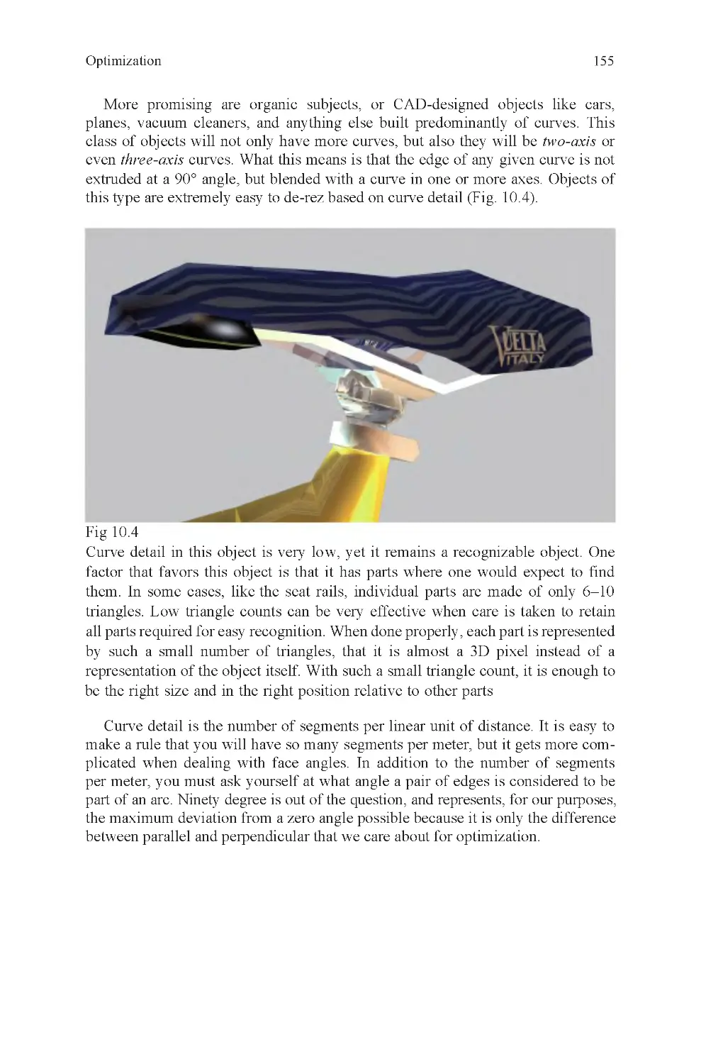
Chapter 10: Optimization............................................................. 153
Chapter 11: UV Editing............................................................... 165
Chapter 12: Nurbs Curves............................................................ 185
v
Contents
Chapter 13: Nurbs Surfaces.......................................................... 199
vi
Contents
Chapter 14: Shapes and Topology................................................... 223
Chapter 15: Quality Standards....................................................... 233
Chapter 16: 3D2: Checklist and Projects........................................... 237
Glossary.................................................................................... 243
Sources...................................................................................... 257
Index....................................................................................... 259
Frontispiece, The Parcel, com-
puter rendering
Fig 0.1 Piero Della Francesca,
Brera Altarpiece 1472–1474
Fig 0.2 Paolo Uccello, Chalice
1450
Fig 0.3 Georges Seurat, Bridge of
Courbevoie 1886/1887
Fig 0.4 Power tech engine block
Fig 0.5 Linear perspective
Fig 0.6 Stereovision
Fig 0.7 Lens curvature
Fig 0.9 Claude Monet, Impres-
sion, Sunrise 1874
Fig 0.10 Pixels
Fig 1.1 Global zero, Armstrong
on the Moon
Fig 1.2 World coordinates
Fig 1.3 2D and 3D coordinate
systems
Fig 1.4 Right-hand rule
Fig 1.5 A vertex
Fig 1.6 Vertices, an edge, and a
face
Fig 1.7 A vector
Fig 1.8 A light ray
Fig 1.9 Transform, rotation, and
scale translation types
Fig 1.10 Local axis
Fig 1.11 Polygon, texmap, and
mapped polygon
Fig 1.12 How a texture map is at-
tached to a polygon
Fig 1.13 Necessity of light
Fig 1.14 Normals and averaged
normals
Fig 1.15 Photon through a pipe:
how normals behave
Fig 1.16 Reversed normals, as
seen in mirror
Fig 1.17 The seven basic ele-
ments of CG
Fig 1.18 Orthographic and per-
spective grids
Fig 1.19 Cube, sphere, and cylin-
der
Fig 1.20 Wireframe display mode
Fig 1.21 Shaded display mode
Fig 1.22 A pivot
Fig 1.23 Vertex translation
Fig 1.24 Edge translation
Fig 1.25 Face extrusion and scale
Fig 1.27 Incorrectly projected
UVs
Fig 1.28 Carton pattern
Fig 1.29 Traced carton pattern as
open polygon
Fig 1.30 Carton pattern, subdi-
vided along fold edges
Fig 1.31 Carton pattern with tex-
ture applied
Fig 1.32 The folded carton
Fig 1.33 Low level of difficulty
Fig 1.34 High level of difficulty
Fig 1.35 Incorrect extrusion
Fig 1.36 Correct extrusion
Fig 1.37 Human and fish differ-
ence: measurements
Fig 1.38 How do you fold along
nonglobal axis?
Fig 1.39 By rotating model so
that axis is aligned with global axis
Fig 1.40 Two examples of UV
layouts
Fig 2.1 A cobweb
Fig 2.2 Triangle count
Fig 2.3 Shared, nonshared, and
coincident vertices
Fig 2.4 A spike
Fig 2.5 A bow-tie face
Fig 2.6 Smoothing error
vii
Fig 1.26 Correctly projected UVs
List of Illustrations
Shadow in the Summer 2005
Fig 0.8 Stephan Martiniere,
viii
Fig 2.7 Floating face
Fig 2.8 Separated faces
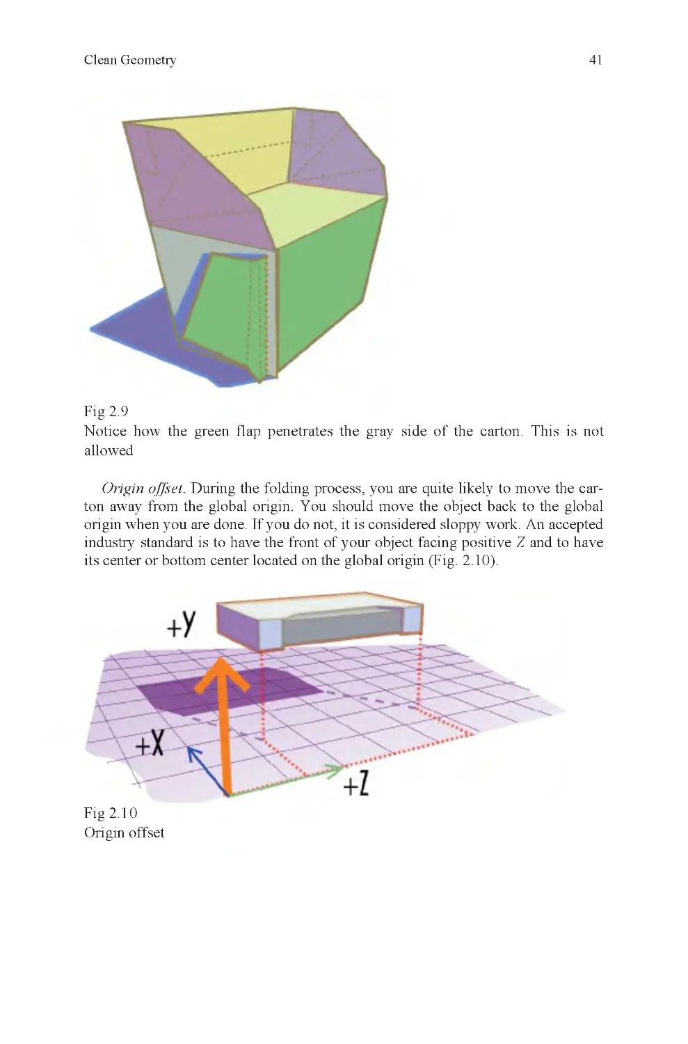
Fig 2.9 Self-penetration
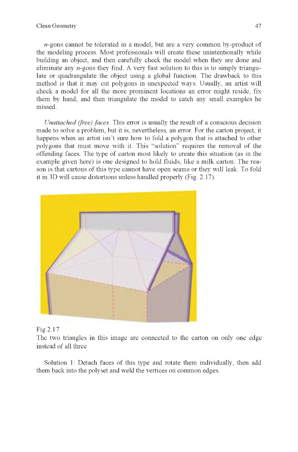
Fig 2.10 Origin offset
Fig 2.11 Nonplanar quads
Fig 2.12 Distorted polygons
Fig 2.13 Reversed normals
Fig 2.14 A superfluous row of
vertices
Fig 2.15 Misaligned texture
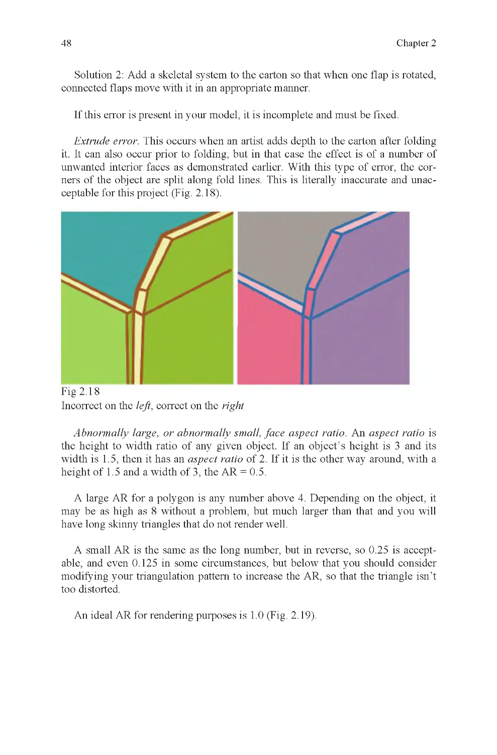
Fig 2.17 Missing faces from a
milk carton
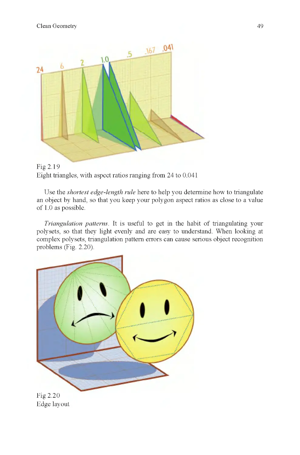
Fig 2.18 Extrusion error at corner
Fig 2.19 Aspect ratio
Fig 2.20 Edge layout
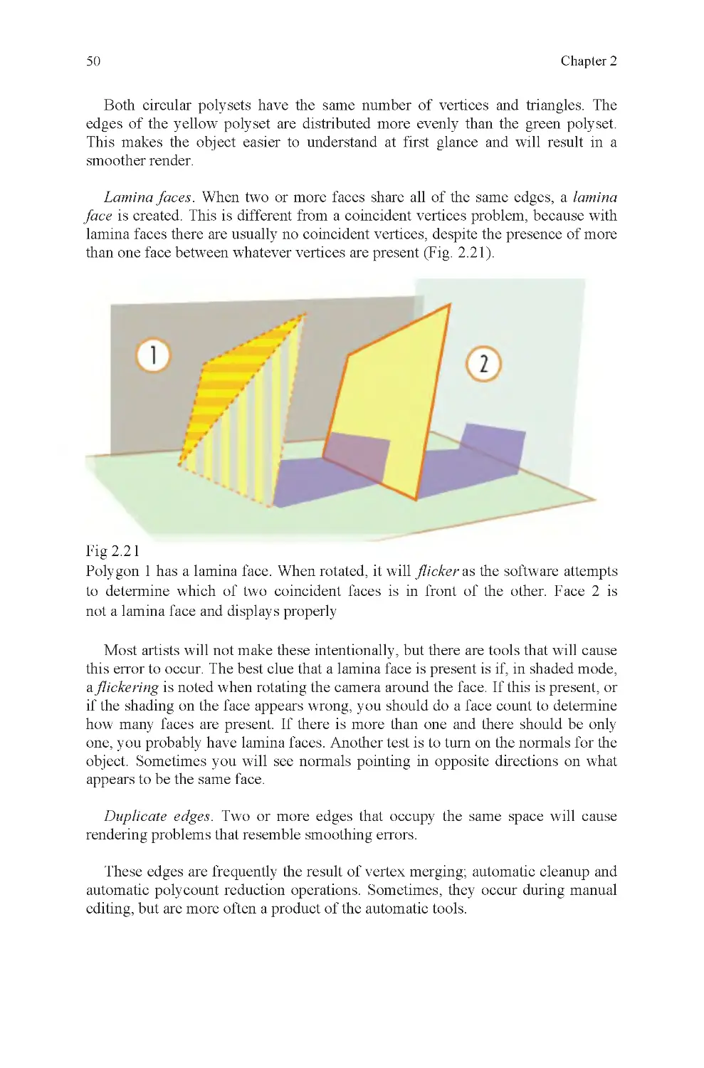
Fig 2.21 Lamina face
Fig 2.22 Hidden edges
Fig 2.23 Duplicate edges
Fig 2.24 Coincident faces
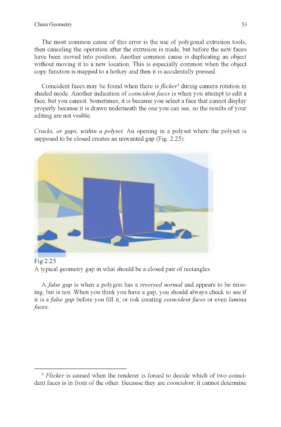
Fig 2.25 Geometry gap (in Death
Valley)
Fig 2.26 Hole and nonhole
polysets
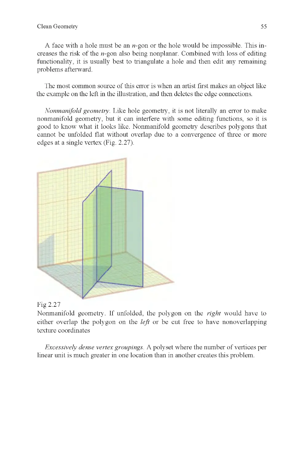
Fig 2.27 Nonmanifold geometry
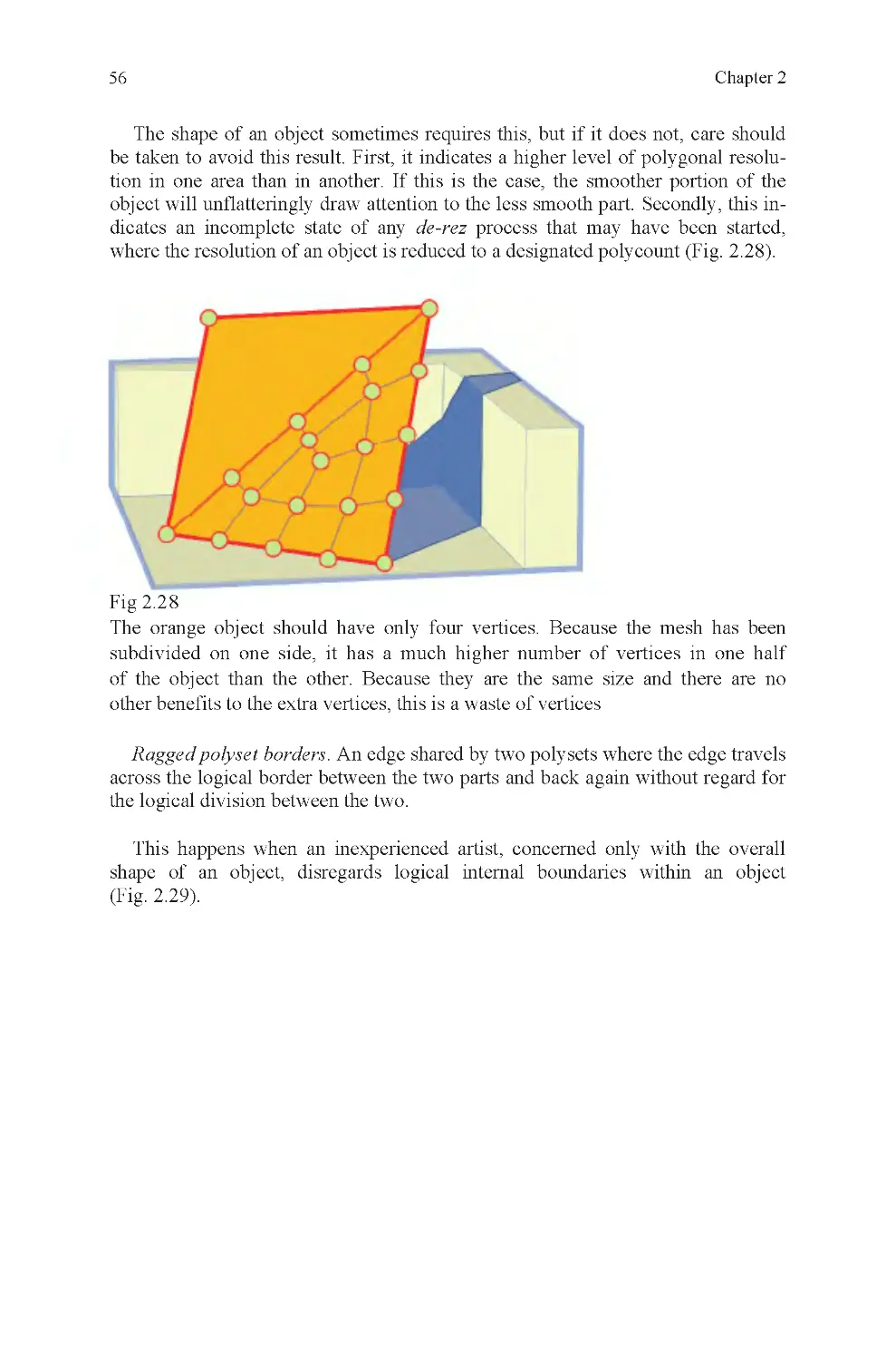
Fig 2.28 Dense, unmotivated ver-
tices
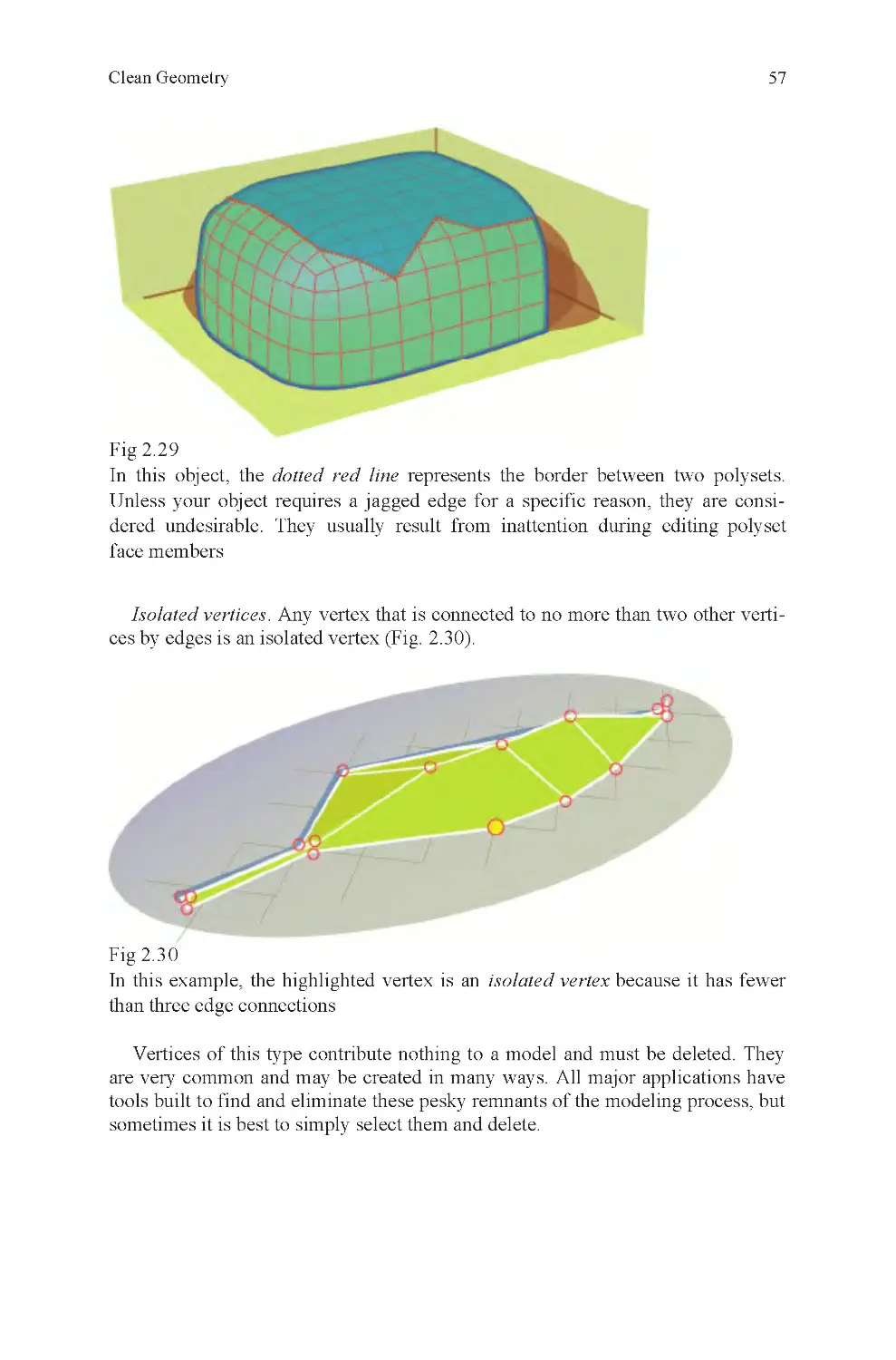
Fig 2.29 Ragged edge
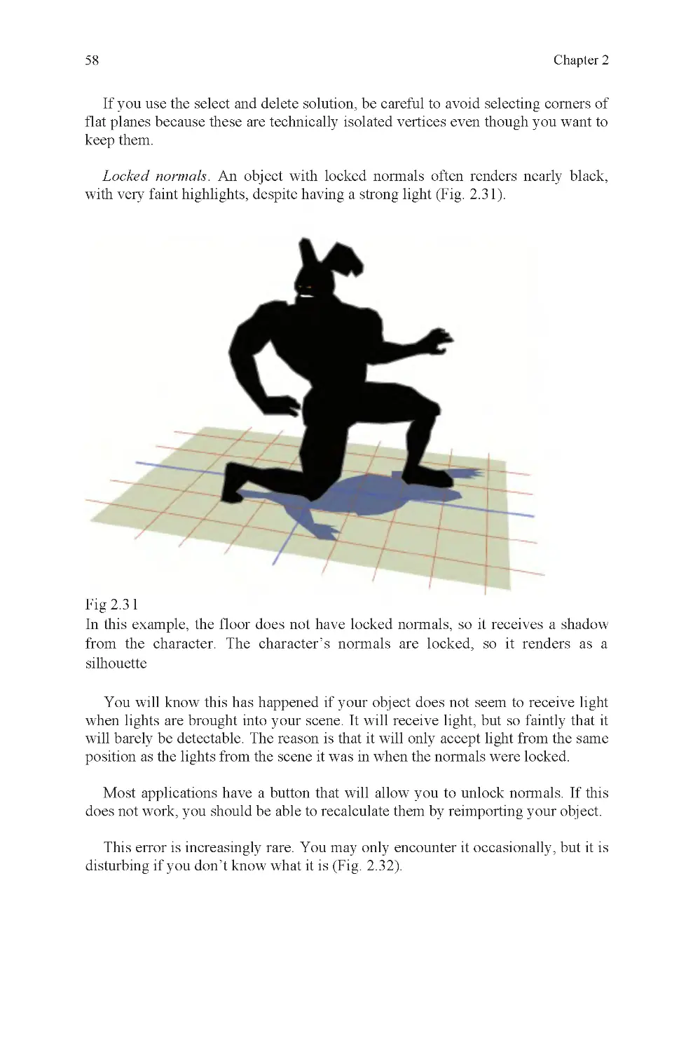
Fig 2.30 Isolated vertex
Fig 2.31 Locked normals
Fig 2.32 Renumbered vertices
Fig 2.33 Zero edge-length face
Fig 2.34 Magnifying glass
Fig 2.35 Hierarchy example
Fig 3.1 Measurements, ruler and
carton
Fig 3.2 Robert Wadlow and
brother, the difference 150% makes
Fig 3.3 Giovanni Bellini, St
Francis in the Desert 1480
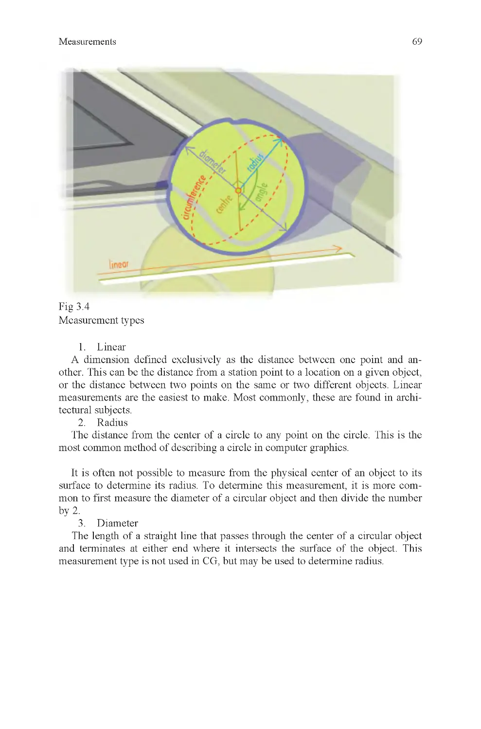
Fig 3.4 Measurement types
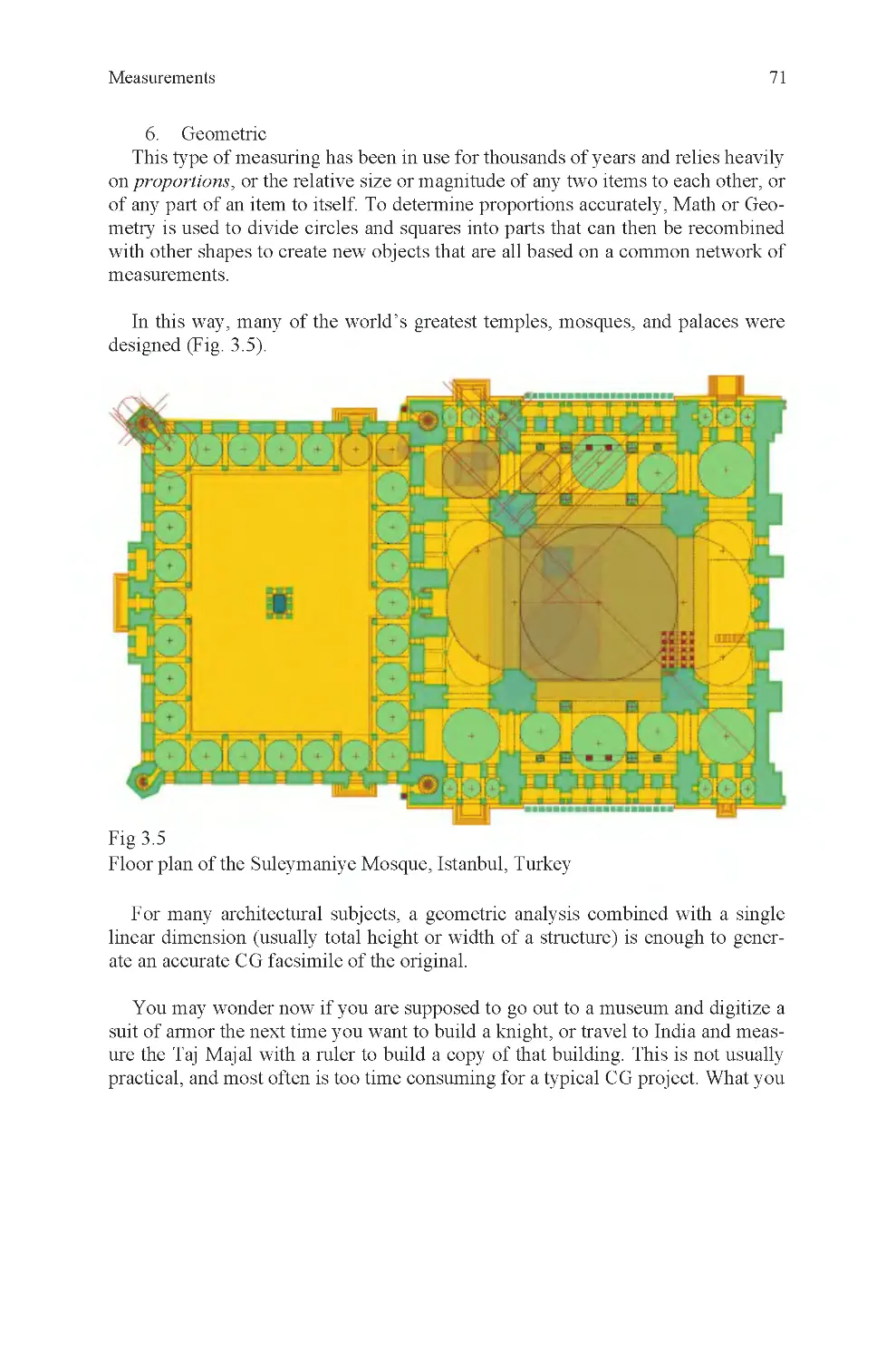
Fig 3.5 Geometric subdivision
Fig 3.6 Measuring instruments
Fig 3.7 Lens length
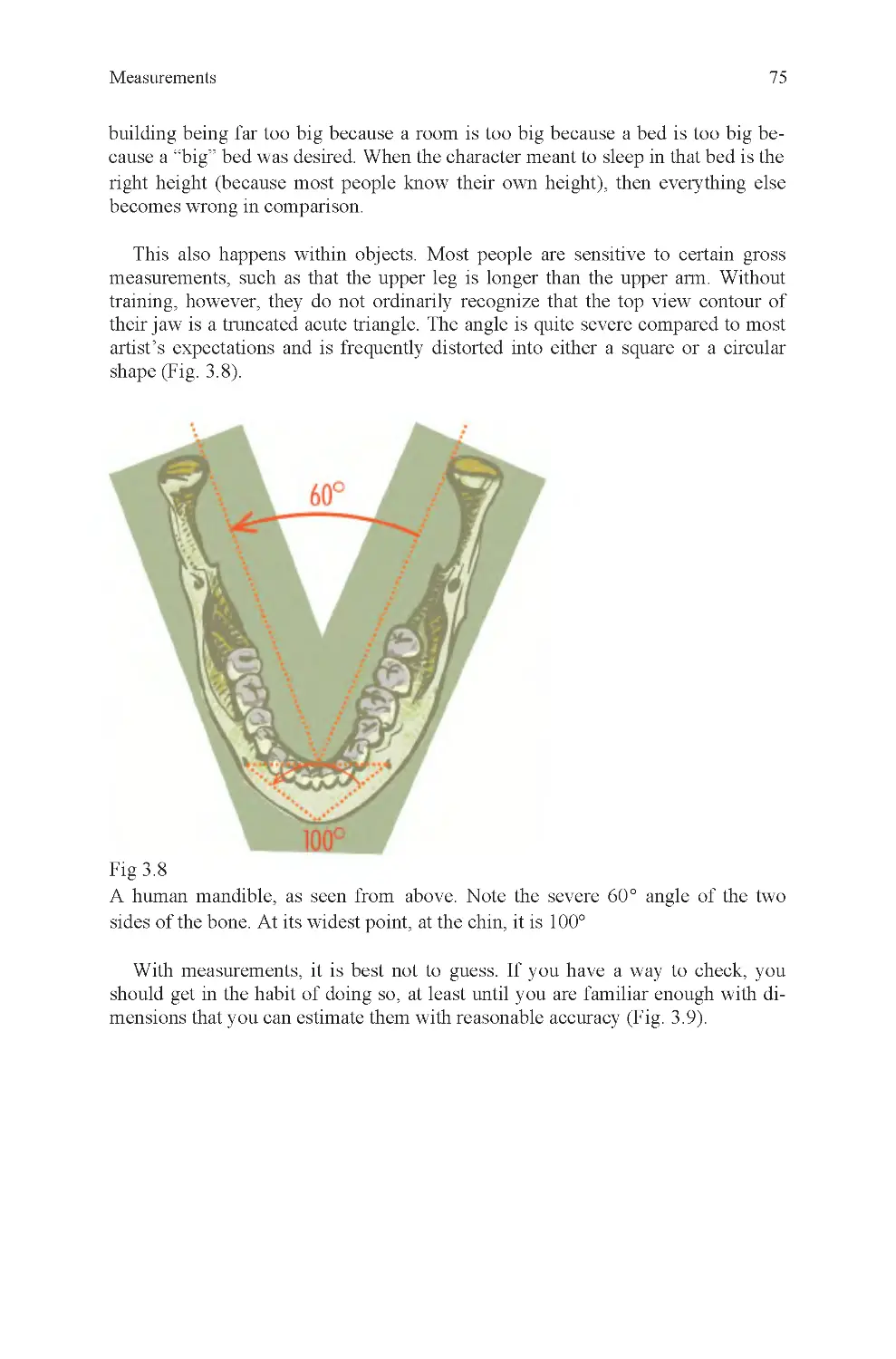
mandible
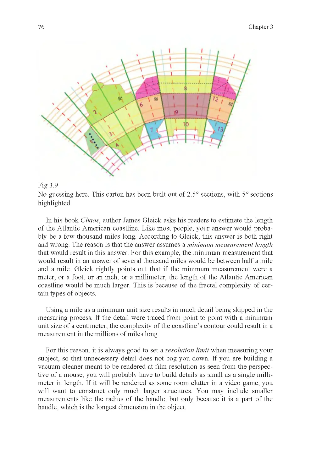
Fig 3.9 Radial breakdown of a
carton
Fig 4.1 Floss container and horse
chestnut
Fig 4.2 Three dolls
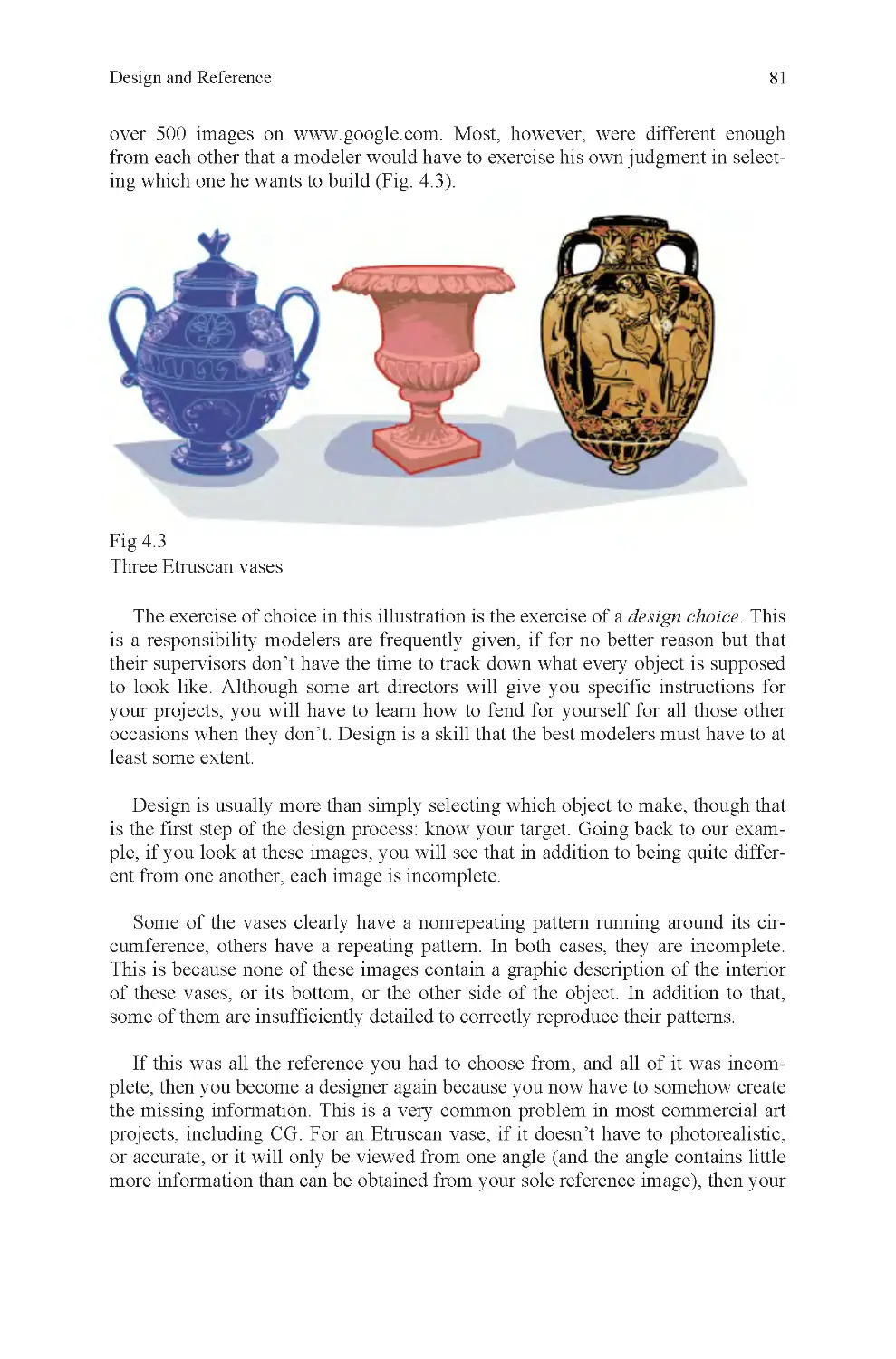
Fig 4.3 Three Etruscan vases
Fig 4.4 Photo reference mosaic
Fig 4.5 Schematic view, court-
house
Fig 4.6 Render, courthouse
Fig 4.7 Rear derailleur assembly
Fig 4.8 Front derailleur assembly
Fig 4.9 Rear hub, schematic
view
Fig 4.10 Brake lever, schematic
view
Fig 4.11 Label textures
Fig 4.12 Material schedule,
courthouse
Fig 4.13 Errors in character pro-
duction sketch
Fig 4.14 Model sheet, Dexter
Green
Fig 5.1 Basic modeling tool
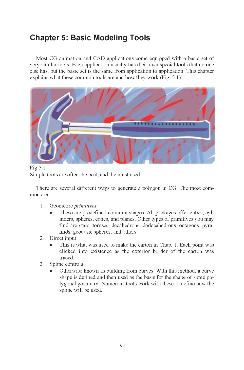
Fig 5.2 Primitive modeling, a
floss container
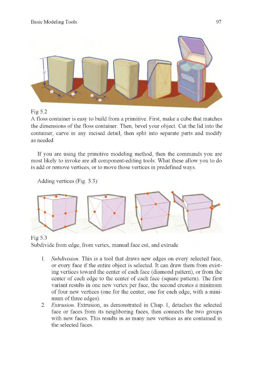
Fig 5.3 Adding vertices
Fig 5.4 Deleting, collapsing, cut-
ting, and beveling
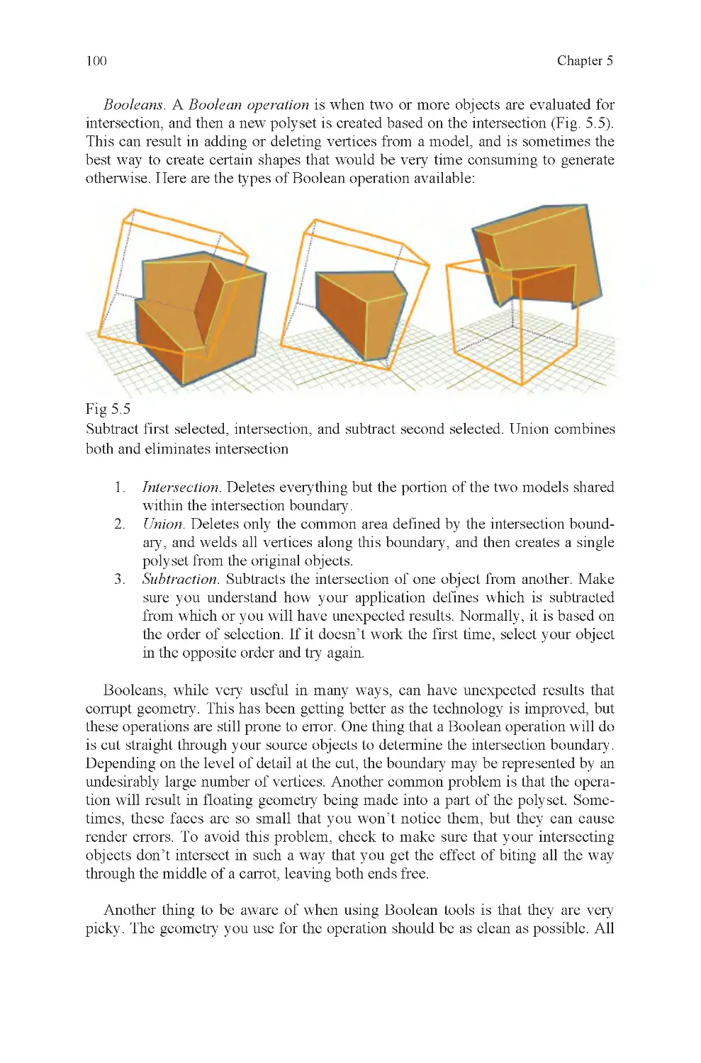
Fig 5.5 Booleans
Fig 5.6 Infinite sampling points
Fig 5.7 Spline-based surface
creation
Fig 6.1 Roses
Fig 6.2 Kneaded eraser, polyset
detail limits
Fig 6.3 High- and low-resolution
character heads
Fig 6.4 Subdivision of geometry
for texturing
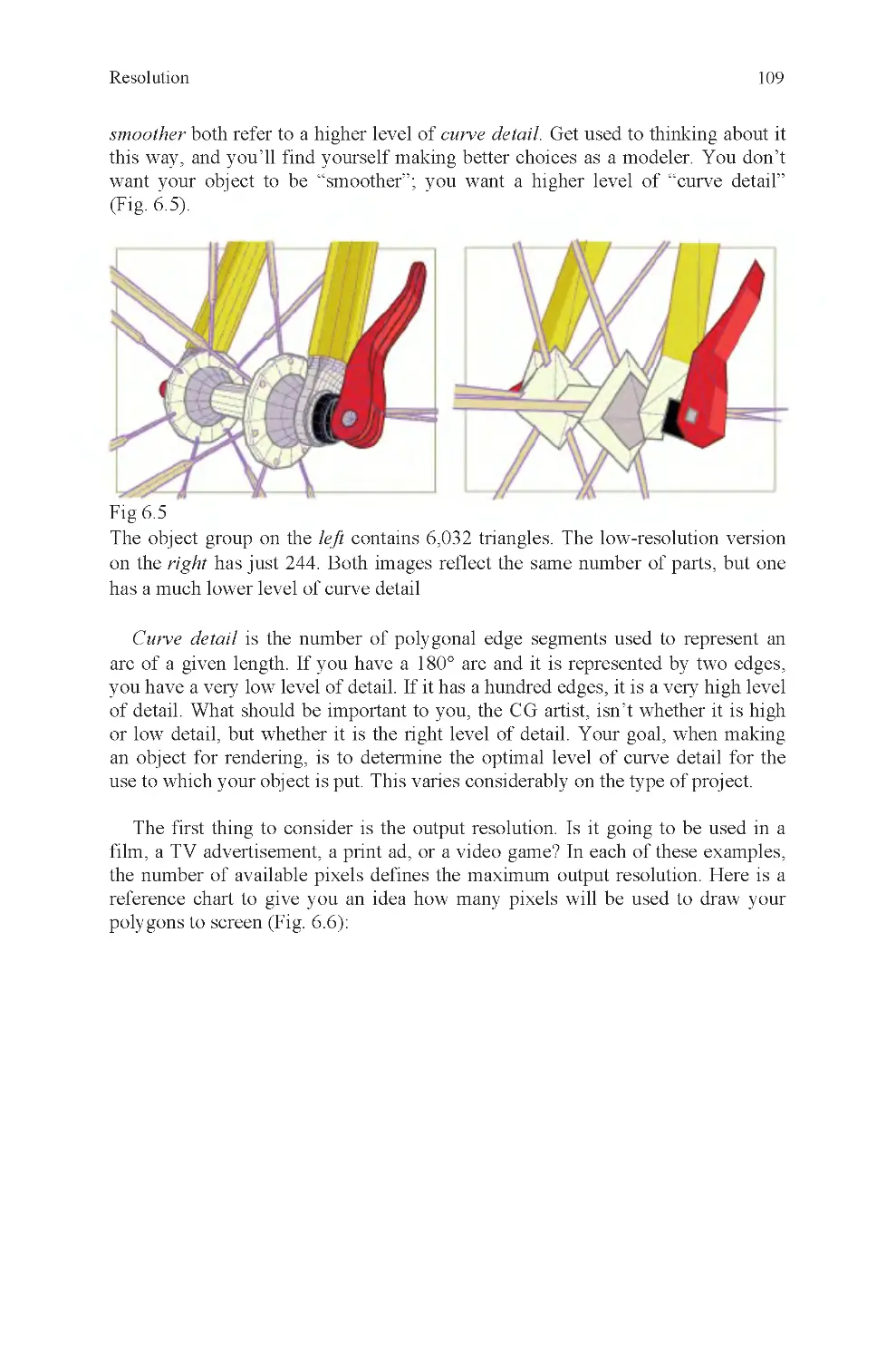
Fig 6.5 Curve detail, hub and
skewer
List of Illustrations
Fig 2.16 N -gons
Fig 3.8 Measuring the angle of a
ix
Fig 6.6 How polygons are trans-
lated into pixels
Fig 6.7 Guardian, example of
high-resolution graphics
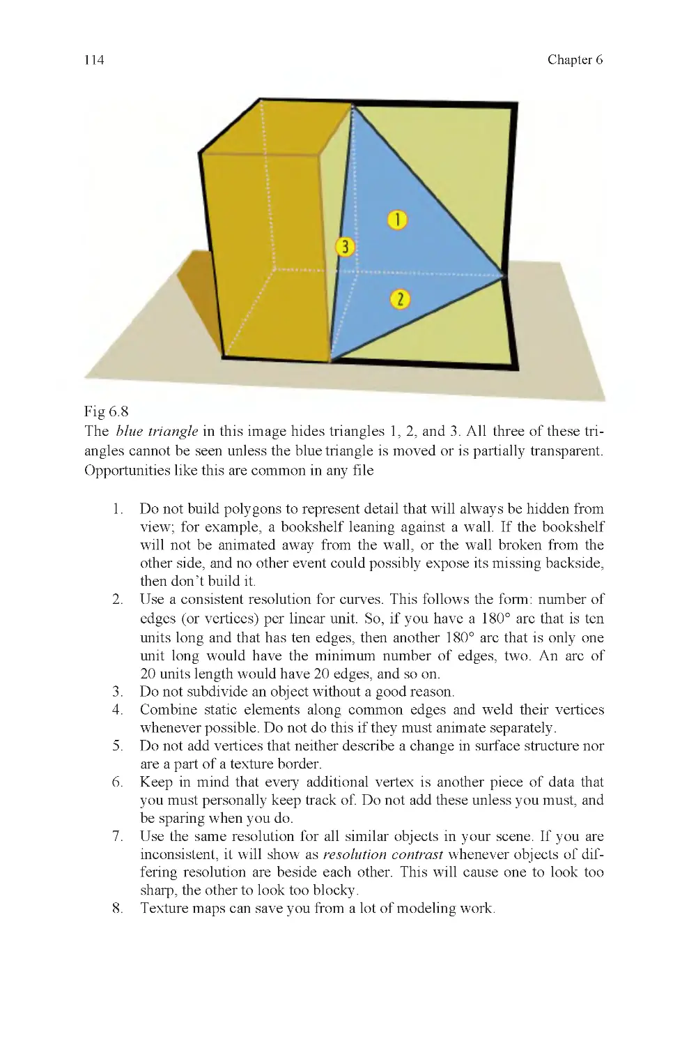
Fig 6.8 Hidden triangles
Fig 7.2 Cube and default coordi-
nates
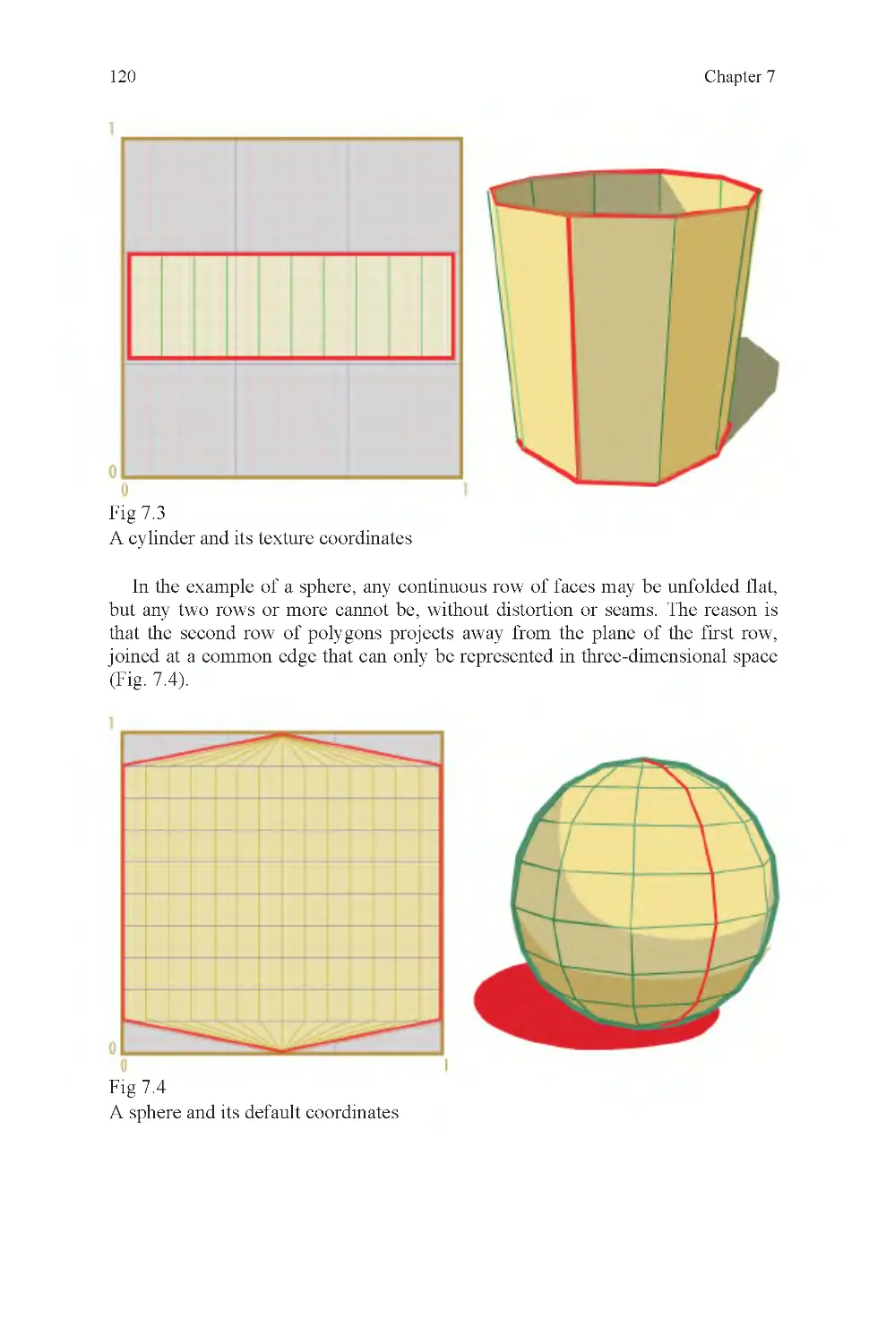
Fig 7.3 Cylinder and default co-
ordinates
Fig 7.4 Sphere and default coor-
dinates
Fig 7.5 Many seams, good tex-
ture layout
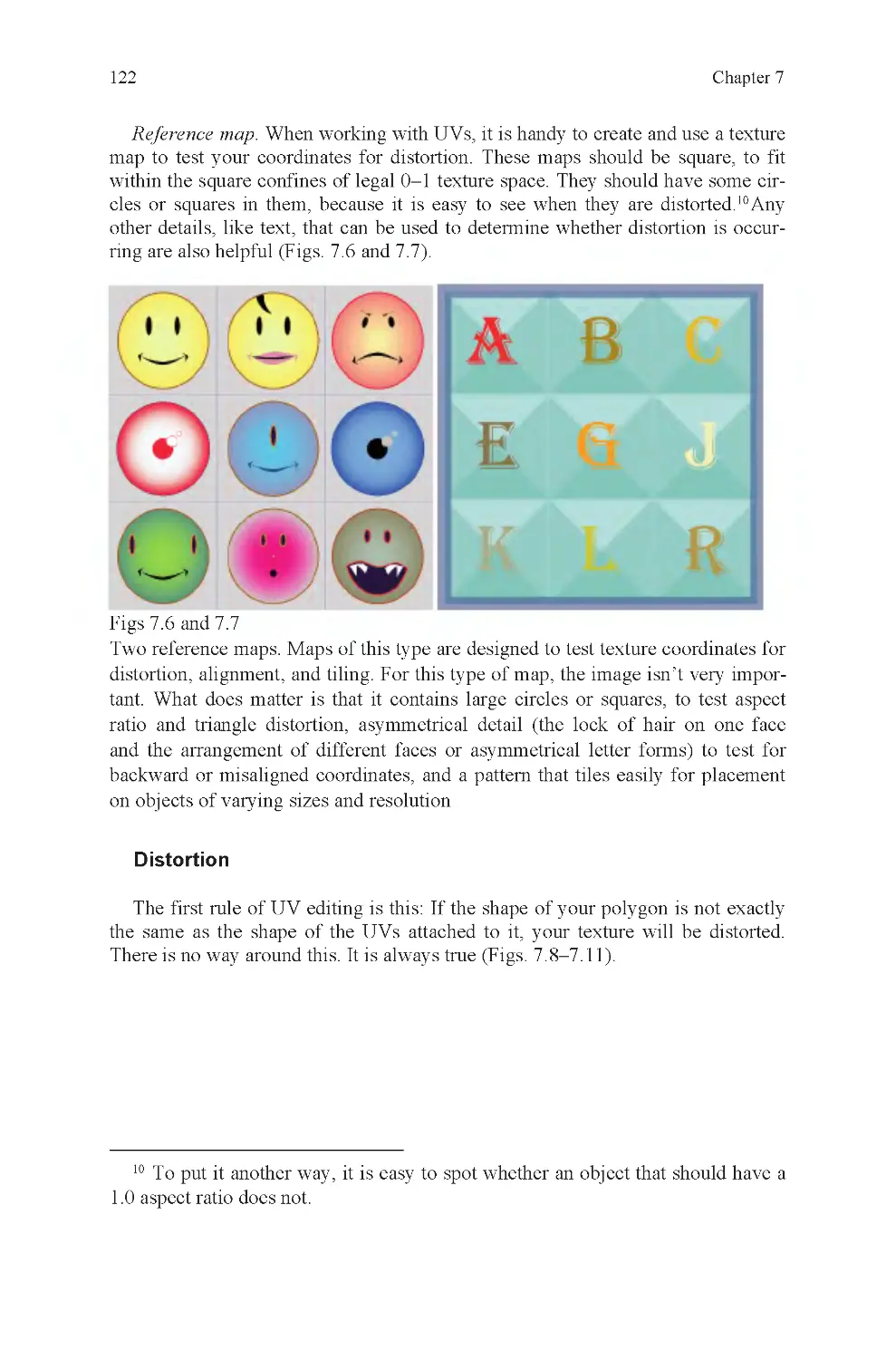
Fig 7.6 Reference map: faces
Fig 7.7 Reference map: type
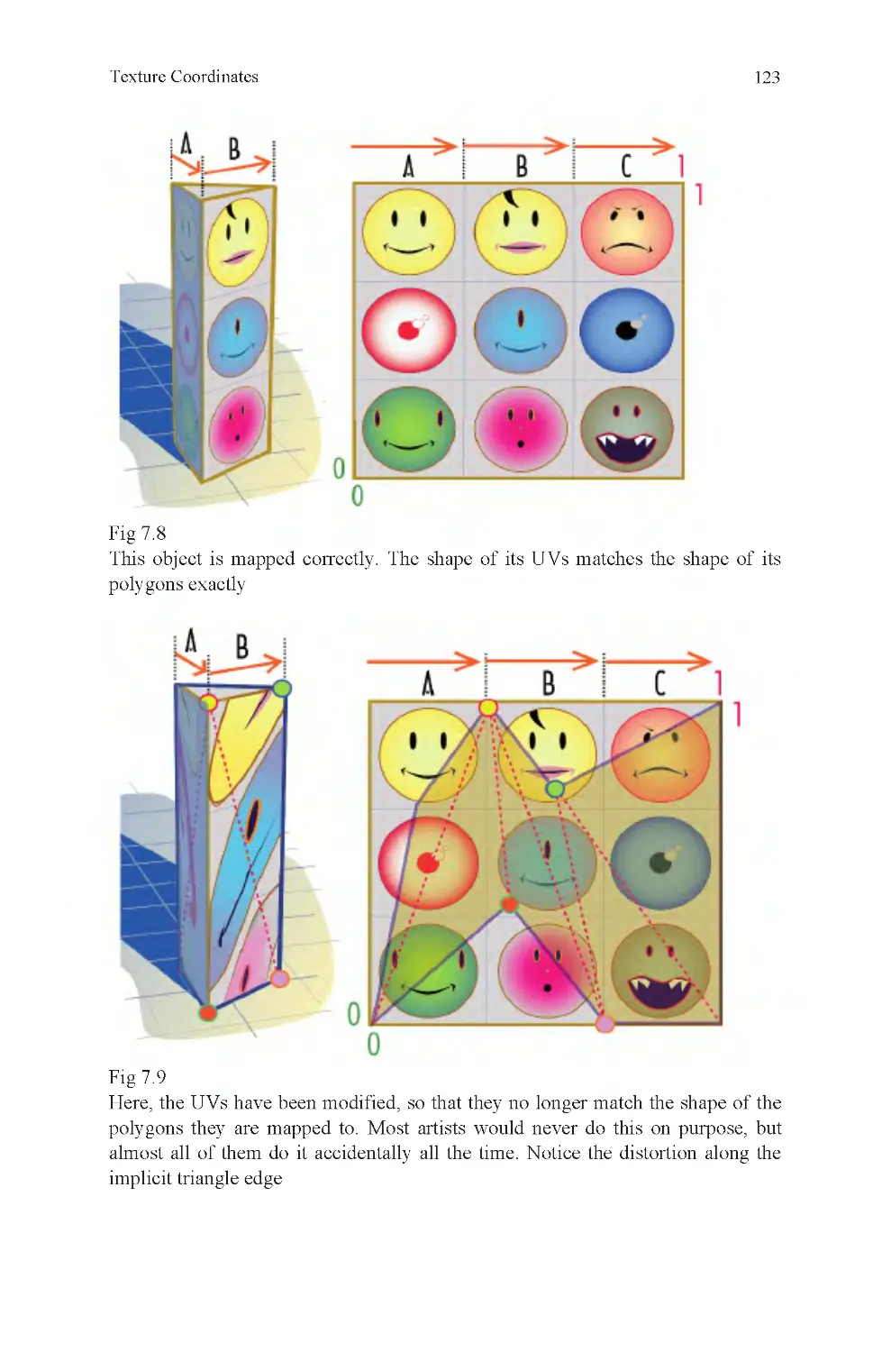
Fig 7.8 No distortion
Fig 7.9 Distorted UVs
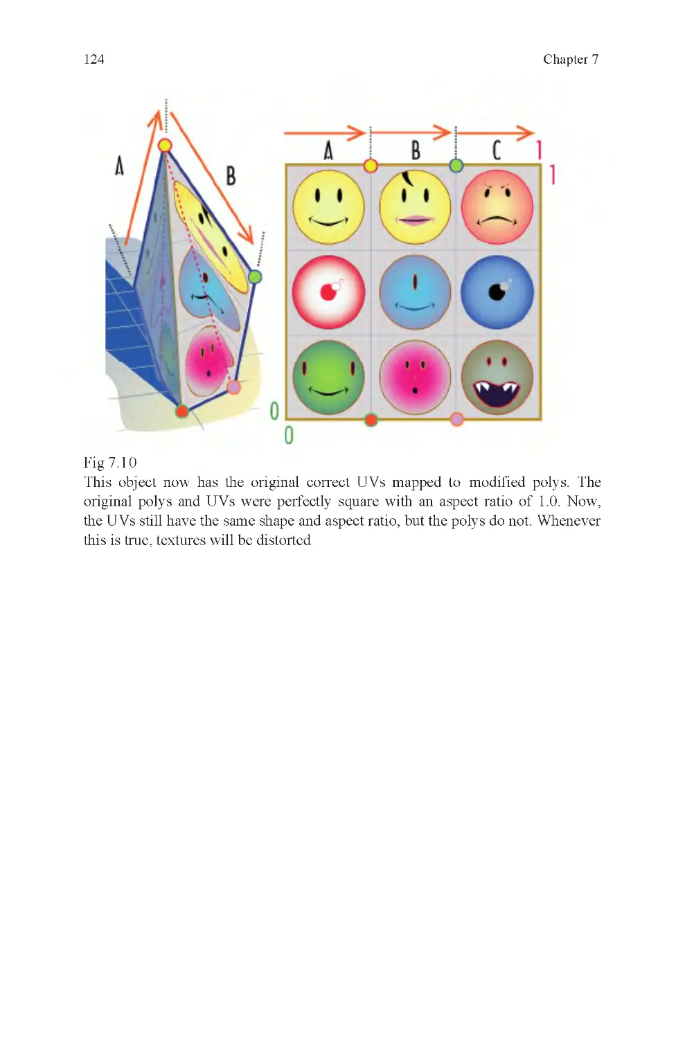
Fig 7.10 Distorted polygons
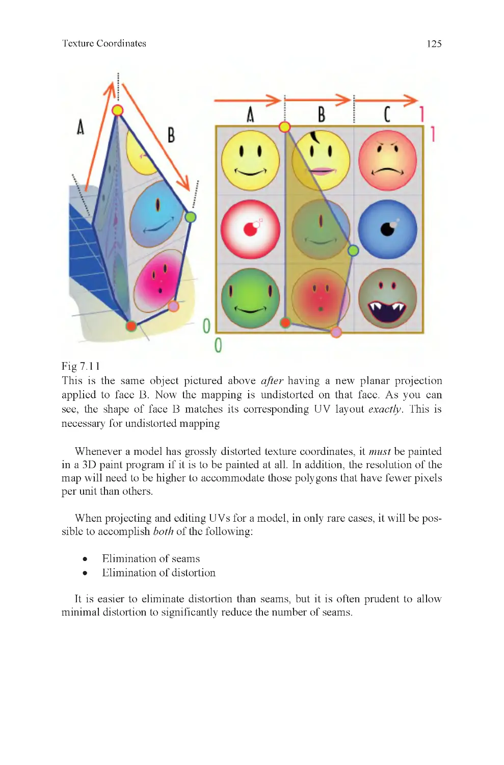
Fig 7.11 Correctly projected UVs
on distorted face
Fig 7.12 Default sphere UVs and
texture
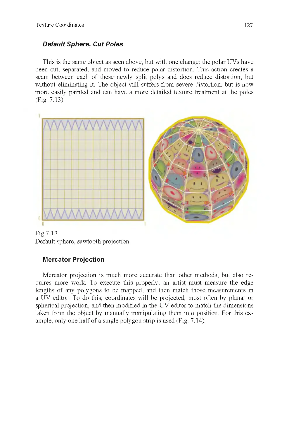
Fig 7.13 Default sphere, sawtooth
projection
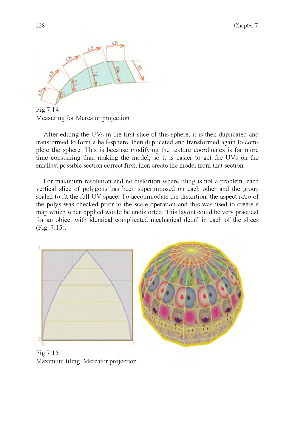
Fig 7.14 Measuring for Mercator
projection
Fig 7.15 Maximum tiling, Merca-
tor projection
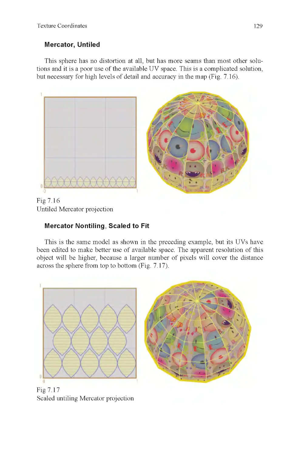
Fig 7.16 Untiled Mercator projec-
tion
Fig 7.17 Scaled untiling Mercator
projection
Fig 7.18 Two proportionate
spherical projections
Fig 7.19 Six proportionate planar
projections
Fig 7.20 Geodesic layout texture
map
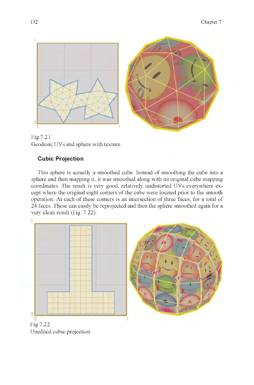
Fig 7.21 Geodesic UVs and
sphere with texture
Fig 7.22 Unedited cubic projection
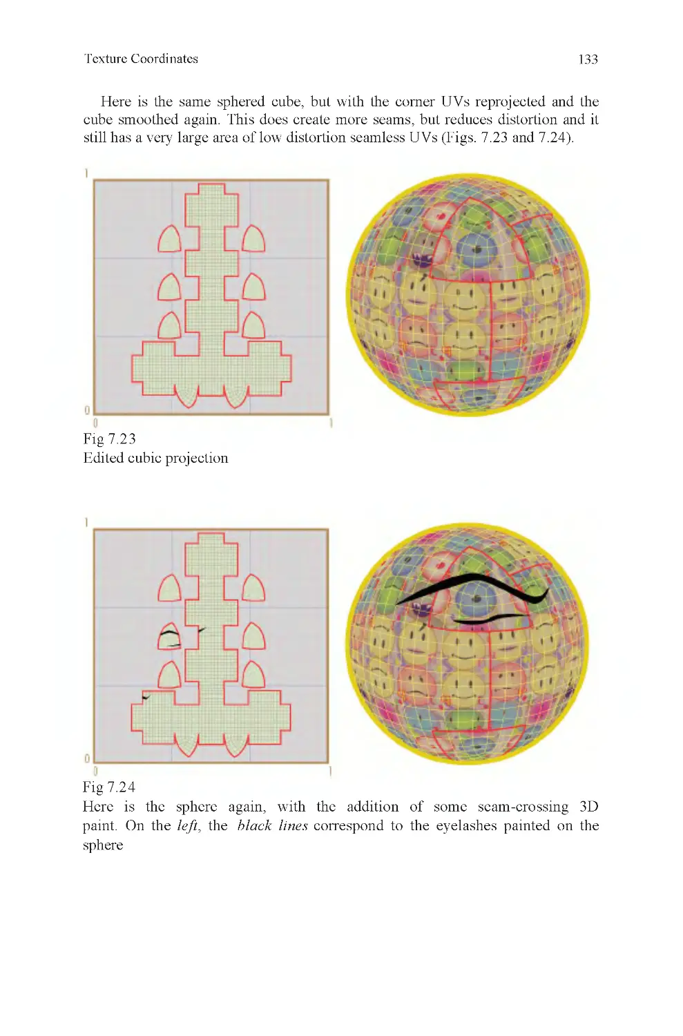
Fig 7.23 Edited cubic projection
Fig 7.24 3D paint on edited cubic
projection
Fig 9.1 Lineup
Fig 9.2 Call to Prayer, observa-
tion example
Fig 9.3 Schematic-level observa-
tion skill
Fig 9.4 Strong observation skill
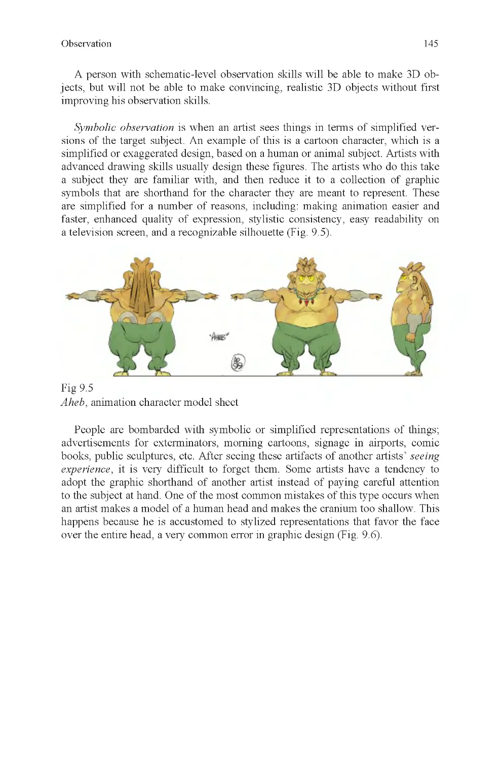
Fig 9.5 Ahab, animation model
sheet
Fig 9.6 Shallow cranium
Fig 9.7 Gradient(s)
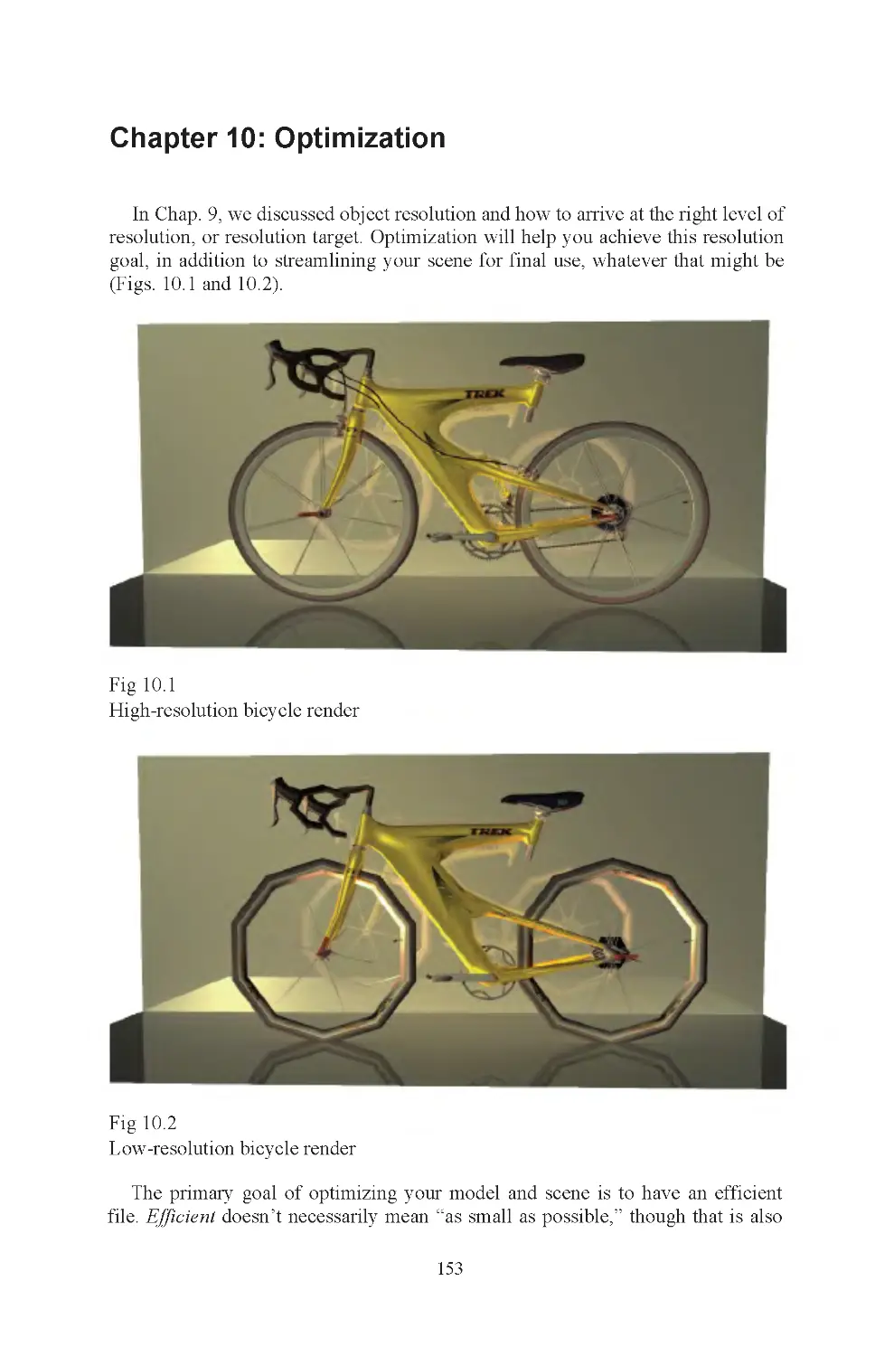
Fig 10.1 High-resolution bicycle
render
Fig 10.2 Low-resolution bicycle
render
Fig 10.3 Hard angles cannot be
removed
Fig 10.4 Bicycle seat, 3D pixels
Fig 10.5 Multiple cannon, part
detail
Fig 10.6 Incised detail
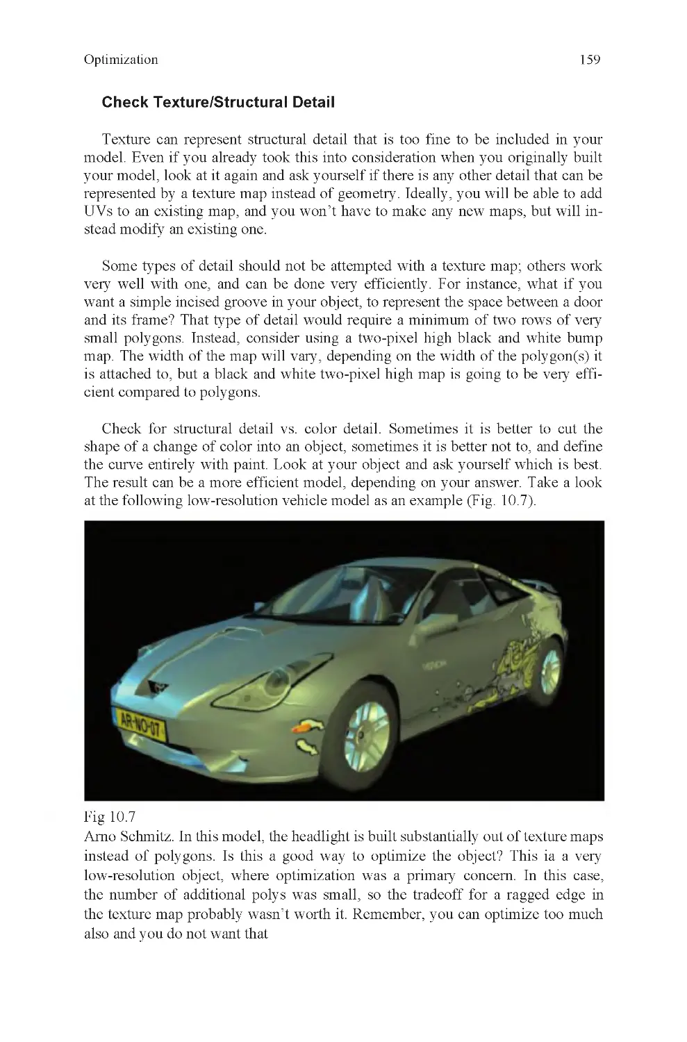
Fig 10.7 Low-resolution auto
Fig 10.8 One thousand triangle
bicycle
Fig 10.9 Power of silhouettes
Fig 11.1 Textured giant crossbow
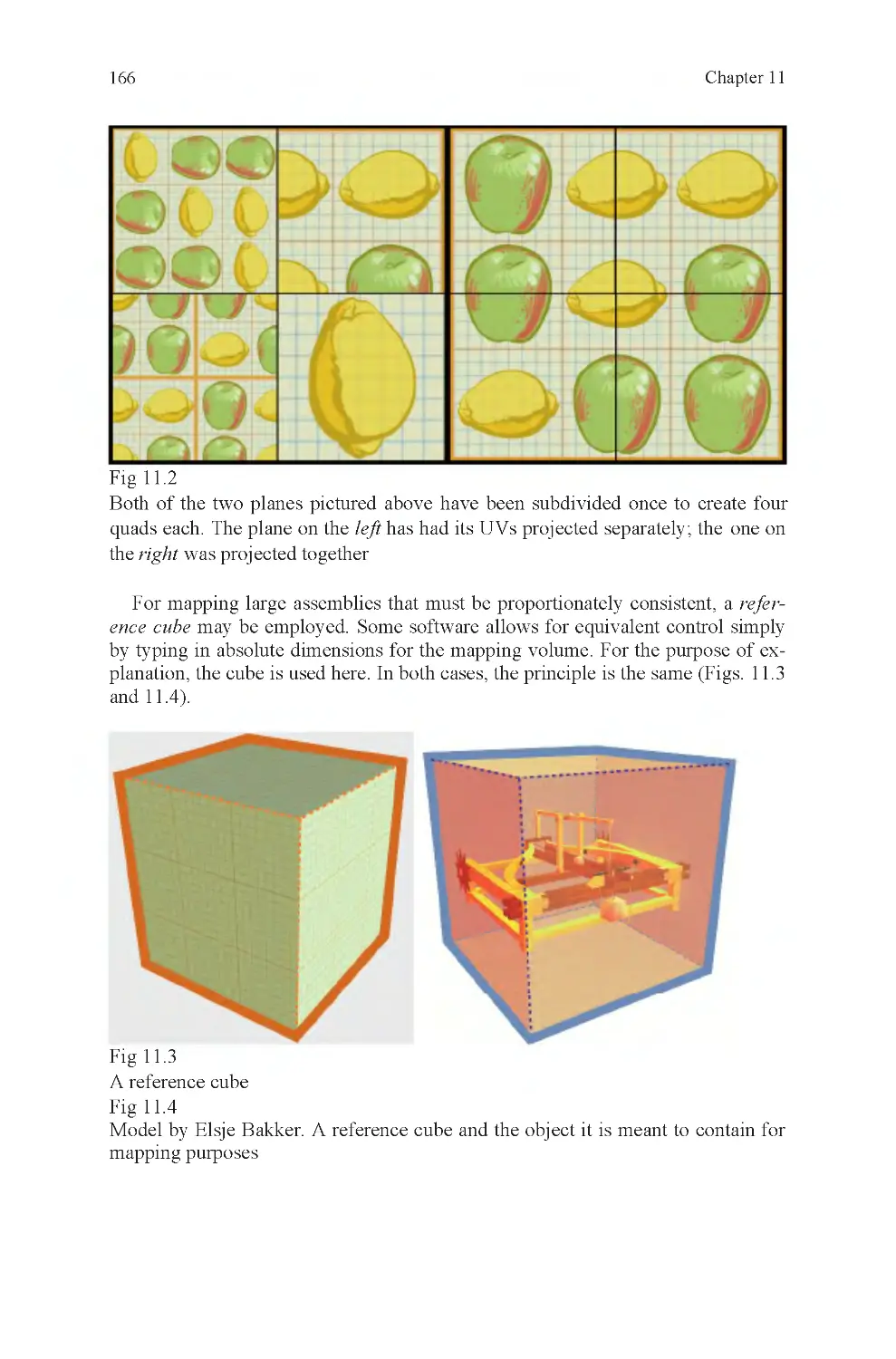
Fig 11.2 Box projection, lemons
and apples
Fig 11.3 Reference cube
Fig 11.4 Projection within a ref-
erence cube
Fig 11.5 Stretched to fit legal UV
space
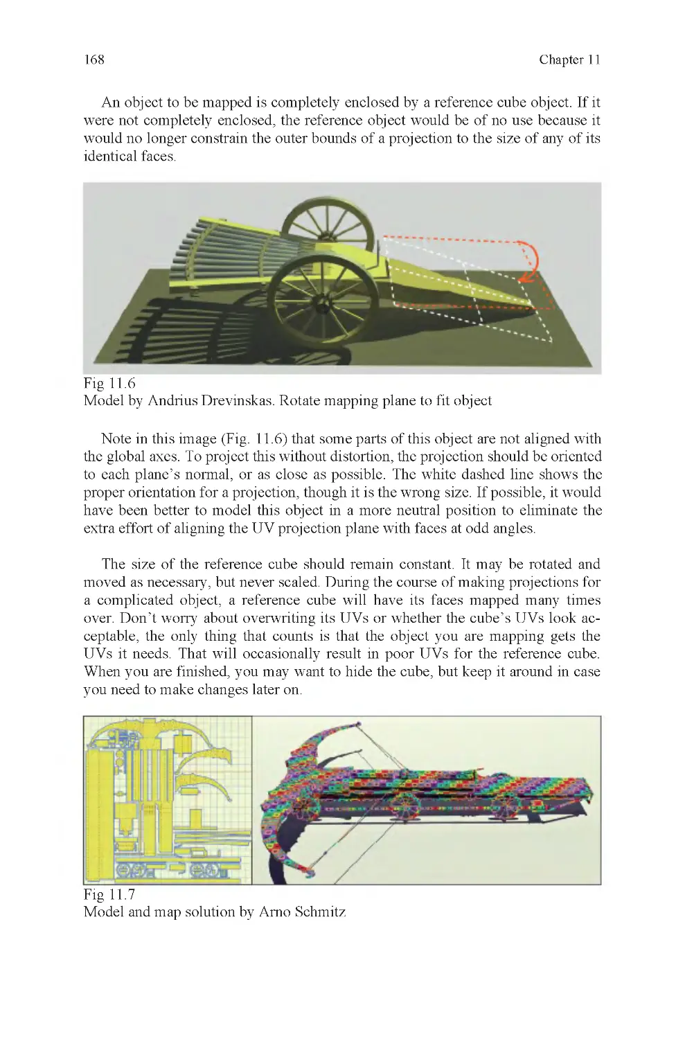
Fig 11.6 Rotate mapping plane to
fit object
Fig 11.7 Multipart object map-
ping solution
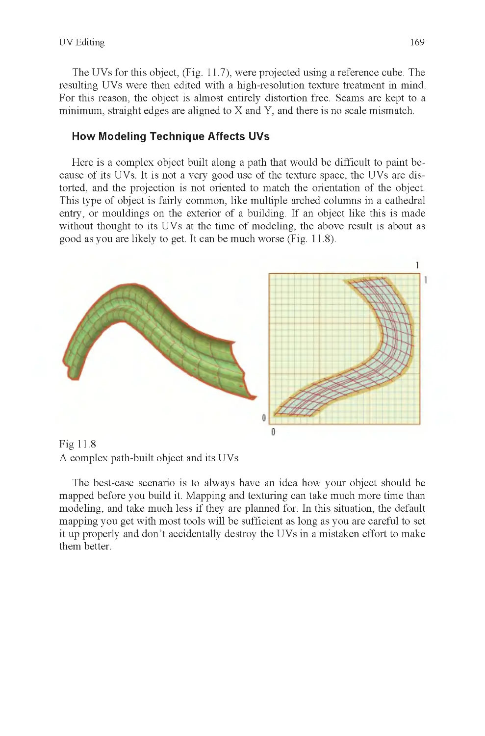
Fig 11.8 Poor coordinates on
lofted curve
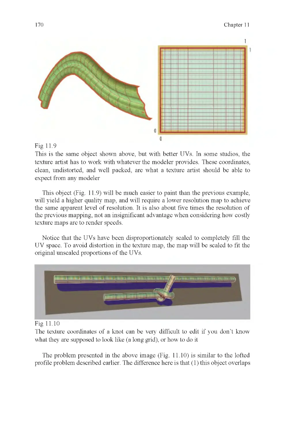
Fig 11.9 Good coordinates on
lofted curve
Fig 11.10 Texturing a knot
List of Illustrations
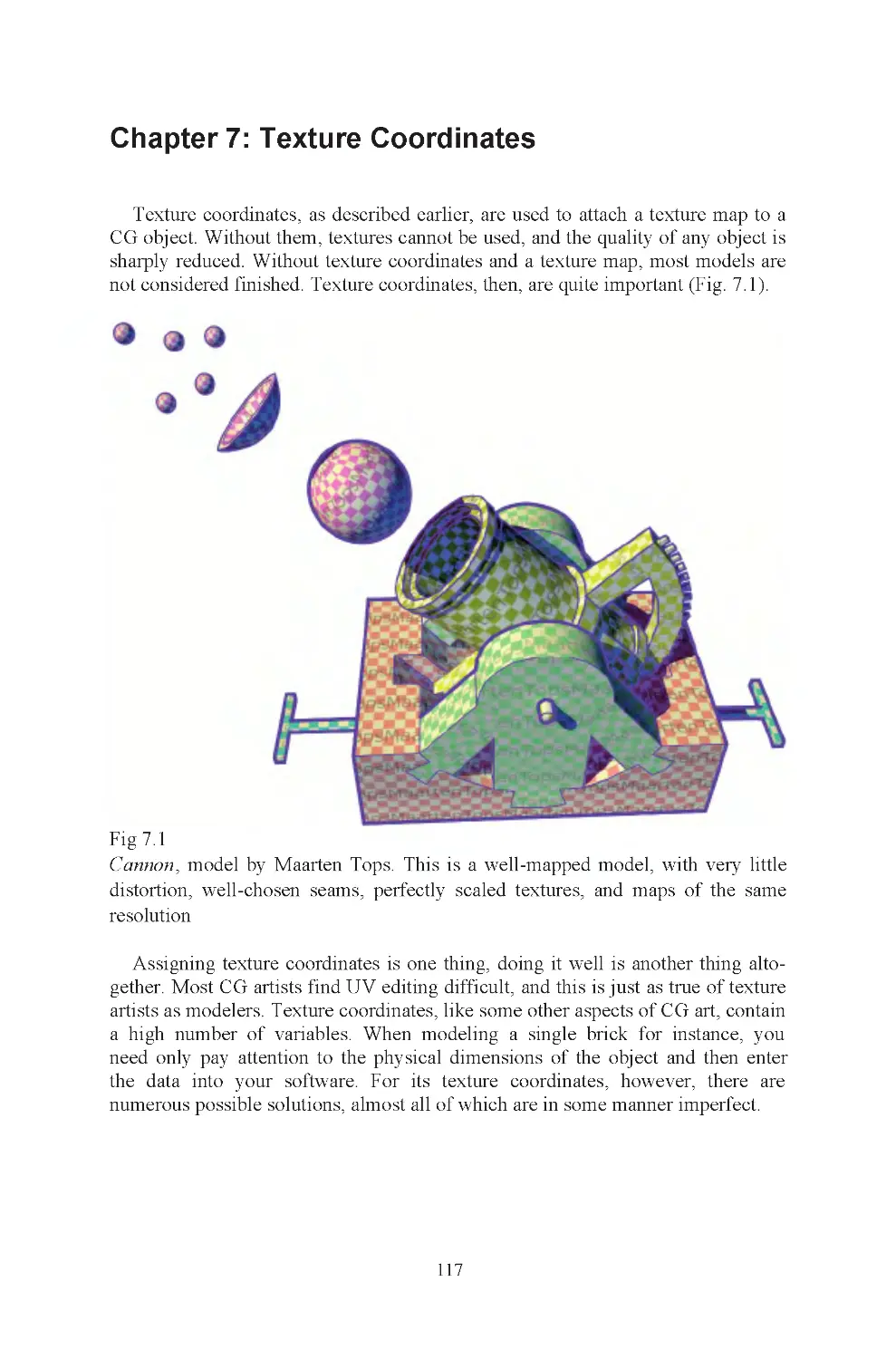
Fig 7.1 Cannon
x
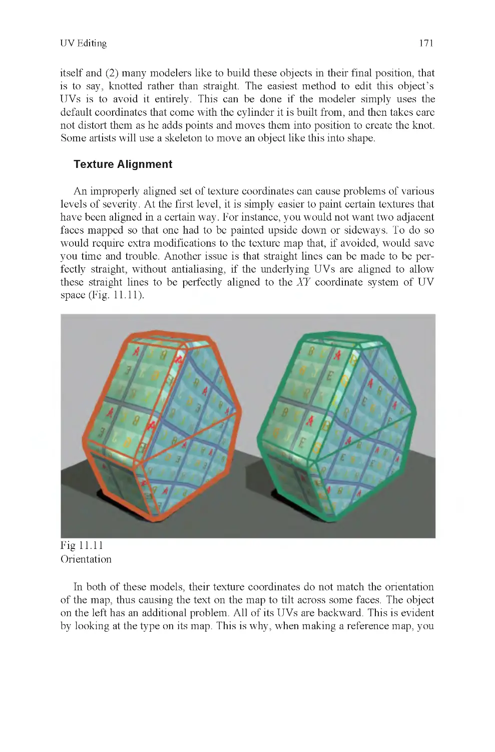
Fig 11.11 Texture alignment and
backward UVs
Fig 11.12 Rotated texture map to
match misaligned UVs
Fig 11.13 Distorted UVs on char-
acter at shoulder joint
Fig 11.14 Seam decision
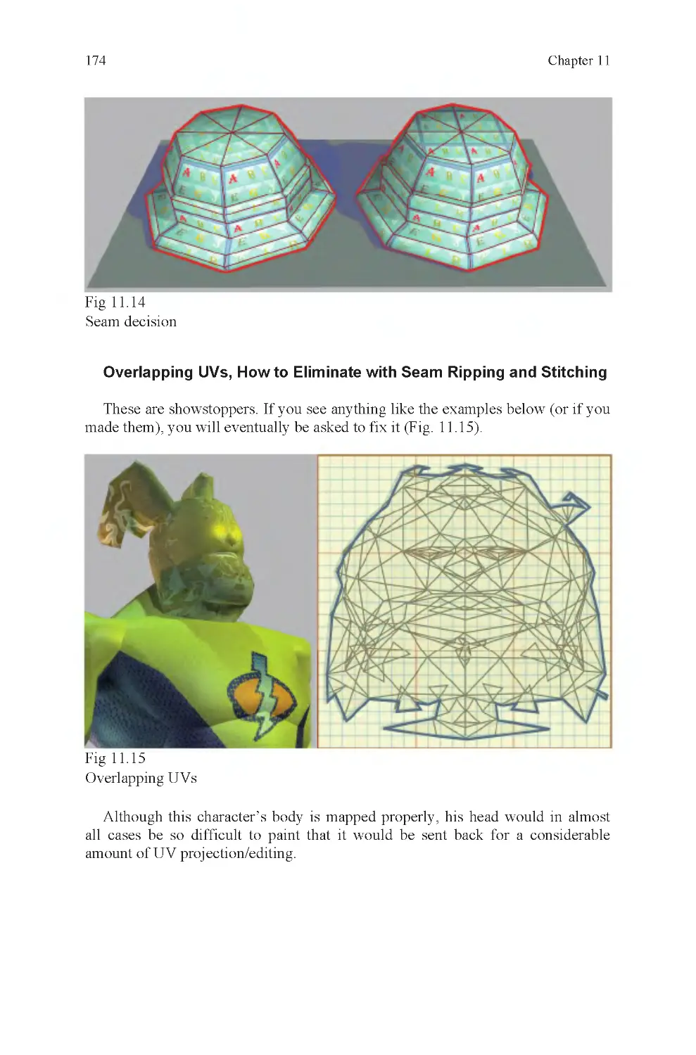
Fig 11.15 Overlapping UVs
Fig 11.16 Nonoverlapping UVs
Fig 11.17 Grouping can cause
mess in texture editor
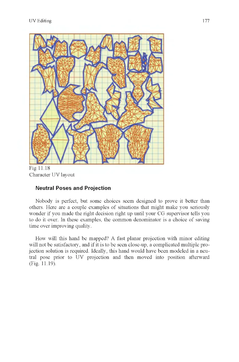
Fig 11.18 Character mapping
layout
Fig 11.19 How do you map a
posed hand?
Fig 11.20 Packing UVs
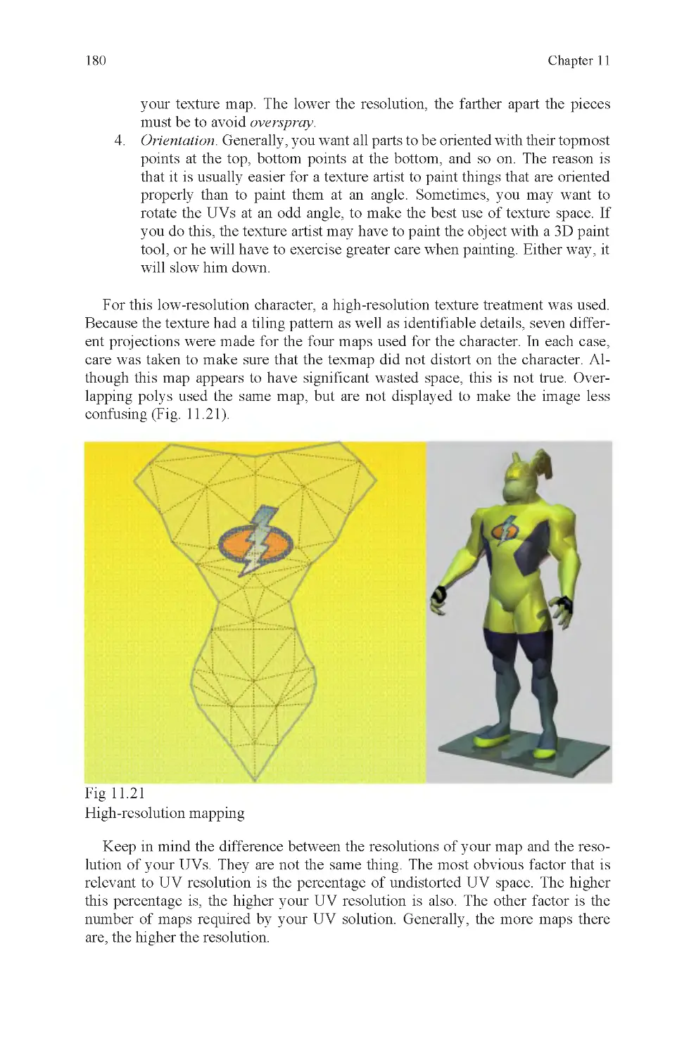
Fig 11.21 High-resolution texture
treatment
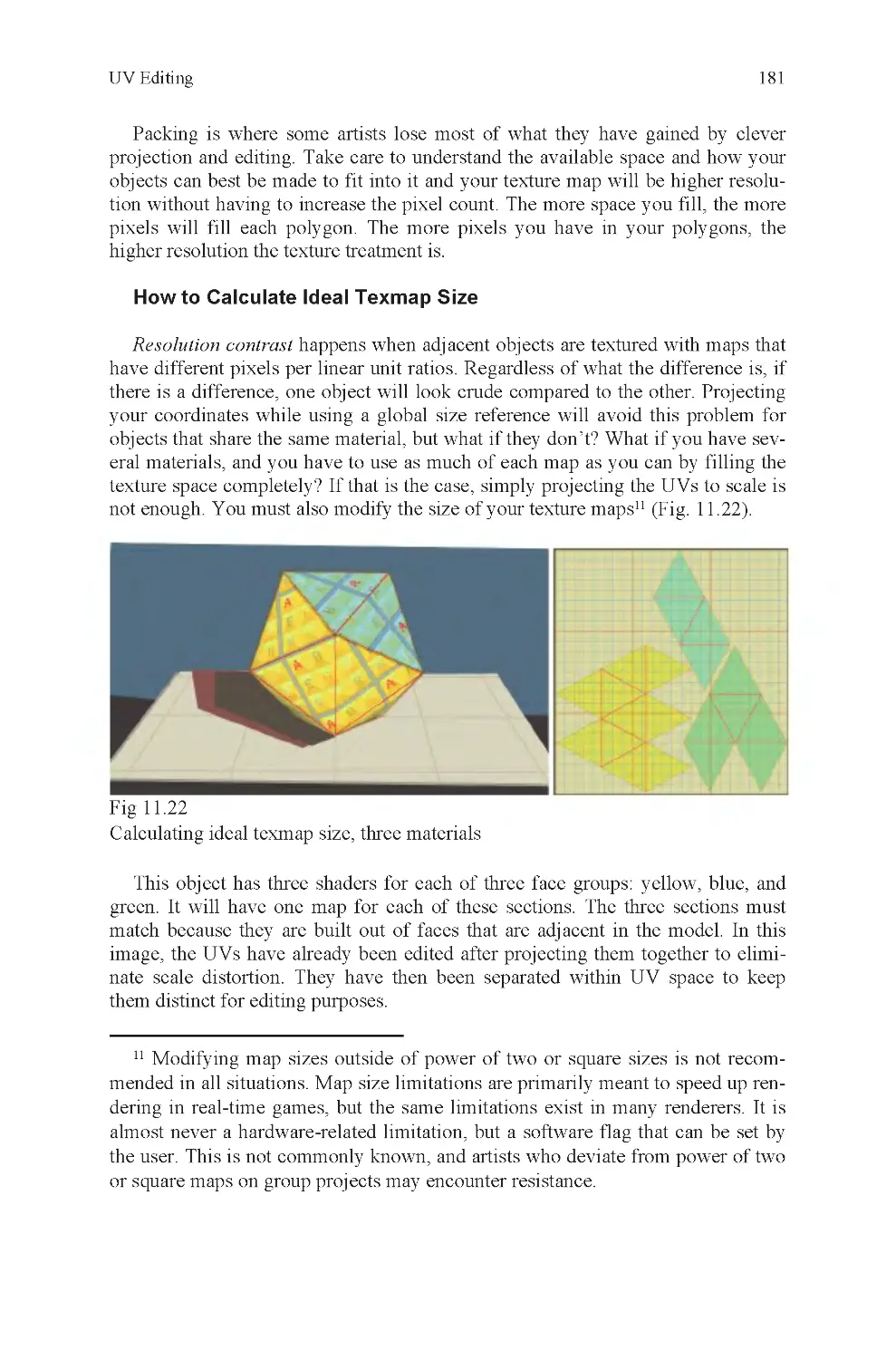
Fig 11.22 Calculating ideal tex-
map size, three materials
Fig 11.23 Calculating ideal tex-
map size, UV layout
Fig 11.24 Calculating ideal tex-
map size, scaled maps
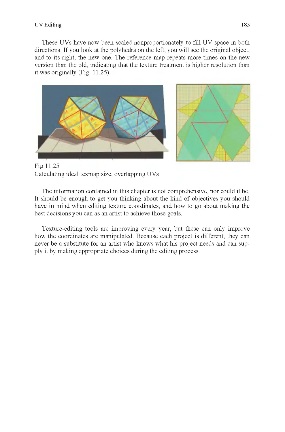
Fig 11.25 Calculating ideal tex-
map size, overlapping UVs
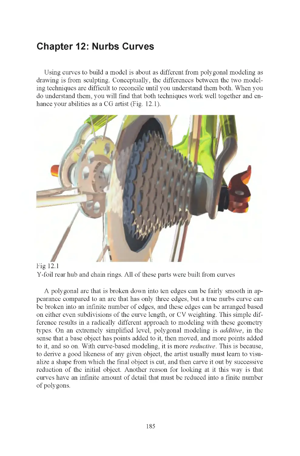
Fig 12.1 Y-foil rear hub and
chain rings
Fig 12.2 A nurbs curve
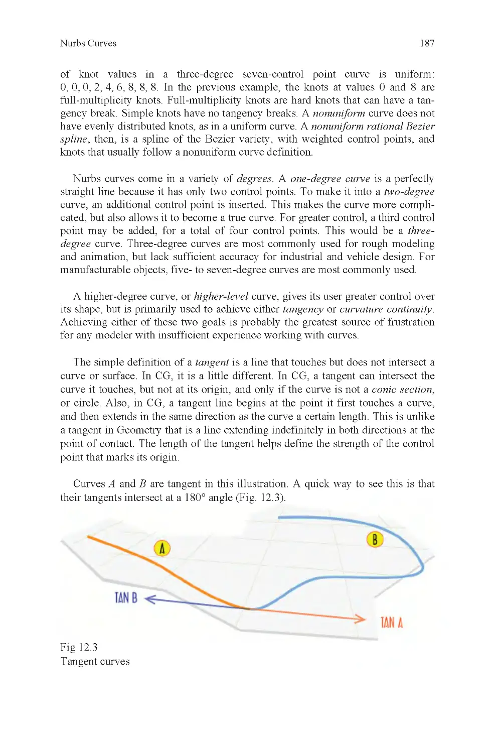
Fig 12.3 Two curves, matching
tangents
Fig 12.4 Two curves, not tangent
Fig 12.5 Tangent surfaces
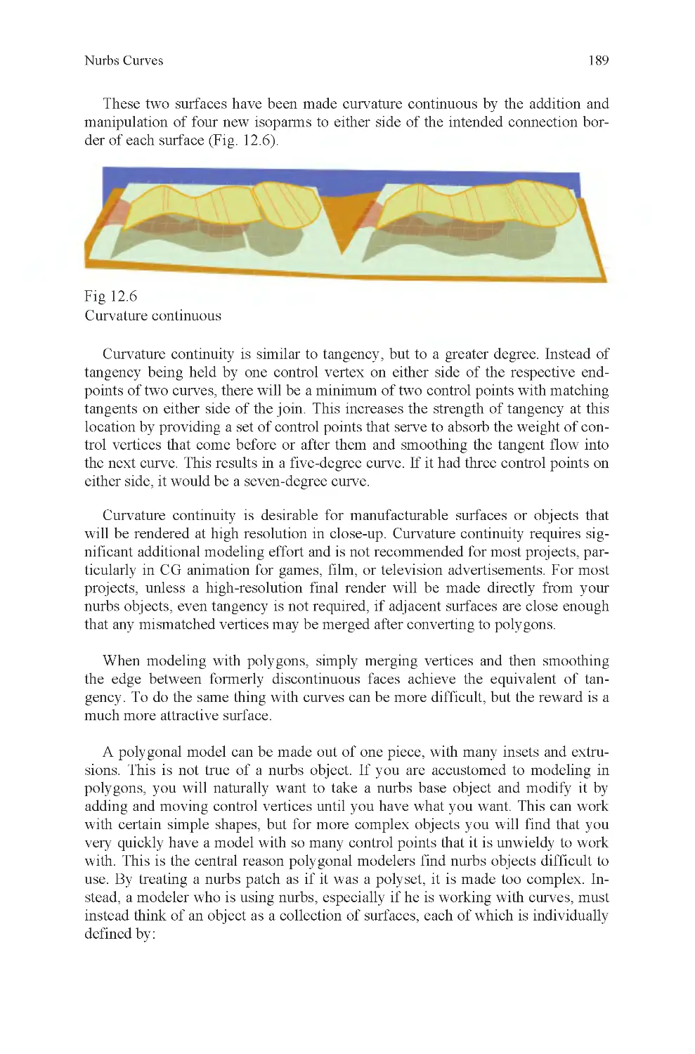
Fig 12.6 Curvature continuous
Fig 12.7 Projecting a curve and
trim
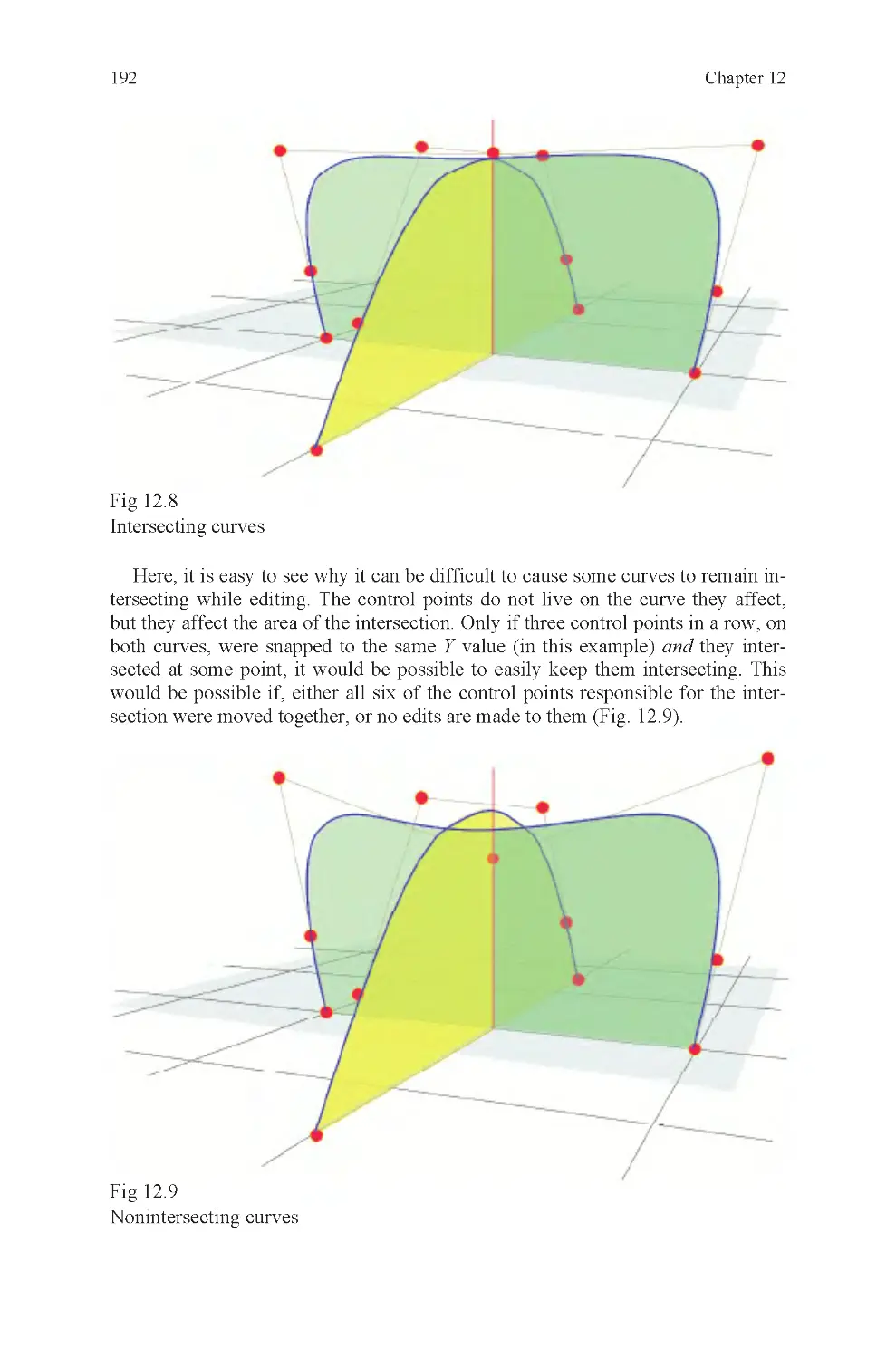
Fig 12.8 Intersecting curves
Fig 12.9 Nonintersecting curves
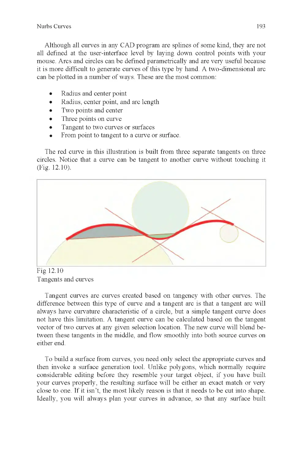
Fig 12.10 Curve tangent to curve
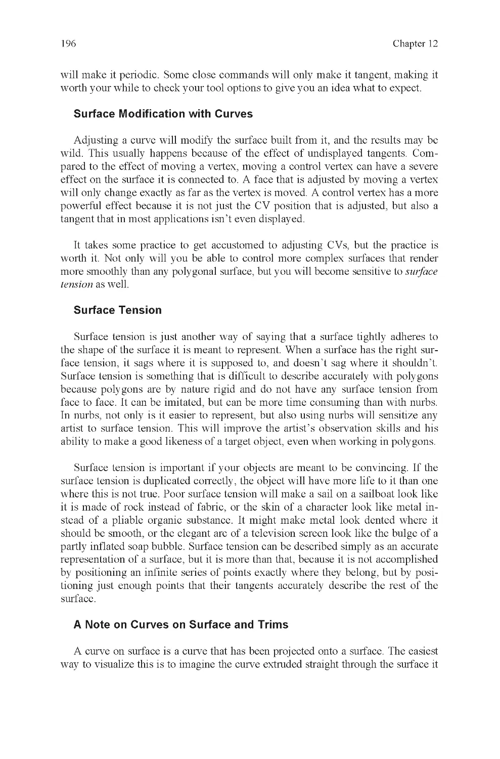
Fig 12.11 Curve simplification
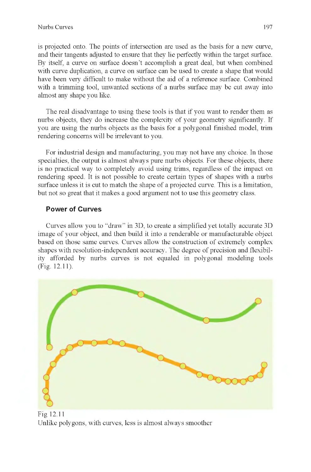
Fig 12.12 Nontangent and tan-
gent surface
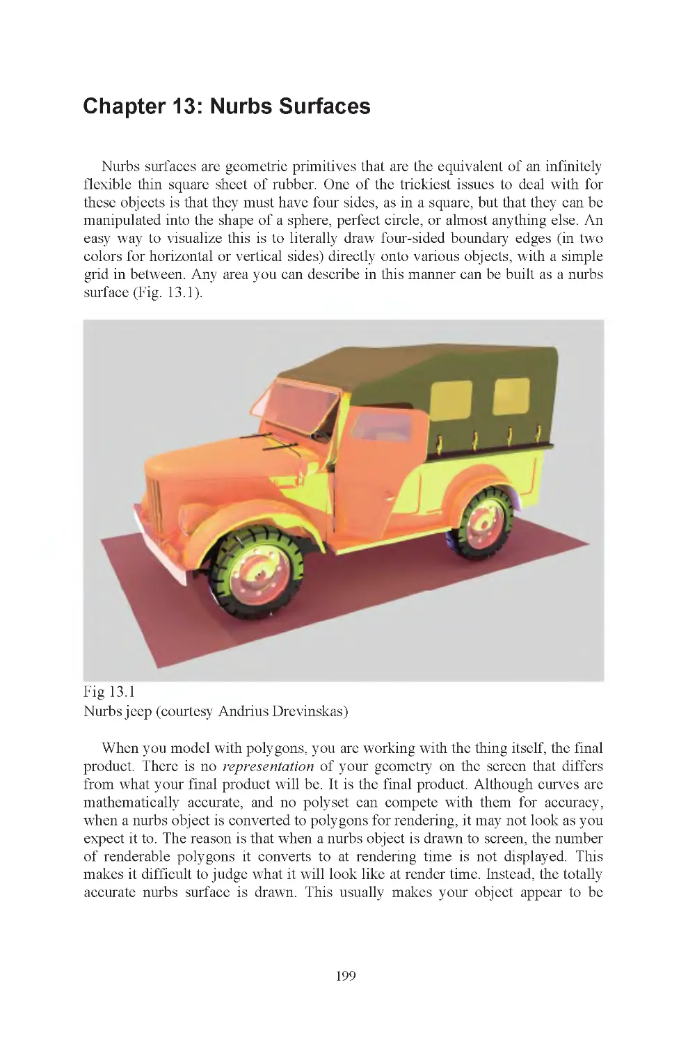
Fig 13.1 Nurbs jeep
Fig 13.2 Like glass and rubber:
polys and nurbs
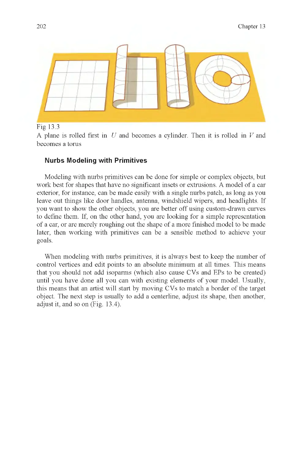
Fig 13.3 Plane to torus transfor-
mation
Fig 13.4 One isoparm at a time
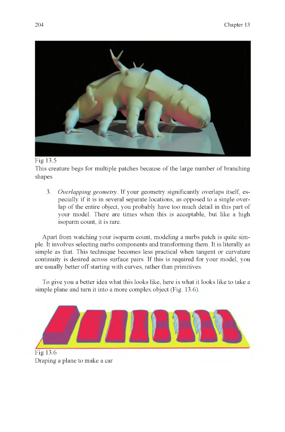
Fig 13.5 Multiple patches re-
quired due to branching detail
Fig 13.6 Nurbs plane transforms
into simple auto
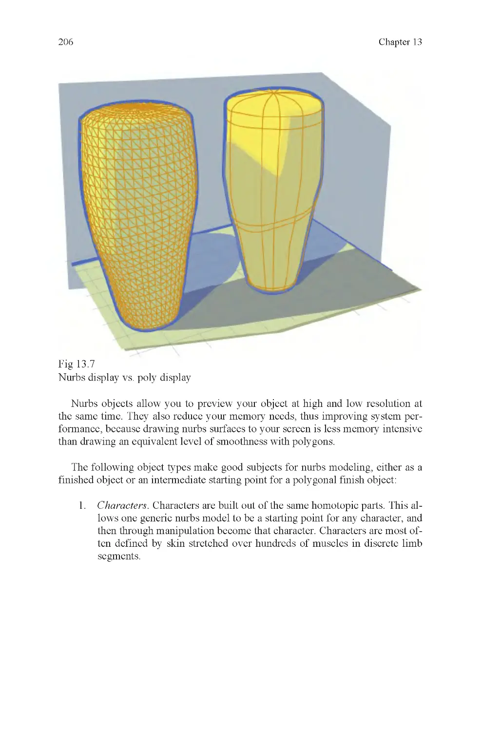
Fig 13.7 Nurbs display is simple
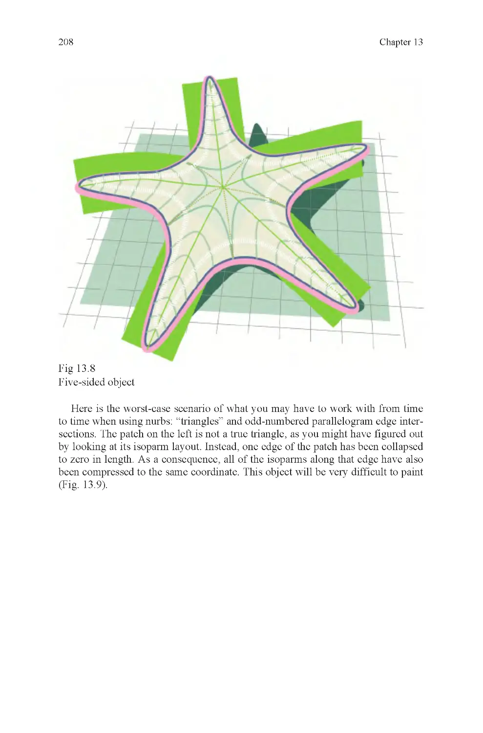
Fig 13.8 Nurbs starfish, odd
number of branches
Fig 13.9 Triangle and odd num-
bered parallelogram intersection
Fig 13.10 Nonright angle corners,
and the same with a trim
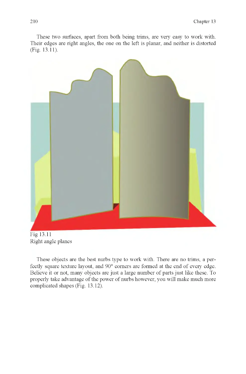
Fig 13.11 Two trims
Fig 13.12 Revolve and planes
Fig 13.13 Three-curve surface
Fig 13.14 Curve direction is good
Fig 13.15 Curve direction is not
good
Fig 13.16 Battle robot head, built
from curves
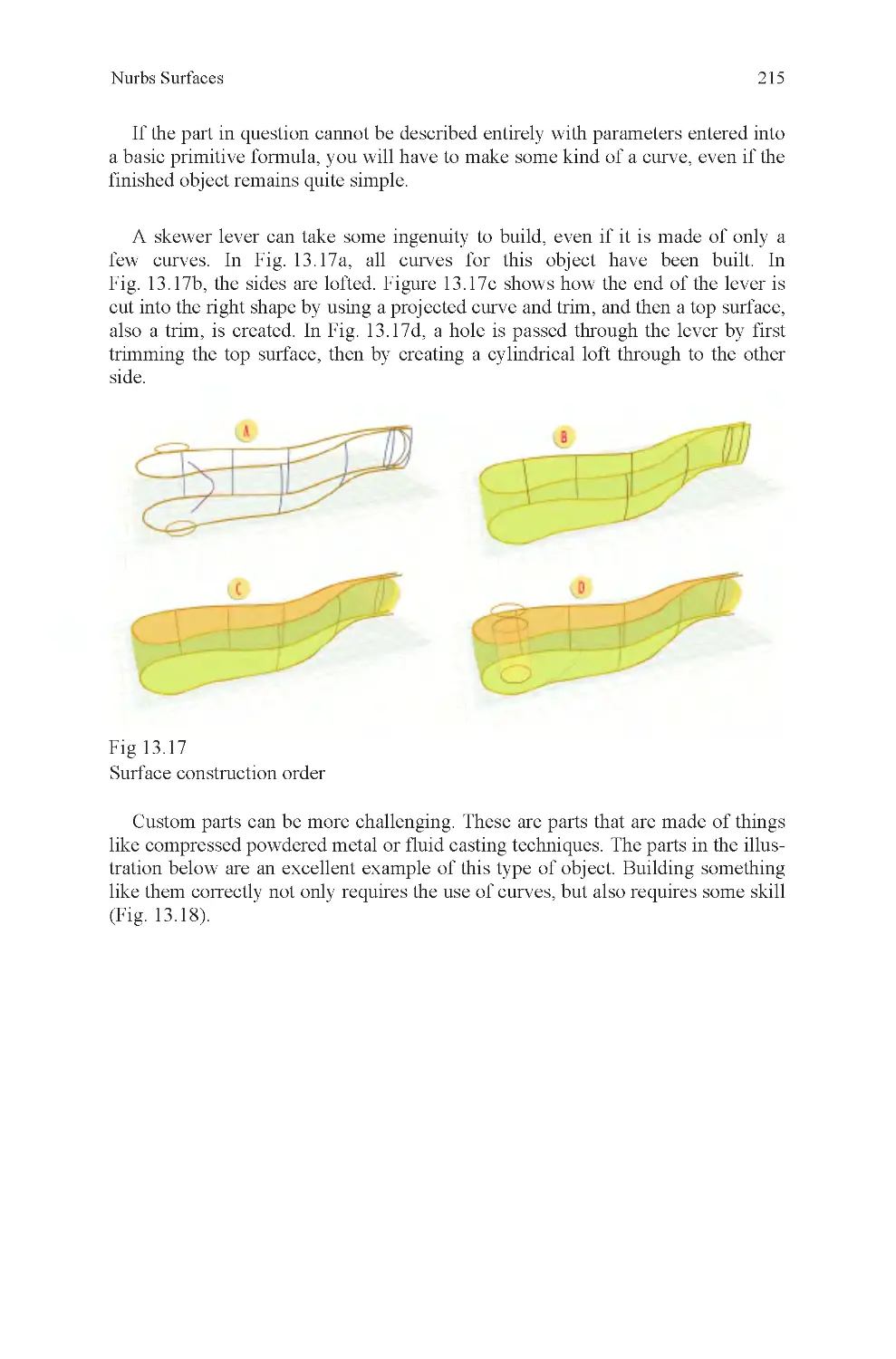
Fig 13.17 Skewer lever, how it
was built
Fig 13.18 Cast powdered metal
parts, a real modeler’s challenge
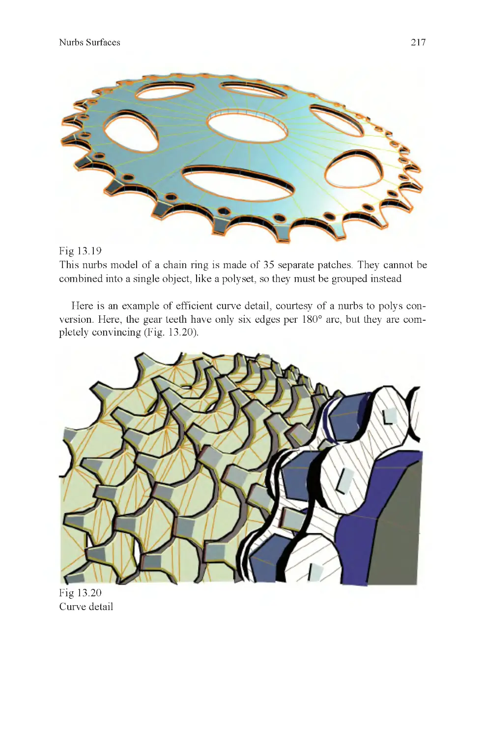
Fig 13.19 Multipatch chain ring
Fig 13.20 Curve detail in chain
rings
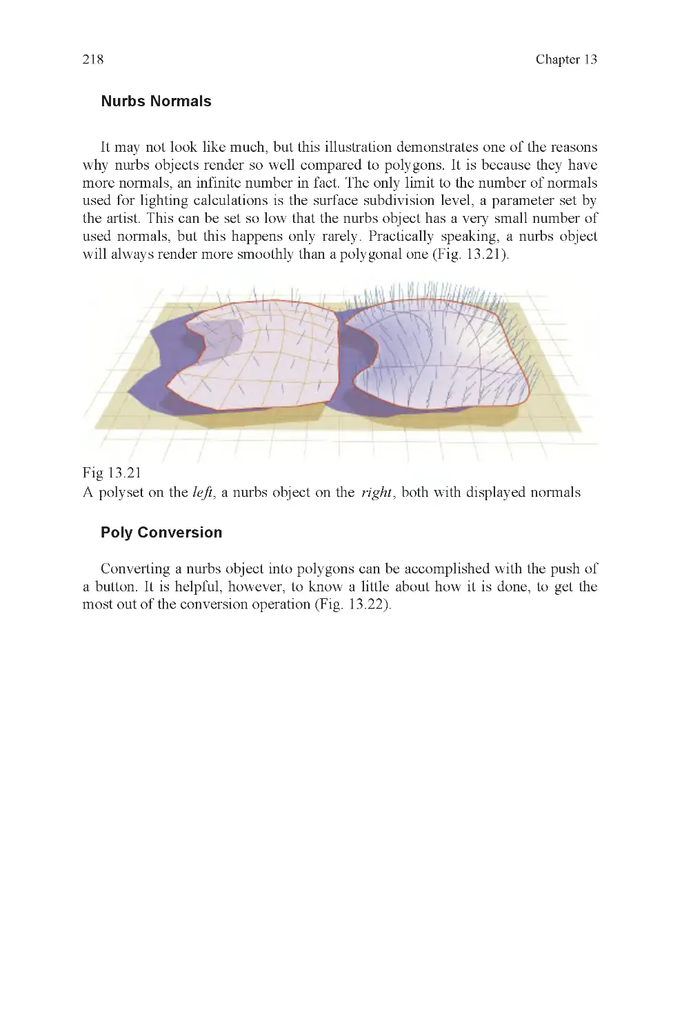
Fig 13.21 Nurbs normals
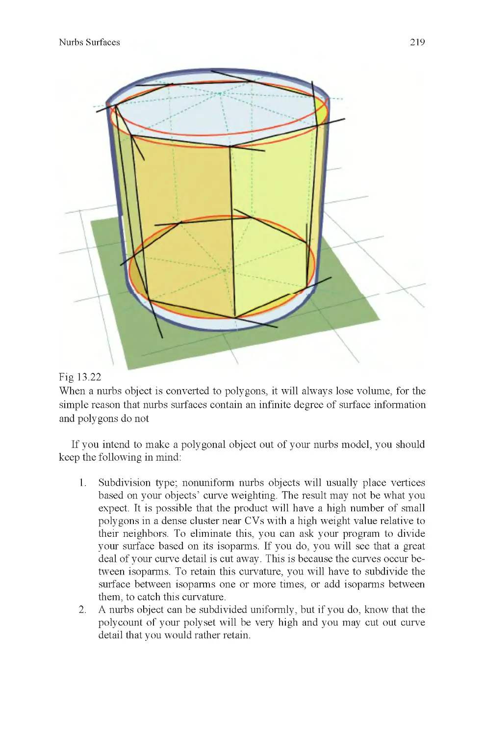
Fig 13.22 Nurbs to poly conversion
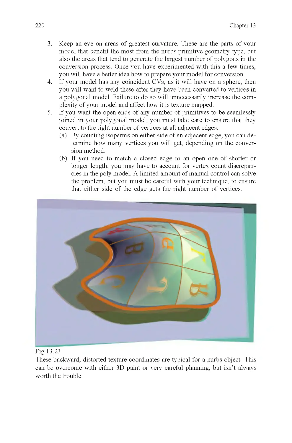
Fig 13.23 Distorted embedded
coordinates on a patch
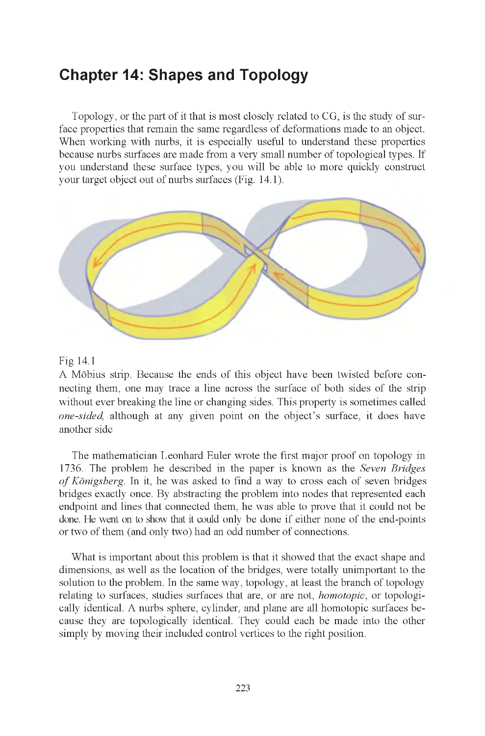
Fig 14.1 Möbius strip
Fig 14.2 Four-sided primitives
Fig 14.3 Nurbs deformability
Fig 14.4 Three-holed primitive
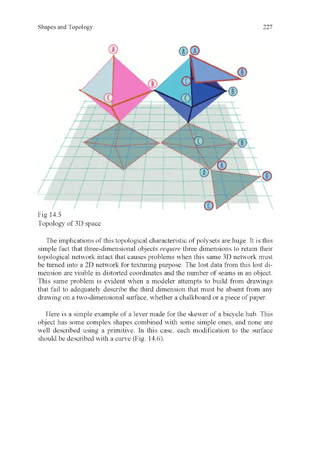
Fig 14.5 2D and 3D space, how it
affects topology
Fig 14.6 Render of skewer lever
Fig 14.7 An artist sketches
List of Illustrations
Introduction
In 1435, the Italian scholar Leon Battista Alberti wrote a Latin treatise titled De
Pictura (on painting). In 1436, it was translated into Italian and distributed. It is
the first known publication on the subject of linear perspective, a subject very
closely related to the very heart of modern computer graphics. The treatise was
partly based on observations made by the great Florentine sculptor and architect
Filippo Brunelleschi, though other artists from the same period were also experi-
menting with the technique. The Italian Renaissance in painting was to some con-
siderable extent dependent on this major discovery.
Linear perspective demonstrated that a realistic representation of a 3D envi-
ronment could be calculated based on rules that govern how our eyes see the
world around us. Because these rules could be written down, and because they
worked, innumerable artists were able to replicate the results Alberti described and
linear perspective became a standard tool for most artists all the way up to the pre-
sent day (Figs. 0 .1 and 0.2).
Fig 0.1
Piero Della Francesca, Brera Altarpiece 1472–1474
Fig 0.2
Paolo Uccello, Chalice 1450
With the invention of the computer, it was inevitable that this knowledge would
be turned into software, and it was. When this happened, the modern era of 3D
xi
xii
computer graphics, perhaps the most significant, advance in the visual arts since
the discovery of perspective was made.
The work of other artists was also used as the basis for innovations in computer
graphics. Leonardo Da Vinci’s work on aerial perspective was incorporated into
3D rendering software, just as the work of Impressionist and Pointillist artists like
Claude Monet and Georges Seurat became the basis for pixel-based representa-
tions of visual information (Fig. 0 .3).
Without the observations of these artists, there would be no computer graphics.
Computer graphics are possible only because there are people who looked at the
world around them, and went to the trouble not only to describe what they saw,
but also to understand what they saw.
Knowledge of a subject is what makes the difference between a novice and an
expert. If I look under the hood of a car, I see a bunch of blackened metal objects.
A mechanic sees an engine, gaskets, spark plugs, hoses, and many other things he
can identify, knows the purpose of, and can assemble himself if necessary. For a
computer graphics artist, the difference between a true expert and a novice who
just sees a jumble of stuff under the hood is observation (Fig. 0.4).
Introduction
Fig 0.3
Georges Seurat, Bridge of Courbevoie 1886/1887
xiii
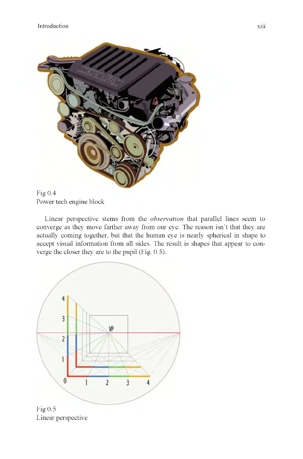
Fig 0.4
Power tech engine block
Introduction
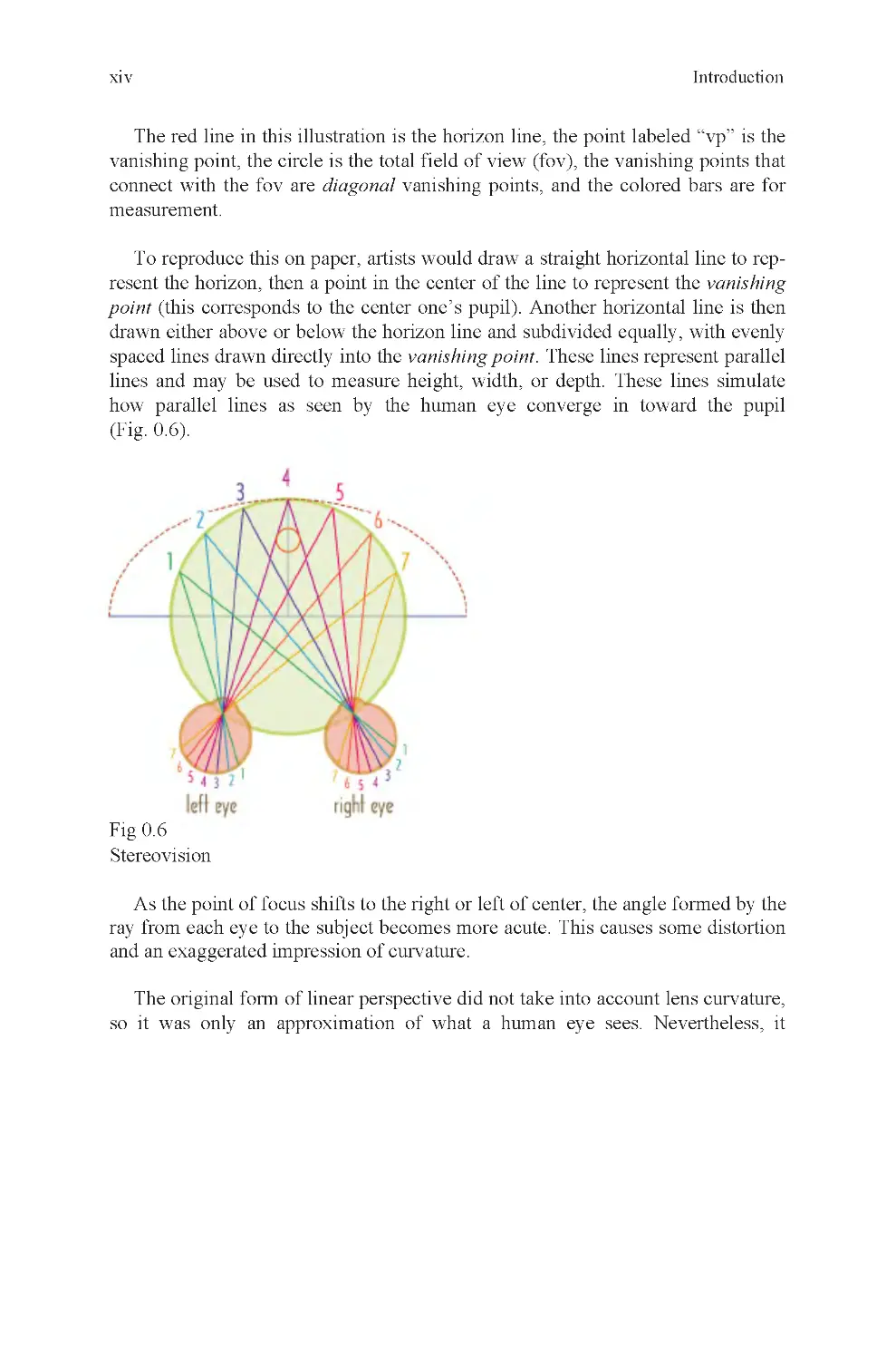
Fig 0.5
Linear perspective
Linear perspective stems from the observation that parallel lines seem to
converge as they move farther away from our eye. The reason isn’t that they are
accept visual information from all sides. The result is shapes that appear to con-
verge the closer they are to the pupil (Fig. 0 .5).
actually coming together, but that the human eye is nearly spherical in shape to
xiv
The red line in this illustration is the horizon line, the point labeled “vp” is the
vanishing point, the circle is the total field of view (fov), the vanishing points that
connect with the fov are diagonal vanishing points, and the colored bars are for
measurement.
To reproduce this on paper, artists would draw a straight horizontal line to rep-
resent the horizon, then a point in the center of the line to represent the vanishing
point (this corresponds to the center one’s pupil). Another horizontal line is then
drawn either above or below the horizon line and subdivided equally, with evenly
spaced lines drawn directly into the vanishing point. These lines represent parallel
lines and may be used to measure height, width, or depth. These lines simulate
how parallel lines as seen by the human eye converge in toward the pupil
(Fig. 0 .6).
Fig 0.6
Stereovision
As the point of focus shifts to the right or left of center, the angle formed by the
ray from each eye to the subject becomes more acute. This causes some distortion
and an exaggerated impression of curvature.
The original form of linear perspective did not take into account lens curvature,
so it was only an approximation of what a human eye sees. Nevertheless, it
Introduction
xv
Fig 0.7
Lens curvature
Notice how the curvature of the reflective hemisphere affects the reflection cast
upon it. This is the same thing that happens when visual information in three-
dimensional space is projected onto your eye.
Leonardo’s observation that colors become less distinct over distance became
known as aerial perspective. He used this to more accurately describe observed
details, most famously in the background of the painting Mona Lisa. Other artists
used the technique as it became better known, and descriptions of it became com-
monplace in books about art. The phenomenon Leonardo saw, described, and went
to some trouble to understand was caused by the fact that our atmosphere contains
many tiny light-occluding particles such as dust and fog. At near distances, they
do not affect our vision because there are not as many of these particles between
our eye and the object we are observing as when we refocus our eyes on a distant
object. In computer graphics, aerial perspective is known as environmental fog.
The effect is used effectively to simulate great distances in computer renderings
(Fig. 0 .8).
Introduction
worked well enough that for 500 years, it was the basis for almost every great
work of art made during that period. Later, engineers worked out engineering per-
spective and they did take lens curvature into account. With it, lens curvature
could be represented accurately. It is this form of perspective that is now used for
computer renderings (Fig. 0 .7).
xvi
Fig 0.8
Shadow in the Summer (© 2005 Stephan Martiniere)
Introduction
xvii
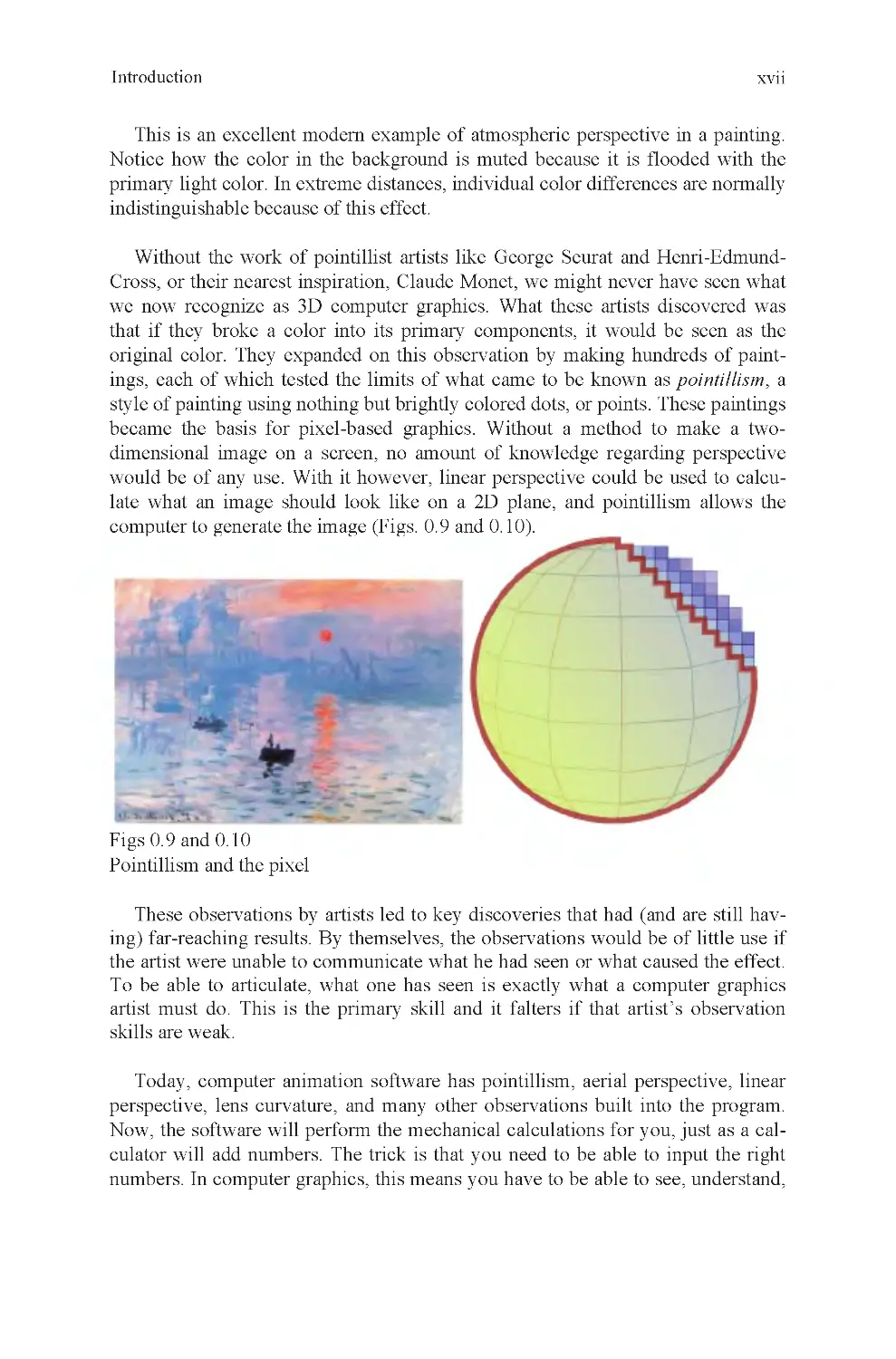
This is an excellent modern example of atmospheric perspective in a painting.
Notice how the color in the background is muted because it is flooded with the
primary light color. In extreme distances, individual color differences are normally
indistinguishable because of this effect.
Without the work of pointillist artists like George Seurat and Henri-Edmund-
Cross, or their nearest inspiration, Claude Monet, we might never have seen what
we now recognize as 3D computer graphics. What these artists discovered was
that if they broke a color into its primary components, it would be seen as the
original color. They expanded on this observation by making hundreds of paint-
ings, each of which tested the limits of what came to be known as pointillism, a
style of painting using nothing but brightly colored dots, or points. These paintings
became the basis for pixel-based graphics. Without a method to make a two-
dimensional image on a screen, no amount of knowledge regarding perspective
would be of any use. With it however, linear perspective could be used to calcu-
late what an image should look like on a 2D plane, and pointillism allows the
computer to generate the image (Figs. 0.9 and 0.10).
Figs 0.9 and 0.10
Pointillism and the pixel
These observations by artists led to key discoveries that had (and are still hav-
ing) far-reaching results. By themselves, the observations would be of little use if
the artist were unable to communicate what he had seen or what caused the effect.
To be able to articulate, what one has seen is exactly what a computer graphics
artist must do. This is the primary skill and it falters if that artist’s observation
skills are weak.
Today, computer animation software has pointillism, aerial perspective, linear
perspective, lens curvature, and many other observations built into the program.
Now, the software will perform the mechanical calculations for you, just as a cal-
culator will add numbers. The trick is that you need to be able to input the right
numbers. In computer graphics, this means you have to be able to see, understand,
Introduction
xviii
and describe your subject to your software in a language it understands. If you do
your job properly, you will receive in return a beautifully rendered image.
Knowledge of a computer animation program will not by itself make anyone
into a competent professional animator. They may learn the buttons, they may
learn the language of the application, but without well-described observations, the
raw data needed to create a computer rendering, this knowledge is insufficient to
be a truly successful computer artist. To be a successful computer artist, you also
need to understand how to look at the world around you, or imagine the one
within, with great clarity. You must be able to see detail that others miss, under-
stand why it is there, what it is for, how to distinguish it from its neighbors, and
describe it to your application.
The skills just described are the basis for this book. They are application inde-
pendent and are true of every 3D application currently made. As 3D professionals,
you will discover that 3D applications change on a nearly annual basis and that
every few years the most popular application will have changed to something new.
When this happens, artists who understand computer graphics for what it is, a way
to place their real-world observations into an application capable of generating a
rendering (even if it is a real-time game engine), will never be out of a job. The
reason is that the applications are much easier to learn than these other skills, and
their employers know that.
This book is about computer graphics; it is not about computer graphics appli-
cations. In this book, you will learn the meaning and usage of computer graphics
tools and terminology, but more importantly, the basic observation skills needed
to do something great with that knowledge.
The information contained herein is meant to comprise the first portion of a
university-level introduction to Computer Graphics course. The layout of the book
follows the class structure of my first two modeling classes for freshman students
(they are staggered with two animation classes). Although a great deal may be
learned by simply reading the text, it is highly recommended that any serious stu-
dent also performs every exercise offered here.
The first part of the book, 3D1, focuses on fundamental principles of how 3D
space is represented in a computer, user interface, basic polygonal modeling tools,
and other information essential to getting started as a 3D artist. The second part of
the book, 3D2, introduces the more complicated subjects of surfaces, topology,
and optimization. Each of these has their own importance, and all help inform the
student to make better creative and technical choices with his work.
Andrew Paquette
Introduction
Part I: 3D1: Introduction to 3D Modeling
Modeling is where all 3D projects must begin, because without a model, there
is nothing to animate or render. Studying modeling is also an excellent means of
familiarizing an artist with basic concepts of Computer Graphics. By under-
standing modeling, an artist will also be more comfortable with the software he
uses, finding errors in his work, and avoiding problems he might otherwise
encounter.
This section is designed to provide a student with a solid foundation in
polygon-based modeling and animation applications.
1
3
Chapter 1: 3D: What Is It?
Imagine American astronaut Neil Armstrong when he first landed on the moon.
Soon after this historic event, he ventured outside the moon lander and planted an
American flag in the dusty gray soil of the moon. Now, imagine the intersection of
that flagpole and the moon’s surface as the center of the universe. In computer
graphics, that would make that point the world origin, and it would be the point
against which every other distance is measured. With that point known, the
distance from the world origin to Armstrong’s hand may be measured, the exact
location of earth may be found, and Bluebeard’s treasure may be located. Without
it, at least as far as your computer is concerned, all these things are floating
aimlessly and invisibly through space (Fig. 1 .1).
Fig 1.1
zero
The origin doesn’t have to be on the moon, it can be anywhere. You can draw
an “x” in a notebook and make that the world origin. It doesn’t matter where it is,
but it does matter that it is there. Without a world origin, there is no universe, at
least as far as your 3D application is concerned. It needs to be given an origin, or a
starting point, so that it knows where things belong. The reason is that in computer
graphics, all 3D data are stored as X, Y, and Z coordinates. These coordinates are
meaningless without a zero point to measure them against.
In surveying, it is called a station point. Usually, it is an iron bar painted with
even divisions on it and planted into the ground, just like Armstrong’s flag. It is
then sighted with surveying instruments, and all distances are calculated from it.
That is exactly what a world origin is for. It is also the first thing the software
needs to know before it can do anything. In your case, you don’t have to know this
fact to start making objects in 3D any more than you have to understand linear
On the left is the location of zero, on the right, a measurement based on
4
Chapter 1
perspective either. In both cases, the software has this information built in and it
does the work for you. However, not knowing this information can cause a great
deal of frustration later, because it affects how tools behave. These concepts are
how your application sees the world, and you have to understand that if you are to
smoothly interact with a 3D application.
You can add numbers with a calculator by pushing buttons, but if you don’t
understand the concept of adding, the calculator is of no use to you because you
won’t know what the results represent. In the same way, a 3D application will
perform many functions invisibly, but if you don’t know what it is doing, you
won’t know what to expect, or how to work out a problem. The first thing you
need to remember then is that the global origin is a station point against which all
dimensions are measured. It is used as a way to locate the center of world space, a
term that describes your working environment.
The world origin is usually represented on screen with a 3D icon of some kind,
to show the three major axes. They are known as the X, Y, and Z axes and
represent the three perpendicular vectors used to define space within your
program. Pointing in the opposite direction are the negative X, Y, Z axes, for a
total of six primary vectors (Fig. 1 .2).
Fig 1.2
World coordinates
depth axis (Fig. 1 .3).
These are very much like the X , Y grids you may have drawn in Math class to
plot the location of a point. They are used in much the same way in 3D applica-
tions as well, but with an additional axis to represent the depth. This is the
Z-axis , also known as the
3D: What Is It?
5
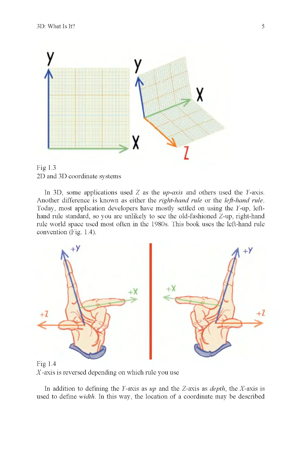
Fig 1.3
2D and 3D coordinate systems
In 3D, some applications used Z as the up-axis and others used the Y-axis.
Another difference is known as either the right-hand rule or the left-hand rule.
Today, most application developers have mostly settled on using the Y-up, left-
hand rule standard, so you are unlikely to see the old-fashioned Z-up, right-hand
rule world space used most often in the 1980s. This book uses the left-hand rule
convention (Fig. 1 .4).
Fig 1.4
X -axis is reversed depending on which rule you use
In addition to defining the Y-axis as up and the Z-axis as depth, the X-axis is
used to define width. In this way, the location of a coordinate may be described
6
Chapter 1
with a group of three numbers, each of which represents a measurement along one
of the three major axes, a given distance from the world origin.
To locate a point in space then, your software needs a global origin, to be used
as a station point. It then needs to have a group of numbers to identify where on
each of three axes the point lies. To your application, this is what such a
coordinate looks like:
231
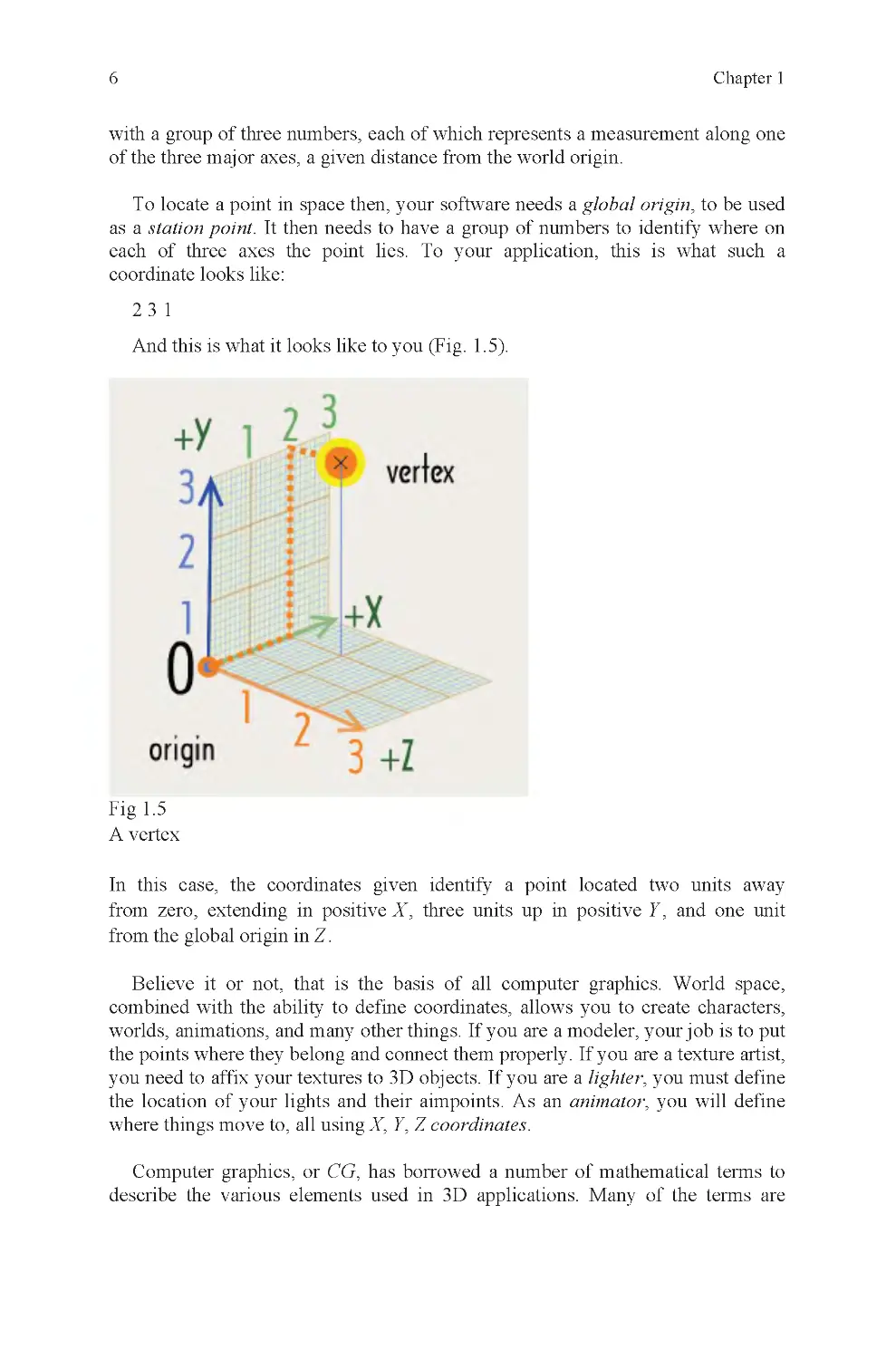
And this is what it looks like to you (Fig. 1 .5).
Fig 1.5
A vertex
Z.
Believe it or not, that is the basis of all computer graphics. World space,
combined with the ability to define coordinates, allows you to create characters,
worlds, animations, and many other things. If you are a modeler, your job is to put
the points where they belong and connect them properly. If you are a texture artist,
you need to affix your textures to 3D objects. If you are a lighter, you must define
the location of your lights and their aimpoints. As an animator, you will define
where things move to, all using X, Y, Z coordinates.
Computer graphics, or CG, has borrowed a number of mathematical terms to
describe the various elements used in 3D applications. Many of the terms are
In this case, the coordinates given identify a point located two units away
from zero, extending in positive X , three units up in positive Y , and one unit
from the global origin in
3D: What Is It?
7
recognizable from the study of Geometry. This fact is the probable origin of the
use of the word Geometry to refer to 3D models. If someone complains to an
animator that “the geometry is messed up,” the animator might respond, “tell it to
the modeler, he’s the one who made it.”
The model is where most files begin, and to understand it a little better, its
elements should be defined.
A vertex is a single coordinate for a point in world space. It has no dimension
and very few properties by itself. To make it into an edge, it requires another
point. This only defines a line, and as such, still cannot be rendered. To render it, a
third point must be defined, to create a triangle, also known as a face or a polygon.
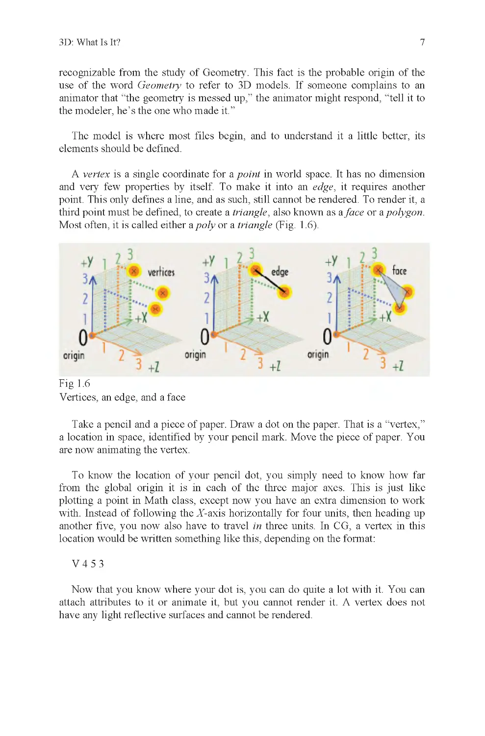
Most often, it is called either a poly or a triangle (Fig. 1 .6).
Fig 1.6
Vertices, an edge, and a face
Take a pencil and a piece of paper. Draw a dot on the paper. That is a “vertex,”
a location in space, identified by your pencil mark. Move the piece of paper. You
are now animating the vertex.
To know the location of your pencil dot, you simply need to know how far
plotting a point in Math class, except now you have an extra dimension to work
with. Instead of following the X-axis horizontally for four units, then heading up
another five, you now also have to travel in three units. In CG, a vertex in this
location would be written something like this, depending on the format:
V453
Now that you know where your dot is, you can do quite a lot with it. You can
attach attributes to it or animate it, but you cannot render it. A vertex does not
from the global origin it is in each of the three major axes. This is just like
have any light reflective surfaces and cannot be rendered.
8
Chapter 1
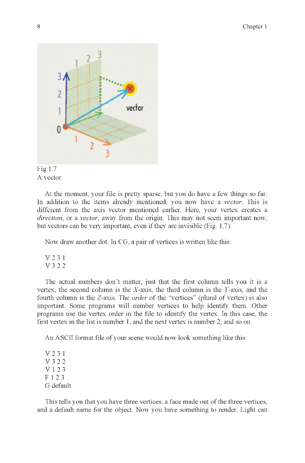
Fig 1.7
A vector
At the moment, your file is pretty sparse, but you do have a few things so far.
In addition to the items already mentioned, you now have a vector. This is
different from the axis vector mentioned earlier. Here, your vertex creates a
direction, or a vector, away from the origin. This may not seem important now,
Now draw another dot. In CG, a pair of vertices is written like this:
V231
V322
The actual numbers don’t matter, just that the first column tells you it is a
vertex, the second column is the X-axis, the third column is the Y-axis, and the
fourth column is the Z-axis. The order of the “vertices” (plural of vertex) is also
important. Some programs will number vertices to help identify them. Other
programs use the vertex order in the file to identify the vertex. In this case, the
first vertex in the list is number 1, and the next vertex is number 2, and so on.
An ASCII format file of your scene would now look something like this:
V231
V322
V123
F123
G default
This tells you that you have three vertices, a face made out of the three vertices,
and a default name for the object. Now you have something to render. Light can
but vectors can be very important, even if they are invisible (Fig. 1 .7).
3D: What Is It?
9
bounce off of a face and that quality is required for a rendering to be made
(Fig. 1 .8).
Fig 1.8
A light ray
There are several ways to modify the components of this face. Regardless of the
tool you use, the end result is a modification to the coordinate value of individual
vertices. This is accomplished with a transformation matrix (Fig. 1 .9).
Fig 1.9
Transform, rotation, scale translation types
A transformation matrix is attached to a node on your object. A node is like a
luggage tag for your suitcases. It tells you what is inside the bag and where it
belongs. The transformation matrix has nine primary attributes. They are:
Transform X, Y, Z
Rotate X, Y, Z
Scale X, Y, Z
They also have one minor attribute, visibility, which can be set to on or off
(default is on). With these ten values, you can do just about anything you can
10
Chapter 1
think of to your object. For animation, a state of the matrix is stored for each
frame of animation, and is used to modify the position, size, and rotation values of
an object over time.
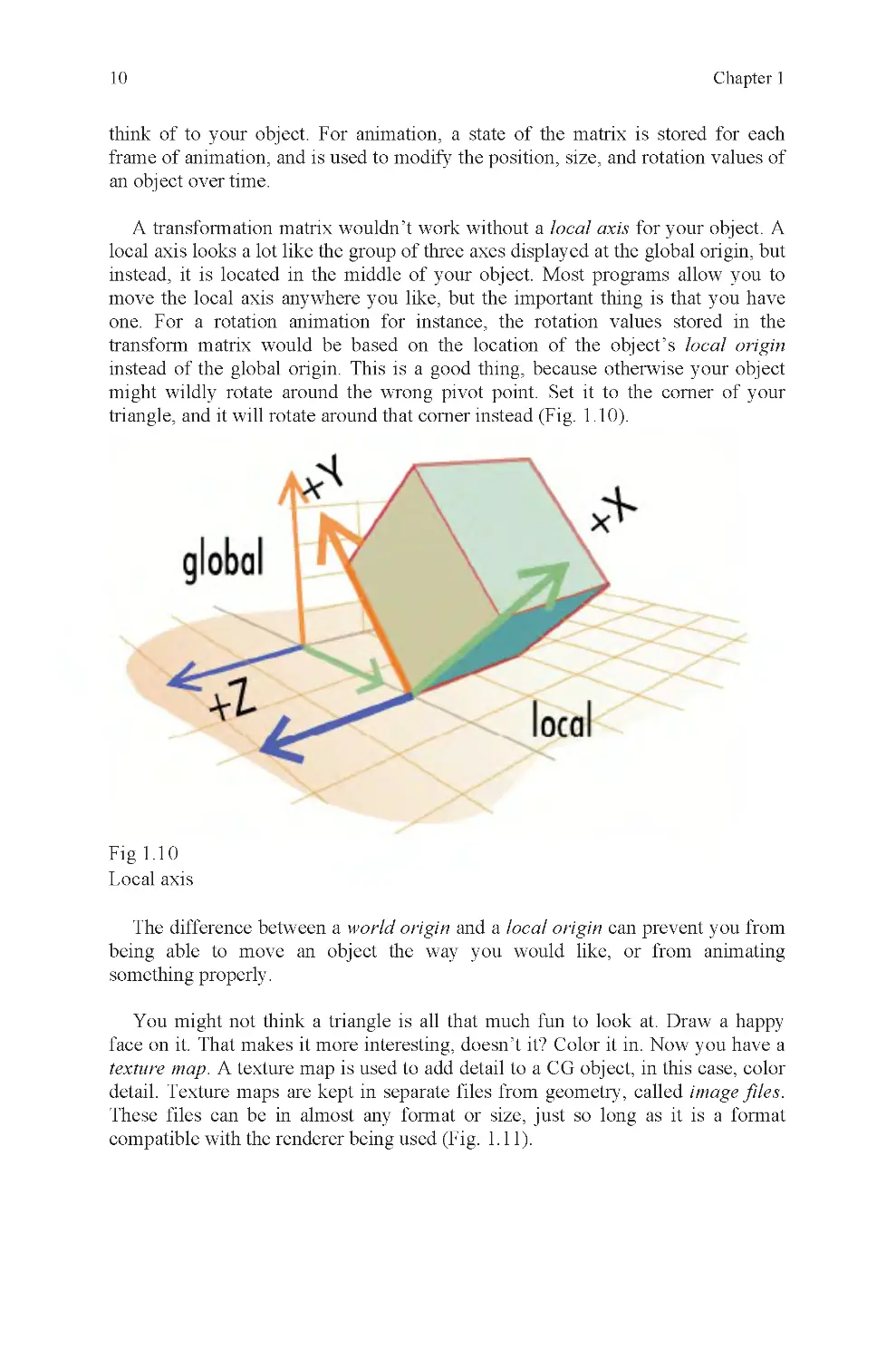
A transformation matrix wouldn’t work without a local axis for your object. A
local axis looks a lot like the group of three axes displayed at the global origin, but
instead, it is located in the middle of your object. Most programs allow you to
move the local axis anywhere you like, but the important thing is that you have
one. For a rotation animation for instance, the rotation values stored in the
transform matrix would be based on the location of the object’s local origin
instead of the global origin. This is a good thing, because otherwise your object
might wildly rotate around the wrong pivot point. Set it to the corner of your
triangle, and it will rotate around that corner instead (Fig. 1 .10).
Fig 1.1 0
Local axis
The difference between a world origin and a local origin can prevent you from
being able to move an object the way you would like, or from animating
something properly.
You might not think a triangle is all that much fun to look at. Draw a happy
face on it. That makes it more interesting, doesn’t it? Color it in. Now you have a
texture map. A texture map is used to add detail to a CG object, in this case, color
detail. Texture maps are kept in separate files from geometry, called image files.
These files can be in almost any format or size, just so long as it is a format
compatible with the renderer being used (Fig. 1.11).
3D: What Is It?
11
Fig 1.1 1
Polygon, texmap, and mapped polygon
A texture map is attached to a triangle, also called a polygon, or poly, by using
texture coordinates, more commonly called UVs. UVs are like vertices, except
they are positioned over a texmap, to identify which part of the map will be
rendered under which UV. The UVs are also attached to the vertices of your
object, to identify which parts of the map are attached to which vertices. If you
liked to build kites, but weren’t very good at it, you might use tacks instead of
glue to pin your kite paper to its wooden struts. The UVs are like the tacks and the
texture map is like the kite paper. The struts are the wireframe of your model
(Fig. 1 .12).
Fig 1.1 2
How a texture map is attached to a polygon
In the triangle example, you will have one UV for each of the three vertices of
your object. These UVs will be connected by edges that correspond to the edges of
12
Chapter 1
your polygon, and the connection pattern between its vertices. The UVs can be
adjusted in a texture editor, to modify which part of a texture map is rendered
within their borders. If done properly, your happy face will show up where it is
supposed to; not upside down, backward, or distorted like a funhouse mirror.
Done right, it will look fine, i.e., if you had any lights.
Turn on the lights in your room. You can see much better now. In CG, it’s even
worse than in real life. In CG, if you don’t have any lights, it’s not just dim, it is
black. You can’t see anything, because every pixel is set to 0 0 0, black.
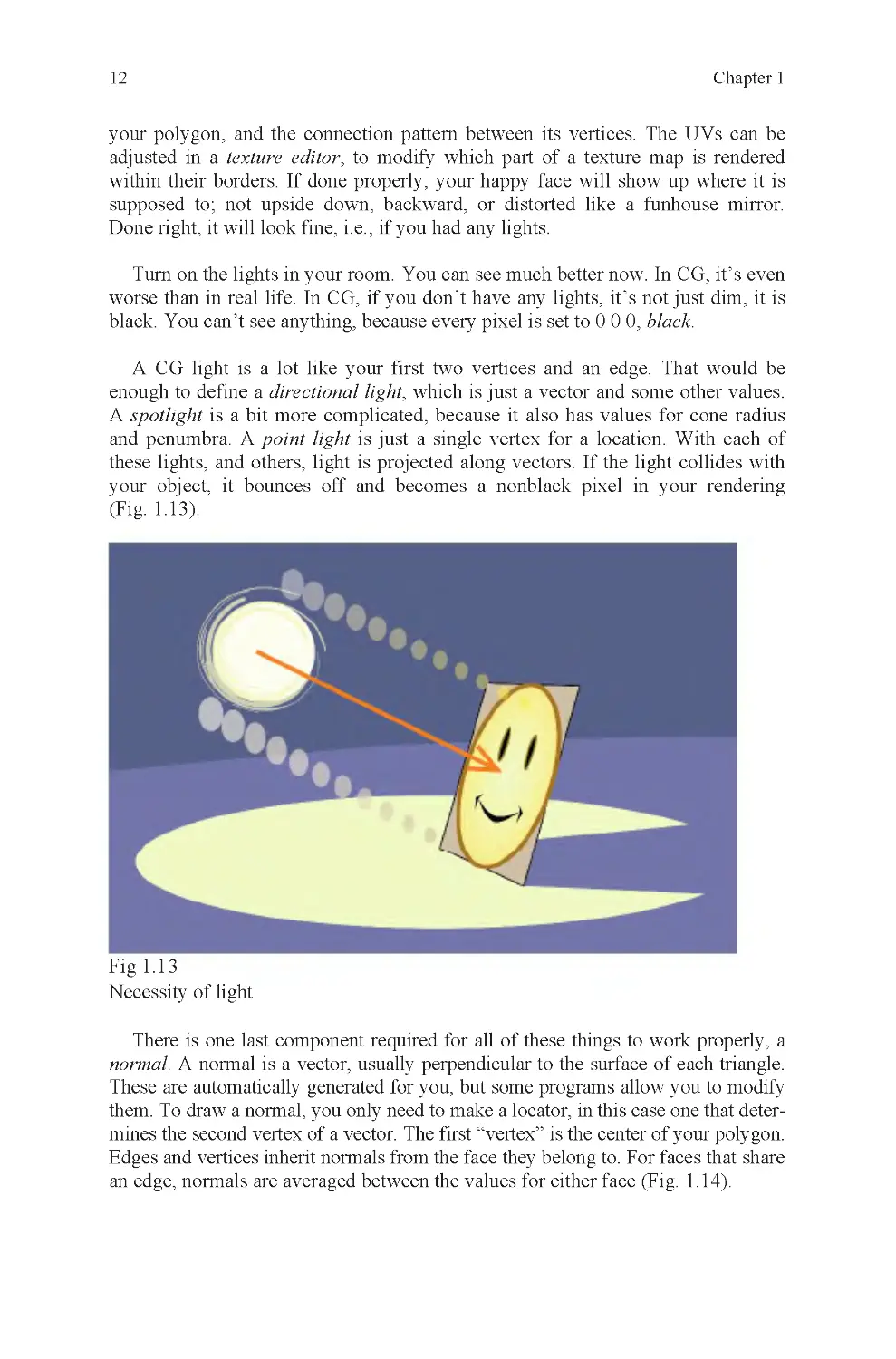
A CG light is a lot like your first two vertices and an edge. That would be
enough to define a directional light, which is just a vector and some other values.
A spotlight is a bit more complicated, because it also has values for cone radius
and penumbra. A point light is just a single vertex for a location. With each of
these lights, and others, light is projected along vectors. If the light collides with
your object, it bounces off and becomes a nonblack pixel in your rendering
(Fig. 1 .13).
Fig 1.1 3
Necessity of light
There is one last component required for all of these things to work properly, a
normal. A normal is a vector, usually perpendicular to the surface of each triangle.
These are automatically generated for you, but some programs allow you to modify
them. To draw a normal, you only need to make a locator, in this case one that deter-
mines the second vertex of a vector. The first “vertex” is the center of your polygon.
Edges and vertices inherit normals from the face they belong to. For faces that share
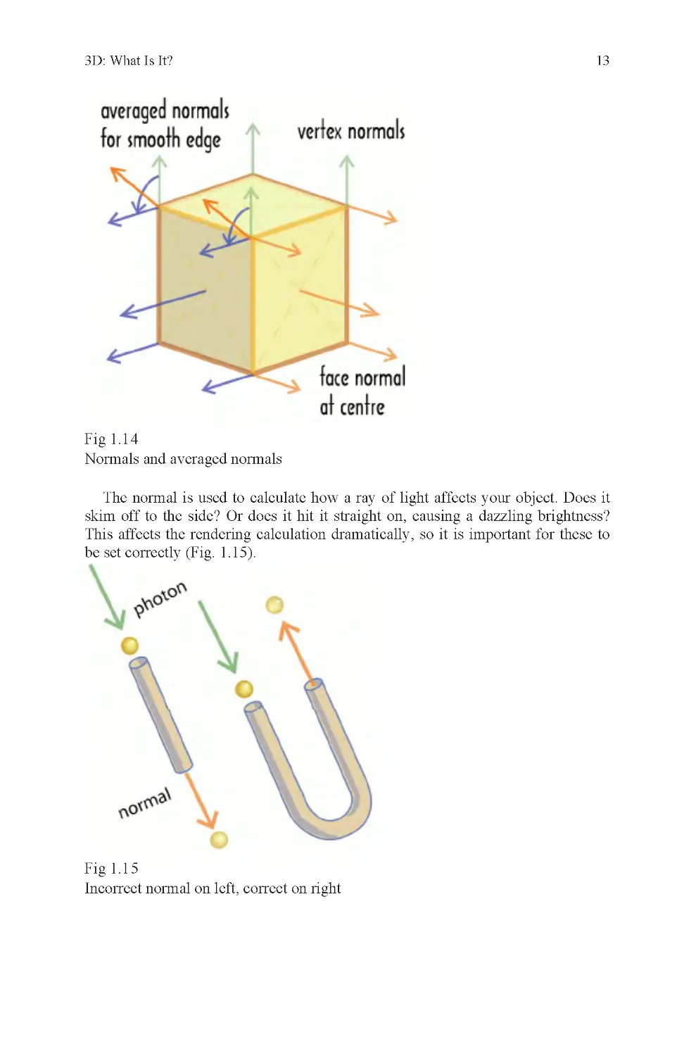
an edge, normals are averaged between the values for either face (Fig. 1 .14).
3D: What Is It?
13
Fig 1.1 4
Normals and averaged normals
The normal is used to calculate how a ray of light affects your object. Does it
skim off to the side? Or does it hit it straight on, causing a dazzling brightness?
This affects the rendering calculation dramatically, so it is important for these to
be set correctly (Fig. 1 .15).
Fig 1.1 5
Incorrect normal on left, correct on right
14
Chapter 1
An incorrect normal will cause light to pass through a polygon, like a ball
through a straight pipe, without returning a color value to the camera. The result is
that back-facing polygons, polygons that should face away from the camera,
instead face toward it and are rendered instead of polygons in front that should
block them. The effect is like looking at the inside of a mold used to cast another
object (Fig. 1 .16).
Fig 1.1 6
Reversed normals, as seen in mirror
These are the seven basic physical elements of CG (Fig. 1 .17):
1. Vertices
2. Edges
3. Faces
4. UVs
5. Textures
6. Lights
7. Normals
3D: What Is It?
15
Fig 1.1 7
The seven basic elements of CG
These are the five basic conceptual elements of CG:
1. Global coordinates
2. Local coordinates
3. Vectors
4. Transformation matrix
5. Light
All computer renderings are built out of the elements just described, or varia-
tions of them. Learn what they are and what they can do, and you will understand
how your software sees the world.
Animation applications vary considerably in some respects, but they also have
much in common. Some take pains to be compatible with other applications;
others go to great lengths to avoid compatibility, even with previous versions of
themselves. Despite these variations, all animation applications do pretty much
the same thing; they allow a user to create a 3D file through a graphical user
interface, also known as a GUI. Therefore, the two things that a user needs to
know to make a 3D object for a CG animation are the basics of 3D and the GUI.
Some programs have specific commands that are not a part of any other
program, but most programs have the same basic tools. They also have very
similar methods of watching what is going on inside their virtual 3D workspace.
When you first open a 3D application, you will see a window, also called a
viewport that has a representation of world space drawn within it. World space is
Basic Tools: Your Interface
16
Chapter 1
literally the global origin and everything around it, all the way to infinity. Of
course, no computer really goes to infinity because the numbers would be too big.
Instead, they are cut off and rounded, usually between six and ten decimal points.
On the screen, world space usually looks like an origin icon plus a grid.
Depending on which viewport you are looking at, orthographic or perspective,
you may be looking at a flat grid made of perpendicular angles, or a grid made out
of convergent lines that can be twirled around in 3D. An orthographic grid is
drawn perpendicular to the orthographic camera and the perspective grid is drawn
to vanishing points determined by the position of the perspective camera. If you
look carefully, you may notice that the convergent lines in the perspective window
are curved. This is because camera lenses are convex and images curve around the
surface of the lens. This effect is noticeable in photographs, but most people do
not notice it when looking around them because they are so accustomed to the
effect on their own eyes (Fig. 1.18).
Fig 1.1 8
Orthographic and perspective grids
If you go to your perspective viewport and expand it, you will find that there
are three primary ways to interact with it. You can pan, tumble, and zoom. This is
what each of these does:
•
Pan – moves the camera within a camera plane as defined by the current
viewport
•
Tumble – rotates the camera in three axes around a fixed point, usually a
selected object or component (your choice)
•
Zoom – moves the camera closer or farther away from an object,
following a vector perpendicular to the viewport
Once you have become acquainted with your applications’ camera and
viewport tools, you can view most anything you want, from any angle or zoom
factor you like. This is the first step of using a 3D package.
3D: What Is It?
17
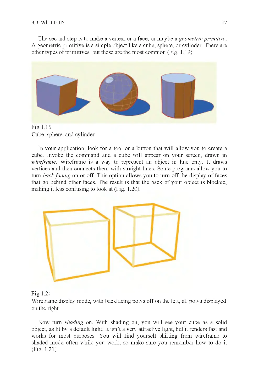
The second step is to make a vertex, or a face, or maybe a geometric primitive.
A geometric primitive is a simple object like a cube, sphere, or cylinder. There are
other types of primitives, but these are the most common (Fig. 1 .19).
Fig 1.1 9
Cube, sphere, and cylinder
In your application, look for a tool or a button that will allow you to create a
cube. Invoke the command and a cube will appear on your screen, drawn in
wireframe. Wireframe is a way to represent an object in line only. It draws
vertices and then connects them with straight lines. Some programs allow you to
turn back facing on or off. This option allows you to turn off the display of faces
that go behind other faces. The result is that the back of your object is blocked,
making it less confusing to look at (Fig. 1.20).
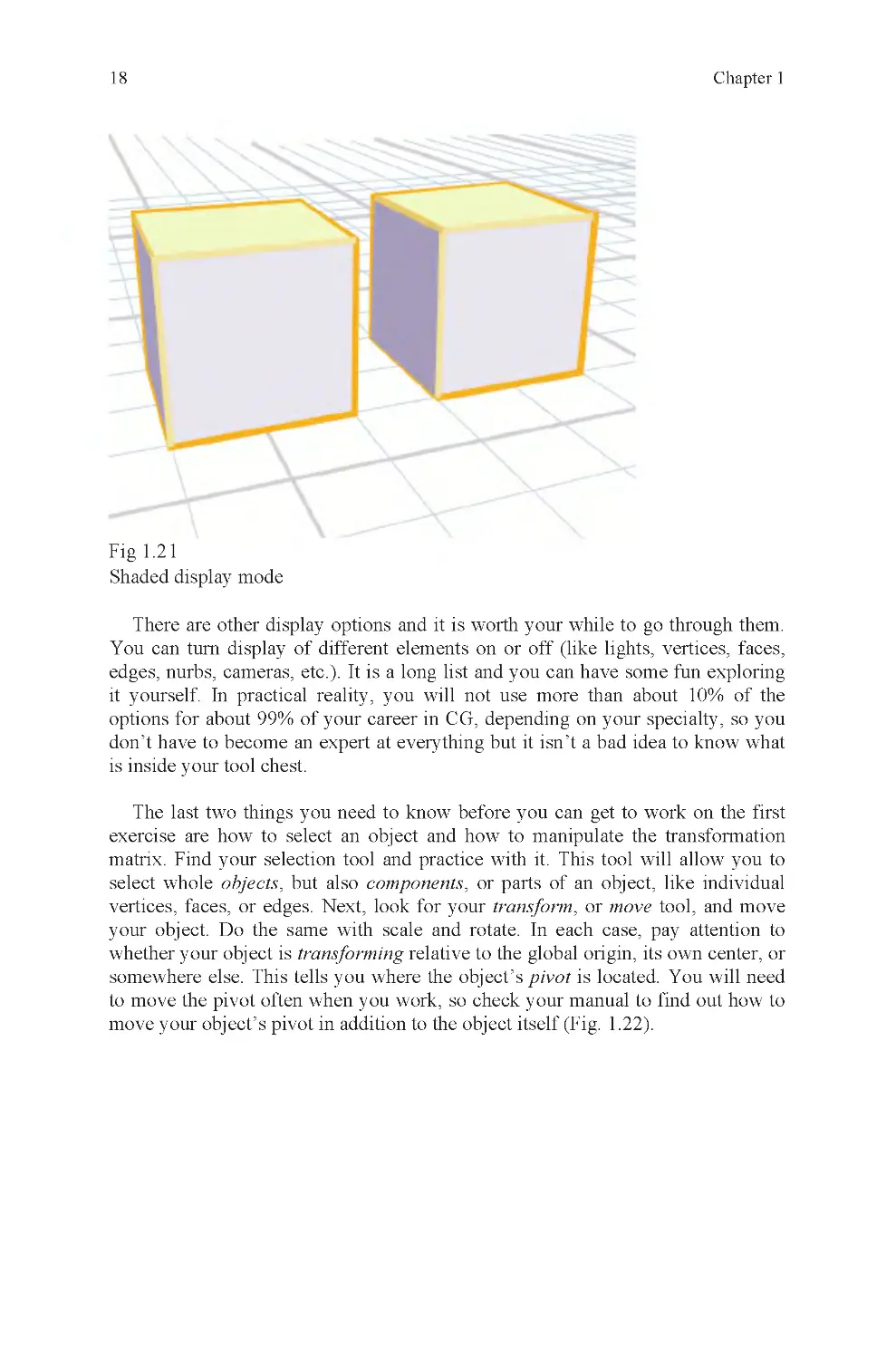
Fig 1.2 0
Now turn shading on. With shading on, you will see your cube as a solid
object, as lit by a default light. It isn’t a very attractive light, but it renders fast and
works for most purposes. You will find yourself shifting from wireframe to
shaded mode often while you work, so make sure you remember how to do it
(Fig. 1 .21).
Wireframe display mode, with backfacing polys off on the left, all polys displayed
on the right
18
Chapter 1
Fig 1.2 1
Shaded display mode
There are other display options and it is worth your while to go through them.
You can turn display of different elements on or off (like lights, vertices, faces,
edges, nurbs, cameras, etc.) . It is a long list and you can have some fun exploring
it yourself. In practical reality, you will not use more than about 10% of the
options for about 99% of your career in CG, depending on your specialty, so you
don’t have to become an expert at everything but it isn’t a bad idea to know what
is inside your tool chest.
The last two things you need to know before you can get to work on the first
exercise are how to select an object and how to manipulate the transformation
matrix. Find your selection tool and practice with it. This tool will allow you to
select whole objects, but also components, or parts of an object, like individual
vertices, faces, or edges. Next, look for your transform, or move tool, and move
your object. Do the same with scale and rotate. In each case, pay attention to
whether your object is transforming relative to the global origin, its own center, or
somewhere else. This tells you where the object’s pivot is located. You will need
to move the pivot often when you work, so check your manual to find out how to
move your object’s pivot in addition to the object itself (Fig. 1 .22).
3D: What Is It?
19
Fig 1.2 2
The three most popular locations for object pivots
Most applications usually have hotkeys associated with the three primary
transformation commands because they are so frequently used. Look up the
hotkey shortcuts and practice using them. Using hotkeys will save you a great deal
of time. Another time saver is direct entry; this allows you to type in a trans-
formation, like 50 units, instead of doing it visually. This is especially useful when
you need your modifications to be exact.
If you want to select only a part of your object, or a component, you will have
to select by component. This usually means using a separate component menu.
Component selection is one of the most important concepts in 3D modeling.
Without it, many editing tools would not work and it would be much more
difficult to make certain models. Component selection also allows a CG artist to
have much greater control over an object than if left reliant on global- or object-
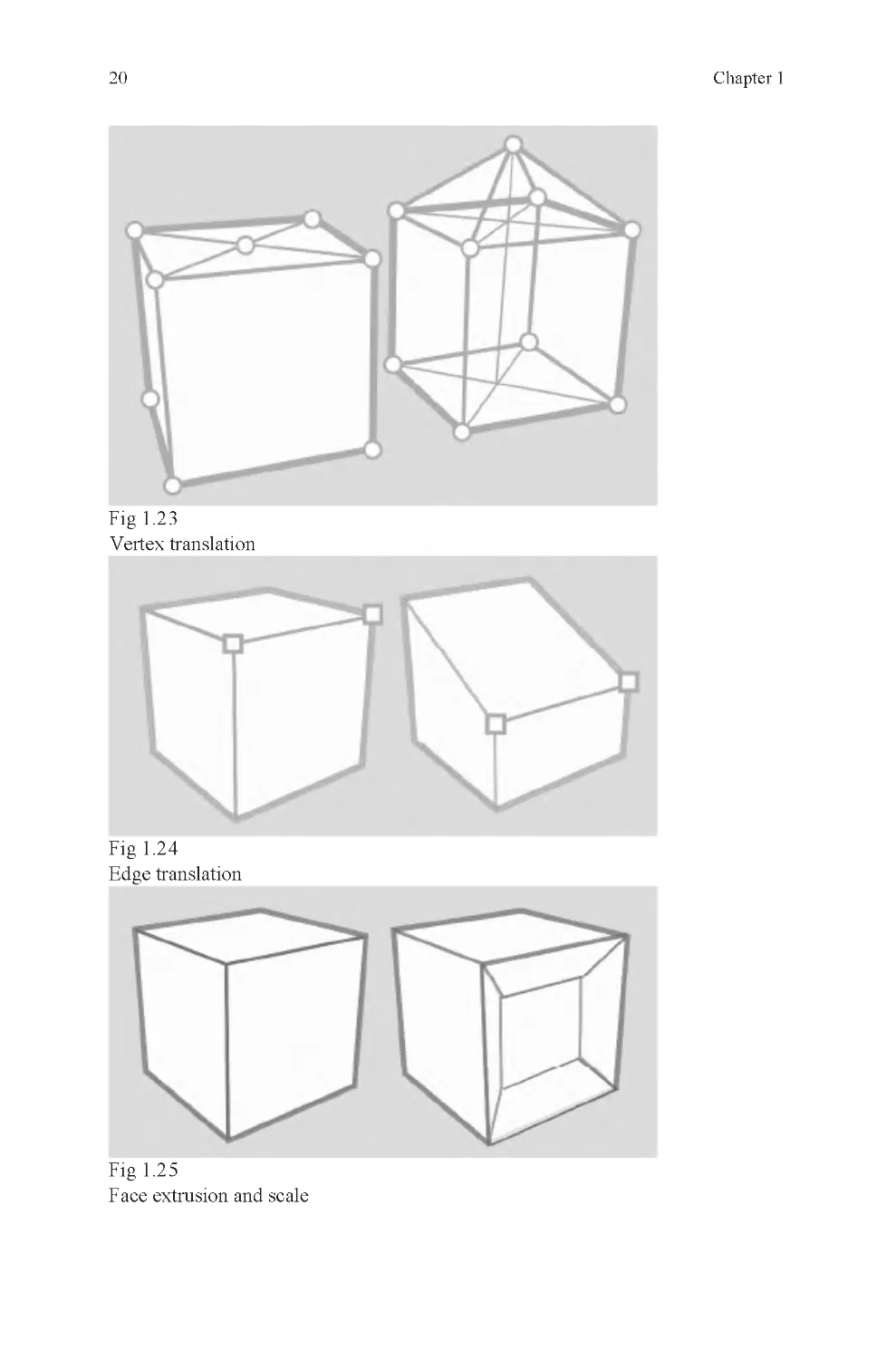
level editing tools alone. Most objects require some amount of component-level
editing (Figs. 1 .23–1 .25).
20
Chapter 1
Fig 1.2 3
Vertex translation
Fig 1.2 4
Edge translation
Fig 1.2 5
Face extrusion and scale
3D: What Is It?
21
Just as you can modify an object by selecting its components and transforming
them, you may create an object out of raw components.
If you want your shape aligned with the grid, you should use grid snap. Snaps
are tools that allow you to position objects and components accurately relative to
the position of something else in the scene. The most common snapping tools are:
•
Grid snap – snaps to grid
•
Curve snap – snaps to a curve
•
Vertex snap – snaps to a vertex
Some less common snaps are these:
•
Edge snap – snaps to edge center
•
Face snap – snaps to face center
•
Object snap – snaps to object center
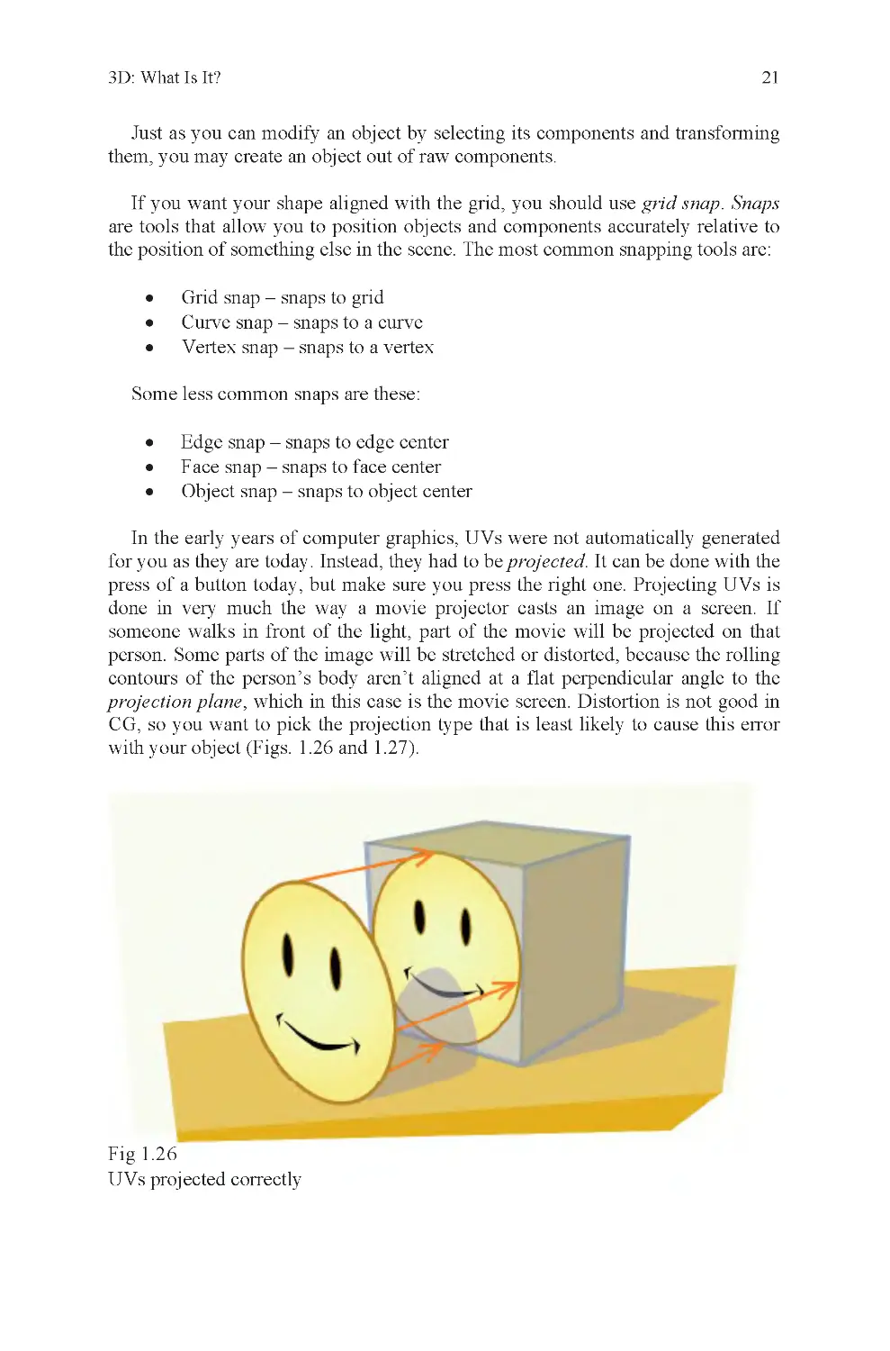
In the early years of computer graphics, UVs were not automatically generated
for you as they are today. Instead, they had to be projected. It can be done with the
press of a button today, but make sure you press the right one. Projecting UVs is
done in very much the way a movie projector casts an image on a screen. If
someone walks in front of the light, part of the movie will be projected on that
person. Some parts of the image will be stretched or distorted, because the rolling
contours of the person’s body aren’t aligned at a flat perpendicular angle to the
projection plane, which in this case is the movie screen. Distortion is not good in
with your object (Figs. 1 .26 and 1.27).
Fig 1.2 6
UVs projected correctly
CG, so you want to pick the projection type that is least likely to cause this error
22
Chapter 1
Fig 1.2 7
UVs projected incorrectly
Basic Transforms and CG Elements Exercise: Folding Carton
Now that you have been introduced to some of the basics involved in 3D, it is
time to see what can be done with it. The following example is designed to
illustrate the following:
•
How a simple polygonal object is constructed
•
Component-level editing
•
Transformation tools
•
User interface
•
The difference between clean and messy geometry
•
The relationship between 2D and 3D space
How it is made:
1. Find a folding carton. This can be a food take-out box from a
restaurant, a snack food box, a milk carton, or any other kind of flat
die-cut box that is folded into a 3D shape (Fig. 1 .28). Video games are
sold in these, perfume bottles, light bulbs, and many other common
items.
•
For extra difficulty, pick a box that has tapered edges instead of
rectangles at fold lines.
•
For a lot of extra difficulty, pick a box with curved fold lines.
A triangle’s vertices all lie in the same plane, and are therefore planar. Because
they are planar, a planar projection is most appropriate, as in the illustration above.
3D: What Is It?
23
Fig 1.2 8
A take-out food container, meant for nonliquid contents
2. Unfold the box.
3. Scan the box. If it is too large to fit on your scanner, scan it in parts,
then stitch them together in an image-editing program like Photoshop.
Be careful to crop the image, so that there are no borders around the
carton itself, not even a single pixel wide.
•
If you don’t have a scanner, measure the box with a ruler and then
make a drawing based on those measurements.
4. Import your image into your 3D program.
5. Trace the outline of the object to make a large multisided polygon
(Fig. 1 .29).
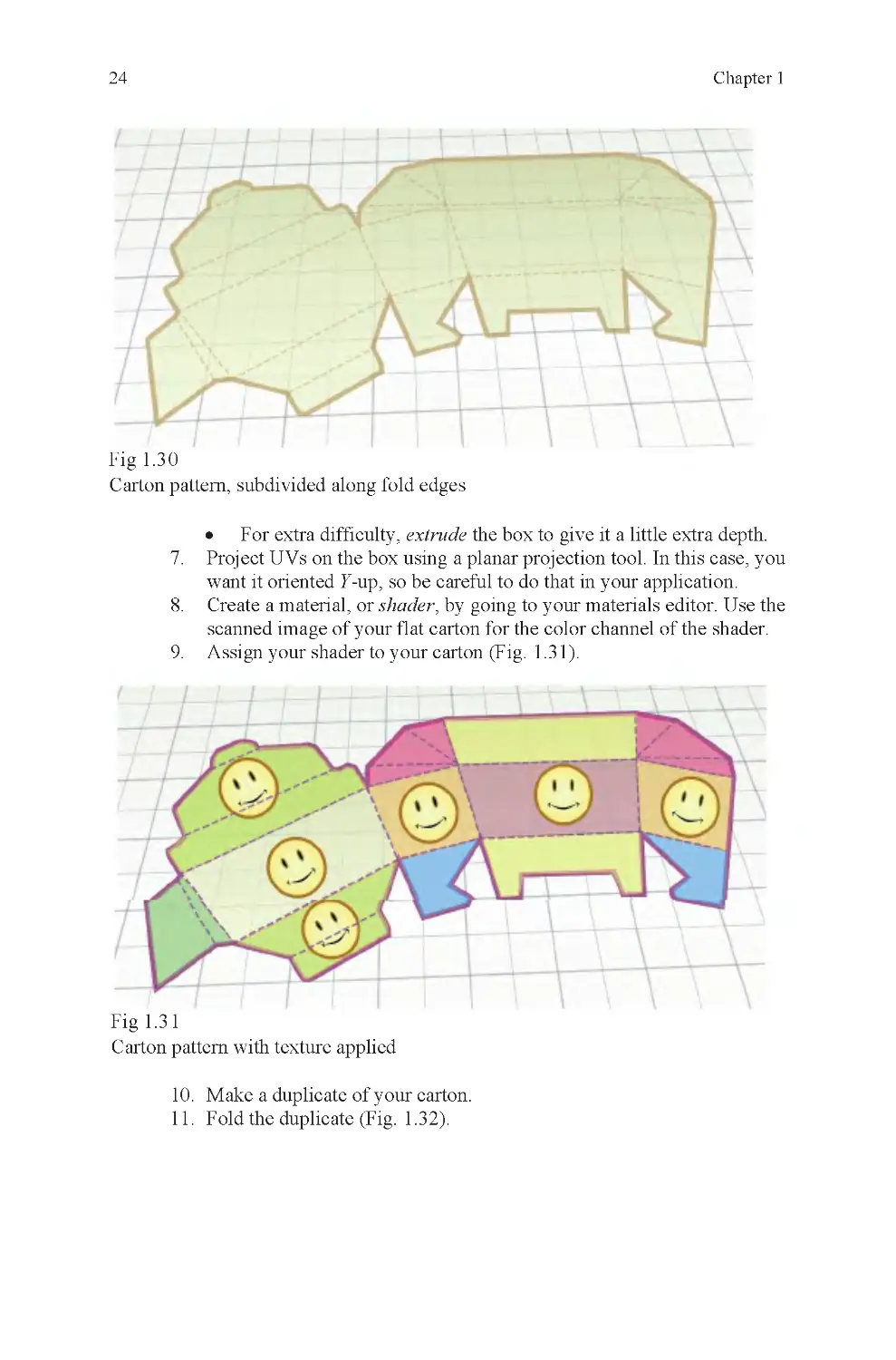
6. Draw the fold and cut lines into the object by cutting it into smaller
sections (Fig. 1 .30).
Fig 1.2 9
Traced carton pattern as open polygon
24
Chapter 1
Fig 1.3 0
Carton pattern, subdivided along fold edges
•
For extra difficulty, extrude the box to give it a little extra depth.
7. Project UVs on the box using a planar projection tool. In this case, you
want it oriented Y-up, so be careful to do that in your application.
8. Create a material, or shader, by going to your materials editor. Use the
scanned image of your flat carton for the color channel of the shader.
9. Assign your shader to your carton (Fig. 1 .31).
Fig 1.3 1
Carton pattern with texture applied
10. Make a duplicate of your carton.
11. Fold the duplicate (Fig. 1 .32).
3D: What Is It?
25
Fig 1.3 2
The folded carton
The finished file will include a flat carton pattern and a folded carton made
from the pattern. The reason a duplicate is made is to compare it with the original
object and also as backup in case of mistakes.
Project Overview
To build the folding carton, a number of things must be done. If done properly,
an attractive carton will be the result. Most students make errors along the way.
The project is not as easy as it may sound at first. The goal is less about making a
perfect carton (though that is a welcome result) and more about practicing with the
primary elements of the interface. In some cases, it will be about doing pitched
battle with the interface.
Fighting your software happens when you don’t understand how to communi-
cate your wishes to the application. If you want your vertex to move along the X-
axis, but it moves along the Y-axis instead, you have a problem. It isn’t an
uncommon problem, even for professionals. In this example, it could be because
you’ve switched from global to local space (or vice versa) and forgotten to switch
it back. This project should expose you to a number of errors like this, so that you
can be comfortable with your interface later on. You do not want to deal with
simple interface errors when you are working on critical models and have a
deadline hanging over your head. The interface is how you communicate to your
application and you need to be very sure of yourself when using it.
26
Chapter 1
The directions require a folding carton. This is the subject. It may also be called
a target, because the goal is to aim for it, and match its appearance as closely as
possible. To the extent this is not accomplished, the target has been missed.
The folding carton was chosen as a target for highly specific reasons. This is
done partly because this type of object has characteristics important to the seeing
part of the lesson, and also to remind you that when you are working, you are not
always able to select your subject and must be able to make any subject you are
asked to build.
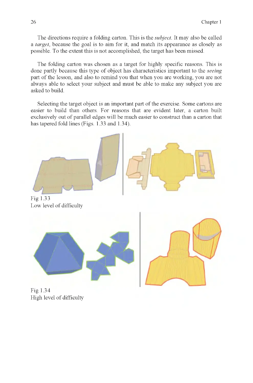
Selecting the target object is an important part of the exercise. Some cartons are
easier to build than others. For reasons that are evident later, a carton built
exclusively out of parallel edges will be much easier to construct than a carton that
has tapered fold lines (Figs. 1 .33 and 1.34).
Fig 1.3 3
Low level of difficulty
Fig 1.3 4
High level of difficulty
3D: What Is It?
27
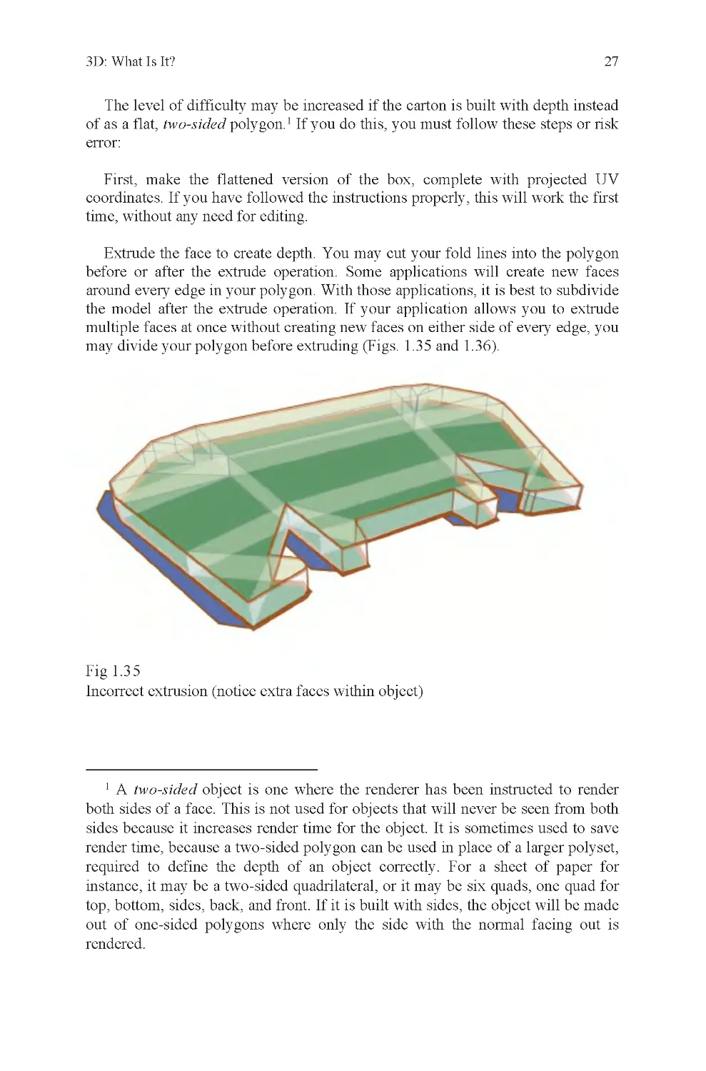
The level of difficulty may be increased if the carton is built with depth instead
of as a flat, two-sided polygon.1 If you do this, you must follow these steps or risk
error:
First, make the flattened version of the box, complete with projected UV
coordinates. If you have followed the instructions properly, this will work the first
time, without any need for editing.
Extrude the face to create depth. You may cut your fold lines into the polygon
before or after the extrude operation. Some applications will create new faces
around every edge in your polygon. With those applications, it is best to subdivide
the model after the extrude operation. If your application allows you to extrude
multiple faces at once without creating new faces on either side of every edge, you
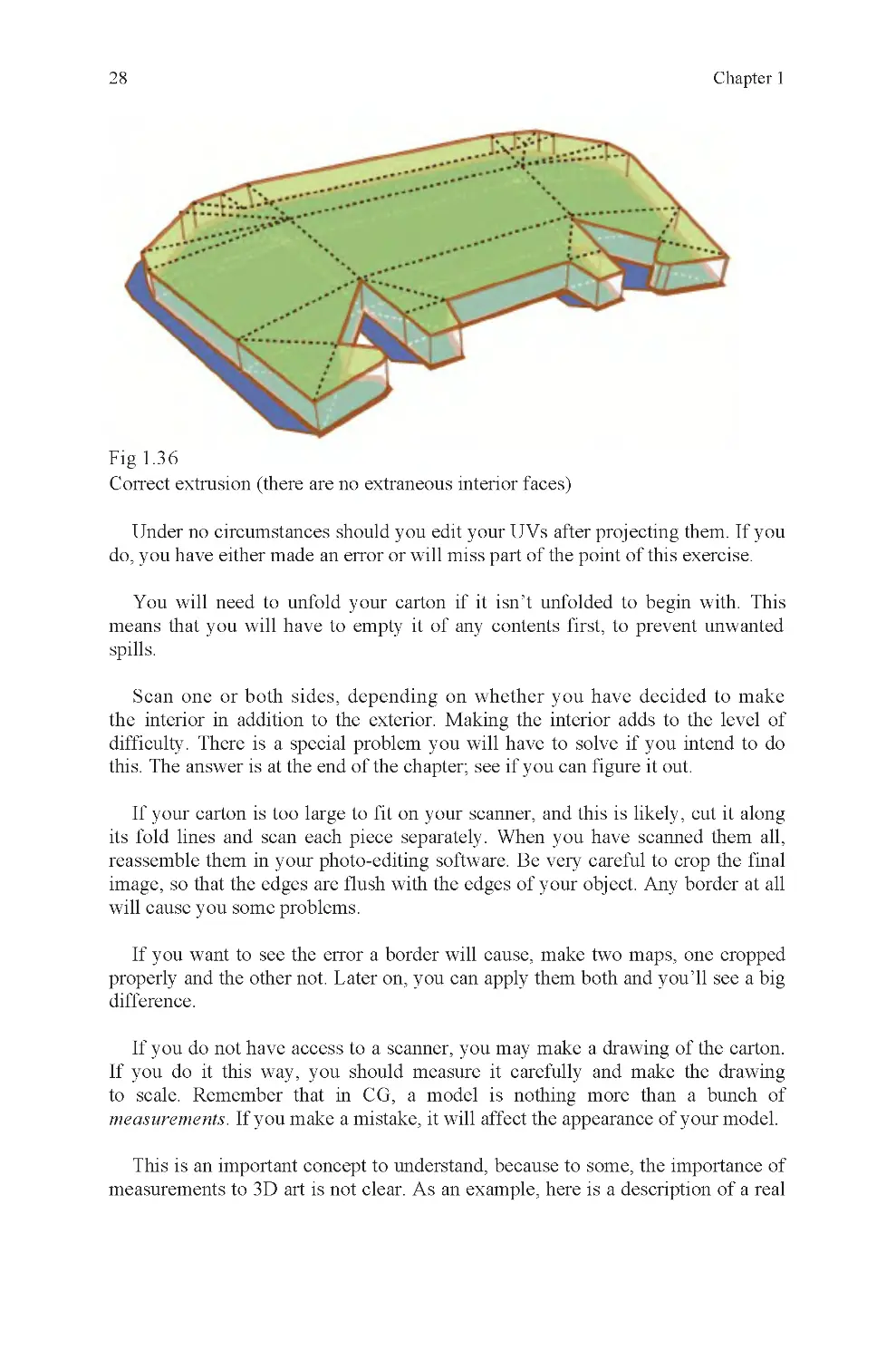
may divide your polygon before extruding (Figs. 1 .35 and 1.36).
Fig 1.3 5
Incorrect extrusion (notice extra faces within object)
1 A two-sided object is one where the renderer has been instructed to render
both sides of a face. This is not used for objects that will never be seen from both
render time, because a two-sided polygon can be used in place of a larger polyset,
required to define the depth of an object correctly. For a sheet of paper for
instance, it may be a two-sided quadrilateral, or it may be six quads, one quad for
top, bottom, sides, back, and front. If it is built with sides, the object will be made
out of one-sided polygons where only the side with the normal facing out is
rendered.
sides because it increases render time for the object. It is sometimes used to save
28
Chapter 1
Fig 1.3 6
Correct extrusion (there are no extraneous interior faces)
Under no circumstances should you edit your UVs after projecting them. If you
Scan one or both sides, depending on whether you have decided to make
the interior in addition to the exterior. Making the interior adds to the level of
difficulty. There is a special problem you will have to solve if you intend to do
this. The answer is at the end of the chapter; see if you can figure it out.
If your carton is too large to fit on your scanner, and this is likely, cut it along
its fold lines and scan each piece separately. When you have scanned them all,
reassemble them in your photo-editing software. Be very careful to crop the final
image, so that the edges are flush with the edges of your object. Any border at all
will cause you some problems.
properly and the other not. Later on, you can apply them both and you’ll see a big
difference.
If you do not have access to a scanner, you may make a drawing of the carton.
If you do it this way, you should measure it carefully and make the drawing
to scale. Remember that in CG, a model is nothing more than a bunch of
measurements. If you make a mistake, it will affect the appearance of your model.
This is an important concept to understand, because to some, the importance of
do, you have either made an error or will miss part of the point of this exercise.
You will need to unfold your carton if it isn’t unfolded to begin with. This
means that you will have to empty it of any contents first, to prevent unwanted
spills.
If you want to see the error a border will cause, make two maps, one cropped
measurements to 3D art is not clear. As an example, here is a description of a real
3D: What Is It?
29
discussion that once took place between the author and an MIT graduate who is
very prominent in the CG industry. The subject was a simulation project we were
both working on, one where a decision had been made to use inaccurate dimen-
sions for an environment to save our engineers the trouble of modifying their
engine to recognize accurate, and different, door widths and so on.
If the project had merely been a game, this might not have been a problem, but
could simultaneously enter any door instead of only one. The MIT graduate didn’t
didn’t understand was that the measurements affected what it looked like, and
because the way it looked was based on its dimensions, it also affected behavior
within the simulation. He was accustomed to faking the results he expected using
2D effects because his primary area of expertise was in film, where the end
product is a 2D image. For our simulation, our job ended with an uneditable 3D
object. The difference is not insignificant.
other things may go wrong as well. In the situation described above, the 3D
elements for our project would be rendered in real time on a game console. This
meant that there would be no opportunity to modify the “images” to “look okay.”
It would look exactly the way it had to look based on whatever its dimensions are
(Fig. 1 .37).
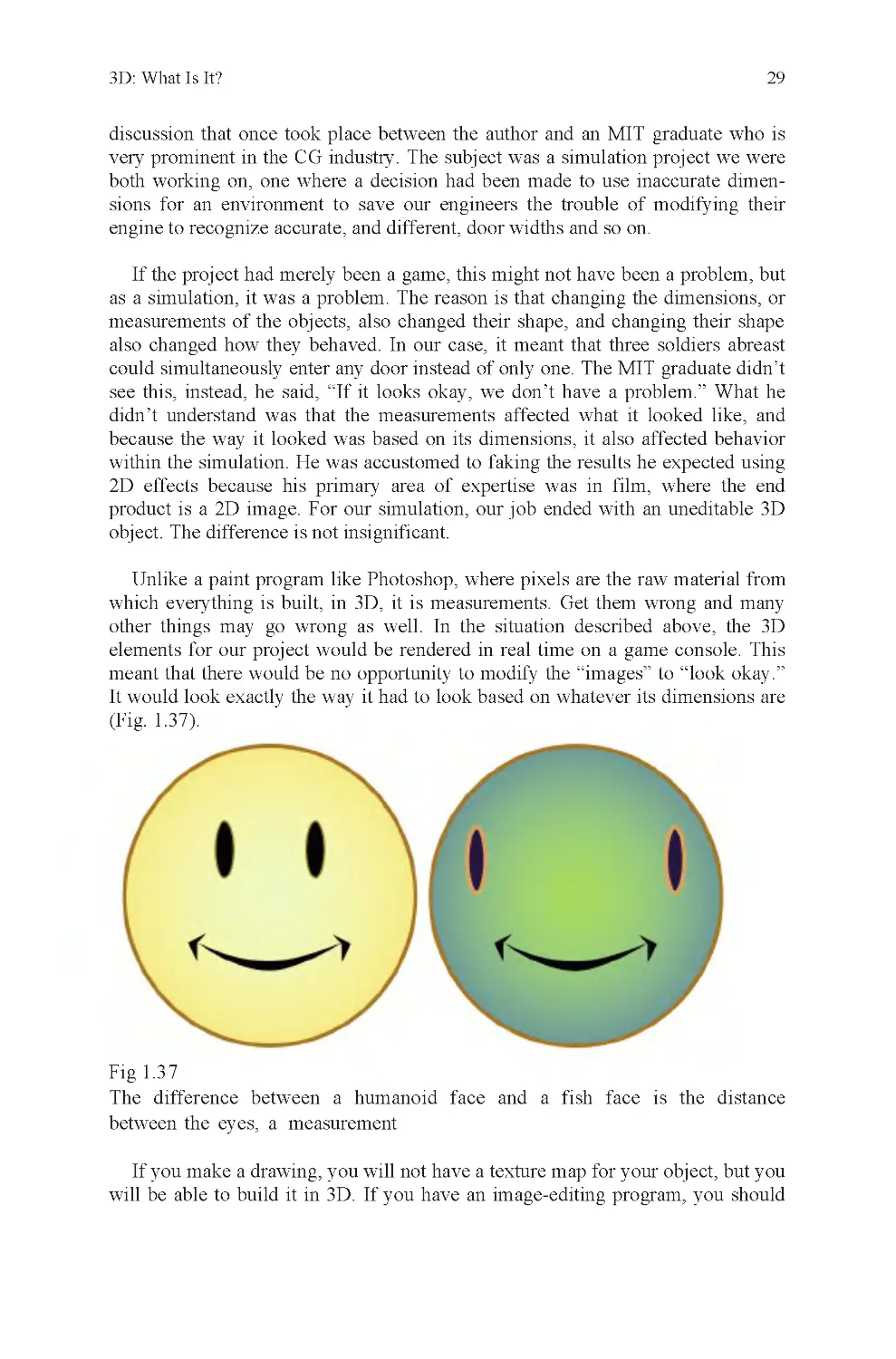
Fig 1.3 7
If you make a drawing, you will not have a texture map for your object, but you
will be able to build it in 3D. If you have an image-editing program, you should
The difference between a humanoid face and a fish face is the distance
as a simulation, it was a problem. The reason is that changing the dimensions, or
measurements of the objects, also changed their shape, and changing their shape
also changed how they behaved. In our case, it meant that three soldiers abreast
which everything is built, in 3D, it is measurements. Get them wrong and many
Unlike a paint program like Photoshop, where pixels are the raw material from
between the eyes, a measurement
see this, instead, he said, “If it looks okay, we don’t have a problem.” What he
30
Chapter 1
construct a texture map that imitates the appearance of your flattened carton. You
will need this to evaluate how well you achieve project goals.
Once you have your reference for the project, you will need to open your 3D
application and build it. When you do, your goals are these:
Do not make too many polygons. Use your own judgment to determine what is
and what is not “too many.” Your answer to this question will be analyzed when
you have finished.
Build the flat version of the carton and apply its texture before you fold it. This
is very important. If you apply the texture afterward, you will have to edit it
heavily to get the same result as if you had done it correctly to begin with.
Fold your carton into shape using your application’s transformation tools. Do
not cheat by creating a carton in its folded state to begin with. If you do, you will
miss some of the learning opportunities present in this exercise.
Folding the carton will require you to properly set the fold axis for each fold.
Whenever this axis corresponds to any of the six major axes of world space, your
job will be fairly easy. If the folds are not aligned to these major axes, it will be
more difficult because you will have to define the axis yourself (Fig. 1 .38).
Fig 1.3 8
edge?
Usually, this is done by selecting either a pair of vertices or an edge and
identifying it as a transformation axis. This is why tapered shapes are less easy to
fold. The tapered edges mean that the object has at least some folds that are not
aligned with the major axes of world space. You can also reset your local axis to
How do you fold the highlighted vertices along the orange highlighted
3D: What Is It?
31
match an edge, or simply rotate the entire object to align the desired transfor-
mation axis with the global coordinate system (Fig. 1.39).
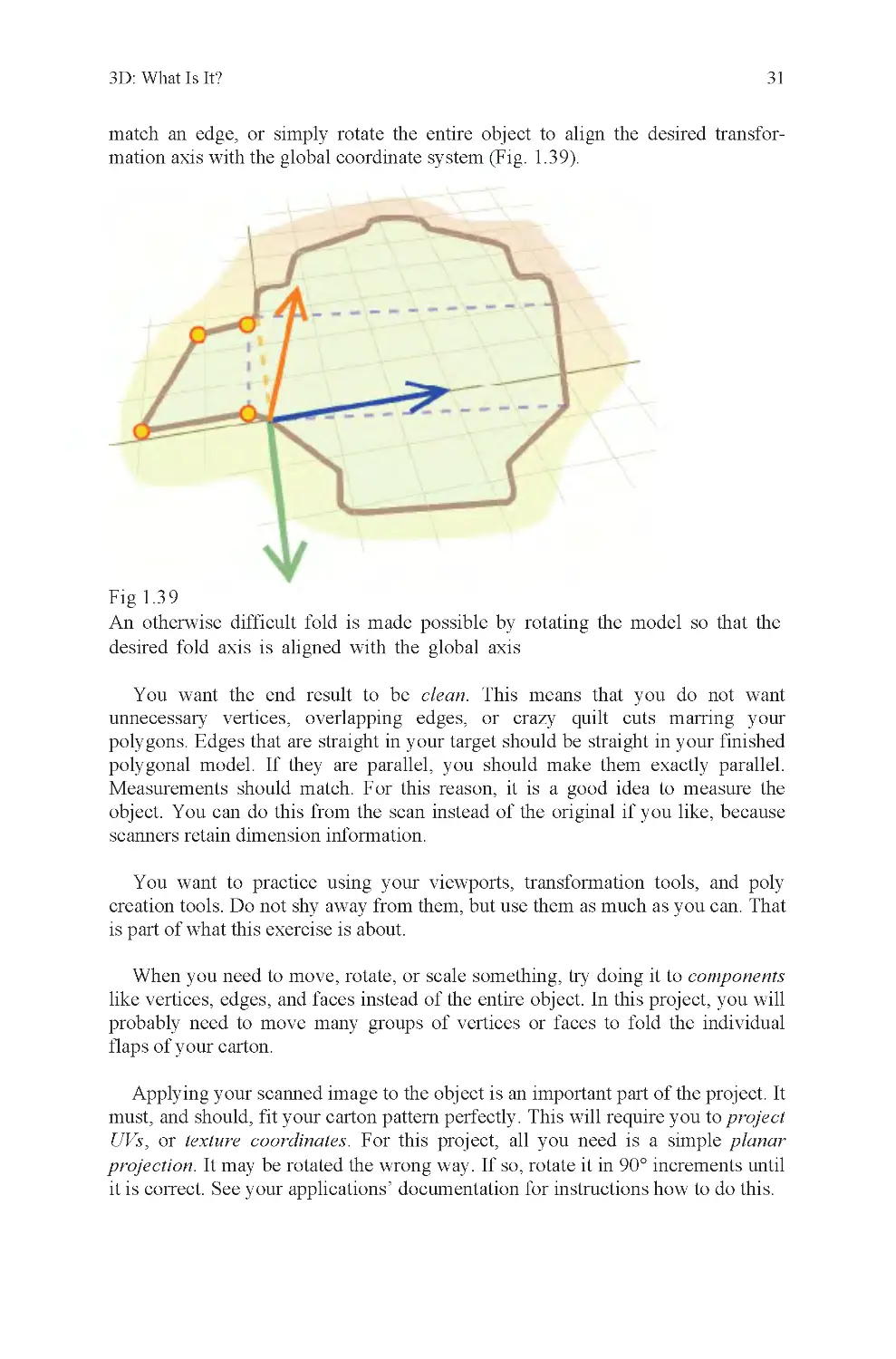
Fig 1.3 9
You want the end result to be clean. This means that you do not want
unnecessary vertices, overlapping edges, or crazy quilt cuts marring your
polygons. Edges that are straight in your target should be straight in your finished
polygonal model. If they are parallel, you should make them exactly parallel.
Measurements should match. For this reason, it is a good idea to measure the
object. You can do this from the scan instead of the original if you like, because
scanners retain dimension information.
You want to practice using your viewports, transformation tools, and poly
creation tools. Do not shy away from them, but use them as much as you can. That
is part of what this exercise is about.
When you need to move, rotate, or scale something, try doing it to components
like vertices, edges, and faces instead of the entire object. In this project, you will
probably need to move many groups of vertices or faces to fold the individual
flaps of your carton.
Applying your scanned image to the object is an important part of the project. It
must, and should, fit your carton pattern perfectly. This will require you to project
UVs, or texture coordinates. For this project, all you need is a simple planar
projection. It may be rotated the wrong way. If so, rotate it in 90° increments until
it is correct. See your applications’ documentation for instructions how to do this.
desired fold axis is aligned with the global axis
An otherwise difficult fold is made possible by rotating the model so that the
32
Chapter 1
UV coordinates editing (Fig. 1.40):
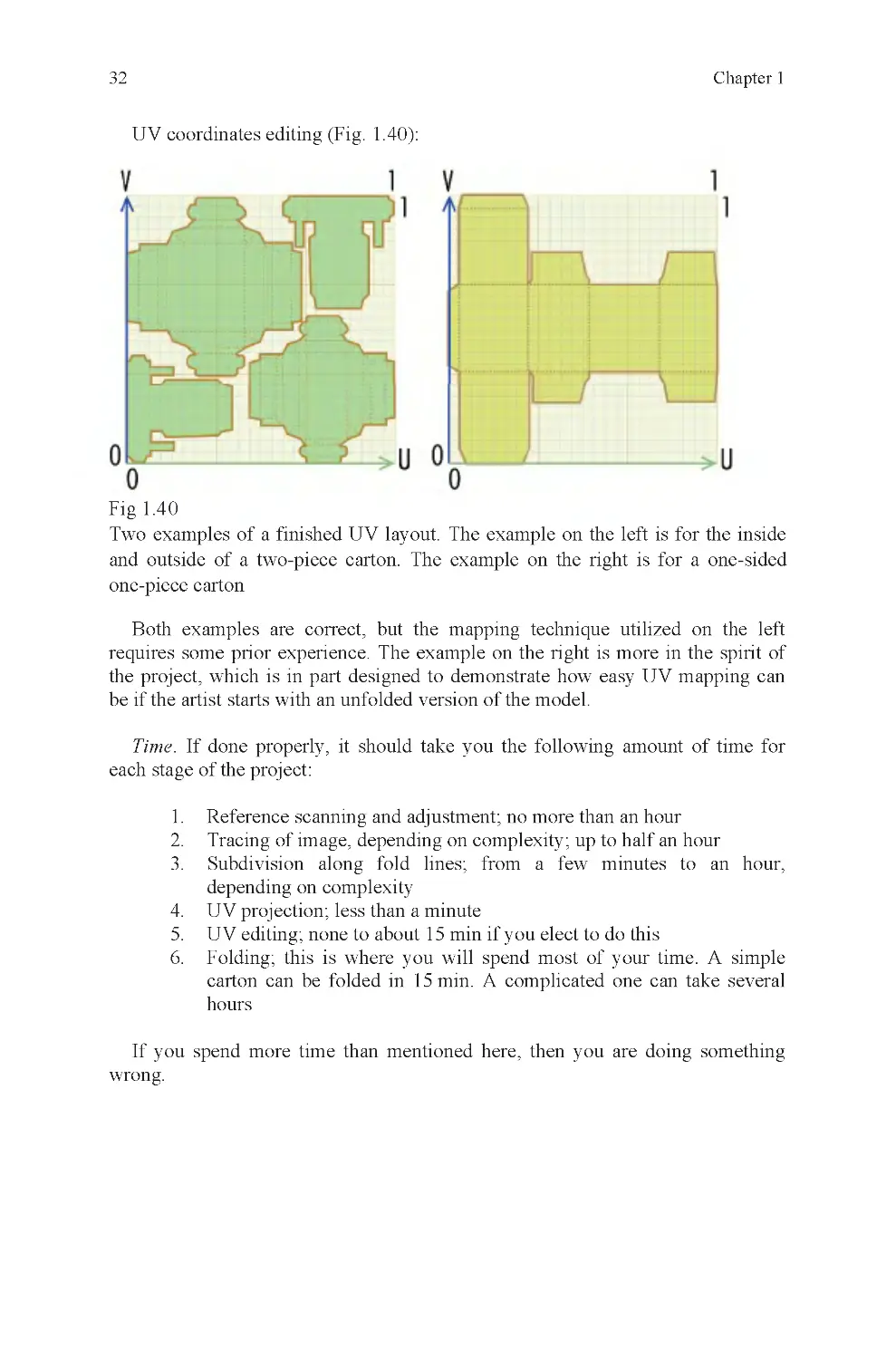
Fig 1.4 0
Both examples are correct, but the mapping technique utilized on the left
requires some prior experience. The example on the right is more in the spirit of
the project, which is in part designed to demonstrate how easy UV mapping can
be if the artist starts with an unfolded version of the model.
Time. If done properly, it should take you the following amount of time for
each stage of the project:
1. Reference scanning and adjustment; no more than an hour
2. Tracing of image, depending on complexity; up to half an hour
3. Subdivision along fold lines; from a few minutes to an hour,
depending on complexity
4. UV projection; less than a minute
5. UV editing; none to about 15 min if you elect to do this
6. Folding; this is where you will spend most of your time. A simple
carton can be folded in 15 min. A complicated one can take several
hours
If you spend more time than mentioned here, then you are doing something
wrong.
Two examples of a finished UV layout. The example on the left is for the inside
and outside of a two-piece carton. The example on the right is for a one-sided
one-piece carton
Chapter 2: Clean Geometry
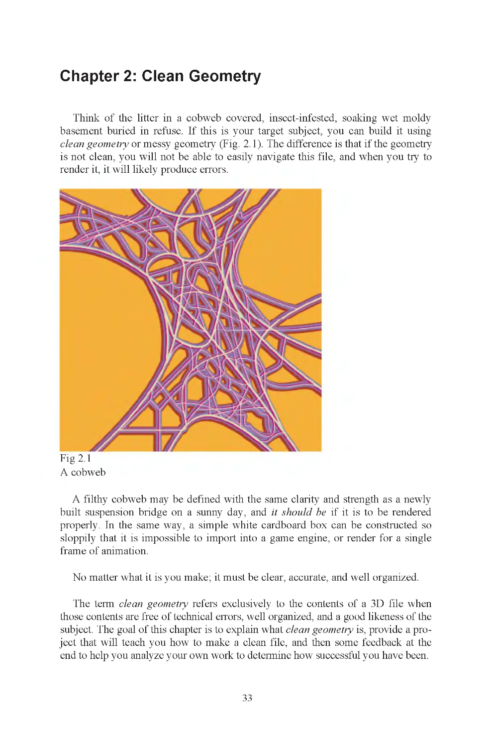
Think of the litter in a cobweb covered, insect-infested, soaking wet moldy
basement buried in refuse. If this is your target subject, you can build it using
Fig 2.1
A cobweb
built suspension bridge on a sunny day, and it should be if it is to be rendered
properly. In the same way, a simple white cardboard box can be constructed so
sloppily that it is impossible to import into a game engine, or render for a single
frame of animation.
No matter what it is you make; it must be clear, accurate, and well organized.
The term clean geometry refers exclusively to the contents of a 3D file when
those contents are free of technical errors, well organized, and a good likeness of the
subject. The goal of this chapter is to explain what clean geometry is, provide a pro-
ject that will teach you how to make a clean file, and then some feedback at the
end to help you analyze your own work to determine how successful you have been.
33
A filthy cobweb may be defined with the same clarity and strength as a newly
clean geometry or messy geometry (Fig. 2.1). The difference is that if the geometry
is not clean, you will not be able to easily navigate this file, and when you try to
render it, it will likely produce errors.
Chapter 2
34
There are many things that can go wrong in the modeling process to corrupt
your geometry. These are technical errors. Sometimes, you will be forced to take
intermediate steps during construction of an object, like setting up wooden frames
before pouring a concrete foundation. If you forget to take down the frames after
the concrete has set, you’ve made a construction error.
If you do not take the time to figure out what every single item in your scene is,
and how you intend to find it again once it is built, you will have organizational
errors. An example of this is naming. If everything in your scene is given a de-
fault name, you will have hundreds or thousands of objects with indecipherable
names. You may remember that P10289736 is the sewing machine and
P10279736 is the fungus on the carpet, but most people don’t remember things
that well. The three types of error described here, technical, construction, and
organizational are the most common causes of sloppy geometry.
Here are examples of each of these error types, using various folding cartons as
examples. Pay careful attention to these descriptions and the illustrations. If your
file contains any of these mistakes, you do not have clean geometry and must fix
your object.
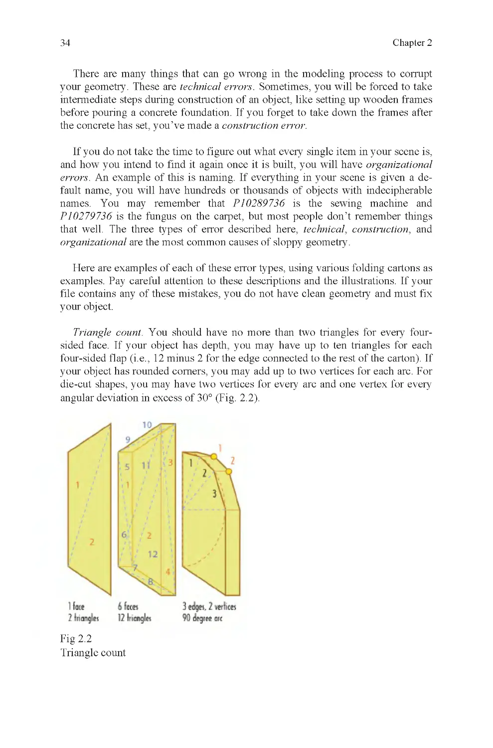
Triangle count. You should have no more than two triangles for every four-
sided face. If your object has depth, you may have up to ten triangles for each
four-sided flap (i.e., 12 minus 2 for the edge connected to the rest of the carton). If
your object has rounded corners, you may add up to two vertices for each arc. For
die-cut shapes, you may have two vertices for every arc and one vertex for every
angular deviation in excess of 30° (Fig. 2.2).
Fig 2.2
Triangle count
Clean Geometry
35
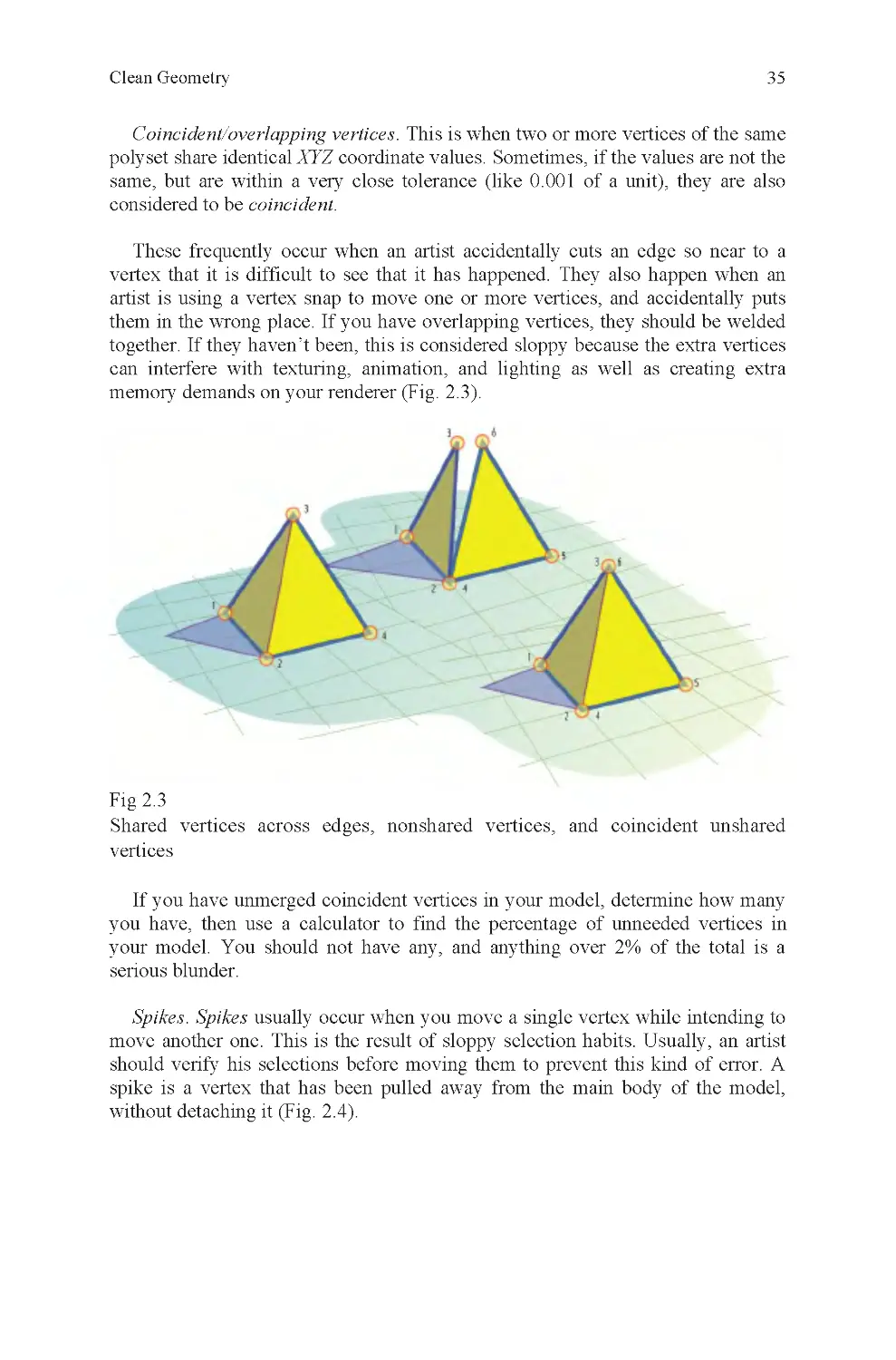
Coincident/overlapping vertices. This is when two or more vertices of the same
polyset share identical XYZ coordinate values. Sometimes, if the values are not the
same, but are within a very close tolerance (like 0.001 of a unit), they are also
considered to be coincident.
These frequently occur when an artist accidentally cuts an edge so near to a
vertex that it is difficult to see that it has happened. They also happen when an
artist is using a vertex snap to move one or more vertices, and accidentally puts
them in the wrong place. If you have overlapping vertices, they should be welded
together. If they haven’t been, this is considered sloppy because the extra vertices
can interfere with texturing, animation, and lighting as well as creating extra
memory demands on your renderer (Fig. 2 .3).
Fig 2.3
vertices
If you have unmerged coincident vertices in your model, determine how many
serious blunder.
Spikes. Spikes usually occur when you move a single vertex while intending to
move another one. This is the result of sloppy selection habits. Usually, an artist
spike is a vertex that has been pulled away from the main body of the model,
without detaching it (Fig. 2 .4).
Shared vertices across edges, nonshared vertices, and coincident unshared
should verify his selections before moving them to prevent this kind of error. A
you have, then use a calculator to find the percentage of unneeded vertices in
your model. You should not have any, and anything over 2% of the total is a
Chapter 2
36
Fig 2.4
A spike. Most often, spikes are less obvious than this
You should not have any spikes in your object. If you have even one, your
model cannot be used as is and must be fixed before delivery.
Bow-tie faces. An n-sided face (usually a quad) that has been twisted so that its
normals, if triangulated, would be facing almost 180° away from each other
(Fig. 2 .5).
Fig 2.5
A bow-tie face
The easiest way to picture this is to imagine a square of cloth stitched to two
rods on either side. If one of the rods were rotated 180°, it would create a bow-tie
shape, where the top and bottom edges cross each other. This is the same as a
bow-tie polygon.
Clean Geometry
37
improper vertex selection followed by a translate operation. Bow-tie faces are
always nonplanar, so if your application has a nonplanar highlight function,
they may be located by its use.
To fix a face of this type, it is often easiest to delete it and then rebuild the face
as it should be built. The only exception is if the vertices of the bow tie are not
represented elsewhere in the model and it would be difficult to reposition new
vertices in those locations. If this is true of your model, then you should trace over
the existing polygon with a new one before deleting the bow-tie face.
You should not have any bow-tie faces in your model. You should check for
these and eliminate any you find before delivery.
Smoothing errors. Split normals when they should be united, or united where
they should be split adversely affect render quality (Fig. 2 .6).
Fig 2.6
Bow-tie faces can be difficult to find if they are quite small or are stretched into
an obscure cavity of your model. Normally, these are made accidentally, due to
Averaged normal on leading edge of box (left), split normal on right ; “smooth”
and “hard,” respectively
Chapter 2
38
To render a smooth edge, your object will have a single averaged normal be-
tween two adjacent faces. What this means is that the value for the normal of each
face is averaged and a median value found. This causes the smoothing effect on
the edge. For a hard edge, the normals are split, so that the edge has two or more
normals at every vertex. Each normal is identical to the normal of each of the
faces that meets at that vertex. This causes hard shading.
Hard shading would typically be used to define the sharp corners of a table.
Smooth shading would be used on every edge of a ball, to prevent a faceted
appearance.
Improper smoothing causes shading anomalies when rendered. These resemble
out-of-place streaks of dirt or unexpected shadows. Depending on textures, the
effect may not be prominent, but often it disrupts the surface of an object enough
that it is undesirable.
If the smoothing attributes of your object have not been properly set, you will
get shadows where they do not belong on your object. On your carton, you may
also get edges that should appear sharp, but do not because this has been ignored
or set improperly.
Smoothing errors significantly degrade the quality of rendered output. There-
fore, it is best to check your model for this type of error and fix any examples
of it that you find before moving on.
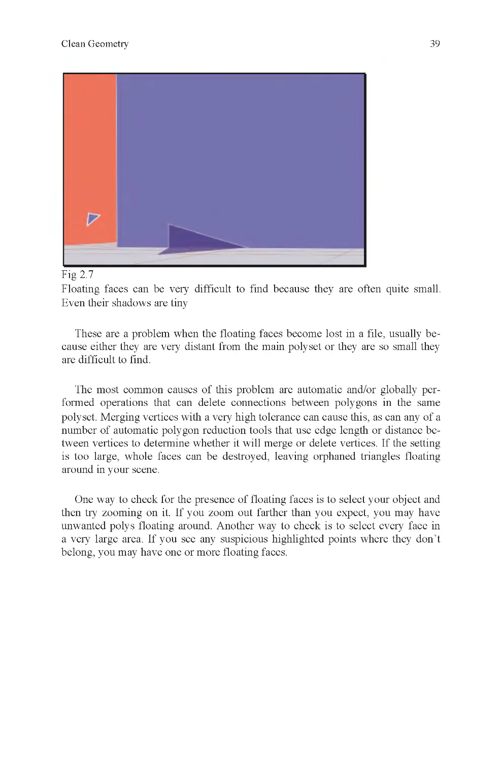
Floating faces. One or more faces that belong to a polyset but are not physi-
cally connected to the main body of the polyset (Fig. 2.7).
Many older video games, primarily those made before Microsoft’s first Xbox,
have significant numbers of smoothing errors. This is because older console sys-
tems were not able to distinguish between hard and soft edges within an object.
Instead, the entire object had to be either hard or soft.
Renderers may render either a hard edge where adjacent faces meet at an edge,
or it may use smooth shading across the edge. Depending on the type of object and
edge, either might be correct. Most objects have edges that fall into both catego-
all hard, or all soft, edges.
2
2
ries, and the more complicated an object is, the more likely it is that it will not be
Clean Geometry
39
One way to check for the presence of floating faces is to select your object and
then try zooming on it. If you zoom out farther than you expect, you may have
unwanted polys floating around. Another way to check is to select every face in
a very large area. If you see any suspicious highlighted points where they don’t
belong, you may have one or more floating faces.
polyset. Merging vertices with a very high tolerance can cause this, as can any of a
number of automatic polygon reduction tools that use edge length or distance be-
tween vertices to determine whether it will merge or delete vertices. If the setting
is too large, whole faces can be destroyed, leaving orphaned triangles floating
around in your scene.
The most common causes of this problem are automatic and/or globally per-
formed operations that can delete connections between polygons in the same
These are a problem when the floating faces become lost in a file, usually be-
cause either they are very distant from the main polyset or they are so small they
are difficult to find.
Fig 2.7
Floating faces can be very difficult to find because they are often quite small.
Even their shadows are tiny
Chapter 2
40
Fig 2.8
object, as shown in the illustration on the left
This particular error is generally considered to be extremely sloppy, as opposed
to a simple oversight, like some of the others already mentioned. This is the type
of mistake that should be quite apparent even to a novice while working on a
model. Do not allow this to happen to your work.
Self-penetration. One of two things, or both, causes this. If your object was not
traced accurately, the sides will not match when the carton is folded. The other
cause is improper rotation. Most often, both are seen together because the artist
will try to over or under transform a flap into position to make up for a measure-
ment error when building the object (Fig. 2.9).
that allows folding without distorting the shape of the polygon, but it is cheating in
the context of the carton assignment, and if the end result is not brought back to-
gether into one polyset, it creates serious geometry errors (Fig. 2.8).
Floating faces cannot be tolerated in any project.
Separated faces. This happens when you build each flap as a separate part or
you accidentally explode your model. For certain fold operations, this is a cheat
The model on the right is incorrect because each of its faces is a separate
Clean Geometry
41
Fig 2.9
allowed
Origin offset. During the folding process, you are quite likely to move the car-
ton away from the global origin. You should move the object back to the global
origin when you are done. If you do not, it is considered sloppy work. An accepted
industry standard is to have the front of your object facing positive Z and to have
its center or bottom center located on the global origin (Fig. 2 .10).
Fig 2.1 0
Origin offset
Notice how the green flap penetrates the gray side of the carton. This is not
Chapter 2
42
Nonplanar faces. Faces with four or more sides where one or more vertices do
not lie within the same plane as any group of three vertices from the same face.
Nonplanar faces are renderable in most renderers, but can cause unpredictable
results. The greater the distance a nonplanar vertex is from the primary plane of
the face, the greater the distortion is likely to be. The reason is that the renderer
triangulates all nonplanar faces.
If the renderer triangulates a face, it must first decide which way to cut the
polygon. Depending on how far from being in the same plane the vertices are, the
result can be anything from invisible to a serious fault (Fig. 2 .11).
Fig 2.1 1
possible outcomes of triangulating the polygon
This is an extremely common mistake, even among professionals. The most
common solution is to disguise the problem by subdividing the object globally
to increase the polycount. This does not eliminate the error, but reduces its promi-
nence to a level that in most cases is difficult to detect. When working on projects
where polycount is an important factor (that would be almost anything), it is better
to modify this by hand, without recourse to global subdivision.
Distortion. Some cartons have flaps that, when folded, pull adjacent flaps with
them because they are not cut along their edges. With objects like this, it is likely
that some distortion will occur during the folding process. There are other causes
for distortion, the most common of which is inattention during the pattern layout
stage of the project (Fig. 2 .12).
This error is not uncommon for inexperienced artists, but it can be very irritat-
ing, especially for animators because their animation depends on a correct, un-
translated start position.
The polygon on the far left is a nonplanar quad. To the right are the two
Clean Geometry
43
Fig 2.1 2
distorted during a rotation operation
Distortion is allowed in certain situations, such as during an animation when it
is thought that the movement of the object or camera blur will disguise any dis-
tortion. In other situations, especially in close-up shots for theatrical effects, this
is not allowed and should be eliminated if present.
Wrong-way normals. A polygonal face where the normal vector is pointing
180° away from the front of the object has wrong-way normals.
Some artists fold one direction; others do the opposite. Depending on which
direction you fold your carton, you may or may not have reversed normals.
It is possible, though rare, to change a face normal so that it renders as if it is
reversed, but the angle of difference is not 180° from the correct orientation.
3
3
In this polyset, triangles connected to flaps A , B, and C have been severely
Chapter 2
44
A face with a reversed normal will appear to be invisible until you turn the
camera to the reverse side of the object, where the face will suddenly reappear.
Whenever you think you are missing a face, the most likely answer is that it has a
reversed normal; these are very easy to check for and simple to fix. They are a
problem only if you have been incautious with your technique and have manu-
factured a great many of them. Then, you must search every face of your entire
model, flipping normals one by one until they all face the right direction. Some
programs allow you to unify an object’s normals, to make them all point inside or
outside, but it doesn’t always work. If you use such a tool, you should be prepared
to check the result (Fig. 2 .13).
Fig 2.1 3
Incorrect normals on the left, correct on the right
Incorrect normals are an extremely serious error and must be fixed wherever
they are found. Unfortunately, it is very easy to create this error and you should
expect that any model you make would contain at least some reversed normals.
Extremely high polycount. If you have faces that do not contribute to the shape
of your object and don’t affect the manner in which it is textured, you have com-
pletely unnecessary polygons in your model (Fig. 2 .14).
Clean Geometry
45
Fig 2.1 4
It is generally accepted that exceeding a polycount budget by as much as 10%
is not an error if the added polygons contribute to the model. If they do not, it is an
error, even if the polycount budget is met exactly.
Misaligned texture. This happens when your texture map is not properly pro-
Fig 2.1 5
•
You have whitespace around your map.
•
You edited the UVs after projecting them.
Depending on the reason this error appears on your model, it can be a more or
less serious error. If the mistake is due to whitespace in your texture border, it is
Three extra rows of vertices are clearly visible on this model from the carton
project
Note the whitespace along the seams. In this example, the error was caused
by improper UV manipulation
For the carton project, it can only happen if one or both of two things is true:
jected and edited (Fig. 2.15).
Chapter 2
46
easy to fix in an image-editing program by cropping the texture map. If it is
due to incorrect texture coordinates, it is more difficult to fix, especially if you’ve
already folded the carton. If this happened with your project, rather than fixing the
UVs on the folded carton, it is better to go back to the original unfolded state,
reproject the texture coordinates, and then fold the carton all over again.
built specialty renderers, most renderers render triangles only. This means that if
it is rendered. If you have a nurbs object, it converts the object into polygons, then
triangulates it before rendering. The reason is that normals for a triangle have an
absolute value, but for four or more sides, they must be averaged. If the object is
planar, or all of its vertices lie within the same plane, the normal for the polygon
will be the same as for any triangle within it. Many game engines and commercial
renderers will not render a polygon with more than four sides. Some will render
the polygon, but there is a serious possibility it will not render properly.
does not render as expected and should be reduced to either quads (four-sided
faces) or triangles. Planar quadrilaterals and triangles only are legal (Fig. 2 .16).
Fig 2.1 6
n -gon
More on these later.
4
4
Note the number of vertices along a single edge. Whenever you have only two
edges on either side of a vertex, you have a polygon that needs to be further
subdivided or risk creation of an illegal
N-gons are frequently, but not always, nonplanar. A nonplanar polygon usually
N-sided polygons, also known as n-gons. With the exception of certain custom-
your object is not built of triangles, the renderer will triangulate your object before
Clean Geometry
47
n-gons cannot be tolerated in a model, but are a very common by-product of
the modeling process. Most professionals will create these unintentionally while
building an object, and then carefully check the model when they are done and
eliminate any n-gons they find. A very fast solution to this is to simply triangu-
late or quadrangulate the object using a global function. The drawback to this
method is that it may cut polygons in unexpected ways. Usually, an artist will
check a model for all the more prominent locations an error might reside, fix
them by hand, and then triangulate the model to catch any small examples he
missed.
Unattached (free) faces. This error is usually the result of a conscious decision
made to solve a problem, but it is, nevertheless, an error. For the carton project, it
happens when an artist isn’t sure how to fold a polygon that is attached to other
polygons that must move with it. This “solution” requires the removal of the
offending faces. The type of carton most likely to create this situation (as in the
example given here) is one designed to hold fluids, like a milk carton. The rea-
son is that cartons of this type cannot have open seams or they will leak. To fold
it in 3D will cause distortions unless handled properly (Fig. 2 .17).
Fig 2.1 7
Solution 1: Detach faces of this type and rotate them individually, then add
them back into the polyset and weld the vertices on common edges.
The two triangles in this image are connected to the carton on only one edge
instead of all three
Chapter 2
48
If this error is present in your model, it is incomplete and must be fixed.
Extrude error. This occurs when an artist adds depth to the carton after folding
it. It can also occur prior to folding, but in that case the effect is of a number of
unwanted interior faces as demonstrated earlier. With this type of error, the cor-
ners of the object are split along fold lines. This is literally inaccurate and unac-
ceptable for this project (Fig. 2 .18).
Fig 2.1 8
Incorrect on the left, correct on the right
Abnormally large, or abnormally small, face aspect ratio. An aspect ratio is
the height to width ratio of any given object. If an object’s height is 3 and its
width is 1.5, then it has an aspect ratio of 2. If it is the other way around, with a
heightof1.5 and a widthof3,theAR =0.5.
A large AR for a polygon is any number above 4. Depending on the object, it
may be as high as 8 without a problem, but much larger than that and you will
have long skinny triangles that do not render well.
A small AR is the same as the long number, but in reverse, so 0.25 is accept-
able, and even 0.125 in some circumstances, but below that you should consider
modifying your triangulation pattern to increase the AR, so that the triangle isn’t
too distorted.
An ideal AR for rendering purposes is 1.0 (Fig. 2 .19).
Solution 2: Add a skeletal system to the carton so that when one flap is rotated,
connected flaps move with it in an appropriate manner.
Clean Geometry
49
Fig 2.1 9
Eight triangles, with aspect ratios ranging from 24 to 0.041
Use the shortest edge-length rule here to help you determine how to triangulate
an object by hand, so that you keep your polygon aspect ratios as close to a value
of 1.0 as possible.
Triangulation patterns. It is useful to get in the habit of triangulating your
polysets, so that they light evenly and are easy to understand. When looking at
complex polysets, triangulation pattern errors can cause serious object recognition
problems (Fig. 2 .20).
Fig 2.2 0
Edge layout
Chapter 2
50
Both circular polysets have the same number of vertices and triangles. The
edges of the yellow polyset are distributed more evenly than the green polyset.
This makes the object easier to understand at first glance and will result in a
smoother render.
Lamina faces. When two or more faces share all of the same edges, a lamina
face is created. This is different from a coincident vertices problem, because with
lamina faces there are usually no coincident vertices, despite the presence of more
than one face between whatever vertices are present (Fig. 2 .21).
Fig 2.2 1
Most artists will not make these intentionally, but there are tools that will cause
this error to occur. The best clue that a lamina face is present is if, in shaded mode,
a flickering is noted when rotating the camera around the face. If this is present, or
if the shading on the face appears wrong, you should do a face count to determine
how many faces are present. If there is more than one and there should be only
one, you probably have lamina faces. Another test is to turn on the normals for the
object. Sometimes you will see normals pointing in opposite directions on what
appears to be the same face.
Duplicate edges. Two or more edges that occupy the same space will cause
rendering problems that resemble smoothing errors.
These edges are frequently the result of vertex merging; automatic cleanup and
automatic polycount reduction operations. Sometimes, they occur during manual
editing, but are more often a product of the automatic tools.
Polygon 1 has a lamina face. When rotated, it will flicker as the software attempts
to determine which of two coincident faces is in front of the other. Face 2 is
not a lamina face and displays properly
Clean Geometry
51
Duplicate edges can be very difficult to find if you aren’t looking for them. The
easiest way to know they exist is if you try to cut a face, but cannot. This some-
times means that the edge you see and want to cut is not the only edge present. In
this case, another edge might not be properly connected to the rest of the face, and
so your cut attempt is impossible because you are unintentionally selecting edges
that do not belong to the same face (Figs. 2 .22 and 2.23).
Fig 2.2 2
In this image, hidden edge 1|4 is exposed when vertex 2 is moved
Fig 2.2 3
In the top image, three vertices are visible. Only when vertex 2 is translated,
as shown in the lower frame, the existence of vertex 4 is known. If the extra edge
This image represents a face with duplicate edges after they have been discovered
and pulled away from the face. Prior to discovery, these edges, and the extra
vertices that define them, are invisible
Chapter 2
52
directly connected between vertices 1 and 2, then vertex 4 would only be visible
from the opposite side of this polygon.
A partially coincident edge is easier to detect than a coincident edge because
you may select an edge and see that its length is not correct. It either terminates
before reaching a visible vertex, or extends straight through and beyond a visible
vertex. In either case, this observation indicates the presence of two or more edges
where you expect to see one. With partially coincident edges, there are usually
three or more.
The most common cause of partially coincident edges is manual editing of
polygons that have five or more sides combined with later use of vertex merging,
face deletion, or other optimization efforts.
Coincident faces. Two or more faces where all of the vertices belonging to each
face have identical XYZ values as corresponding vertices on each of the other
faces (Fig. 2 .24).
Fig 2.2 4
faces A and B are
separated
When face A is made coincident with face B, the polyset C is the result. Polyset
nents. Polyset C will not render properly, but can be fixed if
C contains individually selectable faces A and B as well as all of their compo-
Clean Geometry
53
The most common cause of this error is the use of polygonal extrusion tools,
then canceling the operation after the extrusion is made, but before the new faces
have been moved into position. Another common cause is duplicating an object
without moving it to a new location. This is especially common when the object
Coincident faces may be found when there is flicker during camera rotation in
shaded mode. Another indication of coincident faces is when you attempt to edit a
face, but you cannot. Sometimes, it is because you select a face that cannot display
properly because it is drawn underneath the one you can see, so the results of your
editing are not visible.
Cracks, or gaps, within a polyset. An opening in a polyset where the polyset is
supposed to be closed creates an unwanted gap (Fig. 2 .25).
Fig 2.2 5
A false gap is when a polygon has a reversed normal and appears to be miss-
ing, but is not. When you think you have a gap, you should always check to see if
it is a false gap before you fill it, or risk creating coincident faces or even lamina
faces.
Flicker is caused when the renderer is forced to decide which of two coinci-
dent faces is in front of the other. Because they are coincident, it cannot determine
5
5
A typical geometry gap in what should be a closed pair of rectangles
copy function is mapped to a hotkey and then it is accidentally pressed.
Chapter 2
54
Frequently, unless great care is taken during the design process, shared edges
between different components of an object have a different number of vertices.
For a polyset to be free of gaps, either side of a common edge must have the same
number of vertices. The most practical solution is usually to either add or subtract
vertices from one side or the other, then to snap the vertices together and merge
them when done.
Holes. A hole is a polygon with two or more complete borders, one inner
and one outer, made of adjacent edges that form two or more unbroken loops
(Fig. 2 .26).
Fig 2.2 6
to the outer ring by edges, as on the left. This creates a hole error
Some applications will render a polygon with a hole, but they may not render
it correctly. Depending on your renderer, the result could be like either of the two
examples illustrated above. Unless you have a specific reason for building a hole,
you may want to clean up any that you have built.
Unlike a nonhole polygon, a polygon with a hole does not have an easily de-
fined start and endpoint for triangulation purposes. This can cause some geometry-
editing functions fail.
that either is truly in front of the other. The renderer will then either try to draw
both at the same time or it will switch from one to the other and back again. Either
way, you will see an obvious flickering as the renderer tries to solve this problem.
This error is most often caused by translation or rotation errors. Another com-
mon cause is when two or more pieces are brought together into the same polyset,
but edges that should be adjacent are not sealed.
The polygon on the right does not have the inner ring of vertices connected
Clean Geometry
55
Nonmanifold geometry. Like hole geometry, it is not literally an error to make
nonmanifold geometry, but it can interfere with some editing functions, so it is
good to know what it looks like. Nonmanifold geometry describes polygons that
cannot be unfolded flat without overlap due to a convergence of three or more
edges at a single vertex (Fig. 2 .27).
Fig 2.2 7
Excessively dense vertex groupings. A polyset where the number of vertices per
linear unit is much greater in one location than in another creates this problem.
The most common source of this error is when an artist first makes an object like
the example on the left in the illustration, and then deletes the edge connections.
A face with a hole must be an n-gon or the hole would be impossible. This in-
creases the risk of the n-gon also being nonplanar. Combined with loss of editing
functionality, it is usually best to triangulate a hole and then edit any remaining
problems afterward.
Nonmanifold geometry. If unfolded, the polygon on the right would have to
either overlap the polygon on the left or be cut free to have nonoverlapping
texture coordinates
Chapter 2
56
Fig 2.2 8
Ragged polyset borders. An edge shared by two polysets where the edge travels
the logical division between the two.
This happens when an inexperienced artist, concerned only with the overall
shape of an object, disregards logical internal boundaries within an object
(Fig. 2 .29).
The shape of an object sometimes requires this, but if it does not, care should
be taken to avoid this result. First, it indicates a higher level of polygonal resolu-
tion in one area than in another. If this is the case, the smoother portion of the
object will unflatteringly draw attention to the less smooth part. Secondly, this in-
dicates an incomplete state of any de-rez process that may have been started,
where the resolution of an object is reduced to a designated polycount (Fig. 2 .28).
across the logical border between the two parts and back again without regard for
The orange object should have only four vertices. Because the mesh has been
subdivided on one side, it has a much higher number of vertices in one half
of the object than the other. Because they are the same size and there are no
other benefits to the extra vertices, this is a waste of vertices
Clean Geometry
57
Isolated vertices. Any vertex that is connected to no more than two other verti-
ces by edges is an isolated vertex (Fig. 2 .30).
Fig 2.3 0
Vertices of this type contribute nothing to a model and must be deleted. They
are very common and may be created in many ways. All major applications have
tools built to find and eliminate these pesky remnants of the modeling process, but
Fig 2.29
In this object, the dotted red line represents the border between two polysets.
Unless your object requires a jagged edge for a specific reason, they are consi-
dered undesirable. They usually result from inattention during editing polyset
face members
In this example, the highlighted vertex is an isolated vertex because it has fewer
than three edge connections
sometimes it is best to simply select them and delete.
Chapter 2
58
Fig 2.3 1
You will know this has happened if your object does not seem to receive light
when lights are brought into your scene. It will receive light, but so faintly that it
will barely be detectable. The reason is that it will only accept light from the same
position as the lights from the scene it was in when the normals were locked.
Most applications have a button that will allow you to unlock normals. If this
does not work, you should be able to recalculate them by reimporting your object.
This error is increasingly rare. You may only encounter it occasionally, but it is
disturbing if you don’t know what it is (Fig. 2 .32).
If you use the select and delete solution, be careful to avoid selecting corners of
flat planes because these are technically isolated vertices even though you want to
keep them.
Locked normals. An object with locked normals often renders nearly black,
with very faint highlights, despite having a strong light (Fig. 2 .31).
In this example, the floor does not have locked normals, so it receives a shadow
from the character. The character’s normals are locked, so it renders as a
silhouette
Clean Geometry
59
Fig 2.3 2
Offset vertex order. This usually happens during corrupted save operations
and is not evident until reopening the file. It is one of the few errors that is impossi-
ble to miss. It causes your vertices to be connected improperly. The resulting shape
usually looks like a number of jagged triangles, with a faint resemblance to your
model only evident in its size and silhouette. Depending on how serious the error
is, it may be possible to fix by creating a script to renumber the vertices in your file.
Here, a character model has had its vertices reordered. This causes edges to
connect to the wrong vertices, with the result seen here
Chapter 2
60
Zero edge-length faces. A face whose edges are each zero units in length
(Fig. 2 .33).
Fig 2.3 3
These faces occur during merge vertex and other de-rezing operations. They
can be very difficult to delete because their zero edge-length condition makes
them illegal in a way that makes it difficult to perform many editing operations on
them, including deletion. For instance, they are literally faces, but because they
have no physical dimension, they are not treated as faces. Deleting them is often
not possible, nor can their component edges and vertices be deleted because do-
ing so would delete the face as well. Sometimes, the only way to delete these is to
use a global operation on your object that selectively truncates an entire side of it,
and make sure it is the side containing the zero edge-length faces.
If you have a cleanup tool that can find these, use it. Faces of this type are
highly illegal and can cause crashes in game engines and renderers. Some render-
ers will ignore them, but others may behave unpredictably.
Hidden challenges in the carton project. Putting a skeleton into a carton,
especially the type that contains fluids can eliminate certain types of translation
distortion.
Texture coordinates on the inside of the box will be reversed unless you manu-
ally reverse them. This is only true of cartons where thickness is added.
If you first attempted a very simple object, you should next attempt a more
complicated carton before moving on, to give you the opportunity to solve some
of the more complicated transformation problems that will be present. The skills
taught in this exercise are essential to working in any 3D program. If your object
A zero edge-length face can be selected, but will not be visible as more than a
single highlighted pixel
Clean Geometry
61
contained a large number of errors, you should make another carton before mov-
ing on.
Organization
Fig 2.3 4
Your file should be so well organized that when other artists open your file,
they will be impressed by how neat it is. They will be fascinated to such a degree
that they will check and recheck the file to make sure they haven’t missed any-
thing, but they won’t have because your file will contain no litter.
Accomplishing this is not difficult if you know how, but it does require some
patience. Failure to properly organize your file can lead to serious consequences.
It is one of the primary causes of professional discourtesy between artists. If one
artist cannot locate or use a needed element due to improper organization, dis-
agreements will arise. The larger a file is, the more elements it has, and the more
likely it is that this will happen. In your work, you need to develop good organiza-
tional habits immediately. The sooner you start, the better off you will be.
Organizing a file can be like trying to find your grandparent’s tax returns from
50 years ago. You don’t know where they are, what they look like, how they
might be labeled, or whether they have been destroyed or lost. The principal chal-
lenge, when organizing a CG file then, is to make sure this doesn’t happen. You
want to be able to find any element of your scene quickly. You want to be able to
give your file to someone else, and without any instruction that person should be
able to navigate your file just as well as you can. You don’t want any of the parts
you labored over to get lost, or connections between related objects to be broken
like so many war orphans and their lost parents (Fig. 2 .34).
If your file is well organized, you won’t need to be a detective to find anything
Chapter 2
62
The two primary methods of organizing a 3D file are through naming and
grouping.
Naming simply means to think up and assign a unique name for every element
in your file. Depending on your file, this could mean naming a small group of
element types or a very large group. For a simple model, you may only have to
name the object itself. If there is only one object of that type in your scene, it is
even easier. If it represents a suitcase, the name could simply be suitcase. Here are
some tips for naming objects:
Use padded numbers. These are numbers used as suffixes at the end of a name
for your object. The padding consists of leading zeroes at the beginning of the
number. These cause the numbers to sort properly in a computer. Failing to do
this will result in the number “2” coming after the number “002” or “19.” If you
expect to need less than a hundred numbers, use a two-space pad or ##. If you
need less than a thousand but more than a hundred, use a three number pad,
###, and so on.
Lowercase/uppercase. Capital letters sort ahead of lowercase letters. Keep
this in mind when you decide how you will name objects in your file. Some pro-
grams use capital letters as hotkeys. To avoid accidentally invoking hotkeys, and
to keep their object organization nice and neat, many artists name objects in their
scene starting with a lowercase letter. If it requires more than one word, the
second and each successive word are capitalized. Here is an example: suitcase-
LeatherRed02.
Use a naming convention. A naming convention is most often used for files that
belong to a common database, but is also used to name components within a file.
A famous naming convention that is no longer commonly used is the 8.3 conven-
tion, forced on PC users by the MS-DOS operating system. This convention re-
quired users to provide no more than eight characters for a file’s primary name,
then three characters or less for a suffix, with a dot in between.
In computer graphics, descriptive names are usually preferred because they are
easier to understand by team members. Here are some examples of different con-
ventions:
1. Suitcase.obj (8.3)
2. sc01.obj (initials, padded, 8.3)
3. suitCase (lowercase/uppercase, descriptive)
4. suitCase01 (lowercase/uppercase, descriptive, padded)
Whatever convention you decide to use, you must consistently apply it or it will
be of little value.
Clean Geometry
63
Grouping is an operation that combines objects under a common node
(Fig. 2 .35).
Hierarchy example
If an object is grouped to itself, a new node will be created and the original
object grouped under it. If two or more objects are selected, they will be grouped
under a new node. In some applications, it is possible to group an object to another
object. When that is done, no new node is created. If you do this, keep in mind
that the top-level object will not be individually selectable unless its subordinate
objects are removed from the group.
Grouping is an excellent way to organize different elements of a scene and to
create hierarchies of objects. For instance, if you are building a hairbrush out of
several parts, you will want to group all of the subordinate parts under a name like
hairbrush. If the hairbrush rests on a table littered with other props, you may want
to group all of these items under the group desk props. This in turn might be
grouped to desk, which is a member of the group furniture, and that is part of the
group living room, etc. Ultimately, you want your scene grouped in an ascending
hierarchy that allows you to select different elements of the scene easily, and at
differing levels of detail.
If your hierarchy is not logical, your file may be confusing to others. Worse, it
may not animate or render properly. Grouping affects animation because anima-
tion is applied to individual nodes. If those nodes are part of a group, then all
nodes subordinate to the animated node will be affected by the animation of well.
will rotate together, even if their opposites on both axles remain motionless.
If you have the tires on the right side of a car grouped together, for instance, they
Fig 2.35
Chapter 2
64
If you move a subordinate node from its position below an animated node,
it will immediately cease to be animated by that node. In the same way, if an
animated node is added to a group, all of its new subordinates will inherit its
animation. For this reason, objects that will be animated independently of
other scene elements are kept independent at the group level as well.
From now on, you should get in the habit of naming and grouping everything
you make. This is one of the easiest skills you can possibly pick up, yet the value
it returns is well worth the effort it takes because many people (including profes-
sionals) are not willing to make the extra effort to do this properly. The result is
that people who do name and group their scene objects properly are generally
more highly regarded than those who don’t.
Most 3D applications have layers, a method of sorting selected items under ar-
bitrarily named separation barriers. Often layers have several attribute flags that
may be set for all objects within them. The most common are visibility and sensi-
tivity. If the sensitivity flag is off, objects on that layer cannot be selected, but
they will be drawn to the screen as long as the visibility flag is set to on.
Layers are useful for creating temporary working space as you construct an
object or a scene. With them, you can store stray objects that are either unfinished,
in the way, or temporary save objects just before you execute a risky modeling
operation.
Material assignments are another way to organize data in a 3D file. With these,
you may create several different materials for your scene, like wood, stone, and
glass, and then assign individual polygons, groups of polygons, or polysets to
them. Once this is done, most applications will allow you to select objects based
on material assignment.
Organization is very easily described and executed. It takes a little patience
but pays off disproportionately to your effort, and in your favor. Whenever
you go through the tedious work that naming is sometimes considered to be,
remember that you are saving yourself from future disagreements with colleagues
and will simultaneously earn a reputation for being a considerate modeler.
Like other terms of this type, the actual name of the function will vary de-
pending on which application you are using.
6
6
Chapter 3: Measurements
In the first project, you didn’t have to worry about measurements unless you
weren’t able to scan your carton reference. Even though most of you didn’t overtly
take any measurements, your actions caused measurements to be taken. When
you scanned the carton, the scanner used a consistent pixel to linear dimension
ratio, commonly known as dots per inch, or DPI. By doing this, the exact dimen-
sions of your scanned carton become embedded in the resulting image. If it was
scanned at 150 dpi for instance, and one edge was 750 pixels in length, then that
edge is 5-in. long (Fig. 3 .1).
Fig 3.1
In some ways, modeling is all about measurements, and without them, there
would be no such thing as 3D graphics.
When you built your carton, that 5-in. side could have been almost any length,
because there are many ways to import an image into a 3D program and some ap-
plications will import an image without regard for the DPI setting. This didn’t
matter for the carton exercise, because your goal was more about getting familiar
with your applications’ interface, transformation tools, component editing, and the
for target objects that cannot simply be scanned in flat like a take-out carton, you
will have to acquire the measurements yourself.
All things in a CG environment rely on measurements for their depiction.
Models are constructed entirely of measurements of the distance from a three-
dimensional station point to another three-dimensional location, or vertex. Tex-
tures are located on objects based on two-dimensional measurements within X, Y
65
Correspondence of linear and pixel measurement units
relationship between a design and the finished object. Now it will matter, because
Chapter 3
66
object space. Lights are located based on measurements; their intensity is a
measurement, as are all of their other variables.
Modeling, then, is measuring. The quality of the measurements used in a CG
scene will determine the quality of the scene itself. Ask yourself this: what is the
difference between 2 and 3 mm? In the context of this discussion, the difference
8’11.1” (2.72 m) at his death. At this height, he was 150% as tall as someone who
was 5’11” (1.81 m). Here is an illustration of Mr. Wadlow standing beside his
brother as an example of the difference 50% makes to a measurement (Fig. 3 .2).
Fig 3.2
Robert Wadlow and brother, the difference 150% makes
is 150%. Imagine what that means. Robert Pershing Wadlow, the tallest man
to have his height authenticated by the Guinness book of world records, was
Measurements
67
Despite the enormous difference between the height of Mr. Wadlow and his
brother, and all other things that are 150% the size of something else, CG artists fre-
quently mismeasure their subject by much more than 50%. This is especially
true of newer artists, who have not developed sensitivity to accurate measure-
ments yet.
Measurements, whether accurate or not, are called dimensions in the field of
Computer Graphics (as well as in Architecture and Engineering). Dimensions are
very important to the computer artist because they are the only tools by which the
structure of a three-dimensional object may be described to any CG animation or
CAD application.
So far, we have only discussed height. Height is only one measurement, and it
match; if the bridge of the nose is longer than a finger and the finger is shorter
than an ear, then you have internally inconsistent dimensions that will require a
great deal of editing to fix.
This is why it is important to always have a fixed standard against which you
may test your measurements. One way to do this is to simply decide that all of
your measurements will be in millimeters (for small objects), centimeters (for
human-scale objects), and meters (for larger structures). Once you have made
this decision, you can measure your target object against the dimension units you
have elected to use for that object class. The result will be accurate dimensions
that you may easily use to construct an accurate replica of your target object. If
instead you simply make things bigger or smaller than each other based on an es-
timate of their dimensions, you will have problems.
Measuring different types of objects presents different problems for an artist.
This is why some objects are known to be more difficult than others to represent.
This is as true of computer graphics as it was for artists who painted or sculpted
their works hundreds of years ago. They too were measuring their objects, though
in their case they rarely used measuring tools. Instead, they trained their eyes to
recognize proportional differences between objects and then used this as a fixed
standard against which they could test their dimension observations.
When Giovanni Bellini painted his famous masterpiece St Francis, the realism
of the painting is largely a reflection of the accuracy of his observations regarding
is meaningless if depth and width measurements are inaccurate. If they do not
Chapter 3
68
the dimensions of the elements in the painting, as well as their colors (another
measurement). In this painting, Bellini painted several object classes that are very
difficult to measure accurately in three dimensions. The figure of St Francis, for
example, and his donkey are both characters and are made of many complex sur-
faces. The trees, grass, and other landscape elements are at least as complicated as
the figures and in some cases, even more so (Fig. 3 .3).
Fig 3.3
Giovanni Bellini, St Francis in the Desert 1480
This is because some things cannot easily be measured with a simple ruler or
yardstick. There are many different types of measurements, and many ways to
take these measurements. The primary types are these (Fig. 3.4):
Measurements
69
Fig 3.4
Measurement types
1. Linear
A dimension defined exclusively as the distance between one point and an-
other. This can be the distance from a station point to a location on a given object,
or the distance between two points on the same or two different objects. Linear
measurements are the easiest to make. Most commonly, these are found in archi-
tectural subjects.
2. Radius
The distance from the center of a circle to any point on the circle. This is the
most common method of describing a circle in computer graphics.
It is often not possible to measure from the physical center of an object to its
surface to determine its radius. To determine this measurement, it is more com-
mon to first measure the diameter of a circular object and then divide the number
by 2.
3. Diameter
The length of a straight line that passes through the center of a circular object
and terminates at either end where it intersects the surface of the object. This
measurement type is not used in CG, but may be used to determine radius.
Chapter 3
70
This measurement is usually fairly easily acquired by using a device known as
a caliper.
4. Angle
The measure of deviation of two points from a common location.
This type of measurement is easily accomplished for planar surfaces by using a
protractor or by calculation based on information contained in your target object.
Most often, angle measurements are of use in architectural and industrial design
subjects. These are more easily ascertained than for characters or organic subjects,
where angular measurements are rarely feasible due to surface complexity.
For nonplanar or three-dimensional subjects, angular measurements may be
very difficult to obtain with any degree of accuracy. For extremely complex ob-
jects, these measurements are best taken after digitizing the object with a 3D scan-
ner or digitizer.
5. Surface curvature
The angle of inclination of a tangent at a location on a surface combined with
arc length.
Although all things have surface curvature, in CG, this term is not ordinarily
applied to polygons or planar nurbs surfaces. Instead, it is used when describing
surfaces that have a regular modification of tangent direction and value along the
surface of an object. A car hood, the blade of a propeller, a leaf from a tree, or any
form of human or animal anatomy are all examples of objects that have these
types of surfaces.
Most often, surfaces described this way are known as organic.
Measuring surface curvature of an object is very difficult to accomplish accu-
rately without using a laser scanner or a digitizer.
For objects with a high degree of surface curvature, a number of techniques
are available to describe them. For engineering subjects, nurbs geometry is most
commonly used. For characters and other complex organic subjects, either digi-
tized geometry is used or drawings made of the subject.
In the case of drawings, they are approximations, and rely heavily on the skill
of the artist who makes them and the ability of the modeler to interpret them.
Measurements
71
6. Geometric
This type of measuring has been in use for thousands of years and relies heavily
on proportions, or the relative size or magnitude of any two items to each other, or
of any part of an item to itself. To determine proportions accurately, Math or Geo-
metry is used to divide circles and squares into parts that can then be recombined
with other shapes to create new objects that are all based on a common network of
measurements.
In this way, many of the world’s greatest temples, mosques, and palaces were
designed (Fig. 3 .5).
Fig 3.5
Floor plan of the Suleymaniye Mosque, Istanbul, Turkey
For many architectural subjects, a geometric analysis combined with a single
linear dimension (usually total height or width of a structure) is enough to gener-
ate an accurate CG facsimile of the original.
You may wonder now if you are supposed to go out to a museum and digitize a
suit of armor the next time you want to build a knight, or travel to India and meas-
ure the Taj Majal with a ruler to build a copy of that building. This is not usually
practical, and most often is too time consuming for a typical CG project. What you
Chapter 3
72
Fig 3.6
Measuring tools
If you have access to the subject, you should take as many measurements as
you can. Depending on the object, you may use a ruler, protractor, tape measure,
micrometer, yardstick, or any other measurement device, as appropriate. You
should also take photographs. Your photos should capture all of the information
needed to build your object. At a minimum, you should photograph the subject
from several different orthographic angles:
• Orthographic. Aligned at 90° to the picture plane. For symmetrical objects,
a side, front, and top view are usually sufficient. Asymmetrical details will
require additional photographs.
The longer your lens is, the more orthographic the resulting image will be. The
most common lens lengths (35–50 mm) will produce noticeable fisheye distortion
when photographing large subjects from near distances. A 200 -mm lens will give
you a fairly good result, but you will have to be farther away from your object to
photograph it properly. In enclosed spaces, this will not work (Fig. 3 .7).
should do, however, is to develop a sensitivity to dimensions and respect their
value in any project. Therefore, before building something, you should always
make an effort to obtain as many reliable dimensions as you can before you start.
Here are some of the most common methods of achieving this (Fig. 3 .6).
Measurements
73
Fig 3.7
If you do not have direct access to your subject, you will have to rely on what-
ever you can find through research. In a best-case scenario, you will find di-
mensioned drawings of your subject. This is most likely with architectural and
industrial design objects, whose plans are often a matter of public record. If you
cannot find dimensioned drawings, and quite often this will be true, the next best
thing is a group of orthographic photographs, particularly if combined with a
known measurement of something in the scene.
Sometimes, you will find drawings of your subject, but no photographs. These
may be better than photos, because they usually contain structural information that
would otherwise be obscured by a photo.
A drawing, if it is not dimensioned, or if it is not drawn to scale, is always
subject to interpretation. If you must work from this sort of reference, the degree
to which you are sensitive to dimensions will determine your success.
objects from the simple to the extremely complex.
7
7
The same cube, viewed with six different lenses. The longer the lens, the more
distortion is reduced, with the view becoming nearly orthographic, or without
distortion, at 1,000 mm
Check out the US patent office website for online plans of many interesting
Chapter 3
74
If you are like most people, your answers were incorrect. People who have a
professional knowledge of dimensions can accurately estimate them to within a
single percentage point, but most people are off by at least 150%, or the difference
between the height of the world’s tallest man Robert Wadlow and his brother.
One reason for this is the difference between absolute and relative dimensions.
Absolute dimensions are measurements made against a fixed standard, such as an
inch or a centimeter as represented on a measuring device. Comparing one thing to
another makes a relative measurement. In CG, a relative measurement can be just
as accurate as an absolute measurement, because within a CG environment, all
measurements are based on a fixed standard imposed by the software.
Outside of a computer, many people use a different type of standard for relative
measurements. For them, things are “big,” “small,” or “average.” Robert Wadlow,
then, is not 8’11.2”, an absolute dimension, instead, he is “big.” The result of
measuring in this way is that gross exaggerations take place. If something is “big”
it is made too big. If it is “small” it is too small. If it is “average” and the real di-
mension of “average” is unknown, it could be just about anything. This is why
Lara Croft’s bed in the original Tomb Raider game for the PSX game console is
large enough to accommodate an entire cavalry regiment and the horses they rode
in on. The makers of the game wanted her to have a “big” bed, but gave her some-
thing that would have required special engineering to support and had no practical
value outside of an even “bigger” bedroom, which she also had.
The cascading effect of inaccurate dimension estimates is that each inaccurate
dimension will be compared relative to every other inaccurate dimension as new
objects are added to a scene, and their sizes adjusted to suit. This can result in a
How do you improve your sensitivity to dimensions? By measuring things, this
is the only way. At some point in your life, you learned how to identify colors
because someone indicated to you which color names corresponded to which
colors. In the same way, you can learn dimensions by measuring the objects
around you and remembering the results. How tall is the average seat of a chair?
Think about it for a moment. How tall could it be? How short is it? What is its
absolute height, in feet or meters? Write down what you think the answer is, then
take a ruler and measure a nearby chair and see if you got it right. Do the same
thing for the width of a door, the height of a refrigerator, or any other group of
common objects in your home.
Measurements
75
right height (because most people know their own height), then everything else
becomes wrong in comparison.
This also happens within objects. Most people are sensitive to certain gross
measurements, such as that the upper leg is longer than the upper arm. Without
training, however, they do not ordinarily recognize that the top view contour of
their jaw is a truncated acute triangle. The angle is quite severe compared to most
artist’s expectations and is frequently distorted into either a square or a circular
shape (Fig. 3.8).
Fig 3.8
With measurements, it is best not to guess. If you have a way to check, you
should get in the habit of doing so, at least until you are familiar enough with di-
mensions that you can estimate them with reasonable accuracy (Fig. 3 .9).
building being far too big because a room is too big because a bed is too big be-
cause a “big” bed was desired. When the character meant to sleep in that bed is the
A human mandible, as seen from above. Note the severe 60 ° angle of the two
sides of the bone. At its widest point, at the chin, it is 100°
Chapter 3
76
Fig 3.9
In his book Chaos, author James Gleick asks his readers to estimate the length
of the Atlantic American coastline. Like most people, your answer would proba-
bly be a few thousand miles long. According to Gleick, this answer is both right
and wrong. The reason is that the answer assumes a minimum measurement length
that would result in this answer. For this example, the minimum measurement that
would result in an answer of several thousand miles would be between half a mile
and a mile. Gleick rightly points out that if the minimum measurement were a
meter, or a foot, or an inch, or a millimeter, the length of the Atlantic American
coastline would be much larger. This is because of the fractal complexity of cer-
tain types of objects.
Using a mile as a minimum unit size results in much detail being skipped in the
measuring process. If the detail were traced from point to point with a minimum
unit size of a centimeter, the complexity of the coastline’s contour could result in a
measurement in the millions of miles long.
For this reason, it is always good to set a resolution limit when measuring your
subject, so that unnecessary detail does not bog you down. If you are building a
vacuum cleaner meant to be rendered at film resolution as seen from the perspec-
tive of a mouse, you will probably have to build details as small as a single milli-
meter in length. If it will be rendered as some room clutter in a video game, you
will want to construct only much larger structures. You may include smaller
measurements like the radius of the handle, but only because it is a part of the
handle, which is the longest dimension in the object.
No guessing here. This carton has been built out of 2.5 ° sections, with 5° sections
highlighted
Measurements
77
When you build a 3D model, remember the importance of accurate dimensions
because they will to a large extent determine whether your object is credible to
your audience. Even if you want to exaggerate a dimension, you are starting from
a real dimension. If you are inventing a new object, you do so relative to known
objects with known dimensions. No matter how you decide to do it, when you
make a model, you are entering dimensions into your file. Most artists like to have
control of this and all of the best artists can control it.
Chapter 4: Design and Reference
Almost every person over the age of 6 knows how to hold a pencil, how to use
it to make marks, and how to erase marks previously made. Very few people are
able to create a convincingly realistic drawing with that same pencil. The differ-
ence is less a matter of hand–eye coordination, tool use, or any other mechanical
skill, but one of observation skills and understanding of the subject. When a
skilled artist picks up a pencil to make a drawing of a model, he knows what kind
of marks to make because the combination of his understanding of figure drawing
and his own on-the-spot observations tells him what to do. Holding the pencil is
incidental to his observation skills and his knowledge of how to translate a three-
dimensional scene into a two-dimensional image (Fig. 4 .1).
Fig 4.1
In the same way for a CG artist, your observation skills are more important than
your knowledge of tools. If you don’t know what the object you wish to build is
supposed to look like, how then should you expect to be successful? This means
that you have to be able to describe, as well as recognize, your subject. There is a
large difference between these two things. What makes a 1999 Buick LeSabre
different from the previous year’s model? When you build something in 3D,
you should be able to make the kind of observations necessary to define that sort
of difference between two similar objects. Now that you have an idea what CG
tools you have at your disposal and the technology they are built from, it is time
to consider your target object. The object you want to build is your target
(Fig. 4.2).
This is exactly what a renderer, software in a CG application used to draw
your 3D scene to the screen, does.
79
8
8
Floss container and horse chestnut. Two objects, one is far more complicated
than it looks at first, the other, much simpler
Chapter 4
80
Fig 4.2
Let’s say you are asked to build a CG version of an ancient Etruscan vase.
Some artists would immediately hollow out a cylinder and call it an “Etruscan
vase.” These artists would not last long in the CG industry. To execute a convinc-
ing CG version of this object, the artist must first find out what it is supposed
to look like. This is the reference-gathering phase of a project. Some consider it
to be the most important part of any project.
One of the fastest ways to find out what an Etruscan vase is supposed to look
like is to use the Internet. A quick search of the term “Etruscan vase” brings up
In this drawing of several dolls, they are each separately distinguishable from
each other. This is because observable characteristics that define differences
between these objects have been recorded in the drawing. For instance, one doll
has dark hair, another has lighter hair, and a third has barely any hair. One has
a distinctive dot pattern on its clothing, one wears a dress with a ruffled collar, and
the third wears a simple jumper style dress. All of these are structural details that
are essential to communicating the unique visual character of each of the several
targets in this drawing
Design and Reference
81
over 500 images on www.google.com. Most, however, were different enough
from each other that a modeler would have to exercise his own judgment in select-
ing which one he wants to build (Fig. 4 .3).
Fig 4.3
Three Etruscan vases
The exercise of choice in this illustration is the exercise of a design choice. This
is a responsibility modelers are frequently given, if for no better reason but that
their supervisors don’t have the time to track down what every object is supposed
to look like. Although some art directors will give you specific instructions for
your projects, you will have to learn how to fend for yourself for all those other
occasions when they don’t. Design is a skill that the best modelers must have to at
least some extent.
Design is usually more than simply selecting which object to make, though that
is the first step of the design process: know your target. Going back to our exam-
ple, if you look at these images, you will see that in addition to being quite differ-
ent from one another, each image is incomplete.
Some of the vases clearly have a nonrepeating pattern running around its cir-
cumference, others have a repeating pattern. In both cases, they are incomplete.
This is because none of these images contain a graphic description of the interior
of these vases, or its bottom, or the other side of the object. In addition to that,
some of them are insufficiently detailed to correctly reproduce their patterns.
If this was all the reference you had to choose from, and all of it was incom-
plete, then you become a designer again because you now have to somehow create
the missing information. This is a very common problem in most commercial art
projects, including CG. For an Etruscan vase, if it doesn’t have to photorealistic,
or accurate, or it will only be viewed from one angle (and the angle contains little
more information than can be obtained from your sole reference image), then your
Chapter 4
82
solution can be simple. You can repeat whatever information you see on the front,
so that it covers the back as well. You could guess at the color and shape of the
interior as well as the bottom of the object, secure in the knowledge that hardly
anyone is likely to notice this design sleight of hand.
What if the object doesn’t have to be accurate but the pattern on it had to
be recognizably Etruscan and it couldn’t repeat even once as it wraps around
the vase? If you don’t have reference for it, then you will have to extend the image
yourself, and that might require some drawing skill. This is a common situation
in CG, and most modelers and texture artists will encounter some form of it regu-
larly throughout their careers.
Another possibility is that the pattern can repeat, but the structure of the interior
of the vase must be representative of what might be expected for an object of this
type, even if its exact appearance is unknown. In this case, you would have to try
and find out more about these types of objects, to learn how it would be made, or
even better, to find photos or drawings of other vases of the same period that con-
tain the missing information. With this information, you can add it to your model
to fill in the blanks. Again, that is an example of a CG artist working as a designer,
even though the task is to model an object.
Reference information is almost always incomplete in some way, whether pro-
vided to an artist or acquired by the artist. What if you are asked to make an “old-
looking” vase for a video game? In this case, it doesn’t have to be any specific
kind of old vase, it just has to look “old.” Now, you can either just grab any old
vase you like or can get good reference of, or you can design it completely from
scratch. If you do this, you will have completely designed your object instead of
simply using design skills to fill in missing information.
But how would you do it? What do you know of old vases? If you aren’t an expert
in the field, you will probably have to do some research on the subject. The Internet
is a good place to start your research, and if you get lucky, you may find everything
you need there. As a rule, you can expect that the more general your requirements
are, the more likely you are to acquire what you need on the Internet. The more
specific your requirements are, the less likely you are to find what you want.
For designing something from scratch, if you want it to be interesting and con-
vincing, you should look for similar objects to see how they are made, how they
are painted, and how they are used, to give you a better idea of what your object
should look like. The problem is, if you don’t know anything about designing
things, it will be difficult for you to do it. One of the best ways to learn how to
design things is to first copy existing objects or use designs made by others. If
you do not do this, your own designs are likely to reflect your inexperience.
Design and Reference
83
The best reference of an existing object you could possibly get is access to
the object itself. If you want to model an Etruscan vase and someone gives you
first-hand access to one, you can’t do much better than that. Or can you? Do
you know what information you need to take from the object and communicate
to your 3D modeling software? Almost all objects contain a large amount of
visual information, and sorting through it to find what is, and what is not, im-
portant can be difficult unless you know what you are looking for.
Let’s say you have a vase in front of you. What do you do with it? Do you just
let it sit there beside your computer and take observations by eye as you work
in your CAD application? What if it was a car, or an elephant? What then? Just
because you have access, it doesn’t mean that the job of reference gathering is
over. In reality, it has only just started. And if you don’t have access to the object,
you have to know what information you need to extract to replicate the object in
your computer.
An artist’s ability to acquire legible, accurate reference is often a reliable indi-
cator of the potential success of his project. This point is not to be underestimated.
If you cannot find, acquire, and understand good reference, your ability to produce
a satisfactory result will be severely crippled.
For the feature film Spider-Man, digital sets were made of New York City. This
is because Spider-Man had to convincingly swing through canyons made of these
buildings, and it was felt that using CG buildings would give the filmmakers more
control of the shots.
Before any CG artist was given the task of making models of the buildings, a
team of photographers was sent to New York City to photograph preselected build-
ings for reference. Hundreds of rolls of film were shot. Special permission had to
be obtained from building owners and tenants to photograph buildings from every
floor, as well as the rooftops. This trip was not inexpensive, but it was money well
spent because of the valuable data it produced for the special effects team.
In addition to the custom photography for the project (and all the work of de-
veloping, sorting, scanning, and organizing the results), blueprints were obtained
whenever possible. The success of these buildings in the film is largely a product
of the effort that was made to obtain good reference.
Here are some examples of similar reference-gathering efforts for an independ-
ent project (Figs. 4 .4 –4 .6).
Chapter 4
84
Fig 4.4
Fig 4.5
This photo collage was made from dozens of photographs culled from over a
thousand photos that were shot of this building. Despite the high number of
photographs, significant portions of the building were not photographed (due to
location difficulties and carelessness), as indicated by the color green in this image.
This is a schematic view of the entire exterior of this building, along with a row
of tilable sections located at the upper left. This drawing was generated based
on data contained in reference photos taken at the site, including the assembled
collage reproduced above
Design and Reference
85
Fig 4.6
When looking for reference, you must be careful to keep in mind what you
need and how you will be using it. For film effects work, a detailed master design
document is normally made as a guide for any 3D objects that need to be made for
a project. Depending on the skill of the artist responsible for making the docu-
ment, they can be very useful, or not useful at all. In video games, these docu-
ments are only infrequently made, and then only for the most prominently featured
objects in the game.
The biggest problem with these design documents is that artists who have no
knowledge of how CG objects are built can be assigned to make them. For this
reason, the CG artist himself has to fill in the blanks. On a perfect project, this is
what you would want as reference for a project:
1. Several perspective views of your object, the total group of which
adequately illustrates all pertinent structural information and how all
of your objects’ parts are related to each other (Figs. 4 .7 and 4.8)
The most difficult piece of information to get for this building was a photo from
above. The CG version of the building originally contained several mistakes
because of this missing data, but Google Earth came to the rescue with an excellent
satellite photo and the building was finished
Chapter 4
86
Figs 4.7 and 4.8
2. Several orthographic views of each of your objects’ parts (also known as
schematic views), all drawn to scale (Figs. 4 .9 and 4.10)
Figs 4.9 and 4.10
Schematic views, Rear hub and brake lever, Y-foil
Perspective views, Rear and front derailleur, Y-foil. Take note that dimension
information is provided in this drawing (in millimeters)
Design and Reference
87
3. Color and texture images (Fig. 4 .11)
Fig 4.1 1
4. A material schedule, or description of every type of material used for
your object (Fig. 4 .12)
Fig 4.1 2
Material schedule for courthouse building model
5. Correct names for your object and all of its parts, using a naming conven-
tion if applicable on your project
6. Accurate measurements
Decals for model of Y-foil. A separate drawing would designate where each
label belongs. Note that the labels are scaled correctly relative to each other
Chapter 4
88
7. Photographs of the subject, to show how it looks in different lighting
conditions
It is extremely unlikely that you will find all of this from secondary sources, but
you can make it yourself. Sometimes, your task is to make something so simple
that you don’t need to go to a lot of trouble to make it, in such a case you can get
by with a simple photo from the Internet. If you want to make something that is
truly convincing, however, it is best if you acquire the information listed above.
Any old reference, however, will not do. Here is another example from the film
industry: On the movie X-Men 2, one of the CG artists was asked to texture the
CG double of a character in the movie. A highly paid production designer gave
him a drawing as reference. The problem was that, although every person respon-
sible for approving the drawing had liked it and approved it, none of them realized
that it was entirely insufficient for the CG artist (Fig. 4 .13).
Fig 4.1 3
y artist asked to build a model from it
This drawing is similar to the example described. It is a professional drawing, but
it raises many questions for an
Design and Reference
89
The drawing showed the character from the front, or rather, it showed the right
half of his torso, from the front. The artist had been told that characters could be
mirrored right to left, so he didn’t bother showing both sides of the body. He fig-
ured that he was just a guy in jeans, so he didn’t need to bother showing the legs.
Everyone has the same back muscles, so he didn’t show the back. The drawing
had what appeared to be stylized chest anatomy, but from the way it was drawn,
it was unclear whether it was stylized chest anatomy, or the artist simply didn’t
know his chest anatomy very well. Either way, because it didn’t represent real
human anatomy, it made the CG artist wonder what he was supposed to do with
the character’s back. Should he stylize it also? He didn’t know. To top it all off,
the artist used dramatic lighting in the drawing, with heavy shadows and bright
highlights that concealed structural detail. The drawing did look nice as a drawing,
but as something to model from, it raised more questions than it answered.
The CG artist then asked for more drawings to clarify his questions, but the
original artist had by then moved on to another project. In the end, the CG artist
had to spend several months redesigning the character in such a way that a 3D
model could be made that resembled the sketch, but that could be built in 3D
without any obvious faults.
To do this, he had to answer every design question he had about the drawing.
He found a group of anatomy books and some comic books, to show what the
character looked like in the comic, which was nothing like the movie, and what
human anatomy looked like. He had to determine the shape and size of the cha-
racter’s legs, the creases in his trousers, the anatomy of his back muscles, various
sides of his arms, the back of his head, hairstyle, and anatomical details obscured
by the lighting in his reference drawing. By the time he was done, he’d made a
very nice model that looked great in the film, but he had put more design effort
into it than the original designer (Fig. 4 .14).
Fig 4.1 4
This drawing of a character’s head does answer most questions a modeler might
have about the intended structure of the target object
Chapter 4
90
The type of problems he encountered with the reference drawing is typical.
Even the Spider-Man team, with all their reference photos and blueprints, had
problems. Their reference was about as good as could be hoped, but even so, it
wasn’t perfect. Because the buildings were so tall and so close together, they
couldn’t get a good undistorted view of the front of any building. They did try,
but the resulting photographs show the top of the buildings quickly receding
almost to a point at the top, just like a pair of train tracks in a perspective drawing.
To get around this problem, the crew took photos from different floors of adja-
cent buildings opposite the target building. They then assembled all of these pho-
tographs into a huge digital collage to represent the full face of the building. But,
these weren’t right either. The photos couldn’t help but be taken at different times
of day, so shadows were pointing all over the place, sometimes obscuring this
detail, sometimes another. Other things got in the way too: pigeons on a ledge,
pedestrians, cars, street signs, even the building itself. Some buildings had project-
ing sculptural detail that blocked the photographers’ view of whatever was on
the other side of it.
So, even when you get as much great reference as you can, you still have to
make some of it up. This is where it is handy to have some drawing skills. What
you will have to do in a situation like this is to make some drawings that make
sense of the information you do have, and make a credible attempt to fill in the
data you are missing.
The most common type of source material artists work from when working
in 3D is drawings. The drawings can be made by any of several different people.
Sometimes, they are made by a production designer, sometimes by the art direc-
tor. Depending on the project, your reference may be made by a concept artist.
Sometimes, you make it.
Each of these job titles denotes a different type of skill and level of experience.
People who work under any of these designations will usually approach the pro-
ject slightly differently. The differences can be quite meaningful to the person
who works from their drawings.
Concept artist. Usually, but not always the least experienced of the three job
types mentioned above. A concept artist is generally not required to make highly
finished drawings. Instead, they tend to make many fast sketches, usually of single
objects in a camera-like perspective view. Rarely, they will also generate ortho-
graphic projections of the subject. These are very valuable to the 3D artist if made
correctly.
Design and Reference
91
Production designer. In film, a production designer can have a very strong ef-
fect on the look of a film. These artists are sometimes highly skilled render artists
who do not know how to design anything or how to make any kind of useful or-
thographic breakdown of their designs. The better production designers can make
highly detailed drawings of everything they design, with nothing left to chance.
They will show each object from multiple views; orthographic and perspective, as
structural outlines and with color (texture), with all parts named, and they may
even include some drawings of the object as it is meant to be used or animated.
Art director. An art director from the film or television industry will usually
have either an architectural, interior design, or industrial design background.
These creative professionals are almost always able to make excellent reference
material for 3D model making. If the art director is from the game industry, they
are most likely to have an advanced level of concept design skills, but without the
specific real-world construction experience commonly found among their col-
leagues in filmed entertainment. For this reason, their work frequently suffers
from lack of accuracy and insufficient structural detail.
You. You will be called on to draw your way out of 3D design problems from
time to time. These will be imposed on you in drawings made by other people. If
the drawings do not answer all of your modeling questions, you will likely have to
answer those questions yourself by modifying or recreating the concept with your
own drawings.
This is not a desirable situation, but it is quite common within the industry. Be-
cause designers frequently do not understand the needs of 3D artists, they make
mistakes. Here are some of the most common errors you are likely to encounter:
1.
missing detail.
2.
included in these drawings that the CG artist must learn to ignore.
3.
animated in a manner that is inconsistent with the design.
A single perspective drawing, without orthographic breakdowns, errors
in the perspective that make all attempts at measurement hopeless, and
A highly finished and attractive rendering of the target object. Artists
who are skilled at making these presentation drawings are not aware
that the effort they put into making the drawing appealing as a drawing
actually introduces elements that are problematic for modelers. Shad-
ows, reflections, and motion lines are among the unnecessary artifacts
Mechanically impossible objects. This is a problem if the object will be
Chapter 4
92
When making design documents, pay attention to the checklist below as you
work. It will improve the results.
To make usable reference:
1. Identify your target object.
2. Acquire reference:
•
The object itself
•
Photos
•
Drawings
•
Measurements
3. Analyze your reference for missing design information. It is unusual for
any single reference source to be complete, so whatever you have is
likely to be incomplete. Expect this, and you will more quickly discover
what is missing.
4. Make notes on the missing data and answer any open modeling questions
to the best of your ability. Examples:
•
Is this line closed or open?
•
Is the object symmetrical or not?
•
Is this board meant to be in front of that one, or is it the other way
around?
•
Are these supposed to be regular or irregular divisions between win-
dows?
5. Identify and locate common features in multiple reference sources.
6. Construct your own plan views based on source reference and your
analysis of it.
•
You do not have to be an accomplished draughtsman to execute this
step. Working with measurements is what makes this easy. As long
as you work to scale, all you need to be able to do is convert full-
scale measurements into a smaller scale for your drawing.
7. All parts and groups must be named in your design documents. Take care
to spell all parts correctly, to find out the proper name of each part, and to
create correct grouping hierarchies.
Design and Reference
93
•
A grouping hierarchy is how a number of elements are grouped to-
gether. For instance, you wouldn’t group a left ear on a character
with its right hand because they would never be animated together.
You would, however, group a hand under a wrist, the wrist under the
elbow, and the elbow below the shoulder, because each of these parts
depends on the preceding element of the grouping hierarchy for
physical support.
As you should see by now, design is dependent on reference and reference is
dependent on measurements. If your measurements are wrong, your model will
also be wrong. If your design is poor, your model will be also. If you have insuffi-
cient reference, your model will be incomplete. Learn how to acquire or create
these three things to be the best CG artist you are capable of being.
Chapter 5: Basic Modeling Tools
Most CG animation and CAD applications come equipped with a basic set of
very similar tools. Each application usually has their own special tools that no one
else has, but the basic set is the same from application to application. This chapter
explains what these common tools are and how they work (Fig. 5 .1).
Fig 5.1
There are several different ways to generate a polygon in CG. The most com-
mon are:
1. Geometric primitives
•
These are predefined common shapes. All packages offer cubes, cyl-
inders, spheres, cones, and planes. Other types of primitives you may
find are stars, toruses, decahedrons, dodecahedrons, octagons, pyra-
mids, geodesic spheres, and others.
2. Direct input
•
This is what was used to make the carton in Chap. 1 . Each point was
clicked into existence as the exterior border of the carton was
traced.
3. Spline controls
•
Otherwise known as building from curves. With this method, a curve
shape is defined and then used as the basis for the shape of some po-
lygonal geometry. Numerous tools work with these to define how the
spline will be used.
95
Simple tools are often the best, and the most used
Chapter 5
96
4. Conversion
•
Conversion is used to convert a nonpolygonal format to polygons.
This is useful when normal polygon tools are not able to quickly
describe the target shape. These will be discussed in the second half
of the book.
The purpose of these tools is to quickly arrive at certain types of shapes that
would be difficult to describe without them. You could literally start with a cube
or a plane and, by adding vertices, as they are needed, transform each point until
the final model looks like anything you want it to be. In this way, a cube can be-
come a computer, a tiger, a house, a rock, or anything at all. The problem is that
for certain types of shapes, it is difficult to position each point exactly correctly.
If you wanted to make a sphere out a cube for instance, by simply adding and
repositioning points, although it could be done, it would be very difficult to build
the model without making dents or small bumps all over its surface. This is why
you would use a sphere geometric primitive to make a sphere instead of building
it out of something else.
Most objects are a product of a number of different types of shapes mixed to-
gether. A pen for instance; a pen is not really a simple cylinder, but it is very simi-
lar to a cylinder. Some CG artists might build a pen out of a cylinder primitive for
this reason. They would start with the cylinder, then add points and modify them
until it looked right. Even more likely, an artist would use a revolution tool. This
type of tool will take a profile shape, turn it a specified number of times around a
specified axis, and create faces to connect each of the segments. With this tool, a
model of most pens could be made very quickly and accurately. For those that have
some asymmetrical detail, or a detail that cannot be built as part of the revolution
operation, another object may be attached, like a pen clip, if the pen has one.
Some objects are simple objects, meaning that they can be built in a single
operation, without editing. Other objects are complex objects, meaning that they
require either a combination of polygon creation tools, or editing, or both. Most
objects in CG are complex. Some forms of dinner plates, or a saucer from a cup
and saucer pair, are excellent examples of simple objects. These types of objects
are built from a single profile curve rotated 360° around an axis. A more complex
object is a fork or a spoon. In both cases, there is a difference between the shape
of the handle and the business end of either instrument that requires more than
one tool to create. You should learn to recognize the difference between simple
and complex objects, but to help you do that, you should have an idea what the
various common tools do and how they are used (Fig. 5 .2).
Basic Modeling Tools
97
Fig 5.2
If you are using the primitive modeling method, then the commands you are
most likely to invoke are all component-editing tools. What these allow you to do
is add or remove vertices, or to move those vertices in predefined ways.
Adding vertices (Fig. 5 .3):
Fig 5.3
Subdivide from edge, from vertex, manual face cut, and extrude
1. Subdivision. This is a tool that draws new edges on every selected face,
or every face if the entire object is selected. It can draw them from exist-
ing vertices toward the center of each face (diamond pattern), or from the
center of each edge to the center of each face (square pattern). The first
variant results in one new vertex per face, the second creates a minimum
of four new vertices (one for the center, one for each edge, with a mini-
mum of three edges).
2. Extrusion. Extrusion, as demonstrated in Chap. 1, detaches the selected
face or faces from its neighboring faces, then connects the two groups
with new faces. This results in as many new vertices as are contained in
the selected faces.
A floss container is easy to build from a primitive. First, make a cube that matches
the dimensions of the floss container. Then, bevel your object. Cut the lid into the
container, carve in any incised detail, then split into separate parts and modify
as needed
Chapter 5
98
(a) Extrusion variations:
•
Edge extrusion. Edge extrusion creates a new edge, joins it to the
original edge with new edges (creating a face in the process), and
then offsets the new edge a specified distance from the original
edge. A variant of this tool is a two-dimensional version. With it,
the edge itself is offset, and new edges created as the sides of a
new face to join the original edge and the new one. This does not
create as many new vertices as the other method, and results in
nonmanifold faces.
•
Vertex extrusion. This tool creates a new vertex a specified dis-
tance from the selected vertex, along each connecting edge. This
command creates a minimum of three new vertices. The tool suf-
fers from the same problem as edge extrusion, if the extrusion
offset is too close or overlaps the nearest preexisting edge bound-
ary.
(b) Face extrude around edge. This command extrudes a face as in a nor-
mal extrude command, but does not cut a selected edge out of the
original geometry. The result is that all of the newly created faces ex-
cept two are rectangles, and the two that connect to the selected edge
are triangles.
3. Face cutting. You may, by cutting across faces in a variety of ways, cre-
ate new edges and vertices. Most applications have several tools that al-
low you to do this, some with greater control than others. The simplest of
these tools allows you to cut any face along any edge simply by clicking.
You will be expected to click on edges belonging to either the same face
or connected faces.
(a) Controlled cuts:
i. Plane cuts. A plane cut allows you to define a plane and then cut
through your entire model along that plane, wherever it intersects
an edge on your model. This is a very handy tool for creating a
relationship among vertices on an irregular surface, like a parting
of hair on the skull.
ii. Distance cuts, multiple or single. This allows you to divide edges
one or more times based on either number of cuts desired, center
point cuts, or distance from another vertex on the same edge.
4. Bevel. If you invoke a bevel function with an edge selected, the selected
edge will be shaved from your object, usually at a perpendicular angle to
the edge. Depending on your options, you may get a straight cut or a
smooth curve along the edge. Either way, the result both blunts the edge
and adds vertices to your model.
5. Smooth. This tool will perform a global bevel operation on every vertex
of your model. The result will multiply your polycount by 4, and will be
much smoother in appearance. This command is often used to very
quickly add curve resolution to character models, but this is not advised
because at the same time as the command increases curve resolution in
Basic Modeling Tools
99
your model, it also reduces detail in areas where you want sharp angles to
exist, reduces the volume of the model, and it quadruples your polycount.
(a) An interesting use for this tool is to turn a cube into a sphere. Doing
this will preserve the original cube’s default texture coordinates. In
some circumstances, this might be desirable. More on this is de-
scribed in a later chapter.
Deleting vertices (all of these commands work on any component type, and all
result in the deletion of vertices) (Fig. 5 .4):
Fig 5.4
1. Delete. A true “delete” command will only delete the selected vertex or
vertices without affecting surrounding vertices or edges. Some will delete
the vertex and all connected edges, some will only delete the vertex if it
is isolated. Some applications have a “delete” command that works like a
“collapse” function (described below). These are very different tools, so
be careful that you know which one you are using.
2. Collapse. The collapse function deletes the selected component/
components, and fills the resulting space by averaging the position of
nearby vertices. The effect is of a heavy weight dropped on the apex
of a tent. It pulls everything toward the weight. This tool is very helpful,
especially when de-rezing an object, but if you don’t want neighboring
structures to be affected, use delete instead.
3. Combine/weld/merge. Unlike other commands, this one has several dif-
ferent names from application to application, but they all do the same
thing: it checks for the selected component type within a certain radius of
the selection and then averages the distance between anything found in
that radius with the selected component and then collapses the elements
together. This is a good way to eliminate nearly invisible vertices that are
so close together you’d never find them without this command.
Delete, collapse, cut, and bevel. The first two are delete points only, the second
two are delete, add, and move points
Chapter 5
100
Booleans. A Boolean operation is when two or more objects are evaluated for
intersection, and then a new polyset is created based on the intersection (Fig. 5 .5).
This can result in adding or deleting vertices from a model, and is sometimes the
best way to create certain shapes that would be very time consuming to generate
otherwise. Here are the types of Boolean operation available:
Fig 5.5
1. Intersection. Deletes everything but the portion of the two models shared
within the intersection boundary.
2. Union. Deletes only the common area defined by the intersection bound-
ary, and welds all vertices along this boundary, and then creates a single
polyset from the original objects.
3. Subtraction. Subtracts the intersection of one object from another. Make
sure you understand how your application defines which is subtracted
from which or you will have unexpected results. Normally, it is based on
the order of selection. If it doesn’t work the first time, select your object
in the opposite order and try again.
Booleans, while very useful in many ways, can have unexpected results that
corrupt geometry. This has been getting better as the technology is improved, but
these operations are still prone to error. One thing that a Boolean operation will do
is cut straight through your source objects to determine the intersection boundary.
Depending on the level of detail at the cut, the boundary may be represented by an
undesirably large number of vertices. Another common problem is that the opera-
tion will result in floating geometry being made into a part of the polyset. Some-
times, these faces are so small that you won’t notice them, but they can cause
render errors. To avoid this problem, check to make sure that your intersecting
objects don’t intersect in such a way that you get the effect of biting all the way
through the middle of a carrot, leaving both ends free.
Another thing to be aware of when using Boolean tools is that they are very
picky. The geometry you use for the operation should be as clean as possible. All
Subtract first selected, intersection, and subtract second selected. Union combines
both and eliminates intersection
Basic Modeling Tools
101
of their normals should be facing the right way, nonmanifold geometry will not
work, and cracks or gaps in either polyset will also cause problems. Likewise, un-
merged vertices, nonplanar n-gons, and just about any other error described in
Chap. 2 could have unwelcome results in a Boolean operation.
By adding and deleting vertices, you give yourself the raw material you need to
work with to modify your base primitive and change its shape into whatever you
need it to be. The tools you will use to modify the model will be the basic translation
tools you’ve already been exposed to in Chap. 1: translate, rotate, and scale. To get the
effects you want, you will modify selection sets of components, and will frequently
move your pivot point. This is how modeling with geometric primitives works.
Spline creation tools are based on a device used in the shipbuilding and aircraft
industries by designers who needed a way to draw perfectly smooth curves with a
specific shape. To do this, they would put long strips of thin wood, the spline,
through slots in pegs on the floor of large design lofts. By adjusting the position and
rotation of the pegs, the shape of the spline was affected. Another type of spline used
weights to pull at curves by attaching them to a curve with string or wire. The
weight used would determine the strength of the effect. For computer graphics, there
are two primary types of spline: a normal spline and a bezier spline.
The types of spline are not as important at this stage of your introduction to CG
as your understanding that if you invoke a curve-creation tool, that you can draw a
smooth curve by clicking the points of the curve into existence. This is usually
done in an orthographic viewport, and then if necessary, the points of the curve are
adjusted in other viewports for truly three-dimensional curvature (Fig. 5.6).
Fig 5.6
Infinite sampling points on curves are represented by white dotted line . Actual
polygonal subdivision is uniform , adaptive, and parametric on each polyset
Chapter 5
102
The reason you might want to build a polygonal object from a spline curve is
that a true spline can be evaluated mathematically at any point along its length,
whether or not it has a control point in that location. This makes curves both reso-
lution independent (because they can be split into any number of segments without
affecting the shape) and an easy way to align vertices along a carefully defined
curve. This latter function is very difficult to imitate by hand, and normally would
not be attempted except for models that have an extremely low level of curve
resolution (five vertices per arc or less).
Working from curves allows an artist to define multiple polygons at once, with
extremely smooth results. When working with curves, one of the most important
factors to keep in mind is whether you want your curve subdivided evenly during
the polygon creation process, or if vertices should be added based on curvature
changes in the curve. The results can be quite different, so you should always bear
this in mind while working.
There are a large number of curve-based tools available, too many to cover
here, but there are a few tools in common that are worth the trouble to discuss, and
exist in most packages. As always, the exact name of the tool will vary, but its
function will be the same regardless of application. They are (Fig. 5 .7):
Fig 5.7
1. Loft. This tool takes two or more curves, and creates a polymesh from
them. To do this, it connects the endpoints of each successive curve, usu-
ally in the order selected, and then, based on your settings for the tool,
Extrusion, loft, explicit isoparm and boundary, and revolve spline-based surface
creation. The orange lines are curves used to build the surface, green dashed lines
are boundaries created during the operation
Basic Modeling Tools
103
will either connect control points within the curve or will evenly subdi-
vide each curve into the same number of segments and connect those.
2. Extrude. This tool will take one curve, copy it a given offset from its cur-
rent location, and then connect the two identical curves with polygons.
You may have the option to modify the curve globally during the offset,
and to have multiple subdivisions along the offset axis.
3. Revolve. The revolve command is similar to the extrude command be-
cause it copies the original curve a specified offset, and then connects the
curves with polygons. The difference is that instead of a linear offset, it is
radial and the end result is very much what you would expect from turn-
ing a piece of wood on a lathe. You will have the option of determining
how many degrees you want represented in your final object. This can be
a fraction of a full circle, a full circle, or more than a full circle. For the
latter, you should also have a linear offset option, so that instead of get-
ting overlapping polygons as an end result, you get a helix, or screw
thread shape.
4. Face. This simple command fills the curve with a single face, usually with
several to a large number of isolated vertices.
There are more ways to constrain polygon construction by using curves than
described here, but these are the most basic, and most commonly used, tools of
this type. They will be enough for almost all of your modeling work, and for some
of you, they will be enough for all of your future modeling needs.
An important thing to keep in mind as you look at these tools is that the tools
do not determine the results so much as your knowledge of where the points be-
long. Oftentimes, young modelers get caught in a trap of trying to find ever more
esoteric tools to automate many of their modeling tasks, when they would finish
the job more quickly by using more basic tools combined with component editing.
One of the most powerful aspects of polygonal modeling is that the artist can al-
ways simply select a vertex or group of vertices and then move them to where
they belong. On that level, the only tools required are poly creation, vertex addi-
tion, and translation tools.
Curves are important because they allow you to quickly describe shapes that
would otherwise be complicated to build face by face or vertex by vertex. Certain
types of objects lend themselves to the use of curves, like boats, airplanes, bows,
and anything else where a curve is a major part of its structure.
Geometric primitive-based modeling is also a very powerful method of model-
ing, and one favored for compound structures like anatomical subjects, simple ar-
chitecture, and organic subjects.
With both modeling types, a common workflow is to trace over a reference im-
age using either curves or a geometric primitive. To do this, your application will
have a function allowing you to load an image file into the background of any of
Chapter 5
104
your orthographic viewports, just as was done in the carton example. Most, but not
all, applications will also allow you to load images into your perspective viewport.
When you do this, be sure that any secondary images, such as a top view in addi-
tion to a front view, are the same scale as the first drawing you have loaded. If
they aren’t, you will have to rescale them within the application to match, and do-
ing this accurately is not always easy.
If your reference drawing is made in a vector-based drawing program, there are
various ways to import the data into your application as curves. Be aware though,
that curves from a drawing program may not look as you expect them to. Dep-
ending on how they were made, there may be a large number of overlapping
curves, or an excessively high level of curve resolution. The benefit to working
from vector-based curves is that they are selectable, can be snapped to, can be
used as-is for polygon generation, and will always match your design drawing
perfectly. The downside is that the curves can be quite messy. Usually, it is worth
the effort to create new curves based on the imported curves. An exception is
curves used to define text.
For text, imported vector curves are fairly economical and can be very difficult
to accurately trace in a reasonable amount of time. For this reason, it is usually
best to use them as they are when imported.
One last thing to remember when working with curves: do not expect to be able
to simply click your way to a perfect curve. Like polygonal editing, curve editing
takes some getting used to before you can do it well. Even if you get the shape
right, you still have to learn how to break it down properly for building either
polygonal or nurbs geometry from it.
Chapter 6: Resolution
The San Francisco Museum of Modern Art once had an exhibit of electron
scanning microscope photographs of very tiny things blown up into gigantic
prints. Most of the images were 3–5 m on a side, and sometimes more. The pic-
tures were of flies, the hairs on a fly’s leg, a tiny bug clinging to a hair on a fly’s
leg, the hairs on that insect’s leg, and the miniscule bug clinging to its leg hairs,
then the hairs on that bug’s leg, and all blown up to fill the enormous vertical
height of the walls in the museum (Fig. 6 .1).
Fig 6.1
What this exhibit should illustrate to the would-be CG artist is that there is
always more detail. If you decide to build everything and thereby prove yourself
to be the greatest CG artist ever, you’ll never finish your first project. There is
no practical way to determine an endpoint to the amount of information any given
object contains, so it becomes the CG artist’s job to decide at what level of resolu-
tion he will build something (Fig. 6 .2).
105
Roses, 293,000 triangles. Complicated subjects such as this demand a high level of
resolution, but sometimes it is not obvious how high is exactly right
Chapter 6
106
Fig 6.2
More often, you will be asked to work at a certain resolution, but it doesn’t hurt
to develop the ability to estimate what that resolution should be. If you have no
idea what a reasonable budget is, you won’t know what an unreasonable budget is
either. “Unreasonable” is anything beyond a narrow range of the optimal number,
high or low. If you are given too many triangles to work with, the result can be
just as inappropriate as if you weren’t given enough (Fig. 6 .3).
Fig 6.3
This small chunk of mangled kneaded eraser could require tens of thousands of
triangles to smoothly represent the details given here, but would it be worth it?
The needs of your project will determine the resolution of objects in it, not the
amount of detail in the objects themselves
Two character heads. On e is over half a million triangles, the other is 482
triangles. Either might be appropriate, depending on its use. Together though,
they don’t match and cannot easily inhabit the same scene
Resolution
107
There are several ways to describe the resolution of an object. Some refer to
the object itself, others to the CG “materials” used to construct its CG replica:
1. Object-based resolution:
a. How many parts does it have?
i. How many must be animated separately?
ii. How many must be textured separately?
iii. How many are distinctly separate?
2. CG resolution:
a. Polygon count
b. Texture maps:
i. Texture map size
ii. Number of maps
iii. Number of UVs
c. Animation controls
i. How many bones?
ii. How many control objects?
iii. Etc...
3. Measurements:
a. Nothing less than a kilometer
b. Nothing less than a meter
c. Nothing less than a centimeter
d. Etc...
Most artists flagrantly waste their CG resources on their first few projects, until
they learn to better understand what is and what is not necessary. In the example
given in a previous chapter of dimension errors, 150% is the average error. If only
CG artists limited themselves to this figure when it comes to polygon counts. It is
much more common to use 400,000 polygons where 1,000 would be generous.
Determining what is and what is not appropriate is a fine art that any up-and-
coming CG artist will do well to master.
When building a perfectly straight line, for instance, exactly two points are re-
quired to describe termination points on either end. This is all that is required. A
flat, unbroken rectangular wall requires no more than four points. There are rea-
sons why either of these objects, the line or the wall, might have more vertices, but
these are the minimums. You should get in the habit of always trying to answer
the question, “What is the minimum?” before proceeding on a project. Knowing
the answer to this question will help you decide what your resolution scale should
be. The resolution scale defines the level of curve detail, structural detail that will
or will not be included, and which part classes will be included in your model
(Fig. 6 .4).
Chapter 6
108
Fig 6.4
One reason to increase the vertex count of a rectangular wall is if you want to
have to carve the shape of either side into the wall using new vertices. The mini-
mum number of additional vertices is 2, to cross from one side to another, but can
be higher depending on the complexity of the shape.
If the wall must fold in an animation, you would also have to add vertices along
the fold line, and if it is meant to be a smooth fold, you may have to add several
rows of vertices instead of a single edge. For certain smooth lighting solutions,
you may want to evenly subdivide your object, to create an even distribution of
vertices across its surface, each of which can be used during rendering for a more
accurate, and smoother, lighting calculation.
These are all examples of reasons why you might want to increase the resolu-
tion of an object, and they are all legitimate reasons. This is an important point. If
you want to increase the resolution of an object simply to make it smoother, that
This is usually done for the purpose of creating light maps that are added to a
simpler version of the same geometry, before it was subdivided.
might not be a legitimate reason, and frequently isn’t. The terms smooth and
9
9
The white lines in this image represent the edge boundaries of polygonal geometry
that has been subdivided to accommodate a custom texture solution
apply two different texture maps to it, in distinct locations. In this case, you would
Resolution
109
smoother both refer to a higher level of curve detail. Get used to thinking about it
this way, and you’ll find yourself making better choices as a modeler. You don’t
want your object to be “smoother”; you want a higher level of “curve detail”
(Fig. 6 .5).
Fig 6.5
Curve detail is the number of polygonal edge segments used to represent an
arc of a given length. If you have a 180° arc and it is represented by two edges,
you have a very low level of detail. If it has a hundred edges, it is a very high level
of detail. What should be important to you, the CG artist, isn’t whether it is high
or low detail, but whether it is the right level of detail. Your goal, when making
an object for rendering, is to determine the optimal level of curve detail for the
use to which your object is put. This varies considerably on the type of project.
The first thing to consider is the output resolution. Is it going to be used in a
film, a TV advertisement, a print ad, or a video game? In each of these examples,
the number of available pixels defines the maximum output resolution. Here is a
reference chart to give you an idea how many pixels will be used to draw your
polygons to screen (Fig. 6 .6):
The object group on the left contains 6,032 triangles. The low-resolution version
on the right has just 244. Both images reflect the same number of parts, but one
has a much lower level of curve detail
Chapter 6
110
Fig 6.6
1.
2. Film (size varies): 2,048 × 3,024 = 6,193,152
3. HD: 1,920 × 1,080 = 2,073,600
4. TV (PAL): 768 × 576 = 442,368
5. TV (NTSC): 646 × 485 = 313,310
No polygon can be represented on screen or in print with less than one pixel;
so theoretically, your entire scene shouldn’t have more polygons than there are
pixels available to draw them with. This is not entirely true however, because your
shot might require camera movement through a moderately detailed scene that is,
in aggregate, extremely detailed. For a print ad, where your render is a one-shot
static result, the number of pixels is very closely matched to the upper resolution
limit. If there is animation or movement, it is more flexible.
Even so, let’s look at some of these to see how the output resolution affects
the resolution of your polygonal objects, because there is an effect. First of all,
most CG compositions (arrangements of visual objects) do not fill the entire
screen with a single object. More often, there is a range of near and far objects.
The near objects require a higher level of curve detail to look smooth, far objects
have a low level of curve detail because there aren’t enough pixels available to
represent the curve detail anyway.
The highest level of detail from the incomplete list given above is for a double-
page print advertisement. The most common advertisement of this type is for a car
How polygons are translated into pixels. Note that only the smallest triangle is
translated into a single pixel. In practice, most polygons in a scene will be repre-
sented by hundreds of pixels
Print (size varies): 4,800 × 2,100 = 10,080,000
Resolution
111
or truck. With over eight million pixels available and no animation, these models
can be, and are, very high resolution, with a very high level of curve detail. CG
models of vehicles for this type of image are normally provided by the manufac-
turer and can be several million polygons in size. For a one-shot high profile ren-
der, this is completely acceptable. These are usually combined with a live action
background plate, but in those rare cases where a fanciful CG background is used
instead, it would be difficult to exceed any meaningful polygon budget, except by
excessively wasteful modeling techniques (Fig. 6 .7).
Fig 6.7
The next level of detail is for film. Here, there is a large difference from print,
even though the total number of polygons, about six million, isn’t a great deal dif-
ferent. There are several reasons for this. If you have a car that must appear on
screen at a very far distance and then advance directly into the camera until the en-
tire screen is filled with a very small detail of the car, you will have the following
situation: your object will occupy a minimum of one pixel, and then advance to
full screen, or about six million pixels. You may think then that you can use six
million (or more) polygons for this object. This is not true. In practice, an average
size vehicle in a feature film is between 10,000 and 30,000 polygons.
For the example given above, as the car advances toward the screen, it obscures
other details in the scene. If they are also CG elements, then they use part of the
polygon budget also. Therefore, as it advances, the overall number of polygons
represented on screen goes down, not up. Depending on the shot, there may be
multiple levels of detail (LODs) for the car as it advances, and other elements in
This poster image was made at very high resolution, 7,500 × 3,750 pixels. The
contents of the scene did not require high curve detail however, so the total triangle
count is just 286,210
Chapter 6
112
the scene will probably be rendered separately, to make the best use of rendering
bandwidth and also to provide greater flexibility when compositing various
elements of the shot together for the final footage. Most importantly, a six mil
lion-polygon car will render so slowly that only in the most extraordinary circum-
stances, such a thing would be attempted. In addition to that, when an object is in
motion (or a camera is in motion relative to a stationary object), fine curve detail
is impossible to focus on, making its careful representation in your model a waste
of effort.
If the point of the shot is to see in gory detail a small insect that has been
squashed by a headlight, then separate geometry will be made for the headlight,
insect, and nearby structures, like the fender, grill, and car hood. Even this will not
be as high resolution as the sort of model used in a print ad, for the simple reason
that it is not necessary.
When you build something, always keep in mind not just the maximum
size it will be when rendered, but also whether increasingly fine LODs are even
visible when the object is in motion. Every polygon you make is another piece of
data to be tracked, and to potentially go wrong. If you don’t need it, it shouldn’t be
there.
The last two items in the examples given are most relevant to video games.
Video games are a special class of problem for the CG artist, because many of
them do not use prerendered graphics. Instead, they are rendered on the fly by
real-time render engines. This means that no posteffects are possible. Back-
grounds, trees, buildings, vehicles, and characters are not rendered in separate
passes, but together. In addition to this, the total number of pixels is much smaller,
between 300,000 and 400,000, depending on which standard is used in the target
country.
For 300,000 polygons, you will have either a few highly detailed objects or a
large number of low-resolution objects. A pixel-based standard is unusual in the
industry however, because it merely defines the maximum displayable resolution
on screen, without regard for other factors important to a project, like animation.
The point of mentioning it is that if your object has more triangles than there are
pixels on the screen, you’ve been wasteful in your technique.
A more common standard is based on the rendering power of your computer,
or the game console and it’s real-time rendering software. Using this standard, an
average console video game can render anywhere from 12 to 50 million triangles
a second. If you take 20 million as a common number, at a frame rate of 60 frames
a second, then you are rendering 333,333 triangles per frame, or about as many
pixels as you have on an NTSC TV screen. A polygon budget based on this will
vary depending on the game, but this is about what it will look like:
Resolution
113
1. Characters (or vehicles, if a racing game):
(a) Featured character: 5,000–20,000 triangles
i. Depending on game genre. The higher number is for a one-on -
one fighting game, the lower number for a role-playing or adven-
ture game with detailed environments and multiple characters on
screen simultaneously.
(b) Secondary character: 3,000–7,000 triangles
(c) Background character, or budget for characters in game where hun-
dreds must be on screen at the same time: 500–1,500 triangles
2. Environment:
(a) Buildings:
i. Featured: 5,000–25,000 triangles
ii. Secondary: 1,000–5,000
iii. Background: 12–500
(b) Terrain:
iv. Complex/large: 1,000,000 triangles
v. Average detail: 300,000–600,000
vi. Low detail: 150,000–300,000
Strangely enough, the resolution level used in film special effects is starting to
fall behind that used in video games, at least on an object-by-object basis. The rea-
son is that CG artists who work in the film industry use extremely high-resolution
texture maps and complicated postprocessing techniques to achieve high levels
of realism, but game artists are limited to polygons for almost all visual represen-
tations due to limitations built into their real-time renderers. This is why highly
realistic buildings in feature films might be only a few hundred polygons to a
maximum of about ten thousand, but a video game can go well above those num-
bers even though its output resolution is lower.
When you build something in CG, ask yourself, “Do I really need this many
edges in an arc? Do I really need to subdivide that rectangle? Will I really see this
detail in the finished project?” You should get used to analyzing your target before
you start work, to determine both the minimum and the maximum LODs. This
will very quickly set the boundaries of what kind of resolution limit you need to
work within.
There are a number of tricks used to reduce polycounts to the minimum neces-
sary, even in high-resolution models (just because you have a 2,000,000 triangle
budget is no reason to be careless with it). Here are a few of them (Fig. 6 .8):
Chapter 6
114
Fig 6.8
1. Do not build polygons to represent detail that will always be hidden from
view; for example, a bookshelf leaning against a wall. If the bookshelf
will not be animated away from the wall, or the wall broken from the
other side, and no other event could possibly expose its missing backside,
then don’t build it.
2. Use a consistent resolution for curves. This follows the form: number of
edges (or vertices) per linear unit. So, if you have a 180° arc that is ten
units long and that has ten edges, then another 180° arc that is only one
unit long would have the minimum number of edges, two. An arc of
20 units length would have 20 edges, and so on.
3. Do not subdivide an object without a good reason.
4. Combine static elements along common edges and weld their vertices
whenever possible. Do not do this if they must animate separately.
5. Do not add vertices that neither describe a change in surface structure nor
are a part of a texture border.
6. Keep in mind that every additional vertex is another piece of data that
you must personally keep track of. Do not add these unless you must, and
be sparing when you do.
7. Use the same resolution for all similar objects in your scene. If you are
inconsistent, it will show as resolution contrast whenever objects of dif-
fering resolution are beside each other. This will cause one to look too
sharp, the other to look too blocky.
8. Texture maps can save you from a lot of modeling work.
The blue triangle in this image hides triangles 1, 2, and 3. All three of these tri-
angles cannot be seen unless the blue triangle is moved or is partially transparent.
Opportunities like this are common in any file
Resolution
115
Texture maps represent the structural detail that is too fine or too complex to
practically represent using geometry. Even spray painted graffiti on a wall is still
minute particles of paint, particles that have dimension, adhered to a wall. On a
more recognizable level, tiling patterns of bricks or sidewalk pavers are objects of
easily defined dimensions, but because of their numbers, are often represented
with maps instead of geometry. Keep this in mind when you model, because if you
don’t, you may not be able to make good use of texture maps later.
A CG artist, who takes care to simplify his work to the minimum possible with-
out reducing the quality of his work below the target standard, is very hard to find,
and highly prized when found. An artist who does not do this, even if his observa-
tional skills and other qualities mark him as an excellent artist, will always take
second place to the more efficient artist. Keep this in mind as you work.
Chapter 7: Texture Coordinates
Texture coordinates, as described earlier, are used to attach a texture map to a
CG object. Without them, textures cannot be used, and the quality of any object is
sharply reduced. Without texture coordinates and a texture map, most models are
not considered finished. Texture coordinates, then, are quite important (Fig. 7 .1).
Fig 7.1
Assigning texture coordinates is one thing, doing it well is another thing alto-
gether. Most CG artists find UV editing difficult, and this is just as true of texture
artists as modelers. Texture coordinates, like some other aspects of CG art, contain
numerous possible solutions, almost all of which are in some manner imperfect.
117
Cannon , model by Maarten Tops. This is a well-mapped model, with very little
distortion, well-chosen seams, perfectly scaled textures, and maps of the same
resolution
a high number of variables. When modeling a single brick for instance, you
need only pay attention to the physical dimensions of the object and then enter
the data into your software. For its texture coordinates, however, there are
Chapter 7
118
This is just one of the reasons why UV editing sometimes has a bad name
among CG artists as a necessary evil. The truth is, those CG artists who under-
stand how to manipulate UVs can do very well for themselves, and do not find the
work as difficult as their less-educated peers.
The goals of UV editing are simple to describe:
1. Seamless textures
2. Undistorted textures
3. Efficient textures
That’s it. Those three things are all an artist is supposed to accomplish when
he edits an object’s UV coordinates. The problem is that UVs are edited in two-
dimensional space, but the object the UVs are attached to exists in three-dimensional
space. For objects that are effectively two-dimensional anyway, like a one-sided flat
sheet of paper, this is not a problem, but for almost anything else, it can be.
When you edit UVs, you are unfolding and cutting your object into two-
dimensional space. You are like a costume designer taking a costume apart at the
seams, and then flattening it out and arranging it with other sections of fabric from
the same roll to reconstruct the original uncut fabric from which it was made.
Unlike fabric, however, the polygons used by CG artists are not flexible.
Keep in mind as you work that a good UV solution is almost always a com-
promise between distortion and seams, and that most models contain some distor-
tion and some seams. You cannot realistically expect that you can totally eliminate
both. Editing UVs, then, is an art of judicious compromise. If done well, your UV
sets will be a major feature of a more efficient, easier to render, better-looking
model. If not, your models may not meet minimum professional standards.
Projection
To apply a texture map to an object, it must first have texture coordinates. Most
polygon creation tools will provide automatically constructed texture coordinates,
but by the time you are done working on your model, these coordinates may be
unsatisfactory. If you need to correct the existing coordinates on a model, or create
new ones from scratch, you will have to project the coordinates.
Projecting texture coordinates requires you to select a projection matrix type;
planar, cubic, cylindrical, spherical, or any of several other more esoteric possi-
bilities, and then align the projection matrix with your object. Most programs can
do a good job automatically, but you will sometimes have to align it yourself if the
object you are mapping deviates significantly from perpendicular alignment with
the global axes in your scene.
119
Once the projection matrix is aligned and the project function is invoked, your
object, or the part of it you have selected, will have new UVs. These UVs will
probably, but not always, require further editing. This fact is the primary stum-
bling block for less-experienced artists. They want a projection type that results in
perfect UVs, thus sparing themselves any painstaking UV editing. Get used to the
idea that a single projection, or even multiple unedited projections, will not be
enough. Expect to edit them carefully, and if you don’t have to, you can be pleas-
antly surprised. For the rest of the time, you will get your work done faster if you
assume to begin with that you will be editing your projections extensively.
A cube is a good example. As anyone familiar with the folding carton exercise
will know, a cube can be unfolded into a continuous flat series of coplanar poly-
gons. It is also true that after unfolding a cube into this flat sheet, a seam is created
around its perimeter. Therefore, the cube cannot have a completely seamless tex-
ture. It will be seamless in some areas, but not all (Fig. 7 .2).
Fig 7.2
The texture coordinate layout for a cylinder is similar to that of a cube. The dif-
ference is that, while they both have a single seam tracing their entire perimeter,
the cylinder has only two edges that meet in a single seam, but a cube has eight.
This is because of the two flaps on either side of the cube that seal its top and bot-
tom. If the cylinder were closed, it would have more seams because it too would
have flaps at top and bottom (Fig. 7 .3).
Texture Coordinates
A cube and its texture coordinates. The red lines are seams in the UVs and green
lines are seamless boundaries between adjacent faces
Chapter 7
120
Fig 7.3
A cylinder and its texture coordinates
In the example of a sphere, any continuous row of faces may be unfolded flat,
but any two rows or more cannot be, without distortion or seams. The reason is
that the second row of polygons projects away from the plane of the first row,
joined at a common edge that can only be represented in three-dimensional space
(Fig. 7 .4).
Fig 7.4
A sphere and its default coordinates
121
In the example of the sphere above, you can see that it has the same number of
seams as the cylinder, in contrast to the description of a sphere that had to be
ripped apart to unfold it in two dimensions. The reason for this discrepancy is that
for the sphere in the image, there is a great deal of distortion allowed, making the
object seamless in most areas. The problem is that if no distortion is desired, then
the UVs have to be ripped apart.
Only a tiny class of objects may be mapped without distortions and seams.
These are objects that have only slight topology changes and no insets. The reason
is that true 3D space cannot be represented in 2D texture space. Every part of an
object that is angled away from a single primary projection plane must be folded
into that plane to avoid distortion. Folding all the planes of a three-dimensional
object into the same two-dimensional plane requires the creation of seams. Non-
manifold geometry cannot be unfolded this way, so overlapping sections must be
cut away and treated separately. Polygons that share a common edge, only because
their position in three-dimensional space allows them to, must also be cut apart or
distortion will occur (Fig. 7 .5).
Fig 7.5
The object represented above has a good layout for painting, despite the large
number of seams. For this object, it couldn’t be much better. The object itself will
always dictate your limits, and every object is different. In this case, it has several
insets that forced the artist to create several seams.
Painting across seams can be difficult for texture artists because it may require
the precise alignment of thousands of pixels at different sections of a map or mul-
tiple maps. 3D paint programs are designed to paint across seams and they are per-
fectly capable of doing it. Painting in 3D is slower than painting in 2D, however,
so keeping seams to a minimum is still a good idea.
Texture Coordinates
An example of an object with a significant number of insets and seams (model
and UV layout courtesy of Maarten Tops)
Chapter 7
122
Reference map. When working with UVs, it is handy to create and use a texture
map to test your coordinates for distortion. These maps should be square, to fit
within the square confines of legal 0–1 texture space. They should have some cir-
cles or squares in them, because it is easy to see when they are distorted. Any
other details, like text, that can be used to determine whether distortion is occur-
ring are also helpful (Figs. 7 .6 and 7.7).
Figs 7.6 and 7.7
Distortion
The first rule of UV editing is this: If the shape of your polygon is not exactly
the same as the shape of the UVs attached to it, your texture will be distorted.
There is no way around this. It is always true (Figs. 7 .8–7 .11).
1.0 aspect ratio does not.
10
10 To put it another way, it is easy to spot whether an object that should have a
Two reference maps. Maps of this type are designed to test texture coordinates for
distortion, alignment, and tiling. For this type of map, the image isn’t very impor-
tant. What does matter is that it contains large circles or squares, to test aspect
ratio and triangle distortion, asymmetrical detail (the lock of hair on one face
and the arrangement of different faces or asymmetrical letter forms) to test for
backward or misaligned coordinates, and a pattern that tiles easily for placement
on objects of varying sizes and resolution
123
Fig 7.8
Fig 7.9
Texture Coordinates
This object is mapped correctly. The shape of its UVs matches the shape of its
polygons exactly
Here, the UVs have been modified, so that they no longer match the shape of the
polygons they are mapped to. Most artists would never do this on purpose, but
almost all of them do it accidentally all the time. Notice the distortion along the
implicit triangle edge
Chapter 7
124
Fig 7.1 0
, textures will be distorted
This object now has the original correct UVs mapped to modified polys. The
original polys and UVs were perfectly square with an aspect ratio of 1.0 . Now,
the UVs still have the same shape and aspect ratio, but the polys do not. Whenever
this is true
125
Fig 7.1 1
Whenever a model has grossly distorted texture coordinates, it must be painted
in a 3D paint program if it is to be painted at all. In addition, the resolution of the
map will need to be higher to accommodate those polygons that have fewer pixels
per unit than others.
When projecting and editing UVs for a model, in only rare cases, it will be pos-
sible to accomplish both of the following:
•
Elimination of seams
•
Elimination of distortion
It is easier to eliminate distortion than seams, but it is often prudent to allow
minimal distortion to significantly reduce the number of seams.
Texture Coordinates
This is the same object pictured above after having a new planar projection
applied to face B. Now the mapping is undistorted on that face. As you can
see, the shape of face B matches its corresponding UV layout exactly. This is
necessary for undistorted mapping
Chapter 7
126
Choices
There are many UV mapping solutions that will work for any given object, and
none of them is necessarily “perfect.” Some methods may seem obviously wrong
and yet they work for a specific purpose and vice versa. This section is here to pro-
vide a sampling of the variety of options available for mapping a sphere. All of the
techniques shown are a fraction of the number of options available for any object.
The most important thing you need to keep in mind when you choose your
mapping layout is to understand what you want your map to look like in the end.
For this reason, it can be very helpful to make sketches on paper of various op-
tions you may think of before moving forward to projecting coordinates.
Default Sphere
Default mapping on a polygonal sphere. Notice extreme distortion across
majority of object and even more extreme swirl distortion at the pole. This object
is best painted in a 3D paint program, but only if the poles are to be crossed by
flat or ambiguous color. For many purposes, the UVs on this object are useless
because of severe polar distortion (Fig. 7 .12).
Fig 7.1 2
Default sphere UVs and texture
127
This is the same object as seen above, but with one change: the polar UVs have
been cut, separated, and moved to reduce polar distortion. This action creates a
seam between each of these newly split polys and does reduce distortion, but
without eliminating it. The object still suffers from severe distortion, but is now
more easily painted and can have a more detailed texture treatment at the poles
(Fig. 7 .13).
Fig 7.1 3
Default sphere, sawtooth projection
Mercator Projection
Mercator projection is much more accurate than other methods, but also re-
quires more work. To execute this properly, an artist must measure the edge
lengths of any polygons to be mapped, and then match those measurements in
a UV editor. To do this, coordinates will be projected, most often by planar or
spherical projection, and then modified in the UV editor to match the dimensions
taken from the object by manually manipulating them into position. For this ex-
ample, only one half of a single polygon strip is used (Fig. 7.14).
Default Sphere, Cut Poles
Texture Coordinates
Chapter 7
128
Fig 7.1 4
Measuring for Mercator projection
After editing the UVs in the first slice of this sphere, it is then duplicated and
transformed to form a half-sphere, then duplicated and transformed again to com-
plete the sphere. This is because modifying the texture coordinates is far more
time consuming than making the model, so it is easier to get the UVs on the
smallest possible section correct first, then create the model from that section.
For maximum resolution and no distortion where tiling is not a problem, each
vertical slice of polygons has been superimposed on each other and the group
scaled to fit the full UV space. To accommodate the distortion, the aspect ratio of
the polys was checked prior to the scale operation and this was used to create a
map which when applied would be undistorted. This layout could be very practical
for an object with identical complicated mechanical detail in each of the slices
(Fig. 7 .15).
Fig 7.1 5
Maximum tiling, Mercator projection
129
Mercator, Untiled
This sphere has no distortion at all, but has more seams than most other solu-
tions and it is a poor use of the available UV space. This is a complicated solution,
but necessary for high levels of detail and accuracy in the map (Fig. 7.16).
Fig 7.1 6
Untiled Mercator projection
Mercator Nontiling, Scaled to Fit
This is the same model as shown in the preceding example, but its UVs have
been edited to make better use of available space. The apparent resolution of this
object will be higher, because a larger number of pixels will cover the distance
across the sphere from top to bottom (Fig. 7 .17).
Fig 7.1 7
Scaled untiling Mercator projection
Texture Coordinates
Chapter 7
130
Two Spheres Proportionate
If the above group of solutions is too complicated, here is a simple method to
very quickly improve the quality of your mapping with a minimum of seams. This
object was mapped using two spherical projections, one oriented at a 90° angle to
the other. The objective is to eliminate the area of maximum distortion by map-
are mapped with its area of least distortion. The result is three seams (top, bottom,
and side), and a slightly higher amount of distortion in the central horizontal band
of polys because the UVs are square but the polys are not (Fig. 7 .18).
Fig 7.1 8
Two proportionate spherical projections
Here, the polar projections have been scaled to match the equatorial projec-
tions. About half of the available texture space is wasted. For better use of the
available texture space, the UVs may be stretched to fit the legal 0–1 space, pro-
vided that the texture map is nonproportionately scaled to match. Otherwise, the
map will appear to have been squashed.
Six Planar Projections Proportionate
This is a cubic projection (six planar projections) solution. This creates distor-
tion concentrated around the edges of all seams. Overall, this solution is a good
compromise between seams, distortion, and the time required to edit the UVs
(Fig. 7 .19).
ping those sections of the sphere with another projection oriented so that the poles
131
Fig 7.1 9
Six proportionate planar projections
Geodesic Projection
A geodesic sphere is made entirely of equilateral triangles. These are good to
work with because at low resolution, they distort the shape of a sphere less than
other sphere types. The drawback is that they can only be made with 20, 80, 320,
1,280, 5,120, 20,480... triangles, each successive sphere four times larger than the
last. This limits your resolution options, but it can be worth it. Another advantage is
that mapping a sphere of this type is more flexible than with a polar sphere. In this
case, the UVs have five seams, one for each of the star points (Figs. 7 .20 and 7.21).
Fig 7.2 0
Geodesic layout texture map
Texture Coordinates
Chapter 7
132
Fig 7.2 1
Geodesic UVs and sphere with texture
Cubic Projection
This sphere is actually a smoothed cube. Instead of smoothing the cube into a
sphere and then mapping it, it was smoothed along with its original cube mapping
coordinates. The result is very good, relatively undistorted UVs everywhere ex-
operation. At each of these corners is an intersection of three faces, for a total of
24 faces. These can easily be reprojected and then the sphere smoothed again for a
very clean result (Fig. 7 .22).
Fig 7.2 2
Unedited cubic projection
cept where the original eight corners of the cube were located prior to the smooth
133
Here is the same sphered cube, but with the corner UVs reprojected and the
cube smoothed again. This does create more seams, but reduces distortion and it
still has a very large area of low distortion seamless UVs (Figs. 7 .23 and 7.24).
Fig 7.2 3
Edited cubic projection
Fig 7.2 4
sphere
Texture Coordinates
Here is the sphere again, with the addition of some seam-crossing 3D
paint. On the left, the black lines correspond to the eyelashes painted on the
Chapter 7
134
The point of providing such a wide variety of options for something as simple
as a sphere is to get you thinking of the options available for the more complicated
models you are likely to make. There are many options available, even more than
are represented here for a simple geometric primitive. Imagine the number of op-
tions for a character, or a skyscraper, or an automobile engine. Notice too, that the
type of sphere affects the mapping results. Think of the difference between a geo-
desic, polar, and cubic sphere. The results are not the same. When you model, be
aware of the impact your modeling decisions have on the eventual mapping of
your object. Fail to do so, and you may find yourself forced to rebuild your object,
or parts of it, from scratch.
If you want to be a CG artist, you can get by without knowing some of the
things taught in the previous chapters. If you want to excel in the field, you must
know and understand most, if not all, of the material presented so far. It is not
enough to memorize the data, you have to be able to rotate it in your mind and
apply it to different situations. The concepts described so far are the underly-
ing principles of CG, and how an artist uses CG to arrive at a given goal. It is
here that mistakes are found alongside ingenious solutions. Master the material
and you will not only know more about CG, you will be a better artist, in any
medium.
For your convenience, below is printed a checklist you can use to determine if
your model meets a “clean geometry” standard. It is not exhaustive and may differ
from checklists found elsewhere, but it covers most items that any client would
check for. Until you have established clean modeling habits and have memorized
the error types listed below, you should check every model you make against it
before handing it in.
Clean geometry checklist:
1.
name.extension; for example: paquetteAndrewDaVinci.rar
2.
3. File must contain 3D file and image file
4. All objects named
5. All objects grouped
6. All grouping hierarchies correct
7. All layers named
8. No unused layers
9. All construction geometry deleted
10. All null nodes deleted
for game engine)
14. No coincident vertices within the same polyset
Chapter 8: 3D1 Checklist and Projects
135
File naming convention must be followed: lastnameFirstnameProject-
13. Appropriate polycount (not too low to catch important detail, not too high
File must match specified file format
11. Delete all transform channels
12. File saved with display set to wireframe
Chapter 8
136
15. No gaps in geometry, all objects are solid
16. No spikes
17. No bow-tie faces
18. No smoothing errors
19. No floating faces
20. No separated faces
21. Self-penetration not allowed
22. Object to object penetration not allowed
23. Object must be centered on 0, 0, 0, with its bottommost point at Y = 0
24. Pivots for all parts and groups should be positioned correctly
25. Nonplanar quads must be made planar or triangulated by hand
26. No n-gons
27. No distorted geometry
28. No distorted UVs
29. No wrong-way normals
30. No misaligned textures
31. No isolated vertices
32. All extrusion-related unmotivated gaps must be sealed
edge rule wherever possible
35. Lamina faces are illegal
36. Coincident faces within the same polyset are illegal
37. Coincident faces between separate polysets are allowed
38. Duplicate edges are illegal
39. Holes are illegal
33. Aspect ratio for all triangles and quads should be as close to 1.0 as possi-
ble. This does not mean that other aspect ratios are illegal, but that they are
34. Triangulation patterns should be well ordered, neat, and follow shortest-
not ideal.
40. All vertices must contribute to surface or texture border definition
41. Ragged edge shapes are not ideal. Borders must follow target border shape
42. Locked normals are illegal
43. Reference map path must refer to image in same directory as object file
44. Reference map must be correctly attached
45. Zero edge-length faces are illegal
3D1 Checklist and Projects
137
Projects
3D1
Project 1
Folding carton
Project type: Workshop only
Time limit: Two class periods
Supplies/materials required:
1. A folding carton, cleaned and unfolded
2. Scan of unfolded carton
Instructions:
1. First class:
(a) Unfold carton
(b) Scan carton, both sides
(c) Stitch multiple scans if necessary
(d) Check scan for errors
(e) Import onto background plane
(f)
(g)
Trace carton as a single n-gon
(h)
Use transform tools as needed to straighten out model
(i)
Cut fold lines into model and eliminate n-gons
(j)
Project UVs on carton
(k)
Make shader
(l)
Attach carton scan as map
(m)
Apply shader to model
(n)
Extrude carton to give depth
(o)
Make another shader for carton interior
(p)
Apply shader to interior
(q)
Reproject UVs on interior only
Fold carton using transformation tools
2. Second class:
(a) Check for errors against checklist, and fix all errors
Chapter 8
138
Criteria:
Carton must be complete and folded. Texture maps must be present and undis-
torted. Geometry errors are allowed in small numbers. A large quantity of geome-
try errors is not acceptable.
3D1
Project 2
Skyscraper/reverse carton
Project type: Homework alternate
Time limit: Four class periods
Supplies/materials required:
1. Reference information on a skyscraper
2. Drawing supplies
Instructions:
1. Find a target subject, a skyscraper or large building
2. Analyze the subject, making drawings as necessary
3. Design a way to create a flat pattern of the building that can be folded
into its final shape. Multiple parts are allowed
4. Scan the plans into your computer
5. Create texture-based reference map that contains information on actual
texture elements from your subject
6. Import plans into background plane
7. Trace building as a single n-gon
8. Use transform tools as needed to straighten out model
9. Cut fold lines into model and eliminate n-gons
10. Project UVs on model
11. Make shader
12. Attach reference texture as map
13. Apply shader to model
14. Fold carton using transformation tools
15. Check for errors against checklist, and fix all errors
Criteria:
Building must be complete and folded. Texture maps must be present and un-
distorted. Geometry errors are not allowed.
3D1 Checklist and Projects
139
3D1
Project 3
Da Vinci
Project type: Homework and workshop
Time limit: Five class periods
Supplies/materials required:
1. Clean geometry checklist
2. Drawing supplies
Instructions:
1. Select a drawing of a mechanical subject by Leonardo Da Vinci
2. Determine approximate dimensions of subject using geometric reduc-
tion technique combined with knowledge of real-world dimensions
Make plans of subject
Construct replica of subject:
Apply texture coordinates to model
Apply reference map to model to check for distortion
Check model against checklist and fix all errors
Deliver an archived file containing the following:
(a) Object file
(b) Reference map
(c) Scans of your two best plan drawings for this project
Criteria:
Your project should be complete, delivered on time, resemble the source draw-
to reduce the grade. The degree to which the submitted project does not resemble
the source drawing will cause a grade reduction. Texture distortion is not allowed.
If there is distortion, the grade will be lowered. The reference map must be
adequate to its purpose. If it is not designed in a way that allows for easy distor-
3.
built
Correct all visible design errors by determining how the object may be
4.
5.
6.
7.
8.
9.
ing and built to an acceptable standard of finish. All checklist errors are cause
tion checking, the grade will be reduced. Extra credit for credibly designed modifi-
(a) All models must be built at 100:1 scale (1 m = 1 cm)
cations to the original drawing, or solutions to design problems in same.
Part II: 3D2: Optimization and Surfaces
Natural resolution is not feasible for rendering, though it is required for manu-
facturing. Optimization allows an artist to modify an unrenderable object into one
that can be used in a rendering, while surfaces allow the creation of totally accu-
rate CG representations of objects that can be optimized for rendering quite easily.
In this part, we will explore both concepts and learn to see how they apply to
any artist’s effort to satisfy his artistic goals.
141
Chapter 9: Observation
Observation skills are one’s ability to see, understand, and communicate what
one has seen. It is the difference between hearing a trumpet and understanding that
it is a call to battle. As it applies to the visual arts, observation skills are no less
important to an artist than a soldier’s ability to recognize audio military signals
(Figs. 9 .1 and 9.2).
Fig 9.1
Fig 9.2
painting is made possible by strong observation skills
Some people are more observant than others. Some people see, and remember
that a certain person has a certain color of hair, a certain type of nose, or likes to
wear a certain favorite shirt. For an artist, this is the kind of information that is
required to become a professional. It is only one type of information though,
because within each of these observations remains a wide variety of possibili-
ties. Exactly what kind of nose? Exactly what color of hair? What texture? The
questions are generic; the answers should be as specific as possible.
143
Call to prayer, painting © Andrew Paquette 2006, the level of realism in this
The differences between the characters in this lineup are exaggerated to such a
degree that it doesn’t take much skill to tell them apart
Chapter 9
144
Some people have a hard time noticing specific details. They see things at a
schematic level only. Schematic visual information is knowledge of an object and
the relationship of its parts. A car, for instance, has four wheels in two pairs, with
each pair connected by an axle, and the two axles connected by a perpendicular
drive train. This description is true of all cars, but is not specific enough to iden-
tify any one vehicle, tire type, or axle design. An artist must be sensitive to the
details that distinguish one drive train from another, two brands of tire, or even
two different tires from the same manufacturer (Fig. 9 .3).
Fig 9.3
A schematic level of observation applied to a car
Schematic observation contains gross details that identify the type of object
represented, but is missing fine details that identify the specific characteristics of
the subject (Fig. 9 .4).
Fig 9.4
Strong observation skills capture the overall shape of an object, and the specific
shape of all its parts
Observation
145
A person with schematic-level observation skills will be able to make 3D ob-
jects, but will not be able to make convincing, realistic 3D objects without first
improving his observation skills.
Symbolic observation is when an artist sees things in terms of simplified ver-
sions of the target subject. An example of this is a cartoon character, which is a
simplified or exaggerated design, based on a human or animal subject. Artists with
advanced drawing skills usually design these figures. The artists who do this take
a subject they are familiar with, and then reduce it to a collection of graphic
symbols that are shorthand for the character they are meant to represent. These
are simplified for a number of reasons, including: making animation easier and
faster, enhanced quality of expression, stylistic consistency, easy readability on
a television screen, and a recognizable silhouette (Fig. 9 .5).
Fig 9.5
Aheb, animation character model sheet
People are bombarded with symbolic or simplified representations of things;
advertisements for exterminators, morning cartoons, signage in airports, comic
books, public sculptures, etc. After seeing these artifacts of another artists’ seeing
experience, it is very difficult to forget them. Some artists have a tendency to
adopt the graphic shorthand of another artist instead of paying careful attention
to the subject at hand. One of the most common mistakes of this type occurs when
an artist makes a model of a human head and makes the cranium too shallow. This
happens because he is accustomed to stylized representations that favor the face
over the entire head, a very common error in graphic design (Fig. 9 .6).
Chapter 9
146
Fig 9.6
Shallow cranium on left, correctly proportioned cranium on right
Some artists don’t like to be bothered with small details. They will take in an
impression of the overall shape and function of an object, then invent and sub
stitute their own designs for all of the internal details. This can create numerous
errors if the goal is to replicate the appearance of a specific object, but if the artist
A very common observation error, usually from talented but inexperienced stu-
dents, is the myopic focus error. With artists of this type, they focus on individual
parts of a target object: the hood of a car, a tire, the interior seats, etc. Individually,
the artist may see and record a great deal of detail convincingly, but the details
won’t match each other. Curves won’t line up; edges that should be parallel are
not. Size or scale errors may be present between parts, or edge patterns will not
match across edge borders. In figure drawings, this error causes the artist to focus
so intently on whatever part of the body he draws first, that it is far larger than it
should be. All subsequent anatomical elements gradually decrease in size, for a
telescoping effect. Usually, the drawing goes right off the page and the figure is
incomplete.
The gestalt (guh-stalt) observation type is what artists should strive to achieve.
With this level of observation skill, the artist will see an object as a whole, and
understand how all of its parts contribute to it, and in exactly what proportion.
is good enough, their stylized design will be so appealing that most viewers won’t
notice.
Observation
147
A trait that most people acquire as they mature through life is the ability to re-
member things they have seen, and then to cease looking carefully at those things.
Once we know what a tree is, we don’t have to reexamine every tree we see to
know what it is. Once the difference between a larch and an oak is pointed out, we
don’t need to look at them too carefully anymore to recognize them. Once we
learn to associate the color green with the color of fresh grass, we no longer mis-
take it for red, or blue, or any other color. This trait is probably helpful to the
extent it saves us time, and maybe even a little bit of organic CPU bandwidth. As
artists though, it can be crippling.
Think about the color green for instance. This is a color commonly associated
with the color of leaves on trees, as indeed, many leaves are green. This makes
perfectly good sense. The problem is that there are a wide variety of greens, and
the variety alone is proof that whatever concept of “leaf green” we might have is
more likely wrong than right. Let’s go to a more extreme example: most people
learn that tree trunks are brown. If you look at the kind of brown you get in a box
of crayola crayons, or any other inexpensive paint set, you’re looking at a dark,
high-saturated yellow orange. How many trees actually have bark of this color?
The answer is: very few.
With the exception of a small number of trees, most are closer to being light
gray in color than brown, yet the idea of brown tree trunks persists. Here is an-
other example that is related to color: What color are shadows? If you’re like most
people, you will answer either black or gray. In truth however, shadows come in
a wide variety of colors, and are less often black or gray than any other possibility.
It isn’t even necessarily true that they are going to be low-saturated colors (black
or gray being the most extreme form of this). Depending on the lighting present,
shadows may be much more vibrant than whatever color the shadow is crossing.
It will be darker, but not always less saturated. This observation error comes from
less. Many professional artists make mistakes related to this, as can be easily seen
if you look for it in their work.
Think of it this way: An object has an intrinsic color, this is its absolute color
value. The intrinsic color of an object is not visible without light. Light has its
own color and intensity. It is projected as photons, tiny light-bearing particles.
These strike the surface of your target object, and reveal its color. At the same
time as it strikes your object however, it also changes its color. On collision, the
color of the photons combines with the intrinsic color of the object, providing
a hybrid color in place of the original intrinsic color of the object or the photon
color. Depending on the light, the light color may have such a strong influence
that it completely obliterates the intrinsic color information of the object. Where,
then, would this color be preserved? They are in the shadows, where fewer pho-
tons are available to affect it. This, then, is why shadow colors are frequently more
saturated than lit portions of an object bearing the same intrinsic color. Light,
upon. Darker does not mean black, yet this popular misconception persists regard-
the correct observation that shadows are darker than the color of the thing they rest
Chapter 9
148
quite simply, chips away at color saturation like a sand blaster can clean a surface
of graffiti by blasting sand at the surface it is a part of. Only when the light source
itself is strongly saturated, the lit portion of a target will be more highly saturated
than its intrinsic color, but in those situations, the color of the object will be al-
most completely flooded with the color of the light.
times have you sat down to draw something, and then as you are drawing it,
thought, “no, that can’t be right,” and then drawn it differently? That type of lear-
ned behavior comes from early exposure to graphic symbols for whatever your
subject is. If you are drawing a person, and have the feeling that the nose you are
looking at cannot possibly look the way it does, chances are good that you think so
because of what you think a nose is supposed to look like based on memories of
drawings in some other source, like comic books or animation.
Another type of observation error is partly a by-product of an optical effect. If
you look at a modern jet airplane, you will see that almost every part of it is
curved. No matter what part you look at, it curves away from you. Remarkably,
the largest sections of most jet airplanes are totally straight. The error in seeing
curves where curves don’t exist comes from a couple of factors combined: first,
airplanes are so large that they cannot be viewed in one glance unless from a great
distance. Up close, every edge is beveled to the point where each perfectly straight
wing edge, for instance, has a graceful curve running its entire length. This con-
tributes to the overall impression of a great many curves, and can result in incor-
rect models if you don’t pay careful attention.
are made by artists with little absolute knowledge of anatomy. The reason is that
throughout life, we are bombarded with information about the human body and
Probably, the easiest to describe error of this type comes from the focus of popular
images of the human body. We look at photos of eyes, beautiful full lips, gorgeous
hair, large breasts (or a muscular chest in a man), ample hips, and long legs. Is it
any wonder that so many artists make all of the other parts smaller than they
should? What about the nose? Ears? What about hands, knees, and feet? These
parts are all frequently misrepresented at a fraction of their natural size. Worst of
all, particularly in female characters, the abdomen is almost entirely absent, unless
she is supposed to be pregnant. This happens with men as well, but less often,
thanks to the popularity of “six-pack” style abdominal muscle groups in magazine
layouts.
artist, and all artists should make an effort to avoid falling into this trap. How many
what it looks like. So much that we forget to really look when given the chance.
All of these are examples of how a person’s memory of an old observation can
interfere with his ability to see it fresh in the present. This is not a good thing for an
Models of characters are usually crammed with observation errors, at least, if they
Observation
149
Think of a Photoshop gradient tool and then think of the gradient you would
find on the side of a bag of bright orange and yellow Cheetos (or any other snack
food). If you had to make a texture map of the bag, you would have to be very
all. It is two colors, orange and yellow, totally unmixed, unblended, sitting side by
side. Yet it looks like a gradient. Why? The reason it looks like a gradient is be-
cause these two colors are broken up into circles that gradually diminish in size
as they move through each other. This never actually produces any intermediate
mixed colors, but it does give the impression of a smooth gradient. If you used
Photoshop’s gradient tool to mimic this, it would be a mistake because the gradi-
ent tool does create intermediate colors, a large number of them, to bridge the gap
between the two source colors (Fig. 9 .7).
Fig 9.7
Gradient(s)
Measurements are where CG artists have the most problems, and this is why it
is important to take as many empirical measurements as your project’s schedule
and your ability to find measurable reference allows. For those occasions when
you do not have access to something you can measure, you will be most prone to
making measurement errors. Be aware of this tendency, and stay focused on mak-
ing your estimates as carefully as possible.
Sometimes, what happens when an artist does not have access to his target, but
does have either a photo or a drawing, is that the size of the reference causes er-
rors. What if, in a scale drawing of a helicopter, a single pixel covers an area equal
to about one foot? The drawing will still look like a helicopter, but the detail lost
when the photo was reduced could result in very poor results for you if you are
careful to match the colors and the gradient, right? Except it isn’t a gradient at
Chapter 9
150
working from it. Do you draw your helicopter from the center of each pixel, the
outside, or the inside? This is a pencil-width error, and it used to happen to archi-
tects and engineers if their pencil width was so thick in a scale drawing that the
pencil line itself had a measurable dimension. This is a much bigger problem in
CG, when so much reference is acquired from low-resolution images on the Inter-
net. Your best defense against this kind of error is to be observant enough that you
can detect whether this flaw exists in your reference.
In the first stage of your work then, the most crucial stage of any project, you
have to learn to trust what you see, even if it conflicts with what you think it
should be. It will more often conflict than match your expectations. Get used to
this and rediscover what things actually look like in your work as an artist.
To help you as you work, it is useful to constantly pose questions about your
target, and then answer as objectively as possible. If you have access to a helicop-
ter, for instance, ask yourself, “How many blades are on the primary rotor?” In-
stead of walking around and counting them (which risks forgetting which one
you started with), see if you can get a photo of the helicopter from above, so that
you can see where they all come together, and all at once. If you are building a
plane, and can’t see enough detail from a distance, and can’t see the entire plane
close-up, find a middle distance so that you can see which borders are perfectly
straight and which aren’t. Ask yourself if an edge is convex or concave, or
whether a border is longer or shorter than another one in view. Ask anything you
can think of to help you understand your target better.
The number of questions you can ask to elicit more accurate observations is
too long to attempt a representation here, but the important thing is the idea of
doing it. If you are drawing a pine cone, ask yourself, “Where is this double helix I
keep hearing is a part of a pine cone’s shape?” and you’ll find it. Even better, when
you start asking questions like this, you may even make original observations and dis-
cover things that no one else ever noticed before.
Do be careful that you keep in mind the level of detail you are aiming for how-
ever, or you may find yourself bogged down. If your subject is a tennis ball for wii
tennis, then you do not need to go to the trouble of checking the fuzz on the ball
all that carefully. Spotting the shape of the glue strip on the ball should be enough
to identify it as a tennis ball, and you can be done with that part of your job much
more quickly than if you ran rampant with highly detailed observations. If you had
to build a container of floss for an advertisement, you might be surprised to find,
on opening it, that the container is far more complicated than expected. If it is not
going to be completely taken apart in the ad however, you can, and should, ignore
this detail. The point of being observant isn’t that you catch every tiny detail, it’s
that every detail you catch is correct, and at whatever resolution you are working.
Observation
151
The quality of your observations determines your maximum level of success.
After executing the exercises in this book, your observational skills should im-
prove considerably. Every exercise is meant to enhance these skills while simulta-
neously illustrating important concepts about 3D graphics. Do not forget that your
success as a CG artist is more dependent on your observation skills than your
technical skills. Technical skills are easier to acquire than observation skills, so
take advantage of every opportunity to improve the quality of your observations.
3D artists can practice their observation skills by making 3D models, though
the facility can be developed more quickly by learning how to draw. If you learn
how to recognize and accurately record details related to your target object, you
will be able to utilize this enhanced sensitivity in your 3D projects.
Chapter 10: Optimization
In Chap. 9, we discussed object resolution and how to arrive at the right level of
resolution, or resolution target. Optimization will help you achieve this resolution
goal, in addition to streamlining your scene for final use, whatever that might be
(Figs. 10 .1 and 10.2).
Fig 10.1
High-resolution bicycle render
Fig 10.2
Low-resolution bicycle render
The primary goal of optimizing your model and scene is to have an efficient
file. Efficient doesn’t necessarily mean “as small as possible,” though that is also
153
Chapter 10
154
a goal. Sometimes, efficiency demands more information in a file, such as in
longer, more descriptive object names within a scene. An efficient file will not
contain unnecessary information, but it will not be missing crucial information
either. You do not want to cut out every single triangle around a joint in a charac-
ter, simply because it does not contribute to the overall shape of the object. If
those triangles are used for animation to ensure smooth limb motion, they should
remain. Reducing for the sake of reduction doesn’t always work. Like editing
UVs, optimizing a model is also a series of compromises.
The principal compromise is between amount of information (as little as possi-
ble) and inclusion of all necessary information. Your ability to determine what is,
and what is not, essential will determine your success at optimizing a file. If you
have insufficient experience or comprehension, you will probably make many
errors when optimizing a file. Generally, it is only through trial and error that an
Check Curve Detail
Architectural models are built of polygons that are positioned at sharp angles to
each other, usually right angles. Some modern buildings employ the use of seg-
mented arcs for the appearance of arcs, but these are not common. The angles of
an architectural subject are often sharp, or acute, making them a poor subject for
optimization based on curve detail. In addition to plentiful acute angles, even
when an architectural subject has curvature, it is usually single-axis segmented
curvature. This means that it has already been optimized to at least a limited extent
by the designer of the building, and remains a poor prospect for curve detail opti-
mization (Fig. 10 .3).
Fig 10.3
Hard angles like those pictured in this illustration cannot be reduced in detail
without radically changing the shape of the object
artist learns what is and what is not needed.
Optimization
155
More promising are organic subjects, or CAD-designed objects like cars,
planes, vacuum cleaners, and anything else built predominantly of curves. This
class of objects will not only have more curves, but also they will be two-axis or
even three-axis curves. What this means is that the edge of any given curve is not
extruded at a 90° angle, but blended with a curve in one or more axes. Objects of
this type are extremely easy to de-rez based on curve detail (Fig. 10 .4).
Fig 10.4
Curve detail is the number of segments per linear unit of distance. It is easy to
make a rule that you will have so many segments per meter, but it gets more com-
plicated when dealing with face angles. In addition to the number of segments
Curve detail in this object is very lo w, yet it remains a recognizable object. One
factor that favors this object is that it has parts where one would expect to find
them. In some cases, like the seat rails, individual parts are made of only 6–10
triangles. Low triangle counts can be very effective when care is taken to retain
all parts required for easy recognition. When done properly, each part is represented
by such a small number of triangles, that it is almost a 3D pixel instead of a
representation of the object itself. With such a small triangle count, it is enough to
be the right size and in the right position relative to other parts
per meter, you must ask yourself at what angle a pair of edges is considered to be
part of an arc. Ninety degree is out of the question, and represents, for our purposes,
between parallel and perpendicular that we care about for optimization.
the maximum deviation from a zero angle possible because it is only the difference
Chapter 10
156
If 90° is the maximum, and is not optimized, and zero is parallel and so not part
of a curve, where is the line drawn? It could literally be 89°, if you have enough
segments to create a smooth arc at that angle. More often, you will optimize cur-
ves that are 45° or less. Some programs allow you to set an angle tolerance for
ridding yourself of shallow angles, but these often create difficult to undo errors,
so their use is cautioned. What these tools can do, however, is highlight which
edges are most likely to be lost at any give angular threshold. If you test it at 80°,
then 70°, 60°, 50°, 40°, etc., you will be steadily selecting more and more poly-
gons to be fused together and can decide for yourself which is most optimal.
When considering curve detail, the first question you should ask is whether you
can see the detail at the resolution your object will be seen in the final render. If
it isn’t detectable, then it is too high and you can afford to lose some curve seg-
ments. When you delete curve segments, or collapse them, you can also delete
every connected edge all the way around your object. This can save a large num-
ber of polygons.
Next, you should determine if the structural integrity of your object is com-
promised when a segment is removed. If not, it can safely be taken out. Often, a
You should also make sure that your level of curve detail is consistent through-
out your model. This does not necessarily mean that you must have the same
number of segments for a given distance, it could also mean that you always have
a minimum number of segments no matter how much distance it covers. Whatever
you do decide, you should be consistent about using the rule throughout the
model.
An easy way to spot unneeded curve information is to look for edge-star forma-
tions in your model. This is when five or more edges connect to a single vertex.
Any time you see this, there is a good chance that the angles represented are shal-
low enough that the central vertex of the star may be safely collapsed. Be ready to
undo your actions however, because it isn’t always the case.
Check Part Detail
Parts can be defined in three ways: as a selection set, a material grouping, and
a separate grouped object. A selection set is any collection of elements that have
been named as a set. This is like a group except it does not take the set elements
out of their parent polyset. If they were broken out, then they would no longer be
model is built with high curve detail within a large surface. Because it exists
entirely within the larger boundary of another object, the larger object conceals
much of its silhouette detail. For this reason, deleting or collapsing edges and
replacing them with smoothed edges can save you many polygons with no apparent
degradation of quality.
Optimization
157
elements, or components, but a separate object. A material grouping is like a set,
but it is based on any given face’s material assignments. Most software allows art-
ists to select based on material assignments, making this a quick way to designate
a separate layer of model information. Separate grouped objects are exactly what
they sound like, an object that is grouped into another object or group.
The number of parts in your object is important to control with your object’s
end-use in mind. You can easily have an overwhelmingly high number of parts, or
an irritatingly low number of parts, making sections of your object impossible to
animate. When you consider parts, also consider the difference between parts that
are literally separate objects but grouped together and selection sets of faces that
share vertices. Selection sets of faces are a good way to reduce your vertex count,
but bad for certain types of animation, while having too many grouped parts can
be unwieldy (Fig. 10 .5).
Fig 10.5
It is typical for a low-resolution car to be made of a single polyset for the body
and interior, and then grouped parts for tires and steering wheel. In some cases,
the doors, trunk, and hood are also separated for animation. This moving parts
only rule is very common, and you can expect it to be the primary decision maker
when you examine your parts’ list to see which may be safely combined and
which must remain separate. For a high polycount vehicle to be rendered in a film,
you would likely have to build a very long list of parts and then group them to-
gether (Fig. 10 .6).
In this model, each part of the model is designed to animate independently.
This requires all parts to be whole, solid objects. Optimization for hidden faces
is not possible here (model by Marein Könings)
Chapter 10
158
Fig 10.6
a lot of trouble when texturing
another polygon as incised detail. If so, you can safely detach the extruded ele-
ment as its own object, eliminate the resulting hole (and a number of useless verti-
ces), and then group or add the extruded part back into the original polyset. Many
artists use incised detail often as part of their construction technique. One reason is
that it is easy to ensure that any parts extruded from another are aligned perfectly,
but it also causes a higher polycount because the vertices that define any common
edge between the original object and the extruded part will have to be connected
to the surrounding face(s) to prevent holes. These connections are unnecessary if
the polygons of the original face are recreated without the shape of the incised de-
tail carved into it. Some modelers devote as much as 20% of their models to this
kind of detail. Eliminate it, and their models are now 20% more efficient.
Welding parts together after combining objects is another good method to save
vertices. Unlike eliminating holes, which also recovers polygons, welding edges
of adjacent polysets will only recover vertices, but they are important also, and if
you can save them, you may as well do it. Not only does your model render faster
and with fewer opportunities for render errors, but also your peers will get accus-
tomed to seeing clean models from you and your reputation will be enhanced.
In this illustration, the pink dashed line describes sections of the model where
along borders and can save
texture borders are incised into the geometry. This technique ensures a hard edge
After checking to see which parts are animated independently from others, you can
ask yourself if any of your parts have been carved into, and then extruded from
Optimization
159
Check Texture/Structural Detail
your model, look at it again and ask yourself if there is any other detail that can be
represented by a texture map instead of geometry. Ideally, you will be able to add
UVs to an existing map, and you won’t have to make any new maps, but will in-
stead modify an existing one.
Some types of detail should not be attempted with a texture map; others work
very well with one, and can be done very efficiently. For instance, what if you
want a simple incised groove in your object, to represent the space between a door
and its frame? That type of detail would require a minimum of two rows of very
small polygons. Instead, consider using a two-pixel high black and white bump
map. The width of the map will vary, depending on the width of the polygon(s) it
is attached to, but a black and white two-pixel high map is going to be very effi-
cient compared to polygons.
Check for structural detail vs. color detail. Sometimes it is better to cut the
shape of a change of color into an object, sometimes it is better not to, and define
the curve entirely with paint. Look at your object and ask yourself which is best.
The result can be a more efficient model, depending on your answer. Take a look
at the following low-resolution vehicle model as an example (Fig. 10 .7).
Fig 10.7
Arno Schmitz. In this model, the headlight is built substantially out of texture maps
instead of polygons. Is this a good way to optimize the object? This ia a very
low-resolution object, where optimization was a primary concern. In this case,
the number of additional polys was small, so the tradeoff for a ragged edge in
the texture map probably wasn’t worth it. Remember, you can optimize too much
also and you do not want that
model. Even if you already took this into consideration when you originally built
Texture can represent structural detail that is too fine to be included in your
Chapter 10
160
Optimization Goals
It is important to never lose track of your optimization goals. Your first goal
should always be to eliminate everything that does not contribute to your scene.
After that, you should search for anything that could impair your scene. After
these two things are done, you should look for opportunities to improve your
scene through optimization, and last, you must compare the results with your lim-
its. If you are over your limit, you must continue to reduce, regardless of other
concerns.
The method outlined above presumes starting with a highly detailed, high-
resolution treatment of an object, and then bringing it down to an optimized level.
Optimization can also work in the other direction. Instead of working from high
detail to low, you can work from low detail to high, adding detail until you reach
your resolution ceiling. With this method, your work will probably progress more
quickly, but you are also less likely to include certain types of detail that might
otherwise have become a part of your model.
Organic models usually look better if they start as high-resolution objects and
are then de-rezed. This is because it is very difficult to predict from a low-
resolution model how to average the many complex curved structures in an or-
ganic model. Mechanical and architectural subjects, on the other hand, do not lose
a great deal when started as a low-resolution object and are then increased in detail
until a resolution limit is met.
Compare to Checklist and Cleanup
After you have your object reduced to its optimal polycount, it should be
checked for errors. This error check should always be done before handing off a
model to another artist for animation or rendering. If you are the artist who will be
doing these other tasks, it is still important to check the model for errors. All too
frequently, errors left over from the model construction process create problems
later. Therefore, you want to make an effort to catch these before those errors cost
you time when you cannot afford to spend hours looking for them.
Your error check should always be considered part of the modeling process,
with no model considered complete until it is done. The type of errors you will be
looking for are technical errors, such as those described in Chap. 2, functionality
errors, presentation errors, and efficiency-related errors.
A well-built model will:
•
Be a good likeness of the target
•
Contain no illegal geometry
Optimization
161
•
Have well-balanced texture coordinates
•
Be well organized
•
Have all detail represented at the right resolution
Optimization Cheats
Optimization is almost by definition a way to cheat your model into a convinc-
ing state despite being incomplete in some way. The techniques described so far
are standard methods of optimization however, and not regarded as true “cheats.”
To really cheat your model, you have to be more daring, more outrageous with
your optimization technique. This section is for the more unusual optimization
methods you may have occasion to encounter, though these are only recom-
mended if your poly budget absolutely forces you to use them:
1. Opacity maps. If you cannot spare the polygons to create a complex
shape, consider using an opacity map (also known as a transparency
map) to describe the information (Fig. 10 .8).
Fig 10.8
2. Silhouette. Depending on how your object will be used, you may be able
to reduce the number of triangles to the minimum required to retain its
silhouette in most angles. This can drastically reduce your triangle count,
depending on exact circumstances (Fig. 10 .9).
Arno Schmitz. Many of the details in this model are made of simple polygons
with opacity maps. The spokes, tail rack, brake cables, and gears are all examples
of this
Chapter 10
162
Fig 10.9
Power of silhouettes
3. Fake perspective. For models that are meant to represent large areas of
terrain, if the camera will never stray outside certain clearly defined ar-
eas, terrain well beyond its path may be artificially shortened to reduce
overall polycount. To be effective, a consistent scale must be used, where
concentric contour rings (whether they are ring shaped or not) describe a
certain distance from the camera, and objects between each successively
distant pair of rings are scaled down and brought closer. This means, for
instance, that if all objects are built at 1:1 scale within the nearest camera
range, the next group out would be 75% their original size, the next group
beyond that would be 50%, then 25%, and so on. This method is most
effective if used in combination with environmental fog, nonflat terrain,
and an irregular (not square) terrain border.
4. Card geometry. This is often the most extreme form of optimization.
Card geometry describes objects that are usually rectangular in shape and
are as flat as a card, with a texture map to define all its details instead of
geometry. For this to work, there is usually a color map, sometimes based
on a render of a more complex object, in addition to an opacity map to
define the object’s silhouette, and sometimes a bump or normal map to
enhance the model’s depth. Card geometry is often used to represent
complex objects such as plants. An enhancement to the technique is to
use multiple intersecting cards to cause realistic overlap of elements.
5. Use two-sided geometry sparingly. This should be obvious from previous
chapters, but is easy to forget. Using two-sided geometry immediately
doubles the number of triangles your renderer has to deal with.
There are many other ways to cheat your way out of a low poly budget, or to
simply make a more efficient scene, but these should suffice as a general idea of
the limits one can go to and get away with when optimizing a scene.
Optimization
163
Optimized Geometry and Rendering
Optimized geometry will render much more quickly than geometry that has not
been optimized. The difference can be startling. On the feature film Space Jam,
for instance, optimization was a major priority because the effects crew had to
make over 1,400 shots in a very short period of time. This meant that the render
stations could not be kept busy with hour per frame renders with hundreds of
thousands of frames of animation waiting in the queue.
Because of the throughput problem presented by the combination of number of
shots and the deadline, tests were done and an optimal render time was arrived at:
1 min per frame. Anything more had to be for a very special shot only. Some
frames rendered at only a few seconds each, so great was the optimization of some
scenes. This time-based standard was effective at identifying problems in scenes,
and usually led to improvements in overall quality at the same time as the renders
were made to execute more quickly.
In video games, there is also a time-based standard; frames per second. For a
game to be interactive, player responses must be communicated to the screen with a
result given very quickly or the illusion of interactivity is lost. For most games, this
means that they must run at between 30 and 60 frames a second, preferably 60.
To test frame rate, game objects are brought into the game engine and tested. If
the engine cannot maintain its desired frame rate due to the complexity of the geo-
metry or other problems related to inadequate optimization, the objects will be re-
jected. Rendering, then, becomes the ultimate test of successful optimization,
whether it is for prerendered graphics in a film or real-time rendered graphics in a
game.
The first way to test an object’s renderability is to put a light in your scene and
render your object. This should always be done at least once before proceeding to
the next step. Some modeling errors are difficult to detect, but if they are severe
enough, they will cause an error message or an error in the render itself that will
help you find the problem. It is not necessary to make a beautiful lighting setup for
this test, but it isn’t a bad idea to put together a set of test lights to help you evalu-
ate your model.
These lights should illuminate your model from all sides, and at least one
should cast shadows. If you save the lights to a separate generic file, you can im-
port them as needed to test your geometry.
Testing your object for real-time rendering is best done in the game engine used
for your project, but the hardware shader used in most applications is a reasonable
Chapter 10
164
will not give an accurate fps output. Instead, it will tell you only if you have errors
that interfere with the renderers’ normal performance.
approximation. One thing that will almost certainly be different is that your com-
puter will probably be more powerful than the target platform of most games, so it
Chapter 11: UV Editing
UV editing, unlike UV projection, is where the hard work of texturing a model
is done. It is here that a texture map layout is decided on, and here that an artist
succeeds or fails to make the best use of the pixels available for texture maps. In
the first section of this book, different projection methods were described as an in-
troduction to concepts related to UV editing. To illustrate the different projection
methods, some discussion of editing took place, but not a great deal. This chapter
explores finer details of the UV-editing process not covered earlier (Fig. 11 .1).
Fig 11.1
Box Projection to Avoid Scale Errors
Frequently, parts of an object or components of an assembly are not projected
165
Textured giant crossbow and render by Arno Schmitz
It is important to note that although the objects in the image for each quadrant
appear at a different size, this by itself isn’t necessarily a scale mismatch. What
makes it a mismatch is that it is the same image, mapped to a different number
of linear units. Therefore, the number of pixels used to cover each same length
edge is not the same. The images were generated in a vector-based drawing
program and could be easily recalculated at different resolutions. If this were done
to match the scale of the polygon each section of the image is mapped to, there
would be no scale mismatch.
together. The result is the scale mismatch seen in the plane on the left (Fig. 11 .2).
Chapter 11
166
Fig 11.2
right was projected together
For mapping large assemblies that must be proportionately consistent, a refer-
ence cube may be employed. Some software allows for equivalent control simply
by typing in absolute dimensions for the mapping volume. For the purpose of ex-
planation, the cube is used here. In both cases, the principle is the same (Figs. 11.3
and 11.4).
Fig 11.3
A reference cube
Both of the two planes pictured above have been subdivided once to create four
quads each. The plane on the left has had its UVs projected separately; the one on
the
mapping purposes
Model by Elsje Bakker. A reference cube and the object it is meant to contain for
Fig 11.4
167
A reference cube should always be large enough to contain all objects that must
have proportionate texture coordinates, so that its parts may be included in any
projections. It is very important to scale the cube proportionately. If you do not,
the aspect ratio of some faces will be changed and corresponding texture coordi-
nates will be distorted. Because each of the six projections contains a 1.0 aspect
ratio face of the same dimension, all of your other faces will be proportionately
consistent.
Different applications vary in the method required to make effective use of the
reference cube. In some, you will have to project each axis separately, in others;
you can project them all simultaneously. The difference is whether your applica-
tion always projects into legal 0–1 texture space and whether it allows overlapping
projections. Your goal is to project in such a way that each projection does not
overlap the other. All applications have a way to do this, but whether it is auto-
matic or manual will depend on the application.
Fig 11.5
The fire extinguisher on the left is mapped proportionately. The extinguisher
on the right was mapped based on its own bounding volume, the default map-
ping method used by most UV projection tools
UV Editing
In the following illustration, (Fig. 11 .5), the cube has been scaled to be a little
larger than the height of the target object. After getting it close to the desired size,
it was scaled up to an even number, 5, so that cylindrical projections could be
scaled to an easily remembered value. Notice that the cube does not hug the bor-
ders of this object as a bounding box would. That is so that the 1.0 aspect ratio of
the mapping across all projections is maintained. The UVs for none of the projec-
tions will come close to filling the UV space, but that is permitted because they
will later be combined and at that time they will fill the space.
Chapter 11
168
An object to be mapped is completely enclosed by a reference cube object. If it
were not completely enclosed, the reference object would be of no use because it
would no longer constrain the outer bounds of a projection to the size of any of its
The size of the reference cube should remain constant. It may be rotated and
moved as necessary, but never scaled. During the course of making projections for
a complicated object, a reference cube will have its faces mapped many times
over. Don’t worry about overwriting its UVs or whether the cube’s UVs look ac-
ceptable, the only thing that counts is that the object you are mapping gets the
UVs it needs. That will occasionally result in poor UVs for the reference cube.
When you are finished, you may want to hide the cube, but keep it around in case
identical faces.
Note in this image (Fig. 11.6) that some parts of this object are not aligned with
the global axes. To project this without distortion, the projection should be oriented
to each plane’s normal, or as close as possible. The white dashed line shows the
proper orientation for a projection, though it is the wrong size. If possible, it would
have been better to model this object in a more neutral position to eliminate the
extra effort of aligning the UV projection plane with faces at odd angles.
you need to make changes later on.
Fig 11.6
Model by Andrius Drevinskas. Rotate mapping plane to fit object
Fig 11.7
Model and map solution by Arno Schmitz
169
How Modeling Technique Affects UVs
Here is a complex object built along a path that would be difficult to paint be-
cause of its UVs. It is not a very good use of the texture space, the UVs are dis-
torted, and the projection is not oriented to match the orientation of the object.
This type of object is fairly common, like multiple arched columns in a cathedral
entry, or mouldings on the exterior of a building. If an object like this is made
without thought to its UVs at the time of modeling, the above result is about as
good as you are likely to get. It can be much worse (Fig. 11 .8).
Fig 11.8
A complex path-built object and its UVs
The best-case scenario is to always have an idea how your object should be
mapped before you build it. Mapping and texturing can take much more time than
modeling, and take much less if they are planned for. In this situation, the default
mapping you get with most tools will be sufficient as long as you are careful to set
it up properly and don’t accidentally destroy the UVs in a mistaken effort to make
UV Editing
The UVs for this object, (Fig. 11 .7), were projected using a reference cube. The
resulting UVs were then edited with a high-resolution texture treatment in mind.
For this reason, the object is almost entirely distortion free. Seams are kept to a
minimum, straight edges are aligned to X and Y, and there is no scale mismatch.
them better.
Chapter 11
170
Fig 11.9
Notice that the UVs have been disproportionately scaled to completely fill the
UV space. To avoid distortion in the texture map, the map will be scaled to fit the
Fig 11.10
This is the same object shown above, but with better UVs. In some studios, the
texture artist has to work with whatever the modeler provides. These coordinates,
clean, undistorted, and well packed, are what a texture artist should be able to
expect from any modeler
The texture coordinates of a knot can be very difficult to edit if you don’t know
what they are supposed to look like (a long grid), or how to do it
This object (Fig. 11 .9) will be much easier to paint than the previous example,
will yield a higher quality map, and will require a lower resolution map to achieve
the same apparent level of resolution. It is also about five times the resolution of
the previous mapping, not an insignificant advantage when considering how costly
texture maps are to render speeds.
original unscaled proportions of the UVs.
The problem presented in the above image (Fig. 11 .10) is similar to the lofted
profile problem described earlier. The difference here is that (1) this object overlaps
171
Texture Alignment
An improperly aligned set of texture coordinates can cause problems of various
levels of severity. At the first level, it is simply easier to paint certain textures that
have been aligned in a certain way. For instance, you would not want two adjacent
would require extra modifications to the texture map that, if avoided, would save
you time and trouble. Another issue is that straight lines can be made to be per-
fectly straight, without antialiasing, if the underlying UVs are aligned to allow
these straight lines to be perfectly aligned to the XY coordinate system of UV
space (Fig. 11 .11).
Fig 11.11
Orientation
In both of these models, their texture coordinates do not match the orientation
of the map, thus causing the text on the map to tilt across some faces. The object
on the left has an additional problem. All of its UVs are backward. This is evident
by looking at the type on its map. This is why, when making a reference map, you
UV Editing
itself and (2) many modelers like to build these objects in their final position, that
is to say, knotted rather than straight. The easiest method to edit this object’s
UVs is to avoid it entirely. This can be done if the modeler simply uses the
faces mapped so that one had to be painted upside down or sideways. To do so
default coordinates that come with the cylinder it is built from, and then takes care
Some artists will use a skeleton to move an object like this into shape.
not distort them as he adds points and moves them into position to create the knot.
Chapter 11
172
should avoid symmetrical characters like A, M, and O. In this example, it is from
the letters B, C, E, J, K, G, R, and L that UV direction can be determined. The “A”
Fig 11.12
Rotated texture map to match misaligned UVs
How to Determine an Acceptable Level of Distortion
The type of error discussed in this section would not normally be considered a
serious problem for anything but a close-up shot. However, it is always good to
keep in mind that these are errors and if the opportunity presents itself, they
should be corrected. Every one of them can in certain circumstances delay the
texture artist or make it impossible to paint certain parts of model in the manner
desired. In this case, there were a few polygons with slightly stretched coordi-
From a distance, there is no distortion evident, but in the close-up shot of this
is useless.
cannot be rotated into a position where all of its contiguous faces are oriented at
90° angles to the U- or V-axis of texture space. This is why many artists will
modify their texture map, as shown here, to match the orientation of their object
instead. If this UV solution is desirable, the map must be rotated off axis for each
edge to be aligned to the object, for instance, as a label.
The problem with this object, (Fig. 11 .12), as with many others, is that its UVs
nates that cost an extra 40 minutes or so before the texture artist realized that the
polys could not be painted properly without first fixing the UVs.
character’s back (Fig. 11 .13), distortion is clear in the shoulders. This was not
true when the arm was in its neutral position, but in this pose, the distortion is fairly
strong. The amount of distortion visible on the right could be a problem, depending
173
Fig 11.13
Distorted UVs on character at shoulder joint
In this case, it was not anticipated that the camera would linger on this part of
the character’s anatomy during animation, so the distortion was allowed. For char-
acters, this is a very common problem for shoulder and hip joints because they
both enjoy a full three degrees of freedom in the X-, Y-, and Z-axes .
UV Editing
meant to hold this pose for any length of time, it may not be a problem at all.
on the complexity of its maps and the type of animation planned for it. If it is not
This (Fig. 11 .14) is one of those objects that make you wonder if you want to
take that one last extra step to make it just a bit better. As it was originally
mapped, there is a sawtooth seam running around the edge of the topmost and bot-
tommost faces of this object, as can be seen in the version on the left. Even though
it can be easily painted without distortion, the number of seams is daunting. On
the left, the top faces have been reprojected with a planar projection, so that they
may be painted together. This does not change the number of seams; it just modi-
fies their position to a more logical border. Now, the seam runs entirely around the
group of triangles in a circle, instead of the ragged sawtooth edge it started with.
Chapter 11
174
Fig 11.14
Seam decision
Overlapping UVs, How to Eliminate with Seam Ripping and Stitching
These are showstoppers. If you see anything like the examples below (or if you
made them), you will eventually be asked to fix it (Fig. 11 .15).
Fig 11.15
Overlapping UVs
Although this character’s body is mapped properly, his head would in almost
all cases be so difficult to paint that it would be sent back for a considerable
amount of UV projection/editing.
175
The problem is that the planar projection used is:
•
Not aligned to most of the faces
•
Creates a considerable amount of overlap
Even in 3D paint, the overlap problem makes this object an impossibility to
paint with any degree of accuracy (Fig. 11 .16).
Fig 11.16
of UVs
Grouping and Its Effect on UV-Editing Workflow
One way to organize a large number of parts is by material type, like wood, rubber,
cloth, steel, etc. Most often, you will have fewer parts than you have materials, so
some parts will share the same material. This is already an improvement over having
everything assigned to the same material, and is usually workable. On some occasions,
your parts will be so complex that you will want to keep your objects separate while
texturing them. When that is true, you may want to create temporary shaders, to keep
the UVs separate while you work with them, and then combine them when you are
done (Fig. 11 .17).
Here, the head has been fixed with multiple projections and some editing
UV Editing
Chapter 11
176
Fig 11.17
also separate their texture coordinates
Here, the various pieces for a character have been scaled to match each other
and separated to prevent overlap. This UV solution can work for a low-resolution
treatment, but is insufficient if the character is meant to use multiple material
specifications, like for his skin and clothing. What this shows is what the UVs are
supposed to look like to you while you are editing them, clean, separate, and or-
ganized. It is also what any artist working with your file should be able to expect
to find (Fig. 11 .18).
These are the texture coordinates for an object that has all of its hundreds of parts
attached to the same material. Artists who do this create unnecessary work for
themselves, and fail to take advantage of one of the advantages of having separate
parts: the ability to
177
Fig 11.18
Character UV layout
Neutral Poses and Projection
Nobody is perfect, but some choices seem designed to prove it better than
others. Here are a couple examples of situations that might make you seriously
wonder if you made the right decision right up until your CG supervisor tells you
to do it over. In these examples, the common denominator is a choice of saving
time over improving quality.
How will this hand be mapped? A fast planar projection with minor editing
will not be satisfactory, and if it is to be seen close-up, a complicated multiple pro-
jection solution is required. Ideally, this hand would have been modeled in a neu-
tral pose prior to UV projection and then moved into position afterward
(Fig. 11 .19).
UV Editing
Chapter 11
178
Fig 11.19
A difficult mapping problem
If this had been modeled with some attention paid to how it would be used,
each finger would have been modeled in a neutral position, then mapped, then at-
tached to the palm. For an animated hand, a skeleton would be added to the model
to move the fingers into position. When modeling, always consider the purpose of
your object. Many modelers find their work returned because they failed to do this
simple thing.
UV Packing
“Packing” describes the process of arranging UVs, so that they fill the available
texture space as densely as possible. A well-packed UV set will reduce the amount
of unused pixels in a map. Some objects will naturally use almost all of the space
179
because they are made entirely of right angles, but many objects are the wrong
aspect ratio, or have to be combined with other parts on the same map, or are
not built of right angles. Most objects can be packed into about 80% of the tex-
ture space without distortion (Fig. 11 .20).
Fig 11.20
A number of factors affect packing decisions. The most important factors are
these:
1.
2.
are looking for. Because of their nature, it is sometimes difficult to know
what part you are looking at on a map, so grouping related objects re-
duces the amount of time it takes to locate a certain object.
3.
Alignment. If your object has any straight lines, you may want to align its
UVs to make this possible without any antialiasing artifacts.
Grouping. You should put objects that are related to each other close to
each other on the map. This way, it will be easier to find the parts you
Margins. A 1 –3 pixel border should surround each discrete group of UVs.
Otherwise, it is possible that a pixel meant for one polygon will bleed
into another, but only if it is too close. The reason there is a range given
instead of an absolute value is because it depends on the resolution of
A texture map for a PS2 real-time character. In area, about 8–10% of this map
is not used. This is an acceptable ratio
UV Editing
Chapter 11
180
4.
For this low-resolution character, a high-resolution texture treatment was used.
Because the texture had a tiling pattern as well as identifiable details, seven differ-
ent projections were made for the four maps used for the character. In each case,
care was taken to make sure that the texmap did not distort on the character. Al-
though this map appears to have significant wasted space, this is not true. Over-
lapping polys used the same map, but are not displayed to make the image less
confusing (Fig. 11 .21).
Fig 11.21
High-resolution mapping
Keep in mind the difference between the resolutions of your map and the reso-
lution of your UVs. They are not the same thing. The most obvious factor that is
relevant to UV resolution is the percentage of undistorted UV space. The higher
this percentage is, the higher your UV resolution is also. The other factor is the
number of maps required by your UV solution. Generally, the more maps there
are, the higher the resolution.
your texture map. The lower the resolution, the farther apart the pieces
must be to avoid overspray.
Orientation. Generally, you want all parts to be oriented with their topmost
points at the top, bottom points at the bottom, and so on. The reason is
that it is usually easier for a texture artist to paint things that are oriented
properly than to paint them at an angle. Sometimes, you may want to
rotate the UVs at an odd angle, to make the best use of texture space. If
you do this, the texture artist may have to paint the object with a 3D paint
tool, or he will have to exercise greater care when painting. Either way, it
will slow him down.
181
Packing is where some artists lose most of what they have gained by clever
projection and editing. Take care to understand the available space and how your
objects can best be made to fit into it and your texture map will be higher resolu-
tion without having to increase the pixel count. The more space you fill, the more
pixels will fill each polygon. The more pixels you have in your polygons, the
higher resolution the texture treatment is.
How to Calculate Ideal Texmap Size
Resolution contrast happens when adjacent objects are textured with maps that
have different pixels per linear unit ratios. Regardless of what the difference is, if
there is a difference, one object will look crude compared to the other. Projecting
your coordinates while using a global size reference will avoid this problem for
objects that share the same material, but what if they don’t? What if you have sev-
eral materials, and you have to use as much of each map as you can by filling the
texture space completely? If that is the case, simply projecting the UVs to scale is
not enough. You must also modify the size of your texture maps (Fig. 11 .22).
Fig 11.22
Calculating ideal texmap size, three materials
This object has three shaders for each of three face groups: yellow, blue, and
green. It will have one map for each of these sections. The three sections must
match because they are built out of faces that are adjacent in the model. In this
image, the UVs have already been edited after projecting them together to elimi-
nate scale distortion. They have then been separated within UV space to keep
them distinct for editing purposes.
Modifying map sizes outside of power of two or square sizes is not recom-
mended in all situations. Map size limitations are primarily meant to speed up ren-
dering in real-time games, but the same limitations exist in many renderers. It is
almost never a hardware-related limitation, but a software flag that can be set by
the user. This is not commonly known, and artists who deviate from power of two
or square maps on group projects may encounter resistance.
11
11
UV Editing
Chapter 11
182
As you can see in the illustration, the text in each reference map for the three
materials is about the same dimensions, indicating that the scale is correct across
all parts of the geometry.
Because the largest of the UV groups extended more than 1.0 unit in U, it had
to be scaled to fit within legal UV space. Because all of the pieces have to match,
they must all be scaled together. Left at this scale, each of the three maps would
require a map of the same resolution, though two of those maps would use much
less of the available pixels than the third (Fig. 11 .23).
Fig 11.23
By using the grid squares in your UV editor as a reference, you may determine
exactly how much of the UV space is being used relative to the largest of the
three. Based on this analysis, if map “3” is 1,024 × 1,024, then “2” will be
717 × 973 and “1” will be 307 × 840. If you had a square power of two size limit-
ation, you could add the maps for 2 and 3 into one 1,024 × 1,024 map. Instead
of three maps, then, you’d have two (Fig. 11 .24).
Fig 11.24
Calculating map size
Here, the UVs for all the maps have been scaled, so that the largest of them fills
the legal 0–1 texture space
183
These UVs have now been scaled nonproportionately to fill UV space in both
directions. If you look at the polyhedra on the left, you will see the original object,
and to its right, the new one. The reference map repeats more times on the new
version than the old, indicating that the texture treatment is higher resolution than
it was originally (Fig. 11 .25).
Fig 11.25
Calculating ideal texmap size, overlapping UVs
The information contained in this chapter is not comprehensive, nor could it be.
It should be enough to get you thinking about the kind of objectives you should
have in mind when editing texture coordinates, and how to go about making the
best decisions you can as an artist to achieve those goals.
Texture-editing tools are improving every year, but these can only improve
how the coordinates are manipulated. Because each project is different, they can
never be a substitute for an artist who knows what his project needs and can sup-
ply it by making appropriate choices during the editing process.
UV Editing
Chapter 12: Nurbs Curves
Using curves to build a model is about as different from polygonal modeling as
drawing is from sculpting. Conceptually, the differences between the two model-
ing techniques are difficult to reconcile until you understand them both. When you
do understand them, you will find that both techniques work well together and en-
hance your abilities as a CG artist (Fig. 12 .1).
Fig 12.1
Y-foil rear hub and chain rings. All of these parts were built from curves
A polygonal arc that is broken down into ten edges can be fairly smooth in ap-
pearance compared to an arc that has only three edges, but a true nurbs curve can
be broken into an infinite number of edges, and these edges can be arranged based
on either even subdivisions of the curve length, or CV weighting. This simple dif-
ference results in a radically different approach to modeling with these geometry
types. On an extremely simplified level, polygonal modeling is additive, in the
sense that a base object has points added to it, then moved, and more points added
to it, and so on. With curve-based modeling, it is more reductive. This is because,
to derive a good likeness of any given object, the artist usually must learn to visu-
alize a shape from which the final object is cut, and then carve it out by successive
reduction of the initial object. Another reason for looking at it this way is that
curves have an infinite amount of detail that must be reduced into a finite number
of polygons.
185
Chapter 12
186
Nurbs is an acronym for nonuniform rational Bezier spline. To understand this
best, you may read the acronym backward and start with spline. A spline is a tool
once used in shipbuilding to design smooth curves for boat hulls. Not all splines
are the same, but the idea behind the various types is similar. The two most popu-
lar varieties are these:
For boats. A rod with slots cut into it along its length. These rods are the
spline. They are inserted into holes in the floor at different distances. Strips of
wood are then passed through the slots of successive splines and then fastened to
them. Once this is done, the splines may be rotated and their rotation fixed with a
ratchet or by other means. This has the effect of modifying the curvature of the
wood running through each spline.
For autos. A thin strip of wood with heavy weights connected to it by flexible
cords or by other means. The weights could be changed to increase or decrease
their effect on the wood. These splines were used in much the same way as the rod
and plank splines in ship design, but were meant for tabletop use instead of the
massive warehouses used for boat building.
Fig 12.2
Curve components
The word Bezier refers to Pierre Bezier, a French automobile designer who
published the first paper on nurbs curves, as used in the auto design industry.
Bezier did not invent the method, but his name has become linked to this type of
curve because of his paper on the subject. The word rational refers to the fact that
the curve can be rational, depending on weighted values at each control point.
Most curves are nonrational. They are rational only if the weight of each point is
the same. The term uniform refers to a curve that is evenly divided based on knot
position. Knots control curvature at control points. The more knots there are, the
tighter the curve becomes at that point until it can form a sharp edge, instead of a
smooth tangent. In a uniform curve, it starts and ends with full-multiplicity knots,
with evenly spaced simple knots between them. For example, the following group
In the illustration below, the black line is the curve itself, the green line shows
located in the same locations as edit points. Knots at the beginning and end of
the U curve direction, yellow triangles highlight control points, and knots are
the curve are full-multiplicity knots (Fig. 12 .2).
Nurbs Curves
187
of knot values in a three-degree seven-control point curve is uniform:
0, 0, 0, 2, 4, 6, 8, 8, 8. In the previous example, the knots at values 0 and 8 are
full-multiplicity knots. Full-multiplicity knots are hard knots that can have a tan-
gency break. Simple knots have no tangency breaks. A nonuniform curve does not
have evenly distributed knots, as in a uniform curve. A nonuniform rational Bezier
spline, then, is a spline of the Bezier variety, with weighted control points, and
knots that usually follow a nonuniform curve definition.
Nurbs curves come in a variety of degrees. A one-degree curve is a perfectly
straight line because it has only two control points. To make it into a two-degree
curve, an additional control point is inserted. This makes the curve more compli-
cated, but also allows it to become a true curve. For greater control, a third control
point may be added, for a total of four control points. This would be a three-
degree curve. Three-degree curves are most commonly used for rough modeling
and animation, but lack sufficient accuracy for industrial and vehicle design. For
manufacturable objects, five- to seven-degree curves are most commonly used.
A higher-degree curve, or higher-level curve, gives its user greater control over
its shape, but is primarily used to achieve either tangency or curvature continuity.
Achieving either of these two goals is probably the greatest source of frustration
for any modeler with insufficient experience working with curves.
The simple definition of a tangent is a line that touches but does not intersect a
curve or surface. In CG, it is a little different. In CG, a tangent can intersect the
curve it touches, but not at its origin, and only if the curve is not a conic section,
or circle. Also, in CG, a tangent line begins at the point it first touches a curve,
and then extends in the same direction as the curve a certain length. This is unlike
a tangent in Geometry that is a line extending indefinitely in both directions at the
point of contact. The length of the tangent helps define the strength of the control
point that marks its origin.
Curves A and B are tangent in this illustration. A quick way to see this is that
their tangents intersect at a 180° angle (Fig. 12 .3).
Fig 12.3
Tangent curves
Chapter 12
188
In this illustration, the tangents for curve A are almost at a 90° angle to curve
B’s tangent at the intersection point. For this reason, the two curves cannot be tan-
gent (Fig. 12.4).
Fig 12.4
Nontangent curves
Tangency is when a curve’s out tangent is equal to another curve’s in tangent at
a common point. If you have a three-degree curve connected to another three-
degree curve at a common point, then aligning the last two points on the first
curve with the first two points of the second curve will cause the two curves to be
tangent, because any pair of control points that starts or ends at an open end of a
curve will define the tangent at that location. By aligning them, you ensure that
they are the same for both curves.
These three surfaces are tangent but not curvature continuous because they
only have three tangents aligned at each intersection. This is acceptable for render-
ing, but not for manufacturing (Fig. 12 .5).
Fig 12.5
Tangent surfaces
Nurbs Curves
189
These two surfaces have been made curvature continuous by the addition and
manipulation of four new isoparms to either side of the intended connection bor-
der of each surface (Fig. 12 .6).
Fig 12.6
Curvature continuous
Curvature continuity is similar to tangency, but to a greater degree. Instead of
tangency being held by one control vertex on either side of the respective end-
points of two curves, there will be a minimum of two control points with matching
tangents on either side of the join. This increases the strength of tangency at this
location by providing a set of control points that serve to absorb the weight of con-
trol vertices that come before or after them and smoothing the tangent flow into
the next curve. This results in a five-degree curve. If it had three control points on
either side, it would be a seven-degree curve.
Curvature continuity is desirable for manufacturable surfaces or objects that
will be rendered at high resolution in close-up. Curvature continuity requires sig-
nificant additional modeling effort and is not recommended for most projects, par-
ticularly in CG animation for games, film, or television advertisements. For most
projects, unless a high-resolution final render will be made directly from your
nurbs objects, even tangency is not required, if adjacent surfaces are close enough
that any mismatched vertices may be merged after converting to polygons.
When modeling with polygons, simply merging vertices and then smoothing
the edge between formerly discontinuous faces achieve the equivalent of tan-
gency. To do the same thing with curves can be more difficult, but the reward is a
much more attractive surface.
A polygonal model can be made out of one piece, with many insets and extru-
sions. This is not true of a nurbs object. If you are accustomed to modeling in
polygons, you will naturally want to take a nurbs base object and modify it by
adding and moving control vertices until you have what you want. This can work
with certain simple shapes, but for more complex objects you will find that you
very quickly have a model with so many control points that it is unwieldy to work
with. This is the central reason polygonal modelers find nurbs objects difficult to
use. By treating a nurbs patch as if it was a polyset, it is made too complex. In-
stead, a modeler who is using nurbs, especially if he is working with curves, must
instead think of an object as a collection of surfaces, each of which is individually
defined by:
Chapter 12
190
1. Curve boundaries
a. These are the four boundaries of a patch, either an actual patch
boundary or the curves that will be used to make it.
2. Internal control points
a. These are points along internal surface isoparms and between curves
at surface boundaries. They may be moved or reweighted to alter the
shape of a curve or surface.
3. Curve direction
a. The control point designated as the first point in the curve and the
next control point define a curve’s direction.
b. A surface’s direction is determined in a similar manner, though for
both U and V directions. The start point for U and V will always be at
the same control point.
c. If the directions of curve or patch pairs do not match, any surfaces,
4. Trims
a. A trim is a section of a surface defined by either a closed projected
curve or a group of open projected curves that together completely
enclose an area. The area within the defined region may be defined
as either cut away or remaining. The renderer will then render either
the area outside of the trim curve(s) or within them.
b. Trim surfaces effectively double the amount of geometry for an ob-
ject, because the original untrimmed surface is always retained as a
reference for the renderer.
How a trimmed surface is made. First, a curve is projected onto the surface,
usually using orthographic or two-dimensional projection. Then, the object is de-
fined as two separate parts, based on the new curve within the surface. Next, the
two may be separated (Fig. 12.7).
Fig 12.7
Trimmed surface
either in failure or a seriously distorted curve or surface.
blends, or attempts to join across mismatched curves will result
Nurbs Curves
191
These four elements are crucial to the proper definition of an object and must
be understood by any artist who wishes to work with nurbs.
To make curves tangent, one must align the tangents of two or more curves
where their endpoints are coincident. If you do this, any surfaces generated from
those curves will be tangent or continuous, depending on the degree of the curves
you use. Where this gets difficult is when you have to align more than two curves
at a common point. If, instead of a linear connection where one curve flows
smoothly into another, your intention is to create four tangent patches arranged in
a grid, you have a more difficult problem. The reason is that now, you have eight
curves to deal with instead of two.
Depending on the shape of the curves you are using, this can be easy or diffi-
cult. If they are all planar, your task is simple. If instead they have been heavily
manipulated, the likelihood of matching all eight tangents at the same location is
reduced. Not only that, but now you also have to match tangents at the other side
of each curve, and every tangent/isoparm in between. If you haven’t got the same
number of isoparms on either side of a curve, you probably will not be able to
achieve curvature continuity, though you may be able to achieve near tangency in
most places. Sometimes, tangency is extremely difficult to achieve accurately be-
cause of the position of tangents. When this is true, most applications have tools to
force tangency.
Here are some simple rules to follow that keep tangency problems to a mini-
mum:
1. If possible, first make all your curves as coplanar objects and adjust tan-
gency before adjusting their shape. When you do modify their shape, take
care to move tangency-holding control points together.
2. Align your tangents with the global axes, or use a construction plane for
control point alignment.
3.
have sharply divergent tangents.
4. Count the number of control points in your curves, and make sure that all
curves used for the same patch have the same number of control points.
Other types of curves:
To make a pair of curves intersect is not difficult. To keep them that way while
editing either one of them can be difficult. In this example, if an artist caused the
bend in the green curve to intersect with the red curve, but wants to eliminate the
Design your curves so that endpoints that are meant to be tangent do not
bend after the fact, the intersection will almost certainly be lost (Fig. 12 .8).
Chapter 12
192
Fig 12.8
Intersecting curves
Here, it is easy to see why it can be difficult to cause some curves to remain in-
tersecting while editing. The control points do not live on the curve they affect,
but they affect the area of the intersection. Only if three control points in a row, on
both curves, were snapped to the same Y value (in this example) and they inter-
sected at some point, it would be possible to easily keep them intersecting. This
would be possible if, either all six of the control points responsible for the inter-
section were moved together, or no edits are made to them (Fig. 12 .9).
Fig 12.9
Nonintersecting curves
Nurbs Curves
193
Although all curves in any CAD program are splines of some kind, they are not
all defined at the user-interface level by laying down control points with your
mouse. Arcs and circles can be defined parametrically and are very useful because
it is more difficult to generate curves of this type by hand. A two-dimensional arc
can be plotted in a number of ways. These are the most common:
•
Radius and center point
•
Radius, center point, and arc length
•
Two points and center
•
Three points on curve
•
Tangent to two curves or surfaces
The red curve in this illustration is built from three separate tangents on three
circles. Notice that a curve can be tangent to another curve without touching it
(Fig. 12 .10).
Fig 12.10
Tangents and curves
Tangent curves are curves created based on tangency with other curves. The
difference between this type of curve and a tangent arc is that a tangent arc will
always have curvature characteristic of a circle, but a simple tangent curve does
not have this limitation. A tangent curve can be calculated based on the tangent
vector of two curves at any given selection location. The new curve will blend be-
tween these tangents in the middle, and flow smoothly into both source curves on
either end.
To build a surface from curves, you need only select the appropriate curves and
then invoke a surface generation tool. Unlike polygons, which normally require
considerable editing before they resemble your target object, if you have built
close to one. If it isn’t, the most likely reason is that it needs to be cut into shape.
Ideally, you will always plan your curves in advance, so that any surface built
your curves properly, the resulting surface will be either an exact match or very
•
From point to tangent to a curve or surface.
Chapter 12
194
should require either the addition of new surfaces or the cutting away of existing
ones with trim borders.
The idea of planning your modeling process is important to success with nurbs
objects. Because they are reductive, it isn’t always obvious what the original shape
of an object is before it is cut into a different shape. You will have to become sen-
sitive to the steps necessary to build certain objects, so that when you build them
in nurbs, you are able to layout the steps properly. This is not much of a problem
when designing an object from scratch, but if you are copying an existing product,
it can take some time to reverse engineer how it was built.
Curve Topology
One way to ensure that all of your curves have the same properties, or topology,
is to first build one curve, and then copy it as the base curve for all your other
curves. If you do this, all of your curves will have the right number of control
points and the same direction. This strategy is very effective for creating clean sur-
faces from curves.
You will notice as you practice with curves that it is not so difficult to create
the boundaries of your target object. What takes more work is to define the inte-
rior portion of the surface. This is because nurbs surfaces are very sensitive to the
curves used to produce them. If the curves themselves do not contain the tangent
information necessary to represent a certain shape, then it will be absent from the
final object. For example, if you build an object of three curves, where each curve
is offset the same distance from the last, you will get a patch with three isoparms
to match your three curves. That will define one direction of the object; in this
case, we’ll call it U. What defines the V direction? How many isoparms will it
have? The answer is that it will have as many isoparms as your curves have con-
trol points. These implied isoparms become actual isoparms during the surface
creation process, and their direction from the first point in U will define their di-
rection in V as well. The tangents created by these V control points determine the
shape of your object’s interior portions. If you only have three control points in V,
then the center row of control points has an equal effect on the first and last tan-
gent of each isoparm. This cannot result in a full-bodied curve, if that is your in-
tention. In this example, you would have to add at least one new isoparm, and then
adjust its position to create the curve you desire.
Surfaces Are Very Sensitive to Tangent Direction and Length
One of the first things you will notice after you build a surface from curves is
that small changes to the curves it is built from have a powerful effect on the sur-
face. If your software allows you to display tangents, turn them on and you will
see why. If a tangent is quite long, and then is paired with a short tangent or one
moving in the opposite direction, the surface must be reconciled between the two.
from them matches exactly the shape you intend to build. Any further editing
Nurbs Curves
195
To accomplish this, it is often forced to create an absurdly long or twisted curve
connection. The result is a surface with obvious distortion. The types of distortion
you are likely to see are:
1. Twisting. This is the equivalent of a bow-tie face in polygons, where a
pair of misaligned tangents causes the bow-tie effect.
2. Rippling. This is caused by a full or partial row of control points that
have been moved together from a position between two rows of control
vertices. This happens when an artist doesn’t realize that the selected ver-
tices are close enough to others that moving them will require severe dis-
tortion in a small area to maintain the shape of the surface after the move.
3. Shredded. Excessively long tangents near the last row of control points
before reaching a surface boundary cause this. In an effort to reconcile
the surface out tangents and these long tangents, the surface’s maximum
display subdivision limit is exceeded beyond your application’s ability to
represent the geometry. When this happens, your patch will appear to be
shredded, or torn, around these long tangents. It is not actually torn, as
you will discover if you change the subdivision level to a higher number.
4. Empty. It is possible to create a surface with such serious tangent prob-
lems that it will not display at all. It is more common to make a legal sur-
face and then modify it into this state. Either way, the effect is caused for
reasons similar to a shredded patch. In this case however, the tangents are
so bad that none of it can be displayed. If you ever invoke a create patch
command and don’t seem to get a result, check your scene node diagram
to see if an object was created. Sometimes, you will find that this is the
case. If so, you should delete the error geometry.
5. Cracked. This only happens between two adjacent surfaces. There are
more than one reason for this error:
(a) The surfaces have a different number of control points along the
common edge.
(b) The subdivision level for either patch is different.
(c) Although the surfaces may be partly tangent, they are not tangent at
the crack, causing the surfaces to move away from each other at this
point.
Periodic Curves
A periodic curve is a curve without beginning or end. This isn’t literally true,
but conceptually, that is what it is. To define a periodic curve, the endpoints must
cross with at least two overlapping CVs on either side of the join, for a total of
five CVs. These must all have the same tangent. If these conditions are satisfied,
and the curve is identified to your software as “periodic,” then it will be periodic.
The reason it has to be identified as periodic is that otherwise the endpoints will be
free to move away from each other. As a periodic curve, they cannot be pulled
apart. Most programs have only two ways to make a curve periodic; either make it
that way to begin with, as a circle, for instance, or invoke a close command that
Chapter 12
196
will make it periodic. Some close commands will only make it tangent, making it
worth your while to check your tool options to give you an idea what to expect.
Surface Modification with Curves
Adjusting a curve will modify the surface built from it, and the results may be
wild. This usually happens because of the effect of undisplayed tangents. Com-
pared to the effect of moving a vertex, moving a control vertex can have a severe
effect on the surface it is connected to. A face that is adjusted by moving a vertex
will only change exactly as far as the vertex is moved. A control vertex has a more
powerful effect because it is not just the CV position that is adjusted, but also a
tangent that in most applications isn’t even displayed.
It takes some practice to get accustomed to adjusting CVs, but the practice is
worth it. Not only will you be able to control more complex surfaces that render
more smoothly than any polygonal surface, but you will become sensitive to surface
tension as well.
Surface Tension
Surface tension is just another way of saying that a surface tightly adheres to
the shape of the surface it is meant to represent. When a surface has the right sur-
face tension, it sags where it is supposed to, and doesn’t sag where it shouldn’t.
Surface tension is something that is difficult to describe accurately with polygons
because polygons are by nature rigid and do not have any surface tension from
face to face. It can be imitated, but can be more time consuming than with nurbs.
In nurbs, not only is it easier to represent, but also using nurbs will sensitize any
artist to surface tension. This will improve the artist’s observation skills and his
ability to make a good likeness of a target object, even when working in polygons.
Surface tension is important if your objects are meant to be convincing. If the
surface tension is duplicated correctly, the object will have more life to it than one
where this is not true. Poor surface tension will make a sail on a sailboat look like
it is made of rock instead of fabric, or the skin of a character look like metal in-
stead of a pliable organic substance. It might make metal look dented where it
should be smooth, or the elegant arc of a television screen look like the bulge of a
partly inflated soap bubble. Surface tension can be described simply as an accurate
representation of a surface, but it is more than that, because it is not accomplished
by positioning an infinite series of points exactly where they belong, but by posi-
tioning just enough points that their tangents accurately describe the rest of the
surface.
A Note on Curves on Surface and Trims
A curve on surface is a curve that has been projected onto a surface. The easiest
way to visualize this is to imagine the curve extruded straight through the surface it
Nurbs Curves
197
is projected onto. The points of intersection are used as the basis for a new curve,
and their tangents adjusted to ensure that they lie perfectly within the target surface.
By itself, a curve on surface doesn’t accomplish a great deal, but when combined
with curve duplication, a curve on surface can be used to create a shape that would
have been very difficult to make without the aid of a reference surface. Combined
with a trimming tool, unwanted sections of a nurbs surface may be cut away into
almost any shape you like.
The real disadvantage to using these tools is that if you want to render them as
nurbs objects, they do increase the complexity of your geometry significantly. If
you are using the nurbs objects as the basis for a polygonal finished model, trim
rendering concerns will be irrelevant to you.
For industrial design and manufacturing, you may not have any choice. In those
specialties, the output is almost always pure nurbs objects. For these objects, there
is no practical way to completely avoid using trims, regardless of the impact on
rendering speed. It is not possible to create certain types of shapes with a nurbs
surface unless it is cut to match the shape of a projected curve. This is a limitation,
but not so great that it makes a good argument not to use this geometry class.
Power of Curves
Curves allow you to “draw” in 3D, to create a simplified yet totally accurate 3D
image of your object, and then build it into a renderable or manufacturable object
based on those same curves. Curves allow the construction of extremely complex
shapes with resolution-independent accuracy. The degree of precision and flexibil-
ity afforded by nurbs curves is not equaled in polygonal modeling tools
(Fig. 12 .11).
Fig 12.11
Unlike polygons, with curves, less is almost always smoother
Chapter 12
198
Curve Limitations
Working with curves is always a two-step process. First, you have to make the
curve. Next, you build the surface. In polygons, you just move the polygons or
their vertices. This is one of the reasons why simple objects made from linear seg-
ments are most often built in polygons. The more complex an object’s curve defi-
nition is, the more justified nurbs become.
Nurbs must satisfy certain conditions that are irrelevant to polygonal modeling.
Their direction must be correct or surfaces built from them may be twisted, their
knot definitions must be correct, or they may have unwanted kinks (or not
enough). It is not enough for the endpoints of two curves to be coincident, they
must be tangent as well or there will be a visible tangent break in the render.
In this illustration, the ends of the middle cylinder are no more tangent than the
one on the left despite being coincident. Furthermore, because they are not tan-
gent, a cusp is made, causing an unwanted shadow on the surface of the object.
The smooth transition across endpoints in the rightmost cylinder is only possible
with true tangency along the entire length of the seam (Fig. 12 .12)
Fig 12.12
Nontangent and tangent surface
Chapter 13: Nurbs Surfaces
Nurbs surfaces are geometric primitives that are the equivalent of an infinitely
flexible thin square sheet of rubber. One of the trickiest issues to deal with for
these objects is that they must have four sides, as in a square, but that they can be
manipulated into the shape of a sphere, perfect circle, or almost anything else. An
easy way to visualize this is to literally draw four-sided boundary edges (in two
colors for horizontal or vertical sides) directly onto various objects, with a simple
grid in between. Any area you can describe in this manner can be built as a nurbs
surface (Fig. 13 .1).
Fig 13.1
Nurbs jeep (courtesy Andrius Drevinskas)
When you model with polygons, you are working with the thing itself, the final
product. There is no representation of your geometry on the screen that differs
from what your final product will be. It is the final product. Although curves are
when a nurbs object is converted to polygons for rendering, it may not look as you
expect it to. The reason is that when a nurbs object is drawn to screen, the number
of renderable polygons it converts to at rendering time is not displayed. This
makes it difficult to judge what it will look like at render time. Instead, the totally
accurate nurbs surface is drawn. This usually makes your object appear to be
199
mathematically accurate, and no polyset can compete with them for accuracy,
Chapter 13
completely seamless, even if seams may appear after triangulation. This difference
is limited to renderings.
For manufacturing purposes, computer-aided machining (CAM) software will
vert the surface to triangles because it understands curves and doesn’t need to create
any intermediate geometry. For manufacturing, this makes a nurbs object much
more accurate than a polygonal object, because it has an infinite number of sampling
points embedded in the mathematical description of each surface. It is this accuracy
that makes nurbs essential for industrial design, and highly desirable in certain ani-
mation applications.
A nurbs surface is a parameter-based object, meaning that it may be edited by
modifying parameters. A parameter is a variable that can be modified to change
the shape, position, orientation, or surface type of your object. A nurbs object con-
tains the following primary editable variables:
1. Edit point position
2. Control vertex position
3. Control vertex weight
4. Tangent length
5. Tangent direction
6. Number of isoparms
7. Position of isoparms
8. Curve direction
9. Surface direction/orientation
10. Subdivision level in U
11. Subdivision level in V
Nurbs objects also contain noneditable values that artists familiar with polygon
editing might be surprised by. The principal noneditable values are:
1. Texture coordinates
2. Normals (they can be reversed, but that is all)
Texture coordinates and normals (apart from reversal) are not editable because
these properties are embedded in the surface itself. Because a nurbs surface, or
patch, is always made between four connected edges, the edges may be mapped to
the four sides of UV space where U is the horizontal direction and V is the verti-
cal. This allows a patch to have texture coordinates always mapped to it without
regard for the actual shape of the object (Fig. 13 .2).
understand a nurbs description of a surface and build it flawlessly. It will not con-
200
Fig 13.2
The difference between polys and nurbs; rubber and glass
Embedded texture coordinates in a nurbs surface are just one example of their
flexibility. Flexibility, in the context of nurbs primitives, is one of the primary jus-
tifications for using nurbs objects. A nurbs surface is not a simple collection of in-
dividual vertex coordinates that can exist independently of each other, as in a
polyset. Because every component of a nurbs surface contains surface information
that is shared by or related to the surface information of neighboring components,
changing the position or other values of any part of a surface will automatically af-
fect others. This does not happen with a polyset without attaching special controls.
As a result, a polyset is like brittle glass, causing it to crack into very sharp edges
when its components are adjusted, but a nurbs surface is like flexible nylon, and
may be stretched a great deal without ever tearing.
Examples of Plane to Torus Transformation
To give you an idea how this works, the following illustrations describe, step
by step, how a simple nurbs plane can be made into a torus-like shape. In this ex-
ample, the plane will not literally become a real torus, because its ends will be
open, or coincident. To make it into a true torus, the surface would have to be pe-
riodic. A periodic curve is a closed curve. A periodic surface is a closed surface. A
curve can have only one direction, from the start point to the endpoint of the
curve. A surface has two directions, labeled U and V. These two axes are perpen-
dicular to each other in a square patch, and remain nearly perpendicular in most
patches with moderate distortion. To make the patch periodic, it must be closed in
both U and V, so that there is no endpoint separate from a start point (Fig. 13 .3).
201
Nurbs Surfaces
Chapter 13
Fig 13.3
Nurbs Modeling with Primitives
Modeling with nurbs primitives can be done for simple or complex objects, but
work best for shapes that have no significant insets or extrusions. A model of a car
exterior, for instance, can be made easily with a single nurbs patch, as long as you
leave out things like door handles, antenna, windshield wipers, and headlights. If
you want to show the other objects, you are better off using custom-drawn curves
to define them. If, on the other hand, you are looking for a simple representation
of a car, or are merely roughing out the shape of a more finished model to be made
later, then working with primitives can be a sensible method to achieve your
goals.
When modeling with nurbs primitives, it is always best to keep the number of
control vertices and edit points to an absolute minimum at all times. This means
that you should not add isoparms (which also cause CVs and EPs to be created)
until you have done all you can with existing elements of your model. Usually,
this means that an artist will start by moving CVs to match a border of the target
object. The next step is usually to add a centerline, adjust its shape, then another,
adjust it, and so on (Fig. 13 .4).
202
A plane is rolled first in U and becomes a cylinder. Then it is rolled in V and
becomes a torus
Fig 13.4
The technique becomes limited with extremely complex objects because, as de-
tail is added, the number of isoparms increases. Each new isoparm creates a new
row of CVs all the way around an object, drastically increasing its complexity.
There are a few ways to know if you have gone too far:
1. Isoparm count. If you have more than ten isoparms in U and V, your
model is starting to get heavy. Some models have, and need, hundreds of
isoparms in both directions, but this is rare. More often, if you have ten
divisions along both edges of your patch, you are at your limit. At this
point, you would normally use another patch to model additional detail.
2. Branching topology. If you have started making branching shapes with
your patch, you have probably gone too far. Four-sided patches do not
branch, or extrude, very well. If your target branches, then you are nor-
mally better off using multiple patches to represent the branch than trying
to build it out of a single patch (Fig. 13.5).
203
Nurbs Surfaces
When you have as many isoparms as are present in this model of a dog, each
additional isoparm becomes very costly because it adds control points to every
other isoparm it crosses. It’s like compound interest, but worse. With each new
isoparm, you have that many more isoparms for the next one to intersect
Chapter 13
Fig 13.5
3. Overlapping geometry. If your geometry significantly overlaps itself, es-
pecially if it is in several separate locations, as opposed to a single over-
lap of the entire object, you probably have too much detail in this part of
your model. There are times when this is acceptable, but like a high
isoparm count, it is rare.
Apart from watching your isoparm count, modeling a nurbs patch is quite sim-
ple. It involves selecting nurbs components and transforming them. It is literally as
simple as that. This technique becomes less practical when tangent or curvature
continuity is desired across surface pairs. If this is required for your model, you
are usually better off starting with curves, rather than primitives.
To give you a better idea what this looks like, here is what it looks like to take a
simple plane and turn it into a more complex object (Fig. 13 .6).
Fig 13.6
Draping a plane to make a car
204
This creature begs for multiple patches because of the large number of branching
shapes
Taking a plane and transforming it into a simple auto can be done very quickly.
This technique is not suitable for a detailed treatment of an object, but can be ex-
tremely effective for roughing out a design in 3D. Most objects can be represented
simply this way in under an hour. Some modelers will then convert their nurbs ob-
ject into a polyset and add detail. The value nurbs adds, as a layout tool, is supe-
rior curve information.
As you can see from the above examples, a very smooth nurbs object can be
represented with only a few curves. This is one of the advantages of working with
nurbs. To build a polygonal model with the same level of curve detail would re-
quire thousands more edge loops, the poly equivalent of curves, than are evident
here. This simplification of your model is not an insignificant advantage. It allows
you to work more quickly, and you will be less prone to mistakes. You will not,
for instance, have to sort through a confusing mess of thousands of edges to find
the one you need to work on. Instead, because of the extremely small number of
isoparms, you will more easily find the elements you need to work with, and all of
your transform edits will be accomplished more quickly.
Because a nurbs object can be displayed at a high smoothing value, while ma-
nipulating the equivalent of low-resolution geometry (the curves), you will be able
to see a perfectly smooth version of your model. This is also not to be underesti-
mated. In polygons, if you want to see your object as a smooth mesh, it must be
smoothed. The smoothing process reduces the volume of your object uniformly,
unlike a nurbs object, where its volume is maintained better by the nonuniform tri-
angulation pattern used for rendering.
In this image, a polygonal object sits beside the nurbs object it was built from.
Which would you rather look at while editing the model? Their shapes are identi-
cal, apart from the loss of detail in the polygonal version that comes with its lower
level of surface definition (Fig. 13 .7).
205
Nurbs Surfaces
Chapter 13
Fig 13.7
Nurbs display vs. poly display
Nurbs objects allow you to preview your object at high and low resolution at
the same time. They also reduce your memory needs, thus improving system per-
formance, because drawing nurbs surfaces to your screen is less memory intensive
than drawing an equivalent level of smoothness with polygons.
The following object types make good subjects for nurbs modeling, either as a
finished object or an intermediate starting point for a polygonal finish object:
1. Characters. Characters are built out of the same homotopic parts. This al-
lows one generic nurbs model to be a starting point for any character, and
then through manipulation become that character. Characters are most of-
ten defined by skin stretched over hundreds of muscles in discrete limb
segments.
206
cause of branching problems, nurbs are recommended as an intermediate
stage of the character building process, rather than the final product.
2. Vehicles. Many vehicle types, particularly automobiles, are designed with
nurbs to begin with. This means that a nurbs modeling solution will more
likely match the overall shape of a target of this type more quickly than
polygonal techniques. Simple models of these subjects may be generated
very quickly with nurbs primitives.
3. Industrial design. Most modern examples of industrial design are built
from curve-based models, like vehicles.
4. Objects that will be seen close-up in prerendered graphics. Because
nurbs have a very large number of normals compared to polysets, renders
made from them have much smoother lighting than polygons.
5. Simple organic objects. For reasons similar to those for building charac-
ters with nurbs start primitives, other organic objects are likewise quite
easy to build with nurbs primitives.
Problem Object Types
Objects with an odd number of branches, as in this five-sided starfish, require
special treatment to comply with the four-sided rule of nurbs modeling. It can be
done so smoothly that you’d never know how difficult it was to do, but it may not
be easy. Solutions range from making one point of each of a group of square
patches coincident, and then stretching them into parallelograms instead of rectan-
gles, to allow as many branches as are required. The primary difficulty with this
solution is maintaining tangency or continuity across surfaces (Fig. 13 .8).
This type of topology is easily represented and manipulated with nurbs,
and can quickly be made into a desired shape for this type of object. Be-
207
Nurbs Surfaces
Chapter 13
Fig 13.8
Five-sided object
Here is the worst-case scenario of what you may have to work with from time
to time when using nurbs: “triangles” and odd-numbered parallelogram edge inter-
sections. The patch on the left is not a true triangle, as you might have figured out
by looking at its isoparm layout. Instead, one edge of the patch has been collapsed
to zero in length. As a consequence, all of the isoparms along that edge have also
been compressed to the same coordinate. This object will be very difficult to paint
(Fig. 13.9).
208
Fig 13.9
Triangle and odd-numbered edge-star intersections
The other object, on the right, suffers from some very difficult surface tan-
gency. In this example, each patch is tangent with its neighbors, but at the cost of
a very high number of control points. Because of the high number of control
points, the object itself will be very difficult to edit any further.
These objects are better to work with than the last pair but do have their diffi-
paint, though in other respects it is fine. The second object has that problem and it
is a trim surface. As a trim surface, it has double the visible geometry, and de-
pending on your application, may require special treatment to render (Fig. 13.10).
Fig 13.10
A trim and the object it derives from
209
Nurbs Surfaces
culties. The patch on the left has non right-angle corners, thus making it harder to
Chapter 13
These two surfaces, apart from both being trims, are very easy to work with.
Their edges are right angles, the one on the left is planar, and neither is distorted
(Fig. 13 .11).
Fig 13.11
Right angle planes
These objects are the best nurbs type to work with. There are no trims, a per-
fectly square texture layout, and 90° corners are formed at the end of every edge.
Believe it or not, many objects are just a large number of parts just like these. To
properly take advantage of the power of nurbs however, you will make much more
complicated shapes (Fig. 13 .12).
210
Fig 13.12
Revolve and planes
Making Nurbs Surfaces from Curves
Greater care is required to build a surface from a curve than to work from a
predefined primitive. The reward is that you will have much greater control of the
shape of your surface. This is the preferred method for building in nurbs for indus-
trial design subjects where fidelity is a major concern. In this case, industrial de-
sign subjects can be taken to mean these subjects, whether or not they are made by
an industrial designer and whether or not they are made in CG for the purpose of
CAD design or manufacturing. Industrial subjects, like automobiles, airplanes,
boats, vacuum cleaners, and bicycles, are generally more easily built with nurbs
than polys. The primary reason is that every part of these objects, even examples
that date to before the invention of CAD technology, can be accurately described
in drawing form with lines that are the equivalent of curves. Therefore, even if the
output geometry is meant to be polygonal, most artists will still use curves to de-
fine the shape of the object (Fig. 13 .13).
211
Nurbs Surfaces
Chapter 13
Fig 13.13
The trick to working with curves is to remember that the curves you built must
describe your target object completely. Every change of curve direction, every
tangent created by a stacked group of curves, and every bit of data you create in
your curves must belong to your object and be accurate. The good news is that
working with curves does not require you to use a high level of detail. Instead, you
usually only need to ensure that a few parameters are correct and you may gener-
ate your surface.
The two orange curves that are the basis for this surface are both pointing in the
same direction. The result is a clean surface (Fig. 13.14).
212
An example of a simple three curve nurbs surface and two interior isoparms
Fig 13.14
Matched curve direction
The two orange curves here are not pointing in the same direction, causing the
start and endpoint connections to be reversed and a faulty surface created. This is
conceptually exactly the same as a polygonal bow-tie face, but with much greater
complexity (Fig. 13 .15).
Fig 13.15
Crossed curve direction
The two most common industrial subjects an artist will encounter are simple
extruded or revolved shapes like a tube or a torus, and vacuum-formed or injec-
tion-molded objects like the hood of a coffee maker or the base of an engine
block. The first type of object is quite easily made, with very little investment of
time required.
213
Nurbs Surfaces
Chapter 13
Building from Curves
Good examples of the use of curves are the majority of parts found in a typical
reasons why industrial design subjects with extremely complex surface definitions
can often be more expensive to buy at the retail level than their simpler counter-
parts. A typical seat tube for a bicycle seat is usually just a tube of common di-
mensions for just this reason. Most CG applications will allow you to build it
without even making a curve. All you need do is enter the length of the tube, its
inner radius, its outer radius, and you are done (Fig. 13 .16).
Fig 13.16
For these types of objects, your ability to make a convincing CG model will not
require anything more than accurate measurements of your target. Fancy modeling
techniques are not required. If it is measured properly, and you put the parts where
they belong, it will be a credible model.
bicycle. The shapes are simple for a variety of reasons, one of which is that the eas-
ier they are for you to define, the easier they are to manufacture. This is one of the
214
This battle robot head was built from curves. Designing them to be curvature
continuous was no easy task, despite the small number of parts
A skewer lever can take some ingenuity to build, even if it is made of only a
few curves. In Fig. 13 .17a, all curves for this object have been built. In
Fig. 13 .17b, the sides are lofted. Figure 13.17c shows how the end of the lever is
cut into the right shape by using a projected curve and trim, and then a top surface,
also a trim, is created. In Fig. 13 .17d, a hole is passed through the lever by first
trimming the top surface, then by creating a cylindrical loft through to the other
side.
Fig 13.17
Surface construction order
Custom parts can be more challenging. These are parts that are made of things
like compressed powdered metal or fluid casting techniques. The parts in the illus-
tration below are an excellent example of this type of object. Building something
like them correctly not only requires the use of curves, but also requires some skill
(Fig. 13 .18).
215
Nurbs Surfaces
If the part in question cannot be described entirely with parameters entered into
a basic primitive formula, you will have to make some kind of a curve, even if the
finished object remains quite simple.
Chapter 13
Fig 13.18
Custom bicycle parts; a real challenge to the modeler’s skill
Nurbs and Grouping
One of the most difficult aspects of nurbs modeling for an artist accustomed to
working with polygons is that nurbs modeling often requires more distinct geome-
try parts than a polygonal model of the same subject. This is because nurbs
patches are the equivalent of a polyset, but they rarely represent as much informa-
tion as a typical polygonal polyset. This differs depending on the type of target in
question. A character, for instance, can be very efficiently modeled in nurbs. It
would probably have a separate patch for each limb, the head, ears, and the torso,
plus fingers, for a total of 18 parts. A polygonal model of the same thing would
probably be one polyset. If the subject is architectural, a nurbs model could easily
have six patches for every cube-shaped object, but a polygonal model might be
broken down into different polysets only where certain parts need to be animated
separately from the main polyset, like for windows and doors. In such a case, the
nurbs scene will have a much more complicated grouping of parts compared to a
polygonal model. This is another reason why nurbs objects are sometimes con-
verted into polysets after they have been molded into the right shape. Despite the
large number of parts however, nurbs make up for this drawback with increased
fidelity to target, ease of use while modeling, more efficient curve detail, im-
proved quality at render time, and simplified on-screen display (Fig. 13 .19).
216
Fig 13.19
Here is an example of efficient curve detail, courtesy of a nurbs to polys con-
version. Here, the gear teeth have only six edges per 180° arc, but they are com-
pletely convincing (Fig. 13.20).
Fig 13.20
Curve detail
217
Nurbs Surfaces
This nurbs model of a chain ring is made of 35 separate patches. They cannot be
combined into a single object, like a polyset, so they must be grouped instead
Chapter 13
It may not look like much, but this illustration demonstrates one of the reasons
why nurbs objects render so well compared to polygons. It is because they have
more normals, an infinite number in fact. The only limit to the number of normals
used for lighting calculations is the surface subdivision level, a parameter set by
the artist. This can be set so low that the nurbs object has a very small number of
used normals, but this happens only rarely. Practically speaking, a nurbs object
will always render more smoothly than a polygonal one (Fig. 13 .21).
Fig 13.21
Poly Conversion
Converting a nurbs object into polygons can be accomplished with the push of
a button. It is helpful, however, to know a little about how it is done, to get the
most out of the conversion operation (Fig. 13 .22).
218
Nurbs Normals
A polyset on the left, a nurbs object on the right , both with displayed normals
Fig 13.22
If you intend to make a polygonal object out of your nurbs model, you should
keep the following in mind:
1. Subdivision type; nonuniform nurbs objects will usually place vertices
based on your objects’ curve weighting. The result may not be what you
expect. It is possible that the product will have a high number of small
polygons in a dense cluster near CVs with a high weight value relative to
their neighbors. To eliminate this, you can ask your program to divide
your surface based on its isoparms. If you do, you will see that a great
deal of your curve detail is cut away. This is because the curves occur be-
tween isoparms. To retain this curvature, you will have to subdivide the
surface between isoparms one or more times, or add isoparms between
them, to catch this curvature.
2. A nurbs object can be subdivided uniformly, but if you do, know that the
polycount of your polyset will be very high and you may cut out curve
detail that you would rather retain.
219
Nurbs Surfaces
When a nurbs object is converted to polygons, it will always lose volume, for the
simple reason that nurbs surfaces contain an infinite degree of surface information
and polygons do not
Chapter 13
3. Keep an eye on areas of greatest curvature. These are the parts of your
model that benefit the most from the nurbs primitive geometry type, but
also the areas that tend to generate the largest number of polygons in the
conversion process. Once you have experimented with this a few times,
you will have a better idea how to prepare your model for conversion.
4. If your model has any coincident CVs, as it will have on a sphere, then
you will want to weld these after they have been converted to vertices in
a polygonal model. Failure to do so will unnecessarily increase the com-
plexity of your model and affect how it is texture mapped.
5. If you want the open ends of any number of primitives to be seamlessly
joined in your polygonal model, you must take care to ensure that they
convert to the right number of vertices at all adjacent edges.
(a) By counting isoparms on either side of an adjacent edge, you can de-
termine how many vertices you will get, depending on the conver-
sion method.
(b) If you need to match a closed edge to an open one of shorter or
longer length, you may have to account for vertex count discrepan-
cies in the poly model. A limited amount of manual control can solve
the problem, but you must be careful with your technique, to ensure
Fig 13.23
220
These backward, distorted texture coordinates are typical for a nurbs object. This
can be overcome with either 3D paint or very careful planning, but isn’t always
worth the trouble
that either side of the edge gets the right number of vertices.
6.
(a) Some objects are difficult to project as polygons, but can derive ex-
celent coordinates from a nurbs base object. For these, you should
retain the coordinates automatically generated for you during the
conversion process.
221
Nurbs Surfaces
Polygonal objects are usually easier to map than nurbs objects (Fig. 13 .23)
because of the more flexible rules that apply to polygonal UV editing.
After you have converted your nurbs object, you may want to edit its
UVs, to improve its texture layout. This will almost always be something
you wish to do. The only time you won’t is if you are modeling in nurbs
specifically to take advantage of its embedded coordinates.
Chapter 14: Shapes and Topology
Topology, or the part of it that is most closely related to CG, is the study of sur-
face properties that remain the same regardless of deformations made to an object.
When working with nurbs, it is especially useful to understand these properties
because nurbs surfaces are made from a very small number of topological types. If
you understand these surface types, you will be able to more quickly construct
your target object out of nurbs surfaces (Fig. 14 .1).
Fig 14.1
The mathematician Leonhard Euler wrote the first major proof on topology in
What is important about this problem is that it showed that the exact shape and
dimensions, as well as the location of the bridges, were totally unimportant to the
solution to the problem. In the same way, topology, at least the branch of topology
relating to surfaces, studies surfaces that are, or are not, homotopic, or topologi-
cally identical. A nurbs sphere, cylinder, and plane are all homotopic surfaces be-
cause they are topologically identical. They could each be made into the other
simply by moving their included control vertices to the right position.
223
A Möbius strip. Because the ends of this object have been twisted before con-
necting them, one may trace a line across the surface of both sides of the strip
without ever breaking the line or changing sides. This property is sometimes called
one-sided, although at any given point on the object’s surface, it does have
another side
bridges exactly once. By abstracting the problem into nodes that represented each
endpoint and lines that connected them, he was able to prove that it could not be
done. He went on to show that it could only be done if either none of the end-points
or two of them (and only two) had an odd number of connections.
of Königsberg. In it, he was asked to find a way to cross each of seven bridges
1736. The problem he described in the paper is known as the Seven Bridges
Chapter 14
effectively, you will have to be able to see this four-sided topology in everything
you intend to build. The easiest way to accomplish it is to remember the unfolded
cern how it will unfold in two-dimensional space. By doing this, you will be able
to understand its topology, and know how to build the object using four-sided
nurbs surfaces.
Certain shapes can be made with certain topologies, others cannot. Learn how
to recognize opportunities to use one shape to create another.
How to See Four-Sidedness in Targets
Because nurbs objects are always four-sided, if you intend to build with them,
you need to be able to break objects down into four-sided pieces. To do this, you
must learn how to see four-sidedness in objects. For some things, like a sheet of
paper or a cube, it is easy. For other things, like a triangle or the Y-shaped inter-
section of branches in a tree, it can be more difficult.
A cube is made of six grouped four-sided surfaces, the cone is made of one
four-sided surface that has had one edge collapsed to zero in length, and a cylinder
is a simple rolled four-sided plane (Fig. 14 .2).
Fig 14.2
Four-sided primitive types
There are such a wide variety of shapes in the world that it can be hard to imag-
ine all of them as four-sided patches. It can be done, but it requires an eye for to-
pology. Look at something in your room and think of the folding carton exercise.
How would that object pull apart and flatten out if it was a folding carton? Ask
yourself if the object is made of one piece or more. If more than one, then each
separate piece must be built of a minimum of one patch. Do the pieces have insets,
All nurbs primitives are four-sided. This is a topological limitation. To use them
carton from the first exercise. When you look at objects, analyze your target to dis-
224
Shapes and Topology
holes, or projections? All of these things will require more patches. Practice draw-
ing directly on objects, to find the best places to divide them into four-sided
patches, and to give you a better idea what the curves should look like (Fig. 14 .3).
Fig 14.3
Breaking an object into pieces is the first step to understanding four-sidedness.
Unless you do this, you will have to imagine a square sheet of flexible material
draped over your object and then sucked onto it, as if in a vacuum mold. Nurbs
objects may be built this way, but can be extremely complicated to build because
of the large number of isoparms required to hold the shape of every little detail in
the target. If you break it into smaller pieces, it will be easier to spot pieces that
can be made of four sides and those that need to be broken down further
(Fig. 14 .4).
Fig 14.4
225
The deformability of nurbs surfaces is much greater than indicated in this
illustration, but it does prove that even a square can be a circle, given the right
amount of flexibility
A three-holed primitive, like the Y-shaped intersection of two branches and the
trunk of a tree
Chapter 14
excellent illustration of a way to view subjects in the world around us. Each of the
parts highlighted in the movie could easily have been a four-sided nurbs surface.
In the same way, when you look at a model, you should be able to see its underly-
ing topological characteristics, just as Schwarzenegger’s character was able to size
up bikers in a bar on a mission to steal clothes.
To build a complex CG object, it can be helpful if you first approach it sche-
matically. Instead of worrying about specific shapes, you first determine the total
number of parts and how they are attached to each other. This will allow you to
understand the mechanical properties of your object better. It will also prevent
mistakes that affect animation later in the art pipeline. After you have an idea how
The topological half of the carton project: balanced octahedral. In this illustra-
tion, one face of an octahedron, described by points ABC, is rotated out of position
from pivot A. By looking at the octahedron’s projected shadow, it is clear that
edges AB and AC can only be coincident with the same edges of the parent object
in three-dimensional space. In a two-dimensional construction, where all of the
faces are planar, they must split apart at the seams. This is why, when mapping an
object, CG artists typically tear their objects into strips when preventing distortion
is a priority (Fig. 14 .5).
226
his own dimensions. The filmmakers illustrated this with a series of shots where
you see each bar patron from the cyborg’s point of view (POV), with a wireframe
mesh superimposed on different parts of the target persons’ body. These highlights
emphasized the basic dimensions of each of these body parts, but also provide an
Topology/Schematic View of Things
In the movie Terminator II: Judgment Day, Arnold Schwarzenegger plays a
cyborg from the future. In one scene, his character needs to find some clothes. To
do this, he enters a bar and then analyzes its patrons to see which is most similar to
each part is related to the others, you can examine each part and try to understand
the process that resulted in its final shape. When modeling with nurbs, this is not
just a visualization exercise for students, but something you will do long into your
career as a professional. It is not always obvious at first glance how an object was
made, but it can be discovered if you pay attention.
Shapes and Topology
Fig 14.5
Topology of 3D space
The implications of this topological characteristic of polysets are huge. It is this
simple fact that three-dimensional objects require three dimensions to retain their
topological network intact that causes problems when this same 3D network must
be turned into a 2D network for texturing purpose. The lost data from this lost di-
mension are visible in distorted coordinates and the number of seams in an object.
This same problem is evident when a modeler attempts to build from drawings
that fail to adequately describe the third dimension that must be absent from any
drawing on a two-dimensional surface, whether a chalkboard or a piece of paper.
Here is a simple example of a lever made for the skewer of a bicycle hub. This
object has some complex shapes combined with some simple ones, and none are
well described using a primitive. In this case, each modification to the surface
should be described with a curve (Fig. 14.6).
227
Chapter 14
Fig 14.6
Complex curves become elegant surfaces
If you combine an object’s schematic and topological properties, you will have
a good idea how to build it, and which tools to use. With these factors known, you
the shape of the object and topology or schematic hierarchy at the same time be-
cause these last two factors can affect your model so much that each time you see
the topological structure breaking down a different way, the shape of all its parts
will change as well.
Tool/Object Similarities
Sometimes, deciding which tool to use takes more time than any other single
your object’s topology, you should also be aware of the topological types your
tools are capable of simulating. The more familiar you are with this characteristic
of the tools at your disposal, the more efficient your workflow will be.
The first rule of surface tools is that the end product must have a U and a V di-
rection. This means that either you will provide this information in a curve, or the
tool will provide it for you by either default or modified values in its editable pa-
rameters. No matter what tool you use, these two values must be defined.
For a revolved surface, you define a profile curve, and the tool provides the
other direction in the form of a formula described circle or circle arc. Whether you
loft 2 or 20 curves from one to the next, each provides the U direction from the
curves, and the V direction is calculated based on control points on the curves. In
an extrude operation, you provide two curves, one for U, one for V, forming the
topological equivalent of a cross shape.
need only concentrate on your object’s shape. You do not want to be puzzling over
228
decision in the process of building a CG model. Just as you need to be aware of
Shapes and Topology
importantly though, the intersection shape, two curves crossing at nearly right an-
gles, is just as much a topological characteristic of a surface as the fact that it has
four sides. This fact is important to keep in mind when selecting which tool to use.
The boundary of the object is defined by the four-sided limit, but the shape of the
object is defined by its internal grid intersections. Your tools generate this grid,
and each tool does it in a slightly different way (e.g., revolve tool).
When the revolve tool generates a surface, it rotates a source curve around a
pivot, generating a U surface based on the formula for a circle. A loft tool, on the
other hand, connects the U direction of each of the source curves in a linear fash-
ion, from one to the next, creating new V direction isoparms based on the position
of control vertices on each of the source curves. A boundary patch tool will allow
the user to define a surface by its border curves alone, or the border curves com-
bined with out tangents of surfaces that lie upon those same curves. Extrusion de-
fines a surface by its internal isoparms, and allows your application to create the
boundary on its own, based on tool parameters and the shape of your source
curves.
The number of options, as you may have noticed, is not that extensive. They
are:
1. Boundary edges
2. Internal isoparms
3. Oneedge(UorV)
4. Combinations of the above
In addition to these surface generation types, surfaces may be modified through
trimming and repositioning of control points. It can be confusing to see how many
options most applications provide in their toolboxes, but if you can remember that
all tools build surfaces with just the four basic options mentioned above, tool se-
lection decisions should be easier to make. In polygons, the most important thing
to remember is that your vertices need to be in the right place. With nurbs, it is
your control points. No matter how many options you have, it always comes down
to that. If you have to, you can always move the points using simple transform
tools. In many cases, you will discover that is exactly what you want to do.
229
For any nurbs surface, its interior is defined by the intersection of U and V
isoparms that are defined by your curves or tool settings. These intersections cre-
ate a grid network within your surface that may be used to further modify it. More
Chapter 14
2. Basic primitive, manual manipulation of control points
3. Basic primitive, trimmed
4. Basic primitive, trimmed and combined with another surface
5. Basic primitive, trimmed, combined, made tangent with another surface
These shape types literally represent your range of options. Everything that
looks like something else is just the same thing in a clever disguise. All nurbs ob-
jects are nurbs primitives; regardless how you created it, in the sense that they are
all defined as a four-sided patch. Beyond the position of the points on your sur-
face, it is the same as any other patch. Curve generation and projection are power-
ful tools for editing a surface, and as it so happens, the only other tools you have.
To achieve a likeness of your target is entirely dependent on your ability to put
the points in the right place. You may be able to do it with a tool, but will proba-
bly have to manually manipulate the shape. If you understand your subject, have
good reference, and know your tools, you will be able to model anything.
In other words, after all this technical discussion of nurbs curves and surfaces,
your ability as a modeler is still totally dependent on your observation skills as an
artist. Your observation skills will tell you if your tool did not produce the shape
you need, and will tell you how to fix it. Do not allow your tools to direct your
output, be an artist and direct the tools to do your bidding. If you don’t get what
you want, keep trying. There is always a way. Too many artists have poor obser-
vation skills and fail to recognize the difference between their goal and the results
they get. Failure to recognize this is a key indicator that an artist is not paying
close enough attention to either his subject, his work, or both. In these days of in-
creased artistic and technological sophistication, don’t be one of these artists.
Learn to see (Fig. 14.7).
230
Shape Types
Here are some different shapes, as defined by the tools used to make them:
1. Basic primitive, parameter only adjustment
Shapes and Topology
Fig 14.7
You, an artist
231
Chapter 15: Quality Standards
“Is it good enough?” is a question most people have asked at one time or an-
other, for various reasons. It is a simple question that says quite a lot. Most impor-
tantly, it tells us that the person asking the question doesn’t know what is, or is
not, “good enough.” It is a very important question to ask because it determines
when a painting is finished, when a project is delivered, if a movie is released, or
any one of many, many, other decisions are made. Even seasoned professionals
aren’t always sure when something is good enough, and will ask for multiple opin-
ions before committing to a course of action.
Although standards vary, students of CG should have some idea what com-
monly accepted standards are in industries that use CG products. One of the most
common mistakes students make, and almost all of them make this mistake, is that
they tend to make their objects at such a high level of polygonal detail that they
violate one of the most basic of standards: efficiency. It isn’t done in opposition to
the standard, but out of ignorance of it.
Here, then, are some basic standards you can keep in mind as you work, to
measure whether the work you have done is “good enough.”
Modeling standards. This book is about modeling, so the only standards under
review are modeling standards. Where these standards intersect with other sub-
jects, like lighting, texturing, or animation, this fact will be mentioned.
Clean geometry. Clean geometry, as described in Chap. 2, describes a model
that is well organized and contains no overt technical flaws. This is a minimum
standard. Any model that cannot credibly be described this way has failed the first
test of professional quality.
Game-specific criteria. Geometry meant for use in the video game industry is
held to a very high technical standard. On the other hand, it is not usually held to
the highest artistic standard, except in triple-A titles. In addition to meeting the
clean geometry standard, a successful game industry model will also be:
1. Efficient. It will have an absolute minimum amount of geometry and tex-
ture maps to define the structure and other attributes of the object.
2. Cutting edge. It will take advantage of the latest technological innova-
3. Obey engine limits. Most video games use engines that have highly spe-
cific limitations or requirements. These vary from console to console, but
these limits usually govern the size and bit-depth of texture maps (square,
233
technology, such as normal maps, as introduced in the first Xbox console.
tions in co nsole hardware, specifically for the purpose of showcasing this
Chapter 15
Sometimes, the engine requires that an object be recognizable to the en-
gine by a flag, or attribute, and the modeler will have to add these to the
model. Whatever the requirements are, any model that fails to satisfy all
4. Art style. There has been considerable latitude in this area with some
games, but as games become more mainstream and more money is spent
developing them, style standards are becoming more strictly enforced.
When making a model for a client, you will demonstrate superior skill
not by changing the style to suit your taste, but by matching exactly the
style you are asked to work within. Violating style guides is considered
bad manners at some companies.
5. Art quality. Although the “art” quality standard is rapidly being raised,
video games still lag behind other industries in this area, probably be-
cause of console technology limitations that do not apply to prerendered
graphics. Another limitation that affects this standard is that art directors
in games generally have a different type of experience than their counter-
parts in film and design. Video game-specific experience is based on pre-
vious work, which only a few years ago was so limited by technology
that it was impossible to take advantage of the abilities of extremely
gifted artists. As that changes, the art standard is improving. At the mo-
ment, the area of greatest difference as far as models are concerned is in
accurate environment dimensions. Although inaccurate dimensions dis-
tort an object, it is generally allowed in games, though this is changing.
6. UVs. Games have a very high standard for UV layouts, possibly higher
than any other industry. The reason is that a good UV layout is not only
just efficient for that object, but can also be reused to create numerous
flexibility.
Film FX Criteria
Unlike games, the final output in an animation created for film is a rendered
power of two sizes is a common limitation), number of bones in an object
for animation, file format types, and dimensions of interactive elements.
234
of them will be insufficient.
object modifications easily. A poor layout does not allow this kind of
allows artists some flexibility with their models. Secondly, film FX artists are
not limited to the rendering power of a game console. Instead, they can, and fre-
quently do, use dozens of high-speed processors working simultaneously on the
same frame of animation. Another difference related to the output type is that
film FX artists are not limited to working with polygons. Some studios use nurbs
objects almost exclusively. Some use nurbs, polys, sub-ds, or custom geometry
types. Whatever the mix is, it doesn’t matter as long as it can be rendered into an
frame, a digital image file. The high game industry efficiency standard is not
required in film for two reasons. First, the ability to edit the finished image itself
image.
Quality Standards
Film studios and film FX specialty studios usually pay top dollar for the best
artists they can find. Studios have about a hundred years of experience finding and
pool of very talented artists in the Hollywood community, and this has in turn
helped create a very high standard of aesthetic quality for the final product. In
film, very little less than perfection is considered acceptable:
1. Technical criteria. The clean geometry rule applies to film work as well
used much more heavily than in games, and at much higher resolutions.
2. Aesthetic standards. There are artists who have literally spent months
building simple objects like a tennis shoe for Spider-Man, or a naval ves-
sel in Contact, or an alien spaceship in Space Jam because of the high
aesthetic standard applied in film visual FX. Sometimes, the standard is
“photo-real.”
(a) A photo-real standard implies that all dimensions are accurate, all
colors are accurate, and all material properties are perfectly de-
scribed. This is not usually possible to achieve, so the standard in
practice is simply that the object in question is credible enough to be
considered photo-real. To test this, objects are composited into back-
ground plates they are meant to be a part of, to see if they blend in
well enough and are convincing. If not, they get sent back for more
work.
(b) It is possible to have numerous obvious mistakes and get away with
them even when measured against a photo-real standard. The reason
is that the photo in “photo-real” is a term that is most closely linked
to lighting. If the lighting in a scene is photo-real, most objects in the
scene will blend in regardless of errors. In Spider-Man, there are
buildings where windows are literally cut in half and offset from
their correct position, but this is almost impossible to spot because of
motion blur in their scenes. In that example, the rendering “fixed” an
error in the models.
3. Another standard is simply to match the style of the film. This is true of
all films, but is most important for all-CG movies like Cars or Shrek. If
your work, whatever it is, doesn’t meet the style of the film, there is al-
most no chance at all that it will be used. There is a reason film studios
pay five to ten thousand dollars a week for a good production designer, it
is so that someone who knows how to design can save you a lot of time
So, what is not acceptable in games for technical reasons may well be ac-
as games, though there are some differences. In film, texture maps are
recruiting highly skilled art talent for the film industry. This has created a large
ceptable in a film, as long as the end result is a better image. The same is
true of geometry. Whether it is nurbs, polys, sub-ds, or something else,
the primary concern is that it is renderable. Therefore, although clean
geometry is always appreciated, it is possible to be praised for work that
contains numerous technical errors, as long as the errors do not affect the
final render quality.
235
Chapter 15
by designing everything for you. It is true that production designers
aren’t perfect and will make mistakes, but it is still the job of the CG art
staff to follow the style guides as closely as possible, within the limits of
their medium.
These standards may seem generic, but they aren’t much more complicated
than this. There are many ways to violate these standards, but all violations fall
under one of these two categories:
1. It contains technical problems.
2. It doesn’t look right.
This book describes the majority of all technical errors you are likely to en-
counter. Because of changing technology, it can’t ever be complete, but it is cer-
tainly enough to catch the majority of any errors you will make.
Problems related to whether your object looks right or not come down to your
observation skills. This is literally the most valuable of any group of skills you
may bring to a company. If your observation skills are poor, or you are lazy about
fixing errors that you see, your work will always fail to completely satisfy this
standard. If your observation skills are strong and you are diligent, you will excel.
236
Clean geometry checklist; with additions for nurbs:
1. Surface direction must result in proper surface facing for rendering
2. Trim surfaces should not be used when they violate a renderer’s defini-
3. Triangular surfaces are to be avoided
4. Consideration of mapping requirements should be taken into account
when designing a nurbs surface
5. Curves and surfaces should be made of minimum number of control
points necessary
6. File naming convention must be followed, for example: lastname-
firstnameProjectname.extension
7. File must be archive file to contain multiple files
8. All objects named
9. All objects grouped
10. All grouping hierarchies correct
11. All layers named
12. No unused layers
13. All shaders named
14. All construction geometry deleted
15. All null nodes deleted
16. Appropriate polycount (not too low to catch important detail, not too high
for game engine)
17. No coincident vertices within the same polyset
18. No gaps in geometry, all objects are solid
19. No spikes
20. No bow-tie faces
21. No smoothing errors
22. No floating faces
23. No separated faces
24. Self-penetration not allowed
237
Chapter 16: 3D2: Checklist and Projects
tion of legal geometry
Chapter 15
29. No n-gons
30. No distorted geometry
31. No distorted UVs
32. No wrong-way normals
33. No misaligned textures
34. No isolated vertices
35. Aspect ratio for all triangles and quads should be as close to 1.0 as possi-
ble. This does not mean that other aspect ratios are illegal, but that they
36. Triangulation patterns should be well-ordered, neat, and follow shortest-
edge rule wherever possible
37. Lamina faces are illegal
38. Coincident faces within the same polyset are illegal
39. Coincident faces between separate polysets are allowed
40. Nonparallel part-to-part intersections are allowed for the purpose of
derezing only
41. Duplicate edges are illegal
42. Holes are illegal
43. All vertices must contribute to surface or texture border definition
44. Ragged edge shapes are not ideal. Borders must follow target border
shape
45. Locked normals are illegal
46. Reference map path must refer to image in same directory as project file
47. Reference map must be correctly attached
48. Zero edge-length faces are illegal
25. Object to object penetration not allowed
26. Object must be centered on 0, 0, 0, with its bottommost point at Y = 0
27. Pivots for all parts and groups should be positioned correctly
28. Nonplanar quads must be made planar or triangulated by hand
are not ideal
238
Time limit: One class period
Supplies/materials required:
1. Airplane reference
Instructions:
1. Select subject from examples provided and obtain reference
2. Open reference file
3. Trace reference images using nurbs primitives
4. Modify primitives as needed with component editing and transform tools
5. Deliver file. The file should contain:
(a) Nurbs model of airplane
Criteria:
The finished 3D model should resemble source images very closely or exactly.
The model file should be clean and free of obvious errors. The model should be as
simple as possible. Excessively complex geometry, failure to match appearance of
target, or quantities of geometry errors are grounds for failure.
3D2
Project 2
Boat Hull
Project type: Workshop
Time limit: One class period
Grading: Failure to deliver a satisfactory file by end of class will result in a
half-point reduction to final grade
Projects
3D2
Project 1
Airplane
Project type: Workshop
239
3D2: Checklist and Projects
Chapter 15
(a) Surface may not be edited as a surface. All errors in surface must be
fixed by modification to its base curves
6. Deliver 3D file. The file should contain:
(a) Curves on their own layer
(b) Surfaces built from curves on their own layer
Criteria:
Surfaces built from curves should be distortion free. Curves should be made of
the smallest number of CVs possible. File should contain a minimum of two sur-
faces that share an edge. Tangents at shared edge(s) must be correct.
3D2
Project 3
Motorcycle
Project type: Homework and workshop
Time limit: Five class periods
Supplies/materials required:
1. Drawing supplies
Instructions:
1. Select your subject
2. Create or acquire reference
3. Build nurbs model of motorcycle from reference
Supplies/materials required:
1. Boat hull reference
Instructions:
1. Select subject and obtain reference
2. Open reference file
3. Trace reference images using nurbs curves
4. Modify curves as needed with component editing and transform tools
5. Create surfaces from curves
240
Criteria:
The finished model should resemble reference images closely, be free of obvi-
ous errors, technically sound, contain undistorted, well-packed UVs, and be in
agreement with optimization goals. Violations of polygon geometry checklist will
count against your grade at double their previous value.
11. Check model for errors against both polygon and nurbs checklists and fix
all errors
12. Deliver an archived file containing the following:
a. Two orthographic reference images, jpg format, no bigger than
800 × 600
b. Nurbs model
c. Polygon model
d. Texture map
241
4. Buildat50:1scale(1m=2cm)
5. Convert model to polygons
6. Optimize polygonal model
7. Polygon limit: 5,000 triangles
8. Project and edit UVs
9. Create and assign texture map and shaders to all parts
10. Texture size limitation: all maps should be combined into one
1,024 × 1,024 map
3D2: Checklist and Projects
Glossary
2D Two dimensional.
2D Projection The act of pro-
jecting three-dimensional objects onto
a two-dimensional picture plane.
3D Three dimensional.
3D Paint A method for creating
texture maps where the artist paints
directly onto a 3D object.
3D Scanner A device that uses a
laser to scan an object and capture
coordinate data for its surfaces. These
devices are most commonly used to
capture or measure complex 3D ob-
jects.
3D Space Three-dimensional or
virtual space.
Absolute Pertaining to a meas-
urement of a definite fixed amount.
Acute Angle An angle of less
than 90°.
Adjacent Immediately adjoining
without intervening space; sharing a
common border.
Aerial Perspective The effect of
an accumulation of light reflected
from minute airborne particles over
great distances muting the color of
distant objects.
Align To arrange according to a
value derived from another object,
especially position or normal. To
arrange elements or objects so that
they are parallel or straight.
Alignment The act of aligning
to cause objects to be aligned.
Angle The measure of deviation
of two points from a common loca-
tion.
Anomaly In CG, an unexpected
result for which there is no known
cause.
Antialias A method to reduce
contrast between adjacent pixels with
different color values.
Application A computer program.
Arbitrary Axis An axis desig-
nated by the user, as opposed to the
global axes of the global coordinate
system.
Arc A curve in the shape of an
incomplete circle or ellipse.
ASCII File A readable text-only
file.
Aspect Ratio The height to
width ratio of any given object. If an
object’s height is 3 and its width is
1.5, then it has an aspect ratio of 2.
If it is the other way around, with a
height of 1.5 and a width of 3, the
AR = 0.5.
Assembly View A technical dra-
wing of all parts of a given object,
as they appear when joined to gether
in their proper positions.
Attached Combined for the pur-
pose of translation, but without los-
ing individual identity.
Attribute A characteristic of any
element in CG, usually governed by
user-defined variables.
Averaged Normal The average
of two or more normal values. Used
to cause smooth shading at any given
vertex or number of vertices.
Axis The line about which a
rotating body turns.
243
Glossary
Back-Facing Polygons Polygons
whose normals point away from the
desired direction, usually by 180°.
Bevel To cut at an inclination
that forms an angle other than a right
angle.
Boolean Operation When two
or more objects intersect, the inter-
section boundary is calculated for
the purpose of modifying one or more
of the intersecting objects. In a Un-
ion operation, all polygons from all
polygons that penetrate each other
are subtracted, and the remaining
polygons combined into a single
polyset. In a Subtraction operation,
the shape of one or more polysets is
subtracted from the other. In an In-
tersect operation, all faces that do
not exist within penetration bounda-
ries are removed and the remainder
made into a single polyset.
Boundary A line defining the
limits of an area.
Bow-Tie Face An n-sided face
(usually a quad) that has been twisted
so that its normals, if triangulated,
would be facing almost 180° away
from each other.
CAD An acronym for computer-
aided design.
CAM An acronym for computer-
aided machining.
Card Geometry Usually one or
two triangle planar polysets, com-
bined with an opacity map to change
the silhouette of the polyset. These
are most often used to represent
plants and trees.
Cascading Effect A series of ac-
tions that occurs in successive stages,
each of which is dependent on the
preceding one.
Center A point that is equidis-
tant from the furthest bounding points
of an object or collection of objects.
Checklist A list of items to be
checked for compliance with project
criteria or industry standards.
Child Node A dependent node.
Circle A planar curve where
every point on its surface is equidis-
tant from its center point.
Circumference The length of a
circle.
Clean Geometry The contents
of a 3D file when those contents are
free of technical errors, well organ-
ized, and a good likeness of the sub-
ject.
Closed To join the endpoints of,
and cause them to be inseparable.
Coincident Two or more verti-
ces, edges, faces, or polysets that
share exactly the same vertex coor-
dinates.
Compatibility Capable of being
used by more than one application
without change.
Component A subordinate part
of a geometric entity.
Component Editing The editing
of a component.
Computer Graphics A group of
technologies used to produce art
with a computer. Although the term
includes 2D graphics, its acronym,
CG, is used almost exclusively to
describe 3D graphics.
Construction Error An error that
is the result of the construction proc-
ess.
Control Point A point that lies
off a nurbs curve and directly at ei-
ther end, to define the curvature of
the curve.
244
Glossary
Converge When two or more
things draw near to each other.
Convert When one geometry
type is translated into another; espe-
cially when translating nurbs ge-
ometry into polygons or vice versa.
Convincing A CG representation
that, whether or not it is perfectly ac-
curate, is a credible representation of
its target.
Coordinate The single-axis po-
sition of a given element. If plural,
this can be a complete description of
the location of a point of group of
points.
CPU Acronym for central proc-
essing unit.
Credible Capable of being be-
lieved.
Cube A geometric primitive de-
fined by eight equidistant points
joined by straight edges that form
three right angles at each point. In
CG, a cube may be a solid or wire
representation of this type of primi-
tive.
Curvature Continuous Similar
to tangency, but to a greater degree.
Instead of tangency being held by
one control vertex on either side
of the respective endpoints of two
curves, there will be a minimum of
two control points with matching
tangents on either side of the join.
Curve A collection of points
whose coordinates are continuous
functions of a single independent vari-
able.
Curve Detail See Curve Resolu-
tion.
Curve on Surface A curve that
has been projected onto a surface.
Several methods are available to do
this, their chief difference being that
some will project in a perfectly
straight line and others project based
on normals or other surface-specific
values. Straight-line projection often
changes the length of the projected
curve, but surface-specific methods
do not.
Curve Resolution The number
of line segments used to define a
curve. This is expressed as the
length of the curve divided by the
number of segments used to repre-
sent it.
Cylinder A geometric primitive
defined by height and radius.
Cylindrical Projection A type
of projection where UV coordinates
are projected from a cylinder onto a
usually cylindrical object.
Default A predefined value for a
variable. Values of this type are used
extensively in computer applications
for two reasons: to have a value
where the application requires one,
prior to user input. To have a value
that is understood to be common or
standard.
Delete To permanently remove
from the current scene or file.
Depth Axis The Z-axis.
De-rez To reduce the number of
polygons or other elements in a given
object.
Design The act of graphically
communicating desired characteris-
tics of an object or effect, and de-
termining the appearance of it.
Design Choice To select between
two or more options.
Diameter The length of a straight
line that passes through the center of
a circular object and terminates at
either end where it intersects the sur-
face of the object. This measurement
245
Glossary
type is not used in CG, but may be
used to determine radius.
Dichromatic Distance An effect
of aerial perspective where all colors
are progressively eliminated until in
the farthest distance only two re-
main: the primary light color and
primary shadow color. A variety of
tonal difference may exist, but will
be shallow in extent.
Digitizer A device capable of
recording coordinates based on the
position of its base and the stylus-
like pointer relative to its base.
When used properly, the device can
accurately recreate the surface of
most three-dimensional objects.
Dimension The product of a
measurement.
Direct Entry A method of mod-
eling where the artist enters coordi-
nates by typing them in instead of
using the GUI or any tool to create
them.
Directional Light A light that
projects along parallel vectors only.
Distort To change the shape of
something.
DPI Dots per inch. A ratio of the
number of pixels to each unit of lin-
ear measurement. DPI is sometimes
used to refer to non-English units of
measurement.
Duplicate To copy every part of
a given object’s definition exactly.
Edge Straight-line segments that
lie along the boundary of every
polygon and serve to connect the
vertices of one or more faces. This
word has no meaning for nurbs ge-
ometry, where curve and boundary
satisfy the same function.
Edge Layout The orientation of
edges in a polyset. Because there is
more than one way to connect verti-
ces, the edge layout can have a
strong effect on the appearance of a
model.
Edge-Star Formation A group
of five or more edges that share a
common vertex.
Edit Point An element of a nurbs
curve. It lies on the curve itself and
defines position of a point along the
curve, and tangents at the point.
Editing To modify.
Element A subordinate part of a
larger geometry whole.
Elevation A drawing represent-
ing a view of an object that includes
its height.
Ellipse A circle that has been
modified so that it does not have a
1.0 aspect ratio.
Environmental Fog An effect in
CG where colors become less dis-
tinct over distance. This imitates
aerial perspective, but is usually a
serious exaggeration of it that is
used more to optimize renderings by
eliminating detail than to achieve an
imitation of a real-world effect.
Extraneous Unnecessary.
Extrude To project a face or
group of selected faces along a cho-
sen vector, and then create dupli-
cates of the original faces at that
location and connect them with new
faces to the original selection of faces.
Eye–Hand Coordination The
ability to coordinate visual informa-
tion as observed through the eyes
with movements of one’s hand, es-
pecially when drawing or painting.
246
Glossary
Often mistaken as the primary skill
of an artist.
Face A polygonal plane defined
by a minimum of three vertices and
three edges.
False Gap When a polygon has
a reversed normal and appears to be
missing, but is not.
Flag A geometry element with
an attached variable that is recog-
nized by a render or game engine,
but is invisible in a finished render-
ing.
Flicker When the renderer is
forced to decide which of two coin-
cident faces is in front of the other.
Because they are coincident, it can-
not determine that either is truly in
front of the other. The renderer will
then either try to draw both at the
same time or it will switch from one
to the other and back again. Either
way, because the renderer alternates
between two or more faces in the
same space, the change from one
polygon to the next will be notice-
able as an alternating pattern.
Floating Face One or more
faces that belong to a polyset but are
not physically connected to the main
body of the polyset.
Focal Length The distance be-
tween lenses in a camera. The greater
the distance, the larger the lens ele-
ments and housing become, and the
less distorted any image passing
through the lens will be. A long fo-
cal length lens is called a zoom lens,
and a short focal length is called a
Fold Axis An axis around which
a face or group of faces is rotated.
Four-Sidedness A CG object
that has four sides, or, an object that
is broken into pieces, each of which
has four-sides. The ability to see
how a real-world object may be bro-
ken down into four-sided CG ob-
jects without destroying its likeness.
Fractal A complex geometric
pattern that repeats its larger details
in successively smaller forms into
infinity.
Fractal Complexity A quality
of certain fragmented physical struc-
tures that, because they endlessly
repeat at smaller scales, can be de-
scribed as having dimensions that
exceed their normal spatial dimen-
sions.
Frame Rate The number of
frames rendered in a real-time ren-
derer per second. A common frame
rate is 30 frames per second.
Game Engine Software designed
to perform all functions necessary to
allow a game to be interactively
played.
Gap A condition where a polyset
is missing one or more faces.
Geodesic Sphere A sphere built
entirely of equilateral triangles.
Spheres of this type can only have a
certain number of triangles or they
will not be complete.
Geometric Subdivision A me-
thod of measurement that relies on
successive division of geometric
primitives, like circles, squares, and
triangles to derive measurements
and position information.
Geometry An object defined by
rules of mathematics that define the
properties of points, lines, faces, sur-
faces, solids, and angles.
Global Axes The three major
macro lens.
axes, X, Y, and Z, which intersect at
global coordinate 0, 0, 0.
247
Glossary
Global Coordinates A coordi-
nate based on the location of 0 ,0 ,0.
Global Operation An operation
that affects all things in a scene
equally.
Global Origin The coordinate
0,0,0.
Graphic Communication The
act or the product of communication
with images.
Grid An arrangement of hori-
zontal and vertical lines, spaced at
equal intervals from each other.
Grouping An operation that
combines objects under a common
node.
GUI Acronym for graphical user
interface.
Hard Edge An edge that, at ei-
ther end, has a minimum of two
normals with different values. Be-
cause the normals are different, any
light calculation will result in
greater contrast along an edge de-
fined in this way.
Helix A spiral.
Hierarchy A nested arrangement
of subordinates and superiors.
Highlight The brightest portion
of reflected light on any given sur-
face.
Hole A polygon with two or more
complete borders, one inner and one
outer, made of adjacent edges that
form two or more unbroken loops.
Homotopic Topologically iden-
tical.
Horizon Line An imaginary hori-
zontal line located at the center of a
lens that can be used as an aid when
drawing in perspective.
Hull An element of nurbs ge-
ometry that links control points with
straight-line segments.
ID Acronym for industrial de-
sign.
Illegal UV Space Any coordi-
nates either smaller than zero or
greater than one.
Inaccurate Not correct, not exact.
Incised Detail A polyset or sur-
face with an internal boundary de-
fined by edges or curves, where all
parts of the boundary are coplanar
with their parent object.
Industrial Design A branch of
design that specializes in the con-
ceptualization of objects intended
for mass manufacture.
Instance A data node that repre-
sents another object, for rendering
purposes. An instance contains no
geometry, but only translation in-
formation and the name of the object
represented.
Interactive The quality of re-
sponding nearly instantaneously to
input.
Interface The method by which
a computer user interacts with a
computer program.
Intrinsic Color An object’s ab-
solute, unchanging color value, re-
gardless of lighting conditions.
Invoke To call up a command in
a computer program, usually meant
to cause the command to be carried
out.
Isolated Vertex Any vertex that
is connected to no more than two
other vertices by edges.
Isoparm An interior curve of a
surface, as defined by identical posi-
tions on either end of two nonadja-
cent surface borders.
Knot A component of a nurbs
curve used to define and regulate
how a curve flows through a given
248
Glossary
control point. The more knots are
present, the sharper the flow be-
comes.
Lamina Two or more faces that
share all of their vertices.
Layer A method for treating ob-
jects differently within an interface,
usually by allowing items on differ-
ent layers to be displayed differ-
ently, to more easily navigate what
would otherwise be an excessively
complicated image.
Left-Hand Rule A rule to define
orientation of the three global axes.
To visualize this rule, extend the left
index finger straight up, the middle
finger toward your right, and your
thumb straight toward your chest. In
this configuration, your middle fin-
ger is the X-axis, the index finger is
the Y-axis, and your thumb is the Z-
axis.
Legal UV Space All coordinates
between the numbers 0, 0 and 1, 1.
Lens Curvature A quality of
lenses that affects how reflected light
is received. The greater the degree
of curvature, the greater the degree
of distortion, but also the more de-
tail is received.
Light A virtual entity used to
calculate the effect of casting pho-
tons of given attributes from a given
location.
Linear Measurement A dimen-
sion derived from two points only.
Linear Perspective A method
for projecting the image of three-
dimensional subjects onto a two-
dimensional plane.
Local Axis An axis defined with-
in an object’s attributes.
Local Origin The origin of a
given object.
Locked Normals A condition
where the normals of a polyset no
longer react to lights in a scene be-
cause a lighting calculation already
performed on it, usually in another
application, has been baked into the
object, preventing it from respond-
ing to new lighting conditions.
LOD Acronym for level of de-
tail.
Loft To create polygons or sur-
faces by extension of existing faces
or curves, usually by a specified dis-
tance or from one curve to any
number of other curves arranged in
sequence.
Manifold Geometry that may be
unfolded flat without any overlap-
ping part.
Mapping The process of creat-
ing matching topologies between
different elements, usually used to
describe attaching UVs to polysets.
Margin of Error An amount of
deviation from a target that is con-
sidered acceptable, or as if no devia-
tion was made.
Master Design Document A
document intended to contain all in-
formation pertinent to the design of
a particular thing or group of things.
Material A definition intended
to simulate the appearance of differ-
ent substances.
Material Schedule A descrip-
tion, in table form, of substances and
the objects to be made from them.
Measurement A measured di-
mension.
Mechanical A type of object
that is human-made and usually built
of numerous moving parts.
Memory A physical repository
for storing computer-generated data.
249
Glossary
Mercator Mapping A UV lay-
out that imitates the projection type
used for globes that have been cut
into elliptical strips joined at the
equator. This is known as Mercator
projection after the cartographer
Mercator, who first used it.
Merge To fuse two or more
things into one.
Misaligned A condition where
objects that are meant to be oriented
relative to each other or a common
reference are not so oriented.
Möbius Strip A type of surface
that, as a mathematical construct,
has only one side and cannot be
filled with properly oriented trian-
gles.
Naming To name a node.
n-gon A polygon with more than
four sides.
Node A data flag that may con-
tain information about any element
or group of elements in a CG file.
Usually used to store grouping, hier-
archical, and connectivity data.
Nonmanifold Geometry
that
may not be unfolded flat without
overlap.
Nonplanar A condition where at
least one point of a minimum of four
points does not lie within a plane as
defined by any other three points.
Normal A perpendicular vector
used to define the orientation of a
geometry element.
Normal Map A texture map
containing normal information from
one object, as projected onto another
object’s UV set. This type of map is
used in some renderers to represent
high-resolution 3D information on
low-resolution models.
Null Node A node with no at-
tached data.
Nurbs Acronym for nonuniform
rational Bezier splines.
Object The top node of a data
entity.
Observation Skill The ability to
see, understand, and communicate
what one has seen.
Obtuse Angle An angle greater
than 90°, but less than 180°.
Occlude To progressively block
the passage of light.
Offset To translate from a spe-
cific point, group of points, or vectors.
One-Sided An object that has
been flagged to the renderer as one
which should be rendered on one
side only, usually the side that de-
fines the positive direction of its
normals.
Opacity Map A texture that de-
fines the degree of transparency of
an object. These are typically gray-
scale images, where each gradient
value corresponds to a certain per-
centile of transparency. Also called
transparency map.
Open A curve or surface whose
endpoints, whether they meet or not,
are not curvature continuous and
fused together.
Optimization The act of making
a file more efficient, usually by re-
moval of unneeded elements.
Organic A natural object, grown,
not made.
Organization The orderly ar-
rangement of data.
Organization Error Disordered
organization.
Orientation The constant out-
ward direction of any given point,
250
Glossary
group of points, or any other ele-
ment.
Orthographic Aligned at 90° to
the picture plane.
Overlapping UVs UV coordi-
nates that belong to faces that are
covered, partially or completely, by
UV sets belonging to other faces.
Padded Numbers Numbers used
as suffixes at the end of an object
name. The padding consists of lead-
ing zeroes at the beginning of the
number. These cause the numbers to
sort properly in a computer. Failing
to do this will result in the number
“2” coming after the number “002”
or “19”.
Pan Moves the camera within a
camera plane as defined by the cur-
rent viewport.
Parallel Never convergent, al-
ways equidistant alignment of two
or more linear things, like edges or
curves (whether straight or not).
Parameter A variable that de-
fines a specific value within a fixed
formula.
Parent Node The top node of a
hierarchy.
Periodic Curve A curve without
beginning or end. To define a peri-
odic curve, the endpoints must cross
with at least two overlapping CVs
on either side of the join, for a total
of five CVs. These must all have the
same tangent. If these conditions are
satisfied, and the curve is identified
to your software as “periodic,” then
it will be periodic.
Perpendicular Meeting at a 90°
angle with a given location.
Perspective A system used for
projecting a three-dimensional scene
onto a two-dimensional surface.
Photon A virtual light unit con-
sisting of various properties in com-
mon with a ray but with the added
property that it can continue bounc-
ing until all of its light energy is ex-
pended, causing a more accurate
lighting simulation than ray tracing.
Pivot A coordinate around which
a translation operation may take
place.
Pixel The smallest visible unit
Planar A condition where all
points in question lie within the
same plane.
Planar Projection To project
texture coordinates based on the
normal direction of a single plane.
Plane A flat surface of determi-
nate extent.
Point A dimensionless object
with no properties other than loca-
tion. In CG, flags and other proper-
ties may be attached to a point
without changing the character of
the point.
Pointillism A style of painting
popularized by the work of Georges
Seurat, inspired by the work of the
Impressionist painters, including that
of Claude Monet and Pierre Auguste
Dominique Renoir.
Point Light A light source that
casts light in all directions from its
location.
Poly Budget The number of tri-
angles, or polygons, allocated for a
given use.
Polycount The number of trian-
gles or polygons contained in a given
polyset.
Polygon A geometric primitive
containing a minimum of three ver-
used in computer-based raster graph-
ics.
251
Glossary
tices, three edges, and a face. It can
have only one face, but any number
of vertices and edges above the
minimum.
Polyset A group of polygons,
whether or not they are topologically
contiguous, that are treated as a sin-
gle object-level entity.
Prerendered Graphics Used to
define the difference between using
a sequence of image files as an end
product from 3D objects that are
rendered directly to screen, or real-
time graphics.
Primitive A polyset defined by a
parametric formula.
Production Design A trade spe-
cialty of designing the look or style
of a given production. Production
designers are most often employed
in film, television, and theatre, but
are increasingly working in the video
game industry as well.
Project To push forward, usu-
ally in a perfectly straight line,
either along a constant axis or a va-
riety of normals, for the purpose of
calculating intersections with geo-
metric objects or elements.
Projection Plane The plane from
which a projection is made, based
on its normal direction.
Proportionate Similar to aspect
ratio, the relative measure of related
objects, or internal ratio of different
dimensions within the same object.
Quadrilateral Four-sided, re-
gardless of parallel or perpendicular
edges.
Radius The distance from the
center of a circle to any point on the
circle. This is the most common
method of describing a circle in com-
puter graphics.
Real Time Something that is
rendered immediately to screen,
without noticeable intermission for
the rendering process to complete.
Reference Source material used
for the purpose of ascertaining in-
formation about target objects.
Reference Cube A construction
object used to define an area of cu-
bic space for the purpose of ensuring
that all UVs projected with it as a part
will be projected at the same scale.
Reference Map A texture de-
signed to test an object’s mapping
coordinates for distortion, alignment,
and orientation.
Relative Something dependent
on external conditions for its spe-
cific size, scale, rotation, etc.
Render An image file created as
an end product of calculations made
in a CG application where three-
dimensional objects are projected
onto a two-dimensional picture
plane, and then other calculations
are made to determine the color of
each pixel in the image, usually with
a highly realistic image as a goal.
Renderer A software applica-
tion that renders.
Rendering The process of creat-
ing a render.
Resolution In pixel graphics, this
is the number of pixels in an image,
usually represented by the number
of pixels in X and Y, or horizontal
and vertical. In polygonal models,
resolution refers to polycount and
curve detail.
Resolution Contrast A condi-
tion where two or more objects of
differing resolution are either adja-
cent or near enough that their differ-
ent resolutions are easily noted.
252
Glossary
Resolution Limit The maximum
allowed polycount or image size.
Reversed Normal A polygonal
face where the normal vector is
pointing 180° away from the front
of the object.
Revolve To loft around a circu-
lar axis.
Right-Hand Rule The opposite
of the left-hand rule.
Rotate To turn around an axis.
Rounding Error When a num-
ber is averaged to the next highest or
next lowest whole number, its accu-
racy is reduced, or made errant.
Scale To change the size of.
Scan To import by the use of ei-
ther a 2D or 3D scanner.
Schematic A way of looking at
things that is more topological than
object-specific.
Schematic View Drawings of an
object in one or more orthographic
views, drawn primarily as outlines.
Also known as plan view.
Seam Used most often to define
a break in a UV set between faces
that have a common edge, but do not
share UVs along the shared edge.
Selection Set An arbitrary group
of components or objects, identified
as belonging together by pick-based
selection. These may be named, but
this is not always true.
Self-Penetration When a part of
an object intersects another part of
the same object.
Shaded Display A graphic rep-
resentation of a three-dimensional
object where the object is drawn
with filled colors based on the posi-
tion and orientation of a light source
in combination with the shape and
normals of the object represented on
screen.
Shading Anomaly A condition
where the shading on an object has
no apparent motivation.
Shape An object’s combined
attributes of boundary, surface ori-
entation, and location of all points
relevant to description of its every
surface deviation.
Shortest Edge-Length Rule A
method designed to help organize
edge patterns by flipping them so
that all edges are as short as possi-
ble.
Simulation An interactive soft-
ware product with the goal of accu-
rately predicting the outcome of user
behavior in a given scenario.
Skeleton A topological repre-
sentation of a skeletal system, where
each joint connection is a transfor-
mation matrix, for the purpose of
animating an attached model.
Smoothing A rendering effect
dependent on averaged normals at
shared edges between faces. The re-
sult is a smooth gradient from light
to dark across affected edges, in-
stead of a sharp line of contrast along
the edge.
Snaps A tool that allows a user
more exact control when positioning
objects or elements in a scene. The
tool allows a user to skip from one
predefined unit to the next, effec-
tively eliminating slight errors due
to uncertain mouse movement.
Soft Edge A designation for an
edge that has averaged normals at
every vertex.
Sphere A geometry primitive
whose points are all equidistant from
253
Glossary
its center. Created by revolving a
semicircle around its full diameter.
Spherical Projection A UV pro-
jection along the normals of each
face of a sphere.
Spike An out of position vertex,
usually with very long trailing
edges.
Spline A type of curve built
from weighted control points.
Split Normal Two or more nor-
mals attached to a single vertex. The
result of this condition is a hard
edge when rendered.
Spotlight A light containing a
minimum of the following parame-
ters: light location, target location,
and penumbra.
Station Point A location from
which another thing is measured.
Stretched Coordinates A con-
dition where the shape formed by
UVs does not match exactly the
shape of the vertices they are mapped
to. The result is that any texture map
applied to an affected polyset will be
distorted. Most often, this term is
applied to UVs that have either an
identical U or V value. This happens
when UVs are projected from a par-
allel, instead of perpendicular axis.
Structural Detail Vertices or
control vertices that define a change
in the shape of the object they be-
long to.
Structure The manner by which
a thing is built, or the representation
of objects that define the shape of an
object or collection of objects.
Subdivide To divide a face into
smaller faces, either by dividing from
existing vertices or by adding new
vertices at the center of all edges.
Subject An object designated as
an absolute standard against which
the likeness of a CG model may be
measured.
Subordinate Node Any node
that is below another in a node hier-
archy.
Superior Node Any node that is
above another in a node hierarchy.
Surface A flexible nurbs plane,
capable of extreme deformation into
nonplanar shapes, such as a sphere.
Surface Curvature The angle of
inclination of a tangent at a location
on a surface combined with arc
length.
Surface Tension The degree of
pressure at any given point on a sur-
face, or lack of it.
Tangency When a curve’s out
tangent is equal to another curve’s
in tangent at a common point.
Tangent A line that is in contact
with a curve at a given point and is
pointing in exactly the same direc-
tion as the curve is moving at that
point.
Tangent Break A condition
where coincident endpoints of two
or more curves are not tangent.
Taper To become narrow at one
end.
Target A fixed standard against
which the likeness of a CG model is
compared.
Technical Error A mistake of a
technical, rather than aesthetic, nature.
Texture An image file that is
rendered onto any number of faces
or surfaces for the purpose of de-
scribing the color of that object.
Texture Border An edge or
group of edges within a polyset that
254
Glossary
have two or more UVs for every
vertex.
Texture Coordinates Coordinate
locators attached to polyset vertices
and that have affixed UV position
value in texture space.
Throughput The amount of data
processed through a renderer by the
CPU.
Tile A single image or object, to
be repeated according to a formula.
Tiling Repetition of images or
geometry as defined by a formula.
The resulting pattern may be regular
or irregular.
Tolerance An acceptable range.
Topology The study of shape-
related networks, particularly the
distinction between homotopic (simi-
lar) and nonhomotopic (dissimilar)
shape types.
Torus A surface that is periodic
in U and V and built as a full revolu-
tion of a circle around a center point
that lies off the circle.
Transform To change the posi-
tion of, usually by linear movement,
but also by rotation or scaling.
Transformation Matrix A table
of numbers that represent transfor-
mation values for all three global axes
and all three transformation types;
move, rotate, and scale.
Triangle A geometric body made
of a face defined by exactly three
points.
Triangulate To modify a polyset
so that all of its constituent polygons
are reduced to triangles by succes-
sively splitting all n-gons and quad-
rilaterals.
curve or a group of open projected
curves that together completely en-
close an area. The area within the
defined region may be defined as ei-
ther cut away or remaining.
Tumble Rotate the camera in
three axes around a fixed point, usu-
ally a selected object or component
(your choice).
Two-Sided An object where the
renderer has been instructed to ren-
der both sides of every face. This is
not used for objects that will never
be seen from both sides because
it increases render time for the ob-
ject. It is sometimes used to save
render time, because a two-sided
polygon can be used in place of a
larger polyset, required to define the
depth of an object correctly.
Up-Axis The axis that points in
an upward direction. Also known
UV 1Designates two axis direc-
tions within geometric parameter
space for nurbs objects.
2
An alter-
nate name for a texture coordinate.
UV Layout The pattern created
by projected texture coordinates,
UV Packing A technique for
compressing the amount of space
required by texture coordinates, to
eliminate the largest amount of
wasted pixels in a texture map.
UV Projection The act of caus-
ing texture coordinates to come into
being and be attached to vertices.
Trim A section of a surface de-
fined by either a closed projected
Triangulation Pattern The arrange-
ment of triangles within a polyset,
specifically, the ordering of triangle
in wireframe.
whether or not they have been edited.
as an up-vector. Most CG applications
use Y as the up-vector, some use Z.
edges and how this affects the object’s
surface structure and its readability
255
Glossary
Vector A direction, as defined
by the coordinates of a point and the
world origin.
Vector Graphics Images based
on curves, as opposed to pixels.
Vertex A coordinate in 3D space,
used as a boundary for polygonal
faces in quantities greater than 2.
Weld To fuse two or more ge-
ometry elements into one.
Wireframe A method of dis-
playing vertex and edge geometry on
screen without shading to describe
faces.
World Origin The coordinate
0,0,0.
World Space The coordinate
system used to contain all things in a
CG environment, home to the world
origin.
Wrong-Way Normal A polygo-
nal face where the normal vector is
pointing 180° away from the front
of the object.
Zero Edge-Length Face A face
whose edges are each zero units in
length.
Zoom Moves the camera closer
or farther away from an object, fol-
lowing a vector perpendicular to the
viewport.
Vanishing Point The point at
which all vectors converge. An ele-
ment of linear perspective.
256
http://www.dictionary.com; results from dictionary.com are based on several
different dictionaries, including the following:
•
Random House Unabridged Dictionary, © 2006, Random House
•
Webster’s New Millennium Dictionary of English, Preview Edition, ©
2007, Lexico Publishing Group
•
American Heritage Science Dictionary, © 2002, Houghton Mifflin
Company
http://www.wolfram.com; an excellent resource for anyone interested in Math.
Used primarily for the chapters on curves and nurbs surfaces
http://www.wikipedia.org; principally for articles on concepts related to
topology
257
Sources
259
Index
150% difference 66
2D projection xvii
3D paint 121
3D pixel 155
3D/2D space incompatibility 121
absolute color 147
acute angle, optimization of 154
addition, concept of 3
additive, polygonal modeling 185
aerial perspective xii, xv
aesthetic standards 235
airplane, project 239
Albert, Leon Battista xi
angle, acute 154
animator 6
application, compatibility 15
Armstrong, Neil (world origin
analogy) 3
art director 90–91
art quality 234
art style 234
aspect ratio 48–49
Atlantic coastline, dimension example
76
auto 205, 207
backfacing 17
back-facing polygons 14
Bakker, Elsje 166
basic tools 95
battle robot head 214
Bellini, Giovanni 67
bevel, tool 98
bezier spline 101
Bezier, Pierre 186
Bluebeard’s treasure
(world origin analogy) 3
boolean 100
booleans, problems 100
borders, ragged 56
bounce light 12
boundary 229
bow-tie faces 36
box projection 165
Brunelleschi, Filipo xi
CAD 193, 211
CAD objects, optimization of 155
CAM 200
card geometry 162
Cars, feature film 235
CG resolution 107
chain ring, nurbs 217
Chaos 76
characters 206
checklist, 3D2 237
checklist, clean geometry 135
Cheetos gradient 149
clean geometry checklist 135, 160
clean geometry, description of 33
coincident 35
coincident/overlapping vertices 35
collapse 99
color detail 159
color observation errors 147
combine 99
complex object 96
components 9, 18
compound structures 103
concept artist 90–91
cone radius 12
conic section 187
connection pattern
(of triangle edges) 12
construction errors 34
construction order 215
Contact, feature film 235
control point 188
control points, internal 190
convergence (as it relates to
sight and perspective) xiii
Index
conversion 96
conversion, poly 218
conversion, volume loss 219
coordinate 5
criteria, film 234
criteria, game-specific 233
Cross, Henri-Edmund xvii
cube 17
cubic projection 132–133
curvature 220
curvature continuous 188, 189
curve detail 109, 154
curve detail, consistent 156
curve detail, efficient 217
curve on surface 196, 197
curve snap 21
curve topology 194
curve weighting 219
curve, boundary 190
curve, direction 190, 213
curve, editing 104
curve, intersection 192
curve, limitations 198
curve, periodic 195
curve, simplification 197
curve, tangent 193
curves 185
curves, make tangent 191
cut pole projection 127
cutting edge 233
cyborg 226
cylinder 17
cylindrical projection 167
DaVinci, Leonardo xii
De Pictura xi
default coordinates,
primitives 119–120
deformability 224
degree, curve (various) 187
degrees, as it relates to curves 187
delete 99
descriptive names 62
design choice 81
design professionals 90
dimensions 67
dimensions, absolute 74
dimensions, examples of common
mistakes 75
dimensions, inaccurate, cascading
effect of 74–75
dimensions, relative 74
dimensions, self-assessment
test 74
direct entry 20
direct input 95
directional light 12
display options 18
distortion, acceptable level of 172
distortion, polygon 42
distortion, UVs 118
distortion/seam balance 121,
122–125
dpi, dots-per-inch 65
drawing and observation 79, 230
drawing, importing 104
drawing, vector 104
drawings, for dimensions 73
Drevinskas, Andrius 168, 199
edge 7
edge layout 49
edges, duplicate 50–51
editable variables 200
efficient, file 153
electron scanning
microscope 105
embedded texture coordinates 201
engine limits 233
environmental fog xv
eraser, kneaded 106
error check 160
errors; technical, construction,
organization 34
Etruscan, vase 80–81
Euler, Leonhard 223
explode, geometry 40
extrude 24, 27
260
Index
extrude error 48
extrusion, tool 97
face 7
face cut, tool 98
face, unattached/free 47
face, zero edge-length 60
faces, coincident 52
fake perspective 162
field of view xiv
fighting your software 25
first–hand access 83
fixed standard 67
flag 234
flicker, flickering 50, 53
floating faces 38–39
fly, magnified 105
fold axis 30
fold lines 23
folding carton exercise,
description 22
folding carton, goals 30
folding carton, hidden
challenges 60
folding carton, overview 25
folding carton, time 32
formula 228
four-sided 203
four-sidedness 224
frame rate 163
frames per second 163
full-multiplicity, knots 186, 187
FX, film 234
game engine 163
gaps 53
gear teeth, nurbs 217
geodesic projection 131
geometric primitive 17, 95
geometric subdivision 71
Geometry 7
geometry, clean 31, 33
geometry, clean 233
geometry, overlapping 204
Glieick, James 76
global axis, global axes 3
global size reference 181
Google Earth 85
graffiti 115
grid snap 21
grouping 62, 179
grouping hierarchy 93
grouping, effect on UV
editing 175, 179
GUI, graphical user interface 15
hard edges 13, 38
hierarchy 63
high resolution, mapping
high-level curve 187
hole 54
homotopic 206, 223
horizon line xiv
hotkey 20
hybrid color 147
image file 10
implied isoparms 194
Impressionist xii
incised detail 158
industrial design 197
infinity, camera view 16
injection molded 211
inset 202
interface 15
intersection, boolean 100
intrinsic color 147
isolated vertices 57
isoparm 189, 202–203, 219
isoparm, count 203
Italian Renaissance xi
job of an artist 6
Joosten, Robert back cover
knot(s) 186
knots, simple 186, 187
Königsberg, seven bridges of 223
giant crossbow 165
170
169,
261
Index
lamina faces 50
layers 64
left-hand rule 5
lens curvature xv
lens types, distortion 72–73
lens, convex 16
level of detail 110–111
light bounce 12
light ray 9
light ray/normal calculation 13
light, lights 12
lighter 6
likeness 160
Linear Perspective xi
local axis 10
local origin 10
locator 12
locked normals 58
loft 102
low curve detail 155
manufacturing 188, 189
mapping layout, examples 126–133
mapping resolution 170, 180
mapping, a hand 178
mapping, a knot 170–171
mapping, alignment 168
margins 179
master design document 85
material schedule 87
material, grouping 157
materials, assignments 64, 157
measurements, dimensions 28, 65
measurements, importance
of 29, 65
measurements, resolution of 107
measurements, simulation
example 28
measurements, types of 68–71
measuring tools 72
Mechanic analogy xii
mechanically impossible 91
Mercator projection 127
mercator projection,
examples 128–129
merge 99
messy geometry, web analogy 33
mimimum 107
Möbius, strip 223
modeling xviii, 1
modeling is measuring 66
modeling, standards 233
Mona Lisa xv
Monet, Claude xii, xvii
moon 3
motorcycle, project 240
move, transform 9
moving parts only rule 157
multiplicity 186
myopic focus 146
naming 34, 62
naming convention 62
New York City 83
n-gon 46, 47
node, luggage tag analogy 9
nonblack pixel 12
non-manifold 55
nonplanar 37, 42
nontangent 188
nonuniform 187
normal 12
normal inheritance 12
normal, straight pipe analogy 14
normals, averaged 13, 38
normals, backwards/reversed 14, 43
normals, split 13, 38
normals, unify 44
nurbs 185
nurbs, defined 186
nurbs, display 206
nurbs, normals 218
nurbs, number of parts 189, 216
nurbs, problem geometry
types 208–211
nurbs, surfaces 199
262
Index
object space 65–66
object, geometry 18
object-based resolution 107
observable characteristics 80
observation skills,
examples 143–149, 230, 235
Observation(s) xvii, xviii, 79, 230
observation, car example 79–80
observation, gestalt 146
observation, schematic 144
observation, symbolic 145
octahedral 226
offset vertex order 59
one-degree curve 187
one-sided, surface 223
opacity maps 161
optimization and rendering 163
optimization direction: low
to high, or vice-versa? 160
optimization goals 160
optimization methods 114
optimization, cheats 161
optimization, compromises 154
organic objects 70
organization 61
organizational errors 34
orientation 5
orientation, UVs 180
origin offset 41
orthographic drawing 86
orthographic, camera 16, 72
output resolution 109–110
padded numbers 62
pan 16
parallelogram 207
parameter 200
parameter-based object 200
parametric 193
part detail 109, 156
parts, number of, and animation 157
patch 200
pencil and paper analogy 7
pencil width error 150
penumbra 12
periodic 195
periodic, surface 201
perspective, camera 16
perspective, grid 16
photography, photographers 83
photo-real 235
pivot point 10, 18
Pixel based graphics xii, xvii
pixel scale error 149
planarity, triangle 22
planning, modeling process 194
point 7
point light 12
Pointillist, Pointillism xii, xvii
poly 7
polycount, budget 45
polycount, high 44
polygon, mapped 11
polyset, gaps/cracks 53
primitive 17
primitive, construction technique 97
primitive, modeling 103
production design,
problems with 88–89
production designer 90–91, 235
project, airplane 239
project, motorcycle 240
projection matrix 119
projection plane 21
projection, cylindrical 167
projection, neutral poses 177
projects, chapters 1–7 137 –139
proportional differences 67
proportionately consistent 166
PS2 real-time character 179
quad 46
quality standards 233
radius 193
ragged border 56
rational 186
reductive, nurbs modeling 185
263
Index
reference 82–83
reference cube 167
reference map 122
reference, problems with 90
reference, success, indicator of 83
reference, usable 92
resolution consistency,
importance 106
resolution contrast 181
resolution limit 76
resolution limit,
determined by 106
resolution scale 107
resolution standards 112–113
resolution, infinite detail 105
resolution, reasons to increase
108
resolution, video games 112
resolutions, for various
media 110–111
resource waste 107
revolve 102
revolve 228
right-hand rule 5
rotation 9
San Francisco Museum of Modern
Art 105
scale 9
scale mismatch 165
scan, how to scan large objects 28
schematic 84, 226
Schmitz, Arno 159, 161, 165, 168
Schwarzenegger, Arnold 226
sculpting 185
seams, UVs 118, 120
seeing experience 145
segments per linear unit 155
self-penetration 40
sensitivity 64
separated faces 40
sets, CG 83
Seurat, Georges xii
seven basic elements of CG 14, 15
Seven bridges of Königsberg 223
shading anamoly 38
shading, shaded 17
shading, smooth 38
shallow angle, optimization 156
shallow cranium 146
shape 223
shape types 230
shortest edge-length rule 49
showstoppers 174
Shrek, feature film 235
silhouette 161
simple knots 186, 187
simple object 96
six planar projection 131
skewer lever 215
smooth shading 38
smooth, tool 98
smoothing 13, 38
smoothing errors 37
snaps: grid, curve, vertex, edge, face,
object 21
source curve 229
Space Jam 163, 235
sphere 17
Spider-Man, feature film 83, 90,
235
Spikes 35, 36
spline control 95, 101
spline(s) 186
spline, control of 102
spline, sampling 101
splines, described 101
spotlight 12
St. Francis, painting 67
starfish 207
station point 3
strips 226
structural detail, textural
representation of 159
structural drawing 85–86
subdivide, faces 27
subdivision level 200
subdivision, tool 97
264
Index
sub-ds 235
subject, target 25
subordinate node 64
subtraction, boolean 100
surface 193
surface curvature 70
surface error types 195
surface generation 229
surface tension 196
surface, triangular 237
surveying 3
symmetrical characters 172
tangency 188
tangent 186, 187
tangent, direction 194
tapered edges, difficulty of 31
target object 79
target, subject 25
technical errors 34
Terminator II: Judgment Day 226
test lights 163
texture alignment 171
texture artist 6
texture coordinates,
using well 117
texture coordinates, UVs 11, 234
texture editor 12
texture layout 165
texture layout, drawings 87
texture map, texmap 10
texture, misaligned 45
texture, representation of structural
detail 159
three axis curves 155
throughput 163
tiling pattern 180
tool use, examples 96
tools, limitations 103
tools, purpose of 96
topology 194
topology 223
topology, 3D/2D implications 227
topology, branching 203
topology, limitations 224
topology, tool 228
Tops, Maarten 117, 121
torus 201
transformation, transformation
matrix 9, 18
translation, examples 20
triangle 7
triangle count, how to define
budget 34
triangle pattern, triangulation
pattern 49
triangulation, direction choice 42
trim 190
tumble 16
two axis curves 155
two spheres proportionate
projection 130
two-sided geometry 162
two-sidedness 27
uniform 186
union, boolean 100
up-axis 5
UV editing 165
UV kite analogy 11
UV packing 178, 181
UVs, editing 118
UVs, goals 118
UVs, overlapping 174
UVs, projection 21, 31, 118
UVs, texture coordinates 11, 234
vanishing point (normal
and diagonal) xiv
vector 4, 8
vehicles 207
vertex merging 35
vertex snap 21
vertex, vertices 7, 8
vertices, adding 97
vertices, dense 56
vertices, numbering 59
vertices, to delete 99
265
Index
viewport, window 15
visibility attribute 9
volume loss 219
Wadlow, Rodert 66, 74
weighted values 186
weld 99
welding, as optimization 158
wii tennis 150
wireframe 17
wireframe 226
workspace 15
world origin 3
worldspace 3
www.google.com 81
X-Men 2, feature film 88
Zaxis5
zero edge-length face 60
zero point 3
zoom 16
266