/


Author: Schrekling K.
Tags: aviation construction engines aircraft engines turboprop engines
ISBN: 1-900371-26-Х
Year: 2000


Text
The Model
. .
.
FOR HOME CONSTRUCTION
#'t-
-
'" .
-
.
.
,
'J
,
,)
" -
1 ""--t
..
, 1
,
\
,
-
..
;.. , I . HRE KLING DIPL. r-
........
THE MODELLER'S WORLD
s e::- R , e::- s
The Model
TURBO-PROP
ENGINE
FOR HOME CONSTRUCTION
The Model
.
FOR HOME CONSTRUCTION
BY KURT SCHRECKLING DIPL.-ING.
@ 1. Autlage 2000 by Verlag fljr Technik unci Hamhverk
Postfach 22 74. 76492 Baden-l3aden
English Language @ 2000 Traplet Puhlications Limited
Translated from the original German by Keith Thomas
Technical support hy Tom \'Vilkinson of the Gas Turhine Builders Contact Group
All rights reserved. All trademarks and registered names acknowledged. No part of this book may he copied,
reproduced or transmitted in any form \'vithout the written consent of tlw Puhlishers.
The information in this book is true to the best of our knowledge at the time of compilation. Recommendations
are made without any guarantee. implied or otherwise, on the part of the author or publisher, who also disclaim any
liability incurrecl in connection with the use of data or specifk information contained within thi publication.
Published hy Traplet Publication Limited 2000
Traplet House,
Severn Drive,
Upton-upon-Severn,
Worcestershire. \X'RH OJL
{Tnited Kingdom.
ISBN 1 900371 26 X
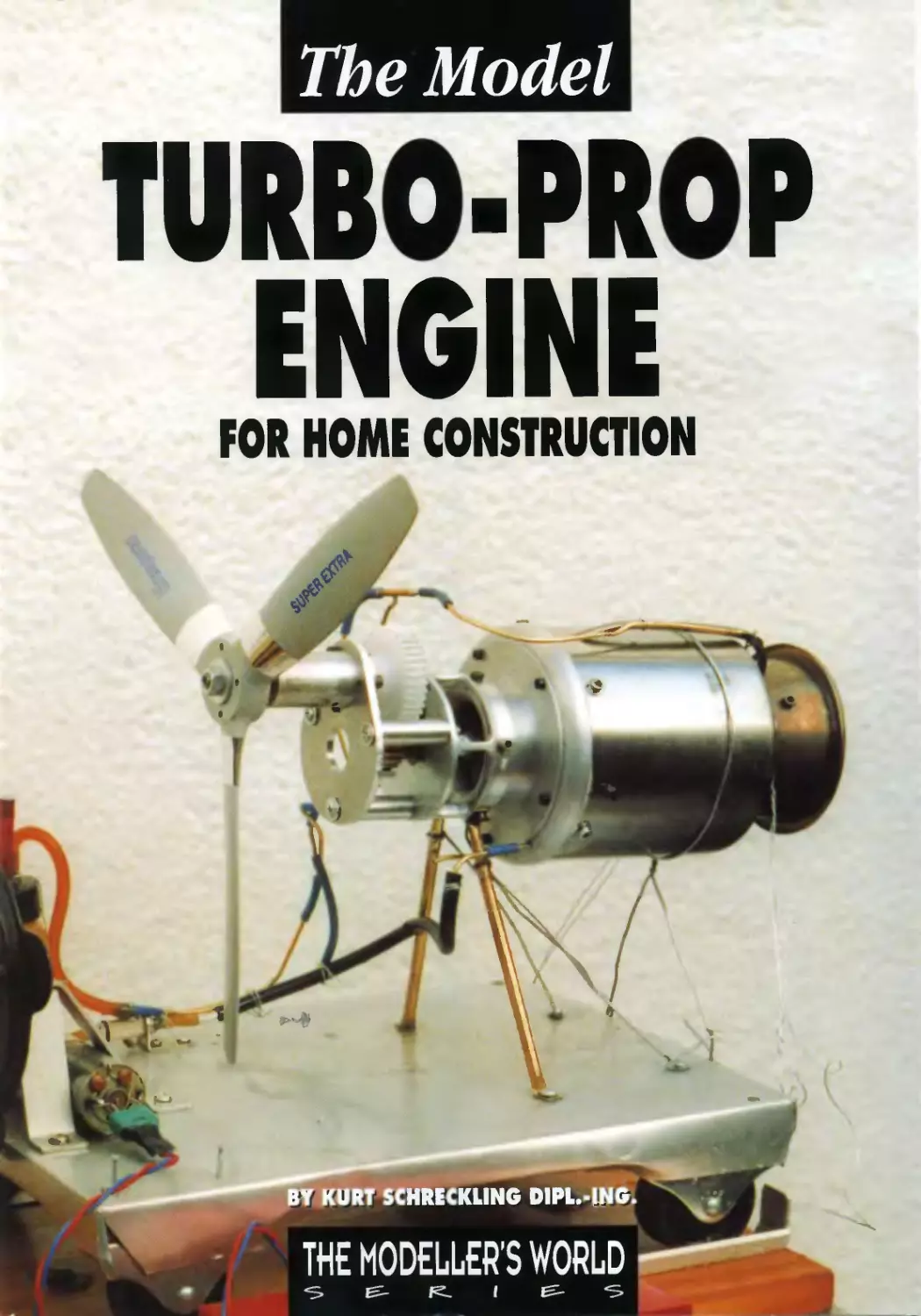
Frol/t Gwer
7bf:" OHfJIF 7 Oil the test ril/[!,.
Back Crwer
The author ll'ith OHDIE 7011 the Kal/p,aroo test aircrt!/t
T R .\ P L. E T
Printed and bound by Stephens & George Limited.
Merthyr Industrial Estate, Dowlais, Merthyr Tydfil. Mid Glamorgan CF-It; 3TD
About the Author
K urt Schreck ling was born in 1939. and his
education began with basic technical studies,
after which he completed a university course in
applied physics. For 32 years he worked in a number of
technical departmL'nts of a large chemical company.
Before his fifth birthday Kurt had his first practical
experiL'nce of model flying when he convL'rted a tangled
kitL' into a model aircraft. Some YL'ars later he started
building model aircraft and developed several radio
control systems.
Herr Schreck ling took early retirement several months
ago, and he has been enjoying his new-found free time
to concentrate eVL'n harder on new forms of model
power plant which he hopes to develop. Kurt would not
deny that hL' also enjoys good food, but he remains in
good health and enjoys life not only as a moclL'l tlyer,
but also as an experimental skier: carrying out unusual
experiments relating to Centre of Gravity and snow. To
date he has survived all this unharmed.
.
I,
. .....
.
-
.....
...
i
t.
,*t ."
. ..c;....-, '
, .19 ..... ",. 4. .,.
. ..* :'.t.'
't," . - _,..
""J.-::....t: -:;
, . # . Ie ...,l
' , ""':$'""
'!"""".... "."
.,...... ., ..,
.." ::iI-. '"':, "J.
:, 'A'''''' "
..... ...
...
-11 ,\:",
..." I _ ,. ,,'''/
. _' . : -, - .;..f
I \ . , : .:.
.."I .. .,'"4 I. ,
Ire..
l
. <""
..
.I
1
]
"\. . ".... -]
\ r
.
'I
7
:1/\,1
\
..
"
......
....;.,
Contents
Pa/{e
Foreword . . .
.9
Chapter 1 Turbines for the non-mathematician
What is a turbine? . . . . . . . .
Mass. force, work. energy. power and efficiency
Applying these findings to model engines
How turbine wheels \\ ork
. . .Il
.Il
. . .13
.14
.1 ')
Chapter 2 From the jet turbine to the shaft turbine
Steps in converting the turbo-jet . . . . . . . . . . . . . . . . .
Internal efficiency. mass flo\\. pre""ure ratio. turhine intake temperature
How much shaft power is possible? How much do we need?
.16
.16
.1 7
.11"
Chapter 3 Operating characteristics of shaft turbines .
Characteristics of the core engine . .. ... . . . . . . . . . . . . . . . . . . . . . . .
Characteristics of the power turhine stage. reciprocal effects on the core engine.
Available shaft power with a mismatched load
Influence of weather and site altitude
Residual thrust
.21
.21
.22
.22
.23
.24
Chapter 'f Guidelines. . . . . . . .
Matching the turbo-prop engine to the propeller or helicopter rotor.
.25
r
.-....
Chapter 5 The Turbo-fan
.2 7
Chapter 6 Fuel
Fuel requirements
How much fuel doe:o. the engine consume?
Fuel metering and power control
Lubricating the bearings
.29
.29
.30
.30
.10
Chapter 7 Auxiliary equipment ................
Fuel tanks, supply lines, shut-off valves. chokes
Pump battery, electronics, auxiliary gas. starter
.31
.31
.32
Chapter 8 \Ieasuring equipment and techniques . .
Measuring compressor and pump pressure . . . .
Measuflng temperature. rotational speed and thrust.
.33
-33
.3-1
Chapter 9 Three shaft turbine engines ..
With free-running power turbines .
OHDIE 5 and the first (turbine-powered) model helicopter
The whole ystem offers the following .ldvantages: . . . . .
OHDIE 6 - the first engine with a "hot" power turbine stage
-35
. .3';
.3';
.36
.3H
Chapter 10 OHDIE 7 . . . . . . . . . . . . . . . . .
The varia hIe engine with concentric shafts
Flight testing ..
. Au
.46
. .-18
Chapter 11
Building instructions
The OHDIE ..., shaft turbine engine
Introduction . . . . . . . . . . . . . . . . . . . . . . . . . . . .
.52
.';2
.';2
Chapter 12 Parts list and drawings ..
Parts list . . . .
1'v1aking the engine components .
Engine huusing, pm1 I
Front COl'er. pm1 2 . . . . . . .
Cm/llectinp, piece. pw1 6.1 . . . .
Tubular sh{!!f. pW1 4. and sealinp, rillg. pm1 4.2 .
Jlachillillp, the compressor II'heel. pW13 . . . . _
Spacer disc. pm1 4.3. and spacer ring, part 4.6 .
Specialnllfs, pm1s 4.1 and 4.H .. ..........
Sh{ift tUllIlel. pw1 5. ll'itb accessuries. pm1s 5.2 tv 5.5
PO/l'er turbine shalt. part 6
Hub. pm16.5 . . . . . . . . . . . . . _
Compressor d!llilser system. parts 7. 71, 7.2 and 7.3 . .
Cumpressor turbine wheel. pm14. 7
POll'er turbine Il'heel. pm1 6.6 .
POlI'er turbine sh{ift rear bearing
POll'er turbine sh{!Ii./i,mt bearillg _
Stw1ing air IlOzzle. pm1 83 . . . . . . . . .
Turbine nuzzle p,uide l'ane system, parts 8 to 83
Combustur. pm1s 9 tu 9.12 .
Gearbux. pm1s 10 to 13 . . .
Dynamic balancing of the wheels .
final assembly . . . . . . . . . . . . . . . . . .
Adjusting the turbine nozzle guide l'ane :l tem to fit the huusinp, .
Illstal/illp, tbe startillg air lIuzzle. pm183 . . . . .
Adjustinf!, the cumjJressor diflilser system to/it the huusing .
Instal/illg the cum bustoI' ............
Instal/ing the cumpressor diffuser Sl'stem .
Illstalling the compressor rotur . . . . .
Installinp, the pO/l'er turbine assemb l' .
Illstalling tbe f!.earbox
. . .53
. . .')3
.70
. . .70
.. ....,0
.. ....,0
. . .71
. .71
.71
71
.71
.72
. .72
.72
. _ .73
.. .:1
.:- 'I
.-'4
.74
.7-.
.'5
.77
.77
. .7H
.7H
.7H
. .7H
.7H
.79
.79
.79
.79
Chapter 13 Instructions for running the engine
Important safety notes
fire Hazard
Ingested foreign body hazard .
Exhaust gas hazard ...
Rotating parts hazard . .
Incompetence/inexperience haLard ....
Before test-running your engine for the first time ..............
A{(justing the electronic cOlltrol sJC tem to match the trallsmitter .
Calibrating the lubria/llt metering cbokes
The starting procedure
.HO
.80
.HI
.Hl
.HI
.Hl
.82
.82
.H2
.H2
.H2
Appendix . . . . . . . . . . .
Bibliography - recommended reading
Thomas Kamps: ModelJet Engines
Thumas Kamps: Radio Ccmtrol/ed JludelJet Guide
K1I/1 Scbreckling' Gas Turbine Enginesfor ,lludel Aircraft
Source of supply
.84
.84
.H4
.H4
.8'1
.84
Notes
.H5
Foreword
I t is just ten years since the first model jet turbine
engines were produced. In the intervening period
development has been extremely rapid, due
primarily to the intensive work of a small number of
committed amateurs. The result is that the main
attractions at many of today's model flying events are
the turbine-powered model jets, often present in a wide
range of aircraft types. Special meetings and
competitions for jet models are now held, and at such
events the turbine-powered model has already assumed
the dominant position.
The literature on this ubject amounts to just a
handful of books - unless you include publications not
aimed at the normal model flyer - and for this reason it
seems a good idea to present my findings to date on the
development of shaft turbines designed to power
models.
If our existing turbines are already so outstandingly
good, we need a good reason to build new variants on
the type. This is the reason: of all the full-size industrial
turbine engines currently being made, the majority are
used to drive shafts_ The shafts in turn power
helicopters, propellers, fans, electrical generators, vehicle
axles and other machinery. Until now only a very small
number of shaft turbines have been built to model scale,
and that is why I wanted to write this book, presenting
my own design of shaft turbines, developed and tested
by myself, in the hope that as many modellers as
possible will take up the challenge and build their own
versions.
At this point I ought to warn you of a particular
hazard: if you continue reading this book. you are very
likely to become infected with the dreaded "turbine
fever" virus. The author declines all liability for the
outcome!
The Model Turbo-Prop Engine For Home Construction
9
Chapter I
Turbines for the
non-mathematician
What is a turbine?
Even though it is ten years since the first turhine-
powered model aircraft actually flew, the same question
crop up again and again at flying displays: "what sort of
engine is there inside a turbine, then?" The question is
posed by folk who appear to think that we have
cunningly hidden some special type of piston engine or
even electric motor inside the turbine. Although I am not
on intimate terms with every single turhine that has ever
been built, I can still state without hesitation: there really
is not a piston engine or electric motor inside the case! If
you have ahsolutely no knowledge of the workings of
the gas turhine, the next section is aimed squarely at
you: I will attempt to explain how it works in a form
which is as easily digestible as possihle. Curiously, in
most physics text books you will not find the term
"turhine" at all. In the new Fischer dictionary we find
this: "turbine: rotary motor in which the energy in a
flowing medium (water, team or gas) is converted into
mechanical energy; its ancestors were windmills and
\vater wheels ." In the relevant technical text hooks
Close to the airport of Mallorca can be seen a special type of shaft turbine engine which demonstrates
that turbine technology has found practical applications for many years. In the background you can see a
modern turbo-prop passenger aircraft on the landing approach.
l -:
-{
1 ,
\
'-
:-, ...
_- It
.--
'"
...:.I;
_ot"it-. .;I,,:"-
-.
:
--
-
.. "' ...,
The .Hodellilrbo-Prop En[!,ine For Home Construction
ti
iN
\..
.!I
. -,
;.,'
.. '1'_
(:
.
... -- .
.
....
- .
,
.f". .
/.
I _-:::'!._: .. J
'.... :.1 . : ;:;'4 .
"
j", ....:J...
'"
.: ::
. .
11
turbines in all their variety are covered in detail under
the umbrella term "flow machines".
An excellent example is the wheel of a water mill, as
we can see exactly what is going on: a flow of water is
directed tangentially onto the vanes mounted on the
periphery of a wheel, or rotor, and this action forces the
wheel to rotate. In this case it is obvious how the energy
in the water affects the wheel. Note that the wheel can
only he used to drive something if the force acting upon
it is directed on its periphery. The energy in the flowing
water is thereby transferred to the wheel or rotor, which
can then perform useful work.
If the water wheel is a water turbine, it follows that a
windmill or wind turhine is an "air turhine", and since
air - the flowing medium - is gaseous, these machines
also justify the description "gas turbine". The photograph
of the wind-driven pump with the turbo-prop passenger
aircraft in the background shows very dearly the wide-
ranging applications of the turbine principle, even when
restricted to the medium of gas.
Wind and water wheels have been in use for
centuries. and they exploit the flow energy which is
present in the natural world. :vtodern turbine engines
which exploit the principle of the ga turhine use
thermal energy to generate their own wind to drive
turbine wheels. This means that they belong in the large
category of thermal engines. In the "Dubbel" pocket
book of engineering we find the following definition:
..the gas turbine is a thermal engine which generates
mechanical power (shaft power) or thmst (e.g. in aircraft
engines) . . . " According to this definition, the term "gas
turbine" can be applied to all kinds of turbo-jet and shaft
turbine engines. Model turbines such as the JPX, FD,
Microturbine, Turbomin, Pegasus, KJ-66 can therefore be
classed as gas turbines. but so also can the OHDIE 5. 6
and 7 shaft turbine engines presented in thIs book,
together with all the other variations on the type which
already exist or will exist in the future. Many model
flyers erroneously confine the term "gas turbine" to jet
engines which use propane gas as fuel. That is quite
simply wrong.
A turbine-propeller engine, generally ahbreviated to
"turbo-prop", is only one representative of the shaft
turbine family. Different applications of the general
principle have produced power plants which are used in
helicopters, manne vessels, ground-based vehicles and
also stationary plant guch a pumps. compressors and
electrical generators, and this list is by no means
complete.
In theory, the term "turbo-motor" would certainly he
appropriate to these engines, although to the layman
thb seem to imply a piston engine fitted with a turbo-
charger. However, all shaft turbine engines have rotating
compressor and turhine wheels instead of pistons and
cylinders, so I shall use the shorter term "shaft turbine"
in the remainder of this book to descrihe this specialised
Turbo-jet powered model aircraft in large numbers seen at the Whittle Ohain Trophy in the Summer of
199B.Just afew years previously it would been thought incredible that such a wide range could have been
produced so soon.
----
....
.
_A."'_
"""
--
,.. -
"---
-...-
-:.
-
.-\
;
\
"" - '"
...
....
12
...
f' ....
-)1
"
, .
. -.
..
,,:
I \
'-
"'-
,.r'
. .
'!'.
...-
... -
- ...
l
.
.-<:
.
-
-.
.'
..
-.- '..
The Model Turbo-Prop Engine For Home ConstnlctlOn
species of the gas
turbine genus. It is
unfortunately the case
that even the experts do
not use the various
terms logically and
clearly in their everyday
speech. It is therefore
absolutely essential to
state exactly what is
meant by the word
"turbine" every time it is
used, otherwise the
uninitiated layman will
be in a constant state of
confusion. Do we mean
the complete engine, or
the turbine wheel, or a
particular turbine stage,
or perhaps something
else?
I shall try to take this
difficulty into account in
my explanation of the
method of working of
the individual parts of
the engine.
Admittedly it is not that easy to remember the correct
meaning of a range of new terms when you hear and try
to use them for the first time. A good example of this
cropped up at a model flying display in which I was
participating: although the announcer was well prepared
and had been thoroughly briefed, he still came to grief
when trying to differentiate between the turbines and
the pulse jets. The result was that my engine was
announced as a "pulse jet turbine", but who knows?
Maybe somebody will invent something some day which
will deserve this name, although he had better take the
trouble to solve the attendant noise problem at the same
time. Fortunately noise is not a problem with shaft
turbines which are designed appropriately for use in
model aircraft.
..
"
" &,; .
-
.
...
"
..".
.,
.-..
t
.,,%--
.-
'"
'\.
\
,,'
I
,""
-,
..."
j -.
.
...
..
....
.F
...... ..
-, gJ.-7 6
--
-. (.
'J'
A Fan-Trainer built by Peter CmyraL Here the fan is driven by a piston engine.
For how much longer?
Mass, force, work, energy, power and
efficiency
It is important to have an overall understanding of the
meaning of these terms as they relate to physics and
technology, otherwise you will quickly become
confused when we start discussing the function and
application of turbine engine:-..
Mass is a measure of the quantity of substance of a
body. Force is present all about us, for example in the
form of gravity due to the gravitational pull of the Earth
on our own body, or when the speed of a vehicle
change . We can see from this that a body of a given
mass can produce forces of varying magnitude
depending on the type of acceleration to which it is
subjected. In terms of physics, "force" is defined as the
product of mass and acceleration, whereby acceleration
is the rate of change in velocity; velocity is defined as
speed in a stated direction. For example, if a model
aircraft dives vertically into the ground, its velocity
changes extremely quickly, which means that its rate of
acceleration is correspondingly high. This example
shows that a body of low mass can still exert a
The Ivlodel Turbo-Prop Engine For Home COllstrllctiOll
considerable destructive force. Where a mass is rotating,
its velocity is constantly changing, and in this situation
"centrifugal forces" take effect. When a mass is repelled
or ejected. the force generated is precisely what is
required to produce propulsion.
Tn terms of physics, work is defined a force
multiplied by distance, measured in the direction of
travel. Energy is the capacity to execute work. This
means that the natural wind possesses kinetic energy in
just the same way as the exhaust flow of a jet engine.
Power is work divided by the period of time in which
the work was performed. The following method of
demonstrating this is extremely impressive if you try it
out yourself: locate a fairly long staircase, and -:limb it
once at your normal speed. Now try it again, moving as
fast as you possibly can. The work performed in both
cases is identical, if we overlook the slight increase in air
resistance due to climbing at high speed. However, you
will be in no doubt that you have generated more
power in the high-speed climb.
The energy required to execute the work is stored in
your muscles and fat reserves in the form of chemical
energy. When we use the term "power" in everyday
speech. it does not always mean the same as the
definition used in physics, as the scientific term says
nothing about the actual work performed.
If you carry out the experiment outlined above
exactly as described, and then analyse the results with a
little more care, you will probably come to the following
realisation: not only have you performed "useful work"
by climbing the staircase, but the effort has also warmed
you up considerably. The "thermal engines" of your
body, namely your mu:-.cles. only convert into useful
work a part of the energy passed to them. The ratio of
useful work to energy consumed is termed efficiency. In
any energy conversion process which works constantly
we can also describe the power ratio as efficiency, in
which case the values are simply stated as a number or
a percentage. Since there are always losses involved in
13
-
-
J
Applying these
findings to
model engines
>-
.
.
'4
\
,
tt
"
...
J
....
, - ',.)
,..
,#
.
If we are to make an
attempt at answering the
UHf> Kilopond question
with some degree of
accuracy. we need to
know one extra factor:
the speed of the model.
For example, a perfectly
practical case is that of a
model aircraft held
stationary on the ground
for a test run. with an
engine producing 50 N
of static thrust. How
much power is being
transferred to the model?
Evidently absolutely
none, for although the
engine is producing 50
N of thrust. it is not
moving the model at all.
However. the engine is
nevertheless converting
considerable energy per
unit of time, su where is
the power it is
generating? Take a look
at the rear of the engine,
and you can see the
answer very clearly: all the engine's power from the
exhaust flow or from the propeller's airflow is
transferred (lo t) to the environment. It makes no
difference whether the thrust is produced by a turbine
engine or by any other form of motor with a propeller.
How about a comparison of power produced by a '50
N jet turbine and a LO cc motor when the model is in
flight? For the moment, let us assume that the model's
airspeed is 180 kmlhr, which corresponds to 50 m/s. At
this speed the thrust of the turbine will fall slightly to 45
N. We also assume that the drag of the model is equal to
the engine's thrust, but acting in the opposite direction.
In this state the model moves forward steadily at a rate
of 50 m every second. We can now calculate the work
performed by the engine as follows:
.....
\
I'
'"
..
"
-,
.
.....
Another example for possible future turbo-j'an applications: a model Harrier
hovering, as demonstrated by Mike Coscela during the first jet meeting in
Mallorca in 1996. The model is fitted with a conventional impeller powered by a
two-stroke engine.
all energy conversion proces e . efficiency b alway le
than I, or smaller than 100%.
What is the equivalent in horsepower of 5 Kilopond
(kp) of thrust? Questions like this are commonly
expressed, and difficult to answer. The question implies
that force and power are unconsciously considered to be
equivalents. and the use of antiquated units such as
brake horsepower (BHP) and kp do nOI clarify the
matter. However, the confusion is also due to the fact
that the performance of internal combustion engines and
electric motors is usually stated in the form of shaft
power, while static thrust is usually quoted for turbine
engines.
There is little point in trying to draw comparisons
here; after all, who wants to know what size of turbine
is required to propel a model horse-drawn cart? Even
fewer modellers are interested in equating the power of
cart -horses with the po er requirements of aircraft. EI'
regulations now state that, as far as possible, only SI
units (SI = System International dTnites = international
system of units) should be used. According to the SI
system, mass is measured in kilograms (abbreviation:
kg), power in Watts. kiloWatts or megaWatts
(abbreviations: W, kW, MW), force in Newtons
(abbreviation: N), work and energy in Joules 0, kJ, \1.n,
whereby k stands for Kilo (one thousand of the stated
units), M for Mega (one million of the stated units).
Equally common are the prefixes Milli- (one thousandth
of the unit in question), Micro- (one millionth of the
unit) etc.
You may not be fully conversant with SI units, but
they make good sense when it comes to carrying out
calculations concerning physical and technical processes.
14
5 N x '50 m = 2,2'50 Nm = 2,250 J (joules).
The unit of time here is one second. Accordingly the
engine's power is:
2,250 J, 1 s = 2.250 "'- (Watts)
In this calculation we have worked out the engine's
power as defined by work divided by time. However we
can obtain the same result by measuring the aircraft's
airspeed in m s and multiplying it by the engine's thrust
measured in j\,. From this information we can derive the
following equation:
Flight power = thrust x speed.
With a standard 10 cc motor this level of power in flight
The ,Uodel Turbo-Prop Engine For HOlne COllstruction
cannot be achieved. as its shaft power is only around
1,200 \'(' The answer to the original question is therefore
as follows: at take-off the jet turhine is as powerful as a
good 10 cc two-stroke, but even at tHO km. hr it is more
po"verful than two of these motors. We can see that this
is likely to be true from a glance at the glow motor's
shaft power: if it produces 1.200 W. its thrust would be
2-f N, if we ignore the losses in the propeller. If we
assume a propeller efficiency of 75%, the motor can only
produce 18 N at the stated airspeed, or 900 W of useful
power. Of course, it IS perfectly possible to achieve L80
km hr with a 10 cc motor. but in this case the drag of
the model I1llIst be much lower than in our example.
How turbine wheels work
The first drawing show,., the flow through an axial
turbine wheel in diagrammatic form. This type of wheel
is termed "axial" because the flow through it is genera II}
in the axial direction. In practical terms, the turbine
blades are completely sealed at the tIp by the turbine
wheel housing. The result is that the gas flow is
deflected backwards at an angle, as shown in the
diagram. As we have already seen. the process of
changing the direction of flow in a fluid medium
produces a force which acts on the periphery of the
wheel. This force varies according tu the change in
peripheral speed and the diameter of the wheel. It is
possible to amplify the effect of the force on the wheel
by directing the flow accurately into the blades of the
wheel. i.e. as close as possible to the wheel's direction
of rotation. This is the purpose of the turbine nozzle
guide vanes. The combination of the nozzle guide vane
(stator) with the turbine wheel trotor) is called a turbine
stage. The pov. er of a single stage of this type can be
calculated from the peripheral speed and the peripheral
force of the turhine wheel. The peripheral force is itself
determined by the mass flow. and the degree to which it
is diverted in the direction opposite to the direction of
rotation. The effectiveness with which the nozzle guide
vanes direct the flow is included in this factor. The
deflection is amplified if the gas contains sufficient
energy to accelerate the flow between the blades of the
turbine wheel in the opposite direction to the direction
of rotation.
A gas flow which moves in the axial direction relative
to the wheel, whilst at the same time rotating around it,
is termed a swirling flow. The peripheral force required
can also be generated by a change in this swirling
motion. The swirl produced in the nozzle guide vanes
alone produces a peripheral force through the action of
diverting the gas in the turbine blacks mounted on the
turbine wheel. It is equally true that a peripheral force is
generated if the gas strikes the vanes of the turbine
wheel in the axial direction. but is diverted in the
direction opposite to the direction of rotation by the
camber uf the blades. \'Vindmills demonstrate this effect
quite dearly.
To obtain maximum efficiency in a single turbine
stage it is ideal if the swirling motion produced by the
nozzle guide vane system is reduced by the rotation of
the turbine wheel to the extent that the gas flows out of
the turbine vv'heel purely in the axial direction, i.e. free
of swirl: at the same time its velocity should be as low
as possible. If this can he achieved. the kinetic energy
which is carried away in the gas flow is minimised.
The i'f,1ode/1itrbu-Prop Engine For Hume Construction
Flow tlJrollglJ all axial tllrbille wlJeel
Flou' tlJrouglJ a radial tllrbille wheel
However, any excess energy which has not yet heen
converted can be converted into shaft power in a
subsequent turbine stage.
The second diagram shows the direction of flow
through a radial turbine wheel. Here the change in swirl,
and \vith it the peripheral force. as the gas flows through
the wheel. occurs from the outside towards the inside.
i.e. in the radial direction. This type of wheel is popular
in the smaller exhaust turbo-charger, and in single-shaft
turbine engines.
'\. peripheral force. or torque. is generated by the
hlades of a turbine wheel even if it does not rotate at all,
provided that gas flows through it.
15
Chapter 2
From the jet turbine to
the shaft turbine
T he turbo-jet engine, more correctly known as an
air turbine jet engine. is in its simplest form a
pure generator of thrust. The drawing on the next
page shows the basic construction and method of
working of a model jet turbine. However. with relatively
little effort it is possible to persuade a jet engine to
transmit its power to a drive shaft, instead of producing
power in the form of a jet. In concrete terms this means
that we can use the technology developed for existing
model jet turbines ,IS the basis for shaft turbines. and in
so doing reap many advantages.
In its simplest form such an engine can be based on
any model turbo-jet you like, without internal
modifications, i.e. the turbine forms the core engine for
a shaft turbme. The term "gas generator" is sometimes
used instead of "core engine",
Steps in converting the turbo-jet
In a turbo-jet engine all the mechanical power is
released in the exhaust jet. We need to exploit the
excess energy which is present in the gas as it leaves the
turbine stage and enters the thrust nozzle. This is the
point at which we apply our modifications:
Step 1
First we remove the thrust nozzle. This causes a very
significant drop in exhaust gas temperature. However, in
This Ulondeifullarge model is simply crying out for turbo-fan engines.
-
? f: ;'
..... ,; '. .; '.;. . ' .. ."" . . . .
.. ";- -: . -. - . . --
. !II
- .._,....;;,..
- .. -
"-
--' ....
--....;;i:..
- "....
- ,
.: : --
ill: .....-.
,
--
-
..... ... -
,rt :-'
....
'.
- "---
. '
......
.
,.
"'-'.
r.,...
i
... .
"'"
i1
;. :
, -'
It"_"';
.. -
--,, ,
._-
;o.. .,
,.... ,,-
.or- __
"
L..:.- -
:,..-,.-a,..,....
,.
-':.,.."."
....
... '
.
..
."
.- ::' I' -
...... ...)-
..
". . . I . ,.
---..J.
", . !!".,... ..-
.: .;:-.
.. .. ..
.('. Pt:r-
.....,
- 7"(11J1fw-"
r. ,
... - -
J . .'
...-..-;:.,.'"
t..
f - i.
, .J//' .
"'" . {'l .L
"," . (./7t
""" l,l
, "
..
"
..
. ......
I"
'"
I.
'.-
>(
'&or.
.........
t:
"
!>.po ,
. ,JIJit <. '.'"3: '.' ,.
. ..,.. . ' .... j. ..... - .... A .1 "
:"';t .:;f1;"" , . ..- --..- -.. '. .... "......
. . , -"!; :..'- . "-<i'/o-'" - ", "'"
It- ,...40" '. .... .':., ".......-. . ' "
. . _ ",:-,\\, :: '-.L ....: ,<t. .'_ Ij..
..: :, ,_:.,,::-"' "..2 '-'::' .,:. \ ..;... . .... "t1, :. f
t. _ _" 'r' -....1 ... ?
..
f.'
!.-
16
_', ..;. >-'i f
. ' -. ;- - . '-I!
;' :t.. " :(::'.1 ...,..
. ....t..
-I"..... . !' 1M.... -' ": '\ ''':.r.,' ...
._"'of _"-\.. -__. ..
'1JIC".f ; _ ; ..
.....
, ;
..
The Model Turbo-Prop Engine For Home Construction
Air
BaUrace
Compressor diffuser vanes
Fuelfeed
..
Annular nozzle
,
. x
Shaft
/.
Combustor
Turbine nozzle guide vanes
The basic method of working of a model turbo-jet engine. The compressor wheel rotates very fast,
and constantly sucks in air, compresses it and feeds it into the combustor. At the same time fuel is
burned and thereby increases the capacity of the gas to perform work considerably. It can now
carry out more work than is required to drive the compressor wheel The turbine wheel draws from
the hot air the necessary energy to drive the compressor wheel The excess work capacity is
converted into kinetic energy in the exhaustflow as it passes through the annular nozzle. This
produces the thrust which propels the model aircraft.
our experience the engine still retains 70% of its
maximum thrust in this form.
Step 2
We install an exhaust diffuser in place of the exhaust
nozzle. If correctly designed, the diffuser causes a
further considerable fall in exhaust gas temperature.
Essentially we do not need to make any further
modifications to the rest of the core engme.
Step 3
We now simply couple a gearbox carrying any
suitable load (e.g. a propeller) to the shaft of a turbine,
as shown in the diagram overleaf. This method is
employed in many "full-size" industrial shaft turbines,
although it is always necessary to calculate the load very
accurately, or provide a means of varying the load.
However, for model applications this is too complex a
solution, and therefore nO[ feasible.
For example. if the load on the turbine is excessive,
e.g. too large a propeller is fitted, the engine would
overheat or even fail to start. To solve this problem a
gearbox is required, in order to reduce the turbine's
running speed of 120,000 r.p.m. or more to usable
propeller speeds. This solution is certainly possible, but
the first point, the accurate calculation of the correct
load, caused me to .lbandon what is known as single-
shaft technology for model use.
Step 4
A second turbine wheel is installed at any suitable
point in the engine where either cold air or the hot gas
from the core engine is flowing through. This second
The Model Turbo-Prop Engine For Home Constnlction
turbine wheel is mounted on a separate shaft - the
power turbine shaft - which is designed to allow both
shafts to rotate independently of each other. This system
can be termed a shaft engine with free-running power
turbine. A second turbine nozzle guide vane system can
be used, but it is not essential.
This book describes three practical variations on this
theme: OHDIE 5, OHDIE 6 and OHDIE 7. In my terms
"practical" means that these engines have actually been
installed in model aircraft (and even a model helicopter)
and powered them in the air. It is very easy to show by
theoretical calculation that shaft turbine engines with the
power turbine stage at the hot end of the gas flow are
much more powerful than engines with a "cold" power
turbine for a given fuel consumption.
Internal efficiency, mass flow,
pressure ratio, turbine intake
temperature
If we wish to calculate the shaft power of a projected
turbine engine - and also the thrust of a standard turbo-
jet engine - we need to understand the influence of the
factors listed in the title. and the way in which they are
inter-connected.
Internal efficiency is a means of assessing the quality
of a single compressor or turbine stage. Efficiency is
stated as a numeric value in the range 70 to 80%, and
significant improvements are unlikely. However, there is
scope for adjusting the other factors within fairly wide
limits.
Mass flow (of the air) is measured in kg/s; note that
we are only concerned here with the mass flow through
17
Propeller
Diagram of a sillgle-shaft turbo-prop ellgille.
the core engine. TypICal numeric values for model
turbo-jet engine:-. are in the range 0.1 to 0.4 kg s at full
load, depending on the size of the engine.
The pressure ratio is defined as compressor pressure
divided by atmospheric air pressure. For our purposes
the practical top limit is a pressure ratio of up to 3.
The turbine intake temperature (abbreviation: T3) b
the temperature ot the gas at the point where it enters
the cliffuser vanes before passing to the turhine wheels.
In practice the maximum temperature is "'oooe if we are
to continue to use normal availahle matenals. If we
allow higher temperatures. we are ohliged to use
extremely exotic materials and or devise complex
cooling techniques.
How much shaft power is possible?
How much do we need?
This section attempts to clarify the connection
between the various factors with the help of diagrams,
in order to avoid the need for complex mathematical
formulae. The diagrams show results which have already
been calculated. Please bear in mind that my own
practical experience extend:-. back over more than ten
years, so the "estimatology" used in the graphs naturally
benefits from that knowledge.
It is standard practice when presenting this type of
information to state the "specific power" in k\X-, kg, i.e.
the power which an engine would generate at a nominal
mass now of I kg/so
In some of the diagrams the compressor pressure is
stated instead of the pressure ratio. This applies where
compressor pressure can actually be measured. The
following conversion formula applie:-. in this ca:-.e: \
18
Exhaust gas diffuser
G '
[
Measured compressor pressure in bar = pressure ratio -1
This is a :-.implification, but it is of practical use; it
only applies at sea level, as atmospheric air pressure at
this altitude can he assumed to be 1 bar with reasonable
accuracy. 1 bar corresponds to 1.000 hPa = 1.000
llectopascal = 100,000 Pascal according to the SI system.
l:nfortunately I have not :-.een an affordahle pressure
gauge calibrated using this unit of measurement vvhich is
suitahle for the typical modeller. Compressor pressure
can be measured in the casing .It a point just
d(}\vnstream of the compressor diffuser vanes.
Let us no\\ examine diagram 1. Example A shuws the
data for the KJ-66 turbo-jet engine. It shows a point on
the graph corresponding to a maximum pressure of 1 2
bar, i.e. a pressure ratio of 2.2. For the moment we will
assume that this engine has already been converted to
form a core engine. If this is the case. we can read off a
specific power of 3 7 kWs, kg air throughput. The actual
air throughput is 0.2"1 kg s. These figures can novv he
used to calculate the actual shaft power of such an
engine:
0.24 kg, s x 37 kWs kg = H.HH kW
Example H shows the case for a core engine in vvhich
the turbine intake temperature is artificially kept low. as
it assumes that a turbine wheel for a small engine
capahle of surviving in very high temperatures is simply
not available. For this reason the maximum pressure is
restricted to 0. 7 har, i.e. the peripheral speed of the
wheels is limited, and a turbine intake temperature of
only Goooe is permitted. The diagram shows that the
engine's specifIC power under such conditions is 22.8
k\Vs kg. Thi:-. means that a :-.mall :-.haft turbine \vith an air
7l1e Model Turho-Pmp EIlp,lIle For Home COllstructioll
throughput of only 0.07'5 kg/s would generate a shaft
power of:
0.075 kgl s x 22.8 kWs/kg = 1. 7 1 kW.
This is already considerably more than a normal 10 cc
two-stroke is capablc of producing.
If wc are able to use a turbine wheel with the same
strength as that employed in the larger jet turbinc, then
we can apply the same limits relating to pressure and
temperature, and therefore obtain the same level of
specific power. The mass throughput of the small engine
would then automatically rise to about 0.11 kg s duc to
thc higher power of the compressor, and in thb case
even the small core
engine would suffice for
a shaft power of more
than 4 kW.
It is also possible [0
estimatc the shaft power
which can be achieved
once the turbo-jet
engine has been
converted into a shaft
turbine by making a
calculation based on its
jet power. l'nder static
running conditions the
jet power is: half mass
flow in kg/s multiplied
by jet velocity squared.
EX.lmple A shows
that the KJ-66 provides
75 N thrust at a mass
flow ofO.2-f kg/so Thrust
divided by mass flow
produces the clcar
answer:
Jet velocity = 312.5 ms
and from the above
equation we find that:
Jet power = 11.""' kW!
With a little effort it is
possible to convert
around 70% of this
11.7 kW into shaft
power. This mcans that
a pcrfectly standard
model jet turbine can be
converted to gcnerate
8.2 kW of shaft power;
a figure which cor-
responds quite well with
the 8.88 kW calculated
from diagram 1
Question: do any of
us need such levels of
power in our model
aircraft, boats or ground
based vehicles? Anyone
with a little practical
experience with piston
engincs and propellers as used in models will know that
.l power output of 8 kW is the sort of figure obtained
only with extremely large engincs. A 10 cc engine
gencrates a shaft power of benvecn 1 and 1.5 k\X ,
which tlw propellcr convcrts into a static thrust of 40 to
')() "I. Four engines of this sizc provide plenty of powcr
for a large model aircraft with a mass of close to 20 kg
,more than 20 kg is not permissible in Germany in any
case). A single 10 cc two-stroke motor produces
adequate powcr for a model helicoptcr with a take-off
mass of 10 kg.
This information shows that a core enginc for a shaft
turbine could rcasonably be much smaller than the
model turbo-jet engincs currently in widesprcad use.
A unique implementation of the micro-turbine by Thomas Kamps: a controllable
vertical take-of.{ machine, demonstrated duri"R the Whittle Ohai" Trophy
meeting ill the Summer of 1998. In the backRroulld call be seell an e.\:perimental
model aircraft designed as a test-bedfor turbojet ellgines.
-.
-- -.
......
,.,."
- ' 01'"
';
-:
.,,
J.
....
.....A -..,.-
""'_. - :-. .. . -
Or
;;
-".-:
:T w
,,1 .
. . .
.,;' r':'fI'
. - 'r '-.
,: ;: . :
....
u '.,;
j .
The Model Turbo-Prop Engine rDr Home CDnstruction
.' .... "
.
l
.
....;c ..
...-
. ....
-
't
-'
:,,-,'
i
...
\.
t"
. . 1
.' 1,
..
)
\
.:
.J;..
- ."
.......
'"')
;..
.
'" .
J
,\
.
\
.
,.
'.
I
":\
-- }.
.
.,--
-
. f
, "'.,
F
;;.__1
\,
.-,..1
.'-!
.
- "..
_ _:" -. !..f
.'"
.-:
*r-
,.
, .
'- .
..:
,
..
,..
., ".
...
....... -: -'(- .
; ..
19
50
40
Example A
'"'
if
.,j
*
30
10.
S:
Q
20
S.
""
10
o
o
0.5
1
1.5 Pressure in bar
2
Diagram 1
Specific power varying with compressor pressure and turbine intake temperature.
Of course, it is possihle to take the shaft turhine
capable of 8.RR kW and throttle it back so that it
generates only 4 kW, Le. run it at lower pressure and a
correspondingly reduced rotational speed. However, the
relatively large engine would consume morc fuel than a
smaller one, which means that the model aircraft would
have to carry an undesirably high load due to the extra
weight of the larger engine. and the larger fuel supply
required for a given operating time. The idle power of
the larger engine is also inevitably higher than is
desirable, and it is already too high for comfort with
many relatively small models under certain
circumstances. The power requirement for model boats
and land-based vehicles is in any case much lower than
we need for model aircraft.
20
The II10dei Turbo-Prop Engine [-<or Home Constnlctiol/
Chapter 3
Operating characteristics
of shaft turbines
A t this point we will only discuss shaft engines
with "free-running" power turbines, whose core
engines are very similar to the familiar turbo-jet
engines used in models. fitted with only one
supplementary turbine stage.
Characteristics of the core engine
The thermal efficiency of any turhine engine
improves steadily with increasing rotational speed, due
to the rise in compression ratio. The engine's power
capacity rises at a much higher rate than its rotational
speed. If rotational speed is douhled, pressure is at least
quadrupled - provided that we stay within the
permissible speed range. Unfortunately these engines all
too easily "forget" the limits which are laid down hy the
rotational speed strength of the rotating components. If
the fuel flow is not governed, the engine self-destructs.
It is therefore absolutely essential in every case to ensure
that the engine is never supplied with too much fuel.
The bottom end of the engine's speed scale is set by
what is known as the sustain speed. Below this speed
the power produced hy the compressor turbine wheel is
too low to overcome the friction losses of the hearings
at temperatures which the engine can tolerate. For safety
reasons the "idle speed" is usually set at three times the
sustain speed. For the OHDIE 7 engine with a
compressor diameter of 50 mm the speed range which is
of practical use currently lies hetween 'to.000 and
130,000 r.p.m. The acceleration time from idle to full
speed is around three seconds, although the core engine
turhine accelerates fairly slowly at the hottom end of the
140
120
100
!.
80
;:
Q
... 60
...
oS
r:z::
40
20
0
0
0.2
0.4
0.6
Compressor pressure (bar)
1
-------.......-...-.----
. .
..._-_..-------------------_............-.-.--.-.
. .
. .
0.8
1.2
1.4
1.6
Diagram 2
Relative rise in power varying with compressor pressure.
The Model Turbo-Prop Engine For Home Construction
21
. .
__...__nn_n.._......mn__...__ m _... m . ..n.....m.nnmn+m.m.......nmm.__m m _+_. ......--..m----.m-------r. .m..._.
---------------_______ _ - -_:-----r-----T-----------r-
speed range. Feeding excessive fuel to the engine at this
time leaLl to spitting and overheating. This rotational
speed range corresponds to a usable compressor
pressure range of 0_1 to 0.- bar. Since it is relatively
difficult to measure rotational speed accurately, it is
usual to monitor compressor pressure to ensure that the
limit range is not exceeded. Diagram 2 shows the
relative rise in the engine's power capacity. In this case a
compres"or pressure of 1.2 bar is set as the full throttle
point; this corresponds to a pressure ratio of 2.2.
Note that a core engine turbine wheel has to be
highly heat-resistant if this value is to be reached in
practice.
Characteristics of the power turbine
stage, reciprocal effects on the core
engine
The extent to which the power capacity of the core
engine can actually be exploited depend" to a very great
extent on the design (i.e. size) of the power turbine
stage. and on careful selection of the load. e.g. in the
form of the appropriate size of propeller. Since the hot
air expands as it flows through the turbine stages, the
power turbine wheel must always be larger than the
turbine wheel of the core engine. A common feature of
all turbine engines is that the lion's share of the engine's
power capacity is absorbed in driving the compressor. In
very coarse terms ¥; of the engine's power is passed
100
90
. .
____________n__...__..__n...........__......___n.......n...__
- .
, .
. .
. .
. .
. .
. .
. .
. .
_n..__hd...huu_h.nhu.......uhun....
80
70
......nnunnn.__n_.._n_...___ _no.
__u".....n.................._...__nh........_...
- -
'"' 60
:..
c
::::
oS
1:1:
50
40
30
20
---c-- --= --.. ----- -- .
10
()
o
().2
().4
back to the compressor. and the remainder is exploited
in the power turbine. It is therefore always the ca"e that
the rotational speed of the power turbine is much lower
than that of the compressor turhine wheel. In our
engine" the usahle range is 0 to 40,000 r.p.m.; the latter
value is the optimum speed at full throttle. If the
rotational speed of the power turbine is 0 r.p.m.. the
power turbine shaft is stationary, and no shaft power is
produced. In fact, experience sho\vs that the core engine
nevertheless continues to run happily in this situation,
although the running temperature is at a maximum.
If the power turhine is left undisturbed. its rotational
speed rises and falls with compressor pressure, although
the scale is not linear. The core engine produces torque
at the power turbine wheel even if the latter is
prevented from spinning. In <Ictual fact, the torque of the
power turbine wheel is at its highest when stalled. and
this is a very important practical point. For example, it IS
permissible to hold a propeller or helicopter rotor
stationary to prevent it rotating while you start the
engine, and there is no risk of damage to the core
engine when you do this. The same applies if a
propeller is stalled due to ground contact.
Available shaft power with a
mismatched load
\Ve will assume that the core engine is running at an
approximately con"tant speed_ \1("e have already
-n--unnn...un....ni_....unon...____ __ _nn____!______n______________________..
___ui________
;
. -
. ,
.....h......un..........un.........uunu..........nn..no____.nnon..
, -
- .
. . .
m-r_- _r----- --J_
________1_______ ___"_'_'____'____."_".__1_""__"""""."
0.6
1
1.2
1.4
()'8
'" n opt.
Diagram 3
Declille ill power of a pOll.er turbille stage due to mismatching.
22
The Model Turbo-Prop E/lf!,i/le For Home CO/lstruction
examined one extreme
case. namely a stalled
power turbine shaft. In
this situation the shaft's
torque is at a maximum,
but it is incapable of
supplying pmver.
The other extreme
case is when the turbine
wheel IS spinning so fast
that ga flow through it
without being deflected.
In practice this occurs if
there is no load on the
secondary shaft, i.e.
shaft power i zero.
rotational speed is max-
imum.
Somewhere between
these two extremes lies
the optimum speed. i.e.
the rotational speed at
which the powel tur-
bine wheel generates
maximum power. This
requires that the load.
e.g. a propeller, is
accurately matched to
this rotational speed.
The practical signi-
ficance of this is that the
gearbox reduction ratio must be selected carefully to suit
each application. In practice it is not always possible to
match the load as accurately as we might wish.
In approximate terms we are able to calculate the
extent to which the engine's actual usable power differs
from its maximum power, if, for example, the propeller
we select is larger than the optimum size. A study of
diagram 3 shows this dearly. For example, if we assume
that the load is so large that it limits the rotational peed
of the power turbine wheel to around 60% of its
optimum speed. we can see from the graph that only
70% of maximum shaft power is available. If we
"strangle" the engine to such an extent that the
secondary shaft is turning at only 20% of its optimum
rotational speed. there is still 23% of maximum shaft
power available. Let us now examine the opposite
problem: if the load is too small. the po'"ver turbine
wheel spins faster. but its power output is reduced. The
graph shows that relative power dedine fairly steeply at
high rotational speech. The power lost due to
mismatching is retained in the exhaust gas, thereby
producing an increa e in exhau t ga velocity and/or
exhaust gas temperature. Thi characteristic dynamic
behaviour is fundamentally different to that of a piston
engine: the torque of the piston engine rises with
rotational peed until it reaches an optimum value. It is
obviou that this type of motor produces no torque
when it is at a standstill. A more relevant comparison to
the shaft turbine is an electric D.C. motor. Like the
turbine. the electric motor's torque is also at a maximum
when the motor is stalled (shaft stationary), although in
thi ca e the situation must be avoided at all cosb unless
you wish to see the motor smoke itself to death;
fortunately for us. this does not occur with the power
turbine.
100
95
90
:::
.
85
80
.
...
.S!
CI::
75
70
65
60
o
500
--------...__....i..................__......__.
Air density
Air pressure
1000 1500 2000
Altitude above NN in 111
2500
3000
DicIgrcim EJ
Reduction in air pressure alld air density willJ illcreasillK altitude.
The .Hodel Turho-Prop EIlp,ille For HOllie COIlStl7lctioll
Itifluence Of weather and site altitude
When you are operating a turbine engine it is
important to take air temperature and pressure into
con ideration. Let us consider first the situation 01
normal Jtmospheric pressure <exactly 1,013 hPa = 1.013
bar). If we now change the temperature of the air
entering the engine by 1°C, the effect is a change of
around 3°C at the turbine intake. in the same direction
as the original change. If the nominal ambient
temperature is 1 "i°C, then at 30°C in the shade the air
temperature in the un dose to the ground may be 40°C
or even higher. In this situation the blades of the core
engine turbine wheel will be around -')OC hotter than
under normal conditions. and at the same time the
compression ratio is significantly reduced due to the
higher intake temperature. In these circumstances, if '"',,e
now run up the core engine to the nominal pressure
calculated for normal conditions. that pressure can only
be achieved by running the compressor (and its turbine
wheel) at higher speed. The turbine wheel is now
running at higher speed and higher temperature than its
design allows, and this can easily be the last straw. The
remedy is therefore to reduce the permissible maximum
pressure of the engine in hOl conditions. A useful
guideline is this: for each degree Celsius higher than the
normal temperature of 1 ')oC, reduce the maximum
pressure of the compressor by 1% by reducing the fuel
supply. If the ambient temperature is lower than
nominal. you are on the safe side in any case. and no
correction is necessary. of course, these rules only apply
strictly when atmospheric conditions are compared with
what i termed the International Standard Atmosphere
USA). The physical values of the ISA are defined as
follows:
..!3
Air pressure:
101.3 kPa
(corresponding to 1.013 mbar
or 1.013 bar)
15°C
1.225 kg/m'
Temperature:
Density:
Weather conditions may cause the atmospheric pressure
at a particular location to vary by around +/-5% from
the average pressure, but in practice this is not
especially critical. However, this is not the case if the site
location is at a high altitude. Diagram 4, calculated with
the help of the international altitude formula, shows the
average percentage reduction in air density and in air
pressure with rising altitude. The 100% value
corresponds to ISA. For example, at an altitude of 1,000
m we find that air pressure is only HR6% of that at sea
level, and air density is reduced to 90.8%. These values
indicate that at 1,000 m altitude the power of a piston
engine - and of a shaft turbine - will decline to 90_R% of
the value under normal conditions.
To find out the exact situation, we have to measure
the air pressure and temperature at the site itself. and
use the gas laws to calculate the actual air density.
However, for practical model flying a rough guide is
quite sufficient: for a given rotational speed, shaft power
falls by 10% with each 1,000 m of altitude, provided that
air temperature does not vary significantly from the
nominal 1 SoC. This implies that you should reduce
compressor pressure by 10% in order to stay within the
rotational speed limits of the turbine.
On its own, a difference in atmospheric pressure has
no significant effect on turbine intake temperature.
There are a number of high-altitude locations in the
world where model turbo-jet engines have been flown
successfully, e.g. in the vicinity of Mexico City, at an
altitude of 2,500 m, although the operators did take the
trouble to familiarise themselves with the guidelines
mentioned here, and applied them as required.
The unavoidable effect of the reduction in air density
due to increasing altitude is to reduce the maximum
power of all types of internal-combustion engine, and
this includes shaft turbines. When a piston engine or a
turbine is turning at a given rotational speed, the volume
of air sucked into it remains constant, regardless of
altitude. However, the work capacity of any internal
combustion engine is dependent upon the mass flow.
Since the density of the air is lower, the mass flow is
reduced, and maximum power falls.
However, there is an important difference between
piston engines and turbo-prop engines in their altitude-
dependent behaviour: the shaft power of the piston
engine declines at the same rate as the drag of the
propeller as it moves through the air. As a result, the
engine's rotational speed stays more or less constant
with increasing altitude. However, this is not quite the
full story, as internal friction losses, which vary with
rotational speed. cause available shaft power to decline
slightly faster than the drag of the propeller. As a result
the rotational speed of the engine must fall steadily with
increasing altitude. An extra complication is that, if the
motor is to produce maximum power, the carburettor
must be adjusted to ensure that virtually the full oxygen
content of the air is exploited for combustion. For this
reason it is also impossible to over-rev an engine just by
setting the carburettor incorrectly.
In contrast, the turbo-prop engine does not possess a
24
self-limiting mechanism in the combustion chamber;
instead the externally metered fuel supply determines
the power level. 1 Tnder normal conditions the engine
burns only a small proportion (around 25-30%) of the
oxygen in the air which passes through the engine, and
this helps to maintain the operating temperature of the
highly stressed turbine wheel within tolerable limits.
However, if we set the fuel feed correctly at sea level,
then run the turbine at a higher altitude, the engine
automatically spins much faster. This can be calculated,
and the effect is as follows: at an altitude of 1,000 m the
engine's rotational speed would already be around 6%
higher than at sea level for a given rate of fuel delivery.
Although shaft power would be the same as that
generated at sea level, the engine's speed would already
be in the yellow red "danger" sector.
Naturally the reduction in air pressure, or more
accurately the reduction in air density, also produces a
reduction in lift generated by the model aircraft's wing.
This means that the take-off speed must be
correspondingly higher, and at the same time less thrust
is available. The net result is that the take-off run to lift-
off is necessarily longer. As a rough guide we can
assume that for every 100 m of additional altitude the
take-off run will be 2 to 3% longer. This problem applies
equally to large and small aircraft. However, since
turbine engines inherently possess relatively high
reserves of power, this presents no fundamental
problems.
Residual thrust
The laws of physics dictate that it is not practical to
reduce the exhaust gas velocity to the ideal level after
the gas leaves the power turbine stage, and this means
that a proportion of the work capacity of the exhaust gas
is inevitably forfeited. However. when a turbine is used
as a turbo-prop engine the loss is not that significant, as
the "wasted" exhaust gas produces a small amount of
thrust in the required direction, i.e. the direction of
/light. The residual thrust of the OHDIE 7 engine has
been measured at around 5 N.
The Model Turbo-Prop Engine For Home Construction
Chapter 4
Guidelines
Matching the turbo-prop engine to the
propeller or helicopter rotor
As we have discovered in the previous chapter, the
potential power of shaft turbine engines is high enough
to compete with conventional internal combustion
engines for use in models. We have also seen that the
rotational speed of the power turbine shaft, at around
40,000 r.p.m., is considerahly higher than is usual with
the propellers employed on model aircraft. The situation
is the same with full-size aircraft, and the same solution
needs to be adopted: a suitable gearbox has to be
installed between the power turhine shaft and the
propeller. It is important to select the appropriate
reduction ratio for the gearbox, and this requires us to
look a little more closely at the optimum propeller to
suit the model and the shaft power available. This is a
suhject which deserves a book by itself; the hook would
be a heavyweight tome, and nobody would read it. For
this reason I will restrict myself here to a few crucial
considerations. and attempt to clarify the situation with
the help of diagrams.
The first step is to determine how much thrust the
model requires, and the shaft power and propeller that
are necessary to achieve this. Let us look at diagram 5.
The numbers on the individual curves relate to propeller
diameter in centimetres. It is obvious that the static
thrust of a particular
propeller rises with
increasing shaft power.
Larger propellers
generate more static
thrust for a given level
of shaft power. Now let
us consider the example
indicated by the arrows
in diagram '5.
Starting from a shaft
power of ] kW we take
a vertical line into the
middle area between
curves 30 and 35, Le.
we select a propeller
with a diameter of 32.5
Cill- Then we take a
horizontal line to the
left to meet the static
thrust axis. There we
read off 42 N. That is a
guideline, and indicates
how much static thrust
we can expect at a shaft
150
100
'-'
...
fI:)
i:
..t!
...
\oj
'..
...
50
o
o
power of 1 kW and the propeller diameter we have
selected. This is not a completely random example, as it
serves as a good basic comparison with a 10 cc motor,
which is often used with propellers of this diameter. The
curves in the diagram apply to propellers of average
pitch, i.e. with a ratio of pitch to diameter of 0.5 to 0.7.
In practice, two- and three-bladed propellers of the
same diameter produce essentially the same static thrust
with the same shaft power, but propellers with an
unusually high pitch:diameter ratio will be significantly
below the curves printed here.
The 160 cm curve represents a helicopter rotor, and
applies to a helicopter motor of the same capacity. From
the diagram we can read off the information that this
rotor supplies no less than 83 N of vertical thrust even at
a shaft power of just 1 kW. This would cope with a
helicopter with a take-off mass of more than 8 kg.
This diagram appears to show that the diameter of
the propeller is not particularly crucial. Provided that the
static thrust is sufficient to get the model into the air in
the first place, one could, for example, select a higher-
pitch propeller with the aim of achieving maximum
possible top speed. However, we must always consider
the load which is placed on the propeller hy the
turhine's rotational speed. Most modern propellers are
supplied with the manufacturer's figures regarding
maximum permissible load. Experience tells us that the
propeller's rotational speed in flight is substantially
1
4
2
Shaft power (kW)
3
Diagram 5
Shaft power, propeller diameter, static thrust.
The Model Turbo-Prop Engine For Home Construction
25
higher than when running on the test stand. For this
reason it is important to establish the potential rotational
speed of the propeller in practical flying conditions, i.e.
at fairly high speed.
Diagram 6 provides the necessary guidelines. Let us
take our 32 cm diameter propeller again, combined with
a shaft power of 1 kW. Curves D 1 kW to D 4 kW
indicate the rotational speeds at the corresponding shaft
powers, i.e. 1 to 4 kW. At a shaft power of 1 kW this
propeller will reach a rotational speed of 10$00 r.p.m.
in flight. If we move up to the curve lJ ] kW, which
shows the propeller's peripheral speed at 1 kW. we can
read off a peripheral speed of 182 m's on the right-hand
axis. If we were to drive the same propeller at 3 k\X',
then its rotational speed in t1ight would rise to 15,500
r.p.m., and the peripheral speed to 262 m, s. This tip
speed is so high that it would cause most of the glass
fibre reinforced plastic propellers in common use to t1y
to pieces.
This shows that. if we actually want to exploit a shaft
power of 3 kW in a model aircraft in a responsible
manner, we should either select a propeller which is
capable of withstanding such stresses, or - preferably -
use a larger three-bladed or four-bladed propeller. The
rotational speed of typical three- and four-bladed
propellers is slightly lower, which means a
corresponding reduction in tip speed
Even so. we must be sure to stay within the
permissible limits as stated by the propeller
manufacturer. For a given blade profile and shaft power.
the rotational speed of a three-bladed propeller is
around 13% lower than that of a two-bladed propeller of
the same size. and for a four-bladed propeller the figure
is around 20% lower.
Once we have established the desired rotational
speed of the propeller, taking into account the
maximum permissible load, all we need to do to
calculate the appropriate gearbox reduction ratio is to
determine the rotational speed of the power turbine
shaft at the shaft power we require. The reduction ratio
is then simply the rotational speed of the power turbine
shaft divided by the rotational speed of the propeller. If
we design the gearhox for optimum t1ying speed using
the procedure outlined here, there will inevitably he a
mismatch when the model is at rest. However, as we
have discovered in the chapter "Operating characteristics
of shaft turbines" in the section entitled "Available shaft
power with a mismatched load". this is of no great
significance for the design of the power system. Further
details on practical aspects of this subject can be found
in the sectIons "OHDIE 6" and "OHDIE T in the Chapter
entitled "Three shaft turbine engines with free-running
power turbines".
30000
Relationship between shaft power, diameter, rotational speed and peripheral speed
300
.....
E 20000 200
Q.
;.:
'- <::1'
II>
-
Q. >b
'"
- II>
I:! II>
;::
Q
. 10000 100
c
o
20
30
Propeller diameter (em)
40
50
60
Diagram 6
Propeller at optimum airspeed.
26
o
Tbe ,Hodel Turbo-Prop EIl}!,ine ror Home Constntction
Chapter 5
The Turbofan
F an engines at model size have been popular for
some time; they are known as impeller power
systems or ducted fans, and are powered by two-
stroke and electric motors. They are used to power
model aircraft which are traditionally known as model
jets. In hIll-size aviation turbo-fans are power plants
based on shaft turbines, and they are now very
commonly employed on passenger aircraft. In the model
world a number of extremely large models of passenger
airliners have already been built, powered by turbo-jet
engines. but real model turbo-fans would undoubtedly
be closer to ""true scale".
Of course. the first question is the thrust which such
an engine could be expected to produce. A fan
accelerates a much greater quantity of air than the core
engine which drives it. The ratio of the airflow through
the fan relative to the airflow through the core engine is
termed the by-pass ratio.
The higher the by-pass ratio, the higher the static
thrust in comparison with a turbo-jet of the same size as
the core engine on which it is based. Diagram 7 shows
the relationship here: a by-pass ratio of 0 corresponds to
a pure turbo-jet engine. and therefore repre enb the
reference value for our purposes. If the by-pass ratio is
6, we can see that the static thrust is doubled. For
example, a core engine which produces 50 N of static
thrust in turbo-jet form
will generate a static
thrust of 100 1\ as a
turbo-fan engine. At the
same time the fuel
consumption would be
the same for both
engmes (and, inci-
dentally, the noi e level
would be drastically
reduced. as is the case
with hIll-size aircraft
engines), The curve
shown in diagram has
been calculated from
practical experiments,
and shows the un-
avoidable losses in the
po\ver conversion pro-
cess. which have already
been taken into account
This also explains why
there is a reduction in
thrust if the by-pass ratio
is very low, i.e. between
o and 1.
We can consider a
1.5
.::.
...
.....
1
turbo-prop engine as a turbo-fan with a very high by-
pass ratio.
Here again we are faced \vith the problem of
matching the fan to the shah power of the engine.
Diagram H is intended to clarify this relationship. As with
propellers. theoretical considerations shovv' that the static
thrust of a fan is fundamentally determined by the
available shaft power and the efflux nOLzle diameter.
Here again we assume rSA. The unavoidable losses in
the fan system have been taken into account in
calculating the curves shown on the graph. For example.
the graph shows that a fan with a diameter of 125 mm at
a shaft power of 1,500 \);' delivers a static thrust of qO N.
This size of fan is typical of high-performance c\ucted
fan power systems desIgned for use with two-st(oke
engines.
It is not as easy to calculate the rotational speed of
the fan at the stated power level as it is with a
conventional propeller. Commercially available fans of
this size are designed for fan speeds in the range 18,000
to 24.000 r.p.m. The shaft power of the two-stroke
engines (10-15 cc) designed to power them can be
assumed to lie in the range 2 kW' to "i kW. The shaft
turbine also produces around the same level of power,
albeit at an optimum rotational speed (of the power
turbine shaft) of around 40.000 r.p.m. This indicates that
2.5
2
0.5
o
o
1
6
2
4
3
5'
By-pass ratio
Diagram 7
Turbofan. thrust increase relative to turbojet engine. ,'arying with
by-pass ratio.
77.ie Model Turbo-Prop EII!;ine For Home COllstnlctiOil
27
100
90
80
70
"'-- 60
..
'"
t 50
..
1.1
'.. 40
..
(;)
30 u .--......-.-.----.--.---.--..
20
10
0
0 1
- --.-_._----_.-.-._...----..-._...-...-----------
....-..........-...........
2
Shaft power (kW)
3
Diagram 8
Fan engine: static thrust, shaft power, nozzle diameter.
the obvious solution is once again to employ a reduction
gearbox. Results of initial test-hench experiments have
already confirmed the feasihility of this concept.
However, there is another potential method of
avoiding the need for a gearbox, and it has been shown
to be a practical solution within certain limits:
Step 1
Use a standard fan without a gearbox, coupled
directly to the power turhine shaft. The inevitahle
mismatch of this system means that less shaft power will
be available than the maximum possible.
Step 2
Design and build a fan which is designed for higher
rotational speeds. This works if you reduce the pitch of
the fan blades. The first test-flights have already been
carried out. with successful results, and the principle
appears to be practical up to a fan diameter of H$O mm.
If the fan diameter is greater than this, the peripheral
speed of the fan blades would be too high, so a gearhox
is essential for fans of larger diameter. This is a field
which certainly deserves further development.
175
150
125
100 R
75
;;.
S!
...
"!
j
,!
4
28
The Model Turbo-Prop Engine For Home Construction
Chapter 6
Fuel
Fuel requirements
Model turbo-jet engines are now familiar power
plants, and they are not very discriminating when it
comes to fuel quality. As you might expect, the shaft
turbines based on them share this characteristic. In
simple terms you might say that any flammable liquid
can be used provided that its viscosity is no higher than
that of diesel fuel.
Of all the available fuels, diesel, and similar liquids
such as kerosene and paraffin, exhibit in general terms
the highe t calorific value, and are therefore the ideal
choice as turbine fuels. Kerosene of the Jet A 1 type is
designed to be used as aircraft fuel, and has a precisely
defined composition; for this reason it is generally the
fuel of choice for our engines.
If Jet A 1 is difficult to procure, paraffin is a good
80
?
'E
* 70
:! 60
$I:
Q
::: 50
;:
40
Q
I,j
I,j
$. 30
I,j
.-......-..................-..-------- ---w----..-..-...------------- .-..........................- ----... ---_.__........................___________
. . :
----..-...............__............
---_.._--------------_._--------------.--.--....-.........
....A...................
__n______.....Uh n__n_
1 5 ()()OC I
........................--...--.--------. -----.-1....-.........---.----------...--......--...--------"---
- = : == - r==---:-- -: =-r= -- :===------ 1 7OO"C
---------_..._----------------.-...._.._--.-.--.--------------------.---
100
choice. It is fairly expensive, but it is the closest relative
to kerosene.
In my experience the ideal compromise fuel consists
of diesel or bio-diesel. with an addition of 15 to 20% of
standard petrol. The petrol content improves the idling
characteristics of turbine engines, but it is not absolutely
essential. Pure standard petrol can also be used, but it
has a slightly lower calorific value than diesel fuel per
unit volume. It can also give rise to potentially explosive
air-petrol vapour mixtures under unfavourable
conditions.
Supplements to turbine fuel designed to increase
power simply do not exist; if you want more power, just
burn more fuel. The power limits are defined by the
laws of physics, the technical design of the engine, and
the characteristics of the materials used in its
construction.
o
0.5
Compressor pressure (bar)
1
1.5
2
The Model Turbo-Prop Engine For Home Construction
90
..........................--
................."!".................
20
10
o
Diagram 9
Specificfuel consumption. varying with compressor pressure and turbine intake temperature.
29
Turbine engines also work with liquid propane gas,
but this fuel calls for a complex high-pressure fuel tank
system, and there is the additional problem of carting
fairly large propane gas bottles to and fro, with their
attendant safety hazards. For these reasons I consider
propane gas a poor second choice as a fuel. Admittedly
all turbines need a small quantity of propane/butane gas
in order to pre-heat the engine. but a supplementary
airborne tank is not required for this (see the section
entitled "The starting procedure" in the Chapter
"Instructions for running the engine").
How much fuel does the engine
consume?
It is relatively easy to calculate a turbine's fuel
consumption based on its air throughput and exhaust
gas temperature. These engines' thermal efficiency is not
particularly high due to the relatively low pressure ratios
employed. On the other hand the burn efficiency in the
combustor is high, i.e. very little unburned fuel escapes
in the exhaust gas
The relationship between specific fuel consumption
and compressor pressure is shown in diagram 9. Specific
consumption means fuel consumption per unit of work
performed. In normal model flying applications flight
times are generally stated in minutes, so the fuel
consumption is stated here in ml/min at a power of I
kW. A typical example will clarify the matter:
Shaft power = 3 k\X
Compressor pressure = 1.2 bar
Turbine inlet temperature = 700°C
Actual consumption = 3 x 34 ml min = 102 ml/min
Differences in fuel consumption between a diesel-petrol
mixture and kerosene are negligible.
One surprising fact is that the turbine intake
temperature has no great mfluence on the specific fuel
consumption. if we assume that the maximum
compressor pressure is 2 bar (max. pressure ratio 3),
which is a typical figure for our turbine applications. In
theory it can be proved that specific fuel consumption
can be reduced if the turbine intake temperature is
raised. but this only applies where pressure ratios are
much higher. That is why full-size turbine engines work
at high pressure ratios and at the same time high
running temperatures. This high level of efficiency is
only achieved by the use of much more complex, multi-
stage compressor and turbine stages.
Now let us return to our diagram, and examine the
working range of our turbine engines. We can see
immediately that specific fuel consumption rises very
significantly at low pressure. That is why a large shaft
turbine uses more fuel when throttled back (low
compressor pressure) than a smaller engine running at
higher pressure to achieve the same power. The terms
"large" and "small" here refer to high and low air mass
flows.
Fuel metering and power control
The power of the core engine, and therefore the
available shaft power, are directly dependent on the rate
of fuel delivery. Fuel must be metered at a constant rate.
Even a very brief interruption in the fuel flow causes the
30
fire in the combustor to be extinguished, and the engine
then inevitably stops.
Fuel can be supplied very effectively by means of a
small geared pump whose output is governed by a
speed controller linked to the radio control system. The
maximum pressure produced by the pump should be
about 0.5 to I bar higher than the maximum pressure of
the compressor. i.e. a fuel pump which can supply a
minimum pressure of 3 bar is adequate for our
purposes.
LubricaUngthebearings
The engine's ballraces operate at very high rotational
speeds, and at the turbine end of the engine they are
also required to run at high temperatures; they must
therefore be supplied with a constant flow of lubricant.
The front bearings of the power turbine shaft and the
propeller shaft bearings are not so highly stressed, and
sealed bearings and long-term grease lubrication are
adequate. All the other bearings have a much harder life,
and a special lubrication system combined with
simultaneous cooling is essential. An oil-air lubrication
system has proved excellent in practice, and type 2
turbine oil is a suitable lubricant
More recently turbo-jet engines have been run
successfully using a fuel-oil method of lubrication. This
involves adding around S% of turbine oil to the fuel. and
a small quantity of this mixture is routed into the cooling
airflow of the bearing cooling system under the pressure
of the fuel pump. This method of lubrication
has worked reliably to date in my latest engine, the
OHDIE 7.
The .Wodel Turbo-Prop Enp,ine For Home Construction
Chapter 7
Auxiliary equipment
Fuel tanks,
supply lines,
shut-off valves,
chokes
A 1000 ml plastic fuel
tank with a felt clunk
pick-up is a good
choice for our purpose.
Remember that the fuel
lines must be made of
petrol-resistant material.
and must also be able to
withstand a pressure 01
around 5 bar, at least on
the pressurised side. i.e.
between the pump out-
put and the engine.
I recommend the
type of thick-walled
hose designed for petrol
engines; it has an in-
ternal diameter of about
1.5 to 2 mm.
Of course, thin meta]
tubing can also be used.
To produce a pressure-
resbtant joint between
rubber hoses and metal
tubing wire can be
wound round the junc-
tion.
Rubber hose which is
absolutely petrol-proof
and at the same time
capable of withstanding
high pressure has not
yet been invented, so it
is essential to replace
the hoses at regular
intervals of two or three
months. Suppliers 0\
model steam engines
and model engineering
requirements are a good
source of suitable metal
fittings and screwed
joinb, if you wish to
produce a high-pressure
fuel line with no plastic
components at all. If
you wish to operate the
.J.
.. ... "
...
-.-........
-----
....,......
......
-
--
-'
t
.or
.
.. -
J.
,-"':-
't ..
...."'..' ..
"'--F... .:IJJL--'
?:? , '--.t7 .._; . . :
s. "'__ :.."...
",- --. ,..
>. :0;. -..........; :..
-;...
" r.
-,-
"'-
;..
-
--'
./
;I.
t. .
J
1
-
,
'"
_-"\
. .
\
.,
. 1'
-"I';
.- l.s. )
-II'
r
j.'. 4'
J
The sportsman's approach: OHDIE 7 can be started with the help of an air
pump.
The iHodel Turbo-Prop EnJ!.ine For Home Construction
31
engine using the hasic system described in the Chapter
"Instructions for running the engine" in the section
entitled "Before test-running your engine", you will
require two manually operated shut-off valves. The usual
types designed for model engines have a Teflon seating,
and are suitable for this application. The chokes are
made from capillary tubing (hypodermic needles) with
an internal diameter of 0.5 to 0.6 m and a length of
about 60 mm. The resistance to flow in the system can
be adjusted by inserting steel rods into the capillary
tubes to a greater or lesser depth, according to the
resistance required. The diameter of these rods should
be about 0.1 mm smaller than the internal diameter of
the capillaries. The capillaries have to be connected to
the fuel feed hoses, and this is made possible by
soldering them into tubes with an outside diameter of 2
to 3 mm. to suit the internal diameter of the fuel lines
you are using.
Pump battery, electronics, auxiliary
gas, starter
A separate NiCad battery is necessary to supply
energy to the fuel pump. The capacity and number of
cells has to be selected to suit the motor used in the
pump.
If you wish to keep your installation as simple as
possible, a small "speed controller" is all you need to
provide remote control of the fuel pump and therefore
of the engine. The only important point is to check that
the controller is actually designed to handle the number
of cells in the battery, and the maximum current which
is likely to flow. An electronic control system makes for
greater convenience, but is not absolutely essential.
These units typically include temperature monitoring, a
method of regulating compressor pressure, and variable
delay times.
You will need a source of auxiliary gas for starting
the engine, and this usually takes the form of a small
bottle of propane/butane with a release valve. as
generally used to start turbines of this type. Gas
cartridges designed for soldering torches are a good
choice.
For static experiments on the test-stand a mains
operated compressor with an air reservoir of around 10
litres works extremely well. It will need to be capable of
producing an air pressure of S to 6 bar. Of course, you
can also use compressed air from a compressed air
bottle, but never be tempted to use pure oxygen to blow
the engine into life - unless, that is, you wish to see a
wonderful firework display as your turbine goes up in
flames.
Those modellers who think of their hobby as a sport
may also care to consider the use of a powerful hand-
operated air pump instead of a compressor or
compressed air bottle. It offers two advantages: it never
runs out, and your pumping assistant gets some real
exercise. The method is tried and tested, but it does call
for some interesting athletic gyrations if you have to
carry out the whole starting procedure by yourself.
32
The Model Turbo-Prop En{!,ine For Home Construction
Chapter 8
Measuring equipment
and techniques
Measuring compressor and pump
pressure
Low-cost analogue pressure gauges with a
measurement range of up to 2 bar (2000 hPaJ are a good
choice for determining compressor pressure. provided
that they do not exhibit serious hysteresis, i.e. that the
needle registers very low changes in pressure. 11 is also
important that the zero point on the scale should not he
suppres ed. If this is not the case. it is difficult to adjust
the critical idle setting accurately and reliahly. You can
check whether the instrument is suitahly responsive by
hlowing into it and watching the needle; incidentally,
the maximum you can achieve by lung-power is only
about 0.2 har. so if your proposed pressure gauge does
not respond to breathing pressure, it is unsuitable for
our purpose.
Electronic measuring equipment is available, offering
The first example of OHDIE 7 in its turbo-prop version on the test-stand. showing the gearbox and
propeller. Thrust, propeller speed and compressor pressure are monitored. At this stage lubricating oil
was still beingfed to the bearingsfrom a separate oil tank. The small box in the foreground on the right
contains the radio control system and the control electronics for the fuel pump.
I
'1' .--
'1 . .
.
, / I c
x
I -.
. . , it.
' t , . .. '..)
:> .
-:; I.
. , . \\ \
. " t '.
w -I ' '>!
. "\. - ..
- - .
.... ....
-. -
r J I
I
'"
-
""'"
...... .-.
...
tr::::5
- : .....
-...-.- ....-
........,, -,:.':"...-
- ...."..
-.&:L ..............-
The Model Turbo-Prop Engine For Home COllstmctioll
33
a resolution of o.O} bar, and these units ,ne also suitable.
However. an instrument with a needle is better able to
reflect problems in the combustion process; these effects
manifest themselves in a marked jittering movement of
the needle.
There is one important point on the subject of
pre ure measurement of which you should be aware:
some turbine builders confu e the "pressure ratio". as
often quoted in books on the subject. with compressor
pressure. In general terms, when we are measuring
pressure. \ve use pressure gauges which register only
the excess pres ure. For example, if we measure an
excess pre ure uf 1.2 bar. then the pressure ratio (;!t sea
level) can be fairly accurately quoted as 2.2. As we are
talking about a ratio bet\v-een two values of the ame
type. there is no unit attached to the pressure ratio. If
you have a turbine engine of any kind which is
designed for a compression ratio of 2.2. and you attempt
to run it up to an excess pressure of 2.2 bar. then it is
guaranteed to reach the "glowing red all over" stage. if it
has not already given up the ghost entirely.
To measure pump pressure you will need a pressure
gauge with a measurement range of '5 to 6 bar; in other
respects the quality requirements are as already
described.
Measuring temperature, rotational
speed and thrust
Digital thermometers based on thermo-couples, with
a measurement range of up to I,lOO°C, are relatively
affordable. and an instrument of this type is absolutely
essential for measuring the exhaust gas temperature.
This value will be about } '50°C lower than the turbine
intake temperature. but varies according to the load on
the turbine. In order to take a measurement the tip of
the sensor must be located a few millimetres behind the
exit plane of the turbine blades. The temperature
distribution is seldom constant all round the periphery,
and \'ariations of +/-'50°C from the average value can be
considered normal. It is therefore important to take
measurements at several points in the outlet plane.
To measure the rotational speed of propellers and
fans specialist shops can supply contactless rev counters
which feature a measurement range suitable for our
purpose. The speed of the power turbine shaft can
easily be calculated from the gearbox reduction ratio. To
measure the rotational speed of the compressor rotor it
would be necessary to install a special sensor inside the
engine, but in practice this measurement b nut really
essential. If the exhaust gas temperature stays within the
permissible limits. and the compressor pressure is also
tolerable. the rotational speed of the compressor can be
guaranteed to remain within the safe limits.
If you wish to measure the thrust produced by a fan
engine, or when using a fairly small propeller on a
turbo-prop engine, you can convert a set of kitchen
scales for the purpose: the entire engine is then
mounted on a platform running on rollers. This is more
difficult if you are using a large propeller in conjunction
with an appropriate gearbox, and in this case the
recommended route is to measure propeller speed as an
indicator of thrust.
34
The 1I1ode/ Turbo-Prop EIlp,ille For Home COllstruction
Chapter 9
Three shaft turbine
.
engInes
With free-running power turbines
OHDIE 5 and the first
(turbine-powered) model helicopter
OHDIE '5 was my first practical solution to the task I
had set myself of creating a model shaft turbine. There
were t\VO crucial rea un fur the initial chuice of a
helicopter:
1. I wanted to be absolutely certain that it was the
power turbine stage. driving the main rotor, which
wa generating the thru t. rather than perllap the
exhaust gas flow. In the case of a helicopter power
plant there can be no argument about this.
2. There were commercial factors involved m the
professiunal productiun of this engine.
Helicopter rotor shaft
Choke
As can be seen from the drawing, the actual core engine
consists of a turbo-jet engine, modified by the addition
of an exhaust gas diffuser.
As the basis for this project I was able to use one of
the experimental versions of the FD3 (,7. The unique
aspect of this engine is that the power turbine stage is
driven by the mtake airtlow, i.e. by the air sucked into
the core engine. One of the photographs huws the
power turbine stage in its dismantled form. The housing
is sealed at the front by a plate on which is mounted the
shaft tunnel which support the power turbine. Between
the plate and the inner wall of the housing you can see
the fixed diffuser vane . and next to them the power
turbine wheel and pinion mounted on its shaft. The
housing contains no other moving parts. \Vhen the
system is assembled. the power turbine wheel is located
in front of the diffuser vanes as shown in the diagram.
The function uf these vane is to remove an) swirl from
Gear
Frollt diffuser valles
Power turbille wheel
Rear diffuser valles
By-pass Ilozzle
Air duct
Schematic diagram ofOHDIE 5.
The Model Turbo-Prop Engine For Home Construction
Core ellgille
[
Exhaust gas
diffuser
35
/1
2. When the engine is
running, the quantity
of air sucked through
the power turbine
stagc can be varied
within wide limits by
adjusting the conical
choke.
When fully open,
shaft power is at a
minimum. This places
the lowest luau on
the core engine,
which results in a
minimum exhaust gas
temperature.
\
" . .:.
/ . J \ 1
- -
..,....
-
\
. . ,...
,.
..
",,'.
".
'.'"
The whole
system offers
the following
advantages:
-, ..
.: -'l
-, ..
- . '.10"
Tbe first experimentalz'ersion of a model sbaft power engine with suction
turbine. Tbe results led to tbe building ofOHDIE 5.
the airflow as it exits the power turbine stage. This
feature was designed to eliminatc problems which the
primary compressor wheel might have encountered with
the turbulent air fed to it.
In a different photo you can see that there is a
flexible connection in the form of a hose between the
outlet of the power turbine stage and the inlet of the
core enginc.
When the system is working at its most efficient, the
core engine sucks all its air through the power turbine
stage. The resultant pressure differential is converted
into torque and rotational speed, and thereby into shaft
power.
The photograph also shows an additional connection:
what is known as the by-pass nozzle. The inlet area of
this nozzle is infinitely variable by means of a conical
body which acts as a choke. The by-pass nozzle has two
functions:
1. It serves as a connection point for the startcr fan
when starting the engine.
The core engine ofOHDIE 5: on the left the exbaust
diffuser for operation as a sbaft turbine, on tbe
rigbt a tbrust nozzle for use as a turbo-jet.
...........
... \
.....
,
---
'
, ...
,
...,
36
1. The power turbine
wheel is located in
the cold airflow, and this makes it possible to use a
very wide variety of materials for the wheel. The
turbine wheel illustrated is made entirely out of
plywood, as is the nozzle guiue vane system and the
housing. In this example the case was reinforced by
winding carbon fibre round the outside.
2. There is very little restriction on the diamcter of the
power turbine wheel, and this factor can then be
chosen to determine the optimum rotational speed of
the system. The diameter of the wheel shown here is
110 mm, and its rotational spced at a nominal load of
around 1,000 W is 15,000 r.p.m. This corresponds
approximately to the rotational speed of a 10 cc two-
stroke engine. This in turn means that a special
gearbox is not required for the model. In the example
shown, the only change in the gearing was to the
pinion; the original pinion had 13 teeth, but for the
The power turbilze wheel. shaft. pinion and
housing ofOHDIE 5. The housing is made of
plywood alld is stiffened 011 tbe outside witb a
willdillg of CFRP. Tbe diffuser vanes call just be
seell ill the allllular opelling. Tbe power turbille is
made exclusively of plywood.
""-
.,
.'1':
ff
\
), .
, ;\
'
' t \ '\
..
\ ':
1-" ,
.t .11
.. ,
. 'I','
1
1\'-'
. '\ 'h
.
,-
The Model Turbo-Prop Engine For Home Construction
"
t ", ... .-
f
;
.. .... --... .'fI1 . ,
',.
- . .
.
..' -
;.
./
::
."
,...
, .., E
- ... , U\ £g
If.
i,;' . . II'
, I. J
4'
....
'-
J
\- '\
\ , ,
\ I
.
....-
,
\
)0.- ...
\
,
t
"
-.......
i
This picture sbows tbe mounting points on tbe frame and on tbe turbine, and also tbe air duct to tbe
power turbine stage.
turbine-driven model it was replaced by a 10-tooth
version. All the other parts of the helicopter
mechanics, including the rotor blades, were left
unchanged.
3. As there is no mechanical connection of any kind
between the power turbine and the core engine, it is
possible to control the power output of the core
engine without having to worry about the momentary
rotational speed of the power turbine shaft. In fact
the core engine continues to run undisturbed even if
the power turbine shaft is stalled; the only change is
a slight rise in the core engine's running temperature.
4. The variable by-pass nozzle can be used to make fine
adjustments to the operation of the power turbine
stage. If the power turbine restricts the airflow
excessively and overloads the core engine, the load
on the core engine can be relieved by opening the
by-pass nozzle; a feature which is particularly useful
in the model helicopter application. With the by-pass
nozzle fully open, it proved possible to hold the main
rotor stationary even when the core engine was
running at full throttle. As a result it proved possible
to remove the standard clutch, as required for piston
engine power.
5. The orientation and installation of the core engine are
not critical, and can be chosen within reasonable
limits to suit the model. In virtually any model it
would be possible to make up the essential
The ll;[odel Turbo-Prop En[!,ille For Home Construction
connection between the power turbine and the core
engine by fitting an air duct of a suitable shape.
6. The system is not restricted to use with the turbo-jet
engine shown here; in fact, any other turbine could
be used. The only requirement would be to construct
and install a suitable exhaust gas diffuser, and - of
course - to produce a power turbine stage designed
to match the core engine.
As the photographs prove. this engine has actually flown
in a helicopter; the machine's first flight took place on
T'th October 1995, and in all probability thb was the
first successful application of a shaft turbine in a model.
The pilot was Uwe Welter, who at that time was a
factory colleague of Dieter Schlueter. As the more senior
modellers amongst you will probably know, Herr
Schlueter was the great pioneer in the field of model
helicopters. lIe assisted us and acted as witness for this
first flight.
For model helicopter flyers here are a few technical
details relating to this experimental model: the helicopter
was an exampk of the Kalt Baron GS Alpha. Originally
it had been fitted with a 22 cc petrol engine and had a
rotor diameter of 1. s6 m. A detailed report on this
experiment was published in the 3/96 issue of FMT
(Flug- und Modell-Technik - German model magazine)
under the title "Modd helicopter with turbine power:
world's first". The take-off weight of the helicopter was
5.7 kg, and the rotor speed in flight was measured at
1,050 r.p.m.
37
-
'"
\ - ..
;:-. .... \....
L
'.
-
J
.\ i
,.
"
- .
L.
':>',
, ",
_.I. "\
(( \ , " .-
\ 'i -_Ii-
_.' . "i. f \r ' .'
,.-__. _, ,.,0 ;
....... '.' . .:< {!j
-'.. . ',... :.I -
.. t . 5.<
. ,:,.
.!
,
. -.
....) :
, . .. ; ,.
: :' ..
,... , \
.'.
. "
1 . -
1". I . ,. "
!.. .. :.
." J
. .
... 11
t .....
: : : - '
. .:..1}..
.....,. g
"5,!...I , ' 0 ! PC; :::
" .t....
-, "," .:
. .t,. L
.s'
.!"'......""'"
; '
,':
'.,
, '.',
View of the first turbine-powered model helicopter
from above. The turbine can be seen installed at
right-angles to the fuselage centreline, together
with the somewhat ol'ersized exhaust gas diffuser.
, ....
r.. ·
. "
"
......
... -
,.....
'-,
,-+ .
'-
The two-stroke engine of a model helicopter shown
here is replaced by the OHDIE 5 shaft turbine
engine.
Naturally, it would be interesting to know the extent
to which the principle of the low pressure turbine can
be exploited. If we assume :.m exhaust gas temperature
of 600°C as a practical limit, then we can safely run the
system at a low pressure of 0.2 bar. In this case the o;haft
power is 1.000 W. These figures are estimates and based
on calculations, but they fit very well with practical
experience to date. The weight of the whole engine. i.e.
including the power turbine stage and ducting, was 1.5
kg.
This amazingly simple solution is certainly capable of
further development, but it does have one essential
disadvantage: the greater the pressure differential at the
power turbine stage. the smaller the absolute pressure at
the intake of the core engine, and this means that the
core engine can only operate at a fairly low pressure
ratio.
The rules of thermo-dynamics dictate that specific
fuel consumption inevitably rises in this situation. The
net result is that this arrangement is not such a good
choice for a high-power engine where low weight and
reasonable fuel con-
sumption are important
factors.
"
.,
i.
-f
....>
The helicopter gearbox consists of the pinion on the power turbine shaft and
the original main gear.
""
.1
I.
--' ,
....
..
!e
..
--
(
.....
. ....
---
.
: \
-fl" - ..... A
'/.L I, ' "t". .........'
.r _ ' I '" \' ...' ''''""'''1:: a....
-I:*- L,i-t..",i.-'......... .
.4
ji-r1
.
r
".
.! j
-
..
--
...,.
38
'"
'J
..
:1
.' ,
1t"4"
,
.;.
OHDIE 6 - the
first engine with
a «hot" power
turbine stage
The next step was to
work out a method of
persuading a standard
turbo-jet engine to
surrender a higher pro-
portion of its power than
is possible using the
intake turbine principle
already described. In
terms of physics it is
fairly simple to prove
that such a system must
work, so all I had to
tackle were the technical
problems.
As already discussed
in the first chapter. the
77:JC ,Hodel TlIr!Jo-Prop ElIp,ine For Home CrmstrllctiOlI
.
. .
---
"R ..
b '
...,).: '",-
\J.
',-.
\
'4
-.....
1>,
'..
..,
A l'iew into the centre of the helicopter.
"
.....
,
,
.'"
.-
.......l
10,'
-...101
;
.-
:,
"
,
.-- --
u tO
- - '-rJ -
- 'ii':. -
. 1- :...... -,
__ ''t -'
-
..... - -...
'-
- -,-
..
--..
-
- --
..
.1
0:
. ,
.-
/I. .
),
,
-
..
.J -...
......
...
;\
).....
-
. 1
Things can get a little warm when starting a turbine.
The .Uodel Turbo-Prup Enp,ine For Home Construction
-....
y
t....... "
" 4,
-:
-'
------
-
..
t
..
.
.,.
)
-'
- .
'''''
39
-
---..
.
.. :,
_1
j
.
..
r
"
..
iIIIII
,.,.,.
-
.
-
The first hop!
..
a
..
.'
Photographlc proof: the first turbine-powered model helicopter actually flying!
40
The Model Turbo-Prop Enp,ine For Home Construction
aim would then be to build a relatively small turbine
engine whose shaft power would lie in the range 2 to 3
kW.
The first stage was to make a reduced-scale version
of a conventional turho-jet engine of the Thomas Kamps
Micro type or KJ-66, and this proved possihle and
indeed straightforward. The smaller compressor wheel
used is also made by KKK. and has a diameter of '50
mm. The shape of this wheel is very similar to those
employed in the larger turho-jet engines mentioned
above. Air throughput at the same peripheral speed and
maximum efficiency is around 1UO g/s. According to the
KKK data sheet maximum efficiency is 73%, whereas the
company claims a figure of 76% for the larger
compressor wheels. The housing is based on a small gas
cartridge of 88 mm diameter, and the turbine nozzle
guide vanes are welded to this. One of the photos
shows the compressor wheel used in the engine,
together with the small turhine wheel used with it. The
diameter of the turbine wheel was '51 mm. It was made
as a one-piece unit from a grade of steel that was
reasonably heat-resistant, although not extremely so.
This material placed a limit on the engine's power. The
engine ran at the first attempt, and produced a thmst of
25 N at a pressure ratio of 1.7. It could only be run up to
a rotational speed of 125,000 r.p.m., at which level the
compressor generated a pressure of 0.7 bar. Much
higher power levels could be expected if an alloy
offering greater heat resistance were to be used.
During the Whittle Ohain Trophy event held in
Summer 1996 I had the opportunity to discuss at great
length the concept of the "hot" power turbine stage with
my Spanish friends Dr. Jesus Artes and Matias Duran.
based on the principle that the core engine was to be
unmodified. The final communique which resulted from
this discussion was photographed, and is reproduced
here - the heermat. The more expert reader will
undoubtedly be able to
decipher this drawing -
at least, if that expert
happened to be present
at the time of the dis-
cussion.
Initial test results
were positive, so I then
made the effort to pro-
duce a simplified cross-
sectional drawing of the
entire engine which was
at least reasonahly ac-
curate.
The next step was
to develop a suitable
power turbine stage. A
reduction in axial vel-
ocity in the power stage
was necessary, and the
easiest way of achieving
this is to employ a
larger turbine wheel.
Fortunately I was able
to persuade Mr. Artes to
part with one of the first
professionally cast tur-
bine wheels which he
had developed in
.
/
\'1'
,
1"'\
"
....
''''''IJI
Size comparison of wheels: the compressor wheel
and the small turbine wheel are those of the
OHDIE 6; below them is a cast blank for the Aries
turbine wheel designedfor the KJ-66. The large
wheel isfrom afull-size helicopter.
conjunction with Thomas Kamps. These wheels were
actually intended for our KJ-66 jet turbine, hut formed
an excellent power turbine wheel for the OHDIE 6. The
diameter of this wheel is 66 mm.
As can also be seen in the photograph, the power
turbine stage consists of two part which are fitted
together. The problem with this arrangement is that the
gearhox shaft and gearbox complete with bearings have
The designer and author of this book with OHDIE 6 during the first ever test
running session.
..... ......."
..
..
t
\
.:y. '. .\0.
'"
-.#It
r
- '£
- '- -
. )
..,: . !Ii"--'" .
The Model Turbo-Prop Engine For Home Constntction
I
.
.:.!l. t
,..
.:
-/,
l .,
,\ ,
.} "' . ,,,-'1
" "
'to
"
,...
O. . . ... ..
'., oO...:t'--
"'"
-
n'
,.
.J.
......
,.
.11" ,.
\ .:....::: i
J::. -.'1If.
..... "-;c.
.'-
""
:""-1\.... .. __. :.....
"""'
..
...----."
. )
,. .
::.
.
----
.; ''''.
. ! ' ::. ,'"
,t'"
'"
.....,
41
Q=@
A brain-stormillg session 011 the subject of shaft
t"rbille engines produced this sketch on a beer
IIwt. The elld-result was called OHDIE 6.
to be protected from the hot exhaust gas flow. This is
the solution I came up with:
1. A flow of cooling air and lubricating oil is fed to the
actual shaft tunnel \vhich supports the power turbine.
As the diagram shows, the cooling air and oil is able
to flow through both bearings, and thereby both
coob and lubricates them. This arrangement made it
possible to make the shaft tunnel from standard
aluminium alloy.
2. The shaft tunnel for the power turbine shaft was also
enclosed in d second sleeve, which communicated
Propeller
\vith the power turbine wheel by mean of several
slots. This allows some of the cooling air to flow
round the outside of the shaft tunnel, and in practice
this system did lubricate and cool the ballraces
adequately.
3. As can be seen in the photographs, the rear of the
casing is angled and open to the air, and also feature
a deflector plate at the gearbox end. This
arrangement forces the exhaust gas to flow out and
upward at an angle. as shown in the diagram.
The next problem was how to lubricate the gears. but
this one solved itself. A proportion of the air-oil mixture,
flowing out of the rear ballrace, happens to strike the
gears at the point v,'here they mesh. and this provides
more than adequate lubricatIOn. In one of the
photographs you can clearly ee the globs of oil on the
light-coloured table top downstream of the gears.
The gearbox consists of a L5-tooth, modulus I, brass
pinion and an HO-tooth Novotex main gear. This pair of
gears made it possible to locate the tunnel for the
propeller shaft very close to and parallel with the main
engine. Although the main gear is only 3 mm thick, the
first signs of wear were actually found on the brass
pinion. The tunnd for the propeller shaft consists of a
simple aluminium tube, screwed to the compressor
housing at the front and to the gearbox block at the rear
by means of two lugs. The propeller shaft is a length of
mm <1 precisIon round steel stock.
rhe tarting procedure turned out to be
straightforward: I already had a suitable starter fan with
adaptor. and this was fitted directly onto the compressor
intake. The propeller was then held still while the core
Combustor .
Nozzle gUld r:;s
Compressor wheel
Power turbine Exhaust gas
\
// 11 Gearbox
..../ .."
__._mm m .nm_n_mmn___mm n__m.mnmn_.m.mn.mnm_mmnm..mn______m__nnnn______n__nnnmn -:;I;
Propeller shaft
Drawing ofOHDIE 6. the first model turbo-prop engine using twin-shaft technology and a "hot"
power turbilw stage.
42
Th(' Jlod('1 Turbo-Prop Ellgil/e For Home Construction
engine was run up to
speed. Pre-heating was
carried out in the usual
way using auxiliary gas
from a small cartridge. A
glowplug was installed
on one side of the
engine, projecting into
the combustor, and this
ignited the mixture. It
also proved possible to
initiate combustion by
applying a flame rather
carefully from the rear.
between the two turbine
stages, with the fan
running and auxiliary
gas supply switched on.
With the engine
mounted on the test
bench, the next step
was to examine its
operating characteristics
\vith different sizes of
propeller. It turned out
that propeller size onl}
has a small influence on
the temperature of the exhaust gas. Indeed, the core
engine continued to fUn without problem even when
the propeller was held stationary.
The dynamic behaviour of the core engine was very
similar to that of a larger turbo-jet, but I was surprised at
the dynamic behaviour of the power turbine. A relatively
slow rate of acceleration \vas to be expected, since the
core engine could not fUn up to speed as fa t as other
power plants such as a good two-stroke motor.
However, as exhaust gas temperature automatically rises
with increasing engine speed. the work capacity of the
power turbine increases at slightly lower pressure. The
net result was that throttle response was satisfactory. and
adequate for practical t1ying. The engine was used with
a manual power control ystell1 based on a standard
speed controller and geared fuel pump.
For the initial test-fUns the nozzle guide vanes before
the power turbine were not fitted, and the engine did
fUn satisfactorily in this state. The most suitable propeller
for this version turned out to be a 1 ":i" x 12" APC type.
which it turned at a maximum speed of 6,500 r.p.m.,
corresponding [0 a shaft power of around ROO W.
Installing the nozzle guide vanes before the power
turbine wheel increased the rotational speed with the
same propeller to 8.100 r.p.m.. with all other conditions
unchanged. This equates to a shaft power of 1,600 \V,
i.e, double the power. Diagram 10 show" the data
calculated from the measured results, corresponding to
t1ying conditions using a compressor pressure of 0.7 bar.
With the maximum power as stated it is possible to
calculate the rotational speed of the power turbine
wheel based on the gearbox reduction ratio of ').33: 1.
The figure was 43,000 r.p.m., which is below the
maximum load limit of the power turbine wheel.
However. later experiments showed that wheels based
on the type used in my first FD 3/64 were also suitable
for thi arrangement. The next chapter describes their
construction.
In late Autumn ] 996 everything was ready for the first
( -/)\
... ....... '_ /I
I
...
. .
. '
f.)
\',
..,. -
:.I
...-
.....
:::
",..-
oj
.... .
"
The first version of OHDIE 6 capable of running.
..
.
The Model Turbo-Prop Engine For Home Construction
-'
..,
.
l
I[ ..
.
\.
View of the power turbine and gearbox of
OHDIE 6.
..
-.....,
1 ,.-.II -
\, ,..-. .-.-
.
.
,
",.
r,
""
;..'0
..-
..
"'"
-
,
..-
10
! ... Iii
. ... \
,-. .
...
..r t
"
- .-
, ., .
.....
...
4r
..
w .
;&
...
t
-.
,
.
i
\;
. ,.
.i.
...... ,
43
" /
r .' , .. ...
,I ... . I"
\ . .
. .t ...., "'
..
- '.,
''4''
... .... -,
,.
. t.
'-".
t
,," '-!: I,
... "IP;-..
. \
>:
.'...
.' \ i .
,I' J
,", .........'
. ., '"
.
I \
\. J
,
... \.
, r] ...
....
"':'It , \ ( ... :---e....,
..,..
"... . ...
, ".. ...I(
... .............
OHDIE 6 on the test-stal,d. The gearbox reduction ratio was 5.33:1, the rotational speed of the
compressor shaft 125,000 r.p.m.
1600 80
Maximum thrust
..
1400 70
1200 60
1000 50
"'"' t;!
I.
4()
Q 800 '"
...
c.. .
...
'-'
600 30
400 20
200 10
0 0
0 10 20 30 40 50 60
Airspeed (m/s)
OHDIE 6 shaft turbine engine with 15" x 12" APC propeller
44
The Model Turho-Prop Engine For Home Construction
test-flight. The experimental model, complete with
engine and 600 ml of fuel, weighed almost exactly 4 kg.
In fact a numher of take-off attempts had to be aborted
hefore a successful maiden flight was completed. The
prohlem was simply a combination of excess power, a
large propeller and a fairly light model. The gyroscopic
effect of the large propeller during the take-off run,
comhined with repeated shocks from the undercarriage,
repeatedly resulted in the model running off course.
However, cautious handling of the throttle eventually
overcome this prohlem. Once in the air, the model
exhibited an extremely impressive performance, to the
point that maximum possible power was not used once.
Even at a propeller speed of 7,000 r.p.m. the model's
speed and rate of dimh were outstanding, despite the
crude and aerodynamically inefficient installation in the
model, as is evident in the photograph.
The 600 ml fuel tank provided plenty of capacity for
a ten-minute flight. Compared with a LO cc two-stroke
the fuel consumption is fairly high, hut the cost per
flight is much lower since kerosene fuel can be used.
After completing these successful experiments I was
in two minds ahout the next step; should I continue the
development of this engine, and produce the necessary
documentation to allow others to build it, or should I
follow up an alternative technical solution which might
prove to be more attractive. I decided on the latter.
\
- ,
I
. -,... -z:.
'
. a
, -
---j
,- ,
, 1
:.. '.c. t!!: -
-).
'\
-I!P'"
"
.
Pr to'" - "/",.
OHDIE 6 mounted in the experimental aircraft
before its first flight in October 1996.
High in the sky: the first fixed-wing model aircraft powered by the OHDIE 6 turbo-prop engine.
.
The Model Turbo-Prop Engine For Home ConstnKtion
45
Chapter
10
OHDIE 7
The l}ariable engine with concentric
shafts
The final section of this book contains the complete
building instructions for this engine. but before we get
down to business I would like to explain some of the
major problems and the olution I adopted. with
reference to the highly simplified drawing below.
1. The shaft of the core engine and the shaft of the
power turbine are designed to be concentric, i.e. one
rotates in ide the other. As the rotational speeds of
the two shafts differ widely, their bearing systems
must be completely independent of each other, and
they must not he allowed to touch at any time. As
can be seen from the diagram, the power turbine
shaft is necessarily fairly long and thin, and this
upen the door to the danger of resonant oscillation
at high rotational speecl. The shorter and thicker the
shaft, and the lower the mass attached to it <e.g. the
turbine wheel}, the higher the resonant speed.
2. I wanted to u e standard commercially produced
small compressor wheels. However, the wheel had to
be bored out to accommodate the larger tubular shaft.
and a different hearing system of correspondingly
larger size was required.
3. The bearings for the power turbine shaft must be
positioned exactly concentric to the axis of the
tubular shaft. The bearing for this shaft at the turbine
end ot the engine is located virtually in the middle of
Size comparison between OHDIE 7 (left, gearbox removed) and a KJ-66 type turbo-jet.
.
....
-:-
..,.
,..
46
I
"
.'
r-
",J..."
'\
.
, .
F.i
1be ,Wodel Turbo-Prop FI/gil/e F'or Home COl/structiol/
Tubular shaft Nozzle guide l'anes
Compressor
turbine wheel
',rLubricant
,/Coolin
cur
, .
"
.-7.'/ Z 0:
[ ,
,
Exhaust
.._....,- gas
.- .:/ /// ;/./"/
i-/,;;.y
,../-
Power
turbine bearing
...........
Power
turbine wheel
Schematic diagram ofOHDIE 7. the first modeljet engine with concentric shaft c'rrangemellt.
Power turbine shaft
the hot exhaust gas flow, and additional cooling
measures are unavoidable.
4. I wanted to spare myself the hot her of making a
nOLzle guide vane system for the power turbine
stage. hut without accepting a significant power loss.
This requirement is met largely by the size of the
compressor turbine stage which was selected. \X'here
the gas exits the compressor turhine it still has
considerable swirl, or twisting motion, and thi makes
it possible to eschew a nozzle guide vane system
designed to rotate
the gas. For further
technical details
please refer to the
next chapter.
based on relatively small helical-cut metal gears. The 12'5
mm 0 fan was taken from a commercially produced
impeller ystem, and the performance was indeed as
expected. although the rate of wear in the gearbox was
so rapid that I decided to try an alternative solution
using a directly driven fan. Instead of havmg to develop
a suitahle gearhox. I mnv had to produce a suitahle fan.
From the outset it was clear that it could not he made to
provide an optimum match for the rotational speed of
the power turbine stage. and this compromise was
deemed unavoidahle and acceptable.
First attempts with the non-geared turbo-fan versiOll betrayed the effects of
resonance, producing oscillations ill the power turbine shaft. In this case the
original sevell-bladedfan was mounted direct9' on the shaft.
Finally. a few words on
my experience to date
in operating this engine.
It was initially subjected
to a thorough series of
static test runs on the
test stand. using various
izes uf propeller. The
propeller data and
measured rotational
peeds make it possihle
to calculate the approx-
imate shaft power of the
engine. When compared
with the calculated shaft
power of the engine
under varying con-
ditions. the results were
found to match the
estimates very closely.
For the first turhofan
version a 2:1 reduction
gearbox was Llsed.
-::;; -:- -
....
-
-r
.;;;;,
""
J
"
.
./
" -
"..
",.. ;' , , ,
...
..
The Model Turbo-Prop E/lgi/le For Home COllstmctio/l
47
i
. . '-,
(,
.. ';t +-: .
s
. /
'\) \
I
'" '""
I'
1-': "
- . .....£.
..
t-
..
;€r ;:- .-
IlE r ' J
f
.-
-
-,
--
\
.-
--
oft
"
""
. ..
.
-
'.!' .. '"
I-
.. .
-'- '
'.
'-
:
.-
.
#
Experiments with a turbo-fan and gearbox. The fan wheel is from a standard commercial ducted fan unit,
and is driven by a reduction gearbox in this version. The experimental set up shown here already
delil1ered 25 N thrust, without any form of fan duct.
For the ungeared turbofan version of the engine, I
made the requisite calculations, built the fan and carried
out initial tests. This first shot turned out to be a lXIII's
eye. Diagram 11 shows the results of a series of
measurements using this fan. A static thrust of 3'5 N at a
compressor pressure of 0.7 bar gives a good idea of
what can be expected. If a compressor turbine wheel
were to be made of highly heat-resistant material, the
expected thrust should be close to 60 N at a compressor
pressure of 1.2 bar.
OHDIE 711'ith turbo-fcmfitted, still without its
jacket. There is aflexible coupling between the
power turbine shaft and the fan shaft. In this
l'ersion of the engine a reduction gearbox is not
necessary.
.
;,
'\
.\.
II
III"" .
"
.
.
..
"----
\
.
.r ,
48
Flight testing
My basic rule is not [0 present a new engine to the
public until it has successfully powered a model aircraft
in flight, and both engine and model have landed safely.
[ have remained true to this philosophy. and this stage
was reached in early February 1999.
The experimental aircraft was a Kangaroo, which was
originally designed to act as a turbo-jet trainer. Its docile
flying characteristics have been widely acknowledged,
and together with its large wing area and good visibility
the model proved to be an excellent test-bed for the
OHDIE 7. Since the engine is mounted above the
This picture of the dismantled fan stage ofOHDIE
7 shows the power shaft and claw coupling at
bottom left, together with the fan shaft.
-
.........
.
.. -11'. .
"'I
The Model Turbo-Prop Enp,ine For Home Constmction
40
---
...
"I
i: 30
...
\,j
'N
...
.:=
VJ 20
60
50
. . . . .
._I I -I--T---4-
nn--nm.r.............. n ........ OO ...... h ---.
--- ......--...i..... nn__n____u_i-
./
./
/
-l----
. .
. . .
..-.. ...._-_...__..._._--..__... ._..-.._-------------------------------
. . .
. .
. .
10
.j-+----r--+--r-
r 00__...00__......'...__ -.h.----t--.h----h-------....!--n m
o
o
0.1
0.6
0.7
0.8
0.9
0.2
0.3
0.4
0.5
Compressor pressure (bar)
Diagram 11
Measured results of turbo :fan version with OHDIE 7.
fuselage, I designed the gearbox to suit a propeller of
relatively small diameter. In view of the propeller
manufacturer's stated maximum load, the maximum
power of the turbo-prop engine was limited when the
-r--
1
1.1
30
25
Q
....
20 c'
::II
-
-b
15
8
c
10 :'I
'-'
5
o
1.2
model was flown with the new engine; compressor
pressure was restricted to a maximum of 0.5 bar for
these test-flights. which gave a take-off propeller speed
of around 12,000 r.p.m. At this speed the engine
Turbo:fan version OHDIE 7 mounted on a Kangaroo before the maidenjlight in March 1999.
"I
...
,
"9
- ..,
\'
"
" ,
\
.......
-.
.
"
'-
;
1
The Model Turbo-Prop Enf!.ine For Home Constnlction
19
1. b..
-
.All"
..
"'11IIII
"
Tbe model takes o£fblto a new realm of turbo :fan flying.
.....
OHDIE 7 powering a 6 kg Kangaroo into tbe sky.
50
The J/odel Turbo-Prop EIlp,ille For Home COllstrllcti()//
\.' J ..
"",
to; r '
- .
"'
",-
.. \
....
, "
,
..
.
'... ""P'II'P""
\.
""
".
-.
'-
.
-
.-..
.
..
-
I
--; ,
"''''''''.
".--". -
or
v..
.'
\
.
.
...".
.......
Here I present my latest hardware on the modelflying site at RC Palmu tie Mallorca.
developed a static thrust of 30 N, which was alkquate
for a safe take-off. In flight there proved to be wide
differences between propellers uscd, i.e. between the
three-bladed and t\vo-bladed types. The three-bladed
propeller restricted the model to fairly modest airspeeds.
The rotational speed of the t\\o-bladed propeller was
significantly higher. and this is evident to the car.
The model's airspeed in level flight was sufficient for
relaxed rolls and loops, but elevator correction was
found to he necessary every time the engine load was
changed. \'Vhen the throttle was opened. the model
showed a clear tendency to dive. \'Vhen throttled back.
the nose tended to rise. However. these pitch trim
changes were easily corrected without the need for largc
control surface movements. One important point to note
with this model is the CG position: on no account fly the
Kangaroo with the CG furthcr aft than the location stated
by the manufacturer; if you do, the model has a distinct
tendency to flip onto its back during a slow landing
approach - as I discovered to my cost.
\X.hen fitted with the non-geared turbo-fan version of
the engine, the model's flying charactcristics were quite
different. The take-off roll was somewhat longer. but in
the air this power system produced a substantially
higher airspeed; indeed it was reminiscent of the much
more pO\verful turbo-jet engine.
A further satisfying point was the engine's fuel
The Model Turbo-Prop Enp,ine Fur Home Constructiull
consumption: 1 litre of kerosene or similar fuel gave a
flight time of ten minutes. Once the turbine wheels and
propellcr (or fan) had been dynamically balanced with
some care. the engine's noise level was also pleasantly
low.
51
Chapter
II
Building instruction
The OHDIE 7 shaft turbine engine
Introduction
First read, then build! These instmctions are aimed at
modellers with a solid background and plenty of
experience in metal-working. If you have never
attempted silver-soldering, and never knew that a
"clock" was an essential piece of workshop equipment
when processing metal, rather than just a time-piece,
then you would be well advised to entmst the work
descrihed in these instmctions to a model engineer with
plenty of experience in the field. You will need a certain
amount of machine-shop equipment as an absolute
minimum: you cannot huild the engine without a lathe
and a MIG welder. Specialised tools are also required,
and they are listed in the appropriate sections. A milling
machine is not absolutely essential, hut it certainly
makes life easier. I constrocted the prototype described
here without the help of such a machine. and some of
the components are designed to avoid the need for its
service .
The parts list states the exact materials recommended.
but it is nO[ mandatory to keep strictly to them. In many
cases similar materials can he used: for example.
materials of similar, hut not identical, thickness.
The following notes are intended to help you find
your way around the plans: the drawings take up a total
of 1') ALl. sheets, marked "Sheet I" to "Sheet 15". The
parts list is suh-divided to show the part numbers for the
components of each sub-assemhly, e.g. parts 9 to 9.11
go to make up the combustor. The sheet which carries
the dimensioned drawings for each suh-assembly is
stated in the parts list in the column "Sheet No.... The
general arrangement drawing on sheet I shows all the
components. In the text I refer to the parts by
description and part number, e.g. "spacer ring 4.6". The
note "front view" means in the direction of the airflow.
In the general arrangement drawing on sheet 1 this
means "looking from left to right". This is important for
some of the components, as not all of them are
symmetrical.
Dimensioned drawings are not provided tor the
ballraces, screws and nuts lIsed in the engine. l'nless
otherwise stated the drawings are shown full-size.
Building the OHDIE 7 engine for commercial gain is
not permitted. The design is legally protected under
Patent No. 29912110.0.
The drawings and texts have heen prepared to the
best of my knowledge, but I cannot guarantee that they
are error-free, and [ deny all liability for compensation
due to errors in the information provided.
52
The Model Turbo-Prop Ellp,ille For Home COllstntctioll
Chapter
12
Parts list and drawings
Parts List
Part No. Description No off. Sheet No. Material, blank, initial dimensions, notes
1 Engine housing 1 2 Stainless steel container, YU-IOO 0, wall
thickness approx. 0.4
1.1 Pressure meter nipple 1 2 Brass tube, 2 x 0.5 or similar
2 Front cover 1 6 Heavy-duty light alloy, 40 0
2.1 Screw 5 1 Mj x 12 cheese head, socket-head
3 Compressor wheel 1 1 KI4-2067GGA S. No. 53141232003 mod.
manufacturer: KKK
4 Tubular shaft I 3 Non-alloyed or low-alloy tool steel, 15 0
4.1 Special nut I I'> MH x 0.75, left-hand, nickel-chrome steel
4.2 Sealing ring 1 I'> Brass, H 0
4.3 Spacer disc 1 IS Precision round steel rod, 25 0, silver steel
4.4 Ballrace I 1 Hybrid spindle bearing, uncaged, ceramic
balls, manufacturer: GR\x'
4.5 Ballrace I I Hybrid spindle bearing, uncaged, ceramic
balls. manufacturer: GR\X
4.6 Spacer ring I 15 Nickel-chrome steel, 12 0
4.7 Compressor turbine wheel 1 R Extreme heat-resistant nickel-nased alloy,
NIMONIC 90 or similar
4.8 Special nut I 1 As part 4.1
5 Shaft tunnel 1 3 + 15 Heavy-duty light alloy, 4U 0
S. I Screw 4 15 M3 x 10 countersunk, socket-head
5.2 Thrust spring 1 15 Spring steel rod, 2 0
S.3 Sliding sleeve 1 15 Precision round steel rod, 25 0, silver steel
S.4 Lubricant tube 1 2 + IS 13rass tune. 2 x 0.5 or similar
5.5 Feed capillary 1 2 + 15 0.5-0.6 LD. nickel-chrome steel, syringe
needle
6 Power turbine shaft 1 3 Precision round steel rod, '> 0. silver steel
6.1 Connecting piece I 4 Light alloy. 60 0
6.2 Bearing housing 1 13 Light alloy, 25 0
6.3 Screw 4 1 M2.5 x R, cheesehead, sucket-head
6.4 13allrace 1 I 5 LD., 11 O.D.
6.5 Hub 1 15 Precision round steel rod, 120, silver steel
6.6 Power turbine wheel I 8 '\fickel-chrome steel sheet, 3 thick
6.7 Ballrace 1 1 I LD., Y a.D., no seals
6.8 Bearing housing 1 15 Precision round steel rod. 120. silver steel
6.9 Stmt 2 2 Nickel-chrome steel sheet, 1 thick
6.10 Combination strut I 2 Nickel-chrome steel rod. 4 0
6.11 Clip 1 2 Nickel-chrome steel sheet, 0.'; thick
6.12 Screw + nut 3 1 M3 x 5 cheesehead, socket-head
6.13 Connecting piece 5 2 Brass, 6 (()
6.14 Tube 1 2 Brass, 5 0
6.15 Cooling air tube I 2 Brass tube, 4 x O. ';
6.16 Capillary 1 2 0.5-0.6 LD. nickel-chrome steel. syringe
needle
6.17 Lubricant tube 2 Brass tube, 2 x 0.5. or similar
The Model Turbo-Prop EIlf!,ine For Home COllstnlCtioll 53
6.1R Bored lug 3 2 '\ickel-chrome steel sheet. I thick
6.19 Round-head rivet 1 Copper. 3 (7)
Diffuser vane holder 1 ') + 1') Light alloy heet, 3 thick
7.1 Baseplate 1 ') + 1') Light alloy sheet, 3 thick
7_2. Compressor guide vane 1') ') + 1 ') Light alloy heet, 3 thick
7.3 Angle bracket ') ') + 15 Heavy-duty light alloy. 10 x 10
.cf crew 10 15 1\13 x ') cheesehead socket-head
7 - Screw 5 ') + 1') M3 x 10 cheese head socket-head
-::>
7.6 Screw 1 1 M2..'i x 2.0 cheesehead socket-head
H Turbine wheel housing 1 7 + lcf Nickel-chrome steel. 70 0
8.1 '\Jozzle guide vane 15 7 + 14 Nickel-chrome-silicon steel sheet.
heat-resistant. 0.6 thick
8.2 Inner ring 7 + 14 Nickel-chrome steel. 'i0 (7)
8.3 Starting air nozzle :\Iickel-chrome steel tube, 3 x n.')
9 Front panel 9 + 12 Nickel-chrome steel sheet, U.') or U.--l thick
9.1 Bracket 2 12. Nickel-chrome steel heet. 0.'5 or O.--l thick
9_2 Threaded bush 2. 12 Nickel-chrome steel, 6 0
9.3 Screw 2 1 1\13 x ') cheesehead. socket-head
9.4 Outer wall 1 11+ 12 Nickel-chrome steel sheet. 0.'5 or 0.4 thick
9.5 Inner wall 1 10 + 12. l\;ickel-chrome steel sheet, U.5 or U.--i thick
9.6 Stick 6 11 + 12 '\Iickel-chrome steel tuhe. 'i x O.'i
9.7 Back panel 1 9 + 12 Nickel-chrome steel sheet, 0.5 or 0.4 thick
9,H Annular tuhe 1 12 Brass tuhe, :3 x 0_ 'i. or imilar
9-9 Bracket 3 12 '\Iickel-chrome steel sheet. 0.5 or 0.4 thick
9.10 Feed capilLlry 6 12 0.')-0.6 J.D. nickel-chrome steel, syringe
needle
9.11 Auxiliary gas feed tuhe 12 Brass tuhe. 2 x O. '), or similar
9.12. Fuel feed tuhe 12 Brass tuhe. 2 x O. 'i. or similar
10 Pinion Brass, 1 'i-tooth, modulus I, tooth width H,
w'ith huh
10.1 Gruhscrew M3 x 5, socket-head
10.2. Gear Plastic. 35-tooth, modulus 1, tooth width K.
with hub
lO.3 Screw + nut 1 ] M3 x 2U cheesehead. socket-head
10.4 Propellershatt 1 U Precision round steel rod. 120, silver steel
10.5 Ballrace 2 ] 6 J.D., 190.0., \\ kith 6, luhricated for life
10.6 Bearing hou ing ] 13 Light alloy, !n (2)
10.7 Spacer sleeve 1 ]3 Light alloy, 12.0
](),R Plate ] 13 Light alloy sheet, 3 thick
10.9 Screw 4 ] M3 xR
10.10 Spacer sleeve 3 ]3 Light alloy, 100
10.11 Screw 3 1 !Viq x --l0, cheesehead. socket-head
10.12. Spacer sleeve ] 13 Light alloy, H 0
1013 Spacer washer 1 13 Light alloy, 2') 0
11 .\lignment hody A ] ! Light alloy, 70 0
] 1.1 \lignment hodv B ] . Precision round steel, L2 0, silver steel
11.2. Screw l-i M3 xl'). cheesehead, socket-head
11.3 Mandrel 11 Steel. 12. 0
11.4 Punch 11 Steel, 12. 0
54
The Model Turbo-Prop EI/f!,il/e For Home COl/structiol/
....
.0
'"
.... ..
.0
"'"
"'-4
o
.....
....
I
I
- .
I
I-T
0'\ '
...../il
0\ t
...... I ' I
0'\
,
.--J I
,
i !
I \
00
......
....
.0
II',
....
.0 '.
K
C'.I
.....
.::::
C'.I
II',
It'\
....
;:
C
'...
C'.I
;:
E
....
'" ---- .'
It'\
..... -,.,-
K
......
K
----
.... \0
.... ."": "": \0
\0 \0 \0
II', \0 ...... 00
\0 \O\O
C'\ C'\
.... \0
\C
'n ""
'.. \0
'JO
'------. ......
\0
(
....
.' ...;
l r / i ... .
''!'
K
.'
.'
....--......
-_...--
.... .
N
'"
..0 . 00_ _..m mn._.._.._n_
..0
....
;::;
....
d ..-,0--.-.-
....
;::;
....
0\ ..........
;::;
....
t
;::;
....
\0 ..._....-.-....-..........---
;::;
....
II',
;::;
....
.... ."
;::;
....
'" .----
;::; .-
....
...-
...-
____m n ___ nmn._..n.nm- C
....
"'--.. -.
..--
--,.-
00
__m_.._ 1::5
....
....
::::
'"
10.
C
oQ
'"
t
o
10.
'"
a
'1::
'Q>
....
oQ
C'J
"'I
'. \0
K
....
\0
--.
..0
00 ....
;::;
....
....
....
;::;
....
o
""
....
--1\Or- l j"<:t<
f ...."" ' 11')
_t C It'\
....
c
....
tJ
--f
I
i2
I
1 1 . 1
"t'I I 0\ 1-
-
oo
I
"<:t<
"t'I
[
g:; I
I
!'oj
"<:t<
.f:.
I\i
;.
I\i
;:
Q
.... "-
\0
! I I '
!
I I d
C 0\ '::'
t".,C ::
I .
,.... I\i
I 'S
, 1;-
I .Q !'oj
! t
, c> I\i
::::
i
er: ....
"" '.
...: 11'\
"'"
er: ...
-
...
I:
B
""
11'\
B
R
....
!"oI
,!"01
I ,
I C\
: ' 1_
B
;::
.
QI
;..
QI
;:
C
.Q
'"
t-..
o
QI
.Q
...
;..
'"
.
E
'I:
QI
.Q
...
...
QI
QI
.Q
"J
5
12
A -...rEo",,!
i
I . I
i 112
I :
- -:-fh II
! i -1: 3 51
I i-r -
,
. I
m_
6(J
I 6.1 I
48
»
I
- -- J-
:B -J I
r-- 30 -1
'L
1
Sectioll C-D
15 40 1.7
7-
7 .
" \.... .--.'
7 - . .
:f'1 .' .' <:.. __._.
/: )(- '::i 6 3"-
'(/ \' \ \
( 60R "
I '- - --- ....----/ /
---
Preparatioll 0
View from frollt
-<
58.5
>1
"70
I<:
90
,
Sheet 4 of the drawillgs for the VHDIE 7 sl.Jafl power ellgille.
o ,
\01
---L
r I
<
r 1 r- rl - II'
-. -Li
i 1 j
"/ f<PL '
'<:t< '__j_
\C
-, C\ -=- r
c I
I'-
""
"'i
I'-
""
c
\O-
r- rl
1__- (' .
'. I I
v
,,' t
--- I
2J\C
t
'7--
'"
,
-" - -7-.-+-----
------ -=-1
\0
C
""
-
.
f'"
...... I :::
\0
..",; e;:
C\ .....
f' ;::
c
i
.....
;::
"
'j::
---- '
--1
I
I
j
CQ
..;;
;::
c
...
.....
"
......
Ii-;
r-.i
"
'"
r',j
-
.
;::
.
!.
:::
c
.:::
'"
I'-
:::
o
.:::
.....
!.
'"
'..
:::
.:::
.....
'c>
11'I
.....
.:::
28.7
32
6.5R
94.8
>1
97
IT]
fi
r
/
{
,
78 ---I----=:-
\
';0
""- , /
"'-.
,-
/"'
---
I - - fP"'-.
"-
36°
Sheet 6 of the drawings for the OHDIE 7 shaft power engine.
CD
1 5 1
14 1.2
Ip8.31
15 0
1.7
Tube 3 x 0.5
55
56
-y-
a
ir 1
,.
Section C-D
Scale 2.5:1
E-F
15 Slots 0.7
45 0
M-
15 0
z
38.5
26
-7
Beforejoining and
Detail Z,finished dimensions
Scale 2.5:1
12
1R
f----
t
A
16
.----1
t
B
1R 0.6 I-- 6 -1
t'//////n.n-
Section A-B
Scale 2.5:1
Sheet 7 of the drawingsfor the OHD1E 7 shaft power engine.
I
I
I
-,
J _ I
ca
"-
....
rm l ""- 1..1....
- " "" ()
==
"'I '</..1 Ii') .
c'i '.11'\ \:: S
J .,
d !-:-______
h:l
11'\
....
o
11'\
....
-
.
....
1::1
"'::
")
:::!'j
c
'N_
\::S
c:z:: VJ
)IT
1
....
Ii-\
::::I'"\j
]
1::1....
1iS
:::
c
:::
\,; \,;
VJ
-:> ""-
-L I
f ' 1:1:1....
1 ( ,,--
11'\ 00 ;::
. '\. ) c
C" 'II ::::
/ 1 \,; \,;
VJ
'00 VJ
c'i
-iJ;
o ________
>1 -___
.S
....
E
'Q>
:::
.
....
\,;
Q
....
;:S
:::
.
10.
:;.
o
.Q"
.Q
'"
"-
a
10.
.£,
'"
oN
:::
.I::i
00
....
---- A
L_____ B
I
A-
/
3R
38.6
I 83.6
--'L
Sectioll A-B
1 R"
3
84.5
59.2
Sectioll C-D
Scale 2.5:1
5heet 9 Of the drall'illgsfor the OHDIF 7 shaft power ellgille.
I
11'\ 11'\
..;
l".I '>:t<
.... l".I
....
.;:,
- !'oj
..S/
Ii! a
.S: ":J
...
-
c
£
Ii!
1::1
.Q
...
!..
1::1
E
'"
E
E
11'\
..S/
\:.'
11'\
II
t:I::
c
c
;:
c..
!..
Ii!
oS
.Q
-
1::1
...
E
...
.Q
":J
Ii!
i
!..
;:
c
c..
.Q
'"
t--
!::
o
.Q
...
!..
'"
.
1::1
-&
.Q
...
'&
c
- ....
.Q
":J
m 'l: '-i
lilt T.
if I _ y l -t-t
iii L- --4---+
U-' - ' 1
iii t _t_ .
iii- , L.
. Tilt ---+ I.
T iii-e-- -L-_ y J
'" - -t-
-rrt _
'" I I '
I!! - t;-+ -
'"
- I
< ! ! i l- t ' - 4- 1
co- I -
\'I
i - +- "' rt
i Jr - - T-") - h --1 t ' e. t b-ri
co" "'... ' . ' ' I '
-m ' -$ - "'?- - '-L-- 4--+- ;: -+---<jT--
'" '" co I r. I. I I ,
i ,_ - - - - + -- i i i ii' i i -' ! i
t -* t ' - t '" - t -!! T 1--'--1: T--r: n !
'" 1L1. - - 1 t -4> ': t-H-t-t
1; iii I _ _ i-- ---t
"'" i r -co
, <::>
I "'"
[;] , l
C\ I
, !
'"
11"\
1
c , /
.'
i '" ,7:, g
"-
\ ! ,/
, I /
\ , '
, 1/
--
0 0
\ !
\!
4
;::
.
;.
;:
c
..::!
'"
t---
o
..::!
....
;.
.
..::!
....
'Q>
...
...
....
..::!
.
:..
;::
.-
s
...
a
N
;..;-
;::
1 1-
-$t
'" W I . -1
c I
'''t<
r\ ' '
'
I
I< -:JIo
'
8
00
.
.
;..;-
N
;::
Q
....;::
!R
ell
II :S
...-
.......
- '"
t:
::::1;
So;;.
d
.S
...
....
:::
.
:..
;;,.
o
'"
.::;,
'"
to..
:::
o
:..
'"
.;:
'S
'Q-
....
..."" ....
Q
::: l:
8
'-'
'"
'"
12
j
6
M6
12
"
II
83
If)
!'5
__ _ -.t
------,-.-.--.-.-. .-
- - - -
25
[10-10]
I
I O
Ie 36 --
't
8
- -,,;-
: t1:-
1 10 . 12 1
1.5
2R
----r
; 10. 13 1
f
73
1 10 . 8 1
Sheet 13 of the drawillgsfor the OHDIE 7 shaft power engilw.
r 45
30°
30
52 i i, .
w; tt- r
!2+--22 q >....,....,
i i "
, ' qc
E'q-
E'
IT] Shape of part 8 before adding ....q
r
57
L.___. ,
--
f i" t .-
55
64
o
-- "
6
J_
11.1
-80
Sheet 14 of the drawings for the OHDIE 7 shaft power engine.
3
. H 5.1
n.SwioU
M 8 x 0.75 left
2'7
Ti -
17 8 12
-.L!::L
2R
@]
-
C
!'!
00
2
11 5.
10
3
7(-2
fl}1.5
3
@]
Polished
-113
1 5J l
Rear view
Sheet 15 of the drawings for the OHDIE 7 shaft power engine.
Making the engine components
Engine housing, part 1
A wide range of manufacturers now produce
eamkss stainless steel containers for domestic use, and
these form an excellent starting point for the engine
housing. You will find a selection of them at reasonable
prices in the supermarket or in household and hardware
shops. The design of the engine requires that the
houslOg should be at least 83 mm long. but this
dimension is easily achieved by shortening a longer
container. The housing shown in the drawing has an
internal diameter of 9-1 mm. with a wall thickness of 0.-1
mm.
As you \HJuld be extremely fortunate to obtain a
container with exactly these dimensions. the design
allows the use of tins with a diameter within the range
90 to 100 mm. with a wall thickness of 0_-1 to 0_0 mm.
Be sure to observe the following points if using a
container of a non-standard size.
a) You will need to correct the dimensions of the
compressor diffuser system components (parts to
7.3) where they are attached to the housing. In all
cases the external diameter of parts 7.1 and -.2
should be H mm smaller than the internal diameter of
the casing.
b) The internal diameter of the front cover must be
adjusted to match the outside diameter of the
housing.
c) The diameter of the outer combustor wall 9.-1 should
be at least 10 mm smaller than the outside diameter
of the housing_ If you have to adjust the size of tlus
component. note that the hole spacing must also be
corrected. If the internal diameter of the housing you
intend to use is larger than 94 mm. you do not need
to change the dimensions of the outer combustor
wall.
Naturally. it is important to measure the diameter of the
front part of the housing blank as accurately as possible,
so that the mating sections of the components
mentioned above can be made to a precision fit. First
Cllt the housing blank to its proper length of 83 mm,
then cut a perfectly circular disc of 10 mm thick
plywood. with its edge tapered slightly. The disc should
be sized so that its smallest diameter just fits inside the
housing. Push the disc into the container, and it will be
stiffened effectively and held absolutely circular.
Cut a 9 mm diameter opening in the bottom of the
engine housing: this process is also best carried out on
the lathe. The 3 mm 0 holes for the screws which
connect the housing to the compressor diffuser system
are made using the corresponding threaded holes in the
connecting pieces 7.3 as ,\ guide. i.e. they are not cut
until the entire compressor diffuser system has been
completed. The position of the elliptical 9 x -4 mm hole
on the periphery cannot be established until the engine
is finally assemhled; the same applies to the holes for
the pressure nipple 1.1, and for the starting air nozzle
8,3.
Ruund off the inside edge of the cut line at the front
lip of the housing slightly.
..
Front cover, part 2
The ideal material for this component is a heavy-duty
light alloy. Note that the inside contour at the front.
leading to the diffuser vane intake. is not very critical,
but in other respects the profile of the front cover
should match the line of the outside edge of the
compressor ",,-heel vanes very precisely. \X'hen the
engine is assembled. ready to run. the gap between the
vanes and the front cover should be no wider than 0.2
mm. although 0.3 mm clearance is permissible at the
front of the vanes.
The maximum in-
ternal diameter has to be
selected to SUIt the out-
side diameter of the
housing you are using;
the permissihle toler-
ance is +0.1 mm.
Don't cut the !VI3
threaded holes and the
2.6 n1l11 0 holes at this
stage; they are made
during the final assem-
bly procedure, using the
mating cumponents as a
guide.
Virtually readJ'-lIlcule turbille housillgs CClll be foulld ill your local superlllarket.
\
\ - )
'if
j
/
.
\
Connecting piece, part
6.1
This part connects
the front support for the
power turbine shaft to
the housing via the front
cover.
This cumpunent IIlUSt
be made accurately, as it
is crucial to the correct
alignment of the power
.,
III
70
771e ,Uode! Turho-Pmp EIlf-!.illl' For HOllie Construction
turbine shaft. part 6. It serves as mounting point for the
gearbox. and also as attachment for a coupling to drive
any other piece of ancillary equipment. e.g. a fan.
Initially the part should be machined on the lathe as
shmvn in the dra\ving. after which the five openings in
the periphery should be drilled out and filed td the
shape shown in section A-B. Round off the struts and
the front edge of the connecting piece using fine
abrasive paper. Polishing these surfaces makes the
finished engine look good. but does not affect the
running qualities of the completed power plant. The 3
mm 0 holes are cut using the corresponding threaded
holes in the front cover 2 as a template. Start by drilling
through both part using a 2.1 mm 0 bit, mark the
relative position of the part and dismantle them. The
holes in the connecting piece can then be drilled out to
3 mm 0. The holes which accept the gearhox must line
up accurately with the gearbox itself.
Tubular shaft, part 4, and sealing ring, part 4.2
Special tools: long-shank '5. '5 mm and 6 l1un 0 drills.
die for "18 x 0.-5 left-hand thread.
The first step is to bore right through the blank.
which should be around 1 S mm in diameter; this is done
on the lathe. The quicke t method b to u e the '5.'5 mm
and 6 mm long-shank drills alternately. in each case
making about 20 mm of progress. starting with the 6 mm
drill. Any attempt to drill from both ends using standard-
length drills is guaranteed to go adrift, in the true sense
of the expression. [f your lathe doe not include a
cooling fluid feed system, turbine oil makes an excellent
lubricant. Once you ha\"C drilled right through the blank,
machine the part to the correct diameters and lengths.
leaving them about + 0.2 mm oversize. The final work is
then cumpleted between centres.
The areas where the ballraces. compressor and
turbine wheels fit should be turned dowl1 to +(J.()l mm:
the final fits are achieved by polishing the shaft at the
appropriate locations. If you do not have gauges
available. all fits invohing the shaft should be a light
press-fit. A loose fit render the entire engine useless. A
good substitute for the correct size of gauge is a
precision ballrace, size 60H. The flanged bearings which
are used in the finished engine cannot be used as
gauges. as they tend to fall apart quite easily if pushed
in slightly off-centre axially. even when quite moderate
force is used. Of course. the fine machining can also be
completed with the help of a precision grinding machine
if you have access to one.
The outside diameter and bore of the tubular shaft
are not critical. and permissible tolerances are quite
wide. However. it is "ery important that the central axes
of bore and shaft are exactly concentric with the
precision-fitted surfaces. An eccentricity of 0.01 111111 is
quite enough to make it impossible to balance the
complete rotor adequately.
The Mii x 0.7'5 left-hand fine thread GlTl be cut on the
lathe if you have thread-cutting facilities.
The final stage on the shaft is to cut the 2 mm 0 vent
holes which should run through the centre of the shaft:
they should be as nearly symmetrical as possible.
The primary purpose of the sealing ring 4.2 is to seal
the gap to the power turbine shaft 6. [t should be
machined on the lathe to form a press-fit in the tubular
shaft. The part should not be fitted in the Iuft until the
final as embly stage.
The .Hodel Turbo-Prop EI/p,il/e For Home COl/structiol/
Machining the compressor wheel, part 3
The recommended compressor wheel is a ready-
made item. but i1 has to be modified for our purpose.
Clamp it In .1 SO I1UI1 collet, and reduce its overall length
to Iii mm by machining metal away from the front. It
also needs to be bored out to 7.R mm O. This bore must
be accurate, and we recommend that you make an
internal gauge whose diameter is 0.01 mm less than the
diameter of the tubular haft 6 at the point where the
compre {)r wheel fib. The bore can then be reamed out
using an adjustable reamer until the internal gauge is an
easy sliding fit through it. You hould aim at obtaining a
good interference fit in the rear third of the bore when
the parts are assembled. At room temperature the wheel
will then be a press-fit on the shaft. fitting it on the shaft
is very easy: just heat up the \\ heel in an oil bath to 120
to 1 S()°e. If the wheel is heated evenly, the bore will
enlarge by 0.018 mm if its temperature is increased by
100°e. Before you run the engine, the compressor
wheel. haft and turbine wheel must be dynamically
balanced in the completely assembled state (see section
entitled "Dynamic balancing").
Spacer disc, part 4.3, and spacer ring, part 4.6
The bore tolerance of the e ring,., is relatively wide:
8H7 is accurate enough. The crucial point is that the
front and rear faces should be exactly piano-parallel.
otherwise the turbine and compressor wheels will not
run true on the shaft, thereby causing dynamic
imbalance. This is very difficult to correct by balancing.
pecial nuts, parts 'Jo.l and 4.8
The easiest way of making these is to start with M6
machine nuts. which can then be bored out to 7.2 mm
o prior to cutting the MR x O.""7S left-hand thread. At the
compressor end a heavy-duty light alloy could also be
used. but for the turbine end nickel-chrome steel or
better is required.
Shaft tunnel, part 5, with accessories,
parts 5.2 to 5.5
Hea\ y-duty light alloy b suitable for the,.,e parts. The
ballrace at the turbine end should be a light push fit in
the shaft tunnel. When drilling the hole to take the oil
feed tube rememher to make it the correct diameter for
the thickness of the tuhe you are using (O.R to 1 111m 0).
The channel through which the oil passes can be cut
with a mini-grinder and hall-nose cutter. It is important
to ensure that oil can flov. through the oil feed tube into
the machined channel and then out of the front of the
ballrace when the parts are assembled, complete with
compres or diffu er ystem. The four M3 threaded holes
in the flange should be drilled and tapped at the same
time as the corresponding holes in the compressor
diffuser system .Ire drilled.
The thrust spring 5.2 IS made from spring steel wire,
and must he ahle to move freely inside the ,.,haft tunnel.
Making this type of spring is problematic even for the
experienced model engineer, and the only solution
seems to be to make repeated attempts. varying the
diameter of the winding former.
Once you have a pring of the correct ,.,ize. finish it in
the usual way by grinding it on the flat face of a
grinding stone. so th.u both ends of the spring form
apprm..imately flat surfaces.
The outside diameter of the sliding sleeve 5.3 should
71
slide easily, but if at all possible should not rattle. Its
outside surface should be polished to ensure ease of
movement. The rear bearing with sliding sleeve and
spring is designed to provide an axial pre-load of about
40 N when the parts are assembled.
Silver-solder the lubricant feed tube 5.4 to the feed
capillary <;.5 while the parts are still straight pieces of
tube. They should be arranged as shown in the "Rear
view" on sheet] <; during final assembly.
Power turbine shaft, part 6
If you use precision-ground round steel rod of <; mm
diameter for this part, there is almost no work to be
done on it. Cut it to length, then machine the shoulder
on the lathe to accept the ballrace. At the other end
simply file a flat surface to engage the grubscrew 10.1
which secures the pinion 10.
Hub, part 6.5
The purpose of the hub is to connect the power
turbine shaft to the power turbine wheel. The bore is of
nominal ') mm diameter, and must be accurate enough
to be a press-fit on the shaft 6. The first step is to turn a
cylinder 10 mm in length and around 12 mm in
diameter. Bore it out to 4.9 mm diameter. and polish the
bore surfaces. Polish the mating surface of the shaft 6
until it is just 0.01 mm larger than the bore of the hub.
The huh blank can now be heated to about 300°C, and
pushed onto the shaft in the correct position. Allow the
parts to coul down, then continue the machining of the
hub to the shape shown in the drawing. Cut the M8 x
0.5 left-hand thread as shown. It is important that the
hub be made from non-alloyed or low-alloy tool steel if
this shrink-fit is to be stable in the long-term.
Compressor diffuser system, parts 7, 7.1, 7.2 and
7.3
The compressor diffuser system is assembled from the
diffuser vane holder 7, the base plate 7.1, fifteen diffuser
vanes 7.2 and five right-angled connecting lugs 7.3.
The diffuser vane holder is prepared as shown in the
dimensioned drawing on sheet q. Cut the blank from 3
mm thick light alloy sheet, and drill a centre hole. Draw
out a template for the diffuser vane slots, then glue it to
Compressor diffuser system before fitting the
vanes.
e-
!r
.
.tr
I '-
...
.-
.....r''1'
:; ,
.co ,
Co .
i: " I
r;,'"
/{. .:'. "1-
" P '-
" .....
t.: 1 '.: .
, '"
\'\. -:-
a
.
<;r
. A./ /
. f.bl
z ...
- _. ' />'/' 8'0 I
..A .... :..... \\"0
')< ,T- 'I \n . ..'
, ,-"" \
{ s't ' . .
._-._ . 1
". -........--/... ...
J
I
'L
_"" , c.,.
72
.. , <..
.,
I
. -
".
.-.........
. ."'-
, \ r
'
,., ,'
""........
\.
"\
Preparation of the diffuser vane holder 7.1
11
..
.
It
"
l
"
.
,, .
.
.
L
..
A view of the completed compressor diffuser
system.
1
the blank. The slots can now be sawn out using a
piercing saw. Drill a centre hole and mark out the same
diameter on the base plate. These parts can now be
epoxied together, but first roughen the contact surfaces
of the two parts using abrasive paper. remove all traces
of grease, and finally clean them again using cellulose
thinners or alcohol. Make sure that the prepared
surfaces are actually the sides to be glued! On the
prototype engines UHU Plus epoxy was used, cured in
an oven at a temperature of 150°C as follows: pre-heat
the oven, place the workpiece inside, then switch off
the oven after ten minutes. When you have allowed the
workpiece to cool down in the oven for 30 minutes, it is
safe to remove it and continue working on it.
Centre the joined discs on the lathe with the help of
the centring hole, then machine the front face of the
diffuser vane holder flat, and turn down the outside
diameter of both discs. The outside diameter should
initially be left 0.2 mm oversize. The 22 mm diameter
bore for the ball race 4.4 can be cut by clamping the
outside diameter of the disc, as shown in the
dimensioned drawing on sheet <;. If the diameter of your
engine housing 1 is not as stated, please note that the
outside diameter of the finished parts 7 and 7.1 should
The Model Turbo-Prop Enp,ine For Home Constntction
be 8 mm smaller than the internal diameter of the
housing.
The next step is to centre the workpiece on the shaft
tunnel 5 using a standard 608-size ballrace (identical
external dimensions to the ballraces 4.4 and 4.5), then
drill the four holes for the M3 countersunk screws, and
drill and tap the corresponding threaded holes in the
flange of the shaft tunnel. The workpiece can then be
screwed to the shaft tunnel. with the centring hallrace in
place. For final machining of these parts on the lathe,
clamp the shaft tunnel in the chuck using the ballrace
for centring, as shown in the dimensioned drawing
"Detail Z" on sheet 5.
Make the blanks for the five right-angle connecting
lugs 7.3 as shown in the dimensioned drawing sheet 5 -
leaving them oversize to accommodate the radiused area
47R.
The diffuser vanes can also be cut from j mm thick
light alloy sheet: this is the procedure: start by curving
the sheet material as shown in the dimensioned
drawing, noting that the parts are not symmetrical. File
the hlanks to the wedge section shown in the drawing.
Round off the front edge to a radius of 0.8 mm, and
chamfer the rear edges.
The next step is to install the diffuser vanes and the
right-angle connecting lugs, but first the excess epox)
must be cleared from the channels in the slotted disc. A
good tool for this is a small hand-held grinder fitted with
a miniature hall-end milling cutter. Any adhesive
residues in the corners of the channels can be left there.
Bore the ten through-holes and tap them M3. The
diffuser vanes and right-angle connecting lugs can then
be glued to parts 7 and ] using the method described
above, fitting the screws 7.5 at the same time.
Screw the diffuser vane holder to the shaft tunnel,
with the ballrace holding alignment, prior to the final
stage of machining on the lathe. The front contour and
outside diameter of the diffuser vanes and the right-
angle connecting lugs can now be machined to match
the shape of the front cover 2 and the engine housing I.
The five M2.5 threaded holes are nO[ cut until the final
stage of assembling the engine.
Remove any excess epoxy in the spaces between the
vanes using miniature grinding discs, and remove any
projecting screw length in the same way. Polish the
surfaces of the diffuser assembly. It is permissible to
leave a fillet of epoxy in the corners with a radius of
around 0.5 mm.
The size and position of the lubricant duct within the
bore for the hallrace 4.4 are not critical. The only
important point to note is that this duct must
communicate with the lubricant feed tube 5.4 through
the flange of the shaft tunnel.
Compressor turbine wheel, part 4.7
Unfortunately no ready-made turbine wheels of
suitable size are available at present. This component is
the part which is subjected to the most severe centrifugal
forces. At the same time it has to withstand an operating
temperature of 600 to 700°C at the blades, so there is no
alternative to the use of a material which is extremely
heat-resistant. The method of making this part is similar
to that employed on the home-made FD 3-64 turbines,
and which has also been used successfully by other
designers, e.g. by Thomas Kamps (see bibliography in
the appendix).
The Model Turbo-Prop Engine For Home Construction
Extremely heat-resistant alloys are very difficult to
machine. The most useful general-purpose tools are
miniature abrasive discs based on silicon carbide and a
high-speed mini-grinder. Hard metal milling cutters can
be used with some success, hut diamond-tipped tools
are nO[ a good choice. To bore the central hole cobalt-
alloy drills of the HSSE type are required. HSS drills can
usually only he used once, and even then they may
spoil the workpiece.
The first step is to cut a disc of around 58 mm
diameter from the sheet material, and then mark the
position of the ] 7 blades on it. Next bore the centre
hole; the disc should be a light interference fit on the
shaft. Ideally you should u e reamers de igned for
working extremely heat-resistant alloys, hut if such tools
are not availahle to you, cur a pilot hole using a 7." mm
o HSSE drill, then machine out the bore using an HSSE
cutter.
Shaping the hlade starts by cutting the 17 radial slots,
ideally using disc cutters 0.5 to 0.6 mm thick. The
turbine disc is clamped securely between two 41 mm 0
steel discs. A steel claw tool can then be used to twist
each blade through 20°, measured relative to the plane
of rotation. Note the correct direction of rotation when
twisting the blades, as shown in Section B-B. If the
material you are using is thicker, you will not need to
twist the blades through such a large angle.
The turbine blades now take the form 01 blocks, 2 x
9.8 mm in section at the periphery, 2 x 7 mm at the root.
The blade profile can now he ground out as shown in
the drawing sheet 8. Start this process using 1 mm thick
fabric-reinforced mini disc cutters of 30 to 40 mm
diameter. Smaller, thinner grinding discs are a better
choice when you reach the fine shaping stage. The
prescribed blade profile is not particularly critical, but it
is important to reduce the trailing edge of the blades to
as sharp a profile as possible. In order to he sure of
adequate structural strength it is also important that the
blade tip profile should he no thicker than the maximum
of 0.5 mm, since lighter blades generate lower
centrifugal forces when the engine is running. For the
same reason (structural strength) the thickness of the
turbine wheel disc should he tapered constantly, starting
at 15 mm diameter and extending to 40 mm diameter, as
shown in the dimensioned drawing. This work can also
be carried out using the grinding tools previously
mentioned. In fact, the turbine wheel can be used with
this area left constant thickness, but the maximum
permissihle load is then significantly lower. I
recommend that you start by making a test turbine
wheel from 2 mm V2A sheet steel, as this can be used
for gaining experience with the engine. Such a wheel
can be used safely with compressor pressures of up to
0.4 bar.
The whole process of grinding produces a huge
quantity of dust and grit, and therefore represents a
health hazard, so a close-fitting dust mask with
replaceable fine dust filters really must be used; cheap
throwaway dust masks are just not good enough.
Spectacle wearers are often tempted to eschew
protective goggles, because they feel that one pair of
goggles on their nose is already enough. However, the
kinetic energy of the grinding particles which inevitahly
strike the spectacle lenses does a very effective job of
etching the surfaces (I speak from experience)!
The outside diameter of the turhine wheel must he
73
finished to match the turbine housing R. and to this end
it makes sense temporarily to assemble the housing. the
haft tunnel and the shaft. The outside diameter of the
turbine wheel hould now be reduced until a gap 0.1
nU11 wide exist (use a feeler gauge to check this). Any
final adjustment must be made during the test-running
stage. once the parts have been dynamically balanced
(see the appropri.ne section later in this chapter).
Power turbine wheel 6.6
Suitable material for this component is 3 mm thick Ni-
Cr steel sheet (V2A-V--i or similar>. a the maximum
rotational speed of thi wheel is only a fraction of that of
the compressor turbine wheel. although heat-resistant
steeb can also be u ed. The e materials are no stronger
than V2A. but they are much more resistant to oxidation.
If thicker sheeI materia] is used. the turbine wheel ends
up correspondingly heaYier, and this reduces the upper
rotational peed limit of the po\ver turbine shaft due to
resonance oscillation effecb.
These materials can be worked straightforwardly
using normal IISS cutting tools. The slots can even be
cut using high-quality fine-tooth piercing saw blades
instead of cutting discs.
The turbine wheel blade hould be shaped as shown
in the dimensioned drawing sheet 8, as described in the
previous section. The wheel is screwed to the hub 6.=;
by means of the M8 x 0.-'-:; threaded hole (core hole
diameter 7.2 mm), and this connects it securely to the
power turbine shaft.
The final outside diameter of the turbine wheel can
be machmed on the lathe; it is permissible for the gap
between the blade tips and the turbine housing 8 to be
as wide as 0.3 mm. Naturally, this wheel must also be
carefully dynamically balanced.
Power turbine shaft rear bearing
The rear ballrace 6. -. is mounted in the bearing sleeve
6.H, which is screwed to the bored lugs 6.18 by means
of the t\\O struts 6.9 and the combination strut 6.10 The
combination strut 6.10 is attached to the corresponding
bored lug using the clip 6. I 1. The combination strut 6.11
also carries the lubricant feed which consists of the
capillary tube b.16 and the connectmg piece ().13. The
tube 6. 14. which is installed laterally. feeds cooling air to
the bearing via the air tube 6.1 =;, and at the same time
<;upplies lubricant via the capillary tube 6.16.
Heat-resistant material or Ni-Cr steel should be used
for the struts 6.9 and 6.10.
The combination strut should be prepared a hown
in the dimensioned drawing. As an alternative to the
stepped hore it is also po sible to press a sleeve of 2.5
mm internal diameter into a tube which you already
have available. The important aspect of this component
is that ib cross-section tapers. Other sizes of tube can
certainly be used; all you need to do is adjust the size ot
the clip 6.11 and/or the cross-hole in the bearing sleeve
6.8 to suit.
The bearing slee\ e 6.8 is machmed from a pIece of
12 mm diameter steel rod. long enough to be held
securely in the lathe chuck. The first step is to turn a
cylinder of 11 mOl diameter, then drill a 3. =; mm OJ hole
about 3 mm deep, close to the front face and at right-
angles to the centre axis. The combination strut 6.10 can
nO\\ be hard-soldered in the hole. and the prepared
struts 6.9 welded to it. The workpiece, with strut fitted.
74
can now be clamped in the lathe chuck and the axial
holes machined. The 9 mm 0 bore must accept the
ballrace 6.7.
The dimensions of the capillary tube 6.16 and the
lubricant tube 6.1-' are not especially critical, since an
additional method of lubricant metering is required in
any case, which means that compensation can be made
for variations in flow resistance.
The clip 6.11. the capillary tube lubricant tube and
the cooling air tube 6.1') are not installed on the engine
until the final assembly stage. The same applies to
installing the bearing with the help of the bored lugs
6.18,
Power turbine shaft front bt:aring
This consists of the ballrace 6.-1. which b mounted in
the bearing housing 6.2. The bearing housing is centred
in the connecting piece 6.1 and screwed to it. The plain
and threaded holes to accept the screws 6.3 are cut
when the e part have been assembled, at which time
their relative position can be marked.
Starting air nozzle, part 8.3
rhe starting air nozzle 8.3 is made from .\ length of 3
x o. =; mm stainless steel tube. The actual nOLzle is
formed using a length of 1 mm 0 steel rod which is
pushed into the tube. CrImp the end of the tube around
one side of the rod using t1at-no e plier hee ection E-
F) sheet 7. \vith a little force the steel rod can then be
vithdrawn. Don't \vorry if you can see a slight gap
where the tube has been crimped; that is not critical.
Turbine nozzle guide vant:s system, parts 8 to 8.3
The turbine nOLzle guide vane system consists of the
turbine wheel housing H, 1 =; nozzle guide vanes 8.1 and
the inner ring 8.2. The wall of the turbine wheel housing
is sufficiently thick to ensure that it acts as a burst-shield
if a turbine ",'heel should suffer structural failure.
The housing is turned from the solid in two stages.
Sheet I--i shows the dimensioned drawing for the first
stage of machining on the lathe. With this procedure
completed, the 1 =; nozzle guide vane slots can be cut.
Note that the width of the cuts must be no more than
0.1 mm larger than the thickness of the vanes you intend
to u e. A spark erosion machine or similar pecialist
equipment is ideal for cutting the slots, but they can also
be made using mini disc cutters and a small drill. 1 'sing
the latter technique 1 recommend that you drill 0.7-0.8
111111 (6 pilot-holes to mark the end-points of the slots
before re OI"ting to the grInder.
The inner ring 8.1 should not be cut to final hape
until the final stage of machining, as shown in "Detail Z"
on sheet -'. The first step is to machine the central 20
mm 0 bore. The slots are cut USIng the procedure
de cribed for part 8.
Make the 1 =; vanes as shown in the dimensioned
drawing. If you are using extremely heat-resistant heet
material. mini cutting discs are again the best toob for
cutting out and shaping these parts.
To assemble the vanes and the other two parts you
will need the alignment jig A, part 11. rhe stated
diameters ensure that the parts are a tight fit together.
Now the vanes can be fed through the slots in part 8
and into the corresponding slots in part 8,2: note that
the worked surface of the vanes should be visible from
the rear. Rounding off the edges of the vanes makes this
1l1e .Hodel Turbo-Prop Engine For HOllie CO/lstniction
-. t, ..,'
I
.. .
....,
:\of
....
I .l
"I ..
,.-\ ,\,\
Tbe nozzle guide L'ane system before final
macbining.
stage ea ler. If the Iot turn out oversize, and the vanes
fall through. curve them slightly to produce a rear-facing
camber in their worked surface. At this point you can
adjust the position of the vanes until they project by
roughly the same amount at both ends, and in this
position weld them to the turbine wheel hou ing on the
outside and to the inner ring using a TIG welder. MIG
welding technology also works if that is all you have
available; in this case you should use a spot-welding
technique. It is not absolutely essential that the joint
seam should be completely gas-tight. The only essential
point is that the front of the joint lines at the periphery
of the turbine wheel housing must be cleaned up in
such a way that the combustor back panel 9 7 can be
pushed on to a depth of about 3 mm without being
ob tructed.
The assembly is now ready for the second stage of
machining on the lathe; clamp the whole component by
means of the projecting 57 mm diameter section. and
complete the shaping of the parts as shown in the
dimensioned drawing. Drill the 26 mm bore in the inner
ring.
Now all that remains is to cut the elliptical hole to
accept the starting air nOLzle: drill a 2.9 mm 0 hole
through at right-angles, then open It up to the correct
elliptical shape using a file. The starting air nozzle is
installed during the final assemhly process.
The final step is to open out the front edge of the
nozzle guide vanes, using a pair of pliers with the edges
of the jaws ground down to a radiused profile, with the
purpose of enlarging the inlet opening between the
vanes. Aim at widening the opening by 1.5 nun in the
centre of the edges.
Combustor, parts 9 to 9.12
For the actual combustor. which consists of tlle front
wall '), the outer wall 9.4. the inner wall 9.5 and the rear
wall 9.7, Ni-Cr steel sheet or heat-resistant steel
containing 25% Cr, 20% Ni and 2% Si, is a good choice;
the material thickness should be either 0.5 or U.4 nun.
The stated dimensions of the outer wall 9A are valid for
an engine housing (part 1) whose internal diameter is at
least 94 mm.
The JIodel Furbo-PrJp Engille For Home COllstnlctioll
The first process is to spin the front and rear walls on
the lathe to the shape shown in the dimensioned
drawing sheet 9. You will need to make a spinning
former. which can he machined from aluminium alloy or
even hard plywood. The spinning tool can be a sealed
ball race with an outside diameter of around 30 mm. The
ballrace should be mounted in a holder designed to be
clamped in the lathe tool holder. Before using the
ballrace, grind off the edges of the outer ring to a radius
of about 2 mm. The acceptable tolerance for the
diameter of the spun parts is +/-0.3 mm.
It is sensible to cut the holes in the outer wall and
inner wall before rolling them to shape; the layout is
shown in the dimensioned drawing sheet 10. You will
encounter no problems in drilling the holes provided
that you lay the sheets on a plywood plate into which
the drill can continue. Carefully remove all rough edges
from each of the drilled holes. You will also need to cut
the twelve slots in the outer wall 9.'t; the slots should he
about 0.5 mm wide. A suitable tool is a piercing saw
fitted with a metal-cutting blade. These slots are later re-
shaped to form hooded openings as shown.
Some of the holes are re-tormed to produce noz7les
of 't mm diameter; this is done using a piece of 4 mm 0
round steel rod, ground to a point at one end. To re-
shape the holes the workpiece is laid on a sheet of hard
plywood, prepared as shown in the sketch (sheet 10);
drive the tool through the pilot-hole in the sheet material
with a hammer. This process automatically achieves the
correct nozzle radius and hole diameter.
\\'ith the preparation complete, the two work pieces
can be rolled into cylinders, adjusting the inside and
outside diameters to match the dimensions of the front
wall exactly. Before you start rolling the panels, note
that the nozzles in the inner wall must be arranged
facing out, and those in the outer wall must face in. Spot
'-\ eld the overlapped joints of the two cylinders. If you
have access to a TIG welder, this makes a good
alternative. The next step is to weld the inner wall to the
front wall using the same technique. The twelve 0.7 mm
wide slots on the rear edge of the inner wall should be
cut using mini disc-cutters. The front wall can then he
\velded to the outer wall. Note that none of the welded
seams needs to be completely gas-tight, as the
completed comhustor is an extensively perforated
container in any case.
The combustor fuel feed system consists uf the
,mnular tube 9.H, the fuel tube 9.12 and the six
capillaries 9.12, which are attached to the rear wall by
means of the brackeb 9.9 once the assembly has been
completed. The first step is to bend the annular tube,
which is made of 3 x 0.5 mm brass tubing. to form an
open-ended ring with an inside diameter of 61 mm.
Next drill the six holes for the capillaries, plus the
hole for the fuel feed tube. Blockages in the tube due to
excess flux can be a problem, so take the trouble to cut
the holes exactly the same size as the 'outside diameter
of the capillaries and the fuel tube. The tubing to make
the fuel feed tube should be around 120 111m lung.
Silver-solder the straight length of tube to the annular
tube, then seal the open ends of the annular tube as
shown in "Section detail X" on sheet 12, by silver-
soldering brass plugs in place. A common mistake when
hard-soldering Ni-Cr steels is to uverheat the parts
without feeding flux to the joint. In this situation the
solder cannot flow, even though the working
75
"
,
.f'
-'"
.'//
"
...
III
l__
........
,
.
",
.
",
'-
If'
"
.
¥....
f
Ir
"III!
-
This photo is worth a thousand words on the subject of spinning sheet metal parts. Here an aluminium
cOlier for a model eflgine is being spun. The tool is a hardwood stick soaked in oiL The former is
cOflcealed by the cOlier itself.
temperature is correct. For this reason you should
always heat the thicker hrass tuhe first, then apply flux
to the joint area, i.e. avoid subjecting the thin capillaries
to the hot flame!
Grind the end of the capillaries at an angle as shown
in the drawing sheet 12, remove rough edges. and
solder them into the appropriate holes in the annular
tuhe while they are still in their straight state. Silver-
solder the joints. You can now clean up and de-burr the
The completed combustor in itsfinishedform,
before final assembly of the engine.
.. ...
:e':'t...
.
..
..
" ,
..
\: .
oo, ,.
.
....--;-
.
-.-.-:::"'"
.
I ·
t
')
\.
.'
.
,oo ....
76
inside of the joints using a length of steel rod slightly
thinner than the inside diameter of the capillaries.
Miniature gas soldering torches are an excellent choice
for these small joints. The hest solder to use is a high
silver content type with an external flux layer. Bend the
capillaries to the shape shown in the dimensioned
drawing hefore attaching the system to the rear wall of
the comhustor.
The sticks 9.6 are made from pieces of tuhe 53 mm
long, and these should be belled out at one end using
the toob 11.3 and 11.4 sheet 11 and light blows of a
hammer. Cut the sticks to length as shown in the
dimensioned drawing (also sheet 11), then insert them
in the appropriate holes in the rear comhustor wall 9.7
and hard-solder them in place. The sticks should be
aligned with their centreline parallel to the axis of the
comhustor; and to this end you should temporaril)
attach the rear wall (complete with sticks) to the outer
jacket. Fit a length of suitahle steel rod into the sticks
from the rear to help you align them accurately.
Bend the three hrackets 9.9 just to the point where
they can be fitted over the annular tube, and only then
close them far enough to hold the tube firmly. Now
position the annular tube relative to the rear wall in
such a way that the ends of the capillaries project about
i mm into the sticks, and rest against the inside surface.
Hold the parts in this position temporarily by wrapping
The iWodel Turbo-Pmp Engine l'or Home Constnlction
,
-
1- I
-..l
Testing thefuelfeed capillaries in their finished
state with the help of butane gas. Equal flame
length means equalflow resistancefor thefueL
them with soft wire. then spot-weld the joints to attach
the brackets to the rear wall. The rear wall can then be
fixed to the outer wall by a few spot-welds, or with
loops of stainless steel wire. for actually running the
engine.
Bend the fuel feed tube 9.12 through 90° so that it
faces forward, running parallel to the outer wall and
about 1 to 2 mm away from it. Insert one end of the
3uxiliary g3S tube through a hole in the rear wall. and
fix it to the outer wall with a loop of wire. The brackets
9.1 and threaded bushes 9.2 can now be prepared; they
are soldered to the front wall of the combustor during
the final assembly process.
If you prefer to use a glowplug for igniting the
engine, you can omit one of the brackets and use the
threaded sleeve (X") as the second fixing point for the
combustor. In this case the threaded sleeve should he
ilver-soldered to the outer walL The best loc3tion for
the threaded sleeve is at the front, between two of the
1.5 mm 0 holes.
Gearbox, parts 10 to 13
The gearbox presented here is suitable for use with
relatively small propellers. It was designed this way
because of its intended location above the fuselage of
the test model which was available. However. in general
terms you can vary the reduction ratio to suit your
preference. The ge3rs used in this version are 3'>
teeth:15 teeth, modulus 1. Experience to date shows that
3 tooth width of 8 mm is adequate. The propeller sh3ft
rotates anti-clockwise. as seen from the front.
The gearbox is supported on the connecting piece
6.1. The propeller shaft 10.4 runs in the ballraces 10.'>,
which are mounted in the bearing housing 10.6. The
plastic ge3r 10.2 is connected securely to the shaft by
means of the through-bolt 10.3. Axial clearance is
provided by the spacer sleeve 10.7 which is longer than
the distance between the ballraces in the bearing
housing. The gear is connected positively to the
propeller by the 3xial tension which is generated
between the propeller driver 10.13 and the inner rings of
the two ballraces when the propeller nut is tightened
firmly.
The bearing assembly is screwed to the gearbox plate
10.8: radial adjustment is pos ible between the plate and
The Model Turbo-Prop Ellf!,ille For Home COllstnlctiOll
\
\
.., \
"'
A different version of the annular fuel tube with
feed capillaries. Here the auxiliary gas tube runs
parallel to thefuelfeed tube.
the connecting piece 6 1. The £\Vo parts 3re joined by
means of the three spacer sleeves 10.10 and the
corresponding screws 10.11, and since two of the holes
in the plate take the form of elongated slots. it can be
swivelled around the axis of the third screw. This
arrangement provides a me3ns of fine-tuning the spacing
between the pinion and main gear, which C3n be locked
when the gears mesh correctly. The pinion is connected
positively to the power turbine shaft during final
assembly by means ot the grubscrew 10.1.
Dynamic balancing of the wheels
GQod dynamic balance of the wheels and their
associated shafts is essential, but without specialised
dynamic balancing equipment you need much patience,
compressed air and a highly developed sensitivity in
your fingertips. The fact that you have completed the
construction process to this point proves that you have
the latter facility. It is sensible to start by dynamically
balancing all the parts separately after you have
completed them, i.e. the turbine wheels should already
be machined to their final outside diameter.
We will start with the dynamic balancing of the
compressor wheel. The first stage is to determine
whether there is any coarse imbalance in the
component. Instead of the angular contact ball races used
in the completed engine, here we use standard ballraces
of the same size. without seals and with any existing
grease lubrication washed out using petroL 1- se turbine
oil or sewing machine oil as lubricant for the balancing
procedure. Install the compressor wheel and tubular
shaft in the sh3ft tunnel, complete with the bearings and
spacer rings, but without the thrust spring and sliding
sleeve. The whole assembly now has to be strapped
down horLwnt3lly in some way. If you tap a met3l rod
on the shaft tunnel, the compressor wheel will rotate
until its heavy side is at the bottom. Mark this point on
the wheel, rotate it through about 90°, and repeat the
procedure. If it again moves to the same position, you
have certainly determined the heavy side. Cut a piece of
fabric-based adhesive tape about 10 x 10 mm and apply
it on the opposite side of the wheel Turn the wheel
77
through 90° again, and repeat the tapping procedure. In
most cases this will produce a change In the position of
the imbalance. Until this point the procedure has only
enabled you to determine any coarse imbalance in the
system. Fine correction using the fingertip method is the
next essential step.
This is the procedure: remove the compressor wheel
and shaft from the shaft tunnel. and fit one of the
bearings used already on it, followed by a spacer disc.
Now grasp the ballrace between the fingertips so that
the shaft hangs down vertically. Direct compressed air
tangentially onto the blades of the compressor wheel.
initially from a fairly generous distance and at low Jir
pressure.
Please note the following safety point: the blades of
the wheels feature fairly sharp ends, and these can result
in hand injuries when the rotational speed rises to more
than 10.000 Lp.m.. as is possible in the following test.
Good protection is afforded by wearing leather
protective gloves with two small holes cut where your
sensitive fingertips hold the ballrace.
Once you have become familiar with the procedure,
try applying the air at a higher rate and from closer
range. If you are lucky, and the wheel is already
perfectly balanced, you will feel no vibration through
your fingers at all. If so, check that all is well by
applying a small patch of fabric tape to any point on the
wheel and repeat the experiment. You should now
clearly feel the vibration; if you don't, then your
fingertips are not suitable for this test. If all is well. you
can move on to establishing the best possible balance,
initially by mounting the wheel on the shaft in different
positions. and then repeating the fingertip test. Be sure
to mark the most favourable position of the wheel
relative to the shaft. otherwise your good work will be
lost.
Any residual imbalance can be detected by applying
pieces of fabric tape of different sizes: repeat the
compressed aIr test as prevIously described. Change the
position of the balance mass. ideally applying it to the
opposite point on the compressor wheel. If you can feel
no difference, move the balance mass through about 90°
and try again.
After you have found the point at which the balance
mass shows the greatest corrective effect according to
your fingertips, grind otf a small sector on the flat face
exactly opposite the balance mass, but only so far that
the rear face is no thinner than 0.5 mm at the outside.
Before applying the grinder be sure to wrap a piece of
dense cloth round the ballraces to protect them. By
changing the size and position of the balance mass, and
grinding off material little by little, you will be able to
achieve the best possible balance of the compressor
wheel. Please don't be tempted to glue counterweights
to the compressor wheel and leave them there while
you rlln the engine. They are guaranteed to fly off. and
the results may even completely wreck your engine!
You can consider the dynamic balancing procedure
to be completed to a satisfactory level if a balance mass
of around '5 x '5 mm of fabric tape produces a just
detectable imbalance effect. If you don't have the
patience to complete this procedure, I suggest vou look
for a different hobby.
The compressor turbine wheel can now be balanced
to the same level of accuracy using the procedure
outlined above. In this case any imbalance is corrected
'8
by grin cling the blades on the heavy side to a thinner
section. In most cases you will find that the vanes have
turned out slightly thicker than those un the opposite
side in any case.
The two wheels, complete with tubular shaft, spacer
rings. thrust spring and sliding sleeves can no", be
installed in the shaft tunnel. For the next stage it is still
permissible to use the standard ball races which you
have used so far for the balancing process. Use the
fingertip method again to check the compressor end of
the assembly, and then the turbine end. Mark on the
wheels any fine corrections which need to be made.
This calls for continued testing in the assembled state.
From this point on the results depend very greatly on
the precision of the ball races you are using. To be
entirely sure you should repeat the tests with the angular
contact ball races which will eventually be used in the
engine. In order to test the power turbine wheel we
need a temporary shaft tunnel into '.vhich the bearings
will fit. The procedure clescribed above is used to check
its balance.
Final assembly
Adjusting the turbine nozzle guide vane system to
fit the housing
The first step is to weld the turbine nozzle guide vane
system to the engine housing. First press it into the
housing from the rear as far as it will go. TIG welding
technology is ideal for this. but r-"llG welding will also du
the job. In this case you will need to spot-weld the parts
together. To avoid burning through the material, I
recommend that you machine a copper or aluminium
ring at least :3 mm thIck with an inside diameter of Dl
mm. and press the ring against the weld point from the
inside. This does not produce a particularly neat welded
seam, but it fulfils its purpose.
Installing the starting air nozzle, part 8.3
Fit the starting air nuzzle through the nozzle guide
vane system from the rear, and solder it to the housing
in such a way that the nozzle outlet is located
approximately in line with the rear edge of the vanes.
You will need to drill a :3.5 mm 0 hole at a suitable
point in the housing to accept the tube. The free end of
the nozzle tube can now be fitted with a suitable nipple.
Adjusting the compressor diffuser system to fit the
housing
Push the compressor diffuser system into the housing
as far as it will go, then drill the holes for the M:3 screws
through the housing and the connecting lugs, using a 2.'5
mm 0 bit initially. For safeties sake mark the position of
the compressor diffuser system relative to the housing:
you can then remove the diffuser system. tap the M3
threads, and open out the holes in the housing to 3 nun
diameter.
Installing the combustor
It b now possible to pOSlllon the combustor
accurately. This means that the gap in the annular tube
must be located in the area of the starting ,lir nozzle.
The holes which accept the combustor lugs should be
spaced 8 mm from the front edge of the housing, and
can be cut at any point on the periphery. Remember
also to cut the oval opening for the cooling air tube 6.1 '5
The Model Turbo-Prop Engine For Home Construction
-.
J
--
-
TlJe tll'O slJC!fts ofOHDIE 7, one rz"wing inside tbe otber, sbowing the turbine wheels. ballrcu.-es and
compressor wlJeel
and for the pre Llre mea urement nipple 1.1. The fuel
feed tube and the auxiliary gas tube can he routed
through holes in the compressor diffuser vanes, in the
same manner as the front oil feed tube. Just determine
the most favourable position for these tube ; it goes
without saying that you should only choose those vanes
which do not already feature threaded holes" These
tubes can be bent to any shape within wide limib. so
you can ahvays find the most favourable exit position.
Once you have drilled the fixing holes for the
combustor. use several wooden blocks to locate the
component in the axial and radial position. The in ide
lug can now be attached to the combustor. and the
ends bent in such a way that they rest against the front
wall. The lugs can then be hard-soldered to the front
wall in this position.
Installing the compressor diffuser system
Fit the fuel feed and oil tubes through the appropriate
holes in the diffuser system from the rear, then pu h the
diffuser syMem into the housing and set it in the
previously marked position. Fit the five fixing screws
7.4.
Installing the conlpressor rotor
Fix the tubular shaft in place together with the
hall race 4.5, the spacer ring 4.6 and the turbine wheel
." by tightening the special nut LH; ensure that the
parts are aligned in the position establi hed during the
balancing proces'i. Fit the thrust spring '5.2 and the
sliding sleeve '5.3 in the shaft tunnel, apply a few drops
of oil to the contact surfaces, then slide the tubular shaft
with the ancillary parts screwed to it through the shaft
tunnel and the front bearing 4.4 from the rear. There is a
danger that the inner ring of the front bearing will be
pushed out when you do this, but you can avoid this by
pushing against it with a length of tube with an inside
diameter of 8 mm. Fit the ballrace 4.4 in the recesses
between the base plate 7.2 and the shaft tunnel. Screw
the shaft tunnel in place using the securing screws and
thread-lock fluid. Push the tubular shaft through to the
point where it rests against the inner ring of the ballrace
IA. This action places the thrust spring under load. With
The Model Turbn-Prop E/lf!.ine For Home CO/lstructiO/l
the parts correctly located. position the spacer ring 4.3.
heat up the compressor wheel to about 1 '50°C and fit it
on the shaft. The rotor can now he finally crewed to
the shaft using the special nut 4.1. Press the sealing ring
f.2 into the tubular shaft from the fronL Check that the
rotor is free to rotate before completing the job by fitting
the front co\"er.
The gap between the front cover and the housing can
be sealed with silicone sealant or similar gasket material.
unles'i the parts are already a tight fiL Allo\y the thread-
lock fluid and sealant to cure, and the engine is then
ready to be test -run on ib own, i.e. \\ ithout the gearbox
and the power turbine shaft (see next chapter).
Installing the power turbine assembly
The first stage is to fix the connecting piece 6.1 to the
bearing housing 6.2 and the ballrace. and to SC.TC.'W this
assembly to the front coyer 2. Instead of fitting the
power turbine shaft. screw the bearing housing 7.5 and
the screw 11.2 to the alignment jig 11.1 hee sketch on
sheet 14>. and slide this assembly into the tubular shaft
from the rear. Fit the clip 6.11 on the combination strut,
then silver-solder the distributor 6.1:3. the capillary 6.16
and the sleeve 6.] t in place. At this stage it is possible to
check that the bored lug 6.1H fit correctly. then weld
them to the turbine wheel housing R Nc.nv undo the
three crews 6.12 agam. remove the alignment Jig ILL
and fit the power turbine shaft complete with power
turbine wheel in its place. Check the gap bet\veen the
blades of the power turbine and its housing. and if
necessary correct the clearance; the permissible range is
0.2 to 0.3 mm. Locate the shaft axially hy fitting the
pinion 10 and tightening the grubscrew 10.1.
Installing the gearbox
The gearbox is fixed to the engine using the screws
] 1. I and the spacer sleeves 11.10; set the correct
meshing clearance between the pinion 10 and the main
gear ]0.2 as already described. Mount a suitable
propeller on the haft, and the engine b ready to be
installed on the test-stand.
79
Chapter
13
Instructions for running
the engine
----------------------------------- -
.
.
.
LA
Important safety notes
The following list of potential hazards which present
themselves when handling model turbo-jet engines
makes no claim to be complete. As we all know, human
imagination is so wide-ranging that no single individual
can ever cover all the possibilities, and this applies in
particular to the unimaginable scope for making
mistakes.
Here are one or two examples just to give you a
taste: a modeller attempts to start a turbine by blasting
pure oxygen into it mstead of compressed air; another
sees a drop uf oil in the intake area and tries to wipe it
away with a cloth; yet another offers his finger to the
intake to see how powerful the suction of his engine is.
All these hasic errors have repercussions on the persons
involved which they could hardly have imagined:
Fuel shut-off valve
Pressure
--------
gauge i
0--1
i
!
By-pass valve
Baffery
Schematic diagram for starting and running the engine.
80
turbines react very badly to a diet of concentrated
oxygen, rags and fingers, and respond by destroying
themselves - not to mention the finger concerned. I
have not invented any of these crass errors! (Note: with
a high concentration of oxygen the combustion
temperature rises to around 3,OOO°C; hot aluminium or
steel components go up in flames, producing a
disastrously impressive fireworks display.)
Any turbine engine which is forcibly wrecked whilst
nmning, regardless of the cause, is an object of extreme
and incalculable danger. It is equally true that problems
due to technical faults have results which are not 100010
predictable. This means that, if you demand absolute
safety, you must avoid all contact with such potentially
hazardous technology.
If you have no practical experience in handling
turbine engines, you should not consider test-running
e-
-,
- -'1).
e..- .
Il-
EI>
Air pump
Auxiliary
gas
LJ
.
Valve
The Model Turbo-Prop Engine For Home Construction
Manometer
0-
Fuel shut-off valve
By-pass valve
BaUery
Pump
Controller
Receiver
Schematic diagram for calibrating the chokes.
your new engine until you have obtained the assistance
of an experienced colleague.
The following section explains the common dangers,
which are by now more or less well acknowledged:
Fire hazard
As a basic rule, it is not possible to exclude the
possibility of a fire outbreak on any model which carries
a source of fire on board. Such potential fire hazards
include: hot-running turbines, electric motors, piston
engines and even short-circuited hatteries. It is therefore
advisahle to abandon any idea of flying powered model
aircraft if there is a risk of forest fire, or if there are fields
of tinder-dry grass or stubble located close to the flying
zone. However, the greatest risk of fire with turbine-
powered models occurs during the process of starting
the engine, and that eventuality can be covered reliably
just by keeping a fire extinguisher close to hand at all
times.
Ingestedforeign body hazard
A particular risk to the engine is the ingestion of any
foreign body; a situation familiar to full-size jet pilots as
"FOD" (Foreign Object Damage). If the turbine engine is
enclosed inside the model's fuselage, it is almost certain
to attract any and all loose parts, and when it sucks
them in the result will with equal certainty he FOD. It is
also true that dirt and dust particles will be thrown up in
the air by the turbulent airflow around the engine,
which then sucks them in with gusto. This is a particular
danger with tricycle undercarriage models whose
The Model Turbo-Prop Engine For Home Construction
Choke
nnn
Measuring cylinder
Fuel/oil mixture
nosewheel is located in front of the intake ducts, or with
models whose undercarriage wells are not properly
sealed from the internal fuselage cavity. Even puddles
on the take-off strip may cause FOD, as water sprays up
and into the engine.
Exhaust gas hazard
Up to a distance of about 1 m the exhaust gas is so
hot that it will burn naked skin virtually instantaneously.
The hot gas therefore works as a highly efficient igniter
of such inflammable materials as dry grass, spilled fuel
etc.
The volume of exhaust gas produced by a turbine is
roughly the same as the exhaust from a medium-sized
car at full-throttle. This means that it is not a particularly
good idea to run a turbine in an enclosed space, or even
in a poorly ventilated room; the oxygen you need to
breathe (and stay alive) will be consumed in a
surprisingly short time. Turbines must only be run in the
open air!
The energy in the exhaust gas flow is sufficient to
'hurl small parts around at high speed, so never direct
the exhaust jet towards spectators!
Rotating parts hazard
When running normally, a turbine engme's revolving
parts are moving at very high peripheral speeds. If a
wheel or propeller should suffer structural failure, the
shrapnel will be hurled out in the plane of rotation, with
impressive penetrative capability. To avoid personal
injury please take the following measures to heart:
81
- f.eep all spectators away from the rotational plane of
the engine!
If you wish to check the maXll11Um power of a
turbine engine, it should be done only on a test-
stand, under radio-control, with no spectators!
- When you are using tilt' turbine to power a model,
never allow it develop the maximum power \vhich
you have established on the test-standi The key to
this crucially important safety measure is to limit the
fuel supply to a safe maximum.
- Never exceed the maximum permissible rotational
speed for the propeller, as stated by the
manufacturer!
- Include a safety margin which allows for the rise in
rotational speed in flight.
If you are working with a turbo-fan engine. and if
you are using a home-made fan. ensure that the fan
housing is burst-proof.
- Don't make your own fan out of metal'
Incompetence/inexperience hazard
This is one area in which every modeller must make
a responsible decision regarding his own competence. II
you are the sort of modeller who enjoys carrying out
maiden flights with any model aircraft before a large
group of spectators. you are, in my opinion. grossly
incompetent, not to say stupid.
Before test-running your engine for
the first time
The diagram shows the basic set up for running the
engine.
Adjusting the electronic control system to match
the transmitter
The first step is to adjust the speed controller and the
full-throttle setting on the transmitter in such a way that
the controller is at "full throttle" just hefore the throttle
stick reaches the corresponding end-stop. If the
controller does not reach full-throttlc when the
transmitter stick is at its limit, it may be tempting to
adjust the travel of that channel at the transmitter to
correct the problem, but you must resist the temptation.
If interference should occur. the controller may suddenly
go to full power, in which case it will feed excessive
fuel to the turhine.
The result may well be sudden and catastrophic
overloading, with the destruction of the engine the most
likely result, unless you have incorporated additional
safety measures to limit the fuel flow.
The simplest method of avoiding this is to install a
non-adjustable choke in the fuel feed line, designed to
ensure that the load limit of the engine is never
exceeded, even when full battery voltage is fed to the
fuel pump.
It should be ohvious that it is essential to set up the
whole system on the test-stand, and to practise the
starting procedure until you are confident.
82
Calibrating the lubricant metering chokes
Another drawing shows the hasic arrangement tor
adjusting the chokes. I assume that your fuel includes
'5% turhine oil. From this mixture 3 to '5% should he hied
off to lubricatc the engine, and it is the chokes which
detcrmine this proportion. The calihration process
should hc carricd out .It a prcssure of about 1 bar, and
this corresponds to a mid-rangc speed on thc fuel
pump. with the fuel shut-off valve part-opcn. If you do
not have a suitable mcasuring cylindcr to hand, you can
use a capture vessel (not a yogurt pot!) and calibrate it
hy weight comparison. Run the pump for a about a
minute, and you should find approximately] 00 g of fucl
in the central capture vessel; when the chokcs are set
correctly, you should find j to '5 g of fuel in the vessels
under the chokcs; if so. then the calibration is in order.
The starting procedure
As with any other combustion engine. supplementary
energy is required initially to start the engine rotating,
followed hy some form of ignition to get the process
under way in the combustor.
All model jet engines designed to run on liquid fuels.
such as kerosene, diesel petro] or similar. rcquire the
combustion zone of the combustor to be pre-hcated in
order to produce a mixture which can be ignitcd. Even if
complex mcasures are taken to atomise the fuel finely
and feed it into thc combustor. ignition will not occur
without pre-hcating, even with the high tempcratures
encountered in an average Central Europcan Summer; at
least. not in my experience. The safcst method of pre-
heating the combustor is to start the cngine running on
propane/hutane from a gas cartridge designed for
soldcring torches (known as the auxiliary gas method).
Immediately he fore you start the engine wc
recommend that you test the luhricant feed system. This
is done by sealing off the fuel feed beforc it reaches the
engine, disconnecting the chokes from the engine. and
nmning the pump briefly at low power.
The starting procedure is a simple mattcr of routine;
the following checklist and associated notes rcfcr to the
diagram and should make everything clear
1. Close the main shut-off valve.
2. Connect the compressed air supply or the air pump.
3. Apply compressed air. and check that the shafts
rotate freely.
I. Switch on the receiver; the pump feeds fuel back to
the fuel tank via the by-pass valve, and thereby
purges the system.
'5. Open the by-pass valve fully.
6. Sct the transmitter throttle stick to idle.
7. Feed a gentlc flow of compressed air to the engine,
and at thc same time open the shut-off valve on the
auxiliary gas container, and apply the ignition source
to the engine's outlet.
. When ignition has taken place, switch the
compressed air supply or air pump to full power.
The J[odel Turbo-Prop Ellf!.ine For Home COllstnlctioll
9. Set the transmitter throttle stick to centre.
10. Carefully open the fuel shut-otT valve, fuel flows into
the sticks and into the combustor. the engine
accelerates until it is running above the self-sustain
speed.
1 L Switch off the compressed air when the compressor
pressure reaches 0.1 bar or higher. If pressure does
not reach 0.1 bar, carefully move the throttle stick
slightly in the direction of full-throttle.
12. Close the auxiliary gas valve. disconnect the auxiliary
gas supply and seal the gas connection at the engine.
13. Move the throttle stick to the full-throttle position.
14. With the fuel sInH-off valve no fully open.
cautiously close the by-pass valve to the point where
the engine is running at the desired maximum
permissible compressor pressure.
1 S. Adjust the idle setting using the throttle trim lever to
0.1 bar.
All aircraft powered by fOllr tllrbo-prop ellgilles is Cl particlIlarly impressive sight.
..0.
'I
....
'\
-
II
f
" .
'..
The }'v!odel Turbo-Prop E/lp,i/le For Home CO/lstruction
83
Appendix
Bibliography - recommended reading
Thomas Kamps: ModelJet Engines
This author has worked very intensively on the
development of model jet engines, and his book
contains all the information required to build a powerful
jet engine based on a commercially produced
compressor wheel designed for a turbo-charger. This
design forms the basis for most of the jet engines
produced to date by home-builders, together with many
commercially produced jet turbines. Thomas Kamps is a
practical modeller, very well versed in the theory of
turbines, and presents the essential theoretical
knowledge in an easily digestible form. The contents of
the hook are exactly as promised by the title.
Thomas Kamps: Radio Controlled ModelJet Guide
This book, richly illustrated with drawings and
photographs, provides all the essential basic information
required to produce your own RC model aircraft
powered by a real turbo-jet engine. Primary subjects
include model selection, from experimental to
sophisticated scale types, engine installation,
maintenance, starting and take-off procedures and flying
characteristics.
Kurt Schreckling: Gas Turbine Engines for Model
Aircraft
This book was a world's first in presenting all the
information required to build a working model turbine
engine with simple means. It includes detailed building
instructions and full design drawings. and also addresses
the technical and physical problems and solutions,
together with methods for calculating the essential
parameters for designing a model turbine engine which
is a practical power plant for current model aircraft.
Measuring techniques. analysis of the results. and
extremely comprehensive practical information on flying
models equipped with the FD3/64 jet turhine are all
included, and these subjects are still highly relevant
despite many advances in the area.
84
Apart from these books there is no specialist literature
available on the subject of the model turbine engine. The
books listed below represent just a small selection of the
comprehensive specialist literature which has helped the
authors Kamps and Schreckling to become experts in
their field.
Willi Boh/: Ventilatoren. Vop,el Buchz'erlap" Wiirzburg
Fritz Dietzel: Gasturbinen kurz und bzlndig Vogel Buch-
verlag, Wiirzburg.
Dubbel- Taschenbuch fiir den Maschinenbau. Springer
Verlag, Berlin.
Der "Dubbel" gilt als Bibel filr Maschinenbauinf<enieure
Wolfp,anf< Kalide: Einfi"ihnmg in die technische
Stromungslehre. Carl Hanser Verlaf<, Miinchen, Wien.
Sources of supply
l'nfortunately there still exists no single specialist
dealer who can supply all the parts, materials and
accessories required for model turbines, so we must still
cast around for certain specialised parts and materials
from non-modelling sources. For example, domestic
hardware shops can supply stainless steel blanks for the
engine housing, and the local pharmacist can supply
hypodermic needles which make good capillaries. A
good source of suppliers and addresses are model flying
events devoted to model jet alfcraft, and that is also the
best place to find other model turbine builders.
Standard ballraces, gears, light alloy sheet, brass and
stainless steel tube are available from some larger
specialist model shops and from electronic component
suppliers. Special ballraces with ceramic balls are
supplied by the firm of Gebrueder Reinfurt of
Wuerzburg, Germany, (generally known as GRW)
amongst others. Suitahle compressor wheels are made
by KKK, and these can be ordered from a number of
contract engineering workshops which specialise in the
repair of turbo-chargers. Their addresses can be found in
the Yellow Pages.
The Model Turbo-Prop Engine For Home Constntction
Notes
Other Titles
RADIO CONTROLLED MODEL}ET GUIDE BY THOMAS KAMPS
Model aircraft powered by real jet engines are fascinating machines, capable of climbing vertical(v. pulling loops of virtual(v
any size and flying at breathlaking speeds. This book explains how to make a successfit/ start in this demanding sport. It
provides valuable help in selecting a suitable model and the best choice of enp,ine, as well as how to install the turbine.
auxiliary equipment required, fuel systems and everything you need to build and fly your own model jet aircraft. Well
illustrated, this book contains a number of photos and drawings providing all the information you need to make your own
radio controlled model jet aircraft and J{v it succesifulry.
MODEL}ET ENGINES BY THOMAS KAMPS
Full details and advice on the construction and running of gas turbines. It includes high(y detailed and well illustrated
building instructions which the advanced model builder can use to make and even design his own jet engine.
GAS TURBINE ENGINES FOR MODEL AIRCRAFT BY KURT SCHRECKLING
Kurt Schreckling's innovative model turbine designs have quick(v become legendary. Any jet modeller's library is incomplete
without this book. It explains how to build Kurt's turbojet motor, the FD3/64 and contains full construction pbotographs and
u'Orking drawings. New chapters by Kurt on the FD3/67 LS 'production' motor, its operation. installation and maintenance
are also included. At last, the exciting world of real miniature Jet' powered aircraft becomes available for all.
RADIO CONTROLLED PROBLEMS SOLVED by Simon Delaney
SCALE CONSTRUCTION by Duncan Hutson.
BEGINNERS GUIDE TO MODEL HEUCOPTERS by Peter Rieksts
SCALE MODEL HEUCOPTERS by Sean Brown
SCALE ELECTRIC FUGHT by Jonas Kessler
GEARBOXES FOR ELECTRIC POWERED MODEL AIRCRAFT by Dirk Juras
SCALE MODEL GUDERS by Cliff Charlesworth
OTHER TRAPLET PRODUCTS
Traplet Publications Limited produce a wide range of specialist modelling magazines, books, videos and plans coverinp, radio
controlled aircraft. marine. military and car models. For information on the fit/I range or to order a free catalogue contact:
UK OFFICE:
Traplet Publications Limited.
Traplet House, Sevem Drive, Upton-upon-Sevem,
Worcestershire. WR8 O}L. England.
Tel: +44 (0) 1684 595300 Fax: +44 (0) 1684 594586
Email: general@traplet.com
Website: www.traplet.com
USA OFFICE:
Traplet Distribution USA Limited.
3103 Tatman Court, Suite 105.
Urbana, IL 61802. USA.
Phone: (217) 328 4444 Fax: (217) 328 2450
Email: usa@traplet.com
Website: www.traplet.com
AUSTRAUAN OFFICE:
Traplet Publications Australia Limited.
Suite lIB, Southem Corporate Centre, 35-37 Railway
Parade, Engadine, NSW 2233. Australia.
Tel: 0061 295200933 Fax: 0061 295200032
Email: aus@traplet.com
Website: www.traplet.com
THE MODEL TURBO-PROP ENGINE
Following Kurt Schreckling's first book, which did so much to encourage the
building of home workshop turbojet engines for model aircrah, this volume
provides a practical approach to producing a small but powerful turbo-prop
engine.
The history of the development, design theory, and operational procedures are all
clearly explained, followed by fully detailed engineering drawings and building
instructions for the OHDIE 7 turbo-prop engine.
, "
,
..
. .,'
.
\
--
-
a
TRAPLET
PUBLICATION
9 781900371261 >
ISBN 1 900371 26 X
UK PRICE £14.95 US PRICE $24.00