/

Tags: electrical engineering electricity technical data sheet transistors
Year: 2010

Text
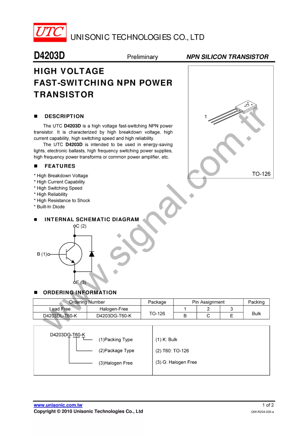
UNISONIC TECHNOLOGIES CO., LTD
D4203D
Preliminary
NPN SILICON TRANSISTOR
HIGH VOLTAGE
FAST-SWITCHING NPN POWER
TRANSISTOR
DESCRIPTION
.tr
om
The UTC D4203D is a high voltage fast-switching NPN power
transistor. It is characterized by high breakdown voltage, high
current capability, high switching speed and high reliability.
The UTC D4203D is intended to be used in energy-saving
lights, electronic ballasts, high frequency switching power supplies,
high frequency power transforms or common power amplifier, etc.
FEATURES
na
l
.c
* High Breakdown Voltage
* High Current Capability
* High Switching Speed
* High Reliability
* High Resistance to Shock
* Built-In Diode
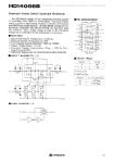
INTERNAL SCHEMATIC DIAGRAM
ig
C (2)
w
.s
B (1)
E (3)
ORDERING INFORMATION
w
w
Ordering Number
Lead Free
Halogen-Free
D4203DL-T60-K
D4203DG-T60-K
www.unisonic.com.tw
Copyright © 2010 Unisonic Technologies Co., Ltd
Package
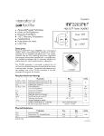
TO-126
1
B
Pin Assignment
2
C
Packing
3
E
Bulk
1 of 2
QW-R204-026.a
D4203D
Preliminary
NPN SILICON TRANSISTOR
ABSOLUTE MAXIMUM RATINGS (TC=25°C)
THERMAL DATA
om
.tr
PARAMETER
SYMBOL
RATINGS
UNIT
Collector- Base Voltage
VCBO
700
V
Collector-Emitter Voltage (IB=0)
VCEO
400
V
Emitter-Base Voltage
VEBO
9
V
Collector Current (DC)
IC
2.0
A
Collector Current (pulse)
ICP
4.0
A
Total Power Dissipation
PC
20
W
Junction Temperature
TJ
150
°C
Storage Temperature
TSTG
-55 ~ +150
°C
Notes: 1. Absolute maximum ratings are those values beyond which the device could be permanently damaged.
Absolute maximum ratings are stress ratings only and functional device operation is not implied.
2. Pulse Test: Pulse Width = 5.0ms, Duty Cycle < 10%.
PARAMETER
SYMBOL
θJC
Junction to Case
ELECTRICAL CHARACTERISTICS
PARAMETER
Collector-Emitter Sustaining Voltage
Collector -Base Breakdown Voltage
Emitter-Base Breakdown Voltage
Collect - Base Cut-off Current
Collect - Emitter Cut-off Current
Emitter - Base Cut-off Current
DC Current Gain
TEST CONDITIONS
IC=10mA, IB=0
IC=1mA, IE=0
IE =1mA, IC=0
VCB=680V, IE=0
VCE=400V,IB=0
VEB=7V, IC=0
VCE =5V, IC=5mA
VCE =10V, IC=200 mA
IC=0.5A, IB=0.1A
IC=1.5A, IB=0.5A
IC=1A, IB=0.25A
MIN
400
700
9
6
8
ig
Collector-Emitter Saturation Voltage
SYMBOL
VCEO(SUS)
BVCBO
BVEBO
ICBO
ICEO
IEBO
hFE1
hFE2
VCE(SAT)1
VCE(SAT)2
VBE(SAT)
tF
tS
fT
na
l.c
RATINGS
6.25
VCC=24 V, IC=2A, IB1=-IB2=0.4A
VCE=10V, IC=0.5A
4
MAX UNIT
V
V
V
100
μA
50
μA
10
μA
40
40
0.5
V
2
V
1.8
V
0.7
μs
4
μs
MHZ
w
w
w
.s
Base-Emitter Saturation Voltage
Fall Time
Resistive Load
Storage Time
Current Gain Bandwidth Product
TYP
UNIT
°C/W
UTC assumes no responsibility for equipment failures that result from using products at values that
exceed, even momentarily, rated values (such as maximum ratings, operating condition ranges, or
other parameters) listed in products specifications of any and all UTC products described or contained
herein. UTC products are not designed for use in life support appliances, devices or systems where
malfunction of these products can be reasonably expected to result in personal injury. Reproduction in
whole or in part is prohibited without the prior written consent of the copyright owner. The information
presented in this document does not form part of any quotation or contract, is believed to be accurate
and reliable and may be changed without notice.
UNISONIC TECHNOLOGIES CO., LTD
www.unisonic.com.tw
2 of 2
QW-R204-026.a