/


Tags: military affairs engineering design handbook
Year: 1965
Similar


Text
AMC PAMPHLET
АМСР 706-179
ENGINEERING DESIGN HANDBOOK
EXPLOSIVES SERIES
EXPLOSIVE TRAINS
HEADQUARTERS, U. S. ARMY MATERIEL COMMAND
MARCH 1965
HEADQUARTERS
UNITED STATES ARMY MATERIEL COMMAND
WASHINGTON, D.C. 20315
9 March 1965
AMCP 706-179, Explosive Trains, forming part of the Explosives
Series of the Army Materiel Command Engineering Design Handbook
Series, is published for the information and guidance of all concerned.
(AMCRD)
FOR THE COMMANDER:
SELWYN D. SMITH, JR.
Major General, USA
Chief of Staff
OFFICIAL:
S T A NLEСК I
Colonel, GS
Chief, Administrative Office
DISTRIBUTION: Special
PREFACE
The Engineering Design Handbook Series of the Army Materiel Command is
a coordinated series of handbooks containing basic information and fundamental
data useful in the design and development of Army materiel and systems. The
handbooks are authoritative reference books of practical information and quanti-
tative facts helpful in the design and development of Army materiel so that it
will meet the tactical and the technical needs of the Armed Forces. The present
handbook is one of a series on explosives.
This handbook presents theoretical and practical data pertaining to explosive
trains. It includes consideration of the various elements which, in considerable
variation, may constitute the explosive train of an item. The main charge of an
explosive item, such as projectile or warhead filler, is also covered. Data are
given on the physical and explosive characteristics of typical explosives and
references are cited in which additional data will be found.
Coverage includes development of the complete explosive train, from ele-
ments suitable for initiation of the explosive reaction to the promotion of effective
functioning of the final, output element. The nature of the explosive reaction,
method of transfer of detonation and measurement of output are discussed.
Design principles and data pertaining to primers, detonators, delay elements,
leads, boosters, main charges and specialized explosive elements are covered.
The effects of environmental conditions and steps to be taken to avoid difficulties
are discussed.
This handbook has been prepared as an aid to ammunition designers. It
should also be of benefit to scientists and engineers engaged in research and
development programs or who have responsibility for the planning and interpre-
tation of experiments and tests relating to the performance of ammunition or
ammunition components.
The handbook was prepared by The Franklin Institute, Philadelphia, Pennsyl-
vania, based on a manuscript prepared by Armour Research Foundation of the
University of Illinois Institute of Technology. The handbook was prepared for
the Engineering Handbook Office of Duke University, prime contractor to the
Army Research Office-Durham. The Explosive Series is Under the technical
guidance and coordination of a special committee with representation from
Picatinny Arsenal and Frankford Arsenal of the Munitions Command, and the
Ballistic Research Laboratories. Chairman of this committee was Mr. Donald
Seeger of Picatinny Arsenal.
Elements of the U. S. Army Materiel Command having need for handbooks
may submit requisitions or official requests directly to Publications and Repro-
duction Agency, Lettcrkenny Army Depot, Chambersburg, Pennsylvania 17201.
Contractors should submit such requisitions or requests to their contracting
officers.
Comments and suggestions on this handbook are welcome and should be
addressed to Army Research Office-Durham, Box CM, Duke Station, Durham,
North Carolina 27706.
TABLE OF CONTENTS
Page
Preface........................................................... i
List of Illustrations........................................... vii
List of Tables................................................... ix
List of Symbols................................................... x
Part One —Fundamental Principles
Chapter 1. Explosive Charges as Components of Weapon Systems
A. Introduction
1. Purpose........................................................ 1
2. The Explosive Train..................................... 1
3. Bases for Selecting Explosive Charges................... 3
B. Systems Approach to Ammunition
4. Vehicular Aspects.............................................. 4
5. Structural Aspects...................................... 6
6, Mechanical Aspects...................................... 7
7. Electrical Aspects...................................... 9
C. General Design Considerations
8. Economics...................................................... 9
9. Reliability............................................ 10
10. Safety................................................. 10
11. Standardization...................................... 1 1
12. Information Sources.................................... 11
Chapter 2. Explosive Reactions and Initiation
A, Thermal Decomposition and Burning
13. Thermal Decomposition............................ 13
14. Reaction Kinetics...................................... 13
15. The “Hot Spot” Theory of Initiation.................... 15
16. Deflagration........................................... 16
B. Detonation
17. Transition from Deflagration to Detonation.......,,,. 17
18. Shock Waves............................................ 19
19. Detonation Waves....................................... 20
C. Initiation
20. Establishing a Self-Propagating Reaction.............. 23
21. Initiation by Heat..................................... 25
22. Initiation by Impact................................... 28
23. Initiation by Other Means.............................. 29
References....................................................... 32
Chapter 3. Detonation Transfer and Output
A. Effectiveness of One Charge in Initiating Another
24. Detonation Propagation...................................... 33
25. Dimensional Interactions............................... 34
iii
TABLE OF CONTENTS (Continued)
Fage
B. Sensitivity to Initiation
26. Sensitivity Tests...................................... 35
27. Variables Affecting Sensitivity........................ 37
28. Misaligned Charges..................................... 40
C. Output
29. Nature of Explosive Output............................. 41
30. Effect of Charge Configuration......................... 41
31. Blast.................................................. 42
32. Fragmentation.......................................... 44
33. Other Effects.......................................... 45
References....................................................... 47
Chapter 4. Environmental Response
34. Military Requirements............................................... 48
A. Temperature
35. High Temperature Storage............................... 49
36. Cook-Off............................................... 51
37. Other Effects of High Temperature Use.................. 53
38. Low Temperature Storage and Use...................... 54
B. Environment
39. Chemical Interactions.................................. 55
40. Simulation of Impact................................... 57
41. Setback Acceleration................................... 58
42. Other Effects.......................................... 59
References...................................................... 61
Part Two —Design Considerations
43. Introduction........................................................ 62
Chapter 5. Primers and Detonators
A. Description and Selection
44. Function and Construction.................................... 62
45. Initiator Types....................................... 63
46. Bases for Selecting an Initiator Type.................. 65
B. Input Characteristics
47. Stab Initiators............................................. 66
48. Percussion Primers..................................... 66
49. Flash Detonators...................................... 67
50. Electric Initiators................................... 67
C. Output Characteristics
51. Output of Primers............................................ 72
52. Output of Detonators................................... 73
D. Construction and Fabrication
53. Initiator Cups............................................... 75
54. Explosive Loading...................................... 77
55. Mechanical Initiators.................................. 77
56. Electric Initiators................................... 77
References....................................................... 79
iv
TABLE OF CONTENTS (Continued)
Page
Chapter 6. Delay Elements
A. Description
57. Function and Construction............................. 80
58. Delay Types........................................... 80
59. Relays................................................ 82
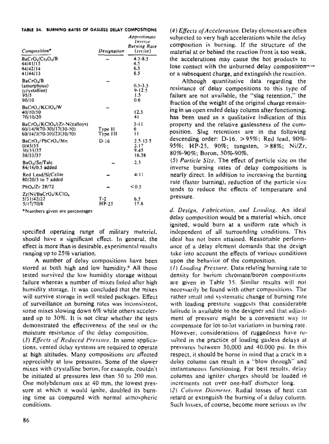
B. Delay Compositions
60. Gas Producing Delay Charges........................... 82
61. Gasless Delay Charges................................. 84
C. Design Principles
62. Obturated vs. Vented Design........................... 87
63. Design Rules of Thumb................................. 87
References...................................................... 88
Chapter 7. Leads and Boosters
A. Description
64. General.............................................. 89
65. Functions............................................. 89
66. Explosives............................................ 90
B. Design Considerations
67. Relation to Fuze Design............................... 92
68, Leads................................................. 92
69. Boosters.............................................. 93
70. Charge Density Effects................................ 94
71. Output Wave Profile................................... 95
C. Construction and Fabrication
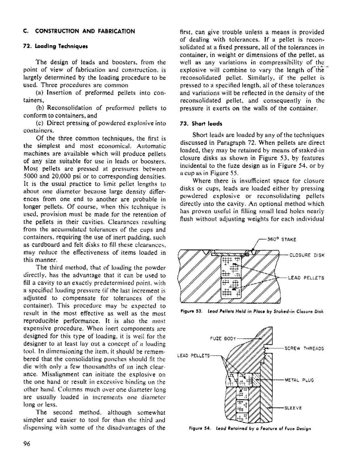
72. Loading Techniques.................................... 96
73. Short Leads........................................... 96
74. Long Leads............................................ 97
75. Boosters.............................................. 98
References...................................................... 99
Chapter 8. Main Bursting Charge
A. Description
76. Function............................................. 100
77. Typical Main Bursting Charges........................ 100
78. Size and Weight...................................... 102
B. Initiation
79. Sensitivity.......................................... 102
80. Explosive Loading................................... 103
81. Booster Position..................................... 103
82. Auxiliary Boosters and Boosted Surrounds............. 103
83. Confinement.......................................... 103
References..................................................... 104
Charier 9. Other Explosive Charges
A. Actuators
84. Description......................................... 105
85. Output Characteristics............................... 106
v
TABLE OF CONTENTS (Concluded)
Page
B. Demolition Devices and Accessories
86. Destructors.................................................. 106
87. Explosive Tubes and Sheets............................ 107
88. Demolition Blocks..................................... 107
89. Explosive Bolts....................................... 108
References...................................................... 108
Chapter 10. Loading and Fabrication
90. Process Selection.................................................. 109
A. Casting
91. Projectile Preparation................................. 109
92. Effect of Casting Procedure on Charge Characteristics... 109
93. Standard Casting Procedure............................ 110
94. Some Special Casting Techniques...................... 1 10
B. Pressing
95. Standard Procedures.................................... Ill
96. Special Procedures.................................... 116
C. Finishing Operations
97. Machining.................................................... 117
98. Cementing of Compound Charges....................... 118
D. Suitability
99, Availability................................................. 118
100. Output Characteristics.............................. 1 19
tOt. Sensitivity........................................... 119
102. Chemical and Physical Properties..................... 120
E. Quality Control
103. Bases for Tolerances....................................... 121
104. Factors Affecting Quality of Explosive Charges....... 121
References...................................................... 122
Chapter 11. Evaluation Procedures
A. Considerations in Evaluation
105. Safety and Reliability Criteria........................... 123
106. Statistical Test Methods.............................. 127
B. Testing Techniques
107. Explosive Materials................................... 128
108, Input................................................. 133
109. Output................................................ 135
110. Environment.......................................... 136
References.................................................... 139
Glossary Of Key Terms....................................... 140
Index.......................................................... 142
vi
LIST OF ILLUSTRATIONS
Figure Page
1 Typical Explosive Train.............................................. 2
2 Computed Explosive Reaction Rates................................... 14
3 Arrangement Used in Observations of Detonation Growth............... 17
4 Formation and Incipient Decay of Shock Wave from Wave of Finite
Amplitude............................................................... 21
5 Energy-Power Relationship for Various Initiators.................... 24
6 Typical Effect of Bridgewire Volume on Input Characteristics........ 25
7 Threshold Conditions for Initiation of Various Explosives in a Shock
Tube.................................................................... 27
8 Input Sensitivity vs. Explosion Temperature......................... 28
9 Standard Firing Pin for Stab Initiators............................. 29
10 Energy-Velocity Relationship for Percussion Primers................. 30
11 Streak Camera Record of Detonation.................................. 33
12 Critical Gap as a Function of Column Diameter....................... 34
13 Critical Axial Air Gaps Across Which Detonation Is Transmitted
Between Lead Azide and Tetryl........................................... 35
14 Small Scale Air Gap Test............................................ 35
15 Minimum Priming Charge and Gap for Critical Propagation........ 36
16 Small Scale Lucite Gap Test........................................ 37
17 Effect of Voids on Booster Sensitivity (Wax Gap Test)............... 38
18 Effect of Voids on Booster Sensitivity (Lucite Gap Test)............ 38
19 Effect of Acceptor Confining Material upon Sensitivity in an Air Gap
Test.............................................................. 39
20 Gap Sensitivity Related to Density and Hardness of Acceptor Con-
fining Medium........................................................... 40
21 Arrangement for Propagation of Misaligned Charges................... 41
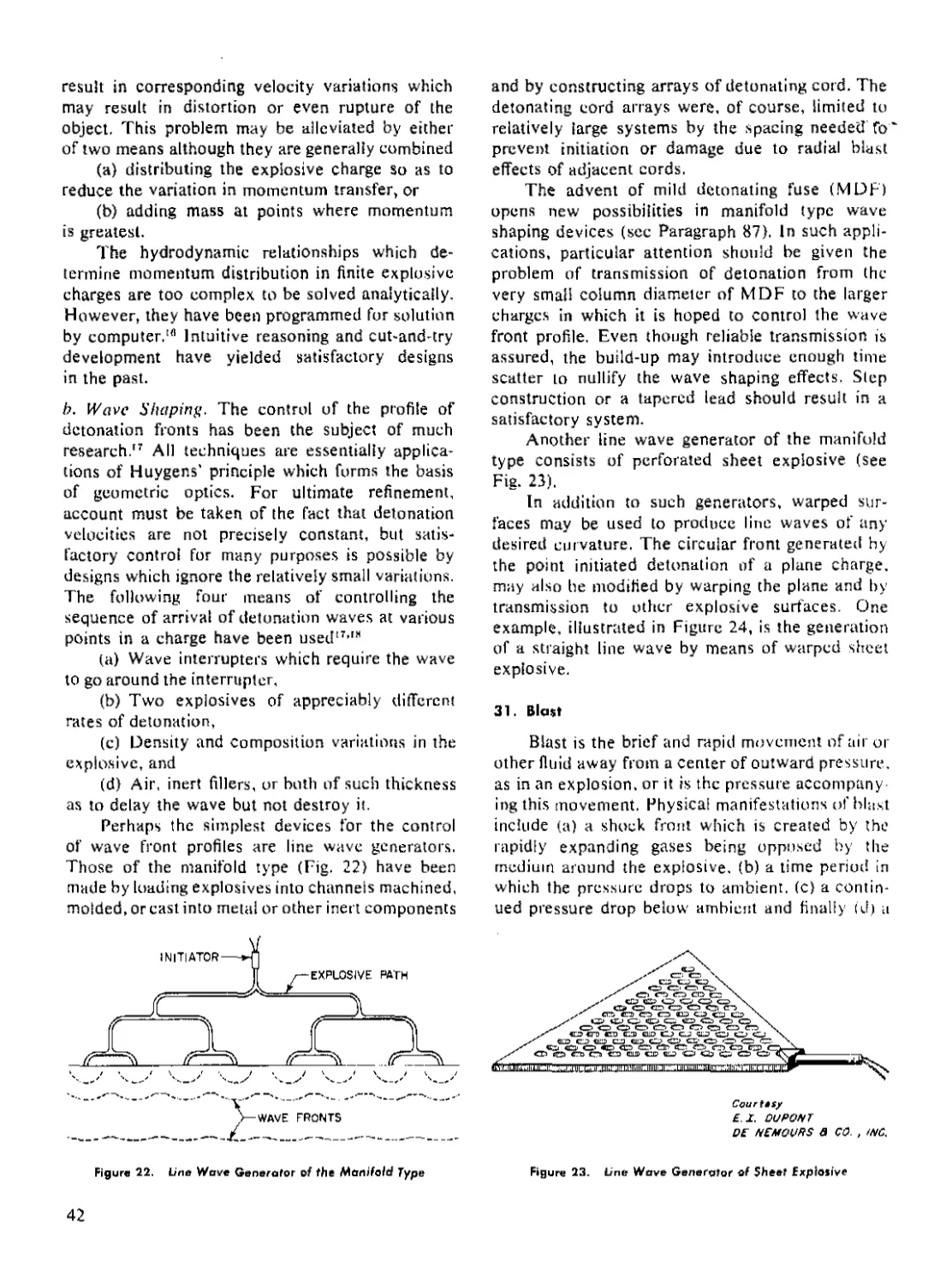
22 Line Wave Generator of the Manifold Type......................... 42
23 Line Wave Generator of Sheet Explosive........................... 42
24 Line Wave Generator of Warped Sheet of Explosive................. 43
25 Pressure-Time Relationship of Explosive Blast....................... 43
26 Postulated Condition for Initiator Failure Caused by Wire-Explosive
Separation.............................................................. 51
27 Test of a Booster in Simulated Missile Flight....................... 52
28 Cook-Off Characteristics of Three Explosives........................ 53
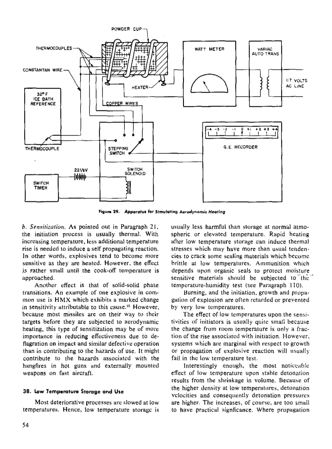
29 Apparatus for Simulating Aerodynamic Heating........................ 54
30 Simulated Aerodynamic Heat Test..................................... 55
31 Typical Time-Acceleration Curve for Projectile While in Gun....... 58
32 Typical Primers and Detonators (Mechanical)......................... 63
33 Typical Primers and Detonators (Electrical)......................... 64
34 Electric Squib (М2)................................................. 64
35 Stab-Electric Detonator (T29)....................................... 64
36 Functioning Times of Hot Wire Bridge Initiators..................... 70
37 Coined Bottom Cup................................................... 76
38 Punch Trimming of Initiator Cups.................................... 76
39 Initiator Cup Crimping.............................................. 76
40 Obturated Delay Element of Bomb Fuze ANM100A2....................... 81
41 Electric Delay Detonator (MARK 35 MOD I)............................ 81
42 Electric Delay Detonator (T65)...................................... 82
43 Scaling Methods for Vented Delays................................... 82
44 Fuze M54............................................................ 82
vii
LIST OF ILLUSTRATIONS (Concluded)
Figure Page
45 Pressure Type Delay................................................ 83
46 Typical Explosive Relays........................................... 83
47 Support of Delay Pellet............................................ 84
48 Characteristics of an Obturated Black Powder Delay Element....... 85
49 Booster (М21A4).................................................... 90
50 2.75-in. HEAT Rocket with Spit-Back Explosive System............... 90
51 20mm Fuze (M5O5)................................................... 91
52 Critical Conditions for Detonation of Lead....................... 93
53 Lead Pellets Held in Place by Staked-in Closure Disk............. 96
54 Lead Retained by a Feature of Fuze Design........................ 96
55 Lead Retained by a Cup........................................... 97
56 Explosive Loaded by Breaking off Excess.......................... 97
57 Lead End Coated with Sealant..................................... 97
58 Lead Cup Crimped in Place........................................ 97
59 Chamfered Booster Pellet........................................... 98
60 Improper Charging of Cup......................................... 98
61 High Explosive Projectile......................................... 101
62 Armor Piercing Projectile......................................... 101
63 General Purpose Bomb.............................................. 101
64 Antitank Mine (M15)............................................... 101
65 High Explosive Antitank Projectile............................... 101
66 Burster Type Chemical Projectile................................. 101
67 Dimple Motor (T3E1).............................................. 105
68 Bellows Motor (TSEI)............................................. 105
69 Piston Motor...................................................... 105
70 Multiple Contact Switch........................................... 106
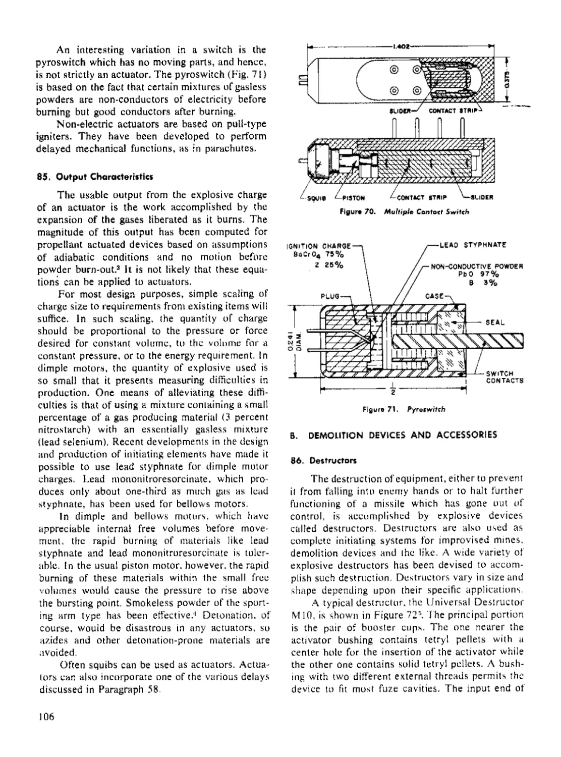
71 Pyroswitch........................................................ 106
72 Universal Destructor (M10)........................................ 107
73 Explosive Bolt in Which Reflected Tension Waves Are Utilized..... 108
74 Vacuum Casting Kettle............................................ 111
75 Scoop Loading..................................................... 112
76 Charging Plate Loading............................................ 112
77 Detonator Loading Tool............................................ 112
78 Tool for Direct Loading of Component.............................. 113
79 Nomograph of Loading Pressure-Density............................ 1 14
80 Pelleting Presses................................................. 115
81 Vacuum Pressing Apparatus......................................... 116
82 Hydrostatic Press Principle....................................... 117
83 Isostatic Press Principle......................................... 117
84 Cumulative Frequency Distribution for a Normally Distributed
Population........................................................... 124
85 Skewed Frequency Distribution Typical of Impact Sensitivity Data 125
86 Picatinny Arsenal Impact Test Apparatus........................... 129
87 Booster Sensitivity Test (Wax Gap)................................ 130
88 Apparatus Which Simulates Setback Pressure........................ 131
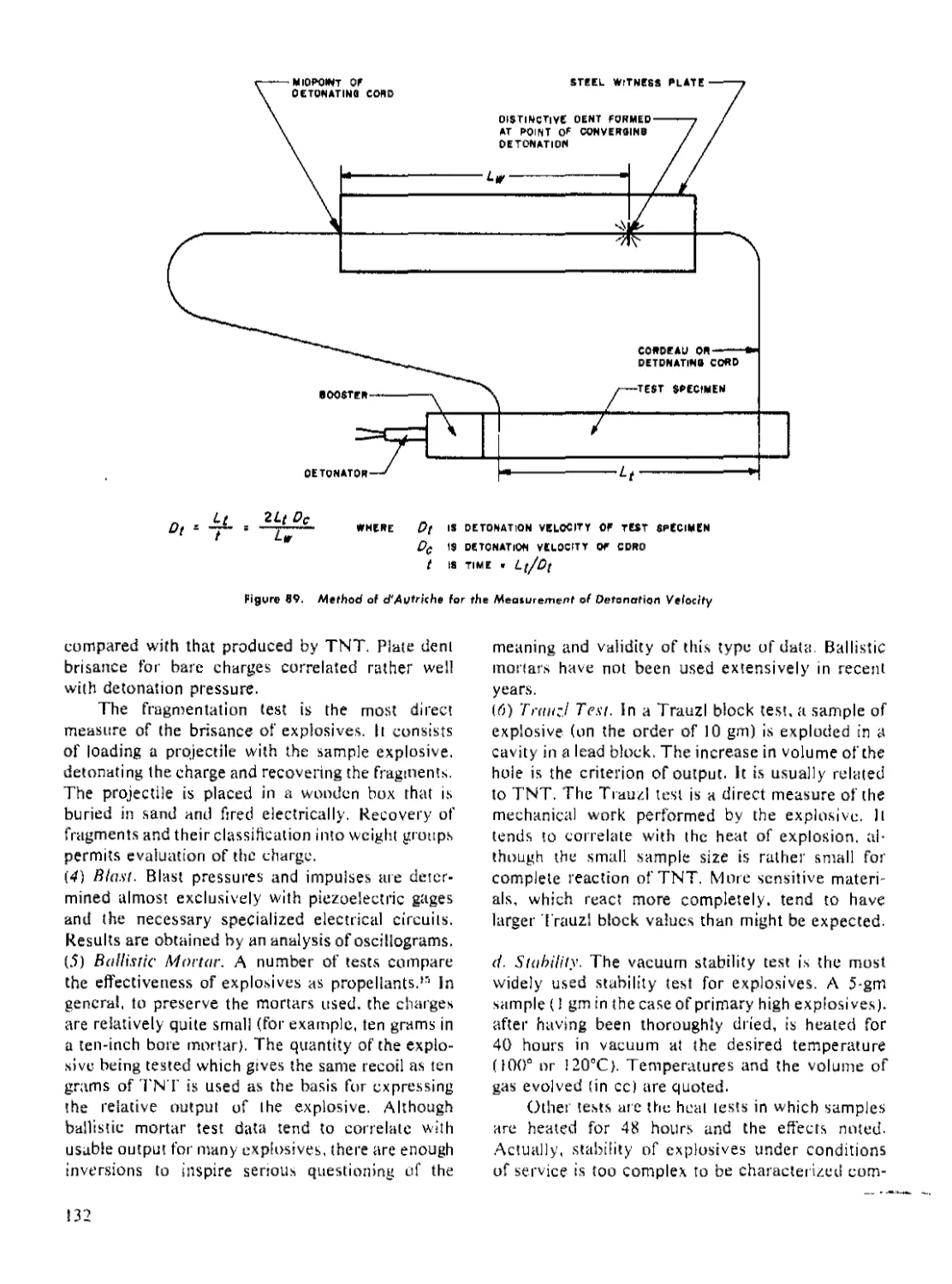
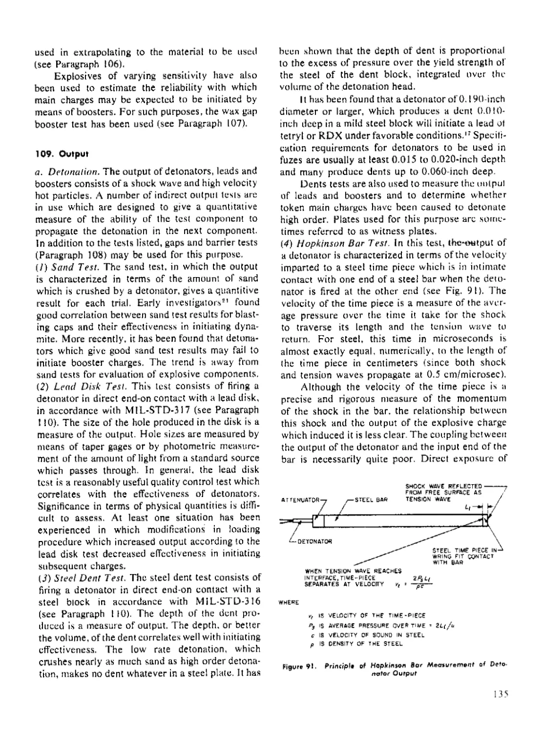
89 Method of d’Autriche for the Measurement of Detonation Velocity.. 132
90 Typical Condenser Discharge Firing Circuit for Testing Electric
Initiators............................................................ 133
91 Principle of Hopkinson Bar Measurement of Detonator Output....... 135
92 Arrangement for Detonator Safety Test............................. 138
viii
LIST OF TABLES
Table Page
1 Values of Acceleration in Ammunition..................................... 6
2 Ignition and Explosion Temperatures.................................... 15
3 Values of the Constant C in Equation 6................................. 17
4 Optimum Loading Densities and Particle Sizes for Growth of Detona-
tion in RDX, HMX and PETN................................................. 18
5 Detonation Velocity Constants for Equation 20.......................... 22
6 Detonation Conditions, Calculated and Measured......................... 22
7 Sensitivity of Various Explosives in Wire Bridge Initiators............ 26
8 Effect of Loading Pressure on Initiator Sensitivity.................... 29
9 Initiation of Explosion by Friction of PETN in the Presence of Grit 30
10 Threshold Ignition Energies............................................ 31
11 Densities and Shock Velocities in Various Metals........................ 35
12 Typical Results of Booster Sensitivity Test............................ 36
13 Initiation Sensitivity Measured by Several Tests....................... 36
14 Relation of Decibangs to Gap Thickness................................. 37
15 Sensitivities of Some Explosives According to the Small-Scale Lucite
Gap Test................................................................... 37
16 Effect of 5 Percent D-2 Wax on the Booster Sensitivity of Various
Cast Explosives (Wax Gap Test)............................................. 39
17 Air Gap Sensitivity Related to Acoustic Impedance of Acceptor Con-
fining Medium.............................................................. 39
18 Sensitivity for Various Spacer Materials (Wax Gap Test).............. 40
19 Gurney Constant for Common Explosives.................................. 44
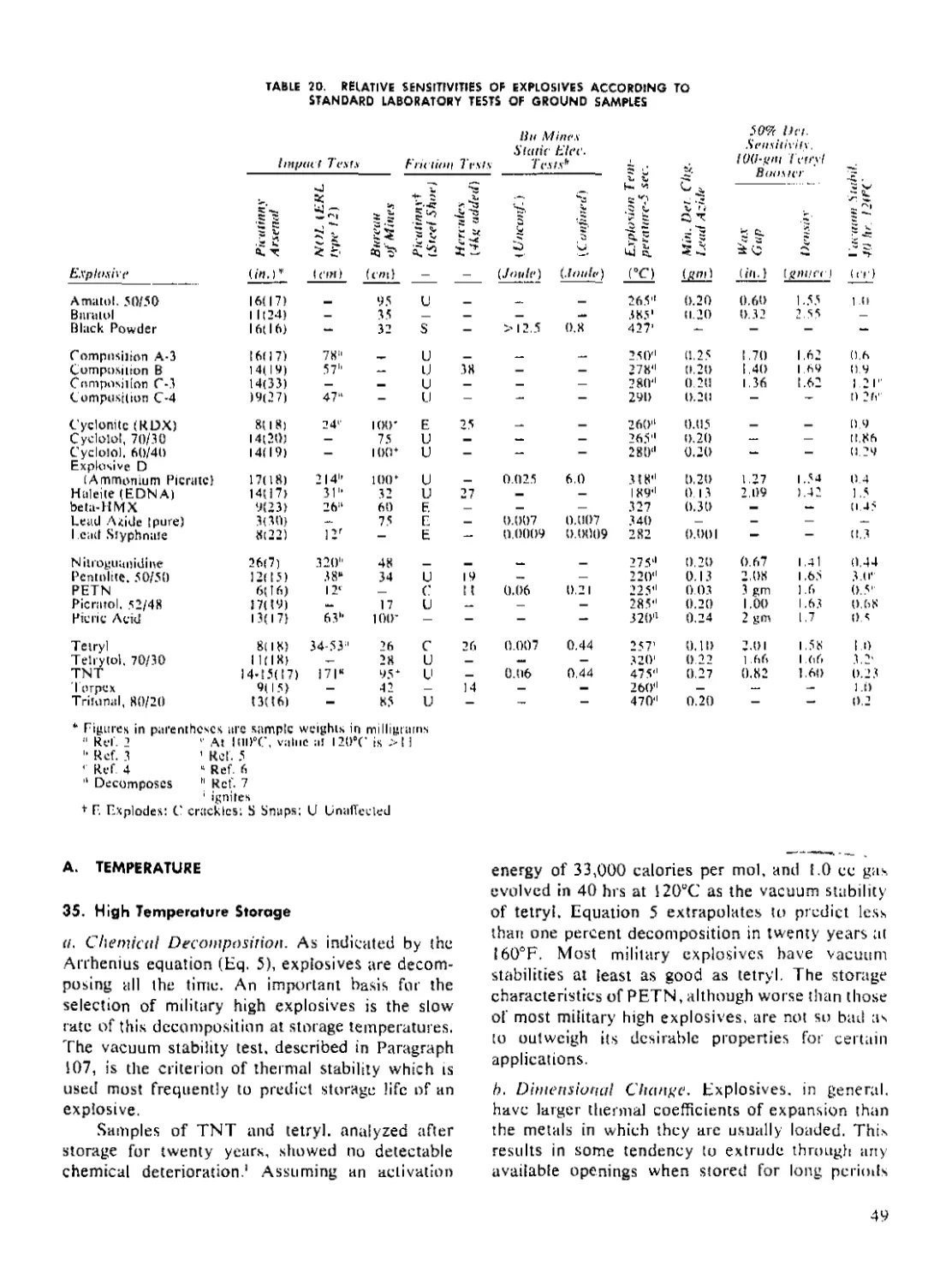
20 Relative Sensitivities of Explosives According to Standard Laboratory
Tests of Ground Samples.................................................... 49
21 Sensitivity of Explosives to Hazards of Use............................ 50
22 Cook-Off Tests of Standard and Modified M47 Detonators.............. 53
23 Compatibility of High Explosives with Metals and Miscellaneous
Materials................................................................ 56
24 Bullet Sensitivity of 50/50 Pentolite................................. 57
25 Critical Setback Pressures of Explosives of Various Size Base
Separations................................................................ 58
26 Data Obtained from Explosives After Exposure to Gamma Radiation 60
27 Common Priming Compositions............................................ 66
28 Effect of Sealing Cup or Disk on Sensitivity........................... 66
29 Resistivities of Bridgewire Materials.................................. 68
30 Firing Times of Hot Bridgewire Initiators.............................. 70
3 1 Heats of Explosion and Detonation Pressures......................... 74
32 Gasless Delay Compositions in Current Use.............................. 84
33 Ignition Powders for Gasless Delay Elements............................ 84
34 Burning Rates of Gasless Delay Compositions............................ 86
35 Effect of Loading Pressure on BaCrO4-B Compositions.................... 87
36 Failure Diameters of Lead and Booster Explosives....................... 93
37 Loading Density of Various Explosives................................. 113
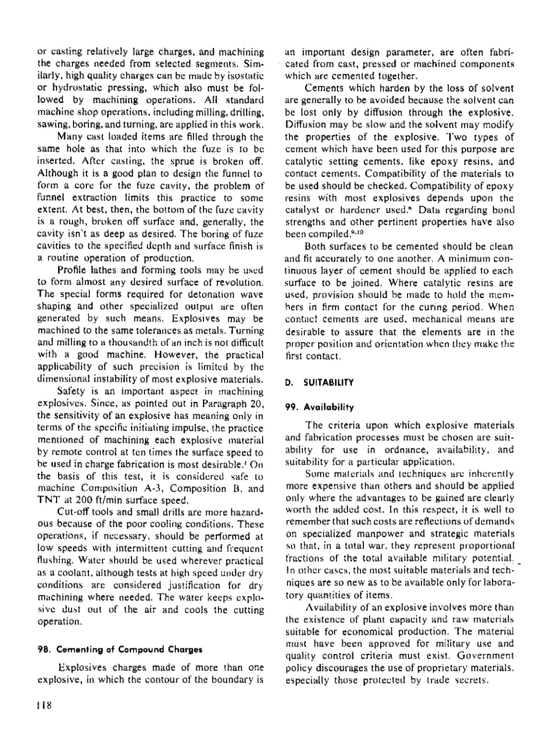
38 Fundamental Characteristics of Explosive Compounds.................... 120
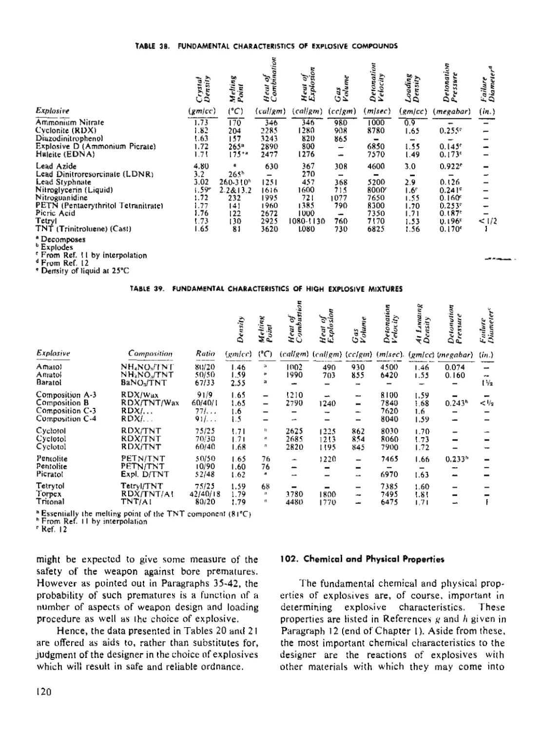
39 Fundamental Characteristics of High Explosive Mixtures................ 120
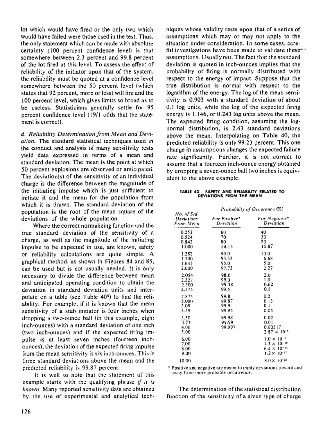
40 Safety and Reliability Related to Deviations from the Mean.......... 126
41 M1L-STD Tests for Fuzes............................................... 137
ix
LIST OF SYMBOLS
A constant m mass
a acceleration n number
В Brinell hardness n polytropic exponei
В Constant P pressure
С capacitance R burning rate
с heat capacity R resistance
Ср thermal mass R universal gas constant
Со velocity of sound r radius
D detonation velocity Гщ resistivity
d depth of dent T temperature
d diameter T, stagnation temperature
Е modulus of elasticity t time
Е voltage и particle velocity
V2E Gurney constant V voltage
Е constant V volume
G constant V velocity
G gap w energy
8 acceleration of gravity W weight
Н agitational energy X sensitivity stimulus in decibang units
1 current У thickness
К Constant a co volume of gas
к thermal conductivity У cooling rate coefficient
к' reaction rate У failure rate
L inductance У ratio of specific heats
L length P density
М Mach number
SUBSCRIPTS
c case, charge о reference condition
d delay composition P priming composition
f firing temperature r recovery, reference
i insulation s short
I long t threshold, test
m metal
x
EXPLOSIVE TRAINS*
PART ONE-FUNDAMENTAL PRINCIPLES
CHAPTER 1
EXPLOSIVE CHARGES AS COMPONENTS OF WEAPON SYSTEMS
A. INTRODUCTION
1. Purpose
This handbook is one in the series of Engineer-
ing Design Handbooks dealing with explosives. Il
covers the principles and factors applicable to the
design of the various individual elements which are
parts of an explosive train. These elements include
primers, detonators, relays, delays, leads, boosters
and main bursting charges. In addition, principles
and factors involved in the design of explosive
items such as actuators, explosive switches and
destructors, which are usually not elements of the
main explosive train of a military item, are men-
tioned, particularly where the principles differ from
those applicable to the main train.
The phenomena of initiation, deflagration and
detonation and their interaction with effects pro-
duced in surrounding materials are discussed with
particular emphasis on those aspects which are
important to designers of explosive charges. Also
discussed are evaluation procedures, loading
methods, and the effects of design upon the proba-
bility of accidental initiation, upon reliability, and
upon the useful life of an item.
2, The Explosive Train
An explosive train is an assembly of explosive
elements arranged in order of decreasing sensitivity.
The function of the explosive train is to accomplish
the controlled augmentation of a small impulse
into one of suitable energy to cause the main charge
of the munition to function.
Explosive trains may be divided into two gen-
era! classes, high explosive trains and low explosive
trains, according to the type of explosive used in
the main charge.! An explosive train may also be
designated according to the item in which it is
assembled or to which it pertains. One of the most
common examples of the high explosive trains is
the fuze explosive train. If the bursting charge is
added, it is commonly called a bursting charge
explosive train. A common example of the low
explosive train is the propelling charge explosive
train.
Propelling charge explosive trains and other
low explosive trains are covered in other hand-
books of the Series. Unless otherwise indicated,
the term explosive train in this handbook signifies
a high explosive train.
The explosive or combustible elements of a
fuze explosive train are so arranged that
(a) they can be activated in the desired manner,
(b) on functioning, they will produce the de-
sired effect reliably, and
(c) the probability of premature functioning is
minimized for all foreseeable conditions of handling,
storage, transport and use.
Essential elements of such an assembly are
generally
(a) A primary or low explosive charge, con-
tained in a suitable housing, that is capable of (1)
being activated by a relatively small stimulus
(mechanical or electrical) and (2) producing a self-
propagating reaction. The output of this initial
charge consists principally of relatively low velocity
hot gases and particles.
* Prepared by Gunilier Cohn, 1 aboraiories for Research and
Development of The franklin Instittue. based on a manuscript
written by R. H. Stresan for Armour Research [mindaiion of
(he 1 llimns Institute of 1 echnoiogy.
lor more (iclailed definitions of explosive m: i г и г i a I. tfr.'
Glossary al 1 tre t?nJ of this handbook.
(b) An intermediate charge of primary high
explosive (most commonly lead azide) in which the
transition from burning to detonation takes place.
(c) A secondary high explosive charge (for
example, RDX) that intensifies the shock output
from the intermediate charge, and
(d) A main charge consisting of a secondary
high explosive (for example, TNT) that produces
the desired effect.
Auxiliary elements which are almost always
included in an explosive train for convenience of
design and for special purposes are
(a) Leads and relays to transmit explosive
reactions between spatially separated elements,
(b) Delay or time element to increase the
interval between activation of the first explosive
element and functioning of the main charge, and
(c) A booster which is sensitive enough to be
initiated by relatively small output of a secondary
high explosive charge and powerful enough to
initiate the insensitive secondary high explosive
usually used for the main charge.
A number of auxiliary elements are used in
some ordnance items which are complete explosive
trains in themselves to accomplish specific tasks
(a) Actuators
(b) Explosive bolts
(c) Destructors
Note that the foregoing description applies
mainly to the most common explosive train, namely
one resulting in high explosive functioning. Where....
the output is nonexplosive, the train is essentially
the same through initiation and auxiliary compo-
nents. However, the explosive train usually never
proceeds beyond the burning stage initiated by the
primer charge. Examples of such nonexplosive
applications are signal flares, smoke bombs, pro-
pellant systems, parachute packs and leaflet bombs.
Figure 1 shows a simple explosive train.
Pictured in schematic form is the M5O5 nose fuze
which is used with 20mm ammunition. The fuze is
shown in both armed and unarmed conditions but
details of mechanical construction have been
omitted. While important, these features are beyond
ARMED
Figure T. Typical Explosive Train
UNARMED
2
the scope of this handbook (for an assembly draw-
ing of this fuze, see Fig, 51).
In the armed condition, the fuze is ready to
function. When it strikes the target, the following
sequence of actions take place
(a) The stab firing pin strikes the input end of
the M47 detonator, piercing the thin metal disk and
pushing into the primer charge. This stabbing
causes a reaction to be initiated in the primer charge.
(b) The primer charge initiates the intermedi-
ate charge of lead azide which is also contained in
the detonator. Here the action is accelerated and
converted to a detonation.
(c) The detonation of the lead azide is trans-
mitted to the RDX base charge of the detonator
and is amplified.
(d) The RDX booster and top off charges serve
to amplify the detonation wave to insure proper
initiation of the main charge in the projectile.
In a superquick fuze, such as this one, this
entire sequence takes place in only a few micro-
seconds, whereas in a fuze having delayed action,
the interval between activation of the primer charge
and explosion of the main charge may be as much
as several hundred milliseconds. Such a delay may
be introduced by a special pyrotechnic charge,
which burns at a definite rate, between primer and
intermediate charges.
The rotor in which the detonator is assembled
is aligned with the remainder of the explosive train
through the action of linear and rotational forces
encountered during propelling the projectile from
the gun. In the unarmed view (Fig. Г) the fuze is in
the safe or out-of-line position. The purpose of this
safety feature of fuzes is to isolate physically the
more sensitive explosives of the explosive train
from the main charge. Since the more sensitive
explosives are more susceptible to accidental initi-
ation, they will not propagate to the main charge,
if initiated, when they are in the out-of-line position.
3. Boses for Selecting Explosive Charges
When the designer is ready to build an ex-
plosive train, he must make a variety of decisions.
Before he can select the explosive charges, he must
have a clear idea of the input Stimulus that will be
used to start his system and of the final output the
system is to have. Between these two extremes, he
must assemble a variety of explosive components.
This complete system will then make up the ex-
plosive train.
Since the objective of the explosive train is to
function the main bursting charge, it is logical to
consider it first. This charge is designed so as to
deliver the output which is required of the ammuni-
tion. While the output is invariably specified for all
design requirements, it is usually given in terms
which the explosive charge designer cannot use
directly.
Specifications start with the user who has a
requirement. For example, the user may want to
defeat a tank, to cause personnel casualties or to
produce a signal. Next, the ammunition designer
translates these needs into terms of specific am-
munition. He may call for a 90mm HEAT round to
be fired from a recoilless rifle, a nonmetallic mine
to be triggered by foot pressure, or a marker
projectile delivering a red smoke puff lasting for
20 seconds. At this point, the explosive charge
designer takes over. He will specify the weight and
configuration of the main high explosive charge in
the HEAT projectile, the amount of charge in the
mine and, together with the ammunition designer,
will fix the size of the mine to result in the desired
effects, or he will specify the weight and configura-
tion of the HE burster charge and the composition
of the chemicals to produce the smoke puff.
Where the design calls for high explosives in a
projectile, bomb, or the like for which caliber is
either specified or the shape of which is fixed by
ballistic considerations, the task of designing the
output charge is fairly straightforward. The given
container is filled with as much explosive as will lit.
Seventy percent of the total weight of a light-case
bomb, for example, is high explosive filler. Design
principles for blast (Paragraph 31) and for frag-
mentation (Paragraph 32) are we'l established.
Explosives for chemical charges must burst the
case and disseminate the contents efficiently. The
design of main charges is discussed in Paragraphs
76 to 83.
At the other end of the train is the initiator.
Selection and design of the proper first element in
the explosive train is probably the most difficult
step. For this reason, this subject is treated in
depth by itself (Paragraph 46). The design of initia-
tors is covered in Paragraphs 44 to 56.
It is a basic safety requirement in almost all
ammunition that the initiator be kept out of line so
that the train will not propagate in the event of
accidental functioning of the sensitive initiator.
While the explosive charge designer is definitely
concerned with such safety devices, they are not
included in this handbook. The design, construc-
3
tion, layout, and evaluation of the various safety
and arming devices are covered in texts on fuze
design.
The next clement to be considered is the
booster charge. Most high explosive ammunition
has boosters. The booster is that charge which is
sensitive enough to be actuated by the small ex-
plosive elements on the one hand and powerful
enough to cause detonation of the main explosive
on the other hand. Tetryl and RDX are common
explosives which have these properties. The
booster charge is best placed into a cavity of the
main charge (the fuze well). The design of boosters
is covered in Paragraphs 64 to 75.
From the standpoint of train propagation, a
booster pellet is all that is required. However, for
reasons of safety and versatility, some military
ammunition calls for a complete booster containing
its own detonator and out-of-line arming device.
This secondary train is designed in the same manner
as the main train.
So far, we have Considered main charges and
boosters at the output end and initiators at the input
end. These three form the basic elements required
in every train. If the explosive train is for a small
device, no additional charges are necessary. Addi-
tional charges are added only to fill a particular need.
If there is to be a time interval between initia-
tion and functioning of the train, a delay element is
inserted. Often a relay is required at the end of the
delay to transform the deflagration of the burning
delay into a detonation wave. Delay elements are
described in Paragraphs 57 to 63.
A common explosive train charge is the lead.
Because of the geometry required to achieve bore
safety, detonator (or relay) and booster are sep-
arated too far for the detonation wave to travel.
This gap is filled with a lead, Leads contain the
same explosives as boosters. Leads are covered in
Paragraphs 64 to 75.
Sometimes functions other than initiation of
the main charge are required. Actuators exert a
force through a small distance to activate controls
or to close switches. Small and reliable, they are
ideally suited for remote control. Explosive bolts
and destructors are other examples of devices
serving auxiliary functions. These designs are
covered in Paragraphs 84 to 89.
Good design practice must be applied to all
explosive charges and to their assembly into a (rain.
Charges must be of the proper geometry and sensi-
tivity and must have the correct density and con-
lincmcnt as discussed in Paragraphs 24 to 28. They
musl be compatible with other explosives and with
metal parts. They must be safe to handle and must
stand the extremes of temperature in storage and
use as discussed in Paragraphs 34 to 42. The design
of explosive charges which make up safe and reli-
able trains has not yet been reduced to a formula.
Rather, it requires considerable experience. The
design of unusual trains, in particular, should never
be attempted by a novice.
After the design is completed, the train is ready
for thorough test and evaluation as discussed in
Paragraphs 105 to 110.
B. SYSTEMS APPROACH TO AMMUNITION
4. Vehicular Aspects
й. General. Most ammunition is projected to its
target over appreciable distances. Both maximum
velocities and ranges continue to increase with
improvements in propellants and design. Four
aspects of this motion must be considered by the
designer of explosive charges.
(a) Range and accuracy of a round depend
upon its aerodynamic characteristics. The external
contours dictated by aerodynamic considerations
are a limitation upon size and shape of the explosive
system.
(b) It is sometimes necessary to adapt the
design of explosive charges in order to distribute
the weight properly for flight stability.
(c) Velocities and flight times of many modem
missiles are such that aerodynamic heating has
introduced a whole new set of explosive-charge-
design problems.
(d) Acceleration forces during launching, flight
and impact arethe principal sources of the structural
loading of ammunition.
In addition to these more or less general con-
sequences of the functioning of military items as
vehicles, itis necessaryfor the designer of explosive
charges to consider special circumstances which
may arise as a result of transport systems. Accelera-
tions due to the mechanical action of rapid-fire
guns and launchers are sometimes quite appreciable
and have been known to produce undesirable re-
sults when they were not taken into consideration
during design. Chambers of rapid-fire weapons are
heated in the course of long bursts to temperatures
which can cause functioning of rounds tiiat remain
in them when firing stops.
The limitations on explosive charge design
imposed by the first two aspects listed above me
4.
those of dimension and spatial configuration. They
are usually clearly stated in design specifications or
military requirements for explosive charges. Effects
of aerodynamic heating and acceleration forces,
however, are not usually obvious from a glance at
the drawings. Frequently, they can influence the
functioning of ammunition.
b. Aerodynamic bleating. Not Only must an ex-
plosive system withstand high temperatures without
premature functioning, it must also function effec-
tively and reliably during or after such exposure.
Insulation of explosive charges can be quite effec-
tive because the exposure time is usually so short
that, with reduced heat transfer rates, the hear
capacity of the explosive is sufficient to keep the
temperature within bounds. However, as velocities
and ranges continue to increase, the necessary
amount of insulation may increase to a point where
it seriously reduces the effectiveness of a warhead,
both by displacing explosive and by wrapping it in
a highly effective shock attenuator. The effects of
high temperatures upon explosives are discussed
in more detail in Paragraphs 35-37. Some of the
newer explosives which are more heat resistant are
not castable. The use of these materials will neces-
sitate design changes in the carrier to facilitate
either (a) consolidation of the explosive charge or
(b) assembly of preformed explosive charges.
The determination of temperature profiles
within ammunition items affected by aerodynamic
heating is difficult, complex, and quite beyond the
scope of the present discussion. It is, however,
frequently possible for a designer, by means of a
few quick calculations using a simplified model of
his system, to obtain a gross answer regarding the
need for more detailed calculations, the substitution
of explosives, or the insulation of explosive charges.
The following discussion is intended as an aid in
making such approximate calculations.
The flow conditions about an object moving
through the atmosphere are most simple if they are
considered in terms of a coordinate system moving
with the object. In such a system, the undisturbed
air is an infinite stream moving at a velocity of
magnitude equal to that of the object in a system of
fixed coordinates. Quite clearly, the object impedes
this flow of air. By Bernoulli's principle (conserva-
tion of momentun) any reduction of the velocity of
part of the slrcam must be accompanied by an
increase in pressure. Rapid compression of a gas
causes its temperature to rise. The highest tempera-
ture which may be anticipated in any point in such a
system, called the stagnation temperature, is that of
air which has been brought to rest with respect to
the object. The formula for the calculation of differ-
ence between the stagnation temperature 7\ is
Г, = T„(l + 0.2ЛЛ (I)
where T„ is the temperature of the undisturbed
atmosphere and M is the Mach number. Tempera-
tures are in °K.
If the stagnation temperature is below that at
which the explosive charge will suffer any ill effects,
as discussed in Paragraphs 36-37, there is no prob-
lem of aerodynamic heating.
A stagnation temperature high enough to have
deleterious effects upon the explosive is not neces-
sarily reason to take special measures. Only a small
fraction of the surface of a moving object is exposed
to air at the stagnation temperature. The boundary
layer of air in contact with the surface at points
where there is an appreciable tangential flow
component approaches a recovery temperature
which is well below the stagnation temperature.
Typical relationships of recovery temperatures T,
to stagnation temperatures are
у Z т = °-8 t0 °’9 (?)
The value of this ratio varies with velocity, position,
and shape of the object.
Most ammunition which flies at speeds at which
the stagnation temperature of atmospheric air is
sufficient to have undesirable effects upon ex-
plosives does so for a limited time. The question as
to whether the explosive materials will reach un-
desirably high temperatures during such an interval
can be answered only by considering the heat flow
into and within each component in detail.
As the stagnation temperatures rise relative to
those at which explosives are stable and as designs
become more intricate, the means of resolving
doubts regarding whether explosive charges will
survive aerodynamic healing become more labo-
rious and less positive. The introduction of a heat
barrier may turn out to be the only way in which
these doubts may be removed. In some cases a
simple barrier will not only be effective in protect-
ing the explosive but it will also reduce the heat
transfer analysis to simple arithmetic. For example,
if a thin layer’ of insulation is applied to the outside
of the metal case of an explosive charge, it may be
assumed as a first approximation that the metal
loses no heat to the explosive, that the surface
coefficient of heat transfer is infinite, and that the
heat capacity of the insulation is negligible. If these
assumptions are made, then the heating rate of the
case is
dTJdt = (Tr- Tc)kilyiycCcp (3)
where Tc is the temperature of the case, Tr is the
reference temperature, kt is the thermal conductivity
of the insulation, y, is the thickness of the insula-
tion, yr is the thickness of the case, p is the density
of the case material, and Cc is the heat capacity of
the case material. It will be noted that all of the
assumptions are conservative in the sense that
they tend to make the calculated temperature rise
more rapid than the real one. Thus, if these calcula-
tions lead to the conclusion that the protection
against aerodynamic heating is adequate, it may be
accepted with a minimum of doubt.
Where the combination of temperature, time,
space, and weight limitations result in inadequate
protection of explosive materials, the use of heats
of evaporation and fusion to increase the effective
capacity of heat sinks has been suggested. Both the
fusion of low melting alloys and the dehydration of
hydrated salts have been suggested as thermal
buffers. Some salts have the added virtue of ex-
panding with dehydration to form porous insulation
media.
A reasonable course for an explosive charge
designer, confronted with a possible aerodynamic
heating problem, might be as follows
(a) Compute the maximum stagnation temper-
ature to which a round might be exposed,
(b) If possible without compromising other-
features of this design, choose an explosive which
will survive this temperature,
(c) If doubt remains regarding survival of aero-
dynamic heating, make a conservative estimate of
the heating rate based either on a simplified model
or experimental data for an analogous system, and
(d) If doubt remains at this point, give serious
consideration to the use of insulation or heat sinks.
(e) Testing of the system may be required.
c. Acceleration. As vehicles, ammunition items
must, of course, be accelerated. The magnitudes of
the accelerations are in some cases immense. To
the designer of explosive charges, accelerations
are a source of structural loading which applies
inherently to all masses including that of the ex-
plosive material. Accelerations associated with
changes in the momentum along the line of flight arc
always variable, usually impulsive, while centrifugal
accelerations of spin stabilized projectiles remain
nearly steady during the time of flight.
When considering the effects of acceleration of
ammunition, its variability must also be considered.
On the one hand, it is often possible to reduce
peaks by use of shock absorber principles. On the
other, the rapid changes can result in impact forces
of much greater magnitude than those due to the
direct effects of gross acceleration. In considering
these effects, the designer should obtain the best
estimate available of the time-acceleration function
to which his device will be subjected. Table 1 lists
the magnitudes of some typical accelerations of
ammunition.
5. Structural Aspects
a. Neglecting the Strength of the Explosive. 'Го
sustain accelerations and stilt retain their functional
capability as explosive charges and mechanisms,
ammunition must be designed with full recognition
of its functions as a structure. The time-honored
practice of neglecting the strength of the explosive
material, that is, of designing the container to hold
a liquid of the density of the explosive, can greatly
simplify structural design and is generally quite
conservative. It may not always result in the best
design and, in some cases, it is inapplicable because
(a) The strengths of al! explosives are far from
negligible and those of some materials are quite
appreciable. The strengths of cast explosives arc on
the order of 2000 psi (compressive) and 200 psi
(tensile). Those of plastic bonded explosives are
somewhat higher.
TABLE 1. VALUES OF ACCELERATION IN AMMUNITION
Ammunition and
Condition of Exposure
Projcciile setback when fired in gun
Projectile piercing armor
Rocket or missile, normal launch
Rocket or missile, gun launched
Missile steering
Missile flight vibration
Mine water entry
Typical Peak
Acceleration Ц') Direction
50.000 Axial
- 150.000 Axial or Oblique
100 Axial
30,000 Axial
40 Transverse
10 Random
-2,500 Axial
Note: Forward acceleration is conventionally assigned a positive value.
6
(b) The resistance of the explosive material to
plastic deformation can result in a load distribution
on the container that is very different from that
computed by assuming the explosive to behave as
a liquid.
(c) In many applications, explosive perfor-
mance could be improved by a smaller metal to
explosive ratio from that dictated by design in
which the strength of the explosive is neglected.
Improvement may also result from a different
spatial configuration in which the strength of the
explosive is utilized.
(d) Some applications require metal so thin
and soft as to have little value as a structural
member.
(e) The resistance to deformation and eventual
failure of an explosive material under stress could
result in impact forces much higher than those
calculated using the hydrostatic approximation.
For these reasons it is always best, and some-
times necessary, to design an explosive item as a
composite structure or, at least, to consider the
effects of its behavior as such.
b. Consequences of Structural Failure of Explosive
Charges. Obviously, those charges whose output
characteristics are closely associated with their
geometrical configurations, such as shaped charges,
will not function properly if the geometry is altered
by structural failure. Other consequences of struc-
tural failure may be more serious when they occur.
Although available evidence indicates that high
mechanical stresses are, in themselves, incapable
of initiating explosive reactions, movement under
high stress, particularly the rather sudden move-
ment resulting from a structural failure, provides a
mechanism for the development of hot spots which
may become reaction nuclei (see Paragraph 15).
Where the failure results in the relative movement
of two adjacent metal members with explosive in
between, action similar to an impact or friction
sensitivity test (where the explosives are pinched,
ground, or impacted) may result in premature
initiation.
The initiating trains of ammunition are gen-
erally composed of a series of rather small charges
which communicate detonation only when properly
spaced and accurately aligned. Hence, a structural
failure can result in either premature functioning
or complete failure.
c. Structural Components as Sources of Fragments.
In many types of ammunition, notably artillery
fragmentation projectiles, the case serves two
somewhat contradictory functions: that of the
principal structural member and that of the source
of fragments. In the one role it has to hold together
under high gun acceleration and centrifugal stresses;
in the other it must fly apart in a prescribed manner.
The high strength which holds it together in He
gun also absorbs a significant amount of the energy
liberated when the explosive detonates. The choice
of a structure and configuration conducive to opti-
mum fragmentation may unduly weaken it. The
charge-to-case weight ratio which is best for frag-
mentation may afford too little metal for structural
stability. In addition, the aerodynamic considera-
tions of stability and range are involved. The design
of such a projectile is a compromise of internal,
external and terminal ballistic considerations
(discussed in Paragraphs 29-33), In other types of
fragment-producing ammunition, where structural
or aerodynamic considerations are less stringent,
the designer has more freedom to adapt shape,
construction, and material to obtain optimum
fragmentation.
d. Interaction of Structure with Explosive Materials.
In addition to the interaction of explosives and inert
parts to form a composite structure and their inter-
action to produce output effects, important interac-
tions between explosives and inerts are involved in
initiation, growth and propagation of detonation.
The pinching, grinding and impact resulting from
the relative movement of inert components in
contact with explosives are, of course, essential
phases of the operation of stab and percussion
initiators. The phenomena involved in such initia-
tion processes are discussed in Paragraphs 20-23.
The importance of confinement in every phase
of the initiation, growth and propagation of explo-
sive reactions cannot be overstressed. A change in
the confining medium can change the critical value
of a dimension by a factor of ten or more. Various
aspects of the effects of confinement upon explosive
reactions are discussed in practically al! of the
chapters of this pamphlet.
Consideration of the role of an explosive mate-
rial as a component of the structure and of its
interaction with inert structural components from
the conceptual stage onward will probably avoid
some problems in the testing and evaluation stages.
6. Mechanical Aipects
a. Functioning. In the sense that their useful output
is generally in the form of mechanical work, cx-
7
plosive charges are mechanical devices. However,
the explosive charge designer must also consider
those aspects of the mechanical functioning of
ammunition which are involved in placing it in the
desired location with respect to its target, safe-
guarding against operation until it gels there, and
initiating the reaction at the desired place and time.
Both the effects of these preliminary mechanical
functions on the explosives and the effects of the
presence of the explosives on the functioning must
be considered. Because mechanical functioning
generally occurs after the ammunition has been
launched, the necessary energy must be either
stored in or derived from the after-launch environ-
ment of the ammunition.
Forms of stored energy which have been used
include elastic (cocked springs, compressed gases),
chemical (batteries, propellants, explosives), mag-
netic (permanent magnets) and electrical (charged
condensers, piezoelectric elements). Environmental
sources include aerodynamic or hydrodynamic
forces incidental to the motion of the ammunition
through the ambient fluid; acceleration forces
related to launching, spin, water entry, and target
impact; hydrostatic forces due to changes in am-
bient pressure; magnetic forces related to move-
ment with respect to the earth's field; electrical
forces related to environmental potential differ-
ences (electrostatic in air and electrolytic in sea
water), and thermal and radiation effects. Quite
clearly, the range of forces represented is so great
that exceptional precautions are necessary at the
one extreme to retain nearly frictionless movement
and, at the other, to protect the dormant mechanism,
structure and explosive charges from damage.
b. Location With Respect to Target. The mechan-
ical functions involved in placing the ammunition
in the desired location with respect to its target
might be considered as part of its functioning as a
vehicle. However, those functions under considera-
tion here are not so clearly vehicular functions as
propulsion and flight of the item. They include such
varied activities as separation of stages in multi-
staged weapons, jump-up action of certain anti-
personnel weapons and opening of parachutes.
Some of these functions are accomplished by means
of explosive actuators (Paragraphs 84. 85). Where
such devices are used, it is a concern of the de-
signers of other components to safeguard against
their premature initiation or other damage. In other
instances, where the source (such as movement of
a small bellows under the action of hydrostatic
pressure) makes only a small quantity of energy
available, precautions are necessary to prevent an
increase in the frictional loading of the system
resulting from the distortion of the weapon case,
due either to dimensional instability of the explosive
material or to differential thermal expansion.
c. Safety and Arming Devices. It is a basic require-
ment of fuze design that the arming action must
result only from some force or condition uniquely
associated with launching or after-launch environ-
ment. Where launching forces are used, arming
must be delayed until a safe distance is attained
between ammunition and the point of launching.
These principles, combined with the wide variety
of launching, propulsion, and stabilization means
used, the range of after-launch environments, and
the inventive ingenuity of fuze designers have
resulted in a proliferation of arming devices and
schemes.
The arming requirements have made necessary
in some instances the use of forces which are so
weak as to place very high standards on tolerances,
finishes and balance of moving parts, some of which
carry explosive components. The designer of
explosive components for use in safety and arming
mechanisms must be particularly careful to safe-
guard against dimensional instability, exudation
and loss of explosive material. Any design change
which results in a change in mass or in mass dis-
tribution should be considered carefully in the light
of its effect upon the functioning of inertial arming
systems, including rotors of fuzes for spin stabilized
devices. The effect of changes in mass distribution
caused by arming operations may sometimes re-
quire examination by an exterior ballistician.
The design of a safety and arming mechanism
is a three way compromise between reliability,
quality control and compactness. If the components
are large enough, they can be reliable even if they
vary greatly from item to item, and quite safe if far
enough apart in the unarmed state. To meet the
increasing demand for miniaturization, it will be
necessary to improve continually the standards of
reproducibility of output and sensitivity of explo-
sive components and the techniques for their evalu-
ation. The designer of the mechanism must lean
heavily on the explosive component designer
because the basic dimensions of the mechanism
depend upon the characteristics of the explosive
components.
8
7. Electrical Aspects
ci. Environments. The complexity of our electrical
environment is staggering. Practically every in-
sulator has a static charge. Any two dissimilar
pieces of metal, wet with slightly impure water,
make a battery of sorts. Weld them together and
change their temperature and we have a thermal
generator. Every spark plug, every switch, every
thunderstorm, and al! the stars keep broadcasting
transients. Hence, all ammunition has, as does
everything else, al! sorts of small currents running
through it at random at all times, in general, these
currents remain so small as to have negligible
heating effect. However, if the assemblage of con-
ductors, semiconductors and dielectrics in the
ammunition is exposed to radiation whose fre-
quency corresponds to a resonant point, fairly high
currents are possible. Electrostatic discharges and
surges due to nearby strokes of lightning can also
develop appreciable currents.
b. Possible Initiation of the Main Bursting Charge.
If, at some point in a circuit, spurious currents are
concentrated in a relatively small path in intimate
contact with explosive material, it is not incon-
ceivable that a hot spot might develop ami form a
reaction nucleus. Analysis of such systems is too
complex to undertake. This is particularly true
in view of the lack of evidence that such accidentally
formed electric initiators have been the cause of
accidents. It is well, however, to check a design for
conditions which are obviously conducive to such
effects,
c. Electric Initiators Exposed to Spttriotts Signals.
A more frequent hazard is that of accidental initia-
tion of electric initiators by static electricity, radio
frequency pickup or induced surges. The system,
where a shorted and grounded lead wire might serve
as a tuned antenna for some frequency and a calked
crack as a microwave leak, is extremely complex.
A series of thorough investigations has estab-
lished that initiation by radio-frequency energy is
a real hazard to electroexplosive devices. Several
solutions have been proposed to alleviate this
problem in the design stage. Those solutions dealing
with the initiation of electric initiators are discussed
in Paragraph 50. The designer of ammunition can
minimize the hazard of initiation caused by the
electrical environment by following these general
design practices
(a) Use of initiators as insensitive as is com-
patible with reliability of the system,
(b) Taking the utmost advantage of the shield-
ing properties of metal casings,
(c) Consideration of all possible roles of each
component of a system as a circuit element,
(d) Incorporation of arming switches, out-or
line safety devices and similar devices to protec1,
the system from premature initiation,
(e) Design of components which are as specific
as possible in their input characteristics, including
where applicable the special schemes discussed in
Paragraph 56, and
(f) Arranging for tests, under the best simula-
tion possible of service electrical environments, to
determine the susceptibility of a system to electrical
hazards.
C. GENERAL DESIGN CONSIDERATIONS
8. Economics
The assessment of a weapons system involves
the comparison of its value with its cost. The value
per round may be considered to be the product of
the military value of the damage of which a round
of ammunition is capable and the probability that
a given round will inflict this damage. The cost of a
round of ammunition includes the cost of delivering
it to its target as well as that of producing it.
Each of these quantities is, in itself, a complex
combination of diverse factors which may include
aspects of statistics, logistics, psychology, aero-
dynamics, ballistics, military strategy and tactics
and all branches of engineering. Most organizations
charged with the development of weapons systems
include operations research or weapons systems
analysis groups who feed combinations of experi-
mental data, rigorously derived mathematical ex-
pressions and careful estimates into electronic
computers to obtain estimates of the military values
of various weapon systems. If a system is under-
going evaluation at the same time that an explosive
charge is being designed for it, the explosive charge
designer may find it comparatively simple to obtain
information regarding the relative value of several
design variants in exchange for data regarding the
influence of these variants upon effectiveness,
reliability or safety. More frequently, the phasing
of the program leaves the explosive charge designer
in the position of having to make these ciu,ions
himself.
The number of details which might affect the
reliability of ordnance have proliferated to such an
extent that an attempt to be sure of everything
could lead to the employment of the whole popula-
tion as inspectors and evaluators. There is a limit
to the manpower which can be expended in making
sure. 1 n addition, the probable consequences of any
type of failure are somewhere short of complete
disaster. The refusal to accept any risk of failure
or premature operation would lead to the certainty
of being outclassed by almost any potential enemy.
Compromise is always necessary in decisions
regarding the design, development, production,
transportation, handling and use of ordnance. A
two-way balance must be attained between the
probability and consequences of failure and pre-
mature operation, and the costs of insuring against
these events.
In attempting to arrive at such compromises,
one's judgement is sometimes impaired by the
feeling that saving a life or winning a war is more
important than any amount of dollars. It must be
borne in mind that the cost of one item represents a
finite fraction of the nation's economic potential,
that it limits the number which can be made avail-
able, and that lives and wars can he lost for the
lack of ammunition as well as by its shortcomings
with respect to safety and reliability. On the other
hand, one well-publicized accident can destroy the
usefulness of a weapon system or material by
causing its rejection either at the command level or
by troops on an individual basis.
9, Reliability
Reliability is a measure of the extent to which
a device behaves as it was designed to behave
during the usually short period between launching
and completion of its mission. Obviously, reliability
of ammunition and of its components is of key
importance. Weapons are useless if they don’t
function as intended.
Reliability is defined in statistical terms. Wc
say that a system has a reliability of say 99 percent
and we make this statement with a confidence of
say 95 percent. The problem for explosives is more
severe for two reasons. First, they are a small part
of a complex system. Since the probability that al!
of the components in a system will function is the
product of the probabilities of the individual com-
ponents, the functioning probability of explosives
must be high, higher than (hat of the total system.
This requirement calls for high reliability of ex-
plosives. Secondly explosives are one-shot devices
which cannot be tested repeatedly. Special work-
or-fail methods of analysis have been developed
which are described in Paragraph 106.
The evaluation of materiel, including estima-
tion of its reliability, is usually carried out by an
organization, or at least a group, other than the
design group. Difficulties between these groups can
be resolved more readily if the designer of explosive
devices is familiar with the techniques used by
evaluators, uses similar techniques to assure him-
self that his designs are reliable, and designs devices
and systems in which reliability is as nearly inherent
as possible. A few general suggestions can be made
for the designer
(a) Whenever possible, use standard compo-
nents with established quality level and other
reliability criteria at least as high as that required
by the application.
(b) Wherever possible, particularly in more
complex and expensive materiel, use redundant
systems,
(c) Specify materials for which (he properties
of importance to your application are well known
and reproducible. Keep in mind that the average
value for a parameter may be less important for
design purposes than the extreme values.
(d) As far as possible, design items in such a
manner that defects which affect reliability can be
detected by means of nondestructive tests or
inspection.
10. Safety
Safety is a basic consideration throughout
item life. We are concerned with the extent to
which a device can possibly be made to operate
prematurely by any accidental sequence of events
which might occur at any time between the start
of its fabrication and its approach to the target.
While safety is also defined statistically, the
approach to safety is somewhat different from that
applied to reliability. The keystone of this approach
is the fail-safe principle, Essentially, this principle
states that any sequence of events other than that
to which a round is subjected in normal operation
shall result in failure rather than detonation of the
round. Compliance with the fail-safe principle is
usually accomplished mechanically, and is the
reason most ordnance devices must be considered
as mechanisms.
In terms of added bulk, weight and complexity,
which can be translated into terms of reliability,
10
effectiveness and logistics, safety is expensive.
Hence, the problem of safety is a double one. The
designer must be certain that his device is safe
enough and yet impose the least impairment of
functioning.
A number of policies, rules, and safety codes
that apply to various types of materiel have been
promulgated. In view of the variety of these codes,
it is well for a designer to examine in advance the
safety criteria that will be applicable to his design.
The preceding remarks on safety emphasized
the protection against premature functioning of the
initiation package. However, this is only one aspect
of system safety. Another example of safety is that
of protecting against direct initiation of main charge
or booster by impulses incidental to handling,
shipping, storage or launching, and accidents which
may occur during these operations. The vulner-
ability of ammunition to initiation by accident or
enemy fire can seriously restrict its tactical useful-
ness or greatly complicate problems of storage,
handling, and transportation. System design can
reduce this vulnerability by affording mechanical
protection, support, and confinement. Hence, safety
is not a separate problem but an integral part of
explosive charge design.
11. Standardization
The decision as to whether to adapt a system
design to the use of a standardized component or to
design a new component especially adapted to a
system is often one of the most difficult a designer
has to make. On the one hand, a new item has often
been developed because, in the layout stage of
design, it took less effort to sketch in something
that fit the dimensions than to find out what was
available. On the other hand, the hard and fast
resolution to use only shelf items has resulted in
systems which are appreciably inferior to the best
attainable with regard to safety, reliability, effective-
ness, or compactness, and in the perpetuation of
obsolete items.
As a genera! rule, the standard item must
always be given first preference and must be con-
sidered carefully. An important reason in explosive
charge design is the cost and time required to
qualify new items (see Paragraphs 105-1 10).
M1L-STD 320 lists a standardized series of
dimensions for newly developed detonators, primers
and leads and for their components.
12. Information Source*
Of the many available publications in both
classified and unclassified literature, we selected a
basic library for the explosive charge designer.
These general references are compiled-and an-
notated at the end of this paragraph.
It is an underlying assumption that the reader
has some knowledge of military explosives. For
this reason, details of explosive materials are not
treated in this handbook. Such data are contained
in References b, g, h, and i. References g and h
contain the most up-to-date collection of the newer
explosives. References d and f contain design data
for specific explosive components. Standard dimen-
sions for explosive components are listed in Refer-
ence < while Reference e treats the design of fuzes
of which explosive components are an important
part. Much information in an earlier handbook.
Reference a. has been used in this handbook. The
handbook is now out of print.
These general references are identified by a
letter to make multiple referral easier. All other
references are numbered and listed at the end of the
chapter to which they pertain.
Other Engineering Design Handbooks contain
information pertinent to explosive trains. For a list
of current titles see inside back cover.
11
GENERAL REFERENCES
a. Report NOLR till, Ordnance Explosive Train Designers'
Handbook (If), U. S. Naval Ordnance Laboratory, April
1952 (Confidential).
A handbook of research results, data, and tests, on explo-
sives and explosive components. Ont of print.
b. TM 9-1910, Military Explosives. Department of the Army,
April 1955.
A manual ahout the common miliiary explosives, covering
descriptions, properties, tests, and handling methods.
c. MIL-STD-320, Terminology, Dimensions, arid Materials of
Explosive Components for Use in Fitzes.
A standard establishing terminology, external and internal
dimensions, and preferred structural materials for explosive
components. Originally issued as MIL-S TD-638.
d. Gunther Cohn./Irnt.v, Navy,and Air Farce Eure Catalog iU I.
The Franklin Institute. Report F-A2238 and Supplement
F-A2238-1, November 1959 (AD-305 024 and AD-3 13 702)
(Confidential).
A compilation of military and technical data on all standard
and developmental fuzes and fuze explosive components.
* See inside back cover for handbook designation.
e. Engineering Design Handbook 2l0, Ammunition Series. -
Fuzes, General and Mechanical.*
A handbook for the designer of fuzes and fuze components,
with particular emphasis on mechanical types.
f. Electrical Initiator Handbook (t/), 3rd Ed.. The Franklin
Institute. April 196(1 (AD-319 980) (Confidential).
Has performance characteristics of twenty-five electric
initiators, with curves of input sensitivity and functioning
time.
g. Engineering Design Handbook 177, Explosive Series.
Properties of Explosives of Miliiary Interest, Set lion I ~
Listing the properties and characteristics of eighty-three
explosive compounds and mixtures.
h. Engineering Design Handbook 178(C), Explosive Series,
Properties of Explosives of Miliiary Interest ((/), Seclion 2
(Confidential).*
Listing the properties and characteristics of twenty-seven
explosive compounds and mixtures.
i. Engineering Design Handbook 106, Elements of Armament
Engineering, Part I, Sources of Energy*
A handbook on fundamental facts about chemical energy
including theory of explosive reactions and properties
of explosives.
12
CHAPTER 2
EXPLOSIVE REACTIONS AND INITIATION
A. THERMAL DECOMPOSITION AND BURNING
13. Thermal Decomposition
Explosives are substances or mixtures of sub-
stances which may be made to undergo a rapid
chemical change, without an outside supply of
oxygen, with the liberation of large quantities of
energy generally accompanied by the evolution of
hot gases. As metastable materials, they react at all
temperatures above absolute zero. The rates of
these reactions are direct functions of temperature.
For explosives of practical interest, the decomposi-
tion rates at normal temperatures of storage,
handling, and transportation, are negligibly small.
As the temperature is increased a few hundred
degrees, the rates of thermal decomposition attain
significant levels. The self heating of the explosive
by the heat evolved in this reaction tends to further
raise the temperature and increase the reaction
rate. Where such circumstances result in a runaway
reaction, a thermal explosion may result.
Most explosive reactions, whether intentional
or accidental, result from highly localized heating
which initiates a self-propagating reaction.1-’* In
such a reaction the heat liberated by the reaction of
the explosive at one point in a charge raises the
temperature in adjacent material sufficiently to
cause it to react at a similar rate. The modes and
rates of such self-propagating reactions so pro-
foundly affect the usable phenomena associated
with the functioning of explosives, that these
phenomena can hardly be considered except in
terms of these modes and rates.
The reaction of a typical charge of solid ex-
plosive, rigorously considered in its ultimate
detail, is so complex as to defy quantitive descrip-
tion. Fortunately, however, the typical situation is
such that one or another aspect of the behavior of
’ Numerical References are listed in the end of each chapter
while lettered References are listed in Paragraph 12 (end of
Chapler 1).
the material is so dominant that other aspects may
be dismissed as second order effects. Hence,
although gradual thermal decomposition, deflagra-
tion and detonation are usually chemically similar
processes, their physical causes and manifestations
are so different that they may be understood best
by considering them as distinct phenomena.
The three modes of explosive reaction, thermal
decomposition, deflagration and detonation, are
similar in that Lheir rates arc directly related tn
temperature, pressure, or both while the reactions
themselves result in the increase of these quantities.
It follows that any charge of explosive, if contained
so as to prevent expansion or losses of matter or
energy, will eventually explode. If the temperature
is uniform throughout the charge, the explosive
will be a pure thermal explosion where each element
of volume experiences the same self-accelerating
temperature rise. More usually, any variations in
temperature will tend to exaggerate themselves so
that the self-heating reaction will run away at the
hottest point from which a deflagration, in turn
self-accelerating, will propagate. The self-acceler-
ating deflagration is characterized by a similarly
accelerating rise in pressure, which is propagated
through the unreacted explosive as a compression
wave, if the charge is large enough, the wave nun
develop into a shock of sufficient amplitude to
propagate as a detonation.
14. Reaction Kinetics
Perhaps the reaction of an explosive material
can be understood best by trying to visualize an
explosive molecule. Such a molecule is a structure
containing atoms which have very strong affinities
for one another, and which are prevented from
responding to these affinities by their places in the
structure. The positions of atoms within rhe struc-
ture of a molecule and that of molecules within rhe
crystal are fixed, not by rigid links, but by equi-
librium of electrostatic and quantum-mechanical
13
exchange forces. Unless the temperature is ab-
solute zero, each atom vibrates about its equilibrium
position with a random motion under the influence
of the similar random motions of its neighbors.
These random motions, which are characteristic of
thermal phenomena, apply to the partition of energy
between molecules and between atoms of each
molecule.
Temperature is a quantity proportional to the
average energy of molecular agitation. At any given
absolute temperature T, the frequency with which
any one atom attains an agitational energy H is
given by the function A'Te~Hllir, where R is the
universal gas constant and/Г is an inverse function
of the restraints to motion of the particular atom.
If the agitational energy H exceeds a value W,
known as the activation energy, the atom may
escape from its position in the molecule and be free
to assume more congenial relationships. This
uproar increases the agitation of neighboring mole-
cules, that is to say, the reaction proceeds with the
evolution of heat. The reaction rate k‘ is the fre-
quency with which the agitational energy H of
individual molecules exceeds W. Thus
k'(T) — A’Te wlltT (4)
The classical Arrhenius equation sets/ГТ ~A
for smalt temperature ranges, and
k'(T) = Ае~И1НТ (5)
has been used more commonly to represent the
temperature dependence of chemical reactions. For
the temperature range of most experiments the
difference between Equations 4 and 5 is not dis-
tinguishable (Fig. 2).
The qualitative implications of the Arrhenius
equation deserve the consideration of all who deal
with explosives. Since W for military explosives
has a value between 10,000 and 100,000, while R
is approximately two (for units of °K, calories and
gram moles), a small percentage change in tempera-
ture results in an order of magnitude change in
reaction rate. The sharply defined temperatures
which many experimenters have associated with
decomposition, ignition or explosion (see Table 2)
are quite readily explained in terms of these equa-
tions and the relatively limited range of rates which
may be measured by most experimental techniques.
(The ignition temperatures shown in the table are
computed while the explosion temperatures are
experimental.)
The Arrhenius equation expresses a charac-
teristic of explosives which has, perhaps, a greater
Figure 1. Computed Expletive Reaction Rates
500
influence upon the initiation process than any of
their other attributes. For example, the reaction
rate of a typical explosive with an activation energy
of 50,000 calorics per gram mole, at 800°C is more
than ten times its reaction rate at 700°C.
14
TABLE 2. IGNITION AND EXPLOSION TEMPERATURES
Explosive Thermal lf;aitian Temperiilure' ("Cl 0.1 sec E-tnlation Temperafure" (°C)
t sec 5 see 10 se.
betu-HMX — 380 327 Decomposes 306
Composition В 526 368 278 Decomposes 255
Cyclonite (RDX) — 405 316 260 Decomposes 240
Haleite (EDNA) — 265 216 189 Decomposes 178
Lead Azide 335 396 356 340 Explodes >335
Lead Styphnale 250 — 282 Explodes 276
Nitroglycerin (Liquid) 200 — — 222 Explodes —
Pentolite. 50/50 — 290 266 220 Decomposes 240
PEI N (Pcniaerythritol Teiranitraie) 215 272 244 225 Decomposes 21 1
Silver Azide 310 — 290 Explodes —
Tetracene 160 — w 160 —
Tetryl 340 314 257 Ignites 238
TNT (Trinitrotoluene) — 570 520 475 Decomposes 465
The experimental determination of the con-
stants of Equations 4 or 5 for various explosives
is complicated by the effects of reaction products,
phase changes and multiple reactions, as well as by
the heat transfer considerations. The reactions of
most of the commonly used explosives are either
accelerated (autocatalysis) or retarded (auto-
stabilization) by the presence of their reaction
products.2 Because of these difficulties, generally
accepted reaction kinetics constants for explosives
are not available. However, the exponential form
of the Arrhenius equation fits most experimental
data so well that many investigators have ignored
the complicating influences and derived more or
less empirical Arrhenius constants from plots of
the logarithm of the rate, or of a rate-dependent
quantity, as a function of the reciprocal temperature.
For the explosive charge designer, (he most
useful consequences of theoretical studies of
thermal decomposition problems are the develop-
ment of (a) a more valid basis for qualitative
thinking, and (b) coordinate systems within which
most experimental data form recognizable patterns.
When confronted with an explosive charge design
problem, a suggested approach to a realistic solu-
tion consists of the following two steps
(a) Obtain, either from available literature or
specifically designed tests, experimental data for
situations which simulate as closely as possible
those to be encountered in service.
(b) Interpolate between data points using
coordinates of inverse temperature, and logarithms
of times, rates or dimensions. These coordinates
may also be used for extrapolation. However,
extreme care should be exercised when extra-
polating because abrupt changes in the decomposi-
tion rate (such as those due to melting of a com-
ponent of an explosive material) may occur outside
of the range of experimental data.
15. The "Hot Spot" Theory of Initiation
The view that nonuniformity of heat distribu-
tion is essential to the usual initiation process has
been called the “hot spot” theory of initiation. In
explosive initiators, the energy available is con-
centrated by the use of small diameter firing pins
and, in electrical devices by dissipating the energy
in short and highly constricted paths. The addition
of grit to primer mixes serves a similar function.
Not only is nonuniformity of energy distribution
essential to most initiation processes, but it is an
important factor in the growth and propagation of
practically all chemical explosive reactions used
in ordnance.
Because of the exponential nature of the
Arrhenius equation (Eq. 5), the reaction rate
inevitably reaches a level such that heat is liberated
faster than it can be lost. From this point on, the
reaction is self-accelerating and quite rapidly be-
comes explosive.
Although a genera! equation which includes
consideration of al! of the complicating factors
would be completely intractable, the use of simpli-
fied models makes possible solutions which con-
tribute to the understanding of the initiation
process. However, simplifications must be used
cautiously. For example, it frequently appears that
each explosive has a critical initiation temperature
which is independent of dimensions. Although
more extensive experiements or more detailed
analyses have usually shown it to be an approxi-
mation which applies to only a specific class of
initiator, this relationship can be a useful design
tool if its limitations are kept in mind. Perhaps the
most important implication of the foregoing is
that, since in any type of system, the critical tem-
perature varies so little with dimensional changes
and since the volumetric specific heats of solids
15
vary Only slightly from one to another, the minimum
energy required to initiate an explosive device is
nearly proportional to the volume of material which
is heated by the input energy pulse. It must be
stressed that this is an approximation which should
be applied only to comparisons of performance
within initiators of the same type initiated in a
specific manner.
Since the energy available for the initiation of
explosives in ordnance is usually limited, initiation
systems are designed to concentrate this energy,
as heat, in a relatively small volume. Obviously it
it won’t stay that way. The smaller the volume in
which a quantity of heat is concentrated, the faster
it is dispersed, other factors remaining similar. In
order to concentrate a given amount of heat in a
nucleus of a given volume, the healing must take
place in a time which is short compared with the
cooling time of the nucleus. If the rate at which
energy is introduced, that is, the input power, is
reduced to a low enough level, the losses will
establish equilibrium with the sum of the input
power and the heat generated by the reaction. An
infinite quantity of energy will not cause initiation
under such equilibrium conditions.
Up to this point, the present discussion has
been concerned with the establishment of reaction
nuclei. Once reaction is established at a nucleus,
the useful functioning of an initiator requires that
the reaction be propagated to the remainder of the
explosive charge of the initiator, and thence, to the
next component of the explosive system. Similarly,
the consequences of accidental initiation depend
upon such propagation. The same heat transfer
mechanisms whereby heat is dissipated from a
prospective reaction nucleus are necessary for the
propagation of the reaction from an established
nucleus. However, conditions which promote
sensitivity to one or another stimulus will some-
times cause failure of propagation if carried to
extremes. Heat may be transmitted by conduction,
convection, radiation and what might be called
thermodynamic heat transfer. All of these mecha-
nisms arc involved in the reaction of explosives,
but their relative importance varies greatly, and
changes as the reaction progresses.
The process referred to as thermodynamic heat
transfer is one of the most important mechanisms
involved in explosive reactions. The cooling of
reaction products, due to abiabatic expansion can.
under some circumstances, quench a reaction,
Conversely, unreacted explosives can be heated by
compression to reaction-inducing temperatures.
When the compression is of sufficient magnitude
and suddenness to cause a significant increase in
temperature, it is generally propagated through
the material as a shock wave. Detonation, the
ultimate goal of most explosive systems, is a type
of reaction propagation which depends upon this
mechanism to transfer the heat of reaction to the
unreacted explosive.
16. Deflagration
The very rapid burning of which explosives
are capable (by virtue of containing all of the ele-
ments needed for the completion of their reaction)
is known as deflagration. Deflagration is distin-
guished from detonation by its subsonic propaga-
tion rate, from which it may be implied that shock
waves are not important factors in the propagation.
Deflagration of a gas may be described quantita-
tively in terms of thermodynamics and hydtor.
dynamics. That of solid explosives is more complex
and, for real situations, is subject to only qualitative
description. Empirical relationships, which are
quite reasonable consequences of the mechanisms
indicated in the qualitative description, are quite
useful in the prediction of the course of this type
of reaction.
The reaction products of most solid explosives
are largely gaseous. Most of the important aspects
of the behavior of these materials are related to
this phase change at the time of reaction. The
surface burning rate is determined by the rate at
which heat is transferred from the hot, gaseous
reaction products to the unreacted solid explosive
material. (The local reaction rate is quite probably
related to temperature by the Arrhenius equation,
but the very steep temperature gradient is reflected
in a much steeper reaction-rate gradient, so that
the reaction zone is almost vanishingly thin.) The
rate at which heat is transferred between a gas and
a solid is the product of the difference between
their temperatures and a surface coefficient. The
surface coefficient is a function of the flow condi-
tions in the gas and its thermodynamic properties,
and is directly proportional to pressure. When a
solid explosive burns, temperature increase, flow
conditions, and thermodynamic properties of its
reaction products are nearly constant. Thus, the
rate at which heat is transferred from the products
to the explosive and, consequently, the surface
burning rate should be directly proportional to the
pressure. For some materials it is, but for most the
situation is somewhat mure complex.
16
The reaction of many, perhaps most, explosive
compounds takes place in the gaseous phase. The
rate of surface burning in such cases is essentially
the rate at which the surface erodes due to sub-
limation. This in turn is proportional to the rate of
heat transfer divided by the heat of sublimation.
Since the heat of sublimation of the solid usually
increases with increasing ambient pressure, the
increase of the surface burning rate with increasing
pressure is somewhat less than linear. A relation-
ship between burning rate ft and pressure P which
has been found to apply to the surface burning of a
number of solid explosives and propellants is
R = GT" (6)
where G is a constant and the exponent n is less
than one. Surface irregularities may increase the
burning rate by increasing the surface area and by
introducing a component of flow parallel to the
surface, thus increasing the surface coefficient of
heat transfer. Table 3:| lists constants of Equation 6
for various common military explosives.
TABLE 3. VALUES OF THE CONSTANT G IN EQUATION 6
Exphtxire G a t0;l
Ammonium Picrate 6.25
Tetryi 8.7
INI 12.5
PETN 21
RDX 36
The pressure dependence of the rate of surface
burning, and the fact that gas is evolved at a rate
proportional to the surface burning rate, result in a
situation where the confinement afforded by the
case of an explosive charge is the most important
factor in determining the course of the reaction, in
a completely enclosed case, pressure continues to
build up and burning rate continues to increase
until the ease bursts or the explosive is expended.
T he explosion which results is entirely due to the
sudden release of gases when the case bursts. If
the case has a leak, orifice or nuzzle, conditions of
equilibrium are possible in which the rate at which
gases are evolved equals that at which they flow
from the container.
For rockets, in which stability of this kind is
extremely important, the effort is made to develop
propellants for which the exponent n of Equation 6
is as low as possible. In initiating elements, the
instability which results from the high values of n
associated with porous explosives is an important
factor in the rapid acceleration of reaction propaga-
tion, a part of the function of such elements.
B. DETONATION
17. Transition from Deflagration to Detonation
a, Transition Process. The transition from deflagra-
tion to detonation is generally divided into three
stages (a) deflagration, (b) low order detonation,
and (c) high order detonation. The transition from
one to the other of these stages is usually quite
sudden and is greatly influenced by three faclurs,
particle size of the material, porosity, and con-
finement provided by the environment.
The process of transition from the first stage
can be described on the basis of the following con-
cepts: The deflagration reaction rate accelerates
rapidly if the particle size is of the right magnitude.
When confined, this increased reaction rate results
in increased pressure which propagates as a shuck
wave in the unreacted explosive. As the shock
wave becomes of increasing strength, shock heating
will cause a fast enough reaction to sustain the
shock, which then propagates as a low order
detonation. This low order detonation then propa-
gates as a shock wave which, if reinforced by suffi-
cient energy, will accelerate to produce a high
order detonation.
Particle size influences the acceleration rate of
the reaction as does particle porosity because of
their effect on the surface area which is exposed to
the hot gaseous reaction. Experimentation has
shown that for each particle size there is a critical
pressure at which the increase in burning rate with
increasing pressure is faster than linear,1 This
critical pressure is inversely related to particle size.
h. Groivih of Detonation in Primary Hit’ll Explo-
sives. In a series of experiments using the arrange-
ment shown in Figure 35 containers were sectioned
after firing and the expansion of the bore was taken
as a measure of the vigor of detonation. The
Figure 3. Arrangement Used in Observations of Detonation
Growth
17
arrangement was also used to measure propagation
velocities.
(1) Lead Styphnate. The growth of reaction in lead
styphnate was very gradual in all cases. It grew
fastest (as indicated by the taper of the bore) in
material pressed at 4000 to 5000 psi. Under these
conditions, the maximum measured propagation
rate for the second inch of column was about 2000
meters per second, which may be compared with
the stable rate of over 4000 meters per second for
these loading conditions. The growth is apparently
continuous, though slow and, in a few experiments,
approached its maximum rate in several inches.
Because of its low rate of growth to detonation,
lead styphnate is not used as a detonating charge,
but mainly as a flash charge, where its reproducible
ignitibility is an advantage.
(2) Lead Azide. It has been frequently asserted
that lead azide detonates immediately when ignited
and that it cannot be “dead pressed.” It is true that
the growth of detonation in lead azide is so much
more rapid, even when loaded at very high pres-
sures, that experiments in which detonation growth
and “dead pressing" can be observed in most other
explosives would lead to this conclusion. However,
these properties of lead azide, combined with the
ever rising pressures for ruggedization and minia-
turization, have resulted in the evolution of designs
for which these assertions must be reexamined.
In experiments of the kind discussed in rhe
foregoing paragraphs, lead azide (dextrinated) made
the transition from burning to detonation quite
suddenly for all combinations of loading pressure,
confinement and initiation. However, when pressed
to densities above 95% of maximum theoretical
(requiring upwards of 100,000 psi loading pressure)
and mildly initiated, it would detonate at rates of
1400-1700 meters per second compared with an
approximate rate of 3000 meters per second
obtained at lower densities.
c. Growth of Detonation in Secondary High
Explosives. One of the principal features which
distinguishes a secondary explosive from a primary
explosive is its much smaller propensity for com-
pleting the transition from burning to detonation.
As in primary explosives, this transition is affected
by the interaction of a number of factors including
charge size, state of aggregation, confinement, and
vigor of initiation. However, for any given com-
bination, the transition is much slower and many
charges, even main bursting charges, are so small
as to be consumed by low order detonation before
the transition can take place. Such main charges
are, of course, much safer to handle and use than
those in which the transition will take place. In
addition to the assessment of. hazards of main
charge detonation after accidental ignition, the
growth of detonation in secondary high explosives
has been investigated by those who are interested
in the development of safer detonators. The latter
have made significant contributions in the determi-
nation of optimum conditions for the most rapid
growth of detonation in some of the more sensitive
secondary high explosives.
Experiments similar to that illustrated in
Figure 3 have been carried out with columns of
PETN, RDX and HMX.# A refinement was the
use of coaxial ionization probes which could be
led in through small radial holes at fairly frequent
intervals along the length without unduly affecting
the confinement. Velocity measurements obtained
with these probes and oscilloscopes and timers
established the correlation between bore deforma-
tion and propagation velocity. The lengths of
columns required to grow to detonation, referred
to as burning lengths were determined fora number
of combinations of particle size and loading density,
Hardly design data, these lengths may be taken as
indications of development goals. For each explo-
sive, optimum values were indicated for each of
these variables at which the burning length reached
a minimum value (see Table 46).
In other experiments it has been established
that the growth of detonation in a column of
secondary explosive is accelerated by the insertion
of a barrier followed by an air gap7 (see Paragraph
TABLE 4. OPTIMUM LOADING DENSITIES AND PARTICLE SIZES FOR GROWTH
OF DETONATION IN RDX, HMX AND PETN
Explosive Optimum Loading Granulatian Landing Density Density Density (gmlcr) Optimum Particle Size liuritittg Length (cm)
Micron rung? nif
RDX Unsieved 1.29 251-124 60-120 1.2
HMX (first sample! 250-135 micron 1.26 251-124 60-120 1.9
HMX (second sample) (Noi deiermined) — 76- 53 200-270 1.4
PETN 420 micron 1.59 124- 76 120-200 0.2
18
27) It might be expected that the explosive material,
particle size, loading density, dimensions and con-
finement on both sides of the barrier-gap combina-
tion interact with the material and thickness of the
barrier and the dimensions of the gap to determine
the burning distance. A factorial experiment to
determine the optimum combination would be a
formidable program.
Growth of detonation has been observed in a
number of cast explosives.8 In Pentolite and DINA,
high order detonation was established in ten to
fifteen centimeters. In Composition B, the propaga-
tion rate grew to about 3000 meters per second,
at which point the container apparently shattered,
relieving the pressure and allowing the reaction to
decay. In TNT, the reaction grew so little in twelve-
inch columns that the containers were practically
undamaged, and the propagation rates so low, 600
to 1000 meters per second, that it was difficult to
obtain satisfactory records. By increasing the
length to 34.5 inches and finally to 58.5 inches, it
was possible to observe the growth of the propaga-
tion velocity to about 2000 meters per second.
The increase was quite regular but seemed to be
accelerating toward the end. The question as to
whether the reaction would continue to accelerate,
stabilize at a low order detonation, or burst the
tube and die out has not yet been answered.
1&. Shock Wave*
Detonation is a mode of propagation of reac-
tion in which the energy that initiates the reaction
is transmitted to the unreacted material in the form
of a shock wave. 11 has been referred to as a reactive
shock. The following discussion of nonreactive
shocks serves as a preface to that of detonation.
Shock waves, like acoustic waves, are a special
class of compression-displacement waves. Although
the behavior of such waves varies with their ampli-
tude, their wave form, and the properties of the
media in which they propagate, many relationships
which derive from fundamental physical laws are
the same for practically al! cases. Although the
typical wave attenuates as it propagates, this
attenuation is so slow compared with the associated
transitions that the wave may be assumed to be
stable when examining its detailed structure. It is
convenient, at the beginning, to assume an infinite
plane wave in which only movements and changes
along the axis of propagation are significant.
Consider, now, a wave propagating through a
stationary medium. In a system moving with the
wave, the conservation of matter demands that the
mass of material passing through each plane per-
pendicular to the axis be equal to that passing
through each other such plane. In other words, the
product of density and velocity is a constant at all
points along the axis. In this system of coordinates,
the undisturbed medium approaches the wave
front at a velocity D equal in magnitude to that at
which the wave propagates in the stationary
medium. The velocity v of the materia! relative to
the wave front is, of course, equal to the difference
between the propagation velocity and the velocity н
of the material at any point relative to the undis-
turbed medium. Thus, the equation of continuity
has the form
p„D ~ pv = p(D — u) (7)*
where p is the density and the subscript <> refers to
conditions in the undisturbed medium.
The impulse applied to the incremental mass
dm which passes through the wave front in the
differential time dt in each unit area is equal to
(P — P„)dt where P is pressure. By conservation
of momentum, the momentum change ndm is equal
to this impulse. The incremental mass, of course, is
equal to p„dx, where dx is the distance traversed by
the shock wave in time dt. Thus
(P — P0)dt = udm = poudx (8)*
P - Po = poudxldt = poDu (9) *
Equations 7 and 9 may be combined and rearranged
to obtain
D = (pSP/p^p)112 (10)*
Equations 7 through 10 apply quite generally
to all pressure-displacement waves for which the
assumption of equilibrium is valid. The relationship
between pressure, volume and temperature is
known as the equation of state of a material.
* tn using Equations 7 through 10 in the estimation of shock
conditions, two convenient systems of units may be derived
from the CGS system. The use of grams as units of mass and
centimeters as units of length results in densities in grams per
cubic centimeter. These densities are numerically equal to the
specific gravities of the materials which are given in most
handbooks. The use of the second as the unit of lime and the
dyne as lite unit offeree resulls, for the usual shock or detona-
tion calculations, in velocities (centimeters per secondl and
pressures (dynes per square centimeter) expressed in numbers
so large as lo elude intuitive grasp. Pressures expressed in bars
(millions of dynes per square centimeter) and times in milli-
seconds can be combined with masses in grams and distances in
centimeters to form a system in which these equations and other
expressions of physical laws may be used without numerical
coefficients. The system of grams, centimeters, microseconds,
and megabars is also compatible and may be even more
convenient.
19
Acoustic waves are those of such small ampli-
tude that the volume change is negligible ami
iSPISp is more accurately expressed as dP/dp.
Thus, the sound velocity c0 is expressed as
cQ = VdPfd^ (ll)
By combining Equation I! with the ideal gas laws,
the familiar equation for the velocity of sound in an
ideal gas is found
ca = Vrff (12)
where у is the ratio of the specific heat at constant
pressure to that at constant volume, and R is the
gas constant. For elastic solids and liquids the
expression becomes
c = VEIp (13)
where E is the elastic modulus appropriate to the
material and mode of propagation.
Waves of finite amplitude (those in which the
compression of the medium is sufficient to result in
a significant change in the compressibility, that is,
dP/dp changes significantly) may, if the pressure
rise is continuous in time and space, be considered
a succession of sound waves each moving in the
medium compressed by its predecessor. The sound
velocity may change as the medium is compressed,
causing a distortion of the wave as it progresses.
For example, in a gas, the temperature rise with
compression causes the higher amplitude portion
of the wave to propagate faster, outrunning the
other portions until it reaches the front (see Fig. 4).
The discontinuity of pressure density, particle
velocity, and temperature which results is known
as a shock. The equations of state of solids are more
complex so that the modification of wave forms at
pressures beyond their elastic limits varies from
one material to another. Shock waves of certain
amplitudes degenerate in some solids.’1 When
compressed sufficiently, however, all matter
becomes less compressible so that compression
waves, if they are of sufficient amplitude, will
develop into shock waves in any medium.
A curve, commonly known as the Hugoniot
curve, may be used with Equations 7 through 10
to define the conditions behind the shock wave.'"
I he Hugoniot curve is the locus of end points of
shock compressions. The propagation velocity
should never be computed from the slope of the
Hugoniot curve but always from that of a chord
connecting the initial point with the final point
using Equation 10. For ideal gases, the equation
of the Hugoniot curve is
Р2ро (]4)
Р» P.-P-P U
where pf = (y — i)/(y ri- 1).
Since the Hugoniot compression results in a
larger temperature rise than does adiabatic com-
pression, the gas becomes less compressible as the
strength of the shock increases. It is thus apparent
from Equation 10 that the velocity of a shock is a
direct function of its strength. For situations where
the density is so close to the limiting value (pj/l}
that variations with pressure may be neglected.
Equation 9 may be rearranged to give
P = p„D2(!-Л) (15)
Using Equation 14 and the gas laws, the relation-
ship may be expressed in terms of the Mach number
M which is the ratio (D/c„) of the shock propaga-
tion velocity to sound velocity in the undisturbed
medium
PiP„ = M’(l + a?) -P1 (16)
All of the conditions behind the shock may
thus be calculated for an ideal gas by combinations
of Equations 7, 9 and 16.
19. Detonation Waves
a. Equations of State. Those concerned with
ordnance have particular interest in the behavior
of gases under two special sets of circumstances,
(a) atmospheric air subjected to explosive shock,
and (b) the reaction products of the detonation of
military high explosives under conditions in the
detonation head.
The rate of propagation of pressure displace-
ment waves is proportional to the square root of the
resistance of the medium of propagation to changes
in density. This relationship, as it applies to various
types of wave in various media, is expressed in
Equations 10 through 13. Equations 12 and 13 for
elastic waves are essentially ready to use. The
constants for various materials are readily available
in general scientific and engineering handbooks.
As the amplitudes of the waves increase and
their forms change, the relationship becomes more
complex. For shock conditions, the irreversible
heating of the Hugoniot compression. Equation I 4.
describes relationship between pressure and density.
With the further increase in amplitude usually
associated with the detonation of solid explosives,
other factors add their influence to that of the
Hugoniot heating to modify the pressure-density
relationship further. These factors involve inter-
20
SYMMETRICAL WAVE OF FINITE AMPLITUDE
PEAK, PROPAGATING AT HIGHER VELOCITY,
MOVES TOWARD FRONT DISTORTING WAVE FORM
DIRECTION OF PROPAGATION
RAREFACTION OVERTAKES
FRONT CAUSING DECAY
Figur» 4. Formation and Incipient Decay of Shock Wave from Wave of Finite Amplitude
and intra-molecular and atomic forces, which derive
from relatively simple electrostatic and quantum
mechanical principles. However, they acquire a
considerable degree of complexity by the time they
have been combined to obtain the attraction and
repulsion functions for a single species of atom.
Hence, calculation of the behavior of strong shocks
and the detonation of solid explosives is carried
out using one or another of several empirical
relationships.
Precise calculations of the thermodynamic
behavior of atmospheric air under strong shock
conditions have been made and presented in tabular
form."
For higher densities, the volume occupied by
the molecules (or, more accurately, that in which
the electrostatic repulsive forces are significant) is
an appreciable fraction of the total volume avail-
able. If (he molecules arc assumed to be incom-
pressible solids, the ideal gas equation of state
PF=/?T (17)
becomes
Р(И-а)=ЛТ (18)
where a is the covolume of the gas, the volume
occupied by the molecules.
The equations of slate which have been applied
to the computation of detonation conditions in
solid explosives are variants of Equation 18 in
which account is taken of the compressibility of
molecules and, in some cases, of their thermal
expansion.2 However, none of the equations pro-
posed are adapted to simple, direct calculation.
For the early stages of expansion, which are of
interest in connection with most military applica-
tions, the pressure-volume relationship
PV* = K (19)
where n and К are constants, is as accurate an
approximation as any. The exact value of n depends
upon composition and loading density of the explo-
sive. For high performance military explosives, the
average value is close to three,
b. Chapman-Joitgitel Conditions for Ideal Detona-
tion. The thermohydrodynamic theory of Chapman
and Jouguet is concerned with (he transition, insofar
as it affects the propagation of detonation (the
Chapman-Jouguet point), between conditions in the
unreacted explosive and those at the completion
of the reaction.
Of the various conditions associated with the
detonation of an explosive, the rate of propagation
D is the most easily measured. Many precise
experimental data are available relating detonation
velocity to density. In general, for military explo-
sives, the relationship is quite accurately repre-
sented by the equation
D = F + ^() (20)
where F and G are constants characteristic of the
explosive. Table 52 gives the constants of Equation
20 for a number of commonly used military
explosives.
Data of this sort, relating detonation velocity
to density, have been used to determine equation-
of-state constants for the reaction products of
detonation reactions. These constants, in turn,
have been used with appropriate equations of state
in the computation of the Chapman-Jouguet con-
ditions for many explosives. More recently, tech-
niques have been developed whereby the move-
ments of metal plates in contact with explosive
charges can be measured precisely and reduced to
pressure-time data for detonation. In Table 612,
calculated values of parameters of the Chapman-
Jouguet condition are given for various explosives.
Experimental data, where available, are included
for comparison. For organic high explosive com-
pounds, the particle velocity is nearly one-fourth
of the detonation velocity. Thus Equation 9
becomes approximately
P=P„D2/4 (21)
Note that in Table 6 the pressures computed
empirically using Equation 21 agree with measured
values nearly as well as those using the more
rigorous theory, certainly well enough for most
design purposes,
c. Actual Detonation. The previous discussion
of detonation has been concerned with a one-
dimensional model. In such a model, the conserva-
tion laws assume the simple forms of Equations
7, 9 and 10. Combined with data regarding the
energy of reaction and equation of state, these laws
completely define the conditions of detonation in
TABLE 5. DETONATION VELOCITY CONSTANTS FOR EQUATION 20
Explosive F (cmlfiset -) c,
Amatol, 50/50 0.095 0.415
Cyclonite (RDX) 0.249 —
Explosive D (Ammonium Pierule) 0.155 0.344
Haleite (EDNA) 0.203 0.328
Lead Azide 0.286 0.056
Nitroguanidine 0.144 0.402
Penlolite, 50/50 0.238 0.310- -
PETN (Penlaerythritol Tetranitrate) 0.160 0.395
Picric Acid 0 221 0.305
Tetryl 0.237 0.325
Tetrytol, 65/35 0,186 0.340
TNT (Trinitrololuenc) 0.178 0.323
this one-dimensional model, which is also described
as an infinite plane wave and as an ideal detonation.
Real charges, of course, have three finite dimen-
sions. It might be questioned whether consideration
of the infinite plane wave has practical significance.
In fact, ideal detonation is closely approximated
when the dimensions of a charge and the radius of
curvature of the detonation front are large when
compared with the reaction zone length (a situation
which is not unusual inasmuch as reaction zone
lengths of many explosives have been estimated
to be of the order of millimeters or even less).
Nearly idea! and definitely nonideai detonation
are both quite common in ordnance performance.
Detonation may be termed nonideal when
the radial flow of energy and material is suffi-
cient to affect significantly the conditions at
the Chapman-Jouguet point. As a result of the
interdependence of these conditions with the veloc-
ity of propagation, such effects are manifest in
velocity variations. Either convergent or divergent
flow results in nonideai detonation. Convergent
detonation is rare except in cases where it is
induced by specialized designs. Divergence, how-
ever, occurs at most interfaces with inert materials.
The most common shape of charges used for
experimental observations of detonation is a long
cylinder, in such charges, the effects of radial
losses of energy and material become apparent as
the diameter is reduced. For this reason such effects
TABLE 6. DETONATION CONDITIONS, CALCULATED AND MEASURED
Loading Detonation Veloeity D C-J Ptensure P Particle Velocity
Explosive Density p„ (cntlpsec) (megabar) (cin!p.sec)
(gm/cc) Calculated Measured Calcttlaled Measured Calculated Measured
Composilion В 1.712 — 0.802 0.275* 0 293 —
Cyclonite (RDX) 1.762 — 0.862 0,327* 0.325 — —
Cyclonite (RDX) 1.80 0.875 — 0 349 0.348* 0.224 0.216
Cyclotol. 75/25 1.743 — 0.825 0.297* 0.313 — —
Cyclotol, 78/22 1.755 0.829 — 0.31 1 0.213 0.213 0.218
TNT 1.64 0.695 0 695 0.2066 0.177 0.178 0.155
TNT 1.58 0.688 0.190* 0.177 — 0.163
TNT 0.624 — 0 380 0.026 — 0.11 • ~
’'From Equation 21.
22
have come to be known as diameter effects.
Observable diameter effects include reduction of
the detonation velocity and failure of detonation.
A rigorous quantitative theory which takes
into account all of the complicating factors would
be quite useless. It would be too cumbersome for a
reasonable computer program even if sufficient
experimental data were available to establish values
for the many physical constants and properties
involved.
Many theories and models have been based on
a group of assumptions regarding the controlling
mechanisms and processes.12'14 Each of the theories
is an attempt to derive a quantitative description
of actual detonation from a consideration of a
manageable number of the aspects of the process.
Still, the solutions remain complex.
Even though a general theory is lacking, it is
possible to make qualitative predictions of the
behavior of actual detonations on the basis of the
following generalities
(a) Other factors remaining constant, charges
of small cross section detonate at lower velocities
than those of larger cross section.
(b) The formula
DID.^l-KIr (22)
where D is the detonation velocity of a column of
radius r and D, is the ideal detonation velocity may
be used to interpolate or extrapolate detonation
velocity data in the range where DjD, = 0.95 or
more.
(c) If the diameter of a charge is too small,
detonation will fail to propagate. Failure diameters
for common explosives are listed in Tables 38
and 39.
(d) The properties of surrounding media can
substantially alter diameter effects. For example,
failure of detonation in TNT has been observed at
diameters of the order of one inch for bar charges'11
while detonation at nearly ideal velocity has been
observed for charges one-tenth this size when
confined in steel or brass.14 As might be expected
from Equation 9, the shock impedance fiuDu is a
good criterion for the effectiveness of the confining
medium.
(e) Velocities of nonideal detonations are
affected by particle size of the explosive. Critical
diameters and detonation velocity losses are re-
duced for fine particle sizes. For some materials in
certain ranges, it appears that the ratio of charge
dimension to average particle dimension is more
significant than either absolute dimension. In cast
explosives, techniques conducive to fine crystalliza-
tion reduce diameter effects.
(f) Particle size distribution is also a factor in
diameter effects. Detonation velocities are higher
and failure diameters smaller for uniform particle
sizes than for mixtures of particle sizes.
(g) The velocity of propagation of actual
detonation is determined by Chapman-Jouguet con-
ditions at the center of the charge. Thus, it is possi-
ble, under some circumstances, for a material to
detonate at near ideal velocity yet for material in
the outer streamlines to react only partially.
(h) Nonldeai detonation does not necessarily
imply incomplete reaction. Many valuable military
items include explosive charges which detonate
at very low velocities compared with the ideal
velocity for the explosives used.
(i) The relationship between density and non-
ideal detonation is complex. Observable phenomena
can be explained and predicted on the basis that,
with increasing porosity, the decreasing homo-
geneity of density is reflected in decreasing homoge-
neity of temperature distribution and consequently
increasing initial reaction rate, while the decrease
in pressure results in slower propagation of the
grain burning reaction and consequently longer
reaction zones. Thus, increasing porosity results in
greater diameter effects upon detonation velocity
but sometimes in smaller failure diameters, particu-
larly under intermediate conditions of confinement.
C. INITIATION
20. Establishing a Self Propagating Reaction
The rate at which the energy of an externally
applied stimulus is transformed into heat and the
degree of concentration of the heat in the explosive
are as important in determining the magnitude of
the stimulus necessary to initiate a reaction as are
the chemical and thermal properties of the explo-
sive. These latter factors are determined by the
interaction of various physical properties of the
explosive with quantities associated with the
system or medium whereby the stimulus is trans-
mitted to the explosive. For this reason, even
though initiation may be thermal in the last analysis,
sensitivity must be considered in terms of the
nature of the initiating stimulus as well as its
magnitude.
Two limiting threshold conditions for initiating
apply to almost every system: that in which the
energy is delivered in a time so short that the losses
23
are negligible during this time, and that in which
the power is just sufficient to eventually cause
initiation. In the first condition, the energy required
is at its minimum while in the second, the power is
at its minimum. These two conditions are repre-
sented by the dashed asymptotes in Figure 5. The
relation between the energy required for initiation
and the rate at which it is applied may be repre-
sented by the hyperbolas. In its genera! terms, the
relationship illustrated applies to almost all initiators.
Initiation occurs when the rate at which heat
is evolved in a reactive nucleus exceeds that at
which it is dissipated. The impedance afforded by
the surroundings to this dissipation is commonly
referred to as confinement. Both experiment and
theory demonstrate the dominant role played by
confinement in the initiation, growth, and propaga-
tion of explosive reactions, particularly when the
dimensions are as small as those of explosive train
components.
The properties of a container which contribute
most to confinement depend upon which of the
several dissipative mechanisms is most important.
This, in turn, depends upon which phase of the
initiation process is most critical in a system.
In the early, self-heating stage of reaction
growth, thermal conduction is the dominant heal
transfer mechanism, in general, the containers of
explosive charges are much better conductors than
(he explosives (hemselves so that a thin outer layer
of explosive is a better insulation than the container.
At this stage, except in rare instances, the prop-
erties of the container have negligible effect upon
the initiation process.
The pressure of detonation of solid explosives
is sufficient to burst or permanently deform any
container which can be made. However, the time
involved in detonation processes is of the same
order of magnitude as the expansion times of the
containers. The rate at which the container expands
Figure 5. Energy-Power Relationship for Various Initiators
24
is determined by momentum considerations and is
inversely related to the mass of container material
which is moved. For a thin wailed container this
mass is essentially that of the wall; for a thick
walled container, since only the material which
has been reached by the shock wave induced by
the detonation is affected, the affected mass is
proportional to the density of the material times
the shock velocity in the material. This product,
known as the shock acoustic impedance, is a good
measure of the effectiveness of a material as a
confining medium for stable detonation.1:1
Initiation is complicated by such a variety of
factors that the most carefully designed experiments
yield data which are difficult to interpret in general
terms. Practical situations are usually even more
complicated. The questions which arise concerning
initiation or explosion are best answered in terms of
direct experiments with military materiel under
service conditions or experiments with models and
conditions which simulate service items and situa-
tions as closely as possible. For specific applications
to initiator design, see Paragraphs 47-50 and for
testing, Paragraph 108.
21. Initiation by Heat
u. Hot Wire Electric Initiators. Hot bridgewire
electric initiators are the simplest and most direct
illustrations of initiation by heat. Since a bridgewire
can be measured, its volume, heat capacity and
resistance can be calculated. Since it is further
possible to generate electrical pulses and currents
of accurately known characteristics, these can be
combined with the bridgewire characteristics to
obtain accurate estimates of power, energy, and
temperature.
A large number of experiments have been car-
ried out in which the interrelationships of the
variables which affect the operation of bridgewire
initiators have been investigated,"'1 These investi-
gations have verified the following principles
(a) The energy required to fire a hot wire
electric initiator is roughly proportional to the
volume of the bridgewire, if the energy is delivered
in a short enough time (see Fig. 6:1),
(b) Closer analysis shows that the threshold
temperature increases with reduced wire diameter.
This trend is less marked when the explosive has a
high activation energy (like lead styphnate).
(c) The energy required per unit volume also
increases snmew'hat with decreasing bridgewire
length. End losses probably account for this.
Figure 6, Typica/ Effect of Bridgewire Volume
on /нриГ ChoracfeHsHcs
(d) For a specific initiator design the energy
requirement approaches a minimum as voltage,
current or power is increased and increases in-
definitely as power is reduced to a minimum.
(e) The relationship stated in (d) above refers
to the average power of a firing pulse. Pulse shape
has a secondary effect which is not easily measured.
(f) The current requirement varies approxi-
mately as the 3/2 power of the wire diameter and
inversely as the resistivity of the bridgeware metal.
1'he behavior of hot wire electric initiators has
been described by an equation which agrees well
w'ith experimental data
Cs,dTldt + yT= l2R (23)
where T is the temperature of a thermal mass Ct,
including the bridgewire and a surrounding layer of
25
explosive, / is the current through the wire, A’ is its
resistance, and у is a cooling rate coefficient.
Although the assumption of a constant ignition
temperature yields remarkably accurate predictions
of the behavior of specific hot wire initiators, it is
an approximation. The generality mentioned as
(b) above is evidence of the limitations of this
approximation. The above equation and others are
based on the assumption of a homogeneous solid
charge of explosive. As applied to hot wire initia-
tors, the equations also imply essentially perfect
thermal contact between bridgewire and explosive.
It has been shown that the separation between the
bridgewire and explosive, which results from some
combinations of mechanical design, loading pro-
cedure, and aging, can be sufficient to cause failure
of hot wire initiators.
Another example of a discrepancy between
calculations and experiment is worth noting. Based
on the usual assumptions, the critical conditions
for initiating secondary explosives, such as PETN
or RDX, have been computed but attempts to
achieve reliable high order detonation in these
materials with hot wires have been negative.7
The initiation of explosives by means of elec-
trically heated wires is at present more subject to
precise quantitative control and theoretical predic-
tion than any other initiation mechanism utilized in
ordnance. The broad range of available bridgewire
materials and sizes makes it possible to vary the
energy sensitivity by a factor of nearly 100 without
changing either the explosive materials or the
external configuration. At the same time, the
process is affected by a wide variety of other vari-
ables including electrical circuit parameters, state
of aggregation of the explosive, and mechanical
design of the initiator. For these reasons, a reason-
ably complete characterization of the hot wire
sensitivity of an explosive would have to be in
terms of a series of performance curves. Such data
are available for only a few materials. Table 7 lists
hot wire sensitivities of a number of primary
explosives obtained for particular conditions.
Extrapolations of these data to other conditions is
a reasonable basis for an experimental development
program but should not be used to make firm design
decisions.
The application of the foregoing to the design
of hot bridgewire electric initiators is discussed in
Paragraph 50.
b. Conductive Film Electric initiators. Both metal-
lic and semiconductor films have been used as
bridges in electric initiators. The general principles
discussed above for wire bridges also apply to
metallic film bridges. In one system, the large ratio
of surface to cross-section area of a film is used to
greatly increase the steady state power require-
ment while retaining a desired resistance and
energy sensitivity.’
TABLE 7. SENSITIVITY OF VARIOUS EXPLOSIVES
IN WIRE BRIDGE INITIATORS
Explosive Energy (erg) 0.0001 inch 0.00029 in< li
dinitieter diameter
DDNP/KClCh. 75/25 260 1050
Lead Azide 340 134(1
Basic Lead Styphnate 125 700
LDNK 138 930
Tetracene 1 15 460
Tungsten wire 0.030 inch long fired at 14-20 volts
In semiconductive films, the negative resis-
tance coefficients typical of such materials can
produce a channeling of the current in a restricted
path between the electrodes and therefore can
result in extremely localized heating. This effect
can be used to produce extremely sensitive initiators
when such items are desired.
Semiconductive bridges used in ordnance are
made of graphite. These bridges normally break
down forming a very hot. localized arc when their
voltage threshold is exceeded. Because of this
behavior, it is difficult to design the bridges for
specific conditions. However, the sensitivity levels
can be determined experimentally with compara-
tive ease.
Present graphite bridge initiators have essen-
tially similar firing characteristics. Their resistance
is on the order of 1000 to 10,000 ohms. The design
and fabrication of film bridge initiators is discussed
in Paragraphs 50 and 56.
c. Conductive Explosive Mix Electric Initiators.
The usual conductive mix consists of an explosive
to which is added a relatively small percentage of
conductive powder. Such mixes are loaded so as to
contact a pair of electrodes. Current flowing be-
tween the electrodes flows from one conductive
particle to another through a series of contact
points. In general, many such paths form a complex
parallel-series network but one such path usually
has a lower resistance than others so that the cur-
rent tends to concentrate. Where the conductor
has a negative resistivity coefficient, like carbon,
the resistive heating tends to reduce the resistance
of the preferred path and further concentrate the
current. Even where the conductor is a metal, the
26
tendency for contact resistance to decrease with
current flow results in a similar concentration in the
preferred path. Along the path, the heat tends to
concentrate at the contact points. The degree of
concentration, and consequently the relationship
between temperature and electrical input, is deter-
mined by a statistical interaction of particle size,
uniformity of mixture, particle shape, composition,
loading density and electrode configuration and
spacing.
The formulation of a logical process for the
design of a conductive mix system of specified
electrical and firing characteristics is a task of such
formidable proportions that it has not been under-
taken. However, remarkable results have been
attained by enlightened cut-and-try procedures?™
The design and fabrication of conductive mix
initiators is discussed in Paragraph 50.
d. Transmission of Hot (Jas. The initiation of
reactions of solids by means of hot gases depends
upon a highly complex heat transfer situation. The
heat transfer between a gas and a solid is propor-
tional to pressure and temperature of the gas but is
also affected greatly by the movement of the gas
relative to the surface and by surface porosity,
roughness and configuration. Since the heat con-
ductivity of the solid is almost invariably much
greater than that of the gas, the temperature attained
by the surface is much lower than that of the body
of the gas unless the duration of exposure-insuffi-
cient for the solid to reach the gas temperature. In
most situations encountered in military materiel,
the total heat capacity of the gas is so much less
than that of surrounding solids that the equilibrium
temperature approached by the gas-solid system is
practically the initial temperature of the solids.
Initiation by hot gases has not been computed
but has been measured in a number of experimental
apparatus.'6 A shock tube is an interesting too! for
the exposure of explosives to high temperature
gases. It has the advantage over other devices in
that pressure and temperature of the gas in con-
tact with the explosive change virtually instantane-
ously from initial conditions to those of the reflected
shock wave. The shock pressures used in such
experiments are too low for the shock waves trans-
mitted into the explosive to be significant factors in
Figure 7. Threshold Conditions For Initiation of Various Explosives in о Shock Tube
27
initiation. Shock pressure, of course, is an important
factor in the heat transfer between the gas and the
solid explosive material. Some of the data for
threshold conditions of initiation are shown in
Figure 7,17 The effects of variations in the gas
composition are apparently quite significant but
require further interpretation.
e. Transmission of Hot Particles. There is reason
to believe that the most effective part of the output
of some primers is the spray of hot, high velocity,
solid particles or of droplets of liquid which they
emit. Quantitative measurements of factors affect-
ing initiation by such means are difficult to make.
The process, however, is essentially the same as
that of initiation of suddenly heated bridgewires,
discussed in the beginning of this paragraph.
22. Initiation by Impact
a. Impact Sensitivity Measured with Laboratory
Machines. Impact initiation of explosives is of
interest to designers of ordnance for the assess-
ment and elimination of hazards and for the design
of stab and percussion initiators. For the assess-
ment of the relative hazards during handling and
use of explosives, several standard impact machines
have been devised. Machines and test methods are
described in Paragraphs 107 and 108, Essentially,
an impact machine consists of an apparatus by
means of which a weight can be dropped from
various predetermined heights so as to strike an
explosive sample. The height from which the
explosive is initiated is a measure of impact sensi-
tivity. Impact sensitivity values of common military
explosives are shown in Table 20.
It has long been agreed that impact initiation
is usually thermal.' The explosive is heated locally
by compression of interstitial gases, intercrystalline
friction, and viscous flow. On this basis it is possible
to compute the reaction rates which may be
expected in an impact machine. The data of one
experiment are shown in Figure 8,|Я Here the
temperature calculated for explosion in 250 micro-
seconds is compared with impact sensitivity.
While impact sensitivity data are used as the
basis for establishing safe practices and for select-
ing explosives which may be used in one or another
application, there are two problems. First, it is
admitted by most investigators that these tests
really do not simulate any situation likely to occur
in manufacture or use of ordnance. Secondly,
different machines rank the same explosives in
different orders, Perhaps part of the problem is that
Figure 8. Input Sensitivity vs. Explosion Temperature
the explosive samples are not prepared in the same
manner as cast or pressed explosive components.
As a result, many have come to doubt the validity
of impact test results as a basis for any binding
decisions, Doubtlessly, sound and valid explana-
tions can be found for the inversions in Table 20.
However, such explanations are not particularly
helpful in efforts to employ the impact machines in
the selection of explosives.
Still, impact test sensitivities are in widespread
use. If a newcomer to the field of explosives
wonders what to make of this, he is in the company
of experts of long experience. One basis which has
been suggested for the assessment of the relative
hazards connected with the use of an explosive is
comparison by means of a variety of machines.
Another is the design of tests more subject to
analysis in physical terms. A third approach is the
use of tests, such as those described in Paragraphs
107 to I 10, which are designed to simulate specific
conditions of service and use.
b. Stab Initiation. For detonators initiated by stab
action, one of the most important functions is that
of converting another form of energy into highly
concentrated heat. As in electrical devices, the
energy necessary is nearly proportional to the
amount of materia! which is heated.
28
The standard firing pin for stab initiators is a
truncated cone (Fig. 9). A rather interesting rela-
tionship has been found to exist between the
sensitivity of the explosive used and the optimum
size of the flat on the firing pin. The less sensitive
the explosive, the larger the optimum diameter of
the flat. This can be related to the compactness of
the affected volume of the explosive. The most
compact shape for a cylinder (that is, the shape
having the least surface area for a given volume) is
one whose length is equal to its diameter. Thus, as
the energy required for initiation is increased, it is
advantageous to distribute it over a large enough
area to limit the effective length to nearly the diam-
eter. The flat diameter given serves the priming
mixes commonly used. Both steel and aluminum
alloys are in common use. Aluminum results in a
significant but not serious decrease in sensitivity/
Alignment is critical because misalignment will
decrease sensitivity.
In general, the higher the density of the explo-
sive, the more sensitive the stab initiator (see
Table 8"). Because the denser explosive offers
more resistance to the penetration of the firing pin,
the kinetic energy of the moving mass is dissipated
over a shorter distance, so that a smaller quantity
of explosive is heated to a higher temperature.
TABLE 8. EFFECT OF LOADING PRESSURE
ON INITIATOR SENSITIVITY
Lmidinp Pressure (1000 psi} Drop lest Height (inch)
15 1.31
25 0.91
40 0.77
60 0,68
80 0.57
NOf. Priming Mix in MARK 102 Cups: 2 oz ball.
Since the resistance of solids to deformation
does not change very much with moderate changes
of deformation rate, the power dissipation by the
displacement of explosive by a firing pin is nearly
proportional to its velocity, which, in a drop weight
system, is proportional to the square root of the
drop height. The energy, on the other hand, is
proportional to the product of the height and the
weight. This energy-power relationship is shown
in Figure 5.
c. Percussion Initiation. As in stab initiation, the
function of the percussion firing pin is to transform
energy into highly concentrated heat. However,
contrary to initiation by stab, the firing pin does not
puncture the case in percussion initiation. Rather,
the pin dents the case and pinches the explosive
between anvil and case. Energy must be supplied
at a rate sufficient to fracture the granular structure
of the explosive. Criteria for percussion firing pins
have not been refined to the same degree as those
for stab pins. It has been established that a hemi-
spherical tip gives greater sensitivity than a trun-
cated cone and that tip radius has little effect on
sensitivity. Typical radius is 0.050 inch.
A study on the effect of firing pin alignment
showed that there is little effect if the eccentricity
is less than 0.02 inch. Above 0.04 inch eccentricity,
sensitivity decreases rapidly because of primer
construction. Sensitivity also decreases as the
rigidity of primer mounting is decreased. 1 n general,
a study of the relationship of cup, anvil, explosive
charge, and firing pin has shown that sensitivity
variations appear to depend on the nature of primer
cup collapse rather than on explosion phenomena
themselves/
The effect of firing pin velocity results in the
same general hyperbolic energy-velocity relation-
ship as that of other initiators (see Fig. 10").
From experimental data it can be inferred that
stab and percussion initiations occur by different
mechanisms. Kinetic energy appears to be the
determining magnitude for stab initiation, momen-
tum for percussion.
23. Initiation by Other Means
tt. Friction. The importance of frictional heating in
the initiation of explosives has been demonstrated
by several investigators.1 The importance of this
type of initiation with respect to handling hazards
29
Figure 10. Entrgy-Vetocrty Re/afronship far Pertutiion Primers
is attested by the experience of press loading
activities, namely “press blows” are much mure
frequent during pellet ejection and ram extraction
than during the actual pressing phase. However,
no quantitative means of measuring this property is
in current use. Perhaps the most pertinent data
regarding friction sensitivity are those shown in
Table 91 which relate impact sensitivity to melting
point and hardness of the intermixed grit.
b. Electric Sparks. The initiation of explosives by
electric sparks is of interest with respect to hazards
of use. An individual may carry a charge of a few
hundredths of a joule on his body, which if dis-
charged could initiate explosives.1” It has been
found that the energy required for initiation is
highly dependent upon physical and electrical
characteristics of the discharge system and the
form of the explosive (sec Table 10).lfi
The military application consists of "high
tension” initiators which are ignited by electric
sparks (see Paragraph 50). A number of experi-
mental detonators are also being studied.7'20 The
sensitivity of common military explosives to static
electricity is shown in Table 20.
c. Exploding Wires. Exploding bridgewire (EBW)
devices are a recent development in explosive
materiel. Of course, almost any bridgewire may be
made to explode if subjected to a sufficiently rapid
and energetic electrical discharge. However, the
feature which classifies an item as an EBW device
is that it will fire only if subjected to such an im-
pulse. Lesser energies or lower rates will burn out
the bridge without initiating the explosive. The key
feature of exploding bridgewires is that they can
initiate secondary explosives directly and hence
result in insensitive initiators.
The exploding wire phenomenon as well as
that of the initiation of explosives thereby is com-
plex. The rate at which the energy can be delivered
is limited by circuit inductance, impedance mis-
TABLE 9. INITIATION OF EXPLOSION BY FRICTION OF PETN IN THE PRESENCE OF GRIT
Grit added Hardness [Mohs' scale) Melting point (’C) Friction explosion efficiency (percent) tmpact explosion efficiency (percent)
Nil (pure PETN) 1.8 141 0 2
Ammonium nitrate 2-1 169 0 3
Potassium bisulphate 3 210 0 3
Silver nitrate 2-3 212 0 2
Sodium dichromale 2-3 320 0 0
Potassium nitrate 2-3 334 0 0
Potassium dichromate 2-3 398 0 0
Silver bromide 2-3 434 50 6
Lead chloride 2-3 501 60 27
Silver iodide 2-3 550 100
Borax 3-4 560 100 30
Bismuthinite 2-2.5 685 100 42
Glass 7 800 100 100
Rock salt 2-2.5 804 50 6
Chalcocite 3-3.5 1100 too 50
Galena 2.5-2.7 1 114 100 60
Calcite 3 1339 100 43
30
TABLE 10. THRESHOLD IGNITION ENERGIES
Material Meltil/mefal electrodes (no added circuit resistance) Rubherlmetal electrodes (I0i ohm series resistance)
Contact sparks (500 p-icf ) Gaseous sparks (lOOOwf) Minimum energy Minimum capacity
Lead azide 20 10,000 2250 500
Lead styphnate 60 — 20 5
Lead dimtroresorcinaie — — 1250 25
Notes', (I) The energy value quoted is the energy (erg) stored on the capacitor; the energy dissipated
in the gap is about one-tenth of this.
(2) The gaseous and contact spark regions of sensitiveness are continuous with lead styphnate.
match between cable and bridgewire and skin
effect in the bridge, which raise the effective
resistance to several ohms during the initial stage of
the discharge. As the discharge continues, the
temperature increase in the wire maintains its
resistance in this range. The discharge time is thus
increased to about two microseconds which is long
enough, even at sonic velocity, for a shock envelope
to expand to a few hundred times the volume of the
wire. Thus, the energy density may be so low that
it is surprising that explosion is initiated.
Gleaned from many research studies?' 211 the
following practical generalities may serve as a
guide to applications of EBW devices
(a) Firing units should consist of special htgh-
rate discharge condensers and of switches with
minimum inductance and transient resistance si>
that the rate of current rise is on the order of 10s
amperes per second. Triggered spark gap switches
are most frequently used.
(b) Transmission lines should be as short as
possible. For more than a few feet of transmission
line, special “flat" low impedance cable is desirable.
All connections must be firm and of negligible
resistance.
(c) Bridgewires of pure metals rather than
higher resistance alloys are more efficient for EBW
purposes. Although silver and copper are satis-
factory in the laboratory, platinum and gold have
been preferred for military items because of their
resistance to corrosion. Diameters between one
and a half and two mils appear to be optimum for
initiation of such explosives as PETN.
(d) The state of aggregation of the explosive
around the bridgewire is quite critical. Loading
densities much higher than one gram per cubic
centimeter greatly increase the energy requirement
for initiation. This increase is so great as to make
devices loaded at higher densities inoperable for
practical purposes. Fine particle size is also
essential.
(e) The reaction initiated by an EBW in
secondary explosives appears to be a low order
detonation. Time measurements indicate initial
velocities which are definitely supersonic yet well
below the stable rates for the explosives and load-
ing densities used. The densities and particle sizes
used in EBW detonators are such that detonation
of PETN grows to its stable rate in a few milli-
meters. For other material, such as RDX, confine-
ment and other measures to augment this trans-
mission are desirable.
31
REFERENCES
CHAPTER 2
ti-i Lettered references are listed in Paragraph 12
(end of Chapter I).
I, F, P. Bowden und A. D. Yoffe. Imfitttion anti Grouv/t of
Explosives in Liquids and Solids. Cambridge University,
Monographs on Physics, Cambridge University Press,
New York, 1952.
2. M. A, Cook. The Science of Hit’ll Explosives, Reinhold
Publishing Corporation, New York, 195B.
3. S. J. Jacobs, Closed Romb Horning of High Explosives rind
Propellants, (from Explosive Research Laboratory) Office
of Scientific Research and Development, OS RD Report
6329, January 22, 1946.
4. J. W. Taylor, “The Rapid Burning of Secondary Explosives
by a Convective Mechanism," Third Symposium on
Delomttion, Office of Naval Research, Navy Dept., Report
ACR-52. Vol, I. pp. 77-87, September 26-28, I960.
5. R. H. Stresau, Low Velocity Detonation oj Certain Primary
Explosives, Naval Ordnance Laboratory (While Oak).
NAVORD Report 2460. 28 May 1962.
6. N. Griffiths and J. M. Grnocock. The Burning to Detnitamm
oj Solid Explosives. Part I. "Ionization Probe Studies in
Confined Channels," ARDF. Report (MX) 5/59. Ministry
of Supply. Armamenl Research and Development Estab-
lishment, Fort Halstead. Kent. England. March 1959.
7. Proceedings of the Electric Initiator Symposium (Ul,
Held al The Franklin Institute November 29-30. i960.
Report F-A2446. Papers 14 ю 18. 27 (AD-323 117)
(Confidential).
8. A. Macek, "Transition From Deflagration Io Detonation in
Cast Explosives," J. Chem. Phys., .11. I. 162-167 (1959).
9. J. Pearson und J. Rinehart. Behavior of Metals Under
Impulsive Loads. American Society for Melals (1954).
If). H. J. Hugoniot, de i'Ecole Polytech, 57, 3 (1887): 5й. I
(1888).
II. C. F. Curtiss and J. О Hirschfeldei, Thermodynamic
Properties of Air, University of Wisconsin Niivai Research
Laboratory, Report CF-79.3. April 1948.
12. Second ONR Symposium on Detomnhtn. Office of Naval
Research, Navy Dept.. February 9-11, 1955, Papers 15 to
18, pp 205-283.
13. H. Eyring et al., "The Stability of Detonation." Chemical
Reviews. 45, I, 69-181, (1949).
14. L. D. Hampton and R. H. Stresau, Small Scale Technitpte
for Measurement of Detonation Velocities, Naval Ord-
nance Laboratory (White Oak), NAVORD Report 2282.
27 December 195 1.
15. P. W. Cooper, Low Tiring Energy Detonator Coutiiiii-
ing No Primary Explosives, Final Report. Contract
DA-1 1-022-501 ORD-2892, Armour Research Founda-
lion, 15 June I96(E
16. F. P. Bowden et al.. “A Discussion of the Initiation and
Growth of Expinsion in Solids." Proc. Royal Society.
Series A. Mulhemalical and Physical Sciences. 246, 1245
(1958).
|7. R. McGill and P. Hott, Eds., Proceedings of the (iifhert
B. L. Smith Memorial Conference on Explosive Sensitivity
(U). Naval Ordnance Laboratory (While Oak), NAVORD
Repot! 5746, 2 June 1958 (Confidential).
18, J. Wenograd, "The Behavior of Explosives at Very High
Temperatures." Third Symposium oit Detonation. Office of
Naval Research, Navy Dept.. Report ACR-52. Vol. I.
pp. 60-76. Scplcmbcr 26-28. i960.
19. F. W. Brown, D. J. Kusler and F. C. Gibson. S’lmsuh’fry of
Explosives to Initiation Electrostatic Disc hrtrges. Bureau
of Mines. Report of Investigations 5002, September 1953.
20. J. M. A. de Bruyne and J A. McLean. "The Initiaiion of
Booster Гуре Explosives by Low Energy Spark Discharges."
American Cyanamid Co,. Contract DA-49-186-502-ORD
537, 1 April 1957.
21 M. T. Hedges, Development of Exploding Wire Initiators,
Picutinny Arsenal, Iniiiator and Explosives Application
Section, Artillery and Rocket Development Laboratory.
Report 84. April I960.
22. W. G. Chace and И. K. Moore. Eds., Exploding Wires,
The Plenum Press, New York, 1959.
23. Proceedings of the HERO Congress (U), held at The
Franklin Institute May 24, 25, and 26, 1961, Report
F-A2424. Coniracl N 1 78-7705, papers 12, 23. 25 (AD-326
263) (Confidential).
32
CHAPTER 3
DETONATION TRANSFER AND OUTPUT
A. EFFECTIVENESS OF ONE CHARGE
IN INITIATING ANOTHER
24. Detonation Propagation
In some cases, two charges are in such close
contact that the transfer of detonation from one to
another is indistinguishable from the propagation
within a single continuous charge. More often,
however, packaging, structural and fabrication
considerations result in the interposition of gaps
and barriers of such magnitude that the agency of
transmission is nonreactive shock, blast, flying
fragments or some combination of these. The con-
ditions induced by such agencies differ in important
respects from those of stable detonation, in general,
it takes time and space to re-establish these con-
ditions in the receptor charge.
Figure 11 illustrates a detonation front as
recorded by a streak camera. Investigators agree
that detonation of the receptor first occurs at a
point within the receptor charge rather than at sur-
face exposed to the initiating impulse.1 Although
this phenomenon must be taken into account in the
design of initiation systems for main charges whose
effectiveness is critically influenced by the form of
the detonation wave front, it is generally ignored in
other explosive train charges. For most practical
purposes, transfer of detonation is considered in
terms of the probability that high order detonation
will be induced in the receptor.
High order detonation is defined as that in
which the detonation rate is equal to or greater
than the stable detonation velocity of the explosive.
It is rarely practical, however, to instrument real
charges for detonation rate measurements. Hence,
Figure 11. Streak Camera Record of Detonation
Covrtfsy
BALLISTIC BfXfAXCH l AfiS
авеноем moving gpouhq
33
high order detonation is generally considered to be
a reaction whose effects are not significantly less
than the maximum which has been observed with a
charge of the type in question. For main charges,
high order may be considered in terms of the
desired effects of the charge. Booster charges, as
usually used, tend either to detonate high order by
almost any criterion or to fail completely.
A proposed law of similitude for sympathetic
detonation slates that the critical distance for trans-
mission between one explosive charge and another
varies with the cube root of the weight of the donor
charge? However, where the intervening space was
filled with air rather than solids, a trend was
noticed toward a relationship of the 2/3 power of
the charge weight.3
25. Dimensional Interactions
The effectiveness of one charge in initiating
another is determined by the interaction of the
properties of the explosive, its loading density,
and the dimensions and confinement of the charge.
The interaction is such that it would be impractical
to discuss these factors separately, except in broad
generalities.
Although, as might be expected, the effective
output of a donor charge increases systematically
with its diameter, the relationship between acceptor
diameter and sensitivity is more complex (see
Fig. 12"). Note that the optimum diameter of an
acceptor, from the point of view of the air gap
across which it can be initiated, is slightly less than
the diameter of the donor. This relationship applies
specifically to well confined columns of explosive.
As might be expected, the increase in the
weight of a donor charge is more effective in
increasing output if it is due to a diameter increase
than to a length increase (see Fig. 13"}.
Most experimental determination of the rela-
tive effectiveness of explosive charges in initiating
other charges has been done as part of a study of a
specific system. Hence, the variables are generally
so intermingled as to make generalizations from
such data difficult. However, the evidence that the
volume of dent which a charge makes in a steel
block is nearly proportional to its effectiveness as
an initiator, combined with relatively broad and
interpretable plate-dent data, makes it possible to
derive relationships which appear to have relatively
broad applicability.'’
Figure 12. Critical Gap a Function of Column Diamefer
acceptor diameter [inches)
34
Confinement has a significant effect. In rela-
tively thin-walled containers, confinement is related
to the weight ratio of case to charge. For heavily
confined charges (where the wall thickness exceeds
the charge radius) the shock impedance of the
confining material is a good criterion of confine-
ment effectiveness. Shock velocities of various
metals are listed in Table 11 (see also Paragraph 52).
TABLE II. DENSITIES AND SHOCK VELOCITIES
IN VARIOUS METALS
Me «it Density (gmhc) Shtnk Yelii (/iimp/tiero.
Aluminum 2.71 7 00
Babbitt 9.73 3.25
Brass 8.50 4.57
Bronze 8.80 4.82
Copper 8.9 4.6*
Lead 11.3 2.1*
Magnesium 1.76 7.83
Steel 7.85 5.30
Zinc Alloy (die casl) 6.60 3,95
*Ref. 5
B. SENSITIVITY TO INITIATION
26. Sensitivity Teits
a. Standard Tests. The sensitivity of an explosive
charge to initiation by another is the result of the
interaction of a number of variables. This inter-
action has not been reduced to a formula. However,
a review of available tests should help the designer
to develop an intuitive grasp of the effects and
interactions of the various factors involved. The
fact that results obtained by various procedures
differ does not necessarily imply that one is right
and another wrong or that one is necessarily better.
Each may be completely valid as a measurement
of the sensitivity of an explosive under the condi-
tions of the test.
One test employed to measure sensitivity to
initiation is the booster sensitivity test in which a
gap between donor and test charge is filled with wax
(see Paragraph 107 for a description of the test).
Typical results are shown in Table 12.l! The 5(Ж
gaps were determined by means of Bruceton tests
(see Paragraph 106). Results of several other tests
are compared in Table 13.
h. Gap Tests. The small scale air-gap test has been
employed by a number of investigators. In this
test, donor and acceptor explosives are separated
by a variable air gap (see Figure 14)/’ Gap distance
is the measure of sensitivity.
35
TABLE 12. TYPICAL RESULTS OF BOOSTER SENSITIVITY TEST
Explosive Preparaiion 50% Chip (IN ) Dettsil; (gm/cc
Amatol 80/20 Pressed 0.83 1.65
Amatol 50/50 Cast 0.60 155
Composition A-3 Pressed 1.70 1.62
Composition В Cast 1.40 1.69
Composition C Pressed 1.36 1.56
Composition С-3 Pressed 1.36 I 62
Cyclonite (RDX) Pressed 2.33 1.54
DBX Cast 1.35 1.76
Ednatol 55/45 Cast 1.28 1.62
Explosive D Pressed 1.27 1.54
(Ammonium Picrate)
1 laleite (EDNA) Pressed 2.09 1.42
Minol-2 Pressed 1.46 1.74
Nitroguanidine Pressed (1.67 1.41
Pentolite 50/5(1 Pressed 2.36 1.61
Pentolite 50/50 Cast 2.08 1.65
Picratol 52/48 Casi 1.00 1.63
Tetryl Pressed 2.01 1.58
letrylol 75/25 Cas! 1 66 1.66
TNT Pressed 1.68 1.55
TNT Cast 0.82 1.60
Tritonal 80/20 Cast 0 58 1.75
!n Figure 15,“ results of this lest are compared
with 'average impact sensitivity results. Impact
data for the various explosives were compared
with results obtained with the small scale gap test.
This test consists of determining the minimum
priming charge by loading the explosive into a cup
of a blasting cap with a priming charge of DDNP.
Both donor and acceptor were loaded at 10,000
psi. Bruceton tests of from fifteen to fifty trials
formed the basis of the estimates of the gap. For
these tests, the logarithm of the gap length was
assumed to be a normalizing function.
A refinement of the small scale gap test is
illustrated in Figure 16.11 Here, a steel dent block
is added and the gap filled with Lucite. Further,
data are analyzed by the gap decibang method. The
gap decibang DB„ is analogous to the decibel in
that it expresses not an absolute energy or stimulus
but rather a comparison with some arbitrarily
established reference level.
This method of expressing explosive sensitivity
is based on a function which transforms sensitivity
data into a normal distribution in which the explo-
sive response increases with increased initiation
intensity. Because the initiation intensity isjn^
Figure IS. Minimum Priming Charge and Gap for Critical
Propagation
TABLE 13. INITIATION SENSITIVITY MEASURED BY SEVERAL TESTS
Explosive Min. Prim.” Chg. (gm) impact / c.u.r CnF. /iir Gap'1 0.2 in. Didfu. (in,) Grit. Lucite Gap' 50% Gup
PA1' (in.) fin. Mines'' (cm i ERI.' Nn. 12
(in. 1 (DBj
Composition В (Dcsens.) 0.19 14(17) 95 82 0.266 5 5.7 5
Cyclonite (RDX) 8(18) 32 — 0.318 0.470 3.28
Cycloniie/Wax
99/i — 34 — .—
98/2 — 35 — — —
97/3 — 43 — —
95/5 — — 47 —
91/9 (Comp. A-3) 0.21 16(17) > 100 — —
Cyclonite/Calcitim Sleurule
99.3/0.7 — — — — 0.392 4.07
98.6/1 4 — — 23 0.33 2 4.79
98.0/2.0 — 37 0, 144 0.313 5.04
97.2/2.8 — 32 — 0.299 5.25
Pentolite, 50/50 0.12 12(15) 34 38 —
10/90 — 14(18) 65 — —
PETN 0.09 6(16) 17 0.47 —
Tetryl 0.17 8(18) 26 — 0.184 0.434 3.63 .
Tetrvtol. 70/30 0.19 1 1(18) 28 —
TNT. Pressed 0.25 14(17) > 95 — 0.281 5.52
Cast — — — — — 0.021 16.7
"Ref. 7. Table shows charge in grams of DDN P io initiate material pressed to density of 1.4 grams per cc.
"Ref. g, figures in parentheses are sample weights in milligrams.
' Ref. 9. 10
“Ref. 8,
"Donor-RDX, 1 inch long. 0.2 inch diameter. Pressed in sled at 10 kpsi.
36
Figure 16. Smalt Stale Lucite Gap Test
TABLE 14. RELATION OF DECIBANGS TO GAP THICKNESS
Intensity 0 3 6 9 (0 13 16 19 ZU
Thickness 1000 501 251 126 100 50.1 25.1 12.6 10.0
(mil)
27. Variable! Affecting Sensitivity
ii. Loading Density. The voids which аге present
in most explosive charges affect the initiation
sensitivity by providing reaction nuclei and by
reducing the pressure in the reaction zone. These
effects, of course, interact with those of charge
size, confinement, and the nature of the transmitting
medium. Results obtained with pressed, granular
explosives in the wax gap sensitivity test are
plotted in Figure 17.™ For material with less than
one percent voids, failures were observed with
no barrier at all. Results with small scale gap tests
were similar. Some data are included in Table I5.11
Figure 18™ shows the results of a test with RDX.
tetryl, and TNT.
b. Lot-to-lot Variations. The variable with the
largest effect on lot-to-lot uniformity is loading
density. While there are other differences in ex-
plosives which cannot be explained in terms of
density effects alone, these are difficult to pinpoint
and even more difficult to control.KJ- Particle size
and its distribution are variables which have been
shown to have an appreciable effect on the sensi-
tivity of explosives in most cases.
TABLE 15. SENSITIVITIES OF SOME EXPLOSIVES
creased by reducing the attenuation of the output
of a standard donor, the transformation function
will show the stimulus to be an inverse function of
barrier thickness. The transformation function is
X = A + 10 В log GrIG, (24)
where X is the stimulus expressed in DBV,A and В
are arbitrary constants, G , is the reference gap,
and G, is the observed (test) gap. The reference
gap G.r has been selected to be 1.0 inch using a
high-intensity RDX-loadetl donor.
Corresponding values of decibang intensity
and gap thickness are shown in Table 14. Table
15" lists sensitivities of some explosives in gap
decibangs as determined by the small scale l.ucite
gap test. It is possible that the method of gap
decibang analysis may have a broader application
than that of an arbitrary intensity measure. It may
serve, for example, as a unit of effective initiating
output of detonator, lead, or booster. The relation-
ship between the dent produced by a donor acting
through a barrier or gap and the gap dccibang level
of the combination appears to be linear.
ACCORDING TO THE SMALL SCALE LUCITE GAP TEST
Explosive t .uacliite Pressure l.odaiHli Density {gmiec) (DB„>
Cyclonite (RDX) 10.0 1.5649 3.28 3
Cyclonite (RDX) 38.2 1.7373 5.069
TNT Casl 1 5746 16.5
TNT 6 2 1,4(178 4.6 IS
TNT 19.0 1.5835 6.1 14
T rilonal Cast 2.0557 17.5
c. Additives. The addition of a few percent of a
waxy substance, such as calcium stearate, reduces
the sensitivity of RDX by a factor of two or three,
as indicated by the air gap test. This effeci may be
noted in Table 13, although on closer consideration,
it is apparent that a large measure of this desensiti-
zation is attributable to the higher density aitainable
at the same loading pressure when a lubricant
is added.
In Table 16, the effects of added wax on the
sensitivity of a number of cast explosives are given
as measured by the wax gap booster sensiiiviiy
test.
37
SENSITIVITY !logio G1 50% p0|NT ( incti)
Figure 17. Eff«t of Voids on Booster Sensitivity (Wax Gap Test)
Figure 18. Effect of Voids en Booster Sensitivity (Lucite Gap Test)
38
TABLE )6 EFFECT OF 5 PERCENT D-2 WAX ON THE
BOOSTER SENSITIVITY OF VARIOUS CAST EXPLOSIVES
(Wax Gap T*v)
Explosive Unwaxed Waxed Different'
Вагона! 0.86 0.64 — 0.22
Comp. В 1.32 1.16 -0.16
Pentolite 2.08 1.96 -0.12
Picratol 52/48 1.00 0.88 -0.12
PIX-2 1.87 1.63 -0.24
TNT 0.82 1.03 + 0.21
Tritonal 80/20 0.58 1.04 + 0.46
d. Confinement. Critical air gaps as determined by
the test illustrated in Fig. 14 are related to con-
fining media of the acceptors used as shown in
Figure 19. However, as may be seen in Table 17,'!
the agreement is somewhat less than perfect.
The sum of a dimensionless density with a
dimensionless Brinell hardness has been proposed
to relate the effect of the confining medium to
sensitivity. This relation is shown in Figure 20.1’
Almost the identical plot results if Brinell hardness
is replaced with a dimensionless strength. All of
the above data were obtained with tetryl acceptor
charges. The effect of confinement upon sensitivity
varies considerably from one explosive to another."
For small columns the differences become morc
marked.
TABLE 17. AIR GAP SENSITIVITY RELATED TO
ACOUSTIC IMPEDANCE OF ACCEPTOR CONFINING MEDIUM
Medium Acceptor Shack Impedance of Acceptor Confinement imefttirayl) Crinctd .Or ( ip.)
Lucile 11.7 0.06 3
Magnesium 1.4 0.088
Zinc (die cast) 2.6 1) 1(11
Babbil t 3.2 0.148
Brass 3.9 ПИ1
Steel (SAE 1 (120) 4.2 0.26(1
*Lead azide to tetryl, 0.150 inch diameter columns
Figure 19. Effect of Acceptor Confining Material upon Sensitivity in an Air Gap Test
39
Fig иг» 20, Gap Sensitivity Related to Density and Hardness of Acceptor Confining Medium
e. Gaps and Burners. In one way or another, gaps,
barriers or spacer materials are components of
explosive systems. In some instances, these fea-
tures are designed into a train to achieve a desired
effect. In other cases, they are inherent to con-
struction just as is confinement. Bottoms of cups
are barriers and manufacturing tolerances introduce
gaps. In some instances, the combination of gaps
and barriers are beneficial. For example, barrier
fragments have transmitted detonation over a gap
which was sometimes forty times that across which
the air blast wave aione could carry it.
Available experimental data relating the vari-
ables are not complete. Figure 52 compares per-
formance under service conditions for several gap
and barrier combinations both unconfined and
confined. In Table IS*’ the effect of changing the
spacer materia! in the wax-gap booster test is
given for four explosives and a number of spacer
materials. Attention is directed to the air gap data.
It has been suggested that (he mechanism of trans-
mission across an air gap to the more sensitive
materials must involve factors other than shock
pressure.
TABLE 18. SENSITIVITY FOR VARIOUS SPACER MATERIALS
(Wax Gap Test)
Spacer Mtnerial 50 Pcrceni Р<й:ч {in. j
Telryl Cnnip. В unx Pcmolhe
Air 5.(14 121 0.91 5.01
Wood funk.) I..19 1.04 0,93 1.47
Capper 1,69 1.17 0.86 1 92
Polystyrene 1.85 1.4.1 1.19 1.911
Acraw;(x В 1.89 1,46 1.28 2.08
Aluminum 1.90 1.51 1.3.1 2.05
Sluuolind W;ix 2.07 1,50 1.28 2 06
28. Misaligned Charges
Out-of-line safety is a general requirement of
fuzes. The usual situation is that of two well con-
fined columns of explosives, one of which is dis-
placed laterally with respect to the other as in
Figure 21.11 Propagation occurs near the point
where the expanded hole of the donor becomes
tangent to the original acceptor charge. In an
experiment with PETN and RDX, transmission
occurred when the charges were displaced some
what beyond the point of tangency. It was also
observed that these explosives sometimes detonated
from an apparent central initiation point. Out-of-
40
Figure 21. Arrangement for Propagation of Misaligned Charges
line safety should always be tested to make certain
that the train does not propagate in the safe posi-
tion (see Paragraph 1 10).
C. OUTPUT
29. Nature of Explosive Output
The mechanism whereby useful output is
derived from an explosion is essentially that of a
heat engine. Heat is transformed into mechanical
energy by the adiabatic expansion of hot, com-
pressed gas. As a heat engine, the detonation of
a military high explosive is remarkably efficient.
Over seventy percent of the theoretical heat of
explosion usually appears as measurable mechan-
ical output. However, the effectiveness of an ex-
plosive charge in any particular application is not
necessarily directly related to its total mechanical
energy output. Only a small fraction of the energy
usually reaches the target and, of this, most is
usually either reflected or absorbed without damage
to the target. Hence, effectiveness is characterized
in terms of the various phenomena which are
utilized to transmit the output to the target. These
phenomena include shock waves, gross movements
of such intervening media as air, water or earth,
and the projection of metal or other materials which
are inert components of explosive ordnance items.
All of these phenomena accompany most explo-
sions, but the partition of energy between them
varies greatly with variation of design and com-
position, as do other quantities associated with
each phenomenon which may be more important
than energy in determining relative effectiveness.
For these reasons, characterization of the
output of an explosive charge in terms of the
phenomena involved in its intended application is
the most valid basis for comparison with charges
of other designs and loadings. Examples of such
phenomena are blast and fragmentation.
The theory of detonation waves is described
in Paragraph 19. The calculations discussed are
based on a number of assumptions which include
ideal detonation (Chapman-Jouguet conditions)
and a certain reaction chemistry. Although in many
investigations agreement has been attained between
experiment and theory, many of the most interest-
ing and important aspects of the output behavior
of real charges stems from their nonideality >r
from deviations in their chemical or thermo-
dynamic behavior from those commonly assumed.
For these reasons, more quantitative predictions
of performance are made by use of the empirical
relationships based on measurements of output
phenomena.
An introduction to actual detonations, those
which are theoretically nonideat, is alstr'ciffitarncii
in Paragraph 19.
30. Effect of Charge Configuration
a. The DetontnioH i'ronj. As a first approximation,
detonation may be considered to propagule in all
directions within a homogeneous charge at the
same velocity. Thus, if a charge is initiated by a
relatively concentrated source, the detonation
front assumes a divergent spherical form. This
curvature (convex in the direction of propagation)
is accentuated at the boundaries of the charge
(see Paragraph 19),
Such curvature, if its radius is small enough to
be comparable with the reaction zone length, results
in a reduction of detonation velocity and pressure
from that associated with ideal detonation. The
explosives used in applications where detonation
pressure is a prime consideration (pentolite,
Compositions A-3 and В and cyclotols) have
reaction zone lengths of the order of a millimeter
or less so that this effect is not usually important,
However, with small charges of such materials
as TNT, Explosive D or tritonal, they can assume
importance. In addition, the pressure and its
gradient vary radially. For some applications, most
notably the controlled propulsion of solids, wave
front profiles and pressure distributions other than
those resulting from the action of hydrodynamic
laws in simple charge configurations are desirable.
For such purposes, special configurations have
evolved.
One of the results of pressure variation behind
the detonation front is the variation in momentum
which the detonation wave imparts to solid objects.
Where it is desired to propel an object of uniform
thickness which has a relatively large area in con-
tact with a charge, these variations in momentum
41
result in corresponding velocity variations which
may result in distortion or even rupture of the
object. This problem may be alleviated by either
of two means although they are generally combined
(a) distributing the explosive charge so as to
reduce the variation in momentum transfer, or
(b) adding mass at points where momentum
is greatest.
The hydrodynamic relationships which de-
termine momentum distribution in finite explosive
charges are too complex to be solved analytically.
However, they have been programmed for solution
by computer.1*1 Intuitive reasoning and cut-and-try
development have yielded satisfactory designs
in the past.
b. Wave Shaping. The control of the profile of
detonation fronts has been the subject of much
research.'7 All techniques are essentially applica-
tions of Huygens’ principle which forms the basis
of geometric optics. For ultimate refinement,
account must be taken of the fact that detonation
velocities are not precisely constant, but satis-
factory control for many purposes is possible by
designs which ignore the relatively small variations.
The following four means of controlling the
sequence of arrival of detonation waves at various
points in a charge have been used17’"*
(a) Wave interrupters which require the wave
to go around the interrupter,
(b) Two explosives of appreciably different
rates of detonation,
(c) Density and composition variations in the
explosive, and
(d) Air, inert fillers, or both of such thickness
as to delay the wave but not destroy it.
Perhaps the simplest devices for the control
of wave front profiles are line wave generators.
Those of the manifold type (Fig, 22) have been
made by loading explosives into channels machined,
molded, or cast into metal or other inert components
and by constructing arrays of detonating cord. The
detonating cord arrays were, of course, limited to
relatively large systems by the spacing needed tb~
prevent initiation or damage due to radial blast
effects of adjacent cords.
The advent of mild detonating fuse (MDF)
opens new possibilities in manifold type wave
shaping devices (see Paragraph 87). In such appli-
cations, particular attention should be given the
problem of transmission of detonation from the
very small column diameter of MDF to the larger
charges in which it is hoped to control the wave
front profile. Even though reliable transmission is
assured, the build-up may introduce enough time
scatter to nullify the wave shaping effects. Slop
construction or a tapered lead should result in a
satisfactory system.
Another line wave generator of the manifold
type consists of perforated sheet explosive (see
Fig. 23).
In addition to such generators, warped sur-
faces may be used to produce line waves of any
desired curvature. The circular front generated by
the point initiated detonation of a plane charge,
may also be modified by warping the plane and by
transmission to other explosive surfaces. One
example, illustrated in Figure 24, is the generation
of a straight line wave by means of warped sheet
explosive.
31. Blast
Blast is the brief and rapid movement of air or
other fluid away from a center of outward pressure,
as in an explosion, or it is the pressure accompany
ing this movement. Physical manifestations of blast
include (a) a shock front which is created by the
rapidly expanding gases being opposed by the
medium around the explosive, (b) a time period in
which the pressure drops to ambient, (c) a contin-
ued pressure drop below' ambient and finally (d) a
Figure 22. Lne Wave Generator of the Marufo/d Гуре
pr hemours a co., wc.
Figure 23. bne Wave Generator of Sheer Explosive
42
Figure 24. Una Wove Generator of Warped Sheet of Explosive
return to ambient pressure. Figure 25" shows this
pressure-time relationship resulting from reactions
of explosive charges. The area under the curve
above ambient is called impulse.
The blast wave is produced by a process which
may involve several steps. It always involves an
initial explosion. It may be enhanced by the after-
burning or reacting of the explosive products with
themselves and with the oxygen in the air. It may
also be enhanced by shock reflection from surfaces
such as ground, water, or walls.
Blast decreases in magnitude at a ratio equiva-
lent to the cube root of the distance from the
charge. Blast pressures are plotted on graphs as
P vs where r is the distance from the charge
and is the cube root of the charge weight.
Various design equations and graphs have been
evolved for predicting the output from explosive
charges, most of which are the results of empirical
studies, 'I'he parameters which affect blast include
(a) type of explosive
(b) confinement
material used
thickness of materia!
(c) configuration of explosive charge
(d) effects of exterior media
atmospheric pressure
water
(e) reflection of blast from surfaces
exterior blast
interior blast
The studies conducted with explosives showed
that there exists a generalized relationship between
energy of the explosive and the output in terms of
peak pressure and impulse. An equation for esti-
mating the blast pressures of cylindrical charges is
available in classified literature.1”
It was found that steel confined charges gen-
erally produced decreasing amounts of blast output
with increasing thickness of confinement.20 The
only exception is a very thin steel confinement
which appears to produce a blast output equal to
or slightly better than bare charges. This is probably
due to the fact that some unconfined charges break
up partially during explosion. Certain materials
when used as confining media for explosives appear
to react in an explosive manner.21 That is. they
increase the blast output when they confine explo-
sives. Some rubbers and plastics exhibit this
behavior.
Studies of the effects of altitude on blast
showed that there is a constant decrease in blast
output with altitude.22 For practical purposes,
there is a 1% decrease in excess pressure for every
1000 ft altitude.
The foregoing studies were concerned with
exterior blasts far from ground or reflective sur-
faces. If the charge is exploded close to a surface,
the shock wave which reaches this surface will be
partially reflected. The reflected wave may sub-
sequently catch up with the original shock wave
and reinforce it. The reason for its caiching up is
that the reflected wave travels through the hoi
gases of the explosive where its velocity is greater,
Figure 25. Pressure-Time Retcfionship of explosive Blast
4^
If many reflective surfaces are available, the result-
ing blast damage can be considerably greater than
that without reflective surfaces. The interior of a
structure or vehicle offers many such reflective
surfaces. Consequently, the damage produced by
exploding a blast charge inside an enclosure is
considerably greater than that outside of it, Less
than 20% of an explosive may be required for an
interior blast kill compared with an exterior one.
Most ammunition is limited in size for tactical
reasons. Artillery projectiles, for example, have a
volume limitation. Hence, the designer must look
for the blast explosive which produces the highest
blast damage for a given volume. The missile war-
head designer faces a weight limitation in the
same manner.
32. Fragmentation
a. Fragmentation Characteristics. As a manifesta-
tion of explosive output, fragmentation is char-
acterized by velocity and size distribution of
fragments. Lor some purposes, the size and shape
of fragments are predetermined either by preform-
ing or by modifications of the case or charge design
which predisposes it to break as desired. Many
studies have been carried out both for fragmenta-
tion projectiles23 and for specialized fragmentation
warheads.24
The initial velocity of fragments is quite
accurately predicted by the Gurney formulas
,— I W
for cylinders r„- V2E j + 0 5 (25)
,—- I w iw
for spheres i-„ = V2£ (
where v„ is the initial fragment velocity
V'"2E is the Gurney constant
Wc is the charge weight
IT,„ is the weight of the fragmenting metal
The empirical constant L is determined for a
particular range of explosive to metal ratios. It is
expressed as the quantity of energy per unit mass
of explosive which is available as kinetic energy
of the fragments. In general, this is somewhat more
than half of the energy of detonation. Rather than
reducing the quantities to theoretical terms. Gurney
constants are usually given as velocities. Table 19
includes Gurney constants for some explosives of
military interest. Initial fragment velocities have
been computed and are available in tabular form.23
TABLE 19. GURNEY CONSTANTS FOR COMMON EXPLOSIVES
vTf
Explosive (J'lisec)
Cnmposition В 8800
Penlolite 8400
TNT 7600
The lethality of a fragment is a function of its
velocity, weight and presented area. The problems
of assessing lethality and vulnerability are quite
difficult because the seriousness of the damage
inflicted depends first on the nature of the target
and then on the point of impact and direction of
the flight of the fragments with respect to the target
as well as its size, velocity, shape, attitude and
materials.
The determination of the optimum fragment
size, in addition to the lethality considerations, re-
quires an estimate of the probable location of the
fragmenting charge with respect to the target at the
time of burst and a knowledge of the azimuthal
distribution of the fragments. In some instances
relative movement of the charge and target is an
important factor. The position of the charge with
respect to the target is sometimes a design variable
which is combined with other factors to maximize
effectiveness. For example, in an air-burst anti-
personnel weapon, burst height, fragment size and
azimuthal distribution are combined to maximize
the lethality.
When a projectile or other container is burst
by the explosion of the explosive contained, the
sizes of the fragments produced vary according to a
statistical distribution. Of course, this size is also
affected by the charge-to-case mass ratio and by
the physical properties of the case material. Where
all aspects of the design of a fragmentation round or
head may be varied tn optimize a design, the choice
of explosive is simplified by this general tendency
for explosives which produce the fastest fragments
to also produce the finest fragments. The explosive
with the highest Gurney constant may thus be
expected to be capable of producing the largest
number of lethal fragments.
Where a case originally designed for anti-
personnel use is to be adapted for use against more
resistant targets, high performance explosives may
break it into fragments too small for effectiveness.
In such situations a less brisant explosive may
improve effectiveness. Generally, in gun projected
missiles such considerations as structural strength
to resist setback and spin accelerations dictate the
use of a case which forms coarser fragments than
is desirable even with the most brisant explosive.
44
b. Controlled Fraamentation. Since the breakup
of charge cases under explosive attack is mainly
two dimensional, the average size of fragments
may be reduced and their number increased by the
use of multiple walled cases. A wide variety of
other methods have been used to produce frag-
ments which are almost ail of the optimum size and
shape. Methods which have been used include2'1
(a) preformed fragments (with or without
matrix)
(b) notched or grooved rings
(c) notched or grooved wire
(d) notched or grooved casings
(e) fluted liners.
One form of preformed fragment is a rod. In
controlled experiments, a rod has been found to be
more effective against aircraft than the same weight
of metal broken into smaller pieces. It can sever
important structural members rather than merely
perforate them.
A discrete rod warhead consists of a number of
rods (usually of steel) arranged like the staves of a
barrel to form a cylindrical container. They arc
joined together with sufficient strength to provide
the needed structural strength for handling, launch-
ing, and flight but in such a manner that their move-
ment under the action of the explosive will not be
impeded significantly. This container, completed
with suitable end plates and usually with auxiliary
thin liners, is loaded with the explosive.
A continuous rod warhead differs from a dis-
crete rod warhead in that the rods are strongly
joined to one another at alternate ends in a pattern
similar to that of a folded carpenters’ rule. This
hoop breaks when its circumference equals the
sum of the rod lengths, if excess energy is imparted
by the explosive.
The value of a discrete rod fragment depends
upon maintenance of its shape (as a relatively
straight rod) and its attitude such that its long axis
is at right angles to its path. The value of a con-
tinuous rod depends upon its retaining its integrity
as such. Each of these requirements, in turn, rests
on a basic requirement that the velocity imparted
to each element of the length of the rod is the same
as that for each other element. This is the most
important application of the momentum distribu-
tion control discussed in Paragraph 30. The losses
of pressure at the ends cause the parts of the rods
near the ends of the warhead to lag behind those
near the midsection. Discrete rods are bent and
twisted, and continuous rods are broken as a result
of the differences in velocity.
33. Other Output Effects
a. Underwater. The effects of an underwater
explosion are separable into two distinct phe-
nomena, the shock wave and the pulsation of the
bubble. It is of interest to note that seventy to
eighty percent of the heat of detonation can be
accounted for in the sum of the energy of the shock
wave and that of the movement of the bubble. The
shock wave is characterized in terms i>f its peak
pressure, energy, impulse and time constant. These
quantities may be computed as functions of dis-
tance and charge weight from existing nomographs.2'1
The pulsation and other movements of the
bubble impart large quantities of momentum to
surrounding water. Under some circumstances,
the migration of the bubble due to hydrodynamic
and gravitational effects can result in highly con
centrated transfer of this momentum to ships or
other structures so that the bubble action can out-
weigh that of the shock wave in its damaging
effects. Bubble parameters may also be calculated
conveniently with a nomogram. The behavior and
actions of bubbles resulting from underwater
explosions has been the subject of several studies.-7
h. Underground. The effects of underground ex-
plosion are more difficult to characterize quantita-
tively than are those in air or water because soils
and rocks arc so much morc variable in character
and because disturbances are transmitted through
them as stress waves with components of shear
and sometimes tension in addition to the pressure
which characterizes waves produced oy explosions
in fluids. The initial wave transmitted from an
explosive charge to almost any solid medium is a
true shock wave and the pressures are far beyond
the elastic limit. However, such shocks attenuate
much faster than those in water because a large
fraction of the energy is expended in shattering the
medium. As the pressure approaches the com-
pressive strength of the material, the shock is
modified to a stress wave. It loses ihe sharp rise
characteristic of a shock and may separate into
several waves, elastic compression wave, plastic
wave, surface wave and a shear wave, which
propagate at different velocities.
Meanwhile, since soil and rock are it.sualh
variable in structure and density, waves are re-
fracted and reflected in paths of various lengths.
In addition, where tlte explosion occurs close
enough to the surface to produce an air blast wave,
this induces another surface wave. As a result of
this wave, at a distance of a mile, the ground dis-
45
turbancc from a single explosion might continue
for thirty seconds. At large distances, the distur-
bances induced by underground explosions have
essentially the same characteristics as seismic
waves produced by earthquakes. However, at
shorter distances, the positive durations of stress
waves are similar in magnitude to the exponential
decay constants for underwater explosions of
charges of similar size.28
In addition to inducing shock, stress, and
seismic waves, underground explosions displace
the surrounding media. When close to the surface,
they produce craters. Explosions too deep to burst
through the surface produce spherical cavities
known as camouflets. The product of the volume
of a camouflet and the strength of the surrounding
medium has been related to the heat of explosion
of the charge which produces it.
c. Shaped Charge. The lined shaped charge is one
of the most effective means for the defeat of armor
in terms of the ratio of thickness penetrated to
diameter of round. Much information is available
on the design of shaped charges.23,29 Action of the
shaped charge is sometimes referred to as the
Munroe effect. Operation is as follows. The metal
of the liner and the explosive moves at the detona-
tion velocity. At the detonation front, the metal
liner is deflected inward. Converging symmetrically
toward the centerline, the metal is deflected along
tjiis line. The slug of metal which accumulates at
the center is squeezed by the continuing con-
vergence to such high pressures that part of it
emerges in a jet, like toothpaste from a tube.
Because the theory of shaped charges is based
on a number of simplifying assumptions and be-
cause of unavoidable variations introduced during
manufacture and loading, a large part of design
and development of shaped charges has been
empirical. The following rules of thumb on the
design of shaped charges, are consistent with the
theory although they might not be quantitatively
predictable.
(a) The optimum cone (included) angle, for
most purposes, is about 42°.
(b) Maximum penetration is obtained with a
stand-off distance between charge and target of
2 to 6 calibers.
(c) The cone liner material which seems to
have the best combination of properties is soft
copper, although mild steel and aluminum have
been used to advantage. ____
(d) Optimum cone liner thickness is about
0.03 caliber for copper.
(c) Detonation pressure seems to be the most
important property of an explosive affecting shaped
charge performance.
(f) In spin stabilized rounds, the centrifugal
forces are sufficient to impair shaped charge per-
formance significantly. This may be counter-
balanced, at least to some extent, by use of fluted
and trumpet shaped liners.
(g) As the cone angle becomes larger, the
velocity of the jet decreases and that of the slug
increases. Shallow shaped charges in which the
slug is the effective, output are referred to as
Misznay-Schardin charges. They are used exten-
sively in land mines.
(h) As the cone angle becomes smaller the
velocity of the jet becomes higher and its mass
becomes smaller until, for a tube, they approach
infinity and zero respectively.
(i) Although penetrations by shaped charges
in armor plate as high as 1 1 calibers have been
observed in the laboratory, the limit for practical
ammunition is closer to four or five cone diameters.
46
REFERENCES
CHAPTER 3
a-i Lettered references are listed in Paragraph 12
(end of Chapter J).
1. M. A. Cook, D. H. Pack, and XV. A. Gey, "Deflagration to
Detonation Transition in Solid and Liquid Explosives,"
Proc. Royal Society, Series A, 246, 1245, 281 (1958).
2. N. A. Tolch, Lu»' of Similitude for Sympathetic Detona-
tions. Aberdeen Proving Ground, BRL Report 385, 17
July 1943.
3. J. Savin, Investigation of Sympathetic Detonation and
Evaluation of Structures for Ammunition Manufacture,
Final Report, Armour Research Foundation, Contract
DA-11-173-QRD-416, October 20, 1955.
4. W. M. Slie, A Study of Output of Detonator Versus Infernal
Design Factors of Limited External Dimensions (U),
Naval Ordnance Laboratory (White Oak), NAVORD
Report 3593, 10 December 1953 (Confidenlial).
5, Ultrasonic Inspection, Nondestructive Testinfl Inspection
Handbook, Quality Assurance Pamphlet AMC. 715-501,
Watertown Arsenal, [7 October i960.
6. E. H. Eyster, L. C. Smith and S. R. Walton, The Sensitivity
of High Explosives to Pure Shocks, Naval Ordnance
Laboratory/White Oak), Memorandum Ю336, 14July (949.
7. Sensitiveness of High Explosives (from Hercules Powder
Co.) Office of Scientific Research and Development, Report
OSRD 6629, March 1946.
8. L. D. Hampton, Sensitivity and Pelleting Char«cterixticx
of Certain Desensitized RDX Mixtures (U), Naval Ord-
nance Laboratory (White Oak), NAVORD Report 4320,
25 June 1956 (Confidential).
9. S. Duck, G. W. Reynolds and L. E. Slarr, Sensitivity of
Explosives to Impticl ((7), Naval Ordnance Labnratory
(White Oak), NAVORD Report 4212, I May 1955 lo I
November 1955 (Confidential).
10. G. Svadcba. Sensitivity of Explosives to Impact ( U). Naval
Ordnance Laboratory (While Oak), NAVORD Report
2940, I May 1952 to I July 1953 (Confidenlial).
fl. J. N. Ayres et ;ti . Farit om/>, 4 Method for Deterniinitig
Detonation-7 rttnxfer Probabilities, Naval Ordnance tahn-
ratory (White Oak), NAVWEPS Report 74) I, July 1961.
12. W. E. Dimmock, L. D. Hampion and [.. E. Sian. Investi-
gation of the Propagation of Dctonarion Between Small
Confined Charges ([/), Naval Ordnance Laboratory
(While Oak), NAVORD Report 2385, I April 1952
(Confidenlial).
13. J. Smith, Some Observations of the Growth of Deratuttion
(U), Naval Ordnance Laboratory (White Oak), NAVORD
Report 3753, August 25, 1954 (Confidenlial).
14. J. Savin, Effect of Acceptor Confinement Upon Acceptor
Sensitivity (O), Naval Ordnance Laboratory (White Oak),
NAVORD Report 2938. 13 November 1953 (Confidential).
15. J. Savitt, Study of Parameters Affecting Fuze Explosive
Train Performance (Ul, Armour Research Foundation.
Report 8, Conlract DA-1 I-022-50I-ORD-2219, February
1957 (Confidential).
16. T. Orlow, E. Piacesi and El. M. Stembert. "A Compuier
Program for the Analysis of Transient Axially Symmetric
Explosion and Shock Dynamics Problems." Third Svm-
posium on Detonation, Office of Naval Research. Navy
Dept., Report ACR-52, Vol. 1, pp. 226-24(1, September
26-28, 1959.
17. Proceedings of Detonation Wave Shaping Conference II/).
Picatinny Arsenal. California Institute of Technology.
Pasadena, California, 5-7 June 1956 (Confidenlial).
I 8. M. A. Cook, Fundamental Principles of Wave Shaping 1 U ).
Utah Universily, Report TR 52, Contract N7-ONR-45 )()7.
August 1, 1956 (Confidential).
19. Robert W. Evans and D. K. Parks, The Development of
Equations for the Prediction of Explosive Effectiveness
(U), Denver Research Institute, Report 8, Contract
DAI-23-072-50bORD(J'b,35. 15 March 196( (AD-523
207) (Confidenlial).
20. S. D. Stein, Effect of Confinement on Blast Performance
of Explosives (U), Picatinny Arsenal Technical Report
2555. November 1958 (Confidential).
21. R. W. Heinemann, R. W. Snook and S. D. Stein, The Effect
of Casing Materials and Explosive Compositions on Blast
(U), Picatinny Arsenal. Ammunition Group, Report
DR-TR-1-60, February 1961 (Confidential).
22. Detonation of Cased Explosive Charges Inside F 47
Aircraft Aft Structures at a Simulated Altitude of 100,000
Feet (U), Aberdeen Proving Ground, Firing Record
P-62416, September 1956 (Confidential).
23. Engineering Design Handbook 245(c). Ammunition Scries.
Design For Terminal Effects (17) (Confidential)’
24. Engineering Design Handbook 290(c), Warheads. General'
(U) (Confidential).*
25. I able of Initial Fragment Velocities Calculated form Sperui
Fornwltts For Farions Ratios and Explosive Energies,
Naval Ordnance Test Station, NAVWEPS Report 7 592.
December 22. i960.
26. E. A. Christian and F. M Fisher, Eds., Explm-ion Effects
Dalit 5her ts (U). Naval Ordnance Laboratory i While Oak i.
NAVORD Report 2986. 4 June 1955 (Confidential).
27. R, H. Cole. Underwater Explosions, Princeion Urtiversri>
Press, 1948.
28. M A. Cook. The Science of High Explosives, Reinhold
Publishing Corp., New York. 1958. p. 83.
29. Truiisuctions o f Symposium on Shaped Charges. Aberdeen
Proving Ground. BRI. Report 985. May 22 24, 1956
* See inside back cove, for handbook designation
47
CHAPTER 4
ENVIRONMENTAL RESPONSE
34. Military Requirement*
A military item must perform as intended after
years of storage under conditions which may vary
from tropical to arctic and from jungle to desert.
In the case of explosive materiel, the situation is
aggravated first by the fact that explosives are of
necessity metastable materials, and second by the
irreversibility of their operation.
The range of-65°F (-54°C) to 160°F (7i°C)
has been prescribed as that which explosive
material must endure in storage and remain
operative. The Temperature and Humidity Test,
MIL-STD-304, tests over these temperatures
(see Paragraph 110) and the most common hot
surveillance or hot storage tests are conducted
I6O°F. “Accelerated aging” tests arc conducted
at higher temperatures although interpretation of
results is subject to question. Both bulk explosives
and loaded items are subjected to hot storage,
surveillance Or accelerated aging tests. After aging,
materials may be weighed and analyzed to detect
chemical decomposition or tested to determine
changes in performance characteristics. Loaded
items are sometimes dissected and their various
components examined and analyzed. More often,
they are tested functionally. Changes in functional
characteristics may result from chemical deteriora-
tion of explosive or inert components, changes in
state of aggregation (such as fusion and recon-
solidation, sintering or redistribution of components
of mixtures) or dimensional distortion.
In the course of their use, some explosive
materiel is exposed to temperatures substantially
higher than !60uF. Three common sources of such
high temperatures are hot guns, heat transferred
through metal parts from rocket motors and aero-
dynamic heating. The hot gun problem, for the
present, is somewhat simplified for the explosive
charge designer because it is not difficult to find
high explosives which are more temperature
resistant than the propellanls used in guns. Rocket
propellants have flame temperatures far beyond
that which any explosive can sustain so that the
designer of rocket warheads must consider the
heat transfer situation. As missiles are projected at
higher velocities for longer times, the aerodynamic
heating problem becomes more severe. At these
higher temperatures, all effects are exaggerated
and accelerated to a point where the deteriorations,
which may take months or years in storage, may
occur in minutes or seconds and the thermal
decomposition of the explosive may become self
sustaining and run away to a thermal explosion.
Such explosions are referred to as cuok-off. in
addition, the higher temperatures may cause dam-
age of types which would never occur at lower
temperatures.
in addition to temperature, explosives arc
subjected to other environments. One of these is
the proximity with metals and other explosives
which may be chemically incompatible.
In the course of military transportation,
handling and use, explosives and explosive charges
are necessarily subjected to rather violent mechan-
ical disturbances. From the viewpoint of analytical
mechanics, the manifestations of these distur-
bances are compression, tension and shear of the
explosive which must be specified in time-depen-
dent terms. However, problems associated with
such disturbances are not usually considered in such
terms. The usual approach is that of attempting io
simulate conditions which may be experienced by
explosive charges in service under quantitatively
controlled conditions and in circumstances where
behavior can be observed. Considered in these
terms, the disturbances to which explosives may
be subjected can be categorized as impact, accelera-
tion, vibration and friction.
The relative sensitivities of common military
explosives according to standard laboratory tests
are given in Table 20 while sensitivities to hazards
of use are tabulated in Table 21. For details of
test procedures, see Paragraph 107.
48
TABLE 20. RELATIVE SENSITIVITIES OF EXPLOSIVES ACCORDING TO
STANDARD LABORATORY TESTS OF GROUND SAMPLES
Impact Tests Frit linn Tests Hu Mines Ж Scnsii ioa-f'itt Btni. Utt. iviiv. Teayl M(T — 4
Slant Tes Elec. IS* £.vpk> wj n T c m - pei<iitfrc~5 sec. ’T
Pich tinny Arseno! (</ ad-Й 'ION Bureau of Mines । 1 Uncunf.)
И'«л' Gtip
Explosive iin.C 1 I'M) (cm) — — (.lonle) (°C) (дт) I in.} l/inncc! (it)
Amatol. 50/50 16(17) 95 и 265" 0.20 0.60 1.55 1.0
Bnraiul 1 1(24) — 35 — — — 385' 0.20 0.32 2.55 —
Diack Powder 16(16) 32 s - >12.5 0.8 427’ — - -
Compnsiiion A-3 16(17) 78" — и — — 250" (1.25 1.70 1.62 0.6
Composition В 14(19) 57" — и 38 — — 278" 0.20 1.40 1 69 0.9
Composiiion C-3 14(33) — и — — — 280" 0 2(1 1.36 1.62 121"
Composition C-4 )9(27) 47“ - и — — — 291) 0.20 — — П 26'-
Cyclonite (RDX) 8(1 8) 24" 100' E 25 — — 260" 0.(15 — — П.Ч
Cyclotol, 70/30 14(20) — 75 U — — 265" 0.20 —- — (1.86
Cyclotol, 60/41) Explosive D 14(19) — 10(1“ U — — — 280" 0.20 — — (124
(Ammonium Picrate) 17(18) 214" 100“ u — 0.025 6.0 3 18" 11.21) 1.27 1.54 0.4
Haleite (EDNA) 14(17) 31" 32 и 27 — — 189" 0 1.3 2.09 ) .4 2 1.5
beta-HMX 9(23) 26" 60 E — — — 327 0.30 — — (1.45
Lead Akide Ipure) 3(3(1) — 75 E — 0.007 0.007 340 — — — —
1 cad Siyphnaie 8(22) 12r - E — (1.0009 0.0009 282 0.001 — — (1.3
Nilroguanidine 26(7) 320" 48 — 275" 0.20 0.67 1.41 (1.44
Pentolite. 50/50 12(15) 38“ 34 и 19 — — 220" 0.13 2.08 1.65 3.1Г
PETN 6(16) I2‘ — C I I 0.06 0.21 225" 0 03 3 gm 1.6 0.5"
Picratol, 52/48 17(19) 17 и — — — 285" 0.20 1.00 1.63 0.68
Picric Acid 13(17) 63" 100' — - - — 320" 0.24 2 gm 1.7 1)3
Teiryl 8(18) 34-53" 26 c 26 0.007 0.44 25 71 0.11) 2.01 1.58 10
Tetrytol, 70/30 11(18) — 28 и — — 320' 0 22 1.66 1 <16 1.2-
TNT 14-15(17) 171“ 95“ С — 0.06 0.44 475" 0.27 0.82 1.60 0.2 3
Torpcx 9(15) — 42 — 14 — — 260" — —- — l.i)
Tritonal, 80/20 13(16) — 85 и — — 470" 0.20 — — 0.2
“ Figures in parentheses are sample weighis in milligrams
" Ret. 2 " At I Hire, value al I 20°C is >11
" Ref. 1 1 Kcl. 5
" Ref 4 “Ref. 6
11 Decomposes " Ref. 7
' ignites
+ F. Explodes: C crackles: 5 Snaps; U Lmaffeiied
A. TEMPERATURE
35. High Temperature Storage
a. Chemical Decomposition. As indicated by the
Arrhenius equation (Eq. 5), explosives are decom-
posing all the time. An important basis for the
selection of military high explosives is the slow
rate of this decomposition at storage temperatures.
The vacuum stability test, described in Paragraph
107, is the criterion of thermal stability which is
used most frequently to predict storage life of an
explosive.
Samples of TNT and tetryl, analyzed after
storage for twenty years, showed no detectable
chemical deterioration.' Assuming an activation
energy of 33,000 calories per mol, and 1.0 cc gas
evolved in 40 hrs at !20“C as the vacuum stability
of tetryl. Equation 5 extrapolates Io predict less
than one percent decomposition in twenty years at
16O°F. Most military explosives have vacuum
stabilities at least as good as tetryl. The storage
characteristics of PETN, although worse than those
of most military high explosives, are no! so bail as
to outweigh its desirable properties for certain
applications.
b. Dimensional Change, Explosives, in general,
have larger thermal coefficients of expansion than
the metals in which they are usually loaded. This
results in some tendency to extrude through any
available openings when stored for long periods
49
at high temperatures. Under some circumstances,
the pressure developed by this expansion is enough
to bulge bulkheads or covers.
Some wave shaping systems (see Paragraph 30)
involve the use of air spaces within or adjacent to
explosive charges. At elevated temperatures, the
gravitational forces are sufficient to induce creep
at a rate such that the configuration, which is so
critical in such applications, is modified within days
to a point where the wave shaping effects are lost.
Materials, like Composition В and cyclotol,
which contain large percentages of TNT, are
particularly susceptible to such distortion because
the high storage temperatures are so close to their
melting points. Temperature cycling causes such
materials to “grow.” The growing is a permanent
expansion which is caused by the opening of
microscopic cracks due to thermal gradient stresses
and (he bridging of these cracks by fusion and
refreezing of multiple component eutectics.
In general, plastic bonded explosives have
better dimensional stability at high temperatures
than castable materials. The dimensional stabilities
of the resin binders of such materials provide
reasonable clues regarding those of the mixtures.
Explosive Property Change. Some explosive
properties, especially those associated with initia-
tion and growth of detonation (see Paragraph
17-23), are determined by the state of aggregation
of an explosive as much as by its composition.
Prolonged storage of an explosive at temperatures
near its melting point can result in changes of struc-
ture and, in the case of mixtures, segregation of
components. Where granular TNT is used in a
booster or other application in which the differential
in initiation sensitivity between cast and granular
TNT is important, prolonged storage at 160°F
results in substantial decrease in sensitivity, and
has caused failures.
Similarly, a bare tetryl booster in an unlined
cavity in Composition B, or other TNT base
material, may be converted to tetrytol by exudation
of the TNT.10 The fuzing system may not be ade-
quate for the initiation of tetrytol. A similar problem
would exist if bare RDX and HMX boosters had
been used.
cl. Exaduiicin. Usually TNT contains a group of
impurities which can form very low melting multi-
ple component eutectics. Much of the TNT used
during World War I contained large enough frac-
tions of such components that they exuded from
the surfaces of charges. The exudate, which was an
explosive and which could turn up in unintended
places, presented a hazard. TNT made in accor-
dance with present specifications does exude at
160°F.,! Pentolite, which has an eutectic of 170uF
and tetrytol, eutectic 153°F, have greater tendencies
to exude. Tetrytol exudes at I 49°F. Composition
B, which has an eutectic at 174*F exudes slightly
at !60°F.
TABLE 21. SENSITIVITY OF EXPLOSIVES TO HAZARDS OF USE
Explosive 100 kg Drop I esv' T7 Max Stije Drop (Ji) Setback'' Critical Pressure (K P-b t) Rifle Btfllcf Trvf (Appra.x. percentage)
10% Height 1/7) Firing Cast Density Igmlcel 60mm Prtij. Armor [fVsec}
F. P 8 и
Composition A-3 3.1 1.64" — — 0 0 0 101)
Composition В 3.1 1.65 209 87,5 3 13 4 80
Composition C-3 — — 0 40 0 61)
Composition C-4 - - - - - 0 0 20 80
Cyclonite (RDX) 100 — —
Cyclotol, 70/30 — —. — 30 311 0 40
Cyclotol, 60/40 — — — — 5 55 25 15
Explosive D (Ammonium Picrate) — — — — — 30 70
beta-HMX — — — — — — — —1
Nitroguanidine — — — о — — — — 100
Pentolite, 50/50 1.5 1.59 170 — 72 20 — 8
PETN — — ->• — 100 — —
Picratol, 52/48 7,i i .50 - 10.000 - - — 40 60
Tetryl 2.8 t.57p 13 54 10 23
Tetrytol, 70/30 — — — 0 5 5 0 45
TNT 6.5 1.54 1 100 5,000 86 0 40 — 60
Torpex — — a- — 2(1 80 — —
Tritonal, 80/20 Ref. 8 " Ref. 9 ' 100-micron aluminum '> Pressed, 10,000 psi 3.8 1.67 E Exploded P Partially Exploded В Burned U Unaffected 509r 87.0 60 40
50
During a study designed to prevent exudation,
it was found that the addition of a small amount of
calcium silicate to charges containing TNT wiil
keep exudation under satisfactory control.11 While
the exudation is controlled, the addition of the cal-
cium silicate renders the explosive charge more
brittle. The degree of increased hazard that this
addition may cause has not yet been determined.
e. Effects in Initiators, The performance of initia-
tors is determined as much by spatial configuration
and the properties of inert components as by those
of the explosive materials.
Bridgewires of electric initiators may be broken
by the tension resulting from the thermal expansion
of the plastic plugs which are often used in such
items. Such failures have been observed.12 In a
test of a wirebridge initiator, substantially increased
firing times after hot storage and temperature-
humidity cycling were noted. Since the basic lead
styphnate charge used is one of the most stable
explosives known and is certainly well below any
softening or phase transition point at 16O°F, these
changes in functioning time must be attributed to
mechanical distortions. One such distortion, which
may be visualized, is the compression of the explo-
sive as a result of the difference in expansion
coefficients of metal case and its plastic and
explosive contents. When the initiator is returned
to normal room temperature, the plastic and the
explosive contract and a separation of bridgewire
and explosive may result as shown in Fig. 26.
No systematic basis exists for the prediction
or prevention of such deterioration of initiators.
Hence, thorough testing in high temperature sur-
veillance and Cycling tests is indicated.
Figure 26. Postulated Condition for Initiator Failure Couied by
Wire-Explosive Separation
36. Cook-OH
a. Threshold Conditions. Of all explosion processes
of practical interest, cook-off is the most nearly
ideal manifestation of the thermal explosion de-
scribed in Paragraph 13. Considered in more
general terms, it is like other initiation processes
in that it is the result of a situation where energy
losses cannot keep pace with the rate at which
energy is released by the reaction of the explosive.
When an explosive charge is exposed to a high
temperature environment, its temperature rises
eventually above that of the surroundings. -The
temperature attained in the interior of the charge
is enough higher than that of the surroundings so
that the heat liberated by the reaction is carried off.
Since the reaction rate is an exponential function
of temperature, Equation 5, a given increase in
the temperature of the surroundings causes a
larger than proportional increase of the temperature
of the interior. A point is reached where equilibrium
cannot be maintained. This temperature, referred
to as the cook-off temperature, is not a constant
property of an explosive but a property of a system
which varies with charge size, thermal properties
of surroundings and time of exposure.
For any given environmental temperature, the
interior equilibrium temperature increases with the
size of the charge because heat flow depends upon
a temperature gradient, and even the same gradient
over a longer distance should give a higher tem-
perature (but more heat is liberated per unit area
in a large charge so that the gradient is steeper).
Thus, the surface temperature which will result in
a thermal explosion, the cook-off temperature,
decreases as the size of a charge is increased. As a
general rule of thumb, cook-off temperature is
decreased about IOO°F for each ten-fold increase
in charge diameter.
The use of thermal insulation, of course,
retards the penetration of heat into an explosive
charge and thus may forestall cook-off where the
time of exposure is limited. However, since it also
retards the dissipation of the heat evolved in the
reaction, it tends to reduce the temperature which
will result in eventual cook-off. Decisions regarding
the use of insulation must be based on the type of
exposure anticipated. The probability of cook-off
is reduced by insulation of charges which are to be
exposed for relatively short times to temperatures
well above cook-off temperatures. Charges to be
exposed to marginal temperatures for times long
enough to approach thermal equilibrium are more
subject to cook-off if insulated than if not.
51
Under usual conditions, exposure to elevated
temperature is for relatively short periods. Fre-
quently a charge is detonated purposely after
exposure to high temperatures for a few minutes.
Under such circumstances, the environment to
which the packaged explosive charge is exposed
may be well above the cook-off temperature of the
charge, but the explosive may be detonated before
it reaches a dangerous temperature. Figure 27,J, a
plot of experimental data, illustrates a case where
the explosive reaches the cook-off temperature
after the end of expected life. Such situations may
be predicted using conventional heat transfer
analysis techniques, although experimental veri-
fication is necessary. Cook-off temperatures of com-
mon military explosives are listed in Reference 14.
b. Cook-Off Experiments, The complications of
heat flow, phase changes and reaction kinetics as
applied to military explosive charges in service
situations has driven many to the conclusion that
the probability of cook-off can be assessed only by
direct experiment. Tests using complete ammuni-
tion under service conditions is usually too expen-
sive. Unless a charge is instrumented, such experi-
ments can yield no more than a yes or no answer
as to whether and when cook-off occurred under
the particular conditions. Instrumentation of a
missile or projectile involves telemetering, adding
to the expense. The compromise which has been
reached most often is that of simulating the thermal
conditions of use as closely as is possible in static
tests using live ammunition, modified only to the
extent necessary for the installation of thermo-
couples (see Paragraph 107).
Typical of the many cook-off experiments is
one which was conducted to measure the cook-off
temperature of the M47 stab detonator and to
determine if this temperature could be raised by
modifying its constituents. The M47, containing
NOL 130 primer mix, an intermediate charge of
lead azide and a base charge of RDX, when heated
in an oven, cooked off at 369°F (see Table 22,K).
Seven additional charge combinations were tested.
The highest cook-off temperature for a complete
detonator (all three charges) was 415°F.
The cook-off characteristics of TN T, RDX
and tetryl are plotted in Figure 28. The curves are
the composites of three separate experiments which
show remarkably close agreement. Data were
obtained in an oven, a Wood's metal bath and in
electrically heated tubing. Other experiments show
that the cook-off threshold of military explosives is
in the range of 350 to 450°F.1'J'2"
Figure 27. Tesf af a Boosfer in Simulated Missile Flight
HEATING RATE USED ON
COPPER SLEEVE IN CONTACT
WITH BOOSTER END CUP
HEATING RATE OF BOOSTER
WELL AT APPROXIMATE POINT
OF BOOSTER-BOOSTER
WELL CONTACT
HEATING RATE OF OUTER
EXPLOSIVE SURFACE AT THE
POINT OF BOOSTER-BOOSTER
WELL CONTACT AS SIMULATED
BY COPPER SLEEVE-END
CUP CONTACT
HEATING RATE OF THE
ALUMINUM BOOSTER CUP
(MIDPOINT)
52
TABLE 22. COOK-OFF TE5T5 OF STANDARD AND MODIFIED M47 DETONATORS
Group Upper Charge Intermediate Charge Base Charge Cook-Off
Designation Explosive Explosive Wt.(mg) Explusi ve Wr.(mg) Troip.Cf-}
Standard NOL 130 primer mix 13 Dextrinated lead azide 105 RDX 34 369
PAX-7 Dextrinated lead azide 115 RDX 40 RDX 40 370
PAX-9 NOL 130 primer mix 13 Dextrinated lead azide [05 Inert" 40 535
PAX-8 Inert" 10 Dextrinated lead azide 105 HMX" 36 435
PAX-11 NOL 130 primer mix 13 Dextrinated lead azide 105 HMX" 34 415
PAX-12 NOL 130 primer mix 13 Dextrinated lead azide 105 HMX' 34 405
DEX Inert" 8 Dextrinated lead azide 105 Inert11 36 520
HMX Inert" 10 Inert" 66 HMX1 34 460
“ Inert charges consisted of CP grade sodium chloride.
“’HMX, recrystallized. Lot PAE-E-23224. 2.5% RDX, max.
г HMX, recrystallized, Lot unknown, 2.5% RDX, max.
d HMX, laboratory recrystallized. Lot unknown, 2.5% RDX. max.
c. Simulation of Aerodynamic Heating. Tempera-
ture and other factors associated with aerodynamic
testing are discussed in Paragraph 4. In some
missile applications, the stagnation temperature.
Equation 2, is well above the cook-off temperature
of any known explosive, and the heating rate is
limited mainly by the surface coefficient of heat
transfer between air and missile. Such a situation
is closely simulated by the use of a heating element
of constant power in close thermal contact with the
container of a charge. Data obtained in such an
experiment with the apparatus shown in Figure
2915 are given in Figure 3O.,ft
37. Other Effect* of High Temperature Use
a. Melting of Explosives. The fact that an explosive
charge reaches its target before cooking off is no
guarantee that it is in the same condition as that in
which it was launched. Ail of the effects of high
temperature storage are exaggerated and accel-
erated at the higher temperatures which sometimes
result from aerodynamic heating, etc. In addition,
some effects which are negligible or nonexistent
at !60°F may become important at higher tem-
peratures.
The castable explosives in common military
use are all based on TNT as a vehicle. TNT melts
at 178°F but most of the commonly used mixtures
melt at slightly lower temperatures. One effect of
the melting of TNT is the “thermal buffering”
which prevents the temperature from rising above
the melting point until it is completely melted. This
effect may keep a tetryl booster, surrounded by
TNT or a TNT mixture well below its cook-off
temperature until a weapon reaches its target.
Most effects of melting are somewhat less
beneficial. Wave shaping systems, which depend
upon accurate retention of charge configuration,
may lose all of their effectiveness with relatively
slight distortion. The segregation of the com-
ponents of mixtures such as HBX can result in
serious changes in explosive properties. A region
in which the RDX concentration is much higher
may he appreciably more sensitive than the
original mixture. A hazard associated with the
melting of explosives is the possibility that the
material will work its way into unintended locations.
In considering the effects of charge melting
in use, a certain amount of common sense is neces-
sary. A warhead full of molten explosive may be
intolerable but a little melting at the corners might
have no ill effect in some applications. Estimates of
the quantity or degree of melting and the location
at which it is anticipated should be considered in
terms of their consequences.
53
Fig ига 29. Арра г at и» for Simulating Aerodynamic Heating
b. Sensitization. As pointed out in Paragraph 2i,
the initiation process is usually thermal With
increasing temperature, less additional temperature
rise is needed to induce a self propagating reaction.
In other words, explosives tend to become more
sensitive as they are heated. However, the effect
is rather small until the cook-off temperature is
approached.
Another effect is that of solid-solid phase
transitions. An example of one explosive in com-
mon use is HMX which exhibits a marked change
in sensitivity attributable to this cause.15 However,
because most missiles are on their way to their
targets before they are subjected to aerodynamic
heating, this type of sensitization may be of more
importance in reducing effectiveness due to de-
flagration on impact and similar defective operation
than in contributing to the hazards of use. It might
contribute to the hazards associated with the
hangfires in hot guns and externally mounted
weapons on fast aircraft.
38. Low Temperature Storage and Use
Most deteriorative processes arc slowed at low
temperatures. Hence, low temperature storage is
usually less harmful than storage at normal atmo-
spheric or elevated temperature. Rapid heating
after low temperature storage can induce thermal
stresses which may have more than usual tenden-
cies to crack some scaling materials which become
brittle at low temperatures. Ammunition which
depends upon organic seals to protect moisture
sensitive materials should be subjected to' the
temperature-humidity test (see Paragraph 110).
Burning, and the initiation, growth and propa-
gation of explosion are often retarded or prevented
by very low temperatures.
The effect of low temperatures upon the sensi-
tivities of initiators is usually quite small because
the change from room temperature is only a frac-
tion of the rise associated with initiation. However,
systems which are marginal with respect to growth
or propagation of explosive reaction will usually
fail in the low temperature test.
Interestingly enough, the most noticeable
effect of low temperature upon stable detonation
results from the shrinkage in volume. Because of
the higher density at low temperatures, detonation
velocities and consequently detonation pressures
are higher. The increases, of course, are too small
to have practical signficance. Where propagation
54
60/40 CYCLOTOL H-6 WITHOUT H-6 NO. 57
NO. 29 WAX NO.21
Figure 30. Simulated Aerodynamic Heat Test
time is critical and must be synchronized with a
process which is independent of temperature, this
effect, now accentuated by reduction in distance,
can be a source of difficulty.21
B. ENVIRONMENT
39, Chemical Interactions
Table 2322 gives the compatibilities of explo-
sives with common metals used in military con-
struction and with a few other materials. More
complete data regarding reactions of explosives with
metals have been compiled in several studies.*1’2*
Of the reactions of explosives with metals,
that of lead azide with copper deserves special
comment. Although this reaction is relatively slow,
even in the presence of moisture, some forms of
copper azide are so sensitive as to create a serious
hazard even in minute quantities, particularly when
in contact with lead azide. For this reason, it is
desirable to utilize only containers of aluminum
and stainless steel.
The compatibility of explosives with a large
number of plastics has also been studied.25 It was
shown that the following types of plastic have
negligible effect on explosives and are themselves
unaffected: acrylates, cclluiosics, ethylenes,
fluorocarbons, nylon, properly cured unmodified
phenolics and silicones.
An important class of explosive materials is
that of mixtures of fuels and oxidants. Oxidants
are added to explosive compounds like TNT which
are deficient in oxygen. Although the compounding
of explosive mixtures is beyond the scope of this
55
TABLE 23. COMPATIBILITY OF HIGH EXPLOSIVES
WITH METALS AND MISCELLANEOUS MATERIALS
\ Materia] Explosive \ Alumina zn Brass E Ё & 4 X Steel Titanium Black paint, acidprool Cement j Pet t nun
Brass NFC coaled Shellac coated Steel Cadmium plated j Copper i plated Parkerized u -3 N a. Sla inJess Steel, acidproof black paint
D W D w D W D W D w D w D W D W D W D w n w D -W D w D W D w
Amatol 50/50 Composil ion C-3 Mercury fulminate Fm F, F, F, s. vs, vs, F, 8, F„ vs, F. vs, F„ vs;. F. F, s,: HJ Fm F, H, VH- F, s^t V5m F, F„ | CJ F, 1 VSm Eh 1L Fe F, F. C. E, F_ Ft H. Fm Fm F, e. W F . E > w Ca> Cl F, F,
PentoUie Picric acid Tetrytol 65/35 E. F Fm F F. F. vsm Fm F, 3. F, F4 F,’ F, S,1 F, Г. F Гн F m F„ &J F, Ft F, Fm VSm Sm Fm Fm П. Fs Fm F. vs. F. F L F L Em L Fm M H_
Tetrytol 75/25 F« F, F„ VS, F,( SJ F, vs. F. Vs. F, vs„ Fe s. F, F, F, F, Hm.
Black powder Composition A-3 Composltinn В Я. F. Fm H. E. F* . _Ь hL._ ul. « ! E X efl crj F_ F. FmT V3,l F,< F,T 3. * K-t. F, 3m ^S- EJ F, vsn F, F,t F, vs. vh„ F, F, vh, 6, B, F. 3, £ F, vs, F, F, s. 3, 3. F, Fm E. Fr^ Fm F, F, F, F, F.n F„ M- I1 * Off JU F, F.
Explosive D Lead abide Fm F-t F. F. F„t F-, Fm 1 F. F. F„ Ph- Fm Fm F„ Pt F,T Fm' F. F, C, F,i F, I Sm F, vsm F, Fm Fm Fm 5, VSn, F, F, F, F, F™ F. F, V M,. 120 DO IV —
PLTN F* vs. F, vs. F,T S„T F, vs„ F, C, F„ VSm F, s, F, F, vs, F, F„ F, Fm F„ F. F, F. Fm F. ,s- F. F, A m m F„ Г F. 1- “1 FT
Picratol 52/48 RDX Tet racene Tetryl Telrylul 70/30 F« E. F„ F, F- vsT F, Fm F» F. Fm Fm F. F„ Ft Ft F- E. FT Hh Ff Fm| En 1 F, F„t F,l F. F„ r. F1T. F. Fm F„. E, F, Fx u F H,
TNT Trllona) Й0/20 Fe F, F- F. F„ F, F. E. F„ ’ H.l F. Fe F;r Fr F, VSJ vs. vs. F. F. F. F, F. r- F„ Fm к N, N to M S to M F.
2 months
♦ 10 monlhs
12 monlhs
1 18 monlhs
Legend
F
= favorable, no visible
evidence of reaction
VS
VH
> very slight corrosion,
Indicated by light tar-
nishing
C
S
H
- slight corrosion, indi-
cated by heavy tarnish-
ing
т heavy corrosion
N
M
= very heavy corrosion
= considerable forrtsion,
indicated by pilling or
rusting
= prohibited
- negligible read ion
i. moderate reaction
U
- undesirable reaction
D
- dry sample
W
.. wet sample
Subscript m - explosive re-
di'lion ori nielai
Subscript x = metal reaction
on explosive
56
handbook, a few remarks regarding the reactions
of some of the oxidants may be useful as a guide to
designers who specify mixtures containing them.
Many of the oxidants used are nitrates,
chlorates and perchlorates. Water solutions con-
taining these ions are highly corrosive to metals.
The alkaline metal salts, with the help of a little
moisture, will pit aluminum quickly. The trend
away from potassium chlorate in priming mixes is
part of the effort to reduce corrosion. Where
explosives are used which contain metallic nitrates,
chlorates or perchlorates in contact with metals,
particular attention should be given the exclusion
of moisture.
In delay compositions, these corrosion prob-
lems have resulted in widespread use of chromates
which, in addition to being insoluble, tend to inhibit
corrosion.
Mixture containing chlorates and perchlorates
in combination with organic materials tend to be
quite sensitive. There has been a general reluctance
to use such mixtures except as primary explosives.
An exception has been ammonium perchlorate.
40. Simulation of Impact
a. Laboratory Impact Tests. The objection to the
laboratory impact tests described in Paragraph 22
is that the explosive sample does not simulate
those in actual use. Hence, a standard machine
was adapted to the testing of pressed and cast
military explosives by the use of modified tools in
which one inch by one inch cylindrical pellets are
cast or pressed directly? The data are given in
Table 21. Other impact tests are described in
Paragraph 107,
b. Ballet Impact. The standard bullet impact test
consists of shooting at a capped pipe nipple, loaded
with the explosive to be tested, with a caliber 30
rifle bullet fired from 90 feet. The test is described
in Paragraph 107 and data obtained are given in
Table 21. Some of the uncontrolled variables have
been eliminated by the use of a test bomb with fiat
target surfaces in which both thickness of the target
plates and explosive column length may be varied
conveniently. Some of the effects of such variations
are shown in Table 24.26 Note that the sensitivity
increases both with plate thickness and charge
length.
In the bullet impact tests of other explosives,
both aluminum and steel target plates were used in
thicknesses ranging from ‘/32 to 3/te inch. Most of
the explosive specimens were three inches long,
but four, five, and six-inch columns were also
tested. To the extent that it was significant, the
effect of charge length varied with the explosive
and with the criterion used to determine whether
or not a charge was initiated. The general trend
toward more frequent and vigorous reaction with
increasing target plate thickness, as noted in Table
24 seemed to apply to most explosives tested.
Initiation was also more frequent with steel plates
than aluminum. These effects of plate material and
thickness were referred to as confinement effects.
Another interpretation is that the heavier
plates serve as more effective anvils for the initia-
tion of the explosives by squeezing or pinching as
the explosive approaches the back plate. One
aspect of this interpretation, that initiation some-
times occurs as the projectile approaches the rear
plate, was the subject of another investigation.1’7
(. Mass Impact. In the course of use, military
explosive charges are often brought to rest from
high velocities by impact. Whether the impact is
intentional or accidental, it is usually undesirable
for tin explosion to result. Explosion due to target
impact is usually deflagration, low order detonation
or, if high order, it starts from the wrong place m at
the wrong time. The undesirability of explosion of
accidentally dropped or jettisoned charges is
obvious.
TABLE 24. BULLET SENSITIVITY OF 50/50 PENTOLITE
Column Length Piute Thickness -4 Clip. Density Observed Effects loiintian
n,--
!in<7r) (inch) (ant ice) Umtffected Snmke Httrmnt; Partial Complete
i 0.146 1.68 0 10 0 0 0
1 0.250 ) .66 0 9 I 0 0
1 0.375 1.69 1 7 7 0 0
2 0. 1 46 1.58 0 0 3 6 0
2 0.250 1.67 0 0 0 9 1
2 0.375 1.63 ) 1 0 4 4
3 0.146 1 62 0 0 3 7 0
3 0.250 1.63 0 0 0 6 4
3 0.375 1.65 0 0 0 2 8
57
The armor plate impact test and bomb drop
test, which are described in Paragraph 107 and
data from which are given in Table 21, are direct
tests under particular sets of service conditions.
Clearly, the velocity or drop height which will
result in an explosion can be expected to vary
substantially with such factors as the design and
striking attitude of the ammunition and the nature
of the surface it strikes.
41. Setback Acceleration
The setback acceleration, experienced by
projectiles as they are propelled from guns, has
been the subject of much research. Although this
work has been specifically concerned with setback,
most of the principles and basic data are equally
applicable to the assessment of effects of accelera-
tion -of similar magnitude from other causes such
as water entry and target or earth impact,
Table I lists some typical magnitudes of accel-
eration to which weapons are subjected in the
course of their use. More specific data are usually
available to the designer of components for a
particular application. Effects of these accelera-
tions on inert components may be computed by
conventional applied mechanics.1' Failure of me-
chanical components as a result of acceleration-
induced stresses may, of course, result in the
application of impact of sufficient magnitude to
initiate an explosive charge. Some types of explo-
sive charge, including shaped charges for example,
are strongly dependent upon both configuration
and point of initiation for their effectiveness. The
explosive material is part of the structure which
maintains such configuration.
Typical setback accelerations experienced by
projectiles are of the order of 30,000 times that of
gravity.2* The acceleration increases from zero to
its maximum value (see Figure 31) in a few milli-
seconds. The duration of the acceleration period is
long compared to the transit time for a compression
wave in the materia], but short compared with the
time required for significant heat transfer. Thus, the
compression which results may be considered
essentially adiabatic. If the explosive is considered
to behave as a fluid, the pressure P at the base of
the charge cavity is essentially the weight of a
column of explosive of unit area, and length equal
to that of the explosive charge, multiplied by the
acceleration in g’s.
Pifj.ii! = 0.036 (27)
Figure 31. Тур/to/ T/me-dcce/erc/hon Curve for Projectile
While in Gun
In a typical projectile with an explosive charge
of Composition В (p„ = 1.7), ten inches long, the
pressure at 30,000 g’s would come to about 18.300
psi. Since this pressure is several times the 2,200
to 3,000 psi compressive strength for Composition
B, the assumption of fluid behavior is quite valid.
The apparatus for the measurement of the
sensitivity of explosives to initiation by rapidly
rising pressure, such as that due to setback, is
described in Paragraph 107. Setback sensitivity
data so obtained for various explosives are listed
in Table 21.
The setback initiation pressure drops linearly
with increasing temperature to zero at the cook-off
temperature. This increase in sensitivity with
increasing temperature can raise the probability
of bore prematures where projectiles are left in hot
gun chambers for appreciable periods before filing.
It was found that, when separation of charge
base from projectile was simulated by separation
of plunger from specimen in the test apparatus,
the critical setback pressures were substantially
reduced (sec Table 25).я This increase in sensitivity
is said to be related to initiation of the explosive by
the adiabatic compression of the air.
Findings that cavities such as bubbles, inci-
dental to the casting process, and grit inclusions
TABLE 25. CRITICAL SETBACK PRESSURES OF
EXPLOSIVES OF VARIOUS BASE SEPARATIONS
Pressure I psi l*
Explosive No Separation '/ifi in. Separation 1/m if!. Sqiuni liuti
Composition В 87.500 3 2,000 J 1,200
Cyclotol 75/25 82,000+ 31.500 —
TNT 86,000 37,000 1 9,500
Trilonal 80/20 87,000 + — —
* Maximum setback pressure at which explosive cannoi be
initiated at 125°F/iti. 25 or more shots.
tExlrapolaied 0% poinl.
58
can cause substantial reduction in critical setback
pressures have resulted in the following suggested
provisions in projectile loading stand ardslS’2S,3fl
(a) No cavities should be permitted at the
interface of explosive charge and inside base of
the projectile.
(b) No cavity should be permitted in the explo-
sive charge close to its base.
(c) No grit should be permitted in the projectile.
(d) No projectile with deep gouges on the
interior surface at the base area should be accepted.
42. Other Effects
a. Vibration. No evidence is available which indi-
cates that explosives as such are affected by vibra-
tion of the types to which ordnance items may be
subjected. As structural materials, of course,
explosives may be severely damaged by vibrations.
Included in such structural damage is crumbling,
after which small particles of explosive, under the
influence of strong vibration, may move consider-
able distances and became lodged in crevices where
vibrational friction or repeated impact might result
in initiation. The prediction of such conditions
cannot be reduced to a formula. However, for items
subject to vibration, some consideration should be
given the resonant properties of explosive and
inert structures.
Standard tests to simulate vibrations to which
materiel is subject are described in Paragraph 1 10.
b. Friction. The sensitivity of explosives to friction
is well known from a qualitative point of view, but
meaningful quantitative techniques for its measure-
ment are not included in the standard explosive
laboratory procedures. Some data are given in
Table 20 anil the test is described in Paragraph 107.
Their quantitative applicability to practical prob-
lems is not clear. Situations in which explosives are
subject to frictional movement should be carefully
avoided in design, as well as in handling and loading
practices. At least one fatal accident has been
ascribed to TNT in screw threads.31
c. Electricity. The electrical influences to which
materiel is exposed are discussed in Paragraph 7.
The most serious electrical problems stem from
the possibility of initiation of electric initiators by
spurious signals. Paragraph 50 contains informa-
tion regarding the input characteristics of such
items. Normally an electric initiator cannot dis-
criminate between intentional and accidentally
applied signals.
Static electricity can be a source of spurious
signals for the initiation of electrical items and, in
addition, is a hazard in the loading of explosives.
Sensitivities to static electricity of powdered explo-
sives arc given in Table 20 and tests are described
in Paragraph 107. Except for primary explosives,
most explosives are quite insensitive to static
electricity after loading. However, most pressed
explosives (with the exception of plastic bonded
explosive) are subject to a certain amount of
crumbling and chalking at exposed surfaces. If
such attrition of the surfaces is not prevented by
appropriate coating or other covering, the powdered
material can constitute a static hazard. Installations
where initiators or bulk explosives are handled or
stored should be made with conductive floors and
bench tops and all personnel should be properly
grounded by conductive shoes, bracelets or other
means.32-13
d. Irradiation. Most materiel is packaged to ex-
clude infrared, ultraviolet and visible radiation and
the likelihood of any appreciable dosage of X-rays
or nuclear radiation seems remote.
Primary explosives, including lead and silver
azide, decompose when exposed to visible and
ultraviolet light. At intensities many rhne?'higher
than that of direct sunlight, a number of investi-
gators have been able to initiate some of these
substances by such radiation.34 The initiation is
found to be basically thermal although there is
some evidence of photochemical action in some
Cases. Decomposition under usual daylight or
artificial illumination is too slow to affect these
materials in the exposure times associated with
ordinary loading. However in the loading plant,
exposure of lead azide to direct sunlight is avoided.
Decomposition of secondary explosives by visible
or ultraviolet radiation is generally too slow to
detect.
Data obtained on the effects of exposure to
gamma radiation at an average rate of 10s r/hr are
summarized in Table 26.34 Note that the effects on
most materials are quite small and that the greatest
effects are those on lead azide.
59
TABLE 36. DATA OBTAINED FROM EXPLOSIVES AFTER EXPOSURE TO GAMMA RADIATION
7 AT Tetryl RDX Lead azide Lead ny/dmitfi Uiazodhti- ' (rophet\f}\ Nitra- glycerin PETN'
Weight of sample (g) 5 5 5 2 5 2 ! 5
Volume of gas produced (ml/g) in the following times (days)
10 0.02 010 0.16 1.10 0.05 0.25 2.5 0.10
20 0.04 0.20 0.44 1.95 0.07 1.35 5.0 0.43
30 0.06 0.35 0.87 2.90 0.09 3.25 7.5 1.04
40 0.08 0.48 1.49 3.95 5.60 9.0 2.33
50 0.11 0.66 5.30 0.10 7.2 10.8 —
90 0.20 1.40 — — 0.12 — —
Tolu] irradiation time (days) 90 90 44 52 90 45 56 42
Purity of sample, by chemical analysis (%)
original material — — — 93.08 — — —
irradiated material — — 89.04 — — — —
Melting points, corrected (°C)
original material 82.1 128.8 204.8 — — — — 140.8
irradiated material 80.9 127.8 204.8 — — — — 137.0
Sensitivity to impact, Picatinny Arsenal machine (in.)“
original material 13 — 9 3 6 7 — —
irradiated material 12 — 8 3 6 2 —. —
Sensitivity to impact, Bureau of Mines machine (cm)*
original material 95 25 40 65 20 4 — —
irradiated material 95 26 25 75 22 3 — ,
Sand test, 200 g bomb, grains of sand crushed when sample was ignited by black-powder fuse only
original material — — — 20.5 14.! 22.1 — —
irradiated material — — 18.7 14.3 14.1 —
Sand lest, 200 g bomh, grams of sand crushed when sample was initiated by 0.30 g of lead azide
original material 48.9 56.4 61.7 — — — —
irradiated material 50.1 56.0 62.0 — — — — —
* Minimum height of fall of 2.0 kg weighl lo produce
at leas! one explosion in ten trials.
60
REFERENCES
CHAPTER 4
a-i Lettered references are listed in Paragraph 12
(end of Chapter !).
I. Surveillance of HigIt Explosives, Picatinny Arsenal Tech-
nical Report 986, August 14, 1939,
2. S. Duck, G. W. Reynolds and L. E. Starr, Setisitiviry of
Explosives to Impact (U), Naval Ordnance Laboratory
(White Oak), Report NAVORD 4212, I May 1955 to 1
November 1955 (Confidential).
3, S. F. Duck et al.. Sensitivity of Explosives to Impact (U),
Naval Ordnance Laboratory (While Oak), NAVORD
Report 4394, 20 December 1956 (Confidential).
4. S. Svadeba, Sensitivity of Explosives to Impact ((7), Naval
Ordnance Laboratory (White Oak), NAVORD Report
2940. 1 May 1952 to 1 July 1953 (Confidential).
5. G. Svadeba, Impact Sensitivity of Primary Explosives ((7),
Naval Ordnance Laboratory (White Oak). NAVORD
Report 2647, 1 November 1952 (Confidential).
6, J. R. Holden, Preliminary Evaluation of Small Cast Samples
far Impact Sensitivity Testing ((/), Naval Ordnance
Laboratory (White Oak), NAVORD Report 4399, 2.3
October 1956 (Confidential).
7. F. W. Brown. D. J. Kusler and F. C. Gibson. Sensitivity of
Explosives to initiation by Electrostatic Discharges, Com-
merce Dept., Bureau of Mines, Report Rl-3852. 1946.
8, R. L. Wagner and M. E. Pollack. Development of an impact
Sensitivity Test for Cast anti pressed Explosives, Picatinny
Arsenal Technical Report 2290. June 1956.
9. R. W. Heinemann and R. T. Schimmel, Sensitivity of Explo-
sives to Setback Pressure, Picatinny Arsenal Technical
Report 2572, December 1958.
10. A. J. Pascazio, The Suitability of a Bare PBX Booster Pellet
in the 2,75-lnclt Head Ml Pocket Head, Picatinny Arsenal
Technical Report 2271. November 1955.
11. R. W. Heinemann and S. J. Lowell, Prevention of Exitdn-
troti from Ammunition Items, Picatinny Arsenal Technical
Report 2675, February I960.
12. G. W. Peet and L. F. Gowen. Evaluation Test Results on
Service anti Experimental Squibs, Naval Ordnance Labora-
tory (While Oak). NAVORD Report 6061,4 March 1958,
13. B. J. Meleskt, Development oj Flexible Explosive lead,
Murk II Mm! 0, and Warhead Booster Mark .16 Moil I
((7), Naval Ordnance Laboratory [White Oak). NAVORD
Report 6664. 30 June 1959 (Confidential).
14. R. W. Heinemann, et al.. Sensitivity of Explosives to Aero-
dynamic Heating (C7). Picatinny Arsenal Technical Report
2651. October 1959 (Confidential).
15. R. McGill and P. L. Holt Eds., Proceedings of the Gilbert
B. L. Smith Memorial Conference on Explosive Sensitivity
((7), Naval Ordnance Laboratory (White Oak). NAVORD
Report 5746, 2 June 1958 (Confidential).
16. W. H. Rinkenbach and A. J. Clear. Standard Laboratory
Procedures for Sensitivity, Brisant e, and Stability of Explo-
sives, Picalinny Arsenal Technical Report 1401, Rev. t.
February 1950.
17. Third Symposium on Detonation, Office of Nava! Research,
Navy Dept., Report ACR-52, September 26-28, I960.
18. R. L, Wagner, Development of a Modified M47 Detonator
Having Improved Cook-Off Characteristics, Picalinny
Arsenal Technical Report 2519, June 1958,
19, R, L. Wagner and R, W. Snook, Thermal Stability of Several
Electric Detonators ((7), Picalinny Arsenal Technical
Report 2482, March (958 (Confidential),
20. Gunther Cohn, Cook-Off in Aircraft Guns, Sttmntttry
1952-1959. The Franklin Institute. Report F-A2144-2.
Contract DA-36-034-501-ORD-1 ORD, June I960 (SPIA
20-688. AD-239 808).
21. G. V. Horvat and E. J, Murray, Propagation of Detonation
in Long Narrow Cylinders of Explosives tit Ambient
Temperature and at — 65’F, Picatinny Arsenal Technical
Report 2389, January 1957.
22. Engineering Design Handbook 245(c), Ammunition Series.
Design for Terminal Effects (U) (Confidential).’
23. L. H. Eriksen, Action of Explosives on Metals Used in
Ammunition. Picatinny Arsenal Technical Report 1493.
24 January 1945,
24. В. V. Zlotucha and M. Baer, The Reactivity of Explosives
With Metals and Protective Finishes, Picatinny Arsenal
Technical Report 2288, May 1956.
25. M. C. St. Cyr. Compatibility of Explosives With Polymers,
Picatinny Arsenal Technical Report 2595, March 1959.
26. S D. Stein and M. E. Pollack, Development iff tut Improved
Rifle Bullet impact Sensitivity Test, Picatinny Arsenal
Technical Report 2247, May 1956
27. R. I.. Jameson and J. S. Williams. Velocity Loss of Pro-
jectiles Passing Through High Explosives. Aberdeen
Proving Ground. BRL Memo Report I 127, October 1957.
28. Engineering Design Handbook 247(c). Ammunition Series.
Design for Projection ([/) (Confidential).*
29. L. Jablansky. Factors Affecting Sensitivity of Composition
В to Setback, Picatinny Arsenal Technical Report 2433.
June 1957.
30, S. D. Stein, Proposed Shell I trading Standards Based oit и
Statistical Study of Setback Sensitivities, Report 63.
Explosives Developmenl Section, FREL, Picatinny Ar-
senal, Muy 1959.
31. S. D, Stein and S. J. Lowell, fuifiution rtf Explosive in She)!
'Threads, Picalinny Arsenal Technical Report 244 1, July
1957.
32. J. N. Ayres and I. Kabik. A Study of the Effects of Statii
Electricity on Low Input Energy Electric Initiators of the
Carbon-Bridge Type. Naval Ordnance Laboratory lWhite
Oak), NAVORD Report 3670. August (954.
33. D. J, Kusler and F. W. Brown, I gullibility of Explosives by
Static Electricity, Bureau of Mines Technical Note 31. 5
May 1944.
34. F. P. Bowden (Leader), "A Discussion on the Initiation and
Growth of Explosion in Solids." Proc. Royal Society. Series
A, Mathematics and Physical Sciences, 246. 1245. (1958)
’ See inside back cover for handbook designation.
61
PART TWO-DESIGN CONSIDERATIONS
43. Introduction
Explosive materiel serves its function only if
exploded at the intended time and place. The fuze
is the mechanism which senses these circumstances
and initiates the explosive reaction in response to
the stimulus generated by target impact, proximity
or some other circumstance or combination of
circumstances to which the fuze is designed to
respond.
The first explosive component or initiator is
that explosive charge which starts the explosive
reaction in response to the initiating stimulus. At
the other end of the train is the main bursting charge
which produces the desired effect at the target. The
intervening components establish a detonation
wave, introduce the desired delay, guide the detona-
tion through the required path and augment the
detonation.
This part is concerned with each of the explo-
sive charges which make up the explosive train.
Each is described, its characteristics are specified
and design procedures are given. In addition, there
are presented a number of other explosive charges
used as auxiliary devices, such as actuators, or the
related field of demolition devices, such as destruc-
tors and explosive bolts. Finally, methods of load-
ing and fabrication and techniques for evaluation
procedures are discussed.
CHAPTER 5
PRIMERS AND DETONATORS
A. DESCRIPTION AND SELECTION
44. Function and Conitruction
The first element of the explosive train is the
initiator. It responds to the target stimulus received
by the fuze and starts the explosive reaction.
Initiators are classified according to the nature of
the stimulus to which they are designed to respond
as stab, percussion or electric and according to
their output characteristics as primers, detonators
or squibs.
A primer is a relatively small sensitive explo-
sive component used as a first element in an
explosive train. As such it serves as an energy
transducer converting mechanical or electrical
energy into explosive energy. In this respect, the
primer is unique among the other explosive com-
ponents in a train. A primer, which is loaded with
sensitive material, has a relatively small explosive
output and will not reliably initiate secondary high
explosive charges. Sometimes, however, the
purpose of the primer is performed for convenience
by a detonator. A squib is a type of electrically
initiated primer.
A detonator is a small sensitive explosive
component which is capable of reliably initiating
high order detonation in the next high explosive
element in the explosive train. It differs from the
primer in that its output will initiate reliably sec-
ondary high explosive charges. It can be initialed
by nonexplosive energy, in which case it includes
the action of a primer, or by the output of the primer.
Furthermore, when acted upon by sufficient heat,
or by mechanical or electrical energy, it will
detonate.
Primers and detonators are housed in cylin-
drical cups of aluminum, stainless steel, copper or
gilding metal. The open end is sealed with a closing
disk of meta! or of paper over which the end of
the cup is crimped. In case of electric initiators, the
cup is crimped over the plug which contains lead
wires or contact pin. Primers contain an explosive
priming mix while detonators contain three charges,
primary, intermediate and base, although sometimes
two of these are combined. The primary charge is
near the input or acceptor end and the base charge
is near the output end.
62
45. initiator Types
a. Stab initiators. The stab initiator is a rather
simple item consisting of a cup loaded with explo-
sives and covered with a closing disk. It is sensitive
to mechanical energy, A typical stab detonator is
shown in Figure 32,
b. Percussion Primers. Percussion primers differ
from stab initiators in that they are initiated and
fired without puncturing or rupturing their con-
tainers. They are therefore used in fuzes mainly as
initiators for obturated (sealed) delay elements.
The essential components of a percussion primer
are a cup, a thin layer of priming mix, a sealing disk
and an anvil. Initiation is accomplished by a blunt
firing pin which squeezes the priming mix between
cup and anvil. Typical percussion primers are
shown in Figure 32. In general, they are less sensi-
tive than stab initiators (12 in-oz is a typical “all-
fire” point). Percussion primer cups are constructed
of ductile metals, commonly brass, in order to avoid
rupture by the firing pin.
c. Flash Detonators. Flash detonators are essen-
tially identical in construction to stab initiators.
They are sensitive to heat. A typical flash detonator
is shown in Figure 32. Flash detonators are con-
sidered to be initiators for convenience of grouping
even though they are not the first element in the
explosive train.
d. Electric initiators. Electric primers and electric
detonators differ from stab initiators in that they
contain the initiation mechanism as an integral
part. They constitute the fastest growing class of
explosive initiators.
Several types of initiation mechanism are com-
monly employed in electric initiators: hot wire
bridge, exploding bridgewire, film bridge, conduc-
tive mixture and spark gap. While these types,
depending on specific design, may or may not pro-
vide initiators with large differences in input
sensitivities, they do exhibit different electrical
characteristics, Typical electric initiators are shown
in Figure 33. Electrical contact is by means of two
wires, by center pin and case, or occasionally by
two pins.
To indicate construction, let us examine a wire
lead initiator. Two lead wires arc molded into a
cylindrical plug, usually of bakelite, so that the
ends of the wire are separated by a controlled
distance on the flat end of the plug. This gap can
then be bridged with a graphite film or a bridge wire.
PERCUSSION PRIMER (М29Д1)
PERCUSSION PRIMER (М39Д1)
Output
End
Figure 32. Typical Primart and Detonators (Mechanical)
e. Squibs. Metal parts of squibs are identical to
those of electric initiators. A typical squib is shown
in Figure 34. A low explosive, flash charge is pro-
vided to initiate the action of pyrotechnic devices.
63
BRIDGEWIRE, WIRE LEAD (M36AI)
Figure 34. Electric Squrb
' GRAPHITE BRIDGE, WIRE LEAD (M5l)
GRAPHITE BRIDGE, BUTTON (T77)
CONDUCTIVE MIX, BUTTON
f. Grouping of I nit tutor Typex. Primers and detona-
tors are commonly placed into two groups, namely
mechanical and electrical. Electrical includes those
which arc initiated by an electric stimulus while all
others are mechanical. Therefore, the mechanical
group includes not only percussion and stab ele-
ments which are initiated by the mechanical motion
of a firing pin but also flash detonators which are
included because of their similarity in construction
and sensitivity. As a group, electric initiators are
more sensitive and differ from the mechanical group
in that they contain the initiating mechanism, the
plug, as an integral part.
One interesting detonator cuts across the two
groups, the stab-electric detonator. It is an in-
genious adaptation of the button type electric
initiator in which the pin is replaced by a small-
diameter stab detonator (see Fig. 35). It is intended
for use where a detonator is initiated either by
means of a stab firing pin (which is centered) or by
means of an electric pulse (applied to outside case
and stab case as contacts). The two components
are designed as conventional separate detonators
except that the stab element is small.
Delay detonators are those initiators which
contain a delay charge after the priming charge so
as to introduce a time delay in the output detona-
tion. These are discussed in Paragraph 57.
EXPLODING BRIDGEWIRE, WIRE LEAD
Figure 33. Гурка/ Primer* and Detonator* (Electrical)
Figure 35. Stab-Electric Detonator (Г29}
64
46. Bases for Selecting an Initiator Type
In selecting an initiator for a specific task, one
must consider two main criteria, input and output.
For the latter, both type of output and time in which
this output is to be delivered are important. In
addition to these main criteria, size, weight, cost
and reliability should also be considered.
With regard to initiator input conditions, it is
probable that the design of the rest of the system
has already established whether an electric or
mechanical initiator is to be used. If not, the de-
signer is free to choose any system which solves
his problem most easily. Mechanical initiators are
usually simpler to use than electric ones. If the item
is to be completely sealed, a percussion primer is
indicated over a stab primer. The need for fast
functioning times, less than a few hundred micro-
seconds, or for functioning an initiator which must
be remotely located from the source of power can
be satisfied most easily by the electric type.
Once having selected the general method of
initiation, the next consideration is that of sensi-
tivity. As a general rule, the designer should use the
least sensitive item available that meets his other
requirements. Stab detonators arc more sensitive
than percussion detonators. Electric initiators can
be made to fail anywhere in a wide range of sensi-
tivities. Initiation by friction or spark cannot be
closely controlled so that components initiated in
this manner are suitable in only those rare instances
where sensitivity is of no concern.
In the case of mechanical initiators, the
designer will select the firing pin so that he has
complete control of the initiation mechanism, For
electric initiators, on the other hand, the power
source may be located elsewhere in the system and
may have other functions to perform. In such in-
stances, close coordination with the other systems
people involved is mandatory so that the initiator
will be certain to receive the correct stimulus.
For each initiator, definite firing input condi-
tions are specified. It is wise to hold very closely
to these conditions. For example, if the specified
input should be designated as 300 volts from a
0.001 microfarad capacitor, then the designer
should make certain that intervening circuitry
between capacitor and initiator does not reduce
the amplitude or modify the wave shape delivered
to the initiator. The assumption that a similar
amount of energy delivered from a different size
capacitor will fire the initiator is risky indeed.
At the same time the designer selects a type of
initiation and an input condition which is compatible
with his system, he must consider the type of output
desired. As in the case of input, the first choice is
relatively simple. The application of the system
should indicate whether the output is to be a
detonation, a flame or a mechanical function. If, for
example, the initiator is to be the first element of an
explosive train leading to the detonation of high
explosives, then the designer requires a detonation
as an output. Unfortunately, available output data
are more sketchy than input data so that firm,
quantitative Choices of output are difficult to make.
Adequate testing is usually required.
In addition to the type of output, one is usually
concerned with the functioning time of the initiator,
which is the interval from delivery of tbe input to
the initiator until the output of the initiator is
realized. If very fast initiation is required, an
initiator using lead azide as its initial charge will
probably be necessary. Somewhat lower acceptable
times may permit the use of lead styphnate as the
initial charge. Functioning times are usually pub-
lished as a function of the input stimuli/
In addition to these criteria, one must consider
size, weight and cost. The smallest and simplest
device is the least expensive, and incidentally the
most reliable, but it is limited in versatility, sensi-
tivity and functioning time. Size and weight are
always of some importance but are relative. They
can become critical in the case of a 20mm fuze
while they may be less important in a large missile.
In the same manner, the unit cost of an item can be
critical if the application calls for millions of devices
while it may be of little concern if a relatively few
items are to be made. High reliability is expensive
but the designer has no choice but to meet this
specification when it is required.
Hence, the bases for selecting initiators arc
not clear cut and require considerable engineering
judgement. Two hints may be offered to simplify
this task. First, initiators have been developed by
the military agencies along certain family lines so
that a specific input may be tied to a series of
explosive components with different mounting
systems, outputs, and functioning times. Con-
versely, a specific type of output can be traced back
to an assortment of initiators requiring differing
inputs. These family groups greatly facilitate final
selection. Second, many explosive trains of different
types cxisl which have a record of proven per-
formance. Compilations of such past practice make
for a good starting place/’
6^
В. INPUT CHARACTERISTICS
47. Stab Initiator*
a. Initiation. The firing pin used for stab initiators,
a truncated conical pin, is shown in Figure 9.
Firing pin characteristics and the relationship of
firing pin velocity to sensitivity are discussed in
Paragraph 22.
Table 27a lists the compositions of common
stab and percussion priming mixtures which are
used by the Armed Forces.
b. Effects of Disk and Cup Thickness. The energy
required to fire stab initiators increases nearly
linearly with the thickness of metal which the firing
pin penetrates. The zero thickness intercept of the
drop height curve may be presumed to be the
energy necessary to pierce the metal. Although
data,are not on hand, it might be expected that use
of stainless steel rather than aluminum in this
application would result in a less sensitive initiator.
There is every reason to expect that this relation-
ship interacts with other variables such as flring-pin
dimensions and tolerances and the composition
and density of the priming mix.
c. Effects of Test Apparatus. Sensitivities of stab
initiators are usually specified in terms of weight
and height, measured with some standard test
apparatus (see Paragraphs 22 and 107). Often the
firing pin is not changed in design when the dropped
weight is varied. As the weight is reduced tn
approach that of the firing pin, motion of the pin
and energy distribution in the system become
quite complex.
The support of the primer is also important.
Cushioned support can make an item seem much
less sensitive than it is.
Care must also be taken that the movement of
the firing pin is not restricted so that its penetra-
tion is less than that which would result from free
movement under the action of the drop weight.
48. Percussion Primers ~
a. Initiation. Percussion primers are fired with
round-nosed firing pins. A typical radius is about
0.050 inch, but variations between 0.023-inch
radius and flat had little effect on sensitivity in one
investigation.8 Other firing pin characteristics and
the relationship of firing pin velocity to sensitivity
are discussed in Paragraph 22. Priming composi-
tions are listed in Table 27.
b. Sealing Dries’ and Cups. The material and thick-
ness of sealing cups affect the sensitivity of per-
cussion primers. As an example, data for the
MARK 101 Primer are given in Table 28.11
TABLE 28. EFFECTS OF SEALING CUP
OR DISK ON SENSITIVITY
Seat Thickness (inch} 50% Firing Height (inch} Std. Dev. (inch}
Paper disk 0.003 1.95 0.41
Tin disk 0.005 3.74 0.34
Copper disk 0.005 4.04 0.56
Tin tup 0.005 4.00 0.63
Copper cup 0.002 3.88 0.69
Copper cup 0.003 4.19 0.64
Copper cup 0.004 4.83 0.9 J
Copper cup 0.005 5.00 0.98
Primer MARK 101,4-Ounce Ball
In a test of the effects of cup hardness, in which
cups ranging from 31.2 to 105.7 Vickers Hardness
were used, the trend toward higher drop heights
with increasing hardness was apparent but was
neither practically nor statistically significant.
c. Other Variables. Loading pressure has a neg-
ligible effect upon sensitivity of percussion primers
in the range from 10,000 to 60,000 psi. Mixtures
which do not contain highly soluble components
are sometimes loaded wet without significant effect
on input properties.
TABLE 27. COMMON PRIMING COMPOSITIONS
Ingredients Composition (percent hy weight}
FA 70 Г A 90 PA 100 PA 101 793 NOLbO NVL130
Lead Styphnate, Basic — — — 53 39 60 40
Lead Styphnate, Normal — — 38 — — — —
Barium Nitrate — — 39 22 44 25 20
Lead Azide — — — — — 20
Telracene 2 5 2 5 5
Lead Dioxide — 5 — —
Calcium Silicide — — 11 — 14 —
Aluminum Powder — — 10 —
Antimony Sulfide t7 12 5 10 —r 10 15
Lead Sulphocyanate 25 25 — — — — —
PETN — 10 —
TNT 5 — —
Potassium Chlorate 52 53 — — — — —
66
Although quantitative data are not available,
it is clear that firing energy requirements can be
expected to increase with thickness and hardness
of the primer cup, and with thickness of the layer
of primer mix between anvil and cup. Movement
of the anvil can drastically reduce the sensitivity
to normal firing pin action, while increasing the
sensitivity to accidental jars and vibrations. Firm
support of the primer is essential.
49. Flash Detonators
a. Initiation. The input characteristics of flash
initiators are difficult to characterize in terms which
are significant indications of performance under
usual conditions. Flash initiators are usually initi-
ated by the spit of a primer, the heat from a delay
column or other action of previous explosive
elements. The exact mechanism of initiation varies
with the application. In some cases, the flame may
ignite the explosive; in others, either the impact or
heat of solid particles or a shock wave may play
important roles. No useful, quantitative results
have been obtained with gap tests. See Paragraph
21 on adiabatic compression theory.
b. Effect of Explosive at Input End. Although U. S.
flash detonators have lead azide at the input (also
called sensitive) end, lead styphnate has been used
in a number of foreign items. Tests indicate that
such items should be appreciably more sensitive
than lead azide items. Although no data are at hand
to support this view, possibly finer particle sizes
and lower loading densities should result in more
sensitive items. The fact that flash detonators are
ignited by rather diffusely distributed heat might
encourage the idea that materials like tetryl and
PETN, which have rather low ignition tempera-
tures, might be effective at the input end of a flash
detonator. However, these materials are much less
sensitive to heat pulses of short duration than lead
azide or lead styphnate.
c. Effect of Construction at Input End. According
to a gas blast tester, a flash detonator, in which the
sensitive end was the unpierced bottom of on alum-
inum cup coined to 0.003-inch thickness, required
gas pressure about three times as high for initiation
as one with a closure consisting of a paper disk
0.0015-inch thick held in place by an aluminum
washer crimped into the cup. The sensitivity of
flash detonators to initiation by hot gases is deter-
mined largely by the heat flow patterns and result-
ing thermal gradients. A factor which undoubtedly
contributes to the insensitivity of the coined bottom
detonator is the continuous metal path from the
bottom around to the sides. Although the paper
disk, as a better insulator, impedes the flow of heat
from the gas to the explosive, it also impedes the
transverse flow to the edges which distributes the
heat more easily.
50. Electric Initiators
a. Input Sensitivity. The input characteristics of
electric initiators are subject to precise control over
quite remarkable ranges. Items have been designed
with threshold firing energies ranging from less than
one erg to hundreds of thousands of ergs, with cur-
rent requirements from hundredths to hundreds of
amperes, and resistance from a few hundredths of
an ohm to tens of megohms.
Determination of input sensitivity of electro-
explosive devices requires sophisticated testing
equipment and is considerably more involved than
that of stab and percussion detonators. For a
discussion of initiation theory, see Paragraph 2 I
and for details on testing of the item, see Paragraph
108. Input characteristics of specific electro-
explosive devices are recorded in the Electric
Initiator Handbook.'
Input sensitivity varies sharply with the type
of transducer. Each type, hot bridgewire, exploding
bridgewire, film bridge, conductive mix and spark
gap. must therefore be considered separately.
b. Hut Bridgewire Initiators. Of ail iniiiators,
those in which explosives are initiated by electrically
heated wires behave most precisely in the manner
which can be logically anticipated. For this reason,
detonators of this type can be designed quite
readily and precisely to any desired input charac-
teristics. within the relatively broad limits imposed
by properties of available materials, and the rather
simple laws which govern their behavior.
(7) Flash Charge Explosives. The explosive in
direct contact with the bridgewire is known as the
flash charge and sometimes as the spotting charge.
Relative sensilivities of a number of explosives
are given in Table 7. Normal lead styphnate has the
broadest general use at present. For applications
where extremely rapid response is needed, lead
azide has been used. Lead azide is also finding
application in initiators which are required to with-
stand extremes of temperatures over the extended
ranges of modern missile applications (see Para-
graphs 36 and 37). -------
67
Since the sensitivity of hot bridgewire initiators
is determined largely by heat-flow patterns, both
particle size and loading density have important
effects on sensitivity. Three aspects of heat-flow
are involved: transfer between wire and explosive,
dissipation through the explosive from the heated
surface and longitudinal flow through the wire
(end effects). Of these aspects, sensitivity is in-
creased by the first and decreased by the other two.
The use of explosives of very fine particle size
results in improved contact between explosive and
wire and, at the same time, reduces the bulk con-
ductivity of the explosive. Explosives have been
ground in ball-mills to take advantage of this
tendency. It was found that milling for longer
periods resulted in more sensitive initiators.1
More recently, both lead styphnate and lead azide
have been manufactured by processes involving
rapid precipitation. The materials so produced
are referred to as colloidal. Information about these
materials is given in specifications MIL-L-17186
for normal lead styphnate and M1L-L-3055A for
lead azide. Basic lead styphnate, as procured under
specification MIL-L-16355, has particle sizes in
the range between 5 and 95 microns, which is
highly satisfactory for flash charge use.
Loading density or pressure, as it is increased,
may increase sensitivity by improving contact
between wire and explosive or decrease it by in-
creasing the rate of dissipation of heat through the
explosive. In lead styphnate, loaded at pressures
between 1000 and 4000 psi, the latter trend appar-
ently dominates. On the other hand, lead azide
loaded at pressures between 3000 and 90,000 psi
becomes more sensitive with increasing loading
pressure.
(2) Bridgeware Resistance. The resistance of a
bridgewire is given by
R = 0.0005Lr,,./</2 (28)
where the resistance R is in ohms, the length L
and diameter d are in mils, and resistivity rK is
in microhm-centimeters. Resistivities of common
bridgewire materials are given in Table 29.2
TABLE 29. RESISTIVITIES OF BRIDGEWIRE MATERIALS
Metal Resistivity atlO'C (mii-ruhm-centimeters) at SOlTC
Tungsten 5.5 20
Platinum 10 30
Platinum/Iridium
TO/10 24 39
gO/20 31 43
Nichrome* 100 (20
Tophet C + 110 132
* Prupiieiury alloy of Driver-Harris Co., Newark, N. J
+ Proprietary alloy of Wilbur Driver Co.. Newark, N, J.
(3) Firing Energy and Power. As pointed out in
Paragraph 20, the assumption of a fixed initiation
temperature is a valid approximation. In combina-
tion with the relatively small variation of volumetric
specific heats of solids (illustrated in Fig. 5), this
approximation can be extended to the general rule
that the firing energy requirement is proportional
to the volume of the reaction nucleus, and further,
the volume of the reaction nucleus is proportional
to that of the bridgewire. Both the variation in
critical temperature with size, and the effects of
end losses are accounted for in the empirical
equation
W, = 25 + 45(W2L (29)
where W, is the threshold firing energy (50% point)
in ergs
d is the diameter of the bridgewire in mils
L is the length of the wire in mils
This equation fits available data within ten
percent for lead styphnate loaded either at 3000 to
5000 psi, or “buttered” or “spotted.”1' 4
On the basis of a fixed initiation temperature,
the threshold power for initiation should be that
required to attain equilibrium with the losses at
that temperature. Experimental data indicate that,
for short bridgewires where end losses dominate,
the firing current requirement of lead styphnate
loaded initiators is estimated from the equation11
E = QA/Rf (short bridgewire) (30)
where I.. is the current in amperes required for
fifty percent functioning, and Rf is the resistance of
the bridgewire at the firing temperature, which has
been assumed to be about 50U°C. Note that the
current is independent of wire dimensions and
material.
For long bridgewires a semi-empirical equation
has been derived which relates the current required
to overcome the radial losses and which accounts
for the tendency for larger wires to initiate “any
given explosive at a lower temperature1'
f( — 2.3c//Viv (long bridgewire) (31)
where /, is the threshold firing current for a lead
styphnate loaded initiator with a bridgewire so long
that end effects are negligible and rM. is the resis-
tivity of the bridgcwirc al the initiation temperature.
Assumed values for v77 are 4.6 for tungsten and
I 1.5 for Tophet C.
The total threshold firing current, l;, is given by
I, = Vt* + /2 (32.)
68
However, either Л or /t is usually so dominant that
the other may be neglected. Hence, bridgewires
are grouped into short or long class depending on
which term dominates in Equation 35.
As pointed out in Paragraph 21, the hyperbolic
relationship between power and energy applies
quite accurately to wire bridge initiators. Details
of the pulse shape are relatively unimportant. The
average power, whether in the form of a damped
RC discharge or an oscillatory discharge, is the
important factor. The response of an initiator to
complex sequences of electrical events is predicted
by
C„dTldt + yT = PR (23)
The constants for Equation 23 are determined from
the limiting threshold energy and current (which
can be calculated by means of Equation 32 for
W< and 35 for /f) using the relations
= (зз)
УЛ = /,2Я (34)
For purposes of prediction of an absolute value
of T t, the temperature of initiators is not important
if Cf> and -y are computed by means of the above
relations. The quantity Tt may be taken as 500°C,
which in practice has given reasonably accurate
results.
(4) Response Times. Condenser discharge firing
times vary with flash charge material as well as
with bridgewire characteristics and firing condi-
tions. Table 304 gives functioning times obtained
in one experiment. Figure 36' shows functioning
times of some typical military items. Azide loaded
items, in general, have much shorter functioning
times than those loaded with other primary explo-
sives. Since the functioning time of a hotwire
initiator is related to the ratio of the firing energy
to the threshold firing energy, the variation of in-
dividual threshold energies within a lot (as indicated
by the standard deviation of the mean) is reflected
in functioning times.
In addition, such factors as particle size and
porosity, which affect the growth of explosion, are
contributing factors in the variability of functioning
times. Precise control of these variables and of
those which determine threshold firing conditions,
can result in highly reproducible functioning times.
Careful control in test items has resulted in func-
tioning times equal to calculated detonation transit
times within a few hundredths of a microsecond
(for firing conditions of 600 volts discharged from
a 0.0! microfarad condenser—18,000 ergs com-
pared with a threshold of about 1300 ergs).
Functioning times at relatively low steady
currents approach those predicted by Equation 35
which is a solution of Equation 23s
(5) Typical Design Problem. Design a hot wire
initiator with a resistance of two ohms, an all-fire
energy of 42,000 ergs, and a no-fire energy of
!5,000 ergs.
Solution: Since firing probabilities tend to be
normally distributed, with respect to the logarithm
of input energy, the fifty percent point should be at
the logarithmic mean of the all-fire and по-fire points
15,000 X 42,000
Wt= 25,000
From Equation 29
fF( = 25 + 450 d2L = 25,000
d2L = 55
Assuming a Tophet C bridgewire and using
Equation 28
R = 0.0005r„L/</2 = 2 = 0.0005 x 110 x Lid2
Lid2 = 36
Solving for L and dy wc get
(.Lid2) (d2L) = 55 x 36 _
L = 45 mils
and
d2 = 55/45 = 1.22
d = J. 1 mils
Thus, the requirements are met by an initiator
with a lead styphnate flash charge and a Tophet C
bridgewire l.l mi! in diameter and 45 mils long. If
the mechanical design of the item makes a longer
bridgewire desirable, the requirements can be mei
with wires of lower resistivity. Where the length is
fixed by other considerations, Equation 29 may be
solved for the diameter corresponding with the
given length. The bridgewire dimensions so ob-
tained may then be substituted in Equation 23 to
determine the resistivity corresponding with the
desired resistance. A suitable material may then
be selected from Table 30. Should the value of
resistivity be below that of available materials,
"heat sinks” can be used which are essentially blind
terminals to which the wire is soldered at one or
more points along its length. The equations are
applied to the design of such a system by consider-
ing each segment separately as a series element.
69
table зо. firing times of hot bridgewire initiators
Explosive M illinp Time (hr) Capacitance (microfarad)
0.5 0.05 0.0047
Polyvinyl Alcohol Lead Azide 24 1.12- L26 1.09- 1.38 1.41- 5.01
Dcxtrinated Lend Azide 64 1.08- 2.43 Lt2- 2.43 3,46- 4.9:
Silver Azide 24 1.13- 1.47 1.17- 1.56 1.9 - 1.3.1
Silver Azide 64 1.23- 1.89 1.23- 2.36 1.3 - 43.1
Normal Lead Styphnate 24 1 1.8 -t2.5 10.0 -20,6 13.1 -374.4
Normal Lead Styphnate 64 10.0 -13.7 10.6 -13.1 10.0 -381.2
Basic Lead Styphnate 24 10.6 -13.1 1 1.2 -23.1 20.0 -430.0
Basic Lead Styphnate 64 4.4 -13.0 12.5 -14.4 10.6 - 60.6
Diazodinitropheno! 24 8.33- 9.00 10.0 -13.8 9L2 -362.5
50 mg loads of explosives, voltage of 450 volts. Times are in microseconds.
Note that while hot bridgewire initiators are
more readily designed by calculation than most
initiators, their exact input characteristics are
affected by a wide variety of variables which are
discussed above as well as in Paragraph 21. The
formulas are empirical and in reasonable agree-
ment with performance data of military fuze items
loaded with colloidal or milled lead azide Or lead
styphnate. Since it is impractical to specify in com-
plete detail some variables (such as particle shape,
particle size distribution and the degree of contact
between explosive and bridgewire) which have
been found to affect input characteristics, experi-
mental verification of these characteristics is always
necessary. If desired characteristics have been
specified within close limits, it is well to be prepared
to adjust one or another of the variables involved
after tests of a preliminary sample.
c. Exploding Bridgewire Initiators. As pointed out
in Paragraph 23, exploding bridgewire (EBW)'
initiators are defined as those which fire only when
subjected to electrical conditions conducive to
explosion of their bridgewires. The initial charges
of EBW initiators are secondary explosives such
as PETN or RDX. Hence, they are relatively safe
from initiation by direct application of heat and
external mechanical influences (impact or vibration)
or from electrical input of most any kind except the
highly specialized pulses for which they are
designed.
Figure 36. Functioning Times of Hof Wire Bridge Initiators
70
И an EBW initiator is subjected to a gradually
increasing current, the bridgewire can burn out at
some point without exploding and initiating the
explosive. The rate at which the current must rise
(dijd!) to result in firing is an important character-
istic of an EBW device. For typical EBW initiators,
this rate must equal or exceed 10H amperes per
second. Remembering that this rate is equal to the
quotient of voltage by inductance and that typical
firing circuits have output voltages in the range of
a few thousand volts, the maximum permissible
inductance is of the order of a few microhenries,
which is close to the minimum practical value for
circuits usable in ordnance. The high rate of rise
results in concentration in the outer layers of the
bridgewire, and an increase in the effective resis-
tance from the static value of a few hundredths of
an ohm to a dynamic value of a few ohms. In addi-
tion to these electrical phenomena, the initiation
of explosives by exploding bridgewires involves
interactions of firing voltage and capacitance,
bridgewire dimensions, melting point, boiling point,
heats of fusion and evaporation, resistivity, coeffi-
cient of resistivity, heat capacity, surface tension
in the liquid state, explosive composition, particle
size and shape and the distributions thereof, charge
dimensions and confinement and some other factors.
Hence, EBW initiators do not lend themselves to
precise calculation.
(/) Bridgewire Dimensions and Materials. Clearly,
the smaller the volume of a bridgcwirc, the less
energy is required to cause it to explode. However,
a given amount of energy in a given circuit will not
necessarily result in increasingly vigorous explo-
sions as the size of the wire is reduced. A smaller
wire, for example, will generally vaporize sooner.
If this occurs before the current approaches the
maximum value, as determined by the circuit,
most of the energy will be dissipated in an arc
discharge, generally diffused in a volume much
larger than that of the original wire, The resulting
explosion may thus be less intense than that from
a larger wire. This effect, combined with the char-
acteristics of practical firing circuits and the
properties of explosives used, will cause the thresh-
old firing energy or voltage of an EBW device to
reach minima at optimum values of bridgewire
diameter and length which have, unfortunately,
not yet been defined.
Of the materials tested, platinum, gold and
copper have given the best results.8 Nichrome,
tungsten and silver, under circumstances for which
data are available, require more energy than the
first named materials. Gold and platinum have been
preferred because of their corrosion resistance.
(2) Explosive Materials. PETN is, for the present,
the most widely used initial charge material for
EBW detonators. RDX and HMK." wfiTcfT tire
desirable because of their better thermal stability,
are somewhat harder to initiate.
EBW devices are most sensitive when loaded
with explosives of very fine particle size at densities
' close to their bulk densities. The energy and voltage
requirements rise sharply with increasing loading
density.
d. Film Bridge Initiators. Conductive films may be
applied to the surfaces of insulators by a variety
of techniques, including chemical precipitation:
painting; drying of suspensions and solutions;
writing, as with a pencil, crayon, or pen; plating;
vacuum evaporation; sputtering and spraying. Most
of these techniques have been used at one time or
other to produce bridges which can be heated or
exploded to initiate explosive reactions.
(/) Initiation Mechanism. The initiation mechanism
of film bridge initiators is complex (see Paragraph
21). Hence film bridges cannot be designed by
computation as can hot wire bridge initiators.
Typical complications result from the fact that
film thickness is much less uniform than is the
diameter of a drawn wire and that various paths
exist between the electrodes. Where the film is a
semiconductor with a negative resistance coeffi-
cient, like carbon, variations in film thickness and
path length combine with the negative resistance
coefficient to channel most of the current into one
or a few preferred paths. Since the volume of
material through which most of the current flows
is only a small fraction of the film, initiators with
carbon film bridges are among the most sensitive
in use.
Although some experimental results have been
obtained with a variety of experimental film bridge
initiators,7 the only type applied in standard fuzes
has been the low-energy graphite bridge type.
(2) Graphite Bridge Films. Bridges of graphite
bridge initiators are all made by essentially the same
process. A droplet of a colloidal suspension of
graphite in water is deposited on a surface which
consists of two or more meta! electrodes separated
by, and often imbedded in, an insulator. The
electrical and electrothermal characteristics of a
bridge made in this manner are determined not only
by such aspects of the design as spacing and con-
figuration of the electrodes and specified dilution
71
of the droplet but also by the manner of droplet
application.
The input characteristics of graphite bridge
initiators (both resistance and sensitivity) are
determined, at least in part, by the chance dis-
tribution of the particles of graphite as they are
deposited. Consequently, the item to item variation
is quite large. The acceptable resistance range for
Army items is 1000 to 10,000 ohms, while that for
Navy items is 700 to 14,000 ohms. Generally,
several hundred ergs of input energy are required
for reliable initiation,
e. Conductive Mix Initiators. By mixing explosives
with metals or other conductive materials, mixtures
can be prepared which are electrically conductive,
and in which sufficient current density results in
initiation of a self-propagating reaction of the
explosive. The input characteristics are functions
of electrode dimensions, spacing, configuration,
particle size shape and distribution of each com-
ponent of the mixture and intimacy of the mixture,
as well as its composition. Flaked or powdered
metals as well as graphite and acetylene black have
been used for the conductive component of the
mixtures while both common primary and secondary
explosives serve as the explosive component.
Conductive mix initiators are rarely used. The
permutations of the variables are so numerous that
a systematic study of their results has not been
completed. A number of these results are discussed
in Paragraph 21. In some cases, rather ritualized
schedules of grinding, mixing and loading are
necessary to attain the desired characteristics.
f Spark (Jap Initiators. Electric sparks of rather
low energy content will initiate some explosives
(see Paragraph 23). The earliest electric blasting
caps were spark gap or “high tension” caps. The
high voltage necessary to fire spark gap initiators
is still a limitation to their usefulness. As the gaps
are reduced to lower the threshold firing voltage,
the critical voltage varies so sharply with both gap
length and electrode configuration that normal
manufacturing variation makes input characteristics
difficult to predict. This situation is not improved
by the presence of a powdered explosive between
the electrodes. For voltages above a few thousand
volts, spark gap initiators can be made with more
reproducible characteristics. Spark gap initiators
are even more rare than conductive mix detonators.
g. Sqitibs. From the standpoint of input, squibs
are identical to other electric initiators. Since most
squibs are wirebridge devices, they are designed
like hot wirebridge initiators described in the
foregoing. The explosive is one of the flash charges
listed in Table 29. Some squibs have a second
charge of black powder or similar material to initiate
materials which are more difficult to ignite.
Squibs are used in pyrotechnic trains? Initia-
tors for propellants are also called squibs at times.
However, these are larger components and should
be called ignitors.
C. OUTPUT CHARACTERISTICS
51. Output of Primen
The output of a primer includes hot gases, hot
particles, a pressure pulse which, in some cases,
may be a strong shock and thermal radiation.
Measurable quantities which have been used to
characterize primer output include: the volume of
the gas emitted, the impulse imparted to a column
of mercury by the pressure pulse, the light output
as measured by a photocell, the temperature rise
of a thermocouple exposed to the output gases and
particles, the ionic conduction between a pair of
probes exposed to the output, the pressure rise in
a chamber in which the output is confined, the
propagation velocity of the air shock, the hangfire,
namely the time lapse between supply of mechanical
energy to the primer and initial primer output, and
flame duration. Some of the more brisant primers
emit pressure pulses of sufficient magnitude to give
measurable results in the sand test and lead disk
test (see Paragraph 109). Each of these measurable
quantities has been related to effectiveness in one
or another application by experiment, theory or
intuition. However, no general quantitative rela-
tionship of value to a designer has been developed.
The design of a primer for appropriate output must
be based on precedent and the following generalities
(a) Both gaseous products and hot particles
emitted by primers play important roles in ignition.
(b) The effectiveness of the gaseous products
in ignition increases directly with temperature and
pressure. Since the pressure is related inversely to
the enclosed volume, an increase in this volume or
a venting of the system may call for primers of
greater output.
(c) It has been shown experimentally that the
heat of an enclosed body of gas is distributed quite
uniformly over the surface to which it is exposed/1
Thus, the insenion of baffles or the introduction of
irregularities which increase the total surface, both
72
inert and reactive, exposed to the primer gases
may necessitate the use of' a primer with more
output energy.
(d) Hot particles of solids or globules of liquids
are particularly effective in the ignition of materials
with high thermal diffusivities (such as those
containing appreciable proportions of metal) or of
those whose melting points are well below their
ignition temperatues.
(e) Hot particles and globules establish a num-
ber of reaction nuclei, rather than burning along a
uniform surface. This action may be undesirable
in short delay columns, or in propellant grains
designed for programmed combustion. Where the
particles or globules arc large, or have high enough
velocities to penetrate beneath the surface, serious
problems may result.
(f) The blast effects of pressure pulse and
accompanying gas movement are both favorable
and adverse in igniting by means of a primer.
Although they result in more rapid heat transfer
between gases and solid materials which are to be
ignited, they may also “blow out the flame” by
moving the hot gaseous products from contact with
the combustible material.
(g) In some applications, shock waves which
are too strong may damage the structure of either
reactive or inert material in such a manner that
control of system behavior is lost.
(h) The reproducibility of the time of a delay
element is related to the reproducibility of the
output of the primer which initiates it. The times
of short obturated delay elements are particularly
sensitive to variations in primer output.
(i) When a primer is used to drive a firing pin
(this combination is used where the sensitivity of a
stab primer is needed in combination with a delay
of the obturated type, which requires a percussion
primer), the important aspect of primer output is
the momentum it is capable of imparting to the
firing pin. Where the output gases are reasonably
well contained, the impulse as measured in the gas
volume and impulse machine is a reasonable gage
of output. Where the system is essentially vented,
blast type phenomena, perhaps as indicated in air
shock velocity or the lead disk test, are more
significant,
52. Output of Detonators
a. Parameters of Detonator Output. As its name
implies, a detonator is intended to induce detona-
tion in a subsequent charge. The two features of its
output which are useful for this purpose arc the
shock wave it emits and the high velocity of the
fragments of its case.
Although it is possible to envision detonator
designs which are effective in inducing detonation
without detonating themselves, the output effective-
ness of detonators of current designs is direct1»
related to the quantity of the explosive wb,...I
detonates, and to the vigor of this detonation. These
quantities are somewhat less predictable than in
most other components because the transitions
from burning to detonation and from low order to
high order detonation take place in the detonator.
These transitions, as pointed out in Paragraph
19, can require anything from a hundredth of an
inch to the whole length of a detonator, depending
upon such factors as loading density, composition,
particle size, confinement and column diameter
However, recent developments in lead azide pro-
duction have resulted in materials in which these
transitions require so little explosive that the output
of a detonator can be predicted with a fair degree
of confidence.
The effective output of a detonator includes
factors of pressure, duration and area over which
the pressure acts. Clearly a simple product of these
quantities is inadequate as a characterization
because a low pressure of either long duration or
large extent would obviously be ineffective.
h. Measurement of Detonator Output. Detonator
output is difficult to characterize except in terms of
the characteristics of a subsequent charge. This is
to be expected because the transmission of detona-
tion involves the interaction of quantities associated
with the acceptor as well as with the donor.
Detonator output is measured by means of gap
or barrier tests, sand test, copper block test, lead
disk test, steel plate dent test, Hopkinson bar test
and in terms of the velocity of the air shock pro-
duced. These tests arc described in Paragraph 109.
No known measurement technique yields a
quantitative measure of the output of an individual
detonator which is usable, without reservation, as a
criterion of the effectiveness of the detonator.
c. Explosives Used in Detonators. In the past, a
detonator was considered to be incomplete unless
it contained three charges of different explosives: a
priming or flash charge for initiation, an intermedi-
ate charge in which the transition from burning to
detonation takes place and a base charge to m.ixi
mize output. Recent trends have been toward the
combination of these functions, but separate ;ijs-
73
cussion is still appropriate. Priming and flash
charges are discussed in Paragraphs 47-50 under
input.
(/) Intermediate Charges. The properties of a
primary explosive which promote the growth of
detonation have not been quantitatively defined.
From a practical point of view, the superiority of
lead azide over other available explosives in this
respect is such that no other explosive is used in a
current detonator for fuze use (except in exploding
bridgewire applications).
Most detonators in current production have
intermediate charges of dextrinated lead azide.
However, the iot-to-!ot variation in the growth of
detonation in dextrinated lead azide, particularly
at loading densities necessary for the output poten-
tialities of this compound, has been a factor in the
trend toward the use of such other forms as
RD 1333. Although silver azide appears to be
superior to the best lead azide in this respect, it may
never be available in sufficient quantities to be
considered for production. In exploding bridgewire
detonators, the function of the intermediate charge
(as well as initial charge) is served by an exploding
wire.
(2) Base Charges, it has been the practice to
include base charges of booster type explosives at
the output ends of detonators. The base charges of
most electric detonators in current production are
PETN. Those of flash and stab detonators of early
designs are tetryl and of more recent designs. RDX.
The difference between electric and non-electric
items is that the former evolved from commercial
electric blasting caps, in which PETN is widely
used, while the latter have a much longer history of
development within military agencies. A number
of experimental electric detonators have been made
with RDX and HMX base charges to obtain better
stability at high temperatures. However, the im-
provement in this respect was not as great as
anticipated."1 Meanwhile, the superiority of lead
azide to any of these materials in thermal stability
has combined with the considerations discussed
below to cause a trend toward the elimination of
explosive base charges.
The limitation of the size of a base charge is
generally that of the volume available. Thus, one
criterion of the relative effectiveness of a base
charge explosive is its volumetric heat of detona-
tion. Another criterion is the detonation pressure.
(Detonation velocity has often been used as a
criterion but is probably involved mainly as a factor
in the detonation pressure.) In Table 31,“ volu-
metric heats of explosion and detonation pressures
of lead azide and various base charge explosives
are given.
TABLE 31. HEATS OF EXPLOSION AND DETONATION PRESSURES
Volumetric Heat
of Explosion Detonation Pressure
Explosive Voidiess (catlcc) Pressed rtf 10,000 psi (cailcc) Voidiess (k bar) Pressed at 10.000 psi (fr bar)
Lead Azide (dext.) 1450 970 317 ! 58
Lead Azide (pure) 1760 1 100 394 161
Tetryl 1900 1720 276 221
PETN 2440 2260 327 264
RDX 2530 2050 354 257
HMX 2580 2070 4t4 261
In general, the comnarisons made for the vari-
ous explosives pressed at 10,000 psi are of more
practical significance than those made for voidiess
materials. Most detonators are loaded at pressures
in this range which is a good compromise value for
several practical reasons. The newer forms of lead
azide, in contrast, are apparently immune to dead
pressing (see Paragraph 17) except at pressures
near or above 100,000 psi, so that realizable output
approaches that for voidiess lead azide, which is
comparable in that of a base charge explosive.
Colloidal, PVA, or RD1333 lead azide, loaded in
place of a base charge at pressures of the order of
50,000 psi, may be expected to result in detonators
similar enough in output to detonators of similar
design with base charges of booster explosives to
be indistinguishable from them. Some investigators
report that RD 1333 lead azide and PEI N base
charges, loaded in the same volumes, have equal
output. Others show an increase in output as a
PETN base charge displaced lead azide." The
iot-to-lot variations in loading characteristics of
both PETN and lead azide probably account for
part of (his disagreement. Variations between test
procedures and output criteria used by various
investigators might also affect relative as well as
absolute output of variously loaded detonators.
In substitution of base charge explosives, bear
in mind that RDX and HMX are less sensitive than
PETN. An intermediate charge which is adequate
for reliable high order initiation of PETN may not
be sufficient for maximum or reproducible results
with these materials. Experimental investigations
of such substitutions should be made in full
cognizance of the effects of confinement on the
growth and transfer of detonation, as outlined in
Paragraphs 20 and 25. Tests which are carried ou
with better confinement and consolidating pressures
than occur in service may be misleading.
74
d. Explosive Quantities and Dimensions. The total
energy released by a detonator is the sum of the
products of the heats of detonation and the quanti-
ties of the various explosives used. Of this energy,
only that from the explosive which detonates high
order is effective output. In general, this includes
the base charge and part of the intermediate charge.
Where the intermediate charge is dextrinated lead
azide, the fraction which detonates may vary
appreciably with loading density, confinement, and
iot-to-lot variations in the lead azide. The azide
which actually detonates must be sufficient to initi-
ate the base charge. In current detonator designs,
this is assured by the use of at least 100 milligrams
of lead azide. A rule of thumb calls for a 0.10 inch
minimum column height. The necessary quantities
of such materials as PVA, colloidal, and RD 1333
are considerably smaller than this. At this time,
design practices have not developed to a point
where a conservatively reliable minimum quantity
of such materials can be specified.
Most detonators are considerably longer than
their diameters. This configuration is dictated by
both fuze and detonator design considerations.
e. Loading Density of Explosives. The growth of
detonation is most rapid in explosives loaded at
densities well below those usually used in military
items. On the other hand, the effective output of
stable detonating explosives increases sharply with
density. Thus, a given quantity of intermediate or
base charge explosive has a maximum effective
output at some optimum density. The value of this
optimum is affected by the composition and particle
size of the explosive, the vigor with which it is
initiated, the dimensions of the charge and the
confinement afforded by surroundings. For the
conditions in the usual fuze application, the opti-
mum density for dextrinated lead azide and normally
used base charge materials is obtained by loading
at between 10,000 and 20,000 psi. As indicated in
the foregoing, the optima for PVA, colloidal and
RD 1333 lead azide are much higher. For most lots
of these materials, in fact, the optimum loading
pressure is beyond practical limits of production
tools.
The optimum density for the initial charge of
an exploding bridgewire detonator is less than one
gm/cc. For some such devices, it has been found
advantageous to load by increments at varying
densities, increasing in stages, as for example,
1.0, 1.2, 1.4 and 1.6 gm/cc. Such gradual increases
are less necessary in PETN than in RDX and other
less sensitive explosives.
f. Confinement of Explosives. Confinement is an
important factor in both the growth of detonation
(sec Paragraph 20) and the effective output of stable
detonation (sec Paragraph 25). The confinement of
a detonator is somewhat difficult to describe in
quantitative terms, because different properties of
the confining structure are involved in the promo-
tion of detonation growth and in augmentation of
the output of stable detonation, and because of the
relative complexity of the structure and configura-
tion of detonators. The confinement afforded by
surrounding fuze structures as well as that of the
detonator itself can contribute significantly to the
effective output of a detonator.
In the early stages of the growth of detonation,
the detonator case, closure, and the surrounding
structure should be considered as a container of
high pressure gases. At the earliest stages, tightness
(the absence of leaks) is the most important factor.
As the growth progresses, the strength of the con-
tainer becomes more important, while the im-
portance of leaks diminishes.
As the detonation approaches its stable rate,
the pressure exceeds the bursting strength of any
feasible container and confinement is mainly a
matter of inertia. In relatively thin-walled con-
tainers, the confinement afforded by the inertia of
the case is related to the weight ratio of case to
charge. For heavy walls (where the thickness equals
or exceeds the charge radius), the shock im-
pedance of the surrounding material (Table I 1) is
the best criterion of its effectiveness in confinement.
The confinement afforded by any component
is related to its proximity to the explosives. For
example, a heavy steel case surrounding a thick
plastic charge holder contributes little to the con-
finement of the explosive inside the charge holder.
The rearward confinement afforded by the
plug of an electric detonator can contribute sig
nificantly to its output. Some of the smaller electric
detonators have appreciably greater output than
have stab or flash detonators of nearly identical
loading.
0. CONSTRUCTION AND FABRICATION
53. Initiator Cups
initiators usually consist of simple cylindrical
metal cups into which explosives are pressed and
various inert parts inserted. M11.-STD-320' de-
scribes design practices and specifies the standard
dimensions, tolerances, finishes and materials for
7.^
initiator cups. In general, ail initiator designs
should conform to this standard. However, it is not
the intent of the standard to inhibit the development
of new concepts so that an occasional departure
from the standard may be necessary for special
circumstances.
An example of a deviation from standard
design is a coined bottom cup. For flash and stab
initiators, it is desirable for both ends to be thinner
than the walls. Cups with standard holes are used
in which the holes are covered from the inside with
thin metal disks. However, this construction results
in a sealing problem at both ends. An alternative
method, which has been used extensively in recent
years, is use of a cup in which the central portion
of the bottom is coined to an appropriate thickness
(see Figure 37).
After drawing, cups are punch trimmed. In this
process, the cup is expanded by means of a punch,
the diameter of which is slightly larger than the
outside of the cup, to the point at which it is to be
trimmed. The cup is then forced through a"<fie“'
which fits the punch, trimming off the expanded
part (Fig. 38).
Initiators are usually closed by crimping with
a succession of conical crimping tools (Fig. 39).
Cups for flat ended cylindrical items should be
made 0.030 inch longer than the finished length to
allow for crimping.
In selecting one of the standard cup materials
from MIL-STD-320, it is important to consider
compatibility of metals with one another and with
the explosives used (see Paragraph 39).
Figure 37. Coined bottom Cup
PUNCH FORCED
INTO CUP
CUP PUSHED
THROUGH DIE
ENLARGED SECTION OF RESULTING CUP EDGE
Figure 36. Punch Trimming of initiator Cups
Figure 39. Initiator Cup Crimping
76
54. Explosive Loading
Initiators are loaded by pressing powdered
explosives into the cup. For details of loading
procedures and considerations, see Paragraph 95.
For flash and spotting charges of electric initiators,
see Paragraph 56.
Most fuze initiators are loaded at between
10,000 and 20,000 psi. Exceptions include per-
cussion and stab priming mixtures which may be
loaded at 30,000 to 80,000 psi and the flash charges
of electric initiators which are loaded at 3000 to
5000 psi, or sometimes are “buttered" into a cavity
in the form of a paste, including solvent and binder.
As suggested in Paragraph 52, experimental
evidence indicates performance advantages may
result from the use of loading pressures between
40,000 and 80,000 psi with PVA, colloidal, and
RD 1333 lead azide. However, the practicality of
using such pressures in production has not, at this
time, been demonstrated.
Where a charge of one explosive is longer than
its diameter, the usual practice is to load it in
increments not over one diameter long. Shorter
increments are sometimes used for a precise control
of density.
The base charge of electric detonators is loaded
first, the initiator plug forming the closure. The
usual practice for stab and flash detonators is to
load the sensitive end first. Some reasons for this
practice are
(a) "Press blows" are most probable when
pressing the priming mix. Both hazards and result-
ing damage are minimized if this is the only material
present.
(b) The greatest sensitivity of stab mixtures is
obtained when they are loaded at pressures higher
than those usually used for intermediate and base
charges. By loading this material first, the charge
may be loaded at any appropriate pressure without
overpressing the other charges.
(c) The priming mix, which is most vulnerable
to moisture and other atmospheric gases, is farthest
from the crimped end (in a coined bottom cup).
(d) The base and intermediate charges have
their density gradients in the most advantageous
direction. The reaction propagates from the low
density end. which is most sensitive to flame or
detonation initiation, to the high density end, which
has the most effective output.
55. Mechanical Initiators
a. Stab and Flush Initiators. Stab and flash initia-
tors are the simplest explosive devices, consisting
of a cup filled with the explosive charges. Where a
pierced cup is used the opening is covered with a
disk. From the standpoint of compatibility, the best
disk material is the same as that of the cup. How-
ever, thickness and material of the disk may be
dictated by sensitivity requirements. Paper disks,
usually supported by metal washers, have been
used for the bottom closure of flash detonators
where there is no sealing requirement because most
of the sensitivity gained by the use of paper is lost
if the paper is coated with sealant. The loading tool
base has a protrusion to fit the pierced hole so as to
form, with the remaining edge of the bottom, a fiat
surface for the support of the disk. Disks for the
closure of the output end are, in general, somewhat
heavier to make crimping more satisfactory. A
commonly used thickness is 0.005 inch.
It is the usual practice to paint the ends of stab
and flash initiators with a lacquer type sealant.
Although waterproof seals have been shown to be
effective in most instances, moisture proofing
according to the Temperature and Humidity Cycling
Test (see Paragraph 110) is seldom achieved.
b. Percussion Primers. A percussion primer con-
sists of a cup, a small charge of priming mix and an
anvil. Sealing disks or cups are sometimes used.
Some anvils are held in place only by a force fit and
protrude beyond the edges of lhe cups. The final
seating of the anvils takes place as they are crimped
in place. Adequate square shoulders should be
provided for the anvil support.
The relatively thin layer of priming mix used
in percussion primers makes it possible to load
these items wet with the expectation that they can
be dried in a reasonable amount of time. Many of
the primers used for small arms are loaded wet.
56. Electric Initiators
a. initiator Plugs. Electric initiators differ in con-
struction from mechanical initiators mainly in that
they include plug assemblies, which are essentially
means of supporting and insulating a pair of
electrodes. The electric firing stimulus is carried
through these electrodes to bridges or other means
of converting electric energy into a form to which
the explosive will respond.
Most plugs are molded of phenolic material.
Powdered iron plugs are now being evaluated.
They are designed to attenuate radio-frequency m
other spurious electrical signals.12 The plug may
have a front region of reduced diameter onto which
a ferrule or charge holder is forced to serve as a
77
receptacle into which the flash charge is pressed or
“buttered” (see Figure 33). For wire lead assem-
blies, two wires are imbedded in a phenolic plug
with the plug acting as the insulator. The button
type assembly consists of two concentric stainless
steel components, pin, and ring shaped plug,
cemented together and insulated from one another
by a thin layer of synthetic resin adhesive. In addi-
tion to their ruggedness and adaptability to certain
fuze designs, the plugs provide rearward confine-
ment which significantly augments the output of
the initiators. Glass-kovar plug assemblies and
other metal ceramic seals provide a basis for the
development of hermetically sealed units. Such
assemblies have found widespread application in
explosive actuated devices, discussed in Paragraphs
84 and 85.
b. Bridging Techniques. Most electric initiators are
wire’ bridge items and most of the remainder are
film bridge initiators. Several techniques have been
developed to apply wires to the electrodes of the
wire bridge type.
(/) Soldered Bridges on Raised Terminals. Solder-
ing a bridgewire to a raised terminal is, of course,
the obvious way to connect one wire to another.
(See M36AI detonator, Figure 33.) For quantity
production, a large number of plugs are lined up in
a fixture and a length of the bridging wire is
stretched so as to bisect the tips of the terminals.
The group is bridged by touching each tip with a
properly tinned soldering iron. Subsequent opera-
tions include removal of all flux, trimming the ends
of each bridge at the outside edges of the terminals,
and pinching the terminals together to put a little
slack in the wire. Although a hand process, it is
reasonably fast. One of the principal disadvantages
of this technique is that the suspended wire is easily
broken by press loading of the explosive.
(2) Flush Soldered Bridges. This fastening tech-
nique is similar to that with raised terminals, except
that the lead wires are ground flush with the face nf
the plug. Explosives may be pressed against such a
bridge. However, buttered or spotted charges may
not contact a flush bridge over as large a fraction
of its surface as they would cover a bridge on
raised terminals.
(5) Welded Bridges. Where soldering is impractical,
bridgewires may be resistance welded, in addition
to eliminating the soldering flux, this technique
reduces the number of metals involved to a mini-
mum. The welding of bridgewires, in its ultimate
development, is ideal for high rate automatic pro-
duction. However, in its present state, it is some-
what slower than soldering. Button type plugs when
used with wire bridges are usually bridged by
welding.
(4) Graphite Film Bridges. Plugs for graphite bridge
initiators are made by molding the plastic about a
twisted pair of enameled wires, and then grinding
the surface flush. This leaves a plastic surface with
two metal islands separated by twice the thickness
of the enamel. A droplet of a diluted colloidal
suspension of graphite in water is applied over the
point of closest approach of these islands and
allowed to dry. While hand daubing of graphite film
remains something of an art, a recently developed
automatic bridging machine has permitted the
application of fairly uniform films.1'1
c. Bridgewire Materials. Bridgewire is selected
first for its resistivity. Next its adaptability to the
bridging process and its compatibility with the
explosive to be used must be considered. The very
small size of the usual bridgewire results in a
situation where an amount of corrosion, which
might be negligible elsewhere, is sufficient to part
the wire. These considerations limit the choice to
relatively few materials (sec Table 30).
Gold, platinum and platinum-iridium are nearly
impervious to chemical attack, and are relatively
easy to solder. However, the low tensile strengths
of these materials makes them difficult to handle
without breakage in sizes much under a thousandth
of an inch. They are extensively used in EBW
devices. Nichrome and Tophet C are similar to
stainless steel in their corrosion resistance and
compatibility characteristics. Although somewhat
more difficult to solder, their higher strength, com-
bined with favorable electrical properties, has
resulted in their use in most heated wire initiators,
in diameters down to about 0.4 mils. Its extremely
high tensile strength makes tungsten the preferred
material for extremely small bridgewires. It is
available in sizes down to 0.1 mil and is not too
difficult to work with in these sizes.
d. Spark Gap Plugs. A plug for a spark gap initiator
is like a plug used for graphite film devices without
the graphite film. The gap between the terminals
is about 0.001 inch or less.
e. Flash and Spotting Charges. The explosive in
intimate contact with the electric bridge is called a
spotting charge. Only a small quantity (on the order
of 5 mg) is used. A ferrule or charge holder may
serve as a receptacle into which the flash charge is
78
“buttered” or pressed. Milled lead styphnate mixed
with nitrocellulose lacquer is the currently used
spotting charge. For flush bridging, dry pressed
flash charges have been used in a number of initia-
tors. The pure explosive and uniform density of
pressed flash charges makes them more reproduci-
ble, particularly in functioning time.
The resistance of graphite film bridges is
stabilized to some extent by covering them with
a relatively thin layer of a lead styphnate-lacquer
mixture which is applied as a meniscus to the plug
surface. Such a charge, known as a spotting charge,
is used on some wire bridges as well as on most
graphite film bridges, [t has been found that faster
functioning can be obtained by the use of lead
azide, either milled or colloidal.
REFERENCES
CHAPTER 5
a-i Lettered references are listed in Paragraph 12
(end of Chapter / ).
!. R. H, Stresau, L. D. Hampton <yid J. Kabik, Firing Char-
acteristics of Electric Initiators Made by the Spray Metal
Process, Naval Ordnance Laboratory (White Oak). Memo-
randum [0771, 30 March 1950.
2. Handbook of Chemistry and Physics, The Chemical Rubber
Publishing Company, Cleveland. 43rd Edition, 1961-1962.
3. O. W. Peet and L. F. Gowen, Evaluation Test Results on
Service and Experimental Squibs, Naval Ordnance Labora-
tory (White Oak), NAVORD Report 6061, 4 March 1958.
4. w. K, Meyer and R. H. Stresau, Initiation l imes of Various
Primary Explosives ((7), Naval Ordnance Laboratory
(White Oak), NAVORD Report 2644, 14 Ocloher 1952
(Confidential).
5. L. A. Rosenthal, Electro-Thermal Equations for Electro-
Explosive Devices, Naval Ordnance Laboratory (White
Oak), NAVORD Report 6684, 15 August [959.
6. W. G, Chace and H. K. Moore, Exploding Wires I'he
Plenum Press, New York. 1959.
7. W. M. Slie, An Insensitive Substitute for Graphite Bridge
Detonators for Laboratory Evaluation of Fare Explosive
Trains, Naval Ordnance Laboratory (White Oak),
NAVORD Report 4512, 6 February 1957.
8. TM 9-t98t. Military Pyrotechnics, Department of the
Army, January 1951.
9. G. J, Bryan and E. C. Noonan, “Energy Requirements for
the Ignition of Seven Solid Explosives," Proc. Royal
Society, Series A, Mathematical and Physical Sciences,
24ft, [245. 167 (1958).
10. R. L. Wagner, Development of a Modified M47 Detonator
Having Improved Cook-Off Chuructcrisiics, Picatinny
Arsenal Technical Report 2519, June 1958.
I I. W. Slie, A Study of Output of Detonators Versus Internal
Design Factors of Limited Extenutl Dimensions (t7). Naval
Ordnance Laboratory (White Oak), NAVORD Repon
3593, 10 December 1953 (Confidential),
12. P. F. Mohrbach, R. F. Wood and N. P. Faunce, Develop-
ment of an RF Attenuated T24EI Detonutar^iU),. The
Franklin Institute Report L.M-A2357-7, Contract DA-36-
034-50I-ORD-3115 RD. June I, 1961 (AD-347 806)
(Confidential).
13. J. F, Heffron and P. F. Mohrbach, Automatic Bridging
Met hattistnfor Electric Detonators (L7), The Franklin Insti-
tute, Report F-A2352. Contract DA-36-034-50I-ORD-
3107 RD, May 1961 (AD-326 667) (Confidential).
79
CHAPTER 6
DELAY ELEMENTS
A. DESCRIPTION
57. Function and Con»truction
Many tactical situations call for the introduc-
tion of a time delay between an input stimulus and
firing. A variety of mechanical and electrical devices
has been employed to delay the firing of explosive
materiel/ However, we are concerned here with
the prolongation of the burning phase to provide
this delay. As pointed out in Paragraph 17, burning
forms an important part of the growth of detonation.
Hence, it is one of the simplest means for providing
delay. It is usually desirable to interpose a column
of a special delay material in which the rate of
burning is more readily controlled than in material
predisposed to the growth of explosion. Since
burning rates are affected by such conditions as
pressure and temperature and their gradients, it
is necessary to take these effects into consideration
when designing initiators for delay columns and
selecting inert components in which they are
housed.
In its barest essentials, a delay element is a
metal tube with an initiator (a primer) at one end
(see Paragraph 45), a delay column in the middle
and a relay or other output charge at the other end.
In addition, depending upon the application and the
delay material used, the element may include
baffles, igniter mixes at one or both ends of the
delay, a housing and provision for internal free
volume. Delay elements are subdivided according
to construction into the two main divisions of
obturated and vented.
58. Delay Types
a. Obtaruted Delays. Obturated delay elements are
so constructed as to retain all gases emitted by the
initiator and the delay element until the relay or
other base charge explodes. This class includes also
the so called “internally vented" delays.1
Advantages of obturated delays include the
inherent independence of these necessarily well
sealed units from effects of pressure or humidity of
the ambient atmosphere, and the absence of fumes
which might have harmful effects on other com-
ponents of a system. Obturation also helps in the
design of short delays because the resulting increase
in pressure increases the burning rate.
(/) Percussion Initiated. The principal use of per-
cussion primers in explosive trains is for the initia-
tion of delay elements. In this application, their
main advantage over stab primers is their adapta-
bility to obturated systems. A typical percussion
initiated obturated delay system is shown in Figure
40.“ Note the heavy construction, to contain the
pressure, and the expansion chamber. Some delays
contain baffles beyond the primer to prevent
erratic delay times Caused by penetration of the
delay column by hot primer particles, erosion by
the action of the gas stream or cracking by the
shock wave.
(2) Electrically Initiated. Some electrically initiated
obturated delay elements are essentially the same
as percussion initiated items with electric initiators
in place of the percussion primers. Others are
military adaptations of commercial delay blasting
caps. The MARK 35 detonator (Fig. 4F’) is an
example of such an adaptation. The delay powder
is loaded, at bulk density, into a lead tube of larger
than the intended finished diameter. The tube is
then drawn to size, consolidating the explosive.
In the electric delay detonator T65 (Fig. 422)
advantage is taken of the small size of spotting
charges of recently developed electric initiators and
of the modern gasless delay compositions to elim-
inate baffle and air space. There may be some ques-
tion as to whether the T65 remains obturated
throughout its delay period because the gas pro
duced is enough to cause high pressures. Occasional
fast times observed during development of 165
80
detonators indicate that those which have satis-
factory delay times do so only because they leak.
However, the advantage of a sealed unit in storage
is realized.
b. Vented Delays. Vented delays have Openings
through which gases may escape. As delays become
longer, the amount of gas they produce and con-
sequently the internal volume needed in an obtu-
rated delay clement increases to a point where the
units become too bulky. In practice, before this
point is reached, vented delays are used. These
designs are usually more reproducible in function-
ing time than obturated delays because the tol-
erances in internal volume, size of priming charge
and gaseous impurities in the delay element have a
cumulative effect of varying pressure and, hence,
burning rate of the delay columns of obturated items.
Vents must be kept closed until the devices are
fired to protect primer and delay column from mois-
ture and other atmospheric deterioration. Figure
43я shows two means for sealing vents, (a) covering
them with disks, and (b) providing a soft, plug to
blow out under the action of the primer.
c. Hing Type Delay. The ring type delay is a special
type of vented delay and is therefore discussed
separately. The delay consists of a column of black
powder which is wound through the fuze cavity
(Fig. 44л). The ring type delay is generally so large
as to comprise a large part of a fuze, The delay
time of the M54 fuze can be set at any desired
value from 0.4 to 25 seconds by rotating the cali-
brated ring, thus varying the length of the delay
train which must be traversed by the flame between
the primer and the output charge.
Figure 40. Obturated Defay f/emenf of Bomb Fuze ANM 7 00A2
— .242
T
8
Figure 41. Efacfrir Defay DefonafQr (/HARK 35 MOD J J
81
0.68
0.7S
METHOD A
Figure 43. Seofing Methods for Vented Delays
Figure 42. E/ectn't De/ay DefortCfTor (T65)
solDeft
PLUG
SOLDERED
IN PLACE
COUNTER’
BORE
METHOD В
d. Delays Achieved by Methods Other than Con-
trolled Rate Burning. Ignition of one charge by
another may be delayed by control of the heat
transfer process. An experimental design in which
primer and output relay were separated by a baffle
with relatively small ports, to delay initiation of the
relay until sufficient gas has passed through the
ports, was not successful?
The pressure evolved by burning black powder
can be utilized to give delays in the order of one to
six milliseconds. The principle involves a rapid
build-up in pressure and terminates in the rupture
of a disk. Designs based on this principle can be
vented or obturated. Figure 45a shows a delay
based on this principle, using a vented type with
baffle.
B IMOVAME TIME
p IniNG
n Striker
J—FLASH ИОСЕ
К—fixed Ttt*i ring
L—PELLET
А—ИЁА0
6— firing pin
C—SUPPORT
D—WIRE
I—detonator
f—к. UNGtR
I—INTERRUPTER
T--MAGAZINE ch^ge
U-PULET
V—PRIMER
RA₽u M90MC
Figure 44. Fuze M54
The input characteristics are essentially those
of a flash detonator (see Paragraph 49) while the
output characteristics can be those of a primer or
a detonator as desired (see Paragraphs 51 and 52).
The usual relay consists of a cup into which
lead azide is pressed at 10,000 psi. In some relays,
a sealing disk is crimped over the open end while
in others, the end is left open, but the skirt left by
partial filling is crimped to an angle. When such
relays are inserted into delay elements and crimped
in place, the crimp is compressed just sufficiently -
to result in a firm and snug fit.
59. Relays
B, DELAY COMPOSITIONS
The output charge of a delay element is usually
a relay. The relay can consist simply of the last
charge increment in the delay element, or it can be
a separate component inserted into the delay
assembly. As separate components, relays are also
used in other parts of the explosive train. Typical
relays are shown in Figure 46.
60. Gas Producing Delay Charges
a. Loading Pressure. Since the burning of gas
producing materials depends upon the transfer of
heat between the gaseous reaction products and the
solid, the burning rate is a direct function of pres-
sure. Thus, the delay’ times of such delays are
82
Figure 45. Ргемиге Type Delay
Figure 46. Typical Explosive Relays
greatly influenced by all factors which affect the
gas pressure at the burning surface. The burning
surface, of course, is all surface exposed to the gas,
including that of pores and cracks which the gas
may penetrate. The largest class of gas producing
delays are black powder elements?
Reproducible behavior of any delay requires
that it burn as a continuous homogeneous sub-
stance. Porosity can result in a discontinuous
relationship between interface pressure and burn-
ing rate. Black powder delays are therefore loaded
at 60,000 psi or more. When a long column is
required, it is pressed in increments, each pellet
being no longer than its diameter (see Paragraph 95).
b. Pellet Support. As a gas producing delay burns,
the surface in frictional contact with the walls
diminishes while (in the case of an obturated delay)
the pressure increases. The point at which a
cylindrical pellet would break free and initiate the
relay would be determined by such random con-
siderations as surface roughness. The time of
breakthrough is made more definite by pressing an
acceleration cavity in the output end of the pellet.
The pellet is supported by a washer or the -relay
detonator cup (Fig. 47'1).
c. Effects of Moisture and Temperature, (he
effect of moisture on the burning rate of black
powder is quite complex. For this reason, black
powder delay elements must be kept dry. Effects
of temperature extremes on performance of black
powder delay elements vary appreciably from one
delay to another. The spread of data almost invari-
ably increases at extreme temperatures. It may be
suspected that these variations are related to subtle
design details.
d. Obturated Delays. In an obturated system, the
pressure in the enclosed free volume is increased,
quickly at first, by the primer or flash charge and
then progressively by the gas liberated by the
burning of the delay column. The result is that the
burning rate (which is usually nearly proportional
to pressure) accelerates continuously. The time
does not increase directly with the column length
unless the free volume is also increased. This
requirement for a volume more or less proportional
to the delay time limits obturated gas producing
delays to about 0.4 seconds with the common
diameter columns of 0.1 to 0.125 inch. The delay
time of an obturated delay element, in addition to
its direct relationship to the free volume, is in-
versely related to the gas volume and heat of
explosion of the primer (Fig. 48я).
If the pressure rise in an obturated system is
sufficient to cause bursting or significant leakage,
the time will be greatly increased or the item may
not burn through. The pressure may be calculated
from thermodynamic consideration of heat and gas
volume liberated by the primer and delay column
and lhe enclosed free volume in which the gases
are confined. For design test purposes, the follow-
ing equation gives a reasonable estimate
30(IFf) + WffV (36!
Where the pressure P is in pounds per square inch,
the weights of the priming composition Hq, and the
delay composition are in milligrams and the
enclosed free volume V is in cubic inches.
83
Figure 47. Support of Delay Pellet
e. Vented Delays. The burning rate of a gas pro-
ducing material is, in general, nearly proportional
to pressure. At atmospheric pressure, a vented
black powder delay column 0,125 inch in diameter,
pressed at 65,000 psi, burns at an inverse rate of
about 5.5 seconds per inch.
When mounted in fuzes, vented delays must
be located so as to vent to the outside or to a rela-
tively large volume. If other components of the
fuze also occupy the volume, account must be
taken of the effects of gaseous combustion products
on these components. Since the behavior of black
powder is adversely affected by moisture, vents
must be sealed until the delay is initiated. Two
methods of sealing are shown in Figure 43.
61. Godess Delay Charges
a. Delay Compositions. The limitations of gas
producing delay compositions and the inherent
problems associated with their design have led to
the development of gasless delay mixes. It is pos-
sible to write stoichiometric equations for many
highly exothermal reactions which produce no
gaseous products. A large number of these have
been considered and many subjected to experi-
mental investigations.5'" However, most of them
have been discarded for one or another of the
following reasons
(a) Erratic burning rates,
(b) Too large column diameter necessary for
reliable propagation,
(c) Large temperature coefficient of burning
rate,
(d) Failure at low temperatures,
(e) Hygroscopicity,
(f) Rapid deterioration,
(g) Unavailability of reproducible supply of
raw materials,
(h) Large pressure coefficient of burning rate,
(i) Failure at low pressure, or
TABLE 32. GASLESS DELAY COMPOSITIONS IN CURRENT USE
Fuel Oxidunl Inert
Boron 4 to 1 I 1 3 to 15 Barium chromate 89 lo 96 40 to 44 Chromic oxide 41 to 46 None
Manganese 45 lo 30 Barium chromate 0 to 40 Lead chromaie 15 to 70 None
20 to 50 Molybdenum 20 to 30 70 to 40 Barium chromate 70 to 60 10 Potassium perchlorate 10 None
Nt-Zr Alloy Barium chromate 60 Potassium perchlorate 14 None
Ni-Zr Mix 5/31 5/17- Barium chromate 70 Potassium perchlorate 42 8 None
Selenium 84 Barium Peroxide 16 — Так 0.5 (added)
Selenium 20 BaO, 80 — Tin/lead alloy powder (15/85) 20
Silicon 20 Red lead 80 — C elite max. 8 parts by weigh!
Tungsten Barium chromaie Potassium perchlorate Diatomaceous earth
27 to 39 59 to 46 9.6 5 to 12
39 to 87 46 to 5 4.8 3 io 10
Zirconium 28 Lead dioxide 72 - None
(j) Reaction products liquid or otherwise sub-
ject to movement from acceleration during burning.
Table 32 lists the gasless delay combinations
in current use. The range of compositions given for
some of the combinations allows for adjustment of
Che burning rates over wide ranges.
h. Ipnitimt Powders. A column of gasless delay
composition is usually preceded by a charge of
igniter mix. Igniters are necessary when the delay
compositions are too insensitive to be initiated
directly by the agent used in the particular applica-
tion. Tabic 33 gives the compositions of igniter
mixes used in gasiess delay elements.
TABLE 33. IGNITION POWDERS FOR GASLESS DELAY ELEMENTS
Fuel Oxidttnf Inert
Boron (30)
Boron (10)
Zirconium (41)
Zirconium (65)
Zirconium (33)
Titanium (I 7)
Lead peroxide (70)
Barium chromate (90)
Ferric oxide (49)
Ferric oxide (25)
Ferric oxide (50)
Diaiomaceous (10)
earth
Diatomaceous (10)
earth
84
Figure 48. Characteriiticj of an Obturated Black Powder Delay fitment
Note that these are aii gasless mixtures which
aiso have application as gasless delay mixtures.
They differ from the mixtures of Table 32 in that
they burn faster and are readily ignitible.
c. Properties of Delay and Ignition Ponders. In
addition to burning rates, properties of delay
powders of interest include variability of burning
rate, temperature coefficient of burning rate,
pressure coefficient of burning rate, effects of
storage (both wet and dry), effects of column
diameter and obturation and mechanical properties.
Other special problems may be associated with the
use of one or another type of composition. Before
discussing these properties, it should be stressed
that they are affected by such variables as particle
size, particle size distribution, intimacy and uni-
formity of mixture, relative distribution of com-
ponents of a mixture, and impurities which are not
readily detectable. To control these variables,
relatively elaborate procedures have been estab-
lished for the procurement, characterization and
treatment of raw materials, and the mixing and
subsequent treatment of the ignition, and delay
powders. It should not be assumed that similar
properties will be observed in all mixtures of the
same nominal chemical composition. The descrip-
tion of the compounding of delay compositions is
beyond the scope of this handbook.
(/) Burning Rales. Table 34е gives the ranges of
burning rates of current gasless delay compositions.
The variation of burning time within a lot of delay
elements is expressed as a coefficient of variation,
the standard deviation of the burning time expressed
as a percentage of the total burning time. Under
controlled laboratory conditions, the coefficients of
variation of most of the materials listed are three
percent or less.
Lot-to-lot variability may be compensated by
adjusting the length of the delay column for each
new lot of delay composition or by adding appropri-
ate ingredients and remixing to speed up or slow
down the mixture. Variation may be greatly reduced
by careful control of raw materials and preparation
procedures.
Coefficients of variation as small as three
percent cannot be expected in practical delay
elements. Variations in other components than the
delay column contribute to the variability. In
general, these other variations affect the shorter
delays most seriously.
(2) Effects of Temperature and Storage, Since the
burning of a pyrotechnic delay composition is
essentially a heat transfer process and since the
peak temperatures are lower than those of most
explosive reactions, it is to be expected that
temperatures of —65T to 4-125°F. the usually
85
TABLE 34. BURNING RATES OF GASLESS DELAY COMPOSITIONS
Composition* Designation Approximate Inverse Bunting Rale (seel in)
BaCrOi/CraOJB 4.5-8.5
44/41/15 4.5
44/42/14 6.5
4t/44/13 8.5
BaCrOJB (amorphous) - 0.5-3.5
(crystalline) 9-12.5
95/5 1.5
90/tO 0.6
BaCrO4/KCIO4/W 40/10/50 12.5
70/10/20 41
BuCrO4/KClO./(Zr.Ni)(alloys) 3-11
60/i4/9(70-30)/17(30-70) Type It 6
6O/14/3(7O-3O)/23(3O/7O) Type HI II
BaCrO, / PbC гО4/ M n D-16 2.5-12.5
0/45/55 2.17
30/33/37 9.45
30/33/37 16.58
BaO2/Se/Talc 84/16/0.5 added 2.3
Red Lead/Si/Ce!iie 80/20/3 to 7 added - 4-11
PbO2/Zr 28/72 — <0.5
Zr/Ni/BaCrO4/KC!O4 5/31/42/22 T-2 6.5
5/17/70/8 HP-25 17.8
•Numbers given are percentages
specified operating range of military materiel,
should have a significant effect. In general, the
effect is more than is desirable, experimental results
ranging up to 25% variation.
A number of delay compositions have been
stored at both high and low humidity.9 Ail those
tested survived the low humidity storage without
failure whereas a number of mixes failed after high
humidity storage. It was concluded that the mixes
will survive storage in well sealed packages. Effect
of surveillance on burning rates was inconsistent,
some mixes slowing down 6% while others acceler-
ated up to 30%, It is not clear whether the tests
demonstrated the effectiveness of the seal or the
moisture resistance of the delay composition.
(3) Effects of Reduced Pressure. In some applica-
tions, vented delay systems are required to operate
at high altitudes. Many compositions arc affected
appreciably at low pressures. Some of the slower
mixes with crystalline boron, for example, couldn't
be initiated at pressures less than 50 to 200 mm.
One molybdenum mix at 40 mm, the lowest pres-
sure at which it would ignite, doubled its burn-
ing time as compared with normal atmospheric
conditions.
(4) Effects of Acceleration. Delay elements are often
subjected to very high accelerations while the delay
composition is burning. If the structure of the
material at or behind the reaction front is too weak,
the accelerations may cause the hot products to
lose contact with the unburned delay compositrom“
or a subsequent charge, and extinguish the reaction.
Although quantitative data regarding the
resistance of delay compositions to this type of
failure are not available, the “slag retention," the
fraction of the weight of the original charge remain-
ing in an open ended delay column after functioning,
has been used as a qualitative indication of this
property and the relative gasiessness of the com-
position. Slag retentions are in the following
descending order: D-16, >95%; Red lead, 90%-
95%; HP-25, 90%; tungsten, >88%; Ni/Zr,
80%-90%; Boron, 50%-90%>.
(5) Particle Size. The effect of particle size on the
inverse burning rates of delay compositions is
nearly direct. In addition to increasing the burning
rate (faster burning), reduction of the particle size
tends to reduce the effects of temperature and
pressure.
d. Design, fabrication, and Lauding. An ideal
delay composition would be a materia! which, once
ignited, would burn at a uniform rate which is
independent of ail Surrounding conditions. This
ideal has not been attained. Reasonable perform-
ance of a delay element demands that the design
take into account the effects of various conditions
upon the behavior of the composition.
(/) Loading Pressure. Data relating burning rate to
density for barium chromate/boron compositions
are given in Table 35. Similar results will not
necessarily be found with other compositions. The
rather small and systematic change of burning rate
with loading pressure suggests that considerable
latitude is available to the designer and that adjust-
ment of pressure might be a convenient way to
compensate for iot-to-lot variations in burning rate.
However, considerations of ruggedness have re-
sulted in the practice of loading gasless delays at
pressures between 30,000 and 40,000 psi. In this
respect, it should be borne in mind that a crack in a
delay column can result in a “blow through" and
instantaneous functioning. For best results, delay
columns and igniter charges should be loaded in
increments not over one-half diameter long.
(2) Column Diameter. Radial losses of heat can
retard or extinguish the burning of a delay column.
Such losses, of course, become more serious as lhe
86
TABLE 35. EFFECT OF LOADING PRESSURE ON BaCrO«-B COMPOSITIONS
Loading Pressure (f0s psi)
95/5 BaCrO4-B 76 18 9 3.6 1.3 0.5
Mean burning rate (sec/inch) 1.69 1.60 1.49 139 1.29 1.2 (
Mean burning rate (sec/gram) 0.648 0.655 0.645 0.642 0.646 0.693
% Coefficient of Variation t.2 0.6 0.7 0.7 0.8 0.8
90/10 BaCrO,-B
Mean burning rale (sec/inch) 0.670 0.653 0.619 0.586 0.558 0.544
Mean burning rate (sec/gram) 0.272 0.276 0.280 0.287 0.297 0.309
% Coefficient of Variation 1.5 (1.9 1.1 1.6 2.0 1.8
column diameter, burning rate and ambient tem-
perature are reduced, and these effects combine to
result in a failure diameter associated with delay
mix and temperature. For the manganese composi-
tions at — 65°F, the failure diameter for a three
second/inch composition is less than 0.109 inch;
that of a ten second/inch mix is between 0.125 and
0.156 inch, while for a 12.5 second/inch composi-
tion, the failure diameter is between 0.156 and
0.203 inch. It is believed that for practical delay
mixtures and at — 65’F, the quarter-inch diameter
usually used is well above the failure diameter.
(3} Wall Thickness. The body into which a delay is
loaded serves as a heat sink. Metals in general are
much better conductors of heat than is the delay
composition. Delay columns close to their low
temperature failure diameters tend to have larger
thermal coefficients as the surrounding wall thick-
ness is increased. For materials well above their
failure diameters, the effect of wall thickness
becomes less important. It has been suggested that
a body with very thin walls of a good thermal con-
ductor might accelerate burning by preheating the
column ahead of the burning front.1"
The strength of the delay body can be im-
portant. Yielding under the loading pressure has
been found to result in erratic delay times." Stress
analysis of the body as a tube stressed hydraulically
is a conservative means of assuring adequate
strength. However, experience indicates that delay
bodies will usually give satisfactory results under
conditions such that calculated stress is well beyond
the yield point.
C. DESIGN PRINCIPLES
62. Obturated vs. Vented Design
The harmful effects of moisture and other
atmospheric gases make sealed delay elements
desirable in ail cases and mandatory for situations
where an element which must be exposed to normal
storage and handling conditions contains materials
which fail after humid surveillance. Obturated
delays are inherently sealed.
Delay powders are divided into two categories,
those whose reaction products are largely gaseous,
and those known as gasless. All current design
effort has been applied to the latter which lend
themselves to obturated design.
The term gasless must not be taken literally.
Gasless delay compositions produce some gas,
chiefiy as a result of impurities. Gas quantity is
much less predictable than that of gaseous delays.
For this reason, it is the best practice to use an
internal volume large enough so that the effect of
pressure build-up on the delay time is negligible.
This is quite practical in relatively short delays.
However, as the length, and consequently the
amount of delay powder increases, the required
free volume also increases, so a delay element can
get quite bulky. Such considerations often drive
the designer to the use of a vented system.
63. Design Rules of Thumb
Because delay compositions are metastable
materials containing ail ingredients necessary for
seif propagating reaction, their burning is metasta-
ble. The effect of any factor which tends to cause
an increase or decrease in burning rate is exag-
gerated. For this reason, satisfactory performance
requires accurate control of all such factors. Control
must be maintained from the procurement of raw
materials until the weapon, of which the delay is a
component, reaches its target. The following rules
should govern the designer
(a) Use delay compositions prepared by a well
established procedure from ingredients of known
and controlled characteristics.
(b) Use obturated or internally vented con-
struction where practical.
(c) Where obturated construction is imprac-
tical, use a seal which opens at ignition.
87
(d) If a sealed unit is not practical, use delay
compositions of demonstrated resistance to con-
ditions of high humidity.
(e) Calculate the effect of cumulative toler-
ances upon such pertinent factors as internal free
volume.
(f) Provide for adequate free volume in ob-
turated units.
(g) Analyze stresses induced by both internal
and external forces which may be anticipated dur-
ing loading, shipping, launching and operation.
(h) Make sure that all components will survive
these stresses taking into account the elevated
temperatures which result from burning of the delay
column.
(i) Specify adequate loading pressures (at
least 60,000 psi for gas producing compositions
and at least 30,000 psi for gasless delay powders},
and short enough increments (one-half diameter).
(j) Provide for proper support of delay column.
(k) Use diameters well above failure diameter
at —65°F. (Usual practice is 0.2 or 0.25 inch for
gasiess mixtures; 0.1 or 0.125 inch for black
powder.)
REFERENCES
CHAPTER 6
a-i Lettered references are listed in Paragraph 12
(end of Chapter /).
1. H. S, Leopold and E. E. Kihnef,/1» hivestigulimt of Internal
Venting far Delay Actiuitars. IU}. Nnval Ordnance Labo-
ratory (While Oak), NAVORD Repor! 5724. 11) September
1957 (Confidenlial).
2. D. E. Seeger and R. E. Trezonn, Development of the 50
Millisecond-Delay T65 Electric Detottrtlor (U). Picalinny
Arsenal Technical Report 2594. April 1959 (Confidential),
3. TM 9-1 300-203. Amtnuttitimt ft>r Antiaircraft, Tank, Anti-
tank, and Field Artillery Weapons, Department of the Army,
August I960.
4. J. Squier and L. Zcrnow. Short Delay Baffle Detonators for
Antiaircraft Crintai't Fuzes. Aberdeen Proving Ground,
BRL Report 690. February 1949.
5. David Hart. Long-Range Development of Delay Powders
for Amtmmition Fuze Application. Picatinny Arsenal Tech-
nical Report 1733, 7 June 1949.
6. Burton Wcrbel. Development of Delay Powders. Picalinny
Arsenal Technical Report 2249. September 1955.
7. R. Cornyn and R. Dwiggins, Surveillance Characteristics
of Gasless Igniters, Naval Ordnance Laboratory (White
Oak). NAVORD Report 1774. 14 March 1951.
8. Effect of Loading Variables on the Bariiitig Characterislit s
of Delay Powders, Naval Ordnance Laboratory (White
Oak), NAVORD Report 2262, December 1951.
9. M. F. Murphy, A Comparative Study of Five Pyrotei hith
Delay Coinporifioris, Naval Ordnance Laboratory [White
Oak). NAVORD Report 5671, 2 April 1958.
10. B. A. Breslow and R. K. Blanche. Sr.. Development of a
Short-Time Interval Fuze Delay Element for 2.75-iach
Folding Fin Aircraft Rocket. Nava! Ordnance Test Station.
NAVORD 3333. May 1954.
II. E. E. Kilrner, The Development of the XE-57R Delay
Primer for the Picket Boat Depth Charge Pistol IO). Naval
Ordnance Laboratory (White Oak). NAVORD Report
6092. 13 October 1958 (Confidential).
88
CHAPTER 7
LEADS AND BOOSTERS
A. DESCRIPTION
64. General
Leads and boosters are those components of
the explosive train whose function is the trans-
mission of the detonation established by the detona-
tor and its augmentation to a level such that the
main charge is initiated reliably, i hey are the most
flexible tools of the explosive train designer and
they are the components most influenced in opera-
tion by his decision regarding the design of inert
parts. They are relatively simple in function and
fabrication.
The explosive contained in a booster is called
a booster charge, In common usage, the term
booster choice is abbreviated to booster. Actually,
a booster consists of a housing and other metal
parts, the booster charge and, as a special feature,
an auxiliary arming device. We are concerned here
only with booster charges.
Figures 49 to 5 1 are sectional views of typical
military items which illustrate the use of leads and
boosters. Figure 49' shows a complete booster, the
М21Л4, which is employed with point detonating
fuzes to effect the functioning of projectiles. It is
typical of boosters used in artillery projectiles. The
external threads screw into the projectile so that
the booster rests in the fuze well, The internal
threads hold the nose fuze, one of the M48 family.
The booster consists of two parts which thread
together, (a) the booster charge Ata tetryl pellet)
held in the aluminum booster cup M and (b) the
brass housing A which contains detonator L, lead
L, and a rotor as well as a variety of pins and
springs which make up the auxiliary arming device.
It is the purpose of the auxiliary arming device to
prevent initiation of the booster in the event of a
premature functioning of the fuze detonator. When
armed by setback and centrifugal forces of firing,
the booster detonator moves into line with the fuze
detonator. The explosive train is then complete so
that the detonator in the fuze initiates the booster
detonator which in turn sets off lead and booster
charge.
Figure 502 illustrates the use of boosters in
spit-back systems. Two booster charges are re-
quired for this application, the donor (auxiliary
booster) at the end of the fuze explosive train and
the receiver (booster) at the bottom of the projectile
cavity. Operation of this fuze is discussed in
Paragraph 71,
Finally, Figure 51" shows a typical small
caliber fuze with booster charge. Because of the
compactness of the 20mm fuze, no lead is required.
When the fuze is armed, the firing pin initiates the
detonator which sets off the booster directly. This
figure illustrates that booster design is not hard and
fast. Here the booster acts as a lead whrleabe top-
off charge loaded into the projectile acts as a
booster (see also Figure I).
65. Functions
ct. Leads. In some constructions, the separation
between detonator and the next charge may be
short, while in others, the detonator is mounted
remotely from the booster. A lead is used lo trans-
mit the detonation from detonator to booster when
the gap is too large for direct transmission. Leads
are also used when complexity or safety of the
train demands them. These various circumstances
have resulted in the evolution of a wide variety of
leads. Some are simple cylindrical charges of
relatively small length-to-diarncter ratios and
others are quite long. Some transmit detonation
around corners or angles and others are flexible.
While the function of a lead is merely the
transmission of a detonation, in practice leads are
often used to augment the output of detonators.
This is done because, for reasons discussed in
Paragraphs 24 and 25, boosters are generally
89
Figure 49. Bootfer (М21A4)
harder to initiate than leads and because leads are
often called upon to initiate subsequent charges
across large gaps or through heavy barriers. On the
other hand, it is possible to design detonators with
output adequate for the direct initiation of boosters,
even where gaps are appreciable. In fuzes for small
arms, leads are usually not necessary (see Fig. 5).
b. Boosters. The main charges of high explosive
materiel are as insensitive as it is practical to make
them. Detonators and leads are as small as is con-
sistent with reliability. In general,neither detonators
nor leads are in themselves sufficient to initiate
main charge explosives reliably. Boosters are
elements of sufficient output to detonate main
charges reliably when initiated by detonators or
leads. Hence, the main function of the booster is
to augment the detonation wave.
Generally, boosters are loaded with the same
or similar explosives to those used in the base
charges of detonators and in leads. Ther efore, their
intensity as characterized by velocity of propaga-
tion. pressure, temperature and particle velocity is
not distinguished from that of detonators and leads.
However, since the booster charge is larger, its
output is correspondingly greater. The function of
a booster is to establish in the main charge a
detonation wave whose dimensions are large com-
pared with the reaction zone length of the main
charge explosive material.
66. Explosives
For many years tetryl was the standard lead
and booster explosive. It is still in more common
use in leads and boosters than any other explosive.
In recent years, the use of other explosives (partictF
larly RDX and some of its mixtures) has been
found advantageous for some applications. Many
of the principal rules of thumb, practices and pro-
cedures which serve as guides in the design and
loading of explosive components and systems
derive in part from the properties of tetryl. For this
reason, tetryl has served as a standard of compari-
son for booster explosives and the development of
some materials has been a deliberate effort to
match its properties.
An essential feature of any military explosive
item is the safety provision of the fuze. This feature
would lose its purpose if the sensitivity of the leads
and booster were not limited. On the other hand,
the booster must be sensitive enough to detonate
reliably when initiated by means of a detonator or
explosive lead. Thus, maximum and minimum
allowable limits of sensitivity must be closer to-
Figure 50. 2.75-/П, HEAT with Sprf-Back Fxp/osive System
90
gether for lead or booster explosive than for other
explosives. Considerations of design economy and
of safety and reliability determinations tend to
compress these limits still further.
The explosive material used in the booster is
somewhat more sensitive than the main charge,
is smaller than the main charge and is less sensitive
than the previous explosive components. It should
be remembered that initiation sensitivity is a func-
tion of a number of variables of the experimental
system including the agency of energy transfer, the
confinement of the explosive elements, the state of
aggregation of the explosive and the dimensions of
the explosive elements. The effects of these vari-
ables interact to make quantitative prediction diffi-
cult unless the experiment is a reasonably accurate
simulation of the conditions of use. Fortunately,
the design and loading practices for leads and
boosters are well enough standardized that a
relatively modest test schedule can be devised to
include conditions representative of all but highly
specialized applications.
Table 13 is a list of the sensitivities of various
booster explosives as measured by several tech-
niques. For comparison, a few typical main charge
explosives have been included. Note that (fie
presence of one or two percent of calcium stearate
or wax has an adverse effect upon the sensitivity of
RDX to initiation. Some designers have considered
these materials only as binder-lubricants for the
improvement of loading properties, overlooking
their effects upon sensitivity. For this reason,
notations appear in drawings or specifications indi-
cating that “up to 1 percent” of these‘materials
may be added. The variation allowed by such
notations can result in a change in gap sensitivity
by a factor of three or four. This is sufficient to
make the difference between a highly reliable
system and one which is almost completely
inoperable.
In choosing an explosive material for a booster,
both the design of inert parts and special environ-
mental conditions associated with the application
must be considered. Sensitivity and output of
explosives may be adjusted by varying their loading
densities. Thus, in some applications, substitution
is possible, without adverse effects upon established
safety or reliability levels if the designer is free to
specify the loading density of the substituted
explosive. However, the loading pressure needed
to attain the necessary density may exceed the
strength of the container. On the other hand, if the
necessary density is too low, the explosive may be
subject to breakage, crumbling or to other mechan-
ical failure.
The need to consider cook-off and thermal
decomposition at high temperatures is obvious. In
the case of leads and boosters, the effects of tem-
perature extremes upon explosive properties, in
particular upon sensitivity, may be more serious
than in other explosive charges. As is shown in
Paragraphs 36-38, these effects can be quite large.
In these respects, RDX and many of its mixtures,
particularly when plastic bonded? are markedly
superior to tetryl.
Most boosters are pressed as pellets. Tetryl
has highly desirable properties for these purposes.
It flows freely through the hoppers of automatic
pelleting machines (in particular if one or two
percent of graphite or a stearate arc added) and,
when loaded at the usual 10,000 psi. forms a pellet
sufficiently firm and strong to withstand the han-
dling necessary between pelleting and insertion
in the booster cup. Pure RDX. on the other hand,
forms low density, crumbly, pellets when pressed
at this pressure, and, at high pressures, the pellets
are so brittle that they often break as they are
pushed from the die. RDX Class C was developed
to alleviate this difficulty, which may be further
reduced by the addition of one or two percent of
a binder-lubricant,
91
Polystyrene bonded RDX (PB-RDX) was
originally intended as a compound for hot molding
as a plastic. However, it can be press loaded at
ordinary room temperatures like other powdered
explosives. When so loaded, its physical properties,
although not as good as those of hot molded
PB-RDX, are definitely superior to those of almost
any other pressed powdered explosive. The sensi-
tivity of PB-RDX. when pressed at similar pres-
sures, is almost identical with that of other booster
explosives, while its output closely resembles that
of tetryl. Improved physical properties and output
can be obtained by hot pressing, higher loading
pressures, or both, but at the expense of somewhat
reduced initiation sensitivity.
B. DESIGN CONSIDERATIONS
67. delation to Fuze Design
As fuze components, dimensions of leads and
boosters are largely determined by the necessities
of fuze design. Similarly, the mechanical design of
the fuze in which it is used is one of the important
governing factors in the confinement afforded an
item of this type. The fact of the matter is that the
design of leads and boosters interacts with the
mechanical design of fuzes to such an extent that
the most practical arrangement is usually that in
which these items are designed by the fuze designer.
The design of leads and boosters is not as
complex as that of initiators. For this reason, many
past designs have been evolved by copying a previ-
ous design which served its purpose satisfactorily.
There is nothing wrong with such an approach
provided improvements are added when possible,
care is taken not to perpetuate errors and due con-
sideration is given to safety and reliability. Since
lead and booster layout and materials affect other
fuze design features to a large extent, it is best to
give them careful consideration in early design
stages before major dimensions are frozen, in the
case of leads, standards have been established for
dimensions and cups.c
68. Leads
a. Length, When a lead is initiated by a detonator
or another lead with a metal covered output end,
some increase in the reliability with which it will be
initiated may be attained by reducing its length to
allow for a gap at its receiving end. Where it has a
closure at the output end, a small gap at this end
may also increase the reliability with which it will
initiate the succeeding element. Although a number
of investigators have noted that detonation is more
effectively transmitted by moving fragments than
by shock, flame, or even by the direct contact of
detonating explosive, the permutations of variables
are so numerous as to have discouraged a quantita-
tive study of their interactions to affect reliability.
Optimum gaps between detonators and leads
ranging from 0,03 inch to 0.125 inch have been
observed.
Where a lead is used to augment the output of
a relatively mild detonator or where it is initiated
for use under adverse conditions such as across a
large gap or through a heavy barrier, it may be
necessary to make leads longer than they would
be just for transmission. It has been found that the
output of a lead which detonates high order for
most of its length reaches a point of diminishing
returns when the length is about four or five diam-
eters or more. The growth of detonation in mar-
ginally initiated leads has been observed to take
place over as many as fifteen diameters but the
reproducibility of this process is not well enough
established to be relied upon, even if systems
involving such gradual growth in leads had attrac-
tive design possibilities. At the present state of the
art, the only valid reason for use of a lead more
than four diameters long is the necessity arising
from the mechanical separation of the components
which it connects.
h. Diameter and Confinement. The most usual
combination of lead diameter and confinement in
military usage is an explosive column between
0.150 and 0.160 inch diameter, heavily confined
in brass or steel. Figure 49 is an example of such a
design. Failure diameters are listed in Table 36,
As is indicated in Paragraph 25, the most reli-
able transmission of detonation between a detonator
and a confined lead occurs when the lead is close
to the same diameter or slightly smaller in diameter
than the detonator. Since a common diameter of
detonators in military use is 0.192 inch O.D. and
about 0.172 inch I.D., the prevalent lead diameter
is well chosen from this point of view.
The effect of lead diameter upon lead sensi-
tivity is not usually of practical significance in the
design of military materiel. Where it is, present
practices are close to ideal.
The importance of diameter and gap to sensi-
tivity is illustrated for idealized acceptors similar
to leads in Figure 12. Effect of gap and confine-
92
Explosive
PETN
RDX
RDX/Calcium Stearate 98/2
Tetryl
TNT (Granular)
TNT (23 p.}
“ Ref. 4
h Ref. 5
' Ref. 6
TABLE 36. FAILURE DIAMETERS OF LEAD ANO BOOSTER EXPLOSIVES (INCH)
Bare
<0.50
0,50-0.70
Confinement
Fabric (Delonafinn cord) Lucite" /Uumimtm1' (0.006 walls) Lead (MDF) Heavy Brass or S tee Iе
0.06 < 0.05 <0.01 <0.05
— — — <0.02
0.14-0.17 — 0.08-0.12
— — 0.10-0.13 — <0.08
<0.63 0.50 — <0.10
— <0.10
BARRIER CONFINEMENT_________________________________
NONE
LUCITE ' ............-I» '"I.
NONE ALUM II1;?/»"!!" ..........~r~~I.-...'..;' ."T
(AIR) BRASS r~................... ~T
STEEL ргетсттч1!-................"•...,h; 1
i___I___,___I---- . . 1 .. ..I_I__I___I___I____
□ 05 10 IS 20 .as .30 35 40 45 SO 55
AIR GAP LENGTH (In)
NONE
LUCITE
STEEL ALUM
BRASS
STEEL
NONE
LUCITE
BRASS ALUM.
BRASS
STEEL
NONE
LUCITE
ALUM. ALUM.
BRASS
STEEL
NONE
LUCITE
WAX ALUM
BRASS
STEEL
О Ol 02 03 04 OS 06 .07 OS .09 10
BARRIER THICKNESS tin.)
STEEL DENT OUTPUT TEST WITH TETRYL LEADS, 0169 INCHES O.D
TIBES DETONATORS IN GROUPS OF 30
MINIMUM DENT FOR HIGH ORDER DETONATION IS 0 0i5 INCHES
0.171 inch nominal diameter, three groups were
tested under identical conditions except for clear-
ance.7 Of those with a snug fit. ten out of ten fired
high order; of those with 0.004-inch diametral
clearance, only four fired high order while all ten
with 0.008 inch clearance failed. In view of these
results, the designer has the following alternatives
(a) Call for force fits of leads,
(b) Load the cup in place. (This procedure is of
value only when the loading pressure is sub-
stantially beyond the yield pressure of the cup), or
(c) Evaluate reliability on the basis that only
the lead cup provides confinement, and safety on
the basis that the lead is well confined.
The foregoing remarks regarding diameter and
confinement of leads is intended to apply to com-
mon arrangements where lead and booster are in
contact or separated only by short gaps and thin
diaphragms incidental to assembly and packaging
within a single unit, if heavy barriers are necessi-
tated by mechanical design or if lead and booster
are mounted in separate structural units of a w eapon
system, larger leads should be used to insure
reliability.
Figure 52. Critical Conditions for Detonation of Load
ment for actual service leads on initiation by
detonators is shown in Figure 52.
The effect of the wall thickness of a confining
tube upon the initiation sensitivity of leads or
similar small columns, has not been quantitatively
evaluated. In one experiment with 0.169-inch
diameter leads, there was no significant difference
resulting from confinements between 0.500 inch
and 12.25 inch O.D.
An important aspect of lead confinement is the
effect of clearance between the lead cup and the
hole in which it is inserted. By resisting radial
expansion, the confining medium directs a larger
fraction of the energy along the axis toward the
booster. In an experiment with a standard lead of
69. Boosters
In general, boosters are so large compared
with the leads or detonators which initiate them
that the initiation may be considered as a local
action which is affected by neither dimensions nor
confinement." Their dimensions are so much larger
than the failure diameters of the explosives with
which they are loaded that neither dimensions not
confinement are factors in propagation within a
booster. All of the important effects of booster
dimensions and confinement are those upon output.
The function of a booster is, of course, to
provide adequate output for the reliable initiation of
the main charge. The size of booster needed to
initiate a main charge, as pointed out in Paragraphs
93
24 and 25, depends not only upon the explosive
materia! of the main charge, but upon its confine-
ment, its state of aggregation as determined by
manufacturing and loading procedures and condi-
tions and the location of the booster with respect
to the main charge.
Although the design of a fuze or booster may
be made with one particular main charge design in
mind, boosters should be made as large and effec-
tive as possible to allow for maximum interchange-
ability and for future changes in main charge
design, loading procedures and explosive materials
which may require more effective booster action.
If the process of making boosters as large as
possible were carried to the extreme, one might
ask, “Why not fill the whole round with a booster
explosive and forget the booster?" This is essen-
tially the way some small caliber rounds are loaded.
The so-called boosters of most 20mm fuzes (see
Fig. 51) are closer to leads than to boosters in their
size and function. For most high explosive materiel,
however, the following motives apply for the reduc-
tion in the size of boosters so that the booster will
be only a small fraction of main charge size.
(a) Because of (he greater sensitivity of
booster explosives to friction, impact and bullets,
the booster should be protected by as much main
charge explosive and metal and offer as small a
target as possible.
(b) Hazards such as cook-off and setback tend
to increase with the mass of a charge as well as
with the sensitivity of the explosive of which they
are composed.
(c) The larger the booster, the more it dis-
places of the main charge explosive, which was
chosen for its special output properties.
in general, the mechanical design of a fuze
leaves a certain amount of the space in the fuze
cavity vacant. If the designer fills this with as large
a cylindrical pellet as practical, allowing for pack-
aging the pellet and stand-off, he will be doing as
well as possible. In this case, booster geometry is
usually not critical.
While it might be possible to derive some
notions from the data in Paragraph 19 regarding an
ideal length-diameter ratio, if such a ratio is attained
by reducing the quantity of explosive in the booster,
the improved ratio will result in a less effective
booster.
The only reservation which might be expressed
about filling the available space derives from the
fact that metal fragments accelerated by the action
of the booster may be more effective in the initia-
tion of a subsequent charge than the direct action
of the explosive. However, quantitative data on
this effect has not been evolved.
70. Charge Density Effect*
The sensitivities of most explosives reach
maxima at a specific density range. The optimum
density varies with the explosive material as well
as with the mode of initiation. For most situations
encountered in military materiel, the optimum
density is well below the range of densities at which
military explosives are generally loaded. For most
practical purposes, the sensitivity of explosives to
initiation may be considered to decrease with
increasing density. Output, of course, increases
with increasing density, the rate of the increase
ranging from linear to cubic depending upon the
aspect of the output under consideration.
Booster and lead explosives for most military
materiel are loaded at densities between 85 percent
and 95 percent of voidless (corresponding with
loading pressures between 5,000 and 20,000 psi).
Within this range, the designer may adjust densities
to attain needed compromises between sensitivity
and output. If there is the need to employ explo-
sives loaded at densities appreciably outside this
range, loading, handling and quality control prob-
lems discussed in Paragraphs 96 and 104 should
be considered. __
in addition to the problems which are clearly
in the province of production or quality control,
the use of extremes of loading density introduces
a group of propagation problems which must be
taken into account. The longer reaction zones and
more gradual growth and decay of detonation in
lower density explosives result in a relatively large
variation in detonation velocity, both stable and
low order. These variations not only increase the
probability of failure due to low order effects at
corners, small sections, or abrupt changes, but
often make it difficult to pinpoint the exact causes
of such failures. In general, very low loading
densities should be used only with larger than
average charge dimensions.
The decrease in sensitivity with increasing
density becomes more abrupt as the voidless density
of an explosive is approached. Thus, small varia-
tions in density cause increasingly larger variations
of sensitivity at very high densities. Before speci-
fying densities in excess of 95 percent of voidless,
a careful investigation should be made of factors
94
in fabrication and loading which can affect loading
density to determine the maximum density which
can be anticipated in production. It should be
determined that the preceding element is adequate
for the initiation of lead or booster at this maxi-
mum density.
71. Output Wave Profile
The output wave profile of the usual cylindrical
booster or lead is a relatively simple curve, convex
in the direction of propagation. For short boosters
initiated by relatively small diameter leads or
boosters, the front is essentially spherical, centered
at the input lead. For longer charges, the curva-
ture is determined by radial flow and shock propaga-
tion as described in Paragraph 18. When the
purpose of the lead or booster is only that of
reliability initiating a subsequent charge, the gain
in effectiveness which might result from a modifica-
tion of this profile will usually be more than offset
by the displacement of high performance explosive
with lower performance explosive and inert mate-
rials used in such modification. However, main
charges for many applications depend for their
effectiveness upon the profiles of the wave fronts,
which in turn are determined, at least in part, by
the boosters which initiate them.
The techniques for the design of charges for
the control of wave front profiles are described in
Paragraph 30. Charges of this kind are often called
explosive lenses because of the close analogy
between these techniques and those of geometrical
optics.
Most of the means used to shape wave pro-
files are present in all boosters. However, in most
shaping applications in military materiel, the wave
shaping features are included in the design of the
main charge rather than the booster. In such cases,
the important requirement, so far as the booster is
concerned, is that it initiates a wave with reproduci-
ble and symmetrical profile in the main charge.
Variable or assymmetrical initiation will, of course,
defeat the best efforts at wave shaping.”
Two alternate means are available to the
designer for the reduction of variability and dis-
tortion of the wave front induced in the main
charge: (a) specification of precise controls of all
variables, or (b) design of a system to minimize
their effects by the closest possible approach to the
situation in which lead, booster and main charge
form a continuum of explosive through which the
wave propagates as a continuous detonation. Of
these, the latter is usually the easiest and most
satisfactory. The following practices will help in
this respect
(a) Use of the most effective lead which is
feasible.
(b> Use of a booster diameter that is large
compared with the failure diameter of the main
charge explosive.
(c) Use of the most sensitive explosives com-
patible with safety.
(d) Minimization of barrier thicknesses and
densities, and of gaps between leads and boosters,
and between boosters and main charges. Л bare
booster in an uniined cavity is nearly ideal.
(e) Use of explosives with the finest particle
sizes available and compatible with reasonable
loading procedures. ______
(f) Use of explosives in a density range high
enough for relatively rapid growth of detonation
and low enough to avoid desensitization (90 to 95
percent of maximum theoretical density is a good
range).
The shaped charge effect, as used in a HEAT
round (see Paragraph 33) results in the concen-
tration of a substantia] fraction of the axial output
of an explosive charge in a rather small diameter
jet. In most situations found in explosive systems,
little advantage accrues from the use of shaped
charge leads or boosters.
The most frequent use of shaped charges in
explosive trains, except in the projectile charge, is
in spit-back fuze systems (Fig. 50). in a spit-back
system, the target is sensed by a nose fuze which
initiates a booster at the rear of the explosive
charge. Initiation of the main charge from the rear
is essential for satisfactory performance of the
shaped main charge. Note that the shaped auxiliary
booster has a hemispherical rather than a conical
liner, so as to have less degradation on spin and to
provide a wider area of impact on target. Since
reliable initiation of the booster in a spit-back
system requires direct hits of the relatively small
part of the booster exposed at the bottom of the
spit-back tube, and since the slug or jet will be
deflected by asymmetry of the liner or of the
detonation front which projects it, close control
is necessary of all dimensions of the auxiliary
booster, of the fuze body which confines it. and in
the loading procedure. In recent years, with the
development of piezoelectric fuze systems, the
interest in spit-back systems has waned.1"
95
C, CONSTRUCTION AND FABRICATION
72. Loading Techniques
The design of leads and boosters, from the
point of view of fabrication and construction, is
largely determined by the loading procedure to be
used. Three procedures are common
(a) Insertion of preformed pellets into con-
tainers,
(b) Reconsolidation of preformed pellets to
conform to containers, and
(c) Direct pressing of powdered explosive into
containers.
Of the three common techniques, the first is
the simplest and most economical. Automatic
machines are available which will produce pellets
of any size suitable for use in leads or boosters.
Most pellets are pressed at pressures between
5000 and 20,000 psi or to corresponding densities.
It is the usual practice to limit pellet lengths to
about one diameter because large density differ-
ences from one end to another are probable in
longer pellets. Of course, when this technique is
used, provision must be made for the retention of
the pellets in their cavities. Clearances resulting
from the accumulated tolerances of the cups and
containers, requiring the use of inert padding, such
as cardboard and felt disks to fill these clearances,
may reduce the effectiveness of items loaded in
this manner.
The third method, that of loading the powder
directly, has the advantage that it can be used to
fill a cavity to an exactly predetermined point, with
a specified loading pressure (if the last increment is
adjusted to compensate for tolerances of the
container). This procedure may be expected to
result in the most effective as well as the most
reproducible performance. It is also the most
expensive procedure. When inert components are
designed for this type of loading, it is well for the
designer to at least lay out a concept of a loading
tool. In dimensioning the item, it should be remem-
bered that the consolidating punches should fit the
die with only a few thousandths of an inch clear-
ance. Misalignment can initiate the explosive on
the one hand or result in excessive binding on the
other hand. Columns much over one diameter long
are usually loaded in increments one diameter
long or less.
The second method, although somewhat
simpler and easier to tool for than the third and
dispensing with some of the disadvantages of the
first, can give trouble unless a means is provided
of dealing with tolerances. If a pellet is recon-
solidated at a fixed pressure, all of the tolerances in
container, in weight or dimensions of the pellet, as
well as any variations in compressibility of the
explosive will combine to vary the length of the
reconsolidated pellet. Similarly, if the pellet is
pressed to a specified length, all of these tolerances
and variations will be reflected in the density of the
reconsolidated pellet, and consequently in the
pressure it exerts on the walls of the container.
73. Short leads
Short leads are loaded by any of the techniques
discussed in Paragraph 72. When pellets are direct
loaded, they may be retained by means of staked-in
closure disks as shown in Figure 53, by features
incidental to the fuze design as in Figure 54, or by
a cup as in Figure 55.
Where there is insufficient space for closure
disks or cups, leads are loaded either by pressing
powdered explosive or reconsolidating pellets
directly into the cavity. An optional method which
has proven useful in filling small lead holes nearly
flush without adjusting weights for each individual
Figure 53. Lead Pellet» Held in Place by Staked-in Closure Disk
96
item is that of loading somewhat more than enough
to fill, and breaking off the excess as in Figure 56.
Where, as in Figure 57a, the open end of a lead is
at a sliding surface, it is the usual practice to coat
the ends with lacquer or varnish to prevent dusting.
Onion skin disks are also used. Allowance should
be made for the sealant in loading. This method
involves the risk of gumming the surface so as to
impede arming. The holes in which leads are to be
loaded directly are sometimes scored to improve
explosive retention.
Most leads are loaded into cups. Both flanged
and straight cups of standardized dimensions are
used.1' Where leads completely packaged in metal
are desired, closure disks are crimped in place.
Moisture resistance is sometimes augmented by
painting the crimped end with a lacquer, but the
seals so obtained are not reliable.
Leads may be installed by crimping in place
(Fig. 58). securing with adhesive, force fitting, or
by pressing the explosive into the cup after
the cup has been inserted into the hole. The first
method is the best adapted to economical produc-
tion but should be specified only if the designer has
taken into account the effects of clearances upon
confinement as discussed in Paragraph 72,
In designing for a force fit, the controlling
dimension is the maximum cup dimension after
loading. The diameter is slightly larger than the
manufactured cup to allow for clearance between
cup and loading tool. Since the hoop stress induced
by the loading pressure is usually larger than the
yield stress of the cup material, the cup expands to
fit the tool. The cup may also expand slightly when
removed from the loading tool because of residual
stresses from loading. Therefore, when the lead cup
is to be assembled as a force fit, diametral dimen-
sion and tolerance should be specified on the load-
ing drawing of the lead.
74. Long Leads
Four types of construction have been used for
explosive transmission between widely separated
arming devices and boosters: (a) elongated leads or
stacks of lead pellets of the types described in
Paragraph 73, (b) spit-back systems, (c) detonating
cord, and (d) MDF (sec Paragraph 87).
Of the various adaptations of short lead fabri-
cation practices to long leads, the reconsolidation
of pellets is preferable. In loading loose pellets in
a long hole, there is always a chance that one will
jam. leaving a gap which can be detected only by
Figure 55. Lead Retained by a Cup
Figure 56, Explosive Loaded by Breaking off Excess
Figure 57. Lead End Coated with Sealant
Figure 58. Lead Cup Crimped in Place
X-ray, Use of pellets without reconsolidation may
lead to failures because of acceleration forces
(setback) producing reconsolidation with resulting
gap. The small ram clearances necessary for direct
loading of powder, combined with a small deviation
- . У
from straightness, can cause enough binding to
seriously affect the reliability of the system.
Spit-back systems are discussed in Paragraph
71. Essentially, a spit-back system consists of a
small shaped charge, which is initiated by a fuze
system and which initiates a remote booster or
receiver by the action of its jet. Most spit-back
systems have been used to attain rear initiation of
shaped charges from nose fuzes.
Detonating cord has the advantage that it can
be bent around curves and may thus be used as the
basis for flexible leads to transmit detonation along
complex paths. As a very convenient form of a
preloaded long explosive column, it has also been
used, for long straight leads. Detonating cord and
mild detonating fuse are described in Paragraph 87.
75. Booster!
Radial confinement is much less important in
its effect upon booster performance than upon lead
performance. For this reason, unreconsolidated
pellets are frequently used in booster construction.
Cardboard disks and felt pads are sometimes used
to take up tolerances, even though they detract
from output if used at the bottom of a booster and
from input sensitivity, if used at the top. An arrange-
ment where the variations in pellet length may be
taken up by screwing a cap to a snug contact with
the pellet would be preferable if possible. A method
of forming booster pellets to clear the fillets in the
bottom of booster cups is illustrated in Fig. 59.
It is important that loading density of boosters
be uniform. If density is allowed to vary unduly,
this variability will be reflected in (he profile of the
wave front generated in the main charge. Most
explosives vary in density from point to point with
a resulting variation in detonation velocity. The
small and reproducible gradient occurring between
the ends of a pellet is not usually serious. However,
with careless charging, it is possible for the explo-
sive to stack obliquely against one side of mold or
container as shown in Figure 60. Explosives so
stacked will not completely redistribute themselves
under pressure so that the resulting pellet may be
appreciably denser at one side than at the other
causing asymmetry of the output wave.
Housings for boosters take many forms. They
may be cavities machined into fuze bodies or they
may be separate packages. Some booster charges
have no housings at all and some are housed in thin
drawn metal cups or thin walled tubing with closure
disks crimped in place. By far the most common
housings are of (he type shown in Figure 49 which
Figure 59. Chamfered Booster ₽e((el
Figure 60. Improper Charging of Cup
are simple cups, drawn, extruded, cast or machined
with walls thick enough to be threaded so as to
screw into the fuze body. For the usual thread
pitch, NS-16, (he walls must be something over a
sixteenth of an inch thick. Unless metal fragments
are needed to defeat a heavy barrier, the walls
through which the detonation is to be communicated
to the main charge should be as light as consistent
with mechanical strength.
Most boosters are closed merely by screwing
the booster cup or cap into or onto the fuze. Others
are closed by crimping a disk in place, cementing
or even soldering the cover on with low melting
solder. Where covers or cups are screwed against
surfaces close to a pellet, it is the usual practice to
use a paper gasket to prevent explosive dust from
being pinched directly between metal surfaces.
Where high spin accelerations are anticipated, it is
a frequent practice to stake the threads heavily
after the booster has been screwed closed. Threads
and crimps are usually sealed. Another precaution
is the use of left-handed threads.
98
REFERENCES
CHAPTER 7
a-i Lettered references are listed in Paragraph 12
{end of Chapter 1),
1. TM 9-1300-203, Ammunition for Antiaircraft. Took, Anti-
tank. and Field Artillery Weapons, Department of the Army,
August 1960.
2. T. Fruchtman, Development of 2,75-IikIi HEAT Rocket
Head T2QEI (Ml) (U), Picatinny Arsenal Technical
Report 2252, December 1955 (Confidential}.
3. A. J. Pascazio, The Suitability of a Bure PBX Booster
Pellet in the 2.75-inch Head Ml Rocket Hritd, Picatinny
Arsenal Technical Report 2271, November 1955.
4. The Rate of Detonation of Various Explosive Compounds
and Mixtures, (from Explosives Research Laboratory)
Office of Scientific Research and Development, OSRD
Report 5611, 15 January 1946.
5. L. D. Hampton, Minimum Diameter for the Propagation
of Detonation in Tetryl, RDX. and PETN IU). Naval
Ordnance Laboratory (White Oak). NAVORD Report
4082, I August 1955 (Confidential).
6. L. D. Hampton and R, H. Stresau, Small Scale Technique
for Measurement of Detonation Velocities, Naval Ordnance
Laboratory (While Oak), NAVORD Report 2282. 27
December 1951.
7. Proceedings of the Electric Initiator Symposium (U). held
at the Franklin institute 11-12 September 1957, paper
XXXIII (AD-153 579) (Confidential).
8, J, Savilt, The Propagation of Detonation in Some Special
Explosive Systems (LO, Nava! Ordnance Laboratory (While
Oak), N AVORD Report 2844, 13 April 1953 (Confidential).
9. Proceedings of Detonation Wave Shaping Conference (IJ),
Picatinny Arsenal, held al Jet Propulsion Laboratories.
California Instilme of Technology, Pasadena, California.
5-7 June 1956, Paper by G. M. Bryan el aL, "Effects of
Asymmetry on Shaped Detonation Waves" (Confidential).
10, T. Fruchtman, Development of the T2OI7EI 2.75-hich
HEAT Rocket Head ((/), Picatinny Arsenal Technical
Report 2257, December 1955 (Confidential).
99
CHAPTER 8
MAIN BURSTING CHARGES
A. DESCRIPTION
76, Function
The purpose of the explosive (rain is achieved
by initiating effective detonation on the main burst-
ing charge of high explosive ammunition, The
resulting detonation is the source of energy for the
output effect of the item, designed lo reduce or
preferably destroy military targets.
For other types of military materiel, such as
chemical ammunition, the main bursting charge
(called burster) is designed to open the case and
disseminate the contents of the round.
Each ammunition item is color-coded to indicate
the type of loading according to MIL-STD-709.1
77. Typical Main Bursting Charges
a. High Explosive (HE) Ammunition. Typical
blast or fragmentation ammunition is primarily a
container filled with explosive. Ils size, shape and
construction are determined by ballistic and struc-
tural considerations which vary depending on the
vehicle,
A typical high explosive projectile is shown in
Figure 61? To withstand setback and spin forces,
such rounds usually have wall thicknesses and
metal to charge ratios greater than optimum for
blast or fragmentation characteristics (see Para-
graphs 31 and 32), Fuze seat liners are desirable
to prevent the occurrence of loose explosive in the
fuze well (which could constitute a hazard during
the fuzing operation).
The armor-piercing projectile shown in Fig,
622 is presented for historical interest. Now,
projectiles of this type contain no explosive filler.
Because the forces to which mortar projectiles
are subjected are much lower, they may be designed
for more nearly optimum charge to weight ratio in
accordance with principles outlined in Paragraphs
19 and 3ti. 1 he same holds true for nickel and
missile warheads and, for that matter, grenades,
which are subject to relatively mild forces.
High capacity, high explosive bombs (Fig. 63я)
are thin walled tanks, the thickness of which is no
more than sufficient to withstand normal rough
handling. As much as 70% of the total weighl.oC
such a bomb may be that of the main bursting
charge. For fragmentation and target penetration,
heavier cases are sometimes used. Land mines are
merely packaged explosive charges with fuzing
systems (Fig. 64:|).
Underwater mines, dep!h charges, and torpedo
warheads arc generally relatively thin-walled con-
tainers with shapes dictated by structural and
pre-explosion functional considerations. These
items arc usually loaded with aluminized explosives
to produce high intensity shock waves.
h. High Explosive Antitank (HEAT) and High
Explosive Plastic (HEP) Ammunition. As is
pointed out in Paragraph 33. the shaped charge
effect of HEAT rounds results from the progressive
collapse of the liner as it is engulfed, from the rear,
by the detonation wave (Fig. 652). Thus, in addition
to requiring a special configuration, a shaped
charge must be initiated from the rear in order to
form an axially symmetrica] detonation wave.
Initiation can be from a piezoelectric nose element
to a base fuze or by means of a spit-back system as
shown in Figure 50, Homogeneity of the explosive
charge is particularly important in HEAT rounds,
The HEP round is one which deforms, to
attain intimate contact with a large area of the
armor which is allacked. before detonating. The
detonation is transmitted to the armor as a shock
wave which, upon being reflected, causes the inner
surface to spall. Both case and filling of such rounds
must deform.
<. Clirniirtd Ammunition. The main bursting
charges of chemical ammunition are no larger than
necessars to burst the case and disseminate the
100
Figure 61. Hi’gft fxpfcwive Fro/ecft’fe
Figure 63. Genera! Furpose Bomb
О
Figure 65. High Explosive ^nfifonfc Pro/erfr/e
Figure 42. Armor Piercing
Figure 64. Anfj'tcnk Mine
Figure 66. Suffer Type Chemical Projectile
contents,4 They are usually small diameter cylin-
drical charges which often extend the full length of
the projectile (see Fig. 662).
78. Size and Weight
The total weight and bulk of weapon plus
ammunition is limited by the capacity of the means
of transportation. In modern warfare, the variety
of such means and combinations which might be
used is so great that such factors can be considered
only in terms of overall operations analysis. The
explosive charge designer will usually be given an
upper limit of dimensions and weight of a round.
Under such circumstances, it is usually best to
utilize as much of this weight and space as possible
in the main charge. Where a definite tactical purpose
is specified, the designer may make a worthwhile
contribution if he can show how to accomplish
this purpose with a significantly smaller or lighter
round. This weight-saving may be used to increase
(he tactical effectiveness of the system by providing
a larger complement of ammunition or by increasing
its mobility. In these terms, the smallest and lightest
round which will serve the specified purpose is (he
best design.
Size and weight is often limited by ballistic
factors. In gun-launched projectiles, the outside
diameter (caliber) is fixed. The length of the round
is limited in spin-stabilized weapons by considera-
tions of stability. Setback forces and still higher
impact forces place such stringent demands on the
structural properties of many rounds that only a
small fraction of the total weight and space remain
for the main charge.
In chemical, flechette, leaflet, signal and bac-
teriological ammunition, where the function of the
bursting charge is that of releasing and sometimes
disseminating non-explosive items, the bursting
charge should be as small as is compatible with the
performance of this function. Not only does a larger
charge displace some of the principal cargo, it
also increases the probability or magnitude of
damage to the cargo. The size and composition of
bursting charges for such items are determined by
the interaction of considerations of case strength,
desired area of dispersion, vulnerability of cargo to
damage, etc. These considerations are clearly so
specifically applicable to particular devices that
formulas of general applicability are not feasible.
Let us consider for example, a marker pro-
jectile. It is intended to produce a conspicuous
colored cloud, visible for a few minutes, to serve
as a signal or marker for ground targets. Red,
green and yellow markers are standard. Standard
projectiles are used with a smoke-producing mate-
rial. They are loaded by drilling a cavity in the
pressed charge and inserting an axial bursting
charge.
The smoke material consists of a fine powder,
usually dye diluted with a nonreactive agent, such
as sodium chloride pulverized to an average 10-
micron particle, treated with an appropriate diluent.
Typical smoke mixtures used in the 90mm M71
projectile are
(Red) 80/20 1-methylamino-anthroquinone/so-
dium chloride
(Yellow) 50/50 diniethylamino-azobcnzene/so-
dium chloride
(Green) 40/40/20 auramine hydrochloride/1,4-
dimethylamino-anthraquinone/sodium chloride?
The bursting charge for this projectile is a cast
cylinder of 67/33 baratnl. A coating of acid-proof
black paint is used on the inner surface of the smoke
charge to prevent chemical interaction between it
and the baratoi bursting charge.
B. INITIATION
79. Sensitivity
An essential factor in the choice of an explosive
for use in main bursting charges of military items is
its insensitivity to stimuli incidental to handling,
storage, and launching which are discussed in
Paragraphs 39-42. Such insensitivity is, in general,
inseparable from that to purposely applied stimuli.
Hence, boosters are usually necessary for the
reliable initiation of main bursting charges.
The initiation of a main charge explosive is not
always a matter of simple fire-misfire reliability.
All main charge explosives (including TNT) are
capable of low order detonation under conditions
where the probability of complete failure is low.
Thus, the problem of main charge initiation is that
of reliably initiating high order detonation. Experi-
mental investigations of this aspect should include
output determinations, such as a fragmentation
test.8
The design of boosters for the reliable initiation
of main charges is discussed in Paragraph 71, The
relative booster sensitivity of various explosives is
given in Table 20. Other comparisons appear in
Tables 12 and 13. When a less sensitive explosive
is to be substituted in a main charge, the adequacy
of the booster must be verified.
102
вО. Explosive Loading
Voids, imperfections and discontinuities in an
explosive charge play an important role in the
transmission and propagation of detonation. For
example, cast charges, in which the voids tend to
be fewer, larger, and farther apart, are appreciably
less sensitive to initiation than pressed charges
of the same composition and density (Table 12).
Casting procedures, such as "cream casting” which
are conducive to the formation of fine, uniform
crystal structure will sometimes increase booster
sensitivity while improving charge quality at the
same time. Other loading techniques are discussed
in Paragraphs 93-96.
In genera], particle size and particle size dis-
tributions which are conducive to the best loading
characteristics are also conducive to initiation
difficulty. The tendency is for sensitivity to increase
with uniformity of particle size and with decreasing
particle size. Explosives tend to become less sensi-
tive with increasing density, within the range used
in military items. In taking advantage of modern
techniques to approach maximum theoretically
attainable densities, the designer may lose more in
reliability than he gains in performance or safety.
81. Booster Position
Since detonation is transmitted between
charges through their adjacent surfaces, the reli-
ability and effectiveness of transmission is directly
related to the area of the surfaces (see Paragraph
25). Hence a booster which intrudes into a cavity in
the main charge, is more effective, other conditions
being equal, than one which can communicate only
through its end.
Intuitive reasoning leads to the expectation
that gaps and barriers will be detrimental to the
transmission of detonation. However, as pointed
out in Paragraph 27, they have been observed under
some circumstances to be useful means of increas-
ing reliability and effectiveness. It may be suspected
that the booster cups (provided primarily as con-
tainers) combine with the clearances provided for
ease of assembly to make many service items as
effective as they are, although relatively few designs
have been consciously optimized from this point
of view. Where improvements in manufacturing
techniques or design changes make it possible to
reduce clearances between boosters and fuze wells,
such reductions should be made only after deter-
mining that they will not adversely affect reliability.
Similarly, changes in booster cup and fuze seat
liner materials should be considered in this respect.
82. Auxiliary Boosters and Boosted Surrounds
When fuzes of several intrusion lengths are .o
be used in a main charge, the fuze well must, of
course, be deep enough to receive the longest fuze.
In such cases, auxiliary boosters, usually pellets
contained in thin drawn sheet metal containers, are
used to fill the space left when shorter fuzes are
used. Where the boosters of existing fuzes are
inadequate, auxiliary boosters may be used, or a
relatively small fraction of the main charge, im-
mediately surrounding the booster, may be loaded
with a more sensitive explosive than the rest of the
charge. These supplementary charges are some-
times referred to as boosted surrounds. TNT sur-
rounds have been used with amatol main charges
in 105mm howitzer projectiles,2 and Composition
A-4 boosted surrounds are used in 40mm projectiles
loaded with MOX type explosives,7 In these exam
pies, the insensitive main charge explosives are
employed for reasons other than safety (which
would be adequate for tbc items named if they had
been loaded entirely with the explosive used in the
boosted surround). Relative advantages of various
designs, from this point of view, must be considered
in terms of desired terminal effects '1
83. Confinement
Confinement has a great effect on the sensi-
tivity of an explosive charge (see Paragraph 27).
Because of the relatively high cost of statistical
experiments with loaded full-scale ammunition,
data are scarce. However, there is every reason to
expect that the trends indicated in initiators also
apply to larger charges. It is reasonable to expect
that the same explosive similarly loaded will be
more sensitive in projectiles than in bombs, and in
armor-piercing projectiles than high capacity pro-
jectiles. For items as heavily confined as projectiles,
smaller projectiles are probably more easily initi-
ated than larger ones, if the booster diameter
remains constant. On the other hand, for non-
metallic mines, which are rather poorly confined,
the self-confinement provided by the surrounding
explosive probably makes larger items more
sensitive.
103
REFERENCES
CHAPTER 8
a-t Lettered references are listed in Paragraph 12
(end of Chapter I).
!. M1L-STD 709, Ammunition Color Coding. June i960.
2. TM 9-1901. Artillery Ammunition, Department of the Army.
September 1950.
3, TM 9-1900, Ammunition General, Department of the Army,
June 1956,
4. Engineering Design Handbook 245(C), Ammunition Series,
Design fttr Terminal Effects (U) (Confidential),*
5. S. D. Stein and Paul B. Tweed, Development of Shallow
Cavity Red Murker Shell for 90 MM Guns, Picatinny Arsenal
Technical Report 2294, Augusl 1956,
6. M. E, Pollack and D, E. Seeger, Study of Initiation of High
Explosives by Booster Pellets (L7), Picatinny Arsenal Tech-
nical Report 1956, 17 September 19.53 (Confidential).
7. S. M, Adelman, P. B. Tweed and J. D. Hopper, Study of
Loading of MQX-2B into 20 MM Shell anti Acceptance
Tests of Cartridge Containing Projectile f illed With This
Explosive ((7), Picatinny Arsenal Technical Report 1935,
I I May 1953 (Confidential).
* See inside back cover for handbook designation.
[04
CHAPTER 9
OTHER EXPLOSIVE CHARGES
A. ACTUATORS
84. Description
Actuators are explosive devices that produce
gas at high pressure in short periods of time into a
confined volume for the purpose of doing work.
They are small, reliable, one-shot devices well
suited to remote control of small movements such
as switch closures. Most actuators are electrically
initiated. Hence, their initiation mechanism and
their input characteristics are (hose of electric
initiators described in Paragraph 52.
A dimple motor is similar in construction to an
electric detonator except that the bottom is out-
wardly concave and the explosive is a small gas
producing charge (Fig. 67). The pressure of the
gas liberated by the reaction inverts the end to a
convex surface. A typical dimple motor imparts a
0.10-inch movement against an eight-pound load.
The relatively complex curvature of the dimple, as
well as accurate control of metal condition, is
necessary for reliable and satisfactory functioning.1
The lower cups of bellows motors are metallic
bellows.2 A typical bellows motor (Fig. 68) moves
one inch against a ten-pound load, in addition to
linear movement, bellows motors may be used to
give a rotary movement. They have been made to
work against loads as large as 100 pounds.
In a piston motor, the gases generated by the
explosive push a piston in the cup which acts as a
cylinder. The one shown in Figure 69 moves 5/te
inch against a 20-pound load.
Each of these motors has been used to open or
close switch contacts or to provide other mechan-
ical movement. A number of commercial units have
been designed containing a motor and a series of
switch contacts within a single unit. The one shown
in Figure 70 has four double-pole, single-throw
switches in which each position is available either
normally open or normally closed.
&IWPLE
BEFORE
FIRING
Figure 67. Dimple Alofor (T3FFJ
WITH NITROCELLULOSE lacquer
Figure 68. Be Nows Moror fTSf
I u5
An interesting variation in a switch is the
pyroswitch which has no moving parts, and hence,
is not strictly an actuator. The pyroswitch (Fig. 71)
is based on the fact that certain mixtures of gasless
powders are non-conductors of electricity before
burning but good conductors after burning.
Non-electric actuators are based on pull-type
igniters. They have been developed to perform
delayed mechanical functions, as in parachutes.
85, Output Characteristics
The usable output from the explosive charge
of an actuator is the work accomplished by the
expansion of the gases liberated as it burns. The
magnitude of this output has been computed for
propellant actuated devices based on assumptions
of adiabatic conditions and no motion before
powder burn-out.3 It is not likely that these equa-
tions can be applied to actuators.
For most design purposes, simple scaling of
charge size to requirements from existing items will
suffice. In such scaling, the quantity of charge
should be proportional to the pressure or force
desired for constant volume, to the volume for a
constant pressure, or to the energy requirement. In
dimple motors, the quantity of explosive used is
so small that it presents measuring difficulties in
production. One means of alleviating these diffi-
culties is that of using a mixture containing a small
percentage of a gas producing material (3 percent
nitrostarch) with an essentially gasless mixture
(lead selenium). Recent developments in the design
and production of initiating elements have made it
possible to use lead styphnate for dimple motor
charges. Lead mononitroresorcinate. which pro-
duces only about one-third as much gas as lead
styphnate, has been used for bellows motors.
In dimple and bellows motors, which have
appreciable internal free volumes before move-
ment, the rapid burning of materials like lead
styphnate and lead mononitroresorcinate is toler-
able. In the usual piston motor, however, the rapid
burning of these materials within the small free
volumes would cause the pressure to rise above
the bursting point. Smokeless powder of the sport-
ing arm type has been effective.1 Detonation, of
course, would be disastrous in any actuators, so
azides and other detonation-prone materials are
avoided.
Often squibs can be used as actuators. Actua-
tors can also incorporate one of the various delays
discussed in Paragraph 58.
Figure 70. Multiple Contort Switch
Figure 71. P/rocwitch
B. DEMOLITION DEVICES AND ACCESSORIES
86. Destructors
The destruction of equipment, either to prevent
it from falling into enemy hands or to halt further
functioning of a missile which has gone out of
control, is accomplished by explosive devices
called destructors. Destructors are also used as
complete initiating systems for improvised mines,
demolition devices and the like. A wide variety of
explosive destructors has been devised to accom-
plish such destruction. Destructors vary in size and
shape depending upon their specific applications.
A typical destructor, the Universal Destructor
MIO, is shown in Figure 72\ The principal portion
is the pair of booster cups. The one nearer the
activator bushing contains tetryl pellets with a
center hole for the insertion of the activator while
the other one contains solid tetryl pellets. A bush-
ing with two different external threads permits the
device to fit most fuze cavities. The input end of
106
Iwbfl 1 Jl И COMTOHWTS
RA PD 2Q5053B
Figurv 72. Universe/ De»h-ucfor fMiOJ
the destructor can accommodate a firing device and
blasting cap combination, a firing device and acti-
vator combination or a blasting cap, electric or
nonelectric.
Construction of such a manual destructor as
the MIO differs greatly from that of destructors
which are built into missiles or classified com-
ponents, The large explosive charges required for
these purposes must be as safe to handle as those
of the main charges. Further, accidental functioning
of such charges must be precluded as definitely as
that of the main charges. For these reasons, large
destructors are essentially special fuzing systems
which have their own explosive trains and safety
devices. Hence, destructors which form a part of
a weapon system are designed in the same manner
as the functioning components of the system. The
destructor is usually tucked away into whatever
free space is available.
87. Explosive Tubes and Sheets
a. Detonating Cord. Detonating cord consists of a
textile or plastic sheath loaded with explosive. The
explosive strength of detonating cord is given in the
number of grains of explosive per foot, Primacord
is made tn a number of loadings: PETN in 30, 40,
50, 60, 100, 150, 175, 200, and 400 grains per foot,
and RDX in 70 and 100 grains per foot. Propaga-
tion rate of standard Primacord is quoted as 6300-
6400 m/s for either explosive. Somewhat higher
velocities are attainable. Coatings (over the textile)
include asphalt, wax, polyethylene, vinyl, Hycar
rubber and polyvinyl chloride.
b. Mild Detonating Fuse (MDF). This material
consists of a column of explosive in a lead sheath.
MDF loaded with PETN is made in loadings of 1,
2, 5, 10, and 20 grains per foot in several diameters.
It has been established that the detonation
velocity of MDF may be raised to over 8100 m/sec
by subjecting it to hydrostatic pressure of 55,000
psi.fi This material has attracted wide interest for
military applications. Several special variants have
been made, including special sizes, other explosives
and metal coverings, A completely contained type
has been produced with textile and plastic covering,
thick enough to be unbroken at the surface after
detonation of the core.
Where MDF is to be used to transmit detona-
tion between a detonator and a charge of booster
explosive, the limitations of transmission of detona-
tion between small and large columns of explosive,
discussed in Paragraphs 25 and 71, must be con-
sidered. A series of mild end primers is available
for use with MDF,
Pyrocore* is similar to MDF, loaded with a
detonating-ignition composition containing hot
particle-producing components as well as organic
high explosives. Compositions are varied to meet
various propellant and pyrotechnic ignition
requirements.
c. Flexible Linear Shaped Charge. A flexible
linear-shaped charge which is essentially MDF
drawn into a V shape, FLSC is available in a
variety of sizes and casing materials. It has been
used successfully in metal cutting applications.
d. Sheet Explosive. Flexible sheet explosive is a
mixture of PETN with some additives. This material
has the consistency of a vinyl floor covering and
can be cut with a sharp knife or razor blade. Sheets
are 10 by 20 inches and of various thicknesses.
Extrusion in other shapes are also available. Blast-
ing caps are recommended for initiation.
88. Demolition Blocks
Composition C-4 and its variants are moldable
mixtures of RDX with various other solids which
forms a putty-like moldable plastic explosive.
Properties of these materials are given in Tables I 2
and 20. They are available in bulk form and in the
form of demolition blocks.7 With reasonable care,
the material from the demolition blocks may be
remolded into almost any desired shape without
appreciable reduction of density from the 1.5tl
gm/cc of the blocks. For mock-up experiments.
Composition C-4 at this density resembles many of
‘Trademark product of E. I. duPonl de Nemours and Co
Wtlminglon, Dei.
107
the standard main charge explosives closely enough
in output characteristics (Paragraphs 29-33) that
experiments with such mockups can be very useful
for the early investigation of design concepts.
Where simulation of explosives of higher perfor-
mance than that of Composition C-4 at a density of
1.5 is desired, it can be consolidated to a density of
1.6 or higher, with relatively low ram pressures, if
vacuum techniques are used. Where less brisant
materials are desired, military dynamites LVD*
and MVD’ may be used.
89. Explosive Bolts
Explosive bolts are a convenient means for
separating subassemblies which, up to the instant
of desired separation, must be firmly attached.
Stage separation of multistage missiles is a typical
application. In its most rudimentary form, an ex-
plosive bolt is merely a bolt loaded with sufficient
explosive to shatter it upon functioning. A bolt of
this description might serve some purposes, but in
many applications, its use would subject nearby
components of the system to damage by fragments.
A more suitable type of explosive bolt for most
applications remains one which parts at a pre-
determined surface and is otherwise essentially
intact. One method of attaining this end is that of so
weakening the bolt at the intended breaking point
that it may be broken by an explosion too weak to
do other damage. A circumferential groove will
achieve this purpose.
By taking advantage of the interactions of
reflected tension waves and the rarefactions which
follow detonation induced shocks, it is possible to
design an explosive bolt of nearly the full strength
attainable in the diameter used which will break
along a predetermined surface. A shock wave in a
condensed medium is reflected from a free surface
as a tension wave. The shock produced by a detona-
tion tends to retain the pressure-time profile, and
hence the pressure-distance profile of the detonation
itself. This profile is sharply peaked, so that the
shock is followed closely by a rarefaction. The
interactions of these reflected tension waves with
one another, and with the rarefaction waves behind
the detonation, induce fracture.'1'" Such inter-
actions arc utilized in the explosive bolt illustrated
in figure 73.
Figure 73. biipfosrve Soft in Which Rejected Tension Wai/es
Are (JHf/zee/
REFERENCES
CHAPTER 9
a~i Lettered references are listed in Paragraph 12
(end of Chapter !).
I, F. K. Van Arsdel, Development of tin Improved M4 \T3}
Explosive Dimple Motor (L/), Picatinny Arsenal Technical
Report 2689, June i960 I Confidential),
2. F. K. Van Arsdel, Development of an Improved M6 Explo-
sive Bellows Motor ({/), Picatinny Arsenal Technical
Report 2648, October 1959 (Confidential).
3. Engineering Design Handbook 270. Propellant Aernuted
Devices.'
4. E. E. Kilmer and M. J. Fulbo, The Development of the
XE-I6A Aetnaior. Explosive, os a Replacement for the
MKt, MOD 0 Actuator, Explosive. Naval Ordnance l.abo-
raterfy (White O;ik). NAVORD Report 611 t. 26 May 1958.
5. TM 9-1941), Military Explosives, Department of the Army.
April 1955.
6 G R. Abrahamson and G. B. Huber. "Precision High-
Velocity Detonating Cord." Kevieu of Scientific Instru-
menls. 30. 10. 934-936 ( 1959).
7. T. W. Stevens, D. E. Seeger and D. [[. Stone. Development
of the M5 and MSA I Demolition Blocks, Picatinny Arsenal
Technical Report 2332, August 1956.
8. B. J. Zlotucha, Preparation of Low-Velocity Military Dyna-
mite on a Semiplani Scale (U), Picatinny Arsenal Tech-
nical Report 2576. November 1958 (Confidential).
9. C. E. Jacobson and B. J. Zlotucha, Development of a MiT-
illtry Dynamite Equivalent to Commercial Dynamite,
Picatinny Arsenal Technical Report 2239, February 1956.
10 J. Savitt, R. H. Stresau and L. E. Starr. "Compression Wave
Velocity Experiments with Copper," J. Applied Physics,
It). 1307-131 I (1954).
11. J. S. Rinehart and J. Pearson. Behavior of Metals Under
Impulsive Loads. American Society of Metals Cleveland.
1954.
* Sec inside hack cover for handbook designalion.
108
CHAPTER 10
LOADING AND FABRICATION
90. Process Selection
Most solid high explosives are manufactured
by processes which yield granular material. Their
bulk densities are generally somewhat less than one
gram per cubic centimeter. They are used in military
applications as solids of well defined configurations,
usually at densities between 1.5 and 1.7.
The two principal loading techniques are
casting and pressing. All explosives in common
military use can be pressed. However, those which
are castable are usually cast because of the greater
convenience and flexibility of this process. As a
rule of thumb, main bursting charges are cast while
small explosive components (initiators to boosters)
are pressed.
More pounds of military explosive are cast
than are loaded by all other processes. Essentially,
the casting of an explosive involves only melting it
and pouring it into a charge case or mold. In prac-
tice. like most fundamentally simple processes, the
procedures necessary to cast charges of the quality
needed for acceptable performance and safety can
become quite elaborate.
The most common procedure for pressing
powdered explosives is that of pouring the puwder
into a mold and pressing it with a ram which fits
snugly. The pressure most frequently specified for
charges used in military items is 10,000 psi. Charges
may be pressed directly into their containers or
pressed into molds and ejected as pellets. Where
they are pressed into containers of lengths greater
than the diameter, the explosive is usually loaded
in increments.
After pressing or casting, it is sometimes
necessary to machine explosives, either to provide
a smooth surface or a fuze cavity at the filling hole,
or to produce complex contours required for some
specialized purposes. In some cases, mating con-
tours of two charges are cemented together,
Of increasing importance are the plastic
bonded explosives (PBX). These arc exactly what
the name implies, and like plastics can be obtained
in many different forms. Hence, PBX's are avail-
able for molding, casting or machining. They vary
from rigid to rubbery consistencies. High mechan-
ical strength and high thermal stability are possible.’
Other considerations for process selection
include fabrication facilities and suitability of the
explosive for its intended application.
A. CASTING
91. Projectile Preparation
As part of the manufacturing process, the
interior wall of the projectile is sprayed with paint
or varnish, primarily to prevent rusting of the
projectile in storage. The requirements of the
coaling are that it be compatible with the explosive,
adhere well to the projectile wall and offer'a good
bonding surface for the explosive. The latter
requirement is necessary to prevent rotation of the
charge relative to the spinning projectile. The
finished coating at the base of the projectile should
be thin enough to assure thorough drying and be
sufficiently smooth to eliminate irregularities that
could otherwise form air pockets.
The molten explosive is usually poured through
a funnel-former. This tool is specially designed to
furnish the desired surface contour upon removal
and to hold a sufficient reservoir of molten explosive
to replenish the shrinking, cooling mass beneath it.
A thin film of silicone grease is applied to the
former to aid in its release when the explosive
has solidified.
92. Effect of Casting Procedure on
Charge Characteristics
и. РоголИу and Cavitation. The porosity of an
explosive charge is usually introduced by two
principal causes, entrained air bubbles and dis-
109
solved gases, and shrinkage which occurs as the
charge solidifies and cools. The higher the tempera-
ture of casting and the more fluid the melt, the larger
is the fraction of the entrained air which forms into
bubbles and floats out of the charge. On the other
hand, these conditions maximize cavitation due to
shrinkage, The most serious effect of shrinkage is
that known to metal founders as "piping.” The
casting solidifies from the outside and consequent
shrinkage is that of an isolated mass at the center
where no additional material is available to fill the
volume left by the shrinkage. The result is a single
large void at the center of the casting.
In a cast charge (unlike in a pressed charge),
both density and pore or cavity size are determined
by the casting procedure. Both of these factors must
be considered by the designer in terms of their
effects upon safety, reliability, and performance.
/>. Crystal Size. The crystals of TNT in cast explo-
sives may vary from microscopic size to a sub-
stantial fraction of the size of the charge, depending
upon casting conditions and procedure. The ap-
proach known as cream casting (Paragraph 80)
results in very fine crystals. In mixed explosives,
which usually are cast in the form of slurries, the
solid particles tend to inhibit crystal growth,
although TNT crystals sometimes apparently grow
around the particles of the slurry. The effects of
particle size on initiation sensitivity, failure diam-
eter and performance characteristics (see Para-
graph 27), have also been observed to apply to
crystal size in cast TNT.
c. Uniformity of Composition. Most castable ex-
plosives are poured as slurries of RDX, aluminum,
etc., in molten TNT. The instant a charge is poured,
the particles of higher density than TNT start to
settle, and those (hat are lighter start to rise. As a
result, by the time the material solidifies, its com-
position varies from point to point within the
charge. Another cause of nonuniformity of com-
position is the tendency of TNT to form essentially
pure crystals, leaving other components of the
mixture at grain boundaries and in lhe center of the
charge which usually solidifies last. The most
serious production problem of this kind is the
settling of aluminum in larger charges of aluminized
explosives. The use of aluminum and other addi-
tives in very fine particle sizes can help to alleviate
this problem but also tends to increase pouring
difficulties because of the higher viscosities of the
melts.
93. Standard Casting Procedure
The most common procedure for filling а
projectile or bomb case is to do so in a single
pouring,2 A funnel or sprue provides a reservoir
of molten explosive to fill the volume left by the
shrinkage. The explosive in the funnel must, of
course, remain liquid and in communication with
the center of the charge. When the filling hole is
large enough, convective heat transfer maintains
such conditions, in other cases, however, such
conditions can be maintained only by means of
steam heated funnels, steam finger or hot probes.
Where the maintenance of a clear channel
between sprue and the slowest freezing part of a
charge is impractical, cavitation is avoided by
casting charges in layers, each of which is allow'ed
to solidify before pouring the next.
TNT melts at 81 °C. It forms eutectics with
RDX, tetryl (68°C), and PETN (76°C) and dis-
solves these materials at higher temperatures.
Thus, there is a general tendency for the solids
content and, hence, the apparent viscosity of most
castable mixtures to decrease as the temperature
is increased. However, a reversal of the tendency
toward the reduction in viscosity has been noted in
Composition В when it is heated above IOO°C.
From the eutectic or melting point, the com-
position of the liquid portion and its viscosity vary
as heal is removed. It has been recommended that
the heat content of any explosive he reduced,
before pouring, to the minimum compatible with
the avoidance of air entrainment. This practice can
be followed when an experienced operator j.s
available.
TNT may be cast after it has cooled to a point
where a fairly large fraction of it has solidified to
form a slurry of very small crystals. Such a slurry
is obtained by stirring it as it cools, as in the making
of chocolate fudge. TNT cast in this manner is
labeled by some as creamed TNT. Some have
applied the term creamed to all explosives which
tire cast after stirring until the last possible instant.
Extreme caution must be taken to avoid air en-
trapment during stirring.
94. Some Special Casting Techniques
a. Pellet Casting. For very large charges, cooling
time is reduced and shrinkage minimized by use of
precast pellets. The best pellet casting technique
is that of pouring a quantity of molten explosive
into the case, and then pouring in pellets, slowly
enough so that they arc not in contact with one
110
anotherto avoid entrapping interstitial air,2 Although
pellet casting reduces the total amount of shrinkage
voids, it makes it nearly impossible to maintain
channels to the pockets of molten material. The
most important advantage of pellet casting is the
reduction of cooling time in large charges.
b. Vacuum Melting and Casting. Entrainment of
air may be avoided by melting and casting under a
vacuum. Vacuum melting is a fairly straight-
forward procedure in the vacuum kettles which are
maintained by many loading facilities (see Fig. 74).
Vacuum casting requires specially designed molds
or a vacuum chamber large enough to contain both
kettle and mold. A divergence of opinion exists
regarding the value of vacuum melting followed by
pouring in air. Some investigators report results
nearly as good as those obtained with complete
vacuum melting and casting. Others maintain that
so much air is entrained in the casting process that
the value of vacuum melting is negligible, A possible
explanation for this difference of opinion is the
difference in techniques which can be applied in
various types of operation. ----—
c. Vibration, Jolting and Centrifugal Casting.
Accelerating of a cast charge after pouring but
before solidification will often expedite the move-
ment of air bubbles to the surface.3 Vibration and
jolting often break the surface tension which
causes bubbles to cling to surfaces.2 Centrifugal
acceleration, of course, also accelerates the settling
of denser components of mixtures?
d. Controlled Cooling. If an explosive charge can
be induced to cool from the bottom up, maintaining
a nearly plane interface between liquid and solid,
densities well in excess of 99 percent of maximum
theoretical are attainable. In a complicated pro-
grammed cooling, the thermal cycle of preheating
the mold, pouring, and cooling takes over forty
hours.4 At the other extreme is lhe use of strategi-
cally placed insulation to cause a charge to cool in
the approximate desired pattern,
B. PRESSING
95. Standard Procedures
a. Measurement of Charges. For small
test quantities or for some premium quality pro-
duction. direct reading one-pun balances are used
They are faster than analytical balances mid pro-
vide an accuracy within one percent. А и юпик ic
weighing machines are also available.
The desire is always to load a specific ucichi
of explosive. This objective can be achieved to .i
sufficient degree of accuracy tor many purposes m.
volumetric control, as tn commercial bia-omc
and squibs. The two most common s okimci ra
measuring devices are scoops and chat emu pi.ues
Scoops i Fig. ?5) arc tilled and leveled ugmn'i
rubber hand. ( areliil scooping is accurale .'nliu
4r/r. Charging plates il ig. 'M tend hcmsclw' to
production rates. After filling holes in the top plate
and scraping off the excess, plaies aic aliened aith
cup holes. Since cxplosne quantities me юти;-,
specified by weight. it is left to thg loading plum
to adjust the volume measured so as to take into
account bulk density.
h. Direct Pressing in Case. A large proportion of
explosive charges are loaded by direct pressing of
EXPLOSIve-
CUP OF —,
CONDUCTING
HARD RUBBER
fLAT RUBBER BAND
MEASURING SCOOP-
AVAILABLE IN A SERIES of
SIZES FINE ADJUSTMENTS
ARE MADE BY FILING TOP
SURFACE.
Figure 75. Scoop Loading
VOLUMETRIC FILLING OF TOP PLATE
Figure 76. Charging Plafe Loading
explosive charges in cases (Fig, 77)''. Fits and
tolerances of explosive charge cases and loading
tools are determined by reconciliation of three
opposing factors
(a) Production costs of components rise
sharply as tolerances are reduced.
(b) Powdered explosives tend to flow into the
clearance between ram and case. In addition to
creating a hazard, the explosives wedged in this
space can increase the frictional resistance to ram
movement, and substantially decrease real loading
pressure.
(c) Interference between ram and case results
in binding (which may be so severe as to prevent
any pressing of the explosive), damage to the case,
inclusion of chips of case material in the explosive,
or all of these.
I he cost of a set of loading tools may be dis-
tributed over a large number of items. For this
reason, they are often made to fits and tolerances
similar to those used for gages.5 Where cases are
Figur* 77. Detonator Loading Tool
made by processes such as forging, drawing and
extrusion, which use most of the tolerance in lot-
to-lot variation, some loading activities have found
it worthwile to maintain a series of loading tools
of graduated dimensions, utilizing those giving the
best fit possible with each lot of cases.
Production loading tools should be hardened
(60 Rockwell C is common). The die should be
ground, honed and lapped or polished to an 8 or
16 rms micro-inch finish. Some claim better results
if the final operation involves longitudinal rather
than rotary motion.
The friction between the explosive and the
walls causes a gradient of pressure, and hence
density, decreasing from the face of the ram. The
slope of this pressure gradient, of course, is propor-
tional to the coefficient of friction between the
explosive and the wails, which varies with both
explosive and case material and also with the
interior finish of the case.4 As a general rule, the
density variations due to these gradients are kept
within reasonable bounds by adherence to the
general rule-of-thumb that the length of an incre-
ment after consolidation should not exceed the
diameter of the cavity.
112
The usual loading pressure of about 10,000
psi is well beyond the bursting strength of charge
eups of any material which Can be economically
deep drawn. Hence, cups are supported by close
fitting loading tools while being pressed. Most of
the difference between the cup diameter before and
after loading is accounted for by the expansion of
the explosive component, relieving residual stresses,
as it is pushed out of the tool. For this reason,
loading tools should be made to fit the maximum
outside diameter of the cup, within a few ten-
thousandths of an inch. Standard dimensions and
tolerances of cups are listed in M1 L-STD-32O.r
Bore finish and hardness of the bushing are impor-
tant factors in trouble-free ejection of finished cups.
Lapped or honed bores are often specified. Where
cases are heavier or where explosives are to be
loaded directly into fuze cavities, the interactions
of case and tool tolerances, which may be sufficient
to cause interference between the ram and any of
the bores through which it passes, should be con-
sidered carefully. In some situations, where explo-
sives are to be loaded directly into fuze holes, the
most practical way to attain alignment is to use a
pin or dowel, similar to the loading ram, to hold the
component in alignment with the ram guide while
it is being clamped in place. It is best to use an
alignment pin a thousandth of an inch or so larger
than the loading ram. Figure 78;I shows a set-up
for hand loading of leads making use of an align-
ment ram and a mandrel.
c. Stop vs. Pressure Loading, [n production, it is
possible either to press a controlled quantity of
explosive to a controlled height (called slop loading)
or to apply a given load to a loading ram of a given
diameter (called pressure loading). The inherent
variations in production material introduce a certain
Figure 78. Tool tor Direct Loading of Component
amount of error in the density obtained by either
method,
The relationship between loading pressure and
charge density for commonly pressed explosives is
given in Table 37? An approximation of the loading
densities of six commonly used explosives is show n
in the nomograph. Fig. 79h. The pressure-density
relationship varies somewhat from lot to lor. In
addition, loading density is affected by such factors
as ram clearance and increment length.
From the usual cup tolerances, it has been
calculated that the cross-section area of the explo-
sive column of a detonator may vary by two or
three percent. In normal production, a reasonable
weighing tolerance for initiator charges is three or
four percent. Thus, in stop loading, assuming that
the height of an increment is exactly reproduced,
the density may vary as much as seven percent.
The implication of the foregoing, that densities
are more readily controlled by the control of load-
ing pressure than by stop loading, has been borne
TABLE 37. LOADING DENSITY OF VARIOUS EXPLOSIVES
Explosive J Pressed {pressure Kpsi} 20 Cart Crystal Density
5 10 12 15
Composition A-3 1,47 — 1 61 1.65 — — — . — —.
Composition В — — t .59 — — — 1.67 —
Cyclonite (RDX) 1.46 1.52 1.60 1,63 1.65 t .68 — 1,82
EDNA (Haleile) — 1.39 1.46 — 1.51 1.55 —. 1.71
Explosive D 1.33 1.41 5.47 1,49 1.61 t.64 — 1.72
Lead Azide 2 46 2.69 2.98 3.05 3.16 3.28 4.68
(2 specimens) 2,62 2.71 2.96 — 3.07 — —
Lead Styphnate (Norm.) 2.12 2.23 2.43 2.47 2,57 2,63 — 3.1
Penlolile, 50-50 — 1,59 — 1.65 —
PETN — 5.48 161 — — — 1.76
Picric Acid 1.4 t.5 1.57 1.59 1.61 1.64 1.71 1.76
Picratol, 52/48 — — — — 1,62 —
Tetracene 1.05 1.22 1.33 1.37 1.41 1.48 — 4.72
Tetryl 1.40 1.47 1.57 1.60 1.63 1.67 — 1 73
TNT 1.34 1.40 1.47 1.49 1.52 1.55 1.59 1.65
113
о
1.0
50,000
40,000
30,000
25,000
20,000
— 15,000
— 3,000
2,500
2,000
1,500
1,000
_ A STRAIGHT LINE THROUGH THE POINT SHOWN FOR
A PARTICULAR EXPLOSIVE WILL INTERSECT THE TWO SCALES TO
~ SHOW THE LOADING DENSITY RESULTING FROM ANY GIVEN LOADING
35 _. PRESSURE.
EXAMPLE! THE DENSITY OF LEAD AZIDE PRESSED AT
— 10,000 psi IS ABOUT 2.9
USE WITH CAUTION AT HIGH PRESSURES
4.0
Figure 79. NomogrupFi of Loot/ing Preavrs-Deniity
out by experience. However, the production ad-
vantages of stop loading are sufficient to outweigh
any theoretical disadvantages. It is important for
stop loading to specifiy dimensions, quantities, and
tolerances such that the maximum pressure is
within limits imposed by tool strength. When items
so loaded are used, safety and reliability determina-
tions should take the effects of variable charge
density into account. In either type of loading, a
check of the loading density for each production
lot is highly desirable.
When density is determined by pressure load-
ing, variation in pressure, cross section area and
charge weight each have an effect upon the column
height. Usually, the length tolerances specified
cannot be held merely by holding the various
quantities mentioned within their tolerances. The
weight of explosive must be adjusted to compen-
sate for the other variables. Commonly, the last
charge loaded is adjusted to fit the space remaining
for it and the weight is specified as "approximate.”
In addition to the pressing properties of the
explosive as such, the relationship between loading
pressure and density is affected by such factors as
ram movement, clearances, increment size and the
coefficient of friction between explosive and case.
The movement of the ram affects the relationship
in two ways.
The first effect may be very serious. Where a
balance or dead weight is used to determine the
loading pressure, a rapid ram movement can result
in a force due to acceleration of the masses moved
I 14
which may vary from a substantial fraction to
several times the force due to gravity. Analyses of
some loading operations have revealed that the
true loading pressure was three or four times that
intended.
The second effect of ram movement usually
works in the opposite direction (slower ram speeds
plus a dwell at the peak pressure may cause an
increase in density). This effect is due to the fact
that, at loading pressures usually used, explosives
are stressed beyond their yield points and creep
or flow plastically. This effect, of course, becomes
more important at very high pressures, such as
those used for delays. In addition to increasing the
density, slower speeds plus dwell of the ram result
in a more uniform density.
d. Pelletizing. Most powdered explosives which
are to be pressed, are prepressed into pellets. The
die of the loading tool permits closer tolerances
and better finishes than are reasonable for cases
which are loaded by direct pressing.
Although pellets for experimental use are
loaded by single operation methods, in which
weighed charges are pressed either by stop loading
or by controlled pressure techniques, quantity
production of pellets is accomplished in automatic
pelleting machinery, in which the explosive is
metered volumetricaily by the controlled move-
ments of punches (Fig. 80). Single stroke presses
of the types used for explosives produce about 90
pellets per minute while rotary presses have rates
of about 700 pellets per minute.
The density gradient resulting from wall fric-
tion, in addition to its effects on explosive perfor-
mance, may adversely affect the handling properties
of pellets. Pellets consolidated from powders at
low densities tend to be weak in two ways; their
resistance to body fractures is often less than
desirable and they may crumble at corners and
chalk off at surfaces. On the other hand, some
materials become brittle and develop residual
strains at high densities.
The effect of density variation on mechanical
properties of pellets may cause difficulties even
though the variation in explosive properties is
tolerable. On the other hand, the general superiority
of the finishes of pelleting molds over those of
charge cases, and the use of double acting loading
equipment, result in somewhat smaller density
gradients in pellets than in direct loaded explosives.
The result of these counterbalancing trends is that
the one-to-one limiting ratio of length to diameter
SINGLE PUNCH
ROTARY
Caurltijr
f.j. stqkss c&tp., Phil*
Figure 80. Pelleting Presses
which applies to increment loading also applies to
pellets. For some materials, somewhat shorter
pellets are desirable, particularly in larger sizes.
The diameter of a pelleting die may be main-
tained to almost any tolerance specified. Similarly,
the distance between the top and bottom punches
of an automatic pelleting machine, or the punch-to-
hed distance in a stop pressing tool, can be held
to any desired tolerance. Thus, the dimensional
variations are essentially the variations in expan-
sion of the material, during and after ejection from
the die. The immediate expansion upon ejection for
a typical explosive used for pressed pellets is about
0.3 percent, Pellet-to-pellct variations are usually
less than 0,1 percent but the expansion continues
with storage at a rate which varies appreciably
with conditions as well as with the composition of
the explosive. Pellets of an explosive of known
expansion characteristics, which are to be inserted
into cups within a few hours after pelleting, may
be held to dimensional tolerances of the Order of
0.1 percent or less. However, tolerances of 0.3
percent to 0,5 percent arc more practical.
Variations in density reflect variations in dimen-
sions with those of the bulk density and flow char-
acteristics of the explosive, and those of the
measured volume. With frequent pellet density
determinations and occasional adjustment of the
pelleting press, explosives with good flow properties
can be pressed into pellets reproducible in density
to one percent in an automatic pelleting press,
e. Reeonsolidation. Frequently, when it is desir-
able to attain the close confinement and continuity
characteristic of explosives loaded directly into
their cases, it is difficult or inconvenient to do so.
In such instances, pellets are inserted into the
cavities and reconsolidated by pressing. In design-
ing for reconsolidation, consideration must be
given to the tolerances and variations of hole
dimensions, pellet weight and pressure-density
relationship that enter into the determination of the
relative location of the surface through which the
reeonsolidation pressure is applied. Where this
dimension is critical, the reeonsolidation is done
to a stop so that the tolerances appear in the density
of the reconsolidated pellet. When reeonsolidation
is specified, the effects of these variations upon
performance should be considered.
96, Special Procedures
rt. Fctcwum Pressing. In the visual pressing opera-
tion, in which a granular explosive is pressed from
a bulk density of about half the crystal density to
about 95 percent of the crystal density, the pressure
rise in the interstitial gases (assuming isothermal
compression and no leakage) may be in the neigh-
borhood of 200 pounds per square inch. The air
may be presumed to diffuse out of the pellet,
through the continuous pores, quite rapidly after
the pellet is ejected or the ram is removed, if it
has not already leaked through the clearance
between ram and cavity during pressing.
When densities reach 99 percent of crystal
density, the calculated pressure of the interstitial
gases rises rapidly, limiting attainable densities.
When under conditions of pressing the explosive
or some component ofit is caused to flow plastically,
the pores may be closed into individual bubbles in
which the compressed gases are retained to cause
excessive growth after pressure removal, in an
open pore material, the relatively mobile gases
tend to increase density gradients by distributing
pressure without a correspondingly even distribu-
tion of the solid explosive. For these three reasons,
vacuum pressing is used where very high or uniform
densities are required, or where significant plastic
flow is anticipated during pressing.
Figure 81 1 is a diagram of a vacuum loading
tool. First, lower and top punches are advanced to
a prepress position to compact the powder slightly.
After evacuating to I mm Hg, full pressure is
applied. Production of extremely high quality
charges of TNT (pressed at elevated temperature)
and Composition A-3 (both at elevated and room
temperature) have been reported,-1 Density spreads
within six-inch diameter charges are 0.005 gm/cc.
b. Hot Pressing. The unique properties of plastic
bonded explosives are realized most fully if (hex
are pressed at elevated temperatures. Appropriate
temperatures are, of course, determined by the
properties of the plastic bonding agents used and
limited by the thermal instability of the explosives.
VALVE ACTUATOR
Figure 81. Vacuum Pressing Apparatus
116
Temperatures as high as 130uC have been used.’
When heated io temperatures approaching their
melting points, explosives and additives used in
explosives, like most solids, are more prone to
plastic flow. Equipment required for hot pressing
of PBX has been found useful in the production of
high density charges of conventional explosives.
TNT is pressed routinely to a density of 1,62 in the
vacuum pressing process described above at 70°C,
whereas cast densities this high are unusual,4
Preheating of the explosive is more efficient than
waiting for it to heat in the mold but cannot be used
when thermosetting resins serve as binder.
c. Hydrostatic and Isostatic Pressing. When an
explosive is pressed in a die by means of a ram, the
friction of the walls tends to cause pressure and
density gradients, in addition, the one-dimensional
compression can result in an anisotropic structure
and produce pellets with residua! strains. Where
dimensional stability, uniformity and high density
are essential to performance, hydrostatic and
isostatic pressing have been used. In both of these
processes, the explosive is compressed by rhe
action of a fluid, from which it is separated by a
rubber (or other elastomer) film.
In hydrostatic pressing, the explosive is placed
on a solid surface and covered with a rubber
diaphragm (big. 82). Although this process elim-
inates the gradients which result from wall friction,
some directionality of compression remains which
can result in anisotropic structure and residual
strains. In isostatic pressing, the explosive is placed
in a rubber bag (big. 83) which is surrounded by the
pressurizing fluid so that the compression is essen-
tially three dimensional.
In addition to the production of high quality
charges, hydrostatic and isostatic pressing can be
used to consolidate explosives which are so sensi-
tive that frictional contact with the walls of a con-
ventional mold creates a hazard. Materials like
pure RDX, of which it is difficult to make firm
pellets except in small sizes, can often be pressed
hydrostatically or isostatically.7
Hydrostatic and isostatic pressing is usually
applied to explosives which have been evacuated,
frequently at elevated temperatures. Temperatures
up to 13O°C and pressures up to 30,000 psi have
been used. The surfaces where pressure is applied
through elastic membranes are, of course, of rela-
tively poorly defined form and dimensions. Hence,
these pressing processes must almost invariably
be followed by machining.
Figure B2. Wydrojfafrc Press Frrnc/pfe
Figure 83. Jsosfaf/c Press Principle
d. Pidsuting Pressures. Experiments have shown
that pressures which pulsate with an amplitude of a
few percent of the static pressure and at a frequency
of about sixty cycles per second, when used with
convential molding tools, make it possible to pro-
duce pellets four or five diameters long with
negligible density gradients. The interesting pos-
sibilities of this technique in production of explo-
sive charges have not yet been exploited.
C. FINISHING OPERATIONS
97. Machining
It has been found that the most uniform
densities and compositions are attained by pressing
1 17
or casting relatively large charges, and machining
the charges needed from selected segments. Sim-
ilarly, high quality charges can be made by isostatic
or hydrostatic pressing, which also must be fol-
lowed by machining operations. AH standard
machine shop operations, including milling, drilling,
sawing, boring, and turning, are applied in this work.
Many cast loaded items are filled through the
same hole as that into which the fuze is io be
inserted. After casting, the sprue is broken off.
Although it is a good plan to design the funnel to
form a core for the fuze cavity, the problem of
funnel extraction limits this practice to some
extent. At best, then, the bottom of the fuze cavity
is a rough, broken off surface and, generally, the
cavity isn't as deep as desired. The boring of fuze
cavities to the specified depth and surface finish is
a routine operation of production.
Profile lathes and forming tools may be used
to form almost any desired surface of revolution.
The special forms required for detonation wave
shaping and other specialized output are often
generated by such means. Explosives may be
machined to the same tolerances as metals. Turning
and milling to a thousandth of an inch is not difficult
with a good machine. However, the practical
applicability of such precision is limited by the
dimensional instability of most explosive materials.
Safety is an important aspect in machining
explosives. Since, as pointed out in Paragraph 20,
the sensitivity of an explosive has meaning only in
terms of the specific initiating impulse, the practice
mentioned of machining each explosive material
by remote control at ten times the surface speed to
be used in charge fabrication is most desirable.' On
the basis of this test, it is considered safe to
machine Composition A-3, Composition B. and
TNT at 200 ft/min surface speed.
Cut-off tools and small drills are more hazard-
ous because of the poor cooling conditions. These
operations, if necessary, should be performed at
low speeds with intermittent cutting and frequent
flushing. Water should be used wherever practical
as a coolant, although tests at high speed under dry
conditions are considered justification for dry
machining where needed. The water keeps explo-
sive dust out of the air and cools the cutting
operation.
98. Cementing of Compound Charges
Explosives charges made of more than one
explosive, in which the contour of the boundary is
118
an important design parameter, are often fabri-
cated from cast, pressed or machined components
which are cemented together.
Cements which harden by the loss of solvent
are generally to be avoided because the solvent can
be lost only by diffusion through the explosive.
Diffusion may be slow and the solvent may modify
the properties of the explosive. Two types of
cement which have been used for this purpose are
catalytic setting cements, like epoxy resins, and
contact cements. Compatibility of the materials to
be used should be checked. Compatibility of epoxy
resins with most explosives depends upon the
catalyst or hardener used.* Data regarding bond
strengths and other pertinent properties have also
been compiled.94'’
Both surfaces to be cemented should be clean
and fit accurately to one another. A minimum con-
tinuous layer of cement should be applied to each
surface to be joined. Where catalytic resins are
used, provision should be made to hold the mem-
bers in firm contact for the curing period. When
contact cements are used, mechanical means are
desirable to assure that the elements are in the
proper position and orientation when they make the
first contact.
D. SUITABILITY
99. Availability
The criteria upon which explosive materials
and fabrication processes must be chosen are suit-
ability for use in ordnance, availability, and
suitability for a particular application.
Some materials and techniques are inherently
more expensive than others and should be applied
only where the advantages to be gained are clearly
worth the added cost. In this respect, it is well to
remember that such costs are reflections of demands
on specialized manpower and strategic materials
so that, in a total war, they represent proportional
fractions of the total available military potential.
In other cases, the most suitable materials and tech-
niques are so new as to be available only for labora-
tory quantities of items.
Availability of an explosive involves more than
the existence of plant capacity and raw materials
suitable for economical production. The material
must have been approved for military use and
quality control criteria must exist. Government
policy discourages the use of proprietary materials,
especially those protected by trade secrets.
Most explosives оГ military interest with their
properties and other details, are listed in References
X and h given in Paragraph 12 (end of Chapter 1).
The existence of a Purchase Description or Specifi-
cation may be taken as evidence of the general
availability of a material for military use. These
purchase documents contain many details about
the explosive including quality control criteria.
The production of a high explosive compound
usually requires a specialized and often elaborate
plant. Before specifying a compound or a mixture,
the designer should assure himself that the neces-
sary plants exist or will exist at the time the item
he is designing reaches the production stage.
Mixtures are more easily made and generally
require only the simplest apparatus. In a sense,
the availability of a mixture may be considered
that of its ingredients. The prevalence of this view-
point is the reason many mixtures have been speci-
fied only by notes on drawings giving their com-
positions, Mixtures so specified usually perform
satisfactorily. However, the properties of mixtures,
particularly their sensitivities, may be affected by
the mixing procedures. Also, in the absence of
specified procedures and quality controls, mixtures
may be less uniform than desirable. For this reason,
some take the view that each mixture is a unique
explosive. Whenever possible, it is wise to use
mixtures which have been standardized."'11 The
most common mixtures are listed in '['able 39 while
priming compositions are shown in Table 27.
The preceding paragraphs of this chapter
describe casting, pressing, and finishing operations
and, hence, indicate the kind of facility which must
be available for fabrication.
100. Output Characteristics
Explosives differ from other forms of stored
energy in that the rates at which they liberate
energy as well as the forms in which it is liberated
are less subject to control by design and more
uniquely by properties of the materials in which
the energy is stored. For this reason, the total
amounts of energy liberated in their reaction, al-
though of importance in evaluating explosives, is
not necessarily a final criterion of relative effective-
ness in any particular application. Other properties,
such as the detonation velocity or detonation pres-
sure, combine with energy to define the effective-
ness of an explosive. A number of these properties
are tabulated in Table 38 for explosive compounds
and in Table 39 for explosive mixtures.
Although the effectiveness of an explosive
material in any particular application is the result
of the interaction of quantities such as those listed
in Tables 38 and 39, quantitative calculation of
effectiveness in various applications is difficult and
often impossible. Some of the quantities are directly
determined by composition. Others are affected by
the state of aggregation of the explosive which is,
in turn, partly determined by loading techniques
and conditions.
The aspect of the state of aggregation which
has the most effect upon output is loading density
(see Paragraphs 27 and 95). In general, the effects
of density are greatest in applications such as
fragmentation and, in particular, shaped charges
where the detonation pressure is an important
factor.
101. Sensitivity
The term sensitivity is often applied as if it
were some fundamental property of an explosive
like its melting point. The fact is that sensitivity
test results are meaningful only in terms of the test
method employed (see Paragraph 26). If one con-
siders the complex series of events and the many
factors involved in the initiation process, this is
hardly surprising.
Sensitivity tests which are of interest to the
designer are of two types: (a) general laboratory
tests, chosen for convenience, reproducibility, and
correlation with experience, whereby the sensi-
tivity of various explosives to such stimuli as im-
pact, friction, and static electricity, may be evalu-
ated, compared, and ordered, (b) tests which are
designed to simulate a specific hazard to which the
explosives may be exposed. The results obtained
in the two types of tests are tabulated in f ables 20
and 21. The various tests are described in Para-
graph 107.
Some of the tabular data are directly applicable
to the design of safe and reliable materiel. Other
aspects of safety are not subject to quantitative
evaluation or prediction. Predicting the abuse to
which ammunition may be subject under extreme
conditions of stress is a difficult task.
Even the more obvious data in the tables
should be applied with caution. For example,
given the maximum setback acceleration, it is
possible to compute the maximum setback pressure
by assuming the explosive to behave as a liquid and
applying Pascal’s Law, Comparison of this pressure
with the setback sensitivity figures of Table 21
I 19
TABLE ЗВ.
FUNDAMENTAL CHARACTERISTICS
OF EXPLOSIVE COMPOUNDS
Explosive 5^ Crystal д Density be 5 .E (’C) £ о J xs e 5 о 1U (call gm) B. Heal of Explosion 4» E 81 on. (cclgm) 5. Detonation Velocity 1 g 3q (gm/cc) Detonation P'essure Q t £ (01.)
Ammonium Nitrate 1.73 170 346 346 980 1000 0.9 * • —
Cyclonite (RDX) 1.82 204 2285 1280 908 8780 1.65 0.255' —
Diuzodinitrophenol 1.63 157 3243 820 865 — — —
Explosive D (Ammonium Picrate) 1.72 265" 2890 800 — 6850 1.55 0.145"
Haleite (EDNA) 1.71 175 ♦’ 2477 1276 -* 7570 L49 0.173" —
Lead Azide 4.80 a 630 367 308 4600 3.0 0.922" —
Lead Dinitrorcsorcinalc (LDNR) 3.2 265” — 270 — —
Lead Styphnate 3.02 260-3(0" 1251 457 368 5200 2.9 0J26 —
Nitroglycerin (Liquid) 5.59- 2.2&I3.2 1616 1600 715 8000' 1.6" 0.241е —
Nitroguanidine 1.72 232 1995 721 1077 7650 1.55 0.160" —
PETN (Pentacrythritol Tetranilrate) 1.77 14! i960 1385 790 8300 1.70 0.253"
Picric Acid 1.76 122 2672 1000 7350 1.71 0J87" —
Tetryl (.73 130 2925 1080-1130 760 7(70 1.53 0.196" < 1/2
TNT (Trinitroluene) (Cast) • Decomposes 1 Explodes ' From Ref. 11 by interpolation d From Ref. 12 ' Density of liquid at 25“C 1.65 81 3620 (.080 730 6825 1.56 0.170е I ———
TABLE 39.
FUNDAMENTAL CHARACTERISTICS OF HIGH EXPLOSIVE MIXTURES
£ be г * 4 isi 41 a E & ItB и 5 e a s 3 5 s c к Ч и a? 4) ? si Qi Failure Diameter*
Explosive Composition Ratio (gmlcc) (°C) (enilgm) (crillgm} (cclgm) tmisec'i (gm/cc) ^negohar) Un.}
Amatol NbLNCWTN T 811/20 1.46 1002 490 930 4500 1.46 0.074 —u
Amatol NHiNOJTNT 50/50 1.59 t> 1990 703 855 6420 1.55 0.160
Baratol BaN Q3/TNT 67/33 2,55 il -* — — — — — (Vi
Composition A-3 RDX/Wax 91/9 1.65 (210 8100 1.59 — шит
Composition В RDX/TNT/Wax 60/40/1 1.65 — 2790 1240 7840 1.68 0.243" <1/2
Composition C-3 RDX/... 77/, .. 1.6 — — 7620 1.6 — —
Composition C-4 RDX/... 91/... 1.5 — — — — 8040 1.59 -* —
Cyclotol RDX/TNT 75/25 70/30 (.71 Il 2625 1225 862 8030 1.70
Cyclotol RDX/TNT 1.71 И 2685 12(3 854 8060 (.73
Cyclotol RDX/TNT 60/40 1.68 Л 2820 1 (95 845 7900 1.72 — —
Pentolite PET N/TNT 50/50 1 65 76 1220 7465 1.66 0.233"
Pentolite PETN/TNT 10/90 1.60 76 — —
Picratol Expl. D/TNT 5 2/48 1.62 <i — — — 6970 1.63 — —
Tetrytol Tetryl/TNT 75/25 1.59 68 — 7385 1.60
!orpex RDX/TNT/AI 42/40/18 1.79 it 3 780 1800 — 7495 (,8(
Tritonal TNT/AI 80/20 1.79 11 4480 1770 — 6475 1,71 f
" Essentially lhe melting point of the TNT component (8ГС)
11 From Ref. I I by interpolation
" Ref. I 2
might be expected to give some measure of the
safety of the weapon against bore prematures.
However as pointed out in Paragraphs 35-42, the
probability of such prematures is a function of a
number of aspects of weapon design and loading
procedure as well as lhe choice of explosive.
Hence, the data presented in Tables 20 and 21
are offered as aids to, rather than substitutes for,
judgment of the designer in the choice of explosives
which will result in safe and reliable ordnance.
102. Chemical and Physical Properties
The fundamental chemical and physical prop-
erties of explosives are, of course, important in
determining explosive characteristics. These
properties are listed in References and h given in
Paragraph 12 (end of Chapter I), Aside from these,
the most important chemical characteristics to the
designer are the reactions of explosives with
other materials with which they may come into
120
contact. For a condensation of compatibility data,
including the moreusual combinations, see Table 23.
An example of a compatibility problem is lead
azide which is subject to a certain amount of hy-
drolysis in the presence of moisture. The hydrazoic
acid formed reacts with most metals to form
metallic azides. The safest practice is to avoid
contact of azide with any metal except the pre-
ferred stainless steel and aluminum alloys.
Exudation is a phenomenon related to the
chemical characteristics of TNT bearing explosives
against which safeguards must be taken (see
Paragraph 35). Because of the similarity of many
of the impurities to the parent explosive, multiple
component eutectics are formed which melt at
ordinary storage temperatures and exude from the
charge in an oily form.
Physical properties pertain to the structural
strength of the explosive. Plastic bonded explosives
were developed for their physical properties
which are far superior to those of cast or pressed
explosives.
E. QUALITY CONTROL
103. Bases for Tolerances
Safety, reliability and performance of an ex-
plosive charge are determined by such design
quantities as dimensions, composition and loading
density. Limits or tolerances must be stated for
each quantity specified. The designer’s responsi-
bility with respect to tolerances does not stop with
the assurance that the specified tolerance will be
satisfactory. It includes determinations of the
maximum limits or tolerances compatible with
requirements for safety, reliability, and perfor-
mance. The tolerance specified should be deter-
mined in the light of the following considerations
(a) Production costs are inversely related to
tolerance limits. The form of this relationship varies
with quantity specified, complexity of the item,
process used, and equipment available. Small
tolerances should be specified only on the basis
that the benefits which accrue are worth the cost.
(b) Where compliance with tolerances re-
quired for satisfactory performance is too expensive
in terms of the cost and value of the item, an investi-
gation should be made of possible design modifica-
tions to permit greater variations in the quantity
considered.
(c) The measurement of quantities which may
be specified in a design is limited in precision.
The designer will often be called upon to
classify defects as critical, major, or minor, and to
specify AQL levels for various defects. The basis
and procedure for such classification and specifica-
tion, as well as the sampling procedures which are
used in inspection, are given in MIL^StT5-4I4.;'1
In essence, as applied to most explosive charges,
critical defects are those which result in hazards to
users, major defects are those which cause failure,
and minor defects are those which do not materially
affect usability.
104. Factors Affectins Quality of Explosive Charges
a. Density. The density of a pellet may be deter-
mined by measuring its dimensions with a microm-
eter and its weight with an analytical balance and
calculating its weight-to-volume ratio. If it is
impervious to water, the chemist's method of
weighing in air and in water can be used. Both of
these methods are somewhat slow for repetitive
operations, such as those of quality control. For
impermeable charges, one of the most convenient
means of checking density is the preparation of two
solutions of a dense salt, one of a density equal to
the upper limit and the other at the lower limiting
density, if a pellet floats in the former and sinks in
the latter, its density is within the specified tolerance.
The density of a cased charge may be deter-
mined by weighing the case empty, filled with water
and after loading. The density in gm/cc is then the
ratio of the net explosive weight to the net water
weight. This method becomes impractical for small
cased charges like those of leads and detonators.
Here, the density may be determined from the
weight as determined by weighing the case before
and after loading, and from the volume as calculated
from the dimensions.
A scheme for continuous quality control is
that of pressing at some constant pressure or dead
load and measuring the intrusion of the ram in each
item. Variations in cavity dimensions, charge
weight, or pressure-density relationship can be
detected by this method. Of course, the method is
incapable of distinguishing between these varia-
tions, and errors of one kind can compensate for
errors of another. However, in a well controlled
process, the probability of each type of error is low
enough that the probability of simultaneous occur-
rence, either compensating or not, is negligible.
The type of data to be collected in each case, to
avoid erroneous conclusions, can usually be deter-
mined by study of the problem.
121
b. Crack and Cavities. In cast charges, the possible
presence of cracks and cavities cannot be ruled out.
Such defects can be detected by means of X-ray
photographs. When such inspection is called for,
as it should be in most cases, a defect classification
chart should be prepared, including full scaled
illustrations of minor, major, and critical defects.
Such classification should be based on quantitative
determinations of effects of defects on safety and
performance. X-rays should be made in at least
two charge orientations.
c. Composition Variation. When homogeneity is
critical, determinations of density and composition
from point to point within a charge are made from
samples obtained by sectioning the item.’4 This is a
destructive test, at least for the explosive charge
itself, and can be done only on a sampling basis.
Variations in aluminum content of aluminized
explosives may be detected in the X-rays which
are made to detect cracks and cavities.
REFERENCES
CHAPTER 10
a-i Lettered references are listed in Paragraph 12
(end of Chapter 1).
I. D. Kite, Jr., A. K. Behlcrt and E. Jercerzewski, Plastic
Bonded Explosives for Use in Ammunition (U), Picatinny
Arsenal Technical Memorandum 2<2-62. March 1962
(Confidential).
2. M. J. Margolin and E. A. Skellini, Ammunition Loading
Techniques. Picatinny Arsenal, Explosives Development
Section, Report 43, December I9J8,
3. G. D. Clift, Centrifugal Casting of Explosive Charges for
HEAT Shell, Picatinny Arsenal Technical Report 2381,
November 1956.
4. E. James, Jr., "Charge Preparation for Precise Detonation
Velocity Studies," Second ONE Symposium <>n Detona-
tion, Office of Naval Research, Navy DcpL, February 9- (I,
1955, pp. 1-17.
5. Engineering Design Handbook 248. Ammunition Series,
Inspection Aspects trf Artillery Ammunition Design.4
6. Explosion Effects Data Sheets, Naval Ordnance Laborator y
(White Oak), NAVORD Report 2986, June 1955.
7. С. C. Misener, Capabilities of Explosive Loading Group of
the Chemical Engineering Division (IV.EA. Naval Ord-
nance Laboratory (White Oak), NAVORD Report 6873,
27 April I960.
8. M. C, St. Cyr, Compatibility of Explosives with Polymers,
Picatinny Arsenal Technical Report 2595, March (959.
9. M. J. Bodnar, Bonding of Explosives to Metal with Adhesive,
Picatinny Arsenal Technical Report 2412, June 1957,
10. M. J. Bodnar. E. R. Kelly and W. J. Powers, Adhesive
Banding of High Explosives to Metals, Picalinny Arsenal
Technical Reporl 2538, August 1958.
11. E, A, Christian and H. G. Snay, Analysis of Experimental
Data an Detonation Velocities. Naval Ordnance Laboralory
(White Oak), NAVORD Report 1.508, February 195 f.
12, G. V. Horvar and E. J, Murray, Propagation of Detonation
in Long Narrow Cylinders of Explosives at Ambient Tem-
perature and at —65°F, Picatinny Arsenal Technical Report
2389, January 1957.
13. MIL-STD-414, Sampling Procedures and Tables for
Inspection by Variables for Percent Defective, June 1957.
14. L. .lablansky and S. D. Stein, Specific Gravity Study and
Composition Analysis of Composition В-Loaded 77mm
T50E2 Shell. Picatinny Arsenal Technical Report 2338,
February 1957.
* See inside back cover for handbook designation.
122
CHAPTER И
EVALUATION
PROCEDURES
A. CONSIDERATIONS IN EVALUATIONS
105. Safety and Reliability Procedures
a. Statistical Inferences. If each type of materiel
could be perfectly made, its properties could be
accurately described by measuring one of each
type. Since this ideal can never be realized in
practice, one can measure the properties of either
every item or a sample which is truly representative
of that type. The simplest, most direct and least
questionable way to demonstrate the safety or
reliability of an explosive charge is to test enough
items under actual service conditions. This will
enable one to determine the reliability or safety of
the charge under actual conditions.
Absolute assurance can never be given unless
all of the units are tested, A quantitative measure,
however, can be obtained in terms of a probability
which can be qualified with a confidence level. As
an example, with a low failure rate y, the number of
trials n without a failure to establish (with 95%
confidence) any specified reliability or safety level is
n-2.3/y (37)
Thus, to establish 99.9% reliability at 95% con-
fidence, it is necessary to test 2300 items without a
failure, and to establish a safety of one explosion
or less in a million exposures, 2,300,000 trials
would be needed.
The designer's task, however, is to provide
sound estimates of what can be expected in terms
of safety and reliability with relatively few samples.
To do so he must be able to recognize the significant
parameters and treat the measurements on a sound
statistical basis. Hence, the following discussion
should be considered as a general guide. It should
not be followed slavishly at the expense of sound
engineering practice. It is strongly recommended
that the reader supplement his background by
studying the referenced texts.1'10 A review of the
normal, binomial, and Poisson distributions would
be particularly helpful. It is important to realize,
on the other hand, that correct design of experi-
ment and performance of statistically significant
tests is a specialty which calls for the services of a
qualified expert.
When computing safety and reliability by
statistical extrapolations of sensitivity data, the
following points will serve as a general guide.
(a) All safety and reliability determinations
are estimates. As such, they should be accompanied
by assessments of their accuracy and confidence
levels.
(b) Safety and reliability determinations apply
specifically to the conditions for which they were
determined. It is part of the function of a designer
to determine, as completely as possible, the range
of conditions which may be expected to prevail in
service and to assure himself of safety and reli-
ability over the whole range.
(c) The surest way to establish safety and
reliability is to test a large enough quantity under
the exact conditions of use. The quantities neces-
sary for such tests are, however, prohibitive,
particularly in the design and development phase.
(d) rill fire points are not what their name
implies. The only way to be sure that all charges of
a kind will fire under any given set of conditions is
to fire them all under these conditions. When this
is done, none will be left to use in ammunition. If
all fire data are accompanied by a 50 percent point
or a no fire point, and the numbers of trials involved
in all fire and no fire determination are specified,
they may be used with a statistical lever technique
to compute safety and reliability levels.
(e) All extrapolations are based on assump-
tions, depending on the nature of the underlying
distribution. Hence, predicted values should be
accompanied by a clear statement of the assump-
tions made and, whenever possible, a justification
for their use.
123
(f) The sensitivity of a charge is determined by
its design and that of its surroundings, as well as
by the explosive materials of which it is composed.
Thus, safety and reliability must be re-evaluated
when the design of either explosive charges or
inert parts is altered. Seemingly small changes are
sometimes important.
(g) Both safety and reliability are related to the
ratio of the difference between the expected service
condition and the mean sensitivity to the standard
deviation of the sensitivity. Either may be improved
by increasing this difference or by reducing the
standard deviation.
(h) Although, as shown in Paragraph 20, the
initiation process often depends upon the non-
homogeneity of explosives, so that sensitivity is
perhaps more inherently statistical in nature than
most quantitative properties, it has been found
that the variability of the sensitivity of most explo-
sive charges is mainly due to variations in such
quantities as dimensions, density, and confinement.
Thus, the standard deviation of the sensitivity can
usually be substantially reduced by improved
control of such quantities.
b. Frequency Distributions. Observations will
usually take the form of variables or attributes.
Data consisting of measured characteristics are
said to be expressed by variables. Attributes are
specific qualities possessed by the item, such as
color, cracked, fired, or not fired. Hence, in general,
the item examined either conforms or does not
conform to some quality standard or specification.
Attributes in the form of go and no-go data, such
as fired and not-fired, are often referred to as quanta!
response data; the event either occurs or does not
occur upon the application of a stimulus. It is often
advantageous to express the latter as a percentage
of occurrence for a given stimulus which in effect
is a means of transforming quanta! data to a
variable form,
One of the methods that can be used to present
the results of a series of observations is a graphical
plot of the frequency of each occurrence with
respect to the independent variable. This plot is a
visual display of the pattern of variation for the
observations. With a graphical technique it is
usually more convenient to plot the cumulative
frequency as a function of the independent variable.
An example of cumulative frequency distribution,
the probability of functioning of an electric initiator,
is shown in Figure 84a. So many types of experi-
mental data fit a pattern of this type (also known as
a normal distribution) that a special graph paper
(probability paper) is made on which this function
will plot as a straight line (Figure 84b). When a
distribution of observations fits such a pattern it can
be described by its mean (the average or 50% value)
and a standard deviation (the root mean square of
the deviation from the mean).
There are cases when the data will yield a
curve on probability paper as shown in Figure 85a.
It is wise in cases of this type to find a suitable
mathematical transform for the independent vari-
able which will give a straight line to take advantage
of the properties of the normal distribution which
are well defined. The transform (or normalizing
function) which has been successfully applied to
Figure 84. CumutaftVt Frequency Dltfributlen hr a
Normally Distributed Population
124
input sensitivity is the logarithm of firing stimulus.
Figure 85b. The probability that mechanical
detonators will fire has been found to be nearly
normally distributed with respect to the logarithm
of drop height which is related to the energy re-
quired for functioning. The analogy also applies to
initiation by another explosive charge, the proba-
bility of which is related to the logarithm of gap
length. The logarithmic relationship has also been
found to be useful for wirebridge electric initiators
with respect to such energy parameters as current
or voltage.
The assumption that statistical quantities are
normally distributed, or may be made that way by
the choice of a normalizing function of the physical
variable, has formed the basis for most statistical
methods and treatments. Most quantitative state-
ments of the variability of experimentally deter-
mined quantities are in these terms. For this reason,
we discuss the variables in terms of this assump-
tion even though recent experiments have cast
some doubt on its applicability to safety and
reliability problems.
Probability paper may be used to extrapolate
from experimental data to predictions of safety
and reliability. Consider, for example, that 23 of 25
electric detonators of a given design fire when
subjected to the discharge of a one-microfarad
condenser charged to 50 volts and only one in 25
fires when the potential is reduced to 25 volts.
Suppose that the firing circuit to be used in service
uses a one-microfarad condenser which will be
charged to at least 65 volts. Assuming that the
firing probability of the initiator is normally dis-
tributed with respect to the logarithm of the firing
voltage, the noted frequencies (92 percent and 4
percent) are plotted on log-probability paper versus
the voltages at which they occurred (50 and 25
volts). A straight line plotted through these points
gives the most probable relationship between firing
voltage and reliability. When extrapolating this line
to 65 volts, the most probable reliability is found
to be 99.4 percent.
<?. Confidence Levels. Although the most probable
reliability, as indicated by constructions such as in
Figure 85, is a valid estimate of the performance
which may be anticipated, the true reliability has as
much chance of being lower as it has of being higher.
For purposes of system evaluation or operations
analysis, it is necessary to quote reliabilities with
confidence levels. Confidence levels are quantita-
tive statements of the reliance which may be
placed upon the statement of a statistical quantity.
In the foregoing example, it is certainly true that the
23 out of 25 which fired at 50 volts is exactly 92
percent of that group of 25. it is also obvious that,
if this group is drawn from a lot of 1000, the fact
that 92 percent of the sample fired does not estab-
lish 92 percent as the reliability of the whole lot at
this level. There is a possibility that by a remote
coincidence of selection, either the only 23 in the
Figure 85. Skewed Frequency Distribution Typical of impact
Senjin'vity Data
125
lot which would have fired or the only two which
would have failed were those used in the test. Thus,
the only statement which can be made with absolute
certainty (100 percent confidence level) is (hat
somewhere between 2,3 percent and 99,8 percent
of the lot fired at this level. To assess the effect of
reliability of the initiator upon that of the system,
the reliability must be quoted at a confidence level
somewhere between the 50 percent level (which
states that 92 percent, more or less) will fire and the
100 percent level, which gives limits so broad as to
be useless. Statisticians generally settle for 95
percent confidence level (59/! odds that the state-
ment is correct).
d. Reliability Determination from Mean and Devi-
ation. The standard statistical techniques used in
the conduct and analysis of many sensitivity tests
yield data expressed in terms of a mean and
standard deviation. The mean is the point at which
50 percent explosions are observed or anticipated.
The deviation(s) of the sensitivity of an individual
charge is the difference between the magnitude of
the initiating impulse which is just sufficient to
initiate it and the mean for the population from
which it is drawn. The standard deviation of the
population is the root of the mean square of the
deviations of the whole population.
Where the correct normalizing function and the
true standard deviation of the sensitivity of a
charge, as well as the magnitude of the initiating
impulse to be expected in use, are known, safety
or reliability calculations are quite simple. A
graphical method, as shown in Figures 84 and 85,
can be used but is not usually needed. It is only
necessary to divide the difference between mean
and anticipated operating condition to obtain the
deviation in standard deviation units and inter-
polate on a table (see Table 40s) to find the reli-
ability. For example, if it is known that the mean
sensitivity of a stab initiator is four inches when
dropping a two-ounce ball (in this example, eight
inch-ounces) with a standard deviation of one inch
(two inch-ounces) and if the expected firing im-
pulse is at least seven inches (fourteen inch-
ounces), the deviation of the expected firing impulse
from the mean sensitivity is six inch-ounces. This is
three standard deviations above the mean and the
predicted reliability is 99.87 percent.
It is well to note that the statement of this
example starts with the qualifying phrase if it is
known. Many reported sensitivity data are obtained
by the use of experimental and analytical tech-
niques whose validity rests upon that of a series of
assumptions which may or may not apply to the
situation under consideration. In some cases, care-
ful investigations have been made to validate these-
assumptions. Usually not. The fact that the standard
deviation is quoted in inch-ounces implies that the
probability of firing is normally distributed with
respect to the energy of impact. Suppose that the
true distribution is normal with respect to the
logarithm of the energy. The log of the mean sensi-
tivity is 0.903 with a standard deviation of about
0.1 log units, while the log of the expected firing
energy is 1.146, or 0.243 log units above the mean.
The expected firing condition, assuming the log-
normal distribution, is 2.43 standard deviations
above the mean. Interpolating on Table 40, the
predicted reliability is only 99.23 percent. This one
change in assumptions changes the expected failure
rate significantly. Further, it is not correct to
assume that a fourteen inch-ounce energy obtained
by dropping a seven-ounce ball two inches is equiv-
alent to the above example.
TABLE 40. SAFETY AND REUABILITY RELATED TO
DEVIATIONS FROM THE MEAN
No. of Sid. Deviations From Mean Prubitbility of Oceurence (%)
Far Positive* Deviation Far Negative* Deviation
0.253 60 40
0.524 70 30
0.842 80 20
t.000 84.(3 15.87
1.282 90.0 10.0
t .500 93.32 6.68
1.645 95.0 5.0
2.000 97.73 2.27
2.054 98.0 2.0
2.327 99.0 1.0
2.500 99.38 0.62
2.575 99.5 0.5
2.875 99.8 0.2
3.000 99.87 0.13
3.09 99 9 O.t
3.29 99.95 0.05
3.50 99.98 0.02
3.73 99.99 0.01
4,00 99.997 0.003 17
5.00 2.87 x 10-’
6.00 1.0 x JO 7
7.00 t.3 x JO"10
8.00 6.4 x to-14
9.00 t.2x 10 17
10.00 8.0 x KT«
* Positive and negative arc meant to imply dcvjaiions toward and
uwuy from more probable occurrence.
The determination of the statistical distribution
function of the sensitivity of a given type of charge
126
to a given type of initialing impulse obviously
requires the test firing of large numbers of charges,
each under closely controlled conditions. For some
relatively inexpensive and easily tested items, such
programs have been carried out.
in view of the high costs of many items and
the relatively low rate at which they can be tested,
it is too much to hope that all aspects of the sensi-
tivity of al! types of charge will ever be character-
ized in this respect. Where the designer is faced
with the necessity of predicting safety or reliability
of an item for which the distribution function is not
known, the most prudent approach is to assume the
function which gives the most pessimistic prediction
(in the case of the last mentioned example, the
log-normal distribution).
106. Statistical Test Methods
a. General Considerations. The sensitivity of an
explosive charge is the magnitude of the minimum
stimulus which will result in its initiation. Stimuli
too weak to initiate charges can still alter them,
sometimes quite obviously, at other times in
ways which can only be detected in terms of
changed sensitivity. Hence, subjecting each charge
to gradually increasing stimuli until it fires is not a
satisfactory means for determining sensitivity.
in recognition of this variability, a number of
statistical plans have been devised for sensitivity
studies. Some of these plans are designed to char-
acterize the entire distribution, others to charac-
terize it in terms of an assumed normal distribution,
and still others to determine some point in the
distribution which was felt to be of particular
interest. Before these plans may be applied, sam-
pling procedure and criteria of acceptance must be
established.
It is a basic assumption regarding any test of a
limited sample that the sample is representative of
the population from which it is drawn. Unless
some effort is made at randomization, this may
not be the case. Many of the variables which affect
sensitivity may vary progressively or periodically
as production proceeds. Selection of a sample for
test by any systematic means might conceivably
produce a biased sample, one in which all items
are more similar in some respect than is the whole
batch or lot. A positive plan of randomization
should be adopted, such as use of a table of random
numbers.
While most explosive charges used in ordnance
function with nearly their maximum vigor, some
vary appreciably in output as the vigor of initiation
is varied. Even within groups of items for which
output is usually independent of input, an occasional
individual item, when initiated marginally, will
explode with significantly less than its maximum
vigor. For these reasons, it is necessary to prescribe
in advance the criterion of fire. Both the quantity
associated with output and its magnitude should be
specified. A shift of criterion part way through a
test reduces the data to uselessness. Sometimes
such shifts are inadvertent. For example, when
plate dent output is used as a criterion, the supply
of plates may be exhausted before completion.
The replenished supply may come from a different
heat of metal with a different response in terms of
dent it sustains.
The criterion of fire will generally depend upon
the purpose of the test. If it is a reliability test, the
charge should be considered to have fired only if it
detonated high order in the sense that its output
cannot be distinguished from the maximum of
which a charge of its type is capable tdue allowance
having been made for statistical fluctuations in this
quantity). For safety tests, on the other hand, any
evidence of burning, scorching, or melting of the
explosive should be considered to be the criterion
of fire.
b. Staircase Method, The Bruceton Test. A stair-
case testing technique is one in w-hich a pre-
determined set of steps in the magnitude of the
initiating stimulus is established before starting and
in which the magnitude used for each trial is deter-
mined by results of previous trials. A number of
staircase techniques have been proposed. Of these,
the simplest and most used is the Bruceton test/
In the Bruceton test, the magnitude of stimulus
used in each trial is determined by the result
obtained in the immediately preceding trial, if the
preceding trial resulted in a misfire, the stimulus
to be used in the present trial is one step higher
than that in the previous trial. If it fired, the
stimulus of the present trial should be of a mag-
nitude one step lower. The test is continued in this
manner for a predetermined number of trials.
The validity of the results of this procedure
depends on whether the assumption is valid that
the steps are of uniform size in a system in which
the frequency of explosions is normally distributed.
The Bruceton test is most applicable to systems for
which extensive tests have established the nature
of a generic normalizing function. Unfortunately, it
is often applied to systems for which it is not
127
economically feasible to carry on such a program.
The logarithm of the initiating stimulus has fre-
quently been assumed as a normalizing function
(giving a geometric progression of step sizes) on
the logical basis that this distribution predicts zero
probability of functioning at zero input and that a
positive stimulus is required for any finite proba-
bility of firing. This choice has been supported by
such observations as the relative constancy of
standard deviations of similar systems over large
ranges of sensitivity. In some cases, rundown tests
have also supported this choice.
It should be noted that the analytical technique
for Bruceton data was originally devised with
much larger tests in mind (100 shots or more) than
those which have been used in most safety and
reliability investigations. It seems to have been
grasped as a straw by evaluators drowning in the
impossible problem of predicting reliabilities to the
99.9+ percent level from samples as small as
twenty-five samples. It is probable that those who
have so little appreciation of the impossibility as to
assign such a problem will accept solutions which
depend on so many untenable assumptions.
The Bruceton experimental technique is often
used as a convenient means for the collection of
data in situations where the assumption of normality
is known to be false and where it is intended to use
other methods of analysis. An objection which
has been raised to this practice is that the strong
tendency of the Bructeon technique to concentrate
testing near the 50 percent point reduces the value
of the data in estimating the nature and deviation
of the distribution. In answer, it may be pointed out
that the sample sizes available w'hen this technique
is used are usually so small that a reasonable esti-
mate of the mean and a rough guess of the deviation
is the most which can be expected.
c. The Frankford Run-Down Method. A run-down
method has been developed at Frankford Arsenal,
which, at the expenditure of a much larger sample,
makes possible a much better assessment of the
distribution of the underlying population/ Begin-
ning at any convenient level of the independent
variable (drop height, voltage, barrier thickness, or
the like) between 0% and 100% of the expected
functioning level, a minimum of 25 trials is made ar
each of several levels above and below the starting
level, using increments equal to or less than the
expected standard deviation. The test is continued
in both directions in this manner until the 0% and
100% functioning levels are reached as indicated
by 0% and 100% functioning in 25 consecutive
trials. A cumulative probability plot is then drawn
from the results of the test which is considered to be
the frequency distribution of the parent population.
d. Probit. Normit, and Logit Procedures. These
procedures are not data collecting schemes but
rather analytical procedures for the estimation of
distribution. They can utilize data collected by any
of a number of schemes. They may be used with
data collected by the Bruceton experimental tech-
nique using nonuniform steps or with incomplete or
abbreviated versions of the run-down method.
Each of these procedures is based upon the
transformation of the observed frequency of fire
or misfire into a number related to the deviation in
terms of an assumed distribution function. In the
probit, for example, the mean is assigned a probit
value of five, the 15.87 percent level (the mean
minus one standard deviation) a value of four, the
84.13 percent point a value of six, and so forth.9
The normit differs from the probit procedure
only in that a value of zero is assigned to the mean.
This necessitates the use of negative values but
frequently simplifies both thinking and arithmetic.
The logit system is similar but assumes the
logit distribution function.’0 In addition to fitting
certain data better than the normal curve, this
function has the advantages of being somewhat
more conservative in its predictions and of being
simple enough to apply without special tables.
B. TESTING TECHNIQUES
107. Explosive Materials
a. General. Explosive compounds or mixtures are
evaluated for acceptance as standard materials on
the basis of programs in which their explosive
properties are determined. Many tests have been
standardized to describe these explosive properties.
In addition, special tests have been developed to
take care of unusual conditions or to simulate a
particular use.
This paragraph describes the purpose, nature,
and key features of the tests on explosive materials.
For a detailed discussion of the tests, the explosive
charge designer should consult one of the hand-
books on expiosives.l,,“ The tests covered here are
included partly for general information and partly
because some of the tests have been applied to
explosive charges, it is important to realize, how-
ever, that the performance of a loose explosive
128
sample may differ greatly from that of the same
explosive when pressed into a cup so as to form an
explosive component.
Tests of explosive materials are conveniently
placed into four groups. Descriptions of tests
pertaining to sensitivity, output, and stability
follow. The fourth group is made up of chemical
tests designed primarily to verify composition and
state of aggregation. As such, these tests are not
included in this volume but can be found in hand-
books on explosives,11'" Included in this group are
tests on flammability, hygroscopicity, volatility,
molecular weight and oxygen balance.
b. Sensitivity. The tests grouped under sensitivity
measure how easily explosive materials are initi-
ated. They simulate the various stimuli which are
capable of setting off the explosive. The stimulus
used most widely is that of impact sensitivity. In
addition to the following tests, the sand bomb test,
listed under brisance output, is also a measure of
sensitivity to initiation.
(/) Impact Test. The impact test consists of
dropping a weight on a sample of explosive. The
two most prevalent impact tests are those by
Picatinny Arsenal (PA) and by the Bureau of Mines
(BM). The PA apparatus is shown in f igure 86.
In the test, a sample of explosive is subjected
to the action of a falling weight, usually 2 kilograms.
A 20-milligram sample is always used in the BM
apparatus while the PA sample weight is stared for
each case. The minimum height at which at least
one of 10 trials results in explosion is the impact
test value. For the PA apparatus, the unit of height
is the inch; for the BM apparatus, it is the centimeter.
in the PA apparatus, the sample is placed in
the depression of a small steel die cup, capped by a
thin brass cover in the center of which is placed a
slot-vented cylindrical steel plug, slotted side down,
in the BM apparatus, the explosive is held between
two flat and parallel hardened steel surfaces. In the
former the impact is transmitted to the sample by
the vented plug, in the latter case by the upper flat
plate. The main differences between the two tests
are that the PA test (a) involves greater confine-
ment (b), distributes the translational impulse over
a smaller area, and (c) involves a frictional com-
ponent. Hence, PA test values are greatly affected
by sample density.
Some additional impact tests differ primarily in
the construction of the sample holder. The tests
have also been modified to accommodate cast and
liquid explosives.
Figure 86. Picatinny Arsenal Impact Test Apparatus
(2) I rictioH Pendnlttin Test. To measure the sensi-
tivity to friction, a 7 gm sample, 50-100 mesh, is
exposed to the action of a steel or fiber shoe swing-
ing as a pendulum at the end of a long steel rod. 7 he
behavior of the sample is described qualitatively to
indicate its reaction to (his experience, that is, the
most energetic reaction is explosion and, in decreas-
ing order of severity, snaps, cracks, and unaffected.
(J) Rifle Bullet Impact Test. The traditional bullet
sensitivity test consists of firing a caliber 30 rifle
into the side of a 3-inch pipe nipple, loaded with
approximately 0.5-poimd of the explosive being
tested, and capped at both ends. Because of the
Curved surface presented as a target, the angle of
incidence, and consequently the test results, can be
greatly affected by the condition of the weapon
and characteristics of the ammunition. An improved
test with a flat target plate was devised at Picatinny
Arsenal."
129
(4) Explosion Temperature Test. A 20-milligram
sample of secondary explosive or a 10-milligram
sample of primary explosive, loose loaded in a
No. 8 blasting cap cup, is immersed in a Wood's
metal bath. The temperature determined is that
which produces explosion, ignition, or decomposi-
tion of the sample in 5 seconds.
(5) booster Sensitivity Test. The sensitivity of
explosives to initiation by a booster is characterized
in terms of the thickness of a wax barrier which,
when placed between a cylindrical booster, 1 s/s
inches by 2 inches, and the explosive being tested,
will result in high order detonation of 50 percent
of specimens. The set-up is shown schematically
in Figure 87.
(6) Setback Pressure Test. To simulate the condi-
tions experienced by the filler of a projectile during
acceleration in agun, the apparatus shown in Figure
88 was developed. By the action of the propellant,
a pressure pulse is transmitted to an explosive
specimen through the piston system which closely
resembles these conditions. The criterion for each
explosive tested is the maximum pressure at which
the explosive cannot be initiated, when at an initial
temperature of !25°F in 25 or more trials.
(7) Armor Plate Test. A modified 60mm M49A2
mortar projectile is loaded with the explosive to be
tested. The loaded projectile, with fins attached, is
fired against armor plate from a five-foot length of
steel tubing by a bazooka igniter and a quantity of
shotgun propellant sufficient to give the desired
у-----NO. В DETONATOR
BOOSTER . 100 GRAMS
f 5/8 DtA Z” HIGH
-WAX SPACER
Figure 87. Booster Sensitivity Test (Wax Gap)
velocity. The velocities are measured electronically,
and lhe reaction is determined by observation (for
example, whether or not flash occurs on impact).
The minimum velocity required to produce an
explosion is recorded.
(8) Bomb Drop Test. Bomb drops are usually made
with bombs assembled in the conventional manner,
but containing either inert or simulated fuzes. The
target is usually reinforced concrete.
(9) Cook-Off Temperature Test. The temperature
at which an explosive charge will explode is related
to the size of the charge, its confinement, and the
length of time it is heated, as well as the composi-
tion and loading density of the explosive. Cook-off
is usually measured by inserting a projectile con-
taining the test explosive into a carefully controlled
oven. Temperature is measured by thermocouples
inserted into the projectile. Rate of heating, location
of thermocouple, and simulation of heat transfer
to other charges and weapon parts all affect the
cook-off temperature so that results vary with
different apparatus. For high-rate-of-fire weapons in
the small arms group, cook-off is best determined
by heating the weapon in actual burst firing and then
inserting an instrumented round into the chamber.12
The cook-off temperatures quoted are threshold
temperatures, those below which cook-off will not
occur in an infinite time (practically, an hour).
(10) Electrostatic Discharge Test. To determine
the sensitivity to electrostatic discharge, a 50
milligram sample of the explosive is placed on a
flat metal electrode. A sharp metal electrode, which
is connected to the first through a condenser
charged to 5000 volts, is brought gradually closer
to the fiat electrode until the condenser discharges.
By varying the electrical capacity, the energy of the
discharge may be varied. Values quoted are maxi-
mum energies in joules for zero probability of
initiation. These data may be related to hazards by
keeping in mind that the human body, on a dry
winter day, may store as much as 0.05 joules of
static electrical energy.
c. Output. The tests grouped under output measure
the effect that an explosive produces. As do the
sensitivity tests, output tests measure a particular-
result which is judged to simulate performance.
(I) Detonation Velocity. Of the fundamental quanti-
ties associated with detonation, the propagation
velocity is the most readily and directly measurable.
While it is not a complete characterization of the
output properties of an explosive, it is a good
criterion of performance in many applications.
130
NEEDLE VALVE ASSEMBLY
Figure 8B. Apparatus Which Simutafel Setback Pressure
Since the detonation velocity varies with both
density and charge dimensions, results must be
accompanied by accurate data regarding these
quantities. Detonation velocity may be measured
by optical techniques, by electrical measurements
of transit time between points and by comparison
with the known velocity of detonating cord.
The optical technique involves the use of a
high speed camera. Streak cameras which have
been used in detonation velocity measurements
include rotating mirror cameras, rotating drum
cameras, high-speed roll film cameras, and elec-
tronic image converter tube cameras.13 Figure I I
is a record obtained by a streak camera. A high
speed framing camera has also been developed
which will take full image pictures at rates higher
than four million frames per second.
The material within a detonation zone is highly
ionized and, hence, an excellent electrical con-
ductor. Thus a pair of electrical probes, placed in or
close to an explosive charge, become electrically
connected when a detonation, or the shock emitted
by a detonation, engulfs them. Time intervals
between such signals are measured with oscil-
loscopes and any of several types of interval
timers.l<15
The d'Autriche method (Fig, 89), depends
upon (he augmentation of radial output at the point
where two waves in a cylindrical charge converge.
Although it is attractive in that it requires no high
cost instrumentation and has the reliability inherent
in its extreme simplicity, this technique has fallen
into disuse in recent years because of the higher
precision obtainable with optical and electronic
methods. With advent of mild detonating fuse,
whose small size makes precision location of the
critical points of Figure 89 possible, and the de-
velopment of precise means of detonation velocity
control, new applications of the d’Autriche method
may be anticipated.
(2) Detonation Pressure. Detonation pressures are
too high to measure directly with any ordinary
pressure gages. The pressures of shocks induced by
detonations in metals may be determined from
measurements of the movement of the metal and of
shock velocity in the metal. From such data and
the laws of shock interaction, it is possible to
deduce detonation pressure.13 Detonation pressure
may also be determined from detonation velocity
and the density within the detonation zone, which
may be measured by means of flash X-rays.
(5) Brisance. The shattering power of an explosive,
as distinguished from its total work capacity, is
termed brisance. Brisance is measured in sand,
plate dent or fragmentation tests.
in the sand test, a 0,4-gm sample of the explo-
sive under test pressed at 3000 psi into a No, 6 cap,
is initiated by lead azide in a sand test bomb con-
taining 200 gm of "on 30 mesh" Ottawa sand, The
sand is resieved and is considered to have been
crushed if it passes a No. 30 sieve. The significance
of the sand test is difficult to state in physical terms.
However, it does correlate, generally, with overall
performance characteristics.
Plate dent tests, as used in brisance measure-
ments, are made with charges long enough com-
pared with their diameters that the detonation head
can reach a stable configuration. I he standard
specimen is 1 s/s inches diameter by 5 inches long.
The depth of dent produced in the steel plate is
131
п . i-t 2LtDc
о'-~ ’ "7“
where Dt IS detonation velocity of test specimen
Dc is detonation velocity of cdro
t is time . Lt/Dt
Figure 59. Mefhod of cTAutnche for the Measurement of Detonation Velocity
compared with that produced by TNT. Plate deni
brisance for bare charges correlated rather well
with detonation pressure.
The fragmentation test is the most direct
measure of the brisance of explosives. It consists
of loading a projectile with the sample explosive,
detonating the charge and recovering the fragments.
The projectile is placed in a wooden box that is
buried in sand and fired electrically. Recovery of
fragments and their classification into weight groups
permits evaluation of the charge.
(4) Blast. Blast pressures and impulses are deter-
mined almost exclusively with piezoelectric gages
and the necessary specialized electrical circuits.
Results are obtained by an analysis of oscillograms.
(5) Ballistic Mortar. A number of tests compare
the effectiveness of explosives as propellants.r' In
general, to preserve the mortars used, the charges
are relatively quite small (for example, ten grams in
a ten-inch bore mortar). The quantity of the explo-
sive being tested which gives the same recoil as ten
grams of TN T is used as the basis for expressing
the relative output of the explosive. Although
ballistic mortar test data tend to correlate with
usable output for many explosives, there are enough
inversions to inspire serious questioning of the
132
meaning and validity of this type of data. Ballistic
mortars have not been used extensively in recent
years.
(6) Trauzl Test. In a Trauzl block test, a sample of
explosive (on the order of 10 gm) is exploded in a
cavity in a lead block. The increase in volume of the
hole is the criterion of output. It is usually related
to TNT. The Trauzl test is a direct measure of the
mechanical work performed by the explosive. It
tends to correlate with the heat of explosion, al-
though the small sample size is rather small for
complete reaction of TNT. More sensitive materi-
als, which react more completely, tend to have
larger Trauzl block values than might be expected.
d. Stability. The vacuum stability test is the most
widely used stability test for explosives. A 5-gm
sample (1 gm in the case of primary high explosives),
after having been thoroughly dried, is heated for
40 hours in vacuum at the desired temperature
(100° пг 120°C). Temperatures and the volume of
gas evolved (in cc) are quoted.
Other tests are the heal tests in which samples
are heated for 48 hours and the effects noted-
Actually, stability of explosives under conditions
of service is too complex to be characterized com-
pleteiy on the basis of standardized laboratory tests.
Tests like that for cook-off, which are tailored to
simulate conditions of use, are often necessary,
108. Input
a. Mechanical Initiators. Most mechanical sensi-
tivity tests, whether for stab or percussion items,
consist of dropping weights from various heights.
The most common means to this end is to release a
weight from a magnet. The weights used in the
testing of stab and percussion initiators are usually
steel balls which are dropped free from the points
of conical magnets. Impact machines include con-
venient means of adjusting the height of the magnet
between drops and means for rapid and precise
determination of the free fall distance (Fig. 86), in
some machines, the height adjustment includes
indexing stops for even intervals of height (usually
fractions of an inch or centimeter). In others a dial,
counter or scale is provided for rapid reading of the
drop height. The latter have the advantage, in
Bruceton type testing, that the step intervals may be
varied to soil the appropriate normalizing function.
The drop test is performed in a manner
similar to that used for explosive materials (Para-
graph 107). A given weight (perhaps 2 ounces) is
dropped from various heights on the firing pin and
the results noted. Height steps are varied by' the
Bruceton technique (Paragraph 106).
b. Electric Initiator. Depending upon the applica-
tion, the sensitivity of electric initiators should be
characterized in terms of the threshold current,
voltage, power, energy or some combination of
these. A specification in terms of only one of them
may be misleading. However, in many applications,
one or another of these quantities is so much more
significant than the others that it is appropriate to
characterize the sensitivity of the initiator in its
terms. The sensitivity response can be defined more
rigorously in most cases by controlling the time as
well as the magnitude of the applied stimulus.
(/) Condenser Discharge Test. The sources used to
fire electric initiators in many military applications
emit pulses in which both current and voltage
exceed, by many times, the threshold conditions
for firing lhe initiator but for a very short duration,
in many cases, the quantity which expresses limita-
tion of output is the available energy. For this
reason, it is a common practice to express the
sensitivity of an electric initiator in terms of its
energy requirement. The energy which is stored in
a charged condenser is
W = 5CE2 (38)
where W is the energy in ergs, C is the capacitance
in microfarads, and E is the voltage. Theoretically,
when a condenser is discharged through a resistance,
all of the energy is dissipated as heat in rhe re-
sistance. Thus a condenser discharge circuit is a
means of dissipating an accurately known quantify
of energy in an initiator, independent of variations
in its resistance. The energy sensitivities of most
of the electric initiators now in military use were
determined by using circuits similar to that shown
in Figure 90, Either voltage or capacitance may be
varied to vary the energy. In many cases, con-
venience has been the basis for the choice. How-
ever, where a particular application is under
consideration, the choice might be made on the
basis of the limitations of the firing circuit in the fuze.
The threshold firing energy tends to vary in-
versely with the rate at which the energy is applied
down to a point, characteristic of the initiator,
MERCURY
CONTACT
SWITCH
Figure 90, Typical Condenser Discharge firing Circuit tor Testing Electric Initiators
I 33
beyond which further increase in the rate of appli-
cation has no effect on the energy required. Here is
an important basic characteristic of an initiator.
For general evaluation purposes, it is recommended
that a condenser discharge circuit be chosen with a
voltage high enough and a correspondingly small
enough condenser that further change in the voltage
will not affect the energy requirement of the detona-
tor, An initiator test set has been developed which
furnishes the proper signal and minimizes con-
denser and switch losses/
(2 ) Voltage Sensitivity. Where the firing circuit is a
very low voltage source, the impedance of which is
low compared with that of the initiator, as for exam-
ple, some types of battery, the threshold voltage
for firing may be the most important criterion of
sensitivity. Test firing circuits for the determina-
tion of threshold firing voltage should be, similarly,
very low impedance circuits. A type of variable
source which has proven useful in this respect is a
high capacity storage battery shunted by a relatively
low resistance potentiometer. The resistance of the
potentiometer should be low compared with that of
the initiator but not so low as to overtax the battery.
Aside from (his, the circuit should provide for
switching and connecting with a minimum of
resistance. Contact potentials and inductive surges
have been misleading in such circuits. As for con-
denser discharge, a test set is also available for
both constant voltage and constant current tests,1"
(J) Steady Current Functioning. Where the firing
source is of high impedance and limited current
capacity, such as the high voltage supply of an
electronic device, the firing current may be the most
significant aspect of the sensitivity of an electric
initiator, A test circuit for the determination of
threshold firing current of an electric initiator should
have an impedance which is high compared with
the maximum resistance of the initiator during
firing. A high voltage supply with a dropping re-
sistor (a ratio of 10 to 1 is desirable) meets these
requirements. The current may be varied from trial
to trial by varying either the voltage or the re-
sistance. In such circuits, if the switch is in series
with the dropping resistance anti the initiator in the
wrong order, the distributed capacitance of the
circuit can get charged to the supply voltage and
discharged with an initial surge sufficient to fire the
initiator. One means of insuring against such
spurious effects is that of shunting the initiator with
a switch which is opened to fire the initiator.
Constant current pentode circuits have much higher
effective impedances than can be realized by
circuits of the kind described. However, the current
requirements of most electric initiators exceed the
capacity of receiving pentodes.
c, Gaps and Barriers. The relative sensitivity of
various explosives to initiation by detonation of
nearby charges can be determined from the results
of trials with varying gaps or barriers interposed.'6'"*
In such evaluations, determinations are made of the
mean and deviation of the gap or barrier using data
collection schemes and statistical procedures
similar to those described in Paragraph 106. The
result is a threshold value of gap or barrier which
will result in detonation.
Et must be remembered, however, that the use
of gap or barrier tests to evaluate the reliability of
systems in which gaps or barriers are not part of
the intended design is dubious at best. As pointed
out in Paragraphs 27 and 68, gaps and barriers,
particularly when combined, may actually improve
a system. For example, it is possible to adopt a
design on the strength of tests indicating a threshold
gap of, say, a half inch and then find a forty percent
failure rate in pilot lot tests with zero gap. Another
possible pitfail in the use of gap and barrier tests
for reliability predictions is the assumption of
normality of the distribution of transmission proba-
bility with respect to the gap length, barrier thick-
ness, or some function of these quantities, In.one
instance, a nonnormalizabie distribution has been
found."' Further, in complex systems, where gaps
and barriers are combined with angular and axial
displacements of consecutive charges, it is difficult
to design gap, barrier, or transverse displacement
tests from which predictions may be made, with
reasonable confidence, of the reliability of trans-
mission of detonation.
For these reasons, the Varicomp technique
has been devised.2" In this technique, construction,
materials, and spatial configuration of a system
under investigation are as nearly identical with
those of the intended design as it is practical to
make them. The probability of transmission be-
tween two consecutive components is reduced by
the substitution of a less sensitive material in the
acceptor element in the transfer under investiga-
tion. By the use of a series of explosives of gr aded
sensitivity, using the sensitivity or composition as
the independent variable in a data gathering system
like the Bruceton technique, data may be obtained
from which it is possible to determine the sensi-
tivity or composition for 50 percent functioning
and its standard deviation. These quantities may be
134
used in extrapolating to the materia! to be used
(see Paragraph 106).
Explosives of varying sensitivity have also
been used to estimate the reliability with which
main charges may be expected to be initiated by
means of boosters. For such purposes, the wax gap
booster test has been used (see Paragraph 107).
109. Output
д. Detonation. The output of detonators, leads and
boosters consists of a shock wave and high velocity
hot particles. A number of indirect output tests are
in use which are designed to give a quantitative
measure of the ability of the test component to
propagate the detonation in the next component.
In addition to the tests listed, gaps and barrier tests
(Paragraph 108) may be used for this purpose.
(7) Sand Test. The sand test, in which the output
is characterized in terms of the amount of sand
which is crushed by a detonator, gives a quantitive
result for each trial. Early investigators5’ found
good correlation between sand test results for blast-
ing caps and their effectiveness in initiating dyna-
mite. More recently, it has been found that detona-
tors which give good sand test results may fail to
initiate booster charges. The trend is away from
sand tests for evaluation of explosive components.
(2) Lead Disk Test. This lest consists of firing a
detonator in direct end-on contact with a lead disk,
in accordance with MIL-STD-317 (see Paragraph
1 10). The size of the hole produced in the disk is a
measure of the output. Hole sizes are measured by
means of taper gages or by photometric measure-
ment of the amount of light from a standard source
which passes through. In general, the lead disk
test is a reasonably useful quality control test which
correlates with the effectiveness of detonators.
Significance in terms of physical quantities is diffi-
cult to assess. At least one situation has been
experienced in which modifications in loading
procedure which increased output according to the
lead disk test decreased effectiveness in initiating
subsequent charges.
(J) Steel Dent Test. The steel dent test consists of
firing a detonator in direct end-on contact with a
steel block in accordance with MIL-STD-316
(see Paragraph 1 10). The depth of the dent pro-
duced is a measure of output. The depth, or better
the volume, of the dent correlates well with initiating
effectiveness. The low rate detonation, which
crushes nearly as much sand as high order detona-
tion, makes no dent whatever in a steel plate. It has
been shown that the depth of dent is proportional
to the excess of pressure over the yield strength of
the steel of the dent block, integrated over the
volume of the detonation head.
It has been found that a detonator of 0.19()-inch
diameter or larger, which produces a dent 0.010-
inch deep in a mild steel block will initiate a lead of
tetryl or RDX under favorable conditions.17 Specifi-
cation requirements for detonators to be used in
fuzes are usually at least 0.015 to 0.020-inch depth
and many produce dents up to 0.060-inch deep.
Dents tests are also used to measure the oolpul
of leads and boosters and to determine whether
token main charges have been caused to detonate
high order. Plates used for this purpose arc some-
times referred to as witness plates.
(4) Hopkinson Bar Test. In (his test, the-онtput of
a detonator is characterized in terms of the velocity
imparted to a steel time piece which is in intimate
contact with one end of a steel bar when the deto-
nator is fired at the other end (see Fig. 91). The
velocity of the time piece is a measure of the aver-
age pressure over the time it take for the shock
to traverse its length and the tension w'ave to
return. For steel, this time in microseconds is
almost exactly equal, numerically, to the length of
the time piece in centimeters (since both shock
and tension waves propagate at 0.5 cm/microsec).
Although the velocity of the time piece is a
precise and rigorous measure of the momentum
of the shock in the bar. the relationship between
this shock and the output of the explosive charge
which induced it is less clear. The coupling between
the output of the detonator and the input end of the
bar is necessarily quite poor. Direct exposure of
SHOCK WAVE REFLECTED-------7
FROM FREE SURFACE AS
WHEN TENSION WAVE REACHES
INTERFACE, TIME-PIECE 2ftL/
SEPARATES AT VELOCITY
WHERE
vf IS VELOCITY OF THE TIME-PIECE
P, IS AVERAGE PRESSURE OVERTIME = 2L(/t*
C IS VELOCITY OF SOUND IN STEEL
p IS DENSITY OF THE STEEL
Figure ?!. Principlf of Hopkinson Bar Measuremenf of Deto-
nator Outpuf
135
the bar to the action of the detonator results in
damage with each shot and progressively changing
characteristics. The effect of attenuators (to protect
the bar) on output has not been established. Hence,
the test is only in experimental use.
(5) Velocity of the Air Shock. Since the velocity of
an air shock is a direct measure of its strength,
measurements of air shock velocity may seem to
be attractice means of measuring detonator output.
However, at the short range over which the blast
output of a detonator is effective, a larger part of
the effectiveness is attributable to the kinetic
energy of the reaction products which support the
shock than to the shock itself. In this respect, an
inversion results from the nonideality of the reaction
product gases. Hence, velocity of the air shock is
not a suitable output measure.
(6) Detonation Pressure Measured by Means of
Shock Transducers. The output of detonators may
be determined by measuring detonation pressure
waves?2 Two types of solid slate transducers are
used to record the intense stress waves involved.
One, based upon changes in electrical conductivity
of materials normally considered as insulators,
provides not only a reading of the peak intensity
of the wave but also a record of pressure variation
with time. The second transducer utilizes the
polarization of molecular solids to provide a device
more capable of resolving the very steep shock
fronts often produced by explosives of high brisance.
The explosive item to be tested is placed with
its output end on the transducer and initiated in the
normal manner. When the detonation wave passes
through the transducer, a signal proportional to the
magnitude of the pressure is produced which is
recorded on an oscilloscope or other electronic
device thus indicating the output of rhe explosive.
b. Nondetonating Items. The output of non-
detonating explosive charges requires entirely
different measuring techniques from those of
detonating charges. On the one hand, detonating
output is more difficult to measure but on the other
hand more work has been done with detonators and
more tests have been standardized. Nondetonating
output includes flames of deflagrating charges
(primers, squibs, delay columns) and mechanical
output (explosive actuators).
(7) Flame Output. The most prevalently used
instrument for the testing of primer output is a
manometer connected to a closed chamber into
which the primer fires. The output pulse of the
primer imparts momentum to the liquid in the
136
manometer, causing it to displace to a maximum
and recede. The maximum displacement is propor-
tional to the momentum and is referred to as the
Impulse of the primer. The volume of gas emitted.
may, of course, be measured after the manometer
reaches equilibrium.
A thermocouple placed in the flame gives some
measure of temperature although the question may
be raised as to whether it ever reaches equilibrium.
Perhaps, in many applications, the temperature
reached by such a thermocouple, which is propor-
tional to the quantity of heat transferred to a solid
by the flame, is more pertinent than the actual
flame temperature.
Light output, as measured by a photocell, has
also been used as a measure of primer output. If the
light is mainly black body radiation, it may be quite
significant. However, the presence of some ele-
ments, such as sodium, which have strong spectral
output, might bias such results unduly.
The lead disk test, employed for detonating
output, has been used for primers. Primer output
does not puncture the disk; rather the volume of
the dent becomes the measure of output. Softer
materials, such as styrofoam, have also been used
experimentally for this purpose to achieve a larger
volume.
A test set has been developed to measure the
output of flame producing charges by measuring
flame temperature and length?3
(2) Mechanical Output. The series of mechanical
actuators includes dimple motors, bellows motors,
piston motors and switches. The output of these
devices is usually specified in terms of pushing a
given weight through a given distance. Use of a
test fixture employing dead weights is therefore best.
Output tests have often been performed by
having the actuator push against a spring. Since the
spring force is not constant, it is important to specify
in this case whether the given force is measured at
the start or end of the stroke. In the case of switches,
it has been suggested that the initial hump in the
load curve of a switch can be simulated by having
a pin rupture a metal foil.
110. Environment
Explosive charges must not only perform as
intended; they must also be safe and operable in
the environment in which they are expected to
perform. Encompassing deep water to outer space,
lhe range of military environments is indeed formi-
dable. A series of tests has been developed to
simulate the various conditions to which ammuni-
tion may be subjected.
Many of the tests have been standardized to
assure uniform conditions. The bulk of the tests of
interest to the explosive charge designer are
grouped in the 300 series of the Military Standards
pertaining to fuzes. These Standards are listed in
Table 4! in two groups, those which apply during
item development and those which determine
quality in production. Ail of the standards are
compiled in Department of Defense Index oj
Specifications and Standards, 30 July 1961, a
consolidation of previous volumes issued by the
three services. A convenient summary of descrip-
tions and use of these tests has been compiled for
fuze components.^
The explosive charge designer faces more
Severe testing problems than the fuze designer
because of the relative smallness of his components
in the system. For some of the components, the
M1L-STD tests are frankly meaningless. There is
no reason, for example, to subject a booster charge
pellet to the jumble test. On the other hand, it is
dangerous to introduce an untested component,
particularly a new concept, into the military en-
vironment. in some instances, other system com-
ponents may help (confinement, structural strength,
sealing, cushioning), in other instances, they may
hinder (incompatible materials, unplanned electric
paths, stress concentrations). This problem must
be resolved by sound engineering judgement. If. for
example, detonators are to be subjected to a drop
test, they can be placed within a jig which permits
positioning and introduces confinement.'21
The chief purpose of environmental tests is to
insure safety during rough handling and surveillance.
The safety tests are of two types, destructive and
non-destructive. Operability is not required after
destructive tests, such as Jolt (MIL-STD-300,
M1L-STD-35O) while operability is required after
non-destructive tests such as Transportation Vibra-
tion (MIL-STD-303, MIL-STD-353). All surveil-
lance tests are non-destructive, such as Tempera-
ture and Humidity (M1L-STD-304, MI L-STD-354).
It is important to understand that M1L-STD
tests are never specified unless they serve a definite
purpose, The selection of tests for application in a
particular case requires engineering judgement.
Tests must not be applied indiscriminately. On the
other hand, once a standard test is prescribed, it is
mandatory that it be performed precisely as speci-
fied without deviation. The 300 series of MI L-STD's
includes a number of tests which apply to special
conditions only, such as Jettison Tests (MlL-STD's
307a to 310). For other conditions, additional tests
TABLE 41, MIL-STD TESTS FOR FUZES
MIL-STD-300
MIL-STD-301
MiL-STD-302
MIL STD-30.1
Ml I.-STD-3 04
MIL-STD-305
Ml I.-STD-306
MlL-STD-3O7a
MIL-STD-308
MH STD-.109
MIL-STD-.1I0
MiL-STD-311
MIL-STD-312
MIL-STD-313
MIL-STD-314
MIL-STD-315
Ml I.-STD-3 16
Ml I.-SID-317
MIL-STD-318
MIL-STD-319
MIL-SID-320
MIL-STD-321
MIL-STD-350
MIL-S FD-351
MIL-STD-.152
MIL-STD-353
Ml L-STD-354
MIL-STD-3 55
MIL-STD-356
MIL-STD-358
Development Series
Jolt Test for Use in Developmeni of Fuze-;.
6 July 1951.
Jumble Test for Use in Development of Fuze-.
6 July 1951.
Forty (40) Fool Drop Test for Use in Develop-
ment of Fuzes, 6 July 1951.
Transportation Vibration Test for Use in
Development of Fuzes, 6 July I95L
Temperature und Humidity Test for Use in
Development of Fuzes, 6 July 1951.
Vacuum-Steam-Pressure Test for Use in De-
velopment of Fuzes, 26 March 1952.
Salt Spray (Fog) Test for Use in Developmeni
of Fuzes, 27 March 1952.
Jettison (Aircraft Safe Drop) Test for Use in
the Development of Fuzes, I 7 November 1958
Jettison (Simulated Aircraft Safe Firing, from
Ground Launcher) Test for Use in the Devcl-
opmenl of Rocket-Type Fuzes. 4 Aligns! 1 953
Jettison (Simulated Aircraft Safe Drop, from
Ground Launcher) Test for Use in tlie Devel-
opment of Fuzes. 5 August t953.
Jettison (Aircraft Safe Firing) tesi for Use in
the Development of Rocket-Type Fuzes. 5
August t953
Accidental Release (Low Altitude. Hurd
Surface) Safety Test for Use in the Develop-
ment of Fuzes. 4 August 1953.
Muzzle I tn pact Safely Tesi for Use in Devel
opmen! of Projectile Fuzes. 15 January 195J.
Impact-Safe Distance Tesi foi Use in Devel-
opment of Projectile Fuzes. 15 January 1954.
Waicrproofncss Test for Use in Development
of Fuzes, 20 September 1954.
Static Detonator Safety Tesi for Use in Devel-
opment of Fuzes. 29 November 1954.
Detonator OiripirT Measurement By the Steel
Den! Test. 22 September 1961.
Detonator Output Measurement by the i end
Disc Test. 17 December (959
Missile Pull-Off From Aircrafl on Arrested
Landing iGround Launcher Simulated) Sufetv
Tes! for Use in Developmeni of Fuzes. 6
February 1959,
Time to Air Burst Tesi for Use in Develop-
ment of Projectile Time Fitzes. 20 May 1959
Terminology, Dimensions, and Materials of
Explosive Components, for Use in Fuzes. 3
Augusl 1959.
Jettison tAircraft Safe Drop) Test for Use in
the Development ol Fuzing Systems. I Sep-
tember 1959.
Production Series
Jolt Test for Use in Production of Fuzes. 6
July 1951.
Jumble Tesi for Use in Production of Fuzes,
6 July t951.
Forty (40) Fool Drop l est Cur Use in Produc-
tion of Fuzes, 6Ju]y 195 1.
Transportation Vibration Test for Use in
Production of Fuzes. 6 July 1951.
Temperature and Humidity Test for Use in
Production of Fuzes. 26 November 1958.
Vacuum-Steam-Pressure Test for Use in Pro-
duction of Fuzes. 13 April 1953.
Sall Spray |Fog| Test for Use iri Production of
Fuzes. 13 April 1953.
Five Foot Drop Test for Use in Production
of Fuzes, 17 November 1958.
137
may have to be performed, such as Sand and Dust
(MIL-E-5272B).
Four tests in the MIL-STD-300 series apply
specifically to explosive components. The Static
Detonator Safety test (MIL-STD-315) determines
whether the rest of the train will be set off when the
detonator is initiated in the unarmed position. The
fuze or test fixture must be modified so that the
detonator may be initiated in the safe position. A
typical modification is shown in Figure 92. The
test is successful if no explosive charge beyond the
arming device functions, chars or deforms.
Detonator output tests by lead disk (MIL-
STD-317) and steel dent (MIL-STD-316) are dis-
cussed in Paragraph 109. Terminology, Dimensions,
and Materials of Explosive Components (M1L-
STD-320) applies to the selection of standard parts
during the design phase. The application of this
standard is discussed in Paragraph 53 and 73.
As in performance tests, programming is im-
portant in the environmental series. It may be
desirable to combine several tests sequentially or to
add tests to introduce such special conditions as
acceleration which can be performed in air gun or
centrifuge. Sufficient samples must be tested to
assure significant results. As a Rile of thumb, no
fewer than five samples should ever be tested. The
quantity depends on the criteria for test acceptance,
the destructive test (criterion: did this item ex-
plode?) requiring fewer samples than the non-
destructive lest (criterion: is performance affected?).
Figure 92. Arrangement for Detonotor Safety Test
138
REFERENCES
CHAPTER 11
a-i Lettered References are listed in Paragraph 12
(end of Chapter I).
I. Engineering Design Handbook i 10, Experimental Statistics.
Section t, Basic Concepts and Analysis of Measurement
Data*
2. Engineering Design Handbook И I, Experimental Statistics,
Section 2, Analysis ofEnitmeratire and Classificarory Data*
3. Engineering Design Handbook I i 2, Experimental Statistics,
Section J, Planning and Analysis of Comparative Experi-
ments,*
4. Engineering Design Handbook 113, Experimental Statistics,
Section 4, Special Topics.*
5. Engineering Design Handbook 114, Experimental Statistics,
Section 5. Tables.*
6. A. Hold, Statistical Theory With Engineering Applications,
John Wiley & Sons, New York. 1952.
7. Statistical Analysis for a New Procedure in Sensitivity
Experiment, AM P Report 101.1R SRG-P No. 40. Slalislical
Research Group, Princeton University, Princeion, N. J.,
July 1944 (ЛТ1-34 558).
8. C. W, Churchman, Statistical Matinal, Methods of Making
Experimental Inferences, Pitman-Dunn Laboratories,
Frankford Arsenal, 1951.
9. D. J. Finney, Probit Analysis, Cambridge University Press,
1947.
10. J. Berkson “A Statislically Precise and Relatively Simple
Melhod of Estimating the Bio-Assay with Quantal Re-
sponse’', J. Am. Statistical Assoc., 48,263, 565-599 (1953).
II. S. D. Stein. Quantitative Study of Parameters Affecting
Ballet Sensitivity of Explosives. Picatinny Arsenal Tech-
nical Report 2636, September 1959,
12, Gunther Cohn, Cook-Off in Aircraft Guns, The Franklin
institute. Report F-A2144-2, Contract DA-36-O34-5O4-
ORD-IORD, June I960 (SPIA 20-668, AD-239 808).
13. Second ONR Symposium on Detonutimt, Office of Naval
Research, Navy Dept., February 9-11, 1955, papers 15-17.
pp. 209-264.
14. L. D. Hampton and R. H. Stresau, Small Scale Technique
for Measurement of Detonation Velocities, Naval Ordnance
Laboratory (White Oak), NAVORD Report 2282, 27
December 1951.
15. С. E. Munroe and J. E. Tiffany, Physical Testing of Explo-
sives at the Bureau of Mines Explosives Experiment Station,
Bruceton, Pa., Commerce Dept., Bureau of Mines, Bulletin
346. 193 E.
16. Proceedings of the Electric Initiator Symposium (U), held
at The Franklin institute September 11-12, 1957, papers
XX1H and XXXiH (AD-153 579) (Confidential).
17. L. D. Hampton. W. M.Slicand R. H. Stresau. Diret < Initia-
tors of Boosters by Electric Iniators ((7), Naval Ordnance
Laboratory (White Oak), NAVORD Report 2815, 13
March 1953 (Confidential).
18. W, M. Slie. A Study of Output of Detonators Versus Internal
Design Characteristics of Limited Externid Dimensions
(U), Naval Ordnance Laboratory (White Oak). NAVORD
Report 3593, 10 December 1953 (Confidential).
(9. R. McGill and P. Holt, Eds., Proceedings of the Gilbert
B. L. Smith Memorial Conference on Explosive Sensitivity
(U), Naval Ordnance Laboratory (White Oak). NAVORD
Report 5746. 2 June 1958, p. XV-B-71 (Confidential).
20. J. N. Ayers et al., Varicomp. A Method for Determining
Detonation-Transfer Probabilities. Naval Ordnance Labo-
ratory (While Oak), NAVWEPS Report 741 1, July 1961
21. C. G. Storm and W. C. Cope, The Sand Test fur Deter-
mining the Strength of Detonators, Bureau of Mines, Dept,
of Interior, Technical Paper 125, 1916.
22. R. J, Eichelberger and G. E. Hauver "SolkE State Trans-
ducers for Recording of Intense Pressure Pulses" Lex
Ondcs de Detonation, Editions du Centre National de la
Recherche Scieniiftque, Paris. 1962.
23. Design and Development of Tests for Characterication of
Iniliittors. University of Denver, Denver Research Insti-
tute, Combined Final Report and Operation Manual, Con-
tracts DAI-28-01 7-50t-ORD(P)-181 I, DAI-23-072-501
ORD(P)-37. December 1958.
24. R. E, Trezonu and E. L. Miller, Forty-Foot Drop Text for
Detonators (12), Picatinny Arsenal, Explosives Develop-
ment Section. Report 28, May 1958 (Confidential|.
* See inside back cover for handbook designation.
г 39
GLOSSARY OF KEY TERMS
This Glossary is an excerpt from Nomenclature and Definilianx in the Ammunition Area, MIL-STD-
444, 6 February 1959, Definitions are often abbreviated and only terms pertaining to explosive charge
design are included.
actuator. An explosive device that produces gas at
high pressure in short periods of time into a con-
fined volume for the purpose of doing work.
Dimple motors, bellows motors and switches are
examples of actuators.
booster. An assembly of metal parts and explosive
charge provided to augment the explosive com-
ponents of a fuze to cause detonation of the main
explosive charge of the ammunition. It may be
an integral part of the fuze. (This term is often
used as an abbreviation for booster charge),
booster charge I. The explosive charge contained
in a booster. It must be sufficiently sensitive to be
actuated by the small explosive elements in the
fuze and powerful enough to cause detonation of
the main explosive filling. 2. The amount or type
of explosive used to reliably detonate the bursting
charge of ammunition.
brisance. The ability of an explosive to shatter the
medium which confines it; the shattering effect
shown by an explosive.
combustion. The continuous rapid combination of a
substance with various elements such as oxygen
or chlorine or with various oxygen bearing com-
pounds, accompanied by the generation of light
and heal.
cook-off. The deflagration or detonation of ammuni-
tion by the absorption of heat from its environ-
ment. Usually it consists of the accidental and
spontaneous discharge of, or explosion in, a gun
or firearm caused by an overheated chamber or
barrel igniting a fuze, propellant charge, or burst-
ing charge.
deflagration. A very rapid combustion sometimes
accompanied by flame, sparks, or spattering of
burning particles. A deflagration, although classed
as an explosion, generally implies the burning of a
substance with self-contained oxygen so that the
reaction zone advances into the unreacled ma-
terial at less than the velocity of sound in the
unreacted material.
delay. An explosive train component that intro-
duces a controlled time delay in the functioning
process.
detonation. An exothermic chemical reactionjhat .
propagates with such rapidity that the rate of
advance of the reaction zone into the unreacted
material exceeds the velocity of sound in the
unreacted material. The rate of advance of the
reaction zone is termed detonation velocity.
When this rate of advance attains such a value
that il will continue without diminution through
the unreacted material, it is termed the stable
detonation velocity. When the detonation velocity
is equal to or greater than the stable detonation
velocity of the explosive, the reaction is termed a
high order detonation. When it is lower, the reac-
tion is termed a low order detonation.
detonator. An explosive train component which
can be activated by either a nonexplosive im-
pulse or the action of a primer and is capable of
reliably initiating high order detonation in a sub-
sequent high explosive component of train.
When activated by a nonexplosive impulse, a
detonator includes the function of a primer. In
general detonators are classified in accordance
with the method of initiation: such as percussion,
stab, electric, flash, etc.
explosion. A chemical reaction or change of state
which is effected in an exceedingly short time
with the generation of a high temperature and
generally a large quantity of gas. An explosion
produces a shock wave in the surrounding
medium. The term includes both detonation and
deflagration.
explosive. A substance or mixture of substances
which may be made io undergo a rapid chemical
change, without an outside supply of oxygen,
with the liberation of large quantities of energy
140
generally accompanied by the evolution of hot
gases.
explosive train. A train of combustible and explo-
sive elements arranged in an order of decreasing
sensitivity. Its function is to accomplish the con-
trolled augmentation of a small impulse into one
of suitable energy to cause the main charge of the
munition to function. It may consist of primer,
detonator, delay, relay, lead, and booster charge,
one or more of which may be either omitted or
combined,
firing pin. An item in a firing mechanism of a fuze
which strikes and detonates a sensitive explosive
to initiate an explosive train.
high explosive (HE), An explosive which when
used in its normal manner detonates rather than
deflagrates or burns; that is, the rate of advance
of the reaction zone into the unreacted material
exceeds the velocity of sound in the unreacted
material.
igniter. A device containing a specially arranged
charge of a ready burning composition, usually
black powder, used to amplify the initiation of a
primer.
initiator. A device used as the first element of an
explosive train, such as a detonator or squib,
which upon receipt of the proper mechanical or
electrical impulse produces a burning or deto-
nating action, it generally contains a small
quantity of a sensitive explosive.
lead. (Rhymes with “feed”) An explosive train
component which consists of a column of high
explosive, usually small in diameter, used to
transmit detonation from a detonator to booster
charge.
low explosive (LE). An explosive which when used
in its normal manner deflagrates or burns rather
than detonates; that is, the rate of advance of the
reaction zone into the unreacted material is less
than the velocity of sound in the unreacted
material. Low explosives include pfopeTlahts,
certain primer mixtures, black powder and delay
compositions,
primary high explosive. An explosive which is
extremely sensitive to heat and shock and is
normally used to initiate a secondary high explo-
sive. A primary explosive is capable of building
up from a deflagration to detonation in an ex-
tremely short distance and time; it can also
propagate a detonation wave in an extremely
small diameter column.
primer. A relatively small and sensitive initial
explosive train component which on being actu-
ated initiates functioning of the explosive train
and will not reliably initiate high explosive
charges. In general, primers are classified in
accordance with the methods of initiation; such
as percussion or stab.
relay. An explosive train component that provides
the required explosive energy to cause the next
element in the train to function reliably. It is
especially applied to small charges that are
initiated by a delay element and, in turn, cause
the functioning of a detonator.
secondary high explosive. A high explosive which is
relatively insensitive to heat and shock and is
usually initiated by a primary high explosive. It
requires a relatively long distance and time to
build up from a deflagration to detonation and will
not propagate in extremely small diameter
columns. Secondary high explosives are used for
boosters and bursting charges. Sometimes called
‘non-initiating high explosives.’
squib. A small explosive device, similar in appear-
ance to a detonator, but loaded with low explo-
sive, so that its output is primarily heat (flash).
Usually electrically initiated, it is provided tu
initiate action of pyrotechnic devices.
141
INDEX
Acceleration, 6, 58, 86
Actuator, 105. 136
Aerodynamic heating, 5, 53
Ammunition, 100
Arrhenius equation, 14
Auxiliary booster, 103
Availability, 118
Ballistic mortar, 1 32
Barrier, 40, 92, 134
Bases for explosive charge selection, 3,65, 87
Bellows motor, 105, 136
Blast, 42
Boosted surround, 103
Booster
charge, 89
construction, 98
design, 92
position, 103
sensitivity test, 36, 1 30
Bridge wire, 25, 30, 51, 67, 78
Brisance, I 3!
Bruceton technique, 127
Bullet impact test. 57
Burning, 13.16
Carbon bridge, 26, 71. 78
Casting, 109
Cementing, 118
Chapman-Jouguet condition, 21
Characteristics. 120
Chemical decomposition. 49
Chemical interaction. 55, 120
Compatibility, 56, 120
Condenser discharge test, 133
Conductive explosive mix electric initiator, 26, 72
Conductive film electric initiator, 26, 71, 78
Confinement, 38, 75, 87, 92, 103
Construction. See specific explosive charge
Cook-off, 48, 51, 130
Cup, 75
d'Autriche method, 131
Deflagration, 13, 16
Delay composition, 82
Delay element, 80
Demolition block, 107
Demolition device, 106
Density. See loading density
Design considerations, 1, 9, 62, 92
Destructor, 106
Detonating cord, 107
Detonation
pressure, 74, 120, 13 1
transfer to another charge, 33. 135
transition from deflagration, 17
velocity, 22, 120, 130
wave, 20, 41, 95
Detonator
construction and fabrication, 75
design. 66
function, 62
output, 73, 135
Dimensional interaction, 34
Dimple motor, 105, 136
Economics, 9
Electric initiation, 25, 80
Electric initiator, 63, 67, 77, 133. See also specific
explosive charge
Electric spark initiation, 30
Electrical aspects, 9, 59, 130
Environmental response, 48, 55, 136
Equation of state, 20
Evaluation procedure, 35, 57, 123
Exploding bridge wire, 30, 70
Explosion temperature, 15, 130
Explosive
bolt, 108
Characteristics, 1 20
material, 71, 73, 90, 128
sheet and lube, 107
train, !
Explosive charge. See also specific explosive
charge (actuator, booster, delay, detonator,
lead, main bursting charge, primer, relay,
squib)
bases for selection. 3, 65, 87
design considerations, 1, 9, 62, 92
fabrication, 109
general description, I, 62, 80, 89, !00, 105
loading, 109
purpose, 1
system approach aspects, 4
Exudation, 50
Fabrication, 109. See also specific explosive charge
Failure diameter, 93. 120
Film bridge electric initiator, 26, 71, 78
142
Finishing operation, 117
Firing pin, 29, 66
Flame output, 136
Flash charge, 78
Flash detonator, 63, 67, 77
Fragmentation, 7, 44
Frankford run-down method, 128
Frequency distribution, 124
Friction, 29, 59, 129
Functioning, 7
Fundamental principles, I
Gap test, 35
Gap and barrier, 40, 92, 134
Gasless delay compositions, 84
Glossary, 140
Graphite film bridge, 26, 71, 78
Gurney constant, 44
Heat initiation, 25
Heat of explosion, 74, 120
High temperature effect, 53
Hopkinson bar test, 135
Hot spot theory of initiation, 15
Hot wire electric initiator, 25, 67
Hugoniot curve, 20
Ignition powder, 84
Ignition temperature, 15
Illustrations, list, vii
Impact initiation, 28
Impact simulation, 57, 129
Information sources, I I
Initiation
by heat, 25, 67
by impact, 28
by other means, 29
effectiveness, 33
general, 23, 33
sensitivity, 35, 49, 102
Initiator, See specific explosive charge
Input characteristics, 66, 133
Irradiation, 59
Lead
construction, 96
design, 92
function, 89
Lead azide, 18, 121
Lead disk test, 135, 138
Lead styphnate, 18
Lethality, fragment, 44
Loading, 109, See also specific explosive charge
Loading density, 27,66,75,82, 86,94, 113, 120, 121
Low temperature effect, 54
Machining, I 17
Main bursting charge, 100
Mechanical aspects, 7
Mechanical initiator. See specific explosive charge
Melting, 53, 120
Mild detonating fuse, 107
Military environment, 48
Military standard, 137
Misaligned charge, 40
Obturated delay, 80, 83
Out-of-line safety, 3, 8
Output, 41,72, 95, 106, 119, I 30, 135
Pelletizing, 1 15
Percussion initiation, 29, 66, 80
Percussion primer, 63, 66, 77, 133
Piston motor, 105, 136
Plug for electric initiator, 77
Pressing, III, 121
Primer
construction and fabrication, 75
design. 66
function, 62
output, 72, 136
Priming composition, 66
Projectile preparation, 109
Quality control, 121
Reaction kinetics, 1 3
References, 12, 32, 47, 61, 79, 88, 99, 104, 108,
122, 139
Relay, 82
Reliability, 10, 123
Resistivity of wire bridge, 68
Ring delay, 81
Safety, 3, 8, 10, 123
Sand test, 135
Sensitivity test, 26, 35, t 19, 128
Sensitivity to initiation, 26, 35, 49, 66, 102
Sensitization, 54
Setback acceleration, 6, 58, 130
Shaped charge, 46
Shock velocity, 35
Shock wave, !9
Simulation of impact, 57
Spark gap electric initiator, 72, 78
Spotting charge, 78
143
Spurious electrical signal, 9
Squib, 63, 72
Stab initiation, 29, 66
Stab initiator, 63, 66, 77, 133
Stagnation temperature, 5
Standardization, 11
Statistical test method, 123
Steel dent test, 135, 138
Structural aspects, 6
Suitability, !! 8
Switch, 105
Symbols, list, x
Systems approach to ammunition, 4
Tables, list, ix
Temperature effect, 49, 85
Testing technique, 35, 57, 123, 128, 135
Thermal decomposition, 13
Transfer of detonation from one charge to another,
33, 135
Transition from deflagration to detonation, I 7
Trauzl test, I 32
Underground output effect, 45
Underwater output effect, 45
Vacuum stability. 1 32
Vehicular aspects, 4
Vented delay. 81, 84
Vibration, 59
Warhead, 45
Wave shaping, 42
Wire bridge, 25, 30, 51, 67, 78
144