/


Text
A. A. GUN COUNTING SERIAL NO.
NOTES
on the
CONSTRUCTION & HANDLING
of the
QUADRUPLE GUN MOUNTING
POR THE .300" MARLIN MACHINE GUN.
Manufactured by -
PHILLIPS & POWIS AIRCRAFT LTD.
Issued by -
Ministry of Aircraft Production,
Factory Defence Section,
MILLBANK, LONDON, S.W.1.
QUADRUPLE MOUNTING
for the
.JOO'MARLIN MACHINE GUN.
CONTENTS,
Рая;е
1. INTRODUCTION.
2. CONSTRUCTION.
4. ELEVATION & TRAVERSE PIVOT»
5. AMMUNITION DRUMS.
7. FEED CHUTES.
9. EMPTY CARTRIDGE CASES.
10. LOADING UP.
11. LOADING THE GUNS.
13. REMOVAL OF GUNS.
15. FIRE CONTROL MECHANISM.
17o SYNCHRONISING FIRE CONTROL.
19-20. CHECKING GUN SIGHTS.
21. RESERVE ^MUNITION DRUMS.
22. WATERPROOF COVER.
Continued.
CONTENTS. (Continued).
Pa^e.
23. SITING THE MOUNTING.
25. POSITIONING THE MOUNTING.
27-29. RING APERTURE SIGHTS.
31-32. THE MARLIN MACHINE GUN.
33-35. SUPPLEMENTS NOTES ON JLJTDLING
MARLIN GUNS.
36-Ш ARMAMENT INSPECTION SCHEDULE ON
M.ARLIN GUNS.
ПЮЕХ ТО ILLUSTRATIONS.
Раке
Frontis- piece. PERSPECTIVE VIE7 OF MOUNTING 1.
3. ELEV.Л? ION & TRIVERSE PIVOT 2.
6. AMMUNITION DRUMS 3
8. FEED CHUTE ASSEMBLY 4
12. GUN ATTACHMENT BRACKETS 5
Ин FIRE CONTROL MECHANISM 6
16. PISTOL GRIP & TRIGGER 7
18. RING & SIGHTS 8
24. POSITIONED THE MOUNTING 9
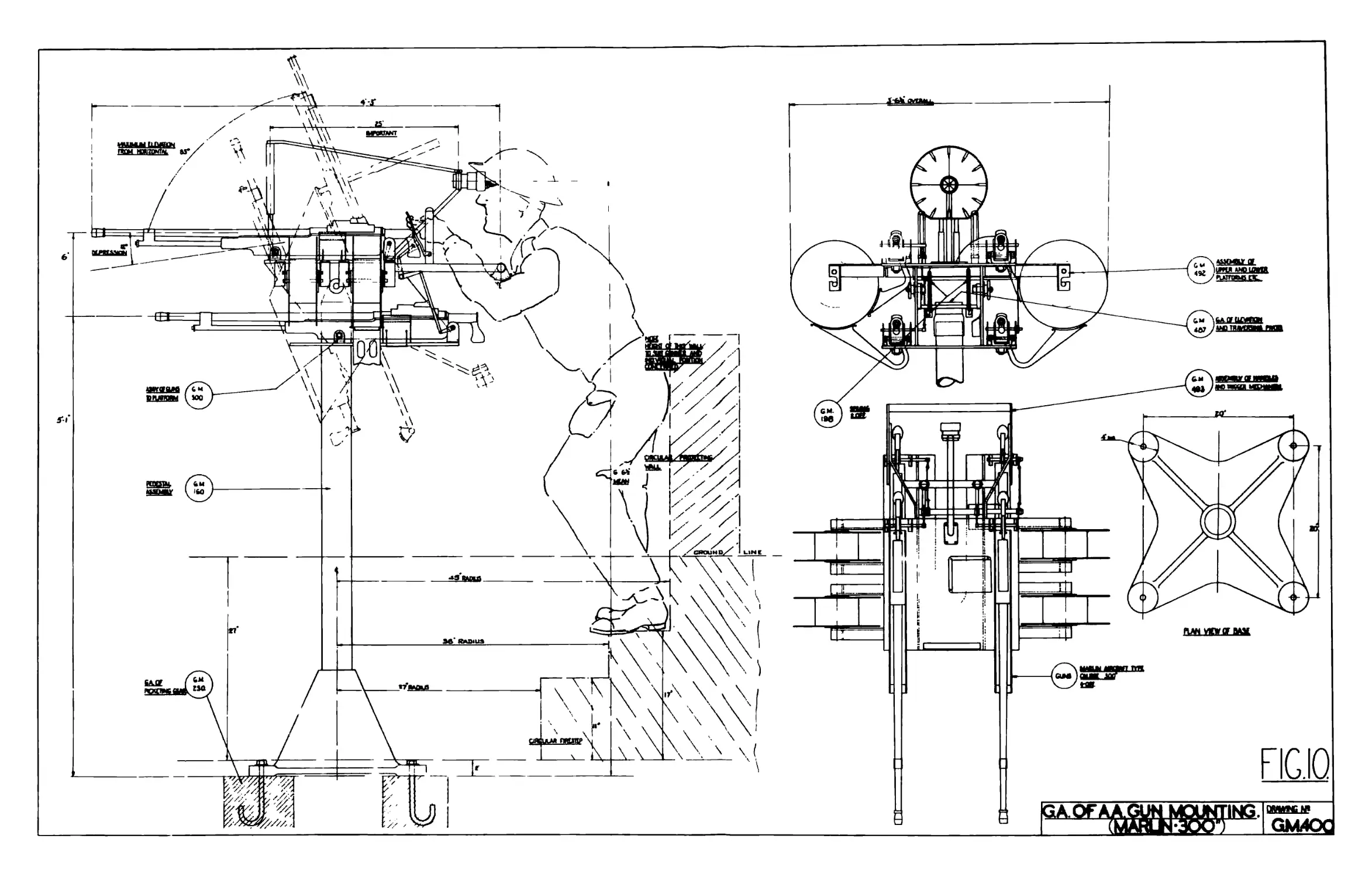
26. GENERAL ARRANGEMENT DRAWING 10
INTRODUC T I О N
This mounting provides for four Marlin
Machine Guns, calibre .300", which can be
traversed continually through ЗбО°, elevated
vertically to 85° and depressed to approximately
20°, in any condition of traverse. Design
approved by 0.1. S. A.
- 1 -
CONSTRUCTION
The upper portion of the unit consists of
two steel platforms mounted one above the other
and connected by two steel side plates. See Fig.
2.
Two guns are mounted on the upper platform
and one each side., outboard of the side plates,
on the lower platforms-
The two lower guns are stepped back in re-
lation to the upper guns.
The complete platform assembly is attached
to the tvzo vertical lugs oi‘ the crosshead by bolts
through the side plates which incorporate a
friction damping device to react upon the ease of
effort required to elevate or depress the armament.
- 2
ELEVATIOiTJHD TRAVERSE PIVOT.
The crosshead transmits elevation and
traverse loads through a thrust bearing which is
housed at the top of a vertical steel tube mounted
in a cast iron base of ample proportions.
Provision is made for lubricating the thrust
bearing through the medium of a Tecalemit grease
nipple. Illustrated in Fig.2.
The cast iron base is provided with feet and
rag bolts to secure the complete unit to any
suitable foundation.
4 -
AMMUNITION DRUMS
Mounted athwartships of the upper platform
are four ammunition drums, each drum has a capacity
of 300 rounds of .300" calibre ammunition when
loa£-.:d in a fabric belt. The end of this belt is
hooked on the screw head protruding from the core
of the drum.
The side plates of the ammunition drums are
constructed from multiply and the core from hard
wood. The raw edges of the side plates are suit-
ably protected by a strip of serrated tape.
An adjustable friction device operates on
each flange of the ammunition drum to prevent the
drums from over-running when the armament is in
operation, (see Fig. 3 which illustrates the con-
struction of the drum.) This friction device
consists of two 2 B.A. bolts with spherical ends
bearing on a steel washer which is integral with
the drum assembly. These bolts also serve to locate
the drums fore and aft so that the periphery of
the side plates are in alignment with the bell
mouth of the feed chutes.
It is necessary only to introduce slight
friction to prevent spinning of the drums which
otherwise should be quite free from other sources
of friction. Care should be exercised in the hand-
ling and storage of these drums which are of
plywood construction.
- 5 -
FEED CHUTES.
The ammunition belts are guided to the paddle
vzheel of the respective guns by means of chutes
manufactured from reinforced plastic material
suitably shaped to prevent the belt from twisting
and to ensure perfect presentation of individual
Rounds to the paddle vzheel of the gun at all angles
of elevation.
If at any time it is necessary to remove a
feed chute from the mounting, care must be taken
when refitting the feed chute to ensure that the
centre line of the throat of the chute lines up
with a fore and aft centre line on the side plate
of the gun above the feed aperture.
Similarly the chute should be so adjusted as
to ensure correct lateral location - that is
chamfered edge on the bottom gun plate must be in
alignment rd th the inner surface of the throat of
the chute.
A typical feed chute assembly is illustrated
at Fig. 4»
- 7 -
EMPTY CARTRIDGE CASES.
The empty cartridge cases are ejected in the
case of the upper left hand gun through a suitably
shaped shroud which is bolted to the upper platform.
In the case of the lower left hand gun a small
deflexion chute is bolted to the side plate, this
ensures that no cartridge case, when the armament
is elevated, vail injure the gunner.
No chutes are fitted to the upper and lower
right hand guns because the ejection is outboard.
Your attention is directed to the fact that
cartridge cases eject with considerable velocity.
Gun crews should, therefore, stand on the left
hand side of the unit.
- 9 -
LOADING UP.
Safety catches should he in "Safe" and guns
cocked. Belts should be loaded with 250 rounds.
Tracer should be loaded into the belts of the
upper guns only in the proportion of one tracer
to five ball. Avoid tight or shrunken belts;
new belts should be stretched. Two feet of loose
belt should be left free at each end. The leading
end should be fed into the chute with the assist-
ance of a piece of wire threaded through the slots
in the underside of the lower feed chutes. Pass
the brass tag end over the feed wheel and then
down through the holes or slots provided in the
base plates - for the two port guns. The loose
end for the top starboard gun should pass over the
forward drum. In the case of the lower starboard
gun the belt will pass straight down rear of the
feed chute. Care should be taken to protect the
belt ends from mud or grit as they reach the ground
in operation.
- 10 -
LOADING- THE GUNS.
Having fed the loose end of the belt through
the gun, pull on the loose end with one hand and
push in the first round with the other until the
feed wheel is turned through one notch. Release
the cocking handle and allow the action to go
forward with a slam. Repeat this cocking motion
once more when a round will he fed into the breech,
(it is advisable to perform these cocking motions
with the guns in the horizontal position). Cocking
actions should be performed vigorously. The for-
ward motion should be performed by merely releasing
the cocking handle from its engagement on the side
plate, and allow it to go forward by spring action
- see that the lanyard handle does not hinder the
full travel. Before firing see that the Action
has gone right for,yard - that is the bob weight
at the rear end of the piston rod should be making
actual contact with the base of the gas cylinder.
If it is not, the "feed-in" is not conplete, and
the gun should be cocked again - this time ejecting
a live round and release once more, (Gun crews
should stand to the left of the mounting to avoid
injury by ejected cases).
Another check can be made by examining the
cartridge extractor (through the inspection door -
right side) and see that it has gripped the rim
of the next round in the belt. It is reiterated
that the certainty of the "feed-in" depends upon
the positive and unimpeded forward movement.
- 11 -
REMOVAL OF GUNS.
Provision has been made to enable the armament
to be cleaned without removal from the mounting,
but owing to the construction of the gun any det-
ailed stripping necessitates complete removal from
the mounting. This is readily accomplished by with-
drawal of the two quick release pins, Fig. 5» These
should be given a half turn and withdrawn. Removal
of the gun by this method does not upset the align-
ment of gun barrels or feed chutes; fixed portions
of the brackets are indicated in Fig, 5 and. are
positioned by the manufacturers. Guns should, how-
ever, be marked, one, two, three and four, so'that
they are replaced in the same positions. This
precaution will obviate any re-adjustment of
trigger mechanism.
- 13 -
FIRE CONTROL MBCIiANISIvI.
The fire control mechanism is illustrated
in Fig. 6.
Each of the two fire control handles operate
two guns, and they are coupled up so that the top
left and bottom right, and top right and bottom
left guns fire conjointly.
Fire control operates through the medium of
cams bearing on a sheath bolted to the trigger of
the gun. Location of this sheath is obtained by
a half round slot cut in the trigger which
registers with the upper securing bolt of the
sheath. See Fig. ?• The cam, manufactured from
hard red fibre, is connected by levers and links
to the two hand grips which are mounted vertically
on the perambulator type bar. Extension of this
bar is adjustable to suit the length of any
individual’s forearm, Two sorbo rubber covered
revolving arm pa/.o are positioned to suit the
bend of the arm. See Pig.6.
- 15 -
fig.7
SYNCHRONISING THE FIRE CONTROL,
The adjustable pull rods have left and right
hand threads at the yoke ends. Adjustment is
provided by turning the rod in the required
direction by means of the hexagon at the centre
of the rod.
It is inportant that the trigger sheath
should have clearance between it and the cam face -
otherwise there is danger of automatic fire when
cocking, and it will not bo possible to engage the
safety catches.
The hammers of each pair of guns should fall
simultaneously when the control lever is depressed
Tests should be made (with unloaded guns) by slowly
pressing the control lever, when the hammers will
be heard to fall. Synchronisation will be ensured
by correct adjustment of the pull rods.
- 17 -
CHECKPIG OF GUN SIGHTS.
Alignment of the gun. barrels and the correct
adjustment of the sights have been carried out at
the Factory. The fixed portions of the gun brackets
on the base plates ensure permanence. The forward,
ring sight is depressed with respect to the aperture
sight by 0.055" to allow for gravity drop of the
bullet at 500 yards range and 60° elevation. The
adjustment is marked suitably for this position to
sinplify removal.
Should it be necessary to check the sights
the following procedure is recommended.
(1) Select a suitable target, not less than 500
yards distant. Sight one gun on this target
by looking through the barrel (with bolt and
pistol grip removed). Then sight the other
three barrels similarly, with the first
barrel held on the target. Should any adjust-
ment be necessary this can be effected by the.
use of shims under the brackets or reposition-
ing the front brackets in the clearance holes.
(2) With all four barrels sighted on the target
adjust the sights to a point 7 ft. below the
barrel line of sight, (The forward ring sight
has provision for any necessary correction).
- 19 -
The "Sight Base" is 25 inches, that is the
distance between the centre of the ring
sight and the eye.
Note: If, for the purpose of these adjustments
the fixed portions of the gun brackets are
moved, it will be necessary to make
corresponding adjustments to the feed
chutes to correct any misalignment brought
about by the above - see page 7»
- 21>
RESERVE AMMUNITION DRUMS.
Accompanying each unit is a spare set of
ammunition drums; these drums are fitted to the
unit in a matter of seconds.
The spindle of the drum is offered up to the
slots of the mounting channel, pushed forward and
dropped heme; any necessary tensioning of the
drum being carried out via the set screws adjacent
to the spindle. Cellulose paint, however, should
be removed on spindles and friction discs of new
drums, preparatory to mounting. Reserve ammunition
on loaded spare drums must be kept dry»
WATERPROOF COVER.
A waterproof cover is supplied with each unit.
It is advisable that use be made of this cover to
ensure that rain, dust and dirt do not interfere
with the component details of the guns and mounting.
Care should be used when drawing off the cover
suddenly not to damage the forward ring sight. A
tie bar is fitted between the two rights as add-
itional support.
SITING THE MOUNTING-.
These A. A. weapons come under the control of
A. A. Commands for Operations and Training.
It may he possible to position the mounting
at a point compatible with A. A. Command require-
ments and at the same time commanding a field of
fire appropriate to a ground (land) defence weapon.
In all such matters however A. A. Command should
be consulted.
Subject to the above, it is possible in some
cases, to predetermine the path through which the
enemy aircraft will fly in low level attack over
the factory. This path is likely to be the longest
straight line across the factory buildings (subject
to local conditions, obstructions, etc.). Where
two quadruple mountings are available, a two point
defence - each some 200 yds. or more away from the
centre of the target - is possible, (as distinct
from positions on the roof of the factory). In
the former case the enemy aircraft is more likely
to come within range of one of the gun mountings
before releasing his bombs.
- 23 -
г'с. э
POSITIONING THE MOUNTING.
The method, of securing the mounting is left
to the individual requirements at each factory;
a typical location is illustrated in Fig. 9»
It is recommended that the mounting he
bolted down to a concrete base wherever possible»
The rigidity thus obtained will absorb most of the
reaction when the guns are in action and tend to
a steadier aim.
Where, however, the Mounting is positioned
pn the roof, it will not always be possible to
secure it to a concrete base. In this instance,
it is suggested that the mounting should be
secured to sleepers by means of rag bolts.
Protection can be provided by means of a.
sand bag surround or brickwork. The height of the
protecting wall will be dependent upon the gun
barrel height in horizontal position (or brought
higher still if the guns are used as A. A. weapons
only).
The overall height and other necessary
dimensions for the construction of the two fire
steps in the sunken pit are shown in Fig. 10.
Some form of camouflage is recommended,
- 25 -
RING AND APERTURE GUN SIGHTS.
The ring and aperture anti-aircraft sights
consist of а ЗбО miles per hour ring foresight
(speeds of 240 nup.h. are indicated by the tips
of the pointers) and an aperture back sight. Both
sights have cross wires to assist alignment. The
sight base is 25”.
Note. The height of the fire steps in the gun pit
should be adjusted to the comfortable stand-
ing height of the gunner. The length of the
adjustable perambulator bar (under which the
crook of the elbows should be placed) should
be set to the length of the forearm.
These precautions will ensure a comfortable
control of the guns at all angles of eleva-
tion and traverse, and at the same time en-
able the gunner to hold the eye close up to
the sorbo pad on the Aperture sight - which
is essential for correct alignment of cross
wires.
- 27 -
SIGHTING.
As soon as an aircraft has been identified,
as hostile, it should be followed with the gun-
sight, fire should be held however until the enemy
aircraft comes within a range of 500 yards. This
not only avoids a probable waste of ammunition but
also delays the evidence of engagement until it is
too late for the enemy to take evasive action.
It will be found more effective if the guns
are layed on a point in the path of flight of the
enemy aircraft in advance of the correct "aim off"
position. The enemy aircraft will then "fly into"
the steady cone of fire. This is a more effective
method of aim than "following" continuously.
- 27a -
To engage an enemy aircraft flying at 90° to
the axis of the Gun Barrels and at a speed of ЗбО
m.p.h., lay the guns so that the cross wires are
coincident and position the target aircraft so
that it lies on the outer ring of the foresight
and appears to ho flying towards the centre of the
cross wires. This is the condition of full
deflection. The amount of deflection or "aim off"
will, however, vary according to the speed and
angle of approach. These two factors, speed and
angle of approach, (or retreat) can only be
estimated and, therefore, the accuracy of fire
will depend largely upon the training and experience
of the gunner. For example, an enemy aircraft in
dive bombing attack will probably have a speed of
224-0 nup.h. (the approximate speed of a dive boniber
using air brakes). In this instance the enemy
aircraft will be placed on the inner ring,
represented by the tips of the pointers (240 m.p.h),
- 28 -
and should appear to be flying towards the centre
of the cross wires.
An. enemy aircraft in a straight dive in the
direction of the gunner will be placed on the
cross-vzires - point blank aim.
When troop-carrying enemy aircraft or para-
chutists are landing within range, it will be
generally advisable to hold fire until they are
almost stationary»
For enemy aircraft flying at low speeds
preparatory to landing, aim must be taken with the
nose of the aircraft flying towards, and close to,
the centre of the cross wires.
The use of tracer ammunition in the lower
guns provides a satisfactory trace if the pro-
portion of five ball to one tracer is used. It
is recommended,however, that crews who have not
hitherto had experience in tracer firing should
be given some instruction in its advantages as
well as its deceptions under particular condit-
ions.
It is suggested that gun crews should
familiarise themselves with the principles of
"Close Range Anti-Aircraft Fire" ("lye Shooting"),
A. A, Command being the responsible authority for
A.A. training.
- 29 -
WLBT MACHINE GUN.
- JO -
THE MARLIN MACHINE ОШ.
The .JOO" American 1918 Pattern Machine Gun
is a belt-fed. Aircraft Gun. It is not’ wellknown in
this country (although it was a standard, weapon
in the Aunerican Air Force for some years). The
Tank Pattern Marlin Gun (which is the type adapted
to the Quadruple Mounting) is a slightly modified
Aircraft guru Air cooling fins were fitted to the
Tank Type Gun (omitted for the Quadruple Mounting)
and a pistol grip with trigger replaces the Con-
stantinesco Interrupter firing gear fitted to the
original aircraft gun. The rate of fire is 600/
700 rounds per minute.
Modifications carried out on the Marlin Gun
for Quadruple Mounting are
(1) Hand grip on the Cocking Handle has been
removed, leaving the limit step on the
slide in position.
(2) A 5/16" hole has been drilled at the rear
end of the cocking handle slide to take
the dog collar clip of the lanyard cocking
handle.
Note. This hole is positioned with its centre
from the end of the slide, (in some
cases however, the hole is positioned
with its centre one inch from the end;
- 31 -
in such instance approximately should, be cut
off the rear end of the slide).
(3) A small half round register has been cut in
the rear face of the trigger to locate the
trigger sheath.
(4) Rear Gun Mounting brackets with 4 screws
per gun are supplied with the mountings by
the Manufacturers (including the lanyard
handles and Trigger Sheath). As these
screws are not tapped with American threads,
but instead, with B.S.P. 5/16" threads, it
will be necessary to drill out the threaded
holes in the heel of the bottom plate and
re-tap to 5/16" B.S.F. This work should be
carried out by Consignees.
- 32 -
SUPPLEMENTARY NOTES ON HANDLING THE MARLIN MACHINE
GUN.
Careful study should he made of the Marlin
Instruction Manual.
A thorough understanding of the function of
each part of the gun should be acquired by examin-
ation of each part. It is advised that half a
dozen dummy rounds in a belt be worked through the
gun by hand so that the full cycle of operations
can be observed.
It is very inportant that the action should
be free, smooth and certain, both backwards and
forwards, to the fullest extent of its travel.
This gun depends upon spring energy for forward
action and feed in. Therefore any resistance due
to stiffness, or excessive drag on the belt in the
feed chute vzill prevent a full ’’feed in". It is
most important therefore to ensure that the action
parts of the gun are quite free, thoroughly clean
and well oiled.
When cocking the gun, use the lanyard handle
smartly and pull back hard to the fullest extent
letting the slide fall into the rearmost notch of
the guide. The forward action should always be
released by disengaging the cocking handle from
the notch and allowing the action to slam forward
- 33 -
without hindrance, thus using the full energy of
the spring and momentum of the moving parts to
ensure a "full feed-in". Always see tha.t the rear
end of the piston rod is making actual contact with
the gas cylinder, thus indicating that the action
has moved right home. If it has not, the "feed
in" will not have been completed. In this event
the gun should be cocked again, ejecting the live
round. Practise with dummy rounds will show how
best to operate the cocking motion.
Observation through the sliding inspection
cover (right side) will also show if the cart-
ridge extractor has gripped the next round.
There are only two adjustments in the guns
(a) The trip gear
(b) Gas chamber.
The trip gear is very important and the cor-
rect setting of the trip by means of the gauge
should be checked frequently and adjusted as set
out in the Armament Inspection Schedule - see page
42.
The gas chamber adjustment is not critical.
It is recommended that it be screwed in to within
one turn.
- 34 -
It is essential that any excessive oil should,
be removed, from the gas chanber, piston, barrel,
and barrel mouthpiece before firing, as after a
few rounds have been fired the excessive lubricant
burns and a smoke cloud obscures the target.
The guns mounted on the /«Л Quadruple Mount-
ing have no aluminium air cooling fins. It has
been found that the gun is capable of firing 100
rounds in "auto-fire" without undue heating. The
moving parts are, however, more exposed to dust
and atmosphere and it is therefore recommended
that the protecting cover issued with these mount-
ings should be in position at all times when the
guns are not in use.
Before issue guns will have been de-greased,
stripped and overhauled. Such new parts as have
been found necessary from tests by C.I. S.A., will
have been fitted and all guns have been proof -
fired. Providing always the foregoing conditions
are maintained there should be vciy little trouble
experienced with Marlin guns.
It is suggested that, during Alerts, guns
should be cocked (a round in the chamber) and
safety catches in "Safe". The guns can then be
brought into action at once after lifting safety
catches.
- 35 -
/JtMAMENT INSPECTION ON MARLIN GUNS.
A study of the Marlin Handbook is recommended.
The Armourer will then understand and appreciate
the functions of the various working parts and
familiarise himself with the American nomenclature.
The limiting factor with this gun - common to
machine guns of this type - is the small reserve
of spring energy for the forward movement and "feed
in", Any friction or excessive resistance (which
can arise from a number of causeswill tend to pre-
vent a full "feed in" on the forward action.
Spare parts and springs are issued with each
gun, and use of the standard issue of tools equip-
ment is recommended.
The Armament Inspection (A. I.) will consist
of
(a) Stripping and thoroughly cleaning.
(b) Testing and replacing springs, (see
para. 15.)
(c) Examination for wear and replacement
with new parts.
(d) Honing or rubbing down when necessary
to ensure absolute free movement.
- J6 -
(e) Assembling, oiling and proof test.
Receiver -
(a) The four threaded holes for lock con-
tainer will probably require rubbing
down on the inside as they are situated
in the path of the bolt (spring washers
must be replaced for the screws other-
wise the screws protrude).
(b) The slide grooves should be cleaned out
and scraped if necessary.
(c) The buffer block should be removed and
springs tested.
(d) The bolt (conplete) should be slid up and
down in the receiver to ensure that it is
free throughout its travel,
(e) Remove all particles of brass (from cart-
ridges) inside Receiver and especially
under the Ejector.
(f) Examine Ejector for wear or stiffness,
(also spring and plunger) and see that
it slides freely in the grooves.
(g) Examine cartridge retainer plunger and
spring (415,417)» When refitting,
- 37 -
retainer screw (416) should he just flush
with side of receiver. (if screwed up
tight spring will be compressed coil on
coil thus preventing cartridge rising).
Ensure that the right spring (417) is re-
placed.
(h) TThen refitting Action Spring Guide (355)
see that the dove-tail attachment to
receiver is properly engaged.
Slide.
(a) Examine for bends or distortion and burrs.
Test sliding action in receiver guides
(dry) and rub down as necessary to ensure
free action. Examine lugs (for feed
lever) for wear and burrs as outer surfaces
bear on side plates. Free movement of this
component is essential.
(b) Examine Cartridge Guides (left and right
85 and 86) for shape and wear and replace
if necessary.
(c) Examine Cartridge Extractor and spring (87
and 89) for wear and spring tension respect-
ively and replace if necessary.
- 38 -
Piston and Cylinder»
Gas chamber and cylinder at forward end should
be scraped out (decarbonised) so as to ensure free
travel of piston. Clear gas hole. Piston should
be screwed into the slide only hand tight up to
the nearest notch. Adjustment of gas chamber is
not critical but it should be screwed inwards to
within one turn for maximum gas pressure.
Barrel.
Clean chamber, examine for damage or burrs
to Extractor slot (barrel cannot be unscrewed or
screwed tip with bolt in the forward position.)
Bottom and Right Hand Plates.
Dismantle feed wheel (63), feed wheel dog and
spring (66, 68). Ratchet lever, pawl and spring
(76,78,79). Feed lever (70). Carefully clean and
examine especially the springs in Ratchet Pawl and
feed wheel dog. Extractor cam and spring (376,378)
should also be dismantled and examined (feed wheel
can be assembled the wrong way round). Over the:
Ratchet Lever (76) is fitted a pressed steel pawl
engagement device (not shewn in the Manual). This
has an inportant safety function in preventing the
jamming of the round should the latter fail to be
extracted from the belt»
- 39 -
Bolt.
Clean and rub down high points. Examine
firing pin (and spring) for wear, straightness
and protrusion through bolt for priming. Action
should be free. Examine shell extractor and
spring for wear and damage (15 and 16). Remove
any burrs on sides of bolt Pin. Try loosely in
receiver for free movement and hone down as
necessary. Examine and test fit of bolt pin.
Action Test.
Assemble the slide without action spring
into Receiver with buffer in position. Assemble
the Bolt (complete) and pin. Screw in the barrel
and fit the Carrier. Attach side and bottom plates
with feed mechanism.
The following can then be observed;-
(a) Full travel and positive action transmitted
to the feed wheel through feed lever,
(b) A load should be placed on the feed wheel
equivalent to the lift of 100 round belt.
This will show up any lost motion between
Feed Lever, Ratchet, Ratchet Pawl and Feed
Wheel. Any lost motion here will prevent a
full feed.
- 40 -
(c) The Feed Wheel dog (66) should engage
positvely behind the feed wheel before the
feed lever has reached full forward travel.
Similarly the Ratchet Pawl should engage
upon the next sprocket tooth before full
rearward travel has been reached by the feed
lever. (The feed lever is moved backwards
and forwards by the lugs on the Slide).
(d) Feed stoppages will occur if the bullet guide
on the left side plate is distorted.
(e) Observe the engagement and movement of the
Carrier and Dog.
(f) The •whole moving action should be quite free,
smooth and easy.
Lock Container.
Thoroughly clean registers and test the fit
(before assembly) on receiver. Remove burrs on
under side around screw holes. Examine Sear and
Trigger noses for wear, (correct Sear spring ten-
sion is an inportant safety factor). Examine
hammer and hammer spring. First assemble hammer
without spring and test for free movement on axis
pin and clearance through slot on top of receiver.
Four screw holes in lock container should be
reamed out if ’’threaded" by the screws.
- 41 -
Assemble all parts with oil ensuring a bedded fit
and screw down firmly, not forgetting the inport-
ant spring washers for this and for the rear
Sight block. If the lock container body is not
a good fit on the top of the receiver, distortion
will result when screwed down.
Trip Lever.
The trip adjustment is vital. First cock
the gun. Insert the thick end of the trip gauge
against the base of the gas cylinder and release
the action. When the trigger is pressed the
hammer should not fall. Cock the gun again and
insert the thin end of the gauge against the
base of the gas cylinder. Ydien the trigger is
pressed the hammer should fall. Adjustment is
made by bending the Trip lever. Closing the angle
of this lever advances the action of the trip.
Such bending of the trip lever should be very
slight and be carried out very carefully.
All springs should be removed for examin-
ation of length and conpression poundage. All
the moving springs described below are important
but the Action Spring (254). end Ratchet Lever Pawl
spring (79) are vitally inportant. It is
recommended that all springs should be treated
together for conplete test. Spare springs are
available for visual conparison of length. If
a set of new springs are kept together as a
- 42 -
Master set no special spring testing gear is
necessary. The only spring requiring compression
measurement is the Action spring. The rated pound-
age at deflection (compressed to Ilf’” as in the
gun with Action forward) is 22 lbs. If this falls
below 19 lbs. it should be changed. A spring
balance is quite satisfactory for this measurement.
List of important springs.
Part No.
A. Action Spring 354
B. Firing pin Spring. 19
C. Hammer Spring. 518
D. Ratchet Lever Pawl Spring. 79
E. Ejector Spring. 390
F. Trigger Spring. 9
G. Sear Spring. 11
H. Carrier Stop Spring. 393
I. Carrier Dog Spring. 26
J. Cartridge Extractor Spring. 89
K. Cartridge Extractor Cam Spring. 378
L. Feed Wheel Dog Spring. 68
M. Cartridge Retainer Plunger Spring. 417
N. Buffer Spring. 364?
Note; In the event of the hammer spring (518)
being changed, and should the gun afterwards per-
sist with a feed stoppage, one coil should be
removed as some of the new springs are excess-
ively strong.
- 43 -
Modifications to Guns for Quadruple Mounting.
Cocking Handle Guide. When assembling, care
should be taken to tighten firmly the screws in the
rear guide as they have a tendency to shear if
loose. It is difficult to remove the broken
portion as the screw is hard and the side plate
soft.
Bolt Pin Retainer. Recent issues of Marlin
Guns have been deficient of the Bolt Pin Retainer
- a split plug fitted into a hole in the left-
hand side plate. Its purpose is to prevent the
bolt pin working out to the left. Supplies of
this part are exhausted and it has been decided
that the special manufacture of this Retainer is
not warranted.
- 44 -