/


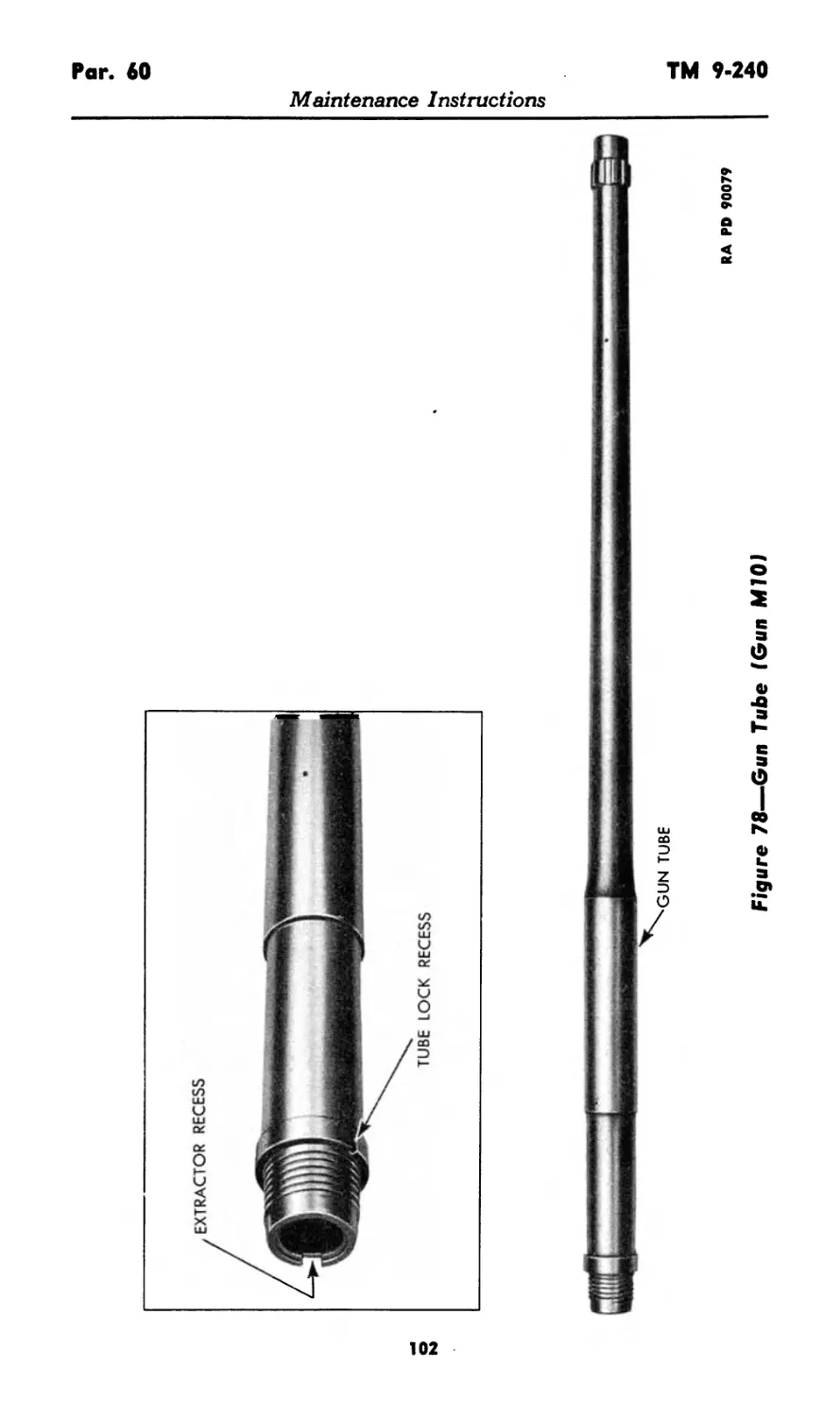

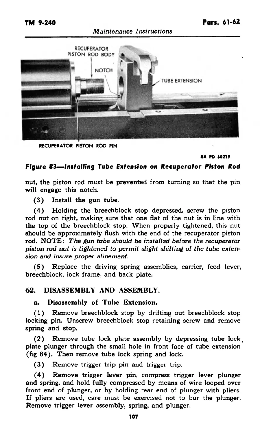


Tags: weapons military affairs
Year: 1945

Text
J
37-MM
AUTOMATIC GUNS
AN-M4 AND MIO-
(AIRCRAFT)
^BRA/ty
a> »..—w
RESTRICTED. D/SSFM/NATiON OF RESTRICTED MATTER.
No person Is entitled solely by virtue of his grade or position
to knowledge or possession of classified matter. Such matter
is entrusted only to those individuals whose official duties
require such knowledge or possession. (See also paragraph
23b, AR 380-5, IS March 1944J
"•« depARtment
7 May t945
WAR DEPARTMENT TECHNICAL MANUAL
TM 9-240
This TM supersedes TM 9-240, dated 1 Nov 43. It also supersedes portions of OI'STB 1200-3,
dated 6 May 43 (reprinted as WDTB Ord 49); WDTB Ord 193. dated 30 Sep 44; and WDTB
Ord 237, dated 26 Dec 44, which apply to the materiel covered in the TM; however, these TB’s
remain in force until incorporated in all other affected TM’s or specifically rescinded.
37-MM
AUTOMATIC GUNS
AN-M4 AND MIO
(AIRCRAFT)
LIBRARY
APR 19 1946
u. s. mi m
WAR DEPARTMENT
7 MAT 1945
RESTRICTED, dissemination of restricted matter.
No person is entitled solely by virtue of his grade or position to knowledge
or possession of classified matter. Such matter is entrusted only to those
individuals whose official duties require such knowledge or possession.
(See also paragraph 23b, AR 380-5, 15 March 1944.)
WAR DEPARTMENT
Washington 25, D. C., 7 May 1945
TM 9-240, 37-mm Automatic Guns AN-M4 and MIO (Aircraft), is
published for the information and guidance of all concerned.
tA.G. 300.7 (24 Dec 43) "1
O.O. 461/57301 J
By order of the Secretary of War:
G. C. MARSHALL,
Chief of Staff.
Official:
J. A. ULIO,
Major General,
The Adjutant General.
Distribution: AAF (10); AGF (10); ASF (2); S Div ASF (1);
Dept (10); AAF Comd (2); Arm & Sv Bd (2); Tech
Sv (2); Sv C (10); PC & S (1); PE, 9 (5); Dist O,
9 (5); Dist Br 0,9 (3); Reg 0,9 (3); Establishments,
9 (5); Decentralized Sub-O, 9 (3); Gen 8t Sp Sv Sch
(10); USMA (20); A (10); CHQ (10); D (2); AF
(2); G (2); S (2); T/O&E: 9-7 (3); 9-9 (3); 9-57
(3); 9-65 (2); 9-67 (3); 9-76 (2); 9-217 (3); 9-315
(2); 9-318 (3); 9-319 (3); 9-377 (3).
(Refer to FM 21-6 for explanation of distribution formula.)
CONTENTS
PART ONE—INTRODUCTION
Paragraph* Pages
Section I. General ............................... 1-2 1- 4
II. Description and data 3-6 4- 6
III. Tools, parts, and accessories 7-8 6-12
PART TWO—OPERATING INSTRUCTIONS
Section IV. General ................................ 9 13
V. Service upon receipt of equipment 10-12 13- 14
VI. Controls 13 14- 15
VII. Operation under usual conditions 14-18 16- 26
VIII. Operation under unusual
conditions............................. 19-23 27- 28
IX. Demolition to prevent enemy use 24-29 28- 29
PART THREE—MAINTENANCE INSTRUCTIONS
Section X. General 30 30
XI. Special organizational tools and
equipment........................... 31 30- 34
XII. Lubrication ..................... 32-36 34- 36
XIII. Preventive maintenance service 37—39 36- 37
XIV. Malfunctions and corrections . 40—49 37- 40
XV. Back plate assembly 50-52 40- 42
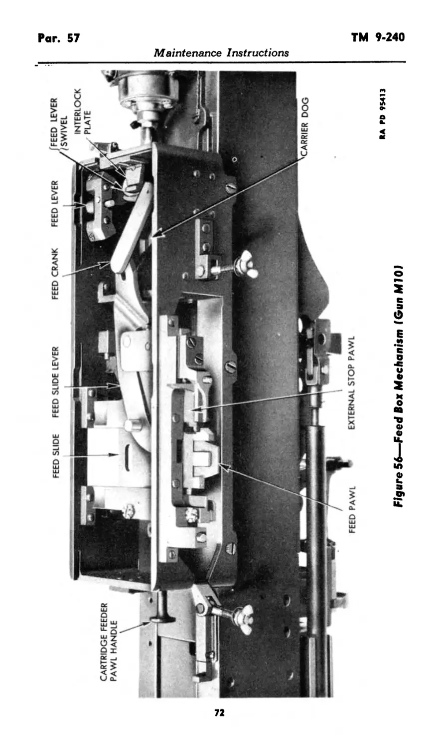
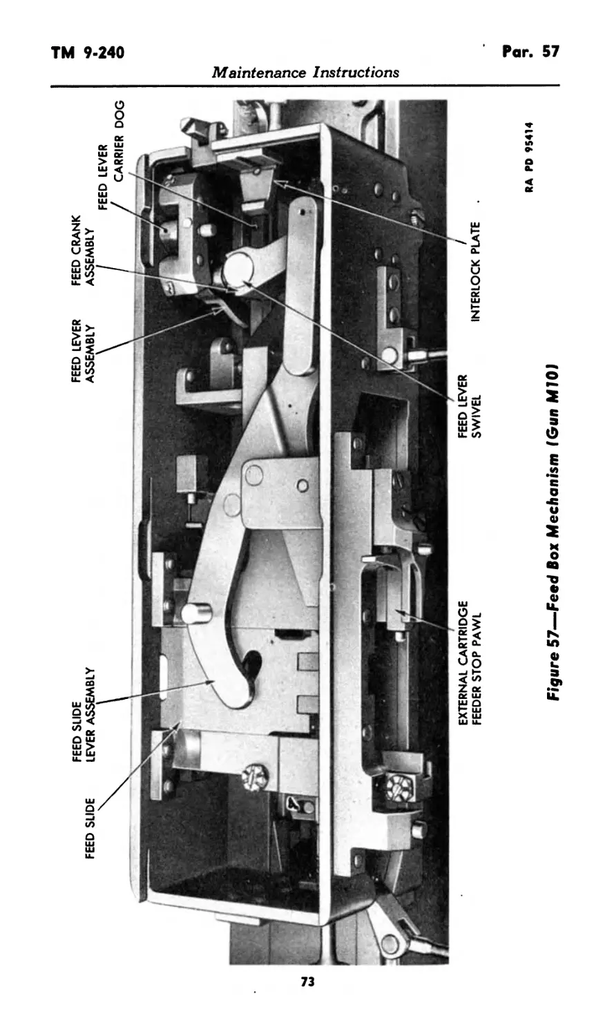
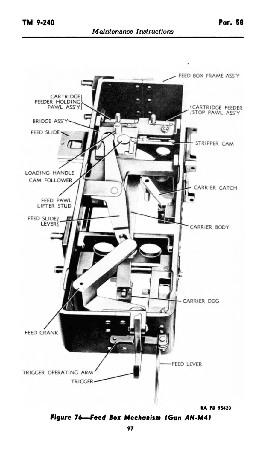
XVI. Breech operating mechanism 53-56 43- 71
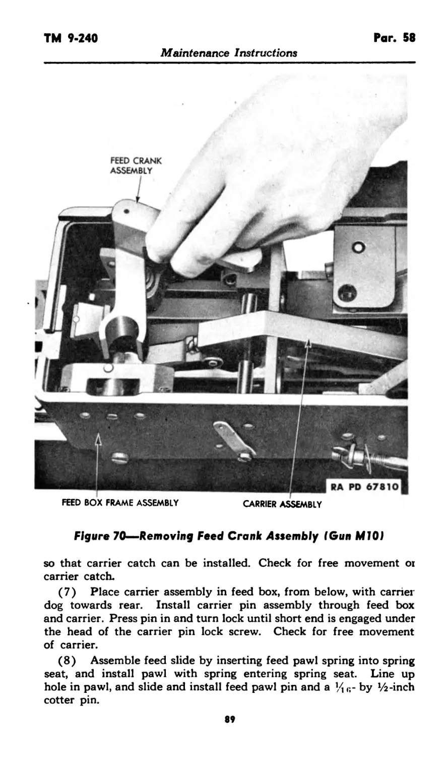
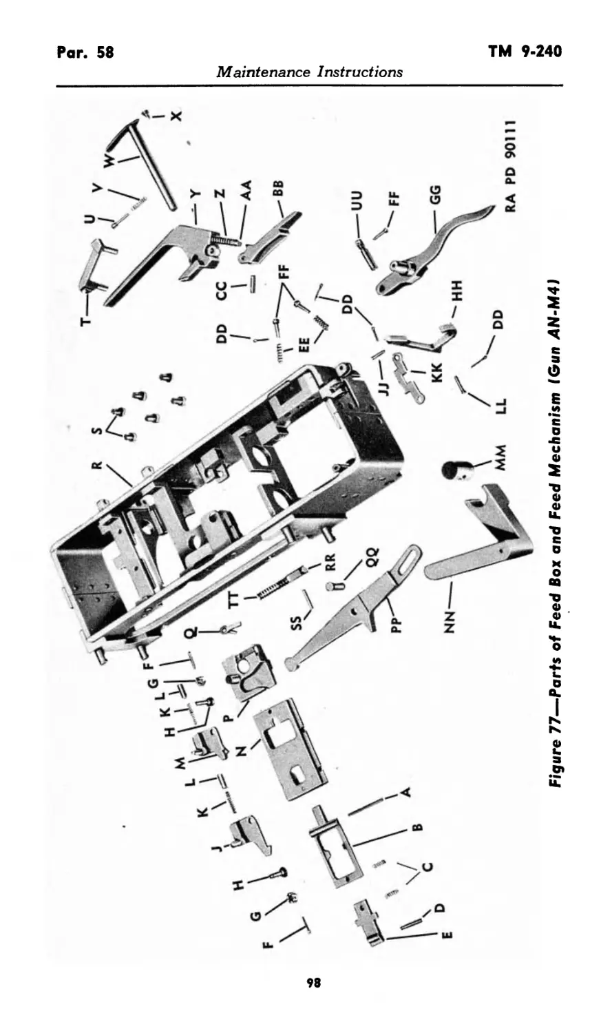
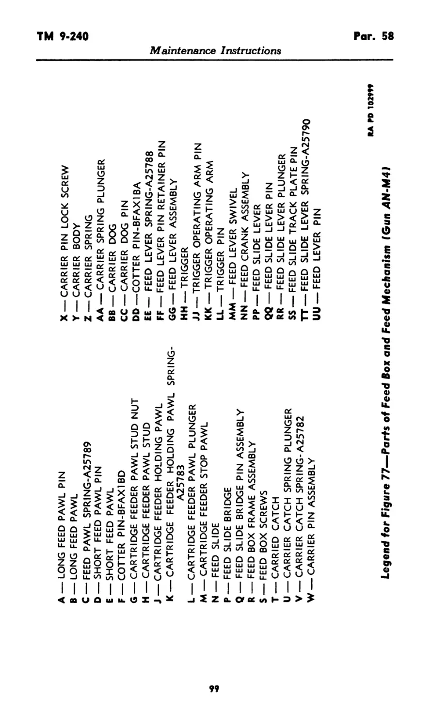
XVII. Feed box group 57-59 71-101
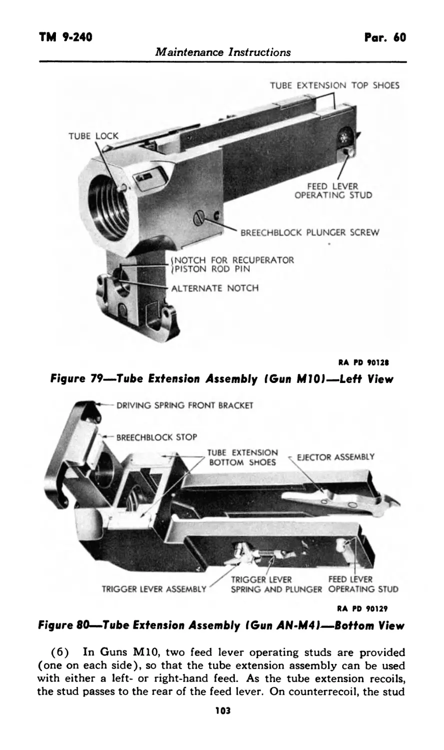
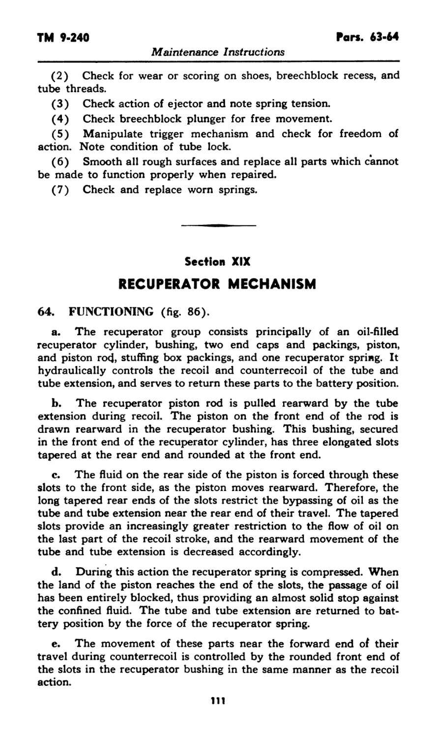
XVIII. Tube and tube extension group 60-63 101-111
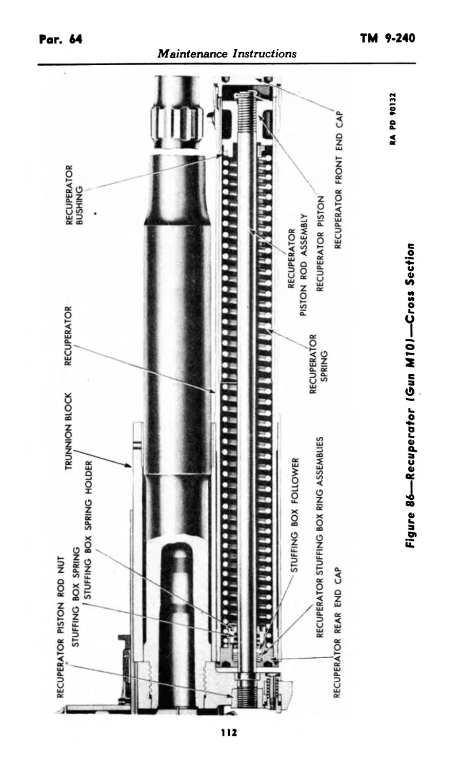
XIX. Recuperator mechanism 64-66 111-117
XX. Receiver group................... 67-69 117-121
XXI. Manual charger 70-73 121-123
XXII. Endless belt magazine M6 74-75 123-125
PART FOUR—AMMUNITION
Section XXIII. General 76 126
XXIV. Ammunition 77-85 126-134
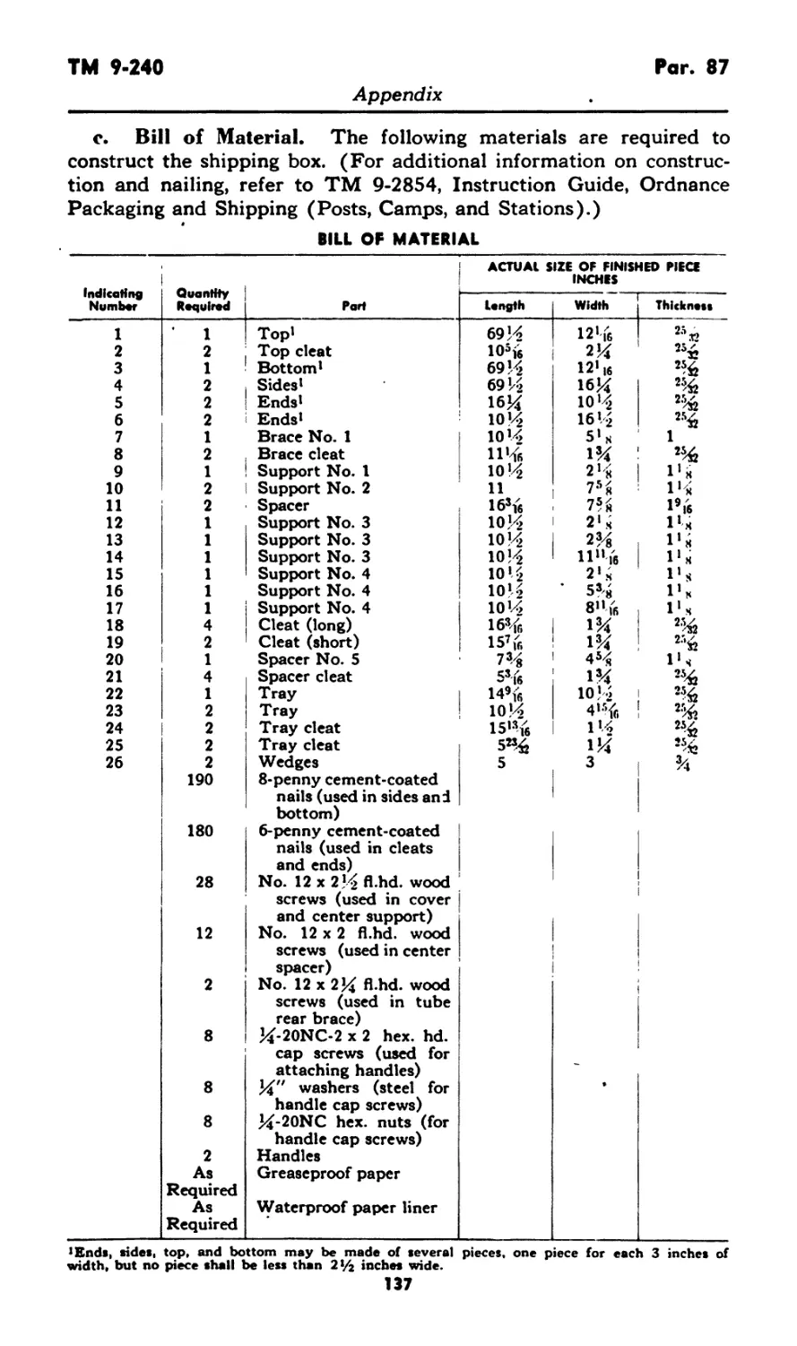
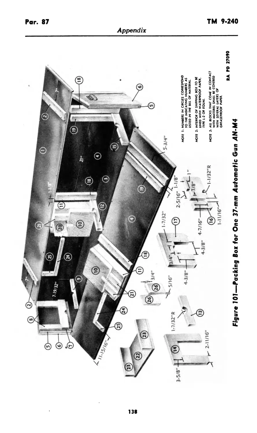
APPENDIX
Section XXV. Shipment and storage 86-87 135-139
XXVI. References 88-90 140-141
Index ................................................ 142-143
RA И> 95387
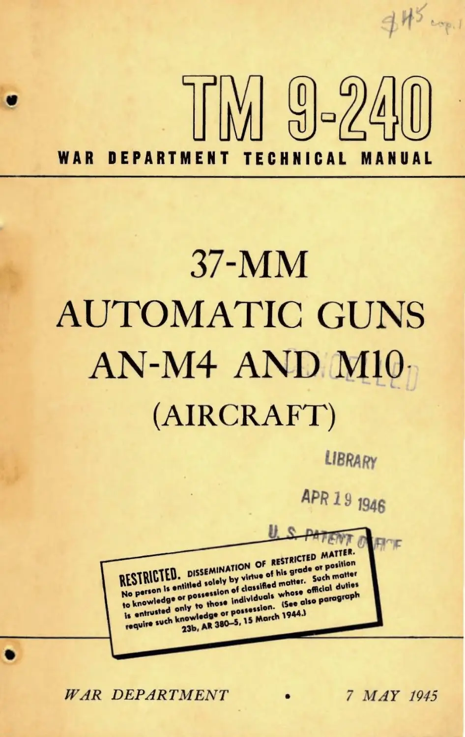
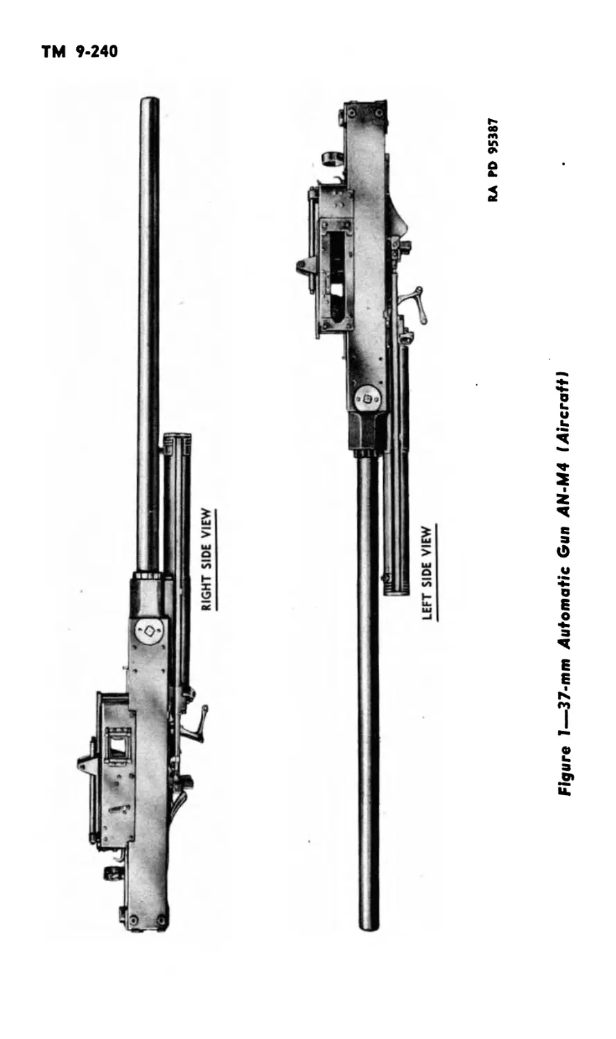
Figure 1—37-mm Automatic Gun AN-M4 (AircraftI
TM 9-240
Pars. 1-2
RESTRICTED
Thio TM supersede* TM 9-240, dated 1 Nov 43. It alio supersedes portions of OFSTB
1200-3, dated 6 May 43 (reprinted as WDTB Ord 49); WDTB Ord 193, dated 30 Sep 44;
and WDTB Ord 237, dated 26 Dec 44, which apply to the materiel covered in the TM; how-
ever, these TB's remain in force until incorporated in all other affected TM'j or specifically
rescinded.
PART ONE—INTRODUCTION
Section I
GENERAL
1. SCOPE.
a. This manual is published for the information and guidance of
the using arms and services.
b. In addition to a description of the 37-mm Automatic Guns
AN-M4 and M10 (aircraft), this manual contains technical informa-
tion required for the identification, use and care of the weapon, am-
munition, and accessory equipment.
c. In all cases where the nature of the repair, modification, or
adjustment is beyond the scope or facilities of the unit, the responsible
ordnance service should be informed in order that trained personnel
with suitable tools and equipment may be provided, or proper instruc-
tions issued.
2. RECORDS.
a. Modification Record Card.
(1) The Modification Record Card (O.O. Form 7451) is used
for the purpose of keeping an accurate record of all modification work
orders performed on the gun.
(2) The top of the card will bear the caliber, model, and serial
number of the gun. Each modification work order applied to the
materiel will be listed on the face of the card by number and short
title. It will show the date applied and initials of the officer or
mechanic responsible for completion of the modification.
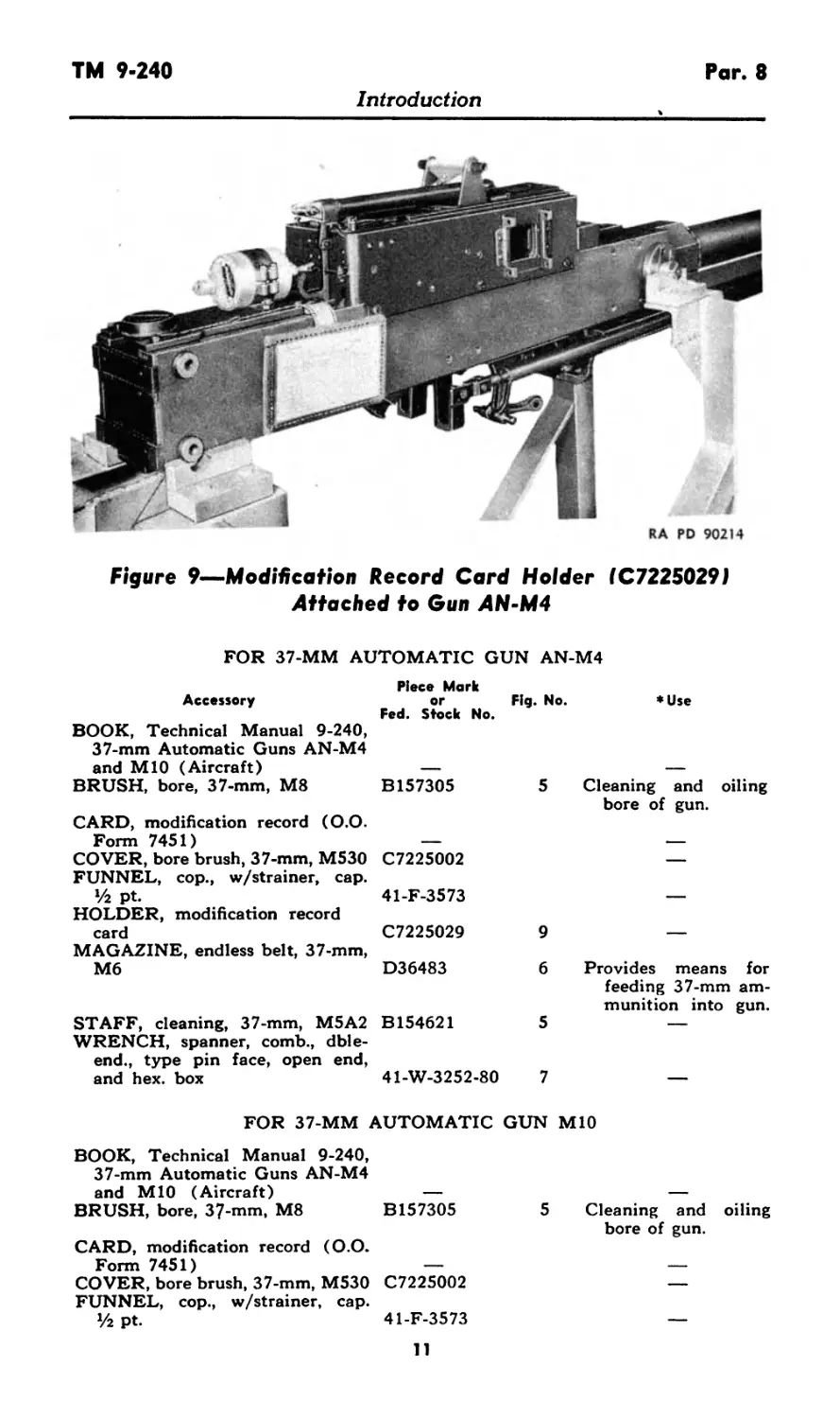
(3) The card should be kept in the holder C7225029 provided
and the holder will be kept attached to the gun at all times. The
holder will be attached under the safety wire on the top plate screw of
the Gun AN-M4 (fig. 9). The holder can be attached under the safety
wire on the top plate screw or to the eye bolt for the feed or link
chutes on the Gun MIO.
(4) If a modification record card is lost, it shall be replaced at
once and all entries brought up to date. A supply of these cards and
holders is available from Ordnance Officer, Air Technical Service
Command, Wright Field, Ohio.
1
RA PD 90075
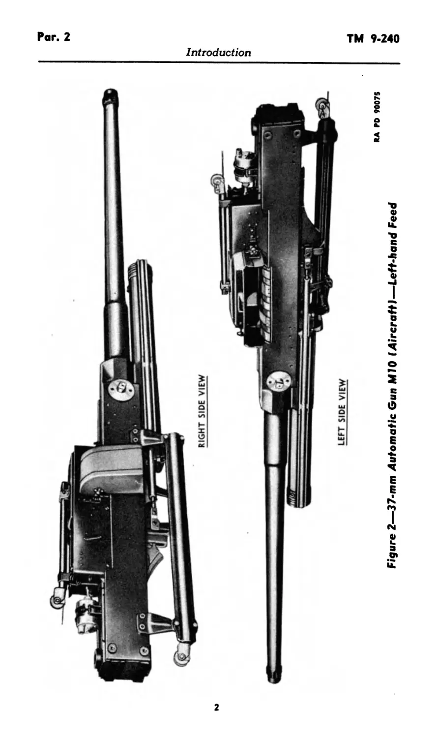
Figure 2—37-mm Automatic Gun MIO (AircraftI—Left-hand Feed
Introduction
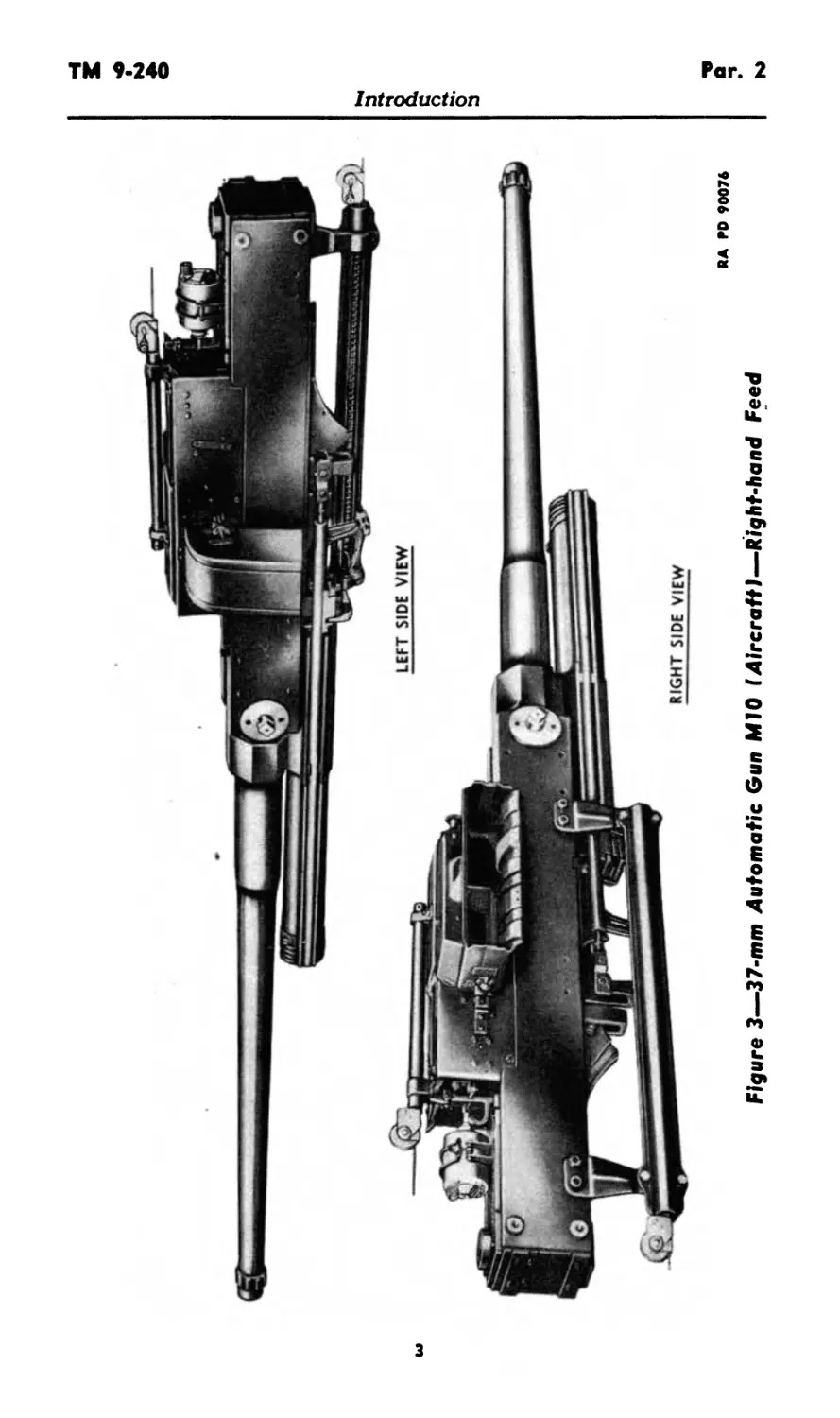
Figure 3—37-mm Automatic Gun MIO (Aircraft!—Right-hand Feed
RA ГО 90074
Introduction
Pars. 2-5
TM 9-240
Introduction
b. Field Report of Accidents. When accident involving the
use of ammunition occurs during training practice, the incident will
be reported as prescribed in AR 750-10 by the ordnance officer under
whose supervision the ammunition is maintained or issued. Where
practicable, reports covering malfunctions of ammunition in combat
will be made to the Chief of Ordnance, giving the type of malfunction,
type of ammunition, the lot number of the complete rounds or separate
loading components, and condition under which fired.
c. Unsatisfactory Report. Suggestions for improvement in
manufacture, design, maintenance, safety, and efficiency of operation
prompted by chronic failure or malfunction of the weapon, spare parts,
or equipment should be reported on WD AAF Form No. 54, Unsatis-
factory Report, with all pertinent information necessary to initiate
corrective action. This form will also be used for reporting complaints
on the application or effect of prescribed petroleum fuels, lubricants,
and preserving materials and, when so used, will contain identifying
details on both the products and the associated equipment. The report
should be forwarded to: Commanding General, Headquarters Air
Service Command, Patterson Field, Fairfield, Ohio. If WD AAF Form
No. 54 is not available, one may be improvised by referring to sample
in TM 37-250.
Section II
DESCRIPTION AND DATA
3. GENERAL.
a. The 37-mm Guns AN-M4 and MIO are fully automatic aircraft
weapons of the long recoil type (figs. 1, 2, and 3). They are mounted
to fire through the propeller shaft. They are not used as synchronized
weapons. These guns may be fired by means of a remotely controlled
solenoid mounted at the rear of the gun.
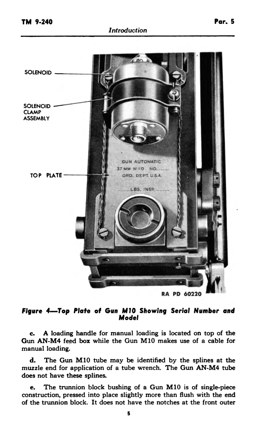
4. IDENTIFICATION INFORMATION.
a. The 37-mm Guns AN-M4 and MIO may be identified by the
model and serial number stamped on the top plate (fig. 4).
5. DIFFERENCES IN MODELS.
a. The feed box and feeding mechanism of the Gun MIO are
designed to feed ammunition from a disintegrating link belt. By
changing the feed box and feeding mechanism, the gun can be made
to feed from left to right or from right to left, the belt links being
ejected through a link chute.
b. The Gun AN-M4 feeding mechanism is designed to feed am-
munition only from left to right and commonly makes use of a 30-
round endless belt, the links of which do not disintegrate. No link
ejection chute is therefore used with this model.
4
TM 9-240
Pan 5
Introduction
SOLENOID
SOLENOID
CLAMP
ASSEMBLY
TOP PLATE
RA PD 60220
Figure 4—Top Plate of Gun MIO Showing Serial Number and
Model
c. A loading handle for manual loading is located on top of the
Gun AN-M4 feed box while the Gun MIO makes use of a cable for
manual loading.
d. The Gun MIO tube may be identified by the splines at the
muzzle end for application of a tube wrench. The Gun AN-M4 tube
does not have these splines.
e. The trunnion block bushing of a Gun MIO is of single-piece
construction, pressed into place slightly more than flush with the end
of the trunnion block. It does not have the notches at the front outer
5
Pars. 5-7
TM 9-240
Introduction
edge of the bushing which are characteristic of the Gun AN-M4
bushing.
f. The back plate assembly is similar for these guns; however, in
early manufacture the Gun MIO buffer adjusting screw is recessed
on the top, and the buffer plunger is longer than in the case of the
Gun AN-M4. In present manufacture the rear buffer assemblies are
the same.
g. A more detailed comparison of these guns will be found in the
following paragraph on data (par. 6).
6. TABULATED DATA.
a. Data Pertaining to 37-mm Guns AN-M4 and MIO
(Aircraft).
(1) General. AN-M4 MIO
Weight of gun 213 lb 231 lb
Weight of tube 55.0 lb 57.5 lb
Length of gun 89.50 in. 89.57 in.
Total length of tube 65 in. 65 in.
Type of breechblock Vertical sliding wedge Vertical sliding wedge
Type of firing mechanism Percussion Percussion
Ammunition—for complete data, see section XXIV.
( 2 ) Performance.
Muzzle velocity (average velocity
with a new gun)
HE shell AP shell 2,000 fps 1,825 fps 2,000 fps 1,825 fps
Cyclic rate of fire .... 150 rounds per minute 165 rounds per minute
Average accuracy life * 1,950 rounds 1,950 rounds
Maximum allowable recoil 9% in. 9% in.
Type of recoil mechanism Hydrospring Hydrospring
Type of recoil oil Light recoil oil Light recoil oil
Recuperator oil capacity 42 oz 42 oz
Section III
TOOLS, PARTS, AND ACCESSORIES
7. ORGANIZATIONAL SPARE PARTS.
a. A set of organizational spare parts is supplied to the using
arm for field replacement of those parts most likely to become broken,
worn, or otherwise unserviceable. The set will be kept complete by
requisitioning new parts for those used. The parts comprising the set
6
TM 9-240
Par. 7
Introduction
are listed below for information only; this list will not be used for
requisitioning. The authority upon which requisitions are based is
SNL A-46.
FOR 37-MM AUTOMATIC GUN AN-M4
Spare Part
EXTRACTOR . ......................................
GUIDE, hammer spring.........................................
HAMMER .....................................
LEVER, cocking ..............................................
LEVER, trigger, assembly .......... ................
LOCK, loading handle cam.....................................
NUT, loading handle cam lock.......................... ...
PACKING, recuperator filler screw ...........................
PIN, cocking lever...........................................
PIN, cotter, split, S., 1/16 x 5/16.................
PIN, cotter, split, S., 1/16 x 5/e ..........................
PIN, cotter, split, S., 3/32 x 3A ...........................
PIN, cotter, split, S., 3/32 x 1 ............................
Piece Mark
В163393
A25658
B163397
В163400
B163436
B163403
A25696
A25672
A25679
BFAX1BA
BFAX1BD
BFAX1CE
BFAX1CG
PIN, firing....................................................A25688
PIN, hammer spring guide.....................................A25690
PIN, locking, breechblock stop................................A25678
PIN, operating lever strut ................................... A25698
PIN, sear.................................................... A25701
PIN, stop, firing pin .........................................A25689
SEAR...........................................................B163416
SPRING, breechblock stop retaining screw...................... A25780
SPRING, carrier catch ........................................A25782
SPRING, cartridge feeder holding pawl .... A25783
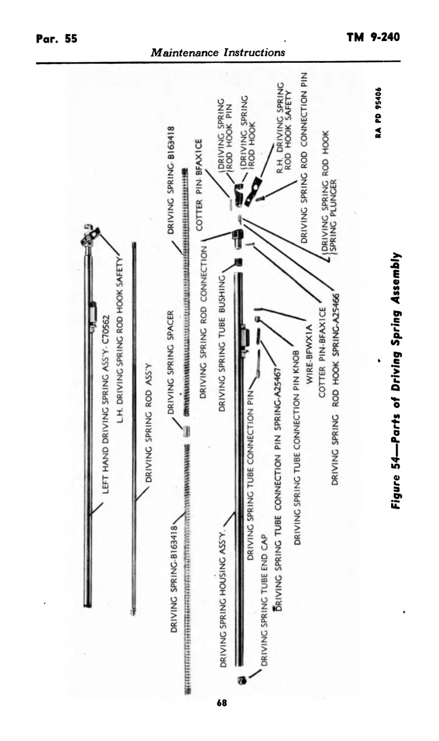
SPRING, driving SPRING, driving, L.H., assembly SPRING, driving, R.H., assembly SPRING, driving, spring rod hook ... B163418 C70562 . C70563 A25466
SPRING, driving, spring tube connection pin A25467
SPRING, ejector SPRING, extractor A25786 А П C *70 *7
SPRING, feed lever А25ло7 A25788
SPRING, feed pawl A25789
SPRING, feed slide lever .... A25790
SPRING, firing pin SPRING, hammer A25791
SPRING, loading handle A25793
SPRING, operating lever SPRING, sear A25795
SPRING, switch . . A/ZZuDIO A25797
SPRING, trigger lever A25798
STRUT, operating lever .... A25809
TRIP, trigger B163423
WIRE, S., low carbon, bright anld., 0.041 in. diam., 25 ft. long BFWX1A
FOR 37-MM AUTOMATIC GUN MIO
EXTRACTOR GUIDE, hammer spring В163393 A94АСЯ
HAMMER R1fi4^Q7
LEVER, cocking . . B163400
LEVER, trigger, assembly . . B163436
PACKING, recuperator filler screw A25672
PIN, cocking lever . . A25679
PIN, cotter, split, S., 1/16 x 5/16 ... BFAX1BA
PIN, cotter, split, S., 1/16 x 7/16 . . BFAX1BB
PIN, cotter, split, S., 1/16 x 5/s BFAX1BD
PIN, cotter, split, S., 3/32 x 3/ч BFAX1CE
PIN, cotter, split, S., 3/32 x 1 ... BFAX1CG
PIN, firing .... A25688
7
Par. 7
TM 9-240
Introduction
BORE BRUSH ON STAFF FOR
CLEANING AND APPLYING
GREASE IN GUN TUBE
FLANNEL PATCH ON CLEANING
STAFF FOR WIPING TUBE DRY
RA PD 26853
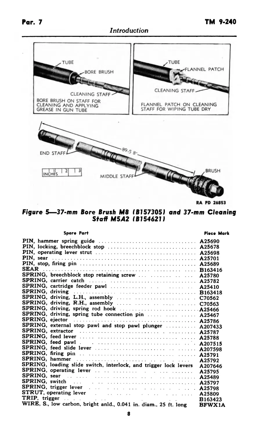
Figure 5—37-mm Bore Brush M8 (Bl57305) and 37-mm Cleaning
Staff M5A2 (Bl546211
Spare Part Piece Mark
PIN, hammer spring guide ................................. A25690
PIN, locking, breechblock stop ............................. A25678
PIN, operating lever strut ................................. A25698
PIN, sear .................................................. A25701
PIN, stop, firing pin....................................... A25689
SEAR ...................................................... B163416
SPRING, breechblock stop retaining screw................... A25780
SPRING, carrier catch ..................................... A25782
SPRING, cartridge feeder pawl.............................. A25410
SPRING, driving ........................................... B163418
SPRING, driving, L.H., assembly ........................... C70562
SPRING, driving, R.H., assembly............................C70563
SPRING, driving, spring rod hook ......................A25466
SPRING, driving, spring tube connection pin................A25467
SPRING, ejector ........................................... A25786
SPRING, external stop pawl and stop pawl plunger .......... A207433
SPRING, extractor ......................................... A25787
SPRING, feed lever......................................... A25788
SPRING, feed pawl.......................................... . A207515
SPRING, feed slide lever....................................A207598
SPRING, firing pin ........................................ A25791
SPRING, hammer A25792
SPRING, loading slide switch, interlock, and trigger lock levers A207646
SPRING, operating lever.................................... A25795
SPRING, sear ..............................................A25489
SPRING, switch ... A25797
SPRING, trigger lever......................................A25798
STRUT, operating lever .............. ..................... A25809
TRIP, trigger B163423
WIRE, S., low carbon, bright anld., 0.041 in. diam., 25 ft. long BFWX1A
8
TM 9-240
Par. 8
Introduction
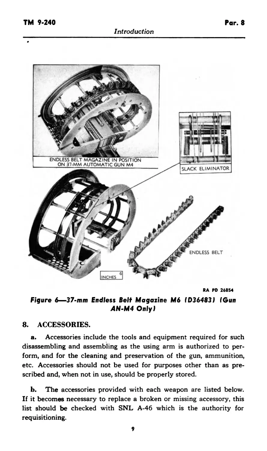
RA PD 26854
Figure 6—37-mm Endless Belt Magazine M6 (D36483J I Gun
AN-M4 Only)
8. ACCESSORIES.
a. Accessories include the tools and equipment required for such
disassembling and assembling as the using arm is authorized to per-
form, and for the cleaning and preservation of the gun, ammunition,
etc. Accessories should not be used for purposes other than as pre-
scribed and, when not in use, should be properly stored.
b. The accessories provided with each weapon are listed below.
If it becomes necessary to replace a broken or missing accessory, this
list should be checked with SNL A-46 which is the authority for
requisitioning.
9
Par. 8
TM 9-240
Introduction
Figure 7—Double-end Combination Spanner Wrench 41 -W-3252-80
REMOVAL OF MIO GUN TUBE
WITH WRENCH
RA PD 26857
Figure 8—Special Splined Opening Single-end Box Wrench
41-W-640-300 (Gun MIO Onlyl
io
TM 9-240
Par. 8
Introduction
Figure 9—Modification Record Card Holder (C7225029)
Attached to Gun AN-M4
FOR 37-MM AUTOMATIC GUN AN-M4
Piece Mark
Accessory or Fig. No. ♦Use
Fed. Stock No.
BOOK, Technical Manual 9-240,
37-mm Automatic Guns AN-M4 and MIO (Aircraft)
BRUSH, bore, 37-mm, M8 B157305 5 Cleaning and oiling
bore of gun.
CARD, modification record (O.O.
Form 7451) — —
COVER, bore brush, 37-mm, M530 FUNNEL, cop., w/strainer, cap. C7225002 —
l/2 pt. HOLDER, modification record 41-F-3573 —
card MAGAZINE, endless belt, 37-mm, C7225029 9 —
M6 D36483 6 Provides means for
feeding 37-mm am- munition into gun.
STAFF, cleaning, 37-mm, M5A2 WRENCH, spanner, comb., dble- end., type pin face, open end, B154621 5 —
and hex. box 41-W-3252-80 7 —
FOR 37-MM AUTOMATIC GUN MIO
BOOK, Technical Manual 9-240,
37-mm Automatic Guns AN-M4
and MIO (Aircraft) — —
BRUSH, bore, 37-mm, M8 В157305 5 Cleaning and oiling
bore of gun.
CARD, modification record (O.O.
Form 7451) — —
COVER, bore brush, 37-mm, M530 C7225002 —
FUNNEL, cop., w/strainer, cap.
i/2 pt. 41-F-3573 —
11
Par. 8
TM 9-240
Introduction
FOR 37-MM AUTOMATIC GUN MIO—Contd.
Accessory Piece Mark or *Use
Fed. Stock No. Fig. No.
HOLDER, modification record card STAFF, cleaning, 37-mm, M5A2 WRENCH, adj., crescent type, C7225029 9 — B154621 5 —
sgle-end., length 8 in., jaw opng. 15/16 in. WRENCH, spanner, comb., dble- end., type pin face, open end, 41-W-486 —
and hex. box WRENCH, box, special, sgle-end., splined opng., size of opng. 4% in., length over-all 15% in. 41-W-3252-80 7 — 41-W-640-300 8 Used for removal of gun tube.
•Where the accessory's use is not indicated, the nomenclature is self-explanatory or the
accessory has general use.
12
TM 9-240
Pars. 9-11
Operating Instructions
PART TWO—OPERATING INSTRUCTIONS
Section IV
GENERAL
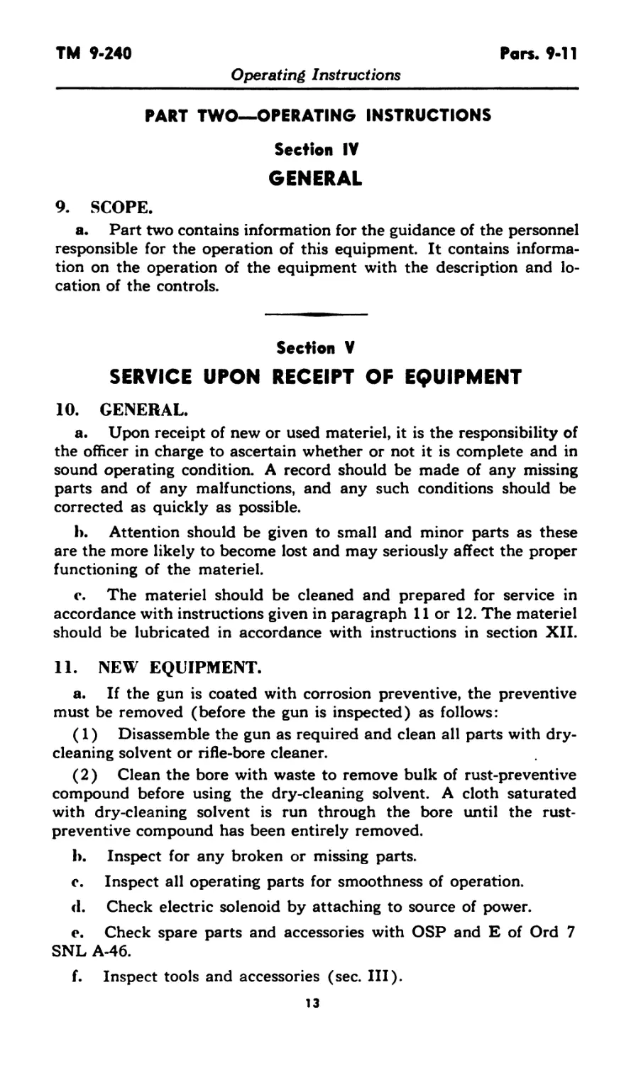
9. SCOPE.
a. Part two contains information for the guidance of the personnel
responsible for the operation of this equipment. It contains informa-
tion on the operation of the equipment with the description and lo-
cation of the controls.
Section V
SERVICE UPON RECEIPT OF EQUIPMENT
10. GENERAL.
a. Upon receipt of new or used materiel, it is the responsibility of
the officer in charge to ascertain whether or not it is complete and in
sound operating condition. A record should be made of any missing
parts and of any malfunctions, and any such conditions should be
corrected as quickly as possible.
b. Attention should be given to small and minor parts as these
are the more likely to become lost and may seriously affect the proper
functioning of the materiel.
c. The materiel should be cleaned and prepared for service in
accordance with instructions given in paragraph 11 or 12. The materiel
should be lubricated in accordance with instructions in section XII.
11. NEW EQUIPMENT.
a. If the gun is coated with corrosion preventive, the preventive
must be removed (before the gun is inspected) as follows:
(1) Disassemble the gun as required and clean all parts with dry-
cleaning solvent or rifle-bore cleaner.
(2) Clean the bore with waste to remove bulk of rust-preventive
compound before using the dry-cleaning solvent. A cloth saturated
with dry-cleaning solvent is run through the bore until the rust-
preventive compound has been entirely removed.
b. Inspect for any broken or missing parts.
c. Inspect all operating parts for smoothness of operation.
<1 . Check electric solenoid by attaching to source of power.
e. Check spare parts and accessories with OSP and E of Ord 7
SNL A-46.
f. Inspect tools and accessories (sec. III).
13
Pars. 12-13 TM 9-240
Operating Instructions
12. USED EQUIPMENT.
a. The services required to insure proper operation of the ma-
teriel are identical with the information given in paragraph 11, except
for the following additional points:
(1) Check Modification Record Card (O.O. Form 7451) to see
if it is up to date.
(2) Check recuperator for proper oil level.
Section VI
CONTROLS
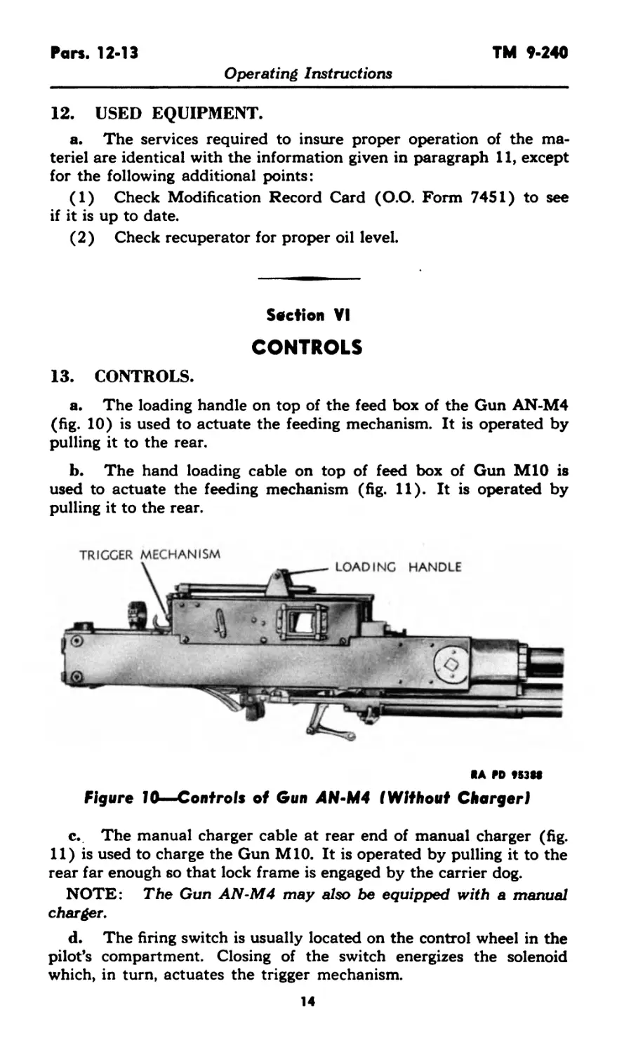
13. CONTROLS.
a. The loading handle on top of the feed box of the Gun AN-M4
(fig. 10) is used to actuate the feeding mechanism. It is operated by
pulling it to the rear.
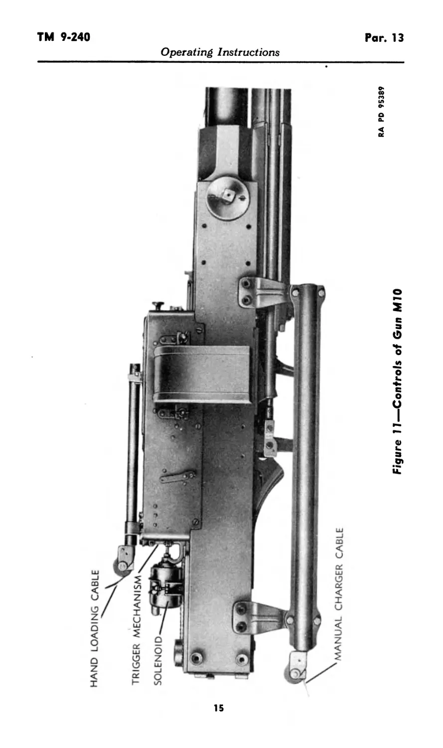
b. The hand loading cable on top of feed box of Gun MIO is
used to actuate the feeding mechanism (fig. 11). It is operated by
pulling it to the rear.
TRIGGER MECHANISM
RA FD 9S38S
Figure 10—Controls of Gun 4N-M4 (Without Charger)
c. The manual charger cable at rear end of manual charger (fig.
11) is used to charge the Gun MIO. It is operated by pulling it to the
rear far enough so that lock frame is engaged by the carrier dog.
NOTE: The Gun AN-M4 may also be equipped with a manual
charger.
d. The firing switch is usually located on the control wheel in the
pilot’s compartment. Closing of the switch energizes the solenoid
which, in turn, actuates the trigger mechanism.
14
HAND LOADING CABLE
Figure 11—Controls of Gun MIO
RA PD 95389
Operating Instructions
Par. 14 TM 9-240
Operating Instructions
Section VII
OPERATION UNDER USUAL CONDITIONS
14. LOADING THE GUN MIO.
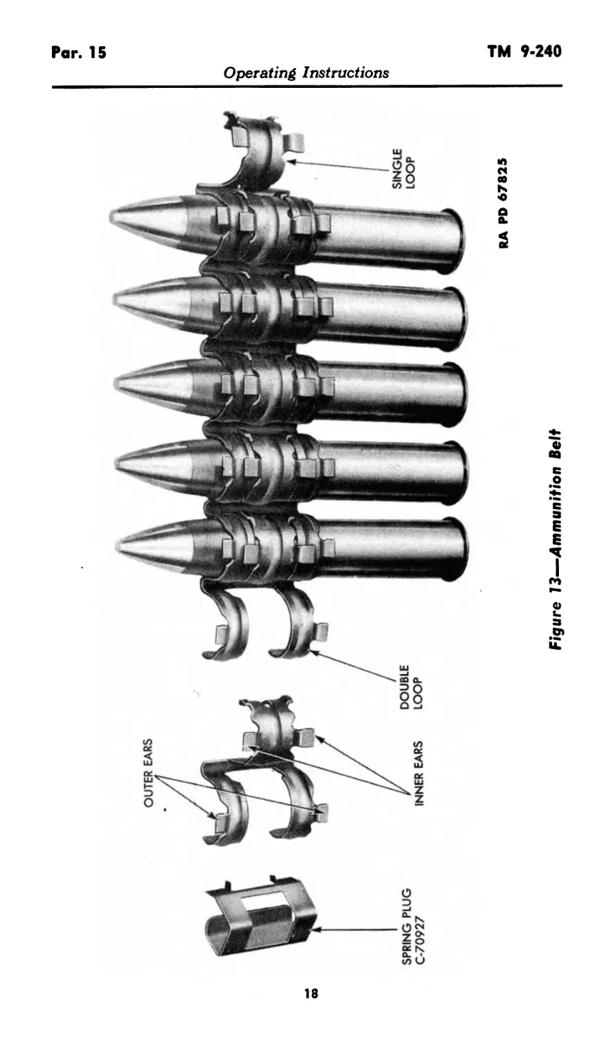
a. Filling the Disintegrating Belt (figs. 12 and 13).
(1) Place the links on a flat surface, open ends up and single loop
to the left. Slide the single loops between the double loops until they
are in line.
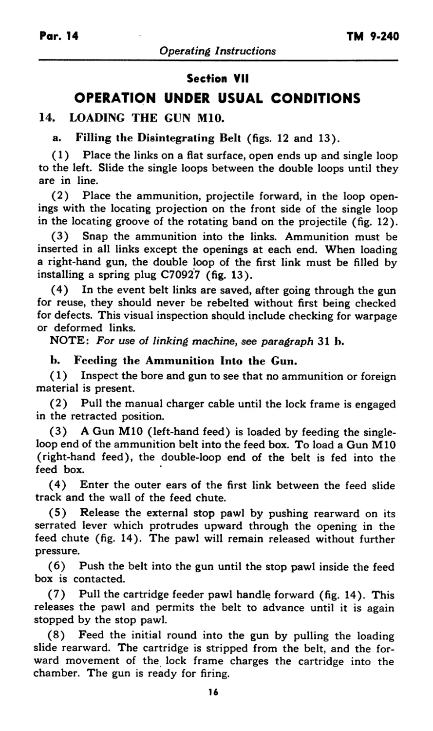
(2) Place the ammunition, projectile forward, in the loop open-
ings with the locating projection on the front side of the single loop
in the locating groove of the rotating band on the projectile (fig. 12).
(3) Snap the ammunition into the links. Ammunition must be
inserted in all links except the openings at each end. When loading
a right-hand gun, the double loop of the first link must be filled by
installing a spring plug C70927 (fig. 13).
(4) In the event belt links are saved, after going through the gun
for reuse, they should never be rebelted without first being checked
for defects. This visual inspection should include checking for warpage
or deformed links.
NOTE: For use of linking machine, see paragraph 31 b.
b. Feeding the Ammunition Into the Gun.
(1) Inspect the bore and gun to see that no ammunition or foreign
material is present.
(2) Pull the manual charger cable until the lock frame is engaged
in the retracted position.
(3) A Gun MIO (left-hand feed) is loaded by feeding the single-
loop end of the ammunition belt into the feed box. To load a Gun MIO
(right-hand feed), the double-loop end of the belt is fed into the
feed box.
(4) Enter the outer ears of the first link between the feed slide
track and the wall of the feed chute.
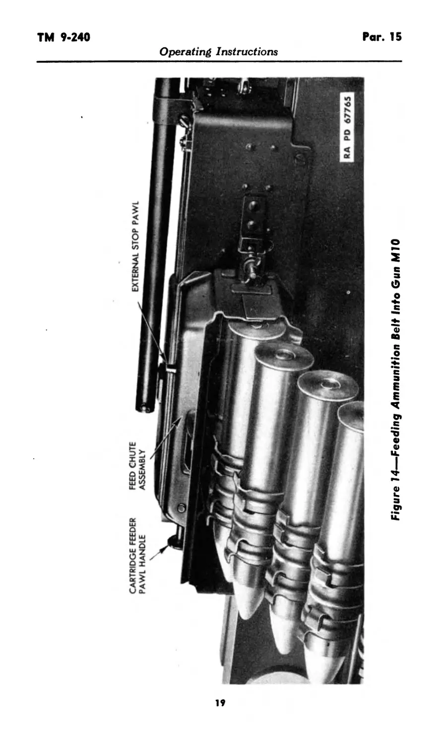
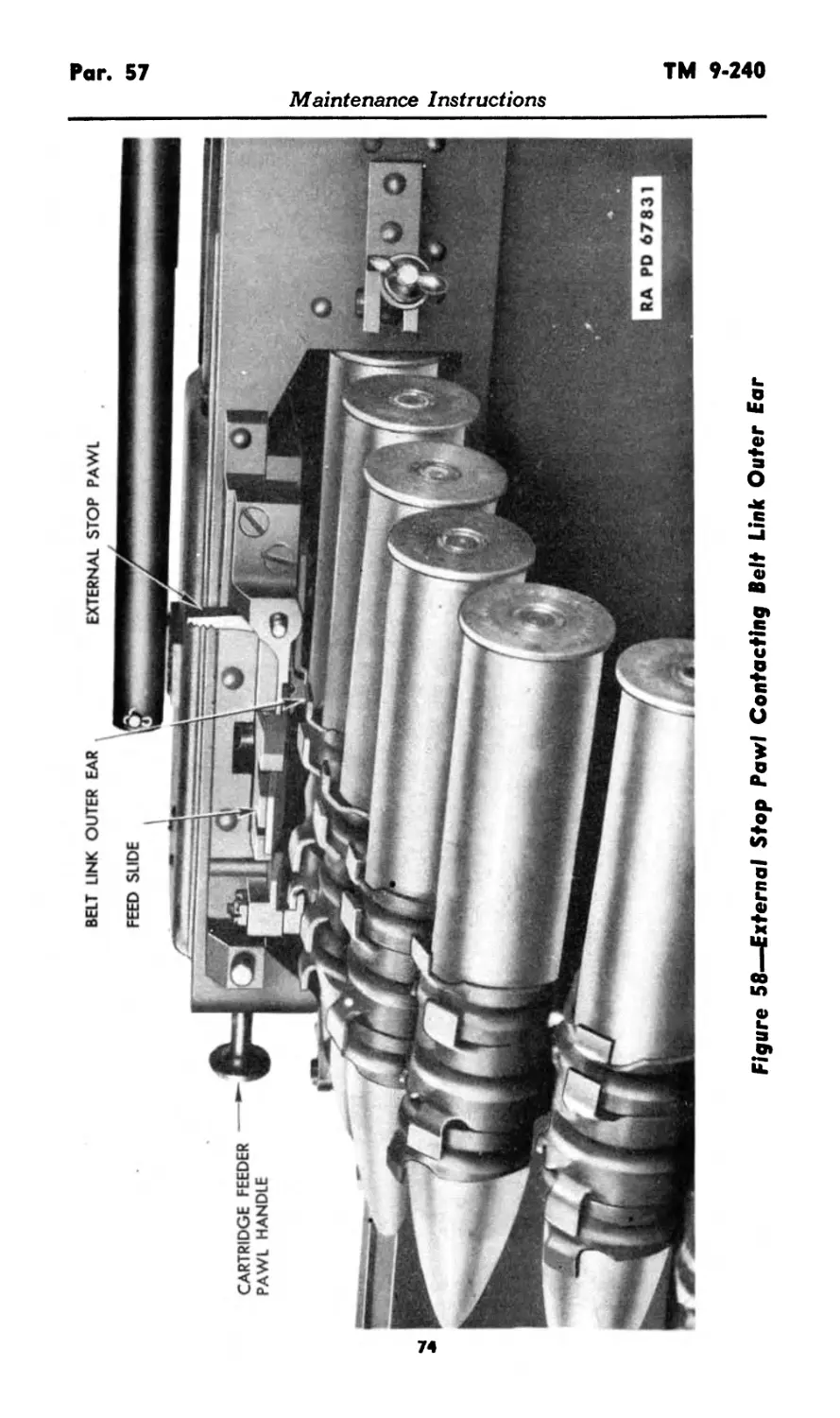
(5) Release the external stop pawl by pushing rearward on its
serrated lever which protrudes upward through the opening in the
feed chute (fig. 14). The pawl will remain released without further
pressure.
(6) Push the belt into the gun until the stop pawl inside the feed
box is contacted.
(7) Pull the cartridge feeder pawl handle forward (fig. 14). This
releases the pawl and permits the belt to advance until it is again
stopped by the stop pawl.
(8) Feed the initial round into the gun by pulling the loading
slide rearward. The cartridge is stripped from the belt, and the for-
ward movement of the lock frame charges the cartridge into the
chamber. The gun is ready for firing.
16
TM 9-240
Par. 15
Operating Instructions
RA PD 95390
Figure 12—Belting 37-mm Ammunition
15. LOADING THE GUN AN-M4.
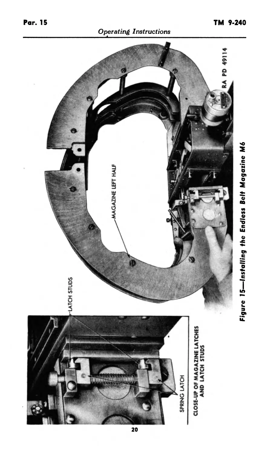
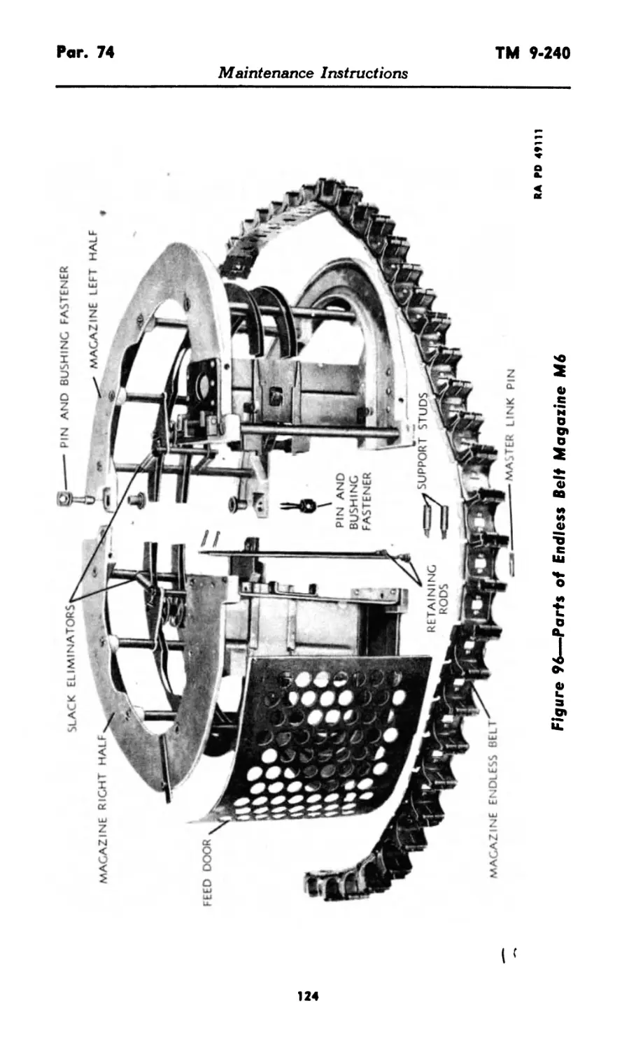
a. Installing the Endless Belt Magazine M6.
(1) Replace the center and front (right side) feed box screws
with magazine support studs (fig. 96).
(2) Attach the right half of the magazine by means of the re-
taining rods and secure with the cotter pins (figs. 15 and 96).
(3) Attach the left half of the magazine so that the spring latches
on the magazine half engage the latch studs on the feed box (figs.
15 and 96).
(4) Secure the magazine halves at the top by replacing the pin
and bushing fasteners on front and rear (fig. 96). NOTE: Early
models may have bolts instead of fasteners as means of securing the
halves.
17
<л
RA PD 67825
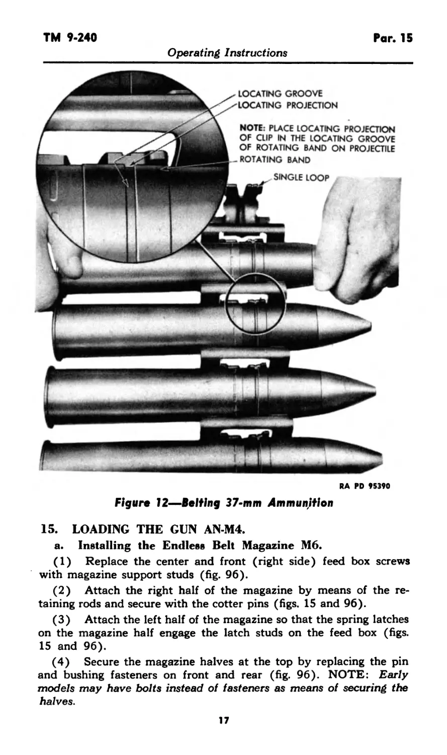
Figure 13—Ammunition Belt
Operating Instructions
CARTRIDGE feeder
pawl handle
FEED CHUTE
assembly
external stop pawl
STUDS
Figure 15—Installing the Endless Belt Magazine M6
RA PD 49114
CLOSE-UP OF MAGAZINE LATCHES
AND LATCH STUDS
TM 9-240
Par. 15
Operating Instructions
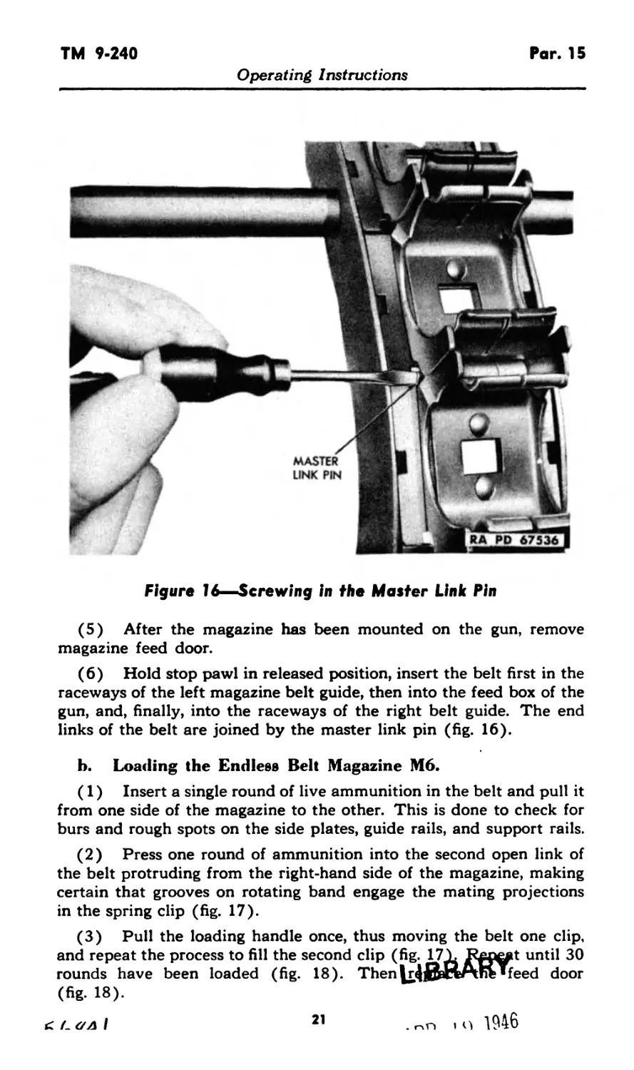
Figure 16—Screwing in the Master Link Pin
(5) After the magazine has been mounted on the gun, remove
magazine feed door.
(6) Hold stop pawl in released position, insert the belt first in the
raceways of the left magazine belt guide, then into the feed box of the
gun, and, finally, into the raceways of the right belt guide. The end
links of the belt are joined by the master link pin (fig. 16).
b. Loading the Endless Belt Magazine M6.
(1) Insert a single round of live ammunition in the belt and pull it
from one side of the magazine to the other. This is done to check for
burs and rough spots on the side plates, guide rails, and support rails.
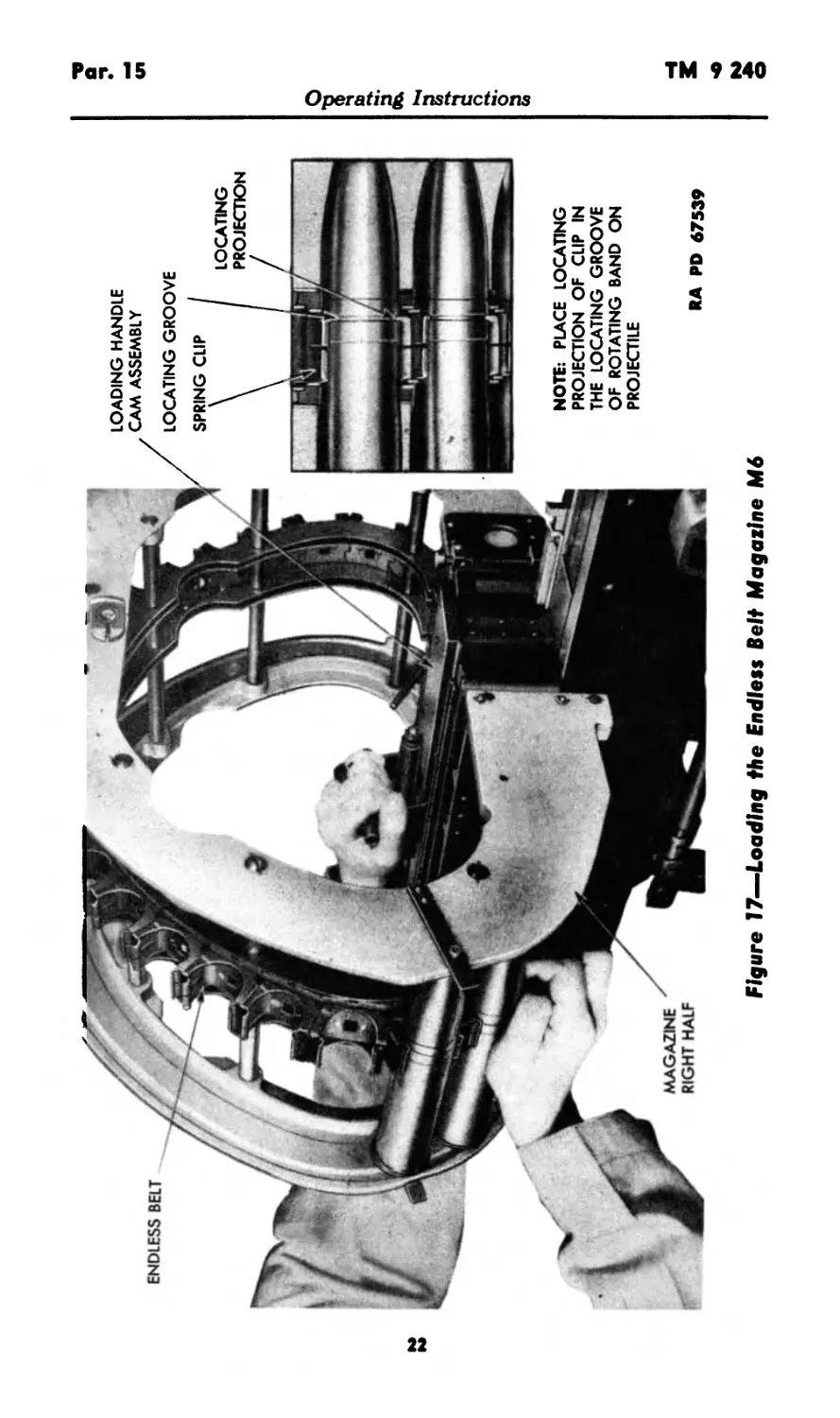
(2) Press one round of ammunition into the second open link of
the belt protruding from the right-hand side of the magazine, making
certain that grooves on rotating band engage the mating projections
in the spring clip (fig. 17).
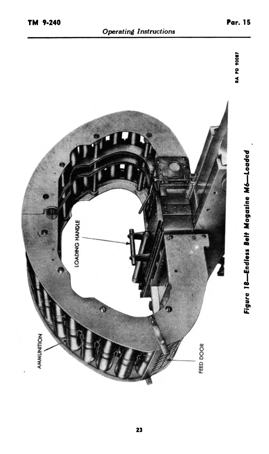
(3) Pull the loading handle once, thus moving the belt one clip,
and repeat the process to fill the second clip (fig. 171. Kgxrat until 30
rounds have been loaded (fig. 18). Then feed door
(fig. 18).
c L ал I 21 . no i q 1946
ENDLESS BELT
LOCATING GROOVE
SPRING CLIP
LOCATING
PROJECTION
LOADING HANDLE
CAM ASSEMBLY
RA PD 67539
Figure 77—Loading the Endless Belt Magazine M6
MAGAZINE
RIGHT HALF
NOTE: PLACE LOCATING
PROJECTION OF CLIP IN
THE LOCATING GROOVE
OF ROTATING BAND ON
PROJECTILE
Operating Instructions
<л
Figure 18—Endless Belt Magazine M6—Loaded
RA PD 90087
Operating Instructions
Pars. 15-18 TM 9-240
Operating Instructions
(4) One empty clip must be protruding from the right side of the
magazine. Instructions for loading are to be rigidly followed to pre-
vent a possibility of double feeding when the gun is loaded manually
by pulling the loading handle. Only 30 rounds are to be loaded. Be-
fore removing any rounds, the magazine feed door must be removed.
c. Feeding the Ammfinition Into the Gun.
(1) To load the gun from the magazine, give the charging handle
and then the loading handle a vigorous pull and release immediately.
Quick operation insures proper functioning of the moving parts of the
loading and charging mechanisms.
(2) The charging handle retracts the lock frame until it is held
by the carrier dog and positions the first round in the feed box; the
loading handle strips the first round from the belt, releasing the carrier.
The released carrier forces the round into position in front of the
charger. Forward movement then chambers the round and the gun is
ready to fire.
CAUTION: If, in loading the belt, a round is positioned inside
the feed box, the operation of the charging handle only will strip it
from the belt and chamber the round. In such a case the loading
handle should not be pulled as this would feed a round into the gun
on top of the charger and result in a jam.
16. FIRING.
a. Closing of the circuit in the firing switch operates the trigger
by means of the solenoid located on the top plate of the gun.
b. The trigger will remain pulled as long as the switch is closed,
and the gun will fire automatically until the ammunition is expended.
When the switch is released, the trigger is returned to its released
position, and firing ceases.
17. CORRECTIONS OF STOPPAGES IN COMBAT FIRING.
a. The design of the gun and its location outside the reach of the
gunner usually make it impossible to remedy stoppages in flight.
b. When a stoppage occurs during combat firing, recharge the
gun immediately, if recharging is possible, and attempt to fire. If the
weapon cannot be recharged, no corrective action is possible.
18. UNLOADING.
a. Gun MIO.
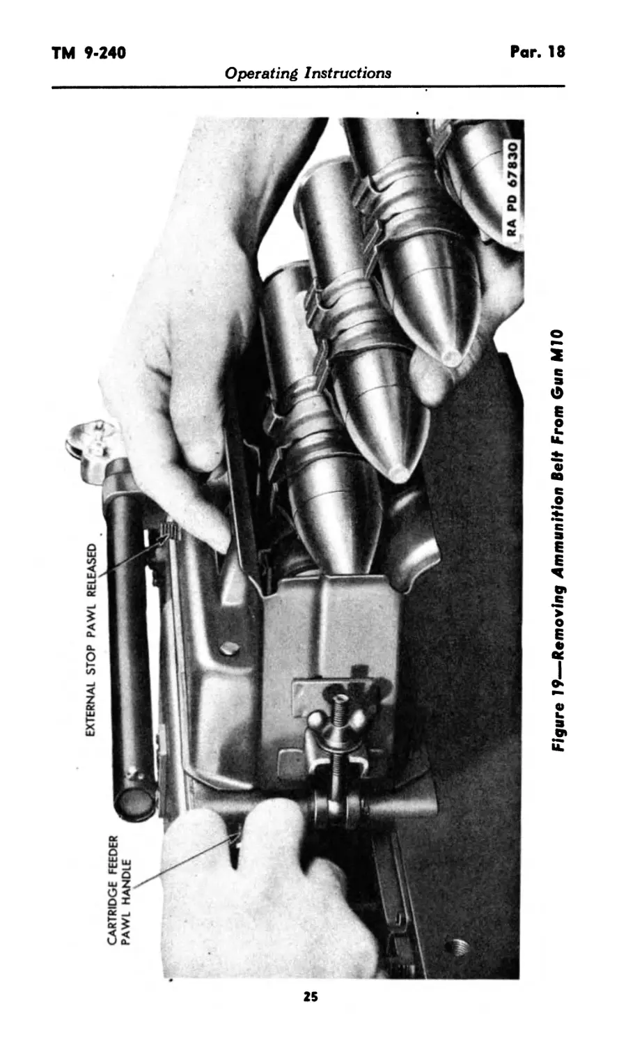
(1) To Remove the Ammunition Belt.
(a) Release the external stop pawl (fig. 19).
(b) Pull forward on the cartridge feeder pawl handle, and hold
in the forward position to keep the holding pawl released (fig. 19).
24
CARTRIDGE FEEDER
PAWL HANDLE
EXTERNAL STOP PAWL RELEASED
Figure 19—Removing Ammunition Belt From Gun MIO
Operating Instructions
Par. 18 TM 9-240
Operating Instructions
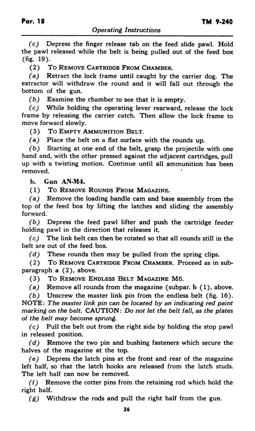
(c) Depress the finger release tab on the feed slide pawl. Hold
the pawl released while the belt is being pulled out of the feed box
(fig. 19).
(2) To Remove Cartridge From Chamber.
(a) Retract the lock frame until caught by the carrier dog. The
extractor will withdraw the round and it will fall out through the
bottom of the gun.
(b) Examine the chamber to see that it is empty.
(c) While holding the operating lever rearward, release the lock
frame by releasing the carrier catch. Then allow the lock frame to
move forward slowly.
(3) To Empty Ammunition Belt.
(a) Place the belt on a flat surface with the rounds up.
(b) Starting at one end of the belt, grasp the projectile with one
hand and, with the other pressed against the adjacent cartridges, pull
up with a twisting motion. Continue until all ammunition has been
removed.
b. Gun AN-M4.
(1) To Remove Rounds From Magazine.
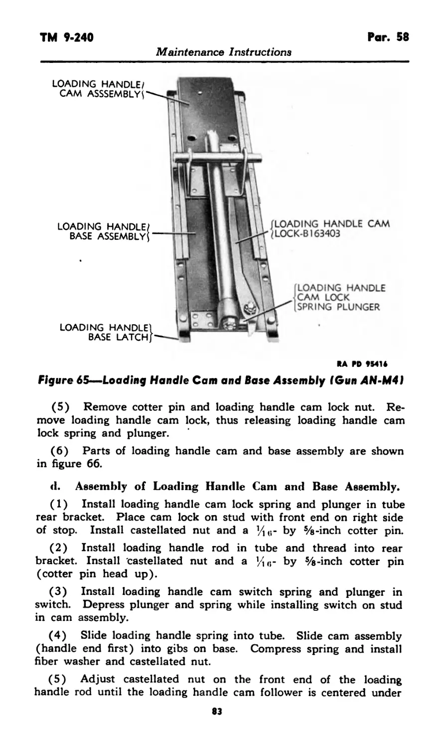
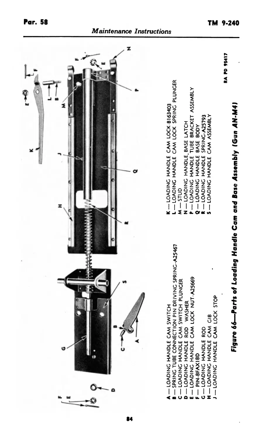
(a) Remove the loading handle cam and base assembly from the
top of the feed box by lifting the latches and sliding the assembly
forward.
(b) Depress the feed pawl lifter and push the cartridge feeder
holding pawl in the direction that releases it.
(c) The link belt can then be rotated so that all rounds still in the
belt are out of the feed box.
(d) These rounds then may be pulled from the spring clips.
(2) To Remove Cartridge From Chamber. Proceed as in sub-
paragraph a (2), above.
(3) To Remove Endless Belt Magazine M6.
(a) Remove all rounds from the magazine (subpar, b (1), above.
(b) Unscrew the master link pin from the endless belt (fig. 16).
NOTE: The master link pin can be located by an indicating red paint
marking on the belt. CAUTION: Do not let the belt fall, as the plates
of the belt may become sprung.
(c) Pull the belt out from the right side by holding the stop pawl
in released position.
(d) Remove the two pin and bushing fasteners which secure the
halves of the magazine at the top.
(e) Depress the latch pins at the front and rear of the magazine
left half, so that the latch hooks are released from the latch studs.
The left half can now be removed.
(f) Remove the cotter pins from the retaining rod which hold the
right half.
(g) Withdraw the rods and pull the right half from the gun.
26
TM 9-240 Pars. 19-21
Operating Instructions
Section VIII
OPERATION UNDER UNUSUAL CONDITIONS
19. GENERAL.
a. When operating the gun under unusual conditions, such as
extreme cold or heat, severe dust or sand conditions, and near salt
water, the precautions listed below should be scrupulously followed.
20. EXTREME COLD.
a. In extremely cold temperatures, it is essential that all moving
parts be kept absolutely free of moisture. Clean and lubricate all
parts but do not use excess lubricant because it may solidify to such
an extent as to cause sluggish movement or complete failure. When
the gun is in the open, cover all unprotected parts with tarpaulin or
other suitable material. Select a firm covering so that no loose ma-
terial will get into the working parts of the gun. When the gun is
transferred from the outside into a heated building, clean and oil it
immediately. After the gun has reached room temperature, wipe it
dry with a clean cloth, and oil again.
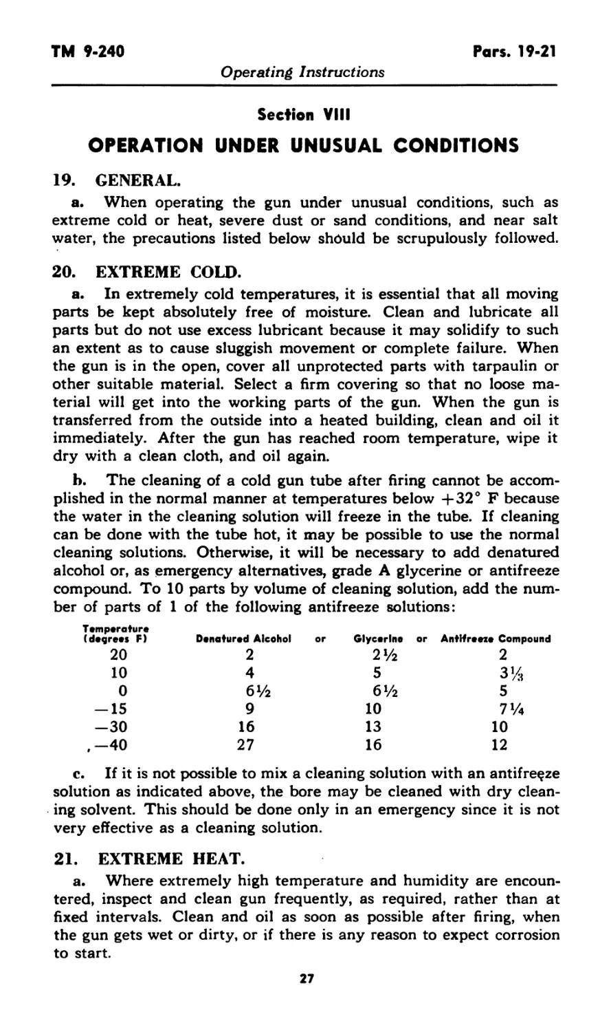
b. The cleaning of a cold gun tube after firing cannot be accom-
plished in the normal manner at temperatures below 4-32° F because
the water in the cleaning solution will freeze in the tube. If cleaning
can be done with the tube hot, it may be possible to use the normal
cleaning solutions. Otherwise, it will be necessary to add denatured
alcohol or, as emergency alternatives, grade A glycerine or antifreeze
compound. To 10 parts by volume of cleaning solution, add the num-
ber of parts of 1 of the following antifreeze solutions:
Temperature
(degrees F) Denatured Alcohol or Glycerine or Antifreeze Compound
20 2 2% 2
10 4 5 3%
0 61/2 61/2 5
-15 9 10 7%
-30 16 13 10
,—40 27 16 12
c. If it is not possible to mix a cleaning solution with an antifreeze
solution as indicated above, the bore may be cleaned with dry clean-
ing solvent. This should be done only in an emergency since it is not
very effective as a cleaning solution.
21. EXTREME HEAT.
a. Where extremely high temperature and humidity are encoun-
tered, inspect and clean gun frequently, as required, rather than at
fixed intervals. Clean and oil as soon as possible after firing, when
the gun gets wet or dirty, or if there is any reason to expect corrosion
to start.
Pars. 22-26
TM 9-240
Operating Instructions
22. SEVERE DUST OR SAND CONDITIONS.
a. If considerable dust is present when the gun is operated, all
lubricants on working surfaces should be reduced to a minimum.
Lubricants contaminated with dust or sand are more harmful to the
gun than no lubricant at all, as the grease or oil will catch and hold
dust or sand which acts as an abrasive. Clean the gun thoroughly
when firing is over, and relubricate.
23. LOCATIONS NEAR SALT WATER.
a. In excessively salty atmosphere, the oil or rust preventive used
should be changed often as the salt has a tendency to emulsify the
oil and destroy its rust-preventive qualities.
Section IX
DEMOLITION TO PREVENT ENEMY USE
24. GENERAL.
a. The destruction of the materiel when subject to capture or
abandonment in the combat zone will be undertaken by the using
arm only as a command function, on authority delegated by the
division or higher command when such action is deemed necessary
as a final resort to keep the materiel from reaching enemy hands.
25. DESTRUCTION BY FIRE.
a. Generally, the destruction of the airplane by incendiary means
is sufficient to render the armament useless. However, since there are
cases where it is impractical to set fire to the plane, additional methods
are outlined below in order of effectiveness.
26. DESTRUCTION BY TNT.
a. Open drain plug on recoil mechanism, allowing recoil fluid to
drain. It is not necessary to wait for the recoil fluid to drain com-
pletely before igniting the fuze (subpar, e, below).
b. Remove an HE shell from a complete round, and seat the
shell in the chamber.
c. Plug the bore for approximately two-thirds of its length, using
a cleaning staff wrapped with cloth or waste to make it fit tightly in
the bore. Mud, stones, clay, etc., may be used to plug the bore in
lieu of the ramrod.
28
TM 9-240 Pars. 26-29
Operating Instructions
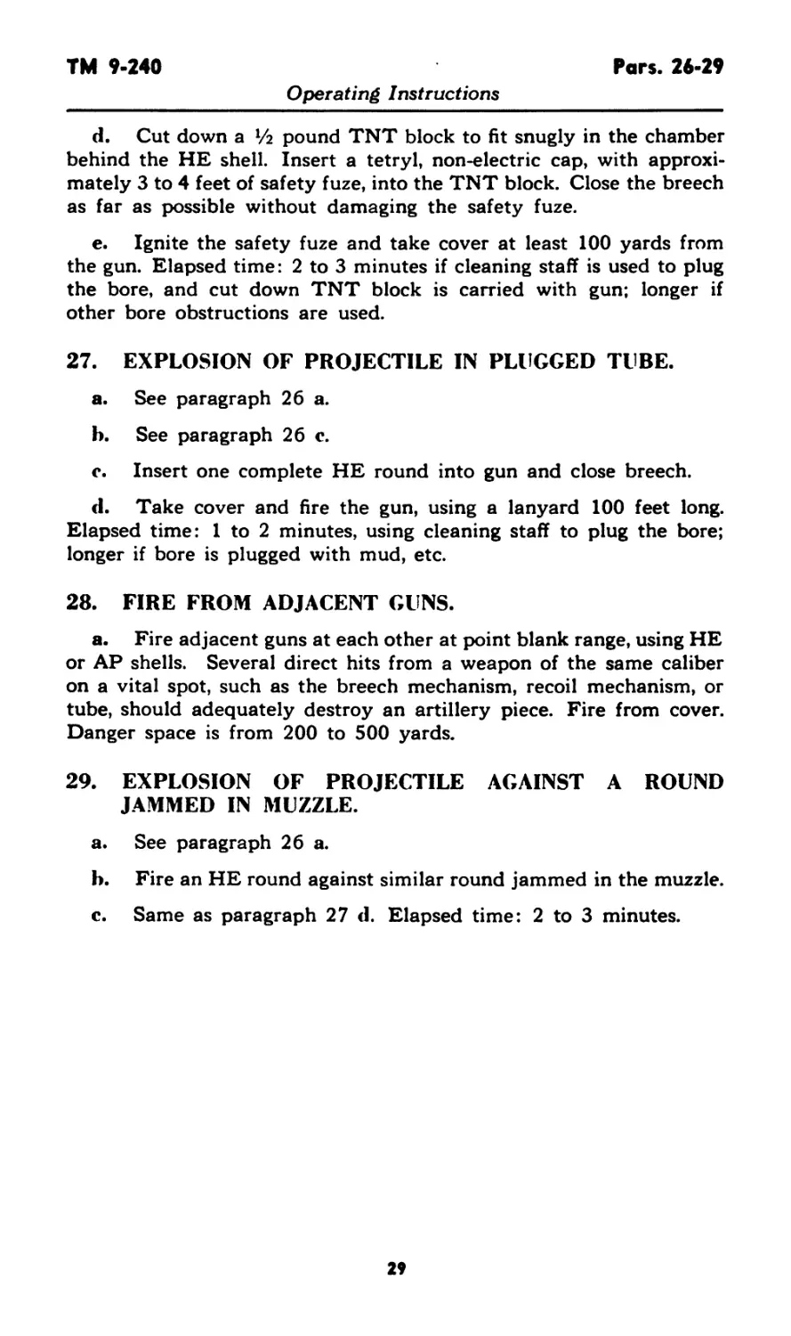
d. Cut down а У2 pound TNT block to fit snugly in the chamber
behind the HE shell. Insert a tetryl, non-electric cap, with approxi-
mately 3 to 4 feet of safety fuze, into the TNT block. Close the breech
as far as possible without damaging the safety fuze.
e. Ignite the safety fuze and take cover at least 100 yards from
the gun. Elapsed time: 2 to 3 minutes if cleaning staff is used to plug
the bore, and cut down TNT block is carried with gun; longer if
other bore obstructions are used.
27. EXPLOSION OF PROJECTILE IN PLUGGED TUBE.
a. See paragraph 26 a.
b. See paragraph 26 c.
c. Insert one complete HE round into gun and close breech.
d. Take cover and fire the gun, using a lanyard 100 feet long.
Elapsed time: 1 to 2 minutes, using cleaning staff to plug the bore;
longer if bore is plugged with mud, etc.
28. FIRE FROM ADJACENT GUNS.
a. Fire adjacent guns at each other at point blank range, using HE
or AP shells. Several direct hits from a weapon of the same caliber
on a vital spot, such as the breech mechanism, recoil mechanism, or
tube, should adequately destroy an artillery piece. Fire from cover.
Danger space is from 200 to 500 yards.
29. EXPLOSION OF PROJECTILE AGAINST A ROUND
JAMMED IN MUZZLE.
a. See paragraph 26 a.
b. Fire an HE round against similar round jammed in the muzzle.
c. Same as paragraph 27 d. Elapsed time: 2 to 3 minutes.
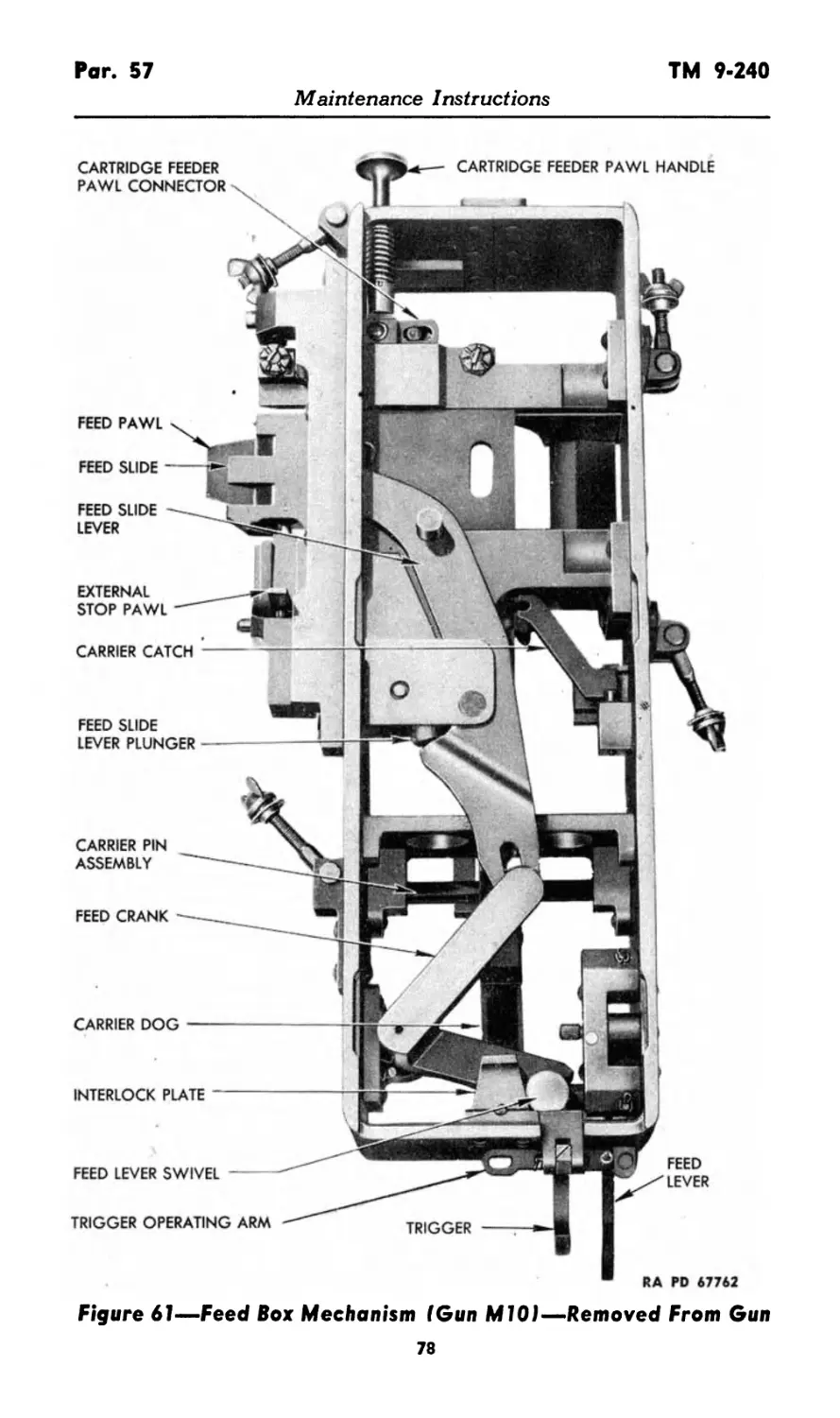
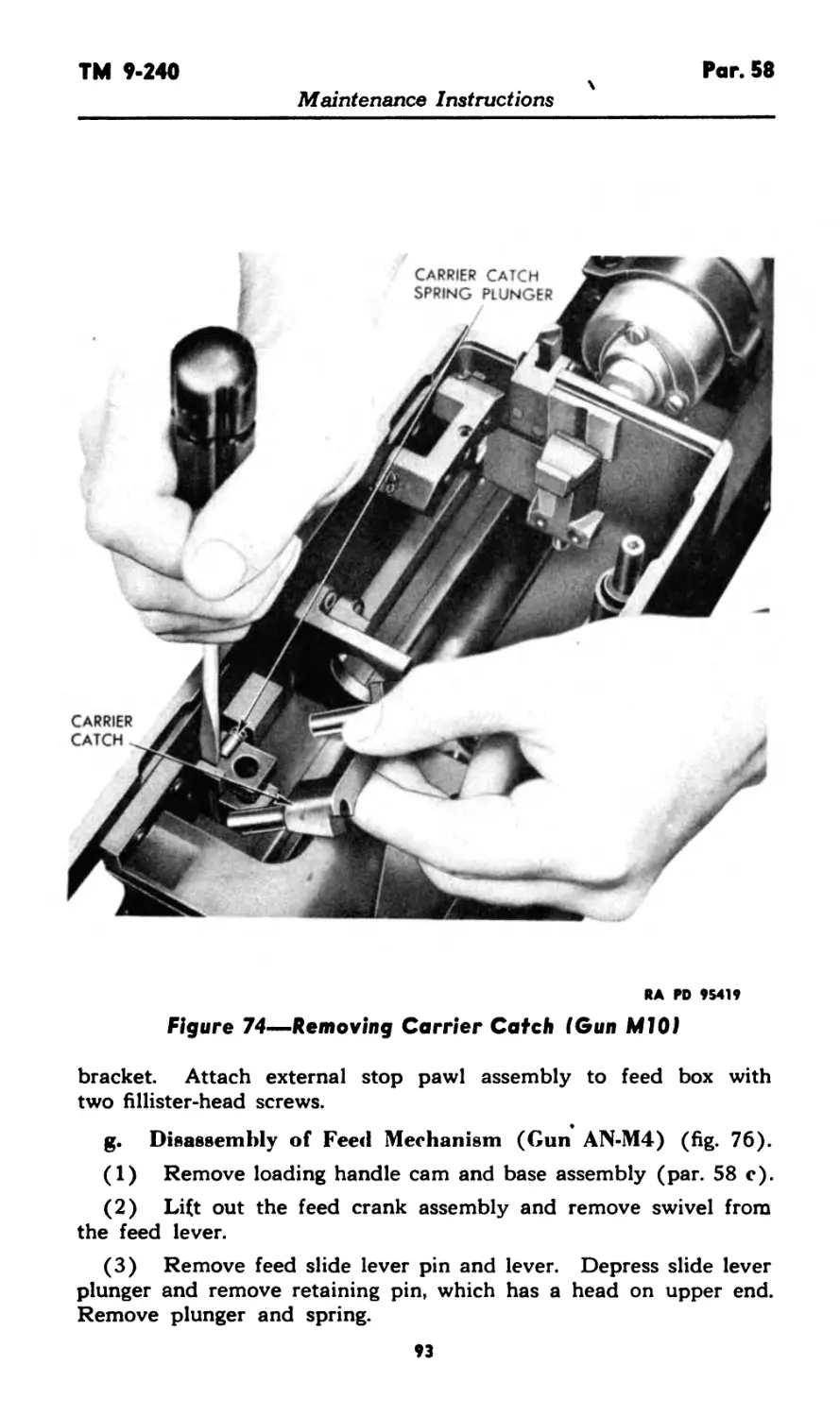
29
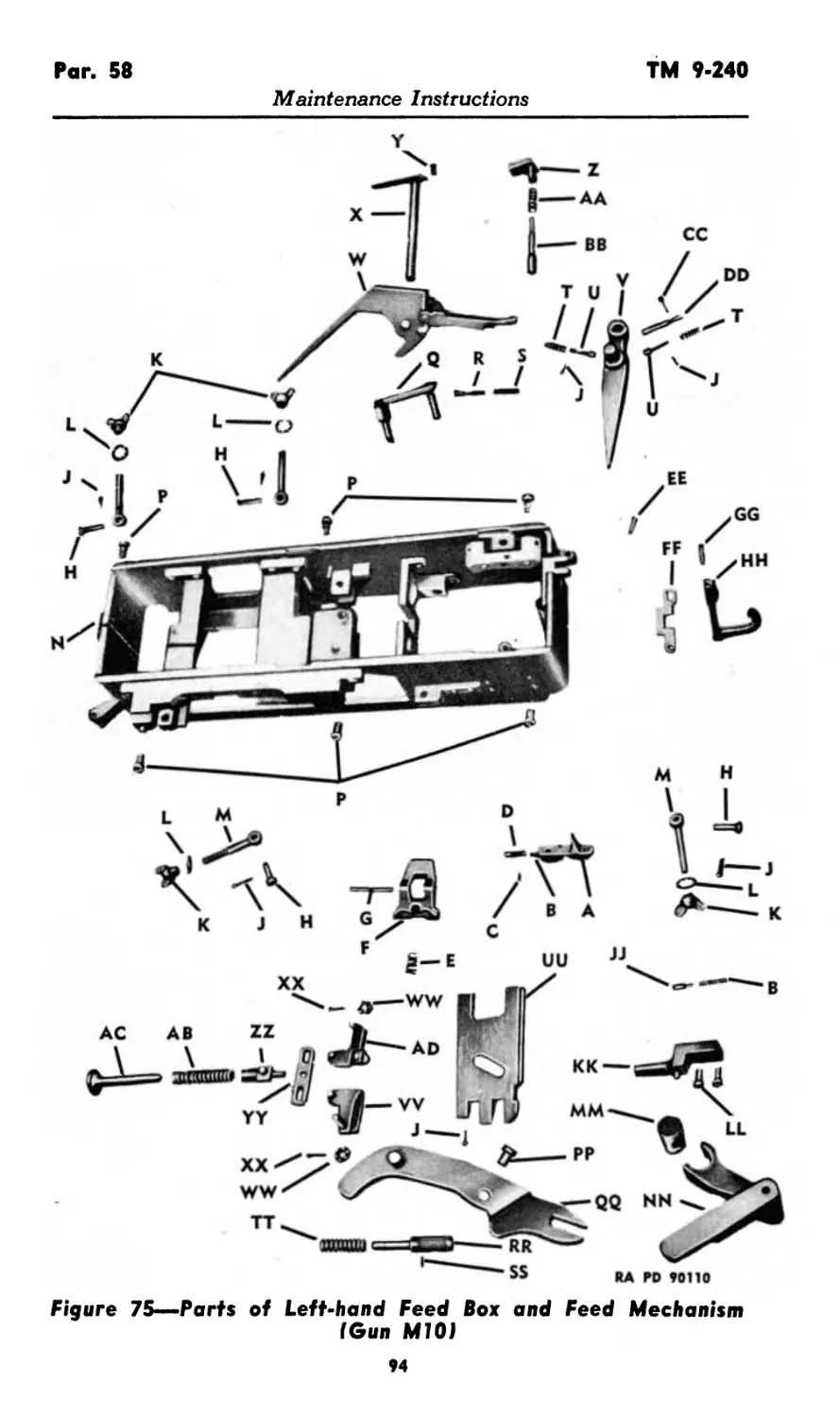
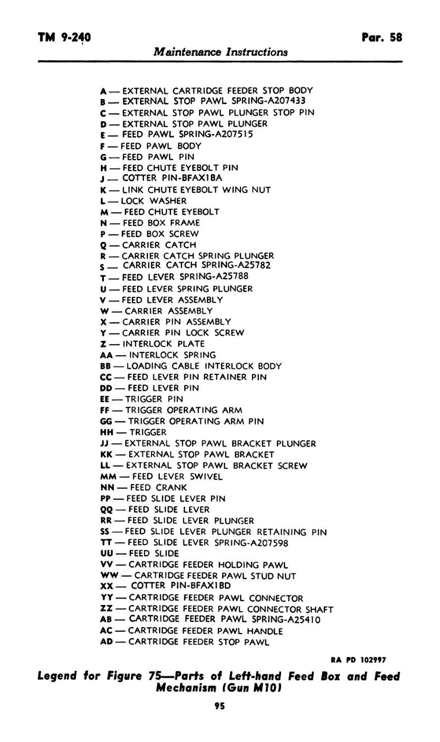
Pars. 30-31
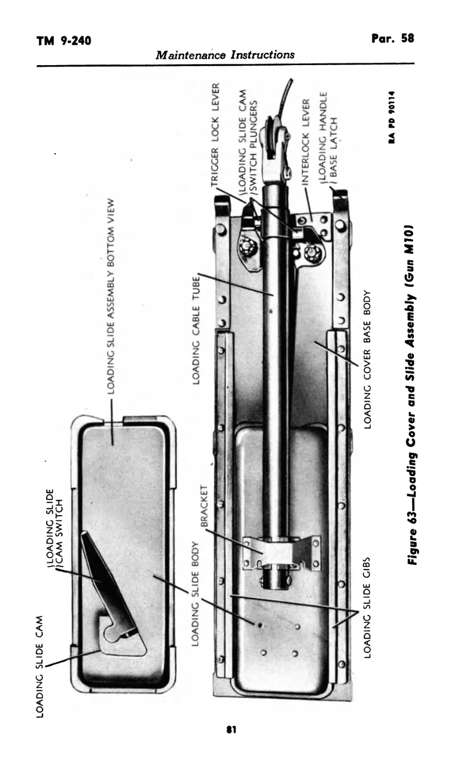
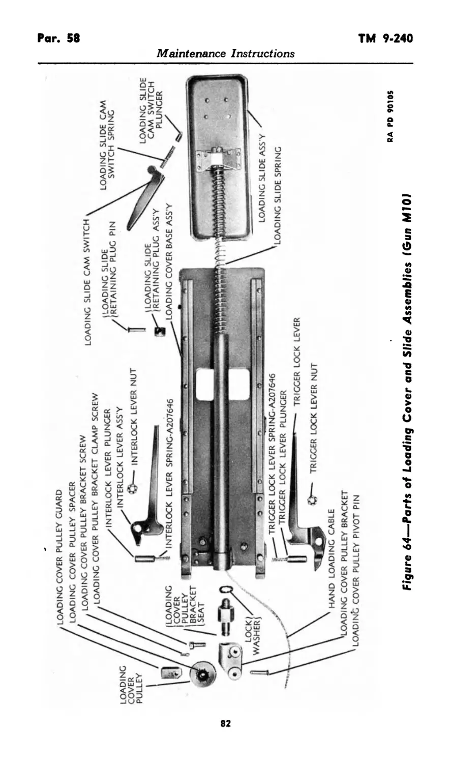
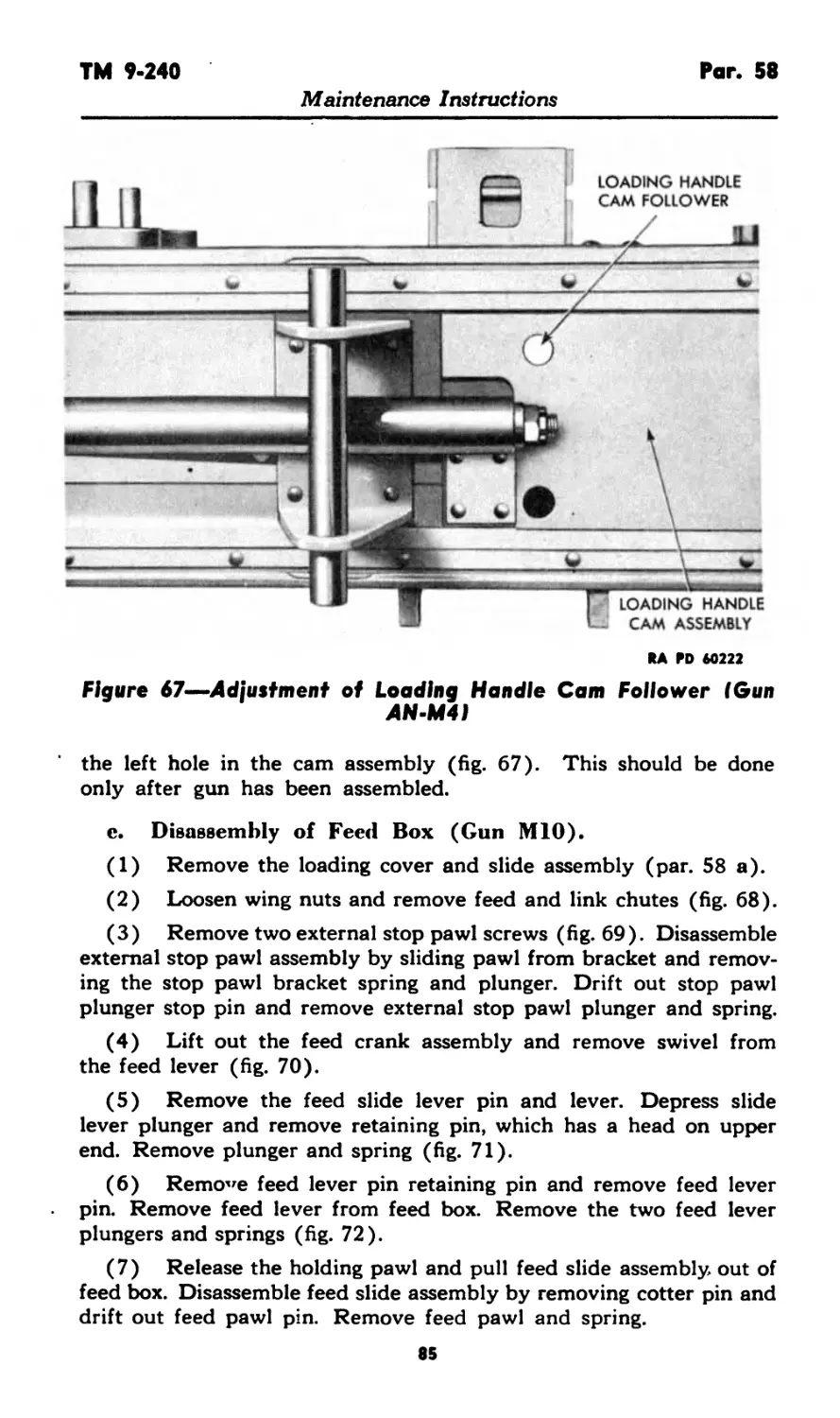
TM 9-240
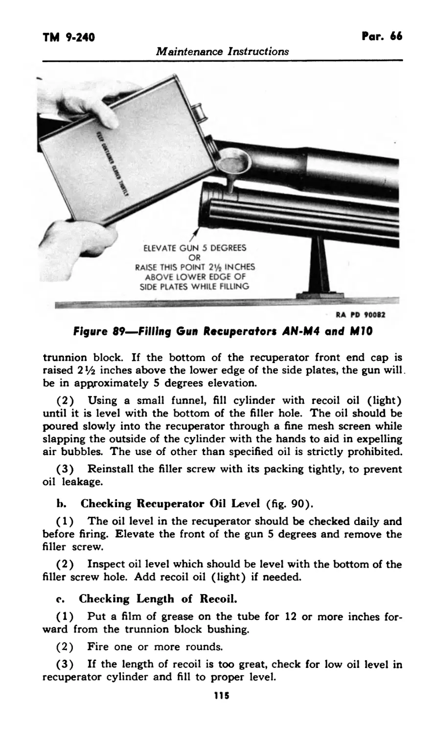
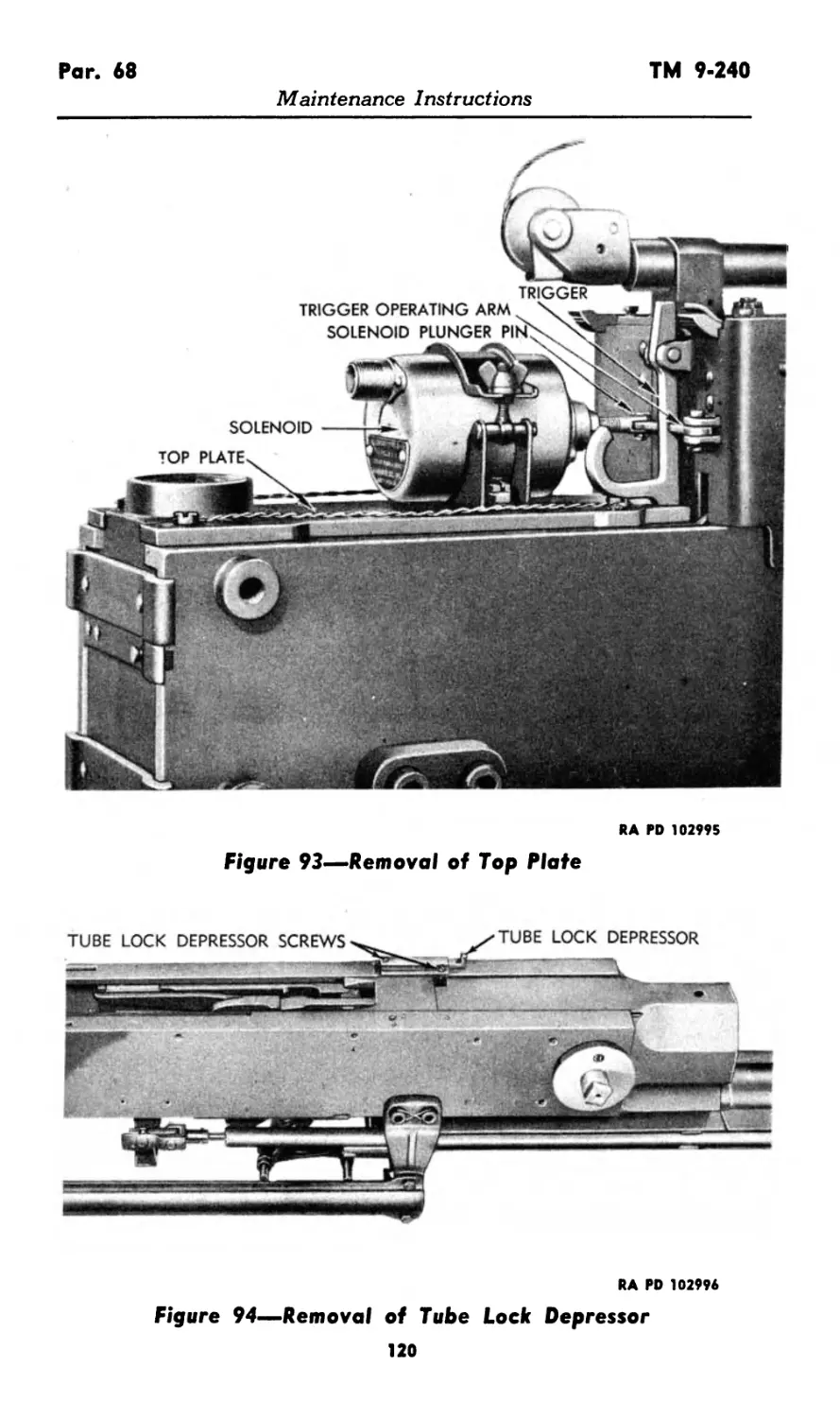
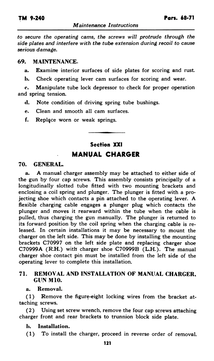
Maintenance Instructions
PART THREE—MAINTENANCE INSTRUCTIONS
Section X
GENERAL
30. SCOPE.
a. Part three contains information for the guidance of the per-
sonnel of the using organizations responsible for the maintenance (1st
and 2nd echelon) of this equipment. It contains information needed
for the performance of the scheduled lubrication and preventive
maintenance services as well as description of the major systems and
units and their functions in relation to other components of the
equipment.
Section XI
SPECIAL ORGANIZATIONAL TOOLS AND EQUIPMENT
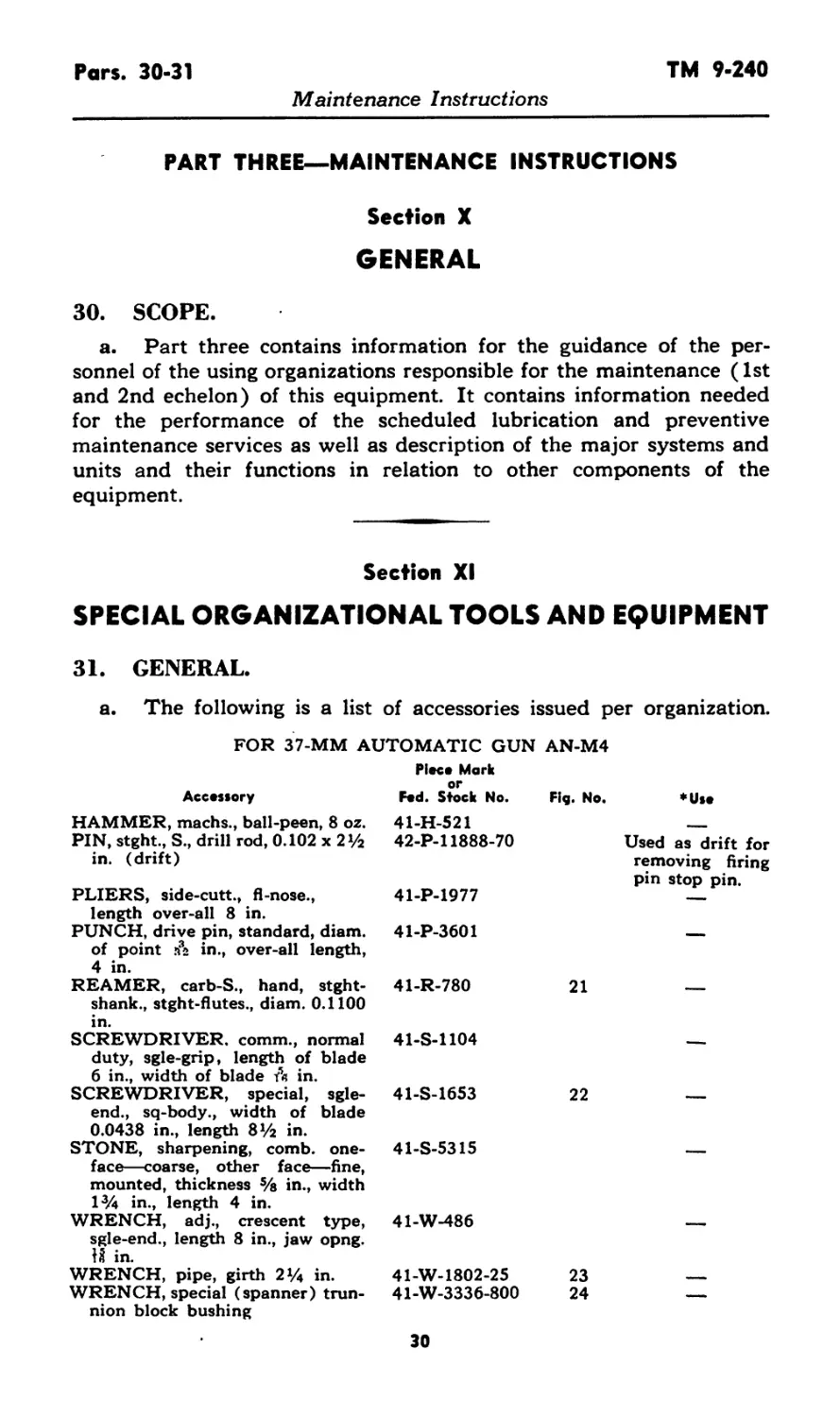
31. GENERAL.
a. The following is a list of accessories issued per organization.
FOR 37-MM AUTOMATIC GUN AN-M4
Piece Mark
Accessory Fed. Stock No. Fig. No. ♦Use
HAMMER, machs., ball-peen, 8 oz. 41-H-521 -
PIN, stght., S., drill rod, 0.102 x 2^2 in. (drift) 42-P-l 1888-70 Used as drift for removing firing pin stop pin.
PLIERS, side-cutt., fl-nose., length over-all 8 in. 41-P-1977 —
PUNCH, drive pin, standard, diam. of point rfb in., over-all length, 4 in. 41-P-3601 —
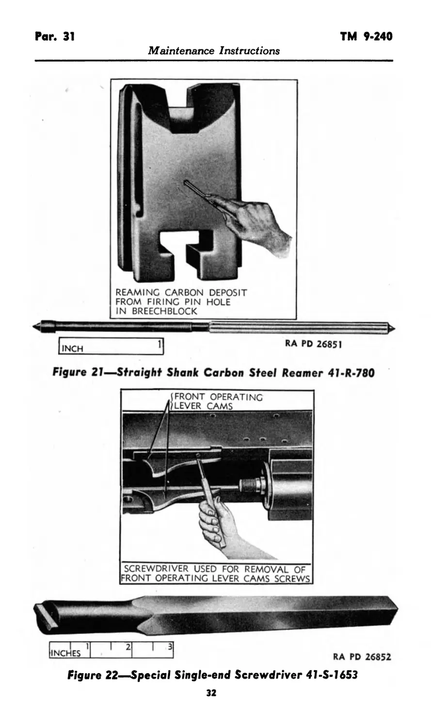
REAMER, carb-S., hand, stght- shank., stght-flutes., diam. 0.1100 in. 41-R-780 21 —
SCREWDRIVER, comm., normal duty, sgle-grip, length of blade 6 in., width of blade Л in. SCREWDRIVER, special, sgle- end., sq-body., width of blade 0.0438 in., length 8V2 in. STONE, sharpening, comb, one- face—coarse, other face—fine, mounted, thickness % in., width l3/4 in., length 4 in. 41-S-1104 —
41-S-1653 22 —
41-S-5315 —
WRENCH, adj., crescent type, sgle-end., length 8 in., jaw opng. IS in. 41-W-486 —
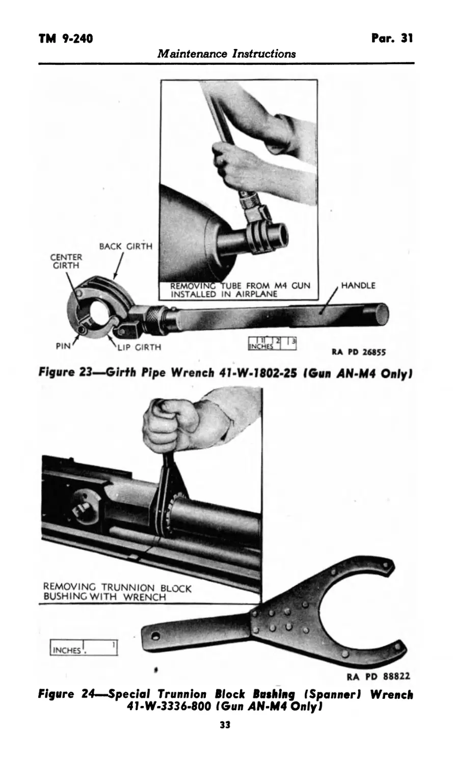
WRENCH, pipe, girth 2% in. WRENCH, special (spanner) trun- nion block bushing 41-W-1802-25 23
41-W-3336-800 24 —
30
TM 9-240
Par. 31
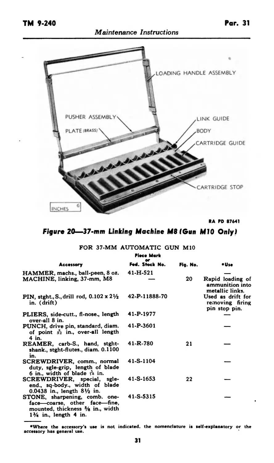
Figure 20—37-mm Linking Machine M8(Gun MIO Only)
FOR 37-MM AUTOMATIC GUN MIO
Piece Mark
Accessory Fed. Stock No. Rg. No. •Use
HAMMER, machs., ball-peen, 8 oz. 41-H-521
MACHINE, linking, 37-mm, M8 — 20 Rapid loading of ammunition into metallic links.
PIN, stght.,S., drill rod, 0.102 x 2 >/2 in. (drift) 42-P-l 1888-70 Used as drift for removing firing pin stop pin.
PLIERS, side-cutt., fl-nose., length over-all 8 in. 41-P-1977 —
PUNCH, drive pin, standard, diam. of point за2 in., over-all length 4 in. 41-P-3601 —
REAMER, carb-S., hand, stght- shank., stght-flutes., diam. 0.1100 in. 41-R-780 21 —
SCREWDRIVER, comm., normal duty, sgle-grip, length of blade 6 in., width of blade Л in. SCREWDRIVER, special, sgle- end., sq-body., width of blade 0.0438 in., length 8 ¥2 in. STONE, sharpening, comb, one- 41-S-1104 —
41-S-1653 22 —
41-S-5315 —
face—coarse, other face—fine,
mounted, thickness 5/e in., width
1% in., length 4 in.
♦Where the accessory's use is not indicated, the nomenclature is
accessory has general use.
self-explanatory or the
31
Par. 31
TM 9-240
Maintenance Instructions
INCH
REAMING CARBON DEPOSIT
FROM FIRING PIN HOLE
IN BREECHBLOCK
RA PD 26851
Figure 21—Straight Shank Carbon Steel Reamer 41-R-780
RA PD 26852
Figure 22—Special Single-end Screwdriver 41-S-1653
1 1 INCHES 1 2 iз
32
TM 9*240
Par. 31
Maintenance Instructions
Figure 23—Girth Pipe Wrench 41-W-1802-2S IGun AN-M4 Only)
Figure 24—Special Trunnion Block Bushing I Spanner i Wrench
41-W-3336-800 (Gun AN-M4 Only!
33
Pars. 31-34 TM 9-240
Maintenance Instructions
b. Instructions as to Use of 37-mm Linking Machine M8. The
linking machine (fig. 20) is used for rapid loading of ammunition
into metallic links for use with the Gun MIO. It may be screwed to
a bench, ammunition box, or other suitable support when in use,
screw holes being provided in its base for this purpose. To operate,
first place the links on the body of the machine, open ends up, single
loop to the left Then slide the single loops between the double loops.
Next place the ammunition in the cartridge guide with the base
against the cartridge stop and the projectiles in the link openings.
Be sure to position the groove of the rotating band on the projectile
in the locating projection on the front side of the single loop. With
the links and projectiles in their proper position, pull the loading
handle assembly forward. This moves the pusher assembly forward
and down until the brass plate on the pusher assembly comes in con-
tact with projectiles directly over links. Continue forward movement
of loading handle assembly until ammunition snaps into the links.
Section XII
LUBRICATION
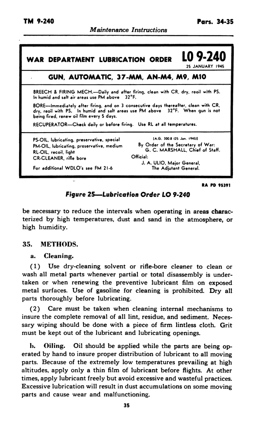
32. LUBRICATION ORDER.
a. Reproductions of War Department Lubrication Order LO 9-240
(fig. 25) prescribe first and second echelon lubrication maintenance.
b. A War Department Lubrication Order is placed on or issued
with each item of materiel and is to remain with it at all times. In
the event the materiel is received without a War Department Lubrica-
tion Order, a replacement will be requisitioned in conformance with
instructions and lists in FM 21-6.
33. LUBRICATION UNDER NORMAL CONDITIONS.
a. Clean with rifle-bore cleaner after firing and on 3 consecutive
days thereafter. After the fourth cleaning, carefully wipe out all
traces of rifle-bore cleaner and coat the bore with preservative lubri-
cating oil (special). Wipe dry and relubricate every 5 days between
firings.
b. Clean and lubricate the following points with preservative
lubricating oil (special) daily or before and after firing:
Breech mechanism
Firing mechanism
Movable parts of the loading and firing mechanisms
Exposed unpainted metal parts
4
34. INTERVALS.
a. Lubrication intervals should be reduced whenever the daily
inspection reveals evidence of the formation of rust. It will usually
34
TM 9-240
Гап. 34-35
Maintenance Instructions
WAR DEPARTMENT LUBRICATION ORDER LO 9-240
25 JANUARY 1945
GUN, AUTOMATIC, 37-MM, AN-M4, M9, MIO
BREECH & FIRING MECH.—Daily and after firing, clean with CR. dry, reoil with PS.
In humid and salt air areas use PM above 32°F.
BORE—Immediately after firing, and on 3 consecutive days thereafter, clean with CR,
dry, reoil with PS. In humid and salt areas use PM above 32°F. When gun is not
being fired, renew oil film every 5 days.
RECUPERATOR—Check daily or before firing. Use RL at all temperatures.
PS-OIL, lubricating, preservative, special
PM-OIL, lubricating, preservative, medium
RL-OIL, recoil, light
CR-CLEANER, rifle bore
For additional WDLO’s see FM 21-6
(A.G. JOO.I (25 J*n. 1945»
By Order of the Secretary of War:
G. C. MARSHALL. Chief of Staff.
Official:
J. A. ULIO, Major General,
The Adjutant General.
RA PD 95391
Figure 25—Lubrication Order LO 9-240
be necessary to reduce the intervals when operating in areas charac-
terized by high temperatures, dust and sand in the atmosphere, or
high humidity.
35. METHODS.
a. Cleaning.
(1) Use dry-cleaning solvent or rifle-bore cleaner to clean or
wash all metal parts whenever partial or total disassembly is under-
taken or when renewing the preventive lubricant film on exposed
metal surfaces. Use of gasoline for cleaning is prohibited. Dry all
parts thoroughly before lubricating.
(2) Care must be taken when cleaning internal mechanisms to
insure the complete removal of all lint, residue, and sediment. Neces-
sary wiping should be done with a piece of firm lintless cloth. Grit
must be kept out of the lubricant and lubricating openings.
b. Oiling. Oil should be applied while the parts are being op-
erated by hand to insure proper distribution of lubricant to all moving
parts. Because of the extremely low temperatures prevailing at high
altitudes, apply only a thin film of lubricant before flights. At other
times, apply lubricant freely but avoid excessive and wasteful practices.
Excessive lubrication will result in dust accumulations on some moving
parts and cause wear and malfunctioning.
35
Pars. 36-39
TM 9-240
Maintenance Instructions
36. LUBRICATION UNDER UNUSUAL CONDITIONS.
a. Substitute preservative lubricating oil (medium) for preserva-
tive lubricating oil (special) for the following conditions:
(1) Salt air areas.
(2) Extremely high humidity or other excessively moist
conditions.
Section XIII
PREVENTIVE MAINTENANCE SERVICE
37. GENERAL.
a. Preventive maintenance services prescribed by Army Regula-
tions are a function of using organization echelons of maintenance.
This section contains preventive maintenance service allocated to
squad and scheduled preventive maintenance service allocated to
(2nd echelon) organizational maintenance. Also paragraph 38 in
this section contains important general preventive maintenance pro-
cedures.
38. COMMON PROCEDURES.
a. The following general preventive maintenance will be observed
in addition to that referred to in the schedules below:
(1) Rust, dirt, grit, gummed oil, and water cause rapid deteriora-
tion of internal mechanisms and outer unpainted surfaces. At tifne of
disassembly, the gun parts should be thoroughly cleaned and inspected
for wear, scoring, cracks, burs, carbon, pitting, and rust. Bearing
surfaces, latches, and their movable parts should be clean, free from
rust and other foreign matter, and well lubricated.
(2) Parts, such as the recuperator cylinder end caps, stuffing
box, and filler screws, should be inspected to see that no oil leaks
exist at these points.
(3) Avoid getting dry-cleaning solvent or Diesel fuel oil on elec-
tric wires, as petroleum products are extremely injurious to rubber.
(4) Wash rubber parts and equipment with soap solution (¥4
pound of soap chips to a gallon of water) or with water alone.
(5) Loose parts will be kept tightened; broken parts replaced;
paint in good condition, etc.
39. PREVENTIVE MAINTENANCE SCHEDULE.
a. The items or points to be inspected and serviced at scheduled
times are listed below with cross references to pertinent instructions
covered in other sections.
36
TM 9-240 Pars. 39-41
Maintenance Instructions
b. Pre-flight.
Point Preventive Maintenance Detailed instructions
Bore Operating mechanisms Clean and dry with burlap or wiping cloths. Test functioning. Paragraph 56 a (1)
Solenoid Test functioning. Paragraph 68 c
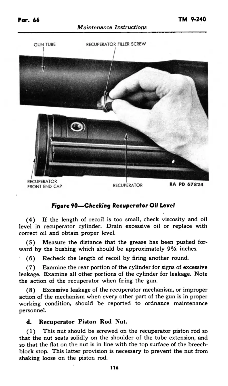
Recuperator Check oil level. Paragraph 66 b
Fill. Paragraph 66 a
c. After Firing. Bore Clean and oil. LO 9-240
Breech and firing Clean and oil. LO 9-240
mechanism Recuperator Fill. Paragraph 66 a
d. Daily. Bore Clean and oil. Paragraph 63 a
Breech and firing Clean and oil. LO 9-240
mechanism
Section XIV
MALFUNCTIONS AND CORRECTIONS
40. MISFIRE.
a. If the gun is not accessible, all stoppages will be considered
misfires. The following procedure will be observed immediately after
the occurrence of a misfire.
(1) Air Testing. If the weapon can be recharged, either manu-
ally or remotely, wait 30 seconds and then recharge. If the weapon
cannot be recharged, no corrective action is possible.
(2) Ground Testing. If firing is being done on the ground, wait
30 seconds from the time of occurrence of the misfire. Recharge the
gun and remove the round from the vicinity of the aircraft. Proceed
to determine the cause of the malfunction or stoppage and to apply
the correction prescribed by referring to the following paragraphs.
CAUTION: If the gun is hot and the round cannot be removed
from the chamber, the breechblock should be closed. It should not be
opened until the hand can be placed on the breech or tube without
discomfort.
41. FAILURE TO FIRE.
a. Examine the extracted round. If there is an indentation on
the primer, the round is defective and the responsible ordnance officer
37
Pars. 41-44 TM 9-240
Maintenance Instructions
should be notified. If there is no indentation on the primer, proceed
as follows:
(1) Check whether or not the trigger is engaged with the trigger
bar. If not, assemble properly. If the trigger or trigger bar is broken,
it must be replaced.
(2) Disassemble the gun far enough to check for broken firing
pin, hammer or hammer spring, warped or broken trigger trip, trigger
lever, or trigger lever connector. Replace broken or worn parts.
42. FAILURE OF TUBE EXTENSION TO RETURN COM-
PLETELY TO BATTERY POSITION.
a. Failure of the tube and tube extension to return to battery
position is usually due to jamming in the feed box mechanism, and
excessive friction caused by dirt, foreign matter, gummy lubricant,
and scored bearing surfaces.
b. Check the feed box mechanism to determine the point of
jamming and remove the cause. Stone the scored bearing surfaces
with a fine oilstone, clean with dry-cleaning solvent or rifle-bore
cleaner, and lubricate. If these corrective measures do not remedy
the malfunction, it is probably caused by a weak or broken recupera-
tor spring, and ordnance maintenance personnel should be notified.
43. FAILURE OF LOCK FRAME TO BE HELD TO REAR
(MOVES FORWARD WITH TUBE EXTENSION WITH-
OUT LOADING).
a. This may be due to insufficient recoil or defective parts of
the weapon.
b. Stone scored bearing surfaces, clean with dry-cleaning solvent
to remove all dirt and gummy lubricant, and then lubricate. Drain
the recuperator and refill with proper oil (par. 66 a).
c. Check the driving spring assemblies for free movement. Clean
and lubricate. Disassemble and replace any damaged parts.
d. Disassemble the weapon far enough to check for broken car-
rier, carrier catch, and carrier dog, and weak or broken carrier spring
and carrier catch spring. Replace worn or broken parts.
44. FAILURE OF BREECHBLOCK TO MOVE COMPLETELY
INTO BATTERY.
a. Failure of the breechblock to move completely into battery
may be due to excessive friction, breechblock plunger adjustment too
tight, weak or broken driving springs, damaged driving spring housing
or rod, and weak or broken operating lever spring.
b. Stone rough spots on breechblock and lock frame with a fine
38
TM 9-240 Pars. 44-47
Maintenance Instructions
oilstone, clean with dry-cleaning solvent or rifle-bore cleaner to remove
dirt, gummy lubricant, and foreign matter, and then lubricate.
c. Check the effect of the breechblock plunger upon the move-
ment of the breechblock. If the breechblock plunger screw is too
tight, the breechblock plunger will hinder the breechblock from mov-
ing completely into battery. If the screw is adjusted too tight, adjust
it so that the breechblock can move completely into battery and then
stake the screw in place.
d. Disassemble the driving spring assemblies and check whether
any springs are weak or broken, housing bent or dented, and rod bent
or burred. Replace damaged parts. Place front end of driving spring
assembly in dry-cleaning solvent or rifle-bore cleaner and thoroughly
flush by operating the rod as a pump. Dry and lubricate lightly.
e. Remove the lock frame assembly and check whether the
operating lever spring is weak or broken. The compressed operating
lever spring assists the operating lever in lifting the breechblock into
battery. Replace the spring if weak or broken.
45. FAILURE TO FEED (CARRY CARTRIDGE INTO POSL
TION TO LOAD).
a. Failure to feed (carry cartridge into position to load) may be
due to improper belting of ammunition or defective parts in feed
mechanism.
b. Remove ammunition belt and examine for stretched links and
for proper positioning of rounds. Position cartridges properly and
replace unserviceable links.
c. Check the feed mechanism for the following:
(1) Worn or broken feed pawl; weak or broken feed pawl spring.
(2) Binding of cartridge feeder stop or holding pawl; worn or
broken pawls; weak or broken feeder pawl spring.
(3) Broken or bent feed lever; broken or bent feed lever swivel.
(4) Weak or broken feed lever plunger spring.
(5) Weak carrier spring.
d. Replace worn or broken parts.
46. FAILURE TO LQAD (CARRY CARTRIDGE INTO
CHAMBER).
a. Lock frame not held to rear. Proceed as in paragraph 43.
47. FAILURE TO EXTRACT.
a. Failure to extract may be due to scored chamber, too fast re-
coil, short recoil, or defective parts.
b. If the chamber is scored, replace with a new tube.
39
Pars. 47-50 TM 9-240
Maintenance Instructions
c. Insufficient oil in recuperator cylinder will produce recoil at
such high speed that the cartridge case will be torn (or extractor
broken). Check oil level in recuperator and fill to proper level (par.
66 a). If necessary, replace the extractor and extractor spring.
d. If recoil is short, proceed as in paragraph 43.
48. RUN-AWAY GUN.
a. A run-away gun may be due to malfunctioning of the trigger
mechanism caused by bent or jammed trigger bar, dirt, grit, or gummy
lubricant around the trigger bar. Disassemble the gun; clean and
lubricate the trigger bar. Replace trigger bar if unserviceable.
49. SLOW-FIRING GUN.
a. A slow-firing gun may be due to excessive friction, slow recoil,
or slow counterrecoil.
b. Disassemble the gun and clean all parts with dry-cleaning
solvent to remove dirt, grit, and gummy lubricant. Stone scored bear-
ing surfaces with a fine oilstone. Oil lightly at assembly.
c. If recoil is slow, drain the recuperator and refill with proper
oil (par. 66 a).
d. If counterrecoil is slow, disassemble feed box mechanism and
check for scored or worn parts and improper lubrication. Stone scored
parts with a fine oilstone. Replace worn parts, clean, and oil lightly
at assembly. See that driving springs are not unhooked; replace weak
or broken driving springs.
e. If recuperator spring is weak, notify ordnance maintenance
personnel.
Section XV
BACK PLATE ASSEMBLY
50. FUNCTIONING.
a. The function of the back plate assembly is to absorb the force
of recoil of the lock frame not absorbed by the driving springs. The
recoil force is absorbed by the resistance of friction pieces and springs.
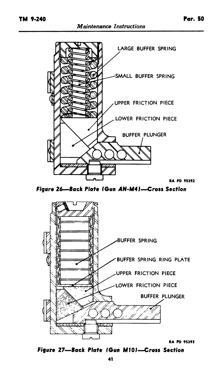
b. As the lock frame of the Gun AN-M4 nears the end of its
rearward travel during recoil, the rear of the lock frame body strikes
the buffer plunger (fig. 26). The plunger forces the two buffer friction
pieces to compress the buffer springs (fig. 26).
40
TM 9*240
Par. 50
Maintenance Instructions
Figure 26—Back Plate (Gun 4N-M4I—Cross Section
KA PD »S3»1
Figure 27—Back Plate (Gun Ml01—Cross Section
41
Fars. 50-52
TM 9-240
Maintenance Instructions
BACK PLATE ASSEMBLY
BACK PLATE LATCH
RA PD 95394
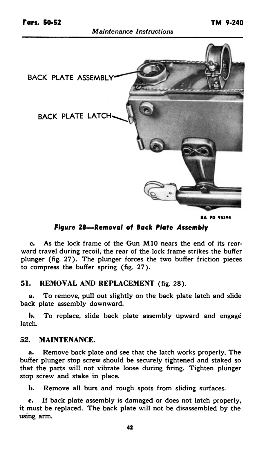
Figure 28—Removal of Back Plate Assembly
c. As the lock frame of the Gun MIO nears the end of its rear-
ward travel during recoil, the rear of the lock frame strikes the buffer
plunger (fig. 27). The plunger forces the two buffer friction pieces
to compress the buffer spring (fig. 27).
51. REMOVAL AND REPLACEMENT (fig. 28).
a. To remove, pull out slightly on the back plate latch and slide
back plate assembly downward.
b. To replace, slide back plate assembly upward and engagё
latch.
52. MAINTENANCE.
a. Remove back plate and see that the latch works properly. The
buffer plunger stop screw should be securely tightened and staked so
that the parts will not vibrate loose during firing. Tighten plunger
stop screw and stake in place.
b. Remove all burs and rough spots from sliding surfaces.
c. If back plate assembly is damaged or does not latch properly,
it must be replaced. The back plate will not be disassembled by the
using arm.
42
TM 9-240 Par. 53
Maintenance Instructions
Section XVI
BREECH OPERATING MECHANISM
53. FUNCTIONING.
a. General. For purposes of explanation» the functioning of the
breech operating mechanism is divided into the stages given below.
b. Cocking and Loading.
(1) When the manual charger is operated by pulling the cable,
the shoe of the manual charger contacts the pin on the operating
lever of the lock frame and causes the lever to rotate. This cams the
hammer rearward beyond the latching hook of the sear, thus per-
mitting the firing pin spring to retract the firing pin. The breechblock
is lowered until it rests against its stop (fig. 29) at the bottom of
the tube extension. The rotation of the operating lever also forces
the strut back against the follower, thus compressing the operating
lever spring located in the body of the lock frame. When the lever
is completely rotated, the lock frame continues rearward, compressing
the driving springs. The lock frame continues rearward until it passes
under and raises the carrier dog and contacts the plunger of the back
plate. In Gun MIO the carrier dog, when raised, contacts the inter-
lock body, lifting the body and plate, thus positioning the interlock
lever to permit operation of the loading slide. With the release of the
charger cable, the lock frame moves forward until the carrier dog
engages the notch in the top of the lock frame.
(2) When the loading slide is pulled rearward, the initial round
is fed into the gun. This actuates the feed box mechanism, which strips
the round from the belt. Just before the cartridge is stripped from the
links, it contacts the carrier catch, moving it sufficiently to release
the carrier. This allows the carrier to snap downward under force of
the carrier spring. As the front end of the carrier pushes the cartridge
downward, the carrier dog releases the lock frame. The cartridge
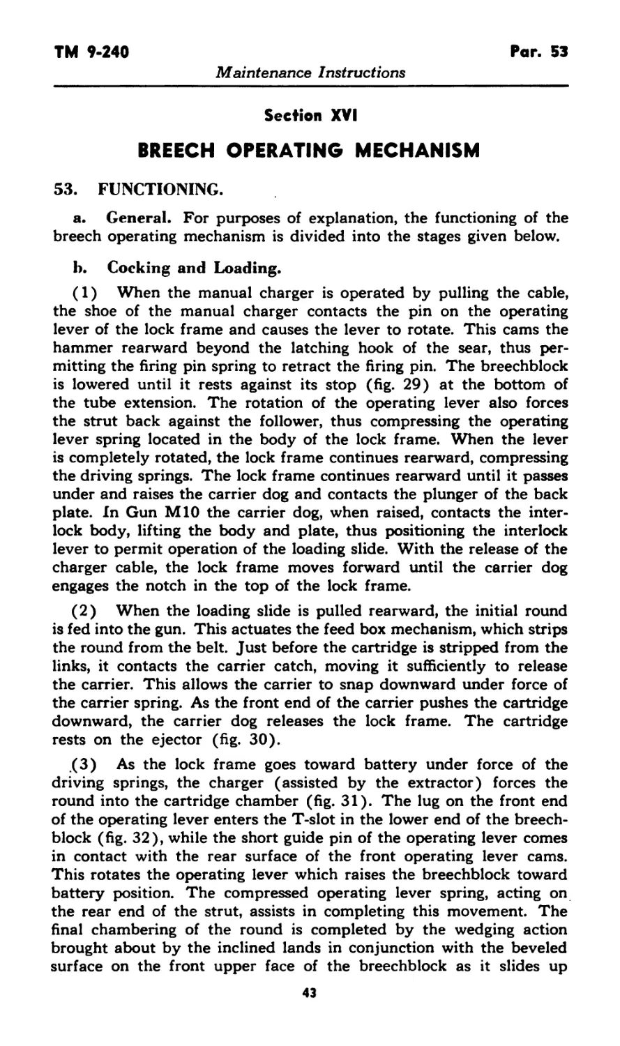
rests on the ejector (fig. 30).
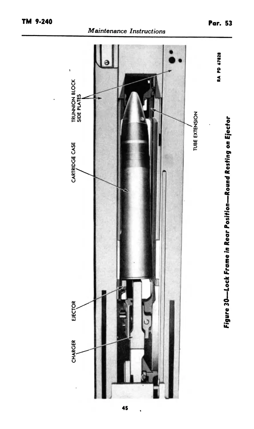
(3) As the lock frame goes toward battery under force of the
driving springs, the charger (assisted by the extractor) forces the
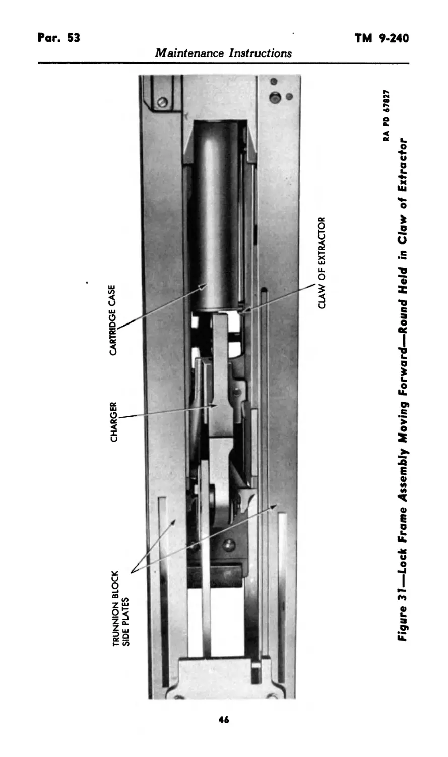
round into the cartridge chamber (fig. 31). The lug on the front end
of the operating lever enters the T-slot in the lower end of the breech-
block (fig. 32), while the short guide pin of the operating lever comes
in contact with the rear surface of the front operating lever cams.
This rotates the operating lever which raises the breechblock toward
battery position. The compressed operating lever spring, acting on
the rear end of the strut, assists in completing this movement. The
final chambering of the round is completed by the wedging action
brought about by the inclined lands in conjunction with the beveled
surface on the front upper face of the breechblock as it slides up
43
LUG OF OPERATING LEVER OPERATING LEVER ASSEMBLY RA PD 67826
TUBE EXTENSION
ASSEMBLY
BREECHBLOCK
“T” SLOT
Maintenance Instructions
Figure 29—Breechblock Down, Resting Against Stop
TUBE EXTENSION
Maintenance Instructions
RA PD 67828
Figure 30—Lock Frame in Rear Position—Round Resting on Ejector
CLAW OF EXTRACTOR
Maintenance Instructions
RA PO 67827
Figure 37—Lock Frame Assembly Moving Forward—Round Held in Claw of Extractor
Figure 32—-Operating Lever and Cams
RA PD 90116
Maintenance Instructions
Par. 53
TM 9-240
Maintenance Instructions
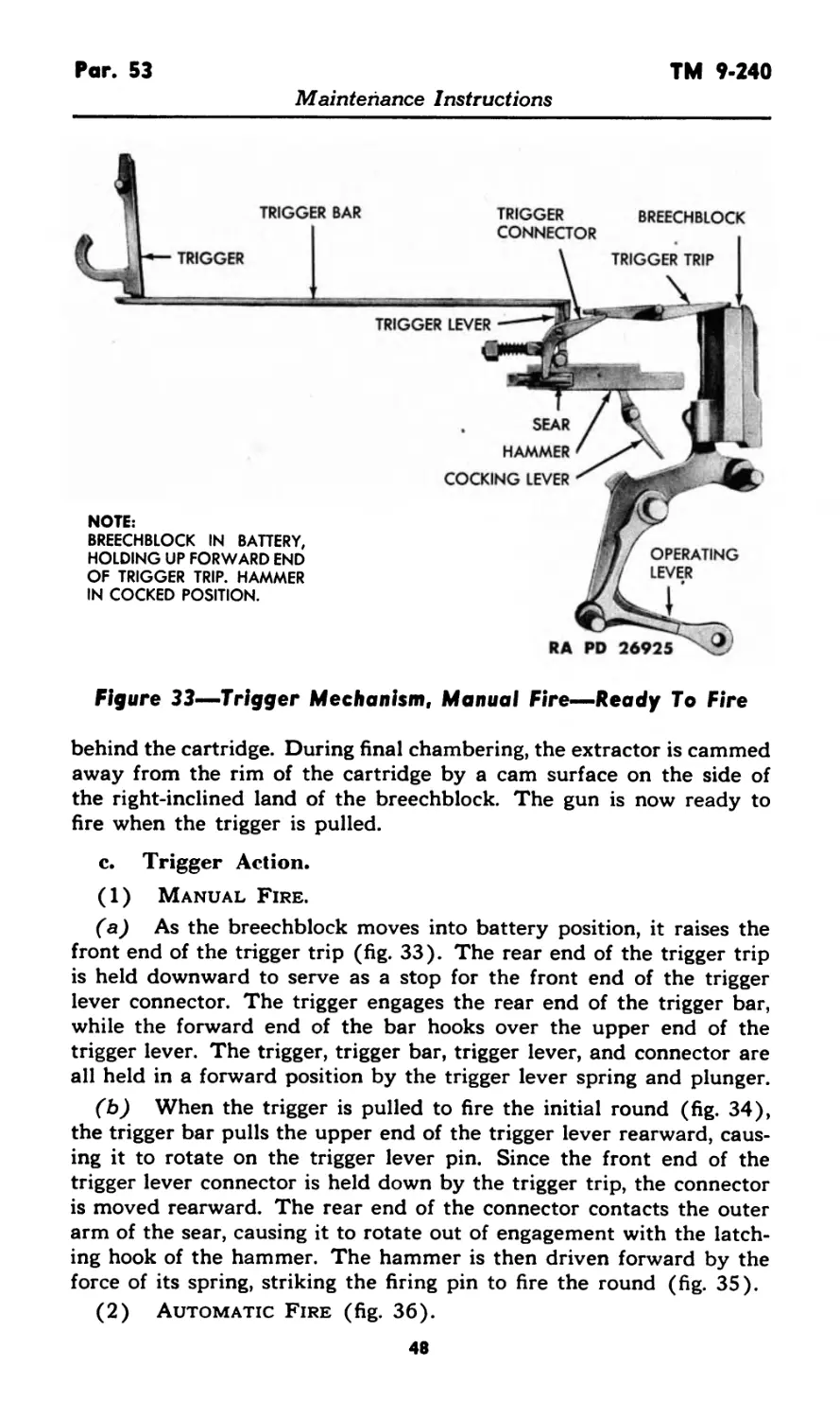
Figure 33—Trigger Mechanism, Manual Fire—Ready To Fire
behind the cartridge. During final chambering, the extractor is cammed
away from the rim of the cartridge by a cam surface on the side of
the right-inclined land of the breechblock. The gun is now ready to
fire when the trigger is pulled.
c. Trigger Action.
(1) Manual Fire.
(a) As the breechblock moves into battery position, it raises the
front end of the trigger trip (fig. 33). The rear end of the trigger trip
is held downward to serve as a stop for the front end of the trigger
lever connector. The trigger engages the rear end of the trigger bar,
while the forward end of the bar hooks over the upper end of the
trigger lever. The trigger, trigger bar, trigger lever, and connector are
all held in a forward position by the trigger lever spring and plunger.
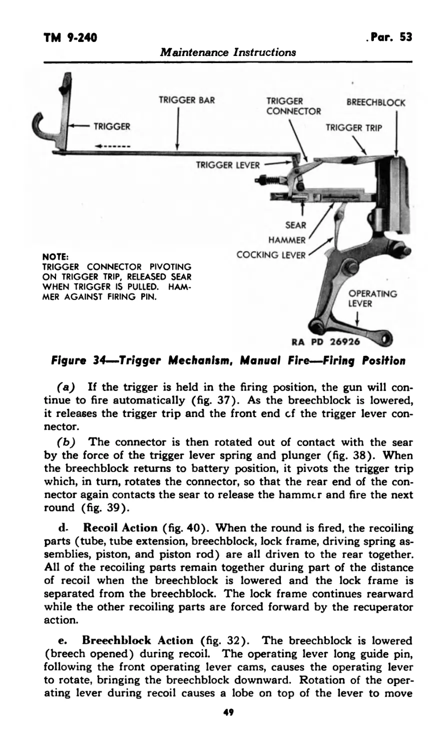
(b) When the trigger is pulled to fire the initial round (fig. 34),
the trigger bar pulls the upper end of the trigger lever rearward, caus-
ing it to rotate on the trigger lever pin. Since the front end of the
trigger lever connector is held down by the trigger trip, the connector
is moved rearward. The rear end of the connector contacts the outer
arm of the sear, causing it to rotate out of engagement with the latch-
ing hook of the hammer. The hammer is then driven forward by the
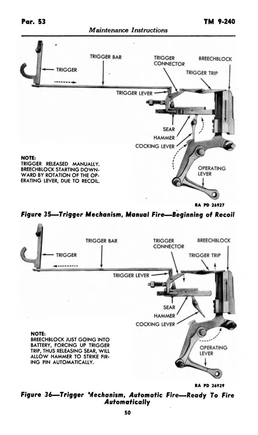
force of its spring, striking the firing pin to fire the round (fig. 35).
(2) Automatic Fire (fig. 36).
48
TM 9-240
Par. 53
Maintenance Instructions
Figure 34—Trigger Mechanism. Manual Fire—Firing Position
(a) If the trigger is held in the firing position, the gun will con-
tinue to fire automatically (fig. 37). As the breechblock is lowered,
it releases the trigger trip and the front end cf the trigger lever con-
nector.
(b) The connector is then rotated out of contact with the sear
by the force of the trigger lever spring and plunger (fig. 38). When
the breechblock returns to battery position, it pivots the trigger trip
which, in turn, rotates the connector, so that the rear end of the con-
nector again contacts the sear to release the hammer and fire the next
round (fig. 39).
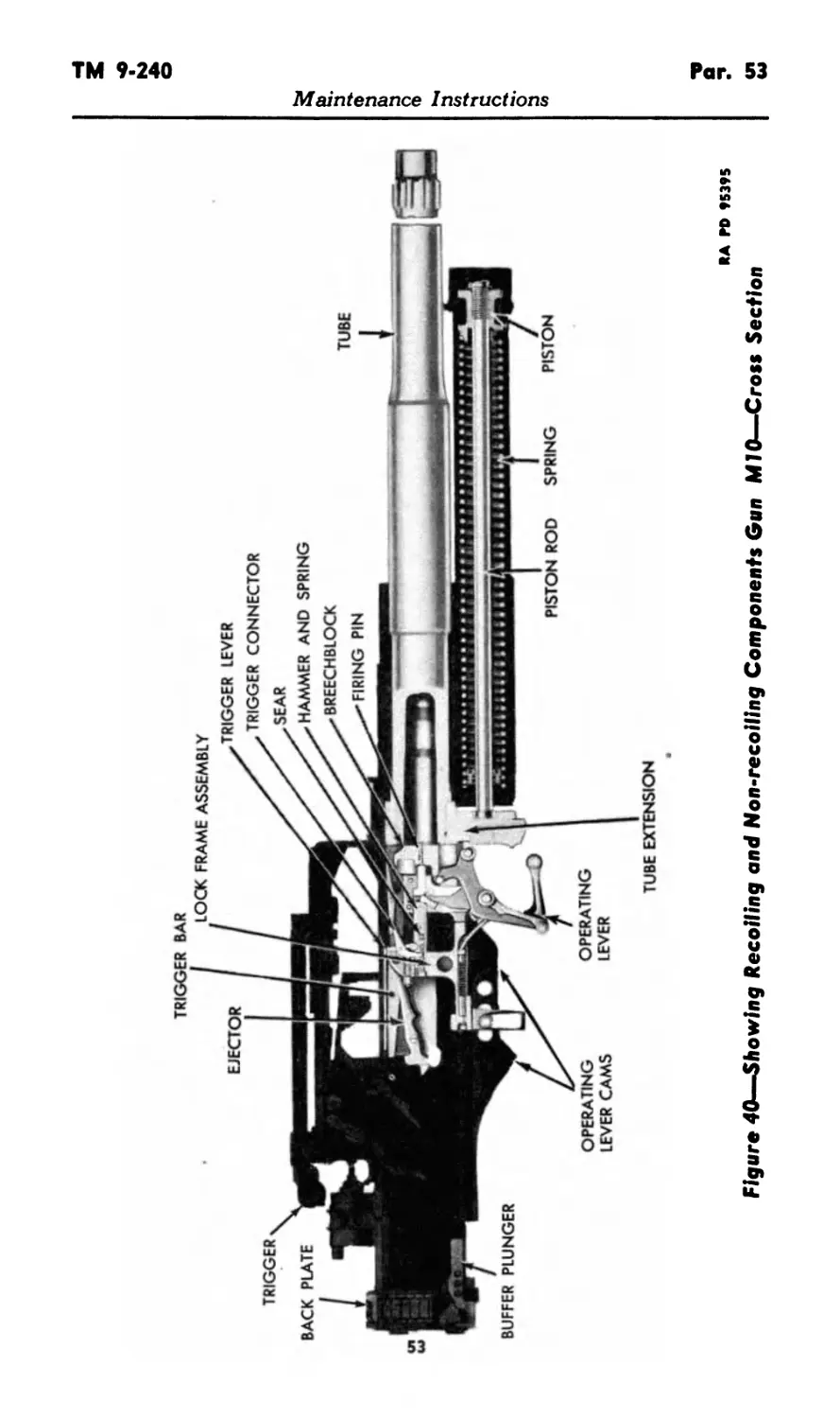
d- Recoil Action (fig. 40). When the round is fired, the recoiling
parts (tube, tube extension, breechblock, lock frame, driving spring as-
semblies, piston, and piston rod) are all driven to the rear together.
All of the recoiling parts remain together during part of the distance
of recoil when the breechblock is lowered and the lock frame is
separated from the breechblock. The lock frame continues rearward
while the other recoiling parts are forced forward by the recuperator
action.
e. Breechblock Action (fig. 32). The breechblock is lowered
(breech opened) during recoil. The operating lever long guide pin,
following the front operating lever cams, causes the operating lever
to rotate, bringing the breechblock downward. Rotation of the oper-
ating lever during recoil causes a lobe on top of the lever to move
49
Par. 53
TM 9-240
Maintenance Instructions
RA PO 26927
Figure 35—Trigger Mechanism, Manual Fire—Beginning of Recoil
TRIGGER
TRIGGER BAR
TRIGGER BREECHBLOCK
CONNECTOR
TRIGGER TRIP
NOTE:
BREECHBLOCK JUST GOING INTO
BATTERY, FORCING UP TRIGGER
TRIP, THUS RELEASING SEAR, WILL
ALLOW HAMMER TO STRIKE FIR-
ING PIN AUTOMATICALLY.
TRIGGER LEVER
SEAR
HAMMER
COCKING LEVER
OPERATING
LEVER
RA PD 26929
Figure 36—Trigger Mechanism, Automatic Fire—Ready To Fire
Automatically
50
TM 9-240
Par. 53
Maintenance Instructions
V
TRIGGER BAR
---TRIGGER
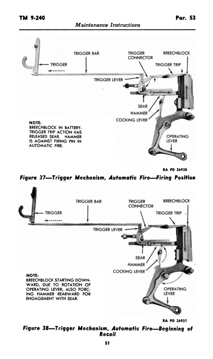
NOTE:
BREECHBLOCK IN BATTERY.
TRIGGER TRIP ACTION HAS
RELEASED SEAR. HAMMER
IS AGAINST FIRING PIN IN
AUTOMATIC FIRE.
TRIGGER LEVER
TRIGGER BREECHBLOCK
CONNECTOR
TRIGGER TRIP
SEAR
HAMMER
COCKING LEVER
OPERATING
LEVER
RA PD 26930
Figure 37—Trigger Mechanism, Automatic Fire—Firing Position
TRIGGER BREECHBLOCK
CONNECTOR
TRIGGER TRIP .
NOTE:
BREECHBLOCK STARTING DOWN-
WARD, DUE TO ROTATION OF
OPERATING LEVER, ALSO FORC-
ING HAMMER REARWARD FOR
ENGAGEMENT WITH SEAR.
TRIGGER LEVER
SEAR
HAMMER
COCKING LEVER
OPERATING
LEVER
RA PD 26931
Figure 38—Trigger Mechanism, Automatic Fire—Beginning of
Recoil
51
Par. 53
TM 9-240
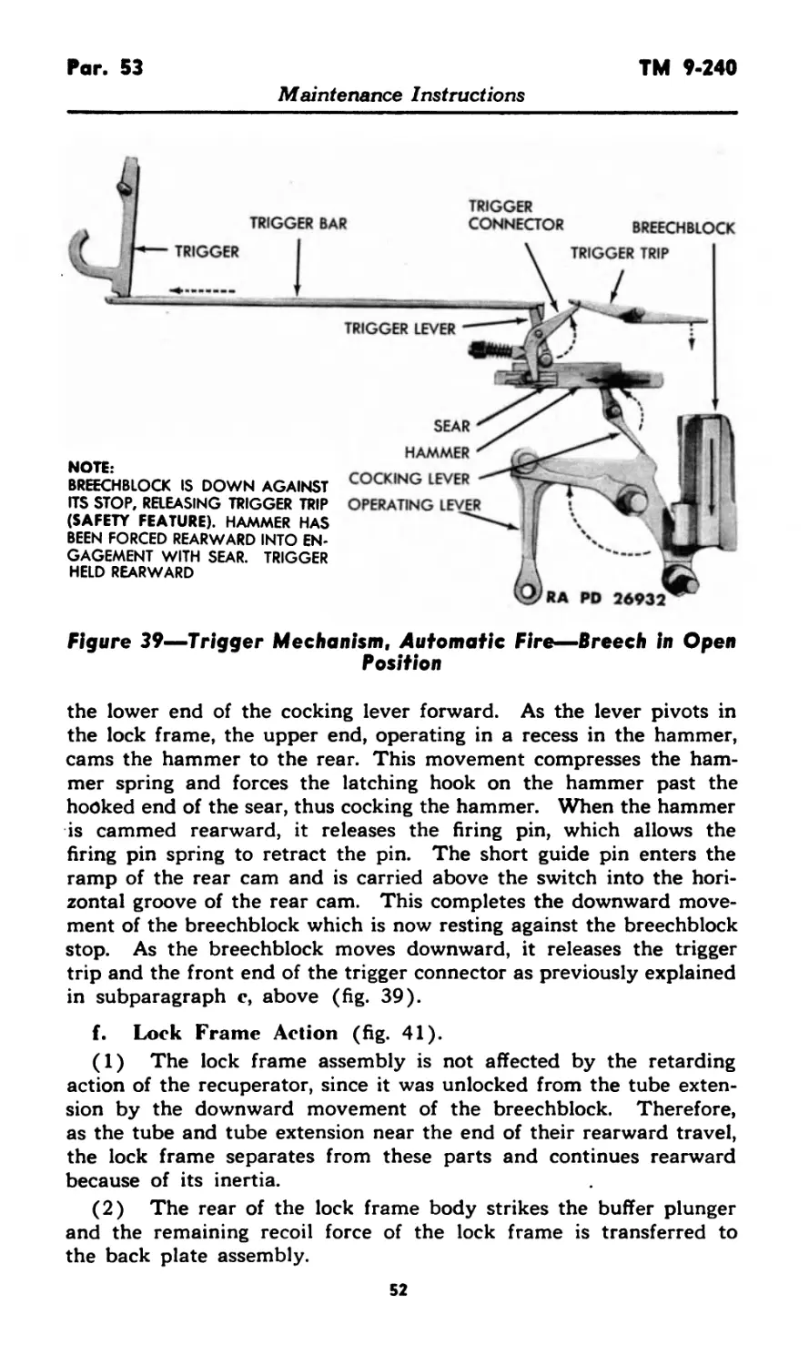
Maintenance Instructions
TRIGGER
CONNECTOR BREECHBLOCK
TRIGGER TRIP
TRIGGER LEVER
TRIGGER
NOTE:
BREECHBLOCK IS DOWN AGAINST
ITS STOP, RELEASING TRIGGER TRIP
(SAFETY FEATURE). HAMMER HAS
BEEN FORCED REARWARD INTO EN-
GAGEMENT WITH SEAR. TRIGGER
HELD REARWARD
Figure 39—Trigger Mechanism, Automatic Fire—Breech in Open
Position
SEAR
HAMMER
COCKING LEVER
OPERATING
the lower end of the cocking lever forward. As the lever pivots in
the lock frame, the upper end, operating in a recess in the hammer,
cams the hammer to the rear. This movement compresses the ham-
mer spring and forces the latching hook on the hammer past the
hooked end of the sear, thus cocking the hammer. When the hammer
is cammed rearward, it releases the firing pin, which allows the
firing pin spring to retract the pin. The short guide pin enters the
ramp of the rear cam and is carried above the switch into the hori-
zontal groove of the rear cam. This completes the downward move-
ment of the breechblock which is now resting against the breechblock
stop. As the breechblock moves downward, it releases the trigger
trip and the front end of the trigger connector as previously explained
in subparagraph c, above (fig. 39).
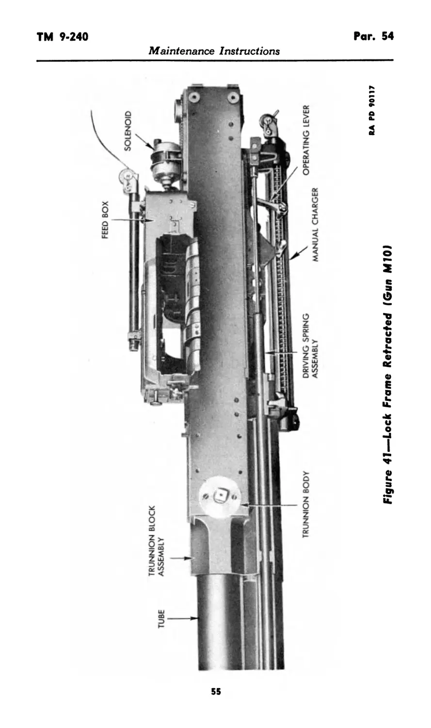
f. Lock Frame Action (fig. 41).
(1) The lock frame assembly is not affected by the retarding
action of the recuperator, since it was unlocked from the tube exten-
sion by the downward movement of the breechblock. Therefore,
as the tube and tube extension near the end of their rearward travel,
the lock frame separates from these parts and continues rearward
because of its inertia.
(2) The rear of the lock frame body strikes the buffer plunger
and the remaining recoil force of the lock frame is transferred to
the back plate assembly.
52
TRIGGER BAR
TUBE EXTENSION
RA PD 95395
Figure 40—Showing Recoiling and Non-recoiling Components Gun MIO—Cross Section
Maintenance Instructions
Pars. 53-54 TM 9-240
Maintenance Instructions
(3) The lock frame is carried forward by action of the driving
springs. After traveling a short distance forward, the carrier dog
engages the notch in the top of the charger (on the lock frame)
holding the lock frame stationary, while the tube and tube extension
continue forward toward battery.
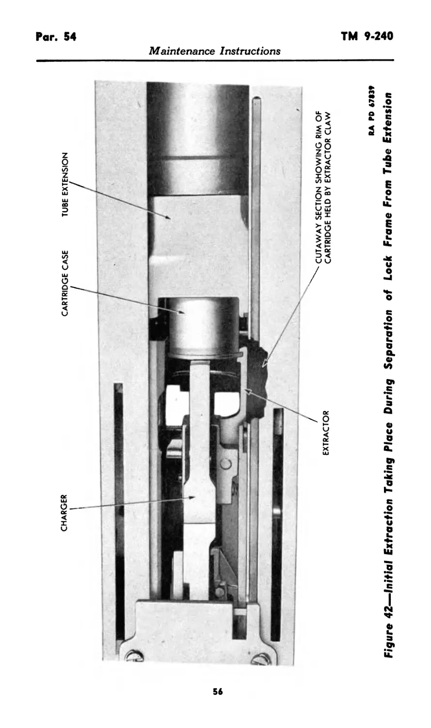
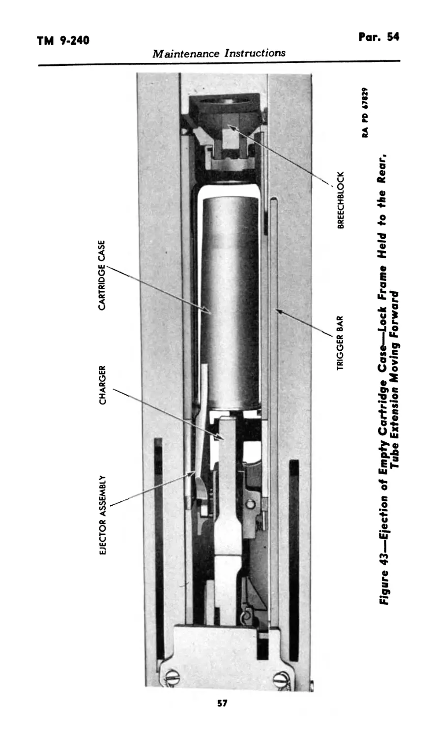
g. Extraction and Ejection (figs. 42 and 43).
(1) Initial extraction occurs during the separation of the lock
frame from the tube extension. The rim of the cartridge case is
engaged by the extractor hook and, as the lock frame assembly
separates from the tube extension, the case is partially withdrawn
from the cartridge chamber (fig. 42).
(2) When the lock frame is held in its rearward position, and
the tube extension has gone forward on counterrecoil to a point
where the empty case is entirely extracted from the chamber, the
ejector is pivoted downward by a cam on the left side of the lock
frame. The front end of the ejector (fig. 43) deflects the empty
case downward between the side plates and out of the gun.
h. Driving Spring Action. The driving spring assemblies are
used to drive the lock frame assembly to battery position. As the
tube extension travels forward on counterrecoil, the driving spring
housings are also carried forward. The rods are connected to the
lock frame (fig. 41) which is held back by the carrier dog; there-
fore, the four driving springs are compressed. These compressed
spripgs act on the driving spring rods to force the lock frame assem-
bly forward into battery position when it is released by the carrier dog.
54. REMOVAL AND REPLACEMENT.
a. Removal of Lock Frame Assembly.
(1) Make sure that lock frame is in the battery position.
(2) Remove the back plate assembly as described in para-
graph 51.
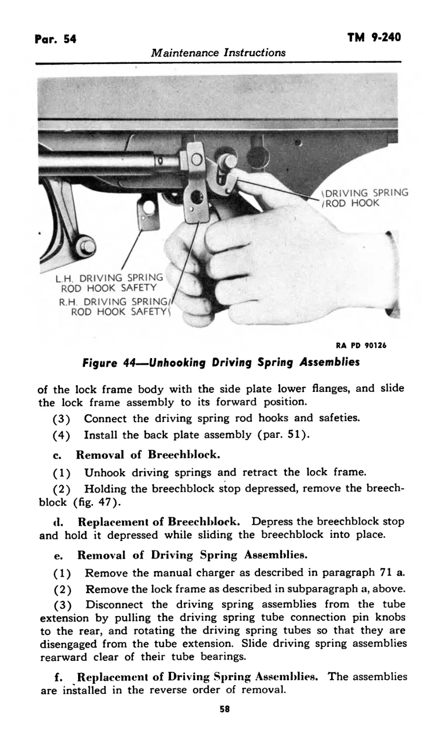
(3) Disconnect the driving spring assembly from the lock frame
by lifting the driving spring rod hook safety and rotating it down-
ward. Pivot the driving spring rod hook down off the lock frame
stud (fig. 44).
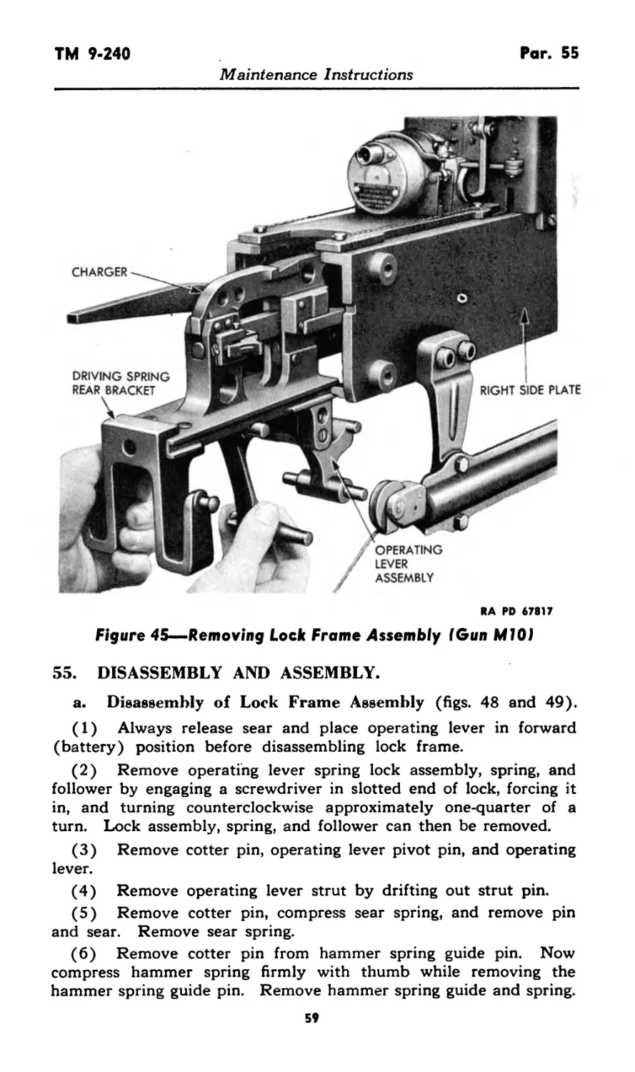
(4) Rotate the operating lever and remove the lock frame from
the gun by sliding it rearward until it clears the side plates. CAU-
TION: Keep a firm grip on the lock frame and on the operating
lever, in order to prevent the operating lever from springing forward
and injuring the operator (fig. 45).
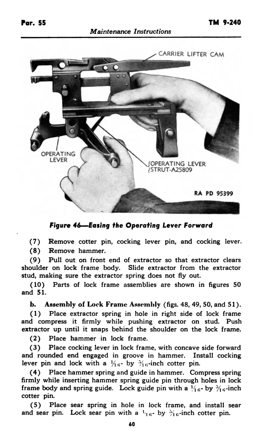
(5) Ease the operating lever into the forward position (fig. 46).
b. Replacement of Lock Frame Assembly.
(1) Release the carrier catch.
(2) Rotate the operating lever to the rear. Engage the grooves
54
ASSEMBLY
MANUAL CHARGER
Maintenance Instructions
RA PD 90117
Figure 41—Lock Frame Retracted (Gun MIO)
RA PD 67131
Figure 42—Initial Extraction Taking Place During Separation of Lock Frame From Tube Extension
Maintenance Instructions
RA PD 67829
Figure 43—Ejection of Empty Cartridge Case—Lock Frame Held to the Rear.
Tube Extension Moving Forward
Maintenance Instructions
Par. 54
TM 9-240
Maintenance Instructions
RA PD 90126
Figure 44—Unhooking Driving Spring Assemblies
of the lock frame body with the side plate lower flanges, and slide
the lock frame assembly to its forward position.
(3) Connect the driving spring rod hooks and safeties.
(4) Install the back plate assembly (par. 51).
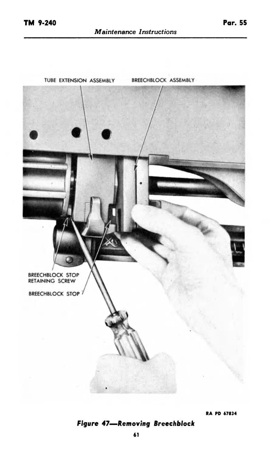
c. Removal of Breechblock.
(1) Unhook driving springs and retract the lock frame.
(2) Holding the breechblock stop depressed, remove the breech-
block (fig. 47).
cl. Replacement of Breechblock. Depress the breechblock stop
and hold it depressed while sliding the breechblock into place.
e. Removal of Driving Spring Assemblies.
(1) Remove the manual charger as described in paragraph 71 a.
(2) Remove the lock frame as described in subparagraph a, above.
(3) Disconnect the driving spring assemblies from the tube
extension by pulling the driving spring tube connection pin knobs
to the rear, and rotating the driving spring tubes so that they are
disengaged from the tube extension. Slide driving spring assemblies
rearward clear of their tube bearings.
f. Replacement of Driving Spring Assemblies. The assemblies
are installed in the reverse order of removal.
58
TM 9-240
Par. 55
Maintenance Instructions
RA PD 67817
Figure 45—Removing Lock Frame Assembly I Gun Ml 01
55. DISASSEMBLY AND ASSEMBLY.
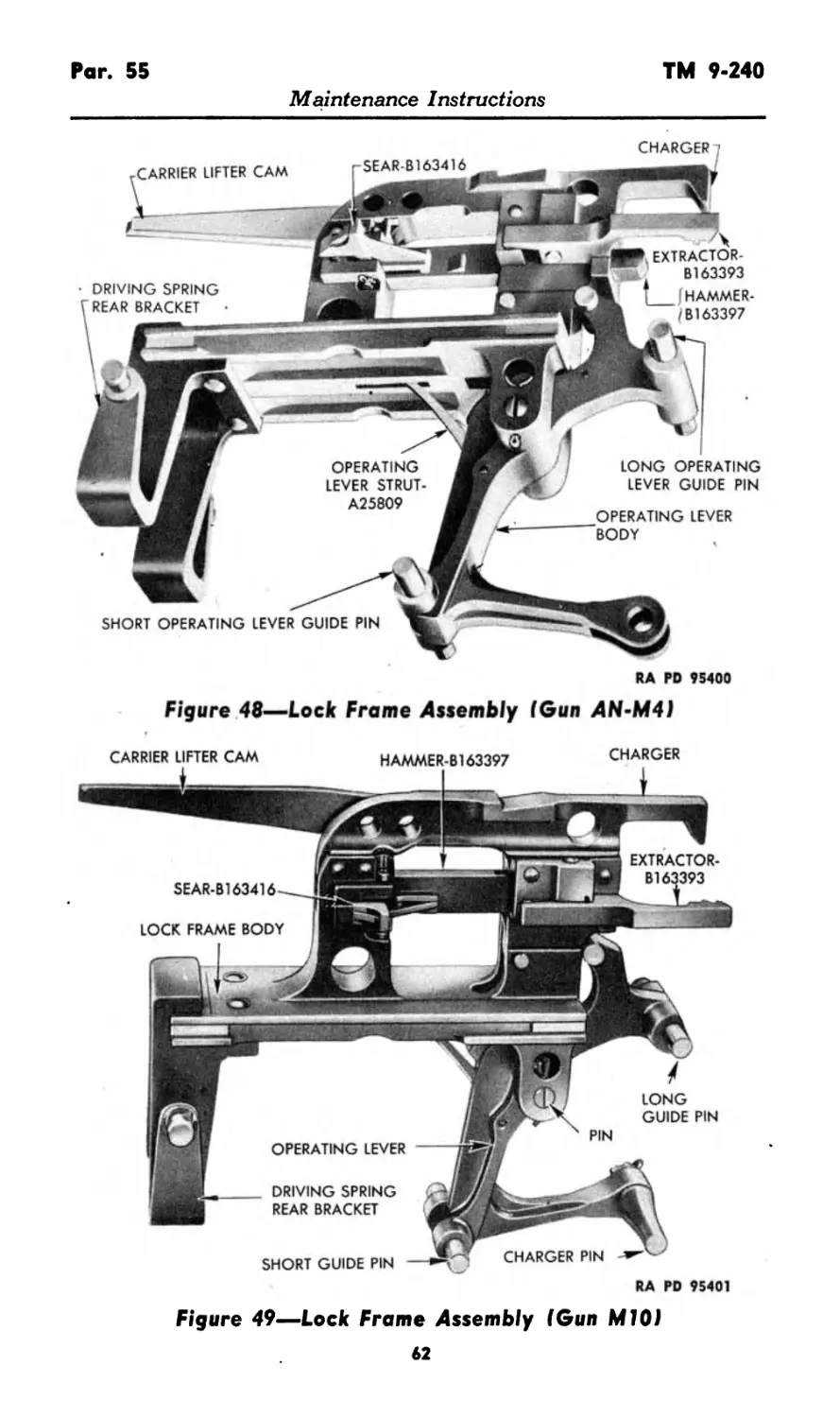
a. Disassembly of Lock Frame Assembly (figs. 48 and 49).
(1) Always release sear and place operating lever in forward
(battery) position before disassembling lock frame.
(2) Remove operating lever spring lock assembly, spring, and
follower by engaging a screwdriver in slotted end of lock, forcing it
in, and turning counterclockwise approximately one-quarter of a
turn. Lock assembly, spring, and follower can then be removed.
(3) Remove cotter pin, operating lever pivot pin, and operating
lever.
(4) Remove operating lever strut by drifting out strut pin.
(5) Remove cotter pin, compress sear spring, and remove pin
and sear. Remove sear spring.
(6) Remove cotter pin from hammer spring guide pin. Now
compress hammer spring firmly with thumb while removing the
hammer spring guide pin. Remove hammer spring guide and spring.
59
Par. 55
TM 9-240
Maintenance Instructions
Figure 46—Easing the Operating Lever Forward
(7) Remove cotter pin, cocking lever pin, and cocking lever.
(8) Remove hammer.
(9) Pull out on front end of extractor so that extractor clears
shoulder on lock frame body. Slide extractor from the extractor
stud, making sure the extractor spring does not fly out.
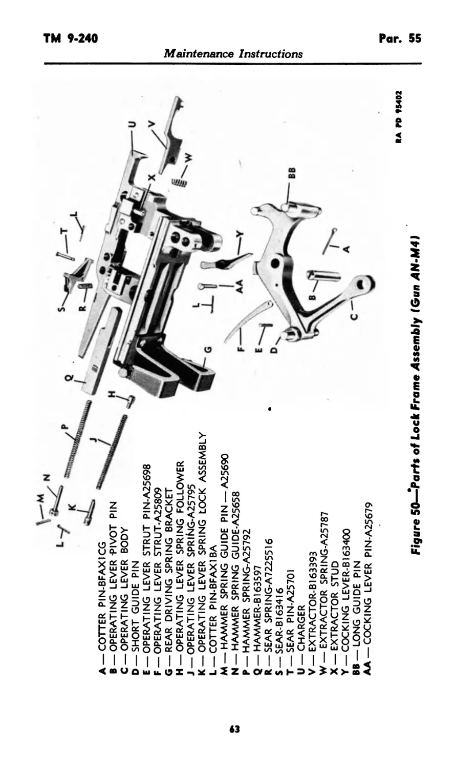
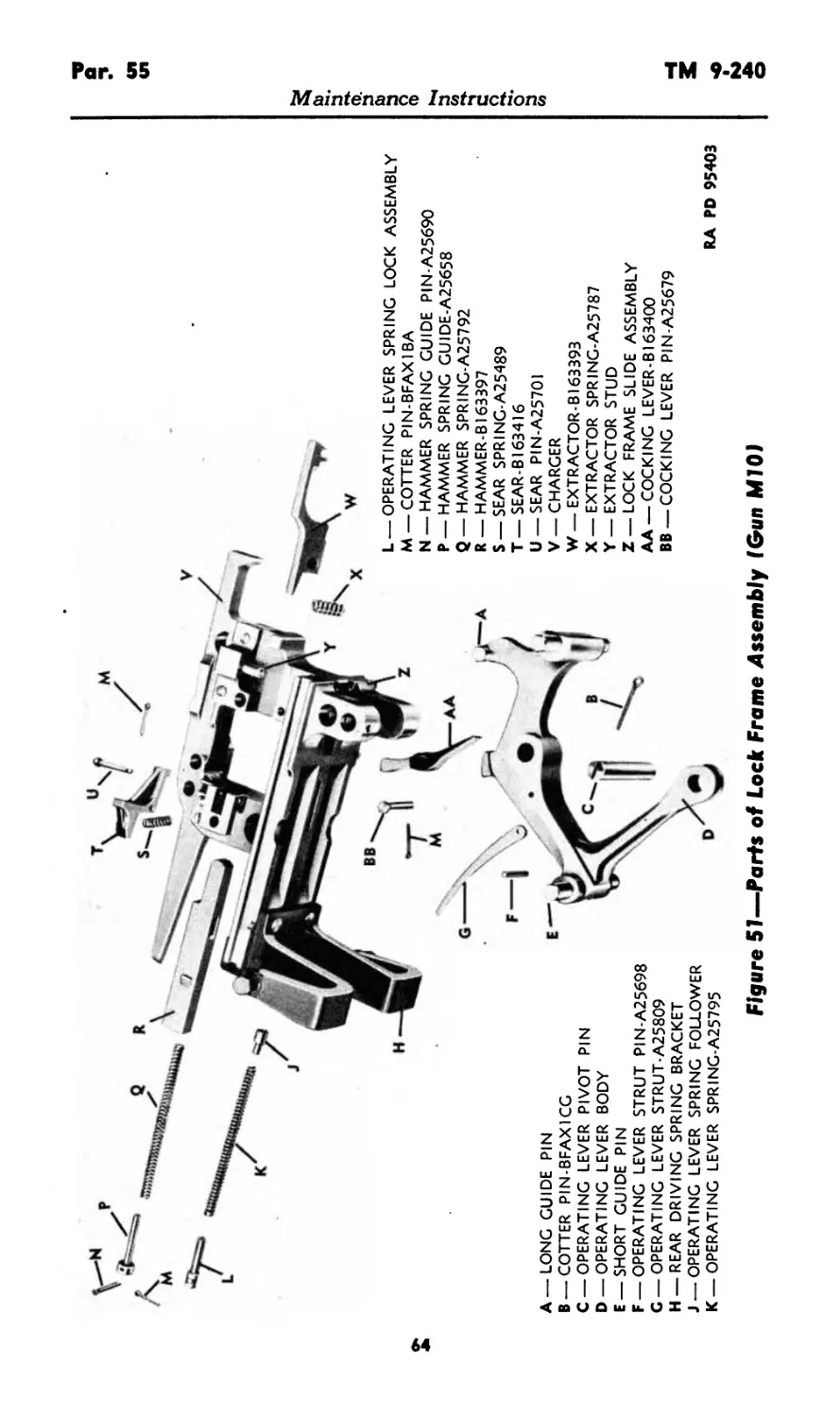
(10) Parts of lock frame assemblies are shown in figures 50
and 51.
b. Assembly of Lock Frame Assembly (figs. 48, 49, 50, and 51).
(1) Place extractor spring in hole in right side of lock frame
and compress it firmly while pushing extractor on stud. Push
extractor up until it snaps behind the shoulder on the lock frame.
(2) Place hammer in lock frame.
(3) Place cocking lever in lock frame, with concave side forward
and rounded end engaged in groove in hammer. Install cocking
lever pin and lock with а y1G- by "/1G-inch cotter pin.
(4) Place hammer spring and guide in hammer. Compress spring
firmly while inserting hammer spring guide pin through holes in lock
frame body and spring guide. Lock guide pin with а Ц n- by % G-inch
cotter pin.
(5) Place sear spring in hole in lock frame, and install sear
and sear pin. Lock sear pin with a y<r by ;;G-inch cotter pin.
60
TM 9-240
Par. 55
Maintenance Instructions
TUBE EXTENSION ASSEMBLY BREECHBLOCK ASSEMBLY
RA PD 67834
Figure 47—Removing Breechblock
61
Par. 55
TM 9-240
Maintenance Instructions
CHARGER
SEAR-B163416
CARRIER LIFTER CAM
SHORT OPERATING LEVER GUIDE PIN
LONG OPERATING
LEVER GUIDE PIN
DRIVING SPRING
REAR BRACKET
OPERATING LEVER
BODY
OPERATING
LEVER STRUT-
A25809
O* EXTRACTOR-
6163393
Г f_____(HAMMER-
b /Bl 63397
RA PD 95400
Figure 48—Lock Frame Assembly (Gun AN-M4)
Figure 49—Lock Frame Assembly (Gun M10J
62
Q
/
A —COTTER PIN-BFAX1CG
B —OPERATING LEVER -PIVOT PIN
C — OPERATING LEVER BODY
D — SHORT GUIDE PIN
E — OPERATING LEVER STRUT PIN-A25698
F — OPERATING LEVER STRUT.A25809
G — REAR DRIVING SPRING BRACKET
H — OPERATING LEVER SPRING FOLLOWER
J —OPERATING LEVER SPRIHG-A25795
K —OPERATING LEVER SPRING LOCK ASSEMBLY
L — COTTER PIN-BFAX1BA
M —HAMMER SPRING GUIDE PIN —A25690
N —HAMMER SPRING GUIDE-A25658
p—HAMMER SPRING-A25792
Q —HAMMER-B163597
R—SEAR SPRING-A7225516
S — SEAR-B163416
T—SEAR PIN-A25701
U — CHARGER
V — EXTRACTOR-B163393
W— EXTRACTOR SPRING-A25787
X — EXTRACTOR STUD
Y —COCKING LEVER-B163400
BB —LONG GUIDE PIN
AA —COCKING LEVER PIN-A25679
Maintenance Instructions
RA PD 95402
Figure 50—-Parts of Lock Frame Assembly (Gun AN-M49
СЛ
<n
Figure 51—Parts of Lock Frame Assembly (Gun MIO)
<л
<л
A —LONG GUIDE PIN
B —COTTER PIN-BFAX1CG
C —OPERATING LEVER PIVOT PIN
D —OPERATING LEVER BODY
E —SHORT GUIDE PIN
F — OPERATING LEVER STRUT PIN-A25698
C —OPERATING LEVER STRUT-A25809
H — REAR DRIVING SPRING BRACKET
J —OPERATING LEVER SPRING FOLLOWER
K —OPERATING LEVER SPRING-A25795
L —OPERATING LEVER SPRING LOCK ASSEMBLY
M —COTTER PIN-BFAX1BA
N —HAMMER SPRING GUIDE PIN-A25690
P —HAMMER SPRING GUIDE-A25658
Q —HAMMER SPRING-A25792
R —- HAMMER-B163397
S —SEAR SPRING-A25489
T —SEAR-B163416
U —SEAR PIN-A25701
V — CHARGER
W — EXTRACTOR-B163393
X —EXTRACTOR SPRING-A25787
Y —EXTRACTOR STUD
Z — LOCK FRAME SLIDE ASSEMBLY
AA —COCKING LEVER-BI63400
BB —COCKING LEVER PIN-A25679
RA PD 95403
Maintenance Instructions
TM 9-240 Par. 55
Maintenance Instructions
(6) Install operating lever strut in operating lever, with concave
side towards rear. Install strut pin and stake in place.
(7) Place operating lever in lock frame, with lobe on the rear
side of cocking lever. Install pivot pin from the right side, and
lock it in place with %2- by 1-inch cotter pin.
(8) Swing end of strut into slot in lock frame. Place operating
lever spring follower, spring, and lock assembly in lock frame, with
the follower engaging end of strut.
(9) Push lock in with screwdriver, engage lock pin in groove in
lock frame, and lock it in position with one-fourth turn clockwise.
c. Disassembly of Breechblock (fig. 52).
(1) Hold finger over the rear end of firing pin.
(2) Drift out the firing pin stop pin which is lightly staked in
place.
(3) Remove the firing pin and firing pin spring.
d. Assembly of Breechblock. Assemble in the reverse order of
disassembly. Be sure that the flat on the firing pin will line up with
the firing pin stop pin. In assembling the breechblock, the firing pin
stop pin should be staked lightly and all burs removed after staking.
e. Disassembly of Driving Spring Assemblies (fig. 53).
(1) Unscrew driving spring tube connection pin knob after first
removing the lock wire, thus releasing connection pin and spring.
(2) Remove cotter pin from driving spring rod connection, thus
releasing the safety, rod hook, plunger, and spring.
(3) Unscrew driving spring tube bushing. The edges of the tube
are staked into slots in the bushing. Withdraw driving spring rod
assembly from the tube.
(4) Remove cotter pin from rod connection and remove connec-
tion from rod. NOTE: These connections and rods are not intei-
changeable. Slide the bushing, two driving springs, and spacer from
rod. Then place connections back on the same rods to avoid inter-
changing these parts.
(5) Unscrew driving spring tube end cap only when absolutely ’
necessary as this part A25454 cannot be removed without rendering
it unserviceable, due to damage of threads caused by heavy staking
of the tube body.
(6) Piston is not to be removed from the rod.
(7) Parts of driving spring assembly are shown in figure 54.
f. Assembly of Driving Spring Assemblies.
NOTE: Both assemblies are identical, except as outlined in the
note in step ( 5 ), below.
(1) Screw driving spring tube cap into front (long) end of tube.
Be sure venthole is clear.
65
Par. 55
TM 9-240
RA PD 95404
Figure 52—Breechblock Assemblies
66
HOOK
COTTER
PIN-BFAXICE
DRIVING \
SPRING I
ROD
DRIVING SPRING ROD CONNECTION PIN
-DRIVING SPRING ROD HOOK SPRING PLUNGER
DRIVING SPRING ROD HOOK SPRING-A25466
DRIVING SPRING HOUSING ASS Y
COTTER PIN-BFAXICE
м
DRIVING SPRING
TUBE BUSHING
\DRIVING SPRING
/ROD CONNECTION
_\DRIVING SPRING
/ROD HOOK SAFETY
'—DRIVING SPRING ROD HOOK PIN
DRIVING SPRINGS-BI63418
DRIVING SPRING SPACER
PIN
DRIVING SPRING TUBE END CAP
ROD ASS Y^
DRIVING SPRING/
ROD PISTON Г
DRIVING SPRING TUBE CONNECTION PIN
\DRIVING SPRING TUBE CONNECTION
/PIN SPRING-A25467
\DRIVING SPRING TUBE
/CONNECTION PIN KNOB
Maintenance Instructions
WIRE-BFWXIA
RA PD 95405
Figure 53—Driving Spring Assembly—Cutaway View
in
in
Q
----- Г==
LEFT HAND DRIVING SPRING ASS Y- C7O562
L.H. DRIVING SPRING ROD HOOK SAFETY
DRIVING SPRING ROD ASS Y
DRIVING SPRING-B1634I8K ,
DRIVING SPRING SPACER
DRIVING SPRING Bl63418
DRIVING SPRING ROD CONNECTION \ COTTER PIN BFAXICE
DRIVING SPRING HOUSING ASS Y.
DRIVING SPRING TUBE CONNECTION PINx^
DRIVING SPRING TUBE END CAP
BRIVING SPRING TUBE CONNECTION PIN SPRING-A25467
DRIVING SPRING TUBE CONNECTION PIN KNOB
WIRE-BFWX1A
COTTER PIN-BFAXICE
DRIVING SPRING ROD HOOK SPRING-A25466
DRIVING SPRING TUBE BUSHING
RH DRIVING SPRING
ROD HOOK SAFETY
J DR IVI NG SPRING ROD HOOK
(SPRING PLUNGER
r ^DRIVING SPRING
//ROD HOOK PIN
I DRIVING SPRING
I ROD HOOK
DRIVING SPRING ROD CONNECTION PIN
RA PO 95406
Figure 54—Parts of Driving Spring Assembly
Maintenance Instructions
•4
м
о
TM 9-240
Pars. 55-56
Maintenance Instructions
(2) Remove connection from rod.
(3) Slide driving spring, spacer, driving spring, and bushing, on
driving spring rod assembly, in the order named. The smaller diameter
ends of the springs must be towards the bronze spacer.
(4) Holding springs compressed, install rod connection on rod
and screw up to index cotter pin holes. Install а by 3/4-inch cotter
pin from opposite side to the hole for the connection pin cotter pin.
(5) Install spring and rod assembly in tube and screw bushing
down flush with end of tube. The edges of the tubes are staked into
the slot in bushing. NOTE: Driving spring assemblies are not inter-
changeable because of the driving spring rod hook safety, left and right.
(6) Place hook spring and plunger in rod connection. Place hook
in the connection, with dowel pin on same side as head of cotter pin
in connection. Install rod connection pin and safety on the same side.
Secure connection pin with a by 3/4-inch cotter pin with head
up (fig. 55).
(7) Place spring on driving spring tube connection pin. Install
pin and spring in tube connection, compress spring, and screw knob
on the pin until locking wire hole is through the knob. Install tube
connection pin locking wire, bending ends around connection pin.
Unscrew knob tight against locking wire.
56. MAINTENANCE.
a. Lock Frame.
(1) Retract lock frame and ease it to battery position several
times, noting the following:
(a) Smoothness of operation of lock frame.
(b) Driving spring action.
(c) Operation of breechblock.
(d) Locking and releasing by carrier dog.
(2) Remove lock frame assembly. Manipulate operating lever,
sear, and extractor, and note spring action and free movement of all
parts.
(3) Check long and short guide pins, hammer, sear, extractor, and
cocking lever for burs, scoring, or worn surfaces.
(4) Check all pins for proper locking with cotter pins.
(5) Clean lock frame slideways, remove burs, and lubricate.
(6) Smooth all pivot and contact points, check springs, and re-
place worn and damaged parts.
(7) Disassemble lock frame; clean and lubricate all parts.
b. Breechblock.
(1) Remove breechblock assembly.
(2) Examine block for burs or scoring. Check firing pin for free
movement and spring action.
(3) Check firing pin point for burs or excessive wear. Smooth all
rough sliding surfaces of breechblock.
69
LH. DRIVING SPRING
ROD HOOK SAFETY
COTTER PIN-
BFAX1CE
L.H. DRIVING SPRING
ASSEMBLY-C70562
jR.H. DRIVING SPRING
j ASSEMBLY-C70563
COTTER PIN-BFCX1CE
DRIVING SPRING ROD HOOK
DRIVING SPRING ROD HOOK PIN
DRIVING SPRING ROD HOOK
RA PD 95412
{DRIVING SPRING ROD
/HOOK SPRING-A25466
{DRIVING SPRING ROD HOOK
/SPRING PLUNGER
|RH DRIVING SPRING
/ROD HOOK SAFETY
Figure 55—Assembly of Driving Spring Rod Hooks and Safeties
ROD CONNECTION
{ROD
/CONNECTION PIN
DRIVING SPRING ROD HOOK
DRIVING
ROD HOOK
{DRIVING SPRING
/ROD HOOK PIN
Maintenance Instructions
TM 9-240
Pars. 56-57
Maintenance Instructions
(4) Replace firing pin if it is worn or bent, and the spring if it
does not return firing pin properly.
c. Driving Spring Assemblies.
(1) No adjustments are provided for the driving springs. A
critical point in the operation occurs when the forward movement of
the lock frame ceases and the breechblock is forced into firing position.
At this point, the driving springs cease to function and give over to
the small operating lever spring in the lock frame itself.
(2) It is important that the connections of the driving spring as-
semblies to the tube extension and lock frame be properly locked and
secure at all times.
(3) Remove driving spring assemblies. Check hooks, safeties,
and connections for proper assembly and condition of cotter pins.
Check for dents in housing, bent rods, or plugged ventholes in front
end caps.
(4) If the driving springs appear to be weak, remove the driving
spring assemblies for thorough cleaning as follows: Place the forward
end in a quantity of dry-cleaning solvent, or rifle bore cleaner, and,
using the rod as a plum plunger, draw solvent through the small hole
in the forward end of the cover. Try to remove all possible gummy
or heavy lubricant in this manner. (Do not clog hole or bend rod.)
After cleaning, flush with preservative lubricating oil (special).
Section XVII
FEED BOX GROUP
57. FUNCTIONING.
a. Gun MIO.
(1) The function of the feed box group is to draw belted am-
munition from a belt or magazine and feed it into the gun auto-
matically as the gun is fired.
(2) When the gun is charged, the lock frame is forced to the
rear, raising the carrier dog (fig. 56). The carrier dog, when raised,
contacts the interlock body and plate (fig. 56), thus positioning the
interlock lever to permit operation of the loading slide. When the
loading slide is pulled to the rear, the initial round is fed into the
mechanism. This actuates the mechanism.
(3) During recoil the feed lever operating stud on the side of
the tube extension contacts the lower end of the feed lever (fig. 56),
pivoting it rearward. The stud passes under the end of the lever which
then snaps back into position, in front of the stud, by the force of
the feed lever rear spring and plunger. During counterrecoil, the op-
erating stud pushes the lower end of the feed lever forward.
(4) The feed lever swivel (fig. 56) actuates the feed crank (fig.
56), which in turn moves the feed slide lever, forcing the feed slide
toward the inside of the feed box. The springloaded feed pawl on the
under side of the slide engages the inner ears of the link holding the
first round. Therefore, as the slide moves inward (fig. 57), the belt is
71
RA ГО 95413
Figure 56—Feed Box Mechanism (Gun M10I
Maintenance Instructions
Figure 57—Feed Box Mechanism I Gun MIO)
RA PD 95414
Maintenance Instructions
a
a
BELT LINK OUTER EAR EXTERNAL STOP PAWL
Figure 58—External Stop Pawl Contacting Belt Link Outer Ear
Maintenance Instructions
Belt Entering Feed Box
Figure 59—External Stop
(Л
Par. 57
TM 9-240
Maintenance Instructions
CARTRIDGE
PAWL SPRING-A25410
CARTRIDGE FEEDER/
PAWL HANDLER
\CARTRIDGE FEEDER
Figure 60—Cartridge Feeder Stop and Holding Pawls I Gun Ml 01
moved with it, bringing this round further into the feed box. Near
the end of the motion of the feed slide, the stop pawl on the front
feed slide guide drops off the tongue of the slide and engages the
outer ear of the link, positioning the round.
(5) The external cartridge feeder stop pawl is pivoted on a
bracket which is attached to the side of the feed box by two screws.
The external stop pawl has a plunger which contacts camming sur-
faces on the feed slide. When assembled to the bracket, a bracket
spring and plunger tend to keep the pawl pivoted in its down posi-
76
TM 9-240
Par. 57
Maintenance Instructions
tion, where it engages the outer ear on the belt link (fig. 58). The
action of the feed slide on the external stop pawl plunger, however,
raises the stop pawl to permit the belt to move into the feed box
(fig. 59). The external cartridge feeder stop pawl differs in action
from the cartridge feeder stop pawl as it does, not disengage from
the link ear when the feed slide returns, thus preventing over-
feeding when there is a heavy load tending to push the rounds
inward. The holding pawl on the front feed slide guide, slides behind
the outer link ear of the following round, preventing the belt from
moving backward as the feed slide returns to engage the next link
to feed in another round. The stop pawls are operated by beveled
surfaces on the feed slide, while the holding pawl is operated by
the outer ears of the belt links (fig. 60).
(6) The carrier pivots vertically on a pin extending through
the sides of the feed box. The carrier dog pivots on a pin (fig. 61)
through the lower rear end of the carrier and is positioned by a
spring and plunger located in the carrier body. During recoil, when
the lock frame cams the carrier dog up, the spring and plunger are
compressed. The compressed spring forces the dog downward, so
that it will engage a notch in the top of the lock frame and thus
hold the lock frame in the rearward position. In this position, the
compressed carrier spring causes the carrier to exert a downward
force on the carrier catch. The carrier catch is so positioned that
it holds the carrier in a horizontal plane just above the incoming
cartridges. As the cartridge is stripped from the belt link, it pushes
the carrier catch against a spring and plunger, thus freeing the
carrier to push the cartridge down into the gun mechanism. During
this downward movement of the carrier, the carrier dog is released
from the notch in the lock frame, thus releasing the lock frame which
drives the cartridge forward into the chamber. The carrier is raised
above the carrier catch by the carrier lifter cam during the forward
movement of the lock frame.
(7) When the tube extension is near the battery position, the
feed lever operating stud passes under the lower end of the feed
lever. The feed slide lever, plunger, and spring then force the feed
slide toward the inlet side of the feed box to pick up the next round.
This movement carries the feed crank and feed lever back to the
initial feeding position (fig. 62). As the belt moves in, the stripper
cam forces the cartridges from the belt links and down into position
for chambering.
b. Gun AN-M4.
(1) The feeding operation of the Gun AN-M4 is very similar
to the Gun MIO; however, the Gun AN-M4 is provided with two
feed pawls instead of one as in the case of the Gun MIO. These
feed pawls engage openings in the endless belt link plates.
(2) Stop and holding pawls engage notches which are cut in
the side of the belt link plates.
77
Par. 57
TM 9-240
Maintenance Instructions
CARTRIDGE FEEDER
PAWL CONNECTOR
CARTRIDGE FEEDER PAWL HANDLE
FEED PAWL
FEED SLIDE
FEED SLIDE
LEVER
FEED SLIDE
LEVER PLUNGER -
CARRIER DOG
INTERLOCK PLATE
EXTERNAL
STOP PAWL
CARRIER CATCH -
CARRIER PIN
ASSEMBLY
FEED CRANK
FEED
LEVER
RA PD 67762
Figure 61—Feed Box Mechanism (Gun M101—Removed From Gun
FEED LEVER SWIVEL
TRIGGER OPERATING ARM
78
CARRIER
CATCH
FEED LEVER
FEED SLIDE
LEVER
JI I
Figure 62—Feed Box Mechanism (Gun MIO)—Hear Section
RA PD 67744
Maintenance Instructions
FEED LEVER
SWIVEL
INTERLOCK
PLATE
FEED
CRANK
Pars. 57-58 TM 9-240
Maintenance Instructions
(3) Due to the fact that the Gun AN-M4 does not incorporate
an external stop pawl in its design, the tendency towards double
feeding is reduced by incorporating an index pawl into the endless
belt magazine. This index pawl is actuated by the upper left end
surface of the feed slide. The index pawl is spring loaded and
engages the openings in the belt link plates.
58. DISASSEMBLY AND ASSEMBLY.
a. Disassembly of Loading Cover and Slide Assembly (fig. 63).
(1) Lift the latches and slide assembly off the feed box.
(2) Remove loading slide retaining plug pin and retainer plug
assembly, and disengage the loading slide assembly from the cover
by moving it to clear the cover gibs. NOTE: The slide assembly
is under tension of the slide spring which must be controlled when
the retaining plug pin is removed.
(3) Remove the loading slide spring and cable from the loading
tube.
(4) Using a small screwdriver, depress the cam switch plunger
and lift the switch from its position in the cam.
(5) Remove the cam switch plunger and cam switch spring.
(6) Remove locking wire, pulley bracket screw, pulley bracket
clamp screw, and pulley pin.
(7) Remove pulley, pulley spacer, and pulley guard.
(8) Unscrew loading pulley seat and remove it and its lock
washer.
(9) Remove the trigger lock lever nut and remove the trigger
lock lever, lever spring, and plunger.
(10) Remove interlock lever nut, interlock lever, spring, and
plunger.
(11) Parts of loading cover and slide assembly are shown in
figure 64.
b. Assembly of Loading Cover and Slide Assembly. Proceed
in reverse order of disassembly.
c. Disassembly of Loading Handle Cam and Base Assembly
(fig. 65).
(1) Lift the latches and slide assembly forward off feed box.
(2) Remove cotter pin and unscrew front loading handle rod
nut, and remove fiber washer, thus releasing loading handle cam
assembly and spring.
(3) To remove loading handle cam. switch, depress plunger and
pull out switch, thus releasing plunger and spring.
(4) Unscrew loading handle rod by removing cotter pin and
rear castellated nut.
80
LOADING SLIDE CAM
LOADING SLIDE GIBS
LOADING COVER BASE BODY
Figure 63_Loading Cover and Slide Assembly (Gun MIO J
RA ГО 90114
Maintenance Instructions
LOADING COVER PULLEY GUARD
LOADING COVER PULLEY SPACER
LOADING COVER PULLEY BRACKET SCREW
LOADING COVER PULLEY BRACKET CLAMP SCREW
INTERLOCK LEVER PLUNGER
INTERLOCK LEVER ASS Y
LOADING SLIDE CAM SWITCH
I LOAD I NG SLIDE
/RETAINING PLUG PIN
INTERLOCK LEVER NUT
LOADING
COVER
PULLEY
LOADING SLIDE
CAM SWITCH
PLUNGER
LOADING SLIDE CAM
SWITCH SPRING
Vo
. ;•к.
LOADING SLIDE SPRING
TRIGGER LOCK LEVER
TRIGGER LOCK LEVER NUT
LOADING CABLE
—
Maintenance Instructions
INTERLOCK LEVER SPRING-A207646
LOADING
COVER
PULLEY
BRACKET
SEAT
}LOADING SLIDE
/RETAINING PLUG ASS Y
LOADING COVER BASE ASS Y
LOADING SLIDE ASS Y
TRIGGER LOCK LEVER SPRING-A207646
TRIGGER LOCK LEVER PLUNGER
HAND
LOADING COVER PULLEY BRACKET
LOADING COVER PULLEY PIVOT PIN
RA PD 90105
Figure 64—Parts of Loading Cover and Slide Assemblies (Gun MIO)
TM 9-240
Par. 58
Maintenance Instructions
LOADING HANDLE/
CAM ASSSEMBLY^
LOADING HANDLE!
BASE LATCHJ
LOADING HANDLE/
BASE ASSEMBLY!
(LOADING HANDLE CAM
/LOCK-В163403
[LOADING HANDLE
CAM LOCK
[SPRING PLUNGER
RA PD 954U
Figure 65—Loading Handle Cam and Base Assembly (Gun AN-M4I
(5) Remove cotter pin and
move loading handle cam lock,
lock spring and plunger.
(6) Parts of loading handle
in figure 66.
loading handle cam lock nut. Re-
thus releasing loading handle cam
cam and base assembly are shown
(I. Assembly of Loading Handle Cam and Base Assembly.
(1) Install loading handle cam lock spring and plunger in tube
rear bracket. Place cam lock on stud with front end on right side
of stop. Install castellated nut and a Унг by s 6/e-inch cotter pin.
(2) Install loading handle rod in tube and thread into rear
bracket. Install castellated nut and a !/нГ by 5/e-inch cotter pin
(cotter pin head up).
(3) Install loading handle cam switch spring and plunger in
switch. Depress plunger and spring while installing switch on stud
in cam assembly.
(4) Slide loading handle spring into tube. Slide cam assembly
(handle end first) into gibs on base. Compress spring and install
fiber washer and castellated nut.
(5) Adjust castellated nut on the front end of the loading
handle rod until the loading handle cam follower is centered under
83
A —LOADING HANDLE CAM SWITCH
B — SPRING TUBE CONNECTION PIN DRIVING SPRING-A25467
C —LOADING HANDLE CAM SWITCH PLUNGER
D —LOADING HANDLE ROD WASHER
E — LOADING HANDLE CAM LOCK NUT-A25669
F — PIN-BFAX1BD
C —LOADING HANDLE ROD
H —LOADING HANDLE CAM GIB
J —LOADING HANDLE CAM LOCK STOP
K — LOADING HANDLE CAM LOCK 8163403
L — LOADING HANDLE CAM LOCK SPRING PLUNGER
M —STUD
N —LOADING HANDLE. BASE LATCH
P — LOADING HANDLE TUBE BRACKET ASSEMBLY
Q —LOADING HANDLE BASE BODY
R —LOADING HANDLE SPRING-A25793
S __ LOADING HANDLE CAM ASSEMBLY
Maintenance Instructions
RA PD 95417
Figure 66—Parts of Loading Handle Cam and Base Assembly (Gun AN-M4I
о
TM 9-240
Par. 58
Maintenance Instructions
LOADING HANDLE
CAM FOLLOWER
RA PD 60222
Follower (Gun
LOADING HANDLE
CAM ASSEMBLY
Figure 67—Adjustment of Loading Handle Cam
AN-M4I
the left hole in the cam assembly (fig. 67). This should be done
only after gun has been assembled.
c. Disassembly of Feed Box (Gun MIO).
(1) Remove the loading cover and slide assembly (par. 58 a).
(2) Loosen wing nuts and remove feed and link chutes (fig. 68).
(3) Remove two external stop pawl screws (fig. 69). Disassemble
external stop pawl assembly by sliding pawl from bracket and remov-
ing the stop pawl bracket spring and plunger. Drift out stop pawl
plunger stop pin and remove external stop pawl plunger and spring.
(4) Lift out the feed crank assembly and remove swivel from
the feed lever (fig. 70).
(5) Remove the feed slide lever pin and lever. Depress slide
lever plunger and remove retaining pin, which has a head on upper
end. Remove plunger and spring (fig. 71).
(6) Remote feed lever pin retaining pin and remove feed lever
pin. Remove feed lever from feed box. Remove the two feed lever
plungers and springs (fig. 72).
(7) Release the holding pawl and pull feed slide assembly out of
feed box. Disassemble feed slide assembly by removing cotter pin and
drift out feed pawl pin. Remove feed pawl and spring.
85
Par. 58 TM 9-240
Maintenance Instructions
(8) Pry carrier pin lock out slightly and rotate until short end
is clear of lock screw; then remove the pin and lock assembly. Lower
the carrier assembly down between the side plates (fig. 73).
(9) Hold the carrier catch spring and plunger depressed while
removing the carrier catch. Remove plunger and spring (fig. 74).
(10) Remove cotter pin and castellated nut from the cartridge
feeder holding pawl (outer) and remove pawl and cartridge feeder
pawl connector.
(11) Remove cotter pin and castellated nut from the cartridge
feeder stop pawl (inner) and remove the pawl.
(12 ) Remove cotter pin, and unscrew cartridge feeder pawl handle .
from the cartridge feeder pawl connector shaft assembly. Remove
handle, spring, and shaft from the feed box.
(13) Remove solenoid plunger shaft pin at trigger operating arm.
(14) Remove trigger operating arm and trigger by removing cot-
ter pins and pins.
(15) Unscrew interlock body from interlock plate and remove
interlock body, spring, and plate.
(16) Remove six attaching screws and lift feed box from gun.
(17) Parts of feed mechanism are shown in figure 75.
f. Assembly of Feed Box Mechanism (Gun MIO).
(1) Install interlock spring and body through feed box rear tie
(interlock bracket). Position interlock plate on top of tie, and screw
body tight to plate with wrench applied to flats on lower end of
interlock body. Stake body to plate. NOTE: The interlock spring
must be positioned in the lower end of the opening through the feed
box tie.
(2) Install trigger and trigger operating arm and pin. Lock pins
with Yicr by %G-inch cotter pins.
(3) Place rear end of cartridge feeder pawl connector shaft as-
sembly in hole in feed slide guide. Place spring between front end
of shaft and feed box. Screw feeder pawl handle into connector shaft
through hole in feed box and through the spring. Aline the cotter pin
holes and install а У] G- by s/e-inch cotter pin.
(4) Install stop pawl (inner pawl) in the feed slide guide. Install
castellated nut and а У1в- by s/e-inch cotter pin. Be sure that pawl
swings freely.
(5) Hold cartridge feeder pawl connector in position to engage
pins on stop pawl and connector shaft while installing holding pawl
(outer pawl) on outer end of feed slide guide. Install castellated
nut and a % G- by %-inch cotter pin. Be sure that pawl swings freely.
(6) Place carrier catch plunger and spring in carrier catch
bracket in feed box frame. Depress plunger with end of screwdriver
86
LINK CHUTE
ASSEMBLY
/
LINK SUPPORT SPRING
RA PD tOOIl
Figure 68—Feed and Link Chute Assemblies I Gun Ml 01
Figure 69—Removal of External Stop Pawl (Gun M10I
RA ГО 95418
Maintenance Instructions
TM 9-240
Par. 58
Maintenance Instructions
Figure 70—Removing Feed Crank Assembly (Gun MIO)
so that carrier catch can be installed. Check for free movement oi
carrier catch.
(7) Place carrier assembly in feed box, from below, with carrier
dog towards rear. Install carrier pin assembly through feed box
and carrier. Press pin in and turn lock until short end is engaged under
the head of the carrier pin lock screw. Check for free movement
of carrier.
(8) Assemble feed slide by inserting feed pawl spring into spring
seat, and install pawl with spring entering spring seat. Line up
hole in pawl, and slide and install feed pawl pin and a ytn- by Va-inch
cotter pin.
89
Figure 71—Removal of Feed Slide Lever (Gun MTOI
RA PD 90109
Maintenance Instructions
TM 9-240
Par. 58
Maintenance Instructions
FEED BOX FRAME ASSEMBLY FEED LEVER ASSEMBLY
RA FD 67119
Figure 72—Removing Feed Lever Assembly (Gun Ml01
(9) Install feed pawl assembly (pawl down and to outside) by
releasing stop pawl and inserting slide into grooves in feed slide guide.
(10) Install feed lever springs and spring plungers in feed lever
bracket (rear corner of feed box) and lock the plungers in place
with by Уг-inch cotter pins.
(11) Install feed lever, pin, and pin retaining pin. Place swivel
on feed lever stud. *
(12) Place feed crank assembly in position, with yoke end -to
rear of feed lever bracket, and with yoke end of feed crank engaging
the feed lever swivel.
(13) Install feed slide lever plunger and pin. Hold the plunger
and spring depressed and insert the retaining pin.
(14) Push feed slide to the inner side of feed box. Install feed
slide lever and pin, with the forked rear end engaging stud on feed
crank, and stud on front end engaged in large slot in top surface
of the feed slide.
(15) Assemble external stop pawl assembly by placing the stop
pawl plunger arid spring in pawl, compressing spring sufficiently to
permit installation of plunger stop pin, which should be staked in
place. Place stop pawl bracket spring and plunger into bracket,
compress spring, and install external stop pawl in position on the
91
Par. 58
TM 9-240
Maintenance Instructions
Figure 73—Removing Carrier Assembly (Gun MIO)
92
TM 9-240
Par. 58
Maintenance Instructions
RA PD 95419
Figure 74—Removing Carrier Catch (Gun Ml 01
bracket. Attach external stop pawl assembly to feed box with
two fillister-head screws.
g. Disassembly of Feed Mechanism (Gun AN-M4) (fig. 76).
(1) Remove loading handle cam and base assembly (par. 58 c).
(2) Lift out the feed crank assembly and remove swivel from
the feed lever.
(3) Remove feed slide lever pin and lever. Depress slide lever
plunger and remove retaining pin, which has a head on upper end.
Remove plunger and spring.
93
Par. 58
TM 9-240
Maintenance Instructions
Figure 75—Parts of Left-hand Feed Box and Feed Mechanism
(Gun MIDI
94
TM 9-240
Par. 58
Maintenance Instructions
a —external cartridge feeder stop body
B — EXTERNAL STOP PAWL SPRING-A207433
C — EXTERNAL STOP PAWL PLUNGER STOP PIN
D — EXTERNAL STOP PAWL PLUNGER
E— FEED PAWL SPRING-A207515
F — FEED PAWL BODY
G— FEED PAWL PIN
H — FEED CHUTE EYEBOLT PIN
j__ COTTER PIN-BFAX1BA
K —LINK CHUTE EYEBOLT WING NUT
L—LOCK WASHER
M — FEED CHUTE EYEBOLT
N — FEED BOX FRAME
P — FEED BOX SCREW
Q —CARRIER CATCH
R — CARRIER CATCH SPRING PLUNGER
S —- CARRIER CATCH SPRING-A25782
T—FEED LEVER SPRING-A25788
U _ feed LEVER spring PLUNGER
V — FEED LEVER ASSEMBLY
W —CARRIER ASSEMBLY
X —CARRIER PIN ASSEMBLY
Y —CARRIER PIN LOCK SCREW
Z — INTERLOCK PLATE
AA—INTERLOCK SPRING
BB — LOADING CABLE INTERLOCK BODY
CC — FEED LEVER PIN RETAINER PIN
DD — FEED LEVER PIN
EE —TRIGGER PIN
FF —TRIGGER OPERATING ARM
GG — TRIGGER OPERATING ARM PIN
HH —TRIGGER
JJ — EXTERNAL STOP PAWL BRACKET PLUNGER
KK — EXTERNAL STOP PAWL BRACKET
LL — EXTERNAL STOP PAWL BRACKET SCREW
MM —FEED LEVER SWIVEL
NN —FEED CRANK
PP —FEED SLIDE LEVER PIN
QQ —FEED SLIDE LEVER
RR —FEED SLIDE LEVER PLUNGER
SS — FEED SLIDE LEVER PLUNGER RETAINING PIN
TT —FEED SLIDE LEVER SPRING-A207598
UU —FEED SLIDE
W —CARTRIDGE FEEDER HOLDING PAWL
WW — CARTRIDGE FEEDER PAWL STUD NUT
XX— COTTER PIN-BFAX1BD
YY —CARTRIDGE FEEDER PAWL CONNECTOR
ZZ —CARTRIDGE FEEDER PAWL CONNECTOR SHAFT
AB—CARTRIDGE FEEDER PAWL SPRING-A25410
AC —CARTRIDGE FEEDER PAWL HANDLE
AD —CARTRIDGE FEEDER STOP PAWL
RA PD 102997
Legend for Figure 75—Parts of Left-hand Feed Box and Feed
Mechanism (Gun M10>
95
Par. 58 TM 9-240
Maintenance Instructions
(4) Remove feed slide bridge pin. Slide bridge slightly to the
left and lift out.
(5) Remove feed slide assembly by releasing cartridge feeder
holding pawl. Drift out long pin and remove long feed pawl and
spring. Drift out short pin and remove short feed pawl and spring.
(6) Remove carrier pin and lock by prying the lock out slightly
and moving it to the rear (counterclockwise) to unlock pin, so that
pin and carrier may be removed.
(7) Hold carrier catch spring and plunger depressed while re-
moving catch.
(8) Remove feed lever pin retaining pin and lever.
(9) Depress feed lever plungers and springs, remove cotter pins,
and carefully remove springs and plungers.
(10) Remove solenoid plunger shaft pin at trigger operating arm.
(11) Remove the six attaching screws and remove feed box frame
assembly.
(12) Remove cartridge feeder stop and holding pawls by re-
moving cotter pins and unscrewing castellated nuts. Remove studs,
pawls, springs, and plungers. NOTE: When servicing this gun, spring
A25783 should be used in both the cartridge feeder holding and
stop pawls.
(13) Remove trigger, and trigger operating arm, from feed box
by removing cotter pins and pivot pins.
(14) Parts of feed box mechanism are shown in figure 77.
h. Assembly of Feed Box Mechanism (Gun AN-M4).
(1) Place trigger operating arm in feed box frame with square
notch in the arm to the outside.
(2) Install operating arm pin with head up, and lock with а y1tr
by ’;1G-inch cotter pin.
(3) Place trigger in feed box frame, and install trigger pin and
a 1 i»r by 7ir,-inch cotter pin.
(4) Place plunger and spring A25783 in cartridge feeder stop
pawl (short pawl). Install pawl on right end of feed slide track with
stud head and pawl on under side. Install castellated nut and lock
with a ’• i,;- by 5/e-inch cotter pin.
(5) Place feed box frame on trunnion block side plates, with end
of trigger in front of arm on trigger bar. Install six screws and stake
in place.
(6) Check for free movement of trigger, trigger operating arm,
and trigger bar.
(7) Install both feed lever plungers and springs and lock in place
with Vig- by G1G-inch cotter pins.
(8) Install feed lever, pin, and pin retaining pin.
96
TM 9-240
Par. 58
Maintenance Instructions
FEED BOX FRAME ASS Y
FEEDER HOLDING
PAWL ASS Y
FEED PAWL
LIFTER STUD
FEED SLIDE/
LEVER (
TRIGGER OPERATING ARM
TRIGGER
----FEED LEVER
CARRIER CATCH
CARRIER BODY
BRIDGE
FEED SLIDE
LOADING HANDLE
CAM FOLLOWER
FEED CRANK
^CARTRIDGE FEEDER
(STOP PAWL ASS Y
1 CARRIER DOG
CAM
RA PD 95420
Figure 76—Feed Box Mechanism (Gun AN-M4I
97
Figure 77—Parts of Feed Box and Feed Mechanism I Gun AN-M4)
Maintenance Instructions
о
<л
oo
м
A — LONG FEED PAWL PIN
в — LONG feed pawl
C — FEED PAWL SPRING-A25789
D — SHORT FEED PAWL PIN
E _ SHORT FEED PAWL
F —COTTER PIN-BFAX1BD
G —CARTRIDGE FEEDER PAWL STUD NUT
H — CARTRIDGE FEEDER PAWL STUD
j_ CARTRIDGE FEEDER HOLDING PAWL
K —CARTRIDGE FEEDER HOLDING PAWL SPRING-
A25783
L — CARTRIDGE FEEDER PAWL PLUNGER
M —CARTRIDGE FEEDER STOP PAWL
N — FEED SLIDE
P —FEED SLIDE BRIDGE
Q —FEED SLIDE BRIDGE PIN ASSEMBLY
R _ FEED BOX FRAME ASSEMBLY
S — FEED BOX SCREWS
T —CARRIED CATCH
U —CARRIER CATCH SPRING PLUNGER
V —CARRIER CATCH SPRING-A25782
W —CARRIER PIN ASSEMBLY
X —CARRIER PIN LOCK SCREW
Y —CARRIER BODY
Z —CARRIER SPRING
AA —CARRIER SPRING PLUNGER
BB —CARRIER DOG
CC —CARRIER DOG PIN
DD—COTTER PIN-BFAX1BA
EE — FEED LEVER SPRING-A25788
FF —FEED LEVER PIN RETAINER PIN
GG — FEED LEVER ASSEMBLY
HH—TRIGGER
JJ—TRIGGER OPERATING ARM PIN
KK — TRIGGER OPERATING ARM
LL —TRIGGER PIN
MM — FEED LEVER SWIVEL
NN — FEED CRANK ASSEMBLY
PP —FEED SLIDE LEVER
QQ — FEED SLIDE LEVER PIN
RR — FEED SLIDE LEVER PLUNGER
SS — FEED SLIDE TRACK PLATE PIN
TT — FEED SLIDE LEVER SPRING-A25790
UU — FEED LEVER PIN
Maintenance Instructions
м
RA PD 1029M
Legend for Figure 77—Parts of Feed Box and Feed Mechanism I Gun AN-M4I
Pars. 58-59 TM 9-240
Maintenance Instructions
(9) Place carrier catch plunger and spring in carrier catch bracket
in feed box frame. Depress plunger with end of screwdriver so that
carrier catch can be installed. When released, the plunger must hook
over the top of carrier catch to hold it in place. Check for free move-
ment.
(10) Place carrier in feed box with dog towards rear. Install
carrier pin and lock through feed box and carrier from the right side.
Press pin in and turn lock clockwise until short end is engaged under
the head of the carrier pin lock screw. Check for free movement of
carrier.
(11) Place spring and short feed pawl in feed slide with notched
end of pawl up. Insert short pin through slide and pawl. Place spring
and long pawl (notched end up) in slide, and insert long pin through
slide and pawl.
(12) Install slide in feed box, with feed pawls downward, bridge
end first.
(13) Place slide bridge on slide and push it to the right. Lock
bridge in place by installing feed slide bridge pin and turn the pin
lock clockwise to engage notch in the rear edge of bridge.
(14) Place feed slide lever spring and plunger in rear feed slide
track in feed box frame. Compress spring and plunger and lock in
place with retaining pin inserted from above.
(15) Install feed slide lever, compress plunger, and install feed
slide lever pin.
(16) Place swivel on feed lever swivel stud, and install feed crank
on feed crank bearing. Lower arm of crank must engage swivel, and
feed crank stud must be entered in the slot in rear end of feed slide
lever.
(17) Operate feed lever through full travel to check for free
movement of all parts of the feed mechanism.
(18) Do not install feed box loading handle base and cam as
sembly (cover) until gun assembly is completed.
59. MAINTENANCE OF FEED BOX MECHANISM.
a. The many parts of the feed box mechanism must be kept
clean and free from dirt, grit, and moisture. All studs, pivoting parts,
holes, and plungers must be kept clean, properly lubricated, and free
from dents and burs. Cotter pins should always be bent close to their
pins or nuts, so that no projecting parts will interfere with the opera-
tion of the mechanism.
b. Remove loading cover base assembly and operate feed lever
to check action of all of the feeding mechanism.
c. Disassemble and remove feed box parts.
100
TM 9-240
Pars. 59-60
Maintenance Instructions
cl. Check thoroughly all parts for burs or wear at points of en-
gagement.
e. Check all springs for proper tension.
f. Replace damaged or missing parts. Smooth all burred pivot
points, such as pins and studs.
Section XVIII
TUBE AND TUBE EXTENSION GROUP
60. GENERAL.
a. This group consists of the tube and tube extension.
b. Gun Tube (fig. 78).
(1) The gun tube is threaded into, and locked to, the front of
the tube extension. There are splines at the muzzle end of the Gun
MIO tube for application of a wrench for removing and replacing the
tube. The breech end has a deep notch to accommodate the extractor,
and a recess is provided to accept the tube lock.
c. Tube Extension (figs. 79 and 80).
(1) The tube extension guides the rear end of the tube and pro-
vides a means of connecting the tube to the recuperator mechanism.
The recoil and counterrecoil of the tube extension actuate the feed
mechanism while the relative movement between the tube extension
and lock frame extracts and ejects the empty cartridge case.
(2) The. spring-loaded tube lock engages a notch provided in
the rear outer circumference of the tube. The lock can be released,
when the tube extension is in battery position, by pushing the tube
lock depressor to the rear.
(3) A breechblock plunger held in contact with the breechblock
by a spring steadies the motion of the breechblock in its slideways
(fig. 79). This plunger holds the breechblock in the open position
in the slideways if the gun or plane is inverted, thus permitting the
weapon to function independent of gravity.
(4) The driving spring front bracket is located at the lower front
end of the tube extension. This bracket has two projections to which
the driving spring tubes are attached (fig. 80).
(5) The spring-loaded breechblock stop is located at the lower
front end of the tube extension. The stop limits the downward move-
ment of the breechblock and positions it where the operating lever
of the lock frame may enter the T-slot. It also provides a lock for
the recuperator piston rod nut.
101
a
102
RA PD 90079
Figure 78—Gun Tube (Gun MIO)
O*
О
Maintenance Instructions
TM 9-240
Par. 60
Maintenance Instructions
TUBE EXTENSION TOP SHOES
RA PD 90128
Figure 79—Tube Extension Assembly I Gun MIO)—Lett View
RA PD 90129
Figure 80—Tube Extension Assembly I Gun AN-M4I—Bottom View
(6) In Guns M10, two feed lever operating studs are provided
(one on each side), so that the tube extension assembly can be used
with either a left- or right-hand feed. As the tube extension recoils,
the stud passes to the rear of the feed lever. On counterrecoil, the stud
103
Pars. 60-61 TM 9-240
Maintenance Instructions
pivots the feed lever forward, thus actuating the entire feeding
mechanism and feeding a new round into the gun. The Gun AN-M4
has but one feed lever operating stud provided on the right side, as
this gun feeds only from the left.
(7) The ejector (fig. 80) pivots on a stud and is located on the
inside of the left side plate of the tube extension. As the cartridge
case is extracted from the cartridge chamber, a stud located in the
left side of the lock frame assembly operates the ejector which forces
the case out through the bottom of the gun.
(8) The trigger lever assembly, trigger lever spring, ard plunger
are located on the right side of the tube extension. The trigger trip
is also located on the right side in a recess provided in the tube ex-
tension. The trigger bar lies in a groove along the top of the right
side plate top flange, and transmits the motion of the trigger to the
sear through the trigger levers. The trigger is pivoted on a pin so that
when its front end is raised by the breechblock (in battery position)
its rear end is held down to serve as a stop for the trigger lever con-
nector. The trigger lever spring and plunger serve to return and hold
the trigger, trigger bar/and trigger lever assembly forward when the
trigger is released.
61. REMOVAL AND REPLACEMENT.
a. Removal of Tube (Gun AN-M4).
(1) Retract the lock frame. This is very important; otherwise the
extractor will be damaged,
(2) Unscrew the trunnion block bushing until the threads are
disengaged from the trunnion block (fig. 24) using special wrench
41-W-3336-800.
(3) Keeping the tube lock depressor pushed to the rear, unscrew
the tube counterclockwise five turns (fig. 23) using girth pipe wrench
41-W-1802-25.
(4) Remove the tube. The trunnion block bushing will be carried
forward by the shoulder of the tube. The halves of the bushing may
be separated by inserting a screwdriver in slots provided for this pur-
pose (fig. 81).
b. Replacement of Tube (Gun AN-M4).
(1) Reassemble the trunnion block bushing on the tube with
flange toward muzzle. CAUTION: Make certain that the lock frame
is retracted,
(2) Coat threads of tube with anti-seize mica-base compound,
to prevent damage to the threads.
(3) Carefully insert tube and bushing until pilot on bushing has
fully entered the trunnion block.
(4) Push the tube rearward until it contacts the tube extension.
Maintaining pressure rearward, slowly turn tube counterclockwise
104
TM 9-240
Par. 61
Maintenance Instructions
RA PD 90080
Figure 81—Tube and Trunnion Block Bushing (Gun AN-M4I
RA PD 95396
Figure 82—Depressing Tube Lock Depressor
until a slight bump is felt, indicating that the end of the thread on the
tube has indexed with the thread in the tube extension. Turn tube
clockwise, approximately five revolutions by hand, until the tube is
105
Par. 61 TM 9-240
Maintenance Instructions
seated. Do not depress the tube lock because it must snap into the
groove in the tube just as the shoulder contacts the tube extension.
Check this lock engagement by looking through the sighting hole.
CAUTION: Tube should thread into tube extension freely. If it does
not, do not force it with the girth wrench. Remove the tube and
examine threads on tube and in extension for burs or rough spots,
which should be removed with a fine stone. NOTE: If the recu-
perator piston rod nut has been removed or loosened'during repairs
to gun, it should not be reinstalled until after the gun tube has been
installed. When indexing the tube threads when this nut is off, it will
be necessary to hold the tube extension forward either by hand or with
a suitable wooden wedge inserted between the lower flange of the side
plate and the tube extension.
c. Removal of Tube (Gun MIO).
(1) Retract lock frame.
(2) Place tube wrench 41-W-640-300, on the splines at the
muzzle end, push tube lock depressor to the rear as far as it will go
(fig. 82), and unscrew the tube counterclockwise (fig. 8). After about
one-quarter turn, the tube lock depressor can be released and the
tube unscrewed by hand until the threads are disengaged after ap-
proximately five turns. If considerable force is required, it is probably
due to binding of the threads which may be avoided by lifting slightly
on the muzzle end and turning only when the tube rotates freely.
(3) Slide the tube from the trunnion block.
d. Replacement of Tube (Gun MIO).
(1) Retract the lock frame, coat threads of tube with anti-seize
compound and install, following the same procedure as in the case
of Gun AN-M4.
e. Removal of Tube Extension.
(1) Remove the lock frame, back plate, breechblock, feed lever,
tube, and carrier from the gun.
(2) Detach the driving spring assemblies from the tube extension.
(3) With the breechblock stop depressed, unscrew the piston rod
nut using wrench 41-W-3252-80 (fig. 7).
(4) Slide the tube extension out through the rear of the trunnion
block side plates.
f. Installation of Tube Extension.
(1) Insert the tube extension into the rear of the trunnion block
assembly and slide it to its forward position.
(2) Aline the pin on the shoulder of the recuperator piston rod
assembly with the mating notch in the front face of the tube exten-
sion (fig. 83). During the installation of the recuperator piston rod
106
TM 9-240
Pars. 61-62
Maintenance Instructions
RECUPERATOR PISTON ROD PIN
RA PD 40219
Figure 83—Installing Tube Extension on Recuperator Piston Rod
nut, the piston rod must be prevented from turning so that the pin
will engage this notch.
(3) Install the gun tube.
(4) Holding the breechblock stop depressed, screw the piston
rod nut on tight, making sure that one flat of the nut is in line with
the top of the breechblock stop. When properly tightened, this nut
should be approximately flush with the end of the recuperator piston
rod. NOTE: The gun tube should be installed before the recuperator
piston rod nut is tightened to permit slight shifting of the tube exten-
sion and insure proper alinement.
(5) Replace the driving spring assemblies, carrier, feed lever,
breechblock, lock frame, and back plate.
62. DISASSEMBLY AND ASSEMBLY.
a. Disassembly of Tube Extension.
(1) Remove breechblock stop by drifting out breechblock stop
locking pin. Unscrew breechblock stop retaining screw and remove
spring and stop.
(2) Remove tube lock plate assembly by depressing tube lock,
plate plunger through the small hole in front face of tube extension
(fig 84). Then remove tube lock spring and lock.
(3) Remove trigger trip pin and trigger trip.
(4) Remove trigger lever pin, compress trigger lever plunger
and spring, and hold fully compressed by means of wire looped over
front end of plunger, or by holding rear end of plunger with pliers.
If pliers are used, care must be exercised not to bur the plunger.
Remove trigger lever assembly, spring, and plunger.
107
Par. 62
TM 9-240
Maintenance Instructions
DEPRESS PLUNGER
THROUGH THIS HOLE
TUBE LOCK PLATE
ASSEMBLY
TUBE LOCK
TUBE LOCK SPRING
TUBE EXTENSION BODY
RA PD 90130
Figure 84—Tube Lock and Lock Plate Assembly
(5) Remove cotter pin and castellated nut from ejector stud,
and remove ejector, ejector stud, spring, and plunger.
(6) Remove breechblock plunger screw, spring, and plunger.
The screw is staked in place.
(7) Riveted parts of the tube extension will not be removed by
using arms. Replacement of these parts will be made only by au-
thorized ordnance service personnel.
(8) Parts of tube extension are shown in figure 85.
b. Assembly of Tube Extension.
(1) Install breechblock plunger, spring, and screw in left side of
• tube extension until screw is slightly below surface. Stake screw in
place. Screw must not be screwed in until it bottoms spring and binds
the breechblock.
(2) Place ejector spring and plunger and stud in ejector. Install
these parts in tube extension with stop pin on ejector in recess in
tube extension. Install castellated nut and lock pin (0.041-by
%-inch wire).
(3) Place trigger lever spring and plunger in the trigger lever
108
EJECTOR SPRING PLUNGER
EJECTOR STUD NUT
EJECTOR SPRING
TUBE LOCK
TUBE LOCK DEPRESSOR SPRING
TUBE EXTENSION BODY
BREECHBLOCK STOP
BREECHBLOCK STOP
RETAINING SCREW
TRIGGER LEVER SPRING STUD \ J«D LEVER
\ OPERATING STUD
TRIGGER TRIP-B16423
TRIGGER LEVER PIN
BREECHBLOCK PLUNGER SPRING
DRIVING SPRING FRONT BRACKET.
BREECHBLOCK STOP LOCKING PIN-A25678
BREECHBLOCK STOP RETAINING
SCREW SPRING-A2578O
TUBE LOCK PLATE ASS Y
---BREECHBLOCK PLUNGER
.TUBE EXTENSION BOTTOM SHOE
EJECTOR ASS Y
EJECTOR STUD
Maintenance Instructions
TRIGGER LEVER ASS Y-Bl63436
TRIGGER TRIP PIN
Figure 85—Parts of Tube Extension Assembly (Gun AN-M4)
TRIGGER LEVER
SPRING PLUNGER
TRIGGER LEVER SPRING-A25798
TUBE EXTENSION
TOP SHOE
RA PD 95421
м
Pars. 62-63 TM 9-240
Maintenance Instructions
stud on tube extension. Hold the spring fully compressed by drawing
back on a wire looped over the front end of the plunger while installing
the trigger lever assembly. Install trigger lever pin. NOTE: Xs an
alternative, the spring may be held fully compressed by pliers on the
rear end of the plunger. However, when using this method, care must
be exercised to avoid burring the plunger.
(4) Install trigger trip and pin with long end of trigger trip to
the front.
(5) Install tube lock and spring. Install tube lock plate assembly,
with tongue on the rear end downward, to engage groove in tube
extension body.
(6) Install breechblock stop retaining screw, spring, and stop.
Screw retaining screw into stop until rear end is flush with surface of
stop. Install locking pin, turning screw slightly as needed to allow
pin to enter groove in end of screw.
NOTE: The Barrels M4 and MIO are interchangeable in their
respective breech rings. When circumstances are such that the barrel
cannot be separated from the breech ring and a complete cannon must
be substituted for an unserviceable barrel, cut off the old barrel about
3 inches from the breech ring. Ship the ring to the Commanding
General, Watervliet Arsenal, Watervliet, N. Y. If the breechblock will
not be needed as a replacement or as a spare block, it should be
shipped with the breech ring. Parts of breech mechanisms that can be
used as spares may be retained. All other parts should be returned
to Watervliet Arsenal.
63. MAINTENANCE OF TUBE AND TUBE EXTENSION.
a. Tube.
(1) Daily, clean the bore out by thoroughly wiping with clean
burlap or wiping cloths and oiling the bore with preservative lubri-
cating oil (special). Because of the possibilities of damage to the
bore, decoppering is prohibited. Steel wire bore brushes will not be
used. Bronze wire brushes are furnished for removing light rust and
residue.
(2) Remove tube and trunnion block bushing. Examine the bore
and note cleanliness and any evidence of pitting, erosion, and wear of
the cartridge chamber. Check exterior polished bearing surface for
mutilation or scoring. Note condition of threads. Check interior sur-
face of trunnion block bushing for wear or scoring.
(3) Smooth down all burs and abrasions with a fine abrasive such
as crocus cloth. Smooth damages on the threads of the gun tube or
tube extension. If the tube does not seat firmly, the trunnion block
bushing or the tube threads might be excessively worn. Replace all
parts which cannot be made to fit properly.
b. Tube Extension.
(1) Remove tube extension.
110
TM 9-240 Pars. 63-64
Maintenance Instructions
(2) Check for wear or scoring on shoes, breechblock recess, and
tube threads.
(3) Check action of ejector and note spring tension.
(4) Check breechblock plunger for free movement.
(5) Manipulate trigger mechanism and check for freedom of
action. Note condition of tube lock.
(6) Smooth all rough surfaces and replace all parts which cannot
be made to function properly when repaired.
(7) Check and replace worn springs.
Section XIX
RECUPERATOR MECHANISM
64. FUNCTIONING (fig. 86).
a. The recuperator group consists principally of an oil-filled
recuperator cylinder, bushing, two end caps and packings, piston,
and piston rod, stuffing box packings, and one recuperator spring. It
hydraulically controls the recoil and counterrecoil of the tube and
tube extension, and serves to return these parts to the battery position.
b. The recuperator piston rod is pulled rearward by the tube
extension during recoil. The piston on the front end of the rod is
drawn rearward in the recuperator bushing. This bushing, secured
in the front end of the recuperator cylinder, has three elongated slots
tapered at the rear end and rounded at the front end.
c. The fluid on the rear side of the piston is forced through these
slots to the front side, as the piston moves rearward. Therefore, the
long tapered rear ends of the slots restrict the bypassing of oil as the
tube and tube extension near the rear end of their travel. The tapered
slots provide an increasingly greater restriction to the flow of oil on
the last part of the recoil stroke, and the rearward movement of the
tube and tube extension is decreased accordingly.
d. During this action the recuperator spring is compressed. When
the land of the piston reaches the end of the slots, the passage of oil
has been entirely blocked, thus providing an almost solid stop against
the confined fluid. The tube and tube extension are returned to bat-
tery position by the force of the recuperator spring.
e. The movement of these parts near the forward end of their
travel during counterrecoil is controlled by the rounded front end of
the slots in the recuperator bushing in the same manner as the recoil
action.
Ill
RECUPERATOR PISTON ROD NUT
STUFFING BOX SPRING
I STUFFING BOX SPRING HOLDER
TRUNNION BLOCK
RECUPERATOR
/
RECUPERATOR
BUSHING
нижшндт
днмимйнне
.. л а ш m и l 11 u 11 н
STUFFING BOX FOLLOWER
RECUPERATOR STUFFING BOX RING ASSEMBLIES
RECUPERATOR
SPRING
RECUPERATOR
PISTON ROD ASSEMBLY
RECUPERATOR PISTON
RECUPERATOR REAR END CAP
RECUPERATOR FRONT END CAP
RA PD 90132
Figure 86— Recuperator IGun M10I—Cross Section
Maintenance Instructions
*O
о
TM 9-240
Pars. 65-66
Maintenance Instructions
TUBE
RECUPERATOR FILLER SCREW
RECUPERATOR FRONT END CAP
RA PD 95397
Figure 87—Recuperator Cylinder (Gun Ml 01
65. REMOVAL AND INSTALLATION.
a. Removal of Driving Spring Tube Front Guard Assembly.
(1) Remove driving spring assembly as described in paragraph
54 e.
(2) Remove recuperator front end cap (fig. 87), using wrench
41-W-3252-80,(fig. 7). CAUTION: Stand clear of front end so that
recoil oil will not flow out on operator, or drain recoil oil before
removal.
(3) Remove the driving spring tube front guard assembly by
drifting forward on rear ends of guards with a brass drift until they
are clear of trunnion block body (fig. 88).
(4) The recuperator spring will not be removed from the re-
cuperator piston rod by the using arms.
b. Installation of Driving Spring Tube Front Guard Assembly.
(1) Install driving spring tube front guard assembly by com-
pressing the rear ends to enter the trunnion block body, while tapping
on front end until spacer contacts shoulder on recuperator.
(2) Install driving spring assembly.
(3) Screw recuperator front end cap into place and tighten, using
wrench 41-W-3252-80 (fig. 7). Fill recuperator cylinder to proper
level with specified oil.
66. MAINTENANCE OF RECUPERATOR MECHANISM.
a. Filling Recuperator Cylinder (fig. 89).
(1) To fill recuperator cylinder, first elevate front of gun 5 de-
grees. Remove the filler screw on the left side of the recuperator.
Gun elevation may be checked by use of a protractor placed on the
113
ML
Figure 88—Removing Driving Spring Tube Front Guard Assembly
RA PD 67779
Maintenance Instructions
TM 9-240
Par. 66
Maintenance Instructions
RA PD 90082
Figure 89—Filling Gun Recuperators AN-M4 and MIO
trunnion block. If the bottom of the recuperator front end cap is
raised 2 х/г inches above the lower edge of the side plates, the gun will.
be in approximately 5 degrees elevation.
(2) Using a small funnel, fill cylinder with recoil oil (light)
until it is level with the bottom of the filler hole. The oil should be
poured slowly into the recuperator through a fine mesh screen while
slapping the outside of the cylinder with the hands to aid in expelling
air bubbles. The use of other than specified oil is strictly prohibited.
(3) Reinstall the filler screw with its packing tightly, to prevent
oil leakage.
b. Checking Recuperator Oil Level (fig. 90).
(1) The oil level in the recuperator should be checked daily and
before firing. Elevate the front of the gun 5 degrees and remove the
filler screw.
( 2 ) Inspect oil level which should be level with the bottom of the
filler screw hole. Add recoil oil (light) if needed.
c. Checking Length of Recoil.
(1) Put a film of grease on the tube for 12 or more inches for-
ward from the trunnion block bushing.
(2) Fire one or more rounds.
(3) If the length of recoil is too great, check for low oil level in
recuperator cylinder and fill to proper level.
115
Par. 66
TM 9-240
Maintenance Instructions
Figure 90—Checking Recuperator Oil Level
(4) If the length of recoil is too small, check viscosity and oil
level in recuperator cylinder. Drain excessive oil or replace with
correct oil and obtain proper level.
(5) Measure the distance that the grease has been pushed for-
ward by the bushing which should be approximately 94 s 6 * 8/s inches.
(6) Recheck the length of recoil by firing another round.
( 7 ) Examine the rear portion of the cylinder for signs of excessive
leakage. Examine all other portions of the cylinder for leakage. Note
the action of the recuperator when firing the gun.
(8) Excessive leakage of the recuperator mechanism, or improper
action of the mechanism when every other part of the gun is in proper
working condition, should be reported to ordnance maintenance
personnel.
d. Recuperator Pieton Rod Nut.
(1) This nut should be screwed on the recuperator piston rod so
that the nut seats solidly on the shoulder of the tube extension, and
so that the flat on the nut is in line with the top surface of the breech-
block stop. This latter provision is necessary to prevent the nut from
shaking loose on the piston rod.
116
TM 9-240 Pars. 66-68
Maintenance Instructions
e. Recuperator Recoil Springs.
(1) The recuperator spring must move the weights of the tube,
the tube extension, and the piston and piston rod and, in addition,
force the oil past the piston. It has very little power in excess of that
required for these functions. The use of recoil oil of improper vis-
cosity, the development of undue friction due to dirt, old grease, or
improper lubricants, may cause the gun to fail to return completely
into battery. If this failure does not exceed one-eighth of an inch, the
gun will fire safely. When the lock frame is more than one-eighth of
an inch out of battery, the breechblock cannot close and the gun
will not fire.
(2) Great care should be exercised in maintaining the correct
amount of oil in the mechanism. With too little oil, it is possible to
have excess recoil to the extent that the recuperator piston drives
against a solid column of the compressed springs, which will severely
damage the gun.
(3) There is no manual adjustment provided for the stuffing
box packing in the rear end of the cylinder. The development of ex-
cess leakage should be reported to ordnance personnel.
Section XX
RECEIVER GROUP
67. GENERAL.
a. The receiver group (figs. 91 and 92) may be considered the
housing of the gun. It consists principally of the trunnion block, side
plates, and top plate assemblies.
68. DISASSEMBLY AND ASSEMBLY.
a. Removal of Top Plate and Solenoid (fig. 93).
(1) Remove cotter pin and solenoid plunger pin from trigger
operating arm.
(2) Remove top plate, with solenoid attached, by removing lock
wire and four screws threaded into side plates.
(3) Loosen solenoid clamp screw and remove solenoid.
b. Installation of Top Plate and Solenoid.
(1) Install solenoid in clamp.
(2) Install top plate and secure with four screws and locking
wire.
(3) Install solenoid plunger pin in trigger operating arm and
secure with cotter pin.
117
Par. 68
TM 9-240
Maintenance Instructions
LEVER CAM ASSEMBLY LEVER CAMS
RA PD 102993
Figure 91—Receiver Group (Gun MIO) With Recuperator Parts
Assembled
c. Adjustment of Solenoid.
(1) Lengthen solenoid plunger shaft until operation of the
solenoid fails to fire the gun.
(2) Shorten the plunger shaft one-half turn at a time until the
gun will fire when the solenoid is operated.
(3) Shorten the shaft one full turn and lock in position with the
check nut.
(4) Connect solenoid to source of power, actuate solenoid and
observe functioning.
d. Removal of Tube Lock Depressor (fig. 94).
(1) Remove the one long and two short fillister-head screws which
secure the tube lock depressor to the side plate flange and remove the
body, depressor, and spring.
e. Installation of Tube Lock Depressor.
(1) Proceed in reverse order of removal.
f. Removal of Operating Lever Cams.
(1) Remove the eight short cap screws which hold the front
operating lever cams and the left rear operating lever cam assembly
to the side plates (fig. 22).
g. Installation of Operating Lever Cams.
(1) When installing, securely tighten screws and stake in place.
CAUTION: Extreme care should be taken that the proper screws
A25765 be used for attaching the operating cams to the side plates.
The attaching screws A25763 for the feed box have the same thread
but are one-eighth of an inch longer. If the feed box screws are used
118
61L
TOP PLATE
1GHT SIDE PLATE
SWITCH
REAR END CAP
RIGHT FRONT
LEFT SIDE
PLATE
REAR OPERATING
LEVER CAM ASSEMBLY
RECUPERATOR
PISTON ROD BODY
OPERATING LEVER CAM
Figure 92—Receiver Group [Gun AN-M4) With Recuperator Parts Assembled
LEFT FRONT X
OPERATING LEVER CAM
RA PD 102994
Maintenance Instructions
9»
CO
Par. 68
TM 9-240
Maintenance Instructions
Figure 93—Removal of Top Plate
RA PD 102995
RA PD 102996
Figure 94—Removal of Tube Lock Depressor
120
TM 9-240 Pars. 68-71
Maintenance Instructions
to secure the operating cams, the screws will protrude through the
side plates and interfere with the tube extension during recoil to cause
serious damage.
69. MAINTENANCE.
a. Examine interior surfaces of side plates for scoring and rust.
b. Check operating lever cam surfaces for scoring and wear.
c. Manipulate tube lock depressor to check for proper operation
and spring tension.
(1 . Note condition of driving spring tube bushings.
e. Clean and smooth all cam surfaces.
f. Replace worn or weak springs.
Section XXI
MANUAL CHARGER
70. GENERAL.
a. A manual charger assembly may be attached to either side of
the gun by four cap screws. This assembly consists principally of a
longitudinally slotted tube fitted with two mounting brackets and
enclosing a coil spring and plunger. The plunger is fitted with a pro-
jecting shoe which contacts a pin attached to the operating lever. A
flexible charging cable engages a plunger plug which contacts the
plunger and moves it rearward within the tube when the cable is
pulled, thus charging the gun manually. The plunger is returned to
its forward position by the coil spring when the charging cable is re-
leased. In certain installations it may be necessary to mount the
charger on the left side. This may be done by installing the mounting
brackets C70997 on the left side plate and replacing charger shoe
C70999A (R.H.) with charger shoe C70999B (L.H.). The manual
charger shoe contact pin must be installed from the left side of the
operating lever to complete this installation.
71. REMOVAL AND INSTALLATION OF MANUAL CHARGER.
GUN MIO.
a. Removal.
(1) Remove the figure-eight locking wires from the bracket at-
taching screws.
( 2 ) Using set screw wrench, remove the four cap screws attaching
charger front and rear brackets to trunnion block side plate.
I) . Installation.
(1 ) To install the charger, proceed in reverse order of removal.
121
Figure 95—Manual Charger Assembly of Gun MIO
Maintenance Instructions
TM 9-240 Pars. 72-74
Maintenance Instructions
72. DISASSEMBLY AND ASSEMBLY OF MANUAL CHARGER.
a. Disassembly of Manual Charger (fig. 95).
NOTE: The disassembly procedure to be described will include only
the operations necessary to change the charger from one side of the
gun to the other. The manual charger will not be further disassembled
by the using arms. *
(1) Remove the front and rear brackets.
(2 ) Remove the plunger shoe screws locking wire. Loosen screws
with set screw wrench and remove. With a finger over the front of
the charger tube to hold the plunger depressed, remove the shoe.
b. Assembly of Manual Charger.
(1) Install the shoe for the opposite side. Replace the screws and
lock with wire. NOTE: If the charger is to be installed on the right-
hand side of the gun, use charger shoe C70999A. When installation is
made on the left-hand side, it will be necessary to substitute charger
shoe C70999B for shoe C70999A.
(2) Install the brackets and four attaching screws on the opposite
side of the charger tube.
73. MAINTENANCE OF MANUAL CHARGER.
a. If the manual charger does not operate properly, it will be
replaced as a unit. Further disassembly other than that given in para-
graph 72 is prohibited.
Section XXII
ENDLESS BELT MAGAZINE M6
74. GENERAL (figs. 6 and 96).
a. The 30-round Endless Belt Magazine M6 is an oval shaped
framework providing a track for the endless belt. The belt is auto-
matically rotated about its track by the feeding mechanism within
the feed box. The magazine is made up of right and left halves. These
halves are attached to their respective sides of the feed box and are
joined at the top by two fasteners. Spring-loaded latches are provided
to attach the left side of the magazine to the brackets on the feed
box. Two each of brackets, retaining rods, and support pins provide
a means of attaching the right half of the magazine to the feed box.
b. The articulated link belt contains 33 clips, although only 30
rounds are ordinarily loaded into the magazine. The end links of
the belt are joined by a link pin and are painted red for identification.
Openings in the center of the link plates are engaged by the feed pawls,
which provide a means of actuating the belt. Notches in the sides of
the link plates are engaged by the stop and holding pawls. Each
123
Figure 96—Parts of Endless Belt Magazine M6
RA PD 4*111
Maintenance Instructions
TM 9-240 Pars. 74-75
Maintenance Instructions
spring clip is provided with a projection which must mate with the
groove in the rotating bands of the ammunition when the magazine
is loaded. The magazine is provided with an index pawl on the plat-
form of the left half. Its purpose is to provide a lock for the belt when
the feed slide is halfway across the full travel, and thus reduce double
feeding, particularly when the magazine is half empty. Each magazine
half is equipped with a slack eliminator to take up the slack of the
belt as the rounds are stripped from the belt.
75. MAINTENANCE OF ENDLESS BELT MAGAZINE M6.
a. The Magazine M6 may be cleaned by removing from the gun,
cleaning the entire unit in dry-cleaning solvent or rifle-bore cleaner
and allowing it to dry.
b. Inspect the ammunition track on aluminum end plates and
remove all dents and burs with a fine stone. Finish by polishing the
ammunition track with succeedingly finer grades of emery cloth, end-
ing with number 400. Remove emery dust by washing with dry-clean-
ing solvent and allow to dry. Apply a light coat of preservative lubri-
cating oil (special).
c. Inspect endless belt track on magazine, smooth rough places,
clean and reoil.
yBHARY
1940
125
Pors. 76-79
TM 9-240
Ammunition
PART FOUR—AMMUNITION
Section XXIII
GENERAL
76. SCOPE.
a. Part four contains information for the guidance of the person-
nel responsible for the operation and maintenance of this equipment.
It contains only the information necessary to using personnel to prop-
erly identify, connect, and protect such auxiliary equipment while
being used or transported with the main equipment. Detailed instruc-
tions pertaining to auxiliary equipment are contained in the TM’s.
Section XXIV
AMMUNITION
77. GENERAL.
a. Ammunition for the 37-mm Aircraft Guns AN-M4 and MIO
is issued in the form of fuzed, complete rounds of fixed ammunition.
The round consists of a primer and propelling charge contained in a
cartridge case which is crimped rigidly to the projectile. The term
“fixed” used in connection with ammunition signifies that the propelling
charge is fixed (not adjustable) and that the round is loaded into the
gun as a unit.
78. FIRING TABLES.
a. Firing tables for aircraft weapons are not available for general
distribution.
79. CLASSIFICATION.
a. Dependent upon the type of projectile, ammunition for the
Guns AN-M4 and MIO is classified as high-explosive, armor-piercing,
practice, and drill. High-explosive projectiles are comparatively thin-
walled and contain a high-explosive bursting charge. They are in-
tended principally for fragmentation or mining effect. Armor-piercing
projectiles in the 37-mm caliber are solid steel and especially designed
for penetration of armor plate. The practice projectile for these
weapons is of the same size, shape, and weight as the service high-
126
TM 9-240
Pars. 79-81
Ammunition
explosive projectile but is inert. The drill cartridge is a completely
inert assembly for practice in loading and handling and for testing
the feed mechanism incident to operation of the weapon.
80. IDENTIFICATION.
a. The various rounds may be identified as follows:
(1) By marking listed below on the components of each round.
On the Projectile1 2 3 1 On the Bose of the Corfridge Cose4 On the Fine4
Ammunition lot number 2 Caliber and type of weapon Model of shell Kind of filler (on HE shell) “WITH TRACER” Lot number of filled projectile 3 Cartridge case lot number Caliber and model of the cartridge case 5 Manufacturer’s initials Year of manufacture Type and model Lot number of the fuze, including loader’s initials and year of manufacture.
( 2 ) As to type, by the color of painting:
High-explosive ........Olive drab, marking in yellow
Armor-piercing......................... Black, marking in white
Practice ............................... Blue, marking in white
Drill .......... . Black, marking in white
b. Ammunition Lot Number. A lot number is assigned all
ammunition at the time of manufacture. It is stenciled on every
loaded complete round and on all packing containers. It is required
for all purposes of record, including reports on condition, functioning,
and accidents in which the ammunition is involved.
81. CARE, HANDLING, AND PRESERVATION.
a. Complete rounds and ammunition components are packed to
withstand conditions usually found in the field. Complete rounds are
shipped in individual moisture-resistant fiber containers inclosed in a
wooden packing box. Nevertheless, since explosives are adversely
affected by moisture and high temperature, due consideration should
be given to the following:
(1) Do not break moisture-resistant seal until the ammunition
is to be used.
(2) Protect ammunition, particularly fuzes, from high tempera-
ture, including direct rays of the sun. More uniform firing is obtained
if the rounds are at the same temperature.
1 Stenciled on the projectile.
2 Lot number will have suffix “X" when projectile is assembled with a steel cartridge case.
3 Stenciled below rotating band, in which position it is hidden by neck of cartridge case.
4 Stamped.
3 Model designation will have "Bl" suffix when case is made of steel.
127
a
128
TETRYL AMM. LOT
Ammunition
Figure
RA PD 69117
97—The High-explosive Shell M54 for 37-mm Aircraft Guns AN-M4 and MIO
Ammunition
RA PD 69118
Figure 98—The Armor-piercing Shot M80 for 37-mm Aircraft Guns AN-M4 and MIO
oo
130
PRACTICE AMM. LOT
Ammunition
RA PD 69119
Figure 99—Practice Shell М55Д 7 for 37-mm Aircraft Guns AN-M4 and MIO
Figure 100— Representative Packing Box for 37-mm Automatic Gun Rounds
ы
RA PD «2447
Ammunition
-o
a
co
TABLE I. AUTHORIZED AMMUNITION
STANDARD NOMENCLATURE OF COMPLETE ROUND1 COMPLETE ROUND PROJECTILE2 ACTION OF FUZE PROPELLING CHARGE
Weight Ob) Length (in) Weight os Nred (lb) CHARGE Type
Kind Weight (lb)
132
Service AmmeaHiea
SHELL, fixed, HE-T, SD, M54, for 37-mm auto, guns, AN-M4 and MIO 1.98 9.75 1.34 Tetryl ' 0.10 SQ FNH 0.15
SHOT, fixed, AP-T, M80, 1,825 ft/sec, for 37-mm auto, guns, AN-M4 and MIO 2.29 9.34 1.66 None — None* FNH 0.15
SHOT, fixed, AP-T, M80, 1,650 ft/sec, for 37-mm auto, guns, AN-M4 and MIO 2.28 9.34 1.66 None — None FNH 0.14
Practice Ammenltion
SHELL, fixed, TP-T, M55A1, for 37-mm auto, guns, AN-M4 and M10 2.00 9.75 1.34 None — Inert FNH 0.17
Drill AmimialHon
CARTRIDGE, drill, M23, 37-mm auto, guns, AN-M4 and M10 (aircraft) 1.93 9.75 —- — — None — —
Ammunition
AP-T—armor-piercing with tracer ft/sec—feet per second SQ—superquick
FNH—-flashless nonhygroscopic HE-T—high explosive with tracer TP-T—target-practice with tracer
SD—shell destroying
1 Nomenclature and data listed refer to rounds assembled with brass cartridge cases. For rounds assembled with steel cases, the nomenclature is the same
except that the words “steel case" are included, immediately following the model designation of the shell. Data for steel-cased rounds also is the same except that
the complete rounds weigh approximately 0.03 lb less than brass-cased rounds.
2 All service and practice projectiles have a tracer with a burning time of approximately 8 seconds. The tracer in the High-explosive Shell M54 causes the shell
to destroy itself at the end of the burn-out in the event that prior functioning of the shell has not been caused by impact.
TM 9-240
Pars. 81-85
Ammunition
b. Do not attempt to disassemble any fuze.
c. Do not remove protection or safety devices from fuzes until
just before use.
<1. Before loading, the complete round should be free of foreign
matter such as, sand, mud, moisture, grease, etc.
e. Rpunds prepared for firing but not fired will be returned to
their original condition $nd packings, and appropriately marked.
Such components will be used first in subsequent firings, in order that
stocks of opened packings may be kept at a minimum.
82. AUTHORIZED ROUNDS.
a. The ammunition authorized for use in the 37-mm Aircraft
Guns AN-M4 and MIO is listed in Table I together with essential
data. The nomenclature completely identifies the ammunition.
83. PREPARATION FOR FIRING.
a. Fixed rounds of 37-mm ammunition once removed from their
packing are ready for firing, it being necessary only to load the rounds
into the belt links provided with the guns.
84. FUZES.
a. Fuze M56. This fuze, shown assembled to the projectile in
figure 97, is a supersensitive type. The fuze is fitted with a firing pin
and safety blocks which move to the armed position under rotational
force after the projectile has left the bore of the gun. The arrange-
ment of the firing pin is such that it will cause the fuze to function
instantly on impact with any light material target. The fuze is made
boresafe by a centrifugally actuated interrupter, set at an angle and
carrying a section of the explosive train. Being a single-action (super-
quick) type, no setting is required.
85. PACKING.
a. Complete packing data covering dimensions, volume, and
weight of the rounds described herein are published in ORD 11 SNL’s
R-l and R-6. Although weight of individual rounds varies somewhat,
dependent upon the type and model, the following data are repre-
sentative for estimating weight and volume requirements:
133
Par. 85
TM 9-240
Ammunition
Pocking Арргож. Weigh* (lb) Volume . (eu H)
40 rounds, packed one round per fiber container, 40 containers (40 rds.) per wooden box 115.0 2.00
Over-all dimensions of box (in.) : 25 x 12% G x 111 ’/jo 10 rounds in portable-type box 51.6 0.75
Over-all dimensions of box (in.) : 13% x 6%G x 12%
134
TM 9-240
Par. 86
Appendix
APPENDIX
Section XXV
SHIPMENT AND STORAGE
86. PREPARATION FOR DOMESTIC SHIPMENT.
a. General. Preparation for domestic shipment and limited
storage will be the same. (Materiel in limited storage is that materiel
which is out of service for less than 30 days or materiel that must be
ready for operation on call.)
b. Cleaning. The materiel shall be thoroughly cleaned and
made free of all foreign matter with dry-cleaning solvent, soap solu-
tion or soda-ash.
c. Lubrication. Lubrication will be accomplished in accordance
with the procedure as prescribed in section XII.
(1 . Painting. All metal surfaces that have become pitted or
rusted will be thoroughly cleaned with aluminum-oxide cloth or
crocus cloth and repainted where necessary.
e. Preservative Materials. Additional materials required for
preparation for storage and shipment are listed below:
(1) COMPOUND, rust-preventive, light.
(2) COMPOUND, rust-preventive, thin film.
(3) PAPER, wrapping, greaseproof.
, (4) PAPER, wrapping, waterproof barrier.
(5) TAPE, adhesive, non-hygroscopic, O.D.
f. Application of Preservatives. Preservatives should be ap-
plied immediately after cleaning and drying, as a rust stain will form
if materiel is handled between operations. Rust-preventive compound
(light) used herein must be heated for proper consistency before
application. (See TM 9-850, dated 24 August 1944, for method of
heating and application of rust-preventive compounds.)
(1) Breech Mechanism. Where possible, the breech mecha-
nism should be partially disassembled and parts dipped, sprayed, or
brushed with rust-preventive compound (light). After assembly of
the breech, apply a coating of rust-preventive compound (light) to
the exterior portion.
(2) Gun Tube. Swab the entire bore of the gun thoroughly with
rust-preventive compound (light).
(3) Exterior Unpainted Surfaces. Use rust-preventive com-
pound (thin film) on exterior unpainted operating or machined sur-
faces from which preservatives should be completely removed before
materiel is placed in operation.
135
Pars. 86-87
TM 9-240
Appendix
g. Sealing.
(1) Muzzle. Seal muzzle with Expendable Muzzle Cover Ml
(see SNL K-l, COVER, muzzle, expendable, Ml), or with non-
hygroscopic adhesive tape. The standard muzzle cover, if available,
will then be installed.
(2) Breech. Seal breech with two layers of greaseproof wrap-
ping material and overwrap with one layer of waterproof barrier
wrapping paper. Secure by wrapping with non-hygroscopic adhesive
tape. Spray over tape with rust-preventive compound (thin film).
If greaseproof wrapper is not available, use canvas or burlap impreg-
nated with rust-preventive compound (thin film) and tie or strap in
place.
(3) Ammunition Boxes. Seal the ammunition boxes with non-
hygroscopic adhesive tape.
h. Gun Book.
(1) During transfer or shipment, the gun book must be kept in a
waterproof envelope fastened to the cannon with waterproof tape.
(2) Under one of the wrappings of tape, one end of a small tab
will be inserted, reading: “Gun Book here”.
i. Inspections. All missing or broken parts will be promptly
repaired or replaced. If repairs cannot be made prior to placing
materiel in storage, a tag will be attached to the materiel specifying
the repairs needed and a written report of these items will be made to
the officer in charge of the materiel.
87. BOXING DATA.
a. Style. The shipping box described herein is a double-end
style 5, nailed wood shipping box, containing one complete gun.
b. Data.
Length (inches) (inside) 66% (outside) 69»/2
Width (inches) (inside) 16% (outside) 17’^
Height (inches) (inside) 10% (outside) 12У16
Square feet 8.22
Volume (cu ft) 8.22
Ship tons 0.205
r>
136
TM 9-240
Par. 87
Appendix
c. Bill of Material. The following materials are required to
construct the shipping box. (For additional information on construc-
tion and nailing, refer to TM 9-2854, Instruction Guide, Ordnance
Packaging and Shipping (Posts, Camps, and Stations).)
BILL OF MATERIAL
Indicating Number Quantity Required Part ACTUAL SIZE OF FINISHED PIECE INCHES
Length | Width j Thickness
1 1 Top' 69)4 12',e 24
2 2 Top cleat IO5» 1 2И 1 ’4
3 1 Bottom1 69)4 12' I, ȣ
4 2 Sides1 691-2 164 24
5 2 Ends1 164 io'4 24
6 2 Ends1 io)4 16'4 24
7 1 Brace No. 1 10’4 54 i
8 2 Brace cleat и 4 1’4 ' 24
9 1 Support No. 1 10'4 24 | 14
10 2 Support No. 2 ii | 7s 8 ' 14
11 2 Spacer 16’,« : 74 i’i«
12 1 Support No. 3 io)4 i 2' s 14
13 1 Support No. 3 io'4 I 2’4 , 14 14
14 1 Support No. 3 io)4 1 П"»
15 1 Support No. 4 10'4 2*8 14
16 1 Support No. 4 io)4 ' 5’4 14
17 1 Support No. 4 10'4 8'4 I 24
18 4 Cleat (long) 16’4, 1 14
19 2 ' Cleat (short) 157(r. ! 1’4 ! 24
20 1 1 Spacer No. 5 7’4 1 44 14
21 4 Spacer cleat 5’ie 1’4 24
22 1 Tray I 14’ii io)4 |
23 2 Tray io!4 4'4 1 24
24 1 2 Tray cleat 15'4 1'4 24
25 2 Tray cleat 5»4 14 •%
26 2 190 180 28 12 2 8 8 8 2 As Required As Required Wedges 8-penny cement-coated nails (used in sides and bottom) б-penny cement-coated nails (used in cleats and ends) No. 12 x 2ЛЦ fl.hd. wood screws (used in cover and center support) No. 12 x 2 fl.hd. wood screws (used in center spacer) No. 12 x 2J4 fl-hd. wood screws (used in tube rear brace) J4-20NC-2 x 2 hex. hd. cap screws (used for attaching handles) 14” washers (steel for handle cap screws) J4-20NC hex. nuts (for handle cap screws) Handles Greaseproof paper Waterproof paper liner 5 3 I я i 1 i
lEnds, sides, top, and bottom may be made of several pieces, one piece for each 3 inches of
width, but no piece shall be less than 2% inches wide.
137
Par. 87
TM 9-240
Appendix
Figure 101—Packing Box for One 37-mm Automatic Gun AN-M4
138
TM 9-240
Par. 87
Appendix
d. Waterproof. Paper. The container must be lined inside with
a case liner, waterproof barrier wrapping paper, type L-2, and the
paper so placed as to effectively surround the entire contents of the
container to prevent entry of direct moisture.
e. Packing Procedure.
(1) Construct the box with the waterproof barrier case liner,
cleats, and shelf supports in place as shown on figure 101. All sup-
porting cleats that come in contact with the materiel shall be wrapped
with several layers of greaseproof wrapping paper.
(2) Place tube in box resting on supports (9), (12), and (15)
with breech end fitting into brace (7).
(3) Insert wedge (26) against muzzle end of tube and drive
other wedge (26) between end of box and first wedge and secure
with one пай. Be extremely careful not to puncture muzzle covering.
(4) Secure tube with center supports (13) and (16).
(5) Lower gun into box so that the gun rests on center supports
(13) and-(16) and secure with top supports (14) and (17).
(6) Feed chute and link chute shall be wrapped separately and
placed in tray (22), (23), (24), and (25).
( 7 ) Place top cover on box and secure by countersinking eighteen
No. 12 x 2x/a-inch wood screws.
139
Pars. 88-89
TM 9-240
Appendix
Section XXVI
REFERENCES
88. PUBLICATIONS INDEXES.
The following publications indexes should be consulted frequently
for latest changes or revisions of references given in this section and
for new publications relating to materiel covered in this manual:
a. Ordnance supply catalog index (index to
SNL’s) ................................ ASF Cat.
ORD 2
b. Ordnance major items and combinations,
and pertinent publications . SB 9-1
c. List of publications for training (listing
CCBP’s, FM’s, FT’s, MTP’s, TB’s,
TM’s, TR’s, TC’s, and LO’s............. FM 21-6
d. List of training films, film strips, and film
bulletins ............................. FM 21-7
e. Military training aids (listing graphic
training aids, models, devices, and
displays) ... FM 21-8
f. List and index of administrative and sup-
ply publications (listing new AR’s, Cir’s,
GO’S, and WDB’s, T/O & E’s, T/O’s,
T E’s, TA’s, T/BA’s, MR’s, RR’s,
WDP’s, SB’s, MWO’s, and forms) WD Pam. 12-6
89. STANDARD NOMENCLATURE LISTS.
a. Ammunition.
Ammunition, fixed and semifixed, includ-
ing subcaliber, for pack, light and me-
dium field, aircraft, tank, and antitank
artillery, including complete round data ASF Cat.
ORD 11 SNL R-l
Ammunition instruction material for pack,
light and medium field, aircraft, tank,
and antitank artillery............. ASF Cat.
ORD 11 SNL R-6
b. Cleaning and Preserving.
Cleaning, preserving, and lubricating ma-
terials; recoil fluids, special oils, and
miscellaneous related items .......ASF Cat.
ORD 5 SNL K-l
140
TM 9-240
Pars. 89-90
. Appendix
Soldering, brazing, and welding materials,
gases and related items................ ASF Cat.
ORD 5 SNL K-2
c. Gun, Automatic, 37-mm, AN-M4 and MIO
(Aircraft) ............................... ASF Cat.
ORD SNL A-46
90. EXPLANATORY PUBLICATIONS.
a. Ammunition.
Ammunition, general ........................ TM 9-1900
Ammunition, inspection guide............ TM 9-1904
Artillery ammunition ................... TM 9-1901
Ballistic data, performance of ammunition TM 9-1907
Qualifications in arms and ammunition
training allowances .................... AR 775-10
Range regulations for firing ammunition
for training and target practice...... AR 750-10
b. Cleaning, preserving, sealing, lubricating,
and related materials issued for ord-
nance mdteriel .............................. TM 9-850
c. General.
Basic maintenance manual ............... TM 37-250
Decontamination......................... TM 3-220
Defense against chemical attack . FM 21-40
Dictionary of U. S. Army Terms ........ TM- 20-205
Instruction guide, ordnance packing and
shipping (posts, camps, and stations) TM 9-2854
O.O. List of Forms
Unsatisfactory Report .................. WD AAF Form
No. 54
Modification Record Card ........... O.O. Form 7451
cl. Film Strips.
Disassembly and assembly.................... FS 9-28
FS 9-29
141
TM 9-240
INDEX
A p°9«
Accessories ... ... 9
Ammunition
authorized rounds . 131
care, handling, and preservation 127
feeding into the gun ........16, 24
firing tables and classification 126
identification ................. 127
packing ........................ 131
preparation for firing.......... 131
table 1......................... 132
В
Back plate assembly
functioning ...................... 40
maintenance, removal, and
replacement................ 42
Base assembly
assembly ......................... 83
disassembly .................. . . 80
Belts, disintegrating ............. 16
Bill of material.................. 137
Boxing data ...................... 136
Breech operating mechanism .... 43
Breechblock
action .......................... 49
disassembly and assembly....... 65
failure to move completely into
battery .................... 38
maintenance ...................... 69
removal..........•............... 58
c
Cartridge, drill, M23 (37-mm guns)
Cartridge feeder, functioning ... 76
Cleaning .......................... 35
Controls, operating instructions . . 14
D
Domestic shipment, preparation for 135
Driving spring assemblies (lock
frame)
action .......................... 54
disassembly and assembly .... 65
maintenance .............. 71
removal and replacement........ 58
Driving spring tube front guard
assembly 113
E Pag»
Equipment
service upon receipt of.......... 13
special organizational .......... 30
F
Feed box
assembly (gun MIO)................ 86
disassembly (gun MIO)......... 85
maintenance of mechanism. . . . 100
Feed box group
disassembly and assembly......80
functioning
gun AN-M4 .................... 77
gun M10....................... 71
Feed lever
functioning of lever, operating
stud, and swivel ........... 71
maintenance instructions for op-
erating studs (gun M10) . . 103
Feed mechanism (gun AN-M4)
assembly ........................ 96
disassembly...................... 93
Firing the gun..................... 24
Fuze M56, description ............ 131
G
Gun book 136
Gun tube
disassembly and assembly......... 107
maintenance .................... 110
removal and replacement
gun AN-M4 ................... 104
gun M10...................... 106
Gun tube extension
assembly ....................... 108
disassembly .................... 107
general discussion ............. 101
maintenance .................... 110
Guns
correction of a run-away gun... 40
data ......................... 4,6
demolition to prevent enemy use 28
description ...................... 4
differences in models........ 4
failure to fire............. 37
failure to load or to extract . . 39
failure to return to battery
position ................... 38
firing...................... 24
general discussion ............. 101
142
TM 9-240
Index
G- 1 СопН. Fag#
Guns—Contd.
loading
AN-M4 ........................ 17
MIO 16
lubrication ..................... 34
operation under:
unusual conditions . . 27
usual conditions.............. 16
shipment and storage . . . 135
unloading
AN-M4 ........................ 26
MIO .......................... 24
I
Identification information (guns) 4
L
Linking machine M8........... 31
Loading cover, disassembly, and
assembly.......................... 80
Loading handle cam
assembly ......................... 83
disassembly...................... 80
Lock frame
action 52
disassembly and assembly . . 59
extraction and ejection 54
maintenance .....................69
malfunctions and corrections 38
removal and replacement .... 54
Lubrication Order LO 9-240 34
Lubrication under:
normal conditions 34
unusual conditions 36
M
Magazine, endless belt, M6
general discussion ... 123
installing ...................... 17
loading 21
maintenance .... .125
Maintenance
instructions ... 30
preventive ...................... 36
Malfunctions and corrections 37
Manual charger
maintenance, disassembly, and
assembly.......................... 123
removal and installation 121
Muzzle velocity, data . .. 6
о
Operating lever cams...............118
p Pag«
Packing procedure 139
Preservatives, application 135
Projectile, explosion in plugged
tube 29
R
Receiver group
disassembly and assembly 117
maintenance ... 121
Recoil
action 49
checking length of . . . 115
Records and reports . . 1
Recuperator cylinder
checking oil level . . 115
filling .... 113
Recuperator mechanism
functioning . Ill
maintenance . 113
removal and installation 113
Recuperator piston rod nut . 116
Recuperator recoil springs 117
s
Shells (37-mm guns), tabulated
data............................ 132
Shipment and storage 135
Shot, fixed, AP-T, M80 . 132
Slide assembly, disassembly, and
assembly 80
Solenoid
adjustment П8
installation and removal. 117
Spare parts .... 6
T
Tools
list of 6
maintenance 30
Top plate, installation and removal 117
Trigger action 48
Tube (See Gun tube and Gun
tube extension)
Tube lock depressor 118
w
Waterproof paper 139
ЯАР031МАУ45-31М 143
PUBLICATIONS DEPARTMENT- RARITAN ARSENAL
NOTES