/


Text
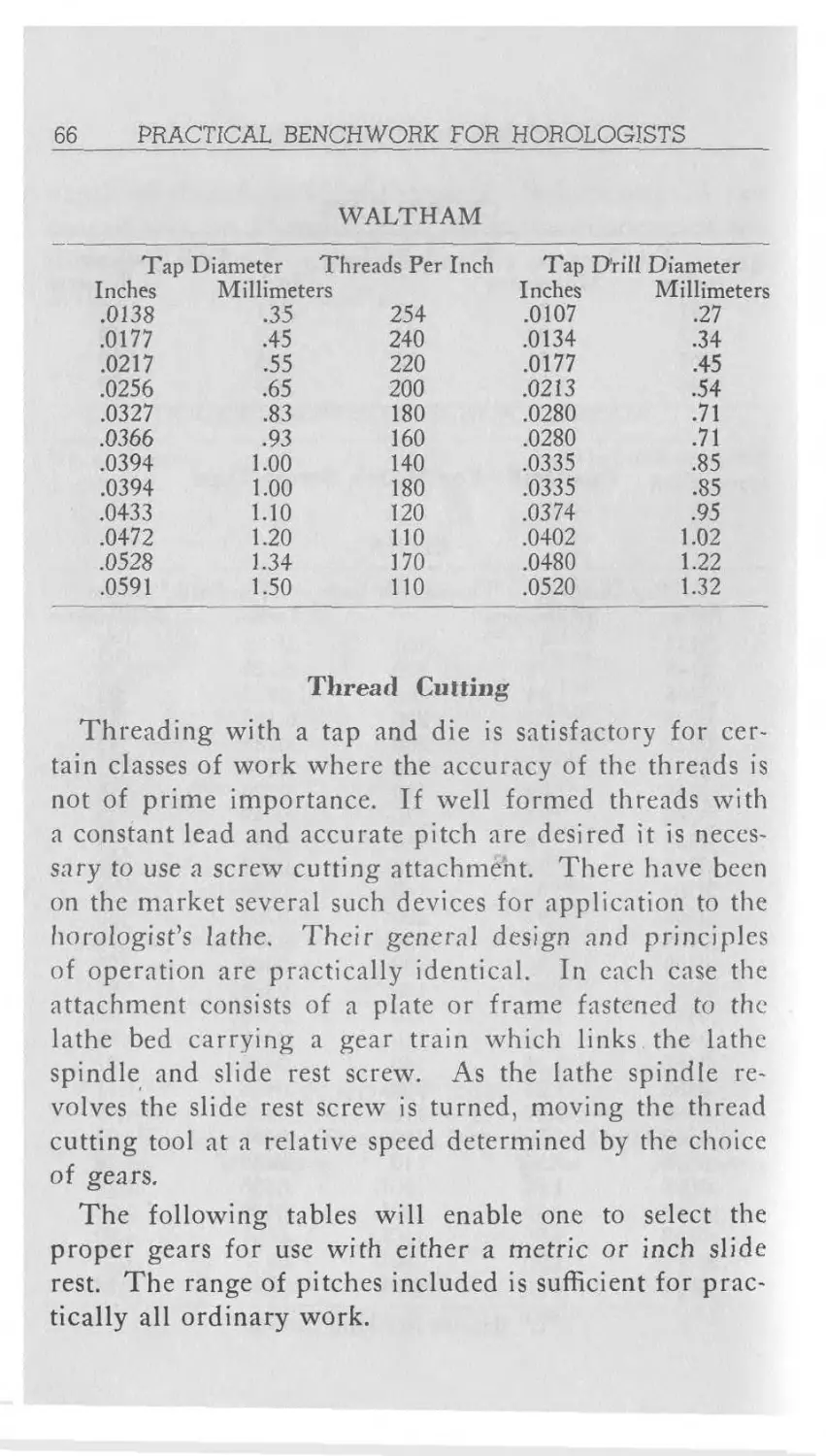
66 PRACTICAL BENCHWORK FOR HOROLOGISTS
WALTHAM
Tap Diameter Threads Per Inch Tap D'rill Diameter
Inches Millimeters Inches Millimeters
.0138 .35 254 .0107 .27
.0177 .45 240 .0134 .3+
.0217 .55 220 .0177 .45
.0256 .65 200 .0213 .54
.0327 .83 180 .0280 .71
.0366 .93 160 .0280 .71
.0394 1.00 140 .0335 .85
.0394 1.00 180 .0335 .85
.0+33 1.10 120 .0374 .95
.0472 1.20 110 .0402 1.02
.0528 1.34 170 .0480 1.22
.0591 1.50 110 .0520 1.32
Thread Cutting
Threading with a tap and die is satisfactory for cer-
tain classes of work where the accuracy of the threads is
not of prime importance. If well formed threads with
a constant lead and accurate pitch are desired it is neces-
sary to use a screw cutting attachment. There have been
on the market several such devices for application to the
horologist’s lathe. Their general design and principles
of operation are practically identical. Tn each case the
attachment consists of a plate or frame fastened to the
lathe bed carrying a gear train which links the lathe
spindle and slide rest screw. As the lathe spindle re-
volves the slide rest screw is turned, moving the thread
cutting tool at a relative speed determined by the choice
of gears.
The following tables will enable one to select the
proper gears for use with either a metric or inch slide
rest. The range of pitches included is sufficient for prac-
tically all ordinary work.
TOOLS AND THEIR USES
67
TABLE OF
GEARS FOR USE WITH METRIC SLIDE REST
Threads per Centimeter Screw Intermediate 1st Stud 2nd Stud Lathe Spindk
1st Gear 2nd Gear 1st Gear 2nd Gear
4 36 72 48 60
5 36 72 60 60
6 36 any 60
7 36 72 84 60
8 36 54 72 60
9 36 48 72 60
10 60 any 60
11 44 48 72 60
12 60 40 48 60
14 84 any 60
15 60 48 72 60
16 96 any 60
18 60 40 72 60
20 100 40 48 60
21 84 48 72 60
22 66 36 72 60
24 96 48 72 60
28 84 36 72 60
30 72 40 100 60
32 96 36 72 60
36 96 36 54 32 48 60
40 96 36 60 32 48 60
42 84 36 72 32 48 60
44 96 36 66 32 48 60
48 96 36 72 32 48 60
50 100 36 72 32 48 60
54 96 36 72 32 54 60
56 96 36 84 32 48 60
60 96 36 72 32 60 60
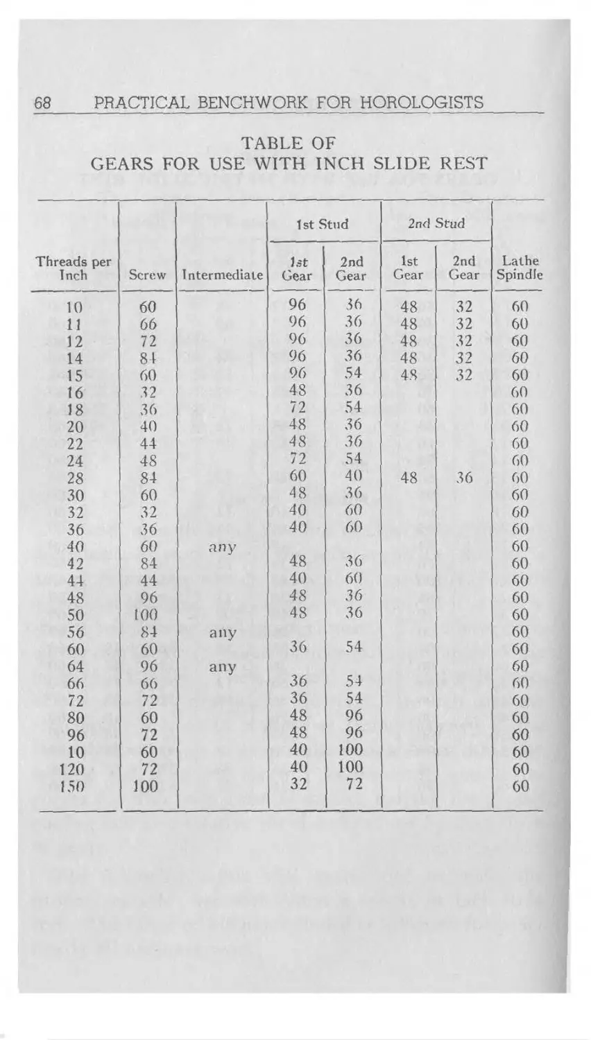
68
PRACTICAL BENCHWORK FOR HOROLOGISTS
TABLE OF
GEARS FOR USE WITH INCH SLIDE REST
Threads per Inch Screw Intermediate 1 st Stud 2nd Stud Lathe Spindle
1st Gear 2nd Gear 1st Gear 2nd Gear
10 60 96 36 48 32 60
11 66 96 36 48 32 60
12 72 96 36 48 32 60
14 84 96 36 48 32 60
15 60 96 54 48 32 60
16 32 48 36 60
18 36 72 54 60
20 40 48 36 60
22 44 48 36 60
24 48 72 54 60
28 84 60 40 48 36 60
30 60 48 36 60
32 32 40 60 60
36 36 40 60 60
40 60 any 60
42 84 48 36 60
44 44 40 60 60
48 96 48 36 60
50 100 48 36 60
56 84 any 60
60 60 36 54 60
64 96 any 60
66 66 36 54 60
72 72 36 54 60
80 60 48 96 60
96 72 48 96 60
10 60 40 100 60
120 72 40 100 60
150 100 32 72 60
TOOLS AND THEIR USES
69
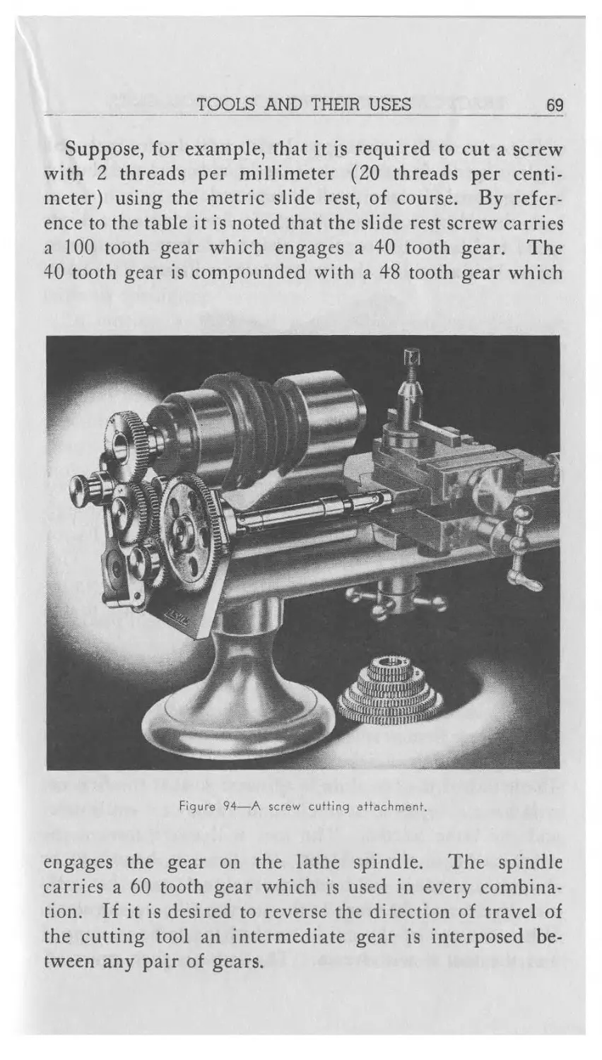
Suppose, for example, that it is required to cut a screw
with 2 threads per millimeter (20 threads per centi-
meter) using the metric slide rest, of course. By refer-
ence to the table it is noted that the slide rest screw carries
a 100 tooth gear which engages a 40 tooth gear. The
40 tooth gear is compounded with a 48 tooth gear which
Figure 94—A screw cutting attachment.
engages the gear on the lathe spindle. The spindle
carries a 60 tooth gear which is used in every combina-
tion. If it is desired to reverse the direction of travel of
the cutting tool an intermediate gear is interposed be-
tween any pair of gears.
70
PRACTICAL BENCHWORK FOR HOROLOGISTS
For most work a cutting tool with a 60 degree included
angle is used. It must be set exactly on center and should
be lubricated if clean work is expected.
A threading tool may be made by grinding a high
speed tool bit to the required shape. A better plan is to
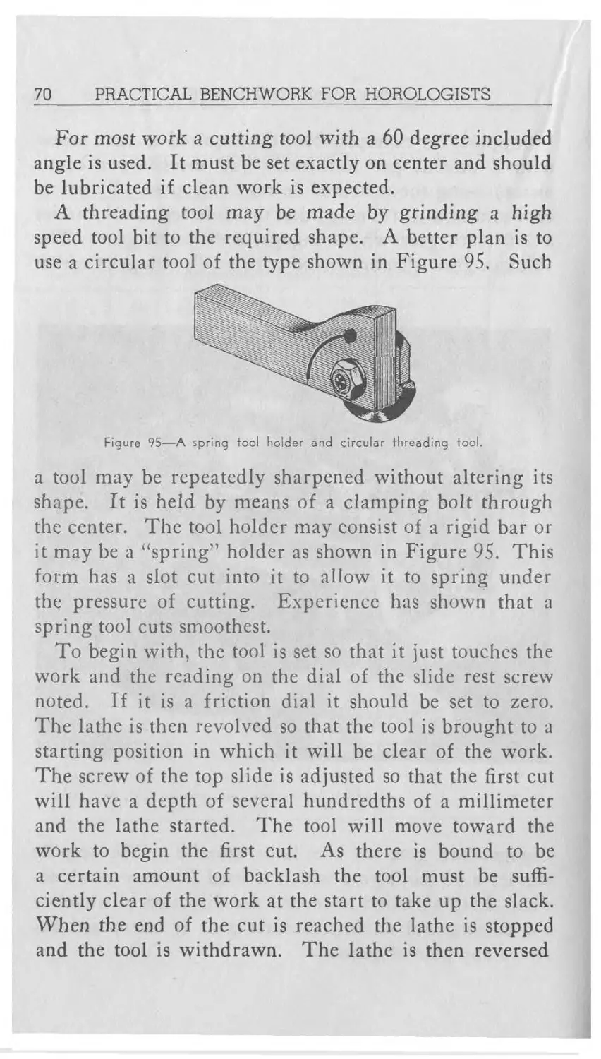
use a circular tool of the type shown in Figure 95. Such
Figure 95—A spring tool holder and circular threading tool.
a tool may be repeatedly sharpened without altering its
shape. It is held by means of a clamping bolt through
the center. The tool holder may consist of a rigid bar or
it may be a “spring” holder as shown in Figure 95. This
form has a slot cut into it to allow it to spring under
the pressure of cutting. Experience has shown that a
spring tool cuts smoothest.
To begin with, the tool is set so that it just touches the
work and the reading on the dial of the slide rest screw
noted. If it is a friction dial it should be set to zero.
The lathe is then revolved so that the tool is brought to a
starting position in which it will be clear of the work.
The screw of the top slide is adjusted so that the first cut
will have a depth of several hundredths of a millimeter
and the lathe started. The tool will move toward the
work to begin the first cut. As there is bound to be
a certain amount of backlash the tool must be suffi-
ciently clear of the work at the start to take up the slack.
When the end of the cut is reached the lathe is stopped
and the tool is withdrawn. The lathe is then reversed
TOOLS AND THEIR USES
71
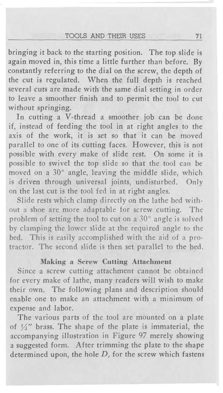
bringing it back to the starting position. The top slide is
again moved in, this time a little further than before. By
constantly referring to the dial on the screw, the depth of
the cut is regulated. When the full depth is reached
several cuts are made with the same dial setting in order
to leave a smoother finish and to permit the tool to cut
without springing.
In cutting a V-thread a smoother job can be done
if, instead of feeding the tool in at right angles to the
axis of the work, it is set so that it can be moved
parallel to one of its cutting faces. However, this is not
passible with every make of slide rest. On some it is
possible to swivel the top slide so that the tool can be
moved on a 30° angle, leaving the middle slide, which
is driven through universal joints, undisturbed. Only
on the last cut is the tool fed in at right angles.
Slide rests which clamp directly on the lathe bed with-
out a shoe are more adaptable for screw cutting. The
problem of setting the tool to cut on a 30° angle is solved
by clamping the lower slide at the required angle to the
bed. This is easily accomplished with the aid of a pro-
tractor. The second slide is then set parallel to the bed.
Making a Screw Cutting Attachment
Since a screw cutting attachment cannot be obtained
for every make of lathe, many readers will wish to make
their own. The following plans and description should
enable one to make an attachment with a minimum of
expense and labor.
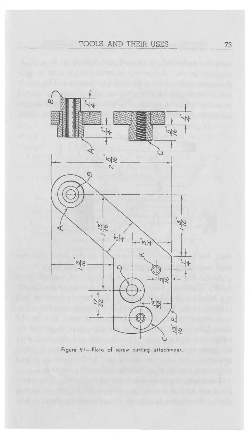
The various parts of the tool are mounted on a plate
of УУ' brass. The shape of the plate is immaterial, the
accompanying illustration in Figure 97 merely showing
a suggested form. After trimming the plate to the shape
determined upon, the hole D, for the screw which fastens
72 PRACTICAL BENCHWORK FOR HOROLOGISTS
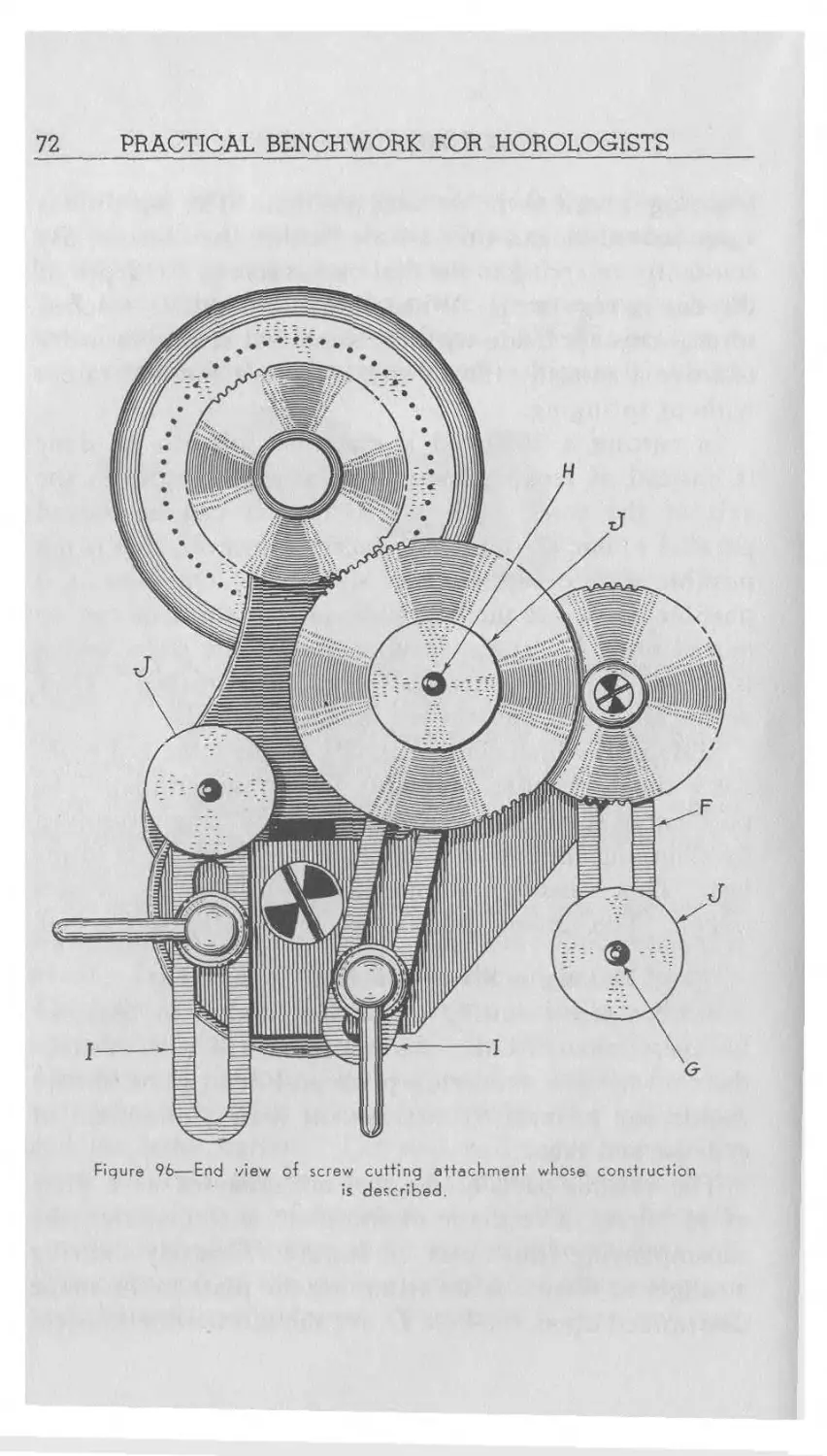
Figure 96—End view of screw cutting attachment whose construction
is described.
TOOLS AND THEIR USES 73
Figure 97—Plate of screw cutting attachment
74
PRACTICAL BENCHWORK FOR HOROLOGISTS
it to the lathe bed, is located and drilled to fit a 10-32
machine screw. A number 21 twist drill is used to drill
the center hole in the lathe bed for tapping. The steady
pin holes should be drilled next. They may be located
at any convenient place. Pins about 3/32" in diameter
are quite satisfactory. Before inserting the pins, how-
ever, the plate should be fastened to the lathe bed and
used as a templet to transfer the steady pin holes.
At K, Figure 97, a hole is drilled and tapped for a
3/16"-32 screw. This hole will receive one of the clamp-
ing bolts for the slotted arms. The other clamping bolt
it fitted to the bushing C which is driven into the plate.
It is necessary to have this bushing in order to raise the
slotted arm sufficiently above the other arm to permit the
compounding of gears. It is drilled and threaded with
the same tap as the hole K. When the arms are in place
and ready for use, a washer 1/16" in thickness is placed
under the arm at K. This should not be forgotten.
The clamping bolts are made of drill rod. The heads
are cross drilled for the pins which are driven in friction
tight. Under the heads are placed washers whose thick-
TOOLS AND THEIR USES _________75
ness may be adjusted so that the handles will point in the
proper direction when locked.
At /7, on the plate, is a bushing which acts as a support
for the arm F. It is made of %" cold rolled steel and is
driven into the plate. The bushing is bored out to a
diameter of 5/16". Into it is driven a bronze bushing
which forms the bearing for the shaft carrying the uni-
versal joint. The hole in the bearing should be carefully
reamed to a 3/16" diameter.
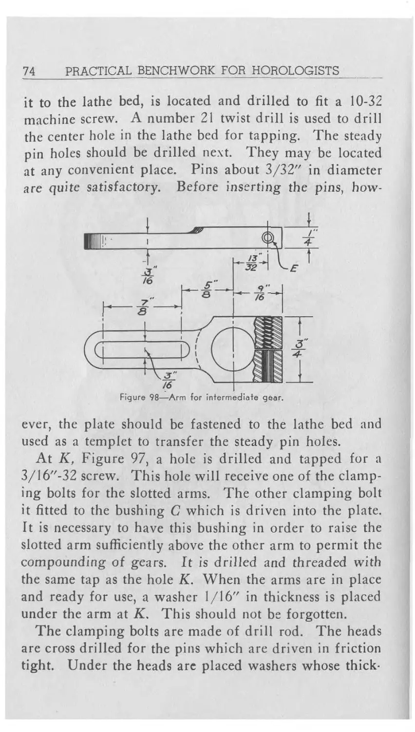
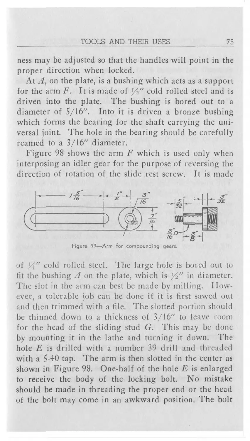
Figure 98 shows the arm F which is used only when
interposing an idler gear for the purpose of reversing the
direction of rotation of the slide rest screw. It is made
Figure 99—Arm for compounding gears.
of %" cold rolled steel. The large hole is bored out to
fit the bushing A on the plate, which is У2" in diameter.
The slot in the arm can best be made by milling. How-
ever, a tolerable job can be done if it is first sawed out
and then trimmed with a file. The slotted portion should
be thinned down to a thickness of 3/16" to leave room
for the head of the sliding stud G. This may be done
by mounting it in the lathe and turning it down. The
hole E is drilled with a number 39 drill and threaded
with a 5-40 tap. The arm is then slotted in the center as
shown in Figure 98. One-half of the hole E is enlarged
to receive the body of the locking bolt. No mistake
should be made in threading the proper end or the head
of the bolt may come in an awkward position. The bolt
76
PRACTICAL BENCHWORK FOR HOROLOGISTS
is made with a cylindrical head which has a cross hole.
A small rod is used for tightening.
The arms I, I are both alike. They are made of cold
rolled steel 3/16" in thickness. The slots, as in the arm
Figure 100—Bushing with key. Used on studs of the arms shown in
Figure 99; also on stud in Figure 101
The lower ends are threaded and screwed into the arms
and the upper ends threaded to fit the nuts J, J. One
will do well to rivet the studs into the arms after they
have been fitted.
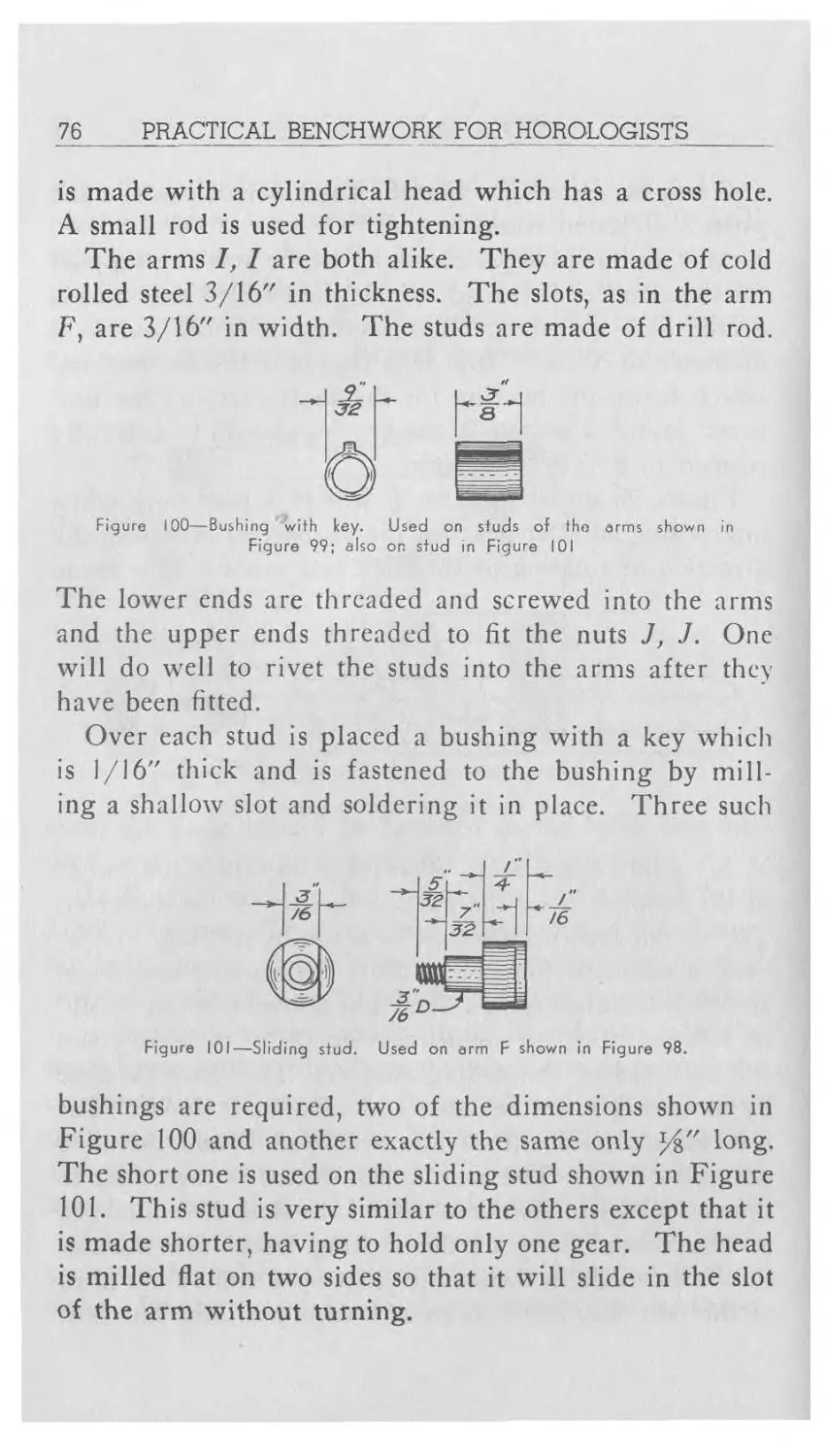
Over each stud is placed a bushing with a key which
is 1/16" thick and is fastened to the bushing by mill-
ing a shallow slot and soldering it in place. Three such
bushings are required, two of the dimensions shown in
Figure 100 and another exactly the same only %" long.
The short one is used on the sliding stud shown in Figure
101. This stud is very similar to the others except that it
is made shorter, having to hold only one gear. The head
is milled flat on two sides so that it will slide in the slot
of the arm without turning.
TOOLS AND THEIR USES
77
When two gears are placed on one of the studs in the
arms I, I they are separated by a washer of the type
shown in Figure 102. The hole in the washer is 9/32"
Figure 102—Spacing washer.
in diameter and has a keyway so that it will fit over the
bushings mentioned above.
The nuts J, J are alike. They are simply discs %" in
diameter and %" thick. The holes are tapped to fit the
threads on the studs. In the circumference two or three
cross holes are drilled to permit the use of a pin for
tightening.
The spindle shown in Figure 103 is made of drill rod.
It also has an inserted key to drive a gear. In milling
Figure 103—Spindle of screw cutting attachment. Connected
screw by means of universal joints.
to slide rest
the slot for the key it is cut right through the flange.
After the key is soldered in place the excess metal is
turned off. This produces a clean, strong job. The
threaded hole is for the screw which holds the gear on
the spindle. A washer should be placed under the head
of the screw. The screw head and washer should not
project over %" or it will be impossible for one of the
compounding gears to pass over them.
78 PRACTICAL BENCHWORK FOR HOROLOGISTS
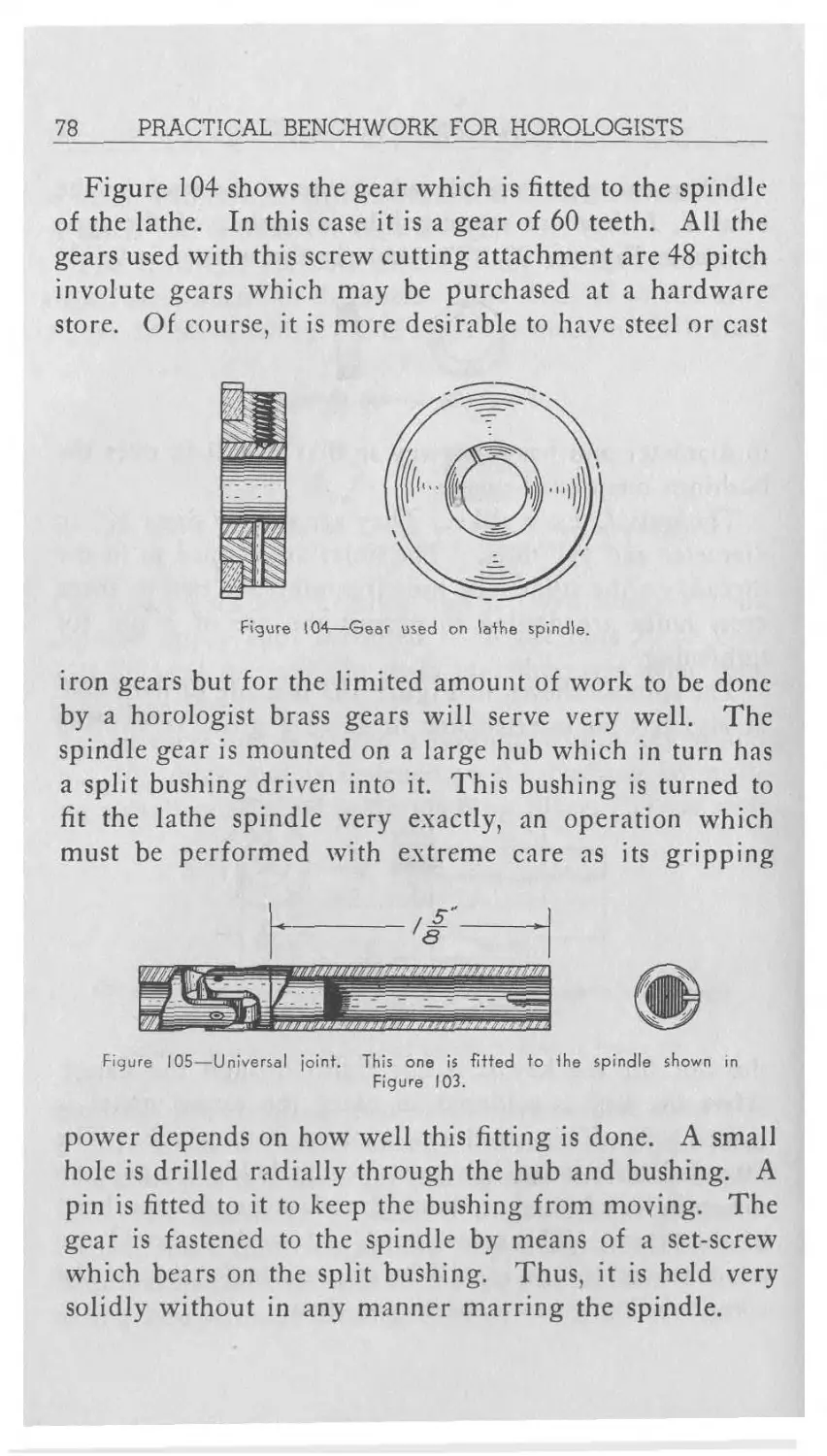
Figure 104 shows the gear which is fitted to the spindle
of the lathe. In this case it is a gear of 60 teeth. All the
gears used with this screw cutting attachment are 48 pitch
involute gears which may be purchased at a hardware
store. Of course, it is more desirable to have steel or cast
Figure 104—Gear used on lathe spindle.
iron gears but for the limited amount of work to be done
by a horologist brass gears will serve very well. The
spindle gear is mounted on a large hub which in turn has
a split bushing driven into it. This bushing is turned to
fit the lathe spindle very exactly, an operation which
must be performed with extreme care as its gripping
Figure 105—Universal joint. This one is fitted to the spindle shown in
Figure 103.
power depends on how well this fitting is done. A small
hole is drilled radially through the hub and bushing. A
pin is fitted to it to keep the bushing from moving. The
gear is fastened to the spindle by means of a set-screw
which bears on the split bushing. Thus, it is held very
solidly without in any manner marring the spindle.
TOOLS AND THEIR USES 79
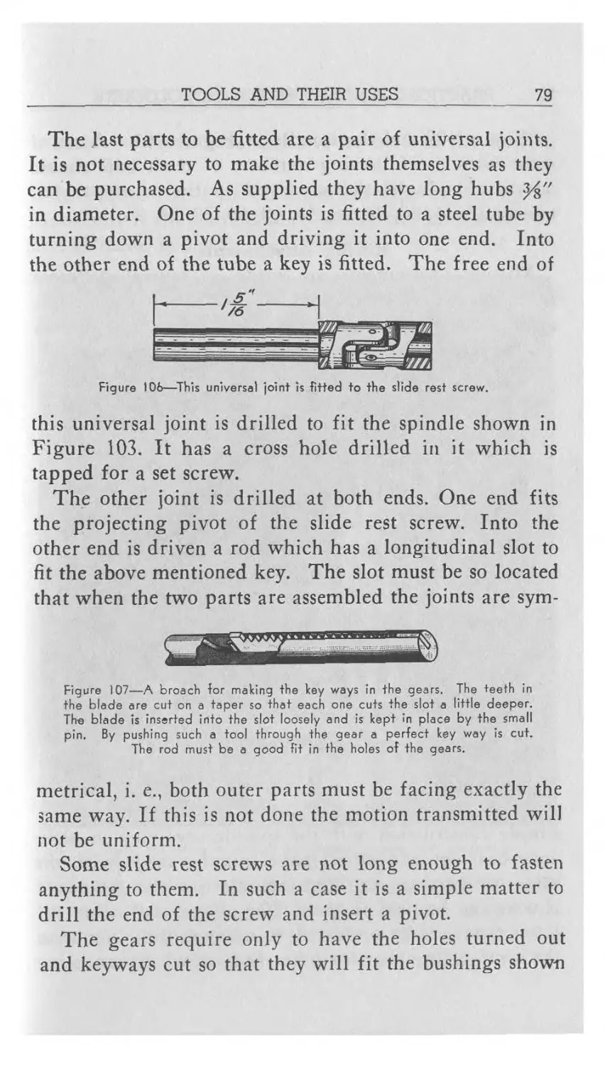
The last parts to be fitted are a pair of universal joints.
It is not necessary to make the joints themselves as they
can be purchased. As supplied they have long hubs
in diameter. One of the joints is fitted to a steel tube by
turning down a pivot and driving it into one end. Into
the other end of the tube a key is fitted. The free end of
Figure 106—This universal joint is fitted to the slide rest screw.
this universal joint is drilled to fit the spindle shown in
Figure 103. It has a cross hole drilled in it which is
tapped for a set screw.
The other joint is drilled at both ends. One end fits
the projecting pivot of the slide rest screw. Into the
other end is driven a rod which has a longitudinal slot to
fit the above mentioned key. The slot must be so located
that when the two parts are assembled the joints are sym-
Figure 107—A broach for making the key ways in the gears. The teeth in
the blade are cut on a taper so that each one cuts the slot a little deeper.
The blade is inserted into the slot loosely and is kept in place by the small
pin. By pushing such a tool through the gear a perfect key way is cut.
The rod must be a good fit in the holes of the gears.
metrical, i. e., both outer parts must be facing exactly the
same way. If this is not done the motion transmitted will
not be uniform.
Some slide rest screws are not long enough to fasten
anything to them. In such a case it is a simple matter to
drill the end of the screw and insert a pivot.
The gears require only to have the holes turned out
and keyways cut so that they will fit the bushings shown
80 PRACTICAL BENCHWORK FOR HOROLOGISTS
in Figure 100 and the spindle in Figure 103. A set of
gears with the following numbers of teeth will enable
one to cut all the threads listed in the accompanying
tables: 32, 36, 40, 44, 48, 54, 60, 66, 72, 84, 96, 100.
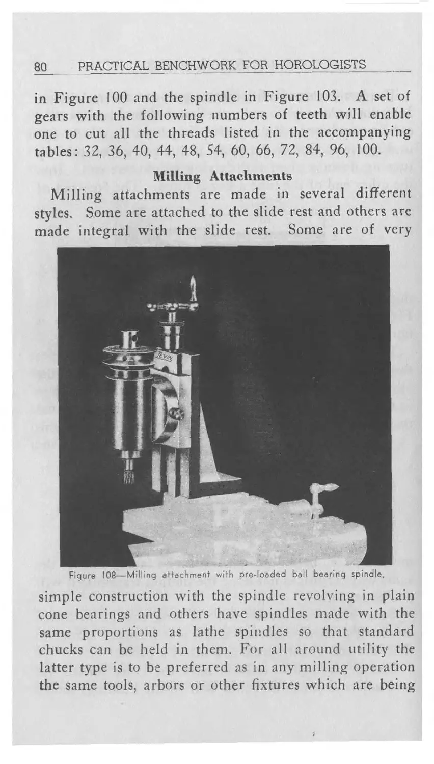
Milling Attachments
Milling attachments are made in several different
styles. Some are attached to the slide rest and others are
made integral with the slide rest. Some are of very
Figure 108—Milling attachment with pre-loaded ball bearing spindle.
simple construction with the spindle revolving in plain
cone bearings and others have spindles made with the
same proportions as lathe spindles so that standard
chucks can be held in them. For all around utility the
latter type is to be preferred as in any milling operation
the same tools, arbors or other fixtures which are being
TOOLS AND THEIR USES
81
used in the lathe head can also be held in the milling
attachment.
In Figure 108 is shown a modern type of milling at-
tachment. It fits the top slide of any standard slide rest
and is made to hold chucks in the spindle. Since it is
Figure 109—View of milling attachment in horizontal position.
equipped with a pre-loaded ball bearing spindle it may
be used for numerous grinding operations as well as
milling. When used in conjunction with a screw cutting
attachment it is easily set up for thread milling.