/


Author: Held G.
Tags: programming languages programming networks wireless networks wireless mesh networks
ISBN: 0-8493-2960-4
Year: 2005


Text
Au2960 _half title 5/10/05 12:44 PM Page 1
Wireless
Mesh
Networks
© 2005 by Taylor & Francis Group.
OTHER AUERBACH PUBLICATIONS
Agent-Based Manufacturing and Control
Systems: New Agile Manufacturing
Solutions for Achieving Peak Performance
Massimo Paolucci and Roberto Sacile
ISBN: 1574443364
Curing the Patch Management Headache
Felicia M. Nicastro
ISBN: 0849328543
Cyber Crime Investigator's Field Guide,
Second Edition
Bruce Middleton
ISBN: 0849327687
Disassembly Modeling for Assembly,
Maintenance, Reuse and Recycling
A. J. D. Lambert and Surendra M. Gupta
ISBN: 1574443348
The Ethical Hack: A Framework for
Business Value Penetration Testing
James S. Tiller
ISBN: 084931609X
Fundamentals of DSL Technology
Philip Golden, Herve Dedieu,
and Krista Jacobsen
ISBN: 0849319137
Mobile Computing Handbook
Imad Mahgoub and Mohammad Ilyas
ISBN: 0849319714
MPLS for Metropolitan
Area Networks
Nam-Kee Tan
ISBN: 084932212X
Multimedia Security Handbook
Borko Furht and Darko Kirovski
ISBN: 0849327733
Network Design: Management and
Technical Perspectives, Second Edition
Teresa C. Piliouras
ISBN: 0849316081
Network Security Technologies,
Second Edition
Kwok T. Fung
ISBN: 0849330270
Outsourcing Software Development
Offshore: Making It Work
Tandy Gold
ISBN: 0849319439
The HIPAA Program Reference Handbook
Ross Leo
ISBN: 0849322111
Quality Management Systems:
A Handbook for Product
Development Organizations
Vivek Nanda
ISBN: 1574443526
Implementing the IT Balanced Scorecard:
Aligning IT with Corporate Strategy
Jessica Keyes
ISBN: 0849326214
A Practical Guide to Security
Assessments
Sudhanshu Kairab
ISBN: 0849317061
Information Security Fundamentals
Thomas R. Peltier, Justin Peltier,
and John A. Blackley
ISBN: 0849319579
The Real-Time Enterprise
Dimitris N. Chorafas
ISBN: 0849327776
Information Security Management
Handbook, Fifth Edition, Volume 2
Harold F. Tipton and Micki Krause
ISBN: 0849332109
Software Testing and Continuous
Quality Improvement,
Second Edition
William E. Lewis
ISBN: 0849325242
Introduction to Management
of Reverse Logistics and Closed
Loop Supply Chain Processes
Donald F. Blumberg
ISBN: 1574443607
Supply Chain Architecture:
A Blueprint for Networking the Flow
of Material, Information, and Cash
William T. Walker
ISBN: 1574443577
Maximizing ROI on Software Development
Vijay Sikka
ISBN: 0849323126
The Windows Serial Port
Programming Handbook
Ying Bai
ISBN: 0849322138
AUERBACH PUBLICATIONS
www.auerbach-publications.com
To Order Call: 1-800-272-7737 • Fax: 1-800-374-3401
E-mail: orders@crcpress.com
© 2005 by Taylor & Francis Group.
Au2960 _title 5/10/05 12:26 PM Page 1
Wireless
Mesh
Networks
Gilbert Held
Boca Raton London New York Singapore
© 2005 by Taylor & Francis Group.
Published in 2005 by
Auerbach Publications
Taylor & Francis Group
6000 Broken Sound Parkway NW, Suite 300
Boca Raton, FL 33487-2742
© 2005 by Taylor & Francis Group, LLC
Auerbach is an imprint of Taylor & Francis Group
No claim to original U.S. Government works
Printed in the United States of America on acid-free paper
10 9 8 7 6 5 4 3 2 1
International Standard Book Number-10: 0-8493-2960-4 (Hardcover)
International Standard Book Number-13: 978-0-8493-2960-9 (Hardcover)
Library of Congress Card Number 2005041065
This book contains information obtained from authentic and highly regarded sources. Reprinted material is
quoted with permission, and sources are indicated. A wide variety of references are listed. Reasonable efforts
have been made to publish reliable data and information, but the author and the publisher cannot assume
responsibility for the validity of all materials or for the consequences of their use.
No part of this book may be reprinted, reproduced, transmitted, or utilized in any form by any electronic,
mechanical, or other means, now known or hereafter invented, including photocopying, microfilming, and
recording, or in any information storage or retrieval system, without written permission from the publishers.
For permission to photocopy or use material electronically from this work, please access www.copyright.com
(http://www.copyright.com/) or contact the Copyright Clearance Center, Inc. (CCC) 222 Rosewood Drive,
Danvers, MA 01923, 978-750-8400. CCC is a not-for-profit organization that provides licenses and registration
for a variety of users. For organizations that have been granted a photocopy license by the CCC, a separate
system of payment has been arranged.
Trademark Notice: Product or corporate names may be trademarks or registered trademarks, and are used only
for identification and explanation without intent to infringe.
Library of Congress Cataloging-in-Publication Data
Held, Gilbert, 1943Wireless mesh networks / Gilbert Held.
p. cm.
ISBN 0-8493-2960-4 (alk. paper)
1. Wireless communication systems. 2. Routers (Computer networks). I. Title.
TK5103.2.H453 2005
621.382′15--dc22
2005041065
Visit the Taylor & Francis Web site at
http://www.taylorandfrancis.com
Taylor & Francis Group
is the Academic Division of T&F Informa plc.
© 2005 by Taylor & Francis Group.
and the Auerbach Publications Web site at
http://www.auerbach-publications.com
AU2960_C000.fm Page v Monday, May 2, 2005 1:37 PM
Dedication
Over the past decade I found that teaching graduate school is a wonderful
way to spend some evenings during the week. Although the job of a
professor is to transfer knowledge, many times it’s a two-way street, with
thought-provoking student questions making me realize that the wonderful
field of communications technology is far from reaching its promoted
ability to link mankind. Thus, I would be remiss if I did not take the
opportunity to thank the students at Georgia College and State University
for their inquisitive minds that make teaching most interesting.
© 2005 by Taylor & Francis Group.
AU2960_C000.fm Page vii Monday, May 2, 2005 1:37 PM
Table of Contents
Preface
Acknowledgments
1 Introduction to Wireless Mesh Networking
1.1 Mesh Networking Defined
Nodes and Links
Control Issues
Modern Mesh Networking
Wireless Networking Structures
Overcoming Transmission Distance Limitations
1.2 Network Evolution
Network Topologies
Point-to-Point
Multipoint
Types of Networking Addressing
Unicast Addressing
Broadcast Addressing
Types of Broadcast Addresses
Multicast Addressing
Bridging and Routing
Wireless LAN Topology
Service Sets
Basic Service Set
Distribution System
Mesh Network Evolution
Routing Algorithms
Dynamic Source Routing
On-Demand Distant Vector
Ad Hoc Mesh Networks
Advantages of Use
Reliability
Self-Configuration
© 2005 by Taylor & Francis Group.
Self-Healing
Scalability
Economics
1.3 Disadvantages of Use
Lack of Standards
Security
Overhead
1.4 Applications
2 Radio Frequency Utilization
2.1 Frequency, Period, and Bandwidth
Frequency
Period
Bandwidth
Frequency Bands
2.2 IEEE Standards
The 802.11 Standard
FHSS
DSSS
Utilization
The WiMax Standard
The ZigBee Standard
2.3 Power Measurements
The Bel
Log Relationships
The Decibel
Decibel above 1 mW
The Decibel Isotropic
2.4 Antenna Systems
Antenna Categories
Polarization
Directionality and EIRP
Types of Antennae
Whip Antenna
Dipole Antenna
Yagi Antenna
Considering Power Limits
Antenna Selection
Receiver Sensitivity
3 Mesh Network Components
3.1 Understanding Mesh Network Components
Wireless LAN Cards
MeshNetworks 6300 Wireless Modem Card
Client Software
Wireless Mesh Router
MeshNetworks Wireless Router
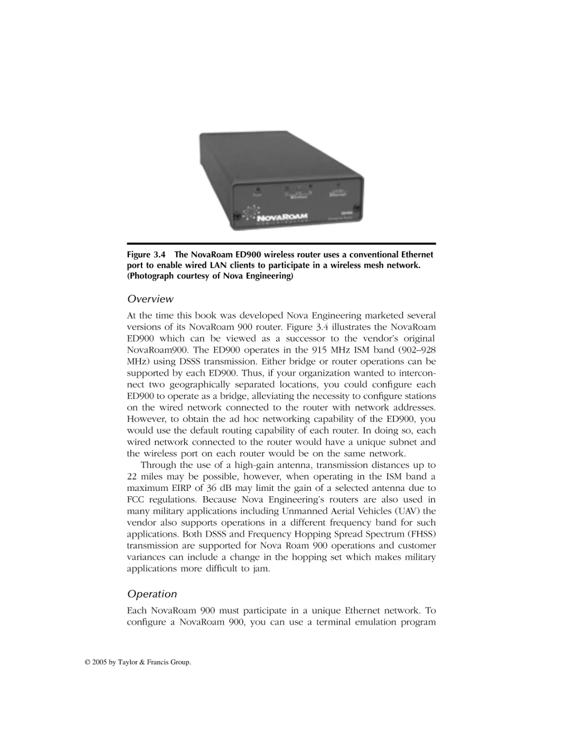
Nova Engineering NovaRoam 900 Router
© 2005 by Taylor & Francis Group.
AU2960_C000.fm Page ix Monday, May 2, 2005 1:37 PM
Overview
Operation
Route Table Utilization
Applications
Access Point
Operation
Types of Access Points
MeshNetworks IAP 6300
Switching Controller
MeshNetworks MiSC
3.2 Integrating Components
4 Routing Protocols
4.1 MANET
Characteristics
Dynamic Topologies
Bandwidth Constraint
Energy Constrained Operation
Limited Security
Scalability
IETF MANET Goals
Near-Term Goals
Long-Term Goals
4.2 MANET Protocols
Types of Protocols
The AODV Routing Protocol
Need for a Routing Protocol
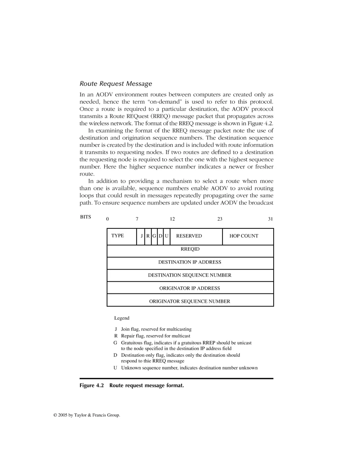
Route Request Message
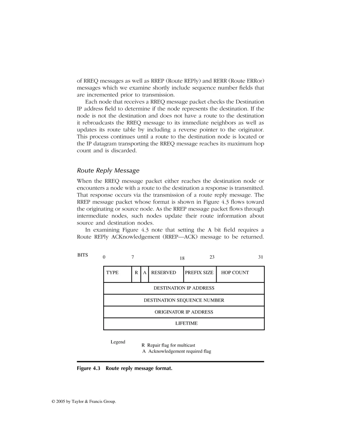
Route Reply Message
RREQ–RREP Message Flow
Route Deletion
HELLO Message
Route Error Message
Gray Area Considerations
TBRPF
Overview
Routing Modules
Neighbor Discovery Module
Routing Module
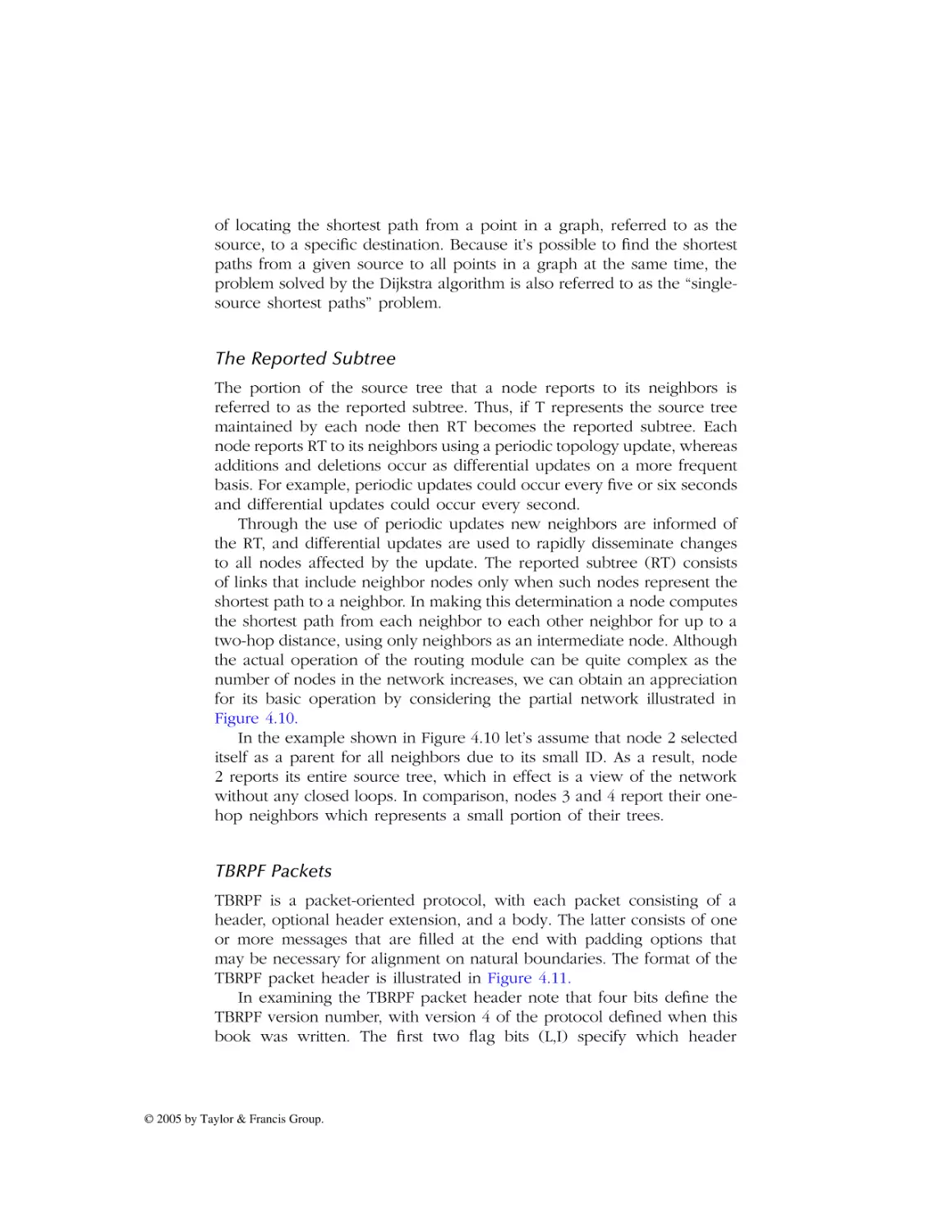
The Reported Subtree
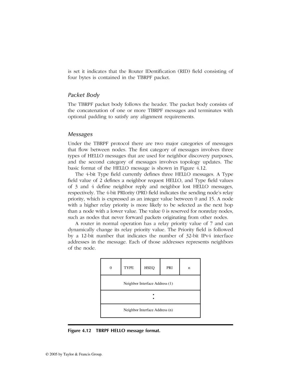
TBRPF Packets
Packet Body
Messages
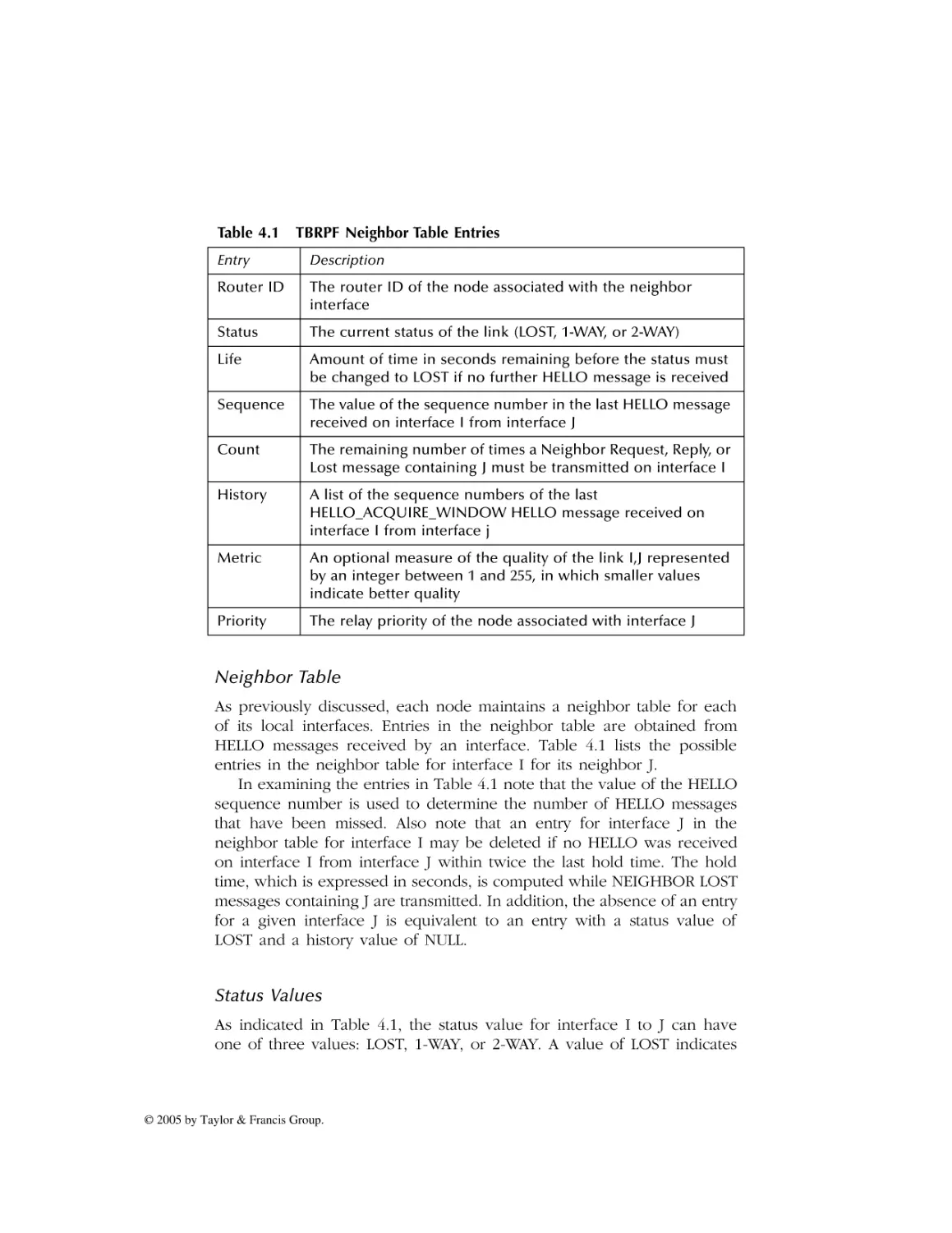
Neighbor Table
Status Values
Transmitting HELLO Messages
Processing HELLO Messages
© 2005 by Taylor & Francis Group.
AU2960_C000.fm Page x Monday, May 2, 2005 1:37 PM
Protocol Comparison
Traffic Support
5 Network Operation
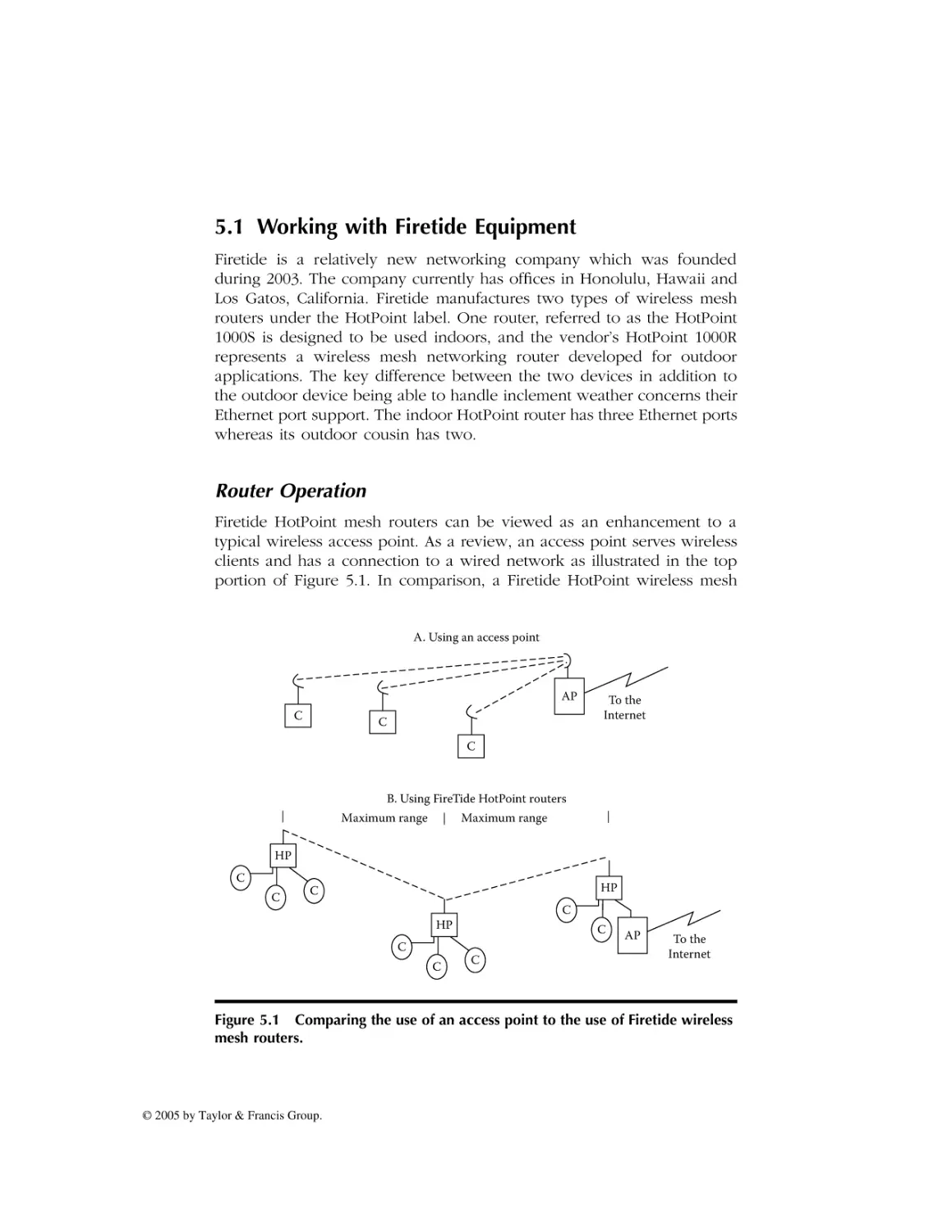
5.1 Working with Firetide Equipment
Router Operation
Routing Protocol Support
Hardware Features
Network Utilization
Security
Modes of Operation
Outdoor Utilization
5.2 LocustWorld Mesh AP and Meshbox Networking
MeshAP
Software Design
Limitations
Software Operation
Security
Software Availability
MeshBox
Applications
WISP
Community Networking
Contract Constraints
Security
Economics
5.3 Packet Hop Networking
Network Components
Network Controller
Network Management System
Network Clients
Multi-Terrain Support
Network Applications
5.4 Nortel Networks Wireless Mesh Networking
IEEE 802.11b/g Products
7220 Access Point
7250 Wireless Gateway
Optivity NMS
The OPTera Metro 2400
6 Creating a HotPoint-Based Mesh Network
6.1 The Networking Environment
Home Networking Environment
Network Access
6.2 Creating a HotPoint Mesh Network
Hotpoint Router Local Connectivity
Port Connection Considerations
Using HotPoint Manager
© 2005 by Taylor & Francis Group.
Inventory View
Mesh View
Setup Tab
Security Tab
Wireless Tab
Update Tab
Monitor Tab
Creating the Indoor Mesh Network
Considering a Community Network
6.3 Observing Intramesh Communications
AiroPeek Operation
Examining Captured Packets
Packet Decoding
The Beacon Frame
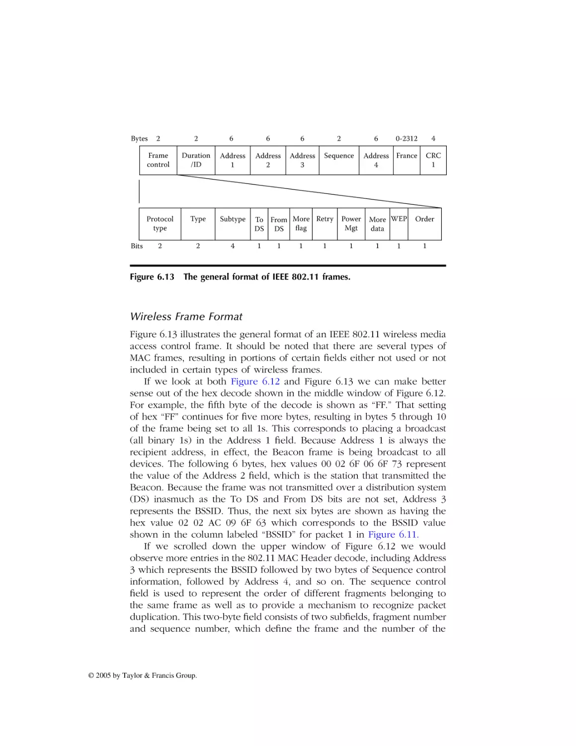
Wireless Frame Format
Data Frame Decode
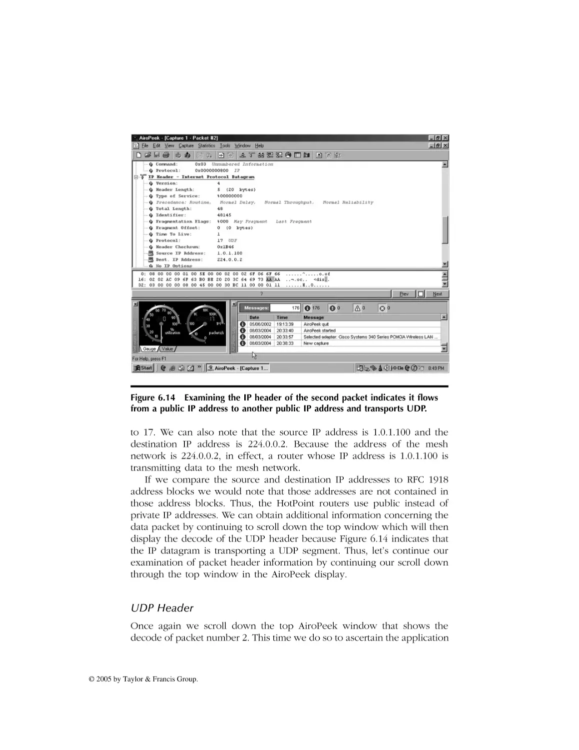
IP Header
UDP Header
7 Wireless Mesh Standards
7.1 Evolution .
Transmission Platform
Routing Protocols
Standards Responsibility
7.2 The Proposed IEEE 802.11s Standard
Objective
Security
Project Status
8 The Future of Wireless Mesh Networking
8.1 Standardization Problems
Economics
Market Drivers
IEEE 802.11a, b, and g Technologies
IEEE Standardization of Mesh Networking
Municipal Hot Spots
8.2 Mesh Networking Prediction
© 2005 by Taylor & Francis Group.
AU2960_C000.fm Page xiii Monday, May 2, 2005 1:37 PM
Preface
Approximately every five or ten years we are blessed with the implementation of a technology that can have a major bearing upon how we work,
facilitates our productivity, and even enhances our recreational capability.
In the past we witnessed the PC revolution, the advent of the PDA, and
the growth in the use of wireless LANs. Today a new technology referred
to as wireless mesh networking has the potential to considerably influence
how we communicate. Although derived from military research into mobile
networks, the emergence of wireless mesh networking has its greatest
potential in the commercial marketplace and is the primary focus of this
book.
Within a few years, wireless mesh networking may revolutionize the
manner by which you can access the Internet as well as communicate
with co-workers and friends. Although the software behind wireless mesh
networking is still evolving, the concept behind the technology that
eliminates the need for a centralized control mechanism is well thought
out and will remain in place. In this book we examine the concept behind
wireless mesh networking, its advantages over existing technologies and
its existing and potential applications, and explore how some of the
networking protocols associated with this technology operate by obtaining
an appreciation for the technology in the office, government agencies,
and in a campus environment as well as in the home.
Because it’s the job of an author to fully inform readers of all sides
of an issue, we note that there are some significant problems associated
with wireless mesh networking. Some problems are associated with the
scale of the network, with an increased area of coverage requiring more
stations than a smaller network. Other problems, such as security, represent issues that must be considered regardless of the size of the mesh
network. Still other problems, such as radio frequency interference, can
represent both controllable and uncontrollable issues because it may be
© 2005 by Taylor & Francis Group.
AU2960_C000.fm Page xiv Monday, May 2, 2005 1:37 PM
difficult or impossible to control the use of machinery and fluorescent
lighting by other organizations, yet alone the periodic sunspots that radiate
hundreds of millions of miles onto our small planet. Thus, at applicable
locations in this book we note the problems associated with wireless mesh
networking as well as actual and potential solutions to such problems.
As a professional author I truly welcome reader comments. Let me
know if you feel I should expand upon a topic, if I provided too much
information, and what topics you might like to read about in a future
edition of this book. Of course, any other comments or suggestions are
also welcomed. You can contact me through my publisher whose address
is on the cover of this book or you can send me an e-mail directly to
gil_held@yahoo.com.
Gilbert Held
Macon, Georgia
© 2005 by Taylor & Francis Group.
AU2960_C000.fm Page xv Monday, May 2, 2005 1:37 PM
Acknowledgments
The preparation of a book in many respects is similar to a sport in that
it is a team effort. This book is certainly no exception, as it required the
efforts of many people to publish the book you are now reading.
Once again this author is indebted to Richard O’Hanley at Auerbach
Publications for green-lighting another idea and providing backing for this
project. I would be remiss if I did not also thank the production staff at
Auerbach Publications for turning this author’s manuscript into the book
you are reading. Concerning the manuscript, it is with a great sense of pride
that I wish to thank my wife, Beverly Jane Held, for her efforts in turning
my handwritten notes into a professionally typed manuscript. Beverly
typed this author’s first book on a 128-kb Macintosh many years ago.
Although technology has certainly changed over the years, Beverly’s typing
skills continue to maintain a level of accuracy that is truly appreciated.
© 2005 by Taylor & Francis Group.
AU2960_book.fm Page 1 Monday, April 11, 2005 11:01 AM
Chapter 1
Introduction to Wireless
Mesh Networking
The purpose of an introductory chapter is to provide readers with basic
information concerning the subject of a book. Because this book is about
wireless mesh networking, as you might surmise the goal of this introductory chapter is to become familiar with this topic, terms associated
with this topic, and even a few associated abbreviations.
In this chapter we begin with an explanation of mesh networking and
wireless mesh networks. This explanation includes a brief examination of
different types of networking, with this author discussing networking
structures commonly referred to as networking topology and the manner
by which such structures evolved. As we review different types of networking topologies, we note some of the advantages and disadvantages
associated with each structure, which will provide a foundation for examining the advantages and disadvantages associated with wireless mesh
networking. Because modern mesh networks are built upon over-the-air
transmission and primarily use existing wireless LAN networking components, it will come as no surprise that we also focus our attention upon
this area in this chapter.
Once we complete our initial examination of networking topology, we
turn our attention to the different types of mesh networks, their advantages, and disadvantages.
In concluding our introduction to the topic of mesh networks and
wireless mesh networking, we examine some of the existing and evolving
applications that have the potential to make wireless mesh networking
© 2005 by Taylor & Francis Group.
AU2960_book.fm Page 2 Monday, April 11, 2005 11:01 AM
into an ubiquitous technology. That said, let’s grab a Coke, Diet Pepsi,
or another drink and our favorite munchies and explore the wonderful
world of wireless mesh networking.
1.1 Mesh Networking Defined
To understand mesh networking, we first need to obtain an appreciation
for what a mesh topology represents. If we have n nodes in a network,
where the term “node” refers to a communications device that can transport data from one of its interfaces to another, then the ability of each
node to communicate with every other node in the network represents a
mesh network topology. We can view the structure of a mesh network
by simplifying the number of nodes in the network from a value of n,
which is what mathematicians like to work with, to an easy-to-visualize
number, such as three, four, or five.
Nodes and Links
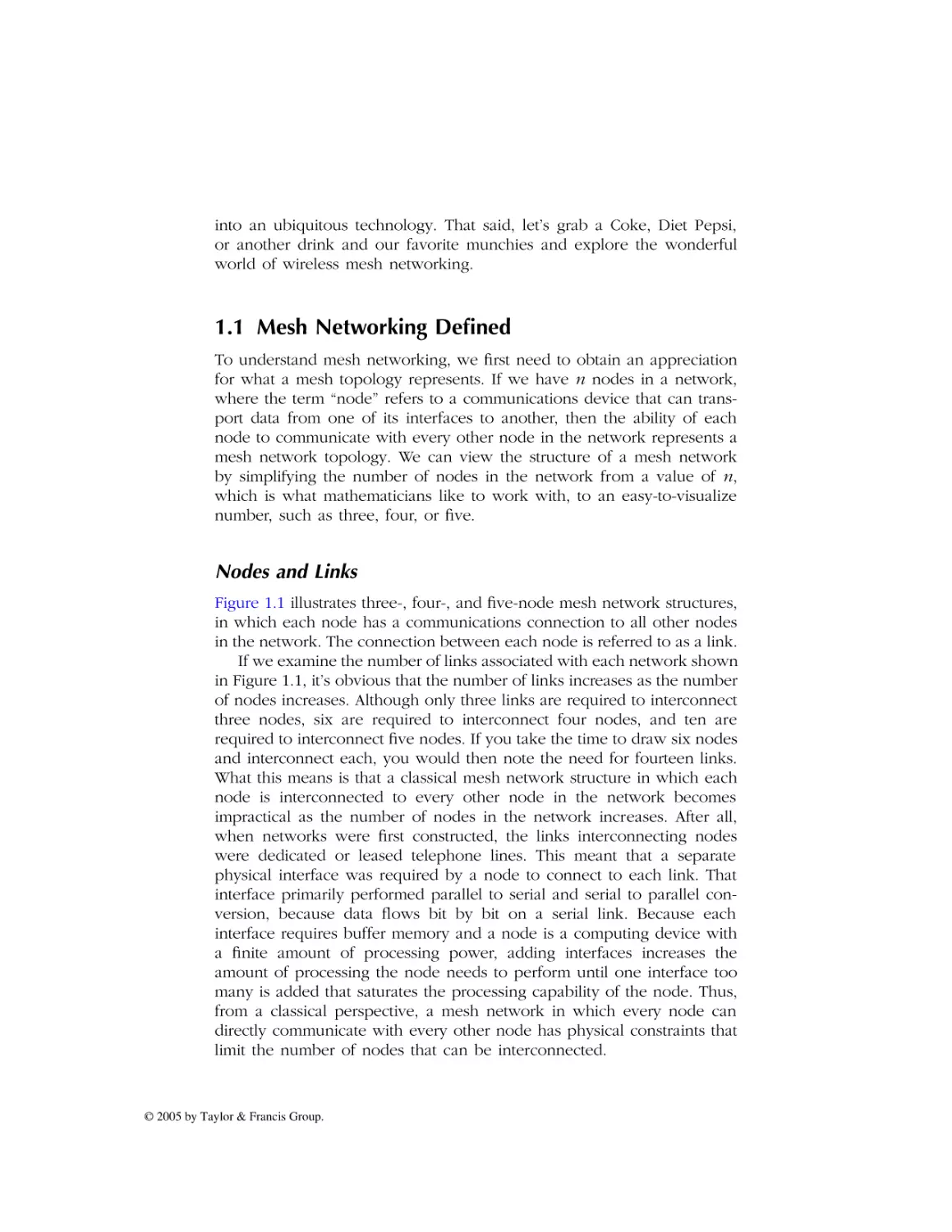
Figure 1.1 illustrates three-, four-, and five-node mesh network structures,
in which each node has a communications connection to all other nodes
in the network. The connection between each node is referred to as a link.
If we examine the number of links associated with each network shown
in Figure 1.1, it’s obvious that the number of links increases as the number
of nodes increases. Although only three links are required to interconnect
three nodes, six are required to interconnect four nodes, and ten are
required to interconnect five nodes. If you take the time to draw six nodes
and interconnect each, you would then note the need for fourteen links.
What this means is that a classical mesh network structure in which each
node is interconnected to every other node in the network becomes
impractical as the number of nodes in the network increases. After all,
when networks were first constructed, the links interconnecting nodes
were dedicated or leased telephone lines. This meant that a separate
physical interface was required by a node to connect to each link. That
interface primarily performed parallel to serial and serial to parallel conversion, because data flows bit by bit on a serial link. Because each
interface requires buffer memory and a node is a computing device with
a finite amount of processing power, adding interfaces increases the
amount of processing the node needs to perform until one interface too
many is added that saturates the processing capability of the node. Thus,
from a classical perspective, a mesh network in which every node can
directly communicate with every other node has physical constraints that
limit the number of nodes that can be interconnected.
© 2005 by Taylor & Francis Group.
AU2960_book.fm Page 3 Monday, April 11, 2005 11:01 AM
Three node mesh network
Four node mesh network
Five node mesh network
Figure 1.1 In a true mesh network structure, each node has a connection to
every other node in the network.
Control Issues
Recognizing the previously mentioned constraints associated with network
nodes resulted in the development of more cost-effective partial mesh
network structures. A good example of a partial mesh network would be
the public packet networks constructed by Tymnet and Sprint during the
1970s and 1980s. Such networks consisted of hundreds to thousands of
nodes, however, instead of each node being directly interconnected to
every other node, they simply had two or more links to other nodes to
provide an alternate routing and traffic balancing capability. Because nodes
are not directly connected to one another, traffic would typically flow
through one or more intermediary nodes to its destination, requiring the
development of routing protocols that are based upon the transfer of
control messages between nodes. Similarly, alternate routing and traffic
balancing operations also required coordination, with control messages
transmitted between nodes and a centralized network operations center
required for controlling the flow of messages between nodes, which in
© 2005 by Taylor & Francis Group.
AU2960_book.fm Page 4 Monday, April 11, 2005 11:01 AM
turn controlled the use of alternate links for backup and traffic balancing
operations. This concept of the use of a partial mesh holds true for the
“mother of all interconnected networks” better known as the Internet.
Modern Mesh Networking
In a wireless environment, a single radio frequency (RF) transmitter/receiver
in one node has the ability to communicate with a virtually unlimited
number of other nodes. Thus, the physical constraints associated with
wired connectivity becomes less of an issue in a wireless environment.
This means it’s both a practical and a relatively simple process for one
node to communicate with many other nodes because a single interface
in the form of an RF transmitter/receiver can be substituted for the multiple
interfaces required in a wired environment. Obviously, other nodes must
be within transmission rage for communications to occur.
Wireless Networking Structures
There are two basic types of wireless LAN networking structures, referred
to as peer-to-peer and infrastructure. In a peer-to-peer networking structure, each node can directly communicate with every other node, assuming
they are in transmission range of one another. In an infrastructure wireless
LAN networking environment, all traffic flows through an access point
(AP). The access point represents a two-port bridge, with one port
connected to a wired network and the second port representing the RF
transmitter/receiver. Thus, in an infrastructure wireless network two nodes
communicating with each other do so by first transmitting to the access
point which then regenerates the data. Because the access point in effect
functions as a relay station, when transmission occurs between two
wireless nodes the transmission distance between nodes can double in
comparison to a peer-to-peer networking environment. However, the
access point represents a central control mechanism and, if it fails or if a
node is out of range of the access point, communications suffer.
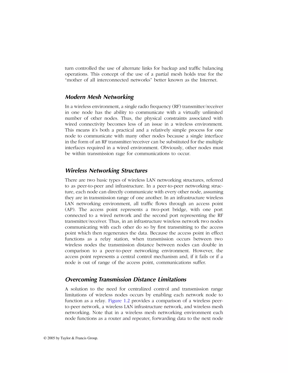
Overcoming Transmission Distance Limitations
A solution to the need for centralized control and transmission range
limitations of wireless nodes occurs by enabling each network node to
function as a relay. Figure 1.2 provides a comparison of a wireless peerto-peer network, a wireless LAN infrastructure network, and wireless mesh
networking. Note that in a wireless mesh networking environment each
node functions as a router and repeater, forwarding data to the next node
© 2005 by Taylor & Francis Group.
AU2960_book.fm Page 5 Monday, April 11, 2005 11:01 AM
Peer to peer
Infrastructure
Access
point
Wired
network
Wireless mesh
Figure 1.2 Comparing wireless LAN topologies.
toward its ultimate destination. In comparison, in a peer-to-peer environment transmission is limited to two nodes communicating with each other
whereas in an infrastructure networking environment all transmissions
occur through a centralized access point. However, because nodes can be
modified to relay information we can group a sequence of peer-to-peer
transmissions to obtain a mesh structure operating environment. Based
upon the preceding, we can define a wireless mesh network as follows.
A wireless mesh network represents a series of peer-to-peer transmissions where each node functions as a router and repeater.
Note from the above definition that there is no requirement for any
centralized control and in fact nodes communicate with each other on a
peer-to-peer basis.
© 2005 by Taylor & Francis Group.
AU2960_book.fm Page 6 Monday, April 11, 2005 11:01 AM
We can use an analogy to obtain additional information concerning
the operation of a mesh network. Assume a room has a group of people,
each having a similar communications device, such as a cell phone or
notebook computer. If we are located in the room and need to send a
message to a person located outside the room we could either move
through the room or convey our message to another person, with the
expectation that that person would relay our message until a person near
the door could open it and deliver the message to the appropriate person
located outside the room. If we think of each person in the room as a
“client” or “node” then one person can relay our message to another as
a peer-to-peer transmission. The person who opens the door to communicate our message to the person behind the door can be thought of as
a network gateway. Thus, in a mesh networking environment, messages
are passed in the form of electronic signals from client to client or node
to node until they reach their destination on the network or a gateway
for transmission off the mesh.
Now that we have a general appreciation for the term “wireless mesh
networking,” let’s backtrack a bit and discuss the general aspects of how
networks evolved. Doing so provides us with a firmer understanding of
wireless mesh networking including its relationship to wireless LANs and
the advantages and disadvantages associated with the technology.
1.2 Network Evolution
Earlier in this chapter when we examined mesh networking we noted the
term “link” was used to refer to the connection between two nodes. Both
of those terms, “link” and “node,” are considered by some people as
antiquated in today’s modern wireless environment. However, they represent a good starting point for examining the evolution of networking
including different types of networks and mechanisms to move or transport
data from one network to another.
Network Topologies
There are two generic types of network topologies or structures that
evolved over the past half century. Those two generic topologies are
referred to as point-to-point and multipoint.
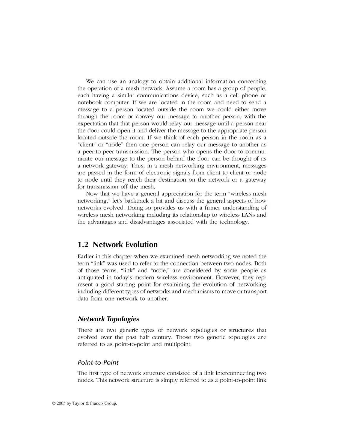
Point-to-Point
The first type of network structure consisted of a link interconnecting two
nodes. This network structure is simply referred to as a point-to-point link
© 2005 by Taylor & Francis Group.
AU2960_book.fm Page 7 Monday, April 11, 2005 11:01 AM
Point-to-point
Multipoint or multidrop
or
Wireless multipoint
Access
point
Figure 1.3 Generic network topologies.
because it directly interconnects two locations. The top portion of Figure
1.3 illustrates a point-to-point network structure.
Multipoint
To conserve the cost of leased lines, vendors developed poll and select
software that enabled multiple terminal devices to be connected to a
common communications line. Referred to as multidrop or multipoint
networking, terminals were either individually located in different geographical areas or were clustered together and connected to a common
communications line by a control unit. For either situation poll and select
software permits multiple terminal devices to share a common communications line. The middle portion of Figure 1.3 illustrates the two types of
multipoint communications used in a wired network environment.
In a wireless environment the transmission of data from an access
point can also be considered as multipoint communications. Although poll
and select software is not necessary, the access point must address data
to specific devices with which it wishes to communicate. Similarly, each
device that needs to communicate with an access point must use the
© 2005 by Taylor & Francis Group.
AU2960_book.fm Page 8 Monday, April 11, 2005 11:01 AM
destination address of the AP (Access Point) to ensure data is delivered
correctly. The lower portion of Figure 1.3 illustrates an example of wireless
multipoint communications.
Through the use of a central facility referred to as a hub, you can
create a star topology by routing point-to-point lines into the hub. Similarly,
creating drops off a common point-to-point line creates what is referred
to as a bus network structure. The key to the ability to create various
network structures resides in different types of network addressing. Thus,
let’s turn our attention to this topic.
Types of Networking Addressing
There are three basic types of networking addresses, technically referred
to as unicast, multicast, and broadcast.
Unicast Addressing
In a unicast address networking environment a packet has a single
destination address. One of the earliest types of network architectures
involved the connection of a front-end processor to control units, with
each control unit interfaced to a group of terminals. In this networking
environment each control unit represented a node and each connection
between the front-end processor and a node represented a link. Data
flowing from the front-end processor to an individual terminal connected
to a control unit needed a specific terminal address to reach its intended
destination. That address, which represented the specific terminal, became
known as a unicast address.
Broadcast Addressing
If it became necessary to transmit a message to every terminal connected
to a control unit, the flow of a sequence of messages in which only the
destination address changed would be far from efficient. Recognizing this
fact resulted in the development of a broadcast address. In our front-end
processor to control unit configuration example, the control unit would
examine each transmission from the front-end processor. If the destination
address was for a specific terminal connected to the control unit the data
would then be directed to that terminal. In comparison, if the destination
address was a control unit broadcast address, the control unit would then
replicate the message to all attached terminals.
In a modern client/server environment routers replaced front-end
processors and control units. Although each router functions as a network
node the term “node” is rarely used today for this type of device. In
© 2005 by Taylor & Francis Group.
addition, because most routers are connected to LANs, which in turn
provide connectivity for tens to hundreds or thousands of personal computers, the need for a mechanism to transmit a common message to all
computers on the network in an efficient manner continues. Because
routers operate at the network layer whereas frames flowing on a LAN
operate at the data link layer, this resulted in two types of broadcast
addresses: a network (layer 3) broadcast address and a media access
control (layer 2) broadcast address.
Types of Broadcast Addresses
In an Internet Protocol (IP) networking environment a network broadcast
address is formed by setting the value of the host address portion of the
Class A, B, or C address to all 1s. For example, if the network address is
198.78.46.0, which is a class C network address, the broadcast address for
that network then becomes 198.78.46.255. Here the value of 255 represents
the decimal value associated with setting each bit in the last byte of the
address to a value of 1. Table 1.1 lists the broadcast address values for
Class A, B, and C IP networks, where the entries x. x. x and x. x. x
represent valid dotted decimal values for each applicable IP class address.
Although a broadcast IP network address is used to deliver one copy
of a packet to all stations on a network, the actual delivery of the packet
requires an address translation. This is because packets are delivered on
a LAN via a data link layer 2 protocol, such as Ethernet or Token Ring.
Thus, the layer 3 IP broadcast address must be converted into a layer 2
broadcast address. This occurs by the router encapsulating the IP packet
into a LAN frame and filling in the 48-bit MAC destination address of the
frame with all 1s.
Although a network broadcast address needs to be converted into a
layer 2 broadcast address for delivery, the reverse is not true. That is,
stations connected to a LAN can transmit broadcast frames to each other
without the frames having to be converted into IP packets. In fact, at
layer 2 broadcasts are restricted to individual LANs. Now that we have
an appreciation for unicast and broadcast transmission let’s turn our
attention to a third type of transmission which is referred to as multicast
and which is based upon multicast addressing.
Table 1.1
© 2005 by Taylor & Francis Group.
IP Broadcast Addresses
Class A
x.255.255.255
Class B
x.x.255.255
Class C
x.x.x.255
AU2960_book.fm Page 10 Monday, April 11, 2005 11:01 AM
Multicast Addressing
A multicast address represents a special type of group address. To understand the rationale for multicast addressing assume there are ten client
stations on a LAN whose operators wish to receive a video of the latest
Mars landing. Without multicast addressing each operator would download
an individual copy of the video in the form of a unicast transmission.
Thus, ten individual video broadcasts would flow over the Internet and
onto the LAN where the ten client stations reside. In addition to consuming
valuable Internet resources in the form of having routers allocate processing power to groups of packets that only vary by their destination address,
the multiple packets would consume both Internet and LAN bandwidth.
Recognizing the potential waste of resources when multiple clients require
access to the same data flow was the key motivation for multicast addressing.
Under multicasting, a term used to denote the multicast process, clients
subscribe to an event, such as the previously mentioned Mars landing
video. In effect, the subscription results in the client station’s software
being programmed to receive all frames that have a destination address
associated with a specific multicast. Then, one sequence of packets flows
through the Internet and onto the LAN, with each client that is associated
with the multicast pulling copies of the LAN frames into memory for
processing. As you might expect, other clients on the LAN that are not
members of the multicast simply ignore LAN frames that are part of the
multicast. Thus, multicast transmission represents a mechanism that conserves router processing power as well as Internet and LAN bandwidth.
Now that we have an appreciation for the three types of network transmission and network addressing, let’s focus our attention upon the two
major methods used to move data from one network to another: bridging
and routing.
Bridging and Routing
Bridging represents a layer 2 method for controlling the flow of data.
Operating at the Media Access Control (MAC) layer, bridging is a relatively
simple process for moving data that depends upon what are referred to
as the three Fs: flooding, forwarding, and filtering.
A bridge operates by constructing what is referred to as a port-address
table. As a frame enters a port on the bridge it examines its destination
address and compares that address to entries in its port-address table. If
the bridge cannot locate a matching destination address it floods the frame
onto all ports other than the port where it entered the bridge. In addition,
the bridge notes the source address of the frame and the port where it
entered the bridge, using this information to update its port-address table.
© 2005 by Taylor & Francis Group.
AU2960_book.fm Page 11 Monday, April 11, 2005 11:01 AM
If the bridge can match the destination address in the frame with an
address in its port-address table it will normally forward the frame onto
the port associated with the address, a technique referred to as forwarding.
The only exception to forwarding is when the port in the port-address
table matches the port on which the frame was received. Because it makes
no sense to forward a frame back to where it came from, the bridge filters
the frame, in effect placing it into the big bit bucket in the sky. Thus, a
bridge operates based upon the 3 Fs, flooding, forwarding, and filtering,
using layer 2 MAC addresses as decision criteria.
Routing represents a layer 3 method for controlling the flow of data.
Because layer 3 represents the network layer, routing involves the flow
of data between networks. In comparison, bridging occurs based upon
layer 2 addressing, which results in the control of data flow between
subnets linked together by a bridge.
There are two key differences between bridging and routing. First,
bridges are self-learning devices whereas routers require manual configuration. This means that a bridge is essentially a plug-and-play device that
can be removed from its packing carton and installed without requiring
manual configuration. In comparison, as a minimum, routers need to have
their layer 3 addresses defined for each interface as well as other configuration data either entered into the device or selected from a predefined
configuration list of options. Because routers are capable of traffic balancing and alternate routing they require a mechanism to alter the flow
of data through a network, which results in the second major difference
between bridges and routers. Routers employ a routing protocol, which
enables data to flow from source to destination between intermediate
devices that can provide alternate routing in the event traffic clogs a more
favorable path or in the event an existing path becomes inoperative. In
comparison, bridges simply examine layer 2 MAC addresses and either
forward, flood, or filter packets without any ability to consider alternate
paths for the flow of data. Now that we have a general appreciation for
the differences between bridging versus routing, let’s focus our attention
upon the topological characteristics of wireless LANs.
Wireless LAN Topology
Every participant on a wireless LAN is commonly referred to as a station.
Because an access point and a client connected to an access point can
both be referred to as stations, the terms “client” and “access point” are
better suited to distinguish one type of device from another and are used
in this book. That is, client refers to laptops, desktops, and PDAs equipped
with wireless LAN adapter cards, and access point is used to refer to a
bridge that provides access between wireless and wired network devices.
© 2005 by Taylor & Francis Group.
AU2960_book.fm Page 12 Monday, April 11, 2005 11:01 AM
Using the preceding information, let’s turn our attention to the manner
by which groups of devices communicate with one another and the
wireless terminology used to refer to certain groupings of devices.
Service Sets
The grouping of two or more wireless LAN devices results in the formation
of a service set. The actual type of service set that is formed depends
upon the type of wireless LAN devices and the manner by which they
communicate. When two or more clients communicate directly with each
other (known as peer-to-peer or ad hoc communications), they form what
is referred to as an independent basic service set. In comparison, when
one or more clients communicate via the use of an access point, the AP
and clients form an infrastructure service set. Because both an independent
service set and an infrastructure service set have the same initials (ISS),
we do not use these initial abbreviations due to possible confusion.
Basic Service Set
The term “Basic Service Set” (BSS) can be used to refer to any group of
two or more wireless devices that communicate with each other, such as
two or more clients that form an independent basic service set or one or
more clients and an access point that form an independent basic service
set. For either situation the wireless devices have a limited range. Thus,
to enable wireless LAN devices to communicate with one another at
extended distances required a mechanism to convey information between
two or more BSSs. That mechanism is referred to as a Distribution System
(DS) which is used to interconnect two BSSs that can be in the same
building or located on different continents.
Distribution System
The actual medium used for the DS is not defined. Thus, the DS could
be a wired Ethernet LAN, a point-to-point leased line, or even a wireless
repeater. Because the BSSs are in effect extended by the DS, the connection
of two BSSs by a DS is referred to as an Extended Service Set (ESS).
Figure 1.4 illustrates the relationship between two BSSs and a DS that
forms an ESS.
Mesh Network Evolution
Although wireless mesh networks can be based upon a variety of technologies, their practical commercial evolution is primarily occurring
© 2005 by Taylor & Francis Group.
Basic Service Set
Basic Service Set
AP
AP
C
C
Distribution System
C
C
Extended Service Set
Legend
Client station
C
AP access point
BSS Basic Service Set
DS Distribution System
ESS Extended Service Set
Figure 1.4 Relationship of wireless LAN service sets.
through the use of wireless LAN communications. One of the first types
of networks that evolved into a wireless mesh network structure was
the wireless LAN ad hoc network. As previously discussed in our review
of wireless LAN topology, the wireless peer-to-peer network structure is
also referred to as an ad hoc network. In addition, an ad hoc network is
commonly referred to as an infrastructureless network inasmuch as client
stations communicate directly with other clients instead of having to go
through a centralized access point. Because clients can enter and exit the
network at will, the term ad hoc is also used to describe this type of
networking environment.
Because an ad hoc network lacks a centralized authority, each node
needs to be capable of relaying information for data to move between
nodes. The top portion of Figure 1.5 illustrates a four-node ad hoc network,
indicating how packets can be routed from node A to D. In this example,
data is not transmitted directly from source to destination. Instead, data
is forwarded through intermediate nodes that in effect act as routers. If
the top portion of Figure 1.5 represented a wired network, every node
except the endpoints would contain two ports. The routing tables would
be similar to those used by bridges, with the address of devices associated
with the ports on each node. The lower portion of Figure 1.5 illustrates
© 2005 by Taylor & Francis Group.
AU2960_book.fm Page 14 Monday, April 11, 2005 11:01 AM
A. Ad-hoc network
0
1
Port
1
0
D
B
A
Node A
Port Address
1
B
1
C
1
D
C
0
1
B. Port Address Tables
Node B
Node C
Port Address
Port Address
0
0
A
B
1
0
C
A
1
1
D
D
Node D
Port Address
0
C
0
B
0
A
Figure 1.5 An ad hoc network where nodes provide routing.
the port-address routing tables that would be established through the
bridge learning process previously described in this chapter.
The network shown at the top of Figure 1.5 is formed by the routing
information developed in each node. Thus, an entry in node A’s routing
table informs it that B is the next hop for all packets destined to nodes
B, C, and D. In a wireless environment each node has a single port in
the form of an antenna. If a directional antenna is used, it becomes
possible for the beam width and focus of the antenna to be adjusted
based upon routing table entries.
Routing Algorithms
There are two routing algorithms that are commonly used with ad hoc
networks that form the basis for the development of a mesh network.
Those routing algorithms are dynamic source routing and on-demand
distant vector. Thus, let’s briefly discuss how each algorithm operates, with
a more detailed examination to occur late in this book.
Dynamic Source Routing
Dynamic source routing represents one of several protocols being investigated by the Internet Engineering Task Force (IETF) for use by ad hoc
wireless networks. This routing protocol is based upon the concept of
source routing, but it was modified to enable each node to be mobile.
As a refresher, source routing represents an Internet Protocol (IP) option.
When enabled, this option allows the originator of a packet to specify
the path it will take to its destination as well as the path responses take
© 2005 by Taylor & Francis Group.
when the destination responds to the originator. Source routing is defined
in the RFC791 standard and is primarily used for diagnostic testing of a
specified route or when the default route for a connection is not optimal,
perhaps due to an expected rise in traffic resulting from the availability
of a new service.
Dynamic source routing is similar to IP source routing. Under dynamic
source routing, a route request is used to determine the path from the
source to the destination. The destination issues a route reply, which
provides the reverse path. Although the route between source and destination does not need to be a reverse image of the path between destination
and source, some protocols require bidirectional connections. One such
protocol is the IEEE 802.11 standard, which enables a destination station
on a wireless LAN using dynamic source routing to simply reverse the
route to itself to determine the route to the source. In a dynamic source
routing environment, each node examines every packet it receives, an
operating method referred to as promiscuous mode. As the node examines
the addresses in each packet, it learns where other devices are located
relative to the node examining packets. Due to this, nodes do not need
to transmit periodic routing advertisements, such as Routing Information
Protocol (RIP) transmissions that are used to inform other nodes of the
state of the network.
On-Demand Distant Vector
A second ad hoc routing algorithm is the On-demand Distance Vector
(ODV) algorithm. Under this routing algorithm, each router advertises its
view of the network to its neighbors in the for m of subnets directly
connected to the device. Each neighbor uses this information to compute
its distance to all other subnets. Unlike dynamic source routing that avoids
routing advertisements, the on-demand distance vector algorithm uses
periodic “HELLO” messages to track the state of the link between two
nodes.
Ad Hoc Mesh Networks
Now that we have an appreciation for the two routing protocols primarily
used in ad hoc networks, let’s go a step further and examine how such
networks can form the basis or foundation for a mesh network. As we
previously noted, an ad hoc network consists of a series of two or more
nodes communicating as peers. As we add additional nodes to the network, we obtain a mesh structure. The mesh structure represents a
multidrop system in which nodes assist other nodes in transmitting packets
through the network. Each node functions as a router, relaying packets
© 2005 by Taylor & Francis Group.
AU2960_book.fm Page 16 Monday, April 11, 2005 11:01 AM
for its neighbors. Through the relay process, a packet will be forwarded
through intermediate nodes to its destination. In addition, because the
routing protocol will adjust to its environment, nodes can enter and leave
the network. Because modern-day communications are primarily client/
server, with the server representing a Web or mail server, the mesh network
will more than likely be connected to the Internet. This is accomplished
by connecting one of the nodes in the mesh to a router which in turn is
connected to the Internet. Although additional nodes can be added to the
network as long as they support the same routing algorithm used by other
nodes, at a certain point in time the searching of routing tables will hinder
network performance. Thus, there is obviously an upper limit on the
number of nodes that can be grouped to form a mesh network. However,
the upper limit will vary based upon the use of the network, with some
applications that require less transmission delay having a lower limit on
nodes than do other applications. Now that we have a general appreciation
for routing protocols and the formation of a mesh network via a series
of ad hoc nodes, let’s turn our attention to the advantages afforded through
the use of a mesh network.
Advantages of Use
There are many reasons to consider the use of a wireless mesh network.
Some reasons, as we note shortly, may be more appropriate to one type
of operating environment than another. The top portion of Table 1.2 lists
six common advantages associated with the use of a wireless mesh network.
Reliability
In a wireless mesh network each node functions as a relay to move
packets toward their ultimate destination. Because nodes can enter and
leave the mesh, each node must be capable of dynamically changing its
Table 1.2 Advantages and Disadvantages
Associated with the Use of Mesh Networks
Advantages
Disadvantages
Reliability
Lack of standards
Self-configuration
Security
Self-healing
Overhead
Scalability
Economics
© 2005 by Taylor & Francis Group.
AU2960_book.fm Page 17 Monday, April 11, 2005 11:01 AM
forwarding pattern based upon its neighborhood. Thus, the mesh topology
enhances reliability because the failure of one link due to RF interference,
the movement of a vehicle between source and destination or another
phenomenon, will result in packets being forwarded via an alternative
link toward their destination.
Self-Configuration
Because nodes in a mesh network learn their neighbors and paths to
other nodes, there is no need to configure each node. Thus, the selfconfiguration capability of nodes can considerably reduce the need for
network administration.
Self-Healing
Because nodes in a wireless mesh network dynamically learn their neighbors as well as links to other nodes, there is automatic compensation for
the failure or removal of a node. Thus, in the event of a transmission
impairment that adversely affects the use of a link or the failure of a node,
other nodes establish alternate paths. The establishment of alternative
paths results in a self-healing capability.
Scalability
As we previously noted, nodes can enter and exit a mesh network as
long as they operate software compatible with other nodes in the network.
This means that you can extend the area of coverage of a wireless mesh
network by simply placing new nodes at appropriate locations where they
can communicate with existing network nodes. Thus, a wireless mesh
network is scalable. However, the number of nodes you may require and
the upper limit concerning the total number of nodes you can have in a
network will vary based upon your organization’s physical and technical
operating environment. Concerning the physical environment, the number
of obstacles as well as the level of RF interference will govern the number
of nodes required within a given area. In comparison, the routing protocol
and processor capability of each node will govern the number of nodes
that can be added to a network prior to transmission degrading to an
unacceptable level.
Economics
If we consider some of the previously mentioned benefits associated with
wireless mesh networks, one implied but not discussed additional benefit
© 2005 by Taylor & Francis Group.
AU2960_book.fm Page 18 Monday, April 11, 2005 11:01 AM
is economics. Because a wireless mesh network does not require centralized administration nor do nodes require manual configuration, such
networks are less expensive to set up and operate than conventional
networks. Similarly, the ability of wireless mesh networks to automatically
resolve link and node outage problems via their self-healing capability
eliminates the necessity for manual intervention when things go wrong.
Because employee hourly rates can easily exceed the cost of wireless LAN
adapters and even some access points, the elimination or even a reduction
of the need for manual intervention can provide considerable economic
benefits for most organizations.
1.3 Disadvantages of Use
To ensure readers have a fair and balanced view of wir eless mesh
networks, this author would be remiss if he did not mention some of the
disadvantages associated with the technology. Those disadvantages which
are listed in the lower portion of Table 1.2 include a lack of standards,
security, and the overhead associated with relaying packets through nodes
to their ultimate destination.
Lack of Standards
At the time this book was written, several organizations were in the process
of developing wireless mesh networking standards. Because it will be
several years until such standards are promulgated and supported by
vendor equipment, organizations that currently create mesh networks can
be viewed as pioneers. Although some people may view pioneers as those
susceptible to catching arrows in their backs, creating a wireless mesh
network using proprietary software is not necessarily bad. The key factor
to note is the lack of interoperability between different vendors because
there are no existing standards with which vendors can tailor their products
to comply.
Security
Because nodes within a wireless mesh network function as routers relaying
packets to other nodes, security is an important issue. As the number of
nodes in a wireless mesh network increases, you in effect have more
locations where insidious persons can view your data. In addition, if
software permits nodes to be added without centralized control, a mechanism is required to ensure the node is legitimate and not a PC operated
by a hacker. This means that a method of authentication of nodes is
© 2005 by Taylor & Francis Group.
AU2960_book.fm Page 19 Monday, April 11, 2005 11:01 AM
required in addition to securing the flow of data through nodes, two
security areas that need to be addressed by both standards and proprietary
products.
Overhead
The old adage, “There is no free lunch,” is also applicable to wireless
mesh networks. Because nodes must learn their neighbors as well as paths
to other nodes, they must create and maintain routing tables. As network
traffic and the number of nodes in the network increases, so will the
amount of processing devoted to routing packets. Thus, the efficiency of
routing software as well as the number of network nodes and level of
network traffic results in processor overhead that can adversely affect the
performance of the node to perform other tasks. Now that we have an
appreciation for the advantages and disadvantages associated with wireless
mesh networks, we conclude this introductory chapter with a brief examination of potential applications suitable for this technology.
1.4 Applications
Similar to other communications technologies, wireless mesh networks
can support a variety of applications that is only limited by one’s imagination. Currently, the primary use of the technology is to support extended
access to the Internet within a geographical area.
Over the past year several vendors introduced proprietary products
that through software convert IEEE 802.11 client stations into mesh network nodes capable of forwarding packets from other nodes toward a
gateway. The gateway, which is connected to the Internet, provides all
nodes with Internet access.
If you envision a group of suburban homes or a group of apartments
within a building, you can immediately visualize the economic benefits
afforded by a wireless mesh network. Instead of each homeowner or
apartment dweller having a separate cable or DSL modem connection to
the Internet, the use of mesh networking technology can considerably
reduce Internet connections. Depending upon the number of homeowners
or apartment dwellers, perhaps one or a few Internet connections will be
able to replace several dozen to a hundred or more separate connections.
In a business environment wireless mesh networking can be used to
extend wireless LANs between floors within a building and even as a
mechanism to interconnect two or more buildings. Although it’s easy to
visualize the economic benefits afforded by reducing the number of
Internet connections from one per client to one per group of clients,
© 2005 by Taylor & Francis Group.
AU2960_book.fm Page 20 Monday, April 11, 2005 11:01 AM
redundancy, reliability, and scalability are also enhanced. In addition,
because a mesh network could provide multiple paths to the Internet that
are dynamically adjusted when transmission impairments occur, the redundancy of such networks will provide enhanced reliability. This means that
a wireless mesh network can be suitable for factory floors and other
“harsh” RF environments where current networking technology encounters
limitations due to the environment.
© 2005 by Taylor & Francis Group.
AU2960_C002.fm Page 21 Monday, May 2, 2005 1:37 PM
Chapter 2
Radio Frequency
Utilization
In the first chapter in this book we became acquainted with various
networking terms including obtaining a definition of a mesh network and
learning about the service sets and operational modes of wireless LANs.
In this chapter we turn our attention to obtaining an understanding of
how wireless mesh networks utilize the frequency spectrum. In doing so
we become familiar with such terms as “frequency” and “bandwidth,” the
location in the frequency spectrum where different frequency bands used
by wireless mesh LAN networks reside, and power measurements, because
the latter are necessary to obtain an understanding of the relationship
between antenna sensitivity and transmission range. Using power measurement information then allows us to discuss the use of antennae and
how antenna sensitivity and barriers in the form of buildings, vehicles, and
even people affect transmission range. Thus, this chapter can be viewed
as building upon our prior knowledge of mesh networking presented in
the previous chapter by focusing our attention upon some specific technical information that governs the operation of wireless transmission.
2.1 Frequency, Period, and Bandwidth
Three key terms that govern the operation of wireless devices are frequency, period, and bandwidth.
© 2005 by Taylor & Francis Group.
AU2960_C002.fm Page 22 Monday, May 2, 2005 1:37 PM
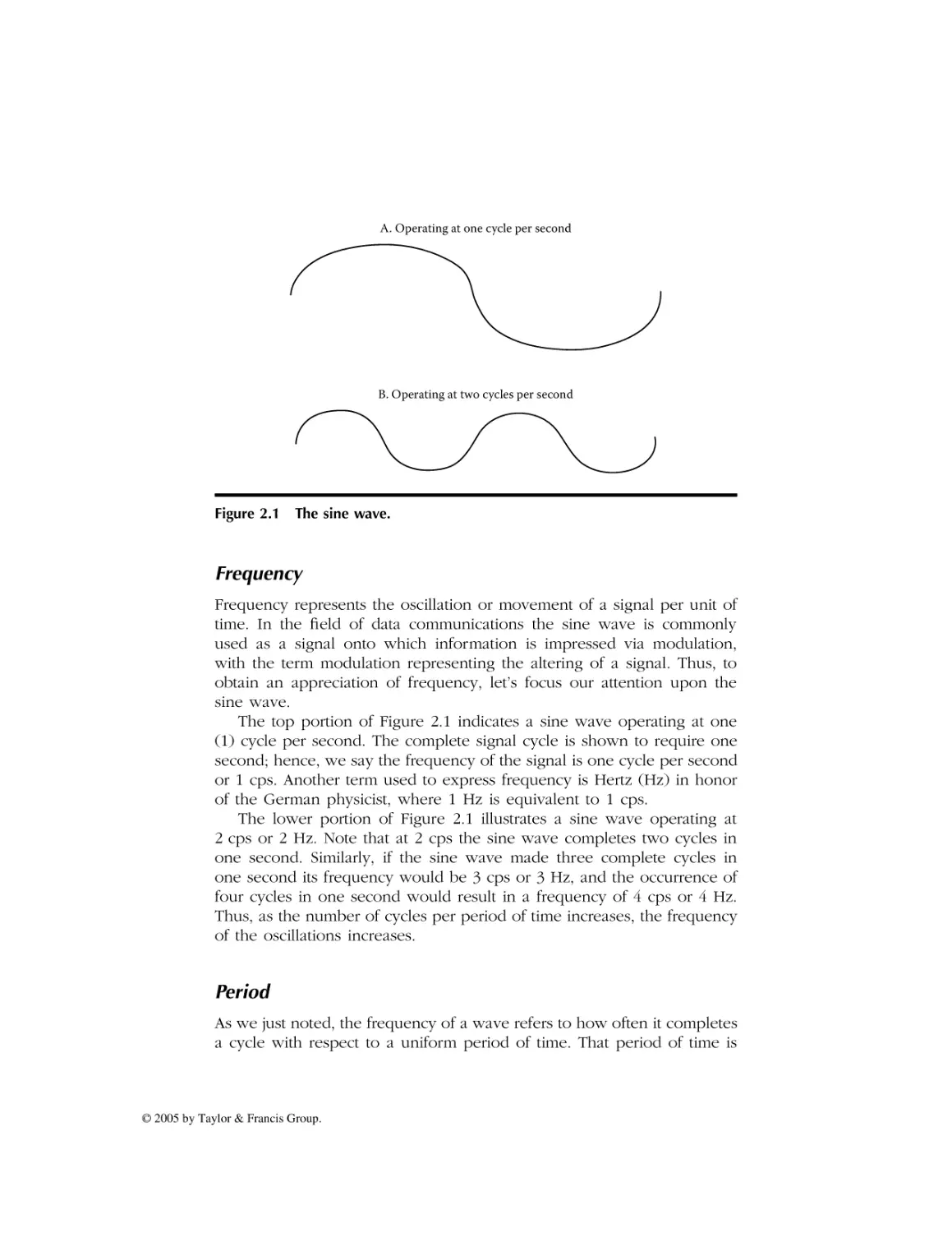
A. Operating at one cycle per second
B. Operating at two cycles per second
Figure 2.1 The sine wave.
Frequency
Frequency represents the oscillation or movement of a signal per unit of
time. In the field of data communications the sine wave is commonly
used as a signal onto which information is impressed via modulation,
with the term modulation representing the altering of a signal. Thus, to
obtain an appreciation of frequency, let’s focus our attention upon the
sine wave.
The top portion of Figure 2.1 indicates a sine wave operating at one
(1) cycle per second. The complete signal cycle is shown to require one
second; hence, we say the frequency of the signal is one cycle per second
or 1 cps. Another term used to express frequency is Hertz (Hz) in honor
of the German physicist, where 1 Hz is equivalent to 1 cps.
The lower portion of Figure 2.1 illustrates a sine wave operating at
2 cps or 2 Hz. Note that at 2 cps the sine wave completes two cycles in
one second. Similarly, if the sine wave made three complete cycles in
one second its frequency would be 3 cps or 3 Hz, and the occurrence of
four cycles in one second would result in a frequency of 4 cps or 4 Hz.
Thus, as the number of cycles per period of time increases, the frequency
of the oscillations increases.
Period
As we just noted, the frequency of a wave refers to how often it completes
a cycle with respect to a uniform period of time. That period of time is
© 2005 by Taylor & Francis Group.
AU2960_C002.fm Page 23 Monday, May 2, 2005 1:37 PM
normally expressed as a second because the terms cps and Hz refer to
oscillations within that amount of time.
The relationship between frequency and period is shown below.
Frequency = 1/period
Period = 1/frequency
As noted, frequency and period are inversely proportional to each other.
We can consider frequency as representing how often something happens,
whereas period represents the time in which the event occurred. Because
the symbol f is used for frequency and the symbol T is used for period,
the relationship between frequency and period can also be expressed as
follows.
F = 1/T and T = 1/F
Now that we understand the relationship between frequency and
period, let’s turn our attention to a third key term, bandwidth.
Bandwidth
Bandwidth represents a range of frequencies. Normally, when we discuss
bandwidth requirements of a communications device we refer to a contiguous range of frequencies required by the device. Thus, we can express
bandwidth as follows.
B = fH – fL
where
fH = highest frequency
fL = lowest frequency
Frequency Bands
In just about every country on our globe, the use of the frequency spectrum
is regulated. To prevent regulations from stifling the development of
electronic equipment most countries belong to the International Telecommunications Union (ITU) and comply with its recommendations concerning
the utilization of frequency. Doing so enables such varied communicationsdependent applications as radio, television, and aircraft navigation systems
to operate as you cross borders from one country to another.
Because it’s desirable to allow certain types of equipment such as
portable telephones, microwave ovens, and similar devices to operate
© 2005 by Taylor & Francis Group.
AU2960_C002.fm Page 24 Monday, May 2, 2005 1:37 PM
without their manufacturers and owners having to acquire licenses, certain
frequency bands are not regulated. Such frequency bands are referred to
as unlicensed bands and are supported by most countries. Some unlicensed bands are available for use on a global basis, although slight
variances in the frequencies of other bands occur as you move from
country to country. The most popular unlicensed frequency bands are
referred to as ISM bands, with the initials ISM referring to Industrial,
Scientific, and Medical. As we examine the operating fr equencies of
wireless LANs later in this chapter, we note that they primarily operate in
two unlicensed ISM frequency bands.
Table 2.1 provides a list of communication-based applications and the
frequency they commonly use. Note that wireless LANs can operate in
the United States in five distinct frequency bands. The first band, which
occurs in the 900- to 929-MHz range, represents a band allocated by the
FCC for personal communications and which was used by manufacturers
of first generation, nonstandardized LANs. Two additional frequency bands
used by wireless LANs are in the 2.4-GHz and 5-GHz frequencies. The
2.4-GHz ISM frequency band is used by IEEE 802.11b- and 802.11gcompliant devices, and the 5-GHz ISM band is used by equipment that
is compatible with the IEEE 802.11a standard.
Although not considered to represent conventional wireless LANs, two
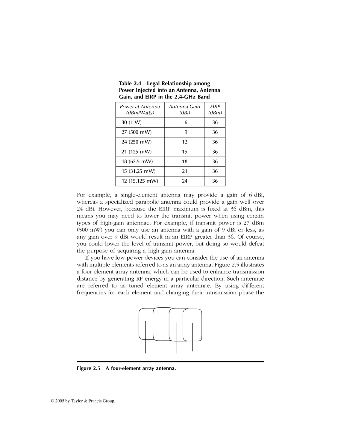
additional types of wireless technology that can be used for mesh network
connectivity are WiMax and ZigBee. WiMax, an acronym for Worldwide
Interoperability for Microwave Devices, is designed to operate in both
unlicensed and licensed frequencies ranging from 2 GHz to 66 GHz. In
comparison, the ZigBee Alliance, which represents a group of semiconductor manufacturers, technology providers, equipment manufacturers, and end
users, was in the process of developing standards for wireless transmission
for data rates of 250 kbps at distances up to 200 feet for both star and mesh
network topologies. Although Zigbee-compliant products will operate in
the 2.4-GHz ISM frequency band (which represents a global unlicensed
band), they will also operate in two other unlicensed bands. Those bands
are 915 MHz for use in North America and 888 MHz for use in Europe.
To assist readers who may lack familiarity with IEEE wireless LAN
standards as well as knowledge of WiMax and ZigBee, let’s briefly focus
our attention on the basic IEEE 802.11 standards, the IEEE 802.16 standard
and the relationship of ZigBee to the IEEE 802.15 radio frequency standard.
2.2 IEEE Standards
In the United States the American National Standards Institute (ANSI)
delegated responsibility for the development of LAN standards to the IEEE.
© 2005 by Taylor & Francis Group.
AU2960_C002.fm Page 25 Monday, May 2, 2005 1:37 PM
Table 2.1 Common Wireless Applications
and Their Frequencies
Application
Frequency Band Used
AM radio
535–1635 kHz
Analog cordless telephone
44–49 MHz
Television
54–58 MHz
FM radio
88–108 MHz
Television
174–216 MHz
Television
470–806 MHz
Wireless data
700–720 MHz
Cellular
806–890 MHz
Digital cordless
900 MHz
Personal communications
900–928 MHz
Nationwide paging
929–932 MHz
Satellite telephone uplink
1610–1625.5 MHz
Personal communications
1850–1990 MHz
Satellite telephone downlink
2.4835–2.5 GHz
IEEE 802.11b/g wireless LANs
2.4 GHz
IEEE 802.15.4/Zigbee alliance
2.4 GHz
IEEE 802.16/WiMax
2–66 GHz
IEEE 802.11a wireless LANs
5 GHz
Large dish satellite TV
4–6 GHz
Small dish satellite TV
11.7–12.7 GHz
Wireless cable TV
28–29 GHz
As a result of this delegation the IEEE initially developed standards for wired
Ethernet and Token Ring LANs during the 1980s. Approximately 20 years
later the IEEE developed its first wireless LAN standard which is referred
to as the 802.11 standard.
The 802.11 Standard
The first wireless LAN standard developed by the IEEE was the 802.11
standard. This standard defined the use of three physical layers for wireless
© 2005 by Taylor & Francis Group.
AU2960_C002.fm Page 26 Monday, May 2, 2005 1:37 PM
communications: infrared, Frequency-Hopping Spread Spectrum (FHSS),
and Direct Sequence Spread Spectrum (DSSS). Vendors developed products
that used FHSS and DSSS for wireless LANs during the late 1990s, however,
to the best of this author’s knowledge no products were ever developed
to follow the IEEE 802.11 infrared communications standard.
FHSS
Under the frequency-hopping spread spectrum a station transmits for a small
period of time at one frequency, with the period referred to as dwell time,
and then hops to a different frequency to continue communications. The
frequency-hopping algorithm is known to each LAN station, enabling each
station to adjust its transmitter or receiver according to its mode of operation.
One of the more interesting aspects of FHSS is the fact that its origin dates
to the actress Hedy Lamarr who suggested the technique to the United States
War Department during WWII as a transmission security mechanism.
DSSS
Direct sequence spread spectrum represents a second transmission technique developed by the military to overcome enemy jamming. Under
DSSS a spreading code is applied to each bit to spread the transmission.
At the receiver a “majority rule” is applied. That is, if the spreading code
is 5 bits and the bits received were 10110, because three bits are set, the
receiver would assume the correct bit is a 1. Under the IEEE 802.11
standard an 11-bit spreading code is employed.
Utilization
The initial use of 802.11 wireless LANs was limited due to their relatively
low data rate. This was because each of the three physical layers was
only defined for operations at 1 Mbps and 2 Mbps. Recognizing the need
for a higher data transmission rate resulted in the IEEE initially developing
two extensions to the basic 802.11 standard. Those extensions are known
as the 802.11a and 802.11b standards.
The 802.11a Standard
The IEEE 802.11a standard defined a series of new modulation methods that
enable data transmission rates up to 54 Mbps. The higher data rates are
obtained by the use of Orthogonal Frequency Division Multiplexing (OFDM),
a technique in which the frequency band is divided into subchannels that
© 2005 by Taylor & Francis Group.
AU2960_C002.fm Page 27 Monday, May 2, 2005 1:37 PM
are individually modulated. The IEEE 802.11a standard defines operations
in the 5-GHz frequency band. This means equipment supporting the
standard is not backward-compatible with the basic 802.11 standard
because that standard defines operations in the 2.4-GHz frequency band.
In addition, because high frequencies attenuate more rapidly than low
frequencies, this results in 802.11a wireless LAN stations having a shorter
range than stations operating in the 2.4-GHz band. This in turn requires
an organization to deploy more access points to obtain a similar geographical area of coverage than would be required via the use of access
points operating in the 2.4-GHz band.
The 802.11b Standard
The second extension to the basic IEEE 802.11 standard is the 802.11b
standard. Under the IEEE 802.11b standard, DSSS was used with two new
modulation methods to provide a data transfer rate of 11 Mbps and
5.5 Mbps. The 802.11b standard also provides compatibility with 802.11
DSSS equipment operating at 2 Mbps or 1 Mbps. To provide this compatibility, the IEEE 802.11b standard specifies the use of the 2.4-GHz
frequency band.
The 802.11g Standard
A comparison of the IEEE 802.11a and 802.11b extensions to the 802.11
standard indicates advantages and disadvantages associated with each.
Although the 802.11a standard provides a higher data transfer rate, its use
of the 5-GHz frequency band results in a shorter transmission distance.
Similarly, in a reverse manner, the IEEE 802.11b standard provides a greater
transmission distance but lower data rate than obtainable from the use of
802.11a-compatible equipment. By combining the modulation method used
in the 802.11a standard with the frequency band employed by the 802.11b
standard, the IEEE provided a mechanism to extend both the data rate and
transmission range of wireless LANs, resulting in the 802.11g standard. To
provide backward compatibility with the large base of 802.11b equipment,
the 802.11g standard also supports DSSS operations at 11, 5.5, 2, and 1 Mbps.
Thus, the relatively new IEEE 802.11g standard can be considered to
represent a dual standard because it provides 802.11b compatibility.
The WiMax Standard
WiMax represents a wide area networking technology that can be used
to transmit broadband signals at distances up to approximately 30 miles.
© 2005 by Taylor & Francis Group.
AU2960_C002.fm Page 28 Monday, May 2, 2005 1:37 PM
WiMax was standardized by the IEEE as the 802.16 standard, which was
published in April 2002.
WiMax has some similarities to wireless LANs; however, it is also
significantly different from the IEEE series of 802.11 standards. Concerning
similarities, like the 802.11-compliant products WiMax involves the use of
client stations using antennae to communicate with a centralized station.
That centralized station is referred to as a central radio base station under
802.16 terminology and is designed to provide an alternative to cabled
access networks, such as coaxial-based systems operated by your cable
company in which you use a cable modem to access the Internet and a
Digital Subscriber Line (DSL) for Internet access commonly offered by
your local telephone company.
Although the original 802.16 standard was defined for use in the 10to 66-GHz frequency band that represents spectrum available on a global
basis, such high frequencies represent a significant deployment problem.
This problem results from the fact that high frequencies have short periods,
which restricts transmission to line-of-sight operations. Recognizing this
problem, the IEEE developed an extension to the 802.16 standard known
as 802.16a. This new standard defines an extension of WiMax to operate
at lower frequencies in the 2- to 11-GHz band, to include operations in
both licensed and unlicensed frequency bands.
As with the series of wireless LAN standards, WiMax supports pointto-point and point-to-multipoint transmission. In addition, the 802.16a
standard extension is designed to add support for mesh networking. Also
similar to its wireless LAN cousins, WiMax supports several modulation
methods, such as single carrier and Orthogonal Frequency Division Multiplexing (OFDM), with the latter support occurring via the use of 256
and 2048 point transforms. Unlike its wireless LAN cousins, WiMax represents a much more sophisticated transmission method and includes
support for Time Division Duplexing (TDD) as well as Forward Error
Correction (FEC) employing Reed–Solomon coding.
The ZigBee Standard
In concluding this section describing IEEE standards suitable for wireless
mesh networking, we focus our attention upon obtaining a brief overview
of a networking technology recently developed to transfer data at distances
between 30 to 200 feet while consuming an extremely low amount of
power. This technology, which is backed by the ZigBee Alliance, is
standardized by the IEEE 802.15.4 specification.
In order to support low-power wireless transmission, ZigBee equipment
operates at a relatively low data rate in comparison to the other IEEE
© 2005 by Taylor & Francis Group.
AU2960_C002.fm Page 29 Monday, May 2, 2005 1:37 PM
standards discussed in this section. ZigBee-compliant products permit data
rates of 250 kbps when operating in the 2.4-GHz band where ten channels
are available for use. When ZigBee-compliant devices operate in the 915MHz band where six channels are available for use, their maximum
operating rate is reduced to 40 kbps, and operations at 868 MHz where
a single channel is available results in a maximum data rate of 20 kbps.
The goal in developing ZigBee technology was to provide a standard
for the operation of remote monitoring sensor devices. Such devices
typically operate on battery power within an industrial environment. Due
to this, batteries powering the remote monitoring and sensor equipment
need to last for a year or more to reduce maintenance cost. Thus, the
low power requirement of ZigBee-compliant products is especially well
suited for remote monitoring and sensor devices. In addition, because
ZigBee battery-powered devices can be placed into a sleep mode of
operation, this action further reduces the drain on a battery.
In addition to remote monitoring and sensor-based applications in
industrial areas, it’s expected that ZigBee-compliant products will find
their way into home-based applications. Such applications can include
wireless home security; remote thermostats for heat pumps, air conditioners, and furnaces; remote lighting; and even remote controls for television
and audio systems.
Under the IEEE 802.15.4 standard’s addressing scheme, 255 active nodes
are supported by a network coordinator. Although most home-based
networks will employ a single network coordinator, multiple network
coordinators can be linked together to create very large networks. For
example, the use of 16 channels in the 2.4-GHz frequency band permits
a ZigBee network to contain over 3000 nodes. ZigBee-compliant devices
can transmit up to approximately 30 meters in comparison to Bluetooth’s
10-meter limit. In addition, a ZigBee network with a single network
coordinator can support up to 255 devices in comparison to 8 for a
Bluetooth network. Due to these differences, ZigBee represents a more
powerful networking technology than Bluetooth, however, it’s important
to remember that at short distances Bluetooth transmission rates are
approximately a magnitude beyond that obtainable by ZigBee products.
2.3 Power Measurements
The ability to understand antenna sensitivity as well as general RF operations depends upon knowledge of power measurements. Thus, in this
section we turn our attention to this topic and obtain an appreciation for
several terms associated with power measurements.
© 2005 by Taylor & Francis Group.
AU2960_C002.fm Page 30 Monday, May 2, 2005 1:37 PM
The Bel
The first power measurement term we discuss traces its roots to the
evolution of the telephone network. Named after the inventor of the
telephone, the Bel (B) uses logarithms to base 10 to express the ratio of
power transmitted to power received. The resulting gain or loss of a circuit
is given by the following formula.
B = log10 (Po /PI)
where
B = power ratio expressed in Bels
Po = received or output power
PI = transmitted or input power
The rationale for the use of logarithms to base 10 corresponds to the
manner by which humans hear sounds. That is, our audio capability
perceives sound or loudness on a logarithmic scale. For example, if you
estimate, based upon your hearing, that a signal doubled in its loudness,
the transmission power actually increased by approximately a factor of ten.
A second reason for the selection of logarithms for use in power
measurements results from the fact that changes to a signal in the form
of signal loss due to resistance or signal gain due to the use of an amplifier
are additive. Thus, the ability to add and subtract when performing power
measurements based on a log scale considerably simplifies computations.
For example, a 10-B signal that encounters a 5-B loss and is then passed
through a 20-B amplifier results in a signal strength of 10 – 5 + 20 or 25 B.
Log Relationships
There are two log relationships worth noting that can be used to simplify
power measurement computations. First, you can note that the logarithm
to the base 10 (log10) of a number is equivalent to determining how many
times 10 is raised to a power to equal the number. For example, log10100
is equivalent to determining how many times 10 is multiplied by itself
(raised to a power) to equal 100, with the answer being 2. Similarly,
log101000 is 3, log101000 is 4, and so on.
In examining the preceding equation we can note that under normal
circumstances the output or received power can be expected to be less
than the input or transmitted power. When this situation occurs the
numerator in the preceding equation (Po) will be less than the denominator
(PI ). To simplify computations when this situation arises we can use a
second property associated with the use of logarithms. This second property
© 2005 by Taylor & Francis Group.
AU2960_C002.fm Page 31 Monday, May 2, 2005 1:37 PM
permits us to easily resolve fractional computations as we merely have to
prefix the computation with a negative sign to flip its fraction to a whole
number. That is,
log101/X = –log10 X
Once we prefix the computation with a negative sign and flip numerator and denominator, it becomes relatively simple to compute the log.
For example, let’s assume that the power received is one-hundredth of
the transmitted power. Then, our initial computation of the gain or loss
becomes:
B = log101/100
As previously noted, log101/x = –log10x. Thus, using this relationship
we obtain:
B = –log10100 = 2
Note that the computational result is negative, which indicates that a
power loss occurred and is precisely what we would expect inasmuch as
the received power was a very small fraction of the transmitted power.
In comparison, a positive Bel value would indicate a power gain, because
the output power would be greater than the input power. Although your
initial reaction might be dubious concerning a power gain, you need to
remember that a signal flowing through an amplifier could result in this
situation occurring. In a wireless LAN environment a client transmitting
to another client through an access point has its signal regenerated by
the AP. If the AP has a higher power level this situation is equivalent to
an amplifier in a wired environment.
Although the Bel was used for many years to categorize the quality
of a transmission circuit, it gradually lost favor due to the requirement for
a more precise measurement. The use of the decibel (dB) provided
industry with the precise measurement it sought and for all practical
purposes has replaced the use of the Bel. Thus, let’s turn our attention
to the decibel, which is better known by its abbreviation, dB.
The Decibel
The decibel represents the standard used today to denote power gains
and losses. As previously noted, the decibel represents a more precise
measurement than the Bel. This is because the dB represents one-tenth
of a Bel. To indicate this, we multiply the previously noted computation of
© 2005 by Taylor & Francis Group.
AU2960_C002.fm Page 32 Monday, May 2, 2005 1:37 PM
the Bel by 10 to obtain the computation for the decibel. That is, the power
measurement in terms of decibels is computed as follows.
dB = 10*log10 (Po /PI)
where
dB = power ratio in decibels
Po = output power or received power
PI = input power or transmitted power
To illustrate an example of the computation of a power ratio in dBs
let’s return to our prior power ratio computational example. In that
example the received power was measured to be one-hundredth of the
transmitted power. Thus, the power ratio in decibels becomes:
dB = 10 log101/100/1 = 10 log101/100
Because log101/x = –log10X, we obtain:
dB = –10 log10100 = –20
In comparing the results of our computations for the Bel and decibel for
the same input and output power measurements, note that the decibel is
precisely 10 times the value computed for the Bel. Thus, the dB provides
the ability for more precise power measurements and today is the preferred
power measurement in use.
Decibel above 1 mW
The terms Bel and decibel represent a ratio or comparison between two
values, such as input and output power. Although they are important
tools, they are not useful for comparing two circuits inasmuch as they do
not specify a common input power level. Thus, for comparing two or
more circuits we would want to inject the same amount of power into
each circuit and observe the level of received power. In the wonderful
world of telecommunications testing a 1-mW signal occurring at a frequency of 800 Hz is used in North America. To ensure that you do not
forget that testing occurred with respect to a fixed 1-mW signal the term
“decibel-milliwatt” (dBm) is used.
Output power with respect to a 1-mW test tone is computed in dBm
as follows.
dBm = 10 log10 (output power/1 mW input power)
© 2005 by Taylor & Francis Group.
AU2960_C002.fm Page 33 Monday, May 2, 2005 1:37 PM
Table 2.2
Relationship of Watts and dBm
Power in Watts
Power in Decibel-Milliwatts
.001 mW
–30
.01 mW
–20
1 mW
0
1W
30
1 kW
60
1 MW
90
Note we use the term dBm to remind us that the output power measurement occurred with respect to a 1-mW test tone. Although the ter m
“decibel-milliwatt” is used in most literature, in actuality dBm means
decibel “above” 1 mW because the output or received signal is based
upon the input of a 1-mW signal. Thus, 10 dBm more correctly represents
a signal 10 dB above or bigger than 1 mW, 20 dBm represents a signal
20 dB above 1 mW, and so on.
One interesting power relationship concerns a 30-dBm signal. A 30dBm signal is 30 dB or 1000 times larger than a 1-mW signal. Thus, 30 dBm
is equal to 1 W. We can use this relationship of 30 dBm being equal to
1 mW to construct a watts to decibel-milliwatt conversion table which is
shown in Table 2.2.
Most of the entries in Table 2.2 should be self-explanatory, however,
let’s review them to ensure we are all on the same path. Let’s start our
review with the third line in the table, where 1 mW is shown as equivalent
to 0 dBm. Because
dBm = 10 log10 (Po /PI)
the only way to achieve 0 dBm is for Po to equal PI . Thus, 0 dBm must
have an output power of 1 mW. Once we understand that 0 dBm is
equivalent to 1 mW, then the other entries in the table are easy to
understand. For example, 1 W is 1000 times greater than 1 mW. Because
30 dBm represents a signal 1000 times that of a 1-mW signal, then 1 W
is equal to 30 dBm. Similarly, 1 kW is 1000 times greater than 1 W and
1 MW is 1000 greater than 1 kW. Thus, we need to add 30 dBm for each,
resulting in 1 kW being equal to 60 dBm and 1 MW being equal to 90 dBm.
The only remaining entries to review are the first two. Because .001 mW
is one-thousandth of the input power of 1 mW, we obtain:
dBm = 10 log101/1000/1 = 10 log101/1000
© 2005 by Taylor & Francis Group.
AU2960_C002.fm Page 34 Monday, May 2, 2005 1:37 PM
or
dBm = –10 log101000 = –30
Thus, –30 dBm is equal to .001 mW of power. Similarly, .01 mW requires
an output one-hundredth of 1 mW, which is equal to –20 dBm.
The Decibel Isotropic
Because wireless devices communicate via the use of antennae another
metric that warrants our attention is decibel isotropic, abbreviated as dBi.
This metric is used to define the gain of an antenna relative to a hypothetical antenna that radiates output uniformly in all directions. This
uniform radiating antenna only exists in theory and is known as an
isotropic antenna. Thus, dBi represents a measurement of how much
better an antenna is in comparison to an antenna that transmits signals
equally in all directions.
The computation of dBi is based upon the decibel, resulting in the
gain (G) of an antenna. Specifically,
G = 10 log10(IA /Ii )
where G is the gain of the antenna in dBi, IA is the electromagnetic field
of intensity measured in microwatts per square meter (mWm2) generated
by antenna A, and Ii represents the electromagnetic field of intensity
produced by an isotropic antenna and similarly measured in microwatts
per square meter, with both measurements occurring at the same distance
from the antennae.
Because the dB is commonly used in communications it’s often helpful
to have access to a table of dB and power ratio values. One such table
is provided in this chapter to assist readers in any computations they may
have to perform. Table 2.3 contains a decibel reference table, with decibels
ranging from 0 dB to 100 dB with the equivalent power ratio for each
dB entry. Because dB values are algebraic, you can add or subtract one
value from another to obtain a desired value. For example, from Table 2.3
the power ratio for 10 dB is 10, and the power ratio for 20 dB is 100,
because doubling the dB increases the power ratio by a factor of ten.
Working up from 10 dB, a +3 dB is equivalent to a power ratio of 2 ×
10 or 20. Thus, 13 dB is equal to a power ratio of 10 + 20 or 30. Similarly,
adding another 3 dB (10 + 3 + 3) for a total of 16 dB results in a power
ratio of 50 (10 + 2 × 10 + 2 × 10). If we added another 2 dB for a total
of 18, our power ratio would become 65.8 (10 + 2 × 10 + 2 × 10 + 1.58 × 10).
© 2005 by Taylor & Francis Group.
AU2960_C002.fm Page 35 Monday, May 2, 2005 1:37 PM
Table 2.3
Decibel Reference Table
dB
Power Ratio
0
0.5
1.0
1.5
2.0
3.0
4.0
5.0
6.0
7.0
8.0
9.0
10
15
20
25
30
40
50
60
70
80
90
100
1.0
1.12
1.26
1.41
1.58
2.00
2.51
3.16
3.98
5.01
6.31
7.94
10.00
31.6
100
316
1000
10000
100000
1000000
10000000
100000000
1000000000
10000000000
Now that we have an appreciation for the use of power measurements
let’s turn our attention to antennae and more specifically those used in
wireless LANs.
2.4 Antenna Systems
An antenna can be considered to represent a conversion device, changing
electrical energy into a magnetic force referred to as RF energy and RF
energy back into electrical energy. As noted earlier in this chapter the
gain of an antenna is measured in dBi. A higher antenna gain is better
than a lower value and the overall gain of an antenna indicates its ability
to pick up a radio signal.
© 2005 by Taylor & Francis Group.
AU2960_C002.fm Page 36 Monday, May 2, 2005 1:37 PM
Antenna Categories
Antennae can be subdivided into two general categories, omnidirectional
and unidirectional. An omnidirectional antenna radiates in all directions.
In comparison, a unidirectional antenna radiates in only one direction.
That direction has a variance, referred to as a beam width, which indicates
the directionality of the antenna.
In general, antenna directionality is closely related to antenna gain. By
concentrating its RF energy in a specific direction, an antenna obtains more
gain. An omnidirectional antenna primarily concentrates its radiated energy
into the horizontal plane. Antenna gain is increased by concentrating
emitted energy out of the antenna horizontally.
Polarization
As we noted earlier in this section, an antenna converts electrical current
into electromagnetic waves that are radiated into space. The direction by
which the electromagnetic waves flow is referred to as the polarization
or the orientation of the emitted radio waves. In general most antennae
radiate either linear or circular waves.
A linear polarized antenna radiates waves entirely in one plane, with
the plane representing the direction of wave propagation. In comparison,
a circular polarized antenna’s plane of polarization rotates in a circle in
which one complete revolution occurs during one period of the wave.
When the rotation of the wave is clockwise it’s referred to as Right-HandCircular (RHC), and a counter-clockwise rotation as you might expect is
referred to as Left-Hand-Circular (LHC).
Antennae can be horizontally or vertically polarized. When horizontally
polarized the majority of the electromagnetic waves flow horizontally or
parallel to the Earth’s surface. In comparison, a vertically polarized antenna
has the majority of its electromagnetic waves flow perpendicular to the
Earth’s surface.
The electromagnetic radiation pattern is normally shown through the
use of two plots. One plot, in the form of a 360˚ circle, has concentric rings
from a center specified in dB as shown in the left portion of Figure 2.2.
A second plot indicates the strength of the electromagnetic waves with
respect to viewing an antenna from its side. An example of this plot is
shown in the right portion of Figure 2.2. Antennae used with most access
points are vertically polarized. This results in a radiation pattern that flows
in all directions outward from the antenna. Because wireless LANs require
a near line-of-sight path due to their low power and high frequency, most
access points include dual antennae. Such antennae are referred to as
© 2005 by Taylor & Francis Group.
AU2960_C002.fm Page 37 Monday, May 2, 2005 1:37 PM
Elevation
(Vertically)
Elevation
(Horizontal)
−40
−30
−20
−10
0
Figure 2.2 Antenna radiation patterns.
diversity antennae and software selects the antenna receiving the better
signal as a method to reduce the effect of signal reflections.
Unlike a stereo where you can turn up the power only limited by your
speakers to whatever setting you desire, the Federal Communications
Commission (FCC) in the United States as well as other regulatory bodies
restrict RF transmission power to include that of wireless LANs. That
restriction occurs in terms of Estimated Isotropic Radiated Power (EIRP).
EIRP considers the transmitter output power, line loss associated with
cabling the transmitter to the antenna, and the antenna gain.
Figure 2.3 illustrates the computation of EIRP. Note that gains are added
to the Transmit Output Power (TOP) and losses are subtracted to obtain
the EIRP. For example, if the transmitter output power is 30 dBm, cable
loss is 1 dB, and the antenna gain is 7 dBi, then the EIRP becomes 30 –
1 + 7 or 36 dBm, which just happens to represent the maximum EIRP
Antenna gain
TPO
Transmitter
Cable Loss
EIRP = TPO − cable loss + antenna gain
Legend: TPO Transmitter Power Output
Figure 2.3 Computing EIRP.
© 2005 by Taylor & Francis Group.
AU2960_C002.fm Page 38 Monday, May 2, 2005 1:37 PM
allowed by the FCC. This means that in order to stay within legal limits,
you need to consider all three components of EIRP.
Directionality and EIRP
Antennae can obtain more gain by focusing their radiated energy in a
specific direction. For example, an omnidirectional antenna primarily
concentrates its energy into the horizontal plane in a 360˚ radius because
transmitting RF energy vertically is not normally beneficial. In comparison,
a unidirectional antenna concentrates its energy in a narrow beam, with
the term “beam width” used to refer to the angular width in degrees
between the half power points (3 dB down from the maximum) of the
major lobe in either the elevation or azimuth radiation pattern.
EIRP represents the effective power in the main lobe of a transmitter
relative to an isotropic radiator that has a 0-dB gain. EIRP equals the sum
of the antenna gain in dBi and the power injected into the antenna less
cabling loss. For example, assume your transmitter outputs a 16-dBm
signal via a cable with a 1-dB loss into an antenna that has a 12-dBi gain.
Then, EIRP = 12 dBi + 16 dBm – 1 dBm = 27 dBm. From the preceding,
note that a 27-dBm signal represents a signal 500 times above 1 mW.
Thus, the effect results in the antenna radiating 500 mW of power.
However, because EIRP is less than 36, you can consider either boosting
transmission power or using an antenna with a higher gain to enhance
transmission and reception of data.
Types of Antennae
There are numerous types of antennae in use today. Some of the more
popular types you will encounter include the whip, dipole, loop, patch,
and yagi. Figure 2.4 illustrates each of the previously mentioned types of
antennae.
Whip
Dipole
Patch
Figure 2.4 Common types of antennae.
© 2005 by Taylor & Francis Group.
Loop
Yagi
AU2960_C002.fm Page 39 Monday, May 2, 2005 1:37 PM
Whip Antenna
A whip antenna is a small vertical rod. Although commonly used in
automobiles they are not normally used in wireless LANs. This is because
the rod does not permit energy to be focused and as a result the whip
antenna does not have a high gain.
Dipole Antenna
The dipole antenna represents a simple type of antenna that is very
popular in communications applications. The dipole antenna has a straight
electrical conductor that measures one-half wavelength from end to end,
connected at the center to an RF feed line or cable.
The dipole antenna is a balanced antenna due to its symmetry. Because
of its design it is also referred to as a doublet. Dipole antennae are
omnidirectional and have a relatively low gain with the RF field primarily
focused in the vertical direction. Because it’s impractical for many communications devices to have both positive and negative dipole areas when
a device sits flat on a desk or other surface, the half dipole is used in
place of a dipole antenna.
Yagi Antenna
A yagi antenna can be viewed as a dipole with directors and reflectors
added before and after the dipole. The reflectors and directors are metal
rods of similar length to the dipole that concentrate RF energy into a
beam, increasing the gain of the antenna.
A yagi antenna commonly has one reflector and one or more directors,
with the overall rating of the antenna being a function of its total number
of elements. A yagi antenna can be considered to represent a directional
form of a dipole antenna.
Considering Power Limits
As previously noted, FCC regulations restrict transmission to 36 dBm (4 W)
EIRP in the 2.4-GHz frequency band. Because transmitter power and
antenna gains are cumulative you need to consider both to stay within
legal limits. Table 2.4 provides a summary of the relationship of power
injected into an antenna, antenna gain in dBi, and EIRP in dB.
Antenna Selection
When the distance between wireless LAN stations increases you can either
add repeaters or use directional antennae to better support communications.
© 2005 by Taylor & Francis Group.
AU2960_C002.fm Page 40 Monday, May 2, 2005 1:37 PM
Table 2.4 Legal Relationship among
Power Injected into an Antenna, Antenna
Gain, and EIRP in the 2.4-GHz Band
Power at Antenna
(dBm/Watts)
Antenna Gain
(dBi)
EIRP
(dBm)
30 (1 W)
6
36
27 (500 mW)
9
36
24 (250 mW)
12
36
21 (125 mW)
15
36
18 (62.5 mW)
18
36
15 (31.25 mW)
21
36
12 (15.125 mW)
24
36
For example, a single-element antenna may provide a gain of 6 dBi,
whereas a specialized parabolic antenna could provide a gain well over
24 dBi. However, because the EIRP maximum is fixed at 36 dBm, this
means you may need to lower the transmit power when using certain
types of high-gain antennae. For example, if transmit power is 27 dBm
(500 mW) you can only use an antenna with a gain of 9 dBi or less, as
any gain over 9 dBi would result in an EIRP greater than 36. Of course,
you could lower the level of transmit power, but doing so would defeat
the purpose of acquiring a high-gain antenna.
If you have low-power devices you can consider the use of an antenna
with multiple elements referred to as an array antenna. Figure 2.5 illustrates
a four-element array antenna, which can be used to enhance transmission
distance by generating RF energy in a particular direction. Such antennae
are referred to as tuned element array antennae. By using dif ferent
frequencies for each element and changing their transmission phase the
Figure 2.5 A four-element array antenna.
© 2005 by Taylor & Francis Group.
AU2960_C002.fm Page 41 Monday, May 2, 2005 1:37 PM
antenna becomes a phased-array antenna, with similar operating characteristics to distant early warning phased array radar. That is, such antennae
become highly directional and their use in wireless LANs may occur by
the time you read this book.
Receiver Sensitivity
In concluding this section let’s turn our attention to receiver sensitivity.
The sensitivity of an antenna has a considerable bearing on its ability to
receive a signal. Although the FCC does not place limits on r eceiver
sensitivity, IEEE standards denote receiver performance standards. For
operations in the 2.4-GHz band, IEEE wireless equipment should have
antenna sensitivity less than or equal to –80 dBm. Because 60 dB is
equivalent to a power ratio of a million to 1, –80 dBm means that the
antenna should be capable of picking up one-hundredth-millionth of a
signal.
Wireless LANs are essentially line-of-sight transmission systems. Thus,
as you might expect, their transmission distance is greater outdoors than
indoors. Table 2.5 lists the transmission distances for a Linksys (now a
part of Cisco) 802.11b access point. By appropriately placing repeaters
it’s possible to extend transmission distances, which enables wireless
devices to form a mesh network that spans a considerable distance. As
we continue our journey of exploration, we note how homes within
communities can be connected to one another in a mesh network environment that enables one or a few Internet connections to be shared
among all users instead of requiring each happy homeowner to pay a
monthly bill.
Table 2.5 Linksys Access Point
Transmission Distances
Data Rate
Indoors (m/ft)
Outdoors (ft)
50 (164)
250 (820)
80 (262)
350 (1148)
2
120 (393)
400 (1312)
1
150 (492)
500 (1640)
11
5.5
© 2005 by Taylor & Francis Group.
AU2960_book.fm Page 43 Monday, April 11, 2005 11:01 AM
Chapter 3
Mesh Network
Components
In previous chapters we became acquainted with wireless mesh networking and the radio frequency spectrum primarily available for use by
evolving mesh networks. In this chapter we build upon the preceding
chapters by turning our attention to common components that function
as building blocks for the construction of mesh networks. Such components include what some vendors refer to as “wireless modems,” mesh
network bridges, routers and extenders, access points, and switches. After
examining a series of components as separate entities, we focus on the
integration of components to form a wireless mesh network.
3.1 Understanding Mesh Network Components
In this section we examine several mesh network components, commencing our examination with the familiar wireless LAN card which is also
referred to as a wireless modem. In doing so we note that many wireless
mesh networking components can be used either as is with special
software for a limited distance or can be obtained with a different radio
technology that provides an extended transmission capability. Thus, the
latter provides you with the ability to construct a wireless mesh network
over a greater geographical area with a minimum number of access points
or routers required for servicing clients.
© 2005 by Taylor & Francis Group.
AU2960_book.fm Page 44 Monday, April 11, 2005 11:01 AM
Wireless LAN Cards
With special software that turns a wireless LAN client into a mesh network
participant you can use standardized IEEE 802.11 client hardware. Such
hardware is available in many form factors, ranging in scope from PCMCIA
adapter cards inserted into a laptop or notebook card slot to PCI adapter
cards that are inserted into a desktop computer’s system expansion slot
and USB combined memory modules and wireless LAN technology. By
adding software that provides routing and relay capabilities, the conventional wireless LAN client becomes a participant in a wir eless mesh
network. Thus, it becomes possible for client computers within a building
or in a neighborhood where homes are in close proximity to one another
to share one or a few high-speed Internet connections.
When it’s not physically possible to communicate within a geographic
area using conventional wireless LAN client technology you can consider
the use of RF technology developed to extend the transmission distance
of client stations while operating in one of the unlicensed ISM frequency
bands. One example of this type of product is the 6300 Wireless Modem
Card marketed by MeshNetworks of Maitland, Florida.
MeshNetworks 6300 Wireless Modem Card
Through the use of a proprietary Quadrature Division Multiple Access
(QDMA) radio protocol that uses the IEEE Direct Sequence Spread Spectrum (DSSS) transmission technique in the ISM 2.4-GHz frequency band,
MeshNetworks extended the transmission range of client stations. This
transmission extension enables communications of approximately one mile
for clear line of sight in comparison to an IEEE 802.11b wireless LAN’s
maximum range of approximately 300 feet. The QDMA protocol used by
MeshNetworks in their wireless modem card includes an enhanced error
correction capability over IEEE 802.11 technology as well as a real-time
equalization algorithm. The latter uses training signals to automatically
adjust a receiver to a transmitter, enabling a receiver to compensate for
a rapidly varying signal commonly generated in a mobile environment
where signal strength can increase or decrease based upon the movements
of two devices communicating on a peer-to-peer basis. Due to the overhead associated with the use of enhanced error correction and real-time
equalization, the overall throughput of the MeshNetworks 6300 wireless
modem card is approximately 6 Mbps in burst mode in comparison to an
IEEE 802.11b wireless LAN’s maximum data rate of 11 Mbps.
Figure 3.1 illustrates the MeshNetworks 6300 wireless modem card.
This card is fabricated as a Type 2 PCMCIA card that supports data rates
© 2005 by Taylor & Francis Group.
AU2960_book.fm Page 45 Monday, April 11, 2005 11:01 AM
Figure 3.1 The MeshNetworks 6300 wireless modem card. (Photograph courtesy
of MeshNetworks)
of 1.5, 3, and 6 Mbps. The card’s output power is up to 22 dBm in the
2.4-GHz frequency band using the company’s proprietary QDMA protocol.
The QDMA wireless technology used by MeshNetworks uses four
separate, nonoverlapping channels in comparison to the three channels
used by IEEE 802.11b/g equipment. One channel is used for contr ol
purposes and the remaining three channels are used for data transfers.
The control channel functions as a coordinator for the transmission of
data between devices within a given geographic area.
Figure 3.2 illustrates the channel relationships between MeshNetworks
QDMA protocol and equipment conforming to the IEEE 802.11b/g standards.
Although at first glance it may appear that the two protocols can interfere
with each other, it’s important to note that IEEE 802.11b/g devices are
limited to operating within one of three available channels. Because the
multi-channel QDMA protocol can use any data channel for transmission
via a dynamic channel allocation capability, it becomes possible to select
a data channel that minimizes interference with an existing IEEE 802.11b/g
wireless LAN. Of course, if there were three IEEE 802.11b/g wireless LANs
within close proximity of one another each operating on a dif ferent
channel frequency, the MeshNetworks QDMA protocol’s dynamic channel
allocation process would more than likely experience difficulty in selecting
a channel with minimal interference.
One of the more interesting aspects of MeshNetwork’s wireless products is the manner by which they provide a location capability. Modern
cell phones now include Global Positioning System (GPS) technology and
© 2005 by Taylor & Francis Group.
AU2960_book.fm Page 46 Monday, April 11, 2005 11:01 AM
Data
Data
Control
Power
Data
Frequency
Legend
QDMA
IEEE 802.11b/g
Figure 3.2 QDMA and IEEE 802.11b/g wireless LAN channel relationships.
depend upon satellites to provide 911 telephone location services. In
comparison, MeshNetworks includes a location provider mechanism built
into its QDMA radio protocol. This location provider enables other radios
in the mesh network to use signal triangulation to determine the position
of mesh network clients within an accuracy of approximately ten meters.
Because the QDMA radio location method does not depend upon the use
of GPS satellites, it operates in many locations where it is difficult to obtain
a GPS position, such as within buildings or when traveling in a tunnel or
through a canyon.
Client Software
As an alternative to the use of the 6300 wireless modem card, MeshNetworks as well as other vendors are marketing software that turns IEEE
802.11 clients into participants on an 802.11 technology-based mesh
network. Such software, which was being tested by several vendors when
this book was prepared, includes a routing algorithm that enables a
conventional wireless network adapter to become a participant in a mesh
network in which all other participants use the same wireless RF technology.
Although such clients cannot communicate with proprietary RF technology,
such as the MeshNetworks 6300 wireless modem card, due to the use of
different RF technologies, higher data transfer rates become available,
although transmission distance is considerably reduced. This is because
IEEE 802.11b/g comparable equipment has a maximum data transfer rate
of 11 Mbps (802.11b) or 54 Mbps (802.11g) in comparison to the 6300
© 2005 by Taylor & Francis Group.
wireless modem cards 6-Mbps data rate, whereas the transmission rate of
approximately 300 feet for IEEE comparable devices pales in comparison
to the approximately one mile range of the 630 modem card. Although
there is a tradeoff between the data transfer rate and transmission distance,
it’s important to note that the conversion of a standard wireless LAN into
a mesh network environment can greatly extend the range of the network
within a building or on a campus. If the building has a large atrium it
may not be possible to position access points within the atrium and run
cables to a wired network. However, by using wireless clients as relay
devices, you can extend your wireless infrastructure within the building.
Wireless Mesh Router
In a conventional wired environment a router functions as a relay device,
routing traffic from one network destined to another toward its final
destination. In a wireless networking environment a router performs a
similar function, however, routing represents one of many functions performed by this device. Other key functions include the use of a mobile
routing algorithm enhanced by an error-correction algorithm to minimize
the effect of RF errors, an extended over-the-air transmission range in
comparison to IEEE 802.11 LAN devices, and, perhaps most obvious, the
ability to support mesh networking. In this section we briefly look at two
products, one from MeshNetworks and a second from Nova Engineering.
MeshNetworks Wireless Router
Similar to its client cards, MeshNetworks wireless routers operate in the
2.4-GHz ISM frequency band using the vendors’ proprietary QDMA protocol and have an output power of up to 22 dBm. This wireless router
functions as a relay or a range extender, enabling clients distant from the
vendor’s Intelligent Access Point (IAP) to gain access to that device.
Figure 3.3 illustrates the MeshNetworks wireless router shown mounted
on an outdoor utility pole. This device can be installed either indoors or
outdoors and measures 6.25 inches × 6.25 inches × 4 inches without an
antenna. With a weight slightly over three pounds, it’s a relatively small
and lightweight device that can be used both in-building and as a geographical area extender. This router uses an omnidirectional 7.5-dBi
antenna and like the vendor’s client 6300 modem, can operate at 1.5, 3,
and 6 Mbps.
The MeshNetworks wireless router supports industry standard IP protocols while adding a proprietary “hopping” technology that enables client
traffic to be moved around local congestion areas. Because the router
© 2005 by Taylor & Francis Group.
AU2960_book.fm Page 48 Monday, April 11, 2005 11:01 AM
Figure 3.3 The MeshNetworks wireless router shown mounted on an outdoor
utility pole. (Photograph courtesy of MeshNetworks)
represents a fixed device, it also functions as a fixed reference point for
the triangulation of clients.
Nova Engineering NovaRoam 900 Router
Unlike MeshNetworks products that operate in the 2.4-GHz frequency
band, Nova Engineering selected the 900-MHz ISM band for its products.
Thus, from a frequency perspective MeshNetworks and Nova Engineering
wireless mesh networking products are incompatible with each other.
Another key difference between the MeshNetworks and Nova Engineering routers concerns their utilization. Unlike MeshNetworks routers
that are designed to support wireless clients, the Nova Engineering
NovaRoam 900 router provides a 10/100-Mbps Ethernet port that enables
clients on wired LANs to communicate through the ad hoc mesh networking capability of the router.
The NovaRoam 900 router supports transmission distances that vary
with the burst data rate setting of the device. For example, at a data rate
of 159 kbps the estimated maximum line-of-sight range is approximately
ten miles, whereas at a maximum data rate of 1.008 Mbps the estimated
range is three miles. Similarly, power output varies from 800 mW at 159 kbps
to 590 mW at 1.008 Mbps. When expressed in dBm the power output
varies from 29 dBm at 159 Kbps to 27.7 dBm at a data rate of 1.008 Mbps.
© 2005 by Taylor & Francis Group.
AU2960_book.fm Page 49 Monday, April 11, 2005 11:01 AM
Figure 3.4 The NovaRoam ED900 wireless router uses a conventional Ethernet
port to enable wired LAN clients to participate in a wireless mesh network.
(Photograph courtesy of Nova Engineering)
Overview
At the time this book was developed Nova Engineering marketed several
versions of its NovaRoam 900 router. Figure 3.4 illustrates the NovaRoam
ED900 which can be viewed as a successor to the vendor’s original
NovaRoam900. The ED900 operates in the 915 MHz ISM band (902–928
MHz) using DSSS transmission. Either bridge or router operations can be
supported by each ED900. Thus, if your organization wanted to interconnect two geographically separated locations, you could configure each
ED900 to operate as a bridge, alleviating the necessity to configure stations
on the wired network connected to the router with network addresses.
However, to obtain the ad hoc networking capability of the ED900, you
would use the default routing capability of each router. In doing so, each
wired network connected to the router would have a unique subnet and
the wireless port on each router would be on the same network.
Through the use of a high-gain antenna, transmission distances up to
22 miles may be possible, however, when operating in the ISM band a
maximum EIRP of 36 dB may limit the gain of a selected antenna due to
FCC regulations. Because Nova Engineering’s routers are also used in
many military applications including Unmanned Aerial Vehicles (UAV) the
vendor also supports operations in a different frequency band for such
applications. Both DSSS and Frequency Hopping Spread Spectrum (FHSS)
transmission are supported for Nova Roam 900 operations and customer
variances can include a change in the hopping set which makes military
applications more difficult to jam.
Operation
Each NovaRoam 900 must participate in a unique Ethernet network. To
configure a NovaRoam 900, you can use a terminal emulation program
© 2005 by Taylor & Francis Group.
AU2960_book.fm Page 50 Monday, April 11, 2005 11:01 AM
operating on a PC which in turn is directly cabled to the router’s auxiliary
port. After entering the default password of “novaroam,” which should
obviously be changed, you can configure the router to include its Ethernet
and wireless interfaces addresses, operating channel, data rate, and its
routing table.
The Ethernet interface settings entry permits you to assign an IP address
to the Ethernet interface. Similarly, the radio settings menu selection
provides you with the ability to enter an IP address that will be assigned
to the wireless interface. A third required setting involves selecting the
channel in the 902- to 928-MHz frequency band the router will use. That
channel must be the same as the channel used by other NovaRoam 900s
in your network. Because all NovaRoam 900 routers in your network must
operate at the same data rate, a fourth setting permits you to specify the
data rate used for communications. Once you configure the IP addresses
for the wired and wireless interfaces, the RF channel, and data rate, you
can add routes into the routers’ route table that define how routers
communicate with each other.
Route Table Utilization
The purpose of the NovaRoam 900’s route table is to define routes from
the router being configured to other networks. The addition of a route
into the NovaRoam 900’s route table requires the entry of four metrics.
Those metrics include the destination IP address of the route, its subnet
mask, the gateway IP address, and the number of hops from the router
to the destination network. Concerning the latter, Nova Engineering refers
to the hop count as a “metric”.
To illustrate the configuration of route table entries let’s assume you
acquired two NovaRoam 900s you intend to use as nodes in your network.
Let’s further assume that the Ethernet and RF IP addresses configured for
the first router are 10.1.1.1 and 10.20.20.1, respectively. Let’s further assume
that the Ethernet and RF IP addresses for the second router are 10.2.1.1
and 10.10.10.2, respectively. Thus, the two routers and their Ethernet and
RF IP addresses would appear as shown in Figure 3.5.
In examining Figure 3.5 note that the IP address block 10.0.0.0 through
10.255.255.255 represents a Class A RFC 1918 group of addresses. As a
refresher, such addresses represent IP addresses that are used for private
Internets and therefore do not represent unique Internet addresses. If we
assume that each router will be considered as part of an overall RF network
then it becomes apparent why the RF IP addresses for each node are on
the same IP network.
© 2005 by Taylor & Francis Group.
AU2960_book.fm Page 51 Monday, April 11, 2005 11:01 AM
RF address
10.10.10.1
Ethernet
address
10.1.1.1
Node 1
RF address
10.10.10.2
Ethernet
address
10.2.2.1
Node 2
Figure 3.5 Assigning RFC 1918 addresses to the Ethernet and RF interfaces of
two NovaRoam routers.
Let’s assume that we need to provide a route table entry to allow node
1 to communicate with node 2. As a refresher, the NovaRoam 900 uses
a route statement whose format is shown below.
Destination IP Address Subnet Mask Gateway, IP Address
Hops
To enable node 1 to communicate with node 2, node 1 would use
the IP address of node 2’s wireless interface as its gateway. Thus, the
route table entry added to node 1 would be as follows.
10.2.1.0 255.255.255.0 10.10.10.2 1
The above entry informs the router that any traffic destined for the
10.2.1.0 network must use the router whose RF IP address is 10.10.10.2.
Similarly, you would enter the following route table entry into node 2 to
allow it to communicate with node 1.
10.1.1.0 255.255.255.0 10.10.10.1 1
Applications
Previously in this section we noted that the NovaRoam 900 is used in
military applications to include pilotless UAVs. In the commercial sector,
one of the more interesting applications of the NovaRoam 900 wireless
router is its capability to provide Internet access over an extended geographic area. According to Nova Engineering, the use of three NovaRoam
900 routers enabled wireless Internet access at a distance of 15 miles from
a base station router that was connected to the Internet. To obtain this
© 2005 by Taylor & Francis Group.
AU2960_book.fm Page 52 Monday, April 11, 2005 11:01 AM
NovaRoam 900
functioning as a repeater
NovaRoam
900
24 miles
9 miles
Internet
Base station
NovaRoam
900
Serving a
business
NovaRoam
900
Ethernet
LAN
Figure 3.6 Using the Nova Engineering NovaRoam 900 to provide long distance
wireless connectivity to the Internet.
extended transmission distance, a base station was located at an elevation
of 320 feet. A second NovaRoam router was placed approximately 9 miles
away. This router was configured to operate in repeater mode and was
placed on a peak at an elevation of 2760 feet. A third NovaRoam 900
was located at a business that required high-speed Internet access but
due to its location was unable to acquire the required service. This
business, however, was within the line of sight of the NovaRoam router
functioning as a repeater and positioned on the mountain peak. Figure 3.6
illustrates the relationship between the three NovaRoam routers.
Each of the routers shown in Figure 3.6 was configured with a yagi
antenna that provided 11 dBi of gain. The antennae were horizontally
polarized as a mechanism to minimize interference from any adjacent
wireless services. Each yagi antenna has a horizontal beamwidth of approximately 40°, however, due to unequal path lengths, the router functioning
as a repeater has its beam aimed toward the router serving the business
instead of toward the base station.
© 2005 by Taylor & Francis Group.
AU2960_book.fm Page 53 Monday, April 11, 2005 11:01 AM
Access Point
In a mesh networking environment an access point provides a similar
level of functionality to that of an AP used in a conventional wireless
LAN. That is, the AP operates as a bridge, providing a mechanism to
forward data from the RF world’s wireless network to the wired network
and vice versa.
Operation
A wireless mesh network access point operates at the Media Access Control
(MAC) layer. It uses MAC addresses as a decision criterion to forward,
flood, or filter data between the wireless and wired networks. To accomplish this task the AP learns MAC addresses associated with its wireless
and wired sides, which are considered to represent distinct ports that
enable the AP to construct port/address tables.
When the AP is powered on, its port/address table is empty. Thus,
the first frame of data received is flooded to the port other than the port
on which it was received. At the same time the access point observes the
source MAC address and the port that the frame was received on, entering
that address and port into its port/address table. If a subsequent received
frame has the same destination address as an entry in the APs port/address
table, the frame is forwarded to the port associated with the destination
address. The only exception to this situation is when the port the frame
was received on matches the port in the port/address table associated
with the destination address. Because it would be illogical to regenerate
the frame back onto the port it was received on, the frame is filtered or
discarded. Thus, an access point operates based upon the three Fs:
forwarding, filtering, and flooding.
Types of Access Points
An access point can become a participant in a wireless mesh network
through the addition of software to an IEEE 802.11-compatible AP. As an
alternative, an AP can be fabricated to employ a proprietary RF transmission method and use specialized software. Typically, the use of a proprietary RF method allows extended transmission distances beyond the typical
range of IEEE 802.11 access points. One example of a proprietary access
point used in a wireless mesh network is the MeshNetworks Intelligent
Access Point 6300 (IAP6300). Thus, let’s turn our attention to this product.
© 2005 by Taylor & Francis Group.
AU2960_book.fm Page 54 Monday, April 11, 2005 11:01 AM
Figure 3.7 MeshNetworks IAP 6300 can be mounted indoors or outdoors. (Photograph courtesy of MeshNetworks)
MeshNetworks IAP 6300
MeshNetworks IAP 6300 is similar to the vendor’s previously described
router in that it can be used either indoors or outdoors and supports its
proprietary QDMA RF modulation protocol. The use of this protocol
enables a burst data transmission rate up to 6 Mbps similar to the vendor’s
wireless modem card. Figure 3.7 illustrates the IAP 6300 mounted in an
outdoor environment. IAPs like the vendor’s routers can be mounted on
utility poles, buildings, billboards, and other locations that provide a
relatively unobstructed level of transmission.
Because a mesh network enables clients to relay messages, the location
of the IAP is not critical. That is, as long as clients can communicate with
other clients and one client can communicate with an IAP, then all clients
obtain this capability. Due to the routing algorithm built into MeshNetworks’
products the use of IAPs becomes one of traffic support instead of focusing
upon the geographic area of coverage. Thus, you would monitor traffic
in hot spots where wireless coverage is provided to determine if an
increase in capacity is required. If so, you can add additional IAP 6300s
© 2005 by Taylor & Francis Group.
AU2960_book.fm Page 55 Monday, April 11, 2005 11:01 AM
without having to worry about their configuration because the IAPs operate
at layer 2 in the protocol stack. This means the new IAPs can automatically
integrate themselves into the existing network.
In addition to acting as a bridge between your wireless and wired
networks, the IAP provides a fixed reference point for the location of
mobile devices. In conjunction with another IAP or the vendor’s router a
mobile client can be triangulated so that its position becomes known. In
addition, software used by IAPs communicates with the vendor’s Mobile
Internet Switching Controller (MiSC) as well as the vendor’s routers and
client devices. When communicating with the MiSC, the IAP becomes
capable of observing the health of the entire network.
Switching Controller
Although many vendors offer client cards, routers, and access points, some
vendors include a switching controller in their product line. You can view
a switching controller as a centralized hub of a mesh network as it can
be interconnected via wired facilities to distributed access points. The
switching controller typically includes a series of management functions
including monitoring network events and providing detailed and summary
statistics concerning the operation of the network. Other vendor products
may include additional functionality, such as operating as a bridge between
the wireless mesh network and a wired network. To obtain an appreciation
of the functionality of a switching controller we focus our attention upon
the MiSC marketed by MeshNetworks.
MeshNetworks MiSC
MeshNetworks’ mobile Internet switching controller represents a scalable
computer that provides routing, switching, and management functions to
a mesh network. MiSC functionality includes operating as a DHCP/DNS
server for clients connected to the device via IAPs. That connection occurs
through the use of leased lines or cables routed through a building or
campus area. Because the MiSC also provides authentication of clients as
well as being capable of supporting IP VPN encryption, it performs several
security-related functions.
In a mesh-enabled architecture the MiSC is interfaced to one or more
IAPs, providing centralized control of the wireless network. Due to its
modular design, the MiSC can provide access to the Public Switched
Telephone Network (PSTN) and the Internet for clients reaching the MiSC
via one or more IAPs. Now that we have an appreciation for the major
components used to construct a wireless mesh network, let’s examine
how these components interact to form this type of network.
© 2005 by Taylor & Francis Group.
AU2960_book.fm Page 56 Monday, April 11, 2005 11:01 AM
3.2 Integrating Components
Because most wireless mesh networks resemble the structure of wireless
LANs, it would come as no surprise that the interrelationship of mesh
network components is very similar to that of a wireless LAN. In fact,
because some vendors market software that literally rides on top of
wireless LAN components to create a mesh network, such components
from a hardware perspective are not distinguishable from wireless LAN
components.
To obtain a general appreciation for the manner by which wireless
mesh network components are used, let’s turn our attention to Figure 3.8.
That figure illustrates the relationship between wireless LAN cards (inserted
into laptop or notebook computers) moving into and out of an ad hoc
network, routers used as network extenders, and two access points, with
the latter used to provide mesh network clients access to the Internet via
a common switching controller.
In examining the components shown in Figure 3.8 note that the wireless
mesh router functions as an extender or bridge, enabling a client that
would otherwise be outside the range of an access point to communicate
To the
Internet
Switching
controller
Access
Point
Router
Client
Access
Point
Client
Client
Figure 3.8 Interrelationship of common wireless MeshNetworks hardware components.
© 2005 by Taylor & Francis Group.
AU2960_book.fm Page 57 Monday, April 11, 2005 11:01 AM
with that device. Each of the access points shown in Figure 3.8 is in turn
shown connected via wired lines to a common switching controller. That
controller can be viewed as functioning similar to a wireless LAN switch
connected to limited functioning access points. This is because the switching controller provides support for the issuing of IP addresses and performs
other functions that are normally built into access points. By doing so it
becomes easier to manage the resulting network.
© 2005 by Taylor & Francis Group.
AU2960_book.fm Page 59 Monday, April 11, 2005 11:01 AM
Chapter 4
Routing Protocols
Similar to other evolving technologies, wireless mesh networking has a
number of vendors offering features that are either proprietary or are
based upon research that has yet to be standardized. One such area,
which is the focus of this chapter, is the routing protocols used by wireless
mesh networks.
At the time this book was prepared wireless mesh networks were
being standardized by the Internet Engineering Task Force (IETF) as a
Mobile Ad hoc NETwork (MANET). Although there are many MANET
protocols that have been defined, very few have actually been implemented outside academic publications and research laboratories. One such
protocol that shows promise to be widely used is the Ad hoc On-demand
Distance Vector (AODV) routing protocol, and a second protocol is known
as the Topology Dissemination Based on Reverse-Path Forward (TBRPF)
routing protocol, both of which are discussed in this chapter. However,
prior to doing so, the first section of this chapter provides a brief overview
of MANET, including its characteristics and the goals of the IETF working
group established to standardize one or more routing protocols for this
mobile network.
4.1 MANET
MANET represents a series of mobile platforms that communicate using
wireless transmission and can move in and out of a geographic area in
a random or arbitrary manner. In doing so each platform is independent
© 2005 by Taylor & Francis Group.
AU2960_book.fm Page 60 Monday, April 11, 2005 11:01 AM
of other platforms because they all have a routing ability, resulting in the
network having a self-forming, self-healing, and self-maintaining capability. The resulting ad hoc network can operate in a stand-alone manner
or, more likely, will have a connection to the Internet.
Although the ITEF MANET effort is focused upon mobile platforms, it
is also applicable for fixed location devices that will more than likely in
this author’s opinion represent the vast majority of wireless mesh network
clients of mesh networks to be constructed during this decade. The
rationale for this opinion is based upon the manner by which humans
use computers. Although your computer may be transported to a Starbucks, an airport lounge, or a hotel lobby, and use a wireless hot spot
to gain access to the Internet, such access commonly occurs with the
computer having a fixed location. Thus, although the computer is mobile,
its operation typically occurs at a fixed location.
Characteristics
MANETs by their very nature have several key characteristics. Those
characteristics include dynamic topologies, a constraint on available bandwidth, some nodes relying upon battery power that constrains available
energy, and perhaps most important, limited physical security. In addition,
because nodes move in and out of the network randomly, the network
needs to be scalable. To obtain an appreciation for each of these constraints let’s turn our attention to obtaining additional information about
each in the following four sections.
Dynamic Topologies
Network nodes can be mobile computers that are free to randomly move
about the network as well as leave the MANET’s transmission area of
coverage. Their participating in a MANET results in routes from a source
node to its destination having a probability of change due to the random
structure of the network. Thus, any routing protocol that is used by a
MANET should support a dynamic topology.
Bandwidth Constraint
A MANET node transmits information wirelessly. Although wireless transmission has an almost infinite frequency range, those pesky regulators in
most countries limit the use of the frequency spectrum to different applications, such as radio, television, cellular phones, and wireless LANs.
Because wireless LANs are commonly restricted to the use of 100 MHz
© 2005 by Taylor & Francis Group.
or less of frequency and its wired cousin is only restricted to the frequency
supported by the media that can range into the GHz band when fiber is
used, we can say that MANETs and wireless mesh networks are bandwidth
constrained. In addition, the use of wireless transmission results in certain
types of transmission impairments that normally do not affect wired
transmission. Such impairments can include the movement of vehicles,
people, and foliage that causes reflections as well as the effect of sunspots,
machinery, and other electrical disturbances. These impairments can result
in retransmissions that additionally affect wireless transmissions and can
result in periods when the transmission capacity of the network becomes
congested. Thus, network managers and LAN administrators must carefully
consider the operational requirements of nodes that come together in a
random manner to form a wireless mesh network.
Although this effort may not be practical when the mesh network
participants join and leave the network in a truly random manner, over
a period of time the peaks and valleys in transmission may be recognizable.
For example, within a hotel that supports mesh networking the network
manager would probably observe transmission peaks in the morning and
evening. By examining the use of the access point connected to the
Internet during such times, the manager could determine if another access
point was required during peak times or if the existing access point was
able to satisfy the requirements of hotel guests and staff.
Energy Constrained Operation
Because most MANET nodes are thought of as mobile devices they are
considered to be operating on battery power. This means that the ability
of the node to operate for a fairly long time will depend upon a variety
of design factors including the manner by which it participates in a
network. Under the IEEE 802.11 series of wireless LAN standards, nodes
can operate in either one of two power modes, active or asleep. When
asleep, the node periodically wakes up and listens to the wireless spectrum
to see if another device has data destined for the sleeping node. If the
node determines that another device has data destined for it, the node in
effect continues to operate in its wake-up mode, otherwise, it goes back
to sleep. In a MANET similar system designs can be expected to be
implemented to conserve energy used to power nodes.
Limited Security
Because MANET uses wireless transmission each node in the network
becomes susceptible to such wireless security threats as spoofing, eavesdropping, jamming, and various denial-of-service attacks. In addition,
© 2005 by Taylor & Francis Group.
AU2960_book.fm Page 62 Monday, April 11, 2005 11:01 AM
because each node in a MANET has routing capability for other nodes it
becomes possible for data from any node to flow through any other node
in the network, providing another security threat that normally does not
occur in traditional wireless LANs. Thus, although existing wireless LAN
security techniques can offer good protection against most threats they
do not address the threat of nodes being able to capture data flowing
through a node.
Scalability
Because some MANETs can be relatively large with hundreds to thousands
of nodes, scalability becomes an issue. Some MANETs, such as mobile
military networks could have thousands of nodes within a geographic
area and a hotel or airport lounge might have a handful to hundreds of
nodes. Although scalability is not unique to MANETs, it must be considered
in developing protocols to support routing.
IETF MANET Goals
Based upon the preceding characteristics of mobile ad hoc networks the
IETF MANET working group developed several goals to support a peerto-peer mobile routing capability in a wireless environment. Those goals
can be subdivided into near-term and long range and are described in
the following two sections.
Near-Term Goals
The primary near-term goal of the IETF MANET working group is to
standardize one or more routing protocols to support operations over a
mobile network. Such protocol(s) need to provide a “discovery” algorithm
that enables newly arriving nodes to learn routes in the network as well
as enables remaining nodes to recognize that one or more nodes left the
network.
In addition to supporting node discovery MANET protocols need to
support connectionless IP service as well as efficiently respond to network
changes and traffic variances.
Long-Term Goals
In addition to short-term goals oriented toward developing dynamic
routing protocols, the IETF MANET working group has a number of issues
© 2005 by Taylor & Francis Group.
AU2960_book.fm Page 63 Monday, April 11, 2005 11:01 AM
that can be considered to represent long-term goals. Those long-term
goals include network security, addressing, and the interaction of layer 3
(network) operations with upper and lower layers of the protocol stack.
Now that we have a general appreciation for MANET characteristics and
the goals of the IETF MANET working group, let’s turn our attention to
MANET protocols.
4.2 MANET Protocols
Over the past half decade several MANET protocols have been specified
in various journals, white papers, and scientific proceedings. Unfortunately, a majority of such protocols have limited implementation data
available outside a research environment.
Types of Protocols
Most MANET protocols can be categorized as either being proactive or
representing an on-demand or reactive type of protocol. Protocols that
can be categorized as being proactive, update the routing information by
exchanging route data at periodic intervals. Such exchanged route data
is placed into tables in each device and provides information on routing
prior to devices requiring route data. Thus, a proactive routing protocol
represents a mechanism to reduce network latency inasmuch as there is
no need to determine a route when data needs to be transmitted. However,
because of the periodic updating of route tables regardless of whether
such data is needed, a proactive network routing protocol can have a
relatively high overhead.
A second category of MANET routing protocols performs route maintenance only when information needs to flow on a new route. This type
of protocol is reactive as it responds to the need to determine a route.
Another moniker or name for this type of reactive protocol is “on-demand,”
because a route is determined only when needed. Because the exchange
of routing information occurs when needed, the overhead associated with
an on-demand routing protocol is typically less than for a proactive routing
protocol. However, because there is no free lunch in communications,
the lower overhead occurs at the expense of an increase in latency which
results from devices having to learn routes at the time information needs
to be transferred. Because of the emergence of the ad hoc on-demand
distance vector routing protocol as a popular protocol for use in wireless
mesh networks we focus our attention upon how this protocol operates.
Once this is accomplished we look at a second protocol. That protocol,
© 2005 by Taylor & Francis Group.
AU2960_book.fm Page 64 Monday, April 11, 2005 11:01 AM
which is known as the topology dissemination based on reverse-path
forwarding routing protocol represents an experimental, proactive routing
protocol currently used by a few wireless mesh networking venders.
The AODV Routing Protocol
As a review, when two or more terminal devices come within close
proximity of each other and require the ability to exchange data we have
a special type of network. That type of network is referred to as an ad
hoc network. This type of network can be formed when students arrive
at a classroom; business people or travelers visit a Starbucks coffee shop,
a hotel lobby, or an airport lounge; or even when a Federal Emergency
Management Agency (FEMA) task group arrives at a site stricken by a
flood, earthquake, or another type of natural disaster.
Need for a Routing Protocol
When only two computers are participants in an ad hoc network they
can directly exchange information. Thus, there is no need for a routing
protocol. However, when three or more computers come together in an
ad hoc network a routing capability can become a necessity. To see why
this is true consider Figure 4.1 which illustrates an ad hoc network
consisting of three wireless hosts or network nodes. If we assume computers A and C are not within range of each other, then the only way
they can reach each other is via a route through computer B, because
B’s service range overlaps A and C. Thus, computer B must learn how
to access A and C whereas computers A and C must learn that the route
to each other is through computer B. Although routing in an ad hoc
network with a larger number of computers becomes more complicated,
Figure 4.1 illustrates the need for a protocol that allows computers to use
the facilities of other devices to access distant computers.
A
B
C
Figure 4.1 An ad hoc network consisting of three wireless computers.
© 2005 by Taylor & Francis Group.
AU2960_book.fm Page 65 Monday, April 11, 2005 11:01 AM
Route Request Message
In an AODV environment routes between computers are created only as
needed, hence the term “on-demand” is used to refer to this protocol.
Once a route is required to a particular destination, the AODV protocol
transmits a Route REQuest (RREQ) message packet that propagates across
the wireless network. The format of the RREQ message is shown in Figure 4.2.
In examining the format of the RREQ message packet note the use of
destination and origination sequence numbers. The destination sequence
number is created by the destination and is included with route information
it transmits to requesting nodes. If two routes are defined to a destination
the requesting node is required to select the one with the highest sequence
number. Here the higher sequence number indicates a newer or fresher
route.
In addition to providing a mechanism to select a route when more
than one is available, sequence numbers enable AODV to avoid routing
loops that could result in messages repeatedly propagating over the same
path. To ensure sequence numbers are updated under AODV the broadcast
BITS
0
TYPE
23
12
7
J R G D U
RESERVED
31
HOP COUNT
RREQID
DESTINATION IP ADDRESS
DESTINATION SEQUENCE NUMBER
ORIGINATOR IP ADDRESS
ORIGINATOR SEQUENCE NUMBER
Legend
J Join flag, reserved for multicasting
R Repair flag, reserved for multicast
G Gratuitous flag, indicates if a gratuitous RREP should be unicast
to the node specified in the destination IP address field
D Destination only flag, indicates only the destination should
respond to thie RREQ message
U Unknown sequence number, indicates destination number unknown
Figure 4.2 Route request message format.
© 2005 by Taylor & Francis Group.
AU2960_book.fm Page 66 Monday, April 11, 2005 11:01 AM
of RREQ messages as well as RREP (Route REPly) and RERR (Route ERRor)
messages which we examine shortly include sequence number fields that
are incremented prior to transmission.
Each node that receives a RREQ message packet checks the Destination
IP address field to determine if the node represents the destination. If the
node is not the destination and does not have a route to the destination
it rebroadcasts the RREQ message to its immediate neighbors as well as
updates its route table by including a reverse pointer to the originator.
This process continues until a route to the destination node is located or
the IP datagram transporting the RREQ message reaches its maximum hop
count and is discarded.
Route Reply Message
When the RREQ message packet either reaches the destination node or
encounters a node with a route to the destination a response is transmitted.
That response occurs via the transmission of a route reply message. The
RREP message packet whose format is shown in Figure 4.3 flows toward
the originating or source node. As the RREP message packet flows through
intermediate nodes, such nodes update their route information about
source and destination nodes.
In examining Figure 4.3 note that setting the A bit field requires a
Route REPly ACKnowledgement (RREP—ACK) message to be returned.
BITS
0
7
TYPE
23
18
R
A RESERVED
PREFIX SIZE
31
HOP COUNT
DESTINATION IP ADDRESS
DESTINATION SEQUENCE NUMBER
ORIGINATOR IP ADDRESS
LIFETIME
Legend
R Repair flag for multicast
A Acknowledgement required flag
Figure 4.3 Route reply message format.
© 2005 by Taylor & Francis Group.
AU2960_book.fm Page 67 Monday, April 11, 2005 11:01 AM
Two other fields in the RREP message differ from the RREQ message and
also deserve mention. Those fields are the Prefix Size and Lifetime fields.
The 5-bit Prefix Size field when set to a nonzero value specifies that
the indicated next hop can be used for any nodes with the same routing
prefix as the requested destination. Thus, the Prefix Size field enables a
subnet router to provide a route for every host in the subnet defined by
the routing prefix. In comparison, the 32-bit lifetime field contains the
time expressed in milliseconds for which nodes receiving the RREP message packet consider the route to be valid.
RREQ–RREP Message Flow
To illustrate the flow of RREQ and RREP messages we need a network.
Thus, let’s assume we have a five-node network as illustrated in Figure
4.4, where node 1 transmits a RREQ message packet in an attempt to
determine a route to node 5, the destination computer in the network.
Because node 2 represents an intermediate node that is not the final
destination this node relays the RREQ message by rebroadcasting it to
nodes 3 and 4.
As the RREQ message continues its propagation through the network
it reaches node 3. At that node the computer determines it is not the
Destination
Node 5
Node 4
Node 2
Source
Node 3
Node 1
Figure 4.4 RREQ message flow from source to destination in a five-node network.
© 2005 by Taylor & Francis Group.
destination nor does it have a path to another node. Thus, the message
packet is dropped by node 3. When the RREQ message packet reaches
node 4, that node forwards the packet to node 5, which is the destination
node. While the RREQ message propagates through the network each
intermediate node observes the value of the packet’s originator IP address
field, enabling the route information table for the source node to be
updated at each node, using the neighbor that propagated the packet as
the next hop.
Once the destination node receives the RREQ message it will respond
with a RREP message packet. The RREP message packet issued by the
destination node, which in our small example is node 5, flows to node
4. At node 4 the computer lookup of its route table indicates that the
next hop toward the source node address is node 2. Thus, the RREP is
propagated to node 2. At that node another table lookup occurs and node
2 notes that the source node is node 1 and relays the RREP to node 1.
This sequence is illustrated in Figure 4.5.
In the preceding example of the determination of a route from source
to destination the RREQ message packet was shown flowing to the
destination. In actuality, a route can be determined when the RREQ either
reaches the destination or an intermediate node that has a route to the
destination. That route should be a fresh route, which means that the
route is a valid route entry for the destination whose associated sequence
Destination
Node 5
Node 4
Node 2
Source
Node 3
Node 1
Figure 4.5 RREP message flow in response to a prior RREQ message.
© 2005 by Taylor & Francis Group.
number is at least as great as the sequence number contained in the RREQ
message. Now that we have an appreciation for the manner by which
routes are determined under AODV let’s turn our attention to their deletion.
Route Deletion
Once a route is determined it will remain in each computer’s node routing
table until the route becomes inactive for a period of time. Each routing
table entry contains an active route timeout field which is updated each
time the route is used to forward a data packet. If the timeout value
expires, the route is then deleted.
A second method can also result in the deletion of a route. That method
involves the failure of a node to receive HELLO messages. Thus, let’s
briefly focus our attention on this message.
HELLO Message
A node can provide connectivity information by broadcasting HELLO
messages when it is part of an active route. A HELLO message is a RREP
message with a Time To Live (TTL) value of 1 set in the IP header of the
message. In the RREP the destination IP address field is set to the node’s
IP address that is broadcasting the HELLO message. The Destination
Sequence Number field is set to the node’s latest sequence number, and
the Hop Count field is set to a value of 0.
If you examine the format of the route request message previously
illustrated in Figure 4.2 you will not see a TTL field. This is because AODV
messages are transported via the User Datagram Protocol (UDP). UDP
messages are in turn prefixed with an Internet Protocol (IP) header to form
an IP datagram, with the IP header containing the TTL field whose value
is then set to 1 when an RREP message is used as a HELLO. Figure 4.6
illustrates the formation of an IP datagram that becomes an AODV HELLO
message.
If a node fails to hear a predefined number of consecutive HELLO
messages from its next hop neighbor, the route table entry will be deleted
IP Header
UDP Header
RREP message
TTL vale = 1
Figure 4.6 An encapsulated AODV HELLO message.
© 2005 by Taylor & Francis Group.
AU2960_book.fm Page 70 Monday, April 11, 2005 11:01 AM
by the listening node. When this action occurs it represents a break in
network connectivity which results in the transmission of a RERR message
packet. That packet is then propagated back to the source node to inform
all nodes that have that route in their routing table that the route is unusable
and should be deleted from their routing tables. When a destination
becomes unreachable a node will transmit a route error message. Thus,
let’s turn our attention to the format and operation of this message.
Route Error Message
Figure 4.7 illustrates the format of the route error message. Note that the
Dest Count field indicates the number of unreachable destinations included
in the message. This field must have a value of at least 1. Similar to other
AODV messages, the RERR message is transported via UDP within an IP
datagram.
To illustrate the flow of the RERR message let’s assume node 5
(previously shown in Figures 4.4 and 4.5) fails or moves outside the range
of node 4. When this situation occurs node 4 will not hear HELLO messages
from node 5. After a predefined number of HELLO messages are missed
node 4 deletes the route to node 5 from its routing table and transmits
an RERR message that marks the route to node 5 as invalid. The RERR
message is transmitted to neighbor nodes that were using node 4 as the
next hop for the route to node 5. Thus, the RERR message is transmitted
to node 2. Similarly, node 2 transmits the RERR message to node 1. After
receiving the RERR message the computer at each node deletes the route
to the unreachable node from its routing table. If a route to the destination
that was just deleted becomes required the source node that needs the
route will initiate a new route discovery process. Figure 4.8 illustrates the
flow of RERR message packets for our 5-node network assuming node 5
became separated from the network.
BITS
0
7
TYPE
18
N RESERVED
23
31
DestCount
Unreachable Destination IP Address
Unreachable Destination Sequence Number
Additional Unreachable Destination IP addresses
Additional Unreachable Destination Sequence Numbers
Figure 4.7 Route error message format.
© 2005 by Taylor & Francis Group.
AU2960_book.fm Page 71 Monday, April 11, 2005 11:01 AM
destination
node 5
node 4
node 2
source
node 3
node 1
Figure 4.8 RERR message flow assuming node 5 becomes detached from the
network.
In concluding our discussion of the AODV routing protocol we turn
our attention to a situation referred to as a “gray area.” In doing so we
note how one vendor modified the AODV protocol to overcome this
situation.
Gray Area Considerations
A gray area occurs when the wireless signal between a mobile node and
a fixed location becomes too weak for application data to r each its
destination. To illustrate how a gray area can occur and the manner by
which one vendor modified the AODV routing protocol we need a sample
network for illustrative purposes. Thus, let’s create one.
Figure 4.9 illustrates two wireless networks interconnected via a pair
of wireless bridges. Each network uses the AODV routing protocol to
support mobile ad hoc operations even though the bridges interconnecting
the two separated geographical areas represent stationary devices. If we
assume that just one host is mobile let’s examine what happens as it
moves from the area served by bridge A to the area served by bridge B.
When the mobile node is within a relatively short distance of other
nodes in the network supported by bridge A it can receive a high enough
level of signal strength to become a participant in the mesh network at
© 2005 by Taylor & Francis Group.
AU2960_book.fm Page 72 Monday, April 11, 2005 11:01 AM
Network B
Network A
Bridge
Bridge
Mobile
node
Figure 4.9 The addition of signal strength to control packets can be used to
minimize the effect of gray zones.
that location. However, as the mobile node moves from the area serviced
by bridge A to the area serviced by bridge B the signal strength between
the mobile node and other wireless nodes that make up network A
decreases. At a certain distance between networks A and B the mobile
node’s ability to pick up signals from the wireless nodes in network A
degrades to the point where the signal strength is just strong enough for
periodic control messages to link the mobile node to network A. In this
situation a route from a node in network A to the mobile node may
remain in the routing tables of other nodes in network A even though
the actual data transfer capability is diminishing toward zero. In fact, as
long as one node in network A continues to receive a minimum number
of HELLO messages from the mobile node, a route to the mobile node
will continue to occur via network A. Only after the mobile node is
completely outside the range of other nodes in network A will a node in
network B become an intermediate node for the route to the mobile
device. The area from which the mobile device loses its ability to communicate with nodes in the network it is leaving until it joins the new
network is commonly referred to as a “gray area” or “gray zone.”
One interesting method used to counter the gray zone problem involves
a change to the manner by which the AODV protocol operates. Under
the implementation of the AODV routing protocol by NovaRoam each
control packet includes a signal-strength metric. If the control packet
signal-strength metric falls below a user-defined threshold an existing link
between nodes will be dropped, in effect forcing the affected nodes to
find new routes. If we return to the example shown in Figure 4.9,
employing the modification to AODV used by NovaRoam, as the mobile
node moves toward network B its signal strength to the nearest node in
network A diminishes to the point where its connection is dropped. As
© 2005 by Taylor & Francis Group.
AU2960_book.fm Page 73 Monday, April 11, 2005 11:01 AM
the mobile node reestablishes a route it moves closer to a node in network
B and finds a new route to network B. Thus, the addition of a signal
strength indicator can be employed to minimize the gray zone or gray
area problem that occurs when truly mobile nodes move between areas
where a grouping of nodes forms a wireless mesh network.
TBRPF
The topology dissemination based on the reverse-path forwarding routing
protocol is both a mouthful to utter in a short period of time as well as
an experimental protocol adapted by a few wireless mesh networking
equipment vendors in modified form. TBRPF is defined in RFC 3684 and
can be considered to represent a proactive, link-state routing protocol
developed for use in mobile ad hoc networks.
Overview
TBRPF is a proactive link-state routing protocol that provides hop-by-hop
routing along the shortest paths to each destination in a network. Each
node in a network using TBRPF computes a source tree that consists of
paths to all reachable nodes based upon practical topological information
stored in a topology table in the nodes. To minimize transmission overhead, each node transmits only a portion of its source tree to neighboring
nodes, using a combination of periodic and differential updates to keep
its neighbors informed of the reported portion of its source tree. Here the
differential updates report only changes in the status of neighbors. Each
node can optionally report additional topology information with a resulting
increase in overhead. In fact, it’s possible to configure nodes in a robust
mobile network environment using TBRPF as the routing protocol to
transmit its full topology to neighbors.
Routing Modules
The TBRPF protocol consists of two main modules. One module is
responsible for neighbor discovery and is known as the neighbor discovery
module, and the second module performs topology discovery and route
computations. The latter is referred to as the routing module.
Neighbor Discovery Module
The TBRPF Neighbor Discovery (TND) module is responsible for discovering neighbors in the network. This protocol enables each node (i) to
© 2005 by Taylor & Francis Group.
AU2960_book.fm Page 74 Monday, April 11, 2005 11:01 AM
quickly detect neighbor nodes (j), such that a bidirectional link (I,J) exists
between an interface I of node i and an interface J of node j.
Similar to the AODV protocol, the TBRPF neighbor discovery module
uses HELLO messages. However, those messages can be differential in
that they only report changes in the status of a link. For example,
differential HELLO messages would include only the IDs of new neighbors
and recently lost neighbors instead of information about all neighbors.
This action can result in HELLO messages that are significantly smaller
than those of other link-state routing protocols. This enables HELLO
messages to be transmitted more frequently and allows faster detection
of topology changes that can be an important consideration if nodes are
truly mobile.
Because TND is designed to be fully modular and independent of the
routing module it only performs direct neighbor sensing. That is, it
determines nodes that are one-hop neighbors, resulting in the routing
module being responsible for discovering neighbors at a greater distance.
If a node has multiple interfaces, such as a server, TND is separately
run on each interface. This action results in the construction and maintenance of a neighbor table for each local interface. The neighbor table is
responsible for storing the status of each link, such as 1-way, 2-way, or
lost. The contents of HELLO messages are then used to update the contents
of the neighbor table and the contents of the neighbor table determine
the contents of HELLO messages.
The actual specifications for the operation of TND is well thought out
as it includes methods to ensure a node will not inadvertently miss the
declaration of a link being lost nor will it establish a link that will be
short lived. Concerning the former, when a node changes the status of a
link it will commonly issue three consecutive HELLO messages. The node
at the opposite end of the link will either receive one of the HELLO
messages or miss all messages, with the latter situation causing the node
to declare the link lost. Concerning short-lived links, nodes must receive
a specified number of HELLOs prior to declaring the link to be operational.
In this manner the counting of HELLO messages becomes an important
criterion for acquiring or losing a link.
Routing Module
Each node operating TBRPF maintains a source tree that indicates the
shortest paths to all reachable nodes in the network. Using partial topology
information stored in its topology table, each node uses a modified Dijkstra
algorithm to compute its topology table. As a refresher, the Dijkstra algorithm, which is named after its discoverer, E.W. Dijkstra, solves the problem
© 2005 by Taylor & Francis Group.
AU2960_book.fm Page 75 Monday, April 11, 2005 11:01 AM
of locating the shortest path from a point in a graph, referred to as the
source, to a specific destination. Because it’s possible to find the shortest
paths from a given source to all points in a graph at the same time, the
problem solved by the Dijkstra algorithm is also referred to as the “singlesource shortest paths” problem.
The Reported Subtree
The portion of the source tree that a node reports to its neighbors is
referred to as the reported subtree. Thus, if T represents the source tree
maintained by each node then RT becomes the reported subtree. Each
node reports RT to its neighbors using a periodic topology update, whereas
additions and deletions occur as differential updates on a more frequent
basis. For example, periodic updates could occur every five or six seconds
and differential updates could occur every second.
Through the use of periodic updates new neighbors are informed of
the RT, and differential updates are used to rapidly disseminate changes
to all nodes affected by the update. The reported subtree (RT) consists
of links that include neighbor nodes only when such nodes represent the
shortest path to a neighbor. In making this determination a node computes
the shortest path from each neighbor to each other neighbor for up to a
two-hop distance, using only neighbors as an intermediate node. Although
the actual operation of the routing module can be quite complex as the
number of nodes in the network increases, we can obtain an appreciation
for its basic operation by considering the partial network illustrated in
Figure 4.10.
In the example shown in Figure 4.10 let’s assume that node 2 selected
itself as a parent for all neighbors due to its small ID. As a result, node
2 reports its entire source tree, which in effect is a view of the network
without any closed loops. In comparison, nodes 3 and 4 report their onehop neighbors which represents a small portion of their trees.
TBRPF Packets
TBRPF is a packet-oriented protocol, with each packet consisting of a
header, optional header extension, and a body. The latter consists of one
or more messages that are filled at the end with padding options that
may be necessary for alignment on natural boundaries. The format of the
TBRPF packet header is illustrated in Figure 4.11.
In examining the TBRPF packet header note that four bits define the
TBRPF version number, with version 4 of the protocol defined when this
book was written. The first two flag bits (L,I) specify which header
© 2005 by Taylor & Francis Group.
AU2960_book.fm Page 76 Monday, April 11, 2005 11:01 AM
4
5
1
8
2
6
3
9
7
10
Legend:
Node 2’s reported subtree
Node 3’s reported subtree
Node 4’s reported subtree
Figure 4.10 TBRPF networking example.
Vers
L
I
R
R
Reserved
Header Extensions
Legend:
Vers
L
I
R
Version
Length Included
Router ID Included
Reserved
Figure 4.11 TBRPF packet header format.
extensions, if any, follow, and the last two flag bits are presently reserved
and are set to a value of zero. The L bit when set indicates a 16-bit length
field which indicates the length of the TBRPF packet. When the I flag bit
© 2005 by Taylor & Francis Group.
AU2960_book.fm Page 77 Monday, April 11, 2005 11:01 AM
is set it indicates that the Router IDentification (RID) field consisting of
four bytes is contained in the TBRPF packet.
Packet Body
The TBRPF packet body follows the header. The packet body consists of
the concatenation of one or more TBRPF messages and terminates with
optional padding to satisfy any alignment requirements.
Messages
Under the TBRPF protocol there are two major categories of messages
that flow between nodes. The first category of messages involves three
types of HELLO messages that are used for neighbor discovery purposes,
and the second category of messages involves topology updates. The
basic format of the HELLO message is shown in Figure 4.12.
The 4-bit Type field currently defines three HELLO messages. A Type
field value of 2 defines a neighbor request HELLO, and Type field values
of 3 and 4 define neighbor reply and neighbor lost HELLO messages,
respectively. The 4-bit PRIority (PRI) field indicates the sending node’s relay
priority, which is expressed as an integer value between 0 and 15. A node
with a higher relay priority is more likely to be selected as the next hop
than a node with a lower value. The value 0 is reserved for nonrelay nodes,
such as nodes that never forward packets originating from other nodes.
A router in normal operation has a relay priority value of 7 and can
dynamically change its relay priority value. The Priority field is followed
by a 12-bit number that indicates the number of 32-bit IPv4 inter face
addresses in the message. Each of those addresses represents neighbors
of the node.
0
TYPE
HSEQ
PRI
Neighbor Interface Address (1)
•
•
Neighbor Interface Address (n)
Figure 4.12 TBRPF HELLO message format.
© 2005 by Taylor & Francis Group.
n
AU2960_book.fm Page 78 Monday, April 11, 2005 11:01 AM
Table 4.1
TBRPF Neighbor Table Entries
Entry
Description
Router ID
The router ID of the node associated with the neighbor
interface
Status
The current status of the link (LOST, 1-WAY, or 2-WAY)
Life
Amount of time in seconds remaining before the status must
be changed to LOST if no further HELLO message is received
Sequence
The value of the sequence number in the last HELLO message
received on interface I from interface J
Count
The remaining number of times a Neighbor Request, Reply, or
Lost message containing J must be transmitted on interface I
History
A list of the sequence numbers of the last
HELLO_ACQUIRE_WINDOW HELLO message received on
interface I from interface j
Metric
An optional measure of the quality of the link I,J represented
by an integer between 1 and 255, in which smaller values
indicate better quality
Priority
The relay priority of the node associated with interface J
Neighbor Table
As previously discussed, each node maintains a neighbor table for each
of its local interfaces. Entries in the neighbor table are obtained from
HELLO messages received by an interface. Table 4.1 lists the possible
entries in the neighbor table for interface I for its neighbor J.
In examining the entries in Table 4.1 note that the value of the HELLO
sequence number is used to determine the number of HELLO messages
that have been missed. Also note that an entry for inter face J in the
neighbor table for interface I may be deleted if no HELLO was received
on interface I from interface J within twice the last hold time. The hold
time, which is expressed in seconds, is computed while NEIGHBOR LOST
messages containing J are transmitted. In addition, the absence of an entry
for a given interface J is equivalent to an entry with a status value of
LOST and a history value of NULL.
Status Values
As indicated in Table 4.1, the status value for interface I to J can have
one of three values: LOST, 1-WAY, or 2-WAY. A value of LOST indicates
© 2005 by Taylor & Francis Group.
AU2960_book.fm Page 79 Monday, April 11, 2005 11:01 AM
that interface I has not received a sufficient number of HELLO messages
from interface J. In comparison, 1-WAY indicates that interface I received
a sufficient number of HELLO messages from interface J but the link is
not 2-WAY. The third possible value, 2-WAY, indicates that interfaces I and
J both received a sufficient number of HELLO messages from each other.
Transmitting HELLO Messages
Under the TBRPF protocol each node must transmit on each of its local
interfaces at least one HELLO message per HELLO_INTERVAL, whose
default value is one second. HELLO messages can be transmitted at more
frequent intervals, however, the time between two consecutive HELLOs
on a given interface must be greater than the NBR_HOLD_TIME parameter
divided by 128. This avoids the possibility that the HELLO sequence
number wraps around to the same value prior to a neighbor that stops
receiving HELLO messages changes the status of the link to LOST. The
default value of the NBR_HOLD_TIME parameter is three seconds.
Because the synchronization of control messages can result in collisions
HELLO messages should not be transmitted at equal intervals. Instead,
nodes select an interval randomly with a value up to the HELLO_INTERVAL
value. Each HELLO message always includes a NEIGHBOR REQUEST
message, where the latter includes the sequence number that is incremented by 1 (module 256) each time a HELLO is sent.
The HELLO message will also include a NEIGHBOR REPLY message
if its list of neighbor addresses is not empty, whereas a NEIGHBOR LOST
message is included if its list of neighbor addresses is nonempty. The
actual contents of the NEIGHBOR REQUEST, NEIGHBOR REPLY, and
NEIGHBOR LOST messages depend upon the setting of the status and
count entries in the neighbor table. Table 4.2 indicates how the contents
of the three messages are determined based upon the values of the
previously mentioned neighbor table entries.
Table 4.2
Neighbor
Status
HELLO Message Content Determination
Table Entries
Count
HELLO Message Content
LOST
>0
Include J in NEIGHBOR LOST message and
decrement count
1-WAY
>0
Include J in NEIGHBOR REQUEST message and
decrement count
2-WAY
>0
Include J in NEIGHBOR REPLY message and
decrement count
© 2005 by Taylor & Francis Group.
AU2960_book.fm Page 80 Monday, April 11, 2005 11:01 AM
An exception to the operations listed in Table 4.2 occurs when a node
restarts. When this condition occurs all entries are purged from the
neighbor table. In addition, the node ensures that for each interface at
least one of the following two conditions is met:
The difference between the transmission times of the first HELLO
sent after restarting and the last HELLO before restarting is at least
twice the Number_Hold_Time in seconds.
Let the parameter value of HSEQ_LAST denote the sequence number of the last HELLO message transmitted prior to restarting and
the sequence number of the first HELLO message transmitted after
restarting be set to the HSEQ_LAST+NBR-HOLD_COUNT + 1 (module 256).
The purpose of either of the above two conditions is to ensure that when
a node restarts each neighbor that has a link to its interfaces will set the
status of the link to LOST.
Processing HELLO Messages
When a node receives a HELLO message it performs a series of predefined
functions. First, it obtains the IP address of the originating interface from
the IP header prefixed to the message. Next, it looks for the router ID
field in the TBRPF packet header of the received HELLO message. If the
HELLO message contains a router ID field, the node uses that value;
otherwise, the node assigns the router ID equal to the IP address it
previously obtained.
In addition to the previously mentioned operations a node performs
other steps depending upon the current status of the link, the router ID
value in the received HELLO message, and the presence of an entry for
the interface. Such operations are described in detail in RFC 3684 which
was issued in February 2004 for the experimental version of the TBRPF
protocol. In addition, the referenced RFC lists the parameters used by the
neighbor discovery protocol portion of the TBRPF protocol to include
their proposed default values, the data structure of the topology tables
maintained by each node, and the format of the topology update message.
Because the RFC is experimental and the operation of the TBRPF protocol
has a good probability that it will change, we conclude this section without
going into the explicit details of the operation of the protocol. Instead,
we conclude this chapter with an overview comparison of the AODV and
TBRPF protocols.
© 2005 by Taylor & Francis Group.
AU2960_book.fm Page 81 Monday, April 11, 2005 11:01 AM
Table 4.3
Comparing Protocol Features
Feature
AODV
TBRPF
Maximum number of nodes
1000±
200 ±
Multiple routes
No
Possible
Unidirectional link support
Possible
No
Multicast support
Possible
No
Protocol Comparison
There are several features most network managers and LAN administrators
need to consider when comparing AODV with TBRPF. Those features
include the maximum number of nodes each protocol can support, the
ability of the protocol to support multiple routes, and unidirectional and
multicast support. In addition, the ability of each protocol to be used in
low- and high-mobility scenarios is important and must be considered.
Table 4.3 provides a general comparison of the previously mentioned
AODV and DSR features. In addition to the four features listed in the table
it is important to note that AODV is a reactive protocol, whereas TBRPF
represents a proactive routing protocol.
Of the four features listed in Table 4.3 this author would consider the
maximum number of nodes supported to be the most critical if you are
in doubt about the potential number of clients your wireless mesh network
will support. For example, when setting up a community network an
initial subscriber base could rapidly expand as additional people become
aware of the service. If you use TBRPF-compliant equipment it’s possible
that you may need to set up additional networks to support an expanding
subscriber base, whereas the use of AODV-compliant equipment could
support an expanded base without the necessity for establishing separate
networks.
Traffic Support
When considering the ability of a routing protocol to support traffic several
metrics need to be considered. Those metrics include the ratio between
the amount of incoming and actually received data packets (packet delivery ratio), the end-to-end delay (latency) of packets, and the total number
of control packets to data packets (routing overhead). Table 4.4 provides
a general comparison between the AODV and TBRPF for low- and highmobility scenarios, with a low traffic rate occurring under low mobility
© 2005 by Taylor & Francis Group.
AU2960_book.fm Page 82 Monday, April 11, 2005 11:01 AM
Table 4.4
AODV versus TBRPF
Mobility/Traffic
Level
Low/low
High/high
Routing Protocol
Feature
AODV
TRBPF
Packet delivery ratio
High
High
Latency
Low
Medium
Routing overhead
Low
Medium
Packet delivery ratio
High
High
Latency
Medium
Medium
Routing overhead
High
Medium
whereas a high traffic rate is presumed to occur under the high-mobility
scenario. Note that the routing overhead is highly dependent upon the
mobility mode of operation. Because AODV transmits many small routing
control packets it is well suited for both low- and high-mobility operations.
Similarly, because TBRPF is proactive and has a constant routing overhead
it is also very suitable for both low- and high-mobility operations.
Latency of AODV for low mobility and low traffic is slightly better than
TBRPF, because AODV uses small routing control packets. However, for
high-mobility and high-traffic operations, latency associated with either
protocol becomes very similar. The last comparison shown in Table 4.4
concerns routing overhead. Although AODV uses smaller routing control
packets than TBRPF, the former is only more efficient when supporting
low-traffic environments. As traffic increases TBRPF, which represents a
proactive protocol, becomes more efficient as it has a constant routing
overhead.
© 2005 by Taylor & Francis Group.
AU2960_book.fm Page 83 Monday, April 11, 2005 11:01 AM
Chapter 5
Network Operation
Although a discussion of the characteristics of wireless mesh networks
and an understanding of routing protocols are important, it’s of equal
importance to understand their potential utilization. In this chapter we
examine how several wireless mesh networks can be used to support a
variety of networking activities. However, because of the lack of mesh
networking standards, we examine network operational examples associated with specific vendor products instead of by application. The rationale
for this method of presentation of network operational examples results
from present interoperability problems among different vendor equipment.
It is hoped that within a few years standards will be promulgated which,
when followed, will enable different vendor products to interoperate.
A second reason for focusing upon wireless mesh networking operational examples by vendor is due to the differences in hardware and
software among vendor products. For example, some vendor products
are designed to interconnect wired LANs or individual clients connected
to routers, and other products enable individual wireless clients to participate directly in a wireless mesh network. By examining network
operations with the viewpoint of a single vendor at a time, we obtain a
better appreciation for the similarities and differences between currently
available wireless mesh networking products. That said, let’s turn our
attention to wireless mesh networks created through the use of single
vendor products.
© 2005 by Taylor & Francis Group.
AU2960_book.fm Page 84 Monday, April 11, 2005 11:01 AM
5.1 Working with Firetide Equipment
Firetide is a relatively new networking company which was founded
during 2003. The company currently has offices in Honolulu, Hawaii and
Los Gatos, California. Firetide manufactures two types of wireless mesh
routers under the HotPoint label. One router, referred to as the HotPoint
1000S is designed to be used indoors, and the vendor’s HotPoint 1000R
represents a wireless mesh networking router developed for outdoor
applications. The key difference between the two devices in addition to
the outdoor device being able to handle inclement weather concerns their
Ethernet port support. The indoor HotPoint router has three Ethernet ports
whereas its outdoor cousin has two.
Router Operation
Firetide HotPoint mesh routers can be viewed as an enhancement to a
typical wireless access point. As a review, an access point serves wireless
clients and has a connection to a wired network as illustrated in the top
portion of Figure 5.1. In comparison, a Firetide HotPoint wireless mesh
A. Using an access point
AP
C
C
To the
Internet
C
B. Using FireTide HotPoint routers
|
Maximum range
|
|
Maximum range
HP
C
C
HP
C
C
HP
C
C
C
C
AP
To the
Internet
Figure 5.1 Comparing the use of an access point to the use of Firetide wireless
mesh routers.
© 2005 by Taylor & Francis Group.
AU2960_book.fm Page 85 Monday, April 11, 2005 11:01 AM
router can be viewed as providing an inverse networking function,
enabling Ethernet switches or individual clients to be wired to the router
which in turn provides a wireless connection to other devices in the
network.
Routing Protocol Support
HotPoint wireless mesh routers use IEEE 802.11 protocols for the transmission of data. However, for routing they use a Firetide enhanced version
of the Topology Broadcast based on Reverse-Path Forwarding (TBRPF)
protocol to manage the mesh network formed by multiple routers. An
overview of this routing protocol was presented in the second section of
Chapter 4. A portion of the enhancement to the TBRPF routing protocol
involves a patented technology that enables HotPoint routers to automatically locate one another and form a mesh networking structure.
Hardware Features
Each HotPoint wireless mesh router includes either two or three 10/100
auto-sensing Ethernet ports. Each Ethernet port can support the connection
of an individual wired client, the output of an Ethernet switch, or an AP
connected to a wired network. As previously noted, HotPoint mesh routers
use a proprietary version of the Topdogy Broadcast based on the TBRPF
routing protocol to support their mesh networking capability.
Network Utilization
The lower portion of Figure 5.1 illustrates the use of three HotPoint
wireless mesh routers to create a mesh network that enables one to three
individual clients to be networked and obtain access to a wired network’s
Internet connection via an access point connected to a port on one
HotPoint router.
In examining the top portion of Figure 5.1, note that the client shown
on the left of the illustration is outside the maximum communications
range of the access point. Due to this, that client cannot establish communications with the access point. In comparison, the two clients within
range of the access point can communicate with that device and use its
bridging capability to obtain a connection to the Internet.
If we turn our attention to the lower portion of Figure 5.1 we can
obtain an appreciation for some of the advantages associated with the
use of wireless mesh networking devices by examining how the three
Firetide HotPoint wireless mesh networking routers are used. Because the
© 2005 by Taylor & Francis Group.
AU2960_book.fm Page 86 Monday, April 11, 2005 11:01 AM
maximum transmission range would not enable the leftmost HotPoint
router shown in Figure 5.1 to be able to communicate directly with the
access point, that router uses the middle HotPoint wireless router as an
intermediate device. Thus, communications from the leftmost router are
relayed via the middle HotPoint router cabled to the access point. This
illustrates how the use of wireless mesh networking equipment can expand
the range of coverage of a wireless LAN. As additional HotPoint routers
are added to the network, the use of their locations as intermediate devices
can result in an additional transmission range becoming available. This
occurs because clients connected to the routers become able to access
the Internet through the extension to the range of the mesh network.
Concerning those clients, at the time this book was written Firetide
HotPoint routers were limited to supporting either two or three conventional 10/100 Mbps Ethernet ports, with the number of ports varying by
the type of router. As previously mentioned, the outdoor router supports
two ports and the indoor router supports three. Because many conventional wireless access points include Ethernet switch ports, this author
called the vendor to determine if Firetide had any plans to upgrade their
HotPoint wireless mesh routers to include a built-in port switching capability that would enable a network segment to be connected to a switch
port. Although the vendor mentioned that they were considering the
addition of this capability, they did not have any anticipated date for which
the addition could be expected.
Security
One of the more interesting aspects of the HotPoint wireless mesh routers
concerns its security for over-the-air transmission. HotPoint routers can
be configured to communicate with one another using triple DES encryption. For additional protection, all HotPoint routers use unique digital
certificates as a mechanism to authenticate each other on the network.
Through the use of authentication and triple-DES encryption, HotPoint
routers remove the security vulnerabilities associated with the use of a
network name, better known as the Service Set Identification (SSID) and
Wired Equivalent Privacy (WEP) used with conventional wireless LANs.
In fact, at the time this book was written HotPoint had added support for
the Advanced Encryption Standard (AES) and allowed the layer 2 link to
be configured to use WEP even though AES was sufficient to secure
transmission. Thus, although the Firetide HotPoint wireless mesh routers
use IEEE 802.11-compliant transmission to form a wireless RF-based network, their security is hardened in comparison to the first generation of
wireless LAN products that reached the market.
© 2005 by Taylor & Francis Group.
AU2960_book.fm Page 87 Monday, April 11, 2005 11:01 AM
Modes of Operation
Firetide HotPoint wireless mesh routers can operate in one of two modes
which define the type of network that can be constructed. The two modes
are public and private and the selection of a specific mode of operation
governs the capability of the device to perform routing and forwarding.
When placed in a public mode of operation Firetide routers forward any
traffic to and from destinations within or beyond the network. Thus, you
would configure HotPoint routers to operate in their public mode if you
wanted clients to have the ability to reach the Internet or a wired network
connected to an access point which in turn was cabled to a port on a
Firetide router that was used to form the mesh network. In comparison,
if the routers are configured for a private network mode of operation,
packets will only be forwarded to or from destinations within the private
network. Thus, setting the Firetide HotPoint routers to a private network
mode of operation precludes the private network from being used as a
transport facility for public networks. However, such transport restrictions
are only applicable to the routing of messages and are not necessarily a
characteristic of client nodes connected to the HotPoint routers.
To illustrate the differences between HotPoint public and private
network operations consider Figure 5.2. That illustration shows four wireless networks, with two set to a public network mode of operation and
the other two set to a private network mode of operation. In this example
traffic from node A cannot traverse either private network to reach node D.
Public network
Private networks
Public network
B
A
D
C
Figure 5.2 By placing routers in a public or private mode of operation, you can
control the flow of packets in a HotPoint mesh-formed network.
© 2005 by Taylor & Francis Group.
AU2960_book.fm Page 88 Monday, April 11, 2005 11:01 AM
However, traffic from node A can communicate with nodes B and C
because the latter two nodes are endpoints within their private networks.
Thus, if node D were an access point connected to the Internet, traffic
from node A on the public network would not be capable of reaching
the mother of all networks. However, changing either of the two private
networks shown in Figure 5.2 into a public network would then allow
node A to communicate with node D.
Outdoor Utilization
The Firetide HotPoint 1000R is a wireless mesh router designed for outdoor
operations. This router includes two weatherproof 10/100 Ethernet connectors and a remote power module with a 100-foot power cable. An
external 24-inch rod attaches to the unit via a connector and cable at the
top of the router’s enclosure. The entire enclosure can be mounted on a
wall or pole.
The HotPoint 1000R outdoor mesh router uses a 200-mW radio. This
enables line-of-sight transmission distances of up to two miles to be
achieved, making the use of outdoor routers applicable for interconnecting
buildings within an office park or campus. For example, consider Figure 5.3
which illustrates a five-building office park. In this example each building
has a Firetide HotPoint 1000R outdoor router mounted on a roof that
provides a line-of-sight transmission capability to other antennae mounted
on the roofs of other buildings in the office park. If we assume a LAN
switch is cabled to a port on each router it becomes possible to interconnect numerous clients within each building into a wireless mesh network
that spans all five buildings in the office park.
Figure 5.3 Using outdoor Firetide HotPoint routers to create a mesh network
within an office park.
© 2005 by Taylor & Francis Group.
AU2960_book.fm Page 89 Monday, April 11, 2005 11:01 AM
5.2 LocustWorld Mesh AP and Meshbox Networking
LocustWorld represents a United Kingdom-based organization that was
one of the pioneers in understanding the potential of free community
networks. Currently LocustWorld offers hardware in the form of its MeshBox
and MeshBox 2X as well as client software that can be used to create
community networks. Both hardware and software use the AODV protocol
to create a mesh networking environment. Each mesh network is autonomous, discovering routes on demand with unused routes eliminated from
routing tables after a predefined period of time. In the following sections
we examine LocustWorld’s client software, which is referred to as MeshAP,
as well as the organization’s two hardware products, which are referred
to as the MeshBox and MeshBox X2.
MeshAP
At the time this book was written MeshAP software was available for free
from http://locustworld.com. This software was developed to enable IEEE
802.11 wireless LAN-enabled hosts to scan the airwaves and join other
nodes in a mesh-enabled network, in effect extending the network. The
software is fully automatic, requiring no setup process nor configuration
of hardware or software. The entire network can be peer-to-peer, because
no central infrastructure in the form of an access point is required. To
obtain an appreciation for the manner by which MeshAP software provides
automatic, configuration-free operation let’s probe further and describe
how its software design facilitates this method of operation.
Software Design
Mesh AP software operates on a wireless LAN-enabled host. That host
then becomes a node in a mesh-enabled network. If the node has a
connection to the Internet, it will function as a gateway node; otherwise,
it functions as a repeater or an extension to the mesh network.
As the software known as MeshAP boots, it allocates itself an RFC
1918 IP address, typically in the 10.X.X.X range. Initially the IP address
is allocated randomly. Once an IP address is allocated the MeshAP software
attempts to locate an internal gateway. In doing so it probes the RFC 1918
address block 192.168.1.1/255.255.128.0 and then using a DHCP client on
the Ethernet interface of a located gateway attempts to log into the device.
If the software cannot locate a gateway via its probe of the previously
mentioned RFC 1918 address block, it considers the host it is residing on
© 2005 by Taylor & Francis Group.
AU2960_book.fm Page 90 Monday, April 11, 2005 11:01 AM
as the only wireless link and thus becomes a repeater cell. The repeater
cell then starts an internal DNS server and transparent Web proxy on port
80 and port 8080, a DHCP server is started, and a random RFC class C
network is selected in the range 192.168.128.0/255.255.128.0.
As other Mesh AP clients become active and connect to the DHCP cell
they will be pointed to the wireless interface for the default gateway and
DNS server. In fact, the DNS server operating on the repeater is designed
to always return the address of the gateway regardless of what domain
name is resolved. At this point the node functioning as a repeater cell
can sign clients on but cannot serve such clients inasmuch as a routing
protocol is required.
As the repeater cell node signs clients on, the AODV module is loaded,
enabling the node to find neighbor cells within its wireless LAN transmission range by transmitting and receiving User Datagram Protocol (UDP)
packets to the network broadcast address. Because any cells within the
mesh that are gateways periodically broadcast a route to a bogus address
which is used to define an Internet gateway, monitoring for that address
enables gateways in the mesh network to be located.
When a cell without a gateway receives the bogus address it will
attempt to establish an encrypted IP tunnel using compression and blowfish encryption. The IP tunnel can occur over multiple hops to the
destination gateway, with the AODV protocol being responsible for the
routing between linked cells. The cell will then switch all its outbound
DNS and IP traffic to flow over its recently established VPN connection
to the gateway. The DHCP configuration will also be updated to function
as the remote gateway address and as a DNS server. Any clients who
signed on to the node prior to the link to the gateway being created will
forward traffic to the local cell. That cell will function as a pr oxy,
transmitting information via HTTP. In comparison, any clients signing on
after the gateway is located will receive services from the remote gateway
and have full IP routing capability. In addition, any client signing on to
a cell that has a local Internet gateway capability will be able to access
the Internet directly via that gateway.
Limitations
Similar to many software programs, the Mesh AP has a number of
limitations. Some of the current limitations concern the operation of the
software and other limitations involve the omission of security features
that would be more than likely required prior to the use of the program
for economic-related activities.
© 2005 by Taylor & Francis Group.
AU2960_book.fm Page 91 Monday, April 11, 2005 11:01 AM
Software Operation
One of the key limitations of the Mesh AP program is only noticeable in
large networks. This limitation is referred to as the absence of a deadlock
avoidance mechanism associated with IP address allocation. Because IP
addresses are selected randomly, as the number of nodes in a mesh network
increases so does the probability that two or more nodes could randomly
be assigned the same IP address, a situation that the developer is aware
of and which can be expected to become the subject of additional effort.
A second operational area that needs further effort concerns the use
of multiple gateways. In an ideal environment the mesh network should
have a mechanism to detect loading over the links and allow for the
optimization of routing based on current loading and probability to enable
full redundancy to be achieved.
Security
The current version of Mesh AP software has several security related
limitations. First is the absence of authentication, which allows a total
stranger to download Mesh AP software and become a participant on a
Mesh AP-created mesh network.
A second security limitation of the Mesh AP software is the absence
of cryptographic registration of nodes. Because participants in a mesh
network tend to commence operations with a predefined key, unless the
key is changed, users downloading Mesh AP software could use default
settings to establish a secure tunnel to a gateway.
In addition to the previously mentioned security issues, the use of the
AODV routing protocol has a limitation—the absence of a checking
mechanism when table updates are transmitted—which means that it’s
possible for a third party to generate false entries which, when transmitted
to neighbors, have the effect of causing potential routing havoc within
the network.
Software Availability
If you want to create a Mesh AP multi-hop wireless mesh network you can
obtain open source software from http://www.locustworld.com and via the
academic mirror at ftp://ftp.mirror.ac.uk/sites.locustworld.com/. From either
location you can download a Zip file of approximately 28 Mbytes that
includes both a “README” file and a file that, when written onto a CD,
becomes a bootable CD that will work in many laptop and desktop
computers.
© 2005 by Taylor & Francis Group.
AU2960_book.fm Page 92 Monday, April 11, 2005 11:01 AM
At the time this book was written Version 06 of the Mesh AP was the
latest version available for download. This version supports several IEEE
802.11 wireless LAN adapter cards to include some of those manufactured
by Lucent, Orinoco, and Buffalo. In addition to creating a mesh network
you can also use this software to turn your laptop or desktop into a
wireless access point or even use your computer to test if the computer
is within range of an existing Mesh AP-based wireless mesh network.
MeshBox
The LocustWorld MeshBox represents a self-contained IEEE 802.11b wireless LAN communications-based computer system that is approximately
the size of a small video recorder. The MeshBox includes a single board
computer and 128 Mbytes of memory as well as 32 Mbytes of nonvotile
storage, dual USB ports, an Ethernet port, serial and parallel ports, and
an antenna.
The MeshBox computer operates a custom version of the Linux kernel,
with mesh routing and interactive functions provided as Linux applications.
Through the use of the AODV routing protocol, the MeshBox communicates
with other MeshBoxes within range of each other to provide a self-organizing
and self-healing network with dynamic routing between nodes. Clients
operating IEEE 802.11b or 802.11g adapters can connect to one MeshBox
and then obtain network services from other mesh nodes, such as a
broadband Internet connection.
Each MeshBox can be connected to a broadband Internet service either
via the computer’s RJ45 Ethernet port or one of its two USB ports.
Connectivity can occur via a cable modem, DSL connection, or even a
wired Ethernet connection. Through the use of an omnidirectional antenna
and built-in IEEE 802.11b communications card, each MeshBox provides
an indoor transmission range of approximately 100 meters (300 feet) and
an outdoor range of approximately 400 meters (1300 feet).
Applications
One of the key application areas for the MeshBox is to provide affordable
broadband Internet access for individuals located outside metropolitan areas
where cable TV and DSL service may not be available or only available
at relatively high prices. Through the use of LocustWorld MeshBoxes,
Wireless Internet Service Providers (WISPs) can provide public access
wireless broadband services.
© 2005 by Taylor & Francis Group.
AU2960_book.fm Page 93 Monday, April 11, 2005 11:01 AM
To the
Internet
1200 feet
MB
Cluster of homes
MB
Cluster of homes
1200 feet
1200 feet
1200 feet
MB
1200 feet
Cluster of homes
Cluster of homes
MB
Legend: Mesh Box
MB
Figure 5.4 Using LocustWorld MeshBoxes to provide rural area Internet
connectivity.
WISP
Figure 5.4 illustrates one example of the use of LocustWorld MeshBoxes
by a wireless Internet service provider to extend Internet connectivity to
a rural area. In this example, the WISP placed three MeshBoxes within
1200 feet of one another to serve three clusters of homes within a rural
area, with a fourth MeshBox used to extend transmission to an area where
the service provider has a broadband connection to the Internet. In this
example clients in each home connect to a MeshBox and are routed to
the Internet, with only one high-speed broadband connection required to
support many users. For the example illustrated in Figure 5.1, MeshBox 1
must have its data relayed via MeshBox 2 or MeshBox 3 to reach the
Internet. In comparison, MeshBox 2 and MeshBox 3 clients can directly
access MeshBox 4 and its high-speed Internet connection or MeshBox 2
can use MeshBox 3’s connection to MeshBox 4, and MeshBox 3 can use
MeshBox 2’s connection to MeshBox 4 and gain Internet access.
In addition to being used by WISPs, MeshBoxes can be set up in a
business environment, within an office park, or on a college campus.
However, despite the diversity of potential applications, the MeshBox has
© 2005 by Taylor & Francis Group.
AU2960_book.fm Page 94 Monday, April 11, 2005 11:01 AM
received a preponderance of publicity for its use in creating community
networks.
Community Networking
One example of the use of MeshBoxes for the establishment of a community network recently occurred in Devon, England. Devon is located
in a part of South Hams, Kingsbridge that is similar to many other areas
in rural portions of the United Kingdom with respect to the availability
of broadband Internet access. Having been passed over by the DSL service
provider, the Devon community pooled their resources to acquire MeshBoxes from LocustWorld to create an adaptive, ad hoc, and self-healing
mesh network with a single broadband connection instead of having
computer users in the village individually investing in separate Internet
connections. The apparent success of Devon resulted in other communities
in the area, such as Gartocharn and the village of Langtoft in East Yorkshire
either considering establishing wireless mesh networks or using MeshBoxes
to establish a network. Concerning the latter, the village of Langtoft used
LocustWorld MeshBoxes to provide wireless broadband access to over
400 residents of the village and surrounding community.
Through the use of a 1-Mbps Aramiska satellite Internet connection
and 8-dB omnidirectional antennae on MeshBoxes a wide area of coverage
was obtainable. The selection of 8-dB omnidirectional antennae instead
of high-gain devices enabled coverage from roofs to customers on ground
floors to be provided. Otherwise, the use of high-gain antennae would
restrict coverage to users on upper floors of buildings where antennae
were mounted on roofs. Other communities, such as Southhampton,
Edinburgh, Cardiff, and Kent were experimenting with wireless LANs at
the time this book was prepared. Since its launch in November 2002,
LocustWorld has sold in excess of 200 MeshBoxes in the United Kingdom
to communities who want to share a broadband connection over a large
number of customers, in effect significantly reducing the cost of broadband
Internet service from the individual broadband service model that telephone companies and cable systems prefer to offer customers.
Contract Constraints
Although end users in communities offering MeshBox service are happy
with the economic savings, communications carriers are not exactly
thrilled. Because U.K. communications carriers are similar to their U.S.
cousins in the fact that the sharing of a residential broadband connection
outside the address being served is against the terms and conditions of
© 2005 by Taylor & Francis Group.
AU2960_book.fm Page 95 Monday, April 11, 2005 11:01 AM
their contracts, the use of MeshBoxes or similar products could wind up
in court. However, because communication carriers also market T1 and
European E1 Internet connections for commercial use, it’s quite possible
that communities could order a T1 or E1 service terminated at a public
building and use MeshBoxes or similar devices to establish a wireless mesh
network over a large geographical area without violating the terms of a
communications carrier’s contract.
Security
The use of MeshBoxes to form a wireless mesh network includes several
operational features beyond standard WEP to provide security. First,
MeshBoxes support 2048-bit certified encryption throughout the formed
mesh network. In doing so all traffic between MeshBoxes is encrypted
via Point-to-Point Tunneling Protocol (PPTP) connections. In addition,
last-hop traffic can be encrypted with a VPN connection to the local node
because each MeshBox supports passthru for both the use of PPTP and
IPSec.
In concluding our discussion of the LocustWorld MeshBox this author
would be remiss if he did not mention the MeshBox X2. The MeshBox
X2 represents an updated MeshBox that includes two IEEE 802.11b adapter
radio modules. At the time this book was written it appeared that the
new MeshBox would be marketed under the name Mexbox although the
term MeshBox 2X was still being used on the vendor’s Web site to refer
to this product.
The goal of the MeshBox X2 or Mexbox is to support large mesh
networks in terms of client node connections. By supporting dual wireless
LAN adapter cards, the MeshBox X2 provides, in effect, a doubling of
bandwidth in comparison to the use of the original MeshBox. Because
there are 11 channels available for use in North America and 13 in Europe,
upon setup each box selects two of the allowable frequencies while
making sure that at least one is the same as any nearby MeshBox or
MeshBox X2. If one box has channels 1 + 2 and a second MeshBox X2
has channels 2 + 3 in operation while a third box has channels 3 + 1 in
operation, then routing can go from 1 to 2 to 3 and back to 1. Through
the use of the Meshbox X2, the capacity of a wireless mesh network is
significantly expanded, enabling more users to simultaneously use the
network to obtain a broadband Internet connection. In fact, a customer
of LocustWorld located in the Caribbean was planning to construct a rural
broadband network in which the use of the MeshBox X2 would enable
the community network to operate with a reduced number of MeshBoxes
due to the added capacity of the newer device.
© 2005 by Taylor & Francis Group.
Economics
At the time this book was written the cost of a MeshBox was approximately
$250, with the price of Meshbox X2 double that. According to LocustWorld,
a commercial mesh network becomes viable with approximately 50
domestic or 20 business users. Because a co-op mesh is operated by
volunteers which results in a lower operating overhead, according to the
company such co-op domestic use wireless mesh networks can become
economical with approximately 20 users.
To determine the economics associated with establishing a wireless
mesh network for a community, you need to consider the cost of three key
elements: the broadband Internet connection, the number of MeshBoxes
required to service an area and their cost, and the cost of personnel to
provide billing and customer support. To illustrate the economics associated with establishing a community network let’s assume two Internet
connection scenarios. In the first scenario we assume the use of a cable
modem or DSL connection is available for $40 per month and the communications vendor will allow the connection to be shared by multiple
households. In the second scenario we assume that due to contract
restrictions the community network operator must install a T1 or E1 circuit
to a community building at a cost of $1000 per month. It should be noted
that in some locations it may be possible to have the local telephone
company install a symmetrical HDSL circuit to provide the Internet connection. If an HDSL circuit is available, the monthly circuit cost could drop
to approximately $500.
Continuing our economic model analysis, let’s assume we need to
cover a geographic area of approximately one-half square mile. Because
a MeshBox can provide an outdoor transmission distance of approximately
1200 feet, the use of nine MeshBoxes would be sufficient to ensure that
all clients within the half-square mile location could access the mesh
network through at least two boxes. Figure 5.5 illustrates how the positioning of nine MeshBoxes could provide a redundancy of coverage that
extends over a geographic area of approximately one-half square mile, an
area that could easily provide service to several suburban neighborhoods.
Because the cost of a MeshBox including its antenna is $500 per unit,
for either scenario the total cost becomes $500 × 9 or $4500. If we assume
that community network organizers will provide their time for billing and
customer support as volunteers, then there is no cost associated with their
effort. Table 5.1 compares the cost of the two scenarios for the first two
years of operation.
In examining the upper portion of Table 5.1 comparing the cost of
community networking for cabled DSL service and T1/E1 Internet access
© 2005 by Taylor & Francis Group.
AU2960_book.fm Page 97 Monday, April 11, 2005 11:01 AM
1200 feet
1200 feet
1200 feet
1200 feet
1200 feet
1200 feet
1200 feet
1200 feet
Figure 5.5 Using nine MeshBoxes provides redundancy for clients over a halfmile geographic area of coverage.
Table 5.1 Community Networking Cost for Coverage of a Half
Square Mile
Cable/DSL Service
First Year
Internet access
MeshBoxes
Second Year
First Year
Second Year
480
480
12000
12000
4500
0
4500
0
0
0
0
0
$4980
480
16500
12000
Support
Total cost
T1/E1 Required
Cost/Month Projections
25 users
16.60
1.60
55.00
40.00
50 users
8.30
.80
27.50
20.00
75 users
5.53
.53
18.33
13.33
100 users
4.15
.40
13.75
10.00
© 2005 by Taylor & Francis Group.
AU2960_book.fm Page 98 Monday, April 11, 2005 11:01 AM
you will note a considerable difference between the two. Unfortunately,
due to most Internet service provider contract terms, you will normally
be precluded from sharing the use of a cable or DSL Internet connection
among multiple homes. Thus, a more realistic cost for establishing a
community network would be associated with the use of a T1 or E1 access
line.
Even though the cost associated with the use of a T1 or E1 access line
is considerably more than that required when a cable or DSL service
connection is used, that cost is only part of the story. To understand the rest
of the story we need to compute the yearly total costs based upon the
number of users within the community that could take advantage of the
community network. Thus, the lower portion of Table 5.1 provides a more
relevant economic projection because it amortizes the total yearly cost
estimate by different numbers of potential community users. In the lower
portion of Table 5.1 this author divided the total cost projections for each
scenario’s first and second year of operation by four different user groups
to obtain four monthly cost estimates. As indicated in the lower portion
of Table 5.1, even when a T1 or E1 connection is required, a community
network base of 100 users can reduce the cost of broadband Internet access
to less than the fees modem users spend on dial-up 56-kbps service.
In addition, it’s important to consider the fact that telecom rates are
in almost a free-fall rate of descent. According to published reports in trade
journals during 2005, users can expect to get between 25 and 30 percent
price reductions when negotiating a new contract for the same service.
In fact, some communications carriers were offering a 200-mile T1 Internet
connection for under $500 per month if the purchaser was willing to sign
a three-year agreement. If you revise the costs shown in Table 5.1 by
halving the yearly cost of a T1 circuit then the cost projection to service
100 users would fall well below $10.00 per month per user during the
first year of community networking and to $5.00 per month per user for
the second and subsequent years of operation! As the commentator Paul
Harvey would say, “Now you know the rest of the story.”
5.3 Packet Hop Networking
A spinoff from SRI International, Packet Hop is a Belmont, Californiaheadquartered startup that was formed during 2003. In February of 2004
Packet Hop delivered a mobile mesh solution for the homeland security
market that enabled communications connectivity via mesh networking
on and in the vicinity of the Golden Gate Bridge to include support for
locations on the water as well as on land around the bridge.
© 2005 by Taylor & Francis Group.
Network Components
The Packet Hop mobile mesh network is formed through the use of
software that is designed to operate on commercial off-the-shelf hardware.
There are three components used to form a Packet Hop mesh network:
a network controller, a network management system, and network clients.
Network Controller
The Packet Hop network controller can be considered to represent a
sophisticated access point that interfaces the mobile mesh network to an
organization’s existing wired network. Besides acting as a bridge between
the wired and wireless world, the network controller manages connectivity
between multiple mobile mesh networks, provides network managers with
the ability to set policies via the use of access control settings, and enables
roaming, security, and Quality of Service (QoS) among the various IP
networks being controlled.
Network Management System
The second major component of the Packet Hop wireless mesh network
is the Network Management System (NMS). The purpose of the Packet
Hop NMS is to enable the mesh network to be managed and provisioned
from either a central location or via multiple locations within the network.
The NMS provides managers with real-time information concerning the
operational status of the mesh network as well as the ability to set network
policies and troubleshoot problems.
Network Clients
The third component of a Packet Hop mesh network is its network clients.
Packet Hop software operates in a Windows environment and supports
IEEE 802.11 wireless LAN products. This means that a Packet Hop wireless
mesh network can be established through the use of IEEE 802.11-compatible RF equipment installed on laptops, PDAs, tablet computers, and even
wearable computers as long as such computers are Windows-compatible.
Multi-Terrain Support
In February, 2004 Packet Hop equipment was used by the Golden Gate
Safety Network in an exercise to establish mobile broadband connectivity
© 2005 by Taylor & Francis Group.
AU2960_book.fm Page 100 Monday, April 11, 2005 11:01 AM
both on and around the Golden Gate Bridge in the San Francisco Bay
area. In a live field exercise Packet Hop equipment was used to provide
communications that enabled over ten multijurisdictional city, state, and
federal agencies to be interconnected. Because some participating agencies, such as the U.S. Coast Guard used Packet Hop equipment in the
San Francisco Bay area and other agencies used equipment on the Golden
Gate Bridge and surrounding land areas, this exercise also demonstrated
the feasibility of creating a mixed-terrain wireless mesh network.
Network Applications
Because Packet Hop network components support QoS among IP networks the network can provide support for many types of applications.
Such applications include the transmission of real-time multicast video
and multimedia messaging. Multicast video can include fixed-to-mobile as
well as mobile-to-mobile video multicasting. Thus, video taken from a
Coast Guard ship located off the Golden Gate Bridge could be transmitted
to clients on land and members of agencies patrolling the bridge on land
could transmit video of suspicious activity to other agencies within the
vicinity of the Golden Gate Bridge that were participating in the wireless
mesh network. Concerning multimedia messaging, Packet Hop supports
instant messaging with images and video for peer-to-peer transmission as
well as for provisioned user groups. This means that in the previously
mentioned Golden Gate Bridge exercise, different city, state, and federal
agencies that participated in the wireless mesh network were capable of
being formed into different user groups to transmit instant messages among
group members including sending images and video when required.
5.4 Nortel Networks Wireless Mesh Networking
Nortel Networks appeared to be the only major communications company
to offer wireless mesh networking products when this book was written.
Marketed under the “wireless mesh network solution” banner, Nortel
offered a series of three interrelated products developed to extend IEEE
802.11 wireless LANs into a mesh networking environment. In addition,
although not a member of the troika of solution products, Nortel also
markets an optical wireless network solution based upon the mesh networking of free space optical links which deserves mention and is covered
in the second half of this section. However, prior to examining the Nortel
© 2005 by Taylor & Francis Group.
AU2960_book.fm Page 101 Monday, April 11, 2005 11:01 AM
optical system, let’s focus our attention upon the company’s wireless mesh
networking products that use IEEE 802.11b and g interfaces.
IEEE 802.11b/g Products
Nortel Networks’ wireless mesh network solution is formed through the
use of three main network components. Those components include the
firm’s 7220 wireless access point, 7250 wireless gateway, and its Optivity
network management system.
7220 Access Point
The Nortel Networks 7200 wireless access point is a most interesting
product as it uses two Industrial, Scientific, and Medical (ISM) frequency
bands. The access point uses the 2.4-GHz frequency band to support
transmission to mobile nodes in what is referred to as the access point’s
access link (AL). Between access points, communications occur in the
5-GHz ISM band over what is referred to as the access point’s Transmit
Link (TL).
The 7220 access point is designed to be hung from an existing utility
pole or wall mounted so that the AP is elevated. The access point uses
a dual-polar antenna with transmission employing IEEE 802.11a technology
on its TL link. Because the wireless AP performs traffic collection and
distribution functions it incorporates a routing capability. In addition,
according to Nortel literature, the 7220 access point also includes security
functions that are used for validating connections to other wireless APs
and controlling access to APs by mobile nodes.
7250 Wireless Gateway
A second major component of a Nortel Networks wireless mesh network
is the firm’s 7250 wireless gateway. A key function of the wireless gateway
is to advertise reachability within an enterprise or an ISP for different
subnets assigned to community area network subscribers and network
entities. Because data flow from the Internet and wired LANs first flows
to the 7250 wireless gateway, that device in effect hides community area
network-specific mobility from the backbone wired infrastructure. Figure 5.6
illustrates a possible hierarchy of Nortel Networks wired and wireless
equipment that can be used to span a geographic area comprised of
several community area networks that are linked by an ISP to the Internet.
© 2005 by Taylor & Francis Group.
AU2960_book.fm Page 102 Monday, April 11, 2005 11:01 AM
Internet
RADIUS
Server
Firewall
7250
Gateway
L3 switch
Router
7250
Gateway
L3 switch
CAN
CAN
CAN
MN
MN
AP
AP
Legend:
MN Mobile node
AP Access point
CAN Community area network
MN
Figure 5.6 Using a hierarchy of Nortel Networks equipment to interconnect
several community area networks to the Internet.
Note the possible use of a RADIUS server and firewall on the wired
portion of the network that extends connectivity to the Internet.
Optivity NMS
A third component of the Nortel Networks wireless mesh networking
solution is the vendor’s Optivity Network Management System (ONMS).
Under version 10.2, support was added for wireless LAN devices. This
support includes a discovery feature which enables the ONMS to discover
wireless LAN devices and display the discovered topology. Other wireless
mesh networking support built into Optivity NMS 10.2 includes organizing
all mesh devices into a common folder to facilitate their organization,
monitoring the performance of wireless mesh network devices, and performing fault management via the use of wireless mesh device traps.
Under ONMS 10.2, support for the Nortel 7220 wireless access point and
© 2005 by Taylor & Francis Group.
AU2960_book.fm Page 103 Monday, April 11, 2005 11:01 AM
7250 wireless packet gateway is provided in addition to the vendor’s
conventional 2220 and 2221 wireless LAN access points and 2250 wireless
LAN security switch. Thus, the use of the ONMS permits both conventional
wireless LANs and wireless mesh networks to be managed. In addition,
because the ONMS also supports the management of wired devices it can
be used on an enterprise basis to manage both the wired and wireless
infrastructure. Now that we have an appreciation for the major Nortel
Networks wireless mesh networking components we conclude our discussion of this vendor’s products by turning our attention to its open-air
system designed for “last mile” access.
The OPTera Metro 2400
One of the major problems associated with “last mile” provisioning is the
cost associated with establishing connectivity to new buildings in suburban
areas. When an office or apartment complex is built in a rural area it can
be quite expensive for a communications carrier to extend service to the
new occupants. This is especially true when the existing central office or
cable network branch is located beyond the support range of new buildings, requiring the communications carrier to invest a substantial amount
in creating an extended infrastructure. Recognizing this problem, Nortel
Networks introduced its OPTera Metro 2400 open-air system. This optical
wireless device supports mesh networking of free space optical communications links at a full duplex data rate of 622 Mbps with a planned
upgrade to a data rate of 2.4 Gbps.
The OPTera Metro 2400 is designed to be mounted on the top of
buildings in a suburban or office park environment or even an apartment
house where a high data rate is needed to support the communications
requirements of the occupants of the building. Each OPTera Metro 2400
functions as an access point node for the building it is mounted on as
well as a relay point for traffic originating elsewhere in the mesh. Because
transmission is optical there is no need for a spectrum license and the
high data rate enables the capacity of optical fiber to reach buildings
where the extension of fiber could be costly and time consuming.
The transmission range of the OPTera Metro 2400 is up to approximately 500 meters. Because it’s possible that a series of OPTera Metro
2400s mounted on rooftops might not extend to a carrier’s nearest facility,
the pole mounting of additional line-of-sight devices can be used to extend
the range of the formed optical mesh network. To support the management
of a group of OPTera Metro 2400 open-air systems Nortel Networks offers
an Element Management System. This system, as you might surmise, is
used to facilitate the management of the mesh network and each of its
nodes.
© 2005 by Taylor & Francis Group.
AU2960_C006.fm Page 105 Monday, May 2, 2005 1:39 PM
Chapter 6
Creating a HotPointBased Mesh Network
Many years ago my old engineering professor was fond of saying that
“The proof of the pudding is in the eating.” His use of the well-known
adage was always accompanied by a short experiment that illustrated an
important concept. In this book on wireless mesh networking, I would
be remiss if I did not follow my engineering professor’s adage and
demonstrate the operation and management of a wireless mesh network.
In doing so the use of mesh-enabled equipment is obviously an essential
part of any operational demonstration. Thus, this author gratefully
acknowledges the shipment of Firetide HotPoint wireless mesh routers
whose use enabled his home to be turned into a wireless community
network. Firetide provided this author with three HotPoint 1000S wireless
mesh routers that were used to establish his in-home community network.
Prior to describing the operation of the routers, a bit of information
concerning the author’s home is in order, as its physical layout and wireless
transmission limitations illustrate how a mesh-enabled network can satisfy
a variety of communications requirements.
6.1 The Networking Environment
As briefly mentioned above, the operation and utilization of Firetide
HotPoint wireless mesh routers occurred in this author’s home. That home,
© 2005 by Taylor & Francis Group.
Figure 6.1 The author’s home served as a testbed for establishing a wireless
mesh network.
which is illustrated in Figure 6.1, is two stories high, with the dimensions
of the first floor approximately 65 by 40 feet.
As a contemporary home, several rooms are two stories tall, however,
the use of Tennessee crab orchard stone both along the front of the home
and in a two-story-high fireplace in the middle of the house considerably
attenuated wireless signals both to the front of the home as well as
between certain rooms in the house. To obtain an appreciation of how
the Firetide HotPoint wireless mesh routers were used to overcome certain
networking constraints we need to first discuss the author’s home networking environment. Thus, let’s turn our attention to this topic.
Home Networking Environment
This author has his high-speed Internet cable modem connection terminated on a built-in desk located in the kitchen of his home. The output
of the cable modem was connected to an SMC Networks wireless Barricade
g router. That router has four RJ-45 10/100-Mbps built-in Ethernet switch
ports for local network connections as well as a 54-Mbps wireless interface
that supports up to 253 mobile users. Because the wireless router supports
the IEEE 802.11g standard, it could also operate as an 802.11b device,
© 2005 by Taylor & Francis Group.
supporting transmission of data rates ranging from a maximum of 11 Mbps
down to 1 Mbps. The router’s switch ports autonegotiate the operating
speed to either 10 or 100 Mbps, with the mode set to half or full duplex.
The pin signals on the switch ports are MDI/MDI-X, which allows the
ports to be connected to any Ethernet-compatible device through the use
of a straight-thru cable.
One of the SMC Networks Barricade wireless router’s switch ports was
cabled to the author’s desktop Gateway Profile computer which was placed
on the kitchen’s built-in desk, leaving three ports available for connection
to other network devices. The default network settings for the wireless
Barricade router include a gateway IP address of 192.168.2.1 and a subnet
mask of 255.255.255.0.
Because the Barricade router includes a DHCP capability this author
could either configure his Gateway Profile computer’s TCP/IP protocol
properties to use an IP address of 192.168.2.XXX with XXX an integer
from 2 to 254 or select the option “obtain an IP address from a DHCP
server.” Because this author periodically used up to six laptops in his
home to test various software as well as equipment, it was easier to set
all computers to receive their addresses from the DHCP server built into
the Barricade router.
Network Access
In this author’s home he could access the Internet via the SMC broadband
Barricade g wireless router using either a laptop or desktop containing
wireless adapters from his office on the second floor, which was located
one room over from being directly above the kitchen where the router
was installed. However, if this author moved down the upstairs hallway
into a bedroom located at the far end of the home, both interior walls as
well as the two-story stone fireplace obstructed his ability to make a
wireless connection to the router downstairs. Thus, positioning one HotPoint wireless mesh router downstairs and two located at strategic positions upstairs would appear sufficient to convert this author’s home into
a community network. This action would enable this author to take a
laptop and achieve connectivity to the Internet from locations that were
anything but ideal for reaching the router in the kitchen. As a side benefit,
it should be mentioned that moving a laptop into the upstairs bedroom
enabled this author to both test the use of mesh networking equipment
as well as watch television, an important consideration if you’re a news
junkie. Now that we have an appreciation for this author’s home networking environment and the potential use of Firetide HotPoint routers, let’s
investigate their setup, configuration, and operation.
© 2005 by Taylor & Francis Group.
AU2960_C006.fm Page 108 Monday, May 2, 2005 1:39 PM
6.2 Creating a HotPoint Mesh Network
In this section we turn our attention to the creation of a wireless mesh
network in this author’s home. First, we examine how HotPoint routers
are set up and configured and then discuss their operation. Using the
WildPackets AiroPeek program this author captures and decodes some
HotPoint router packets to provide further insight concerning their operation. In concluding this chapter we note how Internet connectivity could
be easily expanded to the community of homes around the author’s house
through the addition of HotPoint routers designed for outdoor use as well
as the strategic placement of indoor routers.
Hotpoint Router Local Connectivity
Prior to positioning the HotPoint wireless routers in his home this author
downloaded and installed HotPoint Manager software from the Firetide
Web site as a mechanism to examine wireless mesh networking options
available for configuring the vendor’s routers. Version 1.6.2 of the HotPoint
Manager was downloaded and installed on one of the author’s Windows
XP laptop computers. Other versions of the HotPoint Manager support
MAC OS X, Linux, and other Java-enabled platforms. The installation of
the software used approximately 42 Mbytes of storage and included a
HotPoint Manager User Guide and two warranty files, with the guide and
warranty information stored as Adobe Acrobat documents.
Management of the mesh network requires a hardwired connection
between the platform operating the HotPoint Manager and one HotPoint
router. That hardwired connection requires a straight-thru Ethernet cable.
Fortunately, if your cable is not labeled you can simply look for the
illumination of a green LED on the HotPoint router’s Ethernet port to
ensure you used the correct cable and have connectivity. In addition,
because the default IP addr ess of the mesh network r outer is
192.168.224.100, the computer must be on the same IP addressed network
to obtain a direct connection to the router, with the Firetide manual
suggesting the setting of the computer’s IP address to 192.168.224.200,
with a subnet mark of 255.255.255.0.
Port Connection Considerations
Each HotPoint indoor router contains three 10/100 Ethernet ports.
Although you need to configure the IP address of the computer running
HotPoint Manager to a valid address on the HotPoint network, when
cabling a computer’s LAN port to one router port, it’s important to correctly
© 2005 by Taylor & Francis Group.
configure the TCP/IP protocol properties for other computers that will be
connected to the HotPoint router. For example, one of the HotPoint
wireless mesh routers in this author’s network will be connected to a
switch port on the previously mentioned SMC Networks Barricade wireless
router. That router has an IP address of 192.168.2.1 and it includes a
DHCP server capability. Thus, to access the Internet either from the
computer cabled to the HotPoint router running HotPoint Manager or
from other computers cabled to the other HotPoint router in the network
this author was establishing, you need to configure the TCP/IP protocol
to either an address on the 192.168.2.0 network or select the option “obtain
an IP address from a DHCP server.” Otherwise, if you fail to implement
either option, your browser will simply display an error message each
time you attempt to view a particular Web location because your computer
will not be on the correct network. Now that we have an appreciation
for addressing required when cabling computers to the Ethernet ports
built into the HotPoint router let’s turn our attention to the use of the
HotPoint Manager program.
Using HotPoint Manager
Figure 6.2 illustrates the initial Firetide HotPoint Manager log-in menu.
Note that both the username and password have default settings of “admin”
and should be changed after you log into the router. Also note that the
Mesh IP address of 192.168.224.100 represents the default IP address of
the router. Similar to the default username and password, you can also
change the Mesh IP address.
Once you log into the HotPoint router, the HotPoint Manager program
will display a screen that provides information about all routers in the
mesh network. Because simply observing the state of the router cabled
to a computer would not be very informative nor exciting, this author
unboxed two additional HotPoint wireless mesh network routers. Traveling
upstairs, he strategically positioned those routers at each end of a long
hallway and powered them up. Returning downstairs, the use of the
HotPoint Manager would now be more productive because there were
now three routers operating in the mesh network.
Inventory View
Figure 6.3 illustrates the initial HotPoint Manager program screen display
after you successfully log into the connected router. This screen shows
the View menu pulled down, indicating the two options available for
selection: Inventory and Mesh. Note that the default setting is Inventory,
© 2005 by Taylor & Francis Group.
AU2960_C006.fm Page 110 Monday, May 2, 2005 1:39 PM
Figure 6.2 The log-in screen of the HotPoint Manager requires the user to enter
a username, password, and Mesh IP address.
Figure 6.3 Obtaining an Inventory view of the mesh network through the use
of the HotPoint Manager program.
which produces a tabular display as shown in Figure 6.3. The text obscured
by the pull-down menu is “HotPoint Network Information” which represents the title for the Inventory screen display.
© 2005 by Taylor & Francis Group.
AU2960_C006.fm Page 111 Monday, May 2, 2005 1:39 PM
In examining Figure 6.3 note that the Inventory page has nine columns.
The first column, HotPoint Name, is the unit’s serial number which is
used as a default. Thus, the entries in the first two columns are initially
the same. If you want to rename a HotPoint router you could simply
right-click on a name in the first column to enter a more intuitive name,
such as “kfc roof”, “conference room”, or “office.”
The third column displays the version of firmware used by each router.
The fourth column, which is labeled “Model” was not used with the
version of HotPoint Manager used by this author. The fifth column, which
is labeled “Status,” uses a green “Up” arrow to indicate that a HotPoint
router is actively connected to the mesh. If you power off a previously
viewed router, move the router out of the range of other routers in the
mesh, or incorrectly position the router’s antenna and lose connectivity
to the mesh the symbol in the column will turn to a red “x.” Thus, a
simple glance at the Status column entries can provide you with an instant
determination of the status of the nodes in your HotPoint mesh network.
Continuing our tour of columns in the Inventory View menu, the Neighbor
Count column indicates the number of other mesh nodes with which each
HotPoint router has direct radio access. Because this author was using
three HotPoint routers that could hear one another, each router could
hear two neighbors, resulting in a neighbor count of two for each device.
The last two columns, labeled “Input Packets” and “Output Packets”
provide a running total of packets received from and transmitted onto the
mesh network. This count includes mesh routing traffic, HotPoint Manager
data traffic, and user data traffic.
You can obtain a good indication of the overhead associated with
mesh communications by powering up a series of HotPoint routers and
examining their packet count field values prior to using the mesh network
for moving data traffic. For example, from Figure 6.3 the first HotPoint
router is shown to have an uptime of 26 minutes, which represents 26*60
or 1560 seconds. Because the router transmitted 175,088 packets during
the uptime period, this works out to a packet transmission rate of 175,088
packets/1,560 seconds, or approximately 112 packets per second. Although
the HotPoint Manager does not count octets or bytes, later in this chapter
we examine the use of Wild Packets AiroPeek program to capture and
decode packets transmitted between HotPoint routers. For now, if we
assume 64-byte UDP packets convey intrarouter information, the overhead
becomes:
112 packets second ∗ 64 bytes packet ∗ 8 bits byte
= .005224
11 Mbps
© 2005 by Taylor & Francis Group.
The 11 Mbps used in the equation’s denominator reflect the highest IEEE
802.11b operating rate of the Firetide HotPoint routers. Thus, using 64byte UDP packets for intrarouter communications requires approximately
one-half of one percent of the wireless bandwidth. Thus, the overhead
associated with intrarouter communications can be considered to be
insignificant.
Mesh View
A second option in the View menu provides both a graphic view of your
mesh network and the ability to control several configuration parameters
via a series of menu tabs. That view is the Mesh View, which is illustrated
in Figure 6.4. In examining the Mesh View shown in Figure 6.4, note it
is subdivided into two areas: the upper window provides a graphic view
of the nodes in the mesh network and the lower window provides you
with the ability to view and change, if desired, a series of mesh network
configuration parameters.
Setup Tab
When you select the Mesh View, the lower window displays the contents
of the Setup tab. In Figure 6.4 the default settings associated with the
Mesh IP address, username, and password are displayed. You can change
any or all default values by typing a new entry into an applicable box.
Once you click on the Save button the mesh network will r eboot to
activate the new settings, requiring a period of up to a few minutes during
which all network operations will be suspended.
Security Tab
The second tab in the lower Mesh View window is labeled “Security.” Its
selection provides you with the ability to set and enable AES encryption
and WEP security. Figure 6.5 illustrates the lower window of the Mesh
View selection from the View menu, showing the Security tab parameters.
Firetide wireless mesh routers support 128-bit AES encryption of data
traveling between nodes in the mesh. By default AES encryption is
disabled. If you enable AES encryption you should change the default 32hex character key as that key is printed in every HotPoint Manager user
manual. Similarly, if you enable WEP you should change the 128-bit default
key shown in the right portion of Figure 6.5. Similar to changing the
previously covered Setup tab parameters, changing an encryption setting
will result in the mesh rebooting. This activity can interrupt all mesh
© 2005 by Taylor & Francis Group.
Figure 6.4 The Mesh View provides a graphic illustration of the hop relationship of routers in the mesh as well
as the ability to view and change configuration parameters.
© 2005 by Taylor & Francis Group.
AU2960_C006.fm Page 114 Monday, May 2, 2005 1:39 PM
Figure 6.5 The HotPoint Manager security tab controls enabling AES encryption and WEP security to include
specifying a key for each.
© 2005 by Taylor & Francis Group.
operations for up to a few minutes, during which the new security settings
are distributed and loaded into other routers and those routers are restarted.
Wireless Tab
The Wireless tab controls the setting of the SSID or network name and
the IEEE 802.11b channel used by the routers for communications.
Figure 6.6 illustrates the lower portion of the Mesh View screen when
the Wireless tab is selected. Note that by default the SSID is set to “firetide”
and channel 1 is used for mesh communications. Although there are 11
channels available for use by 802.11 wireless LANs, overlapping of channel
frequency results in channel 1 being a good default value. This is because
most access points by default use either channel 6 or channel 11, resulting
in negligible interference between HotPoint mesh routers and any access
points within the radio area covered by the mesh network. Concerning
radio channels, Firetide reserved channel 11 for future use, resulting in
limiting the selection of a radio channel to 1 to 10 for HotPoint routers.
Update Tab
The Update tab, which is illustrated in Figure 6.7, provides the ability to
update HotPoint routers with the latest release of firmware updates.
Through the use of the Update tab you would first select an update file
previously downloaded from the Firetide Web site. Clicking on the Perform
Upgrade button would update each of the HotPoint 1000S wireless mesh
routers in the network in one operation, alleviating the necessity to
individually upgrade each router.
Monitor Tab
The fifth tab, which is labeled “Monitor” when selected, provides a twowindow view similar to that previously shown in Figure 6.4. However,
the selection of the Monitor tab results in the tabular display of six columns
of data for each of the HotPoint routers in the network being presented
in the lower window. Table 6.1 lists the Monitor View columns displayed
in the lower window as well as a brief description of the entry in each
column.
In examining the entries in Table 6.1 it should be noted that the last
four metric counters are reset to zero when a node reboots. This means
you need to consider making a copy of the statistics prior to performing
a firmware upgrade or another activity that could cause a reboot of the
© 2005 by Taylor & Francis Group.
Figure 6.6 The Wireless tab provides the ability to view and change the SSID and the operating channel the
mesh network uses for communications.
Figure 6.7 The Update tab provides the ability to update firmware on all routers used in a Firetide HotPointbased mesh network.
© 2005 by Taylor & Francis Group.
Table 6.1
Monitor Tab Display Columns
Column Label
Description
HotPoint Name
The name associated with each router, where the
default is the router’s serial number
MAC Address
The MAC address for the RF radio inside each router
No Route
The number of times a packet could not be transmitted
due to the unavailability of a destination, such as
when a node temporarily disconnects from the mesh
Fragment Timeout
The number of times a fragment of a large packet could
not be received in a timely manner
Bad Checksum
The number of times a packet was received with a bad
checksum
routers in the network. By having copies of the screen you can examine
the performance of your mesh network over a prolonged period of time.
Creating the Indoor Mesh Network
As previously mentioned in this chapter, this author used three Firetide
HotPoint routers to establish a mesh network in his home, By positioning
two of the routers on the second floor he was able to overcome some
of the prior wireless transmission limitations associated with a two-story
stone fireplace in the middle of his home that attenuated RF signals
between a wireless router located in his kitchen and certain rooms in the
house.
The top portion of Figure 6.8 illustrates in schematic form the configuration of this author’s Internet cable modem connecting his SMC Networks
Barricade 802.11g wireless router and a Firetide HotPoint Wireless mesh
router located on the built-in desk in the kitchen of his home. The lower
portion of Figure 6.8 indicates the positioning in schematic form of two
Firetide HotPoint routers in the second floor of the author’s home.
In examining Figure 6.8a, as a review, note that the wireless operation
of the SMC router occurred using channel 11 and the HotPoint router
used its default setting of channel 1. This minimized any potential for RF
interference between the two routers located next to each other.
The HotPoint router was cabled to an Ethernet switch port on the SMC
router, with the latter cabled to the cable modem that terminated the cable
connection to the Internet. Because the SMC router was configured to use
its DHCP server capability, this action enabled up to 253 wireless and
© 2005 by Taylor & Francis Group.
AU2960_C006.fm Page 118 Monday, May 2, 2005 1:39 PM
A. Internet connectivity in the kitchen
To the Internet
SMC
router
cable
modem
HotPoint
mesh router
B. Second floor router positioning
Staircase
Bedroom
Bedroom
with TV
Bathroom
Open to dining
room below
Loggia
Open to den below
wall of stone
Library/Study
Home
office
Kitchen below
HotPoint routers upstairs
Figure 6.8 Positioning Firetide HotPoint routers in the author’s home.
wired devices to become participants on the in-house network and share
the single Internet connection.
The RF signals of the SMC router could be received in the author’s
upstairs bedroom. In his upstairs home office, however, signal strength
was limited and adversely affected the data rate obtained from using a
laptop and desktop computer. In addition, a trip with a laptop to either
upstairs bedroom location to work and watch television was not productive
because the two-story-high wall of stone in the author’s den in effect
blocked RF signals from the SMC router located in the first-floor kitchen
area from reaching the upstairs bedroom areas. It should be mentioned
that the bedroom with the TV shown in Figure 6.8b was more like a
second den, because the author’s children are grown and long ago moved
into their own homes at the opposite end of the country. In fact, one
bedroom has a desk, enabling this author to both use a laptop computer
productively as well as view television if the laptop could only communicate with the downstairs SMC router. This communications requirement
was satisfied by connecting a short straight-thru cable from the laptop to
one of the three ports built into the HotPoint router located outside the
© 2005 by Taylor & Francis Group.
AU2960_C006.fm Page 119 Monday, May 2, 2005 1:39 PM
Figure 6.9 The HotPoint mesh network provided a transport facility for obtaining
an IP address from a DHCP server once the IP protocol Properties tab was set
to “obtain an IP address automatically.”
door of the bedroom. That router’s position is denoted by the router
symbol positioned to the left of the loggia in Figure 6.8b.
Because the SMC router was configured to operate as a DHCP server
the only configuration required to be made to the laptop was to use the
Properties tab of the Ethernet adapter’s TCP/IP protocol such that “obtain
an IP address automatically” was selected as shown in Figure 6.9. Once
this action was accomplished, the laptop used the three-router mesh
network as a transport mechanism to the SMC router and through that
route to the Internet. The use of the three HotPoint routers enabled this
author to easily move his laptop between his home office and bedroom,
requiring a simple cable connection to the closest HotPoint router to gain
instant connectivity to the Internet. Because the second HotPoint router
positioned on the second floor outside his home office was oriented more
closely to the router on the first floor than the prior wireless connection
between computers in the office and the SMC router, a higher data rate
was obtained.
Considering a Community Network
Because it would be difficult to coordinate the placement of two Firetide
HotPoint wireless mesh routers in other homes, this author established a
community network within his home. However, the use of the HotPoint
© 2005 by Taylor & Francis Group.
AU2960_C006.fm Page 120 Monday, May 2, 2005 1:39 PM
routers demonstrated the ease with which a true community network
could be established. For example, using the outdoor version of the
HotPoint router this author could strategically position the router on one
of the many pine trees on his property. Because his neighborhood had
underground utilities it would not be possible to coordinate the placement
of HotPoint routers on utility poles. However, for neighborhoods that offer
conventional utility poles it might become possible to contact the telephone or electric company to ascertain their position concerning the
attachment of foreign equipment to their poles. Inasmuch as this was not
a possibility, pine trees would be used in the author’s neighborhood.
This would enable the author as well as other homeowners in the
neighborhood to place HotPoint indoor wireless mesh network routers
either inside their home at locations from which the indoor router could
communicate with the outdoor router or cable their home computer to a
nearby HotPoint outdoor router. For either situation a series of indoor
HotPoint routers communicating with each other through the services of
one or more outdoor routers would form a community network, with the
Internet connection in the author’s home being shared among a number
of happy homeowners. Of course, because the cable network operator
that provides Internet services for this author precludes this type of
community Internet access sharing, a different type of Internet connection
would be required. Other options that would allow the establishment of
a community network with shared Internet access could include a commercial asymmetrical digital subscriber line (ADSL) or even a commercial
satellite Internet access service.
The community network previously described can be extended to other
environments. For example, consider a college campus or office park
where buildings are dispersed over a considerable geographic area.
Through the strategic placement of HotPoint indoor and outdoor routers
within buildings as well as on light poles throughout the campus or office
park it becomes possible to easily establish a community network to serve
a large group of users. Because an average Web page consists of approximately 50,000 characters or 400,000 bits, the IEEE 802.11b wireless LAN
transmission used by HotPoint routers can easily enable the display of
over 600 Web pages per minute by all users of the mesh if we assume
that only half of the 11-Mbps transmission capacity of the mesh network
is available for use. Thus, well over 100 online users could be supported
by a single mesh network if we assume that such users take just ten
seconds to read or scan the contents of a Web page prior to clicking to
a new page. Because most Internet users perform other activities, it’s
probably safe to assume that a much larger base of users could be
supported by a single mesh network.
© 2005 by Taylor & Francis Group.
AU2960_C006.fm Page 121 Monday, May 2, 2005 1:39 PM
Because IEEE 802.11b wireless devices can operate in three nonoverlapped channels it’s possible to create three nonoverlapping RF meshbased networks within a common geographic area. This should provide
sufficient support for satisfying the network requirements of many colleges
and universities as well as office park employees and homeowners in
various suburban and even urban neighborhoods. Now that we have an
appreciation for the manner by which Firetide HotPoint routers can be
used in a variety of network operations, let’s turn our attention to the
manner by which those routers communicate with one another. In doing so
this author used another laptop computer operating WildPackets AiroPeek
wireless LAN packet capture and decoding program to observe RF transmission both from his SMC Barricade wireless router and the Firetide
HotPoint wireless mesh routers operating in his home. Because we are
focusing our attention on the wireless mesh routers in the next section
we limit our attention to observing and discussing the contents of packets
flowing between the HotPoint routers.
6.3 Observing Intramesh Communications
Previously in this chapter we noted that this author was able to set up
three Firetide HotPoint wireless mesh routers with a minimum of effort
to establish a mesh network. In fact, if security were not an issue, one
could use the HotPoint routers straight out of their boxes as they have
the ability to automatically form a mesh network without requiring any
configuration changes to existing router parameters. Because it’s both
interesting and informative to observe the inner workings of wireless
devices by examining their RF signals, this author decided it would be
worthwhile to use a packet decoder to examine their over-the-air transmission. Thus, this author used the WildPackets AiroPeek packet capture
and decoding program to examine the over-the-air transmission occurring
when the SMC Networks and Firetide HotPoint routers were operational.
AiroPeek Operation
Figure 6.10 illustrates the initial AiroPeek screen display after the Capture
icon was selected, resulting in the Capture Buffer Options window displayed in the foreground of the screen. In the background you can observe
that the AiroPeek display is subdivided into three windows. The larger
window, which is currently blank, will display packets captured. In the
lower portion of the screen there are two windows. The leftmost window
© 2005 by Taylor & Francis Group.
AU2960_C006.fm Page 122 Monday, May 2, 2005 1:39 PM
Figure 6.10 The initial WildPackets AiroPeek screen display showing available
capture buffer options.
shows two gauges, indicating the utilization and packet rate of the monitored wireless LAN. By default, gauges are displayed, however, clicking
on the label “Value” will result in the display of numerics. The third
window, which is shown in the lower right portion of the screen indicates
the use of the AiroPeek program, displaying such information as when
the program started and terminated as well as the selection of a particular
wireless adapter for use by the program and its data capture operations.
From that window note that a Cisco Systems 340 series wireless LAN
adapter was being used on the hardware platform running AiroPeek.
Turning our attention to the foreground window labeled “Capture
Buffer Options,” note the setup of the program for packet capture. Instead
of using the default limit of 64 bytes per packet, the default was reset to
128 bytes, however, the buffer size default value of 4096 kbytes was
retained. This setting permits a reasonable amount of packets to be
captured that are of sufficient length to denote the wireless activity
performed by the HotPoint routers.
Once the capture buffer is configured, packet capturing can occur via
the capture menu, resulting in the display of a button labeled “Stop
© 2005 by Taylor & Francis Group.
AU2960_C006.fm Page 123 Monday, May 2, 2005 1:39 PM
Capture” in the upper right corner of the screen. That button’s label will
toggle between “Stop Capture” and “Start Capture” with the label’s wording
based upon the prior state of the buffer capture operation. In addition,
the upper window will be split into two areas. The upper area of the top
window will provide a summary of packets received, filtered, and processed as well as buffer memory usage. Because the proof of the pudding
is in the eating, let’s examine the AiroPeek screen display after a short
packet capture session occurred.
Examining Captured Packets
Figure 6.11 illustrates the AiroPeek display after 155 packets were captured
and stored in the memory of the computer on which AiroPeek operated.
As previously discussed, the upper portion of the AiroPeek display is
subdivided, with the main portion of the screen showing information
about captured packets and the lower portion providing information about
the cumulative number of packets received, filtered, and processed as
well as computer memory usage. In examining the main portion of the
upper window of the AiroPeek display, note information about the source
Figure 6.11 The AiroPeek display after a short packet capture operation.
© 2005 by Taylor & Francis Group.
AU2960_C006.fm Page 124 Monday, May 2, 2005 1:39 PM
and destination addresses in each captured packet, the Basic Service Set
IDentifier (BSSID), data rate, frequency channel, signal strength associated
with the captured packet, and size of the packet in bytes. Simply scrolling
to the desired packet and double-clicking on a row results in the decoding
of the packet.
A quick glance at the source and destination columns in Figure 6.11
indicates some interesting aspects about the HotPoint routers. If you first
look at the source column you will note three unique MAC addresses,
each corresponding to a router. In the destination column you will observe
that the MAC source addresses are transmitting broadcast frames. Because
this author was using three HotPoint routers, the prior description should
come as no surprise inasmuch as each router periodically broadcasts
information about itself as layer 2 frames. Now let’s turn our attention to
layer 3 addresses shown in the source and destination columns in Figure 6.11.
If you carefully examine the source and destination columns shown
in Figure 6.11 you will note four IP addresses, however, as previously
mentioned only three HotPoint routers were used to form the mesh.
Although outwardly the routers form a mesh network that appears as a
layer 2 switch, within the mesh the routers appear as an interconnected
network. Thus, the mesh itself has an IP address and each router also
has a unique IP address, resulting in four IP addresses being used by the
three routers. Returning our attention to Figure 6.11, packets transmitted
with any one of the three IP addresses of 1.0.1.x that communicate with
the IP address 224.0.0.2 are in effect communicating with the mesh.
Packet Decoding
To illustrate the packet decoding capability of AiroPeek as well as to
obtain additional insight into the radio transmission occurring let’s doubleclick on the first packet captured that was positioned at the top of the
upper window shown in Figure 6.11. The upper portion of the top window
displayed by AiroPeek now shows the decoding of the over-the-air transmitted packet. In actuality, the captured transmission represents an IEEE
802.11 wireless frame because all packets are encapsulated by wireless
Ethernet frames for transmission over a wireless network. However,
because most publications refer to transmission in terms of packets we
continue in this tradition even though it is technically incorrect. The only
exception to this occurs when we refer to IEEE 802.11 functions, for which
the term “frame” is used.
In examining a partial decode of the captured packet shown in Figure
6.12 note that the 802.11 MAC header indicates the frame type as “Management” and its subtype is “Beacon.” Thus, prior to examining the frame
a few words are in order concerning operation and utilization.
© 2005 by Taylor & Francis Group.
AU2960_C006.fm Page 125 Monday, May 2, 2005 1:39 PM
Figure 6.12 The initial decode of the second packet indicates it is a data packet.
The Beacon Frame
A Beacon frame is periodically transmitted to announce the presence of
an access point and relay such information as the BSSID of the network
to other stations.
If you return your attention to Figure 6.11 and examine the packets
with a destination address of “Broadcast” you will note three MAC
addresses in the “Source” column associated with broadcast packets. Those
MAC addresses correspond to the three HotPoint wireless mesh routers
that were used to form the mesh network previously described in this
chapter. Returning our attention to Figure 6.12, in the upper portion of
the referenced illustration, only a few bytes of the actual decoding are
shown. To see the rest of the decoding you would need to either scroll
down the upper window, use the File menu to save the decode to a file,
or focus your attention upon the hexadecimal decode shown in the lower
window. Prior to focusing our attention on the last-named, a quick review
of the format of a wireless frame is in order.
© 2005 by Taylor & Francis Group.
AU2960_C006.fm Page 126 Monday, May 2, 2005 1:39 PM
2
2
6
6
6
2
Frame
control
Duration
/ID
Address
1
Address
2
Address
3
Sequence
Protocol
type
Type
Subtype
To From More Retry
flag
DS DS
2
2
4
Bytes
Bits
1
1
1
1
6
Power
Mgt
1
Address France
4
More WEP
data
1
4
0-2312
1
CRC
1
Order
1
Figure 6.13 The general format of IEEE 802.11 frames.
Wireless Frame Format
Figure 6.13 illustrates the general format of an IEEE 802.11 wireless media
access control frame. It should be noted that there are several types of
MAC frames, resulting in portions of certain fields either not used or not
included in certain types of wireless frames.
If we look at both Figure 6.12 and Figure 6.13 we can make better
sense out of the hex decode shown in the middle window of Figure 6.12.
For example, the fifth byte of the decode is shown as “FF.” That setting
of hex “FF” continues for five more bytes, resulting in bytes 5 through 10
of the frame being set to all 1s. This corresponds to placing a broadcast
(all binary 1s) in the Address 1 field. Because Address 1 is always the
recipient address, in effect, the Beacon frame is being broadcast to all
devices. The following 6 bytes, hex values 00 02 6F 06 6F 73 represent
the value of the Address 2 field, which is the station that transmitted the
Beacon. Because the frame was not transmitted over a distribution system
(DS) inasmuch as the To DS and From DS bits are not set, Address 3
represents the BSSID. Thus, the next six bytes are shown as having the
hex value 02 02 AC 09 6F 63 which corresponds to the BSSID value
shown in the column labeled “BSSID” for packet 1 in Figure 6.11.
If we scrolled down the upper window of Figure 6.12 we would
observe more entries in the 802.11 MAC Header decode, including Address
3 which represents the BSSID followed by two bytes of Sequence control
information, followed by Address 4, and so on. The sequence control
field is used to represent the order of different fragments belonging to
the same frame as well as to provide a mechanism to recognize packet
duplication. This two-byte field consists of two subfields, fragment number
and sequence number, which define the frame and the number of the
© 2005 by Taylor & Francis Group.
AU2960_C006.fm Page 127 Monday, May 2, 2005 1:39 PM
fragment in the frame. From the hex decode window shown in Figure 6.12
the Sequence Control Field is shown to have a value of B0 36.
The following field is the Address 4 field. Address 4 is used for the
special case where a wireless distribution system is employed, resulting
in a frame being transmitted from one access point to another. In such
cases the To DS and From DS bits in the Frame Control Field should be
set according to IEEE 802.11 standards. In the 802.11 MAC header shown
in Figure 6.12 note that neither of those two bits are set, however, the
hex decode shown in the middle window of that illustration indicates a
value for address 4 of hex 98 11 4E 6A 00 00. Although a beacon
transmitted by an access point would, under the IEEE 802.11 standard,
set this field to all 0s when the To DS and From DS bits are both set to
0 values, Firetide HotPoint routers do not do so. Instead HotPoint routers
appear to use the Address 4 field in a proprietary manner.
As part of the Beacon frame, the two fields following the Address 4
field contain the Beacon interval and a timestamp. The Beacon interval
represents the amount of time between beacon transmissions. The timestamp field value is used by each receiving station to update its local clock,
enabling synchronization among all routers in the mesh.
Continuing our examination of the decoding of packet 1, the data field
or frame body follows the Address 4 field. If you again focus your attention
upon the hex decode shown in Figure 6.12 you will note that the ninth
through sixteenth bytes following the Address 4 decode are hex values
66 69 72 65 74 69 64 65. As indicated by the English translation on the
third line to the right of the hex decode, those hex values correspond to
the term “firetide” which represents the HotPoint wireless mesh router
default SSID value. Thus, the SSID value of “firetide” represents the
network name or service set identifier, and the BSSID of 02 02 AC 09 6F
63 represents the cell identifier whose value is the same as the MAC
address of the radio and is transported in the Address 3 field in the frame.
There are several additional fields in the Beacon frame that deserve
mention. The SSID field is followed by a Supported Rate field and
Parameter Set field. The Supported Rate field indicates the data rates
supported by the device transmitting the Beacon frame. For example,
because HotPoint routers support the IEEE 802.11b standard, they can
operate at 1, 2, 5.5, or 11 Mbps. Thus, a Beacon frame would indicate
which data rates the device supports. The Parameter Set field indicates
information about the wireless LAN support of the device, such as the
channel number it is using.
Because Firetide HotPoint routers operate in ad hoc mode there is no
access point in a HotPoint wireless mesh network. Instead of an access
point transmitting beacons, one of the HotPoint routers assumes the
responsibility for beacon transmission. After receiving a beacon, each
© 2005 by Taylor & Francis Group.
AU2960_C006.fm Page 128 Monday, May 2, 2005 1:39 PM
station waits a period of time equal to the beacon interval and then
transmits its own beacon if no other station does so after a random time
delay. This action ensures that at least one station transmits a beacon and
the random delay rotates the responsibility for transmitting beacons. Thus,
if you return your attention to Figure 6.11 and examine the Source column
for each Destination column “Broadcast” entry, you will note three distinct
MAC addresses. Those addresses correspond to the MAC addresses of the
three HotPoint routers used to form the wireless mesh network.
Now that we have an appreciation for the general decoding of a
Beacon frame let’s continue our decoding effort. In doing so let’s move
to the second packet shown in Figure 6.11 which has a source IP address
of 1.0.1.100 and a destination IP address of 224.0.0.2.
Data Frame Decode
HotPoint routers use TBRPF, a proactive routing algorithm to route traffic.
Within the mesh formed by the routers they automatically use hidden IP
addresses that are different from the default IP address used with the
HotPoint Manager program. Those hidden IP addresses are observable
from the use of AiroPeek or a similar packet capture and decoding
program, with the use of those IP addresses transparent to the flow of
data through the mesh network. This enables DHCP, DNS, and other
services provided by an access point connected to one HotPoint router
to flow through the mesh and be received by clients connected to other
HotPoint routers.
To illustrate the internal use of IP addresses by HotPoint routers let’s turn
our attention to the second packet that was captured in Figure 6.11. That
packet is shown as having a source IP address of 1.0.1.100 and a destination IP address of 224.0.0.2. Both of those IP addresses are preassigned
to the HotPoint routers and cannot be reconfigured.
The initial portion of the decode of the second packet shown in Figure
6.11 is displayed in Figure 6.13. If you focus your attention upon the
portion of the decode labeled “802.11 MAC Header” and examine the
Type and Subtype field values you will note that the decode indicates
that the second packet represents a data packet. To obtain additional
information about this data packet we need to scroll down the top window
of Figure 6.13, so let’s do so.
IP Header
Scrolling down to the beginning of the IP header results in the display
shown in Figure 6.14. In examining the decode of the IP header we can
note that IP is transporting UDP, because the protocol field value is set
© 2005 by Taylor & Francis Group.
AU2960_C006.fm Page 129 Monday, May 2, 2005 1:39 PM
Figure 6.14 Examining the IP header of the second packet indicates it flows
from a public IP address to another public IP address and transports UDP.
to 17. We can also note that the source IP address is 1.0.1.100 and the
destination IP address is 224.0.0.2. Because the address of the mesh
network is 224.0.0.2, in effect, a router whose IP address is 1.0.1.100 is
transmitting data to the mesh network.
If we compare the source and destination IP addresses to RFC 1918
address blocks we would note that those addresses are not contained in
those address blocks. Thus, the HotPoint routers use public instead of
private IP addresses. We can obtain additional information concerning the
data packet by continuing to scroll down the top window which will then
display the decode of the UDP header because Figure 6.14 indicates that
the IP datagram is transporting a UDP segment. Thus, let’s continue our
examination of packet header information by continuing our scroll down
through the top window in the AiroPeek display.
UDP Header
Once again we scroll down the top AiroPeek window that shows the
decode of packet number 2. This time we do so to ascertain the application
© 2005 by Taylor & Francis Group.
AU2960_C006.fm Page 130 Monday, May 2, 2005 1:39 PM
Figure 6.15 The UDP header indicates that the data packets transports TBRPF
routing information.
transported by UDP. As a refresher, the Protocol field in the IP header
indicates the protocol transported, which when set to a value of 17 indicates
UDP. When attempting to determine the application transported by UDP
we need to examine the destination or port field value in the UDP header,
In examining the UDP header decode shown in Figure 6.15 note that
both source and destination field values are set to 712. That port number
is used to identify the TBRPF routing protocol. Thus, packet number 2
represents an IP datagram consisting of a UDP segment that transports
TBRPF routing protocol information. This means that when the HotPoint
routers are powered on, they broadcast beacons as well as automatically
exchange routing information using TBRPF, all without requiring user
intervention. This explains why, to the end user, HotPoint routers are in
essence plug-and-play devices that can be used straight out of their boxes.
© 2005 by Taylor & Francis Group.
AU2960_book.fm Page 131 Monday, April 11, 2005 11:01 AM
Chapter 7
Wireless Mesh Standards
One of the major limitations of wireless mesh networks is a lack of
standardization. Currently, vendors offering wireless mesh networking
products employ different routing algorithms as well as support different
transmission platforms, such as the IEEE 802.11a, b, and g protocols. In
addition, several vendors modified the operation of the 802.11 MAC (Media
Access Control) layer. This lack of standards means most mesh network
implementations are single-vendor solutions and this obviously ties the
network operator to a single vendor. If that vendor raises equipment
prices, goes out of business, or merges with a different vendor the operator
of the mesh network can experience a significant change in equipment
availability and network support. In addition, the lack of current standards
more than likely adversely affects the efficiency of IEEE 802.11-based
mesh networks. The reason for the latter results from the fact that the
802.11 protocol was not designed with a mesh topology as a primary
consideration.
As mesh networking standards evolve it’s possible that a method will
be defined that enables the capture and distribution of network statistics
throughout a mesh network. This information could then be used by the
upper layer routing protocol to enhance the movement of data across the
mesh network.
In this chapter we first turn our attention to the evolution of mesh
networking standards, discussing some of the more common routing
protocols as well as vendor efforts toward standardization of the technology. In the second section in this chapter we briefly discuss the emerging
IEEE 802.11s standard. Although possibly two to three years away from
© 2005 by Taylor & Francis Group.
being finalized, this standard, when put into effect, offers the promise to
considerably expand the use of mesh networks in the same manner that
the IEEE 802.11a, b, and g standards expanded the growth of wireless
LANs.
7.1 Evolution
The evolution of mesh networking standards can be considered to have
begun with the selection of a transmission platform and routing protocol.
Transmission Platform
During 2003 and moving forward into 2004, several pioneering wireless
mesh networking equipment manufacturers selected the IEEE 802.11 series
of transmission protocols as the basis for the development of mesh
networks. Unfortunately, some vendors slightly modified the operation of
the MAC layer of the transmission protocol they selected for use. This
action negated the benefits of using a transmission standard and represents
a key reason for the need for a standard.
Routing Protocols
In the area of mesh routing protocols the area of potential standardization
is currently very fragmented. Over the past decade papers were published
describing the operation of approximately 50 routing protocols. Although
many of those protocols were implemented in equipment for laboratory
experiments, only a few were actually used in commercial equipment at
the time this book was prepared. To further compound the standardization
problem, vendors modified the operation of some routing protocols in an
attempt to better tailor the operation of the routing protocol they selected
for use in their equipment.
Out of the approximately 50 routing protocols developed, there are 4
that are candidates for potential standardization in an evolving wireless
mesh network standard. A brief description of each mesh routing protocol
is contained in Table 7.1. Of the four listed in the table, AODV and TBRPF
in this author’s opinion are most likely to win the mesh network routing
protocol war and were described earlier in this book. Because AODV and
TBRPF have strengths and weaknesses with respect to the size of the
mesh in terms of nodes supported, this author believes that the evolving
IEEE 802.11s standard that will define the operation of mesh networks
may very well allow the use of either routing protocol, enabling end users
© 2005 by Taylor & Francis Group.
AU2960_book.fm Page 133 Monday, April 11, 2005 11:01 AM
Table 7.1
Mesh Routing Protocols
Protocol
Protocol
Description
AODV
Ad hoc On-demand
Distance Vector
Developed for mobile ad hoc networks.
Has low overhead and is in the public
domain.
DSR
Dynamic Source
Routing
Supports self-organization and self
configuration. Each data packet contains
full route information. Works well in
smaller stable networks.
ODMRP
On-Demand
Multicast Routing
Protocol
A multicast on-demand routing
protocol developed for ad hoc
networks. Using on-demand
procedures, it dynamically builds routes
and maintains multicast group
memberships. Protocol is well suited for
limited bandwidth, frequently changing
topology.
TBRPF
Topology Broadcast
Based on ReversePath Forwarding
Proactive routing protocol that uses
link-state routing and provides hop-byhop routing along minimum hop path.
to select a protocol that operates more efficiently with respect to the
number of nodes in the network.
Standards Responsibility
When discussing mesh networking standards it’s important to understand
the differences between the first two layers and the third layer in the
protocol stack used by mesh networking devices. The first two layers are
the PHY ( Physical) and MAC layers. For products that use an IEEE 802.11
transmission platform, the IEEE defines the standards for those layers. The
actual routing protocol, such as AODV or TBRPF represents a layer 3
Internet Protocol (IP) operation in the protocol stack and is not the
responsibility of the IEEE. Instead, layer 3 IP protocols are the responsibility of the Internet Engineering Task Force (IETF). The IETF standardization process results in the issuance of Request for Comments (RFCs)
which move from a draft to a published standard.
Recognizing the need for standards covering wireless mesh networking,
Cisco Systems and Intel proposed a new standard for wireless mesh
networking at an IEEE meeting in Vancouver, Canada, in January, 2004.
The effort of Cisco and Intel as well as the recognition that the lack of
© 2005 by Taylor & Francis Group.
interoperability was limiting the acceptance of mesh networking products
were more than likely contributing factors in the drafting of a Project
Authorization Request (PAR) for forming an IEEE 802.11 Extended Service
Set (ESS) Mesh Task Group within the IEEE 802.11 Working Group.
Approval of the PAR will eventually result in a new addition to the IEEE
802.11 series of standards, with the 802.11s standard nomenclatur e
reserved for a wireless mesh local area network standard. Thus, in the
remainder of this chapter we turn our attention to the previously mentioned PAR and the goal of the 802.11s standard that will emerge from
the work of the Mesh Task Group. However, as previously discussed,
because the IEEE’s responsibility for standardization is limited to the lower
two layers in the protocol stack, the IETF will be responsible for the
standardization of routing protocols that will, in effect, be transported via
the evolving IEEE wireless mesh standard.
7.2 The Proposed IEEE 802.11s Standard
The PAR for forming an ESS Mesh Task Group within the IEEE 802.11
Working Group as with similar 802.11 standards is concerned with the
two lower layers in the Open System Interconnection (OSI) Reference
Model. Thus, the resulting 802.11s standard will eventually define PHY
and MAC layers for mesh networks that will enable an improvement in
their area of coverage with no single point of failure.
From an examination of the PAR, the expected date of submission for
an initial ballot is shown as January 1, 2006, with a project completion
date indicated as January 1, 2007. Thus, if the Mesh Task Group meets
its schedule the promulgation of a wireless mesh networking standard is
at best several years away.
Objective
The objective of the proposed project is to develop an IEEE 802.11 ESS
mesh using IEEE 802.11 MAC and PHY layers that support broadcast,
multicast, and unicast delivery of information over self-configuring multihop topologies. The effort of the Mesh Task Group will result in an
extension to the current IEEE 802.11 MAC layer, defining an architecture
and protocol that enable an 802.11 ESS mesh to be constructed and enable
its efficient operation.
The 802.11 ESS mesh will be created via a collection of access points
interconnected via wireless transmission that enables automatic topology
learning and dynamic path configuration to occur. In addition, the resulting
© 2005 by Taylor & Francis Group.
mesh network will use the 802.11 MAC to create an 802.11 wireless
distribution system that supports unicast, multicast, and broadcast delivery
at the MAC layer through the mesh.
Under the explanatory notes portion of the PAR it’s mentioned that
the ESS mesh shall be extensible to “enable alternate path selection metrics
and/or protocols based on application requirements.” Thus, it appears
statistical information about path utilization will be distributed and the
lower two layers will support a variety of routing protocols. Also included
in the explanatory notes is a reference to a target configuration of up to
32 devices participating as AP forwarders in the ESS mesh, and larger
configurations may also be contemplated by the standard. Thus, the
ultimate maximum size of a mesh network is unclear at this time. In
actuality, because an ESS mesh will interface with higher layers in the
protocol stack, a combination of nodes and the higher-layer protocols in
use will more than likely govern the ultimate size of the mesh.
Security
A wireless mesh network is similar in scope to a wireless LAN in that
radio transmissions can be intercepted. Thus, it should come as no surprise
that the previously mentioned PAR includes the mention of security. In
the PAR it’s stated that “IEEE 802.11i security mechanisms, or an extension
thereof” will be used to secure an ESS mesh. What this indicates is that
at the present time the exact method that will be used for securing an
ESS mesh may evolve over time as the 802.11s standard evolves.
Project Status
Since the publication of the previously mentioned PAR, the ESS Mesh Task
Group has had two meetings. The first was held during July, 2004 in
Portland, Oregon, and the third occurred during September, 2004 in
Monterey, California. At the July meeting the Task Group decided upon
priorities for the September meeting as well as discussed such important
issues as security, quality of service, routing, and the agreement of basic
definitions. The second meeting during 2004 included a number of presentations of various aspects associated with mesh networking and illustrated why the development of a standard may very well require the full
duration of the PAR period. Issues including support of QoS to enable
VoIP to be transported over the mesh as well as alternate path usage and
the support of a large number of nodes will require a considerable amount
of effort.
© 2005 by Taylor & Francis Group.
AU2960_book.fm Page 137 Monday, April 11, 2005 11:01 AM
Chapter 8
The Future of Wireless
Mesh Networking
In this concluding chapter this author polishes his crystal ball to predict
the future of wireless mesh networking.
In previous chapters we examined the IEEE series of wireless LAN
standards, more formally referred to as the IEEE 802.11a, b, and g standards
to obtain a foundation for examining wireless mesh networking. In succeeding chapters we examined the common protocols used for routing
at the network layer, examined in detail how one vendor’s product
operated within this author’s home as a basis for extending a mesh to
cover a wide geographical area, and discussed the evolving IEEE wireless
mesh networking standard. Unfortunately, we noted that that standard is
several years away from promulgation.
Prior to making a prediction a few words are in order concerning
several important areas. First, we need to obtain an appreciation for the
reason a lack of standards holds back the broad adoption of the technology. Next, we need to obtain an appreciation for the economics associated
with providing equipment to the current main categories of adapters of
the technology. Once this is completed we look at the positive market
drivers for the technology that will enable this author to make a rational
prediction.
© 2005 by Taylor & Francis Group.
AU2960_book.fm Page 138 Monday, April 11, 2005 11:01 AM
8.1 Standardization Problems
Because current wireless mesh networking products are proprietary there
is a reluctance among business organizations and federal government
agencies to establish mesh networks. This probably explains why the
majority of adapters of this technology fall into two or three categories.
The first category is small municipalities that for various reasons either
cannot obtain wideband Internet access at a reasonable price or were
bypassed by one or more communications carriers when the broadband
infrastructure in the form of orange fiber-optic cable was rapidly installed
to link major metropolitan areas around the globe during the late 1990s
through the turn of the new millennium.
The second category of wireless mesh networking adapters is small
companies that are very cost conscious and, due to their size, the fact
that they are locked into a proprietary solution is of little consequence.
In comparison, a large organization that is considering a trial of wireless
mesh networking products will more than likely be hesitant to proceed
because a positive trial that would lead to a corporate rollout would force
the company into a single-vendor solution. As many readers are well
aware, single-vendor solutions based upon proprietary products can result
in significant problems if the vendor exits the market, decides to scale
back support, or initiates an across-the-board price increase for the product
or its support.
The third category of wireless mesh networking adapters is the hobbyists who are constructing mesh networks, commonly in rural areas to
enable their neighbors to share a common broadband Internet connection.
Economics
If we think about the market provided by the three categories of wireless
mesh networking products mentioned previously in this chapter we can
note they represent a minor or niche product market. In fact, during this
author’s research effort performed during the development of this book
it was noted that the major product vendors developing mesh networking
products for the most part are startup companies with a minimal sales
history. That said, let’s examine some of the potential positive drivers that
could shape the market for wireless mesh networking products.
Market Drivers
There are three key market drivers for wireless mesh networking products.
Those drivers include the standardization of the IEEE 802.11a, b, and g
© 2005 by Taylor & Francis Group.
technologies, the pending, albeit two years forward, standardization of
wireless mesh networking products and the growth in the number of
municipalities considering providing hot spots of Internet access. Let’s
discuss each driver to obtain an appreciation as to how they could affect
the market for the technology.
IEEE 802.11a, b, and g Technologies
The IEEE 802.11a, b, and g wireless LAN platforms represent the most
rapid deployment of any LAN technology, wireless or wired. Since the
introduction of the IEEE 802.11 standard, the a, b, and g extensions resulted
in over 10 million wireless LAN adapters and a million access points being
shipped each year for the past two years. Because most vendor products
although proprietary in design use the IEEE 802.11a, b, or g standard as
a transmission base, this means there is an enormous base of equipment
that could be integrated into wireless mesh networks.
IEEE Standardization of Mesh Networking
As mentioned both earlier in this book and briefly in this chapter, the
IEEE is working on the development of a standard for wireless mesh
networking. Assuming the standard can be implemented via a firmware
upgrade into existing IEEE 802.11 series products, this means that once
the standard is promulgated tens of millions of computers with existing
IEEE-compliant wireless LAN adapters would also become mesh-networkenabled products.
Municipal Hot Spots
One of the more interesting aspects in the growth of Internet hot spots
has been municipalities that are starting to offer expanded hot zones that
cover the downtown of a small city. Although some of the first adapters
of hot zones were small municipalities, just recently the city of brotherly
love, better known as Philadelphia, was considering providing Internet
access to all residents of the city.
A variety of solutions can be used to provide Internet access for
residents of municipalities, however, the use of a mesh network probably
provides a more cost-effective solution than the use of WiMax or the
establishment of access points based upon the IEEE 802.11 series of
standards.
Now that we have an appreciation for both existing mesh networking
problems and potential market drivers, this author can dust off his crystal
© 2005 by Taylor & Francis Group.
ball and make an educated prediction that readers can understand the
basis for the prediction.
8.2 Mesh Networking Prediction
For the next two and a half to three years this author predicts that wireless
mesh networking products will continue to represent a niche market,
evolving gradually but without a significant increase in utilization. Approximately two years from now the IEEE’s effort toward the standardization
of wireless mesh networking should be finalized. Assuming mesh networking product vendors incorporate the standard into their products
within a period of six months and individuals can obtain fi rmware
upgrades to their existing IEEE 802.11a, b, and g wireless LAN adapters,
all the forces will be in play to enable the large-scale adoption of the
technology. Thus, it is this author’s prediction that wireless mesh networks
will reach a level of wide-scale deployment within the next two and a
half to three years. This deployment will result in many municipalities
providing their taxpayers with broadband Internet access that could significantly affect the revenue stream of Baby Bells that provide DSL service
and cable television providers that offer broadband Internet access via
cable modem connections. Thus, for the next few years, the use of wireless
mesh networking products will be limited to experiencing a moderate
level of growth. However, upon the standardization of the technology,
the primary impediments that constrict the potential of the technology
will be eliminated and the growth in the level of products shipped and
upgraded via firmware can be expected to represent a significant market.
© 2005 by Taylor & Francis Group.