/


Author: Delaney C.P.
Tags: medicine anatomy surgery surgical anatomy
ISBN: 978-1-4377-0833-2
Year: 2014


Text
New!
The ultimate Netter
Collection is back!
Netter’s timeless work, now arranged
and informed by modern text and
radiologic imaging!
The long-awaited update of The Netter Collection of Medical
Illustrations,
Illustr
ations, also known as the CIB
CIBA
A “gr
“green
een books,” is now
becoming a reality! Master artist-ph
artist-ph
tist-physician,
ysician, Carlos Machado,
and other top medical illustrators
illustrators hav
have
e teamed-u
teamed-up
p wit
with
h
make
e the classic Netter “gr
“green
een books” a
medical experts to mak
reliable
reliab
le and effective
effective current-da
current-da
rent-day
y reference
reference
nce..
• Apply a visual approach—with the classic
classic Netter
Netter art, updated
illustrations,
illustr
ations, and modern imaging-- to normal and abnor
abnormal
mal body
function and the clinical presentation of the patient.
Clearly
arly see
see the connection betw
betw
etween
een basic
basic and clinical science
science
ncess
• Cle
with an integrated overview of each body system.
complex
x topics thr
through
ough a concise
• Get a quick understanding of comple
text-atlas format that provides a context bridge betw
between
een gener
general
al and
medicine..
specialized medicine
25'(5<285672'$<
Learn more about the series at www.NetterReference.com/greenbooks
$60$
$60$
$60$
$60$
*&5*
&5-2
&52
*&5&5-2
&52
Netter’s
Surgical
Anatomy and
Approaches
Conor P. Delaney,
MD, MCh,
PhD, FRCSI, FACS, FASCRS
Chief, Division of Colorectal Surgery
Vice-Chair, Department of Surgery
Surgical Director, Digestive Health Institute
University Hospitals Case Medical Center
Jeffrey L. Ponsky MD Professor of Surgical Education
Case Western Reserve University School of Medicine
Cleveland, Ohio
Illustrations by
Frank H. Netter, MD
Contributing Illustrators
Carlos A. G. Machado, MD
Kristen Wienandt Marzejon, MS, MFA
James A. Perkins, MS, MFA
John A. Craig, MD
1600 John F. Kennedy Blvd.
Ste. 1800
Philadelphia, PA 19103-2899
NETTER’S SURGICAL ANATOMY AND APROACHES
Copyright © 2014 by Saunders, an imprint of Elsevier Inc.
ISBN: 978-1-4377-0833-2
No part of this publication may be reproduced or transmitted in any form or by any means,
electronic or mechanical, including photocopying, recording, or any information storage and
retrieval system, without permission in writing from the publisher. Details on how to seek
permission, further information about the Publisher’s permissions policies and our arrangements
with organizations such as the Copyright Clearance Center and the Copyright Licensing Agency
can be found at our website: www.elsevier.com/permissions.
This book and the individual contributions contained in it are protected under copyright by the
Publisher (other than as may be noted herein).
Permission for Netter Art figures may be sought directly from Elsevier’s Health Science Licensing
Department in Philadelphia, PA: phone 1-800-523-1649, ext. 3276, or (215) 239-3276; or email
H.Licensing@elsevier.com
Notices
Knowledge and best practice in this field are constantly changing. As new research and
experience broaden our understanding, changes in research methods, professional practices, or
medical treatment may become necessary.
Practitioners and researchers must always rely on their own experience and knowledge in
evaluating and using any information, methods, compounds, or experiments described herein.
In using such information or methods they should be mindful of their own safety and the
safety of others, including parties for whom they have a professional responsibility.
With respect to any drug or pharmaceutical products identified, readers are advised to check
the most current information provided (i) on procedures featured or (ii) by the manufacturer
of each product to be administered, to verify the recommended dose or formula, the method
and duration of administration, and contraindications. It is the responsibility of practitioners,
relying on their own experience and knowledge of their patients, to make diagnoses, to
determine dosages and the best treatment for each individual patient, and to take all
appropriate safety precautions.
To the fullest extent of the law, neither the Publisher nor the authors, contributors, or
editors, assume any liability for any injury and/or damage to persons or property as a matter of
products liability, negligence or otherwise, or from any use or operation of any methods,
products, instructions, or ideas contained in the material herein.
ISBN: 978-1-4377-0833-2
Senior Content Strategist: Elyse O’Grady
Senior Content Development Manager: Marybeth Thiel
Publishing Services Manager: Patricia Tannian
Senior Project Manager: John Casey
Senior Design Manager: Steven Stave
Printed in China
Last digit is the print number:â•… 9â•… 8â•… 7â•… 6â•… 5â•… 4â•… 3â•… 2â•… 1
In memory of my father,
Peter Vincent Delaney,
whose love of surgery and its ability to help others led me to this field
About the Artists
Frank H. Netter, MD
Frank H. Netter was born in 1906, in New York City. He studied art at the Art Students’ League
and the National Academy of Design before entering medical school at New York University,
where he received his MD degree in 1931. During his student years, Dr. Netter’s notebook
sketches attracted the attention of the medical faculty and other physicians, allowing him to
augment his income by illustrating articles and textbooks. He continued illustrating as a sideline
after establishing a surgical practice in 1933, but he ultimately opted to give up his practice in
favor of a full-time commitment to art. After service in the United States Army during World
War II, Dr. Netter began his long collaboration with the CIBA Pharmaceutical Company (now
Novartis Pharmaceuticals). This 45-year partnership resulted in the production of the extraordinary collection of medical art so familiar to medical professionals worldwide.
In 2005, Elsevier, Inc. purchased the Netter Collection and all publications from Icon Learning Systems. Over 50 publications featuring the art of Dr. Netter available through Elsevier, Inc.
(in the US: www.us.elsevierhealth.com/Netter and outside the US: www.elsevierhealth.com)
Dr. Netter’s works are among the finest examples of the use of illustration in the teaching
of medical concepts. The 13-book Netter Collection of Medical Illustrations, which includes the
greater part of the more than 20,000 paintings created by Dr. Netter, became and remains one
of the most famous medical works ever published. The Netter Atlas of Human Anatomy, first
published in 1989, presents the anatomical paintings from the Netter Collection. Now translated into 16 languages, it is the anatomy atlas of choice among medical and health professions
students the world over.
The Netter illustrations are appreciated not only for their aesthetic qualities, but, more
important, for their intellectual content. As Dr. Netter wrote in 1949, “… clarification of a
subject is the aim and goal of illustration. No matter how beautifully painted, how delicately
and subtly rendered a subject may be, it is of little value as a medical illustration if it does not
serve to make clear some medical point.” Dr. Netter’s planning, conception, point of view, and
approach are what inform his paintings and make them so intellectually valuable.
Frank H. Netter, MD, physician and artist, died in 1991.
Learn more about the physician-artist whose work has inspired the Netter Reference collection: http://www.netterimages.com/artist/netter.htm
Carlos Machado, MD
Carlos Machado was chosen by Novartis to be Dr. Netter’s successor. He continues to be the
main artist contributing to the Netter collection of medical illustrations.
Self-taught in medical illustration, cardiologist Carlos Machado has meticulous updated
some of Dr. Netter’s original plates and has created many original paintings of his own in the
style of Netter as an extension of the Netter collection. Dr. Machado’s photorealistic expertise
and keen insight into the physician-patient relationship informs his vivid and unforgettable
visual style. His dedication to researching each topic and subject he paints places him among
the premier medical illustrators at work today.
Learn more about his background and see more of his art at: http://www.netterimages.com/
artist/machado.htm
vi
Preface
The Atlas of Human Anatomy by Frank H. Netter, MD, has been the pinnacle of demonstrating
the anatomy of the human body for generations of students. To those who would wish to
perform or understand surgical procedures, however, there has been no direct link between
the beautiful images created by Dr. Netter and the surgical procedures being performed. In
Netter’s Surgical Anatomy and Approaches, we try to address a request by many Netter users to tie
these anatomical diagrams to the procedures they perform.
This book presents the curriculum of basic and common general surgical procedures in
chapters that portray the relevant anatomy for each procedure. In his very first edition, Dr.
Netter stated that “anatomy of course does not change, but our understanding of anatomy and
its clinical significance does.” Consequently, in some cases we have been able to pair the
anatomy demonstrated in his illustrations with a modern intraoperative photograph or radiographic image. For some chapters, a new Netter-style illustration has been created to demonstrate a key anatomical point for an operative procedure or to show a key sur�gical perspective
or orientation that is not captured in the original Netter images. The result is a volume that
covers the most important and commonest areas in surgery, addressing common procedures
in the head and neck, endocrine surgery, upper and lower gastrointestinal surgery, hepatobiliary surgery, surgery for hernias, vascular surgery, access and emergency procedures, breast and
oncology surgery, and urology and gynecology.
A book like this would not be possible without the help of many people. Being fortunate
to work at institutions such as University Hospitals Case Medical Center and Case Western
Reserve University, I elected to enlist the support of my faculty colleagues in many different
surgical specialties. It is only with the guidance and assistance of the editorial team of Jerry
Goldstone, Jeffrey Hardacre, Julian Kim, Pierre Lavertu, Mark Malangoni, Jeffrey Marks,
Christopher McHenry, Lee Ponsky, Michael Rosen, Christopher Siegel, and Sharon Stein, and
the direction and guidance of the ever-patient Marybeth Thiel at Elsevier that this project has
been completed.
On behalf of my co-editors and I, we hope you enjoy Netter’s Surgical Anatomy and Approaches.
Conor P. Delaney, MD, MCh, PhD
vii
This page intentionally left blank
Video Contents
1.
2.
3.
4.
5.
6.
7.
8.
9.
10.
11.
12.
13.
14.
15.
Neck Dissection (Chapter 1)
Tracheotomy (Chapter 2)
Thyroidectomy and Parathyroidectomy (Chapter 3)
Gastric Bypass (Chapter 11)
Laparoscopic Cholecystectomy (Chapter 12)
Appendectomy (Chapter 19)
Right Colectomy (Chapter 21)
Left Colectomy (Chapter 22)
Low Anterior Resection with Total Mesorectal Excision and Anastomosis (Chapter 24)
Carotid Endarterectomy (Chapter 32)
Abdominal Aortic Aneurysm (Chapter 33)
Oblique Femoral Artery Exposure for EVAR (Chapter 36)
Posterior Popliteal Artery Exposure (Chapter 38)
Retroperitoneal Sarcoma (Chapter 50)
Radical Prostatectomy (Chapter 54)
ix
This page intentionally left blank
Contributors
EDITOR
Mark A. Malangoni, MD, FACS
Conor P. Delaney, MD, MCh, PhD, FRCSI, FACS,
FASCRS
Associate Executive Director
American Board of Surgery
Adjunct Professor of Surgery
University of Pennsylvania
Philadelphia, Pennsylvania
Chief, Division of Colorectal Surgery
Vice-Chair, Department of Surgery
University Hospitals Case Medical Center
Professor of Surgery
Case Western Reserve University School of Medicine
Cleveland, Ohio
SECTION EDITORS
Jerry Goldstone, MD, FACS, FRCSEd
Division Chief Emeritus
Division of Vascular Surgery and Endovascular Therapy
University Hospitals Case Medical Center
Professor of Surgery
Case Western Reserve University School of Medicine
Cleveland, Ohio
Jeffrey M. Hardacre, MD, FACS
Section Head, Pancreatic Surgery
University Hospitals Case Medical Center
Associate Professor of Surgery
Case Western Reserve University School of Medicine
Cleveland, Ohio
Julian A. Kim, MD
Chief, Division of Surgical Oncology
University Hospitals Case Medical Center
Program Director, Case Surgery
Charles Hubay Professor of Surgery
Case Western Reserve University School of Medicine
Cleveland, Ohio
Pierre Lavertu, MD
Director of Head and Neck Surgery
Department of Otolaryngology—Head and Neck Surgery
University Hospitals Case Medical Center
Professor
Case Western Reserve University School of Medicine
Cleveland, Ohio
Jeffrey M. Marks, MD, FACS
Director of Surgical Endoscopy
University Hospitals Case Medical Center
Associate Professor, Department of Surgery
Case Western Reserve University School of Medicine
Cleveland, Ohio
Christopher R. McHenry, MD
Vice Chairman, Department of Surgery
MetroHealth Medical Center
Cleveland, Ohio
Lee E. Ponsky, MD, FACS
Leo and Charlotte Goldberg Chair in Advanced Surgical
Therapies
Director, Urologic Oncology and Minimally Invasive
Therapies Center
Urology Institute
University Hospitals Case Medical Center
Associate Professor, Urology
Case Western Reserve University School of Medicine
Cleveland, Ohio
Michael J. Rosen, MD, FACS
Professor of Surgery
Chief, Division of GI and General Surgery
Director, Case Comprehensive Hernia Center
University Hospitals Case Medical Center
Associate Professor of Surgery
Case Western Reserve University School of Medicine
Cleveland Ohio
xi
xii
C o n t r i b u t ors
Christopher T. Siegel, MD, PhD
Bradley J. Champagne, MD
Associate Professor of Surgery
Division of Transplant and Hepatobiliary Surgery
University Hospitals Case Medical Center
Cleveland, Ohio
Associate Professor
Case Western Reserve University School of Medicine
Cleveland, Ohio
Sharon L. Stein, MD, FACS
Associate Program Director, General Surgery
Surgical Director, Inflammatory Bowel Disease Center,
Digestive Health Institute
University Hospitals Case Medical Center
Assistant Professor of Surgery
Division of Colorectal Surgery
Case Western Reserve University School of Medicine
Cleveland, Ohio
CONTRIBUTORS
Mujjahid Abbas, MD
Staff Surgeon
Louis Stokes Cleveland Veterans Administration Medical
Center
Cleveland, Ohio
Robert Abouassaly, MD, MSc
Assistant Professor
Urology Institute
University Hospitals Case Medical Center
Cleveland, Ohio
Matthew T. Allemang, MD
Department of Surgery
University Hospitals Case Medical Center
Cleveland, Ohio
Henry R. Baele, MD
Assistant Professor of Surgery
Department of Surgery, Division of Vascular Surgery
University Hospitals Case Medical Center
Cleveland, Ohio
Jeffrey A. Blatnik, MD
General Surgery Resident
Allen Research Scholar
University Hospitals Case Medical Center
Cleveland, Ohio
Joshua I. S. Bleier, MD
Assistant Professor of Surgery
Division of Colon and Rectal Surgery
Hospital of the University of Pennsylvania
Philadelphia, Pennsylvania
Walter S. Cha, MD, FACS
Cleveland Clinic General Surgery
Digestive Disease Institute
Cleveland, Ohio
Edward Cherullo, MD
Vice Chairman, Clinical Operations
Program Director, Urology Institute
University Hospitals Case Medical Center
Associate Professor of Urology
Case Western Reserve University School of Medicine
Cleveland, Ohio
Jeffrey A. Claridge, MD, MS
Associate Professor of Surgery
Division of Trauma, Critical Care, and Burns
MetroHealth Medical Center
Cleveland, Ohio
John J. Como, MD, MPH
Associate Professor of Surgery
Division of Trauma, Critical Care, and Burns
MetroHealth Medical Center
Cleveland, Ohio
Robert L. DeBernardo, MD
Assistant Professor
Division of Gynecologic Oncology
Seidman Cancer Center
Case Western Reserve University School of Medicine
Cleveland, Ohio
Samuel J. DeJoy, DMD, MD
Assistant Professor of Anesthesiology
Case Western Reserve University School of Medicine
MetroHealth Medical Center
Cleveland, Ohio
Thomas J. Edwards, BSc, MBBS, MSc, FRCS
Consultant, Colorectal Surgeon
Taunton Hospitals NHS Trust
Somerset, England
Heidi L. Elliott, MD
Department of Surgery
University Hospitals Case Medical Center
Cleveland, Ohio
Bruce L. Gewertz, MD
Surgeon-in-Chief, H. & S. Nichols Endowed Chair in
Surgery
Chairman, Department of Surgery
Vice President for Interventional Services
Cedars-Sinai Medical Center
Los Angeles, California
Contributors
Jason F. Hall, MD, MPH
Jeremy M. Lipman, MD
Surgeon, Department of Colon and Rectal Surgery
Lahey Clinic
Burlington, Massachusetts;
Assistant Professor of Surgery
Tufts University School of Medicine
Boston, Massachusetts
Assistant Professor of Surgery
Case Western Reserve University School of Medicine
MetroHealth Medical Center
Department of Surgery
Cleveland, Ohio
Michael D. Holzman, MD, MPH
Yi-Chun Carol Liu, MD
Associate Professor, Department of Surgery
Vanderbilt University Medical Center
Nashville, Tennessee
Resident Physician
Ear, Nose, and Throat Institute
University Hospitals Case Medical Center
Cleveland, Ohio
Harry A. Hoyen, MD
Mark L. Manwaring, MD
Associate Professor
Department of Orthopaedic Surgery
Case Western Reserve University
Cleveland, Ohio
Colorectal Surgery
Department of Surgery
East Carolina University
Greenville, North Carolina
Natalie E. Joseph, MD, FACS
Eric L. Marderstein, MD, MPH
Assistant Professor of Surgery
Case Western Reserve University School of Medicine
Division of Surgical Oncology
MetroHealth Medical Center
Cleveland, Ohio
Director of Colorectal Surgery Services
Louis Stokes Cleveland VA Medical Center
Assistant Professor of Surgery
Division of Colorectal Surgery
University Hospitals Case Medical Center
Cleveland, Ohio
Arielle Kanters, MD
Division of Pediatric Surgery
University Hospitals Case Medical Center
Cleveland, Ohio
Vikram S. Kashyap, MD, FACS
Chief, Division of Vascular Surgery and Endovascular
Therapy
Co-Director, Harrington Heart and Vascular Institute
University Hospitals Case Medical Center
Professor of Surgery
Case Western Reserve University School of Medicine
Cleveland, Ohio
Jonathan E. Kiechle, MD
Resident Physician
Urology Institute
University Hospitals Case Medical Center
Cleveland, Ohio
Evan R. McBeath, MD
Resident Physician
Ear, Nose, and Throat Institute
University Hospitals Case Medical Center
MetroHealth Medical Center
Louis Stokes Cleveland VA Medical Center
Cleveland, Ohio
Amy McDonald, MD, FACS
Assistant Professor of Surgery
Case Western Reserve University School of Medicine
Director, Trauma Intensive Care Unit
MetroHealth Medical Center
Cleveland, Ohio
Husein Moloo, MD, FRCS
Department of Surgery
University Hospitals Case Medical Center
Cleveland, Ohio
Assistant Professor and Interim Chair
Division of General Surgery
University of Ottawa
Interim Chief, Division of General Surgery
Director, Minimally Invasive Surgery Program
The Ottawa Hospital
Ottawa, Ontario, Canada
Matthew J. Kruse, MD
Yuri W. Novitsky, MD
David M. Krpata, MD
Department of Surgery
Cedars-Sinai Medical Center
Los Angeles, California
Co-Director, Case Comprehensive Hernia Center
Director, Surgical Research
Department of Surgery
University Hospitals Case Medical Center
Associate Professor of Surgery
Case Western Reserve University School of Medicine
Cleveland, Ohio
xiii
xiv
C o n t r i b u t ors
Raymond Onders, MD
Juan Sanabria, MD, MSc, FRCSC, FACS
Professor of Surgery
Director of Minimally Invasive Surgery
Margaret and Walter Remen Chair of Surgical
Innovation
University Hospitals Case Medical Center
Cleveland, Ohio
Director, Pancreas Transplant Program
University Hospitals Case Medical Center
Assistant Professor of Surgery and Nutrition
Case Western Reserve University School of Medicine
Cleveland, Ohio
Melissa S. Phillips, MD
Assistant Professor
Department of Surgery
University of Tennessee Graduate School of Medicine
Knoxville, Tennessee
Gilles Pinault, MD, FACS
Department of Vascular Surgery
Case Western Reserve University School of Medicine
Louis Stokes Cleveland VA Medical Center
Cleveland, Ohio
Todd Ponsky, MD
Associate Professor of Surgery and Pediatrics
Division of Pediatric Surgery
Akron Children’s Hospital
Akron, Ohio
Benjamin K. Poulose, MD, MPH
Assistant Professor, Department of Surgery
Vanderbilt University Medical Center
Nashville, Tennessee
Kimberly Resnick, MD
Assistant Professor, Division of Gynecologic Oncology
Department of Obstetrics and Gynecology
University Hospitals Case Medical Center
Cleveland, Ohio
Harry L. Reynolds, Jr., MD, FACS, FASCRS
Director, Section of Colon and Rectal Cancer Surgery
Division of Colon and Rectal Surgery
University Hospitals Case Medical Center
Associate Professor of Surgery
Case Western Reserve University School of Medicine
Cleveland, Ohio
Rod Rezaee, MD, FACS
Assistant Professor
Director, Microvascular Head and Neck Reconstructive
Surgery
Department of Otolaryngology—Head and Neck Surgery
University Hospitals Case Medical Center
Cleveland, Ohio
Alan A. Saber, MD, MS, FACS, FASMBS
Chief of Minimally Invasive Surgery
Medical Director of Bariatric and Metabolic Surgery
The Brooklyn Hospital Center
The Weill Medical College of Cornell University
The New York Presbyterian Healthcare System
New York, New York
Edmund Q. Sanchez, MD
Surgical Director, Liver and Pancreas Transplant
Programs
Division of Transplant and Hepatobiliary Surgery
Department of Surgery
University Hospitals Case Medical Center
Cleveland, Ohio
Victor M. Sandoval, MD
Resident Physician
Department of Surgery
University Hospitals Case Medical Center
Cleveland, Ohio
James Schulak, MD
Director, Transplant Institute
Chief, Division of Transplant and Hepatobiliary Surgery
Department of Surgery
University Hospitals Case Medical Center
Cleveland, Ohio
Charles E. Smith, MD, FRCPC
Professor, Case Western Reserve University School of
Medicine
Director, Cardiothoracic and Trauma Anesthesia
MetroHealth Medical Center
Cleveland, Ohio
Christopher J. Smith, MD
Assistant Professor of Surgery
Division of Vascular Surgery
Case Western Reserve University School of Medicine
MetroHealth Medical Center
Cleveland, Ohio
Lee L Swanstrom, MD, FACS
Division Chief, GI and Minimally Invasive Surgery
The Oregon Clinic
Clinical Professor of Surgery
Oregon Health and Sciences University
Portland, Oregon
William Tabayoyong, MD, PhD
Urology Institute
University Hospitals Case Medical Center
Cleveland, Ohio
Anthony Visioni, MD
General Surgery Resident
University Hospitals Case Medical Center
Cleveland, Ohio
Contributors
xv
John C. Wang, MD
Kenneth J. Woodside, MD
Assistant Professor of Surgery
Case Western Reserve University School of Medicine
Division of Vascular Surgery and Endovascular Therapy
University Hospitals Case Medical Center
Cleveland, Ohio
Director, Living Kidney Donor Program
Division of Transplant and Hepatobiliary Surgery
Department of Surgery
University Hospitals Case Medical Center
Cleveland, Ohio
Scott M. Wilhelm, MD, FACS
Jessica Mae Yih, MD
Associate Professor of Surgery
Department of Surgery
University Hospitals Case Medical Center
Cleveland, Ohio
Resident Physician
Urology Institute
University Hospitals Case Medical Center
Cleveland, Ohio
Virginia Wong, MD, FACS
Chad A. Zender, MD, FACS
Assistant Professor of Surgery
Department of Surgery, Division of Vascular Surgery and
Endovascular Therapy
University Hospitals Case Medical Center
Cleveland, Ohio
Assistant Professor
Department of Otolaryngology—Head and Neck Surgery
Case Western Reserve University School of Medicine
Cleveland, Ohio
This page intentionally left blank
Contents
SECTION
1
The Neckâ•… 1
Section Editor: Pierre Lavertu
Chapter 1
Selective (Supraomohyoid) Neck
Dissection, Levels I-IIIâ•… 3
SECTION
Tracheotomy and Cricothyrotomyâ•… 13
Cholecystectomyâ•… 127
Juan Sanabria
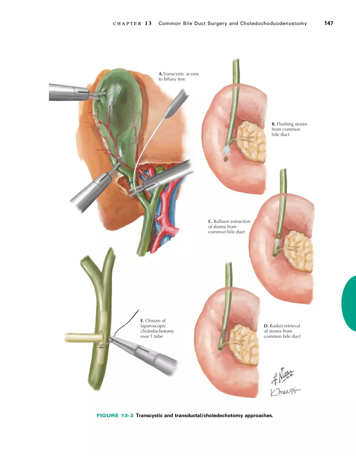
Chapter 13 Common Bile Duct Surgery and
Choledochoduodenostomyâ•… 141
Rod Rezaee, Yi-Chun Carol Liu, and
Pierre Lavertu
SECTION
2
Endocrineâ•… 19
Section Editor: Christopher R. McHenry
Chapter 3
Thyroidectomy and
Parathyroidectomyâ•… 21
Christopher R. McHenry
Chapter 4
Laparoscopic Adrenalectomyâ•… 37
Scott M. Wilhelm
SECTION
3
Upper Gastrointestinalâ•… 49
Section Editor: Jeffrey M. Marks
Chapter 5
Esophagectomyâ•… 51
Lee L. Swanstrom
Chapter 6
Chapter 7
Truncal and Highly Selective
Vagotomyâ•… 81
Chapter 8
Gastrectomyâ•… 93
Melissa S. Phillips
Jeffrey M. Hardacre
Chapter 9
Walter S. Cha
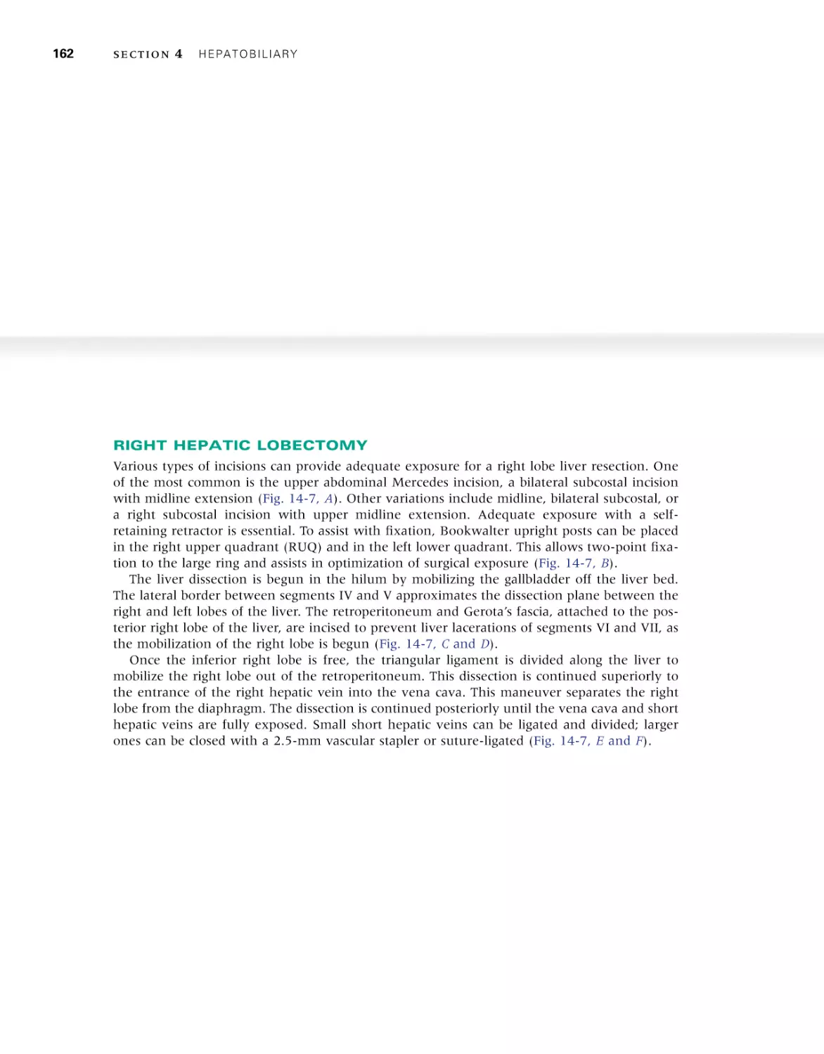
Chapter 14 Hepatectomyâ•… 153
Christopher T. Siegel
Chapter 15 Distal Pancreatectomyâ•… 171
Natalie E. Joseph
Chapter 16 Pancreaticoduodenectomyâ•… 185
Jeffrey M. Hardacre
Chapter 17 Splenectomyâ•… 197
Christopher T. Siegel and
Raymond Onders
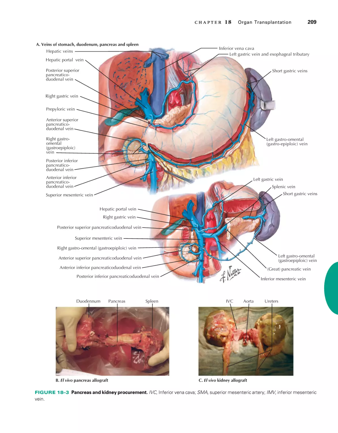
Chapter 18 Organ Transplantationâ•… 203
Kenneth J. Woodside, Edmund Q. Sanchez, and
James A. Schulak
Nissen Fundoplicationâ•… 65
Benjamin K. Poulose and Michael D. Holzman
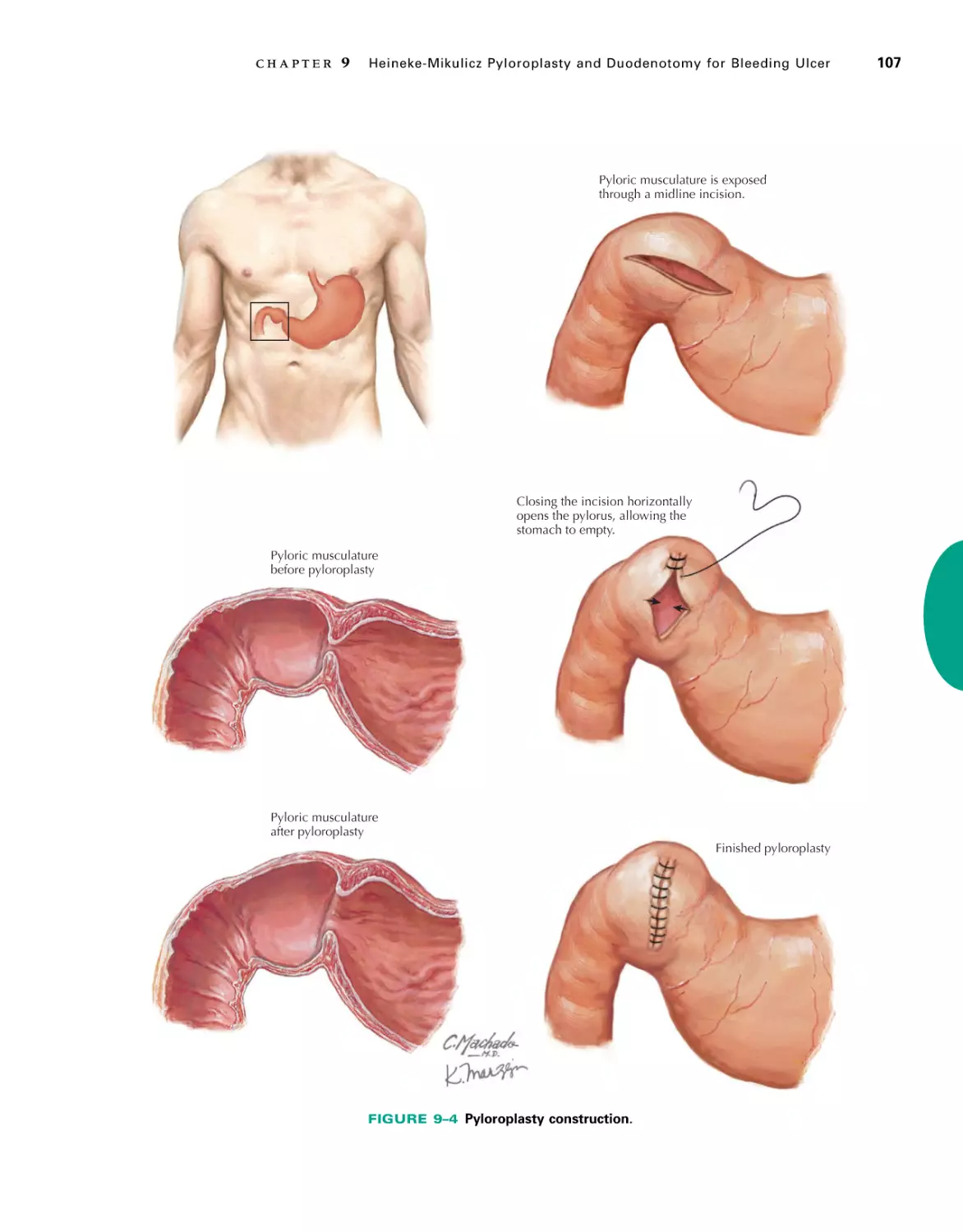
Heineke-Mikulicz Pyloroplasty and
Duodenotomy for Bleeding Ulcerâ•… 101
Jeffrey M. Marks
Chapter 10 Pyloromyotomy for Pyloric Stenosisâ•… 109
Arielle Kanters and Todd Ponsky
Chapter 11 Laparoscopic Roux-en-Y Gastric
Bypassâ•… 119
Alan A. Saber
Hepatobiliaryâ•… 125
Section Editors: Christopher T. Siegel and
Jeffrey M. Hardacre
Chapter 12 Laparoscopic and Open
Chad A. Zender, Evan McBeath, and
Pierre Lavertu
Chapter 2
4
SECTION
5
Lower Gastrointestinalâ•… 229
Section Editor: Sharon L. Stein
Chapter 19 Appendectomyâ•… 231
Mark L. Manwaring
Chapter 20 Abdominal Wall Anatomy and Ostomy
Sitesâ•… 245
Jeremy M. Lipman
Chapter 21 Right Colectomyâ•… 257
Sharon L. Stein
Chapter 22 Left Colectomyâ•… 265
Bradley J. Champagne and
Thomas J. Edwards
Chapter 23 Transverse Colectomyâ•… 277
Eric L. Marderstein and Mujjahid Abbas
xvii
xviii
C ontents
Chapter 24 Low Anterior Resection with Total
Mesorectal Excision and
Anastomosisâ•… 287
Conor P. Delaney
Chapter 25 Abdominoperineal Resectionâ•… 307
Harry L. Reynolds, Jr.
Chapter 26 Hemorrhoids and
Hemorrhoidectomyâ•… 319
Jason F. Hall
Chapter 27 Perirectal Abscess and Fistula in
Anoâ•… 327
Joshua I. S. Bleier and Husein Moloo
SECTION
6
Chapter 29 Laparoscopic Inguinal Hernia Repairâ•… 355
Heidi L. Elliott and Yuri W. Novitsky
Chapter 30 Femoral Hernia Repairâ•… 367
Jeffrey A. Blatnik and Michael J. Rosen
Chapter 31 Open Ventral Hernia Repairâ•… 375
Michael J. Rosen
7
Vascularâ•… 387
Section Editor: Jerry Goldstone
Chapter 32 Exposure of the Carotid Bifurcationâ•… 389
Jerry Goldstone
Henry R. Baele
Chapter 34 Exposure of the Superior Mesenteric
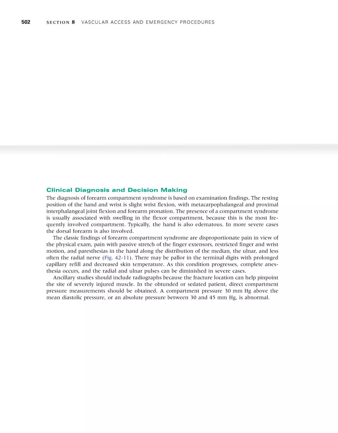
Chapter 42 Leg and Forearm Fasciotomyâ•… 485
Christopher J. Smith and Harry A. Hoyen
Chapter 43 Chest Tube Placementâ•… 507
Jeffrey A. Claridge
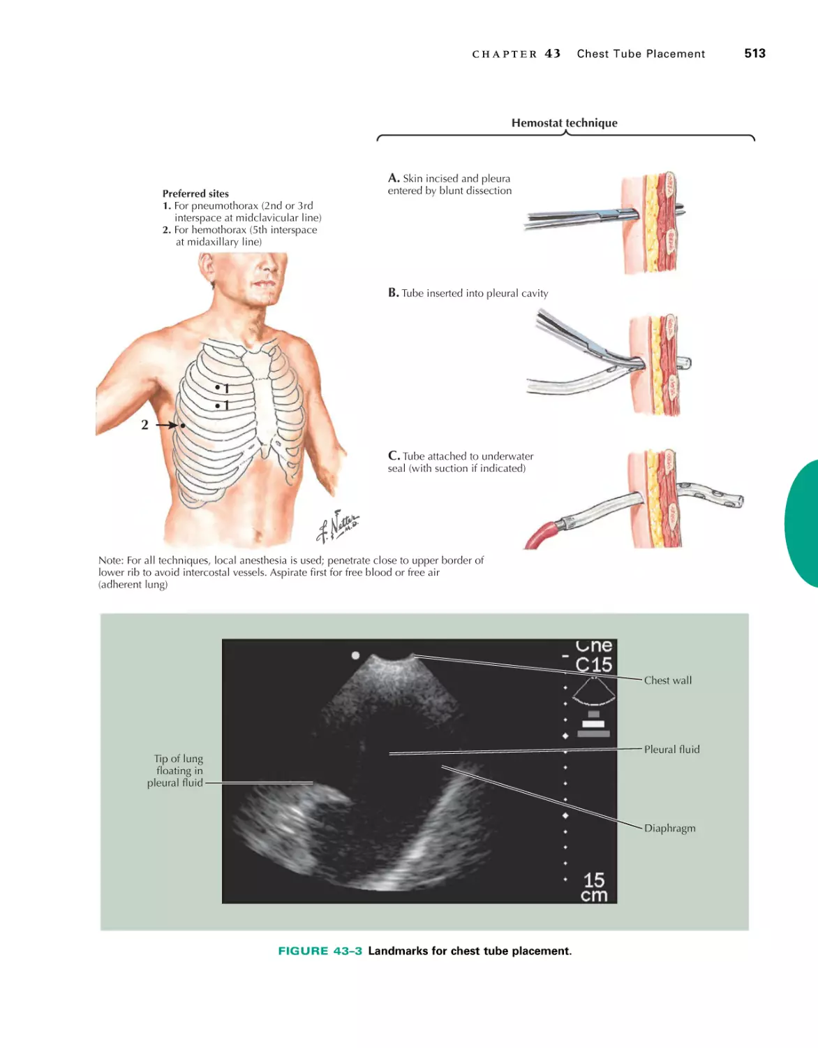
Chapter 44 Emergency Thoracotomy for
Traumaâ•… 515
Amy McDonald
Chapter 45 Tracheal Intubation and Endoscopic
Anatomyâ•… 525
Samuel DeJoy and Charles E. Smith
SECTION
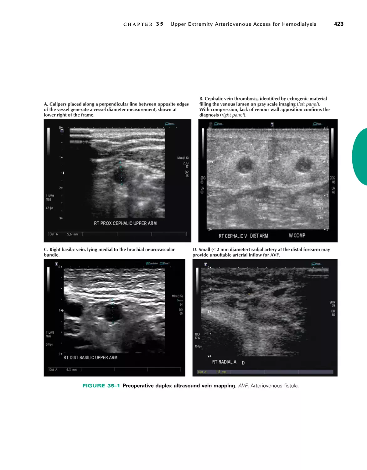
Chapter 35 Upper Extremity Arteriovenous Access
for Hemodialysisâ•… 421
Virginia Wong
Chapter 36 Saphenofemoral Exposureâ•… 431
Victor M. Sandoval, Matthew T. Allemang, and
Vikram S. Kashyap
Chapter 37 Exposure of the Common Femoral Artery
and Veinâ•… 439
John C. Wang
Chapter 38 Exposure of the Popliteal Artery and
Veinâ•… 449
Matthew T. Allemang and Vikram S. Kashyap
Chapter 39 Above-Knee and Below-Knee
Amputationâ•… 457
Gilles Pinault
9
Breast and Oncologyâ•… 539
Section Editor: Julian A. Kim
Chapter 46 Mastectomyâ•… 541
Anthony Visioni and Julian A. Kim
Chapter 47 Duct Excisionâ•… 547
Anthony Visioni and Julian A. Kim
Chapter 48 Sentinel Lymph Node Biopsyâ•… 553
Anthony Visioni and Julian A. Kim
Chapter 49 Axillary and Inguinal
Lymphadenectomyâ•… 561
Anthony Visioni and Julian A. Kim
Chapter 50 Retroperitoneal Sarcomaâ•… 569
Anthony Visioni and Julian A. Kim
Artery and Celiac Axisâ•… 413
Matthew J. Kruse and Bruce L. Gewertz
Vascular Access and
Emergency Proceduresâ•… 467
Chapter 41 Arterial Line Anatomyâ•… 477
John J. Como
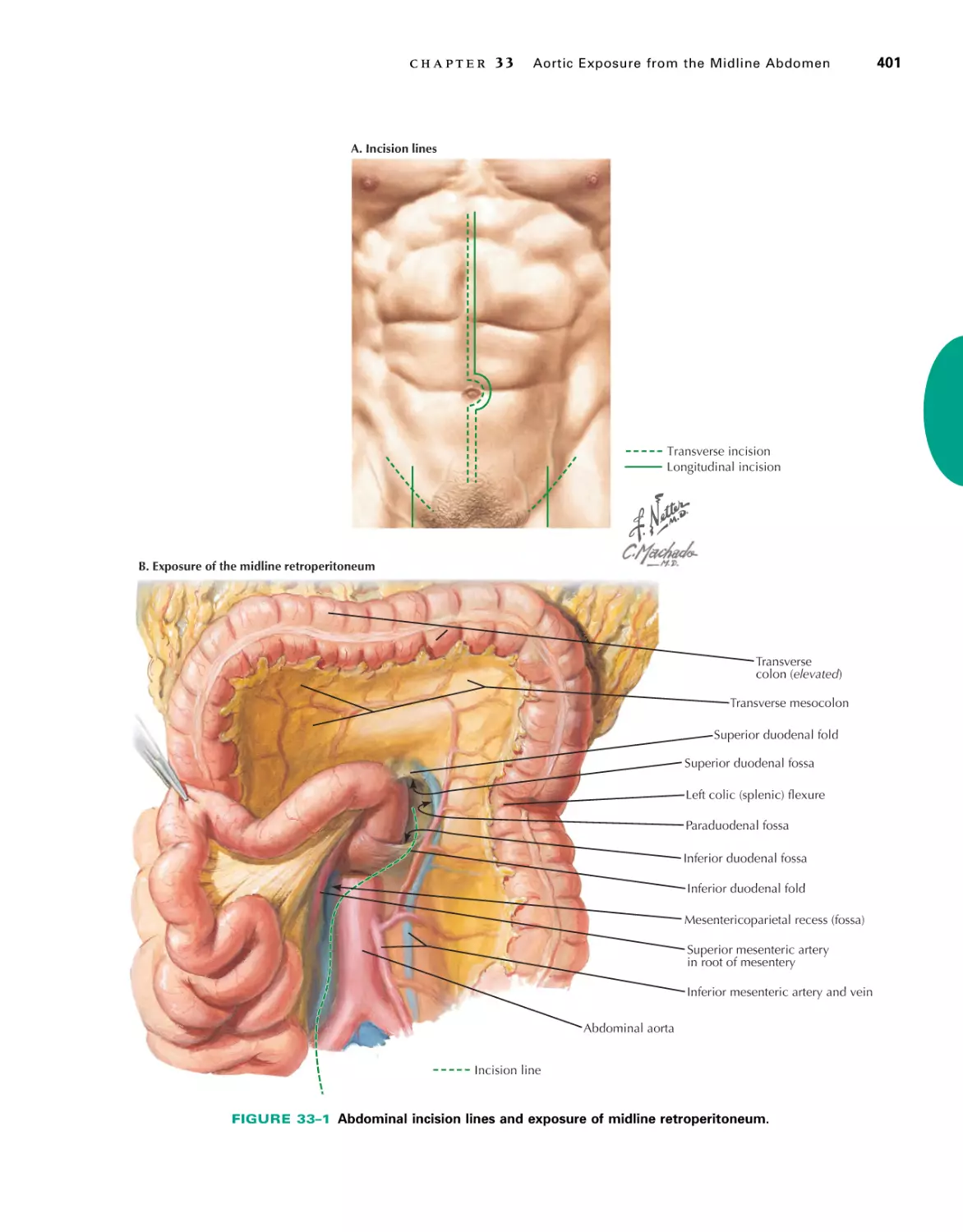
Chapter 33 Aortic Exposure from the Midline
Abdomenâ•… 399
8
Section Editor: Mark A. Malangoni
Chapter 40 Central Line Anatomyâ•… 469
Mark A. Malangoni
Herniaâ•… 339
Section Editor: Michael J. Rosen
Chapter 28 Open Inguinal Hernia Repairâ•… 341
David M. Krpata and Michael J. Rosen
SECTION
SECTION
SECTION
10
Urology and Gynecologyâ•… 575
Section Editor: Lee E. Ponsky
Chapter 51 Hysterectomy for Benign and Malignant
Conditionsâ•… 577
Kimberly Resnick
Chapter 52 Oophorectomy for Benign and Malignant
Conditionsâ•… 587
Robert L. DeBernardo
Chapter 53 Laparoscopic Transperitoneal Radical
Nephrectomyâ•… 597
Lee E. Ponsky
Chapter 54 Radical Prostatectomyâ•… 607
William Tabayoyong and Robert Abouassaly
Chapter 55 Radical Cystectomyâ•… 621
Jessica M. Yih, Jonathan E. Kiechle, and
Edward E. Cherullo
S E C T I O N
1
The Neck
SECTION EDITOR:
Pierre Lavertu
1
2
Selective (Supraomohyoid) Neck
Dissection, Levels I-III
Tracheotomy and Cricothyrotomy
This page intentionally left blank
C H A P T E R
1
â•…
Selective (Supraomohyoid) Neck
Dissection, Levels I-IIIâ•…
Chad A. Zender, Evan McBeath, and Pierre Lavertu
INTRODUCTION
Neck dissection has been a standard method of removing at-risk or involved cancerous lymph
nodes in the head and neck for more than 100 years. Crile first described the radical neck
dissection in the early 1900s, but modifications by Bocca and others helped reduce the morbidity associated with lymph node removal, allowing for nerve and structure preservation
when oncologically sound. This chapter discusses one of these modifications in detail, the
selective or supraomohyoid neck dissection. A selective neck dissection, including levels I
through III, is typically used for malignancies of the oral cavity in patients with N0 disease.
When a larger nodal burden is present, an extended (levels I-IV) selective neck dissection
or a modified radical neck dissection (levels I-V) is indicated. Lesions in the oral cavity that
approach or cross the midline require treatment of both sides of the neck.
3
4
SECTION
1
THE NECK
NECK ANATOMY FOR SURGICAL PLANNING
Understanding the regional lymphatic drainage pathways is critical when planning which type
of neck dissection will be employed (Fig. 1-1). A supraomohyoid neck dissection is performed
when treating patients who are at risk for micrometastasis in levels I, II, and III. The boundaries of levels I (submental and submandibular), II (upper jugular nodal chain), and III (midjugular nodal chain) are defined as follows:
Level Ia: Bounded laterally by the medial aspects of the anterior belly of the digastric muscles,
and ending medially at a line drawn from the mandible to the hyoid bone at the anatomic
midline.
Level Ib: Bounded by the lateral aspect of the anterior belly of the digastric muscle, the medial
aspect of the posterior belly of the digastric and stylohyoid muscles, and the inferior border
of the mandibular body superiorly.
Level IIa: Bounded anteriorly and superiorly by the posterior belly of the digastric and stylohyoid muscles, posteriorly by the vertical plane defined by the spinal accessory nerve and
sternocleidomastoid muscle (SCM), and inferiorly by the horizontal plane defined by the
inferior border of the hyoid bone.
Level IIb: Bounded anteriorly by the jugular vein and inferiorly by the vertical plane defined
by the spinal accessory nerve, posteriorly by the posterior border of the SCM, and superiorly
by the skull base.
Level III: Bounded superiorly by the horizontal plane defined by the inferior border of the
hyoid bone, inferiorly by the horizontal plane defined by the inferior border of the cricoid
cartilage and/or the omohyoid muscle as it crosses the internal jugular vein, anteriorly
by the lateral border of the sternohyoid muscle, and posteriorly by the posterior border of
the SCM.
CHAPTER
1
5
Selective (Supraomohyoid) Neck Dissection, Levels I-III
Mandibular
nodes
Superior lateral
superficial cervical
(external jugular)
node
Submandibular
nodes
Accessory nerve (XI)
The patient is positioned
on the table with his neck
extended, typically on a
shoulder roll, and head
turned away from the
operative side.
Jugulodigastric node
Submental
nodes
Suprahyoid node
Superior deep lateral cervical
(internal jugular) nodes
Superior thyroid nodes
Jugulo-omohyoid node
Anterior deep cervical
(pretracheal and thyroid) nodes
(deep to infrahyoid muscles)
Anterior superficial cervical
nodes (anterior jugular nodes)
Posterior lateral
superficial cervical
(spinal accessory)
nodes
Intercalated node
Inferior deep
lateral cervical
(scalene) node
Thoracic duct
Transverse
cervical
chain of
nodes
Jugular trunk
Supraclavicular nodes*
Subclavian trunk
and node
*The supraclavicular group of nodes (also known as the lower deep cervical group),
especially on the left, are also sometimes referred to as the signal or sentinel lymph
nodes of Virchow or Troisier, especially when sufficiently enlarged and palpable.
These nodes (or a single node) are so termed because they may be the first
recognized presumptive evidence of malignant disease in the viscera.
Parotid
gland
Superior flap dissected up along deep surface of anterior facial
vein and facial (external maxillary) artery, thus elevating ramus
marginalis mandibulae of facial nerve out of operating field.
Vessels ligated and distal end of vascular stump sutured to
undersurface of flap.
Platysma
muscle
Posterior
facial vein
Common
facial vein
Facial (external
maxillary)
artery and
anterior
facial vein
Ramus
marginalis
mandibularis
of facial nerve
Mandible
Hyoid bone
Fascia over
strap muscles
Anterior
jugular vein
Platysma
muscle
Transverse
cervical nerves
Sternocleidomastoid
muscle
Supraclavicular
nerves
Operative field exposed
FIGURE 1–1╇ Patient positioning and anatomy in neck dissection.
Great auricular
nerve
External jugular
vein
Accessory
nerve
Trapezius
muscle
Platysma
muscle
6
SECTION
1
THE NECK
INCISION PLANNING AND PATIENT POSITIONING
FOR NECK DISSECTION
Positioning for a neck dissection includes extending the neck and turning the patient’s head
away from the surgeon. This usually entails placing a shoulder roll under the patient to facilitate
adequate extension.
Various types of incisions may be employed. The authors typically use a “hockey stick” incision that extends from the mastoid tip down the middle of the SCM and then across the neck
in a crease, which is usually over the lowest level that will be surgically treated. The incision
can be brought across the midline to the contralateral neck in the same manner, creating an
“apron” incision, which will allow access to both sides of the neck when indicated to treat
bilateral neck disease.
Raising the Subplatysmal Flap
Skin and subcutaneous incisions are continued down through the subcutaneous fat and platysma muscle, but not through the superficial layer of the deep cervical fascia. A superior
subplatysmal flap is then elevated up to the inferior border of the mandible. Care is taken to
keep the plane of elevation immediately subplatysmal, to aid in identification and preservation
of the marginal mandibular branch of the facial nerve. Laterally, the platysma muscle is not
developed, and elevation must proceed over the external jugular vein and great auricular
nerve. This allows for complete elevation of the flap (Fig. 1-2).
Inferior elevation is performed in a subplatysmal manner down below where the omohyoid
crosses the jugular vein. This allows for complete exposure of level III and for incorporation
of level IV if needed. The flap elevation can be extended down to within 5 to 10╯mm of the
clavicle to aid visualization.
CHAPTER
1
Selective (Supraomohyoid) Neck Dissection, Levels I-III
Height of subplatysmal elevation
Platysma muscle elevated
FIGURE 1–2╇ Flap elevation in neck dissection.
7
8
SECTION
1
THE NECK
LEVEL IA-IB NECK DISSECTION
After flap elevation, expose the anterior belly of the digastric muscle by making a midline
incision from below the mentum to the hyoid bone. It is important to include all the fibrofatty
contents from the contralateral medial edge of the digastric muscle. The elevation continues
to the medial aspect of the submandibular gland to complete the level Ia dissection (Fig. 1-3).
The marginal mandibular branch of the facial nerve can be located approximately 1╯cm
inferior to angle of the mandible. Incisions brought across the neck are always two fingerbreadths below the angle to prevent inadvertent injury to this nerve. The marginal mandibular
branch of the facial nerve lies between the superficial layer of the deep cervical fascia and the
adventitia investing the anterior facial vein. The superficial layer of the deep cervical fascia is
incised at the inferior border of the submandibular gland. It must be elevated and may be
tacked to the platysma muscle to aid in elevation.
Care must be taken to preserve the marginal mandibular branch of the facial nerve and
reflect it superiorly, along with the superficial layer of the deep cervical fascia, and to remove
any submandibular retrovascular (perifacial) lymph nodes in the area. This is accomplished by
developing a plane between the vein and superficial layer of the deep cervical fascia, keeping
the fat pad that contains the facial nodes down in the specimen, along with the submandibular
gland, and elevating and protecting the nerve.
At this point the anterior belly of the digastric muscle is isolated, and the gland and fibrofatty
contents of level Ia are brought posteriorly across the mylohyoid muscle.
Retract the mylohyoid muscle; identify and preserve the lingual and hypoglossal nerves;
then identify, ligate, and divide the submandibular duct, submandibular ganglion, and corresponding vasculature. Level I is released and left pedicled by the inferior fibrofatty attachments
to levels II and III (Fig. 1-3).
CHAPTER
1
Selective (Supraomohyoid) Neck Dissection, Levels I-III
Marginal mandibular
branch of facial nerve
Facial artery and vein
Parotid gland
Level Ia
Greater
auricular nerve
External
jugular vein
Digastric muscle
(anterior belly)
Mylohyoid muscle
Level Ib
Mylohyoid muscle
(retracted)
Lingual nerve
Submandibular
ganglion
Hypoglossal nerve
Submandibular gland
FIGURE 1–3╇ Dissection of level I (submental and submandibular regions).
9
10
SECTION
1
THE NECK
LEVEL II-III NECK DISSECTION
Identify the posterior belly of the digastric muscle, creating the digastric tunnel back to the
mastoid tip under the SCM (Fig. 1-4).
Incise the investing fascial layer along the anterior border of the SCM, ligating and dividing
the external jugular vein in the process. An attempt should be made to preserve the greater
auricular nerve, if not involved with disease.
Unwrap the SCM from its investing fascia. This is accomplished along a broad, superior-toinferior plane, from the digastric muscle superiorly to the omohyoid muscle inferiorly.
Identify the spinal accessory nerve at its entrance into the SCM, and trace it under the
posterior belly of the digastric muscle. The spinal accessory nerve typically passes lateral to
the internal jugular vein just before diving under the posterior belly of the digastric muscle.
The nerve will occasionally bisect or run deep to the jugular vein.
The spinal accessory nerve is released from the surrounding soft tissue, and then level IIb
is released from the skull base, the back of the jugular vein, the SCM, and the deep cervical
fascia. Level IIb is left attached to IIa and brought under the spinal accessory nerve.
Once the investing fascial layer is elevated off the SCM down to the level of the deep cervical rootlets, the dissection is taken medially across the rootlets from the omohyoid muscle to
the spinal accessory nerve superiorly. Care must be taken to avoid injuring the spinal accessory
nerve in this area as it exits the SCM posteriorly (Fig. 1-5).
Dissect levels II and III medially in a plane lateral to the cervical rootlets and the carotid
sheath, which invests the carotid artery, internal jugular vein, and vagus nerve.
Once the elevation reaches the jugular vein, the fascia from the internal jugular vein is
unwrapped. Branches of the vein may be ligated and divided as the specimen is brought medially. The ansa cervicalis will be transected during the inferior dissection as the specimen is
brought across the jugular vein to the lateral aspect of the strap muscles. Superiorly, the hypoglossal nerve, which runs lateral to the carotid artery and medial to the jugular vein, must be
protected under the digastric muscle. The ansa hypoglossi will likely need to be transected as
the specimen is brought medially to the hyoid bone and strap musculature.
The specimen is then dissected away from the hypoglossal nerve and posterior belly of the
digastric muscle until it can be easily removed. The anterior dissection will meet with the
posterior dissection as the specimen is brought across the strap muscles, carotid artery, and
jugular vein (Fig. 1-5).
CHAPTER
1
11
Selective (Supraomohyoid) Neck Dissection, Levels I-III
Stylohyoid muscle
Digastric muscle
(posterior belly)
Sternocleidomastoid
muscle (retracted)
Level IIa
Level IIb
Greater
auricular
nerve
External
jugular vein
Hyoid bone
Sternohyoid muscle
Omohyoid muscle
Sternocleidomastoid muscle
Level III
FIGURE 1–4╇ Dissection of levels II (upper jugular nodal chain) and III (midjugular nodal chain).
12
SECTION
1
THE NECK
Internal jugular vein
Sternocleidomastoid muscle
Spinal accessory nerve
Cervical rootlets
Level I
Level II
Level III
Level I
Level II
Level III
FIGURE 1–5╇ Lymphadenectomy (levels I-III).
SUGGESTED READINGS
Janfaza P, editor. Cummings otolaryngology: head and neck surgery, 5th ed. Philadelphia:
Saunders; 2010.
Myers EN, editor. Operative otolaryngology: head and neck surgery, 2nd ed. Philadelphia:
Saunders; 2008.
C H A P T E R
2
â•…
Tracheotomy and Cricothyrotomyâ•…
Rod Rezaee, Yi-Chun Carol Liu, and Pierre Lavertu
INTRODUCTION
Tracheotomy (tracheostomy) is one of the oldest surgical procedures known, with the first
reference 3000 to 4000 years ago. Chevalier Jackson is credited with standardizing the tracheotomy procedure in 1932, outlining the individual steps for establishing a direct airway
through the anterior neck tissues and into the trachea. Jackson had the foresight to consider
potential surgical complications when he warned against placement of a high tracheotomy
or cricothyrotomy (cricothyroidotomy). Although the procedure has evolved and now
includes a percutaneous technique, this chapter focuses on open tracheotomy.
INDICATIONS AND PRINCIPLES OF TRACHEOTOMY
Indications for tracheotomy are multiple and include the need to bypass an airway obstruction
caused by congenital anomaly, vocal cord paralysis, inflammatory disease, benign or malignant
laryngeal pathology, laryngotracheal trauma, facial trauma, or severe sleep apnea refractory
to other interventions. Additional indications for tracheotomy include the need to provide an
airway for patients receiving mechanical ventilation for respiratory failure and for those with
chronic aspiration secondary to inadequate cough. Tracheotomy may also allow for a more
secure and comfortable airway for home ventilation in patients with neuromuscular or other
chronic diseases.
13
14
SECTION
1
THE NECK
Preoperative Considerations
Once a tracheotomy is planned, certain factors influence whether patients should have an open
tracheotomy or a percutaneous dilatational tracheotomy, as first described by Ciaglia in 1985.
Regardless of the tracheotomy method chosen, a patient’s overall medical condition must be
optimized, body habitus assessed, and coagulation profile addressed. Other preoperative factors
to consider include the urgency of the procedure (emergency vs. elective); need for general or
local anesthesia, adult or pediatric patient, current status of the airway (intubated vs. nonintubated patient), availability of proper equipment, patient portability, surgeon’s experience
(open vs. percutaneous technique), and capability of the institution to perform bedside procedures. This will determine which team performs the procedure and whether it will be done in
the operating room or at the bedside in the intensive care unit.
SURGICAL ANATOMY AND TRACHEOTOMY PROCEDURE
External Anatomy
The patient is placed in the supine position. The surgeon might consider placing the neck into
slight extension, but this should not be too far past the neutral position, so that the skin incision remains in line with the tracheal incision. A shoulder roll may be used in some patients
to assist with positioning (Fig. 2-1).
The thyroid notch superiorly, cricoid cartilage, and suprasternal notch inferiorly can usually
be palpated and should be marked (Fig. 2-1). If an awake tracheotomy is being performed, the
skin is injected with 1% lidocaine with 1â•›:â•›100,000 epinephrine solution for hemostasis and
anesthesia. According to surgeon preference, this injection may also be done for general anesthesia patients. A vertical or horizontal incision is made in the midline of the neck, about 2╯cm
above the sternal notch, and is carried down until the strap muscles are visible.
Strap Muscles and Midline Raphe
The anterior jugular veins are typically located on the strap musculature and may require ligation if encountered in the midline (Fig. 2-2). Small cricothyroid arteries traverse the superior
aspect of the cricothyroid space, forming an anastomosis near the midline. This may cause
problematic bleeding in the setting of emergent airway access or if dissection is carried out
above the cricoid cartilage. In the lower neck, the surgeon must be aware that the innominate
artery crosses over anterior to the trachea at the level of the thoracic inlet and is higher on
the right side. Before dissection of the strap muscles, the surgeon should palpate for innominate
pulsations in the suprasternal notch and should be cognizant of the pathway of the surgical
dissection in the setting of a high-riding vessel.
Midline dissection is essential for hemostasis and avoidance of paratracheal structures,
including the great vessels of the neck. The midline raphe between the paired sternohyoid and
sternothyroid muscles can be easily identified. Lateral retraction of the strap muscles along the
midline raphe will expose the underlying thyroid gland. Palpation of the trachea can help
maintain a midline course of dissection in those individuals with thick subcutaneous tissues.
CHAPTER
2
Tracheotomy and Cricothyrotomy
15
4. Strap muscles retracted
to expose trachea
Isthmus of thyroid gland
Strap muscles
Pretracheal venous plexus
1. Position of patient for tracheotomy;
shoulders elevated by sandbag
Thyroid cartilage
Cricothyroid membrane
Cricothyroid muscle
Common carotid artery
Cricoid cartilage
5. Pretracheal venous plexus
divided. Trachea stabilized
by hooks. Cruciate incision
in trachea.
Edge of
sternocleidomastoid
muscle
Thyroid gland
Skin incision
Dome of pleura
Tracheal incision
Trachea
Suprasternal notch
2. Anatomy and surface topography
relative to line of incision
Strap muscles
in cervical fascia
Anterior jugular vein
3. Skin and fat retracted
FIGURE 2–1╇ Tracheotomy procedure, steps 1-6.
6. Tracheotomy tube
tied securely in place
over gauze square
16
SECTION
1
THE NECK
Thyroid Isthmus
The strap muscles are separated using blunt dissection and retracted to either side until the
thyroid isthmus is visible. The isthmus of the thyroid gland generally lies across the first to
fourth tracheal rings. It must be divided when overlying the tracheotomy site, because this
will make reinsertion safer and easier in the setting of accidental dislodgement. The isthmus
can be addressed in one of several ways. First, the fascial attachments of the thyroid to the
anterior trachea may be dissected free, thus allowing the gland to be retracted above or below
the planned entry site into the trachea. If the thyroid is enlarged and cannot be retracted out
of the way, it will need to be divided by further dissecting it from the anterior tracheal wall in
the immediate pretracheal plane to establish a bloodless plane of dissection. By identifying the
bright-white layer of the tracheal cartilage, the surgeon will minimize bleeding from trauma
to the posterior aspect of the gland.
Once the thyroid isthmus is elevated from the trachea, the surgeon may use two clamps on
either side, then cutting in the midline with a Bovie cautery device. Once divided, the two
ends of isthmus are then suture-ligated using a running or figure-of-eight 2-0 silk stitch. If
available, other methods of dividing the gland include using the Harmonic scalpel or other
device, based on surgeon preference. Use of cautery alone to divide the thyroid is discouraged,
to minimize risk of postoperative hemorrhage.
Anatomy with Trachea Visualized
A cricoid hook may be used to help stabilize the position of the trachea before entering the
airway. A hook may also be used to elevate the trachea out of the chest in the patient with
kyphosis or a low-lying laryngotracheal complex. Once the anterior wall of the trachea is
visualized, the space between the second and third tracheal rings is identified by palpation
using a hemostat. A horizontal incision is made between the rings with a scalpel and can be
extended laterally in each direction using scissors. Care is taken not to rupture the cuff of the
endotracheal tube (ETT) by either deflating it before entering the airway or advancing it distally.
It is preferable to maintain the ETT inflated during the procedure. It allows ventilation and
minimizes the spray of blood and secretions into the surgical field.
Surgeon preference and age of the patient may influence the type of tracheal incision used.
In children, a vertical incision may be used, but in adults the most common technique is to
create an anterior tracheal window by removing a section of a single ring. Another technique
creates an inferiorly based “trapdoor” flap (Björk flap) composed of an anterior portion of a
single tracheal ring and interspace tissue below. After an intercartilaginous incision is made,
scissors are used to cut downward on either side to create an inferiorly based flap of tracheal
tissue. The superior edge of this flap is then stitched to the skin edge to exteriorize and secure
the trachea. Although some consider this to be the safest method because the airway is secured
to the skin, this may lead to future complications.
CHAPTER
Hyoid bone
2
Tracheotomy and Cricothyrotomy
17
Digastric muscle (anterior belly)
Mylohyoid muscle
Thyrohyoid membrane
Hyoglossus muscle
External carotid artery
Stylohyoid muscle
Internal jugular vein
Digastric muscle (posterior belly)
Thyrohyoid muscle
Fibrous loop for intermediate
digastric tendon
Thyroid cartilage
Omohyoid muscle
(superior belly)
Sternohyoid and omohyoid
muscles (cut)
Sternohyoid muscle
Thyrohyoid muscle
Median cricothyroid
ligament
Oblique line of thyroid cartilage
Cricoid cartilage
Cricothyroid muscle
Sternothyroid muscle
Scalene
muscles
Omohyoid muscle
(superior belly) (cut)
Trapezius
muscle
Thyroid gland
Omohyoid muscle
(inferior belly)
Sternohyoid muscle (cut)
Trachea
Clavicle
Styloid process
Mastoid process
Stylohyoid muscle
Mylohyoid muscle
Digastric muscle (posterior belly)
Digastric muscle (anterior belly)
Thyrohyoid muscle
Geniohyoid muscle
Oblique line of thyroid cartilage
Sternohyoid muscle
Omohyoid muscle (inferior belly)
Omohyoid muscle (superior belly)
Sternothyroid muscle
Infrahyoid and
suprahyoid muscles and
their action: schema
Sternum
Scapula
FIGURE 2–2╇ Infrahyoid and suprahyoid musculature for tracheotomy.
18
SECTION
1
THE NECK
Anatomy with Tracheotomy Tube in Place
Once the airway is entered, the ETT is pulled out slowly by the anesthesiologist until it is just
above the newly created tracheotomy. The tracheotomy tube or ETT is then placed through
the opening into the trachea. After the airway is secured, as confirmed by CO2 monitor or
ventilator, the oral ETT is then removed. The tracheostomy tube is then sutured to the skin
using 2-0 silk to minimize the risk of accidental dislodgement. In addition, a circumferential
tie is placed and secured around the neck, allowing at least one finger to slide underneath to
minimize constriction.
A flexible extension tube is used to connect the tube to the ventilator circuit to minimize
unnecessary movement of the tube in the immediate postoperative period.
SUMMARY
Tracheotomy is used to establish a surgical airway in patients requiring prolonged mechanical
ventilation. Surgeon mastery of anatomy and proper technique will maximize successful
patient outcomes and minimize potential complications.
SUGGESTED READINGS
Bailey BJ. Head and neck surgery: otolaryngology. 4th ed. Philadelphia: Lippincott-Raven;
2006, pp 785-800.
Beatrous WP. Tracheostomy: its expanded indications and its present status. Laryngoscope
1968;78(3):3-55.
Pahor AL. Ear, nose and throat in ancient Egypt. J Laryngol Otol 1992;106(9):773-9.
Shapiro BA, Harrison RA, Trout CA. The artificial airway: clinical application of respiratory
care, 2nd ed. Chicago: Year Book; 1979, pp 177-186.
S E C T I O N
Endocrine
SECTION EDITOR:
Christopher R. McHenry
3
4
Thyroidectomy and
Parathyroidectomy
Laparoscopic Adrenalectomy
2
This page intentionally left blank
C H A P T E R
3
â•…
Thyroidectomy and Parathyroidectomyâ•…
Christopher R. McHenry
THYROIDECTOMY
Thyroidectomy is the most common endocrine surgical procedure performed. It is indicated
for nodular thyroid disease when fine-needle aspiration biopsy is malignant or suspicious
for malignancy, consistent with a Hürthle or follicular cell neoplasm, persistent atypia/
follicular lesion of undetermined significance, or is persistently nondiagnostic. Thyroidectomy is indicated for benign thyroid nodules that progressively increase in size, extend
substernally, cause compressive symptoms, or impinge on the trachea, esophagus, recurrent
laryngeal nerve, or major vessels. Thyroidectomy is also an option for treatment of thyrotoxicosis caused by a solitary hyperfunctioning nodule, multinodular goiter, or Graves’
disease. The goal of thyroid surgery is to remove all diseased thyroid tissue safely, relieve
symptoms, minimize recurrent disease, and prolong survival.
21
22
SECTION
2
ENDOCRINE
Surgical Anatomy for Thyroidectomy
The thyroid gland consists of two lobes and an isthmus (Fig. 3-1). Between 30% and 60% of
patients also have a pyramidal lobe that forms as a result of the persistence of the embryologic
thyroglossal duct. The principal blood supply to the thyroid gland comes from the inferior
thyroid artery, a branch of the thyrocervical trunk and the superior thyroid artery, which is
the first branch of the external carotid artery. The venous drainage of the thyroid gland is from
the superior and middle thyroid veins, which empty into the internal jugular vein, and the
inferior thyroid veins, which empty into the brachiocephalic veins.
CHAPTER
3
Thyroidectomy and Parathyroidectomy
External carotid artery
Hyoid bone
Internal carotid artery
Superior laryngeal nerve
Internal branch
External branch
Infrahyoid artery
Superior thyroid artery and vein
Thyroid cartilage (lamina)
Superior laryngeal artery
Median cricothyroid
ligament
Thyrohyoid membrane
Ansa
cervicalis
Superior root
Cricothyroid muscles
Inferior root
Common carotid artery
Cricoid cartilage
Cricothyroid artery
Pyramidal lobe
(often absent
or small)
Right lobe
Left lobe
Isthmus
Internal jugular vein
Phrenic nerve
Middle thyroid vein
Inferior thyroid veins
Ascending cervical artery
Thyroid
gland
Pretracheal lymph nodes
Inferior thyroid artery
Phrenic nerve
Superficial cervical artery
Anterior scalene muscle
Suprascapular artery
Vagus nerve (X)
Thyrocervical trunk
External jugular vein
Subclavian
artery and vein
Anterior jugular vein
1st rib (cut)
Vagus nerve (X)
Left recurrent laryngeal nerve
Right recurrent
laryngeal nerve
Brachiocephalic trunk
Brachiocephalic veins
Superior vena cava
Aortic arch
Thyroid cartilage
Cricothyroid ligament
Common carotid artery
Medial margin of
sternocleidomastoid muscle
Cricothyroid muscle
Cricoid cartilage
Thyroid gland
Cupula (dome) of pleura
Trachea
FIGURE 3–1╇ Thyroid gland, anterior view.
23
24
SECTION
2
ENDOCRINE
Surgical Anatomy for Thyroidectomy—Cont’d
Determining the surface anatomy of the neck is necessary for proper placement of the skin
incision (Figs. 3-1 and 3-2). The patient is positioned supine on the operating room table with
the arms tucked at the side, a soft roll placed lengthwise beneath the shoulders, and the head
in a soft-foam headrest with the neck extended (Fig. 3-2). Important landmarks that should
be palpated include the prominence of the thyroid cartilage, the cricoid cartilage, and the
sternal notch. The isthmus of the thyroid gland lies immediately below the cricoid cartilage. A
transverse skin incision is made in a normal skin crease below the cricoid cartilage for an
optimal cosmetic result.
CHAPTER
3
Thyroidectomy and Parathyroidectomy
25
Digastric muscle (anterior belly)
Mylohyoid muscle
Parotid gland
Submandibular gland
Platysma muscle
(cut away)
Fibrous loop for
intermediate
digastric tendon
Mastoid process
Stylohyoid muscle
Digastric muscle
(posterior belly)
Hyoid bone
External carotid artery
Carotid sheath
Internal jugular vein
Fascia of infrahyoid
muscles and cut edge
Thyrohyoid muscle
Omohyoid muscle
(superior belly)
Thyroid cartilage
Sternohyoid muscle
Investing layer of (deep)
cervical fascia and cut edge
Sternothyroid muscle
Scalene muscles
Cricoid
cartilage
Trapezius muscle
Omohyoid muscle
(inferior belly)
Clavicle
Deltoid muscle
Clavicular head
Sternal head
Pretracheal layer of
(deep) cervical fascia over
thyroid gland and trachea
Sternocleidomastoid
muscle
Pectoralis major muscle
Suprasternal space (of Burns)
Manubrium of sternum
The patient is positioned supine on the
operating room table with the arms
tucked at the sides. To enhance the
accessibility of the thyroid gland, the
patient is positioned on a soft roll (arrow)
placed lengthwise under the houlders,
and the neck is extended on a soft-foam
headrest. The bed is placed in reverse
Trendelenburg position to decrease the
venous pressure in the neck and reduce
potential bleeding.
Jugular notch
Incision line
A silk suture is used to mark the site of the
incision. Important anatomic landmarks
are the thyroid cartilage, the cricoid cartilage,
and the sternal notch. The site for the incision
is being marked just below the cricoid cartilage.
FIGURE 3–2╇ Anatomic landmarks for thyroidectomy or parathyroidectomy incision.
26
SECTION
2
ENDOCRINE
Anatomy for Exposing the Thyroid Gland
It is necessary to create a working space to remove the thyroid gland. This is accomplished first
by dividing the subcutaneous tissue and platysma muscle to expose the sternal head of the
sternocleidomastoid muscles laterally and the sternothyroid muscles in the midline of the incision (Figs. 3-2 and 3-3, A). Superior and inferior skin flaps are raised in the subplatysmal plane,
anterior to the anterior jugular veins. The skin flaps are raised superior to the prominence of
the thyroid cartilage, inferior to the sternal notch, and lateral to the sternal head of the sternocleidomastoid muscles.
The right and left sternohyoid muscles are separated along the median raphe from the
thyroid cartilage superiorly to the sternal notch inferiorly. The median raphe is avascular and
consists of the pretracheal or deep cervical fascia over the thyroid gland and trachea. The sternothyroid muscle is freed from the anterior surface of the thyroid lobe by dividing the intervening loose areolar tissue. The sternothyroid and sternohyoid muscles are retracted laterally,
and the lobe of the thyroid gland is mobilized anteromedially. The sternohyoid and sternothyroid muscles may be divided when additional exposure is necessary, especially for patients with
large goiters. The muscles are divided at the level of the cricoid cartilage to avoid injury to the
ansa cervicalis, which enters the muscle inferiorly.
Anatomy for Mobilization of the Thyroid Lobe
Anteromedial traction is applied to the lobe of the thyroid gland, and the middle thyroid vein
is divided (Fig. 3-3, B). The areolar tissue between the thyroid gland and the common carotid
artery is separated using a combination of blunt and sharp dissection, allowing for further
anteromedial mobilization of the thyroid gland. The superior thyroid artery and the superior
thyroid veins are exposed by applying caudal and lateral traction to the thyroid parenchyma
at the superior pole. This helps expose the cricothyroid space and facilitates the individual
ligation of the superior-pole vessels close to the thyroid gland, staying lateral to the muscles
of the pharynx and the larynx to avoid injury to the external branch of the superior laryngeal
nerve (EBSLN).
CHAPTER
3
Thyroidectomy and Parathyroidectomy
27
A. Muscles of the neck (lateral view)
Mastoid process
Ramus of mandible
Styloid process
Parotid gland (cut)
Stylohyoid muscle
Masseter muscle
Digastric muscle
(posterior belly)
Submandibular gland
Hyoglossus muscle
Middle pharyngeal
constrictor muscle
Mylohyoid muscle
Longus capitis muscle
Body of mandible
Splenius capitis muscle
Digastric muscle
(anterior belly)
Sternocleidomastoid muscle
Hyoid bone
Levator scapulae muscle
Scalene muscles
Thyrohyoid muscle
Posterior
Middle
Anterior
Omohyoid muscle
(superior belly)
Sternohyoid muscle
Brachial plexus
Inferior pharyngeal
constrictor muscle
Trapezius muscle
Omohyoid muscle
(inferior belly)
Sternothyroid
muscle
Acromion
Sternal head
Clavicle
Clavicular head
Deltoid
muscle
Sternocleidomastoid
muscle
Pectoralis major muscle
Manubrium of sternum
B. Parathyroid glands (right lateral view)
External carotid artery
Internal branch of
superior laryngeal nerve
Superior thyroid vein
Superior laryngeal artery
External branch of
superior laryngeal nerve
Superior thyroid artery (cut)
Inferior pharyngeal
constrictor muscle
Common carotid artery
Superior parathyroid gland
Thyroid gland (right lobe)
(retracted anteriorly)
Internal jugular vein
Middle thyroid vein
Inferior parathyroid gland
Inferior thyroid artery
Right recurrent laryngeal nerve
Esophagus
Inferior
thyroid vein
FIGURE 3–3╇ Surgical anatomy for thyroidectomy and parathyroidectomy.
28
SECTION
2
ENDOCRINE
Anatomy of the Superior Laryngeal Nerve
The superior laryngeal nerve is a branch of the vagus nerve from high in the neck (Fig. 3-4,
A and B). At 2 to 3╯cm above the superior-pole vessels, the superior laryngeal nerve divides
into an internal branch that provides sensory innervations to the supraglottic area of the larynx
and the base of the tongue and an external branch that provides motor innervation to the
cricothyroid muscle.
The EBSLN is not routinely identified during thyroidectomy or parathyroidectomy. It is a
thin nerve that usually travels along the medial border of the superior-pole vessels. It usually
crosses the superior-pole vessels 1╯cm or more above the junction of the vessels and the thyroid
parenchyma. In 20% of patients the EBSLN crosses or is immediately adjacent to the superiorpole vessels at its junction with the thyroid gland, increasing the likelihood of injury and
underscoring the importance of individual ligation of the vessels to preserve the EBSLN.
Anatomy of the Recurrent Laryngeal Nerve
The recurrent laryngeal nerves (RLNs) are branches of the vagus nerve from within the thorax
(Fig. 3-4). The right RLN “recurs” around the right subclavian artery, and the left RLN recurs
around the arch of the aorta. The RLNs ascend into to the neck from the thoracic inlet, passing
from lateral to medial into the tracheoesophageal groove. The left RLN enters the neck in a
more medial location than the right RLN, which has a more oblique course.
The RLN is identified inferior to the inferior thyroid artery, where its location is most constant. In the neck the RLN crosses the inferior thyroid artery and then maintains a paratracheal
location for approximately 1╯cm before passing posterior to the inferior edge of the inferior
pharyngeal constrictor muscle to enter the larynx (see Fig. 3-3, B).
In 85% to 90% of patients, thyroid parenchyma tissue protrudes from the posterolateral
margin of the lateral lobe of the thyroid gland, known as the tubercle of Zuckerkandl (Fig. 3-4,
C). This is an important anatomic landmark because the RLN passes in the tracheoesophageal
groove beneath the inferior portion of the tubercle of Zuckerkandl before it turns posteriorly
to enter the larynx. Before entering the larynx, the RLN divides into two or more branches in
40% to 80% of patients (Fig. 3-4, D). The RLN innervates all the muscles of the larynx except
the cricothyroid muscle.
CHAPTER
3
Thyroidectomy and Parathyroidectomy
A. Nerves of larynx
Internal branch of superior laryngeal nerve
Sensory branches to larynx
Superior
laryngeal nerve
Ansa of Galen
Aryepiglottic muscle
Thyroepiglottic muscle
Internal branch
External branch
Inferior pharyngeal
constrictor muscle
Transverse and oblique arytenoid muscles
Thyroarytenoid muscle
Vocalis muscle
Lateral cricoarytenoid muscle
Posterior cricoarytenoid muscle
Cricothyroid muscle
Cricopharyngeus muscle
(part of inferior
pharyngeal constrictor)
Thyroid articular surface
Anterior and posterior branches of
inferior laryngeal nerve
Right recurrent laryngeal nerve
Right recurrent
laryngeal nerve
Right lateral
view
Right lateral view:
thyroid cartilage lamina removed
B. Parathyroid glands (posterior view)
External carotid artery
Thyrohyoid membrane
Hyoid bone
Superior laryngeal nerve
Internal branch
Internal carotid artery
Superior thyroid artery
External branch
Vagus nerve (X)
Superior aryngeal artery
Epiglottis
Common carotid artery
Superior thyroid artery
Inferior pharyngeal constrictor muscle (cut)
Common carotid artery
Fibrous capsule of thyroid gland (cut)
Cricopharyngeus muscle (part of inferior
pharyngeal constrictor)
Superior parathyroid gland
Fibrous capsule of thyroid gland (cut)
Superior parathyroid gland
Right lobe of thyroid gland
Left lobe of thyroid gland
Inferior parathyroid gland (may be more
caudally located, even within mediastinum)
Inferior thyroid artery
Ascending cervical artery
Inferior parathyroid gland
Right recurrent laryngeal nerve
Transverse cervical artery
Left recurrent laryngeal nerve
Suprascapular artery
Esophagus
Thyrocervical trunk
Subclavian artery
Vertebral artery
Subclavian artery
Brachiocephalic trunk
Trachea
Trachea
Recurrent
laryngeal nerve
Tubercle of
Zuckerkandl
C. Tubercle of Zuckerkandl
29
TG
T
P
D. Intraoperative photograph
demonstrating the recurrent laryngeal
nerve (RLN). An anterior motor branch
and a posterior sensory branch are
present in the normal paratracheal
location (T=trachea). A normal right
superior parathyroid gland is depicted
(P). The thyroid gland (TG) has been
mobilized anteromedially.
LN
R
Esophagus
FIGURE 3–4╇ Anatomy of superior and recurrent laryngeal nerves.
30
SECTION
2
ENDOCRINE
Anatomy for Ligation of the Inferior Thyroid Artery
and Preservation of the Parathyroid Glands
Whenever possible, the parathyroid glands should be preserved in situ by dissecting them
downward, away from the capsule of the thyroid gland. Once the RLN has been exposed
superior to the inferior thyroid artery, the branches of this artery are ligated close to the thyroid
parenchyma, preserving the blood supply to the parathyroid glands. Truncal ligation of the
inferior thyroid artery should be avoided.
When a parathyroid gland cannot be preserved in situ, it is removed and a small portion
submitted for frozen-section examination to confirm the presence of parathyroid tissue. The
remainder of the gland is minced and autotransplanted into a pocket of the sternocleidomastoid
muscle. Ninety percent of freshly autotransplanted parathyroid glands retain function.
Once the thyroid lobe has been dissected away from the RLN, the ligament of Berry,
connective tissue that suspends the thyroid gland to the trachea, is divided sharply. A small
remnant of thyroid tissue can be left in place where the RLN contacts the thyroid parenchyma
at the ligament of Berry, to preserve the integrity of the RLN. For patients undergoing a thyroid
lobectomy and isthmusectomy, the thyroid gland is mobilized to the contralateral side of the
trachea and divided. The cut edge of the contralateral lobe of the thyroid gland is oversewn.
For patients undergoing total thyroidectomy, anteromedial mobilization of the contralateral
thyroid lobe is begun.
PARATHYROIDECTOMY
Parathyroidectomy is indicated for treatment of primary, secondary, and tertiary hyperparathyroidism (HPT). Approximately 85% to 90% of patients with primary HPT have a single
adenoma, whereas patients with secondary and tertiary HPT have parathyroid hyperplasia.
Minimally invasive parathyroidectomy (MIP) is used to treat patients with primary HPT caused
by a solitary adenoma, whereas bilateral neck exploration with subtotal parathyroidectomy or
total parathyroidectomy and parathyroid autotransplantation is the standard treatment for
parathyroid hyperplasia.
Photographs
Accurate preoperative parathyroid localization is a prerequisite for performing MIP. Technetium
99m sestamibi scintigraphy and high-resolution ultrasonography are the localizing procedures
of choice (Fig. 3-5). Intraoperative parathyroid hormone (IOPTH) measurement is used to
determine whether additional hyperfunctioning parathyroid tissue remains. A greater than
50% decline in IOPTH levels 10 minutes after excision of all hyperfunctioning parathyroid
tissue is indicative of a curative parathyroidectomy. Failure of IOPTH levels to decline by more
than 50% indicates that residual hyperfunctioning tissue remains and that further exploration
is necessary.
CHAPTER
Anterior immed
3
Thyroidectomy and Parathyroidectomy
Anterior 1 hr delay
Technetium 99m sestamibi scan demonstrating an abnormal focus of
radiotracer accumulation seen in the left side of the neck on immediate
and 1 hour delayed images.
Static sonographic image in the sagittal plane demonstrating a
homogeneous, hypoechoic mass inferior to the left lobe of the
thyroid gland that corresponded to a left inferior parathyroid adenoma.
FIGURE 3–5╇ Preoperative imaging of neck: scintigram (top) and sonogram (bottom).
31
32
SECTION
2
ENDOCRINE
Anatomy and Embryology of Parathyroid Glands
A normal parathyroid gland is oval, bean shaped or spherical, yellow-tan in color, 5╯mm in
maximum dimension, and weighs 35╯mg or less. It is usually surrounded by adipose tissue
(Fig. 3-6, A). A parathyroid gland can be flattened in appearance, especially when it is within
the capsule or adherent to the thyroid gland.
The superior parathyroid glands are usually posterior and superior to the RLN, approximately 1╯cm cephalad from the junction of the RLN and inferior thyroid artery at the level of
the cricoid cartilage, where the RLN enters posterior to the inferior pharyngeal constrictor
muscle (see Fig 3-3, B). The superior glands are often found in a subcapsular location. The
inferior parathyroid glands are usually anterior to the RLN along the posterolateral aspect of
the inferior pole to the thyroid gland, approximately 1╯cm caudal to the junction to the RLN
and inferior thyroid artery. The inferior parathyroid glands are less often subcapsular. The
inferior thyroid artery is the principal blood supply to the parathyroid glands, although they
may also obtain blood supply from the superior thyroid artery and small vessels from the
capsule of the thyroid gland.
The steps necessary to expose the parathyroid glands are similar to those used for thyroidectomy, except a smaller incision is used (2.5 to 4.0╯cm). Superior and inferior skin flaps are
raised; the strap muscles are separated in the midline; and the lobe of the thyroid gland is
mobilized and retracted anteromedially. The search for an enlarged parathyroid gland begins
with an exploration of the normal anatomic locations for the superior and inferior parathyroid
glands (Fig. 3-6, B). Division of the middle thyroid vein and the superior-pole vessels is generally unnecessary, but this may be helpful in exposing parathyroid glands, especially in ectopic
locations.
The inferior parathyroid glands and the thymus develop from the third bronchial pouch
(Fig. 3-6, C). The superior parathyroid glands and the lateral lobes of the thyroid gland develop
from the fourth bronchial pouch. Inferior parathyroid glands undergo extensive migration with
the primordium of the thymus and eventually become located on the dorsolateral surface of
the inferior pole of the thyroid lobe. These superior parathyroid glands undergo minimal migration and become located on the dorsomedial surface of the superior pole of the thyroid gland.
CHAPTER
3
Thyroidectomy and Parathyroidectomy
A
33
TG
TG
A
P
A. A normal superior parathyroid gland (P) surrounded by adipose tissue
(A) is demonstrated with the thyroid gland (TG) retracted anteromedially.
B. A left inferior parathyroid adenoma (A) is depicted in its normal
anatomic position with the thyroid gland (TG) mobilized anteromedially.
C. Development of the thyroid and parathyroid glands
1st pharyngeal pouch
1st branchial cleft
4th aortic arch
Internal
carotid
artery
4th branchial
cleft
1st aortic
arch
4th pharyngeal
pouch
Disintegrating
buccopharyngeal
membrane
Dorsal aorta
Maxillary
process
4th branchial arch
Thyroid gland
Trachea
1st branchial arch (mandibular)
Esophagus
Heart
Lung bud
I
II
III
IV
Trachea
Lung bud
Pharyngeal pouches
Pharynx (ventral view) 4th week
Mouth cavity
Thyroid gland
Pharynx and derivatives (between 6th and 7th weeks)
Pharyngeal
Foramen
cavity
cecum
1st pouch
Tongue
2nd pouch
Epithelium
of larynx
3rd pouch
Parathyroid III
Lateral
thyroid
lobe
Thymus
4th pouch
Parathyroid IV
Esophagus
Trachea
Esophagus
FIGURE 3–6╇ Anatomy and embryology of parathyroid glands.
Thyroid
isthmus
34
SECTION
2
ENDOCRINE
Anatomy and Embryology of Parathyroid Glands—Cont’d
The inferior parathyroid glands, because of their extensive embryologic migration, are more
often present in ectopic locations. The most common location for an ectopic inferior parathyroid gland is within the thymus (Fig. 3-7, top, circled A). Other sites include the thyrothymic
ligament and the anterosuperior mediastinum (B), undescended in a submandibular location
(C), or within the thyroid gland (D). The most common ectopic location for a superior parathyroid gland is in the tracheoesophageal groove (E). Ectopic superior parathyroid glands may
also be found in a retropharyngeal (F), retroesophageal (G), posterior mediastinal (H), or intrathyroidal (D) location. Preoperative localization is important to identify ectopic glands, particularly the retrosternal, intrathymic adenoma (Fig. 3-7, bottom scans and photo) or the undescended
submandibular adenoma.
When resecting abnormal parathyroid tissue, care should be taken not to enter the capsule
of the gland. Violation of the capsule of an abnormal parathyroid gland can lead to recurrent
HPT from soft tissue implantation of parathyroid cells, known as parathyromatosis. In patients
with a solitary adenoma, mobilization of the adenoma is completed before taking the blood
supply. Before taking the blood supply of the adenoma, blood is obtained from the internal
jugular or a peripheral vein for IOPTH measurement. The main blood supply to the adenoma
is ligated and additional blood obtained 5 and 10 minutes after excision of the adenoma
for IOPTH measurement. A greater than 50% decline in IOPTH compared with the preexcisional or preoperative value is indicative of cure of the HPT, and no additional exploration is
necessary.
The management of patients with parathyroid hyperplasia should consist of subtotal parathyroidectomy or total parathyroidectomy with parathyroid autotransplantation. The operative
approach is primarily based on surgeon preference. When a subtotal parathyroidectomy is
performed, the parathyroid remnant should be created first and its viability confirmed before
resecting other glands. A search for supernumerary glands, which occur in 10% to 15% of
patients, should be routinely performed with either approach. Because a supernumerary gland
is most often found in the thymus, a routine transcervical thymectomy should also be
performed.
CHAPTER
Sites for ectopic parathyroid glands.
Open circles depict the normal
location for the superior and inferior
parathyroid glands.
3
Thyroidectomy and Parathyroidectomy
35
C
F
E
D
Thyroid
G
H
B
A
Planar
Planar
Thymus
Technetium 99m sestamibi images demonstrating an abnormal focus
of radiotracer accumulation in a retrosternal location on the right. In the
first image, radiopaque markers are present on the cricoid cartilage (CC)
and the suprasternal notch (SSN).
CC
SSN
ant w marker
Planar
ant/1mm
w/o marker
Intrathymic parathyroid adenoma (arrow) that corresponds to the
abnormal focus of radiotracer accumulation seen on the technetium
images.
FIGURE 3–7╇ Anatomic sites for ectopic parathyroid adenoma, with images of abnormal focus and a corresponding specimen.
36
SECTION
2
ENDOCRINE
SUGGESTED READINGS
Ander S, Johansson K, Lennquist S, Smed S. Human parathyroid blood supply determined by
laser Doppler flowmetry. World J Surg 1994;18(3):417-20.
Irvin GL 3rd, Prudhomme DL, Deriso GT, Sfakianakis G, Chandarlapaty SK. A new approach
to parathyroidectomy. Ann Surg 1994;219:574-9.
McHenry CR. Thyroidectomy for nodules and small cancers. In: Duh QY, Clark OH, Kebebew
E, editors. Atlas of endocrine surgery techniques. Surgical Techniques Atlas Series. Philadelphia: Saunders; 2010, pp 3-24.
Phitayakorn R, McHenry CR. Parathyroidectomy: overview of the anatomic basis and surgical
strategies for parathyroid operations. Clin Rev Bone Miner Metab 2007;5:89-102.
Phitayakorn R, McHenry CR. Incidence and location of ectopic abnormal parathyroid glands.
Am J Surg 2006;191(3):418-23.
C H A P T E R
4
â•…
Laparoscopic Adrenalectomy
Scott M. Wilhelm
INTRODUCTION
The adrenal glands reside in the retroperitoneum just above the kidneys (Fig. 4-1). Histologically, the adrenal glands are divided into an outer cortex comprising three layers—zona
glomerulosa, zona fasciculata, and zona reticularis—and an inner medulla (Fig. 4-2). These
histologic layers correspond to various hormones produced by the adrenal glands.
When considering which adrenal tumors may require surgical resection and which can
be monitored, physicians can determine the need for surgical intervention using the following three general categories:
1. Functional tumors based on excessive hormone production: hyperaldosteronism or Conn
syndrome, hypercortisolism or Cushing syndrome, sex hormone–producing tumors, or
pheochromocytomas, which lead to excess catecholamine production.
2. Tumors suspicious for malignancy: primary adrenocortical cancer (ACC) or adrenal
metastases.
3. Tumors that initially do not meet criteria for categories 1 or 2 but continue to increase in
size and volume on interval radiographic follow-up at a rate concerning for a malignant
process, or become hypersecretory on repeat laboratory testing.
37
38
SECTION
2
ENDOCRINE
Esophagus
Diaphragm
Left suprarenal gland
Right suprarenal
gland
Celiac trunk
Right kidney
Left kidney
Right renal
artery and vein
Left renal artery
and vein
Right subcostal nerve
Superior mesenteric
artery (cut)
Transversus
abdominis muscle
Subcostal nerve
Abdominal aorta
Quadratus
lumborum muscle
Iliohypogastric nerve
Iliac crest
Ilioinguinal nerve
Psoas major muscle
Iliacus muscle
Lateral femoral
cutaneous nerve
Right ureter
Genitofemoral nerve
Left testicular
(ovarian) artery and vein
Right common
iliac artery
Inferior mesenteric
artery (cut)
Right external
iliac artery
Peritoneum (cut)
Right internal
iliac artery
Sigmoid mesocolon (cut)
Urinary bladder
Rectum
Esophagus
Gastrophrenic ligament
Inferior vena cava
Left suprarenal gland
Area for bare
area of liver
Splenorenal ligament
Right
suprarenal gland
Area for stomach
Area for spleen
Peritoneum
(cut)
Tail of pancreas
Area for liver
Duodenum
Transverse mesocolon
Peritoneum
(cut)
Area for small intestine
Area for descending colon
Area for colon
Area for
small intestine
Anterior relations
of kidneys
FIGURE 4–1 Adrenal glands in situ, anterior views.
CHAPTER
4
Laparoscopic Adrenalectomy
Capsule
Zona
glomerulosa
Clear cells ( 700,
H&E stain)
Zona
fasciculata
Zona
reticularis
Compact cells ( 700,
H&E stain)
C
Medulla
Normal human adrenal gland
V
G
Human adrenal gland after
administration of ACTH
Medulla ( 700,
chromaffin stain)
Adrenal artery
(one of many)
Capsular
plexus
V = Venous capillary
C = Capillary
G = Ganglion cell
Capsule
Capsule
Permanent
cortex
Glomerulosa
Cortical
capillaries
Fasciculata
Fetal
cortex
(containing
dark cells
destined
to form
medulla)
Medullary
arteriole
Reticularis
Medullary
capillaries
Medulla
Central
vein
Muscle
fibers
Schematic stereogram of intrinsic
adrenal circulation
Adrenal gland of newborn
FIGURE 4–2 Histology of adrenal glands. ACTH, Adrenocorticotropic hormone; H&E, hematoxylin and eosin.
39
40
SECTION
2
ENDOCRINE
SURGICAL PRINCIPLES
The “gold standard” for adrenalectomy has become the transabdominal laparoscopic adrenalectomy. The only current contraindication to the laparoscopic approach is malignancy in the
form of adrenocortical carcinoma, which should be approached by an open technique to ensure
adequate en bloc tumor resection.
To begin the transabdominal laparoscopic approach, the patient is positioned in the lateral
decubitus position to allow gravity to assist with the dissection. A patient requiring right adrenalectomy is placed into a left lateral decubitus position in a jackknife position. Four laparoscopic ports are used, with a 10- to 12-mm port along the lateral border of the right rectus
muscle at approximately the level of the umbilicus for the camera and three 5-mm ports along
the costal margin. The port closest to the xiphoid process is used for a liver retractor, and two
working ports are used for the operative dissection. For left adrenalectomy, the patient is
reversed into the right lateral decubitus position, and because there is no need for retraction
of the liver, three ports can be triangulated for the operative procedure (Fig. 4-3).
CHAPTER
4
Laparoscopic Adrenalectomy
41
Port site placement for left
laparoscopic adrenalectomy
Port site placement for right
laparoscopic adrenalectomy
5 mm
10 mm
5 mm
10 mm
FIGURE 4–3 Port site placement for transabdominal laparoscopic adrenalectomy. Patient is in lateral decubitus position with
ipsilateral arm supported.
42
SECTION
2
ENDOCRINE
SURGICAL TECHNIQUE
Right Laparoscopic Adrenalectomy
After the ports are placed (Fig. 4-3), a liver retractor is used to elevate the liver superiorly and
medially to expose the superior border of the right adrenal gland. The retroperitoneal fascia is
then incised from the lateral border of the inferior vena cava (IVC) out to the right triangular
ligament of the liver. Figure 4-4 shows a cutaway view of the retroperitoneum with the liver
removed to illustrate the right adrenal gland, kidney, and IVC. The line of incision would be
just inferior to the liver (Fig. 4-5).
Once the superior border of the adrenal gland is cleared, the next goal is identification of
the right adrenal vein as it enters the IVC. The vein generally enters along the medial border
of the right adrenal gland at about the 2 o’clock position on the gland, as viewed in a craniocaudal position (Fig. 4-6). The right adrenal vein should then be divided with surgical clips.
The remaining adrenal attachments and vasculature can then be divided in the retroperitoneum by standard techniques with surgical clips or an energy device such as the Harmonic
scalpel or Ligasure.
CHAPTER
Laparoscopic Adrenalectomy
Falciform ligament
Hepatic
veins
Superior recess of omental bursa (lesser sac)
Attachment of lesser omentum and
left gastric artery
Coronary ligament of liver
Esophagus
Right suprarenal gland
Right triangular
ligament
Left triangular
ligament
of liver
Gastrophrenic
ligament and
left inferior
phrenic artery
Attachment
of transverse
mesocolon
and right
gastro-omental
(gastroepiploic)
vessels
Short gastric
vessels
Splenorenal
(lienorenal)
ligament and
splenic vessels
Duodenum
Right kidney
Phrenicocolic
ligament
Parietal
peritoneum
Pancreas and
splenic artery
(retroperitoneal)
Root of
mesentery
Attachment of
transverse
mesocolon
Site of
ascending
colon
Superior
mesenteric
vessels
Common iliac
artery (retroperitoneal)
Site of
descending
colon
External iliac
artery (retroperitoneal)
Attachment of
sigmoid
mesocolon
and sigmoid
vessels
Testicular
vessels (retroperitoneal)
Superior
rectal vessels
Ureters (retroperitoneal)
Median
umbilical
fold
(contains
urachus)
43
Abdominal aorta and celiac trunk
Inferior vena cava
(Common) bile duct and
proper hepatic artery
4
Rectum
Urinary
bladder
Sacrogenital
fold (ligament)
Lateral
umbilical fold
(contains
inferior epigastric vessels)
Medial
umbilical fold
(contains
occluded part
of umbilical
artery)
FIGURE 4–4 Peritoneum of posterior abdominal wall.
44
SECTION
2
ENDOCRINE
A. The liver is retracted superiorly to expose the right adrenal mass. The
retroperitoneum overlying the mass would be incised between the two
arrows to expose the superior border of the gland.
B. Right adrenal vein exiting the right adrenal gland into the IVC (arrow).
FIGURE 4–5 Right laparoscopic adrenalectomy technique. IVC, Inferior vena cava.
CHAPTER
Liver (retracted superiorly)
4
45
Laparoscopic Adrenalectomy
Superior suprarenal arteries
(from inferior phrenic artery)
Inferior vena cava (retracted medially)
Suprarenal vein
Branches of middle suprarenal
arteries (from abdominal aorta)
Peritoneum (cut edge)
Pancreas and spleen
(retracted superiorly)
Left inferior phrenic artery
Superior suprarenal
arteries
Suprarenal gland
Renal (Gerota’s)
fascia
Left
kidney
Splenic
vein
Aorta
Renal
(Gerota’s)
fascia
Right kidney
(pulled down)
Suprarenal gland
Duodenum
(pulled down)
Inferior suprarenal artery
(from renal artery)
A. Abdominal exposure of right suprarenal gland.
Right adrenal vein can be seen entering the IVC.
Capsule
Cortex
Medulla
Duodenojejunal flexure
Left colic (splenic)
flexure (pulled medially)
Middle suprarenal artery
C. Cross section
through suprarenal
gland
Suprarenal vein
Inferior suprarenal artery
Left renal artery
and vein
Peritoneum
(cut edges)
B. Abdominal exposure of left suprarenal gland. Pancreas and
spleen are superior and medially to expose the left adrenal gland.
FIGURE 4–6 Arteries and veins of suprarenal glands in situ. IVC, Inferior vena cava.
46
SECTION
2
ENDOCRINE
Left Laparoscopic Adrenalectomy
After ports are placed (see Fig. 4-3), the first step is to “take down” the splenic flexure of the
colon and divide a portion of the gastrocolic ligament to expose the inferior border of the
pancreas and Gerota’s fascia overlying the left adrenal gland and kidney. Next, the lateral
attachments of the spleen are divided, allowing the spleen and pancreas to be rotated superiorly
off the left adrenal gland as a unit (Fig. 4-7, A).
The left adrenal vein is identified as it exits the left adrenal gland and enters into the left
renal vein (Fig. 4-7, B). The left adrenal vein is then divided with surgical clips. The remaining
attachments to the retroperitoneum and arterial branches can then be divided with an energy
device or surgical clips, as described previously for the right adrenalectomy. It is important to
note the left inferior phrenic artery and vein as they descend from the diaphragm to the superior pole of the left adrenal gland, which can be prominent and may need to be divided with
surgical clips (Fig. 4-7, C).
CHAPTER
4
Laparoscopic Adrenalectomy
Spleen
Splenic vein
Left adrenal gland
Pancreas
A. Pancreas, splenic vein, and spleen are seen rolled superiorly
off the left adrenal gland.
B. Left adrenal vein (black arrow) seen entering the left renal
vein (white arrow).
Left adrenal gland
Diaphragm
Inferior phrenic artery
Fundus of stomach
C. The left adrenal gland has been freed of all its attachments
except for the superior adrenal artery (also known as the inferior
phrenic artery) as it descends from the diaphragm. The fundus
of the stomach can also be seen.
FIGURE 4–7 Left laparoscopic adrenalectomy technique.
47
48
SECTION
2
ENDOCRINE
SUGGESTED READINGS
Assalia A, Gagner M. Laparoscopic adrenalectomy. Br J Surg 2004;91(10):1259-74.
Barresi R, Prinz RA. Laparoscopic adrenalectomy. Arch Surg 1999;134:212-7.
Kebebew E, Siperstein AE, Clark OH, Duh QY. Results of laparoscopic adrenalectomy for suspected and unsuspected malignant adrenal neoplasms. Arch Surg 2002;137:948-53.
Mazzaglia PA, Vezeridis MP. Laparoscopic adrenalectomy: balancing the operative indications
with the technical advances. J Surg Oncol 2010;101(8):739-44.
National Institutes of Health (NIH). 2002 Consensus Development program. http://
consensus.nih.gov/2002/2002adrenalincidentalomasos021html.htm
S E C T I O N
3
Upper Gastrointestinal
SECTION EDITOR:
Jeffrey M. Marks
5
6
7
8
9
10
11
Esophagectomy
Nissen Fundoplication
Truncal and Highly Selective
Vagotomy
Gastrectomy
Heineke-Mikulicz Pyloroplasty and
Duodenotomy for Bleeding Ulcer
Pyloromyotomy for Pyloric Stenosis
Laparoscopic Roux-en-Y Gastric
Bypass
This page intentionally left blank
C H A P T E R
5
â•…
Esophagectomy
Lee L. Swanstrom
INTRODUCTION
Franz Torek performed the first successful esophagectomy in 1913, after this high-risk
surgery had been described 30 years with no patient survivors. Improvements in technique
and patient care have reduced the mortality and morbidity, but esophagectomy remains one
of the most dangerous surgeries performed, with a mortality rate of 4% to 10% and a complication rate of 20% to 60%. This dramatic risk profile results from (1) difficult anatomic
position of the esophagus (Fig. 5-1), (2) involvement of three body cavities in the resection,
(3) tenuous blood supply of all reconstruction options, and (4) nutrition impact on the surgical patient.
INDICATIONS
Because of the associated morbidity, most esophagectomies are performed on cancer patients
(Fig. 5-2, A and B). Benign indications arise from absolute loss of function caused by end-stage
motility disorders or from refractory strictures (Fig. 5-2, C). Worldwide, the primary esophageal
cancer is squamous cell type, the result of dietary insults or smoking. In North America,
however, this is no longer true: 80% or more of esophageal cancers are now adenocarcinomas
related to gastroesophageal reflux and Barrett syndrome (metaplasia).
Radical resectional surgery remains the only cure for invasive esophageal cancers that are
relatively resistant to radiation and chemotherapy. Neoadjuvant chemoradiation, however, is
gaining popularity as a treatment for stage II and stage III cancers, although the survival benefit
is not great. Overall, the 5-year survival rate for esophageal cancer is dismal: 18% for all
patients and 25% for those able to have surgery.
Preemptive esophagectomy for patients with Barrett syndrome with high-grade dysplasia
once was the most frequent indication for esophagectomy at most high-volume centers. This
is no longer the case; endoscopic treatments such as radiofrequency ablation and cryotherapy
are now effective low-morbidity alternatives.
51
52
SECTION
3
UPPER GASTROINTESTINAL
Longus colli muscle
Common carotid artery
Cervical part of esophagus
Anterior scalene muscle
Recurrent laryngeal nerves
Phrenic nerve
Thoracic duct
Posterior scalene muscle
Internal jugular vein (cut)
Brachial plexus
Subclavian vein (cut)
Subclavian artery
Left brachiocephalic vein (cut)
Thyrocervical trunk
Internal thoracic artery (cut)
Vagus nerve (X)
Phrenic nerve (cut)
1st rib (cut)
Common carotid artery
Brachiocephalic
trunk
Subclavian artery
Vagus nerve (X)
Trachea
Left recurrent
laryngeal nerve
Arch of
aorta
Arch of
azygos vein
Costal
pleura
(cut edge)
Right main
bronchus
Left main
bronchus
Thoracic part
of esophagus
Thoracic
(descending)
aorta
Esophageal
plexus
Mediastinal part of
parietal pleura
(cut edge)
Mediastinal
part of
parietal pleura
(cut edge)
Pericardium
(cut edge)
Diaphragm
Diaphragmatic
part of
parietal pleura
Inferior
vena cava
(cut)
Anterior
vagal trunk
Hepatic
veins (cut)
Inferior
vena cava
Right and
left crura of
diaphragm
Inferior phrenic arteries
Stomach
Celiac trunk
Abdominal
part of
esophagus
Abdominal aorta
FIGURE 5–1 Esophagus in situ.
CHAPTER
5
Esophagectomy
A. Malignant tumors of midportion of esophagus
Fungating
carcinoma
Ulcerative,
infiltrative
carcinomaa
Esophagoscopic view
B. Malignant tumors of distal portion of esophagus
Primary
carcinoma
of lower end
of esophagus
Adenocarcinoma of cardiac
end of stomach infiltrating
esophagus submucosally
Esophagoscopic view
C. Esophageal stricture
Lye structure
Peptic stenosis
FIGURE 5–2 Indications for esophagectomy.
53
54
SECTION
3
UPPER GASTROINTESTINAL
SURGICAL APPROACHES
Active controversy surrounds the necessity for surgery, with minimalists stressing the morbidity
of radical surgery and the poor survival statistics for patients with esophageal cancers. Recently,
however, the trend has been for more radical en bloc resections, which offer survival advantages for patients with some early-stage cancers.
The three main approaches to esophagectomy are transhiatal, Ivor Lewis, and “three-hole,”
or modified McKeown. Increasingly, all three approaches are performed with laparoscopy or
thoracoscopy for an approach called minimally invasive esophagectomy (MIE). Choosing among
the three approaches depends partly on the surgical indication (e.g., transhiatal approach for
benign and low-grade cases), stage of cancer, and location of the tumor. The approach is mostly
determined by institutional and surgeon preference, because no overwhelming evidence exists
to demonstrate that one approach is dramatically better than the others.
Reconstruction of the resected esophagus is most often performed using the stomach, either
tubularizing it or as a “whole-stomach” interposition. Less frequently, a colonic interposition
is used, and, rarely, a jejunal interposition, often with microvascular augmentation. Because
the vascularity of any of these conduits is tenuous at best, the surgeon needs to be familiar
with the other esophageal replacement options.
TRANSHIATAL ESOPHAGECTOMY
The transhiatal esophagectomy is performed with the patient supine and the left side of the
neck prepped and exposed. Either an upper midline incision or, increasingly, a five-port laparoscopic access is performed. Exploration is performed to rule out disseminated tumor, which
would obviate resection in most cases. The greater curvature of the stomach is retracted anteriorly, and the gastrocolic omentum is divided from the spleen to the hepatic flexure, wide of
the gastroepiploic blood supply, which is critical for the viability of the gastric graft (Fig. 5-3,
A). Once the greater curvature is fully mobilized, the retrogastric adhesions to the peritoneum
are divided. The lesser curvature of the stomach is then mobilized, a Kocher maneuver is performed to mobilize the duodenum, and the gastrohepatic ligament is divided near its attachment to the liver (Fig. 5-3, B). This exposes the D1 node area, which is routinely dissected.
CHAPTER
A. Arteries of stomach, liver, and spleen
Right and left inferior phrenic arteries
Abdominal aorta
Celiac trunk
Dorsal pancreatic artery
Left hepatic artery
Right hepatic artery
5
Esophagectomy
55
Left gastric artery
Esophageal branch of left gastric artery
Splenic artery
Recurrent branch of left inferior
phrenic artery to esophagus
Short gastric arteries
Cystic artery
Cystic duct
Splenic branches of
splenic artery
Proper hepatic artery
(Common) bile duct
Hepatic portal vein
Left gastro-omental
(gastroepiploic) artery
Right gastric artery
Supraduodenal
artery
Posterior superior,
Anterior superior
pancreaticoduodenal
arteries
Common hepatic artery
Gastroduodenal artery
Right gastro-omental
(gastroepiploic) artery
B. Arteries of stomach, duodenum, pancreas, and spleen
Abdominal aorta
Common hepatic artery
Right gastric artery
Celiac trunk
Right and left inferior phrenic arteries
Left gastric artery
Splenic artery
Recurrent branch of left inferior phrenic artery
Fundic branch
Right gastroepiploic artery
Supraduodenal artery
Gastroduodenal artery
Anterior superior
pancreaticoduodenal artery
Posterior superior
pancreaticoduodenal
(retroduodenal) artery
Posterior inferior
pancreaticoduodenal artery (phantom)
Anterior inferior
pancreaticoduodenal artery
Superior mesenteric artery
Short gastric arteries
Left gastroepiploic artery
Caudal pancreatic artery
Inferior polar artery
Superior polar artery
Large pancreatic artery (pancreatica magna)
Dorsal pancreatic (superior pancreatic) artery
Transverse pancreatic artery
Middle colic artery
Inferior (common) pancreaticoduodenal artery
Jejunal arteries
FIGURE 5–3╇ Anatomy of the lesser curve, second portion of the duodenum, and gastrohepatic ligament (stomach is rotated
cephalad).
56
SECTION
3
UPPER GASTROINTESTINAL
Transhiatal Esophagectomy—Cont’d
Node dissection margins include the porta hepatis (hepatic portal) structures, the hepatic artery,
and the vena cava (Fig. 5-4, A). Dense nodal tissue around the base of the left gastric artery
is dissected, and the coronary vein and left gastric artery are divided with an energy sealing
device, stapler, or suture ligation. Node tissue is left in continuity with the specimen. The hiatus
is typically opened by excising a rim of the hiatal musculature and entering the mediastinum
in the plane of the mediastinal pleura, pericardium, and preaortic and prespinal planes. This
maneuver is more feasible with a laparoscopic approach and allows good lymphatic clearance
of the lower mediastinum.
Open transhiatal surgery is performed by the surgeon, with the smallest hand on the team
cupping the esophagus in the extended fingers and bluntly stripping the esophagus up to the
proximal mediastinum. Care must be taken at the upper end of the blind dissection to avoid
injury to the recurrent laryngeal nerve or membranous portion of the trachea (see Fig. 5-1).
Laparoscopic mediastinal dissection is performed by advancing the angled laparoscope into
the mediastinum with the surgeon’s instruments. At the same time, a 5- to 7-cm incision is
made in the left side of the neck from the sternal notch along the anterior margin of the sternocleidomastoid muscle (Fig. 5-4, B). The platysma muscle is divided and the sternocleidomastoid is retracted laterally (Fig. 5-4, C). After dividing the omohyoid muscle, the esophagus is
located and surrounded by a soft drain. The upper mediastinal dissection is performed with
lubricated gauze on a long, curved vascular clamp to meet with the dissection from below.
The gastric conduit is prepared by grasping the longest portion of the gastric cardia and
stretching it into the left upper quadrant. Starting at the “crow’s foot,” a green load linear
staple is used to divide the stomach parallel to the greater curvature to create a 3- to 4-cm
gastric conduit (Fig. 5-4, D). Once transected, the specimen is placed in a plastic specimen
bag and withdrawn through the neck. A chest tube is inserted through the neck and into the
abdomen, and the gastric conduit is sutured to it and pulled up into the neck. A hand-sewn
or stapled anastomosis is created to restore continuity.
CHAPTER
A. Lymph vessels and nodes of pancreas
Anterior view
Left gastric nodes
5
Esophagectomy
57
B. Patient position
Head to side; incision along
anterior margin of
sternocleidomastoid muscle
Hepatic
nodes
Pyloric
nodes
Splenic nodes
Superior pancreatic nodes
Celiac nodes
Superior mesenteric nodes
(central superior group)
Celiac nodes
Posterior view
Cystic node
(of Calot)
Hepatic
portal vein
Pancreaticoduodenal
nodes
Superior
pancreatic nodes
Hepatic nodes
around bile ducts
and proper hepatic
artery
Splenic vein
Inferior
mesenteric vein
Pancreaticoduodenal
nodes
Superior mesenteric
artery and vein
Superior mesenteric nodes
(central superior group)
Esophagus
Platysma muscle Trachea
Sternocleidomastoid
muscle
Platysma muscle
C. Surgical approaches to esophagectomy
D. A green load linear staple is used to divide the stomach
parallel to the greater curve to create a 3- to 4-cm gastric
conduit.
FIGURE 5–4 Transhiatal esophagectomy.
58
SECTION
3
UPPER GASTROINTESTINAL
IVOR LEWIS AND MCKEOWN APPROACHES
The McKeown and Ivor Lewis approaches both require transthoracic access, either by a posterolateral thoracotomy in the 6th intercostal space or by thoracoscopy. The Ivor Lewis approach
is defined by an intrathoracic anastomosis, whereas the McKeown procedure brings the anastomosis up to the neck. The order in which the dissection is performed also differs between
techniques. The Ivor Lewis approach addresses the gastric mobilization first, then proceeds
with the thoracic (or thoracoscopic) mobilization and intrathoracic anastomosis. The modified
McKeown procedure uses right thoracoscopy or thoracotomy to dissect out the mediastinal
esophagus, with or without an en bloc lymph node dissection.
The patient is then repositioned to allow the abdominal dissection and gastric conduit creation. In this procedure the left side of the neck is exposed, often by a second operating team,
and a gastric conduit is created along the greater curve of the esophagus. This is then brought
to the neck to perform the anastomosis.
Ivor Lewis Esophagectomy
The patient is positioned supine for the Ivor Lewis esophagectomy, and in the case of a laparoscopic procedure, in split-leg position. The abdomen is accessed through an upper abdominal
incision or by five-port upper abdomen laparoscopic placement.
After a careful staging examination, the left lobe of the liver is retracted to expose the
stomach. For potentially curative resections for cancer, we routinely perform a D1 or D2 lymph
node dissection. For benign resections, the goal is to stay on the stomach and esophagus to
prevent ancillary damage.
The gastrocolonic omentum is divided, staying 1 to 2╯cm away from the critical gastroepiploic vessels of the greater curvature of the stomach (see Fig. 5-3, A). This dissection is extended
medially past the second portion of the duodenum and laterally to the inferior pole of the
spleen. This allows the stomach to be reflected anteriorly, exposing the lesser sac to allow the
surgeon to check for metastatic disease, and exposes the right gastric artery to allow dissection
of station 8 lymph nodes, if indicated (see Fig. 5-4, A). The greater curvature of the stomach
is further mobilized by dividing the short gastric vessels, once again wide of the gastric margin.
This dissection is taken to the left crus. For the lesser curvature, the gastrohepatic omentum
is divided from the 2nd part of the duodenum up to the right crus. The base of the left gastric
artery is identified either from the right side of the stomach or from underneath the stomach.
It is skeletonized and divided to provide access to the preaortic plane, which will be extended
into the mediastinum.
CHAPTER
5
Esophagectomy
FIGURE 5–5 Ivor Lewis esophagectomy: five-port laparoscopic placement.
Ivor Lewis Esophagectomy—Cont’d
The gastric interposition is created by stapling the stomach as described for transhiatal esophagectomy, except that the final staple load to separate the fundus is not fired. The esophageal
hiatus is dissected several centimeters into the mediastinum. Lastly, a feeding jejunostomy tube
is placed by tacking the jejunum to the anterior abdominal wall and accessing it percutaneously
with a guidewire and then a dilator with peel-away sheath that allows placement of a 12-Fr
catheter. Addition of a pyloroplasty to improve gastric emptying is controversial. In general, if
a wide gastric tube or whole-stomach pull-up is used, a pyloroplasty is performed. If a narrow
gastric tube is created, theoretically a pyloroplasty is unnecessary because physical properties
enable better emptying.
The patient is then repositioned in a left lateral decubitus position to allow access to the
right side of the chest (5th intercostal posterolateral thoracotomy or four-port thoracoscopy).
The right mediastinal pleura is widely excised in continuity with the esophagus. The esophagus
is isolated away from the tumor and surrounded by a plastic drain for retraction. A wide resection of the esophagus is performed, incorporating surrounding node-bearing tissues with the
specimen (Fig. 5-5). The esophagus is divided above the azygos vein, high in the mediastinum,
with an endoscopic linear cutting stapler. The specimen is pulled up into the chest, along with
the attached gastric conduit. A staple or hand-sewn anastomosis is performed, according to
surgeon preference.
59
60
SECTION
3
UPPER GASTROINTESTINAL
Modified McKeown (Three-Hole) Esophagectomy
The modified McKeown approach begins with thoracic mobilization. Therefore, if not routinely
used by the surgeon, it is certainly the best choice for middle and upper cancers or when thoracic staging is important to determine resectability.
The three-hole procedure begins with the patient in the left lateral decubitus position with
the arm carefully positioned overhead. A 5th or 6th intercostal posterolateral thoracotomy is
done or a four-port thoracoscopic access is created. Wide resection of the right mediastinal
pleura leaves the pleura with the esophagus, particularly over the area of the tumor. The azygos
vein is typically divided with ties or a vascular stapler (Fig. 5-6, A). The esophagus is surrounded
with a drain for retraction, and with the use of cautery or ultrasonic coagulating shears, the
esophagus with all of its surrounding lymph node–bearing tissues is progressively mobilized.
Controversy surrounds the required extent of the dissection. Some argue that both the
azygos vein and thoracic duct need to be resected with the periesophageal tissue, whereas
others believe that only the periesophageal nodes require resection (Fig. 5-6, B). The proximal
dissection should be taken as far as possible into the thoracic outlet and the distal dissection
down to the crura.
Particular care must be taken throughout the mediastinal dissection because there are multiple critical structures, particularly in the more proximal mediastinum. In the area of the carina
the particularly dense and vascular node tissue can bleed, and proximally the membranous
trachea can be easily injured, with disastrous results. The aortic arch, recurrent laryngeal nerve,
pulmonary hilum, and pericardium also must be safeguarded.
CHAPTER
5
61
Esophagectomy
B. Lymph vessels and nodes of esophagus
Inferior deep cervical
(internal jugular) nodes
Thoracic duct
A. Mediastinum: azygos system of veins
Internal jugular vein
Paratracheal
nodes
Inferior thyroid vein
Internal jugular vein
Vertebral vein
Subclavian vein
External jugular vein
Subclavian vein
Superior and
inferior
tracheobronchial
nodes
Thoracic
duct
Juxtaesophageal
and superior
phrenic nodes
Left
brachiocephalic vein
Left superior
intercostal vein
Right
brachiocephalic
vein
Superior vena cava
Right superior
intercostal vein
Posterior
mediastinal
nodes
Intercostal
nodes
Posterior
parietal
nodes
Esophageal vein (plexus)
Accessory hemiazygos vein
Azygos vein
Junction of hemiazygos
and azygos vein
Superior phrenic
nodes
Hemiazygos vein
Left gastric nodes
(cardiac nodes of
stomach)
Left inferior phrenic vein
Short gastric vein
Inferior vena cava (cut)
Celiac nodes
Hepatic vein
Inferior
vena cava
Hepatic
portal vein
Right renal vein
Left gastric vein
Left gastro-omental
(gastroepiploic) vein
Right gastric vein
Esophageal branches
of left gastric vein
Left renal vein
Splenic vein
Inferior mesenteric vein
Superior mesenteric vein
Right gastro-omental
(gastroepiploic) vein
FIGURE 5–6 Modified McKeown esophagectomy: azygos system of veins and esophageal lymph nodes/vessels.
62
SECTION
3
UPPER GASTROINTESTINAL
Modified McKeown (Three-Hole) Esophagectomy—Cont’d
Once the thoracic dissection is complete, a chest tube is left inside the patient and the chest is
closed. The patient is repositioned supine as described for transhiatal esophagectomy. Gastric
mobilization is done and an interposition conduit is created as previously described. Once again,
the final staple load to transect the stomach is not done. A second team will typically open the
left side of the neck and surround the esophagus.
The upper esophageal dissection is performed by staying on the esophagus and using mostly
blunt dissection. Care must be taken to avoid the recurrent laryngeal nerve in this area as well
(Fig. 5-7, B). Small tumors can be brought out through the neck incision, pulling the interposition up at the same time. Larger cancers should be pulled into the abdomen, placed in an
impermeable specimen bag, and withdrawn through a small abdominal incision. The anastomosis is performed with staples (circular or double linear firing) or is hand-sewn. Drains are
placed and the incisions are closed.
CHAPTER
5
Esophagectomy
A. Subdivisions and mediastinum
Sternal angle
T1
1st rib
Superior mediastinum
T4
T5
Anterior mediastinum
Middle mediastinum
Inferior mediastinum
Posterior mediastinum
T10
Diaphragm
T12
B. Nerves of heart
Superior cervical sympathetic ganglion
Vagus nerve (X)
Middle cervical sympathetic ganglion
Phrenic nerve
Cervicothoracic (stellate) ganglion
Superior cervical sympathetic ganglion
Vagus nerve (X)
Superior cervical (sympathetic) cardiac nerve
Middle cervical sympathetic ganglion
Vertebral ganglion
Ansa subclavia
Thoracic cardiac branch of vagus nerve
Thoracic (sympathetic) cardiac branches
Cardiac plexus
Thoracic (sympathetic) cardiac branches
Thoracic cardiac branch of vagus nerve
Recurrent laryngeal nerve
FIGURE 5–7 Subdivisions of mediastinum and cardiac nerves. T, Thoracic vertebra.
63
64
SECTION
3
UPPER GASTROINTESTINAL
SUGGESTED READINGS
Bogoevski D, Bockhorn M, Koenig A, et al. How radical should surgery be for early esophageal
cancer? World J Surg 2011;35(6):1311-20.
Briez N, Piessen G, Bonnetain F, et al. Open versus laparoscopically assisted oesophagectomy
for cancer: a multicentre randomised controlled phase III trial: the MIRO trial. BMC Cancer
2011;11:310.
Defoe SG, Pennathur A, Flickinger JC, et al. Retrospective review of patients with locally
advanced esophageal cancer treated at the University of Pittsburgh. Am J Clin Oncol
2011;34(6):587-92.
Jaroszewski DE, Williams DG, Fleischer DE, et al. An early experience using the technique of
transoral OrVil EEA stapler for minimally invasive transthoracic esophagectomy. Ann Thorac
Surg 2011;92(5):1862-9.
Ng T, Vezeridis MP. Advances in the surgical treatment of esophageal cancer. J Surg Oncol
2010;101(8):725-9.
Palmes D, Brüwer M, Bader FG, et al. Diagnostic evaluation, surgical technique, and perioperative management after esophagectomy: consensus statement of the German Advanced
Surgical Treatment Study Group. Langenbecks Arch Surg 2011;396(6):857-66.
Wajed SA, Veeramootoo D, Shore AC. Surgical optimisation of the gastric conduit for minimally
invasive oesophagectomy. Surg Endosc 2012;26(1):271-6.
C H A P T E R
6
â•…
Nissen Fundoplication
Benjamin K. Poulose and Michael D. Holzman
INTRODUCTION
Gastroesophageal reflux disease (GERD) remains one of the most common diseases for which
patients seek medical attention. Identifying suitable candidates for surgical management of
GERD is a complex process involving documentation of pathologic reflux, assessment of
esophageal motility, and discussion of postoperative expectations with patients. The surgical
approach to GERD serves to reestablish the original anatomic barriers to reflux, supplemented by fundoplication. The 360-degree fundoplication originally proposed by Rudolph
Nissen in the mid-20th century remains the standard by which interventional approaches
to GERD are measured.
65
66
SECTION
3
UPPER GASTROINTESTINAL
SURGICAL PRINCIPLES
The goals of successful surgical management of GERD are to restore the intraabdominal esophagus, repair the diaphragmatic crura, and reestablish a competent lower esophageal sphincter.
A thorough understanding of hiatal anatomy, upper abdominal organ relationships, and mediastinal structures is critical to safe and effective operations for GERD (Figs. 6-1 to 6-3). Restoration of the lower esophageal sphincter is usually accomplished with a “floppy” 360-degree
(Nissen) fundoplication formed around the distal esophagus.
CHAPTER
6
Nissen Fundoplication
Esophageal branch
Inferior thyroid artery
Common
carotid artery
Subclavian
artery
Esophageal branch
Inferior thyroid artery
Cervical part of esophagus
Thyrocervical trunk
Subclavian artery
Vertebral artery
Internal thoracic artery
Common carotid artery
Brachiocephalic trunk
Trachea
Arch of aorta
3rd right posterior intercostal artery
Right bronchial artery
Superior left bronchial artery
Esophageal branch of right bronchial artery
Inferior left bronchial artery and esophageal branch
Thoracic (descending) aorta
Esophageal branches of thoracic aorta
Thoracic
part of
esophagus
Abdominal
part of
esophagus
Diaphragm
Stomach
Inferior phrenic arteries
Common hepatic artery (cut)
Esophageal
branch of left
gastric artery
Left gastric artery
Celiac trunk
Splenic artery (cut)
FIGURE 6–1╇ Arteries of esophagus.
Common variations: Esophageal
branches may originate from left
inferior phrenic artery and/or
directly from celiac trunk.
Branches to abdominal esophagus
may also come from splenic or
short gastric arteries.
67
68
SECTION
3
UPPER GASTROINTESTINAL
Inferior thyroid vein
Internal jugular vein
Inferior thyroid vein
Internal jugular
vein
External jugular vein
Subclavian vein
Vertebral vein
Right
brachiocephalic vein
Superior vena cava
Right superior
intercostal vein
Subclavian
vein
Thoracic
duct
Left brachiocephalic vein
Left superior
intercostal vein
Esophageal veins
(plexus)
Esophagus
Accessory
hemiazygos vein
6th right posterior
intercostal vein
Venae comitantes
of vagus nerve
Azygos vein
Junction of hemiazygos
and azygos veins
Inferior vena cava (cut)
Hemiazygos
vein
Submucous venous plexus
Left inferior phrenic vein
Diaphragm
Short gastric veins
Liver
Hepatic
veins
Inferior
vena
cava
Hepatic
portal
vein
Splenic
vein
Left
suprarenal
vein
Right renal vein
Left gastric vein
Right gastric vein
Esophageal branches of left gastric vein
Left renal
vein
Omental
(epiploic)
veins
Left gastro-omental
(gastroepiploic) vein
Inferior mesenteric vein
Superior mesenteric vein
Right gastro-omental (gastroepiploic) vein
FIGURE 6–2╇ Veins of esophagus.
CHAPTER
Anterior view
6
Nissen Fundoplication
Superior ganglion of vagus nerve
Superior cervical sympathetic ganglion
Inferior ganglion of vagus nerve
Esophagus
Pharyngeal branch of vagus nerve
Vagus nerve (X)
Recurrent laryngeal
nerves
Right recurrent
laryngeal nerve
Superior laryngeal nerve
Cervical sympathetic trunk
Middle cervical sympathetic ganglion
Cervical (sympathetic and vagal) cardiac nerves
Vertebral ganglion of cervical sympathetic trunk
Ansa subclavia
Ansa subclavia
Branch to esophagus and recurrent
nerve from stellate ganglion
3rd
intercostal
nerve
Cervicothoracic (stellate)
ganglion
Left recurrent laryngeal nerve
Gray and
white rami
communicantes
Thoracic (vagal
and sympathetic)
cardiac branches
3rd thoracic
sympathetic
ganglion
Pulmonary plexuses
Thoracic
sympathetic
trunk
Right greater
splanchnic nerve
Sympathetic
fibers along
left inferior
phrenic artery
Branch of
posterior vagal
trunk to celiac
plexus
Cardiac plexus
Esophageal plexus
(anterior portion)
Branches to esophageal
plexus from sympathetic
trunk, greater splanchnic
nerve, and thoracic
aortic plexus
Left greater splanchnic nerve
Anterior vagal trunk
Vagal branch to hepatic plexus
via lesser omentum
Principal anterior vagal branch
to lesser curvature of stomach
Vagal branch to fundus
and body of stomach
Greater
splanchnic
nerves
Esophageal
plexus
(posterior
portion)
Posterior
vagal
trunk
Vagal
branch
to celiac
plexus
Sympathetic
fibers along
esophageal
branch of left
gastric artery
Celiac plexus
and ganglia
Posterior view
Cardiac part
of stomach
FIGURE 6–3╇ Innervation of esophagus.
Posterior vagal
branch to lesser
curvature
69
70
SECTION
3
UPPER GASTROINTESTINAL
PREOPERATIVE STUDIES
Preoperative studies include upper endoscopy, upper gastrointestinal (GI) series, esophageal
manometry, and pH testing. Esophageal impedance may help identify patients with pathologic
nonacid reflux. Patients with chronic nausea and emesis may benefit from a gastric emptying
study to ascertain whether gastroparesis contributes to their symptomatology.
Upper endoscopy can reveal intraluminal pathology that can alter surgical decision making
and can help ascertain anatomic changes that would impact the operation for GERD. The most
common anatomic abnormality seen in this setting is the sliding, type I hiatal hernia (Fig. 6-4).
Upper endoscopy can also reveal a shortened esophagus. The upper GI series also helps define
anatomic abnormalities and is useful when more complex hiatal hernias are noted (types II-IV).
Testing for acid exposure, nonacid reflux, and assessment of esophageal motility are also important nonimaging modalities that help in preoperative decision making.
CHAPTER
6
71
Nissen Fundoplication
Congenital short
esophagus with herniation
Esophagus
Gastroesophageal junction
Herniated portion of stomach
Esophagus
Sliding hernia
Peritoneal sac
Herniated
portion of
stomach
Diaphragm
Herniated
portion of
stomach
Stomach distal
to diaphragm
The most common anatomic abnormalities encountered during the operative management of
gastroesophageal reflux disease include the sliding hiatal hernia and shortened esophagus.
FIGURE 6–4╇ Sliding hiatal hernia.
72
SECTION
3
UPPER GASTROINTESTINAL
ANATOMY FOR ESOPHAGEAL MOBILIZATION
Adequate esophageal mobilization is important to ensure that sufficient esophagus is present
within the abdomen for fundoplication. The end goal of these steps is to confirm at least 4 to
5╯cm of esophagus below the diaphragm with circumferential mobilization of the esophagus
from surrounding tissues and structures.
Diaphragmatic Crura (Superior and Inferior Views)
In most patients the fibers of the right crus of the diaphragm encircle the esophagus, making
the right and left pillars of the right crus the pertinent structures of the esophageal hiatus (Fig.
6-5, A). Abdominal exposure of the right crus is usually obtained by retraction of the left lobe
of the liver anteriorly and by incision of the filmy pars flaccida. The right pillar is usually readily
identified and bluntly separated from the esophagus (Fig. 6-5, B). If a sizable hiatal hernia is
encountered, the plane between the hernia sac and mediastinal structures is developed while
preserving healthy endoabdominal fascia overlying the pillars of the crus.
6
CHAPTER
Nissen Fundoplication
73
A. Relationships of the right and left crura of the diaphragm. Note that
the right and left pillars of the right crus form the esophageal hiatus.
Left phrenic nerve and its
course on abdominal
surface of diaphragm
Central tendon
of diaphragm
Inferior
vena cava
Esophagus
Portion of right
Esophagus
crus passing
to left of esophagus
Portion of right
crus passing to
left of esophagus
Ligament
of Treitz
Left crus of
diaphragm
Portion of right
crus passing to
right of esophagus
Medial and lateral
arcuate ligaments
Right phrenic nerve and
its course on abdominal
surface of diaphragm
Left crus of
diaphragm
Inferior phrenic arteries
Right crus of diaphragm
Celiac axis
3rd lumbar vertebra
Inferior
vena cava
Aorta
Abdominal aorta
4th lumbar vertebra
Diaphragmatic crura and
orifices viewed from above
Diaphragmatic crura and
orifices viewed from below
Vertebral columnn
B. Anterior retraction of the liver and division of the pars flaccida facilitate
exposure of the right pillar of the right diaphragmatic crus.
Left lobe of liver
Hepatoduodenal lig.
Hepatogastric lig.
Lesser omentum
Abdominal part
of esophagus
Falciform lig.
Round lig. of liver
(obliterated umbilical v.)
Quadrate lobe of liver
Cardiac
part of
stomach
Body
of stomach
Spleen
va
tu
re
Duodenum
Right kidney
(retroperitoneal)
Pyl
o
Py cana ric
l
lor
ic p
art
of
Le
sse
r
Pylorus
Angular notch
(incisure)
cur
vatu
re
Gallbladder
Omental (epiploic)
foramen (Winslow)
Cardiac notch (incisure)
Fundus of stomach
Diaphragm
stom
ach
Pyloric
antrum
Left colic (splenic) flexure
r
cu
ter
a
e
Gr
Right colic
(hepatic) flexure
Greater omentum
FIGURE 6–5╇ Anatomy for esophageal mobilization.
74
SECTION
3
UPPER GASTROINTESTINAL
Phrenoesophageal Ligament
Division of the phrenoesophageal ligament is required to free the esophagus from its immediate surrounding attachments. Figure 6-6 shows the relationship of the phrenoesophageal ligament to the esophageal hiatus. Division of this ligament for more complete esophageal exposure
often requires excision of the fatty tissue anterior to the esophagus. Care is taken to preserve
the anterior vagus nerve.
CHAPTER
6
Nissen Fundoplication
75
Phrenoesophageal ligament and relation to the esophageal hiatus. Complete
mobilization of the esophagus requires division of the phrenoesophageal ligament.
Longitudinal esophageal muscle
Circular esophageal muscle
Esophageal mucosa
Gradual slight muscular thickening
Submucosa
Phrenoesophageal ligament (ascending or upper limb)
Supradiaphragmatic fascia
Diaphragm
Infradiaphragmatic (transversalis) fascia
Diaphragm
Phrenoesophageal ligament
(descending limb)
Subhiatal fat ring
Zigzag (Z) line: juncture of
esophageal and gastric mucosa
Cardiac part (cardia) of stomach
Peritoneum
Cardiac notch
Gastric folds
(rugae)
The sac is completely mobilized from the
mediastinum and separated from the crural
pillars, leaving endoabdominal fascia on the
pillars.
FIGURE 6–6╇ Anatomy for esophageal mobilization—cont’d.
76
SECTION
3
UPPER GASTROINTESTINAL
ANATOMY FOR GASTRIC MOBILIZATION
Once the right pillar of the right crus is exposed and the phrenoesophageal ligament divided,
the left pillar is then approached by mobilizing the greater curvature of the stomach. The goals
of this step are to separate the esophagogastric junction completely from the left pillar of the
crus and to ensure circumferential esophageal mobilization.
Short Gastric Vessels
Dissection commences at the level of the inferior pole of the spleen, about 1╯cm from the
greater curve. At this point the short gastric vessels are divided using an appropriate energy
source (ultrasonic shears or bipolar electrosurgery), and the lesser sac is entered (Fig. 6-7). As
the short gastric vessels are divided cephalad, care is taken to avoid splenic or gastric injury
while ensuring hemostasis. As the left pillar is approached, it is critical to ensure hemostatic
transection of the short gastric vessels because hemorrhage in this area can be difficult to
control. Posterior gastric attachments to the pancreas are also divided to ensure adequate gastric
mobilization.
Dissection of the Left Pillar and Mobilization of
Retroesophageal Space
After division of the short gastric vessels along the greater curve of the stomach, the left pillar
of the diaphragmatic hiatus is identified. The esophagus and stomach are bluntly separated
from the left pillar.
If a sizable hiatal hernia is present, the posterior sac is mobilized from the mediastinum at
this step. Complete circumferential esophageal mobilization of the esophagus is ensured. It is
often necessary to reflect the esophagus to the left and return to the right side of the esophagus
to ensure circumferential mobilization of the esophagus. Care is taken to identify and preserve
the posterior vagus nerve. The confluence of the right and left pillars is dissected away from
the posterior esophagus.
6
CHAPTER
Right and left inferior phrenic
arteries (shown here from common trunk)
View with stomach
reflected cephalad
Common hepatic artery
Celiac trunk
Nissen Fundoplication
77
Left gastric artery
Esophageal branch of left gastric artery
Recurrent branch of left
inferior phrenic artery
to esophagus
Splenic artery
Right gastric artery
Hepatic artey proper
Left gastro-omental
(gastroepiploic) artery
Supraduodenal artery
Short gastric
arteries
Right
gastro-omental
(gastroepiploic)
artery
Gastroduodenal
artery
Anterior superior
pancreaticoduodenal
artery
Posterior superior
pancreaticoduodenal
artery
Left gastro-omental
(gastroepiploic) artery
Artery to tail of pancreas
(partially in phantom)
Anterior inferior
pancreaticoduodenal
artery
Greater pancreatic artery
Dorsal pancreatic artery
Posterior branch of inferior
pancreaticoduodenal
artery (phantom)
Inferior pancreatic
artery (phantom)
Middle colic artery (cut)
Anterior branch of inferior
pancreaticoduodenal artery
Superior mesenteric artery
Inferior pancreaticoduodenal artery
Mobilization of greater curve of stomach. The greater curve
is retracted toward the right of the patient to facilitate
exposure of short gastric vessels.
FIGURE 6–7╇ Anatomy for gastric mobilization.
78
SECTION
3
UPPER GASTROINTESTINAL
ANATOMY FOR CRURAL CLOSURE AND
360-DEGREE FUNDOPLICATION
Proper closure of the diaphragmatic crura helps minimize herniation of the stomach into the
mediastinum. Critical steps to adequate creation of a 360-degree (Nissen) fundoplication
include identification of the posterior gastric fundus and creation of the fundoplication around
intraabdominal esophagus.
Crural Closure
Thick bites of crura are taken with nonabsorbable suture, ensuring healthy bites of endoabdominal fascia as well as muscle (Fig. 6-8, A). Pledgets can be used to buttress tenuous tissue.
Care is taken not to injure the aorta posteriorly or the inferior vena cava to the right of the
hiatus. An adequate opening is left to allow passage of a 58- to 60-Fr bougie to prevent
dysphagia.
Identification of Posterior Gastric Fundus
The mobilized greater curvature of the stomach is identified and followed cephalad until the
posterior gastric fundus is visualized. This is “fed” from left to right through the retroesophageal
space while maintaining anterior traction on the esophagus (Fig. 6-8, B). Care is taken to ensure
that the posterior fundus is passed behind the esophagus, and that the fundus is not simply
passed behind the stomach itself. This can be facilitated by performing the “shoe-shine” maneuver, which helps to confirm the position of the anterior and posterior fundus for plication (Fig.
6-9, A). Adequate mobilization is ensured such that the posterior fundus does not retract
readily back through the retroesophageal space.
Fundoplication Created around Esophagus
Nonabsorbable mural sutures are placed on each side of the fundoplication, taking mural
esophageal bites superiorly to create a 2-cm fundoplication (Fig. 6-9, B). These sutures are
placed such that the entire wrap is performed around the esophagus. A floppy fundoplication
is preferred; careful passage of a bougie can help assess the “floppiness” of the fundoplication.
Upper endoscopic evaluation is then performed to confirm adequate formation and position
of the fundoplication (Fig. 6-9, C).
CHAPTER
A. Crural closure. Thick bites of crural pillars are taken
with nonabsorbable suture, ensuring traversal of
endoabdominal fascia to help prevent recurrence.
6
Nissen Fundoplication
79
B. Posterior gastric fundus
Maloney
dilator
Gastric fundus
1. Esophagogastric junction
exposed through upper abdominal
incision. Hernia reduced and
Maloney dilator passed into stomach.
Hiatal
closure
Additional
sutures
2. Gastric fundus passed
behind esophagus
3. Heavy interrupted silk sutures passed
through seromuscular layers of fundus,
lightly incorporating anterior esophageal wall
4. Sutures tied, creating 360-degree
fundoplication around distal esophagus
FIGURE 6–8╇ Crural closure, Nissen (360-degree) fundoplication, and gastropexy.
80
SECTION
3
UPPER GASTROINTESTINAL
A. “Shoe-shine” maneuver. Used to verify
that the gastric fundus slides easily posterior
to the esophagus and is adequately mobilized.
B. Creation of 360-degree Nissen fundoplication. The posterior fundus
of the stomach is brought around the esophagus and sutured
anteriorly with nonabsorbable suture; muscular bites of esophagus
are taken superiorly, and the posterior aspect of the fundoplication
may be sutured to the crural closure for fixation. The “shoe-shine”
maneuver helps ensure that the anterior fundus and posterior fundus
are used for the plication.
C. Endoscopic appearance of Nissen fundoplication. Note that the
fundoplication is confirmed to be created around the esophagus
without twisting.
FIGURE 6–9╇ Laparoscopic Nissen (360-degree) fundoplication and endoscopy.
SUGGESTED READINGS
DeMeester TR, Bonavina L, Albertucci M. Nissen fundoplication for gastroesophageal reflux
disease: evaluation of primary repair in 100 consecutive patients. Ann Surg 1986;204(1):
9-20.
Nissen R. [Hiatus hernia and its surgical indication]. Deutsche Medizinische Wochenschrift
1955;80(14):467-9.
C H A P T E R
7
â•…
Truncal and Highly Selective Vagotomy
Melissa S. Phillips
INTRODUCTION
Vagotomy was once the “gold standard” for patients with duodenal and gastric ulcers.
However, the widespread use of medical techniques to manage ulcer disease has dramatically
decreased the need for elective surgical intervention. The development of effective acid suppression medications, including histamine receptor blockers and proton pump inhibitors, has
helped with this evolution in treatment. Also playing an important role is the recognition,
diagnosis, and treatment of Helicobacter pylori as a factor in the development of peptic ulcer
disease. Now used much less often than in the past, surgical management is reserved for
patients who have failed maximum medical therapy and undergone treatment and eradication of H. pylori and for those presenting with complications of peptic ulcer disease, including
bleeding, perforation, and gastric outlet obstruction.
Excessive gastric acid production contributes to the formation of duodenal and gastric
ulcers. When medical therapy is inadequate, surgical intervention is designed to interrupt
the neural pathway responsible for this. Options include truncal vagotomy, selective vagotomy,
and highly selective (or proximal gastric) vagotomy. Knowledge of the general anatomy of the
upper abdomen, specifically the innervation of the stomach, as well as the pathophysiology
of complications, is vital to all surgeons caring for patients with this disease process.
81
82
SECTION
3
UPPER GASTROINTESTINAL
CLINICAL INDICATIONS
Acute ulcer disease presents as acute gastrointestinal hemorrhage or perforation (Fig. 7-1).
Knowledge of the anatomy of the stomach and its surrounding arterial supply can help predict
the complication of ulceration (Fig. 7-2). Erosion of the ulcer posteriorly into the gastroduodenal artery can lead to life-threatening hemorrhage, presenting as tachycardia, hypotension,
and hematemesis. Anterior erosion can lead to perforation of the duodenal wall with an acute
abdomen, including tachycardia, abdominal tenderness with guarding and rigidity, and pneumoperitoneum on upright chest radiograph. In a more chronic scenario, recurrent episodes
may lead to gastric outlet obstruction from repeated scarring.
Less severe presentations of peptic ulcer disease often include complaints of burning epigastric abdominal pain. Definitive diagnosis and elimination of other conditions can be made by
upper gastrointestinal endoscopy or upper gastrointestinal series (Fig. 7-3). Any gastric ulcerations seen on endoscopy should be biopsied at multiple sites around the border to determine
if the lesion harbors a malignancy. Patients should be evaluated for the presence of H. pylori
and treated if positive. They should also undergo medical treatment with acid suppression
medication before surgery is considered. Patients with persistent severe disease, especially after
maximal medical therapy and treatment for H. pylori, should be considered for a definitive
acid-reducing procedure.
CHAPTER
7
Truncal and Highly Selective Vagotomy
Perforated
ulcer of
lesser curvature
Acute perforation of
duodenal ulcer of
anterior wall
Penetration of posterior wall ulcer
of duodenum to pancreatic head
(walled-off perforation)
Free air in abdominal cavity
(subphrenic space)
following rupture of
duodenal or gastric ulcer
FIGURE 7–1╇ Complications of gastric and duodenal ulcers.
83
84
SECTION
3
UPPER GASTROINTESTINAL
Right and left inferior phrenic arteries
Abdominal aorta
Left gastric artery
Splenic artery
Celiac trunk
Esophageal branch of left gastric artery
Left hepatic artery
Recurrent branch of left inferior
phrenic artery to esophagus
Right hepatic artery
Short
gastric
arteries
Cystic
artery
Cystic
duct
Proper
hepatic
artery
(Common)
bile duct
Hepatic
portal vein
Right
gastric
artery
Supraduodenal
artery
Posterior superior,
Anterior superior
pancreaticoduodenal arteries
Splenic branches of
splenic artery
Common hepatic artery
Left gastro-omental
(gastroepiploic) artery
Right gastro-omental
(gastroepiploic) artery
Gastroduodenal artery
Dorsal pancreatic artery
FIGURE 7–2╇ Arterial supply of stomach.
CHAPTER
Endoscopy
7
Truncal and Highly Selective Vagotomy
Endoscopy affords
direct observation
and tissue-sampling
ability
Biopsy
forceps
Duodenal ulcer
Cytology
brush
Gastritis with erosions
Radiography (barium meal examination)
Barium filling ulcer crater
Deformed duodenal bulb
FIGURE 7–3╇ Endoscopic and upper gastrointestinal evaluation.
85
86
SECTION
3
UPPER GASTROINTESTINAL
SURGICAL DECISION MAKING
The decision regarding which procedure is performed depends on multiple factors, including
patient age, risk for ulcer recurrence, severity of symptoms, clinical status, and body mass
index. Truncal vagotomy has a higher rate of cure but also a higher rate of postvagotomy side
effects, such as dumping syndrome, diarrhea, and problems with gastric emptying. Conversely,
highly selective vagotomy has a lower incidence of side effects but a higher ulcer recurrence
rate, as high as 15% at 5 years. Recognizing and applying patient-specific factors as well as
balancing these risks are essential in selecting the appropriate procedure.
INNERVATION OF STOMACH
Sympathetic innervation parallels the arterial supply of the stomach (Fig. 7-4, A). Parasympathetic innervation is controlled by the vagus nerve, with one trunk on the right and one on
the left that enter from the thoracic cavity with the esophagus (Fig. 7-5). As the vagus nerve
enters the abdomen, the two nerves rotate so that the left trunk becomes anterior and the
right trunk posterior to the esophagus. Both trunks innervate the stomach along the lesser
curvature. Vagal stimulus to the stomach induces the parietal cells to secrete hydrochloric acid
and control the motor activity of the stomach (Fig. 7-6).
The left/anterior vagus nerve continues to give off a branch that innervates the gallbladder,
biliary tract, and liver. The right/posterior vagus nerve continues to innervate the pancreas,
small intestine, and proximal colon. The right branch gives off a small branch behind the
esophagus called the “criminal nerve of Grassi” that, if not divided, can lead to recurrent disease
(Fig. 7-4, B). The vagus nerve also supplies motor function to the circular muscle fibers of the
antrum and pylorus, which is why a drainage procedure is important after truncal vagotomy
(see Chapter 10).
CHAPTER
A. Association of innervation and arterial supply – anterior view
Anterior and posterior layers of lesser omentum
Right greater thoracic splanchnic nerve
7
Truncal and Highly Selective Vagotomy
87
Right and left inferior phrenic arteries and plexuses
Hepatic branch of anterior vagal trunk
Anterior vagal trunk
Celiac branch of
posterior vagal trunk
Celiac branch of
anterior vagal trunk
Vagal branch from hepatic plexus
to pyloric part of stomach
Left gastric artery and plexus
Hepatic plexus
Right gastric artery and plexus
Anterior gastric branch of anterior vagal trunk
Left greater thoracic splanchnic nerve
Left lesser thoracic splanchnic nerve
Splenic artery and plexus
Celiac ganglia and plexus
Plexus on gastro-omental (gastroepiploic) arteries
Superior mesenteric artery and plexus
Plexus on anterior superior and anterior inferior
pancreaticoduodenal arteries (posterior pancreaticoduodenal arteries and plexuses not visible in this
view)
B. Innervation of the stomach – posterior view
Plexus on gastro-omental
(gastroepiploic) arteries
Branch from hepatic plexus to cardia via lesser omentum
Posterior gastric branch of posterior vagal trunk
Right inferior phrenic artery and plexus
Posterior vagal trunk
Celiac branch of posterior vagal trunk
Hepatic plexus
Right gastric
artery and
plexus
Hepatic branch of anterior vagal trunk via lesser omentum
Celiac branch of anterior vagal trunk
Left gastric artery and plexus
View with
stomach
reflected
cephalad
Left inferior phrenic artery and plexus
Celiac ganglia and plexus
Greater, lesser, and least thoracic
splanchnic nerves
Greater,
Lesser,
Least
thoracic splanchnic nerves
Aorticorenal ganglia
Plexus on gastroduodenal artery
Superior mesenteric ganglion and plexus
Splenic artery and plexus
Plexus on anterior superior and anterior
inferior pancreaticoduodenal arteries
Plexus on posterior superior and posterior
inferior pancreaticoduodenal arteries
FIGURE 7–4╇ Innervation and arterial supply of stomach.
88
SECTION
3
UPPER GASTROINTESTINAL
Right 6th thoracic
ganglion of
sympathetic
trunk
Esophageal plexus
Left greater thoracic
splanchnic nerve
Gray,
White
rami communicantes
Aortic plexus
Spinal sensory
(dorsal root)
ganglion
Left 9th thoracic
ganglion of
sympathetic trunk
Anterior
(ventral) root
of spinal nerve
Posterior vagal trunk
and celiac branch
Right greater thoracic
splanchnic nerve
Anterior vagal trunk
and celiac branch of
vagus nerve (X)
Right lesser thoracic
splanchnic nerve
Left gastric artery
Celiac ganglia
Least thoracic
splanchnic nerve
Celiac trunk
Splenic artery
Common
hepatic artery
Short gastric
arteries
Proper
hepatic artery
Superior
mesenteric
ganglion
Aorticorenal
ganglia
Right gastric artery
Right renal artery
Gastroduodenal artery
Posterior and anterior
superior pancreaticoduodenal arteries
Left,
Right gastroomental
(gastroepiploic)
arteries
Superior
mesenteric
artery
Posterior
and anterior
inferior
pancreaticoduodenal
arteries
Sympathetic fibers
Preganglionic
Postganglionic
Parasympathetic fibers
Preganglionic
Postganglionic
Afferent fibers
FIGURE 7–5╇ Innervation of stomach and duodenum.
CHAPTER
7
89
Truncal and Highly Selective Vagotomy
Cephalic
(central)
stimulation
Sight
Smell and taste
Hypoglycemia
+
HCI
+
Enteric
plexus
Gastrin
Vagal
efferent
+
Vagovagal
(long loop)
reflex
+
Intramural
(short loop)
reflex
Distention
Vagal
afferent
Gastric acid secretion initiated and modulated by nervous system via central stimulation
through vagal efferents and enteric plexus and by intramural (short) feedback loop and
a second (long, or vagovagal) feedback loop, both stimulated by gastric antral distention
FIGURE 7–6╇ Vagal control of gastric secretion. HCl, Hydrochloric acid.
Amino
acids/
peptides
90
SECTION
3
UPPER GASTROINTESTINAL
TRUNCAL VAGOTOMY
Truncal vagotomy involves complete transaction of the vagus nerve at or above the level
of the diaphragmatic hiatus. Figures 7-4 and 7-5 illustrate the anatomic site for division. This
approach denervates not only the parietal cells but also the abdominal viscera, including the
antral pump and pyloric sphincter mechanism. Because the truncal vagotomy disrupts gastric
motility, a gastric drainage procedure is required for gastric emptying. The most common procedure is a pyloroplasty, although antrectomy with reconstruction is another viable option, as
is gastrojejunostomy (see Chapters 5 and 8).
The surgical approach for truncal vagotomy involves adequate mobilization of the left lobe
of the liver to allow for exposure of the diaphragmatic hiatus. The phrenoesophageal ligament
is opened with electrocautery, and gentle downward traction on the stomach aids with visualization. Exposure is accomplished through traction right and posteriorly and for the left
(anterior) nerve and traction left and anteriorly for the right (posterior) nerve (Fig. 7-7). Once
identified, the main trunk is then clipped both proximally and distally and divided, removing
a segment at least 2╯cm in length for pathologic confirmation.
HIGHLY SELECTIVE VAGOTOMY
Highly selective vagotomy, also referred to as proximal gastric vagotomy or parietal cell vagotomy,
divides only the branches of the vagus nerve that innervate the parietal cell mass. Figure 7-4
illustrates the anatomic site for division. The preservation of the “crow’s foot” (terminal and
most distal divisions of vagus nerve) allows the antral pump and pyloric sphincter mechanisms
to remain intact, eliminating the need for a gastric emptying procedure.
The surgical approach begins by examining the lesser curve of the stomach to identify the
left gastric vessels and the gastric branch of the anterior vagus nerve (Fig. 7-7). Division of the
distal branches of the vagus nerve occurs on the stomach side of the left gastric artery, leaving
the crow’s foot, typically located near the incisura angularis (angular or gastric notch), intact
for gastric emptying. This dissection starts approximately 7╯cm proximal to the pylorus and
should be continued to the gastroesophageal junction, taking care to stay close to the stomach
and leave the main trunk of the vagus nerve intact. The distal esophagus should be denervated
for 6╯cm in length to ensure adequate parietal cell signal disruption.
The posterior gastric branch of the vagus nerve can be identified through the lesser sac or
by rotating the stomach and should be divided in a similar manner. Care must be taken to
identify the criminal nerve of Grassi, a branch of the right/posterior vagus nerve. Lack of division of this branch can lead to continued parietal cell stimulation and resultant recurrent peptic
ulcer disease.
CHAPTER
7
Truncal and Highly Selective Vagotomy
91
Anterior division of
vagus nerve
Right crus
Vagotomy cuts
Esophagus
retracted
anterolaterally
Vagus nerve
Posterior
vagus nerve
Posterior vagus nerve as identified for truncal vagotomy
Left crus
Anterior
vagus
nerve
Vagus nerve along lesser curvature as identified for selective
vagotomy
Esophagus
Anterior vagus nerve as identified for truncal vagotomy
FIGURE 7–7╇ Truncal and highly selective vagotomies.
92
SECTION
3
UPPER GASTROINTESTINAL
SUGGESTED READINGS
Bertleff MJ, Lange JF. Laparoscopic correction of perforated peptic ulcer: first choice? A review
of literature. Surg Endosc 2010;24(6):1231-9.
Donahue PE. Parietal cell vagotomy versus vagotomy-antrectomy: ulcer surgery in the modern
era. World J Surg 2000;24(3):264-9.
Steger AC, Galland RB, Spencer J. Remaining indications for vagotomy with drainage or
antrectomy in duodenal ulcer. Ann R Coll Surg Engl 1987;69(1):24-6.
Zittel TT, Jehle EC, Becker HD. Surgical management of peptic ulcer disease today: indication,
technique and outcome. Langenbecks Arch Surg 2000;385(2):84-96.
C H A P T E R
8
â•…
Gastrectomy
Jeffrey M. Hardacre
INTRODUCTION
The number and types of gastric procedures performed by surgeons-in-training have changed
dramatically over time. With the advent of histamine receptor (H2) blockers and proton
pump inhibitors, as well as the discovery of Helicobacter pylori, surgery for peptic ulcer disease
has all but disappeared, with the exception of emergency operations for perforation or bleeding. Concomitant with the decrease in the surgical treatment of ulcer disease has been the
dramatic decrease in the incidence of gastric cancer in the United States. Opposing these
decreasing trends in the surgical treatment of gastric disease has been the explosion in bariatric surgery during last 10 to 15 years.
Even though many more bariatric procedures are performed than standard gastric resections, the ability to perform partial and total gastrectomy must be part of the surgeon’s
armamentarium. Currently, about 21,000 new cases of gastric cancer occur each year in the
United States.
93
94
SECTION
3
UPPER GASTROINTESTINAL
PRINCIPLES OF GASTRIC CANCER TREATMENT
The treatment of gastric cancer depends on a number of factors; the most important are histologic type and location. This chapter focuses on surgical approaches to the treatment of gastric
adenocarcinoma.
The treatment of gastric cancer begins with accurate staging. This includes a complete patient
history and physical examination, upper gastrointestinal (GI) endoscopy, and computed tomography (CT) of the chest, abdomen, and pelvis. Endoscopic ultrasound may be useful, particularly when neoadjuvant therapy is being considered. Staging laparoscopy is appropriate, because
CT-occult disseminated disease may be found in as much as 30% of patients. Palliative resection usually is not needed with current endoscopic interventions.
Surgical resection, including en bloc removal of lymph nodes and adherent organ(s), remains
the mainstay of gastric cancer treatment. However, prospective randomized trials have shown
that (1) surgery followed by chemoradiation therapy or (2) chemotherapy followed by surgery
followed by more chemotherapy are both better than surgery alone. Given the propensity for
gastric cancer to spread within the wall of the stomach, gross margins of 5 to 6╯cm are usually
needed to ensure negative final, histologic margins. The American Joint Committee on Cancer
recommends that at least 16 lymph nodes be assessed for staging.
SURGICAL APPROACH FOR GASTRECTOMY
The abdomen is explored to evaluate for metastatic disease, usually through an upper midline
incision, although some surgeons prefer a chevron incision. Laparoscopic-assisted approaches
to gastric resection are increasingly used. Figure 8-1 shows the stomach in situ with its relationship to surrounding structures. Figures 8-1, 8-2, and 8-3, A, show the arterial and venous
anatomy pertinent to gastric resection.
Once disseminated disease is excluded, dissection begins with mobilization of the stomach.
The lesser sac is entered by taking the omentum off the transverse colon, keeping the omentum
with the stomach. This approach provides wide exposure of the posterior aspect of the stomach
and lesser sac (Figs. 8-2 and 8-3) and allows the surgeon to assess for any posterior invasion
by the tumor.
Next, the lesser omentum is divided, keeping the lymphatic tissue with the stomach. Care
must be taken to look for a replaced left hepatic artery coming off the left gastric artery.
At this point, an assessment is made as to the extent of resection that will be required. Distal
tumors (Fig. 8-4, A) are treated with distal/subtotal gastrectomy, and proximal tumors (Figure
8-4, B with total gastrectomy. Achieving negative margins for tumors along the lesser curvature
of the stomach is more difficult than for tumors along the greater curvature of the stomach;
thus, lesser curve tumors more often require total gastrectomy.
CHAPTER
Hepatoduodenal ligament
Falciform
ligament
Left lobe of liver
Hepatogastric ligament
Gastrectomy
Lesser omentum
Cardiac notch (incisure)
Abdominal part
of esophagus
Round
ligament
of liver
(obliterated
umbilical
vein)
8
Fundus of stomach
Diaphragm
Spleen
Inferior
border
of liver
Cardiac
part of
stomach
Quadrate
lobe of
liver
Pylorus
Duodenum
rva
r c
u
e
ur
va
t
Pyl
o
can ric
al
Py
l or
ic
p ar
t of
ss e
Omental
(epiploic)
foramen
(of Winslow)
Angular notch
(incisure)
Body
of stomach
Le
Gallbladder
t ur
e
Right lobe
of liver
s t om ac
h
Pyloric
antrum
e
Gr
er
at
cu
r
Right kidney
(retroperitoneal)
Right colic
(hepatic)
flexure
Greater omentum
FIGURE 8–1╇ Stomach in situ.
Left colic (splenic) flexure
95
96
SECTION
3
UPPER GASTROINTESTINAL
Left hepatic artery
Gastroduodenal artery
Right hepatic artery
Common hepatic artery
Recurrent branch of left inferior
phrenic artery to esophagus
Short gastric arteries
Splenic branches of
splenic artery
Cystic artery
Cystic duct
Proper hepatic artery
(Common) bile duct
Left gastro-omental
(gastroepiploic) artery
Hepatic portal vein
Esophageal branch of
left gastric artery
Right gastric artery
Supraduodenal artery
Right and left inferior
phrenic arteries
Left gastric artery
Posterior superior,
Anterior superior
pancreaticoduodenal
arteries
Abdominal aorta
Splenic artery
Right gastro-omental
(gastroepiploic) artery
Celiac trunk
Dorsal pancreatic artery
Right and left inferior phrenic arteries
Celiac trunk
Left gastric artery
Splenic artery
Recurrent branch of left
inferior phrenic artery
Abdominal aorta
Common hepatic artery
Fundic branch
Short gastric arteries
Right gastric artery
Left gastroepiploic artery
Right gastroepiploic artery
Superior polar artery
Supraduodenal artery
Gastroduodenal artery
Caudal pancreatic artery
Anterior superior
pancreaticoduodenal artery
Inferior polar artery
Posterior superior pancreaticoduodenal
(retroduodenal) artery
Large pancreatic artery (pancreatica magna)
Posterior inferior pancreaticoduodenal
artery (phantom)
Dorsal pancreatic (superior pancreatic) artery
Transverse pancreatic artery
Anterior inferior pancreaticoduodenal artery
Superior mesenteric artery
Middle colic artery
Inferior (common) pancreaticoduodenal artery
Jejunal arteries
FIGURE 8–2╇ Arterial supply of stomach.
CHAPTER
8
97
Gastrectomy
A. Venous drainage of stomach
Inferior vena cava
Hepatic veins
Left gastric vein and esophageal tributary
Hepatic portal
vein
Short
gastric
veins
Posterior superior
pancreaticoduodenal vein
Right gastric vein
Prepyloric vein
Anterior superior
pancreaticoduodenal vein
Left gastro-omental
(gastroepiploic) vein
Right
gastro-omental
(gastroepiploic)
vein
Hepatic portal
vein
Left gastric vein
Posterior inferior
pancreaticoduodenal vein
Splenic vein
Short
gastric
veins
Anterior inferior
pancreaticoduodenal vein
Right gastric vein
Posterior superior
pancreaticoduodenal vein
Superior mesenteric vein
Superior mesenteric vein
Right gastro-omental
(gastroepiploic) vein
Anterior superior
pancreaticoduodenal vein
Anterior inferior
pancreaticoduodenal vein
Left gastro-omental
(gastroepiploic) vein
(Great) pancreatic vein
Posterior inferior
pancreaticoduodenal vein
Inferior mesenteric vein
B. Lymphatic drainage of stomach
Right superior
Hepatic nodes pancreatic node
Suprapyloric
nodes
Celiac nodes
Nodes around cardia
Left gastric nodes
To cisterna
chyli
Zones and pathways of
gastric lymph drainage
(zones not sharply demarcated)
Left gastric nodes
Left gastroomental
(gastroepiploic)
node
Splenic nodes
Subpyloric
nodes
Left gastro-omental
(gastroepiploic)
node
Right gastro-omental
(gastroepiploic) nodes
Suprapyloric, retropyloric,
and subpyloric nodes
Right gastro-omental
(gastroepiploic) nodes
Right superior pancreatic node
FIGURE 8–3╇ Venous and lymphatic drainage of stomach.
Nodes around
cardia
Splenic
nodes
Left superior pancreatic
nodes
Celiac nodes
Superior mesenteric nodes
98
SECTION
3
UPPER GASTROINTESTINAL
Surgical Approach for Gastrectomy—Cont’d
The duodenum is divided with a surgical stapler. The duodenal stump may be left as a simple
staple line, or it may be oversewn by using simple Lembert sutures or by burying the staple
line and suturing the duodenum to the capsule of the pancreas. The left gastric artery is taken
at its origin; in some patients, this is best done along the lesser curvature of the stomach or
with the stomach retracted cranially (see Fig. 8-2). Proximal transection is achieved with multiple firings of the surgical stapler. If a total gastrectomy is performed and a circular-stapler
anastomosis is planned, the purse-string staple device may be used for the proximal transection. Both proximal and distal margins are assessed through frozen section, and further resection is undertaken if necessary.
While performing the resection, the surgeon must be cognizant not only of margins but also
of the extent of lymphadenectomy. Figure 8-3 highlights the 16 lymph node basins. A D1
lymphadenectomy refers to removal of the perigastric lymph nodes. A D2 lymphadenectomy
adds removal of nodes along the left gastric, celiac, and splenic arteries, as well as the nodes
in the splenic hilum. A D3 lymphadenectomy adds removal of nodes in the hepatic portal
(porta hepatis) and the periaortic regions.
Controversy persists regarding the appropriate extent of lymphadenectomy, with the
competing issues being appropriate staging and survival benefit versus increased surgical morbidity and mortality. Two Western prospective randomized trials have shown no survival
benefit when doing a D2 versus a D1 lymphadenectomy, while having greater morbidity
associated with the D2 dissection (see Suggested Readings). Despite this, treatment guidelines
published by the National Comprehensive Cancer Network recommend a D2 versus a D1
lymphadenectomy.
Reconstruction after a distal gastrectomy is usually accomplished with a Billroth II gastrojejunostomy (Fig. 8-4, C). This instrument is generally favored over a Billroth I (gastroduodenostomy) reconstruction because of concerns regarding anastomotic tension as well as potential
tumor recurrence. Reconstruction after a total gastrectomy may be performed with either a
Roux-en-Y esophagojejunostomy or a loop esophagojejunostomy with a distal enteroenterostomy, with the hope of diverting bile and pancreatic juice from the esophagus. Some favor
formation of a jejunal pouch as a “neostomach,” but this has shown no clear benefit. For either
a distal or a total resection, the jejunum may be brought up for reconstruction in an antecolic
or a retrocolic manner. Drains are not routinely placed after a gastrectomy.
CHAPTER
A. Distal gastric cancer
8
Gastrectomy
99
B. Proximal gastric cancer
Carcinoma of cardia
Polypoid adenocarcinoma
Adenocarcinoma
with colloid
Carcinoma of fundus
C. Reconstruction after distal gastrectamy
Area of stomach
removed
Billroth I
Area of stomach
removed
Billroth II,
Antecolic
(Polya)
FIGURE 8–4╇ Distal and proximal gastric cancer and reconstruction.
100
SECTION
3
UPPER GASTROINTESTINAL
SUGGESTED READINGS
Bonenkamp JJ, Hermans J, Sasako M, van de Velde CJ. Extended lymph node dissection for
gastric cancer. N Engl J Med 1999;340:908.
Cunningham D, Allum WH, Stenning SP, et al. Perioperative chemotherapy versus surgery
alone for resectable gastroesophageal cancer. N Engl J Med 2006;355:11.
Cuschieri A, Fayers P, Fielding J, et al. Postoperative morbidity and mortality after D1 and D2
resections for gastric cancer: preliminary results of the MRC randomised controlled surgical
trial. Lancet 1996;347:995.
Cuschieri A, Weeden S, Fielding J, et al. Patient survival after D1 and D2 resections for gastric
cancer: long-term results of the MRC randomized surgical trial. Br J Cancer 1999;79:1522.
Hartgrink HH, van de Velde CJ, Putter H, et al. Extended lymph node dissection for gastric
cancer: who may benefit? Final results of the randomized Dutch Gastric Cancer Group trial.
J Clin Oncol 2004;22:2069.
MacDonald JS, Smalley SR Benedetti J, et al. Chemoradiotherapy after surgery compared with
surgery alone for adenocarcinoma of the stomach or gastroesophageal junction. N Engl J
Med 2001;345:725.
C H A P T E R
9
â•…
Heineke-Mikulicz Pyloroplasty and
Duodenotomy for Bleeding Ulcer
Jeffrey M. Marks
INTRODUCTION
Surgery for bleeding duodenal ulcers is required less often now as a result of advances in
endoscopic and interventional radiology techniques and acid suppression agents. When these
measures fail to control a bleeding ulcer, however, surgical exposure of the intraluminal
posterior wall of the duodenum is required to provide hemostasis.
101
102
SECTION
3
UPPER GASTROINTESTINAL
PRINCIPLES OF TREATMENT
Patients with upper gastrointestinal bleeding (UGIB) may have either hematemesis or melena/
hematochezia, depending on the volume and briskness of the bleeding. Multiple sources for
UGIB are well described, including esophageal or gastric varices, gastritis or gastric ulcers, and
duodenal ulcers. Comorbid diseases such as portal hypertension, renal failure, and chronic
pancreatitis, as well as chronic nonsteroidal antiinflammatory drug (NSAID) use, may help to
predict the etiology.
Patients who are seen with symptoms of UGIB initially require full clinical assessment and
hemodynamic stabilization. Depending on the amount of blood loss, this may include multiple
blood transfusions, medical support of blood pressure, and endotracheal intubation. In patients
seen with blood per rectum, placement of a nasogastric tube and aspiration of gastric contents
may help confirm an upper GI source for bleeding if clear, nonbloody bile is seen. A nonbloody
and nonbilious aspirate does not exclude a postpyloric source of bleeding.
Duodenal ulcers that result in bleeding are usually positioned in the posterior duodenal bulb
(Fig. 9-1, A). There are numerous submucosal arterial vessels around the duodenum, but invasion of the gastroduodenal artery is the predominant source for massive duodenal ulcer bleeding
(Fig. 9-1, B).
After stabilization of the patient, the first diagnostic (and often therapeutic) intervention is
upper endoscopy (Fig. 9-1, C). Multiple endoscopic adjuncts for providing hemostasis are available, including clips, cautery, and injection of sclerotherapy agents. If these endoscopic
approaches are unsuccessful and the patient continues to have evidence of bleeding from an
identified duodenal ulcer, radiologic interventions are typically used. The gastroduodenal artery
is accessed with transarterial catheters through the celiac trunk, and the site of bleeding is then
identified and treated with a combination of intraluminal coils, foams, and autologous clots.
Vasoactive medications can also be delivered by a subselective catheter left in place with its tip
into the gastroduodenal artery to assist in hemostasis.
CHAPTER
9
Heineke-Mikulicz Pyloroplasty and Duodenotomy for Bleeding Ulcer
A. Duodenal bulb and mucosal surface of duodenum
Foramen of Winslow
Normal duodenal bulb
B. Blood supply of stomach and duodenum
Celiac trunk
Splenic artery
Hepatic artery proper
Common hepatic artery
Supraduodenal artery
Gastroduodenal artery
(partially in phantom)
Posterior superior
pancreaticoduodenal artery
(Common) bile duct
Right gastro-omental
(gastroepiploic) artery
(phantom, cut)
Greater pancreatic
artery
Anterior superior
pancreaticoduodenal
artery (phantom)
Dorsal
pancreatic artery
Inferior
pancreatic
artery
Anastomotic branch
Posterior branch of
inferior pancreaticoduodenal artery
Superior
mesenteric artery
Inferior
pancreaticoduodenal artery
Posterior view
Anterior branch of
inferior pancreaticoduodenal artery (phantom)
C. Endoscopic view of duodenum
Endoscopy affords
direct observation
and tissue sampling
ability
Biopsy
forceps
Cytology
brush
Duodenal ulcer
FIGURE 9–1╇ Duodenal bulb, blood supply, and endoscopic view.
Gastritis with erosions
103
104
SECTION
3
UPPER GASTROINTESTINAL
SURGICAL APPROACH
The surgical approach to the duodenum is usually performed using an open upper midline or
right subcostal abdominal incision. Laparoscopic approaches have also been described. Although
the majority of the duodenum is in the retroperitoneum, the duodenal bulb and first portion
of the duodenum are intraperitoneal structures. Incising the lateral attachments to the second
and third portions of the duodenum allows elevation of the duodenum and pancreas to provide
improved exposure of the duodenal bulb region. Mobilization of the hepatic flexure of the
colon is sometimes necessary to access the retroperitoneal areas of the duodenum.
Incision of the lateral attachments of the second portion of the duodenum, called a Kocher
maneuver, allows better control as well as laxity of tissues at the level of the pylorus. Structures
adjacent to the duodenum include the inferior vena cava, common bile duct, pancreas,
gastroduodenal artery, and portal vein. The pancreas sits adjacent to the “C loop” of the
duodenum, and the other structures are posterior to the duodenum.
Bleeding duodenal ulcers are often located in the posterior pyloric bulb and penetrate into
the gastroduodenal artery, which lies just posterior to the duodenum (see Fig. 9-2, A). Access
to these ulcers is best achieved using a longitudinal incision across the pylorus, including several
centimeters of both the stomach and the duodenum. This procedure is termed a pyloromyotomy
(Fig. 9-2, B). Once the duodenum has been entered at this site, control of the bleeding posterior
ulcer is achieved by placement of sutures in the four quadrants around the ulcer. It must be
remembered that the common bile duct is just lateral and posterior to this site, so sutures
should not be placed too deep (Fig. 9-3).
After suture control of a bleeding duodenal ulcer through a pyloromyotomy, the gastro�
duodenotomy or pyloromyotomy must be closed. To avoid narrowing of this site, as well
as to provide adequate drainage if a truncal vagotomy is also performed, the longitudinal
incision is closed in a transverse orientation. This repair is called a Heineke-Mikulicz pyloroplasty
(Fig. 9-4).
CHAPTER
9
Heineke-Mikulicz Pyloroplasty and Duodenotomy for Bleeding Ulcer
105
A. Bleeding lesions of stomach and duodenum
Bleeding
gastric ulcer
Bleeding duodenal ulcer,
with blood discoloring
gut wall
Endoscopic
view after
suctioning
of blood
B. Duodenitis and duodenal ulcers seen via a pyloromyotomy
Duodenal ulcer
Pyloric channel
Bulbar area
Duodenitis with
erosions
Postbulbar area
Common sites of
duodenal ulceration
Multiple ulcers
(“kissing” ulcers)
Ulcer in second portion
of duodenum
Prestenotic
pseudodiverticula
FIGURE 9–2╇ Duodenal ulcers.
106
SECTION
3
UPPER GASTROINTESTINAL
Position of duodenum and pancreas
Duodenum and pancreas
in situ: anterior view
Inferior vena cava
Splenic artery
Celiac trunk
Abdominal aorta
Hepatic portal vein
Portal triad
Hepatic artery proper
Spleen
(Common) bile duct
Stomach (cut)
Right free margin of lesser omentum
Suprarenal gland
Tail
Duodenum
Pancreas
Body
Right kidney
(retroperitoneal)
Left colic
(splenic)
flexure
Neck
Attachment
of transverse
mesocolon
Head
Right colic
(hepatic) flexure
Transverse
colon (cut)
Left kidney (retroperitoneal)
Transverse
colon (cut)
Attachment of
transverse mesocolon
Jejunum (cut)
Duodenojejunal flexure
Superior mesenteric artery and vein
Uncinate process of pancreas
Root of mesentery (cut)
FIGURE 9–3╇ Anatomy of structures adjacent to duodenum.
CHAPTER
9
Heineke-Mikulicz Pyloroplasty and Duodenotomy for Bleeding Ulcer
Pyloric musculature is exposed
through a midline incision.
Closing the incision horizontally
opens the pylorus, allowing the
stomach to empty.
Pyloric musculature
before pyloroplasty
Pyloric musculature
after pyloroplasty
Finished pyloroplasty
FIGURE 9–4╇ Pyloroplasty construction.
107
108
SECTION
3
UPPER GASTROINTESTINAL
SUGGESTED READINGS
Hunt PS, McIntyre RL. Choice of emergency operative procedure for bleeding duodenal ulcer.
Br J Surg 1990;77(9):1004-6.
Jawaid W, Abdalwahab A, Blair G, Skarsgard E, Webber E. Outcomes of pyloroplasty and
pyloric dilatation in children diagnosed with nonobstructive delayed gastric emptying.
J Pediatr Surg 2006;41(12):2059-61.
Millat B, Hay JM, Valleur P, Fingerhut A, Fagniez PL. Emergency surgical treatment for bleeding duodenal ulcer: oversewing plus vagotomy versus gastric resection—a controlled randomized trial. French Associations for Surgical Research. World J Surg 1993;17(5):568-73;
discussion 574.
Sharma KK, Ranka P, Goyal P, Dabi DR. Gastric outlet obstruction in children: an overview
with report of Jodhpur disease and Sharma’s classification. J Pediatr Surg 2008;43(10):
1891-7.
C H A P T E R
10
â•…
Pyloromyotomy for Pyloric Stenosis
Arielle Kanters and Todd Ponsky
INTRODUCTION
Pyloric stenosis occurs in approximately 3 of every 1000 births in the United States and is
a common cause of gastric outlet obstruction in infants. First described in 1911, the Ramstedt
approach to pyloric stenosis repair (extramucosal pyloromyotomy) has been the surgical
standard of care until recently. This technique involves splitting the antropyloric mass while
leaving the mucosa intact. Morbidity of the Ramstedt procedure is less than 10% and the
mortality rate is less than 0.5%. The laparoscopic modification of the Ramstedt procedure
has gained great support in recent years, and some argue that it has improved morbidity
and mortality rates compared with the traditional open approach.
Pyloric stenosis results from hypertrophy of the musculature surrounding the pylorus, but
the etiology is currently unknown. Possible causes include compensatory work hypertrophy
from increased gastric mucosa, neurologic degeneration, and aberrant endocrine signaling.
Strong evidence exists for many of these theories, indicating a multifactorial etiology. Risk
factors for pyloric stenosis include gender, race, family history, maternal age, birth order, and
maternal feeding patterns.
109
110
SECTION
3
UPPER GASTROINTESTINAL
CLINICAL PRESENTATION AND DIAGNOSIS OF
PYLORIC STENOSIS
A diagnosis of pyloric stenosis depends on both patient history and physical examination. Most
patients will initially be seen with progressive, nonbilious projectile vomiting at 2 to 8 weeks
of age. Patients may show signs of metabolic alkalosis, dehydration, and malnutrition, depending on duration of symptoms. On examination, visible peristaltic waves at the epigastrium and
a palpable mass in the left upper quadrant may be present when the abdominal wall is relaxed.
The mass is typically olive shaped, smooth, hard, and about 1 to 2╯cm in size (Fig. 10-1). The
hypertrophied pylorus can also be appreciated using ultrasonography or an upper gastrointestinal (GI) contrast study.
CHAPTER
10
Pyloromyotomy for Pyloric Stenosis
Hypertrophy
of pyloric
muscle
External view of
hypertrophic
pylorus
Occlusion of pyloric
lumen in cross section
Pyloric olive. Visible peristalsis,
dehydration, and weight loss
FIGURE 10–1╇ Hypertrophic pyloric stenosis.
111
112
SECTION
3
UPPER GASTROINTESTINAL
PREOPERATIVE IMAGING OF PYLORIC STENOSIS
The ultrasonographic criteria for pyloric stenosis include an elongated pyloric channel
(14 to 20╯mm), an enlarged pyloric diameter (>12╯mm), and a thickened muscle wall (>3╯mm)
(Fig. 10-2, A). A contrast study will demonstrate a distended stomach with a narrowed and
elongated pyloric channel. These findings are often referred to as the “string” sign or “double
track” sign. Upper GI studies can also show “shoulders” at the proximal end of the pylorus,
indicating the hypertrophied muscle bulging into the gastric lumen, and a pyloric “beak” at
the pyloric entrance to the antrum (Fig. 10-2, B).
PRINCIPLES OF PYLOROMYOTOMY
Before surgical intervention can be considered, it is important to assess and treat any signs of
dehydration, metabolic alkalosis, or malnutrition, which can result from prolonged emesis.
Although pyloric stenosis can be self-limiting, the standard of care in the United States is pyloromyotomy, performed as an open or laparoscopic procedure. The Ramstedt extramucosal
pyloromyotomy is the classic open approach and can be performed through a number of incisions, including transverse right upper quadrant, Robertson gridiron, or circumbilical. Of the
three, the circumbilical incision offers superior cosmetic results and decreased perioperative
morbidity.
First described by Alain in 1991, the laparoscopic approach has been widely supported and
has gained significant popularity in recent years. . Proponents of minimally invasive surgery
cite many benefits, including faster recovery time, decreased postoperative pain, sooner return
to feeding, and earlier discharge from the hospital. Advocates of the open approach argue that
the two approaches have comparable recovery time, and that the laparoscopic approach has a
greater complication rate, including mucosal injury, incomplete myotomy, increased operative
time, and increased expense to the patient.
CHAPTER
10
Pyloromyotomy for Pyloric Stenosis
113
A. Ultrasound of pyloric stenosis
B. Upper GI contrast study
Shoulder sign
String sign
Characteristic findings of hypertrophic pyloric stenosis in a 7-week-old boy with a 4-week history of vomiting.
The pyloric canal is narrow, demonstrating a double string sign. Indentation of the hypertrophied muscle on
the lesser curvature is identified by the double arrows.
FIGURE 10–2╇ Ultrasonography and upper gastrointestinal contrast studies of pyloric stenosis. (B from Goske MJ, Schlesinger
AE. Hypertrophic pyloric stenosis. In Slovis TL, editor. Calley’s pediatric diagnostic imaging. St Louis: Mosby; 2008.)
114
SECTION
3
UPPER GASTROINTESTINAL
OPEN SURGICAL APPROACH
The open pyloromyotomy can be performed through a small, right upper quadrant incision.
Alternatively, the surgeon may choose to enter the abdomen through a circumbilical incision.
With this technique, an omega-shaped incision is made in a supraumbilical skin fold, through
which the midline fascia is identified and exposed one-third to one-half the distance from the
umbilicus to the xiphoid. To visualize the pylorus, the omentum must first be mobilized using
gentle traction, thereby exposing the transverse colon. With the transverse colon displaced
caudally, the gastric antrum is visible (Fig. 10-3, A).
Gently grasping the greater curvature of the stomach with a sponge, the surgeon brings the
pylorus into the wound by inferior and lateral traction on the stomach. The surgeon identifies
the gastroduodenal junction by the prepyloric vein (Fig. 10-3, B). The surgeon secures the
duodenal portion of the pylorus with the index finger of the nondominant hand and makes a
1- to 2-cm longitudinal incision along the plane of the transverse muscle fibers, from the
proximal thickening of the muscle to within 3╯mm of the antrum. The incision is taken through
the serosal and muscle layers using blunt dissection, then widened using a Benson spreader
until the submucosa bulges into the cleft (Fig. 10-3, C). Care should be taken to avoid injury
to the distal pylorus, because the duodenal mucosa is fragile.
On completion of the myotomy, the two sides of the hypertrophied pylorus should move
independently. Before closing the peritoneum and fascia of the transversalis muscle, the
surgeon assesses the pylorus for leaks by filling the stomach with 60 to 100╯mL of air. The air
is then gently milked toward the antrum while the duodenum is sealed off with compression.
Bubbles or bile-stained fluid would indicate leakage and thus mucosal injury. Any mucosal
disruption must be repaired immediately and can be closed with fine nonabsorbable sutures.
The fascial layers and skin are closed routinely.
10
CHAPTER
A. Gastric antrum
Hepatoduodenal ligament
Left lobe of liver
Hepatogastric ligament
Pyloromyotomy for Pyloric Stenosis
Lesser omentum
115
C. Open pyloromyotomy
Avascular area
Cardiac notch
(incisure)
Cardiac
part of
stomach
Duodenum
Right kidney
(retroperitoneal)
at
ur
e
Pyl
o
P y cana ric
l
lo r
ic p
art
o
Incision in pylorus
Le
Pylorus
Body
of stomach
sse
Angular notch
(incisure)
r c
urva
tur
e
Right lobe
of liver
f s to
m a ch
Pyloric
antrum
Gr
t
ea
er
rv
cu
Transverse
colon
B. Veins of stomach, duodenum, pancreas, and spleen
Hepatic portal
vein
Hepatic veins
Inferior vena cava
Left gastric vein and
esophageal tributary
Posterior
superior
pancreaticoduodenal
vein
Short
gastric
veins
Right
gastric vein
Spread muscle
apart until mucosa
bulges to level of serosa
Prepyloric vein
(Mayo vein)
Anterior
superior
pancreaticoduodenal
vein
Mucosa
Serosa
Left gastroomental
(gastroepiploic)
vein
Right
gastro-omental
(gastroepiploic)
vein
Posterior
inferior
pancreaticoduodenal
vein
Anterior
inferior
pancreaticoduodenal vein
Lumen
Thickened
muscle
Mucosa
Lumen
Superior mesenteric vein
FIGURE 10–3╇ Open pyloromyotomy.
Cross section of pylorus
116
SECTION
3
UPPER GASTROINTESTINAL
LAPAROSCOPIC APPROACH
The infant is placed in the supine position on the operating table with folded towels under the
head and back to maintain reverse Trendelenburg position, allowing the intestines to fall away
from the upper abdomen.
The umbilicus is entered bluntly with a fine mosquito clamp. A 3-mm, 4-mm, or 5-mm
trocar, followed by a 30-degree telescope, is inserted through the umbilicus, and two 3-mm
stab incisions are created in the left and right epigastrium (Fig. 10-4). A knife blade exposed
to no more than 3╯mm, or an extended-length, insulated Bovie electrocautery device with
3╯mm of exposed blade, is placed in the left upper quadrant incision, while a pyloric grasper
is inserted into the right upper quadrant incision. The grasper is used to secure the distal
pylorus, and an incision is made along the anterior surface of the pylorus, extending from the
prepyloric vein to the antrum of the stomach. The blunt blade of the knife or cautery blade is
pushed into the myotomy incision, then rotated 60 to 90 degrees, thereby breaking down the
muscular wall. As the incision is made deeper, the knife is replaced by the pyloric spreader.
The myotomy is complete when the two cut edges move independently (Fig. 10-4).
As with the Ramstedt approach, the stomach is inflated with air while the duodenum is
obstructed to test for injury to the mucosa. This approach also confirms that air can pass
smoothly from the antrum to the stomach. If present, damage to the mucosa can be repaired
with a single layer of nonabsorbable suture at the site of injury and covered with an omental
patch. The incisions are closed routinely.
CHAPTER
10
Pyloromyotomy for Pyloric Stenosis
1. A 3-mm-deep incision is made from the prepyloric vein to the
antrum of the stomach.
2. A pyloric spreader is used to separate the two ends of the
myotomy incision.
3. The myotomy is complete when the two edges move independently.
4. The mucosa can be seen bulging to the level of the serosa.
FIGURE 10–4╇ Laparoscopic approach to pyloric stenosis repair.
117
118
SECTION
3
UPPER GASTROINTESTINAL
SUGGESTED READINGS
Adibe O, Nichol P, Flake A, Mattei P. Comparisons of outcomes after laparoscopic and open
pyloromyotomy at a high volume pediatric teaching hospital. J Pediatr Surg 2006;41(10):
1676-8.
Aspelund G, Langer J. Current management of hypertrophic pyloric stenosis. Semin Pediatr
Surg 2007;16:27-33.
Bufo AJ, Merry C, Shah R, et al. Laparoscopic pyloromyotomy: a safer technique. Pediatr Surg
Int 1998;13(4):240-2.
Campbell BT, McLean K, Barnhart DC, Drongowski RA, Hirschl RB. A comparison of laparoscopic and open pyloromyotomy at a teaching hospital. J Pediatr Surg 2002;37(7):
1068-71.
Hall NJ, Ade-Ajayi N, Al-Roubaie J, et al. Retrospective comparison of open versus laparoscopic
pyloromyotomy. Br J Surg 2004;91(10):1325-9.
Hussain M. Sonographic diagnosis of infantile hypertrophic pyloric stenosis: use of simultaneous grey-scale and colour Doppler examination. Int J Health Sci 2008;2(2):143-50.
St Peter SD, Holcomb GW 3rd, Calkins CM, et al. Open versus laparoscopic pyloromyotomy
for pyloric stenosis: a prospective, randomized trial. Ann Surg 2006;244(3):363-70.
C H A P T E R
11
â•…
Laparoscopic Roux-en-Y Gastric Bypassâ•…
Alan A. Saber
INTRODUCTION
Obesity is a major health problem worldwide and has reached an epidemic proportion in
Western society. A major risk factor for many diseases, obesity is associated with significant
morbidity and mortality.
Bariatric surgery is currently the only modality that provides significant, long-term weight
loss for the patient who is morbidly obese, with resultant improvement in obesity-related
comorbidities. Gastric bypass is becoming the “gold standard” for surgical management of
morbid obesity in the United States.
119
120
SECTION
3
UPPER GASTROINTESTINAL
SURGICAL CRITERIA
Surgery for obesity should be considered a treatment of last resort after dieting, exercise, psychotherapy, and drug treatments have failed. National Institutes of Health (NIH) criteria for
surgical treatment include a body mass index (BMI) of greater than 40╯kg/m2 or a BMI of
greater than 35╯kg/m2 in combination with high-risk comorbid conditions.
SURGICAL ANATOMY
Gastric bypass is the most common bariatric procedure. It has two components, restrictive and
malabsorptive, which are both demonstrated in the depiction of a Roux-en-Y gastric bypass
(Fig. 11-1, A). Because these patients are by definition morbidly obese, the excessive intra�
abdominal fat can make identification of the anatomy difficult. This chapter describes the
anatomic landmarks during Roux-en-Y gastric bypass procedure.
The restrictive component of gastric bypass depends on manufacture of a constricted,
vertically oriented 20-mL gastric pouch, based on the lesser curvature of the stomach. The
lesser curvature musculature is thick and less likely to distend than the fundus of the stomach
(Fig. 11-1, B).
Identification and dissection of the angle of His (the angle between the fundus and abdominal
esophagus) is a crucial step during construction of the gastric pouch. The angle of His is just
to the left of the midline and the gastroesophageal fat pad of Belsey. Transection of the stomach
at the angle of His will separate the gastric fundus from the gastric pouch, because the gastric
fundus can distend, with resultant weight gain (Fig. 11-1, C). This approach also avoids stapling
of the esophagus.
The anterior and posterior nerves of Latarjet descend along the lesser curvature of the
stomach and usually lie 0.5 to 1╯cm from the gastric wall. On opening the gastrohepatic ligament, the surgeon must perform dissection perigastrically to avoid injury of the anterior or
posterior nerve of Latarjet. Injury of these nerves may result in delayed emptying of the distal
stomach. Retrogastric adhesions are taken down to allow complete mobilization of the stomach,
eliminate any redundant posterior wall of the pouch, and exclude the fundus from the gastric
pouch.
CHAPTER
A. Roux-en-Y gastric bypass
Laparoscopic Roux-en-Y Gastric Bypass
121
B. Stomach musculature
Stomach
pouch
Longitudinal muscle of esophagus
End-to-side type of
anastomosis between
gastric pouch and
Roux-en-Y limb
Outer longitudinal muscle layer of stomach
(concentrated chiefly at lesser and greater
curvatures and at pyloric part)
Bypassed
portion of
stomach
Duodenum
11
Middle circular muscle layer of stomach
Jejunum
Longitudinal
muscle of duodenum
C. Angle of His
Hepatoduodenal ligament
Lesser omentum
Hepatogastric ligament
Left lobe of liver
Abdominal part
of esophagus
Fundus of stomach
Diaphragm
Falciform
ligament
Cardiac
part of
stomach
Duodenum
Right kidney
(retroperitoneal)
r c
urva
tur
Hypertonic stomach
Orthotonic stomach
Le
Pyl
o
P y cana ric
l
lo r
ic p
art
of s
Body
of stomach
sse
Angular notch
(incisure)
at
ur
e
Pylorus
e
Right lobe
of liver
Omental
(epiploic)
foramen
(of Winslow)
Variations in position and
contour of stomach in
relation to body habitus
Angle of His
t omac
h
Pyloric
antrum
Gr
te
ea
rc
v
ur
Right colic
(hepatic)
flexure
Hypotonic stomach
Greater omentum
Left colic (splenic) flexure
FIGURE 11–1╇ Roux-en-Y bypass, stomach musculature, and angle of His.
Atonic stomach
122
SECTION
3
UPPER GASTROINTESTINAL
Surgical Anatomy—Cont’d
Three options to bring the Roux limb up to the gastric pouch are antecolic antegastric, retrocolic
retrogastric, and retrocolic antegastric. Retrocolic retrogastric is the shortest path to the gastric
pouch (tension free), whereas antecolic antegastric is the simplest of the three approaches.
The greater omentum is divided vertically in the midline, starting from the inferior edge of
the omentum to the transverse colon. This approach will decrease the tension on antecolic
antegastric Roux limb.
The ligament of Treitz is identified to the left of midline, with the inferior mesenteric vein
to its left (Fig. 11-2). On creating a retrocolic path for the Roux limb, a defect in the transverse
mesocolon must be anterior and to the left of ligament of Treitz to avoid injury to the middle
colic vessels and to the pancreas.
The left gastric artery is the main arterial supply to the gastric pouch, which arises from the
celiac artery. Initially, it runs superiorly and to the left to approach the gastroesophageal junction, where it gives rise to esophageal branches, turns inferiorly to follow the lesser curvature
of the stomach, and terminates by anastomosing with the much smaller right gastric artery. In
25% of cases, the left gastric artery also gives rise to the left hepatic artery (or accessory left
hepatic arteries), which runs through the superior part of the gastrohepatic ligament (Fig. 11-3,
A; see also Fig. 6-4).
During Roux-en-Y gastric bypass, several internal defects must be closed with running nonabsorbable suture to avoid internal hernia. These defects include Peterson’s defect (between
Roux limb mesentery and transverse mesocolon), intermesenteric defect, and the defect in the
transverse mesocolon (in retrocolic technique) (Fig. 11-3, B). Bleeding and leakage may also
occur but are minimized with good surgical technique. Late fistulization from the small gastric
pouch remnant to the large residual stomach is an unusual cause of failure.
CHAPTER
11
Laparoscopic Roux-en-Y Gastric Bypass
Transverse
colon (elevated)
Transverse mesocolon
Ligament of Treitz
Superior duodenal fold
Superior duodenal fossa
Left colic (splenic) flexure
Paraduodenal fossa
Inferior duodenal fossa
Inferior duodenal fold
Mesentericoparietal recess (fossa)
Superior mesenteric artery
in root of mesentery
Inferior mesenteric artery and vein
Abdominal aorta
Esophagus
Right crus of diaphragm
(part passing to right
of esophageal hiatus)
Right crus of diaphragm
(part passing to left
of esophageal hiatus)
Left crus of diaphragm
Exposure of suspensory
muscle of duodenum
(ligament of Treitz)
Celiac trunk
Suspensory muscle of
duodenum (ligament of
Treitz)
Superior mesenteric artery
Duodenojejunal flexure
Ascending (4th) part
of duodenum
Jejunum
Inferior (horizontal, or
3rd) part of duodenum
Descending (2nd) part
of duodenum
FIGURE 11–2╇ Roux-en-Y approach and ligament of Treitz.
123
124
SECTION
3
UPPER GASTROINTESTINAL
A. Cross section of abdominal vasculature (coronal view)
Common hepatic artery
Left hepatic artery
Splenic artery
Proper hepatic artery
Right hepatic artery
Gastroduodenal artery
Left gastric artery
Celiac artery
Superior mesenteric artery
B. Potential herniation sites
Peterson’s
defect
Intermesenteric
defect
Transverse mesocolon defect (not shown)
FIGURE 11–3╇ Gastric arterial supply and closing of internal defects.
SUGGESTED READINGS
Higa KD, Boone KB, Ho T, Davies OG. Laparoscopic Roux-en-Y gastric bypass for morbid
obesity: technique and preliminary results of our first 400 patients. Arch Surg 2000;135(9):
1029-33.
Saber AA, Jackson O. Omental wrap: a simple technique for reinforcement of the gastrojejunostomy during Roux-en-Y gastric bypass. Obes Surg 2007;17(1):15-8.
Sarr MG. Open Roux-en-Y gastric bypass: indications and technique. J Gastrointest Surg
2004;8(4):390-2.
S E C T I O N
4
Hepatobiliary
SECTION EDITORS:
Christopher T. Siegel and
Jeffrey M. Hardacre
12
13
14
15
16
17
18
Laparoscopic and Open
Cholecystectomy
Common Bile Duct Surgery and
Choledochoduodenostomy
Hepatectomy
Distal Pancreatectomy
Pancreaticoduodenectomy
Splenectomy
Organ Transplantation
This page intentionally left blank
C H A P T E R
12
â•…
Laparoscopic and
Open Cholecystectomyâ•…
Juan Sanabria
INTRODUCTION
Removal of the gallbladder is one of the most common surgeries performed in United States.
More than 650,000 cholecystectomies are done each year, with the majority accomplished
by laparoscopic techniques. Indications for cholecystectomy include benign and malignant
processes. By far the most frequent indication for cholecystectomy is symptomatic gallstone
disease.
127
128
SECTION
4
HEPATOBILIARY
GALLBLADDER ANATOMY
The gallbladder is an ovoid bag located in the gallbladder fossae of the liver capable of storing
up to 50 mL of bile. The gallbladder has a fundus, body, and infundibulum, and it continues
by the cystic duct to join the common hepatic duct (CHD) and form the common bile duct
(CBD) (Fig. 12-1).
The right hepatic artery passes behind the CHD, where the cystic artery originates, and
reaches the gallbladder at the cystic node level. This represents the most common anatomic
variation but is present in only 50% to 70% of patients. The surgeon must be aware of all
anatomic variations of the biliary tree and hepatic artery to avoid injury to the CBD and vascular structures (Figs. 12-2 and 12-3).
CHAPTER
Right and left
hepatic ducts
Common
hepatic duct
Cystic
artery
Cystic duct
Hepatic
portal vein
Liver
(Common)
bile duct
12
Right and left hepatic arteries
Proper hepatic artery
Anterior layer of
lesser omentum (cut edge)
Left
Spiral Smooth
fold
part
Gastroduodenal
artery
Stomach
Right
Cystic duct
Common
hepatic artery
Neck
Infundibulum
(Hartmann’s
pouch)
Superior (1st)
part of
duodenum
Head of
pancreas
Hepatic ducts
Right gastric artery
Gallbladder
Transverse
colon (cut)
129
Laparoscopic and Open Cholecystectomy
Body
Common
hepatic
duct
Gland
orifices
Gallbladder
(Common)
bile duct
Fundus
Descending
(2nd) part of
duodenum
Intermediate
hepatic artery
Hepatopancreatic
ampulla (of Vater)
Major duodenal papilla (of Vater)
Gallbladder
Right hepatic
artery
Cystic artery
Left hepatic artery
Cystohepatic
triangle
(of Calot)
Hepatic portal vein
Cystic duct
Left gastric artery
Common hepatic duct
Proper hepatic artery
Right and left inferior phrenic
arteries (shown here from
common stem)
(Common) bile duct
Right gastric artery
Supraduodenal
artery
Gastroduodenal
artery
Abdominal aorta
Splenic artery
Celiac trunk
Common hepatic artery
Inferior pancreaticoduodenal artery
Superior mesenteric artery
FIGURE 12–1╇ Gallbladder and extrahepatic bile ducts and arterial supply.
Pancreatic
duct
130
SECTION
4
HEPATOBILIARY
Variations in cystic duct
Low union
with common
hepatic duct
Adherent to
common
hepatic duct
Cystic duct
absent or
very short
Anterior spiral
joining common
hepatic duct on
left side
High union
with common
hepatic duct
Posterior spiral
joining common
hepatic duct on
left side
Accessory (aberrant) hepatic ducts
Joining common
hepatic duct
Joining (common)
bile duct
Joining
cystic duct
Joining
gallbladder
Two accessory
hepatic ducts
FIGURE 12–2╇ Variations in cystic and hepatic ducts.
CHAPTER
12
Laparoscopic and Open Cholecystectomy
131
Middle hepatic artery
Left hepatic artery
Right hepatic artery
1. Replaced
common
hepatic artery
taking origin
from superior
mesenteric
artery
Left gastric
artery
Splenic artery
Gastroduodenal
artery
2. Proximal
bifurcation of
hepatic artery or
right and left
hepatic arteries
originating
separately
from celiac trunk
3. Replaced right
hepatic artery
taking origin
from superior
mesenteric
artery
4. Replaced left
hepatic artery
taking origin
from left
gastric artery
5. Accessory
right hepatic
artery from
superior
mesenteric
artery
6. Accessory
left hepatic
artery from
left gastric
artery
7. Accessory
left hepatic
artery from
right hepatic
artery
8. Right hepatic
artery crossing
anterior to
common
hepatic duct
instead of
posterior
FIGURE 12–3╇ Hepatic artery variations.
132
SECTION
4
HEPATOBILIARY
SYMPTOMATIC GALLSTONES: CLINICAL
MANIFESTATIONS
Although more than 60% of adults older than 60 have gallstones in Western countries, only
20% become symptomatic. The hallmark of symptomatic gallstone disease is abdominal pain,
usually in the right upper quadrant (RUQ), with radiation to the back, right shoulder, or epigastrium (Fig. 12-4). Pain classically occurs 30 minutes to 2 hours after the ingestion of a fatty
meal and varies in severity. Pain typically is not constant and may be associated with nausea
and vomiting. This presentation as biliary colic could progress to an acute inflammatory state
promoted by the impaction of a stone in the neck of the gallbladder (see Fig. 12-1).
Patients with acute cholecystitis have constant RUQ pain, tenderness at deep palpation (a surrogate of Murphy sign), hyperthermia, and elevated white blood cell count (Fig. 12-4). The
stone may pass to the CBD, causing obstruction and development of jaundice. A patient with
RUQ pain, fever, leukocytosis, and jaundice, with or without mental changes and hemodynamic compromise, has cholangitis, a true surgical emergency. Other stones produce distal
obstruction of the CBD and pancreatic duct, causing an acute episode of pancreatitis. However,
most stones that reach the CBD pass into the duodenum, to be passed without consequence.
In another complication of gallstone disease, gallstone ileus, the stone erodes through the
gallbladder wall and passes into the duodenum or colon. If the stone becomes impacted in
the duodenum, it manifests as gastric outlet syndrome (Bouveret syndrome). More often, if
it becomes stuck in the terminal ileum, the stone manifests as small bowel obstruction with
pneumobilia.
CHAPTER
12
133
Laparoscopic and Open Cholecystectomy
Sudden obstruction (biliary colic)
Calculus in
Hartmann’s pouch
Transduodenal
view of bulging
of ampulla
Calculus in
common duct
Visceral pain, mediated by splanchnic nerve,
results from increased intraluminal pressure
and distention caused by sudden calculous
obstruction of cystic or common duct.
Sites of pain in biliary colic
Ampullary
stone
Persistent obstruction (acute cholecystitis)
Edema, ischemia,
and transmural
inflammation
Sites of pain and hyperesthesia in
acute cholecystitis
Parietal epigastric or right upper quadrant
pain results from ischemia and inflammation of
gallbladder wall caused by persistent calculous
obstruction of cystic duct. Prostaglandins are released.
Patient lies motionless because jarring or
respiration increases pain. Nausea is common.
FIGURE 12–4╇ Cholelithiasis (gallstones).
134
SECTION
4
HEPATOBILIARY
LAPAROSCOPIC APPROACH
Indications for laparoscopic cholecystectomy include biliary colic, acute and chronic cholecystitis, cholangitis, and gallstones pancreatitis. The author recommends starting the planned
procedure laparoscopically, but with a low threshold for conversion to open cholecystectomy
in patients with suspected Mirizzi syndrome, gallbladder cancer, or unusual anatomic variation
and patients with severe portal hypertension. The surgeon is positioned on the left side of the
patient with a camera assistant at the surgeon’s side and a second assistant on the right side.
Positioning and Trocar Placement
The patient is placed in a supine position. Pneumoperitoneum is achieved by the placement
of a 10-mm umbilical trocar using the open technique or by the use of the Veress needle. The
author favors the use of the open Hasson trocar technique. Once the gallbladder is visualized,
one subxyphoid 5-mm or 10-mm trocar is placed, and as needed, one or two 5-mm trocars,
in the RUQ. Infiltration of local anesthetic is recommended before trocar placement. Surgeons
with advanced laparoscopic skills may place three trocars (only one RUQ trocar) or may use
single-port techniques.
The Critical View
Ideal retraction of the gallbladder is exercised by its fundus in a cephalad fashion and by its
neck in a lateral manner. Position of the patient with the head up (reverse Trendelenburg) and
the right side up, in addition to a decompressed stomach, is recommended.
Once the cystic node is identified, division of the anterior and posterior peritoneal folds is
performed, followed by blunt dissection of Calot’s triangle until demonstration of (1) a tubular
structure that goes from the gallbladder infundibulum toward the porta hepatis, (2) a tubular
structure with arterial pulse running from the porta hepatis to the gallbladder, and (3) liver
tissue in the background with no other structure in between (Fig. 12-5).
Once this critical view is confirmed, the cystic artery and the cystic duct are controlled
and ligated. Intraoperative cholangiography (IOC) is performed at the surgeon’s discretion.
Some surgeons are “routine cholangiographers,” whereas others employ selective cholangiography. Indications for IOC include unclear anatomy, history of CBD stones, and suspected
malignancy.
CHAPTER
12
Laparoscopic and Open Cholecystectomy
135
Cholecystectomy
2. Cystic artery
divided. Cystic
duct catheterized
for intraoperative
cholangiography
3. Cystic duct divided between
ligatures and transfixed with
additional suture
Cystic artery
Transfixion
suture
Cholangiocatheter
Common duct
1. Peritoneum opened.
Cystic duct isolated
Cystic duct
5. Peritoneum
closed with
continuous
suture
4. Peritoneum incised.
Gallbladder retracted
toward fundus
Peritoneal
edge
Gallbladder
bed in liver
Critical view in open and laparoscopic cholecystectomy
The critical view in open cholecystectomy.
Note the GB is retracted in a cephalad fashion by
its fundus while the infundibulum is retracted in
a lateral way, opening the critical view with
demonstration of the cystic duct, artery, and no
other structure in between.
The critical view in laparoscopic cholecystectomy. Although similar
retraction is exercised as in an open cholecystectomy (GB is retracted in a
cephalad fashion by its fundus while the infundibulum is retracted in a lateral
way, opening the critical view), not enough dissection is initially seen between
the cystic duct and cystic artery (first arrow) and between the cystic artery and
the cystic plate on the liver (second arrow). Further dissection was performed
with a clear demonstration of the critical view.
FIGURE 12–5╇ Cholecystectomy and the critical view. GB, Gallbladder.
136
SECTION
4
HEPATOBILIARY
Intraoperative Ultrasound and Cholangiography
The choice of imaging modality is determined by surgical indication and the practice styles of
individual surgeons. Intraoperative ultrasound (IOU) has a high degree of sensitivity and specificity for intraluminal CBD defects, lymphadenomegaly, and vascular assessment. IOU also can
be performed on both the liver and the pancreas. It requires a 12-mm trocar for the introduction of the laparoscopic probe. For the assessment of biliary anatomy, mucosal lesions, or
intraluminal defects, IOC is favored (Fig. 12-6, A).
Familiarity with the different kits available for cholangiography is advised. The author uses
a dynamic cholangiogram with fluoroscopy to observe the infusion of 50% diluted contrast
through a preflushed soft, 5-Fr tube with a 1-mL occlusion balloon. Proper evaluation of
a cholangiogram includes identification of the cystic duct with filling of the CBD (Fig. 12-6,
B), passage of the contrast to the duodenum (12-6, C), visualization of the CHD and its bifurcation (12-6. D), and lack of mucosal abnormalities or luminal defects. In some patients, the
administration of intravenous glucagon is required to achieve passage of contrast into the
duodenum.
Meniscal morphology with obstruction should prompt the search for a CBD stone, and a
mucosal abnormality signals possible malignancy (Fig 12-6, E). If segmental biliary duct injury
is suspected, identification of all intrahepatic segmental ducts is mandatory.
Gallbladder Removal and Extraction
The gallbladder is dissected from the liver bed with cautery, achieving complete hemostasis
and ensuring no other tubular structures are divided (i.e., abnormal subsegmental bile ducts).
The gallbladder is then placed in a plastic bag and removed under direct vision. The gallbladder
specimen is opened in the operating room and verification of proper anatomy established.
CHAPTER
12
Laparoscopic and Open Cholecystectomy
137
A. Cholecystography, cholangiography, portal venography
Cholecystography–routes of dye
and possible points of blockage:
1. Failure of absorption
2. Failure of excretion by liver
3. Bile duct obstruction with back
pressure arresting secretion
4. Cystic duct obstruction
5. Failure of gallbladder (diseased)
to concentrate
2
B
4
5
Oral route
Cholecystogram
3
C
Intravenous
route
1
Portal venogram
(into spleen through
abdominal wall)
Cholangiogram
(through biliary
fistula)
D
B-D. Proper evaluation of
a cholangiogram includes
identification of the cystic
duct with filling of the CBD
(B), passage of the contrast
to the duodenum (C), visualization of the CHD and its
bifurcation (D), and lack of
mucosal abnormalities or
luminal defects.
Cholangiogram
Cholangiogram
(into gallbladder
through laparotomy
or peritoneoscope)
Portal venogram
Routes for cholangiography
and portal venography
Portal venogram
(into mesenteric
vein through
laparotomy)
E
E. CBD stones during ERCP
FIGURE 12–6╇ Intraoperative imaging in cholecystectomy. CBD, Common bile duct; CHD, common hepatic duct; ERCP, endoscopic
retrograde cholangiopancreatography.
138
SECTION
4
HEPATOBILIARY
CONVERSION TO OPEN CHOLECYSTECTOMY
Open cholecystectomy is performed most commonly through a right subcostal incision (Kocher
incision), but it can also be approached through an upper midline incision. The dissection starts
exactly as described for the laparoscopic approach until the critical view is achieved (see Fig.
12-5). Caution should be exercised if vigorous traction of the cystic duct is performed, because
it may result in avulsion of the cystic duct from the CBD or inclusion of the CBD during placement of the cystic duct clamp, as illustrated in Figure 12-7.
An alternative approach, used when severe inflammation is encountered at Calot’s triangle,
is to start the dissection at the fundus of the gallbladder and dissect toward the infundibulum,
keeping the dissection as close as possible to the gallbladder wall. The fundocystic approach
also has been suggested as a safer technique in difficult laparoscopic cholecystectomies. In
exceptional cases where anatomic planes of dissection are not found because of severe inflammation or portal hypertension, the gallbladder can be drained of bile and stones, and the dissection could be carried down to the infundibulum following the mucosal lining. Such cases
merit IOC to document proper identification of the anatomy.
CHAPTER
12
139
Laparoscopic and Open Cholecystectomy
mm Hg
50
0
10 sec
Duodenum
Sphincter of
Oddi
SO1
SO2
SO3
Manometric tracing shows
tachyoddia
Biliary colic may continue, resulting
from variety of conditions
Stricture of bile duct
Stenosis of major duodenal papilla
Stones passing
through hepaticopancreatic
ampulla cause
inflammation
Stricture
Inadvertent trauma to common duct at surgery can
result in stricture and symptoms of obstruction
Inflammation
results in fibrosis
and thickening
of papilla and
transampullary
septum
Papilla
FIGURE 12–7╇ Postcholecystectomy syndromes.
Transampullary
septum
140
SECTION
4
HEPATOBILIARY
SPECIAL CIRCUMSTANCES
Acute cholecystitis in the older population and in patients with diabetes can result in necrosis
of the gallbladder wall or perforation and bile peritonitis. If the patient is unfit for surgery,
resuscitation and percutaneous drainage can arrest the systemic inflammatory response to
allow for an elective approach later. In these populations the acute inflammation of the gallbladder could be the result of stone pathology or ischemia (acalculous cholecystitis).
Symptomatic gallstone disease is a common surgical consultation in pregnant women. In
general, surgery should be avoided during the first and last trimesters if possible. A laparoscopic
approach is not contraindicated.
SUGGESTED READINGS
Garden OJ. Iatrogenic injury to the bile duct. Br J Surg 1991;78(12):1412-3.
Mercado MA, Domínguez I. Classification and management of bile duct injuries. World J Gastrointest Surg 2011;27;3(4):43-8.
Sicklick JK, Camp MS, Lillemoe KD, et al. Surgical management of bile duct injuries sustained
during laparoscopic cholecystectomy: perioperative results in 200 patients. Ann Surg 2005;
241(5):786-92; discussion 793-5.
Strasberg SM, Hertl M, Soper NJ. An analysis of the problem of biliary injury during laparoscopic cholecystectomy. J Am Coll Surg 1995;180:101-25.
C H A P T E R
13
â•…
Common Bile Duct Surgery
and Choledochoduodenostomy
Walter S. Cha
INTRODUCTION
Approximately 15% of patients with gallbladder stones will also have stones within the
common bile duct (CBD). Currently, the majority of patients with CBD stones can be
managed by using endoscopic techniques. However, endoscopic management of CBD stones
may be problematic with multiple large stones or stones above a stricture, in young patients,
and in patients with difficult access to the ampulla of Vater (prior gastrectomy or Roux-en-Y
gastric bypass). Patients who are not candidates for endoscopic or percutaneous procedures
may require surgical intervention. Surgical approaches to the CBD include laparoscopic CBD
exploration through a transcystic approach or a choledochotomy, open CBD exploration,
and biliary-enteric anastomosis.
141
142
SECTION
4
HEPATOBILIARY
CYSTIC DUCT ANATOMY AND VARIANTS
In most individuals (64% to 75%) the cystic duct joins the hepatic duct at approximately a
40-degree angle (Fig. 13-1). Less frequently (17% to 23%) the cystic duct runs parallel to the
hepatic duct for a distance and may even enter the duodenum separately. In 8% to 13% of
individuals the cystic duct may enter the hepatic duct on the left side after passing in front of
or behind the common hepatic duct. Infrequently, the gallbladder may be sessile, with little to
no cystic duct.
CHAPTER
13
Common Bile Duct Surgery and Choledochoduodenostomy
Cystic duct
Spiral Smooth
fold
part
Hepatic ducts
Right
Left
Neck
Infundibulum
(Hartmann’s
pouch)
Common
hepatic
duct
Gland
orifices
Body
Gallbladder
(Common)
bile duct
Fundus
Descending
(2nd) part of
duodenum
Pancreatic
duct
Hepatopancreatic
ampulla (of Vater)
Major duodenal papilla (of Vater)
Variations in cystic duct
Low union
with common
hepatic duct
Adherent to
common
hepatic duct
Cystic duct
absent or
very short
Anterior spiral
joining common
hepatic duct on
left side
FIGURE 13–1╇ Cystic duct anatomy and variants.
High union
with common
hepatic duct
Posterior spiral
joining common
hepatic duct on
left side
143
144
SECTION
4
HEPATOBILIARY
LAPAROSCOPIC COMMON BILE DUCT EXPLORATION
If CBD stones are identified at laparoscopic cholecystectomy, laparoscopic CBD exploration
may be warranted (Fig. 13-2). Successful laparoscopic CBD exploration avoids the risks associated with deferring treatment of a CBD stone or a subsequent endoscopic procedure.
Trocar placement for laparoscopic CBD exploration is similar to the port configuration used
during laparoscopic cholecystectomy. An additional port in the right upper abdomen may be
used for the choledochoscope or catheters.
CHAPTER
13
Common Bile Duct Surgery and Choledochoduodenostomy
Multiple,
faceted
stones
Large stone
and numerous
small ones:
chronic
cholecystitis
Markedly thickened
gallbladder contracted
about solitary large stone
Transduodenal
view: bulging
of ampulla
Laparoscopic port placement
for bile duct exploration
Multiple,
faceted
stones in
common
bile duct
Solitary
stone in
common duct
Ampullary stone
Intrahepatic
stones
T-tube cholangiogram shows retained
stone in common duct
FIGURE 13–2╇ Choledocholithiasis: pathologic features.
145
146
SECTION
4
HEPATOBILIARY
Transcystic Approach
The transcystic approach to CBD exploration avoids a choledochotomy and eliminates the
subsequent need for a T tube. After controlling the cystic duct on the gallbladder side, a cystic
ductotomy is created and a cholangiocatheter placed. The cystic duct may need to be dilated
with a balloon before subsequent interventions to extract calculi (Fig. 13-3, A).
The CBD is irrigated with saline to flush the stone. If unsuccessful, balloon catheters or wire
baskets can be passed into the CBD under fluoroscopic guidance to capture and retrieve the
stones. An additional option is antegrade balloon dilation of the sphincter under fluoroscopic
guidance, followed by flushing to clear the duct of stones (Fig. 13-3, B-D). After clearance of
the CBD, the cystic duct is ligated with clips or an endoloop.
Transductal/Choledochotomy Approach
Transcystic extraction may not be feasible with large stones, small cystic ducts, or stone locations in the proximal bile ducts. Laparoscopic choledochotomy may provide access to these
stones for subsequent removal.
With the gallbladder retracted cephalad, a longitudinal incision is made on the anterior
aspect of the distal CBD because blood supply to the duct is lateral. The length of the incision
is typically limited to 1╯cm or the size of the largest stone. The stones are cleared by flushing,
followed by basket or balloon retrieval.
Choledochoscopy can be performed. The choledochotomy is typically closed over a T tube
using laparoscopic suturing techniques and absorbable sutures (Fig. 13-3, E). Alternately, an
antegrade stent can be placed through the sphincter, and the choledochotomy can be primarily
closed without a T tube.
CHAPTER
13
Common Bile Duct Surgery and Choledochoduodenostomy
A.Transcystic access
to biliary tree
B. Flushing stones
from common
bile duct
C. Balloon extraction
of stones from
common bile duct
E. Closure of
laparoscopic
choledochotomy
over T tube
D. Basket retrieval
of stones from
common bile duct
FIGURE 13–3╇ Transcystic and transductal/choledochotomy approaches.
147
148
SECTION
4
HEPATOBILIARY
OPEN COMMON DUCT EXPLORATION
When minimally invasive options are not feasible or fail, open CBD exploration may be warranted. In addition, open exploration may be performed at open cholecystectomy when CBD
stones are identified. The procedure is generally performed through a right subcostal incision
(Fig. 13-4, A). An upper midline incision may be used as an alternative. After a wide Kocher
maneuver, a choledochotomy is created (Fig. 13-4, B). A variety of instruments can be used
to extract the stones: irrigation catheters, balloon catheters, biliary scoops, stone forceps, Bakes
dilators, and flexible choledochoscopes. After clearance of the CBD, the choledochotomy is
closed over a T tube using absorbable sutures (Fig. 13-4, C-E).
CHAPTER
A. Right
subcostal
incision
13
Common Bile Duct Surgery and Choledochoduodenostomy
B. Following a wide
Kocher maneuver,
a choledochotomy
is created
Kocher
incision
C. Flushing
common bile
duct to clear
stones
D. Biliary
scoops to
extract
common
bile duct
stones
E. Closure of
choledochotomy
over T tube
FIGURE 13–4╇ Open common bile duct exploration.
149
150
SECTION
4
HEPATOBILIARY
CHOLEDOCHODUODENOSTOMY
Choledochoduodenostomy may be useful after common duct exploration if there is concern
about retained stones, as well in patients with recurrent biliary stones or a distal biliary
stricture.
A wide Kocher maneuver is performed and the CBD exposed. A choledochotomy of 2-cm
length is made as close to the duodenum as possible. The biliary tree is cleared of calculi. A
longitudinal duodenotomy is created, also 2╯cm in length and adjacent to the choledochotomy
(Fig. 13-5). An anastomosis is created between the CBD and the duodenum using synthetic
absorbable sutures.
CHAPTER
13
Common Bile Duct Surgery and Choledochoduodenostomy
Common bile duct incision
Duodenal incision
Planned incision sites
on common bile duct
and duodenum for
choledochoduodenostomy
Anastomosis being
created between
common bile duct
and duodenum
Completed
choledochoduodenostomy
FIGURE 13–5╇ Choledochoduodenostomy.
151
152
SECTION
4
HEPATOBILIARY
SUGGESTED READINGS
Cameron J, Sandone C, editors. Atlas of gastrointestinal surgery, 2nd ed. Hamilton: BC Decker;
2007.
DeAretxabala X, Bahamondes J. Choledochoduodenostomy for common bile duct stones.
World J Surg 1998;22:1171-4.
Extrahepatic biliary tract and gallbladder. In Skandalakis J, Colborn G, Weidman T, et al.
Skandalakis’ surgical anatomy. Athens: BMP; 2004.
Petelin JB. Laparoscopic common bile duct exploration. Surg Endosc 2003;17(11):1705-14.
C H A P T E R
14
â•…
Hepatectomy
Christopher T. Siegel
INTRODUCTION
Multiple factors have contributed to a significant increase in the current number of liver
surgeries performed annually. Improvements in surgical and anesthetic techniques as well
as in patient selection have reduced the mortality associated with liver resection to between
1% and 5% at experienced centers, with acceptable associated morbidity. The improved
surgical outcomes associated with the increased incidence of newly diagnosed cancers of the
liver and biliary tree, along with substantial improvement in the adjuvant treatment of
metastatic colon cancer to the liver, has helped to establish liver resection as the primary
treatment modality for many patients with hepatocellular carcinoma, cholangiocarcinoma,
and metastatic colon cancer to the liver. Every resident and general surgeon should at least
be familiar with the principles involved in liver resection, or hepatectomy.
153
154
SECTION
4
HEPATOBILIARY
SURGICAL PRINCIPLES
A major advance in the ability to perform liver resections is the understanding of the segmental
anatomy of the liver, as described by Couinaud in 1957. In addition to the portal vein, the
arterial supply, biliary drainage, and hepatic outflow must also be considered in planning the
resection. Because of the significant variations in liver mass, vascular and biliary anatomy,
tumor location, and extent of resection margin, adequate preoperative imaging is critical.
For primary liver tumors, a margin of 1 to 2╯cm is preferred. The resection margin for metastatic lesions is somewhat more controversial, but recent studies on resection of colorectal liver
metastasis demonstrated a survival advantage with a resection margin of at least 1╯cm. When
a liver resection is planned, the remnant liver needs to have adequate mass for the patient as
well as adequate arterial, portal, and hepatic vein flow. The remnant must also have adequate
biliary drainage.
The liver is composed of eight segments based on the portal inflow into the organ (Fig.
14-1). Segments I to IV constitute the left lobe (colored purple, blue, and green on illustration)
and segments V to VIII, the right lobe. Preoperative understanding of the patient’s underlying
liver anatomy is critical when planning a liver resection. Because of the wide variability in all
the hepatic vascular and biliary structures, as well as a considerable amount of variability in
the relative sizes of the right and left lobes, imaging is performed to delineate the key structures
that may be encountered during the resection (Fig. 14-2). The most useful studies are triplephase computed tomography or a high-resolution magnetic resonance imaging with contrast
(Fig. 14-3).
CHAPTER
Right lobe
Anatomic
lobes
Lateral
division
Hepatectomy
Left lobe
Right (part of) liver
Functional
surgical
segments
14
Division into segments is
based on ramifications of
bile ducts and hepatic vessels.
It does not entirely correspond
with division into anatomic lobes.
Left (part of) liver
Medial
division
Medial division
Lateral division
Lateral segment (II)
(Lateral superior area)
Posterior
lateral
segment
(VII)
(Posterior
superior
area)
Posterior medial
segment (VIII)
(Anterior
superior area)
(Medial
superior
area)
Left anterior
lateral segment
(III)
(Lateral
Parietal
inferior
surface
area)
Medial
segment (IV)
(Medial
inferior
area)
Anterior
medial
segment (V)
(Anterior
inferior area)
Right
anterior
lateral
segment
(VI)
(Posterior
inferior
area)
Left lobe
Right lobe
Anterior medial
segment (V)
(Anterior
inferior
Right
anterior area)
lateral
segment (VI)
(Posterior
inferior area)
Visceral
surface
Posterior lateral
segment (VII)
(Posterior superior
area)
7
5
13
9
3
1
6
4
2
12
15
14
10
Phantom division
between anterior and
posterior superior areas
Inferior vena cava
Right
Left
Left
anterior
lateral
segment (III)
(Lateral
inferior area)
Lateral
segment (II)
(Lateral superior
area)
(Medial
superior
area)
Caudate
lobe
Distribution of vessels
and ducts
16
15
Po
st
se erio
gm r
en (ca
t ( ud
I) al
)
Caudate
process
8
11
(Medial
inferior
area)
Quadrate
lobe
Medial
segment (IV)
Common hepatic duct, hepatic portal
vein, and proper hepatic artery
1
2
3
4
5
6
7
8
9
10
11
12
13
14
15
16
Right branch
Left branch
Anterior segment
Medial segment
Posterior segment
Lateral segment
Anterior inferior area
Medial inferior area
Anterior superior area
Medial superior area
Posterior inferior area
Lateral inferior area
Posterior superior area
Lateral superior area
Caudate lobe
(right and left)
Caudate process
FIGURE 14–1╇ Liver segments and lobes: vessel and duct distribution.
155
156
SECTION
4
HEPATOBILIARY
Middle hepatic artery
Left hepatic artery
Right hepatic artery
1. Replaced
common
hepatic artery
originating
from superior
mesenteric
artery
Left gastric
artery
Splenic artery
Gastroduodenal
artery
2. Proximal
bifurcation of
hepatic artery or
right and left
hepatic arteries
originating
separately
from celiac trunk
3. Replaced right
hepatic artery
originating
from superior
mesenteric
artery
4. Replaced left
hepatic artery
taking origin
from left
gastric artery
5. Accessory
right hepatic
artery from
superior
mesenteric
artery
6. Accessory
left hepatic
artery from
left gastric
artery
7. Accessory
left hepatic
artery from
right hepatic
artery
8. Right hepatic
artery crossing
anterior to
common
hepatic duct
instead of
posterior
FIGURE 14–2╇ Variations in origin and course of hepatic artery and branches.
CHAPTER
14
Hepatectomy
157
Left hepatic vein
Right hepatic vein
Middle hepatic vein
Hepatic portal vein
Gallbladder
Common bile duct
Right hepatic artery
FIGURE 14–3╇ Hepatic artery: magnetic resonance image and surgical view. (CT image from Kamel IR, Liapi E, Fishman E. Liver
and biliary system: evaluation by multidetector CT. Radiol Clin North Am 2005;43(6):977-97.)
158
SECTION
4
HEPATOBILIARY
Surgical Principles—Cont’d
Arterial supply to the liver is through the hepatic artery, which supplies branches to the right
and left lobes. Variations in the arterial supply to the liver include an additional, accessory, or
replaced right or left hepatic artery and an aberrant origin of the common hepatic artery (Fig.
14-4). The most common variants of the arterial blood supply to the liver include an additional
or replaced right hepatic artery from the superior mesenteric artery. This vessel is usually one
of the first branches off the superior mesenteric and courses behind the head of the pancreas,
posterior to the portal vein and common bile duct, traveling directly into the right lobe of
the liver.
The biliary tree also has significant variations, which can add to the risk of biliary leaks from
the cut edge of the liver. Bile leaks are one of the more common and problematic complications
of liver resection. Maintaining continent drainage of the remaining segments is critical in preventing biliary complications. Comparison of preoperative imaging with intraoperative cholangiogram can often help clarify areas of confusion.
Considerable variations exist in the relative size of the right and left lobes of the liver (Fig.
14-5). In addition to the size of each lobe, the underlying health of the liver parenchyma must
also be factored into the decision regarding the minimum amount of liver that must remain
for the patient to avoid liver insufficiency. Patients with cirrhosis or hepatic steatosis may need
larger residual volumes after resection to maintain adequate function (Fig. 14-6).
CHAPTER
14
Hepatectomy
Variations in cystic ducts
Low union
with common
hepatic duct
Adherent to
common
hepatic duct
Cystic duct
absent or
very short
Anterior spiral
joining common
hepatic duct on
left side
High union
with common
hepatic duct
Posterior spiral
joining common
hepatic duct on
left side
Accessory (aberrant) hepatic ducts
Joining common
hepatic duct
Joining (common)
bile duct
Joining
cystic duct
Joining
gallbladder
Two accessory
hepatic ducts
FIGURE 14–4╇ Variations in cystic and hepatic ducts.
159
160
SECTION
4
HEPATOBILIARY
Very small left
lobe, deep costal
impressions
Transverse, “saddlelike” liver,
relatively large left lobe
Very deep renal
impression and
“corset constriction”
Complete atrophy
of left lobe
(left portal vein
compression)
“Tonguelike”
process of
right lobe
Diaphragmatic
grooves
FIGURE 14–5╇ Variations in form of liver.
CHAPTER
Fatty septal cirrhosis
14
161
Postnecrotic cirrhosis
Biliary cirrhosis
Nonfatty septal cirrhosis
Hepatectomy
A
B
A
D
A
C
B
D
C
Micromembranes develop,
radiating from portal tracts (A),
around fatty cysts (B), in necrotic
areas (C), and in “stress fissures”
between areas of irregularly
distributed fat (D). Simultaneously
regeneration (purple) starts
diffusely around lobular periphery.
Micromembranes radiate diffusely
through parenchyma, often
originating at portal triads (A),
as result of irritation (granulomatous
disease, hemachromatosis, viral
hepatitis?); or from central fields (B)
(passive congestion, intoxications).
Regeneration starts (purple).
RN
RN
RN
RN
RN
RN
RN
RN
RN
RN
RN
RN
RN
RN
RN
Micromembranes aggregate
into thicker two-dimensional
irregularly radiating sheets or
septa, which dissect the lobules.
Regenerative nodules (RN)
further alter the architecture.
Circumscribed collapse after
massive or submassive necrosis
causes stress in surrounding tissue,
and fissures appear. Septa develop
in these as well, as a result of less
severe involvement of surrounding
parenchyma. Regeneration starts
(purple).
RN
RN
RN
RN
In infected or prolonged extrahepatic biliary obstruction or in
primary ductal disease, fibers
form around diseased bile ducts
and may also extend around
intralobular ductules. Strands, not
sheets, traverse the lobules as a
network (pseudocirrhosis).
As in fatty type, membranes aggregate
into dissecting septa and regenerative
nodules (RN) develop. Note septa
connecting portal triads and central
veins.
In later stages, as result of inflammation or other irritation, septa
form, partly between strands, in
part independently, dissecting
lobules and compromising the
circulation. Regenerative nodules
(RN) appear.
Broad bands of connective tissue
result from massive collapse,
whereas surrounding tissue is
subdivided into small and multilobular nodules because of
developing membranes, while
regeneration takes place in
nodules and in lobules.
Massive or relentless piecemeal
necrosis and extensive regeneration
Irregular distribution of variablesized nodules, many multilobular,
and of septa, many of which are
broad bands; postnecrotic cirrhosis
Regular formation of small
nodules and thin septa,
characteristic of “Laennec’s”
cirrhosis
FIGURE 14–6╇ Cirrhosis I: pathways of formation.
162
SECTION
4
HEPATOBILIARY
RIGHT HEPATIC LOBECTOMY
Various types of incisions can provide adequate exposure for a right lobe liver resection. One
of the most common is the upper abdominal Mercedes incision, a bilateral subcostal incision
with midline extension (Fig. 14-7, A). Other variations include midline, bilateral subcostal, or
a right subcostal incision with upper midline extension. Adequate exposure with a selfretaining retractor is essential. To assist with fixation, Bookwalter upright posts can be placed
in the right upper quadrant (RUQ) and in the left lower quadrant. This allows two-point fixation to the large ring and assists in optimization of surgical exposure (Fig. 14-7, B).
The liver dissection is begun in the hilum by mobilizing the gallbladder off the liver bed.
The lateral border between segments IV and V approximates the dissection plane between the
right and left lobes of the liver. The retroperitoneum and Gerota’s fascia, attached to the posterior right lobe of the liver, are incised to prevent liver lacerations of segments VI and VII, as
the mobilization of the right lobe is begun (Fig. 14-7, C and D).
Once the inferior right lobe is free, the triangular ligament is divided along the liver to
mobilize the right lobe out of the retroperitoneum. This dissection is continued superiorly to
the entrance of the right hepatic vein into the vena cava. This maneuver separates the right
lobe from the diaphragm. The dissection is continued posteriorly until the vena cava and short
hepatic veins are fully exposed. Small short hepatic veins can be ligated and divided; larger
ones can be closed with a 2.5-mm vascular stapler or suture-ligated (Fig. 14-7, E and F).
CHAPTER
A. Mercedes incision
E. Dissection of short hepatic veins
Hepatectomy
B. Exposure for surgery
C. Open retroperitoneum with cautery
Short hepatic vein
14
D. Retroperitoneal plane of dissection
Vena cava
F. Right lobe dissected off vena cava
FIGURE 14–7╇ Right hepatic lobectomy.
163
164
SECTION
4
HEPATOBILIARY
Right Hepatic Lobectomy—Cont’d
Once all the short hepatic veins are divided, the right hepatic vein can be encircled and controlled with a vessel loop (Fig. 14-8, G). At this time, attention returns to the hilum. The
common bile duct can be followed to the bifurcation, and the right hepatic duct can be encircled
with a vessel loop. Arterial branches lateral to the bile duct can be identified, ligated proximally
and distally, and then divided. The bifurcation of the right and left portal vein branches can
now be identified, and the right portal vein can be controlled proximally and distally, divided,
and then oversewn, or it can be stapled with a vascular stapler (Fig. 14-8, H and I).
At this time, a demarcation plane should be evident on the surface of the liver. Although
inflow vessels have been taken, better homeostasis can be obtained if inflow occlusion (i.e.,
Pringle maneuver) is performed.
After a 10-minute course of preischemic conditioning with an adequate recovery, the porta
hepatis is clamped, the right hepatic vein is taken, and the liver parenchyma is divided (Fig.
14-8, J). Intraoperative ultrasound is useful at this point to mark a plane of dissection lateral
to the middle hepatic vein and to mark branches from the right lobe that drain through the
middle vein, if present. Liver parenchymal dissection can be done with a crush technique, an
ultrasonic device, or high pressure water dissection (ERBE). Other techniques include using a
stapler to divide the tissue or a bipolar cautery device.
After the parenchymal dissection is complete, the liver edge is cauterized with argon beam
coagulation and then coated with an absorbable layer of fibrin glue. The surgeon then removes
the portal clamp in a graded manner while watching for bleeding sites. A drain is left along
the cut edge of the liver in case of biliary leak.
CHAPTER
Right hepatic vein
Vena cava
Portal vein
Hepatic artery
14
Hepatectomy
Common bile duct
G. Control of right hepatic vein
H. Isolation and control of right portal structures
I. Isolation of right hepatic duct
J. Division of liver parenchyma
FIGURE 14–8╇ Right hepatic lobectomy—cont’d.
165
166
SECTION
4
HEPATOBILIARY
LEFT HEPATIC LOBECTOMY
The left lobe of the liver comprises segments I to IV. The segments are defined by the portal
branches. The left lobe lends itself better to segmental resection than the right lobe because
of the easy access to the segmental branches of the left portal system. Segmental resection of
the left lateral segment (segment II-III) or segment II-III-IV requires dissection further out into
the porta hepatis to preserve the branches to the remaining segments. The hilar structures
enter the lobe between segments III and IVb. Often, a bridge of liver tissue overlying the structures will need to be divided if segmental resections are planned. This allows access to the
segmental portal and bile duct branches. Anomalous arterial and biliary anatomy is common
for the left lobe.
Accessory or replaced left hepatic arteries will arise from the left gastric artery and travel in
the gastrohepatic ligament to the liver. If planning a segmental resection of the left lateral
segment, knowledge of the anatomy of the bile duct to segment IV is important to avoid inadvertent ligation or injury to the draining duct.
Exposure for surgery can be performed with a bilateral subcostal incision, a bilateral subcostal with a midline extension, or a midline incision.
The left lateral segment of the liver is mobilized by dividing the left triangular ligament (Fig.
14-9, A). The left segment is then retracted laterally and the gastrohepatic ligament opened.
If present, an accessory or replaced left hepatic artery will travel in the gastrohepatic ligament
to the liver. It can be ligated at this point in the dissection; otherwise, the peritoneum over the
proximal hepatic artery lymph node is incised and the hepatic artery exposed. The hepatic
artery is dissected proximally into the hilum to expose the left hepatic artery (Fig. 14-9, B).
If a formal left hepatectomy is being performed, the left hepatic artery can be ligated after
it leaves the main hepatic artery. If segment I is to be left, the artery should be taken after it
gives off the branch to segment I. Often, segment IV will have a separate branch off the main
hepatic artery. If a formal left hepatic lobectomy is to be performed, the main hepatic artery
can be followed to the common bile duct to see if segmental arteries to segment IV are present
(Fig. 14-9, C).
Once the left hepatic artery is taken, the gallbladder can be dissected off the liver bed and
the cystic artery and duct ligated and divided. The common bile duct is then followed to the
bifurcation, and the main left duct is encircled with a vessel loop (Fig. 14-9, D). If segment I
is to be left, the duct must be taken distal to the segment I bile duct takeoff. The duct can be
taken early if performing a formal left lobectomy. If segmental resections are planned, it is
often better to leave the duct until the parenchymal dissection, to facilitate identification of
small ducts that travel into segments to be left.
CHAPTER
14
Common bile duct
A. Mobilization of left triangular ligament
Common
bile duct
C. Accessory left hepatic artery
Accessory left
hepatic artery
B. Isolation of left hepatic artery
Proper
hepatic artery
D. Common bile duct
FIGURE 14–9╇ Left hepatic lobectomy.
Hepatectomy
Segment I
167
Pancreas
168
SECTION
4
HEPATOBILIARY
Left Hepatic Lobectomy—Cont’d
At this time, the main left portal vein can be identified and encircled with a vessel loop (Fig.
14-10, E). The portal vein can be taken with a stapler or can be controlled with clamps, divided,
and then oversewn. If the caudate lobe is to be left, the portal branch to the caudate must
be saved.
The caudate lobe is mobilized off the vena cava. Short hepatic vein branches are ligated and
divided to mobilize the left lobe off the vena cava. Large short hepatic veins can be easily taken
with an endovascular GIA stapler. Once the mobilization is complete, the caudate lobe and left
segment can be retracted lateral to help expose the left and middle hepatic veins (Fig. 14-10,
F). These can be dissected off the vena cava and marked with a vessel loop.
The veins can be controlled and divided either with a vascular GIA stapler or between vascular clamps.
The demarcation plane of the right and left lobes should be evident. Using intraoperative
ultrasound, the resection plane lateral to the middle hepatic vein can be marked on the surface
of the liver. Using a parenchymal transection technique, the liver parenchyma is divided (Fig.
14-10, G). Larger vessels encountered in the parenchymal dissection can be taken with a stapler
or suture-ligated (14-10, I). Once the parenchymal dissection is complete, the cut surface is
cauterized with argon beam coagulation and covered with absorbable fibrin glue (14-10, J). A
Pringle maneuver or portal inflow occlusion can be performed during the parenchymal dissection if significant bleeding is encountered during the separation of the liver.
A drain is left along the cut surface of the liver at the conclusion of the procedure to monitor
for bile duct leak.
CHAPTER
E. Left portal vein marked with vessel loop
G. Parenchymal dissection
I. Stapling large venous structures
14
Hepatectomy
F. Mobilization of segment I
H. Hepatic vein branches crossing dissection plane
J. Fibrin glue on cut edge of liver
FIGURE 14–10╇ Left hepatic lobectomy—cont’d.
169
170
SECTION
4
HEPATOBILIARY
SUGGESTED READINGS
Aragon RJ, Solomon NL. Techniques of hepatic resection. J Gastrointest Oncol 2012;3(1):
28-40.
Blumgart LH, Belghiti J. Surgery of the liver, biliary tract, and pancreas. 4th ed. Philadelphia:
Saunders-Elsevier; 2007.
Celinski SA, Gamblin TC. Hepatic resection nomenclature and techniques. Surg Clin North Am
2010;90(4):737-48.
C H A P T E R
15
â•…
Distal Pancreatectomy
Natalie E. Joseph
INTRODUCTION
Distal pancreatectomy is the term applied to resection of that portion of the pancreas extending
to the left of the midline and not including the duodenum and distal bile duct. First described
by Billroth in 1884, distal pancreatectomy is performed for various benign and malignant
conditions involving the body and tail of the pancreas. These include inflammatory conditions such as chronic pancreatitis and symptomatic pseudocysts, pancreatic trauma, neuroendocrine tumors, pancreatic adenocarcinoma, solid neoplasms of indeterminate etiology,
and cystic neoplasms of the pancreas. Because of the lower incidence of resectable malignant
pancreatic neoplasms involving the body and tail of the pancreas, as well as the late appearance of clinical symptoms in this portion of the gland, distal pancreatectomy is performed
less often than resection of the pancreatic head.
171
172
SECTION
4
HEPATOBILIARY
PREOPERATIVE EVALUATION
The indication for distal pancreatectomy will dictate preoperative workup and also influence
surgical decision making. Multidetector, dynamic, contrast-enhanced computed tomography
(CT) is the preoperative imaging modality of choice for all indications and is essential to surgical planning. CT provides detailed images of the pancreatic pathology and its relationship to
surrounding organs, major vasculature, and pancreatic ducts, as well as the presence of metastatic disease (Fig, 15-1). Other modalities, such as endoscopic retrograde cholangiopancreatography (ERCP) and endoscopic ultrasound (EUS), may also be helpful when a definitive mass
is not well visualized.
CHAPTER
Sagittal image of the upper abdomen
Superior epigastric vessels
Falciform
ligament
Transversalis fascia
Parietal peritoneum
15
Distal Pancreatectomy
173
Linea alba
Rectus abdominis muscle
Liver
Lesser omentum
Left gastric artery and vein
Visceral peritoneum of liver
7th costal cartilage
External
oblique muscle
Proper hepatic artery (bifurcation)
Costodiaphragmatic
recess of pleural
cavity
Diaphragm
Stomach
Gallbladder
Common hepatic duct
Cystic duct
Gastrosplenic
ligament and
short gastric
vessels
Hepatic
portal vein
Pleura
Intercostal
vessels and
nerve
Omental (epiploic)
foramen (of Winslow)
Spleen
Common
hepatic artery
(retroperitoneal)
Splenorenal ligament
with splenic vessels
Omental bursa
(lesser sac)
Inferior vena cava
Intercostal
muscles
Hepatorenal recess
(Morison’s pouch)
Parietal peritoneum
on posterior wall
of omental bursa
Right crus of diaphragm
Azygos vein
Thoracic duct
Right sympathetic trunk
Anterior longitudinal ligament
Celiac ganglia
Abdominal aorta
Latissimus
dorsi muscle
Iliocostalis
Erector spinae
Longissimus muscle
Spinalis
Body of T12 vertebra
CT scan demonstrating solid tumor in the tail of the pancreas
FIGURE 15–1╇ Anatomy for preoperative evaluation of pancreas.
Left suprarenal gland
Left kidney
174
SECTION
4
HEPATOBILIARY
SURGICAL APPROACH
The standard approach to resection of the body and tail of the pancreas is through an upper
midline incision from the xiphoid process to just below the umbilicus. Alternatively, a bilateral
subcostal incision can be used. The surgical approach depends on the indication, with several
different approaches available.
Open Retrograde Distal Pancreatectomy
with Splenectomy
Retrograde distal pancreatectomy with splenectomy is the standard procedure for management
of proven or suspected cancers in the body and tail of the pancreas, to ensure the adequacy
of the lymph node dissection, or with tumors when the anatomic constraints dictate sacrificing
the spleen (Fig. 15-2, A).
The pancreas is approached by opening the lesser sac through the gastrocolic ligament below
the gastroepiploic vessels (Fig. 15-2, B). The peritoneum overlying the inferior border of the
pancreas is divided lateral to the superior mesenteric vessels toward the tail. The splenocolic
and splenorenal attachments are divided to mobilize the spleen anteriorly and to the right,
separating it from splenic flexure of the colon and from Gerota’s fascia (Fig. 15-2, C).
The short gastric vessels connecting the splenic hilum with the greater curvature of the
stomach must be isolated and divided to facilitate mobilization of the tail of the pancreas. The
dissection along the inferior margin of the pancreas is continued, and the inferior and posterior
peritoneal attachments are divided. Care must be taken because there are numerous venous
tributaries from the posterior aspect of the pancreas into the splenic vein. This dissection opens
up the retroperitoneal window behind the pancreas.
CHAPTER
A. Relationship of pancreatic tail tumors to the spleen
Inferior vena cava
Portal triad
Celiac trunk
15
Splenic artery
Stomach (cut)
Spleen
Hepatic portal vein
Proper hepatic artery
(Common) bile duct
Attachment of
transverse mesocolon
Right free margin of lesser omentum
Suprarenal gland
Duodenum
Tail
Right kidney
(retroperitoneal)
Duodenojejunal flexure
Left kidney
(retroperitoneal)
Pancreas
Body
Left colic (splenic)
flexure
Neck
Attachment of
transverse
mesocolon
175
Distal Pancreatectomy
Head
Transverse colon (cut)
Right colic
(hepatic) flexure
Jejunum (cut)
Transverse colon (cut)
Inferior mesenteric vein (retroperitoneal)
Uncinate process of pancreas
Middle colic artery
and vein
Root of mesentery (cut)
C. Elevation of the spleen off the kidney
after division of the splenorenal ligament
Superior mesenteric
artery and vein
Pancreas and spleen
(retracted superiorly)
Left inferior phrenic artery
Superior suprarenal
arteries
B. Entering the lesser sac through
the gastrocolic ligament
Splenic
vein
Subphrenic recess
Stomach
Suprarenal gland
Renal (Gerota’s)
fascia
Aorta
Left
kidney
Diaphragm
Spleen
Liver
Pancreas
Left kidney
Middle suprarenal artery
Suprarenal vein
Left renal artery
and vein
Peritoneum (cut edges)
Abdominal exposure of left suprarenal gland
Inferior suprarenal artery
Descending (second) part of duodenum
FIGURE 15–2╇ Open retrograde distal pancreatectomy with splenectomy.
176
SECTION
4
HEPATOBILIARY
Division of Splenic Artery and Vein
Understanding the vascular anatomy of the pancreas is essential to safe technique (Fig. 15-3,
A). The splenic artery is identified at its origin from the celiac trunk and traced distally along
the posterosuperior border of the pancreas. It is divided just distal to its origin. The splenic vein
is then isolated and divided just proximal to its confluence with the portal vein, preserving the
inferior mesenteric vein if possible (Fig. 15-3, B).
Division of Pancreas
The pancreas is rotated medially and the point of transection determined based on the location
of the tumor. The pancreatic parenchyma may be divided using one of several techniques,
including a gastrointestinal stapler or electrocautery. If well visualized, the pancreatic duct is
oversewn (Fig. 15-3, C and D).
CHAPTER
15
Distal Pancreatectomy
177
A. Blood supply of the pancreas
Common hepatic artery
Supraduodenal artery
Gastroduodenal artery
Artery to tail of pancreas
Greater pancreatic artery
Posterior superior
pancreaticoduodenal
artery (phantom)
Splenic artery
Dorsal pancreatic artery
Inferior pancreatic artery
Anastomotic branch
Inferior pancreaticoduodenal artery
Anterior superior
pancreaticoduodenal artery
Right gastro-omental
(gastroepiploic) artery
Superior mesenteric artery
Posterior inferior pancreaticoduodenal artery
Anterior inferior pancreaticoduodenal artery
B. Intraoperative photograph of division of the
splenic artery and vein
Pancreas
D. Carcinoma of tail adherent to spleen, metastases to lymph nodes and liver
C. Intraoperative photograph showing the
mobilized pancreas and spleen rotated medially
FIGURE 15–3╇ Division of splenic artery and vein and pancreas.
178
SECTION
4
HEPATOBILIARY
Radical Antegrade Modular
Pancreaticosplenectomy
The goals of pancreatic resection for cancer should be to perform a complete resection with
clear margins and resection of regional lymph nodes (Fig. 15-4). Radical antegrade modular
pancreaticosplenectomy (RAMPS), described by Strasberg in 2003, is a modified technique of
distal pancreatectomy developed to allow for en bloc resection of the pancreas with an N1
lymphadenectomy. With this approach, dissection proceeds from medial to lateral (right to left),
removing all nodal tissue surrounding the body and tail of the pancreas.
Division of Neck of Pancreas
The lesser sac is entered as previously described and the dissection carried to the origin of the
right gastroepiploic artery. From the inferior border of the pancreas, the pancreatic neck is
dissected off the superior mesenteric vein and the portal vein. The middle colic vein may be
ligated to facilitate exposure. The hepatic artery is identified at the superior border of the pancreas and traced to identify the lymph nodes on the hepatic artery and portal vein. The gastroduodenal artery is ligated to expose the anterior surface of the portal vein, which is then
dissected away from the neck of the pancreas; the neck is transected as previously described.
The splenic artery and vein are then ligated and divided at their origins. The dissection is then
extended posteriorly to include the retroperitoneal tissue and lymphatic tissue anterior to the
left renal vein and all lymphatics to the left of the superior mesenteric artery and inferior
to the celiac artery. The spleen is mobilized by dividing the splenorenal and splenocolic
attachments.
CHAPTER
15
Distal Pancreatectomy
179
Anterior view
Left gastric nodes
Hepatic nodes
Splenic nodes
Pyloric nodes
Superior pancreatic nodes
Celiac nodes
Superior mesenteric nodes
(central superior group)
Pancreaticoduodenal nodes
Cystic node
(of Calot)
Celiac nodes
Hepatic
portal vein
Posterior view
Hepatic nodes
around bile ducts
and proper hepatic
artery
Superior pancreatic nodes
Splenic vein
Inferior mesenteric vein
Superior mesenteric
artery and vein
Pancreaticoduodenal
nodes
Superior mesenteric nodes
(central superior group)
FIGURE 15–4╇ Lymphatic drainage of pancreas.
180
SECTION
4
HEPATOBILIARY
Distal Pancreatectomy with Splenic Preservation
Preservation of the spleen can be selectively applied in other benign conditions. Splenic preservation has the advantage of fewer infectious complications and no long-term risk of postsplenectomy sepsis. Distal pancreatectomy with splenic preservation can be performed using
one of two techniques: (1) preserving the splenic artery and vein, by isolating and dividing the
small branches between these vessels and the pancreas, or (2) ligating the splenic artery and
vein with the pancreas, but preserving the collateral blood supply to the spleen provided by
the short gastric and left gastroepiploic vessels, as described by Warshaw (see Suggested
Readings).
If the spleen will be preserved, the surgical approach is similar to that for RAMPS. The lesser
sac should be opened generously to allow for full exposure from the right gastroepiploic vessels
medially, to the short gastric vessels laterally. The short gastric vessels are not divided when
splenic preservation is planned. The lesser sac is opened, exposing the anterior aspect of the
pancreas. The procedure can be carried out in a medial-to-lateral direction. An incision is made
in the peritoneum along the inferior border of the body and tail of the pancreas, dissecting
along the neck of the pancreas until the superior mesenteric vein and portal vein are exposed.
The splenic vein is identified posteriorly.
An incision is then made along the superior edge of the pancreas to the left of the gastroduodenal artery. A plane is then developed between the portal vein and the neck of the pancreas by gentle blunt dissection. Once the opening is complete, a Penrose drain can be passed
under the neck of the pancreas for anterior traction (Fig. 15-5). This facilitates mobilization of
the splenic vein away from the proximal body of the pancreas. The small, fragile venous
branches from the pancreatic parenchyma to the splenic vein should be divided. A distance of
2 to 3╯cm is dissected laterally. The neck of the pancreas is divided, sparing the splenic vessels.
Once the pancreas is divided, the body of the pancreas is retracted superiorly to visualize
the splenic artery. Small branches of the splenic artery should be controlled at this juncture to
minimize bleeding. The distal pancreas is elevated off the splenic artery and vein. The remaining superior and inferior peritoneal attachments are divided to the level of the splenic hilum.
The proximal jejunum may be in close proximity at this point and should be reflected
inferiorly.
The final attachments of the pancreas can then be divided. The posterior margin of the dissection will be the splenic vein and artery. In the presence of larger tumors, sparing the splenic
vessels may be difficult because of distortion in the course of the vessels.
CHAPTER
15
Distal Pancreatectomy
FIGURE 15–5╇ Mobilization of pancreas during spleen-preserving distal pancreatectomy.
181
182
SECTION
4
HEPATOBILIARY
LAPAROSCOPIC DISTAL PANCREATECTOMY
The last decade has seen increasing use of the laparoscopic approach to distal pancreatectomy,
particularly in the management of cystic and benign lesions. The patient may be placed supine
or in a modified lithotomy position with the left side elevated. If a laparoscopic resection will
be performed, particular attention is paid to port placement, but the surgical approach is the
same.
Trocar Placement for Laparoscopic Approach
Five ports are placed (Fig. 15-6); a 10-mm supraumbilical port is placed just to the left of
midline. After the abdomen is insufflated, a 10- to 12-mm port is placed in the left midclavicular
line, a 5-mm port in the subxiphoid area, a 5-mm trocar in the left anterior axillary line, and
a 5-mm port in the right midclavicular line.
Laparoscopic Mobilization and Dissection
The majority of the dissection can be performed using a harmonic scalpel. The lesser sac is
entered through the gastrocolic ligament. The spleen is mobilized by dividing the splenocolic
attachments. The short gastric vessels are divided using clips or harmonic scalpel. The pancreas
is freed from its superior attachments to identify the splenic artery.
The pancreas is then freed inferiorly and a window created posteriorly. The splenic artery
and vein are then reflected off the pancreas, and the pancreas is divided using an endoscopic
gastrointestinal stapler. The pancreas is reflected laterally, and the splenic vein and artery are
sequentially divided using a vascular GIA stapler. The remaining splenic attachments are
divided.
CHAPTER
15
Distal Pancreatectomy
5 mm
5 mm
10 mm
5 mm
12 mm
FIGURE 15–6╇ Port site placement for laparoscopic distal pancreatectomy.
183
184
SECTION
4
HEPATOBILIARY
SUGGESTED READINGS
Bell RH, Denham EW. Distal pancreatectomy. In Clavien PA, Sarr MG, Fong Y, editors. Atlas
of upper gastrointestinal and hepato-pancreato-biliary surgery. Berlin: Springer; 2007,
pp 929-47.
Fisher WE, Andersen DK, Bell RH, et al. Pancreas. In Brunicardi FC. Schwartz’s principles of
surgery, 9th ed. New York: McGraw-Hill; 2010.
Lillimoe KD, Kaushal S, Cameron JL, et al. Distal pancreatectomy: indications and outcomes
in 235 patients. Ann Surg 1999;229:693-700.
Napolitano C, Valvano L, Grillo M. Distal splenopancreatectomy: indications for surgery
and technical notes. In Surgical treatment of pancreatic diseases. Milan: Springer; 2009,
pp 321-8.
Pierce RA, Spitler JA, Hawkins WG. Outcomes analysis of laparoscopic resection of pancreatic
neoplasms. Surg Endosc 2007;21:579.
Root J, Nguyen N, Jones B, et al. Laparoscopic distal pancreatic resection. Am Surg 2005;71:744.
Schulick RD, Cameron JL. Cancer of the pancreas and other periampullary cancers. In Maingot’s abdominal operations, 11th ed. New York: McGraw-Hill; 2007.
Strasberg SM, Drebin JA, Linehan D. Radical antegrade modular pancreatosplenectomy.
Surgery 2003;133:521-7.
Warshaw AL. Conservation of the spleen with distal pancreatectomy. Arch Surg 1988;123:
550-3.
C H A P T E R
16
â•…
Pancreaticoduodenectomy
Jeffrey M. Hardacre
INTRODUCTION
Resection of tumors of the periampullary region has its origins in the writings of Kausch
(1912) and Whipple (1935). Pancreaticoduodenectomy, or pancreatoduodenectomy, pre
viously was accompanied by a mortality rate of 20% to 25%. Currently, however, most
experienced pancreatic surgery centers report a mortality rate of 3% or less. Complication
rates remain 20% to 50%, with the most troublesome complication being leakage at the
pancreatic anastomosis.
The most common indication for pancreaticoduodenectomy is periampullary adenocarci
noma, predominantly of pancreatic duct origin. Cystic pancreatic neoplasms, particularly
intraductal papillary mucinous neoplasms (IPMNs), have become a more frequent indication
for pancreatic head resection.
185
186
SECTION
4
HEPATOBILIARY
PRINCIPLES OF PANCREATIC CANCER TREATMENT
It is well established that pancreatic cancer is best treated in a multidisciplinary manner, using
surgical resection, cytotoxic chemotherapy, and radiation therapy. Despite this approach, the
survival rates have not changed dramatically during the past 3 decades.
The treatment of pancreatic cancer begins with accurate staging, including a complete
history and physical examination. The most important component of staging is a multiphase
computed tomography (CT) scan of the abdomen using a multidetector scanner (Fig. 16-1).
With CT of the chest, this allows patients to be staged clinically as resectable (15% to 25%),
borderline resectable or locally advanced/unresectable (30% to 40%), or metastatic (40% to
50%). Endoscopic ultrasound is rarely needed for staging purposes, and laparoscopy is favored
by some authors. Debate continues about the utility of preoperative biliary decompression in
jaundiced patients. Recently, laparoscopic approaches to pancreaticoduodenectomy have been
described, but these remain nascent.
Pancreaticoduodenectomy is the mainstay of pancreatic head cancer treatment. No survival
benefit has been shown when an extended lymphadenectomy is added, and no survival dif
ference is seen when a classic pancreaticoduodenectomy is performed compared with a pyloruspreserving resection.
Most centers perform surgery first, followed by adjuvant therapy; however, some prefer a
neoadjuvant approach to the treatment of pancreatic cancer. In the United States, chemo
therapy combined with radiation therapy has historically been used most often in the adjuvant
setting, whereas in Europe, chemotherapy alone is the standard adjuvant therapy. Given the
still-poor outlook for patients, even with resected pancreatic cancer, novel therapies are des
perately needed.
CHAPTER
16
Pancreaticoduodenectomy
Pancreas
Common
bile duct
Carcinoma of head
invading duodenum
Duodenum
Carcinoma on posterior
surface of head obstructing
common bile duct
Multiphase computed tomography (C7)
FIGURE 16–1╇ Pancreatic cancer: clinical features.
IVC
187
188
SECTION
4
HEPATOBILIARY
SURGICAL APPROACH
The abdomen is explored to evaluate for metastatic disease, either through an upper midline
incision, diagnostic laparoscopy, or a chevron incision. If metastatic disease is found, or after
thorough assessment, if a tumor is believed to be unresectable, many surgeons favor palliative
biliary and duodenal bypasses, as well as a celiac plexus block.
The dissection begins with a generous Kocher maneuver to lyse the lateral retroperitoneal
attachments of the duodenum (Fig. 16-2, A and B). This elevates the duodenum and head of
the pancreas out of the retroperitoneum. By taking the Kocher maneuver to its fullest extent,
the surgeon identifies the superior mesenteric vein (SMV) in the groove between the head
of the pancreas and the transverse mesocolon (Fig. 16-2, C). Further, the relationship of the
tumor in the head of the pancreas to the SMV and superior mesenteric artery (SMA) is assessed.
At this point, the surgeon should feel for evidence of a replaced or accessory right hepatic
artery coming off the SMA (Fig. 16-3).
With the SMV identified, dissection is carried along this vessel cranially toward the inferior
border of the pancreatic neck. The right gastroepiploic vein and its branches are identified and
ligated, allowing the development of the plane posterior to the neck of the pancreas and ante
rior to the SMV (Fig 16-4).
CHAPTER
16
Pancreaticoduodenectomy
A. Artenes of stomach, duodenum, pancreas, and spleen
Left gastric artery
Splenic artery
Recurrent branch of left inferior phrenic artery
Superior polar artery
Fundic branch
Short gastric arteries
Left gastroepiploic artery
Large pancreatic artery (pancreatica magna)
Right and left
inferior phrenic
arteries
Abdominal aorta
Celiac trunk
Common hepatic
artery
Right gastric artery
Caudal pancreatic artery
Right gastroepiploic
artery
Supraduodenal
artery
Dorsal pancreatic (superior pancreatic) artery
Gastroduodenal
artery
Inferior polar
artery
Anterior superior
pancreaticoduodenal
artery
Common bile duct
Transverse pancreatic artery
Jejunal arteries
Posterior superior
pancreaticoduodenal
(retroduodenal) artery
Anterior inferior
pancreaticoduodenal artery
Posterior superior
pancreaticoduodenal
(retroduodenal) artery
Posterior inferior
pancreaticoduodenal
artery (phantom)
Anterior inferior
pancreaticoduodenal
artery
Inferior (common)
pancreaticoduodenal
artery
Superior mesenteric artery
Middle colic artery
Gastroduodenal artery
Anterior superior
pancreaticoduodenal
artery (phantom)
Superior
mesenteric
artery
Posterior inferior
pancreaticoduodenal
artery
Inferior (common)
pancreaticoduodenal
artery
B. Duodenum and
pancreatic head
reflected to left
Pancreatic head
Superior mesenteric vein
Duodenum
Transverse mesocolon
C. Exposure of the superior mesenteric vein
FIGURE 16–2╇ Arterial supply of stomach and duodenum.
189
190
SECTION
4
HEPATOBILIARY
Middle hepatic artery
Left hepatic artery
Right hepatic artery
2. Proximal
1. Replaced
common
hepatic artery
originating
from superior
mesenteric
artery
Left gastric
artery
Splenic artery
Gastroduodenal
artery
bifurcation of
hepatic artery or
right and left
hepatic arteries
originating
separately
from celiac trunk
3. Replaced right
4. Replaced left
5. Accessory
6. Accessory
hepatic artery
originating
from superior
mesenteric
artery
right hepatic
artery from
superior
mesenteric
artery
7. Accessory
left hepatic
artery from
right hepatic
artery
hepatic artery
originating
from left
gastric artery
left hepatic
artery from
left gastric
artery
8. Right hepatic
artery crossing
anterior to
common
hepatic duct
instead of
posterior
FIGURE 16–3╇ Variations in origin and course of hepatic artery and branches.
CHAPTER
Falciform and
round ligaments
Umbilicus
16
Pancreaticoduodenectomy
Esophageal veins
Paraumbilical veins
Blood from superior
mesenteric vein
Blood from splenic, gastric,
and inferior mesenteric veins
1
Mixture of above two
2
Right
gastric
vein
Caval tributaries
Left gastric vein
Portal
vein
2
Posterior,
anterior
superior
pancreaticoduodenal
veins
1
Short
gastric
veins
4
Left
gastroomental
(gastroepiploic)
vein
4
4
Superior mesenteric vein
4
Posterior,
anterior
inferior
pancreaticoduodenal
veins
4
Middle
colic vein
Right
colic vein
4
Splenic vein
Right gastroomental (gastroepiploic) vein
4
Inferior
mesenteric
vein
4
Left colic
vein
4
4
Sigmoid and
rectosigmoid
veins
Ileocolic
vein
Anterior,
posterior
cecal
veins
Left and right
superior
rectal vein
4
Appendicular
vein
Middle rectal veins
3
1
2
Portocaval anastomoses
3 Rectal
Esophageal
4 Retroperitoneal
Paraumbilical
Levator ani muscle
Inferior rectal veins
FIGURE 16–4╇ Hepatic portal vein tributaries: portocaval anastomoses.
191
192
SECTION
4
HEPATOBILIARY
Surgical Approach—Cont’d
When the plane has been developed as far as possible from the inferior aspect, attention is
turned to the hepatoduodenal ligament (Fig. 16-5, A and B). Care is taken to identify and
preserve a replaced or accessory right hepatic artery. The common bile duct (CBD) is identified
and encircled with a vessel loop. Some surgeons prefer to divide the CBD at this point. The
gastroduodenal artery (GDA) is identified and encircled with a vessel loop as well (Fig. 16-5,
C). Before ligating the GDA, the surgeon must be sure that when it is occluded, there is still a
pulse in the hepatic artery going to the liver. Loss of that pulse may indicate an arcuate liga
ment syndrome, celiac stenosis, or variant arterial anatomy (see Fig. 16-3).
With the GDA ligated and the CBD retracted laterally or transected, the portal vein is easily
identified. The plane posterior to the neck of the pancreas is then fully developed, connecting
the dissection from inferior and superior. A Penrose drain is placed through that plane. With
this plane developed and assessment confirming lack of SMV or SMA involvement, resectability
has been confirmed.
If not done previously, the CBD is transected. Either the first portion of the duodenum (for
a pylorus-preserving pancreaticoduodenectomy) or the distal stomach (for a classic pancreati
coduodenectomy) are dissected out and transected with a GIA stapler. The pancreatic neck is
then transected and a margin sent from the remnant for frozen-section analysis.
CHAPTER
A. Liver in Situ
Round ligament (ligamentum teres) of liver
(obliterated umbilical vein)
Quadrate lobe
Gallbladder
16
Pancreaticoduodenectomy
Left lobe of liver
Caudate lobe seen through lesser
omentum (hepatogastric ligament)
Right lobe of liver
Window cut in lesser omentum
(hepatoduodenal ligament)
Omental
(epiploic)
foramen
(Winslow)
Hepatic artery proper
(Common) bile duct
Hepatic portal vein
Kidney
(retroperitoneal)
Lesser
omentum
(hepatogastric
ligament)
Spleen
Duodenum
Stomach
Greater
omentum
Left colic
(splenic)
flexure
Right colic
(hepatic)
flexure
Greater
omentum
B. Arteries of pancreas, duodenum, and spleen
Intermediate hepatic artery
Proper hepatic artery
Right hepatic artery
Gallbladder
Left hepatic artery
Hepatic portal vein
Common hepatic
artery
Left
gastric
artery
Right and left inferior phrenic
arteries (shown here from
common stem)
Celiac trunk
Abdominal aorta
Short
gastric
arteries
Left gastro-omental
(gastroepiploic) artery
Cystic artery
Artery to tail of pancreas
Cystohepatic
triangle
(of Calot)
Cystic duct
Vessel loop around
gastroduodenal artery
Common hepatic duct
(Common) bile duct
Right gastric artery
Supraduodenal
artery
Gastroduodenal
artery
Greater
pancreatic
artery
Splenic artery
Dorsal pancreatic
artery
Inferior pancreatic
artery
Posterior superior
pancreaticoduodenal
artery (phantom)
Anterior superior
pancreaticoduodenal artery
Right gastro-omental
(gastroepiploic) artery
Anastomotic branch
Middle colic artery (cut)
Superior mesenteric artery
Inferior pancreaticoduodenal artery
Posterior inferior
Anterior inferior
pancreaticoduodenal artery
pancreaticoduodenal artery
Stomach
Vessel loop around
common bile duct
C. Dissection of common bile duct and
gastroduodenal artery in hepatoduodenal
ligament
FIGURE 16–5╇ Liver and arterial anatomy of hepatoduodenal ligament for suprapancreatic dissection.
193
194
SECTION
4
HEPATOBILIARY
Surgical Approach—Cont’d
The duodenum and head of the pancreas are dissected away from the portal vein and SMV.
There are few, if any, anterolateral small venous branches. The posterior superior pancreatico
duodenal vein is reliably identified and ligated (Fig. 16-6, A). The uncinate process is then
dissected away from the SMA, taking care to ligate the pancreaticoduodenal arteries (see Fig.
16-2). Usually, one half to two thirds of the uncinate dissection is completed at this time.
Attention is then turned to the proximal jejunum, which is transected about 10 to 15╯cm
distal to the ligament of Treitz with a GIA stapler. The distal duodenal and proximal jejunal
mesenteries are ligated, and then the bowel is fed underneath the SMA and SMV to the right
upper quadrant. The uncinate dissection is completed, again flush with the SMA, and the
specimen is marked and sent to pathology. While the surgeon is completing the uncinate dis
section, the first jejunal branch off the SMV generally enters the vein on the right posterolateral
surface and runs underneath the SMV to the patient’s left. This branch can be problematic if
not identified, and it usually is ligated. With the specimen removed, the operative field appears
as shown in Figure 16-6, B.
Before reconstruction, a negative margin must be confirmed by frozen section for the pan
creatic neck and bile duct. A frozen section of the uncinate (SMA margin) is not necessary
because no more tissue can be taken from that area.
Reconstruction is generally done in the following order: pancreas, bile duct, duodenum/
stomach. The jejunum is generally brought through a defect in the transverse mesocolon. In
this case the ligament of Treitz is closed. Some surgeons bring the jejunum back through the
ligament, underneath the SMA and SMV. The pancreatic and biliary anastomoses are univer
sally done in a retrocolic manner. The duodenal/gastric anastomosis may either be done in a
retrocolic or antecolic manner. Most surgeons leave one or two drains near the pancreatic and
biliary anastomoses, but this practice is controversial.
CHAPTER
A. Veins of stomach, duodenum, pancreas, and spleen
Hepatic veins
Hepatic portal
vein
16
195
Pancreaticoduodenectomy
Inferior vena cava
Left gastric vein and esophageal tributary
Posterior
superior
pancreaticoduodenal
vein
Short
gastric
veins
Right
gastric vein
Prepyloric
vein
Anterior
superior
pancreaticoduodenal
vein
Right
gastro-omental
(gastroepiploic)
vein
Left gastroomental
(gastroepiploic)
vein
Posterior
inferior
pancreaticoduodenal
vein
Left gastric vein
Splenic vein
Anterior
inferior
pancreaticoduodenal vein
Short
gastric
veins
Superior mesenteric vein
Hepatic portal vein
Right gastric vein
Posterior superior
pancreaticoduodenal vein
Superior mesenteric vein
Right gastro-omental
(gastroepiploic) vein
Common
bile duct
Inferior
vena cava
Portal vein
Anterior superior
pancreaticoduodenal vein
Left gastro-omental
(gastroepiploic) vein
(Great) pancreatic vein
Anterior inferior
pancreaticoduodenal vein
Posterior inferior
pancreaticoduodenal vein
Pancreatic
neck
Superior
mesenteric vein
B. Operative field after specimen removed
FIGURE 16–6╇ Venous anatomy and the resection bed.
Inferior mesenteric vein
196
SECTION
4
HEPATOBILIARY
SUGGESTED READINGS
Cameron JL. Rapid exposure of the portal and superior mesenteric veins. Surg Gynecol Obstet
1993;176:395.
Farnell MB, Pearson RK, Sarr MG, et al. A prospective randomized trial comparing standard
pancreatoduodenectomy with pancreatoduodenectomy with extended lymphadenectomy
in resectable pancreatic head adenocarcinoma. Surgery 2005;138:618.
Kausch W. Das carinom de papilla duodeni und seine radikale entfernung. Beltrage sur
Klinischen Cirurgie 1912;78:439.
Lillemoe KD, Cameron JL, Hardacre JM, et al. Is Prophylactic gastrojejunostomy indicated for
unresectable periampullary cancer? A prospective randomized trial. Ann Surg 1999;230:322.
Lillemoe KD, Cameron JL, Kaufman HS, et al. Chemical splanchnicectomy in patients with
unresectable pancreatic cancer: a prospective randomized trial. Ann Surg 1993;217:447.
Neoptolemos JP, Stocken DD, Bassi C, et al. Adjuvant chemotherapy with fluorouracil plus
folinic acid vs gemcitabine following pancreatic cancer resection. JAMA 2010;304:1073.
Oettle H, Post S, Neuhaus P, et al. Adjuvant chemotherapy with gemcitabine vs observation in
patients undergoing curative-intent resection of pancreatic cancer. JAMA 2007;297:267.
Regine WF, Winter KA, Abrams RA, et al. Fluorouracil vs gemcitabine chemotherapy before
and after fluorouracil-based chemoradiation following resection of pancreatic adenocarci
noma. JAMA 2008;299:1019.
Whipple AO, Parsons WB, Mullins CR. Treatment of carcinoma of the ampulla of Vater. Ann
Surg 1935;102:763.
Yeo CJ, Cameron JL, Lillemoe KD, et al. Pancreaticoduodenectomy with or without distal
gastrectomy and extended retroperitoneal lymphadenectomy for periampullary adenocarci
noma. Part 2. Randomized controlled trial evaluating survival, morbidity, and mortality. Ann
Surg 2002;236:355.
C H A P T E R
17
â•…
Splenectomy
Christopher T. Siegel and Raymond Onders
INTRODUCTION
Nontraumatic splenectomy is usually indicated for patients with benign or malignant hematologic disorders who are not responding to medical therapy. Indications include idiopathic
thrombocytopenic purpura (ITP) or other hematologic disorders that lead to splenic sequestration of platelets and red blood cells; patients with thrombotic thrombocytopenic purpura
(TTP), hereditary spherocytosis, autoimmune hemolytic anemia, or symptomatic thalassemias may also respond to splenectomy. Splenectomy may also be a treatment option for
malignancies such as primary lymphoma or metastatic disease to the spleen.
197
198
SECTION
4
HEPATOBILIARY
SURGICAL PRINCIPLES
The key to safe splenectomy is understanding the anatomy surrounding the spleen (Fig. 17-1).
The spleen must be safely mobilized from all the surrounding structures to prevent common
perioperative complications related to the splenic anatomy, including gastric injury or leak
during division of short gastric vessels; pancreatitis or pancreatic fistula from the pancreatic
tail during mobilization of the splenic hilum; colon injury during division splenic flexure; left
pleural effusion or left pulmonary atelectasis from excessive diaphragm manipulation; and
bleeding from short gastric vessels, splenic artery, or splenic vein.
During the postoperative period, splenic vein thrombosis can lead to inferior mesenteric vein
or portal vein thrombosis, with serious consequences (Fig. 17-2, A). The most serious long-term
complication of splenectomy is sepsis, which can be decreased with preoperative immunization
for the common encapsulated organisms, including meningococcal, pneumococcal, and Haemophilus influenzae type B infections, either 2 weeks before or on the last day of admission after
surgery.
In the preoperative period, radiologic imaging can be obtained in patients with an enlarged
spleen to assist in surgical planning (Fig. 17-2, B). The surgical approach to splenectomy often
depends on the size of the spleen. Clinical data for elective splenectomies support a purely
laparoscopic approach for spleens less than 20╯cm in size and a hand-assisted or open approach
for larger spleens.
CHAPTER
Gastrosplenic ligament
Posterior
extremity
Splenectomy
Posterior
extremity
Superior border
Short
gastric
vessels
17
Gastric
impression
Renal
impression
Hilum
Inferior
border
Splenorenal
(lienorenal)
ligament
Splenic artery
Left gastro-omental
(gastroepiploic)
vessels
Splenic vein
Inferior
border
Colic impression
Anterior extremity
Diaphragmatic
surface
Visceral surface
Short gastric vessels
in gastrosplenic ligament
Anterior extremity
Diaphragm
Spleen
Stomach (cut)
Serosa (visceral
peritoneum)
9th rib
Fibrous
capsule
Splenic pulp
Splenic
trabeculae
Splenic vein
and artery
Hilum
Cross section
Suprarenal gland
Left kidney
Splenic artery and vein
Transverse colon
Splenorenal (lienorenal) ligament
Tail of pancreas
Attachment of transverse mesocolon (cut)
Spleen in situ
FIGURE 17–1╇ Spleen and surrounding structures.
199
200
SECTION
4
HEPATOBILIARY
LAPAROSCOPIC SURGICAL TECHNIQUE
The patient is placed in a right lateral position with the surgeon on the patient’s right side and
the patient flexed at the waist to open up the space between the costal margin and the iliac
crest. Three or four ports are placed subcostally, with the camera port in the center to facilitate
the triangulation for dissection. A 5-mm port is placed in the epigastric area, and a 12-mm
port in the anterior axillary line will be used for the endoscopic staplers. These ports can be
moved lower depending on the size of the spleen.
Initially and throughout each stage of the procedure, accessory spleens are searched for and
removed if identified. Dissection is done with an ultrasonic energy source beginning at the
lower pole of the spleen, mobilizing the splenic flexure by dividing the lienocolic ligament.
The goal of the mobilization is to be able to place a vascular stapler safely across the hilum of
the splenic structures, as shown in Figure 17-1. The gastrosplenic ligament and the short gastric
vessels are divided. The posterior and lateral splenophrenic attachments are also divided. These
are usually avascular unless the patient has portal hypertension.
At this point, the splenic hilum can clearly be seen, and a vascular stapler can be placed
perpendicular to the vessels before firing. At times, it may take several reapplications of the
stapler to divide completely all the branches to the upper pole of the spleen. Once the splenic
artery is divided, if there is significant thrombocytopenia and bleeding is a concern, platelets
can now be given.
Once the last retroperitoneal attachments have been divided, the spleen can be placed into
a specimen bag and removed from the abdominal cavity by either extending the incision or
morcellating the specimen with ring forceps. The abdominal cavity is evaluated again for evidence of accessory spleens and bleeding. Drains are not usually placed.
Hand-Assisted or Open Approach
If a hand-assisted approach is used, the patient is placed in a modified right lateral decubitus
position with only 45- to 60-degree elevation. The hand port is placed in the upper midline
position, with two other ports in the subcostal position. The dissection is similar to the laparoscopic approach, but the surgeon’s nondominant hand is used to assist with the dissection.
The spleen is then delivered through the hand port.
CHAPTER
17
Splenectomy
201
Left gastric vein
Splenic vein
Short gastric veins
Hepatic portal vein
Right gastric vein
Posterior superior
pancreaticoduodenal vein
Superior mesenteric vein
Right gastro-omental
(gastroepiploic) vein
Anterior superior pancreaticoduodenal vein
Left gastro-omental
(gastroepiploic) vein
Anterior inferior pancreaticoduodenal vein
Posterior inferior pancreaticoduodenal vein
(Great) pancreatic vein
Inferior mesenteric vein
A. Venous drainage of spleen showing connection with the inferior mesenteric vein
Stomach
Spleen
Splenic vein
Pancreas
10th rib
Left kidney
B. Radiologic imaging can be used to estimate size of the spleen (spleen shown not enlarged)
FIGURE 17–2╇ Venous anatomy and the resection bed in splenectomy. (B from Weber EC, Vilensky JA, Carmichael JW. Netter’s
radiologic anatomy. Philadelphia: Elsevier; 2008.)
202
SECTION
4
HEPATOBILIARY
SUGGESTED READINGS
Bulus H, Mahmoud H, Altun H, et al. Outcomes of laparoscopic versus open splenectomy.
J Korean Surg Soc 2013;84(1):38-42.
Fraser SA, Bergman S, Garzon J. Laparoscopic splenectomy: learning curve comparison between
benign and malignant disease. Surg Innov 2012;19(1):27-32.
Habermalz B, Sauerland S, Decker G, et al. Laparoscopic splenectomy: the clinical practice
guidelines of the European Association for Endoscopic Surgery (EAES). Surg Endosc
2008;22(4):821-48.
Katkhouda N, Manhas S, Umbach TW, Kaiser AM. Laparoscopic splenectomy. J Laparoendosc
Adv Surg Tech A 2001;11(6):383-90.
C H A P T E R
18
â•…
Organ Transplantation
Kenneth J. Woodside, Edmund Q. Sanchez, and James A. Schulak
INTRODUCTION
Organ transplantation is a surgical treatment for end-stage organ disease. The optimal
approach to treatment of the patient with end-stage kidney disease is a kidney transplant,
with the allograft obtained from either a voluntary living donor or a deceased donor. Similarly, patients with type 1 diabetes mellitus can be treated with a pancreas transplant. Typically, these types of transplant are performed in heterotopic locations, with the original
recipient organs remaining in situ. Cirrhosis, as well as certain metabolic conditions and
certain primary liver tumors, can be treated with orthotopic liver transplant, although heterotopic and split-liver transplants are also performed. Most liver allografts are obtained from
deceased donors.
Before initiating the transplant, the blood type of the recipient and donor should be confirmed. In addition, immunologic crossmatching is performed. If the patient is not sensitized,
engraftment may occur before the crossmatch has returned. If there is a degree of sensitization, a negative crossmatch should be confirmed before engraftment. For liver transplantation, crossmatching is typically retrospective.
203
204
SECTION
4
HEPATOBILIARY
ABDOMINAL ORGAN DONATION
Deceased donors are a requisite to organ transplantation. The success of the donor surgery
depends on the knowledge of the anatomy of the targeted organs for transplantation. Typically,
no predonation anatomic imaging is performed, and successful recovery relies on the surgical
familiarity and experience of the surgeon performing the operation. The most important structures to preserve are the hepatic arterial vasculature, which arises from the celiac axis in most
cases, the portal venous trunk, and the extrahepatic bile ducts. There is significant anatomic
variation in both the arterial and the biliary systems. In renal allograft retrieval, preservation
of the renal arteries, veins, and ureters is important. Pancreas allografts require adequate length
of portal vein, superior mesenteric artery, and splenic artery stumps.
The organs are procured through (1) standard deceased donor (DD) and (2) donation after
cardiac death (DCD). The main difference is that the DD must have “brain death” declared,
whereas DCD does not. Logistically, the DCD procedure cannot start until the patient has been
declared dead by the primary team, which occurs after they have withdrawn support, cardiac
arrest has occurred, and asystole has been documented for at least 5 minutes. Both procedures
rely on retrograde or antegrade flushing of the organs with preservation solution through a
cannula inserted in the distal aorta. After procurement, the cooled and flushed organs are
transported to the appropriate transplant centers for engraftment.
The goals of the donor operation are to isolate the necessary anatomic structures and to
prevent any damage to the structures to allow successful transplantation. This procedure
involves the preservation of arterial and venous supplies to the relatively solid organs. Also,
the cannulas must be placed for organ flush and perfusion with preservative solution. Typically,
retrograde flush of the organs is accomplished through the distal aorta, with proximal clamping
above the celiac axis. The venous effluent is released through an incision in the right atrium
or cannulation of the distal cava (Fig. 18-1, A).
Abdominal Surgical Approach
The incision for the donor surgery extends from the sternal notch to the pubis of the donor
(Fig. 18-1, B and C). A sternotomy is performed, and most often, a sternal retractor and large
Balfour retractor are used to provide exposure. When more abdominal exposure is needed, an
abdominal cruciate incision can be utilized.
Mobilization of the right hemicolon with a right medial visceral rotation (Cattell-Braasch
maneuver) is performed to expose the distal abdominal aorta and inferior vena cava (IVC) (Fig
18-1, D). The left renal vein can be exposed through this maneuver, and further dissection
cephalad to the left renal vein will allow the surgeon to control the superior mesenteric artery
(SMA). The distal aorta is encircled and cannulated, and the aorta is ligated just proximal to
the iliac bifurcation after full heparinization before cross-clamping. Additionally, the inferior
mesenteric vein (IMV) also can be isolated and encircled, which can provide access for portal
system flush, if elected (Fig. 18-1, E).
18
CHAPTER
Organ Transplantation
205
A. Inferior vena cava
Hepatic veins
Inferior phrenic veins
Right renal vein
Left suprarenal veins
and anastomosis
with inferior
phrenic vein
Psoas major muscle (cut)
Subcostal vein
Left renal vein
1st to 4th right
lumbar veins
Ovarian
(testicular) veins
Ascending
lumbar veins
Common iliac vein
Common iliac vein
Ovarian (testicular) veins
and ureter (cut)
Internal iliac vein
Median sacral vein
External iliac vein
Inferior
epigastric vein (cut)
B. Incision lines
IVC
C. Organ donor exposure
Aorta
D. Exposure of the distal aorta and IVC
Pancreas
SMA
IMV
E. Exposure of the SMA and IMV caudal to the
pancreas
FIGURE 18–1╇ Abdominal anatomy and organ procurement exposures. IVC, Inferior vena cava; SMA, superior mesenteric artery;
IMV, inferior mesenteric vein.
206
SECTION
4
HEPATOBILIARY
Abdominal Surgical Approach—Cont’d
To obtain proximal intraabdominal aortic control for retrograde flush, the surgeon exposes the
supraceliac aorta by dividing the crus of the diaphragm while retracting the left lobe of the
liver (Fig. 18-2, A). The supraceliac aorta is encircled at this time with a vessel loop or umbilical tape. The gastrohepatic ligament is inspected for accessory left hepatic artery, which arises
from the left gastric artery (see Chapter 16, Fig. 16-3). If present, the accessory left hepatic
artery is preserved by careful dissection along the lesser curvature of the stomach. Also, the
lateral portion of the portal triad is palpated for the presence of a replaced right hepatic artery;
if present, it is preserved down to its origin arising from the SMA.
The portal triad structures are dissected to expose more of the hepatic artery, portal vein,
and common bile duct (CBD) (Fig. 18-2, B). The peritoneum is divided at the cephalad border
of the duodenum to expose the CBD laterally, and the gastroduodenal artery and common
hepatic artery (CHA) medially. A full Kocher maneuver can also be performed at this time to
trace a replaced right hepatic artery to the SMA origin. This is not necessary if there is no
replaced right hepatic artery, or if the pancreas will not be procured. The gastroduodenal artery
is identified and followed up to the CHA, which is dissected out to determine whether there
are any other anatomic variations. Further dissection to the origin of the splenic artery is often
performed “in the warm” (before cross-clamp and perfusion), whereas the rest of the dissection
down to the celiac trunk is usually performed “in the cold” (after cross-clamp and perfusion).
The donor liver must have a celiac trunk in continuity with the CHA for the intended recipient
(Fig. 18-2, C).
CHAPTER
18
Organ Transplantation
207
Esophagus
Inferior vena cava
A. Anterior view. Openings from top
to bottom are for inferior vena cava,
esophagus, and aorta
B. Arteries of liver, pancreas, duodenum, and spleen
C. Celiac trunk and hepatic artery on aortic patch (arrow)
Hepatic portal vein
Left hepatic artery
Common hepatic artery
Left gastric artery
Right and left inferior phrenic arteries
(shown here from common stem)
Celiac trunk
Gallbladder
Abdominal aorta
Intermediate hepatic artery
Short gastric arteries
Cystic artery
Left gastro-omental
(gastroepiploic) artery
Right hepatic artery
Cystohepatic triangle (of Calot)
Artery to tail
of pancreas
Cystic duct
Common hepatic duct
Proper hepatic artery
Common bile duct
Right gastric artery
Supraduodenal artery
Greater pancreatic artery
Splenic artery
Dorsal pancreatic artery
Inferior pancreatic artery
Gastroduodenal artery
Anastomotic branch
Posterior superior
pancreaticoduodenal
artery (phantom)
Middle colic artery (cut)
Inferior pancreaticoduodenal artery
Anterior superior
pancreaticoduodenal artery
Right gastro-omental
(gastroepiploic) artery
Superior mesenteric artery
Posterior inferior pancreaticoduodenal artery
Anterior inferior pancreaticoduodenal artery
FIGURE 18–2╇ Suprahepatic aortic exposure during abdominal organ procurement.
208
SECTION
4
HEPATOBILIARY
Abdominal Surgical Approach—Cont’d
Once the arterial dissection is completed, the CBD is ligated proximally and transected. The
gallbladder is opened and irrigated with saline irrigation, because bile remaining in the liver,
ducts, or preservative solution during transportation can cause tissue damage.
When the pancreas is also being recovered for transplant, the entire pancreaticoduodenal
allograft is taken in continuity. The spleen is then mobilized in continuity with the tail of the
pancreas. The maneuvers are identical to performing a distal pancreatectomy (see Chapter 15).
Once completed, the jejunum just distal to the ligament of Treitz is divided. Some surgeons
perform gut decontamination of the stomach and duodenum by flushing iodine solution down
the nasogastric tube. The proximal duodenum is then divided distal to the pylorus. The vascular
supply of the whole pancreaticoduodenal allograft consists of the portal vein, the SMA stump,
and the splenic artery. These structures are left intact for engraftment (see Pancreas Transplantation). The reconstruction of the arterial system is performed at the backtable (backbench) by
anastomosing the iliac artery conduit (from the same donor) limbs to the SMA and the splenic
artery by the recipient surgeon.
After cross-clamping the aorta and retrograde flushing of the organs, the surgeon completes
dissection of the vessels for all the allografts being retrieved. The IVC is mobilized from the
intrapericardial IVC to the infrahepatic IVC proximal to the renal veins. The CHA is dissected
to the celiac trunk with a Carrel patch from the aorta. A stump of splenic artery is left with
the pancreas, and the gastroduodenal artery is divided. The portal vein can be mobilized to the
confluence of the superior mesenteric vein (SMV) and IMV. and splenic vein if the pancreas
is not being taken (Fig. 18-3, A). In cases of pancreas recovery, approximately 1╯cm of portal
vein is left with the pancreas allograft.
For pancreas recovery, the entire pancreaticoduodenal allograft containing the duodenal
segment, the entire pancreas, and the spleen is removed, often en bloc with the liver (Fig.
18-3, B). The small bowel mesentery is divided and oversewn or stapled. The SMA is kept in
continuity with the pancreas allograft, and the IMV is ligated.
The kidneys are removed after the other abdominal organs. Dissection of the ureters in the
retroperitoneum is performed as distal as possible. The IVC is divided proximal to the bifurcation, and the aorta and IVC are dissected en bloc, protecting the renal arteries and veins. The
kidneys are dissected and removed en bloc with the adrenal glands (Fig. 18-3, C).
CHAPTER
A. Veins of stomach, duodenum, pancreas and spleen
18
Organ Transplantation
209
Inferior vena cava
Left gastric vein and esophageal tributary
Hepatic veins
Hepatic portal vein
Posterior superior
pancreaticoduodenal vein
Short gastric veins
Right gastric vein
Prepyloric vein
Anterior superior
pancreaticoduodenal vein
Right gastroomental
(gastroepiploic)
vein
Left gastro-omental
(gastro-epiploic) vein
Posterior inferior
pancreaticoduodenal vein
Anterior inferior
pancreaticoduodenal vein
Left gastric vein
Splenic vein
Short gastric veins
Superior mesenteric vein
Hepatic portal vein
Right gastric vein
Posterior superior pancreaticoduodenal vein
Superior mesenteric vein
Right gastro-omental (gastroepiploic) vein
Left gastro-omental
(gastroepiploic) vein
Anterior superior pancreaticoduodenal vein
Anterior inferior pancreaticoduodenal vein
(Great) pancreatic vein
Posterior inferior pancreaticoduodenal vein
Duodennum
B. El vivo pancreas allograft
Pancreas
Spleen
Inferior mesenteric vein
IVC
Aorta
Ureters
C. El vivo kidney allograft
FIGURE 18–3╇ Pancreas and kidney procurement. IVC, Inferior vena cava; SMA, superior mesenteric artery; IMV, inferior mesenteric
vein.
210
SECTION
4
HEPATOBILIARY
KIDNEY TRANSPLANTATION
As the kidney transplant operation has evolved, different locations have been utilized. Although
occasionally placed intraabdominally, especially if engrafted at the same time as a pancreas,
kidneys are typically placed in the left or right retroperitoneal space at the iliac vessels. If these
are unavailable or unusable, any appropriately sized inflow artery and outflow vein (e.g., aorta,
IVC) may be used. Either the left or the right donor kidney may be placed on either side of
the recipient. The donor ureter must be able to reach the bladder or urinary conduit. Because
the donor ureter only obtains blood flow from the direction of the kidney, care must be taken
to preserve that flow. High injuries to the donor ureter can be disastrous.
Kidney Surgical Approach
The kidney must be prepared for engraftment. Backbenching the kidney involves mobilizing the
blood vessels and cutting away excess Gerota’s fascia, the adrenal gland, and diaphragm. Living
donor kidneys are often easier to backbench because most of these extra tissues are left in the
recipient, although they will not have the aortic patch or IVC to use during anastomosis.
Classic renal anatomy includes single renal artery, renal vein, and ureter (Fig. 18-4, A),
although multiple blood vessels can be present, and kidneys with duplicate ureters can still be
used for transplant (18-4, B). If present, multiple arteries can be implanted on a common patch,
joined together for a common anastomosis (Fig. 18-4, C), or implanted separately, depending
on the distance between the vessels. Smaller accessory renal veins can be ligated because the
venous system is collateralized within the kidney. For right kidneys, the donor IVC can be used
as an extension, because the right renal vein can be very short. These reconstructions are often
performed on the backbench.
CHAPTER
A. Gross structure of kidney
Superior pole
Organ Transplantation
Right kidney sectioned in
several planes, exposing
parenchyma and renal pelvis
Anterior surface
of right kidney
Cortex
Renal capsule
(cut and peeled
back)
Medulla
(pyramids)
Medial border
Lateral
border
18
Renal
papilla
Hilum
Renal
column
(of Bertin)
Renal vein
Renal pelvis
Base of
pyramid
Medial border
Ureter
Inferior pole
Renal capsule
Minor calyces
Blood vessels
entering renal
parenchyma
Renal sinus
Major calyces
Renal artery
Stellate veins
visible through
capsule
Suprarenal gland
and lobulated
kidney of infant
Renal pelvis
Fat in renal
sinus
Minor calyces
Ureter
B. Renal vasculature: variations in renal artery and vein
2
Proximal
subdivision
of renal
artery
Multiple renal veins
1
211
1 Low accessory right renal
artery may pass anterior to inferior
vena cava instead of posterior to it
2 Inferior phrenic artery with
superior suprarenal arteries may arise
from renal artery (middle suprarenal
artery absent)
Double left renal
vein may form ring
around abdominal aorta
C. Common anastomosis (arrow)
FIGURE 18–4╇ Anatomic variations of kidney allograft.
Persistent left
inferior vena cava
may join left renal vein
212
SECTION
4
HEPATOBILIARY
Kidney Surgical Approach—Cont’d
The preperitoneal space is entered on the right or left side. Gibson’s incision starts at the midline
just over the pubis and is extended laterally to the edge of the rectus abdominis muscle sheath,
at which point it follows the muscle’s edge (Fig. 18-5, A). The fascial incision is made along
the edge of the rectus abdominis muscle (18-5, B). Without entering the peritoneum, the
surgeon develops plane between the peritoneum and the lateral abdominal wall, from the area
above the bladder laterally and along the psoas muscle superiorly, exposing the external iliac
artery and vein, as well as the spermatic cord in men (Fig. 18-5, C). The rectus abdominis
muscle usually does not need to be divided and is retracted medially along with the spermatic
cord. The vessels are exposed.
The venous anastomosis is usually performed first, followed by the arterial anastomosis (Fig.
18-5, D). Clamps are taken off the vein first. The renal artery is temporarily occluded, and the
clamps are taken off the iliac artery. The renal artery occlusion is released, reperfusing the
kidney.
CHAPTER
A. Gibson’s incision
18
Organ Transplantation
213
C. Arteries of ureters and urinary bladder
Abdominal aorta
Superior mesenteric
artery
Renal artery and vein
Ureteric branch
from renal artery
Ovarian artery
Ureter
Inferior
mesenteric artery (cut)
Ureteric branch from aorta
Ureteric branches from
ovarian and common
iliac arteries
Common iliac artery
B. Fascial incision
Median sacral artery
Internal iliac artery
Iliolumbar artery
Superior gluteal artery
Lateral sacral artery
Inferior gluteal and
internal pudendal arteries
Umbilical artery
(patent part)
Obturator artery
Uterine artery
Inferior vesical artery
and ureteric branch
Superior vesical arteries
Inferior epigastric artery
Ureteric branch from
superior vesical artery
Medial umbilical ligament
D. Arterial anastomosis
Renal artery
Renal artery
Renal vein
External iliac artery
Ureter
Renal vein
FIGURE 18–5╇ Vascular anastomoses of kidney allograft.
214
SECTION
4
HEPATOBILIARY
Kidney Surgical Approach—Cont’d
Once hemostasis is obtained, the bladder is distended in retrograde fashion and a 2-cm incision
is made through the muscle layers of the bladder, exposing mucosa (Fig. 18-6, A and B). The
ureter is cut to length and spatulated, and the surgeon performs a modified Lich-Gregoir
ureteroneocystostomy with absorbable suture after creating a hole in the mucosa. A tunnel is
then made over a portion of the anastomosis (Fig. 18-6, C and D).
Alternatively, primary uretero-ureterostomies (donor ureter to recipient ureter) can be performed instead. Often, the ureteroneocystostomy is performed over a double-J ureteral stent.
Occasionally, a drain is placed. The kidney is placed laterally in the pocket created earlier, and
the fascia is closed in one or two layers, depending on surgeon preference. Immunosuppression
can impede healing, so Scarpa’s fascia can also be closed with an absorbable suture, followed
by skin.
CHAPTER
18
215
Organ Transplantation
A. Exposing mucosa
Peritoneum reflected with contents
Donor kidney
Common iliac artery
External iliac artery
Internal iliac (hypogastric) artery
Donor renal artery
Donor renal vein
Donor ureter
Psoas major muscle
Urinary bladder
Bladder
mucosa
Tunnel
Ureter
Ureter
B. Exposure of bladder
mucosa
C. Distal transplanted ureter
spatulation
D. Tunnel creation over
ureteroneocystostomy
FIGURE 18–6╇ Ureteral anastomosis of kidney allograft.
216
SECTION
4
HEPATOBILIARY
PANCREAS TRANSPLANTATION
A pancreas transplant is done for patients with type 1 diabetes. Some centers have criteria to
allow transplant for select patients with type 2 diabetes who have more of a type 1 physiology.
Typically, a pancreas transplant is not done in isolation, but rather at the same time as a kidney
transplant, or in a patient with an existing renal transplant.
The pancreas needs arterial inflow, venous outflow, and exocrine drainage. Several surgical
approaches are available for placement and anastomosis. The pancreas can be placed in the
retroperitoneum, similar to a kidney, although a transabdominal approach is most common.
The arterial inflow typically comes from the iliac artery. Venous outflow can be systemic, via
the iliac vein or IVC, or portal, via the SMV. Exocrine drainage is typically enteric—to the small
bowel—although drainage of the donor duodenal remnant to the recipient duodenum or
bladder can also be performed. If a kidney is already present, the pancreas is typically put on
the other side. If not, it is typically put on the right, and the kidney can then be placed on the
left. This section describes the systemic/enteric approach, which is the most straightforward.
Pancreas Surgical Approach
Proper backbench preparation of the pancreas is critical. During the procurement, the donor
duodenum remains attached (see Fig. 18-2, B). The proximal end should be examined to ensure
the pylorus is not present. The duodenum can be shortened to a reasonable length and the
staple lines oversewn. The spleen is removed, with the splenic arteries and veins ligated at the
tip of the tale of the pancreas. The bile duct should have been ligated during the donor procedure, which should be confirmed on the backbench. The blood vessels are mobilized. The
portal vein should be long enough to allow visualization during anastomosis in the recipient.
Infrequently, venous extension grafts may be needed to lengthen the vein. A Y graft, utilizing
donor iliac artery bifurcation, is constructed, bringing the splenic artery and SMA onto the
common trunk of the donor common iliac artery (Fig. 18-7).
If a kidney transplant will be performed at the same time, the kidney is prepared as well.
CHAPTER
18
Organ Transplantation
Anterior view
Duodenum
Pancreas
Papilla of Vater:
endoscopic view
Posterior view
Portal vein
Y graft
Splenic artery
Duodenum
Superior mesenteric artery
FIGURE 18–7╇ Arterial reconstruction for pancreas allograft.
217
218
SECTION
4
HEPATOBILIARY
Pancreas Surgical Approach—Cont’d
A midline incision is made and the retractors are placed. The surgeon mobilizes the cecum and
right colon medially, taking care to avoid damaging the recipient ureter or duodenum. If
needed, the pancreas can be placed on the left as well. The iliac vein and distal IVC are exposed,
as well as the common iliac artery. If portal drainage is planned instead, the SMV is exposed
at this time (Fig. 18-8).
For standard systemic and enterically drained pancreata, the tail of the pancreas is placed
superiorly, with the duodenum facing the pelvis. Vascular anastomoses are performed in a
similar manner to the kidney transplant, as previously described. Typically, the distal IVC or
proximal common iliac vein is used, and the anastomosis to the donor portal vein is performed,
followed by the anastomosis of the donor artery Y graft to the recipient common iliac artery.
The venous clamp is removed first, followed by the arterial clamps, and reperfusion is
complete.
Once hemostasis has been obtained, the donor duodenum needs to be connected to the
bowel or bladder. Most often, a side-to-side duodenoenterostomy is performed, typically to a
segment of small bowel away from the terminal ileum or to a Roux-en-Y ileal limb. Anastomosis of the donor duodenum to the bladder was performed frequently in the past but is rarely
done at present, because of the metabolic and infectious complications of such exocrine drainage from the bicarbonate loss.
Once the pancreas is complete, the kidney is placed on the other side, if a simultaneous
transplant is planned. Care must be taken to avoid excessive retraction on the pancreas transplant during kidney placement. Although the technique for kidney placement is modified
somewhat (left and sigmoid colon segments are mobilized), because it is intraabdominal, the
approach is essentially the same as described for kidney transplant. The midline incision is
closed in the standard manner.
CHAPTER
18
Organ Transplantation
Portal vein
Superior
mesenteric vein
FIGURE 18–8╇ Superior mesenteric vein anatomy for portal drainage of pancreas allograft.
219
220
SECTION
4
HEPATOBILIARY
LIVER TRANSPLANTATION
One of the mainstays of treatment of end-stage liver disease and hepatocellular carcinoma is
liver transplantation (Fig. 18-9). Other common indications for liver transplant include viral
hepatitis, alcoholic cirrhosis, autoimmune liver diseases (primary biliary cirrhosis, primary
sclerosing cholangitis), and nonalcoholic fatty liver disease. Adult and pediatric liver transplant
is considered treatment for appropriate liver tumors and end-stage liver disease of varied etiology. Overall patient survival rate is greater than 85% at 1 year, with a 5-year survival rate of
60% to 70%.
Liver transplant surgery essentially restores or creates venous drainage for the liver allograft
and reestablishes portal, arterial, and biliary continuity. Postoperative surveillance of vascular
patency is easily done with Doppler ultrasound. More detailed imaging can be performed with
computed tomographic or magnetic resonance angiography or conventional arteriography, as
needed. The biliary anatomy can be imaged using magnetic resonance cholangiopancreatography, endoscopic retrograde cholangiopancreatography (ERCP), or percutaneous transhepatic
cholangiography, depending on the reconstruction technique.
CHAPTER
18
Organ Transplantation
Regular formation of small
nodules and thin septa, characteristic
of Laennec’s cirrhosis
Azygos v.
Superior
vena cava
Esophagus
Gross view
Right atrium
Esophageal
varices
Inferior vena cava
Hepatic v.
Regenerative
nodule and
fibrosis obstruct
hepatic vv.
Spleen
Arteriovenous
anastomosis in
fibrous septa
Short
gastric
v.
Portahepatic
shunts decrease
blood supply
to remainder
of lobule
and bypass
liver cells
Left gastric
(coronary) v.
Splenic v.
Relative increase
in hepatic a. flow
Portal v. pressure rises from
10 mm Hg to 20, 30, or more
Hepatic vv. compressed by
regenerative nodules and fibrosis
Regenerative
nodes
Necrosis
Hepatic a. branch
Portahepatic shunts
in fibrous septa
Portal v. branch
Arteriovenous
anastomoses
in fibrous septa
FIGURE 18–9╇ End-stage liver disease.
221
222
SECTION
4
HEPATOBILIARY
Liver Surgical Approach
Orthotopic liver transplant (OLT) dissection focuses on the IVC and portal triad. The liver
transplant surgeon must be familiar with many anatomic variations. There are two exposure
goals for the liver transplant incision (Fig. 18-10, A). First, the most cephalad extent of the
incision must allow the surgeon to visualize and gain access to the suprahepatic IVC. Second,
the right, most lateral extent of the incision must allow the surgeon to visualize and gain access
to the infrahepatic IVC. The left subcostal extension can often be omitted, especially in patients
with large ascites or in small donor liver allograft implantation.
Mobilization of the left and right lobes of the liver is performed (Fig. 18-10, B). The left and
right triangular ligaments, ligamentum teres, and falciform ligaments are all divided. The falciform can contain significant collateral vessels (i.e., recanalized umbilical vein) and should be
controlled before division. At this time, a retractor (Omni, Thompson, or Bookwalter) can be
applied to maintain cephalad subcostal retraction.
CHAPTER
A. Liver transplant incision
18
223
Organ Transplantation
B. Surfaces and bed of liver
Left triangular
ligament
Coronary ligament
Diaphragm (pulled up)
Fibrous
appendix
of liver
Right
triangular
ligament
Left lobe
of liver
Right lobe
of liver
Falciform
ligament
Costal
impressions
Gallbladder
(fundus)
Anterior view
Round ligament (ligamentum
teres) of liver (obliterated left
umbilical vein) forming free
border of falciform ligament
Porta hepatis
Fissure for ligamentum teres
Hepatic portal vein
Colic impression
Round ligament of liver
Gallbladder
Proper hepatic artery
Quadrate lobe
Caudate process
Duodenal impression
Renal impression
Cystic duct
Common hepatic duct
Caudate lobe
Fissure for ligamentum venosum
Esophageal impression
Common bile duct
Gastric impression
Right triangular ligament
Hepatorenal portion of
coronary ligament
Suprarenal impression
Bare area
Inferior vena cava
Hepatic veins
Left triangular
ligament
Coronary ligament
Visceral surface
Left triangular ligament
Falciform ligament
Coronary ligament
Bare area
Inferior vena cava
Suprarenal gland
Left
triangular
ligament
Right kidney
Fissure for
ligamentum
venosum
Groove for (inferior) vena cava
Right triangular
ligament
Superior recess
of omental bursa
Stomach
Duodenum
Bed of liver
Posterior view
FIGURE 18–10╇ Liver anatomy.
224
SECTION
4
HEPATOBILIARY
Liver Surgical Approach—Cont’d
The portal triad is dissected out carefully (see Fig. 18-2, B). There are multiple small collateral
vessels that form as a result of portal hypertension, especially with portal vein thrombosis. The
main structures (hepatic arteries, common hepatic or common bile duct, portal vein) are dissected out and divided at the most cephalad position possible, to preserve length of these
structures in the recipient. Similar to the donor surgery, a left accessory or right replaced hepatic
artery must be identified (see Fig. 16-3). At this point, venovenous bypass is an option
(Fig. 18-11, A).
Once the portal vein is divided, this allows the surgeon to mobilize fully the right and left
lobes of the liver. The portal vein can be cannulated and drained into the venovenous bypass
circuit, or a temporary end-to-side portocaval shunt can be performed to minimize portal
congestion during the implantation of the liver allograft. The retrohepatic dissection is completed to allow placement of clamps for the caval interposition technique. Otherwise, the
anterior surface of the retrohepatic IVC (see Fig. 18-1) is cleared by dividing the small vessels
between the IVC and the posterior surface of the liver, completing mobilization of the liver
up to the level of the hepatic veins.
CHAPTER
18
Organ Transplantation
A. Schematic of venovenous bypass
Right internal
jugular vein
Inflow of
oxygenated
blood
Deoxygenated
venous blood
Portal vein
Femoral Vein
B. Completed liver transplant, with bicaval anastomosis and choledochocholedochotomy
Suprahepatic vena cava anastomosis
Donor liver
C. Roux-en-Y choledochojejunostomy
Choledochojejunostomy
Hepatic artery anastomosis
Portal vein anastomosis
End-to-end anastomosis
of common bile duct
Infrahepatic vena cava anastomosis
Donor-recipient sites for vascular and biliary anastomoses
Roux-en-Y
anastomosis
Choledochojejunostomy with Roux-en-Y
avoids use of recipient common bile
duct in primary sclerosing cholangitis
FIGURE 18–11╇ Liver surgical approaches and completed transplant.
225
226
SECTION
4
HEPATOBILIARY
Liver Surgical Approach—Cont’d
Once completed, the final anastomoses in a liver transplant restore continuity in the vena cava,
hepatic artery, portal vein, and biliary drainage. The first vascular anastomosis in the liver
transplant is performed to reestablish vena caval outflow. This anastomosis can be accomplished
in one of three ways: caval interposition (Fig. 18-11, B), piggyback anastomosis (Fig. 18-12,
A), or side-to-side cavocavostomy (Fig. 18-12, B). The portal vein is typically reconstructed
after caval reconstruction. The portal vein anastomosis is done in an end-to-end fashion, using
a growth knot.
The arterial management can be done in a number of ways, mostly by using the proper or
common hepatic artery of the recipient as the inflow source (see Fig. 18-11, B). Because of
the number of variations in the hepatic artery, the inflow can sometimes be created by using
an alternate artery or even by using an arterial conduit originating from the supraceliac or
infrarenal aorta (Fig. 18-12, C-E). The arterial anastomosis can be completed before or after
reperfusion of the portal vein.
Once the portal or arterial anastomoses are completed, reperfusion can occur. The vena
caval and hepatic vein clamps are removed first. The portal and arterial clamps are then
removed to reperfuse liver completely. Portal reperfusion is done slowly, to allow for thermal
accommodation and to maintain hemodynamic stability. Reperfusion can be associated with
cardiac arrest and significant hypothermia if done too quickly.
The duct anastomosis in the liver transplant surgery is usually straightforward. Most cases
require a primary end-to-end duct-to-duct anastomosis (choledochocholedochostomy). Primary
sclerosing cholangitis patients almost always require a Roux-en-Y choledochojejunostomy (Fig.
18-11, C), because of potential disease in the remnant recipient ducts, which can cause biliary
obstruction later. Once hemostasis is obtained, drains can be placed, and the incision is closed
in the standard fashion.
CHAPTER
18
Organ Transplantation
227
C. Anastomosis of the
donor hepatic artery to
a large recipient right
replaced hepatic artery
A. Piggyback anastomosis of the
donor vena cava to the orifice made
from the recipient hepatic veins.
D. Anastomosis of
the donor hepatic artery
to the recipient supraceliac
aorta, often performed with
donor conduit graft.
B. Side-to-side cavocavostomy
Portal vein
E. Anastomosis of the donor
hepatic artery to an infrarenal conduit.
FIGURE 18–12╇ Anastomoses in liver transplant.
228
SECTION
4
HEPATOBILIARY
SUGGESTED READINGS
Demartines N, Schiesser M, Clavien PA. An evidence-based analysis of simultaneous pancreaskidney and pancreas transplantation alone. Am J Transplant 2005;5:2688-97.
Kelly WD, Lillehei RC, Merkel FK, Idezuk Y, Goetz FC. Allotransplantation of the pancreas and
duodenum along with the kidney in diabetic nephropathy. Surgery 1967;61:827-37.
Mazzaferro V, Regalia E, Doci R, et al. Liver transplantation for the treatment of small hepatocellular carcinomas in patients with cirrhosis. N Engl J Med 1996;334:693-699.
Merion RM, Ashby VB, Wolfe RA, et al. Deceased-donor characteristics and the survival benefit
of kidney transplantation. JAMA 2005;294:2726-33.
Moers C, Smits JM, Maathuis MH, et al. Machine perfusion or cold storage in deceased-donor
kidney transplantation. N Engl J Med 2009;360:7-19.
Murray JE, Merrill JP, Harrison JH. Renal homotransplantation in identical twins. Surg Forum
1956;6:432-6.
Starzl TE, Marchioro TL, von Kaulla KN, et al. Homotransplantation of the liver in humans.
Surgery 1963;117:659-76.
S E C T I O N
5
Lower Gastrointestinal
SECTION EDITOR:
Sharon L. Stein
19
20
21
22
23
24
25
26
27
Appendectomy
Abdominal Wall Anatomy and
Ostomy Sites
Right Colectomy
Left Colectomy
Transverse Colectomy
Low Anterior Resection with Total
Mesorectal Excision and
Anastomosis
Abdominoperineal Resection
Hemorrhoids and
Hemorrhoidectomy
Perirectal Abscess and Fistula
in Ano
This page intentionally left blank
C H A P T E R
19
â•…
Appendectomy
Mark L. Manwaring
INTRODUCTION
More than 280,000 appendectomies are performed annually in the United States. First
described as a treatment for appendicitis by Reginald Fitz in 1886, appendectomy has become
the standard of care because of its efficacy and low morbidity. Thorough knowledge of the
diagnostic evaluation, preoperative considerations, operative decision making, anatomy, and
technique for appendectomy is critical for every trainee and abdominal surgeon.
231
232
SECTION
5
LOWER GASTROINTESTINAL
ANATOMIC PRINCIPLES OF DIAGNOSIS
AND EVALUATION
There is considerable variation in the clinical presentation of appendicitis. The classic patient
presents with several hours of periumbilical pain that “migrates” to the right lower abdomen,
with associated anorexia. The migration of the pain is mediated by the separate innervation
of visceral and parietal tissues. Appendiceal obstruction and inflammation, which occur early
in the process, cause irritation of autonomic visceral afferent nerves of the superior mesenteric
ganglion that result in a nonspecific, poorly localized epigastric or periumbilical pain, secondary
to the location and lack of specificity of the autonomic ganglion (Fig. 19-1). Ileus, nausea,
anorexia, and diarrhea may also be mediated in this manner. Once inflammation reaches
parietal surfaces of the peritoneum (e.g., through perforation), somatic sensory fibers create
localized pain in the right lower quadrant (RLQ) with findings of peritonitis, including rigidity,
distention, and hyperesthesia.
Examination of the patient with appendicitis may further localize inflammation and determine the stage of the diagnosis. Tenderness in the RLQ at McBurney’s point is typical. Wellrecognized signs include RLQ pain on palpation of the left abdomen (Rovsing’s sign) and
internal rotation of the right hip resulting in motion of deep pelvic musculature, which can
cause pain in the case of pelvic appendicitis (obturator sign). Pain with extension of the right
hip is caused by motion of the psoas muscle posterior to the cecum (psoas sign) (Fig. 19-2, A).
Although the diagnosis of appendicitis may often be made with physical examination
alone, computed tomography (CT) has been increasingly used for the evaluation of patients
with appendiceal pathology because of its high sensitivity and specificity. Coronal and sagittal
reconstructions provide excellent anatomic detail that is useful in surgical planning (Fig. 19-2,
B and C).
CHAPTER
Great splanchnic
nerve
19
Appendectomy
233
Vagus nerves
Great splanchnic nerve
TII
White ramus
Lesser splanchnic nerve
Gray ramus
Least splanchnic nerve
12th thoracic
symp. ganglion
Celiac ganglia
and plexus
1st lumbar
symp. ganglion
Superior mesenteric
ganglion
Superior
mesenteric
artery
and plexus
L2
L3
Inferior
mesenteric
ganglion
L4
Inferior mesenteric
artery and plexus
L5
1st
sacral
symp.
ganglion
1st
sacral
nerve
S2
Hypogastric
plexus
SI
Superior
hemorrhoidal
artery
and plexus
SI
S2
S2
2nd sacral
nerve
S3
Sacral
plexus
S3
Pelvic nerve
(nervus erigens)
S3
S3
S4
S4
S5
Pelvic nerve
(nervus erigens)
Pudendal nerve
(somatic)
Pelvic
plexus
S5
S4
S5
S4
S5
Pelvic
plexus
Sacral
plexus
Pudendal
nerve
(somatic)
FIGURE 19–1╇ Autonomic innervation of the intestine. Symp., Sympathetic; T11, 11th thoracic.
234
SECTION
5
LOWER GASTROINTESTINAL
SURGICAL PRINCIPLES
Exposure
When the laparoscopic approach is used, placing the patient in a left-side down, Trendelenburg
position aids laparoscopic visualization by employing gravity to retract intestinal structures
away from the RLQ and cecum. The small intestine can be manipulated manually into the left
upper quadrant to prevent injury and aid in visualization. The greater omentum often wraps
the ileocecal area, localizing the infectious process to the right lower quadrant. Blunt dissection
using an atraumatic laparoscopic instrument with gentle traction can mobilize the omentum
away from the cecum, revealing the appendix. The challenges of dissection in appendectomy
are typically related to inflammatory changes that make the appendix adherent to inflamed
surrounding tissues. Again, blunt dissection in this setting is most effective for safely separating
inflamed tissues. If a neoplastic process is suspected, however, an en bloc open resection is
indicated.
In the open setting, incision length and type should allow adequate visualization of the
critical anatomy. The choice of incision should be based on the patient’s body habitus, previous
surgical sites, physical examination findings, preoperative imaging, and surgeon preference.
Use of small, handheld Richardson or appendiceal retractors is standard practice when an RLQ
Rocky-Davis (transverse) or McBurney (oblique) incision is used. Retrocecal appendicitis may also
be approached in this manner, although a somewhat longer incision is often required to mobilize the cecum adequately for appendectomy. When the surgeon uses an open approach,
patients with perforated appendicitis, generalized peritonitis, or those with suspected neoplastic
processes may best be approached with the use of a standard midline laparotomy.
CHAPTER
19
235
Appendectomy
A. Cross-sectional anatomy at the sacral promontory
Sacral promontory
Linea alba
Ileum
Left inferior epigastric artery and vein
(lateral umbilical ligament)
Vermiform appendix
S1
Medial umbilical ligament
Rectus abdominis muscle
Cecum
Descending colon
(becoming sigmoid colon)
Internal oblique muscle
External oblique muscle
Transversus
abdominis muscle
External iliac artery
Left ureter
Right ureter
Obturator nerve
Gluteus
minimus muscle
Femoral nerve
Iliacus muscle
Psoas major
muscle
Internal
iliac artery
Common
iliac vein
Gluteus
medius muscle
Lumbosacral trunk
Synovial portion
of sacroiliac joint
Ala (wing) of sacrum
Gluteus maximus muscle
Syndesmotic portion
of sacroiliac joint with
interosseous ligaments
Intervertebral foramen
and spinal sensory
(dorsal root) ganglion
Anterior sacral foramen
with ventral ramus of S1
Posterior sacral foramen
Vermiform
appendix
Ascending colon
Cecum
Small bowel
Dilated enhancing appendix
B. Axial CT
C. Oblique coronal reconstruction, abdominal CT
FIGURE 19–2╇ Cross-sectional periappendicular anatomy. CT, Computed tomography; S1, 1st sacral vertebra.
Sigmoid
colon
236
SECTION
5
LOWER GASTROINTESTINAL
Operative Anatomy
The appendix is a tubular organ located at the base of the cecum; it begins invariably at the
fused origin of the taenia coli. The appendix varies considerably in length and orientation relative to the cecum (Figs. 19-3 and 19-4). The appendix receives its blood supply from the
appendiceal artery, a terminal branch of the ileocolic pedicle supplied by the superior mesenteric artery. The appendiceal artery travels posterior to the terminal ileum and into the mesoappendix (Fig. 19-5).
The terminal ileum joins the cecum at the ileocecal valve and generally lies medial to the
appendiceal base (Fig. 19-6, A). The ureter lies within the retroperitoneum and is usually
located medial to the appendix, although it must be considered when dissection in the region
is performed. The appendix often courses over the right iliac vessels into the pelvis (Fig. 19-6,
B). Laparoscopically, relational anatomy must be conceptualized because wide visualization can
be limited; Figure 19-7 shows a laparoscopic depiction of the relevant anatomy.
Identification of the appendiceal base and full resection of length of the appendix are critical
to avoid partial appendectomy. Complete appendectomy prevents recurrent infection of the
appendiceal stump. In addition, ligation in an area of healthy tissue away from appendiceal
inflammation is necessary to ensure safe closure of the cecum. Full dissection of the appendix
along its course, followed by firm but atraumatic traction on the appendix, can aid in directing
dissection to allow visualization of the base of the appendix. Before division, the terminal
ileum, base of the cecum, and retroperitoneum should be identified and preserved.
CHAPTER
19
Appendectomy
237
Ileocolic artery
Colic branch
Ileal branch
Superior mesenteric artery
Posterior cecal artery
Appendicular artery
Anterior cecal artery
Vascular fold of cecum
Superior ileocecal recess
Ileocecal fold (bloodless fold o f Treves)
Terminal part of ileum
Inferior ileocecal recess
M esoappendix
Appendicular artery
Vermiform appendix
Free taenia
(taenia libera)
External iliac vessels
(retroperitoneal)
Cecum
Retrocecal recess
Cecal folds
Right paracolic gutter
Appendicular artery
M esocolic taenia
Omental taenia
Posterior cecal artery
Cecal folds
Retrocecal recess
S ome variations in posterior peritoneal attachment of cecum
Attached
area
Lines of
posterior
peritoneal
reflection
Attached
area
Lines of
posterior
peritoneal
reflection
Attached
area
FIGURE 19–3╇ Ileocecal region.
Lines of
posterior
peritoneal
reflection
Attached
area
Lines of
posterior
peritoneal
reflection
238
SECTION
5
LOWER GASTROINTESTINAL
SURGICAL TECHNIQUE
Laparoscopic Approach
Midline umbilical access is accomplished by using the open Hassan technique, and pneumoperitoneum is established. Next, using laparoscopic assistance and avoiding the inferior epigastric vessels, the surgeon places a 12-mm port in the left lower quadrant, which allows use of
a stapling device and provides an aperture for specimen removal at the conclusion of the procedure. A third suprapubic port offers a good cosmetic option but is not always appropriate,
depending on the patient’s anatomy. Alternative approaches include use of a periumbilical port
for stapling and specimen removal.
The patient is placed in the Trendelenburg position, and the operating table is “airplaned”
to the left. This arrangement facilitates exposure of the right lower quadrant. Initial exploration
includes retraction of the omentum, evaluation for abscesses or collections, and evaluation of
the adnexa laparoscopically.
The tip of the appendix is identified and dissected, with care taken to preserve periappendiceal structures, which can include adnexa, gonadal vessels, and ureter. Once freed, the
appendix is grasped and elevated by using an atraumatic grasper. An aperture in the mesoappendix is created bluntly at its base along the wall of the appendix using a Maryland dissector.
This window is widened to admit a bowel grasper to identify the cecal-appendiceal junction
clearly. The mesoappendix is then ligated with a vascular stapler load, or alternatively the
appendiceal artery may be dissected and clipped. An endoloop or laparoscopic tissue stapler is
then used to ligate or divide the appendiceal base. This procedure is performed at a site where
tissue quality is adequate for the technique. If there is any doubt about tissue quality, the
stapler may be applied slightly onto the base of the cecum.
The appendix is placed in a specimen bag and removed through the 12-mm port in the left
lower quadrant. Any abscess or fluid collections can be irrigated before closure. If needed, a
Jackson-Pratt drain can be left in place at the site of an abscess.
CHAPTER
19
Appendectomy
239
Barium radiograph of unusually long appendix
McBurney’s
point (on
spinoumbilical
line)
Cecum
Appendix
Fixed retrocecal
appendix
Variations in position of appendix
Mesoappendix
Serosa (visceral peritoneum)
Continuous longitudinal muscle
Circular muscle
Submucosa
Aggregate lymphoid
nodules
Crypts of Lieberkühn
FIGURE 19–4╇ Vermiform appendix.
240
SECTION
5
LOWER GASTROINTESTINAL
Open Technique
An open incision is made at McBurney’s point, located one-third the distance between the
anterior superior iliac spine and the umbilicus (see Fig. 19-4). This area generally corresponds
to the location of the base of the appendix. Subcutaneous tissues are opened to the level of
the external oblique muscle by using electrocautery, and its fascia is incised parallel to its fibers.
External oblique fibers run inferomedially and are separated along their length, exposing the
internal oblique muscle and then the transversus abdominis muscle. These muscles also are
preserved and separated through blunt retraction along their length. The peritoneum is opened
sharply, with caution taken to avoid injury to underlying viscera.
The right lower quadrant is explored to identify the pathology. A finger sweep can be used
to identify an inflamed appendix, which typically feels firm and indurated, revealing its location. Alternatively, identification of the decussation of the taenia coli can be used to identify
the base of the appendix. The appendix should be followed to the tip to ensure complete resection. In the case of a retrocecal appendix, the cecum may need to be mobilized fully for adequate exposure (see Fig. 19-4).
After identification and mobilization, the base of the cecum and appendix can be flipped up
into the wound. While holding traction on the appendiceal tip with the aid of a moist sponge
or Babcock clamp, the surgeon sequentially divides the mesoappendix and appendiceal artery
from distal to proximal to the base, freeing the appendix to be drawn out to length. Mesenteric
attachments should be taken with fine clamps and ties to avoid hemorrhage when the mesentery retracts into the abdominal cavity.
Once the appendiceal base is visible, the appendix is clamped at its base; an absorbable tie
is used to ligate the base. It is divided sharply distal to the tie, and the appendix is passed off
the field and sent for pathologic review. Some surgeons invert the appendiceal stump by using
a purse-string suture. Although its necessity has not been proved, this step may be used provided that tissue quality is appropriately pliant. The peritoneum may be closed with a running
absorbable suture, and the fascia and skin are closed routinely.
CHAPTER
Ileocolic a.
Colic
branch
Ant. cecal a.
Append. a.
Post. cecal a.
Colic
branch
Ant. cecal a.
Post. cecal a.
Anterior cecal and posterior cecal
arteries originate from arcade between
colic and ileal branches of ileocolic
appendicular artery from ileal branch
Ileal
branch
Ant. cecal a.
Anterior cecal and posterior cecal
arteries originate from colic branch;
appendicular artery from ileal branch
of ileocolic artery
Ileocolic a.
Colic
branch
Ileal
branch
Ant. cecal a.
Post. cecal a.
Post. cecal a.
Append. a.
Anterior cecal and posterior cecal
arteries originate from arcade between
colic and ileal branches of ileocolic
artery; appendicular artery from
colic branch bifurcates high
Ileocolic a.
Colic branch
Ileal
branch
Append. a.
Post. cecal a.
Append. a.
Multiple arcades between ileal branch and
colic branch of ileocolic artery. Anterior
cecal and posterior cecal originate from
these arcades; appedicular artery from
ileal branch
Ileal
branch
Append. a.
Ant. cecal a.
Post. cecal a.
Append. a.
Append. a.
Ant. cecal a.
Ileocolic a.
Colic
branch
Ileal
branch
Append. a.
Append. a.
Append. a.
Append. a.
Anterior cecal and posterior cecal
arteries have common origin from
arcade; appendicular artery from
ileocolic artery proper
Ileocolic a.
Colic
branch
Ileal
branch
Append. a.
Ant. cecal a.
Post. cecal a.
Append. a.
Anterior cecal and posterior cecal
arteries originate from ileal branch
of ileocolic artery; appendicular
artery from posterior cecal
Ileocolic a.
Colic
branch
Ant. cecal a.
Post. cecal a.
241
Appendectomy
Ileocolic a.
Ileal
branch
Ileocolic a.
Colic
branch
19
Append. a.
Anterior cecal and two posterior cecal
arteries originate from arcade;
appendicular artery from ileal branch
of ileocolic artery
Ileal
branch
Append.
arteries
Ileocolic a.
Colic
branch
Post. cecal a.
Ant. cecal a.
Append.
arteries
Append.
arteries
Append.
arteries
Anterior cecal and posterior cecal
arteries originate from arcade between
colic and ileal branches of ileocolic
artery; two appendicular arteries, one
deriving form arcade, the other from
ileal branch, are present
Ileal
branch
Anterior cecal and posterior cecal
arteries originate from arcade; two
appendicular arteries, one deriving from
anterior cecal, the other from posterior
cecal, are present
FIGURE 19–5╇ Variations in cecal and appendicular arteries.
242
SECTION
5
LOWER GASTROINTESTINAL
A. Ileocecal region
Free taenia
Ileocecal lips: labial form of ileal orifice
(as seen commonly postmortem
and occasionally in vivo)
Terminal part of ileum
Orifice of vermiform appendix
Frenulum
Free taenia
Vermiform appendix
B. Iliac vessels
Left kidney
Right kidney
Left ureter
Duodenum
Inferior
mesenteric artery
Superior
mesenteric artery
Left colic artery
Right colic artery
Sigmoid arteries
Right ureter
Ileocolic artery
Superior rectal
artery (cut)
Testicular vessels
Genitofemoral nerve
Common iliac artery
Internal iliac artery
External iliac artery
Inferior vesical artery
Appendix
Middle rectal artery
Ductus deferens
Urinary bladder
FIGURE 19–6╇ Ileocecal region and iliac vessels.
CHAPTER
Pelvic rim
Cecum
19
Appendectomy
Terminal ileum
Appendix (inflamed)
Appendicular artery
Iliac artery and vein
FIGURE 19–7╇ Right lower quadrant anatomy: laparoscopic view.
SUGGESTED READINGS
Cameron JL. Current surgical therapy. 10th ed. St Louis: Mosby; 2011, pp 219-23.
Morris KT, Kavanagh M, Hansen P, et al. The rational use of computed tomography scans in
the diagnosis of appendicitis. Am J Surg 2002;183(5):547.
Sauerland S, Lefering R, Neugebauer EA. Laparoscopic versus open surgery for suspected
appendicitis. Cochrane Database Syst Rev 2004;CD001546.
Wei HB, Huang JL, Zheng ZH, et al. Laparoscopic versus open appendectomy: a prospective
randomized comparison. Surg Endosc 2010;24(2):266-9.
243
This page intentionally left blank
C H A P T E R
20
â•…
Abdominal Wall Anatomy and
Ostomy Sites
Jeremy M. Lipman
INTRODUCTION
Proper ostomy creation can significantly minimize the potential for associated morbidity.
Incidents of peristomal hernia, pouch leak, skin complications, and bowel prolapse can all
be reduced with an appropriately created ostomy.
245
246
SECTION
5
LOWER GASTROINTESTINAL
SURGICAL PRINCIPLES
The general location of the stoma will be determined by the type of ostomy required (proximal
or distal bowel, small or large intestine) and by the reach of the mesentery associated with the
bowel to be brought through the skin. Ideally, the patient should be examined preoperatively
and potential ostomy sites marked by the surgeon or a trained enterostomal nurse. In cases in
which the exact stoma location is unknown preoperatively, multiple acceptable locations may
be marked to provide the surgeon with several options for placement. Markings are usually
performed with permanent marker and may be scored with a needle intraoperatively to avoid
removal during surgery.
The planned ostomy site should be placed over the rectus abdominis muscle whenever possible. Care should be taken to observe the patient standing, sitting, and reclining to identify
and avoid skin creases and bony prominences that may cause pouching difficulties. Placement
of the site should avoid the patient’s belt line and ensure easy visualization and reach by the
patient, accounting for any functional limitations. Ideally, stomas should be located far enough
from incisions to allow for placement of a stoma appliance lateral to existing or new incisions.
By locating the stoma in the upper abdomen in obese patients, the surgeon may avoid placing
the stoma through the pannus, decrease the amount of subcutaneous tissue between fascia
and skin, and provide better visualization of the stoma for the patient.
ABDOMINAL WALL ANATOMY
The fasciae of the external and internal oblique and transversus abdominis muscles converge
at the linea semilunaris, lateral to the rectus muscles (Fig. 20-1). Medially, these fasciae converge again at the linea alba. Superior to the linea semicircularis (arcuate line), usually at the
umbilicus, the fasciae divide to encircle the rectus muscles completely, forming an anterior and
a posterior rectus sheath. Inferior to the linea semicircularis, all layers of the fasciae are anterior
to the rectus muscles, with only the transversalis fascia posterior.
Preoperative Imaging
Although no imaging is specifically required for ostomy creation, available imaging should be
reviewed to avoid existing fascial defects during operation (Fig. 20-1, C).
CHAPTER
20
247
Abdominal Wall Anatomy and Ostomy Sites
A. Cross-sectional anatomy of rectus sheath
Section above arcuate line
Aponeurosis
Anterior layer
of internal
of rectus sheath
oblique m.
Aponeurosis Rectus
Skin
abdominis m.
of external
oblique m.
Linea alba
Aponeurosis
of transversus
abdominis m.
Transversus
abdominis m.
Internal
oblique m.
External
oblique m.
Peritoneum
Posterior layer Falciform ligament
of rectus sheath
Subcutaneous
tissue (fatty layer)
Extraperitoneal Transversalis
fascia
fascia
Section below arcuate line
Aponeurosis
of internal
oblique m.
Anterior layer
of rectus sheath
Aponeurosis
Rectus
of external
abdominis m.
oblique m.
Skin
Transversus
abdominis m.
Internal
oblique m.
Aponeurosis
of transversus
abdominis m.
Peritoneum
External
oblique m.
Transversalis fascia
Extraperitoneal
fascia
Medial umbilical Subcutaneous
lig. and fold
tissue (fatty and
Urachus (in median
membranous layers)
umbilical fold)
Corset
Rectus muscle
Flexor mm.
Psoas
External oblique
Internal oblique
Transversus
Linea semicircularis
(arcuate line)
Rectus abdominis
Linea semilunaris
Linea alba
B. Muscles of anterior abdominal wall
C. Preoperative imaging
FIGURE 20–1╇ Abdominal wall anatomy and rectus sheath.
Peritoneum covering bowel
in fascial/hernia defect
248
SECTION
5
LOWER GASTROINTESTINAL
External Landmarks
The ideal ostomy location is on the summit of the infraumbilical fat pad, within the boundaries
of the rectus abdominis muscle (Fig. 20-2, A).
CREATING THE TREPHINE
A circle of dermis is excised at the site of the planned ostomy; the subcutaneous tissues are
not removed. When a midline incision has been made, the surgeon grasps the converged fasciae
at the linea alba with a Kocher forceps through the skin incision. This forceps will be pulled
medially to ensure the skin and muscular layers are aligned during creation of the trephine.
Using a second Kocher forceps, the surgeon grasps the subcutaneous tissues at the planned
ostomy site. A sponge is placed deep to the peritoneum through the incision and pushed anteriorly on the abdominal wall to protect the bowel and minimize the distance between abdominal wall layers (Fig. 20-2, B).
The subcutaneous fat is longitudinally divided with cautery through the fasciae of the anterior rectus sheath, exposing the rectus abdominis muscle. A clamp is placed between the fibers
of the rectus muscle and is slowly spread transversely, separating the fibers without dividing
them. The posterior sheath is then longitudinally divided with cautery onto the sponge pressing anteriorly against the peritoneum.
CHAPTER
20
Abdominal Wall Anatomy and Ostomy Sites
249
A. External landmarks. An estimate of the
appropriate ostomy location can be derived by
forming the stoma at the center of the “ostomy
triangle”: a triangle connecting the anterior superior
iliac spine, umbilicus, and pubic symphysis.
Anterior rectus sheath
Ostomy
triangle
Subcutaneous tissue
Rectus abdominis
Posterior rectus sheath
Transversalis fascia
Peritoneum
B. Ileostomy incision technique
Stoma site
Operative incision site
Transverse section
Incision site
Dermis
Rectus
sheath
Peritoneum
1. Abdominal wall aperture is
prepared. Clamps are placed
on dermis, rectus sheath, and
peritoneum, and aligned to
prevent “shutter” effect.
3 cm
2. Traction is maintained on clamps and
a 3-cm disk of skin is removed while
upward pressure is exerted on wall.
Laparotomy pad
3. Subcutaneous fat is sharply incised, then
fascia, and the underlying rectus is bluntly
separated.
Fascia
Rectus
Fat
4. The exposed posterior fascia and peritoneum
are incised for 3 cm until supporting laparotomy
pad is encountered.
Fascia
and
peritoneum
5. An adequate opening allows
two fingers to be inserted to the
proximal interphalangeal joint.
Fingers emerging
from abdominal
cavity
Rectus
Lap. pad
FIGURE 20–2╇ Ileostomy: anatomic landmarks and surgical technique.
250
SECTION
5
LOWER GASTROINTESTINAL
END OSTOMY
Elevating the Bowel
The distal aspect of the divided small or large intestine is then oriented to ensure the mesentery
has no twists or turns. A Babcock clamp is passed through the trephine and the intestine is
brought through to the skin. No tension is applied, to prevent inadvertent damage to the
intestines or mesentery (Fig. 20-3).
CHAPTER
20
Abdominal Wall Anatomy and Ostomy Sites
251
Operative incision site
Stoma site
Distal
descending colon
Mesentery
Skin
1. Distal descending colon is
brought through stoma site
with no tension, and with
mesentery in place to provide
adequate blood supply.
Fat
Fascia
Rectus
abdominis
Peritoneum
Mesentery
Parietal
peritoneum
2. Colostomy is “matured” by suturing
full-thickness, freshened, viable colonic
wall to dermis, avoiding epidermis.
3. Appearance of properly
constructed end colostomy
FIGURE 20–3╇ End colostomy.
252
SECTION
5
LOWER GASTROINTESTINAL
Maturing the Ostomy
Several centimeters of bowel should be brought beyond the skin level. Sutures are placed full
thickness from mucosa to serosa at the open end. The suture is then passed subcutaneously at
the corresponding site on the trephine, taking care not to pass through the epidermis. Once
sutures are placed in four quadrants, the bowel is everted while the sutures are tied (Fig. 20-4).
CHAPTER
Ileostomy site
20
Operative
incision site
Abdominal Wall Anatomy and Ostomy Sites
1. Ileum is divided. End of ileum with its
mesentery is delivered through prepared
stoma site.
Ileum
Mesenteric
edge
3. Final sutures (8 to 10) are placed through fullthickness bowel and dermis (avoiding
epidermis) and are left untied.
2. Stump of intestine is resected.
Everted bowel
5. Final spigot conformation
protrudes above skin and is
fitted with stoma appliance
at end of procedure.
4. After all sutures are
placed, progressive
traction is applied,
everting bowel to
create the spigot.
Skin and intestine
edges are approximated
and the sutures tied.
Small slivers of Penrose
drain may be placed in
subcutaneous space
during tying of sutures.
Suture
FIGURE 20–4╇ Brooke ileostomy technique.
253
254
SECTION
5
LOWER GASTROINTESTINAL
LOOP OSTOMY
Elevating the Bowel
An appropriate segment of bowel is selected for the loop ostomy. Sutures of differing colors
can be placed to mark the proximal and distal limbs to ensure correct orientation as the bowel
is elevated. A window is created in the mesentery adjacent to the bowel, and umbilical tape
is passed through the opening. The ends of the tape are then grasped through the trephine,
elevating the ostomy above the skin. The umbilical tape is then exchanged for an ostomy rod
(Fig. 20-5, step 1).
Maturing the Ostomy
The distal aspect of the loop is opened transversely across two-thirds its circumference, leaving
the posterior wall intact. Distally, absorbable sutures are then placed (Fig. 20-5, step 2), with
one in the center and one laterally just inferior to the rod on both sides. Sutures should be
full thickness through the bowel and into the dermis, again taking care not to pass through
the epidermis.
Sutures are placed proximally, in the same locations. While they are tied, the bowel is
everted as a Brooke ileostomy. Brooke ileostomy allow for easier placement of the stoma appliance by elevating the stoma above the level of the epidermis (Fig. 20-5, steps 3 and 4).
CHAPTER
Stoma site
20
Abdominal Wall Anatomy and Ostomy Sites
Operative
incision site
Marking suture
on proximal
limb of loop
1. Umbilical tape is passed through the
mesentery adjacent to bowel. After
proximal and distal bowel segments are
marked with sutures, loop of bowel is
drawn through stoma site.
Suture to mark
distal bowel
Functional
spigot
Recessed
end
Full-thickness
bowel-to-dermis
suture
2. At the marked distal end of bowel, a transverse incision is made
through two-thirds of the bowel wall, leaving the posterior wall intact.
Supporting rod is pulled beneath loop using umbilical tape as a guide.
Recessed end
Functional
spigot
Supporting
rod
3. Sutures are placed between full-thickness bowel and dermis. After
all sutures are placed, they are gently drawn taut, everting bowel
over supporting rod into desired stoma configuration. Proximal
spigot is functional; distal spigot is nonfunctional.
4. An appliance is fitted postoperatively,
usually directly over the small supporting
rod.
FIGURE 20–5╇ Loop-end ileostomy technique.
255
256
SECTION
5
LOWER GASTROINTESTINAL
SUGGESTED READINGS
Beck DE. The ASCRS textbook of colon and rectal surgery. New York: Springer; 2011.
Corman ML. Colon and rectal surgery. New York: Lippincott; 2004.
Gordon PH. Principles and practice of surgery for the colon, rectum and anus. New York:
Informa; 2007.
C H A P T E R
21
â•…
Right Colectomyâ•…
Sharon L. Stein
INTRODUCTION
A right colectomy is performed to treat a number of pathologies. Common indications
include an unresectable polyp, colon cancer, Crohn disease of the terminal ileum, and rightsided diverticular disease. Ischemia and volvulus may also be indications. Resection of the
terminal ileum and cecum is common to all these procedures. The distal extent of the right
hemicolectomy will vary depending on the indication, oncologic principles, and adequacy
of perfusion to the right or transverse colon.
257
258
SECTION
5
LOWER GASTROINTESTINAL
SUPERFICIAL ANATOMY AND
TOPOGRAPHIC LANDMARKS
Before making an incision, either laparoscopic or open, it is important to understand the relationship between surface anatomy and the abdominal anatomy (Fig. 21-1, A). Understanding
the location of the most difficult part of the anatomy or most tethered portion of the colon
will assist in appropriately placing an incision. Also, in the morbidly obese patient, surface
anatomy, such as the location of the umbilicus, may be greatly altered. The umbilicus may
reach down to the pubis and overlie a large pannus, which may distort normal relationships
with internal anatomy.
Although the right colon is typically tethered by the ileocolic artery, lateral attachments,
and the middle colic artery, the inferior portion of the right colon and ileum will be very mobile
after the surgery is performed. Attachments to the middle colic and lesser sac are typically
the most tethered portion of the operation. In addition, appropriate isolation and evaluation
of adequate blood flow of the middle colic vessels is often the most difficult part of the case
(Fig. 21-1, B). For this reason, laparoscopic extraction incisions are usually made over the
middle colic arteries.
The middle colic arteries typically lie approximately midway between the xiphoid process
and the umbilicus in a nonobese patient. The inferior extent of the procedure (inferior dissection of terminal ileum and cecum) is typically only centimeters below the umbilicus and medial
to the anterior superior iliac spine. Therefore, an open right colectomy can often be performed
through a relatively small periumbilical midline or right-sided transverse incision in a thin
patient.
CHAPTER
A. Right colectomy
1
3
2
21
Right Colectomy
2
Ileocolic
anastomosis
3
1
Superior
mesenteric artery
Ascending branch
of left colic artery
Partial colectomy for cancer of right colon removes
cancer and mesenteric lymphatic drainage, while
preserving supply based on remaining branches
of superior mesenteric artery or ascending branch
of left colic artery.
Lesions of right and
transverse colon
Dashed lines and black circled numbers resection,
depending on site of lesion (green circled numbers).
Note inclusion of branches of middle colic artery
depending on location of tumor.
B. Arteries of the colon
Middle colic artery
Transverse mesocolon
Straight arteries (arteriae rectae)
Inferior pancreaticoduodenal arteries
259
(Common portion)
Posterior
Anterior
Marginal artery
Superior mesenteric artery
Jejunal and ileal (intestinal) arteries
Marginal artery
Inferior mesenteric artery
Left colic artery
Marginal artery
Ascending branch
Right colic artery
Descending branch
Ileocolic artery
Marginal artery
Colic branch
Ileal branch
Sigmoid arteries
Sigmoid mesocolon
Marginal artery
Anterior cecal artery
Posterior cecal artery
Appendicular artery
Internal iliac artery
Median sacral artery (from abdominal aorta)
Middle rectal artery
Branch of superior rectal artery
Straight arteries (arteriae rectae)
Superior rectal artery
Inferior rectal artery
FIGURE 21–1╇ Right colectomy and arteries of the colon.
260
SECTION
5
LOWER GASTROINTESTINAL
ANATOMIC APPROACH TO RIGHT COLECTOMY
Different surgical approaches to the right colon have been described and include medial to
lateral, lateral to medial, inferior to superior, and superior to inferior. Varying the approach
can allow for a safe, oncologically appropriate operation, depending on body habitus and
pathology. Although anatomic relationships are constant, the surgeon’s awareness of proximity
of structures must change.
Medial to Lateral
Many surgeons prefer a medial-to-lateral approach for for laparoscopic and often open right
colectomy. This provides several benefits: the vessels are taken early in the operation, decreasing stretch and torque and providing ligation before manipulation of the tumor in the patient
with malignancy. In addition, this approach demonstrates the location of the duodenum, a
crucial step early in the surgery.
The medial-to-lateral approach is more difficult in patients with thickened Crohn’s mesentery; often the mesentery is extremely difficult to mobilize and resect and requires the use of
Kelly clamps and suture ligature. In these patients the lateral dissection is performed early in
the operation, and having obtained greater mobilization to the colon, ligation of the ileocolic
vessels can safely be performed.
Identification of Ileocolic Vessels
To expose the ileocolic vessels, the small bowel must be swept to the left side or into the pelvis.
Grasping and lifting the mesentery just proximal to the ileocolic valve tents the ileocolic artery
(ICA), even in heavy patients. A single vessel is noted extending from the superior mesenteric
artery (SMA) to the ileocolic junction. Scoring the peritoneum just below this fullness, usually
with electrocautery or bipolar device, allows isolation of the pedicle. An avascular space exists
below the vessel. In oncologic resections, this isolation should occur close to the SMA, including the lymphatic vessels. If performed too distally along the ICA, many branches to the ileum
will be noted as the arcades are encountered, and dissection will be more tedious.
Once the avascular plane is identified, dissection can be carried posterior to the mesentery
in a superior, medial, and lateral direction within this avascular space. Borders of the space
will be the mesentery of the right colon superiorly, attachments of the colon to the liver
superiorly and Toldt’s fascia laterally. The retroperitoneum will form the floor of the space
(Fig. 21-2).
Just lateral to the origin of the ileocolic vessels, care must be taken to prevent injury to the
duodenum, which lies close to the SMA-ICA junction. Just above the duodenum, a subtle
change in fat identifies the head of the pancreas, which should also be preserved. In fact, the
plane anterior to the head of the pancreas mobilizes the transverse colon mesentery to complete
the medial dissection for a right colectomy. Reaching the liver superiorly, the pancreas medially, and Toldt’s fascia laterally facilitates later dissection (Fig. 21-2).
CHAPTER
21
261
Right Colectomy
Left kidney
Right kidney
Left ureter
Duodenum
Inferior
mesenteric artery
Superior
mesenteric artery
Left colic artery
Right colic artery
Sigmoid arteries
Right ureter
Ileocolic artery
Superior rectal
artery (cut)
Testicular vessels
Genitofemoral nerve
Common iliac artery
Internal iliac artery
External iliac artery
Inferior vesical artery
Middle rectal artery
Ductus deferens
Urinary bladder
Ileocolic artery
Superior
mesenteric
artery
Duodenum
Retroperitoneum
Mesentery
Duodenum
Ileocolic artery
(ligated)
FIGURE 21–2╇ Retroperitoneal structures.
262
SECTION
5
LOWER GASTROINTESTINAL
Transection of Ileocolic Vessels
Once the duodenum has been identified and the proximal ICA has been isolated, this can be
transected just distal to the SMA. Means of transection include energy device, clips, staplers,
and ties.
Variation in Arteries of Right Colon
Many textbooks demonstrate a distinct ICA and right and middle colic vessels, but arterial
variation is common in this location. Often, the right colic artery (RCA) is either a branch from
the ICA or not found at all. If a high ligation of the ICA is performed, the RCA may not need
to be transected again. If it is a separate branch of the SMA, the RCA will also need to be
transected, high if the operation is performed for oncologic reasons (Fig. 21-3).
Middle Colic Vessels
Middle colic anatomy is often varied. A single vessel to more than five branches may extend
from the SMA in this location. Level of transection will depend on oncologic principles (see
Fig. 21-1, A). If a tumor is located at the hepatic flexure or proximal transverse colon, it may
be necessary to resect all the branches with a high ligation. However, for a typical right hemicolectomy, only the right branch is resected. This provides additional lymphatic information
with the specimen as well as important mobility to the transverse colon.
In addition to isolating and transecting the vessels, it is important to free the mesentery
extending to the bowel wall. If surgery is performed laparoscopically, torque and tension may
be applied while exteriorizing the bowel. Cleaning the mesentery to the bowel margin minimizes the risk of tension and prevents unnecessary bleeding.
Omentum and Lesser Sac
To mobilize the transverse colon for anastomosis and perform a full hemicolectomy, the lesser sac
must be entered. Anatomically, the easiest place to enter the lesser sac is toward the midline,
where layers of the omentum and lesser sac are fused. A subtle change in color or texture of
fat differentiates extraneous epiploic and colonic adipose tissue from the omentum. Typically,
an avascular plane close to the colon can be identified and entered.
Full dissection is ensured by visualization of the posterior aspect of the stomach, with gastroepiploic branches on the superior aspect of the stomach when elevated. In patients with
hepatic flexure tumors, it may be necessary to transect and remove the omentum with the
specimen for oncologic principles. The lesser sac should still be entered medially to the pathology, to ensure full mobilization. A branch of the venous drainage from the gastroepiploic vein
to the colon mesentery is often noted toward the midline and may need to be transected to
prevent injury.
CHAPTER
Key
AR – Arc of Riolan
C – Celiac trunk
D – Duodenum
DP – Dorsal pancreatic
artery
H – Hepatic artery
IC – Ileocolic artery
IM – Inferior mesenteric
artery
LC – Left colic artery
M – Marginal artery
MC – Middle colic artery
RC – Right colic artery
RGE – Right gastroepiploic
artery
RRH – Replaced right
hepatic artery
RS – Rectosigmoid arteries
S – Sigmoid arteries
SM – Superior mesenteric
artery
Sp – Splenic artery
SR – Superior rectal artery
TP – Transverse pancreatic
artery
M
MC SM
M
RC
D
M
IM
LC
IC
M
AR
SM
S
SR
S
RS
S
M
Arc of Riolan
21
Right Colectomy
M
MC
SM
M
D
M
S
SR
S
RS
DP
S
M
Discontinuity of
marginal artery
(between right colic
and ileocolic arteries)
M
M
Sp
C
H
M
IM
LC
RC
IC
M SM
M
MC
263
C
Sp
H
MC
TP
TP
M
DP
M
M
IC
M
IM
RC
LC
SM
Middle colic artery originates from celiac trunk via dorsal pancreatic artery
H
C Sp
RRH
MC
SM
IM
RC
IC
LC
Middle colic artery gives origin to dorsal pancreatic artery
Middle colic artery
has common origin with
right gastroepiploic
from superior
mesenteric artery
H
C
Sp
DP
TP
RGE
M
MC
M
M
SM
Middle colic artery originates from or with
replaced right hepatic artery (from sup. mesenteric a.)
FIGURE 21–3╇ Variations in vascular anatomy of right colon.
M
264
SECTION
5
LOWER GASTROINTESTINAL
Omentum and Lesser Sac—Cont’d
After the lesser sac has been entered, if a full mobilization of the retroperitoneum has occurred,
a thin purple plane will be noted as the hepatic flexure is approached. This will be the only
remaining layer between the previous medial dissection and the hepatic flexure. Opening this
layer will facilitate the dissection and identification of planes.
When approaching the line of Toldt from a superior approach, it is important to stay close
to the colon just inside the white line, unless necessary for oncologic margins. If lateral to the
line of Toldt, it is easy to migrate into the retroperitoneum and behind the kidney. Staying
immediately on the colon side of the line of Toldt will help prevent entering the incorrect
plane. Dissection is typically continued inferiorly to the cecum, just inside the line of Toldt,
but preserving the fascia propria of the mesocolon.
Inferior Dissection
The inferior approach to the cecum, appendix, and terminal ileum creates a potential risk to
the gonadal vessels and ureter. A thin, filmy plane separates the natural attachments from the
retroperitoneum and must be carefully dissected. The ureter crosses the iliac vessels medial to
the gonadal vessels, just inferior to the cecum or ileum. Identification of the ureter within the
pelvis and following it back to the dissection plane can prevent injury. Once this plane has
been entered, dissection should continue to ensure adequate mobility of the ileum for the
anastomosis. If necessary, dissection of the small bowel mesentery off the retroperitoneum can
continue all the way to the duodenum, without transection of any vessels.
Anastomosis
The mesentery of both the ileum and the colon should be dissected to the bowel wall at the
level of transection before anastomosis. This reduces mesenteric bleeding during creation of
the anastomosis, which may be stapled or hand-sewn.
SUGGESTED READINGS
Mancino AT. Laparoscopic colectomy. In Scott-Conner CEH, editor. The SAGES manual: fundamentals of laparoscopy, thoracoscopy and GI endoscopy, 2nd ed. New York: Springer;
2006.
Okuda J, Tanigawa N. Right colectomy. In Milson JW, Bohm B, Nakajima K, editors. Laparoscopic colorectal surgery. New York: Springer; 2006
Scott-Conner CEH. Right colectomy for cancer. In Chaissin’s operative strategy in general
surgery: an expositive atlas, 3rd ed. New York: Springer; 2002.
Sonoda T. Laparoscopic medial to lateral. In Wexner SD, Fleshman JW, editors. Colon and
rectal surgery: abdominal operations. Philadelphia: Lippincott, Williams & Wilkins; 2012.
C H A P T E R
22
â•…
Left Colectomyâ•…
Bradley J. Champagne and Thomas J. Edwards
INTRODUCTION
Left colectomy is a resection of the colon within the territory supplied by the inferior mesenteric artery. The arterial supply of the colon is divided by the embryologic partitioning
between midgut and hindgut, so a left colectomy is a resection of the hindgut, excluding the
rectum. Terms such as left hemicolectomy, sigmoid colectomy, and sigmoid wedge resection also
apply to left-sided colonic resection. Common indications include neoplasia, ischemia, and
diverticulitis.
265
266
SECTION
5
LOWER GASTROINTESTINAL
SURGICAL PRINCIPLES
The pattern of left colonic resection is defined by the indication for surgery, the need to facilitate a tension-free colo-colonic anastomosis, and the blood supply. The most common indication for isolated left colonic resection is neoplasia. In this case, a radical lymphadenectomy is
necessary for staging and prognosis, and lymphatic drainage must be considered. Because the
pattern of lymphatic drainage for the colon follows that of the arterial supply, the inclusion of
the mesocolic envelope containing the inferior mesenteric artery (IMA) and its branches, with
ligation of the IMA close to its origin, ensures that this is achieved. This is referred to as a high
ligation of the IMA. This approach may devascularize the entire left colon, requiring its resection and the mobilization of the distal right colon for anastomosis to the upper rectum.
Other indications for left colonic resection include diverticular disease, ischemia, Crohn
disease, sigmoid volvulus, rectal prolapse, and secondary involvement in noncolonic processes,
such as ovarian carcinoma. None of these conditions requires high ligation of the IMA, and in
these cases it may be acceptable to ligate only the relevant branches of the IMA, perform a
less extensive mobilization of the left colon, and create a tension-free anastomosis.
ANATOMY FOR PREOPERATIVE IMAGING
For colonic carcinoma, computed tomography (CT) of the chest, abdomen, and pelvis provides
preoperative staging of the disease. CT includes identification of distant metastases, gross local
lymph node involvement, and local invasion of the primary tumor (Fig. 22-1, A). Full colonoscopic evaluation determines the presence of synchronous lesions. For benign disease, CT and
colonoscopy may help to identify pathologic features, such as the extent of Crohn disease or
ischemia, that may affect approach and extent of dissection.
SURFACE ANATOMY, INCISION, AND
PORT PLACEMENT
Left colectomy may be performed as either an open or a laparoscopic procedure. For either
approach, the patient should be in the Lloyd-Davis position, supine, with the patient’s buttocks
at the foot of the table and legs slightly flexed in the horizontal position and held in leg supports. For a laparoscopic approach, the patient is secured with gel pad or bean bag in anticipation of an extreme head-down and right lateral tilt position.
A number of different port configurations have been described; the authors’ preferred
approach is shown in Figure 22-1, B. Open left hemicolectomy may be performed through
either a midline or a left transverse incision.
CHAPTER
22
Left Colectomy
A. Preoperative computed tomographic imaging
Thicken sigmoid secondary to diverticular disease with marked
inflammatory fat stranding
Sigmoid descending junction obstructing carcinoma with dilated
proximal large and small bowel
B. Key landmarks of the surface anatomy of the anteriolateral abdominal wall
Standard laparoscopic port placement
FIGURE 22–1╇ Left colectomy: authors’ preference for laparoscopic port placement.
267
268
SECTION
5
LOWER GASTROINTESTINAL
VASCULAR ANATOMY
The anatomy of the vascular supply to the colon is demonstrated in Figure 22-2. Knowledge
of these vessels, the autonomic nerves, and the lymphatic drainage, as well as its relationship
to the spleen, pancreas, kidney, and ureter, is required for successful completion of the left
hemicolectomy (Figs 22-3 and 22-4, A).
The arterial blood supply to the left colon is derived from the IMA, which is the most distal
of the three midline branches of the abdominal aorta. The ascending left colic or left colic artery
is the first branch of the IMA. This supplies the descending colon and the splenic flexure, via
the marginal artery of Drummond. The marginal artery joins the middle colic branch of the
superior mesenteric artery in the midtransverse colon (see Fig. 22-2, A). The arterial supply to
the splenic flexure is subject to a great degree of variability (Fig. 22-4, A). The marginal artery
may be augmented by a second arcade, located more proximally in the mesocolon, known as
the arc of Riolan. Also, both the marginal artery of Drummond and the arc of Riolan may be
absent. Therefore, if the IMA and its branches have been ligated, it is essential to assess the
vascularity of the colon at the proximal resection margin intraoperatively to ensure an adequate blood supply to the anastomosis.
Distally, branches of the IMA supply the sigmoid colon and vary greatly in number. The
IMA itself proceeds to pass over the pelvic brim and thereby changes its name to the superior
rectal artery, at which point it bifurcates and supplies the majority of the rectum.
Venous drainage of the left colon and hindgut is through tributaries of the inferior mesenteric vein (IMV) (see Fig. 22-2, B). The IMV lies in the base of the left mesocolon and passes
posterior to the lower border of the pancreas, just lateral to the 4th portion of the duodenum.
Under the pancreas, the IMV joins the splenic vein and superior mesenteric vein to form the
portal vein. The IMV is significant in colorectal disease because it tethers the left colon, and
high ligation is necessary for full left colon mobilization. Division of the IMV 1 inch (2.5╯cm)
below the inferior border of the pancreas provides several inches of extra mobility, often assisting the creation of a tension-free anastomosis (Fig. 22-4, B and C).
CHAPTER
22
Left Colectomy
269
A. Arteries of large intestine. Note the proximity of the left ureter to the IMA tunk and branches at the pelvic brim.
Transverse mesocolon
Middle colic artery
Inferior pancreaticoduodenal arteries
(Common portion)
Posterior
Anterior
Marginal artery
Jejunal and ileal (intestinal) arteries
Marginal artery
Inferior mesenteric artery
Ureter
Left colic artery
Ascending branch
Superior mesenteric artery
Marginal artery
Right colic artery
Descending branch
Ileocolic artery
Sigmoid arteries
Median sacral artery
(from abdominal aorta)
Superior rectal artery
Sigmoid mesocolon
Straight arteries (arteriae rectae)
Inferior rectal artery
B. Veins of large intestine. Note the proximity of the IMV to the lateral border of the fourth part of the duodenum and the inferior
border of the body of the pancreas.
Left gastric vein
Splenic vein
Superior mesenteric vein
Inferior mesenteric vein
Left colic vein
Left testicular (ovarian) vessels
Inferior mesenteric vein
Sigmoid veins
Median sacral vein
Superior rectal vein
Tributaries of left and right
superior rectal veins
Perimuscular rectal venous plexus
Left middle rectal vein
Left internal pudendal vein
in pudendal canal (Alcock’s)
External rectal venous plexus
FIGURE 22–2╇ Vascular supply to colon. IMA, Inferior mesenteric artery; IMV, inferior mesenteric vein.
270
SECTION
5
LOWER GASTROINTESTINAL
A. Left-sided resection pattern. Shaded area
denotes extent of intended lymph node harvest.
Indicate point of ligation for
the IMA and IMV
Indicate division of the colon
B. Innervation of small and large intestines. Note the right
and left hypogastric nerves, the superior hypogastric plexus,
and the inferior mesenteric ganglion, artery, and plexus.
Left lumbar sympathetic trunk
Intermesenteric (aortic) plexus
Left colic artery and plexus
Inferior mesenteric
ganglion, artery, and plexus
Sacral sympathetic trunk
Sigmoid arteries and plexuses
Right sacral plexus
Superior hypogastric plexus
Superior rectal artery and plexus
Pelvic splanchnic nerves
Right inferior hypogastric (pelvic) plexus
Right and left hypogastric nerves
Middle rectal artery and plexus
Rectal plexus
Vesical plexus
Urinary bladder
Nerves from inferior hypogastric (pelvic)
plexuses to sigmoid colon, descending
colon, and left colic (splenic) flexure
FIGURE 22–3╇ Left resection pattern; autonomic nerves and lymphatic drainage to colon. IMA, Inferior mesenteric artery;
IMV, inferior mesenteric vein.
CHAPTER
A. Vascular variations of the large intestine
Superior
mesenteric
artery
Middle
colic artery
Right
colic
artery
Middle colic
artery
Middle colic
artery absent
Right
colic
artery
Ileocolic
artery
Common trunk for
right colic and middle
colic arteries
Ileocolic
artery
Common trunk for
right colic and
ileocolic arteries
Middle
colic artery
Absence of middle colic
artery replaced by large
branch from left colic artery
Arc of Riolan
Middle colic
artery
Right colic
artery
absent
Superior
mesenteric artery
Right colic
artery
Inferior mesenteric
artery
Ileocolic
artery
Ileocolic
artery
Left Colectomy
Large branch
from left colic artery
Right colic
artery
Ileocolic
artery
22
Left colic
artery
Arc of Riolan between
middle colic and
left colic arteries
Absence of right
colic artery
B. Duodenal fossae and ligament of Treitz demonstrating proximity of IMV
Transverse
colon
(elevated)
Transverse
mesocolon
Superior
duodenal fold
Superior
duodenal fossa
C. Laparoscopic view of IMV and 4th part of duodenum
Left colic
(splenic) flexure
Paraduodenal fossa
Inferior
duodenal fossa
Inferior
duodenal fold
Mesentericoparietal
recess (fossa)
Inferior mesenteric
artery and vein
Superior mesenteric artery
in root of mesentery
Abdominal aorta
FIGURE 22–4╇ Vascular variations in colon; duodenal anatomy. IMV, Inferior mesenteric vein.
271
272
SECTION
5
LOWER GASTROINTESTINAL
SPLENIC FLEXURE
For left colonic resection, the sigmoid and descending colon, splenic flexure, proximal rectum,
and distal transverse colon all require mobilization. Although there is no mandatory sequence
in which this procedure should be undertaken, the authors usually prefer to commence at the
splenic flexure.
Although the splenic flexure is not mobilized routinely by all surgeons, this is an important
skill to manage splenic flexure tumors and ischemic bowel and to allow sufficient mobility of
the remaining proximal colon to fashion a safe, tension-free anastomosis. The flexure may be
mobilized from a medial, lateral, or inferior approach, each of which may be used in laparoscopic or open surgery. Often, successful mobilization requires the use of a combination of
approaches, allowing the surgeon to “cone in” to the most inaccessible section of the flexure.
Starting at the midtransverse colon, the greater omentum is elevated superiorly, demonstrating the avascular plane between omentum and transverse colon. At its left lateral extent, the
omentum often exhibits adhesions to both the splenic flexure and the capsule of the spleen.
Traction on the flexure may cause inadvertent trauma to the spleen. This complication may
be mitigated by superior/cephalad retraction of the greater omentum in the midline and commencing dissection in the midtransverse colon. Opening this plane medially provides entry to
the lesser sac, identified by visualization of the posterior wall of the stomach, and exposes the
superior aspect of the transverse mesocolon (Fig. 22-5, A).
As with the lateral descending and sigmoid mobilization, there is a line of reflection between
the parietal and visceral peritoneum. This line is less easy to see than the white line of Toldt
but is present nevertheless (Fig. 22-5, B). The peritoneum must again be incised just above
this line of reflection (closer to the colon). Mobilization too far from the retroperitoneum (too
close to the colon) makes a defect through the mesentery of the colon. While mobilizing,
attention must be paid to the jejunum, which is often only a layer of peritoneum away from
the area of dissection. Superior mobilization is complete when the colon to the left of the
midline is fully freed from its superior attachments.
Full mobilization of the splenic flexure requires division of the IMV. The inferior approach
to the splenic flexure uses this as the starting point. With the transverse colon retracted superiorly and the small bowel retracted to the patient’s right, the 4th part of the duodenum and
ligament of Treitz are visualized (see Figs. 22-4, B and C, and 22-5, C). This approach exposes
the IMV inferior to the vessel passing posterior to the pancreas. Once this has been divided,
with Toldt’s fascia identified, mobilization of the proximal descending colon continues from
medial to lateral, through the mesocolon to the left lateral side wall. The retroperitoneum,
gonadal vessels, and ureter are protected deep to the dissection, and the mesocolon and colon
are preserved anteriorly.
Toldt’s fascia continues superiorly, posterior to the body of the pancreas. Therefore, at the
inferior border of the pancreas, the surgeon must cease to use this as the plane of dissection
and instead release the transverse mesocolon from the anterior surface of the pancreas. This
is most readily achieved toward the tail of the pancreas. In doing so, the lesser sac is entered.
The lateral attachments are then divided, and the greater omentum is freed from the colon as
previously described.
CHAPTER
22
Left Colectomy
A. Laparoscopic view of the lesser sac displaying the transverse colon,
posterior wall of the stomach, greater omentum, and left lobe of the liver
Posterior wall of stomach (reflected)
Spleen
Pancreas
Omental adhesions to spleen, abdominal
side wall, and splenic flexure of colon
Splenic flexure
Dotted line denoting point of incision in the
peritoneal covering of the transverse mesocolon
Greater omentum incised; in operative surgery
this is freed from the colon and reflected
Transverse mesocolic reflection
B. Omental bursa (stomach reflected). Attachments of greater omentum and
splenic flexure and spleen as well as pancreas. Note the dotted line indicates
the line of incision in the visceral peritoneum of the transverse mesocolic
reflection to allow full mobilization of the splenic flexure and distal transverse
colon.
C. IMV skeletonized and clipped prior to division
FIGURE 22–5╇ Splenic flexure. IMV, Inferior mesenteric vein.
273
274
SECTION
5
LOWER GASTROINTESTINAL
SIGMOID AND DESCENDING COLON
The left colon, as a part of the hindgut, originated as a midline structure. Through developmental rotation, however, the left colon has come to reside on the left side of the abdominal
cavity, with the descending colon/mesocolon adherent to the parietal peritoneum overlying
the retroperitoneum. The junction of parietal peritoneum and retroperitoneum is known as
Toldt’s fascia, or the white line of Toldt. Dissection at this junction mobilizes the mesocolon
and restores the left colon to the midline.
The sigmoid colon may be mobilized by starting on the medial or lateral side. When the
correct planes are defined, Toldt’s fascia is carefully preserved. The left gonadal vessels, left
ureter, and para-aortic autonomic nerves are posterior to this layer and should therefore be
protected. In open surgery, this is best performed from the lateral aspect, where the “white
line of Toldt” indicates the reflection of the parietal and visceral peritoneum. The peritoneum
should be incised just above this line. The sigmoid mesocolon is then elevated from the retroperitoneum under slight tension and mobilization continued medially.
The peritoneum is scored proximal and distal to the inferior mesenteric artery. This approach
allows the origin of the IMA to be encircled before division (Fig. 22-6), and it is the first step
in a laparoscopic medial-to-lateral approach. Having confirmed the plane of dissection and
preservation of the ureter in the retroperitoneum, the surgeon continues dissection laterally
to the lateral peritoneal attachment.
Rather than aiming for flush ligation at its origin, a 1- to 2-cm length of the IMA should be
preserved, to ensure that the superior hypogastric plexus of the autonomic nervous system is
not inadvertently damaged where it encircles the IMA (Fig. 22-6). For tumors of the left colon,
the IMA should be divided proximal to the takeoff of the left colic artery to ensure a full
lymphadenectomy.
UPPER MESORECTAL MOBILIZATION,
TRANSECTION, AND ANASTOMOSIS
Although by definition, no rectum is resected in a left hemicolectomy, it is often necessary to
mobilize the proximal rectum to allow the passage of the circular stapling devices for a stapled
anastomosis, or to ensure a good blood supply to the distal component of the anastomosis.
This approach is covered in detail in Chapter 24.
Once an adequate distal margin has been obtained, the rectum may be transected. The
specimen is removed from the field.
If the IMA has been preserved and there is adequate length of distal sigmoid colon, a handsewn anastomosis may then be performed. If the distal transection line is at or below the pelvic
brim, it is more straightforward to perform a stapled anastomosis.
CHAPTER
22
Left Colectomy
IMA before (top) and after (bottom) skeletonization
FIGURE 22–6╇ Left hemicolectomy: skeletonization. IMA, Inferior mesenteric artery.
275
276
SECTION
5
LOWER GASTROINTESTINAL
SUGGESTED READINGS
Farquharson M, Moran B. Farquharson’s textbook of operative general surgery, 9th ed. Philadelphia; 2005.
Kirk RM, Winslet MC. Essential general surgical operations, 2nd ed. New York: Churchill Livingston; 2007.
Sinnatamby CS. Last’s anatomy: regional and applied, 12th ed. New York: Churchill Livingstone; 2011.
C H A P T E R
23
â•…
Transverse Colectomy
Eric L. Marderstein and Mujjahid Abbas
INTRODUCTION
Transverse colectomy is an uncommon procedure. Potential indications for transverse colectomy include transverse colon cancer, segmental inflammatory bowel disease, and segmental transverse colon ischemia. In most cases, however, an extended right hemicolectomy
with anastomosis of terminal ileum to the distal transverse colon or the descending colon is
preferred, secondary to the more robust vascular supply. If a surgeon is planning to perform
an isolated transverse colectomy or as part of a subtotal colectomy, it is important that the
anatomy of the transverse colon and the particular pitfalls of the surgery are well
understood.
SURGICAL PRINCIPLES
Transverse colectomy requires detailed knowledge of the vascular supply of the colon, the
anatomy of the hepatic and splenic flexures, and the relationship of the omentum to the colon
and stomach. The goal of the operation is to resect the transverse colon and create a tensionfree, well-vascularized bowel anastomosis. The procedure usually involves the following steps:
1. Mobilization of hepatic flexure
2. Mobilization of splenic flexure
3. Dissection of greater omentum off transverse colon, or resection of the omentum
4. Division of middle colic artery and vein
5. Proximal division of the colon
6. Distal division of the colon
7. Reanastomosis of the divided bowel
The procedure is somewhat unique in that steps 1 to 4 can be performed in any order desired
by the surgeon. This is particularly important for the distal colonic segment, which will
be perfused retrograde from the inferior mesenteric artery through the marginal artery of
Drummond.
277
278
SECTION
5
LOWER GASTROINTESTINAL
ANATOMY FOR TRANSVERSE COLECTOMY
Hepatic Flexure
The hepatic (or right) flexure is the anatomic name for the bend in the colon as it transitions
from the ascending colon to the transverse colon. The hepatic flexure usually contains only
small, unnamed vessels, although in some patients there are larger vessels that require ligation.
Certain disease states, such as portal hypertension with retroperitoneal collateralization, can
cause the hepatic flexure to become quite vascular.
The intraoperative photograph demonstrates the hepatic flexure in situ (Fig, 23-1, A). The
liver is cephalad and the right kidney is posterior. The ascending colon is mobilized from its
lateral attachments at the white line of Toldt. As the ascending colon is mobilized medially,
the dissection is complete when the duodenum is identified and preserved posteriorly with the
retroperitoneum. Aggressive traction near the end of the mobilization may cause avulsion
injury to the middle colic vein, which results in difficult-to-control hemorrhage.
An alternative and more common strategy for mobilization of the hepatic flexure is to begin
by dividing the lateral attachments of the ascending colon along the white line of Toldt. The
dissection then proceeds distally around the hepatic flexure at the ascending-transverse junction and continues medially.
Splenic Flexure
The splenic (or left) flexure of the colon is the bend in the bowel where the distal transverse
colon transitions to the descending colon. To mobilize the splenic flexure, the avascular
lateral attachments of the descending colon to the retroperitoneum must be divided along the
white line of Toldt. The splenocolic (lienocolic) ligament is the superior extension of this and
forms connective bands connecting the apex of the splenic flexure to the inferior aspect of the
splenic capsule. The anatomic relations of the splenic flexure in situ are shown in Figure 23-1,
B and C.
The dissection continues from distal to proximal on the descending colon in the proper plane
along the white line of Toldt, as appropriate medial traction is applied. Aggressive downward
traction on the flexure can cause avulsion injury to the splenic capsule, resulting in dangerous
bleeding that may rarely require splenectomy. Variation in the splenic flexure redundancy,
angle, and location can greatly affect the difficulty in mobilization. A low-lying, nonredundant
flexure is much easier to mobilize than a high, redundant colon that is closely adherent to the
spleen.
For difficult splenic flexures in open surgery, the incision must be of adequate size to provide
optimal lighting and retraction. In laparoscopic surgery, extralong instruments, additional
working ports, and changes in patient position may be necessary.
Dorsally, attachments to the kidney and filmy adhesions to the tail of the pancreas must be
freed to supply adequate mobilization of the splenic flexure. The renocolic ligament is connective tissue posteriorly adherent from the colon to the kidney and must be divided to complete
the dissection.
CHAPTER
A. Hepatic flexure in situ
Right lobe of liver
23
C. Splenic flexure
Transverse colon
Transverse Colectomy
Spleen
Descending colon
Transverse colon
Small bowel
B. Spleen in situ
Stomach
Spleen
Left kidney
Splenic vein
10th rib
Pancreas
Phrenicocolic ligament
Splenic flexure of colon
FIGURE 23–1╇ Hepatic and splenic flexures.
279
280
SECTION
5
LOWER GASTROINTESTINAL
Relationships of Greater Omentum to Transverse
Colon and Stomach
Before dissecting the mesentery of the transverse colon, the surgeon may prefer to dissect the
omentum from the colon. Performing this step before mesenteric dissection provides better
control of the mesenteric vessels.
The surgeon must decide whether to resect the greater omentum with the specimen or to
preserve it; in general the decision depends on whether the procedure is being performed for
malignancy. The omentum is a common site for intraabdominal cancer recurrence. The authors’
practice is to resect the omentum in patients with transverse colon cancer. In colitis, separation
of the omentum from the colon can be difficult because of inflammation. Preservation of the
omentum can result in bleeding or inadvertent colon perforation; thus, resection of the
omentum in severe colitis can be helpful. Some surgeons resect the greater omentum as a
matter of routine.
The omentum originates from the greater curvature of the stomach and continues anteriorly
and caudad over the top of the transverse colon. If the omentum is to be resected, the gastroepiploic artery, which parallels the greater curve of the stomach, is preserved while the blood
vessels of the omentum itself require ligation. The stomach is reflected cephalad to provide
entry to the lesser sac (Fig. 23-2, A). If the omentum is to be preserved, the surgeon must
dissect it off of the colon in the anatomic plane and reflected cephalad, making sure the colon
is not injured in the process. A thin, filmy plane without vascular supply is noted between
the transverse colon and the omentum and should be entered and can be followed into the
lesser sac.
The plane of dissection in sagittal view is illustrated in Figure 23-2, B, which clearly shows
the transverse colon mesentery originating off the anterior border of the pancreas. The dissection plane to separate the greater omentum off the transverse colon is shown in Figure 23-2,
C. This mobilization is complete when the posterior wall of the stomach is clearly visualized
and isolated from the mesentery of the transverse colon.
CHAPTER
A. Omental bursa (stomach reflected)
Gastro-omental (gastroepiploic) arterial anastomosis (enclosed
in gastrocolic ligament)
Inferior vena cava (retroperitoneal)
Common hepatic artery
(in peritoneal fold)
23
Transverse Colectomy
281
Stomach (posterior surface)
Caudate lobe of liver
Probe in superior recess of omental bursa
Left gastric artery (in gastropancreatic fold)
Hepatoduodenal ligament
(right margin of lesser omentum)
Left inferior phrenic artery
(retroperitoneal)
Probe in omental
(epiploic) foramen
Gastrophrenic ligament
Head of pancreas (retroperitoneal)
Gastrosplenic (gastrolienal)
ligament
Splenorenal (lienorenal)
ligament
Descending (2nd)
part of duodenum
Phrenicocolic ligament
Kidney (retroperitoneal)
Left colic (splenic) flexure
Right colic (hepatic) flexure
Transverse mesocolon
Right gastro-omental (gastroepiploic)
artery (covered by peritoneum)
Posterior layers
of gastrocolic ligament
Anterior layers (cut)
Anterior superior pancreaticoduodenal artery (retroperitoneal)
B. Abdominal wall and viscera (parasagittal section)
Diaphragm
(central tendon)
T10
T11
Liver
T12
Lesser omentum
Omental bursa
(lesser sac)
Stomach
Transverse mesocolon
Parietal peritoneum (of
anterior abdominal wall)
Transverse colon
Greater omentum
Small intestine
Fatty layer of subcutaneous
tissue (Camper’s fascia)
Membranous layer of
subcutaneous tissue
(Scarpa’s fascia)
Esophagus
Omental (epiploic)
foramen (Winslow)
Celiac trunk
Renal vessels
Pancreas
L1
L2
Superior mesenteric artery
L3
Inferior (horizontal, or 3rd)
part of duodenum
L4
Abdominal aorta
L5
Parietal peritoneum (of
posterior abdominal wall)
S1
Transversalis fascia
Coronary ligament
enclosing bare
area of liver
Mesentery of small intestine
S2
Rectovesical pouch
C. Omentum and transverse colon
Rectum
Prostate
Urinary bladder
Retropubic (prevesical)
space (cavity of Retzius)
Levator ani muscle
Testis
FIGURE 23–2╇ Greater omental and stomach in transverse colectomy. Vertebrae: L1, 1st lumbar; S1, 1st sacral; T10, 10th
thoracic.
282
SECTION
5
LOWER GASTROINTESTINAL
Middle Colic Artery and Vein
Division of the middle colic artery and vein are the most difficult aspect of a transverse colectomy because of the potential for rapid and difficult-to-control hemorrhage. The middle colic
artery is the second branch of the superior mesenteric artery (SMA), after the inferior pancreaticoduodenal artery. The middle colic artery originates from the right lateral aspect of the SMA
and classically bifurcates into right and left branches, although as many as five different
branches are often noted. The classic arrangement of arteries to the large intestine is shown
in Figure 23-3. Although called the middle colic artery, it is generally oriented more to the
patient’s right than the middle (Fig. 23-4, A).
A number of anatomic variations of the middle colic arteries are possible, and a variation
from normal is often seen. Several cadaver dissection studies have provided insight into
the frequency of these anomalies. Some uncommon variations of the middle colic arteries
within the SMA system are outlined in Chapter 21 (see Fig. 21-3). The middle colic is a short
artery, with a mean length of 32╯mm, sometimes presenting difficulties in transection. The
view of the transverse colon with flexures and mesenteric vessels is best seen with a laparoscope (Fig. 23-4, B).
As previously stated, the middle colic artery and vein may be transected after the greater
omentum has been dissected from the transverse colon or the omental arteries ligated and
the lesser sac opened. A clear space to the patient’s left of the middle colic artery is often
used for retrocolic Roux limbs, such as those used for gastric bypass surgery (see Chapter 11).
This space has been opened to facilitate subsequent division of the middle colic arteries
(Fig. 23-4, C).
CHAPTER
Middle colic artery
Transverse
mesocolon
Marginal
artery
Transverse Colectomy
283
Superior mesenteric artery
Straight arteries
(arteriae rectae)
Inferior
pancreaticoduodenal
arteries
23
Jejunal and ileal
(intestinal) arteries
Marginal artery
(Common
portion)
Inferior mesenteric
artery
Posterior
Anterior
Left colic artery
Marginal artery
Ascending branch
Descending branch
Right colic artery
Marginal artery
Ileocolic artery
Sigmoid arteries
Colic
branch
Ileal
branch
Sigmoid mesocolon
Marginal artery
Anterior cecal artery
Posterior cecal artery
Appendicular artery
Internal iliac artery
Straight
arteries
(arteriae
rectae)
Median sacral artery
(from abdominal aorta)
Superior rectal artery
Middle rectal artery
Inferior rectal artery
Branch of superior rectal artery
FIGURE 23–3╇ Arteries of large intestine.
284
SECTION
5
LOWER GASTROINTESTINAL
COMPLETION OF TRANSVERSE COLECTOMY
Once both flexures are mobilized, the omentum dissected, and the middle colic artery and vein
ligated, the bowel is divided to create a tension-free, well-vascularized anastomosis. The
authors’ preferred technique for bowel anastomosis in this situation is an end-to-end handsewn anastomosis. A stapled side-to-side, functional end-to-end anastomosis is possible but it
can withstand greater tension, especially at the “crotch” of the anastomosis.
CHAPTER
23
Transverse Colectomy
A. Origin of middle colic artery
off of the superior mesenteric
artery (arrow)
B. Transverse colon
Transverse mesocolon
Middle colic artery
Superior mesenteric artery
C. Middle colic artery being
prepared for division
FIGURE 23–4╇ Middle colic artery in transverse colectomy.
285
286
SECTION
5
LOWER GASTROINTESTINAL
SUGGESTED READINGS
Chitra R. Clinically relevant variations of the coeliac trunk. Singapore Med J 2010;51(3):
216-9.
Garcia-Ruiz A, Milsom JW, Ludwig KA, Marchesa P. Right colonic arterial anatomy: implications for laparoscopic surgery. Dis Colon Rectum 1996;39(8):906-11.
Gerber SA, Rybalko VY, Bigelow CE, et al. Preferential attachment of peritoneal tumor metastases to omental immune aggregates and possible role of a unique vascular microenvironment in metastatic survival and growth. Am J Pathol 2006:169(5):1739-52.
Lawrance RJ, Loizidou M, Cooper AJ, Alexander P, Taylor I. Importance of the omentum in
the development of intraabdominal metastasis. Br J Surg 1991;78(1):117-9.
McGory ML, Zingmond DS, Sekeris E, Ko CK. The significance of inadvertent splenectomy
during colorectal cancer resection. Arch Surgery 2007;142(7):668-74.
C H A P T E R
24
â•…
Low Anterior Resection with Total
Mesorectal Excision and Anastomosisâ•…
Conor P. Delaney
INTRODUCTION
Colon cancer is the second most common tumor in men and women in the Western world.
Tumors occur most frequently in the rectum and sigmoid colon and are usually treated by
resection and primary anastomosis. Surgery is the mainstay of therapy, and patients with
positive nodal disease also require adjuvant chemotherapy.
Rectal cancer is a more challenging surgical problem than colon cancer, and its management is more complex. Since Miles’ initial description of abdominoperineal resection in 1925,
the main change in approach occurred when Dixon described the technique of anterior
resection and reanastomosis for tumors of the upper rectum and distal sigmoid. The surgical
principles involve wide resection of the rectum, including the entire investing fascia with
the enclosed mesentery of the rectum. The results of total mesorectal excision (TME) indicate
that complete excision with clear radial margins is important, and that local recurrence rates
much lower than 10% can be achieved with good surgical technique.
287
288
SECTION
5
LOWER GASTROINTESTINAL
SURGICAL PRINCIPLES
The current standards of care for patients with low rectal cancer include complete excision of
the rectum and surrounding mesorectum, generally ensuring a minimal distal margin of 2╯cm
before a coloanal anastomosis is performed. In general, this procedure is performed in conjunction with a high ligation of the inferior mesenteric artery and vein and mobilization of the
splenic flexure (see Chapter 22). The autonomic nerves are carefully protected. Patients with
colon cancer require a minimum 5-cm proximal and distal margin, with at least 12 lymph
nodes being harvested in the mesocolic excision. Patients with rectal cancer require a 1- to
2-cm margin depending on anatomy, tumor location, and tumor differentiation.
ANATOMY FOR PREOPERATIVE IMAGING
Preoperative imaging of rectal cancer is extremely important and helps define tumors that may
threaten the circumferential resection margin, therefore requiring preoperative chemoradiation. Both sagittal and coronal views are obtained, and magnetic resonance imaging (MRI) is
used more frequently because of the high-quality resolution obtained (Figs. 24-1 and 24-2).
Ultrasound is also used in the assessment of rectal cancer and can provide excellent results for
T staging (tumor infiltration), particularly of early T-stage lesions.
ANATOMY FOR COLONIC MOBILIZATION
AND DISSECTION
The anatomy of the vascular supply to the colon is demonstrated in Figure 24-3. A knowledge
of these vessels, the autonomic nerves, and the ureters is required before the surgeon begins
the steps of the procedure (Figs. 24-4 and 24-5).
CHAPTER
24
Low Anterior Resection with Total Mesorectal Excision and Anastomosis
289
Median (sagittal) section
Sacral promontory
Uterosacral ligament
Ureter
Vesicouterine pouch
Suspensory ligament of ovary
Uterine (fallopian) tube
Rectouterine pouch
(of Douglas)
Ovary
External iliac vessels
Cervix of uterus
Ligament of ovary
Posterior vaginal fornix
Body of uterus
Anterior vaginal fornix
Round ligament of uterus
(ligamentum teres uteri)
Rectum
Fundus of uterus
Vagina
Urinary bladder
Perineal membrane
Pubic symphysis
Urethra
Levator ani
muscle
Sphincter urethrae
Deep transverse perineal muscle
External anal
sphincter muscle
Deep dorsal vein of clitoris
Crus of clitoris
Anus
External urethral orifice
Labium minus
Vaginal orifice
Labium majus
Sacrum
Mesorectum
Rectal cancer
Distal rectum
Sagittal section MRI showing a midrectal cancer
FIGURE 24–1╇ Pelvic viscera and perineum: female.
290
SECTION
5
LOWER GASTROINTESTINAL
Female: superior view (peritoneum and loose areolar tissue removed)
Medial umbilical ligament (occluded part of umbilical artery)
Urinary bladder and vesical fascia
Rectus abdominis muscle
Superior vesical artery in lateral ligament of bladder
Inferior epigastric artery
and
Pubic branch
Linea terminalis of pelvis
Femoral ring
Umbilical prevesical fascia
Median umbilical ligament (urachus)
Pubic symphysis
Inferior (arcuate) pubic ligament
Deep dorsal vein of clitoris
Retropubic (prevesical) space
Transverse perineal ligament (anterior
thickening of perineal membrane)
Transversalis
fascia
Medial pubovesical ligament
Lateral pubovesical
ligament
Deep inguinal ring
Iliopubic tract
Vesicocervical
fascial fibers
External iliac
vessels
Deep circumflex
iliac vessels
Superior fascia of
pelvic diaphragm
(superior levator
ani fascia)
Tendinous arch
of pelvic fascia
(reflected laterally)
Obturator canal
and obturator
artery
Iliac fascia
Obturator internus
fascia
Ovarian vessels in
suspensory ligament
of ovary
Tendinous arch of
levator ani muscle
Inferior vesical
and vaginal arteries
Tendinous arch of
pelvic fascia
Ureter
Internal iliac vessels
Iliacus muscle
Cardinal (transverse
cervical or Mackenrodt’s)
ligament with uterine artery
Psoas major muscle
Middle rectal artery
Uterosacral ligament
Hypogastric (neurovascular) sheath
Vaginorectal fascial fibers
Cervix of uterus and uterine fascia
Superior rectal artery (left branch)
Rectum and rectal fascia
Rectovaginal (potential) space
Presacral (potential) space (spread open)
Presacral fascia (pulled away)
Anterior sacrococcygeal ligament
Vesicocervical and vesicovaginal (potential) spaces
Median sacral artery
Hip
Mesorectal fascia
Rectal cancer
Mesorectum
Sacrum
Axial MRI showing rectal cancer, surrounding
mesorectum, and mesorectal fascia
FIGURE 24–2╇ Endopelvic fascia and potential spaces: female.
CHAPTER
24
Low Anterior Resection with Total Mesorectal Excision and Anastomosis
291
Hepatic portal vein
Prepyloric vein
Left gastric vein
Superior mesenteric vein
Splenic vein
Right gastro-omental
(gastroepiploic) vein
(Dorsal or superior)
pancreatic vein
Anterior superior
pancreaticoduodenal vein
Tributary from colon (cut)
Inferior mesenteric vein
Posterior inferior
pancreaticoduodenal vein
Anterior inferior
pancreaticoduodenal vein
Jejunal and ileal (intestinal) veins
Left colic vein
Left testicular (ovarian) vessels
Middle colic vein (cut)
Inferior mesenteric vein
Right colic vein
Sigmoid veins
Median sacral vein
Ileocolic vein
Superior rectal vein
Anterior cecal vein
Posterior cecal vein
Appendicular vein
Right testicular (ovarian) vessels
Tributaries of left and right
superior rectal veins
Perimuscular rectal venous plexus
External iliac vessels
Left middle rectal vein
Internal iliac vein
Obturator vein
Superior gluteal vein
Left internal pudendal vein in
pudendal canal (Alcock’s)
External rectal venous plexus
Right middle rectal vein
Right inferior rectal vein
(to internal pudendal vein)
Straight arteries (arteriae rectae)
Transverse mesocolon
Middle colic artery
Marginal artery
Superior mesenteric artery
(Common portion)
Inferior pancreaticoPosterior
duodenal arteries
Anterior
Marginal artery
Marginal artery
Jejunal and ileal (intestinal) arteries
Right colic artery
Ileocolic artery
Colic branch
Ileal branch
Inferior mesenteric artery
Ascending branch
Marginal artery
Marginal artery
Descending branch
Anterior cecal artery
Left colic artery
Posterior cecal artery
Sigmoid arteries
Appendicular artery
Sigmoid mesocolon
Internal iliac artery
Median sacral artery (from abdominal aorta)
Straight arteries (arteriae rectae)
Middle rectal artery
Branch of superior rectal artery
Superior rectal artery
Inferior rectal artery
FIGURE 24–3╇ Arteries and veins of colon and rectum.
292
SECTION
5
LOWER GASTROINTESTINAL
Right sympathetic trunk
Anterior,
Posterior
vagal trunks
Thoracic duct
Right greater
and lesser thoracic
splanchnic
nerves
Left gastric artery
and plexus
Right phrenic nerve
Left greater thoracic
splanchnic nerve
Inferior phrenic
arteries and plexuses
Left lesser thoracic
splanchnic nerve
Right greater
and lesser thoracic
splanchnic
nerves
Splenic artery
and plexus
Celiac ganglia
Common hepatic
artery and plexus
Right suprarenal
plexus
Superior mesenteric
ganglion and plexus
Right aorticorenal ganglion
Left aorticorenal
ganglion
Right least thoracic
splanchnic nerve
Left sympathetic
trunk
Right renal
artery and plexus
Intermesenteric
(aortic) plexus
Right
sympathetic trunk
Inferior mesenteric
ganglion
White and gray
rami communicantes
Left colic artery
and plexus
Cisterna chyli
Inferior mesenteric
artery and plexus
Gray ramus communicans
Left common iliac
artery and plexus
3rd lumbar ganglion
of sympathetic trunk
Superior rectal
artery and plexus
2nd and 3rd lumbar
splanchnic nerves
Superior hypogastric
plexus
Right ureter and plexus
Internal and external
iliac arteries and
plexuses
Right testicular (ovarian)
artery and plexus
Right and left
hypogastric nerves
to inferior hypogastric (pelvic) plexus
4th lumbar splanchnic nerve
1st sacral ganglion
of sympathetic trunk
Gray rami communicantes
FIGURE 24–4╇ Autonomic nerves and ganglia of abdomen.
CHAPTER
24
Low Anterior Resection with Total Mesorectal Excision and Anastomosis
293
Ureters in male:
anterior view
Left kidney
Right kidney
Left ureter
Duodenum
Inferior
mesenteric artery
Superior
mesenteric artery
Left colic artery
Right colic artery
Sigmoid arteries
Right ureter
Ileocolic artery
Superior rectal
artery (cut)
Testicular vessels
Genitofemoral nerve
Common iliac artery
Internal iliac artery
External iliac artery
Inferior vesical artery
Middle rectal artery
Ductus deferens
Diagonal course
of ureter
through bladder
wall
Urinary bladder
Urinary bladder
Bladder mucosa
Medial umbilical
ligament (occluded
part of umbilical artery)
Ureter
Round ligament
of uterus
Superior vesical artery
Uterine artery
Umbilical artery
Ovary
Obturator artery
and nerve
Ureter
Broad ligament
Uterosacral
(sacrogenital)
fold
Vaginal artery and
inferior vesical branch
External iliac artery
Ureter
(retroperitoneal)
Ovarian vessels (cut)
Intersigmoid recess
Internal iliac artery
Sigmoid mesocolon
Ureters in female:
superior view
FIGURE 24–5╇ Anatomic relations of ureters: male and female.
Common iliac artery
Root of mesentery
294
SECTION
5
LOWER GASTROINTESTINAL
Inferior Mesenteric Artery and Vein: Anterior View
The sigmoid colon may be mobilized starting on the medial or the lateral side. When the correct
planes are defined, Toldt’s fascia is carefully preserved and remains as a parietal layer over the
retroperitoneum. The ureters and para-aortic autonomic nerves are by definition posterior to
this layer. The mesentery of the distal sigmoid is then elevated from the retroperitoneum under
slight tension. The peritoneum to the right of the inferior mesenteric artery (IMA) is opened
parallel to the vessel, allowing the index finger of the left hand to encircle the origin of the
IMA (Fig. 24-6).
CHAPTER
24
Low Anterior Resection with Total Mesorectal Excision and Anastomosis
295
Inferior mesenteric artery
Ureter
Para-aortic
autonomic nerves
The surgeon mobilizes the
inferior mesenteric artery is
mobilized while protecting the
autonomic nerves and ureters.
The laparoscopic approach
gives a right oblique view of the
retroperitoneum, rather than
the classical anterior
perspective of open surgery.
Left colic artery
Mesocolon
Sigmoid colon
Inferior
mesenteric vein
Sacral
promontory
Inferior mesenteric vein can be seen deep to the peritoneum, while the
rectosigmoid junction is stretched anteriorly to place it under tension.
Inferior
mesenteric artery
Mesocolon
Sacral
promontory
Once the peritoneum is opened, parallel and posterior to the inferior
mesenteric artery, the autonomic nerves are swept posteriorly and
protected. The left ureter can be seen behind and lateral to the artery.
FIGURE 24–6╇ Inferior mesenteric artery.
296
SECTION
5
LOWER GASTROINTESTINAL
Inferior Mesenteric Artery and Vein:
Medial Oblique View
The same anatomy is approached differently in laparoscopic surgery. The position of the camera
means that the perspective of the vessels is from a much more oblique view. Nevertheless, the
same structures can be observed. When the IMA is divided, this is performed 2╯cm distal to its
origin to protect the para-aortic autonomic nerves, but proximal to the left colic artery. The
IMA is then divided again just below the takeoff of the left colic artery, thereby preserving
the left colic’s bifurcation to maximize blood flow to the segment of bowel that will be used
as the neorectum (Fig. 24-7).
Splenic Flexure
Although the splenic flexure is not mobilized routinely by all surgeons, this is an important
and frequently necessary skill. The flexure can be mobilized from a medial, lateral, or inferior
approach. Entry to the lesser sac exposes the superior aspect of the transverse mesocolon,
which inserts to the anterior border of the pancreas. Mobilization too far from the retroperitoneum (too close to the colon) creates a defect through the mesentery of the colon. While
the surgeon is mobilizing the flexure, care must be paid to the jejunum, which is often only
two cell layers away (through the mesentery) from the area of dissection.
The greater omentum is then elevated superiorly, demonstrating the avascular plane between
this and the transverse colon. This plane is opened, mobilizing the splenic flexure so that the
colon to the left of the midline is fully freed from its attachments. At this stage the colon is
tethered by the inferior mesenteric vein (IMV) as it enters the splenic vein behind the pancreas.
The IMV is divided just below the pancreas, giving several extra inches of reach to allow the
descending colon to reach into the pelvis (Fig. 24-7).
CHAPTER
24
Low Anterior Resection with Total Mesorectal Excision and Anastomosis
297
Transverse colon (elevated)
Transverse mesocolon
Superior duodenal fold
Superior duodenal fossa
Left colic (splenic) flexure
Paraduodenal fossa
Inferior duodenal fossa
Inferior duodenal fold
Mesentericoparietal recess (fossa)
Superior mesenteric artery
in root of mesentery
Inferior mesenteric artery and vein
Abdominal aorta
Ascending branch of
left colic artery
Descending branch of
left colic artery
Retroperitoneum
Inferior mesenteric vein
Transverse colon
Spleen
Greater omentum
Mesocolon
The splenic flexure is mobilized to obtain adequate reach for a colorectal anastomosis. The operative photographs
demonstrate the view of the splenic flexure lying in the retroperitoneum before mobilization.
FIGURE 24–7╇ Inferior mesenteric vein and splenic flexure.
Splenic flexure
298
SECTION
5
LOWER GASTROINTESTINAL
ANATOMY FOR RECTAL MOBILIZATION
AND DISSECTION
The anatomy of the dissection of the upper rectum is demonstrated in Figure 24-6, along with
the pelvic autonomic nerve anatomy. Knowledge of these vessels and the autonomic nerves
is required before beginning the pelvic dissection.
Upper Mesorectum: Posterior Mesorectal Anatomy
Dissection commences behind the rectum, staying between the plane of the parietal peritoneum and the fascial layer investing the mesorectum. The initial dissection is in the midline
posteriorly and continues down to the level of the levator muscles, demonstrating the bilobed
appearance of the intact mesorectum. Adequate distraction of tissues assists in demonstration
of the correct anatomic planes. Dissection continues laterally on both sides until the rectum
becomes tethered by the anterior peritoneal attachments at the pouch of Douglas (Fig. 24-8).
CHAPTER
24
Low Anterior Resection with Total Mesorectal Excision and Anastomosis
299
The mesorectum is
mobilized by dissecting in
the preperitoneal space. By
dissecting in this loose
areolar tissue, the presacral
fascia and the fascia of the
mesorectum are separated,
permitting a bloodless,
oncologically appropriate
dissection.
The rectosigmoid junction is drawn
anteriorly and cephalad, placing
the loose areolar tissue under tension to
permit dissection.
Cutaway of Toldt’s fascia
demonstrating presacral
autonomic nerves
Loose areolar tissue
demonstrated while
the dissection
continues.
Mesorectum
Loose areolar tissue in
plane of dissection
Toldt’s fascia blending
into presacral fascia
Sacral promontory
FIGURE 24–8╇ Upper posterior mesorectal dissection.
300
SECTION
5
LOWER GASTROINTESTINAL
Lower Mesorectum: Anterior Mesorectal Anatomy
The bladder or uterus is then drawn anteriorly, and cautery is used to continue the lateral
dissection anteriorly, opening the peritoneum immediately behind Denonvilliers’ fascia. The
dissection then continues distally until the levators are seen to curve distally into the anal
canal, protecting the anterolateral neurovascular bundles (Fig. 24-9).
CHAPTER
24
Low Anterior Resection with Total Mesorectal Excision and Anastomosis
Rectus abdominis muscle
Inferior epigastric vessels
Arcuate line
301
Left medial umbilical
ligament (obliterated
left umbilical artery)
Inguinal triangle (Hesselbach’s)
Transversalis fascia (cut)
Right medial umbilical fold
Interfoveolar ligament
Deep circumflex iliac vessels
Median umbilical ligament
(obliterated urachus) and
paraumbilical veins in
median umbilical fold
Deep inguinal ring
Cremasteric and pubic
branches of inferior
epigastric artery
Umbilical prevesical fascia
Lateral umbilical fold
(contains inferior
epigastric vessels)
Testicular vessels
External iliac vessels
Femoral nerve
Spermatic cord
Iliopsoas muscle
Femoral sheath
External iliac vessels
Lacunar ligament (Gimbernat’s)
Supravesical fossa
Pectineal ligament (Cooper’s)
Transverse vesical fold
Inguinal falx (conjoint tendon)
Obturator internus muscle
Umbilical artery (occluded
part distal to this point)
Seminal vesicle
Levator ani muscle
Obturator nerve and vessels
Ureter (cut)
Bulbourethral (Cowper’s) gland embedded
in deep transverse perineal muscle
Anterior recess of ischioanal fossa
Superior vesical artery
Ductus (vas) deferens
Prostate and sphincter urethrae muscle
Urinary bladder
Perineal membrane
Laparoscopic
Lateral
pelvic
attachment of
retractor
mesorectum
Denonvillier’s
fascia
Denonvillier’s
fascia
Mesorectum
Loose areolar
tissue in plane
of dissection
Mesorectum
Lateral pelvic
side wall
Space behind
previously
mobilized
mesorectum
The upper rectum is drawn posteriorly, placing the
anterior attachments under tension to permit dissection.
The upper rectum is drawn posteriorly, placing the anterior
attachments under tension to permit dissection.
FIGURE 24–9╇ Lower anterior mesorectal dissection.
302
SECTION
5
LOWER GASTROINTESTINAL
Rectal Transection from Above
Once an adequate distal margin has been obtained, the rectum may be transected below the
level of the tumor, usually at the anorectal junction. At this level there is no mesorectum to
divide, and a stapler fits easily around the rectum. The specimen is amputated and removed
from the field. This approach leaves a transverse staple line that can be easily seen from above,
sitting just into the upper anal canal within the sling of the levators, ready for a stapled coloanal anastomosis (Fig. 24-10).
CHAPTER
24
Low Anterior Resection with Total Mesorectal Excision and Anastomosis
Superior view
303
Inferior (arcuate) pubic ligament
Pubic symphysis
Deep dorsal vein of clitoris
Transverse perineal ligament
Inguinal ligament
(Poupart’s)
Fascia of deep perineal muscles
Urethra
Vagina
Obturator canal
Obturator fascia
(over obturator
internus muscle)
Pubococcygeus muscle
(part of levator ani
muscle)
Tendinous arch of
levator ani muscle
Rectum
Iliococcygeus muscle
(part of levator ani muscle)
Ischial spine
Levator plate (median raphe)
of levator ani muscle
Coccygeus (ischiococcygeus)
muscle
Coccyx
Piriformis muscle
Anterior sacrococcygeal ligament
Sacral promontory
Anorectal
junction
Denonvillier’s
fascia
Laparoscopic
stapler
Transected anorectal junction
Levator ani
Levator ani
FIGURE 24–10╇ Stapled rectal transection.
304
SECTION
5
LOWER GASTROINTESTINAL
Rectal Transection from Below
Some patients have insufficient distal margin for a stapled anastomosis, usually less than 1 or
2╯cm from the dentate line. In these cases the intraabdominal dissection proceeds as previously
described until the anal canal is reached. At this stage the surgeon moves to the perineum. An
operating anoscope is used to visualize the dentate line, which is incised circumferentially with
cautery. The dissection is continued to the internal sphincter, which is transected circumferentially. An intersphincteric dissection is then performed joining the prior plane of dissection
from above (Fig. 24-11).
The anastomosis between the neorectum and the anal canal may then be sutured or stapled.
A defunctioning proximal ostomy is usually created to mitigate complications of anastomotic
leak.
CHAPTER
24
Low Anterior Resection with Total Mesorectal Excision and Anastomosis
305
Rectum
Levator ani
Tumors within 1 cm of the
dentate line can be
treated with an
intersphincteric resection,
where part or all of the
internal anal sphincter is
resected. The sagittal
section demonstrates the
intersphincteric plane.
Intersphincteric
plane (dotted line)
Dentate line
Internal sphincter
External sphincter
Intersphincteric plane
Dentate line
With the use of an operating anoscope,
the dentate line can be incised and
intersphincteric resection performed.
FIGURE 24–11╇ Intersphincteric transanal transection of rectum.
306
SECTION
5
LOWER GASTROINTESTINAL
SUGGESTED READING
Delaney CP. Low anterior resection. In Operative techniques in general surgery. Philadelphia:
Saunders; 2003, pp 214-23.
C H A P T E R
25
â•…
Abdominoperineal Resection
Harry L. Reynolds, Jr.
INTRODUCTION
Abdominoperineal resection (APR) is most often employed for lower-third rectal cancers
with involvement of the sphincters. Tumors above the levator muscles can typically be
treated with sphincter-sparing techniques. Patients with anal squamous cell carcinoma
refractory to, or who are not eligible for, chemoradiation may also be treated with APR.
Occasionally, patients with inflammatory bowel disease and severe perianal disease may
require an APR. This chapter describes a standard, reproducible resection technique.
307
308
SECTION
5
LOWER GASTROINTESTINAL
PRINCIPLES OF PREOPERATIVE EVALUATION
The patient is screened with a full colonoscopy. Digital rectal examination and proctoscopy are
performed to confirm tumor location and to assess feasibility of a sphincter-sparing approach
(Fig. 25-1, A). Digital vaginal examination and vaginoscopy are performed with the proctoscope
to assess for local invasion. CT scanning of the chest, abdomen, and pelvis is done to survey
for metastatic disease. Endorectal ultrasound is used for staging to assess the need for preoperative chemoradiation (Fig. 25-1, B).
Pelvic magnetic resonance imaging (MRI) is increasingly used, providing a more complete
and less operator-dependent picture of the extent of the tumor in the pelvis. MRI can provide
extremely useful information on circumferential mesorectal margins or frank involvement of
the pelvic side wall, sacrum, or anterior organs. MRI is particularly useful in men with anteriorly based tumors, because it can determine whether local involvement of the prostate,
seminal vesicles, or bladder exists, indicating a need for exenteration.
Patients staged with clinical stage II or stage III tumors are usually treated with preoperative
chemoradiation. Long-course therapy is routinely used, and surgery is typically performed 8
weeks after radiation therapy. The patient is reassessed with proctoscopy and the response to
chemoradiation is noted. Some patients not thought to be candidates for a low anterior resection may be determined to be suitable for sphincter-sparing procedures when assessed after
neoadjuvant therapy. Caution should be used in determining the extent of resection necessary.
For patients with sphincter involvement or adjacent organ involvement before neoadjuvant
therapy, the surgeon should excise the clinically involved tissue en bloc. Microscopic deposits
are frequently seen in deep specimens despite clear mucosa.
CHAPTER
25
Abdominoperineal Resection
A. Rigid proctoscopy. Performed on all patients with rectal tumors.
Location from anal verge should be noted as well as location and tumor
characteristics prior to neoadjuvant or surgical therapy.
B. Endorectal ultrasonography. A digital exam
can determine tumor characteristics, local invasion,
and fixation of tumor. Anatomic location of the
tumor can help to predict possible invasion into
prostate or vagina anteriorly, side wall or coccyx
posteriorly. It is very important to determine invasion
of the levator muscles distally prior to therapy.
Endorectal ultrasound can stage the tumor infiltration
(T stage) as well as presence or absence of pathologic
nodes. These findings will determine whether the
patient is a candidate for surgical therapy or
neoadjuvant chemoradiation.
Water-filled balloon
Ultrasound transducer
Endorectal ultrasonography assesses
depth of tumor penetration and
degree of perirectal involvement
Ultrasonogram. Rectal tumor invades perirectal fat
Perirectal fat
Muscularis/
fat interface
Muscularis
Muscularis/
submucosa
interface
Submucosa/
mucosa
Mucosa/H2O
balloon interface
H2O
Ultrasonogram. Rectal tumor and involvement of
perirectal lymph nodes (arrows)
Ultrasound
transducer
Intact rectum typically shows
five-banded echoic pattern on
ultrasound examination
FIGURE 25–1╇ Proctoscopy and endorectal ultrasonography.
309
310
SECTION
5
LOWER GASTROINTESTINAL
ANATOMIC APPROACH TO LEFT
COLON MOBILIZATION
The left colon is mobilized just medial to the line of Toldt, preserving the fascia of the mesocolon. This approach allows a bloodless mobilization of the descending colon to the midline.
The left gonadal and ureter are easily identified and protected throughout the dissection
because they lie posterior to Toldt’s fascia, which is kept intact over the retroperitoneum. If
difficult to find, dissection either proximally toward the kidney or distally into the pelvis can
assist in identifying the ureter.
The mobilization is extended to the root of the mesentery, and the inferior mesenteric artery
is identified at its takeoff from the aorta (Fig. 25-2, A). Branches of the sympathetic nerves,
which lie deep to the IMA, are protected by keeping close to the fascia of the mesocolon as it
wraps around the IMA, if necessary sweeping nerve branches dorsally and away from the
vessel (Fig. 25-2, B). The IMA is isolated, clamped, and ligated. The left colic artery and
the inferior mesenteric vein are divided and ligated at the level of the IMA (Fig. 25-2, C). The
mesentery is divided perpendicularly to the level of the marginal artery, just proximal to the
1st sigmoidal branch. Unlike in low anterior resection, where extra length is needed for a
tension-free colorectal anastomosis, mobilization of the splenic flexure is not required unless
the patient is morbidly obese and extra length is needed for stoma construction.
The colon is divided proximal to the 1st sigmoid branch, and pulsatile arterial flow is confirmed in the marginal artery.
CHAPTER
25
Abdominoperineal Resection
311
A. Arteries of the large intestine and rectum. For rectal tumors, a high ligation of the inferior
mesenteric artery at its takeoff from the aorta is performed. The left colic artery may be preserved.
The dissection is carried out to the marginal artery proximal to the first sigmoidal branch.
Superior mesenteric artery
Middle colic artery
Jejunal and ileal
Marginal artery
Transverse mesocolon
(intestinal) arteries
Straight arteries (arteriae rectae)
Marginal artery
(Common
Inferior
Inferior
pancreatico- portion)
mesenteric
duodenal
Posterior
artery
arteries
Anterior
Left colic
artery
Marginal artery
Ascending
branch
Right colic artery
Descending
branch
Ileocolic artery
Marginal
artery
Colic branch
Ileal branch
Sigmoid
arteries
Marginal artery
Sigmoid
mesocolon
Anterior cecal
artery
Posterior cecal
artery
B. Nerves of the rectum and pelvis. Note the close
proximity of the sympathetic plexus to the inferior
mesenteric artery.
Appendicular
artery
Internal iliac artery
Median sacral artery
(from abdominal aorta)
Straight arteries
(arteriae rectae)
Middle rectal artery
Superior rectal artery
Branch of superior rectal artery
Inferior mesenteric artery
at takeoff from aorta
Inferior rectal artery
Hypogastric nerves
Inferior mesenteric vein
Sacral splanchnic
nerves (sympathetic)
Inferior hypogastric
(pelvic) plexus
Obturator nerve
and artery
Ductus
deferens
and plexus
Vesical plexus
Rectal plexus
Prostatic plexus
Cavernous nerves
of penis
C. Arteries and veins of the left colon.
Posterior
scrotal nerves
FIGURE 25–2╇ Arteries and nerves of pelvis and rectum.
Inferior mesenteric ganglion,
artery, and plexus
5th lumbar splanchnic nerve
Gray rami
communicantes
Pelvic splanchnic
nerves
(parasympathetic)
Piriformis muscle
Gluteus maximus
muscle and sacrotuberous ligament
Coccygeus (ischiococcygeus) muscle
and sacrospinous
ligament
Pudendal nerve
Levator ani muscle
Inferior anal (rectal) nerve
Perineal nerve
Dorsal nerve of penis
312
SECTION
5
LOWER GASTROINTESTINAL
APPROACH FOR RECTAL DISSECTION
The patient is placed in the Trendelenburg position and a self-retaining retractor is inserted. It
is helpful to place a figure-of-eight absorbable suture in the uterine fundus, retracting it anteriorly, and securing the suture to the self-retaining retractor (Fig. 25-3, A). In open surgical
cases, the dissection is greatly facilitated by the use of lighted, deep pelvic retractors.
Mobilization of the rectum and its investing mesorectum and fascia begins behind the inferior mesenteric vessels, in the loose areolar tissue between the mesorectal fascia and the presacral fascia. The lateral peritoneum overlying the mesorectum is then scored (Fig. 25-3, B).
Unless an extended resection is being performed, the ureters are generally easily protected
because they lie deep to the fascia of the retroperitoneum. Nevertheless, the ureters’ location
is verified throughout the dissection (Fig. 25-3, C). The right and left hypogastric nerves are
identified and swept posteriorly and are carefully avoided. The dissection continues posteriorly
to the pelvic floor with the use of electrocautery (Fig. 25-3, D).
Dissection of the pelvis proceeds posteriorly, then laterally, and finally anteriorly. By
lifting the rectosigmoid junction anterior and cephalad and indenting the mesentery, this
avascular plane can be identified and entered, anterior to the nerves. If in the proper plane,
cautery is adequate for hemostasis. Posteriorly, the dissection is continued through the filmy,
avascular plane until the dissection reaches the rectosacral (Waldeyer’s) fascia. While the dissection proceeds posteriorly, its direction will tilt more anteriorly, above the level of the coccyx
(Fig. 25-3, E).
Laterally, the presacral parasympathetic nerves (nervi erigentes) can be seen along the pelvic
side wall at approximately the level of the lateral stalks and middle rectal arteries (Fig. 25-3,
F). The mesorectum is retracted medially and the dissection is continued on the right and left,
and the nervi erigentes are allowed to fall laterally as the dissection ensues. This procedure is
continued until the pelvic floor and levator muscles are reached.
CHAPTER
25
Abdominoperineal Resection
313
A. Uterus retracted anteriorly by suture attached to self-retaining
retractor
B. Mesorectal peritoneum scored bilaterally
C. View into the pelvis, localization of the right ureter prior to
dissection
D. IMA retraction anteriorly and starting dissection in the proper
mesorectal plane identifying the hypogastric nerves. Lighted deep pelvic
retractor facilitates dissection.
E. Completion of posterior dissection to the pelvic floor, showing pelvic
floor/levators
F. Lateral attachments with the nervi erigentes at border of
mesorectum
FIGURE 25–3╇ Approach for rectal dissection. IMA, Inferior mesenteric artery.
314
SECTION
5
LOWER GASTROINTESTINAL
Approach for Rectal Dissection—Cont’d
The anterior dissection is now begun. The peritoneum in the cul-de-sac is scored just anterior
to the fold at the peritoneal reflection. Denonvilliers’ fascia is reflected posteriorly to keep the
mesorectum intact on the specimen. The surgeon must keep in mind the location of the pelvic
plexus of nerves that overlies the seminal vesicles anteriorly in the male. It is important to
avoid skeletonizing the vesicles to prevent nerve injury. Also to avoid injury, the proximity of
the ureters to the apex of the seminal vesicles must be considered (Fig. 25-4). The anterior
dissection is continued to the pelvic floor.
In women with a bulky, anteriorly based tumor, en bloc posterior vaginectomy is typically
performed. The uterus and ovaries can be mobilized en bloc with the rectum if a hysterectomy
has not been performed. The round ligaments are divided and ligated on the lateral side walls.
The gonadal vessels are taken distal to the pelvic brim after identification and preservation of
the ureters. The bladder is separated from the vagina anteriorly. The uterine vessels are serially
clamped and suture-ligated directly adjacent to the cervix, to avoid the ureters. The anterior
vagina is then opened, and the lateral borders of the vagina are divided with the cautery,
leaving the posterior vagina en bloc with the rectum. Once at the pelvic floor, the abdominal
dissection is complete.
It should be emphasized that the common error of creating a narrow waist of tissue just
proximal to the pelvic floor should be avoided. Because the mesorectum naturally tapers above
the levator muscles, the surgeon must avoid “coning in” on the specimen and compromising
the circumferential margin. This error must be consciously avoided throughout the distal pelvic
dissection to complete an oncologic extra-levator dissection, more recently called a “cylindrical
resection” by some authors.
CHAPTER
25
Abdominoperineal Resection
315
Note the location of the tip of the seminal
vesicle in relation to the ureter and its
entrance in to the bladder. The pelvic plexus
of nerves is immediately overlying the
seminal vesicles and the prostate.
Ureteric orifice
Seminal vesicle
Trigone of urinary bladder
Internal urethral sphincter
Prostate
Rectum and
rectal fascia
Seminal colliculus
Prostatic utricle
Rectovesical or
ectoprostatic
(Denonvilliers’)
fascia
Opening of ejaculatory duct
Sphincter urethrae muscle
Perineal body
Bulbourethral (Cowper’s) gland
Opening of bulbourethral duct
Sagittal section
Urinary bladder
Ureter
Ductus deferens
Ampulla of
ductus deferens
Beginning of
ejaculatory duct
Seminal vesicle
Base of prostate
Ischiopubic ramus
Apex of prostate
Deep transverse perineal
muscle and fascia
Bulbourethral (Cowper’s) glands
Posterior view
FIGURE 25–4╇ Prostate and seminal vesicles.
316
SECTION
5
LOWER GASTROINTESTINAL
Approach for Rectal Dissection—Cont’d
After the abdominal dissection is completed, two options exist for the perineal dissection. The
stoma can be created, the abdomen closed, and the stoma matured, followed by subsequent
turning of the patient to the prone jackknife position. Some surgeons believe that this approach
greatly facilitates the perineal dissection. Alternatively, the patient’s legs can be moved to
high lithotomy position and the perineal dissection completed with the surgeon seated between
the legs.
Regardless of positioning, the margins of dissection are determined by tumor location. In
general, the posterior margin is determined by palpation of the coccyx, the lateral margins by
palpation of the ischial tuberosities, and the anterior margin by the urethra in the male and
the posterior vaginal wall in the female. As noted, posterior vaginectomy is typically performed
for any bulky, anteriorly based lesion.
After outlining margins, the skin is scored. The amount of skin that needs to be taken is not
great, and usually the anal verge suffices, except with a larger squamous lesion. The dissection
is continued until the ischiorectal fossa is entered circumferentially (Fig. 25-5, A). Usually, the
posterior dissection is performed first because it has the clearest landmarks. The dissection
proceeds to join the abdominal dissection, just above the coccyx. The surgeon continues the
lateral dissection up to the lateral origin of the levator muscles, staying in an extra-levator
plane. A finger is placed in the patient’s pelvis and hooked behind the levators, and cautery is
used to divide the left and right muscles (Fig. 25-5, B).
The anterior dissection is finally undertaken. In the male patient, the urethra is noted by
palpation of the Foley catheter, and great care is taken to avoid injury. In the female patient,
a finger in the vagina can help to define the anterior plane. After the dissection is completed
circumferentially, the specimen is delivered through the perineum and carefully examined for
adequacy of margins (Fig. 25-5, C).
Closure of the perineum is accomplished in layers with absorbable sutures. Generous bites
are taken from the remaining ischiorectal fat. A deep layer is placed in the subcutaneous fat.
The vagina, although somewhat narrowed, can usually be closed in a tubular fashion. The
perineum is then closed with interrupted vertical mattress sutures, beginning at the introitus
(Fig. 25-5, D).
CHAPTER
A. Perineal dissection and entrance into ischiorectal
fossa, taking posterior vagina en bloc
25
Abdominoperineal Resection
B. Abdomen is entered posteriorly anterior to coccyx; the
levators are hooked with the index finger and divided.
C. Note the intact mesorectum, en bloc vagina, uterus,
and ovaries and absence of narrowing just proximal to
the levators in the specimen.
D. Closed vagina and perineum
FIGURE 25–5╇ Perineal dissection.
317
318
SECTION
5
LOWER GASTROINTESTINAL
SUGGESTED READINGS
Han JG, Want ZJ, Wei GH, et al. Randomized clinical trial of conventional versus cylindrical
abdominoperineal resection for locally advanced lower rectal cancer. Am J Surg 2012;204:
274-82.
Perry WB, Connaughton JC. Abdominoperineal resection: how is it done and what are the
results? Clin Colon Rectal Surg 2007;20(3):213-20.
Stelzner S, Hellmich G, Schubert C, et al. Short-term outcome of extra-levator abdominoperineal excision for rectal cancer. Int J Colorectal Dis 2011;26:919-25.
C H A P T E R
26
â•…
Hemorrhoids and Hemorrhoidectomy
Jason F. Hall
INTRODUCTION
Complaints attributable to hemorrhoidal disease are common in both primary care and
specialty settings. The vast majority of hemorrhoidal presentations can be managed with
nonsurgical treatments, although procedural intervention is required in some circumstances.
A firm grasp of anorectal anatomy is essential for choosing the appropriate method of
treatment.
319
320
SECTION
5
LOWER GASTROINTESTINAL
ANATOMY OF HEMORRHOIDS
Hemorrhoids are specialized, nonpathologic, vascular cushions found within the anal canal.
They are typically organized into three anatomically distinct cushions located in the left lateral,
right anterolateral, and right posterolateral anal canal (Fig. 26-1, A). Hemorrhoids are found
in the submucosal layer and are considered sinusoids because they typically have no muscular
wall. They are suspended in the anal canal by the muscle of Treitz, which is a submucosal
extension of the conjoined longitudinal ligament.
Hemorrhoids are classified as internal or external. Internal hemorrhoids are located proximal
to the dentate line and have visceral innervation; therefore the most common presentation is
painless bleeding. Because they are close to the anal transitional zone (ATZ), internal hemorrhoids can be covered by columnar, squamous, or basaloid cells. External hemorrhoids are located
in the distal third of the anal canal and are covered by anoderm (squamous epithelium).
Because of the somatic innervation of external hemorrhoids, patients who have these are more
likely to be seen with pain (Fig. 26-1, B).
Hemorrhoids are thought to enhance anal continence and may contribute 15% to 20% of
resting anal canal pressure. They also provide complete closure of the anus, enhancing control
of defecation. In addition to making important contributions to the maintenance of continence
through pressure phenomena, hemorrhoids also relay important sensory data regarding the
composition (gas, liquid, stool) of intrarectal contents.
The central causative pathway for the development of hemorrhoidal pathology is an associated increase in intraabdominal pressure. This increase may be secondary to straining, constipation, or obesity. Other etiologic factors can include diarrhea, pregnancy, and ascites. Aging
is also associated with dysfunction of the supporting smooth muscle tissue, resulting in prolapse
of hemorrhoidal tissues.
Hemorrhoids are normal structures and thus are treated only if they become symptomatic.
Common complaints include bleeding, pain, and swelling. After nonoperative measures have
failed, treatment is largely applied on the basis of size and symptomatology. Hemorrhoids classically are categorized into grade 1, with enlargement, but no prolapse outside the anal canal;
grade 2, with prolapse through the anal canal on straining, but with spontaneous reduction;
grade 3, manual reduction required; and grade 4, hemorrhoids cannot be reduced into the anal
canal.
First-degree hemorrhoidal disease can usually be treated with nonsurgical measures. The
primary goal is to decrease straining with bowel movements and thus reduce the intraabdominal pressure transmitted to the hemorrhoidal vessels. The mainstay of nonoperative hemorrhoidal treatment is increased fiber and water consumption.
Patients with 2nd-degree hemorrhoids can be offered a trial of nonsurgical management,
although a number of these measures will fail and require procedural intervention. The 3rdand 4th-degree hemorrhoids generally require surgery.
CHAPTER
26
321
Hemorrhoids and Hemorrhoidectomy
A. Anatomy of hemorrhoids
Left
lateral
Right
posterior
Rectosigmoid
junction
Fibers of taenia spread out to form
longitudinal muscle layer of rectum
Right
anterior
Usual position of internal
hemorrhoids, or anal cushions
Sigmoid
colon
Free taenia
(taenia libera)
Fibers from longitudinal muscle join
circular muscle layer
External hemorrhoidal
plexus
Dentate line
Internal hemorrhoidal plexus
Window cut in longitudinal muscle layer
to expose underlying vasculature
Circular muscle layer
Levator ani muscle
Parts* of
Deep
external anal
Superficial
Subcutaneous sphincter muscle
Fibrous septum
Corrugator cutis ani muscle
Anterior view
Perianal skin
*Parts variable and often indistinct
B. Types of hemorrhoids
Origin below
dentate line
(external plexus)
Internal hemorrhoids
External hemorrhoids
and skin tabs
Origin above
dentate line
(internal plexus)
Prolapsed ”rosette” of
internal hemorrhoids
Thrombosed external
hemorrhoid
FIGURE 26–1╇ Anatomy and types of hemorrhoids.
Origin above and
below dentate line
(internal and
external plexus)
322
SECTION
5
LOWER GASTROINTESTINAL
OFFICE PROCEDURES
Common office procedures in the management of patients with symptomatic hemorrhoids
include rubber band ligation, infrared coagulation, bipolar diathermy, sclerotherapy, and cryotherapy. All these techniques rely on some form of tissue destruction, which then results in
fixation of the remaining hemorrhoidal tissues.
Rubber band ligation is the most frequently used procedure used in the United States. This
technique is most often used to address 1st- and 2nd-degree hemorrhoids, although 3rd-degree
hemorrhoids can occasionally be treated with this technique as well (Fig. 26-2, A). The rubber
band necroses the intervening tissue over the course of 7 to 10 days and is passed in
the patient’s stool. The most common of the many implements available for application of
the rubber bands is a suction ligator, which allows the surgeon to draw in the hemorrhoidal
tissue and apply the rubber band with one hand. Other devices require that the operator grasp
the hemorrhoidal pile with a long forceps and apply the rubber band with the other hand
(Fig. 26-2, B).
Hemorrhoidal banding controls bleeding in more than 90% of cases. Complications are rare
but include vasovagal response, pain, bleeding, and pelvic sepsis. Most complications can be
avoided by ensuring that the rubber band is placed well above the dentate line, close to the
base of the hemorrhoidal pile (Fig. 26-2, C). Pelvic sepsis may result from incorporation of the
distal rectal wall into the band. The combination of pain, urinary retention, and fever after
banding should raise suspicion of pelvic sepsis.
CHAPTER
26
323
Hemorrhoids and Hemorrhoidectomy
A. Injection of internal hemorrhoids
B. Ligature of internal hemorrhoids
Loading elastic ligatures
over special conical
loading device
Two ligatures
in place, ready
for use
Elastic ligature around
base of hemorrhoid,
which then sloughs away,
followed by granulation
and healing
Hemorrhoid grasped by Allis clamp, drawn into
drum of instrument; trigger about to be pulled,
to push ligature around base of hemorrhoid
C. Surgical management of internal hemorrhoids: Elastic ligation technique
Bands on
inner drum
Bands
released
Elastic bands on inner drum
Outer drum
Hemorrhoid grasped by clamp and
pulled through drums of instrument
Ligated
hemorrhoid
Inner drum retracts and releases
bands onto base of hemorrhoid
FIGURE 26–2╇ Office procedures for hemorrhoids.
Elastic
band
324
SECTION
5
LOWER GASTROINTESTINAL
OPERATIVE HEMORRHOIDECTOMY
Patients for whom medical or nonsurgical therapies are not successful are candidates for operative hemorrhoidectomy. Typically, these patients have 3rd- or 4th-degree hemorrhoids. Fortunately, postsurgical recurrence is rare. The most common procedures are the Ferguson and
Milligan-Morgan hemorrhoidectomy. Both techniques involve elliptical excision of the internal
and external hemorrhoidal complex (Fig. 26-3, A).
An operating anoscope is placed in the anal canal. An ellipse of anoderm is raised and dissected back toward the anal canal. The hemorrhoids are then raised off the anal sphincters.
The layer of connective tissue that is present can be left on the sphincters, although some
surgeons directly expose the sphincters. During this dissection it is important to separate the
hemorrhoidal tissue from the internal sphincter without damaging the latter. After completion,
the procedure is repeated on any further hemorrhoid columns that require removal.
The Ferguson technique is frequently used in the United States. After removal of the hemorrhoidal tissues, the base of the hemorrhoid is suture-ligated, and the anal mucosa/anoderm
are reapproximated using a running absorbable stitch.
The Milligan-Morgan technique is used primarily in the United Kingdom. The defect is left
open and allowed to granulate inward over 4 to 8 weeks.
STAPLED HEMORRHOIDOPEXY
Stapled hemorrhoidopexy was described as an alternative to traditional excisional hemorrhoidectomy because of the pain associated with the latter technique. The procedure involves placement of a mucosal purse-string suture 2 to 3╯cm above the dentate line. A specially designed
surgical hemorrhoidal stapler is used to resect the mucosa and submucosa associated with the
hemorrhoid and to close the resultant defect.
This technique is associated with less pain and analgesic use and higher rates of recurrence
and residual prolapse. The most common complication of stapled hemorrhoidopexy is bleeding
from the staple line. This is easily controlled with suture ligature or electrocautery. Other, rare
complications include rectal perforation, pelvic sepsis, and chronic pain syndrome.
STRANGULATED HEMORRHOIDS
Strangulated (or incarcerated) hemorrhoids are 3rd- or 4th-degree hemorrhoids that become
thrombosed because of chronic prolapse and resultant swelling. Patients typically have severe
anal pain and sometimes urinary retention. Physical examination typically reveals thrombosis
of the internal and external hemorrhoids, with or without evidence of necrosis (Fig. 26-3, B).
Patients can usually be managed with emergent excisional hemorrhoidectomy. If there
is evidence of tissue necrosis, all nonviable tissue should be excised and the incision left
open. In poor candidates for surgical intervention, the anoderm can be infiltrated with local
anesthesia. The anesthesia causes the internal sphincter to relax, and the internal hemorrhoids
can be reduced with gentle massage. External thrombectomies and multiple rubber band
ligations of the internal hemorrhoids can be performed as an alternative to excisional
hemorrhoidectomy.
CHAPTER
26
Hemorrhoids and Hemorrhoidectomy
325
A. Surgical management of internal hemorrhoids: Excision technique for mixed hemorrhoids
Hemorrhoid grasped
and pulled down
External sphincter
External hemorrhoid dissected free;
dissection carried cephalad to free
internal portion
Deep suture
ligation of
vascular
pedicle
External
sphincter
Dead space
closed with suture
incorporating skin
edges and muscle
Internal
sphincter
B. Incarcerated hemorrhoids
Entire ring of internal
hemorrhoids incarcerated
outside of anal canal
Injection of
local anesthetic
with epinephrine
and hyaluronidase
Manual compression
results in dissipation
of edema
Reduced hemorrhoids then treated by
standard techniques (internal sphincterotomy if spasm present)
FIGURE 26–3╇ Hemorrhoidectomy and incarcerated (strangulated) hemorrhoids.
326
SECTION
5
LOWER GASTROINTESTINAL
SUGGESTED READINGS
Lestar B, Pennickx F, Kerremans R. The composition of anal basal pressure: an in vivo and in
vitro study in man. Int J Colorectal Dis 1989;4:118-22.
Milligan ET, Morgan CN, Jones LE. Surgical anatomy of the anal canal and the operative treatment of hemorrhoids. Lancet 1937;2:119-24.
Schubert MC, Sridhar S, Schade RR, Wexner SD. What every gastroenterologist needs to know
about common anorectal disorders. World J Gastroenterol 2009;15(26):3201-9.
Su MY, Chiu CT, Wu CS, et al. Endoscopic hemorrhoidal ligation of symptomatic internal
hemorrhoids. Gastrointestinal Endosc 2003;58:871-4.
Thomson WH. The nature of haemorrhoids. Br J Surg 1975;62:542-52.
C H A P T E R
27
â•…
Perirectal Abscess and Fistula in Ano
Joshua I. S. Bleier and Husein Moloo
INTRODUCTION
Cryptoglandular infection and abscess is a common problem encountered by general and
colorectal surgeons. Development of abscesses is anatomically related to infection of the anal
glands. Located in the intersphincteric space, the anal glands drain into the anal canal at the
level of the anal crypts located at the dentate line; thus, strictly speaking, all these conditions
start as intersphincteric abscesses.
327
328
SECTION
5
LOWER GASTROINTESTINAL
PERIRECTAL ABSCESS
Anatomic Description
Anorectal abscess are defined by their anatomic relationship to the internal and external
sphincter and levator musculature (Fig. 27-1). Abscesses that remain localized to the body of
the gland in the potential intersphincteric space, between internal and external sphincters, are
termed intersphincteric abscesses. Abscesses that perforate laterally through the external sphincter into the lower extrarectal space are called ischiorectal abscesses. The ischiorectal space is a
pyramidal area bordered by the rectum and anus medially and pelvic side wall laterally. The
apex of the ischiorectal space is formed by the levator ani muscle, and posteriorly the sacrotuberous ligament and gluteus maximus muscle form its borders. Importantly, the pudendal
and internal pudendal vessels run through the superolateral wall of the ischiorectal space.
Most often, the infection will track through the intersphincteric space into the base of the
ischiorectal space and into perianal soft tissue. This is termed a simple perirectal (perianal) abscess
(PRA). This space contains both the external hemorrhoidal plexus and the subcutaneous part
of the external anal sphincter.
Rarely, the infection will track cephalad and is termed supralevator abscess. More frequently,
infections in the supralevator space originate in the pelvis, usually as a result of a diverticular
abscess eroding through the pelvic floor. This space is bordered inferiorly by the muscles of the
levator ani, laterally by the obturator fascia, and medially by the rectum.
CHAPTER
27
Perirectal Abscess and Fistula in Ano
Supralevator
Submucous
Ischiorectal
Intersphincteric
Subcutaneous
(perianal)
FIGURE 27–1╇ Sites of perirectal abscess.
329
330
SECTION
5
LOWER GASTROINTESTINAL
Surgical Management of Anorectal Abscess
The main issue in the management of PRA is control of sepsis by draining the abscess. Surgical
management requires not only adequate drainage but also effective anesthesia, for perioperative management as well as early postoperative pain control. An appropriate perianal block
must be administered at surgery and relies on blocking nociceptive impulses from the pudendal
nerve bilaterally. This approach allows for maximal relaxation and also sphincter relaxation,
which augments exposure.
A perianal block is administered by injection of local anesthetic at the root of the pudendal
nerve as it exits from Alcock’s canal just medial to the pubic tubercle (Fig. 27-2, A). The tubercle
is easily palpated through the skin, and the needle is introduced medial to this, as deeply as
possible. Additional local anesthetic is fanned out in a diamond shape adjacent to the sphincters, to infiltrate the ramifying branches of the nerve. Another option is to perform a ring block,
in which local anesthetic is introduced into the perianal skin and the underlying sphincter
muscle.
Lastly, the skin immediately surrounding the abscess can be infiltrated. For all these methods,
a small-bore needle (25 gauge) should be used because rapid infiltration through a large-bore
needle can cause pain. Further, the acidic milieu that results from a purulent environment
leads to less effective anesthesia if directly infiltrated; therefore the nonerythematous skin in
the area should be targeted.
Specific Abscesses
Superficial anorectal abscesses are drained directly; the incision should be large enough to
provide adequate drainage. Incisions should be made radially to avoid disruption of sensory
and motor nerves.
Ischiorectal abscesses are deeper but they are approached in a manner similar to superficial
abscesses. Whenever possible, these procedures should be done with the patient under anesthesia to allow for appropriate exposure and pain control. We routinely position the patient
in the prone jackknife position, with buttock retraction using tape (Fig. 27-2, B). This position
allows for optimal exposure for both surgeon and assistant. The incision should be large enough
to allow for adequate drainage. Blunt dissection should be avoided to minimize damage to
small nerves and blood vessels in the ischiorectal fossa. Packing of the abscess cavities is unnecessary and counterproductive to effective drainage and should be used only when needed to
control hemorrhage.
The patient with intersphincteric abscess often shows no external stigmata of abscess. The
patient will complain of severe pain, especially during defecation, and bedside examination is
often prohibitively painful. In these cases, once the abscess is localized by needle aspiration,
drainage through the wall of the rectum is indicated, with adequate division of the overlying
internal sphincter musculature to allow for adequate drainage.
Supralevator abscesses should not be drained by the transanal approach and may require
percutaneous drainage using interventional radiology, or appropriate operative control through
a transrectal approach.
Abscess with Fistula
Often, perianal infection is accompanied by perianal fistula, and a careful survey must be done
at surgery for any fistula. Purulent drainage through an internal fistula opening can sometimes
be seen perioperatively, and if not, injection of dilute hydrogen peroxide or methylene blue
through the abscess cavity can be performed to help elucidate fistulous anatomy. If no fistula
can be easily found, simple abscess drainage is performed. If a fistula is encountered, it should
be managed appropriately (see later section).
CHAPTER
27
Perirectal Abscess and Fistula in Ano
331
A. Perineal innervation. Pudendal nerve exits from below the pubic tubercle and ramifies through the ischiorectal fossa.
Dorsal nerve of penis
Posterior scrotal nerves
Perineal membrane (cut to show neurovascular
Superficial
structures on superior aspect of perineal membrane)
Deep
Perineal
nerves
Dorsal nerve of penis
(continuation of
pudendal nerve supplying
muscles on superior aspect of
perineal membrane)
Superficial perineal
(Colles’) fascia (cut
to open superficial
perineal space)
Superficial and deep
branches of
perineal nerve
Dorsal nerve of penis
(passes superior to
perineal membrane)
Perineal nerve
Obturator fascia
(of obturator
internus muscle)
Posterior femoral
cutaneous nerve
Pudendal canal
(Alcock’s) (opened up)
Pudendal nerve
Sacrotuberous
ligament (cut)
Gluteus maximus
muscle (cut)
Inferior
cluneal nerves
Inferior anal
(rectal) nerves
Perforating cutaneous nerve
Anococcygeal nerve
Piriformis muscle
Coccygeus (ischiococcygeus)
muscle
Ischial spine
Pudendal nerve
Levator ani muscle
Obturator internus muscle
Inferior anal (rectal) nerve
Perineal nerve
B. Patient positioning. The patient is in the prone jackknife
position, with the buttocks distracted by tape, allowing for
optimal visualization of the perianal area.
FIGURE 27–2╇ Perineal innervation and patient positioning.
332
SECTION
5
LOWER GASTROINTESTINAL
Deep Postanal Space
The deep postanal space abscess is a unique case that requires a high index of suspicion to
identify. Chronic recurrent bilateral ischiorectal abscesses are called “horseshoe” abscesses and
are pathognomonic for an abscess source in the deep postanal space. The deep postanal space
is located cephalad to the anococcygeal ligament in the posterior midline and continues to
bilateral ischiorectal spaces. Injection of either ischiorectal abscess cavity will usually result in
drainage from an internal fistula in the posterior midline.
Effective management of these fistulas requires not only drainage through counterincisions
over each ischiorectal space, but also unroofing of the deep postanal space. This approach
requires division of the anococcygeal ligament and entry into this space (Fig. 27-3, A). The
surgeon should work toward and just distal to the coccyx to guide the appropriate dissection.
Division of the anococcygeal ligament and discharge of purulent fluid will confirm entry into
this space.
If a fistula is encountered in the posterior midline, division of the internal sphincter musculature distal to the fistula and into the deep postanal space is performed to allow adequate
drainage. Counterincisions over the ischiorectal abscess are performed, and drainage catheters
or Penrose drains are passed through to facilitate decompression. In patients with recurrent
fistula, wide division of the residual external sphincter may be required, termed the modified
Hanley procedure.
Occasionally, deep ischiorectal fossa abscesses cannot be easily drained by superficial incisions. In these cases, drainage may be facilitated by placement of catheter with a mushroom
or flared tip. This approach allows for continued drainage and development of a persistent
tract, which will remain open after the catheter is removed (Fig. 27-3, B).
CHAPTER
27
Perirectal Abscess and Fistula in Ano
A. Deep postanal space
Anococcygeal ligament
Deep postanal space
External sphincter
Internal sphincter
B. Catheter drainage of perirectal abscesses
Mushroom
catheter
A mushroom or flared-tip
catheter can be placed in
deep ischiorectal abscesses
to maintain drainage
Malecot catheter
(allows ingrowth of fibrous tissue, making removal difficult)
FIGURE 27–3╇ Deep postanal space abscess.
333
334
SECTION
5
LOWER GASTROINTESTINAL
FISTULA IN ANO
Approximately 30% to 50% of anorectal abscesses will have associated fistulas. A fistula is
defined as an epithelialized tract that connects two epithelially lined organs, in this case the
rectum and the skin. This condition is usually heralded by chronic or recurrent drainage from
a prior draining abscess site. Appropriate determination of the presence and anatomy of a
fistula is imperative to guide treatment.
Anatomic Description
Types of Fistula
Fistulas are defined by their anatomic relationship to the pelvic floor musculature and sphincter
complex (Fig. 27-4, A). The majority of fistulas track low through the subcutaneous soft tissue
with minimal sphincteric involvement and are termed simple, or superficial. Simple lay-open
fistulotomy is a time-honored and effective approach with a high success rate. Complex fistulas
traverse a significant component of the sphincter or levator musculature and must be approached
with caution. Performing a fistulotomy would require division of significant amount of sphincter muscle and may impair the continence mechanism.
Intersphincteric fistulas track through the intersphincteric space and exit on the perianal skin.
Transsphincteric fistulas traverse both internal and external sphincter muscles. Extrasphincteric
fistulas track above the sphincter complex from an internal opening and exit superficially,
whereas suprasphincteric fistulas originate above the muscular pelvic diaphragm and exit
externally.
The relationship of the external opening to the anal verge can offer clues as to the source
of the internal opening using Goodsall’s rule: An imaginary line is drawn transversely across
the anal opening, and fistulas anterior to this line generally track radially to internal rectal
openings (Fig. 27-4, B). Fistulas posterior to this line, as well as those located greater than 2╯cm
from the verge, tend to originate from a posterior midline opening.
Preoperative Imaging and Patient Positioning
If a complex tract is suspected, magnetic resonance imaging (MRI), ultrasound, or fistulography
can be performed before initial examination in the operating room. This procedure can be
especially helpful with Crohn fistulas, which tend to have multiple or complex tracts (see later
section).
As mentioned earlier, patients are best examined placed in the prone jackknife position with
the buttocks distracted with tape (Fig. 27-5, A). A headlight and Lockhart-Mummery fistula
probes are important equipment that can facilitate identification of the tract.
Surgical Management of Anorectal Fistula
Complex fistulas are treated initially by management of local sepsis through adequate abscess
drainage. To spare sphincter musculature, a draining seton is usually the initial step in management. Draining setons are biologically inert drains through the fistula tract to provide ease of
egress of infected material (Fig. 27-5, B).
Once sepsis and inflammation have resolved, the anatomy of the fistula and its relationship
to the sphincter musculature can be better defined, either by careful clinical examination or
adjunctive imaging studies such as ultrasound or pelvic MRI.
Intersphincteric fistulas can usually be safely approached with fistulotomy. Division of part
or all of the internal sphincter muscle can usually be accomplished with little to no change in
continence. This procedure is most easily done by placing a fistula probe through the fistula
and dividing along it with electrocautery.
CHAPTER
27
Perirectal Abscess and Fistula in Ano
335
A. Types of anorectal fistula
Extrasphincteric
Superficial
Transsphincteric
B. Goodsall-Salmon’s rule
FIGURE 27–4╇ Types of anorectal fistula and Goodsall’s rule.
Intersphincteric
Suprasphincteric
336
SECTION
5
LOWER GASTROINTESTINAL
Surgical Management of Anorectal Fistula—Cont’d
Special consideration must be given to female patients, especially those of reproductive age
and with anterior fistulas, because the sphincter complex is usually thinner and more tenuous
anteriorly. In addition, the rate of occult sphincter injury after vaginal delivery is significant,
approaching 30%, and further compromise of the sphincter musculature may result in changes
of continence in a previously asymptomatic female.
It can be difficult at times to differentiate between the internal and external sphincter. One
helpful surgical maneuver is to place the sphincter mechanism on gentle stretch with an operating anoscope and use the back of a dissecting forceps or finger to feel the groove between
the internal and external sphincter. In doing this, surgeons can be reassured as to whether
they are dealing with an intersphincteric or a transsphincteric fistula. Additionally, only fibers
of the voluntary external sphincter will twitch when stimulated by electrocautery. The involuntary internal sphincter should not react to electrocautery.
Transsphincteric fistulas are best treated conservatively with sphincter-sparing approaches.
Many techniques have been developed for their management. Initial approaches should include
sphincter-sparing techniques, such as injection of fibrin glue along the fistula tract to seal the
fistula and promote healthy tissue ingrowth. This approach is safe and has not been shown to
affect continence; however, success rates are uniformly poor, often less than 20%, and require
expensive materials.
The fistula plug is currently the most widely used approach and involves pulling a tapered
plug of porcine submucosa or fibrous scaffolding through the fistula tract and anchoring it to
the sphincter muscle. Initial reports of success with this approach were encouraging, with
success rates as high as 80%. However, time and experience have shown durable results to be
much lower in general, with success rates in the range of 30% to 40%. In addition, the plugs
are expensive and often not covered by insurance.
More recently, the development of the LIFT—ligation of the intersphincteric fistula tract—
procedure has been used with significant success. This technique involves isolating the fistula
tract as it traverses the intersphincteric space, ligating it, and excising the intersphincteric
component. Preliminary results show it to be comparable or even superior to the fistula plug,
with a similar safety profile. This technique is easy to perform and becoming more widely used,
with a randomized clinical trial of LIFT versus fistula plug underway.
Persistent failure or extrasphincteric fistulas may also be approached with the advancement
flap. This technique is more difficult and involves mobilization of a full-thickness or partialthickness flap of anoderm (endoanal) or rectal wall (endorectal). After excising the internal
opening and scarred mucosa, the surgeon sutures a flap over the internal fistulous opening.
This technique is more technically demanding, requires significant experience and training,
puts large sections of otherwise healthy tissue at risk for ischemia and tissue loss, and can result
in larger internal defects. Also, these dissections are associated with a not-insignificant risk of
changes in continence because of the dissection of internal and external sphincters.
Suprasphincteric fistulas often arise from a pelvic source, usually a diverticular abscess.
Appropriate source control and management of the source will usually result in closure of the
fistula.
Occasionally, complex fistulas remain refractory to sphincter-sparing approaches. Strong
consideration must be given to maintenance of a long-term indwelling seton to minimize the
risk of recurrent sepsis and avoid the risk of significant impairment in continence.
CHAPTER
27
Perirectal Abscess and Fistula in Ano
337
A. Probe through fistula tract
B. Seton placement
Fistula
tract
Probe
Seton
(heavy suture
or rubber
band)
Seton
Crohn
ulcer
Sepsis of fistula tract controlled by placing seton
(avoids fistulotomy wounds, which heal poorly
and may lead to incontinence)
Seton left in place between internal and
external openings to prevent abscess formation
and further destruction of sphincter mechanism
FIGURE 27–5╇ Perirectal fistula examination and management.
338
SECTION
5
LOWER GASTROINTESTINAL
CROHN-RELATED ABSCESS AND FISTULA
Complex perianal abscesses and fistulas are a hallmark of anorectal Crohn disease. As with
benign anorectal abscesses, treatment requires initial management of local sepsis, with drainage
and minimal dissection, because healing is impaired in patients with inflammatory bowel
disease (IBD). Once local sepsis is managed, appropriate medical therapy can be initiated. The
use of biologic modifiers (e.g., anti-tumor necrosis factor therapy) has been shown to have
significant efficacy in healing anorectal fistulas, and thus surgery may not be necessary.
Unlike benign cryptoglandular fistulas, Crohn-related fistulas are often complex with multiple blind-end tracts. In general, they do not follow Goodsall’s rule (see earlier). Because of
the issues related to recurrence and difficulty with healing, typical surgical approaches are
associated with high morbidity and chronic wounds that may not heal.
In the patient with quiescent disease and superficial fistulas, fistulotomy has been shown
to be effective. With medically controlled disease and transsphincteric fistulas, sphinctersparing approaches (e.g., fistula plug, fibrin glue) may have some success. Often, chronic use
of indwelling setons is indicated to avoid significant morbidity and risk of sphincter injury
associated with repair attempts. Patients with Crohn-related abscess and fistula should be
referred to specialists who often see patients with Crohn disease.
SUGGESTED READINGS
Abbas MA, Lemus-Rangel R, Hamadani A. Long-term outcome of endorectal advancement flap
for complex anorectal fistulae. Am Surg 2008;74:921-4.
Bleier JI, Moloo H, Goldberg SM. Ligation of the intersphincteric fistula tract: an effective new
technique for complex fistulas. Dis Colon Rectum 2010;53:43-6.
Champagne BJ, O’Connor LM, Ferguson M, et al. Efficacy of anal fistula plug in closure of
cryptoglandular fistulas: long-term follow-up. Dis Colon Rectum 2006;49:1817-21.
Christoforidis D, Pieh MC, Madoff RD, Mellgren AF. Treatment of transsphincteric anal fistulas
by endorectal advancement flap or collagen fistula plug: a comparative study. Dis Colon
Rectum 2009;52:18-22.
Dudding TC, Vaizey CJ, Kamm MA. Obstetric anal sphincter injury: incidence, risk factors, and
management. Ann Surg 2008;247:224-37.
Garcia-Aguilar J, Belmonte C, Wong WD, Goldberg SM, Madoff RD. Anal fistula surgery:
factors associated with recurrence and incontinence. Dis Colon Rectum 1996;39:723-9.
Hanley PH. Conservative surgical correction of horseshoe abscess and fistula. Dis Colon Rectum
1965;8:364-8.
Johnson JK, Lindow SW, Duthie GS. The prevalence of occult obstetric anal sphincter injury
following childbirth: literature review. J Matern Fetal Neonatal Med 2007;20:547-54.
Lewis RT, Maron DJ. Anorectal Crohn’s disease. Surg Clin North Am 2010;90:83-97, table of
contents.
Lindsey I, Smilgin-Humphreys MM, Cunningham C, Mortensen NJ, George BD. A randomized,
controlled trial of fibrin glue vs. conventional treatment for anal fistula. Dis Colon Rectum
2002;45:1608-15.
Malik AI, Nelson RL. Surgical management of anal fistulae: a systematic review. Colorectal Dis
2008;10:420-30.
Rojanasakul A, Pattanaarun J, Sahakitrungruang C, Tantiphlachiva K. Total anal sphincter
saving technique for fistula-in-ano: the ligation of intersphincteric fistula tract. J Med Assoc
Thai 2007;90:581-6.
Swinscoe MT, Ventakasubramaniam AK, Jayne DG. Fibrin glue for fistula-in-ano: the evidence
reviewed. Tech Coloproctol 2005;9:89-94.
S E C T I O N
6
Hernia
SECTION EDITOR:
Michael J. Rosen
28
29
30
31
Open Inguinal Hernia Repair
Laparoscopic Inguinal Hernia Repair
Femoral Hernia Repair
Open Ventral Hernia Repair
This page intentionally left blank
C H A P T E R
28
â•…
Open Inguinal Hernia Repair
David M. Krpata and Michael J. Rosen
INTRODUCTION
Approximately 75% of hernias occur in the groin, which makes inguinal hernia repair one
of the most common procedures performed by the general surgeon. The anatomy can be
difficult to grasp, however, and before performing inguinal herniorrhaphy, the surgeon must
understand inguinal anatomy to avoid complications such as chronic pain and recurrence.
341
342
SECTION
6
HERNIA
TERMINOLOGY
In referring to inguinal hernias, a major defining point is location of the defect—direct versus
indirect. This distinction is strictly anatomic because the operative repair is the same for both
types. Approximately two thirds of inguinal hernias are indirect. Men are 25 times more likely
to have an inguinal hernia than women, and indirect hernias are more common regardless of
gender. A direct inguinal hernia is defined as a weakness in the transversalis fascia within the
area bordered by the inguinal ligament inferiorly, the lateral border of the rectus sheath medially, and the epigastric vessels laterally (Fig. 28-1). This area is referred to as Hesselbach’s
triangle.
Located lateral to the inferior epigastric vessels, an indirect inguinal hernia is characterized by
the protrusion of the hernia sac through the internal inguinal ring toward the external inguinal
ring and, at times, into the scrotum. Indirect inguinal hernias result from a failure of the processus vaginalis to close completely (Fig. 28-2). An inguinal hernia that has direct and indirect
components is referred to as a pantaloon hernia.
A hernia is defined as reducible if its contents can be placed back into the peritoneal cavity,
alleviating their displacement through the musculature. In contrast, a hernia with contents
that cannot be reduced is termed incarcerated (Fig. 28-3). If the blood supply to the contents
of the hernia is compromised, the hernia is defined as strangulated. Strangulation is a potentially fatal complication of a hernia and should always be considered a surgical emergency.
Less common inguinal hernias include Amyand’s hernia, with the appendix (normal or
acutely inflamed) contained in the hernia sac, and Littre’s hernia, which contains a Meckel’s
diverticulum.
CHAPTER
28
Open Inguinal Hernia Repair
343
Anterior view
Linea alba
External oblique
muscle and
aponeurosis
Rectus sheath
(anterior layer)
Anterior superior iliac spine
Transversalis
fascia within
inguinal triangle
(site of direct
inguinal hernia)
Internal oblique muscle
(cut and reflected)
Transversus abdominis muscle
Deep inguinal ring
(in transversalis fascia)
Inguinal falx
(conjoint
tendon)
Cremaster muscle
(lateral origin)
Reflected
inguinal
ligament
Inferior epigastric vessels
(deep to transversalis fascia)
Intercrural
fibers
Inguinal ligament (Poupart’s)
Lacunar ligament (Gimbernat’s)
External
spermatic fascia
on spermatic
cord exiting
Superficial
inguinal ring
Fundiform
ligament of penis
Cremaster muscle
(medial origin)
Superficial inguinal ring
Lateral crus
Medial crus
Pubic crest
Posterior (internal) view
Rectus sheath (posterior layer)
Arcuate line
Medial umbilical ligament
Anterior superior iliac spine
Transversalis fascia (cut away)
Rectus abdominis muscle
Iliopubic tract
Inferior epigastric vessels
Inguinal (Hesselbach’s) triangle (dashed line)
Femoral nerve
Genital branch of genitofemoral nerve
and testicular vessels
Deep inguinal ring
Iliacus muscle
External iliac vessels
Femoral ring (dilated) (broken line)
Psoas (major) muscle
Lacunar ligament (Gimbernat’s)
Pectineal ligament (Cooper’s)
Ductus (vas) deferens
Accessory obturator vessels
Obturator vessels
Pubic branches of inferior epigastric vessels
Median umbilical ligament
Pubic symphysis
Hesselbach’s triangle by Carlos Machado after Frank Netter
FIGURE 28–1╇ Inguinal region: dissections.
344
SECTION
6
HERNIA
Peritoneum
Inguinal
ligament
Vas deferens
Obliterated
processus
vaginalis
Normally obliterated
processus vaginalis
Completely
patent
processus
vaginalis
Tunica vaginalis
Partially
patent processus
vaginalis (small
congenital hernia)
Loop of
bowel entering
hernial sac
Origin of internal
spermatic fascia from
transversalis fascia at
deep inguinal ring
Peritoneum
Inferior
epigastric
vessels
Extraperitoneal
fascia
Transversalis fascia
Superficial
inguinal ring
External
spermatic
fascia
Internal
spermatic
fascia
Cremaster
muscle and
fascia
Hernial sac
Ductus (vas) deferens
and vessels of spermatic cord
FIGURE 28–2╇ Patent processus vaginalis and indirect inguinal hernia.
CHAPTER
28
Open Inguinal Hernia Repair
Strangulated
inguinal hernia
Inguinal hernia incarcerated due
to old thickened sac and adhesions
Inflamed appendix
in hernial sac
FIGURE 28–3╇ Types of hernias: incarcerated, strangulated, and Amyand’s (appendix in sac).
345
346
SECTION
6
HERNIA
SURGICAL APPROACH
Open inguinal hernia repair has evolved from primary tissue repairs (tension repairs) to
tension-free repair with mesh placement. However, an understanding of tissue-based repairs
remains important, particularly for surgeons repairing inguinal hernias in the setting of contamination. Tension-free repair with mesh can be performed with many different techniques.
Several unique mesh modifications enable the surgeon to patch the defect through an anterior
approach (Lichtenstein), use a prosthetic plug (plug and patch), or place a bilayered mesh for
anterior and posterior repair. Each of these approaches has unique advantages and disadvantages. This chapter focuses on the Lichtenstein repair, which remains one of the most common
open inguinal hernia repairs.
To understand the anterior approach, the surgeon must appreciate the layers of the abdominal wall and their relation to the inguinal canal. The layers and the location of their neurovascular structures include skin, subcutaneous fat (e.g., Camper’s and Scarpa’s fasciae), muscles
(external and internal oblique, transversus abdominis), transversalis fascia, preperitoneal fat,
and peritoneum (Fig. 28-4, A).
The inguinal canal is approximately 4╯cm in length and extends from the internal inguinal
ring to the external inguinal ring. Within the inguinal canal lies the spermatic cord, which
consists of the testicular artery, pampiniform venous plexus, the genital branch of the genitofemoral nerve, the vas deferens, cremasteric muscle fibers, cremasteric vessels, and the lymphatics. The superficial border of the inguinal canal is the external oblique aponeurosis. As the
external oblique aponeurosis forms the inguinal (Poupart’s) ligament, it rolls posteriorly,
forming a “shelving edge,” and defines the inferior border of the inguinal canal with the lacunar
ligament. Posteriorly, the inguinal canal is bound by the transversalis fascia, often referred to
as the “floor” of the inguinal canal. The inguinal canal is bound superiorly by the internal
oblique and transversus abdominis musculoaponeurosis (see Fig. 28-1).
Before making an incision, it is essential for the surgeon to identify the landmarks defining
the inguinal ligament. The anterior superior iliac spine (ASIS) and pubic tubercle are the insertion points for the inguinal ligament (Fig. 28-4, B). One of the challenging aspects of open
inguinal hernia repair is securing the mesh to medial components. To help expose this area,
the incision should begin over the pubis and extend 1 to 2╯cm cephalad to the inguinal ligament, from the external ring to the internal ring.
CHAPTER
A. Layers of the abdominal wall
Ductus (vas) deferens
Cremasteric vessels
External iliac vessels covered by peritoneum
28
Open Inguinal Hernia Repair
347
Testicular vessels and genital branch of genitofemoral nerve
Testicular vessels covered by peritoneum
External obliquemuscle
Ductus (vas) deferens covered by peritoneum
Internal oblique muscle
Inferior epigastric vessels
Transversus abdominis muscle
Medial umbilical ligament
(occluded part of umbilical artery)
Transversalis fascia
Urinary bladder
Extraperitoneal
fascia (loose
connective tissue)
Peritoneum
Umbilical prevesical fascia
Median umbilical
ligament (urachus)
Anterior
superior
iliac spine
Rectus abdominis
muscle
Origin of internal
spermatic fascia
from transversalis
fascia at deep
inguinal ring
Pyramidalis muscle
Superficial
inguinal rings
Ilioinguinal nerve
Pubic
symphysis
(covered by
intermingling
fibers of
external
oblique
aponeurosis)
Spermatic
cord
Femoral
vessels
Pubic tubercle
External spermatic fascia
enveloping spermatic cord
Inguinal falx (conjoint tendon)
Intercrural fibers
Inguinal ligament (Poupart’s)
Cremaster muscle
and cremasteric
fascia on
spermatic cord
B. Anatomic landmarks
Rectus abdominis muscle
Anterior superior iliac spine
Inguinal ligament
Pubic tubercle
Tendinous intersection
External oblique muscle
Linea alba
Semilunar line
Umbilicus
Iliac crest
Superficial epigastric veins
Inguinal ligament
Pubic symphysis
FIGURE 28–4╇ Abdominal wall and anatomic landmarks in hernia repair.
348
SECTION
6
HERNIA
Surgical Approach—Cont’d
Dissection through the subcutaneous fat and Scarpa’s fascia leads to the external oblique aponeurosis. Once encountered, the external oblique aponeurosis is completely exposed and the
external inguinal ring is identified. The external oblique aponeurosis is incised sharply. The
incision is extended along the fibers of the external oblique aponeurosis to the external inguinal
ring, to expose the inguinal canal (Fig. 28-5, A).
At this time it is important to identify and isolate the iliohypogastric and ilioinguinal nerves
to avoid injury. Failure to identify these nerves puts patients at greater risk of developing
chronic pain through entrapment or transection. The iliohypogastric nerve is typically found
lying on the internal oblique abdominal muscle after the edges of the external oblique aponeurosis are elevated. The ilioinguinal nerve runs along the spermatic cord through the internal
inguinal ring and terminates at the skin of the upper and medial parts of the thigh (Fig. 28-5,
B). Studies suggest a similar incidence of chronic pain whether the nerves are intentionally
transected or preserved. Regardless of approach, identification of the nerves is critical to prevent
inadvertent entrapment.
Through a combination of sharp and blunt dissection, the spermatic cord is mobilized at the
pubic tubercle (Fig. 28-5, C). Staying close to the pubic tubercle avoids confusion of the tissue
planes and disruption of the floor of the inguinal canal. Once mobilized, the spermatic cord is
encircled with a Penrose drain to allow for easy retraction. Avoiding excessive traction is
important to reduce testicular engorgement and early postoperative discomfort.
To facilitate identification of the hernia sac, the cremaster muscle is separated from the
spermatic cord through blunt dissection. The hernia sac is usually found anterior and superior
to the spermatic cord in an indirect hernia, whereas the sac protrudes directly through the
floor of the inguinal canal in a direct hernia. During repair of an indirect hernia, the sac is
cautiously separated from the spermatic cord down to the level of the internal inguinal ring.
The hernia sac is examined for visceral contents. With a large hernia, the sac may be opened
to ensure there are no contents before ligation and reduction. The hernia sac can be reduced
into the preperitoneal space, or the neck of the sac is ligated at the internal inguinal ring and
excess sac excised (Fig. 28-5, D). If present, a lipoma of the cord, with retroperitoneal fat herniating through the internal inguinal ring, should be ligated and excised before the surgeon
begins repair of the inguinal canal.
CHAPTER
A. Exposure of the external oblique aponeurosis
28
Open Inguinal Hernia Repair
349
C. Spermatic cord mobilized at the pubic tubercle
External oblique
aponeurosis
External inguinal ring
B. Inguinal nerves
Lateral cutaneous branch
of iliohypogastric nerve (L1)
Anterior branch of
iliohypogastric nerve (L1)
Ilioinguinal nerve (L1)
Anterior cutaneous branch
of iliohypogastric nerve (L1)
External oblique
aponeurosis (cut)
Femoral branches of
genitofemoral nerve (L1, 2)
Anterior cutaneous branch
of iliohypogastric nerve (L1)
Ilioinguinal nerve (L1)
Cremasteric muscle
of spermatic cord
Anterior scrotal branch
of ilioinguinal nerve (L1)
D. Isolation and ligation of
the hernia sac
External spermatic fascia
of spermatic cord
Genital branch of
genitofemoral nerve (L1, 2)
Sac separated
Sac transfixed
FIGURE 28–5╇ Exposed anatomy for hernia repair.
350
SECTION
6
HERNIA
TENSION-FREE REPAIR
Guided by the principle that tension increases recurrence in hernia repair, placement of synthetic mesh to reinforce the floor of the inguinal canal and recreate the internal inguinal ring
has become the primary method of anterior inguinal hernia repair. Using a nonabsorbable
synthetic mesh, a slit is cut in the distal lateral edge to accommodate the spermatic cord. The
mesh is first secured to the pubic tubercle with a nonabsorbable monofilament running suture
(Fig. 28-6, A).
Three or four interrupted sutures are placed along the conjoined tendon or transversus
abdominis muscle to the internal inguinal ring. Inferolaterally, the suture is run along the
shelving edge of the inguinal ligament to a point lateral to the internal inguinal ring. The tails
of the mesh are sutured together, creating a new internal inguinal ring through which the
spermatic cord structures and ilioinguinal nerve are placed (Fig. 28-6, A).
It is of critical importance when fixing the mesh in place at the inguinal ligament to respect
the femoral vessels, which run directly below the inguinal ligament in the femoral sheath
(Fig. 28-6. B).
After the mesh is secured, the external oblique aponeurosis is reapproximated with braided
absorbable suture from lateral to medial. During closure of the external oblique aponeurosis,
the external inguinal ring is recreated. Scarpa’s fascia is reapproximated, and a continuous
subcuticular stitch is used for skin closure (Fig. 28-6, C).
CHAPTER
28
Open Inguinal Hernia Repair
351
A. Mesh placement and recreation of the internal inguinal ring
Lateral overlap
of mesh tails
New internal
inguinal
ring created
First stitch
placed at the
pubic tubercle
B. Vascular anatomy of the groin
Transversalis fascia (cut edge)
Extraperitoneal fascia
Parietal peritoneum
Median umbilical ligament (urachus)
Medial umbilical ligament (occluded part
of umbilical artery)
Inferior epigastric vessels
Deep circumflex iliac vessels
Testicular vessels
Cremasteric artery
Ductus (vas) deferens
External iliac vessels
Accessory obturator vessels
External oblique aponeurosis (cut)
Internal spermatic fascia on spermatic cord
Femoral nerve (deep to iliopsoas fascia)
Femoral vessels in femoral sheath
Falciform margin of saphenous opening
(cut and reflected)
C. Closure of the external oblique aponeurosis
Urinary
bladder
Pectineal
ligament
(Cooper’s)
Lacunar
ligament
(Gimbernat’s)
Inguinal
ligament
(Poupart’s)
Transversalis
fascia forms
anterior wall of
femoral sheath
(posterior wall
formed by
iliopsoas fascia)
Inguinal ligament
FIGURE 28–6╇ Tension-free hernia repair.
352
SECTION
6
HERNIA
PRIMARY TISSUE REPAIR
Knowledge of primary tissue repair techniques will aid any surgeon who encounters an inguinal hernia in the setting of contamination, where mesh placement is contraindicated. Methods
of primary tissue repair include the Bassini, McVay, and Shouldice repairs. The Bassini repair is
performed by suturing the conjoined tendon (inguinal falx)—the distal ends of the transversus
abdominis and internal oblique muscles—to the inguinal ligament (Fig. 28-7, A).
An alternative to suturing the musculoaponeurotic structures to the inguinal ligament is to
suture them to Cooper’s ligament. The McVay repair, or Cooper’s ligament repair, uses a relaxing
incision through the anterior rectus sheath to limit the tension on the suture line. To initiate
this repair, interrupted nonabsorbable suture is used to approximate the transversus abdominis
muscle to Cooper’s ligament. This is continued down the pubic spine to the end of the ligament. A transition stitch is placed to approximate Cooper’s ligament and the iliopubic tract.
The McVay repair is completed by approximating the edge of transversus abdominis muscle to
the iliopubic tract (Fig. 28-7, B).
The Shouldice repair is a four-layer tissue repair that has the lowest recurrence rate of primary
tissue repairs. The 1st layer involves securing the transversus abdominis aponeurosis to the
iliopubic tract in continuous fashion from medial to lateral. For the 2nd layer, the same suture
is then run from lateral to medial and approximates the transversalis fascia to the shelving
edge of the inguinal ligament. The 3rd layer begins at the medial portion of the new internal
inguinal ring, securing the conjoined tendon or internal oblique aponeurosis to the shelving
edge of the inguinal ligament, and is taken to the pubic tubercle. The same suture is then run
medial to lateral and again approximates the internal oblique muscle to the inguinal ligament
as a more superficial 4th layer, ending at the internal inguinal ring.
CHAPTER
28
Open Inguinal Hernia Repair
A. Bassini repair
Internal
oblique
muscle
External oblique
aponeurosis
Conjoined
tendon
Internal oblique muscle and conjoined tendon
sutured to inguinal ligament beneath cord
Inguinal
(Poupart’s)
ligament
External oblique
aponeurosis
B. McVay repair
Relaxing incision in rectus sheath
Internal oblique muscle
External oblique aponeurosis
Femoral
sheath
over vein
Pectineal
fascia
Lacunar ligament
Cooper’s ligament
Inguinal (Poupart’s) ligament
Conjoined tendon
Exposure, attenuated fibers of posterior wall of inguinal canal
(conjoined tendon and transversus abdominis trimmed away,
Cooper’s ligament cleaned)
Conjoined tendon and internal oblique sutured to
Cooper’s ligament, pectineal fascia, and anterior
wall of femoral canal. Lateral margin of incision in
rectus sheath sutured to rectus muscle and tendon
FIGURE 28–7╇ Bassini and McVay hernia repairs.
353
354
SECTION
6
HERNIA
SUMMARY
A solid foundation of inguinal anatomy is essential to the successful performance of an inguinal
hernia repair, regardless of the technique chosen. Defining an inguinal hernia as reducible,
incarcerated, or strangulated aids acute decision making because strangulated hernias are surgical emergencies. Techniques include anterior and posterior approaches for fixing inguinal
hernias. Although tension-free repair with mesh is the mainstay of anterior approaches for
inguinal hernia repair, knowledge of primary tissue repairs gives surgeons the versatility
needed for situations in which mesh is contraindicated.
SUGGESTED READINGS
Fitzgibbons RJ Jr, Giobbie-Hurder A, Gibbs JO, et al. Watchful waiting vs repair of inguinal
hernia in minimally symptomatic men: a randomized clinical trial. JAMA 2006;295:
285-92.
Neumayer L, Giobbie-Hurder A, Jonasson O, et al. Open mesh versus laparoscopic mesh repair
of inguinal hernia. N Engl J Med 2004;350:1819-27.
Sarosi GA, Wei Y, Gibbs JO, et al. A clinician’s guide to patient selection for watchful waiting
management of inguinal hernia. Ann Surg 2011;253:605-10.
Woods B, Neumayer L. Open repair of inguinal hernia: an evidence-based review. Surg Clin
North Am 2008;88:139-55, ix-x.
C H A P T E R
29
â•…
Laparoscopic Inguinal Hernia Repair
Heidi L. Elliott and Yuri W. Novitsky
INTRODUCTION
Inguinal hernias form because of a defect in the myopectineal orifice that allows intra
abdominal contents to protrude into the groin. Accounting for approximately 800,000 cases
annually in the United States alone, inguinal hernia repair is one of the most common
operations performed by general surgeons. Open anterior surgical repair with mesh prosthe
sis was the technique of choice until the early 1990s, when the introduction of laparoscopy
revolutionized inguinal hernia repair. Benefits of the laparoscopic technique include lower
incidence of chronic pain and faster return to work. The laparoscopic approach also affords
significant advantages for patients with bilateral hernias, recurrent hernias previously
repaired by an anterior approach, and femoral hernias. Regardless of the approach, an
in-depth knowledge of groin anatomy is essential to achieve a durable repair.
355
356
SECTION
6
HERNIA
LAPAROSCOPIC APPROACHES
The two most common laparoscopic hernia repair approaches are the transabdominal preperi
toneal (TAPP) and the totally extraperitoneal (TEP). In the TAPP technique the abdominal
cavity is entered and a transverse incision is made in the peritoneum, starting at the medial
umbilical ligament and continuing out laterally just short of the anterior superior iliac spine
(ASIS). The peritoneum is peeled down from the transversalis fascia to expose the entire myo
pectineal orifice and create a “pocket.” Mesh is then placed into this pocket in the preperitoneal
position and secured with tacks and/or glue. The peritoneum is then reclosed with suture or
tacks, thus excluding the mesh from the intraabdominal contents to prevent bowel adhesions
and minimize the risk of intestines being “trapped” in the preperitoneal space.
The TEP approach differs by avoiding entry into the abdominal cavity. Instead, balloon dis
section creates a pocket for the mesh between the rectus abdominis muscle and the transver
salis fascia.
No significant difference has been found between TAPP and TEP with regard to length of
surgery, return to normal activity, or rate of recurrence. Some studies suggest a higher inci
dence of port-site hernias and visceral injuries with TAPP, whereas more conversions may occur
with TEP. Ultimately, surgeons should choose the technique they are most comfortable with
to obtain the best outcomes.
Regardless of the approach taken, the goal of laparoscopic herniorrhaphy remains a durable
repair. In contrast to the open repair, the failures of the laparoscopic repair occur at the inferior
border as the viscera “sneaks in” underneath the inferior edge of the mesh. As a result, suf
ficient dissection of the pocket along the inferior border is paramount to reduce recurrence.
In addition, the authors often use fibrin glue to fixate the inferior edge of the mesh.
KEY ANATOMIC CONCEPTS FOR
LAPAROSCOPIC REPAIR
Myopectineal Orifice
The myopectineal orifice is one of the most important anatomic features of the groin anatomy
(Fig. 29-1, dashed ovals). All hernias of the groin originate from this single zone of weakness,
which is covered only by transversalis fascia and peritoneum. Bisected by the inguinal ligament,
the myopectineal orifice comprises the inguinal canal superiorly and the femoral canal inferi
orly. The inferior border consists of the superior pubic ramus and the pectineal (Cooper’s) liga
ment. Medially, the myopectineal orifice is bordered by the rectus abdominis muscle and the
inguinal falx (conjoined tendon). The conjoined (conjoint) tendon (fusion of internal oblique
muscle and transversalis fascia) is also the superior border of the orifice. Laterally, the bound
aries consist of the iliopsoas muscle and lateral border of the femoral sheath.
CHAPTER
29
Laparoscopic Inguinal Hernia Repair
357
A. Anterior view
Inguinal ligament
Myopectineal orifice
Spermatic cord
Femoral artery and vein
B. Posterior view
Rectus sheath (posterior layer)
Arcuate line
Medial umbilical ligament
Myopectineal
orifice
Anterior superior iliac spine
Transversalis fascia (cut away)
Rectus abdominis muscle
Iliopubic tract
Inferior epigastric vessels
Inguinal (Hesselbach’s) triangle (dashed line)
Femoral nerve
Genital branch of genitofemoral nerve
and testicular vessels
Deep inguinal ring
Iliacus muscle
External iliac vessels
Femoral ring (dilated) (broken line)
Psoas (major) muscle
Lacunar ligament (Gimbernat’s)
Pectineal ligament (Cooper’s)
Ductus (vas) deferens
Accessory obturator vessels
Obturator vessels
Pubic branches of inferior epigastric vessels
Median umbilical ligament
Pubic symphysis
FIGURE 29–1╇ Anterior and posterior views of myopectineal orifice.
358
SECTION
6
HERNIA
Inguinal Ligament versus Ileopubic Tract
Although a key anatomic landmark for open (anterior) inguinal hernia repair, the inguinal
ligament is not seen in the laparoscopic (posterior) repair because it is an anterior lamina struc
ture (Fig, 29-2, A). The inguinal (Poupart’s) ligament is the inferior edge of the external oblique
aponeurosis, extending from the ASIS to the pubic tubercle, turning posteriorly to form the
“shelving edge.” This shelving edge is used to secure the inferior border of the mesh in an open
inguinal hernia repair (see Chapter 28). The iliopubic tract is the continuation of the transver
sus abdominis aponeurosis and fascia. It is located posterior to the inguinal ligament, extends
from the pubic tubercle medially, and passes over the femoral vessels to insert on the ASIS
laterally. This posterior lamina structure is an important landmark in laparoscopic inguinal
hernia repair; lateral to the internal ring, no tacks should be placed below the iliopubic track
because of the risk of injury to the lateral femoral cutaneous, genitofemoral, and femoral
nerves.
Pectineal Ligament
The pectineal (Cooper’s) ligament refers to the periosteum found along the superior ramus
of the pubic bone, posterior to the iliopubic tract (Fig. 29-2, B). The pectineal ligament is an
extension of the lacunar (Gimbernat’s) ligament, which connects the inguinal ligament to
Cooper’s ligament near their insertion site at the pubic tubercle. Cooper’s ligament is frequently
used for medial fixation of the mesh in a laparoscopic hernia repair.
CHAPTER
29
Laparoscopic Inguinal Hernia Repair
A. Posterior view of right inguinal region
Tansversalis fascia
Secondary internal ring
Iliopsoas muscle
Transversus abdominis muscle
Internal oblique muscle
External oblique muscle
External iliac artery and vein
Internal inguinal ring
Iliopubic tract
Spermatic cord
Inguinal ligament
B. Anterior view of left inguinal region
Ureter
Genitofemoral nerve
Lateral femoral cutaneous nerve
Iliac fascia
Genital branch of genitofemoral nerve
Femoral branch of genitofemoral nerve
Testicular vessels
External iliac vessels
Inferior epigastric vessels
Ductus (vas) deferens and cremasteric artery
Pectineal ligament (Cooper’s)
Femoral ring
Transversalis fascia forms
anterior wall of femoral sheath
Lacunar ligament (Gimbernat’s)
Inguinal ligament (Poupart’s)
Lymph node (Cloquet’s) in femoral canal
Femoral sheath (cut open)
Pectineal fascia
FIGURE 29–2╇ Posterior and anterior views of inguinal region.
359
360
SECTION
6
HERNIA
Inguinal Geometry
Hesselbach’s (inguinal) triangle is formed by the lateral border of the rectus sheath, inferior
epigastric vessels, and inguinal ligament (see Fig. 29-1, B). Direct hernias occur through this
space, medial to the inferior epigastric arteries. Indirect hernias are found lateral to Hesselbach’s
triangle and the lateral umbilical ligaments, which contain the epigastric arteries.
The “triangle of doom” contains the external iliac artery and vein (Fig. 29-3, A). It is formed
medially by the vas deferens, laterally by the gonadal vessels, and inferiorly by the peritoneal
edge. No tacks should be placed in this triangle to avoid injury to the iliac vessels.
The “triangle of pain” is defined by the gonadal vessels medially, iliopubic tract laterally, and
peritoneal edge inferiorly (Fig. 29-3, A). It contains the lateral femoral cutaneous nerve,
femoral branch of the genitofemoral nerve, and the femoral nerve. Tacks in this area risk nerve
entrapment, causing pain on the anterolateral aspect of the thigh.
The “circle of death,” also known as corona mortis, is a vascular ring formed by the anasto
mosis of an aberrant artery from the external iliac artery with the obturator artery, branching
from the internal iliac artery (Fig. 29-3, B). Tacks should be avoided here because profuse
bleeding can occur if the ring is injured.
PRINCIPLES OF LAPAROSCOPIC REPAIR
General anesthesia is preferred in most TEP cases and is required for the TAPP approach.
Patients are asked to void immediately before surgery, obviating the need for catheterization
and helping prevent bladder injuries. Identification of the anatomic landmarks of Cooper’s
ligament medially, psoas muscle inferiorly, as well as the peritoneal sac, gonadal vessels, round
ligament or vas deferens, iliac vessels, and the iliopubic tract, is key to operative safety and
efficacy. Separation of the hernia sac from the cord structures before reduction of the sac helps
avoid injury to the gonadal vessels and vas deferens.
Complete reduction of the hernia sac is critical to preventing recurrent hernias, as is dissec
tion of a wide pocket for placement of the mesh and ample coverage of the direct, indirect,
and femoral spaces. Minimal use of tacks, including avoidance of tacks below the iliopubic
tract, is mandatory to avoid complications of chronic pain caused by nerve injury.
Importantly, a number of anatomic structures seen during the open anterior inguinal hernia
approach are not visualized in the laparoscopic approach, including the inguinal and lacunar
ligaments and the ilioinguinal and iliohypogastric nerves. Also, the spermatic cord, consisting
of the cremasteric fibers from the internal oblique muscle, cremasteric vessels, testicular vessels,
genital branch of genitofemoral nerve, vas deferens, and lymphatics, only becomes an entity
within the inguinal canal, which is not seen in the laparoscopic view. The gonadal vessels, vas
deferens, and genital branch of the genitofemoral nerve are seen entering the internal ring, at
the entrance to the inguinal canal.
CHAPTER
29
Laparoscopic Inguinal Hernia Repair
361
A. Triangle of doom and pain
Genital branch of genitofemoral nerve
Femoral branch of genitofemoral nerve
Iliopubic tract
Femoral nerve
Iliacus muscle
Lateral femoral cutaneous nerve
Triangle of pain
Triangle of doom
B. Circle of death
Rectus abdominis muscle
Inferior epigastric artery
Obturator artery
Corona mortis (circle of death)
FIGURE 29–3╇ Inguinal landmarks in hernia repair: warning triangles and corona mortis.
362
SECTION
6
HERNIA
TRANSABDOMINAL PREPERITONEAL APPROACH
The patient is positioned supine, with both arms tucked at the sides. Port placement for the
TAPP approach typically begins by placing a 12-mm port at the umbilicus. Once pneumoperi
toneum is established to 15╯mm╯Hg, an angled laparoscope is introduced into the abdomen.
Two additional, 5-mm ports are then placed, one at the lateral border of each rectus muscle,
taking care to avoid injury to the inferior epigastric artery.
Next, both inguinal areas are inspected for hernias. Identification of the following landmarks
are critical to begin dissection: medial umbilical ligament (containing obliterated umbilical
artery), testicular vessels, inferior epigastric vessels (lateral umbilical ligament), and external
iliac vessels (Fig. 29-4, A).
To begin the incision, the laparoscopic scissors are used to make a transverse incision in the
peritoneum, starting at the medial umbilical ligament and continuing laterally along the ante
rior abdominal wall, ending just short of the ASIS. This incision line essentially parallels the
arcuate line of Douglas. The peritoneum is then grasped along its edge and dissected away
from the transversalis fascia, which remains on the anterior abdominal wall. When creating
this peritoneal flap, great care must be taken to avoid injury to the epigastric vessels and to
sweep all layers toward the anterior abdominal wall, except the thin peritoneal layer. This
pocket is dissected out medially to expose the pubic symphysis and Cooper’s ligament, a white
glistening structure along the superior pubic ramus (Fig. 29-4, B). Lateral exposure continues
3 to 5╯cm lateral to the opening of the internal inguinal ring and inferiorly until the edge of
the psoas muscle is visible.
Dissection of the hernia sac, if present, is performed by placing inward traction on the peri
toneum and carefully separating the sac from the cord structures. As the hernia sac is “reduced,”
the spermatic cord (running posterolaterally to sac) is identified and protected. If a direct hernia
is present, the sac must be separated from the transversalis fascia within Hesselbach’s triangle.
It is important to separate the cord structures from the sac before reducing the sac, to avoid
inadvertent injury to the vessels or vas deferens. Laterally, the gonadal vessels are also identi
fied and dissected away from the lateral edge of the sac.
Once the peritoneal sac is completely reduced and the pocket enlarged to expose the entire
myopectineal orifice, the pocket is ready for placement of the mesh. The surgeon must inspect
the peritoneum for any defects made during dissection that could allow exposure of the mesh
to the abdominal cavity. All defects must be repaired, or mesh with a barrier coating should
be selected. The mesh is then introduced into the abdominal cavity through the umbilical port,
then placed in the peritoneal pocket and unrolled to cover the entire myopectineal orifice with
significant overlap. Essentially, the mesh is then positioned to cover the direct, indirect, and
femoral openings. The authors typically use mesh that is 14╯cm in medial-to-lateral dimension
by 11 to 12╯cm in craniocaudal direction (Fig. 29-4, C).
CHAPTER
29
Laparoscopic Inguinal Hernia Repair
Inferior epigastric
vessels
Medial umbilical
ligament
Internal ring
Testicular
vessels
Vas deferens
A. Laparoscopic view of right groin
Direct
hernia space
Indirect
hernia space
Femoral space
Iliopubic tract
Cooper’s ligament
Psoas muscle
Peritoneal flap
Iliac vessels
B. Medial aspect of TAPP dissection
C. Mesh coverage prior to reperitonealizing
FIGURE 29–4╇ Laparoscopic dissection: transabdominal preperitoneal (TAPP) approach to inguinal hernia.
363
364
SECTION
6
HERNIA
Totally Extraperitoneal Approach—Cont’d
The authors use an endoscopic tacker to fixate the mesh medially to Cooper’s ligament, antero
medially to the rectus abdominis muscle, and anterolaterally to the area above the internal
ring. If tacks are used lateral to the internal inguinal ring, all tacks must be placed above the
iliopubic tract, to avoid the triangle of pain and triangle of doom (see Fig. 29-3, A). The surgeon
ensures this placement by manually palpating the tip of the tacker from the outside the abdomi
nal cavity, above the inguinal ligament. If desired, fibrin glue is an excellent adjunct for mesh
fixation inferiorly.
The peritoneal flap is then reapproximated over the mesh with the endoscopic tacker. Great
care must be taken to avoid placing tacks into the epigastric vessels. No large gaps may be left
in the closure, which would expose the mesh to the bowel and potentially allow for bowel to
herniate inside the peritoneal flap. At the conclusion of the procedure, the surgeon should
check to ensure both testicles are in their normal anatomic position within the scrotum.
TOTALLY EXTRAPERITONEAL APPROACH
The patient is positioned supine with both arms tucked at the sides and a single laparoscopic
tower at the foot of the bed. Port placement differs from TAPP technique in that all ports for
a TEP approach are placed vertically in the midline. To begin, a 10-mm infraumbilical incision
(port) is made, and the anterior rectus sheath on the side of the hernia defect is opened lon
gitudinally. The rectus abdominis muscle fibers are retracted laterally to expose the posterior
rectus sheath. Finger dissection is performed to free the muscle fibers from their posterior
attachments, to accommodate the dissection balloon. The key here is to avoid entering the
peritoneal cavity, since the dissection plane is in the preperitoneal space. The dissecting-balloon
trocar is slid into the space between the rectus muscles anteriorly and the transversalis fascia
and peritoneum posteriorly until the tip reaches the pubic symphysis (Fig. 29-5). Great care
must be taken in this step not to injure the epigastric vessels. Insufflation is done under direct
laparoscopic visualization until an adequate space is developed. The dissecting balloon is
deflated and replaced with a blunt-tipped trocar.
After placement of two additional, 5-mm ports in the lower midline, dissection is carried
out similar to a TAPP repair. The landmarks of the pubic tubercle, Cooper’s ligament, and
inferior epigastric vessels aid in orienting the dissection. Often a direct hernia, if present, will
reduce spontaneously with pneumopreperitoneum. Otherwise, clearing off the Cooper’s liga
ment until the iliac vessels are reached, ensures exposure of the direct and femoral space.
Unlike TAPP technique, the indirect space must always be dissected out because a hernia
here may not be readily apparent in a TEP approach. The peritoneum must be gently dissected
from the anterior abdominal wall, from the level of the ASIS to below the iliopubic tract. If
the peritoneal cavity is violated during dissection, insufflations of the abdomen may obscure
the working space.
When all hernia sacs have been reduced, the mesh is ready for implantation, as in a TAPP
approach. The choice of whether or not to use tacks depends on surgeon preference. Most will
recommend one or two tacks in Cooper’s ligament if a direct hernia component is present.
Once positioned, the insufflation is released as graspers hold the lower edge of the mesh in
place. All trocars are removed, and the anterior rectus fascia at the 10-mm port site is closed.
CHAPTER
Transversalis fascia
Peritoneum
29
Laparoscopic Inguinal Hernia Repair
Endoscope with balloon
in preperitoneal space
Rectus muscle
Intestine
Pubis
Bladder
Balloon inflated in preperitoneal space
Peritoneum
FIGURE 29–5╇ Laparoscopic balloon dissection: totally extraperitoneal (TEP) approach to inguinal hernia.
365
366
SECTION
6
HERNIA
SUGGESTED READINGS
Cameron J. Hernia. In Current surgical therapy, 8th ed. Philadelphia: Elsevier; 2004, pp
545-52.
Scott-Conner CEH. Operative anatomy, 2nd ed. Philadelphia: Lippincott, Williams & Wilkins;
2003, pp 593-604.
C H A P T E R
30
â•…
Femoral Hernia Repair
Jeffrey A. Blatnik and Michael J. Rosen
INTRODUCTION
A femoral hernia is a type of groin hernia in which the hernia sac is located below the inguinal ligament. It can often be difficult to differentiate between femoral and inguinal hernias
clinically, and thus the surgeon sometimes cannot distinguish between them preoperatively.
Femoral hernias are much more common in women than in men (4â•›:â•›1) but are still less
common than other types of inguinal hernias; they constitute only one third of all groin
hernias in women and about 2% in men. Compared with inguinal hernias, femoral hernias
are much more likely to become incarcerated or strangulated because of its anatomic location and rigid boundaries. For this reason, elective repair of femoral hernias is highly recommended to avoid the complications associated with incarceration or strangulation.
367
368
SECTION
6
HERNIA
ANATOMY
By definition, the femoral hernia protrudes through the femoral canal, bordered by the inguinal ligament superiorly, the femoral vein laterally, and the pubic ramus inferomedially (Fig.
30-1, A). This space is tight and cannot expand, which leads to the high risk of incarceration
and strangulation.
CLINICAL PRESENTATION
The femoral hernia often is seen as an asymptomatic bulge inferior to the inguinal ligament,
and as it enlarges, the sac can extend onto the thigh (Fig. 30-1, B). The hernia may or may
not be reducible, and patients often report a sensation of fullness. Patients who have incarceration or strangulation often report significant pain, and they may also have evidence of a small
bowel obstruction.
IMAGING
Additional imaging is not required but can provide useful information, especially when the
diagnosis is unclear. Ultrasound or computed tomography (CT) scans can help differentiate
between a femoral hernia, inguinal hernia, and inguinal lymphadenopathy (Fig. 30-1, C).
CHAPTER
30
369
Femoral Hernia Repair
External oblique
muscle
Rectus sheath
(anterior layer)
Internal oblique
muscle
External oblique
aponeurosis
(cut and reflected)
Inguinal
ligament
Hernia sac
Femoral
vein
Inguinal ligament
(Poupart)
Deep inguinal ring
Cremaster muscle
(lateral origin)
Inguinal falx
(conjoint tendon)
Cremaster muscle
(medial origin)
Femoral vein
Femoral canal
Great saphenous
vein
Saphenous
opening
Pubic
ramus
A. Femoral hernia protrudes through the medial femoral canal which is bordered
by the inguinal ligament superiorly, the femoral vein laterally, and the pubic
ramus medially.
Course of hernial sac
through femoral ring, femoral
canal, and fossa ovalis
C. CT scan showing a femoral hernia. In this cut the
femoral vein and inguinal ligament which serve as
boundaries for the femoral canal can be seen.
Sac turned upward over
inguinal ligament along
uperficial epigastric vein
Bilocular sac
resulting from aberrant
obturator artery
B. Demonstrates different courses that the hernia sac can take after it protrudes through the femoral canal. If the sac is turned upwards as in the
second picture, this can mimic an inguinal hernia on physical exam.
FIGURE 30–1╇ Anatomy of femoral hernia.
370
SECTION
6
HERNIA
OPEN SURGICAL REPAIR
If a patient has signs of incarceration or strangulation, urgent repair is warranted. If the diagnosis of a femoral hernia is confirmed preoperatively, the incision can be placed below the
inguinal ligament on the upper thigh. If the etiology of the hernia is uncertain, a standard
inguinal hernia incision can be made, with plans to divide the transversalis fascia to expose
the femoral space. The dissection can be completed from above the inguinal ligament or below
(Fig. 30-2).
If the hernia sac cannot be reduced, the lacunar (Gimbernat’s) ligament can be divided. In
rare circumstances in which the contents still cannot be reduced, the inguinal ligament can be
transected. The hernia sac can be reduced through the femoral defect to transition it into an
inguinal defect. If the hernia sac is opened during reduction of the hernia contents, it can be
ligated at this time.
The defect can be repaired by a number of methods. The simplest repair involves suturing
the inguinal ligament anteriorly to Cooper’s (pectineal) ligament posteriorly, with a permanent
monofilament suture to close the defect. Care should be taken to avoid injuring or narrowing
the femoral vein because it is the lateral border of the repair.
As an alternative, the transversalis fascia can be affixed to Cooper’s ligament medially and
the iliopubic tract laterally.
Another method of open repair involves the use of mesh reinforcement. Recent studies
comparing open mesh repairs with open nonmesh repairs showed a similar rate of postoperative complications. However, fewer hernia recurrences were reported in patients who underwent mesh repair.
CHAPTER
30
Femoral Hernia Repair
Demonstrates the exposure when the repair is performed
from above the inguinal ligament.
After the hernia sac is dissected from the femoral defect,
it can be opened, and the contents reduced into the
abdominal cavity. The hernia sac can then be ligated.
Demonstrates a simple suture repair of a femoral hernia,
which includes sewing Cooper’s ligament to the inguinal
ligament.
FIGURE 30–2╇ Open surgical repair of femoral hernia.
371
372
SECTION
6
HERNIA
Laparoscopic Surgical Repair
The laparoscopic repair of a femoral hernia is performed in the same manner as that of a standard inguinal hernia (see Chapter 28). Studies have reported both a transabdominal preperitoneal (TAPP) and a total extraperitoneal (TEP) approach for femoral hernia repair. For TAPP
repair, traditionally three ports are used. Initial access is obtained at the umbilicus, and the
additional working ports are placed to the right and left of midline at the level of the umbilicus.
Initial examination reveals the defect near the femoral canal (Fig. 30-3).
The surgeon begins the procedure by taking down the peritoneum from the lateral abdominal wall to the midline. The femoral hernia can then be identified in the femoral triangle, and
the hernia sac reduced into the abdominal cavity to expose the borders of the defect. For repair
of the defect, a 12 × 15–cm piece of synthetic mesh is introduced into the abdomen through
one of the laparoscopic ports. The mesh is laid in place overlying the defect, and is usually
secured with tacks or fibrin glue. To complete the surgery, the created peritoneal defect is closed
with titanium staples.
For TEP repair, the surgeon begins by making a 2-cm incision inferior and slightly lateral to
the umbilicus. The rectus muscle is retracted laterally to allow visualization of the posterior
rectus sheath. Using an S retractor or a finger, the surgeon develops the preperitoneal plane.
A dissecting balloon is then passed into the space and insufflated under direct laparoscopic
visualization. The dissecting balloon is then removed, and a port with a small stay balloon is
inserted. Two 5-mm working ports are placed in the midline 2╯cm and 5╯cm superior to the
pubic tubercle. The preperitoneal space can be developed with the assistance of a laparoscopic
Kitner dissection. The repair technique is similar to that used for a TAPP repair, with the placement of mesh overlying the defect. However, because the surgery remains extraperitoneal,
there is no need to close a peritoneal flap.
CHAPTER
A. Initial laparoscopic view of a right femoral hernia. The defect
is located superior to Cooper’s ligament, inferior to the inguinal
ligament, medial to the femoral vein, and lateral to the lacunar
ligament.
C. Border of the femoral defect after the hernia contents have been
removed.
30
Femoral Hernia Repair
B. Peritoneal lining reflected inferiorly to allow access to the defect.
D. Placement of a macroporous synthetic mesh overlying the
hernia defect.
E. To complete the TAPP repair, the peritoneal flap created earlier
is secured with tacks or staples to exclude the mesh from the
abdominal contents.
FIGURE 30–3╇ Laparoscopic surgical repair of femoral hernia.
373
374
SECTION
6
HERNIA
SUGGESTED READINGS
Chan G, Chan CK. Long-term results of a prospective study of 225 femoral hernia repairs:
indications for tissue and mesh repair. J Am Coll Surg 2008;207(3):360-7.
Dahlstrand U, Wollert S, Nordin P, Sandblom G, Gunnarsson U. Emergency femoral hernia
repair: a study based on a national register. Ann Surg 2009;249(4):672-6.
Hernandez-Richter T, Schardey HM, Rau HG, Schildberg FW, Meyer G. The femoral hernia: an
ideal approach for the transabdominal preperitoneal technique (TAPP). Surg Endosc
2000;14(8):736-40.
McCormack K, Scott NW, Go PM, Ross S, Grant AM. Laparoscopic techniques versus open
techniques for inguinal hernia repair. Cochrane Database Syst Rev 2003;(1):CD001785.
C H A P T E R
31
â•…
Open Ventral Hernia Repair
Michael J. Rosen
INTRODUCTION
Ventral (abdominal) hernia repair is one of the most common procedures performed by
general surgeons, with more than 200,000 done each year in the United States. Despite the
prevalence of this procedure, there is little consensus as to the indications for repair, optimum
technique, or appropriate position of the prosthetic mesh. Given the wide variety of patient
and hernia factors, no single approach will likely suffice to repair all abdominal wall defects.
Options include a laparoscopic or an open repair. The laparoscopic approach is typically
reserved for obese patients with small to medium-sized defects, to avoid extensive subcutaneous dissection and potential mesh infections. The open repair can be performed with
several methods.
Most surgeons agree that all incisional hernias should be repaired with prosthetic (synthetic or biologic) mesh, because recurrence rates are reduced by half. Prosthetic mesh can
be placed as an inlay (sewn to the fascial edge), an onlay (sewn above the fascia), or a sublay
(underneath the fascia). Sublay mesh can be placed in the intraperitoneal, preperitoneal, or
retrorectus position. The inlay approach has been largely abandoned because of high recurrence rates, and the onlay approach is discouraged because the prosthetic mesh is placed in
the subcutaneous position at highest risk for mesh sepsis. Most herniologists agree that the
prosthetic mesh should be placed as a sublay. This chapter focuses on the sublay repair, with
particular attention to the retrorectus placement of the mesh.
375
376
SECTION
6
HERNIA
SURGICAL PRINCIPLES
General principles of incisional hernia repair include gaining access to the reoperative abdomen,
complete adhesiolysis, preparation of the abdominal wall for prosthetic mesh placement, mesh
deployment, and reconstruction of a dynamic abdominal wall with reapproximation of the
linea alba. Safe access to the reoperative abdomen typically involves extending incisions in a
cephalad direction to enter the undissected peritoneum. Complete adhesiolysis of the anterior
abdominal wall is important to free the abdominal wall musculature and allow it to advance
to the midline during eventual reconstruction of the midline.
Reestablishing the linea alba is an important concept in abdominal wall reconstruction. If
the linea alba is seen as the tendinous insertion of the rectus abdominis muscle and oblique
muscles, it is critical to achieve appropriate physiologic loading of the abdominal wall. In particular, reconstructing a completely tension-free repair in fact renders the oblique muscles
nonfunctional, with constant lateral displacement of the abdominal wall leading to mesh displacement at the mesh-tissue interface. This chapter emphasizes surgical methods to reapproximate the rectus complex.
PREOPERATIVE IMAGING
Preoperative imaging of the abdominal wall is very helpful. The author typically performs
abdominal pelvic computed tomography (CT) scans in all patients undergoing complex abdominal wall reconstruction. CT images can help delineate the location, size, and complexity of the
hernia, particularly in obese patients. Attention to the relationship of the hernia to bone structures (e.g., xiphoid, costal margin, iliac crest, pelvis) is important for surgical planning. Recognizing the appropriate plane is paramount to gain sufficient overlap of the mesh and achieve
the most durable repair. Likewise, the integrity of the rectus abdominis muscle is important.
If the rectus muscle is narrow, the mesh cannot be placed in the retrorectus position and will
need to be located in the preperitoneal position, as described later. If the rectus muscle is
destroyed, absent, or atrophic, alternative methods are necessary.
Some surgeons have advocated abdominal wall ultrasound to detect hernias, but the author
has found this to be very user dependent, with minimal experience.
ANATOMY OF ABDOMINAL WALL
Figures 31-1 and 31-2 show the anatomy of the vascular supply and innervation of the abdominal wall. Understanding the relationships of these nerves and vessels and their location in the
abdominal wall is critical to preserve them during dissection, to maintain an innervated functional abdominal wall.
The blood supply of the anterior abdominal wall can be divided into three zones (Fig. 31-3).
Zone 1 consists of the upper and midcentral abdominal wall and is supplied by the deep superior and deep inferior epigastric arteries. Zone 2 consists of the lower abdominal wall and is
supplied by the epigastric arcade and the superficial inferior epigastric, superficial external
pudendal, and superficial circumflex iliac arteries. Zone 3 consists of the lateral abdominal wall
(flank) and is supplied by the musculophrenic and lower intercostal and lumbar arteries. Recognizing the location of prior transverse incisions that may have compromised abdominal wall
blood supply is important to limit ischemic skin complications.
Sensory innervation of the abdominal wall is derived from the 7th thoracic (T7) to 1st
lumbar (L1) intercostal and subcostal nerves. These nerves run alongside the intercostal and
lumbar arteries in the plane between the internal oblique and transversus abdominis muscles.
The rectus abdominis muscle is segmentally innervated by the lower six intercostal nerves.
These nerves penetrate the linea semilunaris at the lateral border of the rectus muscle. It is
important to preserve these nerves during dissection of the lateral abdominal wall, to avoid
denervation of the rectus complex.
CHAPTER
Erector spinae muscle
Trapezius muscle
31
Open Ventral Hernia Repair
377
Ventral (anterior) ramus of spinal nerve (intercostal nerve)
Collateral branch
Lateral branch of
External intercostal muscle
Internal intercostal muscle
Latissimus dorsi muscle
Innermost intercostal muscle
Subcostal muscles
Medial branch
Dorsal (posterior) ramus
Spinal nerve trunk
Dorsal root
Communicating branch
Window cut in innermost intercostal muscle
Serratus anterior muscle
Internal intercostal muscle
Ventral root
Spinal sensory (dorsal root) ganglion
Meningeal branch
Collateral branch rejoining intercostal nerve
Lateral cutaneous branch
Greater and lesser splanchnic nerves
Innermost intercostal muscle
Sympathetic trunk
Internal intercostal muscle
Gray and white rami communicantes
External intercostal muscle
Superior costotransverse ligaments
Slip of costal part of diaphragm
Internal intercostal membranes anterior
to external intercostal muscles
External intercostal membrane
External oblique muscle
Linea alba
Costal cartilage
Rectus abdominis muscle
Transversus abdominis muscle
Anterior cutaneous branch
Medial brachial cutaneous nerve
Intercostobrachial nerve (T1, 2)
Long thoracic nerve
Latissimus dorsi muscle
Lateral cutaneous branches
of intercostal nerve (T2–11)
Anterior cutaneous branches
of intercostal nerve (T1–11)
Lateral cutaneous branch
of subcostal nerve (T12)
Lateral cutaneous branch
of iliohypogastric nerve (L1)
Anterior cutaneous branch
of subcostal nerve (T12)
Lateral femoral cutaneous nerve (L2, 3)
Anterior cutaneous branch
of iliohypogastric nerve (L1)
Femoral branches of
genitofemoral nerve (L1, 2)
Anterior scrotal branch
of ilioinguinal nerve (L1)
Genital branch of
genitofemoral nerve (L1, 2)
2
2
3
4
5
6
7
3
4
5
Serratus anterior muscle
External oblique muscle (cut)
6
7
8
9
10
11
8
9
10
11
Posterior layer of rectus sheath
Anterior layer of rectus sheath (cut)
Rectus abdominis muscle
Transversus abdominis muscle
Internal oblique muscle and
aponeurosis (cut)
Anterior and lateral cutaneous branches
of subcostal nerve (T12)
Anterior branch of iliohypogastric nerve (L1)
Ilioinguinal nerve (L1)
External oblique aponeurosis (cut)
Anterior cutaneous branch of
iliohypogastric nerve (L1)
Ilioinguinal nerve (L1)
Cremasteric muscle of spermatic cord
External spermatic fascia of spermatic cord
FIGURE 31–1╇ Innervation of abdomen and perineum.
378
SECTION
6
HERNIA
Ventral root
Dorsal root
(spinal) ganglion
Dorsal ramus of thoracic nerve
Spinal (radicular, or segmental medullary)
branch of posterior intercostal artery
Dorsal branch of posterior intercostal artery
Trapezius muscle
Rhomboid major muscle
Medial branch
Lateral branch
Erector spinae muscle
Intercostal nerve (ventral
ramus of thoracic spinal nerve)
Posterior intercostal artery
Internal intercostal membrane
Internal intercostal membrane
deep to external intercostal
muscle
Scapula
Infraspinatus muscle
Subscapularis muscle
Serratus anterior muscle
Gray and white
rami communicantes
Thoracic aorta
Sympathetic trunk and ganglia
Innermost intercostal muscle
Internal intercostal muscle
Right posterior
intercostal
arteries (cut)
External intercostal muscle
Lateral
cutaneous
branch of
intercostal
nerve
Transversus
thoracis muscle
Innermost intercostal muscle
Internal intercostal muscle
External intercostal muscle
Sternum
Internal thoracic artery
Anterior branch
of lateral cutaneous
branch of
intercostal nerve
External
oblique
muscle
External oblique
muscle
Lateral cutaneous
branch of posterior
intercostal artery
Perforating
branch
Pectoralis major muscle
Anterior cutaneous branch of intercostal nerve
Superior
epigastric artery
Rectus abdominis muscle
External intercostal membrane
Anterior intercostal arteries
FIGURE 31–2╇ Course and relations of intercostal nerves and arteries.
CHAPTER
Axillary artery
31
Open Ventral Hernia Repair
379
Subclavian artery
Internal thoracic arteries
Pericardiacophrenic
artery with
phrenic nerve
Branch to falciform
ligament of liver
Anterior
intercostal arteries
Intercostal
muscles
Musculophrenic
arteries
Superior epigastric
arteries
External
Internal
Innermost
Diaphragm
Transversus abdominis
muscle and aponeurosis
Rectus abdominis
muscles
Anastomoses with lower
intercostal, subcostal,
and lumbar arteries
Internal
oblique muscle
External,
Internal
oblique
muscles
External
oblique muscle
Transversus abdominis muscle
Posterior layer of
rectus sheath
Ascending branch of
deep circumflex iliac artery
Arcuate line
Inferior epigastric
artery
Superficial
circumflex iliac artery
Superficial epigastric
artery
Superficial
epigastric artery (cut)
Femoral artery
Superficial external
pudendal artery
Femoral artery
Cremasteric and testicular
arteries and artery to ductus
deferens in spermatic cord
Deep external
pudendal artery
FIGURE 31–3╇ Arteries of anterior abdominal wall.
380
SECTION
6
HERNIA
SURGICAL TECHNIQUE
A standard midline incision is created to encompass all previous surgical incisions, if possible.
The abdomen is entered sharply, and the anterior abdominal wall is completely freed of adhesions to the lateral gutters (adhesiolysis). It is important to separate all adhesions to avoid
injuring visceral contents during dissection of the lateral abdominal planes, and to allow these
structures to slide to the midline during eventual abdominal wall reconstruction. A surgical
towel is placed over the viscera to protect them during dissection. All prior prosthetic materials
are removed from the abdominal wall.
Creation of Retrorectus Space
The linea alba is grasped with Kocher clamps, and the posterior rectus sheath is incised approximately 0.5╯cm lateral from its edge (Fig. 31-4, A and B). This typically is begun just above the
umbilicus. The plane is created using cautery, with care taken to avoid injuring the underlying
rectus muscle. The retromuscular plane is then developed in a cephalad and caudal direction.
The dissection is carried laterally to the linea semilunaris. This anatomic plane is localized by
identifying the perforating intercostal nerves and vessels (Fig. 31-4, C). It is typically 1╯cm
lateral to the inferior epigastric vessels.
If the rectus muscle is relatively well preserved and sufficiently wide, the dissection is complete; the posterior components are closed and prosthetic mesh is placed. In larger hernias,
requiring more overlap, or in atrophic narrowed rectus muscles, the dissection can be continued to the lateral abdominal wall (see Lateral Dissection in Preperitoneal Plane).
CHAPTER
31
381
Open Ventral Hernia Repair
A. Cross-sectional anatomy of the anterior abdominal wall
Section above arcuate line
Anterior layer
of rectus sheath
Skin
Rectus abdominis m.
Aponeurosis of
Aponeurosis of
Linea alba
internal oblique m. external oblique m.
Aponeurosis
of transversus
abdominis m.
Transversus
abdominis m.
Internal
oblique m.
External
oblique m.
Peritoneum
Posterior layer
of rectus sheath
Extraperitoneal
fascia
Transversalis fascia
Falciform ligament
Subcutaneous
tissue (fatty layer)
Aponeurosis of internal oblique muscle splits to form anterior and posterior layers of rectus sheath.
Aponeurosis of external oblique muscle joins anterior layer of sheath; aponeurosis of transversus abdominis
muscle joins posterior layer. Anterior and posterior layers of rectus sheath unite medially to form linea alba.
Aponeurosis of
internal oblique m.
Section below arcuate line
Anterior layer
of rectus sheath
Skin
Aponeurosis of
Rectus abdominis m.
external oblique m.
Transversus
abdominis m.
Aponeurosis
of transversus
abdominis m.
Peritoneum
Internal
oblique m.
External
oblique m.
Transversalis fascia
Extraperitoneal
fascia
Medial umbilical Subcutaneous
ligament and fold tissue (fatty and
Urachus (in median
membranous layers)
umbilical fold)
Aponeurosis of internal oblique muscle does not split at this level but passes completely anterior to
rectus abdominis muscle and is fused there with both aponeurosis of external oblique muscle and that
of transversus abdominis muscle. Thus, posterior wall of rectus sheath is absent below arcuate line,
and rectus abdominis muscle lies on transversalis fascia.
B. Initial operative view of incising the posterior rectus sheath
C. Posterior rectus sheath has been separated from the rectus muscle
with the intercostal nerves visible penetrating at the linea semilunaris,
innervating the rectus muscle
FIGURE 31–4╇ Cross section of anterior abdominal wall and creation of retrorectus space.
382
SECTION
6
HERNIA
Exposure of Cooper’s Ligament and Pelvis
The dissection can be continued inferiorly to the pubis, if necessary (Figs. 31-5 and 31-6, A).
The space of Retzius is entered bluntly to expose the pubic symphysis in the midline. If undissected, this plane is typically bloodless and can be easily developed. If the bladder has previously
been mobilized, using a three-way Foley catheter with instillation of 300╯mL of saline into the
bladder can aid in identifying and avoiding a bladder injury. This plane is below the arcuate
line and therefore consists of the peritoneum and transversalis fascia only. Fenestrations can
occur and should be recognized and repaired accordingly. The pubis and bilateral Cooper’s
(pectineal) ligament are exposed. The inferior epigastric vessels, iliac vessels, and cord structures should be identified and carefully preserved in this dissection plane.
Lateral Dissection in Preperitoneal Plane
In patients with insufficient mobilization of the posterior sheath to reapproximate in the
midline, narrow atrophied rectus muscles, and inability to place wide prosthetic mesh, the
dissection is carried into the lateral abdominal plane. Ideally, this plane is entered while
the innervation of the rectus complex is preserved. The preperitoneal space is entered approximately 1╯cm medial to the perforating nerves at the linea semilunaris (Fig. 31-6, B and C). The
posterior rectus sheath is divided throughout its length. With the use of blunt Kitner dissection,
the preperitoneal space is developed to the psoas muscle, if necessary. This preperitoneal plane
is particularly useful for subxiphoid hernias because the peritoneum can be swept off the costal
margin several centimeters superiorly. As the dissection continues cephalad, the posterior
sheath typically consists of the transversus abdominis muscle. This muscle must be divided to
enter the preperitoneal space.
Posterior Layer Reconstruction
Once the release is completed on both sides, the posterior components are reapproximated in
the midline, completely excluding the bowel from the mesh (Fig. 31-6, D).This procedure is
performed with a running absorbable suture. Defects in the posterior layer are closed with
interrupted figure-of-eight sutures or buttressed with native tissue (omentum, fat). Antibiotic
irrigation is typically performed.
CHAPTER
31
Open Ventral Hernia Repair
Diaphragm
383
Round
ligament
(ligamentum
teres) of liver
and
paraumbilical
veins
Falciform
ligament
Peritoneum
(cut edges)
Transversalis
fascia and
its cut edge
Umbilicus
Peritoneum
Transversalis
fascia
Arcuate line
Rectus
abdominis
muscle
External and
Internal
oblique
muscles
Inferior
epigastric
vessels
Transversus
abdominis
muscle
Inguinal
triangle
(Hesselbach’s)
Left medial
umbilical
ligament
(obliterated
left umbilical
artery)
Transversalis
fascia (cut)
Interfoveolar
ligament
Right medial
umbilical fold
Deep
circumflex
iliac vessels
Median
umbilical
ligament
(obliterated
urachus) and
paraumbilical
veins in median
umbilical fold
Deep
inguinal ring
Cremasteric
and pubic
branches of
inferior
epigastric artery
Testicular vessels
Umbilical prevesical
fascia
Lateral umbilical fold
(contains inferior
epigastric vessels)
External iliac vessels
Spermatic cord
Femoral nerve
Femoral sheath
Iliopsoas muscle
Lacunar ligament (Gimbernat’s)
Pectineal ligament (Cooper’s)
External iliac vessels
Supravesical fossa
Inguinal falx (conjoint tendon)
Transverse vesical fold
Umbilical artery
(occluded part distal to this point)
Obturator internus muscle
Obturator nerve and vessels
Levator ani muscle
Bulbourethral (Cowper’s) gland embedded
in deep transverse perineal muscle
Ureter (cut)
Anterior recess of ischioanal fossa
Superior vesical artery
Ductus (vas) deferens
Seminal vesicle
Prostate and sphincter urethrae muscle
Urinary bladder
Perineal membrane
FIGURE 31–5╇ Posterior view of pelvis and lower abdominal wall.
384
SECTION
6
HERNIA
Mesh Deployment
The prosthetic mesh is placed in the sublay retromuscular position. Because the mesh is placed
extraperitoneally, extensive sutures are not necessary because the bowel cannot herniate
around the mesh. Likewise, a standard macroporous mesh is sufficient without an antiadhesive
barrier. Full-thickness transfascial sutures are placed. These sutures serve two key purposes:
providing stability to the mesh immediately after the repair to prevent displacement and
helping medialize the rectus muscles and redistribute the tension of the repair to the lateral
abdominal wall through the mesh. It is important to understand this concept, because this is
not meant to be a true tension-free hernia repair. Instead, it restores appropriate physiologic
tension to the abdominal wall. If the mesh is placed without tension, and the abdominal wall
is then reapproximated, there is almost always some buckling of the mesh, which leads to
seromas, infections, and lack of incorporation.
The inferior edge of the mesh can be secured directly to Cooper’s ligament. If the defect is
suprapubic, the sutures are backed off the edge of the mesh, to allow the prosthetic material
to drape below the pelvis. Suction drains are placed in the retromuscular space, above the
mesh. These drains are removed rapidly if synthetic mesh is chosen, or are left for several
weeks if biologic mesh is used.
Reconstruction of Linea Alba
The anterior rectus sheath is then reapproximated in the midline using slowly absorbable
figure-of-eight sutures. If plateau airway pressures increase more than 10╯mm╯Hg, the fascia
is not reapproximated and a bridged repair is planned. All excessive skin and hernia sac are
excised, and the wound is closed in layers.
CHAPTER
A. Intraoperative view of space of Retzius with bladder mobilized
and pelvis exposed.
31
Open Ventral Hernia Repair
B. Initial transection of the transversus abdominis muscle just medial
to the perforating intercostal nerves at the linea semilunaris
C. Complete mobilization of the lateral peritoneum and posterior
complex.
D. Posterior components reapproximated in the midline, creating
an entirely extraperitoneal plane for mesh deployment.
FIGURE 31–6╇ Open ventral (abdominal) hernia repair.
385
386
SECTION
6
HERNIA
SUGGESTED READINGS
Iqbal CW, Pham TH, Joseph A, et al. Long-term outcome of 254 complex incisional hernia
repairs using the modified Rives-Stoppa technique. World J Surg 2007;31(12):2398-404.
Luijendijk RW, Hop WC, van den Tol MP, et al. A comparison of suture repair with mesh repair
for incisional hernia. N Engl J Med 2000;343(6):392-8.
Novitsky YW, Porter JR, Rucho ZC, et al. Open preperitoneal retrofascial mesh repair for multiply recurrent ventral incisional hernias. J Am Coll Surg 2006;203(3):283-9.
Ramirez OM. Inception and evolution of the components separation technique: personal recollections. Clin Plast Surg 2006;33(2):241-6, vi.
Stoppa RE. The treatment of complicated groin and incisional hernias. World J Surg
1989;13(5):545-54.
S E C T I O N
7
Vascular
SECTION EDITOR:
Jerry Goldstone
32
33
34
35
36
37
38
39
Exposure of the Carotid Bifurcation
Aortic Exposure from the Midline
Abdomen
Exposure of the Superior Mesenteric
Artery and Celiac Axis
Upper Extremity Arteriovenous
Access for Hemodialysis
Saphenofemoral Exposure
Exposure of the Common Femoral
Artery and Vein
Exposure of the Popliteal Artery and
Vein
Above-Knee and Below-Knee
Amputation
This page intentionally left blank
C H A P T E R
32
â•…
Exposure of the Carotid Bifurcationâ•…
Jerry Goldstone
INTRODUCTION
Carotid endarterectomy is one of the most frequently performed vascular operations. The
vast majority of these procedures are for atherosclerosis at the bifurcation of the common
carotid artery, which lies within the anterior triangle of the neck, usually at the upper border
of the thyroid cartilage (Fig. 32-1, A). The key anatomic boundaries are the sternocleidomastoid muscle, the midline, and the mandible (Fig. 32-1, B).
389
390
SECTION
7
VASCULAR
CAROTID ENDARTERECTOMY
The procedure begins with proper positioning of the patient, with the neck extended and
turned toward the opposite side. The incision can be made along the anterior border of the
sternocleidomastoid muscle (SCM) or transversely (obliquely) in a skin crease overlying the
carotid bifurcation (Fig. 32-1, B). The bifurcation can easily be located with duplex ultrasound.
The platysma muscle is then divided, exposing the deep cervical fascia (Fig. 32-1, C).
CHAPTER
32
Exposure of the Carotid Bifurcation
391
A. Stenosis or occlusion of carotid artery
Atheroma with or
without clot at bifurcation
of internal carotid artery
into anterior and middle
cerebral arteries
At siphon within
cavernous sinus
Angiogram (lateral view) showing
moderately severe stenosis at
origin of left internal carotid
artery, with ulceration indicated
by protrusion of contrast medium
(arrows). Such a case is suitable
for endarterectomy.
Dissecting aneurysm of
internal carotid artery below
base of skull (string sign
radiographically)
B. Incision lines
Atheroma with or without
clot at bifurcation of common
cartoid artery into internal
and external carotid arteries
(most common)
At origin of common carotid
artery from brachiocephalic
trunk or aorta (uncommon)
Angle of mandible
C. Platysma
A
Anterior triangle
of the neck
B
External jugular
vein
Trapezius
muscle
Clavicle
Jugular notch
Orbicularis
oris muscle
Clavicular head of
sternocleidomastoid
muscle
Sternal head of
sternocleidomastoid muscle
A Incision along anterior border of
the sternocleidomastoid
Investing layer of
(deep) cervical fascia
B Incision transverse/obliquely in a
skin crease overlying the carotid
bifurcation
Platysma muscle
Clavicle
Sternum
FIGURE 32–1╇ Carotid stenosis, incision lines for endarterectomy, and platysma.
392
SECTION
7
VASCULAR
Surgical Principles
The external jugular vein and greater auricular nerve lie in this plane; the vein can be ligated,
but the nerve must be preserved to avoid numbness of the ear lobe (Fig. 32-2, A).
Next, two key steps are necessary to expose the carotid bifurcation. The first is mobilization
of the anterior border of the SCM, which is invested within two layers of the deep cervical
fascia (Fig. 32-2, B). If a transversely oriented incision is used, this requires creation of subplatysmal flaps, both cephalad and caudad, on the plane of the anterior SCM fascial layer.
The second step, after the SCM is retracted laterally, is mobilization of the internal jugular
vein, which lies lateral and anterior to the common carotid artery within the carotid sheath.
This sheath is loose, fibroareolar tissue rather than a single, well-defined layer. Mobilization
of the internal jugular vein exposes the common carotid artery as well as the vagus nerve,
which usually is posterior to the artery but may be anterior, where it is more susceptible
to injury.
CHAPTER
32
Exposure of the Carotid Bifurcation
393
A. Nerves and vessels of neck
Common facial vein
Great auricular nerve
External jugular vein
Tranverse cervical nerves
Lesser occipital nerve
Great auricular nerve
Sternocleidomastoid
muscle (cut,
reflected superiorly)
C2 spinal nerve
(ventral ramus)
Accessory nerve (XI)
Ligated facial vein
Subclavicular
nerves
C3 spinal nerve
(ventral ramus)
Levator scapulae muscle
Middle scalene muscle
Anterior scalene muscle
Internal jugular vein
Ansa Superior root
cervicalis Inferior root
Vagus nerve (X)
Transverse cervical
artery
Vertebral artery
Thyrocervical trunk
Omohyoid
muscle
(inferior
belly) (cut)
Phrenic nerve
Subclavian artery and vein
Brachial plexus
Dorsal scapular artery
Suprascapular artery
B. Fascial layers of neck
Superficial (investing) layer of
deep cervical fascia
Skin
Platysma muscle
Trachea
Thyroid gland
Recurrent laryngeal nerve
Omohyoid muscle
Esophagus
Common carotid artery
Carotid sheath
Sternocleidomastoid muscle
Subcutaneous tissue
Internal jugular vein
Superficial (investing)
layer of deep cervical
fascia roofing posterior
cervical triangle
Vagus nerve (X)
Sympathetic trunk
Fat in posterior
cervical triangle
Prevertebral layer
of (deep) cervical
fascia
Cervical vertebra (C7)
Cross section
FIGURE 32–2╇ Nerves and fascial layers of neck.
394
SECTION
7
VASCULAR
Anatomic Landmarks
The ansa cervicalis nerve (also known as ansa hypoglossi) is often seen running along the anterior
surface of the common carotid artery (Fig. 32-2, A). This nerve can be divided with impunity,
and the cranial end followed to its junction with the hypoglossal nerve. The hypoglossal nerve
runs between the internal jugular vein and internal carotid artery and is usually found about
2╯cm above the carotid bifurcation. However, its position can vary. Often, small jugular venous
tributaries drain the SCM at this level, along with accompanying arteries that must be divided.
Extreme care must be taken to avoid bleeding in this location; attempts to control bleeding are
a common cause of injury to the hypoglossal nerve.
The largest tributary of the internal jugular vein is the common facial vein, an important
landmark that almost always overlays the location of the carotid bifurcation. The facial vein
should be carefully mobilized, divided, and suture-ligated. The jugular vein can then be
retracted laterally and its position maintained with a self-retaining retractor. Rarely, the hypoglossal nerve is low lying and closely attached to the underside of the facial vein, making it
vulnerable to injury when the vein is divided.
ARTERIAL DISSECTION
The arterial dissection begins with the common carotid artery, which should be mobilized as
far proximally as the omohyoid muscle, which usually marks the proximal extent of the dissection. The internal and external carotid arteries should be mobilized before the carotid bifurcation. The external carotid artery is usually more anterior and lateral and should be mobilized
before the internal carotid artery. The superior thyroid artery is encountered near the bifurcation of the common carotid and may be a branch of either the common or the external carotid.
The superior thyroid is usually the only arterial branch at the level of bifurcation. Adequate
mobilization of the external carotid artery should extend beyond its first bifurcation.
The internal carotid artery is mobilized next. This procedure often requires division and
mobilization of an adipose and lymphatic mass that contains small venous tributaries of the
internal jugular vein and their accompanying arteries. These vessels, especially the sternocleidomastoid branch of the occipital artery, tether the hypoglossal nerve and may need to be
divided to mobilize it. Although tiny, these vessels can cause troublesome bleeding, and careful
dissection is required to identify and ligate them. The internal carotid artery lies immediately
deep to this layer, as does the hypoglossal nerve. Mobilization of the hypoglossal nerve anteriorly enables more distal exposure of the internal carotid artery to the level of the diagastic
muscle (Fig. 32-3).
Division of the digastric muscle allows further exposure of the internal carotid artery to
within 1 or 2╯cm of the skull base. Cephalad retraction at this level must be gentle to avoid
compression of the marginal mandibular branch of the facial nerve against the mandible, which
can weaken the orbicularis oris muscle, resulting in asymmetric movement of the mouth. The
occipital artery is usually found crossing the internal carotid artery at this level and can be
ligated, if necessary, but the spinal accessory nerve also crosses the internal carotid at this level
and must be protected from injury. The sympathetic chain is also vulnerable to injury where
it lays just posterior to the internal carotid artery. Good lighting and gentle retraction are critical to safe dissection at this level.
CHAPTER
32
395
Exposure of the Carotid Bifurcation
A. Nerves of oral and pharyngeal regions
Facial nerve (VII) (cut)
Accessory nerve (XI) (cut)
Glossopharyngeal nerve (IX) and
tonsillar branch
Hypoglossal nerve (XII)
Carotid sinus nerve
(of Hering) (IX)
and carotid body
Superior laryngeal nerve (X)
Internal carotid artery
Ansa cervicalis Superior root
(C1, 2, 3) Inferior root
External carotid artery
Nerves to superior and inferior bellies
of omohyoid, sternohyoid, and sternothyroid
muscles (ansa cervicalis)
Vagus nerve (X) and superior
cervical cardiac branch
Recurrent laryngeal nerve (X)
Sympathetic trunk
and middle cervical ganglion
Superficial
temporal artery
Common carotid artery
Vertebral artery
Occipital artery
Thyrocervical trunk
Digastric muscle
(phantom)
Subclavian artery
Transverse
facial artery
Maxillary
artery
Posterior
auricular artery
Descending branch
Sternocleidomastoid
branch
Ascending pharyngeal
artery
Internal carotid artery
B. Carotid arteries
Parotid space
(bed): right
lateral dissection
Facial
artery
External carotid artery
Styloid process
Stylohyoid Superior thyroid artery and
superior laryngeal branch
muscle
External carotid artery
Facial nerve (VII) (cut)
Sternocleidomastoid
muscle (cut)
Digastric muscle
(posterior belly) (cut)
Glossopharyngeal nerve (IX)
Occipital artery and
sternocleidomastoid branch
Accessory nerve (XI)
Hypoglossal
nerve (XII)
Common carotid artery
Omohyoid muscle
(phantom)
Inferior thyroid artery
Thyrocervical
trunk
Superior root
Ansa cervicalis
Inferior root
Lingual artery
Vagus nerve (X)
Vertebral
artery
Right external carotid artery
branches: schema
Ascending pharyngeal artery
Carotid branch of glossopharyngeal
nerve (IX) and carotid body
Internal carotid artery
External carotid artery
Internal jugular vein
Superior thyroid artery
Common carotid artery
Lingual
artery
Facial artery
Hyoid bone
Digastric muscle
(anterior belly)
FIGURE 32–3╇ Endarterectomy for extracranial carotid artery atherosclerosis.
396
SECTION
7
VASCULAR
Carotid Bifurcation
The carotid bifurcation should be mobilized last, after the internal and external carotid arteries.
The carotid bulb is actually the first portion of the internal carotid artery. The tissue within the
carotid bifurcation contains the ascending pharyngeal artery as well as baroreceptor nerves. It
does not need to be divided in most cases, but when complete mobilization of the bifurcation
is required, this tissue should be ligated rather than coagulated.
The superior laryngeal nerve runs posterior to the external carotid artery and is usually not
seen, but the nerve can be injured during this portion of the exposure. Rarely and almost
exclusively on the right side, the recurrent laryngeal nerve arises from the vagus nerve at the
level of the bifurcation and runs directly to the larynx (nonrecurrent recurrent laryngeal
nerve). Therefore, no nerves posterior to the carotid vessels should be divided.
Extremely gentle dissection of the bifurcation is important to prevent dislodgement and
downstream embolization of material from underlying artherosclerotic plaque. When completed, this dissection should permit gentle lifting of the vessels toward the surface of the
wound and greatly ease shunt insertion when necessary (Fig. 32-4).
ARTERIOTOMY AND CLOSURE
The arteriotomy should begin in the distal common carotid artery and extend through the
carotid bulb, avoiding the flow divider, and extend far enough distally to allow visualization
of the distal extent of the plaque. The arteriotomy should be closed with a patch, preferably
vein or bovine pericardium.
After completion of the endarterectomy and achieving hemostasis, closure is straightforward. The deep cervical fascia does not need to be closed, although many surgeons choose to
do so. The platysma layer should be reapproximated, followed by the skin. If necessary, drains
should be placed within the carotid sheath and brought out through a separate site posterior
and inferior to the incision (Fig. 32-4).
CHAPTER
Internal carotid
artery
32
Exposure of the Carotid Bifurcation
397
External carotid
artery
Common carotid
artery
Longitudinal incision to remove
atherosclerotic obstruction at
carotid bifurcation
Silastic tube inserted for shunt
during endarterectomy. T permits
clearance of air from tube.
Sloping cut
through intima
Endarterectomy
performed
FIGURE 32–4╇ Nerves and carotid arteries.
Vein or prosthetic patch
used to widen vessel
if necessary. Arteriotomy
closed by direct suture.
398
SECTION
7
VASCULAR
SUGGESTED READINGS
Lord RSA, Raj TB, Staryl DL, et al. Comparison of saphenous vein patch, polytetrafluoroethylene patch and direct arteriotomy closure after carotid endarterectomy: postoperative
result. J Vasc Surg 1989;9:521-9.
Roseborough GS, Perler BA. Carotid artery disease: endarterectomy. In Cronenwett J, Johnston
KW, editors. Rutherford’s vascular surgery, 7th ed. Philadelphia: Saunders; 2010,
pp 1443-68.
Zarins CK, Gewertz BL. Carotid artery surgery. In: Atlas of vascular surgery, 2nd ed.
Philadelphia: Saunders; 2005, pp 3-38.
C H A P T E R
33
â•…
Aortic Exposure from the
Midline Abdomenâ•…
Henry R. Baele
INTRODUCTION
Aortic pathology is a common problem, and even with endovascular therapy of abdominal
aortic aneurysm (AAA) and aortoiliac occlusive disease, open surgical reconstruction of the
abdominal aorta through a midline abdominal incision is still a mainstay in the vascular
surgeon’s toolbox. Complex neck, juxtarenal, or suprarenal AAA may be treated with a
midline abdominal approach, although the author frequently uses a retroperitoneal or low
thoracoabdominal approach through the left 10th interspace.
399
400
SECTION
7
VASCULAR
SURGICAL PLANNING
A midline incision is usually made from the xiphoid to pubic symphysis if a juxtarenal or
infrarenal AAA is being repaired. A shorter, lower midline incision ending just below the
umbilicus is used if an aortobifemoral bypass (AF2) is being performed.
Disease of the aortoiliac arteries can manifest as aneurysmal or occlusive disease. Aneurysmal disease is mainly of the juxtarenal or infrarenal aorta and may or may not involve the
common iliac arteries. The external iliac arteries are usually spared, so an extensive midline
abdominal incision gives all the exposure necessary. If the disease process is occlusive, it can
take multiple forms or patterns. The external iliac arteries are frequently involved or become
involved over time, so an AF2 is the best surgical option. This procedure requires a smaller
abdominal incision, usually ending just below the umbilicus, and two groin incisions, transverse or longitudinal, depending on surgeon preference. If there is a combination of aortic
aneurysm and aortoiliac disease, a full abdominal incision (xiphoid to pubis) with groin incisions is necessary.
Although angiography was once the mainstay of preoperative planning, it has a more limited
role today. A computed tomographic angiogram (CTA) with 3-mm cuts and reconstructions
provides the needed information. The CTA can be supplemented with sagittal and coronal cuts
and three-dimensional (3D) reconstruction. This type of CTA is also used to plan endovascular
aortic repair (EVAR).
INCISIONAL ANATOMY
To begin the operation, the patient is placed on the operating room table in a supine position.
A midline abdominal incision is made from the xiphoid process to below the umbilicus for an
appropriate distance (Fig. 33-1, A). An AF2 or AAA not involving the common iliac arteries,
and for which a predetermined tube graft will be performed, is sufficiently exposed with a
shorter abdominal incision. If groin incisions will be used, the groin is opened first in the patient
with no previous abdominal incision, with minimal difficulty predicted in exposing the abdominal aorta.
In patients with previous abdominal surgery, the author usually begins with the abdominal
incision because of a higher likelihood of enterotomy during lysis of adhesions, and the groin
would remain unscarred. In patients with extensive prior surgery, especially involving infection
with peritonitis, a retroperitoneal or low thoracoabdominal approach may be warranted.
The choice of groin incision is also predetermined by looking at the patient and the CTA. A
straightforward anastomosis to the common femoral artery or the anastomosis, including the
first centimeter of superficial femoral artery or profunda femoris (deep femoral) artery, can be
exposed with a transverse incision. Complexity in the groin necessitating more extensive or
expansile exposure of the superficial femoral artery, or more often the profunda femoris artery,
requires a longitudinal incision, the length of which can be modified to suit the situation.
A midline incision is made as illustrated in Figure 33-1. The small bowel is moved to the
right and superiorly in the abdomen, and the sigmoid colon is gently retracted to the left. These
maneuvers expose the midline retroperitoneum, and depending on the patient’s body mass
index (BMI), retroperitoneal structures can be easily identified or obscured by retroperitoneal
fat (Fig. 33-1, B).
CHAPTER
33
Aortic Exposure from the Midline Abdomen
A. Incision lines
Transverse incision
Longitudinal incision
B. Exposure of the midline retroperitoneum
Transverse
colon (elevated)
Transverse mesocolon
Superior duodenal fold
Superior duodenal fossa
Left colic (splenic) flexure
Paraduodenal fossa
Inferior duodenal fossa
Inferior duodenal fold
Mesentericoparietal recess (fossa)
Superior mesenteric artery
in root of mesentery
Inferior mesenteric artery and vein
Abdominal aorta
Incision line
FIGURE 33–1╇ Abdominal incision lines and exposure of midline retroperitoneum.
401
402
SECTION
7
VASCULAR
ILIAC EXPOSURE
Palpation of the aortic bifurcation identifies the midline, and the author incises the pelvic
retroperitoneum either in the midline or slightly to the right. This approach allows the surgeon
to dissect the right common iliac bifurcation, retracting the peritoneum and its attached fat to
the right. Remember that the ureter crosses the iliac vessels anteriorly and at the level of the
common iliac bifurcation bilaterally (Fig. 33-2, A). Depending on the level of bypass, vessel
loops can be placed around the right external and internal iliac arteries or around the distal
common iliac artery, respecting the intimate relationship between the iliac arteries and veins.
The most common atherosclerotic pattern demonstrates disease at the distal common iliac
artery, so vessel loops around the external and internal iliac arteries are preferred. The vessels
are usually soft at this location and will provide the most flexibility in constructing the
anastomosis.
The left common iliac bifurcation reveals the same anatomic pattern of ureter anteriorly and
a close relationship between the arteries and the fragile veins. Accessing the left common iliac
bifurcation is more difficult because of the colonic mesentery. The author usually pulls on this
mesentery to visualize the desired plane to go under. A layer of tissue that usually contains
sympathetic nerves is left over the left common iliac artery, and the left iliac bifurcation is
palpated. The ureter is then found, and the entire mass of tissue containing the ureter and
sigmoid colon mesentery is gently retracted to dissect the bifurcation and carefully place vessel
loops.
Lateral Approach
An alternate approach to the left iliac bifurcation is a lateral approach, reflecting the sigmoid
colon’s mesentery to the right and incising the peritoneum over the left external iliac artery
(Fig. 33-2, B). This approach is helpful in patients with a large, left common iliac artery aneurysm, or if the retractors used to access the left iliac bifurcation from the medial side place too
much tension on the ureter or sigmoid colon mesentery. With a larger common iliac artery
aneurysm, if there is known internal iliac artery occlusion, the lateral approach could allow
an end-to-end anastomosis to the left external iliac artery and thus exclude the entire
aneurysm.
If there is severe calcific disease of the left common iliac artery, again the dissection could
be simplified to the lateral approach, exposing the external iliac artery and developing a subureteral tunnel. The common iliac artery can be ligated and an end-to-side anastomosis to the
external iliac artery constructed, allowing backward flow to the left internal iliac artery and
forward flow to the left leg. The anastomosis can be done in the more hospitable lateral exposure to the external iliac artery instead of the deeper area of the left iliac bifurcation. It can
also be accomplished with much less traction on the sigmoid colon. This option should be
considered to keep the entire operation to a single midline abdominal incision, thus avoiding
a groin dissection.
CHAPTER
33
Aortic Exposure from the Midline Abdomen
A. Arteries of ureters and urinary bladder
Abdominal aorta
Superior mesenteric
artery
Renal artery and vein
Ureteric branch
from renal artery
Ovarian artery
Ureter
Inferior
mesenteric artery (cut)
Ureteric branch from aorta
Ureteric branches from
ovarian and common
iliac arteries
Common iliac artery
Median sacral artery
Internal iliac artery
Iliolumbar artery
Superior gluteal artery
Lateral sacral artery
Inferior gluteal and
internal pudendal arteries
Umbilical artery
(patent part)
Obturator artery
Uterine artery
Inferior vesical artery
and ureteric branch
Superior vesical arteries
Inferior epigastric artery
Ureteric branch from
superior vesical artery
Medial umbilical
ligament
Sigmoid colon (reflected)
Sigmoid mesocolon
Intersigmoid recess
Ureter
B. Mesenteric relations of
intestines (reflected)
External iliac vessels
Parietal peritoneum
FIGURE 33–2╇ Aortic and iliac arterial relationships with retroperitoneal structures.
403
404
SECTION
7
VASCULAR
AORTIC DISSECTION
The main dissection of the aorta then proceeds (see Fig. 33-1, B). An incision is made along
the right lateral border of the nonaneurysmal aorta and on the right side of an aneurysmal
aorta. This approach is used to avoid injuring the inferior mesenteric artery or any collateral
flow to the sigmoid colon. The duodenum comes into view, and the peritoneum is incised
about 2╯cm around the inferior edge of the duodenum, to access the plane under the duodenum and on the anterior surface of the aorta. The 2╯cm of peritoneal cuff provides adequate
tissue to close at the end of the aortic repair.
The plane on the anterior surface of the aorta is then developed, and the duodenum is
retracted cephalad and slightly to the right. The inferior mesenteric vein usually can be ligated
to facilitate this plan and exposure (Fig. 33-3, A). Be sure to palpate the bundle in which the
inferior mesenteric vein travels; if an accompanying arch of Riolan is contributing to overall
rectosigmoid blood supply, this bundle should be retracted. The goal of this dissection is to
access the aorta just below the renal arteries, where a clamp should be applied for AF2 or
AAA repair.
CHAPTER
33
Aortic Exposure from the Midline Abdomen
405
Superior mesenteric vein
Right gastro-omental
(gastroepiploic) vein
Inferior
mesenteric vein
Anterior superior
pancreaticoduodenal vein
Jejunal and ileal
(intestinal) veins
Tributary from colon (cut)
Left colic vein
Posterior inferior
pancreaticoduodenal vein
Left testicular
(ovarian) vessels
Anterior inferior
pancreaticoduodenal vein
Inferior
mesenteric vein
Middle colic vein (cut)
Sigmoid veins
Right colic vein
Median
sacral vein
Ileocolic vein
Anterior cecal vein
Superior
rectal vein
Posterior cecal vein
Appendicular vein
A
Superior
mesenteric
artery
Left renal
vein
Inferior
mesenteric
artery
C. CT angiogram showing the usual relationship between the
aorta, superior mesenteric artery, and left-to-right crossing
left renal vein.
Duodenum
B
D. Infrarenal aorta in preparation for AF2. The left renal vein
is seen to the right, the vena cava superiorly, and the suction
device pointing to the right renal artery.
FIGURE 33–3╇ Aortic relationships: colon, duodenum, and left renal vein. AF2, Aortobifermoral bypass.
406
SECTION
7
VASCULAR
Renal Vasculature
The next structure seen is the left renal vein, with its left-to-right flow and its intimate relationship with the anterior surface of the aorta (Fig. 33-3, B-D). The left renal vein can be dissected free and retracted cephalad to achieve greater exposure of the aorta and renal arteries
(Fig. 33-4). The left renal vein usually marks the neck of an infrarenal AAA and lies slightly
caudal to the renal arteries. The aorta can be circumferentially dissected at the level of the
cross-clamp.
Care should be taken not to damage lumbar vessels. These vessels originate from the posterior half of the aorta between lumbar vertebrae. Therefore, instrument or finger dissection
posterior to the aorta has a clear space in the concavity of the lumbar vertebrae, between actual
discs (Fig. 33-5, A). With a large AAA, there is anterior deviation or angulation of the neck,
allowing less dissection and still sufficient purchase for safe, complete clamping of the aorta
(Fig. 33-5, B).
If the AAA is juxtarenal, or if the aorta is occluded to the renal arteries and an AF2 is being
performed, suprarenal control of the aorta is necessary. To accomplish this, the surgeon decides
whether the renal vein should be retracted or divided and subsequently repaired. If the left
renal vein must be cut, its adrenal, gonadal, and lumbar branches should remain intact (see
Fig. 33-4). The left renal vein is then secured with large bulldog clamps 2╯cm apart and cut
between, leaving a cuff of 1╯cm on either side to repair when the procedure is completed.
Usually the renal vein can be retracted; considerable retraction can be tolerated if the
gonadal and lumbar branches are ligated and the renal vein is dissected circumferentially from
the inferior vena cava (IVC) to the adrenal and suprarenal branches. Dissection of a small
amount of IVC and its retraction with the left renal vein facilitate dissection of the right renal
artery.
CHAPTER
33
Aortic Exposure from the Midline Abdomen
407
Esophagus
Inferior vena cava
Right and left inferior phrenic arteries
Left inferior phrenic vein
Left superior
suprarenal arteries
Right superior
suprarenal arteries
Left middle
suprarenal artery
Right suprarenal vein
Right middle
suprarenal artery
Left suprarenal vein
Celiac trunk
Left inferior
suprarenal artery
Right inferior
suprarenal artery
Ureteric branch
of right renal artery
Ureteric branch of
left renal artery
Left renal artery and vein
Right renal artery and vein
Left testicular (ovarian) artery and vein
Left 2nd lumbar vein and communication
to ascending lumbar vein
Right testicular (ovarian) artery and vein
Inferior vena cava
Abdominal aorta
Inferior mesenteric artery
Superior mesenteric artery (cut)
Inferior mesenteric vein
Right and left
renal arteries
Left adrenal vein
Inferior vena cava
Left gonadal vein
Lumbar vein
FIGURE 33–4╇ Aortic relationships with retroperitoneum and left renal vein.
408
SECTION
7
VASCULAR
SPECIAL CONCERNS
Dissection of the suprarenal aorta can then be done with finger and instrument dissection, but
usually not circumferentially. The surgeon must always be cognizant of the superior mesenteric
artery (SMA), and its retraction should be monitored. A space usually exists between the lateral
takeoff of the renal arteries and the midline anterior origin of the SMA. The space for suprarenal clamping can vary but can be anticipated from careful inspection of the preoperative CT
scan (Fig. 33-5, B and C).
Another potential area of concern or danger is variable venous anatomy. The main venous
variations or anomalies are (1) left-sided or dual IVC and (2) the retroaortic left renal vein,
which usually travels from lower left posterior to upper right, where it connects to the vena
cava. The retroaortic left renal vein is usually not perpendicular to the aorta, as is the normal
left renal vein. Again, the preoperative CT scan can demonstrate these variations.
CHAPTER
33
Aortic Exposure from the Midline Abdomen
409
A. Abdominal wall
Lesser omentum
T12
Hepatic portal vein and
proper hepatic artery
in right margin of
lesser omentum
Stomach
Splenic vessels
Renal vessels
L2
Middle colic artery
Pancreas
L3
Transverse mesocolon
Transverse colon
Celiac trunk
L1
Omental bursa
(lesser sac)
Superior mesenteric artery
Lumbar vessels
Inferior (horizontal, or 3rd) part
of duodenum
L4
Greater omentum
Small intestine
Omental (epiploic)
foramen (of Winslow)
Abdominal aorta
Parietal peritoneum (of
posterior abdominal wall)
L5
Mesentery of small intestine
S1
S2
B. Sagittal CT angiogram showing the angulation of
the neck of a large 8-cm AAA. Also seen is an
accentuated concavity in the lumbar vertebrae.
C. CT angiogram showing contrast in the aorta, renal arteries, and origin of
the superior mesenteric artery. Note the proximity of these vessels. Note the
unusually close proximity of these vessels in this patient.
FIGURE 33–5╇ Aortic relationships with lumbar spine and visceral vessels. AAA, Abdominal aortic aneurysm.
410
SECTION
7
VASCULAR
AORTOBIFEMORAL BYPASS
If an AF2 is indicated for aortoiliac occlusive disease, a shorter incision is usually made from
the xiphoid to just below the umbilicus (see Fig. 33-1). The groin incisions are made transversely or horizontally depending on the complexity of the femoral reconstruction. The shorter
abdominal incision is adequate because dissection of the aorta from its bifurcation to the renal
arteries is the goal (see Fig. 33-3, D).
An end-to-side or end-to-end proximal anastomosis is done at the surgeon’s preference. If
both external iliac arteries are occluded and there is flow to at least one internal iliac artery,
or if a large inferior mesenteric artery (IMA) is present, an end-to-side aortic anastomosis is
preferred. A shorter abdominal incision also is preferable because the femoral limbs of the AF2
are tunneled to the groin incision. These tunnels are created on top of the iliac vessels with
blind finger dissection from the groins to the aorta. An infraureteral tunnel is created to prevent
stenosis or pressure on the urterer after scarring around the graft occurs. The tunnels are
usually marked with an umbilical tape, and the limbs are pulled through the tunnels at the
appropriate time (Fig. 33-6, A).
RUPTURED ABDOMINAL AORTIC ANEURYSM
The open approach to the ruptured AAA is usually the same as previously described, with a
midline incision and dissection into the retroperitoneum to the right of midline, then along
the duodenum, pushing it to the right. Care is maintained not to injure the duodenum or
incise the retroperiteoneum too far to the left, where collaterals to the sigmoid colon or the
IMA may travel. The renal vein can be difficult to identify because of the hematoma and the
tissue staining, making the entire retroperitoneum the same deep-maroon, purple color.
Occasionally, clamping the aorta at the diaphragmatic hiatus is necessary to gain proximal
control. This technique can be an especially helpful maneuver in the trauma victim with a
central hematoma (Fig. 33-6, B). This dissection is greatly enhanced by placing a nasogastric
tube in the stomach. Usually, this maneuver is performed under less-than-ideal conditions.
The left lobe of the liver is taken down, and the anterior portion of the crus of the diaphragm
is incised. With the liver retracted to the right and the stomach retracted left, blunt finger dissection on both sides of the aorta allows pressure with a sponge stick or occlusion with a
straight aortic clamp.
CHAPTER
33
Aortic Exposure from the Midline Abdomen
411
A. Abdominal aortic aneurysm (infrarenal)
Aortic
arch
Aneurysm
opened
Celiac artery
Prosthetic
graft sewn
into position
Renal arteries
Graft
Aneurysm
Incision lines for
opening aneurysm
Common
iliac arteries
Indications for surgery include
aneurysm diameter twice normal
aorta, rapid enlargement, or
symptomatic aneurysm.
Aneurysm
wall
Walls of aneurysm sewn over
graft, forming sleeve
B. Esophagus and thoracic aorta
Thoracic part of esophagus
Diaphragm
Abdominal part of esophagus
Stomach
Inferior phrenic arteries
Esophageal branch of left gastric artery
Left gastric artery
Celiac trunk
FIGURE 33–6╇ Abdominal aortic aneurysm and anatomy. Completion of aortic repair with tube graft and relationships of
supraceliac aorta, stomach, and crus of stomach.
412
SECTION
7
VASCULAR
SUGGESTED READINGS
Moore W, editor. Vascular and endovascular surgery: a comprehensive review. 7th ed.
Philadelphia: Saunders-Elsevier; 2006.
Turnipseed WD, Carr SC, Tefera G, et al. Minimal incision aortic surgery. J Vasc Surg
2001;34:47-53.
Valentine RJ, Wind GG, editors. Anatomic exposures in vascular surgery; 2nd ed. Philadelphia:
Lippincott, Williams & Wilkins; 2003.
Wahlberg E, Olofsson P, Goldstone J; Emergency vascular surgery: a practical guide. Berlin:
Springer; 2007. (See Chapter 7 on AAA for illustrations of supraceliac cross-clamp
technique.)
C H A P T E R
34
â•…
Exposure of the Superior Mesenteric
Artery and Celiac Axis
Matthew J. Kruse and Bruce L. Gewertz
INTRODUCTION
Unimpeded access to the aorta and its visceral branches is essential to successful surgical
treatment of mesenteric ischemia. This chapter briefly addresses clinical presentations of
acute and chronic mesenteric ischemia that most often require surgery and considers the
various options to achieve optimal exposure.
CLINICAL PRESENTATION
Approximately half of the cases of acute mesenteric ischemia are caused by embolization of thrombus from cardiac pathology or arrhythmia. Patients present with the sudden, acute onset of
epigastric pain not associated with rebound tenderness. The diagnosis is made by clinical correlation (e.g., history of cardiac arrhythmias) and angiographic findings of a focal arterial filling
defect consistent with embolus. Radiographic findings of bowel ischemia (e.g., wall thickening,
mesenteric edema) or bowel infarction (e.g., pneumatosis, portal venous gas) may be present.
The other primary cause of acute mesenteric ischemia is sudden thrombosis of one or more
dominant mesenteric blood vessels. Although these patients frequently have symptoms similar
to those with embolic events, prodromal symptoms such as postprandial abdominal pain
(“intestinal angina”) and a history of atherosclerotic complications (peripheral vascular disease,
myocardial infarction) are often elicited.
Chronic mesenteric ischemia is almost always caused by atherosclerosis of the mesenteric
vessels; the classic symptoms are postprandial abdominal pain, weight loss, and food avoidance
(“food fear”). The syndrome disproportionately affects women and heavy tobacco users. In
most cases, two of the three major visceral vessels (celiac axis, superior and inferior mesenteric
arteries) must be significantly narrowed or occluded for symptoms to occur. Arteriographic
findings of multiple arterial plaques at the vessel origins confirm the diagnosis. Less common,
nonatherosclerotic causes of chronic mesenteric ischemia include fibromuscular dysplasia,
median arcuate ligament syndrome, and vasculitis.
The diagnosis of acute or chronic mesenteric ischemia requires both knowledge of the multiple clinical presentations and supporting findings from arterial imaging studies. Computed
tomography angiography has an increasing role in diagnosis, with conventional angiography
often reserved for potential therapeutic intervention such as fibrinolysis or angioplasty.
413
414
SECTION
7
VASCULAR
SURGICAL ANATOMY
The celiac axis refers to a short arterial trunk originating from the anterior surface of the proximal abdominal aorta as it passes between the diaphragmatic crura at the level of the 12th
thoracic vertebra (T12). The artery divides most often into three major branches within 2╯cm
of its origin: the common hepatic, splenic, and left gastric arteries (Fig. 34-1, A and B). These
arterial branches and their tributaries provide the blood supply for the stomach, liver, spleen,
portions of the pancreas, and proximal duodenum. The common hepatic artery gives rise to
the superior pancreaticoduodenal arteries, cystic artery, and right gastric artery in addition to
its left and right hepatic arteries. In approximately 18% of cases, the right hepatic artery is
“replaced” and originates from the superior mesenteric artery. The splenic artery gives off the
dorsal pancreatic artery, left gastroepiploic artery, and short gastric arteries before completing
its tortuous course toward the spleen. The left gastric artery supplies the gastric cardia and
fundus before anastomosing with the right gastric artery. A “replaced” left hepatic artery originates from the left gastric artery in approximately 12% of cases.
The next branch of the aorta, the superior mesenteric artery (SMA), provides the major
arterial supply to the middle and distal small bowel as well as the ascending and transverse
colon. The SMA is the major target artery for revascularization in patients with visceral ischemia caused by arterial insufficiency. The SMA typically arises about 1╯cm distal to the celiac
axis just inferior to the diaphragmatic hiatus at the level of the first lumbar vertebra (L1). It
travels behind the neck of the pancreas, in front of the uncinate process and over the third
portion of the duodenum. The SMA gives rise to the inferior pancreaticoduodenal artery, which
anastomoses with the corresponding superior branch from the celiac circulation, and to the
middle colic artery just before entering the base of mesentery of the small bowel.
Atherosclerotic pathology of the SMA most likely involves its origin, whereas emboli
may lodge more distally in its course proximal or distal to the origin of the middle colic artery
(Fig. 34-1, C and D).
CHAPTER
A. Anatomy of celiac axis
Left hepatic artery
Right hepatic artery
34
Exposure of the Superior Mesenteric Artery and Celiac Axis
415
B. Normal celiac axis angiogram
Common hepatic artery
Left gastric artery
Splenic artery
Proper hepatic artery
Right gastric artery
Left gastric artery
Proper
hepatic
artery
Right
gastric
artery
Common hepatic artery
Gastroduodenal artery
Splenic branches
of splenic artery
Celiac trunk
Splenic artery
Celiac trunk
Superior mesenteric artery
C. Superior mesenteric artery as it courses below the
inferior border of the pancreas
D. Volume rendered 3D CT angiogram demonstrating normal
anatomy of the celiac axis and SMA in the sagittal view (left) and
normal branching pattern of the SMA in the coronal view (right).
Left gastric
artery
Common hepatic artery
Middle colic artery (cut)
Superior mesenteric artery
Inferior pancreaticoduodenal artery
FIGURE 34–1╇ Celiac axis and superior mesenteric artery (SMA). (D from Horton KM, Fishman EK. Multidetector CT angiography
in the diagnosis of mesenteric ischemia. Radiol Clin North Am 2007;45:275-88.)
416
SECTION
7
VASCULAR
SURGICAL PLANNING
The most common procedures for mesenteric ischemia are SMA embolectomy for acute
embolic occlusion and antegrade and retrograde aorto-SMA bypass for atherosclerotic occlusive
disease. When performing a surgical procedure for chronic mesenteric ischemia, it is generally
wise to revascularize the celiac axis as well. The optimal procedure depends on the disease
process, indication for operation, patient anatomy, comorbidities, and surgeon experience.
A technical goal common to all these procedures is accessing a portion of the SMA distal to
the occlusion, to facilitate either the distal anastomosis of a bypass graft or the arteriotomy for
introduction of balloon embolectomy catheters. Given anatomic constraints, the most accessible
portions of the SMA are the origin of the vessel from the aorta and the more distal vessel
within the mesentery at the inferior border of the pancreas.
ANTERIOR TRANSPERITONEAL EXPOSURE
Anterior transperitoneal exposure is a simple and serviceable approach to the visceral vessels
and aorta, although it does not afford continuous exposure of the abdominal and distal thoracic
aorta unless combined with a medial visceral rotation. An upper midline incision provides
adequate exposure in most patients, whereas bilateral subcostal incisions may be advantageous
in patients with previous midline incisions or large abdominal girth.
For antegrade bypass of the SMA, attention is first directed to exposing the supraceliac aorta.
This portion of the aorta is often the last to be involved in patients with extensive atherosclerosis and is the preferred site of proximal anastomosis for a bypass graft. The esophagus and
lesser curvature of the stomach are identified and retracted to the patient’s left after division
of the gastrohepatic ligament. The triangular ligament of the left lobe of the liver is divided
(Fig. 34-2, A), and the left lateral segment of the liver is gently retracted to the right.
Care is taken to avoid excessive force when using self-retaining retraction systems, to
prevent damage to liver parenchyma as the left lobe is folded toward the right. The right crus
of the diaphragm is divided by electrocautery and the underlying median arcuate ligament
incised, often through dense lymphatic and neural tissue. The posterior peritoneum may then
be incised and the supraceliac aorta visualized and evaluated for its suitability for proximal
anastomosis. Dissection in an inferior direction will expose the origin of the celiac axis and its
primary branches. If the pancreas can be anteriorly retracted, the celiac origin and a limited
portion of the SMA origin can be accessed (Fig. 34-2, B). If bypass to the celiac axis is planned,
adequate exposure will be available for graft anastomosis to either the common hepatic artery
or the cut end of the main celiac trunk.
Most patients with atherosclerotic disease will require a bypass to a more distal portion of
the SMA. Through the main peritoneal cavity, elevating and superiorly displacing the transverse colon allows palpation of its mesentery and identification of the middle colic artery and
the SMA. The main vessel is exposed by incising the peritoneum directly above it at the root
of the mesentery (Fig. 34-2, C). The vessel usually is easily identified, but care must be taken
to avoid injury to parallel veins and often-sizable arterial branches. A retropancreatic tunnel
is formed by blunt finger dissection to allow passage of a graft from the supraceliac aorta to
the exposed portion of the SMA (Fig. 34-2, D).
CHAPTER
34
Triangular ligament
A. Incision of the triangular ligament of the liver,
which will be greatly retracted to the right in
preparation for supraceliac aortic exposure
Superior
mesenteric
artery
417
Exposure of the Superior Mesenteric Artery and Celiac Axis
B. Incision of celiac plexus to expose
celiac axis and SMA origins
Superior
mesenteric
artery
Duodenum
Bifurcated graft
D. Anastomosis of
celiac and SMA grafts
C. Incision at base of small bowel mesentery to expose
SMA distal to location of vascular compromise
FIGURE 34–2╇ Anterior transperitoneal exposures and configuration of graft. SMA, Superior mesenteric artery.
418
SECTION
7
VASCULAR
ANTERIOR TRANSPERITONEAL EXPOSURE—Cont’d
The SMA may also be approached from a right lateral direction by mobilization of the 4th
portion of the duodenum and incision of the ligament of Treitz. Alternatively, the SMA can be
located in the lesser sac by incising the gastrocolic ligament, although the exposure is limited
distally.
If a retrograde bypass is planned, the infrarenal aorta or left iliac arteries are exposed directly
by either retracting the duodenum to the right and incising the retroperitoneum or medially
reflecting the left colon. The vessel least involved with atherosclerosis is selected as the originating anastomotic site for a bypass graft, to be directed in a gradual curved path back to the
SMA. Retrograde bypass is less favored because of extensive atherosclerotic involvement of the
distal aortoiliac segment and potential kinking of grafts. Specific indications for retrograde
bypass include a “hostile” upper abdomen or severe heart disease, which makes supraceliac
aortic occlusion undesirable.
A most useful alternative to the transcrural approach to the SMA origin is medial visceral
rotation. This approach is preferred for more extensive proximal revascularization, such as
transaortic endarterectomy of the celiac artery, SMA, and renal vessels or repair of suprarenal
aortic aneurysms. Incising the left lateral peritoneal reflection from the diaphragm to the pelvis
allows mobilization of the descending colon (Fig. 34-3, A).
Next, the splenorenal and phrenocolic ligaments are carefully divided. With extension of
the surgeon’s hand under the descending colon, stomach, pancreas, and spleen, the visceral
bundle is rotated anteriorly and medially. The plane of the dissection can be anterior or posterior to the left kidney (Fig.34-3, B). The posterior approach provides continuous exposure
of the visceral aorta as well as the proximal SMA and celiac axis (Fig. 34-3, C). As discussed
next, rotating the patient to a lateral position with the right side down facilitates this
exposure.
RETROPERITONEAL EXPOSURE
Retroperitoneal exposure to the abdominal aorta and its visceral branches is the favored
approach for many vascular surgeons. In addition to affording excellent and continuous aortic
exposure, the retroperitoneal route is particularly useful in patients with an ostomy or prior
abdominal surgery and dense intraperitoneal adhesions. Further, retroperitoneal approaches
have been associated with overall decreased perioperative morbidity and fewer respiratory
complications, more rapid return of bowel function, and shorter ICU and hospital stays.
The patient is positioned with the left side up, rotated about 60 degrees from the supine
position. Care is taken to position the “break” of the operating room table equidistant between
the rib cage and pelvis and properly pad both the torso and the left arm, which is secured on
a special arm holder and positioned crossing the chest (Fig. 34-3, D). Depending on how high
an exposure is needed, the left flank incision is made along the 9th, 10th, or 11th rib. The
selected rib is carefully dissected free from the intercostal neurovascular bundle on its underside. The OR table is flexed upward in its midpoint, enlarging the musculoskeletal portal. The
peritoneal envelop is identified laterally and posteriorly and the dissection carried out as previously described for transperitoneal medial visceral rotation.
In patients with suspected acute ischemia, the surgeon may need to enter the peritoneal
cavity at the conclusion of the procedure to assess bowel viability.
CHAPTER
34
Exposure of the Superior Mesenteric Artery and Celiac Axis
B. Planes of dissection from medial
visceral rotation approach illustrating
planes in front and behind left kidney
A. Incision of the left lateral
peritoneal reflection
Intercostal spaces
11 10 9
60
D. Patient positioning for
retroperitoneal approach
C. Transperitoneal medial visceral rotation
leaving kidney in situ
FIGURE 34–3╇ Retroperitoneal exposures through abdomen or flank.
419
420
SECTION
7
VASCULAR
SUGGESTED READINGS
Klempnauer J, Grothues F, Bektas H, Pichlmayr R. Long-term results after surgery for acute
mesenteric ischemia. Surgery. 1997 Mar;121(3):239-43.
Moawad J, McKinsey J, Wyble CW. Current results of surgical therapy for chronic mesenteric
ischemia. Arch Surg 1997;132:613-46.
Schlidt SA, Desai TR, Gewertz BL. Anatomy and physiology of the mesenteric circulation.
In Gewertz BL, editor. Surgery of the aorta and its branches. Philadelphia: Saunders; 2000,
pp 329-34.
C H A P T E R
35
â•…
Upper Extremity Arteriovenous Access
for Hemodialysis
Virginia Wong
INTRODUCTION
Establishment and maintenance of functional permanent arteriovenous (AV) access for
hemodialysis remain a significant challenge for patients with chronic renal failure and their
physicians. Early referral for surgical evaluation and access creation can reduce the need for
temporary catheter access and improve patient outcomes. Attention to detail and commitment to principles of site preservation and long-term results are also important factors for
success.
421
422
SECTION
7
VASCULAR
PREOPERATIVE EVALUATION
History, physical examination, vein mapping by duplex ultrasound, and in some cases venography play a role in establishing the surgical approach to AV access in a particular patient. In
general, use of the nondominant upper extremity is preferred. Patients with advanced chronic
kidney disease should be instructed to “save” an arm, avoiding venipuncture or peripheral
intravenous (IV) placement, to preserve surface vein integrity for future creation of an arteriovenous fistula (AVF) or as outflow for an arteriovenous graft (AVG). AVF is preferred over AVG
because of the lower risk of infection, lower rate of subsequent intervention for patency, and
overall longevity.
However, AVFs require significantly more time to dilate and mature (weeks to months)
before they are suitable for cannulation. Furthermore, a significant percentage of AVFs created
may never mature sufficiently for use. This fact must be taken into account when selecting
the best approach for an individual patient. Most algorithms direct surgeons to use more anatomically distal sites first (e.g., wrist fistula before arm fistula, forearm graft before brachioaxillary graft). This principle preserves proximal venous outflow for future AVF or AVG, if needed.
In addition, establishment of distal AV flow can dilate the arm veins, preparing these for use
as an AVF in the future.
Technical Considerations
The hemodialysis patient population, often advanced in age, suffers from serious systemic
disease and multiple comorbidities. Tissues are often fragile, arteries may be calcified or diseased, and surgical wounds may heal slowly or poorly. Therefore, meticulous technique, use
of fine instruments, and gentle tissue handling are essential to avoid complications. Care must
be taken to avoid cautery or retraction trauma to nearby sensorimotor nerves. Minimizing
vessel manipulation can reduce vasospasm of artery or vein.
End-to-side or side-to-side AV anastomosis may be performed, depending on the ability to
mobilize the vein in question and the need to preserve multiple (retrograde) venous outflow
paths. Surface venous anatomy varies considerably, particularly near the antecubital fossa;
adjustment in placement of the skin incision or use of draining venous side branches may be
necessary. Anastomosis diameter, relative to size of inflow artery and outflow vein, may be a
factor in achieving adequate arterial inflow for fistula dilation or in the development of “arterial steal” from the hand circulation. Subcutaneous tunneling of prosthetic graft material must
be deep enough to allow puncture site sealing, but not so deep to be undetectable for cannulation. Attention to hemostasis and layered coverage of underlying vascular anastomosis or
prosthetic graft material will protect against wound complications and graft infection.
Preoperative Vessel Mapping by Duplex Ultrasound
Standard vessel-mapping protocols provide important information regarding approach to the
best AVF or AVG location. Cephalic vein diameter is shown in Figure 35-1, A. Venous fibrosis,
identified by thickened vein walls or incomplete compressibility, may predict poor distensibility
with arterial inflow. Thrombosis from venipuncture or IV placement is shown in gray-scale
imaging (Fig. 35-1, B). The basilic vein often lies deep and medial in the arm and will need
superficialization if used for AVF (Fig. 35-1, C). A small or heavily calcified radial artery at the
wrist, a common finding in diabetic patients, may contraindicate use of this artery for inflow
(Fig. 35-1, D).
CHAPTER
35
Upper Extremity Arteriovenous Access for Hemodialysis
A. Calipers placed along a perpendicular line between opposite edges
of the vessel generate a vessel diameter measurement, shown at
lower right of the frame.
C. Right basilic vein, lying medial to the brachial neurovascular
bundle.
B. Cephalic vein thrombosis, identified by echogenic material
filling the venous lumen on gray scale imaging (left panel).
With compression, lack of venous wall apposition confirms the
diagnosis (right panel).
D. Small (< 2 mm diameter) radial artery at the distal forearm may
provide unsuitable arterial inflow for AVF.
FIGURE 35–1╇ Preoperative duplex ultrasound vein mapping. AVF, Arteriovenous fistula.
423
424
SECTION
7
VASCULAR
ARTERIOVENOUS FISTULAS
Radiocephalic Fistula
The approach for radiocephalic AVF is through a longitudinal skin incision along the anterolateral distal forearm that allows exposure of both the cephalic vein and the radial artery
proximal to the flexor retinaculum. The superficial branch of the radial nerve, a small sensory
branch, is often identified in the surgical field; excessive traction or transection may cause
annoying numbness along the posterior thumb or lateral dorsum of the hand (Fig. 35-2, A;
see also later Fig. 35-4).
After dilation and maturation, fistula cannulation takes place on the dorsolateral forearm.
Brachiocephalic Fistula
The approach for brachiocephalic AVF is through a transverse or curvilinear skin incision at or
just distal to the antecubital crease, where cephalic vein is close to the distal brachial artery
(Fig. 35-2, B). The cephalic vein must be mobilized sufficiently to deliver it medially and into
the deeper plane, where the brachial artery resides. Radial artery takeoff is variable and may
occur anywhere between axillary artery and brachial artery terminus. A smaller-caliber artery
encountered in the more superficial incision may represent radial artery variation. In this case,
clamping of brachial artery will not diminish radial artery pulsation at the wrist.
Toward the brachial artery terminus, the large median nerve diverges medially but may still
be encountered close to the artery at this level. This important sensorimotor nerve should be
preserved. Interruption of smaller sensory nerves, such as branches of lateral or medial antebrachial cutaneous nerves, may result in annoying numbness over lateral or medial forearm,
respectively (see Fig. 35-4).
Once mature, cannulation of brachiocephalic AVF takes place on the anterior arm.
Brachiobasilic Fistula
For brachiobasilic AVF, transposition of the basilic vein to a more superficial and anterior location is generally required for comfortable arm position during cannulation and to prevent
inadvertent puncture of the adjacent (and pulsatile) brachial artery in thin patients. The basilic
vein, often inaccessible with venipuncture, is sometimes the obvious choice in patients without
suitable cephalic or median cubital veins. Skin incision for anastomosis is sited medially at,
above, or below the antecubital crease, depending on basilic and antecubital surface venous
anatomy. Curved extension of the incision onto the medial arm may be helpful.
During same-stage transposition, the incision is extended cephalad on the medial arm, or
skip incisions are used, to mobilize and harvest the basilic vein up to its entry into the axillary
vein. Side branches are divided between ligatures. Branches of the medial antebrachial cutaneous nerve are often entwined around the basilic vein, making superficialization impossible
without dividing one or the other. To avoid annoying numbness over the medial forearm, the
vein must be divided and then anastomosed to itself after delivering it from under the nerve
branch.
For two-stage transposition, AV anastomosis is performed at the first operation through a
limited skin incision, followed several weeks later by harvest and superficialization of arterialized basilic vein. Cannulation of the mature and superficialized fistula takes place on the
anteromedial arm.
CHAPTER
35
Upper Extremity Arteriovenous Access for Hemodialysis
425
A. Radiocephalic AVF. Usual location of surgical
incision (shown) allows mobilization of cephalic vein and
access to the more anteromedially situated radial artery.
Radial artery
Cephalic vein
Flexor retinaculum
Superficial branch
of radial nerve
B. Brachiocephalic and brachiobasilic AVF.
Position of brachial artery relative to both cephalic
and basilic veins is shown. Location of clinically
important sensory nerves and the large sensorimotor
median nerve is also depicted.
Brachial artery
Cephalic vein
Basilic vein
Medial antebrachial
cutaneous nerve
Lateral antebrachial
cutaneous nerve
Median nerve
Median cubital vein
Cephalic vein
Intermediate antebrachial vein
FIGURE 35–2╇ Radiocephalic, brachiocephalic, and brachiobasilic arteriovenous fistulas.
426
SECTION
7
VASCULAR
PROSTHETIC ARTERIOVENOUS GRAFT
Forearm Looped Graft
This common configuration places a loop of prosthetic material between arterial and venous
circulations. The forearm looped approach is by transverse or longitudinal skin incision in the
proximal forearm, just below the antecubital crease (Fig. 35-3). This approach allows exposure
of both the inflow artery, usually the brachial artery terminus or proximal radial artery, and
an outflow vein, either median cubital or median cephalic/basilic, depending on anatomy. If
no antecubital surface vein is suitable, a deep brachial vein may be accessible through the same
exposure.
Prosthetic graft, usually expanded (porous) polytetrafluoroethylene (ePTFE), is passed
through a shallow subdermal tunnel and looped over the anterior forearm. A small counterincision just distal to the apex aids graft placement. Leaving enough subcutaneous tissue for
layered closure of this counterincision will minimize risk of prosthetic exposure, should the
skin incision break down.
By convention, the venous (return) limb is sited laterally on the forearm. If a medial outflow
vein is selected, graft limbs may be crossed over one another proximally. Maintaining the
expected subcutaneous configuration will avoid misidentification of graft limbs during cannulation. Construction of the venous anastomosis over venous side branches and bifurcations helps
maximize outflow and may develop arm veins for use as a future AVF.
Attention to hemostasis and careful layered closure over prosthetic material may reduce risk
of graft exposure and infection. Prosthetic AVG do not require time to dilate and may be cannulated as soon as tissue incorporation occurs. Any perigraft edema or ecchymosis should be
allowed to resolve. Most AVGs are usable 7 to 14 days after implantation.
Brachioaxillary Graft
The brachioaxillary approach is used when more distal options have been exhausted, or when
distal arterial or venous anatomy is not adequate to support AV flow. Arterial inflow is from
the distal brachial artery, exposed through a longitudinal skin incision in the medial arm, above
antecubital crease.
The median nerve is closely associated with the brachial artery at this level, usually encountered first on opening the neurovascular sheath. Great care must be taken with use of cautery
and retraction. Mobilization of the large, motor median nerve will allow gentle vessel loop
retraction posteriorly, to expose the brachial artery fully. The axillary vein is exposed through
a second skin incision, placed at the base of the hair-bearing area. A longitudinal incision allows
extension if significant venous branching dictates additional exposure in either direction. The
axillary vein is fairly superficial and will be encountered before reaching the axillary artery.
Prosthetic graft, usually ePTFE, is passed through a shallow subdermal tunnel created
between the two incisions, arching laterally onto the anterior arm, in a C configuration.
Although most of the graft must be shallow enough for cannulation, tunneling the anastomotic
ends more subcutaneously allows layered closure of the incisions and reduces the risk of prosthetic exposure, should the skin incision break down. Time to AVG cannulation is as described
earlier.
CHAPTER
35
Upper Extremity Arteriovenous Access for Hemodialysis
Prosthetic arteriovenous graft (AVG).
Common configurations for both forearm looped
AVG and brachioaxillary AVG are shown.
Axillary vein
Cephalic vein
Brachial artery
Median cubital vein
Radial artery
FIGURE 35–3╇ Prosthetic arteriovenous graft.
427
428
SECTION
7
VASCULAR
CUTANEOUS INNERVATION OF UPPER LIMB
Annoying sensory deficits can be caused by cautery or retraction trauma or by division of
smaller nerve branches. The superficial branch of the radial nerve, encountered during radiocephalic AVF exposure, affects the area over the dorsal hand and thumb. Lateral and medial
antebrachial cutaneous nerves, encountered during distal brachial exposure, affect forearm
areas colored green and purple, respectively, in Figure 35-4.
Again, the median nerve, likely the only major motor nerve encountered during these procedures, is closely associated with the brachial artery and must be protected from injury to
avoid motor and sensory loss at the wrist, lateral hand, and fingers.
CHAPTER
35
Upper Extremity Arteriovenous Access for Hemodialysis
Anterior (palmar) view
Posterior (dorsal) view
Supraclavicular nerves
(from cervical
plexus–C3, 4)
Supraclavicular nerves
(from cervical
plexus–C3, 4)
Axillary nerve
Superior lateral brachial
cutaneous nerve
(C5, 6)
Axillary nerve
Superior lateral
brachial cutaneous
nerve (C5, 6)
Radial nerve
Inferior lateral
brachial cutaneous
nerve (C5, 6)
Radial nerve
Posterior brachial cutaneous
nerve (C5–8)
Inferior lateral cutaneous
nerve
Posterior antebrachial
cutaneous nerve
(C[5], 6–8)
Intercostobrachial
nerve (T2)
and medial
brachial
cutaneous
nerve
(C8, T1, 2)
Lateral antebrachial
cutaneous nerve*
(C5, 6 [7])
(terminal part of
musculocutaneous
nerve)
Radial nerve
Superficial branch
(C6–8)*
429
Medial
antebrachial
cutaneous
nerve
(C8, T1)*
Lateral antebrachial cutaneous
nerve
(C5, 6 [7])
(terminal part of
musculocutaneous
nerve)
Ulnar nerve (C8, T1)
Palmar
branch
Dorsal branch
and dorsal
digital branches
Palmar
digital
branches
Proper palmar
digital
branches
Median nerve
Palmar branch
and
Palmar
digital branches
(C6–8)
*Superficial branch of the radial nerve, encountered
during radiocephalic AVF exposure, affects area over
dorsal hand and thumb
Radial nerve*
Superficial branch
and dorsal digital
branches (C6–8)
Median nerve
Proper palmar
digital branches
Note: Division variable between ulnar and radial
innervation on dorsum of hand and often aligns with
middle of 3rd digit instead of 4th digit as shown
FIGURE 35–4╇ Cutaneous innervation of upper limb. AVF, Arteriovenous fistula.
430
SECTION
7
VASCULAR
SUGGESTED READINGS
National Kidney Foundation. KDOQI clinical practice guidelines and clinical practice recommendations for 2006 update: vascular access. Am J Kidney Dis 2006;48(Suppl 1):
S176-276.
Scher LA, Vesely TM. Hemodialysis access: perspectives for current clinical practice. Semin Vasc
Surg 2007;20(3).
Davidson I. On call in . . . vascular access: surgical and radiologic procedures. Austin, Texas:
Landes Bioscience; 1996.
C H A P T E R
36
â•…
Saphenofemoral Exposureâ•…
Victor M. Sandoval, Matthew T. Allemang, and Vikram S. Kashyap
INTRODUCTION
This chapter discusses the significance of groin anatomy for both open surgical exposure and
percutaneous vascular access. Within the groin area are the femoral artery, femoral vein,
and femoral nerve. The two main branches of the common femoral artery are the superficial
femoral and profunda femoris arteries. The venous tributary of significance is the great
saphenous vein, which joins the femoral vein in the fossa ovalis; this area is also called the
saphenofemoral venous junction. Multiple venous branches are also present in this area. Vascular
exposure is necessary for multiple procedures, including endarterctomy, embolectomy,
bypass, and endovascular repair of aneurysms.
431
432
SECTION
7
VASCULAR
FEMORAL ANATOMY
The femoral artery is an extension of the external iliac artery and by convention begins at the
inguinal ligament. The first segment of the femoral artery and the femoral vein are enclosed
within the femoral sheath and separated by a fiber septum (Fig. 36-1, A). The femoral sheath is
a dense, fibrous band primarily consisting of two layers of fascia; the posterior aspect is a continuation of the fascia covering the pectineus muscle, and the anterior aspect is an extension
of the transversalis fascia.
The iliac artery travels along the medial portion of the psoas muscle, then traverses the
femoral triangle as the femoral artery. Moving laterally to medially within the femoral triangle
are the femoral nerve, femoral artery, femoral vein, and the lymphatic tissue (NAVEL). The
boundaries of the triangle are made up of the inguinal ligament superiorly, the sartorius muscle
laterally, and the adductor longus medially. The roof of the triangle is composed of skin,
Camper’s fascia, the inguinal lymph nodes, and the fascia lata.
As the femoral artery moves obliquely over the pectineus muscle, it divides into two
branches, the profunda femoris and superficial femoral (Fig. 36-1, B). The superficial femoral
artery exits the femoral triangle into the subsartorial (Hunter’s) canal, crosses above the adductor longus muscle, and runs beneath the sartorius muscle (Fig. 36-1, C). As it moves distally,
the superficial femoral artery decreases in caliber, eventually forming the popliteal artery.
CHAPTER
A. Femoral sheath and inguinal canal
Ureter
Genitofemoral nerve
36
Saphenofemoral Exposure
433
(Common) femoral artery
Profunda femoris artery
Lateral femoral cutaneous nerve
Iliac fascia
Genital branch of genitofemoral nerve
Femoral branch of genitofemoral nerve
Testicular vessels
External iliac vessels
Inferior epigastric vessels
Ductus (vas) deferens and cremasteric artery
Pectineal ligament (Cooper’s)
Femoral ring
Transversalis fascia forms
anterior wall of femoral sheath
Lacunar ligament (Gimbernat’s)
Inguinal ligament (Poupart’s)
Lymph node (Cloquet’s) in femoral canal
Femoral sheath (cut open)
Pectineal fascia
(Superficial) femoral artery
B. Digital subtraction angiogram of the (common)
femoral, profunda femoris, and (superficial) femoral
arteries of the thigh
Anterior superior iliac spine
C. Muscles of thigh: anterior view
Anterior superior iliac spine
Iliacus muscle
Gluteus medius muscle
Psoas major muscle
Inguinal ligament
Iliopsoas muscle
Sartorius muscle (origin)
Anterior inferior
iliac spine
Ligaments
of hip joint
Tensor fasciae latae muscle (origin)
Pectineus
muscle
Rectus femoris muscle (origin)
Pubic tubercle
Greater trochanter
Tensor fasciae latae muscle
Iliopsoas muscle (cut)
Pectineus muscle
Adductor longus muscle
Gracilis muscle
Sartorius muscle
Rectus femoris muscle*
Vastus lateralis muscle*
Vastus intermedius muscle*
Vastus medialis muscle*
Iliotibial tract
Rectus femoris tendon (becoming
part of quadriceps femoris tendon)
Lateral patellar retinaculum
Patella
Medial patellar retinaculum
Patellar ligament
Sartorius tendon
Gracilis tendon
Anteromedial
intermuscular
septum
Rectus femoris tendon (cut)
Iliotibial tract (cut)
Pes anserinus
Quadriceps femoris tendon
Patella
Lateral patellar retinaculum
Medial patellar retinaculum
Head of fibula
Patellar ligament
Tibial tuberosity
*Muscles of quadriceps femoris
Semitendinosus
tendon
Tibial
tuberosity
FIGURE 36–1╇ Femoral canal and inguinal anatomy with digital subtraction angiogram.
Sartorius
tendon
434
SECTION
7
VASCULAR
EXPOSURE OF FEMORAL ARTERY
The most common approach allowing complete exposure of the common femoral artery and
its branches is the vertical incision. The incision starts approximately at the midpoint of the
inguinal ligament (Fig. 36-2, A). The patient is placed in the supine position. Location of the
femoral pulse will guide the incision. Starting the incision directly over the pulse, 2 to 3╯cm
above the inguinal ligament, the surgeon continues the incision 4 to 8╯cm distally toward the
tip of the femoral triangle. In some cases, the patient’s pulse may not be palpable because of
extensive calcification. If no pulse can be palpated, anatomic landmarks are identified: the
pubic tubercle and anterior iliac spine (Fig. 36-2, B). The incision should be made at the midpoint between these two structures.
As the dissection deepens into the subcutaneous tissue, several small arteries (e.g., superficial
epigastric, circumflex iliac) are encountered; these can be retracted or occasionally ligated and
divided. Multiple lymph nodes and lymphatic channels lie within the path of dissection and
should also be ligated and divided to avoid postoperative leak or lymphocele. Dissection is then
continued through the fascia lata, exposing the medial margin of the sartorius muscle. With
lateral retraction of the sartorius, the anterior lamella of the femoral sheath can be opened
longitudinally with scissors or forceps to expose the femoral artery (Fig. 36-2, A). The lateral
circumflex vein crosses over the origin of the profunda femoris and can be divided for adequate
exposure of this artery.
An oblique incision is used where limited exposure of the femoral vessels is needed, as with
endovascular device placement. The oblique approach is associated with lower wound morbidity than the standard vertical approach, including risk of infection and lymph leak. The patient
is placed in the supine position and the inguinal ligament identified. Making an oblique incision approximately 2 to 2.5 fingerbreadths above the groin crease, the surgeon should make
a cut in line with the inguinal ligament that runs over the palpated femoral pulse (Fig. 36-2,
A). The incision is carried through the subcutaneous tissues to the fascia lata. Often, this is an
avascular plane. All lymphatic tissue should be carefully ligated and divided to avoid a postoperative lymphocele. With the femoral sheath in view, it is then opened longitudinally, exposing the femoral artery.
CHAPTER
36
Saphenofemoral Exposure
A. Inguinal region
Plane of section
Inferior epigastric
artery and vein
External iliac artery
and vein
Peritoneum
Urinary
bladder
Anterior
longitudinal
ligament
B. Bones and ligaments of pelvis
Iliac
fossa
Iliac crest
Iliolumbar
ligament
Outer lip
Intermediate zone
Tuberculum
Inner lip
Anterior sacroiliac ligament
Sacral promontory
Greater sciatic foramen
Anterior superior iliac spine
Linea
terminalis
Sacrotuberous ligament
Sacrospinous ligament
Anterior inferior iliac spine
Ischial spine
Iliopectineal
line
Arcuate line
Lesser sciatic foramen
Iliopubic eminence
Superior pubic ramus
Anterior view
Pecten pubis
(pectineal line)
Obturator foramen
Inferior pubic ramus
Pubic tubercle
FIGURE 36–2╇ Anatomic landmarks for femoral incisions.
Anterior
sacral
(pelvic)
Coccyx
foramina
Anterior
sacrococcygeal
ligaments
Pubic
symphysis
435
436
SECTION
7
VASCULAR
SAPHENOFEMORAL ANATOMY
The saphenofemoral junction is another important structure within the groin, located at the
saphenous orifice (fossa ovalis) (Fig. 36-3, B). The saphenous opening is a small aperture in
the fascia lata, inferior and lateral to the pubic tubercle and superior to the femoral vein. The
fascia forms a curved edge lateral to the great saphenous vein. Its roof is composed of the
cribriform fascia, the saphenous vein, and the venous tributaries that enter here.
The great saphenous vein, common femoral vein, and the superficial inguinal veins join to
form the saphenofemoral junction. Just before the fossa ovalis, multiple venous tributaries
enter the great saphenous vein (e.g., superficial circumflex, superficial epigastric, lateral and
medial accessory saphenous, external pudendal). Beginning at the superficial arch of the foot,
the saphenous vein travels cephalad through the medial portion of the leg, above the deep
fascia of the thigh, and then pierces the fascia of the femoral triangle, entering the fossa ovalis
(Fig. 36-3, B).
EXPOSURE OF SAPHENOFEMORAL JUNCTION
For exposure of the saphenofemoral junction, palpation of the femoral pulse can guide the
incision. After locating the pulse, an angled incision should be made approximately 1 to 1.5╯cm
medial to the pulse. The incision should be extended distally for 4 to 6╯cm. If the pulse is
weak or not palpable, the femoral crease can be used as an anatomic landmark for the incision.
Sharp dissection is carried through the superficial fascia into the subcutaneous space. Use of
rake retractors or a self-retaining retractor provides adequate exposure and traction.
The great saphenous vein is found in the subcutaneous layer, coursing anteromedially along
the thigh (Fig. 36-3, B).With the saphenous vein in view, the incision should be extended
to the saphenofemoral junction (Fig. 36-3, A). The fascial covering of the trunk is dissected
off the vein. Multiple tributaries enter the great saphenous vein, which then enters the fossa
ovalis and joins the femoral vein. These venous tributaries can be ligated and divided. Identification of the external pudendal artery defines the lower border of the saphenofemoral
opening.
CHAPTER
36
437
Saphenofemoral Exposure
A. Inguinal and femoral regions
External oblique muscle
External oblique aponeurosis
Rectus sheath
(anterior layer)
Linea alba
Anterior superior
iliac spine
Inguinal ligament
(Poupart’s)
Superficial
epigastric vessels
Intercrural fibers
Superficial
inguinal ring
Spermatic cord (cut)
Pubic tubercle
Suspensory
ligament of penis
Cribriform fascia over
saphenous opening
Superficial
circumflex
iliac vessels
B. Superficial nerves and veins of lower limb: anterior view
Lateral cutaneous
branch of
subcostal nerve
Inguinal ligament
(Poupart’s)
Lateral femoral
cutaneous nerve
Superficial circumflex
iliac vein
Femoral branches
of genitofemoral
nerve to femoral triangle
Saphenous opening
(fossa ovalis)
Fascia lata
Anterior cutaneous
branches of femoral nerve
Superficial
epigastric vein
Ilioinguinal nerve
(scrotal branch)
(usually passes
through superficial
inguinal ring)
Genital branch of
genitofemoral nerve
Femoral vein
Superficial external
pudendal vein
Accessory
saphenous vein
Great saphenous vein
Cutaneous branches
of obturator nerve
Great saphenous vein
Fascia lata
Skin and subcutaneous tissue removed
Patellar nerve plexus
Branches of lateral
sural cutaneous nerve
(from common fibular
[peroneal] nerve)
Deep fascia of leg
(crural fascia)
External oblique muscle
Internal oblique muscle
Rectus sheath (anterior layer)
Superficial fibular
(peroneal) nerve
External oblique aponeurosis
(cut and reflected)
Medial dorsal
cutaneous branch
Inguinal ligament (Poupart’s)
Intermediate dorsal
cutaneous branch
Deep inguinal ring
Small saphenous vein
and lateral dorsal cutaneous
nerve (from sural nerve)
Cremaster muscle (lateral origin)
Inguinal falx (conjoint tendon)
Cremaster muscle (medial origin)
Lateral dorsal digital nerve
and vein of 5th toe
Femoral vein
Great saphenous vein
External oblique aponeurosis reflected
and cribriform fascia removed
Dorsal metatarsal veins
Saphenous
opening
Dorsal digital
nerves and veins
FIGURE 36–3╇ Saphenofemoral junction exposure and lower limb veins/nerves.
Infrapatellar branch
of saphenous nerve
Saphenous nerve
(terminal branch
of femoral nerve)
Great saphenous vein
Dorsal digital nerves
Dorsal venous arch
Dorsal digital nerve and
vein of medial side
of great toe
Dorsal digital branch
of deep fibular
(peroneal) nerve
438
SECTION
7
VASCULAR
SUGGESTED READINGS
Beirne C, Martin F, Hynes N, Sultan S. Five years’ experience of transverse groin incision for
femoral artery access in arterial reconstructive surgery: parallel observational longitudinal
group comparison study. Vascular 2008;16(4):207-12.
Caiati JM, Kaplan D, Gitlitz D, Hollier LH, Marin ML. The value of the oblique groin incision
for femoral artery access during endovascular procedures. Ann Vasc Surg 2000;14(3):
248-53.
Schneider DB, Sarkar R, Messina LM, Stoney RJ. Extended iliac exposure from the groin. Vasc
Surg 2001;35(2):131-6.
Swinnen J, Chao A, Tiwari A, et al. Vertical or transverse incisions for access to the femoral
artery: a randomized control study. Ann Vasc Surg 2010;24(3):336-41.
C H A P T E R
37
â•…
Exposure of the Common Femoral
Artery and Vein
John C. Wang
INTRODUCTION
Anatomic knowledge of the common femoral artery (CFA) and its surrounding structures is
important for safe and successful access during percutaneous or open vascular procedures.
These procedures can be diagnostic or therapeutic and include arterial monitoring lines,
intraaortic balloon pump placement, cardiac catheterization, and peripheral angiography,
with or without endovascular intervention. More invasive access to the CFA includes femoral
control for bleeding in traumatic injuries, cannulation during cardiopulmonary bypass,
femoral cutdown for delivery of aortic endografts, and arterial revascularization procedures
such as femoral endarterectomy and bypass (aortobifemoral, axillobifemoral, femorofemoral,
infrainguinal).
439
440
SECTION
7
VASCULAR
FEMORAL ANATOMY
The CFA measures approximately 5╯cm and is the direct continuation of the external iliac
artery, distal to the inguinal ligament. The femoral neurovascular bundle emerges from the
retroperitoneum of the pelvis at the inguinal level on its way into the thigh. Just as the umbilicus is located toward the midline, the mnemonic NAVEL refers to these structures deep to
the inguinal ligament, from lateral to medial: femoral Nerve, common femoral Artery (CFA),
common femoral Vein (CFV), Empty space in femoral canal containing lymph vessels and
lymph nodes, and lacunar Ligament (Fig. 37-1, A).
The inguinal (Poupart’s) ligament, which spans from the anterior superior iliac spine (ASIS)
to the pubic tubercle, also forms the superior border of the femoral triangle (Fig. 37-1, B). The
lateral and medial borders are the sartorius and adductor longus muscles, respectively. The
femoral triangle appears as a depressed plane on thigh flexion and external rotation and contains the femoral neurovascular bundle, including the two major CFA branches, the femoral
and profunda femoris (deep femoral) arteries and their corresponding veins. Proximally, deep
to the NAVEL structures, the floor of the triangle comprises, from lateral to medial, the iliopsoas
and pectineus muscles and pectineal ligament condensation on the superior pubic ramus (Fig.
37-1, C). The roof of the triangle is formed by fascia lata of the thigh, which has an oval opening
at the superomedial aspect (fossa ovalis) through which the greater saphenous vein and lymphatic vessels join the deeper structures. Lymphatic vessels and lymph nodes are oriented
parallel to the CFA and CFV, as well as along the inguinal ligament (Fig. 37-1, D).
CHAPTER
37
Exposure of the Common Femoral Artery and Vein
441
Anterior superior iliac spine
Inguinal ligament
Iliopsoas muscle
Superficial circumflex iliac vessels
Superficial epigastric vessels
Superficial and
Deep external
pudendalvessels
External iliac lymph nodes
Lateral femoral
cutaneous nerve
ASIS
Femoral nerve
Femoral ring
Inguinal ligament
(Poupart’s)
Lacunar
ligament
(Gimbernat’s)
Ductus (vas)
deferens
Femoral sheath
Pubic
tubercle
Femoral sheath
Femoral nerve, artery, and vein
Femoral canal
(opened)
Deep artery of thigh
Femoral artery
and vein
Adductor longus muscle
Gracilis muscle
Great saphenous vein
A. Structures of the inguinal ligament
Deep inguinal
lymph nodes
Sartorius muscle
Deep circumflex
iliac artery
B. Femoral triangle
External iliac artery and vein
Superficial
circumflex
artery
Superficial epigastric artery
Deep artery of thigh
Lateral femoral
cutaneous nerve
Femoral artery and vein (cut)
Pectineus muscle (cut)
Superficial external pudendal artery
Sartorius
muscle (cut)
Obturator
canal
Iliopsoas
muscle
Obturator
externus muscle
Ascending, transverse
and descending
branches of
Lateral circumflex
femoral artery
Adductor longus
muscle (cut)
Medial circumflex
femoral artery
Adductor brevis
muscle
C. Floor of the femoral triangle (deep dissection)
Anterior branch and
Posterior branch of
obturator nerve
Superficial inguinal nodes
Deep inguinal nodes
Femoral artery
Femoral vein
D. Lymphatic chain and nodes of the inguinal region
FIGURE 37–1╇ Anatomy of inguinal region and femoral triangle. ASIS, Anterior superior iliac spine.
442
SECTION
7
VASCULAR
SURGICAL PRINCIPLES
The location of CFA for percutaneous access is usually guided by palpation of its pulse, typically located just medial and inferior to the midpoint of the inguinal ligament. A common
misconception that leads to low arterial sticks and possible injury to the femoral or profunda
artery is that the groin crease directly corresponds to the inguinal ligament (Fig. 37-2, A). The
inguinal ligament is two to three fingerbreadths cephalad to the crease and is most reliably
identified by bony landmarks (ASIS, pubic tubercle) on palpation or fluoroscopy. The CFA
usually overlies the medial two thirds of the femoral head (Fig. 37-2, B). These guidelines are
helpful when the CFA is pulseless (heavy calcification, severe stenosis) or indiscernible (body
habitus, obesity).
Inadvertent high sticks into the external iliac artery, especially if through the anterior and
posterior walls, may cause significant retroperitoneal bleeding and exsanguination because no
posterior wall buttress exists for tamponade, even with application of direct pressure. Unlike
the CFA, which has the femoral triangle floor for effective tamponade, the external iliac artery
lies within the retroperitoneum, which is a massive potential space.
Incisions and Closure
Operative exposure of the CFA can be achieved through vertical or oblique incisions. A vertical
incision is favored if access to the CFA, femoral artery, and profunda femoris artery (PFA) is
required. The PFA takeoff is usually 3 to 5╯cm below the inguinal ligament in a posterolateral
direction. The vertical extent of skin incision can therefore be adjusted to the required level
of dissection (Fig. 37-2, C). Dissection in a vertical plane lessens inadvertent transection of
lymphatic vessels that travel parallel to the CFA. Along with meticulous ligation of lymphatic
tissue before transection, complications (lymphatic leak, lymphocele) and subsequent wound
infection can be minimized.
Oblique incisions should be made at a level between the groin crease and inguinal ligament,
overlying the CFA. This technique is favored if only a segment of CFA is required, such as for
delivery of aortic endografts. A separate skin incision inferiorly can be made to allow tunneling
of the endograft delivery device (vascular sheath) through subcutaneous fat to reach the CFA
at a suitable entry angle (Fig. 37-2, D).
Closure of groin wounds should be meticulous and achieved in layers to avoid exposure of
bypass conduits or angioplasty patch material. The deep and superficial fascia should be closed
separately by using running continuous sutures to ensure effective closure and binding of any
residual cut lymphatic vessels. Skin can be approximated with subcuticular sutures or skin
staples.
Nerve and Venous Injury
Care should be observed during dissection of the femoral vessels so as not to injure the femoral
vein or nerve. Venous injury contributes to unnecessary blood loss, and venous repairs (venorrhaphy) may be associated with the increased morbidity of deep vein thrombosis (DVT).
Femoral nerve injury may cause weakness of the quadriceps muscle and pain or paresthesia
at the groin or along the medial thigh and leg.
CHAPTER
37
Exposure of the Common Femoral Artery and Vein
443
A. Location of inguinal ligament in relation to groin crease
External iliac
artery
Inguinal
ligament
B. Relation of CFA overlying the femoral head
on angiogram
Attempted
arterial access
(too high)
CFA
Attempted
arterial access
(too lateral)
Groin
crease
PFA
FA
C. Access to the CFA and branches by vertical incision
Pubic tubercle
Inguinal ligament
ASIS
D. Access to the CFA by oblique incision and
counterincision for delivery of vascular sheath
CFA
PFA
FV
FA
CFA
CFV
Oblique incision
Counterincision
Vascular sheath
FIGURE 37–2╇ Accessing the femoral artery. ASIS, Anterior superior iliac spine; CFA, common femoral artery; CFV, common
femoral vein; FA, femoral artery; FV, femoral vein; PFA, profunda femoris artery.
444
SECTION
7
VASCULAR
MAJOR ARTERIAL BRANCHES
The distal external iliac artery gives off two small branches, the inferior epigastric artery and
the deep circumflex iliac artery, which runs between the peritoneum and transversalis fascia
just cephalad to the inguinal ligament (Fig. 37-3, A). The inferior epigastric artery supplies the
lowest part of the rectus abdominis muscle, entering at the level of the arcuate line. An aberrant obturator artery may be present in 20% of cases, originating from the inferior epigastric
artery instead of the internal iliac artery. This aberrant obturator artery is prone to injury during
bypass graft tunneling (aortofemoral or iliofemoral) or femoral hernia repairs, because it lies
across the femoral canal and pectinate line, coursing to exit at the obturator foramen (Fig.
37-3, B). The deep circumflex iliac vessels, especially the vein, are also prone to injury because
they course along the lateral portion of the inguinal ligament. Control of the vein by division
between silk ties is recommended before blunt tunneling of the retroperitoneum from the
femoral triangle into the abdomen, to accommodate a bypass graft.
The CFA gives rise to three superficial branches that emerge through the deep fascia of the
femoral sheath and thigh (fascia lata), to supply the subcutaneous tissue and skin of the lower
abdomen and upper thigh: superficial epigastric, superficial external pudendal, and superficial
circumflex iliac arteries (Fig. 37-3, C). These arteries may develop to become prominent collateral branches in peripheral vascular occlusive disease and therefore should be preserved as
much as possible. Their corresponding veins converge at the greater saphenous vein (GSV)
close to the saphenofemoral junction. Dissection along any of these tributaries in a central
direction can help identify the GSV if needed as a vein conduit for bypass surgery.
The deep branches of the CFA include the deep external pudendal artery and two large
terminal branches, the femoral artery and PFA. The femoral artery traverses the femoral triangle and passes through the adductor (Hunter’s) canal between the adductor and quadriceps
muscles. The highest geniculate artery (descending geniculate artery) usually takes off before
entry into Hunter’s canal and may become an important collateral in femoropopliteal occlusive
disease. The PFA (deep femoral artery) usually arises on the posterolateral side of the CFA and
runs posteromedial to the femur shaft. It gives off the medial and lateral circumflex femoral
branches near its origin and continues posterior to the adductor longus muscle as it gives rise
to four perforating branches. The lateral circumflex femoral vein crosses the PFA origin and
should be controlled by division between silk ties if access and adequate control to the PFA is
required. Along with branches from the internal iliac artery (obturator artery, superior and
inferior gluteal arteries), the PFA and its branches supply the musculature of the thigh.
CHAPTER
37
Exposure of the Common Femoral Artery and Vein
445
A. Branches of the distal external iliac artery
Common iliac vessels
Internal iliac vein
Ovarian (testicular)
veins and ureter (cut)
Superior gluteal vein
Inferior gluteal vein
External iliac vessels
Median sacral veins
Internal pudendal vein
Lateral sacral veins
Middle rectal vein
Uterine vein
Deep circumflex
iliac vessels
Deep circumflex iliac vein
Inferior epigastric vein (cut)
Obturator vein
Superficial circumflex
iliac vessels
Superior vesical vein
Pubic (obturator anastomotic) vessels
Round ligament of uterus
Superficial epigastric vein (cut)
Femoral vessels
External pudendal vein
Great saphenous vein
Inferior epigastric vessels
Rectal venous plexus
Anterior abdominal wall (turned down)
Inferior
epigastric artery
Course of aberrant
obturator artery
Uterovaginal venous plexus
Vesical venous plexus
Deep circumflex
iliac artery
Superficial
circumflex
iliac artery
Femoral artery
Obturator
canal
Ascending branch,
Transverse branch,
Descending branch of
Lateral circumflex
femoral artery
Deep artery of thigh
(profunda femoris)
External
iliac artery
Inferior
epigastric artery
Superficial
epigastric artery
Superficial external
pudendal artery
Obturator artery
Deep external
pudendal artery
Medial circumflex
femoral artery
Femoral artery
Muscular branches
Perforating branches
External iliac
artery
Internal
iliac artery
Obturator artery
Femoral artery passing
through adductor hiatus
B. Aberrnat obturator artery
Descending
genicular artery
Articular branch
Saphenous branch
C. Branches of common femoral artery
FIGURE 37–3╇ Branches of external iliac and common femoral arteries; aberrant obturator artery.
446
SECTION
7
VASCULAR
AVOIDING THE COMMON FEMORAL ARTERY
When avoiding the CFA is indicated, as in redo surgery and extensive scarring, the PFA may
be an adequate recipient vessel for bypass with a slanted incision along the lateral border of
the sartorius muscle. Dissection of the CFA bifurcation and proximal PFA can be achieved deep
to the sartorius (Fig. 37-4, A). The bypass graft can be tunneled more laterally toward the ASIS,
superficial to the inguinal ligament in an axillo-PFA bypass, or deep to the ligament in an
aorto-PFA bypass (Fig. 37-4, B).
In the more morbid situation of graft infection involving the groin area, after complete excision of infected graft material and debridement of infected tissue, revascularization can also be
achieved with an obturator bypass. The obturator artery is best approached with a lowerquadrant incision along the direction of the external oblique muscle fibers. The internal oblique
and transversalis muscles are divided and the peritoneum and its contents are retracted superomedially to expose the retroperitoneum and iliac vessels (Fig. 37-4, C). The surgeon passes the
bypass conduit through the central portion of the obturator fascia, taking care not to injure
the obturator artery and vein passing into the obturator canal. Using a curved tunneler, the
surgeon can bring the graft behind the pectineus and adductor muscles to the midthigh for
anastomosis with the femoral artery, or to the adductor canal for anastomosis with the supragenicular popliteal artery (Fig. 37-4, D).
CHAPTER
37
B. Schematic for tunneling in axilloprofunda bypass graft (A) superficial to
inguinal ligament, and aortoprofunda bypass graft (B) deep to inguinal ligament
A. Lateral exposure of right CFA
bifurcation and profunda artery
Sartorius
muscle
(retracted)
447
Exposure of the Common Femoral Artery and Vein
Deep circumflex iliac vessels
(B) Aortoprofunda graft
(A) Axilloprofunda graft
Lateral
circumflex
femoral vein
ASIS
Inguinal ligament
CFA
Pubic tubercle
Profunda
artery
Femoral artery
CFA
CFV
Vastus
lateralis
muscle
Sartorius muscle
Femoral artery
Profunda artery
C. Retroperitoneal exposure of the iliac
arteries for obturator bypass
Peritoneum and contents
(retracted superomedially)
Retroperitoneum
D. Path of obturator bypass.
Sartorius and quadriceps
muscles removed.
External iliac
artery and vein
Obturator artery
and nerve
Inguinal
ligament
Iliopsoas muscle
Incision on
obturator
fascia
Obturator
canal
CFA
Ureter
Profunda
artery
Pectineus
muscle
Adductor
longus muscle
Pubic tubercle
Obturator
vessels
Curve
tunneler
Gracilis
muscle
Bypass graft
Adductor
magnus muscle
Adductor
(Hunter’s)
canal
FIGURE 37–4╇ Avoiding the femoral artery. ASIS, Anterior superior iliac spine; CFA, common femoral artery; CFV, common femoral
vein.
448
SECTION
7
VASCULAR
SUGGESTED READINGS
Lawrence RF. Arterial bypass through the obturator foramen. In Baker RJ, Fisher JE,
editors: Mastery of surgery, 4th ed. Philadelphia: Lippincott, Williams & Wilkins; 2001,
pp 2109-14.
McMinn RMH. Lower limbs. In Last’s anatomy: regional and applied, 9th ed. London: Churchill
Livingstone; 1994, pp 145-70.
Valentine RJ, Wind GC. Common femoral artery. In Anatomic exposures in vascular surgery,
2nd ed. Philadelphia: Lippincott, Williams & Wilkins; 2003, pp 375-411.
C H A P T E R
38
â•…
Exposure of the Popliteal Artery
and Veinâ•…
Matthew T. Allemang and Vikram S. Kashyap
INTRODUCTION
Exposure of the popliteal artery and vein is relevant to many surgical specialties, including
general, vascular, and trauma. The approach to the popliteal anatomy can be dictated by the
pathology, with specific conditions unique to this mobile area. Thus, this chapter encompasses both medial and posterior approaches to the popliteal artery and vein. Causes of
popliteal artery disease include atherosclerosis, aneurysm, trauma (pseudoaneurysm, dissection, rupture), popliteal entrapment syndrome, and cystic adventitial disease. Although less
common, venous pathology usually encompasses trauma, aneurysm, and entrapment as
well. Treatment of each is largely determined by the anatomic location, and therefore knowledge of basic anatomy and relevant landmarks is critical.
449
450
SECTION
7
VASCULAR
SURGICAL PRINCIPLES
The popliteal artery begins at the adductor canal within the adductor magnus muscle (Hunter’s
canal) as it enters the popliteal space behind the knee joint. The popliteal artery ends when it
splits in the lower leg to become the anterior tibial artery and tibioperoneal trunk. Several
important geniculate collaterals increase in caliber in cases of progressive atherosclerotic occlusion of the distal superficial femoral and popliteal arteries (Fig. 38-1, A). If an acute occlusion
is present in this area, however, the collateral vessels are not sufficient and the leg is usually
threatened, requiring immediate revascularization. Venous anatomy, on the other hand, is
more variable.
MEDIAL SUPRAGENICULATE APPROACH
The medial suprageniculate approach is most often used in femoral-to-popliteal artery (femoropopliteal) bypass above the knee. The patient is placed in the supine position with the knee
slightly flexed. An incision is made on the distal portion of the medial thigh over the estimated
location of the sartorius muscle (Fig. 38-1, B).
After locating the junction between the sartorius (posterior) and vastus medialis (anterior),
the surgeon places a self-retaining retractor there (Fig. 38-2).
The popliteal artery should be easily palpable below the fascia tissue between the adductor
magnus and semimembranosus muscles (Fig. 38-3, A). It is important to avoid injury to any
collateral arteries and veins.
Once this next fascia layer is opened, the vascular sheath containing the proximal popliteal
artery and vein is seen as these vessels emerge through the canal. The adjacent popliteal vein
is usually encountered first in the authors’ experience, but venous anatomy can be variable
(Fig. 38-3, B). Sharp dissection is used to isolate the artery or vein proximally up to the adductor canal. Vessel loops are used to encircle the artery. The surgeon must be careful and look
for a bifid popliteal vein with a second vein behind the artery; injury to the vein can lead to
significant blood loss.
CHAPTER
38
Exposure of the Popliteal Artery and Vein
A. Arteries of knee
Femoral artery passing
through adductor hiatus
Descending genicular artery
Articular branch
Saphenous branch
Superior medial genicular artery
Superior lateral genicular artery
Popliteal artery (phantom)
Patellar anastomosis
Inferior lateral genicular artery
(partially in phantom)
Inferior medial genicular artery
(partially in phantom)
Posterior tibial recurrent artery
(phantom)
Circumflex fibular branch
Anterior tibial artery
Interosseous membrane
Middle genicular artery (phantom)
Anterior tibial recurrent artery
Posterior tibial artery (phantom)
Fibular (peroneal) artery (phantom)
B. Medial view of a left leg depicting suprageniculate (black arrow) and infrageniculate (white arrow) incisions.
FIGURE 38–1╇ Arteries of knee and thigh incisions.
451
452
SECTION
7
VASCULAR
Anterior superior iliac spine
Anterior superior iliac spine
Iliacus muscle
Sartorius muscle (origin)
Psoas major muscle
Anterior inferior
iliac spine
Gluteus medius muscle
Inguinal ligament
Ligaments
of hip joint
Pubic tubercle
Iliopsoas muscle
Pectineus
muscle
Tensor fasciae latae muscle
Pectineus muscle
Tensor fasciae latae muscle (origin)
Rectus femoris muscle (origin)
Greater trochanter
Iliopsoas muscle (cut)
Adductor longus muscle
Gracilis muscle
Sartorius muscle
Rectus femoris muscle*
Vastus lateralis muscle*
Vastus intermedius muscle*
Vastus medialis muscle*
Iliotibial tract
Rectus femoris tendon (becoming part
of quadriceps femoris tendon)
Lateral patellar retinaculum
Patella
Medial patellar retinaculum
Anteromedial
intermuscular
septum
Patellar ligament
Sartorius tendon
Gracilis tendon
Semitendinosus tendon
Tibial tuberosity
Pes anserinus
Iliotibial tract (cut)
Rectus femoris tendon (cut)
Quadriceps femoris tendon
Patella
Lateral patellar retinaculum
Medial patellar retinaculum
Head of fibula
Patellar ligament
*Muscles of quadriceps femoris
Tibial tuberosity
FIGURE 38–2╇ Muscles of thigh: anterior view.
Sartorius
tendon
CHAPTER
38
Exposure of the Popliteal Artery and Vein
A. Knee: medial view
Sartorius muscle
Vastus medialis
muscle
Gracilis muscle
Tendon of semitendinosus muscle
Quadriceps
femoris tendon
Semimembranosus muscle and tendon
Medial
epicondyle
of femur
Adductor magnus tendon
Tibial
collateral
ligament
Semimembranosus
bursa
Parallel fibers
Oblique fibers
Patella
Medial patellar
retinaculum
Anserine bursa
deep to
Semitendinosus,
Gracilis, and
Sartorius tendons
Joint capsule
Patellar ligament
Pes
anserinus
Gastrocnemius muscle
Tibial tuberosity
Soleus muscle
B. Muscles of thigh: anterior view
Deep dissection
Anterior superior iliac spine
Pectineus muscle (cut and reflected)
Superior ramus of pubis
Anterior inferior iliac spine
Ligaments of hip joint
Greater trochanter of femur
Iliopsoas muscle (cut)
Adductor longus muscle (cut and reflected)
Pubic tubercle
Adductor brevis muscle (cut)
Pectineus muscle
(cut and reflected)
Gracilis muscle (cut)
Adductor brevis muscle
(cut and reflected)
Obturator externus muscle
Vastus intermedius muscle
Adductor longus muscle
(cut and reflected)
Femoral artery and vein
passing through hiatus
of adductor magnus muscle
Vastus medialis muscle (cut)
Vastus lateralis muscle (cut)
Rectus femoris tendon (cut as it
becomes part of quadriceps tendon)
Lateral epicondyle of femur
Patella
Lateral patellar retinaculum
Fibular collateral ligament
Head of fibula
Patellar ligament
Tibial tuberosity
Quadratus femoris muscle
Adductor minimus part of
Adductor magnus muscle
Openings for perforating
branches of profunda femoris
(deep femoral) artery
Tendon of adductor magnus muscle
inserting on adductor tubercle
on medial epicondyle of femur
Gracilis muscle (cut)
Tibial collateral ligament
(superficial fibers)
Medial patellar retinaculum
Sartorius tendon (cut)
Gracilis tendon
Pes anserinus
Semitendinosus tendon
FIGURE 38–3╇ Muscles of knee and thigh (deep dissection): medial and anterior views.
453
454
SECTION
7
VASCULAR
MEDIAL INFRAGENICULATE APPROACH
The medial infrageniculate technique is most often used in cases of femoropopliteal bypass
below the knee. As for the suprageniculate approach, the patient is placed in the supine position with the knee slightly bent and the hip externally rotated. The incision is started just distal
to the medial tibial plateau and runs longitudinally along the posterior border of the tibia
approximately 1 fingerbreadth (see Fig. 38-1, B). This incision can be extended distally down
the lower leg as needed for adequate exposure. It is important to avoid injury to the greater
saphenous vein (GSV) or branches during the initial incision as it lies in the same approximate
position. The GSV is often used as the bypass conduit and should be sought out first and protected during the dissection.
Next in the medial infrageniculate approach, the fascia overlying the medial head of the
gastrocnemius muscle is incised and the muscle retracted posteriorly using a self-retaining
retractor (see Fig. 38-3, A). Again, the vascular bundle is encountered, usually with the popliteal vein first medially. Through sharp dissection, the popliteal artery or vein is isolated, and
vascular loops are placed for control. If additional length is needed, the soleus muscle can be
divided from its tibial attachments distally. Alternately, the tendons of the pes anserinus (semitendinosus, gracilis, and sartorius muscles) can be temporarily divided proximally, but care
must be taken to reattach these tendons after completion of the procedure for knee stability.
POSTERIOR APPROACH
Best used for treatment of trauma, aneurysms, cystic adventitial disease, and popliteal entrapment syndrome, the posterior approach begins with the patient in the prone position. A lazy
S-shaped incision is made to prevent debilitating wound-healing contracture across a mobile
joint. Starting at the proximal medial aspect of the lower thigh along the muscle bodies of the
semimembranosus and semitendinosus, the surgeon carries the incision down to the popliteal
crease and crosses it horizontally from medial to lateral, then down distally along the lateral
calf (Fig. 38-4, A). At this point, the small (short) saphenous vein is encountered and ligated
or harvested for bypass, if it is of adequate size (Fig. 38-4, B).
The surgeon then incises the fascia overlying the popliteal fossa with a vertical incision,
being vigilant to avoid injury to the numerous nerve branches. At this point, the popliteal
artery should be palpable (medial) between the two heads of the gastrocnemius muscle. A
self-retaining retractor is placed. The tibial and common peroneal nerves traverse the popliteal
space and should only be gently retracted to prevent traction injury. The vascular sheath can
be incised and popliteal artery or vein sharply dissected with vessel loops placed for control. If
necessary, the two heads of the gastrocnemius can be dissected distally to allow more
exposure.
Figure 38-5 provides an example of a popliteal artery aneurysm and subsequent bypass with
polytetrafluoroethylene (PTFE) using the posterior approach.
CHAPTER
38
Exposure of the Popliteal Artery and Vein
A. Muscles of thigh: posterior view
Superficial dissection
Deeper dissection
Semitendinosus muscle
Biceps femoris muscle (long head)
Adductor minimus part of
Adductor magnus muscle
Semimembranosus muscle
Iliotibial tract
Gracilis muscle
Biceps femoris muscle
Short head
Long head
Semimembranosus muscle
Semitendinosus muscle
Popliteal vessels and tibial nerve
Common fibular (peroneal) nerve
Plantaris muscle
Gastrocnemius muscle
Medial head
Lateral head
Sartorius muscle
Popliteus muscle
Tendinous arch of
Soleus muscle
Plantaris tendon (cut)
B. Muscles of leg (superficial dissection): posterior view
Semitendinosus muscle
Semimembranosus muscle
Gracilis muscle
Popliteal artery and vein
Sartorius muscle
Superior medial genicular artery
Gastrocnemius muscle (medial head)
Nerve to soleus muscle
Small saphenous vein
Iliotibial tract
Biceps femoris muscle
Tibial nerve
Common fibular (peroneal) nerve
Superior lateral genicular artery
Plantaris muscle
Gastrocnemius muscle (lateral head)
Lateral sural cutaneous nerve (cut)
Medial sural cutaneous nerve (cut)
Gastrocnemius muscle
Soleus muscle
Soleus muscle
Plantaris tendon
Flexor digitorum longus tendon
Tibialis posterior tendon
Posterior tibial artery and vein
Tibial nerve
Medial malleolus
Flexor hallucis longus tendon
Flexor retinaculum
Calcaneal branch of
posterior tibial artery
Fibularis (peroneus) longus tendon
Fibularis (peroneus) brevis tendon
Calcaneal (Achilles) tendon
Lateral malleolus
Superior fibular (peroneal) retinaculum
Fibular (peroneal) artery
Calcaneal branches of fibular (peroneal) artery
Calcaneal tuberosity
FIGURE 38–4╇ Muscles of thigh (superficial/deeper dissections) and leg (superficial dissection).
455
456
SECTION
7
VASCULAR
Popliteal artery aneurysm before (left) and after (right) PTFE bypass graft.
FIGURE 38–5╇ Popliteal artery aneurysm repair.
SUGGESTED READINGS
Gelabert HA, Colburn MD, Machleder HI. Posterior exposure of the popliteal artery in reoperative vascular surgery. Ann Vasc Surg 1996;10(1):53-8.
Kropman RH, van Santvoort HC, Teijink J, et al. The medial versus the posterior approach in
the repair of popliteal artery aneurysms: a multicenter case-matched study. J Vasc Surg
2007;46(1):24-30.
Norgren L, Hiatt WR, Dormandy JA, et al. Inter-society consensus for the management of
peripheral arterial disease (TASC II). J Vasc Surg 2007;45(Suppl):S5-7.
Ziegler KR, Muto A, Eghbalieh SD, Dardik A. Basic data related to surgical infrainguinal revascularization procedures: a twenty year update. Ann Vasc Surg 2011;25(3):413-22.
C H A P T E R
39
â•…
Above-Knee and
Below-Knee Amputation
Gilles Pinault
INTRODUCTION
Amputations above and below the knee are common surgical procedures performed by
vascular, orthopedic, and general surgeons. The indications for these procedures include
infection, acute ischemia, chronic progressive ischemia, trauma, intractable pain, neuropathy, and nonhealing wounds. In developed countries, the primary indications for lowerextremity amputation are complications of peripheral vascular disease and diabetes
mellitus.
PREOPERATIVE EVALUATION
The level of amputation is predicated on skin healing and the patient’s functional status. In
patients who are ambulatory before surgery, the goal is to perform amputation at the most
distal level that returns the patient to maximum function. Typically, the below-knee amputation (BKA) requires much less energy postoperatively to walk and allows patients to remain
fully ambulatory. Patient can be ambulatory after above-knee amputation (AKA), but walking
is more difficult and requires a significant increase in energy expenditure, which may not be
available to older patient with significant comorbidities. If a patient is nonambulatory, AKA
improves the chance of healing and limits complications from contractures. Preoperative noninvasive testing is helpful in determining lower-extremity blood flow and appropriate level of
amputation for successful healing.
Preoperative evaluation and optimization prepare the patient for surgery and minimize
perioperative complications. Glucose control and underlying nutritional status should be evaluated and optimized. Occasionally, initial guillotine amputation is indicated to provide drainage
and control of deep space infection, with a secondary procedure for definitive closure. Recognition of the importance of amputation as the first step of the patient’s rehabilitation to recovery of functional status should be emphasized to the patient and health care team. Successful
rehabilitation depends on aggressive postoperative physical and occupational therapy. Group
amputee therapy is helpful in patients with psychological issues surrounding the actual
amputation.
457
458
SECTION
7
VASCULAR
SURGICAL PRINCIPLES
Surgical technique should emphasize gentle handling of the tissues, strict hemostasis, use of
viable tissue for closure, and ligation of nerves under tension to allow retraction out of the
area of surgical incision. Retraction and atrophy of tissues associated with normal healing and
scarring should be considered when transection of bone is performed, to avoid the complication of wound breakdown from tension on the healed scar.
Use of immediate postoperative prosthesis (IPOP) typically is surgeon and institution specific.
IPOP allows for early weight bearing and ambulation and is well suited for younger, motivated
patients. The goal of operation is to provide a healed wound with a stump that can fit into a
prosthetic limb. For BKA, the long posterior myocutaneous flap is typically used, although
circular and fish-mouth incisions may be necessary with wounds in or on the calf. Newer
prosthetic techniques allow for mediolateral or anteroposterior flaps with good functional
outcome. The importance of identifying the fascial layers for closure and meticulous handling
of the tissues should be emphasized (Fig. 39-1).
The length of the stump depends on preoperative functional status with expected postoperative potential for prosthetic fitting, but usually the tibial transection is made about 10╯cm
beyond the tibial tuberosity. For AKA, it is preferable to leave the residual femur as long
as possible, except in nonambulatory patients with severe peripheral vascular disease who
undergo AKA for palliation of pain or nonhealing ulcers and may benefit from a shorter stump
to maximize healing potential. Understanding the bony landmarks, arterial supply, nerves, and
compartments of the lower extremity is essential to perform an appropriate procedure (Figs.
39-2 and 39-3).
CHAPTER
39
Above-Knee and Below-Knee Amputation
Deep fascia of leg
(crural fascia)
459
Interosseous membrane
Anterior compartment
Extensor muscles
Tibialis anterior
Extensor digitorum longus
Extensor hallucis longus
Fibularis (peroneus) tertius
Anterior tibial artery and veins
Deep fibular (peroneal) nerve
Tibia
Deep posterior compartment
Deep flexor muscles
Flexor digitorum longus
Tibialis posterior
Flexor hallucis longus
Popliteus
Posterior tibial artery and veins
Tibial nerve
Fibular (peroneal) artery and veins
Anterior intermuscular septum
Lateral compartment
Fibularis (peroneus) longus muscle
Fibularis (peroneus) brevis muscle
Superficial fibular (peroneal) nerve
Transverse intermuscular septum
Superficial posterior compartment
Superficial flexor muscles
Soleus
Gastrocnemius
Plantaris (tendon)
Posterior intermuscular septum
Fibula
Deep fascia of leg (crural fascia)
Cross section just above middle of leg
Tibialis anterior muscle
Extensor hallucis longus muscle
Anterior tibial artery and veins and
deep fibular (peroneal) nerve
Tibia
Extensor digitorum longus muscle
Interosseous membrane
Superficial fibular (peroneal) nerve
Great saphenous vein
and saphenous nerve
Anterior intermuscular septum
Tibialis posterior muscle
Deep fascia of leg
(crural fascia)
Fibularis (peroneus)
longus muscle
Flexor digitorum longus
muscle
Fibular (peroneal) artery
and veins
Fibularis (peroneus)
brevis muscle
Posterior tibial artery
and veins and tibial nerve
Posterior intermuscular septum
Fibula
Flexor hallucis longus
muscle
Lateral sural cutaneous nerve
Deep fascia of leg (crural fascia)
Transverse intermuscular septum
Plantaris tendon
Soleus muscle
Gastrocnemius muscle (medial head)
Gastrocnemius muscle (lateral head)
Sural communicating branch
of lateral sural cutaneous nerve
Medial sural cutaneous nerve
Small saphenous vein
FIGURE 39–1╇ Fascial compartments of leg.
460
SECTION
7
VASCULAR
Sartorius muscle
Deep artery and vein of thigh
Pectineus muscle
lliopsoas muscle
Fascia lata
Branches of femoral nerve
Femoral artery and vein
Adductor longus muscle
Great saphenous vein
Rectus femoris muscle
Obturator nerve (anterior branch)
Vastus medialis muscle
Adductor brevis muscle
Lateral cutaneous nerve of thigh
Obturator nerve
(posterior branch)
Vastus intermedius muscle
Femur
Gracilis muscle
Vastus lateralis muscle
Adductor magnus muscle
Tensor fasciae latae muscle
Sciatic nerve
lliotibial tract
Posterior cutaneous
nerve of thigh
Gluteus maximus muscle
Semimembranosus muscle
Semitendinosus muscle
Biceps femoris muscle (long head)
Vastus medialis muscle
Rectus femoris muscle
Medial intermuscular septum of thigh
Vastus intermedius muscle
Vastus lateralis muscle
Iliotibial tract
Lateral intermuscular
septum of thigh
Biceps
femoris
muscle
Short head
Long head
Semitendinosus muscle
Semimembranosus muscle
Sartorius muscle
Nerve to vastus
medialis muscle
Saphenous nerve
in adductor
canal
Femoral artery and vein
Great saphenous vein
Adductor longus muscle
Gracilis muscle
Adductor brevis muscle
Deep artery and vein of thigh
Adductor magnus muscle
Rectus femoris tendon
Vastus intermedius muscle
lliotibial tract
Vastus lateralis muscle
Articularis genus muscle
Lateral intermuscular
septum of thigh
Femur
Biceps femoris muscle
Common fibular
(peroneal) nerve
Tibial nerve
Posterior intermuscular septum of thigh
Sciatic nerve
Vastus medialis muscle
Sartorius muscle
Saphenous nerve and descending genicular artery
Great saphenous vein
Gracilis muscle
Adductor magnus tendon
Popliteal vein and artery
Semimembranosus muscle
Semitendinosus muscle
FIGURE 39–2╇ Cross-sectional anatomy of thigh.
CHAPTER
Superficial nerves and veins (anterior view)
Lateral cutaneous
branch of
subcostal nerve
Inguinal ligament
(Poupart’s)
Lateral femoral
cutaneous nerve
Superficial
circumflex
iliac vein
Femoral branches
of genitofemoral
nerve to femoral triangle
Saphenous opening
(fossa ovalis)
Fascia lata
Anterior cutaneous
branches of femoral nerve
39
Above-Knee and Below-Knee Amputation
461
Arteries of leg
Superficial
epigastric vein
Ilioinguinal nerve
(scrotal branch) (usually
passes through superficial
inguinal ring)
Genital branch of
genitofemoral nerve
Deep
circumflex
iliac artery
Superficial
circumflex
iliac artery
Femoral artery
Femoral vein
Superficial external
pudendal vein
Accessory
saphenous vein
Great
saphenous vein
Cutaneous branches
of obturator nerve
External
iliac artery
Inferior
epigastric artery
Superficial
epigastric artery
Superficial
external
pudendal artery
Obturator artery
Ascending branch,
Transverse branch,
Descending branch of
Lateral circumflex
femoral artery
Profunda femoris
(deep femoral)
artery
Deep external
pudendal artery
Medial
circumflex
femoral artery
Femoral artery
Muscular
branches
Perforating branches
Patellar nerve plexus
Branches of lateral
sural cutaneous nerve
(from common fibular
[peroneal] nerve)
Deep fascia of leg
(crural fascia)
Infrapatellar branch
of saphenous nerve
Saphenous nerve
(terminal branch
of femoral nerve)
Great
saphenous vein
Superficial fibular
(peroneal) nerve
Medial dorsal
cutaneous branch
Intermediate dorsal
cutaneous branch
Small saphenous vein
and lateral dorsal
cutaneous nerve
(from sural nerve)
Lateral dorsal digital nerve
and vein of 5th toe
Dorsal metatarsal veins
Dorsal digital
nerves and veins
Dorsal digital nerves
Dorsal venous arch
Dorsal digital nerve
and vein of medial
side of great toe
Dorsal digital
branch of deep
fibular (peroneal)
nerve
Femoral artery
passing through
adductor hiatus
within adductor
magnus muscle
Descending
genicular artery
Articular
branch
Saphenous
branch
Superior lateral
genicular artery
Superior medial
genicular artery
Patellar
anastomosis
Popliteal
artery (phantom)
Inferior lateral
genicular artery
(partially in phantom)
Posterior tibial
recurrent artery
(phantom)
Circumflex
fibular branch
Anterior
tibial artery
Interosseous
membrane
FIGURE 39–3╇ Arteries and veins of leg.
Middle genicular
artery (phantom)
Inferior medial
genicular artery
(partially in
phantom)
Anterior tibial
recurrent artery
Posterior tibial
artery (phantom)
Fibular (peroneal)
artery (phantom)
462
SECTION
7
VASCULAR
BELOW-KNEE AMPUTATION
The myocutaneous skin flap can be measured or created freehand. For a typical posterior flap
in below-knee amputation (BKA), the anterior skin incision is made approximately 10╯cm
below in the tibial tuberosity to the level of the fascia (Fig. 39-4, A).
The skin and fascia are transected with care in the same vertical plane. The anterior compartment musculature is transected with cautery. The anterior tibial artery and vein are identified beneath these muscles, lying on the interosseous membrane with the peroneal nerve, and
should be individually ligated. Medially, the musculature is transected. The tibia is dissected
clear of surrounding tissues and the interosseous membrane transected. The fibula is also dissected circumferentially. The posterior skin and muscle flap are transected to fascia before bone
transection, to maintain length.
The tibia is then transected at approximately the level of the skin incision by using a power
saw (Fig. 39-4, B). The anterior tibia is beveled 60 degrees. The fibula is then transected 1 to
2╯cm proximal to the tibia. This technique permits exposure of the posterior tibial and peroneal
neurovascular bundles, which are individually ligated.
The posterior flap in BKA is fashioned with an amputation knife or cautery. Strict hemostasis
is achieved; placement of a drain is optional. Closure is performed with absorbable fascial
sutures. Special care is taken with the skin closure, using staples or nonabsorbable vertical
mattress sutures (Fig. 39-4, C and D). A well-padded sterile dressing is applied. IPOP is an
option in younger, highly motivated patients. Other BKA patients may benefit from a rapidly
removable cast or knee immobilizer to minimize contracture.
CHAPTER
39
Above-Knee and Below-Knee Amputation
A. Below-knee amputation
Tapered posterior
muscle flap
B. Posterior flap
1. Short anterior and long posterior skin
flaps created. Tibia and fibula resected
2. Completed posterior muscle flap
C. Fascial closure
Myofascial
closure
Myofascial
closure
Drain
3. Posterior muscle flap sutured to
anterior fascia and periosteum
Skin closure
4. Completed closure
D. Completed amputation
FIGURE 39–4╇ Below-knee amputation and closure.
463
464
SECTION
7
VASCULAR
ABOVE-KNEE AMPUTATION
The most common closure in above-knee amputation (AKA) is an anteroposterior fish-mouth
incision, but as in BKA, this can be modified to obtain adequate tissue coverage (Fig. 39-5, A).
A short fish-mouth incision minimizes the length of incision in AKA. The incision is carried
down to the level of the fascia, which is transected. The quadriceps muscles are transected with
Bovie cautery. Medial division of the sartorius muscle allows entry into the popliteal fossa,
where the superficial femoral artery and vein are ligated and transected. The sciatic nerve is
deep to these vessels and should be ligated and divided separately. Laterally, the iliotibial band
and intermuscular septum are divided, along with the large lateral muscles.
The femur is dissected clear of surrounding tissues. The periosteum is raised to the appropriate level (Fig. 39-5, B). The femur is transected with a power saw. The bone should be transected generously proximal to the skin incision, allowing for skin retraction during healing and
avoiding tension on the distal incision by the remaining femur. The posterior flap is then fashioned with an amputation knife or cautery. The sciatic nerve is ligated as far proximal as possible, then allowed to retract with transection.
Strict hemostasis is achieved with cautery and silk ligatures in the AKA patient. The fascia
is approximated with absorbable sutures; the skin is closed with staples or nonabsorbable suture
(Fig. 39-5, C and D). A padded sterile dressing is applied with a final application of an impervious dressing.
POSTOPERATIVE CARE
The use of barrier occlusive dressing is recommended to avoid postoperative soiling. Early
indications to evaluate the amputation site include significant pain, hematoma, and unexplained fever; otherwise the initial operative dressing is maintained for 5 days. Proper positioning of the stump and use of knee immobilizers or IPOP to prevent contracture are imperative.
Early transfer to rehabilitation minimizes deconditioning and optimizes functional outcome in
the patient with lower-extremity amputation.
CHAPTER
39
Above-Knee and Below-Knee Amputation
A. Above-knee amputation
Skin and myofascial flaps
tailored for closure
Myofascial and skin flaps
closed over drain
C. Fascial closure
B. Anterior posterior fish-mouth incision
D. Completed amputation
FIGURE 39–5╇ Above-knee amputation and closure.
465
466
SECTION
7
VASCULAR
SUGGESTED READINGS
Eidt JF, Kalapatapu VR. Lower extremity amputation: techniques and results. In: Cronenwett
J, Johnston KW, editors. Rutherford’s vascular surgery, 7th ed. Philadelphia: Saunders; 2010.
Goodney PP, Holman K, Henke PK, et al. Regional intensity of vascular care and lower extremity amputation rates. J Vasc Surg. 2013 Feb 1. [Epub ahead of print]
Robinson KP. Amputations in vascular patients. In: Bell PRF, editor. Surgical management of
vascular disease, Philadelphia: Saunders; 1992.
S E C T I O N
8
Vascular Access and
Emergency Procedures
SECTION EDITOR:
Mark A. Malangoni
40
41
42
43
44
45
Central Line Anatomy
Arterial Line Anatomy
Leg and Forearm Fasciotomy
Chest Tube Placement
Emergency Thoracotomy for
Trauma
Tracheal Intubation and Endoscopic
Anatomy
This page intentionally left blank
C H A P T E R
40
â•…
Central Line Anatomy
Mark A. Malangoni
INTRODUCTION
Understanding the anatomic relationships of the large veins used for placement of central
catheters is key to successful cannulation and avoidance of complications. The internal
jugular, subclavian, and femoral veins can be accessed for fluid infusion, blood sampling,
hemodialysis, cardiac pacemaker placement, and measurement of central venous pressures.
Ultrasonography is a safe and noninvasive imaging method that can help identify the target
vessels and their relationship to surrounding structures. Ultrasound allows for assessment of
the patency of the target vessel and reduces complications when using the internal jugular
approach. Infection or injury in the local area, distortion at the entry site, occlusion of the
target vein, and an uncooperative patient are relative contraindications to line placement in
these vessels.
469
470
SECTION
8
VASCULAR ACCESS AND EMERGENCY PROCEDURES
COMMON DETAILS FOR VENOUS
CATHETERIZATION
When internal jugular or subclavian vein catheterization is selected, the patient is placed in
the Trendelenburg position with a roll put lengthwise between the shoulders. This position
helps distend the veins, improve the line of access, and reduce the incidence of air embolism.
The head is rotated slightly away from the proposed insertion site.
After the skin is prepared with a chlorhexidine-based solution, the area for insertion is
draped; a cap, mask, eye protection, and sterile gowns and gloves are donned; and aseptic
technique is maintained. Local anesthetic, usually 1% lidocaine, is injected into the patient’s
skin and surrounding tissues. The ultrasound probe should be covered with a sterile transparent sheath and sterile acoustic gel applied.
Although a variety of methods are used for central venous cannulation, this chapter describes
the most common approaches.
INTERNAL JUGULAR VEIN CATHETERIZATION
The internal jugular vein is located in the triangle formed by the two heads of the sternocleidomastoid muscle and clavicle in the anterior neck (Fig. 40-1). Cannulation of the right internal
jugular vein is preferred to the left vein because the right provides more direct access to the
right atrium, avoids the thoracic duct, and is associated with fewer complications. The ultrasound probe is placed to position the vein in the center of the image. The surgeon differentiates
the internal jugular vein from the carotid artery by noting that the vein compresses with gentle
pressure.
The needle is inserted 2 to 3╯cm (1 inch) above the clavicle, pointed toward the ipsilateral
nipple, and maintained at a 30- to 45-degree angle during advancement. The needle can be
identified parallel to the vein when the probe is placed in a longitudinal orientation, but it
appears only as a dot when the probe is oriented in cross section. Gentle aspiration is applied
to the connected syringe as the needle is advanced. Once nonpulsatile blood return is established, the Seldinger technique is used to pass a guidewire into the vein and then a catheter
over the wire.
Ultrasound can verify that the catheter is within the lumen of the vessel. The wire is removed
and the catheter is secured to the skin with sutures. The catheter tip should rest about 12 to
15╯cm (5 to 6 inches) from the skin insertion site. Each port is flushed with saline solution
and the presence of blood return demonstrated. A sterile dressing is applied. A chest radiograph
is obtained to confirm proper placement of the catheter, which should not go beyond the junction of the superior vena cava and right atrium.
CHAPTER
40
Central Line Anatomy
Insertion site
for internal
jugular vein
catheter
Insertion site
for subclavian
vein catheter
Hyoid bone
Thyrohyoid membrane
External carotid artery
Internal jugular vein
Thyrohyoid muscle
Thyroid cartilage
Omohyoid muscle
(superior belly)
Sternohyoid muscle
Sternohyoid
and omohyoid
muscles (cut)
Thyrohyoid muscle
Oblique line of
thyroid cartilage
Cricoid cartilage
Cricothyroid muscle
Scalene
muscle
Sternothyroid muscle
Trapezius
muscle
Omohyoid muscle
(inferior belly)
Thyroid gland
Trachea
Sternohyoid
muscle
Clavicle
FIGURE 40–1╇ Internal jugular vein anatomy and insertion sites for catheterization.
471
472
SECTION
8
VASCULAR ACCESS AND EMERGENCY PROCEDURES
SUBCLAVIAN VEIN CATHETERIZATION
The subclavian vein passes just below the point where the clavicle deviates from the 1st and
2nd ribs (Fig. 40-2). Here the vein is anterior and inferior to the subclavian artery. The needle
is inserted at a point 2╯cm lateral and 2╯cm inferior to the junction of the middle and lateral
thirds of the clavicle. The needle penetrates the skin at a 15- to 30-degree angle and can be
directed toward a point 1 to 2╯cm above the sternal notch.
Although not as useful as for internal jugular cannulation, an ultrasound probe can facilitate
cannulation by detailing the relationship between the vein and subclavian artery. If ultrasound
is used, Doppler flow may be needed to differentiate the subclavian vein from the artery. After
the needle is inserted and blood return demonstrated, insertion is completed as previously
described.
CHAPTER
40
Central Line Anatomy
473
Sternocleidomastoid muscle
Sternal head
Clavicular head
Sternal notch
Clavicle
Insertion site for subclavian-view catheter
Deltoid muscle
Body of sternum
Nipple
Cephalic vein
Serratus anterior muscle
Thyroid gland
Omohyoid, sternothyroid, and sternohyoid muscles
Manubrium of sternum
Sternocleidomastoid muscle
External jugular vein
1st rib
Clavicle
Common carotid artery
Internal jugular vein
Phrenic nerve
Anterior scalene muscle
Thoracic duct
Brachial plexus
Subclavian artery and vein
Pectoralis major muscle
Pectoralis minor muscle
Internal thoracic artery and vein
Axillary artery and vein
Intercostal muscle
FIGURE 40–2╇ Subclavian vein anatomy and insertion sites for catheterization.
474
SECTION
8
VASCULAR ACCESS AND EMERGENCY PROCEDURES
FEMORAL VEIN CATHETERIZATION
The femoral vein lies within the femoral triangle in the inguinal-femoral area (Fig. 40-3). The
triangle is formed by the inguinal ligament, adductor longus muscle, and sartorius muscle.
When the inguinal ligament is not easily seen, its position can be determined as it courses
between the pubic tubercle and anterior superior iliac spine. The femoral artery lies at the
midpoint along the course of the inguinal ligament, and the femoral vein lies medial to the
artery below the inguinal ligament.
Ultrasound is useful to determine the location of the femoral vein, which can be differentiated from the artery by its more medial position and by its easy compression with the ultrasound probe. The needle is inserted at a 30-degree angle 2 to 3╯cm below the inguinal ligament
and directed toward the left shoulder. When blood return is established, insertion is completed
as described previously.
COMPLICATIONS
The use of ultrasound guidance has reduced the incidence of catheter-related complications
for internal jugular vein insertion. The common complications of central vein catheterization
include misplacement of the catheter, cannulation of the artery, pneumothorax, hemothorax,
localized bleeding or hematoma at the insertion site, or air embolism. Late complications
include infection and thrombosis of the cannulated vein.
Femoral vein catheters should not be used in ambulatory patients because of the increased
risk of catheter dislodgement and fracture. Femoral vein catheterization avoids hemothorax
and pneumothorax, but the risk of infection is also increased because of the proximity of the
perineum and groin, both of which harbor increased levels of bacteria.
CHAPTER
40
Central Line Anatomy
475
Anterior view
Anterior superior iliac spine
Lateral femoral cutaneous nerve
Iliac crest
Inguinal ligament
Anterior
superior iliac
spine
Iliopsoas muscle
Superficial circumflex
iliac vessels
Tensor fasciae
latae muscle
Superficial
epigastric vessels
Superficial and
Deep external pudendal vessels
Sartorius muscle
Rectus femoris
muscle
Vastus
lateralis muscle
Inguinal ligament
Pubic tubercle
Insertion site for
femoral vein
catheter
Great saphenous
vein
Vastus medialis
muscle
Rectus femoris
tendon
Iliotibial tract
Femoral sheath
Quadriceps
femoris tendon
Patella
Patellar ligament
Femoral nerve,
artery, and vein
Tibial tuberosity
Profunda femoris
(deep femoral)
artery
Anterior border
of tibia
Gracilis muscle
Adductor longus
muscle
Great saphenous
vein
Sartorius muscle
Lateral malleolus
Vastus medialis muscle
Fascia lata (cut)
Rectus femoris muscle
Vastus lateralis muscle
Tensor fasciae latae muscle
FIGURE 40–3╇ Femoral vein and inguinal anatomy and site for catheter insertion.
Medial malleolus
476
SECTION
8
VASCULAR ACCESS AND EMERGENCY PROCEDURES
SUGGESTED READINGS
Braner D, Lai S, Eman S, Tegtmeyer K. Central venous catheterization: subclavian vein. N Engl
J Med 2007;357:e26.
Kron IL, Ailawadi G. Cardiovascular monitoring and support. In Fischer JE, editor. Fischer’s
mastery of surgery, 6th ed. Philadelphia: Wolters Kluwer/Lippincott, Williams & Wilkins;
2012, pp 65-82.
Ortega R, Song M, Hansen CJ, Barash P. Ultrasound-guided internal jugular vein cannulation.
N Engl J Med 2010;362:e57.
C H A P T E R
41
â•…
Arterial Line Anatomy
John J. Como
INTRODUCTION
Arterial lines are used in the intensive care unit setting when continuous invasive blood
pressure monitoring is deemed essential, or if frequent arterial blood gas levels or other laboratory determinations are needed. Arterial lines are most often placed in the radial artery,
although the axillary, brachial, femoral, and dorsalis pedis arteries are also frequently
accessed.
477
478
SECTION
8
VASCULAR ACCESS AND EMERGENCY PROCEDURES
RADIAL ARTERY
The radial artery is chosen most frequently for arterial cannulation because it is readily accessible, relatively easy to cannulate, easily tested for collateral circulation, and associated with
few long-term complications (Fig. 41-1). The radial artery is palpated between the distal radius
and the flexor carpi radialis tendon. In this area the radial artery is covered by skin, subcutaneous tissue, and fascia only.
Ultrasound can be used to locate the radial artery when it is not palpable. Either a 20-gauge
angiocatheter or an arterial line kit may be used, depending on the preference of the practitioner. The catheter is inserted at a 30- to 45-degree angle to the skin until there is pulsatile
flow from the artery, at which point the catheter is advanced.
The Allen test is often used to test for collateral circulation using the ulnar artery, although
its utility is questionable. To perform this test, the radial and ulnar arteries are manually
occluded, preferably after a fist is made by the patient. The ulnar artery is then released, and
if collateral circulation is sufficient, perfusion should return to the hand in several seconds.
On occasion, the radial artery is not available for cannulation. In these situations the practitioner must be aware of alternative sites for arterial cannulation, such as the axillary, brachial,
femoral, and dorsalis pedis arteries. The technique for cannulation of these sites is similar to
that of the radial artery, except that a longer catheter (12╯cm) should be used for the axillary,
brachial, and femoral sites. Ultrasound may also be helpful in locating these arteries.
CHAPTER
Palmar view
Median duo
Palmaris longus tendon
Median nerve
41
Flexor digitorum superficialis
tendons and flexor digitorum
profundus tendons
Radial artery
Flexor carpi radialis
tendon
Radial trio
Flexor pollicis longus
tendon in tendon
sheath (radial bursa)
(Synovial) tendon sheath
Palmar carpal ligament (reflected)
479
Arterial Line Anatomy
Two tendon
quartets
Common flexor sheath
(ulnar bursa)
Ulnar artery
Ulnar nerve
Flexor carpi
ulnaris
tendon
Ulnar trio
Trapezium
Pisiform
Superficial palmar (arterial) arch
1st metacarpal bone
Transverse carpal ligament (flexor retinaculum)
Abductor digiti minimi muscle
Opponens pollicis muscle
Adductor pollicis muscle
Flexor digiti minimi brevis muscle
Opponens digiti minimi muscle
Abductor pollicis brevis
muscle (reflected)
Flexor pollicis
brevis muscle
(reflected)
Lumbrical muscles
Site of intra-arterial
injection at radial artery
FIGURE 41–1╇ Arrangement of tendons, vessels, and nerves at the wrist.
480
SECTION
8
VASCULAR ACCESS AND EMERGENCY PROCEDURES
AXILLARY ARTERY
The axillary artery can be palpated in the axilla with the patient’s arm elevated over the head
(Fig. 41-2, A). The axillary artery lies lateral to the axillary vein throughout its course, and it
is divided into three parts on the basis of its relationship to the pectoralis minor muscle. The
third or most distal segment is located lateral to the pectoralis minor muscle and is available
for cannulation. The close relationship between the brachial plexus and the axillary artery
should be recognized because of the risk of nerve injury with axillary artery cannulation.
BRACHIAL ARTERY
At the lower border of the teres major muscle, the axillary artery becomes the brachial artery
(Fig. 41-2, B). It then traverses the flexor compartment of the arm, eventually bifurcating into
the radial and ulnar arteries. The brachial artery is superficial throughout its course, covered
only by skin, subcutaneous tissue, and fascia, and is palpable between the biceps and triceps
muscles proximal to the antecubital fossa. The brachial artery gives off numerous muscular
branches and a nutrient artery to the humerus. Some of these vessels take part in the arterial
anastomosis at the elbow joint. The largest branch is the profunda brachii artery. The brachial
artery is accompanied by a pair of brachial veins. Although limb ischemia is a feared complication of brachial arterial lines, little evidence supports this concern.
CHAPTER
41
Arterial Line Anatomy
481
A. Axillary artery
Acromial branch
Pectoralis minor tendon (cut)
Coracoid process
Cephalic vein
Musculocutaneous nerve
Anterior circumflex humeral artery
Deltoid branch
Clavicular branch
Thoracoacromial artery
Pectoral branch
Anterior scalene muscle
Sternocleidomastoid muscle
Phrenic nerve
Omohyoid muscle
Transverse cervical artery
Pectoralis major muscle (cut)
Deltoid muscle
Dorsal scapular artery
and nerve
Axillary nerve and posterior
circumflex humeral artery
Suprascapular artery and nerve
Coracobrachialis muscle
Biceps brachii muscle
Median nerve
Brachial plexus
Subclavian artery and vein
Clavicle and subclavius
muscle (cut)
Axillary artery
Ansa pectoralis
Musculocutaneous nerve
Brachialis muscle
Profunda brachii
(deep brachial)
artery
Superior thoracic artery
Lateral pectoral nerve
Upper subscapular nerve
Radial nerve
Brachial veins
Triceps brachii muscle
Ulnar nerve
Brachial artery
Medial antebrachial
cutaneous nerve
Basilic vein
Ulnar nerve
Medial pectoral nerve
Medial brachial
cutaneous nerve
Pectoralis minor (cut)
Intercostobrachial
nerve
Subscapular artery
Lateral thoracic artery and
long thoracic nerve
Circumflex
scapular artery
Lower subscapular nerve
Teres major muscle
Latissimus dorsi muscle
Thoracodorsal artery and nerve
Serratus anterior muscle
B. Brachial artery
Brachial artery
Median nerve
Muscular branch
Ulnar nerve
Medial antebrachial
cutaneous nerve
Long head
of triceps
Medial head brachii muscle
Biceps brachii muscle
Superior ulnar collateral artery
Brachialis muscle
Radial recurrent artery
Biceps brachii tendon
Site of intra-arterial injection
at brachial artery
Medial intermuscular septum
Inferior ulnar collateral artery
Medial epicondyle of humerus
Bicipital aponeurosis
Radial artery
Pronator teres muscle
Ulnar artery
Brachioradialis
muscle
Flexor carpi radialis muscle
FIGURE 41–2╇ Axilla (dissection: anterior view) and brachial artery in situ.
482
SECTION
8
VASCULAR ACCESS AND EMERGENCY PROCEDURES
FEMORAL AND DORSALIS PEDIS ARTERIES
The femoral artery is a continuation of the external iliac artery below the inguinal ligament
(Fig. 41-3). It is palpable at this level at the midinguinal point, that is, halfway between the
anterior superior iliac spine and the pubic symphysis. The artery courses lateral to the femoral
vein and medial to the femoral nerve.
As it enters the foot, the anterior tibial artery becomes the dorsalis pedis artery (Fig. 41-4).
It runs superficial to other structures over the dorsum of the foot until it passes through the
first intermetatarsal space to anastomose with the plantar arch on the sole of the foot. The
dorsalis pedis artery is palpable over the dorsum of the foot between the first and second
metatarsal bones.
CHAPTER
41
Arterial Line Anatomy
483
Sites of intra-arterial injection
Pectineus muscle (cut)
Femoral artery
Obturator canal
External iliac artery and vein
Femoral artery and vein (cut)
Deep circumflex iliac artery
Inguinal ligament (Poupart’s)
Lateral femoral
cutaneous nerve
Sartorius muscle (cut)
Iliopsoas muscle
Tensor fasciae latae
muscle (retracted)
Obturator externus muscle
Gluteus medius and
minimus muscles
Adductor longus muscle (cut)
Femoral nerve
Rectus femoris muscle (cut)
Ascending, transverse, and
descending branches of
Lateral circumflex femoral artery
Medial circumflex femoral artery
Pectineus muscle (cut)
Profunda femoris
(deep femoral) artery
Perforating branches
Adductor longus muscle (cut)
Vastus lateralis muscle
Vastus intermedius muscle
Rectus femoris muscle (cut)
Saphenous nerve
Anteromedial intermuscular
septum (opened)
Vastus medialis muscle
Quadriceps femoris tendon
Patella and patellar
anastomosis
Medial patellar retinaculum
Patellar ligament
Anterior branch and
Posterior branch of
obturator nerve
Quadratus femoris muscle
Adductor brevis muscle
Branches of posterior branch
of obturator nerve
Adductor magnus muscle
Gracilis muscle
Cutaneous branch of obturator nerve
Femoral artery and vein (cut)
Descending genicular artery
Articular branch
Saphenous branch
Adductor hiatus
Sartorius muscle (cut)
Adductor magnus tendon
Adductor tubercle on
medial epicondyle of femur
Superior medial genicular artery
(from popliteal artery)
Infrapatellar branch of
Saphenous nerve
Inferior medial genicular artery
(from popliteal artery)
FIGURE 41–3╇ Arteries and nerves of thigh: deep dissection (anterior view).
Relations of femoral
artery, vein, and nerve
below inguinal
ligament
484
SECTION
8
VASCULAR ACCESS AND EMERGENCY PROCEDURES
Superficial fibular (peroneal) nerve (cut)
Fibularis (peroneus) longus tendon
Fibularis (peroneus) brevis
muscle and tendon
Extensor digitorum longus muscle and tendon
Fibula
Perforating branch of fibular (peroneal) artery
Anterior lateral malleolar artery
Lateral malleolus
Soleus muscle
Tibialis anterior muscle and tendon
Tibia
Anterior tibial artery and deep fibular
(peroneal) nerve
Extensor hallucis longus muscle and tendon
Anterior medial malleolar artery
Medial malleolus
Dorsalis pedis artery
Medial branch of deep fibular (peroneal) nerve
Lateral branch of deep peroneal nerve (to muscles
of dorsum of foot) and lateral tarsal artery
Fibularis (peroneus) longus tendon (cut)
Extensor digitorum brevis and extensor
hallucis brevis muscles (cut)
Fibularis (peroneus) brevis tendon (cut)
Fibularis (peroneus) tertius tendon (cut)
Abductor digiti minimi muscle
Dorsal metatarsal arteries
Metatarsal bones
Dorsal interosseous muscles
Lateral dorsal cutaneous nerve
(continuation of sural nerve) (cut)
Anterior perforating branches
from plantar metatarsal arteries
Dorsal digital arteries
Dorsal branches of proper plantar
digital arteries and nerves
Medial tarsal arteries
Tuberosity of navicular bone
Arcuate artery
Posterior perforating branches from
deep plantar arch
Deep plantar artery to deep plantar arch
Abductor hallucis muscle
Extensor hallucis longus tendon
Extensor hallucis brevis tendon (cut)
Extensor digitorum brevis
tendons (cut)
Extensor digitorum
longus tendons (cut)
Extensor expansions
Dorsal digital branches of
deep fibular (peroneal) nerve
Dorsal digital branches of
superficial fibular (peroneal) nerve
FIGURE 41–4╇ Muscles, arteries, and nerves of front of ankle and dorsum of foot: deeper dissection.
SUGGESTED READINGS
Gordon LH, Brown M, Brown OW, Brown EM. Alternative sites for continuous arterial monitoring. South Med J 1984;77:1498-1500.
Hall-Craggs ECB. Anatomy as a basis for clinical medicine, 2nd ed. New York: Urban & Schwarzenberg; 1990.
Okeson GC, Wulbrecht PH. The safety of brachial artery puncture for arterial blood sampling.
Chest 1998;114:748-51.
Slogoff S, Keats AS, Arlund C. On the safety of radial artery cannulation. Anesthesiology
1983;59:42-7.
Tegtmeyer K, Brady G, Lai S, Hodo R, Braner D. Videos in clinical medicine: placement of
an arterial line. N Engl J Med 2006;354: e13. http://www.nejm.org/doi/full/10.1056/
NEJMvcm071974#figure=preview.gif. Accessed January 23, 2011.
C H A P T E R
42
â•…
Leg and Forearm Fasciotomy
Christopher J. Smith and Harry A. Hoyen
INTRODUCTION
Compartment syndrome of the lower extremity is a morbid condition that can lead to limb
loss, functional impairment, renal failure, and death. Fasciotomy is required to treat the
syndrome and prevent or minimize complications. Compartment syndrome can develop in
any anatomic compartment, but the most common site is the lower extremity, in particular
the leg. The lower-extremity compartments include those of the buttocks, thigh, leg, and
foot.
Compartment syndrome of the forearm and hand is usually seen after blunt trauma.
Other conditions that contribute to the development of upper-extremity compartment syndromes include blood dyscrasias, clotting abnormalities, metabolic fluid shifts, longstanding
compression, direct fluid injection, and infection. Increased pressure in the forearm compartments results from direct muscle injury, hematoma from soft tissue and osseous injuries, or
secondary swelling. The condition can occur in the rapid acute manner or after fluid resuscitation in a seriously injured patient.
485
486
SECTION
8
VASCULAR ACCESS AND EMERGENCY PROCEDURES
LEG FASCIOTOMY
The lower leg is divided into four compartments: anterior, lateral, superficial posterior, and
deep posterior (Fig. 42-1). The anterior compartment is especially prone to ischemic injury
because of its relative paucity of collateral arterial supply. Compared with the other compartments, especially the posterior compartments, the anterior compartment is also more firmly
constrained. The spatial relationships among the nerve, vascular, muscular, and bony structures
change from proximal to distal in the leg, an especially relevant consideration in performing
complete lysis of the posterior compartments (Figs. 42-2 and 42-3).
CHAPTER
Deep fascia of leg (crural fascia)
42
Leg and Forearm Fasciotomy
487
Interosseous membrane
Anterior compartment
Extensor muscles
Tibialis anterior
Extensor digitorum longus
Extensor hallucis longus
Fibularis (peroneus) tertius
Anterior tibial artery and veins
Deep fibular (peroneal) nerve
Tibia
Deep posterior compartment
Deep flexor muscles
Flexor digitorum longus
Tibialis posterior
Flexor hallucis longus
Popliteus
Posterior tibial artery and veins
Tibial nerve
Fibular (peroneal) artery and veins
Anterior intermuscular septum
Lateral compartment
Fibularis (peroneus) longus muscle
Fibularis (peroneus) brevis muscle
Superficial fibular (peroneal) nerve
Transverse intermuscular septum
Posterior intermuscular septum
Fibula
Deep fascia of leg (crural fascia)
Superficial posterior compartment
Superficial flexor muscles
Soleus
Gastrocnemius
Plantaris (tendon)
Cross section just above middle of leg
Tibialis anterior muscle
Extensor hallucis longus muscle
Extensor digitorum longus muscle
Superficial fibular (peroneal) nerve
Anterior tibial artery and veins and
deep fibular (peroneal) nerve
Tibia
Interosseous membrane
Great saphenous vein
and saphenous nerve
Anterior intermuscular septum
Tibialis posterior muscle
Deep fascia of leg
(crural fascia)
Flexor digitorum longus
muscle
Fibularis (peroneus)
longus muscle
Fibular (peroneal) artery
and veins
Fibularis (peroneus)
brevis muscle
Posterior tibial artery
and veins and tibial nerve
Posterior intermuscular septum
Fibula
Flexor hallucis longus
muscle
Lateral sural cutaneous nerve
Deep fascia of leg (crural fascia)
Transverse intermuscular septum
Plantaris tendon
Soleus muscle
Gastrocnemius muscle (lateral head)
Sural communicating branch
of lateral sural cutaneous nerve
Gastrocnemius muscle (medial head)
Medial sural cutaneous nerve
Small saphenous vein
FIGURE 42–1╇ Cross-sectional anatomy of leg and fascial compartments.
488
SECTION
8
VASCULAR ACCESS AND EMERGENCY PROCEDURES
Gracilis, semitendinosus, sartorius t.
insertion (pes anserinus)
Tibia
Popliteus m.
Tibialis anterior m.
Posterior tibial a.
Tibialis posterior m.
Great saphenous v.
Interosseous membrane
(IOM)
Tibial n.
Anterior tibial a.
Soleus m.
Extensor digitorum
longus m.
Plantaris t.
Fibularis
longus m.
Common
peroneal
(fibular) n.
Gastrocnemius m.,
medial head
Fibula
Fibularis
brevis m.
Flexor hallucis
longus m.
Gastrocnemius m.,
lateral head
Axial 1
Sural n.
FIGURE 42–2╇ Cross-sectional leg anatomy, below knee.
CHAPTER
Tibialis anterior m.
42
Leg and Forearm Fasciotomy
Tibia
Great saphenous v.
Tibialis posterior m.
Fibular a.
Flexor digitorum longus m.
Anterior tibial a.
Posterior tibial a.
Deep peroneal
(fibular) n.
Extensor digitorum
longus m.
Soleus m.
Extensor hallucis
longus m.
Plantaris t.
Superficial
peroneal
(fibular) n.
Interosseous
membrane
(IOM)
Fibularis
longus m.
Gastrocnemius m.
Fibula
Tibial n.
Fibularis brevis m.
Flexor hallucis longus m.
Sural n.
Axial 2
Tibialis anterior
m. & t.
Tibia
Extensor hallucis
longus m.
Great saphenous v.
Anterior tibial a.
Flexor digitorum
longus m.
Deep peroneal
(fibular) n.
Posterior tibial a.
Medial dorsal cutaneous
branch of superficial
peroneal n.
Tibial n.
Intermediate dorsal
cutaneous branch of
superficial peroneal n.
Soleus m.
Plantaris t.
Extensor digitorum longus
and fibularis tertius mm.
Interosseous
membrane (IOM)
Gastrocnemius t.
Fibular a.
Fibularis longus m.
Tibialis posterior m.
Fibula
Fibularis brevis m.
Axial 3
Flexor hallucis longus m.
Sural n.
FIGURE 42–3╇ Cross-sectional leg anatomy, middle and lower tibia.
489
490
SECTION
8
VASCULAR ACCESS AND EMERGENCY PROCEDURES
Etiology of Compartment Syndrome
Compartment syndrome occurs when the compartmental pressure rises sufficiently to prevent
adequate tissue perfusion. This condition can result from increased volume in the compartment
caused by bleeding, infiltration of exogenous fluid, or reperfusion edema (Fig. 42-4). Increased
compartment pressures can also result from external constraint on the compartment, such as
with casts, braces, or bandages. A compartment pressure greater than 30╯mm╯Hg is accepted
as sufficiently elevated to cause compartment syndrome. This pressure is usually sufficient to
restrict venous outflow from the compartment, thereby leading to further increases in compartment pressure.
Compartment syndrome can occur at lower compartment pressures, especially in the patient
with hypotension. In clinical practice, compartment syndrome more often occurs in the setting
of reperfusion after arterial revascularization for acute, limb-threatening ischemia, as well as
in the trauma patient. Reperfusion injury after arterial revascularization is more common after
a longer period of ischemia, and prophylactic fasciotomy should be considered when acute
ischemia lasts longer than 4 to 6 hours. In the injured extremity, contributing factors to development of compartment syndrome include intracompartmental bleeding, crush or blast injury,
and arterial insufficiency from direct vascular injury or shock. In the trauma patient, concomitant venous injury may also lead to venous hypertension, further increasing the risk of compartment syndrome.
CHAPTER
42
Leg and Forearm Fasciotomy
Constriction of
compartment
Closure of fascial defect
Scarring and contraction of skin or
fascia, or both, due to burns
Direct
arterial trauma
Intracompartmental hemorrhage
Fracture
Increased
fluid
content in
compartment
Muscle
swelling
due to
overexertion
Fluid from capillaries (edema) secondary
to bone or soft tissue trauma, burn
toxins, venous or lymphatic
obstruction
Infiltration of
exogenous fluid
(intravenous
needle slipped
out of vein)
Burns
External
compression
Excessive or prolonged inflation
of air splint
Tight cast or dressing
FIGURE 42–4╇ Etiology of compartment syndrome.
Prolonged compression of limb (as in
alcohol- or druginduced, metabolic,
or traumatic coma)
491
492
SECTION
8
VASCULAR ACCESS AND EMERGENCY PROCEDURES
Clinical Diagnosis and Decision Making
In the appropriate clinical setting, compartment syndrome should always be considered. Pain
is the most prevalent symptom, but the patient may report diminished motor strength and
altered or reduced sensation (Fig. 42-5). Pain with passive movement and palpation is extremely
common, although the absence of pain in the extremity with compromised neurologic function
can be misleading.
Findings consistent with arterial insufficiency are not always present, so their absence does
not exclude the presence of compartment syndrome. Therefore the presence of palpable pedal
pulses (dorsalis pedis artery, posterior tibial artery) does not rule out the diagnosis of compartment syndrome. Because neuronal tissue is sensitive to ischemia, peripheral nerve dysfunction
is common in the patient with compartment syndrome and is caused by neuronal ischemia.
Diminished motor strength can be tested by assessing dorsiflexion and plantar flexion of the
great toe and the ankle, which reflect function of the major muscle groups the leg.
Light touch sensation is often diminished before the development of motor weakness and
can best be tested in the web space between the first and second toes. Touch sensation reflects
the function of the deep peroneal nerve (Fig. 42-6).
When findings are equivocal, compartment pressure can be measured by introducing a
needle or intravenous catheter into the compartment(s) and directly measuring the pressure
(Fig. 42-7). The decision to perform fasciotomy is made on the basis of the index of suspicion,
clinical findings, and presence of increased compartment pressure. In the appropriate clinical
setting with positive physical findings, compartment pressure measurements are not required
to justify fasciotomy.
CHAPTER
Paresthesia
42
Leg and Forearm Fasciotomy
493
Pressure (palpable, painful
tenseness of compartment)
Paresis (footdrop)
Pain on stretch
(site of pain)
Pulse present
Six Ps, often early manifestations
of compartment syndrome
Pink color
0˚
Plantar flexion
Dorsiflexion
20˚
50˚
90˚
Normally, pressure of
tissue fluid is less than
30 mm Hg, which
permits blood to flow
freely through large
arteries, smaller
arterioles, and
capillaries to nourish
and oxygenate tissues
Circulatory pathophysiology
Popliteal a.
Posterior tibial a.
Anterior tibial a.
Peroneal a.
Dorsalis pedis a.
Differential diagnosis
Pressure increased in compartment
Pain on stretch
Paresthesia or anesthesia
Paresis or paralysis
Pulses intact
Compartment syndrome
Arterial occlusion
Neurapraxia
+
+
+
+
+
–
+
+
+
–
–
–
+
+
+
When pressure of tissue fluid rises above
30 mm Hg, as in compartment syndrome,
small nutrient arterioles and capillaries
compressed. Flow in larger, more resistant
arteries persists. Pulse may therefore be
palpable despite tissue ischemia, giving
false impression of adequate circulation.
FIGURE 42–5╇ Clinical diagnosis of compartment syndrome.
494
8
SECTION
VASCULAR ACCESS AND EMERGENCY PROCEDURES
Common fibular
(peroneal) nerve
(phantom)
Lateral sural cutaneous nerve (phantom)
Articular branches
Biceps femoris tendon
Recurrent articular nerve
Common fibular (peroneal)
nerve (L4, 5, S1, 2)
Head of fibula
Fibularis (peroneus)
longus muscle (cut)
Extensor digitorum longus muscle (cut)
Deep fibular (peroneal) nerve
Tibialis anterior muscle
Superficial fibular
(peroneal) nerve
Branches of lateral
sural cutaneous nerve
Fibularis (peroneus)
longus muscle
Extensor digitorum
longus muscle
Cutaneous innervation
Extensor hallucis
longus muscle
Fibularis (peroneus)
brevis muscle
Lateral sural
cutaneous nerve
Superficial fibular
(peroneal) nerve
Medial dorsal cutaneous nerve
Intermediate dorsal
cutaneous nerve
Inferior extensor
retinaculum (partially cut)
Lateral dorsal cutaneous nerve
(branch of sural nerve)
Dorsal digital nerves
Lateral branch of
deep fibular
(peroneal) nerve to
Extensor hallucis brevis
and
Extensor digitorum brevis
muscles
Medial branch of
deep fibular
(peroneal) nerve
Deep fibular
(peroneal) nerve
Sural nerve via lateral
dorsal cutaneous branch
FIGURE 42–6╇ Common fibular (peroneal) nerve: mixed motor/sensory function.
CHAPTER
42
Leg and Forearm Fasciotomy
Wick catheter technique
Recorder
Pressure
transducer
Trocar withdrawn
Catheter
Wick
Intravenous placement unit inserted into
muscle, trocar withdrawn, and saline–filled
wick catheter connected to pressure transducer
passed through needle, which is withdrawn
over it. Catheter taped to skin for continuous
monitoring of intracompartmental pressure.
Wick between
muscle fibers
Slit catheter technique
Tip of slit catheter protrudes
from needle during filling with
saline. All air bubbles expressed,
and catheter tip withdrawn into
needle before insertion into muscle.
Compact device with combined pressure transducer,
digital recorder, and saline syringe may be used
with slit catheter or wick catheter. Device and
catheter may be taped to limb for continuous
monitoring.
FIGURE 42–7╇ Measurement of intracompartmental pressure.
495
496
SECTION
8
VASCULAR ACCESS AND EMERGENCY PROCEDURES
Surgical Principles
The fundamental objective of fasciotomy is to decompress the involved compartment(s) completely. Complete lysis of the containing compartmental fascia is mandatory to allow for adequate expansion of the involved soft tissues. Direct visualization of the fascial envelope is
required, and the fasciotomy must extend the entire length of the compartment. Partial lysis
of the compartment may provide incomplete decompression and contribute to further morbidity. Inadvertent injury to peripheral nerves can also occur as a result of fasciotomy.
Surgical Anatomy and Technique
Fasciotomy in the leg can be achieved with a single lateral incision. More frequently, both
medial and lateral incisions are used (Fig. 42-8). The medial incision is used to decompress the
posterior compartments, and the lateral incision addresses the anterior and lateral compartments. The medial incision is made approximately 1 to 2╯cm posterior to the medial margin
of the tibia.
The posterior deep and superficial compartments are incised along the length of the leg,
essentially from the proximal tibia to the medial malleolus. The long saphenous vein and its
tributary branches may be encountered in the surgical field, and care should be taken to avoid
injury to these vessels. The venous tributaries can be ligated and divided as needed, allowing
the saphenous vein to be reflected either anteriorly or posteriorly to facilitate adequate
fascial lysis.
CHAPTER
42
Leg and Forearm Fasciotomy
Interosseous membrane
Anterior compartment
Extensor muscles
Tibialis anterior
Extensor digitorum longus
Extensor hallucis longus
Anterior tibial a. and v.
Deep peroneal n.
Tibia
Deep posterior compartment
Deep flexor muscles
Flexor digitorum longus
Tibialis anterior
Flexor hallucis longus
Posterior tibial a. and n.
Tibial n.
Peroneal a. and n.
Anterolateral incision
Anterior intermuscular
septum
Posteromedial incision
Lateral compartment
Peroneal muscles
Peroneus longus
Peroneus brevis
Superficial peroneal n.
Transverse
intermuscular
septum
Superficial
posterior compartment
Superficial flexor muscles
Soleus
Gastrocnemius
Plantaris tendon
Posterior intermuscular septum
Fibula
Crural (encircling) fascia
Fascial incision into superficial
posterior compartment
Fascial incision into deep
posterior compartment
Fascial incision into
lateral compartment
Fascial incision into deep
anterior compartment
Tibia
Anterior intermuscular septum
Junction of transverse intermuscular
septum with crural fascia
Superficial peroneal n.
Posteromedial incision for
superficial and deep posterior
compartments
Anterolateral incision for
anterior and lateral
compartments
FIGURE 42–8╇ Incisions for compartment syndrome of leg.
497
498
SECTION
8
VASCULAR ACCESS AND EMERGENCY PROCEDURES
Surgical Anatomy and Technique—Cont’d
The saphenous nerve is parallel and immediately adjacent to the long saphenous vein in the
lower leg, and inadvertent injury to this sensory nerve should also be avoided. The pro�ximal
third of the soleus muscle is attached to the tibia and fibula. In addition to entering
the posterior deep compartment in the middle and distal leg, the soleus must be detached
from the tibia for adequate lysis of the proximal portion of the posterior deep compartment
(Fig. 42-9).
The lateral incision is placed approximately 1╯cm anterior to the border of the fibula. The
crural fascial envelope in the lateral compartment is identified and lysed. Care should be taken
to avoid injury to the superficial fibular nerve as it emanates from beneath the fibularis (peroneus) longus muscle. Proximally, the common fibular (peroneal) nerve can also be inadvertently injured.
The anterior intermuscular septum is then identified and the anterior compartment crural
fascia incised in a longitudinal direction.
CHAPTER
42
Leg and Forearm Fasciotomy
499
Vastus lateralis muscle
Biceps femoris muscle
Long head
Iliotibial tract
Short head
Quadriceps femoris tendon
Tendon
Superior lateral genicular artery
Patella
Fibular collateral ligament
Lateral patellar retinaculum
Common fibular (peroneal) nerve
Lateral condyle of tibia
Patellar ligament
Inferior lateral genicular artery
Tibial tuberosity
Head of fibula
Tibialis anterior muscle
Gastrocnemius muscle
Soleus muscle
Extensor digitorum longus muscle
Fibularis (peroneus) longus muscle
and tendon
Superficial fibular (peroneal) nerve (cut)
Extensor digitorum longus tendon
Fibularis (peroneus) brevis muscle
and tendon
Fibula
Lateral malleolus
Calcaneal (Achilles) tendon
Extensor hallucis longus muscle and tendon
Superior extensor retinaculum
Inferior extensor retinaculum
Extensor digitorum brevis muscle
Extensor hallucis longus tendon
Extensor digitorum longus tendons
(Subtendinous) bursa of tendocalcaneus
Superior fibular (peroneal) retinaculum
Fibularis (peroneus) brevis tendon
Fibularis (peroneus) tertius tendon
5th metatarsal bone
Inferior fibular (peroneal) retinaculum
Fibularis (peroneus) longus tendon passing
to sole of foot
FIGURE 42–9╇ Muscles of leg with superficial peroneal nerve: lateral view.
500
SECTION
8
VASCULAR ACCESS AND EMERGENCY PROCEDURES
FOREARM FASCOTOMY
The forearm compartments consist of a single volar compartment and two dorsal compartments. The volar compartment has distinct septae within its muscle groups. There are typically
two to three subcompartments arranged in a volar-to-dorsal direction. The most superficial of
these contains the flexor carpi radialis, palmaris longus, flexor carpi ulnaris, and superficial
portion of the pronator teres (Fig. 42-10). The next division contains the flexor digitorum
superficialis, and the flexor digitorum profundus and flexor pollicis longus make up the final
section. The main dorsal compartments are divided into the extrinsic finger extensors, thumb
extensors with the index proprius, and the wrist extensors with the brachioradialis muscle.
These anatomic divisions are important to consider during fasciotomy of the forearm.
CHAPTER
Note: Brachioradialis muscle
not shown because it is
flexor of elbow
42
Lateral epicondyle
Common flexor tendon
Common flexor tendon
Coronoid process
Coronoid process
Flexor carpi radialis
501
Medial epicondyle
Medial epicondyle
Lateral epicondyle
Lateral epicondyle
Leg and Forearm Fasciotomy
Interosseous membrane
Radius
Radius
Flexor digitorum superficialis
Palmaris longus
Interosseous
membrane
Flexor carpi ulnaris
Radius
Flexor digitorum profundus
Flexor pollicis longus
Ulna
Radius
Radius
Ulna
Ulna
Flexor digitorum superficialis
tendons (cut away)
Pisiform
Hook of hamate
Palmar aponeurosis (cut)
Flexor digitorum
profundus tendons
Flexors right forearm:
anterior (palmar) views
Flexors right forearm:
anterior (palmar) view
Medial epicondyle
Extensors of wrist
Extensor carpi radialis longus
Extensor carpi radialis brevis
Extensor carpi ulnaris
Olecranon
Lateral epicondyle
Common extensor tendon
Extensors of digits (except thumb)
Extensor digitorum
Extensor digiti minimi
Extensor indicis
Ulna
Extensors of thumb
Abductor pollicis longus
Extensor pollicis brevis
Extensor pollicis longus
Extensor indicis tendon
Extensor digitorum and extensor
digiti minimi tendons (cut)
Medial epicondyle
Olecranon
Lateral epicondyle
Common extensor tendon
Extensor digitorum and extensor
digiti minimi (cut away)
Interosseous membrane
Radius
Ulna
Note: Anconeus muscle not shown
because it is extensor of elbow
Extensors right forearm:
posterior (dorsal) views
FIGURE 42–10╇ Individual muscles of forearm: flexors and extensors.
502
SECTION
8
VASCULAR ACCESS AND EMERGENCY PROCEDURES
Clinical Diagnosis and Decision Making
The diagnosis of forearm compartment syndrome is based on examination findings. The resting
position of the hand and wrist is slight wrist flexion, with metacarpophalangeal and proximal
interphalangeal joint flexion and forearm pronation. The presence of a compartment syndrome
is usually associated with swelling in the flexor compartment, because this is the most frequently involved compartment. Typically, the hand is also edematous. In more severe cases
the dorsal forearm is also involved.
The classic findings of forearm compartment syndrome are disproportionate pain in view of
the physical exam, pain with passive stretch of the finger extensors, restricted finger and wrist
motion, and paresthesias in the hand along the distribution of the median, the ulnar, and less
often the radial nerve (Fig. 42-11). There may be pallor in the terminal digits with prolonged
capillary refill and decreased skin temperature. As this condition progresses, complete anesthesia occurs, and the radial and ulnar pulses can be diminished in severe cases.
Ancillary studies should include radiographs because the fracture location can help pinpoint
the site of severely injured muscle. In the obtunded or sedated patient, direct compartment
pressure measurements should be obtained. A compartment pressure 30╯mm╯Hg above the
mean diastolic pressure, or an absolute pressure between 30 and 45╯mm╯Hg, is abnormal.
CHAPTER
42
Leg and Forearm Fasciotomy
Lateral
Posterior
Medial
503
Cords of brachial plexus
Medial brachial
cutaneous nerve
Medial antebrachial
cutaneous nerve
Axillary nerve
Musculocutaneous nerve
(dominant nerve to anterior
compartment muscles of arm)
Median nerve
(dominant nerve to anterior
compartment muscles of
forearm, thenar hand muscles)
Radial nerve
(dominant nerve to posterior
compartment muscles of
arm and forearm)
Ulnar nerve
(dominant nerve to
muscles of hand, flexor
carpi ulnaris, and medial
half of flexor digitorum
profundus in forearm)
Anterior
Radial nerve
(posterior cutaneous
nerve of arm)
T2
Musculocutaneous nerve
(lateral cutaneous
nerve of forearm)
T1
Radial nerve
(superficial branch)
Ulnar nerve
Median nerve
Radial nerve
(posterior cutaneous
nerve of arm)
T2
Musculocutaneous nerve
(lateral cutaneous
nerve of forearm)
T1
Radial nerve
(superficial branch)
Ulnar nerve
Median nerve
(innervates nail beds)
FIGURE 42–11╇ Nerves of upper limb.
Posterior
504
SECTION
8
VASCULAR ACCESS AND EMERGENCY PROCEDURES
Surgical Principles
Nonoperative treatment should be implemented in patients with potential or equivocal situations. This treatment includes elevation of the limb to the heart level, application of an elbowto-finger splint, and avoidance of excess intravenous fluids. Any intravenous lines in the
affected extremity should be removed.
Surgical Anatomy and Technique
The mainstay of treatment for confirmed compartment syndrome is decompressive fasciotomy.
The volar compartment is most often involved and is approached initially through an extensile
anterior or Henry-type approach. A carpal tunnel release is included if the swelling is significant
in the distal forearm or palmar aspect of the wrist. Decompression should be extended proximal
to the elbow flexion crease if there is swelling in that area. In more severe cases the dorsal
compartments should also be decompressed.
The fascia overlying the respective compartments should be completely incised. The septae
between the muscle groups is also incised to ensure full decompression (Figs. 42-12 and
42-13). Often the deepest or most dorsal volar subcompartment is involved in early cases.
This compartment is not well visualized without a deeper dissection. In more severe cases this
compartment often has the most muscle destruction. The relationship of the median and ulnar
nerves within the compartments is such that the ulnar nerve lies adjacent to the flexor digitorum profundus muscle, and the median nerve is generally between the flexor digitorum
superficialis and flexor digitorum profundus muscles in the midforearm. The anatomy can be
quite distorted as a result of the excessive swelling. The necessity for further surgical intervention is determined by the extent of muscle necrosis.
Closure
A clean and healthy muscle bed is necessary before closure can be considered. In the forearm,
several techniques can be used for staged skin closure. Skin staples with intervening vessel
loops can be used to approximate the skin sequentially. A vacuum-assisted closure method
may be helpful. The distal and proximal extents are primarily approximated, and the central
defect is covered with a split-thickness skin graft. The entire wound rarely can be primarily
closed.
SUGGESTED READINGS
Sheridan GW, Matsen FA. Fasciotomy in the treatment of the acute compartment syndrome.
J Bone Joint Surg Am 1976;58:112.
Velmahos GC, Theodorou D, Demetriades D, et al. Complications and nonclosure rates of fasciotomy for trauma and related risk factors. World J Surg 1997;21:247.
Williams AB, Luchette FA, Papaconstantinou HT, et al. The effect of early versus late fasciotomy
in the management of extremity trauma. Surgery 1997;122:861.
http://www.operationgivingback.facs.org/stuff/contentmgr/files/a384bb3c7b77e154ad25c613
6d7be344/miscdocs/lab_manual_extremity_chapter_4__2_.pdf
CHAPTER
Wick catheter in volar compartment
42
Leg and Forearm Fasciotomy
505
Volar incision
Antebrachial (encircling) fascia
Radial a. and superficial branch of radial n.
Median n.
Ulnar a. and n.
Antebrachial (encircling) fascia
Radius
Anterior interosseous a. and n.
Dorsal interosseous a. and n.
Interosseous membrane
Deep branch of radial n.
Ulna
Wick catheter in dorsal compartment
Dorsal incision
Section through midforearm
Dorsal forearm incision
Volar forearm incision
Note: fascial incisions
are the same lines as
skin incisions
Hand incisions (for
decompression of
interosseous muscles)
FIGURE 42–12╇ Cross-sectional anatomy and incisions for compartment syndrome of forearm and hand.
506
SECTION
8
VASCULAR ACCESS AND EMERGENCY PROCEDURES
Median nerve: anterior view
Note: Only muscles innervated by median nerve shown
Ulnar nerve: anterior view
Note: Only muscles innervated by ulnar nerve shown
Ulnar nervea
(C7, 8, T1)
(no branches
above elbow)
Musculocutaneous nerve
Medial Cords of
Posterior brachial
Lateral
plexus
Median nerve (C5, 6, 7, 8, T1)
Inconstant contribution
Inconstant
contribution
Medial brachial
cutaneous nerve
Pronator teres muscle (humeral head)
Medial epicondyle
Medial antebrachial
cutaneous nerve
Articular branch
Articular branch
(behind condyle)
Axillary nerve
Flexor carpi radialis muscle
Flexor digitorum profundus
muscle (medial part only;
lateral part supplied by
anterior interosseous
branch of median nerve)
Radial nerve
Palmaris longus muscle
Ulnar nerve
Pronator teres muscle (ulnar head)
Flexor digitorum superficialis muscle
(turned up)
Flexor carpi ulnaris muscle
(drawn aside)
Flexor digitorum profundus muscle
(lateral part supplied by median
[anterior interosseous] nerve;
medial part supplied by ulnar nerve)
Anterior interosseous nerve
Flexor pollicis brevis muscle
(deep head only; superficial
head and other thenar muscles
supplied by median nerve)
Flexor pollicis longus muscle
Dorsal branch of ulnar nerve
Palmar branch
Pronator quadratus muscle
Palmar branch of median nerve
Thenar
muscles
Superficial branch
Adductor pollicis muscle
Abductor pollicis brevis
Opponens pollicis
Superficial head of
flexor pollicis brevis
(deep head
supplied by
ulnar nerve)
Palmar view
Palmaris brevis
Abductor digiti minimi
Flexor digiti minimi brevis
Opponens digiti minimi
Communicating
branch of median
nerve with ulnar
nerve
Common palmar
digital nerves
1st and 2nd
lumbrical muscles
Dorsal branches to
dorsum of middle and
distal phalanges
Deep branch
Hypothenar
muscles
Common palmar digital nerve
Communicating branch of median nerve with
ulnar nerve
Palmar and dorsal interosseous muscles
Proper palmar
digital nerves
3rd and 4th lumbrical muscles (turned down)
Proper palmar digital nerves
(dorsal digital nerves are from dorsal branch)
Dorsal branches to dorsum of
middle and distal phalanges
Cutaneous
innervation
Cutaneous
innervation
Posterior (dorsal) view
Palmar view
FIGURE 42–13╇ Median and ulnar nerve in forearm.
Posterior (dorsal) view
C H A P T E R
43
â•…
Chest Tube Placement
Jeffrey A. Claridge
INTRODUCTION
The most common indications for placement of a chest tube are pneumothorax (simple or
tension), hemothorax, hemopneumothorax, empyema, and pleural effusion (acute or
chronic). A chest tube needs to be placed in three defined situations. In the urgent situation
the patient has unstable physiologic parameters and requires immediate chest tube placement. In the semiurgent situation the mandatory chest tube is needed “sooner rather than
later,” and has an acute problem or indication but appears hemodynamically stable. However,
delay in placing the chest tube could result in the patient becoming unstable and the need
for an urgent procedure because of clinical deterioration. The nonurgent situation is typically
elective and occurs in patients with stable hemodynamics and a chronic or recurrent physiologic problem. In other elective situations a chest tube is needed as part of a scheduled
procedure, such as diaphragm repair or thoracotomy.
507
508
SECTION
8
VASCULAR ACCESS AND EMERGENCY PROCEDURES
SUPERFICIAL ANATOMY AND
TOPOGRAPHIC LANDMARKS
Regardless of the indication or urgency, five key anatomic concepts must be understood to
maximize the effectiveness and safety of accessing the pleural space when placing a chest tube,
as follows:
1. Identification of superficial landmarks
2. Relationship of the ribs and neurovascular bundle
3. Recognition of the boundaries of the chest and pleural space
4. Differences between right and left chest
5. Cross-sectional anatomy to visualize layers of the chest wall
The first important concept of placing a chest tube or accessing the pleural space involves
the ability to identify superficial anatomic landmarks (Fig. 43-1, A). The key landmarks for
accessing the pleural space are identification of the clavicular head; midclavicular line; the
anterior, middle, and posterior axillary lines; and intercostal spaces with corresponding ribs.
The ability to count ribs accurately will facilitate the placement of chest tubes. In a female
patient the nipple should not be used as a landmark. Instead, the inframammary fold should
be used to identify the 5th rib at the anterior axillary line. In a male patient the lower border
of the pectoralis major muscle is a good approximation for the site of tube insertion.
The second key concept when accessing the pleural space is to recognize that the intercostal
neurovascular bundles lie just below the inferior portion of the ribs (Fig. 43-1, B). Thus it is
important to place the chest tube over the most superior portion of the rib to avoid injuring
the intercostal neurovascular bundle.
CHAPTER
43
Chest Tube Placement
A. Surface anatomy of the thorax
509
Biceps brachii muscle
Sternocleidomastoid muscle
Sternal head
Clavicular head
Triceps brachii muscle
Axilla
Clavicle
Anterior axillary fold
Jugular notch
Posterior axillary fold
Deltoid muscle
Pectoralis major muscle
Clavicular head
Sternal head
Body of sternum
Nipple
Latissimus dorsi muscle
Xiphoid process of sternum
Cephalic vein
Serratus anterior muscle
Chest tube
insertion site
Linea alba
Rectus abdominis muscle
External oblique muscle
Tendinous intersection
Serratus anterior muscle
Sternothyroid muscle
Sternohyoid muscle
Internal jugular vein
Anterior scalene muscle
Subclavian artery and vein
Clavicle (cut)
Brachiocephalic vein
B. Anterior thoracic wall – internal view
Manubrium of sternum
Common carotid artery
Brachiocephalic trunk
Subclavian artery and vein
Brachiocephalic vein
Internal thoracic artery and vein
Phrenic nerve and pericardiacophrenic
artery and vein
Anterior intercostal arteries and veins
and intercostal nerve
Internal thoracic artery and vein
Internal intercostal muscles
Anterior intercostal arteries and veins
and intercostal nerve
Perforating branches of internal thoracic
artery and vein and anterior cutaneous
branch of intercostal nerve
Innermost intercostal muscles
Collateral branches of
intercostal artery and vein
Transversus thoracis muscle
Body of sternum
Sternocostal triangle
Diaphragm
Slips of costal origin
of diaphragm
Musculophrenic artery and vein
Transversus abdominis muscle
Sternal part of diaphragm
Xiphoid process
Internal thoracic artery and veins
Superior epigastric artery and veins
FIGURE 43–1╇ Anatomy of thorax.
510
SECTION
8
VASCULAR ACCESS AND EMERGENCY PROCEDURES
SUPERFICIAL ANATOMY AND TOPOGRAPHIC
LANDMARKS—Cont’d
The third anatomic principle is to recognize the boundaries of the chest and pleural space.
Failure to recognize these boundaries can result in misadventures in chest tube placement such
as placing a tube into or below the diaphragm, which can cause bleeding or injury to intraabdominal or major vascular structures (Fig. 43-2, A).
The fourth critical anatomic concept is to understand the difference between the left and
right chest (Fig. 43-2, B). The key differences between the left and right chest must be appreciated when accessing the pleural space. The right lung has three lobes and the left has two
lobes. The location of the horizontal fissure on the right and oblique fissure on the left is at
approximately the 4th rib at the anterior axillary line. Staying below this rib can help avoid
placement of the tube within a fissure.
The fifth and final important anatomic detail is to understand the cross-sectional anatomy
of the chest wall and the layers that must be traversed to access the chest. These layers include
the skin, subcutaneous tissue, intercostal muscles, and parietal pleura (Fig. 43-2, C).
CHAPTER
A. Topography of lungs – anterior view
Cervical (cupula, or dome, of)
parietal pleura
Clavicle
1st rib and costal cartilage
Right border of heart
Horizontal fissure
of right lung (often
incomplete)
43
511
Chest Tube Placement
Sternoclavicular joint
Thyroid cartilage
Thyroid gland
Cricoid cartilage
Trachea
B. Lungs in situ – anterior view
Jugular (suprasternal) notch
Apex of lung
Arch of aorta
Costomediastinal recess of pleural cavity
Cardiac notch of left lung
Left border of heart
Sternocleidomastoid muscle
Manubrium of sternum
External jugular vein
Costal part of parietal
pleura (cut away)
1
Omohyoid, sternothyroid, and
sternohyoid muscles
Thyroid gland
Trachea and inferior thyroid veins
Common carotid artery
Internal jugular vein
Thoracic duct
Clavicle
Pectoralis major muscle
Pectoralis
minor muscle
2
3
Intercostal
muscles
4
Phrenic nerve
Subclavian artery and vein
Internal thoracic artery
and vein
Axillary artery
and vein
5
Right dome of
diaphragm
Oblique fissure
of right lung
Inferior border
of right lung
Costodiaphragmatic
recess of pleural
cavity
6
7
8
9
10
Liver
Pleural reflection
Spleen
Gallbladder
Xiphoid process
Inferior border
Bare area of pericardium
of left lung
Left dome of diaphragm
Stomach
Oblique fissure
Pleural reflection of left lung
Superior lobe,
Middle lobe,
Inferior lobe
of right lung
Oblique fissure
Horizontal fissure
of right lung
Superior lobe,
Inferior lobe
of left lung
Cardiac notch
of left lung
Costodiaphragmatic recess
C. Transverse section: level of T7, 3rd interchondral space
Oblique fissure
Diaphragmatic
Musculophrenic artery
part of parietal pleura
Lingula of superior lobe of left lung
T7
Sternum (body)
Diaphragm
Internal thoracic artery
Internal thoracic artery and vein
Right ventricle
Mediastinal part of parietal pleura
7th costal cartilage
Left atrium
Pectoralis major muscle
Fibrous pericardium
Right atrium
Xiphoid process
Pleural reflections
Apex of heart
Superior vena cava
Esophagus
Azygos vein
Serratus
anterior muscle
Latissimus
dorsi muscle
Neck of 7th rib
Inferior
angle of
scapula
Triangle of auscultation
Left ventricle
Descending aorta
Thoracic duct
Body of T7 vertebra
Head of 7th rib
Latissimus dorsi muscle
Triangle of auscultation
Trapezius muscle
FIGURE 43–2╇ Lung topography, lungs in situ, and chest wall cross section.
512
SECTION
8
VASCULAR ACCESS AND EMERGENCY PROCEDURES
SPECIFIC INDICATIONS AND CONDITIONS
Urgent Placement
A chest tube placed under urgent conditions needs to be done quickly and efficiently. Local
anesthetic is often not indicated in this situation. It is still recommended to prepare the area
with an antiseptic solution, usually chlorhexidine or povidone-iodine. Towels are placed to
outline the aseptic field. The nipple should be visible to help identify the appropriate landmarks,
and the ipsilateral arm should be abducted over the patient’s head if possible.
Identify the anterior axillary line and the inframammary or subpectoral fold, and identify
the rib at this location. Make a 2- to 3-cm skin incision directly over the center of the rib with
a No. 10 blade, and take the incision down to the periosteum of the rib. In a thin patient,
retracting the skin cranially before making the incision will create more soft tissue for
tunneling.
After the incision is made, tunnel through the intercostal muscles and the parietal pleura,
and enter the pleural space. The classic description is to use a medium or large Kelly clamp
with combined pushing and spreading, but in an urgent situation, this procedure should be
done quickly with one or two passes. Once the chest cavity is entered, be sure to spread enough
to allow a finger to be placed into the chest. The chest tube can be inserted through this tunnel
with the assistance of the large Kelly clamp. Either close the Kelly clamp over the tube, or
place the clamp tip through one of the side holes and slide it out the end of the tube (Fig.
43-3). The Kelly clamp can assist in directing the tube posteriorly to evacuate fluid or anteriorly
to evacuate a pneumothorax. All the holes in the chest tube must be within the pleural space
for the tube to work properly.
Semiurgent Placement
The semiurgent technique is similar to the placement of an urgent chest tube. However, the
practitioner will have time to infuse local anesthetic and more completely towel and drape the
patient. Local anesthetic can be infused in two steps: infiltration of anesthetic in the skin and
soft tissue over the incision site, followed by infiltration over the rib into the intercostal muscles
and pleura. A useful strategy is to infiltrate this deeper layer after the skin incision.
The needle should follow the direction of the planned tunnel, aspirating the entire way until
the pleura space is entered. If the procedure is performed for pneumothorax or effusion, air
or fluid will be aspirated in the syringe; at this point, stop advancing and start withdrawing
the needle tip slowly. Infiltrate a large bolus of local anesthetic while slowly withdrawing the
needle through the parietal pleura and intercostal muscles.
The tunnel is then dissected as previously described. However, this procedure can be done
more slowly in the semiurgent situation than with an urgently placed chest tube.
Nonurgent (Elective) Placement
There are no major changes in technique with nonurgent compared with semiurgent tube
placement. With an elective situation, however, there is time to review all imaging and select
a more precise location for chest tube placement.
CHAPTER
43
Chest Tube Placement
Hemostat technique
Preferred sites
1. For pneumothorax (2nd or 3rd
interspace at midclavicular line)
2. For hemothorax (5th interspace
at midaxillary line)
A. Skin incised and pleura
entered by blunt dissection
B. Tube inserted into pleural cavity
2
1
1
C. Tube attached to underwater
seal (with suction if indicated)
Note: For all techniques, local anesthesia is used; penetrate close to upper border of
lower rib to avoid intercostal vessels. Aspirate first for free blood or free air
(adherent lung)
Chest wall
Pleural fluid
Tip of lung
floating in
pleural fluid
Diaphragm
FIGURE 43–3╇ Landmarks for chest tube placement.
513
514
SECTION
8
VASCULAR ACCESS AND EMERGENCY PROCEDURES
SUGGESTED READINGS
Dev SP, Nascimiento B, Simone C, Chien V. Chest-tube insertion. N Engl J Med 2007;357:e15.
Hoth JJ, Kincaid EH, Meredith JW. Injuries to the chest. In Ashley SW, editor. ACS surgery:
principles and practice. Hamilton, Ontario: Decker; 2012. www.acssurgery.com.
Varghese TK Jr. Chest trauma. In Mulholland MH et al, editors. Greenfield’s surgery: scientific
principles and practice, 5th ed. Philadelphia: Wolters Kluwer/Lippincott, Williams & Wilkins;
2011, pp 370-84.
C H A P T E R
44
â•…
Emergency Thoracotomy for Trauma
Amy McDonald
INTRODUCTION
Injury to the thoracic cavity is second only to brain injury as a leading cause of trauma
deaths. Most thoracic injuries are managed with nonsurgical therapies. Emergency thoracotomy is a lifesaving procedure only used in select circumstances. Knowledge of the appropriate indications for thoracotomy and thoracic anatomy are paramount. The American
College of Surgeons (ACS) Committee on Trauma has summarized indications for use of
thoracotomy in the ED as follows (Fig. 44-1, A):
Emergency Department Thoracotomy is best applied to patients sustaining penetrating cardiac injuries who arrive at trauma centers after a short scene and transport time with witnessed or objectively
measured physiologic parameters (signs of life): pupillary response, spontaneous ventilation, presence
of carotid pulse, measurable or palpable blood pressure, extremity movement, and cardiac electrical
activity.
515
516
SECTION
8
VASCULAR ACCESS AND EMERGENCY PROCEDURES
SURGICAL PRINCIPLES
The most expeditious entry into the thoracic cavity is through a left anterolateral thoracotomy
incision performed in the 4th or 5th intercostal space (Fig. 44-1, B). This incision can be performed easily with a scalpel and then Mayo scissors, if available. A right anterolateral thoracotomy incision does not provide adequate exposure for control of most cardiac injuries but is
useful for penetrating injuries to the right chest cavity.
The patient should be placed in the supine position with the arms stretched out. If time
allows, a wedge should be placed under the left side of the chest, creating an approximately
15-degree tilt for better exposure. The 4th or 5th intercostal space is located just below
the nipple in men and, with the breast retracted, at the inframammary fold in women. The
incision should extend from the left sternal edge to the midaxillary line. The inferior portion
of the pectoralis major and minor, serratus anterior, and intercostal muscles are divided
(Fig. 44-1, C).
If necessary, the incision can be extended across the sternum to the right midaxillary
line as a “clamshell” thoracotomy. Dividing the sternum transversely also will divide the
internal mammary arteries, which can lead to troublesome bleeding if they are not ligated
(Fig. 44-1, D).
Placement of a rib retractor with the handle toward the left axilla allows for easier extension
of the incision into the right side of the chest. Assisted ventilation should be stopped during
incision of the pleura to minimize iatrogenic injury to the lung. The emergent nature of the
thoracotomy does not allow time for placement of a double-lumen endotracheal tube (ETT)
before pleural incision.
THORACOTOMY TECHNIQUE
After ventilation is resumed, the inflated left lung can inhibit further progress. Deflation of the
left lung can be facilitated by advancing the ETT into the right main bronchus, which can help
improve exposure to the underlying structures. Five major maneuvers can be performed,
depending on the findings, as follows:
1. Mobilization of the left lung
2. Relief of cardiac tamponade and control of the cardiac defect
3. Performance of open cardiac massage
4. Control of the pulmonary hilum
5. Clamping of the descending thoracic aorta
CHAPTER
44
517
Emergency Thoracotomy for Trauma
B. Left anterolateral thoracotomy
Subclavius muscle invested by
clavipectoral fascia
Perforating branches of internal thoracic artery and
anterior cutaneous branches of intercostal nerves
Thoracoacromial artery
(pectoral branch) and lateral
pectoral nerve
Pectoralis major muscle
Cephalic vein
Medial
pectoral
nerve
1
2
3
4
A. Area of chest wall where penetrating
wounds should alert physician to possibility
of cardiac injury
5
Long thoracic nerve and
lateral thoracic artery
6
Latissimus dorsi muscle
7
Digitations of serratus anterior muscle
8
Lateral cutaneous branches of intercostal
nerves and posterior intercostal arteries
9
External oblique muscle
10
Linea alba
D. “Clamshell” thoracotomy
Internal jugular vein
Cephalic vein
Pectoralis major
muscle (cut)
Pectoralis minor
Anterior
Middle
Scalene muscles
Posterior
Phrenic nerve
Brachial plexus
Thoracic duct
Subclavian
artery and vein
Digitations of serratus
anterior muscle
External intercostal
membranes anterior to
internal intercostal
muscles
External intercostal muscles
Internal oblique muscle
Incision paths
Rectus abdominis muscle
Axillary
artery and
vein
1
2
3
3
Superior thoracic
artery
4
Long thoracic nerve
and lateral thoracic
artery
Pectoralis minor
muscle
External intercostal
muscles
Internal thoracic
artery and veins
5
External intercostal
muscle
6
Digitations of
serratus anterior muscle
Lateral cutaneous
branches of intercostal
nerves and posterior
intercostal arteries
4
Internal intercostal
muscle (cut)
7
5
Transversus thoracis
muscle
Anterior intercostal
branches of internal
thoracic artery
Intercostal nerve
8
9
10
Superior epigastric arteries and veins
Incision paths
C. Skin and pectoralis major muscle have been
divided and reflected; intercostal and pectoralis
minor muscles are divided in 4th interspace
FIGURE 44–1╇ Entry into thoracic cavity: “clamshell” and left anterolateral thoracotomy.
518
SECTION
8
VASCULAR ACCESS AND EMERGENCY PROCEDURES
Lung Mobilization
The surgeon can visualize the heart by pushing the patient’s left lung posteriorly. Bulging or
visualization of pericardial blood requires immediate pericardiotomy. The incision in the pericardium is performed anterior and parallel to the phrenic nerve, which courses along the
posterior third of the pericardium. The incision should be long enough to allow delivery of the
heart into the left side of the chest for inspection and temporary control of cardiac wounds.
Control of Cardiac Injury
Definitive control of cardiac injury is best managed in the operating room. The thin walls of
the atria should be reapproximated with atraumatic vascular clamps (i.e., Satinsky clamps),
followed by closure with a running suture (Fig. 44-2). The muscular left ventricle is usually
repaired with pledgeted sutures.
CHAPTER
44
Emergency Thoracotomy for Trauma
2. Firm retraction of sternum and
pericardiotomy
1. Pericardium grasped with Kocher clamp before
incision: irrigating syringe in readiness
4. Repair of auricular
or great-vessel wound
3. Digital control of bleeding and cardiorrhaphy
Pledgeted repair of left ventricle
FIGURE 44–2╇ Pericardiotomy and cardiorrhaphy.
5. Repair close to
coronary artery
519
520
SECTION
8
VASCULAR ACCESS AND EMERGENCY PROCEDURES
Cardiac Massage
Delivery of the heart upward through the pericardial incision is helpful in performing massage.
Open cardiac massage is best performed with two hands by using a hinged clasping motion
with the proximal palms as the fulcrum. The heart is compressed from the apex to the base
(Fig. 44-3, A).
Control of a major pulmonary or pulmonary hilar injury is facilitated by incising the inferior
pulmonary ligament. Care must be taken not to lacerate the inferior pulmonary vein during
this maneuver (Fig. 44-3, B).
Control at Hilum and Injury Repair
The pulmonary hilum can be controlled manually or with an atraumatic clamp. Another useful
maneuver to control hemorrhage involves twisting the lung 180 degrees. Hilar occlusion is not
well tolerated, particularly in the hypotensive patient, and carries a high mortality; it should
be used only if absolutely necessary.
CHAPTER
A. Open cardiac massage
44
Emergency Thoracotomy for Trauma
521
B. Left anterolateral thoracotomy
4th intercostal space
5th intercostal
space
Heart in pericardium
Apex of heart
Inferior pulmonary vein
Inferior pulmonary
ligament
Diaphragm
C. Incision of inferior pulmonary ligament
Left lung
FIGURE 44–3╇ Cardiac massage, left thoracotomy, and ligament incision.
522
SECTION
8
VASCULAR ACCESS AND EMERGENCY PROCEDURES
Control at Hilum and Injury Repair—Cont’d
Pulmonary injuries are best treated by nonanatomic resection, direct suture repair, or pulmonary tractotomy. Pulmonary tractotomy is especially suitable for through-and-through injuries.
The injury tract is opened with a linear stapling device or between clamps (Fig. 44-4, A). Bleeding vessels are then oversewn within the tract (Fig. 44-4, B).
Aortic Clamping
Occlusion of the descending thoracic aorta is done to preserve cerebral and coronary blood
flow and to stop major vascular hemorrhage from below the diaphragm before laparotomy.
The benefit of this maneuver is controversial. Thoracic aortic cross-clamping results in cardiac
strain secondary to a sudden increase in arterial afterload. This maneuver also increases visceral
ischemia below the cross-clamp and bleeding from injuries proximal to the site of occlusion.
Cross-clamping of the descending thoracic aorta is accomplished by retracting the left lung
anteriorly. The aorta is identified as the first longitudinal tubular structure encountered anterior
to the thoracic vertebral bodies. It should not be confused with the esophagus, which is in a
more anterior position.
Placement of a nasogastric or orogastric tube can facilitate identification of the aorta
(Fig. 44-4, C). The mediastinal pleura is opened anteriorly and the parietal pleura posteriorly
by using either blunt or sharp dissection. A cross-clamp is then placed. The aorta is not completely encircled because injury to the intercostal vessels may occur. The aortic cross-clamp
should be removed as soon as practical to prevent ongoing cardiac strain and visceral
ischemia.
CHAPTER
A. Pulmonary tractotomy with
linear stapling device
44
523
Emergency Thoracotomy for Trauma
C. Thoracic aorta (lateral view)
Inferior pharyngeal
constrictor muscle
Thyroid cartilage
Cricoid cartilage
Cricopharyngeus (muscle)
part of inferior pharyngeal
constrictor
Trachea
C4
C6
T1
Esophagus
T3
Arch of aorta
2
T5
3
4
T7
Heart in
pericardium
5
T9
6
7
Diaphragm
B. Individual ligation of bleeding vessels
and oversewing staple line
T11
L1
L3
FIGURE 44–4╇ Pulmonary tractotomy.
524
SECTION
8
VASCULAR ACCESS AND EMERGENCY PROCEDURES
CONCLUSION
Emergency thoracotomy is a lifesaving maneuver in select trauma patients, especially those
with isolated penetrating cardiac injury. Knowledge of thoracic anatomy allows for the safe
and effective performance of this procedure.
SUGGESTED READINGS
American College of Surgeons. Practice management guidelines for emergency department
thoracotomy. Committee on Trauma Working Group, Ad Hoc Subcommittee on Outcomes.
J Am Coll Surg 2001;193:303-9.
Cothren CC, Moore EE. Emergency department thoracotomy for the critically injured patient:
objectives, indications, and outcomes. World J Emerg Surg 2006;24:1-4.
Hunt PA, Greaves I, Owens WA. Emergency thoracotomy in thoracic trauma: a review. Injury
2006;37:1-19.
Morgan BS, Jordan JP. Emergency thoracotomy: the indications, contraindications and evidence. J Army Med Corps 2009;155:87-93.
C H A P T E R
45
â•…
Tracheal Intubation and
Endoscopic Anatomy
Samuel DeJoy and Charles E. Smith
INTRODUCTION
Proficiency in airway management and tracheal intubation requires a firm foundation of
knowledge in airway anatomy. This chapter provides an overview of airway anatomy for
tracheal intubation with conventional laryngoscopy, videolaryngoscopy (GlideScope), and
flexible fiberoptic bronchoscopy. Airway assessment and recognition of a difficult airway are
also reviewed. Although the numerous airway management devices include video laryngoscopes, optical stylets, rigid fiberoptic laryngoscopes, and supraglottic ventilatory devices
(beyond the scope of this chapter), all require similar anatomic considerations.
525
526
SECTION
8
VASCULAR ACCESS AND EMERGENCY PROCEDURES
AIRWAY ANATOMY
The pulmonary system consists of lungs and a series of airways that are subdivided into upper
and lower segments.
Upper Airway
The upper airway consists of the nose, mouth, pharynx, and larynx. There are three pharyngeal
segments: (1) nasopharynx, posterior to the soft palate; (2) oropharynx, posterior to the tongue
from the tip of the uvula to the tip of the epiglottis; and (3) laryngopharynx, posterior to the
epiglottis (Fig. 45-1). The pharyngeal segments are collapsible because the anterior and lateral
walls lack bony support.
Inspiratory patency of the pharynx is maintained primarily by contraction of the tensor
palatine, genioglossus, and hyoid bone muscles. Loss of muscle tone leads to pharyngeal collapse. During general anesthesia or intravenous sedation, the upper airway becomes obstructed
because of a decrease in the anteroposterior diameter of the pharynx at the level of the soft
palate and epiglottis. Many anesthetic agents and sedative drugs diminish the action of pharyngeal dilator muscles, which promotes pharyngeal collapse and airway obstruction.
CHAPTER
45
Tracheal Intubation and Endoscopic Anatomy
Pharyngeal ostium of
eustachian tube
Pharyngeal tonsil
Sella turcica
Sphenoid sinus
Frontal sinus
Spheno-occipital suture
Pharyngeal tubercle
(of occipital bone)
Pharyngobasilar fascia
Nasal septum
Nasopharynx
Anterior longitudinal ligament
Anterior atlantooccipital ligament
Soft palate
Palatine glands
Hard palate
Apical ligament
of dens
Oral cavity
Incisive canal
Body of tongue
Oral pharynx
Palatine tonsil
C1
C1
Orbicularis oris
muscle
C2
C2
Foramen cecum
Genioglossus muscle
Lingual tonsil
Root of tongue
Mandible
Geniohyoid muscle
Mylohyoid muscle
Hyoid bone
Hyoepiglottic ligament
Epiglottis
Thyrohyoid membrane
Laryngeal pharynx (hypopharynx)
C5
Laryngeal aditus
Thyroid cartilage
C7
Vocal cord
Transverse
arytenoid muscle
Cricoid cartilage
Trachea
Esophagus
Cervical fascia
(enveloping layer)
Surface
projection
527
Thyroid gland (isthmus)
Vertebral bodies
Prevertebral fascia and
anterior longitudinal lig.
Esophageal musculature
Suprasternal space
Sternum
FIGURE 45–1╇ Sagittal section of pharynx.
T1
528
SECTION
8
VASCULAR ACCESS AND EMERGENCY PROCEDURES
Larynx
The larynx serves as the connecting structure between the upper and lower airways (Fig. 45-2).
The adult larynx extends from the 4th to the 6th cervical vertebra, and it is composed of nine
cartilages, with six paired and three single. The three single cartilages include the thyroid,
cricoid, and epiglottis. The paired arytenoid cartilages secure the vocal cords to the larynx. The
endolarynx is constructed of two pairs of folds that form the supraglottis and glottis.
The internal and external laryngeal muscles control vocal cord length and tension and movement of the larynx as a whole. These muscles aid in swallowing, respiration, and vocalization
and are integral in preventing aspiration into the trachea and lower airway. The hyoid bone
suspends and anchors the larynx.
Note the location of the superior laryngeal nerve (important for nerve block anesthesia)
adjacent to the hyoid bone (Fig. 45-2). Motor innervation of the laryngeal muscles is through
the superior laryngeal nerve (cricothyroid muscle) and recurrent laryngeal nerve (remainder
of laryngeal muscles). Stimulation of the supraglottic region, especially where the piriform
recesses blend with the hypopharynx, can result in laryngospasm with complete glottic closure.
45
CHAPTER
529
Tracheal Intubation and Endoscopic Anatomy
Epiglottis
Foramen for superior
laryngeal vessels and
internal branch of
superior laryngeal nerve
Aryepiglottic
fold
Cuneiform
tubercle
Hyoid bone
Corniculate
tubercle
Oblique and transverse
arytenoid muscles
Aryepiglottic
muscle
Posterior cricoarytenoid
muscle
Oblique
arytenoid muscle
Transverse
arytenoid muscle
Straight
part
Oblique
part
Posterior
cricoarytenoid
muscle
Cricoid cartilage
Cricothyroid
muscle
Right lateral view
Posterior view
Arytenoid
cartilage
Epiglottis
Muscular process
Vocal process
Lamina of cricoid cartilage
Aryepiglottic
muscle
Oblique and
transverse
arytenoid muscles
Posterior
cricoarytenoid
muscle
Thyroid articular
surface
Thyroepiglottic
muscle
Thyroarytenoid
muscle
Lateral
cricoarytenoid
muscle
Conus elasticus
Posterior cricoarytenoid
muscle
Lateral
cricoarytenoid
muscle
Transverse and
oblique arytenoid
muscles
Cricothyroid
muscle
Thyroarytenoid
muscle
Cricothyroid muscle
(cut away)
Conus
elasticus
Vocalis muscle
Lateral dissection
Vocal ligament
Superior view
Root of tongue
(lingual tonsil)
Median
glossoepiglottic
ligament
Epiglottis
Vocal folds
(true cords)
Ventricula
folds (false cords)
Trachea
Aryepiglotti fold
Pyriform
fossa
Cuneiform tubercle
Corniculate
tubercle
Esophagus
Interarytenoid incisure
Normal larynx: Inspiration
FIGURE 45–2╇ Views of larynx.
Normal larynx: Phonation
Lamina of
thyroid cartilage
530
SECTION
8
VASCULAR ACCESS AND EMERGENCY PROCEDURES
Nose and Nasopharynx
Nasotracheal intubation is an alternative approach to orotracheal intubation. The two nasal
fossae extend from the nostrils to the nasopharynx. The nasal fossae are divided by the midline
cartilaginous septum and medial portions of the lateral cartilages (Fig. 45-3, A). The nasal fossa
is bounded laterally by inferior, middle, and superior turbinate bones. The mucosa covering
the middle turbinate is highly vascular, receiving its blood supply from the anterior ethmoid
artery, and also contains a large plexus of veins. The middle turbinate is susceptible to avulsion
by trauma and is associated with massive epistaxis. The paranasal sinuses (sphenoid, ethmoid,
maxillary, and frontal) open into the lateral wall of the nose. The inferior turbinate usually
limits the size of the nasotracheal tube.
Lower Airway
The lower airway consists of the trachea, bronchus, bronchioles, respiratory bronchioles, and
alveoli. The adult trachea, which begins at the cricoid cartilage opposite the 6th cervical vertebra, contains 16 to 20 cartilaginous rings. The posterior part of the trachea is devoid of cartilage (Fig. 45-3, B). Pressure over the cricoid cartilage (Sellick maneuver) is often applied
during rapid-sequence induction and intubation (RSI) to minimize the risk of aspiration in
unfasted (full stomach), anesthetized, and paralyzed patients before intubation. However,
cricoid pressure may distort airway anatomy, making intubation more difficult.
The trachea divides into two bronchi at the carina. The right and left bronchi are positioned
differently; the right extends vertically from the trachea, which allows for an easier pathway
for aspirate and foreign particles to enter. This accounts for the higher incidence of unintentional right main bronchus intubations.
Bronchial divisions continue down the pulmonary pathway into increasingly smaller airways.
The alveoli complete the final phase of the pulmonary system and constitute the area of
primary gas exchange, where oxygen enters the bloodstream and carbon dioxide is removed.
CHAPTER
45
Tracheal Intubation and Endoscopic Anatomy
A. Lateral view of the nose
531
Sphenoethmoidal recess
Frontal sinus
Superior nasal concha
Hypophysis
(pituitary gland)
in sella turcica
Superior nasal meatus
Sphenoidal sinus
Middle nasal concha
Pharyngeal tonsil
(adenoid if enlarged)
Middle nasal meatus
Basilar part of
occipital bone
Inferior nasal concha
(turbinate)
Choana
Torus tubarius
Opening of
pharyngotympanic
(auditory) tube
Nasal vestibule
Inferior nasal meatus
Palatine process of maxilla
Pharyngeal recess
Incisive canal
Horizontal plate of
palatine bone
B. Trachea and major bronchi
Thyroid cartilage
Connective tissue sheath
(visceral layer of pretracheal fascia)
Tracheal cartilage (ring)
Elastic fibers
Gland
Small artery
Lymph vessels
Nerve
Epithelium
Median cricothyroid
ligament
Cricoid cartilage
Connective tissue
sheath (visceral layer
of pretracheal fascia)
(cut away)
Annular (intercartilaginous)
ligaments
Ant erior wall
Tracheal cartilages
Cross section
through trachea
Mucosa of posterior tracheal
wall shows longitudinal folds
formed by dense collections
of elastic fibers
Posterior wall
Epithelium
Trachealis (smooth)
muscle
Nerve
Esophageal muscle
Superior lobar
(eparterial)
bronchus
Small arteries
Gland
B1
To
superior
lobe
Superior lobar
bronchus
B1+2
B2
B3
Middle
lobar bronchus
Right and left
main bronchi
To
4
middle B
B5
lobe
To
inferior
lobe
B6
B7+8
Inferior lobar
bronchus
B9
Intrapulmonary
B10
Inferior lobar
bronchus
Extrapulmonary
B3
Superior division
bronchus
Lingular bronchus
B4 To
lingula
B5
Intermediate
bronchus
B6
B7
B8
Lymph vessels
Elastic fibers
B10
To
inferior
lobe
B9
Intrapulmonary
FIGURE 45–3╇ Nose and lower airway/trachea.
To
superior
lobe
532
SECTION
8
VASCULAR ACCESS AND EMERGENCY PROCEDURES
INDICATIONS FOR INTUBATION
Inadequate oxygenation and ventilation can rapidly lead to brain injury or death. Initial ventilatory support is usually accomplished by relieving airway obstruction (suction, chin lift, jaw
thrust, oral airway, nasal airway) and bag-mask ventilation (BMV) with 100% oxygen. The
oral airway is designed to hold the tongue away from the posterior pharyngeal wall and prevent
the tongue from obstructing the glottis.
The nasopharyngeal airway is an uncuffed, trumpetlike tube that is inserted through the
nasopharynx, bypassing the oropharynx and mouth. The distal end is just superior to the epiglottis and inferior to the base of the tongue. The proximal end has a flange to prevent the
airway from migrating into the nose (Fig. 45-4, A).
Indications for intubation include respiratory failure, severe pulmonary, or multisystem
injury, depressed level of consciousness, cardiac arrest, shock, and inadequate BMV. Advantages of intubation include maintenance of a definitive airway; ability to deliver positive pressure ventilation, high inspired oxygen concentration, and positive end-expiratory pressure
(PEEP); and decreased risk of aspiration.
PREINTUBATION AIRWAY EXAMINATION
Airway examination should include anatomic and pathologic factors that can predict likelihood
of a difficult airway (Fig. 45-4, B). Anatomic factors that increase tracheal intubation difficulty
include Mallampati class III (only soft palate visible when patient opens mouth wide and protrudes tongue), limited mouth opening, protruding maxillary incisors, narrow mouth width,
cleft lip/palate, small oral cavity, large tongue, tumors, trauma, and infection.
The American Society of Anesthesiologists (ASA) defines the difficult airway as that clinical
situation in which a conventionally trained anesthesiologist experiences difficulty with BMV,
intubation, or both. Difficult direct laryngoscopy occurs when it is not possible to visualize any
portion of the vocal cords after multiple attempts at conventional laryngoscopy. Difficult intubation occurs when intubation requires multiple attempts. Failed intubation occurs when
placement of the endotracheal tube (ETT) fails after multiple attempts.
Pathologic factors that further challenge practitioners include tumors, deep fascial plane
infections of the face or neck, burns, congenital anomalies, airway trauma, thermal and inhalation injury, and cervical spine trauma (Fig. 45-4, C-E).
CHAPTER
A. Oral and nasopharyngeal airway
Oropharyngeal
airway
45
Tracheal Intubation and Endoscopic Anatomy
533
B. Axial view of the floor of the mouth
showing the oropharynx and glottic opening
Buccinator muscle
Vestibule
Epiglottis
Glottis
Superior pharyngeal
constrictor muscle
Masseter muscle
Nasopharyngeal
airway
Styloglossus muscle
Stylopharyngeus muscle
Stylohyoid muscle
Retromandibular vein
External carotid artery
Parotid gland
Longus capitis muscle
C. 3D reconstruction.
Patient sustained multiple
traumas after a car
accident, including facial
fractures and brain injury.
The right manibular condyle
has been displaced
intracranially, preventing
mouth opening. A surgical
airway was necessary.
D. Sagittal CT of the cervical spine after
blunt trauma. Airway management and
tracheal intubation is complicated by the
requirement for neck immobilization,
making conventional laryngoscopy more
difficult. The patient sustained a type II
odontoid fracture, flexion tear-drop
fracture of C7, and fractures involving
the articular pillars of C4 and C7 on the
right. She required fiberoptic nasotracheal
intubation with in-line immobilization for
surgical repair of her fractures.
E. Allergic conditions of pharynx
Angioneurotic edema
of arytenoid region
Allergic pharyngitis (as often seen after
use of antibiotic or other throat lozenges)
Angioneurotic edema of soft palate
and uvula (Quincke edema)
FIGURE 45–4╇ Indications and examination for intubation. 3D, Three-dimensional; C7, 7th cervical vertebra; CT, computed
tomography scan. (D courtesy of Timothy Moore, MD, Department of Orthopedic Surgery, MetroHealth Medical Center, Cleveland,
Ohio.)
534
SECTION
8
VASCULAR ACCESS AND EMERGENCY PROCEDURES
Anesthesia
Unless the patient has experienced cardiac arrest, anesthesia is required to insert the ETT.
Anesthesia choice ranges from general anesthesia with or without neuromuscular blocking
drugs (paralytics) to nerve block anesthesia or topical anesthesia. When general anesthesia is
not used, sedative agents are routinely administered. With fiberoptic bronchoscopy an anti�
sialagogue is given; nasal intubation requires mucosal vasoconstriction.
LARYNGOSCOPY
After suitable anesthesia is given, an appropriate-sized laryngoscope blade is inserted to the
right of the patient’s tongue, which must be displaced and compressed (Fig. 45-5, A). Head
extension and the sniffing position facilitate line of sight for the practitioner to insert the tube
through the vocal cords. With infants and neonates, use of a straight blade is preferred. Because
of the proximity of the upper airway to the cervical spine (see Fig. 45-1), some movement of
the atlanto-occipital and atlanto-axial segments generally occurs during laryngoscopy.
With the GlideScope, the blade is introduced into the mouth in the midline and rotated
around the tongue. The camera, embedded in the blade, points upward to provide a view of
the glottis. An appropriately shaped stylet is necessary to deliver the ETT to the larynx.
During intubation, different views of the glottic opening are achieved, depending on patient
anatomy and practitioner skills (Fig. 45-5, B). Pressure over the thyroid cartilage often improves
the view at laryngoscopy. The ETT is introduced through the vocal cords until the cuff disappears. Ventilation is confirmed by sustained presence of end-tidal carbon dioxide, auscultation
of bilateral breath sounds with absence of air over the epigastrium, and chest rise. The tube is
securely taped or tied at the appropriate depth. In adults, an average distance of 20 to 24╯cm
is required to place the distal end of the tube in the midtracheal position.
Malpositioning may occur by inserting the ETT into the esophagus or by advancing the tube
too distal into the trachea past the carina (endobronchial intubation).
CHAPTER
A. Endotracheal intubation
45
Tracheal Intubation and Endoscopic Anatomy
535
B. Cormack and Lehane laryngeal grades
1. Endotracheal tube
introduced into larynx
under direct vision
with laryngoscope to
avoid false passage
into esophagus
Grade 1. Full glottic opening is visible
Grade 2. Only the posterior portion of
the glottic opening is visible
2. Oral view
To respirator
Grade 3. Only the tip of the epiglottis visible
Grade 4. Only the soft palate is visible
3. Laryngoscope withdrawn and cuff
inflated with air by syringe. Endotracheal
tube to be connected to respirator
FIGURE 45–5╇ Laryngoscopy. (B illustrations courtesy of Mike Mustar, medical illustrator, MetroHealth Medical Center, Cleveland,
Ohio.)
536
SECTION
8
VASCULAR ACCESS AND EMERGENCY PROCEDURES
FLEXIBLE FIBEROPTIC BRONCHOSCOPY
Flexible fiberoptic bronchoscopy (FOB) intubation is often done in conscious, spontaneously
breathing patients with a known or suspected difficult airway (e.g., unstable cervical spine,
cooperative patient). A silicone spray or other lubricant is helpful to ensure easy advancement
of the ETT over the FOB. Jaw thrust may improve visualization of anatomic structures. The
Ovassapian airway cannula is useful as a guide for traversing the oral cavity with the oral
approach. FOB may also be done via a laryngeal mask. Thermosoftening of the ETT (35°â•›C
saline) improves navigability through the nasal passageways and reduces epistaxis and nasal
damage with the nasal approach.
Oral Approach
The FOB is advanced past the base of the tongue and into the posterior oropharynx, with the
epiglottis and glottic opening just distal. In a spontaneously ventilating patient the vocal cords
will move with respiration. Successful FOB is achieved by traversing the glottic opening
through the vocal cords to view the tracheobronchial tree. Tracheal rings and viewing a distal
bronchus after ETT advancement confirm tracheal placement.
Nasotracheal Approach
As the nose is entered with the FOB, it is imperative to visualize the inferior and middle turbinates (Fig. 45-6). As the FOB is advanced from the anterior nasal cavity to the posterior nasal
cavity, the following anatomic structures should be visualized:
1. Upper nasal pathway. The practitioner will visualize the orifice of the ethmoid air cells and
the maxillary sinus.
2. Lower nasal pathway (preferred pathway). The orifice of the nasal lacrimal duct is
encountered.
With continued advancement of the scope, the adenoids and opening of the eustachian
tubes can be visualized. Once the FOB is at this level, the posterior pharynx and base of the
tongue should come into view, with the epiglottis and glottic opening again just distal. The
glottic opening, vocal cords, and tracheal rings are visualized as with the oral approach. Maneuvers to optimize the view are similar as with oral FOB.
Careful attention must be given to the location of the middle and inferior turbinates. These
landmarks determine the borders of the two paths usually taken by a tracheal tube passing
through the nasal passage. Standard practice is to use the lower pathway to avoid structures
of the ethmoid bone and cribriform plate.
CHAPTER
45
Tracheal Intubation and Endoscopic Anatomy
Video unit
70
0
To video
monitor
Eyepiece
Eyepiece used
for direct vision,
or endoscope
attached to
video monitor
0
12
Telescope
30
Fiberoptic
light cable
Variety of angled viewing tips
for optimal visualization
Superior
turbinate
Ostium of
sphenoid sinus
Adenoids
30
Opening of
eustachian tube
Middle
turbinate
Ostium of sphenoid sinus
Middle turbinate
Inferior
turbinate
Opening of
eustachian
tube
Nasal
septum
Adenoids
Posterior nasal cavity
Eustachian tube opening
and adenoid
FIGURE 45–6╇ Sinus endoscopy.
537
538
SECTION
8
VASCULAR ACCESS AND EMERGENCY PROCEDURES
FAILED INTUBATION
It is essential to have contingency plans in the event that intubation is not successful. Such
plans usually consist of BMV with oral and nasopharyngeal airways, a supraglottic device (e.g.,
laryngeal mask airway), or a surgical airway (see Chapter 2).
SUMMARY
The airway is a complex structure. Knowledge of airway anatomy together with clinical skills,
judgment, and familiarization with equipment and techniques for ventilation, oxygenation,
and intubation are essential to ensure good outcomes, especially during emergency
situations.
SUGGESTED READINGS
American Society of Anesthesiologists. Practice guidelines for management of the difficult
airway: an updated report by the American Society of Anesthesiologists task force on management of the difficult airway. Anesthesiology 2013;118:251-70.
Cooper RM, Pacey JA, Bishop MJ, McCluskey SA. Early clinical experience with a new videolaryngoscope (GlideScope) in 728 patients. Can J Anaesth 2005;52:191-8.
Crosby E. Airway management after upper cervical spine injury: what have we learned? Can
J Anesth 2002;49:733-44.
Crosby ET, Cooper RM, Douglas MJ, et al. The unanticipated difficult airway with recommendations for management. Can J Anaesth 1998;45:757-76.
Kheterpal S, Han R, Tremper KK, et al. Incidence and predictors of difficult and impossible
mask ventilation. Anesthesiology 2006;105:885-91.
Smith CE, DeJoy S. New equipment and techniques for airway management in trauma. Curr
Opin Anaesthesiol 2001;14:197-209.
S E C T I O N
Breast and Oncology
SECTION EDITOR:
Julian A. Kim
46
47
48
49
50
Mastectomy
Duct Excision
Sentinel Lymph Node Biopsy
Axillary and Inguinal
Lymphadenepathy
Retroperitoneal Sarcoma
9
This page intentionally left blank
C H A P T E R
46
â•…
Mastectomy
Anthony Visioni and Julian A. Kim
INTRODUCTION
Breast cancer is the most common cancer diagnosed and the second leading cause of cancer
mortality in women. Major advances in recent years, including hormonal and monoclonal
antibody therapy, have greatly improved outcomes in breast cancer patients. Historically,
breast cancer has primarily been a surgically treated disease. In 1894, Halsted (per Dorland’s)
and Myers described the landmark radical mastectomy. This operation removes the breast
tissue, nipple-areola complex, overlying skin, and pectoralis major and minor muscles, in
addition to a complete axillary lymphadenectomy. While the radical mastectomy is effective
at improving survival, the procedure carries a high morbidity.
Since then, surgeons have developed techniques to minimize morbidity and maximize
survival rates. These procedures include partial mastectomy, simple or total mastectomy,
modified radical mastectomy, and nipple-sparing mastectomy. Together these procedures
have maintained survival rates in properly selected patients while greatly reducing the morbidity of the Halsted radical mastectomy. The approach to surgical intervention is made on
the basis of tumor size in relation to breast size, multifocal disease, bilateral disease, specific
pathologic considerations of the tumor, the patient’s genetic status, and patient preference.
This chapter addresses the most common surgical interventions, the partial mastectomy and
total mastectomy.
541
542
SECTION
9
BREAST AND ONCOLOGY
PARTIAL MASTECTOMY
Breast-conserving surgery (i.e. partial mastectomy, lumpectomy, tylectomy, wide local excision,
segmental mastectomy) can be considered for early-stage disease (e.g., stages 0, I, and II). When
combined with radiation therapy for properly selected patients, breast-conserving surgery has
the same survival rate as modified radical mastectomy. Partial mastectomy is increasingly used
because the oncologic outcomes are also the same, while improving aesthetics, quality of life,
and psychological impact on the patient.
Partial mastectomy is often performed with axillary sentinel lymph node biopsy (SLNB)
when the diagnosis of invasive cancer is made. Partial mastectomy can also be performed as
excisional biopsy (lumpectomy) without SLNB for a palpable mass or suspicious radiographic
finding.
With breast conservation and aesthetics the focus of partial mastectomy, the choice of incision is of great importance (Fig. 46-1, A). Circumareolar incisions provide good cosmesis.
Curvilinear incisions that parallel Langer’s lines of tension in the upper half of the breast also
work well. In the inferior half of the breast, radial incisions provide good cosmesis. For palpable
lesions, the incision should be made directly over the tumor. For nonpalpable tumors localized
with a wire, care should be made to make the incision over the expected location of the tumor
and not necessarily at the insertion of the wire.
Small skin flaps are raised, and then dissection can be performed sharply or with electrocautery. Breast tissue can be grasped with an Allis forceps to facilitate dissection, but care should
be used to avoid tearing the tissues (Fig. 46-1, B).
Although currently no consensus exists on margins to obtain for breast-conserving surgery,
it is important that the entire lesion is removed with negative margins. Once removed, the
specimen must be oriented so that if a margin is positive, another more localized excision can
be done (Fig. 46-1, C).
Depending on the size of the breast and the size of the specimen being resected, oncoplastic
techniques may be used. For large specimens that may cause dimpling of the skin or obvious
deformity, rotation of a portion of breast tissue into the cavity may improve aesthetics. Also,
for large breasts and a large specimen, breast reduction techniques may be used to preserve
symmetry.
CHAPTER
46
Mastectomy
A. Incision for partial mastectomy
Incision for axillary
exploration and
sentinel lymph
node biopsy
Infiltrating carcinoma
Seen in cross section
of breast
Stellate,
irregular
mass
B. Dissection of breast
With aesthetic in mind, the incisions of choice
are circumareolar, curvilinear that parallel
Langer’s lines (upper half of the breast), and
radial (inferior half of the breast).
Axillary vein and
lymph nodes
Pectoral fascia
C. Removed specimen oriented
with a suture
FIGURE 46–1╇ Partial mastectomy.
543
544
SECTION
9
BREAST AND ONCOLOGY
TOTAL MASTECTOMY
When patients have large tumors in relation to breast size, multifocal disease, or advancedstage disease, total mastectomy may be the treatment of choice. Other factors, such as patient
preference and genetic mutation status, also play an important role in determining surgical
treatment options. There is increasing use of genetic testing to screen women at exceptionally
high risk for developing breast cancer. Many of these genetically high-risk women are choosing
prophylactic mastectomy over close surveillance.
Modified Radical Mastectomy
For most breast cancer patients in whom mastectomy is indicated, the procedure of choice is
the modified radical mastectomy. This approach combines total mastectomy (discussed below)
with axillary lymph node dissection (see Chapter 49). In the case of prophylactic mastectomy,
the typical procedure is the total mastectomy.
The incision for the procedure is typically an ellipse centered on the areola (Fig. 46-2, A).
This incision should encompass previous biopsy and excision scars. Methylene blue dye is
injected along the superior border of the nipple for SLNB (see Chapter 48).
Skin flaps are then raised, typically with the use of skin hooks or rakes to provide tension
(Fig. 46-2, B). The skin flaps should be approximately 7 to 10╯mm and thick enough to avoid
necrosis and buttonholes, but thin enough to resect all breast tissue. These flaps are carried
superiorly to the level of the clavicle and inferiorly to the inframammary fold. The flaps should
reach the lateral border of the sternum medially and the latissimus dorsi muscle laterally.
Figure 46-2, C, shows a lateral view of the breast with the correct plane of dissection for
mastectomy being deep to the pectoral fascia.
The breast is then dissected off the chest wall, starting superiorly at the clavicle (Fig. 46-2,
D and E). This dissection continues inferiorly deep to the retromammary fascia and investing
fascia of the pectoralis major muscle. The breast tissue is retracted inferiorly as electrocautery
is used to dissect the tissue and investing fascia of the pectoralis from the underlying muscle.
Care should be taken to identify perforating vessels from the pectoralis muscle to the breast
tissue and divide them accordingly. These vessels can bleed briskly and if divided too close to
the pectoralis, they may retract into the muscle.
Breast Removal and Reconstruction
For a total mastectomy, once the dissection has reached the inframammary fold, the breast can
be removed and the overlying skin closed with drains in place (Fig. 46-2, F). If a modified
radical mastectomy is performed, the lateral border of the breast that is attached to the axilla
should be left in place, and the axillary lymph node dissection is completed. This approach will
remove a single specimen containing the breast and contents of the axilla.
An important consideration of breast surgery is reconstruction options. It is important to
have a candid discussion with patients before any surgical intervention. Also, it is advisable to
consult with a reconstructive plastic surgeon to devise an optimal treatment plan for each
patient. Some patients may be candidates for mastectomy and reconstruction at the same
surgery, whereas others require delayed reconstruction.
CHAPTER
A
46
545
Mastectomy
B
During development of the skin flaps,
the breast tissue is retracted downward
while the flaps, superior and inferior
are retracted perpendicularly
to the chest wall.
Superior
skin flap
Inferior
skin flap
Incision site
C
D
Pectoralis
major m.
Rotter’s (interpectoral)
lymph nodes
Pectoral
fascia
Pectoralis major m.
Pectoralis minor m.
Serratus anterior m.
Pectoral fascia
partially dissected
Breast tissue
partially dissected
Breast
tissue
F
E
Postoperative appearance
Axillary vessels
Long thoracic n.
Latissimus dorsi m.
FIGURE 46–2╇ Total mastectomy with modified radical technique.
546
SECTION
9
BREAST AND ONCOLOGY
SUMMARY
Discussion with the breast cancer patient and multidisciplinary team is essential to determine
the most appropriate surgical approach. Skin flap thickness is important; if too thin, there is
risk of necrosis, and if too thick, risk of recurrence. When the surgeon is dissecting the investing fascia off the pectoralis major, the perforating vessels can be a source of postoperative
bleeding, and care should be taken to ligate or cauterize them appropriately. Breast reconstruction options can affect aspects of the resection and should be planned in advance.
SUGGESTED READINGS
Clarke M, Collins R, Darby S, et al. Effects of radiotherapy and of differences in the extent of
surgery for early breast cancer on local recurrence and 15-year survival: an overview of the
randomised trials. Lancet 2005;366(9503):2087-106.
Kuerer HM. Kuerer’s breast surgical oncology. New York: McGraw-Hill Medical; 2010.
National Institues of Health (NIH) consensus conference. Treatment of early-stage breast
cancer. JAMA 1991;265(3):391-5.
Salhab M, Bismohun S, Mokbel K. Risk-reducing strategies for women carrying BRCA1/2
mutations with a focus on prophylactic surgery. BMC Womens Health 2010;10:28.
Soltanian H, Okada H. Understanding genetic analysis for breast cancer and its implications for
plastic surgery. Aesthet Surg J 2008;28(1):85-91.
Van Dongen JA, Voogd AC, Fentiman IS, et al. Long-term results of a randomized trial comparing breast-conserving therapy with mastectomy. European Organization for Research and
Treatment of Cancer 10801 trial. J Natl Cancer Inst 2000;92(14):1143-50.
C H A P T E R
47
â•…
Duct Excision
Anthony Visioni and Julian A. Kim
INTRODUCTION
Nipple discharge is a common complaint for women, with the possibility of intraductal cancer
the greatest concern. However, benign disease is more often the cause of nipple discharge.
It is therefore important to identify patients who might be at risk for malignancy and would
be candidates for surgical resection. Nipple discharge can be defined as physiologic versus
pathologic. Pathologic nipple discharge (PND) usually requires surgery to rule out malignancy. PND is typically unilateral, spontaneous, bloody or serous, and from a single duct.
Green, creamy, bilateral, nonspontaneous drainage or drainage from multiple ducts usually
indicates a nonmalignant process that does not require surgery.
547
548
SECTION
9
BREAST AND ONCOLOGY
PREOPERATIVE WORKUP
Diagnostic mammography is currently the test of choice in the workup of PND and is generally
indicated in all patients. Ultrasound, magnetic resonance imaging (MRI), and ductography are
being studied for prediction of malignant disease in PND, although no consensus exists on their
use. Also under investigation is ductoscopy, real-time endoscopic imaging of the ductal system.
Ductoscopy can differentiate normal ducts from intraductal papilloma and provide therapeutic
options (Fig. 47-1, A). Although great advances have been made in the equipment and success
of ductoscopy, its use is still limited to specialized centers.
Cytology is of limited use for the diagnosis of PND. Even in properly selected patients, cytology is not extremely sensitive or specific.
There are several algorithms for the workup of PND, but the most important aspect of the
evaluation is to prove that the discharge is not caused by a malignancy (Fig. 47-1, B and C).
This often requires surgical resection and pathologic examination of the duct.
CHAPTER
47
Duct Excision
A. Ductoscopy
Ductoscopy can differentiate normal ducts (left) from intraductal papilloma (right) and provide therapeutic options.
B. Clinical considerations with nipple discharge
Character of discharge:
Bloody milky
purulent
Presence or absence
of a mass
Single or multiple
duct involvement
Serous
serosanguineous
C. Management algorithm for nipple discharge
Purulent
Antibiotics
Follow-up
Normal (physiologic)
Character
Milky
Serum Prolactin
Elevated
No
No
Nipple discharge
Evaluate for cause
Single duct
Unilateral
Yes
Reassure and watch
Mammography
Yes
Duct
radiography
No
Mass
Yes
Mammography
Biopsy and treatment
FIGURE 47–1╇ Management algorithm for nipple discharge.
549
550
SECTION
9
BREAST AND ONCOLOGY
SURGICAL PRINCIPLES
Duct anatomy is complex, and therefore an attempt should be made to identify the duct from
which there is pathologic discharge. Several methods are used to achieve this. First, the nipple
can be expressed in the operating room and the draining duct cannulated with a lacrimal probe
(Fig. 47-2). Another method is to inject methylene blue preoperatively to guide the dissection
of the correct duct. Some authors suggest preoperative ductography to distend the duct of
interest and determine the distance needed to dissect from the ductal orifice to the lesion.
Some centers equipped with ductoscopy can attempt to visualize and remove the lesion endoscopically; if this is not successful, a standard duct excision is done.
EXCISION TECHNIQUE
If the affected duct cannot be identified on the day of surgery, a central duct excision can be
performed. This procedure removes all the duct tissue, as opposed to a major duct excision
that removes only the affected duct. Some authors argue that this method is overaggressive
and recommend breast MRI and close follow-up if no abnormality is noted.
Once the duct is identified, the standard incision for a major duct excision is curvilinear
around the nipple-areolar complex. If there is a palpable mass, a curvilinear or radial incision
over the mass may be used.
After incision, the nipple-areolar complex is sharply dissected and raised as a flap. Major
ducts should be divided close to the nipple. Care must be taken to ensure proper thickness of
the flap; a buttonhole or necrosis can occur if the flap is too thin, and segments of duct containing pathology can be left behind if it is too thick.
A cone of tissue surrounding the duct of interest is dissected down to the gland lobule (Fig.
47-2). After the duct and surrounding tissue are removed, the remaining defect can be closed
with absorbable suture. Before closing the skin, the nipple should be checked to ensure it is
everted. If not, a subcutaneous stitch can be placed to evert the nipple.
CHAPTER
Anterolateral dissection
Pectoralis
major muscle
(deep to
pectoral
fascia)
47
551
Duct Excision
Suspensory ligaments
of breast (Cooper’s)
Areolar glands
(of Montgomery)
Nipple
Areola
Lactiferous ducts
Lactiferous sinus
Serratus anterior muscle
Fat
Gland lobules
External oblique muscle
Solitary intraductal papilloma
Blood-tinged or brownish nipple discharge
suggests intraductal papilloma
Single large papilloma
located within a dilated
mammary duct
Palpation will often reveal a mass near the nipple.
Duct opening can be cannulated with a fine probe,
and only involved duct need be excised
FIGURE 47–2╇ Duct excision and intraductal papilloma.
552
SECTION
9
BREAST AND ONCOLOGY
SUMMARY
Surgeons must differentiate pathologic from physiologic nipple discharge and therefore surgical
from nonsurgical candidates. The duct should be transected close to the nipple and dissected
to the gland lobule to ensure that the lesion is removed. Women should be counseled preoperatively about the impact on breastfeeding and cosmesis.
SUGGESTED READINGS
Dietz JR, Crowe JP, Grundfest S, Arrigain S, Kim JA. Directed duct excision by using mammary
ductoscopy in patients with pathologic nipple discharge. Surgery 2002;132(4):582-7; discussion 587-8.
Hussain AN, Policarpio C, Vincent MT. Evaluating nipple discharge. Obstet Gynecol Surv
2006;61(4):278-83.
Kuerer HM. Kuerer’s breast surgical oncology. New York: McGraw-Hill Medical; 2010.
Louie LD, Crowe JP, Dawson AE, et al. Identification of breast cancer in patients with pathologic nipple discharge: does ductoscopy predict malignancy? Am J Surg 2006;192(4):
530-3.
Mokbel K, Escobar PF, Matsunaga T. Mammary ductoscopy: current status and future prospects.
Eur J Surg Oncol 2005;31(1):3-8.
C H A P T E R
48
â•…
Sentinel Lymph Node Biopsy
Anthony Visioni and Julian A. Kim
INTRODUCTION
Several cancers, including breast cancer and melanoma, are similar in that regional lymph
node metastasis greatly impacts treatment, chance of recurrence, and survival rate. Therefore, management of regional lymph node metastasis is of great interest in patients with
these diseases. Previously, the standard of care for a patient diagnosed with invasive cancer
was to perform a lymphadenectomy—removal of all regional lymph tissue. Although associated with high morbidity, the procedure was performed to diagnose and treat regional lymph
node disease and to correctly stage a patient for further systemic therapy.
Sentinel lymph node biopsy (SLNB) has dramatically changed the management of breast
cancer and melanoma patients. The procedure was first described in 1977 by Cabanas for
penile cancer; diagnostic and therapeutic applications have since grown. Instead of routine
lymphadenectomy, patients who are clinically node negative can now be accurately staged
with minimal morbidity.
553
554
SECTION
9
BREAST AND ONCOLOGY
DYE/RADIOTRACER AND INJECTION SITES
The injection site for the blue dye or the radiotracer can be either over the tumor or the areola
(Fig. 48-1). In the operating room the surgeon then looks for a blue lymph node (if dye is
used), a radioactive lymph node (if radiotracer is used), or both. With a radiotracer, multiple
nodes may be radioactive. It is important to search for the node with the highest level of
radioactivity. This node, as well as all nodes with more than 10% of the highest count, should
be removed for pathologic evaluation.
In breast cancer, the choice of blue dye or radiolabeled colloid to perform SLNB has been
the subject of multiple studies. Some studies report that the combination of blue dye and
radiolabeled colloid is optimal for identification of sentinel nodes, whereas other studies show
equivalence. In general, the choice of blue dye or radiolabeled colloid should be dictated by
surgeon preference as well as contraindications in patients (e.g., pregnancy, allergy).
LYMPHATIC DRAINAGE
Another important consideration is the choice of injection site. The lymphatic drainage of the
breast and overlying skin are the same: both drain to the axillary lymph nodes. Therefore,
intradermal injection (vs. peritumoral injection) of radiotracer is an acceptable practice. Periareolar and subareolar injections work equally well for SLNB. However, intradermal injection
of blue dye may lead to skin discoloration and should be avoided in breast cancer. This approach
contrasts with melanoma, in which intradermal injections are required; the discoloration
of the skin is irrelevant because a wide local excision will be performed at the time of SLNB
(Fig. 48-1).
In the case of melanoma, injection of radiolabeled colloid allows for preoperative lymphoscintigraphy. The lymphatic drainage is more variable in melanoma; therefore, lymphoscintigraphy with use of intraoperative gamma probe increases the likelihood of identifying the sentinel
lymph node in melanoma involving various anatomic locations.
CHAPTER
48
Sentinel Lymph Node Biopsy
Central axillary nodes
Posterior axillary
(subscapular) nodes
Apical axillary
(subclavian) nodes
Lateral axillary
(humeral) nodes
Internal
jugular vein
Right lymphatic
duct
Pectoralis
minor
muscle
Pectoralis
major
muscle
Parasternal
nodes
Interpectoral
(Rotter’s) nodes
Anterior axillary
(pectoral) nodes
Inframammary
lymph nodes
Tumor
Sentinel
lymph node
Injection
sites
Biopsy
site
Blue dye
injection
FIGURE 48–1╇ Sentinel lymph node biopsy.
555
556
SECTION
9
BREAST AND ONCOLOGY
LESION DRAINAGE TO LYMPH NODES
Unlike breast cancer, the variable locations of cutaneous melanoma lead to SNLB being performed in multiple locations. Typically, upper-extremity melanoma will drain to the axillary
lymph nodes, although epitrochlear lymph nodes may also contain the sentinel node in distal
tumors (Fig. 48-2, A). Lesions of the scalp typically drain to the posterior cervical lymph nodes,
whereas lesions of the face and oral cavity usually drain to the anterior cervical lymph nodes
(Fig. 48-2, B). Lower-extremity tumors can drain into the popliteal or inguinal node basins
(Fig. 48-2, C and D).
Incisions for the sentinel lymph node biopsies are guided by the expected location of sentinel
nodes. For breast cancer, a curvilinear incision at the inferior margin of the axillary hairline is
almost uniformly used. This approach allows excellent access to the axilla, as well as excision
of the scar if subsequent lymphadenectomy is required. This incision is also used for melanoma
in the axilla. Preoperative lymphoscintigraphy for patients with melanoma will indicate if there
is an epitrochlear or popliteal sentinel node in tumors of the distal extremity. If a node is found
in these beds, a small axial incision over the bed will suffice. If the sentinel node is located in
the inguinal region, a 3-cm axial incision below the inguinal ligament should provide the
necessary exposure. However, these incisions can be tailored to the location of the sentinel
nodes seen on lymphoscintigraphy.
CHAPTER
Superficial parotid nodes
(deep parotid nodes
deep to and within
parotid gland)
A. Axillary lymph nodes
48
557
Sentinel Lymph Node Biopsy
B. Cervical lymph nodes
Deltopectoral node
Axillary nodes
(along axillary vein)
Cephalic vein
Subparotid node
Basilic vein
Facial nodes
Nasolabial
Buccinator
Cubital nodes
Occipital nodes
Mastoid nodes
Sternocleidomastoid
nodes
Superior lateral
superficial cervical
(external jugular) node
Accessory nerve (XI)
Mandibular
nodes
Median cubital vein
Submandibular
nodes
Cephalic vein
Submental
nodes
Basilic vein
Jugulodigastric node
Posterior lateral
superficial cervical
(spinal accessory)
nodes
Suprahyoid node
Superior deep lateral cervical
(internal jugular) nodes
Intercalated node
Superior thyroid nodes
Inferior deep
lateral cervical
(scalene) node
Juguloomohyoid node
*The supraclavicular group of nodes
(also known as the lower deep cervical
Anterior deep cervical
group), especially on the left, are also
(pretracheal and thyroid) nodes
sometimes referred to as the signal or
(deep to infrahyoid muscles)
sentinel lymph nodes of Virchow or
Anterior superficial cervical
Troisier, especially when sufficiently
nodes (anterior jugular nodes)
enlarged and palpable. These nodes
(or a single node) are so termed because
Jugular trunk
they may be the first recognized
presumptive evidence of malignant
disease in the viscera.
C. Popliteal lymph nodes
Thoracic duct
Transverse
cervical
chain of
nodes
Supraclavicular nodes*
Subclavian trunk and node
D. Inguinal lymph nodes
Popliteal vein
Highest deep inguinal
node (of Cloquet)
Popliteal lymph nodes
Superolateral nodes
(horizontal group)
Superficial
inguinal nodes
Small saphenous vein
Inguinal ligament
(Poupart’s)
Inferior nodes
(vertical group)
Superomedial nodes
(horizontal group)
Deep inguinal nodes
Femoral vessels and nerve
Fascia lata (cut away)
FIGURE 48–2╇ Axillary, cervical, popliteal, and inguinal lymph nodes.
558
SECTION
9
BREAST AND ONCOLOGY
IDENTIFICATION OF THE SENTINEL LYMPH NODE
After entering the approximate area of the sentinel node, the surgeon begins localized dissection. If blue dye is used, careful dissection is performed until a blue node is discovered. If
radiolabeled colloid is used, a gamma probe will guide the dissection (Fig. 48-3, A).
It is important to understand the relationship between the injection site and the direction
the probe is pointing. In a phenomenon referred to as “shine through,” pointing the gamma
probe in the direction of the injection site could cause falsely elevated counts and mislead the
approach of the dissection. It is also important to understand this principle, as it applies to the
lymph nodes themselves.
After identifying a “hot” lymph node (Fig. 48-3, B), the surgeon should examine the tissue
directly behind it to ensure that the node is truly hot and not just registering background from
another node (Fig. 48-3, C).
CHAPTER
48
Sentinel Lymph Node Biopsy
A. Gamma counter unit
B. Identifying “hot” lymph node
C. After identifying a “hot” lymph node (left), the tissue directly behind it should be examined to insure that the
node is truly “hot” and not just registering background from another node (right).
FIGURE 48–3╇ Identification of “hot” lymph node.
559
560
SECTION
9
BREAST AND ONCOLOGY
SUMMARY
Both radiolabeled colloid and blue dye can be used with equivalent identification of sentinel
nodes. In breast cancer, subdermal, intradermal, periareolar, and subareolar injections lead to
equivalent identification of sentinel nodes, although prior axillary surgery, multicentric tumors,
and other factors may affect the choice. Intradermal blue dye should be avoided in breast
cancer. Sentinel lymph node biopsy usually does not require extensive deep dissection, but
care is taken in the axillary, inguinal, and popliteal dissection to avoid vascular structures.
When using radioactive colloid, the surgeon should remove the node with any highest count
and any nodes within 10% of the highest count should be removed.
SUGGESTED READINGS
Ashikaga T, Krag DN, Land SR, et al. Morbidity results from the NSABP B-32 trial comparing
sentinel lymph node dissection versus axillary dissection. J Surg Oncol 2010;102(2):
111-18.
Bagaria SP, Faries MB, Morton DL. Sentinel node biopsy in melanoma: technical considerations
of the procedure as performed at the John Wayne Cancer Institute. J Surg Oncol
2010;101(8):669-76.
Kelly TA, Kim JA, Patrick R, Grundfest S, Crowe JP. Axillary lymph node metastases in patients
with a final diagnosis of ductal carcinoma in situ. Am J Surg 2003;186(4):368-70.
Krag DN, Anderson SJ, Julian TB, et al. Sentinel-lymph-node resection compared with conventional axillary-lymph-node dissection in clinically node-negative patients with breast
cancer: overall survival findings from the NSABP B-32 randomised Phase 3 trial. Lancet
Oncol 2010;11(10):927-33.
Lynch MA, Jackson J, Kim JA, Leeming RA. Optimal number of radioactive sentinel lymph
nodes to remove for accurate axillary staging of breast cancer. Surgery 2008;144(4):525-31;
discussion 531-2.
Menes TS, Schachter J, Steinmetz AP, Hardoff R, Gutman H. Lymphatic drainage to the popliteal basin in distal lower extremity malignant melanoma. Arch Surg 2004;139(9):
1002-6.
Sloan P. Head and neck sentinel lymph node biopsy: current state of the art. Head Neck Pathol
2009;3(3):231-7.
C H A P T E R
49
â•…
Axillary and Inguinal
Lymphadenectomy
Anthony Visioni and Julian A. Kim
INTRODUCTION
British surgeon Sir Berkeley Moynihan stated, “Surgery of cancer is not the surgery of the
organs; it is the surgery of the lymphatic system.” This statement is especially true of breast
cancer and melanoma, in which specific operations are carried out to remove regional lymph
node metastases. Lymph node dissection (LND) was the standard of care for staging as well
as treating these patients. However, sentinel lymph node biopsy (SLNB) changed the way
surgeons stage and treat both breast cancer and melanoma (see Chapter 48).
Currently, LND is rarely used as a staging procedure. Furthermore, emerging evidence
indicates LND may not impact survival rate in select patients with breast cancer. However,
it continues to have a role in regional treatment of cancer for melanoma and breast cancer.
Typically, most patients seen for LND have had their primary tumor excised and SLNB performed, which has shown metastatic disease in lymph nodes. These patients then undergo
a workup to determine whether they are free of distant metastatic disease. Patients with
distant metastatic disease are usually not candidates for LND and would benefit more from
systemic therapies.
561
562
SECTION
9
BREAST AND ONCOLOGY
AXILLARY LYMPH NODE DISSECTION
A thorough understanding of the anatomy of the axilla is extremely important when performing an axillary lymph node dissection (ALND). The procedure involves an extensive dissection
around important neurovascular structures.
The boundaries of the axilla are the axillary vein superiorly, serratus anterior muscle and
chest wall medially, subscapularis and teres minor posteriorly, latissimus dorsi laterally, and
pectoralis minor and major muscles anteriorly (Fig. 49-1, A). These structures create a pyramid,
with the apex positioned superiorly.
The lymph nodes of the axilla are divided into levels I, II, and III, on the basis of their anatomic location in relation to the pectoralis minor (Fig. 49-1, B). Level I nodes are lateral to the
lateral edge of the pectoralis minor muscle, level II nodes are posterior to the pectoralis minor,
and level III nodes are medial to the medial edge. Lymph nodes are also located between the
pectoralis minor and major muscles (Rotter’s interpectoral nodes).
CHAPTER
49
Axillary and Inguinal Lymphadenectomy
563
A. Axillary vessels and muscles
Pectoralis minor tendon (cut)
Acromial branch
Musculocutaneous nerve
Cephalic vein
Transverse cervical artery
Anterior circumflex humeral artery
Axillary nerve and posterior circumflex humeral artery
Dorsal scapular artery and nerve
Suprascapular artery and nerve
Pectoralis major muscle (cut)
Clavicle and subclavius muscle (cut)
Basilic vein
Clavicular branch
Medial antebrachial
cutaneous nerve
Brachial artery
Deltoid branch
Pectoral branch
Median nerve
Axillary artery
Thoracoacromial artery
Lateral pectoral nerve
Medial pectoral nerve
Intercostobrachial
nerve
Circumflex scapular artery
Radial nerve
Lower subscapular nerve
Subscapular artery
Apical axillary (subclavian) nodes
Pectoralis minor (cut)
Interpectoral (Rotter’s) nodes
Parasternal nodes
Thoracodorsal artery and nerve
Latissimus dorsi muscle
Level 3
Lateral thoracic artery and long thoracic nerve
Level 2
Serratus anterior muscle
B. Axillary lymph nodes
Level 1
Lateral axillary (humeral) nodes
Latissimus dorsi
Posterior axillary (subscapular) nodes
Central axillary nodes
Anterior axillary (pectoral) nodes
Axillary vein
Pathway to anterior mediastinal nodes
Pathways to opposite breast
Pathways to inferior phrenic (subdiaphragmatic) nodes and liver
FIGURE 49–1╇ Axilla (dissection) and lymph vessels/nodes of mammary gland.
564
SECTION
9
BREAST AND ONCOLOGY
Axillary Lymph Node Dissection—Cont’d
The patient should be positioned with the arm abducted 90 degrees. If the patient is undergoing a modified radical mastectomy, access to the axilla is gained through the mastectomy incision (see Chapter 46). Otherwise, a curvilinear incision at the inferior margin of the axillary
hairline is typically used (Fig. 49-2, A). If present, a scar from previous SLNB should be used
for the incision instead.
The initial step in ALND is creating skin flaps. The flaps should be raised superiorly to the
level of the axillary vein and inferiorly to the 4th or 5th rib. Laterally, the flaps should extend
to the latissimus dorsi and medially to the pectoralis major. If the ALND is part of a modified
radical mastectomy, these flaps may be already raised as part of the mastectomy.
After raising the skin flaps, the surgeon should identify the axillary vein (Fig. 49-2, B). This
is typically performed by following the latissimus dorsi muscle to its insertion. Its tendon will
course posterior to the lateral aspect of the axillary vein. Once identified, the axillary vein
should be skeletonized inferiorly, with its inferior branches ligated. It is important to recognize
the thoracodorsal vessels and nerve; these course inferiorly, but will actually enter the axillary
vein posteriorly, and should not be ligated.
The axillary vein can be followed medially, leading to the dissection of level II nodes. Currently, there is little indication to remove level III nodes, which therefore are typically not
dissected.
After the superior dissection is completed, the specimen can be retracted inferiorly and the
remainder of the lymphatic tissue (level I nodes) removed. When the surgeon is beginning to
dissect inferiorly, special care should be taken to identify and preserve the long thoracic nerve.
This nerve will follow a course along the chest wall and insert into the serratus anterior muscle.
Excessive traction on the specimen can raise or tent the long thoracic nerve, which may make
the nerve appear to insert into the specimen, subjecting it to ligation.
The thoracodorsal nerve is also important to identify, coursing laterally along the medial
surface of the latissimus dorsi muscle (Fig. 49-2, B).
While the surgeon is dissecting inferiorly, an intercostobrachial nerve is seen coursing from
the chest wall through the axilla to the upper arm. The intercostobrachial nerve is a sensory
nerve to the medial upper arm. Although it can be sacrificed if involved with prominent
adenopathy, an attempt should be made to preserve the intercostobrachial nerve.
CHAPTER
49
Axillary and Inguinal Lymphadenectomy
565
Typical
ALND
incision
Previous
SLNB scar
A
Axillary artery
Axillary artery
Intercostobrachial nerve
2nd rib
Thoracodorsal nerve
Pectoralis minor muscle
Thoracodorsal artery
Thoracodorsal vein
Long thoracic nerve
Latissimus dorsi muscle
B
FIGURE 49–2╇ Axillary lymph node dissection. ALND, Axillary lymph node dissection; SLNB, sentinel lymph node biopsy.
566
SECTION
9
BREAST AND ONCOLOGY
INGUINAL LYMPH NODE DISSECTION
Similar to an ALND, dissection of the inguinal lymphatic tissue requires an understanding of
the relevant anatomy to avoid neurovascular injury. For an inguinal lymph node dissection
(ILND), the borders of the operation are defined by the sartorius muscle laterally, the adductor
longus muscle medially, and the inguinal ligament superiorly. The sartorius courses medially
across the thigh, creating a triangle containing lymphatic tissue.
The lymphatic tissue of the inguinal region is divided into superficial and deep (Fig. 49-3).
The superficial lymph nodes are those in the previously mentioned triangle, superficial to the
fascia lata. The lymph tissue surrounds the greater saphenous vein medially and extends laterally and superiorly toward the anterior superior iliac spine (ASIS). These are the primary nodes
removed during an ILND.
The deep inguinal nodes are deep to the fascia lata and within the femoral sheath. The nodes
course superiorly with the artery and vein beneath the inguinal ligament. Although not routinely excised during ILND, the deep inguinal nodes should be removed as well if there is
obvious adenopathy or bulky disease.
Access to this region is obtained through an elongated curvilinear incision (Fig. 49-3, A).
Skin flaps are then raised laterally to the sartorius muscle and medially to the adductor longus
muscle.
Typically, the surgeon starts the dissection by clearing the lymphatic tissue superior to the
inguinal ligament and just medial to the ASIS. The dissection can then be carried inferiorly
and laterally along the sartorius muscle (Fig. 49-3, B).
Once the lateral border of the specimen has been dissected, attention is turned to the medial
border. While the medial border of the specimen is cleared, the aponeurosis of the external
oblique muscle will be identified with the superficial inguinal ring. Also identified is the femoral
sheath, containing the femoral artery, vein, and nerve. Care is taken to identify the great
saphenous vein, which will uniformly be superficial to the fascia of the medial thigh (Fig. 49-3,
C). The great saphenous vein will then drain into the femoral vein through the saphenous
opening or fossa ovalis.
This procedure removes the superficial inguinal nodes. If access to the deep nodes is
required, an incision can be made through the aponeurosis of the external oblique muscle and
inguinal ligament.
If exposed femoral vessels are a concern after the specimen has been removed, a sartorius
muscle flap may be used for coverage (Fig. 49-3, D). This maneuver involves dissecting the
sartorius from its insertion on the ASIS and rotating it medially over the femoral vessels. This
flap is then sutured into place along the inguinal ligament. Care should be taken to ensure
that its medial blood supply remains intact.
49
CHAPTER
567
Axillary and Inguinal Lymphadenectomy
A
Anterior
superior
iliac spine
Planned
incision,
lateral to
medial
B
External iliac
lymph nodes
Lateral femoral
cutaneous nerve
Femoral nerve
Previous
scar
Femoral ring
Inguinal ligament
(Poupart’s)
Lacunar
ligament
(Gimbernat’s)
Ductus (vas)
deferens
Femoral sheath
Femoral canal
(opened)
C
Femoral artery
and vein
Sartorius
muscle
Great saphenous vein
Cribriform
fascia
within
saphenous
opening
Fascia
lata
Horizontal group:
Superolateral
nodes
Superomedial
nodes
Vertical group:
Inferior nodes
Superficial
inguinal
nodes
Anterior superior
iliac spine
Great
saphenous vein
Superficial
lymph vessels
Deep inguinal
lymph nodes
Femoral
sheath
Aponeurosis of
external oblique muscle
D
Inguinal
ligament
Reflected
sartorius
muscle flap
Superior
inguinal
ring
Fossa ovalis
Femoral artery
Femoral vein
Greater
saphenous vein
FIGURE 49–3╇ Inguinal lymph node dissection.
568
SECTION
9
BREAST AND ONCOLOGY
SUMMARY
Careful attention to neurovascular structures coursing through lymphatic beds will prevent
injury during axillary and inguinal lymphadenectomy. For axillary procedures, only tissue
inferior to the axillary vein is removed. For inguinal surgery, deep nodes are not routinely
resected, and a sartorius flap may be used for exposed vessels.
SUGGESTED READINGS
Dzwierzynski WW. Complete lymph node dissection for regional nodal metastasis. Clin Plast
Surg 2010;37(1):113-25.
Faries MB, Thompson JF, Cochran A, et al. The impact on morbidity and length of stay of early
versus delayed complete lymphadenectomy in melanoma: results of the Multicenter Selective Lymphadenectomy Trial (I). Ann Surg Oncol 2010;17(12):3324-9.
Giuliano AE, Hunt KK, Ballman KV, et al. Axillary dissection vs no axillary dissection in women
with invasive breast cancer and sentinel node metastasis: a randomized clinical trial. JAMA
2011;305(6):569-75.
Schmidt C. How to handle positive sentinel nodes. J Natl Cancer Inst 2010;102(24):1820-3.
C H A P T E R
50
â•…
Retroperitoneal Sarcomaâ•…
Anthony Visioni and Julian A. Kim
INTRODUCTION
Retroperitoneal sarcomas account for 10% to 15% of adult soft tissue sarcomas, or about
1000 new cases each year. Patients have relatively poor survival rates because these tumors
often do not produce symptoms until late in the disease. Retroperitoneal sarcomas can
become quite large before symptoms begin; about half will exceed 20╯cm at diagnosis.
Nonsurgically treated lymphoma should be ruled out in patients with retroperitoneal
masses. Computed tomography (CT) scans should be performed to determine the extent of
the tumor, show its relationship to surrounding structures, and identify possible distant
metastases. CT-guided biopsy of the mass is the technique of choice for definitive
diagnosis.
Complete margin-negative resection is the standard of care for retroperitoneal sarcoma.
These tumors can invade surrounding organs, with kidney, colon, pancreas, and spleen most
often involved. Also, these tumors create intense reactions in surrounding tissues; these
reactions make it difficult to assess whether the tumors are invading, rather than just
pushing on, surrounding structures.
569
570
SECTION
9
BREAST AND ONCOLOGY
PREOPERATIVE IMAGING AND INCISION
The retroperitoneum has many vital structures, including the kidneys, pancreas, inferior vena
cava (IVC), and the aorta (Fig. 50-1). These structures are close to each other and can become
greatly distorted by a large retroperitoneal tumor. Preoperative imaging is particularly useful;
the CT scan in Figure 50-1 shows a large, right retroperitoneal tumor. This tumor encroaches
on the IVC and clearly involves the right kidney. Availability of this information before surgery
can allow for preoperative assessment of kidney function in the event of nephrectomy and
planning for possible vascular resection (consulting with vascular surgeon).
Incisions for this operation are varied. A standard midline laparotomy incision works well
for most cases. In other situations, placement of the patient in the lateral decubitus position
and performing a curvilinear flank incision allows the best exposure. Most cases can be performed through a midline incision, and this chapter focuses on the procedure through this
incision.
CHAPTER
Inferior vena cava
(Common) bile duct and proper hepatic artery
Hepatic
veins
50
Retroperitoneal Sarcoma
Abdominal aorta and celiac trunk
Falciform ligament
Superior recess of omental bursa (lesser sac)
Coronary ligament of liver
Attachment of lesser omentum and left gastric artery
Esophagus
Left triangular ligament of liver
Right suprarenal gland
Right triangular ligament
Gastrophrenic ligament and left
inferior phrenic artery
Attachment of transverse mesocolon
and right gastro-omental
(gastroepiploic) vessels
Short gastric vessels
Splenorenal (lienorenal) ligament
and splenic vessels
Duodenum
Right kidney
Phrenicocolic ligament
Parietal peritoneum
Pancreas and splenic artery
(retroperitoneal)
Root of mesentery
Attachment of transverse mesocolon
Site of ascending colon
Superior mesenteric vessels
Common iliac artery (retroperitoneal)
Site of descending colon
Attachment of sigmoid mesocolon
and sigmoid vessels
External iliac artery (retroperitoneal)
Testicular vessels (retroperitoneal)
Superior rectal vessels
Ureters (retroperitoneal)
Sacrogenital fold (ligament)
Rectum
Lateral umbilical fold (contains
inferior epigastric vessels)
Urinary
bladder
Median umbilical fold
(contains urachus)
Medial umbilical fold (contains
occluded part of umbilical artery)
Right kidney
Liver
Stomach
Inferior vena cava
Right renal artery
Tumor
571
Aorta
Spleen
Left kidney
FIGURE 50–1╇ Retroperitoneal anatomy and CT scan of large tumor.
572
SECTION
9
BREAST AND ONCOLOGY
ABDOMINAL EXPOSURE FOR TUMOR REMOVAL
After the surgeon enters the abdomen, the retroperitoneal tumor is often the first structure to
be seen and distorts the normal anatomy; a common site is shown in Figure 50-2. It is in these
situations that correctly recognizing structures and being in the correct plane are vital.
Typically, the first step to approaching a retroperitoneal tumor, or gaining access to the retroperitoneum for any procedure, is to retract the colon (either ascending or descending) medially and find the reflection of peritoneum, the white line of Toldt. This line will guide the
dissection and provide exposure into the right or left retroperitoneum, where tumors typically
develop. (Toldt’s fascia, or membrane, is part of the renal fascia anterior to the kidney.)
If more superior exposure is required in the right retroperitoneum, a Kocher maneuver can
be performed. This maneuver involves freeing the lateral border of the duodenum from its
retroperitoneal attachments and retracting it medially.
Once full exposure of the tumor is obtained, a more detailed assessment can be made of the
surrounding structures that are involved. Margin status has a major impact on survival rate,
so every attempt should be made for a complete en bloc, margin-negative resection. This often
means that the kidney, portions of the colon, vascular structures, or portions of the duodenum
are resected.
Figure 50-2 shows the right retroperitoneum after removal of a large retroperitoneal tumor.
Notice that the right kidney was resected as well. In this case the right colon and the duodenum have been mobilized and retracted medially.
CHAPTER
50
573
Retroperitoneal Sarcoma
Gallbladder
Liver
Sarcoma
Small intestine
Gallbladder
Liver
Inferior vena cava
Psoas major
Common iliac artery
Right ascending colon
Abdominal exposure of right adrenal gland
Liver (retracted superiorly)
Abdominal exposure of left adrenal gland
Pancreas and spleen (retracted superiorly)
Left inferior
phrenic artery
Superior adrenal arteries
(from inferior phrenic artery)
Inferior vena cava
(retracted medially)
Adrenal vein
Superior adrenal
arteries
Splenic vein
Middle adrenal artery
Renal (Gerota's)
fascia
Adrenal gland
Peritoneum (cut edge)
Adrenal gland
Aorta
Left kidney
Duodenojejunal flexure
Branches of middle
adrenal arteries
(from abdominal
aorta)
Inferior adrenal artery
Duodenum
(pulled down)
Renal (Gerota's)
fascia
Inferior adrenal artery
(from renal artery)
Right kidney (pulled down)
Left colic (splenic) flexure
(pulled medially)
Peritoneum
(cut edges)
Adrenal vein
Left renal artery and vein
FIGURE 50–2╇ Abdominal exposure of retroperitoneal tumor.
574
SECTION
9
BREAST AND ONCOLOGY
SUMMARY
Tissue diagnosis is required before excision of retroperitoneal tumors because large tumors may
be lymphomas or other nonsurgically treated disease. Preoperative imaging to determine extent
of tumor and possible invasion into surrounding structures is useful. Kidney function is
assessed preoperatively in case nephrectomy is needed. Margin-negative resection without
rupture of the pseudocapsule is the goal, with use of a multidisciplinary approach (e.g., vascular
surgeon, radiation oncologist).
SUGGESTED READINGS
Anaya DA, Lev DC, Pollock RE. The role of surgical margin status in retroperitoneal sarcoma.
J Surg Oncol 2008;98(8):607-10.
Hueman MT, Herman JM, Ahuja N. Management of retroperitoneal sarcomas. Surg Clin North
Am 2008;88(3):583-97, vii.
Raut CP, Pisters PW. Retroperitoneal sarcomas: combined-modality treatment approaches.
J Surg Oncol 2006;94(1):81-7.
Thomas DM, O’Sullivan B, Gronchi A. Current concepts and future perspectives in retroperitoneal soft-tissue sarcoma management. Expert Rev Anticancer Ther 2009;9(8):1145-57.
S E C T I O N
10
Urology and Gynecology
SECTION EDITOR:
Lee E. Ponsky
51
52
53
54
55
Hysterectomy for Benign and
Malignant Conditions
Oophorectomy for Benign and
Malignant Conditions
Laparoscopic Transperitoneal
Radical Nephrectomy
Radical Prostatectomy
Radical Cystectomy
This page intentionally left blank
C H A P T E R
51
â•…
Hysterectomy for Benign and
Malignant Conditions
Kimberly Resnick
INTRODUCTION
Hysterectomy may be performed for both benign and malignant conditions of the uterus.
The surgical approach to hysterectomy is determined by the pathology at hand as well as
operator experience. Surgical approaches may include total abdominal hysterectomy, total
laparoscopic hysterectomy, laparoscopic assisted vaginal hysterectomy, robotic hysterectomy
or total vaginal hysterectomy. This chapter focuses on the basic description of the total
abdominal extrafascial hysterectomy. Oophorectomy is described in Chapter 52.
577
578
SECTION
10
UROLOGY AND GYNECOLOGY
SURGICAL ANATOMY
Cardinal and Uterosacral Ligaments
Excellent knowledge of both intraperitoneal and extraperitoneal anatomy is critical to perform
a hysterectomy. Uterine support is provided by the cardinal and uterosacral ligaments (Fig.
51-1). The cardinal ligaments extend laterally from the level of the cervical-uterine junction
and divide the pelvic cavity in potential spaces: the paravesical spaces divide the cavity anteriorly and the pararectal spaces divide it posteriorly. The uterosacral ligaments extend from the
cardinal ligaments posteriorly toward the ischial spines and sacrum. Between the uterosacral
ligaments lies the uppermost portion of the rectovaginal septum covered by peritoneum. This
area can serve as the entry point into the retrouterine space.
Round and Broad Ligaments
The round ligaments arise from the fundus of the uterus and extend laterally along the ventral
aspect of the abdominal wall toward the inguinal canal. The round ligaments comprise smooth
muscle and small vessels and terminate in the fat pad of the labium majora.
The broad ligament consists of an anteroposterior layer of peritoneum draped over the
uterus and extends from the round ligament to the infundibulopelvic ligaments posteriorly
(Fig. 51-2). The retroperitoneal space and structures can be accessed through the broad ligament, which contains areolar fat.
Vascular Landmarks and Ureteral Injury
Uterine blood supply is derived from the uterine artery, which originates in the anterior branch
of the hypogastric (internal iliac) artery (Fig. 51-3, A). Additional branches and collateral
vessels include the vaginal and cervical branches of the uterine artery. The uterine artery
crosses the lower third of the ureter before the uterine entry point at the cervicouterine junction. The majority of pelvic surgery–related ureteral injuries occur at this location, and detailed
knowledge of ureteral anatomy and the relationship to the uterus and uterine blood supply is
necessary to avoid iatrogenic injury to the ureter (Fig. 51-3, B).
Additional uterine blood supply is obtained from the ovarian blood vessels (direct branch
from aorta). Venous drainage enters into the hypogastric veins, inferior vena cava (right
ovarian vein), and left renal vein (left ovarian vein).
CHAPTER
Suspensory ligament of ovary
51
Hysterectomy for Benign and Malignant Conditions
Posterior view
Mesosalpinx (of broad ligament)
Isthmus
Uterine (fallopian) tube
Infundibulum
Ampulla
Epoöphoron
Ligament of ovary
Vesicular
appendix
(hydatid of
Morgagni)
Fundus of
uterus
Fimbriae
Abdominal
ostium
Corpus luteum
Ovary
Suspensory ligament
of ovary
Ovary
Mesovarium (of
broad ligament)
Ligament of ovary
Body
of uterus
Mesometrium (of
broad ligament)
Ureter
Uterosacral ligament
Rectouterine pouch
(of Douglas)
Uterine (fallopian) tube
lla
pu
Am
Fundus of uterus
Body
of uterus
Uterine
ostium
Uterine
part
Isthmus
Infundibulum
Folds of
uterine
tube
Isthmus
of
uterus
Internal
os
Cervix
of
uterus
Fimbriae
Ligament
of ovary
Suspensory ligament
of ovary (contains
ovarian vessels)
Endometrium
Myometrium
Vesicular appendix
(hydatid of Morgagni)
Mesometrium (of
broad ligament)
Epoöphoron
Uterine vessels
Cardinal (transverse
cervical or
Mackenrodt’s)
ligament
Follicle
(graafian)
Corpus albicans
Corpus luteum
Cervical canal
with palmate folds
External
os
Vaginal fornix
Vagina
Frontal section
FIGURE 51–1╇ Uterus, ovaries, and uterine tubes.
of ovary
579
580
SECTION
10
UROLOGY AND GYNECOLOGY
Mesovarium
Broad ligament
Cut edge of peritoneum
forming floor of
paravesical pouch
Suspensory
ligament of ovary
Ovary
Uterine
(fallopian) tube
Plane of section
Angle of view
Round ligament
of uterus
Uterus
(pulled up)
Internal iliac
artery and vein
Linea terminalis
(pelvic brim)
Ligament
of ovary
Cervix
of uterus
Uterine vessels
Cardinal (transverse
cervical or
Mackenrodt’s)
ligament
Obturator
membrane
Obturator
fascia
Tendinous arch
of levator ani
muscle
Obturator
internus muscle
Vaginal artery
Levator ani muscle
(iliococcygeus and
pubococcygeus
muscles)
Ureter
Uterovaginal fascia
Anterior recess
of ischioanal fossa
Ischiopubic ramus
Compressor
urethralis muscle
Crus of clitoris
Ischiocavernosus
muscle
Perineal
membrane
Fascia lata of thigh
Artery of bulb of vestibule
Superficial perineal
space
Sphincter urethrovaginalis muscle
Perineal artery
Terminal part of round
ligament of uterus
Superficial perineal
(Colles’) fascia
Labium majus
Bulbospongiosus muscle and deep
perineal (investing or Gallaudet’s) fascia
Labium minus
Bulb of vestibule
Vestibule
Vaginal wall
Vagina
Hymenal caruncle
FIGURE 51–2╇ Ligamentous and fascial support of pelvic viscera.
CHAPTER
51
Hysterectomy for Benign and Malignant Conditions
581
A. Arteries and veins of pelvic organs: anterior view
Renal artery and vein
Renal artery and vein
Ovarian artery and vein
Abdominal aorta
Kidney
Ureter
Ovarian artery and vein
Inferior mesenteric artery
Ureter
Psoas major muscle
Inferior vena cava
Common iliac artery
Median sacral vessels
Superior rectal artery (cut)
Psoas major muscle
Round ligament of uterus (cut)
Peritoneum (cut edge)
Ovarian artery
Suspensory
ligament of ovary
contains ovarian vessels
Anterior division
Rectum
Obturator artery and nerve
Ovary
Umbilical artery (patent part)
Internal iliac artery
External iliac artery
Middle rectal artery
Uterine (fallopian) tube
Uterine artery
Vaginal artery
Uterus
Inferior vesical artery
Round ligament of uterus
Round ligament of uterus (cut)
Vagina
Superior vesical arteries
Inferior epigastric artery and vein
Urinary bladder
Umbilical artery (occluded part)
Medial umbilical fold
Superior vesical arteries
Medial umbilical ligament
Median umbilical ligament (urachus)
B. Injuries to the ureter
Ureter caught
in clamp applied
to overlying
uterine vessels
in course of
hysterectomy
Perforation of weakened
ureteral wall by catheter
during attempt to bypass
a calculus
FIGURE 51–3╇ Arteries and veins of pelvic organs and ureteral Injury.
582
SECTION
10
UROLOGY AND GYNECOLOGY
HYSTERECTOMY
Total abdominal hysterectomy with ovarian preservation may be indicated for a variety of both
benign and malignant conditions. Dysfunctional uterine bleeding, uterine leiomyomas, and
endometriosis may all be benign indications for hysterectomy. Persistent cervical dysplasia,
endometrial hyperplasia or malignancy, ovarian malignancy, and microinvasive cervical cancer
are neoplastic indications for hysterectomy.
Surgical Approach
The abdominal incision may be chosen on the basis of operator experience, patient body
habitus, and uterine size or pathology. With a diagnosis of malignancy or large uterine size,
the author recommends a traditional vertical midline incision. Once this incision is made and
the peritoneal cavity entered, careful abdominal and pelvic exploration is undertaken. Pelvic
washings are taken if necessary as part of a surgical staging procedure. The patient’s intestines
are packed into the upper abdomen, and a self-retaining retractor (e.g., Balfour, Bookwalter)
is used.
Kelley clamps are placed on the uterine cornua bilaterally, and gentle upward traction is
used. The round ligaments are identified bilaterally and suture-ligated with 0 Vicryl (Fig. 51-4,
A). These sutures are left long and tagged. The round ligaments are transected, and the retroperitoneal space is entered.
Abdominal Dissection
The vesicouterine peritoneum is grasped and cut just below the reflection onto the lower
uterus. In this way the bladder is moved inferiorly away from the patient’s cervix. Gentle blunt
dissection, dissection with a sponge forceps, or sharp dissection may be used. If the patient has
a history of previous pelvic surgery, including cesarean section, the author would recommend
sharp dissection. This maneuver may be facilitated by grasping the lower uterine segment and
cervix between the thumb and forefinger and pushing the uterine cervix anteriorly.
The posterior broad ligament is dissected parallel to the course of the infundibulopelvic ligaments bilaterally (Fig. 51-4, B). If significant dissection into the retroperitoneum is planned,
this dissection may be continued along the white line of Toldt, with mobilization of the cecum
and the sigmoid colon. Once this dissection is performed, the retroperitoneal space is now
clearly visible through the layer of areolar fat. This tissue may be dissected with gentle blunt
dissection, monopolar cautery, or gentle dissection with a suction tip.
The ureter will be identified coursing along the medial leaf of the broad ligament, below
the infundibulopelvic ligaments. The pararectal space may be developed by gentle dissection
between the hypogastric artery and ureter (Fig. 51-5). The author recommends awaiting ureteral peristalsis so as not to confuse the ureter with anterior division of the hypogastric artery.
Once these structures are clearly identified and the ureters identified and out of harm’s way,
bilateral salpingo-oophorectomy may be performed (see Chapter 52).
CHAPTER
51
Hysterectomy for Benign and Malignant Conditions
583
A. Round ligaments identified
Sponge forceps
Peritoneum
Bladder
Cervix
Uterus
Round ligament
(cut)
Bladder
Cervix
B. Infundibulopelvic ligaments
Uterus
External iliac
artery and vein
Ovary
Infundibulopelvic
ligament (contains
ovarian vessles)
Common iliac
artery and vein
FIGURE 51–4╇ Abdominal hysterectomy: isolation of round and infundibulopelvic ligaments.
584
SECTION
10
UROLOGY AND GYNECOLOGY
Ovarian Preservation
In the hysterectomy with ovarian preservation, a window is created beneath the infundibulopelvic ligament and parallel to it. This window may be extended to the level of the uterine
artery. The utero-ovarian pedicles may be double-clamped with either slightly curved Heaney
or Zeppelin clamps and the pedicle cut between the two clamps. The ovarian pedicle is doubleligated with 0 Vicryl suture. The clamps may remain on the uterine side to be used for gentle
upward traction, and the previously placed Kelley clamps may be removed. The remaining
tubes and ovaries may be gently packed into the upper abdomen.
Clamping and Mobilization
The uterine vessels are skeletonized bilaterally. The vessels are subsequently clamped with a
slightly curved heavy clamp (e.g., Heaney, Zeppelin). A secondary clamp is placed above this
clamp to prevent back-bleeding from the uterus. The vessels are cut with scissors and sutureligated with a single 0 Vicryl suture. Care should be taken to pass the needle directly though
the tip of the clamp to avoid passing it through the vascular portion of this pedicle. The heavy
clamp is then removed.
The remaining cardinal ligaments and uterosacral ligaments are subsequently clamped with
straight heavy clamps, cut with a scalpel, and suture-ligated with 0 Vicryl sutures. Care must
be taken to remain close to the cervicouterine junction to avoid lateral migration and injury
to the ureter.
Specimen Removal and Closure
The pubocervical fascia is incised and careful blunt traction used to ensure that the bladder is
well below the cervix. Heavy right-angle clamps are then placed bilaterally below the patient’s
cervix, thus clamping the top portion of the vagina.
Heavy scissors (Jorgensen) are used to amputate the specimen from the vagina. The specimen is inspected to make certain the cervix is intact and no portion remains. The vaginal angles
are suture-ligated below the heavy clamps, which are removed. The angle sutures are left long
and tagged. The remaining vaginal cuff is closed with interrupted figure-of-eight sutures with
0 Vicryl.
By placing gentle traction on the vaginal-angle sutures, the surgeon should inspect the cuff
for hemostasis. The pelvis should be copiously irrigated and hemostasis achieved. The sutures
remaining on the vaginal angles and round ligaments may then be cut. The fascia may be
closed in standard fashion.
CHAPTER
51
Hysterectomy for Benign and Malignant Conditions
585
Female: superior view (peritoneum and loose areolar tissue removed)
Umbilical prevesical fascia
Medial umbilical ligament (occluded part of umbilical artery)
Urinary bladder and vesical fascia
Rectus abdominis muscle
Superior vesical artery in lateral ligament of bladder
Linea terminalis of pelvis
Femoral ring
Inferior epigastric artery
and
Pubic branch
Deep inguinal ring
Iliopubic tract
Transversalis
fascia
Median umbilical ligament (urachus)
Pubic symphysis
Inferior (arcuate) pubic ligament
Deep dorsal vein of clitoris
Retropubic (prevesical) space
Transverse perineal ligament (anterior
thickening of perineal membrane)
Medial pubovesical ligament
Lateral pubovesical ligament
Vesicocervical fascial fibers
Superior fascia of pelvic
diaphragm (superior
levator ani fascia)
Obturator canal and
obturator artery
External
iliac
vessels
Deep
circumflex
iliac
vessels
Tendinous arch
of pelvic fascia
(reflected
laterally)
Iliac
fascia
Ovarian
vessels in
suspensory
ligament
of ovary
Iliacus muscle
Obturator
internus
fascia
Ureter
Psoas major muscle
Internal iliac vessels
Tendinous arch of
levator ani muscle
Inferior vesical
and vaginal arteries
Tendinous arch of
pelvic fascia
Hypogastric (neurovascular) sheath
Middle rectal artery
Uterosacral ligament
Cervix of uterus and uterine fascia
Superior rectal artery (left branch)
Rectum and rectal fascia
Rectovaginal (potential) space
Presacral (potential) space (spread open)
Median sacral artery
Cardinal (transverse cervical or
Mackenrodt’s) ligament with uterine artery
Vaginorectal fascial fibers
Presacral fascia (pulled away)
Anterior sacrococcygeal ligament
Vesicocervical and vesicovaginal (potential) spaces
FIGURE 51–5╇ Pelvic cross section with peritoneum removed.
586
SECTION
10
UROLOGY AND GYNECOLOGY
SUGGESTED READINGS
Baggish MS, Karram MM. Atlas of pelvic anatomy and gynecologic surgery, 3rd ed.
Philadelphia: Saunders; 2010.
Rock JA, Jones HW. TeLinde’s operative gynecology, 9th ed. Philadelphia; Lippincott, Williams
& Wilkins, 2003.
Wheeless CR, Parker J. Atlas of pelvic surgery, 3rd ed. Philadelphia: Lippincott, Williams &
Wilkins; 1997.
C H A P T E R
52
â•…
Oophorectomy for Benign and
Malignant Conditions
Robert L. DeBernardo
INTRODUCTION
The ovary is a complex organ from both a histologic and a functional standpoint. As a result,
numerous tumors, both benign and malignant, can arise in the adnexa. The surgical approach
is often determined by the pathology as well as the desire to preserve gonadal function and
fertility.
Although the vast majority of tumors arising in the ovary will be benign, especially in
younger women, proper surgical management of ovarian or tubal malignancy is much more
complex. Epithelial ovarian and tubal malignancies tend to metastasize early and spread
along peritoneal surfaces throughout the abdomen. These surgeries are designed to render
the patient with minimal residual disease and often require pelvic peritonectomy with en
bloc rectosigmoid resection to clear the pelvis. Proper surgery often includes equally radical
upper abdominal resection. Multiple studies have shown that complete cytoreduction of
metastatic disease impacts both overall survival rates and progression-free survival rates in
women with epithelial ovarian malignancy. Overall survival rates of 66 to 120 months is
achievable even in women with advanced disease.
587
588
SECTION
10
UROLOGY AND GYNECOLOGY
PREOPERATIVE IMAGING
Preoperative imaging of an adnexal mass helps not only to characterize the tumor, but also to
assess for ascites, hydronephrosis, lymphadenopathy, and omental implants that may impact
the preoperative counseling and surgical approach. Ultrasonography is the most frequently
used modality to assess a pelvic mass. It is readily accessible, noninvasive, and provides excellent characteristics of the lesion itself. The ultrasonographer should comment on lesion size,
cystic/solid components, complexity, and Doppler flow along with evidence of hydronephrosis
and ascites. Magnetic resonance imaging (MRI) can provide significantly more information
about an ovarian tumor, but in reality MRI is rarely helpful in triaging an adnexal mass. Most
lesions believed to be complex should be removed in all age groups. Computed tomography
(CT) scans are essential to evaluate the retroperitoneum and upper abdomen in women with
an ovarian mass that may be malignant.
SURGICAL APPROACH
The most prudent approach to a patient with an adnexal mass is made on the basis of the
patient’s age, desire for future fertility/hormonal preservation, and imaging characteristics.
Almost all pelvic masses in children, premenopausal girls, and postmenopausal women should
be evaluated. Triage is made on the basis of imaging characteristics, symptoms, and concern
for malignancy. Low-risk lesions, especially in premenopausal girls, can often be followed for
spontaneous resolution, especially if these are primarily cystic in nature. Solid masses or
complex masses in any age group are more likely to be malignant and usually require surgical
evaluation. Tumor markers (e.g., CA125) should be obtained preoperatively, although these
may be informative in only 90% of cases. The surgical approach, whether laparoscopic, robotic,
or conventional laparotomy, depends on the nature of the lesion and the likelihood of identifying a malignancy.
ANATOMY AND DISSECTION OF THE ADNEXA
The adnexa refers to both the ovary and fallopian tube. An intimate understanding of the
vascular supply to the adnexa and the relationship to the underlying ureter and uterus is
required before commencing surgery (Fig. 52-1). The general principles are similar regardless
of surgical approach (open, laparoscopic, or robotic).
CHAPTER
52
Oophorectomy for Benign and Malignant Conditions
589
Anterior view
Renal artery and vein
Ovarian artery and vein
Renal
artery
and vein
Abdominal aorta
Kidney
Ureter
Ovarian
artery
and vein
Inferior mesenteric artery
Psoas major muscle
Ureter
Common iliac artery
Inferior
vena cava
Median sacral vessels
Superior rectal artery (cut)
Psoas major
muscle
Round ligament of uterus (cut)
Peritoneum
(cut edge)
Ovarian artery
Internal iliac artery
Suspensory
ligament
of ovary
contains
ovarian
vessels
Anterior division
External iliac artery
Obturator artery and nerve
Rectum
Umbilical artery
(patent part)
Ovary
Middle rectal artery
Uterine
(fallopian)
tube
Uterine artery
Vaginal artery
Uterus
Inferior vesical artery
Round
ligament
of uterus
Round ligament
of uterus (cut)
Vagina
Superior vesical arteries
Urinary
bladder
Inferior epigastric
artery and vein
Medial
umbilical fold
Umbilical artery
(occluded part)
Superior vesical arteries
Medial umbilical ligament
Median umbilical ligament (urachus)
FIGURE 52–1╇ Arteries and veins of female pelvic organs.
590
SECTION
10
UROLOGY AND GYNECOLOGY
Gonadal Vessels and Infundibulopelvic Ligament
The best approach to removing a pelvic mass is first to open the retroperitoneum and identify
the gonadal vessels and ureter. The gonadal blood supply, or infundibulopelvic ligament (IP),
originates from the aorta and runs parallel to the ureter, crossing into the pelvis over the
bifurcation of the common iliac vessels (Fig. 52-2, A).
These vessels run through the adnexa, providing blood supply to the ovary and fallopian
tube, then anastomose to the uterus and become the utero-ovarian vessels. The peritoneum
is incised lateral to the IP along the psoas muscle and external iliac artery and can be extended
to the white line of Toldt. Gentle dissection with a large Kelly clamp along the sacrum will
develop this space, with the gonadal vessels superiorly, the ureter on the medial leaf of the
peritoneum, and the iliac vessels laterally.
The IP can then be isolated, clamped, and cut, with the ureter under direct visualization.
The adnexa can be elevated out of the pelvis and its peritoneal attachments mobilized until
reaching its attachment to the uterus, the utero-ovarian pedicle (Fig. 52-2, B).
CHAPTER
A. Pelvic cavity: lymphatics (female pelvis)
52
591
Oophorectomy for Benign and Malignant Conditions
Lateral aortic (lumbar) nodes
Preaortic lymph nodes
Promontorial (middle sacral) nodes
Common iliac nodes
Internal iliac node
Lateral (superior) external iliac node
Medial (inferior) external iliac nodes
Obturator node
Superficial inguinal nodes
Highest deep inguinal node (of Cloquet)
Deep inguinal nodes
B. Adult uterus, ovaries, and uterine tubes
Suspensory ligament of ovary
Mesosalpinx (of broad ligament)
Epoöphoron
Uterine (fallopian) tube
Ampulla
Isthmus
Infundibulum
Ligament of ovary
Fundus of uterus
Fimbriae
Vesicular
appendix
(hydatid of
Morgagni)
Abdominal
ostium
Corpus luteum
Ovary
Suspensory
ligament of ovary
Body of uterus
Mesometrium (of broad ligament)
Ovary
Ureter
Mesovarium (of
broad ligament)
Uterosacral ligament
Ligament of ovary
Rectouterine pouch (of Douglas)
Posterior view
Uterine (fallopian) tube
a
pull
Am
Uterine ostium
Fundus of uterus
Body of uterus
Endometrium
Uterine Isthmus
part
Infundibulum
Folds of
uterine tube
Myometrium
Mesometrium (of broad ligament)
Uterine vessels
Isthmus of uterus
Internal os
Cervix of uterus
Ligament
of ovary
Cardinal
(transverse
cervical or
Mackenrodt’s)
ligament
Cervical canal
with palmate folds
Vaginal fornix
External os
Fimbriae
Suspensory ligament of ovary
(contains ovarian vessels)
Vesicular appendix (hydatid of Morgagni)
Epoöphoron
Follicle (graafian)
Corpus albicans
of ovary
Corpus luteum
Vagina
FIGURE 52–2╇ Pelvic cavity lymphatics and adult uterus, ovaries, and tubes.
Frontal section
592
SECTION
10
UROLOGY AND GYNECOLOGY
Utero-ovarian Vessels
The utero-ovarian vessels are supplied by both the gonadal vessels cephalad and the uterine
vessels caudad. This pedicle needs to be secured when removing the ovary, unless the uterus
is being removed concurrently. Unlike the gonadal vessels, the utero-ovarian pedicle is poorly
defined in many patients, and securing it can be challenging; a large clamp (e.g., Heaney) with
a suture ligature works best. A vascular stapling device or Ligasure is frequently used in laparoscopic cases.
It is important to recognize that the ureter is deep and lateral to the utero-ovarian pedicle,
except when the tumor is encasing the pelvic side wall, as can be seen in endometriosis or,
more often, ovarian malignancy.
LARGE MASSES AND MODIFIED APPROACHES
Unfortunately, some ovarian tumors can routinely grow to be greater than 20 or 30╯cm before
they are identified. In these cases, it may not be possible to isolate the blood supply and identify
the ureter before removing the mass itself (Fig. 52-3, A).
It is preferable to remove an ovarian mass intact, without rupture, to avoid seeding the
peritoneum should malignancy exist. In cases of malignancy, the surgical approach should be
modified in one of two ways. If the utero-ovarian pedicle can be identified, the safest approach
is to sacrifice this pedicle first and proceed with the operation described earlier, but in reverse.
This approach allows for the mobilization of the adnexa cephalad by incising the peritoneum
along the pelvic side wall, thus allowing for the ureter to drop away from the gonadal blood
supply. Once the dissection is carried to the pelvic brim, the IP generally is easily isolated and
secured.
In some cases, neither the IP nor the utero-ovarian pedicle can be identified, and the mass
itself can often be delivered through the incision and the adnexa itself clamped. In the author’s
experience, there is little chance of inadvertently injuring the ureter because it runs deep to
the IP pedicle (Fig. 52-3, B).
Nonetheless, it is prudent to develop the retroperitoneum once the mass has been removed,
and identify the ureter to ensure it has been uninjured.
CHAPTER
52
593
Oophorectomy for Benign and Malignant Conditions
A. Clear cell carcinoma of ovary
Pelvic mass (up to 30 cm)
Partially cystic 40% bilateral
predominantly
Surgical Management
Bladder
Papillary
projections
Tumor
Lymph node biopsy
for tumor staging
Glycogen-containing cells create
“hobnailed” histologic appearance.
Similar tumors occur in endocervix,
vagina, and endometrium.
Total abdominal hysterectomy with
bilateral salpingo-oophorectomy
Closure of pelvic peritoneum
postoperative appearance
B. Diagnosis of ovarian neoplasms
Pedunculated
Lateral
Anterior
Intraligamentous
Posterior
Impacted
Parasitic
Torsion with
infarction
Hemorrhage
Infiltration
Secondary
infection
FIGURE 52–3╇ Ovarian carcinomas: diagnosis and management.
Rupture
594
SECTION
10
UROLOGY AND GYNECOLOGY
RADICAL OOPHORECTOMY
In rare cases in which the previous techniques fail, or more often in the setting of an advanced
pelvic malignancy, a more radical surgical approach becomes necessary. This is often the case
when there is extensive pelvic pathology, such as stage IV endometriosis or advanced ovarian
malignancy. Not only are the normal anatomic landmarks obscured, but the pelvic peritoneum
is extensively involved in the disease process.
The resection of the adnexa in these patients starts in the upper abdomen at or near the
origin of the gonadal blood supply. Generally, the white line of Toldt is developed bilaterally
and the abdominal ureter and gonadal blood supply identified. It may be helpful to isolate the
ureters at this point on vessel loops to keep them under continuous surveillance. Gentle tension
facilitates the dissection. The gonadal vessels can be sacrificed at their origin or anywhere along
their abdominal path. In the setting of an ovarian malignancy, the peritoneum overlying the
gutters is incorporated along with this pedicle and taken en bloc into the pelvis, incorporating
any extrapelvic disease (Fig. 52-4, A).
The dissection is then carried into the pelvis proper. Staying in the retroperitoneum, any
involved peritoneal surfaces are included circumferentially to encompass the tumor. Anteriorly,
the lateral pelvic side wall peritoneum is mobilized off the external iliac vessels and psoas
muscle with gentle traction and monopolar cautery. The round ligaments are sacrificed at this
point, and the bladder peritoneum can be resected when necessary, often without need for
partial cystectomy.
This peritoneum is contiguous with the peritoneum overlying the uterus. Advanced ovarian
malignancy disease almost always involves the posterior pelvic peritoneum and sigmoid
mesentery, requiring rectosigmoid resection to eradicate the disease completely. Once the
sigmoid is transected, the retroperitoneal dissection is carried laterally to encompass the anterior dissection and posteriorly along the sacrum. Similar to a colorectal malignancy, the dissection continues behind the rectum in the plane between the peritoneum and mesorectum
(Fig. 52-4, B).
Unlike a situation involving colorectal cancer, the objective here is not to obtain gross
margins, but to debulk gross tumor to microscopic, residual disease. In the vast majority of
cases, the tumor respects the peritoneum, and the dissection down to the level of the levator
muscles is unnecessary. Once beyond the rectal reflection, the rectum can be skeletonized.
At this point, the adnexal structures are completely incorporated in the surgical specimen.
The procedure is completed by isolating the uterine arteries, either at their origins or just medial
to where they cross the ureters. Dissection is carried down along the cervix until the cervicovaginal refection is identified. A colpotomy is performed and the rectovaginal septum developed. The rectum can then be transected with a stapling device and the specimen removed
(Fig. 52-4, C).
CHAPTER
52
Oophorectomy for Benign and Malignant Conditions
Uterus
Bladder
Ovary with malignancy
Small bowel
Rectosigmoid
A. Ovarian malignancy invading rectosigmoid, uterus, and pelvic peritoneum
Rectosigmoid
Bladder
Vagina
Bladder and pelvic
peritoneum
Rectal stump
Ovarian malignancy
Psoas muscle
Left ureter
Uterus
Right ureter
Contralateral ovary
B. Radical oophrectomy specimen: ovaries, tubes, uterus with
en bloc rectosigmoid resection, and pelvic peritoneum
C. Pelvis after radical resection
FIGURE 52–4╇ Ovarian malignancy and radical oophorectomy.
595
596
SECTION
10
UROLOGY AND GYNECOLOGY
SUGGESTED READINGS
Alcázar JL, Royo P, Jurado M, et al. Triage for surgical management of ovarian tumors in
asymptomatic women: assessment of an ultrasound-based scoring system. Ultrasound Obstet
Gynecol 2008;32(2):220-5.
Chang SJ, Bristow RE. Evolution of surgical treatment paradigms for advanced-stage ovarian
cancer: redefining “optimal” residual disease. Gynecol Oncol 2012;125(2):483-92.
Esselen KM, Rodriguez N, Growdon W, et al. Patterns of recurrence in advanced epithelial
ovarian, fallopian tube and peritoneal cancers treated with intraperitoneal chemotherapy.
Gynecol Oncol 2012;127(1):51-4.
Giuntoli RL 2nd, Vang RS, Bristow RE. Evaluation and management of adnexal masses during
pregnancy. Clin Obstet Gynecol 2006;49(3):492-505.
Moore RG, Miller MC, Disilvestro P, et al. Evaluation of the diagnostic accuracy of the risk
of ovarian malignancy algorithm in women with a pelvic mass. Obstet Gynecol 2011;118
(2 Pt 1):280-8.
C H A P T E R
53
â•…
Laparoscopic Transperitoneal
Radical Nephrectomy
Lee E. Ponsky
INTRODUCTION
Increased use of three-dimensional (3D) imaging has led to better detection of renal tumors
in recent years. Since the introduction of laparoscopic nephrectomy by Clayman and colleagues in 1990, this minimally invasive approach to kidney removal has become the “gold
standard.” Laparoscopic radical nephrectomy has demonstrated oncologic outcomes comparable to those seen with open radical nephrectomy, but with less morbidity, shorter hospital
stay, less pain, quicker recovery, and improved cosmesis.
597
598
SECTION
10
UROLOGY AND GYNECOLOGY
PREOPERATIVE IMAGING
Typically, a contrast-enhanced computed tomography (CT) scan or a magnetic resonance (MR)
image is obtained before surgery. Although not necessarily required, CT and MRI offer precise
mapping of the kidney, its vasculature, and relation to adjacent organs. Also, imaging of the
renal vein and vena cava helps ensure no evidence of tumor thrombus and provides preoperative clinical staging. It is also prudent to visualize the contralateral kidney to confirm adequate
function. Cross-sectional images are usually sufficient, but coronal images can be extremely
helpful as well (Fig. 53-1, A).
SURGICAL APPROACH
The kidney can be removed by using either a transperitoneal or a retroperitoneal approach.
Both techniques have been demonstrated to be safe and effective. The transperitoneal approach
is more common, but it is helpful for surgeons to be able to perform the retroperitoneal
approach, particularly for patients with multiple previous intraabdominal surgeries or a hostile
abdomen. The retroperitoneal approach also offers the ability to control the renal hilum almost
immediately. However, with limited recognizable landmarks for orientation using the retroperitoneal approach, the majority of laparoscopic radical nephrectomies are performed
transperitoneally.
PATIENT POSITIONING AND TROCAR PLACEMENT
For a left radical nephrectomy, the patient is placed in the right lateral decubitus position
with the left flank up (Fig. 53-1, B). The patient is centered over the break in the bed. The
lower leg is bent and the top leg straight, and the dependent hip, knee, and ankle padded
appropriately. Pillows can be placed between the legs. An axillary roll should be placed under
the axilla, to protect from nerve damage. The patient’s lower arm is placed straight out on
an arm board, and the upper arm should be secured to an upper arm board. The upper arm
must be safely positioned away from the working field to ensure full access to laparoscopic
instrumentation.
It is important to secure the patient to the table with heavy tape wrapped around the patient
(preferably directly to skin) and table several times, to prevent the patient from moving or
sliding during surgery. For the transperitoneal approach, the patient can be rotated posteriorly
just before being secured to the table. It is also helpful to plan for the extraction site, marking
it before positioning and including it in the prepped and draped area.
Port sites have been described in several ways, depending on surgeon preference. The
author’s group typically uses the Verres needle for access, although the Hasson cutdown technique is also appropriate. Correct placement of the right-handed port is typically marked half
the distance between the anterior superior iliac spine and the umbilicus, then moved superiorly
up to the level of the umbilicus. This would typically be a 10-mm port. The middle camera
port is typically placed just lateral to the rectus abdominis muscle, approximately in line with
the tip of the 12th rib. The left-handed, typically 5-mm port is approximately at the junction
of the lateral aspect of the rectus muscle and the subcostal border.
CHAPTER
53
Laparoscopic Transperitoneal Radical Nephrectomy
A. Preoperative imaging of renal mass
Cross-sectional CT of left renal mass
Coronal CT of left renal mass
Coronal MRI of left renal mass
B. Surgical approach to the kidney
Patient positioned
for flank approach
FIGURE 53–1╇ Preoperative imaging of renal mass and surgical approach.
599
600
SECTION
10
UROLOGY AND GYNECOLOGY
MOBILIZATION OF LEFT COLON
Once the abdomen is entered, a brief survey completed, and any adhesions dissected free, the
first step is to reflect the left colon. Although the standard description of mobilizing the colon
describes incising along the white line of Toldt, it is not necessary to incise that laterally; in
fact, it could be more challenging to incise that laterally because the peritoneum needs to be
dissected off Gerota’s fascia posteriorly and reflected medially to expose the retroperitoneum
and kidney (Fig. 53-2).
It is important to incise the peritoneum lateral to the colon. If the white line of Toldt is
incised, the surgeon must be certain not to continue to follow that plane posteriorly, to prevent
dissecting the kidney’s lateral attachments, complicating the dissection. It is useful to leave the
kidney’s lateral attachments until after the hilum is controlled; the lateral attachments help
“retract” the kidney up without using one of the instruments to retract the kidney. This peritoneal layer is very thin; the surgeon must stay outside Gerota’s fascia, but avoid entering the
posterior mesentery. There is a clear difference in the appearance of the fat layers of Gerota’s
fascia (paler yellow) and posterior mesentery (brighter yellow).
It is often helpful to free up the upper-pole attachments between the spleen and kidney to
avoid an inadvertent capsular tear of the spleen from a retraction injury. It is important to
reflect the colon far enough superiorly to ensure sufficient access to the upper pole of the
kidney, and low enough to ensure access to the ureter below the lower pole.
CHAPTER
53
Hepatic portal v.
Hepatic a. proper
(Common) bile duct
Right free margin of lesser omentum
(hepatoduodenal lig.)
Portal triad
Laparoscopic Transperitoneal Radical Nephrectomy
Head of pancreas
Celiac trunk
Superior mesenteric vessels
Suprarenal gland
Liver (cut)
Kidney
Suprarenal gland
Transverse
mesocolon
and its cut edges
Pylorus
Kidney
Transverse mesocolon
and its cut edges
Left colic (splenic)
flexure
Transverse colon (cut)
Duodenojejunal
flexure and
jejunum (cut)
Inferior
duodenal
fold and fossa
Abdominal
aorta
Inferior
vena cava
Duodenum
Superior (1st) part
Descending (2nd) part
Inferior (horizontal,
or 3rd) part
Ascending (4th) part
Root of mesentery
(cut edges)
Exposed Gerota's fascia, typically
a pale yellow color
Posterior aspect of reflected colon,
typically a brighter yellow color
Posterior aspect of the mesentery reflected medially off the Gerota’s fascia.
The Gerota’s fascia is more pale than the posterior mesenteric fat.
FIGURE 53–2╇ Reflected colon and mesentery medially; kidney and Gerota’s fascia laterally.
601
602
SECTION
10
UROLOGY AND GYNECOLOGY
DISSECTION
Ureter
Once the colon is reflected, it is helpful to dissect the ureter free. Starting below the lower pole
of the kidney, the surgeon should dissect lateral to the aorta, identifying the ureter and gonadal
vein (Fig. 53-3). Once identified, the ureter should be retracted laterally, exposing the psoas
muscle posteriorly. At that point, the ureter can be clipped and divided with the lateral attachments to the ureter all the way to the abdominal side wall. The proximal end of the divided
ureter can then be used for gentle retraction to help follow the psoas muscle, ureter, and
gonadal vein (on the left) as landmarks up to the renal hilum.
CHAPTER
53
Laparoscopic Transperitoneal Radical Nephrectomy
603
Ilioinguinal nerve
Subcostal nerve
Lateral femoral
cutaneous nerve
Iliohypogastric nerve
Left kidney
Peritoneum (cut)
Left renal artery
and vein
Left suprarenal gland
Abdominal aorta
Genitofemoral nerve
Left testicular (ovarian)
artery and vein
Esophagus
Sigmoid
mesocolon (cut)
Inferior mesenteric
artery (cut)
Rectum
Urinary bladder
Right common
iliac artery
Right internal
iliac artery
Right external
iliac artery
Celiac trunk
Superior mesenteric
artery (cut)
Right suprarenal gland
Right renal
artery and vein
Right kidney
Quadratus
lumborum muscle
Diaphragm
Right ureter
Psoas major
muscle
Right subcostal nerve
Transversus
abdominis muscle
Iliacus muscle
Iliac crest
The left ureter and gonadal vein are retracted up, exposing the psoas muscle
posteriorly.
FIGURE 53–3╇ Anatomic relations of kidney and psoas exposure.
604
SECTION
10
UROLOGY AND GYNECOLOGY
Renal Hilum
Typically the renal vein will be anterior to the renal artery. Once the attachments overlying
the hilum are divided, the renal artery should be identified posterior to the renal vein. Some
variation may be seen, because the renal artery can be directly posterior, inferior, or slightly
superior to the renal vein, but typically is directly posterior (Fig. 53-4, A).
The renal artery should be controlled and divided before dividing the renal vein. The surgeon
should be cautious because accessory arteries or veins and lumbar vessels may require control.
Preoperative imaging is typically helpful, but these accessory vessels are not always identified,
and intraoperative caution should be taken while dissecting the renal hilum.
Adrenal Gland
The original description of the radical nephrectomy involved removal of the adrenal gland, but
more recent evidence shows that removal of the adrenal gland may not be necessary for all
radical nephrectomies. The adrenal gland is often preserved in many contemporary series of
radical nephrectomies.
If the surgeon desires to preserve the adrenal gland, the dissection should start immediately
superior to the renal vein (Fig. 53-4, B). On the left, the renal vein should be divided distal to
the adrenal vein insertion into the renal vein. The adrenal gland should be dissected from the
upper pole of the kidney. On the right side, special caution is taken because the right adrenal
vein is short, with its insertion directly into the vena cava.
CHAPTER
53
Laparoscopic Transperitoneal Radical Nephrectomy
605
A. Demonstrates the renal vein typically anterior to the renal artery
Superior mesenteric
vein and artery
Abdominal
aorta
Inferior
vena cava
Duodenum
Right kidney
Right colic (hepatic) flexure
Duodenojejunal flexure
Left renal vein and artery
Left kidney
Peritoneum
Descending
colon
Liver
Transversalis
fascia
Pararenal fat
(retroperitoneal)
Perirenal fat
Quadratus lumborum muscle
Transverse section through 2nd
lumbar vertebra demonstrates
horizontal disposition of renal fascia
Fibrous capsule of kidney
Crura of diaphragm
Psoas major muscle and fascia
Anterior and posterior
layers of renal (Gerota’s) fascia
B. Demonstrates the relationship between the adrenal and upper pole of the kidney
Esophagus
Inferior vena cava
Right and left
inferior phrenic arteries
Right superior
suprarenal arteries
Left inferior phrenic vein
Left superior suprarenal arteries
Right suprarenal vein
Left middle suprarenal artery
Celiac trunk
Left suprarenal vein
Right middle
suprarenal artery
Left inferior suprarenal artery
Right inferior
suprarenal artery
Left renal artery and vein
Left 2nd lumbar vein
and communication
to ascending lumbar vein
Ureteric branch
of right renal artery
Superior
mesenteric artery (cut)
Right renal
artery and vein
Right testicular
(ovarian) artery and vein
Left testicular
(ovarian) artery and vein
Inferior vena cava
Inferior mesenteric artery
Abdominal aorta
FIGURE 53–4╇ Relationships of renal vessels and adrenal gland.
606
SECTION
10
UROLOGY AND GYNECOLOGY
Lateral Attachments Divided
Once the ureter, hilum, and upper pole attachments are all divided, the kidney’s lateral attachments can be divided, freeing up the kidney completely. Care should be taken to stay outside
Gerota’s fascia, but not intrude into the abdominal side wall.
EXTRACTION
Once free from all attachments, the kidney should be placed into a nonpermeable sac for
removal. An extraction site should be determined before surgery; a Pfannenstiel or a Gibson
extraction incision is often used. Once the kidney is removed, the extraction incision is closed.
With any trocar incisions greater than 5╯mm, the fascia should be closed and the skin
reapproximated.
SUGGESTED READINGS
Colombo JR Jr, Haber GP, Jelovsek JE, et al. Seven years after laparoscopic radical nephrectomy: oncologic and renal functional outcomes. Urology 2008;71(6):1149-54.
Maurice MJ, Ponsky L. Laparoscopic radical nephrectomy (adrenal gland sparing). Urologybook.com. http://www.urologybook.com/laparoscopic-radical-nephrectomy-adrenal-glandsparing/
Pareek G, Hedican SP, Gee JR, Bruskewitz RC, Nakada SY. Meta-analysis of the complications
of laparoscopic renal surgery: comparison of procedures and techniques. J Urol 2006;
175(4):1208-13.
Ponsky L, Cherullo E, Moinzadeh A, et al. The Hem-o-lok clip is safe for laparoscopic nephrectomy: a multi-institutional review. Urology 2008;71(4):593-6.
C H A P T E R
54
â•…
Radical Prostatectomyâ•…
William Tabayoyong and Robert Abouassaly
INTRODUCTION
Radical prostatectomy for the treatment of prostate cancer has been performed for more
than 100 years. The location of the prostate deep in the pelvis challenged surgical extirpation
and caused significant morbidity. Radical prostatectomy is a “gold standard” in the treatment
of localized prostate cancer, and level 1 evidence confirms that it offers a survival advantage
over the absence of treatment in men with this disease. With increased understanding of
the anatomy of the prostate and surrounding structures, along with improvements in instrumentation, the morbidity associated with radical prostatectomy has decreased substantially.
Currently, urinary continence is achieved in approximately 90% of patients, and erectile
function is preserved in most men with good preoperative function.
Traditionally, radical prostatectomy has been performed in the open retropubic or perineal
approach. In the last decade, however, use of minimally invasive approaches has dramatically increased, particularly laparoscopic robot-assisted radical prostatectomy (Fig. 54-1, A).
This approach has gained popularity because of its greater technical ease for the surgeon,
especially with laparoscopic suturing, which allows for more precise suture placement during
the vesicourethral anastomosis.
607
608
SECTION
10
UROLOGY AND GYNECOLOGY
PROSTATE CANCER: THERAPEUTIC PRINCIPLES
Once the diagnosis of prostate cancer is made on biopsy, staging is obtained depending on the
patient’s Gleason score, prostate-specific antigen (PSA), clinical stage, and life expectancy.
Staging can include a bone scan and pelvic CT or MRI scan. If the malignancy has a high probability of being localized to the prostate, treatment options are discussed with the patient,
including active surveillance, radiation therapy, or surgery, depending on disease factors, life
expectancy, and patient preference. Radical prostatectomy is considered in men with life expectancy greater than 10 years who have prostate cancer at significant risk of progression.
The variation in prostate size and shape, as well as its location deep in the pelvis between
the bladder and urethra and adjacent to the rectum, make surgical extirpation challenging (Fig.
54-1, B). Additionally, the prostate is surrounded by a venous plexus, and the neurovascular
bundles responsible for erection run alongside the prostate. Therefore the surgical dissection
required during radical prostatectomy should be performed meticulously by a surgeon with
detailed knowledge of the anatomic relationships of the prostate.
CHAPTER
54
Radical Prostatectomy
609
Robotic radical
prostatectomy
A. Laparoscopic robotassisted radical
prostatectomy
Monitor
Robot slave system
Assistant
Surgeon console
B. Anatomical position of the prostate. The prostate is located within
the pelvis between the bladder and urethra, adjacent to the rectum,
surrounded by a venous plexus and neurovascular bundles.
Retropubic
approach
Perineal
approach
Retropubic
Perineal
Postoperative
appearance
Either perineal or retropubic
approach used to gain access
to prostate
Voluntary erectile function
is lost if neurovascular
bundle sectioned proximal
to branching of corporal
nerves
Radical prostatectomy
removes entire prostate,
seminal vesicles, and
periprostatic tissue
Retropubic approach can
initiate bleeding from
pudendal plexus
After prostate is removed,
bladder neck is reconstructed
and anastomosed to urethra
Neurovascular bundle
Section results in loss of erection
Urinary incontinence can
result from damage to
intrinsic urethral sphincter
Line of section to maintain erection
Corporal nerve
Bladder neck
reconstruction
Urethra
FIGURE 54–1╇ Robot-assisted prostatectomy and surgical approaches to prostate.
610
SECTION
10
UROLOGY AND GYNECOLOGY
SURGICAL APPROACH
Posterior Prostatic Dissection
Initial inspection of the pelvis is performed to identify the relevant landmarks: the
medial umbilical ligaments and the vasa deferentia. The rectovesical cul-de-sac (pouch of
Douglas) is approached, and the courses of the vasa are identified through the peritoneal layer
(Fig. 54-2, A-D).
The overlying peritoneum is incised, and the ampulla of the vas deferens is isolated and
transected. Retraction on the vas deferens ventromedially allows for identification and dissection of the ipsilateral seminal vesicle. The artery to the seminal vesicle is either clipped or
controlled with bipolar electrocautery. The contralateral vas deferens and seminal vesicle are
then dissected in a similar manner.
The seminal vesicles and vasa are retracted ventrally, exposing Denonvilliers’ fascia (Fig.
54-2, E and F). This fascia is incised sharply just dorsal to the base of the prostate. This approach
allows entry into a plane containing perirectal fat, and the surgeon can then carefully dissect
the prostate off of the rectum in an antegrade direction to the prostatic apex.
CHAPTER
A. Pelvis before incision of overlying peritoneum
54
Radical Prostatectomy
B. Medial umbilical ligaments
Medial umbilical ligaments
Median umbilical fold
and ligament (urachus)
Medial umbilical fold and ligament
(occluded part of umbilical artery)
Rectovesical pouch
Rectovesical cul-de-sac
C. Posterior view of prostate
Urinary bladder
D. Vasa deferentia identified
Ureter
Ductus deferens
Ampulla
of ductus
deferens
Beginning
of ejaculatory
duct
Base of
prostate
Ischiopubic
ramus
611
Seminal vesicle
Apex of prostate
Bulbourethral
(Cowper’s) glands
Deep transverse
perineal muscle
and fascia
Vas deferens
E. Posterior antegrade dissection between bladder and rectum
F. Seminal vesicles and vasa are retracted
ventrally, exposing Denonvilliers’ fascia
Vas deferens
Seminal vesicle
Vas deferens
Bladder
Denonvilliers’ fascia
Rectum
Seminal vesicle
FIGURE 54–2╇ Posterior prostatic dissection.
Denonvilliers’ fascia
612
SECTION
10
UROLOGY AND GYNECOLOGY
Development of Space of Retzius
The urachus and medial umbilical ligaments are transected with electrocautery just inferior to
the umbilicus (Fig. 54-3). The bladder is carefully dissected off of the anterior abdominal wall
just deep to the posterior rectus sheath and transversalis fascia. The lateral limits of the dissection are the lateral borders of the medial umbilical ligaments.
The bladder is then swept off of the iliac vessels and obturator muscles. The endopelvic fascia
is exposed and sharply incised from the base of the prostate to the puboprostatic ligaments
bilaterally. The superficial dorsal vein is coagulated with bipolar electrocautery and transected.
Levator muscle fibers are then swept off of the lateral aspects of the prostate, exposing the
prostate-urethral junction. The puboprostatic ligaments are sharply transected, allowing greater
access to the prostatic apex. The deep dorsal venous complex (DVC) is then suture-ligated.
CHAPTER
54
Radical Prostatectomy
A. Urachus and medial
umbilical ligaments are
transected inferior to
the umbilicus
Transversalis fascia
Left medial umbilical
ligament
Right medial umbilical fold
Deep circumflex
iliac vessels
Median umbilical ligament
External iliac vessels
Urinary bladder
Obturator internus muscle
Levator ani muscle
C. The dorsal venous complex is suture-ligated.
B. The bladder is dissected off of the anterior abdominal
wall and swept off of the iliac vessels and obturator
muscles. The endopelvic fascia is then sharply incised.
Ligated DVC
Pubic bone
Incised
endopelvic
fascia
FIGURE 54–3╇ Development of space of Retzius.
613
614
SECTION
10
UROLOGY AND GYNECOLOGY
Bladder Neck Dissection
The contour of the prostate, the pliability of the tissues, and the balloon from the urethral
catheter are used to identify the bladder neck just proximal to the base of the prostate. Electrocautery is then used to dissect the anterior, lateral, then posterior bladder neck off of the
base of the prostate (Fig. 54-4, A).
An enlarged median lobe of the prostate, if present, is identified at this point in the procedure. The dissection is modified to ensure complete excision with the prostate specimen.
Care is taken by the surgeon during the posterior bladder neck dissection to avoid injuring
the ureters by visually identifying and avoiding the ureteral orifices. Once through the posterior
bladder neck, the surgeon can enter the posterior plane developed earlier in the procedure,
and the transected vasa and seminal vesicles can be visualized and grasped for retraction.
Neurovascular Bundle Preservation
Release of the neurovascular bundles can be performed at this point in the procedure, or after
control of the vascular pedicles to the prostate (Fig. 54-4, B). The levator fascia is sharply incised
over the anterolateral prostate, preserving the underlying prostatic fascia. This incision is
carried distal beyond the prostatic apex, and proximal to the vascular pedicles.
The dissection is then carried dorsally along the surface of the prostate until the posterior
plane is entered, and the neurovascular bundles are completely released off of the prostatic
surface. In many patients, venous or small arterial tributaries coursing between the neurovascular bundles and the prostate are encountered, and these must be ligated and transected.
CHAPTER
54
Radical Prostatectomy
615
A. Bladder neck dissection
Prostate
Bladder neck
Bladder
Division of bladder neck
B. Neurovascular bundle preservation. The neurovascular
bundles are completely released off of the prostatic surface.
Hypogastric nerve
Pelvic nerve
Levator
ani muscle
Neurovascular bundle
Hypogastric
artery and vein
Obturator
artery and vein
Inferior rectal
artery and vein
Inferior vesical
artery and vein
Pelvic plexus
Neurovascular
bundle
Rectum
Prostate
Corporal nerve
Urogenital
diaphragm
Lateral venous
plexus
Medial puboprostatic
ligament
Deep dorsal
vein of penis
FIGURE 54–4╇ Bladder neck dissection and neurovascular bundle.
616
SECTION
10
UROLOGY AND GYNECOLOGY
Prostatic Pedicle Ligation and Division of
Deep Dorsal Venous Plexus
The base of the prostate is left attached by the vascular pedicles (Fig. 54-5). The seminal vesicles
and vasa are retracted anteriorly and contralaterally, defining the prostatic pedicles at the 5
and 7 o’clock positions. The pedicles are then clipped or suture-ligated and transected sharply.
The DVC is transected immediately proximal to the previously placed suture ligature. If
bleeding from the DVC occurs, repeated suture ligation invariably results in adequate hemostasis. Once the DVC is completely divided, the prostate can be retracted farther out of the
pelvis, and the junction between the prostatic apex and urethra can be seen.
CHAPTER
54
Radical Prostatectomy
617
Inferior
vesical artery
Branch to prostate
Urethral branches
Capsular branches
Hyperplastic middle lobe
Hyperplastic lateral lobe
Sphincter urethrae muscle
Arterial supply of prostate
(frontal section, anterior view of
specimen with benign hyperplasia)
Urethra (Foley)
Contour of prostate
Vascular pedicle
Clips on vascular pedicle
FIGURE 54–5╇ Prostatic pedicle ligation and division of deep dorsal venous plexus.
618
SECTION
10
UROLOGY AND GYNECOLOGY
Division of Urethra
The apex of the prostate is further defined with careful dissection around the urethra (Fig.
54-6, A). Inspection is done to confirm the neurovascular bundles are dissected off of the
prostatic apex to ensure that the bundles will not be inadvertently transected during urethral
division. The anterior urethra is then divided sharply just distal to the prostate apex.
Care is taken to inspect the contour of the posterior prostatic apex before dividing the posterior urethra. In some cases the posterior prostatic apex can protrude beyond the anterior
apex, requiring a more distal dissection in this area. Once the urethra is divided, the prostate
is free to be placed in a specimen bag for later extraction.
Vesicourethral Anastomosis
The vesicourethral anastomosis is created by running two sutures in opposite directions from
the midposterior to the midanterior bladder neck (Fig. 54-6, B). Adequate apposition of the
posterior bladder neck is needed to avoid postoperative urine leaks, because this is the area of
greatest tension.
A urethral catheter is placed under vision at the completion of the anastomosis. A closed
suction drain is then left in the prevesical space, adjacent to but not directly on the
anastomosis.
Specimen Extraction
Incisions in the fascia and skin of the umbilical port are extended appropriately to allow safe
extraction of the entrapped prostate specimen. Fascial and skin incisions are closed and dressings applied.
CHAPTER
54
Radical Prostatectomy
619
A. Division of the urethra
Deep dorsal
venous complex
Prostate
Neurovascular
bundle
Bladder
Seminal vesicle
Vas deferens
Urethra
Transected DVC
Urethra
Neurovascular
bundle
Prostatic apex
Neurovascular
bundle
Prostate
Prostatic apex exposure
B. Vesicourethral anastomosis. The anastomosis is created by running two sutures in opposite directions from the midposterior neck to the
midanterior bladder neck.
Urethra
Posterior anastomosis
Open bladder neck
Neurovascular
bundle
Bladder
Reconstruction of bladder and urethra
FIGURE 54–6╇ Division of urethra and vesicourethral anastomosis.
Completed anastomosis
620
SECTION
10
UROLOGY AND GYNECOLOGY
SUGGESTED READINGS
Bill-Axelson A, Holmberg L, Ruutu M, et al. Radical prostatectomy versus watchful waiting in
early prostate cancer. N Engl J Med 2011;364:1708.
Ficarra V, Novara G, Artibani W, et al. Retropubic, laparoscopic, and robot-assisted radical
prostatectomy: a systematic review and cumulative analysis of comparative studies. Eur Urol
2009;55:1037.
Hu JC, Gu X, Lipsitz SR, et al: Comparative effectiveness of minimally invasive vs open radical
prostatectomy. JAMA 2009;302:1557.
National Comprehensive Cancer Network: Clinical practice guidelines in oncology. 2010;V.3.201.
www.nccn.org
Young HH: The early diagnosis and radical sure of carcinoma of the prostate. Johns Hopkins
Hosp Bull 1905;16:315.
C H A P T E R
55
â•…
Radical Cystectomy
Jessica M. Yih, Jonathan E. Kiechle, and Edward E. Cherullo
INTRODUCTION
In the United States, bladder cancer is the fourth most common type in men and the ninth
most common type of cancer in women. Non–muscle-invasive bladder cancer can often be
treated with transurethral resections of bladder tumors and possible intravesical immunotherapy or chemotherapy with cystoscopic surveillance. Unfortunately, for muscle-invasive
bladder cancer or for tumors with high-grade features and invasion into the lamina propria
(T1) without metastatic disease, radical cystectomy with urinary diversion remains the cornerstone of treatment. Other indications for cystectomy include bacille Calmette-Guérin
(BCG)–refractory carcinoma in situ (CIS), and as a palliative procedure for patients with
severely symptomatic, metastatic bladder cancer necessitating acute hospital care and
readmissions.
The first reported total cystectomy was in 1887 by Bernhard Bardenheuer. Radical cystectomy in men classically involves the removal of the bladder, distal ureters, prostate, and
seminal vesicles. In women who choose not to maintain their fertility and who have extensive disease, anterior pelvic exenteration is traditionally performed, including cystectomy,
salpingo-oophorectomy, hysterectomy, urethrectomy, and resection of the anterior one third
of the vaginal wall. For radical cystoprostatectomy, advances in surgical technique have
included nerve-sparing procedures to preserve potency in men and prostate-sparing procedures to accompany orthotopic bladder substitution. Recent data also challenge anterior
pelvic exenteration in female patients and support more limited resection in those without
extensive disease, preserving the anterior vaginal wall, uterus, ovaries, and pelvic supporting
ligaments. Pelvic lymphadenectomy is performed regardless of gender.
621
622
SECTION
10
UROLOGY AND GYNECOLOGY
SURGICAL APPROACH
Cystectomy has traditionally been performed through a low abdominal midline incision.
Advances in laparoscopic technique now offer patients the option of laparoscopic or roboticassisted cystectomy. However, despite reports of successfully completed intracorporeal laparoscopic construction of urinary diversions, the postcystectomy method of urinary reservoir
formation is generally still completed with open techniques.
Bladder Mobilization
The midline incision length is determined on the basis of surgeon preference and experience,
individual patient anatomy, extent of disease, and planned urinary diversion. Inferiorly, the
incision should extend to the symphysis pubis to obtain adequate exposure. After incision of
the skin and anterior and posterior layers of anterior abdominal wall fascia, the extraperitoneal
space is entered first, and the space of Retzius is developed to mobilize the bladder away from
the symphysis pubis anteriorly and to expose the external iliac artery and vein laterally.
The peritoneum located at the proximal midline incision is opened and extended laterally
from the medial umbilical ligament to the internal inguinal rings. The urachus is divided high
near the level of the umbilicus and subsequently used for retraction. Anatomically, an avascular
plane of fibroareolar connective tissue can be followed, between the posterior rectus sheath
and the peritoneum and along the medial umbilical ligaments. Care should be taken to avoid
injury to the inferior epigastric arteries, which course in this plane and serve as the primary
blood supply to the rectus abdominis muscle.
With the medial umbilical ligaments traced inferiorly and the space of Retzius open, a selfretaining retractor can be placed to facilitate exposure. Extra care is taken when applying
traction on the most inferior aspect of the wound; injury to the femoral and genitofemoral
nerves can result from prolonged stretch or compression. The symphysis should be visible
with the retractor in place (Fig. 55-1, A).
The sigmoid colon is often adherent laterally to the side wall and occasionally to the bladder.
The sigmoid colon is mobilized medially at this point by opening the peritoneum at the white
line of Toldt. The small bowel can be placed in a damp, countable towel and pushed cephalad,
and the sigmoid laid in the midline, with gentle retraction holding this exposure. These maneuvers provide excellent exposure and facilitate dissection.
The peritoneal wings previously left in place by developing the space of Retzius and opening
the peritoneum from the umbilicus to the inguinal ring are easily seen and divided with electrocautery to the level of the vas deferens in the male patient. The vas deferens is divided with
the understanding that vascular structures are associated with both vasa. The authors prefer
to use ties to allow later identification of the seminal vesicles (Fig. 55-1, B).
CHAPTER
55
Radical Cystectomy
623
A. Sagittal section of fascial planes
Umbilicovesical fascia (urachus)
Denonvilliers’ fascia
(rectogenital septum)
Rectal fascia
Retrovesical space
Seminal vesicle
Prerectal space
Symphysis pubis
Rectal fascia
Prevesical space (of Retzius)
Prostatic fascia (capsule)
Retroprostatic space
B. Pelvic contents: male (superior view)
Inferior epigastric vessels
and lateral umbilical fold
Median umbilical fold
and ligament (urachus)
Medial umbilical fold
and ligament (occluded
part of umbilical artery)
Deep inguinal ring
Urinary bladder and
transverse vesical fold
Ductus deferens
(in peritoneal fold)
External iliac vessels
Rectovesical pouch
Ureteric fold
Seminal vesicle
(subperitoneal)
Vesicosacral
(sacrogenital) fold
Rectum
Left paracolic gutter
Pararectal fossa
Descending colon
Root of mesentery
Ureter
FIGURE 55–1╇ Male: fascial planes and pelvic contents.
624
SECTION
10
UROLOGY AND GYNECOLOGY
Dissection of Ureters
After bilateral ligation of the vas deferens, the immediate posterior peritoneum along the
bladder and above the sigmoid is opened. This approach allows identification of the ureters as
they cross the iliac vessels and anterior mobilization of the bladder off the proximal rectum to
the level of the prostate and seminal vesicles. This maneuver can be done with a gentle blunt
movement; extra care should be taken because this loose plane of connective tissue becomes
dense at the level of the prostate and cannot always be easily bluntly dissected. Forceful blunt
dissection here risks rectal injury.
The left ureter is identified posterior to the sigmoid colon, in a position often more medial
than expected. The retroperitoneal space behind the sigmoid colon at the level of the sacral
promontory is opened to allow the ureter to be passed to the other side after its division. The
right ureter is found by dividing the visible peritoneal fold overlying it (Fig. 55-2).
The ureters are mobilized cephalad approximately 5╯cm and caudad to the ureterovesical
junction. Care must be taken to preserve soft tissue around the ureter. The periureteral blood
supply is enveloped in this layer, and excellent vascularity will aid in a successful, patent anastomosis for the urinary diversion. The distal 5╯mm of each ureter can then be divided and sent
as a frozen section to ensure adequacy of the margin. In some cases of CIS, numerous frozen
sections may need to be sent before an adequate margin is achieved. However, this practice
has come under debate in recent years, with contradictory conclusions regarding the value of
a negative margin in reducing risk of upper tract cancer recurrence.
This dissection allows for clear visualization of the common, external, and internal iliac
arteries and prepares the surgeon to commence with pelvic lymphadenectomy.
CHAPTER
55
Radical Cystectomy
625
Duodenum
Right kidney
Parietal
peritoneum
Root of
mesentery
Site of
ascending
colon
Common iliac
artery (retroperitoneal)
Site of
descending
colon
External iliac
artery (retroperitoneal)
Attachment of
sigmoid
mesocolon
and sigmoid
vessels
Testicular
vessels (retroperitoneal)
Superior
rectal vessels
Ureters (retroperitoneal)
Median
umbilical
fold
(contains
urachus)
Rectum
Urinary
bladder
Sacrogenital
fold (ligament)
Lateral
umbilical fold
(contains
inferior epigastric vessels)
Medial
umbilical fold
(contains
occluded part
of umbilical
artery)
FIGURE 55–2╇ Peritoneum of posterior abdominal wall.
626
SECTION
10
UROLOGY AND GYNECOLOGY
PELVIC LYMPHADENECTOMY
Limits of the lymphadenectomy are often variable depending on extent of disease. It has been
demonstrated that 25 to 30 nodes should be resected to determine nodal status, and that this
can be curative in some cases of micrometastatic nodal disease. The most limited dissection
should at least include all fibroadipose and lymphatic tissue between the external iliac artery
laterally, the internal iliac artery medially, the crossing of the ureter at the common iliac artery
cranially, the circumflex iliac vein or inguinal ligament of Cooper caudally, and the obturator
nerve inferiorly. More extensive dissection can extend to the genitofemoral nerve laterally and
the bifurcation of the aorta cranially or even to the inferior mesenteric artery (Fig. 55-3).
Two important anatomic notes during the lymphadenectomy are the frequent presence of
an accessory obturator vein draining into the external iliac vein and the proximity of the
obturator nerve during dissection. Injury to the obturator nerve will result in difficulty adducting the ipsilateral lower extremity. The obturator artery and vein can be sacrificed with no
adverse sequelae.
CHAPTER
55
Radical Cystectomy
Cortical lymph vessels along cortical
radiate (interlobular) arteries
Subcapsular
lymphatic plexus
Lymph vessels along arcuate arteries
Lymph vessels along interlobar arteries
Medullary
lymph vessels
Note: Arrows
indicate direction
of flow.
Lumbar lymph trunks to
cisterna chyli and thoracic duct
Lateral aortic (lumbar), precaval,
and postcaval nodes
Common iliac nodes
Promontorial (middle sacral) node
Internal iliac nodes
External iliac nodes
Lymph vessels from dorsal
part and trigone of bladder
Lymph vessels from superior
and anterior parts of bladder
Lateral vesical and
prevesical nodes
FIGURE 55–3╇ Lymph vessels and nodes of kidneys and bladder.
627
628
SECTION
10
UROLOGY AND GYNECOLOGY
PEDICLE DISSECTION
Knowledge of vascular anatomy is the key to successful dissection of the lateral and posterior
pedicles of the bladder. With the internal iliac artery already exposed and the vas deferens
divided, the superior vesical artery, the first anterior branch of the internal iliac artery, can be
safely ligated near its branching from the internal iliac artery (Fig. 55-4, A).
The remainder of the vascular supply to the bladder and prostate, although termed vessels,
is carried in arteries of small enough caliber that collective division between stapling devices,
clips, thermal dissectors, or ligation can be accomplished without individual identification. It
is extremely important to remember that the use of stapling devices or thermal dissectors will
divide tissues irrespective of tissue planes, and precise knowledge of the patient’s anatomy is
critical to avoid injury to adjacent structures.
After ligating the superior vesicle artery, the surgeon can divide the remaining lateral and
posterior pedicles of the bladder as previously described, to the level of the endopelvic fascia.
Anterior retraction of the bladder exposes the pedicles, facilitating their division.
Using a combination of sharp and blunt dissection, the surgeon brings bladder with the
seminal vesicles forward off the rectum. The posterior pedicles can now be visualized, posteromedial to the divided ureteral stump. This pedicle is divided to the level of the seminal vesicles
with a thermal dissector or surgical stapler. Continuing distally, a plane may be developed
between the rectum posteriorly and the posterior lamina of Denonvilliers’ fascia anteriorly,
taking care to stay anterior to the prerectal fat.
The space posterior to the prostate is developed caudally as close to the prostatic apex as
possible. Here the surgeon may choose to continue with either nerve-sparing or non–nervesparing technique. Care should be taken to avoid damaging any of the autonomic nerves
from the pelvic plexuses, because these nerves innervate the urinary sphincters and will play
an important role in postoperative continence if an orthotopic urinary diversion is constructed
(Fig. 55-4, B).
To preserve the autonomic plexus, an incision should be made between the lateral pelvic
fascia and Denonvilliers’ fascia to find the neurovascular bundles that lie posterolaterally along
the prostate (Fig. 55-4, C and D).
CHAPTER
55
Radical Cystectomy
629
B. Innervation of small and large intestine
A. Arteries of male pelvis
Abdominal aorta
Right umbilical artery
(patent part)
External iliac
artery (cut)
Internal
iliac artery
Superior
gluteal artery
Obturator
artery
Superior vesical
artery
Inferior
vesical artery
Inferior
epigastric artery
Inferior hypogastric
(pelvic) plexus
Obturator nerve
and artery
Ductus deferens
and plexus
Medial umbilical
ligament
Vesical plexus
Prostatic plexus
Rectal plexus
Cavernous nerves
of penis
C. Neural and vascular supply of prostate and penis
D. Voluntary erectile function is lost if neurovascular
bundle sectioned proximal to branching of corporal nerves
Hypogastric nerve
Hypogastric artery
and vein
Obturator artery
and vein
Pelvic nerve
Levator
ani muscle
Inferior rectal
artery and vein
Inferior vesical
artery and vein
Neurovascular
bundle
Pelvic plexus
Neurovascular
bundle
Rectum
Prostate
Corporal nerve
Urogenital diaphragm
Section results in
loss of erection
Lateral venous
plexus
Line of section to
maintain erection
Medial puboprostatic
ligament
Deep dorsal
vein of penis
Corporal nerve
Urinary incontinence can result from
damage to intrinsic urethral sphincter
FIGURE 55–4╇ Male: vascular supply of pelvic organs and loss of erection.
630
SECTION
10
UROLOGY AND GYNECOLOGY
URETHRAL LIGATION
After dissection of the pedicles, urethral ligation is completed in a manner similar to a
prostatectomy.
Continuing caudally from the previously developed space of Retzius, the space anterior to
the prostate is first opened, and the prostate is separated from its anterior attachments to the
pubis. The endopelvic fascia and puboprostatic ligaments are exposed anteriorly, and the endopelvic fascia is opened, revealing the muscular attachments of the levator muscles to the prostate. With the endopelvic fascia open bilaterally, the anterior prostatic fascia, the extension of
the endopelvic fascia over the prostate, can be suture-ligated. The dorsal venous complex
(Santorini’s plexus) is located within this fascia (Fig. 55-5).
The lateral edges of the prostate are dissected from the remaining muscular attachments of
the levator ani muscle. The urethra is then freed with blunt dissection, isolated, and divided.
This approach exposes the triangular extension of Denonvilliers’ fascia; when incised, this
exposes the rectum. Any remaining pedicle attachments of the bladder or prostate are then
divided. The specimen, comprising the bladder, terminal ureters, seminal vesicles, and prostate,
can then be removed en bloc. Anastomotic sutures can be placed in the remaining proximal
urethra if orthotopic urinary diversion is planned.
CHAPTER
Median (sagittal) section
55
Radical Cystectomy
Vesical fascia
Rectovesical pouch
Rectum
Urachus
Seminal vesicle
Prostate
Urinary bladder
Rectoprostatic
(Denonvilliers’)
fascia
Pubic symphysis
Dorsal venous
(Santorini’s) plexus
Sphincter
urethrae
muscle
Perineal membrane
Bulbourethral
(Cowper’s) gland
FIGURE 55–5╇ Pelvic viscera and perineum: male
631
632
SECTION
10
UROLOGY AND GYNECOLOGY
ANTERIOR PELVIC EXENTERATION
In female patients who have extensive disease, anterior pelvic exenteration is traditionally
performed, including cystectomy, salpingo-oophorectomy, hysterectomy, urethrectomy, and
resection of the anterior one third of the vaginal wall. After a lower abdominal midline incision, the peritoneum is incised laterally toward the round ligaments, which are then ligated.
An anterior retraction stitch on the fundus of the uterus facilitates exposure of the uterine
vessels.
First, the ovarian vessels and infundibulopelvic ligaments are ligated, which allows for better
exposure because the intestines can be packed upward into the abdomen away from the pelvis.
The ureters are traced to the vascular supply of the uterus. The uterine vessels are suture-ligated
at their origin from the internal iliac vessels to mobilize and expose the ureters to the ureterovesical junction, where they are ligated (Fig. 55-6, A).
The uterus is now mobilized laterally from its attachments at the cervix and inferior ligaments. The uterus can be left attached anteriorly to the posterior aspect of the bladder to be
removed en bloc with the specimen.
Bladder Mobilization
Technique for division of the lateral pedicles varies depending on whether a vagina-sparing
procedure is being performed. The lateral blood supply is isolated as it branches from the
internal iliac artery, and the inferior uterine arteries must be ligated. The bladder is mobilized
medially away from the lateral walls of the pelvis to expose the endopelvic fascia, the perirectal
fat pad, and the lateral pedicles.
A povidone-iodine (Betadine) swab stick in the vagina is elevated cranially and ventrally to
aid exposure of the apex of the vagina, which is opened immediately distal to the cervix into
the posterior vagina by cautery. The incision at the apex of the vagina can be continued down
bilaterally on the anterolateral sides of the vagina to the bladder neck.
The authors’ preference is to spare the anterior vaginal wall when the disease appears confined to the bladder or when cystectomy is being performed for benign disease. If vaginal
sparing is not possible, on entering the vagina anteriorly, the surgeon can divide the lateral
bladder pedicles en bloc with the anterior wall of the vagina, using thermal dissectors or suture
ligation (Fig. 55-6, B). Staples and clips should be avoided in this situation because these objects
may migrate into the vagina postoperatively.
The lateral pedicles with the remaining small, unnamed vessels can be ligated to the level
of the endopelvic fascia.
Vagina-Sparing Technique
Alternatively, if the vagina is to be spared fully, or in cases of limited disease and previous
hysterectomy, the space between the anterior vagina and the posterior bladder wall is developed, taking care to dissect closely to the anterior vaginal wall. If hysterectomy is required, a
circumferential incision of the vagina close to the vaginal apex allows for removal of the cervix
and uterus. Closure of the vagina depends on the method of urethrectomy described below
(Fig. 55-6, B).
CHAPTER
55
Radical Cystectomy
633
A. Arteries and veins of pelvic organs: female (anterior view)
Renal artery and vein
Ovarian artery and vein
Abdominal aorta
Ureter
Inferior mesenteric artery
Psoas major muscle
Common iliac artery
Renal artery and vein
Kidney
Ovarian artery and vein
Ureter
Inferior vena cava
Median sacral vessels
Superior rectal artery (cut)
Round ligament of uterus (cut)
Ovarian artery
Internal iliac artery
Anterior division
External iliac artery
Psoas major muscle
Peritoneum (cut edge)
Suspensory ligament of ovary
contains ovarian vessels
Obturator artery and nerve
Rectum
Umbilical artery (patent part)
Ovary
Middle rectal artery
Uterine artery
Uterine (fallopian) tube
Vaginal artery
Uterus
Inferior vesical artery
Round ligament of uterus (cut)
Round ligament of uterus
Superior vesical arteries
Vagina
Inferior epigastric artery and vein
Urinary bladder
Umbilical artery (occluded part)
Medial umbilical fold
Superior vesical arteries
Medial umbilical ligament
Median umbilical ligament (urachus)
B. Female bladder and urethra
En bloc resection of
bladder, uterus, anterior
1/3 of vagina, and urethra
Sphincter
urethrae
Vagina
Sphincter
urethrovaginalis
muscles
Urethra
Resection of bladder and
uterus, with preservation
of vagina and urethra to
allow for more successful
reconstruction
Resection of bladder,
uterus, anterior 1/3 of
vagina, and urethra, with
preservation of small
portion of distal anterior
vagina
Resection of bladder,
uterus, and urethra with
preservation of vagina
FIGURE 55–6╇ Female: vascular supply of pelvic organs and anterior exenteration resections.
634
SECTION
10
UROLOGY AND GYNECOLOGY
URETHRECTOMY
Classically, a urethrectomy is performed in radical cystectomy. In the event that an orthotopic
neobladder is planned, a frozen section of the urethra can be sent to confirm a negative margin,
in which case the urethra can be left intact to aid in maintenance of continence with the neobladder. Otherwise, to perform a complete urethrectomy, the patient must be positioned to
allow for access to the introitus.
The labia are retracted laterally to expose the urethra. If vagina-sparing techniques are not
used, a U-shaped incision can be made from the top of the introitus surrounding the anterior
vaginal wall and carried around the urethra (Fig. 55-7, A). Within the pelvis, the pubourethral
suspensory ligaments, corresponding to the puboprostatic ligaments in men, are ligated to
release the bladder and urethra. The dorsal vein complex superior to the urethra is isolated
and ligated. Any other periurethral attachments are released circumferentially and passed in
continuity through the vaginal incision in to the pelvis.
Alternatively, a circular incision can be made around the urethra. The portion of the anterior
vagina below the bladder neck is left in the pelvis to support the reconstruction of the vagina.
The urethra is sharply dissected off the anterior vaginal wall and, after ligation of all other
periurethral attachments, passed in to the pelvis (see Fig. 55-6, B).
Vaginal Reconstruction
When the anterior wall of the vagina is removed, vaginal reconstruction is necessary. Classically, and the authors’ preference, is to fold the posterior wall of the vagina toward the apex
as a flap for coverage of the introital defect (Fig. 55-7, B). The reconstruction is completed with
an absorbable suture, typically 2-0 Vicryl or its equivalent. This maneuver obligatorily shortens
the vagina.
Alternatively, the lateral edges of the vagina can be approximated. Often this leads to a very
narrow, nonfunctional vagina, and the suture line may be under tension. Preservation of the
anterior vagina is recommended when considering construction of an orthotopic neobladder;
overlapping suture lines between the vagina and neobladder may predispose to fistula
formation.
CHAPTER
55
Radical Cystectomy
A
Labium
majus
An inverted U-shaped incision can be made around the urethral
meatus, and the urethra is mobilized. The venous plexus anterior
to the urethra is ligated within the pelvis, and the incisions made
in the anterolateral vaginal wall within the pelvis are connected
to the dissection at the perineum.
Urethral
meatus
Labium
minus
Vagina
B
Pubic symphysis
Deep dorsal
vein of clitoris
Urethra
Pubic branch of inferior
epigastric vessels
External iliac vessels
Posterior vagina
Rectum
FIGURE 55–7╇ Urethra incision and resection.
635
636
SECTION
10
UROLOGY AND GYNECOLOGY
SUGGESTED READINGS
Chang SS. Radical cystectomy. In Smith J, Howards SS, Preminger GM, Hinman F, editors.
Hinman’s atlas of urologic surgery. Philadelphia: Saunders-Elsevier; 2012.
Gakis G, Efstathiou J, Lerner SP, et al. Radical cystectomy and bladder preservation for muscleinvasive urothelial carcinoma of the bladder. ICUD-EAU International Consultation on
Bladder Cancer. Eur Urol 2012.
Ghonheim MA. Radical cystectomy in men. In Graham SD, Keane TE, editors. Glenn’s urologic
surgery. Philadelphia: Lippincott, Williams & Wilkins; 2009.
Weizer AZ, Lee CT. Radical cystectomy in women. In Graham SD, Keane TE, editors. Glenn’s
urologic surgery. Philadelphia: Lippincott, Williams & Wilkins; 2009.
Index
A
Abdomen
autonomic nerves and ganglia, 292f
innervation of, 377f
organ procurement exposures, 205f
posterior layer reconstruction, 382
right lower quadrant anatomy, 243f
upper, sagittal view, 173f
vasculature, 124f
Abdominal aorta, 38f, 43f, 52f, 55f, 73f, 84f,
96f, 106f, 129f, 173f
Abdominal aortic aneurysm
aortic and iliac arterial relationships, 403f
aortic dissection, 404-406
exposure of midline retroperitoneum,
401f
iliac exposure, 402
incisional anatomy, 400
lateral approach to left iliac bifurcation,
402
left renal vein, 405f, 407f
lumbar spine and visceral vessels, 409f
midline abdominal approach, 399
renal vasculature, 406
ruptured, 410
special concerns, 408
surgical planning, 400
tube graft repair, 411f
Abdominal cavity, free air in, 83f
Abdominal dissection, in hysterectomy, 582
Abdominal exposure, for retroperitoneal
tumor removal, 572, 573f
Abdominal organ donation
dissection of portal triad structures, 206
incision for donor surgery, 204
kidney and pancreas procurement, 209f
organ procurement exposures, 205f
pancreaticoduodenal allograft, 208
suprahepatic aortic exposure, 207f
Abdominal ostium, 579f
Abdominal wall
and anatomic landmarks in hernia repair,
347f
anatomy
for ostomy placement, 246-248
for ventral hernia open repair, 376
anterior, and creation of retrorectus space,
381f
Page numbers followed by f indicate figures;
t, tables; b, boxes.
Abdominal wall (Continued)
aperture preparation, 249f
posterior, peritoneum of, 43f, 625f
and viscera, 281f
Abdominoperineal resection
indications for, 307
left colon mobilization, anatomic approach
to, 310
perineal dissection, 317f
preoperative evaluation, 308
rectal dissection approach, 312-316, 313f
Above-knee amputation, 464, 465f
arteries and veins of leg, 461f
cross-sectional anatomy of thigh, 460f
fascial compartments of leg, 459f
indications for, 457
preoperative evaluation, 457
Abscess
Crohn-related, 338
intersphincteric, 327
perirectal
anatomic description, 328
deep postanal space, 333f
with fistula, 330
perineal innervation and patient
positioning, 331f
sites of, 329f
surgical management, 330-332
Accessory hemiazygos vein, 68f
Accessory hepatic arteries, 131f, 156f, 167f,
190f
Accessory hepatic ducts, 130f, 159f
Accessory nerve (XI), 5f, 393f
Accessory obturator vessels, 343f, 357f
Acromion, 27f
Acute cholecystitis, 132, 133f, 140
Acute mesenteric ischemia, 413
Adductor brevis muscle, 453f, 460f
Adductor (Hunter’s) canal, 447f
Adductor longus muscle, 433f, 440, 452f
Adductor magnus muscle, 447f, 453f, 455f,
460f
Adductor magnus tendon, 453f
Adductor pollicis muscle, 506f
Adenocarcinoma
gastric, 94
infiltrating esophagus, 53f
polypoid, 99f
Adenoids, 537f
Adenoma
inferior parathyroid, 33f
intrathymic parathyroid, 35f
Adnexa, anatomy and dissection of,
588-592
Adrenal artery, 39f
Adrenal glands, 47f, 573f
dissection, in radical nephrectomy, 604
histology of, 39f
and renal vessels, relationships, 605f
Adrenal tumors, surgical interventions, 37
Adrenal vein, 44f-45f
Adrenalectomy
left laparoscopic, 46
port site placement for, 41f
right laparoscopic, 42
transabdominal laparoscopic, 40
Advancement flap, 336
Airway anatomy for tracheal intubation
flexible fiberoptic bronchoscopy, 536
laryngoscopy, 534, 535f
larynx, 528, 529f
lower airway, 530
nose and nasopharynx, 530
pharynx: sagittal section, 527f
preintubation airway examination,
532-534, 533f
sinus endoscopy, 537f
trachea, 531f
upper airway, 526-530
Ala of sacrum, 235f
Allen test, 478
Allergic pharyngitis, 533f
Allograft
kidney, 209f
anatomic variations of, 211f
ureteral anastomosis of, 215f
vascular anastomoses of, 213f
pancreas, 209f
arterial reconstruction for, 217f
portal drainage of, 219f
pancreaticoduodenal, 208
Ampulla of ductus deferens, 315f
Ampullary stone, 133f, 145f
Amputation
above- and below-knee
arteries and veins of leg, 461f
cross-sectional anatomy of thigh, 460f
fascial compartments of leg, 459f
indications for, 457
postoperative care, 464
preoperative evaluation, 457
surgical principles, 458
above-knee, 464, 465f
below-knee, 462, 463f
Amyand’s hernia, 342, 345f
Anal glands, 327
Anastomosis
AV, 422, 424
of celiac and superior mesenteric artery
grafts, 417f
637
638
Index
Anastomosis (Continued)
between common bile duct and
duodenum, 151f
ileocolic, 259f
in left colectomy, 274
in liver transplantation, 225f, 226, 227f
patellar, 451f, 461f
in right colectomy, 264
in transverse colectomy, 284
ureteral, of kidney allograft, 215f
vascular
of kidney allograft, 213f
of pancreas allograft, 218
vesicourethral, 618, 619f
Anesthesia, for tracheal intubation, 534
Aneurysm
abdominal aortic. See Abdominal aortic
aneurysm
dissecting, of carotid artery, 391f
popliteal artery, 456f
Angioneurotic edema, of arytenoid region,
533f
Angle of His, 120, 121f
Ankle, muscles, arteries, and nerves of,
484f
Anococcygeal ligament, 333f
Anorectal fistula, 335f
Anorectal junction, 303f
Ansa cervicalis, 23f, 393f, 397f
Ansa of Galen, 29f
Ansa subclavia, 63f, 69f
Anserine bursa, 453f
Anterior cecal artery, 237f, 259f
Anterior cecal vein, 190f, 291f
Anterior compartment of leg, 459f
Anterior deep cervical nodes, 5f
Anterior facial vein, 5f
Anterior inferior iliac spine, 435f, 453f
Anterior intercostal arteries, 379f
Anterior intermuscular septum, 459f
Anterior jugular nodes, 5f
Anterior jugular vein, 5f, 23f
Anterior longitudinal ligament, 173f, 435f
Anterior mediastinum, 63f
Anterior pelvic exenteration
bladder mobilization, 632
vagina-sparing technique, 632
Anterior sacral foramina, 435f
Anterior sacrococcygeal ligament, 290f,
303f
Anterior sacroiliac ligament, 435f
Anterior scalene muscle, 23f, 393f
Anterior superficial cervical nodes, 5f
Anterior superior iliac spine, 343f, 347f,
357f, 433f, 435f, 437f, 452f-453f
Anterior tibial artery, 451f, 461f
Anterior tibial recurrent artery, 451f
Anterior transperitoneal exposure, to
visceral vessels, 416-418
Anterior vagal trunk, 52f, 69f
Anteromedial intermuscular septum, 433f,
452f
Anus, 289f
Aorta, 45f, 73f
clamping of, 522
dissection of, 404-406
relationships with
colon, duodenum, and left renal vein,
405f
lumbar spine and visceral vessels, 409f
retroperitoneal structures, 403f
retroperitoneum and left renal vein,
407f
thoracic, 378f, 523f
Aortic arch, 23f, 52f, 67f
1st, 33f
Aortic exposure from midline abdomen
for aneurysm, 399
ruptured, 410
aortic and iliac arterial relationships,
403f
aortic dissection, 404-406
aortobifemoral bypass, 410
esophagus and thoracic aorta, 411f
exposure of midline retroperitoneum,
401f
iliac exposure, 402
incisional anatomy, 400
lateral approach to left iliac bifurcation,
402
left renal vein, 405f, 407f
lumbar spine and visceral vessels, 409f
renal vasculature, 406
special concerns, 408
surgical planning, 400
Aortic plexus, 88f
Aorticorenal ganglia, 87f-88f, 292f
Aortobifemoral bypass, 410
Aortoprofunda graft, 447f
Apical axillary (subclavian) nodes, 543f
Appendectomy
laparoscopic approach, 238-240
open approach, 240
surgical principles
exposure, 234
operative anatomy, 236, 237f
Appendicitis
diagnosis and evaluation, 232
retrocecal, 234
Appendicular artery, 237f, 241f, 243f, 259f,
281f, 291f
Appendix
cecal and appendicular arteries, variations
in, 241f
ileocecal region, 237f
and iliac vessels, 242f
inflamed, 243f
in hernial sac, 342, 345f
operative anatomy, 236, 237f
right lower quadrant anatomy, 243f
variations in position of, 239f
vermiform, 235f, 237f, 239f
Arc of Riolan, 263f, 268, 271f
Arcuate artery, 484f
Arcuate line, 301f, 343f, 357f, 379f, 383f,
435f
Areolar glands (of Montgomery), 551f
Arteriae rectae, 259f, 269f, 281f, 291f, 311f
Arterial line anatomy
axillary artery, 480, 481f
brachial artery, 480, 481f
dorsalis pedis artery, 482
femoral artery, 482
in ICU setting, 477
radial artery, 478
Arterial reconstruction, for pancreas
allograft, 217f
Arterial supply
abdominal wall, 376, 379f
colon, 259f, 268
duodenum, 103f, 189f, 193f, 207f
esophagus, 67f
knee, 451f
large intestine, 269f, 283f, 311f
leg, 461f
liver, 158, 207f
pancreas, 177f, 189f, 193f, 207f
pelvis and rectum, 311f
prostate, 617f
spleen, 189f, 193f, 207f
stomach, 55f, 84f, 87f, 96f, 103f, 124f,
189f
Arterial variations
arteries of right colon, 262, 263f
cecal and appendicular arteries, 241f
hepatic arteries, 131f, 156f, 190f
of large intestine, 271f
renal artery, 211f
Arteriovenous (AV) access for hemodialysis:
upper extremity
AV fistulas, 424, 425f
cutaneous innervation of upper limb, 428,
429f
duplex ultrasound vein mapping, 423f
factors for success, 421
preoperative evaluation, 422
prosthetic AV graft, 426, 427f
Arteriovenous (AV) fistulas
brachiobasilic, 424
brachiocephalic, 424
radiocephalic, 424
Articular surface of thyroid, 29f
Aryepiglottic muscle, 29f
Ascending cervical artery, 23f, 29f
Ascending colon, 235f
site of, 43f
Atheroma, at carotid bifurcation, 391f
Atherosclerosis of mesenteric vessels, 413,
416
Atonic stomach, 121f
Atrophy, of left hepatic lobe, 160f
Auricular wound repair, 519f
Axillary artery, 379f, 511f
cannulation, 480, 481f
Axillary lymph node dissection, 562-564,
565f
creation of skin flaps, 564
Axillary lymph nodes, 557f, 563f
Axillary nerve, 429f
Axillary vein, 427f, 511f
Axillary vessels, 545f
Axilloprofunda bypass graft, 447f
Azygos vein, 68f, 173f, 221f, 511f
arch of, 52f
mediastinal system of veins, 61f
B
Backbench preparation
of kidney, 210
of pancreas, 216
Balloon, laparoscopic, in TEP procedure,
365f
Balloon catheters, in transcystic stone
extraction, 146, 147f
Base of pyramid, renal, 211f
Basilic vein, 423f
Basket retrieval of stones, from common bile
duct, 147f
Bassini repair, 352
Below-knee amputation, 462, 463f
arteries and veins of leg, 461f
cross-sectional anatomy of thigh, 460f
fascial compartments of leg, 459f
indications for, 457
preoperative evaluation, 457
Below-knee anatomy, 488f
Bicaval anastomosis, 225f
Biceps brachii tendon, 481f
Biceps femoris muscle, 455f, 460f
Bicipital aponeurosis, 481f
Bile leaks, 158
Biliary cirrhosis, 161f
Biliary colic, 132, 133f
Biliary tree
transcystic access to, 147f
variations in, 158
Index
Billroth II gastrojejunostomy, 98, 99f
Björk flap, 16
Bleeding ulcer, duodenal
principles of treatment, 102
surgical approach, 104
Body
of gallbladder, 129f, 143f
of mandible, 27f
of T12 vertebra, 173f
of uterus, 289f
Boundaries
anatomic, in carotid endarterectomy, 389
of neck dissection levels I through III, 4
Bowel elevation
in end ostomy, 250
in loop ostomy, 254
Bowel eversion, to create spigot, 253f
Bowel loop, entering hernial sac, 344f
Bowel-to-dermis suture, 255f
Brachial artery, 425f, 427f
cannulation, 480, 481f
Brachial plexus, 27f, 52f, 393f
Brachioaxillary AV graft, 426, 427f
Brachiobasilic AV fistula, 424, 425f
Brachiocephalic AV fistula, 424, 425f
Brachiocephalic trunk, 23f, 29f, 52f, 67f,
509f
Brachiocephalic veins, 23f, 52f, 61f, 68f
Brachioradialis muscle, 481f
Branchial cleft, 1st, 33f
Breast cancer. See also Pathologic nipple
discharge (PND)
morbidity and survival, 541
partial mastectomy, 542, 543f
total mastectomy
breast removal and reconstruction, 544
modified radical, 544, 545f
Breast cancer: SLNB, 553
dye/radiotracer and injection sites, 554,
555f
identification of sentinel lymph node, 558,
559f
lesion drainage to lymph nodes, 556
lymphatic drainage, 554
Bronchi
right and left, 52f
superior lobar, 531f
Bronchial artery, 67f
Bronchoscopy, flexible fiberoptic, 536
Brooke ileostomy, 253f
Buccinator muscle, 533f
Buccopharyngeal membrane, disintegrating,
33f
Bulbospongiosus muscle, 580f
Bulbourethral gland, 301f, 315f, 383f
C
Calcaneal (Achilles) tendon, 455f
Calcaneal tuberosity, 455f
Calculus, in Hartmann’s pouch, 133f
Cancers
breast. See Breast cancer
esophageal, 51
gastric, principles of treatment, 94
pancreatic
clinical features, 187f
principles of treatment, 186
prostate, radical prostatectomy for, 608
urinary bladder, cystectomy for, 621
Cancers: rectal
anatomy
for colonic mobilization and dissection,
288-296
for preoperative imaging, 288
Cancers: rectal (Continued)
for rectal mobilization and dissection,
298-304
endopelvic fascia and potential spaces,
290f
history of management of, 287
pelvic visceral and perineum, 289f
surgical principles, 288
Cannulation, radial artery, 478
Capsular plexus, adrenal gland, 39f
Capsule
adrenal, 39f, 45f
fibrous
of spleen, 199f
of thyroid gland, 29f
joint, 453f
Carcinomas
clear cell, of ovary, 593f
esophageal, 53f
of gastric fundus, 99f
of pancreatic tail adherent to spleen, 177f
Cardiac massage, 520, 521f
Cardiac nerves, 63f, 69f
Cardiac notch, 73f, 75f, 95f, 115f
Cardiac plexus, 63f, 69f
Cardinal ligaments, 290f, 578
Cardiorrhaphy, 519f
Carotid arteries, 397f
Carotid bifurcation
arterial dissection, 394-396
atherosclerotic obstruction at, 395f
exposure, 392
anatomic landmarks, 394
mobilization, 396
Carotid endarterectomy
anatomic boundaries, 389
anatomic landmarks, 394
arterial dissection, 394-396
arteriotomy and closure, 396
carotid arteries, 395f
carotid bifurcation, 396
incision lines, 391f
nerves and fascial layers of neck, 393f
platysma muscle division, 390
right external carotid artery branches, 397f
surgical principles, 392
Carotid sheath, 25f
Carotid sinus nerve (of Hering), 397f
Catheterization
femoral vein, 474, 475f
internal jugular vein, 470, 471f
subclavian vein, 472, 473f
venous, common details for, 470
Catheters
for drainage of perirectal abscess, 333f
transarterial, 102
Caudal pancreatic artery, 55f, 96f, 189f
Cavocavostomy, side-to-side, 227f
Cecal arteries, 241f
Cecum, 235f
variations in posterior peritoneal
attachment of, 237f
Celiac artery, 124f
Celiac axis, 73f, 414, 415f
Celiac ganglia, 87f, 173f, 233f, 292f
Celiac nodes, 57f, 97f, 179f
Celiac plexus, 87f, 233f
branch of posterior vagal trunk to, 69f
Celiac trunk, 38f, 52f, 77f, 88f, 96f, 106f,
129f, 175f, 207f, 263f, 407f
Central line anatomy
common details for venous
catheterization, 470
complications, 474
femoral vein catheterization, 474
internal jugular vein catheterization, 470
639
Central line anatomy (Continued)
subclavian vein catheterization, 472
target vessel identification with
ultrasound, 469
Central tendon of diaphragm, 73f
Central vein, 39f
Cephalic vein, 425f, 427f, 517f
thrombosis, 423f
Cervical fascia
investing layer of, 25f, 391f
pretracheal layer of, 25f
Cervical lymph nodes, 557f
Cervical rootlets, 12f
Cervical sympathetic trunk, 69f
Cervicothoracic (stellate) ganglion, 63f, 69f
Cervix of uterus, 289f-290f, 580f, 583f
Chemoradiation, preoperative, 308
Chest tube placement
chest wall cross section, 511f
indications for, 507
landmarks for, 508-510, 513f
left and right chest, 510
lung topography, 511f
nonurgent (elective) placement, 512
semiurgent placement, 512
superficial anatomy, 508-510
thoracic anatomy, 509f
urgent placement, 512
Chest wall, cross section of, 511f
Cholangiocatheter, 135f
Cholangiogram, 136, 137f
T-tube, 145f
Cholecystectomy
laparoscopic, 134-136
open, 138
Cholecystitis
acute, 132, 133f, 140
chronic, 145f
Cholecystography, 137f
Choledochoduodenostomy, 150, 151f
Choledochojejunostomy, Roux-en-Y, 225f
Choledocholithiasis, 145f
Choledochotomy, 146, 149f
Cholelithiasis, 133f, 134-136
Chronic mesenteric ischemia, 413
Circle of death, 360, 361f
Circular esophageal muscle, 75f
Circular muscle, vermiform appendix, 239f
Circumflex scapular artery, 481f
Cirrhosis
Laennec’s, 221f
pathways of formation, 161f
Cisterna chyli, 292f
Clamping
of aorta, 522
of uterine vessels, in hysterectomy, 584
Clamshell thoracotomy, 517f
Clavicle, 17f, 25f, 27f, 391f, 473f
Clear cell carcinoma of ovary, 593f
Clear cells, 39f
Clinical presentation
of femoral hernia, 368
of mesenteric ischemia, 413
of pyloric stenosis, 110
Closure of defects, during Roux-en-Y gastric
bypass, 122
Coccygeus muscle, 303f, 331f
Coccyx, 303f, 435f
Colectomy
left
anatomy for preoperative imaging, 266
indications for, 265
sigmoid and descending colon, 274
splenic flexure, 272
surface anatomy, incision, and port
placement, 266
640
Index
Colectomy (Continued)
surgical principles, 266
upper mesorectal mobilization, 274
vascular anatomy, 268
right
anastomosis, 264
identification of ileocolic vessels, 260
indications for, 257
inferior dissection, 264
medial to lateral approach, 260
middle colic vessels, 262
omentum and lesser sac, 262-264
retroperitoneal structures, 261f
superficial anatomy and topographic
landmarks, 258
transection of ileocolic vessels, 262
variation in arteries of right colon, 262,
263f
Colic impression
hepatic, 223f
splenic, 199f
Colles’ fascia, 331f
Colloid, radiolabeled, 554, 560
Colon
anatomy for mobilization and dissection
in TME, 288-296
area for, 38f
arterial supply, 259f
left
anatomic approach to mobilization, 310
mobilization in radical nephrectomy,
600
right, variations in vascular anatomy,
263f
vascular supply, 269f, 291f
Common bile duct, 43f, 55f, 84f, 96f, 106f,
137f, 157f, 167f
end-to-end anastomosis, 225f
gallstones in, 141
hepatic duct joining, 130f
laparoscopic exploration, 144-146
obstructed by pancreatic cancer, 187f
open exploration, 148, 149f
in pancreaticoduodenectomy, 192, 193f
stricture of, 139f
transcystic approach, 146
Common carotid artery, 15f, 27f, 29f, 52f,
67f, 397f
Common facial vein, 5f, 393f, 394
Common femoral artery, 433f
accessing, 443f
anatomy, 440
avoidance of, 446, 447f
exposure, 439
major arterial branches, 444, 445f
surgical principles
incisions and closure, 442
nerve and venous injury, 442
Common femoral vein, 443f
Common fibular (peroneal) nerve, 460f,
494f
Common hepatic artery, 77f, 84f, 88f, 96f,
103f, 124f, 177f, 415f
Common hepatic duct, 129f, 137f, 155f,
173f
cystic duct adherent to, 130f
Common iliac artery, 38f, 43f, 213f, 242f,
261f, 403f
Common iliac vein, 205f, 235f
Common iliac vessels, 445f
Compact cells, 39f
Compartment syndrome, 485
forearm, 485
clinical diagnosis and decision making,
502
incisions for, 505f
Compartment syndrome (Continued)
leg
circulatory pathophysiology, 493f
clinical diagnosis and decision making,
492
etiology, 490, 491f
incisions for, 497f
Complex fistula, 334, 336
Complications
catheter-related, 474
of duodenal ulcers, 83f
of splenectomy, sepsis, 198
Computed tomography (CT)
angiogram
of abdominal aortic aneurysm, 409f
of celiac axis and superior mesenteric
artery, 415f
of femoral hernia, 369f
multiphase, in pancreatic cancer, 187f
of periappendicular anatomy, 235f
preoperative, for retroperitoneal sarcoma,
570, 571f
Continuous longitudinal muscle, 239f
Contrast studies, of pyloric stenosis, 112,
113f
Cooper’s ligament repair, 352
Cormack and Lehane laryngeal grades, 535f
Corona mortis, 360, 361f
Coronary artery repair, 519f
Coronary ligament of liver, 43f, 223f, 571f
Coronary vein, 221f
Corrugator cutis ani muscle, 321f
Corset, 247f
Corset constriction, hepatic, 160f
Cortex, adrenal, 45f
Cortical capillaries, 39f
Costal cartilage, 7th, 173f
Costal pleura, 52f
Costodiaphragmatic recess of pleural cavity,
173f, 511f
Cowper’s gland, 301f, 315f, 383f
Cremaster muscle, 343f-344f, 349f, 369f,
437f
Cremasteric artery, 359f, 379f, 433f
Cremasteric branch of inferior epigastric
artery, 301f
Cremasteric vessels, 347f
Cribriform fascia, 567f
over saphenous opening, 437f
Cricoid cartilage, 15f, 17f, 23f, 25f, 35f
Cricopharyngeus muscle, 29f
Cricothyroid artery, 23f
Cricothyroid ligament, 23f
Cricothyroid membrane, 15f
Cricothyroid muscle, 15f, 17f, 23f, 29f, 471f
Critical view
in laparoscopic cholecystectomy, 134
in open cholecystectomy, 135f
Crohn-related abscess and fistula, 338
Crohn ulcer, 337f
Crossmatching, immunologic, 205f
Cruciate incision, in trachea, 15f
Crura of diaphragm, 123f, 173f
closure, and 360-degree fundoplication,
78, 79f
in esophageal mobilization, 72
in gastric mobilization, 76
pillars of right crus, 73f
in relation to truncal vagotomy, 91f
right and left, 52f
Crus of clitoris, 289f, 580f
Crypts of Lieberkühn, 239f
Cupula of pleura, 15f, 23f
Curve tunneler, 447f
Cutaneous innervation, of upper limb, 428,
429f
Cystectomy, radical
anterior pelvic exenteration
bladder mobilization, 632
vagina-sparing technique, 632
indications for, 621
pedicle dissection, 628
pelvic lymphadenectomy, 626
surgical approach
bladder mobilization, 622
dissection of ureters, 624
urethral ligation, 630
urethrectomy, vaginal reconstruction,
634
Cystic artery, 55f, 84f, 96f, 129f, 135f
Cystic duct, 55f, 84f, 129f, 173f, 193f
variations in, 130f, 142, 143f, 159f
Cystic node (of Calot), 57f, 179f
Cystohepatic triangle (of Calot), 129f, 134
D
Deep artery and vein of thigh, 460f
Deep circumflex iliac vessels, 290f, 301f
Deep dorsal vein
of clitoris, 289f-290f, 303f, 635f
of penis, 615f
Deep dorsal venous plexus, division of, 616,
617f
Deep external pudendal artery, 379f
Deep external pudendal vessels, 440
Deep fascia of leg, 459f
Deep fibular (peroneal) nerve, 494f
Deep inguinal lymph nodes, 440, 566
Deep inguinal ring, 290f, 301f, 343f, 357f,
369f, 383f, 437f, 623f
Deep postanal space, 332, 333f
Deep posterior compartment of leg, 459f
Deep transverse perineal muscle, 289f, 315f
Dehydration, in hypertrophic pyloric
stenosis, 111f
Deltoid muscle, 25f, 27f, 473f
Denonvilliers fascia, 301f, 303f, 315f, 610,
611f, 623f, 631f
Dentate line, 305f, 321f
Descending colon, 235f
area for, 38f
distal, brought through stoma, 251f
in left colonic resection, 274
site of, 43f
Descending genicular artery, 445f, 451f
Diagnosis
of compartment syndrome
forearm, 502
leg, 492, 493f
of pyloric stenosis, 110
Diaphragm, 38f, 47f, 68f, 95f, 173f, 379f,
383f
right and left crura, 52f, 72, 73f
sternal part, 509f
stomach distal to, 71f
urogenital, 615f
Diaphragmatic grooves, hepatic, 160f
Diaphragmatic surface, of spleen, 199f
Digastric muscle (anterior belly), 9f, 17f, 25f,
27f, 397f
Digastric muscle (posterior belly), 11f, 17f,
25f, 27f
Direct hernia space, 363f
Direct inguinal hernia, 342
Dissecting aneurysm, of carotid artery, 391f
Distal pancreatectomy
indications for, 171
laparoscopic
mobilization and dissection, 182
trocar placement, 182
Index
Distal pancreatectomy (Continued)
open retrograde, with splenectomy,
174-176, 175f
preoperative evaluation, 172
radical antegrade modular
pancreaticosplenectomy, 178
with splenic preservation, 180
Distal rectum, 289f
Donor surgery
abdominal incision for, 204
dissection of portal triad structures, 206
goals of, 204
kidney and pancreas procurement, 209f
organ procurement exposures, 205f
pancreaticoduodenal allograft, 208
suprahepatic aortic exposure during, 207f
Dorsal digital nerves and veins, 437f, 461f
Dorsal nerve of penis, 331f
Dorsal pancreatic artery, 55f, 77f, 84f, 96f,
103f, 177f, 189f, 263f
Dorsal root ganglion, 88f, 235f, 377f
Dorsal scapular artery, 393f
Dorsal venous complex, 612, 613f
Dorsalis pedis artery, 482, 484f
Drainage
of ischiorectal abscess, 332
of perirectal abscess, 333f
setons, through fistula in ano, 334
Duct anastomosis, in liver transplant, 226
Duct excision for PND
and intraductal papilloma, 551f
management algorithm, 549f
preoperative workup, 548
surgical principles, 550
technique, 550
Ductoscopy, 549f
Ductus deferens, 242f, 293f, 301f, 315f,
343f-344f, 347f, 357f, 359f, 383f, 433f,
623f
Duodenal bulb, 103f
deformed, 85f
Duodenal fossae, 123f, 271f
Duodenal/gastric anastomosis, 194
Duodenal impression, hepatic, 223f
Duodenal ulcers, 81, 85f
bleeding
principles of treatment, 102
surgical approach, 104
complications of, 83f
in second portion of duodenum, 105f
Duodenitis, 105f
Duodenoenterostomy, 218
Duodenojejunal flexure, 45f, 106f, 175f
Duodenotomy, for bleeding ulcer, 104
Duodenum, 43f, 45f, 73f, 121f, 175f, 242f,
261f, 405f
anatomy, 271f
anatomy of structures adjacent to, 106f
descending part, 123f, 281f
innervation, 88f
pancreatic cancer invading, 187f
superior part, 129f
Duplex ultrasound, preoperative vessel
mapping, 422, 423f
Dye, for SLNB, 554, 560
E
Ectopic parathyroid glands, 35f
Edema, angioneurotic, 533f
Ejaculatory duct, 315f
Elastic ligation of internal hemorrhoids, 323f
Emergency thoracotomy for trauma
aortic clamping, 522
cardiac massage, 520, 521f
Emergency thoracotomy for trauma
(Continued)
clamshell and left anterolateral
approaches, 517f
control at hilum and injury repair,
520-522
control of cardiac injury, 518
deflation of left lung, 516
indications for, 515
lung mobilization, 518
pericardiotomy and cardiorrhaphy, 519f
pulmonary tractotomy, 523f
surgical principles, 516
End colostomy, 251f
End ostomy
elevation of bowel, 250
maturing of, 252
End-stage liver disease, 221f
Endopelvic fascia, 613f
Endorectal ultrasonography, 309f
Endoscopic retrograde
cholangiopancreatography (ERCP),
137f
Endoscopy
of bleeding duodenal ulcer, 102, 103f,
105f
gastrointestinal, 85f
of Nissen fundoplication, 80f
sinus, 537f
Endotracheal tube, 16, 18, 532, 534, 535f
Enteric plexus, 89f
Epiglottis, 29f, 533f
Epiploic veins, 68f
Erector spinae muscle, 173f, 377f
Esophageal hiatus, 73f, 75f
Esophageal impression, hepatic, 223f
Esophageal mobilization, anatomy for,
72-74
Esophageal plexus, 52f, 68f-69f, 88f
Esophageal sphincter, lower, 66
Esophageal stricture, 53f
Esophageal varices, 221f
Esophageal veins, 190f
Esophagectomy
indications, 51
Ivor Lewis approach, 58-59
three-hole (modified McKeown), 60-62
transhiatal, 54-56
Esophagogastric junction, 79f
Esophagus, 27f, 29f, 38f, 43f, 393f, 407f
abdominal part, 52f, 73f, 95f, 121f
arteries of, 67f
cervical part, 52f
congenital short, with herniation, 71f
embryonic, 33f
fundoplication created around, 78
innervation of, 69f
in relation to truncal vagotomy, 91f
thoracic part, 52f, 411f
veins of, 68f
Eustachian tube, 537f
Extensor digitorum longus muscle, 459f
Extensor hallucis longus muscle, 459f
Extensor hallucis longus tendon, 484f
Extensor muscles, 501f
External anal sphincter muscle, 289f, 305f,
321f, 333f
External branch of superior laryngeal nerve,
28
External carotid artery, 17f, 23f, 25f, 27f,
29f, 397f
External hemorrhoidal plexus, 321f
External hemorrhoids, 320
External iliac artery, 43f, 215f, 235f, 261f,
359f, 442
branches of, 445f
641
External iliac lymph nodes, 567f
External iliac vein, 205f, 359f
External iliac vessels, 289f-290f, 301f, 347f,
357f, 359f, 433f, 435f, 635f
External inguinal ring, 349f
External intercostal muscle, 377f
External jugular node, 5f
External jugular vein, 5f, 9f, 11f, 23f, 61f,
68f, 391f, 393f
External oblique muscle, 173f, 235f, 247f,
347f, 359f, 369f, 378f, 381f, 437f, 551f
aponeurosis, 343f, 353f, 381f, 437f, 567f
External pudendal vein, 445f
External spermatic fascia, 344f, 347f
External urethral orifice, 289f
Extra-levator dissection, 314
Extraction of kidney, 606
Extrahepatic bile ducts, 129f
Extramucosal pyloromyotomy (Ramstedt),
109, 112
Extraperitoneal fascia, 344f, 381f
Extraperitoneal plane, for mesh deployment,
385f
Extrasphincteric fistula, 334, 335f
F
Facial artery, 9f
external maxillary, 5f
Facial nerve (VII), 397f
marginal mandibular branch, 8, 9f
Facial vein, 9f
ligated, 393f
Failed tracheal intubation, 538
Falciform ligament, 43f, 73f, 173f, 383f
Falciform round ligaments, 190f
Fallopian tube, 289f, 579f, 591f, 633f
Fascia lata, 437f, 460f
Fascia of deep perineal muscles, 303f
Fascia over strap muscles, 5f
Fascial compartments of leg, 459f, 487f
Fascial layers of neck, 393f
Fascial support of pelvic viscera, 580f
Fasciotomy: forearm, 500-504
compartment syndrome
clinical diagnosis and decision making,
502
incisions for, 505f
surgical anatomy and technique, 504
surgical principles, 504
flexor and extensor muscles, 501f
median and ulnar nerves, 506f
nerves of upper limb, 503f
Fasciotomy: leg, 486-498
circulatory pathophysiology, 493f
common fibular (peroneal) nerve, 494f
compartment syndrome
clinical diagnosis of, 492
etiology of, 490, 491f
incisions for, 497f
cross-sectional anatomy, 488f-489f
fascial compartments, 487f
measurement of intracompartmental
pressure, 495f
muscles of leg with superficial peroneal
nerve, 499f
surgical anatomy and technique, 496-498
surgical principles, 496
Fatty septal cirrhosis, 161f
Femoral artery, 357f, 379f, 447f, 461f
cannulation, 482
exposure, 434
Femoral branch of genitofemoral nerve,
359f, 361f
Femoral canal, 369f
642
Index
Femoral exposure
anatomic landmarks for femoral incisions,
435f
femoral anatomy, 432
of femoral artery, 434
saphenofemoral anatomy, 436
of saphenofemoral junction, 436, 437f
thigh muscles, 433f
Femoral hernia repair
anatomy, 368, 369f
clinical presentation, 368
diagnostic imaging, 368
Femoral nerve, 235f, 351f, 357f, 361f, 383f,
440
Femoral ring, 290f, 343f, 357f, 359f, 433f,
567f
Femoral sheath, 301f, 359f, 432, 433f
Femoral space, 363f
Femoral triangle, 441f
Femoral vein, 225f, 357f, 369f, 437f, 483f
catheterization, 474, 475f
injury to, 442
Femoral vessels, 347f, 351f
Femur, 460f
Ferguson hemorrhoidectomy, 324
Fibrin glue, on cut edge of liver, 169f
Fibrous appendix of liver, 223f
Fibrous capsule, splenic, 199f
Fibrous loop for intermediate digastric
tendon, 17f
Fibula, 459f
head of, 433f, 452f
Fibular (peroneal) artery, 451f, 455f, 461f
Fibularis brevis tendon, 455f, 484f
Fibularis (peroneus) longus muscle, 459f
Fibularis longus tendon, 455f
First rib, 23f, 52f, 63f
Fish-mouth incision, 465f
Fistula
in ano
anatomic description, 334
preoperative imaging and patient
positioning, 334
surgical management, 334-336
arteriovenous, for hemodialysis, 422, 424
Crohn-related, 338
perianal abscess with, 330
Fistula plug, 336
Flap elevation, subplatysmal, 6, 7f
Flexible fiberoptic bronchoscopy
nasotracheal approach, 536
oral approach, 536
Flexor carpi radialis tendon, 479f
Flexor carpi ulnaris tendon, 479f
Flexor digitorum longus muscle, 459f
Flexor digitorum longus tendon, 455f
Flexor hallucis longus muscle, 459f
Flexor hallucis longus tendon, 455f
Flexor muscles, 247f, 501f
Flexor retinaculum, 425f, 455f
Flushing of donor organs, 204, 206
Fold of Treves, 237f
Foot, 484f
Foramen cecum, 33f
Forearm
compartment syndrome, 485
clinical diagnosis and decision making,
502
incisions for, 505f
cutaneous innervation of, 429f
fasciotomy, 500-504
surgical anatomy and technique, 504
surgical principles, 504
individual muscles of, 501f
median and ulnar nerve in, 506f
nerves of upper limb, 503f
Forearm looped AV graft, 426, 427f
Frenulum, 242f
Fundoplication, 360-degree. See Nissen
fundoplication
Fundus
of gallbladder, 129f, 143f
of stomach, 47f, 73f, 95f, 120, 121f
carcinoma of, 99f
of uterus, 289f, 579f
Fungating carcinoma, esophageal, 53f
G
Gallbladder, 73f, 95f, 157f, 173f, 193f
anatomy, 128
hepatic ducts joining, 130f
parts of, 129f, 143f
removal and extraction of, 136
Gallstone ileus, 132
Gallstones
in common bile duct, 141
symptomatic, 132
Gamma counter unit, 559f
Gamma probe, 558
Gastrectomy
surgical approach, 94-98
surgical trends, 93
Gastric antrum, 115f, 117f
Gastric artery, 55f, 77f, 84f, 88f, 124f, 129f,
411f, 415f
attachment of, 43f
esophageal branch of, 69f
Gastric bypass, laparoscopic Roux-en-Y,
120-122, 123f
Gastric cancer, principles of treatment,
94
Gastric folds (rugae), 75f
Gastric impression
hepatic, 223f
splenic, 199f
Gastric mobilization, anatomy
and retroesophageal space mobilization,
76
short gastric vessels, 76
Gastric nodes, 57f, 179f
Gastric outlet syndrome, 132
Gastric secretion, vagal control of, 89f
Gastric ulcers, 81
complications of, 83f
Gastric veins, 61f, 68f, 190f, 201f, 221f
Gastritis, with erosions, 85f, 103f
Gastro-omental arteries, 55f, 77f, 84f, 87f,
96f, 103f, 177f, 207f
Gastro-omental nodes, 97f
Gastro-omental vein, 61f, 68f, 97f, 190f,
195f, 201f, 405f
Gastro-omental vessels, 43f, 199f
Gastrocnemius muscle, 453f, 455f, 459f
Gastroduodenal artery, 55f, 77f, 84f, 88f,
96f, 102, 124f, 129f, 177f, 192
Gastroepiploic artery, 55f, 77f, 88f, 96f, 103f,
177f, 189f, 207f
Gastroesophageal junction, 71f
Gastroesophageal reflux disease (GERD)
anatomy for
crural closure and 360-degree
fundoplication, 78
esophageal mobilization, 72-74
gastric mobilization, 76
preoperative studies, 70
surgical principles, 66
Gastropexy, 79f
Gastrophrenic ligament, 38f, 43f, 281f
Gastrosplenic ligament, 173f, 199f
Geniohyoid muscle, 17f
Genitofemoral nerve, 38f, 242f, 261f, 293f,
359f
femoral branch, 349f, 433f
genital branch, 343f, 357f, 361f, 377f
Gerota’s fascia, 45f, 46, 601f
Gibson’s incision, 212, 213f
Glossopharyngeal nerve (IX), 397f
Glottis, 533f
Gluteus maximus muscle, 235f, 331f, 460f
Gluteus medius muscle, 235f, 433f, 452f
Gluteus minimus muscle, 235f
Gonadal vein, 407f
Gonadal vessels, 590
Goodsall’s rule, 335f
Gracilis muscle, 433f, 440, 447f, 452f, 455f,
460f
Gracilis tendon, 433f, 452f
Grafts
axilloprofunda bypass, 447f
popliteal artery bypass, 456f
prosthetic AV
brachioaxillary graft, 426
forearm looped graft, 426
repair of abdominal aortic aneurysm,
411f
superior mesenteric artery, 417f
Gray rami communicantes, 292f, 378f
Gray ramus, 233f, 292f
Great auricular nerve, 5f, 9f, 11f, 393f
Great saphenous vein, 369f, 437f, 440, 445f,
459f, 461f, 475f
Great splanchnic nerve, 233f
Greater omentum, 73f, 95f, 121f, 193f,
297f
relationship to transverse colon and
stomach, 280
Greater pancreatic artery, 77f, 103f, 177f
Greater sciatic foramen, 435f
Greater splanchnic nerve, 69f
Greater thoracic splanchnic nerve, 87f-88f,
292f
Greater trochanter, 433f, 452f-453f
Groin
crease, inguinal ligament in relation to,
443f
femoral anatomy, 432
incision, in abdominal aortic aneurysm
surgery, 400
saphenofemoral anatomy, 436
vascular anatomy, 351f
wound closure, 442
H
Hand
compartment syndrome, 485
incisions for, 505f
cutaneous innervation of, 429f
Hand-assisted approach, splenectomy, 200
Hartmann’s pouch, 129f, 133f, 143f
Heart
apex of, 511f, 521f
injury, control of, 518
Heineke-Mikulicz pyloroplasty, 104
Hemiazygos vein, 61f, 68f
Hemodialysis: upper extremity AV access
AV fistulas, 424, 425f
cutaneous innervation of upper limb, 428,
429f
duplex ultrasound vein mapping, 423f
factors for success, 421
preoperative evaluation, 422
prosthetic AV graft, 426, 427f
Hemorrhoidectomy, operative, 324, 325f
Hemorrhoidopexy, stapled, 324
Index
Hemorrhoids
anatomy of, 319, 321f
external, 321f
internal, 321f
office procedures for, 323f
rubber band ligation, 322
strangulated, 324, 325f
Hemostat technique, 513f
Hemothorax, chest tube placement, 513f
Hepatectomy
bile leaks and, 158
cirrhosis, pathways of formation, 161f
improved surgical outcomes, 153
left hepatic lobectomy, 166-168, 167f,
169f
MRI and surgical view, 157f
parenchymal dissection, 164, 168
right hepatic lobectomy, 162-164, 163f,
165f
surgical principles, 154-158
variations in
cystic and hepatic ducts, 159f
form of liver, 160f
Hepatic arteries, 55f, 67f, 84f, 96f, 415f
anastomosis, 225f, 227f
variations in, 131f, 156f, 190f
Hepatic ducts, 129f, 143f
variations in, 130f
Hepatic flexure, 73f, 106f, 121f, 175f, 279f
mobilization, in transverse colectomy, 278
Hepatic nodes, 57f, 179f
Hepatic plexus, 87f
vagal branch to, 69f
Hepatic portal vein, 55f, 68f, 84f, 96f, 106f,
157f, 179f, 195f, 201f
division of, 224
tributaries, 191f
Hepatic veins, 52f, 61f, 68f, 97f, 169f, 205f
Hepatoduodenal ligament, 73f, 95f, 115f
arterial anatomy, 193f
Hepatogastric ligament, 73f, 95f, 115f
Hepatopancreatic ampulla (of Vater), 129f
Hepatorenal recess (Morison’s pouch), 173f
Hernial sac, 344f
dissected from femoral defect, 371f
identification of, 348
inflamed appendix in, 345f
isolation and ligation of, 349f
reduction of, 360
through femoral ring, 369f
Hernias
femoral
anatomy of, 369f
clinical presentation, 368
laparoscopic surgical repair, 372, 373f
open surgical repair, 370-372, 371f
inguinal. See Inguinal hernia
ventral. See Ventral hernia open repair
Herniation, potential sites of, 124f
Hesselbach’s triangle, 301f, 342, 343f, 360
Hiatal hernia, sliding, 70, 71f
High ligation of inferior mesenteric artery,
266
Highly selective vagotomy
decision making regarding, 86
surgical approach, 90
Hilum
pulmonary, control of, 520-522
renal, 211f
dissection of, 604
splenic, 199f
Hip joint ligaments, 433f, 452f-453f
Horseshoe abscess, 332
Hot lymph node, 558, 559f
Hydrochloric acid, 89f
Hyoglossus muscle, 17f, 27f
Hyoid bone, 5f, 11f, 17f, 25f, 29f, 397f, 471f
Hyperplasia, parathyroid, 34
Hypertonic stomach, 121f
Hypertrophic pyloric stenosis, 111f
Hypogastric nerves, 292f, 313f, 615f
Hypogastric plexus, 233f
Hypogastric sheath, 290f
Hypoglossal nerve (XII), 9f, 394, 397f
Hypothenar muscles, 506f
Hypotonic stomach, 121f
Hysterectomy
abdominal dissection, 582
arteries and veins of pelvic organs, 581f
clamping and mobilization, 584
isolation of round and infundibulopelvic
ligaments, 583f
ligamentous and fascial support of pelvic
viscera, 580f
ovarian preservation, 584
pelvic cross section with peritoneum
removed, 585f
specimen removal and closure, 584
surgical anatomy
cardinal and uterosacral ligaments, 578
round and broad ligaments, 578
vascular landmarks and ureteral injury,
578
surgical approach, 582
uterus, ovaries, and uterine tubes, 579f
I
Ileal artery, 281f
Ileocecal region, 237f
and iliac vessels, 242f
Ileocolic artery, 237f, 259f, 261f
Ileocolic vein, 190f
Ileocolic vessels
identification of, 260
transection of, 262
Ileopubic tract, 358
Ileostomy
anatomic landmarks and surgical
technique, 249f
Brooke technique, 253f
Ileum, 235f
division of, 253f
terminal part, 237f, 242f-243f
Ileus, gallstone, 132
Iliac crest, 38f, 435f, 475f
Iliac fascia, 290f, 359f, 433f
Iliac fossa, 435f
Iliac vessels, 242f-243f
Iliacus muscle, 38f, 235f, 290f, 343f, 357f,
361f, 433f, 452f
Iliococcygeus muscle, 303f
Iliohypogastric nerve, 38f, 348, 349f, 377f
Ilioinguinal nerve, 38f, 347f, 348, 349f,
377f, 461f
Iliolumbar artery, 213f, 403f
Iliolumbar ligament, 435f
Iliopectineal line, 435f
Iliopsoas muscle, 359f, 383f, 433f, 447f,
452f-453f, 460f, 475f
Iliopubic eminence, 435f
Iliopubic tract, 290f, 343f, 357f, 361f
Iliotibial tract, 433f, 452f, 455f, 460f
Incarcerated hemorrhoids, 324, 325f
Incarcerated inguinal hernia, 342, 345f
Incision planning
for carotid endarterectomy, 391f
for choledochoduodenostomy, 151f
for compartment syndrome
of forearm and hand, 505f
of leg, 497f
643
Incision planning (Continued)
for neck dissection, 6
for partial mastectomy, 542, 543f
for retroperitoneal sarcoma, 570
for SLNB, 556
Indirect hernia space, 363f
Indirect inguinal hernia, 342
Inferior anal nerve, 331f
Inferior approach, to right colectomy, 264
Inferior deep lateral cervical node, 5f
Inferior duodenal fossa, 401f
Inferior epigastric artery, 213f, 290f, 361f,
379f, 403f, 445f
Inferior epigastric vein, 205f
Inferior epigastric vessels, 301f, 343f, 347f,
359f, 383f, 435f
Inferior ganglion of vagus nerve, 69f
Inferior gluteal vein, 445f
Inferior laryngeal nerve, 29f
Inferior lateral genicular artery, 451f
Inferior mediastinum, 63f
Inferior mesenteric artery, 38f, 123f, 233f,
266, 268, 295f, 403f, 405f
anterior view in TME, 294
medial oblique view in TME, 294
Inferior mesenteric ganglion, 233f
Inferior mesenteric plexus, 233f
Inferior mesenteric vein, 57f, 68f, 97f, 123f,
175f, 201f, 205f, 268, 273f, 311f, 407f
anterior view in TME, 294
medial oblique view in TME, 296
Inferior pancreatic artery, 77f, 103f, 177f
Inferior parathyroid gland, 29f, 32
adenoma of, 33f
Inferior pharyngeal constrictor muscle, 27f,
29f
Inferior phrenic artery, 43f, 46, 55f, 67f, 77f,
84f, 96f, 189f, 281f, 411f
Inferior phrenic plexus, 87f
Inferior phrenic vein, 46, 68f, 205f
Inferior polar artery, 55f, 96f
Inferior (arcuate) pubic ligament, 290f, 303f
Inferior pulmonary ligament, incision of, 521f
Inferior pulmonary vein, 521f
Inferior rectal artery, 269f, 311f
Inferior rectal veins, 190f
Inferior suprarenal artery, 45f
Inferior thyroid artery, 23f, 27f, 67f
anatomy for ligation of, 30
Inferior thyroid veins, 23f, 27f, 68f
Inferior vena cava, 38f, 61f, 68f, 97f, 106f,
115f, 155f, 173f, 195f, 208, 407f
Inferior vesical artery, 242f, 261f, 290f, 293f,
403f, 617f, 633f
Infradiaphragmatic fascia, 75f
Infrahepatic vena cava anastomosis, 225f
Infrahyoid artery, 23f
Infrahyoid muscles, fascia of, 25f
Inframammary lymph nodes, 543f
Infrarenal aorta, 405f
Infundibulopelvic ligaments, 583f, 590
Infundibulum, 129f, 143f
Inguinal canal, 433f
Inguinal falx (conjoint tendon), 301f, 343f,
353f, 369f, 383f, 437f
Inguinal hernia
Amyand’s, 345f
incarcerated, 345f
indirect, 344f
strangulated, 345f
Inguinal hernia laparoscopic repair
benefits of, 355
inguinal region, 359f
key anatomic concepts
inguinal geometry, 360
inguinal ligament vs. ileopubic tract, 358
644
Index
Inguinal hernia laparoscopic repair
(Continued)
myopectineal orifice, 356, 357f
pectineal ligament, 358
landmarks: warning triangles and corona
mortis, 361f
principles of, 360
totally extraperitoneal approach, 356, 364,
365f
transabdominal preperitoneal approach,
356, 362-364, 363f
Inguinal hernia open repair
anatomic landmarks, 346, 347f
Bassini repair, 353f
exposed anatomy for, 349f
ilioinguinal and iliohypogastric nerves,
348
McVay repair, 353f
primary tissue repair, 352
surgical approach, 346-348
tension-free repair, 350, 351f
terminology, 342
Inguinal ligament, 357f, 359f, 433f, 443f,
447f, 452f
Inguinal (Poupart’s) ligament, 303f, 343f,
353f, 358, 359f, 369f, 437f, 440, 441f
Inguinal lymph nodes, 557f
dissection, 566, 567f
Inguinal region, 343f, 359f, 435f, 437f, 475f
Inguinal triangle (Hesselbach’s), 301f, 342,
343f, 357f, 360, 383f
Injection
of incarcerated hemorrhoids, 325f
of internal hemorrhoids, 323f
sites
intra-arterial, 481f, 483f
for SLNB, 554
Innervation
of abdomen, 292f, 377f
of abdominal wall, 376
of ankle and foot, 484f
cutaneous, of upper limb, 428, 429f
of duodenum, 88f
of esophagus, 69f
of intestine, 233f
of leg, 461f
of oral and pharyngeal regions, 397f
of pelvis and rectum, 311f
perianal, 331f
of small and large intestine, 270f, 629f
of stomach, 86, 87f-88f
of upper limb, 503f
of wrist, 479f
Insertion site for chest tube, 509f, 513f
Inspiration, normal larynx, 529f
Intercalated node, 5f
Interchondral space, third, 511f
Intercostal muscles, 173f, 379f, 473f
Intercostal nerves, 173f
and arteries, course and relations of,
378f
third, 69f
Intercostal space, 4th and 5th, 521f
Intercostal vessels, 173f
Intercostobrachial nerve, 565f
Intercrural fibers, 347f, 437f
Interfoveolar ligament, 301f, 383f
Intermediate antebrachial vein, 425f
Intermediate digastric tendon, fibrous loop
for, 25f
Intermediate hepatic artery, 129f
Intermesenteric defect, 124f
Intermesenteric plexus, 292f
Internal anal sphincter, 305f, 333f
Internal branch of superior laryngeal nerve,
29f
Internal carotid artery, 23f, 29f, 33f, 394,
397f
Internal hemorrhoidal plexus, 321f
Internal hemorrhoids, 320
office procedures for, 323f
surgical management, 325f
Internal iliac artery, 38f, 213f, 215f, 235f,
242f, 259f, 281f, 403f
Internal iliac vein, 205f
Internal iliac vessels, 290f
Internal inguinal ring, 359f
Internal intercostal muscle, 377f
Internal jugular nodes, 5f, 61f
Internal jugular vein, 12f, 17f, 23f, 27f, 52f,
61f, 68f, 393f
catheterization, 470, 471f
Internal oblique muscle, 235f, 343f, 353f,
359f, 369f, 381f, 437f
aponeurosis of, 247f
Internal pudendal artery, 403f
Internal pudendal vein, 269f
Internal spermatic fascia, 344f
Internal thoracic artery, 52f, 67f, 378f-379f
Interosseous membrane, 451f, 459f
Interpectoral (Rotter’s) nodes, 543f, 545f
Intersigmoid recess, 293f, 403f
Intersphincteric abscess, 327, 329f, 330
Intersphincteric fistula, 334, 335f
Intersphincteric transanal transection of
rectum, 305f
Intervertebral foramen, 235f
Intestine
autonomic innervation, 233f, 270f
large
arteries of, 269f, 283f, 311f
innervation of, 270f, 629f
vascular variations of, 271f
veins of, 269f
small, 235f, 409f
area for, 38f
innervation of, 270f, 629f
Intra-arterial injection sites, 481f, 483f
Intracompartmental pressure measurement,
leg, 495f
Intraductal papilloma, 551f
Intrahepatic stones, 145f
Intramural reflex, 89f
Intraoperative parathyroid hormone
(IOPTH), 30, 34
Intraoperative ultrasound
in cholecystectomy, 137f
of gallbladder, 136
Intubation: tracheal
airway anatomy
larynx, 528, 529f
lower airway, 530
nose and nasopharynx, 530
pharynx: sagittal section, 527f
trachea, 531f
upper airway, 526-528
anesthesia, 534
failed, 538
flexible fiberoptic bronchoscopy
nasotracheal approach, 536
oral approach, 536
indications for, 532, 533f
laryngoscopy, 534, 535f
preintubation airway examination,
532-534
sinus endoscopy, 537f
Ischial spine, 303f, 331f, 435f
Ischioanal fossa, anterior recess of, 301f,
383f
Ischiococcygeus muscle, 331f
Ischiopubic ramus, 315f
Ischiorectal abscess, 328, 329f, 330, 332
Isthmus of thyroid gland, 15f, 16
Ivor Lewis esophagectomy, 58-59
J
Jejunal arteries, 55f, 96f, 189f, 269f, 281f,
291f
Jejunum, 121f, 123f, 175f
Joint capsule, 453f
Jugular notch, 25f, 391f, 509f
Jugular trunk, 5f
Jugulo-omohyoid node, 5f
Jugulodigastric node, 5f
Juxtaesophageal nodes, 61f
K
Kidney transplantation
allograft
anatomic variations of, 211f
ureteral anastomosis of, 215f
vascular anastomoses of, 213f
backbenching, 210
entering peritoneum, 212
ureteroneocystostomy, 214
Kidneys, 38f, 45f, 95f, 106f, 175f, 242f, 261f
allograft, 209f
anatomic relations of, 603f
gross structure of, 211f
lateral attachments, division of, 606
lymph vessels and nodes of, 627f
retroperitoneal, 73f
Knee
above- and below-knee amputation
above-knee, 464, 465f
arteries and veins of leg, 461f
below-knee, 462, 463f
cross-sectional anatomy of thigh, 460f
fascial compartments of leg, 459f
postoperative care, 464
preoperative evaluation, 457
surgical principles, 458
arteries of, 451f
muscles of, 453f
Kocher maneuver, 104, 149f, 150, 188, 206
L
Labial form of ileal orifice, 242f
Labium majus, 289f, 635f
Labium minus, 289f, 635f
Lactiferous ducts, 551f
Lacunar ligament (Gimbernat’s), 301f, 343f,
351f, 357f, 359f, 383f, 433f, 440
Laennec’s cirrhosis, 161f, 221f
Landmarks
anatomic
for femoral incisions, 435f
in inguinal hernia repair, 347f
for carotid bifurcation exposure, 394
external, for ostomy location, 248, 249f
identifying inguinal ligament, 346
for thyroidectomy, 24, 25f
topographic
for chest tube placement, 508-510, 513f
for right colectomy, 258
vascular, for hysterectomy, 578
Laparoscopic approach
appendectomy, 238-240
principles of exposure, 234
cholecystectomy
critical view, 134
positioning and trocar placement, 134
Index
Laparoscopic approach (Continued)
common bile duct exploration, 144-146
transcystic approach, 146
transductal/choledochotomy approach,
146
distal pancreatectomy, 182
femoral hernia repair, 372, 373f
left colectomy, 266
pyloromyotomy for pyloric stenosis, 116,
117f
Roux-en-Y
and ligament of Treitz, 123f
surgical anatomy, 120-122
surgical criteria, 120
splenectomy, 200
TME, oblique view of retroperitoneum,
295f
transperitoneal radical nephrectomy
dissection procedures, 602-606
extraction, 606
mobilization of left colon, 600
surgical approach, 598
Laparoscopic inguinal hernia repair
benefits of, 355
inguinal region, 359f
key anatomic concepts
inguinal geometry, 360
inguinal ligament vs. ileopubic tract,
358
myopectineal orifice, 356, 357f
pectineal ligament, 358
landmarks: warning triangles and corona
mortis, 361f
principles of, 360
totally extraperitoneal approach, 356, 364,
365f
transabdominal preperitoneal approach,
356, 362-364, 363f
Laparoscopic ports
in adrenalectomy, 40, 41f
five-port placement, in Ivor Lewis
esophagectomy, 59f
placement
in bile duct exploration, 145f
for distal pancreatectomy, 183f
for left colectomy, 266, 267f
Laparoscopic stapler, 303f
Laparotomy pad, 249f
Large intestine
arteries of, 269f, 283f, 311f
innervation of, 270f, 629f
vascular variations of, 271f
Laryngeal grades, Cormack and Lehane,
535f
Laryngoscopy, 534, 535f
Larynx, 528, 529f
epithelium of, 33f
nerves of, 29f
Lateral antebrachial cutaneous nerve, 425f,
429f
Lateral arcuate ligament, 73f
Lateral compartment of leg, 459f
Lateral cricoarytenoid muscle, 29f
Lateral cutaneous nerve of thigh, 460f
Lateral femoral cutaneous nerve, 38f, 359f,
361f, 433f, 437f
Lateral malleolus, 455f, 484f
Lateral patellar retinaculum, 433f
Lateral pubovesical ligament, 290f
Lateral sacral artery, 213f, 403f
Lateral sural cutaneous nerve, 455f, 459f
Lateral thyroid lobe, 33f
Lateral umbilical fold, 43f
Lateral umbilical ligament, 235f
Latissimus dorsi muscle, 377f, 509f, 545f
Least splanchnic nerve, 233f
Left anterolateral thoracotomy, 517f
Left colectomy
anatomy for preoperative imaging, 266
indications for, 265
sigmoid and descending colon, 274
splenic flexure, 272
surface anatomy, incision, and port
placement, 266
surgical principles, 266
upper mesorectal mobilization, 274
vascular anatomy, 268
Left colic artery, 259f, 295f
Left colic flexure, 45f, 73f, 95f, 175f, 193f,
271f, 297f, 401f
Left colic vein, 190f, 269f, 405f
Left colon mobilization, 310
in radical nephrectomy, 600
Left common iliac bifurcation, 402
Left hepatic lobectomy, 166-168
Left inferior epigastric artery and vein, 235f
Left laparoscopic adrenalectomy
port site placement, 41f
surgical technique, 46
Left ventricle, 511f
pledgeted repair of, 519f
Leg
arteries and veins, 461f
common fibular (peroneal) nerve, 494f
compartment syndrome, 485
clinical diagnosis and decision making,
492, 493f
etiology, 490, 491f
incisions for, 497f
cross-sectional anatomy
below knee, 488f
middle and lower tibia, 489f
fascial compartments of, 459f, 487f
fasciotomy, 486-498
surgical anatomy and technique,
496-498
surgical principles, 496
measurement of intracompartmental
pressure, 495f
muscles of, 455f
with superficial peroneal nerve, 499f
Lesser occipital nerve, 393f
Lesser omentum, 43f, 73f, 87f, 95f, 115f,
121f, 129f, 173f, 175f, 409f
Lesser sac
laparoscopic view, 273f
in right colectomy, 262-264
Lesser sciatic foramen, 435f
Lesser splanchnic nerve, 233f
Lesser thoracic splanchnic nerve, 88f, 292f
Levator ani muscle, 190f, 281f, 289f, 305f,
331f, 383f
Levator scapulae muscle, 27f, 393f
Levators, divided, 317f
Level Ia-Ib neck dissection, 8
Level II-III neck dissection, 10
Lichtenstein repair, 346
Lienorenal ligament, 199f, 281f
Ligament of Treitz, 73f, 122, 123f, 271f
Ligamentous support of pelvic viscera, 580f
Ligamentum teres of liver, 223f
Ligamentum venosum, fissure for, 223f
Ligation of intersphincteric fistula tract
(LIFT), 336
Linea alba, 173f, 235f, 247f, 343f, 381f,
437f
reconstruction of, 384
in ventral hernia repair, 376
Linea semilunaris, 385f
Linea terminalis of pelvis, 290f, 435f
Lingual artery, 397f
Lingual nerve, 9f
645
Littre’s hernia, 342
Liver, 68f
anatomy, 223f
variations in, 154, 160f
area for bare area of, 38f
coronary ligament of, 43f
distribution of vessels and ducts, 155f
inferior border, 95f
resection. See Hepatectomy
Liver transplantation
anastomoses in, 226, 227f
for end-stage liver disease, 221f
incision, exposure goals for, 222
indications for, 220
postoperative surveillance, 220
retrohepatic dissection, 224
Roux-en-Y choledochojejunostomy, 225f
Lobectomy
left hepatic, 166-168, 167f, 169f
right hepatic, 162-164, 163f, 165f
Lobes of liver, 73f, 95f, 115f, 121f, 155f,
193f, 223f
caudate, 281f
variations in, 158, 160f
Lobes of thyroid gland, 23f, 26, 27f, 29f
Long thoracic nerve, 565f
Longitudinal esophageal muscle, 75f, 121f
Longus capitis muscle, 27f, 533f
Longus colli muscle, 52f
Loop-end ileostomy, 255f
Loop ostomy, 254
Lower airway anatomy for tracheal
intubation
bronchial divisions, 530
preintubation airway examination,
532-534, 533f
trachea, 530, 531f
Lower anterior mesorectal dissection, 301f
Lower deep cervical group of nodes, 5f
Lower esophageal sphincter, 66
Lower limb, veins and nerves of, 437f
Lower mesorectum, anterior mesorectal
anatomy, 300
Lumbar spine, aortic relationship with, 409f
Lumbar sympathetic ganglion, 1st, 233f
Lumbar veins, 205f, 407f
Lumbar vertebrae, 3rd and 4th, 73f
Lumbosacral trunk, 235f
Lumbrical muscles, 479f
Lung bud, 33f
Lungs
left
deflation in thoracotomy, 516
mobilization of, 518
topography of, 511f
Lymph nodes. See also Sentinel lymph node
biopsy (SLNB)
of breast, 543f
esophageal, 61f
femoral, 440
in femoral canal (Cloquet’s), 359f, 433f
of inguinal region, 441f
of kidneys and bladder, 627f
lesion drainage to, 556
mammary gland, 563f
in neck, 5f
pancreatic, 57f
pancreatic carcinoma metastatic to, 177f
perirectal, tumor involvement of, 309f
regional, metastasis, 553
Lymphadenectomy
axillary, 562-564, 565f
in gastrectomy, 98
inguinal, 566, 567f
levels I-III, 12f
pelvic, 626
646
Index
Lymphatic drainage
and choosing dye/radiotracer injection
site, 554
of pancreas, 179f
of stomach, 97f
Lymphoid nodules, aggregate, 239f
M
Mackenrodt’s ligament, 290f
Magnetic resonance imaging (MRI)
hepatic artery, 157f
pelvic, 308
Maloney dilator, 79f
Mammary gland lymph nodes, 563f
Mandible, 5f, 27f
Mandibular nodes, 5f
Manometric tracing, showing tachyoddia,
139f
Marginal artery, 259f, 269f, 281f
Marginal mandibular branch of facial nerve,
8, 9f
Masseter muscle, 27f
Mastectomy
partial, 542, 543f
radical, 541
total
breast removal and reconstruction, 544
modified radical, 544, 545f
Mastoid process, 17f, 25f, 27f
Maturing
end colostomy, 251f
end ostomy, 252
loop ostomy, 254
McBurney’s point, 239f
McKeown esophagectomy (modified),
three-hole approach, 60-62
McVay repair, 352
Medial antebrachial cutaneous nerve, 425f,
429f
Medial arcuate ligament, 73f
Medial circumflex femoral artery, 440, 483f
Medial epicondyle of femur, 453f
Medial infrageniculate approach, exposure
of popliteal artery and vein, 454
Medial malleolus, 455f
Medial patellar retinaculum, 433f, 453f
Medial pubovesical ligament, 290f
Medial suprageniculate approach, exposure
of popliteal artery and vein, 450
Medial sural cutaneous nerve, 455f, 459f
Medial to lateral approach, to right
colectomy, 260
Medial umbilical ligament, 213f, 235f, 247f,
290f, 301f, 347f, 357f, 403f, 612, 613f
Median cricothyroid ligament, 17f, 23f
Median cubital vein, 425f, 427f
Median nerve, 429f, 479f, 506f
Median sacral artery, 213f, 259f, 269f, 290f,
403f
Median sacral vein, 205f, 269f, 445f
Median umbilical fold, 43f, 571f
Median umbilical ligament, 343f, 357f, 383f
Mediastinum
azygos system of veins, 61f
subdivisions of, 63f
Medulla
adrenal, 39f, 45f
renal, 211f
Medullary arteriole, 39f
Melanoma: SLNB, 553
dye/radiotracer and injection sites, 554,
555f
identification of sentinel lymph node, 558,
559f
Melanoma: SLNB (Continued)
lesion drainage to lymph nodes, 556
lymphatic drainage, 554
Mercedes incision, in right hepatic
lobectomy, 163f
Mesenteric ischemia
anterior transperitoneal exposure,
416-418
and configuration of graft, 417f
celiac axis and superior mesenteric artery,
415f
clinical presentation, 413
retroperitoneal exposure, 418
through abdomen or flank, 419f
surgical anatomy, 414
surgical planning, 416
Mesentericoparietal recess, 123f, 271f, 297f,
401f
Mesentery, root of, 43f, 175f, 293f, 623f
Mesh reinforcement
in repair of femoral hernia, 370, 373f
in tension-free inguinal hernia repair, 350,
351f
in ventral hernia open repair, 375, 384,
385f
Mesoappendix, 237f, 239f
Mesocolon, 295f
Mesorectal fascia, and potential spaces, 290f
Mesorectal peritoneum, 313f
Mesorectum, 289f, 299f
lower, anterior mesorectal anatomy, 300
upper, posterior mesorectal anatomy, 298
Metatarsal bones, 484f
Metatarsal veins, 437f
Middle cervical sympathetic ganglion, 63f,
69f
Middle colic artery, 55f, 96f, 175f, 189f,
193f, 259f, 282, 409f
Middle colic vein, 175f, 190f, 282
Middle colic vessels, 262
Middle mediastinum, 63f
Middle pharyngeal constrictor muscle, 27f
Middle rectal artery, 242f, 259f, 261f, 290f
Middle rectal vein, 190f
Middle scalene muscle, 393f
Middle suprarenal artery, 45f
Middle thyroid vein, 23f, 27f
Midjugular nodal chain boundary, of neck
level III, 4, 11f
Midline raphe, in tracheotomy procedure,
14
Midline retroperitoneum, exposure of, 401f
Milligan-Morgan hemorrhoidectomy, 324
Minimally invasive surgeries
esophagectomy, 54
radical prostatectomy, 607
Minor calyces, 211f
Mobilization
esophageal, 72-74
gastric, 76
of hepatic flexure, in transverse
colectomy, 278
of left colon, 310
in radical nephrectomy, 600
of pancreas, 181f
of right hemicolon, 204
of right hepatic lobe, 162
of splenic flexure, 272, 278
of thyroid gland, 26
upper mesorectal, 274
of urinary bladder
in anterior pelvic exenteration, 632
in radical cystectomy, 622
Modified Hanley procedure, 332
Modified radical mastectomy, 544, 545f
Mouth cavity, 33f
Mucosa
esophageal, 75f
exposing, for kidney allograft, 215f
urinary bladder, 293f
Multiphase CT, in pancreatic cancer, 187f
Muscle fibers, adrenal, 39f
Muscle flap, in below-knee amputation, 463f
Muscles
of ankle and foot, 484f
of axilla, 563f
of knee, 453f
of leg, 455f
with superficial peroneal nerve, 499f
of neck, 27f
of thigh, femoral exposure, 433f
Muscular thickening, esophageal, 75f
Musculature
abdominal, 377f
infrahyoid and suprahyoid, for
tracheotomy, 17f
pyloric, before and after pyloroplasty, 107f
of stomach, 121f
Musculophrenic arteries, 379f, 509f
Mushroom catheter, 333f
Mylohyoid muscle, 9f, 17f, 25f, 27f
Myofascial flaps, in above-knee amputation,
465f
Myopectineal orifice, 356, 357f
N
Nasal septum, 537f
Nasopharyngeal airway, 533f
Nasopharynx, 530
Nasotracheal intubation, 530
NAVEL structures, 440
Neck
anterior triangle of, 391f
muscles, 27f
nerves and fascial layers, 393f
scintigram and sonogram of, 31f
Neck dissection (supraomohyoid)
incision planning and patient positioning,
6
level Ia-Ib, 8
level II-III, 10
neck anatomy for surgical planning, 4
Necrosis, liver, 221f
Neoplasms, ovarian, 593f
Nephrectomy, radical
dissection
adrenal gland, 604
lateral attachments divided, 606
renal hilum, 604
ureter, 602
extraction, 606
Gerota’s fascia exposed, 601f
mobilization of left colon, 600
patient positioning and trocar placement,
598
preoperative imaging, 598, 599f
surgical approach, 598
Nerve to soleus muscle, 455f
Nerves of Latarjet, 120
Nervi erigentes, 233f, 312, 313f
Neurovascular bundle, 609f
preservation of, 614, 615f
sectioning, and loss of erection, 629f
Newborn, adrenal gland, 39f
Ninth rib, 199f
Nipple discharge, pathologic, 547
duct excision
and intraductal papilloma, 551f
surgical principles, 550
technique, 550
Index
Nipple discharge, pathologic (Continued)
management algorithm, 549f
preoperative workup, 548
Nissen fundoplication
anatomy for
crural closure and, 78
esophageal mobilization, 72-74
gastric mobilization, 76
preoperative studies, 70
surgical principles for GERD, 66
Nonfatty septal cirrhosis, 161f
Nonurgent (elective) placement of chest
tube, 512
Nose
lateral view, 531f
nasotracheal intubation, 530
O
Oblique line of thyroid cartilage, 17f
Obturator anastomotic vessels, 445f
Obturator artery, 213f, 361f, 403f
aberrant, 445f
Obturator bypass, 446, 447f
Obturator canal, 303f, 440, 483f
Obturator externus muscle, 440
Obturator fascia, 331f
Obturator foramen, 435f
Obturator internus fascia, 290f
Obturator internus muscle, 331f, 580f
Obturator nerve, 235f, 301f, 383f, 460f
Obturator vein, 291f
cutaneous branches, 437f
Obturator vessels, 301f, 343f, 357f
Omental bursa, 173f, 273f, 281f, 409f
superior recess of, 43f, 223f
Omental foramen (Winslow), 73f, 95f, 103f,
173f, 193f, 409f
Omental taenia, 237f
Omental veins, 68f
Omentum, in right colectomy, 262-264
Omohyoid muscle, 11f, 17f, 25f, 27f, 393f,
471f
Oophorectomy
anatomy and dissection of adnexa,
588-592
arteries and veins of pelvic organs, 589f
for benign and malignant conditions, 587
gonadal vessels and infundibulopelvic
ligament, 590
large masses and modified approaches, 592
pelvic cavity lymphatics, 591f
preoperative imaging, 588
radical, 594, 595f
surgical approach, 588
utero-ovarian vessels, 592
Open inguinal hernia repair
abdominal wall, 347f
anatomic landmarks, 346, 347f
Bassini and McVay repairs, 353f
exposed anatomy for, 349f
ilioinguinal and iliohypogastric nerves,
348
inguinal region: dissections, 343f
patent processus vaginalis and indirect
inguinal hernia, 344f
primary tissue repair, 352
surgical approach, 346-348
tension-free repair, 350, 351f
terminology, 342
types of hernias, 345f
Open retrograde distal pancreatectomy with
splenectomy, 174-176, 175f
division of pancreas, 176
division of splenic artery and vein, 176
Open surgical approach
appendectomy, 240
principles of exposure, 234
cholecystectomy, 138
critical view, 135f
common bile duct exploration, 148, 149f
femoral hernia repair, 370-372, 371f
left colectomy incisions, 267f
pyloromyotomy for pyloric stenosis, 114,
115f
Open ventral hernia repair
abdominal wall
anatomy of, 376
anterior, 379f
posterior, 383f
creation of retrorectus space, 380, 381f
exposure of Cooper’s ligament and pelvis,
382
innervation of abdomen and perineum,
377f
intercostal nerves and arteries, 378f
lateral dissection in preperitoneal plane,
382
mesh deployment, 384, 385f
posterior layer reconstruction, 382
preoperative imaging, 376
reconstruction of linea alba, 384
surgical principles, 376
Opponens digiti minimi muscle, 479f
Opponens pollicis muscle, 479f
Oral region nerves, 397f
Orbicularis oris muscle, 391f
Organ transplantation
abdominal organ donation, 204-208
crossmatching, 203
kidney, 210-214
liver, 220-226
pancreas, 216-218
Oropharyngeal airway, 533f
Orthotonic stomach, 121f
Orthotopic liver transplant, 222
Ostium
abdominal, 579f
of sphenoid sinus, 537f
Ostomy
abdominal wall anatomy
external landmarks, 248
preoperative imaging, 246
creation of trephine, 248
end colostomy, 251f
end ostomy
elevating bowel, 250
maturing of, 252
ileostomy, 249f
Brooke technique, 253f
loop ostomy, 254
planned site of, 246
Ovarian artery, 213f, 403f
Ovarian veins, 205f
Ovarian vessels, 293f
Ovaries, 289f, 579f, 591f, 633f
clear cell carcinoma of, 593f
preservation, in hysterectomy, 584
P
Pain
in acute cholecystitis, 133f
in biliary colic, 133f
right lower quadrant, 232
Palmaris longus tendon, 479f
Pancreas, 43f, 47f, 106f
allograft, 209f
anatomy for preoperative evaluation,
173f
647
Pancreas (Continued)
division of, 176, 177f
head of, 129f
cancer treatment, 186
lymph vessels and nodes, 57f
lymphatic drainage, 179f
mobilization of, 181f
neck of, 195f
division of, 178
tail of, 38f, 199f
artery to, 77f
Pancreas transplantation
allograft
arterial reconstruction for, 217f
portal drainage of, 219f
backbench preparation, 216
side-to-side duodenoenterostomy, 218
Pancreatectomy, distal
indications for, 171
laparoscopic
mobilization and dissection, 182
trocar placement, 182
open retrograde, with splenectomy,
174-176, 175f
preoperative evaluation, 172
radical antegrade modular
pancreaticosplenectomy, 178
with splenic preservation, 180
Pancreatic duct, 129f, 143f
Pancreatic vein, 201f, 209f
Pancreatica magna, 55f, 189f
Pancreaticoduodenal allograft, 208
Pancreaticoduodenal arteries, 55f, 77f, 88f,
96f, 103f, 129f, 177f, 193f, 207f, 259f,
269f, 281f, 311f
Pancreaticoduodenal nodes, 57f, 179f
Pancreaticoduodenal vein, 97f, 115f, 195f,
201f, 291f, 405f
Pancreaticoduodenectomy
indications for, 185
principles of pancreatic cancer treatment,
186
surgical approach, 188-194
Pancreaticosplenectomy, radical antegrade
modular, 178
Pantaloon hernia, 342
Papilla
major duodenal, stenosis of, 139f
renal, 211f
of Vater, 217f
Papilloma, intraductal, 551f
Para-aortic autonomic nerves, 295f
Paraduodenal fossa, 271f, 297f, 401f
Parasitic neoplasm of ovary, 593f
Parathyroid glands, 27f, 29f
anatomy and embryology of, 32-34
ectopic, 35f
preservation of, 30
Parathyroidectomy
anatomic landmarks for incision, 25f
localizing photographs, 30
surgical anatomy for, 27f
Paratracheal nodes, 61f
Paraumbilical veins, 190f, 383f
Parenchymal dissection in hepatectomy,
164, 165f, 168, 169f
Parietal peritoneum, 43f, 173f, 351f, 403f
Parietal pleura, mediastinal part of, 52f
Parietal surface of liver, 155f
Parotid gland, 5f, 9f, 25f, 27f, 533f
Partial mastectomy, 542, 543f
Patella, 433f, 452f-453f, 475f
Patellar anastomosis, 451f, 461f
Patellar ligament, 433f, 453f, 483f
Patellar nerve plexus, 437f
Patent processus vaginalis, 344f
648
Index
Pathologic nipple discharge (PND), 547
duct excision
and intraductal papilloma, 551f
surgical principles, 550
technique, 550
management algorithm, 549f
preoperative workup, 548
Patient positioning
for examination of fistula in ano, 334
for neck dissection, 5f, 6
for retroperitoneal exposure to abdominal
aorta, 418, 419f
for transperitoneal radical nephrectomy,
598, 599f
for visualization of perianal area, 331f
Pecten pubis, 435f
Pectineal fascia, 359f, 433f
Pectineal ligament (Cooper’s), 301f, 351f,
357f, 358, 383f, 433f
exposure, in ventral hernia repair, 382
sewn to inguinal ligament, 371f
Pectineus muscle, 433f, 447f, 452f-453f,
460f
Pectoralis major muscle, 25f, 27f, 378f, 509f,
517f, 545f, 551f
Pectoralis minor muscle, 543f, 565f
Pedicle dissection, bladder, in radical
cystectomy, 628
Pedicle ligation, prostatic, 616, 617f
Pedunculated neoplasm of ovary, 593f
Pelvic lymphadenectomy, 626
Pelvic nerve, 233f
Pelvic organs: arteries and veins, 311f, 581f,
589f
in female pelvis, 633f
in male pelvis, 629f
Pelvic side wall, lateral, 301f
Pelvic splanchnic nerves, 270f
Pelvic viscera
ligamentous and fascial support, 580f
male, 631f
and rectal cancer, 289f
Pelvis
bones and ligaments of, 435f
cross section, with peritoneum removed,
585f
exposure, in ventral hernia repair, 382,
385f
fascial planes and pelvic contents (male),
623f
following radical oophorectomy, 595f
nerves of, 311f
posterior, and lower abdominal wall, 383f
Penis
deep dorsal vein of, 615f
dorsal nerve of, 331f
fundiform ligament of, 343f
neural and vascular supply of, 629f
suspensory ligament of, 437f
Peptic stenosis, 53f
Perianal abscess, 329f
Perianal block, 330
Periappendicular anatomy, 235f
Pericardiacophrenic artery, 379f
Pericardiotomy, 519f
Pericardium, 52f, 519f
Perimuscular rectal venous plexus, 269f
Perineal membrane, 289f, 383f, 631f
Perineal nerves, 331f
Perineum
innervation of, 377f
male, 631f
MRI showing midrectal cancer, 289f
Perirectal abscess
anatomic description, 328
deep postanal space abscess, 332, 333f
Perirectal abscess (Continued)
with fistula, 330
perineal innervation and patient
positioning, 331f
sites of, 329f
surgical management, 330-332
Perirectal fat, rectal tumor invading, 309f
Peristalsis, visible, in hypertrophic pyloric
stenosis, 111f
Peritoneal flap, 363f
Peritoneal sac, 71f
Peritoneum, 38f, 75f, 381f, 435f
incised, and gallbladder retraction, 135f
mesorectal, scored bilaterally, 313f
of posterior abdominal wall, 43f, 625f
reflected with contents, 215f
Persistent left inferior vena cava, 211f
Pes anserinus, 433f, 452f-453f
Peterson’s defect, 124f
Pharyngeal branch of vagus nerve, 69f
Pharyngeal region nerves, 397f
Pharynx
allergic conditions of, 533f
developmental anatomy, 33f
sagittal section, 527f
Phonation, normal larynx, 529f
Phrenic nerve, 23f, 52f, 63f, 73f, 292f, 393f,
511f
Phrenicocolic ligament, 43f, 279f, 281f, 571f
Phrenoesophageal ligament, 74, 75f
Physiologic nipple discharge, 547
Piggyback anastomosis, of donor vena cava,
227f
Pillars, crural, 72, 73f, 76, 79f
Piriformis muscle, 303f, 331f
Plantaris tendon, 455f, 459f
Platysma muscle, 5f, 25f, 57f, 391f
elevated, 7f
Pleura, cupula of, 15f, 23f
Pleural cavity, costodiaphragmatic recess of,
173f
Pleural fluid, 513f
Pneumothorax, chest tube placement, 513f
Polypoid adenocarcinoma, 99f
Popliteal artery, 460f
Popliteal artery exposure, 449
aneurysm repair, 456f
arteries of knee and thigh incisions, 451f
medial infrageniculate approach, 454
medial suprageniculate approach, 450
muscles of knee and thigh, 453f
muscles of leg, superficial dissection, 455f
muscles of thigh
anterior, 452f
superficial/deeper dissections, 455f
posterior approach, 454
surgical principles, 450
Popliteal lymph nodes, 557f
Popliteal vein, 460f
Popliteal vein exposure, 449
medial infrageniculate approach, 454
medial suprageniculate approach, 450
muscles of knee and thigh, 450
muscles of leg, superficial dissection, 455f
muscles of thigh
anterior, 450
superficial/deeper dissections, 455f
posterior approach, 454
surgical principles, 450
Porta hepatis, 223f
Portahepatic shunts, 221f
Portal drainage, of pancreas allograft, 219f
Portal triad, 106f, 175f, 206
Portal venogram, 137f
Portocaval anastomoses, 191f
Postcholecystectomy syndromes, 139f
Posterior approach
exposure of popliteal artery and vein, 454
prostatic dissection, 610, 611f
Posterior cecal artery, 237f, 259f, 281f, 311f
Posterior cecal vein, 190f, 405f
Posterior cricoarytenoid muscle, 29f
Posterior cutaneous nerve of thigh, 460f
Posterior facial vein, 5f
Posterior gastric fundus, 78, 79f-80f
Posterior intercostal artery, 3rd right, 67f
Posterior intercostal vein, 6th right, 68f
Posterior lateral superficial cervical nodes, 5f
Posterior mediastinum, 63f
Posterior parietal nodes, 61f
Posterior scrotal nerves, 331f
Posterior tibial artery, 459f
Posterior tibial recurrent artery, 451f
Posterior tibial vein, 459f
Posterior vagal trunk, 88f
branch to celiac plexus, 69f
Postnecrotic cirrhosis, 161f
Postoperative surveillance, for liver
transplantation, 220
Potential spaces, mesorectal fascia and, 290f
Pouches, pharyngeal, 33f
Pregnancy, symptomatic gallstone disease in,
140
Preoperative evaluation
for abdominoperineal resection, 308
for above- and below-knee amputation,
457
for distal pancreatectomy, 172
for upper extremity AV access for
hemodialysis, 422
Preoperative imaging
for abdominoperineal resection, 308
for distal pancreatectomy, 172, 173f
for fistula in ano, 334
for left colectomy, 266
for oophorectomy, 588
for ostomy creation, 246
of pyloric stenosis, 112
for retroperitoneal sarcoma, 570, 571f
for total mesorectal excision, 288
for transperitoneal radical nephrectomy,
598, 599f
for ventral hernia open repair, 376
Preoperative localization, for
parathyroidectomy, 34
Preoperative studies, for GERD, 70
Preperitoneal plane, lateral dissection of,
382
Prepyloric vein, 97f, 117f, 195f
Prerectal space, 623f
Presacral fascia, 290f
Presacral space, 290f
Preservation
of neurovascular bundle, in radical
prostatectomy, 614
of ovaries, in hysterectomy, 584
of parathyroid glands, 30
of spleen, in distal pancreatectomy, 180,
181f
Prestenotic pseudodiverticula, 105f
Pretracheal nodes, 5f, 23f
Pretracheal venous plexus, 15f
Prevesical space (of Retzius), 623f
Primary tissue repair, of inguinal hernia,
352
Proctoscopy, 309f
Profunda femoris artery, 433f, 442, 443f,
444, 446, 461f, 475f, 483f
Prolapsed hemorrhoids, 321f
Proper hepatic artery, 43f, 55f, 77f, 88f, 96f,
106f, 124f, 129f, 167f, 173f, 193f, 223f
Prostate cancer, therapeutic principles, 608
Index
Prostate gland, 281f, 301f, 315f
anatomical position of, 609f
neural and vascular supply of, 629f
Prostatectomy
bladder neck dissection, 614, 615f
development of space of Retzius, 612,
613f
division of deep dorsal venous plexus, 616
division of urethra, 618, 619f
neurovascular bundle preservation, 614
posterior prostatic dissection, 610, 611f
prostatic pedicle ligation, 616, 617f
radical, 607
robot-assisted, 609f
specimen extraction, 618
vesicourethral anastomosis, 618, 619f
Prostatic fascia, 623f
Prostatic pedicle ligation, 616, 617f
Prostatic utricle, 315f
Prosthesis, immediate postoperative, 458
Prosthetic AV graft
brachioaxillary, 426
forearm looped, 426
Pseudodiverticula, prestenotic, 105f
Psoas major muscle, 38f, 215f, 235f, 247f,
290f, 343f, 357f, 363f, 433f, 452f
Psoas muscle exposure, in radical
nephrectomy, 603f
PTFE bypass graft, popliteal artery, 456f
Pubic crest, 343f
Pubic ramus, 369f
Pubic symphysis, 289f, 303f, 343f, 357f,
435f, 623f, 635f
Pubic tubercle, 347f, 433f, 435f, 437f, 447f,
452f
Pubococcygeus muscle, 303f
Pudendal canal (Alcock’s), 331f
Pudendal nerve, 233f, 331f
Pulmonary plexuses, 69f
Pulmonary tractotomy, 522, 523f
Pyloric musculature, before and after
pyloroplasty, 107f
Pyloric nodes, 57f, 179f
Pyloric spreader, 117f
Pyloric stenosis
clinical presentation and diagnosis of, 110
hypertrophic, 111f
preoperative imaging, 112
pyloromyotomy, 109
laparoscopic approach, 116
open surgical approach, 114
principles of, 112
Pyloromyotomy, 104
for bleeding duodenal ulcer, 105f
for pyloric stenosis, 112, 114, 116
Pyloroplasty, Heineke-Mikulicz, 104, 107f
Pylorus, 73f, 95f
cross section of, 115f
Pyramidalis muscle, 347f
Q
Quadrate lobe of liver, 73f
Quadratus lumborum muscle, 38f
Quadriceps femoris tendon, 433f, 452f-453f,
483f
Quincke edema, 533f
R
Radial artery, 423f, 425f, 427f
cannulation, 478
Radial nerve, superficial branch, 425f, 429f
Radial recurrent artery, 481f
Radical antegrade modular
pancreaticosplenectomy, 178
Radical cystectomy
anterior pelvic exenteration
bladder mobilization, 632
vagina-sparing technique, 632
indications for, 621
pedicle dissection, 628
pelvic lymphadenectomy, 626
surgical approach
bladder mobilization, 622
dissection of ureters, 624
urethral ligation, 630
urethrectomy, vaginal reconstruction, 634
Radical mastectomy, 541
modified, 544
Radical nephrectomy
dissection
adrenal gland, 604
lateral attachments divided, 606
renal hilum, 604
ureter, 602
extraction, 606
Gerota’s fascia exposed, 601f
mobilization of left colon, 600
patient positioning and trocar placement,
598
preoperative imaging, 598, 599f
surgical approach, 598
Radical oophorectomy, 594, 595f
Radical prostatectomy
bladder neck dissection, 614, 615f
development of space of Retzius, 612, 613f
division of deep dorsal venous plexus, 616
division of urethra, 618, 619f
minimally invasive approaches, 607
neurovascular bundle preservation, 614
posterior prostatic dissection, 610, 611f
prostatic pedicle ligation, 616
robot-assisted, 609f
specimen extraction, 618
vesicourethral anastomosis, 618, 619f
Radiocephalic AV fistula, 424, 425f
Radiography, upper GI, 85f
Radiotracer, for SLNB, 554
Rami communicantes, gray and white, 69f,
88f
Ramus marginalis mandibularis, of facial
nerve, 5f
Ramus of mandible, 27f
Reconstruction
after gastrectomy, 98, 99f
after pancreaticoduodenectomy, 194
arterial, for pancreas allograft, 217f
in modified radical mastectomy, 544
vaginal, in urethrectomy, 634
Rectal cancer
anatomy for
colonic mobilization and dissection,
288-296
preoperative imaging, 288
rectal mobilization and dissection,
298-304
endopelvic fascia and potential spaces,
290f
historical management of, 287
pelvic visceral and perineum, 289f
surgical principles, 288
Rectal fascia, 290f, 623f
Rectal plexus, 270f
Rectal venous plexus, 445f
Rectosigmoid, ovarian malignancy invading,
595f
Rectosigmoid arteries, 263f
Rectosigmoid junction, 299f, 321f
Rectosigmoid vein, 190f
649
Rectouterine pouch (of Douglas), 289f, 579f
Rectovaginal space, 290f
Rectovesical pouch, 281f, 631f
Rectum, 38f, 43f, 281f, 289f-290f, 611f, 635f
anatomy for mobilization and dissection
in TME, 298-304
arteries and nerves of, 311f
dissection, 312-316, 313f
echoic pattern on ultrasound, 309f
transection from above, 302, 303f
transection from below, 304, 305f
Rectus abdominis muscle, 173f, 212, 235f,
247f, 290f, 301f, 343f, 347f, 357f, 361f,
383f
Rectus femoris muscle, 433f, 452f, 460f
Rectus femoris tendon, 433f, 460f
Rectus sheath, 247f, 343f, 357f, 369f, 379f,
437f
relaxing incision in, 353f
Recurrent laryngeal nerve, 52f, 63f, 69f,
393f
anatomy of, 28
intraoperative photo of, 29f
Reducible inguinal hernia, 342
Regenerative nodules, in cirrhosis, 161f,
221f
Renal artery, 38f, 88f, 403f
donor, 215f
in relation to renal vein, 605f
variations in, 211f
Renal column (of Bertin), 211f
Renal (Gerota’s) fascia, 45f, 175f
Renal impression, splenic, 199f
Renal pelvis, 211f
Renal vasculature, 406
Renal veins, 38f, 61f, 68f, 205f, 403f
donor, 215f
left, 405f, 407f, 408
in relation to renal artery, 605f
variations in, 211f
Reperfusion
injury, 490
portal, 226
Resection bed
in pancreaticoduodenectomy, 195f
in splenectomy, 201f
Retrocecal appendix, 239f
Retrocecal recess, 237f
Retroesophageal space, mobilization of, 76
Retrograde bypass, aorto-superior mesenteric
artery, 416, 418
Retromandibular vein, 533f
Retroperitoneal exposure
to abdominal aorta, 418
of iliac arteries for obturator bypass, 447f
Retroperitoneal sarcomas
abdominal exposure for tumor removal,
572, 573f
preoperative imaging and incision, 570
retroperitoneal anatomy, 571f
Retroperitoneal structures, 261f
aortic and iliac arterial relationships with,
403f
Retroperitoneum, 297f, 447f
anatomy, 571f
aortic relationships with, 407f
midline, exposure of, 401f
open, 163f
Retroprostatic space, 623f
Retropubic space, 290f
Retrorectus space, creation of, 380
Retrovesical space, 623f
Ribs
first, 23f, 52f, 63f
ninth, 199f
tenth, 279f
650
Index
Right and left chest, differences between,
510
Right atrium, 511f
Right colectomy
anastomosis, 264
identification of ileocolic vessels, 260
indications for, 257
inferior dissection, 264
medial to lateral approach, 260
middle colic vessels, 262
omentum and lesser sac, 262-264
retroperitoneal structures, 261f
superficial anatomy and topographic
landmarks, 258
transection of ileocolic vessels, 262
variation in arteries of right colon, 262,
263f
Right colic artery, 261f
Right colic flexure, 73f, 106f, 121f, 175f
Right colic vein, 190f
Right hemicolon mobilization, 204
Right hepatic lobectomy, 162-164, 163f,
165f
Right laparoscopic adrenalectomy
port site placement, 41f
surgical technique, 42
Right lower quadrant anatomy, 243f
Rigid proctoscopy, 309f
Robot-assisted prostatectomy, 609f
Root of mesentery, 43f, 175f, 293f, 623f
Round ligaments
of liver, 73f, 95f, 223f, 383f
of uterus, 289f, 293f, 445f, 578, 583f,
633f
Roux-en-Y choledochojejunostomy, 225f
Roux-en-Y gastric bypass, laparoscopic,
120-122, 123f
Rubber band ligation, of hemorrhoids,
322
Rupture
of abdominal aortic aneurysm, 410
of ovary, 593f
S
Sacral nerve, 233f
Sacral plexus, 233f, 270f
Sacral promontory, 235f, 289f, 295f, 299f,
303f, 435f
Sacral sympathetic ganglion, 1st, 233f
Sacral sympathetic trunk, 270f
Sacrogenital fold, 43f
Sacroiliac joint, synovial portion, 235f
Sacrospinous ligament, 435f
Sacrotuberous ligament, 331f, 435f
Sacrum, 289f
Saddlelike liver, 160f
Saphenofemoral venous junction, 431
exposure of, 436, 437f
Saphenous nerve, 459f
Saphenous opening, 369f
Sarcomas, retroperitoneal
abdominal exposure for tumor removal,
572, 573f
margin-negative resection for, 569
preoperative imaging and incision, 570
Sartorius muscle, 433f, 440, 452f-453f,
460f
Sartorius tendon, 433f
Scalene muscles, 17f, 25f, 27f, 52f, 517f
Scalene node, 5f
Scapula, 17f
Scarpa’s fascia, 281f
Sciatic nerve, 460f
Segments of liver, 155f
Selective neck dissection
incision planning and patient positioning,
6
level Ia-Ib, 8
level II-III, 10
neck anatomy for surgical planning, 4
Semimembranosus bursa, 453f
Semimembranosus muscle, 455f, 460f
Semimembranosus tendon, 453f
Seminal colliculus, 315f
Seminal vesicle, 301f, 315f, 610, 611f, 623f,
631f
Semitendinosus muscle, 455f, 460f
Semitendinosus tendon, 433f
Semiurgent placement of chest tube, 512
Sensory branches to larynx, 29f
Sentinel lymph node biopsy (SLNB)
in cancer management, 553
dye/radiotracer and injection sites, 554,
555f
identification of sentinel lymph node, 558,
559f
lesion drainage to lymph nodes, 556
lymphatic drainage, 554
Sentinel lymph nodes of Virchow (or
Troisier), 5f
Sepsis
complication of splenectomy, 198
of fistula tract, 337f
Serosa
splenic, 199f
visceral peritoneum, 239f
Serratus anterior muscle, 377f, 473f, 481f,
551f
digitations of, 517f
Setons, for fistula drainage, 334, 337f
Shoe-shine maneuver, 80f
Short gastric arteries, 77f, 84f, 88f, 96f, 193f,
199f
Short gastric veins, 68f, 97f, 115f, 190f,
195f, 201f, 209f
Short gastric vessels, 43f, 55f, 76, 174
Short hepatic vein, 163f
Shouldice repair, 352
Sigmoid arteries, 242f, 259f, 269f, 281f, 293f
Sigmoid colon, 235f, 295f, 403f
in left colonic resection, 274
Sigmoid mesocolon, 38f, 43f, 259f, 281f,
293f, 403f
Sigmoid vein, 190f
Signs, of appendicitis, 232
Simple perirectal abscess, 328
Sinus endoscopy, 537f
Sinusoids, 320
Skeletonization, left hemicolectomy, 275f
Skin flaps
in axillary lymph node dissection, 564
in modified radical mastectomy, 544, 545f
Sliding hiatal hernia, 70, 71f
Slit catheter technique, 495f
SLNB. See Sentinel lymph node biopsy
(SLNB)
Small intestine, 235f, 409f
area for, 38f
innervation, 270f, 629f
Small saphenous vein, 437f, 455f, 459f
Soft palate, angioneurotic edema, 533f
Soleus muscle, 453f, 455f, 459f
Space of Retzius, development of, 612, 613f
Specimen removal
in hysterectomy, 584
in radical prostatectomy, 618
Spermatic cord, 301f, 347f, 349f, 357f, 359f,
383f, 437f
Sphincter urethrae, 289f, 301f, 633f
Spinal accessory nerve, 12f
Spinal accessory nodes, 5f
Spinal nerve
C2 and C3, 393f
ventral root, 88f
Spinal nerve trunk, 377f
Spinal sensory ganglion, 88f, 235f
Spleen, 73f, 95f, 297f
area for, 38f
mobilization of, 182
omental adhesions, 273f
preservation, in distal pancreatectomy,
180, 181f
and surrounding structures, 199f
veins of, 115f
Splenectomy
indications for, 197
laparoscopic technique, hand-assisted or
open approach, 200
open retrograde distal pancreatectomy
with, 174-176, 175f
surgical principles, 198
Splenic artery, 43f, 55f, 67f, 77f, 84f, 87f,
96f, 103f, 124f, 129f, 177f, 199f
division of, 176, 177f
Splenic flexure, 45f, 73f, 95f, 175f, 193f,
279f, 401f
in left colonic resection, 272
mobilization, in transverse colectomy, 278
in TME, 296, 297f
Splenic nodes, 57f, 179f
Splenic plexus, 87f
Splenic pulp, 199f
Splenic trabeculae, 199f
Splenic vein, 45f, 47f, 57f, 68f, 97f, 195f,
199f, 221f
division of, 177f
Splenius capitis muscle, 27f
Splenorenal ligament, 38f, 43f, 173f, 199f,
281f
Stapled hemorrhoidopexy, 324
Stapling
large venous structures, 169f
in pulmonary tractotomy, 523f
Stellate ganglion, branch to esophagus and
recurrent nerve, 69f
Stenosis
of carotid artery, 391f
of major duodenal papilla, 139f
pyloric. See Pyloric stenosis
Sternocleidomastoid muscle, 5f, 12f, 25f,
27f, 57f, 391f, 473f
edge of, 15f
medial margin of, 23f
retracted, 11f
sternal and clavicular heads, 27f
unwrapping from investing fascia, 10
Sternohyoid muscle, 11f, 17f, 25f, 26, 27f
Sternothyroid muscle, 25f, 26, 27f
Sternum, 17f, 378f
manubrium of, 25f, 27f
Stoma site
in end colostomy, 251f
in ileostomy, 249f
location of, 246
in loop-end ileostomy, 255f
Stomach, 52f, 129f, 173f, 409f, 411f
area for, 38f
arterial supply, 55f, 84f, 87f, 96f, 103f
bleeding lesions of, 105f
cardiac part, 73f, 75f
fundus, 47f
posterior, 78, 80f
greater curvature, 95f
mobilization of, 77f
herniated portion of, 71f
innervation, 86, 87f-88f
Index
Stomach (Continued)
lesser curvature
anterior vagal branch to, 69f
perforated ulcer of, 83f
posterior wall, 273f
relationship to greater omentum, 280
venous and lymphatic drainage, 97f
Stomach pouch, 120, 121f
Strangulated hemorrhoids, 324
Strangulated inguinal hernia, 342, 345f
Strap muscles
fascia over, 5f
in tracheotomy procedure, 14
Stricture, of bile duct, 139f
Styloglossus muscle, 533f
Stylohyoid muscle, 11f, 17f, 25f, 27f, 533f
Styloid process, 17f, 27f
Subclavian artery, 29f, 52f, 67f, 379f, 397f,
509f
Subclavian trunk and node, 5f
Subclavian vein, 23f, 52f, 61f, 68f
catheterization, 472, 473f
Subclavicular nerves, 393f
Subcostal muscles, 377f
Subcostal nerve, 38f, 437f
Subcutaneous tissue
abdominal, 381f
rectus sheath, 247f
Subhiatal fat ring, 75f
Sublay mesh, in ventral hernia open repair,
375, 384
Submandibular boundary of neck level I, 4
Submandibular ganglion, 9f
Submandibular gland, 9f, 25f, 27f
Submandibular nodes, 5f
Submental boundary of neck level I, 4, 9f
Submental nodes, 5f
Submucosa
esophageal, 75f
vermiform appendix, 239f
Submucous abscess, 329f
Submucous venous plexus, 68f
Subphrenic recess, 175f
Subplatysmal flap, raising, 6
Subpyloric nodes, 97f
Subsartorial (Hunter’s) canal, 432
Superficial anorectal abscess, 330
Superficial cervical artery, 23f
Superficial circumflex iliac artery, 379f,
461f
Superficial circumflex iliac vessels, 437f
Superficial epigastric vessels, 437f
Superficial femoral artery, 433f
Superficial fibular (peroneal) nerve, 437f,
459f, 494f
Superficial fistula, 335f
Superficial inguinal ring, 344f, 347f, 437f
Superficial peroneal nerve, 499f
Superficial posterior compartment of leg,
459f
Superior cervical sympathetic ganglion, 63f,
69f
Superior deep lateral cervical nodes, 5f
Superior duodenal fold, 123f, 297f, 401f
Superior duodenal fossa, 297f, 401f
Superior epigastric artery, 378f
Superior epigastric vessels, 173f
Superior fibular retinaculum, 455f
Superior flap dissection, along deep surface
of anterior facial vein, 5f
Superior ganglion of vagus nerve, 69f
Superior gluteal artery, 213f, 403f
Superior gluteal vein, 291f, 445f
Superior hemorrhoidal artery, 233f
Superior hemorrhoidal plexus, 233f
Superior hypogastric plexus, 270f
Superior ileocecal recess, 237f
Superior intercostal veins, 61f, 68f
Superior laryngeal artery, 23f, 27f
Superior laryngeal nerve, 23f, 29f, 69f, 397f
anatomy of, 28
external branch of, 27f, 28
Superior lateral genicular artery, 451f
Superior lateral superficial cervical node, 5f
Superior mediastinum, 63f
Superior mesenteric artery, 38f, 55f, 57f,
77f, 87f, 103f, 129f, 175f, 177f, 188,
194, 205f, 233f, 237f, 261f, 291f, 403f,
408
accessible portions, 416
below pancreas, 415f
exposure, in mesenteric ischemia, 414
Superior mesenteric ganglion, 88f
Superior mesenteric nodes, 57f, 179f
Superior mesenteric plexus, 87f, 233f
Superior mesenteric vein, 57f, 68f, 97f, 115f,
175f, 188, 189f, 194, 201f, 219f
Superior mesenteric vessels, 43f
Superior pancreatic nodes, 57f, 97f, 179f
Superior parathyroid gland, 27f, 29f, 32, 33f
Superior pharyngeal constrictor muscle,
533f
Superior phrenic nodes, 61f
Superior polar artery, 55f, 96f
Superior ramus of pubis, 435f, 453f
Superior rectal artery, 259f, 269f, 281f, 290f,
311f
Superior rectal veins, 190f, 405f
Superior rectal vessels, 43f
Superior suprarenal arteries, 45f
Superior thyroid artery, 23f, 27f, 29f, 397f
Superior thyroid nodes, 5f
Superior thyroid vein, 23f, 27f
Superior vena cava, 23f, 61f, 68f
Superior vesical arteries, 213f, 301f, 383f,
403f
Supraclavicular nerves, 5f, 429f
Supraclavicular nodes, 5f
Supradiaphragmatic fascia, 75f
Supraduodenal artery, 55f, 77f, 84f, 96f,
103f, 177f, 189f
Suprahepatic aorta, 207f
Suprahepatic vena cava anastomosis, 225f
Suprahyoid node, 5f
Supralevator abscess, 328, 330
Supraomohyoid neck dissection
incision planning and patient positioning,
6
level Ia-Ib, 8
level II-III, 10
neck anatomy for surgical planning, 4
Suprapancreatic dissection, 193f
Suprapyloric nodes, 97f
Suprarenal glands, 38f, 43f, 106f, 175f, 199f,
211f
arteries and veins of, 45f
Suprarenal plexus, 292f
Suprarenal vein, 68f, 205f, 407f
Suprascapular artery, 23f, 29f, 393f
Suprasphincteric fistula, 334, 336
Suprasternal notch, 15f, 35f
Suprasternal space (of Burns), 25f
Supravesical fossa, 383f
Surgical anatomy
fasciotomy
forearm, 504
leg, 496-498
hysterectomy, 578
laparoscopic Roux-en-Y, 120-122
mesenteric ischemia, 414
parathyroidectomy, 27f
thyroidectomy, 22-24
651
Suspensory ligament
of breast, 551f
of ovary, 289f-290f, 579f-580f
of penis, 437f
Sympathetic cardiac branches, 63f
Sympathetic ganglion, 12th thoracic, 233f
Symptomatic gallstones, 132
Symptomatic hemorrhoids, 320, 322
Syndesmotic portion of sacroiliac joint, 235f
T
T-tube, closure of laparoscopic
choledochotomy over, 147f, 149f
Tachyoddia, 139f
Taenia libera, 237f, 242f, 321f
Technetium 99m sestamibi scan
of cricoid cartilage, 35f
of neck, 31f
Tendinous arch
of levator ani muscle, 303f
of pelvic fascia, 290f
Tendon of semitendinosus muscle, 453f
Tendons of wrist, 479f
Tension-free inguinal hernia repair, 346,
350, 351f
Tensor fasciae latae muscle, 433f, 452f, 460f
Tenth rib, 279f
Terminal ileum, 237f, 242f-243f
Testicular artery, 379f
Testicular (ovarian) artery and plexus, 292f
Testicular (ovarian) artery and vein, 38f,
269f, 405f
Testicular vessels, 43f, 242f, 261f, 293f, 301f,
347f, 351f, 359f, 433f
Thenar muscles, 506f
Thigh
arteries and nerves, 483f
cross-sectional anatomy, 460f
muscles, 433f
anterior view, 452f
deep dissection, 453f
posterior view, 455f
Thoracic anatomy, for chest tube placement,
509f
Thoracic aorta, 52f, 67f
Thoracic cardiac branch of vagus nerve, 63f
Thoracic duct, 5f, 52f, 61f, 68f, 173f, 292f
Thoracic ganglion of sympathetic trunk, 88f
Thoracic sympathetic ganglion, 3rd, 69f
Thoracic sympathetic trunk, 69f
Thoracoacromial artery, 517f
Thoracodorsal artery, 481f, 565f
Thoracodorsal nerve, 481f, 565f
Thoracotomy for trauma, emergency
aortic clamping, 522
cardiac massage, 520, 521f
clamshell and left anterolateral
approaches, 517f
control at hilum and injury repair,
520-522
control of cardiac injury, 518
deflation of left lung, 516
indications for, 515
lung mobilization, 518
pericardiotomy and cardiorrhaphy, 519f
pulmonary tractotomy, 523f
surgical principles, 516
Thorax, 509f
Three-hole esophagectomy (modified
McKeown), 60-62
Thrombosis, cephalic vein, 423f
Thyroarytenoid muscle, 29f
Thyrocervical trunk, 23f, 29f, 52f, 67f, 393f,
397f
652
Index
Thyroepiglottic muscle, 29f
Thyrohyoid membrane, 17f, 23f, 29f
Thyrohyoid muscle, 17f, 25f, 27f
Thyroid cartilage, 15f, 17f, 23f, 25f
lamina removed, 29f
Thyroid gland, 15f, 17f, 23f, 473f
anatomy for exposing, 26
embryonic, 33f
fibrous capsule, 29f
right lobe, 27f
Thyroid isthmus, 33f
Thyroidectomy
indications, 21
surgical anatomy for, 22-24, 27f
Tibia, 459f, 489f
Tibial collateral ligament, 453f
Tibial nerve, 455f
Tibial tuberosity, 433f, 453f
Tibialis anterior muscle, 459f
Tibialis posterior muscle, 459f
Tibialis posterior tendon, 455f
Tissue sampling, endoscopic, 85f
TME. See Total mesorectal excision (TME)
Toldt’s fascia, 272, 299f
Tongue, embryonic, 33f
Total mastectomy
breast removal and reconstruction, 544
modified radical, 544, 545f
Total mesorectal excision (TME)
anatomy for
colonic mobilization and dissection,
288-296
preoperative imaging, 288
rectal mobilization and dissection,
298-304
arteries and veins of colon and rectum,
291f
autonomic nerves and ganglia of
abdomen, 292f
endopelvic fascia and potential spaces,
290f
inferior mesenteric artery and vein
anterior view, 294, 295f
medial oblique view, 296, 297f
lower mesorectum: anterior mesorectal
anatomy, 298, 300
pelvic viscera and perineum, 289f
rectal transection
from above, 302
from below, 304
intersphincteric transanal, 305f
splenic flexure, 296
stapled rectal transection, 303f
surgical principles, 288
upper mesorectum: posterior mesorectal
anatomy, 298, 299f
Totally extraperitoneal (TEP) hernia repair
femoral, 372
inguinal, 356, 364, 365f
Trachea, 15f, 23f, 29f, 52f, 57f, 67f, 393f,
531f
embryonic, 33f
Tracheal intubation
airway anatomy
larynx, 528, 529f
lower airway, 530
nose and nasopharynx, 530
pharynx: sagittal section, 527f
trachea, 531f
upper airway, 526-528
anesthesia, 534
failed, 538
flexible fiberoptic bronchoscopy
nasotracheal approach, 536
oral approach, 536
indications for, 532, 533f
Tracheal intubation (Continued)
laryngoscopy, 534, 535f
preintubation airway examination,
532-534
sinus endoscopy, 537f
Tracheobronchial nodes, 61f
Tracheostomy tube, in place, 15f
Tracheotomy
anatomy with trachea visualized, 16
anatomy with tracheotomy tube in place,
18
external anatomy, 14
indications and principles, 13-14
preoperative considerations, 14
strap muscles and midline raphe, 14
thyroid isthmus, 16
Tractotomy, pulmonary, 522, 523f
Transabdominal laparoscopic adrenalectomy,
40
Transabdominal preperitoneal (TAPP) hernia
repair
femoral, 372, 373f
inguinal, 356, 362-364, 363f
Transampullary septum, 139f
Transcystic approach, to common bile duct
exploration, 146, 147f
Transductal/choledochotomy approach, to
common bile duct exploration, 146,
147f
Transhiatal esophagectomy, 54-56
Transperitoneal medial visceral rotation,
419f
Transperitoneal radical nephrectomy,
laparoscopic
dissection
adrenal gland, 604
lateral attachments divided, 606
renal hilum, 604
ureter, 602
extraction, 606
Gerota’s fascia exposed, 601f
mobilization of left colon, 600
patient positioning and trocar placement,
598
preoperative imaging, 598, 599f
surgical approach, 598
Transplantation, organ
abdominal organ donation, 204-208
crossmatching, 203
kidney, 210-214
liver, 220-226
pancreas, 216-218
Transsphincteric fistula, 334, 335f, 336
Transversalis fascia, 173f, 247f, 290f, 301f,
344f, 351f, 357f, 381f, 433f
Transverse cervical artery, 29f, 393f
Transverse cervical chain of nodes, 5f
Transverse cervical nerves, 5f, 393f
Transverse colectomy
creation of anastomosis, 284
hepatic flexure, 278
indications for, 277
middle colic artery and vein, 282
relationships of greater omentum to
transverse colon and stomach, 280
splenic flexure, 278
surgical principles, 277
Transverse colon, 106f, 115f, 123f, 129f,
175f, 199f, 297f, 401f
relationship to greater omentum, 280
Transverse intermuscular septum, 459f
Transverse mesocolon, 38f, 43f, 123f, 175f,
189f, 199f, 259f, 271f, 297f, 401f
Transverse pancreatic artery, 55f, 96f,
189f
Transverse perineal ligament, 290f, 303f
Transversus abdominis muscle, 38f, 235f,
247f, 343f, 347f, 359f, 381f, 385f, 509f
Transversus thoracis muscle, 378f
Trapdoor flap, 16
Trapezius muscle, 5f, 17f, 25f, 27f, 377f378f, 471f
Trephine creation, for ostomy, 248
Triangle of auscultation, 511f
Triangle of doom, 360, 361f
Triangle of pain, 360, 361f
Triangular ligament of liver, 43f, 223f, 417f,
571f
mobilization of, 167f
Triceps brachii muscle, 481f
Trocar placement in laparoscopic procedures
cholecystectomy, 134
distal pancreatectomy, 182
transperitoneal radical nephrectomy, 598
Truncal vagotomy
decision making regarding, 86
surgical approach, 90
Tube graft, in aortic aneurysm repair, 411f
Tubercle of Zuckerkandl, 28, 29f
Tumors
adrenal, 37
esophageal, 53f
ovarian, large masses, 592
rectal, invasion of perirectal fat, 309f
retroperitoneal, 571f
in tail of pancreas, 173f
Turbinates, 537f
U
Ulcers
anterior and posterior erosion, 82
Crohn, 337f
duodenal, 81, 85f
gastric, 81, 85f
multiple (kissing ulcers), 105f
surgical decision making, 86
Ulnar nerve, 429f, 481f, 506f
Ultrasonography
duplex, preoperative vessel mapping, 422,
423f
endorectal, 309f
in identification of target vessels, 469
intraoperative, of gallbladder, 136
of neck, 31f
of pyloric stenosis, 112, 113f
Umbilical artery, 213f, 301f, 403f
Umbilical prevesical fascia, 301f, 347f, 383f
Umbilicovesical fascia, 623f
Umbilicus, 190f, 383f
Uncinate process of pancreas, 106f, 175f, 194
Upper abdomen, sagittal view, 173f
Upper airway anatomy for tracheal
intubation, 526-528
larynx, 528, 529f
nose and nasopharynx, 530
pharynx, 527f
preintubation airway examination,
532-534, 533f
Upper extremity AV access for hemodialysis
AV fistulas, 424, 425f
cutaneous innervation of upper limb, 428,
429f
duplex ultrasound vein mapping, 423f
factors for success, 421
preoperative evaluation, 422
prosthetic AV graft, 426, 427f
Upper GI bleeding, 102
Upper GI contrast studies, of pyloric
stenosis, 113f
Upper GI series, 70
Index
Upper jugular nodal chain boundary, of
neck level II, 4, 11f
Upper limb
cutaneous innervation of, 429f
nerves of, 503f
Upper mesorectum
mobilization, 274
posterior mesorectal anatomy for TME,
298
Upper posterior mesorectal dissection, 299f
Urachus, 381f, 612, 613f, 623f, 631f
Ureteroneocystostomy, 214, 215f
Ureters, 38f, 43f, 209f, 235f, 242f, 261f,
269f, 289f, 315f, 359f, 383f
anatomic relations of, 293f
arteries of, 213f, 403f
dissection
in radical cystectomy, 624
in radical nephrectomy, 602-606
injury to, 578, 581f
Urethra, 289f, 303f, 617f
division of, 618, 619f
female, 633f
ligation of, in cystectomy, 630
Urethral meatus, 635f
Urethrectomy, in radical cystectomy, 634,
635f
Urgent placement of chest tube, 512
Urinary bladder, 38f, 43f, 215f, 242f, 270f,
289f, 315f, 347f, 435f
arteries of, 213f
cancer, cystectomy for, 621
lymph vessels and nodes of, 627f
mobilization
in anterior pelvic exenteration, 632
in radical cystectomy, 622
neck of, dissection of, 614, 615f
trigone of, 315f
Urogenital diaphragm, 615f
Uterine artery, 213f, 403f
Uterine tubes, 579f
Utero-ovarian vessels, 592
Uterosacral ligaments, 289f-290f, 578
Uterovaginal venous plexus, 445f
Uterus, 579f, 591f
anterior retraction, 313f
body of, 289f
hysterectomy
abdominal, 583f
surgical anatomy, 578
surgical approach, 582-584
total abdominal extrafascial, 577
V
Vagal control of gastric secretion, 89f
Vagal trunk, 87f
Vagina, 289f, 303f
in abdominoperineal resection, 314
closed, in perineal dissection, 317f
reconstruction, in urethrectomy, 634
sparing technique, in anterior pelvic
exenteration, 632
Vaginal artery, 580f
Vaginal fornix, 289f
Vagotomy
cuts, 91f
decision making regarding, 86
Vagovagal reflex, 89f
Vagus nerve (X), 23f, 29f, 52f, 63f, 69f, 91f,
233f, 393f
Vas deferens, 610, 611f
Vascular fold of cecum, 237f
Vasculature
abdominal, 124f
axillary, 563f
pelvic organs, 581f, 589f
renal, 211f, 406
Vastus intermedius muscle, 433f, 452f-453f,
460f
Vastus lateralis muscle, 433f, 447f, 452f,
460f, 475f
Vastus medialis muscle, 433f, 452f-453f,
460f
Venae comitantes of vagus nerve, 68f
Venous blood, deoxygenated, 225f
Venous catheterization, 470
Venous drainage
left colon, 268
spleen, 201f
stomach, 97f
Venous supply
abdominal organs, 209f
colon and rectum, 291f
duodenum, 195f
esophagus, 68f
large intestine, 269f
leg, 461f
mediastinal system of, 61f
pancreas, 195f
spleen, 195f
stomach, 115f, 195f
Ventral hernia open repair
abdominal wall
anatomy of, 376
anterior, 379f
posterior, 383f
creation of retrorectus space, 380, 381f
exposure of Cooper’s ligament and pelvis,
382
innervation of abdomen and perineum,
377f
intercostal nerves and arteries, 378f
lateral dissection in preperitoneal plane,
382
Uploaded by [StormRG]
653
Ventral hernia open repair (Continued)
mesh deployment, 384, 385f
posterior layer reconstruction, 382
preoperative imaging, 376
reconstruction of linea alba, 384
surgical principles, 376
Vermiform appendix, 235f, 237f
Vertebral artery, 29f, 67f, 393f, 397f
Vertebral column, 73f
Vertebral ganglion, 63f
of cervical sympathetic trunk, 69f
Vertebral vein, 61f, 68f
Vesical plexus, 270f
Vesical venous plexus, 445f
Vesicocervical space, 290f
Vesicosacral (sacrogenital) fold, 623f
Vesicourethral anastomosis, 618, 619f
Vesicouterine pouch, 289f
Visceral surface
of liver, 155f, 173f
of spleen, 199f
Visceral vessels
anterior transperitoneal exposure,
416-418
aortic relationship with, 409f
Vocalis muscle, 29f
Volar forearm incision, 505f
W
Warning triangles, inguinal region, 360,
361f
White rami communicantes, 378f
White ramus, 233f, 292f
Wick catheter technique, 495f
Wrist, tendons and nerves of, 479f
X
Xiphoid process of sternum, 509f
Y
Y graft, in pancreas transplantation, 216,
217f
Z
Z line, juncture of esophageal and gastric
mucosa, 75f
Zona fasciculata, 39f
Zona glomerulosa, 39f
Zona reticularis, 39f