/
Tags: weapons military affairs submachine gun
Year: 1976


Text
United States Patent п(л
Orozco
[ii] 3,977,297
[45] Aug. 31, 1976
[54] SUBMACHINE GUN WITH REMOVABLE
GUN BOLT GUIDE
[76] Inventor: Hector Mendoza Orozco, Adolfo
Prieto 1709, Mexico City 12,
Mexico
[22] Filed: June 30, 1975
[21] AppL No.: 591,566
Related U.S. Application Data
[62] Division of Ser. No. 433,162, Jan. 14, 1974, Pat. No.
3,906,833.
[30] Foreign Application Priority Data
Jan. 31, 1973 Mexico................ 141299
[52] U.S. Cl..............................89/199
[51] Int. Cl.2........................F41D 11/00
[58] Field of Search.......... 42/72; 89/196, 199
[56] References Cited
UNITED STATES PATENTS
2,683,948 7/1954 Catron................ 42/72
FOREIGN PATENTS OR APPLICATIONS
1,153,181 3/1958 France............... 89/196
226,588 4/1909 Germany.............. 89/196
780,541 8/1957 United Kingdom....... 89/196
201,958 8/1923 United Kingdom....... 89/196
Primary Examiner—Stephen C. Bentley
Attorney, Agent, or Firm—Ladas, Parry, Von Gehr,
Goldsmith & Deschamps
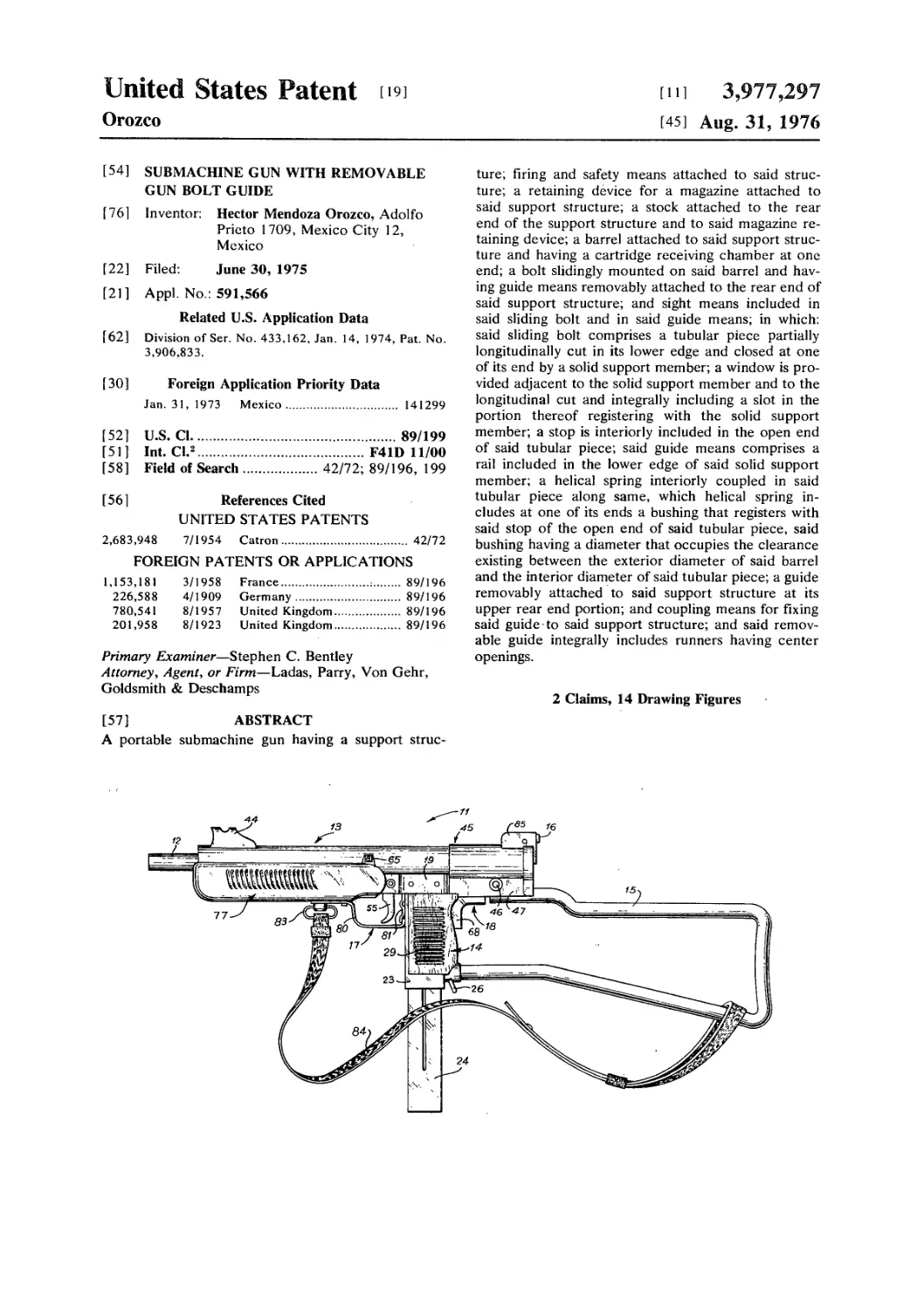
[57] ABSTRACT
A portable submachine gun having a support struc-
ture; firing and safety means attached to said struc-
ture; a retaining device for a magazine attached to
said support structure; a stock attached to the rear
end of the support structure and to said magazine re-
taining device; a barrel attached to said support struc-
ture and having a cartridge receiving chamber at one
end; a bolt slidingly mounted on said barrel and hav-
ing guide means removably attached to the rear end of
said support structure; and sight means included in
said sliding bolt and in said guide means; in which:
said sliding bolt comprises a tubular piece partially
longitudinally cut in its lower edge and closed at one
of its end by a solid support member; a window is pro-
vided adjacent to the solid support member and to the
longitudinal cut and integrally including a slot in the
portion thereof registering with the solid support
member; a stop is interiorly included in the open end
of said tubular piece; said guide means comprises a
rail included in the lower edge of said solid support
member; a helical spring interiorly coupled in said
tubular piece along same, which helical spring in-
cludes at one of its ends a bushing that registers with
said stop of the open end of said tubular piece, said
bushing having a diameter that occupies the clearance
existing between the exterior diameter of said barrel
and the interior diameter of said tubular piece; a guide
removably attached to said support structure at its
upper rear end portion; and coupling means for fixing
said guide to said support structure; and said remov-
able guide integrally includes runners having center
openings.
2 Claims, 14 Drawing Figures
U.S. Patent Aug. 31, 1976 Sheet I of 6 3,977,297
U.S. Patent Aug. 3i, 1976
Sheet 2 of 6
3,977,297
U.S. Patent Aug. 31, 1976 Sheet 3 of 6
3,977,297
U.S. Patent Aug. 3i, 1976
Sheet 4 of 6
3,977,297
U.S. Patent Aug. 3i, 1976
Sheet 5 of 6
3,977,297
U.S. Patent Aug. 3i, 1976
Sheet 6 of 6
3,977,297
3,977,297
1
SUBMACHINE GUN WITH REMOVABLE GUN
BOLT GUIDE
This is a division of application Ser. No. 433,162 filed
Jan. 14, 1974, now Pat. No. 3,906,833.
BACKGROUND OF THE INVENTION
To date, a great variety of rapid fire sub-machine
guns or rapid fire pistols are known, which generally
function by means of a mechanism known as an open
cover inasmuch as these are low pressure arms. These
arms always include a case inside of which the firing
and safety mechanism are located, as well as the fire-
arm bolt, and to which case the grip of the firearm is
joined, together with or separately from the magazine
of the same, the barrel and, optionally, a detachable or
folding stock.
These known sub-machine guns have many disadvan-
tages; thus when the stock is needed, since the barrel is
joined to the case, these firearms turn out to be of
considerable length, and therefore very cumbersome.
In order to avoid the above, folding stocks were
thought of; nevertheless, these also have disadvantages
because after firing or when needed to strike with, they
are not very adequate inasmuch as they bend since they
are not fixed.
Another disadvantage of the folding stock is that in
the case of combat fractions of a minute are very im-
portant, and getting the stock in place slows down the
operation.
One of the greatest problems and disadvantages of
the known sub-machine guns is that when the bolt is
included within the case it can always jam due to for-
eign matter getting into the case; this is very dangerous
because when it is not possible to move the bolt in time
to free the firing mechanism of the firearm, or it moves
in an inadequate manner, the desired shot will not be
produced or said shot will be interfered with and thus
dangerous to the shooter.
Aside from the aforementioned disadvantages, an-
other difficulty with having the bolt inside the case is
that the cleaning of the same is complicated and re-
quires appreciable time, time that must be taken into
consideration for, as has already been said, in the case
of combat, it is all important.
An additional problem with the interior bolt is that it
requires guides which guide it in its travel and, also, it
includes only a simple dwell or retention lever on the
same.
Another of the problems of the known sub-machine
guns is that the type of safety used is generally related
to the trigger or firing device, which in reality does not
provide for complete reliability inasmuch as on many
occasions it allows the arm to fire without squeezing
the trigger; and this causes innumerable accidents since
there is no set target. Also we can not really be certain
that the firearm is not ready to fire. And there is no
assurance against this because if the firearm were for
example to be dropped and strike on the back side it
would actually fire as the bolt moved as a result of the
shock of the fall; and consequently said accidents can
occur.
Another disadvantage of this type of known firearms
is that in all of them, after they have been used for some
time, the firing pin or device that causes the detonation
of the primer of the cartridges deteriorates and does
5
10
15
20
25
30
35
40
45
50
55
60
65
2
not function properly and therefore must be replaced
by a new one.
Finally, another problem with the known sub-
machine guns is that the sight included in the chamber
is fixed and in many cases there is no way to adjust it
according to the conditions of firing the firearm. Con-
sequently these arms do not afford very accurate aim,
and in firearms this is definitely necessary.
OBJECTS OF THE INVENTION
It is therefore one of the objectives of the present
invention to provide an improved portable firearm of
the rapid fire type (submachine gun), which is very
compact, and which has a fixed stock with which ade-
quate support is obtained for firing a good shot, also,
that it may be safely used for striking; and furthermore,
in the case of combat that there be no loss of time in
bringing the stock into place.
Another object of the present invention is to provide
an improved portable firearm of the sub-machine gun
type in which it is difficult for the bolt to jam because
of foreign matter inasmuch as, since it is exposed, a
simple shaking or hand wipe will eliminate said foreign
matter.
An additional object of the present invention is to
provide an improved portable firearm of the sub-
machine gun type which includes a bolt which does not
have any guides inasmuch as it is designed in such a
way that it functions in an adequate way without such
guides.
Another objective of the present invention is to pro-
vide an improved portable firearm of the sub-machine
gun type in which the bolt is brought into firing position
by means of a double fastener, which is to say, by
means of two detention levers.
Another objective of the present invention is to pro-
vide an improved portable firearm of the sub-machine
gun type which has a safety in addition to the one on
the trigger, and said additional safety prevents the
movement of the bolt except when the firearm is
gripped and therefore if the firearm falls it cannot fire.
Another object of the present invention is to provide
an improved portable firearm of the sub-machine gun
type which comprises an invertable and reusable firing
pin, because once the end of the same has deteriorated
due to use, the firing pin is removed from its lodging
and is inverted, thus affording a new firing pin.
It is another object of the present invention to pro-
vide an improved portable firearm of the sub-machine
gun type which has a rear sight which is adjustable on
its transverse axis for more accurate aiming as firing
conditions require.
Finally, it is an object of the present invention to
provide an improved portable firearm of the sub-
machine gun type which comprises a support structure
in which the firing and safety means are mounted; to
which a grip, a stock and a barrel are fixed; and to
which a sliding bolt is joined, said sliding bolt including
an invertable firing pin, a guiding means for the bolt
and an open cover both removable.
These and other objects to be provided in practice by
the present invention will be better understood and
appreciated by reading the following description which
refers to the drawings of the preferred embodiment of
the present invention.
3,977,297
3
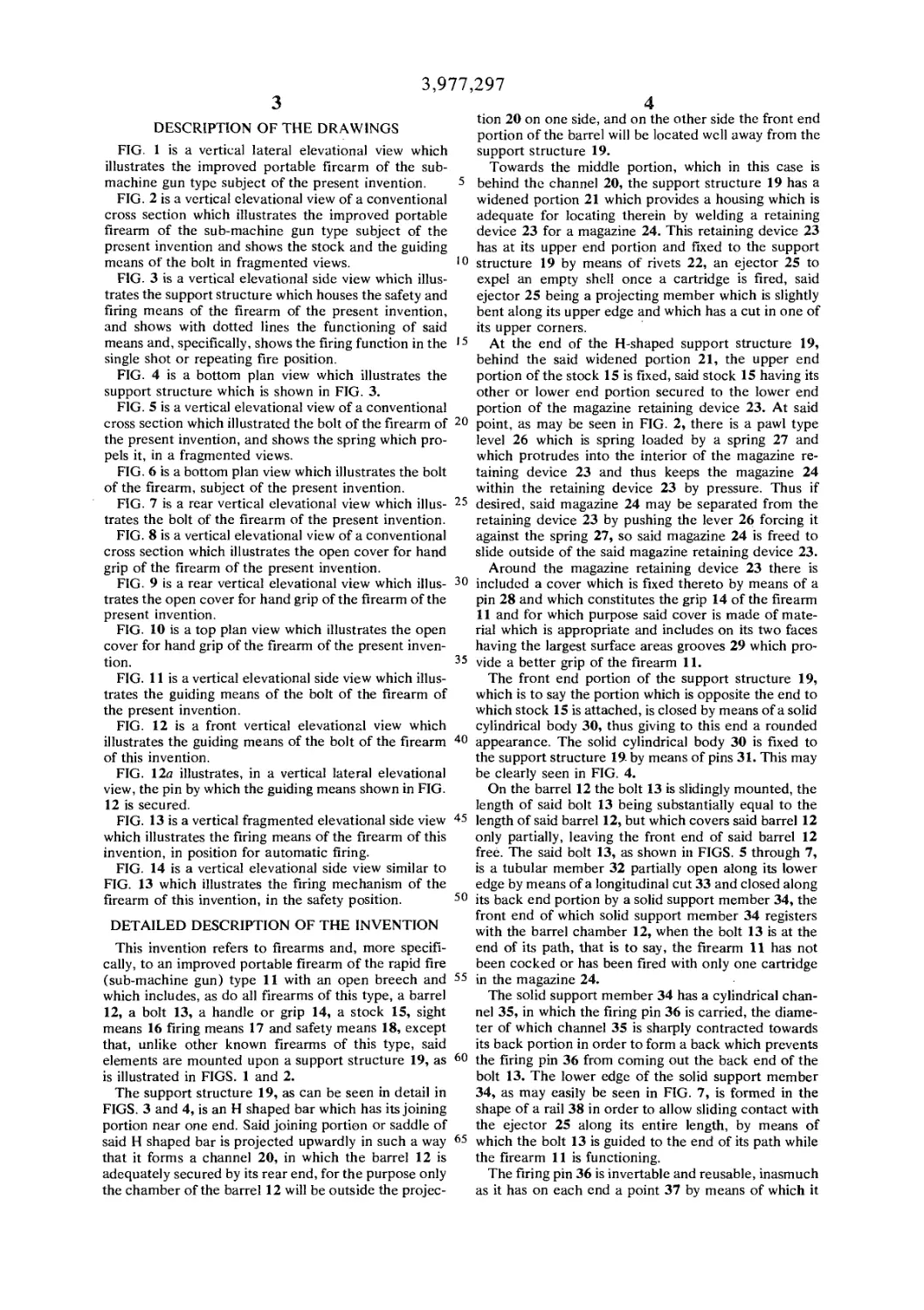
DESCRIPTION OF THE DRAWINGS
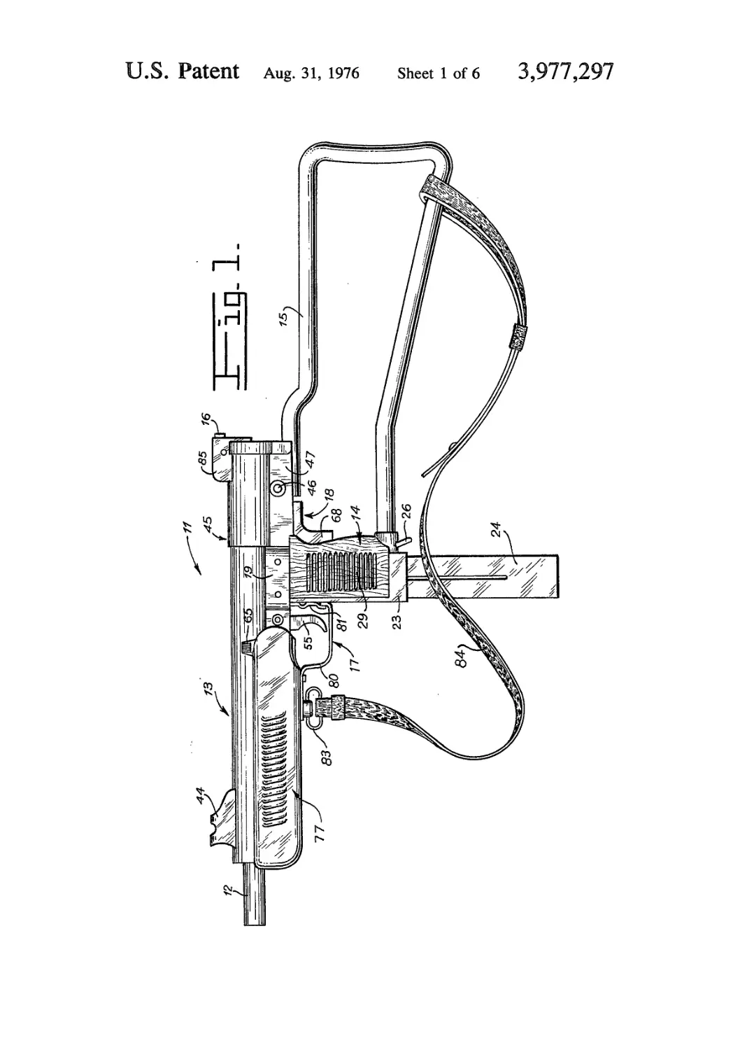
FIG. 1 is a vertical lateral elevational view which
illustrates the improved portable firearm of the sub-
machine gun type subject of the present invention.
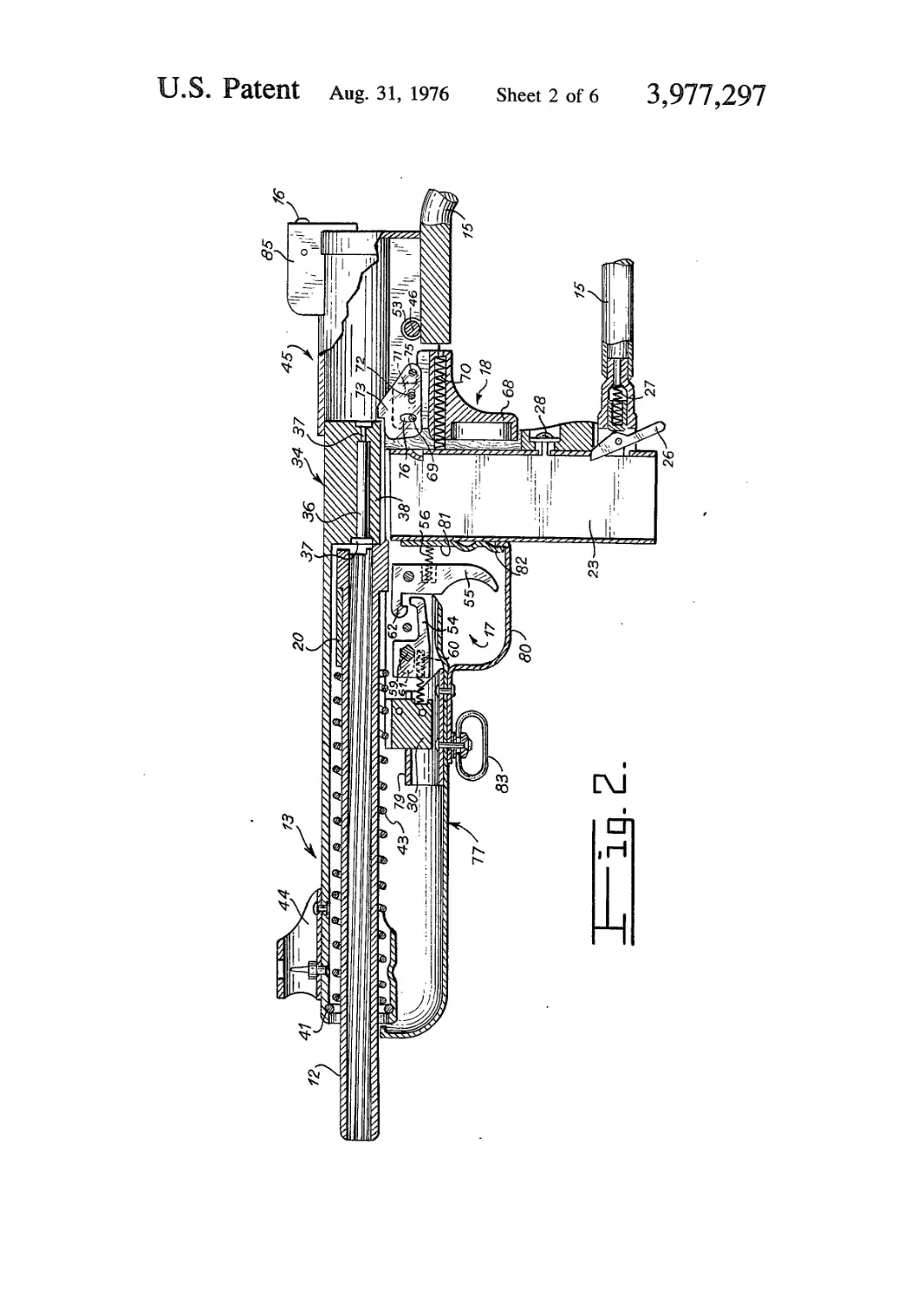
FIG. 2 is a vertical elevational view of a conventional
cross section which illustrates the improved portable
firearm of the sub-machine gun type subject of the
present invention and shows the stock and the guiding
means of the bolt in fragmented views.
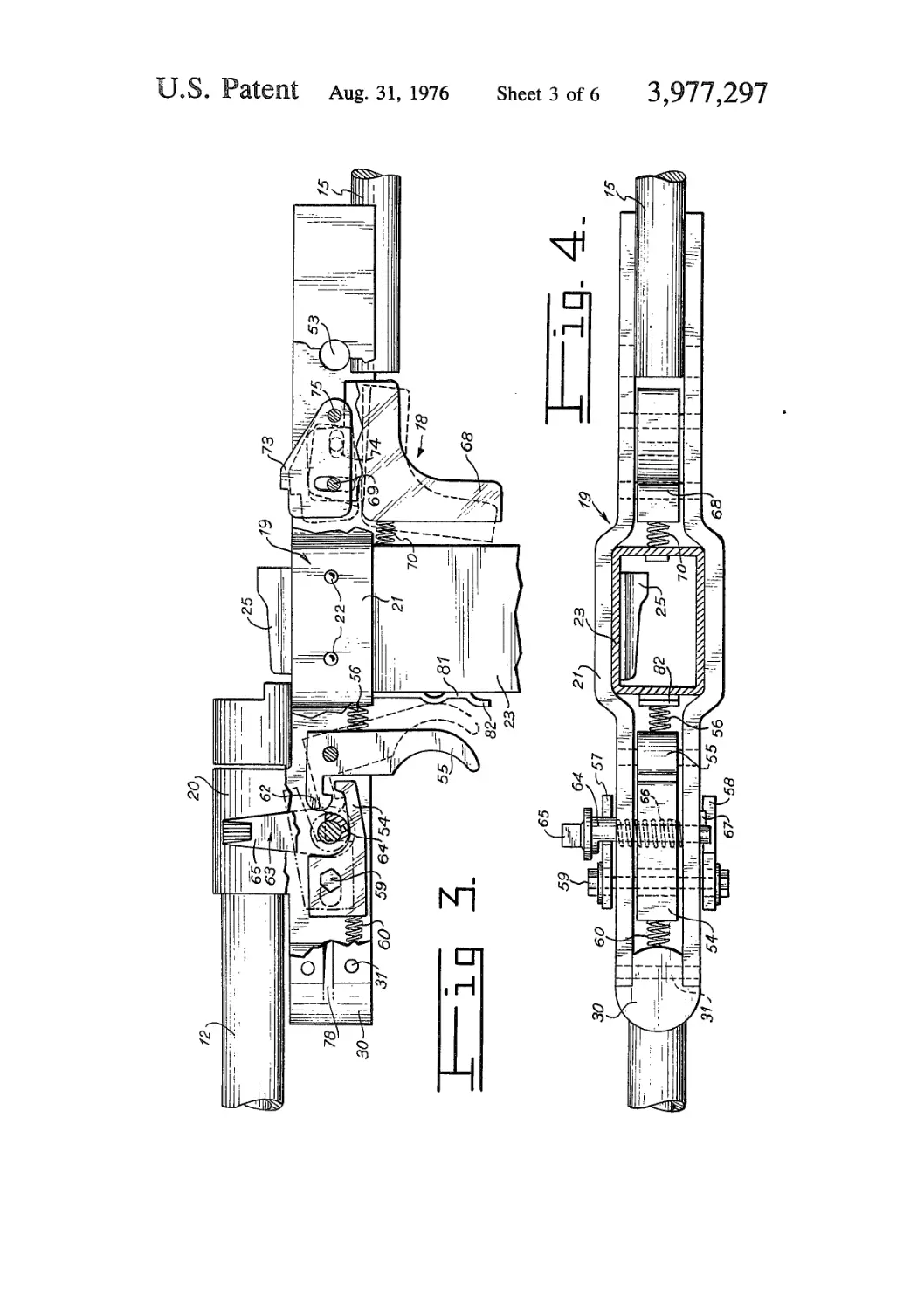
FIG. 3 is a vertical elevational side view which illus-
trates the support structure which houses the safety and
firing means of the firearm of the present invention,
and shows with dotted lines the functioning of said
means and, specifically, shows the firing function in the
single shot or repeating fire position.
FIG. 4 is a bottom plan view which illustrates the
support structure which is shown in FIG. 3.
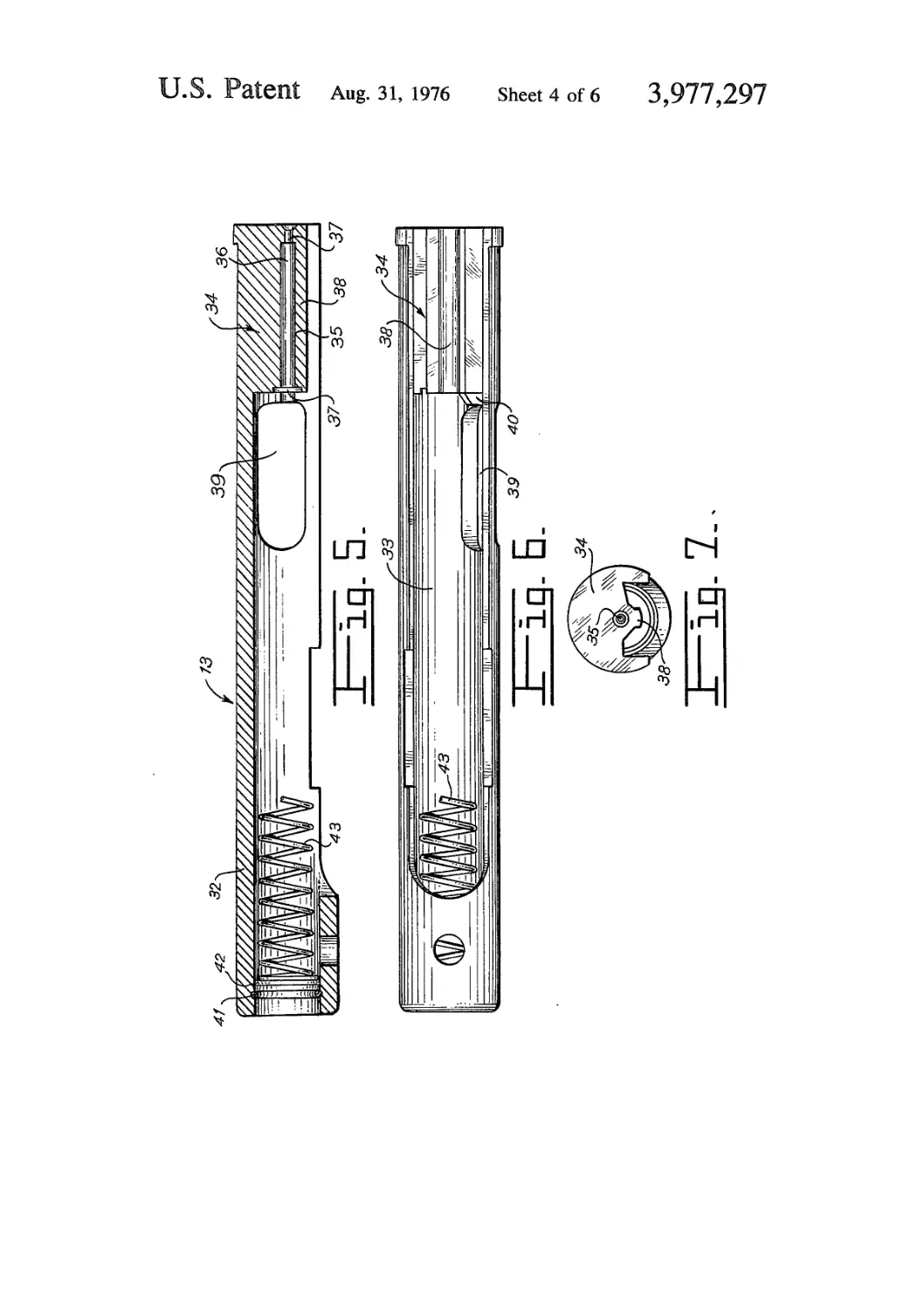
FIG. 5 is a vertical elevational view of a conventional
cross section which illustrated the bolt of the firearm of
the present invention, and shows the spring which pro-
pels it, in a fragmented views.
FIG. 6 is a bottom plan view which illustrates the bolt
of the firearm, subject of the present invention.
FIG. 7 is a rear vertical elevational view which illus-
trates the bolt of the firearm of the present invention.
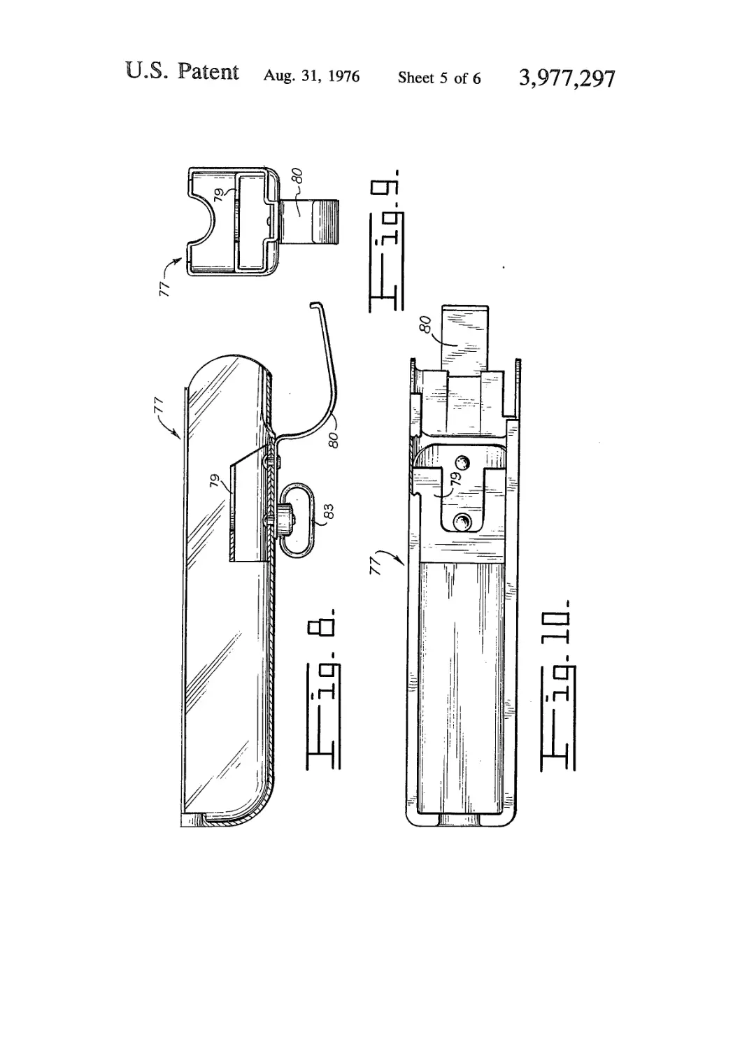
FIG. 8 is a vertical elevational view of a conventional
cross section which illustrates the open cover for hand
grip of the firearm of the present invention.
FIG. 9 is a rear vertical elevational view which illus-
trates the open cover for hand grip of the firearm of the
present invention.
FIG. 10 is a top plan view which illustrates the open
cover for hand grip of the firearm of the present inven-
tion,
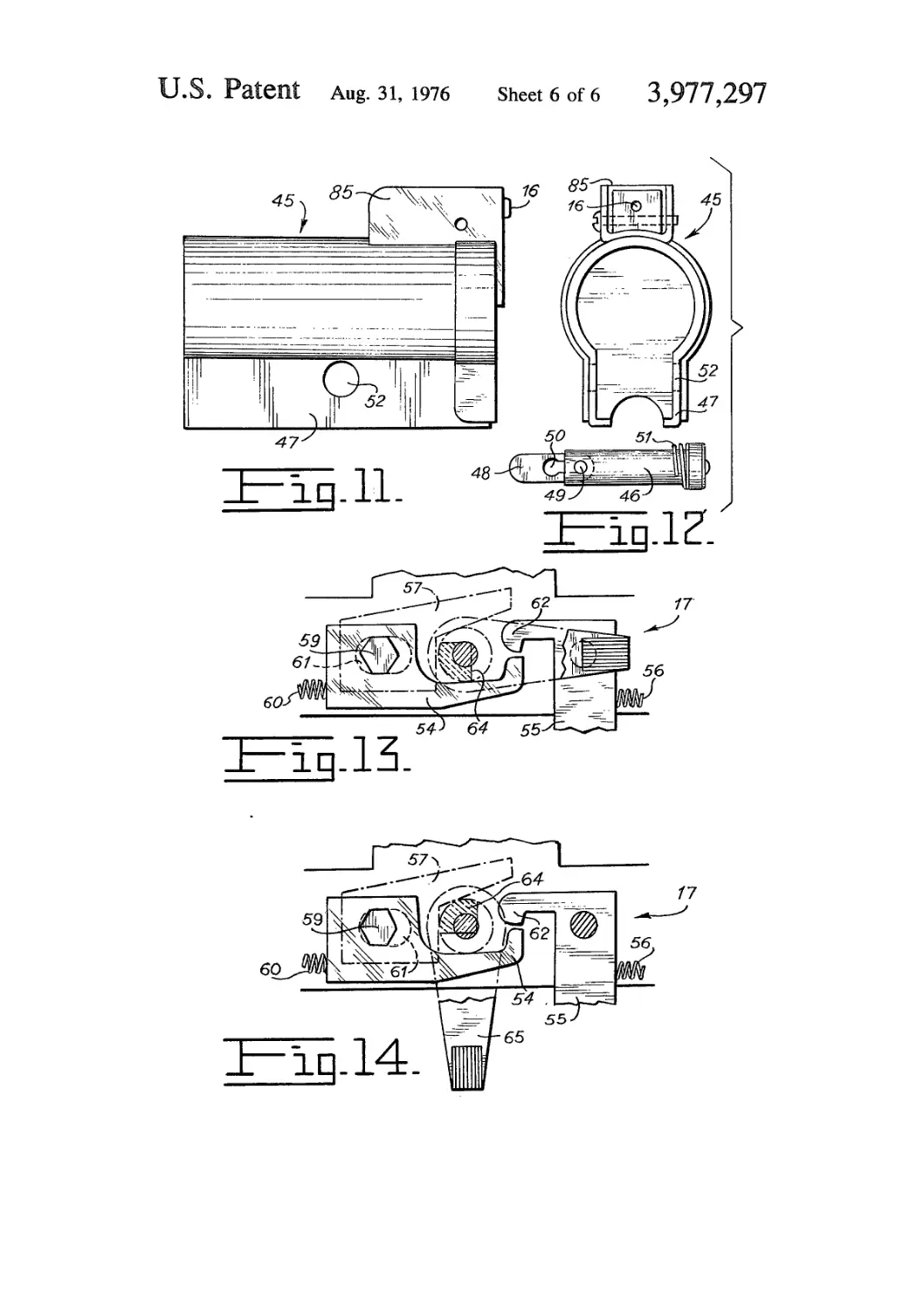
FIG. 11 is a vertical elevational side view which illus-
trates the guiding means of the bolt of the firearm of
the present invention.
FIG. 12 is a front vertical elevational view which
illustrates the guiding means of the bolt of the firearm
of this invention.
FIG. 12a illustrates, in a vertical lateral elevational
view, the pin by which the guiding means shown in FIG.
12 is secured.
FIG. 13 is a vertical fragmented elevational side view
which illustrates the firing means of the firearm of this
invention, in position for automatic firing.
FIG. 14 is a vertical elevational side view similar to
FIG. 13 which illustrates the firing mechanism of the
firearm of this invention, in the safety position.
DETAILED DESCRIPTION OF THE INVENTION
This invention refers to firearms and, more specifi-
cally, to an improved portable firearm of the rapid fire
(sub-machine gun) type 11 with an open breech and
which includes, as do all firearms of this type, a barrel
12, a bolt 13, a handle or grip 14, a stock IS, sight
means 16 firing means 17 and safety means 18, except
that, unlike other known firearms of this type, said
elements are mounted upon a support structure 19, as
is illustrated in FIGS. 1 and 2.
The support structure 19, as can be seen in detail in
FIGS. 3 and 4, is an H shaped bar which has its joining
portion near one end. Said joining portion or saddle of
said H shaped bar is projected upwardly in such a way
that it forms a channel 20, in which the barrel 12 is
adequately secured by its rear end, for the purpose only
the chamber of the barrel 12 will be outside the projec-
5
10
15
20
25
30
35
40
45
50
55
60
65
4
tion 20 on one side, and on the other side the front end
portion of the barrel will be located well away from the
support structure 19.
Towards the middle portion, which in this case is
behind the channel 20, the support structure 19 has a
widened portion 21 which provides a housing which is
adequate for locating therein by welding a retaining
device 23 for a magazine 24. This retaining device 23
has at its upper end portion and fixed to the support
structure 19 by means of rivets 22, an ejector 25 to
expel an empty shell once a cartridge is fired, said
ejector 25 being a projecting member which is slightly
bent along its upper edge and which has a cut in one of
its upper corners.
At the end of the H-shaped support structure 19,
behind the said widened portion 21, the upper end
portion of the stock 15 is fixed, said stock 15 having its
other or lower end portion secured to the lower end
portion of the magazine retaining device 23. At said
point, as may be seen in FIG. 2, there is a pawl type
level 26 which is spring loaded by a spring 27 and
which protrudes into the interior of the magazine re-
taining device 23 and thus keeps the magazine 24
within the retaining device 23 by pressure. Thus if
desired, said magazine 24 may be separated from the
retaining device 23 by pushing the lever 26 forcing it
against the spring 27, so said magazine 24 is freed to
slide outside of the said magazine retaining device 23.
Around the magazine retaining device 23 there is
included a cover which is fixed thereto by means of a
pin 28 and which constitutes the grip 14 of the firearm
11 and for which purpose said cover is made of mate-
rial which is appropriate and includes on its two faces
having the largest surface areas grooves 29 which pro-
vide a better grip of the firearm 11.
The front end portion of the support structure 19,
which is to say the portion which is opposite the end to
which stock 15 is attached, is closed by means of a solid
cylindrical body 30, thus giving to this end a rounded
appearance. The solid cylindrical body 30 is fixed to
the support structure 19 by means of pins 31. This may
be clearly seen in FIG. 4.
On the barrel 12 the bolt 13 is slidingly mounted, the
length of said bolt 13 being substantially equal to the
length of said barrel 12, but which covers said barrel 12
only partially, leaving the front end of said barrel 12
free. The said bolt 13, as shown in FIGS. 5 through 7,
is a tubular member 32 partially open along its lower
edge by means of a longitudinal cut 33 and closed along
its back end portion by a solid support member 34, the
front end of which solid support member 34 registers
with the barrel chamber 12, when the bolt 13 is at the
end of its path, that is to say, the firearm 11 has not
been cocked or has been fired with only one cartridge
in the magazine 24.
The solid support member 34 has a cylindrical chan-
nel 35, in which the firing pin 36 is carried, the diame-
ter of which channel 35 is sharply contracted towards
its back portion in order to form a back which prevents
the firing pin 36 from coming out the back end of the
bolt 13. The lower edge of the solid support member
34, as may easily be seen in FIG. 7, is formed in the
shape of a rail 38 in order to allow sliding contact with
the ejector 25 along its entire length, by means of
which the bolt 13 is guided to the end of its path while
the firearm 11 is functioning.
The firing pin 36 is invertable and reusable, inasmuch
as it has on each end a point 37 by means of which it
3,977,297
5
can ignite the cartridge. This firing pin 36 is a metal bar
which is slightly bent before it is tempered and there-
fore it is not perfectly straight; and when it is intro-
duced into the channel 35 it becomes lodged with
enough pressure to give it a degree of fixation.
The tubular member 32 has on the back portion, near
the solid support member 34 and near said cut 33, an
opening or window 39, the back end of which is inte-
grated with a groove (not illustrated) which has in its
interior a small bar tiltingly attached, said bar having its
front end bent in the form of a hook, and functioning as
a puller finger 40 to remove the empty shell from the
inside of the chamber.
The bolt 13 comprises, near its front end or mouth,
an interior stop 41 which is fixed thereto and which is
formed by an open ring lodged in a peripheral interior
groove near the mouth of said bolt 13. The stop 41
holds a bushing 42 which is welded to an end of a heli-
cal spring 43, which spring 43 guides, pushes and pro-
vides the functioning travel of the bolt 13, and has a
length slightly greater than that of the bolt 13. The
diameter of bushing 42 is such that it lies in the clear-
ance which exists between the exterior diameter of the
barrel 12 and the interior diameter of the bolt 13 and
which furthermore maintains the concentricity of of
both elements, whereby the bolt 13 freely slides over
the barrel 12.
On its upper front end portion, the bolt 13 has a
projecting part which is formed as a ledge 44 to permit
easily drawing the bolt 13 against the spring 43 and
moving it to the firing position. This ledge 44, in order
that it may be operated by only one finger, has a slight
concavity at its front end. This ledge 44 since it is hol-
low, is also used to enclose and at the same time protect
the front sight which establishes the line of aiming of
the sight means 16.
The bolt 13 is also partially guided at its outer end by
a guide 45 removably joined to the support structure 19
by means of a pin 46 which is removable and by run-
ners 47 which are integral with said guide 45.
The pin 46 is a smooth pin, which has in the end
opposite its head a pivotal tongue 48 fixed by a shaft
49. The said tongue 48 has, from its middle portion to
its end, a slot 50; the end of the slot 50 which registers
with the center of the tongue 48 is enlarged. A spring
51 encompasses the shaft of pin 46 and presses against
the head of pin 46, thus applying pressure against
tongue 48 when said tongue 48 is crosswise to the pin
46, after said pin 48 has been introduced through open-
ings 52 in the runners 47 and matching openings 53 in
the support structure 19 in order to mount the guide 45
in said support structure 19.
In the interior of the support structure 19 near the
widened portion 21 and at each end of the same, the
firing means 17 and the safety means 18 are included.
The firing means 17, as can be clearly seen in FIGS.
2 through 4 and 13 through 14, is comprised of three
levers, there being one central lever 54 which is located
in the interior of the support structure 19 and is the
mechanism brought into action by a trigger 55, when
the latter is forced against a spring 56 and thus fires the
shot. The other two levers are located outside the sup-
port structure 19 and are detention levers 57 and 58 of
the bolt 13 in the initial position of its travel, which is
to say in the position of preparation for firing. In this
manner, once the central lever 54 is brought into action
by the trigger 55, the lever 54 tilts downward, providing
the same movement for the detention levers 57 and 58
5
10
15
20
25
30
35
40
45
50
55
60
65
6
because said three levers 54, 57 and 58 have a common
axis 59 which is partially polyhedral, in this case hexag-
onal, in its end portions and in its middle portion, on
which said portions the three said levers 54, 57 and 58
are mounted. This common shaft 59 is cylindrical in
those portions which are carried in the support struc-
ture 19, in such a way that they can tilt freely relative
to said support structure 19. Therefore, in the forego-
ing operation, the bolt 13 is freed from the action of the
detention levers 54, 57 and 58 and the firearm 11 is
fired in this fashion.
So then, as has already been stated, the detention
levers 57 and 58 provide the initial position of travel of
the bolt 13. This position is achieved by manually forc-
ing bolt 13 against spring 43 by means of ledge 44 until
the said detention levers 57 and 58 fall into place in
some indentations made in the longitudinal cut 33 near
the front end of said bolt 13. These levers 57 and 58
drop into place by the action of a spring 60 of the firing
means 17 which forces said levers 57 and 58 into a
raised position and for this reason, once the indenta-
tions in the longitudinal cut 33 reach the detention
levers 57 and 58 the latter are lifted up and at the same
time hold the bolt 13 at the point where they strike the
rear ends of the said indentations. With this movement
of the bolt 13 into position for firing, in the event that
there is an empty shell in the chamber of the barrel 12,
the puller finger 40 will pull it out of said chamber until
said empty shell is thrown outside of the firearm 11
through the window 39 by action of the ejector 25 at
the moment that the latter registers with said window
39.
In order for the central lever 54 to be activated by the
trigger 55 it must necessarily be forced against the
spring 60 which has one of its ends fixed to the end of
the central lever 54, opposite the trigger 55 and its
other end fixed to the solid cylindrical body 30 in the
support structure 19. This position is provided by the
bolt 13 at the initial point of its travel when held in
place by the detention levers 57 and 58; made and it is
possible because the common shaft 59 of said detention
levers 57 and 58 is mounted in the support structure 19
through openings 61 which are slightly elongated,
whereby the three levers 54, 57 and 58 have a slight
sliding action in order that the central lever 54 registers
with a catch 62 of the trigger 55 which activates the
firing means 17.
In order to select the type of firing to be done with
the firearm 11, subject of the present invention, which
may be repeating fire,, single shot, or automatical,
there is included in the firing means 17 a firing selector
63. This selector 63 comprises a shaft one end portion
64 of which is cut at an angle, and at this same end it
also has a positioning device 65 by means of which the
selector 63 is positioned for the type of firing desired.
The selector 63 is fixed, by means of its shaft, to the
support structure 19 pressing against a spring 66 and
fixed by means of a retainer pin 67 which is located in
the end opposite the positioning device 65, and which
is lodged in some slots (not .illustrated) of the support
structure 19 which have the same positions as those of
the selector 63 and therefore said positions are ob-
tained in a precise fashion.
It may be said that the selection of the type of firing
is really provided by the indented portion 64 inasmuch
as its cut angle allows the detention lever 57, which
registers the same and furthermore has a base which is
slightly larger than that of the other detention lever 58,
3,977,297
7
to remain in a different position in the elongated open-
ing 61, and to remain fixed or not in its tilting move-
ment according to the type of firing desired. For exam-
ple, as shown in FIG. No. 3, when the positioning de-
vice 65 is placed vertically upward, the cut of the in-
dented portion 64 allows the detention lever 57 to
remain completely free to slide along the whole length
of the elongated opening 61, and its tilting movement
of be total. Consequently, once the bolt has been re-
leased, said levers 54, 57 and 58 return to their initial
position in the elongated opening 61 and the central
lever 54 remains out of engagement with the catch 62
of the trigger 55.
Accordingly, in order for the three levers 54, 57 and
58 to move into an adequate firing position, the trigger
55 must be allowed to return to its initial position in
order for the bolt 13, moved by the gases caused by the
firing to return to its initial position of travel and be
held there by the detention levers 57 and 58; and with
this position the central lever 54 now registers with the
catch 62 of the trigger 55 and the firing means 17 may
be activated by once again squeezing the trigger 55. So
then, we may deduce from the foregoing that the said
vertical position of the selector 63 provides a repeating
or shot-by-shot type of firing, and in this mode every
time a new shot is desired the trigger 55 must be
squeezed.
Another type of firing of the firearm 11 which is the
subject of this invention is that which is provided by the
position of the firing means 17 which is shown in FIG.
13. In this case the positioning device 65 is in a horizon-
tal position which leaves the cut of the indented portion
64 so placed that levers 54, 57 and 58, by means of
detention lever 57, are pressed against the spring 60 at
the end of the elongated opening 61, opposite the trig-
ger 55. Therefore, the common shaft 59 of said levers
remains fixed in this position and by this means the
central lever 54 always remains registering, with the
catch 62 in order to be activated by the trigger 55 in an
uninterrupted fashion; because, the central lever 54
never escapes the action of the trigger 55, as already
stated, since as a result of the gases let off by the firing,
and the bolt 13 returns and moves into its initial posi-
tion of its travel, allowing the firearm 11 to function
continuously as long as the trigger 55 is squeezed and
there are cartridges which provide the proper pressure
by means of the gases given off upon firing.
A third position provided by the selector 63 is the
safety position, which is illustrated in FIG. 14. This
safety position is achieved when the positioning device
65 is in a vertical position downward and prevents the
detention levers 57 and 58 from freeing the bolt 13,
and therefore there is no firing. In this case the in-
dented portion 64 remains in such a position that its
uncut part bears against the detention lever 57 as a
result of its wider base and blocks it, forcing the levers
57 and 58 to lodge in the slots of the lengthwise cut 33,
i.e., in the position of detention of the bolt 13. Conse-
quently, although the central lever 54 remains register-
ing with the catch 62 of the trigger 55 since the three
levers 54, 57 and 58 remain in the end of the elongated
opening 64 opposite the trigger 55, when the latter is
squeezed the tilting movement of the central lever 54 is
prevented. This happens because the detention lever
57 is fixed and as a result of the effect of the common
shaft 59, because as we known, by virtue of said com-
mon shaft 59 the three levers 54, 57 and 58 have a
simultaneous movement.
5
10
15
20
25
30
35
40
45
50
55
60
65
s
In addition to the safety provided by the selector 63,
we have the specific safety means 18. This safety means
18 is such that it prevents the firearm 11 from being
fired unless said safety is gripped, inasmuch as other-
wise it prevents the bolt 13 from moving to the initial
position of its travel, in other words, the firearm cannot
be cocked. The safety mechanism 18 can be readily
seen in FIGS. 2 and 3. This mechanism is mounted in
the support structure 19 behind the widened portion 21
of same, and comprises an activating lever 68 which is
square-shaped and which has a tilting movement with
relation to the support structure 19, since it is thereon
mounted by means of a shaft 69 and since it is spring
loaded on the back side of the magazine retaining de-
vice 23 by a spring 70. This square-shaped piece results
the activating lever 68; because the portion of this
piece extending into the support structure 19 includes
projections 71 which pivotingly support safety plates
73 by means of shaft 72 that passes through horizon-
tally elongated holes 74. Said safety plates 73 are piv-
oted at one end to support structure 19 by means of
shaft 75, and have a vertically elongated hole 76 in
their portion registering with shaft 69 of the activating
lever 68, to enable bolt 13 to slide to the starting posi-
tion of its travel; thus they provide proper functioning
of the safety means 18.
The aforementioned function is clearly illustrated
with dotted lines in FIG. 3 and works as follows: upon
pushing the activating lever 68 against the spring 70 the
safety plates 73 are lowered and as has already been
said, allow bolt 13 to be moved into the initial position
of its travel. Therefore, due to the fact that the activat-
ing lever 68 is located in the grip 14 in that portion
opposite the trigger 55, each time the firearm 11 is
gripped the safety means 18 is released and the only
way in which to release the safety except by gripping
the gun, is by specifically pressing the lever 68.
In order to provide a point of hand support in the
front part of the firearm 11 subject of this invention an
open cover 77 is attached to the support structure 19
which is shown in FIGS. 8 through 10. This cover 77 is
fixed by means of two connections: on one side to the
support structure 19 by means of slots 78 included in
the front end of said support structure 19 in which slots
78 a rail plate 79 slides, said rail plate 79 being secured
in the inner back portion of the open cover 77; and on
the other side, to the magazine retaining device 23 by
means of a metal strip 80 which is slightly turned up at
its free end, which free edge attaches to the front face
of the said retaining device 23 by means of a bar 81.
Said bar 81 has in its upper end portion an opening in
which one end of the spring 56 of trigger 55 is lodged,
by means of which spring 56 the slipping of trigger 55
is avoided and the proper support of same is given. On
its lower end, bar 81 has an angular lip which forms a
channel 82 in which the metal strip 80 is lodged due to
the tension of its free end. In this way the open cover 77
remains fully secured to the support structure 19 and
trigger 55 is provided with a guard by the metal strip
80; furthermore, a ridge included in bar 81 acts as a
stop for trigger 55 when it is pulled.
Said open cover 77 on the rear end near the metal
strip 80 carries a pivotal ring 83 which supports one
end of a belt 84 the other end of which is supported by
the stock 15 as shown in FIG. 1.
As previously noted the front sight is located within
the ledge 44 on the front end of the bolt 13; therefore
in order to have a line of aiming an opening is needed,
3,977,297
9
which opening is located in a rear sight 85 which is a
raised element movably connected to the upper rear
end of guide 45 opposite bolt 13, thus constituting the
complete sight assembly for aiming. Inasmuch as the
rear sight 85 is laterally adjustable, it may be said that
the sight means 16 is adjustable for windage. This type
of adjustment is required because for the use of this
type of firearm the aim must be exact in the tranverse
axis of the target.
From the foregoing description we observe that the
present invention provides a firearm 11 with a great
many advantages over known firearms, which advan-
tages have been fully indicated. Nevertheless, in a short
summary we may say that they are:
The bolt 13 is exposed which avoid interference in its
functioning. Said bolt 13 covers almost the entire bar-
rel 12; hence it is a very short firearm, thus allowing the
stock 15 to be fixed. It includes a safety 63 which pre-
vents the firearm 11 from being fired except when it is
gripped. It is a firearm 11 with very few estructural
elements and therefore is very light and easy to arm and
to take to pieces without any tools and in a very short
time.
Although the foregoing description was made in rela-
tion to one specific model of the invention, it must be
understood by all of those who are experts in this field
that any change whatsoever in form or detail will be
comprised within the field and scope of the same.
I claim;
1. A portable submachine gun comprising a support
structure having upper and lower edges and front and
rear ends; firing and safety means attached to said
structure; a retaining device for a magazine attached to
said support structure; a stock attached to said rear end
of the support structure and to said magazine retaining
device; a barrel attached to said support structure and
having a cartridge receiving chamber at one end; a bolt
slidingly mounted on said barrel and having guide
means removably attached to the rear end of said sup-
port structure; and sight means included in said sliding
bolt and in said guide means; in which: said sliding bolt
comprises a tubular piece partially longitudinally cut in
its lower edge and closed at one of its end by a solid
support member; a window is provided adjacent to the
solid support member and to the longitudinal cut and
integrally including a slot in the portion thereof regis-
tering with the solid support member; a stop is interi-
orly included in the open end of said tubular piece; said
guide means comprises a rail included in the lower edge
of said solid support member; a helical spring interiorly
5
10
15
20
25
30
35
40
45
50
55
60
10
coupled in said tubular piece along same, which helical
spring includes at one of its ends a bushing that regis-
ters with said stop of the open end of said tubular piece,
said bushing having a diameter that occupies the clear-
ance existing between the exterior diameter of said
barrel and the interior diameter of said tubular piece; a
guide removably attached to said support structure at
its upper rear end portion; and coupling means for
fixing said guide to said support structure; and said
removable guide integrally includes runners having
center openings.
2. A portable submachine gun comprising a support
structure having upper and lower edges and front and
rear ends; firing and safety means attached to said
structure; a retaining device for a magazine attached to
said support structure; a stock attached to said rear end
of the support structure and to said magazine retaining
device; a barrel attached to said support structure and
having a cartridge receiving chamber at one end; a bolt
slidingly mounted on said barrel and having guide
means removably attached to the rear end of said sup-
port structure; and sight means included in said sliding
bolt and in said guide means; in which: said sliding bolt
comprises a tubular piece partially longitudinally cut in
its lower edge and closed at one of its end by a solid
support member; a window is provided adjacent to the
solid support member and to the longitudinal cut and
integrally including a slot in the portion thereof regis-
tering with the solid support member; a stop is interi-
orly included in the open end of said tubular piece; said
guide means comprises a rail included in the lower edge
of said solid support member; a helical spring interiorly
coupled in said tubular piece along same, which helical
spring includes at one of its ends a bushing that regis-
ters with said stop of the open end of said tubular piece,
said bushing having a diameter that occupies the clear-
ance existing between the exterior diameter of said
barrel and the interior diameter of said tubular piece; a
guide removably attached to said support structure at
its upper rear end portion; coupled means for fixing
said guide to said support structure; and said coupling
means for fixing said guide to said support structure
comprises a smooth head pin including in its headed
end a spring and including in its end opposite to said
headed end a pivotal tongue which tongue includes a
slot having one of its ends enlarged, said enlarged end
registering with the central portion of the pivotal
tongue.
* * * * *
65